code generation from uml models with semantic variation points
TRANSCRIPT

Code generation from UML Models with semanticvariation points ∗
Franck Chauvel and Jean-Marc Jezequel(VALORIA, INRIA & Universite Rennes 1)
July 4, 2005
Abstract
UML semantic variation points provide intentional degrees of freedom for theinterpretation of the metamodel semantics. The interest of semantic variation points isthat UML now becomes a family of languages sharing lot of commonalities and somevariabilities that one can customize for a given application domain. In this paper, wepropose to reify the various semantic variation points of UML 2.0 statecharts intomodels of their own to avoid hardcoding the semantic choices in the tools. We do thesame for various implementation choices. Then, along the line of the OMG’s ModelDriven Architecture, these semantic and implementation models are processed alongwith a source UML model (that can be seen as a PIM) to provide a target UML model(a PSM) where all semantic and implementation choice are made explicit. This targetmodel can in turn serve as a basis for a consistent use of code generation, simulation,model-checking or test generation tools.
1 IntroductionUML (Unified Modeling Language) has been widely critized in the past for its fuziness,making it difficult to build code generators, simulation, model-checking or test generationtools working in a consistent manner. Many tool vendors are nevertheless producinguseful tools, some of them even have reach a certain level of industrial acceptance. Theinterest of having a unified modeling language is however questionable if the meaning ofa UML model depends on which tool is used for any given purpose. With the advent ofUML 2.0 [14] though, many of previous version UML fuziness issues have been solved,and some of the rest have been encapsulated into the notion of semantic variation points.
A semantic variation point is a point of variation in the semantics of a metamodel.It provides an intentional degree of freedom for the interpretation of the metamodel se-mantics. For instance, we find on page 40 of [14] The precise lifecycle semantics ofaggregation is a semantic variation point. The interest of semantic variation points is thatUML now becomes a family of languages sharing lot of commonalities and some vari-abilities that one can customize for a given application domain. This makes a lot of sense,
∗This work has been partially supported by the Amadeus project of Region Bretagne.
1

because for instance the type of behavior one would expect from the statecharts of booksin a library business application has some differences with the statecharts of a CD playerin a real-time system. Furthermore the code one wants to see generated definitively doesnot look the same.
Similarly to working with product lines [18], the challenge of the tool builders isthen obviously to capitalize on commonalities while making it possible to customize theirtools with respect to the choosen variants. We propose to reify these semantic variationpoints as well as possible implementation choices into models of their own. Then alongthe line of the OMG’s Model Driven Architecture [15], these models are processed alongwith a source UML model (that can be seen as a PIM) to provide a target UML model (aPSM) where all semantic and implementation choice are made explicit. This target modelcan in turn serve as a basis for a consistent use of code generation, simulation, model-checking or test generation tools. In this paper we concentrate on behavioral aspectsdescribed through UML 2.0 statecharts. Section 2 introduces the running example of a CDplayer modeled as a statechart at a PIM level. It then discusses semantic variation pointsfor UML statecharts and proposes a model Ms for them. Section 3 discusses severalimplementation techniques for UML statecharts and also proposes a model Mi for them.Section 4 describes how a PSM can be automatically obtained from these three models,(the PIM, Ms and Mi) through model transformations. Section 5 discusses related works,and Section 6 concludes and present some perspectives to this work.
2 Semantic variation points for UML 2.0 StatechartsLet’s consider a simple CD player supporting three main functionalities: one can openthe player and play a CD, as well as suspend and resume the playing. Furthermore, if theplaying is suspended (in pause) for more than 10 minutes, the player automatically stops.This is modeled with a simple statechart [6, 8] as illustrated in Figure 1.
entry / openDrive()exit / closeDrive()
Open
entry / stop()
Stop
do / playtrack()
Play
Pause
open
open
[CDinside()] play
play / pause()
Playing
endOfTrack
[cd.hasMoretrack()] / cd.nextTrack()
CDPlayerSM
stop
after(10min)
play
Figure 1: Behavior of a CD player
Before dealing with semantic variation points let’s have a look at the UML Statecharts
2

meta-model which is shown on figure 2. UML 2.0 Statecharts define a set of concepts thatcan be used to define finite state-transitions systems.
Region
Transition
+ kind : TransitionKind
internallocaleexternal
<< enumeration >>TransitionKind
StateMachine
initialdeepHistoryShallowHistoryjoinforkchoiceentryPointexitPointterminate
PseudoStateKind<< enumeration >>
+region1..*
1..* +region
0..1
Vertex+target
+source
1
1
+outgoing
+incoming
1..*
1..*
+doActivity
+exit
+entry
0..1
0..1
0..1
0..1
0..1
0..1
Activity+effect
0..1
0..1
+container +container
+subvertex
0..10..1
* *
State
+kind : PseudoStateKind
PseudoState
+transition
+trigger*
0..1 Event
Figure 2: Excerpt of the UML 2.0 Statecharts Meta-Model
Numerous semantics have already been developed to precisely define the meaning ofstatecharts notations (see Von der Beek’s impressive catalog [3]). Along this line, UML2.0 defines yet another semantics for statecharts, or more precisely a family of semanticssince it lets a number of issues open. These semantic variation points mainly concern 3aspects: time management (synchronous vs. asynchronous), the event selection policy,and the transition selection policy.
2.1 Time ManagementWith respect to the statechart progression, time can be either synchronous or asynchronous.
Under the asynchronous hypothesis, time is discrete. On each step, the statechart pro-cesses events that have occurred between the current and the previous step. Thestatechart thus needs to store incoming events into some sort of collection. De-pending on the policy choosen for event processsing (see below) this collectionmight be a queue, a bag or a stack or even something more exotic.
Under the synchronous hypothesis, time is continuous. As soon as an event occurs, itis processed in zero time. So, there is no more need of any data structure to storeevents.
2.2 Event ManagementDifferent kinds of events can be considered. Events can be internal/external or dis-crete/continuous.
3

Events are called external if they are produced by an object different from the targetobject. Let’s consider two objects O1 and O2 where O2 reacts when event e1 occurs. Inthe context of O2, e1 is an external event because it was produced by object O1. If it wereproduced by O2 itself, it would have been viewed as an internal event.
Events are either discrete if they trigger only one transition during their life cycle, orcontinuous otherwise. In UML 2.0, we also have deferred events: a state may specify aset of event types that may be deferred in that state. If an event occurs in a state where itcannot trigger any transitions, then it should not be discarded if its type matches one ofthe types in the deferred event set of that state. Instead, it should remain in the event poolwhile another non-deferred event is dispatched instead.
Using deferred events can lead to conflict: for instance when a substate defers an eventwhile the composite state consumes it, or vice versa. In case of a composite orthogonalstate, substates of orthogonal regions may also introduce deferral conflicts. To solvethis kind of conflict, UML 2.0 consider that nested states override composite state and aconsumer state overrides a deferring state when conflict appears between two orthogonalregions.
SpontaneousEvent
ChangeEventTimeEvent
ReceivingEvent
Object
+receiver
+sender
1
1 +receiving
+invocation
0..*
0..*Event
0..*
+deferredState
Figure 3: Events in UML 2.0
One other variation point in UML is the way to select an event in the event pool. Itis explicitly listed as a semantic variation point in the UML 2.0. In fact, there are manyways to do this. The structure can be a queue and so events are selected by incomingorder. It can also be a stack if the most recent event is selected. We can also use anypriority systems or a mail box system to define more powerful selection policies.
2.3 Transition ManagementUsing a composite state (such as the ”playing” state in our CD player) can lead to conflictsamong transitions. To solve this, the UML defines a transition priority system based onsource states, with transitions originating from deeper states having higher priority. Forexample, if s2 is a substate of s1 then transitions originating from s2 have higher prioritythan transitions originating from s1.
This kind of priority system does not solve every conflicts. For example, considerthe case of two transitions originating from the same state, triggered by the same event,but with different guards. If that event occurs and both guard conditions are true, thenonly one transition should be fired. Only one transition can be fired simultaneously ex-
4

cept for concurrent state’s regions. So we need a way to decide between two conflictingtransitions. There are two main ways to solve this kind of conflicts: we can either alwayschoose the same arbitrary transition or use a randomized choice (for fairness purposes forexample).
2.4 Modeling statechart semantic variation pointsTo explicitly express these semantic variation points, we need a model describing thevarious event selection policies and transition policies. This model can be seen as a reifi-cation of the part of the semantics which is subject to variability, with the variability itselfmodeled using standard OO features such as inheritance and delegation (see Figure 6).
Harel [8] describes the operational semantics of statecharts based on the descriptionof a run-to-completion step as it shown in figure 4.
The way this procedure is called depends on whether the time model is synchronousor asynchronous. Under the asynchronous hypothesis, time is discrete and so the stepprocedure must be triggered by a third party mechanism like a clock for example. Underthe synchronous hypothesis, time is continuous and this procedure must be encapsulatedinto an infinite loop to process events as soon as they occur.
procedure step()begin
eventSet := eventPool.select();anEvent := eventSet.choice();transitionSet := getFirableTransition(anEvent).select();aTransition := transitionSet.choice();aTransition.fire();
end.
Figure 4: The run-to-completion procedure
With respect to the semantic variation points described above, this run-to-completionprocedure looks like a GoF’s Template Method [4], that is the skeleton of an algorithm inan operation, deferring some steps to subclasses. The steps we want to be able to redefinehere are the following:
1. We apply some priority scheme in order to determine which event we want to pro-cess (cf. operation ”eventPool.select()” on figure 4).
2. Since this priority scheme might return more than one event (events of the samepriority), we then need to choose the one we actually process (cf. operation ”event-Pool.choice()”).
3. With this event, we now can select the set of firable transitions (cf. operation ”get-FirableTransition(anEvent)”).
4. On this transition set, we apply some other priority scheme to first resolve sim-ple cases of non-determinism (cf. operation ”transitionSet.select()”), and then ifthis is not enough to get only one transition, we need to decide between selectedtransitions.
5

5. finally, fire the transition.
All the semantic variation points are then encapsulated in the operations select andchoice called on event sets and transition sets. So to model statecharts semantics we needto add some behavior behind these operations. Quite straightforwardly, we can use theStrategy pattern [4] twice to define both an event management policy and a transitionmanagement policy. Each one is described with both a selection policy and a conflictresolution policy (See figure 6).
Event and transition management can be explicitly described with an action languagesuch as the Action Semantics. In figure 5, we use the Kermeta Language [12] to describethe semantic of our ”select” operation. Kermeta is an object-oriented meta-language andso is well suited to define semantics into meta-models. So, to define a new event selectionpolicy for example, one just needs to extends the ”event selection Policy” and to redefinethe select() operation (See figure 6). For instance, we can define a new event selectionpolicy where TimeOut events have an higher priority than other events as described in theexample below.
class MyEventSelection inherits EventSelectionPolicy{method select() : OrderedSet<Event> isdoresult := eventPool.select{e | TimeEvent.isInstance(e)}.first()
end}
Figure 5: A event selection policy defined with KerMeta
3 Implementing UML statechartsEven if we would have settled on a single possible semantics for statecharts, there canstill be many ways to implement them. There are indeed many trade-off to make tohandle non-functional issues such as execution time, memory footprint, flexibility, main-tenability, possibility of dynamic upgrade and so on. For example, if we need a compactand efficient implementation, we might want to use enumerated values representing statesand events. If we rather want a more flexible solution, we might prefer to resort to theState Pattern and/or the Command Pattern [4]. In this section, we propose to model theseimplementation choices in the same spirit as for the modeling of semantic variation points.
3.1 Enumeration vs. ReificationFor each of the statechart notions, such as states, events, or transitions, we typically facethe choice of either hard code it (into static tables or switch blocs) for maximum efficiency,or reify it for maximum flexibility (using the State Pattern, the Command Pattern, andreifying transitions).
The easiest way to manage states is to represent them with an enumeration. In ourexample, this type would be ”open, stop, playing Play, playing Pause”. Note that this
6

StatechartsSemantics
+ step()
(from UML::State_Machines)StateMachine
Asynchronous
Synchronous
RandomFIFO LIFO Fixed
Event SelectionPolicy
<< MTLOperation >>
+ select()
<< MTLOperation >>
Event ConflictResolution
+ choice()
EventManagement
+ choice()+ select()
+choice 1+select1
<< MTLOperation >>
Transition SelectionPolicy
+ select()
<< MTLOperation >>
Transition ConflictResolution
+ choice()
TransitionManagement
+ select() + choice()
+select1 +choice1
Pattern Strategy
+semantic
1 1
Figure 6: Model of the UML Statecharts Semantic Variation Points
7

solution is not however very well suited for hierarchical statecharts, because it requiresto first flatten the state hierarchy. Another solution is to reify the possible states into aspecific class hierarchy through the application of the state pattern [4]. See the right sideof Figure 7 for an illustration of the application of the state pattern to our CD playerstatechart. This solution would even allow us to dynamically add new states, which couldbe very useful to modify a system behavior without stopping it.
Using an enumeration to manage events requires to put the statechart progressionmechanism into a specific method called for instance ”processEvent(e : event)”. Its roleis to select the right transition using two ”switch” statements. Alternatively we can reifyevents using the Command Pattern [4]. Then, the progression mechanism is distributedinto event classes through object-oriented method dispatch. If the states have not beenreified, we still need to select the right state with a ”switch” statement.
CDPlayer
+ process(evt : CDEvent) + pause()+ playTrack()+ CDinside() : boolean+ stop()+ openDrive()+ closeDrive()
CDPlayerState
Pause
Stop Playing Open
Play
Pattern State
PlayEvent StopEvent OpenEvent
CDPlayerEvent
+ execute(target : CDPlayer)
+context
concreteCommand
Pattern CommandabstractCommand
<< uses >>
1
+currentState
abstractState
concreteState
invoker
context
Figure 7: Implementing CD player using states and events reification
It is also possible to reify both states and events as illustrated in Figure 7. Then, theprogression mechanism is distributed into the event classes and the state classes. In fact,here, we use a double dispatch to select the right behavior according to the event and thecurrent state.
We might go as far as also reifying the transition concept. There are some patternsindeed reifying most of the statechart notions (like Tomura’s statecharts pattern [16]),including guard condition, actions, etc.
3.2 Statechart progessionBeyond states, events and transitions, we also have to care for variations about the imple-mentation of the statechart “engine”, i.e. the method that makes it progress by selectingwhich transition must be triggered according to events and to the current state. The basicchoice here is whether the engine is shared accross multiple statecharts or whether it is
8
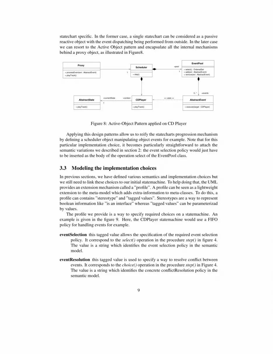
statechart specific. In the former case, a single statechart can be considered as a passivereactive object with the event dispatching being performed from outside. In the later casewe can resort to the Active Object pattern and encapsulate all the internal mechanismsbehind a proxy object, as illustrated in Figure8.
Scheduler
+ step()+ playTrack()+ processEvent(evt : AbstractEvent)
Proxy
+ execute(target : CDPlayer)
AbstractEventCDPlayer
+ playTrack()
AbstractState
+ playTrack()
+ add(evt : AbstractEvent)+ remove(evt : AbstractEvent)
EventPool
1 1
+pool
+events0..*
<< uses >>+currentState
1
+context
+ select() : OrderedSet
Figure 8: Active-Object Pattern applied on CD Player
Applying this design patterns allow us to reify the statecharts progression mechanismby defining a scheduler object manipulating object events for example. Note that for thisparticular implementation choice, it becomes particularly straightforward to attach thesemantic variations we described in section 2: the event selection policy would just haveto be inserted as the body of the operation select of the EventPool class.
3.3 Modeling the implementation choicesIn previous sections, we have defined various semantics and implementation choices butwe still need to link these choices to our initial statemachine. To help doing that, the UMLprovides an extension mechanism called a ”profile”. A profile can be seen as a lightweightextension to the meta-model which adds extra-information to meta-classes. To do this, aprofile can contains ”stereotype” and ”tagged values”. Stereotypes are a way to representboolean information like ”is an interface” whereas ”tagged values” can be parameterizadby values.
The profile we provide is a way to specify required choices on a statemachine. Anexample is given in the figure 9. Here, the CDPlayer statemachine would use a FIFOpolicy for handling events for example.
eventSelection this tagged value allows the specification of the required event selectionpolicy. It correspond to the select() operation in the procedure step() in figure 4.The value is a string which identifies the event selection policy in the semanticmodel.
eventResolution this tagged value is used to specify a way to resolve conflict betweenevents. It corresponds to the choice() operation in the procedure step() in Figure 4.The value is a string which identifies the concrete conflictResolution policy in thesemantic model.
9

entry / openDrive()exit / closeDrive()
Open
entry / stop()
Stop
do / playtrack()
Play
Pause
open
open
[CDinside()] play
play / pause()
Playing
endOfTrack
[cd.hasMoretrack()] / cd.nextTrack()
CDPlayerSM
stop
after(10min)
{eventImplantation="StatePattern"}{transitionSelection="Internal"} {transitionResolution = "Random"}{eventSelection="FIFO"} {eventResolution = "Random"}
play
Figure 9: The CDPlayerSM with some stereotypes specifying semantic
transitionSelection this tagged value is used to specify the required transition selection.It corresponds to the choice() operation in the procedure step() in Figure 4. Thevalue is a string which identifies the concrete transition selction policy in the se-mantic model.
transitionResolution this tagged value is used to specify a way to resolve conflict be-tween firable transitions. It corresponds to the choice() operation in the procedurestep() in Figure 4. The value is a string which identifies the concrete conflictReso-lution policy in the semantic model.
eventImplantation this tagged value represent the technic used to specify implantationof event. This is an enumerate value, which can be ”enumerate” or ”reify” to useda command pattern.
stateImplantation this tagged value represent the technic used to specify implantationof state. This is an enumerate value, which can be ”enumerate” or ”reify” to used astate pattern.
4 Processing Semantics and Implementation Variants throughModel Transformations
We can now combine the description of a statecharts, its semantics choices and imple-mentation choices in a consistent manner for various software engineering activities suchas automatic code generation, simulation, model-checking and test generation.
4.1 Implementing code generation as a model TransformationFor that we need a model transformation language and engine able to process these 3models as input, and produce either an implementation model or a validation model. In
10

the following, we describe how we used MTL [13], an imperative object oriented languagebased on OCL for that purpose. Our model transformation can be divided in three mainsteps (See figure 10).
Modela Semantic
Modela UML
Meta−ModelImplementation
Meta−ModelSemantic Transformation
MTL
Modela UML
Meta−ModelUML
ModelAn Implementation
Figure 10: Processing Statecharts, Semantics and Implementation models to provide aPSM model
Firstly, we search input models for semantic and implementation choices. An abstractfactory is then used to dynamically select and configure the needed transformations, mostof which are actually quite simple pattern applications [5].
In a second step, we apply the selected patterns. Defining a general way to applydesign patterns is a non-trivial issue, but we face here only a subset of this problem:we just need to apply (or not apply) 3 patterns in a specific order, which slightly reducethe combinatory aspect of the problem. So we start with either a direct implementationor with the active-object pattern to define a common structure to implement statechartsmechanisms. Then, depending on the previous choice, we can apply (or not apply) thestate and command patterns in an orthogonal way. (See figure 11 for the result of theapplication of the 3 patterns in a row).
Anyway, we have obtained a detailed model where the statecharts progression mech-anism has been fully reified. So, we can easily attach the statecharts semantics by fillingthe corresponding methods. For example, the semantics specified by the user for the eventselection policy would go into the select method of the class Pool (See figure 11). To dothat, we used the MTL language at the meta-model level to describe semantic choices inthe input semantic model. As for OCL on which it is based, MTL can also be used at themodel-level as a kind of simple action language for UML, making it easy to translate thedescription of the semantics into its implementation.
Finally, our model is refined to the point where each statecharts concept has beenmapped onto structural OO notions like classes or operations. An example of behaviorof this output model is presented on the figure 12. It can then be directly translatedinto executable code using any off-the-self UML code generator, including the MTL one.Indeed, using MTL to describe operation bodies allows us to re-use the MTL Java codegenerator to generate for free an executable Java code corresponding to our input model.
11

+ pause()+ playTrack()+ CDinside() : boolean+ stop()+ openDrive()+ closeDrive()
CDPlayerState
CDPlayer
+ process(evt : CDEvent)
Scheduler
+ step()
Stop Playing Open
Play Pause
PlayEvent StopEvent OpenEvent
CDPlayerEvent
+ execute(target : CDPlayer)
+ select()+ addEvent(evt : CDEvent)+ delEvent(evt : CDEvent)
Pool
Pattern Command
1
1
+currentState
+context
concreteState
context
Pattern StateabstractState
1
0..*
<< depends >>
abstractCommand
concreteCommand
Figure 11: Output model of the transformation
: CDPlayer :Scheduler :Pool : Pause
evt : PlayEvent
: Main
processEvent(evt)addEvent(evt)
select()
execute() playTrack()
step()
new
Figure 12: Behavior of the output model
12

4.2 Handling UML variability into UMLAUT NGUMLAUT NG [9] is an object-oriented framework dedicated to model transformationsin a MOF based context. It provides both a library of model transformations specific toUML models (e.g.; UML2RDBMS which translate a UML model to a relational model)as well as composition operators. UMLAUT NG was designed as an open tool workingwith several flavors of XMI, in order to be easily connected to various CASE tools.
UMLAUT NG also provides a way to connect MDD to formal technics initially de-veloped for SDL, Lotos and others. UMLAUT NG supports model transformations fortransforming UML models into labelled transition systems (LTS), to be used with theCADP tool box which provides tools for model checking, simulation, test synthesis andvizualization of the state spaces.
The integration into UMLAUT NG of our approach at reifying statecharts semanticvariation points makes it possible to uncouple all of these tools from a specific choice ofthe statechart semantics. It can be seen as an easy way to specialize a complex tool chaintowards a specific domain (e.g.; small embedded devices) where a particular interpretationof the statechart semantics is preferred.
5 Related worksThe work of [3] has been one of the starting point of our work. Indeed, many papers tryto define a formal semantics for Statecharts and especially for UML-Statecharts. Amongthis works, M.Von der Beeck [17] proposes a structured operational semantics for UMLStatecharts. Borger provide another semantics based on abstract StatesMachines [1]. Allthese works contribute to give a formal ground to UML at the price of choosing a par-ticular semantics, which might be adequate for a particular application domain, but notthat much for others, which is the basic reason why the UML provides semantic variationpoints. In this paper we specifically address this semantic variation point issue.
Building on formal semantics, many tools are able to simulate UML models and spe-cially statecharts [7]. Another example is iUML of Kennedy Carter [2] which includes amodeler and a simulator based on the ASL language. Most of these tools are based onmore or less formalized semantics and do not take into account semantic variation points.
Another way to execute UML models is to generate executable code directly frommodels. In an MDA perspective, many models transformations are required to get codefrom high level models. This process starts at the highest level with the platform indepen-dent model (PIM) and continues until a Plateform Specific Model (PSM) is generated. Webelieve that actual code generation should be used only when a model is low level enoughto be directly translated to C++ or Java. However most of dedicated code generationtools provide code generation directly from e.g. statecharts. For instance Tanaka [11, 10]proposes an UML to Java code generation from statecharts diagrams (based on the statepattern with events reified as method calls), or Rhapsody, a UML Case tool, proposes acode generator where events and states are selected using a switch statement (which is arelevant choice for its commercial target which is the real-time domain). These code gen-erators tends to hard code semantic and implementation choices, making them difficultor even irrelevant to use outside of their sometimes very narrow domain. On this aspect,
13

the main contribution of our work consists in providing a way to uncouple semantics is-sues and implementation choices from code generation, and let them open-ended. Userscan always add a particular semantics and choose a particular implementation technics byextending the existing framework.
6 Conclusion and future worksThe interest of semantic variation points in UML is that it now becomes a family of lan-guages sharing lot of commonalities and some variabilities that one can customize for agiven application domain. In this paper, we have proposed to reify the various seman-tic variation points of UML 2.0 statecharts into models of their own to avoid hardcodingthe semantic choices in the tools. We did the same for various implementation choices.Through model transformations, these semantic and implementation models are then pro-cessed along with a source UML model to provide a target UML model where all semanticand implementation choice are made explicit. We have shown how this target model canin turn serve as a basis for a consistent use of code generation, simulation, model-checkingor test generation tools.
This process has been implemented within our UMLAUT framework for model trans-formations, along with others tools such as statecharts generation from sequences dia-grams or sequences diagram generation from textual requirements. Even if a a completechain of model transformations from requirements to executable code is not a realistic ap-proach, UMLAUT aims at providing building blocks that can be customized for a specificmodel driven design and validation process.
In the future, we plan to use the same approach to reify other semantic variation pointsin the UML2.0 metamodel. In the UML2.0 component model for example, we can findsome open issues like the semantics of method dispatch, interfaces conformity or thesupport of QoS attributes. It could be interesting to describe these semantic choices as wedid for statecharts and to merge them with a component model to get a PSM model.
References[1] Egon Borger, Alessandra Cavarra, and Elvinia Riccobene. On formalizing UML
state machines using ASM. Information & Software Technology, 46(5):287–292,2004.
[2] Kennedy Carter. iUMLite tool suite and ASL language. from Kennedy Carter’swebsite (http://www.kc.com).
[3] Michael Von der Beeck. A comparison of statecharts variants. In L. De Roever andJ. Vytopil, editors, In Formal technics in Real-Time and Fault-tolerant Systems, vol-ume 863 of Lecture Notes in Computer Science, pages 128–148, New-York, 1994.Springer Verlag.
[4] Gamma, Erich, Helm, Richard, Johnson, Ralph, and Vlissides, John. Design Pat-terns: Elements of Reusable Object-Oriented Software. Addison-Wesley LongmanPublishing Co., Inc., 1995.
14

[5] Alain Le Guennec, Gerson Sunye, and Jean-Marc Jezequel. Precise modeling ofdesign patterns. In Proceedings of UML 2000, volume 1939 of LNCS, pages 482–496. Springer Verlag, 2000.
[6] David Harel. Statecharts: A visual formalism for complex systems. Science ofComputer Programming, 8(3):231–274, June 1987.
[7] David Harel and Eran Gery. Executable object modeling with statecharts. In ICSE’96: Proceedings of the 18th international conference on Software engineering,pages 246–257. IEEE Computer Society, 1996.
[8] Harel, David and Naamad, Amnon. The STATEMATE Semantics of Statecharts.ACM Transactions on Software Engineering and Methodology, 5(4):293–333, octo-ber 1996.
[9] Wai-Ming Ho, Jean-Marc Jezequel, Alain Le Guennec, and Francois Pennaneac’h.UMLAUT: an extendible UML transformation framework. In Proc. Automated Soft-ware Engineering, ASE’99, Florida, October 1999.
[10] Jauhar, Ali and Tanaka, Jiro. Implementation of the Dynamic Behavior of ObjectOriented System. In Third World Conference on Integrated Design and ProcessTechnology (IDPT’98), volume 4, Berlin, Germany, July 1998.
[11] Jauhar, Ali and Tanaka, Jiro. Implementing the dynamic behavior represented asmultiple state diagrams and activity diagrams. Journal of Computer Science & In-formation Management (JCSIM), 2(1):24–36, 2001.
[12] Franck Fleurey Pierre-Alain Muller and Jean-Marc Jezequel. Weaving executabil-ity into object-oriented meta-languages. In Proceedings of UML MoDELs 2005,Jamaica, LNCS. Springer Verlag, 2005. to be published.
[13] Damien Pollet, Didier Vojtisek, and Jean-Marc Jezequel. OCL as a core UMLtransformation language. WITUML 2002 Position paper, Malaga, Spain, jun 2002.http://ctp.di.fct.unl.pt/ ja/wituml02.htm.
[14] UML Revision Task Force RTF. UML draft version 2.0 specification, April 2003.
[15] Soley, Richard and OMG Staff Group. Model Driven Architecture. White papers,Object Management Group, Novembre 2000.
[16] Toyoaki Tomura and Satoshi Kanai. Developing simulation models of open dis-tributed control system by using object-oriented structural and behavioral patterns.In ISORC, pages 428–437, 2001.
[17] Michael von der Beeck. A structured operational semantics for UML-statecharts.Software and System Modeling, 1(2):130–141, 2002.
[18] Twefik Ziadi. Manipulation de lignes de produits en UML. PhD thesis, Universit deRennes 1, 2004.
15