cobblestone landing restoraton and ... - tn.gov
TRANSCRIPT
Addendum No. 3 PIN 108673.00; Cobblestone Landing Restoration and Improvements; Memphis; Shelby Co., TN Page 1 of 17
COBBLESTONE LANDING RESTORATON AND IMPROVEMENTS
(also known as “Cobblestone Landing Restoration and Walkway”) 83 S. Riverside Drive, Memphis, TN 38103
TDOT PIN: 108673.00 Federal Project No.: HPP-9409(108) State Project No.: 79LPLM-F3-039
City of Memphis Project No.: 10C31A.2 For the City of Memphis Division of Parks & Neighborhoods
City of Memphis RFQ No.: 3577
ADDENDUM NO. 3
Issued: July 10, 2020
TO ALL POTENTIAL OFFERORS:
This Addendum, including all items listed below, shall become a part of the bid package for “Cobblestone Landing Restoration and Improvements”; and shall be taken into account in preparing your bids.
This addendum includes the following information:
1. Clarifications and modifications to the Bid Documents.
2. Responses to Written Questions.
3. Attachments:
Revised Bid Form
Revised Technical Specification Sections 01315, 02311 and 02465
Photographs of Gayoso Bayou Culvert
Bidders are required to complete the “Acknowledgement of Receipt of Addendum” form included in the bound Proposal Contract bid book; and submit the bound form with your proposal. Failure to sign and include this form will result in your proposal being considered invalid.
Addendum No. 3 PIN 108673.00; Cobblestone Landing Restoration and Improvements; Memphis; Shelby Co., TN Page 2 of 17
Clarifications and Modifications to Bid Documents
Proposal Contract Bid Book
ITEM 1. Refer to Table of Contents, Other Technical Special Provisions. Rename Section 02465 to Bored Piles (Grout Cased Micropiles).
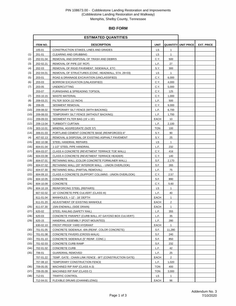
ITEM 2. Replace Bid Form with attached revised Bid Form. Revisions are summarized as follows:
a. Added Item No. 203-10.15 WASTE MATERIAL
b. Added Item No. 740-10.04 GEOTEXTILE (TYPE IV) (STABILIZATION)
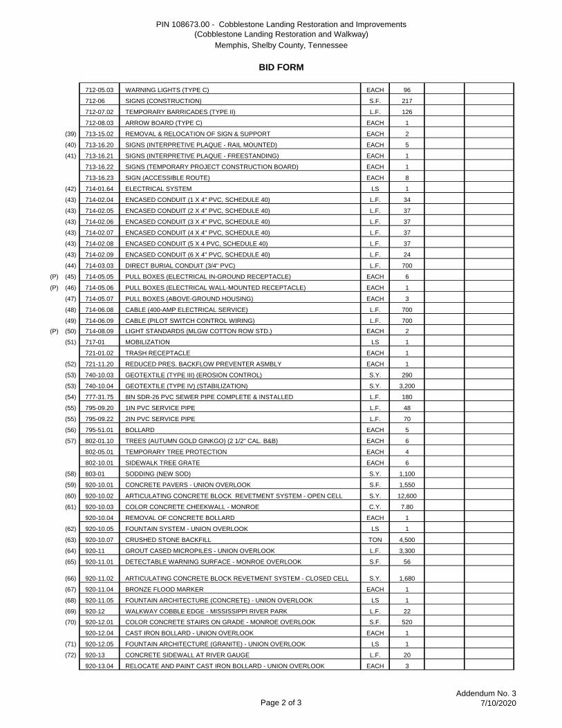
c. Changed description of Item No. 920-11 to GROUT CASED MICROPILES - UNION OVERLOOK.
d. Added Item No. 920-15.05 GROUT CASED MICROPILES (DESIGN AND TESTING) - UNION OVERLOOK.
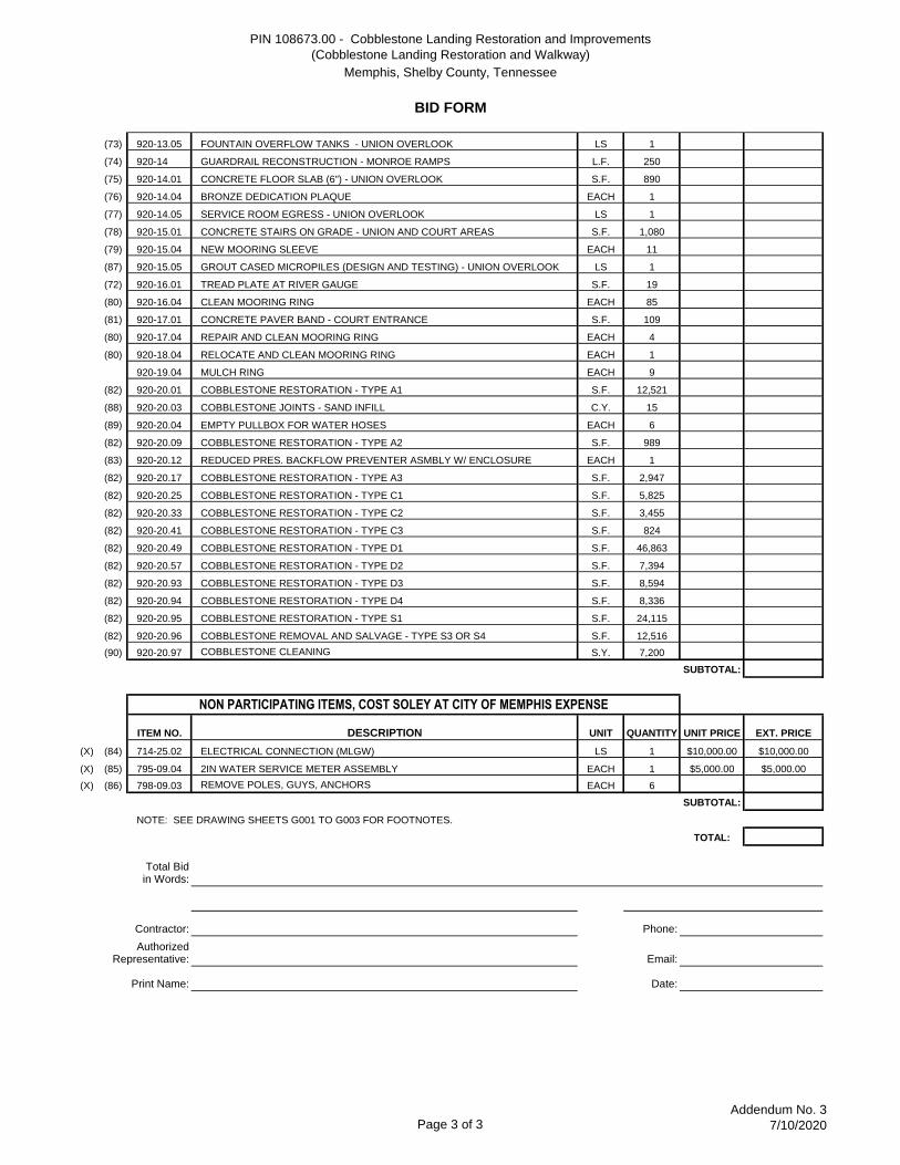
e. Added Item No. 920-20.03 COBBLESTONE JOINTS - SAND INFILL
f. Added Item No. 920-20.97 COBBLESTONE CLEANING
g. Added specific prices for Item Nos. 714-25.02 and 795-09.04 per Addendum No. 2, ITEM 6.
ITEM 3. Refer to Other Technical Special Provisions, technical specifications:
a. Refer to Section 01100 – Summary of Work. Add Sub-Paragraphs 1.2.D and 1.2.E as follows:
D. The Contractor is required to obtain a Street Cut Permit from the City of Memphis Land Development Department of the City Engineer’s Office located at 125 North Main, Room 644, Memphis, TN 38103. The Street Cut Permit procedures can be found at the City of Memphis website:
https://memphistn.gov/government/engineering
http://memphis.hosted.civiclive.com/UserFiles/Servers/Server_11150732/File/Gov/Engineering%20Division/005_STREET_CUT_PERMIT_AMENDED91807.pdf
The ARCH D (24”x36”) construction drawing mylars have been approved by the City Engineer and copies may be obtained by Tetra Tech after Contract Award. These drawings do not include information
Addendum No. 3 PIN 108673.00; Cobblestone Landing Restoration and Improvements; Memphis; Shelby Co., TN Page 3 of 17
which is not also shown on the Construction Drawings issued for bid. The Street Cut Permit fee was established in 2017 as $2,070.08 with a
$10,000.00 performance bond required. The costs of securing the permit shall be included in the bid and are considered incidental to other pay items.
E. The Contractor is required to obtain a Building Permit and related Electrical and Plumbing Permits from the Memphis and Shelby County Office of Construction Code Enforcement at 6465 Mullins Station Road, Memphis, TN 38134. The project is on file with Code Enforcement as Building Permit Application No. B1105098 at 83 Riverside Drive, Memphis, TN 38103.
The project construction documents have been reviewed and conditionally approved, pending shop drawing submittals for certain items such as the custom electrical pull boxes and the fountain. All costs for obtaining the Code Enforcement permits are the Contractor’s responsibility and shall be included in the bid. The permit(s) are considered incidental to other pay items.
b. Replace Section 01315 - River Stages with attached revised Section 01315.
c. Replace Section 02311 – Articulating Concrete Block (ACB) Revetment System with attached revised Section 02311.
d. Replace Section 02465 – Bored Piles (Helical Pulldown Micropiles) with attached revised Section 02465 – Bored Piles (Grout Cased Micropiles).
Drawings
ITEM 4. Refer to Sheet G001. Revise Footnote Nos. 1 and 9 as follows:
(1) PAY ITEM 201-01 IS FOR INITIAL SITE CLEARING AND GRUBBING AND INCLUDES REMOVAL AND OFF-SITE DISPOSAL OF ALL TRASH AND DEBRIS WITHIN THE PROJECT LIMITS; AND REMOVAL OF TREES, SHRUBS, VEGETATION AND TOPSOIL WHERE REQUIRED FOR GRADING OR NEW FEATURES. REMOVAL OF PAVEMENTS, STRUCTURES AND OTHER FIXED FEATURES ARE INCLUDED IN OTHER PAY ITEMS. AFTER INITIAL SITE CLEARING IS COMPLETED AND ACCEPTED, REMOVAL OF SUBSEQUENT DEPOSITED TRASH AND DEBRIS WILL BE INCLUDED PAY ITEMS 202-01.04. INITIAL SEDIMENT REMOVAL IS INCLUDED PAY ITEM 209-05.
(7) PAY ITEM 203-05 IS FOR UNDERCUTTING (OVER-EXCAVATION) OF UNSUITABLE SUBGRADE MATERIALS; AND INCLUDES REMOVAL AND OFF-SITE DISPOSAL OF UNSUITABLE MATERIALS, REPLACEMENT WITH SUITABLE MATERIALS (ON-
Addendum No. 3 PIN 108673.00; Cobblestone Landing Restoration and Improvements; Memphis; Shelby Co., TN Page 4 of 17
SITE OR OFF-SITE BORROW SOURCES), BACKFILLING AND COMPACTION. MEASUREMENT FOR PAYMENT WILL BE BY THE BANK CUBIC YARD, BASED ON CROSS-SECTIONAL MEASUREMENTS OR OTHER FEASIBLE METHOD ACCEPTABLE TO TDOT. UNDERCUTTING AND ASSOCIATED FINAL QUANTITIES SHALL BE AS DIRECTED BY THE GEOTECHNICAL ENGINEER AND OWNER'S CEI REPRESENTATIVE.
REMOVAL AND OFF-SITE DISPOSAL OF UNSUITABLE MATERIALS RESULTING FROM OTHER EARTHWORK ACTIVITIES SUCH AS ROAD & DRAINAGE EXCAVATION SHALL BE INCLUDED IN PAY ITEM 203-10.15 WASTE MATERIAL.
(9) PAY ITEM 209-05 IS FOR GENERAL SEDIMENT REMOVAL AND OFF-SITE DISPOSAL, INCLUDING SEDIMENT DEPOSITED FROM THE WOLF RIVER HARBOR AND SEDIMENTATION RESULTING FROM ON-SITE SOIL DISTURBANCE DURING CONSTRUCTION. SEDIMENT REMOVAL SHALL BE IMPLEMENTED AS REQUIRED THROUGHOUT THE CONTRACT DURATION FOR MAINTAINING EROSION AND SEDIMENT CONTROL MEASURES, AND TO ACCOMODATE CONSTRUCTION ACTIVITIES AND FEATURES. THIS PAY ITEM ALSO INCLUDES FINAL SEDIMENT REMOVAL FOR PROJECT CLOSEOUT
ITEM 5. Refer to Sheet G002. Revise Footnote Nos. 53, 63 and 64 as follows:
(53) PAY ITEM 740-10.03 IS FOR GEOTEXTILE AT EPSC MEASURES SUCH AS TEMPORARY CONSTRUCTION EXIT OR SEDIMENT FILTER BAGS.
PAY ITEM 740-10.04 IS FOR STABILIZATION GEOTEXTILE AT NORTH/SOUTH REVETMENT TERRACE.
(63) PAY ITEM 920-10.07 IS FOR GRADED CRUSHED LIMESTONE AT NORTH/SOUTH REVETMENT TERRACE, WITH 3" MAX TO #57 MIN. STONE AND 5% MAX. FINE-GRADED MATERIAL (SEE DETAIL 2/L501). STABILIZATION GEOTEXTILE AT BASE OF GRADED CRUSHED LIMESTONE IS INCLUDED IN PAY ITEM 740-10.04. MEASUREMENT FOR PAYMENT WILL BE MADE BY THE TON OF GRADED CRUSHED LIMESTONE, COMPLETED AND ACCEPTED.
ALL EARTHWORK ACTIVITIES (CUT, FILL OR UNDERCUTTING) TO ACHIEVE THE PROPOSED BOTTOM OF GRADED LIMESTONE SECTION PER DETAIL 2/L501 ARE INCLUDED WITH OTHER PAY ITEMS.
Addendum No. 3 PIN 108673.00; Cobblestone Landing Restoration and Improvements; Memphis; Shelby Co., TN Page 5 of 17
(64) PAY ITEM 920-11 IS FOR FURNISHING AND INSTALLING THE COMPLETE GROUT CASED MICROPILE SYSTEM AT UNION AVENUE OVERLOOK (INDICATED AS "HELICAL PILES" ON DRAWINGS) INCLUDING VERTICAL PILES, BATTERED PILES, GROUT, CASINGS, BEARING PLATES, SHAFT CONNECTIONS, BRACKETS AND OTHER RELATED WORK. THE CONCRETE FOOTINGS WHICH CAP THE PILES ARE INCLUDED IN OTHER PAY ITEMS. MICROPILE DESIGN, SHOP DRAWINGS AND SUBMITTALS, MOBILIZATION AND LOAD TESTING ARE INCLUDED IN PAY ITEM 920-15.05. MEASUREMENT FOR PAYMENT WILL BE MADE BY THE LINEAL FEET OF HELICAL PILES, COMPLETED AND ACCEPTED.
THE CONTRACTOR IS RESPONSIBLE FOR THE COST OF ANY MICROPILES DAMAGED DURING INSTALLATION, AS WELL AS FOR ANY EXCAVATION AND REMOVAL OF OBSTRUCTIONS, AND FOR ANY ASSOCIATED BACKFILLING.
ITEM 6. Refer to Sheet G003:
a. Add the following General Quantity Note:
9. “DIRT” IS SYNONYMOUS WITH “SEDIMENT” FOR THIS PROJECT, IN REGARDS TO THE X-SHEET RESTORATION PLANS AND DETAILS.
b. Revise Footnote No. 82 as follows:
(82) SEE DWGS. X101, X102, X103, X104 AND X500 FOR LOCATIONS AND DESCRIPTIONS OF THE VARIOUS COBBLESTONE TREATMENTS. ALL WORK REQUIRED FOR EACH TYPE SHALL BE INCLUDED IN THE RESPECTIVE PAY ITEM, EXCEPT FOR SEDIMENT REMOVAL (SUCH AS CONDITION D1) WHICH IS INCLUDED IN PAY ITEM 209-05.
c. Add the following Footnotes:
(87) PAY ITEM 920-15.05 IS FOR ENGINEERING AND LOAD TESTING OF THE COMPLETE GROUT CASED MICROPILE SYSTEM AT UNION AVENUE OVERLOOK (INDICATED AS "HELICAL PILES" ON DRAWINGS) AND INCLUDES DESIGN BY A TENNESSEE REGISTERED PROFESSIONAL ENGINEER, SHOP DRAWINGS AND OTHER SUBMITTALS, MOBILIZATION, LOAD TESTING, AND LOAD TESTING REPORTS.
(88) PAY ITEM 920-20.03 IS FOR JOINT INFILLING OF THE COBBLESTONE FIELD AT OR NEAR END OF PROJECT, FOR A PORTION OF THE AREAS OUTSIDE THE PRIMARY
Addendum No. 3 PIN 108673.00; Cobblestone Landing Restoration and Improvements; Memphis; Shelby Co., TN Page 6 of 17
RESTORATION AREAS (A1-S4), AS DIRECTED BY THE LANDSCAPE ARCHITECT. REFER TO GENERAL NOTES - RESTORATION ON SHEETS X100 TO X104.
POLYMERIC SAND WILL BE ADDED ONLY TO VOIDS THAT MAY EXIST IN COBBLESTONE JOINTS IN EXISTING CONDITION OR AFTER REMOVAL OF VEGETATION. POLYMERIC SAND WILL BE RECESSED BELOW THE COBBLESTONE SURFACE, WITH SAND ONLY BETWEEN THE VERTICAL EDGE OF ADJACENT STONES.
(89) PAY ITEM 920-20.05 IS FOR THE EMPTY UTILITY BOXES (PROPRIETARY) ALONG THE EAST/WEST UNION UTILITY CORRIDOR AS SHOWN ON DETAIL 3/C502; AND INCLUDES CUSTOM STAINLESS STEEL PULL BOX ENCLOSURE, CONCRETE-FILLED STAINLESS STEEL LID, GRAVEL BASE, PULLBOX SUBMERSION TESTING/CERTIFICATION AND ALL ASSOCIATED SUBMITTALS/SHOP DRAWINGS.
(90) PAY ITEM 920-20.97 IS FOR CLEANING OF THE COBBLESTONE FIELD AT OR NEAR END OF PROJECT, FOR A PORTION OF THE AREAS OUTSIDE THE PRIMARY RESTORATION AREAS (A1-S4), AS DIRECTED BY THE LANDSCAPE ARCHITECT. REFER TO GENERAL NOTES - RESTORATION ON SHEETS X100 TO X104.
THIS ITEM INCLUDES REMOVAL OF REMAINING MINOR SEDIMENT FROM COBBLESTONE SURFACES (BUT NOT IN JOINTS), AND VEGETATION AFTER APPLICATION OF HERBICIDE. MAJOR QUANTIFIABLE SEDIMENT REMOVAL IS INCLUDED IN PAY ITEM 209-05. JOINT INFILLING IS INCLUDED IN PAY ITEM 920-20.03.
ITEM 7. Refer to Sheet C181:
a. Replace Gayoso Outfall note as follows:
GAYOSO OUTALL PLACE RIPRAP (TDOT CLASS "C", 3'-6" THICK MINIMUM) AT OUTLET OF EXISTING GAYOSO INTERCEPTOR CULVERT. REFER TO DETAIL B/C501. IF RIVER STAGES ARE NOT FAVORABLE DURING CONSTRUCTION, RIPRAP MAY BE PLACED “IN THE WET” WITH GRADING OR SUBGRADE PREPARATION NOT REQUIRED UNDERWATER, AND THE RIPRAP LAYER THICKNESS MAY VARY. THE INTENT IS TO STABILIZE THE OUTLET AND ADJACENT BANK TO PREVENT FURTHER SCOUR, AND TO ACHIEVE THE PROPOSED GRADES AS CLOSE AS POSSIBLE.
Addendum No. 3 PIN 108673.00; Cobblestone Landing Restoration and Improvements; Memphis; Shelby Co., TN Page 7 of 17
b. Replace riprap note at north end of Beale Street Landing as follows:
PLACE RIPRAP (TDOT CLASS "C", 3'-6" THICK MINIMUM) AS DIRECTED BY ENGINEER AT SCOURED AREA AT NORTH END OF EXISTING BEALE STREET LANDING SHEET PILE WALL. IF RIVER STAGES ARE NOT FAVORABLE DURING CONSTRUCTION, RIPRAP MAY BE PLACED “IN THE WET” WITH GRADING OR SUBGRADE PREPARATION NOT REQUIRED UNDERWATER.
ITEM 8. Refer to Sheet C501, Detail C - Typical Revetment Section.
a. Change “ 1/4” MIN. GALVANIZED STEEL CABLES ” to “REVETMENT CABLES”.
b. Replace Note 1 as follows:
1. SCHEDULING OF REVETMENT WORK SHALL BE CAREFULLY COORDINATED WITH THE RIVER STAGES. REFER TO SPECIFICATION SECTIONS 01315 AND 02311 FOR FURTHER INFORMATION.
ITEM 9. Refer to Sheet C502, Detail 3 – Utility Box Detail. Provide two (2) spare lids – in addition to the six (6) required for installation - with associated hardware and deliver to Memphis River Parks Partnership at the end of the project. The cost of the spare lids shall be considered incidental to Pay Item 920-20.04.
ITEM 10. Refer to Sheet L501, Detail 2 – North/South Revetment Terrace.
a. Change “ 1/4”Ø STEEL CABLE ” to “REVETMENT CABLE”
b. Add the following leader note at the bottom of the graded limestone:
GEOTEXTILE (TYPE IV – STABILIZATION)
ITEM 11. Refer to Sheet E001, Pullbox Connector Section. Provide two (2) spare lids - in addition to the six (6) required for installation - with associated hardware and deliver to Memphis River Parks Partnership at the end of the project. The cost of the spare lids shall be considered incidental to Pay Item 714-05.05.
Responses to Written Questions
1. Question: Will the piers require grout if we can provide the loads without the grout?
Answer: Yes, grout is required.
2. Question: Will an onsite full load test [for piers] be required on the project?
Answer: Yes, onsite load testing is required for the grout cased micropiles. Refer to Specification Section 02465.
Addendum No. 3 PIN 108673.00; Cobblestone Landing Restoration and Improvements; Memphis; Shelby Co., TN Page 8 of 17
3. Question: The GENERAL NOTES – RESTORATION indicated on the “X” drawings would appear to apply to all of the areas that are not currently covered by a specific type of restoration. Please verify this is correct.
If so, where is the cost for this work to be listed as this is a much larger area than what is covered by the specific repair notes?
Please let us know how to proceed.
Answer: On sheets X100-X104, GENERAL NOTES - RESTORATION apply generally to all areas of the cobblestone field not specifically covered by restoration Key Notes (A1-S4); but the specific measures will need to be applied only to a portion of these areas and will be further coordinated in construction.
This work is covered in the attached revised Bid Form with new Item Nos. 920-20.03 COBBLESTONE JOINTS - SAND INFILL and 920-20.97 COBBLESTONE CLEANING. At the end of the project, no sediment or vegetation should be present on the cobblestone surface. It is NOT necessary to remove sediment, dirt or sand from the cobblestone joints.
Polymeric sand is used only for infill if there are voids present in cobblestone joints. These voids could be existing condition, or a result of vegetation and sediment removal. Where void infilling is required, polymeric sand will be recessed below the top of cobblestones, as the stones have rounded, weathered edges. Polymeric sand will only infill the space, if there is any, between the vertical edge of adjacent stones. The sand will not need to infill the top and wider portion of the joint, where the top edge of stones are weathered and rounded.
See Clarifications and Modifications to Bid Documents - ITEMS 2e, 2f and 6c (Footnote No. 90).
4. Question: There is a detail on the “X” drawings 2/X500 that depicts RECYCLED STONE COBBLESTONES – MORTAR JOINT.
This detail is not referenced on any of the schemes specifically listed for cobblestone repair and there is not a Bid Item we can find either.
My question is, where does this particular scope of work apply?
Answer: Refer to Addendum No. 2, Pre-Bid Conference Record, Question 6 (pages 11-12 of the Record).
5. Question: It looks like everything on the job will be bid unit price. So they are allowing us 3300 ft on the 54 piers, and wanting us to give a per foot cost for piers. I understand our material can vary depending on the depth which the piers will drive, but what about our set cost such as engineering fees, pile load test, mobilization ect. No matter how deep the piers may drive, the cost of our set prices we still cost us the
Addendum No. 3 PIN 108673.00; Cobblestone Landing Restoration and Improvements; Memphis; Shelby Co., TN Page 9 of 17
same. So I am wondering if we can bid the helical piers by the foot and then give a price for the testing and engineering separate.
Answer: Concur. See Clarifications and Modifications to Bid Documents - ITEMS 2c, 2d, 3d, 5 (Footnote No. 64), and 6c (Footnote No. 87)
6. Question: On the “X” drawings, GENERAL NOTES – RESTORATION.
Note 5 as part of the description states that the contractor is to “PHYSICALLY REMOVE ALL REMAINING VEGETATION FROM COBBLESTONE SURFACE AND JOINTS. INFILL VOIDS IN JOINTS WITH POLYMERIC SAND.”
Our question is, how deep are we to clean the joints?
It may not seem like a big deal, but since there is about 364,000 SF of Cobblestone surface that this note applies to, it does add up rather quickly.
Answer: Refer to the response for Question # 3 above.
7. Question: Should there not be enough salvaged cobblestones to infill some of the areas that call for salvaged stones, will the Unit Price for Bid Item 920-20.94 (Cobblestone Restoration – Type D4) be used for the purchase of the additional “precast” cobblestones?
Answer: Yes.
8. Question: Is the excavation that will be required to install the gravel base at the top of the ACB per detail 2/L501 part of the Excavation listed on the Bid Form or is it to be part of the Gravel Bid Item?
Currently the bid item for the gravel does not mention that it includes this excavation.
Answer: This information was mistakenly included in Footnote No. 53 instead of No. 63 and has been corrected. See Clarifications and Modifications to Bid Documents, ITEM 5. Also, it will depend if the terrace is in a cut or fill situation per the grading plans and cross sections; and if undercutting is required per Geotechnical Engineer during construction.
9. Question: Just an observation from when we were at the site this morning with several of our people that worked on the adjacent Beale Street Landing project.
That area with the 4,500 tons of gravel fill at the top of the ACB needs to have some type of fabric under the gravel. Any gravel that is just dumped on that wet silt will simply disappear in the muck.
Answer: Concur. See Clarifications and Modifications to Bid Documents - ITEMS 2b, 5 (Footnote No. 53), and 10b.
Addendum No. 3 PIN 108673.00; Cobblestone Landing Restoration and Improvements; Memphis; Shelby Co., TN Page 10 of 17
10. Question: The sections of ACB that are extending out from 80’ to 120’ are really causing a issue. To get the material from 0’ to 80’ we will have to build a temporary level road (because of the slope) on the bank and can use a 250 Ton Crane to make that reach. Those panels farther out will require a 350 to 400 Ton Crane. Not that many of that size around and they really like those. It appears that the plan is to install ACB basically down to zero on the river gauge, but just pointing this out. EDIT: On the ACB past the 80 line that I questioned earlier, we can cut those panels down from the 40’ indicated to a smaller size that the 250 ton can handle.
Answer: We anticipate that the mats could vary in length depending on the project requirements. The Contractor is required to submit shop drawings for the layout of the ACB mats in accordance with Specification Section 02311. Coordinate with the manufacturer as required.
A temporary level access road(s) or pad(s) for cranes could be allowed for the revetment construction, depending on the Contractor’s Work Plan; but they would not be new pay items and should be incidental to the other bid prices. Keep in mind that it is also required to protect the existing cobblestones and maintain access to the Memphis Riverboats floating dock facility (which can shift north or south) at all times.
11. Question: The pay item for the 3,000 TONS of Rip-Rap (709-05.09), on drawing C181 it mentions that “Flowable Fill” at the Gayosa Box Culvert is to be included but is considered “incidental”. As this area is currently under water and can’t be inspected, should we consider the flowable fill to be limited to 10CY, 100CY or other.
Please give us an idea of what you observed to make this note so that we can bid it correctly.
Answer: Two photographs of the Gayoso Bayou culvert outfall in low-water conditions are attached for reference. For the purposes of bidding, you may assume up to a 6-foot by 6-foot section of flowable fill needed across the entire culvert width (see Outlet Plan 2/S113).
12. Question: Are all the granite materials on the Union Ave fountain to be furnished & installed by the fountain contractor or the masonry contractor?
Answer: Our opinion is the granite materials for the fountain should be furnished and installed by the masonry subcontractor, as this is their area of expertise. Close coordination with the fountain subcontractor and other trades is required. The General Contractor is responsible for directing all the various trades involved in the project as required.
13. Question: Are the new precast concrete wall caps to be furnished & installed by the masonry contractor or the concrete contractor installing the concrete walls?
Answer: Our opinion is the precast concrete wall caps should be furnished and installed by the masonry subcontractor, as this is their area of expertise. Close coordination with the concrete subcontractor is required. The General Contractor is
Addendum No. 3 PIN 108673.00; Cobblestone Landing Restoration and Improvements; Memphis; Shelby Co., TN Page 11 of 17
responsible for directing all the various trades involved in the project as required.
14. Question: Based on a comparison of the stone cobblestone restoration type square footages given on the bid form and the cobblestone restoration key notes on the plans, it appears that there will be a very large shortage of salvaged stone cobblestones to complete the entire restoration process. Areas noted as cobblestone restoration areas A3, C3, D2, & D3 require the use of salvaged stone cobblestones since none are present and total 18,280 SF of area (Note on area D2 states assume 20% are present). Areas noted as salvaged stone cobblestone areas S3 & S4 represent 12,516 SF based on the bid form. Of this 12,516 SF, 319 SF (S4 stone cobblestones), are to be removed and reset back in their area. So that leaves 12,197 SF of salvaged stone cobblestones. If we have 12,197 SF of salvaged stone cobblestones for use in-fill areas and 18,280 SF of total areas to infill, we are left with a shortage of around 6,100 SF of area that there will not be any salvaged stone cobblestones left to use. How should the masonry contractor make up for this shortage? Could additional new replacement concrete cobblestones as called out on the plans (D4 areas), be used to make up for this shortage of stone cobblestones? If so, will the 50% / 50% blend of the two sizes of concrete cobblestones be required?
Answer: Refer to the response for Question # 22 above. If there is a shortage of recycled stone cobbles for infill, new precast concrete cobbles shall be used. In this case, the size of precast concrete cobbles shall be a mix of 10 1/4" x 5" or 7 5/8" x 5" and shall generally match the size and installation pattern of existing stone cobbles in the immediately surrounding area. Also refer to Detail 1/X500.
15. Question: Based on onsite testing in areas of existing pavement over the top of the cobblestone pavers, the existing pavement is easily removed without damaging the existing cobblestones. This is not the case in testing areas where existing poured concrete is over the top of the cobblestone pavers. The concrete cannot be removed from the cobblestones without a considerable amount of damage & breakage to the cobblestones and this would result in a shortage of materials. Should new replacement concrete cobblestones be considered in these areas as well since there will not be enough materials left over from the separation of the concrete & stone cobblestones?
Answer: In certain areas, our understanding is that the concrete paving overlay has a visqueen or plastic layer separating concrete from the stone cobbles. Where this is not present, and if concrete cannot be carefully removed without damaging the stone cobbles, then those cobbles will be replaced by stone cobbles recycled from the project. If the supply of recycled stone cobbles is depleted, then precast concrete cobbles will be used for infill, with the size and pattern generally matching the adjacent area.
16. Question: Is it correct to assume that there will be no work in all other remaining areas of cobblestones outside of the key noted & legend noted areas (A1, A2, A3, C1, C2, C3, D1, D2, D3, D4, S1, S2, & S4) on the plans. There is a substantial total square footage of areas of cobblestones on the restoration drawings without identification of required work by either a key note or legend noted on them. Confirm
Addendum No. 3 PIN 108673.00; Cobblestone Landing Restoration and Improvements; Memphis; Shelby Co., TN Page 12 of 17
that there is no work to these areas of cobblestones.
Answer: The primary restoration work is covered on the X-drawings by 14 Key Notes (A1-S4). For areas not covered by Key Notes, refer to GENERAL NOTES - RESTORATION on the X-drawings. Also see the response to Question #3 above.
17. Question: The limited Mississippi River Data in Appendix B indicates that the Record Low for the river was 173.2’ (back in 1988). The Grading Plans, specifically C181, indicate that some of the rip-rap is to be installed at an elevation of 165’.
How can this work be performed if the sub-grade that needs to be achieved is +/- 10’ below the “Record Low”?
Answer: If necessary, the rip rap may be installed “in the wet”. See Clarifications and Modifications to Bid Documents, ITEM 7.
18. Question: The footnotes for items 701-01.05 (30) and 701.01.10 (32) on page G001 of the plans state that sample panels are required for review and approval. In the notes of details 1A/500 & 3/500 on sheet L500 in the plans , it also states that sample panels must be made for approval by owner and landscape architect. Will the sample panels be measured and paid for per the item unit price? It would be difficult to price the sample panel(s) if they are not paid by the unit, as it is unknown how many panels will need to be produced. Can the sample panels be left in place as permanent work, provided they are approved?
Answer: Sample panels are normally stand-alone panels and not part of the permanent work. The cost for sample panels is incidental to the appropriate Item No. and shall be incorporated in bid prices for completed and accepted work for that item. However, if the contractor elects to set up a sample panel as part of the permanent work in accordance with the construction drawings, the contractor will only be paid for a sample panel that is accepted and approved.
19. Question: In pay item footnotes 2 and 9 on sheet G002, it states that the initial Sediment Removal and Removal of Trash and Debris will be paid for under the lump sum Clearing and Grubbing. Could the initial sediment removal and removal of trash and debris be measured and paid for under their bid items, instead of paying for it in a lump sum as clearing and grubbing? It is difficult to price this work as a lump sum, as the amount of material to remove in both bid items could change dramatically between now and the start of the project.
Answer: This has been clarified in revised Footnote Nos. 2 and 9 which are on Sheet G001. See Clarifications and Modifications to Bid Documents, ITEM 4.
20. Question: It is assumed that unless specified in the contract documents, “clean cobblestone surface” as noted on plan sheets X 100 to X104 can be accomplished without removing the cobblestones from their current position. Also, it is assumed that this cleaning can be accomplished by washing or pressure washing the cobblestones in place, after removal of asphalt overlay, concrete overlay, or gravel
Addendum No. 3 PIN 108673.00; Cobblestone Landing Restoration and Improvements; Memphis; Shelby Co., TN Page 13 of 17
as applicable. Please verify this is the intent of the bid items.
Answer: Yes, this assumption is correct. Cobblestones to be cleaned shall definitely remain in place!
21. Question: Will Tetra Tech allow the substitution of a fully grouted hollow bar micropile in place of the Helical Pulldown piles beneath the Union Ave Overlook?
Hollow Bar Micropiles are drilled using rotary plus percussion machines that can penetrate through obstructions that will most likely be encountered along the river. Additionally, hollow bar micropiles are drilled to the desired depth and then pressure grouted from the bottom up, ensuring that all spoils are extracted and that all voids are fully grouted with a rich mixture of neat grout cement (water and portland Type 1/2 only) that achieves 5000 PSI in a matter of days. Hollow bars are threaded which will accommodate the designed 8" square bearing plates with nuts at multiple elevations within the pile cap. Both tension and compression load testing will be conventionally performed (ASTM D1143 and D3689). Finally, hollow bar micropiles produce a full depth bond between the soils and the pile which produces a much higher resistance to buckling especially in the upper 1/3 of the pile where helical elements are typically weakest.
Answer: Bid as shown in the drawings and specifications. Alternate designs may be submitted for review and approval after Contract Award; but at no additional cost to the City. Also see Clarifications and Modifications to Bid Documents - ITEMS 1, 2c, 2d, 3d, 5 (Footnote No. 64), and 6c (Footnote No. 87).
22. Question: Unless I am reading the River Stages incorrectly, the River Gauge needs to be a little below Zero to expose the area where the ACB is to be installed. In 2019 the closest the river level got to that was 6’ and that was only for about a week. So far is 2020 the river has not been within 13’ of that level. The area where the top of the ACB goes has been underwater all of this year.
What is the plan should the level not drop enough for a long enough period of time to get the concrete foundations in, the grading done, a temporary road built to support the 200 ton crane and then the installation of the ACB?
Answer: The open-cell revetment mats may be installed “in the wet”. If river stages are not favorable for the work, then a request for time extension can be submitted for review. Specification Sections 01315 and 02311 have also been revised. See Clarifications and Modifications to Bid Documents, ITEM 3b and 3c.
23. Question: Special Provision 01315 River Stages appears problematic. It provides a table of days for which the contractor is required to complete work at given elevations. Appendix B provides average annual fluctuation elevations for the river between the years of 1945 and 1993. The table indicates that the contractor should expect 34 working days at elevation 182 (typical lower level of required work). Research of the river elevations for the last ten years (2010 to June of 2020) found that the number of days where an elevation would be dry is considerably less than
Addendum No. 3 PIN 108673.00; Cobblestone Landing Restoration and Improvements; Memphis; Shelby Co., TN Page 14 of 17
what is provided in the specification. In addition;
a. The table excludes the work that could be most affected (open cell revetment, related bank clearing, grading and revetment toe of slope trenching) by higher river elevations from additional time consideration.
b. The table does not indicate consecutive working days availability.
c. In the event that a time compensation would be allowed, there would still be considerable costs incurred by the contractor that are not covered.
d. In the last 10 years there have only been two instances where the river elevation stayed below 182 for more than 34 days. Our interpretation is that out of the last 10 years, there have only been more than 15 days where the river elevation was below 182 in three of those years.
e. As shown in the data provided there is a short window (low water period) in which the majority of the work can be done and therefore impacts will have a dis-proportional impact on the project delivery (i.e. – a 5 day impact on water level could require an additional season of work resulting in a 10-12 month delay to the completion of the project)
Due to the non-typical nature of the work and unknown factors associated with the site and conditions, please change Part D of the specification to consider restrictions to the work conditions described as a differing site condition and an Excusable Compensable delay per TDOT Standard Specification 108.07 C.
Answer: See response to Question # 22 above. In addition, see responses to the other comments:
a. This table has been further clarified in the attached revised specification section 01315. The river stages/days in the table are for informational purposes and not a contractual timeline. The primary consideration is whether the 2-year critical path schedule is impacted.
b. This has been further clarified in the attached revised specification section 01315.
c. Refer to response after “e”.
d. Noted. We understand that the river stage may not get below or close to 182 for a significant duration during the two-year contract duration, if at all. For this reason, the open-cell mat revetment and rip rap can be installed “in the wet”. For this work and other affected work, time extensions will also be considered.
e. Refer to the response to “d” above.
Addendum No. 3 PIN 108673.00; Cobblestone Landing Restoration and Improvements; Memphis; Shelby Co., TN Page 15 of 17
Specification Section 01315, Paragraph 1.4.D reflects the Owner’s goal to award the contract with the project construction costs being reasonably known at the time of bidding. The intent is to complete the project within two years; and significant additional unforeseen costs beyond that timeframe, if not included in the bids, could prevent the project from being successfully completed.
We cannot respond to a specific situation which has not yet occurred. However the Project Team’s opinion is that generally, the rising and falling of the River is not a differing site condition covered under TDOT Standard Specification 108.07 C or 104.02 A, which refers to “subsurface or latent physical conditions are encountered at the site differing materially from those indicated in the Contract or if unknown physical conditions of an unusual nature, differing materially from those ordinarily encountered and generally recognized as inherent in the Work provided for thin the Contract….” The rising and falling of the River is not a subsurface or latent condition and we do not believe it to be of an unusual nature.
Moreover, the work at the lower levels such as the ACB mats and rip rap may be constructed “in the wet” and extensions for time may be approved if the critical path schedule is impacted.
Furthermore, TDOT Standard Specification 108.07 B for Excusable, Non-Compensable Delays refers to conditions which are neither the fault of the Contractor or the Government (in this case, the City). Unfavorable river stages would be neither the fault of the Contractor or the City.
The Bidders should carefully consider all of the information included in the drawings and specifications, including the Addenda, and provide bid pricing on that basis to deliver the complete constructed project.
24. Question: Special Provision 01315 states that the “installation of the open cell revetment mat and related bank clearing, grading and revetment toe-of-slope trenching” is expected to be able to occur in wet conditions when the elevation of the river is higher than the toe of the revetment mat. However, it seems that wet placement would not be possible given the current specifications regarding the subgrade and revetment mat placement which include requirements for achieving 95% density on the subgrade under the mat, no deviation in grade greater than one half inch, the embankment of the buried toe of the mat, and others. Modification of these specifications would be necessary if this work were to be performed in a wet condition in our experience.
Please provide modified specifications to accommodate “wet condition” installation of the items described in the specification in order for a contractor to base their bid.
Please also reconsider the requirement to cover filter fabric within 72 hours of placement as this may be obsolete given the improved quality of current materials. Could consider following manufacturer recommendations.
Answer: Specification Section 02311 has been revised. See Clarifications and
Addendum No. 3 PIN 108673.00; Cobblestone Landing Restoration and Improvements; Memphis; Shelby Co., TN Page 16 of 17
Modifications to Bid Documents, ITEM 3d.
25. Question: Plan sheets X100 to X104 state that the entire cobblestone area should have an herbicide applied to it, and that this area should then have all vegetation removed and the area between cobblestones should be filled with polymeric sand as needed. Some of this area is not noted for any other cobblestone repair work. Under what pay item would this work be included for payment?
Answer: Refer to the response for Question # 3 above.
26. Question: If the material excavated from the jobsite is not suitable for re-use as embankment, what should be done with the material? What item would the handling of this material be paid under?
Answer: Any excess or unsuitable material that cannot be re-used for embankment or backfill, as determined by the Geotechnical Engineer, needs to be disposed of off-site in accordance with TDOT Specification 203.07. Based on the project grading requirements, we anticipate that most unsuitable soil would be covered under Pay Item No. 203-05 UNDERCUTTING; or 209-05 SEDIMENT REMOVAL. A new Pay Item No. 203-10.15 WASTE MATERIAL has been added for unsuitable soil which may not fit in the other categories. See Clarifications and Modifications to Bid Documents, ITEM 2a and ITEM 4 (Footnote No. 7).
27. Question: Will a grouted micro-pile be an acceptable replacement to the helical pulldown micro piles in Bid Item 920-11?
Answer: A grouted cased micropile (helical pile) system is the intended Basis of Design per Specification Section 02465. See Clarifications and Modifications to Bid Documents - ITEMS 1, 2c, 2d, 3d, 5 (Footnote No. 64), and 6c (Footnote No. 87)
28. Question: The helical specification 02465 for the A.B. Chance Helical Pulldown Micropile is a proprietary system. We request that the design team review the following questions pertaining to our request for acceptance of an alternate competing helical pile manufacturer to the AB Chance Helical Pulldown Micropile System that would also meet or exceed the stated loads:
1. Are we able to use the Magnatude grouted helical pile system if we include a stamped submittal by a licensed engineer for the State of Tennessee as an approved alternative? See attached product information
2. Is the added grout of the pulldown pile system shown due to the slender shaft instability of the square bar -or- is there an additional lateral force not shown in the stated capacities for each pile? We understand via addendum #1 that a working load of 50 kips in compression is necessary for each pile.
3. Are we able to use larger, non-grouted helical pile system that can meet or exceed the stated capacity of 50 kips working load in compression? We would also include a stamped submittal by a licensed engineer for the State
Addendum No. 3 PIN 108673.00; Cobblestone Landing Restoration and Improvements; Memphis; Shelby Co., TN Page 17 of 17
of Tennessee. See attached MHL 325BR
Answer: It was not intended for the Specification Section 02465 to include a proprietary micropile system. See Clarifications and Modifications to Bid Documents - ITEMS 1, 2c, 2d, 3d, 5 (Footnote No. 64), and 6c (Footnote No. 87). In response to the three sub-questions:
1. We will not comment on specific companies at this time, but a grouted cased micropile (helical pile) system is the intended Basis of Design per Specification Section 02465.
2. We can discuss the Basis of Design approach or assumptions further after Contract Award.
3. Bid as shown in the drawings and specifications. Alternate designs may be submitted for review and approval after Contract Award; but at no additional cost to the City.
29. Question: Does the cable for the Articulated block need to follow Buy America Requirements per bid documents?
Answer: Special Provision SP106A applies to iron and steel products, and it is the Contractor’s responsibility to ensure compliance with SP106A. Specification Section 02311 has been revised to include an option for polyester revetment cables. See Clarifications and Modifications to Bid Documents, ITEM 3d, ITEM 8a and ITEM 10a.
PIN 108673.00 - Cobblestone Landing Restoration and Improvements(Cobblestone Landing Restoration and Walkway)
Memphis, Shelby County, Tennessee
BID FORM
ITEM NO. DESCRIPTION UNIT QUANTITY UNIT PRICE EXT. PRICE
ESTIMATED QUANTITIES
105-01 CONSTRUCTION STAKES, LINES AND GRADES LS 1
(1) 201-01 CLEARING AND GRUBBING LS 1
(2) 202-01.04 REMOVAL AND DISPOSAL OF TRASH AND DEBRIS C.Y. 500
(3) 202-02.21 REMOVAL OF PIPE (15" RCP) L.F. 27
(4) 202-03 REMOVAL OF RIGID PAVEMENT, SIDEWALK, ETC. S.Y. 300
(3) 202-04.01 REMOVAL OF STRUCTURES (CONC. HEADWALL, STA. 29+03) LS 1
(5) 203-01 ROAD & DRAINAGE EXCAVATION (UNCLASSIFIED) C.Y. 6,000
(6) 203-03 BORROW EXCAVATION (UNLASSIFIED) C.Y. 4,000
(7) 203-05 UNDERCUTTING C.Y. 5,000
203-07 FURNISHING & SPREADING TOPSOIL C.Y. 125
(7) 203-10.15 WASTE MATERIAL C.Y. 1,000
(8) 209-03.21 FILTER SOCK (12 INCH) L.F. 500
(9) 209-05 SEDIMENT REMOVAL C.Y. 9,000
(10) 209-08.02 TEMPORARY SILT FENCE (WITH BACKING) L.F. 6,700
(10) 209-08.03 TEMPORARY SILT FENCE (WITHOUT BACKING) L.F. 1,700
(11) 209-09.03 SEDIMENT FILTER BAG (15' x 15') EACH 10
(12) 209-13.04 TURBIDITY CURTAIN L.F. 2,100
(13) 303-10.01 MINERAL AGGREGRATE (SIZE 57) TON 100
(14) 306-01.03 PORTLAND CEMENT CONCRETE BASE (REINFORCED) 6" S.Y. 90
(4) 407-02.13 REMOVAL & DISPOSAL OF EXISTING ASPHALT PAVEMENT S.Y. 25
(15) 602-10.08 STEEL HANDRAIL REPAIRS LS 1
(16) 604-01.04 1-1/2" STEEL PIPE HANDRAIL L.F. 232
(17) 604-03.07 CLASS A CONCRETE (REVETMENT TERRACE TOE WALL) C.Y. 416
(18) 604-03.08 CLASS A CONCRETE (REVETMENT TERRACE HEADER) C.Y. 140
(19) 604-07.01 RETAINING WALL (COLOR CONCRETE FORMLINER WALL) S.F. 2,170
(20) 604-07.02 RETAINING WALL (20" INTERIOR WALL - UNION OVERLOOK) S.F. 265
(21) 604-07.30 RETAINING WALL (PARTIAL REMOVAL) L.F. 75
(22) 604-09.10 CLASS A CONCRETE (SUPPORT COLUMNS - UNION OVERLOOK) C.Y. 2.57
(23) 604-10.05 CONCRETE S.F. 890
(24) 604-10.09 CONCRETE C.Y. 5.60
(25) 604-10.19 REINFORCING STEEL (REPAIRS) LS 1
607-02.02 15" CONCRETE PIPE CULVERT (CLASS III) L.F. 40
611-01.04 MANHOLES, > 12' - 16' DEPTH EACH 1
611-01.20 ADJUSTMENT OF EXISTING MANHOLE EACH 2
(26) 611-07.30 15IN ENDWALL (SIDE DRAIN) EACH 1
(27) 620-02 STEEL RAILING (SAFETY RAIL) L.F. 355
(28) 620-03 CONCRETE PARAPET (CURB WALL AT GAYOSO BOX CULVERT) L.F. 35
(29) 620-15 HANDRAIL ASSEMBLY (POST-MOUNTED) L.F. 280
630-02.10 FROST PROOF YARD HYDRANT EACH 1
(30) 701-01.05 CONCRETE SIDEWALK -6IN (REINF. COLOR CONCRETE) S.F. 11,280
(31) 701-01.08 CONCRETE PAVERS (CROSS-WALK) S.F. 240
(32) 701-01.10 CONCRETE SIDEWALK (5" REINF. CONC.) S.F. 850
(33) 701-02.03 CONCRETE CURB RAMP S.F. 232
(34) 702-01.02 CONCRETE CURB L.F. 42
(35) 706-01 GUARDRAIL REMOVED L.F. 25
707-01.22 TEMP. GATE - CHAIN LINK FENCE - 6FT (CONSTRUCTION GATE) EACH 2
707-08.10 TEMPORARY CONSTRUCTION FENCE L.F. 1,020
(36) 709-05.05 MACHINED RIP RAP (CLASS A-3) TON 400
(37) 709-05.09 MACHINED RIP RAP (CLASS C) TON 3,000
(38) 712-01 TRAFFIC CONTROL LS 1
712-04.01 FLEXIBLE DRUMS (CHANNELIZING) EACH 96
Page 1 of 3Addendum No. 3
7/10/2020
PIN 108673.00 - Cobblestone Landing Restoration and Improvements(Cobblestone Landing Restoration and Walkway)
Memphis, Shelby County, Tennessee
BID FORM
712-05.03 WARNING LIGHTS (TYPE C) EACH 96
712-06 SIGNS (CONSTRUCTION) S.F. 217
712-07.02 TEMPORARY BARRICADES (TYPE II) L.F. 126
712-08.03 ARROW BOARD (TYPE C) EACH 1
(39) 713-15.02 REMOVAL & RELOCATION OF SIGN & SUPPORT EACH 2
(40) 713-16.20 SIGNS (INTERPRETIVE PLAQUE - RAIL MOUNTED) EACH 5
(41) 713-16.21 SIGNS (INTERPRETIVE PLAQUE - FREESTANDING) EACH 1
713-16.22 SIGNS (TEMPORARY PROJECT CONSTRUCTION BOARD) EACH 1
713-16.23 SIGN (ACCESSIBLE ROUTE) EACH 8
(42) 714-01.64 ELECTRICAL SYSTEM LS 1
(43) 714-02.04 ENCASED CONDUIT (1 X 4" PVC, SCHEDULE 40) L.F. 34
(43) 714-02.05 ENCASED CONDUIT (2 X 4" PVC, SCHEDULE 40) L.F. 37
(43) 714-02.06 ENCASED CONDUIT (3 X 4" PVC, SCHEDULE 40) L.F. 37
(43) 714-02.07 ENCASED CONDUIT (4 X 4" PVC, SCHEDULE 40) L.F. 37
(43) 714-02.08 ENCASED CONDUIT (5 X 4 PVC, SCHEDULE 40) L.F. 37
(43) 714-02.09 ENCASED CONDUIT (6 X 4" PVC, SCHEDULE 40) L.F. 24
(44) 714-03.03 DIRECT BURIAL CONDUIT (3/4" PVC) L.F. 700
(P) (45) 714-05.05 PULL BOXES (ELECTRICAL IN-GROUND RECEPTACLE) EACH 6
(P) (46) 714-05.06 PULL BOXES (ELECTRICAL WALL-MOUNTED RECEPTACLE) EACH 1
(47) 714-05.07 PULL BOXES (ABOVE-GROUND HOUSING) EACH 3
(48) 714-06.08 CABLE (400-AMP ELECTRICAL SERVICE) L.F. 700
(49) 714-06.09 CABLE (PILOT SWITCH CONTROL WIRING) L.F. 700
(P) (50) 714-08.09 LIGHT STANDARDS (MLGW COTTON ROW STD.) EACH 2
(51) 717-01 MOBILIZATION LS 1
721-01.02 TRASH RECEPTACLE EACH 1
(52) 721-11.20 REDUCED PRES. BACKFLOW PREVENTER ASMBLY EACH 1
(53) 740-10.03 GEOTEXTILE (TYPE III) (EROSION CONTROL) S.Y. 290
(53) 740-10.04 GEOTEXTILE (TYPE IV) (STABILIZATION) S.Y. 3,200
(54) 777-31.75 8IN SDR-26 PVC SEWER PIPE COMPLETE & INSTALLED L.F. 180
(55) 795-09.20 1IN PVC SERVICE PIPE L.F. 48
(55) 795-09.22 2IN PVC SERVICE PIPE L.F. 70
(56) 795-51.01 BOLLARD EACH 5
(57) 802-01.10 TREES (AUTUMN GOLD GINKGO) (2 1/2" CAL. B&B) EACH 6
802-05.01 TEMPORARY TREE PROTECTION EACH 4
802-10.01 SIDEWALK TREE GRATE EACH 6
(58) 803-01 SODDING (NEW SOD) S.Y. 1,100
(59) 920-10.01 CONCRETE PAVERS - UNION OVERLOOK S.F. 1,550
(60) 920-10.02 ARTICULATING CONCRETE BLOCK REVETMENT SYSTEM - OPEN CELL S.Y. 12,600
(61) 920-10.03 COLOR CONCRETE CHEEKWALL - MONROE C.Y. 7.80
920-10.04 REMOVAL OF CONCRETE BOLLARD EACH 1
(62) 920-10.05 FOUNTAIN SYSTEM - UNION OVERLOOK LS 1
(63) 920-10.07 CRUSHED STONE BACKFILL TON 4,500
(64) 920-11 GROUT CASED MICROPILES - UNION OVERLOOK L.F. 3,300
(65) 920-11.01 DETECTABLE WARNING SURFACE - MONROE OVERLOOK S.F. 56
(66) 920-11.02 ARTICULATING CONCRETE BLOCK REVETMENT SYSTEM - CLOSED CELL S.Y. 1,680
(67) 920-11.04 BRONZE FLOOD MARKER EACH 1
(68) 920-11.05 FOUNTAIN ARCHITECTURE (CONCRETE) - UNION OVERLOOK LS 1
(69) 920-12 WALKWAY COBBLE EDGE - MISSISSIPPI RIVER PARK L.F. 22
(70) 920-12.01 COLOR CONCRETE STAIRS ON GRADE - MONROE OVERLOOK S.F. 520
920-12.04 CAST IRON BOLLARD - UNION OVERLOOK EACH 1
(71) 920-12.05 FOUNTAIN ARCHITECTURE (GRANITE) - UNION OVERLOOK LS 1
(72) 920-13 CONCRETE SIDEWALL AT RIVER GAUGE L.F. 20
920-13.04 RELOCATE AND PAINT CAST IRON BOLLARD - UNION OVERLOOK EACH 3
Page 2 of 3Addendum No. 3
7/10/2020
PIN 108673.00 - Cobblestone Landing Restoration and Improvements(Cobblestone Landing Restoration and Walkway)
Memphis, Shelby County, Tennessee
BID FORM
(73) 920-13.05 FOUNTAIN OVERFLOW TANKS - UNION OVERLOOK LS 1
(74) 920-14 GUARDRAIL RECONSTRUCTION - MONROE RAMPS L.F. 250
(75) 920-14.01 CONCRETE FLOOR SLAB (6") - UNION OVERLOOK S.F. 890
(76) 920-14.04 BRONZE DEDICATION PLAQUE EACH 1
(77) 920-14.05 SERVICE ROOM EGRESS - UNION OVERLOOK LS 1
(78) 920-15.01 CONCRETE STAIRS ON GRADE - UNION AND COURT AREAS S.F. 1,080
(79) 920-15.04 NEW MOORING SLEEVE EACH 11
(87) 920-15.05 GROUT CASED MICROPILES (DESIGN AND TESTING) - UNION OVERLOOK LS 1
(72) 920-16.01 TREAD PLATE AT RIVER GAUGE S.F. 19
(80) 920-16.04 CLEAN MOORING RING EACH 85
(81) 920-17.01 CONCRETE PAVER BAND - COURT ENTRANCE S.F. 109
(80) 920-17.04 REPAIR AND CLEAN MOORING RING EACH 4
(80) 920-18.04 RELOCATE AND CLEAN MOORING RING EACH 1
920-19.04 MULCH RING EACH 9
(82) 920-20.01 COBBLESTONE RESTORATION - TYPE A1 S.F. 12,521
(88) 920-20.03 COBBLESTONE JOINTS - SAND INFILL C.Y. 15
(89) 920-20.04 EMPTY PULLBOX FOR WATER HOSES EACH 6
(82) 920-20.09 COBBLESTONE RESTORATION - TYPE A2 S.F. 989
(83) 920-20.12 REDUCED PRES. BACKFLOW PREVENTER ASMBLY W/ ENCLOSURE EACH 1
(82) 920-20.17 COBBLESTONE RESTORATION - TYPE A3 S.F. 2,947
(82) 920-20.25 COBBLESTONE RESTORATION - TYPE C1 S.F. 5,825
(82) 920-20.33 COBBLESTONE RESTORATION - TYPE C2 S.F. 3,455
(82) 920-20.41 COBBLESTONE RESTORATION - TYPE C3 S.F. 824
(82) 920-20.49 COBBLESTONE RESTORATION - TYPE D1 S.F. 46,863
(82) 920-20.57 COBBLESTONE RESTORATION - TYPE D2 S.F. 7,394
(82) 920-20.93 COBBLESTONE RESTORATION - TYPE D3 S.F. 8,594
(82) 920-20.94 COBBLESTONE RESTORATION - TYPE D4 S.F. 8,336
(82) 920-20.95 COBBLESTONE RESTORATION - TYPE S1 S.F. 24,115
(82) 920-20.96 COBBLESTONE REMOVAL AND SALVAGE - TYPE S3 OR S4 S.F. 12,516
(90) 920-20.97 COBBLESTONE CLEANING S.Y. 7,200
SUBTOTAL:
ITEM NO. DESCRIPTION UNIT QUANTITY UNIT PRICE EXT. PRICE
(X) (84) 714-25.02 ELECTRICAL CONNECTION (MLGW) LS 1 $10,000.00 $10,000.00
(X) (85) 795-09.04 2IN WATER SERVICE METER ASSEMBLY EACH 1 $5,000.00 $5,000.00
(X) (86) 798-09.03 REMOVE POLES, GUYS, ANCHORS EACH 6
SUBTOTAL:
NOTE: SEE DRAWING SHEETS G001 TO G003 FOR FOOTNOTES.
TOTAL:
Total Bidin Words:
Contractor: Phone:
AuthorizedRepresentative: Email:
Print Name: Date:
NON PARTICIPATING ITEMS, COST SOLEY AT CITY OF MEMPHIS EXPENSE
Page 3 of 3Addendum No. 3
7/10/2020
COBBLESTONE LANDING RESTORATION AND IMPROVEMENTS
RIVER STAGES 01315 - 1
SECTION 01315 – RIVER STAGES
PART 1 - GENERAL
1.1 RELATED DOCUMENTS
A. All Contract Documents as defined in the Contract and Other Technical Special Provisions.
1.2 SUMMARY
A. This Section includes general procedural requirements governing execution of the Work as it relates to, but not limited to, the falling or rising of Mississippi River stages and corresponding Wolf River Harbor stages and any Contractor’s request(s) for time extension due to higher than anticipated river stages as well as other delays due to fluctuating stages. These requirements supplement time extension requirements prescribed in TDOT’s Standard Specifications for Roads and Bridge Construction, Section 108.07 Determination of Contract Time Extensions and Excusable Delays and other relevant sections. Time extensions granted for higher than anticipated river stages and/or related to fluctuating stages shall be non-compensatory.
1.3 DEFINITIONS
A. River Stage: Water level above a given point (datum) in the river, as measured in U.S. feet and gathered through U.S. Geological Survey (USGS) and the U.S. Army Corps of Engineers gauges installed along various river locations. Fluctuations in river stages can occur and without much warning. How high and how fast a river will rise during a storm depends on numerous factors including how much rain is falling, where the current stage of the river is when the storm begins, saturation level of the soil, and how hard and in what areas of the watershed (drainage basin or catchment area) the rain is falling. Historical river stages along the Mississippi River at the Memphis gage can be obtained from the U.S. Army Corps of Engineers at its website located athttp://rivergages.mvr.usace.army.mil/WaterControl/stationinfo2.cfm?dt=S&sid=MS126&fid=. This web address site is subject to change. Forecasted river stages at the Memphis gage can be obtained from the National Oceanic and Atmospheric Administration (NOAA) National Weather Service River Forecast Center at its web address located athttp://www.srh.noaa.gov/lmrfc/?n=lmrfc-mississippiandohioriverforecast. This web address site is subject to change. The forecasted river stages are only estimates of what the river stage will be in the future. The actual river stages that occurred compared to the forecasted stages could vary significantly. Therefore, the contractor should use caution in using forecasted stages.
1.4 SCHEDULE AND RIVER/HARBOR STAGE FLUCTUATIONS
A. The Cobblestone Landing site is adjacent to the Wolf River Harbor, which is a slack water harbor. The water levels of the Wolf River Harbor are directly dependent on the stages of the Mississippi River.
B. Project Schedule: The time of completion of the Work (contract duration) as stipulated in the Proposal Contract is 730 Calendar days. This includes all time for construction and related
COBBLESTONE LANDING RESTORATION AND IMPROVEMENTS
RIVER STAGES 01315 - 2
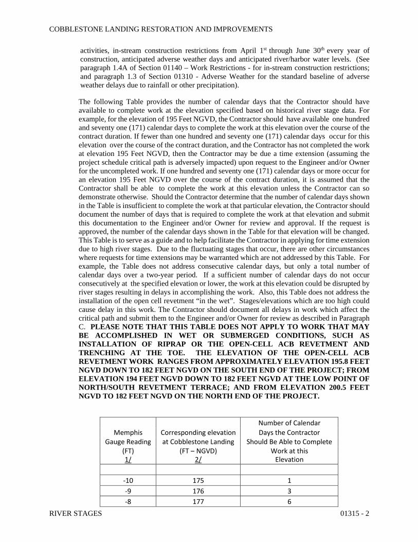
activities, in-stream construction restrictions from April 1st through June 30th every year of construction, anticipated adverse weather days and anticipated river/harbor water levels. (See paragraph 1.4A of Section 01140 – Work Restrictions - for in-stream construction restrictions; and paragraph 1.3 of Section 01310 - Adverse Weather for the standard baseline of adverse weather delays due to rainfall or other precipitation).
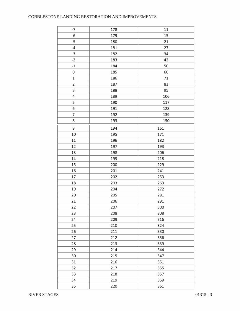
The following Table provides the number of calendar days that the Contractor should have available to complete work at the elevation specified based on historical river stage data. For example, for the elevation of 195 Feet NGVD, the Contractor should have available one hundred and seventy one (171) calendar days to complete the work at this elevation over the course of the contract duration. If fewer than one hundred and seventy one (171) calendar days occur for this elevation over the course of the contract duration, and the Contractor has not completed the work at elevation 195 Feet NGVD, then the Contractor may be due a time extension (assuming the project schedule critical path is adversely impacted) upon request to the Engineer and/or Owner for the uncompleted work. If one hundred and seventy one (171) calendar days or more occur for an elevation 195 Feet NGVD over the course of the contract duration, it is assumed that the Contractor shall be able to complete the work at this elevation unless the Contractor can so demonstrate otherwise. Should the Contractor determine that the number of calendar days shown in the Table is insufficient to complete the work at that particular elevation, the Contractor should document the number of days that is required to complete the work at that elevation and submit this documentation to the Engineer and/or Owner for review and approval. If the request is approved, the number of the calendar days shown in the Table for that elevation will be changed. This Table is to serve as a guide and to help facilitate the Contractor in applying for time extension due to high river stages. Due to the fluctuating stages that occur, there are other circumstances where requests for time extensions may be warranted which are not addressed by this Table. For example, the Table does not address consecutive calendar days, but only a total number of calendar days over a two-year period. If a sufficient number of calendar days do not occur consecutively at the specified elevation or lower, the work at this elevation could be disrupted by river stages resulting in delays in accomplishing the work. Also, this Table does not address the installation of the open cell revetment “in the wet”. Stages/elevations which are too high could cause delay in this work. The Contractor should document all delays in work which affect the critical path and submit them to the Engineer and/or Owner for review as described in Paragraph C. PLEASE NOTE THAT THIS TABLE DOES NOT APPLY TO WORK THAT MAY BE ACCOMPLISHED IN WET OR SUBMERGED CONDITIONS, SUCH AS INSTALLATION OF RIPRAP OR THE OPEN-CELL ACB REVETMENT AND TRENCHING AT THE TOE. THE ELEVATION OF THE OPEN-CELL ACB REVETMENT WORK RANGES FROM APPROXIMATELY ELEVATION 195.8 FEET NGVD DOWN TO 182 FEET NGVD ON THE SOUTH END OF THE PROJECT; FROM ELEVATION 194 FEET NGVD DOWN TO 182 FEET NGVD AT THE LOW POINT OF NORTH/SOUTH REVETMENT TERRACE; AND FROM ELEVATION 200.5 FEET NGVD TO 182 FEET NGVD ON THE NORTH END OF THE PROJECT.
Number of Calendar
Memphis Corresponding elevation Days the Contractor Gauge Reading at Cobblestone Landing Should Be Able to Complete
(FT) (FT – NGVD) Work at this 1/ 2/ Elevation
-10 175 1
-9 176 3
-8 177 6
COBBLESTONE LANDING RESTORATION AND IMPROVEMENTS
RIVER STAGES 01315 - 3
-7 178 11
-6 179 15
-5 180 21
-4 181 27
-3 182 34
-2 183 42
-1 184 50
0 185 60
1 186 71
2 187 83
3 188 95
4 189 106
5 190 117
6 191 128
7 192 139
8 193 150
9 194 161
10 195 171
11 196 182
12 197 193
13 198 206
14 199 218
15 200 229
16 201 241
17 202 253
18 203 263
19 204 272
20 205 281
21 206 291
22 207 300
23 208 308
24 209 316
25 210 324
26 211 330
27 212 336
28 213 339
29 214 344
30 215 347
31 216 351
32 217 355
33 218 357
34 219 359
35 220 361
COBBLESTONE LANDING RESTORATION AND IMPROVEMENTS
RIVER STAGES 01315 - 4
36 221 362
37 222 363
38 223 364
39 224 364
41 226 365
42 227 365
43 228 365
44 229 365
45 230 365
46 231 365
47 232 365
48 233 365
Footnotes:
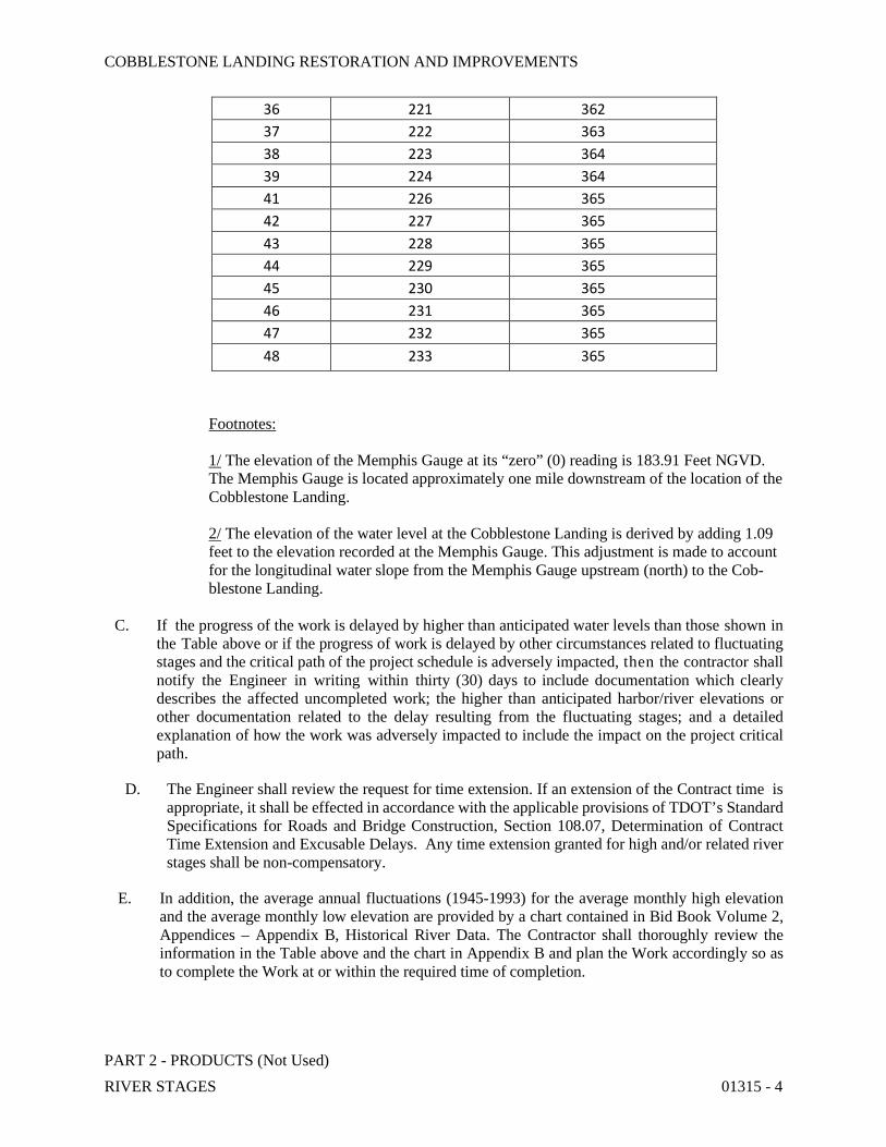
1/ The elevation of the Memphis Gauge at its “zero” (0) reading is 183.91 Feet NGVD. The Memphis Gauge is located approximately one mile downstream of the location of the Cobblestone Landing.
2/ The elevation of the water level at the Cobblestone Landing is derived by adding 1.09 feet to the elevation recorded at the Memphis Gauge. This adjustment is made to account for the longitudinal water slope from the Memphis Gauge upstream (north) to the Cob- blestone Landing.
C. If the progress of the work is delayed by higher than anticipated water levels than those shown in the Table above or if the progress of work is delayed by other circumstances related to fluctuating stages and the critical path of the project schedule is adversely impacted, then the contractor shall notify the Engineer in writing within thirty (30) days to include documentation which clearly describes the affected uncompleted work; the higher than anticipated harbor/river elevations or other documentation related to the delay resulting from the fluctuating stages; and a detailed explanation of how the work was adversely impacted to include the impact on the project critical path.
D. The Engineer shall review the request for time extension. If an extension of the Contract time is appropriate, it shall be effected in accordance with the applicable provisions of TDOT’s Standard Specifications for Roads and Bridge Construction, Section 108.07, Determination of Contract Time Extension and Excusable Delays. Any time extension granted for high and/or related river stages shall be non-compensatory.
E. In addition, the average annual fluctuations (1945-1993) for the average monthly high elevation and the average monthly low elevation are provided by a chart contained in Bid Book Volume 2, Appendices – Appendix B, Historical River Data. The Contractor shall thoroughly review the information in the Table above and the chart in Appendix B and plan the Work accordingly so as to complete the Work at or within the required time of completion.
PART 2 - PRODUCTS (Not Used)

COBBLESTONE LANDING RESTORATION AND IMPROVEMENTS
RIVER STAGES 01315 - 5
PART 3 - EXECUTION (Not Used)
END OF SECTION 01315
COBBLESTONE LANDING RESTORATION AND IMPROVEMENTS
ARTICULATING CONCRETE BLOCK (ACB) REVETMENT SYSTEM 02311 - 1
SECTION 02311 – ARTICULATING CONCRETE BLOCK (ACB) REVETMENT SYSTEM
PART 1 - GENERAL
1.1 SCOPE OF WORK
A. The contractor shall furnish all labor, materials, equipment, and incidentals required and perform all operations in connection with the installation of the Articulating Concrete Block (ACB) revetment system in accordance with the lines, grades, design and dimensions shown on the Contract Drawings and as specified herein.
1.2 SUBMITTALS
A. Contractor shall submit to the Engineer of Record (hereinafter, “Engineer”) for review and approval, qualifications and technical data for the ACB revetment system intended for use on the project at least sixty (60) calendar days prior to planned start of installation; and within fourteen (14) calendar days of the project pre-construction meeting, whichever is earlier. Submittal packages shall include, as a minimum, the following:
1. Evidence of satisfactory full-scale laboratory testing in accordance with ASTM D 7277,Standard Test Method for Performance Testing of Articulating Concrete Block (ACB) Revet-ment Systems for Hydraulic Stability in Open Channel Flow, performed on behalf the submit-ting manufacturer on a qualifying test flume.
2. Associated engineered calculations quantifying the Factor of Safety (FoS) of the proposed ACB system under the design conditions of the specific project, stamped and signed by a reg-istered Professional Engineer (hereinafter, “ACB Design Professional”) residing in and li-censed to practice in the State of Tennessee. The Contractor shall bear all costs associated with engaging the services of the ACB Design Professional. Such costs shall be incidental to the respective pay items for open- and closed-cell ACB revetment systems.
3. The Contractor shall also submit to the Engineer an appropriate geotextile, selected for the site being protected on the basis of the gradation and permeability of the surface soils. Ge-otechnical information is provided in Appendix A of Bid Book Volume 2.
4. A list of 5 comparable projects, in terms of size and application, in the United States, where the satisfactory performance of the specific ACB system can be verified after a minimum of five (5) years of service life;
5. Information about, or certifications of, all materials associated with the ACB system as detailed above, including (but not limited to) cable, fittings, geotextile, and any other materials required for satisfactory installation in accordance with ASTM D 6884-03, Standard Practice for Installation of Articulating Concrete Block (ACB) Revetment Systems;
6. The names and contact information (phone numbers and e-mail addresses, at a minimum) for the suppliers’ representatives, for technical, production or logistics questions, at least one of whom must reside in the state where the project is located.
COBBLESTONE LANDING RESTORATION AND IMPROVEMENTS
ARTICULATING CONCRETE BLOCK (ACB) REVETMENT SYSTEM 02311 - 2
7. Manufacturer's certificates of compliance for ACBs/mats, revetment cable, geotextile, and any revetment cable fittings and connectors.
8. Manufacturer's specifications, literature, shop drawings for the layout of the mats, installation and safety instructions, and any recommendations, if applicable, that are specifically related to the project.
PART 2 - PRODUCTS
2.1 GENERAL
A. All ACB mats shall be prefabricated as an assembly of concrete blocks having specific hydrau-lic capacities, and laced with revetment cables. The ACB system may also be assembled on-site by hand-placing the individual units either with or without subsequent insertion of cables.
B. Individual units in the system shall be staggered and interlocked for enhanced stability. The mats shall be constructed of open and/or closed cell units as shown on the contract drawings. The open cell units have two (2) vertical openings of rectangular cross section with sufficient wall thickness to resist cracking during shipping and installation. Parallel strands of cable shall extend through two (2) cable ducts in each block allowing for longitudinal binding of the units within a mat. Each row of units shall be laterally offset by one-half of a block width from the adjacent row so that any given block is cabled to four other blocks (two in the row above and two in the row below).
C. Each block shall incorporate interlocking surfaces that minimize lateral displacement of the blocks within the mats when they are lifted by the longitudinal revetment cables. The interlock-ing surfaces must not protrude beyond the perimeter of the blocks to such an extent that they reduce the flexibility or articulation capability of the ACB mats or become damaged or broken when the mats are lifted during shipment or placement. Once the mats are in place, the inter-locking surfaces shall minimize the lateral displacement of the blocks even if the cables should become damaged or removed. The mats must be able to flex a minimum of 18 between any given row or column of blocks in the uplift direction and 45 in the downward direction.
D. The cables inserted into the mats shall form lifting loops at one end of the mat with the corre-sponding cable ends spliced together to form a lifting loop at the other end of the mat. The En-gineer shall review and approve appropriate sleeves for use in order to splice the lifting loop. The cables shall be inserted after sufficient time has been allowed for the concrete to complete the curing process.
E. The ACB mats shall be placed on a filter fabric as specified herein. Under no circumstances shall the filter fabric be permanently affixed or otherwise adhered to the blocks or mats; i.e., the filter fabric shall be independent of the block system.
F. Certification (Open-Channel Flow): ACB mats will only be accepted when accompanied by documented hydraulic performance characteristics that are derived from tests under controlled flow conditions. Testing shall conform to ASTM D 7277-08, Standard Test Method for Perfor-mance Testing of Articulating Concrete Block (ACB) Revetment Systems for Hydraulic Stability
COBBLESTONE LANDING RESTORATION AND IMPROVEMENTS
ARTICULATING CONCRETE BLOCK (ACB) REVETMENT SYSTEM 02311 - 3
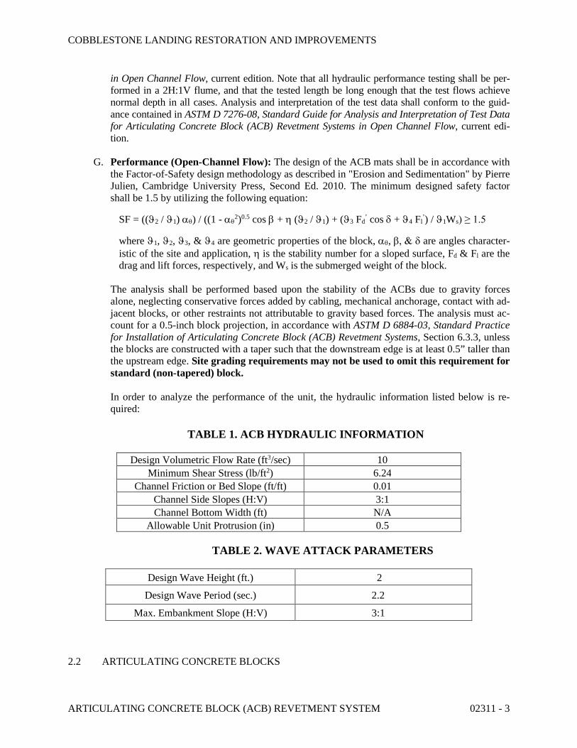
in Open Channel Flow, current edition. Note that all hydraulic performance testing shall be per-formed in a 2H:1V flume, and that the tested length be long enough that the test flows achieve normal depth in all cases. Analysis and interpretation of the test data shall conform to the guid-ance contained in ASTM D 7276-08, Standard Guide for Analysis and Interpretation of Test Data for Articulating Concrete Block (ACB) Revetment Systems in Open Channel Flow, current edi-tion.
G. Performance (Open-Channel Flow): The design of the ACB mats shall be in accordance with the Factor-of-Safety design methodology as described in "Erosion and Sedimentation" by Pierre Julien, Cambridge University Press, Second Ed. 2010. The minimum designed safety factor shall be 1.5 by utilizing the following equation:
SF = ((2 / 1) ) / ((1 - 2)0.5 cos + (2 / 1) + (3 Fd
’ cos + 4 Fl’) / 1Ws) ≥ 1.5
where 1, 2, 3, & 4 are geometric properties of the block, , are angles character-istic of the site and application, is the stability number for a sloped surface, Fd & Fl are the drag and lift forces, respectively, and Ws is the submerged weight of the block.
The analysis shall be performed based upon the stability of the ACBs due to gravity forces alone, neglecting conservative forces added by cabling, mechanical anchorage, contact with ad-jacent blocks, or other restraints not attributable to gravity based forces. The analysis must ac-count for a 0.5-inch block projection, in accordance with ASTM D 6884-03, Standard Practice for Installation of Articulating Concrete Block (ACB) Revetment Systems, Section 6.3.3, unless the blocks are constructed with a taper such that the downstream edge is at least 0.5” taller than the upstream edge. Site grading requirements may not be used to omit this requirement for standard (non-tapered) block.
In order to analyze the performance of the unit, the hydraulic information listed below is re-quired:
TABLE 1. ACB HYDRAULIC INFORMATION
Design Volumetric Flow Rate (ft3/sec) 10
Minimum Shear Stress (lb/ft2) 6.24
Channel Friction or Bed Slope (ft/ft) 0.01
Channel Side Slopes (H:V) 3:1
Channel Bottom Width (ft) N/A
Allowable Unit Protrusion (in) 0.5
TABLE 2. WAVE ATTACK PARAMETERS
Design Wave Height (ft.) 2
Design Wave Period (sec.) 2.2
Max. Embankment Slope (H:V) 3:1
2.2 ARTICULATING CONCRETE BLOCKS
COBBLESTONE LANDING RESTORATION AND IMPROVEMENTS
ARTICULATING CONCRETE BLOCK (ACB) REVETMENT SYSTEM 02311 - 4
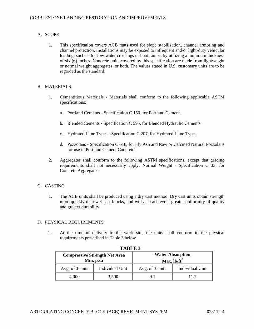
A. SCOPE
1. This specification covers ACB mats used for slope stabilization, channel armoring and channel protection. Installations may be exposed to infrequent and/or light-duty vehicular loading, such as for low-water crossings or boat ramps, by utilizing a minimum thickness of six (6) inches. Concrete units covered by this specification are made from lightweight or normal weight aggregates, or both. The values stated in U.S. customary units are to be regarded as the standard.
B. MATERIALS
1. Cementitious Materials - Materials shall conform to the following applicable ASTM specifications:
a. Portland Cements - Specification C 150, for Portland Cement.
b. Blended Cements - Specification C 595, for Blended Hydraulic Cements.
c. Hydrated Lime Types - Specification C 207, for Hydrated Lime Types.
d. Pozzolans - Specification C 618, for Fly Ash and Raw or Calcined Natural Pozzolans for use in Portland Cement Concrete.
2. Aggregates shall conform to the following ASTM specifications, except that grading requirements shall not necessarily apply: Normal Weight - Specification C 33, for Concrete Aggregates.
C. CASTING
1. The ACB units shall be produced using a dry cast method. Dry cast units obtain strength more quickly than wet cast blocks, and will also achieve a greater uniformity of quality and greater durability.
D. PHYSICAL REQUIREMENTS
1. At the time of delivery to the work site, the units shall conform to the physical requirements prescribed in Table 3 below.
TABLE 3
Compressive Strength Net Area Min. p.s.i
Water Absorption
Max. lb/ft3
Avg. of 3 units Individual Unit Avg. of 3 units Individual Unit
4,000 3,500 9.1 11.7
COBBLESTONE LANDING RESTORATION AND IMPROVEMENTS
ARTICULATING CONCRETE BLOCK (ACB) REVETMENT SYSTEM 02311 - 5
2. Provide manufacturer’s test reports in accordance with ASTM D 6684-04, Standard Specification for Materials and Manufacture of Articulating Concrete Block (ACB) Revetment Systems.
E. VISUAL INSPECTION
1. All units shall be sound and free of defects that would interfere with the proper placing of the unit or impair the strength or permanence of the construction. Surface cracks incidental to the usual methods of manufacture, or surface chipping resulting from customary methods of handling in shipment and delivery, shall not be deemed grounds for rejection.
2. Cracks exceeding 0.25 inches in width and/or 1.0 inch in depth shall be deemed grounds for rejection.
3. Chipping resulting in a weight loss exceeding 10% of the average weight of the blocks shall be deemed grounds for rejection.
4. Blocks rejected prior to delivery from the point of manufacture shall be replaced at the manufacturer's expense. Blocks rejected at the job site shall be repaired with structural grout at the expense of the contractor.
F. SAMPLING AND TESTING
1. The Engineer, CEI Representative or Owner (or their authorized representative) shall be accorded access to the relevant manufacturing facility or facilities, if desired, in order to inspect and/or sample the ACB units from lots ready for delivery prior to release for delivery to the job site. Such inspections are at the sole expense of the requesting entity.
2. Field installation shall be consistent with the way the system was installed in preparation for hydraulic testing pursuant to ASTM D 7277-08, Standard Test Method for Performance Testing of Articulating Concrete Block (ACB) Revetment Systems for Hydraulic Stability in Open Channel Flow. Any external restraints, anchors, or other ancillary components (such as synthetic drainage mediums) shall be employed as they were during testing; e.g., if the hydraulic testing installation utilized a drainage layer, then the field installation must also utilize a drainage layer. This does not preclude the use of other section components for other purposes, e.g., a geogrid for strengthening the subgrade for vehicular loading, or an intermediate filter layer of sand to protect very fine-grained native soils.
3. Hydraulic testing shall be conducted on the thinnest block in a “family” of similar blocks (i.e., same footprint but different thicknesses), with the tested critical shear value then converted to a critical shear at 0° before extrapolation to thicker blocks within the same family. Such extrapolation may not be made from a thicker block to a thinner block. The extrapolation method is detailed in the National Concrete Masonry Association (NCMA) “Design Manual for Articulated Concrete Block (ACB) Revetment Systems”, section 4.2.
4. Engineer, CEI Representative or Owner may request additional testing other than that provided by the manufacturer as needed. Such requested testing will extend any stated
COBBLESTONE LANDING RESTORATION AND IMPROVEMENTS
ARTICULATING CONCRETE BLOCK (ACB) REVETMENT SYSTEM 02311 - 6
lead times for manufacturing and delivery, if the results of such testing are a prerequisite to approval (i.e., approval for release to manufacturing). Costs associated with such testing shall be borne by the requesting entity.
G. MANUFACTURER
1. Cellular articulating concrete blocks (ACB’s) must be manufactured in accordance with ASTM D 6684-04, Standard Specification for Materials and Manufacture of Articulating Concrete Block (ACB) Revetment Systems.
2. The selected articulated concrete blocks shall be a minimum of 4.75” thick, and be accompa-nied by fully referenced and independently verifiable Factor of Safety calculations demon-strating satisfactory performance with a minimum FoS of 2.0.
H. REVETMENT CABLE AND FITTINGS
1. Option 1. Polyester Revetment Cable and Fittings
a. Revetment cable shall be constructed of high tenacity, low elongating, and continu-ous filament polyester fibers. Cable shall consist of a core construction comprised of parallel fibers contained within an outer jacket or cover.
b. The size of the revetment cable shall be selected such that the minimum acceptable strength is at least five (5) times that required for lifting of the mats, in accordance with ASTM D-6684 paragraph 5.5.2. This design shall include a reduction factor for splicing of 60%, unless a larger factor can be substantiated by laboratory testing.
c. The revetment cable shall exhibit resistance to most concentrated acids, alkalis and solvents. Cable shall be impervious to rot, mildew and degradation associated with marine organisms. The materials used in the construction of the cable shall not be af-fected by continuous immersion in fresh or salt water.
d. Selection of cable and fittings shall be made in a manner that ensures a safe design factor for mats being lifted from both ends, thereby forming a catenary. Considera-tion shall be taken for the bending of the cables around hooks or pins during lifting. Fittings such as sleeves and stops shall be aluminum and washers shall be plastic un-less otherwise shown on the Contract Drawings.
2. Option 2. Galvanized Steel Revetment Cable and Fittings
a. Revetment cable shall be constructed of preformed galvanized aircraft cable (GAC). The cables shall be made from individual wires and strands that have been formed during the manufacture into the shape they have in finished cable.
b. Cable shall consist of a core construction comprised of seven (7) wires wrapped with-in seven (7) or nineteen (19) wire strands.
c. The size of the revetment cable shall be selected such that the minimum acceptable strength is at least five (5) times that required for lifting of the mats, in accordance with ASTM D-6684 paragraph 5.5.2. This design shall include a reduction factor for splicing of 75%, unless a larger factor can be substantiated by laboratory testing.
d. The revetment cable shall exhibit resistance to mild concentrations of acids, alkalis, and solvents. Fittings such as sleeves and stops shall be aluminum, and the washers shall be galvanized steel or plastic. Furthermore, depending on material availability,
COBBLESTONE LANDING RESTORATION AND IMPROVEMENTS
ARTICULATING CONCRETE BLOCK (ACB) REVETMENT SYSTEM 02311 - 7
the cable type (7x7 or 7x19) can be interchanged while always ensuring the required factor of safety for the cable.
e. Selection of cable and fittings shall be made in a manner that insures a safe design factor for mats being lifted from both ends, thereby forming a catenary. Considera-tion shall be taken for the bending of the cables around hooks or pins during lifting. Fittings such as sleeves and stops shall be aluminum and washers shall be plastic un-less otherwise shown on the Contract Drawings.
I. ANCHORS
Permanent anchoring of the open-cell ACB revetment mats, by attachment of the lifting cable loops to the north/south revetment terrace wall, shall be provided as shown on the drawings. However, the manufacturer’s design of the ACB revetment system shall provide hydraulic sta-bility without the use of such anchors.
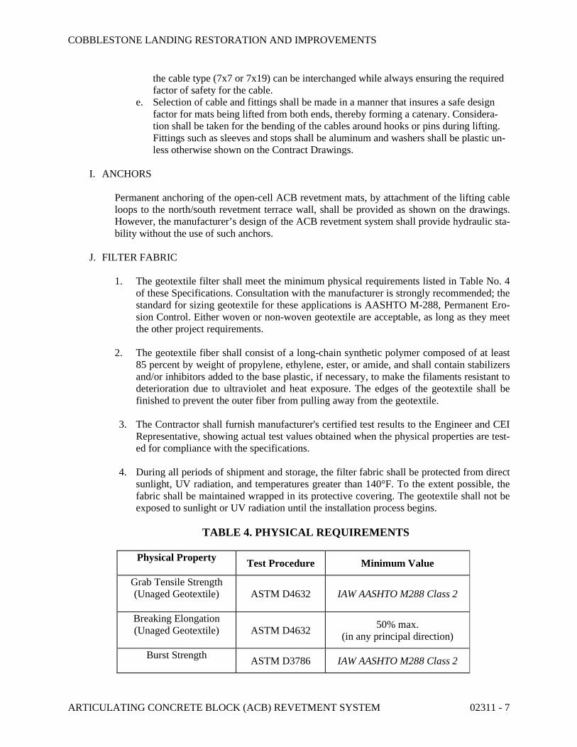
J. FILTER FABRIC
1. The geotextile filter shall meet the minimum physical requirements listed in Table No. 4 of these Specifications. Consultation with the manufacturer is strongly recommended; the standard for sizing geotextile for these applications is AASHTO M-288, Permanent Ero-sion Control. Either woven or non-woven geotextile are acceptable, as long as they meet the other project requirements.
2. The geotextile fiber shall consist of a long-chain synthetic polymer composed of at least 85 percent by weight of propylene, ethylene, ester, or amide, and shall contain stabilizers and/or inhibitors added to the base plastic, if necessary, to make the filaments resistant to deterioration due to ultraviolet and heat exposure. The edges of the geotextile shall be finished to prevent the outer fiber from pulling away from the geotextile.
3. The Contractor shall furnish manufacturer's certified test results to the Engineer and CEI Representative, showing actual test values obtained when the physical properties are test-ed for compliance with the specifications.
4. During all periods of shipment and storage, the filter fabric shall be protected from direct sunlight, UV radiation, and temperatures greater than 140°F. To the extent possible, the fabric shall be maintained wrapped in its protective covering. The geotextile shall not be exposed to sunlight or UV radiation until the installation process begins.
TABLE 4. PHYSICAL REQUIREMENTS
Physical Property Test Procedure Minimum Value
Grab Tensile Strength (Unaged Geotextile) ASTM D4632 IAW AASHTO M288 Class 2
Breaking Elongation (Unaged Geotextile) ASTM D4632
50% max. (in any principal direction)
Burst Strength ASTM D3786 IAW AASHTO M288 Class 2
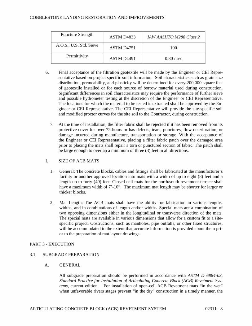
COBBLESTONE LANDING RESTORATION AND IMPROVEMENTS
ARTICULATING CONCRETE BLOCK (ACB) REVETMENT SYSTEM 02311 - 8
Puncture Strength ASTM D4833 IAW AASHTO M288 Class 2
A.O.S., U.S. Std. Sieve ASTM D4751 100
Permittivity ASTM D4491 0.80 / sec
6. Final acceptance of the filtration geotextile will be made by the Engineer or CEI Repre-sentative based on project specific soil information. Soil characteristics such as grain size distribution, permeability, and plasticity will be determined for every 200,000 square feet of geotextile installed or for each source of borrow material used during construction. Significant differences in soil characteristics may require the performance of further sieve and possible hydrometer testing at the discretion of the Engineer or CEI Representative. The locations for which the material to be tested is extracted shall be approved by the En-gineer or CEI Representative. The CEI Representative will provide the site-specific soil and modified proctor curves for the site soil to the Contractor, during construction.
7. At the time of installation, the filter fabric shall be rejected if it has been removed from its protective cover for over 72 hours or has defects, tears, punctures, flow deterioration, or damage incurred during manufacture, transportation or storage. With the acceptance of the Engineer or CEI Representative, placing a filter fabric patch over the damaged area prior to placing the mats shall repair a torn or punctured section of fabric. The patch shall be large enough to overlap a minimum of three (3) feet in all directions.
I. SIZE OF ACB MATS
1. General: The concrete blocks, cables and fittings shall be fabricated at the manufacturer’s facility or another approved location into mats with a width of up to eight (8) feet and a length up to forty (40) feet. Closed-cell mats for the north/south revetment terrace shall have a maximum width of 7’-10”. The maximum mat length may be shorter for larger or thicker blocks.
2. Mat Length: The ACB mats shall have the ability for fabrication in various lengths, widths, and in combinations of length and/or widths. Special mats are a combination of two opposing dimensions either in the longitudinal or transverse direction of the mats. The special mats are available in various dimensions that allow for a custom fit to a site-specific project. Obstructions, such as manholes, pipe outfalls, or other fixed structures, will be accommodated to the extent that accurate information is provided about them pri-or to the preparation of mat layout drawings.
PART 3 - EXECUTION
3.1 SUBGRADE PREPARATION
A. GENERAL
All subgrade preparation should be performed in accordance with ASTM D 6884-03, Standard Practice for Installation of Articulating Concrete Block (ACB) Revetment Sys-tems, current edition. For installation of open-cell ACB Revetment mats “in the wet” when unfavorable rivers stages prevent “in the dry” construction in a timely manner, the
COBBLESTONE LANDING RESTORATION AND IMPROVEMENTS
ARTICULATING CONCRETE BLOCK (ACB) REVETMENT SYSTEM 02311 - 9
subgrade preparation requirements may be altered or waived as directed by the Engineer during Construction; and in accordance with the Manufacturer’s recommendations. Closed-cell ACB Revetment mats may not be installed “in the wet”.
B. GRADING.
1. The slope shall be graded to a smooth plane surface to ensure that intimate contact is achieved between the slope face and the geotextile (filter fabric), and between the geotex-tile and the entire bottom surface of the individual ACBs. All slope deformities, roots, grade stakes, and stones which project normal to the local slope face must be re-graded or removed. No holes, "pockmarks", slope board teeth marks, footprints, or other voids greater than 0.5 inch in depth normal to the local slope face shall be permitted. No grooves or depressions greater than 0.5 inches in depth normal to the local slope face with a dimension exceeding 1.0 foot in any direction shall be permitted. Where such are-as are evident, they shall be brought to grade by placing compacted homogeneous materi-al. The slope and slope face shall be uniformly compacted, and the depth of layers, ho-mogeneity of soil, and amount of compaction shall be as required by the Engineer or CEI Representative.
2. Excavation and preparation for anchor trenches, flanking trenches, and toe trenches or aprons shall be done in accordance to the lines, grades and dimensions shown in the Con-tract Drawings. The anchor trench hinge-point at the top of the slope shall be uniformly graded so that no dips or bumps greater than 0.5 inches over or under the local grade oc-cur. The width of the anchor trench hinge-point shall also be graded uniformly to assure intimate contact between all ACBs and the underlying grade at the hinge-point.
3. For installation of open-cell ACB Revetment mats “in the wet” when unfavorable rivers stages prevent “in the dry” construction in a timely manner, the grading requirements may be altered or waived as directed by the Engineer during Construction; and in accord-ance with the Manufacturer’s recommendations. The intent is to provide a minimum 3h:1v bank slope along the revetment, and flatter at the proposed small-craft boat ramp at the north end of project. In these conditions, toe trenching may be jetted in accordance with Manufacturer’s recommendations. Closed-cell ACB Revetment mats may not be installed “in the wet”.
C. INSPECTION
Immediately prior to placing the filter fabric and ACB mats, the prepared subgrade shall be inspected by the Engineer as well as the CEI Representative. No fabric or blocks shall be placed thereon until that area has been approved by each of these parties.
. For installation of open-cell ACB Revetment mats “in the wet” when unfavorable rivers
stages prevent “in the dry” construction in a timely manner, the subgrade inspection may be waived as directed by the Engineer but there will still be an observation of the existing conditions and proposed installation in these conditions. Closed-cell ACB Revetment mats may not be installed “in the wet”.
D. PRE-CONSTRUCTION CONFERENCE
COBBLESTONE LANDING RESTORATION AND IMPROVEMENTS
ARTICULATING CONCRETE BLOCK (ACB) REVETMENT SYSTEM 02311 - 10
Contractor shall schedule a separate pre-construction conference with the Owner’s CEI Representative, Engineer, superintendent, manufacturer’s representative, major relevant sub-contractors, and other concerned parties before starting construction on the Articulat-ing Concrete Block (ACB) Revetment System at a time convenient to the Owner’s CEI Representative and Engineer; but no later than 30 calendar days prior to starting installa-tion of the ACB Revetment System. Hold the conference at the Project site or another convenient location. Conduct the meeting to review responsibilities and personnel as-signments.
3.2. PLACEMENT OF GEOTEXTILE FILTER FABRIC
A. General.
1. All placement and preparation shall be performed in accordance with ASTM D6884-03, Standard Practice for Installation of Articulating Concrete Block (ACB) Revetment Systems, current edition.
2. Filter Fabric, or filtration geotextile, as specified elsewhere, shall be placed with-in the limits of ACBs shown on the Contract Drawings.
B. Placement. The filtration geotextile shall be placed directly on the prepared area, in inti-mate contact with the subgrade, and free of folds or wrinkles. The geotextile shall not be walked on or disturbed when the result is a loss of intimate contact between the ACB and the geotextile or between the geotextile and the subgrade. The geotextile filter fabric shall be placed so that the upstream strip of fabric overlaps the downstream strip. The longitudinal and transverse joints shall be overlapped at least two (2) feet. The geotextile shall extend at least one (1) foot beyond the top and bottom revetment termination points. If ACBs are assembled and placed as large mattresses, the top lap edge of the geotextile shall not occur in the same location as a space between ACB mats unless the space is concrete filled.
For installation of open-cell ACB Revetment mats “in the wet” when unfavorable rivers stages prevent “in the dry” construction, the filter fabric can be attached to the ACB mats prior to installation with a minimum of (three) 3-foot overlap in the fabric joints. Refer to the Manufacturer for specific procedures and recommendations. Closed-cell ACB Re-vetment mats may not be installed “in the wet”.
3.3. PLACEMENT OF ACBs/MATS
A. General.
1. ACB placement and preparation shall be performed with ASTM D 6884-03, Standard Practice for Installation of Articulating Concrete Block (ACB) Re-vetment Systems, current edition.
2. Cellular concrete block/mats shall be constructed within the specified lines and grades shown on the Contract Drawings.
B. Placement.
COBBLESTONE LANDING RESTORATION AND IMPROVEMENTS
ARTICULATING CONCRETE BLOCK (ACB) REVETMENT SYSTEM 02311 - 11
1. The subgrade shall be prepared in such a manner as to produce a smooth plane surface prior to placement of the ACBs or mats. No individual block within the plane of placed ACBs shall protrude more than one-half inch or as otherwise specified by the Engineer. ACBs shall be flush and develop intimate contact with the subgrade section, as approved by the Engineer or CEI Representative. Proposed hand placing is only to be used in limited areas, specifically identified by manufacturers’ mat layout drawings, as reviewed by the Engineer. Refer to Paragraph 3.1.A regarding subgrade preparation for “in the wet” conditions.
2. If assembled and placed as large mattresses, the ACB mats shall be attached to a spreader bar or other approved device to aid in the lifting and placing of the mats in their proper position by the use of a crane or other approved equipment. The equipment used shall have adequate capacity to place the mats without bumping, dragging, tearing or otherwise damaging the underlying fabric. The mats shall be placed side-by-side, so that the mats abut each other, and/or end-to-end. Mat seams or openings between mats greater than two (2) inches shall be backfilled with 4000 p.s.i. non-shrink grout, concrete or other material approved by the En-gineer. Whether placed by hand or in large mattresses, distinct changes in grade that results in a discontinuous revetment surface in the direction of flow shall re-quire backfill at the grade change location so as to produce a continuous surface.
For installation of open-cell ACB Revetment mats “in the wet” when unfavorable rivers stages prevent “in the dry” construction in a timely manner, grouting be-tween seams may be waived as directed by the Engineer, but should be abutted together as closely and neatly as possible in accordance with Manufacturer’s rec-ommendations. Closed-cell ACB Revetment mats may not be installed “in the wet”.
3. Termination trenches and side trenches shall be backfilled and compacted flush with the top of the blocks. The integrity of the trench backfill must be maintained so as to ensure a surface that is flush with the top surface of the ACBs for its en-tire service life. Toe trenches shall be backfilled as shown on the Contract Draw-ings. Backfilling and compaction of trenches will be completed in a timely fash-ion. No more than 500 linear feet of placed ACBs with non-completed anchor and/or toe trenches will be permitted at any time.
For installation of open-cell ACB Revetment mats “in the wet” when unfavorable rivers stages prevent “in the dry” construction in a timely manner, the toe trench-ing may be jetted in accordance with Manufacturer’s recommendations. Closed-cell ACB Revetment mats may not be installed “in the wet”.
G. Finishing. Infill joints of the open-cell and closed-cell ACBs as shown on Contract Drawings. The cell openings in the open-cell ACBs do not require backfilling.
H. Consultation. The manufacturer of the ACBs/mats shall be expected to provide design and construction advice during the submittal and installation phases of the project. The ACB supplier shall provide, at a minimum, one full day or two half-days of on-site pro-ject support during initial installation. This consultation shall be incidental to other pay

COBBLESTONE LANDING RESTORATION AND IMPROVEMENTS
ARTICULATING CONCRETE BLOCK (ACB) REVETMENT SYSTEM 02311 - 12
items, and any costs associated shall be borne by the Contractor or manufacturer, at no additional cost to the Owner.
END OF SECTION
COBBLESTONE LANDING RESTORATION AND IMPROVEMENTS
BORED PILES (GROUT CASED MICROPILES) 02465 - 1
SECTION 02465 BORED PILES (GROUT CASED MICROPILES)
PART 1 - GENERAL
1.01 Description
This work pertains to furnishing and installing Grout Cased Micropiles (Helical Piles) and Bracket Assemblies shown in the Contract in accordance with the Contract Drawings and this specification. Each Grout Cased Micropile (Helical Pile) shall be installed at the location and to the elevation, minimum length, installation torque, and allowable capacities shown on the contract drawings or as established. This work also pertains to load testing and pre-loading Grout Cased Micropiles (Helical Piles).
1.02 Related Project Specifications
1. TDOT Standard Specifications for Road and Bridge Construction (2015)
1.03 Referenced Codes and Standards
This specification is based on nationally recognized codes and standards including the references listed below. In case of a conflict between the reference and this specification, this specification shall govern.
A. American Society for Testing and Materials (ASTM):
1. ASTM A36/A36M Structural Steel 2. ASTM A123-02 Standard Specification for Zinc (Hot-Dip Galvanized) Coatings on Iron and Steel
Products 3. ASTM A153-05 Standard Specification for Zinc Coating (Hot Dip) on Iron and Steel Hardware 4. ASTM A513/A513M-07 Standard Specification for General Requirements for Carbon and Low
Alloy Steel Tubes 5. ASTM D1143/D1143M-07 Standard Test Method for Piles Under Static Axial Compressive Load 6. ASTM D3689 Standard Test Method for Individual Piles Under Static Axial Tensile Load 7. ASTM D3966-07 Standard Test Method for Piles Under Lateral Loads
B. American Society of Mechanical Engineers (ASME):
1. ANSI/ASME Standard B18.2.1-1996, Square and Hex Bolts and Screws, Inch Series
C. Occupational Safety and Health Administration (OSHA): 1. Excavation Safety Guidelines
D. ICC-Evaluation Services, Inc.:
1. AC358 Acceptance Criteria for Helical Foundation Systems and Devices
E. American Welding Society
1. ANSI/AWS B2.1-00 Standard for Welding Procedure and Performance Qualification
1.04 Definitions

COBBLESTONE LANDING RESTORATION AND IMPROVEMENTS
BORED PILES (GROUT CASED MICROPILES) 02465 - 2
A. Contractor: The general contractor for the overall project. B. Installer: The subcontractor responsible for performing the Grout Cased Micropile work. C. Grout Cased Micropile (Helical Pile): Manufactured steel foundation with one or more helical bearing
plates that is rotated into the ground to support structures. D. Helical Anchor: Same as a Helical Pile. Term generally used when axial tension is the primary service
load. E. Engineer: Professional engineer or professional engineering firm retained by Owner. F. CEI Representative: Individual(s) associated with the Owner to perform construction engineering, and
inspection services. G. Allowable Bearing Capacity: Ultimate bearing capacity of the bearing stratum divided by a factor of
safety. H. Lead Section: The first section of a Grout Cased Micropile to enter the ground. Lead Sections consist
of a central shaft with a tapered end and one or more helical bearing plates affixed to the shaft. I. Extension Section: Grout Cased Micropile sections that follow the Lead Section into the ground and
extend the Helical Lead to the appropriate depth. Extension Sections consist of a central shaft and may have helical bearing plates affixed to the shaft.
J. Brackets: Cap plate, angle, thread bar, or other termination device that is bolted or welded to the end of a Grout Cased Micropile after completion of installation to facilitate attachment to structures or embedment in cast-in-place concrete.
K. Augering: Rotation of the shaft with little or no advancement. It can occur when the helical bearing plates pass from a relatively soft material into a comparatively hard material. Augering can also result from insufficient crowd or downward pressure during installation. In some cases, augering may be (temporarily) necessary in order to grind through an obstruction.
L. Pile Design Professional: Individual or firm responsible for the design of Grout Cased Micropiles and Brackets.
1.05 Qualifications
A. Any subcontractor desiring to bid as the Grout Cased Micropile installer for this project (“Installer”) shall submit information pertaining to the Grout Cased Micropiles and Brackets to the Engineer for review and approval at least thirty (30) calendar days prior to planned start of installation; and within fourteen (14) calendar days of the project pre-construction meeting, whichever is earlier. The information must include:
1. A product catalog and all necessary technical data sufficient to qualify the proposed products. 2. Evidence showing manufacturer has at least ten (10) years’ experience in the design and
manufacture of Grout Cased Micropiles and Brackets. 3. Current ICC-ES product evaluation report or complete description of product testing and
engineering calculations used to assess product capacity. 4. Current ISO9001 certificate or manufacturing quality assurance program documentation showing
methods used to assess and maintain product quality.
B. Any subcontractor desiring to bid as the Grout Cased Micropile installer for this project (hereinafter the “Installer”) shall submit information confirming their training and other qualifications pertaining to the successful installation of Grout Cased Micropiles and Brackets to the Engineer for review and approval at least thirty (30) calendar days prior to planned start of installation; and within fourteen (14) calendar days of the project pre-construction meeting, whichever is earlier. The information must include:
1. A recent company brochure indicating experience in this type of work.

COBBLESTONE LANDING RESTORATION AND IMPROVEMENTS
BORED PILES (GROUT CASED MICROPILES) 02465 - 3
2. Evidence of having installed Grout Cased Micropiles on at least ten (10) projects, including project name, number and type of Grout Cased Micropiles , project location, and client contact information.
3. Resume of subcontractor’s foreman including experience in the oversight of Helical Pile installation on at least five (5) projects in the last five (5) years, including project name, number and type of Grout Cased Micropiles installed, project location, and client contact information; and evidence of training from the supplier of the Grout Cased Micropiles and Brackets in the proper methods of installation of Grout Cased Micropiles and the mounting of Brackets.
4. List of installation and testing equipment and detailed description of proposed method of installation and load testing Grout Cased Micropiles.
5. Current ANSI/AWS welding certificate and documentation of welder experience within the last 5 years (if welding is required).
C. Any subcontractor desiring to bid as the Grout Cased Micropile installer for this project shall submit information confirming the identity and qualifications of their Pile Design Professional(s) to the Engineer for review and approval at least thirty (30) calendar days prior to planned start of installation; and within fourteen (14) calendar days of the project pre-construction meeting, whichever is earlier. The request must include:
1. The curriculum vitae of the designated Pile Design Professional indicating at least ten (10) years experience in this type of work as well as graduate education in structural and/or geotechnical engineering.
2. Evidence of Pile Design Professional having designed Grout Cased Micropiles on at least ten (10) projects, including project name, number and type of Grout Cased Micropiles, project location, and client contact information.
3. Professional errors, omissions liability, and workers compensation insurance certificate documenting coverage meeting or exceeding the contract requirements.
4. Evidence of current license to practice engineering in the project state.
D. The Installer shall not subcontract the whole or any part of the Grout Cased Micropile system work without the express written permission of the Owner.
1.06 Submittals
A. The Installer shall prepare, and the Contractor shall submit to the Engineer for review and approval, Shop Drawings and specifications for the Grout Cased Micropiles intended for use on the project at least thirty (30) calendar days prior to planned start of installation. The Shop Drawings shall include the following:
1. Grout Cased Micropile product identification number(s) and designation(s) 2. Maximum allowable mechanical compression and tensile strength of the Grout Cased Micropiles 3. Number of Grout Cased Micropiles and respective design allowable capacities from the Drawings 4. Planned installation depth and the number of lead and extension sections 5. Preliminary helical configuration (number and diameter of helical bearing plates) 6. Manufacturer’s recommended capacity to installation torque ratio 7. Minimum final installation torque(s) 8. Product identification numbers and designations for all Bracket Assemblies and number and size of
connection bolts or concrete reinforcing steel detail 9. Corrosion protection coating on Grout Cased Micropiles and Bracket Assemblies 10. Inclination of HPM

COBBLESTONE LANDING RESTORATION AND IMPROVEMENTS
BORED PILES (GROUT CASED MICROPILES) 02465 - 4
11. Minimum overall length 12. Cutoff elevation 13. Grout column length
B. The Installer’s Pile Design Professional shall prepare, and the Contractor shall submit to the Engineer for review and approval, the design calculations for the Grout Cased Micropiles and Brackets intended for use on the project at least thirty (30) calendar days prior to planned start of installation. The submitted calculations shall include the following:
1. Reduction in shaft dimension and strength by the sacrificial thickness anticipated based on corrosion loss over the design life for project soil conditions.
2. Considerations for downdrag, buckling, and expansive soils (as appropriate). 3. Minimum installation depth to reach bearing stratum and to achieve pullout capacity (if required). 4. Soil bearing and pullout capacity. 5. Lateral resistance of the shaft (if required). 6. Estimated pile head movement at design loads.
C. Contractor shall submit to the Engineer calibration information certified by an independent testing agency for the torque measurement device and all load testing and monitoring equipment to be used on the project. Calibration information shall have been tested within the last year of the date submitted. Calibration information shall include, but is not limited to, the name of the testing agency, identification number or serial number of device calibrated, and the date of calibration.
D. Contractor shall submit for review and acceptance the proposed load testing procedure. The proposal shall provide the minimum following information:
1. Type and sensitivity of load equipment 2. Type and sensitivity of load measuring equipment 3. Type and sensitivity of pile-head deflection equipment 4. General description of load reaction system, including description of reaction anchors or bearing
plate 5. Calibration reports for equipment, including hydraulic jack, pressure gauges, and deflection dial
gauges
E. Manufacturer shall provide a five (5) year warranty against manufacturing defects on Grout Cased Micropile and Bracket products.
F. Work shall not begin until all the submittals have been received and approved by the Engineer. The Contractor shall allow the Engineer at least twenty-one (21) calendar days to review, comment, and return the submittal package after a complete set has been received. All costs associated with incomplete or unacceptable submittals shall be the responsibility of the Contractor.
1.07 Shipping, Storage, and Handling
A. All Grout Cased Micropile and Bracket Assemblies shall be free of structural defects and protected from damage. Store Grout Cased Micropiles and Bracket Assemblies on wood pallets or supports to keep from contacting the ground. Damage to materials shall be cause for rejection.
COBBLESTONE LANDING RESTORATION AND IMPROVEMENTS
BORED PILES (GROUT CASED MICROPILES) 02465 - 5
B. All Grout Cased Micropile and Bracket Assemblies shall be free of structural defects and protected from damage. Store Grout Cased Micropiles and Bracket Assemblies on wood pallets or supports to keep from contacting the ground. Damage to materials shall be cause for rejection.
1.08 Closeout Submittals:
A. Warranty: Warranty documents specified herein 1. Project Warranty: Refer to Conditions of the Contract for project warranty provisions 2. Manufacturer’s Warranty: Submit, for Owner’s Acceptance, five (5) year warranty
document executed by authorized company official. Manufacturer’s warranty is in addition to, and not a limitation of, other rights the Owner may have under Contract Document.
B. Installer’s Field Reports: Installer’s field reports: Accurately record the following: Type, size, and actual locations of HPM, torque installation records on all HPM, and torque monitoring calibration data.
PART 2 PRODUCTS
2.01 Grout Cased Micropiles and Brackets
A. Unless noted otherwise, it is the responsibility of the Installer’s Pile Design Professional responsibility to select the appropriate size and type of Grout Cased Micropiles and Brackets to support the design loads shown on the Drawings. These specifications and the Drawings provide minimum requirements to aid the Contractor/Installer in making appropriate materials selections. The size and number of helical bearing plates must be such that the Grout Cased Micropiles achieve the appropriate torque and capacity in the soils at the site within the minimum and maximum length requirements. Failure to achieve proper torque and capacity shall result in Installer replacing Grout Cased Micropiles as appropriate to support the required loads. All material replacements shall be acceptable to Engineer.
B. The design strength of the helical bearing plates, shaft connections, Brackets, and the pile shaft itself shall be sufficient to support the design loads specified on the Drawings times appropriate service load factors. In addition, all Grout Cased Micropiles shall be manufactured to the following criteria.
1. Central Shaft: The central shaft shall be 3-inch, 4.5-inch, or 5.72-inch outside diameter (O.D.) high strength structural steel tube meeting the requirements of ASTM A513 Grade 65. The central shaft shall have design wall thicknesses of 0.125, 0.25, 0.31, 0.37, or 0.46 inches.
2. Helical Bearing Plates: One or more helical bearing plates shall be affixed to the central shaft. Helical bearing plates shall be 8, 10, 12, 14, 16, 20, or 24 inches in diameter depending on required bearing area. Helical bearing plates mounted to 3-inch, 4.5-inch, or 5.72-inch O.D. shafts shall have a minimum thicknesses of 1 inch, and shall meet the requirements of ASTM A36 or ASTM A572, Grade 50. Helical bearing plates shall be attached to 3-inch, 4.5-inch, or 5.72-inch O.D. shafts via 3/16, 5/16, or 7/16 inch fillet welds, respectively, continuous on top and bottom and around the leading edges. Helical bearing plates shall be cold pressed into a near perfect helical shape that when affixed to the central shaft are perpendicular with the central shaft, of uniform pitch, and such that the leading and trailing edges are within 3/8 inch of parallel. Average helical pitch shall be within plus or minus 1/4 inch of the thickness of the helical bearing plate plus 3 inches.
3. Corrosion Protection: Grout Cased Micropiles and associated components shall be hot-dip galvanized per ASTM A123 after fabrication. All pipe shafts shall be grouted solid.
COBBLESTONE LANDING RESTORATION AND IMPROVEMENTS
BORED PILES (GROUT CASED MICROPILES) 02465 - 6
4. Shaft Connections: The Grout Cased Micropile shaft connections shall consist of an external sleeve connection or a welded connection. External sleeve connections shall be in-line, straight and rigid and shall have a maximum tolerable slack of 1/16-inch. Welded connections shall consist of a full penetration groove weld all-around the central shaft. Shaft connections shall have a flexural strength at least as great as the shaft itself.
5. Displacement Plates/Centralizers: Fabricate displacement plates (lead or extension plates) from steel or other material that will not affect the structural integrity of the central steel shaft or grout column. Do not use wood for this purpose.
6. Bolts: External sleeve connections for 3-inch, 4.5-inch, or 5.72-inch O.D. shafts shall be made via one, two, or three bolts, respectively. Bolts shall be either 7/8, 1, 1-1/4, or 1-1/2-inch diameter as required for strength. Bolt holes through the external sleeve and central shaft shall have a diameter that is 1/16th inch greater than the bolt diameter. Bolts and nuts used to join Grout Cased Micropile sections at the shaft connections shall be bare steel, epoxy coated, or zinc coated to match the corrosion protection used for the central shaft. Bolts shall be ASME SAE Grade 8 for MH325R piles or ASME SAE Grade 5 for all other piles. All Grout Cased Micropile bolts shall be securely snug tightened.
7. Plug Welds: Alternatively, external sleeve connections may be made using plug welds matching the diameter and number of bolt holes.
8. External sleeve: External sleeve Grout Cased Micropile shaft connections shall consist of a 3.375-inch diameter by 0.13-inch thick wall, 3.625-inch diameter by 0.25-inch thick wall, 3.75-inch diameter by 0.31inch thick wall, 5.25-inch diameter by 0.31-inch thick wall, or 6.77-inch diameter by 0.46-inch thick wall high strength structural steel tube outer sleeve meeting the requirements of ASTM A513 Grade 65. The outer sleeve shall be welded to the central shaft via a continuous fillet weld all-around. The fillet weld shall have a throat thickness equal to the external sleeve tube thickness.
9. Reinforced connections: Reinforced shaft connections shall have a 2.75inch diameter by 0.125-inch thick wall, 2.500-inch diameter by 0.25-inch thick wall, 4-inch diameter by 0.25-inch thick wall, 3.88-inch diameter by 0.25-inch thick wall, 5.22-inch diameter by 0.25-inch thick wall, 4.97-inch diameter by 0.375 thick wall, or 4.80-inch diameter by 0.46-inch thick wall high strength structural steel tube inner sleeve meeting the requirements of ASTM A513 Grade 65. The inner sleeve shall be welded to the central shaft via plug welds oriented 90 degrees from and located slightly below the bolt holes.
C. Grout Cased Micropiles shall be fitted with a manufactured Bracket that facilitates connection to the structure. Brackets shall be rated for the design loads shown on the Drawings. Brackets shall be affixed to the end of Grout Cased Micropiles via bolts, plug welds, or continuous penetration welds meeting the requirements for shaft connections given previously in these specifications and as shown on the drawings.
D. Buried brick, rubble, concrete, abandoned utilities, and other obstructions may be present at locations where Grout Cased Micropiles will be installed. Grout Cased Micropiles either must penetrate any such obstructions without being damaged during installation or the Contractor/Installer must excavate (predrill) and backfill any such obstructions such that Grout Cased Micropiles can be installed according to the Contract. THE CONTRACTOR IS RESPONSIBLE FOR THE COST OF ANY GROUT CASED MICROPILES DAMAGED DURING INSTALLATION, AS WELL AS FOR ANY EXCAVATION AND REMOVAL OF OBSTRUCTIONS, AND FOR ANY ASSOCIATED BACKFILLING.
2.02 Accessories
A. Provide the following accessory components:
COBBLESTONE LANDING RESTORATION AND IMPROVEMENTS
BORED PILES (GROUT CASED MICROPILES) 02465 - 7
1. Water: Water for mixing grout shall be potable, clean and free from impurities, which may be detrimental to grout or steel. Potable water shall be available in quantities sufficient to mix grout and for equipment cleanup.
2. Cement: Cement for Micropile grout shall be Portland cement conforming to ASTM C150 Type I or Type II. Prepackaged, non-shrink cement grouts shall be subject to the review and acceptance of the Owner and shall conform to the requirements of ASTM C1107.
3. Admixtures and Chemical Admixtures a. Conform to the requirements of ASTM C494. Do not use accelerators. b. Chemical admixtures, if used, shall be compatible with the central steel shaft and mixed in
accordance with the grout manufacturer’s recommendations. c. Chemical admixtures which control bleed water, improve consistency, reduce water/cement
ratio and retard set may be used in the grout subject to the review and acceptance of the Owner.
d. Expansive admixtures may be used to fill confined areas of the central steel shaft coupling joints or to compensate for drying shrinkage.
e. Conform to the requirements of ASTM C618 (coal fly ash) or C1240 (silica fume). f. Mineral admixtures, which provide thixotropic consistency, reduce porosity, increase
compressive strength and resist segregation, may be used in the grout subject to the review and acceptance of the Owner.
g. Mineral admixtures, if used, shall be compatible with the central steel shaft and mixed in accordance with the grout manufacturer’s recommendations.
2. Aggregate: a. Sand fillers may be used in the grout mix as an extender with large diameter grout columns,
subject to the approval of the Owner. Do not include aggregate in small diameter grout columns.
b. Use fine sand only. Do not use medium or coarse sand.
PART 3 EXECUTION
3.01 Examination
A. Contractor/Installer shall take reasonable effort to locate all utilities and structures above and underground in the area of the Work. Contractor/Installer shall determine the exact location of underground utilities and buried structures within a distance from a Grout Cased Micropile equal to three times the maximum helix diameter. Contractor/Installer are responsible for protection of utilities and structures shown on the Drawings. Costs of avoiding, relocating, or repair of utilities not shown on Drawings will be paid by Owner as extra work.
B. Contractor/Installer shall determine subsurface conditions for sizing and installation of Grout Cased Micropiles. Soil boring records are available from the geotechnical/subsurface investigation report(s) included in Appendix A of Bid Book Volume 2. No guarantee is made that these boring records are representative of the subsurface conditions that may be encountered at Cobblestone Landing. The Contractor/Installer may conduct supplemental site investigations at their own risk and cost if additional subsurface information is needed. The Installer could also elect to install one or more Helical Probe Piles at location(s) at the project site at their own risk and cost. Using accepted installed torque vs. capacity relationships, a presumptive soil profile could be generated in this matter.
C. Contractor and Installer shall make a site visit to observe conditions prior to the start of Work.
COBBLESTONE LANDING RESTORATION AND IMPROVEMENTS
BORED PILES (GROUT CASED MICROPILES) 02465 - 8
D. Contractor shall notify Engineer of any condition that would affect proper installation of Grout Cased Micropiles immediately after the condition is revealed.
E. If excavation is required for proper installation of Grout Cased Micropiles, Contractor/Installer shall make safe excavations in accordance with OSHA standards. All excavations greater than 20 feet in depth or not in strict accordance with OSHA standard details shall be designed by a registered design professional specializing in the design of excavations and shoring. The costs of all excavations, shoring, and related design shall be borne by the Contractor/Installer unless noted otherwise in the Contract.
F. Contractor shall notify the Engineer at least 48 hours prior to installation of Grout Cased Micropiles to schedule quality assurance observations required on the Drawings.
3.02 Installation Equipment
A. Torque Motor: Grout Cased Micropiles should be installed with high torque, low RPM torque motors, which allow the helical plates to advance with minimal soil disturbance. The torque motor shall be hydraulic power driven with clockwise and counter-clockwise rotation capability. The torque motor shall be adjustable with respect to revolutions per minute during installation. Percussion drilling equipment shall not be permitted. The torque motor shall have torque capacity equal to or greater than the minimum final installation torque required for the project. The connection between the torque motor and the installation rig shall have no more than two pivot hinges oriented 90 degrees from each other. Additional hinges promote wobbling and affect lateral capacity.
B. Installation Equipment: The installation equipment shall be capable of applying adequate crowd and torque simultaneously to ensure normal advancement of the Grout Cased Micropiles. The equipment shall be capable of maintaining proper alignment and position.
C. Drive Tool: The connection between the torque motor and Grout Cased Micropile shall be in-line, straight, and rigid, and shall consist of a hexagonal, square, or round kelly bar adapter and helical shaft socket. To ensure proper fit, the drive tool shall be manufactured by the Grout Cased Micropile manufacturer and used in accordance with the manufacturer’s installation instructions.
D. Connection Pins: The central shaft of the Grout Cased Micropile shall be attached to the drive tool by ASME SAE Grade 8 smooth tapered pins matching the number and diameter of the specified shaft connection bolts. The connection pins should be maintained in good condition and safe to operate at all times. The pins should be regularly inspected for wear and deformation. Pins should be replaced with identical pins when worn or damaged.
E. Torque Indicator: A torque indicator shall be used to measure installation torque during installation. The torque indicator can be an integral part of the installation equipment or externally mounted in-line with the installation tooling. The torque indicator shall be capable of torque measurements with increments not exceeding 500 ft-lb. Torque indicators shall have been calibrated within 1-year prior to start of Work. Torque indicators that are an integral part of the installation equipment shall be calibrated on-site. Torque indicators that are mounted in-line with the installation tooling shall be calibrated either on-site or at an appropriately equipped test facility. Indicators that measure torque as a function of hydraulic pressure shall be re-calibrated following any maintenance performed on the torque motor. Torque indicators shall be re-calibrated if, in the opinion of the Engineer, reasonable doubt exists as to the accuracy of the torque measurements.
COBBLESTONE LANDING RESTORATION AND IMPROVEMENTS
BORED PILES (GROUT CASED MICROPILES) 02465 - 9
3.03 Installation Procedures
A. The number and size of helical blades shall be determined by the Installer’s Pile Design Professional in order to achieve the required torque and tensile/bearing capacity for the soil conditions at the site. The ratio of design load to the total area of the helical bearing plates shall not exceed the Allowable Bearing Capacity.
B. Connect the lead section to the Torque Motor using the Drive Tool and Connection Pins. Position and align the Lead Section at the location and to the inclination shown on the Drawings and crowd the pilot point into the soil. Advance the Lead Section and continue to add Extension Sections to achieve the Termination Criteria. All sections shall be advanced into the soil in a smooth, continuous manner at a rate of rotation between 10 and 40 revolutions per minute. Snug tight all coupling bolts.
C. Constant axial force (crowd) shall be applied while rotating Grout Cased Micropiles into the ground. The crowd applied shall be sufficient to ensure that the Grout Cased Micropile advances into the ground a distance equal to at least 80% of the blade pitch per revolution during normal advancement.
D. The torsional strength rating of the Grout Cased Micropile shall not be exceeded during installation.
E. Bolt hole elongation due to torsion of the shaft of a Grout Cased Micropile at the drive tool shall be limited to ¼ inch. Grout Cased Micropiles with bolt hole damage exceeding this criterion shall be uninstalled, removed, and discarded.
F. When the Termination Criteria of a Grout Cased Micropile is obtained, the Installer shall adjust the elevation of the top end of the shaft to the elevation shown on the Drawings or as required. This adjustment may consist of cutting off the top of the shaft and drilling new holes to facilitate installation of Brackets to the orientation shown on the Drawings. Alternatively, installation may continue until the final elevation and orientation of the pre-drilled bolt holes are in alignment. Installer shall not reverse the direction of torque and back-out the Grout Cased Micropile to obtain the final elevation.
G. The Installer shall install Brackets in accordance with Grout Cased Micropile manufacturer’s details or as shown on the Drawings.
H. All Grout Cased Micropile components including the shaft and Bracket shall be isolated from making a direct electrical contact with any concrete reinforcing bars or other non-galvanized metal objects since these contacts may alter corrosion rates.
I. After installation, Grout Cased Micropiles shall be pre-tensioned if indicated on the Drawings.
3.04 Termination Criteria
A. Grout Cased Micropiles shall be advanced until all of the following criteria are satisfied.
1. Axial capacity is verified by achieving the final installation torque as shown on the Drawings, as provided by the Pile Design Professional, or as specified here. A minimum factor of safety of 2.0 shall be used to determine allowable capacity.
2. Minimum depth is obtained. The minimum depth shall be as shown on the Drawings, that which corresponds to the planned bearing stratum, or the depth at which the final installation torque is measured, whichever is greater. In addition, Grout Cased Micropiles shall be advanced until the average torque over the last three (3) feet equals or exceeds the required final installation torque.
COBBLESTONE LANDING RESTORATION AND IMPROVEMENTS
BORED PILES (GROUT CASED MICROPILES) 02465 - 10
B. If the torsional strength rating of the Grout Cased Micropile and/or the maximum torque of the installation equipment has been reached or Augering occurs prior to achieving the minimum depth required, the Installer shall have the following options:
1. Terminate the installation at the depth obtained subject to the review and acceptance of the Engineer and Owner.
2. Remove the Grout Cased Micropile and install a new one with fewer and/or smaller diameter helical bearing plates or with dual cutting edge helical bearing plates. The new helical configuration shall be subject to review and acceptance of the Engineer and Owner.
3. Remove the Grout Cased Micropile and pre-drill a 4-inch diameter pilot hole in the same location and reinstall the anchor/pile.
4. If the obstruction is shallow, remove the Grout Cased Micropile and remove the obstruction by surface excavation. Backfill and compact the resulting excavation and reinstall the anchor/pile.
5. Remove the Grout Cased Micropile and relocate 1-foot to either side of the installation location subject to the review and acceptance of Engineer and Owner.
6. Reverse the direction of torque, back-out the Grout Cased Micropile a distance of 1 to 2 feet and attempt to reinstall by decreasing crowd and Augering through the obstruction.
7. Remove the Grout Cased Micropile and sever the uppermost helical bearing plate from the Lead Section if more than one helical bearing plate is in use, or reshape the helical bearing plates to create the patented Magnum dual cutting edge shape by cutting with a band saw. Reinstall the anchor or pile with revised helical bearing plate configuration.
C. If the final installation torque is not achieved at the contract length, the Installer shall have the following options:
1. Until the maximum depth is achieved (if any), install the Grout Cased Micropile deeper using additional Extension Sections.
2. Remove the Grout Cased Micropile and install a new one with additional and/or larger diameter helical bearing plates.
3. Decrease the rated load capacity of the Grout Cased Micropile and install additional Grout Cased Micropiles. The rated capacity and additional unit location shall be subject to the review and acceptance of the Engineer and Owner.
3.05 Allowable Tolerances
A. Grout Cased Micropiles shall be installed as close to the specified installation and orientation angles as possible. Tolerance for departure from installation and orientation angles shall be +/- 5 degrees.
B. Grout Cased Micropiles and Bracket Assemblies shall be installed at the locations and to the elevations shown on the Plans. Tolerances for Bracket Assembly placement shall be +/-1 inch in both directions perpendicular to the shaft and +/- 1/4 inch in a direction parallel with the shaft unless otherwise specified.
3.06 Quality Assurance
A. The Contractor shall provide the Engineer, CEI representative and Owner copies of installation records within 24 hours after each installation is completed. These installation records shall include, but are not limited to, the following information:
COBBLESTONE LANDING RESTORATION AND IMPROVEMENTS
BORED PILES (GROUT CASED MICROPILES) 02465 - 11
1. Name of project and Grout Cased Micropile Installer 2. Name of Installer’s supervisor during installation 3. Date and time of installation 4. Name and model of installation equipment 5. Type of torque indicator used 6. Location of Grout Cased Micropile by grid location, diagram, or assigned identification number 7. Type and configuration of Lead Section with length of shaft and number and size of helical bearing
plates 8. Type and configuration of Extension Sections with length and number and size of helical bearing
plates, if any 9. Installation duration and observations 10. Total length installed 11. Final elevation of top of shaft and cut-off length, if any 12. Final plumbness or inclination of shaft 13. Installation torque at minimum three-foot depth intervals 14. Final installation torque 15. Comments pertaining to interruptions, obstructions, or other relevant information 16. Verified axial load capacity
B. Unless specified otherwise on the Drawings or by local codes, the Engineer, the Pile Design Professional, or an inspection agency accepted by the Engineer shall observe and document all Grout Cased Micropile installations.
3.07 Load Testing
A. Grout Cased Micropile Compression Tests
1. Contractor shall perform one compression test for each pile type. 2. Compression tests shall be performed following the “quick test” procedure described in ASTM
D1143 specifications 3. Load tests shall be observed and documented by the Grout Cased Micropile Design Professional. 4. Unless otherwise shown on the Contract Drawings, the maximum test load shall be 200% of the
allowable load shown on the Contract Drawings 5. The locations of Grout Cased Micropiles to be tested shall be determined by the Contractor/Installer,
and reviewed by the Engineer for approval. 6. Installation methods, procedures, equipment, products, and final installation torque shall be identical
to the production Grout Cased Micropiles to the extent practical except where otherwise approved by the Owner or Engineer
7. A load test shall be deemed acceptable provided the maximum test load is applied without Grout Cased Micropile failure and the deflection of the pile head at the design load is less than 1-inch unless noted otherwise on the Contract Drawings. Failure is defined when continuous jacking is required to maintain the load.
B. Grout Cased Micropile Tension Tests
1. Contractor shall perform one tension load test for each pile type. 2. Proof load tests shall be performed following the procedure described in ASTM D3689
specifications, Procedure F.
COBBLESTONE LANDING RESTORATION AND IMPROVEMENTS
BORED PILES (GROUT CASED MICROPILES) 02465 - 12
3. Proof load tests shall be observed and documented by the Grout Cased Micropile Design Professional.
4. Unless otherwise shown on the Contract Drawings, the maximum test load shall be 200% of the allowable load shown on the Contract Drawings
5. The locations of Grout Cased Micropiles to be tested shall be determined by the Contractor/Installer,and reviewed by the Engineer for approval.
6. Installation methods, procedures, equipment, products, and final installation torque shall be identical to the production piles to the extent practical except where otherwise approved by the Owner or Engineer
7. A proof load test shall be deemed acceptable provided the maximum test load is applied without Grout Cased Micropile failure. Failure is when continuous jacking is required to maintain the load.
D. If a load test fails the forgoing acceptance criteria, the Contractor/Installer shall modify the Grout Cased Micropile design and/or installation methods and retest the modified pile, as directed by the Owner or Engineer. These modifications include, but are not limited to, de-rating the load capacity, modifying the installation methods and equipment, increasing the minimum final installation torque, changing the helical configuration, or changing the product (i.e., duty). Modifications that require changes to the structure shall have prior review and acceptance of the Owner. Any modifications of design or construction procedures, and any retesting required shall be at the Contractor’s expense.
E. The Contractor shall provide the Owner and Engineer copies of load test reports confirming configuration and construction details within 24 hours after completion of the load tests. This written documentation will either confirm the load capacity as required on the working Contract Drawings or propose changes based upon the results of the tests. At a minimum, the documentation shall include:
1. Name of project and Contractor, Installer and testing personnel 2. Date, time, and duration of test 3. Location of test Grout Cased Micropile by grid location, diagram, or assigned identification
number 4. Test procedure (ASTM D1143, D3689, or D3966) 5. List of any deviations from procedure 6. Description of calibrated testing equipment and test set-up 7. Type and configuration of Grout Cased Micropile including lead section, number and type of
extension sections, and manufacturer’s product identification numbers 8. Load steps and duration of each load increment 9. Cumulative pile-head movement at each load step 10. Comments pertaining to test procedure, equipment adjustments, or other relevant information
END OF SECTION
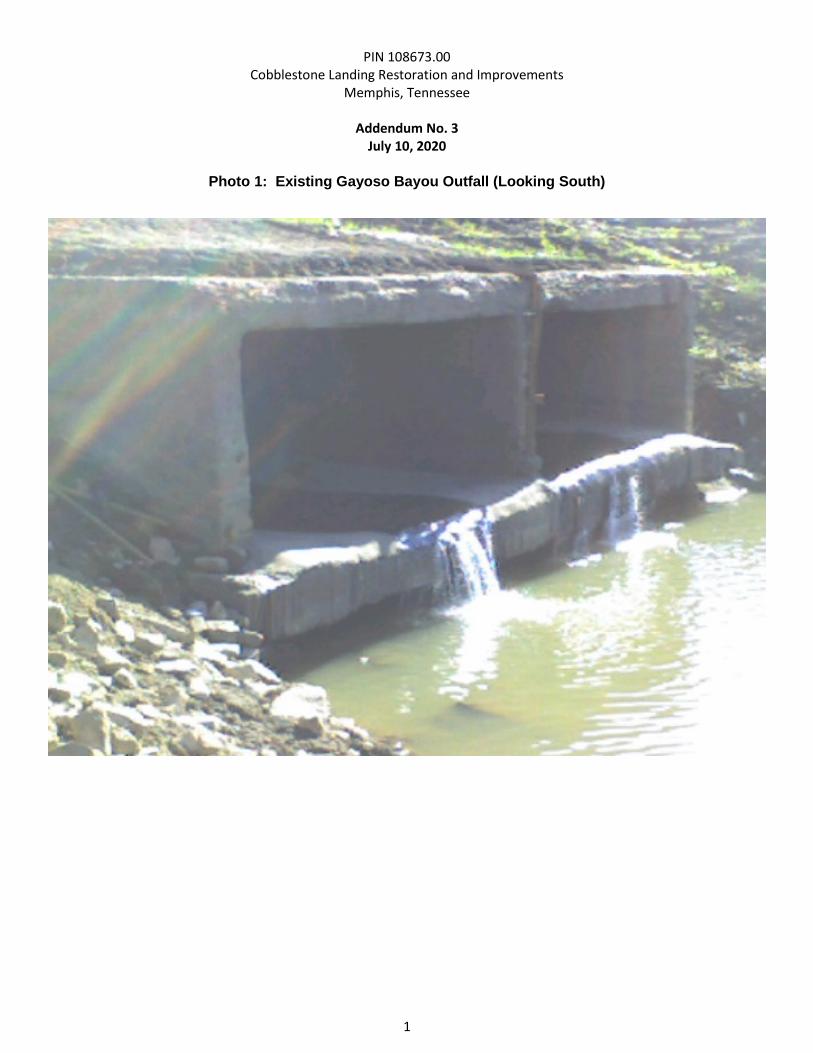
PIN 108673.00 Cobblestone Landing Restoration and Improvements
Memphis, Tennessee
Addendum No. 3 July 10, 2020
1
Photo 1: Existing Gayoso Bayou Outfall (Looking South)
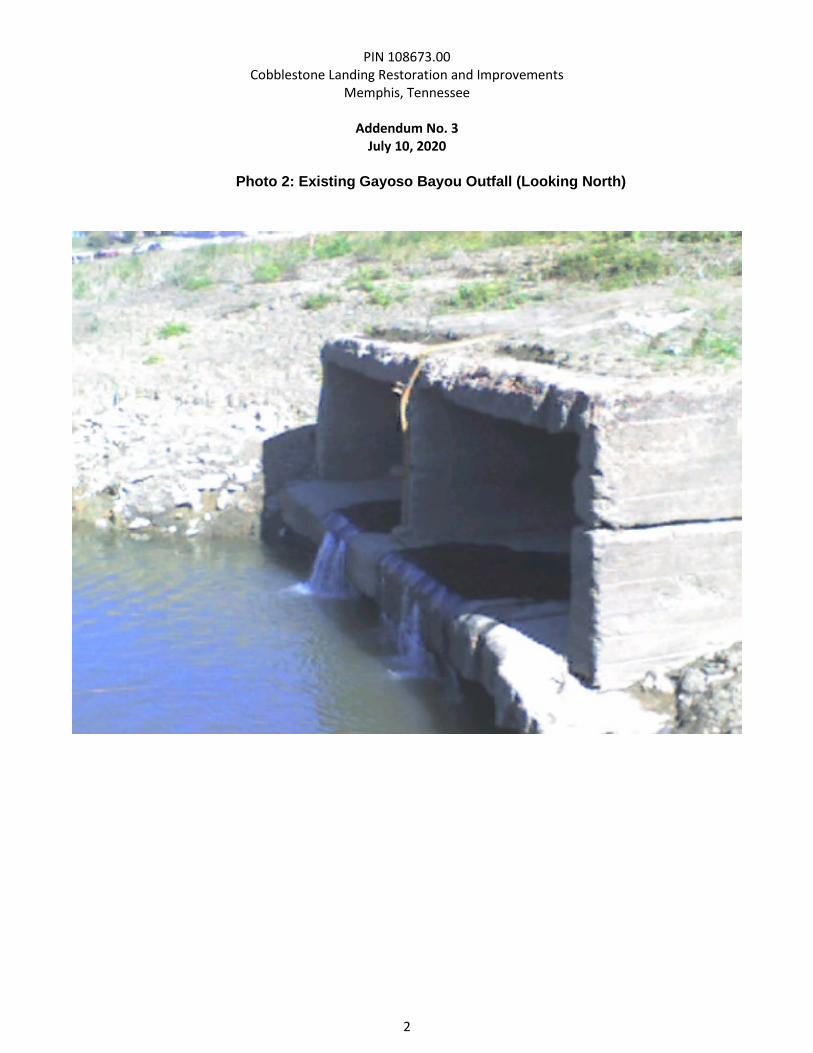
PIN 108673.00 Cobblestone Landing Restoration and Improvements
Memphis, Tennessee
Addendum No. 3 July 10, 2020
2
Photo 2: Existing Gayoso Bayou Outfall (Looking North)