c&nw. timetable 13. 1994-04-10.pdf - jonroma.net
TRANSCRIPT
CHICAGO AND NORTH V,E87211N
TRANSPORTATION COMPANY
I I
TIMETABLE No. 13
EFFECTIVE0001 APRIL 10, 1994
CONTINENTAL CENTRAL STANDARD TIME(EXCEPT MOUNTAIN STANDARD
TIME WEST OF CHADRON)
For the information andgovernment of employees only
R.A. JAHNKE, Senior Vice President-OperationsJ.H. KOCH, Vice President-Transportation
M.C. VAN CLEAVE, Vice President-Commuter & Coal Operations
44hAFETY.....FIRST ALWAYS
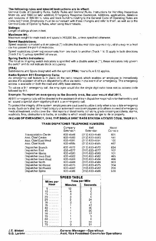
The following rules and special instructions are in effect:General Code of Operating Rules, Safety Rules and General Rules, Instructions for Handling HazardousMaterials, and 1990 (or later addition) Emergency Response Guidebook. Additions, applications, deletionsand revisions of definitions, rules and track bulletins relating to the General Code of Operating Rules arecontained herein. Employees must be conversant with these changes and refer to them, as well as to theGeneral Code of Operating Rules, when using this timetable.
Sidings:Length of sidings shown in feet.
Maximum Wt.:Maximum weight for main track and spurs is 263,000 lbs., unless specified otherwise.
Speed Restrictions:Speed restrictions marked with an asterisk ( *) indicates that the restriction applies only until the engine or leadcar has passed the point of restriction.Speed restrictions governing movements from one track to another (Track 1 to 2) apply in both directions(Track 2 to 1) unless specified otherwise.
Spring Switch Indicators:The location of spring switch indicators is specified with a double asterisk ( * *), these indicators only governthe switch and do not indicate block occupancy.
(FRA)Subdivisions and Spurs designated with the symbol (FRA) means Rule 6.12 applies.
Radio System 911 Emergency Calls:An emergency call feature is in place on the radio network which enables an employee to immediatelyaccess the assistant chief train dispatcher's office via radio in the event of an emergency. The emergencyaccess is available on both the road and utility base stations.
To initiate a 911 emergency call, the employee would dial the single digit radio base station access codefollowed by 911.
Example: To report an emergency in the Beverly area, the user would dial 2911.All 911 emergency calls will be directed to the assistant chief train dispatcher responsible for that territory andwill sound a special alarm signifying that it is an emergency call.
To protect the integrity of the system, employees are cautioned to utilize it only when a bona fide emergencyexists. Such calls shall be limited to injury or extreme illness to employees or to others in need of emergencymedical treatment, and to cover the initial reports of derailments, collisions, grade crossing accidents, storms,washouts, fires, obstructions to tracks, or conditions which would cause danger to life or property.
IN CASE OF EMERGENCY, DIAL THE SINGLE DIGIT BASE STATION ACCESS CODE, THEN 911.
TRAIN DISPATCHER TELEPHONE NUMBERSCompanyExtension
BellExtension
RadioConsole
Transportation Center 633 -4548 (312) 633 -4548 931Asst. Chief Central 633 -4593 (312) 633 -4593 441Asst. Chief East /West 633 -4591 (312) 633 -4591 100Asst. Chief North 633 -4595 (312) 633 -4595 467
Dispatcher Branch 633 -4572 (312) 633-4572 834Dispatcher East 633 -4577 (312) 633 -4577 102Dispatcher Illinois 633 -4580 (312) 633-4580 101Dispatcher Iowa East 633 -4582 (312) 633 -4582 465Dispatcher Iowa West 633 -4584 (312) 633 -4584 466Dispatcher North 633 -4569 (312) 633-4569 903Dispatcher Northeast 633 -4575 (312) 633-4575 304Dispatcher Northwest 633 -4562 (312) 633-4562 200Dispatcher Spine 633 -4586 (312) 633-4586 530
SPEED TABLEMiles per
HourTime per Mile
Minutes Seconds5 12 0
10 6 015 4 020 3 025 2 2430 2 035 1 4340 1 3045 1 2050 1 1255 1 560 1 065 0 5570 0 51
J.E. Biebel General Manager -OperationsG.G. Larson Asst. Vice President -Commuter Operations
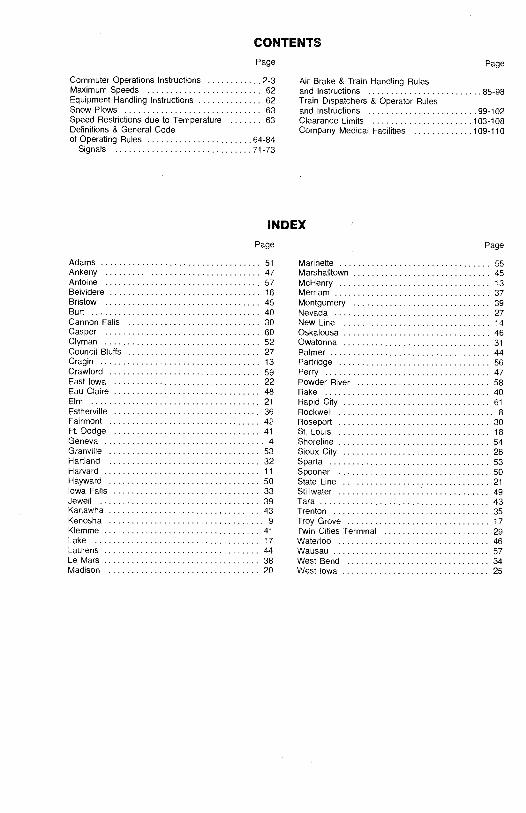
CONTENTS
Page
Commuter Operations Instructions 2 -3Maximum Speeds 62Equipment Handling Instructions 62Snow Plows 63Speed Restrictions due to Temperature 63Definitions & General Codeof Operating Rules 64 -84
Signals 71 -73
Page
Air Brake & Train Handling Rulesand Instructions 85 -98Train Dispatchers & Operator Rulesand Instructions 99 -102Clearance Limits 103 -108Company Medical Facilities 109 -110
INDEX
Page
Adams 51Ankeny 47Antoine 57Belvidere 16Bristow 45Burt 40Cannon Falls 30Casper 60Clyman 52Council Bluffs 27Cragin 13Crawford 59East Iowa 22Eau Claire 48Elm 21Estherville 36Fairmont 42Ft. Dodge 41Geneva 4Granville 53Hartland 32Harvard 11
Hayward 50Iowa Falls 33Jewell 39Kanawha 43Kenosha 9Klemme 41Lake 17Laurens 44Le Mars 38Madison 20
Page
Marinette 55Marshalltown 45McHenry 13Merriam 37Montgomery 39Nevada 27New Line 14Oskaloosa 46Owatonna 31
Palmer 44Partridge 56Perry 47Powder River 58Rake 40Rapid City 61
Rockwell 8Roseport 30St. Louis 18Shoreline 54Sioux City 28Sparta 53Spooner 50State Line 21Stillwater 49Tara 43Trenton 35Troy Grove 17Twin Cities Terminal 29Waterloo 46Wausau 57West Bend 34West Iowa 25
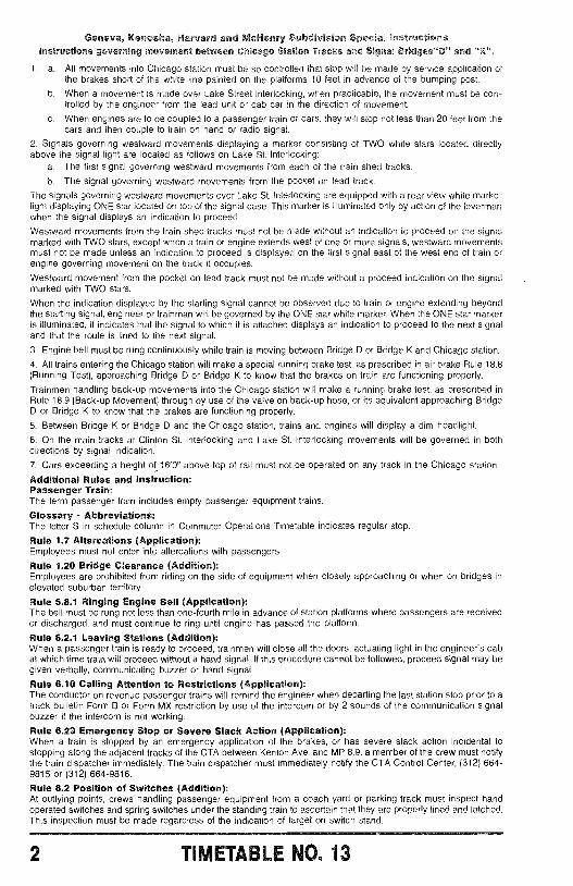
Geneva, Kenosha, Harvard and McHenry Subdivision Special InstructionsInstructions governing movement between Chicago Station Tracks and Signal Bridges "D" and "K"
1. a. All movements into Chicago station must be so controlled that stop will be made by service application ofthe brakes short of the white line painted on the platforms 10 feet in advance of the bumping post.
b. When a movement is made over Lake Street Interlocking, when practicable, the movement must be con-trolled by the engineer from the lead unit or cab car in the direction of movement.
c. When engines are to be coupled to a passenger train or cars, they will stop not less than 20 feet from thecars and then couple to train on hand or radio signal.
2. Signals governing westward movements displaying a marker consisting of TWO white stars located directlyabove the signal light are located as follows on Lake St. Interlocking:
a. The first signal governing westward movements from each of the train shed tracks.
b. The signal governing westward movements from the pocket on lead track.
The signals governing westward movements over Lake St. Interlocking are equipped with a rear view white markerlight displaying ONE star located on top of the signal case. This marker is illuminated only by action of the levermanwhen the signal displays an indication to proceed.
Westward movements from the train shed tracks must not be made without an indication to proceed on the signalmarked with TWO stars, except when a train or engine extends west of one or more signals, westward movementsmust not be made unless an indication to proceed is displayed on the first signal east of the west end of train orengine governing movement on the track it occupies.
Westward movement from the pocket on lead track must not be made without a proceed indication on the signalmarked with TWO stars.
When the indication displayed by the starting signal cannot be observed due to train or engine extending beyondthe starting signal, engineer or trainman will be governed by the ONE star white marker. When the ONE star markeris illuminated, it indicates that the signal to which it is attached displays an indication to proceed to the next signaland that the route is lined to the next signal.
3. Engine bell must be rung continuously while train is moving between Bridge D or Bridge K and Chicago station.
4. All trains entering the Chicago station will make a special running brake test, as prescribed in air brake Rule 18.8(Running Test), approaching Bridge D or Bridge K to know that the brakes on train are functioning properly.
Trainmen handling back -up movements into the Chicago station will make a running brake fest, as prescribed inRule 18.9 (Back -up Movement) through by use of the valve on back -up hose, or its equivalent approaching BridgeD or Bridge K to know that the brakes are functioning properly.
5. Between Bridge K or Bridge D and the Chicago station, trains and engines will display a dim headlight.
6. On the main tracks at Clinton St. Interlocking and Lake St. Interlocking movements will be governed in bothdirections by signal indication.
7. Cars exceeding a height of 16'0" above top of rail must not be operated on any track in the Chicago station.
Additional Rules and Instruction:Passenger Train:The term passenger train includes empty passenger equipment trains.
Glossary - Abbreviations:The letter S in schedule column in Commuter Operations Timetable indicates regular stop.
Rule 1.7 Altercations (Application):Employees must not enter into altercations with passengers.
Rule 1.20 Bridge Clearance (Addition):Employees are prohibited from riding on the side of equipment when closely approaching or when on bridges inelevated suburban territory.
Rule 5.8.1 Ringing Engine Bell (Application):The bell must be rung not less than one -fourth mile in advance of station platforms where passengers are receivedor discharged, and must continue to ring until engine has passed the platform.
Rule 6.2.1 Leaving Stations (Addition):When a passenger train is ready to proceed, trainmen will close all the doors, actuating light in the engineer's cabat which time train will proceed without a hand signal. It this procedure cannot be followed, proceed signal may begiven verbally, communicating buzzer or hand signal.
Rule 6.10 Calling Attention to Restrictions (Application):The conductor on revenue passenger trains will remind the engineer when departing the last station stop prior to atrack bulletin Form B or Form MX restriction by use of the intercom or by 2 sounds of the communication signalbuzzer if the intercom is not working.
Rule 6.23 Emergency Stop or Severe Slack Action (Application):When a train is stopped by an emergency application of the brakes, or has severe slack action incidental tostopping along the adjacent tracks of the CTA between Kenton Ave. and MP 8.9, a member of the crew must notifythe train dispatcher immediately. The train dispatcher must immediately notify the CTA Control Center, (312) 664-9815 or (312) 664 -9816.
Rule 8.2 Position of Switches (Addition):At outlying points, crews handling passenger equipment from a coach yard or parking track must inspect handoperated switches and spring switches under the standing train to ascertain that they are properly lined and latched.This inspection must be made regardless of the indication of target on switch stand.
2 TIMETABLE NO. 13
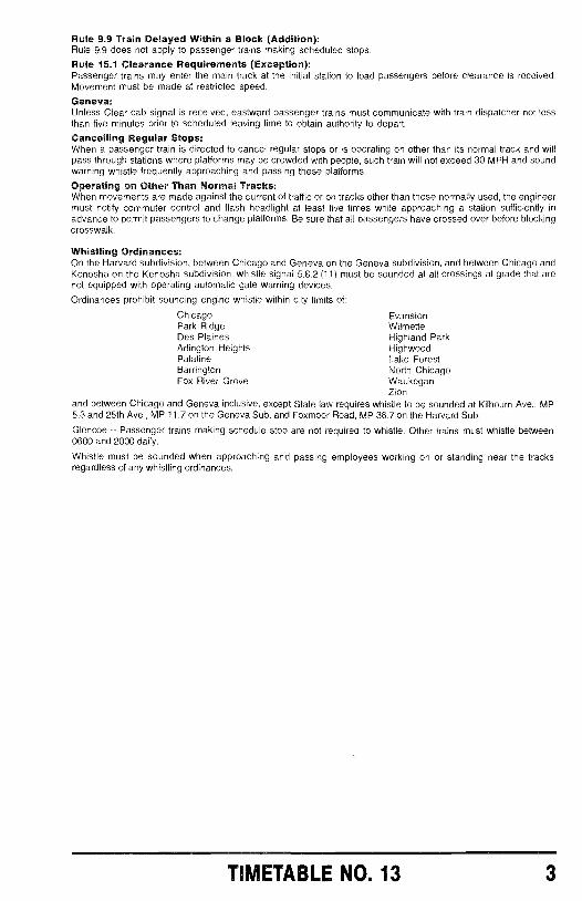
Rule 9.9 Train Delayed Within a Block (Addition):Rule 9.9 does not apply to passenger trains making scheduled stops.
Rule 15.1 Clearance Requirements (Exception):Passenger trains may enter the main track at the initial station to load passengers before clearance is received.Movement must be made at restricted speed.
Geneva:Unless Clear cab signal is received, eastward passenger trains must communicate with train dispatcher not lessthan five minutes prior to scheduled leaving time to obtain authority to depart.
Cancelling Regular Stops:When a passenger train is directed to cancel regular stops or is operating on other than its normal track and willpass through stations where platforms may be crowded with people, such train will not exceed 30 MPH and soundwarning whistle frequently approaching and passing these platforms.
Operating on Other Than Normal Tracks:When movements are made against the current of traffic or on tracks other than those normally used, the engineermust notify commuter control and flash headlight at least five times while approaching a station sufficiently inadvance to permit passengers to change platforms. Be sure that all passengers have crossed over before blockingcrosswalk.
Whistling Ordinances:On the Harvard subdivision, between Chicago and Geneva on the Geneva subdivision, and between Chicago andKenosha on the Kenosha subdivision, whistle signal 5.8.2 (11) must be sounded at all crossings at grade that arenot equipped with operating automatic gate warning devices.
Ordinances prohibit sounding engine whistle within city limits of:
Chicago EvanstonPark Ridge WilmetteDes Plaines Highland ParkArlington Heights HighwoodPalatine Lake ForestBarrington North ChicagoFox River Grove Waukegan
Zionand between Chicago and Geneva inclusive, except State law requires whistle to be sounded at Kilbourn Ave., MP5.3 and 25th Ave., MP 11.7 on the Geneva Sub. and Foxmoor Road, MP 36.7 on the Harvard Sub.
Glencoe - Passenger trains making schedule stop are not required to whistle. Other trains must whistle between0600 and 2000 daily.
Whistle must be sounded when approaching and passing employees working on or standing near the tracksregardless of any whistling ordinances.
TIMETABLE NO. 13 3
GENEVA SUB
áE
EoW
v,f
c3ívm
cm ö
" `°
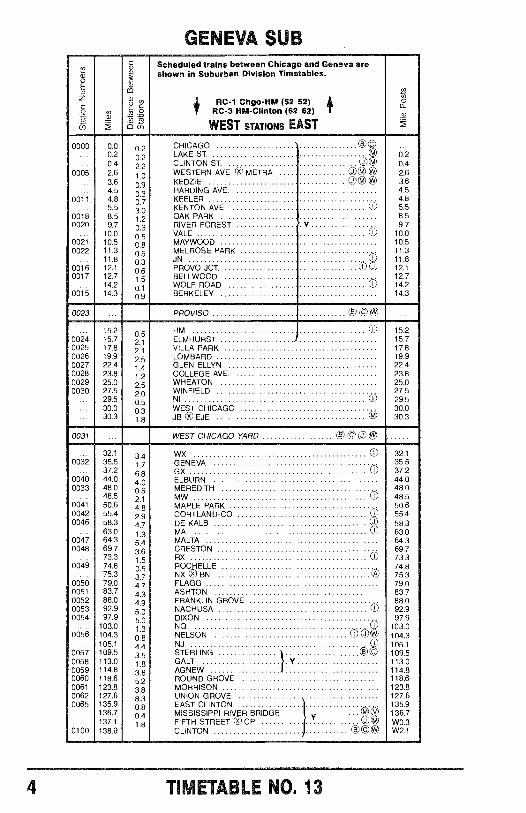
Scheduled trains between Chicago and Geneva areshown in Suburban Division Timetables.
ifRC -1 Chgo -HM (52 52) if
RC -3 HM- Clinton (62 62)
WEST STATIONS EAST
á
0000 0.0 02 CHICAGO ©© ...... 0.2 a2 LAKE ST. © 0.2
0.4 2.2 CLINTON ST. 00 0.40005 2.6 1.0 WESTERN AVE. 0 METRA ©® 2.6
3.6 0.9 KEDZIE 00 ® 3.64.5 0 3 HARDING AVE. 4.5
0011 4.8 0 7 KEELER 4.85.5 30 KENTON AVE. OO 5.s
0018 8.5 1.2 OAK PARK 8.50020 9.7 0.3 RIVER FOREST Y 9.7
10.0 0.5 VALE 0 10.00021 10.5 08 MAYWOOD 10.50022 11.3 05 MELROSE PARK 11.3
11.8 JN 0 11.80016 12.1 0.6 PROVO JCT. 0 U 12.10017 12.7 15 BELLWOOD 12.7
14.2 01 WOLF ROAD 14.20015 14.3 0 9 BERKELEY 14.3
0023 ... PROVISO © © ® ...
15.2 0.5 HM 0 15.20024 15.7 21 ELMHURST 15.70025 17.8 21 VILLA PARK 17.80026 19.9 a5 LOMBARD 19.90027 22.4 1.4 GLEN ELLYN 22.40028 23.8 1.2 COLLEGE AVE. 23.80029 25.0 25 WHEATON 25.00030 27.5 20 WINFIELD 27.5
... 29.5 0,5 NI 0 29.530.0 03 WEST CHICAGO 30.0
... 30.3 1.8 JB © EJE 0 30.3
0031 ... WEST CHICAGO YARD © © C
32.1 3.4 WX 0 32.10032 35.5 17 GENEVA 35.5
37.2 6 8 GX 0 37.20040 44.0 40 ELBURN 44.00033 48.0 as MEREDITH 48.0
48.5 21 MW 0 48.50041 50.6 48 MAPLE PARK 50.60042 55.4 a9 CORTLAND -CO 0 55.40046 58.3 4.7 DE KALB U 58.3
63.0 t 3 MA E 63.00047 64.3 54 MALTA 64.30048 69.7 36 CRESTON 69.7
73.3 1.5 RX D 73.30049 74.8 0.5 ROCHELLE 74.8
75.3 37 NX 0 B 0 75.30050 79.0 4:7 FLAGG 79.00051 83.7 4.3 ASHTON 83.70052 88.0 49 FRANKLIN GROVE 88.00053 92.9 50 NACHUSA D 92.90054 97.9 5:0 DIXON 97.9
103.0 1.3 NO 103.00056 104.3 08 NELSON D U 104.3
105.1 4.4 NJ D 105.10057 109.5 35 STERLING } 0© 109.50058 113.0 1 8 GALT } Y1 113.00059 114.8 38 AGNEW 114.80060 118.6 52 ROUND GROVE 118.60061 123.8 38 MORRISON 123.80062 127.6 8.3 UNION GROVE 127.60065 135.9 08 EAST CLINTON 135.9
... 136.7 MISSISSIPPI RIVER BRIDGE V 136.7137.1 1.8 FIFTH STREET E CP M W0.3
0100 138.9 CLINTON ® ©® W2.1
4 TIMETABLE NO. 13
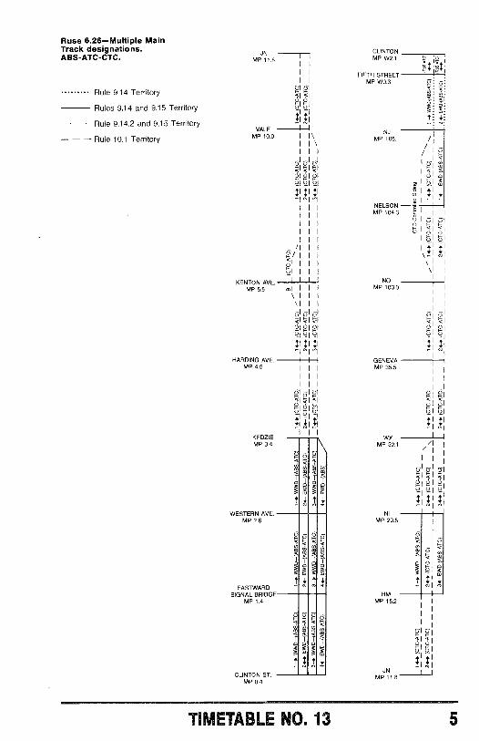
Ruse 6.26- Multiple MainTrack designations.ABS- ATC -CTC.
Rule 9.14 Territory
Rules 9.14 and 9.15 Territory
- - Rule 9.14.2 and 9.15 Territory
- - - Rule 10.1 Territory
JNMP 11.8
2YVALE -II -11
MP 10.0
KENTON AVE.MP 5.5
HARDING AVE.MP 4.5
KEDZIEMP 3.4
WESTERN AVE.MP 2.6
EASTWARDSIGNAL BRIDGE
MP 1.4
CLINTON ST.MP 0.4
< ÛU FÇ) U
YY
Ú
b:1
E
TIMETABLE NO. 13
CLINTONMP W2.1
FIFTH STREETMP W0.3
NJMP 105.1
4
IFI
Q
mIU H
°IYNELSON
&I
MP 104.3 tÚ ÛF G
\
NOMP 103.0
GENEVAMP 35.5
WXMP 32.1
NIMP 29.5
HMMP 15.2
U U
Ù
Ú_
ti
5
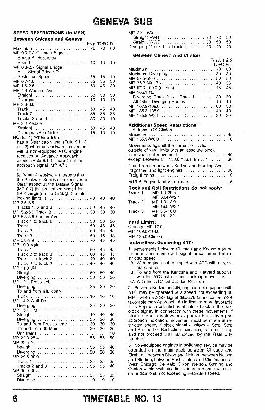
GENEVA SUBSPEED RESTRICTIONS (In MPH)Between Chicago and Geneva
Psgr. TOFC Frt.Maximum 70 70 60MP 0.0 -0.3 Chicago -Signal
Bridge A. RestrictedSpeed 10 10 10
MP 0.3 -0.7 Signal BridgeA - Signal Bridge D.Restricted Speed 15 15 10
MP 0.7 -1.6 35 35 30MP 1.6 -2.6 50 45 30MP 2.6 Western Ave.
Straight 30 30 30Diverging 10 10 10
MP 2.6 -3.6Track 1 50 45 40Track 2 35 35 35Tracks 3 and 4 30 30 10
MP 3.6 KedzieStraight 50 45 40Diverging (See Note) 15 10 10
NOTE: (1) When a trainhas a Clear cab signal (Rule 9.1.13);or, (2) when an eastward movementwith a non -equipped ATC enginereceives an Advance Approachaspect (Rule 9.1.6, figure 9) at theapproach signal (MP 4.7);or,(3) when a westward movement onthe Rockwell Subdivision receives aClear aspect at the Distant Signal(MP 0.7) the prescribed speed forthe diverging route through the inter-locking limits is 40 40 40
MP 3.6 -5.5Tracks 1, 2 and 3 50 45 40
MP 5.2 -5.6 Track B 30 30 30MP 5.5 -5.6 Kenton Ave.
Track 1 to track B 30 30 30Track 1 50 45 45Track 2 50 45 45Track 3 50 45 45
MP 5.6 -9.9 70 45 45MP 10.0 Vale
Track 1 60 45 45Track 2 to track 3 60 45 45Track 1 to track 2 40 40 40Track 2 to track 2 40 40 40
MP 11.8 JNStraight 50 50 40Diverging 30 30 30
MP 12.1 Provo Jct.Diverging 35 30 30To and from IHB Conn.Track 10 10 10
MP 14.2 Wolf Rd.Diverging 35 30 30
MP 15.1 HMStraight 40 40 40Diverging 35 30 30To and from Proviso lead 30 30 30To and from 30 Main 20 20 20Unit trains 10
MP 22.3 -25.4 55 55 50MP 29.5 NI
Straight 55 55 40Diverging 30 30 30
MP 29.5 -30.0Track 1 35 35 35Tracks 2 and 3 55 55 40
MP 30.0 -30.5Straight 35 35 35Diverging 10 10 10
MP 32.1 WXStraight EWD 70 70 50Straight WWD 50 50 50
Diverging (Track 1 to Track 1) 40 40 40
Between Geneva And ClintonTrack 1 & 2
TOFC Frt.Maximum 70 60Maximum Diverging 30 30MP 57.5 -59.0 50 50MP 75.3 NX (BN) 40 35MP 97.0 -100.0 (curves) 45 45MP 105.1 NJ
Diverging: Track 2 to Track 1 30 30All Other Diverging Routes 10 10
MP 107.9 -109.6 60 50MP 135.3 -135.9 40 40MP 135.9 -W2.1 30 30
Additional Speed Restrictions:Unit trains: GX- ClintonMaximum 45MP 135.9 -W0.0 10
Movements against the current of trafficoutside of yard limits with an absolute blockin advance of movement 40except between MP 132.6 -133.1, track 1 30
4 and 5 main between Kedzie and Harding Ave:Psgr train and light engines 20Freight trains 10
M19 -A Engine facility trackage 5
Rock and Roll Restrictions do not apply:Track 1 MP 1.0 -29.5
MP 30.4 -W2.1Track 2 MP 1.0 -13.0
MP 16.5 -W2.1Track 3 MP 3.6 -10.0
MP 15.1 -32.1
Yard Limits:Chicago -MP 17.0MP 109.0 -114.0MP 135.0- Clinton
Instructions Governing ATC:1. Movements between Chicago and Kedzie may bemade in accordance with signal indication and at re-stricted speed:A. With engines not equipped with ATC with or with-
out cars; or,B. To and from the Kenosha and Harvard subdivs.
with the ATC cut out and back -up moves; or,C. With the ATC cut out due to failure.
2. Between Kedzie and JN, engines not equipped withATC may be operated at a speed not exceeding 40MPH when a block signal displays an indication morefavorable than Approach. An indication more favorablethan Approach establishes absolute block to the nextblock signal. In connection with these movements, ifblock signal displays an approach or divergingapproach indication, movement must be made at re-stricted speed. If block signal displays a Stop, Stopand Proceed or Restricting indication, train must stopand not proceed until authorized by the Train Dis-patcher.
3. Non- equipped engines in switching service may beoperated on the main track between Chicago andElmhurst, between Dixon and Nelson, between Nelsonand Sterling, between East Clinton and Clinton, and atWest Chicago, De Kalb, Dixon, Nelson, Sterling andClinton within switching limits, in accordance with sig-nal indications, not exceeding restricted speed.
6 TIMETABLE NO. 13
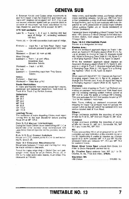
GENEVA SUB4. Between Kedzie and Clinton when movements toand from repair shops for inspection and repairs aremade with engines not equipped with ATC, they mustnot exceed restricted speed until an absolute block inadvance of movement has been established by thetrain dispatcher, and then not to exceed 40 MPH.ATC test sections:Lake St. - Tracks 1, 2, 3 and 4, starting 200 feet
west of Bridge "A ", extending westward100 feet.
Provo Jct. - On IHB connection track east of bridge.
Elmhurst - Track No. 1 at York Road. Signal mustindicate proceed to get proper ATC test.
ProvisoWestward - 29 and 30 main at HM.West ChicagoEastward - Track 7 at yard office.
Downtown lead.Belvidere Subdiv.
Westward - Track 1 at WX.
De KalbEastward - Connecting track from Troy Grove
Subdiv.
NelsonEastward - East wye.Westward - West wye at NJ.Route Restriction:All trains and transfer movements except light engine,passenger and passenger equipment, must move viaTrack B or Track 3 at Kenton Avenue.Detectors:MP 29.0MP 46.1MP 64.0MP 78.8MP 95.0MP 113.2MP 127.9
Leaving Times:The conductor of trains departing Clinton must reportleaving time to the train dispatcher before passingRoute 84 at MP 135.3
Rule 9.12.2 Manual Interlockings:During the hours Clinton Street Interlocking (MP 0.4) isunattended crew member must communicate withLake Street Control Operator and be governed accord-ingly.
Rule 9.13 Dual Control Switches:Kedzie and CTC control points Kedzie to and includ-ing NJ except JB.
Rule 15.1 Clearance Requirements:Movements between Chicago and Harding Ave. maybe made without a clearance.Except for trains originating at Global One and pas-senger trains, trains for which Kedzie, Provo Jct., orHM is the inital subdivision station, must obtain theirclearance at Proviso.
Relay crews, yard transfer crews, and foreign railroadcrews operating between Kedzie and HM must havein their possession a copy of all track bulletins in effectfor that territory, and must communicate with train dis-patcher to verify possession of correct track bulletinsbefore passing Ogden Jct. or Kedzie (westward) orProviso (eastward).
Passenger trains originating at West Chicago Yard forwhich WX, Geneva or West Chicago is the initial sub-division station, must obtain their clearance at WestChicago Yard.
Rule: 18.2.2 Intermediate Point:Proviso is a designated terminal.Kenton Ave.:When the westward approach signal on Track 1 dis-plays an Approach Diverging aspect (Rule 9.1.7), fig-ure 6), prepare to diverge to Track B. Absolute signalwill display a Diverging Clear (Rule 9.1.10), figure 4) ora Diverging Approach (Rule 9.1.9), figure 3) aspect.When the westward approach signal displays anApproach Diverging aspect (Rule 9.1.7), figure 3), pre-pare to diverge to Track 2. Absolute signal will displaya Diverging Clear (Rule 9.1.10), figure 2) or a Diverg-ing Approach (Rule 9.1.9), figure 2) aspect.
JR:When approach signal MP 10.7 displays an ApproachDiverging aspect (Rule 9.1.7), figure 6), prepare todiverge into Proviso yard. Absolute signal will displaya Diverging Approach aspect (Rule 9.1.9), figure 3).
Elmhurst:Westward trains stopping on Track 1 at Elmhurst andmaking an eastward movement over York Road mustuse the crossing warning system manual control atMP 15.8 to raise the gates at Cottage Hill Crossing.This also activates the ATC test section located at MP15.6 for the eastward movement.
Note: Trains making an eastward movement afterstopping on Track 1 at Elmhurst must not activate thecancel button as this will cancel the eastward ATC testsection located east of York Road.Efburn:Village ordinance prohibits the sounding of enginewhistle for First St., MP 43.8 and Route 47, MP 43.9.
Cortland:Village ordinance prohibits the sounding of enginewhistle for Llanos St., MP 55.1, Somonauk Rd., MP55.3 and Loves Rd., MP 55.8
NX:Trains approaching NX must be prepared for an ATCrestriction and stop indication at the absolute signal atthe BN interlocking if unable to maintain an averagespeed of 21 MPH between MP 71.4 and MP 75.0 forwestward trains and between MP 78.5 and MP 75.9for eastward trains.
Dixon River Track Spur extends from Dixon, 3.4miles to Dixon -Marquette cement facility.
St. Charles Spur extends from MP 32.1 to St.Charles, St. No. 7122 (5.0 miles), (PRA).
Maximum Wt:HM- Clinton 315,000 lbs.
TIMETABLE NO 13 7
ROCKWELL SUB
T
E
41 I1 RC -1 (52 52) 1
o,no
u)
op WEST STATIONS EAST t 06
0004 GLOBAL ONE ©OO© 2.30.4
OGDEN JCT. O 1.91.2 Y
ROCKWELL JCT. O© 0.70.7
KEDZIE OMg© 0.0
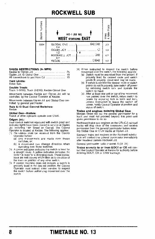
SPEED RESTRICTIONS (In MPH)Kedzie to Ogden Jct. 25Ogden Jct. to Global One 10All connections to and from CJ 15
Yard Limits:Entire Sub.
Double Track:Track 1 -WWD, Track 2 -EWD, Kedzie- Global One.
Movements between Kedzie and Ogden Jct. will becontrolled by the Control Operator at Kedzie.Movements between Ogden Jct. and Global One con-trolled by general yardmaster.
Rule 9.13 Dual Control Switches:Kedzie
Global One -Kedzie:Trains of other railroads operate over CNW.Odgen Jct.:Dual control switches equipped with switch point andindicator lights have been placed in service at OgdenJct. including 14th Street on Conrail. The ControlOperator is located at Kedzie. The following applies:(1) Permission must be received from the Control
Operator before:(a) any movements are made over these
switches, or:(b) a movement can change direction when
operating over these switches.(2) A green indication indicates the switch is lined for
a straight route. A yellow indication indicates theswitch is lined for a diverging route. These indica-tions do not convey information as to condition ofthe track or position of any other switch.If control machine does not indicate a switch isproperly lined in the desired position, the ControlOperator must instruct crew member to inspectthe switch before authorizing movement over theswitch.
(3)
(4) When instructed o inspect the switch beforemovement over the switch, the following applies:(a) Switch must be examined from the ground. If
properly lined for desired route and switchpoints fit properly, movement may be made.
(b) If switch is not lined for desired route or switchpoints do not fit properly, take switch off powerby removing switch lock and operate theswitch by hand.
(c) After at least one unit or car of the movementhas passed over the switch, return switch topower by replacing lock in latch and lock,unless instructed to leave the switch offpower. Notify Control Operator of position andstatus of switch.
Trains and engines entering Global One:Morgan Street will call the general yardmaster for atrack and must not proceed beyond this point untilgiven permission to do so.
Northward trains and engines on the CRI (CJ) railroadtracks will stop clear of the crossovers and receivepermission from the general yardmaster before enter-ing Global One or CNW tracks at Ogden Jct.Eastward trains and engines on the Rockwell subdivi-sion will contact the general yardmaster immediatelyafter headend passes Rockwell Jct.
General yardmaster radio channel: 5 (31 31).
Trains enroute to or from BOCT or CR will con-tact the Control Operator at Kedzie for authority beforeentering BOCT, CR or CNW trackage.
TIMETABLE NO. 13
0000
0501
0503
0506
0511
0513
0514
0516
0517
0518
0520
0519
0521
0523
0526
0525
0527
0528
0529
0531
0532
0549
0533
0534
0530
0537
0538
0539
0542
0543
0544
0545
0S11 :4 SUB
_T,
0.0
0.3
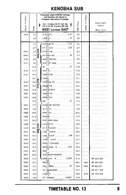
Scheduled trains between Chicagoand Kenosha are shown in
Computer Operations Timetable.
RC-1 Clinton St-CY (52 52)RC-3 CY-St. Francis (62 62)
WEST STATIONS EAST
CHICAGO ltelV)0.3
LAKE ST.0.2
o
22
0.0
0.3
05 CLINTON ST. 0.5
27
2.9
(25x.2CY 500to 02t-4 CLYBOURN
C:1)0) 2.7
2.9
3.30.4th DEERING BR. 3.3
4 3.26.5 RAVENS WOOD 6.5
2.99.4 ROGERS PARK 9.4
1.210.6 RP 10.6
OA11.0 MAIN ST. 11.0
1.012.0 EVANSTON 12.0
0.712.7 CANAL 12.7
0.613.3 4 CENTRAL ST.
o 1.113.3
14.4 WILMETTEo 0.8144
15.2 KENILWORTH 15.20.6
15.8 INDIAN HILL 15.80.8
16.6 WINNETKA 16.60.4
17.0 WK 17.00.7
17.7 HUBBARD WOODS 17.71.5
19.2 GLENCOE 19.21.3
20.5 BRAESIDE 20.51.0
21.5 RAVINIA 21.51.5
23.0 HIGHLAND PARK 23.01.5
24.5 HIGHWOOD 24.5
25.71.24 FT. SHERIDAN 25.72.6
28.3 4 LAKE FOREST 28.31.9
30.2 LAKE BLUFF 0)0) 30.22.0
32.2 GREAT LAKES 32.21.5
33.7 NORTH CHICAGO 33.22.7
35.9 WAUKEGAN Y (8)(0 35.96.2
42.1 ZION 42.12.4
44.5 WINTHROP HARBOR 44.57.1
51.6 KENOSHA Y Etl)t)* 51.68.9
60.5 RACINE 60.512.1
72.6 OAK CREEK 72.62.1
74.7 SO. MILWAUKEE 74.73.5
78.2 CUDAHY 78.21.7
79.9 ST. FRANCIS (1.60V 79.9
6880
11600
6072
Direct TrafficControl
Block Limits
MP 52.8-58.6
MP 58.6-62.5
MP 62.5-67.1
MP 67.1-76.0
MP 76.0-79.9
TIMETABLE NO. 13 9
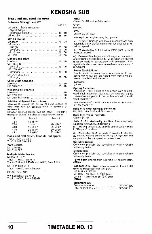
KENOSHA SUBSPEED RESTRICTIONS (In MPH)Between Chicago and CY
MP 0.5 -0.7 Signal Bridge B-Signal Bridge KRestricted Speed
MP 0.7 -2.4
MP 2.4 -CanalMaximum 70 30MP 2.4 -3.3
Straight 35 30Diverging 30 30
MP 3.5 -3.9 50 30MP 12.0 50 30
Canal -Lake BluffMaximumMP 106.6 RP
DivergingMP 17.0 WK
DivergingMP 30.4 Lake Bluff
Diverging
Lake Bluff- KenoshaMaximumMP 50.8 -51.6
Psgr. Frt.
15 1035 10
70 30
40 30
40 30
30 30
70 6060 40
403025
ofof
Kenosha -St. FrancisMaximumMP 77.0 -79.9MP 79.9 St. Francis
Additional Speed Restrictions:Movements against the current of traffic outsideyard limits with an absolute block in advancemovement:Between Deering Bridge and Kenosha - 40 MPHexcept for public crossings at grade shown below:
MP
18.428.440.841.942.1
Track 115 MPH*
15 MPH*25 MPH*15 MPH*
Track 2
20 MPH*25 MPH*30 MPH*35 MPH*
Rock and Roll Restrictions do not apply:Track 1: MP 3.3 -38.0Track 2: MP 30.0 -3.4
Yard Limits:MP 33.0 -38.0MP 51.0 -52.8
Multiple Main Tracks:Clinton St. - CYTrack 1 WWD, Rule 9.14Tracks 2, 3 and 4 EWD and WWD, Rule 9.14.2
CY - RP, Rule 9.14Track 1 -WWD, Track 2 -EWD
RP -WK Rule, 10.1
WK- Kenosha, Rule 9.14Track 1 -WWD, Track 2 -EWD
ABS:Clinton St. -RP and WK- Kenosha
CTC:RP -WK
ATS:Clinton St-MP 52.1Non -equipped engines may be operated:
(a) Between Chicago and Canal in accordance withautomatic block signal indications not exceeding re-stricted speed.
(b) At Waukegan and Kenosha within yard limits atrestricted speed.
(c) Between Waukegan and Chicago for inspectionand repairs not exceeding 40 MPH. Such movementmust be made in accordance with automatic blocksignal indications and an absolute block in advance ofmovement.
Route Restrictions:Double stack container loads in excess of 19 feetabove top of rail are prohibited from operating be-tween Lake Bluff and Kenosha.
Detector:MP 46.1
Spring Switches:Waukegan -Track 1 east end of coach yard to east-ward track- movement governed by absolute signal,instructions are posted in control box located on east-ward platform.**
Kenosha -End of double track MP 52.8. Normal posi-tion for Track 1**
Rule 9.13 Dual Control Switches:RP, WK, Lake Bluff and St. Francis.
Rule 9.15 Track Permits:Clinton St. -RP
Rule 9.18.1 Authority to Use ElectronicallyLocked Switches (Addition):(a) Waiting period is 20 seonds after placing handlein "Request" position.
(b) It indication does not display "Unlocked" after the20 second waiting period notify the CY operator andbe governed by the operators instructions.
So. Milwaukee:Ordinance prohibits the sounding of engine whistlewithin city limits.
Milwaukee:Ordinance prohibits the sounding of engine whistlewithin city limits.
Farm Spur extends from Kenosha 4.2 miles to Bain.(FRA).National Ave. Spur extends from St. Francis 4.0miles to Milwaukee (Sta. No. 0547).MP 81.8 -Ox CPOMP 82.5 - KK River Br. ©® StopMP 83.1 - Milw River Br. ©O Stop(FRA)Maximum Wt:Chicago- Evanston 232,000 lbs.Lake Bluff -St. Francis 315,000 lbs.
10 TIMETABLE NO. 13
0000
0501
0605
0607
0614
0615
0616
0618
0621
0622
0623
8003
0624
0620
0625
0627
0628
0630
0632
0635
0634
0636
0636
0637
0638
0640
0641
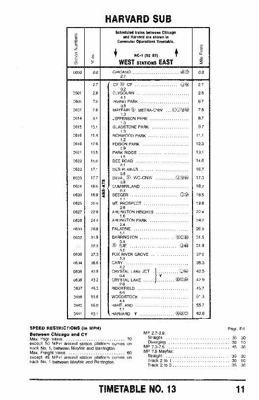
HARVARD SUBScheduled trains between Chicago
and Harvard are shown inCommuter Operations Timetable.
RC -1 (52 52)
WEST STATIONS EAST
w
0.0 CHICAGO2.7
e c 0.0
2.7 CYx® CP 2.70.2
2.9 CLYBOURN 2.84.1
7.0 IRVING PARK 6.70.8
7.8 MAYFAIR xO METRA -CNW 7.61.3
9.1 JEFFERSON PARK 8.71.0
10.1 GLADSTONE PARK 9.71.3
11.4 NORWOOD PARK 11.11.2
12.6 EDISON PARK 12.30.9
13.5 PARK RIDGE 13.11.5
15.0 DEE ROAD 14.62.1
17.1 DES PLAINES 16.70.6
17.7 DEVAL xO WC -CNW CO ®W 17,30.9
18.6 4r0
CUMBERLAND0.3
18.2
18.9 m4 SEEGER O® 18.51.1
20.0 MT. PROSPECT 19.62.8
22.8 ARLINGTON HEIGHTS 22.41.6
24.4 ARLINGTON PARK 24.22.4
26.8 PALATINE 26.55.1
31.9 BARRINGTON 00g 31.50.4
32.3 xO EJE Og 31.95.0
37.3 FOX RIVER GROVE 37.01.3
38.6 CARY 38.34.2
42.8 CRYSTAL LAKE JCT. OO W 42.50.4
V43.2 CRYSTAL LAKE OB ©W 42.92.8
46.0 RIDGEFIELD 45.75.6
51.6 WOODSTOCK 51.34.4
56.0 HARTLAND 55.77.1
63.1 HARVARD Y 000 62.8
SPEED RESTRICTIONS (In MPH)Between Chicago and CYMax. Psgr. trains 70except 50 MPH around station platform curves ontrack No. 1, between Mayfair and Barrington.Max. Freight trains 60except 45 MPH around station platform curves ontrack No. 1 between Mayfair and Barrington.
Psgr.MP 2.7 -2.9:
Frt.
Straight 35 30Diverging 30 10
MP 7.0 -7.6 45 30MP 7.6 Mayfair:
Straight 35 30Track 2 to 1 30 10Track 2 to 3 35 30
Tq .MELE NO. 13 11
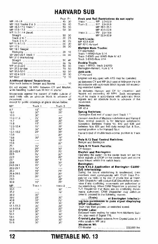
HARVARD SLhPsgr. Frt.
MP 7.6 -7.8 45 30MP 13.2 Tracks 2 & 3 55 40MP 16.4 -17.0 Track 1 50 30MP 17.0 -17.2 50 30MP 17.2 -17.4 Deval:
Straight 50 30Track 2 to 1 30 25Track 3 to 2 30 25
MP 17.4 -17.5 50 30MP 17.5 35 30MP 18.7 Seeger:
Diverging 20 10MP 29.0 -29.4 Track 1 55 50MP 31.0 Interlocking:
Straight 50 40Diverging 35 35
MP 31.0 -32.0 50 40MP 37.3 Bridge 70 50MP 50.6 -52.0 50 50MP 62.4 -62.9 30 30MP 63.0 10 10
Additional Speed Restrictions:Wye track between Seeger and Norma 10
Do not exceed 10 MPH between CY and Mayfair,while handling loaded cars 39 feet or shorter.
Movements against the current of traffic outside ofyard limits with an absolute block in advance ofmovement 40except for public crossings at grade shown below:
MP Track 1 Track 39.7 15* 10'10.1 30* 35*10.3 30*11.0 -11.3 25* 30*11.7 - 35' 30*11.8 15* 30*12.2 -12.4 15* 20*12.5 35* 30*13.1 -13.2 25* 30*13.8 ---- 20*18.8 20* 15*19.6 - - -- 15*19.8 - - -- 20*20.1 15* - - --21.5 25* 30*22.3 -22.4 25* 25*22.5 25° 20'22.9 15* 20°23.1 30* 15*23.8 15* 30*24.0 -24.1 15° 15*26.0 -26.1 15* - - --26.3 15° 25*26.4 -26.5 35' 20'27.3 20* 20*28.0 - - -- 20'30.9 10' 20'MP Track 1 Track 233.0 - - -- 30'35.2 - - -- 15*38.3 30*39.0 25* 30*40.8 35* 25*41.6 25° 35°51.1 -51.3 35* 25*51.5 -51.6 20' 20*51.7 20* 15*53.1 30* 30*54.4 20* 10°55.8 30* 30*57.8 30° 30*
Rock and Roll Restrictions do not apply:Track 1 MP 2.9 -62.9Track 2 MP 2.9 -31.0
MP 36.1 -39.1MP 43.0 -62.8
Track 3 MP 2.9 -18.6MP 22.9 -30.9
Yard Limits:MP 42.4 -43.6MP 62.0 HarvardMultiple Main Tracks:CY- BarringtonTrack 1 -WWD -Rule 9.14Track 2 -EWD and WVVD -Rule 9.14.2Track 3 -EWD -Rule 9.14
Double Track:Track 1 -WWD, Track 2 -EWDBarrington- Harvard, Rule 9.14
ABS -ATS:CY- Harvard
Engines not equipped with ATS may be operated:(a) Between CY and MP 25.0 west of Arlington Park inaccordance with automatic block signals not exceed-ing restricted speed.(b) Between Harvard and CY for inspection andrepairs not exceeding 40 MPH. Such movementsmust be made in accordance with automatic blocksignals and an absolute block in advance of themovement.Detector:MP 47.4Spring Switches:Barrington -East end of coach yard Track 1. *'Harvard -Junction of Madison subdivision and HarvardSpur, normal position is for Madison subdivision.Exception: Between Trains No. 610 and 636 andbetween Nos. 639 and 645 daily except Sat. & Sun.,normal position is for Harvard Spur.Harvard -End of double track -normal position is Track1.
Rule 9.13 Dual Control Switches:Seeger and BarringtonRule 9.15 Track Permits:CY- Seeger.Mayfair and Barrington:Operating the switch on the center track will set theblock signals at STOP on the center track and on thetrack toward which this switch leads.Barrington:Rule 9.12.2 Application at Barrington C&NW -EJE Interlocking:During the hours interlocking is unattended, crewmembers must communicate with CNW Train Dis-patcher via radio or by use of phone box at tower.CNW Dispatcher will contact EJE Dispatcher to deter-mine if any conflicting movements are authorized atthe interlocking. When CNW Dispatcher is advised byEJE Dispatcher that there are no conflicting move-ments authorized, CNW Dispatcher may authorizecrew to proceed in the following manner:
(Train) at Barrington interlock-ing has permission to pass signal displayingSTOP Indication."Train may then proceed at restricted speed.Crystal Lake:Eastward trains waiting for trains from McHenry Sub -div., stay west of Signal 776.Crystal Lake Spur extends from Crystal Lake Jct. 2miles south to MP 56.0Maximum Wt:CY- Mayfair 232,000 lbs.
12 ,rtn :0. 13
0612
0611
0607
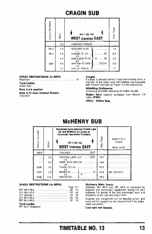
CRAGIN SUB
RC -1 (52 52)
WEST STATIONS EAST
0.0 HARDING AVENUE
1.2 AUGUSTA BLVD. 1.21.1
2.3 CRAGIN Ox CP © 2.32.5
5.0 GRAYLAND x0 CR Y © 5.0
5.6 MAYFAIR O CNW ©O© 5.61.5
7.1 END OF TRACK 7.1
SPEED RESTRICTIONS (In MPH)Maximum
Yard Limits:Entire Sub.
Rule 5.4.4 appliesRule 9.13 Dual Control Switch:Grayland.
0000
0090
0091
0092
Cragin:10 If a train is delayed within Cragin Interlocking limits, a
member of the crew must immediately communicatewith Control Operator at Tower A -5 for instructions.
Whistling Ordinance:Ordinance prohibits sounding of engine whistle.Weber Spur extends westward from Mayfair 3.9miles. (FRA)(FRA) - Entire Sub.
McHENRY SUB
aai
Scheduled trains between Crystal LakeJct. and McHenry are shown InCommuter Operations Timetable.
RC -1 (52 52)
WEST STATIONS EAST
CHICAGO s c
ÿo Direct TrafficControl
Block Limits
0.0 CRYSTAL LAKE JCT. 58.00.4
0.4 WEST WYE SWITCH 58.42.9
3.3 TERRA COTTA 61.34.5
7.8 McHENRY
©
65.8 MP 58.0-65.43.4 Y
11.2 RINGWOOD!
69.2
SPEED RESTRICTIONS (In MPH):Psgr. Frt.
MP 58.0 -58.4 20 10MP 58.4 -59.9 50 40MP 59.9 -65.1 59 40MP 65.1 -65.4 30 20MP 65.4 -69.2 20 10
Yard Limits:MP 65.4- Ringwood
McHenry Main Track:Between MP 65.2 and MP 65.9 is occupied byengines and passenger equipment during the timebetween the arrival of the first passenger train anddeparture of the last passenger train.
Engines and equipment are on standby power andmust not be coupled to nor moved except by autho-rized personnel.
Line -ups not issued.
TIMETABLE NO. 13 13
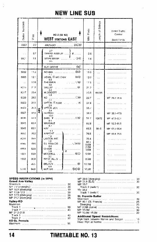
NEW I[1 SUB
RC -3 (62 62)
WEST STATIONS EAST
Direct TrafficControl
Block Limits
0023 0.0
2.7
8001 7.5
8002 11.0
8003 12.1
17.6
8015 21.2
8017 23.4
8020 29.3
8023 31.5
8023 35.3
8027 37.8
8035 51.3
8043 60.4
8045 65.1
8050 76.2
8055 78.0
0545 79.6
0553 82.0
1301 83.9
1302 86.9
88.5
5716 94.9
PROVISO Bc®
2.7GRAND AVENUE .... . Y 2.6 ...
4.8BRYN MAWR OO @ 7.4
3.5
ELK GROVE a b
NORMA Ah 10.91.1
DEVAL (i.t0 WC -CNW i 12.05.5
SHERMER (m) 17.53.6
VALLEY fit) 21.22.2
BLODGETT 23.85.9
KO (si.)0+ 29.72.2
UPTON ) EJ &E n9 31.93.8
UPTON JCT. 35.7m 3.8
? GURNEE 38.213.5
BAIN Y (CM 51.79.1
WAXDALE 60.84.7
KAY 65.511.1
AIRPORT 76.61.8
LAYTON AVE. 78.41.6 80.1
ST. FRANCIS ... ....... (OM)* 0.0M2.4 2.3M
CHASE 3.6M1.9 Y
MITCHELL 0© 5.5M3.0
WEST ALLIS 8.5M1.6
BELTON ® 10.1M6.4
BUTLER ®©® 16.5M
W1285
12672
9915
MP 29.7-35.8
MP 38.1-47.5
MP 47.5-50.1
MP 52.3-61.5
MP 61.5-66.4
MP 66.4-76.6
SPEED RESTRICITIONS (In MPH) MP 29.8 (diverging) 30Grand Ave -Valley MP 31.9 (EJE) 30Maximum 50 MP 35.7MP 7.2 (diverging) 30 Track 2 (switch) 30MP 10.9 (diverging) 10 Mp 38.2MP 11.9 -12.3 30 Track 1 (switch) 30MP 17.5 (diverging) 30 St. Francis -ButlerMP 21.2 (diverging) 25 Maximum 40Valley -KO MP 80.1 (St. Francis) 25Maximum Diverging 25
Track 1 s 50 MP 2.3M (curve) 25Track 2 40 MP 10.0M 30
MP 21.2 -21.8 MP 15.0M -16.5M 30Track 1 40 Additional Speed Restrictions:Track 2 30 Wye track between Norma and Seeger 10KO -St. Francis Dead Wye at Norma 5Maximum 50
14 TIMET LAE NO 13
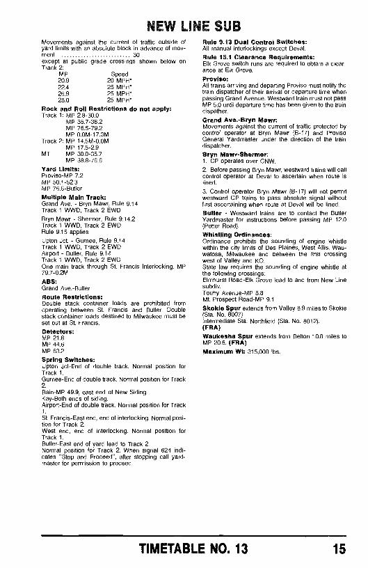
NEW LIEGE SUBMovements against the current of traffic outside ofyard limits with an absolute block in advance of mov-ment 30except at public grade crossings shown below onTrack 2:
MP Speed20.9 20 MPH*22.4 25 MPH`26.9 25 MPH*28.0 25 MPH*
Rock and Roll Restrictions do not apply:Track 1: MP 2.8 -30.0
MP 35.7 -38.2MP 76.5 -79.2MP 0.0M -17.3M
Track 2: MP 14.5M -0.0MMP 17.5 -2.9
MT MP 30.0 -35.7MP 38.8 -76.6
Yard Limits:Proviso -MP 7.2MP 50.1 -52.3MP 76.6- Butler
Multiple Main Track:Grand Ave. - Bryn Mawr, Rule 9.14Track 1 WWD, Track 2 EWDBryn Mawr - Shermer, Rule 9.14.2Track 1 WWD, Track 2 EWDRule 9.15 applies
Upton Jct. - Gurnee, Rule 9.14Track 1 WWD, Track 2 EWDAirport - Butler, Rule 9.14Track 1 WWD, Track 2 EWDOne main track through St. Francis Interlocking, MP79.7-02M
ABS:Grand Ave. -Butler
Route Restrictions:Double stack container loads are prohibited fromoperating between St. Francis and Butler. Doublestack container loads destined to Milwaukee must beset out at St. Francis.Detectors:MP 21.8MP 44.6MP 63.2
Spring Switches:Upton Jct -End of double track. Normal position forTrack 1.Gurnee -End of double track. Normal position for Track2.Bain -MP 49.9, east end of New Siding.Kay -Both ends of siding.Airport-End of double track. Normal position for Track1.
St. Francis -East end, end of interlocking. Normal posi-tion for Track 2.West end, end of interlocking. Normal position forTrack 1.Butler -East end of yard lead to Track 2.Normal position for Track 2. When signal 624 indi-cates "Stop and Proceed ", after stopping call yard-master for permission to proceed.
Rule 9.13 Dual Control Switches:All manual interlockings except Deval.
Rule 15.1 Clearance Requirements:Elk Grove switch runs are required to obtain a clear-ance at Elk Grove.
Proviso:All trains arriving and departing Proviso must notify thetrain dispatcher of their arrival or departure time whenpassing Grand Avenue. Westward train must not passMP 5.0 until departure time has been given to the traindispather.
Grand Ave. -Bryn Mawr:Movements against the current of traffic protected bycontrol operator at Bryn Mawr (B -17) and ProvisoGeneral Yardmaster under the direction of the traindispatcher.
Bryn Mawr -Shermer:1. CP operates over CNW.2. Before passing Bryn Mawr, westward trains will callcontrol operator at Deval to ascertain when route islined.
3. Control operator Bryn Mawr (B-17) will not permitwestward CP trains to pass absolute signal withoutfirst ascertaining when route at Deval will be lined.Butler - Westward trains are to contact the ButlerYardmaster for instructions before passing MP 12.0(Potter Road).
Whistling Ordinances:Ordinance prohibits the sounding of engine whistlewithin the city limits of Des Plaines, West Allis, Wau-watosa, Milwaukee and between the first crossingwest of Valley and KO.State law requires the sounding of engine whistle atthe following crossings:Elmhurst Road -Elk Grove lead to and from New Linesubdiv.Touhy Avenue -MP 8.8Mt. Prospect Road -MP 9.1
Skokie Spur extends from Valley 8.9 miles to Skokie(Sta. No. 8007)Intermediate Sta: Northfield (Sta. No. 8012).(FRA)Waukesha Spur extends from Belton 10.8 miles toMP 20.6. (FRA)Maximum Wt: 315,000 lbs.
TIMETABLE NO. 13 15
BELVIDZRE SUB
.aNi
0031 0.0
0067 9.3
10.9
12.4
0072 25.4
0073 32.6
0074 36.0
0076 50.4
0080 62.3
RC -1 (52 52)
WEST STATIONS EAST
Direct TrafficControl
Block Limits
WEST CHICAGO YARDS9.3 ©©
SOUTH ELGIN1.6
ELGIN1.5
WEST ELGIN13.0
HUNTLEY7.2
UNION3.4
MARENGO14.4
BELVIDERE Y11.9
ROCKFORD Y
39.4
41.0
42.5
55.5
62.7
66.1
80.5
92.4
1529
MP 32.4-53.6
MP 53.6-77.8
MP 83.0-92.4
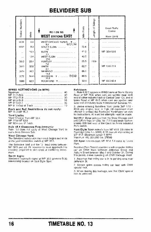
SPEED RESTRICTIONS On MPH)Maximum 40MP 41.7 -43.5 30MP 77.2 -77.8 30MP 80.3 -81.6 10MP 81.6 -91.1 30MP 91.1 -End of Track 10
Rock and Roll Restrictions do not apply:MP 31.3 -MP 80.3
Yard Limits:West Chicago Yard -MP 32.4MP 77.8 -MP h3.0MP 92.4 -End of Track.
Rule 15.1 Clearance Requirements:Rule 15.1.does not apply at West Chicago Yard totrains from Geneva Sub.
West Chicago Yard:The Belvidere subdivision main track begins and endsat the yard connection switch at MP 30.5.
The Belvidere lead and the "J" lead cross betweenMP 30.5 and JB. All movements must approach thiscrossing prepared to stop short of conflicting move-ment.
South Elgin:Westward approach signal at MP 39.5 governs B -35interlocking located on East Elgin Spur.
Belvidere:1. Rule 6.32.2 applies to WWD trains at Stone QuarryRoad at MP 79.4, when cars are spotted near westend of either industry track at Central Grain Co. and at!peen Road at MP 82.5 when cars are spotted nearwest end of industry track at Intermodal Services Inc.
2. Before entering Belvidere Yard Limits (MP 77.8 -83.0) any engine, train or high rail equipment mustattempt to contact the Footboard Yardmaster on dutyfor instructions. At least two attempts must be made.Ingalton Spur extends from the West Chicago yard(via EJE) to Ingalton (Sta. No. 7111) and ends approx-imately 600 feet west of the Carolina Acres IndustrialPark switch.
East Elgin Spur extends from MP 41.0 2.8 miles toEast Elgin (Sta. No. 0086). B -35 manual interlocking atMP 41.0. Maximum speed 5 MPH.Maximum Wt.: 251,000 lbs. (FRA)1W Spur extends from MP 92.4 5.4 miles to LovesPark.
Rockford Park District operates a self -propelled trolleycar on CNW track between Jefferson Street andAuburn Street between May 1 and October 31. Duringthis period, crews operating on CNW trackage must:1. Ascertain that trolley car is in its parking area nearJefferson St.
2. Secure gates across trolley car lead with CNWspecial lock.
3. When leaving this trackage, see that CNW speciallock is unlocked.
16 TIMETABLE NO. 13
LAKE SUBEw
ERCgd
a /v -1 (52 52) 1
WEST STATIONS EAST
N
o
8020
0532
0.0
1.9
,ap4
KO1.9
LAKE BLUFF Da29.8
31.7
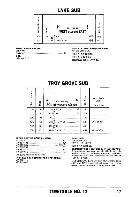
SPEED RESTRICTIONS(In MPH)Maximum 30
ABS:KO -Lake Bluff
Rule 9.13 Dual Control Switches:KO and Lake Bluff.
Rule 9.14.2 applies.Rule 9.15 applies.Maximum Wt: 315,000 lbs.
TROY GROVE SUB
w
E
z j / f') Direct Traffic
ó ® RC -1 (52 52) f a_ Control
SOUTH STATIONS NORTH Block Limits
0046 0.0 DE KALB Y O 26.712.2
... 12.2 BX ® BN © 38.97.3
3017 19.5 ROLLO 46.26.2
3020 25.7 EARLVILLE U BN © 52.4 MP 29.5 -53.07.7
3022 33.4 TRIUMPH 60.13.7
3024 37.1 TROY GROVE Y 63.8 MP 53.0 -63.0
SPEED RESTRICTIONS (In MPH)Maximum 30MP 38.3 -38.9 20*MP 38.9 (BN) STOPMP 38.9 -39.2 20*MP 51.7 -52.2 20*MP 63.8 -64.5 10
Unit trains restricted to 50 cars.Rock and Roll Restrictions do not apply:MP 29.2 -41.3MP 51.5 -63.8
Yard Limits:DeKalb -MP 29.5MP 63.0 -Troy Grove
Rule 5.4.4 applies.BX Interlocking is controlled by BN train dispatcher.Crew member must communicate with BN train dis-patcher for instructions before operating pushbutton.Pushbutton boxes with instructions are mounted oneach signal mast.
Line ups: SWD trains will not depart DeKalb before0900 and NWD trains will not depart Troy Grovebefore 1100 except under Form O precedures.
TIMETABLE NO. 13 17
ST. LOUIS GP -I El
2RC -1 (52 52)
SOUTH STATIONS NORTHm2
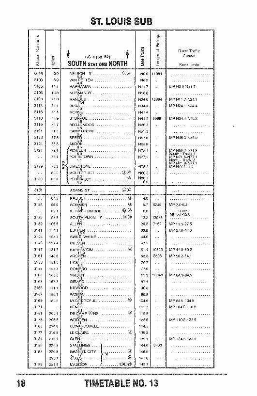
0056 0.0 NELSON Y ON N0.06.9
3103 6.9 VAN PETTEN N6.94.8
3105 11.7 HAHNAMAN N11.7 ... }. MP N3.0 -N11.75.1
3106 16.8 NORMANDY N16.87.2
3109 24.0 MANLIUS N24.0 12684 ? MP N11.7 -N24.110.4
3113 34.4 BUDA N34.4 ... MP N24.1 -N34.47.0
3116 41.4 MORSE N41.43.5
3118 44.9 STORAGE N44.9 9999 MP N34.4 -N46.31.8
3119 46.7 BROADMOOR N46.74.6
3121 51.3 CAMP GROVE N51.36.5
3123 57.8 SPEER N57.8 ... MP N46.3 -N58.25.8
3125 63.6 AKRON N63.88.5
3127 72.1 PIONEER N72.1 ... ?. MP N58.2 -N71.85.0 ! South - Track 1
... 77.1 POTTSTOWN N77.1 ... MP N71.8 -N77.11.1 ì North - Track 2
cf)`. MP N71.8 -N77.1
3129 78.2 LIMESTONE N78.2 ... ! MP N77.1- 2.01.8
80.0 MOLITOR JCT. Ug N80.0
3130 80.3 , PEORIA JCT. @ N80.34.0 0.0
Direct TrafficÇ Controló,C
Block Limits
11084
3131 ADAMS ST OO
3126
3135
3139
3141
3145
3146
3147
3151
3153
3155
3160
3163
3165
3167
3169
3171
3181
3178
3183
3177
3184
3186
3187
3188
84.3
86.0
89.1
93.5
106.6
114.1
1243
127.4
131.7
143.6
151.0
157.3
163.6
1 67.7
171.1
180.1
185.2
200.1
203.8
214.8
216.5
219.4
224.3
226.8
228.1
229.6
PPU JCT. JO
SOMMER OIL. RIVER BRIDGE ® OSOUT4H PEKIN Y ©©
13.1ALLEN
7.5LUTHER
10.2SWEETWATER
3.1CULVER
4.BARR V CIM OO
11.9ARCHER
7.4LICK
COMPRO6.3
VIRDEN4.1
GIRARD3.4
NILWOOD9.0
WOMAC
MONTEREY JCT.6.8
BENLD8.1
DE CAMP VJ NS CAS
3.7WORDEN
11.0EDWARDSVILLE
LE CLAIRE (J2.9
GLEN4.9
STALLINGS
GRANITE CITY
QS) ALS Y OA
MADISON I 8.
4.0
5.7
8.8
13.2
26.3
33.8
44.0
47.1
51.4
63.3
70.7
77.0
83.3
87.4
90.8
99.8
104.9
111.7
119.8
123.5
134.5
136.2
139.1
144.0
146.5
147.8
149.3
6248 '. MP 2.0 -6.4
RiverMP 6.4 -12.0
13976
7162 ? MP 15.5-27.6
MP 27.6-44.0
10603 ! MP 44.0-50.2
3508 MP 50.2-64.1
10948 + MP 64.1-84.5
MP 84.5-104.9
MP 104.9-110.2
MP 1102-134.5
MP 124.5-143.0
8403
18 .ET. .1LE O. 13
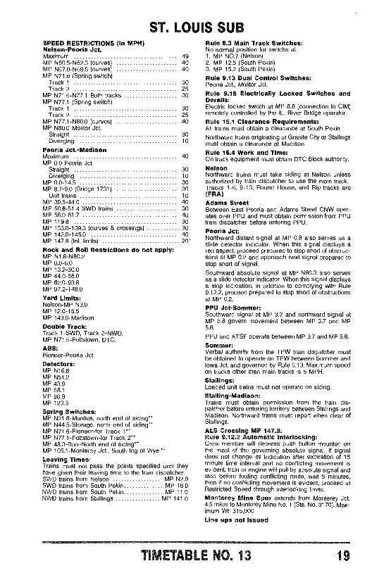
ST. LOUIS SUBSPEED RESTRICTIONS (In MPH)Nelson- Peoria Jet.Maximum 49MP N60.5 -N62.3 (curves) 40MP N67.0 -N68.5 (curves) 40MP N71.6 (Spring switch)
Track 1 30Track 2 25
MP N71.6 -N77.1 Both tracks 30MP N77.1 (Spring switch)
Track 1 30Track 2 25
MP N77.1 -N80.0 (curves) 40MP N80.0 Molitor Jct.
Straight 30Diverging 10
Peoria Jet- MadisonMaximum 40MP 0.0 Peoria Jct
Straight 30Diverging 10
MP 0.0 -14.5 30MP 8.7 -9.0 (Bridge 1731) 30
Unit trains 10MP 30.5 -44.0 40MP 50.6 -51.4 SWD trains 30MP 56.0 -61.7 40MP 119.8 30MP 133.0 -139.3 (curves & crossings) 30MP 142.0 -145.0 40MP 147.8 (Int. limits) 20*
Rock and Roll Restrictions do not apply:MP N1.8 -N80.2MP 0.0 -6.0MP 13.2 -30.0MP 44.0 -56.0MP 62.0 -93.8MP 97.2 -148.0
Yard Limits:Nelson -MP N3.0MP 12.0 -15.5MP 143.0- Madison
Double Track:Track 1 -SWD, Track 2 -NWD.MP N71.6- Pottstown, DTC.
ASS:Pioneer- Peoria Jct.
Detectors:MP N16.8MP N51.2MP 43.9MP 68.1MP 90.9MP 123.3
Spring Switches:MP N21.8- Manlius, north end of siding -MP N44.5- Storage, north end of siding *"MP N71.6- Pioneer -for Track 1 "*MP N77.1- Pottstown -for Track 2 "*MP 48,3- Barr -North end of siding **MP 105.1- Monterey Jct., South leg of Wye. **
Leaving Times:Trains must not pass the points specified until theyhave given their leaving time to the train dispatcher.SWD trains from Nelson MP N2.9SWD trains from South Pekin MP 16.0NWD trains from South Pekin MP 11.0NWD trains from Stallings MP 141.0
Rule 8.3 Main Track Switches:No normal position for switchs at:1. MP NO.7 (Nelson)2. MP 12.5 (South Pekin)3. MP 15.2 (South Pekin)Rule 9.13 Dual Control Switches:Peoria Jct., Molitor Jct.
Rule 9.18 Electrically Locked Switches andDerails:Electric locked switch at MP 8.8 (connection to CIM)remotely controlled by the IL. River Bridge operator.Rule 15.1 Clearance Requirements:All trains must obtain a clearance at South Pekin.Northward trains originating at Granite City or Stallingsmust obtain a clearance at Madison .Rule 16.4 Work and Time:On track equipment must obtain DTC Block authority.
NelsonNorthward trains must take siding at Nelson unlessauthorized by train dispatcher to use the main track.Tracks 1 -6, 9 -13, Round House, and Rip tracks are(FRA)Adams StreetBetween East Peoria and Adams Street CNW oper-ates over PPU and must obtain permission from PPUtrain dispatcher before entering PPU.
Peoria Jet:Northward distant signal at MP 0.8 also serves as aslide detector indicator. When this signal displays ared aspect, proceed prepared to stop short of obstruc-tions at MP 0.2 and approach next signal prepared tostop short of signal.
Southward absolute signal at MP N80.3 also servesas a slide detector indicator. When this signal displaysa stop indication, in addition to complying with Rule9.12.2, proceed prepared to stop short of obstructionsat MP 0.2.
PPU Jet- Sommer:Southward signal at MP 3.7 and northward signal atMP 5.8 govern movement between MP 3.7 and MP5.8.
PPU and ATSF operate between MP 3.7 and MP 5.8.
Sommer:Verbal authority from the TPW train dispatcher mustbe obtained to operate on TPW between Sommer andIowa Jct. and governed by Rule 6.13. Maximum speedon tracks other than main tracks is 5 MPH.Stallings:Loaded unit trains must not operate on siding.Stalling- Madison:Trains must obtain permission from the train dis-patcher before entering territory between Stallings andMadison. Northward trains must report when clear ofStallings.
ALS Crossing MP 147.8:Rule 9.12.3 Automatic interlocking:Crew member will depress push button mounted onthe mast of the governing absolute signal. If signaldoes not change its indication after expiration of 15minute time interval and no conflicting movement isevident, train or engine will pull by absolute signal andstop before fouling conflicting route, wait 5 minutes,then if no conflicting movement is evident, proceed atRestricted Speed through interlocking limits.
Monterey Mine Spur extends from Monterey Jct.4.5 miles to Monterey Mine No. 1 (Sta. No. 3170). Max-imum Wt: 315,000
Line ups not issued
IT'E T ,3LE NO® 13 19
0641
0643
0645
0646
0648
0649
0908
0910
0911
0913
0914
0915
0916
0917
0922
0923
0925
0926
0927
3.
0.0
8.1
15.7
19.7
25.4
35.3
44.5
51.1
56.7
65.8
68.8
72.0
76.9
81.7
86.5
97.0
104.0
110.2
113.3
119.6
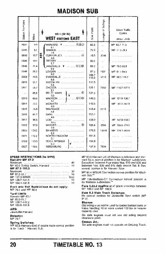
MADISON
RC -1 (52 52)
WEST STATIONS EAST
HARVARD Y OO a C
8.1SHARON
7.6m CLINTON JCT.
4.0TIFFANY
5.7JANESVILLE Y OC*
9.9LEYDEN
9.2EVANSVILLE
6.6BROOKLYN
5.6OREGON
9.1MX ® WIWR
3.0MADISON
3.2MENDOTA
4.9WAUNAKEE
4.8DANE
4.8LODI
10.5BADGER
7.0BARABOO
6.2NORTH FREEDOM
3.1ROCK SPRINGS
6.3REEDSBURG
SPEED RESTRICTIONS (In MPH)Harvard -MP 87.2Maximum 40MP 63.0 Spring Switch, Harvard 10MP 87.2 -183.5Maximum 30MP 87.2 -91.7 10MP 137.3 -WIWR StopMP 138.7 -141.0 10MP 184.4 -191.9 10
Rock and Roll Restrictions do not apply:MP 78.5 and MP 86.0Yard LimitsHarvard -MP 63.7MP 85.9 -91.7MP 136.7 -141.2MP 183.6 -191.9
ABS:Janesville -Harvard
Detector:MP 73.7
Spring Switches:MP 62,8- Harvard -End of double track -normal positionis for Track 1 Harvard Sub.
m
62.8
70.9
78.5
82.5
88.2
97.5106.7115.9
122.5
128.1
137.3
140.3
143.5
148.4
153.2
158.0
168.4
175.5
181.8
184.8
191.9
3006
1931
5513
7332
2112
2504
10619
7834
Direct TrafficControl
Block Limits
MP 63.7-71.0
MP 71.0-79.3
MP 79.3-85.9
MP 91.7-98.0
MP 98.0-116.7
MP 116.7-127.9
MP 127.9-136.7
MP 141.2-147.9
MP 147.9-159.0
MP 159.0-174.1
MP 174.1-183.6
MP 63.0- Harvard Jct. of Madison subdivision and Har-vard Spur, normal position is for Madison subdivision.Exception: between Psgr trains Nos. 610 and 636 andbetween Nos. 639 and 645 daily except Sat. & Sun.normal position is for Harvard Spur.MP 91.4 -WSOR Connection normal position for Madi-son Sub."MP 138- Madison -CP Connection normal position isfor Madison subdivision."Rule 8.32.2 applies at all grade crossings betweenMP 186.0 and MP 192.0.
Rule 8.3 Main Track Switches:No normal position for Janesville Spur switch (MP91.5(.
Sharon:Old siding must not be used by loaded ballast trains ortrains handling 10 or more loaded 100 ton or heaviercapacity cars.
Six axle engines must not use old siding beyondclearance point.
Clinton Jct.:Six axle engines must not operate on DeLong Track.
20 :17 r;o. 13
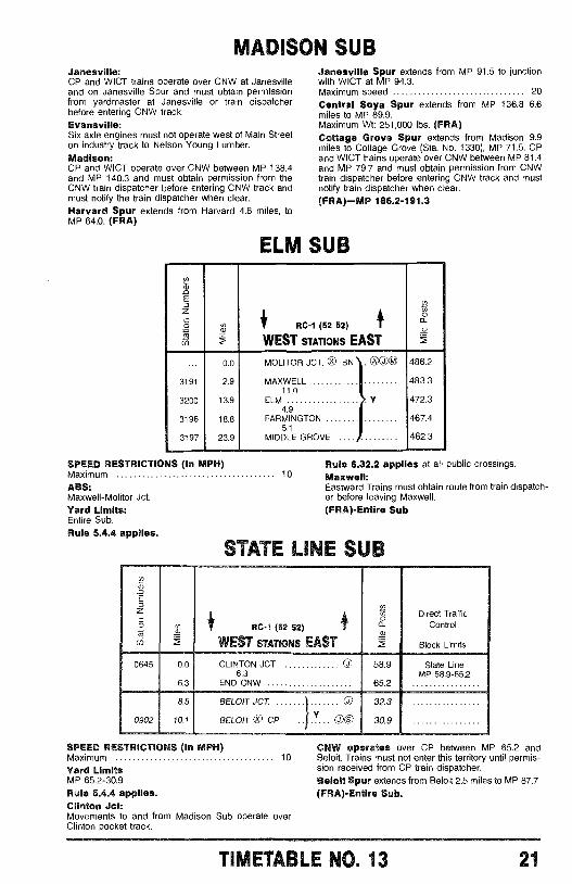
MADISON SUBJanesville:CP and WICT trains operate over CNW at Janesvilleand on Janesville Spur and must obtain permissionfrom yardmaster at Janesville or train dispatcherbefore entering CNW track.Evansville:Six axle engines must not operate west of Main Streeton industry track to Nelson Young Lumber.Madison:CP and WICT operate over CNW between MP 138.4and MP 140.3 and must obtain permission from theCNW train dispatcher before entering CNW track andmust notify the train dispatcher when clear.Harvard Spur extends from Harvard 4.8 miles, toMP 64.0. (FRA)
Janesville Spur extends from MP 91.5 to junctionwith WICT at MP 94.3.Maximum speed 20
Central Soya Spur extends from MP 136.8 6.6miles to MP 89.9.Maximum Wt: 251,000 lbs. (FRA)Cottage Grove Spur extends from Madison 9.9miles to Cottage Grove (Sta. No. 1330), MP 71.5. CPand WICT trains operate over CNW between MP 81.4and MP 79.7 and must obtain permission from CNWtrain dispatcher before entering CNW track and mustnotify train dispatcher when clear.(FRA) -MP 186.2 -191.3
ELM SUB
-Ea
ó $ RC -1 (52 52) f ó
u) WEST STATIONS EAST
0.0 MOLITOR JCT. 0 BN . (D © 486.2
3191 2.9 MAXWELL 483.311.0
3200 13.9 ELM Y 472.34.9
3196 18.8 FARMINGTON 467.45.1
3197 23.9 MIDDLE GROVE 462.3
SPEED RESTRICTIONS (In MPH)MaximumABS:Maxwell -Molitor Jct.
Yard Limits:Entire Sub.Rule 5.4.4 applies.
10Rule 6.32.2 applies at all public crossings.Maxwell:Eastward Trains must obtain route from train dispatch-er before leaving Maxwell.(FRA)- Entire Sub
STATE LME CUB
0645
0902
I RC -1 (52 52)
WEST STATIONS EASTd2
Direct TrafficControl
Block Limits
0.0 CLINTON JCT. OO 58.9 State Line6.3 MP 58.9 -65.2
6.3 END CNW 65.2
8.5 BELOIT JCT. OJ 32.3
10.1 BELOIT O CPY
GDO 30.9
SPEED RESTRICTIONS (In MPH)Maximum 10
Yard LimitsMP 65.2 -30.9
Rule 5.4.4 applies.Clinton Jct:Movements to and from Madison Sub operate overClinton pocket track.
CNW operates over CP between MP 65.2 andBeloit. Trains must not enter this territory until permis-sion received from CP train dispatcher.Beloit Spur extends from Beloit 2.5 miles to MP 87.7.(FRA)- Entire Sub.
TIMETABLE NO, 13 21
EAST iOWA SUB
100
102
104
105
106
107
108
110
111
114
115
118
109
122
123
125
127
128
131
134
136
137
138
142
143
144
147
150
RC-1 (52 52)
WEST STATIONS EAST
E
g")
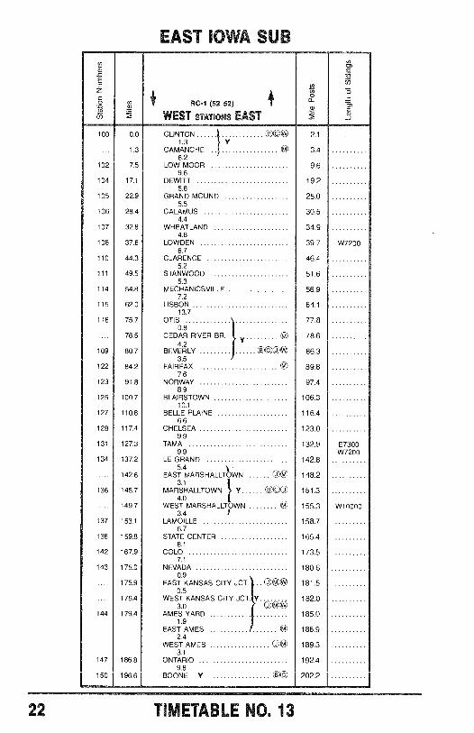
0.0 CLINTON COOW 2.11.3
Y1.3 CAMANCHE 3.4
6.27.5 LOW MOOR 9.6
9.617.1 DEWITT 19.2
5.822.9 GRAND MOUND 25.0
5.528.4 CALAMUS 30.5
4.432.8 WHEATLAND 34.9
4.837.6 LOWDEN 39.7
6.744.3 CLARENCE 46.4
5.249.5 STAN WOOD 51.6
5.354.8 MECHANICSVILLE 56.9
7.262.0 LISBON 64.1
13.775.7 OTIS 77.8
0.876.5 CEDAR RIVER BR, 78.6
4.280.7 BEVERLY T3VOW 86.3
3.584.2 FAIRFAX 89.8
7.691.8 NORWAY 97.4
8.9100.7 BLAIRSTOWN 106.3
10.1110.8 BELLE PLAINE 116.4
6.6117.4 CHELSEA 123.0
9.9127.3 TAMA 132.9
9.9137.2 LE GRAND 142.8
5.4 1142.6 EAST MARSHALLTOWN Og 148.2
3.1145.7 MARSHALLTOWN V CBV0 151.3
4.0149.7 WEST MARSHALLTOWN 155.3
3.4153.1 LAMOILLE 158.7
6.7159.8 STATE CENTER 165.4
8.1167.9 COLO 173.5
7.1175.0 NEVADA 180.6
0.9175.9 EAST KANSAS CITY JCT. .. 181.5
0.5176.4 WEST KANSAS CITY JCT. Y 182.0
3.0 OgW179.4 AMES YARD 185.0
1.9EAST AMES 186.9
2.4WEST AMES Og 189.3
3.1186.8 ONTARIO 192.4
9.8196.6 BOONE Y 202.2
W7200
E7300W7200
W10000
22 TIiTtELE NO. 13
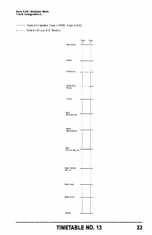
Rule 6.26 -Multiple MainTrack designations.
Rules 9.14 territory Track 1 -WWD, Track 2 -EWD
- - Rule 9.14.2 and 9.15 Territory
Fifth Street
Clinton
Camanche
Cedar RiverSedge
Fairfax
EastMarshalltown
WestMarshalltown
EastKansas City Jct.
West KansasCity Jct.
East Ames
West Ames
Boone
Track Track2 t
TIMETABLE NO. 13 23
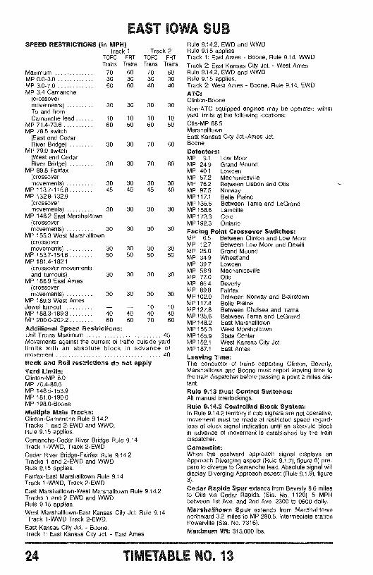
FAnT IOWA aJ BSPEED RESTRICTIONS (In MPH)
Track 1TOFC FRTTrains Trains
Track 2TOFC FRTTrains Trains
Maximum 70 60 70 60MP 0.0 -3.0 30 30 30 30MP 3.0 -7.0 60 60 40 40MP 3.4 Camanche
(crossovermovements) 30 30 30 30To and fromCamanche lead 10 10 10 10
MP 71.4 -73.6 60 50 60 50MP 78.5 switch
(East end CedarRiver Bridge) 30 30 70 60
MP 79.0 switch(West end CedarRiver Bridge) 30 30 70 60
MP 89.8 Fairfax(crossovermovements) 30 30 30 30
MP 113.7 -116.8 45 40 45 40MP 132.8 -132.9
(crossovermovements) 30 30 30 30
MP 148.2 East Marshalltown(crossovermovements) 30 30 30 30
MP 155.3 West Marshalltown(crossovermovements) 30 30 30 30
MP 153.7 -154.8 50 50 50 50MP 181.4 -182.1
(crossover movementsand turnouts). 30 30 30 30
MP 186.9 East Ames(crossovermovements) 30 30 30 30
MP 189.3 West AmesJewel turnout - - 10 10MP 188.3 -189.3 40 40 40 40MP 200.0 -202.2 60 50 70 60
Additional Speed Restrictions:Unit Trains Maximum 45Movements against the current of traffic outside yardlimits with an absolute block in advance ofmovement 40
Rock and Roll restrictions do not applyYard Limits:Clinton -MP 8.0MP 76.4 -88.5MP 148.5 -153.9MP 181.0 -190.0MP 198.0 -Boone
Multiple Main Tracks:Clinton -Camanche Rule 9.14.2Tracks 1 and 2 -EWD and WWD,Rule 9.15 applies.Comanche -Cedar River Bridge Rule 9.14.Track 1 -WWD, Track 2 -EWDCedar River Bridge- Fairfax Rule 9.14.2Tracks 1 and 2 -EWD and WWDRule 9.15 applies.Fairfax -East Marshalltown Rule 9.14Track 1 -WWD, Track 2 -EWDEast Marshalltown -West Marshalltown Rule 9.14.2Tracks 1 and 2 EWD and WWDRule 9,15 applies.West Marshalltown -East Kansas City Jct. Rule 9.14Track 1 -WWD Track 2 -EWD.
East Kansas City Jct. - Boone.Track 1: East Kansas City Jct. - East Ames
Rule 9.14.2, EWD and WWDRule 9.15 appliesTrack 1: East Ames - Boone, Rule 9.14, WWDTrack 2: East Kansas City Jct. - West AmesRule 9.14.2, EWD and WWDRule 9.15 applies.Track 2: West Ames - Boone, Rule 9.14, EWDATC:Clinton -Boone
Non -ATC equipped engines may be operated withinyard limits at the following locations:Otis -MP 88.5MarshalltownEast Kansas City Jct.-Ames Jct.Boone
Detectors:MP 9.1 Low MoorMP 24.9 Grand MoundMP 40.1 LowdenMP 57.2 MechanicsvilleMP 76.2 Between Lisbon and OtisMP 97.5 NorwayMP 117.1 Belle PlaineMP 135.5 Between Tama and LeGrandMP 158.6 LamoilleMP 173.3 ColoMP 192.3 OntarioFacing Point Crossover Switches:MP 6.5 Between Clinton and Low MoorMP 12.7 Between Low Moor and DewittMP 25.0 Grand MoundMP 34.9 WheatlandMP 39.7 LowdenMP 56.9 MechanicsvilleMP 77.0 OtisMP 86.4 BeverlyMP 89.8 FairfaxMP 102.0 Between Norway and BlairstownMP 117.4 Belle PlaineMP 127.8 Between Chelsea and TamaMP 135.6 Between Tama and LeGrandMP 148.2 East MarshalltownMP 155.3 West MarshalltownMP 165.9 State CenterMP 182.1 West Kansas City Jct.MP 187.1 East AmesLeaving Time:The conductor of trains departing Clinton, Beverly,Marshalltown and Boone must report leaving time tothe train dispatcher before passing a point 2 miles dis-tant.
Rule 9.13 Dual Control Switches:All manual interlockings.Rule 9.14.2 Controlled Block System:In Rule 9.14.2 territory if cab signals are not operative,movement must be made at restricted speed regard-less of block signal indication until an absolute blockin advance of movement is established by the traindispatcher.
Camanche:When the eastward approach signal displays anApproach Diverging aspect (Rule 9.1.7), figure 6) pre-pare to diverge to Camanche lead. Absolute signal willdisplay Diverging Approach aspect (Rule 9.1.9), figure3).
Cedar Rapids Spur extends from Beverly 8.6 milesto Otis via Cedar Rapids. (Sta. No. 1120). 5 MPHbetween 1st Ave. and 2nd Ave. 2300 to 0600 daily.Marshalltown Spur extends from Marshalltownnorthward 3.2 miles to MP 280.5. Intermediate stationPowerville (Sta. No. 7316).Maximum Wt: 315,000 Ibs.
24 Tr 717:71 no. 13
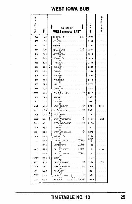
WEST IOWA SUB
EOzó
/*
RC -1 (52 52) I
WEST STATIONS EAST
ó
co0)_inó
150 0.0 BOONE Y CO 202.29.3
152 9.3 OGDEN 214.55.4
153 14.7 BEAVER 219.95.2
154 19.9 GRAND JCT. ©® 225.16.7
155 26.6 JEFFERSON 231.88.8
157 35.4 SCRANTON 241.04.9
158 40.3 RALSTON 245.9U 4.6
160 44.9 Q GLIDDEN - 250.57.9
162 52.8 CARROLL 258.410.0
164 62.8 ARCADIA 268.43.1
165 65.9 WESTSIDE 271.56.0
166 71.9 VAIL 277.58.9
168 80.8 DENISON 286.44.7
9869 85.5 WEST DENISON C) 291.12.0
169 87.5 ARION 293.110.2
173 97.7 DUNLAP 303.30.8
9870 98.5 EAST DUNLAP U 304.1 90001.8
9871 100.3 WEST DUNLAP n 305.9U 7.2
175 107.5 Ú WOODBINE 313.10.6
9872 108.1 < EAST WOODBINE () 313.7 130002.6
9873 110.7 WEST WOODBINE U 316.34.9
176 115.6 LOGAN 321.26.0
9874 121.6 EAST MO. VALLEY CD 327.22.2
178 123.8 MO. VALLEY 329.40.2 329.6
124.0 MO. VALLEY JCT. 01)0)W 0.40.5
.... 124.5 NORTH WYE )w 0.95.0
4703 129.5 CAL. JCT. EAST TO@ 5.9 31500.4
.... 129.9 CAL. JCT. WEST j)l(D 6.36.9
6007 136.8 Ñ BLAIR 13.2U 7.2
9875 144.0 EAST KENNARD ID 20.4 100002.1
9876 146.1 WEST KENNARD U 22.56.9
6017 153.0 ARLINGTON 29.45.8
9877 158.8 EAST FREMONT C 35.2
6023 160.6 FREMONT .....)1.8 Y
.... e C © 37.0
TIMETABLE NO. 13 25
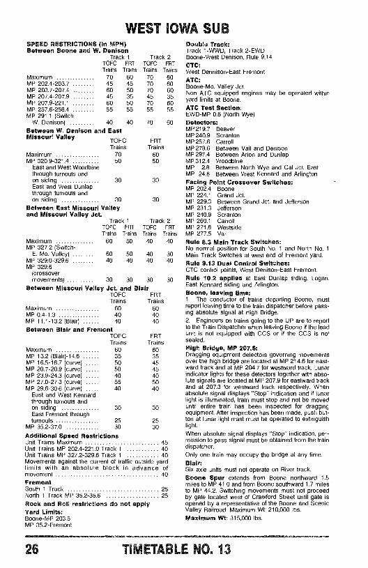
WEST IOWA SUBSPEED RESTRICTIONS (In MPH)Between Boone and W. Denison
Track 1TOFC FRTTrains Trains
Track 2TOFC FRTTrains Trains
Maximum 70 60 70 60MP 202.4 -203.7 45 45 70 60MP 203.7 -207.4 60 50 70 60MP 207.4 -207.9 45 35 45 35MP 207.9 -221.1 60 50 70 60MP 257.6 -258.4 55 55 55 55MP 291.1 (Switch -
W. Denison) 40 40 70 60
Between W. Denison and EastMissouri Valley
TOFCTrains
FRTTrains
Maximum 70 60MP 320.9 -321.4 50 50
East and West Woodbinethrough turnouts andon siding 30 30East and West Dunlapthrough turnouts andon siding 30 30
Between East Missouri Valleyand Missouri Valley Jct.
Track 1TOFC FRTTrains Trains
Track 2TOFC FRTTrains Trains
Maximum 60 50 40 40MP 327.2 (Switch -
E. Mo. Valley) 60 50 40 30MP 329.0 -329.6 40 40 40 40MP 329.6
(crossovermovements) 30 30 30 30
Between Missouri Valley Jct. and BlairTOFC FRTTrains
Maximum 60MP 0.4 -1.3 40MP 11.1 -13.2 (Blair) 40
Between Blair and FremontTOFCTrains
Trains604040
FRTTrains
Maximum 60 60MP 13.2 (Blair) -14.6 35 35MP 16.5 -16.7 (curve) 50 45MP 20.7 -20.9 (curve) 50 45MP 23.9 -24.3 (curve) 40 40MP 27.0 -27.3 (curve) 55 50MP 29.6 -30.6 (curve) 40 40
East and West Kennardthrough turnouts andon siding 30 30East Fremont throughturnouts 25 25
MP 35.2 -37.0 30 30
Additional Speed RestrictionsUnit Trains Maximum 45Unit Trains MP 202.4 -221.0 Track 1 40Unit Trains MP 327.2 -329.6 Track 1 40Movements against the current of traffic outside yardlimits with an absolute block in advance ofmovement 40
FremontSouth 1 Track 25North 1 Track MP 35.2 -35.6 25
Rock and Roll restrictions do not applyYard Limits:Boone -MP 203.5MP 35.2- Fremont
Double Track:Track 1 -WWD, Track 2 -EWDBoone -West Denison, Rule 9.14CTC:West Dennison -East FremontATC:Boone -Mo. Valley Jct.Non ATC equipped engines may be operated withinyard limits at Boone.ATC Test Section:EWD -MP 0.8 (North Wye)Detectors:MP 219.7 BeaverMP 240.9 ScrantonMP 257.6 CarrollMP 278.6 Between Vail and DenisonMP297.4 Between Arion and DunlapMP 312.4 WoodbineMP 2.8 Between North Wye and Cal Jct. EastMP 24.8 Between West Kennard and ArlingtonFacing Point Crossover Switches:MP 202.4 BooneMP 224.1 Grand Jct.MP 229.3 Between Grand Jct. and JeffersonMP 231.3 JeffersonMP 240.9 ScrantonMP 260.1 CarrollMP 271.6 WestsideMP 277.5 Vail
Rule 8.3 Main Track Switches:No normal position for South No. 1 and North No. 1Main Track Switches at west end of Fremont yard.Rule 9.13 Dual Control Switches:CTC control points, West Denison -East Fremont.Rule 10.2 applies at East Dunlap siding, Logan,East Kennard siding and Arlington.Boone, leaving time:1. The conductor of trains departing Boone, mustreport leaving time to the train dispatcher before pass-ing absolute signal at High Bridge.2. Engineers on trains going to the UP are to reportto the Train Dispatcher when leaving Boone if the leadunit is not equipped with CCS or if the CCS is nosealed.
High Bridge, MP 207.6:Dragging equipment detectors governing movementsover the high bridge are located at MP 214.6 for east -ward track and at MP 204.7 for westward track. Lunarindicator lights for these detectors together with abso-lute signals are located at MP 207.9 for eastward trackand at 207.3 for westward track respectively. Whenabsolute signal displays "Stop" indication and if lunarlight is illuminated, train must stop and not be moveduntil entire train has been inspected for draggingequipment. After inspection has been made, push but -ton at lunar light mast must be operated to extinguishlight.
When absolute signal displays "Stop" indication, per-mission to pass signal must be obtained from the traindispatcher.Only one train may occupy the bridge at any time.Blair:Six axle units must not operate on River track.Boone Spur extends from Boone northward 1.5miles to MP 41.0 and from Boone southward 1.7 milesto MP 44.2. Switching movements must not proceedby gate located west of Crawford Street until gate isopened by a representative of the Boone and ScenicValley Railroad. Maximum Wt: 210,000 lbs.Maximum Wt: 315,000 lbs.
26 H0. 13
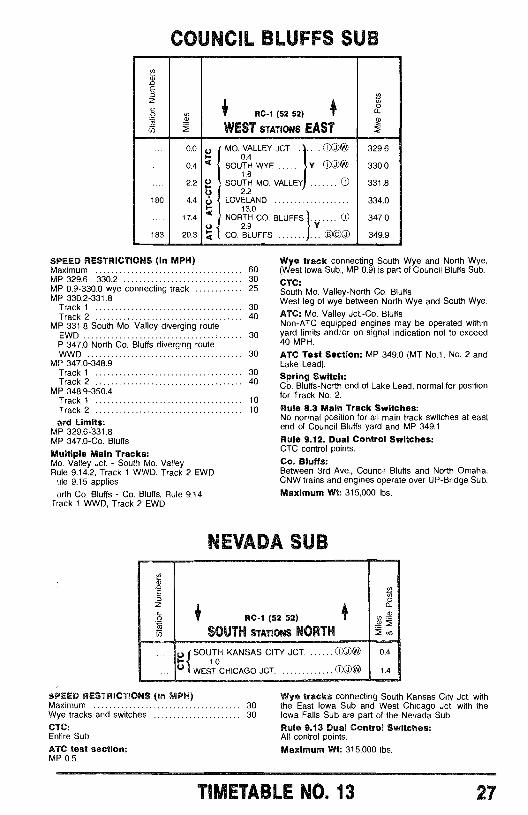
COUNCIL BLUFFS SUBQ)
iv
E
ó
u)
co RC -1 (52 52) T
WEST STATIONS EAST
Q)
0
180
183
0.0
0.4
2.2
4.4
17.4
20.3
Va
áUUr-
q
MO. VALLEY JCT. ®0.4
SOUTH WYE Y g W1.8
SOUTH MO. VALLEY 02.2
LOVELAND13.0
NORTH CO. BLUFFS ECO. BLUFFS
Y
000
329.6
330.0
331.8
334.0
347.0
349.9
SPEED RESTRICTIONS (In MPH)Maximum 60MP 329.6 -330.2 30MP 0.9 -330.0 wye connecting track 25MP 330.2 -331.8
Track 1 30Track 2 40
MP 331.8 South Mo. Valley diverging routeEWD 30P 347.0 North Co. Bluffs diverging routeWWD 30
MP 347.0 -348.9Track 1 30Track 2 40
MP 348.9 -350.4Track 1 10Track 2 10
.ard Limits:MP 329.6 -331.8MP 347.0 -Co. Bluffs
Multiple Main Tracks:Mo. Valley Jct. - South Mo. ValleyRule 9.14.2, Track 1 WWD, Track 2 EWD
ile 9.15 appliesorth Co. Bluffs - Co. Bluffs, Rule 9.14
rrack 1 WWD, Track 2 EWD
Wye track connecting South Wye and North Wye,(West Iowa Sub., MP 0.9) is part of Council Bluffs Sub.
CTC:South Mo. Valley -North Co. BluffsWest leg of wye between North Wye and South Wye.
ATC: Mo. Valley Jct. -Co, BluffsNon -ATC equipped engines may be operated withinyard limits and /or on signal indication not to exceed40 MPH.
ATC Test Section: MP 349.0 (MT No.1, No. 2 andLake Lead).
Spring Switch:Co. Bluffs -North end of Lake Lead, normal for positionfor Track No. 2.Rule 8.3 Main Track Switches:No normal position for all main track switches at eastend of Council Bluffs yard and MP 349.1Rule 9.12. Dual Control Switches:CTC control points.
Co. Bluffs:Between 3rd Ave., Council Bluffs and North Omaha,CNW trains and engines operate over UP- Bridge Sub.
Maximum Wt: 315,000 lbs.
TMA SUB
RC -1 (52 52)
SOUTH STATIONS NORTH
gy SOUTH KANSAS CITY JCT. DOWW1.0
WEST CHICAGO JCT. @ O W
SPEED RESTRICTIONS (In MPH)Maximum 30Wye tracks and switches 30
CTC:Entire Sub
ATC test section:MP 0.5.
0
0.4
1.4
Wye tracks connecting South Kansas City Jct. withthe East Iowa Sub and West Chicago Jct. with theIowa Falls Sub are part of the Nevada Sub.Rule 9.13 Dual Control Switches:All control points.
Maximum Wt: 315,000 lbs.
TIMETABLE NO. 13 27
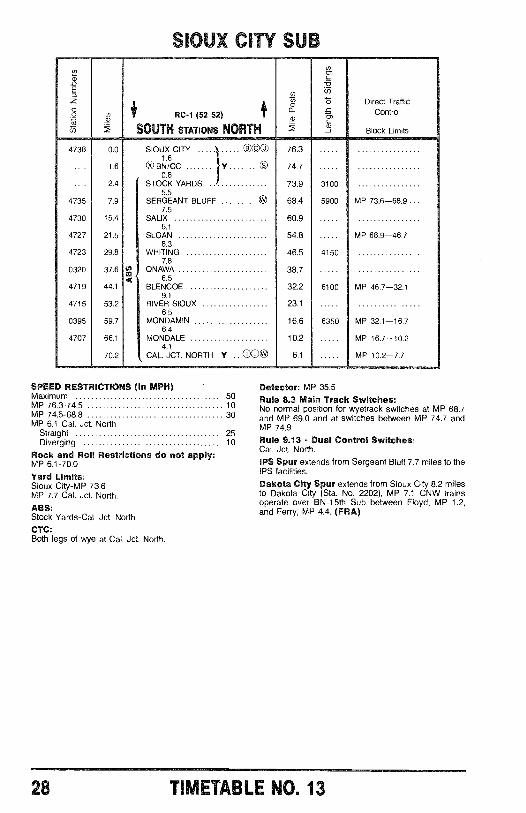
SIOUX CITY SUB
a)
E
zó 1 RC-1 (52 52)
SOUTH STATIONS NORTH
4738 0.0 SIOUX CITY ©UU 76.31.6
1.6 xO BN /CC 74.70.8
2.4 STOCK YARDS 73.95.5
4735 7.9 SERGEANT BLUFF 68.47.5
4730 15.4 SALIX 60.96.1
4727 21.5 SLOAN 54.88.3
4723 29.8 WHITING 46.57.8
0320 37.6 ONAWA 38.7< 6.5
4719 44.1 BLENCOE 32.29.1
4715 53.2 RIVER SIOUX 23.16.5
0395 59.7 MONDAMIN 16.66.4
4707 66.1 MONDALE 10.24.1
70.2 CAL. JCT. NORTH Y cook, 6.1
SPEED RESTRICTIONS (In MPH)Maximum 50MP 76.3 -74.5 10MP 74.5 -68.8 30MP 6.1 Cal. Jct. North
Straight 25Diverging 10
Rock and Roll Restrictions do not apply:MP 6.1 -70.0
Yard Limits:Sioux City -MP 73.6MP 7.7 -Cal. Jct. North.
ABS:Stock Yards-Cal. Jct. North
CTC:Both legs of wye at Cal. Jct. North.
3100
Direct TrafficControl
Block Limits
5900 MP 73.6-68.9 ...
4150
MP 68.9-46.7
6100 MP 46.7-32.1
6350 MP 32.1-16.7
MP 16.7-10.2
MP 10.2-7.7
Detector: MP 35.5Rule 8.3 Main Track Switches:No normal position for wyetrack switches at MP 68.7and MP 69.0 and at switches between MP 74.7 andMP 74.9
Rule 9.13 - Dual Control Switches:Cal. Jct. North.
IPS Spur extends from Sergeant Bluff 7.7 miles to theIPS facilities.
Dakota City Spur extends from Sioux City 8.2 milesto Dakota City (Sta. No. 2202), MP 7.1 CNW trainsoperate over BN -15th Sub between Floyd, MP 1.2,and Ferry, MP 4.4. (FRA)
28 TIMETABLE NO. 13

INSTRUCTIONS APPLICABLE INTWIN CITIES TERMINAL
ó2UW
o 6.3
LYNDALE JCT.
SHOREHAM
Ñ-z^` -,m
á
UNIVERSITY AVENQ
MW JCT. J1.0
J NORTHTOWN
(HOLDEN ST.) 3.30.9
CEDAR LAKE
HOPKINS O
EASTMINNEAPOLIS ,4P
1.8,,T
5.7 c5.6QÓ
d MINN.COMMERCIAL'COMMERCIAI'
EAST ST.PAUL
EAU CLAIRESUB
7TH ST.e
ROBERT ST.BRIDGE
n /2.4 1.0 e\;9
0101101MERRIAM ,_ O 10 1 1 0 1 1 1 1 1 1Fé Zd 2,
'q200?` )2J¿ 2Y PARK JCT.
4O`,4, P -.
3RD T.
e,3 DIVISION ST.401.6
SUB
C &NW
I I I CPX X BN
AMERICAN HOIST SPUR- - ST. PAUL UNION DEPOT TRK.-0-00 STATE ST. SPUR
HOFFMAN AVE.1.0
CNW operates over:BN between -Division St. and St. AnthonyEast Minneapolis and Cedar Lake, LyndaleJct. and MW Jct., Mpls. Jct. and Northtown
CP Line between -University Ave. and Shoreham.MW Jct. and Glenwood Jct.Hoffman Ave. and Chestnut St.
BN -CP Line Joint track between -Hoffman Ave. and Division St.
CP operates over CNW between Chestnut St. andCliff. Roberts St. Interlocking and Park Jct., HoffmanAve. and Roseport.
BN East hump dispatcher controls movements onBN trackage at St. Anthony and between St. Anthonyand St. Paul.
BN West hump dispatcher controls movementson BN trackage west of St. Anthony.Eastward movements from Western Ave. willbe governed by instructions from CP at St. Paul Yard.
St. Paul Union Depot1. Rule 6.13 governs on the St. Paul Union Depottracks between Robert Street Interlocking and 3rdStreet.
Maximum speed 10 MPH
2. The entrance to St. Paul Union Depot trackage iscontrolled on the east by signal indication at 3rd Streetor verbal authority from BN Hump Dispatcher East,and on the west by signal indication or verbal authorityfrom the CP Dispatcher at St. Paul Yard (Pigs Eye).
ROSEPORTSUB
SO. ST.PAUL
JOT.SWITCHOWATONNA
SUB
DAY TONS4 - BLUFF
PIGS EYEYARD
South St. Paul to Union DepotAuthority for Movement1. Before entering the State Street Spur, permissionmust be obtained from the CNW yardmaster at SouthSt. Paul.
2. South St. Paul yardmaster must notify the RobertStreet bridgetender of all movements at 221 -9334.3. Rule 9.12.2, governs movements over Robert Streetmanually controlled interlocking (CP).
When a train or engine is stopped by a stop indicationat this interlocking, a member of the crew must com-municate with the CP dispatcher at St. Paul Yard (PigsEye) on Channel 94.Note: If the engine is not equipped with a multi-channel radio, it will be necessary to inform the SouthSt. Paul yardmaster and /or Robert Street bridgetenderof same so he may contact the CP dispatcher on thetelephone at 778 -3692 to request the CP dispatcher tocome in on Channel 71. The yardmaster will NOTrelay authority for movement between parties, andbridgetender will NOT be included in any communica-tion relative to the CP Robert Street Interlocking.
City of Minneapolis Street CrossingsCity ordinance prohibits any switch engine to be oper-ated into or across a public street within Minneapolisunless there is a crew member located so as to beable to pass signals to the engineer. This employeemay be either on the groud in the crossing or on theleading end of the engine.Whistling Ordinances:Minneapolis city ordinance prohibits the sounding ofengine whistle.
TWETABLE NO. 13 29
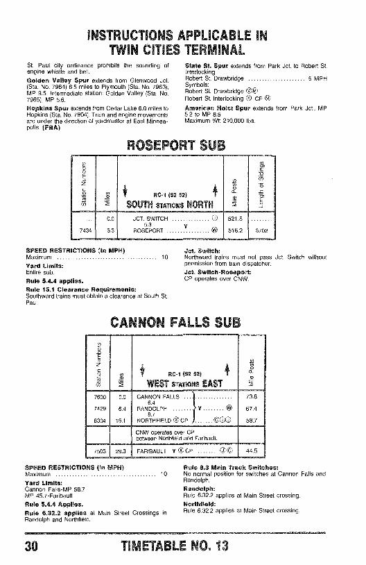
INSTRUCTIONS APPLICAE L LrI
TWIN CITIES TERMINALSt. Paul city ordinance prohibits the sounding ofengine whistle and bell.
Golden Valley Spur extends from Glenwood Jct.(Sta. No. 7964) 6.5 miles to Plymouth (Sta. No. 7963),MP 9.5. Intermediate station: Golden Valley (Sta. No.7965), MP 5.6.
Hopkins Spur extends from Cedar Lake 6.0 miles toHopkins (Sta. No. 7904). Train and engine movementsare under the direction of yardmaster at East Minnea-polis. (FRA)
State St. Spur extends from Park Jct. to Robert St.InterlockingRobert St. Drawbridge 5 MPHSymbols:Robert St. Drawbridge OORobert St. Interlocking x0 CP
American Hoist Spur extends from Park Jct., MP5.2 to MP 8.5Maximum WI: 210,000 lbs.
JCT. SWITCH5.3
ROSEPORT
SPEED RESTRICTIONS (In MPH)Maximum
Yard Limits:Entire sub.
Rule 5.4.4 applies.Rule 15.1 Clearance Requirements:Southward trains must obtain a clearance at South St.Paul.
Jct. Switch:10 Northward trains must not pass Jct. Switch without
permission from train dispatcher.
Jct. Switch- Roseport:CP operates over CNW.
7600
7429
8304
C I C V.%LLS SUB
0.0
6.4
15.1
RC -1 (52 52)
WEST STATIONS EAST
CANNON FALLS6.4
RANDOLPH Y N8.7
NORTHFIELD 0 CP 000
73.8
67.4
58.7
7503 29.3
CNW operates over CPbetween Northfield and Faribault
FARIBAULT Y CP © 44.5
SPEED RESTRICTIONS (In MPH)Maximum 10
Yard Limits:Cannon Falls -MP 58.7MP 45.7 -Faribault
Rule 5.4.4 Applies.Rule 6.32.2 applies at Main Street Crossings inRandolph and Northfield.
Rule 8.3 Main Track Switches:No normal position for switches at Cannon Falls andRandolph.
Randolph:Rule 6.32.2 applies at Main Street crossing.Northfield:Rule 6.32.2 applies at Main Street crossing.
30 TIMET DLL I 3. 13
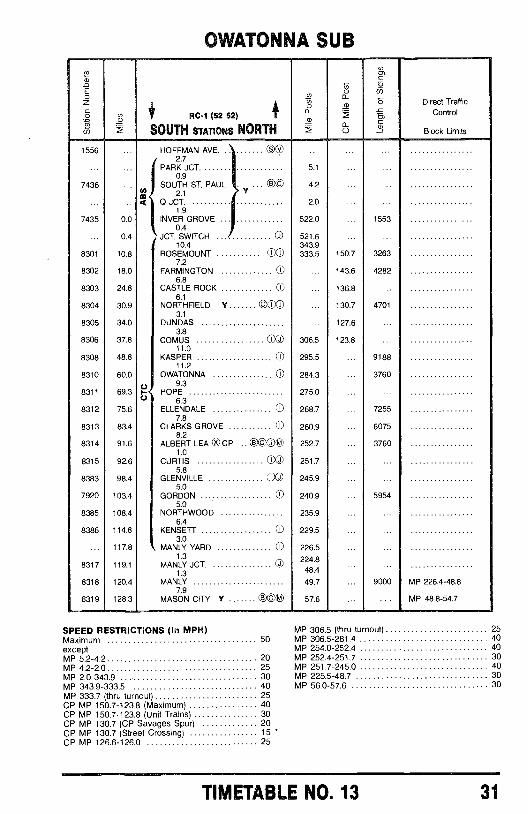
OWATONNA SUBu)m
Ñ C
EÑo iq
z ó ó Direct Traffic
ó + RC -9 (52 52) m Control
u SOUTH STATIONS NORTH 0 Block Limits
1556 ... HOFFMAN AVE. 002.7
... ...
... ... PARK JCT. 5.1 ... ...0.9
7436 ... SOUTH ST. PAUL ... e C
m 2.14.2 ... ...
... ... 4 Q JCT. 2.0 ... ...1.9
7435 0.0 INVER GROVE 522.0 ... 15530.4
0.4 JCT. SWITCH © 521.610.4 343.9
8301 10.8 ROSEMOUNT 00 333.5 150.7 32637.2
8302 18.0 FARMINGTON 0 ... 143.6 42826.8
8303 24.8 CASTLE ROCK 0 ... 136.86.1
8304 30.9 NORTHFIELD Y 00J ... 130.7 47013.1
8305 34.0 DUNDAS ... 127.63.8
8306 37.8 COMUS CO 306.5 123.811.0
8308 48.8 KASPER 0 295.5 ... 918811.2
8310 60.0 OWATONNA 0 284.3 ... 37609.3
8311 69.3 F HOPE 275.0 ... ...U 6.3
8312 75.6 ELLENDALE 0 268.7 ... 72557.8
8313 83.4 CLARKS GROVE 0 260.9 ... 60758.2
8314 91.6 ALBERT LEA x®CP .. 000® 252.7 ... 37601.0
8315 92.6 CURTIS CO 251.7 ... ...5.8
8383 98.4 GLENVILLE 00 245.9 ... ...5.0
7920 103.4 GORDON 0 240.9 ... 59545.0
8385 108.4 NORTHWOOD 235.96.4
8386 114.8 KENSETT 0 229.53.0
117.8 MANLY YARD 0 226.51.3 224.8
8317 119.1 MANLY JCT. 0 ...1.3 48.4
8318 120.4 MANLY 49.7 ... 9000 MP 226.4 -48.87.9
8319 128.3 MASON CITY Y (D O@ 57.6 ... ... MP 48.8 -54.7
SPEED RESTRICTIONS (In MPH) MP 306.5 (thru to pout) 25
Maximum 50 MP 306.5 -281.4 40
except MP 254.0 -252.4 40MP 5.2 -4.2 20 MP 252.4 -251.7 30MP 4.2 -2.0 25 MP 251.7 -245.0 40
MP 2.0 -343.9 30 MP 225.5 -48.7 30
MP 343.9 -333.5 40 MP 56.0 -57.6 30
MP 333.7 (thru turnout) 25CP MP 150.7 -123.8 (Maximum) 40CP MP 150.7 -123.8 (Unit Trains) 30CP MP 130.7 (CP Savages Spur) 20CP MP 130.7 (Street Crossing) 15CP MP 126.6 -126.0 25
TIMETABLE NO. 13 31
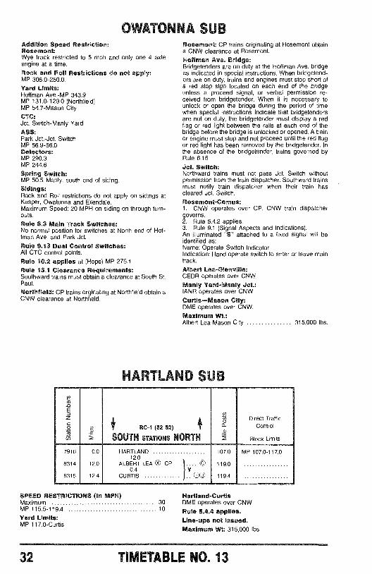
OWATONNA SUBAddition Speed Restriction:Rosemont:Wye track restricted to 5 mph and only one 4 axleengine at a time.
Rock and Roll Restrictions do not apply:MP 306.0- 250.0.
Yard Limits:Hoffman Ave. -MP 343.9MP 131.0 -129.0 (Northfield)MP 54.7 -Mason City
CTC:Jct. Switch -Manly Yard
ABS:Park Jct. -Jct. SwitchMP 56.9 -56.0Detectors:MP 290.3MP 244.6
Spring Switch:MP 50.5 -Manly, south end of siding.
Sidings:Rock and Roll restrictions do not apply on sidings atKasper, Owatonna and Ellendale.Maximum Speed: 20 MPH on siding on through turn-outs.
Rule 8.3 Main Track Switches:No normal position for switches at North end of Hof-fman Ave. and Park Jct.
Rule 9.13 Dual Control Switches:All CTC control points.
Rule 10.2 applies at (Hope) MP 275.1Rule 15.1 Clearance Requirements:Southward trains must obtain a clearance at South St.Paul.
Northfield: CP trains orginating at Northfield obtain aCNW clearance at Northfield.
Rosemont: CP trains originating at Rosemont obtaina CNW clearance at Rosemont.Hoffman Ave. Bridge:Bridgetenders are on duty at the Hoffman Ave. bridgeas indicated in special instructions. When bridgetend-ers are on duty, trains and engines must stop short ofa red stop sign located on each end of the bridgeunless s proceed signal, or verbal permission re-ceived from bridgetender. When it is necessary tounlock or open the bridge during the period of timewhen special instructions indicate that bridgetendersare not on duty, the bridgetender must display a redflag or red light between the rails at each end of thebridge before the bridge is unlocked or opened. A trainor engine must stop and not proceed until the red flagor red light has been removed by the bridgetender. Inthe absence of the bridgetender, trains governed byRule 6.16
Jct. Switch:Northward trains must not pass Jct. Switch withoutpermission from the train dispatcher. Southward trainsmust notify train dispatcher when their train hascleared Jct. Switch.
Rosemont -Comus:1, CNW operates over CP. CNW train dispatchergoverns.2. Rule 5.4.2 applies.3. Rule 9.1 (Signal Aspects and Indications).An illuminated "S" attached to a fixed signal will beidentified as:Name: Operate Switch IndicatorIndication: Hand operate switch to enter or leave maintrack.
Albert Lea -Glenville:CEDR operates over CNW.
Manly Yard -Manly Jct.:IANR operates over CNW.
Curtis -Mason City:DME operates over CNW.
Maximum Wt.:Albert Lea -Mason City 315,000 lbs.
H 71T i'17 r3 n
7916
8314
8315
0.0
12.0
12.4
RC-1 (52 52)
SOUTH STATIONS NORTH
HARTLAND12.0
ALBERT LEA Ox CP .1.... C0.4
CURTISV
I J
ó Direct Trafficn Controla2 Block Limits
107.0 MP 107.0 -t 17.0
119.0
119.4
SPEED RESTRICTIONS (In MPH) Hartland -CurtlsMaximum 30 DME operates over CNWMP 115.5 -119.4 10 Rule 5.4.4 applies.
Line -ups not Issued.Maximum Wt: 315,000 lbs.
Yard Limits:MP 117.0 -Curtis
32 TIMETABLE NO. 13
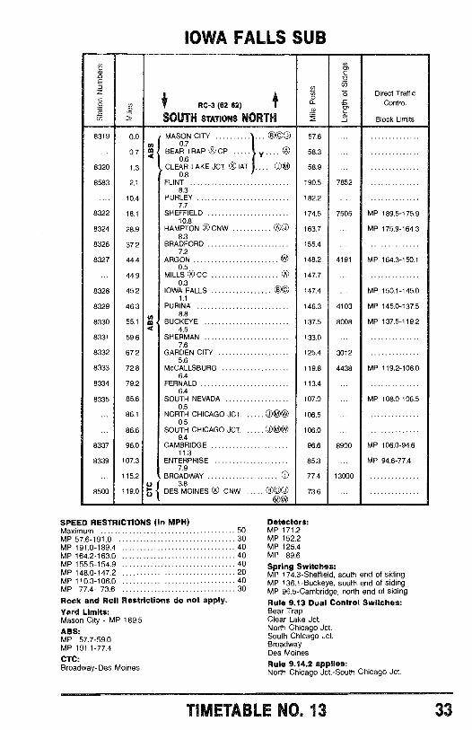
IOWA FALLS SUB
t4Ti .f
1® RC -3 (62 62) 1
SOUTH STATIONS NORTH
oLf
mg.
co
óm
Direct TrafficControl
Block Limits
8319 0.0en
MASON CITY 00® O0.7
57.6 ...
0.7 ¢ BEAR TRAP 0 CP y .... 0 58.30.6
8320 1.3 CLEAR LAKE JCT. OIAT .... O© 58.9 ...0.8
8583 2.1 FLINT 190.5 78528.3
.... 10.4 HURLEY 182.2 ...7.7
8322 18.1 SHEFFIELD 174.5 7505 MP 189.5 -175.910.8
8324 28.9 HAMPTON OCNW 00 163.7 ... MP 175.9 -164.38.3
8326 37.2 BRADFORD 155.47.2
8327 44.4 ARGON W 148.2 4191 MP 164.3 -150.10.5
... 44.9 MILLS 0 CC 0 147.7 ...0.3
8328 45.2 IOWA FALLS ©© 147.4 ... MP 150.1 -145.01.1
8329 46.3 PURINA 146.3 4103 MP 145.0 -137.58.8
8330 55.1 m BUCKEYE 137.5 8008 MP 137.5 -119.24 4.5
8331 59.6 SHERMAN 133.0 ...7.6
8332 67.2 GARDEN CITY 125.4 30125.6
8333 72.8 McCALLSBURG 119.8 4438 MP 119.2 -108.06.4
8334 79.2 FERNALD 113.46.4
8335 85.6 SOUTH NEVADA 107.0 ... MP 108.0 -106.50.5
... 86.1 NORTH CHICAGO JCT. O ®W 106.5 ...0.5
... 86.6 SOUTH CHICAGO JCT. O ®W 106.0 ...9.4
8337 96.0 CAMBRIDGE 96.6 8900 MP 106.0 -94.611.3
8339 107.3 ENTERPRISE 85.3 ... MP 94.6 -77.47.9
115.2 BROADWAY 0 77.4 13000
8500 119.0(
Ú S DES 3MOINES 0 CNW 000 73.6 ...®W
SPEED RESTRICTIONS (In MPH)Maximum 50MP 57.6 -191.0 30MP 191.0 -189.4 40MP 164.2 -163.0 40MP 155.5 -154.9 40MP 148.0 -147.2 20MP 110.3 -106.0 40MP 77.4- 73.6 30
Rock and Roil Restrictions do not apply.Yard Limits:Mason City - MP 189.5ABS:MP 57.7 -59.0MP 191.1 -77.4
CTC:Broadway -Des Moines
Detectors:MP 171.2MP 152.2MP 125.4MP 89.6Spring Switches:MP 174.3 -Sheffield, south end of sidingMP 136.1- Buckeye, south end of sidingMP 96.5- Cambridge, north end of siding
Rule 9.13 Dual Control Switches:Bear TrapClear Lake Jct.North Chicago Jct.South Chicago Jct.BroadwayDes Moines
Rule 9.14.2 applies:North Chicago Jct. -South Chicago Jct.
TIMETABLE NO. 13 33
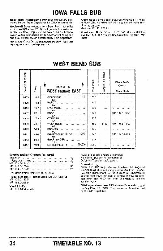
RC-4 (71 17)
WEST STATIONS EAST
8405
8406
8416
8407
8408
8409
8410
8411
8413
8417
0.0
8.3
16.7
22.1
27.2
32.7
38.9
48.6
58.4
70.9
IOWA FALLS SUBBear Trap Interlocking (MP 58.3) signals are con-trolled by the Train Dispatcher for CNW movements.Rockwell Spur extends from Bear Trap 11.4 milesto Rockwell (Sta. No. 2614). Unit grain trains restrictedto 50 cars. Bear Trap: Junction switch is a dual controlswitch within interlocking limits. CNW absolute signalsand dual control switch controlled by train dispatcher.
MP 105.7: ® IAT 0. Swifts: Eastside Industry Track -Stopsigns govern two crossings with CP.
Alden Spur extends from Iowa Falls westward 5.3 milesto Alden (Sta. No. 0190) MP 26.1. Loaded unit trains res-tricted to 25 cars.Maximum Wt: 251,000 lbs.
Sentiment Spur extends from Des Moines (EastonBlvd.) MP 74.6 10.5 miles to Bondurant (Sta. No. 7321) MP232.9.
WES GEM Su
GOLDFIELD OO
8.3HARDY
8.4LIVERMORE
5.4BODE
5.1OTTOSEN
5.5WEST BEND
6.2RODMAN
EMMETSBURG Ox CP ... OO9.8
GRAETTINGER12.5
ESTHERVILLE Y O©e
136.0
144.3
152.7
158.1
163.2
168.7
174.9
184.6
194.4
206.9
6150
Direct TrafficControl
Block Limits
MP 136.0-166.8
MP 166.8-184.0
MP 184.0-206.2
SPEED RESTRICTIONS (In MPH)Maximum 40
Unit grain trains 30MP 135,9 -136.7 10MP 145.5 -168.0 30MP 184.2 -185.2 20
Unit grain trains restricted to 75 cars.
Rock and Roll Restrictions do not apply:MP 136.0 -145.5MP 168.0 -206.9
Yard Limits:MP 206.2 -Estherville
Rule 8.3 Main Track Switches:No normal position for switches at:Goldfield- Transfer track switch.
Emmetsburg:CNW and CP may use each others trackage atEmmetsburg after obtaining permission from respec-tive train dispatchers. CP yard limits at Emmetsburgextend from 7500 feet east of switch to new connec-tion track and 7500 feet west of switch to existingtransfer track.
CNW operates over CP between Emmetsburg andHartley (Sta. No. 8579). Train movements authorizedby the CP dispatcher.
34 TI é LE N0. 13
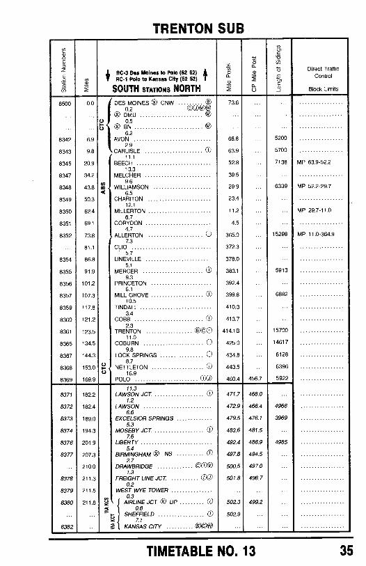
TRENTON SUB
Ña Ñ
Nc.9ä
0
Z RC -3 Des Moines to Polo (62 62) ó m ó Direct Traffic
óif
RC -1 Polo to Kansas City (52 52a g Control
rg_g2
SOUTH anon NORTH 'f 0 Block Limits
8500 0.0 DES MOINES ® CNW . .0.2
. 73.6
©O DMU
Ñ 0.5... ... ...
0 8N6.2
8342 6.9 AVON 66.8 .. 52002.9
8343 9.8 CARLISLE 0 63.9 ... 570011.1
8345 20.9 BEECH 52.8 ... 7138 MP 63.9 -52.213.3
8347 34.2 MELCHER 39.59.6
8348 43.8 CÓ WILLIAMSON 29.9 ... 6339 MP 52.2 -29.76.5
8349 50.3 CHARITON 23.4 ... ...12.1
8350 62.4 MILLERTON 11.2 ... ... MP 29.7 -11.06.7
8351 69.1 CORYDON 4.54.7
8352 73.8 ALLERTON 0 365.0 ... 15298 MP 11.0 -364.97.3
... 81.1 CLIO 372.3 ... ...5.7
8354 86.8 LINEVILLE 378.0 ... ...5.1
8355 91.9 MERCER 0 383.1 ... 59139.3
8356 101.2 PRINCETON 392.4 ... ...6.1
8357 107.3 MILL GROVE 0 399.8 ... 688210.5
8359 117.8 TINDALL 410.3 ... ...3.4
8360 121.2 COBB 0 413.7 ... ...2.3
8361 123.5 TRENTON 0 ©0 414.1B ... 1570011.0
8365 134.5 COBURN 0 425.0 ... 146179.8
8367 144.3 LOCK SPRINGS 0 434.8 ... 61288.7
8368 153.0 ÑuNETTLETON 0
16.9443.5 ... 6396
8369 169.9 POLO 460.4 456.7 5922
11.38371 182.2 LAWSON JCT. 0 471.7 468.0 ...
1.28372 182.4 LAWSON 472.9 466.4 4966
6.68373 189.0 EXCELSIOR SPRINGS 479.5 476.1 3969
5.38374 194.3 MOSEBY JCT. 0 483.6 481.5 ...
7.68376 201.9 LIBERTY 492.4 488.9 4985
5.48377 207.3 BIRMINGHAM 0 NS 0 497.8 494.5 ...
2.7210.0 DRAWBRIDGE ODD 500.5 497.0
1.38378 211.3 FREIGHT LINE JCT J 501.8 498.7
0.28379 211.5 WEST WYE TOWER
0.38380 211.8 AIRLINE JCT. 0 UP 0 502.3 499.2
_6 0.6
ú SHEFFIELD 0Y 7.1
502.9
8382 ... - KANSAS CITY 00@
TIMETABLE NO. 13 35
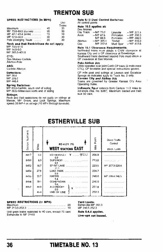
TRENTON SUBSPEED RESTRICTIONS (In MPH)
UnitTrains
Maximum 40 35MP 73.6 -69.0 (curves) 30 30MP 42.7 -43.4 (slide) 10 10MP 57.0 -56.0 30 30Polo Diverging Route 30 30
Rock and Roll Restrictions do not apply:MP 73.5 -51.0MP 14.0 -0.0MP 365.0 -401.0
CTC:Des Moines -CarlisleAllerton -Polo
ABS:Carlisle -Allerton
Detectors:MP 39.4MP 378.6MP 448.4
Spring Switches:MP 63.9 -Carlisle, south end of sidingMP 30.8 -Williamson north end of siding
Sidings:Rock and Roll restrictions do not apply on sidings atMercer, Mill Grove, and Lock Springs. Maximumspeed: 20 MPH on sidings (10 MPH through turnouts).
8417
8450
8452
8454
8455
8456
8457
Rule 9.13 Dual Control Switches:All control points
Rule 10.2 applies at:Des MoinesCity Track -MP 73.2 LinevilleAvon -MP 67.6 Princeton
MP 66.9 PrincetonAllerton -MP 365.1 TindallClio -MP 372.4 Mud Spur
-MP 377.4-MP 392.3-MP 392.6-MP 410.3-MP 472.8
Rule 15.1 Clearance Requirements:Northward trains must obtain a CNW clearance atKansas City and a CP clearance at Drawbridge.Southward trains destined beyond Polo must obtain aCP clearance at Des Moines.
Polo -Airline Jct:CNW operates over joint CNW -CP track (2 main trackCTC). CP timetable and special instructions govern.
CP mile post and sidings at Lawson and ExcelsiorSprings as indicated apply to Track No. 2 only.Kansas City and Airline Jct:Trains are governed by Greater Kansas City AreaOperating Rules.
Indianola Spur extends from Carlisle 11.3 miles toIndianola (Sta. No. 8387). Maximum loaded unit trainsize 50 cars.
ESTHERVILLE SUB
to RC -4 (71 71)
WEST STATIONS EAST
Ñáa:
Direct TrafficControl
Block Limits
0.0 ESTHERVILLE Y OB ©OO 206.96.9
6.9 SUPERIOR 213.89.8
16.7 SPIRIT LAKE 223.6 MP 207.3-228.411.1
27.8 LAKE PARK 234.75.9
33.7 HARRIS 240.6 MP 228.4-246.55.4
39.1 OCHEVEDAN 246.05.8
44.9 ALLENDORF 251.80.5 Y
45.4 END OF LINE . 252.3
SPEED RESTRICTIONS (In MPH)Maximum 20MP 213.0 -252.3 10
Unit grain trains restricted to 40 cars, except 75 carsEstherville to MP 214.0
Yard Limits:Estherville -MP 207.3MP 246.5 -252.3
Rule 5.4.4 applies.Line -ups not issued.
36 TIMETABLE NO. 13
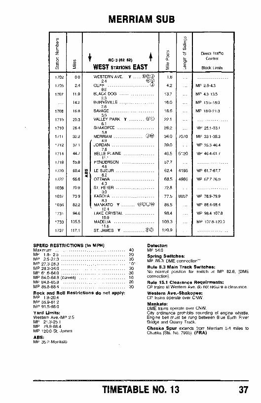
MERRIAM SUB
Ng.ro
z 1 1 ó Direct Traffic
o ® RC -3 (62 62) 1 m Control
fa' AWEST STATIONS EAST Block Limits
1702 0.0 WESTERN AVE. Y .... ©l J2.4 N vUU
t.8 ...
1705 2.4 CLIFF 0 4.2 ... MP 2.5 -4.39.5
1707 11.9 BLACK DOG 13.7 ... MP 4.3 -13.52.3
.... 14.2 BURNSVILLE 16.0 ... MP 13.5 -18.02.6
1708 16.8 SAVAGE 18.6 ... MP 18.0 -21.33.5
1715 20.3 VALLEY PARK Y ú© 22.1 ...6.1
1710 26.4 SHAKOPEE 28.2 ... MP 25.1 -33.15.8
1711 32.2 MERRIAM ©® 34.0 7070 MP 33.1 -35.34.9
1712 37.1 JORDAN 39.0 ... MP 35.3 -46.47.6
1714 44.7 BELLE PLAINE 46.5 5120 MP 46.4 -61.711.1
1718 55.8 HENDERSON 57.74.6
1720 60.4 ti) LE SUEUR 62.4 4195 MP 61.7 -67.7
1722 66.6ait 6.2
OTTAWA 68.5 4986 MP 67.7 -76.94.3
1038 70.9 ST. PETER 72.8 ...3.0
1037 73.9 KASOTA 77.5 8057 MP 76.9 -79.98.3
1036 82.2 MANKATO Y 0,00W0® 85.5 ... MP 88.4 -98.412.4
1731 94.6 LAKE CRYSTAL 98.4 ... MP 98.4 -107.810.9
1733 105.5 MADELIA 109.3 ... MP 107.8 -120.011.6
1737 117.1 ST. JAMES Y 0© 120.9
SPEED RESTRICTIONS (In MPH)Maximum 40MP 1.8- 2.5 20MP 2.5 -27.3 30MP 27.3 -28.3 10*MP 28.3 -34.0 30MP 61.6 -84.0 30MP 84.0 -84.8 (curves) 10MP 84.8 -85.8 20MP 85.8 -88.4 30
Rock and Roll Restrictions do not apply:MP 1.8 -20.4MP 55.9 -61.2MP 91.5 -98.0
Yard Limits:Western Ave. -MP 2.5MP 21.3 -25.1MP 79.9 -88.4MP 120.0 -St. James
ABS:MP 35.2- Mankato
Detector:MP 54.0
Spring Switches:MP 88.3: DME connection"Rule 8.3 Main Track Switches:No normal position for switch at MP 82.6, (DMEconnection).
Rule 15.1 Clearance Requirments:CP trains at Western Ave. do not require a clearance.
Western Ave. -Shakopee:CP trains operate over CNW.
Mankato:DME trains operate over CNW.City ordinance prohibits sounding of engine whistle.Engine bell must be rung between Blue Earth RiverBridge and Quarry Track.Chaska Spur extends from Merriam 5.4 miles toChaska (Sta. No. 7905). (FRA)
TIMETABLE NO. 13 37
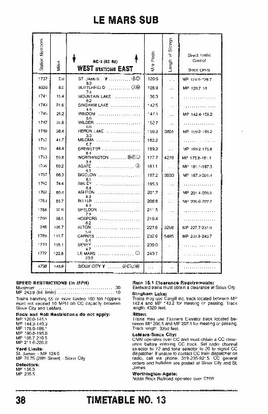
LE MARS SUB
1737
4020
1741
1743
1745
1747
1749
1750
1751
1753
1756
1757
1760
1762
1763
1764
1766
248
1769
1770
1772
4738
0.0
8.0
15.4
21.6
26.2
31.8
38.4
41.7
48.4
56.8
60.2
66.3
74.4
80.8
85.7
90.6
98.5
106.7
111.7
118.1
122.8
145.8
RC -3 (62 62)
WEST STATIONS EAST
ST. JAMES Y e c8.0
BUTTERFIELD OO7.4
MOUNTAIN LAKE6.2
BINGHAM LAKE4.6
WINDOM5.6
WILDER6.6
HERON LAKE3.3
MILOMA6.7
BREWSTER8.4
WORTHINGTON3.4
AGATE O6.1
BIGELOW8.1
SIBLEY6.4
ASHTON4.9
RITTER4.9
SHELDON7.9
HOSPERS8.2
ALTON5.0
CARNES6.4
SENEY4.7
LE MARS O23.0
O©O
SIOUX CITY Y e C O©
ó 5 Direct Traffica r Control
Block Limits
120.9 ... MP 124.0-128.7
128.9 ... MP 128.7-14
136.3
142.5
147.1 ... MP 142.4-159.2
152.7
159.3 3801 MP 159.2-169.2
162.2
169.3 ... MP 169.2-175.8
177.7 4279 MP 175.8-181.1
181.1 ... MP 181.1-187.3
187.2 3033 MP 187.3-201.4
195.3
201.7 ... MP 201.4-206.6
206.6 ... MP 206.6-227.7
211.5
219.4
227.6 3258 MP 227.7-231.9
232.6 5485 MP 231.9-243.7
239.0
243.7
SPEED RESTRICTIONS (In MPH)Maximum 30MP 243.8 (Int. limits) 10
Trains handling 55 or more loaded 100 ton hoppersmust not exceed 10 MPH on CC capacity betweenSioux City and LeMars.
Rock and Roll Restrictions do not apply:MP 126.0 -141.1MP 144.3 -149.3MP 178.0 -188.1MP 190.8 -195.0MP 195.7 -210.5MP 211.6 -226.9
Yard Limits:St. James - MP 124.0MP 76.75 (28th Street) - Sioux CityDetectors:MP 156.3MP 235.5
Rule 15.1 Clearance Requirements:Eastward trains must obtain a clearance at Sioux City.
Bingham Lake:Trains may use Cargill Inc. track located between MP142.4 and MP 143.2 for meeting or passing. Tracklength: 4320 feet.
Ritter:Trains may use Farmers Elevator track located be-tween MP 206.5 and MP 207.1 for meeting or passing.Track length: 3350 feet.
LeMars-Sioux City:CNW operates over CC and must obtain a CC clear-ance before entering CC track. Set radio channelselector to 72 and tone selector to 20 to signal CCdispatcher. If unable to contact CC train dispatcher onradio, call via phone: 319- 235 -9215. CC generalorders and bulletins are posted at Sioux City and St.James.
Worthington- Agate:Noble Rock Railroad operates over CNW.
38 TIVL-17ABL; HO. 13
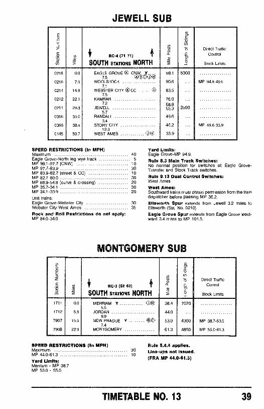
JEWELL SUB
ofE
Nm
rñz
® ó Direct Traffic
ó oa RC -4 (71 71) @ a m Control
EsSOUTH STATIONS NORTH Block Limits
0218 0.0 EAGLE GROVE 0 CNW Y 98.1 53007.5 ®000®
0216 7.5 WOOLSTOCK 90.6 ... MP 94.9 -49.67.1
0214 14.6 WEBSTER CITY Ox CC 0 83.57.5
0212 22.1 KAMRAR 76.07.2 68.8
0211 29.3 JEWELL 55.3 25005.7
0366 35.0 RANDALL 49.6 ...3.4
0365 38.4 STORY CITY 46.2 ... MP 49.6 -33.912.3
0145 50.7 WEST AMES 0® 33.9
SPEED RESTRICTIONS (in MPH)Maximum 40Eagle Grove -North leg wye track 5MP 98.1 -97.7 (CNW) 10MP 97.7 -83.9 30MP 83.9 -82.7 (street & CC) 10MP 82.7 -80.0 30MP 68.9 -54.8 (curve & crossing) 20MP 35.7 -341 30MP 34.1 -33.9 20
Unit trains:Eagle Grove -Webster City 30Webster City -West Ames 35
Rock and Roll Restrictions do not apply:MP 84.0 -34.0
Yard Limits:Eagle Grove -MP 94.9.
Rule 8.3 Main Track Switches:No normal position for switches at: Eagle Grove -Transfer and Stock Track switches.
Rule 9.13 Dual Control Switches:West Ames
West Ames:Southward trains must obtain permission from the traindispatcher before passing MP 36.2.Ellsworth Spur extends from Jewell 3.2 miles toEllsworth (Sta. No. 0210).
Eagle Grove Spur extends from Eagle Grove west-ward 3.4 miles to MP 101.5.
MONTGOMERY SUE
gN0)it
o
®i ó Direct Traffic
4ami
RC -3 (62 62) i - Controltn
SOUTH STATIONS NORTH Block Limits
1711 0.0 MERRIAM Y 0® 38.4 70705.5
1712 5.6 JORDAN 44.0 ...9.9
7907 15.5 NEW PRAGUE Y OC) 53.9 4300 MP 38.7 -53.07.4
7908 22.9 MONTGOMERY 61.3 4850 MP 55.0 -61.3
SPEED RESTRICTIONS (In MPH)Maximum 30MP 44.0 -61.3 10
Yard Limits:Merriam - MP 38.7MP 53.0 -55.0
Rule 5.4.4 applies.Line -ups not Issued.(FRA MP 44.0 -61.3)
TIMETABLE NO. 13 39
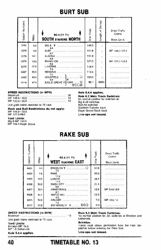
BURT SUB
N cri
N C
cnz 5 Direct Traffic
ó m RC -4 (71 71) f Control
SOUTH STATIONS NORTH Block Limits
0281 0.0 BIG 6 Y 146.04.4
0278 4.4 BURT 141.6 ... MP 144.0 -127.09.7
0276 14.1 ALGONA 131.9 ...4.9
0274 19.0 IRVINGTON 127.0 ... MP 127.0 -104.38.6
0270 27.6 LUVERNE 118.47.9
0267 35.5 RENWICK 110.5 ...7.5
0263 43.0 GOLDFIELD 0 103.0 ...4.9 YI0218 47.9 EAGLE GROVE x CNW 0 98.1 6600
©66®
SPEED RESTRICTIONS (in MPH)Maximum 30MP 146.0 -145.0 10MP 133.0-130,9 10
Unit grain trains restricted to 75 cars.
Rock and Roll Restrictions do not apply:MP 144.0 -133.0MP 127.0 -99.0
Yard Limits:Big 6 -MP 144.0MP 104.3 -Eagle Grove
8431
8430
8429
8428
8427
8426
8425
8417
Rule 5.4.4 applies.Rule 8.3 Main Track Switches:No normal position for switches at:Big 6 -All switchesBurt-All switchesGoldfield- Transfer trackEagle Grove -Stock track
Line -ups not issued.
RAKE SUB
RC -4 (71 71)
WEST STATIONS EAST
NiN
o-°
1)
Direct TrafficControl
Block Limits
0.0 BRICELYN Y 57.67.6
7.6 RAKE 50.011.6
19.2 LAKOTA 38.411.0
30.2 SWEA CITY 27.48.8
39.0 ARMSTRONG 18.6 MP 54.8-18.66.1
45.1 MAPLE HILL 12.55.5
50.6 GRUVER 7.0 MP 18.6-1.67.0
57.6 ESTHERVILLE Y 000 0.0
SPEED RESTRICTIONS (In MPH)Maximum 10
Unit grain trains restricted to 75 cars.
Yard Limits:Bricelyn -MP 54.8MP 1.6- Estherville
Rule 5.4.4 applies.
Rule 8.3 Main Track Switches:No normal position for Jct. switches at Bricelyn andEstherville.
Bricelyn:Trains must obtain permission from the train dis-patcher before entering the Rake Sub.Line -ups not issued.
40 TIMETABLE NO. 13
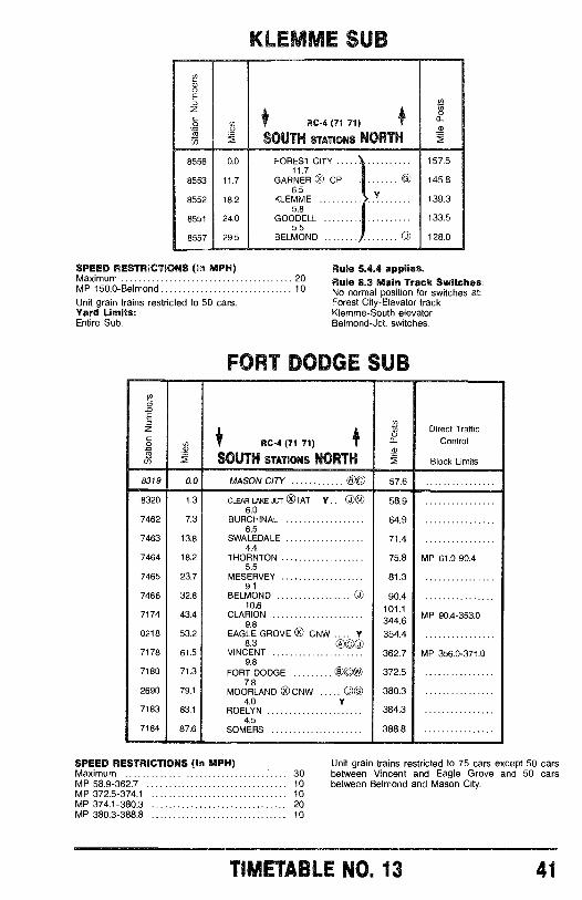
8556
8553
8552
8551
8557
KLEMME SUB
RC-4 (71 71)
SOUTH STATIONS NORTH
0.0 FOREST CITY11.7
157.5
11.7 GARNER ® CP cO 145.86.5
18.2 KLEMME Y 139.35.8
24.0 GOODELL 133.55.5
29.5 BELMOND OO 128.0
SPEED RESTRICTIONS (In MPH)Maximum 20MP 150.0 -Belmond 10
Unit grain trains restricted to 50 cars.Yard Limits:Entire Sub.
Rule 5.4.4 applies.Rule 8.3 Main Track Switches:No normal position for switches at:Forest City- Elevator trackKlemme -South elevatorBelmond -Jct. switches.
FORT DODGE SUBD,
nE
z m Direct Traffic
ó i RC -4 (71 71) # - Control
u SOUTH STATIONS NORTH Block Limits
8319 0.0 MASON CITY 00 57.6
8320 1.3 CLEAR LAKE ,1CT ® IAT Y .. 04 58.96.0
7462 7.3 BURCHINAL 64.96.5
7463 13.8 SWALEDALE 71.44.4
7464 18.2 THORNTON 75.8 MP 61.0 -90.45.5
7465 23.7 MESERVEY 81.39.1
7466 32.8 BELMOND © 90.410.6 101.1
7174 43.4 CLARION MP 90.4 -353.09.8 344.6
0218 53.2 EAGLE GROVE 0 CNW .... Y 354.48.3 A 0ÒÒ0
7178 61.5 VINCENT 362.7 MP 356.0 -371.09.8
7180 71.3 FORT DODGE ©c @ 372.57.8
2690 79.1 MOORLAND 0 CNW ©J ®8 380.34.0 Y
7183 83.1 ROELYN 384.34.5
7184 87.6 SOMERS 388.8
SPEED RESTRICTIONS (In MPH)Maximum 30MP 58.9 -362.7 10MP 372.5 -374.1 10MP 374.1 -380.3 20MP 380.3 -388.8 10
Unit grain trains restricted to 75 cars except 50 carsbetween Vincent and Eagle Grove and 50 carsbetween Belmond and Mason City.
TIMETABLE NO. 13 41
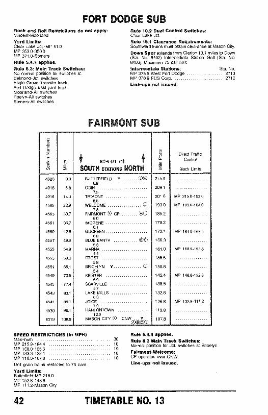
FORT DODCZ ViaRock and Roll Restrictions do not apply:Vincent -Moorland
Yard Limits:Clear Lake Jct. -MP 61.0MP 353.0 -356.0MP 371.0- Somers
Rule 5.4.4 applies.Rule 8.3: Main Track Switches:No normal position tor switches at:Belmond -Jct. switchesEagle Grove -Transfer trackFort Dodge -East yard leadMoorland -All switchesRoelyn -All switchesSomers -All switches
4020
4018
4016
4565
4563
4561
4559
4557
4555
4553
4551
4549
4545
4543
4541
4539
8319
Rule 10.2 Dual Control Switches:Clear Lake Jct.Rule 15.1 Clearance Requirements:Southward trains must obtain clearance at Mason City.
Dows Spur extends from Clarion 13.1 miles to Dows(Sta. No. 8402) Intermediate Station Galt (Sta. No.8403). Maximum 75 car limit.
Intermediate Stations: Sta. No.MP 375.5 West Fort Dodge 2713MP 376.9 PCS Corp. 2712
Line -ups not issued.
F6-cY1'1V'd'w \iVB
TRC-4 (71 71)
SOUTH STATIONS NORTH9?
Direct TrafficControl
Block Limits
0.0 BUTTERFIELD Y 215.96.8
6.8 ODIN 209.17.5
14.3 TRIMONT 201.6 MP 215.0-193.6
22.98.6
WELCOME © 193.0 MP 193.6-184.07.8
30.7 FAIRMONT ® CP (DO 185.26.0
36.7 IMOGENE 179.26.1
42.8 GUCKEEN 173.1 MP 184.0-168.56.8
49.6 BLUE EARTH C8)0 166.35.3
54.9 MARNA 161.0 MP 168.5-152.84.4
59.3 FROST 156.65.8
65.1 BRICELYN Y OJ 150.85.4
70.5 KEISTER 145.4 MP 148.8-132.86.9
77.4 SCARVILLE 138.55.7
83.1 LAKE MILLS 132.86.0
89.1 JOICE 126.8 MP 132.8-111.27.0
96.1 HANLONTOWN 119.812.0
108.9 MASON CITY ® CNW 107.8®000
SPEED RESTRICTIONS (In MPH)Maximum 30MP 215.9 -184.4 10MP 168.0 -165.5 10MP 133.3 -132.1 10MP 110.0 -107.8 10
Unit grain trains restricted to 75 cars.Yard Limits:Butterfield -MP 215.0MP 152.8 -148.8MP 111.2 -Mason City
Rule 5.4.4 applies.Rule 8.3 Main Track Switches:Normal position for Jct. switches at Bricelyn.
Fairmont -Welcome:CP operates over CNW.Line -ups not issued.
42 TIMETABLE NO. 13
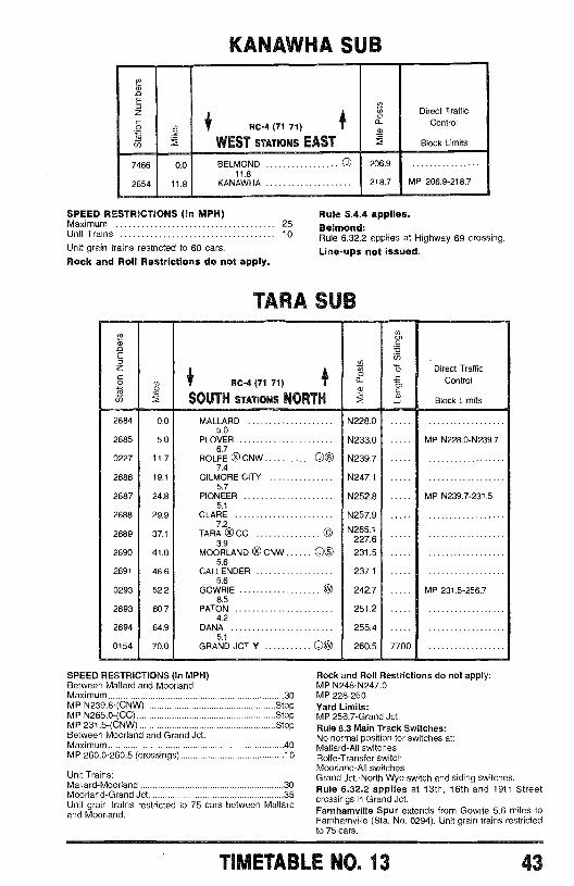
KANAWHA SUB
_oE_zó
in
7466
2654
0.0
11.8
RC -4 (71 71)
WEST STATIONS EAST
BELMOND JO
11.8KANAWHA
SPEED RESTRICTIONS (In MPH)Maximum 25Unit Trains 10
Unit grain trains restricted to 60 cars.Rock and Roll Restrictions do not apply.
w i
a>
206.9
218.7
Direct TrafficControl
Block Limits
MP 206.9-218.7
Rule 5.4.4 applies.Belmond:Rule 6.32.2 applies at Highway 69 crossing.
Line -ups not issued.
TARA SUB
RC-4 (71 71)
SOUTH STATIONS NORTH
áa
Direct TrafficControl
Block Limits
2684
2685
0227
2686
2687
2688
2689
2690
2691
0293
2693
2694
0154
0.0
5.0
11.7
19.1
24.8
29.9
37.1
41.0
46.6
52.2
60.7
64.9
70.0
MALLARD5.0
PLOVER6.7
ROLFE 0 CNW CD®7.4
GILMORE CITY5.7
PIONEER5.1
CLARE7.2
TARA x®CC3.9
MOORLAND ®CNWO®5.6
CALLENDER5.6
GOWRIE8.5
PATON4.2
DANA5.1
GRAND JCT Y OqP
SPEED RESTRICTIONS In MPH)Between Mallard and MoorlandMaximum 30MP N239.8 -(CNW) StopMP N265.0 -(CC) StopMP 231.5 -(CNW) StopBetween Moorland and Grand Jct.Maximum 40MP 260.0 -260.5 (crossings) 10
Unit Trains:Mallard -Moorland 30Moorland -Grand Jct. 35Unit grain trains restricted to 75 cars between Mallardand Moorland.
N228.0
N233.0
N239.7
N247.1
N252.8
N257.9
N265.1227.6
231.5
237.1
242.7
251.2
255.4
260.5 7700
MP N228.0-N239.7
MP N239.7-231.5
MP 231.5-256.7
Rock and Roll Restrictions do not apply:MP N248- N247.0MP 228 -260Yard Limits:MP 256.7 -Grand Jct.Rule 8.3 Main Track Switches:No normal position for switches at:Mallard -All switchesRolfe- Transfer switchMoorland -All switchesGrand Jct. -North Wye switch and siding switches.Rule 6.32.2 applies at 13th, 16th and 19th Streetcrossings in Grand Jct.Farnhamville Spur extends from Gowrie 5.6 miles toFarnhamville (Sta. No. 0294). Unit grain trains restrictedto 75 cars.
TIMETABLE NO. 13 43
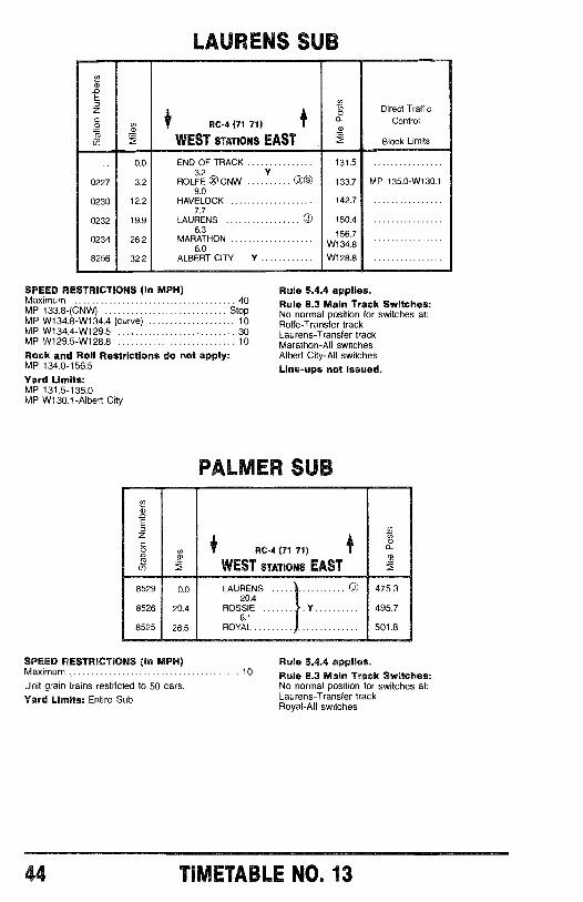
LAURENS SUB
E
-E
zCo i RC-4 (71 71) 4
EDirect Traffic
Control
WEST STATIONS EAST - Block Limits
0.0 END OF TRACK 131.53.2 Y
0227 3.2 ROLFE 0 CNW 00 133.7 MP 135.0-W130.19.0
0230 12.2 HAVELOCK 142.77.7
0232 19.9 LAURENS 0 150.4
0234 26.26.3
MARATHON156.7
6.0 W134.8
8256 32.2 ALBERT CITY Y W128.8
SPEED RESTRICTIONS (In MPH)Maximum 40MP 133.8-(CNW) StopMP W134.8-W134.4 (curve) 10MP W134.4-W129.5 30MP W129.5-W128.8 10
Rock and Roll Restrictions do not apply:MP 134.0-156.5
Yard Limits:MP 131.5-135.0MP W130.1-Albert City
Rule 5.4.4 applies.Rule 8.3 Main Track Switches:No normal position for switches at:Rolfe-Transfer trackLaurens-Transfer trackMarathon-All switchesAlbert City-All switches
Line-ups not issued.
PALMER SUB
8529
8526
8525
0.0
20.4
26.5
RC-4 (71 71)
WEST STATIONS EAST
LAURENS20.4
ROSSIE
Y
6.1ROYAL
475.3
495.7
501.8
SPEED RESTRICTIONS (in MPH)Maximum 10
Unit grain trains restricted to 50 cars.Yard Limits: Entire Sub
Rule 5.4.4 applies.Rule 8.3 Main Track Switches:No normal position for switches at:Laurens-Transfer trackRoyal-All switches
44 TIMETABLE NO. 13
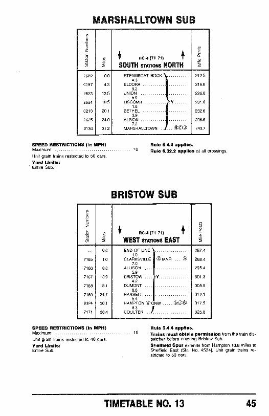
MARSHALLTOWN SUBV2iv
Eo
áE5
l® RC-4 (71 71>
SOUTH STATIONS NORTH
0a2
2622 0.0 STEAMBOAT ROCK 212.54.3
0197 4.3 ELDORA 216.89.2
2623 13.5 UNION 226.05.0
2624 18.5 LISCOMB Y 231.01.6
0213 20.1 BETHEL 232.63.9
2625 24.0 ALBION 23657.2
0136 31.2 MARSHALLTOWN ...000 243.7
SPEED RESTRICTIONS (In MPH)Maximum 10
Unit grain trains restricted to 50 cars.
Yard Limits:Entire Sub.
Rule 5.4.4 applies.Rule 6.32.2 applies at all crossings.
BRISTOW SUB
V2a)
E
;ó
roi RC -4 (71 71)
WEST STATIONS EAST
0.0 END OF LINE 287.41.0
7165 1.0 CLARKSVILLE ®IANR ... ® 288.47.0
7166 8.0 ALLISON 295.45.9
7167 13.9 BRISTOW Y 301.34.2
7168 18.1 DUMONT 305.56.6
7169 24.7 HANSELL 312.15.4
8324 30.1 HAMPTON 0 CNW A ,l ® 317.58.3
7171 38.4 COULTER 325.8
SPEED RESTRICTIONS (In MPH)Maximum 10
Unit grain trains restricted to 40 cars.Yard Limits:Entire Sub.
Rule 5.4.4 applies.Trains must obtain permission from the train dis-patcher before entering Bristow Sub.Sheffield Spur extends from Hampton 10.8 miles toSheffield East (Sta. No. 4534). Unit grain trains re-stricted to 50 cars.
TIMETABLE NO. 13 45
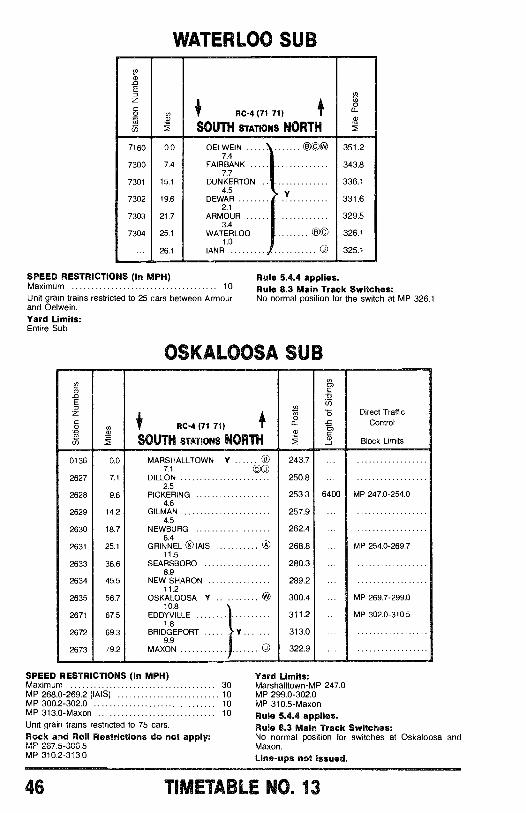
WATERLOO SUB
:2
E
z
ó i RC-4 (71 71)0
a
(-5 SOUTH STATIONS NORTH
7160 0.0 OELWEIN OCA 351.27.4
7300 7.4 FAIRBANK 343.87.7
7301 15.1 DUNKERTON . 336.14.5
7302 19.6 DEWAR 331.62.1
7303 21.7 ARMOUR 329.53.4
7304 25.1 WATERLOO (DC) 326.11.0
... 26.1 IANR g 325.1
SPEED RESTRICTIONS (In MPH)Maximum 10
Unit grain trains restricted to 25 cars between Armourand Oelwein.Yard Limits:Entire Sub.
Rule 5.4.4 applies.Rule 8.3 Main Track Switches:No normal position for the switch at MP 326.1.
OSKALOOSA SUBEE..
Ncn
E 65
z ti 5 Direct Traffic1 0
.2 v RC -4 (71 71) Control
6aui
SOUTH STATIONS NORTH Block Limits
0136 0.0 MARSHALLTOWN Y © 243.77.1 00
2627 7.1 DILLON 250.82.5
2628 9.6 PICKERING 253.3 6400 MP 247.0 -254.04.6
2629 14.2 GILMAN 257.94.5
2630 18.7 NEWBURG 262.4 ...6.4
2631 25.1 GRINNEL ® IAIS ® 268.8 ... MP 254.0 -269.711.5
2633 36.6 SEARSBORO 280.3 ...8.9
2634 45.5 NEW SHARON 289.2 ...11.2
2635 56.7 OSKALOOSA Y ® 300.4 ... MP 269.7 -299.010.8
2671 67.5 EDDYVILLE 311.2 ... MP 302.0 -310.51.8
2672 69.3 BRIDGEPORT Y 313.0 ...9.9
2673 79.2 MAXON n 322.9 ...
SPEED RESTRICTIONS (In MPH)Maximum 30MP 268.0 -269.2 (IAIS) 10MP 300.2 -302.0 10MP 313.0 -Maxon 10
Unit grain trains restricted to 75 cars.Rock and Roll Restrictions do not apply:MP 287.5 -306.5MP 310.2 -313.0
Yard Limits:Marshalltown -MP 247.0MP 299.0 -302.0MP 310.5 -MaxonRule 5.4.4 applies.Rule 8.3 Main Track Switches:No normal position for switches at Oskaloosa andMaxon.
Line -ups not Issued.
46 TIMETABLE NO. 13
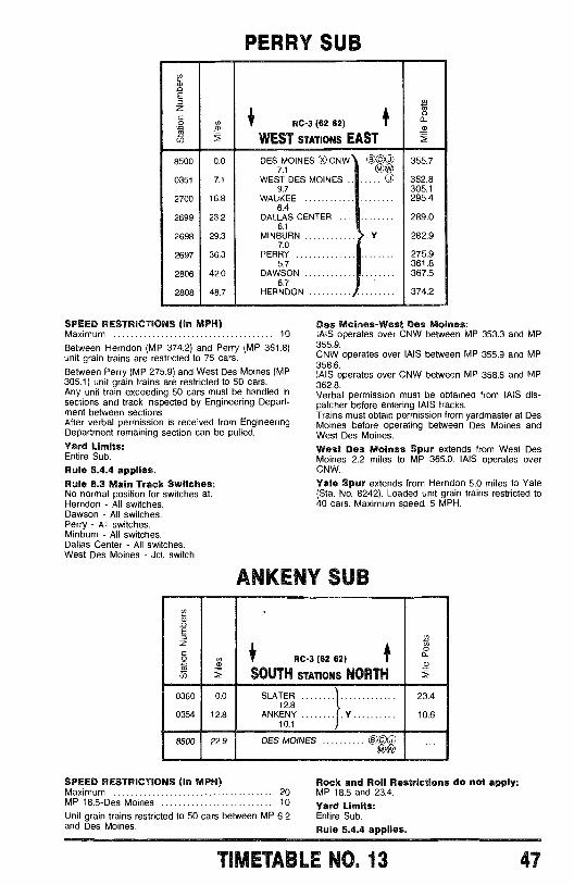
PERRY SUB
T3
E
grgn
4' RC -3 (62 62) 1
WEST STATIONS EAST
0
8500 0.0 DES MOINES Ox CNW 000 355.77.1
0351 7.1 WEST DES MOINES .. ..... 0 362.89.7 305.1
2700 16.8 WAUKEE 295.46.4
2699 23.2 DALLAS CENTER 289.06.1
2698 29.3 MINBURN Y 282.97.0
2697 36.3 PERRY 275.95.7 361.8
2806 42.0 DAWSON 367.56.7
2808 48.7 HERNDON 374.2
SPEED RESTRICTIONS (In MPH)Maximum 10
Between Herndon (MP 374.2) and Perry (MP 361.8)unit grain trains are restricted to 75 cars.Between Perry (MP 275.9) and West Des Moines (MP305.1) unit grain trains are restricted to 50 cars.Any unit train exceeding 50 cars must be handled insections and track inspected by Engineering Depart-ment between sections.After verbal permission is received from EngineeringDepartment remaining section can be pulled.Yard Limits:Entire Sub.
Rule 5.4.4 applies.Rule 8.3 Main Track Switches:No normal position for switches at:Herndon - All switches.Dawson - All switches.Perry - All switches.Minburn - All switches.Dallas Center - All switches.West Des Moines - Jct. switch.
Des Moines -West Des Moines:IAIS operates over CNW between MP 353.3 and MP355.9.CNW operates over IAIS between MP 355.9 and MP358.6.IAIS operates over CNW between MP 358.6 and MP362.8.Verbal permission must be obtained from AIS dis-patcher before entering IAIS tracks.Trains must obtain permission from yardmaster at DesMoines before operating between Des Moines andWest Des Moines.
West Des Moines Spur extends from West DesMoines 2.2 miles to MP 365.0. IAIS operates overCNW.
Yale Spur extends from Herndon 5.0 miles to Yale(Sta. No. 8242). Loaded unit grain trains restricted to40 cars. Maximum speed: 5 MPH.
ANKENY SUB
RC-3 (62 62)
SOUTH STATIONS NORTH
0360
0354
0.0
12.8
SLATER12.8
ANKENY10.1
23.4
10.6
8500 22.9 DES MOINES
SPEED RESTRICTIONS (In MPH)Maximum 20MP 18.5 -Des Moines 10
Unit grain trains restricted to 50 cars between MP 6.2and Des Moines.
000
Rock and Roll Restrictions do not apply:MP 18.5 and 23.4.
Yard Limits:Entire Sub.
Rule 5.4.4 applies.
TIMETABLE N0. 13 47
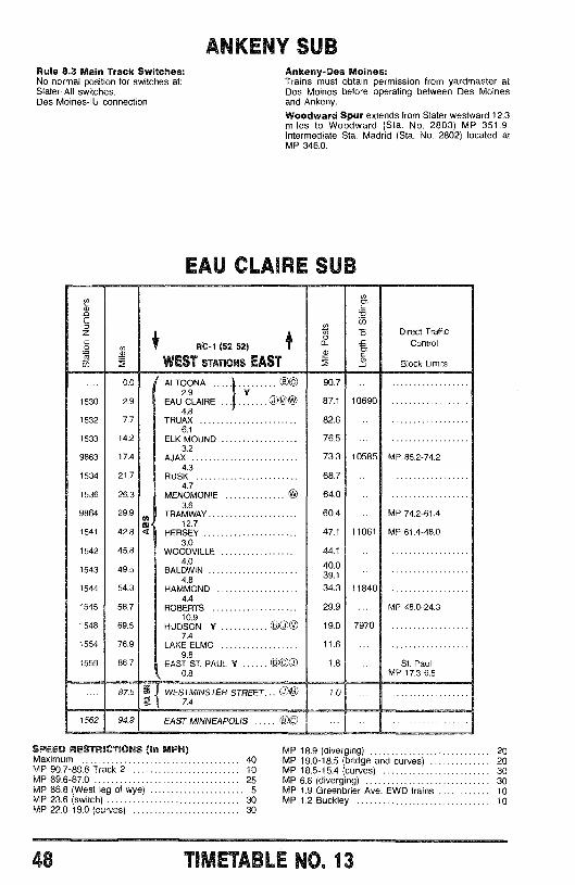
Rule 8.3 Main Track Switches:No normal position for switches at,Slater -All switches.Des Moines -IU connection
1530
1532
1533
9863
1534
1536
9864
1541
1542
1543
1544
1545
1548
1554
1559
ái
0.0
2.9
7.7
14.2
17,4
21.7
26.3
29.9
42.8
45.8
49.5
54.3
58.7
69.5
76.9
86.7
ArrMlY SUBAnkeny -Des Moines:Trains must obtain permission from yardmaster atDes Moines before operating between Des Moinesand Ankeny.
Woodward Spur extends from Slater westward 12.3miles to Woodward (Sta. No. 2803) MP 351.9.Intermediate Sta. Madrid (Sta. No. 2802) located atMP 346.0.
EAU CLAIRE SUB
RC-1 (52 52)
WEST STATIONS EAST
ALTOONA 00EAU CLAIRE
2.9 Yg@%
4.8TRUAX
6.1ELK MOUND
3.2AJAX
4.3RUSK
4,7MENOMONIE
3.6TRAMWAY
12.74 HERSEY
3.0WOODVILLE
4.0BALDWIN
4.8HAMMOND
4.4ROBERTS
10,9HUDSON Y 00 OO
7,4LAKE ELMO
9.8EAST ST. PAUL Y
0.8000
m
90.7
87.1
82.6
76.5
73.3
68.7
64.0
60.4
47.1
44.1
40.039.1
34.3
29.9
19.0
11.6
1.8
10690
10585
11061
11840
7970
Direct TrafficControl
Block Limits
MP 85.2-74.2
MP 74.2-61.4
MP 61.4-48.0
MP 48.0-24.3
St. PaulMP 17.3-6.5
87.5 m I WESTMINSTER STREET... 0eÿl 7,41.0
1562 94.9 EAST MINNEAPOLIS e c
SPEED RESTRICTIONS (In MPH)MaximumMP 90.7 -89.6 Track 2MP 89.6 -87.0MP 86.8 (West leg of wye)MP 23.6 (switch)MP 22.0 -19.0 (curves)
MP 18.9 (diverging) 2040 MP 19.0 -18.5 (bridge and curves) 2010 MP 18.5 -15.4 (curves) 3025 MP 6.6 (diverging) 30
5 MP 1.9 Greenbrier Ave. EWD trains 1030 MP 1.2 Buckley 1030
ilMLiALLE NO. 13
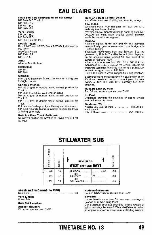
EAU CLAIRE SUBRock and Roll Restrictions do not apply:MP 88.0 -84.0 Track 1MP 56.5 -52.7MP 48.1 -44.0MP 18.9 -17.1
Yard Limits:MP 90.7 -85.2MP 24.3 -17.3MP 6.5 -East St. PaulDouble Track:Rule 9.14 Track 1 -EWD, Track 2 -WWD (trains keep tothe right):Altoona -MP 89.6MP 23.6 -18.9MP 6.6 -1.8
ABS:Altoona -East St. Paul
Detectors:MP 68.7MP 28.6
Sidings:Eau Claire- Maximum Speed: 30 MPH on siding andthrough turnouts.
Spring Switches:MP 89.6: End of double track; normal position forTrack 1.MP 85.2: Eau Claire -West end of siding.MP 23.6: End of double track; normal position forTrack 2.MP 18.9: End of double track; normal position forTrack 1.Both ends of sidings at Ajax, Hersey and Hammond.MP 6.6: End of double track; normal position for Track2, facing point lock.
Rule 8.3 Main Track Switches:No normal position for switches at Payne Ave. in EastSt. Paul.
Rule 9.13 Dual Control Switch:Eau Claire, east end of siding and east leg of wye.Eau Claire:Westward trains must not pass MP 87.1 until DTCauthority has been obtained.Movements over Shawtown bridge handling cars over200,000 lbs. must have empties placed betweenloads. No six (6) axle engines.
Hudson:Absolute signals at MP 18.4 and MP 18.9 activatedautomatically govern movement over bridge 414(Hudson Bridge).Exception: Movements from the Stillwater Sub aregoverned by Rule 9.17 and by the indication displayedon the absolute signal located 100 feet west of theswitch on Stillwater Sub.When a train operates from MP 18.4 to MP 18.9 andthen needs to make a reverse movement, activate thewestward absolute signal by operating a pushbuttonlocated on signal mast at MP 18.9.Rule 9.12.2 applies when stopped by a stop indiction.
Eastwared trains must not pass the east switch at MP23. 6 and westward trains must not pass the westswitch at MP 18.9 until DTC authority has beenobtained.
Hudson -East St. Paul:BN, CP and MNNR operate over CNW.St. Paul:Ordinance prohibits the sounding of engine whistleand bell within city limits.
Maximum Wt:Altoona Jct. -East St. Paul 315,00 lbs.Yard track toCity of Menomonie 253, 000 lbs.
STILLWATER SUB
_oE
#
«OO
ó i RC-1 (52 52)
iñ WEST STATIONS EAST
1548 0.0 HUDSON ®01 0.03.0
1553 3.0 BAYPORT Y 3.02.5
1552 5.5 STILLWATER 5.5
SPEED RESTRICTIONS (In MPH)Maximum 20
Yard Limits:Entire Sub.
Rule 5.4.4 applies.Hudson -Bayport:CP trains operate over CNW.
Hudson -Stillwater:BN and MNNR trains operate over CNW.
Bayport:Do not handle more than 55 cars over crossings atBayport or at NSP King Plant.City ordinance prohibits sounding engine whistle orbell at crossings between 2200 and 0600 except whenan engine is about to move from a standing position.
TIMETABLE NO. 13 49
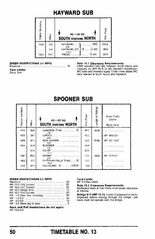
HAYWARD SUB
1634
1627
0.0
6.4
19.2
RC -1 (52 52)
SOUTH STATIONS NORTH
HAYWARD a c6.4
HAYWARD JCT. Y ... © WC13.3
TREGO O WC
SPEED RESTRICTIONS (In MPH)Maximum 10
Yard Limits:Entire Sub.
103.0
96.6
83.3
Rule 15.1 Clearance Requirements:CNW operates over WC between South Itasca andHayward Jct. (MP 96.6) on the Hayward Subdivision.WC rules and timetable apply. CNW crews obtain WCtrack warrant at South Itasca and Hayward.
SPOONER SUB
RC-1 (52 52)
SOUTH STATIONS NORTHm
Direct TrafficControl
Block Limits
1674
1672
1669
1665
1664
1662
1530
30.8
38.7
47.5
55.9
57.4
68.5
70.7
80.7
CAMERON ®WC CA)
7.9CHETEK
8.8NEW AUBURN
84BLOOMER
1.5CO -OP
11.1NORMA
2.2CHIPPEWA FALLS ® WC.... (?)
10.0EAU CLAIRE Y LXM)NT
49.0
42.0
33.2
24.8
23.3
12.2
10.0
0.0
SPEED RESTRICTIONS (In MPH)Maximum 40MP 12.2 -10.9 (curves) 25MP 10.9 -10.7 (curves) 20MP 10.7 (bridge 614) 10MP 10.7 -10.0 (curves) 20MP 1.6 (Starr Ave. crossing) 25*MP 1.6 -0.3 30MP 0.3 -0.0 10MP 0.0 (West leg of wye) 5
Rock and Roll Restrictions do not apply:MP 12.0 -0.2
4008
6796
3923
MP 49.0-33.1
MP 33.1-12.5
MP 12.5-0.3
Yard Limits:MP 0.3 -Eau Claire
Rule 15.1 Clearance Requirements:Northward trains at Eau Claire must obtain clearanceat Altoona
Bridge 614 (MP 10.7): Loads of pulpwood must beinspected before moving through the bridge. Unittrains must not operate over this bridge.
50 TDAETABLE NO. 13
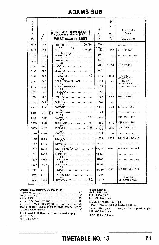
ADAMS SUB
n
óti LD
RC -1 Butler -Adams (52 52)RC -3 Adams -Altoona (62 62) T
WEST STATIONS EAST
ao
af
mg.
tm_
Direct TrafficControl
Block Limits
5716 0.0 BUTLER B C 16.5M ...
5715 0.8 BJ0.8
Y ° ©W 1 13.4 8448 MP 17.9 -39.716.1
5731 16.9 NORTH LAKE 29.6 ...
5.1
5736 22.0 MAPLETON 34.7 ...5.8
5740 27.8 ROCK 40.5 11094 MP 39.7 -48.74.2
5746 32.0 LEBANON 44.76.8
5752 38.8 CLYMAN JCT. © 51.5 12572 Clyman11.5 MP 48.7 -53.0
5764 50.3 SOUTH BEAVER DAM 63.0 ... Beaver7.6 MP 53.0 -62.2
5772 57.9 SOUTH RANDOLPH 70.6 ...
6.45778 64.3 FRIESLAND 77.0 ...
8.85787 73.1 DALTON 85.8 10602 MP 62.2 -87.7
10.1
5797 83.2 GLENOAK 95.9 ...10.6
5807 93.8 OXFORD 106.5 6044 MP 87.7 -105.310.9
5818 104.7 m GRAND MARSH 117.4 ...8.1
5826 112.8 ADAMS Y 00 125.5 ... MP 105.3 -123.312.8
5839 125.6 NECEDAH © 138.3 5150 MP 128.5 -139.215.6 153.9
5855 141.2 WYEVILLE OW N173.5 10050 MP 139.2- N173.29.4
1510 150.6 WARREN N164.1 ...8.3
1512 158.9 MILLSTON N155.7 10211 MP N173.2- N157.712.1
1517 171.0 LEVIS N142.1 ...10.5
1518 181.5 MERRILLAN 0.0 FVW n N13t.5 11891 MP N157.7- N131.45.8
1521 187.3 HUMBIRD N125.7 ...6.8
1522 194.1 FAIRCHILD N118.8 ...9.3
1524 203.4 AUGUSTA N109.5 ...5.6
1525 209.0 RODELL N103.9 10201 MP N131.4- N104.94.3
1526 213.3 FALL CREEK N99.5 ...8.8 Eau Claire
1530 222.1 ALTOONA Y 0© N90.7 ... MP N104.9 -N93.4
SPEED RESTRICTIONS (In MPH)Maximum 40Butler -MP 13.8 30MP N173.5 25MP N131.5 FVW crossing 30MP N93.3 Track 1 (diverging) 30Trains handling blocks of 55 or more loaded 100 tonhoppers Altoona -Butler 30
Rock and Roll Restrictions do not apply:MP 69.0 -72.0MP 138.2 -126.6
Yard Limits:Butler -MP 17.9MP 123.3 -128.5MP N93.4- Altoona
Double Track, Rule 9.14Track 1 -WWD, Track 2 -EWD, Butler -BJ
Track 1 -EWD, Track 2 -WWD (trains keep to the right)MP N93.3- Altoona
ABS: Butler -Altoona
TIMETABLE NO. 13 51
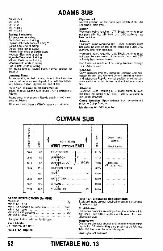
ADAMS SUBDetectors:MP 28.9MP 91.2MP N168.2MP N123.3
Spring Switches:BJ -West end of siding.Rock -Both ends of siding.Clyman Jct. -Both ends of siding. "'Dalton -East end of siding.Oxford -west end of siding.Adams -Both ends of South track.Necedah -East end of siding.Wyeville -West end of siding.Millston -Both ends of siding.Merillan -Both ends of siding.Rodell -Both ends of siding.MP N93.3 -End of double track, normal position forTrack 2.
Leaving Time:Trains must give their leaving time to the train dis-patcher as soon as train departs from Altoona, Merril -Ian, Adams, Dalton, Clyman Jct. and Butler.
Rule 15.1 Clearance Requirements:Trains enroute Sparta Sub obtain a CP clearance atAdams.
Trains enroute Wisconsin Rapids obtain a WC clear-ance at Adams.All trains must obtain a CNW clearance at Adams.
0652
0653
1318
0654
0656
0658
5752
0.0
5.7
8.1
11.0
19.1
19.4
27.4
28.5
Clyman Jct.:Normal position for the north wye switch is for OldLakeshore main track.
Butler:Westward trains requiring DTC Block authority mustnot pass Lilly Rd., MP 14.8, until DTC authority hasbeen obtained.
Adams:Eastward trains requiring DTC Block authority mustnot pass the east switch of the south track until DTCauthority 'has been obtained.
Westward trains requiring DTC Block authority mustnot pass the west switch of the south track until DTCauthority has been obtained.
Unit trains are restricted from using Tracks 5 through12 in Adams Yard.
Necedah:CNW operates over WC between Necedah and Wis-consin Rapids. WC General Orders posted at Adamsand Wisconsin Rapids. Normal position of connectiontrack switch on siding is lined and locked for connec-tion.
Altoona:Eastward trains requiring DTC Block authority mustnot pass the switch at MP N93.3 until DTC authorityhas been obtained.
Camp Douglas Spur extends from Wyeville 9.2miles to Camp Douglas.
Maximum Wt: 315, 000 lbs.
CLYMAN SUB
RC -1 (52 52)
WEST STATIONS EAST
FT. ATKINSON5.7
JEFFERSON Y2.4
JEFFERSON JCT. 1. .. Da ©®2.9
JOHNSON CREEK8.1
x®CP0.3
WATERTOWN8.0
CLYMAN1.1
CLYMAN JCT.
111.5
117.2
119.6
122.5
130.6
130.9
138.9
140.0
Direct TrafficControl
Block Limits
JeffersonMP 120.6 -140.0
SPEED RESTRICTIONS (In MPH)Maximum 30MP 111.5 -117.4 10MP 117.4 Candice St. Jefferson StopMP 117.4 -120.6 10MP 130.6 CP crossing 20*MP 139.4 -140.0 10
Unit grain trains restricted to 60 cars.Yard Limits:
-Ft. Atkinson -MP 120.6
Rule 5.4.4 applies.
Rule 15.1 Clearance Requirements:Eastward trains are not required to obtain a clearanceat Jefferson Jct.
Ft. Atkinson:Ordinance prohibits sounding of engine whistle withincity limits. Rule 6.32.2 applies at Sherman Ave. andMilwaukee Ave.
Watertown:Ordinance prohibits sounding of engine whistle withincity limits. CP interlocking cars must not be left lessthan 300 feet from the absolute signal.
Line -ups not issued.
52 TIMETABLE NO. 13
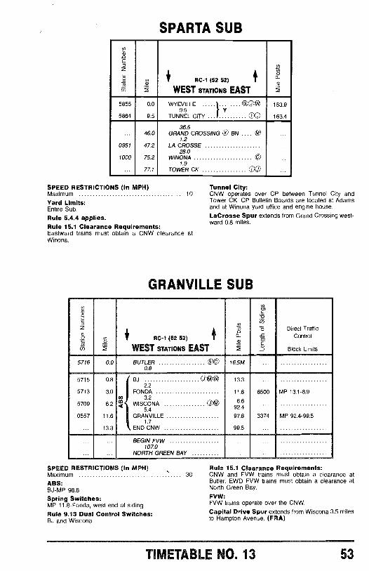
SPARTA SUB
n)
E
Ç°_ $ RC -1 (52 52) 1
N
WEST STATIONS EAST
5855 0.0 WYEVILLE ©C® 153.99.5 Y
5864 9.5 TUNNEL CITY 163.4
36.5... 46.0 GRAND CROSSING 0 BN .... ® ...
1.20951 47.2 LA CROSSE ...
28.01000 75.2 WINONA © ...
1.9... 77.1 TOWER CK 00
SPEED RESTRICTIONS (In MPH) Tunnel City:Maximum 10 CNW operates over CP between Tunnel City and
Tower OK. CP Bulletin Boards are located at AdamsYard Limits:Entire Sub.
Rule 5.4.4 applies.Rule 15.1 Clearance Requirements:Eastward trains must obtain a CNW clearance atWinona.
and at Winona yard office and engine house.LaCrosse Spur extends from Grand Crossing west-ward 0.8 miles.
GRANVILLE SUB
RC-1 (52 52)
WEST STATIONS EAST
áDirect Traffic
Control
Block Limits
5716
5715
5713
5709
0557
0.0
0.8
3.0
6.2
11.6
13.3
BUTLER (X)0.8
BJ OO®®2.2
FONDAco{m WISCONA OJ ©Q
5.4GRANVILLE
1.7END CNW
BEGIN FVW107.0
NORTH GREEN BAY
SPEED RESTRICTIONS (In MPH)Maximum 30
ABS:BJ -MP 98.8
Spring Switches:MP 11.8- Fonda, west end of siding
Rule 9.13 Dual Control Switches:BJ and Wiscona
16.5M
13.3
11.8
8.692.4
97.8
99.5
8500
3374
MP 13.1-8.9
MP 92.4-99.5
Rule 15.1 Clearance Requirements:CNW and FVW trains must obtain a clearance atButler. EWD FVW trains must obtain a clearance atNorth Green Bay.
FVW:FVW trains operate over the CNW.Capital Drive Spur extends from Wiscona 3.5 milesto Hampton Avenue. (FRA)
TIMETABLE NO. 13 53
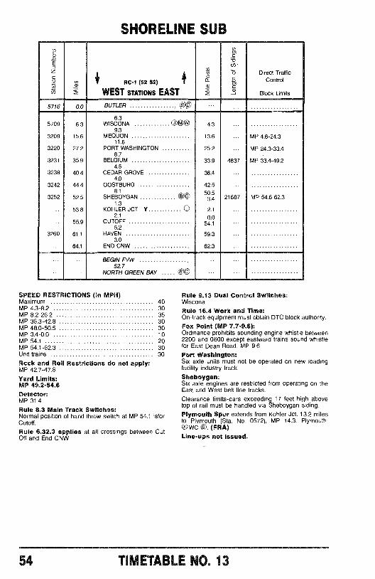
SHORELINE SUB
RC -1 (52 52)
WEST STATIONS EAST
Ñ
.a2
Direct TrafficControl
Block Limits
5716
5709
3209
3220
3231
3238
3242
3252
3260
0.0
6.3
15.6
27.2
35.9
40.4
44.4
52.5
53.8
55.9
61.1
64.1
BUTLER OC)
6.3WISCONAO®*J9.3
MEQUON11.6
PORT WASHINGTON8.7
BELGIUM4.5
CEDAR GROVE4.0
OOSTBURG8.1
SHEBOYGAN 001.3
KOHLER JCT Y O2.1
CUTOFF5.2
HAVEN3.0
END CNW
4.3
13.6
25.2
33.9
38.4
42.5
50.53.4
2.1
0.054.1
59.3
62.3
4837
21687
BEGIN FVW52.7
NORTH GREEN BAY e c
SPEED RESTRICTIONS (In MPH)Maximum 40MP 4.3 -8.2 30MP 8.2 -26.2 35MP 36.3 -42.8 30MP 48.0 -50.5 30MP 3.4 -0.0 10MP 54.1 20MP 54.1 -62.3 30Unit trains 30
Rock and Roll Restrictions do not apply:MP 42.7 -47.6
Yard Limits:MP 49.2 -54.6Detector:MP 31.4Rule 8.3 Main Track Switches:Normal position of hand throw switch at MP 54.1 isforCutoff.
Rule 6.32.3 applies at all crossings between CutOff and End CNW,
MP 4.6-24.3
MP 24.3-33.4
MP 33.4-49.2
MP 54.6-62.3
Rule 9.13 Dual Control Switches:Wiscona
Rule 16.4 Work and Time:On -track equipment must obtain DTC block authority.
Fox Point (MP 7.7 -9.6):Ordinance prohibits sounding engine whistle between2200 and 0600 except eastward trains sound whistlefor East Dean Road, MP 9.6Port Washington:Six axle units must not be operated on new loadingfacility industry track.
Sheboygan:Six axle engines are restricted from operating on theEast and West belt line tracks.
Clearance limits -cars exceeding 17 feet high abovetop of rail must be handled via Sheboygan siding.Plymouth Spur extends from Kohler Jct. 13.2 milesto Plymouth (Sta. No. 0572), MP 14.3. Plymouth:0 WC ©. (FRA)Line -ups not issued.
54 TIMETABLE NO 13
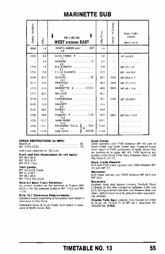
MARINETTE SUB
a)nE
zóL5
SR
RC -1 (52 52)
WEST STATIONS EAST
ó
cnm=äiñ
Direct Traffic
Control
Block Limits
0686 0.0 NORTH GREEN BAY s c 1.42.8
0700 2.8 DUCK CREEK Y 4.2 ... MP 4.2 -6.51.5
4.3 HOWARD (7) 5.73.2
0702 7.5 BIG SUAMICO 8.9 ... MP 6.5 -14.86.4
0704 13.9 LITTLE SUAMICO 15.3 ... MP 14.8 -29.213.8
0708 27.7 OCONTO Ñ 29.1 4318 MP 29.2 -41.713.3
0711 41.0 PESHTIGO 42.4 2826 MP 41.7 -47.36.6
0712 47.6 MARINETTE Y ©COXJ) 49.0 5900 MP 49.7 -72.416.1
0717 63.7 WALLACE 66.1 ...6.3
0719 70.0 STEPHENSON 72.4 3445 MP 72.4 -90.73.0
0720 73.0 DAGGETT 75.4 ...9.2
0723 82.2 CARNEY 84.6 _.7.6
0726 89.8 POWERS Y 0:* 92.2 2855 MP 93.0 -112.910.9
0730 100.7 BARK RIVER 103.1 ...11.4
0734 112.1 ESCANABA 0 ELS . 1 n© 114.5 ...1.4 Y
0735 113.5 ORE DOCKly
CO@ 115.9 ...
SPEED RESTRICTIONS (In MPH)Maximum 30MP 114.5 -(ELS) 10"
Unit trains restricted to 120 cars.
Rock and Roll Restrictions do not apply:MP 86.4 -92.0MP 79.5 -81.6MP 97.2 -112.2
Yard Limits:MP 4.0 -Duck CreekMP 47.3 -49.7MP 90.7 -93.0MP 112.9 -Ore Dock
Rule 8.3 Main Track Switches:No normal position for the switches at Powers (MP92.2) or for the switches between MP 113.6 and MP115.9.
Rule 15.1 Clearance Requirements:Eastward trains originating at Escanaba must obtain aclearance at Ore Dock.Westward trains at Duck Creek must obtain a clear-ance at North Green Bay.
Duck Creek:CNW operates over FVW between MP 4.0 east ofDuck Creek and North Green Bay. Eastward trainsmust report to FVW yardmaster at North Green Bayfor permission to pass MP 4.0. FVW bulletins areposted at Ore Dock. FVW radio channels: Radio 1 (4949), Road 2 (15 15).
Duck Creek -Howard:ELS and FVW trains operate over CNW between MP4.0 and MP 5.7.Marinette:ELS trains operate over CNW between MP 48.5 andMP 52.5.
Escanaba:Engines must stop before crossing Danforth Roadcrossing on the new connection between CNW andELS. During inclement weather and between dusk anddawn, lighted fusees must be placed to warn approach-ing vehicles.
Oconto Falls Spur extends from Oconto 8.3 milesto Stiles Jct. (Ox ELS CAS at MP 46.1). Maximum Wt:220,000 lbs. (FRA)
TIMETABLE NO. 13 55
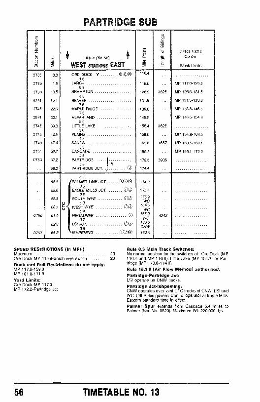
0735
0760
0739
0741
0745
0821
0746
0748
0749
0751
0753
0755
0757
RTIIDGE 5U3
RC -1 (52 52)
WEST STATIONS EASTa2
_-0i7)
óó>cJ
Direct TrafficControl
Block Limits
0.0 ORE DOCK Y1.6
*OW 116.4sAsSAVI
1.6 LARCH 118.0 MP 117.0-126.58.9
10.5 BRAMPTON 126.9 3825 MP 126.5-131.54.6
15.1 BEAVER 131.5 MP 131.5-138.87.5
22.6 MAPLE RIDGE 139.0 MP 138.8-146.57.5
30.1 McFARLAND 146.5 MP 146.5-154.88.9
39.0 LITTLE LAKE 155.4 36283.6
42.6 PLAINS 159.0 MP 154.8-163.54.8
47.4 SANDS 163.8 1657 MP 163.5-169.15.3
52.7 CASCADE 169,9 MP 169.1-172.24.5
57.2 PARTRIDGE 173.6 39350.8 Y
58.0 PARTRIDGE JCT. Ci 174.4
0.558.5 PALMER LINE JCT CrXJ)W 174.9
0.559.0 EAGLE MILLS JCT. 0)g 175.4
59.5
60.5U
0.5SOUTH WYE
1.0WEST WYE
(1)0
0Q)
175.9WC
164.5
1.4 WC
61.9 NEGAUNEE 165.9 42420.7 WC
62.6 LSI JCT 166.6
as CNW
66.2 ISHPEMING 1 J @ 182.6
SPEED RESTRICTIONS (In MPH)Maximum 40Ore Dock MP 115.9 -South wye switch 20
Rock and Roll Restrictions do not apply:MP 117.0 -159.0MP 161.0 -171.9
Yard Limits:Ore Dock -MP 117.0MP 172.2- Partridge Jct.
Rule 8.3 Main Track Switches:No normal position for the switches at: Ore Dock (MP116.4 and MP 116.6); Little Lake (MP 154.7) or Par-tridge (MP 173.0 -174.0).
Rule 18.2.9 (Air Flow Method) authorized.Partridge -Partridge Jet:LSI operate on CNW tracks.Partridge Jct- Ishpeming:CNW operates over joint CTC tracks of CNW, LSI andWC. LSI Rules govern. Control operator at Eagle Mills.Eastern standard time in effect.Palmer Spur extends from Cascade 5.4 miles toPalmer (Sta. No. 0823). Maximum Wt: 220,000 lbs.
56 TIMETABLE NO. 13
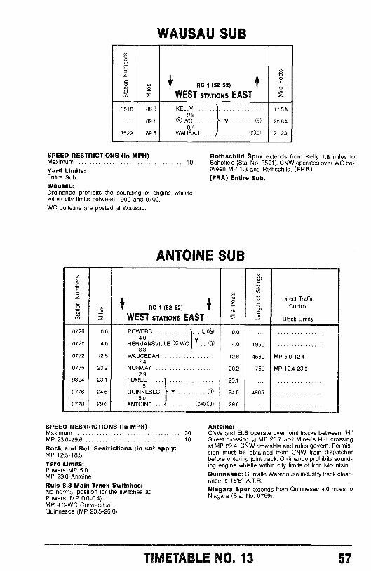
WAUSAU SUB
To
Eo
C 1 /* N
g 1 RC-1 (52 52) 1
in f WEST STATIONS EAST f3518 86.3 KELLY 17.5A
2.889.1 O WC Y .... n 20.8A
0.43522 89.5 WAUSAU .. .. .. .. .. .. ... CB© 21.2A
SPEED RESTRICTIONS (In MPH) Rothschild Spur extends from Kelly 1.8 miles toMaximum 10 Schofield (Sta. No. 3521). CNW operates over WC be-
tween MP 1.8 and Rothschild. (FRA)(FRA) Entire Sub.
Yard Limits:Entire Sub.
Wausau:Ordinance prohibits the sounding of engine whistlewithin city limits between 1900 and 0700.WC bulletins are posted at Wausau.
ANTOINE SUBNvÉ
omC
o N 0)
o 15 Direct Traffic
a RC-1 (52 52) I -c
Control
f WEST STATIONS EAST f 3Block Limits
0726 0.0 POWERS 0® 0.04.0
Y0770 4.0 HERMANSVILLE 0 WC .. n 4.0 19608.8
0772 12.8 WAUCEDAH 12.8 4580 MP 5.0 -12.47.4
0775 20.2 NORWAY 20.2 750 MP 12.4 -23.02.9
0824 23.1 FUMEE 23.1 ...1.5
0776 24.6 QUINNESEC Y 0 24.6 49655.0
0778 29.6 ANTOINE 000 0 29.6 ...
SPEED RESTRICTIONS (In MPH)Maximum 30MP 23.0 -29.6 10
Rock and Roll Restrictions do not apply:MP 12.5 -18.5
Yard Limits:Powers -MP 5.0MP 23.0- Antoine
Rule 8.3 Main Track Switches:No normal position for the switches at:Powers (MP 0.0 -0.4)MP 4.0 -WC ConnectionQuinnesce (MP 23.5 -26.0)
Antoine:CNW and ELS operate over joint tracks between "H"Street crossing at MP 28.7 and Miner's Hall crossingat MP 29.4. CNW timetable and rules govern. Permis-sion must be obtained from CNW train dispatcherbefore entering joint track. Ordinance prohibits sound-ing engine whistle within city limits of Iron Mountain.Quinnesec: Gunville Warehouse industry track clear-ance is 18'5" A.T.R.
Niagara Spur extends from Quinnesec 4.0 miles toNiagara (Sta. No. 0769).
TIMETABLE NO. 13 57
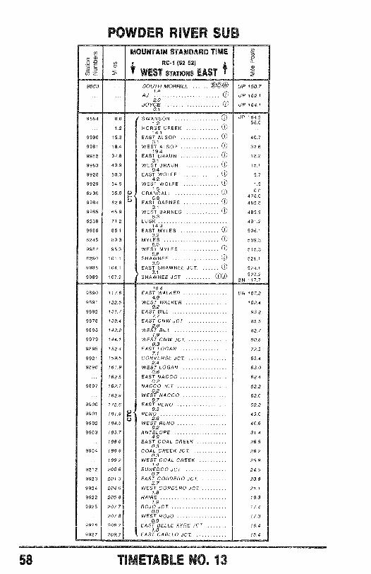
POWDER I :e nUß
- Eo
9853
MOUNTAIN STANDARD TIME
RC -1 (52 52)
WEST STATIONS EAST
SOUTH MORRILL co*AJ 14 O
2.0JOYCE O
0a
UP 160.7
UP 162.1
UP 164.10.1
9884 0.0 SWANSON O UP 164.2
1.2 56.0
1.2 HORSE CREEK O14.1
9980 15.3 EAST ALSOP CO 40.73.1
9981 18.4 WEST ALSOP CO 37.619.4
9982 37.8 EAST BRAUN CO 18.23.1
9983 40.9 WEST BRAUN O 15.19.4
9928 50.3 EAST WOLFE O 5.74.2
9929 54.5 WEST WOLFE CO 1.5
6230
9984
56.0
62.8
f72
1.5CRANDALL CD
6.8EAST BARNES CO
0.0
476.0
482.83A
9985 65.9 WEST BARNES 485.95.3
6238 71.2 LUSK 491.214.9
9986 86 EAST MYLES O 506.13.2
6245 89.3 MYLES CO 509.3
9987 95.3 WEST MYLES O 515.35.8
6250 101,1 SHAWNEE O 521.13.0
9988 104.1 EAST SHAWNEE JCT. O 524.1
9989 107.23.1
SHAWNEE JCT. 0X 527.2BN 117.7
10.49890 117.6 EAST WALKER BN 107.3
4.99891 122.5 WEST WALKER 102.4
929892 131.7 EAST BILL 93.2
7.79878 139.4 EAST CNW JCT 85.5
2.89893 142.2 WEST BILL 82.7
1.99979 144.1 WEST CNW JCT 80.8
8.39895 1524 EAST LOGAN 72.5
7.19921 159.5 CONVERSE JCT. 65.4
2.49896 161.9 WEST LOGAN 63.0
162.50.6
EAST NACCO 62.40.2
9897 162.7 NACCO JCT 62.20.2
162.9 WEST NACCO 62.09.7
9900 172.6 EAST RENO 52.39.3
9901 181.9 H t RENO 43.02.6
9902 184.5 WEST RENO 40.69.2
9903 193.7 ANTELOPE 31.44.9
198.6 EAST COAL CREEK 26.50.3
9904 198.9 COAL CREEK JCT 26.20.3
199.2 WEST COAL CREEK 25.91.4
9212 200.6 SUNEDCO JCT 24.50.7
9923 201.3 EAST CORDERO JCT 23.82.7
9924 204.0 WEST CORDERO JCT 21.11.8
9922 205.8 HAIRE 19.3
9925 207.71.9
ROJO JCT. 17.40.0
207.8 WEST ROJO 1 7.30.9
9926 208.7 EAST BELLE AVRE .IrT 16.4.0
9927 209.7 EAST CABLLO JCT 15.4
58 TIMETABLE NO. 13
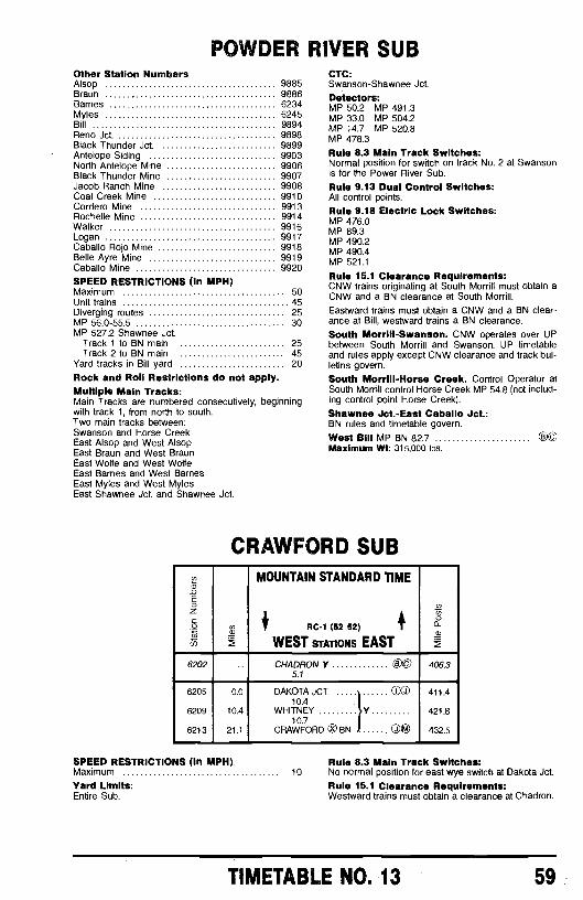
POWDER RIVER SUBOther Station NumbersAlsop 9885Braun 9886Barnes 6234Myles 6245Bill 9894Reno Jct. 9898Black Thunder Jct. 9899Antelope Siding 9903North Antelope Mine 9906Black Thunder Mine 9907Jacob Ranch Mine 9908Coal Creek Mine 9910Cordero Mine 9913Rochelle Mine 9914Walker 9916Logan 9917Caballo Rojo Mine 9918Belle Ayre Mine 9919Caballo Mine 9920
SPEED RESTRICTIONS (In MPH)Maximum 50Unit trains 45Diverging routes 25MP 56.0 -55.5 30MP 527.2 Shawnee Jct.
Track 1 to BN main 25Track 2 to BN main 45
Yard tracks in Bill yard 20
Rock and Roll Restrictions do not apply.Multiple Main Tracks:Main Tracks are numbered consecutively, beginningwith track 1, from north to south.Two main tracks between:Swanson and Horse CreekEast Alsop and West AlsopEast Braun and West BraunEast Wolfe and West WolfeEast Barnes and West BarnesEast Myles and West MylesEast Shawnee Jct. and Shawnee Jct.
CTC:Swanson- Shawnee Jct.
Detectors:MP 50.2 MP 491.3MP 33.0 MP 504.2MP 14.7 MP 520.8MP 478.3
Rule 8.3 Main Track Switches:Normal position for switch on track No. 2 at Swansonis for the Power River Sub.Rule 9.13 Dual Control Switches:All control points.Rule 9.18 Electric Lock Switches:MP 476.0MP 89.3MP 490.2MP 490.4MP 521.1
Rule 15.1 Clearance Requirements:CNW trains originating at South Morrill must obtain aCNW and a BN clearance at South Morrill.Eastward trains must obtain a CNW and a BN clear-ance at Bill, westward trains a BN clearance.South Morrill- Swanson. CNW operates over UPbetween South Morrill and Swanson. UP timetableand rules apply except CNW clearance and track bul-letins govern.
South Morrill -Horse Creek. Control Operator atSouth Morrill control Horse Creek MP 54.8 (not includ-ing control point Horse Creek).
Shawnee Jct. -East Caballo Jct.:BN rules and timetable govern.
West Bill MP BN 82.7 ©©Maximum Wt: 315,000 lbs.
CRAWFORD SUBN
oEDz4 á
MOUNTAIN STANDARD TIME
/*
11
RC -1 (52 52) 1
yó
u WEST STATIONS EAST
6202 CHADRON Y CV 406.35.1
6205 0.0 DAKOTA JCT. TO 411.410.4
6209 10.4 WHITNEY Y 421.810.7
6213 21.1 CRAWFORD C BN ©® 432.5
SPEED RESTRICTIONS (In MPH).Maximum 10
Yard Limits:Entire Sub.
Rule 8.3 Main Track Switches:No normal position for east Wye switch at Dakota Jct.
Rule 15.1 Clearance Requirements:Westward trains must obtain a clearance at Chadron.
TIMETABLE NO. 13 59
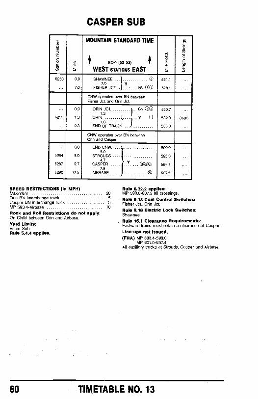
CASPER SUB
v2N
EoZ
co
w
t
MOUNTAIN STANDARD TIME
RC -1 (52 52) 4WEST STATIONS EAST
N
m.673inO
0,
6250 0.0 SHAWNEE 1 07.0 y
521.1
... 7.0I}
FISHER JCT. - BN J 528.1
CNW operates over BN betweenFisher Jct. and Orin Jct.
0.0 ORIN JCT. BN CXD 530.71.3
6255 1.3 ORIN Y © 532.0 36801.0
2.3 END OF TRACK 533.0
CNW operates over BN betweenOrin and Casper.
0.0 END CNW. .... .... 590.05.0
6284 5.0 STROUDS 595.0 ...4.7
6287 9.7 CASPER ...... ....... OOO 599.7 ....7.8
6290 17.5 AIRBASE ® 607.5
SPEED RESTRICTIONS (In MPH)Maximum 20Orin BN interchange track 5Casper BN interchange track 5MP 593.4 -Airbase 10
Rock and Roll Restrictions do not apply:On CNW between Orin and Airbase.Yard Limits:Entire Sub.Rule 5.4.4 applies.
Rule 6.32.2 app lea:MP 590.0 -607.5 all crossings.
Rule 9.13 Dual Control Switches:Fisher Jct., Orin Jct.Rule 9.18 Electric Lock Switches:Shawnee
Rule 15.1 Clearance Requirements:Eastward trains must obtain a clearance at Casper.
Line -ups not issued.(FRA) MP 593.4 -599.0
MP 601.0 -607.4All auxiliary tracks at Strouds, Casper and Airbase.
60 TIMETABLE N0. 13
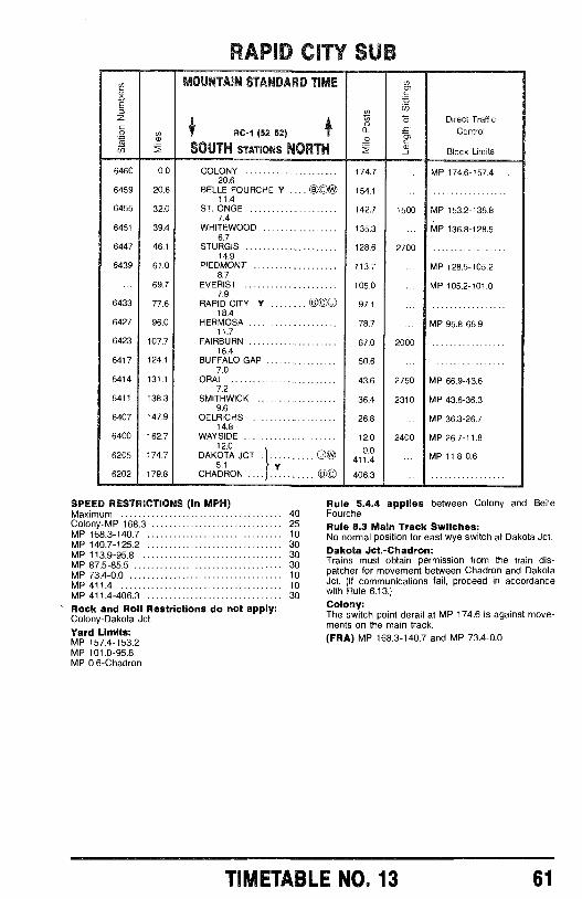
ai
6460 0.0
6459 20.6
6455 32.0
6451 39.4
6447 46.1
6439 61.0
69.7
6433 77.6
6427 96.0
6423 107.7
6417 124.1
6414 131.1
6411 138.3
6407 147.9
6400 162.7
6205 174.7
6202 179.8
ìAID CITY SUPMOUNTAIN STANDARD TIME
RC-1 (52 52)
SOUTH STATIONS NORTH
áa)
2
Direct TrafficControl
Block Limits
COLONY 174.720.6
BELLE FOURCHE Y e C ® 154.1 ...11.4
ST. ONGE 142.7 15007.4
WHITEWOOD 135.3 ...6.7
STURGIS 128.6 270014.9
PIEDMONT 113.7 .. .8.7
EVERIST 105.0 ...7.9
RAPID CITY Y ... 000I 97.1 ...18.4
HERMOSA 78.711.7
FAIRBURN 67.0 200016.4
BUFFALO GAP 50.6 ...7.0
ORAL 43.6 27507.2
SMITHWICK 36.4 23109.6
OELRICHS 26.8 ...14.8
WAYSIDE 12.0 240012.0
0.0DAKOTA JCT. ONO0.0
5.1CHADRON .. s C 406.3 ...
MP 174.6-157.4
MP 153.2-136.8
MP 136.8-128.5
MP 128.5-105.2
MP 105.2-101.0
MP 95.8-66.9
MP 66.9-43.6
MP 43.6-36.3
MP 36.3-26.7
MP 26.7-11.8
MP 11.8-0.6
SPEED RESTRICTIONS (In MPH)Maximum 40Colony -MP 168.3 25MP 168.3 -140.7 10MP 140.7 -125.2 30MP 113.9 -95.8 30MP 87.5 -85.5 30MP 73.4 -0.0 10MP 411.4 10MP 411.4 -406.3 30
Rock and Roll Restrictions do not apply:Colony- Dakota Jct.Yard Limits:MP 157.4 -153.2MP 101.0 -95.8MP 0.6- Chadron
Rule 5.4.4 applies between Colony and BelleFourcheRule 8.3 Main Track Switches:No normal position for east wye switch at Dakota Jct.Dakota Jct.- Chadron:Trains must obtain permission from the train dis-patcher for movement between Chadron and DakotaJct. (If communications fail, proceed in accordancewith Rule 6.13.)Colony:The switch point derail at MP 174.6 is against move-ments on the main track.(FRA) MP 168.3 -140.7 and MP 73.4 -0.0
TIMETABLE NO. 13 61
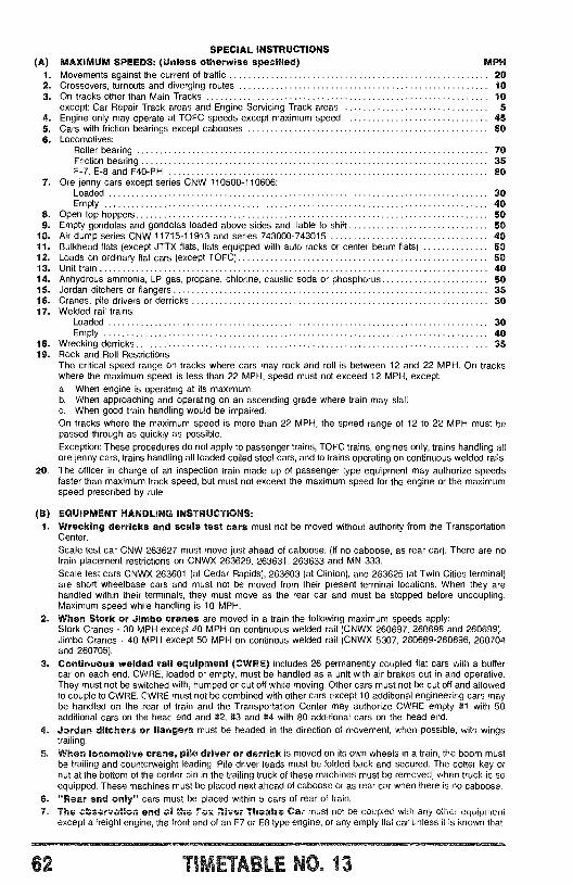
SPECIAL INSTRUCTIONS(A) MAXIMUM SPEEDS: (Unless otherwise specified) MPH
1. Movements against the current of traffic 202. Crossovers, turnouts and diverging routes 103. On tracks other than Main Tracks 10
except: Car Repair Track areas and Engine Servicing Track areas 54. Engine only may operate at TOFC speeds except maximum speed 455. Cars with friction bearings except cabooses 606. Locomotives:
Roller bearing 70Friction bearing 35F -7, E -8 and F40 -PH 80
7. Ore jenny cars except series CNW 110500- 110606:Loaded 30Empty 40
8. Open top hoppers 509. Empty gondolas and gondolas loaded above sides and liable to shift 50
10. Air dump series CNW 11715 -11913 and series 743000 -743015 4011. Bulkhead flats (except JTTX flats, flats equipped with auto racks or center beam flats) 5012. Loads on ordinary flat cars (except TOFC) 5013. Unit train 4014. Anhydrous ammonia, LP gas, propane, chlorine, caustic soda or phosphorus 5015. Jordan ditchers or flangers 3516. Cranes, pile drivers or derricks 3017. Welded rail trains:
Loaded 30Empty 40
18. Wrecking derricks 3519. Rock and Roll Restrictions:
The critical speed range on tracks where cars may rock and roll is between 12 and 22 MPH. On trackswhere the maximum speed is less than 22 MPH, speed must not exceed 12 MPH, except:a. When engine is operating at its maximum.b. When approaching and operating on an ascending grade where train may stall.c. When good train handling would be impaired.On tracks where the maximum speed is more than 22 MPH, the speed range of 12 to 22 MPH must bepassed through as quickly as possible.Exception: These procedures do not apply to passenger trains, TOFC trains, engines only, trains handling allore jenny cars, trains handling all loaded coiled steel cars, and to trains operating on continuous welded rails.
20. The officer in charge of an inspection train made up of passenger type equipment may authorize speedsfaster than maximum track speed, but must not exceed the maximum speed for the engine or the maximumspeed prescribed by rule.
(B) EQUIPMENT HANDLING INSTRUCTIONS:1. Wrecking derricks and scale test cars must not be moved without authority from the Transportation
Center.
Scale test car CNW 263627 must move just ahead of caboose. (If no caboose, as rear car). There are notrain placement restrictions on CNWX 263629, 263631, 263633 and MN 333.Scale test cars CNWX 263601 (at Cedar Rapids), 263603 (at Clinton), and 263625 (at Twin Cities terminal)are short wheelbase cars and must not be moved from their present terminal locations. When they arehandled within their terminals, they must move as the rear car and must be stopped before uncoupling.Maximum speed while handling is 10 MPH.
2. When Stork or Jimbo cranes are moved in a train the following maximum speeds apply:Stork Cranes - 30 MPH except 40 MPH on continuous welded rail (CNWX 260697, 260698 and 260699).Jimbo Cranes - 40 MPH except 50 MPH on continous welded rail (CNWX 5307, 260689- 260696, 260704and 260705).
3. Continuous welded rail equipment (CWRE) includes 26 permanently coupled flat cars with a buffercar on each end. CWRE, loaded or empty, must be handled as a unit with air brakes cut in and operative.They must not be switched with, humped or cut off while moving. Other cars must not be cut off and allowedto couple to CWRE. CWRE must not be combined with other cars except 10 additional engineering cars maybe handled on the rear of train and the Transportation Center may authorize CWRE empty #1 with 50additional cars on the head end and #2, #3 and #4 with 80 additional cars on the head end.
4. Jordan ditchers or flangers must be headed in the direction of movement, when possible, with wingstrailing.
5. When locomotive crane, pile driver or derrick is moved on its own wheels in a train, the boom mustbe trailing and counterweight leading. Pile driver leads must be folded back and secured. The cotter key ornut at the bottom of the center pin in the trailing truck of these machines must be removed, when truck is soequipped. These machines must be placed next ahead of caboose or as rear car when there is no caboose.
6. "Rear and only" cars must be placed within 5 cars of rear of train.7. The observation and of the Fox River Theatre Car must not be coupled with any other equipment
except a freight engine, the front end of an F7 or E8 type engine, or any empty flat car unless it is known that
62 TIMETABLE NO. 13
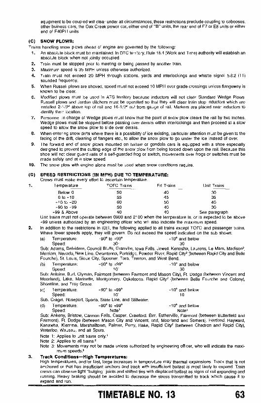
equipment to be coupled will clear under all circumstances, these restrictions preclude coupling to cabooses,other buiness cars, the Oak Creek power car, either end of "B" units, the rear end of F7 or E8 units or eitherend of F4OPH units.
(C) SNOW PLOWS:Trains handling snow plows ahead of engine are governed by the following:
1. An absolute block must be maintained. In DTC territory, Rule 16.4 (Work and Time) authority will establish anabsolute block when not jointly occupied.
2. Train must be stopped prior to meeting or being passed by another train.3. Maximum speed is 35 MPH unless otherwise authorized.4. Train must not exceed 20 MPH through stations, yards and interlockings and whistle signal 5.8.2 (11)
sounded frequently.5. When Russell plows are shoved, speed must not exceed 10 MPH over grade crossings unless flangeway is
known to be clear.6. Modified plows must be used in ATS territory because inductors will not clear Standard Wedge Plows.
Russell plows and Jordan ditchers must be operated so that they will clear train stop inductors which areinstalled 2-1/2' above top of rail and 16-1/2" out from gauge of rail. Markers are placed near inductors toidentify their location.
7. Personnel in charge of Wedge plows must know that the point of snow plow clears the rail by two inches.Wedge plows must be stopped before passing over derails within interlockings and then proceed at a slowspeed to allow the snow plow to slide over derails.
8. When entering snow drifts where there is a possibility of ice existing, particular attention must be given to thefacing of the drift, cleaning of flangers etc., to allow the snow plow to go under the ice instead of over.
9. The forward end of snow plows mounted on ballast or gondola cars is equipped with a shoe especiallydesigned to prevent the cutting edge of the snow plow from being forced down upon the rail. Because thisshoe will not clear guard rails of a self -guarded frog or switch, movements over frogs or switches must bemade safely and at a slow speed.
10. The snow plow with engine alone must be used when snow conditions require.
(D) SPEED RESTRICTIONS (IN MPH) DUE TO TEMPERATURE:Crews must make every effort to ascertain temperature.
1. Temperature TOFC Trains Frt Trains Unit Trains
Below 0 50 40 300 to +10 55 45 35
+10 to +20 60 50 40+90 to +99 50 40 30
+99 & Above 40 40 See paragraphUnit trains must not operate between 0900 and 2100 when the temperature is, or is expected to be above+99 unless authorized by an engineering officer who will also indicate the maximum speed.
2. In addition to the restrictions in (D)1, the following applied to all trains except TOFC and passenger trains.Where lower speeds apply, they will govern. Do not exceed the speed indicated on the sub shown:(a) Temperature: +90° to +99° -10° and below
Speed: 30' 30Sub: Adams, Belvidere, Council Bluffs, Granville, Iowa Falls, Jewell, Kenosha, Laurens, Le Mars, Madison2,Merriam, Nevada, New Line, Owantonna, Partridge, Powder River, Rapid City, (between Rapid City and BelleFourche), St. Louis, Sioux City, Spooner, Tara, Trenton, and West Bend.(b) Temperature: +90° to +99° -10° and below
Speed: 101 30Sub: Antoine, Burt, Clyman, Fairmont (between Fairmont and Mason City), Ft. Dodge (between Vincent andMoorland), Lake, Marinette, Montgomery, Oskaloosa, Rapid City, (between Belle Fourche and Colony),Shoreline, and Troy Grove.(c) Temperature: +90° to +99° -10° and below
Speed: 101 10Sub: Cragin, Roseport, Sparta, State Line, and Stillwater.(d) Temperature: +90° to +99° -10° and below
Speed: Note3 Note3Sub: Ankeny, Bristow, Cannon Falls, Casper, Crawford, Elm, Estherville, Fairmont (between Butterfield andFairmont), Ft. Dodge (between Mason City and Vincent, and, Moorland and Somers), Hartland, Hayward,Kanawha, Klemme, Marshalltown, Palmer, Perry, Rake, Rapid City, (between Chadron and Rapid City),Waterloo, Wausau, and all Spurs.Note 1: Applies to unit trains only.'Note 2: Applies to all trains,Note 3: Movements may not be made unless authorized by engineering officer, who will indicate the maxi-
mum speeds?3. Track Conditions -High Temperatures:
High temperatures, and /or fast, large increases in temperature may thermal expansions. Track that is notanchored or that has insufficient anchors and track with insufficient ballast is most likely to expand. Traincrews can observe tight "bulging" joints and shifted ties with displaced ballast as signs of rail expanding andrunning. Heavy braking should be avoided to decrease the stress transmitted to track which cause it toexpand and run.
TIMETABLE NO. 13 63
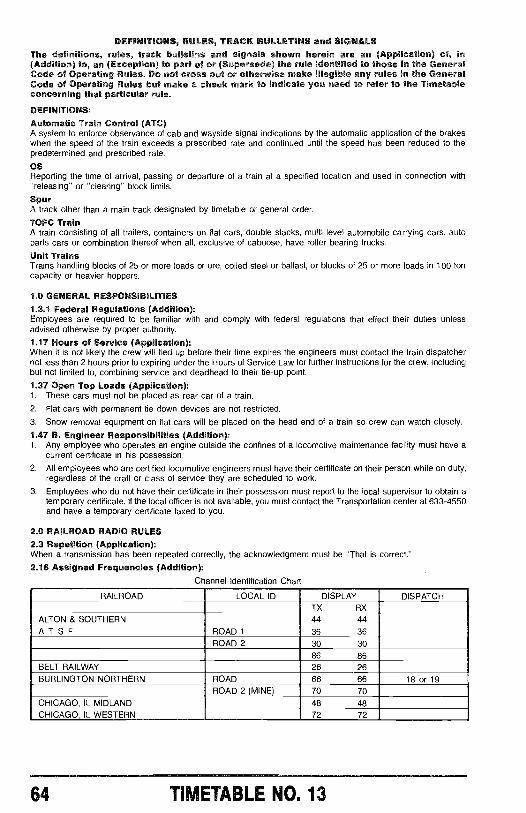
DEFINITIONS, RULES, TRAC BULLETINS and SIGNALSThe definitions,(Addition) to, an (Exception) to part of or (Supersede) the rule identified to those in the GeneralCode of Operating Rules. Do not cross out or otherwise make illegible any rules in the GeneralCode of Operating Rules but make a check mark to indicate you need to refer to the Timetableconcerning that particular rule.
DEFINITIONS:
Automatic Train Control (ATCA system Io enforce observance of cab and wayside u/o"a/mmoati000bymeamvmatioxnnnwati"nofmom"mswhen the speed of the train exceed a prescribed rate and continued until the speed has been reduced to thepredetermined and prescribed rate.
OS
nom°om° arrival, nuasmov,u^nuummatmmuon^moou/ov*/vn and used mwnn°m/onwuxre/°uomu'o,''o/ou,/no'' block limits.
SpurA track other than a main track designated by timetable or general order.
TOFC TrainA train consisting of all trailers, containers on flat cars, double stacks, multi-level automobile carrying cars, autoparts cars or combination thereof when all, exclusive of caboose, have roller bearing trucks.
Unit TrainsTrains handling blocks of 25 or more loads or ore, coiled steel or ballast, or blocks of 25 or more loads in 100 toncapacity or heavier hoppers.
1.0 GENERAL RESPONSIBILITIES1.3.1 Federal Regulations (Addition):Employees are required to be familiar with and comply with federal regulations that effect their duties unlessadvised otherwise by proper authority.
1.17 Hours of Service (Application):When it is not likely the crew will tied up before their time espiresires the engineers must contact the train dispatchernot less than 2 hours prior to expiring under the Hours of Service Law for further instructions for the crew, includingbut not limited to, combining service and deadhead to their tie-up point.
1.37 Open Top Loads (Application):1. These cars must not be placed as rear car of a train.
2. Flat cars with permanent tie down devices are not restricted.
3. Snow removal equipment on flat cars will be placed on the head end of a train so crew can watch closely.
1.47 B Engineer Responsibilities (Addition):1. Any employee who operate an engine outside the confines of a locomotive maintenance facility must have a
current certificate in his possession.
2. All em / who are certified locomotive engineers must have their certificate on their person while on duty,regardless of the craft or class of service they are scheduled to work.
3. Employees who do not have their certificate in their possession must report to the local supervisor to obtain atemporary certificate, If the local officer is not available, you must contact the Transportation center at 633-4550and have a temporary certificate taxed to you.
2.0 RAILROAD RADIO RULES2.3 Repetition (Application):When a transmission has been repeated correctly, the acknowledgment must be "That is correct."
2.16 Assigned Frequencies (Addition):Channel Identification Chart
RAILROAD LOCAL ID DISPLAY DISPATCHTX RX
ALTON & SOUTHERN 44 44
ATSF ROAD 36 36
ROAD 2 30 30
86 86
BELT RAILWAY 26 26
BURLINGTON NORTHERN ROAD 66 66 18 or 19ROAD 2 (MINE) 70 70
CHICAGO, IL MIDLAND 48 48
CHICAGO, IL WESTERN 72 72
64 TIMETABLE NO. 13
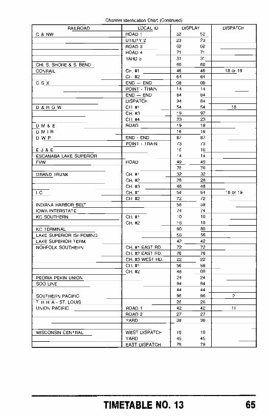
Channel Idenfication Chart (Continued)
RAILROAD LOCAL ID DISPLAY DISPATCH
C & NW ROAD 1 52 52UTILITY 2 23 23ROAD 3 62 62ROAD 4 71 71
YARD 5 31 31
CHI. S. SHORE & S. BEND 60 60
CONRAIL CH. #1 46 46 18 or 19CH. #2 64 64
C S X END - END 08 08
POINT - TRAIN 14 14
END - END 84 84
DISPATCH 94 84
D&RGW CH. #1 54 54 18
CH. #3 19 97
CH. #4 23 23
D M & E ROAD 19 19
DMIR 16 16
D W P END - END 87 87
POINT - TRAIN 73 73
E J & E 16 16
ESCANABA LAKE SUPERIOR 14 14
FVW ROAD 49 4976 76
GRAND TRUNK CH. #1 32 32CH. #2 28 28CH. #3 48 48
I C CH. #1 54 54 18 or 19CH. #2 72 72
INDIANA HARBOR BELT 58 58
IOWA INTERSTATE 74 74
KC SOUTHERN CH. #1 10 10
CH. #2 16 10
KC TERMINAL 80 80
LAKE SUPERIOR ISHPEMING 56 56
LAKE SUPERIOR TERM. 42 42
NORFOLK SOUTHERN CH. #1 EAST RD. 72 72CH. #2 EAST RD. 76 76
CH. #3 WEST RD. 22 22
CH. #1 56 56
CH. #2 48 09
PEORIA PEKIN UNION 24 24
SOO LINE 94 9444 44
SOUTHERN PACIFIC 96 96 2
T R R A - ST. LOUIS 26 26
UNION PACIFIC ROAD 1 42 42 11
ROAD 2 27 27
YARD 38 38
WISCONSIN CENTRAL WEST DISPATCH 10 10
YARD 45 45EAST DISPATCH 79 79
TIMETABLE NO. 13 65
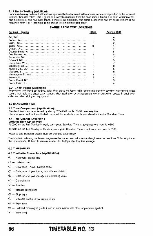
2.17 Radio Testing (Addition):Engine radio may be tested at locations specified below by entering the access code corresponding to the terminallocation, then dial "033 ". This triggers an automatic response from the base station if radio is in good working order.The response is two ring -back tones. It there is no response, wait about 5 seconds and try again. If there is noresponse after 3 or 4 attempts, radio should be considered bad order.
ENGINE RADIO TEST LOCATIONS
Terminal Location Radio Access code
Bill, WY 1 4Boone, IA 1 5Butler, WI 1 2Butler, WI 3 4Clinton, IA 1 1
Council Bluffs, IA 1 5Des Moines, IA 3 5Escanaba, MI 1 7Fremont, NE 1 5Green Bay, WI 1 7Janesville, WI 1 0Kansas City, MO 1 5Madison, IL 1 8Minneapolis /St. Paul 3 2Proviso, IL 3 4South Morrill, NE 1 3South Pekin, IL 1 4
2.21 Chest Packs (Addition):Employees with hand set radios, other than those equipped with remote microphone- speaker attachment, mustsecure that radio in a chest pack harness when getting on or off equipment and, except when seated in engine orcaboose, when riding on equipment.
3.0 STANDARD TIME
3.3 Time Comparison (Application):Standard time may be obtained by dialing 783 -8463 on the CNW company line.The time given will be Coordinated Universal Time which is six hours ahead of Central Standard Time.
3.4 Time Change (Addition):Uniform Time Act of 1966:At 0200 on the first Sunday in April, each year, Standard Time is advanced one hour to 0300.
At 0200 on the last Sunday in October, each year, Standard Time is set back one hour to 0100.
Watches and standard clocks must be changed accordingly.
Track bulletin advising the time change must be issued to conductors and engineers not less than 24 hours prior tothe time change. Bulletin to remain in effect for 6 days after the time change.
4.0 TIMETABLES
4.3 Timetable Characters (Application):
- Automatic interlocking
- Bulletin board
© - Clearance - Track bulletin office
© - Gate, normal position against this subdivision
- Gate, normal position against conflicting route
O - Control point
O - Junction
© - Manual interlocking
U - Stop signs
O - Movable bridge (draw, swing or lift)
- Wye track
O - Railroad crossing at grade (used in conjunction with other appropriate symbol)
Y - Yard limits
66 13
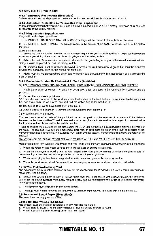
5.0 SIGNALS AND THEIR USE
5.4.1 Temporary Restrictions (Exception)Yellow flags will not be displayed in conjunction with speed restrictions in track bulletin Form A.
5.4.4 Authorized Protection by Yellow -Red Flag (Application):When communicating between train crew and employee in charge in Rule 5.4.4 Territory, reference must be madeto location of the yellow -red flag.
5.4.8 Flag Location (Appplication):Flags will be displayed as follows:
1. ON DOUBLE TRACK OR 2 TRACKS IN CTC -The flags will be placed to the outside of the track.
2. ON MULTIPLE MAIN TRACKS -For outside tracks, to the outside of the track. For inside tracks, to the right ofthe track.
Special Instructions:1. Where the condition to be protected would normally require the yellow -red or red flag to be placed between themain track and siding, they must be placed in advance of the siding switch.
2. Where the end of the restriction would normally require the green flag to be placed between the main track andsiding, it must be placed beyond the siding switch.
3. At junctions, flags must be properly displayed to provide required protection. A green flag must be displayedbeyond the clearance point on the routes not restricted.
4. Flags must not be placed where other cars or trains could prevent them from being seen by an approachingtrain or engine.
5.4.9 Protection Of Men Or Equipment In Yards (Addition):WHEN REMOVING YARD TRACKS AND LEADS FROM SERVICE FOR MAINTENANCE AND REPAIRS:
1. Notify yardmaster or officer in charge the designated track or tracks to be removed from service and thepurpose.
2. Protect the work area as follows:(a) The switches connected to the yard track or to the location on the lead that men or equipment will occupy mustbe lined away from the work area, secured and red ribbon tied to the handles, or;
(b) Rail turned to prevent movements from entering, or;
(c) Derails placed in a manner to prevent other movements from entering, or;
(d) A combination of the above.
The yard track on either side of the yard track to be occupied must be removed from service if the distancebetween center lines is within 20 feet. If removed from service, the switches must be lined against movement to thattrack and a yellow ribbon tied to the switch handles.
Trains or engines must not operate on those adjacent tracks until permission is obtained from foreman in charge ofthe work. The foreman may authorize movement after men or equipment are clear of the track to be used. Whenmovement has been completed, the switches must again be lined against movement to that track and foreman soadvised.
MAINTENANCE OR REPAIR WORK ON YARD TRACKS AND LEADS WHILE THEY ARE IN SERVICE.
Men or equipment may work on yard tracks and yard leads while they are in service under the following conditions:
1. When the foreman has been advised there are no train or engine movements.
2. When an employee is working with a yard engine crew during snow storms or other emergencies and anunderstanding is had that will assure protection of the employee at all times.
3. When an employee has been designated to watch over and govern the entire operation.
4. When the work required will not restrict train and engine movements and can be performed safely.
5.4.10 West End Proviso Hump YardThe procedures below must be followed to lock out the West end of the Proviso Hump Yard when maintenance orrepair work is to be done.
1. Before men or equipment occupy a Proviso hump track that is connected with a power switch, the employeecontrolling the power switches must apply red and yellow tags as requested to the switches controlling movementto the designated tracks.
2. The common must be pulled and switches tagged.
3. The tags must not be removed until informed by engineering employee in charge that it is safe to do so.
5.5 Permanent Speed Signs (Exception):This rule does not apply on the CNW.
5.8.2 Sounding Whistle (Addition):The whistle must be sounded regardless of any whistling ordinance.1. When there is doubt or uncertainty whether or not the whistle should be used.2. When approaching men working on or near the tracks.
TIMETABLE NO. 13 67
3. In emergencies to save life or property,4. When a situation of danger arises which may be lessened or eliminated by sounding of the whistle,
5. When persons are seen crossing the tracks, or walking on the tracks of your train or engine or on adjacenttrack(s),
6. When view is restricted by weather or any other unusual condition,
7. When a train or engine is meeting or passing a train stopping, standing, or starting from a station platform orwhen meeting or passing a train or engine in the vicinity of a grade crossing, whistle will be sounded until theother train or engine has been completely passed -this paragraph is not applicable at stations listed in Rule6.30 item.
8. When necessary for train communication,
9. When GX procedures are in effect except if employee is on the ground protecting the crossing,or
10. When required by other operating rules or special instructions.
5.8.2 (11) Application:The whistle post sign identified as multiple crossings indicates the requirement to sound the whistle at more thanone crossing located close together. Individual whistle post signs will not be displayed for each crossing.
5.13 F. Movement in Engine Service Area (Application):When blue flag protection is removed from one entrance of a track under blue flag protection to allow an engine toenter or leave the engine servicing area, workers on the affected track must be notified before any movement ismade.
6.0 MOVEMENT OF TRAINS AND ENGINES
6.3 Main Track Authorization (Addition):Rule 9.14.2 Controlled Block System (CBS)
6.4.1 Permission for Reverse Movements (Supersede):Reverse movements must not be made without authority from the train dispatcher and if reverse movement will bebeyond the limits of the occupied block, the train dispatcher must be notified when request for reverse movement ismade.
Reverse movements must be made at restricted speed.
6.6 Picking -Up Crew Member (Item 4 Supersede):4. Back -up movements must not be made into control point or interlocking limits.
6.11 Spacing Trains (Exception):This rule does not apply on the CNW.
6.13 Yard Limits (Exception):1. The second paragraph does not apply to scheduled trains operating with the current of traffic in ABS territory.
2. The main track must be cleared at the time a scheduled train is due to leave the nearest station in thedirection of its approach where time is shown.
3. Where yard limits are in effect in CBS territory, the control operator must authorize any movement on themain track.
6.19 Flag Protection (Application):Flagging distance on subdivisions where the maximum speed is above 40 MPH is two miles, where the maximumspeed is 40 MPH or less, one mile.
6.23 Emergency Stop Or Severe Slack Action (Application):For TOFC trains, solid loaded unit trains and ore trains, the following applies when stopped by an emergencyapplication of the brakes and no harsh slack action is experienced incidental to stopping:
1. If brake pipe pressure on rear car has been restored as indicated by rear car gauge or device, leakage testmust be made and be within prescribed limits, then train may proceed without providing inspection on eachside of all cars and units.
2. If brake pipe pressure cannot be restored or leakage test is not within prescribed limits; or if there is harshslack action incidental to stopping; or if train required excessive power to start after stopping; then both sidesof entire train must be inspected.
6.24 Movement on Double Track (Supersede):On double track, train keeps to the left unless otherwise instructed.
6.25 Movements Against The Current of Traffic (Application):Movements against the current of traffic may also be made when authorized by signal indication. Before authorizingsuch movements the track on which the movement is to be made must be clear of opposing trains and: the signalsgoverning conflicting movements must be set to display Stop indication and markers and /or blocking devicesapplied to control machine to prevent clearing signals for a conflicting movement into the track affected.
6.26 Use of Multiple Main Tracks (Application):1. In multiple main tracks territory, unless otherwise specified, track 1 is on the lett facing west /south (timetable
direction) and numbered consecutively to the right.
68 TIMETABLE 0. 13
2. Unless authorized by signal indication, a main track must not be fouled or occupied or crossover movementsmade from one main track to another without authority from the train dispatcher.
3. The use of tracks is designated on subdivision pages.
6.29.1 Trackside Warning Detectors and Inspection (Application):1. Except as provided in item 7.A, avoid stopping train or applying brakes over detector. Avoid transmitting on theradio when approaching and passing radio -equipped detectors. These detectors can identify hot journals, hotwheels, and dragging equipment.
2. Train must stop when notified that inspection is required. When stopping for a hot journal, good judgment mustbe used as to what type of braking to use. Train should be stopped with either a light air brake application and /orwith dynamic brake.
After stopping and trainman has detrained, train may pull forward as directed by trainman, except when detectorhas stated, "You have a hot journal, stop your train," (7.A)
3. Locate the car and axle with the defect. The mechanical counter must be used. Detectors announce eachdefect by axle count starting with the lead axle on the lead unit. Wheel reports or train consists must not be used tolocate the car. Visually inspect entire truck for hot journal, hot wheels, hand brake set, broken bolster, broken truckside, loose wheel, fouled brake rigging, sticking brakes etc. On friction bearing cars, open journal box cover andcheck for loose bearing material, lead, smoke, odor, insufficient lubricant or burned lubricator.
4. Inspection with temp stick must be made on both sides of the car on which a defect is indicated. If the defect isnot found on that car, both sides of the 3 cars ahead and 3 cars behind the car with the defect must be inspected.When temp stick is used, apply to the front face of the roller bearing adapter and on wheel hub of roller bearingcars; and to the front edge of journal bearing and on wheel hub of friction bearing cars. If a liquid smear results, setout the car.
5. When the defect is located and cannot be corrected, or if car cannot be handled safely, it must be set out. Whentaking car to set out point, watch closely and do not exceed 10 MPH.
6. If another detector indicates a defect on the same car, a qualified conductor must inspect the car and, ifnecessary, the 3 cars ahead and 3 cars behind that car. If a third inspection on the same car is required, the carmust be set out.
7. Examples of Detector Messages Train Crew ResponseA. Hot Journals.
"You have a hot journal, stop your train."(While passing detector)
B.
C.
D.
E.
Other Defects."You have a defect"(While passing detector)
Inoperative System.(1) "Integrity Failure."
(2) "Integrity Failure" combined with defectmessage.
(3) "Cold train, no defects." or, "Cold train (direction)side, no defects."
(4) "Cold train." or "Cold train (direction) side,"combined with defect message.
Defective Message:"Hot journal at axle (number) (Direction) side""Hot wheel at axle (number).""Hot wheels from axle (number) to axle (number).""Dragging equipment near axle (number)."
No Message Be governed by paragraph 8.
This indicates an extremely hot journal. Stop atonce and be alert for further message which willspecify defects. If further message is not received,inspect entire train. Train must not be moved afterstopping.
Complete movement over detector, prepare to stopmovement and receive defect message.
Part of the system is inoperative, be governed byparagraph 8.
Part of the system is inoperative. Defects given withmessage must be inspected.
Part of the system is inoperative. Trains are gov-erned by paragraph 8.
Part of the system is inoperative. Defects given withmessage must be inspected.
8. Freight trains must stop and inspect entire train if a message C(1) or C(3) is received from two consecutivedetectors or if detectors have failed completely, unless a visual inspection of train can be made within 10 miles fromsecond detector. Speed must not exceed 30 MPH until inspection completed. When message C(3) is received, onlythe cold side of the train need be inspected.
Passenger trains are not required to stop in response to messages C(1) or C(3), but crew members must, inaddition to frequently inspecting their train while moving, make a visual observation of their train as time will permitat station stops.
9. In the application of paragraph 6 or 8, the detectors may be on different subdivisions, crew districts or traindispatching territories, therefore, train dispatchers and conductors must communicate information relative to inoper-ative detector or defective car to one another.
TIMETABLE NO. 13 69
10. If hot wheels are detected on a business car and if no other defects are detected, the officer in charge mayauthorize train to proceed without stopping.
11. When a detector reports defects on a unit, the engineer must inspect the entire truck for fouled brake rigging,brake shoes dragging on wheel or hand brake set; feel the gear case with gloved hand. If no unusual heat isdetected, feel those parts carefully with a bare hand. If any of the above are noticeably hotter than others, set out theunit unless it can be moved safely.
12. Results of all inspections required by detectors must be reported to the train dispatcher. These results toinclude the axle counts inspected, car number, location and nature of defect, if any, disposition of car and length ofdelay. Identification of journals is made by facing the hand brake, those on the left are L -1, L -2 etc., and those onthe right are R -1, R -2 etc.
6.29.2 Train Inspection by Crew Members (Applications):At meeting points or at other locations where a train is going to be delayed more than 30 minutes a walkinginspection of the train must be made.
6.30 Receiving or Discharging Passengers (Applications):On the Kenosha, Harvard and Geneva Subdivisions, the following will govern:
1. Passenger trains must not enter a station at which another passenger train is stopped to receive or dischargepassengers until first bringing train to a stop, after which they may proceed with caution to or through the platform,ringing bell and sounding whistle. When a train is "laying back" to delay entering a station, the train laying backmust not enter that station until the departing train has cleared the platform area and the platform area can beplainly seen.
2. When two passenger trains are nearing a station at the same time and only one of them is scheduled to stop,the train to stop must not enter the station until the other train has cleared the platform area and the platform areacan be plainly seen.
3. When two passenger trains are nearing a station at the same time and both are scheduled to stop, both trainsmay enter simultaneously. They must enter the station with caution ringing the bell and sounding the whistle whennecessary.
When passenger trains cannot enter together the less important train must allow the more important train to enterfirst. Eastward trains have preference from midnight until noon, and westward trains have preference from noon untilmidnight.
4. Freight trains must make every effort, consistent with safety and efficient train handling, to avoid passing astation at which a passenger train has stopped to receive or discharge passengers until the passenger train hascleared the platform area and the platform area can be plainly seen. If this cannot be avoided, the whistle must besounded as a warning until front of the freight train has passed through the platform area.
If freight trains stop or become disabled at station platforms at or near scheduled times of passenger trains, theengineer will, when possible, contact commuter control BEFORE train is moved so that public address announce-ments can be made to inform public to stand clear. Required whistle signals must be sounded BEFORE anymovement is made.
5. The engineers of trains involved in the above will communicate by radio with the other trains to plan themovements.
6. A street or road crossing adjoining or immediately adjacent to the station platform will be considered a part ofthe platform or platform area.
7. The provisions of paragraphs (1) through (4) above do not apply at Kedzie, Oak Park, River Forest, WestChicago, Clybourn, Jefferson Park, Ravenswood, Rogers Park, Main St. Evanston, Central St, Indian Hill, Winnetka,Hubbard Woods, Great Lakes and Kenosha.
6.32.1 Cars Shoved, Kicked or Dropped (Application):Employee must have an unobstructed view of at least 300 feet in both directions to be assured no traffic isapproaching.
6.32.2 Automatic Crossing (Addition):At public crossings designated in the timetable, track bulletin, or general order, trains must not obstruct that crossinguntil;1. It is known that automatic crossing warning devices are working2. Vehicular and pedestrian traffic has stopped or3. That the crossing is protected by a member of the crew or other employee, on the ground at the crossing, untilfront of movement has passed over the crossing. At night, if crew member is on the ground, he will display lightedfusees, which will be left on each side of the crossing.
Track bulletin Form GX will be issued when necessary to identify crossings not designated in timetable or specialinstructions.
6.32.4 Clear of Crossing and Signal Circuits (Addition):State law require the following clearance:500 feet in Illinois, 300 feet in Wisconsin.
70 TIMETABLE NO. 13
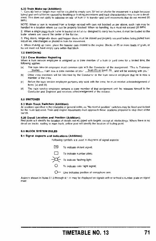
6.33 Train Make -up (Addition):1. Cars 80 feet or longer must not be coupled to empty cars 39 feet or shorter for movement in a train becauselateral and vertical forces caused by throttling or braking procedures and track characteristics may cause a derail-ment. This does not apply to caboose on rear of train or to transfer and yard movements that do not exceed 20MPH.
NOTE: When a train is received from a foreign railroad with cars not blocked as per above, such train may behandled to a location where car can be properly blocked. When so handling, train must not exceed 20 MPH.
2. When a single piggy -back trailer is loaded on a flat car designed to carry two trailers, it must be loaded so thetrailer wheels are toward the center of the flat car.
3. Plug doors, refrigerator doors and hopper doors must be closed and properly secured before being pulled fromindustries, interchanges or placed in train for movement.
4. When making up trains, place the heavier cars closest to the engine. Blocks of 25 or more loads of grain, orballast must not have empty cars within that block.
7.0 SWITCHING
7.2.1 Crew Member ReportingWhen a train service employee is assigned as a crew member of a train or yard crew for a limited time, thefollowing applies:
(a) The train service employee must communicate with the Conductor of the assignment: "This is Trainman(name) I am now a crew member of your (train ID) or (yard ID) and will be working with you."
(b) Other crew members will be informed by the Conductor or the train service employee that he is now amember of the crew.
(c) Before the train service employee performs any work with the crew, he must receive acknowledgement ofItems (a) and (b).
(d) The train service employee remains a crew member of that assignment until he releases himself to theConductor and Engineer and receives acknowledgement of the release.
8.0 SWITCHES
8.3 Main Track Switches (Addition):At locations specified in the timetable or general order, as "No normal position" switches may be lined and lockedfor the route last used. Train and engine movements must approach these locations prepared to stop short of theswitch.
8.20 Derail Location and Position (Addition):Red posts will identify the location of derails not equipped with targets, except at interlockings. Where there is noderail on tracks leading to main track, yellow post will identify the location of fouling point.
9.0 BLOCK SYSTEM RULES
9.1 Signal Aspects and Indications (Addition):Following symbols are used in diagrams of signal aspects:
0 To indicate distant signal;
To indicate number plate;
To indicate flashing light;
O To indicate color light signal;
0- Line indicates position of semaphore arm.
Aspects shown in Rules 9.1.3 through 9.1.11 may be displayed on signals with or without a number plate on signalmast.
TIMETABLE NO. 13 71
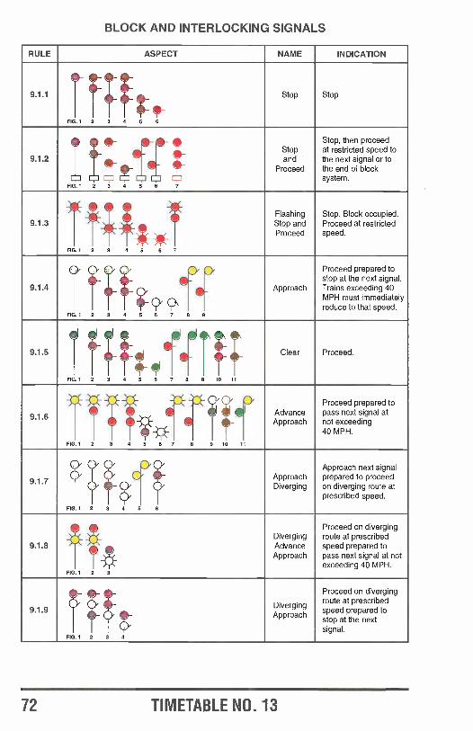
BLOCK AND INTERLOCKING SIGNALS
RULE ASPECT NAME INDICATION
9.1.1 ID- f ; Stop Stop
FIG. 1 2 3 4 5 6
StopStop, then proceedat restricted speed to
9.1.2 /- fi JET iFIG.1 2 3 4 5 6 7
andProceed
the next signal or tothe end of blocksystem.
Flashing Stop. Block occupied.9.1.3
-4 TT__Ft_7,
I
Stop andProceed
Proceed at restrictedspeed.
Fla 1 2 3 4 5 6 7
Proceed prepared to
stop at the next signal.9.1.4 for Approach Trains exceeding 40
MPH must immediatelyreduce to that speed.
FIG.1 2 3 4 5 6 7 8 9
9.1.5 4r Clear Proceed.
FIG.1Y
2 3 4 5 6 7 8 9 10 11
Proceed prepared to
9.1.6á
AdvanceApproach
pass next signal atnot exceeding
FIG.1 2 3 4 5 6 7 J8 10 11
Approach next signal
9.1.7ApproachDiverging
prepared to proceedon diverging route atprescribed speed.
FIG.1 2 3 4 5 6
Proceed on diverging
9.1.8
FIG.
-3;
1 2 3
DivergingAdvance
Approach
route at prescribedspeed prepared topass next signal at notexceeding 40 MPH.
7 ; Diverging
Proceed on divergingroute at prescribed
preparedspeed reared toApproach
stop at the nextsignal.
FIG.1 2 3 4
72 TIMETABLE NO. 13
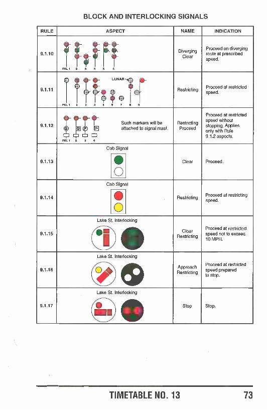
BLOCK AND INTERLOCKING SIGNALS
RULE ASPECT NAME INDICATION
9.1.10
FIG.1 2 3 4 5 6
DivergingClear
Proceed on divergingroute at prescribedspeed.
9.1.11
FIG.1 2 3 4
LUNAR --4,
speed.
T Q5 6 7 8 9
estrictingProceed at restricted
9.1.120-
FIG.1 2
] P
3 4
eSuch markers will be] attached to signal mast.
RestrictingProceed
Proceed at restrictedspeed withoutstopping. Appliesonly with Rule9.1.2 aspects.
9.1.13
Cab Signal
Clear Proceed.QO
9.1.14
Cab Signal
RestrictingProceed at restrictingspeed.
9.1.15.
Lake
Q
-
St. Interlocking
OClear
Restricting
Proceed at restrictedspeed not to exceed10 MPH.
9.1.16
Lake St. Interlockingspeede;)ApproachRestricting
Proceed at restrictedprepared
to stop.
9.1.17
Lake St. Interlocking
Stop Stop.
IQ
TIMETABLE NO. 13 73
9.4 Improperly Displayed Signals or Absent Lights (Application):In ATC territory the cab signal will govern if the light is absent or a white light is displayed on a block signal. If thatsignal governs a diverging route the train must approach prepared to diverge.
9.7 Failure to Display Most Restrictive Indication (Addition):The following is required
1. Each crew member must provide a written statement to a supervisor of all facts concerning the incident prior togoing off duty. This information must include:a. Reason signal should have been more restrictive (block occupied, switch open, etc.,) and all signal aspects
involved.b. Exact location of signal. (Engine in ATC territory).c. The time, speed and particular train movements taking place.d. Other train movements in the area and position of switches that could affect the signal system.e. Weather conditions.
2. Conductor must contact the train dispatcher before going off duty to ascertain whether additional information isneeded.
3. The train dispatcher must notify all concerned and arrange for removal of event recorder information, if engineis so equipped.
9.10 Initiating Movement between Signals (Exception):In ATC territory the train may proceed according to cab signal indication.
9.12.2 Manual Interlocking (Application):During the time of the year that the navigation season is closed the drawbridges will be lined and locked for therailroad route. If the signal that governs movement over the bridge displays a Stop indication a crew member mustvisually verify the bridge is in the proper position for the train to pass. The train dispatcher must be contacted andobtain permission to proceed. The train may then proceed at restricted speed not to exceed 5 MPH until entire trainis over the bridge.
9.13 Dual Control Switches (Addition):When the control operator verbally authorizes movement the following words will be used: "(Train) at (Location) youmust operate switch(s) by hand per Rule 9.13.1 for (specify route). You have authority to pass signal display-ing Stop."
When a following train is to use the same route as the train ahead and the control operator has instructed the trainahead to leave the switches in hand position or if the switches have been lined by hand and left in hand position bya qualified employee the train may be instructed to proceed at restricted speed after stopping.
9.14 Movement with Current of Traffic (Addition):A train having received its clearance may proceed with the current of traffic.
9.14.2 Controlled Block System (CBS) (Addition):On designated tracks specified in the timetable train movements will be authorized by a controlled signal indicationor verbal authority from the control operator. The control operator must verify that conflicting movements are pro-tected before giving authority. The authority will establish the current of traffic on tracks designated for movement inboth directions.
A train must not enter or occupy any track within CBS limits unless:
a. A governing signal displays a proceed indication.or
b. Verbal authority is granted. Waiting 5 minutes per Rule 9.17 (Entering Main Track at Hand -Operated orSpring Switch) is not required within CBS limits.
A movement must proceed only in the direction authorized unless:
a. Authority granted is Rule 9.15 (Track Permits).b. Movement is made on signal indication.
orc. Authority granted stated movement may be made in both directions in the occupied block.
A movement that clears any track within CBS limits must not reenter that track without new authority unless:a. The switch is left open.b. The movement reenters the track at that opened switch.
9.15 Track Permits (Application):A track permit does not authorize movement within interlocking or control points limits unless the train dispatcher sodesignates by stating "including (name) interlocking /control point limits."
9.17 Entering Main Track at Hand Operated or Spring Switch. (Addition):A switch must not be opened to a main track when the semaphore arm is horizontal or the disc is visible in theindicator. If after five minutes, no movement is approaching, Rule 9.17 second paragraph applies.
9.18.1 Authority to used Electrically Locked Switches (Addition):When authorized to use an electrically locked switch, remove the switch lock and:
1. On those equipped with a foot pedal, depress the pedal and when the light comes on, operate the switch lever.If the light does not come on, it may be that the light is burned out, try to operate the switch lever anyway to see if itis released. If it is not released, there is a timing period (maximum 10 minutes), after which light should come on.(Do not remove the `Press the Release" lever during the timing period).
74 TIMETABLE NO. 13
2. On those equipped with electric lock cabinet, open the door and the indicator should show "unlocked" and if so,move the unlocking handle completely to the left and operate the switch. If the indicator shows "locked ", move theunlocking handle to the "request" position and after a specified timing period (maximum 10 minutes), the indicatorshould show "unlocked ". (Do not move the unlocking handle during the timing period).
3. If, after the expiration of the timing period in either 1 or 2, the switch lever is not released, obtain authority fromthe control operator to use the emergency release.
4, When movement is not made immediately after receiving instructions, permission must again be obtainedbefore unlocking the switch or making the movement. The padlock must not be inserted in electric lock until use ofthe switch is completed unless necessary to lock the switch for another movement on the main track.
5. When a train or engine is occupying the main track and it is desired to operate a switch equipped with electricswitch lock for movement from main track to siding or crossover to an adjacent main track the leading truck ofengine or car must be less than 75 feet from switch.
10.0 RULES APPLICABLE ONLY IN CENTRALIZED TRAFFIC CONTROL10.3 Track and Time (Application):1. A track and time permit does not authorize movement within interlocking unless the train dispatcher so desig-nates by stating "including (name) interlocking /control point limits.
2. When part of a track and time permit is released, that part of the permit becomes void and that portion of thetrack must not be reentered.
11.0 RULES APPLICABLE IN ACS AND ATS TERRITORIES (Exceptions):On the CNW these rules apply in other territories.
11.2 Signal Indications Within Absolute Block (Addition):When an absolute block in advance of movement is established and signal indications are used to maintain theabsolute block in advance of movement, the dispatcher must ascertain from the engineer that the train is proceed-ing on a clear block signal; and be assured that conflicting movements will not enter the track effected. A blocksignal displaying a proceed indication other than one requiring movement at restricted speed continues to establishan absolute block in advance of movement to the next block signal.
12.0 RULES APPLICABLE ONLY IN AUTOMATIC TRAIN STOP SYSTEM (ATS) TERRITORY(Supersedes):Rules in Section 12 of the General Code do not apply on the CNW. The following rules apply:
12.1 Automatic Train Stop Territory:ATS territory is specified in special instructions. An engine must not be operated in ATS territory if it is not equippedwith an operable automatic train stop system unless otherwise authorized by special instructions or the train dis-patcher.
12.1.2 ATS Seals and Keys:An ATC numbered seal will be used to seal the ATS in freight service. An ATS key will be used in passengerservice. The ATS must be sealed /locked for the type of service engine is to be used in, i.e., passenger or freight.When service requirements are changed enroute, engineer must change the position of the change -over lever andnotify the train dispatcher.
12.2 Taking Charge:Engineers must know, before taking charge of an engine equipped with ATS in automatic train stop territory orentering such territory, that the ATS system is "cut -in" and sealed.
When an engineer applies an ATS seal, he must report the number of that seal to the train dispatcher.
The ATS system or any part of it must not be cut out while operating in ATS territory unless authorized by the traindispatcher or when it has failed.
12.3 Cut -in and Cut -out Information:
12.3.1 Cut -in ATS:1. Air brake system must be charged.2. Close switch to start motor -generator set.3. Cut in ATS cut -in cock, push in plunger and lock with key and /or seal it.4. Operate reset lever to full opposite positon.
12.3.2 Cut -out ATS:1. Unlock with key and /or break seal, pull out plunger and cut out cut -out cock.2. Open switch to stop motor -generator set.
12.4 Departure Test Procedures:
12.4.1 Inductors:At test inductor locations, move the engine at 2 MPH or more. Hold acknowledging lever in full position for not over15 seconds to determine that acknowledging whistle sounds and that a brake application does not occur.
At locations where there are two test inductors, move the engine over the second one at 2 MPH or more and do notacknowledge the acknowledging whistle. A brake application will occur. Operate reset lever to full opposite positionand release the brakes.
TIMETABLE NO. 13 75
12.4.2 No Inductors:At locations where there are not ATS inductors, a pass under the ATS receiver must be made with test bar whilethe acknowledging lever is held back. The acknowledging whistle should sound. Another pass must be made afterthe acknowledging lever is released. A brake application should occur and the brakes may be released.
12.4.3 Commuter Operations:1. When changing ends on suburban trains, leave the generator set ON.2. At M19A, after the departure test has been completed, the actuator may be cut out, but the electrical switch
must be left on.
12.4.4 Reporting Test:Report Departure Test as required by Rule 13.11 (Departure Test Reporting).
12.5 ATS Procedures:When a block signal displays an indication other than proceed, place the acknowledging lever in the acknowledg-ing position before engine passes inductor. Hold it there until the acknowledging whistle stops sounding.
12.6.1 Penalty Application:A penalty brake application will occur if acknowledgment is not made when required. If a penalty brake applicationdoes occur, wait until the brakes are fully applied then operate the reset lever. Brakes may be releasd after theexpiration of 60 seconds in passenger service and 120 seconds in freight service.
12.5.2 Cars Ahead:Acknowledgment must be made at each inductor when engine is shoving cars, snow plow or other equipment.
12.6 ATS Failures:The ATS device or any part of it must not be cut out unless it has failed. When through failure of the engine device,it becomes necessary to cut out ATS device, the engineer must immediately notify the conductor and the traindispatcher. After cut out is completed train or engine will proceed being governed by automatic block signal indica-tions. Train or engine must not exceed 40 MPH until the train dispatcher is notified and his instructions received.
12.6.1 Two Penalty Applications:When two successive penalty ATS brake applications have occurred while passing over inductors at signals dis-playing Proceed, engineer must acknowledge at each succeeding inductor thereafter, regardless of signal indica-tion, and report to the train dispatcher.
If acknowledging at succeeding inductors does not prevent penalty stops, the ATS device will be considered asfailed.
12.6.2 Whistle Failure:If the acknowledging whistle fails to sound when acknowlegement is made over an inductor at a wayside signalindicating other than Proceed, or if brakes do not apply upon failure to acknowlege such indications, it must beconsidered as failed.
12.6.3 Damaged Receiver:When the absence of, or damage to, an ATS receiver is noted, it must be considered as failed.
12.6.4 Damaged Inductor:Engineers noting the absence of or damage to a wayside inductor in approach to a signal must report same to thetrain dispatcher.
The train dispatcher must immediately call the signal maintainer and instruct him to cause the signal to display itsmost restrictive indication until inductor is replaced or repaired.
12.7 Train Dispatcher Directions:When advice is received as to failures, the train dispatcher will direct the conductor and engineer on what basis toproceed.1. To continue to proceed not to exceed 40 MPH to location where an engine with ATS will be provided.
or2. Establish an Absolute Block in Advance of Movement per Rule 11.1 (Establishing Absolute Block) and Rule
11.2 (Signal Indications With Absolute Block).
When operating under absolute block in advance of movement with ATS cut out and with automatic block signalsworking properly, train and engine may proceed being governed by the indications displayed and .in accordancewith timetable rules. Passenger trains must not exceed 70 MPH and freight trains must not exceed 59 MPH.
13.0 RULES APPLICABLE ONLY IN AUTOMATIC CAB SIGNAL SYSTEM ACS TERRITORY (Super-sedes):Rules in Section 13 of the General Code do not apply on the CNW. The following rules apply.
13.1 Automatic Train Control Territory:ATC territory is specified in special instructions. An engine must not be operated in ATC territory if it is not equippedwith an operable automatic train control system unless otherwise authorized by special instructions or the traindispatcher.
13.2 Taking Charge:Engineers must know, when taking charge of an engine equipped with ATC in automatic train control territory orentering such territory, that the ATC system is "cut -in" and sealed with an ATC numbered seal.
In addition the following must be sealed with a mechanical seal:1. Speedometer case2. Speedometer cables3. High speed whistle cut -out cock
76 TIMETABLE NO. 13
The ATC system or any part of it must not be cut out in ATC territory unless authorized by the train dispatcher orwhen it has failed. The train dispatcher may issue authority to cut -out the ATC only when it has failed or whenrequired for movements against the current of traffic, in connection with track bulletin Form DS.
13.3.1 Cut -In ATC:1. Pump the air to full pressure.2. Close switch to start motor -generator set.3. Out in ATC cut -in cock, push in plunger and lock with key and /or seal it.4. Acknowledge when acknowledging horn sounds.
13.12 Cut -out ATC:1. Unlock, pull out plunger or break seal and cut out ATC cut -out cock.2. Open switch to stop motor -generator set.
If the ATC is cut -out due to failure enroute, the engineer must, at the next stop, make necessary checks to deter-mine if it is again operable.
114 Departure Test Procedures:13.4.1 Energized Test Loop:When engine is standing on energized test loop the cab signal should display a Clear signal. When the test loop isde- energized or when the engine is moved off of the test loop, the aspect will change to a Restricting signal and theacknowledging horn will sound. Do not acknowledge the horn and do not move the brake valve handle. An auto-matic brake application should occur within 8 seconds. Move the brake valve handle to suppression until the P.C.light has gone out The brakes may then be released. When the acknowledging horn again sounds, acknowledge toprevent brake application,
13.4.2 De- energized Track:When engine is standing on de- energized track (dead track), release the brakes. Do not acknowledge the acknowl-edging horn. An automatic brake application should occur. Move the brake valve handle to suppression until theP.C. light has gone out. The brakes may then be released. When the acknowledging horn again sounds, acknowl-edge to prevent brake application.
Exception: In the Chicago passenger terminal, if the test is being performed on de- energized track as describedabove, after the brakes release, move over the test loop and acknowledge the acknowledging horn when moving offof the test loop to prevent brake application.
114.3 Receivers on Both Ends:When an engine has ATC receivers on both ends and is standing on energized track (live track), the cab signalshould display a Clear signal. Place the reverser in the "reverse" position which will result in the aspect changing toa Restricting signal and the sounding of the acknowledging horn. Do not acknowledge and do not move the brakevalve handle. An automatic brake application will occur. Move the brake valve handle to suppression until the P.C.light has gone out. The brakes may then be released. When the acknowledging horn again sounds, acknowledge toprevent brake application.
13.4A Cab Cars:When a cab car is on energized track, the cab signal should display a Clear signal. Hold down the test button.Repeat the underlined. After the brakes have released hold the test button down a second time, when acknowleginghorn sounds, acknowledge to prevent brake application.
13.42 Departure Test Procedure GE 040 -8, C42 -8 and C44 -9W and EMD SD6OM Locomotives:The ATC departure test may be made as follows on locomotives equipped with solid -state Union Switch & SignalATC /CCS equipment.1. Locomotive must be standing on dead track with independent brake fully applied and automatic brake released.2. Generator field switch must be on, reverser must be in Forward position, and signal circuit breaker must be on.3. Place CNW Cut -Out switch in Cut -In position.4. Place CNW Cutout Cock in Cut -In position and seal with ATC seal.5. Departure test box must be opened and test switch placed in On position. ATC system begins internal testing
during which the Clear and Restricted aspects are turned off and motion light flashes.6. After internal test is complete, approximately 10 seconds, Clear aspect is turned on and engineer must press
and release the acknowledge button. Clear aspect is then turned off.
The system then turns on the Restricted aspect and engineer must press and release the acknowledge button.Restricted aspect is then turned off.
7. Next the system drives the speedometer to locate the setting of the Union Pacific overspeed within the spee-dometer. The speedometer is driven to the overspeed point four times. The system will then drive the speed-ometer to the CNW Restricted overspeed of 23 MPH. The Restricted aspect is turned ON and the engineermust press and release the acknowledge button.
The system then drives the speedometer to the CNW overspeed setting. The Clear aspect is turned on andacknowledge alarm is activated. Engineer must press and release acknowledge button. The Clear aspect isturned off and speedometer is returned to 0 MPH.
8. The engineer must then fully release independent brake, acknowledge alarm is activated (do not acknowledge)and penalty brake application will occur. Engineer must then press and release the acknowledge button.
9. The system will indicate successful completion of the departure test by continuously beeping the overspeedalarm and flashing all lights. Engineer must then place the Departure Test Switch to Off position.
10. If the locomotive is to be operated in non -ATC territory before entering ATC territory, the engineer must thenpush the Arm button that is located next to the Departure Test Switch.
TIMETAA 3. 13 77
11. If departure test is unsuccessful, the engineer can repeat the test. If the test is again unsuccessful, an ATCdeparture test as prescribed by Rule 13.4.1 or 13.4.2.
13.4.6 Departure Test Procedure MICROCAB System:1. Turn on the DEPT TEST SWITCH.
All ADU aspects are extinguished. The MOTION indicator is flashed throughout Departure Test. The overspeedalarm is activated intermittently for approximately 1 second then silenced to indicate the start of the test.
The system delays approximately 6 seconds before proceeding to the next step. The overspeed alarm isactivated intermittently for approximately 1 second then silenced to indicate the end of the delay.
The system simulates a 100 Hz steady carrier signal at a level above the calibrated threshold. It allows up to 5seconds for the carrier to be detected. Detection of the carrier causes the Clear aspect to be illuminated. Theacknowledge alarm is activated continuously upon either detection of the carrier or failure to detect the carrierafter the time period.
The operator must press and release the acknowledge switch. Failure of the operator to respond within6 seconds results in a penalty brake application.
2. The system simulates a 100 Hz steady carrier signal at a level below the calibrated threshold. It allows up of 5seconds for the carrier loss to be detected. Detection of the loss of carrier causes the Clear aspect to beextinguished and the Restricted aspect to be illuminated. The acknowlege alarm is activated continuously uponeither the loss of carrier or the presence of the carrier after the timer period.The operator must press and release the acknowledge switch. The Restricted aspect is then extin-guished. Failure of the operator to respond within 6 seconds results in a penalty brake application.
The overspeed alarm is activated intermittently for approximately 1 second, then silenced to indicate the com-pletion of carrier tests.
3. The system then drives the speedometer to the Clear trip speed. It is the responsibility of the operator to visuallyconfirm that the expected speed ( +3, -1 MPH) is displayed by the speedometer. The acknowledge alarm isactivated continously. The operator must press and release the acknowledge switch.
4. The system then drives the speedometer to the restricted trip speed of 23 MPH. It is the responsibility of theoperator to visually confirm that the expected speed (' 1 MPH) is displayed by the speedometer. The acknowl-edge alarm is activated continuously. The operator must press and release the acknowledge switch.The system stops driving the speedometer and it returns to a reading of 0 MPH. The overspeed alarm isactivated intermittently for approximately 1 second then silenced to indicate the confirmation of the test.
5. The system waits indefinitely for the operator to press and release the acknowledge switch. Uponrelease of the switch, the overspeed alarm is activated intermittently for approximately 1 second then silencedto indicate the start of a penalty delay.
Within approximately 6 seconds of the alarm, the system initiates a penalty brake application by de- energizingthe EPV output. The acknowlege alarm is activated continuously. It is the responsibility of the operator toconfirm that a penalty brake application physically occured.
In order to silence the alarm and proceed, the operator must press and release the acknowledgeswitch. This also re- energizes the EPV output.
6. Successful completion of the Departure Test is indicated by the system activating the overspeed alarm intermit-tently until the DEPT TEST SWITCH is turned offf.Turn off the DEPT TEST SWITCH. On the ADU only the Restricted aspect is illuminated. All other indicatorsare extinguished. The acknowledge and' overspeed alarms are silent.
Following a successful Departure Test, the system may be armed by the operator pressing and releasing theARM SWITCH.
13.5 ATC Test Locations:On engines equipped with an automatic ATC cut -in circuit, the cab signal will display a Clear signal when passing a"B" sign (Beginning ATC test section) and the speed whistle will sound for 3 or 4 seconds. The cab signal willchange to a Restricting signal when the "E" (End ATC test section) is passed. When speed exceeds 40 MPH, thehigh speed whistle will sound until a Clear signal is displayed. When it is below 40 MPH, the acknowledging hornwill sound at which time it must be acknowledged.
13.5.1 Automatic Cut -in Circuit:The ATC actuator will be cut in and sealed on engines equipped with the automatic ATC cut -in circuit. The gover-nor motion light will be illuminated enroute to ATC territory at speeds of 6 MPH or more. Other cab signal aspectswill be extinguished.
Engines not equipped with the automatic ATC cut -in circuit must stop and perform the departure test before enter-ing ATC territory.
13.6 High Speed Setting of The Governor:When a cab signal displays a Clear signal and the speed of the train exceeds the high speed setting of thegovernor, a high speed whistle will sound continuously which will require a full service brake application within 6seconds to prevent a penalty brake application.
78 TIMETABLE NO. 13
13.6.1 Over 40 MPH:The high speed whistle will sound when the speed is over 40 MPH at the time the cab signal changes to aRestricting signal. The engineer must, within 6 seconds, move the brake valve handle to full service application toprevent a penalty brake application. When speed is reduced to under 40 MPH the high speed whistle will stop andthe acknowledging horn will sound. The engineer must acknowledge the acknowledging horn. The speed must bereduced to restricted speed within 70 seconds from the time the acknowledging horn was acknowledged.
13.6.2 Under 40 MPH:The acknowledging horn will sound if the cab signal changes from Clear to Restricting when the speed is under 40MPH. The engineer must acknowledge the acknowledging horn within 6 seconds to prevent a penalty brake appli-cation. Within 70 seconds the speed must be reduced to restricted speed.
13.6.3 Restricting Signal:While the cab signal displays a restricting signal the acknowledging horn will sound approximately every 90seconds to alert the crew members of the restriction. When the speed is approaching the low speed setting, the lowspeed whistle will sound intermittently to alert crew members that speed must be reduced.
13.7 Cab Signal, Block and interlocking Signals:Cab signal indications do not supersede the indication displayed on block and interlocking signals, except whencab signal changes from Restricting to Clear after train has passed a block signal or when initiating movement,speed may be increased at once.
13.7.1 Approaching Diverging Route:When the cab signal changes from restricting to clear after engine passes a signal displaying an Approach or amore restricting indication and the next signal can display an indication for a diverging route, the train mustapproach the next signal at the speed prescribed for the most restrictive route at that location unless the signal isseen to display an indication for a more favorable route in which case the speed for that route governs.
13.8 ATC Failure /Cut -out Enroute:When the ATC system is "cut -out" enroute due to failure or when authorized by the train dispatcher, movement ofthe train is governed as follows:
1. By the indication displayed on block signals or, on cab signals it they are operable, but not exceeding 40 MPHuntil an absolute block in advance of movement is established by the train dispatcher. When so established, themaximum speed is 70 MPH for passenger trains and 59 MPH for freight trains.
2. If cab signals are not operable and there are not continous block signals, train must proceed at restricted speeduntil an absolute block in advance of movement is established by the train dispatcher. When so established, themaximum speed is 40 MPH except the maximum speed for passenger trains and TOFC trains is 59 MPH in CTCterritory and 49 MPH in other territory.
13.8.1 Speed Indicator:An inoperative or inaccurate speed indicator, as prescribed by Rule 1.39 (Accuracy of Speed Indicator), is consi-dered an ATC failure.
13.8.2 Governor Motion Light:If the governor motion light is not on when the speed is 6 MPH or above, proceed in accordance with Rule 13.8paragraph (1).
13.9 Improper Display of Cab Signal:When a cab signal displays a Clear signal when it should display a Restricting signal aspect due to an open switch,occupied block, or other condition, the train must stop and warn other trains by radio of exact location and status oftrain. Contact the train dispatcher and be governed by his instructions. Rule 9.7 (Most Restrictive Indication, Addi-tion) applies. If the train dispatcher gives permission to proceed train must proceed at restricted speed until anabsolute block in advance of movement is established by the train dispatcher after which the maximum speed is 40MPH.
The train dispatcher must issue the following restriction to trains that have not been issued an absolute block inadvance of movement:"Proceed at Restricted Speed between and account defective ATC system."When notified of improper cab signal display, the train dispatcher must make a record of the indications displayedin CTC territory, leave the switches in same position if possible, obtain pertinent information from the crew reportingthe defect and notify the signal supervisor.13.10 Sperry Rail Detector Cars:Sperry Rail Detector cars, except when testing, must operate under absolute block in ATC territory.
13.11 Departure Test Reporting:Records made in connection with the performing of ATC and ATS tests must be retained for 92 days and a formshowing certain information in connection with those tests must be placed in the engine cab. The procedures belowapply:
1. Motive Power Department will fill out forms 41 -06036 and 41- 00400. Form 41 -06036 must be retained at the testlocation for 92 days. Form 41 -00400 must be placed in the inspection holder in the engine cab.
2. At points where engineers are required to perform ATC or ATS departure tests, engineers must fill out Form41- 00402, sign it, place it in the inspection holder of the engine and notify the trains dispatcher. Crew members arenot to remove this form unless specifically instructed to do so.
TIf r:ET'a(-ILE NO. 13 79
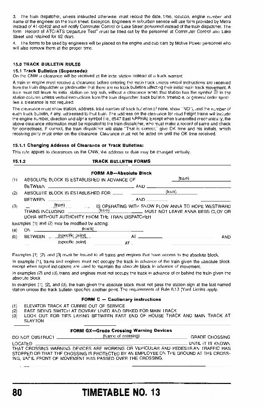
3. The train dispatcher, unless instructed otherwise, must record the date, time, location, engine number andname of the engineer on the train sheet. Exception: Engineers in suburban service will use form provided by Metrainstead of 41 -00402 and will notify Commuter Control or Lake Street personnel instead of the train dispatcher. Theform "Record of ATC /ATS Departure Test" must be filled out by the personnel at Commuter Control and LakeStreet and retained for 92 days.
4. The forms to be used by engineers will be placed on the engine and cab cars by Motive Power personnel whowill also remove them at the proper time.
15.0 TRACK BULLETIN RULES15.1 Track Bulletins (Supersede):On the CNW a clearance will be received at the mitai station instead of a track warrant.
A train or engine must receive a clearance before entering the main track unless verbal instructions are receivedfrom the train dispatcher or yardmaster that there are no track bulletins affecting their initial main track movement. Atrain must not leave its initial station on any sub, without a clearance when that station has the symbol © in thestation column unless verbal instructions from the train dispatcher, track bulletin, timetable, or general order speci-fies a clearance is not required.
The clearance must show station, address, total number of track bulletins (if none, show "NO "), and the number ofeach track bulletin, if any, addressed to that train. The address on the clearance for road freight trains will includethe engine number, direction and alpha symbol (i.e., 8547 East NPPRA). Except when transmitted mechanically, theabove clearance information must be repeated to the train dispatcher, who must make a record of same and checkfor correctness. If correct, the train dispatcher will state "That is correct," give OK time and his initials, whichreceiving party must enter on the clearance. Clearance must not be acted on until the OK time received.
15.1.1 Changing Address of Clearance or Track Bulletins:This rule applies to clearances on the CNW, the address or date may be changed verbally.
15.1.2 TRACK BULLETIN FORMS
FORM AB- Absolute Block(1) ABSOLUTE BLOCK IS ESTABLISHED IN ADVANCE OF
BETWEEN AND
(2) ABSOLUTE BLOCK IS ESTABLISHED FOR
(train)
(train)
BETWEEN AND(3) (train) IS OPERATING WITH SNOW PLOW ANNA TO HOPE WESTWARD
TRAINS INCLUDING (train) MUST NOT LEAVE ANNA BESS CLOY ORDORA WITHOUT AUTHORITY FROM THE TRAIN DISPATCHER
Examples (1) and (2) may be modified by adding:
(a) ON (track)
(b) BETWEEN (specific point) AT AND(specific point) AT
Examples (1), (2), and (3) must be issued to all trains and engines that have access to the absolute block.
In example (1), trains and engines must not occupy the track in advance of the train given the absolute block,except when signal indications are used to maintain the absolute block in advance of movement.
In examples (2) and (3), trains and engines must not occupy the track in advance of or behind the train given theabsolute block.
In examples (1), (2), and (3), the train given the absolute block must not pass the station sign at the last namedstation unless the track bulletin specifies another point. The requirements of Rule 6.13 (Yard Limits) apply.
(1)
(2)(3)
FORM C - Cautionary instructionsELEVATOR TRACK AT CURRIE OUT OF SERVICEEAST SIDING SWITCH AT DOVRAY LINED AND SPIKED FOR MAIN TRACKLOOK OUT FOR TIES LAYING BETWEEN EAST END OF HOUSE TRACK AND MAIN TRACK ATSLAYTON
FORM GX -Grade Crossing Warning DevicesDO NOT OBSTRUCT (Name of crossing) GRADE CROSSING
LOCATED UNTIL IT IS KNOWNTHAT CROSSING WARNING DEVICES ARE WORKING OR VEHICULAR AND PEDESTRIAN TRAFFIC HASSTOPPED OR THAT THE CROSSING IS PROTECTED BY AN EMPLOYEE ON THE GROUND AT THE CROSS-ING, UNTIL FRONT OF MOVEMENT HAS PASSED OVER THE CROSSING.
80 TIMETABLE NO. 13
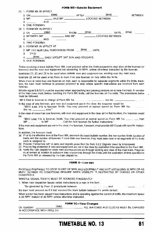
FORM MX- Outside Equipment(1) 1. FORM MX IN EFFECT
2. ON (date) AFTER (time) BETWEEN
3. MP AND MP LOCATED BETWEEN4 AND5. ONE FOREMAN
(2) 1. FORM MX IN EFFECT
2. ON (date) FROM (time) UNTIL (time)
3. BETWEEN MP AND MP LOCATED BETWEEN4 AND5. TWO FOREMEN
(3) 1. FORM MX IN EFFECT AT
2. MP 74.5 NEW LINE SUBDIVISION FROM _ (time) UNTIL3. (74.5)4 (time) DAILY EXCEPT SAT SUN AND HOLIDAYS5. ONE FOREMAN
Trains receiving a track bulletin Form MX must proceed within the limits prepared to stop short of the foreman (orforemen) and the men and equipment not exceeding 10 MPH, unless otherwise instructed by the foreman.
Examples (1), (2) and (3) to be used when outside men and equipment are working near the main track.
Example (2) will be used when there is more than one foreman on duty within the limits.
When there is more than one foreman on duty, each is responsible for separate segments within the limits, there-fore, the train must continue to proceed prepared to stop unless specific instructions are received from eachforeman.
Whistle signal 5.8.2(11) must be sounded when approaching and passing persons on or near the track. A memberof the train crew must, before reaching the Form MX limits, call the foreman on the radio. The procedures belowmust be followed:
"6915 East to foreman in charge of Form MX No. line no.
In the case of one foreman, and men and equipment are in the clear, the response would be:"6915 East, this is foreman Smith. You may proceed at normal speed on Form MX Noline no. over."
In the case of more than one foreman, with men and equipment in the clear at the first location, the response wouldbe:
"6915 East, this is foreman Smith. You may proceed at normal speed on Form MX No fromMP to MP Call the next foreman for further instructions."
If the men and equipment are not in the clear, the foreman, if present, must provide 6915 East with specific instruc-tions.
In addition, the foremen must:(a) Prior to the effective time of the Form MX, ascertain the track bulletin number, the line number limits, location of
trains and the number of foremen. If more than one foreman, they must determine what segments of the limitseach is assigned to.
(b) Provide themselves with a radio and signals prescribed by Rule 5.2.2 (Signals Used by Employees)(c) Provide flag protection if men and equipment are not in the clear by expiration time specified in the Form MX.(d) Notify the train dispatcher when men and equipment are through working and clear of the main track. Flagman
must remain at location to authorize train movements through the limits until the expiration of time specified inthe Form MX or released by the train dispatcher.
FORM 0-Line-ups
PROCEED PREPARED TO STOP SHORT OF MEN AND EQUIPMENT AND NOT EXCEEDING 30 MPH OR ASMUCH SLOWER AS CONDITIONS REQUIRE WHEN VISIBILITY IS RESTRICTED BY CURVES OR OTHERCONDITIONS.
WHISTLE SIGNAL 5.8.2(11) MUST BE SOUNDED FREQUENTLY
1. When train dispatcher issues verbal instructions to a train in the form:
"Be governed by Form O procedures between and
the train must proceed as if it had received the track bulletin between the points named.
When a train has been issued these instructions and is operating against the current of traffic, the maximum speedis 20 MPH instead of 30 MPH unless otherwise instructed.
FORM TC -Time ChangesON SUNDAY (date) ALL WATCHES AND CLOCKS MUST BE CHANGEDIN ACCORDANCE WITH RULE 3.4
TIMETABLE NO. 13 81
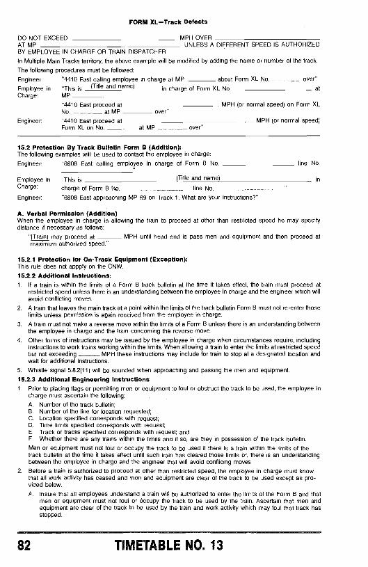
FORM XL -Track Defects
DO NOT EXCEED MPH OVERAT MP UNLESS A DIFFERENT SPEED IS AUTHORIZEDBY EMPLOYEE IN CHARGE OR TRAIN DISPATCHER
In Multiple Main Tracks territory, the above example will be modified by adding the name or number of the track.
The following procedures must be followed:
Engineer: "4410 East calling employee in charge at MP about Form XL No over"
Employee in "This is (Title and name) in charge of Form XL No atCharge: MP
"4410 East proceed at MPH (or normal speed) on Form XLNo at MP over"
Engineer: "4410 East proceed at MPH (or normal speed)Form XL on No at MP over"
15.2 Protection By Track Bulletin Form B (Addition):The following examples will be used to contact the employee in charge:
Engineer: "6808 East calling employee in charge of Form B No. line No.
Employee in "This is (Title and name) inCharge: charge of Form B No. line No
Engineer: "6808 East approaching MP 69 on Track 1. What are your instructions ?"
A. Verbal Permission (Addition)When the employee in charge is allowing the train to proceed at other than restricted speed he may specifydistance if necessary as follows:
"(Train) may proceed at MPH until head end is pass men and equipment and then proceed atmaximum authorized speed."
15.2.1 Protection for On -Track Equipment (Exception):This rule does not appply on the CNW.
15.2.2 Additional Instructions:1. If a train is within the limits of a Form B track bulletin at the time it takes effect, the train must proceed at
restricted speed unless there is an understanding between the employee in charge and the engineer which willavoid conflicting moves.
2. A train that leaves the main track at a point within the limits of the track bulletin Form B must not re -enter thoselimits unless permission is again received from the employee in charge.
3. A train must not make a reverse move within the limits of a Form B unless there is an understanding betweenthe employee in charge and the train concerning the reverse move.
4. Other forms of instructions may be issued by the employee in charge when circumstances require, includinginstructions to work trains working within the limits. When allowing a train to enter the limits at restricted speedbut not exceeding MPH these instructions may include for train to stop at a designated location andwait for additional instructions.
5. Whistle signal 5.8.2(11) will be sounded when approaching and passing the men and equipment.
15.2.3 Additional Engineering Instructions1. Prior to placing flags or permitting men or equipment to foul or obstruct the track to be used, the employee in
charge must ascertain the following:
A. Number of the track bulletin;B. Number of the line for location requested;C. Location specified corresponds with request;D. Time limits specified corresponds with request;E. Track or tracks specified corresponds with request; andF. Whether there are any trains within the limits and if so, are they in possession of the track bulletin.
Men or equipment must not foul or occupy the track to be used if there is a train within the limits of thetrack bulletin at the time it takes effect until such train has cleared those limits or, there is an understandingbetween the employee in charge and the engineer that will avoid conflicing moves.
2. Before a train is authorized to proceed at other than restricted speed, the employee in charge must knowthat all work activity has ceased and men and equipment are clear of the track to be used except as pro-vided below.
A. Insure that all employees understand a train will be authorized to enter the limits of the Form B and thatmen or equipment must not foul or occupy the track to be used by the train. Ascertain that men andequipment are clear of the track to be used by the train and work activity which may foul that track hasstopped.
82 TIMETABLE NO. 13
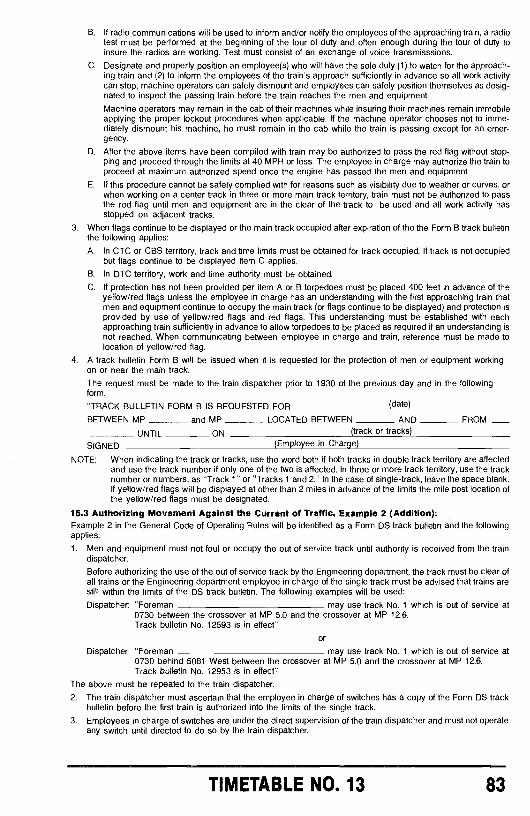
B. If radio communications will be used to inform and /or notify the employees of the approaching train, a radiotest must be performed at the beginning of the tour of duty and often enough during the tour of duty toinsure the radios are working. Test must consist of an exchange of voice transmisssions.
C. Designate and properly position an employee(s) who will have the sole duty (1) to watch for the approach-ing train and (2) to inform the employees of the train's approach sufficiently in advance so all work activitycan stop, machine operators can safely dismount and employees can safely position themselves as desig-nated to inspect the passing train before the train reaches the men and equipment.
Machine operators may remain in the cab of their machines while insuring their machines remain immobileapplying the proper lockout procedures when applicable. If the machine operator chooses not to imme-diately dismount his machine, he must remain in the cab while the train is passing except for an emer-gency.
D. After the above items have been compiled with train may be authorized to pass the red flag without stop-ping and proceed through the limits at 40 MPH or less. The employee in charge may authorize the train toproceed at maximum authorized speed once the engine has passed the men and equipment.
E. If this procedure cannot be safely complied with for reasons such as visibility due to weather or curves, orwhen working on a center track in three or more main track territory, train must not be authorized to passthe red flag until men and equipment are in the clear of the track to be used and all work activity hasstopped on adjacent tracks.
3. When flags continue to be displayed or the main track occupied after expiration of the the Form B track bulletinthe following applies:
A. In CTC or CBS territory, track and time limits must be obtained for track occupied. If track is not occupiedbut flags continue to be displayed Item C applies.
B. In DTC territory, work and time authority must be obtained.
C. If protection has not been provided per item A or B torpedoes must be placed 400 feet in advance of theyellow /red flags unless the employee in charge has an understanding with the first approaching train thatmen and equipment continue to occupy the main track (or flags continue to be displayed) and protection isprovided by use of yellow /red flags and red flags. This understanding must be established with eachapproaching train sufficiently in advance to allow torpedoes to be placed as required if an understanding isnot reached. When communicating between employee in charge and train, reference must be made tolocation of yellow /red flag.
4. A track bulletin Form B will be issued when it is requested for the protection of men or equipment workingon or near the main track.
The request must be made to the train dispatcher prior to 1930 of the previous day and in the followingform.
"TRACK BULLETIN FORM B IS REQUESTED FOR (date)
BETWEEN MP and MP LOCATED BETWEEN AND FROM
UNTIL ON (track or tracks)
SIGNED (Employee in Charge)
NOTE: When indicating the track or tracks, use the word both if both tracks in double track territory are affectedand use the track number if only one of the two is affected. In three or more track territory, use the tracknumber or numbers, as "Track 1" or "Tracks 1 and 2." In the case of single- track, leave the space blank.If yellow /red flags will be displayed at other than 2 miles in advance of the limits the mile post location ofthe yellow /red flags must be designated.
15.3 Authorizing Movement Against the Current of Traffic, Example 2 (Addition):Example 2 in the General Code of Operating Rules will be identified as a Form DS track bulletin and the followingapplies:
1. Men and equipment must not foul or occupy the out of service track until authority is received from the traindispatcher.
Before authorizing the use of the out of service track by the Engineering department, the track must be clear ofall trains or the Engineering department employee in charge of the single track must be advised that trains arestill within the limits of the DS track bulletin. The following examples will be used:
Dispatcher: "Foreman may use track No. 1 which is out of service at0730 between the crossover at MP 5.0 and the crossover at MP 12.6.Track bulletin No. 12593 is in effect"
or
Dispatcher: "Foreman may use track No. 1 which is out of service at0730 behind 5081 West between the crossover at MP 5.0 and the crossover at MP 12.6.Track bulletin No. 12953 is in effect"
The above must be repeated to the train dispatcher.
2. The train dispatcher must ascertain that the employee in charge of switches has a copy of the Form DS trackbulletin before the first train is authorized into the limits of the single track.
3. Employees in charge of switches are under the direct supervision of the train dispatcher and must not operateany switch until directed to do so by the train dispatcher.
TIMETABLE NO. 13 83
4. Employees in charge of switches must verify that train is complete by observation of the rear end marker on therear car and will inform the train dispatcher when a train is clear of the DS limits.
5. Employees in charge of switches must be instructed to line switches for route to be used and train dispatchermust be notified that switches are properly lined before movement is authorized.
6. Train dispatcher will communicate directly with the trains whenever practicable. Employees in charge ofswitches may, under direction of the train dispatcher, authorize movement by controlled signal indication, ver-bally or by hand signal.
7. Verbal authority for a train to proceed into the limits will be as follows:"6839 East may proceed on track bulletin No. 20067."
A train must operate on the track designated unless a superseding track bulletin has been received as in thefollowing example:
"6839 East will use the track instead of the track on track bulletinNo. 20067."
8. When circumstances require a train to work on a portion of the out of service track, such as a work train or atrain needing head room, movements must be made at restricted speed.
9. Trains operating with the current of traffic, that are within the limits at the time that the DS track bulletin takeseffect, may proceed.
10. Movements against the current of traffic must not be authorized until an absolute block in advance of movementis established. Exception: A train with automatic train control cut -in may be authorized to follow another train inwhich case the following train must protect against the train ahead.
11. When operating against the current of traffic and a train is reporting clear of the DS limits, or reporting clear of aportion of the DS limits, the provisions of Rule 9.14.1 (Reporting of a Track Having a Current of Traffic) applies.
12. When a train is authorized to move against the current of traffic, the following instructions govern:(a) Maximum speed 40 MPH outside of yard limits.(b) Protection against following trains is not required.(c) All signal indications must be complied with, but may pass a restricting signal without stopping or commun-
icating with train dispatcher.(d) When movement returns to the current of traffic, Rule 9.10 (Initiating Movment Between Signals) applies. In
ATC territory movement may be made in accordance with cab signal indication after returning to current oftraffic.
(e) In ATC Territory, the ATC must not be cut out unless authorized by the train dispatcher.(f) The train dispatcher may authorize the ATC to be cut out after an absolute block has been established in
advance of movement and it has been ascertained that the engineer has an extra ATC seal or will beprovided with one.
(g) The ATC must be cut in (receiving a restricting cab signal) and sealed before the engine returns to currentof traffic.
When Form DS track bulletin is requested by the Engineering department, the request must be made to the traindispatcher before 1930 of the previous day and in the following form:
TRACK BULLETIN FORM DS IS REQUESTED FOR REMOVING
FROM SERVICE ON (date) FROM
MP AND MP LOCATED BETWEEN AND
SIGNED (Employee in Charge)
15.7 Coping Track Bulletins (Application):The train dispatchers will state "That is correct" then give "OK" time and his initials.
(track)
UNTIL BETWEEN
16.0 RULES APPLICABLE ONLY IN DIRECT TRAFFIC CONTROL (DTC) LIMITS16.2 DTC Block Authority (Application):When a relief crew takes control of a train that occupied 2 DTC blocks the relief crew only needs block authority inthe block the head end of the train is in unless they are going to make a reverse move. The relief crew will notrelease the rear block but must report clear of that block when train is clear of the limits.16.4 Work and Time (Jointly Occupied) Application:Work and time may be granted as follows:1. With another train or employee in charge of on -track equipment with work and time, both movements must
have joint work and time.Issue format:
Train Dispatcher: "7241 East, with Engineer Anderson, I am granting you joint work and time in one block, Anna
until 1010." ( "with train ") will be added if it is known who the block will be jointly occupied with.
2. After a train with directional authority has passed the location where movement will enter the DTC block.
Issue format:Train Dispatcher: "7241 East, with Engineer Anderson, I am granting you joint work and time behind (train) inone block, Anna until 1000."
84 TIMETABLE NO. 13
18.0 AIR BRAKES AND TRAIN HANDLING RULES18.1 Air Test:Members of train crew are responsible for the proper tests of air brakes as outlined herein except that at points orterminals designated in the timetable or by other special instructions, examination and testing of air brake apparatuscan be performed by other employees and members of the train crew will be relieved of such duties. At such pointsor terminals, after engine has been coupled to train and air cut in, an automatic brake application and release test ofair brakes on rear car must be made.
18.1.1 Effective Condition:Each train must have the air brakes in effective operating condition, and at no time shall the number and location ofoperative air brakes be less than permitted by Federal requirements. When piston travel is in excess of 101/2 inches,the air brakes cannot be considered in effective operating condition.
18.1.2 Condensation:Condensation must be blown from the pipe from which air is taken before connecting yard line or engine to train.
18.2.0 INITIAL TERMINAL ROAD TRAIN AIR BRAKE TESTS18.2.1 Where Test Are Required:Each train must be inspected and tested as specified in this section by a qualified person at points:1. Where the train is originally made up (initial terminal);2. Where train consist is changed, other than by adding or removing a solid block of cars, and the train brake
system remains charged; and3. Where the train is received in interchange if the train consist is changed other than by:
A. Adding or removing a solid block of cars from the head end or rear end of the train;B. Changing engines;C. Removing or changing the caboose; orD. Any combination of the changes listed in (A), (B), and (C) of this subparagraph.
18.2.2 Intermediate Points:Intermediate inspection points as designated by subdivision special instructions shall be established within a limitnot to exceed 1,000 miles where additional inspection will be made to determine that:1. Brake pipe leakage does not exceed 5 pounds per minute.2. Brakes apply on each car from a 20 pound service brake pipe reduction.3. Brake rigging is properly secured and does not bind or foul.
18.2.3 Performing Test:Train air brake system must be charged to required air pressure, angle cocks and cut -out cocks must be properlypositioned, air hose must be properly coupled and must be in condition for service. An examination must be madefor leaks and necessary repairs made to reduce leakage to a minimum. Retaining valves and retaining valve pipesmust be inspected and known to be in condition for service.1. The brake system on a freight train will be charged to within 15 pounds of the setting of the feed valve on the
engine, but not less than 60 pounds as indicated by an accurate gauge at the rear of the train and on apassenger train to not less than 70 pounds.
2. Upon receiving the signal to apply the brakes for test, a minimum of a 20 pound, not to exceed full service,brake application must be made.
3. After the blow at the brake valve has ceased the pressure maintaining feature will be cut out, wait 45 seconds,then observe that brake pipe leakage does not exceed 5 pounds per minute as indicated by the brake pipegauge.
4. Inspect train brakes to determine that the angle cocks are properly positioned, that the air brakes are applied oneach car, and that the piston travel is correct, the brake rigging does not bind or foul, and that all parts of thebrake equipment are properly secured.
5. After inspection has been completed, the pressure maintaining feature will be cut in and the brakes released.Each brake must be inspected to see that all have released.
6. Each train leaving initial terminal must have air brakes in effective operating condition on all cars.
18.2.4 Piston Travel:At initial terminals, piston travel of body mounted brake cylinders which is less than 7 inches or more than 9 inchesmust be adjusted to nominally 7 inches.
Minimum brake cylinder piston travel of truck mounted brake cylinders must be sufficient to provide proper brakeshoe clearance when brakes are released. Maximum piston travel must not exceed 6 inches.
Piston travel of brake cylinders on freight cars equipped with other than standard single capacity brake, must beadjusted as indicated on badge plate or stenciling on car located in a conspicuous place near brake cylinder.
18.2.5 Performed by Other Qualifed Employee:When test of air brakes has been completed, the engineer and conductor must be advised that train is in propercondition to proceed.
A qualified person participating in the test and inspection, or who has knowledge that it was made, shall notify theengineer that the initial terminal road train air brake test has been completed. The qualified person shall provide thenotification in writing if the road crew reports for duty after the qualified person goes off duty. The qualified personshall also provide the notification in writing if the train that has been inspected is to be moved in excess of 500 mileswithout being subject to another initial terminal air brake test.
TIMETABLE NO. 13 85
18.2.6 Signs Given:During standing test, brakes must not be applied or released until proper signal is given.
18.2.7 Yard Air:When train air brake system is tested from a yard test plant, an engineer's brake valve or suitable test device mustbe used to provide increase and reduction of brake pipe air pressure at the same or a slower rate as with engi-neer's brake valve and yard test plant must be connected to the end which will be nearest to the hauling roadlocomotive.
When yard test plant is used, the train air brake system must be charged and tested as prescribed by Rules 18.2.3(Performing Test) and when practicable should be kept charged until road engine is coupled to train, after which, anautomatic brake application and release test of air brakes on rear car must be made.
If after testing the brakes as prescribed above the train is not kept charged until road engine is attached, the brakesmust be tested as prescribed by Rule 18.2.3 (Performing Test)
18.2.8 Adjustments:Before adjusting piston travel or working on brake rigging, cut -out cock in brake pipe branch must be closed and airreservoirs must be drained. When cut -out cocks are provided in brake cylinder pipes, these cut -out cocks only maybe closed and air reservoirs need not be drained.
18.2.9 Air Flow Method (AFM):On subdivisions authorized, the initial terminal road train air brake test may be performed using the "Air FlowMethod" (AFM). Trains using this method must have an operative rear end telemetry device. The test will beperformed as follows:(a) The brake system will be charged to within 15 pounds of the setting of the regulating valve on the engine, but
not less than 60 pounds as indicated by an accurate gauge at the rear of the train. When the air flow gaugereads 60 cubic feet per minute (CFM) or less the engineer will inform the employees involved that the brakesystem is charged.
(b) Upon receiving the signal to apply the brakes for a test, a minimum of 20 pounds, not to exceed full servicebrake application, must be made.
(c) Inspect train brakes to determine that the angle cocks are properly positioned, that the air brakes are applied oneach car, and that the piston travel is correct, the brake rigging does not bind or foul, and that all parts of thebrake equipment are properly secured.
(d) After inspection has been completed, the brakes will be released and inspected to see that all are released.(e) Each train leaving initial terminal must have air brakes in effective operating condition on all cars.
18.2.10 Car Added:When a train qualified by AFM adds cars not previously tested, the added cars may be tested using AFM.
After this test is completed, it must be determined that the brakes on the rear car of the train apply and release byuse of the end of train device.
18.2.11 Increase Air Flow:When a train qualified by AFM is in operation and experiences an increase in brake pipe air flow and /or increase inpipe gradient and the moveable pointer does not return to the limit established in the initial terminal train air braketest within a reasonable time, the train crew shall:(a) Stop the train for inspection and repair leaks, if detected.(b) If unable to make repairs, arrange to set out defective cars, and /or(c) Proceed with due caution to the next location where corrective action can be taken.
18.3 Road Train and Intermediate Terminal Train Air Brake Tests18.3.1 Passenger Trains:Before engine is detached or angle cocks are closed on a passenger train, except when closing angle cocks forcutting off one or more cars from the rear end of the train, automatic air brake must be applied. After recoupling,brake system must be recharged to required air pressure and before proceeding and upon receipt of properrequest or signal, application and release tests of brakes on rear car must be made from engine. Inspector ortrainman must determine if brakes on rear car of train properly apply and release.
18.3.2 Freight Trains:When engine is to be cut away from cuts of cars or train, brakes must be applied with not less than a 20 poundbrake pipe reduction. The brake pipe angle cock on lead car of cars left standing will be left open. When required tohave angle cock on lead car closed, wait at least two minutes after brake pipe reduction before closing, except asprovided for in Rule 18.6 (Inbound Brake Equipment Inspection).
After recoupling and after angle cocks are opened, it must be known that brake pipe air pressure is being restoredas indicated by a rear car gauge or device.
18.3.3 Points where Cars are Set Out or Engine Changed:At a point other than an initial terminal where an engine or caboose is changed, or where one or more consecutivecars are cut off from the rear end or head end of a train with the consist otherwise remaining intact, after the trainbrake system is charged to within 15 pounds of the regulating valve setting on the engine, but not less than 60pounds as indicated at the rear of a freight train and 70 pounds on a passenger train, a 20 -pound brake pipereduction must be made and it must be determined that the brakes on the rear car apply and release. As analternative to the rear car brake application and release test, it shall be determined that brake pipe pressure of thetrain is being reduced as indicated by a rear car gauge or device and then that brake pipe pressure of the train isbeing restored as indicated by a rear car gauge or device.
86 TIMETABLE NO. 13
18.3.4 Cars Added:Cars added to a train must receive an initial terminal air brake test. When a solid block of cars, which has receivedan initial terminal test is added to a train, it must be determined that the brakes on the rear car of the train apply andrelease. As an alternative to the rear car application and release test, it shall be determined that brake pipe pres-sure of the train is being reduced as indicated by a rear car gauge or device and then that brake pipe pressure ofthe train is being restored as indicated by a rear car gauge or device.
13.3.5 Pressure Reduced /Restored:Brake pipe pressure of the train is being reduced means a pressure reduction of at least 5 pounds and the phrasebrake pipe pressure of the train is being restored means a pressure increase of at least 5 pounds.
18.4 End -of -train Device (EDT):1. Upon installation of an end -of -train device, it shall be determined that the identification code entered into the
engine receiver is identical to the unique identification code on the rear -of -train transmitter.
2. The functional capability of the device shall be determined at the point of installation, after charging the train, bycomparing the quantitative value displayed on the receiver with the quantitative value displayed on the transmit-ter or on an air gauge. The end -of -train air gauge device may not be used if the difference between the tworeadings exceeds three pounds.
3. The transmitter shall be calibrated for accuracy at least every 92 days. A tag, sticker, or other method ofinformation storage that provides the date of the last calibration, the location where the calibration was made,and the name of the person doing the calibration shall be affixed to the transmitter.
18.5 Transfer Test:Transfer train or yard train movements not exceeding 20 miles, must have the air brake hose coupled between allcars, and after the brake system is charged to not less than 60 pounds, a 20 pound service brake pipe reductionmust be made to determine that the brakes are applied on each car before releasing and proceeding.
Transfer train and yard train movements exceeding 20 miles must have an initial terminal air brake test.
18.8 Inbound Brake Equipment Inspection:At points where inspectors are employed to make general inspection of trains upon arrival at terminals, visualinspection must be made of retaining valves and retain valve pipes, release valves and rods, brake rigging, safetysupports, hand brakes, hose and position of angle cocks and make necessary repairs or mark for repair tracks anycars to which yard repairs cannot be promptly made.
Freight trains arriving at terminals where facilities are available and at which special instructions provide for imme-diate brake inspection and repairs, shall be left with air brakes applied by a brake pipe reduction of 20 pounds sothat inspectors can obtain a proper check of the piston travel. Trainmen will not close any angle cock or cut theengine off until the 20 pound service reduction has been made. Inspection of the brakes and needed repairs shouldbe made as soon thereafter as practicable.
18.7 Inoperative Air Brakes Enroute:A car on which the air brake becomes defective enroute may be handled to the next repair point. However, at notime shall the number of operative brakes be less than 85% of the total number of air brakes in the train. If the airbrakes on any car become defective after leaving a terminal and before reaching a repair point, the conductor willpromptly notify the train dispatcher, giving nature of defect, car initials and number and location in train.
Unless specifically authorized not more than two consecutive cars shall be operated in a train with the air brakescut out. Movement may not be authorized beyond the nearest point where cars can be repositioned in train, set out,or to the nearest repair point, whichever occurs first.
Exceptions:The above will not apply when handling a "Hospital" or "Wrecking" train under the direct supervision of a CarDepartment Supervisor, nor will it apply when handling Welded Rail Trains, loaded or empty, nor to other trains thathave fixed or permanently coupled cars, and for which special instructions are in effect.
18.8 Running Tests -Passenger Trains:When engine, engine crew or train crew has been changed, angle cocks have been closed except for cutting offone or more cars from the rear end of train, running test of train air brakes on passenger train must be made, assoon as speed of train permits, by use of automatic brake. Throttle must not be shut off unless required and runningtest must be made by applying train air brakes with sufficient force to ascertain whether or not brakes are operatingproperly. If air brakes do not properly operate, train must be stopped, cause of failure ascertained and correctedand running test repeated.
A running test of air brakes on a passenger train must be made, when practicable, two miles from meeting points,junctions, railroad crossings, drawbridges, and other points where failure of the brakes to operate properly wouldresult in hazard.
18.9 Back Up Movement:A back -up hose, or its equivalent, must be used for backing passenger trains, whether loaded or empty. A trainmanmust be at the rear of the car.
When a trainman controlling a back -up movement of a passenger train sees a signal at stop or necessity forstopping, a brake test must be made to assure himself that he has full control of train. If he is required to leave rearend of the train for any cause, the valve on the back -up hose, or its equivalent, must be left open sufficiently toprevent train from being moved until he returns.
TILLTABLE NO. 13 87
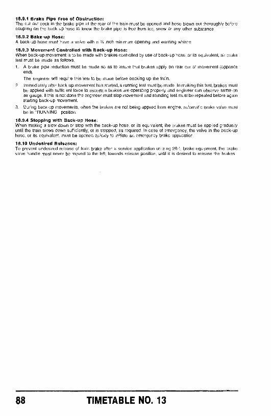
18.9.1 Brake Pipe Free of Obstruction:The cut -out cock in the brake pipe at the rear of the train must be opened and hose blown out thoroughly beforecoupling on the back -up hose to know the brake pipe is free from ice, snow or any other substance.
18.9.2 Bake -up Hose:A back -up hose must have a valve with a 3/a inch minimum opening and warning whistle.
18.9.3 Movement Controlled with Back -up Hose:When back -up movement is to be made with brakes controlled by use of back -up hose, or its equivalent, air braketest must be made as follows:
t. A brake pipe reduction must be made so as to insure that brakes apply on rear car of movement (oppositeend).
The engineer will require this test to be made before backing up the train.
2. Immediately after back -up movement has started, a running test must be made. In making this test, brakes mustbe applied with sufficient force to ascertain brakes are operating properly and engineer can observe same onair gauge. If this is not done the engineer must stop movement and standing test must be repeated before againstarting back -up movement.
3. During back -up movements, when the brakes are not being applied from engine, automatic brake valve mustbe in "RUNNING" position.
18.9.4 Stopping with Back -up Hose:When making a slow down or stop with the back -up hose, or its equivalent, the brakes must be applied graduallyuntil the train slows down sufficiently, or is stopped, as required. In case of emergency, the valve in the back -uphose, or its equivalent, must be opened quickly to initiate an emergency brake application.
18.10 Undesired Releases:To prevent undesired release of train brake after a service application utilizing 26 -L brake equipment, the brakevalve handle must never be moved to the left, towards release position, until it is desired to release the brakes.
88 TIMETABLE NO. 13
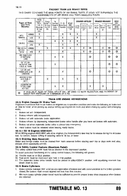
18.11FREIGHT TRAIN AIR BRAKE TESTS
THIS CHART CONTAINS THE MAIN POINTS OF AIR BRAKE TESTS. IT DOES NOT SUPERSEDE THEREQUIREMENTS OF AIR BRAKE AND TRAIN HANDLING RULES.
Type f Testand RuleNumber
Charge
System ToWithin
15 PSI. OfRegulating
Or FeedValve
Charge
System ToNot LessThan 60
PSI.
No
SpecifiedCharge In
Brake
System
20 PSI.Brake PipeReduction
BRAKE
PIPE
LEAKAGE
TEST
BRAKES APPLIES BRAKES RELEASE BRAKE
PIPE
PRESSUREBEING
RESTORED
ENTIRE
TRAIN
CAR (S)PICKED
DP
REAR
CAR
ENIRE
TRAIN
CAR (S)PICKED
DP
REAR
CAR
INITIAL
TERMINAL
NORMAL X X X X X
AFM X X X X
1000 MILENORMAL X X X X
AFM X X X
ADD CAR (S)NOT PRE
TESTED
NORMAL X X X X O X O O
AFM X X X O X O O
ADD SOLID BLOCK
OF PRETESTED
CARSX X O O O
CUT OFF AND
RECOUPLED SAME
LOCO. & TRAINX O O
CUT OFF CARS
CHANGE LOCO. & ORCABOOSE
X X O O O
TRANSFER & YARD
LESS THAN 20MILES
X X X
LOCOMOTIVE ON
AFTER A YARD
AIR TESTX X X X
IF AVAILABLE, REAR OF TRAIN DEVICE WILL BE USED TO NOTE REDUCTION AND INCREASE OFO BRAKE PIPE PRESSURE OF A MINIMUM OF 5 PSI.
TRAIN AND ENGINE INSTRUCTIONS18.12 Engine Consist Air Brake Test:Engineers must know that the air brakes on engines are in operative condition and make the following air brake testat initial terminal, when picking up and /or setting out engines en route and when changing control unit (changingends):
1. Brakes set with independent.
2. Brakes release with independent.
3. Brakes set with automatic brake application.4. Brakes release by depressing independent brake valve handle after you have set brakes with automatic.5. Brakes set when automatic brake valve is placed into emergency.6. Hand brakes must be released when leaving ready tracks.
18.12.1 SD 18 Engines 6622 -6647:When MUing engines 6622 -6647 with other engines, the independent brake may fail to release during the air braketest. To correct, reduce setting of reducing valve to 38 lbs. or lower.
18.13 Draining Main Reservoir:Water and foreign matter must be drained from main reservoir before starting each trip or days work and, also,enroute when opportunity permits.
18.14 Safety Control Feature: (Deadman Pedal):The safety control foot pedal must not be blocked in the depressed position.To avoid undesired functioning of the safety control feature, the following will govern:(a) Throttle must be in IDLE position.(b) Foot pedal must be depressed and held in that position.(c) The automatic brake valve handle must be placed in EMERGENCY position, until equalizing reservoir has
blown down to zero.
18.15 Brake Cylinders:1. Brake cylinder leakage: With a full service application of brakes and with communication to the brake cylinders
closed, the brakes must remain applied not less than five minutes.2. Minimum brake cylinder piston travel must be sufficient to provide proper brake shoe clearance when brakes
are released.
TIMETABLE NO. 13 89
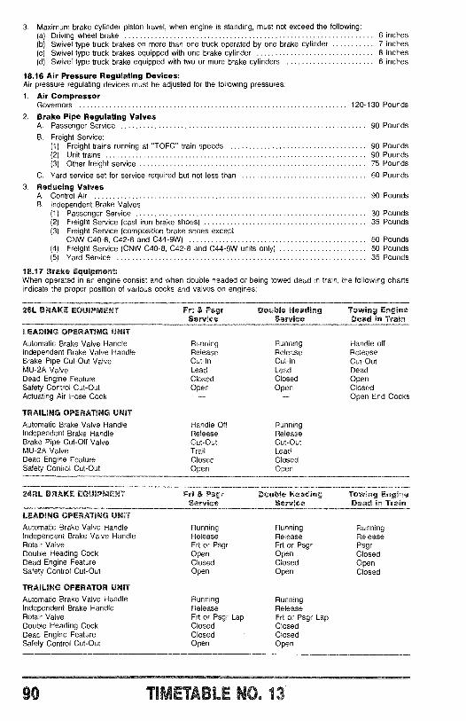
3. Maximum brake cylinder piston travel, when engine is standing, must not exceed the following:(a) Driving wheel brake 6 inches(b) Swivel type truck brakes on more than one truck operated by one brake cylinder 7 inches(c) Swivel type truck brakes equipped with one brake cylinder 8 inches(d) Swivel type truck brake equipped with two or more brake cylinders 6 inches
18.16 Air Pressure Regulating Devices:Air pressure regulating devices must be adjusted for the following pressures:
1. Air CompressorGovernors 120 -130 Pounds
2. Brake Pipe Regulating ValvesA. Passenger Service 90 Pounds
B. Freight Service:(1) Freight trains running at "TOFC" train speeds 90 Pounds(2) Unit trains 90 Pounds(3) Other freight service 75 Pounds
C. Yard service set for service required but not less than 60 Pounds
3. Reducing ValvesA. Control Air 90 PoundsB. Independent Brake Valves
(1) Passenger Service 30 Pounds(2) Freight Service (cast iron brake shoes) 35 Pounds(3) Freight Service (composition brake shoes except
CNW C40 -8, C42 -8 and C44 -9W) 50 Pounds(4) Freight Service (CNW C40 -8, C42 -8 and C44 -9W units only) 60 Pounds(5) Yard Service 35 Pounds
18.17 Brake Equipment:When operated in an engine consist and when double headed or being towed dead in train, the following chartsindicate the proper position of various cocks and valves on engines:
26L BRAKE EQUIPMENT Frt & Psgr Double Heading Towing EngineService Service Dead in Train
LEADING OPERATING UNITAutomatic Brake Valve Handle Running Running Handle offIndependent Brake Valve Handle Release Release ReleaseBrake Pipe Cut -Out Valve Cut -In Cut -In Cut -OutMU-2A Valve Lead Lead DeadDead Engine Feature Closed Closed OpenSafety Control Cut -Out Open Open ClosedActuating Air Hose Cock .- - Open End Cocks
TRAILING OPERATING UNITAutomatic Brake Valve Handle Handle Off RunningIndependent Brake Handle Release ReleaseBrake Pipe Cut -Off Valve Cut -Out Cut -OutMU -2A Valve Trail LeadDead Engine Feature Closed ClosedSafety Control Cut -Out Open Open
24RL BRAKE EQUIPMENT Frt & Psgr Double Heading Towing EngineService Service Dead in Train
LEADING OPERATING UNITAutomatic Brake Valve Handle Running Running RunningIndependent Brake Valve Handle Release Release ReleaseRotair Valve Frt or Psgr Frt or Psgr PsgrDouble Heading Cock Open Open ClosedDead Engine Feature Closed Closed OpenSafety Control Cut -Out Open Open Closed
TRAILING OPERATOR UNITAutomatic Brake Valve Handle Running RunningIndependent Brake Handle Release ReleaseRotair Valve Frt or Psgr Lap Frt or Psgr LapDouble Heading Cock Closed ClosedDead Engine Feature Closed ClosedSafety Control Cut -Out Open Open
90 [1."'- 'O. 13
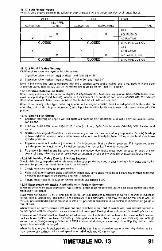
18.17.1 Air Brake HosesWhen MUing engine consists the following chart indicates (X) the proper position of air brake hoses:
24 RL 26 -L LEAD
ACTUATINGIND. APPL
& REL ACTUATING EQUALIZING TRAIL
26 -L
X X EQUALIZING
X X ACTUATING
CLOSED CLOSED BRK. PIPE CUT -OUT
24 -L
X X ACTUATING
X X IND. APPL & REL
CLOSED CLOSED BRK. PIPE CUT -OUT
18.17.2 MU -2A Valve Setting:CNW engines have two types of MU -2A valves:
1. 2- position valve marked "lead or dead" and "trail 24 or 26."
2. 3- position valve marked "lead or dead," "trail 6 -26" and "trail 24."
Note: If the controlling unit is equipped with the 2- position valve and a trailing unit is equipped with the older3- position valve, then the MU -2A on the trailing unit must be set on "trail 24" position.
18.18 Brakes Release on Units:When using automatic brake valve on engines equipped with 26 -L type brake equipment, independent brake valvemust be kept in depressed (bail -off) position for a minimum of 5 seconds for each unit in consist, after the exhauststops from automatic brake valve, to insure that brakes on all units are released.
When there is any other type brake equipment in the engine consist, then the independent brake valve oncontrolling unit must be kept in depressed (bail -off) position continually while automatic brake valve is in applicationposition.
18.19 Engine Flat Spots:1. Engineer receiving an engine with flat spots will notify the train dispatcher and make entry on Enroute Excep-
tion Report.
2. If the flat spots occur while engineer is in charge of unit, report must be made indicating time, location andcause.
3. SD40 -2 units, regardless of their location in an engine consist, have a tendency to permit a recurring build -upof brake cylinder pressure. Independent brake valve must continually be bailed off to prevent build up of brakecylinder pressure.
4. Engineers must not make adjustments to the independent brake cylinder pressure. If independent brakecylinder pressure is not correct, it must be reported to mechanical forces for correction.
5. To prevent jackknifing and flat spots on units, the independent brake must never be used for stops or slowdowns of trains when the same results can be obtained by use of the dynamic or automatic brake valve.
18.21 Minimizing Delay Due to Sticking Brakes:Should difficulty be experienced in releasing brakes after picking up cars, or after making a light brake applicationenroute, the procedures listed below should be followed:
1. Check regulating valve for proper setting.
2. Make a 20 -pound service brake application. When blow at the brake valve stops if standing, or when train stopsif moving, place train in emergency and wait 3 minutes.
3. Return brake valve to release or running position and charge train.
18.22 Emergency Air Brake Applications in Freight Service:When an emergency brake application has occured, a train must not proceed until the air brake system has beenadequately recharged.
Train must not exceed 10 MPH until gauge at rear of train indicates a pressure of within 5 pounds of indicationshown prior to emergency application. If the pressure is not attainable, train may resume normal speed after 15minutes provided brake pipe is restored to within 15 pounds of regulating valve setting as indicated on gauge atrear of train.
When there is no communication with rear end crew members or with end of train device, train may not proceed atnormal speed until the engineer has ascertained that brake pipe leakage does not exceed 5 pounds per minute.
If terrain is such that normal train handling would require use of air brakes within three miles, trains will not proceeduntil air brake system has been adequately recharged as outlined above, except trains blocking interlockingsand /or road crossings -may proceed at 5 MPH to clear interlockings or crossings then stopping until air brakesystem is adequately recharged.
When the lead engine is equipped with an AFM and the train has an operative rear end telemetry device the trainmay operate at maximum authorized speed when AFM indicates 60 cfm or less.
TIMETABLE NO. 13 91
18.23 Cast iron and Composition Brake Shoes:Engines in the series 4600 -4634, 6650 -6659 and 6567 -6589 have cast iron brake shoes. When they trail a unithaving composition brake shoes, the engine brake cylinder pressure must not exceed 40 pounds.
18.24 Units Set Out or Picked Up:When necessary to uncouple units, air hoses must not be uncoupled by hand. The angle cocks should be closedand unit moved to uncouple hoses.
When disconnecting 27 point jumper cable it must be stored in the engine air compressor compartment unless theengine is provided with a special receptacle for both ends of the cable. The jumper cable must be left with enginebeing set out.
18.24.1 Separating UnitsWhen connecting or separating units of an engine consist, the engineer or hostlier is responsible for the work to beperformed. When separating units, the work will be done in the following order:1. Grab iron chains,2. 27 -point jumper cable,3. cut -out cocks and angle cocks.
18.25 Changing Operating Ends:To change operation of brakes to opposite control unit of a multiple unit consist or suburban train proceed asfollows:
A. 26 -L Equipment1. Make a 20 pound brake pipe reduction and move brake pipe cut -out cock to cut -out position.2. Place MU -2A valve in proper position for type of equipment which will be the leading unit.3. Move the automatic brake valve to handle off position and remove the handle.4. Move independent brake valve to release position and remove handle.
To assume control of brakes at opposite end:1. Insert both brake valve handles and move independent brake valve to fully applied position.2. Place MU -2A valve in lead position.3. Move the brake pipe cut -out cock to cut -in position.4. Move automatic brake valve to running position.5. Test brakes.
B. 24 -RL Equipment1. Make a 20 pound brake pipe reduction and close double heading cock.2. Have both independent and automatic brake valves to running position and remove handles.
To assume control of brakes at opposite end:1. Insert both brake valve handles and move independent brake valve to fully applied position.2. Move double heading cock to open position.3. Test brakes.
C. 26 -B1 Equipment (Suburban Cab Cars)1. Move brake valve handle to full service position.2. Depress center of brake pipe cut -off valve with tool suspended from chain and move handle 'h turn to
cut -out position.3. Move brake valve handle to "handle off" position.4. Place handle in receptacle and lock.5. Release parking brake.
To assume control of brakes at opposite end: :1. Apply parking brake.2. Remove brake valve handle from receptacle locked with switch lock and insert in brake valve.3. Depress center of brake pipe cut -off valve with tool suspended from chain and move cut -off valve handle to
cut -in position. (This requires 1/2 turn.)4. Move brake valve handle to left or running position, and note that:
a. Brake pipe pressure raises to 90 psi as indicated by gauge.b. Main reservoir pressure reduces to some value below 130 psi and then recovers to 130 -140 psi. (the
recovery of main reservoir pressure will indicate that air supply is being replenished from engine).5. Release parking brake.6. Test brakes.
18.26 Dynamic Brakes:When using automatic air brakes in conjunction with dynamic braking, the independent brake valve handle must be"bailed" off during this cycle.
CAUTION: When CNW units are in the lead, dynamic braking is retained when an emergency brake applicationoccurs. The engineer must use caution when emergency or penalty application occurs, so that independent brakedoes not apply on top of dynamic brake causing excessive forces which can cause wheels to slide.
92 TIMETABLE NO. 13
18.26.1 Buff Forces:Engine consists are restricted to a maximum of 24 axles used in dynamic braking. Under most circumstancesconcentrated buff forces should not exceed 250,000 lbs. to avoid damage to cars and the occurrence of high lateralforces which can cause derailments. Modern high horsepower engines develop up to 10,000 lbs. of retarding forceper traction motor at maximum amperage, therefore a 24 axle limitation gives a maximum of 240,000 lbs. of forcewhich is in safe limits.
Account SD60 and C40 -8, C42 -8 and C44 -9W engines have a high capacity dynamic brake with a maximumretarding force of 81,000 lbs. vs. 60,000 lbs. on other 6 axle engines, each unit in this series will be counted as 8axles when determining the number of axles to be used in dynamic braking except loaded unit trains, all 100 ton ormore capacity cars, are restricted to 28 axles of dynamic braking.
When operating through turnouts, crossovers and curves exceeding 4 degrees, dynamic brake amperes must notexceed a maximum of 350 amps until one -half the train has negotiated turnout, crossover or curve. This is particu-larly important when the dynamic brake is being used entirely for controlling the speed of the train. Under theseconditions a harsh bunching of slack or run -in combined with the curvature can cause high forces and possiblycause a derailment.
When operating in territory where grade changes from descending to ascending, dynamic brake must be reducedproportionately to degree of change. When curves over 2 degrees are located at points where grades change,dynamic brake must not exceed 350 amps. Under these conditions the gravity forces change when grade changeswhich increase forces in the train to a point where derailment can occur.
18.27 Break -In -Two:if a train parts while running, forward portion must be kept moving, if possible, until rear portion has stopped. Whennecessary to replace knuckle or perform any work under or between separated portions of train, angle cock on bothportions of train must be left open until work is complete and train is ready to be moved or recoupled. Sufficientnumber of hand brakes must be applied on both portions of train if standing on a grade.
18.28 Back Up Movements:When shoving cars or trains, extreme care must be exercised. The tractive effort on the initial start creates thegreatest potential for jackknifing due to the high buff forces. This high buff force must be reduced by advancing thethrottle only to the minimum position required to move. The brakes must be released prior to shoving. Beforeshoving, consideration must be given to:1. Horsepower2. Position of slack3. Number of units4. Track conditions, curves and grade5. Position of loads and empties and the tonnage.Note: Engine consist includes engines in tow when coupled to same.
18.29 Helper Service:1. A "helper engine" is defined as an engine in "helper service" coupled to the rear of a train for assistance. Other
cars, except a caboose when necessary, must not be coupled to it. Helper engine must be between train andcaboose when practical. When necessary to assist from behind the caboose, the caboose must not be occu-pied.
2. When necessary to perform helper service without radio, the procedures to follow must be understood betweenengineers prior to moving. The engineer on the front of the train is in charge.
3. Couplers must be stretched twice after helper engine is coupled to train. Prior to cutting in the air, the regulatingvalve must be reduced to at least 10 p.s.i. below train line setting. Brake pipe must be cut out by placing brakepipe cut out cock in cut -out position. Independent brake valve must be left cut -in, when feasible, to preventdamage to wheels when automatic brakes are set. The automatic brake valve handle on 26 -L equipment mustbe left in "handle -off" position.
4. A 20 lb. brake pipe reduction must be made on the engine on the front of the train after brake system ischarged, to determine that brakes on helper engine apply and release. The gauges must be observed to seethat reduction was made and the brake pipe pressure is restored upon completion of test.
5. The maximum number of units permitted in the helper engine consist is 5 with only 2 on the line. There mustnot be any "dead" units or "idling" units between the train and the units providing the "power" in helper service.
6. Minimum throttle settings must be used on the helper engine. The engine on the front of the train must be in ahigher throttle setting, except when in the number 8 setting. The helper engine must be the first to reducethrottle settings.
7. Dynamic braking is confined to the engine on the front of the train with helper engine in idle.8. The throttle on the helper engine must not exceed the number 5 setting when operating on curves in excess of
2 degrees or through crossovers and turnouts, if there are empty cars located within the rear 10 cars or if thehelper engine is behind the caboose.
9. The helper engine must be placed in "idle" when a brake pipe reduction is observed on the helper engineunless information from the engineer on the front of the train dictates otherwise.
18.29.1 Double Heading and Helper Service:When double heading, the engineer of the lead unit shall operate the brakes. On all other units in the train the brakepipe cut -out cock to the brake valve must be closed, the maximum main reservoir pressure maintained and brakevalve handles kept in the prescribed position. if it becomes necessary for the lead unit to give up control of the train,a test of the brakes must be made to see that the brakes are operative from the automatic brake valve of the enginetaking control.
TIMETABLE NO. 13 93
18.30 Daily Engine Inspections:Engines in service must be inspected once each calendar day. A written report of the inspection shall be made onForm 41- 00042, "Diesel Locomotive Inspection Report." This report shall contain the initial and number of theengine, place, date and time of the inspection, a description of any defects disclosed by the inspection and thesignature of the employee making the inspection.
In addition to filling out the Inspection Report, the daily cab card must also be filled out. The location, date, time andsignature must correspond on both the daily cab card and the inspection report.
Example: An engine that was inspected at 0001, August 5, does not have to be inspected again until 2359 August 6.
18.31 Engine Cab:Enginemen need not accept engines when the cabs which they will occupy are cluttered with debris. When cab iscluttered with debris, engineer will bring it to the attention of the proper authority for an assessment of the situation,At outlying locations, or when proper authority is not available, engineer will make a report to the traveling engineer.Enginemen are responsible for the cleanliness of the cab upon completion of tour of duty. They must see that cabdoors and windows on trailing units are closed when not occupied. They must also check radios and E.O.T.receivers when making engine inspection. When a radio or E.O.T. receiver is defective, damaged or missing, theymust report it to the train dispatcher and record it on enroute work report.
The radio and E.O.T. receiver are integral parts of the engine and are under the responsibility of engineer.
18.31.1 Receipt of Engines In Interchange:Engines received in interchange must be observed for obvious safety defects such as shattered glass, oil onwalkways, bent hand rails and steps or any other condition which is unsafe.
18.32 Detour Movements:When detours require CNW engines in lead for ATC, the horsepower- tonnage ratios are not in effect. All foreignengines will be kept on line so fuel usage is equalized.
18.33 Throttle vs. Speed Restrictions:Simulations have shown that engine consists which exceed 13,000 horsepower can create drawbar forces in thearea of 400,000 to 450,000 lbs. of draft. This is higher than the allowable range of 250,000 to 375,000 lbs. whereincoupler components can fail.
The guidelines below must be followed when engine consist exceeds 13,000 horsepower:Throttle
Speed (MPH) Position0 -1 31 -3 43 -6 57 -9 610 -12 713+ 8(The same restrictions apply when reducing speed on ascending grade.)
When any combination of 3 C40 -8, C42 -8, C44 -9W, SD60 or SD50 units make up the engine consist, the guide-lines below must be followed:
ThrottleSpeed (MPH) Position0 -7 68 -9 710+ 8
The transportation superintendent at Bill has issued additional instructions relative to Throttle vs. Speed which areapplicable to trains on the Powder River Subdivision. Engineers operating on that subdivision must avail them-selves of those instructions.
18.33.1 Traction Motor Damage:Under no circumstances will power be applied while train is at standstill unless attempt is being made to start train.
Extensive damage to traction motors will occur if power is applied to hold train at standstill.
18.34 Fuel Conservation:1. Engine shutdown policy:When temperature exceeds 35 °, units in yard, wayfreight and transfer service must be shut down when delay willexceed 30 minutes. Road service units will be shut down when delay will exceed 1 hour, except one unit may beleft idling to keep train line charged. Engineers are responsible for determining length of delay time. When it cannotbe determined, units will be shut down.
2. HP /Ton Ratio Policy:When temperature exceeds 35 °, excess units on freight trains must be shut down when HP /Ton ratio is exceeded.Enter "Unit shut down for fuel conservation" on enroute exception report. Show the date and time the unit shutdown. When temperature is between 35° and 20° excess units will be isolated. When temperature is 20° or lower,all units will be left on line.
HP /Ton ratio is calculated by dividing total operating horsepower by the total tonnage (tonnage of train plus locomo-tives). Unless exceptions have been granted, the HP /Ton ratio is one horsepower per ton except between:
Mpls- Altoona 1.3Itasca -Altoona 1.3Chicago -Fremont 1.3TOFO 2.5
94 T3 ErtPLE NO. 13
Trains handling empty ballast, ore, potash, grain or coal hoppers, will operate with one unit unless the total numberof cars handled exceeds 115 cars or if permission received from the train dispatcher. These trains will operateunder applicable HP /Ton ratio when handling more than 115 cars.
Exception: Trailing unit need not be shut down when occupied by employees unless temperature is above 60 °.
Dynamic Braking Policy:Do not use power or stretch braking when making planned slow downs or stops with two or more operatingdynamic brakes. Power or stretch braking is keeping throttle in power position when using automatic brake valve.
18.35 Engine Tie Up -Cold Weather Instructions:1. When temperature will be between 10 and 20 degrees, the throttle must be left in No. 2 position, when below 10
degrees in No. 4 position. Good judgement must be used when temperatures are at or near the above parame-ter. Move the generator field switch to the "off" position, close doors and windows and leave electrical cabinetdoor open if not sealed.
2. When a low- horsepower engine is left running and unattended because it will be subject to freezing tempera-tures, the "engine monitor unit" (located on the control stand) will sound an alarm via radio if the engine shutsdown. To enable the "engine monitor unit" to function properly, the instructions below must be followed:
1. Engine consist must be MU'ed, however only one of the "engine monitor units" is to be activated.2. Engine isolation switch must be left in "run" position.3. Radio must be left with power "on" and set to Channel 23 -23 (Utility 2).
Exceptions: Sub Area ChannelAdams Wisconsin Rapids 52 -52 Road 1Eau Claire East Minneapolis 71 -71 Road 4Marinette Marinette 52 -52 Road 1Antoine Quinesec 52 -52 Road 1Waterloo Waterloo 71 -71 Road 4Rapid City Rapid City 52 -52 Road 1Crawford Chadron 52 -52 Road 1
4. Engine Monitor Unit:A. Select base 'station access code with thumbwheel.B. Put "normal" light on, wait for two seconds and slide test switch to right...put "test" light on...wait a few
minutes...when "normal" light comes back on, the test has passed. If test fails, report to the train dis-patcher that test failed.
(These instructions are also included on a small aluminum tag affixed to the engine monitor unit.)
18.35.1 Cab Heaters:Cab heaters on trailing units must be turned onto the fan position with heater supply valves open to maintain at least40° in the cabs to prevent heaters or air equipment from freezing.
18.36 Restarting Engines:Engine protective devices sometimes cause engine shutdowns because of momentary events. In many cases, if thedevice is reset, and the engine is restarted, no further problems will be encountered.
1. Check engine water sight glass -Water level should be near the Full (Engine Dead) mark. If water is not visiblein sight glass, DO NOT ATTEMPT TO RESTART THE ENGINE.
2. Check that the overspeed trip lever is not in the tripped position. Lever should be angled to the left while facingthe front of the engine. If the lever is angled to the right, it is tripped and should be reset by pushing over to theleft.
3. Check the low oil trip plunger on the governor. Push in to reset.4. Check the engine protective device to see if either the low water or crankcase button is tripped. The lower
water may be reset by pushing in. Crankcase pressure button may not be reset. If crankcase button is trippedDO NOT ATTEMPT TO RESTART ENGINE.
5. Check the governor oil sight glass. Do not attempt to restart unless oil can be seen in the glass.
6. Check around the engine and air compressor for obvious damage caused by failed components. Do notattempt a restart if damage is evident.
7. Check that the Battery Switch is closed and that all required circuit breakers are turned on.
8. If the unit is trailing in a consist with MU cables connected, the Generator Field, Engine Run, and Control andFuel Pump Switches on the control stand must ALL be in the off position. If the unit is a single unit or is leadinga consist, only the Control and Fuel Pump Switch should be on.
9. Place the throttle in idle. Turn the Isolation Switch to the Isolate /Start position.
10. On most engines, the Start/Prime Switch is located on the right hand side of the engine on the accessory rack.On some units, the switch is located in the cab. Turn the switch to the Prime position and hold until the fuelreturn sight glass has filled with fuel and is clear of bubbles. This normally takes 10 -15 seconds. Release thePrime switch. (See item 17 below for restarting GE C40 -8, C42 -8 and C44 -9W engines.)
11. On units equipped with engine purge control (identified on starter panel), hold engine layshaft at full off (pull outfrom engine.) On all other units, push the layshaft in to about one -third rack (1.6 on indicator).
TIMETABLE NO. 13 95
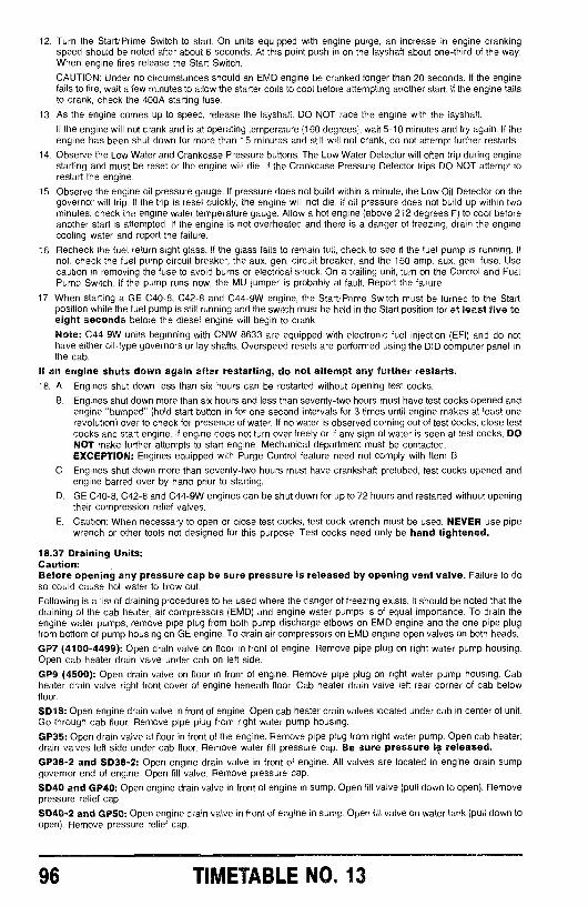
12. Turn the Start/Prime Switch to start. On units equipped with engine purge, an increase in engine crankingspeed should be noted after about 6 seconds. At this point push in on the layshaft about one-third of the way.When engine fires release the Start Switch.
CAUTION: Under no circumstances should an EMD engine be cranked longer than 20 seconds. If the enginefails to fire, wait a few minutes to allow the starter coils to cool before attempting another start. If the engine failsto crank, check the 400A starting fuse.
13. As the engine comes up to speed, release the layshaft. DO NOT race the engine with the layshaft.
If the engine will not crank and is at operating temperature (160 degrees), wait 5 -10 minutes and try again. If theengine has been shut down for more than 15 minutes and still will not crank, do not attempt further restarts.
14. Observe the Low Water and Crankcase Pressure buttons. The Low Water Detector will often trip during enginestarting and must be reset or the engine will die. If the Crankcase Pressure Detector trips DO NOT attempt torestart the engine.
15. Observe the engine oil pressure gauge. If pressure does not build within a minute, the Low Oil Detector on thegovernor will trip. If the trip is reset quickly, the engine will not die. If oil pressure does not build up within twominutes, check the engine water temperature gauge. Allow a hot engine (above 212 degrees F) to cool beforeanother start is attempted. If the engine is not overheated and there is a danger of freezing, drain the enginecooling water and report the failure.
16. Recheck the fuel return sight glass. If the glass fails to remain full, check to see if the fuel pump is running. Ifnot, check the fuel pump circuit breaker, the aux. gen. circuit breaker, and the 150 amp. aux. gen. fuse. Usecaution in removing the fuse to avoid burns or electrical shock. On a trailing unit, turn on the Control and FuelPump Switch. If the pump runs now, the MU jumper is probably at fault. Report the failure.
17. When starting a GE C40 -8, C42 -8 and C44 -9W engine, the Start/Prime Switch must be turned to the Startposition while the fuel pump is still running and the switch must be held in the Start position for at least five toeight seconds before the diesel engine will begin to crank.
Note: C44 -9W units beginning with CNW 8633 are equipped with electronic fuel injection (EFI) and do nothave either oil -type governors or lay shafts. Overspeed resets are performed using the DID computer panel inthe cab.
If an engine shuts down again after restarting, do not attempt any further restarts.18. A. Engines shut down less than six hours can be restarted without opening test cocks.
B. Engines shut down more than six hours and less than seventy -two hours must have test cocks opened andengine "bumped" (hold start button in for one second intervals for 3 times until engine makes at least onerevolution) over to check for presence of water. If no water is observed coming out of test cocks, close testcocks and start engine. If engine does not turn over freely or if any sign of water is seen at test cocks, DONOT make further attempts to start engine. Mechanical department must be contacted.EXCEPTION: Engines equipped with Purge Control feature need not comply with Item B.
C. Engines shut down more than seventy -two hours must have crankshaft prelubed, test cocks opened andengine barred over by hand prior to starting.
D. GE C40 -8, C42 -8 and C44 -9W engines can be shut down for up to 72 hours and restarted without openingtheir compression relief valves.
E. Caution: When necessary to open or close test cocks, test cock wrench must be used. NEVER use pipewrench or other tools not designed for this purpose. Test cocks need only be hand tightened.
18.37 Draining Units:Caution:Before opening any pressure cap be sure pressure is released by opening vent valve. Failure to doso could cause hot water to blow out.
Following is a list of draining procedures to be used where the danger of freezing exists. It should be noted that thedraining of the cab heater, air compressors (EMD) and engine water pumps is of equal importance. To drain theengine water pumps, remove pipe plug from both pump discharge elbows on EMD engine and the one pipe plugfrom bottom of pump housing on GE engine. To drain air compressors on EMD engine open valves on both heads.
GP7 (4100- 4499): Open drain valve on floor in front of engine. Remove pipe plug on right water pump housing.Open cab heater drain valve under cab on left side.
GP9 (4500): Open drain valve on floor in front of engine. Remove pipe plug on right water pump housing. Cabheater drain valve right front cover of engine beneath floor. Cab heater drain valve left rear corner of cab belowfloor.
SD18: Open engine drain valve in front of engine. Open cab heater drain valves located under cab in center of unit.Go through cab floor. Remove pipe plug from right water pump housing.
GP35: Open drain valve at floor in front of the engine. Remove pipe plug from right water pump. Open cab heater;drain valves left side under cab floor. Remove water fill pressure cap. Be sure pressure is released.GP38 -2 and SD38 -2: Open engine drain valve in front of engine. All valves are located in engine drain sumpgovernor end of engine. Open fill valve. Remove pressure cap.
SD40 and GP40: Open engine drain valve in front of engine in sump. Open fill valve (pull down to open). Removepressure relief cap.
SD40 -2 and GP50: Open engine drain valve in front of engine in sump. Open fill valve on water tank (pull down toopen). Remove pressure relief cap.
96 TIMETABLE NO. 13
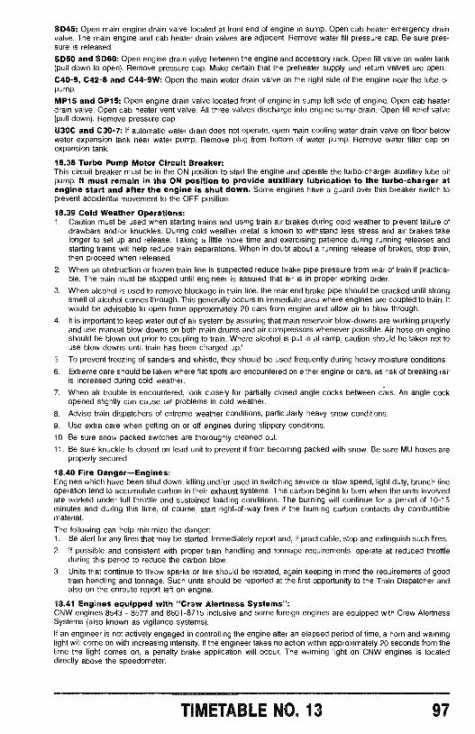
SD45: Open main engine drain valve located at front end of engine in sump. Open cab heater emergency drainvalve. The main engine and cab heater drain valves are adjacent. Remove water fill pressure cap. Be sure pres-sure is released.
SD50 and SD60: Open engine drain valve between the engine and accessory rack. Open fill valve on water tank(pull down to open). Remove pressure cap. Make certain that the preheater supply and return valves are open.
C40 -8, C42 -8 and C44 -9W: Open the main water drain valve on the right side of the engine near the lube -oilpump.
MP15 and GP15: Open engine drain valve located front of engine in sump left side of engine. Open cab heaterdrain valve. Open cab heater vent valve. All three valves discharge into engine sump drain. Open fill relief valve(pull down). Remove pressure cap.
U30C and C30 -7: If automatic water drain does not operate, open main cooling water drain valve on floor belowwater expansion tank near water pump. Remove plug from bottom of water pump. Remove water filler cap onexpansion tank.
18.38 Turbo Pump Motor Circuit Breaker:This circuit breaker must be in the ON position to start the engine and operate the turbo -charger auxiliary lube oilpump. It must remain in the ON position to provide auxiliary lubrication to the turbo -charger atengine start and after the engine is shut down. Some engines have a guard over this breaker switch toprevent accidental movement to the OFF position.
18.39 Cold Weather Operations:1. Caution must be used when starting trains and using train air brakes during cold weather to prevent failure of
drawbars and /or knuckles. During cold weather metal is known to withstand less stress and air brakes takelonger to set up and release. Taking a little more time and exercising patience during running releases andstarting trains will help reduce train separations. When in doubt about a running release of brakes, stop train,then proceed when released.
2. When an obstruction or frozen train line is suspected reduce brake pipe pressure from rear of train if practica-ble. The train must be stopped until engineer is assured that air is in proper working order.
3. When alcohol is used to remove blockage in train line, the rear end brake pipe should be cracked until strongsmell of alcohol comes through. This generally occurs in immediate area where engines are coupled to train. Itwould be advisable to open hose approximately 20 cars from engine and allow air to blow through.
4. It is important to keep water out of air system by assuring that main reservoir blow -downs are working properlyand use manual blow -downs on both main drums and air compressors whenever possible. Air hose on engineshould be blown out prior to coupling to train. Where alcohol is put in at ramp, caution should be taken not touse blow -downs until train has been charged up.'
5. To prevent freezing of sanders and whistle, they should be used frequently during heavy moisture conditions.
6. Extreme care should be taken where flat spots are encountered on either engine or cars, as risk of breaking railis increased during cold weather.
7. When air trouble is encountered, look closely for partially closed angle cocks between cars. An angle cockopened slightly can cause air problems in cold weather.
8. Advise train dispatchers of extreme weather conditions, particularly heavy snow conditions.
9. Use extra care when getting on or off engines during slippery conditions.
10. Be sure snow packed switches are thoroughly cleaned out.
11. Be sure knuckle is closed on lead unit to prevent it from becoming packed with snow. Be sure MU hoses areproperly secured.
18.40 Fire Danger- Engines:Engines which have been shut down, idling and /or used in switching service or slow speed, light duty, branch lineoperation tend to accumulate carbon in their exhaust systems. This carbon begins to burn when the units involvedare worked under full throttle and sustained loading conditions. The burning will continue for a period of 10 -15minutes and during this time, of course, start right -of -way fires if the burning carbon contacts dry combustiblematerial.
The following can help minimize the danger:1. Be alert for any fires that may be started. Immediately report and, if practicable, stop and extinguish such fires.
2. If possible and consistent with proper train handling and tonnage requirements, operate at reduced throttleduring this period to reduce the carbon blow.
3. Units that continue to throw sparks or fire should be isolated, again keeping in mind the requirements of goodtrain handling and tonnage. Such units should be reported at the first opportunity to the Train Dispatcher andalso on the enroute report left on engine.
18.41 Engines equipped with "Crew Alertness Systems ":CNW engines 8543 - 8577 and 8601 -8715 inclusive and some foreign engines are equipped with Crew AlertnessSystems (also known as vigilance systems).
If an engineer is not actively engaged in controlling the engine after an elapsed period of time, a horn and warninglight will come on with increasing intensity. If the engineer takes no action within approximately 20 seconds from thetime the light comes on, a penalty brake application will occur. The warning light on CNW engines is locateddirectly above the speedometer.
TIMETABLE NO. 13 97
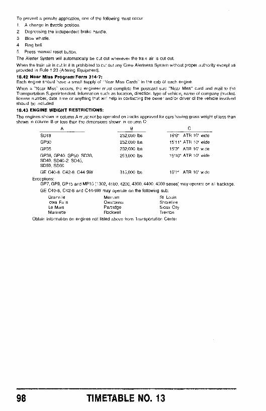
To prevent a penalty application, one of the following must occur:
1. A change in throttle position.
2. Depressing the independent brake handle.
3. Blow whistle.
4. Ring bell.
5. Press manual reset button.
The Alerter System will automatically be cut out whenever the train air is cut out.
When the train air is cut in it is prohibited to cut out any Crew Alertness System without proper authority except asprovided in Rule 1.23 (Altering Equipment).
18.42 Near Miss Program /Form 314 -7:Each engine should have a small supply of "Near Miss Cards" in the cab of each engine.
When a "Near Miss" occurs, the engineer must complete the postcard size "Near Miss" card and mail to theTransportation Superintendent. Information such as location, direction, type of vehicle, name of company (trucks),license number, date, time or anything that will help in contacting the owner and /or driver of the vehicle involvedshould be included.
18.43 ENGINE WEIGHT RESTRICTIONS:
The engines shown in column A must not be operated on tracks approved for cars having gross weight of less thanshown in column B or less than the dimensions shown in column C:
A B C
SD18 232,000 lbs. 16'6" ATR 10' wideGP30 232,000 lbs. 15'11" ATR 10' wide
GP35 232,000 lbs. 15'3" ATR 10' wideGP38, GP40, GP50, SD38, 263,000 lbs. 15'10" ATR 10' wideSD40, SD40 -2, SD45,SD50, SD60
GE C40 -8, C42 -8, C44 -9W 315,000 lbs. 16'1" ATR 10' wideExceptions:
GP7, GP9, GP15 and MP15 (1302, 4100, 4200, 4300, 4400, 4500 series) may operate on all trackage.
GE C40 -8, C42 -8 and C44 -9W may operate on the following sub:
Granville Merriam St. LouisIowa Falls Owatonna ShorelineLe Mars Partridge Sioux CityMarinette Rockwell Trenton
Obtain information on engines not listed above from Transportation Center.
98 TIMETABLE NO. 13
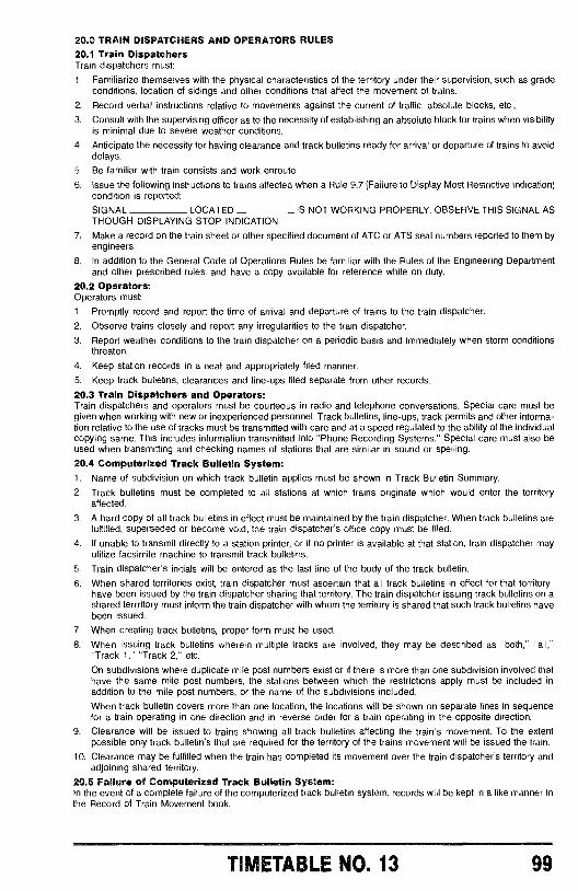
20.0 TRAIN DISPATCHERS AND OPERATORS RULES20.1 Train DispatchersTrain dispatchers must:
1. Familiarize themselves with the physical characteristics of the territory under their supervision, such as gradeconditions, location of sidings and other conditions that affect the movement of trains.
2. Record verbal instructions relative to movements against the current of traffic, absolute blocks, etc.,
3. Consult with the supervising officer as to the necessity of establishing an absolute block for trains when visibilityis minimal due to severe weather conditions.
4. Anticipate the necessity for having clearance and track bulletins ready for arrival or departure of trains to avoiddelays.
5. Be familiar with train consists and work enroute.
6. Issue the following instructions to trains affected when a Rule 9.7 (Failure to Display Most Restrictive Indication)condition is reported:
SIGNAL LOCATED IS NOT WORKING PROPERLY. OBSERVE THIS SIGNAL ASTHOUGH DISPLAYING STOP INDICATION.
7. Make a record on the train sheet or other specified document of ATC or ATS seal numbers reported to them byengineers.
8. In addition to the General Code of Operations Rules be familiar with the Rules of the Engineering Departmentand other prescribed rules, and have a copy available for reference while on duty.
20.2 Operators:Operators must:
1. Promptly record and report the time of arrival and departure of trains to the train dispatcher.
2. Observe trains closely and report any irregularities to the train dispatcher.
3. Report weather conditions to the train dispatcher on a periodic basis and immediately when storm conditionsthreaten.
4. Keep station records in a neat and appropriately filed manner.
5. Keep track bulletins, clearances and line -ups filed separate from other records.
20.3 Train Dispatchers and Operators:Train dispatchers and operators must be courteous in radio and telephone conversations. Special care must begiven when working with new or inexperienced personnel. Track bulletins, line -ups, track permits and other informa-tion relative to the use of tracks must be transmitted with care and at a speed regulated to the ability of the individualcopying same. This includes information transmitted into "Phone Recording Systems." Special care must also beused when transmitting and checking names of stations that are similar in sound or spelling.
20.4 Computerized Track Bulletin System:1. Name of subdivision on which track bulletin applies must be shown in Track Bulletin Summary.
2. Track bulletins must be completed to all stations at which trains originate which would enter the territoryaffected.
3. A hard copy of all track bulletins in effect must be maintained by the train dispatcher. When track bulletins arefulfilled, superseded or become void, the train dispatcher's office copy must be filed.
4. If unable to transmit directly to a station printer, or if no printer is available at that station, train dispatcher mayutilize facsimile machine to transmit track bulletins.
5. Train dispatcher's initials will be entered as the last line of the body of the track bulletin.
6. When shared territories exist, train dispatcher must ascertain that all track bulletins in effect for that territoryhave been issued by the train dispatcher sharing that territory. The train dispatcher issuing track bulletins on ashared terrritory must inform the train dispatcher with whom the territory is shared that such track bulletins havebeen issued.
7. When creating track bulletins, proper form must be used.
8. When issuing track bulletins wherein multiple tracks are involved, they may be described as "both," "all,""Track 1," "Track 2," etc.
On subdivisions where duplicate mile post numbers exist or if there is more than one subdivision involved thathave the same mile post numbers, the stations between which the restrictions apply must be included inaddition to the mile post numbers, or the name of the subdivisions included.
When track bulletin covers more than one location, the locations will be shown on separate lines in sequencefor a train operating in one direction and in reverse order for a train operating in the opposite direction.
9. Clearance will be issued to trains showing all track bulletins affecting the train's movement. To the extentpossible only track bulletin's that are required for the territory of the trains movement will be issued the train.
10. Clearance may be fulfilled when the train has completed its movement over the train dispatcher's territory andadjoining shared territory.
20.5 Failure of Computerized Track Bulletin System:In the event of a complete failure of the computerized track bulletin system, records will be kept in a like manner inthe Record of Train Movement book.
TIMETABLE NO. 13 99
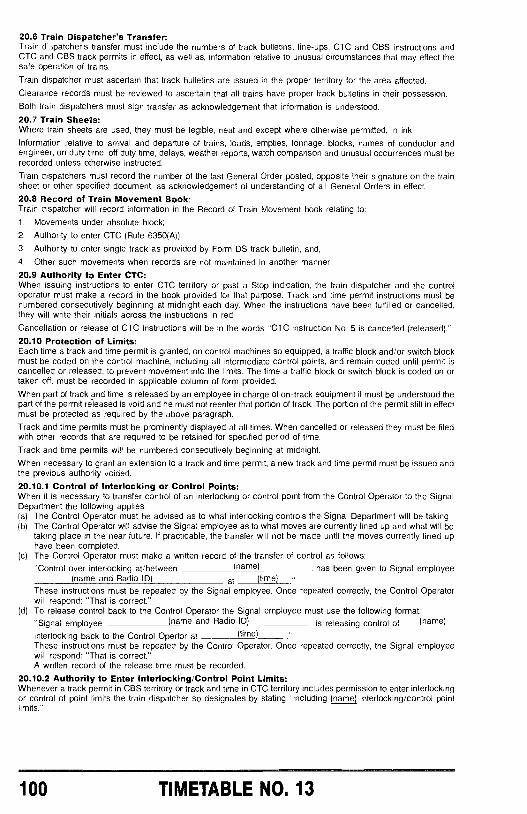
20.6 Train Dispatcher's Transfer:Train d ,;patcher's transfer must include the numbers of track bulletins, line -ups, CTC and CBS instructions andCTC and CBS track permits in effect, as well as, information relative to unusual circumstances that may effect thesafe operation of trains.
Train dispatcher must ascertain that track bulletins are issued in the proper territory for the area affected.
Clearance records must be reviewed to ascertain that all trains have proper track bulletins in their possession.
Both train dispatchers must sign transfer as acknowledgement that information is understood.
20.7 Train Sheets:Where train sheets are used, they must be legible, neat and except where otherwise permitted, in ink.
Information relative to arrival and departure of trains, loads, empties, tonnage, blocks, names of conductor andengineer, on duty time, off duty time, delays, weather reports, watch comparison and unusual occurrences must berecorded unless otherwise instructed.
Train dispatchers must record the number of the last General Order posted, opposite their signature on the trainsheet or other specified document, as acknowledgement of understanding of all General Orders in effect.
20.8 Record of Train Movement Book:Train dispatcher will record information in the Record of Train Movement book relating to:
1. Movements under absolute block;
2. Authority to enter CTC (Rule 6350(A));
3. Authority to enter single track as provided by Form DS track bulletin, and,4. Other such movements when records are not maintained in another manner.
20.9 Authority to Enter CTC:When issuing instructions to enter CTC territory or past a Stop indication, the train dispatcher and the controloperator must make a record in the book provided for that purpose. Track and time permit instructions must benumbered consecutively beginning at midnight each day. When the instructions have been fulfilled or cancelled,they will write their initials across the instructions in red.
Cancellation or release of CTC instructions will be in the words "CTC instruction No. 5 is cancelled (released)."
20.10 Protection of Limits:Each time a track and time permit is granted, on control machines so equipped, a traffic block and /or switch blockmust be coded on the control machine, including all intermediate control points, and remain coded until permit iscancelled or released, to prevent movement into the limits. The time a traffic block or switch block is coded on ortaken off, must be recorded in applicable column of form provided.
When part of track and time is released by an employee in charge of on -track equipment it must be understood thepart of the permit rèleased is void and he must not reenter that portion of track. The portion of the permit still in effectmust be protected as required by the above paragraph.
Track and time permits must be prominently displayed at all times. When cancelled or released they must be filedwith other records that are required to be retained for specified period of time.
Track and time permits will be numbered consecutively beginning at midnight.
When necessary to grant an extension to a track and time permit, a new track and time permit must be issued andthe previous authority voided.
20.10.1 Control of interlocking or Control Points:When it is necessary to transfer control of an interlocking or control point from the Control Operator to the SignalDepartment the following applies:(a) The Control Operator must be advised as to what interlocking controls the Signal Department will be taking.(b) The Control Operator will advise the Signal employee as to what moves are currently lined up and what will be
taking place in the near future. If practicable, the transfer will not be made until the moves currently lined uphave been completed.
(c) The Control Operator must make a written record of the transfer of control as follows:
"Control over interlocking at /between (name) has been given to Signal employee(name and Radio ID) at (time)
These instructions must be repeated by the Signal employee. Once repeated correctly, the Control Operatorwill respond: "That is correct."
(d) To release control back to the Control Operator the Signal employee must use the following format:"Signal employee (name and Radio ID) is releasing control of (name)
interlocking back to the Control Opertor at (time)
These instructions must be repeated by the Control Operator. Once repeated correctly, the Signal employeewill respond: "That is correct."A written record of the release time must be recorded.
20.10.2 Authority to Enter Interlocking /Control Point Limits:Whenever a track permit in CBS territory or track and time in CTC territory includes permission to enter interlockingor control of point limits the train dispatcher so designates by stating "including (name) interlocking /control pointlimits."
100 TIMETABLE NO. 13
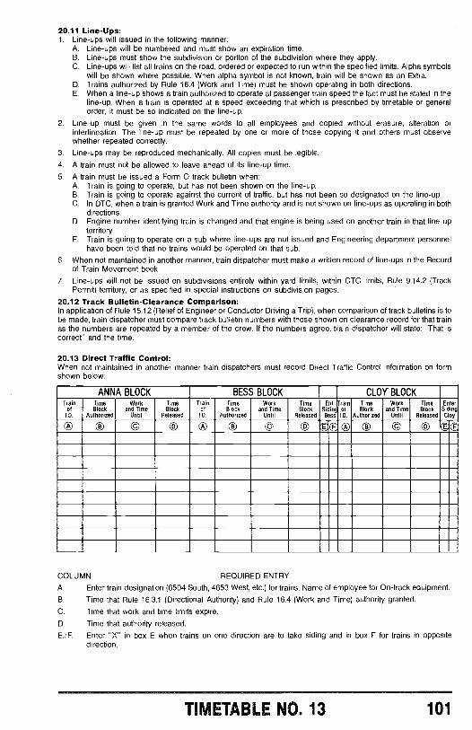
20.11 Line -Ups:1. Line -ups will issued in the following manner:
A. Line -ups will be numbered and must show an expiration time.B. Line -ups must show the subdivision or portion of the subdivision where they apply.C. Line -ups will list all trains on the road, ordered or expected to run within the specified limits. Alpha symbols
will be shown where possible. When alpha symbol is not known, train will be shown as an Extra.D. Trains authorized by Rule 16.4 (Work and Time) must be shown operating in both directions.E. When a line -up shows a train authorized to operate at passenger train speed the fact must be stated in the
line -up. When a train is operated at a speed exceeding that which is prescribed by timetable or generalorder, it must be so indicated on the line -up.
2. Line -up must be given in the same words to all employees and copied without erasure, alteration orinterlineation. The line -up must be repeated by one or more of those copying it and others must observewhether repeated correctly.
3. Line -ups may be reproduced mechanically. All copies must be legible.
4. A train must not be allowed to leave ahead of its line -up time.
5. A train must be issued a Form O track bulletin when:A. Train is going to operate, but has not been shown on the line -up.B. Train is going to operate against the current of traffic, but has not been so designated on the line -up.C. In DTC, when a train is granted Work and Time authority and is not shown on line -ups as operating in both
directions.D. Engine number identifying train is changed and that engine is being used on another train in that line -up
territory.E. Train is going to operate on a sub where line -ups are not issued and Engineering department personnel
have been told that no trains would be operated on that sub.
6. When not maintained in another manner, train dispatcher must make a written record of line -ups in the Recordof Train Movement book.
7. Line -ups will not be issued on subdivisions entirely within yard limits, within CTC limits, Rule 9.14.2 (TrackPermit) territory, or as specified in special instructions on subdivision pages.
20.12 Track Bulletin- Clearance Comparison:In application of Rule 15.12 (Relief of Engineer or Conductor Driving a Trip), when comparison of track bulletins is tobe made, train dispatcher must compare track bulletin numbers with those shown on clearance record for that trainas the numbers are repeated by a member of the crew. If the numbers agree, train dispatcher will state: "That iscorrect" and the time.
20.13 Direct Traffic Control:When not maintained in another manner train dispatchers must record Direct Traffic Control information on formshown below:
ANNA BLOCK BESS BLOCK CLOY BLOCKTrain
ID.Block
ID.
Time
Authorized
Workand Time
Until
TimeBlock
Released
TrainofLD.
TimeBlock
Authorized
Workand Time
Until
TimeBlock
Released
Ent.SidingBess
TrainorID.
TimeBlock
Authorized
Workand Time
Until
TimeBlock
Released
EnterSidingCloy
© © © ® © CO © Ú®0 ® © © ®È F
COLUMN REQUIRED ENTRY
A. Enter train designation (6504 South, 4653 West, etc.) for trains. Name of employee for On -track equipment.
B. Time that Rule 16.3.1 (Directional Authority) and Rule 16.4 (Work and Time) authority granted.
C. Time that work and time limits expire.
D. Time that authority released.
E. /F. Enter "X" in box E when trains on one direction are to take siding and in box F for trains in oppositedirection.
TIMETABLE NO. 13 101
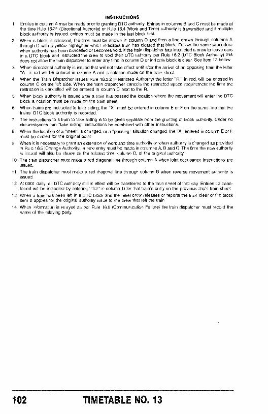
INSTRUCTIONS
1. Entries in column A may be made prior to granting DTC authority. Entries in columns B and C must be made atthe time Rule 16.31 (Directional Authority) or Rule 16.4 (Work and Time) authority is transmitted and if multipleblock authority is issued, entries must be made in the last block first.
2. When a block is released, the time must be shown in column D and then a line drawn through columns Athrough D with a yellow highlighter which indicates train has cleared that block. Follow the same procedurewhen authority has been cancelled or becomes void. If the train dispatcher has instructed a crew to leave carsin a DTC block and instructed the crew to void their DTC authority per Rule 16.2 (DTC Block Authority) thisdoes not allow the train dispatcher to enter any time in column D or indicate block is clear. See Item 13 below.
3. When directional authority is issued that will not take effect until after the arrival of an opposing train the letter"A" in red will be entered in column A and a notation made on the train sheet.
4. When the Train Dispatcher issues Rule 16.3.2 (Restricted Authority) the letter "R," in red, will be entered incolumn C on the left side. When the train dispatcher cancels the restricted speed requirement the time therestriction is cancelled will be entered in column C next to the R.
5. When block authority is issued after a train has passed the location where the movement will enter the DTCblock a notation must be made on the train sheet.
6. When trains are instructed to take siding, the "X" must be entered in column E or F on the same line that thetrains' DTC block authority is recorded.
7. The instructions to a train to take siding is to be given separate from the granting of block authority. Under nocircumstances can "take siding" instructions be combined with other instructions.
8. When the location of a "meet" is changed, or a "passing" situation changed, the "X" entered in column E or Fmust be circled for the original point.
9. When it is necessary to grant an extension of work and time authority or when authority is changed as providedin Rule 16.5 (Change Authority), a new entry must be made in columns A, B and C. The time the new authorityis issued will also be shown as the release time, column D, of the original authority.
10. The train dispatcher must make a red diagonal line through column A when joint occupancy instructions areissued.
11. The train dispatcher must make a red diagonal line through column B when reverse movement authority isissued.
12. At 0001 daily, all DTC authority still in effect will be transferred to the train sheet of that day. Entries so trans-ferred will be indicated by entering "tfrd" in column D for that train's entry on the previous day's train sheet.
13. When a train has been left in a DTC block and the relief crew releases or reports the train clear of the blockItem 2 applies for the original authority issue to the crew that left the train.
14. When information is relayed as per Rule 16.9 (Communication Failure) the train dispatcher must record thename of the relaying party.
102 TIMETABLE NO. 13
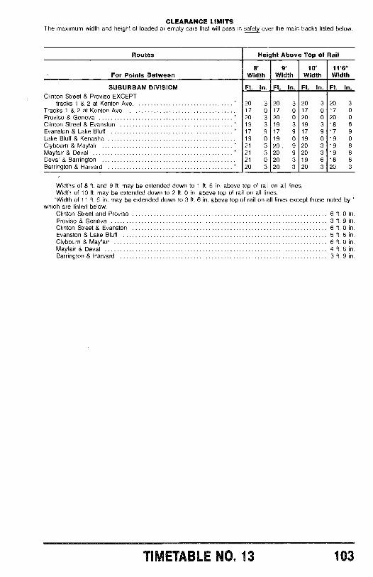
CLEARANCE LIMITSThe maximum width and height of loaded or empty cars that will pass in safety over the main tracks listed below.
Routes Height Above Top of Rail
For Points Between8'
Width9'
Width10'
Width11'6"Width
SUBURBAN DIVISION Ft. In. Ft. In. Ft. In. Ft. In.Clinton Street & Proviso EXCEPT
tracks 1 & 2 at Kenton Ave. * 20 3 20 3 20 3 20 3Tracks 1 & 2 at Kenton Ave. 17 0 17 0 17 0 17 0Proviso & Geneva " 20 3 20 0 20 0 20 0Clinton Street & Evanston " 19 3 19 3 19 3 18 6Evanston & Lake Bluff ' 17 9 17 9 17 9 17 9Lake Bluff & Kenosha 19 0 19 0 19 0 19 0Clybourn & Mayfair * 21 3 20 . 9 20 3 19 6Mayfair & Deval ' 21 3 20 9 20 3 19 6Deval & Barrington 21 0 20 3 19 6 18 6Barrington & Harvard ' 20 3 20 3 20 3 20 3
Widths of 8 ft. and 9 ft. may be extended down to 1 ft. 6 in. above top of rail on all lines.Width of 10 ft. may be extended down to 2 ft. 0 in. above top of rail on all lines.
*Width of 11 ft. 6 in. may be extended down to 3 ft. 6 in. above top of rail on all lines except those notedby "which are listed below:
Clinton Street and Proviso 6 ft. 0 in.Proviso & Geneva 3 ft. 9 in.Clinton Street & Evanston 6 ft. 0 in.Evanston & Lake Bluff 5 ft. 6 in.Clybourn & Mayfair 6 ft. 0 in.Mayfair & Deval 4 ft. 6 in.Barrington & Harvard 3 ft. 9 in.
..111110l0M1061=80
TIMETABLE NO. 13 103
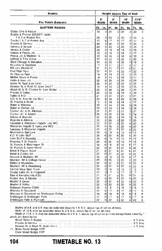
Routes Height Above Top of Rail
For Points Between8'
Width9°
Width10'
Width11'6"Width
EASTERN REGION Ft. In. Ft. In. Ft. In. Ft. In.Global One & Kedzie * 20 3 20 3 20 3 20 3Kedzie & Proviso EXCEPT tracks
1 & 2 at Kenton Ave. 20 3 20 3 20 3 20 3Tracks 1 & 2 at Kenton Ave. 17 0 17 0 17 0 17 0Proviso & Geneva * 20 3 20 3 20 3 20 3Geneva & Nelson 20 3 20 3 20 3 20 3Nelson & Clinton 20 3 19 9 19 0 18 0Nelson & Peoria Jct. 19 3 19 0 18 3 17 3Peoria Jct. & Madison, IL 19 9 19 3 18 9 18 0DeKalb & Troy Grove 22 0 22 0 22 0 22 0West Chicago & Belvidere 20 0 20 0 20 0 19 3Belvidere & Rockford 17 3 17 3 17 3 17 3KD Line (Rockford) 21 6 21 6 21 6 21 6East Elgin Spur 22 0 22 0 22 0 22 0St. Charles Spur 19 6 19 6 19 6 19 6Middle Grove & Peoria 19 3 19 0 18 3 17 3Hollis & Iowa Jct. 20 0 20 0 20 0 20 0Noble St. Spur (Low Line) 22 0 22 0 22 0 22 0Division St. & Rush St. (Low Line)I1I 15 3 15 3 15 3 15 3Wood St. & St. Charles Air Line Bridge 20 3 20 3 20 3 20 3Proviso & Valley * 20 3 19 9 19 3 18 3Valley & K.O. 21 3 21 3 21 3 21 3K.O. & St. Francis (via Bain) 20 9 20 9 20 9 20 9St. Francis & Butler 19 0 18 9 18 3 17 3Butler & Wiscona 20 0 19 6 18 9 18 0Butler & Clyman Jct. 20 0 19 6 18 9 18 0Clyman Jct. & Ft. Atkinson 21 3 21 3 21 3 21 3Clyman Jct. & Adams 20 0 22 0 19 9 18 6Adams & Wyeville 21 0 20 3 19 9 18 6Wyeville & Altoona 20 3 20 3 20 3 20 3Necedah & Wisconsin Rapids (via WC) 22 0 22 0 22 0 22 0Wisconsin Rapids & Itasca (via WC) 20 0 20 0 20 0 20 0Nekoosa & Wisconsin Rapids 22 0 22 0 22 0 22 0Menominee Belt Line 19 0 19 0 19 0 19 0K.O. & Lake Bluff 20 6 20 6 20 6 20 6Lake Bluff & Kenosha 19 0 19 0 19 0 19 0Kenosha & St. Francis 20 6 20 0 19 6 18 9St. Francis & Washington St. 19 6 19 0 18 6 17 9St. Francis & Jones Island 22 0 22 0 22 0 22 0Beloit & Poplar Grove 21 6 21 6 21 6 21 6Beloit & Clinton Jct. 22 0 22 0 22 0 22 0Harvard & Madison, WI 19 3 19 3 18 9 17 9Madison, WI & Cottage Grove 20 6 20 3 20 3 20 3Belton & Waukesha 22 0 22 0 22 0 22 0Madison, WI & Reedsburg 22 0 22 0 22 0 22 0Central Soya Spur Track 19 3 19 3 19 3 19 3Crystal Lake Jct. & Ringwood 17 3 17 3 17 3 17 3Bain & Kenosha (via K.D ) 21 9 21 9 21 9 21 9Kenton Ave. & Mayfair 22 0 22 0 22 0 22 0Mayfair & Devon 22 0 22 0 22 0 22 0Mayfair & Valley 22 0 22 0 22 0 22 0Bellwood (Former CGW) 18 3 18 3 18 3 18 3Wiscona & Cleveland 17 0 17 0 17 0 17 0Wiscona & Cleveland via Sheboygan Siding 19 6 19 6 19 6 19 6Sheboygan & Sheboygan Falls 17 0 17 0 17 0 17 0Sheboygan Falls & Plymouth 22 0 22 0 22 0 22 0
Widths of 8 ft. and 9 ft. may be extended down to 1 ft. 6 in. above top of rail on all lines.Width of 10 ft. may be extended down to 2 ft. 0 in. above top of rail on all lines.
*Width of 11 ft. 6 in. may be extended down to 3 ft. 6 in. above top of rail on all lines except those noted by *which are listed blow:
Wood Street & Kedzie 6 ft. 0 in.Proviso & Geneva 3 ft. 9 in.Division St. & Rush St. (Low Line ) 4 ft. 0 in.
(1) Wells Street Bridge 15'8"Clark Street Bridge 15'6"
104 TIMETABLE NO. 13
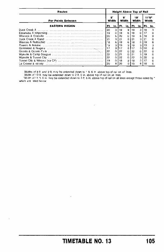
Routes Height Above Top of Rail
For Points Between8'
Width9'
Width10'
Width11'6"Width
EASTERN REGION Ft. In. Ft. In. Ft. In. Ft. In.Duck Creek & 20 3 19 9 19 3 18 3Escanaba & Ishpeming 19 0 18 6 18 0 17 0Wiscona & Granville 20 6 20 0 19 6 18 9Duck Creek & Eland 21 0 21 0 21 0 21 0Wausau & Rothschild 18 6 18 6 18 6 18 6Powers & Antoine 19 3 19 3 19 3 19 3Quinnesec & Niagara 17 9 17 6 17 0 16 6Oconto & Oconto Falls 22 0 22 0 22 0 22 0Wyeville & Camp Douglas 22 0 21 0 21 3 19 6Wyeville & Tunnel City 22 0 22 0 22 0 22 0Tunnel City & Winona (via CP) 19 0 18 9 18 3 17 6La Crosse & vicinity 20 6 20 0 19 6 18 6
Widths of 8 ft. and 9 ft. may be extended down to 1 ft. 6 in. above top of rail on all lines.Width of 10 ft. may be extended down to 2 ft. 0 in. above top of rail on all lines.
*Width of 11 ft. 6 in. may be extended down to 3 ft. 6 in. above top of rail on all lines except those noted by *which are listed below:
TIMETABLE NO. 13 105
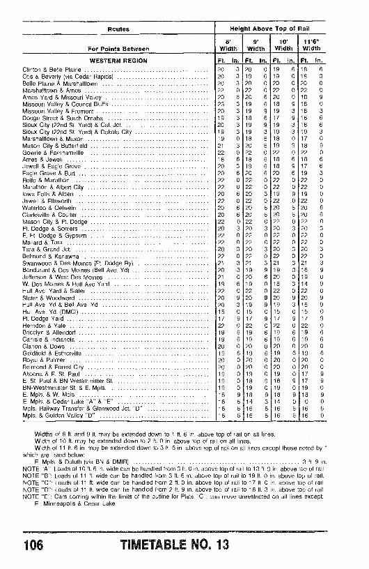
Routes - Height Above Top of Rail
For Points Between8'
Width9'
Width19'
Width11'6"Width
WESTERN REGION Ft. In. Ft. In. Ft. In. Ft. In.
Clinton & Belle Plaine 20 3 20 0 19 6 18 6Otis & Beverly (via Cedar Rapids) 20 3 19 6 19 0 18 3Belle Plaine & Marshalltown 20 3 20 0 20 0 20 0Marshalltown & Ames 22 0 22 0 22 0 22 0Ames Yard & Missouri Valley 20 6 20 6 20 0 18 9Missouri Valley & Council Bluffs 23 3 19 6 18 9 18 0
Missouri Valley & Fremont 20 3 19 9 19 3 18 3Dodge Street & South Omaha 19 3 18 6 17 9 16 6Sioux City (22nd St. Yard) & Cal. Jct. 20 3 19 9 19 3 18 6Sioux City (22nd St. Yard) & Dakota City 19 3 19 3 19 3 19 3Marshalltown & Maxon 19 0 18 6 18 0 17 0Mason City & Butterfield 21 3 20 6 19 9 18 9Gowrie & Farnhamville 22 0 22 0 22 0 22 0Ames & Jewell 18 6 18 6 18 6 18 6Jewell & Eagle Grove 20 3 19 6 18 9 17 6Eagle Grove & Burt 20 6 20 6 20 6 19 3Rolfe & Marathon 22 0 22 0 22 0 22 0Marathon & Albert City 22 0 22 0 22 0 22 0Iowa Falls & Alden 20 6 20 3 19 9 19 0Jewell & Ellsworth 22 0 22 0 22 0 22 0Waterloo & Oelwein 20 6 20 6 20 6 20 6
Clarksville & Coulter 20 6 20 6 20 6 20 6
Mason City & Ft. Dodge 22 0 22 0 22 0 22 0Ft. Dodge & Somers 20 3 20 3 20 3 20 3E. Ft. Dodge & Gypsum 22 0 22 0 22 0 22 0Mallard & Tara 22 0 22 0 22 0 22 0Tara & Grand Jct. 20 3 20 3 20 3 20 3Belmond & Kanawha 22 0 22 0 22 0 22 0Swanwood & Des Moines (Ft. Dodge Ry) 21 3 21 3 21 3 21 3Bondurant & Des Moines (Bell Ave. Yd) 20 3 19 9 19 3 16 9Jefferson & West Des Moines 21 0 20 6 20 0 19 0W. Des Moines & Hull Ave Yard 19 6 19 0 18 3 14 9Hull Ave. Yard & Slater 22 0 22 0 22 0 22 0Slater & Woodward 20 9 20 9 20 9 20 9Hull Ave. Yd & Bell Ave. Yd 20 3 19 9 19 3 16 9Hull Ave. Yd. (DMCI) 15 0 15 0 15 0 15 0Ft. Dodge Yard 17 9 17 9 17 9 17 9Herndon & Yale 22 0 22 0 22 0 22 0Bricelyn & Allendorf 19 6 19 6 19 6 19 6Carlisle & Indianola 19 6 19 6 19 6 19 6Clarion & Dows 20 0 20 0 20 0 20 0Goldfield & Estherville 19 6 19 6 19 6 19 6Royal & Palmer 20 0 20 0 20 0 20 0Belmond & Forest City 20 0 20 0 20 0 20 0Altoona & E. St. Paul 19 0 19 0 19 0 17 9
E. St. Paul & BN- Westminister St. 19 0 18 9 18 9 17 9BN- Westminister St. & E. Mpls. 19 0 19 0 19 0 19 0E. Mpls. & W. Mpls. 18 9 18 9 18 9 18 9E. Mpls. & Cedar Lake "A" & "E" 16 6 14 3 14 0 0 0Mpls. Railway Transfer & Glenwood Jct. "D" 16 6 16 6 16 6 16 6Mpls. & Golden Valley "D" 16 6 16 6 16 6 16 0
Widths of 8 ft. and 9 ft. may be extended down to 1 ft. 6 in. above top of rail on all lines.Width of 10 ft. may be extended down to 2 ft. 0 in. above top of rail on all lines.Width of 11 ft. 6 in. may be extended down to 3 ft. 6 in. above top of rail on all lines except those noted by '
which are listed below:E. Mpls. & Duluth (via BN & DMIR) 3 ft. 9 in.
NOTE "A ": Loads of 10 ft. 6 in. wide can be handled from 3 ft. 0 in. above top of rail to 13 ft. 9 in. above top of rail.NOTE "B ": Loads of 11 ft. wide can be handled from 3 ft. 6 in. above top of rail to 19 ft. 0 in. above top of rail.NOTE "C ": Loads of 11 ft. wide can be handled from 2 ft. 0 in. above top of rail to 17 ft. 0 in. above top of rail.NOTE "D ": Loads of 11 ft. wide can be handled from 2 ft. 9 in. above top of rail to 16 ft. 3 in. above top of rail.NOTE "E ": Cars coming within the limits of the outline for Plate "C", can move unrestricted on all lines except:
E.: Minneapolis & Cedar Lake
106 TIMETABLE NO. 13
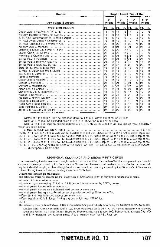
Routes Height Above Top of Rail
For Points Oetween8'
Width9'
Width10'
Width11'6"Width
WESTERN REGION Ft. In. Ft. In. Ft. In. Ft. In.Cedar Lake & 1st Ave. N. "A" & "E" 16 6 14 3 14 0 0 0Railway Transfer & Mpls., 1st Ave. N. 16 6 16 6 16 6 16 6E. St. Paul ( Westminister St.) & Union Depot 19 5 19 5 19 5 19 5St. Paul Union Depot & Chestnut St. "B" 19 0 19 0 19 0 0 0St. Paul (Chestnut St.) & Western Ave. 22 0 22 0 22 0 22 0Western Ave. & Mankato 21 3 21 3 21 3 21 3Mankato & Sioux City (22nd St. Yard) 20 6 20 0 19 6 18 9Mason City & So. St. Paul 20 3 20 0 19 6 19 6Northfield & Cannon Falls 21 6 21 6 21 6 21 6So. St. Paul & Roseport 21 6 21 6 21 6 21 6So. St. Paul & Hoffman Ave. Yd. 20 3 19 3 18 9 17 9So. St. Paul & State St., St. Paul 22 0 22 0 22 0 22 0State St., St. Paul & E. St. Paul 19 0 18 6 18 0 17 9E. Mpls. & Duluth (via BN & DMIR) 19 0 18 3 18 3 18 0Eau Claire & Cameron 20 0 19 6 19 0 18 3Trego & Hayward 19 9 19 3 18 6 17 6Cedar Lake & Hopkins 19 9 19 9 19 9 19 9Chaska & Merriam 21 6 21 6 21 6 21 6Merriam & Montgomery 21 6 21 6 21 6 21 6Albert Lea & Hartland 21 0 21 0 21 0 21 0Menomonie Jct. & Menomonie "C" 18 6 18 0 17 6 10 0Hudson & Stillwater 21 3 20 9 20 3 19 6Fremont & Norfolk (via UP) 20 0 20 0 20 0 20 0Chadron & Rapid City 19 6 19 0 18 9 18 0Rapid City & Belle Fourche 18 0 17 6 17 0 16 3Belle Fourche & Colony 22 0 22 0 22 0 22 0Joyce & E. Caballo Jct. (WRPI) 22 0 22 0 22 0 22 0
Widths of 8 ft. and 9 ft. may be extended down to 1 ft. 6 in. above top of rail on all lines.Width of 10 ft. may be extended down to 2 ft. 0 in. above top of rail on all lines.Width of 11 ft. 6 in. may be extended down to 3 ft. 6 in. above top of rail on all lines except those noted by "
which are listed below:E. Mpls. & Duluth (via BN & DMIR) 3 ft. 9 in.
NOTE "A ": Loads of 10 ft. 6 in. wide can be handled from 3 ft. 0 in. above top of rail to 13 ft. 9 in. above top of rail.NOTE "B ": Loads of 11 ft. wide can be handled from 3 ft. 6 in. above top of rail to 19 ft. 0 in. above top of rail.NOTE "C ": Loads of 11 ft. wide can be handled from 2 ft. 0 in. above top of rail to 17 ft. 0 in. above top of rail.NOTE "D ": Loads of 11 ft. wide can be handled from 2 ft. 9 in. above top of rail to 16 ft. 3 in. above top of rail.NOTE "E ": Cars coming within the limits of the outline for Plate "C ", can move unrestricted on all lines except:
E.. Minneapolis & Cedar Lake
ADDITIONAL CLEARANCE AND WEIGHT RESTRICTIONSLoads exceeding the dimensions or weights outlined in the timetable, may be handled if accompanied by a specificclearance message issued by the Supervisor of Clearances. Trainmen and yardmen must know that cars exceed-ing the indicated weight, width and height restrictions have been properly cleared by the Supervisor of Clearancesbefore placing them in trains or hauling them over CNW lines.Clearance Message Required:The following must be cleared by the Supervisor of Clearances prior to movement regardless of route:-Loads 11 ft. 6 in. wide or more-Loads or cars exceeding 17 ft. 0 in. A.T.R. (except those covered by NOTE, below).-Any shipment loaded with an overhang.-Any shipment loaded as a bolstered load on two or more cars.-Any shipment having a combined center of gravity exceeding 96 inches A.T.R.-Cars 35 ft. or less in length, except ore jenny cars.-Cars less than 40 ft. in length having a gross weight over 220,00 lbs.NOTE:The following may be handled over CNW lines without being individually cleared by the Supervisor of Clearances:1. Double Stack Container loads and TTQX Type Multilevels up to 20'2" A.T.R. moving between the following
locations: Global I & II and Council Bluffs, IA, Fremont, NE, Kansas City, MO, Belvidere, IL; Kansas City, MOand E. Minneapolis, MN; Council Bluffs, IA and Western Ave. Yard -St. Paul, MN.
TIMETABLE NO. 13 107
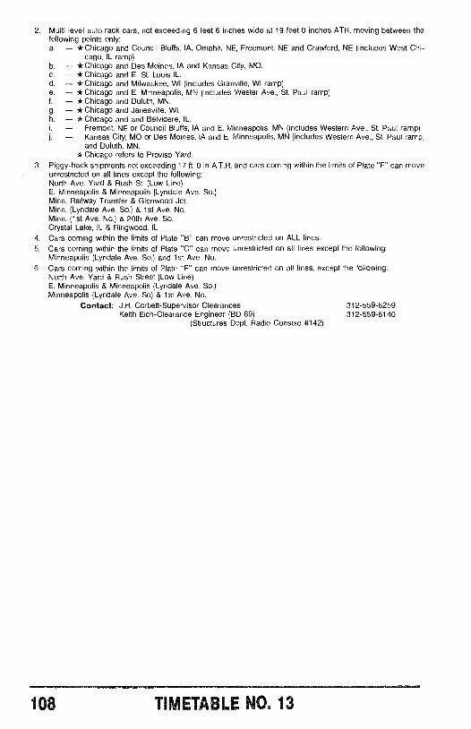
2. Multi level auto rack cars, not exceeding 6 feet 6 inches wide at 19 feet 0 inches ATR, moving between thefollowing points only:a. -* Chicago and Council Bluffs, IA, Omaha, NE, Freemont, NE and Crawford, NE (includes West Chi-
cago, IL ramp).b. -* Chicago and Des Moines, IA and Kansas City, MO.c. -* Chicago and E. St. Louis IL.d. - *Chicago and Milwaukee, WI (includes Granville, WI ramp).e. -* Chicago and E. Minneapolis, MN (includes Wester Ave., St. Paul ramp).f. -* Chicago and Duluth, MN.g. -* Chicago and Janesville, WI.h. -* Chicago and and Belvidere, IL.- Fremont, NE or Council Bluffs, IA and E. Minneapolis, MN (includes Western Ave., St. Paul ramp)j. - Kansas City, MO or Des Moines, IA and E. Minneapolis, MN (includes Western Ave., St. Paul ramp,
and Duluth, MN.* Chicago refers to Proviso Yard.
3. Piggy -back shipments not exceeding 17 ft. 0 in A.T.R. and cars coming within the limits of Plate "F" can moveunrestricted on all lines except the following:North Ave. Yard & Rush St. (Low Line)E. Minneapolis & Minneapolis (Lyndale Ave. So.)Minn. Railway Transfer & Glenwood Jct.Minn. (Lyndale Ave. So.) & 1st Ave. No.Minn. (1st Ave. No.) & 20th Ave. So.Crystal Lake, IL & Ringwood, IL
4. Cars coming within the limits of Plate "B" can move unrestricted on ALL lines.5. Cars coming within the limits of Plate "C" can move unrestricted on all lines except the following:
Minneapolis (Lyndale Ave. So.) and 1st Ave. No.6. Cars coming within the limits of Plate "E" can move unrestricted on all lines, except the following:
North Ave. Yard & Rush Street (Low Line)E. Minneapolis & Minneapolis (Lyndale Ave. So.)Minneapolis (Lyndale Ave. So) & 1st Ave. No.
Contact: J.H. Corbett- Supervisor Clearances 312 -559 -6259Keith Eich- Clearance Engineer (BD 89) 312- 559 -6140
(Structures Dept. Radio Console 8142)
108 TIMETABLE NQ. 13
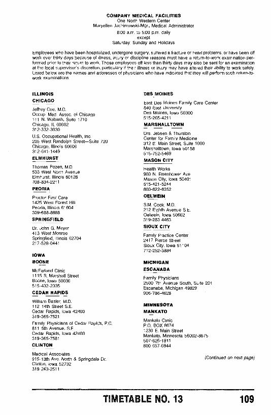
COMPANY MEDICAL FACILITIESOne North Western Center
Maryellen Jachimowski -Mgr., Medical Administrator
8:00 a.m. to 5:00 p.m. dailyexcept
Saturday, Sunday and Holidays
Employees who have been hospitalized, undergone surgery, suffered a fracture or heart problems, or have been offwork over thirty days because of illness, injury or discipline reasons must have a return -to -work examination per-formed prior to their return to work. Those employees off less than thirty days may also be sent for an examinationat the local supervisor's discretion, particulary if their illness or injury may have altered their ability to work safely.Listed below are the names and addresses of physicians who have indicated that they will perform such return -to-work examinations.
ILLINOISCHICAGO
Jeffrey Coe, M.D.Occup. Med. Assoc. of Chicago111 N. Wabash, Suite 1710Chicago, IL 60602312 - 332 -3030
U.S. Occupational Health, Inc.205 West Randolph Street -Suite 720Chicago, Illinois 60606312 -641 -1449
ELMHURST
Thomas Pozen, M.D.533 West North AvenueElmhurst, Illinois 60126708 -834 -2211
PEORIA
Proctor First Care1425 West Forest HillPeoria, Illinois 61604309 -688 -8888
SPRINGFIELD
Dr. John G. Meyer413 West MonroeSpringfield, Illinois 62704217 -528 -0441
IOWABOONE
McFarland Clinic1115 S. Marshall StreetBoone, Iowa 50036515 -432 -2335
CEDAR RAPIDS
William Basler, M.D.112 14th Street S.E.Cedar Rapids, Iowa 42400319 -365 -7521
Family Physicians of Cedar Rapids, P.C.811 5th Avenue, S.E.Cedar Rapids, Iowa 42400319 -365 -7581
CLINTON
Medical Associates915 -13th Ave. North & Springdale Dr.Clinton, Iowa 52732319 -243 -2511
DES MOINES
East Des Moines Family Care Center840 East UniversityDes Moines, Iowa 50300515- 265 -4211
MARSHALLTOWN
Drs. Jebsen & ThurstonCenter for Family Medicine312 E. Main Street, Suite 1000Marshalltown, Iowa 50158515 -752 -5469
MASON CITY
Health Works900 N. Eisenhower Ave.Mason City, Iowa 50401515 -421 -5244800- 622 -6352
OELWEIN
S.M. Cook, M.D.212 Eighth Avenue S.E.Oelwein, Iowa 50662319- 283 -4463
SIOUX CITY
Family Practice Center2417 Pierce StreetSioux City, Iowa 51104712- 252 -3884
MICHIGANESCANABA
Family Physicians2500 7th Avenue South, Suite 201Escanaba, Michigan 49829906 -786 -4628
MINNESOTAMANKATO
Mankato ClinicP.O. BOX 86741230 E. Main StreetMankato, Minnesota 56002 -8675507- 625 -1811800 -657 -6944
(Continued on next page)
TIVETABLE NO. 13 109
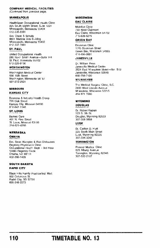
COMPANY MEDICAL FACILITIES(Continued from previous page)
MINNEAPOLIS
HealthSpan Occupational Health Clinic825 South Eighth Street, Suite 1224Minneapolis, Minnesota 55404612 -336 -8381
Drs. Olson & Schultz8601 Medical Arts BuildingMinneapolis, Minnesota 55402612- 332 -7881
ST. PAUL
United Occupational Health280 North Smith Avenue -Suite 144St. Paul, Minnesota 55102612 -220 -8106
WORTHINGTON
Worthington Medical Center508 10th StreetWorthington, Minnesota 56187507- 372 -2921
MISSOURIKANSAS CITY
Business & Industry Health Group720 Oak StreetKansas City, Missouri 64106816- 842 -1146
ST. LOUIS
Barnes Care401 N. Pine StreetSt. Louis, Missouri 63100314 -621 -4300
NEBRASKAOMAHA
Drs. Dean Wampler & Ron OlnhausenRegency Physician's ClinicOccupational Health Dept. - 3rd Floor10060 Regency CircleOmaha, NE 68114402- 390 -1425
SOUTH DAKOTARAPID CITY
Black Hills Family Practice /Ind. Med.902 Columbus St.Rapid City, SD 57701605 -348 -2273
WISCONSINEAU CLAIRE
Midelfort Clinic733 West ClairmontEau Claire, Wisconsin 54702715- 839 -5279
GREEN BAY
Dousman Clinic1745 Dousman StreetGreen Bay, Wisconsin 54303414 -494 -9661
JANESVILLE
Dr. William PennJanesville Medical Center3524 East Milwaukee Street -Rm. B13Janesville, Wisconsin 53546608 -756 -7100
MILWAUKEE
The Medical- Surgical Clinic, S.C.2400 West Lincoln AvenueMilwaukee, Wisconsin 53215414 -671 -7000
WYOMINGDOUGLAS
Dr. Robert Kaplan123 S. 5th St.Douglas, Wyoming 82633307- 358 -9898
LUSK
Dr. Carlton D. Huitt225 South Main StreetLusk, Wyoming 82225307- 334 -3242
TORRINGTON
Pioneer Medical Clinic625 Albany AvenueTorrington, Wyoming 82240307 -532 -2107
110 TIMETABLE NO. 13
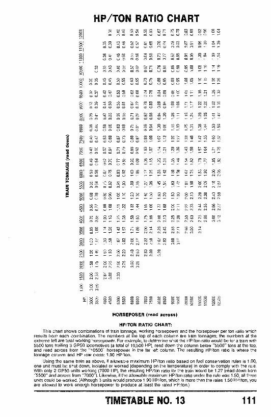
LO
Ó
Ó
OLOLO
Ó
Ó
LO
HP /TON RATIO CHARTQ o , ao
o ööáö0000ôóóóóo
6 C0 o oCO 600 00 00 00 00 00 00 06 ñCO or o o ÓQ Ó O0 0 ö 0 ö ö 0 0 ö 0 0 0 ö om rn rn ó0 0 0 0 0 0 0 0 0 0 0 0 0 ö.-
o ñ w O 60 O o ö ö 0 0 0 0 0 o Oö ö r
CV M CO 6 6 ct 6 V O> O O0 0 0 0 Ó Ó 0 0 O O O O O6 CO V O < Ó ÓO O 0 0 ö ö O O 0 0 O OM V V O 6 O c.. ti N or, Ó6 LO Ó
6 LO
O- a
CV CV
6 CO
CV CO M
o OO O O O O O O O O O
pCD m Ó6 CO
r O OO O O O O O 0 0
0 0 O O O O OoM
C71 OCV
CO
CO 6
O M cV0 Oo O> CO OCO
o 0 O O 00 O O
LO CO O CO Ó CV 6 6 6 CO
V CO 1- OO
6 LO O Ñ LO 6 COCV O ci
rp ON N cv 6 Moo
O¡I M M
I °Ó Ó Ó Ó Ó Ó °Ó Ó ÓS0 oLO mr rLO 6
HORSEPOSER (read across)
HP /TON RATIO CHART:This chart shows combinations of train tonnage, working horsepower and the horsepower per ton ratio which
results from each combination. The numbers at the top of each column are train tonnages; the numbers at theextreme left are total working horsepower. For example, to determine what the HP /ton ratio would be for a train with5500 tons trailing 3 GP50 locomotives (a total of 10,500 HP), read down the column below "5500" tons at the top,and read across from the "10500" horsepower in the far left column. The resulting HP /ton ratio is where thetonnage column and HP row cross: 1.90 HP /ton.
Using the same train as above, if allowable maximum HP /ton ratio based on fuel conservation rules is 1.00,one unit must be shut down, isolated or worked (depending on the temperature) in order to comply with the rule.With only 2 GP50 units working (7000 HP), the resulting HP /ton ratio for the train would be 1.27 (read down from"5500" and across from "7000 "). Likewise, if the allowable maximum HP /ton ratio under the rule was 1.50, all threeunits could be worked. (Although 3 units would produce 1.90 HP /ton, which is more than the rates 1.50 HP /ton, youare allowed to work enough horsepower to produce at least the rated HP /ton.)
TIMETABLE NO. 13 111
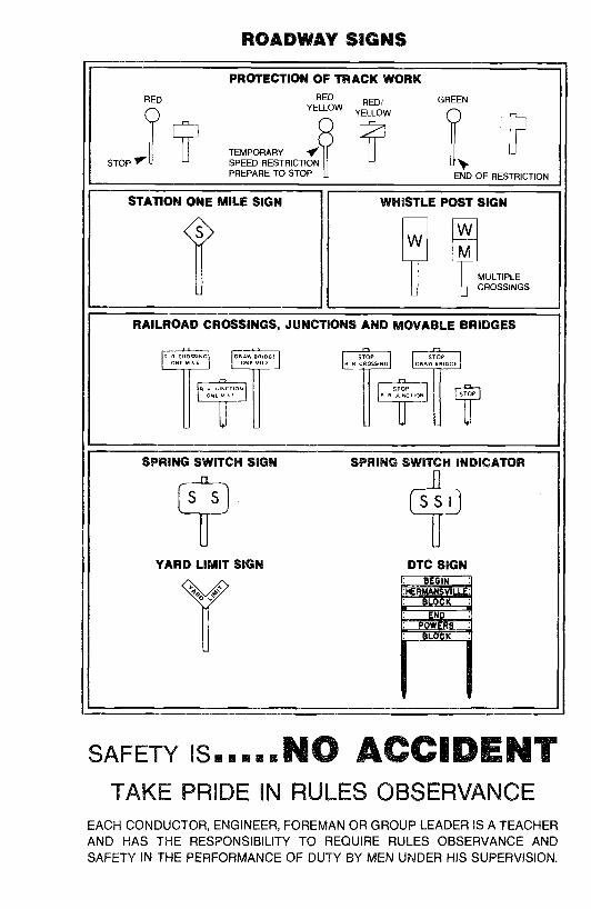
ROADWAY SIGNS
RED
STOP
PROTECTION OFRED
YELLOW
TEMPORARY 7SPEED RESTRICTIONPREPARE TO STOP
TRACK
RED/YELLOW
WORK
GREEN
END OF RESTRICTION
STATION ONE MILE SIGN
$
WHISTLE
W
POST
WM
SIGN
MULTIPLECROSSINGS
RAILROAD CROSSINGS, JUNCTIONS AND MOVABLE BRIDGES
uOSSrNCONE MILE
ORW BRmcE STOPN N CROSSING
S OPDRAW BRIDGE
atiR RO
ti0NON Frni
$TOPR R NC iOnl
I I _
SPRING SWITCH SIGN SPRING SWITCH INDICATOR
laI
YARD LIMIT SIGN
IDTC SIGN
V IN
R 3135IslT3 11111IMIII
SAFETY IS..... NO ACCIDENTTAKE PRIDE IN RULES OBSERVANCE
EACH CONDUCTOR, ENGINEER, FOREMAN OR GROUP LEADER IS A TEACHERAND HAS THE RESPONSIBILITY TO REQUIRE RULES OBSERVANCE ANDSAFETY IN THE PERFORMANCE OF DUTY BY MEN UNDER HIS SUPERVISION.
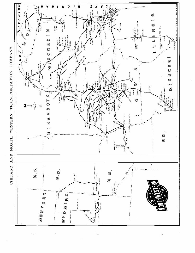
CH
ICA
GO
AN
D N
OR
TH
WE
STE
RN
TR
AN
SPO
RT
AT
ION
CO
MPA
NY
.
^ ,
Iu1W
/M
.._.._
.._...
...-
OC
AB
ALL
O J
CT
.
m 3
4O
0PS
2,'
SS
Q,A
BLL
.
p 6ry
-
OR
INJCT.
---.
_,.-
--...
--;_
CO
LON
Y
(MV
]nj (V
¡(W
CO
AL
CR
EE
K J
CT
.
SH
AW
NE
E J
CT
.
SHAWNE
ÇRANDALI
FIS
HE
R O
CT
.
I i i .-.-
-,-.
_--_
-
CH
ICA
GG
TI'
N 0
I i ¡IN
. 00
I.
I 1v
c D
. I
^ I I I
RA
PID
CIT
Y
I II
I Ì DA
KO
TA
JC
T.
CH
AD
RO
N
CRAWFORD
,
NI
oS
WA
NS
ON
SO
UT
H M
OR
RIL
L
I I I
51E
RN
.
t-._
L A
K E
/A/
DU
LUT
H2
.S
UP
ER
IOR
. ' IT
AS
CA
iii
SA
UN
DE
RS
DM
IR
GO
RD
ON
\m
=i
_..
£.
1
./n
.. HAYWARD
I
HIN
CK
LEY
.S
PR
INC
Bft0
0K..
HA
YW
AR
D J
CT
.
-.._
..-..-
..;/
TR
EC
O'
kC/
M M
I¡
{y¡y
¡/(¡
(M
BV
U0
UV
YV
IO
mC
AM
ER
ON
VV
" / 0
V,.
I
WA
US
IM
EN
NO
MK
ELL
Y
SC
HO
FIE
LDP
LYM
OU
TH
.
SU P
ER
/OR
ISH
PE
MIN
G
PA
LME
R
o
- -
--A
NT
OIN
ÉO
UIN
NE
SE
CL
NIA
GA
RÁ
,,
M IlV''
pNS
.O
CO
NT
O
DU
CK
CR
EE
K
GR
EE
N B
AY
RA
PID
S
CA
SC
A O
E
ES
CA
BA
pOW
ER
at tab
I
Ca)
CLE
VE
LAN
D,
SH
EB
OY
GA
N
IH
OP
KIN
S,P
AR
K4'
44iy
OE
AU
CLA
IRE
3'
CH
AS
KA
JCT
.,C
E.
4.'
RO
TH
SC
HIL
D
ME
RR
IAM
RO
SE
PO
RT
OJ
IR
OS
EM
OU
N\
Op
JUN
CT
ION
CIT
Y
W
CA
NN
Ot
(¿
NO
RiN
FIE
La
LS
WIS
CO
NS
IN
LEV
ISN
EK
OO
SA
CO
MV
S
IM
AN
KA
TO
ti A
\.W
YE
VIL
LN
EC
EO
AN
Iyy
,`v2
OW
AT
ON
NA
WIN
ON
A \
CP
rLH
CA
MP
PD
AM
S
BU
TT
ER
FIE
LOl,
.yF
000G
LAS
MA
NC
HE
ST
ER
lolq
O'4
4}c
RE
ED
SBURG
ALBERT LEA
CROl '
AG
AT
E\
Syf
EA
RA
B00
,.._.
.---
I
NO
RT
HW
OO
DE
ST
HE
RV
ILLE
SIB
LEY
\A
LLE
ND
E/R
E9.
0F
OR
ES
TM
AD
ISO
N
`S0
CIT
YW
AN
LY
CP
MO
BU
RT
.,F
2pCION\
VERONA'
HA
RT
LEY
9y,
!0 Q ,ROCKWELL
/R
OY
AL
MA
LLA
RD
y94,
../..1
9S
HE
FF
IELD
_ -
MPRATHON.
Cl
.p
\:R
OLF
E44
4H
AN
,PT
ON
CLP
RK
SV
ILLE
OE
LWE
Irv
\ /R
.LE
MA
RS
ALB
ER
T C
IT' A
2yC
OLO
FIE
Li'
r"A
\- -
--.._
"_--
.D
OR
OV
E,F
ALL
S
SIO
UX
CIT
YM
OO
RLA
ND
,D
OD
GE
DE
AS
TE
AM
BO
AT
RO
CK
4p?
\D
AK
OT
A C
ITY
'S
OM
ER
S.
JELL
FA
RN
HA
MV
ILE
EL
SW
OR
T5r
Cs
'
FF
eR
4ND
®¡
.C
ED
AR
RA
PA
S
4',
0 T
CLI
NT
ON
NE
LSO
N
PLY
MO
UT
HI
CLY
MA
N J
CT
.B
C
RrA
CN
WV
EI LRL
,J
WIS
CO
NA
CO
TT
AG
EB
UT
LER
'G
RO
VE
WA
UK
ES
HM
ILW
AU
KE
E
.FT
.p'd
.
S;
FRPNCIS
ATKINSON O
CLI
NT
ION
O K
.D.
KENOSHA
BE
LOIT
,p¢
4C
PW
IÓÓ
D
RO
CK
FO
R.'
L,K
O'
ALL
ET
Cgr
EV
AA
YF
aIR
J
ST.CHARLES:
HLY
BO
UR
NC
HIC
AG
O
^C
k P
ff07
B9
%,..
. OC
j Le
klp
f"F
o0b
TR
OY
GR
OV
E
MO
LIT
OR
JC
T.
PE
OR
IA
EO
RIA
- A
DA
MS
ST
.
SO
UT
H P
EK
IN
.
0a
o 0
MO
NT
ER
EY
JC
T.
h'
MA
RC
H 9
, 199
4
OE
NIS
ON
y-t,
SLA
TE
R 4
CH
ICA
GO
o
'
HE
RN
DO
Nk
JCT
.
4Y
ALE
Qpp
OO
k/
14,,
. BO
ND
UR
AN
T¡,
.U
PF
RE
MO
NT
'O
CO
NE
EM
ISS
OU
RI V
ALL
EY
DE
S M
OIN
ES
CO
LUM
BU
S
ZC
AR
LIS
LE
VO
OM
AH
AC
OU
NC
ILU
PIN
DIA
NO
LA
MA
%B
RID
GE
PO
RT
`
.C
HP
RIT
ON
/42
"
MID
DLE
00
ALL
ER
TO
rv
Q-
GR
OV
E
\..-
..-..-
.._..-
..\r.
._.._
.._.._
.._.._
..I
SO
MM
ER
\I
\-TRENTON
,I
_.._
..--.
_.._
.._.._
._.
, ,';..
L L
\P
OLO
MO
NT
ER
EY
n
151A
B5P
l'7!(
1
EN
LD
1,Ú
r S
HE
FF
IELD
JCT
MI 0
¡O
OI (
I0
MA
DIS
ON
KA
NS
AS
CIT
Y
`\:J
vI
E. S
T. L
OU
L5
J,\5
0205
\TIM
ET
BL
.MA
P,30
94