cmp he - ferroli
TRANSCRIPT
CMP HECONDENSING UNITSFOR INDOOR INSTALLATION
INSTALLATION AND OPERATION MANUAL
RE
FRIGERANT G
AS
E
CO-FRIEND
LY

2
The manufacturer declines all the responsabilities regarding inaccuracies contained in this manual, if due to printing or typing mi-stakes. The manufacturer reserves the right to apply changes and improvements to the products at any time without notice.
Dear Customer,Thank you for having purchased a FERROLI product. It is the result of many years of experiences and of particular research studies and has been made with top quality materials and advanced technologies. The CE mark guarantees that the products satisfy all the applicable European Directives.The qualitative level is kept under constant control and FERROLI products therefore offer SAFETY, QUALITY and RELIABILITY.Due to the continuous improvements in technologies and materials, the product specification as well as performances are subject to variations without prior notice.
Thank you once again for your preference FERROLI S.p.A

3
TABLE OF CONTENTS
GENERAL FEATURES . . . . . . . . . . . . . . . . . . . . . . . . . . . . . . . . . . . . . . . . . . . . . . . . . . . . . . . . . . . . . . . . . . . . . . . . . . . . . . . . . . 4General instructions . . . . . . . . . . . . . . . . . . . . . . . . . . . . . . . . . . . . . . . . . . . . . . . . . . . . . . . . . . . . . . . . . . . . . . . . . . . . . . . . . . 4Declaration of conformity . . . . . . . . . . . . . . . . . . . . . . . . . . . . . . . . . . . . . . . . . . . . . . . . . . . . . . . . . . . . . . . . . . . . . . . . . . . . . . 4Unit dataplate . . . . . . . . . . . . . . . . . . . . . . . . . . . . . . . . . . . . . . . . . . . . . . . . . . . . . . . . . . . . . . . . . . . . . . . . . . . . . . . . . . . . . . . 4Unit description . . . . . . . . . . . . . . . . . . . . . . . . . . . . . . . . . . . . . . . . . . . . . . . . . . . . . . . . . . . . . . . . . . . . . . . . . . . . . . . . . . . . . . 5Unit identification code . . . . . . . . . . . . . . . . . . . . . . . . . . . . . . . . . . . . . . . . . . . . . . . . . . . . . . . . . . . . . . . . . . . . . . . . . . . . . . . . 5Description of components . . . . . . . . . . . . . . . . . . . . . . . . . . . . . . . . . . . . . . . . . . . . . . . . . . . . . . . . . . . . . . . . . . . . . . . . . . . . . 6Control system . . . . . . . . . . . . . . . . . . . . . . . . . . . . . . . . . . . . . . . . . . . . . . . . . . . . . . . . . . . . . . . . . . . . . . . . . . . . . . . . . . . . . . 7Options . . . . . . . . . . . . . . . . . . . . . . . . . . . . . . . . . . . . . . . . . . . . . . . . . . . . . . . . . . . . . . . . . . . . . . . . . . . . . . . . . . . . . . . . . . . . 7Accessories . . . . . . . . . . . . . . . . . . . . . . . . . . . . . . . . . . . . . . . . . . . . . . . . . . . . . . . . . . . . . . . . . . . . . . . . . . . . . . . . . . . . . . . . 7
TECHNICAL DATA AND PERFORMANCES . . . . . . . . . . . . . . . . . . . . . . . . . . . . . . . . . . . . . . . . . . . . . . . . . . . . . . . . . . . . . . . . . 8Technical data. . . . . . . . . . . . . . . . . . . . . . . . . . . . . . . . . . . . . . . . . . . . . . . . . . . . . . . . . . . . . . . . . . . . . . . . . . . . . . . . . . . . . . . 8NOMINAL performances - Base setting up (AB) . . . . . . . . . . . . . . . . . . . . . . . . . . . . . . . . . . . . . . . . . . . . . . . . . . . . . . . . . . . . 9NOMINAL performances - Low noise setting up (AS) . . . . . . . . . . . . . . . . . . . . . . . . . . . . . . . . . . . . . . . . . . . . . . . . . . . . . . . . 9COOLING performances . . . . . . . . . . . . . . . . . . . . . . . . . . . . . . . . . . . . . . . . . . . . . . . . . . . . . . . . . . . . . . . . . . . . . . . . . . . . . . 10HEATING performances . . . . . . . . . . . . . . . . . . . . . . . . . . . . . . . . . . . . . . . . . . . . . . . . . . . . . . . . . . . . . . . . . . . . . . . . . . . . . . . 11Operating limits. . . . . . . . . . . . . . . . . . . . . . . . . . . . . . . . . . . . . . . . . . . . . . . . . . . . . . . . . . . . . . . . . . . . . . . . . . . . . . . . . . . . . . 12Electrical data . . . . . . . . . . . . . . . . . . . . . . . . . . . . . . . . . . . . . . . . . . . . . . . . . . . . . . . . . . . . . . . . . . . . . . . . . . . . . . . . . . . . . . . 13Noise levels . . . . . . . . . . . . . . . . . . . . . . . . . . . . . . . . . . . . . . . . . . . . . . . . . . . . . . . . . . . . . . . . . . . . . . . . . . . . . . . . . . . . . . . . 13Weights . . . . . . . . . . . . . . . . . . . . . . . . . . . . . . . . . . . . . . . . . . . . . . . . . . . . . . . . . . . . . . . . . . . . . . . . . . . . . . . . . . . . . . . . . . . . 13Overall dimensions . . . . . . . . . . . . . . . . . . . . . . . . . . . . . . . . . . . . . . . . . . . . . . . . . . . . . . . . . . . . . . . . . . . . . . . . . . . . . . . . . . . 14Minimum operating area . . . . . . . . . . . . . . . . . . . . . . . . . . . . . . . . . . . . . . . . . . . . . . . . . . . . . . . . . . . . . . . . . . . . . . . . . . . . . . . 14
CONNECTIONS . . . . . . . . . . . . . . . . . . . . . . . . . . . . . . . . . . . . . . . . . . . . . . . . . . . . . . . . . . . . . . . . . . . . . . . . . . . . . . . . . . . . . . . . 15Refrigerant connections . . . . . . . . . . . . . . . . . . . . . . . . . . . . . . . . . . . . . . . . . . . . . . . . . . . . . . . . . . . . . . . . . . . . . . . . . . . . . . . 15Electrical connections . . . . . . . . . . . . . . . . . . . . . . . . . . . . . . . . . . . . . . . . . . . . . . . . . . . . . . . . . . . . . . . . . . . . . . . . . . . . . . . . . 16
RECEIVING AND POSITIONING . . . . . . . . . . . . . . . . . . . . . . . . . . . . . . . . . . . . . . . . . . . . . . . . . . . . . . . . . . . . . . . . . . . . . . . . . . 17Receiving . . . . . . . . . . . . . . . . . . . . . . . . . . . . . . . . . . . . . . . . . . . . . . . . . . . . . . . . . . . . . . . . . . . . . . . . . . . . . . . . . . . . . . . . . . 17Positioning . . . . . . . . . . . . . . . . . . . . . . . . . . . . . . . . . . . . . . . . . . . . . . . . . . . . . . . . . . . . . . . . . . . . . . . . . . . . . . . . . . . . . . . . . 17
START UP . . . . . . . . . . . . . . . . . . . . . . . . . . . . . . . . . . . . . . . . . . . . . . . . . . . . . . . . . . . . . . . . . . . . . . . . . . . . . . . . . . . . . . . . . . . . 18Start up . . . . . . . . . . . . . . . . . . . . . . . . . . . . . . . . . . . . . . . . . . . . . . . . . . . . . . . . . . . . . . . . . . . . . . . . . . . . . . . . . . . . . . . . . . . . 18
CONTROL SYSTEM . . . . . . . . . . . . . . . . . . . . . . . . . . . . . . . . . . . . . . . . . . . . . . . . . . . . . . . . . . . . . . . . . . . . . . . . . . . . . . . . . . . . 19Control system . . . . . . . . . . . . . . . . . . . . . . . . . . . . . . . . . . . . . . . . . . . . . . . . . . . . . . . . . . . . . . . . . . . . . . . . . . . . . . . . . . . . . . 19Menu structure . . . . . . . . . . . . . . . . . . . . . . . . . . . . . . . . . . . . . . . . . . . . . . . . . . . . . . . . . . . . . . . . . . . . . . . . . . . . . . . . . . . . . . 21Inputs and outputs . . . . . . . . . . . . . . . . . . . . . . . . . . . . . . . . . . . . . . . . . . . . . . . . . . . . . . . . . . . . . . . . . . . . . . . . . . . . . . . . . . . 22Controller technical data . . . . . . . . . . . . . . . . . . . . . . . . . . . . . . . . . . . . . . . . . . . . . . . . . . . . . . . . . . . . . . . . . . . . . . . . . . . . . . . 22Configurations for the remote heat exchange management. . . . . . . . . . . . . . . . . . . . . . . . . . . . . . . . . . . . . . . . . . . . . . . . . . . . 23Alarms. . . . . . . . . . . . . . . . . . . . . . . . . . . . . . . . . . . . . . . . . . . . . . . . . . . . . . . . . . . . . . . . . . . . . . . . . . . . . . . . . . . . . . . . . . . . . 24Alarms table . . . . . . . . . . . . . . . . . . . . . . . . . . . . . . . . . . . . . . . . . . . . . . . . . . . . . . . . . . . . . . . . . . . . . . . . . . . . . . . . . . . . . . . . 25Functions available for the user . . . . . . . . . . . . . . . . . . . . . . . . . . . . . . . . . . . . . . . . . . . . . . . . . . . . . . . . . . . . . . . . . . . . . . . . . 26Serial communication . . . . . . . . . . . . . . . . . . . . . . . . . . . . . . . . . . . . . . . . . . . . . . . . . . . . . . . . . . . . . . . . . . . . . . . . . . . . . . . . . 27Probes characteristics . . . . . . . . . . . . . . . . . . . . . . . . . . . . . . . . . . . . . . . . . . . . . . . . . . . . . . . . . . . . . . . . . . . . . . . . . . . . . . . . 28
MAINTENANCE . . . . . . . . . . . . . . . . . . . . . . . . . . . . . . . . . . . . . . . . . . . . . . . . . . . . . . . . . . . . . . . . . . . . . . . . . . . . . . . . . . . . . . . . 29Maintenance . . . . . . . . . . . . . . . . . . . . . . . . . . . . . . . . . . . . . . . . . . . . . . . . . . . . . . . . . . . . . . . . . . . . . . . . . . . . . . . . . . . . . . . . 29
SAFETY AND POLLUTION . . . . . . . . . . . . . . . . . . . . . . . . . . . . . . . . . . . . . . . . . . . . . . . . . . . . . . . . . . . . . . . . . . . . . . . . . . . . . . . 30General considerations. . . . . . . . . . . . . . . . . . . . . . . . . . . . . . . . . . . . . . . . . . . . . . . . . . . . . . . . . . . . . . . . . . . . . . . . . . . . . . . . 30Refrigerant safety card . . . . . . . . . . . . . . . . . . . . . . . . . . . . . . . . . . . . . . . . . . . . . . . . . . . . . . . . . . . . . . . . . . . . . . . . . . . . . . . . 30
DECLARATION OF CONFORMITY . . . . . . . . . . . . . . . . . . . . . . . . . . . . . . . . . . . . . . . . . . . . . . . . . . . . . . . . . . . . . . . . . . . . . . . . 33

4
GENERAL FEATURES
General instructions
Declaration of conformity
Unit dataplate
The figure shows the fields reported on the unit dataplate :
This manual and the wiring diagram supplied with the unit must be kept in a dry place for possible future consultation.The manual provides information on installation and correct use and maintenance of the unit. Before carrying out installation, please carefully read all the information contained in this manual, which describes the procedures necessary for correct installation and use of the unit .
Follow carefully the instructions contained in this manual and respect the safety regulations in force. The unit must be installed in conformity with the laws in force in the country of use. Unauthorized tampering with the electrical and mechanical equipment INVALIDATES THE WARRANTY.Check the electrical specifications given on the dataplate before making the electrical connections. Read the instructions given in the specific section on electrical connections.Deactivate the equipment in case of fault or poor operation.If the unit requires fixing, contact only specialized service centers recognized by the manufacturer and use original spare parts.The unit must be installed indoor and connected to a hydronic cooling and/or heating system. Any use different from that permitted or outside the operating limits indicated in this manual is prohibited (unless previously agreed with the firm).
The manufacturer declines any responsability for damage or injury due to non-compliance with the information given in this manual.
The firm declares that the present unit complies with the requirements of the following directives :
• Machinery directive (MD) 2006/42/EC • Pressure equipment directive (PED) 97/23/EC • Electromagnetic compatibility directive (EMC) 2004/108/EC • Low voltage directive (LVD) 2006/95/EC
CodiceCode B1 Rev
Ferroli SpaVia Ritonda 78/A(VR) Italy
A - TrademarkB - ModelB1 - CodeC - Serial numberD - Capacity in coolingE - Capacity in heating (heat pump)F - Power input in coolingG - Power input in heating (heat pump)H - Reference standardI - Power supplyL - Maximum absorbed currentM - Refrigerant type and charge weightN - Unit weightO - Sound pressure level at 1 metreP - IP protection levelQ - Maximum pressure - high pressure sideR - Maximum pressure - low pressure sideS - PED certification body

5
SP 26 .1 VB AB 0M5
GENERAL FEATURES
Unit description
This series of condensing units satisfies the cooling and heating requirements of residential plants of small and medium size.All the units are suitable for indoor installation and can be con-nected to a remote heat exchanger properly designed in order to transfer to the plant all the cooling (and heating for reversible units) power generated.It is possible for example to connect direct expansion coils pla-ced inside air handling units or remote plate heat exchangers placed inside technical rooms. In both cases the lack of outdoor hydraulic pipes eliminates the freezing problems and avoids bri-ne solutions to be used. The refrigerant circuit, contained in a compartment protec-ted from the air flow to simplify the maintenance operations, is equipped with scroll compressor mounted on damper supports, centrifugal fans (plug fan), finned coil made of copper pipes and aluminium louvered fins and shut off valves on the liquid line and on the gas line. The reversible units are moreover supplied with reverse cycle valve, thermostatic expansion valve (working in heating mode) and liquid receiver.
The circuit is protected by high and low pressure switches.All the units are equipped with variable speed fans control that allows the units to operate with low outdoor temperatures in co-oling and high outdoor temperature in heating and permits to reduce noise emissions in such operating conditions.The low noise acoustic setting up (AS) is obtained, starting from the base setting up (AB), reducing the rotational speed of the fans and mounting sound jackets on the compressors.All the units are supplied with an outdoor temperature sensor, al-ready installed on the unit, in order to realize the climatic control.All the units are provided with a phase presence and correct sequence controller device.All the units are accurately built and individually tested in the factory.All the units are supplied with refrigerant charge inside.Only electric and refrigerant connections (between condensing unit and remote heat exchanger) are required for installation.
Unit identification code
The codes that identify the units and the meaning of the letters used are described below.
Power supply
5 - 400 V - 3N - 50 Hz
Operating range
M - Medium temperature.The unit is suitable to be instal-led in temperate climates.
Refrigerant type
0 - R410A
Acoustic setting up
AB - Base setting upAS - Low noise setting up
Unit type
SR - Unit suitable for splitted plant instal-lation operating as chillerSP - Unit suitable for splitted plant instal-lation operating as reversible heat pump
Unit version
VB - Base version
N° compressors
Unit model
CMP HE

6
GENERAL FEATURES
Description of components
External structure. Basement, supporting structure and lateral panels are made of galvanized and painted sheet-steel (colour RAL 7035) to guarantee good resistance to atmospheric agents. Accessibility to internal parts is possible removing the frontal panel. For extraordinary manteinances also the rear panel can be removed.
Refrigerant circuit. It is contained inside a compartment separated from the air flow to simplify maintenance and control operations.The hermetic scroll compressor (1) is mounted on damper supports and is protected against overtemperatures and overcurrents. It is equipped with an electrcal heater, that is activated when the compressor turns off, to keep the compressor crankcase oil temperature high enough to prevent migration of the refrigerant during winter stops and to evaporate any liquid present in the crankcase, in order to prevent possible liquid rushes on starting (only heat pump models).
The source side heat exchanger (2) is a finned coil realized with grooved copper pipes and aluminium fins with notched profile to increase the heat exchange coefficient. A tray is obtained in the basement to collect the condensate generated in heating mode.
The refrigerant circuit of the heat pump models contains moreover a 4 way reverse cycle valve (3) to allow operating mode change reversing the refrigerant flow, an expansion device (4) for heating mode, a thermostatic expansion valve with external equalizer, that allows the unit to adjust itself to the different operating conditions keeping steady the set superheating, a solid core hermetic filter dryer (5) to restrain impurity and moisture residuals that could be present in the circuit and a liquid receiver (6) to compensate the different refrigerant charge required in heating and in cooling mode.
The refrigerant circuit of each unit contains moreover high and low pressure switches in order to assure the compressor to operate inside the permitted limits, shut off ball valves on the liquid line and on the gas line to allow maintenance operations on the unit and pressure connections SAE 5/16” - UNF 1/2” - 20 equipped with pin, gasket and blind nut, as required for the use of R410A refrigerant (they allow the complete check of the refrigerant circuit: compressor inlet pressure, compressor outlet pressure and thermostatic expansion valve upstream pressure).
The fans (7) (source side) are plug fan type fans equipped with EC direct current motor and embedded inverter. The fans rotational speed is modulated continuosly to control the condensation pressure (in cooling) and the evaporation pressure (in heating) in order to optimize the operating conditions of the unit and to reduce noise emissions. The maximum rotational speed can be modified by parameter in order to set the available static head of the fan to the plant requirements.
Electrical panel. It contains all the power, control and security components necessary to guarantee the unit to work properly. The unit is managed by a microprocessor controller to which all the electrical loads and the control devices are connected. The user interface, placed on the frontal panel, allows to view and to modify, if necessary, all the parameters of the unit.All the units are supplied with an outdoor temperature sensor, already installed on the unit, in order to realize the climatic control.
°C
1 2 1 2
mode
disp

7
GENERAL FEATURES
Control system
The unit is managed by a microprocessor controller to which, through a wiring board, all the electrical loads and the control devices are connected. The user interface is realized by a display and four buttons that allow to view and, if necessary, modify all the operating parameters of the unit. It's available, as an accessory, a remote control that reports all the functionalities of the user interface placed on the unit.The main functions available are :- water temperature management (through set point
adjustment)- adaptive function- climatic control in heating and in cooling mode (automatic set
point adjustment according to outdoor air temperature)- dynamic defrost cycle management according to outdoor air
temperature
- alarm memory management and diagnostic- fans management by means of continuous rotational speed
control- pump management- integrative electrical heaters management in heating mode
(2 step logic)- compressor and pump operating hours recording- serial communication through Modbus protocol- remote stand by- remote cooling-heating- general alarm digital output
Options
Integrativeelectricalheaters
Standard in the tank
Integrate or replace the heating power supplied by the heat pump and are managed by the unit controller with a 2 step logic.They are also activated as antifreeze electrical heaters.Available only for the VA version.
Soft starter Reduces the compressor start current.
Compressor power factor correction Allows to reduce the phase shift between the absorbed current and the power sup-ply voltage keeping it above the value of 0,9.
Electrical loadsprotection
Fuses Allows to protect the electrical loads with fuses.
Thermal magneticcircuit breakers
Allows to protect the electrical loads with thermal magnetic circuit breakers simpli-fying the maintenance operations.
Rubber vibration dampers Allow to reduce the transmission to the unit support plane of the mechanical vibrations generated by the compressor and by the fans in their normal operating mode.
Coil protection grille Protects the external surface of the finned coil..
Remote control It is suitable for wall mounting and reports all the control and visualization functions available on the user interface placed on the unit. It therefore allows the complete remote control of the unit.
Modbus serial interfaceon RS485
It allows to communicate with the unit controller and to view the operating conditions of the unit through Modbus communication protocol. The RS485 serial line ensures the signal quality up to distances of about 1200 meters (that can be extended by means of proper repeaters).
Programmer clock It allows the unit to be turned on and off according to a set program, through the digital input available on the unit wiring board (remote stand by).
Phase sequence andvoltage controller
It checks not only the presence and correct order of the power supply phases but also the voltage level on each phase and avoid the unit to operate with voltage levels outside the permitted limits.
Remoteplate heat exchanger
Stainless steel brazed plate heat exchanger properly sized for cooling and heating operating mode supplied with thermal insulation, differential pressure switch on the water side, temperature probes (water inlet and outlet) and antifreeze electrical heater.
Liquid line(for SR units)
It contains a thermostatic expansion valve sized for cooling operating mode, filter dryer, liquid indicator and solenoid valve.
Liquid line(for SP units)
It contains a thermostatic expansion valve sized for cooling operating mode, filter dryer, liquid indicator, solenoid valve and check valve (to be installed in parallel to the expansion valve).
High and low perssuregauges Allow to visualize the evaporation and the condensation pressures.
Accessories

8
TECHNICAL DATA AND PERFORMANCES
Frame 1 2Model 19 .1 22 .1 26 .1 30 .1 35 .1 40 .1 U.M.
Power supply 400 - 3N - 50 400 - 3N - 50 400 - 3N - 50 400 - 3N - 50 400 - 3N - 50 400 - 3N - 50 V-ph-Hz
Technical data
RefrigerantType R410A R410A R410A R410A R410A R410A -
CompressorType scroll scroll scroll scroll scroll scroll -
Quantity 1 1 1 1 1 1 n°
Power steps 0 - 100 0 - 100 0 - 100 0 - 100 0 - 100 0 - 100 %
Oil charge 2,51 3,25 3,25 3,25 3,25 3,25 kg
Source side heat exchangerType finned
coilfinned
coilfinned
coilfinned
coilfinned
coilfinned
coil -
Quantity 1 1 1 1 1 1 n°
Frontal surface 1,45 1,45 1,45 1,75 1,75 1,75 m2
Fans
Typeplug fan
with EC motorand embedded
inverter
plug fanwith EC motorand embedded
inverter
plug fanwith EC motorand embedded
inverter
plug fanwith EC motorand embedded
inverter
plug fanwith EC motorand embedded
inverter
plug fanwith EC motorand embedded
inverter
-
Quantity 1 1 1 1 1 1 n°
Diameter 630 630 630 630 630 630 mm
Maximum rotational speed 1200 1200 1200 1200 1200 1200 rpm
Total installed power 2,8 2,8 2,8 2,8 2,8 2,8 kW

9
TECHNICAL DATA AND PERFORMANCES
Frame 1 2Model 19 .1 22 .1 26 .1 30 .1 35 .1 40 .1 U.M.
Power supply 400 - 3N - 50 400 - 3N - 50 400 - 3N - 50 400 - 3N - 50 400 - 3N - 50 400 - 3N - 50 V-ph-Hz
NOMINAL performances - Base setting up (AB)
Frame 1 2Model 19 .1 22 .1 26 .1 30 .1 35 .1 40 .1 U.M.
Power supply 400 - 3N - 50 400 - 3N - 50 400 - 3N - 50 400 - 3N - 50 400 - 3N - 50 400 - 3N - 50 V-ph-Hz
NOMINAL performances - Low noise setting up (AS)
Data declared with superheating and subcooling equal to 5°C. The values are referred to units without options and accessories.
SR
Cooling A35E5 ( source : air in 35°C d.b. / plant : evaporation temeprature 5°C )Cooling capacity 21,8 24,2 28,3 34,2 39,7 44,9 kW
Power input 6,48 7,10 8,25 10,2 11,8 13,3 kW
EER 3,36 3,41 3,43 3,36 3,38 3,38 -
SP
Cooling A35E5 ( source : air in 35°C d.b. / plant : evaporation temeprature 5°C )Cooling capacity 21,4 23,8 27,8 33,6 39,0 44,1 kW
Power input 6,42 7,03 8,16 10,1 11,7 13,2 kW
EER 3,33 3,39 3,40 3,34 3,33 3,33 -
Heating A7C45 ( source : air in 7°C d.b. 6°C w.b. / plant : condansation temperature 45°C )Heating capacity 22,4 24,8 28,9 35,1 40,7 46,1 kW
Power input 5,66 6,19 7,19 8,86 10,3 11,7 kW
COP 3,96 4,01 4,02 3,96 3,95 3,94 -
Heating A7C50 ( source : air in 7°C d.b. 6°C w.b. / plant : condansation temperature 50°C )Heating capacity 20,3 22,5 26,2 31,8 36,9 41,8 kW
Power input 6,43 7,02 8,16 10,1 11,7 13,2 kW
COP 3,16 3,21 3,21 3,15 3,15 3,17 -
SR
Cooling A35E5 ( source : air in 35°C d.b. / plant : evaporation temeprature 5°C )Cooling capacity 21,0 23,2 27,2 32,9 38,2 43,2 kW
Power input 7,01 7,67 8,91 11,0 12,7 14,3 kW
EER 2,99 3,03 3,05 3,00 3,01 3,02 -
SP
Cooling A35E5 ( source : air in 35°C d.b. / plant : evaporation temeprature 5°C )Cooling capacity 20,5 22,8 26,7 32,3 37,5 42,3 kW
Power input 6,94 7,59 8,82 10,9 12,6 14,2 kW
EER 2,96 3,00 3,02 2,97 2,98 2,98 -
Heating A7C45 ( source : air in 7°C d.b. 6°C w.b. / plant : condansation temperature 45°C )Heating capacity 21,2 23,5 27,6 33,4 38,7 43,9 kW
Power input 5,43 5,95 6,90 8,51 9,90 11,2 kW
COP 3,91 3,95 4,00 3,92 3,91 3,92 -
Heating A7C50 ( source : air in 7°C d.b. 6°C w.b. / plant : condansation temperature 50°C )Heating capacity 19,2 21,3 25,0 30,2 35,0 39,7 kW
Power input 6,16 6,75 7,83 9,66 11,2 12,7 kW
COP 3,12 3,15 3,19 3,13 3,12 3,13 -

10
TECHNICAL DATA AND PERFORMANCES
COOLING performances
The graphs allow to get the corrective factors to be applied to the nominal performances in order to obtain the real performances in the selected operating conditions.
The reference nominal condition is :A35E5source : air in 35°C d.b.plant : evaporation temperature 5°C
Evaporation temperatureplant side :A = 22°CB = 16°CC = 10°CD = 5°C
Cooling capacity
Inlet air temperature d.b. [°C]
Inlet air temperature d.b. [°C] Inlet air temperature d.b. [°C]
Power input EER
0.4
0.6
0.8
1.0
1.2
1.4
1.6
1.8
2.0
15 20 25 30 35 40 45 500.5
0.6
0.7
0.8
0.9
1.0
1.1
1.2
1.3
1.4
1.5
15 20 25 30 35 40 45 50
0.5
0.6
0.7
0.8
0.9
1.0
1.1
1.2
1.3
1.4
1.5
15 20 25 30 35 40 45 50
A B C D
A
B
C
DA
B
C
D

11
TECHNICAL DATA AND PERFORMANCES
HEATING performances
The graphs allow to get the corrective factors to be applied to the nominal performances in order to obtain the real performances in the selected operating conditions.
The reference nominal condition is :A7W50source : air in 7°C d.b. 6°C w.b.plant : condensation temperature 50°C
Outlet temperatureplant side :A = 60°CB = 50°CC = 40°CD = 30°C
Heating capacity
Inlet air temperature w.b. [°C]
Inlet air temperature w.b. [°C] Inlet air temperature w.b. [°C]
Power input COP
0.5
0.6
0.7
0.8
0.9
1.0
1.1
1.2
1.3
1.4
1.5
15 10 5 0 5 10 15 20
D
C
B
A
0.4
0.6
0.8
1.0
1.2
1.4
1.6
1.8
2.0
1 10 0 10 1 200.5
0.6
0.7
0.8
0.9
1.0
1.1
1.2
1.3
1.4
1.5
15 10 5 0 5 10 15 20
A
B
C
D
A B C D

12
TECHNICAL DATA AND PERFORMANCES
Operating limits
-15
-10
-5
0
5
10
15
20
25
30
35
-25 -20 -15 -10 -5 0 5 10 15 20 25 30 35 0 5 50
COOLING
Inlet air temperature d.b. [°C]
Eva
pora
tion
tem
pera
ture
- pl
ant s
ide
[°C
]
-5
0
5
10
15
20
25
30
35
40
45
50
55
60
65
-25 -20 -15 -10 -5 0 5 10 15 20 25 30 35 40 45 50
HEATING
Inlet air temperature d.b. [°C]
Con
dans
atio
n te
mpe
ratu
re -
plan
t sid
e [°
C]
The graphs reported below show the operating area inside which the correct working of the unit is guaranteed.
Modulating fans control
(condensation control)
Superheating Subcooling
Maximum value 10 8 °C
Minimum value 3 2 °C

13
Electrical data
Frame 1 2Model 19 .1 22 .1 26 .1 30 .1 35 .1 40 .1 U.M.
Power supply 400-3N-50 400-3N-50 400-3N-50 400-3N-50 400-3N-50 400-3N-50 V-ph-Hz
F.L.A. Maximum total current input 28,9 30,9 33,0 28,0 32,0 36,1 A
F.L.I. Maximum total power input 13,0 14,3 15,6 16,8 19,4 22,0 kW
M.I.C.Maximum total start current 108 124 131 131 146 180 A
Maximum total start currentwith soft starter (option) 65 74 78 75 84 104 A
Unit
TECHNICAL DATA AND PERFORMANCES
Noise levels
ModelSound power levels [dB]
by octave bands [Hz]Sound power
level
Sound pressure level
at 1 metre at 5 metres at 10 metres
63 125 250 500 1000 2000 4000 8000 [dB] [dB(A)] [dB(A)] [dB(A)] [dB(A)]Base setting up (AB)
19 .1 85,1 79,4 74,3 73,2 71,3 68,4 62,6 57,6 87 76 60 50 45
22 .1 85,3 79,6 74,5 73,4 71,5 68,6 62,8 57,8 87 76 60 50 45
26 .1 86,3 80,6 75,5 74,4 72,5 69,6 63,8 58,8 88 77 61 51 46
30 .1 89,3 83,6 78,5 77,4 75,5 72,6 66,8 61,8 91 80 64 54 49
35 .1 89,8 84,1 79,0 77,9 76,0 73,1 67,3 62,3 92 81 65 55 49
40 .1 90,3 84,6 79,5 78,4 76,5 73,6 67,8 62,8 92 81 65 55 50
Low noise setting up (AS)19 .1 83,1 77,4 72,3 71,2 69,3 66,4 60,6 55,6 85 74 58 48 43
22 .1 83,3 77,6 72,5 71,4 69,5 66,6 60,8 55,8 85 74 58 48 43
26 .1 84,3 78,6 73,5 72,4 70,5 67,6 61,8 56,8 86 75 59 49 44
30 .1 87,3 81,6 76,5 75,4 73,5 70,6 64,8 59,8 89 78 62 52 47
35 .1 87,8 82,1 77,0 75,9 74,0 71,1 65,3 60,3 90 79 63 53 47
40 .1 88,3 82,6 77,5 76,4 74,5 71,6 65,8 60,8 90 79 63 53 48
Reference conditionsPerformances referred to units operating in cooling mode at nominal conditions A35E5.Unit placed in free field on reflecting surface (directional factor equal to 2).Unit ducted on the sunction and on the flow side for 2 meters.The sound power level is measured according to EN 9614-1:1995.The sound pressure level is calculated according to ISO 3744 and is referred to a distance of 1/5/10 metres from the external surface of the unit.
Frame 1 2Model 19 .1 22 .1 26 .1 30 .1 35 .1 40 .1 U.M.
Weights
Unit without options 255 258 278 283 303 305 kg
Components weights
Unit without options 271 274 294 303 323 325 kg
Transport weights

14
TECHNICAL DATA AND PERFORMANCES
Overall dimensions
Minimum operating area
Respect the free area around the unit as shown in the figure in order to guarantee a good accessibility and facilitate maintenance and control operations.
A 400 mm
B 450 mm
C 200 mm
Liquid line
Gas line
Frame 1 2
Model 19 .1 22 .1 26 .1 30 .1 35 .1 40 .1
1 1"1/4 F 1"1/4 F 1"1/4 F 1"1/4 F 1"1/4 F 1"1/4 F -
2 1"1/4 M 1"1/4 M 1"1/4 M 1"1/4 M 1"1/4 M 1"1/4 M -
D 1494 1704 mm
E 728 938 mm
F 738 948 mm
G 376 271 mm

15
CONNECTIONS
Refrigerant connections
To design properly the system respect the local safety regulations in force.The refrigerant lines must be properly designed in order to :• guarantee the remote plant heat exchanger to be properly
fed• guarantee the oil return to the compressor• avoid liquid return on the compressor inlet• avoid too high pressure losses
Suggestions for the realization of the refrigerant linesPlace the unit as near as possible to the remote plant heat exchanger in order to minimize the pressure losses and maximize the efficiency of the system.Design the liquid line with a maximum total pressure loss corresponding to a saturated temperature variation of 0,5 °C.Design the gas line with a maximum total pressure loss corresponding to a saturated temperature variation of 1,0 °C.Install a filter dryer, a liquid indicator and a solenoid valve before the expansion device used (in cooling mode) to feed the remote heat exchanger.
Refrigerant chargeThe unit is supplied with a refrigerant charge suitable for operating with a plate remote heat exchanger properly sized.The charge in any case must be integrated according to the type of remote heat exchanger and to the selected refrigerant lines lenght.Fot the heat pump models it is necessary to check if the volume of the liquid receiver, installed inside the unit, is correct for the final refrigerant charge of the system and to replace it or integrate it with an adding receiver, if necessary.
ConnectionsThe connections of the liquid line and of the gas line consist of a shut off ball valve and a short copper stub closed and filled with nitrogen.• Discharge the nitrogen using the pressure connection• Braze the refrigerant lines to the copper stubs• Get the vacuum on the refrigernat lines• Open the shut off valves• Integrate the refrigerant charge in order to guarantee the
system to work properly
External diameter Thickness Refrigerant charge integration [g/m][inch] [mm] [mm] Liquid line Gas line3/8 " 9,52 0,70 47 21/2 " 12,7 0,75 89 45/8 " 15,88 0,9 141 67/8 " 22 1,0 285 11
1 " 1/8 28 1,0 481 191 " 3/8 35 1,5 729 291 " 5/8 42 1,5 1089 432 " 1/8 54 2,0 1781 70
Legend1 Dryer filter2 Solenoid valve3 Liquid indicator4 Thermostatic valve5 Remote heat exchanger6 Check valve (only for heat pumps)

16
CONNECTIONS
Electrical connections
The electrical wirings must be carried out by qualified personnel according to the regulations in force at the installation time in the country of installation. Before starting any work on the electrical circuit make sure that the unit power supply line is disconnected at the start.N .B . Refer to the electrical diagram enclosed in the unit.
Power supply systemThe power cables of the heat pump power supply line must be connected to :- for single phase power supply : from a single phase voltage
system provided with neutral conductor and separated earth wire :
V = 230 V ± 10 %f = 50 Hz
- for three phase power supply : from a symmetrical three phase voltage system provided with neutral conductor and separated earth wire :
V = 400 V ± 10 %f = 50 Hz
The units are shipped completely factory wired and arranged for the connection to the power supply.The power cables must enter the unit through the holes on the lateral panel and must be connected to the power supply terminals of the unit.
Unit power supplyThe power supply cables must have an adequate section for the power absorbed by the unit and must be chosen in conformity with the regulations in force. Design the power supply line, always referring to the total FLI and FLA values of the unit, taking into account the selected options (except the integrative electrical heaters) and the installed accessories.
Upstream protectionAn automatic switch suitable for ensuring protection against overcurrents and indirect contacts must be installed upstream each power supply line.Coordination between line switch must be carried out observing the regulations in force on electrical safety, regarding the type of installation and the installation ambient conditions.
Connections available for the userThe wiring board inside the electrical panel contains dedicated
terminals for the following connections.General alarmVoltage output (230V - max 2A) to be used to notify the presence of an active alarm.Output active : active alarmsOutput not active : no active alarms Remote stand byTo turn on and off the unit, a remote device (selector, program-mer clock, centralised supervision device ...) with a voltage free contact suitable for switching loads of very low power, can be connected.This function must be enabled by parameter (see the section “Adjustment and control”) and prevails the settings made on the user interface.Remote Cooling-HeatingIt is possible to switch between cooling mode and heating mode from remote by connecting a device equipped with a voltage free contact suitable for switching loads of very low power.This function must be enabled by parameter (see the section “Adjustment and control”) and prevails the settings made on the user interface.Remote control It is possible to connect a remote control that has all the control and display functions available on the user interface on the unit and therefore enables the complete remote control of the unit.Pump / return fan controlThe controller of the unit can directly activate the circulating pump or the return fan by means of a voltage free contact (ma-ximum absorbed current 4A).
ATTENTIONCarry out all the connections outside the unit avoiding the power cables and the probe cables to be coupled.

17
RECEIVING AND POSITIONING
Receiving
Check on receivingAs soon as the unit is received verify accurately the correspon-dance of the load to what was ordered to make sure that all the material has been delivered. Check carefully that the load has not been damaged. In case of goods with visible damages inform promptly the haulage contractor reporting on the delivery note the phrase “Collected with reserves owing to evident damage”. Delivery ex works implies reimbursement of any da-mage on charge of the insurance company as established by law.
Safety instructionsObserve the safety regulations in force concerning the equip-ment to use for unit handling or the operating formalities to fol-low.
HandlingBefore handling the unit, check the weight of the unit, reported both on the dataplate and on the technical documentation. Make sure the unit to be handled with care avoiding any kind of colli-sion that could damage the operating parts of the unit.On the packaging of the unit are reported all the instructions
necessary for a corect handling during storing and installation.The unit is supplied on a pallet suitable for the transport. It is advisable to place protective material between the truck and the unit to avoid damages to the unit. Prevent the unit or parts of it from falling down.
StoringThe units must be stored in a dry place, repaired from sun, rain, sand or wind.Do not stack the units.Maximum temperature = 60 °CMinimum temperature = -20 °CHumidity = 90 %
Packaging removalRemove the packaging taking care not to damage the unit.Check for any visible damage.Get rid of the packaging material sending them to specialized recycling centres (observe the regulations in force).
Positioning
The units are suitable for indoor installation.Verify that the support surface can bear the weight of the selec-ted unit and is perfectly horizontal. In order to limit the vibrations transmitted by the unit it is possible to place, between the unit base and the support surface, a strip of hard rubber or, if a hi-gher level of insulation is required, vibration dampers.In any case it is not advisable to place the unit near private offi-ces, bedrooms or zones where very low noise levels are requi-red.
Protect the finned coil against direct sunlight and prevailing win-ds and do not place the unit on dark ground (for example tarred surfaces) to avoid the risk of overheating during operation.Do not place the unit under roofs or near plants (even if the unit is only partly covered) in order not to reduce the possibility of air recirculation.Respect the minimum operating area and verify that the installa-tion place is not subject to flooding.

18
START UP
Start up
The following operations must be carried out only by properly trained personnel. To make the contractual warranty effective, start up must be carried out by authorized service centres.Before calling the service centre it is advisable to make sure that all the installation steps have been completed (positioning, electrical connections, refrigerant connections, hydraulic connections, aeraulic connections).
Preliminary checks before turning on
1. Verify that :- the unit has not suffered visible damages due to transport or positioning- the unit is placed on an horizontal surface able to bear its weight- the minimum operating area are respected- the ambient conditions comply with the provided operating limits- the refrigerant, hydraulic, aeraulic and electrical connections has been carried out correctly
2. Disconnect the unit power suply line at the start and make sure that :- the unit power supply line complies with the regulations in force- the screws, fastening the electrical cables to the components inside the electrical panel of the unit, are well tightened (vibrations
during transport phases could have caused some loosening)
3. Connect the unit power supply line and verify that :- the voltage of the power supply line complies with the the nominal one of the unit- for three phase power supply units, the unbalance between the phases is lower than 2% (a higher value produces an excesive
current input on one or more phases causing possible damages to the electrical components of the unit)
NOTE. Example of phase unbalance calculation
- Read the value of the three line voltages using a voltmeter : line voltage between phases L1 and L2 : V1-2 = 390 V line voltage between phases L2 and L3 : V2-3 = 397 V line voltage between phases L3 and L1 : V3-1 = 395 V- Calculate the difference between the maximum and minimum value of the measured line voltages : ΔVmax = max ( V1-2 ; V2-3 ; V3-1 ) - min ( V1-2 ; V2-3 ; V3-1 ) = V2-3 - V1-2 = 397 - 390 = 7 V- Calculate the average line voltage value : Δaverage = ( V1-2 + V2-3 + V3-1 ) / 3 = ( 390 + 397 + 395 ) / 3 = 394 V- Calculate the percentage unbalance value : ΔVmax / Vaverage x 100 = 7 / 394 x 100 = 1,78 % < 2 %
Turning onTurn on the main switch of the unit (ON position).A wrong sequence of the power supply phases is immediately detected by the phase sequence controller (standard on all the three phase power supply units) and reported on the display of the unit. To eliminate the error switch each other two phases of the power supply line.Start all the plant components necessary to guarantee an adequate water or air flow rate on the plant remote heat exchanger.Activate the unit in cooling or in heating mode operating on the user interface and setting a set point suitable to require the unit to work.
Checks and adjustments after turning on
Make sure that :- there are no refrigerant leakages (all the caps of the pressure connections must be fitted and screwed down)- the saturation temperature (dew point) corresponding to the condensing pressure is about 10-15°C higher than the outdoor air
temperature in cooling and about 5°C higher than the water outlet temperature or about 10-15°C higher than the treated air tem-perature in heating
- the saturation temperature (dew point) corresponding to the evaporating pressure is about 5°C lower than the water outlet tempe-rature or about 5-10°C lower than the treated air temperature in cooling and about 5-10°C lower than the outdoor air temperature in heating
- the superheating and the subcooling are inside the operating limits- the compressor outlet temperature is 30-40°C higher than the saturation temperature (dew point) corresponding to the conden-
sing pressure- the current absorbed by the compresor and the fans is lower than the maximum value admitted (FLA), as indicated in the section
"Technical data and performances"
N .B . The reported values are reference values, to be considered only for units operating with temperatures similar to the nominal ones.

19
CONTROL SYSTEM
The unit is managed by a microprocessor controller to which, through a wiring board, all the electrical loads and the control devices are connected. The user interface is reali-zed by a display and four buttons that allow to view and, if necessary, modify all the operating parameters of the unit. It's available, as an accessory, a remote control that reports all the functionalities of the user interface placed on the unit. The interface, placed on the frontal panel of the unit, is ac-cessible from the outside and is protected by a transparent plastic door.It's available, as an accessory, a remote control that reports all the functionalities of the user interface placed on the unit.
To each button are associated :
- a direct function : indicated on the button itself and activated pressing the button
- an associated function : indicated on the front of the instrument at the corresponding button and activated pressing the button for long (3 seconds)
- a combined function : activated pressing 2 buttons at the same time
°C
1 2 1 2
mode
disp
Button Direct function Associated function
UP To increase the value of the selected parameterTo scroll up the menu - -
DOWN To decrease the value of the selected parameterTo scroll down the menu - -
ESC To go to the higher level of the menu without saving modeTo access the
“Operating mode”menu
SETTo go to the higher level of the menu saving
To go to the lower level of the menuAccess the "Status" menu
- -
- ALL Alarm deactivation - -
Button Combined function
+UP+
DOWNManual reset
+ESC
+SET
To access the “Programming”
menu
Control system

20
CONTROL SYSTEM
Icon Description Colour Steady on Flashing on
Sta
tus
and
oper
atin
g m
odes
Alarm Red Active alarm Deactivated alarm
Heating Green Heating modefrom keyboard
Heating modefrom remote
Cooling Green Cooling modefrom keyboard
Cooling modefrom remote
Stand by Green Stand byfrom keyboard
Stand byfrom remote
Defrost Green Defrost in progress -
Economy Green not used -
Mea
sure
uni
ts
Clock Red Time displayformat 24.00
Time settingformat 24.00
Celsius degrees Red Unit of measureof the selected parameter -
Bar Red not used -
Relative humidity Red not used -
Menu Red Menu browsing -
Load
s
Compressor Amber Active load Safety timein progress
not used - - -
Antifreeze heaterIntegrative heater 1st step Amber Active load Safety time
in progress
Integrative heater 2nd step Amber Active load Safety timein progress
not used - -
Fans Amber Active load Safety timein progress
PumpReturn fan Amber Active load Safety time
in progress
DisplayNormally are shown :• the setting temperature that is the remote heat exchanger water or air inlet temperature (in tenths of Celsius degree with decimal dot)
• alarm code, if at least one alarm is active (if more alarms are active, the first one according to the order of the Alarm Table, is shown)In menu mode the informations on the display change according to the position inside the menu (see the structure of the menu).
88:8.8
Remoto controlSuitable for wall mounting, it reports all the functions available on the user inter-face placed on the unit.The buttons, functions associated with the buttons and the display indications are the same as those provided for the standard interface.All configuration and control operations are further facilitated by the double di-splay which allows the name and value of the selected parameter to be shown at the same time.
Refer to the enclosed manual for the installation and connection procedures and operating instructions.

21
CONTROL SYSTEM
Menu Access procedure Sub menu Parameters Available functions
Operatingmode
Press ESC button for long(ESC button associated function)
Stby
-Operating mode
changeHEAT
COOL
Status Press SET button(SET button direct function)
Ai
Ai01 Display input AI1
Ai02 Display input AI2
Ai03 Display input AI3
Ai04 Display input AI4
Di
Di01 Display input ID1
Di02 Display input ID2
Di03 Display input ID3
Di04 Display input ID4
Di05 Display input ID5
AO
AO1 Display output AO1
AO2 Display output AO2
AO3 Display output AO3
DO
DO01 Display output DO1
DO02 Display output DO2
DO03 Display output DO3
DO04 Display output DO4
DO05 Display output DO5
CL
HOUR Clock adjustment : time
Date Clock adjustment : date
year Clock adjustment : year
AL - Display active alarms
SPHEAT Set point display and setting : heating
COOL Set point display and setting : cooling
SRHEAT Display real set point : heating
COOL Display real set point : cooling
HrCP01 Display compressor operating hours
PU01 Display pump / return fan operating hours
Programming
PressESC + SET
buttons at the same time(combined functioni
ESC + SETbuttons)
PAR
CF
CF19 Remote stand by enable
CF20 Remote Cooling-Heating enable
CF63 Device address (Modbus protocol)
CF66 Display parameter map code
CF67 Display parameter map revision
trtr01 Heat pump enable
tr17 Heat pump lock set point
PIPI05 Modulating pump / return fan speed : cooling
PI11 Modulating pump / return fan speed : heating
Hi Hi02 Integrative electrical heaters enable
FNC EUR Alarm memory reset
EU - Alarm memory display
The control system provides for three menus with tree structure.
To go from one level to the level below press the SET button. To return to the upper level press the ESC button.To scroll the menu up and down inside the same level, press respectively the UP and DOWN buttons.
To modify the value of the selected parameter press the UP and DOWN buttons. Press the SET button to confirm the new value. Press the ESC button not to confirm the new value.
Menu structure

22
CONTROL SYSTEM
DESCRIPTION CHARACTERISTICSAnalogue inputs
AI1 SIW water / air inlet probe NTC temperature sensor (-30°C ÷ 90°C)AI2 SUW water / air outlet probe NTC temperature sensor (-30°C ÷ 90°C)AI3 SL liquid line probe NTC temperature sensor (-30°C ÷ 90°C)AI4 STAE outdoor air probe NTC temperature sensor (-30°C ÷ 90°C)
Digital inputs
ID1PA High pressure switch
voltage free digital inputTVE Fan thermal protectionSS Soft starter alarm
ID2PB Low pressure switch
voltage free digital inputSEQ Phase presence and sequence controller
ID3 PD Differential pressure switch voltage free digital input
ID4 ON-OFF Remote stand by / Heating request voltage free digital input
ID5 E-I Remote Cooling-Heating / Colling request voltage free digital inputAnalogue outputs
AO1 VE Fan PWM output for relay or inverter controlAO3 PM Modulating pump / return fan 10V voltage output
Digital outputsDO1 ALL Alarm relay 2 A resistive - 250 VacDO2 CP Compressor relay 2 A resistive - 250 VacDO3 VIC Reverse cycle valve relay 2 A resistive - 250 Vac
DO4RSC Plate heat exchanger antifreeze heater
relay 2 A resistive - 250 VacRAG RE1
Tank antifreeze heaterIntegrative heater 1st step
DO5 P Pump / return fan 500mA - 12Vdc voltage outputfor control of relay K1 (4 A resistive - 250 Vac)
AO2 RE2 Integrative heater 2nd step 10V voltage outputfor control of relay KA2 (12 A resistive - 250 Vac)
All the inputs and outputs are connected to the wiring board except for output AO2 which directly controls a relay inside the electrical panel of the unit and output AO3 which directly control the modulating pump or return fan.
Description Typical Minimum MaximumPower supply voltage * 12,0 V~ 10,8 V~ 13,2 V~Power supply frequency 50 Hz / 60 Hz - -Power 5 VA - -Insulation class 2 - -Protection degree Frontale IP0 - -Ambient operating temperature 25 °C -10 °C 60 °CAmbient operating humidity (not condensing) 30 % 10 % 90 %Ambient storage temperature 25 °C -20 °C 85 °CAmbient storage humidity (not condensing) 30 % 10 % 90 %
* The controller is powered by a proper insulated transformer mounted on the wiring board.
Inputs and outputs
In order to control the unit, the controller is equipped with the following inputs and outputs :• Analogue inputs : 4• Digital inputs : 5• Analogue outputs : 2• Digital outputs : 6
Controller technical data
23
CONTROL SYSTEM
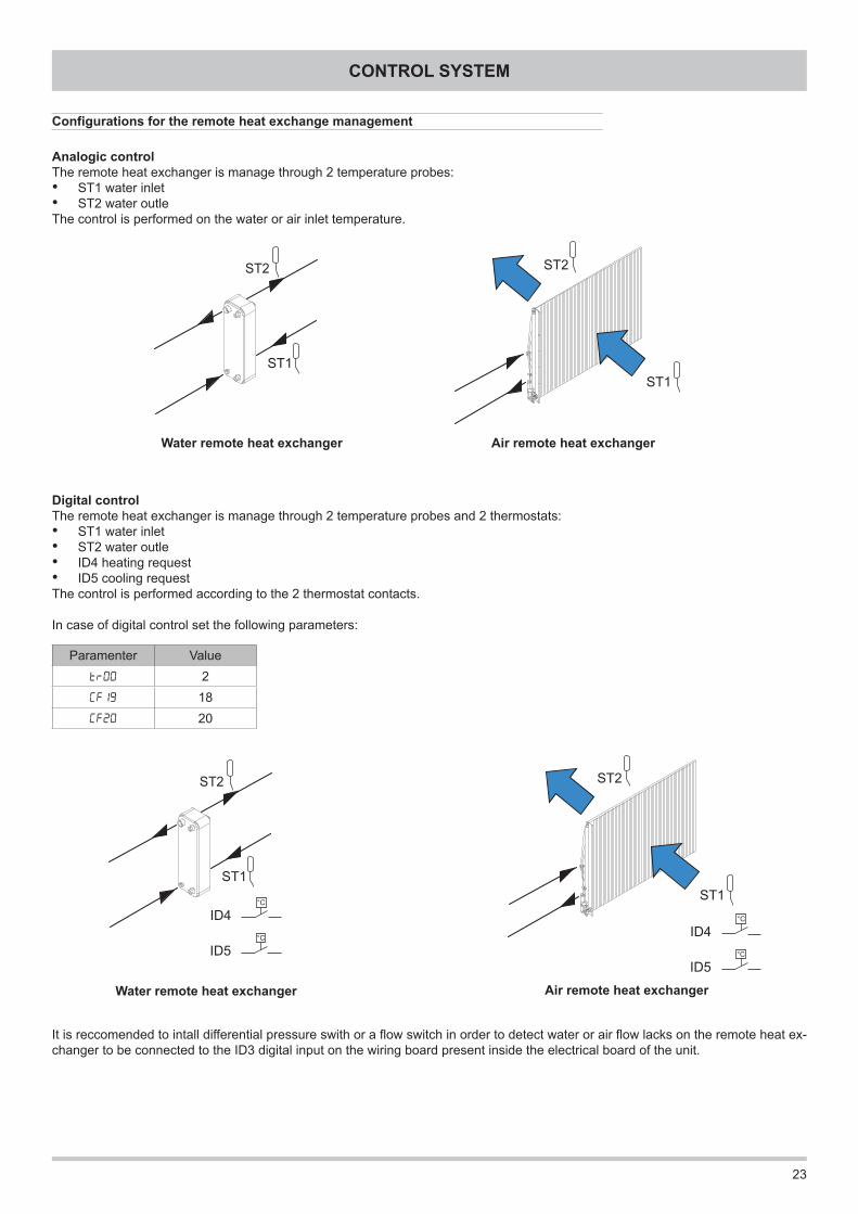
Configurations for the remote heat exchange management
Analogic controlThe remote heat exchanger is manage through 2 temperature probes:• ST1 water inlet• ST2 water outleThe control is performed on the water or air inlet temperature.
Water remote heat exchanger Air remote heat exchanger
Digital controlThe remote heat exchanger is manage through 2 temperature probes and 2 thermostats:• ST1 water inlet• ST2 water outle• ID4 heating request• ID5 cooling requestThe control is performed according to the 2 thermostat contacts.
In case of digital control set the following parameters:
It is reccomended to intall differential pressure swith or a flow switch in order to detect water or air flow lacks on the remote heat ex-changer to be connected to the ID3 digital input on the wiring board present inside the electrical board of the unit.
Water remote heat exchanger Air remote heat exchanger
Paramenter ValueTR00 2Cf19 18Cf20 20

24
CONTROL SYSTEM
Alarm activation and resetThe controller can perform a complete diagnosis of the unit, detecting all the operating faults and reporting a set of alarms.Activation of an alarm involves :• locking of the loads concerned• reporting of the alarm code on the display (in case of simultaneous alarms the one with the lowest index is displayed whereas the complete list of active alarms can be shown by accessing the “Status \ AL” menu)• recording of the event in the alarms memory
Alarms that can damage the unit or the plant require a manual reset that implies an action by the operator to reset the controller (pressing the UP and DOWN buttons at the same time). It is reccomended to carefully check the cause of the alarm and make sure the problem is eliminated before restarting the unit. In any case the unit restarts only if the cause of the alarm has disappeared.
Less critical alarms are automatically reset. As soon as the cause of the alarm is eliminated the unit starts working again and the alarm code disappears from the display. Some of these alarms require a manual reset if the number of events per hour exceeds a fixed limit.
Pressing any button it's possible to deactivate the alarm : alarm report disappears from the display, the alarm LED starts flashing and the Alarm digital output is disabled. The deactivation of the alarm does not affect the alarm in progress.
Number of events per hourFor some alarms the number of events per hour is recorded : if, in the last hour, the number of events reaches a fixed limit, the alarm reset change from automatic to manual.Sampling of alarms occurs every 112 seconds. If an alarm is activated several times in a sampling period (112 seconds) it is counted only once.
Esempio. If the fixed limit of events per hour is 3, in order to change from automatic to manual reset, tha alarm has to remain active for a period of time between 2*112 seconds and 3*112 seconds.
Campionamentoallarmi
112 s 112 s112 s112 s
Riarmo Manuale Riarmo Automatico
Tempo
1 2 3Conteggio
Allarme
Alarms memoryThe controller enables the recording of the alarms occurred during the unit operation (up to a maximum 99 events). The following informations are recorded for each event :• alarm code• activation time• activation date• deactivation time• deactivation date• type of alarm (automatic or manual reset)Such informations can be shown by accessing the “Programming \ EU” menu.When the number of events recorded is higher than 99 the following events are recorded overwriting the oldest alarms.The alarms memory can be cancelled by means of the Evr function available inside the “Programming \ FnC” menu, keeping pressed the SET button till YES appears on the display.
Alarms
Automatic reset Manual reset
Alarm
Counter
TimerAlarm sampling

25
CONTROL SYSTEM
Locked loads
Com
pres
sor
Ant
ifree
ze h
eate
rIn
tegr
ativ
e he
ater
s1st
ste
p
Pum
pR
etur
n fa
n
Inte
grat
ive
heat
ers
2nd s
tep
Fans
CODE ALARM RESEt (1) INPUT DO2 DO4 DO5 AO3 AO1
Er05Low pressure
Phase presence and sequence controller A / M ID2 X X
Er20 Differential pressure switch A / M ID3 X X X (2) X XEr30 Antifreeze M AI2 X X
Er41High pressure / Fan thermal protection source side/
Soft starter alarm A / M ID1 X X
Er45 Clock fault A -Er46 Clock to be adjusted A -Er47 Communication error with remote control A -Er60 Water / air inlet probe fault A AI1 X X X X XEr61 Water / air outlet probe fault A AI2 X X X X XEr62 Liquid line probe fault A AI3Er68 Outdoor air probe fault A AI4Er80 Configuration error A - X X X X X
Notes:(1) A = automatic reset , M = manual reset(2) Only when the alarm change to manual reset
Er05 Low pressure – Phase presence and sequence controllerThe alarm change to manual reset when the number of events per hour is more than 3.The alarm is bypassed for 120 seconds from the activation of the compressor or of the reverse cycle valve.The alarm is disabled during defrosting.
Er20 Differential pressure switchThe alarm is activated if the associated digital input remains activated for at least 5 seconds and automatically resets if the digital input remains not activated for at least 3 seconds. The alarm change to manual reset if the digital input remains activated for more than 10 seconds.The alarm is bypassed for 30 seconds from the activation of the pump or of the return fan.
Er30 AntifreezeThe alarm is bypassed for 3 minutes from switching on of the unit (in heating mode only).
Er41 High pressure / Fan thermal protection / Soft starter alarmThe alarm change to manual reset when the number of events per hour is more than 3.
Er62 Liquid line probe faultWhen the alarm is activated the fans work with on-off logic according to compressor request. The defrost cycle inlet and outlet are managed according to the operating time of the compressor.
Er68 Outdoor air probe faultWhen the alarm is activated, neither climate control nor dynamic defrost are available.
Alarms table

26
CONTROL SYSTEM
Operating mode selectionIt's possible to select the operating mode by accessing the “Operating mode” menu :- Cooling COOL- Heating HEAT- STAND BY * StdBY* The antifreeze function is still active.Remote STAND BYThis function allows remote selection of the STANDBY mode. If the input is activated (open contact) the controller is in STANDBY mode and the operating mode can not be modified from the user interface.The digital input used is ID4. Set the parameter CF19 = -27 to enable this function.The function is not available if the digital input ID4 is used as heating request.La funzione non è disponibile se l'ingresso digitale ID4 è utilizzato come richiesta riscaldamento.Remote Cooling-HeatingThis function allows remote selection of Cooling or Heating mode. If the input is activated (open contact) the unit is in heating mode. If the input is not activated (closed contact) the unit is in cooling mode. The operating mode can not be modified from the user interface (but STAND BY mode can be selected).The digital input used is ID5. To enable this function set the parameter CF20 = 14.The function is not available if the digital input ID5 is used as cooling request.Set pointThe set point value in cooling (COOL) and heating (HEAT) can be set by accessing the “Status \ Sp” menu. These values must be between a fixed maximum and minimum value. The purpose of the controller is to keep the air/water temperature at the unit inlet as close as possible to the set value, by activating the compressor according to an on-off logic.Operating in heat pump modeFor all the heat pump units the parameter tr01 enables operation in heat pump mode when its value is 1. It is possible to set an ou-tdoor air temperature value (parameter tr17) below which heat pump mode is locked (in any case the integrative electrical heaters, if present, remain activated).AntifreezeThe remote heat exchanger is protected by the activation of an electrical antifreeze heater (if present) and the activation of the an-tifreeze alarm, occurring in sequence when the temperature of the water or air at the exchanger outlet reaches dangerous values. Dynamic defrostThe activation limit is modified in a dynamic way according to the outdoor air temperature.Serial communicationThe device is configured to communicate on a serial line using the MODBUS protocol. When the device is connected, it must be assigned an address univocally identifying it among all the devices connected to the same serial line (“Modbus individual address”). This address must be between 1 and 247 and is configurable by means of the parameter CF63 (see section on serial communication).Operating hours recordingThe controller can record the operating hours of compressor and pump or return fan. Access the “Status \ Hr” menu to see the values. The hours are reset by pressing the SET button for long, while the hours of operation are displayed.Power failureIn case of a power failure, when the power is restored the controller will return to the status before the power failure. If a defost cycle was in progress the procedure is cancelled. All safety timing in progress are cancelled and reinitialized.ClockThe controller is equipped with an internal clock to record date and time of each alarm occurred during unit operation (see “Alarms memory”). The clock can be set by accessing the “Status \ CL” menu.Modulating pump or return fan managementIt is possible to set the rotational speed of the modulating pump or return fan in order to get the water or air flow rate required to man-tain the desired temperature difference between the inlet and outlet of the remote heat exchanger. Modifying the parameters PI05 (for cooling mode) and PI11 (for heating mode) from 40 to 100, the rotational speed changes from the minimum to the maximum speed.
Functions available for the user
27
CONTROL SYSTEM
The unit can communicate on a serial line using the Modbus communication protocol with RTU coding.The unit can be connected to an RS485 network by means of the serial interface supplied as an accessory, and reply to the requests of any master device connected to the network.
Serial line settingsThe serial line must be set as follows :• baud rate : 9600• data bits : 8• stop bits : 1• parity : evenAll the devices connected to the same serial line MUST use the same settings.
Device addressTo communicate properly, each device connected to the serial network must have an univocal address (“Modbus individual address”) contained between 1 and 247. This address can be set by modifying the parameter CF63.
Modbus commandsThe Modbus commands implemented by the controller are :• parameter reading 3 (Hex 03 : Read Holding Registers)• parameter writing 16 (Hex 10 : Write Multiple Registers)
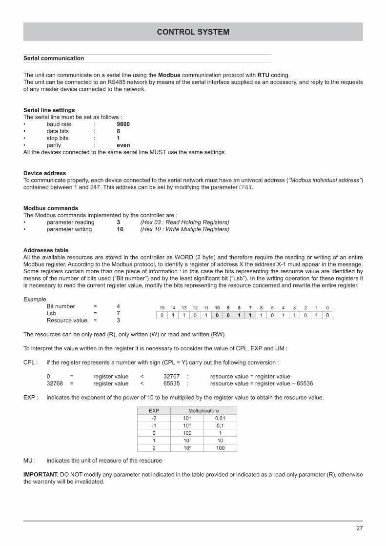
Addresses tableAll the available resources are stored in the controller as WORD (2 byte) and therefore require the reading or writing of an entire Modbus register. According to the Modbus protocol, to identify a register of address X the address X-1 must appear in the message.Some registers contain more than one piece of information : in this case the bits representing the resource value are identified by means of the number of bits used (“Bit number”) and by the least significant bit (“Lsb”). In the writing operation for these registers it is necessary to read the current register value, modify the bits representing the resource concerned and rewrite the entire register.
Example. Bit number = 4 Lsb = 7 Resource value = 3
The resources can be only read (R), only written (W) or read and written (RW).
To interpret the value written in the register it is necessary to consider the value of CPL, EXP and UM :
CPL : if the register represents a number with sign (CPL = Y) carry out the following conversion :
0 = register value < 32767 : resource value = register value 32768 = register value < 65535 : resource value = register value – 65536
EXP : indicates the exponent of the power of 10 to be multiplied by the register value to obtain the resource value.
MU : indicates the unit of measure of the resource
IMPORTANT . DO NOT modify any parameter not indicated in the table provided or indicated as a read only parameter (R), otherwise the warranty will be invalidated.
15 14 13 12 11 10 9 8 7 6 5 4 3 2 1 0
0 1 1 0 1 0 0 1 1 1 0 1 1 0 1 0
EXP Moltiplicatore-2 10-2 0,01-1 10-1 0,10 100 11 101 102 102 100
Serial communication

28
CONTROL SYSTEM
Label Description RWRegisteraddress Bit
number Lsb CPL EXP UMDec Hex
COOL Set point cooling RW 16900 4204 16 0 Y -1 °CHEAT Set point heating RW 16902 4206 16 0 Y -1 °CCF19 Remote stand by enable RW 49303 C097 8 0 Y 0 -CF20 Remote Cooling-Heating enable RW 49304 C098 8 0 Y 0 -CF63 Device serial address RW 49178 C01A 8 0 N 0 -tr01 Heat pump enable RW 49665 C201 8 0 N 0 -tr17 Heat pump lock set point RW 16930 4222 16 0 Y -1 °CPI05 Modulating pump / return fan speed : cooling RW 49749 C255 8 0 N 0 %PI11 Modulating pump / return fan speed : heating RW 49757 C25D 8 0 N 0 %Hi02 Integrative electrical heaters enable RW 49858 C2C2 8 0 N 0 -CP01 Compressor operating hours R 753 02F1 16 0 N 0 orePU01 Pump / return fan operating hours R 763 02FB 16 0 N 0 oreAI01 Water / air inlet probe R 344 0158 16 0 Y -1 °CAI02 Water / air outlet probe R 346 015A 16 0 Y -1 °CAI03 Liquid line probe R 348 015C 16 0 Y -1 °CAI04 Outdoor air probe R 350 015E 16 0 Y -1 °C
- Unit operating in COOLING R 33028 8104 1 4 N 0 -- Unit operating in HEATING R 33028 8104 1 6 N 0 -- Unit in STAND BY (user interface or serial communication) R 33028 8104 1 2 N 0 -- Unit in STAND BY (digital input) R 33028 8104 1 3 N 0 -- Unit in OFF R 33028 8104 1 0 N 0 -- COOLING mode enable * W 33471 82BF 1 3 N 0 -- HEATING mode enable * W 33471 82BF 1 4 N 0 -- STAND BY enable * W 33471 82BF 1 5 N 0 -- HEATING request R 33094 8146 1 3 N 0 -- COOLING request R 33094 8146 1 4 N 0 -- Unit switching on ( 1 = ON ; 0 = OFF ) W 33471 82BF 1 7 N 0 -- Alarm Er05 R 33037 810D 1 5 N 0 -- Alarm Er20 R 33039 810F 1 4 N 0 -- Alarm Er30 R 33040 8110 1 6 N 0 -- Alarm Er41 R 33042 8112 1 1 N 0 -- Alarm Er45 R 33042 8112 1 5 N 0 -- Alarm Er46 R 33042 8112 1 6 N 0 -- Alarm Er60 R 33044 8114 1 4 N 0 -- Alarm Er61 R 33044 8114 1 5 N 0 -- Alarm Er62 R 33044 8114 1 6 N 0 -- Alarm Er68 R 33045 8115 1 4 N 0 -
* If several operation modes are enabled by mistake :- OFF has priority over STAND BY, HEATING, COOLING- STAND BY has priority over HEATING, COOLING- HEATING has priority over COOLING
Temperature Resistance
[°C] [kΩ]0 25,79505 21,3963
10 17,747715 14,721320 12,211025 10,128730 8,401535 6,968840 5,780545 4,794850 3,977155 3,2989
Probes characteristics
The temperature probes used are NTC 10K (10 kΩ at 25°C).When the probe bulb is at the temperature of 25°C the electrical resi-stance measurable at the probe ends is 10 kΩ.The thermistor of these probes has a negative temperature coefficient: the electrical resistance value decreases as the temperature increases.
To find out if a temperature probe is faulty or disconnected, check the correspondence between the resistance value in kΩ and the bulb tem-perature in °C according to the table.
For a reliable verify it is not necessary to check all the single values but is enough to check some random values. If the instrument indicates neverending resistance then the probe is interrupted.

29
MAINTENANCE
IMPORTANT. MAKE SURE THE UNIT IS NOT ELECTRICALLY POWERED BEFORE CARRYING OUT ANY CLEANING OR MAIN-TENANCE OPERATION. ALL ORDINARY AND EXTRAORDINARY MAINTENANCE OPERATIONS MUST BE CARRIED OUT BY SPECIALIZED AND AUTHORIZED PERSONNEL, IN ORDER TO ENSURE COMPLIANCE WITH THE CURRENT SAFETY REGU-LATIONS.
NB .: always make sure that the power supply lines (of the unit and of the integrative electrical heaters) are disconnected at the start before carrying out any maintenance operation.
This section is extremely important for efficient operation of the unit during the years. A few operations carried out periodically can avoid the need to call specialized personnel. The operations to be carried out do not require particular technical knowledge and con-sist of simple checks of the components of the unit.Contact an authorized service centre if maintenance is required.
StructureTo prevent noise and strange vibrations to rise make sure that the various steel parts are well fastened together and that the inspec-tion panels are properly fixed to the unit.In case of oxidation, treat with paints, suitable to avoid or reduce the problem, the parts of the unit affected.
Hydraulic plantVisually check that the hydraulic plant is leaks free and is pressurized. Verify there is no air in the circuit (acting on the air vents). Verify that the filters in the plant are clean.
Electrical plantVerify that the power supply cable that connects the unit to the distribution panel is not affected by cuts, cracks or alterations that could compromise the insulation. Contact an authorized service center if maintenance is required. After a first period of time from the first start up and at every stop or seasonal start up carefully check that each electrical connection is well fixed.
FansVerify that the fans are well fixed to the protective grilles and to the structure of the unit. Check any unbalance of the fans pointed out by anomalous vibrations and noise.
Finned coilAccidental contact with the exchanger fins can cause small cuts. Use protective gloves to carry out the operations described below. The exchangers must be able to ensure the maximum heat exchange, therefore their surfaces must always be clear of any dirt and dust that can present on them due to the action of the fans. Using a brush, remove all the impurities present on the surface of the coil. Clean the aluminium surface of the coil with a compressed air jet, making sure to aim the jet with the direction of the fins so as to avoid damages. If the aluminium fins has been damaged, “comb” the coil with a special tool until the damage is completely eliminated.
Finned coil condensate drainageVerify that, during the defrosting cycles that take place in heating mode, the drainage of the water from the finned pack occurs pro-perly and that the drainage fitting on the unit basement is not clogged. If the flow is not correct, with low outdoor temperature, a layer of ice could be generated on the unit basement and the operating of the unit could be compromised.
Maintenance

30
SAFETY AND POLLUTION
Accessing the unitThe access to the unit must be granted exclusively to qualified personnel trained to operate on this type of units and provided with the necessary protection equipment. Moreover such personnel, to operate, must be authorized by the owner of the unit and recognized by the Manufacturer.
Residual risksThe unit are designed and built in such a way to minimize risks for people and for the place where the unit is installed. The residual risks, impossible to eliminate during the design process, are reported in the following table along with the indications necessary for their neutralization.Considered part Residual risk Mode PrecautionsCompressor Burns Contact Use protective glovesRefrigerantcircuitpipes
Burns Contact Use protective gloves
Cold burns Fuoriuscita di refrigerante e contatto con la pelle Use protective gloves
Electrical circuit Electrocutions Contact with live partsVerify the unit earth connectionDisconnect the power supply line before carrying out any operation inside the unit
Finned coil Cuts Contact Use protective gloves
General considerations
1 SUPPLIER COMPANY AND PRODUCT IDENTIFICATIONCard No. FRIG 8Product R-410ASupplier company identification RIVOIRA SpA2 COMPOSITION / INFORMATION ON INGREDIENTSSubstance / Preparation PreparationComponents / Impurities Contains the following components : Difluoromethane (R32) 50 % in weight Pentafluoroethane (R125) 50 % in weightEEC No. Non-applicable for mixturesTrade-name / /3 IDENTIFICATION OF HAZARDSIdentification of hazards Liquefied gas. The vapours are heavier than air and can cause suffocation, reducing the oxygen available for brea-
thing. Rapid evaporation of the fluid can cause freezing. Can cause cardiac arrhythmia.4 FIRST-AID MEASURESInhalation Do not administer anything if the person has fainted. Take the person outdoors. Use oxygen or artificial respiration if necessary. Do not administer adrenaline or similar substances.Contact with eyes Rinse thoroughly with plenty of water for at least 15 minutes and see a doctor.Contact with skin Wash immediately with plenty of water. Immediately remove all contaminated garments.Swallowing5 FIRE-PREVENTION MEASURESSpecific hazards Increase in pressure.Dangerous fumes Halogen acids, traces of carbonyl halides.Fire-extinguishing means usable All the known fire-extinguishing means can be used.Specific methods Cool the containers/tanks with water sprays.Special protection equipment Use self-contained breathing apparatus in confined spaces.6 MEASURES AGAINST ACCIDENTAL SPILLING OF THE PRODUCTPersonal protection Evacuate personnel to safe areas. Provide for adequate ventilation. Use personal protection equip-
mentProtection for the environment It evaporates.Product removal methods It evaporates.7 HANDLING AND STORAGEHandling and storage Ensure an adequate air change and/or extraction in the workplaces. Only use well-ventilated rooms.
Do not breathe vapours or aerosols. Carefully close the containers and keep them in a cool, dry and well-ventilated place. Keep in the original containers.
Incompatible products Explosives, flammable materials, organic peroxides.8 CONTROL OF EXPOSURE / PERSONAL PROTECTIONPersonal protection Ensure adequate ventilation, especially in closed areas.Control parameters Difluoromethane (R32): Recommended exposure limits: AEL (8h and 12h TWA) = 1000 ml/m3 Pentafluoroethane (R125): Recommended exposure limits: AEL (8h and 12h TWA) = 1000 ml/m3
Refrigerant safety card
PollutionThe unit contains refrigerant gas and lubricating oil. During discarding such fluids must be recovered and eliminated according to the regulations in force in the country where the unit is installed. The unit must not be abandoned during discarding.

31
SAFETY AND POLLUTION
Respiratory tract protection For rescue and for maintenance works in tanks, use self-contained breathing apparatus. The vapours are heavier than air and can cause suffocation, reducing the oxygen available for breathing.
Eye protection Total protection glasses.Hand protection Rubber gloves.Hygiene measures Do not smoke.9 CHEMICAL-PHYSICAL PROPERTIESRelative density, gas (air=1) Heavier than air.Solubility in water (mg/l) Not known, but deemed very low.Appearance Colourless liquefied gas.Odour Similar to ether.Fire point Does not ignite.10 STABILITY AND REACTIVITYStability and reactivity No decomposition if used according to the special instructions.Materials to be avoided Alkali metals, alkali-earth metals, granulated metal salts, Al, Zn, Be, etc. in powder.Hazardous products of decomposition Halogen acids, traces of carbonyl halides.11 TOXICOLOGICAL INFORMATIONLocal effects Concentrations substantially above the value TLV (1000 ppm) can cause narcotic effects. Inhalation
of highly concentrated products of decomposition can cause respiratory insufficiency (pulmonary oedema).
Long-term toxicity No carcinogenic, teratogenic or mutagenic effects have been recorded in experiments on animals.Specific effects Rapid evaporation of the fluid can cause freezing. Can cause cardiac arrhythmia.12 ECOLOGICAL INFORMATIONEffects linked to ecotoxicity Pentafluoroethane (R125) Potential global warming with halocarbides; HGWP (R-11 = 1) = 0.84 Potential impoverishment of the ozone; ODP (R-11 = 1) = 013 CONSIDERATIONS ON DISPOSALGeneral Do not dispose of where accumulation can be hazardous. Usable with reconditioning. The depressurised containers must be returned to the supplier. Contact the supplier if instructions for use are deemed necessary.14 INFORMATION FOR TRANSPORTDesignation for transport LIQUEFIED GAS N.A.S. ( DIFLUOROMETHANE, PENTAFLUOROETHANE )UN No. 3163Class/Div 2.2ADR /RID No. 2, 2nd AADR/RID hazard no. 20ADR label Label 2 : non-toxic non-flammable gas.CEFIC Groupcard 20g39 - AOther information for transport Avoid transport on vehicles where the loading zone is not separate from the cab. Make sure the driver is informed about the potential risk of the load and knows what to do in case of accident or emergency. Before starting transport, make sure the load is properly secured and : make sure the valve of the container is closed and does not leak; make sure the blind cap of the valve (when provided) is correctly fitted; make sure the cap (when provided) is correctly fitted and that there is an adequate ventilation passage; ensure compliance with the current provisions.15 INFORMATION ON REGULATIONSThe product must not be labelled according to Directive 1999/45/EC.Comply with the regulations given below, and the relevant applicable updates and amendments.Circulars no. 46/79 and 61/81 of the Ministry of Labour : Risks related to the use of products containing aromatic aminesLeg. Decree no. 133/92 : Regulations on the discharge of hazardous substances in watersLeg. Decree no. 277/91 : Protection of workers against noise, lead and asbestosLaw 256/74, Decree 28/1/92, Leg. Decree no. 52 dated 3/2/97, Decree dated 28/4/97 as amended : Classification, packing and labelling of hazardous substances and preparationsDecree no. 175/88, as amended : Activities with significant accident risks (Seveso Law)Decree no. 203/88 : Emissions into the atmosphereDecree no. 303/56 : Work hygieneDecree no. 547/55 : Regulations on accident preventionLeg. Decree no.152 dated 11/5/99 : Protection of waters16 OTHER INFORMATIONRecommended uses RefrigerantCan cause suffocation in high concentration.Keep in a well-ventilated place.Do not breathe the gas.The risk of suffocation is often underestimated and must be clearly explained during the training of operators.Ensure compliance with all the national and regional regulations.Before using this product in any new process or trial, an in-depth study on safety and compatibility of the product with the materials must be carried out.The above information is based on our current know-how and describes the product according to the safety requirements. It does not however repre-sent a guarantee and assurance of the qualities in a legal sense. Each person responds personally for compliance with such regulations.
The manufacturer declines all responsibility for any inaccuracies in this manual due to printing or typing errors.The reserves the right to modify the products contents in this catalogue without previous notice.

32

33
DECLARATION OF CONFORMITY

34

35

Ferroli spa ¬ 37047 San Bonifacio (Verona) Italy ¬ Via Ritonda 78/A tel. +39.045.6139411 ¬ fax +39.045.6100933 ¬ www.ferroli.it
CO
D.
3QE
3236
0