checklist for expert evaluation of hmis of automated vehicles
TRANSCRIPT
information
Discussion
Checklist for Expert Evaluation of HMIs ofAutomated Vehicles—Discussions on Its Value andAdaptions of the Method within an Expert Workshop
Nadja Schömig 1,*, Katharina Wiedemann 1, Sebastian Hergeth 2 , Yannick Forster 2,Jeffrey Muttart 3, Alexander Eriksson 4 , David Mitropoulos-Rundus 5, Kevin Grove 6 ,Josef Krems 7, Andreas Keinath 2, Alexandra Neukum 1 and Frederik Naujoks 2
1 Würzburg Institute for Traffic Sciences GmbH (WIVW), D-97209 Veitshöchheim, Germany;[email protected] (K.W.); [email protected] (A.N.)
2 BMW Group, D-80937 München, Germany; [email protected] (S.H.);[email protected] (Y.F.); [email protected] (A.K.); [email protected] (F.N.)
3 Crash Safety Research Center, LLC, 201 W High Street, B8 East Hampton, New York, NY 06424, USA;[email protected]
4 Volvo Car Corporation, Torslanda, SE-405 31 Göteborg, Sweden; [email protected] Hyundai American Technical Center, Superior Township, MI 48198, USA; [email protected] Virginia Tech Transportation Institute, 3500 Transportation Research Plaza, Blacksburg, VA 24061, USA;
[email protected] Department of Behavioural and Social Sciences, Technische Universität Chemnitz,
09111 Chemnitz, Germany; [email protected]* Correspondence: [email protected]; Tel.: +49-931-78009-208
Received: 28 February 2020; Accepted: 20 April 2020; Published: 24 April 2020�����������������
Abstract: Within a workshop on evaluation methods for automated vehicles (AVs) at the DrivingAssessment 2019 symposium in Santa Fe; New Mexico, a heuristic evaluation methodology that aimsat supporting the development of human–machine interfaces (HMIs) for AVs was presented. The goalof the workshop was to bring together members of the human factors community to discuss themethod and to further promote the development of HMI guidelines and assessment methods for thedesign of HMIs of automated driving systems (ADSs). The workshop included hands-on experienceof rented series production partially automated vehicles, the application of the heuristic assessmentmethod using a checklist, and intensive discussions about possible revisions of the checklist andthe method itself. The aim of the paper is to summarize the results of the workshop, which willbe used to further improve the checklist method and make the process available to the scientificcommunity. The participants all had previous experience in HMI design of driver assistance systems,as well as development and evaluation methods. They brought valuable ideas into the discussionwith regard to the overall value of the tool against the background of the intended application,concrete improvements of the checklist (e.g., categorization of items; checklist items that are currentlyperceived as missing or redundant in the checklist), when in the design process the tool should beapplied, and improvements for the usability of the checklist.
Keywords: automated vehicles; automated driving systems; HMI; guidelines; heuristic evaluation;checklist; expert evaluation
1. Background
With the Federal Automated Vehicles Policy, the U.S. National Highway Traffic SafetyAdministration (NHTSA) has provided an outline that can be used to guide the developmentand validation of automated driving systems (ADS).
Information 2020, 11, 233; doi:10.3390/info11040233 www.mdpi.com/journal/information
Information 2020, 11, 233 2 of 16
With regard to the human–machine interface (HMI), the policy proposes that an automated vehicle(AV) HMI at minimum shall inform the user that the system is either of the following [1]:
1. Functioning properly;2. Engaged in automated driving mode;3. Currently ‘unavailable’ for use;4. Experiencing a malfunction; and/or5. Requesting a control transition from ADS to the operator.
A suitable design of mode indicators should effectively support the driver in using an ADS andprevent a false understanding of the current driving mode. NHTSA encourages implementing anddocumenting a process for the testing, assessment, and validation of each element [1]. However, detailson how entities can assess and validate if a specific HMI meets these requirements are not proposed.Therefore, a test procedure was developed that serves to evaluate the conformity of SAE level 3(conditional automation) ADS HMIs with the requirements outlined in NHTSA’s Automated Vehiclespolicy (for an overview, see [2]). Before this publication, no standardized tools for the assessment ofthe usability and safety of ADS HMIs existed.
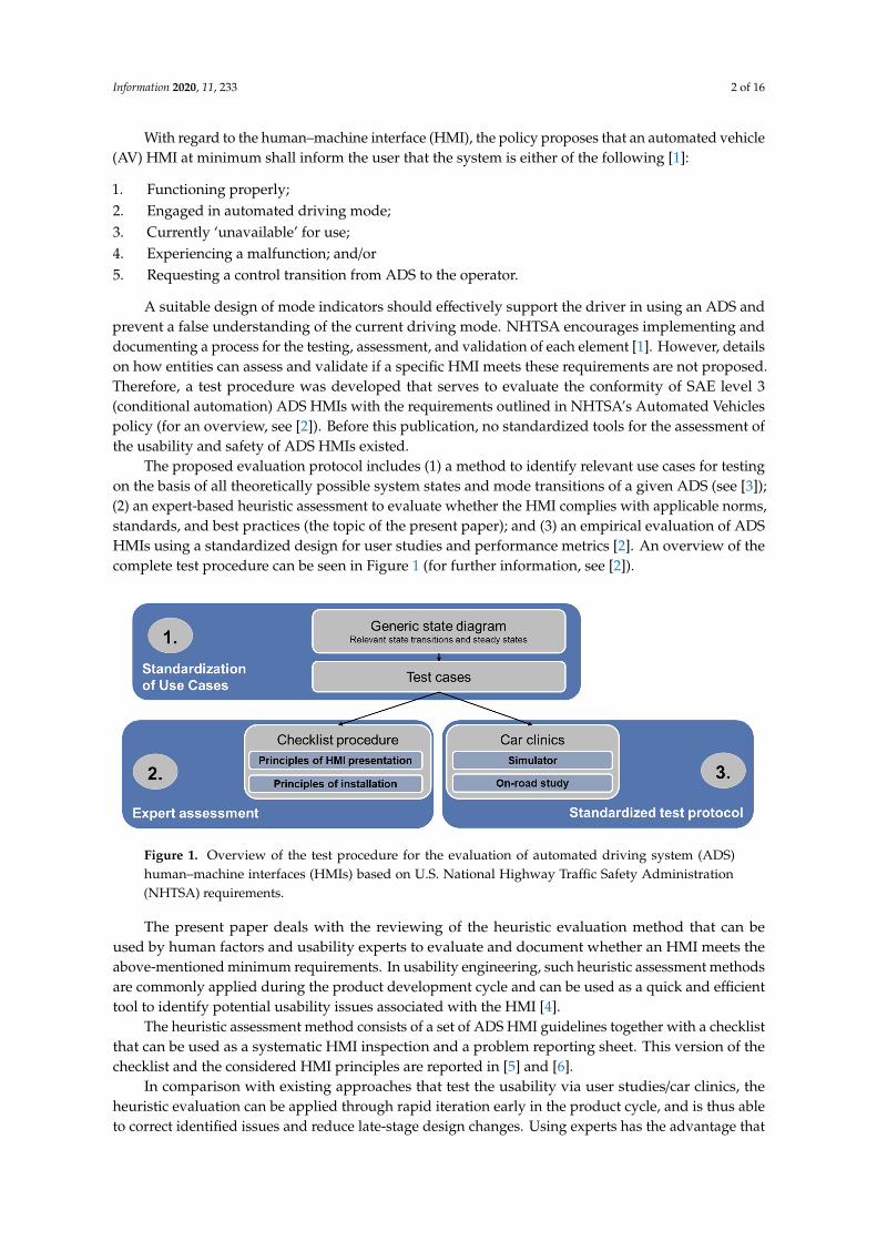
The proposed evaluation protocol includes (1) a method to identify relevant use cases for testingon the basis of all theoretically possible system states and mode transitions of a given ADS (see [3]);(2) an expert-based heuristic assessment to evaluate whether the HMI complies with applicable norms,standards, and best practices (the topic of the present paper); and (3) an empirical evaluation of ADSHMIs using a standardized design for user studies and performance metrics [2]. An overview of thecomplete test procedure can be seen in Figure 1 (for further information, see [2]).
Information 2020, 11, x FOR PEER REVIEW 2 of 17
With regard to the human–machine interface (HMI), the policy proposes that an automated vehicle (AV) HMI at minimum shall inform the user that the system is either of the following [1]:
1. Functioning properly; 2. Engaged in automated driving mode; 3. Currently ‘unavailable’ for use; 4. Experiencing a malfunction; and/or 5. Requesting a control transition from ADS to the operator.
A suitable design of mode indicators should effectively support the driver in using an ADS and prevent a false understanding of the current driving mode. NHTSA encourages implementing and documenting a process for the testing, assessment, and validation of each element [1]. However, details on how entities can assess and validate if a specific HMI meets these requirements are not proposed. Therefore, a test procedure was developed that serves to evaluate the conformity of SAE level 3 (conditional automation) ADS HMIs with the requirements outlined in NHTSA’s Automated Vehicles policy (for an overview, see [2]). Before this publication, no standardized tools for the assessment of the usability and safety of ADS HMIs existed.
The proposed evaluation protocol includes (1) a method to identify relevant use cases for testing on the basis of all theoretically possible system states and mode transitions of a given ADS (see [3]); (2) an expert-based heuristic assessment to evaluate whether the HMI complies with applicable norms, standards, and best practices (the topic of the present paper); and (3) an empirical evaluation of ADS HMIs using a standardized design for user studies and performance metrics [2]. An overview of the complete test procedure can be seen in Figure 1 (for further information, see [2]).
Figure 1. Overview of the test procedure for the evaluation of automated driving system (ADS) human–machine interfaces (HMIs) based on U.S. National Highway Traffic Safety Administration (NHTSA) requirements.
The present paper deals with the reviewing of the heuristic evaluation method that can be used by human factors and usability experts to evaluate and document whether an HMI meets the above-mentioned minimum requirements. In usability engineering, such heuristic assessment methods are commonly applied during the product development cycle and can be used as a quick and efficient tool to identify potential usability issues associated with the HMI [4].
The heuristic assessment method consists of a set of ADS HMI guidelines together with a checklist that can be used as a systematic HMI inspection and a problem reporting sheet. This version of the checklist and the considered HMI principles are reported in [5] and [6].
In comparison with existing approaches that test the usability via user studies/car clinics, the heuristic evaluation can be applied through rapid iteration early in the product cycle, and is thus able to correct identified issues and reduce late-stage design changes. Using experts has the advantage that inadequate mental models that might influence evaluations of naïve users can be
Figure 1. Overview of the test procedure for the evaluation of automated driving system (ADS)human–machine interfaces (HMIs) based on U.S. National Highway Traffic Safety Administration(NHTSA) requirements.
The present paper deals with the reviewing of the heuristic evaluation method that can beused by human factors and usability experts to evaluate and document whether an HMI meets theabove-mentioned minimum requirements. In usability engineering, such heuristic assessment methodsare commonly applied during the product development cycle and can be used as a quick and efficienttool to identify potential usability issues associated with the HMI [4].
The heuristic assessment method consists of a set of ADS HMI guidelines together with a checklistthat can be used as a systematic HMI inspection and a problem reporting sheet. This version of thechecklist and the considered HMI principles are reported in [5] and [6].
In comparison with existing approaches that test the usability via user studies/car clinics, theheuristic evaluation can be applied through rapid iteration early in the product cycle, and is thus ableto correct identified issues and reduce late-stage design changes. Using experts has the advantage that
Information 2020, 11, 233 3 of 16
inadequate mental models that might influence evaluations of naïve users can be better controlled.Furthermore, experts are trained to concentrate on single HMI aspects separately from each other intheir evaluations. In addition, by means of the checklist, experts can evaluate an HMI in absolute valuesindependently from a comparison with other HMIs. However, both heuristic evaluation and car clinicsare recommended to be used as complementary methods in the evaluation protocol (see Figure 1).
The paper at hand has the goal to disseminate the already published work on the developed testprocedure to a scientific community and to further adapt the checklist based on the results of the expertworkshop. Suggestions for improvement from human factors experts and practitioners are discussedagainst the background of feasibility (keeping it an easy-to-use tool) and appropriateness for use in achecklist compared with other methods.
2. Content and Usage of the Checklist
2.1. Checklist Items
The aim of the assessment is to evaluate whether a set of pre-defined HMI principles (the“heuristics”) are met. Thus, the checklist consists of 20 items summarizing the most important designrecommendations for visual-auditory and visual-vibrotactile HMIs derived from existing norms,applicable standards, design guidelines, and empirical research, pertaining to in-vehicle interfaces.The complete list of items is presented in Table 1. The derivations of these items from the literature areelaborately described in [5].
Table 1. List of heuristics (see also [5]). HMI, human–machine interface.
# Item
1 Unintentional activation and deactivation should be prevented2 The system mode should be displayed continuously3 Mode changes should be effectively communicated
4 Visual interfaces used to communicate system states should be mounted to a suitable position and distance.High-priority information should be presented close to the driver’s expected line of sight
5 HMI elements should be grouped together according to their function to support the perception of mode indicators6 Time-critical interactions with the system should not afford continuous attention7 The visual interface should have a sufficient contrast in luminance and/or color between foreground and background
8 Texts (e.g., font types and size of characters) and symbols should be easily readable from the permittedseating position
9 Commonly accepted or standardized symbols should be used to communicate the automation mode. Use ofnon-standard symbols should be supplemented by additional text explanations
10 The semantic of a message should be in accordance with its urgency
11 Messages should be conveyed using the language of the users (e.g., national language, avoidance of technicallanguage, use of common syntax)
12 Text messages should be as short as possible13 Not more than five colors should be consistently used to code system states (excluding white and black)14 The colors used to communicate system states should be in accordance with common conventions and stereotypes15 Design for color-blindness by redundant coding and avoidance of red/green and blue/yellow combinations16 Auditory output should raise the attention of the driver without startling her/him or causing pain17 Auditory and vibrotactile output should be adapted to the urgency of the message18 High-priority messages should be multimodal19 Warning messages should orient the user towards the source of danger20 In case of sensor failures, their consequences and required operator steps should be displayed
2.2. Method Description
The method should be conducted by a pair of HMI experts. Preferably, experts should havereceived formal training in human factors and usability engineering or have demonstrable practicalexperience in the assessment and evaluation of automotive HMIs. However, the evaluators should haveno prior experience with the vehicle and features to be tested. The most suitable testing environmentdepends on the maturity of the product. In the very early development stages, where there is only aprototype available and series production is far away, it is recommended to use a driving simulator.For series production vehicles or high-fidelity prototypes, it is advised to conduct the study on-road as
Information 2020, 11, 233 4 of 16
this provides the most realistic conditions for testing. Each of the two evaluators completes a fixedset of use cases, observes the visual, auditory and haptic HMI output, and records potential usabilityissues arising from the non-compliance with the checklist items (see Figure 2 for an example). The usecase set consists of the various system states and the transitions between them (e.g., activating thesystem, deactivating the system, switching between system modes, required control transition fromthe system to the operator) and depends on the specific design of the ADS with respect to the availablelevels of automation (e.g., whether only manual or conditional automation are available, or if partialautomation (level 2) is also available within the same vehicle). While one of the evaluators is the driver,the other one is seated in the passenger seat, providing step-wise instructions about the desired systemstate to the driver at appropriate times during the drive. To ensure that both observers are able toexperience each use case and resulting system and user reactions and responses in a comparable way,they switch position after one driving session and repeat the drive. The aim of the heuristic assessmentis twofold:
1. For the minimum HMI requirements to be fulfilled, each of the use cases should be reflected in amode indicator or the change of a mode indicator that must be present in the in-vehicle HMI.At minimum, a persistent mode indicator should be presented visually. In addition, auditory,tactile, or kinaesthetic cues for mode transitions are recommended.
2. The design of the respective mode indicator should be in accordance with the common HMIstandards and best practices that are the basis of the checklist.
Checklist compliance and identified usability issues should be initially documented independentlyby each of the evaluators. Each of the checklist items should be answered using the followingrating categories:
• “major concerns”: non-compliance with guideline;• “minor concerns”: partial fulfilment of guideline, but some aspects of the HMI are non-compliant;• “no concerns”: compliance of all HMI aspects with guideline;• “measurement necessary”/”subject to verification”: no definite conclusion can be given on the basis
of the checklist and empirical testing is needed. This category should be chosen if highly innovativedesigns are used that are not covered by current standards and best practices. An example wouldbe the use of other communication channels than the above-mentioned (e.g., olfactory cues);
• “not applicable”: respective design recommendation not applicable to the system underinvestigation (e.g., HMI without vibrotactile output).
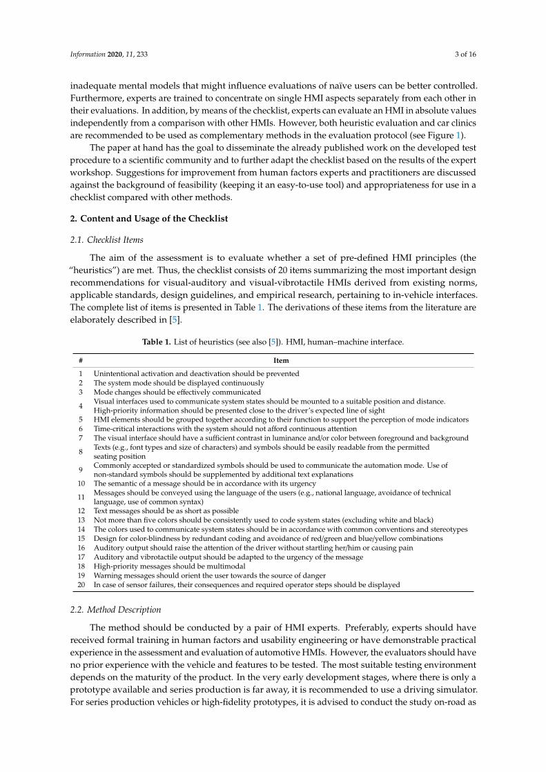
The reasons for “major” and “minor” concerns should be documented in a separate reportingsheet. After the individual assessment, the results should be discussed between the evaluators to cometo a unanimous rating decision for each item, which should also be documented. Figure 2 shows asimplified flow chart of the test procedure.
Information 2020, 11, x FOR PEER REVIEW 4 of 17
evaluators completes a fixed set of use cases, observes the visual, auditory and haptic HMI output, and records potential usability issues arising from the non-compliance with the checklist items (see Figure 2 for an example). The use case set consists of the various system states and the transitions between them (e.g., activating the system, deactivating the system, switching between system modes, required control transition from the system to the operator) and depends on the specific design of the ADS with respect to the available levels of automation (e.g., whether only manual or conditional automation are available, or if partial automation (level 2) is also available within the same vehicle). While one of the evaluators is the driver, the other one is seated in the passenger seat, providing step-wise instructions about the desired system state to the driver at appropriate times during the drive. To ensure that both observers are able to experience each use case and resulting system and user reactions and responses in a comparable way, they switch position after one driving session and repeat the drive. The aim of the heuristic assessment is twofold:
1. For the minimum HMI requirements to be fulfilled, each of the use cases should be reflected in a mode indicator or the change of a mode indicator that must be present in the in-vehicle HMI. At minimum, a persistent mode indicator should be presented visually. In addition, auditory, tactile, or kinaesthetic cues for mode transitions are recommended.
2. The design of the respective mode indicator should be in accordance with the common HMI standards and best practices that are the basis of the checklist.
Checklist compliance and identified usability issues should be initially documented independently by each of the evaluators. Each of the checklist items should be answered using the following rating categories:
• “major concerns”: non-compliance with guideline; • “minor concerns”: partial fulfilment of guideline, but some aspects of the HMI are
non-compliant; • “no concerns”: compliance of all HMI aspects with guideline; • “measurement necessary”/”subject to verification”: no definite conclusion can be given on the
basis of the checklist and empirical testing is needed. This category should be chosen if highly innovative designs are used that are not covered by current standards and best practices. An example would be the use of other communication channels than the above-mentioned (e.g., olfactory cues);
• “not applicable”: respective design recommendation not applicable to the system under investigation (e.g., HMI without vibrotactile output).
The reasons for “major” and “minor” concerns should be documented in a separate reporting sheet. After the individual assessment, the results should be discussed between the evaluators to come to a unanimous rating decision for each item, which should also be documented. Figure 2 shows a simplified flow chart of the test procedure.
Figure 2. Simplified flow chart of the test procedure.
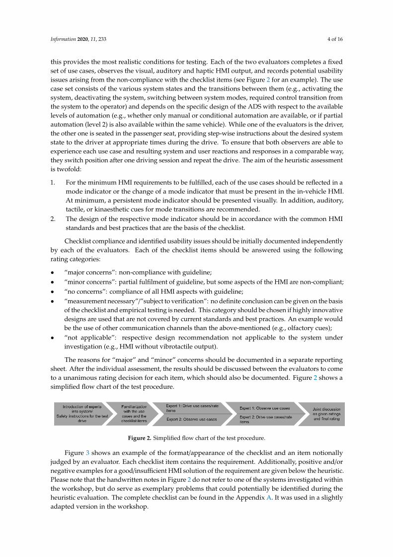
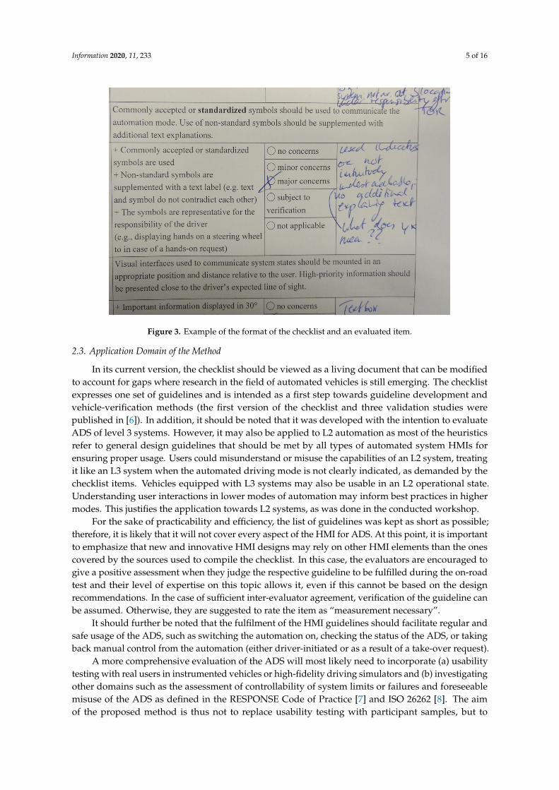
Figure 3 shows an example of the format/appearance of the checklist and an item notionally judged by an evaluator. Each checklist item contains the requirement. Additionally, positive and/or negative examples for a good/insufficient HMI solution of the requirement are given below the heuristic. Please note that the handwritten notes in Figure 2 do not refer to one of the systems investigated within the workshop, but do serve as exemplary problems that could potentially be identified during the heuristic evaluation. The complete checklist can be found in the Appendix A. It was used in a slightly adapted version in the workshop.
Figure 2. Simplified flow chart of the test procedure.
Figure 3 shows an example of the format/appearance of the checklist and an item notionallyjudged by an evaluator. Each checklist item contains the requirement. Additionally, positive and/ornegative examples for a good/insufficient HMI solution of the requirement are given below the heuristic.Please note that the handwritten notes in Figure 2 do not refer to one of the systems investigated withinthe workshop, but do serve as exemplary problems that could potentially be identified during theheuristic evaluation. The complete checklist can be found in the Appendix A. It was used in a slightlyadapted version in the workshop.
Information 2020, 11, 233 5 of 16
Information 2020, 11, x FOR PEER REVIEW 5 of 17
Figure 3. Example of the format of the checklist and an evaluated item.
2.3. Application Domain of the Method
In its current version, the checklist should be viewed as a living document that can be modified to account for gaps where research in the field of automated vehicles is still emerging. The checklist expresses one set of guidelines and is intended as a first step towards guideline development and vehicle-verification methods (the first version of the checklist and three validation studies were published in [6]). In addition, it should be noted that it was developed with the intention to evaluate ADS of level 3 systems. However, it may also be applied to L2 automation as most of the heuristics refer to general design guidelines that should be met by all types of automated system HMIs for ensuring proper usage. Users could misunderstand or misuse the capabilities of an L2 system, treating it like an L3 system when the automated driving mode is not clearly indicated, as demanded by the checklist items. Vehicles equipped with L3 systems may also be usable in an L2 operational state. Understanding user interactions in lower modes of automation may inform best practices in higher modes. This justifies the application towards L2 systems, as was done in the conducted workshop.
For the sake of practicability and efficiency, the list of guidelines was kept as short as possible; therefore, it is likely that it will not cover every aspect of the HMI for ADS. At this point, it is important to emphasize that new and innovative HMI designs may rely on other HMI elements than the ones covered by the sources used to compile the checklist. In this case, the evaluators are encouraged to give a positive assessment when they judge the respective guideline to be fulfilled during the on-road test and their level of expertise on this topic allows it, even if this cannot be based on the design recommendations. In the case of sufficient inter-evaluator agreement, verification of the guideline can be assumed. Otherwise, they are suggested to rate the item as “measurement necessary”.
It should further be noted that the fulfilment of the HMI guidelines should facilitate regular and safe usage of the ADS, such as switching the automation on, checking the status of the ADS, or taking back manual control from the automation (either driver-initiated or as a result of a take-over request).
A more comprehensive evaluation of the ADS will most likely need to incorporate (a) usability testing with real users in instrumented vehicles or high-fidelity driving simulators and (b) investigating other domains such as the assessment of controllability of system limits or failures and foreseeable misuse of the ADS as defined in the RESPONSE Code of Practice [7] and ISO 26262 [8]. The aim of the proposed method is thus not to replace usability testing with participant
Figure 3. Example of the format of the checklist and an evaluated item.
2.3. Application Domain of the Method
In its current version, the checklist should be viewed as a living document that can be modifiedto account for gaps where research in the field of automated vehicles is still emerging. The checklistexpresses one set of guidelines and is intended as a first step towards guideline development andvehicle-verification methods (the first version of the checklist and three validation studies werepublished in [6]). In addition, it should be noted that it was developed with the intention to evaluateADS of level 3 systems. However, it may also be applied to L2 automation as most of the heuristicsrefer to general design guidelines that should be met by all types of automated system HMIs forensuring proper usage. Users could misunderstand or misuse the capabilities of an L2 system, treatingit like an L3 system when the automated driving mode is not clearly indicated, as demanded by thechecklist items. Vehicles equipped with L3 systems may also be usable in an L2 operational state.Understanding user interactions in lower modes of automation may inform best practices in highermodes. This justifies the application towards L2 systems, as was done in the conducted workshop.
For the sake of practicability and efficiency, the list of guidelines was kept as short as possible;therefore, it is likely that it will not cover every aspect of the HMI for ADS. At this point, it is importantto emphasize that new and innovative HMI designs may rely on other HMI elements than the onescovered by the sources used to compile the checklist. In this case, the evaluators are encouraged togive a positive assessment when they judge the respective guideline to be fulfilled during the on-roadtest and their level of expertise on this topic allows it, even if this cannot be based on the designrecommendations. In the case of sufficient inter-evaluator agreement, verification of the guideline canbe assumed. Otherwise, they are suggested to rate the item as “measurement necessary”.
It should further be noted that the fulfilment of the HMI guidelines should facilitate regular andsafe usage of the ADS, such as switching the automation on, checking the status of the ADS, or takingback manual control from the automation (either driver-initiated or as a result of a take-over request).
A more comprehensive evaluation of the ADS will most likely need to incorporate (a) usabilitytesting with real users in instrumented vehicles or high-fidelity driving simulators and (b) investigatingother domains such as the assessment of controllability of system limits or failures and foreseeablemisuse of the ADS as defined in the RESPONSE Code of Practice [7] and ISO 26262 [8]. The aimof the proposed method is thus not to replace usability testing with participant samples, but to
Information 2020, 11, 233 6 of 16
complement empirical approaches with an economical heuristic evaluation tool. It may serve asa guide or sieve to identify and improve poorly performing HMIs before going into further userstudies. Further limitations of the current approach are also discussed in the corresponding sections ofthis paper.
3. Intention of the Workshop
The intention of the conducted workshop at the Driving Assessment 2019 symposium in SantaFe, New Mexico was to present the developed method and its application to human factors expertsin the scientific community of automated vehicle research in order to further improve the method.A higher level goal was to stimulate the discussion within a larger scientific and technical communitytowards future standards that may be appropriate for guiding the development of automated vehicleHMIs. Another goal is to facilitate a more rapid convergence towards an agreed-upon set of robustguidelines and verification methods that can serve the industry in the important evolution of automationwithin vehicles.
4. Evaluation Procedure during the Workshop
The workshop was organized by WIVW GmbH (a company providing research services in thefield of human factors, especially from the automotive sector) and was held following the closingsession of the conference, on 27 June 2019 at the El Dorado Hotel in Santa Fe. In total, 14 participantstook part in the workshop. The workshop was announced via the conference website and was openfor application to all conference participants. The workshop attendees were selected based on theirscientific background either as practitioners or academics in the automotive domain with previousexperience in the HMI design, development, or evaluation methods of driver assistance systems.The resulting workshop group consisted of agents from the automotive industry, scientific institutes,and national agencies. In preparation of the workshop, the participants received publications thatdescribed the background of the checklist method [3] and its application [6].
Regarding the agenda, the workshop started with a short introduction of the organizers, whogave an outline of the workshop. Afterwards, the method and its background were presented. Then,the 14 participants were split into small groups of 3–4 people who would apply the method whileriding together in two vehicles equipped with L2 driving automation systems: a Tesla Model 3 withthe Autopilot system (AP) and a Cadillac with the GM Supercruise (SC) system.
These two systems were chosen as their system architecture, system operation principles, as well astheir system performance (e.g., regarding the threshold required for overriding the system by steeringinput) are different from each other. The Tesla had a large center-stack touch screen for the HMIdisplay, while the Cadillac used a classical instrument cluster and a light bar at the steering wheelfor communicating the current system mode. The Cadillac had many of the automation controllingbuttons on the steering wheel, while the Tesla system is operated by a lever behind the steering wheel.The two systems also offered different warning and alerts, different both in the type of alerts and whenthey occurred. Systems also differed in their approaches for driver monitoring; while the Tesla used ahands-on detection system, the SC determines whether the driver has enough visual attention on theroad via a camera system. Furthermore, the Cadillac had more constraints to use than the Tesla L2system (for further descriptions of the system, see Chapter 5).
Before starting the drive, each participant received a copy of the checklist and familiarizedthemselves with the items and the rating procedure. It was emphasized that the rating of the systemsitself was not the relevant outcome of the evaluation process and that methodological issues emergingwhen applying the method were of greater importance.
The participants experienced both systems as passengers in a 30 min drive on the interstate 25(Denver–Albuquerque). The first system was experienced while being driven in one direction on theinterstate. After a stop at an exit, the groups switched vehicles and experienced the second system
Information 2020, 11, 233 7 of 16
on the way back to the interstate exit. The drive from the conference site to the interstate took about10 min.
Owing to safety and insurance reasons, the workshop organizers drove the vehicles. Therefore,the evaluation process during the workshop did not follow exactly the one proposed in the heuristicevaluation procedure, where the evaluators should really drive the vehicle (see [6]). On the way tothe interstate, the drivers briefly explained the control elements (button, lever, and so on) used foroperating the system and which HMI elements had to be observed by the evaluators. The test itselfstarted when the vehicle reached the interstate. Up to here, the Tesla theoretically permitted to use theAutopilot, while the SC could not be used before entering the interstate. The drivers conducted severaluse cases in which the system could be experienced:
• The activation of the system;• Driving with active L2 for a longer time interval (i.e., 4–5 min);• Experiencing the driver monitoring system, which required a take-over in case the driver did not
react to it;• The deactivation of the system;• Short-term standby modes, for example, in the case of non-detection of lane markings or
lane changes;• Planned system limits when exiting the interstate.
After getting back to the workshop room, participants were asked to fill out the checklist basedon the second system they experienced. After all four groups had experienced the two vehicles,all workshop participants jointly discussed methodological issues they noticed during the applicationof the method.
5. Description of the Evaluated Systems
Although the rating of the systems themselves was not in the scope of the evaluation, a shortdescription of both systems is inserted here to better understand the resulting discussions.
5.1. The GM Supercruise System
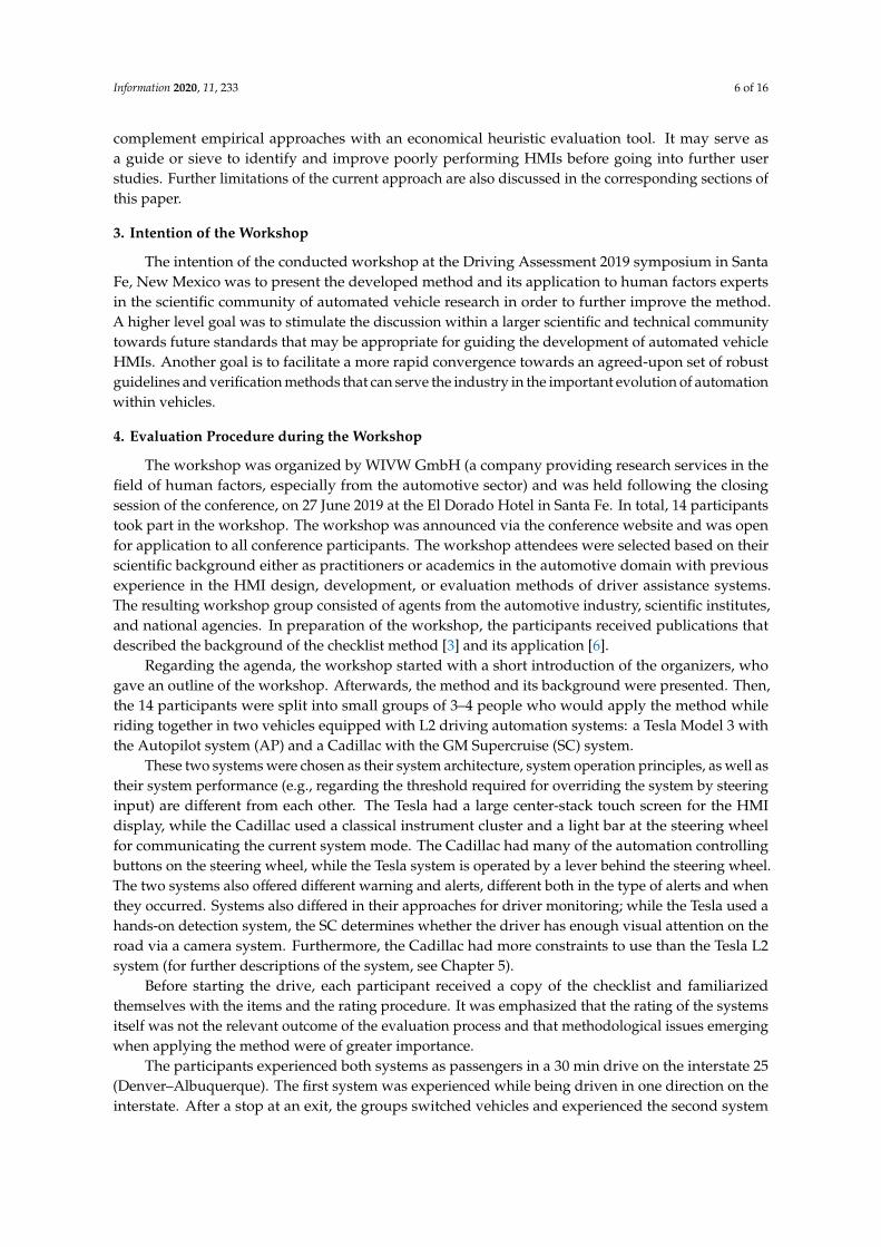
The GM Supercruise system is operated via buttons on the steering wheel. The system mode isindicated by presenting graphics, icons, and text messages at the instrument cluster (see Figure 4).In addition, there is a light bar on the steering wheel that is also used to indicate the current systemmode by different colours and pulsation (static vs. flashing lights). The system is geofenced, meaningthat it is only available on certain roads, such as interstates. Other preconditions for activation are thatthe driver has to drive in the center of the lane and that adaptive cruise control (ACC) is active. If thedriver tries to activate the system outside these conditions, they receive a text message at the rightside of the instrument cluster. The system state is indicated by a specific area on the left side of theinstrument cluster as well as by telltales in the centre of the cluster. In order to activate Supercruise,first, ACC has to be shifted into standby mode (separate button) and activated by setting the speed.After that, Supercruise can be activated by a separate button. The activity of Supercruise is indicated bya green steering wheel together with green horizontal bars for ACC shown in the cluster. A short-termdegraded standby mode (meaning lateral control is not active) is indicated by a blue steering wheeland the steering wheel light bar in blue. Lateral control is automatically resumed if the conditionsare fulfilled once again. The Supercruise system does not require the driver to keep their handspermanently at the steering wheel, as UN-CE-R-79 [9] regulating this matter does not apply for theUnited States. However, if the driver tries to deactivate the system without having their hands at thewheel, a take-over request is triggered by a text message and red indicators. The driver monitoringsystem consists of a camera on the top of the steering wheel that determines whether the driver islooking towards the road. If the time not looking at the road exceeds a certain threshold, the steeringwheel first flashes green before it turns red and lateral control is deactivated.
Information 2020, 11, 233 8 of 16
Information 2020, 11, x FOR PEER REVIEW 8 of 17
Figure 4. HMI elements of the GM Supercruise system.
5.2. The Tesla Autopilot
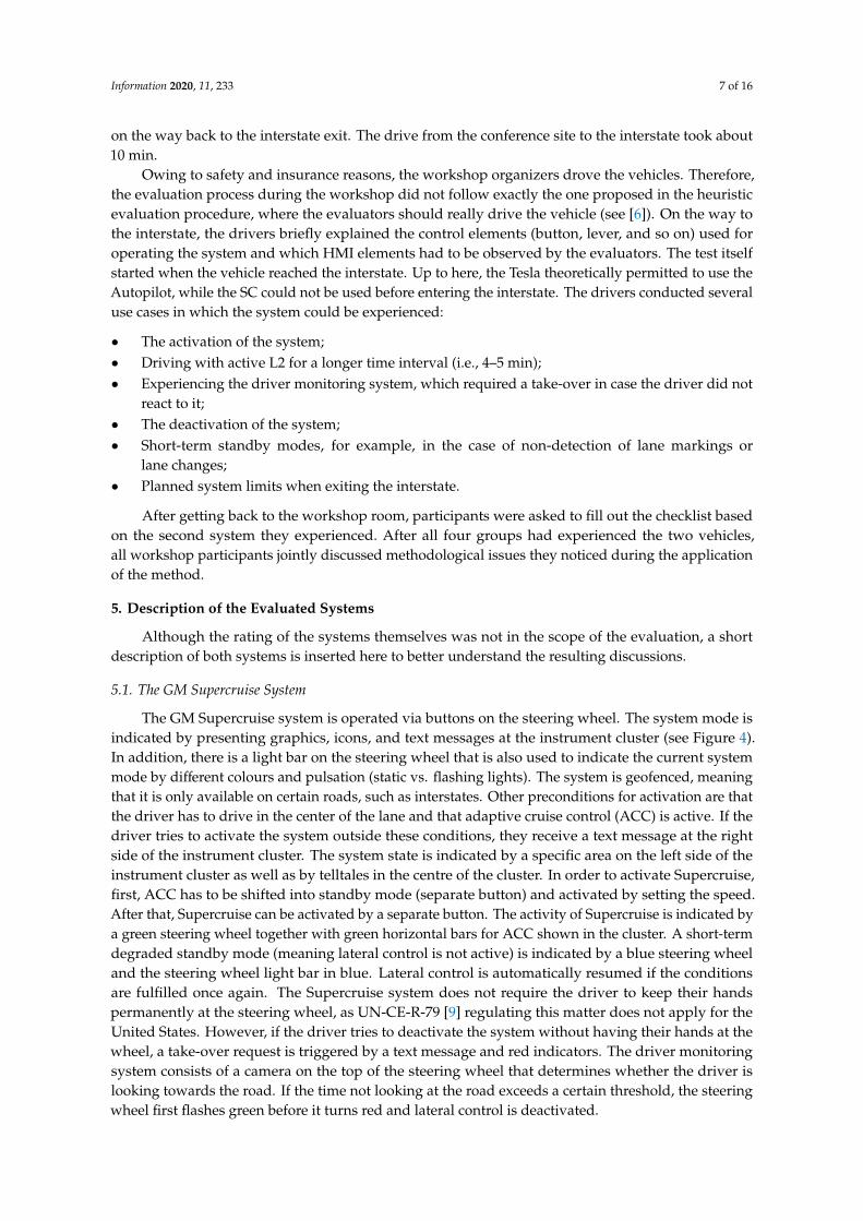
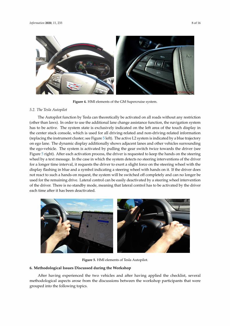
The Autopilot function by Tesla can theoretically be activated on all roads without any restriction (other than laws). In order to use the additional lane change assistance function, the navigation system has to be active. The system state is exclusively indicated on the left area of the touch display in the center stack console, which is used for all driving-related and non-driving-related information (replacing the instrument cluster; see Figure 5 left). The active L2 system is indicated by a blue trajectory on ego lane. The dynamic display additionally shows adjacent lanes and other vehicles surrounding the ego-vehicle. The system is activated by pulling the gear switch twice towards the driver (see Figure 5 right). After each activation process, the driver is requested to keep the hands on the steering wheel by a text message. In the case in which the system detects no steering interventions of the driver for a longer time interval, it requests the driver to exert a slight force on the steering wheel with the display flashing in blue and a symbol indicating a steering wheel with hands on it. If the driver does not react to such a hands-on request, the system will be switched off completely and can no longer be used for the remaining drive. Lateral control can be easily deactivated by a steering wheel intervention of the driver. There is no standby mode, meaning that lateral control has to be activated by the driver each time after it has been deactivated.
Figure 5. HMI elements of Tesla Autopilot.
6. Methodological Issues Discussed during the Workshop
After having experienced the two vehicles and after having applied the checklist, several methodological aspects arose from the discussions between the workshop participants that were grouped into the following topics.
6.1. Design Issues of the Checklist
Figure 4. HMI elements of the GM Supercruise system.
5.2. The Tesla Autopilot
The Autopilot function by Tesla can theoretically be activated on all roads without any restriction(other than laws). In order to use the additional lane change assistance function, the navigation systemhas to be active. The system state is exclusively indicated on the left area of the touch display inthe center stack console, which is used for all driving-related and non-driving-related information(replacing the instrument cluster; see Figure 5 left). The active L2 system is indicated by a blue trajectoryon ego lane. The dynamic display additionally shows adjacent lanes and other vehicles surroundingthe ego-vehicle. The system is activated by pulling the gear switch twice towards the driver (seeFigure 5 right). After each activation process, the driver is requested to keep the hands on the steeringwheel by a text message. In the case in which the system detects no steering interventions of the driverfor a longer time interval, it requests the driver to exert a slight force on the steering wheel with thedisplay flashing in blue and a symbol indicating a steering wheel with hands on it. If the driver doesnot react to such a hands-on request, the system will be switched off completely and can no longer beused for the remaining drive. Lateral control can be easily deactivated by a steering wheel interventionof the driver. There is no standby mode, meaning that lateral control has to be activated by the drivereach time after it has been deactivated.
Information 2020, 11, x FOR PEER REVIEW 8 of 17
Figure 4. HMI elements of the GM Supercruise system.
5.2. The Tesla Autopilot
The Autopilot function by Tesla can theoretically be activated on all roads without any restriction (other than laws). In order to use the additional lane change assistance function, the navigation system has to be active. The system state is exclusively indicated on the left area of the touch display in the center stack console, which is used for all driving-related and non-driving-related information (replacing the instrument cluster; see Figure 5 left). The active L2 system is indicated by a blue trajectory on ego lane. The dynamic display additionally shows adjacent lanes and other vehicles surrounding the ego-vehicle. The system is activated by pulling the gear switch twice towards the driver (see Figure 5 right). After each activation process, the driver is requested to keep the hands on the steering wheel by a text message. In the case in which the system detects no steering interventions of the driver for a longer time interval, it requests the driver to exert a slight force on the steering wheel with the display flashing in blue and a symbol indicating a steering wheel with hands on it. If the driver does not react to such a hands-on request, the system will be switched off completely and can no longer be used for the remaining drive. Lateral control can be easily deactivated by a steering wheel intervention of the driver. There is no standby mode, meaning that lateral control has to be activated by the driver each time after it has been deactivated.
Figure 5. HMI elements of Tesla Autopilot.
6. Methodological Issues Discussed during the Workshop
After having experienced the two vehicles and after having applied the checklist, several methodological aspects arose from the discussions between the workshop participants that were grouped into the following topics.
6.1. Design Issues of the Checklist
Figure 5. HMI elements of Tesla Autopilot.
6. Methodological Issues Discussed during the Workshop
After having experienced the two vehicles and after having applied the checklist, severalmethodological aspects arose from the discussions between the workshop participants that weregrouped into the following topics.
Information 2020, 11, 233 9 of 16
6.1. Design Issues of the Checklist
With regard to better usability of the checklist, it was proposed to reorganize its design. For abetter overview, some items could be grouped together into higher-level categories (e.g., with regardto color usage). Another suggestion for grouping the items was to categorize them with regard to usecases, for example, group all items with regard to change of system mode together. However, withthe intention of the checklist to only test the minimum requirements set by NHTSA policy, this ideawould prove as impractical as this would mean repetitions of some items that are valid for several usecases, which would unnecessarily stretch the checklist. The idea of shifting the positive and negativedesign examples to an appendix as added material was judged as not appropriate as the raters couldprofit from the current position of the examples, while there is a chance that an appendix tends to beoverlooked during the rating process.
In addition to the current rating categories, it was proposed to add a category for “suggestedimprovements”, not only in the final reporting sheet, but also on the item level to encourage experts tothink about better solutions instead of simply marking “concerns”.
6.2. Missing and Redundant Items
One concern regarding the selection of the checklist items was that some of them should not beevaluated subjectively by experts, but must be better objectively measured by technicians. These itemscomprise the following:
• Displaying HMI elements close to the line of sight (part of item 4);• Checking color contrast (item 7);• Checking text size (character height and stroke width, item 8);• Design of auditory or vibrotactile feedback with regard to length, loudness, and frequency
(item 17).
It is agreed that, for later stages of the HMI development, objective measurement by a technician isnecessary, while in an early stage, a heuristic assessment of these items might be acceptable. Therefore,methods used for early stage and later stage assessment of the HMI might differ. It was discussedwhether only those items should remain in the checklist, which must be subjectively assessed byexperts. Other objectively measurable items could be deleted from the checklist and inserted into aseparate technical checklist. Finally, there was some discussion about items that should be added tothe checklist as they seem to cover aspects that are currently not adequately addressed.
Regarding extensions of the checklist, the greatest benefit, but also the greatest challenge, wouldbe to rate the overall complexity of the system/HMI. The (perceived) complexity in using a systemwill heavily influence acceptance and trust in the system (e.g., [10]). The term includes two types ofcomplexity. First, the system complexity, meaning the logic behind the various system modes andits transitions (e.g., are lateral and longitudinal control separate sub-functions that can be used incombination as well as independently of each other? Are standby modes included?). The systemcomplexity will likely influence the complexity of system operation (e.g., sequence of operational stepsto be performed or number of possible operation steps in order to reach a certain system state) orthe demands on the distinctiveness of the several system modes (how many different indicators arenecessary and how are they designed in order to clearly identify the current system mode). The latteris linked to the second type of complexity, the display complexity, which can be described by thearrangement of the information elements on the display, for example, in terms of display layout,number of display elements relative to display size (so-called visual clutter), spatial proximity ofelements (e.g., in terms of overlapping), and so on.
Another possibility to operationalize the term complexity would be the categorization intodifferent types of demands that are put on the operator of the system and that result in a certain levelof perceived complexity in system usage. One possibility would be to define dimensions according
Information 2020, 11, 233 10 of 16
to typical categorizations of workload based on Wicken’s multiple resource model [11]. This modelcategorizes workload based on the following:
• Visual demands that result from the design of the visual displays, including contentand arrangement;
• Motoric demands that result from the number and arrangement of the operational devices;• Cognitive demands that result from the system logic and the difficulty in understanding the
various system modes and the conditions for the transitions between them;• In addition, temporal demands, meaning the requirements on the reaction to hazards play an
important role and are influenced by the design of warning messages and the take-over request.
To sum up this issue, in the general discussion about the aim of the checklist, workshop participantstended to agree that complexity can be reasonably assessed by experts. Therefore, it was proposedto consider the system complexity in future iterations of the checklist. It is recommended to reflectthe multidimensionality of this item in the checklist. One way would be to define multiple itemsaddressing the defined sub-dimensions from the chapter above and group them together in the moreglobal category of “complexity”. The other option (which might be more appropriate as concretestandards for the assessment of complexity are missing) would be to formulate one single more genericitem with the defined sub-items as positive/negative examples.
With regard to the evaluation of system operation, currently, there is only one item includedthat deals with the avoidance of unintentional activation and deactivation of the system (see also, forexample, currently ongoing work by UNECE on the ACSF regulation (automatically commandedsteering function) [12]). The reason for the limitation to only this item is that, at the creation of thechecklist, there were no clear design guidelines or recommendations on how system operations shouldbe designed. At the moment, there are some concrete specifications on activation, deactivation, anddriver input principles under ongoing consideration in the UNECE ACSF document (e.g., the systemshould be deactivated when the driver overrides the system by steering, braking, or accelerating whileholding the steering control). However, issues concerning the system logic are outside the scope of thechecklist. However, the design of operational devices might be an extension of the checklist whenmore research and valid guidelines on this topic are available.
Highly correlated to the term complexity is the learnability of the system’s logical operation andthe HMI. Learnability is said to be one major attribute of usability (beside effectiveness, error tolerance,satisfaction, and memorization; for example, see [4]) and will be influenced by interface design(e.g., visibility of successful operations, feedback, continuity of task sequences, design conventions,information presentation, user assistance, error prevention) and conformity to users’ expectations tothe car manufacturer’s philosophy (differences in functionality, differences in interaction style, conceptclarity, and completeness of information [13]). Beside an intuitive first contact with a system, theconcept of learnability should also include the aspect of re-learning the use of the system again aftera longer interval of non-usage and the resources involved. However, it seems difficult for expertsto provide a meaningful rating regarding learnability as an expert involved in system design, andassessment is likely biased when it comes to learnability owing to their experience. The same willbe true for in-house testers who have extensive knowledge about currently developed products.This aspect should thus better be tested with naïve users. A small sample may be enough, and mayinclude people not involved in ADS design. According to Nielsen [4], most of the usability problemscan be identified by a number of five experts.
Another issue that could be considered by the checklist is the evaluation of other display elementsbeside the conventional ones, such as instrument cluster and head-up displays. This should containnot only the mere presence of peripheral displays, which are considered as an example in item 4(“peripheral displays supporting noticing of mode changes, e.g., by movement or size of displays”),but also more concrete items referring to the design of those displays (e.g., steering wheel light bars).However, up to now, there are no concrete design guidelines, but a few empirical studies exist on
Information 2020, 11, 233 11 of 16
the positive effects of ambient displays on mode awareness and take-over performance (e.g., [14]).Beside concrete design aspects, it can be requested that such elements should be congruent with theones displayed in the instrument cluster, as otherwise, this might be problematic for understanding ofsystem modes.
For the design of warnings, it was discussed whether to consider additional aspects beside theones that are already included dealing with the communication channels to be used (in multiplemodalities; item 18) and the desired effect of not distracting the driver (item 19). Such aspects are, forexample, nomenclature choices and linguistic complexity (i.e., fault messages based on engineeringnomenclature vs. easily comprehensible names of system modes). In addition, the content of thewarning could be defined more explicitly. It was proposed to positively evaluate if the potentialconsequences of a system limit are displayed (e.g., what would happen if the user does not interveneand how can the user recover or reactivate the system, for example, in the case of repeated hand-off
warnings).American National Standards Institute (ANSI) suggests that a safety warning should include the
following (ANSI Z353 [15]):
1. Identification of the hazard;2. Identification of a means to avoid the hazard;3. The consequences of not avoiding the hazard.
While there is not a need to adhere closely to the ANSI warning standard, such a standard couldbe considered as a guideline. In the context of automated driving, warnings can occur owing to lesstime critical hazards such as sensor failures that do not inevitably require an immediate action like aforward collision warning. However, reaching system limits can be interpreted as imminent hazardsthat require the driver to immediately take over the driving task to avoid an accident. Signal wordsthat can be used for describing the identification of the hazard are “Danger”, “Warning”, “Caution”, or“Notice”. Then, a notice of what to do next to avoid a hazard should be given.
In the case of an urgent take-over request, these first two aspects are probably the most criticalpoints. Typically, the HMI addresses them by displaying a short text such as “Take Over” togetherwith a warning sign. The third aspect, conveying the consequence of inaction, seems to be the mostproblematic point in the case of take-over requests, as it is not always clear what happens in the case inwhich the system is deactivated without the immediate reaction of the driver. This information mightbe better explained by a user manual of the system instead of by the HMI in the imminent situation.
Finally, there were some suggestions for new items to be included in the checklist. One examplewas about the usage of a dynamic environment display that shows the surrounding traffic. Such adisplay is currently included in the Tesla Autopilot HMI. However, up to the current state-of-art, thebenefit of such a display has not yet been established, and it is thus not clear how such an additionaldisplay should be evaluated. Does it have a positive effect on situation awareness or might it distractthe driver from extracting relevant status information from the display and promote over trust in thesystem? It is possible that displays utilizing motion/animation may blunt the driver’s response towarnings as motion is a powerful attention grabber, and thus a driver may start filtering out displaycontent that is more relevant in the respective situation (i.e., notices, state changes). Owing to the lackof empirical evidence on the potential effects, the formulation of a checklist item regarding such adisplay is problematic, and will thus be postponed until more research is available.
Another example is a potential item for the ease of overriding the system. This item wouldaddress the controllability of a system, which was not the initial scope of the checklist. Currently, it isnot clear whether it is good or bad if a system can be easily overridden by the driver. In addition, it isargued that such highly complex interactions between various factors (e.g., the degree of lateral controlwill play an important factor on this issue) seem to be better assessed in user studies. Therefore, noitem regarding this issue will be included for now.
Information 2020, 11, 233 12 of 16
6.3. Human Factors Aspects to be Considered by Other Methods
All workshop participants jointly agreed that other aspects such as differences in system behaviour,system logic, system operation logic (beside some describable specific aspects in the item of complexity),and their effects on system usability require additional evaluation methods, as the correlation betweenthese different factors is not yet clear in order to formulate concrete design recommendations. Moreover,their effects on system acceptance and system trust must be assessed by user studies. User experience(UX)-related aspects such as the hedonistic quality of the system and the HMI are also recommendedto be evaluated by user studies. In this way, real users can experience the system and report theiremotions and attitudes towards the system.
High agreement was also achieved for the fact that, especially on the type of control, user studiesare needed (e.g., operation via steering wheel buttons vs. touch screen) with regard to performancetimes or distraction potential before checklist items can be deduced.
6.4. Test Procedure
Regarding the test procedure, the workshop participants recommended to put more emphasis onthe fact that the experts should take the perspective of naive users. A naive user can be defined as “aperson that tests the ADAS under evaluation with no more experience and prior knowledge of thesystem than a later customer would have” ([7], p. 7). This should allow that the requirements are validfor the average population. The inclusion of certain items also makes it possible to address the needsof certain specific driver groups, for example, drivers with colour-blindness.
Nevertheless, it should be kept in mind that this method should not replace, but rather supplementother approaches like user studies that allow for eye tracking, reaction time testing, and performancemeasurement on tasks dealing with the handling of the system. Both methods are proposed to beconducted within the complete evaluation protocol (see Figure 1).
The proposed test procedure (a team of two experts rates the system after having once experiencedthe use cases themselves as a driver and having watched the other evaluator driving) was rated asa reasonable approach. This approach has the advantage that both experts do not merely observesomeone interacting with the system, but really experience that interaction themselves. In addition,the fact that one evaluator can directly document their first impression while the other evaluator isdriving (compared with a retrospective documentation) avoids negative effects such as memory decay.For later reference, it is suggested to capture video of the driving experience (by scenario and systemresponse) using small video cameras mounted in locations that capture cluster, head unit, and otherdisplays and controls, while not covering the rater’s view on these elements.
It was further proposed to conduct the evaluation with a larger group of experts if no time andresource constraints object to this approach. However, as this might complicate the process, to reachan agreement in a joint discussion, we would recommend only consulting a third external evaluator ifno such agreement can be made between the evaluators even after a longer discussion.
Owing to the variety of systems that can be evaluated and the fact that new and innovative HMIdesigns are currently not covered by the checklist items, there will be situations in which adaptationsneed to be made by the experts to accommodate for specific circumstances. In this case, we suggestthat experts follow the following approach.
1. Search for common published standards;2. If 1 does not apply, evaluate the system by extrapolating those concepts from the checklist that
seems to be transferable to the innovative HMI;3. If 1 and 2 do not apply, conduct empirical testing.
6.5. General Value of the Checklist
It was jointly agreed that the developed method is a useful tool in the design process of AV HMIs.It is primarily intended to facilitate the assessment of system usability. It is able to check whether the
Information 2020, 11, 233 13 of 16
minimum requirements proposed in the NHTSA policy are fulfilled. It is also reasonable as the currentrapid evolvement of automated systems makes it extremely difficult to identify the “best design” ofsuch a system and its HMI. This method serves as a tool to guide and make quick changes duringthe development process, that is, testing several concepts and narrowing down options, as well asensuring a “basic” compliance throughout the design loops.
As said above, for a global evaluation, the assessment of aspects such as different system logics,different concepts for system operation (e.g., longitudinal and lateral control as separate systems, L2 asadd on to L1, stepwise activation of L1, then L2, and so on), and different design philosophies shouldbe considered, which are better answered by user studies.
7. Conclusions and Outlook
On the basis of the discussions with the workshop participants, the following adaptions of thechecklist were decided:
• The structure of the checklist will be revised in order to achieve a better usability for theexperts. This will mainly refer to a re-arrangement of the items into more global categories andunderlying subcategories.
• Items regarding measurable aspects such as text sizes, line of sight, or colour contrasts will remainin the checklist to be assessed subjectively by the experts (as confirmation from a user perspectivebased on technical tests that will be conducted later in the design process). Absolute measurablenumbers will be removed from the examples list.
• A new category of perceived complexity will be included in the checklist. This categorywill comprise several items/examples, which still have to be defined. Issues that should beconsidered are
# the visual demands of the HMI in general;# the cognitive demands resulting from the complexity of the system’s logic;# the motoric demands resulting from the number, positioning, and arrangement of
operational devices;# the ease of learning the interaction with the system.
• The following new items will be included in the checklist
# An item on the appropriate design of other display elements;# An item on the content of a warning/take-over request.
• The test procedure itself will remain in the proposed manner with two experts experiencing thesystem to be evaluated within a defined set of use cases in real drives, first separately filling outthe checklist, and finally give a global rating based on a joint discussion.
It is planned to transfer the checklist into a computer-application that can be used, for example,on tablets in order to support the experts in the documentation of the tests, the discussion of its output,and the recommendations for system improvements.
Author Contributions: Workshop organization: K.W., N.S., Workshop participation: N.S., K.W., Y.F., F.N., J.M.,A.N., D.M.-R., K.G., J.K.; Writing – review and editing: All authors. All authors have read and agreed to thepublished version of the manuscript.
Funding: This research received no external funding.
Acknowledgments: The development of the method was funded by BMW Group. The workshop was organizedby WIVW GmbH and hosted by the Driving Assessment Conference. Thanks to all workshop participants for theirvaluable inputs to the methodological discussions during the workshop. Special thanks to all of those workshopparticipants who additionally contributed to the present publication with input and comments (Jeffrey Muttart,Alexander Eriksson, Kevin Grove, David Mitropoulos-Rundus, Josef Krems, Sebastian Hergeth, Frederik Naujoks,and Yannick Forster).
Conflicts of Interest: The authors declare no conflict of interest.
Information 2020, 11, 233 14 of 16
Appendix A
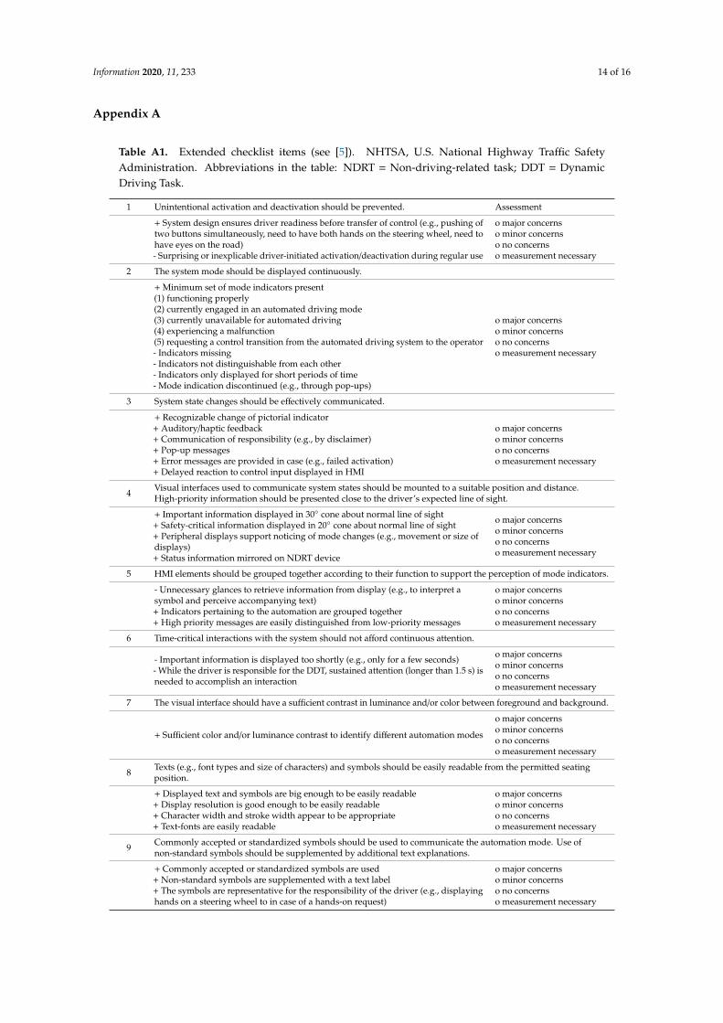
Table A1. Extended checklist items (see [5]). NHTSA, U.S. National Highway Traffic SafetyAdministration. Abbreviations in the table: NDRT = Non-driving-related task; DDT = DynamicDriving Task.
1 Unintentional activation and deactivation should be prevented. Assessment
+ System design ensures driver readiness before transfer of control (e.g., pushing oftwo buttons simultaneously, need to have both hands on the steering wheel, need tohave eyes on the road)- Surprising or inexplicable driver-initiated activation/deactivation during regular use
o major concernso minor concernso no concernso measurement necessary
2 The system mode should be displayed continuously.
+ Minimum set of mode indicators present(1) functioning properly(2) currently engaged in an automated driving mode(3) currently unavailable for automated driving(4) experiencing a malfunction(5) requesting a control transition from the automated driving system to the operator- Indicators missing- Indicators not distinguishable from each other- Indicators only displayed for short periods of time- Mode indication discontinued (e.g., through pop-ups)
o major concernso minor concernso no concernso measurement necessary
3 System state changes should be effectively communicated.
+ Recognizable change of pictorial indicator+ Auditory/haptic feedback+ Communication of responsibility (e.g., by disclaimer)+ Pop-up messages+ Error messages are provided in case (e.g., failed activation)+ Delayed reaction to control input displayed in HMI
o major concernso minor concernso no concernso measurement necessary
4 Visual interfaces used to communicate system states should be mounted to a suitable position and distance.High-priority information should be presented close to the driver’s expected line of sight.
+ Important information displayed in 30◦ cone about normal line of sight+ Safety-critical information displayed in 20◦ cone about normal line of sight+ Peripheral displays support noticing of mode changes (e.g., movement or size ofdisplays)+ Status information mirrored on NDRT device
o major concernso minor concernso no concernso measurement necessary
5 HMI elements should be grouped together according to their function to support the perception of mode indicators.
- Unnecessary glances to retrieve information from display (e.g., to interpret asymbol and perceive accompanying text)+ Indicators pertaining to the automation are grouped together+ High priority messages are easily distinguished from low-priority messages
o major concernso minor concernso no concernso measurement necessary
6 Time-critical interactions with the system should not afford continuous attention.
- Important information is displayed too shortly (e.g., only for a few seconds)- While the driver is responsible for the DDT, sustained attention (longer than 1.5 s) isneeded to accomplish an interaction
o major concernso minor concernso no concernso measurement necessary
7 The visual interface should have a sufficient contrast in luminance and/or color between foreground and background.
+ Sufficient color and/or luminance contrast to identify different automation modes
o major concernso minor concernso no concernso measurement necessary
8 Texts (e.g., font types and size of characters) and symbols should be easily readable from the permitted seatingposition.
+ Displayed text and symbols are big enough to be easily readable+ Display resolution is good enough to be easily readable+ Character width and stroke width appear to be appropriate+ Text-fonts are easily readable
o major concernso minor concernso no concernso measurement necessary
9 Commonly accepted or standardized symbols should be used to communicate the automation mode. Use ofnon-standard symbols should be supplemented by additional text explanations.
+ Commonly accepted or standardized symbols are used+ Non-standard symbols are supplemented with a text label+ The symbols are representative for the responsibility of the driver (e.g., displayinghands on a steering wheel to in case of a hands-on request)
o major concernso minor concernso no concernso measurement necessary
Information 2020, 11, 233 15 of 16
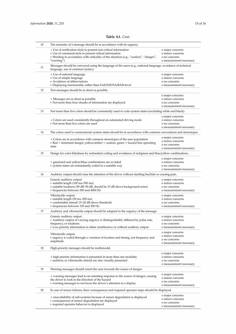
Table A1. Cont.
10 The semantic of a message should be in accordance with its urgency.
+ Use of notification-style to present non-critical information+ Use of command-style to present critical information+ Wording in accordance with criticality of the situation (e.g., “caution”, “danger”,“warning”)
o major concernso minor concernso no concernso measurement necessary
11 Messages should be conveyed using the language of the users (e.g., national language, avoidance of technicallanguage, use of common syntax).
+ Use of national language+ Use of simple language+ Avoidance of abbreviations+ Displaying functionality rather than SAE/NHTSA/BASt-level
o major concernso minor concernso no concernso measurement necessary
12 Text messages should be as short as possible.
+ Messages are as short as possible+ Not more than four chunks of information are displayed
o major concernso minor concernso no concernso measurement necessary
13 Not more than five colors should be consistently used to code system states (excluding white and black).
+ Colors are used consistently throughout an automated driving mode+ Not more than five colors are used
o major concernso minor concernso no concernso measurement necessary
14 The colors used to communicate system states should be in accordance with common conventions and stereotypes.
+ Colors are in accordance with common stereotypes of the user population+ Red = imminent danger, yellow/amber = caution, green = hazard-free operatingstate
o major concernso minor concernso no concernso measurement necessary
15 Design for color-blindness by redundant coding and avoidance of red/green and blue/yellow combinations.
+ green/red and yellow/blue combinations are avoided+ system states are redundantly coded in a suitable way
o major concernso minor concernso no concernso measurement necessary
16 Auditory output should raise the attention of the driver without startling her/him or causing pain.
Generic auditory output+ suitable length (100 ms–500 ms)+ suitable loudness (50 dB–90 dB, should be 15 dB above background noise)+ frequencies between 500 and 4000 Hz
o major concernso minor concernso no concernso measurement necessary
Vibrotactile output+ suitable length (50 ms–200 ms)+ comfortable stimuli 15–20 dB above threshold+ frequencies between 150 and 300 Hz
o major concernso minor concernso no concernso measurement necessary
17 Auditory and vibrotactile output should be adapted to the urgency of the message.
Generic auditory output+ Auditory output of varying urgency is distinguishably different by pulse rate,frequency, or loudness+ Low-priority information is either unobtrusive or without auditory output
o major concernso minor concernso no concernso measurement necessary
Vibrotactile output+ urgency is coded through a variation of location and timing, not frequency andamplitude
o major concernso minor concernso no concernso measurement necessary
18 High-priority messages should be multimodal.
+ high priority information is presented in more than one modality+ auditory or vibrotactile stimuli are also visually presented
o major concernso minor concernso no concernso measurement necessary
19 Warning messages should orient the user towards the source of danger.
+ warning messages lead to an orienting response to the source of danger, causingthe driver to look in the direction of the hazard+ warning messages to not focus the driver’s attention to a display
o major concernso minor concernso no concernso measurement necessary
20 In case of sensor failures, their consequences and required operator steps should be displayed.
+ unavailability of sub-systems because of sensor degradation is displayed+ consequences of sensor degradation are displayed+ required operator behavior is displayed
o major concernso minor concernso no concernso measurement necessary
Information 2020, 11, 233 16 of 16
References
1. National Highway Traffic Safety Administration. Automated Driving Systems 2.0: A Vision for Safety;NHTSA: Washington, DC, USA, 2017.
2. Naujoks, F.; Hergeth, S.; Wiedemann, K.; Schömig, N.; Forster, Y.; Keinath, A. Test procedure for evaluatingthe human–machine interface of vehicles with automated driving systems. Traffic Inj. Prev. 2019, 20, 146–151.[CrossRef] [PubMed]
3. Naujoks, F.; Hergeth, S.; Wiedemann, K.; Schömig, N.; Keinath, A. Use cases for assessing, testing, andvalidating the human machine interface of automated driving systems. In Proceedings of the Human Factorsand Ergonomics Society Annual Meeting, Philadelphia, PA, USA, 1–5 October 2018.
4. Nielsen, J. Usability Engineering; Academic Press: Boston, MA, USA, 1993.5. Naujoks, F.; Wiedemann, K.; Schömig, N.; Hergeth, S.; Keinath, A. Towards guidelines and verification
methods for automated vehicle HMIs. Transp. Res. Part F Traffic Psychol. Behav. 2019, 60, 121–136. [CrossRef]6. Naujoks, F.; Hergeth, S.; Keinath, A.; Wiedemann, K.; Schömig, N. Development and application of an
expert based assessment for evaluating the usability of SAE Level 3 ADS HMIs. In Proceedings of the ESVConference 2019, Eindhoven, The Netherlands, 10–13 June 2019.
7. RESPONSE Consortium. Code of Practice for the Design and Evaluation of ADAS; RESPONSE 3: APReVENT Project; 2006. Available online: https://www.acea.be/uploads/publications/20090831_Code_of_Practice_ADAS.pdf (accessed on 21 April 2020).
8. ISO 26262. Road Vehicles Functional Safety; International Organization for Standardization: Geneva,Switzerland, 2008.
9. UN ECE R79: Uniform Provisions Concerning the Approval of Vehicles with Regard to Steering Equipment.2017. Available online: https://www.unece.org/fileadmin/DAM/trans/main/wp29/wp29regs/2017/R079r3e.pdf (accessed on 21 April 2020).
10. Hoff, K.A.; Bashir, M. Trust in Automation: Integrating Empirical Evidence on Factors That Influence Trust.Hum. Factors 2015, 57, 407–434. [CrossRef] [PubMed]
11. Wickens, C.D. Processing resources in attention. In Varieties of Attention; Parasuraman, R., Davies, R., Eds.;Academic Press: New York, NY, USA, 1984; pp. 63–101.
12. UNECE. Uniform Provisions Concerning the Approval of Vehicles with Regard to Automated Lane KeepingSystem. Informal Document ACSF-25-03. Available online: https://wiki.unece.org/download/attachments/92013066/ACSF-25-23%20%28Chairs%29%20Draft%20UN%20Regulation%20for%20ALKS%20for%20GRVA.pdf?api=v2 (accessed on 18 February 2020).
13. Linja-aho, M. Creating a framework for improving the learnability of a complex system. Hum. Technol. 2006,2, 202–224. [CrossRef]
14. Borojeni, S.S.; Chuang, L.; Heuten, W.; Boll, S. Assisting Drivers with Ambient Take-Over Requests in HighlyAutomated Driving. In Automotive’ UI: Proceedings of the 8th International Conference on Automotive UserInterfaces and Interactive Vehicular Applications; Association for Computing Machinery: New York, NY, USA,2016; pp. 237–244.
15. ANSI Z535.4-2011 (R2017). American National Standard for Product Safety Signs and Labels. Availableonline: https://webstore.ansi.org/preview-pages/NEMA/preview_ANSI+Z535.4-2011+(R2017).pdf (accessedon 18 February 2020).
© 2020 by the authors. Licensee MDPI, Basel, Switzerland. This article is an open accessarticle distributed under the terms and conditions of the Creative Commons Attribution(CC BY) license (http://creativecommons.org/licenses/by/4.0/).