characterization and design mechanics for fiber-reinforced
TRANSCRIPT
r
NASA TECHNICAL NOTE
CHARACTERIZATION A N D DESIGN MECHANICS FOR FIBER-REINFORCED METALS
by Christos C. Chamis
Lewis Research Center CZeueZand, Ohio 4413 5
N A T I O N A L A E R O N A U T I C S A N D SPACE A D M I N I S T R A T I O N W A S H I N G T O N , D. C. MAY 1970
TECH LIBRARY KAFB, NM
Certain aspects of f iber composite mechanics a r e utilized to character ize f iber- reinforced meta ls in the elastic range of the fiber when the propert ies of their con- stituents a r e available and the fabrication p rocesses a r e known. The concept is il- lustrated by selecting a boron aluminum unidirectional f iber composite system. system i s charac te r ized f rom the geometry, thermoelastic response, and strength behavior viewpoints. Some comparisons with limited experimental data a r e made for correlation purposes. Theoretical r e su l t s of the boron aluminum composite a r e pre- sented to i l lustrate the t rends in the thermoelastic and strength propert ies and to
This
1
I lllllllllll llllllllll l~llllllllllllllllllll
I
. -.
0132504
19. Security Classif. (of this report)
Unclassified
2. Government Accession No. I 1. Report No.
NASA TN D-5784 4. T i t le and Subtitle CHARACTERIZATION AND DESIGN
MECHANICS FOR FIBER-REINFORCED METALS
20. Security Clossif. (of this page)
Unclassified
I 3. Recipient's Cotalog No.
I
5. Report Date I May 1970 I 6. Performing Organization Code
7. Authods)
Christos C. Chamis ~ ~~
9. Performing Organizotion Name and Address
Lewis Research Center National Aeronautics and Space Administration Cleveland? Ohio 44135
National Aeronautics and Space Administration Washington? D. C. 20546
12. Sponsoring Agency Name and Address
8. Performing Organization Report No.
E-5364 10. Work Unit No.
129-03 11 1 . Contract or Grant No.
13. Type of Report and Period Coverod
Technical Note
114. Sponsoring Agency Code
17. Kev Words I S u g e e s t e d b y A u t h o r f s N 1 18. Distribution Statement
Fibe r composites; metallic matrix; com- 1 Unclassified - unlimited Dosite mechanics: composite character iza-
I I I I
*For s a l e by the Clearinghouse for Federal Scientific and Technical Information Springfield, Virginia 22151
L
CHARACTERIZATION AND DESIGN MECHANICS FOR
FIB ER-REINFORCED METALS
by Chr i s tos C. Chamis
Lewis Research Center
SUMMARY
Certain aspects of fiber composite mechanics a r e utilized to characterize fiber- reinforced metals in the elastic range of the fiber when the properties of their constit- uents a r e available and the fabrication processes a r e known. The concept is illustrated by selecting a boron aluminum unidirectional fiber composite system. This system is characterized from the geometry, thermoelastic response, and strength behavior view- points. purposes. Theoretical resul ts of the boron aluminum composite a r e presented to illus- t ra te the trends in the thermoelastic and strength properties and to point out difficulties in experimental work and design. these properties a r e a lso illustrated. axis loading a r e constructed as an aid to designers. posites a r e presented. References dealing with other aspects of composite mechanics, not covered herein, are cited. Other design factors such as ply thickness, density, delamination, and buckling parameters a r e discussed, and design curves for these fac- t o r s a r e plotted.
linear characterization and generation of design data of fiber-reinforced metals. Areas a r e pointed out where additional experimental data and further research a r e needed.
Some comparisons with limited experimental data a r e made for correlation
The detrimental effects of voids (porosity) on some of Failure envelopes for combined s t r e s s and off-
Some resul ts for angle-ply com-
The composite mechanics proposed herein provides a useful tool for the complete
INTRODUCTION
The technology of fiber-reinforced metals has advanced to the point where actual hardware components are being fabricated from these materials. References 1 to 5 provide a thorough review of the state-of-the-art of fiber-reinforced metals. Several of their underlying principles, their various fabrication processes, and some of their peculiarities are described in these references. Some systems that have been success-
fully fabricated and hold promise for structural components are carbon-filament- reinforced cobalt and nickel (ref. 6), beryllium-fiber-reinforced aluminum (ref. 7), refractory-fiber-reinforced superalloys (refs. 8 and 9), boron-fiber- reinforced titanium (ref. lo) , graphite-fiber-reinforced nickel (ref. l l) , and boron-fiber-reinforced alum- inum (ref. 12). ,Studies on the compatibility of fibers with metal matr ices are reported in reference 13. The joining of metallic matr ix composites is described in reference 14. One specific application of composites to blading for g a s turbine engines is illustrated in reference 15. Additional references on fabrication processes are cited in refer- ence 3.
complishment of several research objectives such as determination of several possible composite systems, demonstration of several possible fabrication processes, and reso- lution of constituent compatibility, elementary mechanics, and experiments for constit- uent load transfer. component design from fiber-reinforced metals is s t i l l in i t s infant stage. important portion of the theoretical aspect of the information domain i s treated. theoretical treatment is supplemented with recommendations on experimental and addi- tional theoretical work which wi l l help complete the major par t of th i s domain.
and stress analysis, representative macro- and micromechanics, mathematical models, and efficient optimization algorithms. sign of fiber composites, in general, require knowledge of several thermoelastic and strength properties and certain other design factors. Composite properties depend strongly on the quantities of constituent materials present and the angle between the loading and the fiber directions. and fiber orientations in a composite make i t considerably difficult, i f not impossible, to determine experimentally the thermoelastic and strength properties required in de- sign and analysis. (ref. 16) to predict several or all of these properties for unidirectional fiber compos- i t e s (UFC or plies) (fig. 1). Then lamination theory can be used for composite proper- t i e s in general. The thermoelastic and strength behavior of unidirectional composites is influenced by several factors, some of which are quite difficult t o incorporate in mathematical models (ref. 16). Most of these difficulties are bypassed by developing semiempirical theories.
The semiempirical theories proposed in references 17 and 18 have been success- fully applied in predicting all the thermoelastic and strength properties of fiber, nonmetallic-matrix composites which exhibit linear behavior. Herein, these theories are applied t o predict all of the thermoelastic and strength properties of fiber, metallic- matrix composites in the linear fiber regime.
*
The available work to date is significant in many respects and. has resulted in the ac- .
The experimental and theoretical work which leads t o efficient Herein, a n
The
The theoretical portion of the information domain contains theories for structural
Structural and stress analysis and optimum de-
The large number of possible constituent combinations
The other alternative is to construct micromechanics theories
I
3
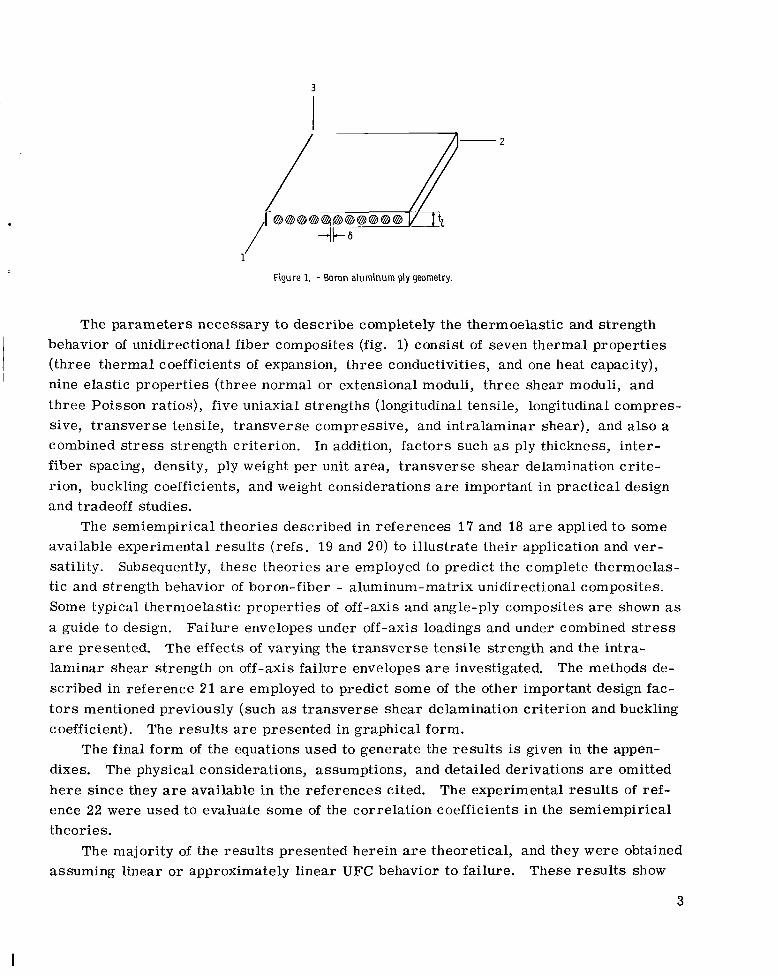
Figure 1. - Boron a luminum ply geometry.
The parameters necessary t o describe completely the thermoelastic and strength behavior of unidirectional fiber composites (fig. 1) consist of seven thermal properties (three thermal coefficients of expansion, three conductivities, and one heat capacity), nine elastic properties (three normal or extensional moduli, three shear moduli, and three Poisson ratios), five uniaxial strengths (longitudinal tensile, longitudinal compres- sive, transverse tensile, transverse compressive, and intralaminar shear), and also a combined s t r e s s strength criterion. In addition, factors such as ply thickness, inter- f iber spacing, density, ply weight per unit area, t ransverse shear delamination cri te- rion, buckling coefficients, and weight considerations a r e important in practical design and tradeoff studies.
The semiempirical theories described in references 17 and 18 are applied t o some available experimental resul ts (refs. 19 and 20) to illustrate their application and ver- satility. Subsequently, these theories a r e employed to predict the complete thermoelas- tic and strength behavior of boron-fiber - aluminum-matrix unidirectional composites. Some typical thermoelastic properties of off-axis and angle-ply composites a r e shown as a guide to design. Failure envelopes under off-axis loadings and under combined s t r e s s are presented. laminar shear strength on off-axis failure envelopes are investigated. The methods de- scribed in reference 2 1 are employed to predict some of the other important design fac- t o r s mentioned previously (such as t ransverse shear delamination criterion and buckling coefficient).
dixes. The physical considerations, assumptions, and detailed derivations are omitted he re since they are available in the references cited. The experimental results of ref- ence 22 were used to evaluate some of the correlation coefficients in the semiempirical theories.
The effects of varying the t ransverse tensile strength and the intra-
The resul ts are presented in graphical form. The final form of the equations used to generate the resul ts is given in the appen-
The majority of the resul ts presented herein are theoretical, and they were obtained assuming linear or approximately linear UFC behavior to failure. These resul ts show
3
L
the application of composite mechanics in the characterization and generation of design data for fiber-reinforced metals. In addition, they bring into focus the type of informa- tion needed in design, the a r e a s of difficulty in obtaining this information, the experi- mental data which a r e still needed, and the possible areas of immediate and future r e - search. The discussion is supplemented by pertinent references in all cases. To this end, the detailed discussion of one specific composite system is sufficient.
c
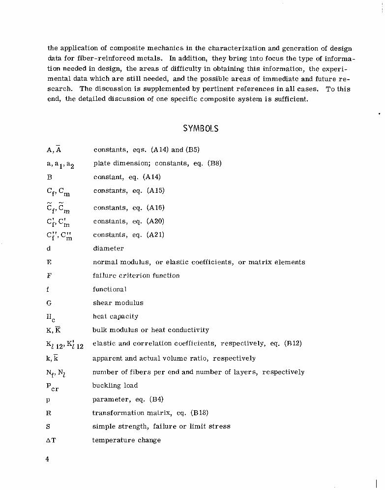
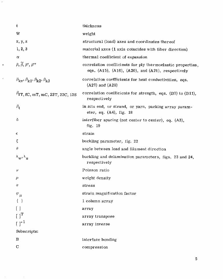
SYMBOLS
constants, eqs. (A14) and (B5)
plate dimension; constants, eq. (B8)
constant, eq. (A14)
constants, eq. (A15)
constants, eq. (A16)
constants, eq. (A20)
constants, eq. (A21)
diameter
normal modulus, o r elastic coefficients, o r matrix elements
failure cri terion function
functional
shear modulus
h eat capacity
bulk modulus o r heat conductivity
elastic and correlation coefficients, respectively, eq. (B12)
apparent and actual volume ratio, respectively
number of f ibers per end and number of layers, respectively
buckling load
parameter, eq. (B4)
transformation matrix, eq. (B18)
simple strength, failure or limit s t r e s s
temperature change
PfT, fC, mT, mC, 22T, 22C, 12s
pt
6
V
P
a
% { I [ I [ IT r 1-1 Subs c r ipt s :
thickness
weight
structural (load) axes and coordinates thereof
material axes (1 axis coincides with fiber direction)
thermal coefficient of expansion
correlation coefficients for ply thermoelastic properties, eqs. (Al5 ) , (A16), (A20), and (A21), respectively
correlation coefficients for heat conductivities, eqs. (A27) and (A28)
correlation coefficients f o r strength, eqs. (BY) t o (B l l ) , respectively
in situ end, o r strand, or yarn, packing a r r a y param- eter, eq. (A4), fig. 18
interfiber spacing (not center to center), eq. (A3), fig. 19
strain
buckling parameter, fig. 22
angle between load and filament direction
buckling and delamination parameters, figs. 23 and 24, respectively
Poisson ratio
weight density
s t r e s s
s t ra in magnification factor
1 column array
a r r a y
a r r a y transpose
a r r a y inverse
B
C
interface bonding
compression
5
I I1 II 1111111111111 I I 111 1111 I I I I I . ~ 1 1 1 1 1 - I I . I I I 111.11..1.-
C
D
f
i
I
m
P
R
S
T
V
X , Y , Z
1 , 2 7 3
0, P
composite property
debonding
filament property
ply index
PlY property
matrix property
limiting property
residual stress
shear
tension
void
structural (load) axes direction
material axes directions (1 axis coincides with the fiber direction)
T o r C, tension o r compression
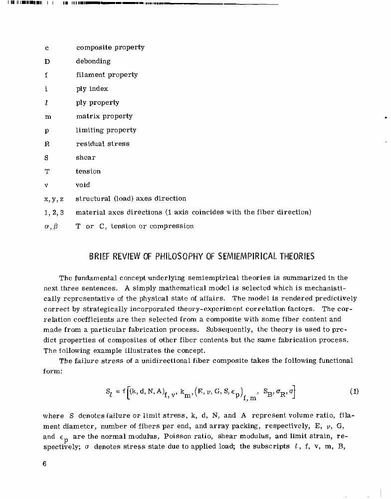
BRIEF REVIEW OF PHILOSOPHY OF SEMIEMPIRICAL THEORIES
The fundamental concept underlying semiempirical theories is summarized in the next three sentences. A simply mathematical model is selected which is mechanisti- cally representative of the physical state of affairs. correct by strategically incorporated theory-experiment correlation factors. relation coefficients a r e then selected from a composite with some fiber content and made from a particular fabrication process. Subsequently, the theory is used to pre- dict properties of composites of other fiber contents but the same fabrication process. The following example illustrates the concept.
form:
The model is rendered predictively The cor-
The failure s t r e s s of a unidirectional fiber composite takes the following functional
where S denotes failure o r limit s t r e s s , k, d, N, and A represent volume ratio, f i l a - ment diameter, number of f ibe r s per end, and a r r a y packing, respectively, E, V , G, and E a r e the normal modulus, Poisson ratio, shear modulus, and limit strain, r e - P spectively; D denotes s t r e s s state due to applied load; the subscripts 1 , f , v, m, B,
6
.
and R denote ply, fiber, void, matrix, bond strength, and residual stress, respec- tively. plex statistical mathematical formalisms. On the other hand, the ply longitudinal ten- sile failure s t r e s s SI llT (fig. 1) can be expressed simply by using a rule-of-mixtures model (eq. (B7), appendix B):
Conversion of equation (1) into an explicit form, i f possible, would require com-
where the ba r red quantities indicate actual volume content, and pfT and pmT are the experiment-theory correlation factors which convert equation (1) to (2). e t e r s pfT and pmT embody all the variables which appear in equation (1) but are ab- sent from equation (2). e s s variables. Variables such kv, A, SB, and aR are associated with a particular fabrication process. A s a result, the correlation factors have to be evaluated for some particular composite system for each fabrication process (refs. 17 and 18). Subsequent application of the theories wi l l illustrate evaluation of the theory-experiment correlation factors.
The semiempirical theory described herein wi l l handle composites exhibiting linear Composites containing ductile f ibers exhibit some non-
The strength properties of these composites can be pre-
The param-
Another way to think of these parameters is as fabrication proc-
or approximate linear behavior. linear s t ress-s t ra in behavior. dicted by the semiempirical theory in conjunction with the we l l known incremental load concepts.
APPLICATION OF SEMIEMPIRICAL THEORIES TO SOME EXISTING DATA
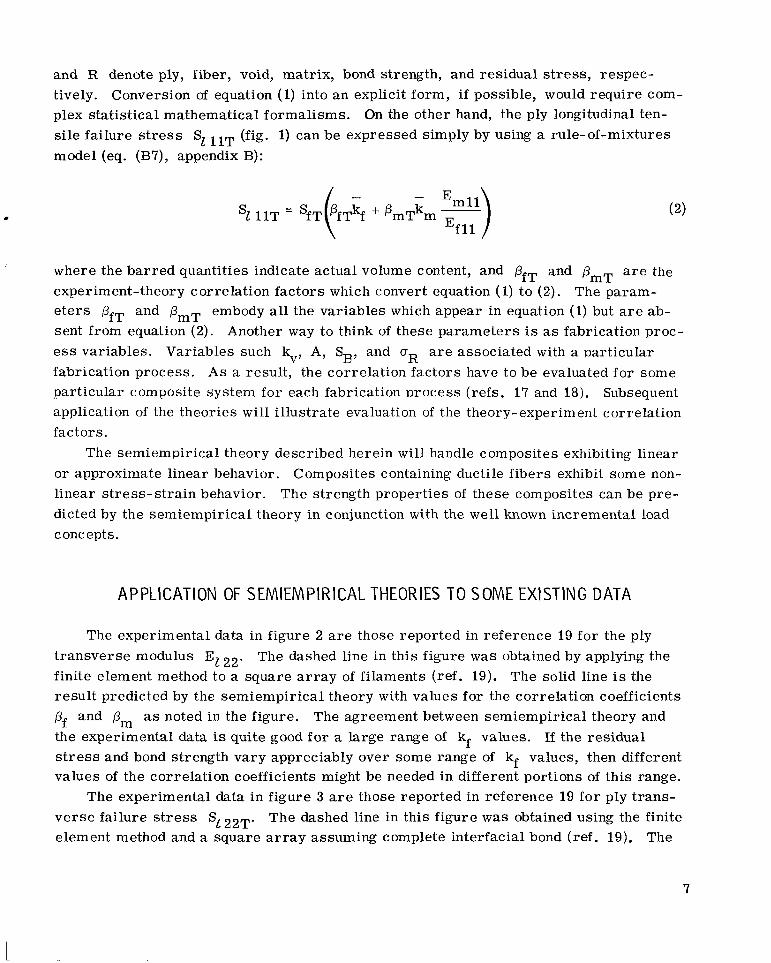
The experimental data in figure 2 are those reported in reference 19 for the ply t ransverse modulus El 22. finite element method to a square a r r a y of filaments (ref. 19). The solid line is the result predicted by the semiempirical theory with values for the correlation coefficients pf and pm as noted in the figure. the experimental data is quite good fo r a large range of kf values. If the residual s t r e s s and bond strength vary appreciably over some range of kf values, then different values of the correlation coefficients might be needed in different portions of this range.
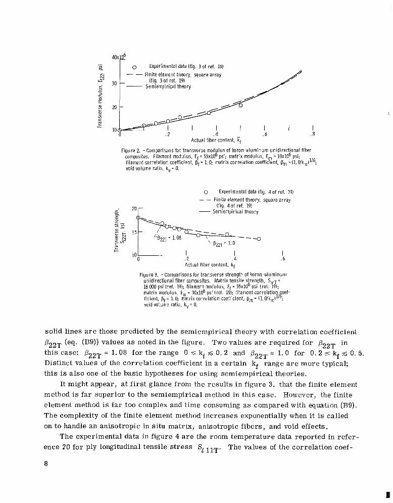
v e r s e failure stress S122T. The dashed line in this figure was obtained using the finite element method and a square a r r a y assuming complete interfacial bond (ref. 19).
The dashed line in this figure w a s obtained by applying the
The agreement between semiempirical theory and
The experimental data in figure 3 are those reported in reference 19 fo r ply trans-
The
7
0 Experimental data (fig. 3 of ref. 19) - - Fini te element theory, square array
- (fig. 3 o f ref. 19) Semiempirical theory
. 2 . 4 .6 I I
8 Actual fiber content,
composites. Filament modulus, Ef = 55x106 psi; mat i i x modulus, Em = 10x106 psi; f i lament correlation coefficient, pf = 1.0; matrix correlation coefficient, pm = (1. O/km)1'6; void volume ratio, kv = 0.
Figure 2. - Comparisons for transverse modulus of boron-aluminum unidirect ional f iber
0 Experimental data (fig. 4 of ref. 19) _ _ Fin i te element theory, square ar ray
- Semiempirical theory (fig. 4 o f ref. 19)
--3 y322T = 1.0
E l 10
0 I 1
. 2 . 4 Actual f iber content, if
I . 6
Figure 3. - Comparisons for transverse strength of boron-aluminum unidirectional fiber composites. Matr ix tensile strength, SmT =
18 000 psi (ref. 19); f i lament modulus, Ef = 5 5 ~ 1 0 ~ psi (ref. 19); matrix modulus, E, = 1 0 ~ 1 0 ~ psi (ref. 19); f i lament correlation oef- ficient, pf = 1.0; matrix correlation coefficient, pm = (1.O/km)'/'; void volume ratio, kv = 0.
solid lines are those predicted by the semiempirical theory with correlation coefficient P22T (eq. (B9)) values as noted in the figure. Two values are required for P22T in this case: PZZT = 1.08 for the range 0 5 kf 5 0 . 2 and @22T = 1.0 for 0 . 2 5 kf 5 0. 5. Distinct values of the correlation coefficient in a certain kf range are more typical; this is also one of the basic hypotheses for using semiempirical theories.
It might appear, at first glance from the results in figure 3, that the finite element method is far superior to the semiempirical method in this case. However, the finite element method is far too complex and time consuming as compared with equation (B9). The complexity of the finite element method increases exponentially when i t is called on to handle an anisotropic in si tu matrix, anisotropic fibers, and void effects.
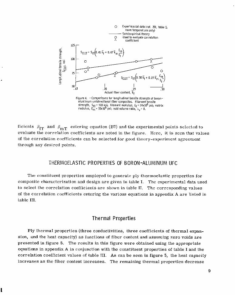
ence 20 f o r ply longitudinal tensile s t r e s s SL llT.
8
The experimental data in figure 4 a r e the room temperature data reported in refer- The values of the correlation coef-
0 Experimental data (ref. a), table I;
Semiempirical theory R Used to evaluate correlation
room temperature only)
coefficient 125 r
I .25
I 20 Actual f iber content, kf
I .30
Figure 4. -Comparisons for longitudinal tensile strength of boron- a luminum unidirect ional f iber composites. Filament tensi le strength, Sn = 510 ksi. f i lament modulus, Ef = 59x106 psi; matrix modulus, Em = 10x106 ;si; void volume ratio, kv = 0.
ficients pfT and p,, entering equation (B7) and the experimental points selected to evaluate the correlation coefficients are noted in the figure. of the correlation coefficients can be selected for good theory-experiment agreement through any desired points.
Here, it is seen that values
THERMOELASTIC PROPERTIES OF BORON-ALUMINUM UFC
The constituent properties employed to generate ply thermoelastic properties for composite characterization and design a r e given in table I . The experimental data used to select the correlation coefficients are shown in table 11. The corresponding values of the correlation coefficients entering the various equations in appendix A a r e listed in table 111.
Therma l Propert ies
Ply thermal properties (three conductivities, three coefficients of thermal expan- sion, and the heat capacity) as functions of fiber content and assuming ze ro voids are presented in figure 5. The resul ts in this figure were obtained using the appropriate equations in appendix A in conjunction with the constituent properties of table I and the correlation coefficient values of table 111. As can be seen in figure 5, the heat capacity increases as the fiber content increases. The remaining thermal properties decrease
9
I
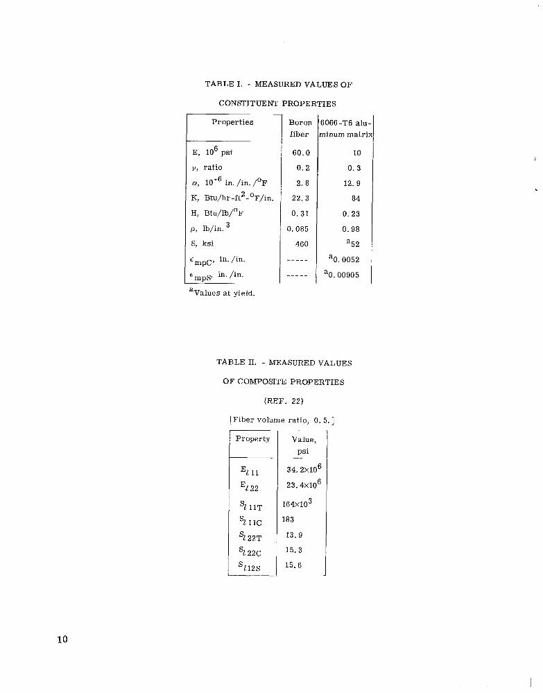
TABLE I. - MEASURED VALUES OF
CONSTITUENT PROPERTIES
Properties
E, lo6 psi
V, ratio
a, in. /in. /OF
K, Btu/hr -ft2 - OF/in.
H, Btu/lb/'F
p , lb/in.
S, ksi
'mpC7 in. /in.
E ~ ~ ~ , in. /in.
3
'Values at yield.
Boron fiber
60.0
0 .2
2.8
22.3
0. 31
0.085
460
- -__ -
- -_-_
i066-T6 ah. 7inum matri.
10
0 . 3
12. 9
84
0. 23
0.98
a52
aO. 0052
aO. 00905
TABLE II. - MEASURED VALUES
OF COMPOSITE PROPERTIES
(REF. 22)
[Fiber volume ratio, 0. 5. ]
Property
El 11
El 22
s1 11c
'1 11T
'1 22T
22c
s112s
~
Value, psi
~~
34.2x10⁶
23. 4X10⁶
1 6 4 ~ 1 0 ~
183
13.9
15. 3
15.6
10
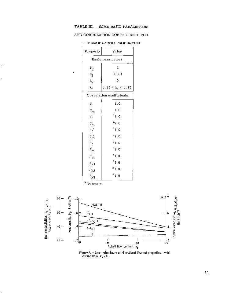
TABLE In. - SOME BASIC PARAMETERS
AND CORRELATION COEFFICIENTS FOR
THE RMOE LASTIC PROPERTIES
Nf
df
'G kf
Property 1 Value
1
0.004
0
0.35 < kf < 0.75
I
Basic parameters
I
Correlation coefficients
Pf
4n Pi 4n Pi'
P;
Pf
om
4.x
N
N
Pkl
Pk2
Pk3
aEstimate.
1.0
4.0
1.0 a
a2. 0
al. 0
a2. 0
al. 0
a2. 0
al. 0
al . 0
1.0 a
1.0 a
.45 .55 .65 .75 Actual fiber content,
Figure 5. - Boron-aluminum unidirect ional thermal properties. Void volume ratio, kv = 0.
11
with increasing fiber content. thermal properties of fiber-reinforced metals.
The l i terature is virtually void of measured data of
Elastic Properties
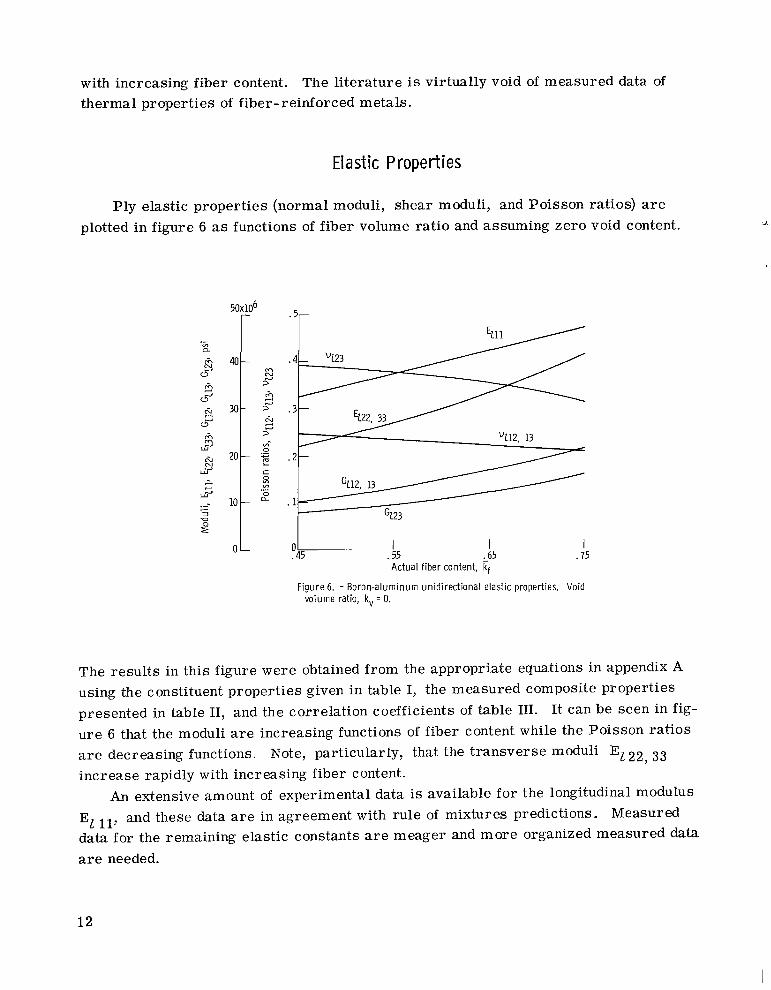
Ply elastic properties (normal moduli, shear moduli, and Poisson ratios) are plotted in figure 6 as functions of fiber volume ratio and assuming zero void content.
5Ox1O6 r I
5 30t T vi 0
20 5 c 0 VI VI
0 .-
10 a 1 OL
.5r
"112, 13
.2-
GZ23
1 I I .55 .65 .75 Actual fiber content,
I- 045
Figure 6. - Boron-aluminum unidirectional elastic properties. Void volume ratio, k, = 0.
The results in this figure were obtained from the appropriate equations in appendix A using the constituent properties given in table I, the measured composite properties presented in table 11, and the correlation coefficients of table 111. u r e 6 that the moduli a r e increasing functions of fiber content while the Poisson ratios a r e decreasing functions. increase rapidly with increasing fiber content.
El 11, and these data a r e in agreement with rule of mixtures predictions. Measured data for the remaining elastic constants a r e meager and more organized measured data are needed.
It can be seen in fig-
Note, particularly, that the t ransverse moduli El 22, 33
An extensive amount of experimental data is available for the longitudinal modulus
12
PLY STRENGTHS
Ply strength, in the sense used here, denotes that s t r e s s level in the ply which
The ply strengths are characterized by the ply uniaxial strengths and a combined causes incipient material nonlinear response (ref. 18).
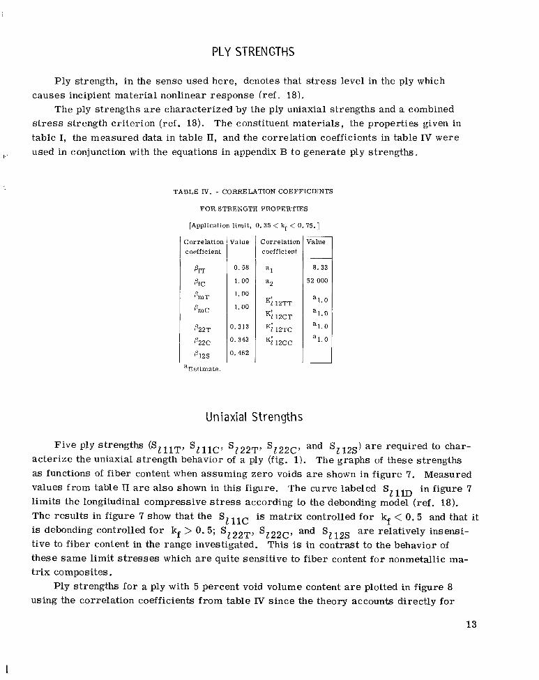
s t r e s s strength criterion (ref. 18). The constituent materials, the properties given in table I, the measured data in table II, and the correlation coefficients in table IV were
I used in conjunction with the equations in appendix B t o generate ply strengths.
TABLE IV. - CORRELATION COEFFICIENTS
FOR STRENGTH PROPERTIES
[Application l imit , 0.35 < kf < 0.75.1
Cor relation coefficient
P22T
O22C
4 2 s
aEstimate.
Value
0.58
1.00
1.00
1.00
0.313
0.343
0. 462
Correlation coefficient
a l
a2
Ki 12TT
Ki 12CT
Ki 12TC
K112cc
-__ Value
a. 33
52 000
a1.0
a l . O
a1 .0
al. 0
U n i axi al Strength s
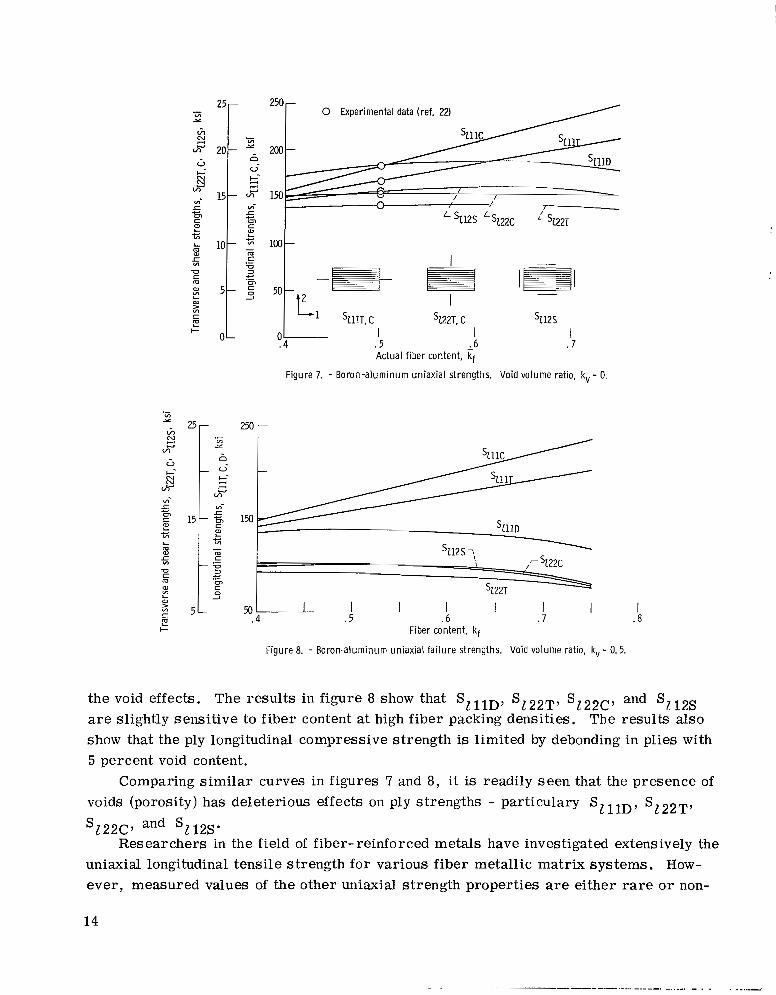
Five ply strengths (SZllT, SZllc, SZ22T, S 1 2 2 c , and Sz12s) are required to char- acterize the uniaxial strength behavior of a ply (fig. 1). The graphs of these strengths as functions of fiber content when assuming zero voids are shown in figure 7. Measured values from table I1 are also shown in this figure. The curve labeled SlllD in figure 7 limits the longitudinal compressive stress according to the debonding model (ref. 18). The results in figure 7 show that the Szllc is matrix controlled fo r kf < 0.5 and that it is debonding controlled fo r kf > 0.5; Sz22T, Sz22c, and Sz12s are relatively insensi- tive to fiber content in the range investigated. This is in contrast to the behavior of these s a m e limit stresses which are quite sensitive to fiber content for nonmetallic ma- trix composites.
Ply strengths fo r a ply with 5 percent void volume content are plotted in figure 8 using the correlation coefficients f rom table Tv since the theory accounts directly fo r
13
I
.;i 25r Y
3, $I Gi- 20- G k- 2 VI- S D c W L c VI
c
10- W
5
3
U
m c
L P
.- VI Y
~ u 5
5 E 2
4
15- VI-
m S
c
m c U 3
c Ul
2
.-
5 - 2
250 - 0 Experimental data (ref. 22)
200 -
25- lh N A u
wl
G c- N
js!
5 Ul
VI-
a, L c VI
L m a,
5 U c m a, VI L a,
5
I I
250 - .- VI Y
n - 0-
5 mi
1 5 - F 1%
- 4
VI- c
a, L c VI - m c
- = 2 c (51 c 0 2
.-
I . 8
50 l 1 I I I I .7 . 6
- .5
5 -
m %22T. C s112s I
. 7 1 .6
I ‘ 1 I L1 SZ1lT,C L
04 . 5 0 I-
Actual fiber content, Ff Figure 7. - Boron-aluminum uniaxial strengths. Void volume ratio, kv = 0.
the void effects. The results in figure 8 show that SZllD, Sz22T, S122c, and S112s are slightly sensitive to fiber content at high fiber packing densities. show that the ply longitudinal compressive strength is limited by debonding in plies with 5 percent void content.
Comparing s imi l a r curves in figures 7 and 8, it is readily seen that the presence of voids (porosity) has deleterious effects on ply strengths - particulary SZllD, SZ22T,
The results also
SZ22C’ and sz12s. Researchers in the field of fiber- reinforced metals have investigated extensively the
uniaxial longitudinal tensile strength for various fiber metallic matrix systems. How- ever , measured values of the other uniaxial strength properties are either rare o r non-
14
- - ........ .
existent. Measured data fo r the uniaxial strengths SzlIc , Sz22T, Sz22c, and Sz12s are mandatory if fiber- reinforced metals are to become ser ious contenders for structural components and if their interfacial characteristics are to be better understood.
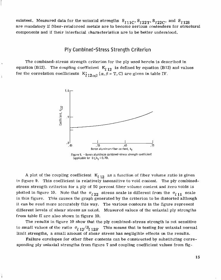
Ply Combined-Stress Strength Criterion
The combined-stress strength criterion for the ply used herein is described in , equation (B12). fo r the correlation coefficients K i 12alp (a, lp = T, C) a r e given in table IV.
The coupling coefficient Kl 12 is defined by equation (B13) and values
I I .55 .65 .75
.8 I .45
Boron a luminum fiber content, kf
Figure 9. - Boron a lum inum combined-stress strength coefficient (applicable for 0 <_ k, < 0.20).
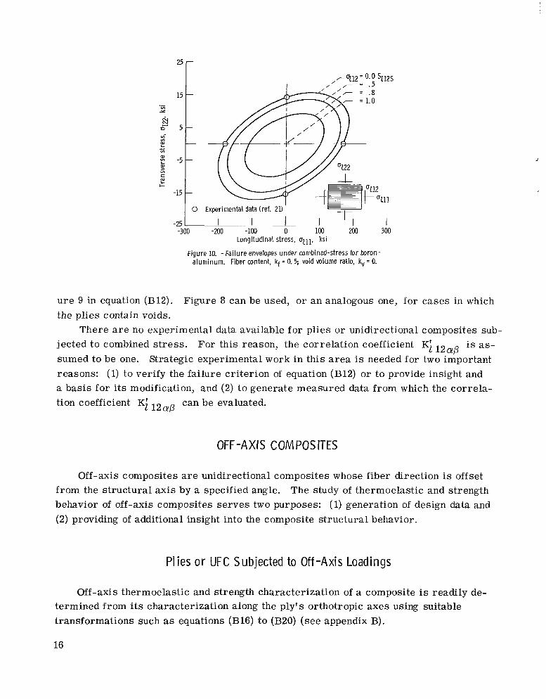
A plot of the coupling coefficient Kl 12 as a function of fiber volume ratio is given in figure 9. s t r e s s strength criterion for a ply of 50 percent fiber volume content and zero voids is plotted in figure 10. Note that the a1 22 s t r e s s scale is different from the a1 11 scale in this figure. it can be read more accurately this way. different levels of shear s t r e s s as noted. f rom table I1 a r e a l so shown in figure 10.
to small values of the ra t io al 12/Sl 12s. limit strengths, a smal l amount of shear s t r e s s has negligible effects on the results.
sponding ply uniaxial strengths from figure 7 and coupling coefficient values from fig-
This coefficient is relatively insensitive to void content. The ply combined-
This causes the graph generated by the criterion to be distorted although The various contours in the figure represent Measured values of the uniaxial ply strengths
The resu l t s in figure 10 show that the ply combined-stress strength is not sensitive This means that in testing for uniaxial normal
Failure envelopes for other fiber contents can be constructed by substituting cor re-
15
YI
E
L -5 c VI
aJ m
> y1
-15
I I I I Longitudinal stress, ulll, ksi
Figure 10. -Fa i lu re envelopes under combined-stress for boron- aluminum. Fiber content, kf = 0.5; void volume ratio, kv = 0.
u r e 9 in equation (B12). the plies contain voids.
jected t o combined s t r e s s . For this reason, the correlation coefficient KL 12ap is as- sumed to be one. Strategic experimental work in this area is needed for two important reasons: (1) to verify the failure criterion of equation (B12) or to provide insight and a basis for i t s modification, and (2) t o generate measured data from which the correla- tion coefficient Ki 12ap can be evaluated.
Figure 8 can be used, or a n analogous one, for cases in which
There are no experimental data available for plies or unidirectional composites sub-
OFF-AXIS COMPOSITES
Off-axis composites are unidirectional composites whose fiber direction is offset from the structural axis by a specified angle. The study of thermoelastic and strength behavior of off-axis composites s e rves two purposes: (1) generation of design data and (2) providing of additional insight into the composite structural behavior.
Pl ies or UFC Subjected to Off-Axis Loadings
Off-axis thermoelastic and strength characterization of a composite is readily de- termined from its characterization along the ply's orthotropic axes using suitable transformations such as equations (B16) to (B20) (see appendix B).
16
I
Off -Axis P ly Thermoelast ic Propert ies
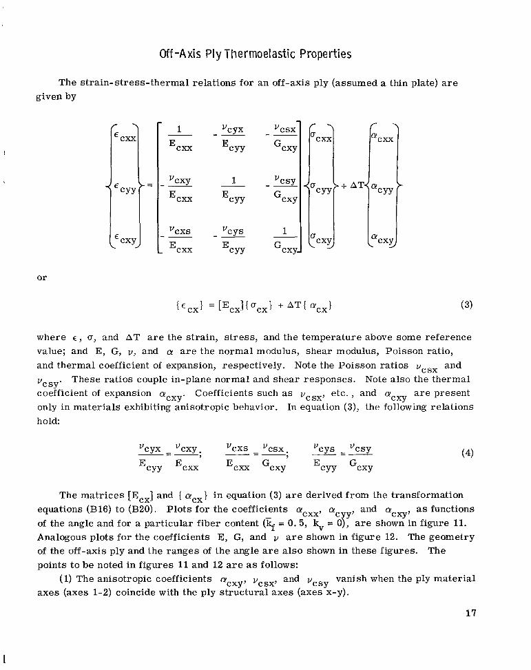
The s t ra in-s t ress- thermal relations for an off-axis ply (assumed a thin plate) a r e given by
or
where E , u, and AT
1
vcxy
E,* --
CYX V -- EcYY
1
EcYY
a r e the strain, s t r e s s , and the temperature above some reference value; and E, G, V, and a! a r e the normal modulus, shear modulus, Poisson ratio, and thermal coefficient of expansion, respectively.
coefficient of expansion acXy. only in mater ia ls exhibiting anisotropic behavior. h o Id:
Note the Poisson ratios vcSx and These ratios couple in-plane normal and shear responses. Note also the thermal
etc. , and a! a r e present Cxy Coefficients such as vcSx,
In equation (3), the following relations
vc sy'
The matr ices [Ecx] and { a!ycx} in equation (3) a r e derived from the transformation
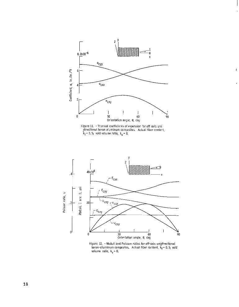
of the angle and for a particular fiber content (T;f = 0.5, \ = 07, a r e shown in figure 11. Analogous plots for the coefficients E, G, and I, a r e shown in figure 12. The geometry of the off-axis ply and the ranges of the angle are a lso shown in these figures. points to be noted in figures 11 and 12 are as follows:
and v vanish when the ply mater ia l (1) The anisotropic coefficients acXy, vcSx, axes (axes 1-2) coincide with the ply structural axes (axes x-y).
as functions Cxy'
equations (B16) to (B20). Plots for the coefficients a!cxx, a! c y' and a!
The
C S Y
I
I 8. 0x1K6 r
;l-.---rl--..\. 0 30 60 90
Orientation angle, 8, deg
Figure 11. -Thermal coefficients of expansion for off-axis uni- - directional boron a luminum composites. Actual f iber content, kf = 0.5; void volume ratio, k, = 0.
r -
4 0 ~ 1 0 ~ r -
Y 2 1
-csy
I I 1 0 30 60 90
Orientation angle, 8, deg
boron-aluminum composites. Actual f iber content, kf = 0.5; void volume ratio, kv = 0.
Figure 12. - M o d u l i and Poisson ratios for off-axis unidirectional
18
(2) The anisotropic coefficients except the shear modulus attain significant magni- tudes at a certain angle. At these angles, residual s t r e s s e s and severe end effects can be induced. Residual s t r e s s e s and end effects a r e the pr imary obstacles in theory-experiment correlation and in interpreting experimental data.
Plots for other fiber contents can be obtained by using figures 5 and 6 in conjunction
I
I ! I with equations (B16) to (B20). In the case of voids, plots analogous to those of figures
5 and 6 need to be generated first from the equations in appendix A for the specific void content. Heat conductivities for off-axis plies can a l so be obtained by transformation.
I The ply heat capacity remains invariant. Again, strategic experimental data to check the transformation equations a r e
needed.
Off -Axis Ply Fai l u re Envelopes
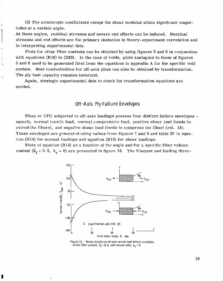
Pl ies or UFC subjected to off-axis loadings possess four distinct failure envelopes - namely, normal tensile load, normal compressive load, positive shear load (tends to extend the fibers), and negative shear load (tends to compress the fiber) (ref. 18). These envelopes a r e generated using values from figures 7 and 9 and table IV in equa- tion (B14) for normal loadings and equation (B15) for shear loadings.
Plots of equation (B14) as a function of the angle and for a specific fiber volume content ($ = 0. 5, kv = 0) a r e presented in figure
._ VI Y
9 x x -
13. The filament and loading direc-
Y
I g X OZXX
j ,
m- x
- m
E 0 z
50 t -t, Ozxx X
p 0 Experimental data (ref. 22)
-250 I 0
I 30
I 60
Orientation angle, 8, deg
Figure 13. - Boron-alum_inum off-axis normal load fa i lure envelopes. Actual fiber content, kf = 0.5; void volume ratio, kv = 0.
19
I
tions and the experimental strength points ( e = 0' and 90') f rom table 11 are a lso shown I
in the figure. The resu l t s in figure 13 indicate a rapid drop in the ply strength as load direction deviates f rom the filament direction for both normal tensile and compressive loads. signing for longitudinal strength.
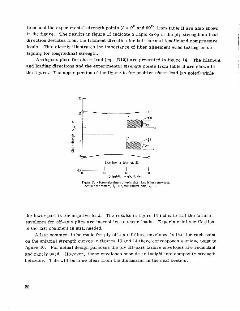
and loading directions and the experimental strength points f rom table 11 are shown in the figure. The upper portion of the figure is for positive shear load (as noted) while
I This clearly i l lustrates the importance of fiber alinement when testing or de- I
Analogous plots for shear load (eq. (B15)) a r e presented in figure 14. The filament I
I
-15(/
Experimental data (ref. 22)
the lower part is for negative load. envelopes for off -axis plies a r e insensitive to shear loads. Experimental verification of the last comment is still needed.
A last comment to be made for ply off-axis failure envelopes is that for each point on the uniaxial strength curves in figures 13 and 14 there corresponds a unique point in figure 10. For actual design purposes the ply off-axis failure envelopes a r e redundant and ra re ly used. However, these envelopes provide an insight into composite strength behavior. This will become clear from the discussion in the next section.
The resu l t s in figure 14 indicate that the failure
20
Effects of I n t ra lam ina r Shear and Transverse St rengths o n
P ly Off -Axis Fa i lu r e Envelopes
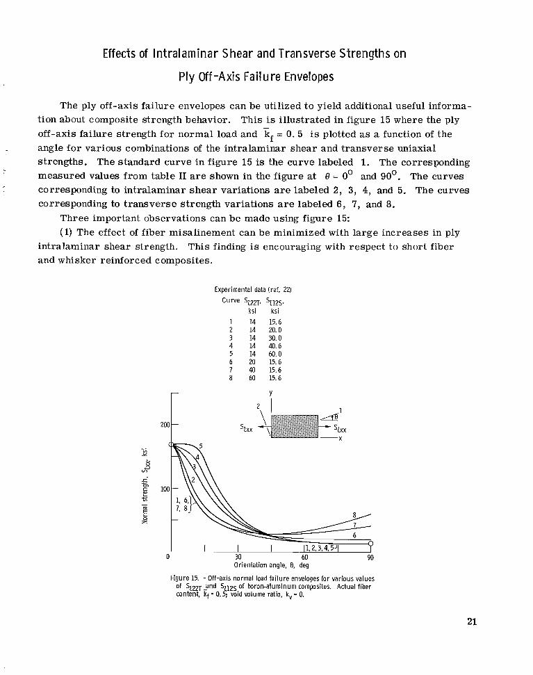
The ply off-axis failure envelopes can be utilized to yield additional useful informa- tion about composite strength behavior. off-axis failure strength for normal load and kf = 0. 5 is plotted as a function of the angle for various combinations of the intralaminar shear and t ransverse uniaxial strengths. The standard curve in figure 15 is the curve labeled 1. The corresponding measured values f rom table I1 are shown in the figure at 8 = 0' and 90'. The curves corresponding to intralaminar shea r variations are labeled 2, 3, 4, and 5. The curves corresponding to t ransverse strength variations are labeled 6, 7, and 8.
This is illustrated in figure 15 where the ply
Three important observations can be made using figure 15: (1) The effect of fiber misalinement can be minimized with large increases in ply
intralaminar shear strength. This finding is encouraging with respect to short fiber and whisker reinforced composites.
Experimental data (ref. 22)
Curve 'Z22Tj sZ12Ss ksi ksi 14 15.6 14 20.0 14 30.0 14 40.6 14 60.0 20 15.6 40 15.6 60 15.6
Y
2 1 4 l
szxx - szxx ~
Orientation angle, 8, deg
Figure 15. - Off-axis normal load fai lure envelopes for various values of SZ22-f 2 n d 5212s of boron-aluminum composites. Actual f iber content, kf = 0.5; void volume ratio, kv = 0.
21
(2) The ply off-axis failure envelope is sensitive to t ransverse strength in the
(3) The ply in angle-ply composites has four predominant failure modes: these a r e
0 30°< 0 5 90 range.
longitudinal tension o r compression, 0' 5 8 .C 3'; int ralaminar shea r , 3' 5 8 5 30'; shea r o r t ransverse tension o r compression, 30' c= 8 -= 60'; t ransverse tension o r com- pression, 60' 5 8 -= 90'. These observations s t em f rom the fact that a ply within an angle-ply composite is reinforced by its adjacent plies, relative to intralaminar shea r and t ransverse failure stress modes. This type of reinforcement has the s a m e effects on the ply off-axis failure envelope as do the variations of intralaminar shea r and t ransverse strengths noted in figure 15.
reinforced metals of potential use for structural components. Also, experimental data to verify the three points previously mentioned are needed.
; I -
Appropriate experimental data a r e lacking for ply failure envelopes for fiber-
SOME PROPERTIES OF ANGLE-PLY COMPOSITES
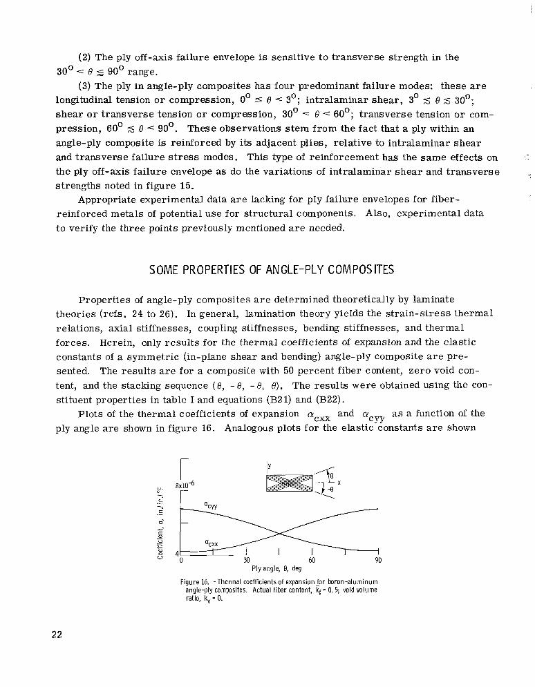
Propert ies of angle-ply composites a r e determined theoretically by laminate theories (refs. 24 to 26). In general, lamination theory yields the s t ra in-s t ress thermal relations, axial stiff ne s s e s, c oupling stiff ness e s, bending s t i f fne ss e s , and t her ma 1 forces. constants of a symmetric (in-plane shear and bending) angle-ply composite a r e pre- sented. tent, and the stacking sequence ( 8 , - 8, - 8, e). The results were obtained using the con- stituent properties in table I and equations (B2 1) and (B22).
ply angle a r e shown in figure 16. Analogous plots for the elastic constants a r e shown
Herein, only resu l t s for the thermal coefficients of expansion and the elastic
The results a r e for a composite with 50 percent fiber content, zero void con-
as a function of the CYY
Plots of the thermal coefficients of expansion acxx and CY
L .- -... c .- a- +- c a, V
a, 0 V
.- .- c c
4 0 30 60 90
Ply angle, 8, deg
Figure 16. -Thermal coefficients of expansion for b r o n - a l u m i n u m angle-ply composites. Actual fiber content, kf = 0.5; void volume ratio, kv = 0.
22
.- 0-
e - VI
c 5:
a VI .- 0
I I 60 90
I I n 30
.1
Ply angle, 0, deg
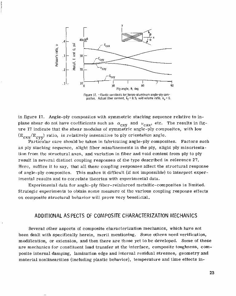
Figure 17. - Elastic constants for-boron-aluminum angle-ply com- posites. Actual fiber content, kf = 0.5; void volume ratio, kv = 0.
in figure 17. Angle-ply composites with symmetric stacking sequence relative to in- plane shear do not have coefficients such as CY
u r e 17 indicate that the shear modulus of symmetric angle-ply composites, with low
( E ~ ~ ~ / E C Y Y
as ply stacking sequence, slight fiber misalinements in the ply, slight ply misorienta- tion from the structural axes, and variation in fiber and void content from ply to ply result in several distinct coupling responses of the type described in reference 27. Here, suffice it to say, that all these coupling responses affect the structural response of angle-ply composites. This makes i t difficult (if not impossible) to interpret exper- imental resul ts and to correlate theories with experimental data.
Strategic experiments to obtain some measure of the various coupling response effects on composite structural behavior will prove very beneficial.
and vcSx, etc. The resul ts i n fig- CXY
) ratio, is relatively insensitive to ply orientation angle. Particular ca re should be taken in fabricating angle-ply composites. Factors such
Experimental data for angle-ply fiber-reinforced metallic-composites is limited.
ADDITIONAL AS PECTS OF COMPOSITE CHARACTERIZATION MECHANICS
Several other aspects of composite characterization mechanics, which have not been dealt with specifically herein, meri t mentioning. modification, or extension, and then there are those yet t o be developed. Some of these are mechanics fo r constituent load transfer at the interface, composite toughness, com- posite internal damping, lamination edge and internal residual s t r e s ses , geometry and material nonlinearities (including plastic behavior), temperature and t ime effects in-
Some others need verification,
23
cluding creep, and cyclic loading and fatigue. References 28 to 37 should provide some direction in all these a reas .
perimental) to investigate various aspects of the previously mentioned a reas wi l l be of great service to the fiber-reinforced metals research and design community.
A deeper assessment and carefully formulated programs (both analytical and ex-
OTHER DESIGN FACTORS
Composite thickness, interfiber spacing, composite density, delamination, and buckling parameters a r e important variables in component design. ables can be related to fiber geometry, packing ar ray , void content, and other constit- uent properties by elementary relations described in reference 21. Results a r e pre- sented here for a boron aluminum composite.
Some of these vari-
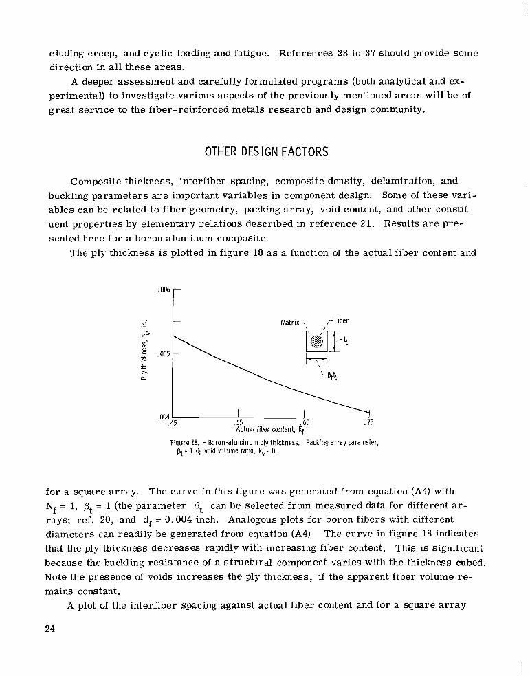
The ply thickness is plotted in figure 18 as a function of the actual fiber content and
r' .- -Fiber
._ r > a
c -
-
.45 .55 .65 .75 Actual fiber content, 4
.004
Figure 18. - Boron-aluminum ply thickness. Packing array parameter, pt = 1.0; void volume ratio, kv = 0.
f o r a square array. The curve in this figure was generated from equation (A4) with Nf = 1, pt = 1 (the parameter pt can be selected from measured data for different ar- rays; ref. 20, and df = 0.004 inch. Analogous plots for boron fibers with different diameters can readily be generated from equation (A4) that the ply thickness decreases rapidly with increasing fiber content. This is significant because the buckling resis tance of a structural component var ies with the thickness cubed. Note the presence of voids increases the ply thickness, if the apparent fiber volume re- mains constant.
The curve in figure 18 indicates
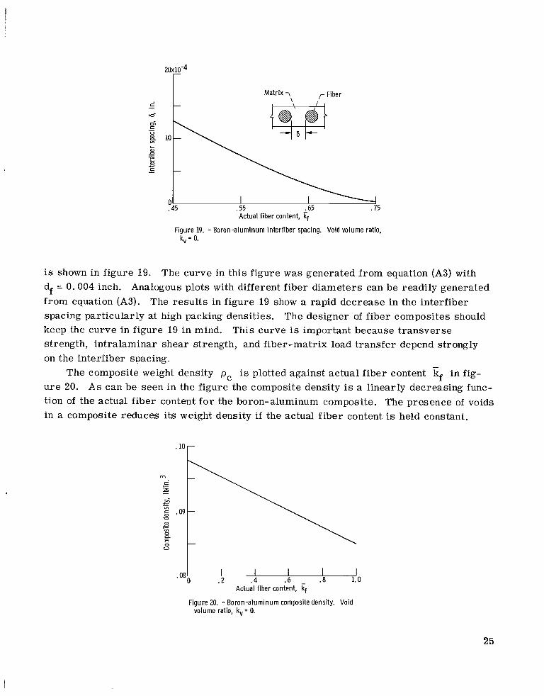
A plot of the interfiber spacing against actual fiber content and for a square a r r a y
24
20x10-4
Matr ix 7 r Fiber
Actual f iber content, Ef Figure 19. - Boron-aluminum interf iber spacing. Void volume ratio,
k, = 0.
is shown in figure 19. df = 0.004 inch. from equation (A3). spacing particularly at high packing densities. keep the curve in figure 19 in mind. strength, intralaminar shear strength, and fiber-matrix load transfer depend strongly on the interfiber spacing.
The composite weight density pc is plotted against actual f iber content kf in fig- u r e 20. A s can be seen in the figure the composite density is a linearly decreasing func- tion of the actual fiber content f o r the boron-aluminum composite. The presence of voids in a composite reduces its weight density if the actual fiber content is held constant.
The curve in this figure w a s generated from equation (A3) with Analogous plots with different fiber diameters can be readily generated
The resul ts in figure 19 show a rapid decrease in the interfiber The designer of fiber composites should
This curve is important because transverse
1- .2 .4 .6 .a 1.0
I 0
.08
Actual f iber content, if Figure 20. - Boron-aluminum composite density. Void
volume ratio, kv = 0.
25
I .8
I .6
I . 4
Actual f iber content, 4 . wo20 u
. 2
Figure 21. - Boron-aluminum ply weight. Void volume ratio, k, = 0. Figure 22. - Boron-aluminum buckling parameter for
simply supported square plates. Void volume ratio, k, = 0.
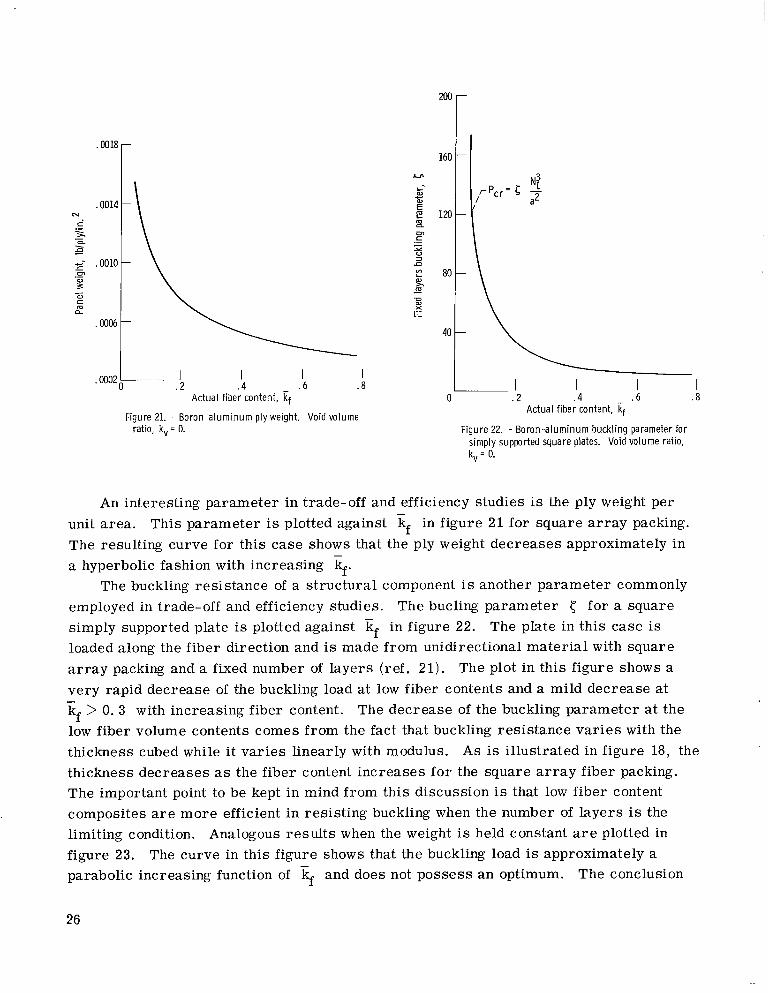
An interesting parameter in trade-off and efficiency studies is the ply weight per unit area. This parameter is plotted against kf in figure 21 for square a r r a y packing. The resulting curve for this case shows that the ply weight decreases approximately in a hyperbolic fashion with increasing if.
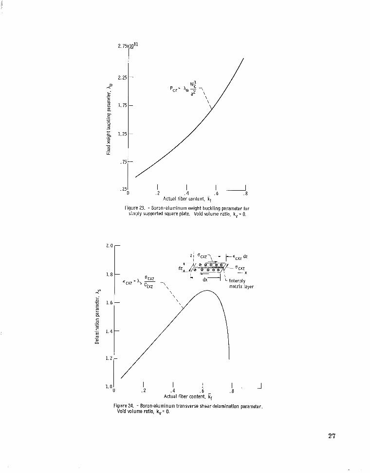
The buckling resistance of a structural component is another parameter commonly employed in trade-off and efficiency studies. The bucling parameter < for a square simply supported plate is plotted against kf in figure 22. loaded along the fiber direction and is made from unidirectional material with square a r r a y packing and a fixed number of layers (ref. 21) . The plot in this figure shows a very rapid decrease of the buckling load a t low fiber contents and a mild decrease at kf > 0.3 with increasing fiber content. The decrease of the buckling parameter a t the low fiber volume contents comes from the fact that buckling resistance va r i e s with the thickness cubed while i t var ies linearly with modulus. thickness decreases as the fiber content increases for the square a r r a y fiber packing. The important point to be kept in mind from this discussion is that low fiber content composites are more efficient in resisting buckling when the number of layers is the limiting condition. Analogous resul ts when the weight is held constant are plotted in figure 23. parabolic increasing function of kf and does not possess a n optimum.
The plate in this case is
-
As is illustrated in figure 18, the
The curve in this figure shows that the buckling load is approximately a The conclusion
26
2 . 7 5 ~ 1 0 ~ ~ r
2. (
1. E
VI x L- a,
1.6 4-.
E m L m 0.
c 0 c m r
m m
._
._ E 1.4 - n
1.2
1.0
Figure 23. - Boron-aluminum weight buckling parameter for simply supported square plate. Void volume ratio, kv = 0.
ocxz E C W = A - GZxz T, matrix layer
1 . 2
I 1 .8
I .6
I 4
Actual fiber content, Ff Figure 24. - Boron-aluminum transverse shear delamination parameter.
Void volume ratio, k, = 0.
27

I
in this case is that high fiber content composites r e s i s t buckling loads more efficiently when the composite weight is the limiting condition.
Ply delamination, either due to adjacent ply relative rotation (scissoring effect) o r interply t ransverse shear (through the thickness, horizontal), is a possible failure mode for multilayered composites (ref. 2 1). The delamination parameter for t ransverse shear is plotted against kf in figure 24. The equation of the curve and the correspond- ing geometry are a lso shown in the figure. The notation in the equation is as follows:
interply t ransverse shear strain; As, delamination parameter; ccXz, inter ply t ransverse shear s t r e s s ; GI xz, interply shear modulus in the x-z plane (ref. 21). Re- place x with y for the equation in the y-z plane. The resulting curve in figure 24 indi- cates that the delamination parameter for t ransverse shea r is very sensitive to kf with a maximum kf This means that low and very high fiber content boron-aluminum composites a r e l e s s susceptible to delamination than a r e those of intermediate kf values. Results for the delamination parameter due to adjacent ply relative rotation are not pre- sented because evaluation of this parameter requires specific measured data which are not available at this time. Reference 2 1 describes the type of data needed. Measured data for several of these factors and theory-experiment correlation a r e still needed.
ECXZ'
- 0.65.
CONCLUDING REMARKS
The semiempirical theories developed pr imari ly for nonmetallic composites can a l so be employed in characterization and design mechanics for metallic composites which exhibit linear or approximately linear behavior. This is important in optimum designs of components made from these mater ia ls where the fiber content is taken as a design variable. It is a l so important in designing experiments and interpreting experi- mental results.
The resu l t s of this investigation lead to the following conclusions concerning boron fiber - aluminum matrix composites:
1. The uniaxial strengths SL llD, SI 22T, SI 22c, and SI 12s a r e relatively insen- sitive to fiber content in the range investigated when voids a r e absent but a r e sensitive at high fiber contents in the presence of voids.
2. The longitudinal compressive strength is limited by both matrix yield (Ef < 0. 5) and debonding (kf > 0. 5) in the absence of voids. (0.40 < kf < 0.75) when the void content is about 5 percent.
3. The failure envelopes for off-axis normal loadings show rapid loss of strength when the angle between fiber and load directions increases in the 1' < 0 < 30' range. The strength remains practically invariant at angles greater than 30'.
4. The failure envelopes for off-axis shear loadings are practically invariant with angle.
This strength is governed by debonding
28
5. The normal tensile load failure envelope is quite sensitive to variations in intra- laminar shear strength for load angles less than 30' and to variations in t ransverse ten- sile strength for load angles greater than 45'.
longitudinal tension or compression when 0 5 0 4 3O, intralaminar shear when 3' 5 8 4 30°, intralaminar shear or transverse tension o r compression when 30 's 8 5 60°, and t ransverse tension or compression when 60' -= 8 5 90'.
with angle at low E l 11/E122 ratios. 8. The ply thickness, interfiber spacing, composite density, and ply weight per unit
area decrease with increasing fiber content. 9. The buckling load of a simply supported square plate made from a unidirectional
boron aluminum composite, in which fibers are arranged in a square a r r a y and which is loaded in the plane of the plate, decreases with increasing fiber content when the number of plies is held constant but increases when the weight is held constant.
10. The delamination cri terion indicates that the transverse shear s t ra in in the ma- t r ix increases with fiber content up to about 65 percent fiber content and then it de- c r eases very rapidly.
combined failure c r i te r ia are needed. Well defined programs to investigate tempera- ture, time, material, and geometry nonlinearities, damping, impact, and cyclic load- ings are required.
6. The predominant failure modes for off-axis normally loaded composites are 0
7. The shear modulus of off-axis and angle-ply composites is practically invariant
11. Experimental data for thermal properties, transverse strength properties, and
Lewis Research Center, National Aeronautics and Space Ad mini strati on,
Cleveland, Ohio, February 2, 1970, 129-03.
29
APPENDIX A
EQUATIONS FOR PLY GEOMETRIC, ELASTIC, AND THERMAL PROPERTIES
The equations of the semiempirical theory a r e given herein. Most of the detailed derivations are ra ther lengthy and a r e not included here; however, they are given in appendixes A and B of reference 26. It is assumed that the various thermoelastic prop- e r t i e s of the constituents in their precomposite state a r e known. It is further assumed that the apparent filament volume ratio kf is given. (weight) of the whole equals the sum of its pa r t s is used, it can be shown that
When the axiom that the volume
- km = (1 - kf)(l - kv) (A21
where the bar red quantities denote actual volume ratio. The interfiber spacing 6 and the ply thickness tl a r e , respectively, given by
and
tl = (#2 - df 2
where pt is the in situ a r r a y rectangle length to width ratio (ref. 21). Let the normal s t ra in-s t ress - temperature relations along the orthotropic axes for ply, filament, and matr ix be given, respectively, by
30
, The normal elastic properties and the thermal coefficients of expansion are given, re- spectively, by
[E l ] =
where
v112 1 -- El 11 El 22
" 2 2 1 -- 1
[ G El 22
"1 23 -- 1 "113 -- 1 Elll El 22
"131 -- El 33
El 33
El 33
" 2 32 --
1
az 11 ...) .("l 33
Analogous equations fo r filament and matr ix a r e obtained by replacing the subscripts in equations (A10) and (All) .
The filament and matr ix s t r e s s e s ply s t r e s s relations are
- 1
AEm 1 lkm
0
0
0
1 - cf
where
1 - 'm
0
0
1 -
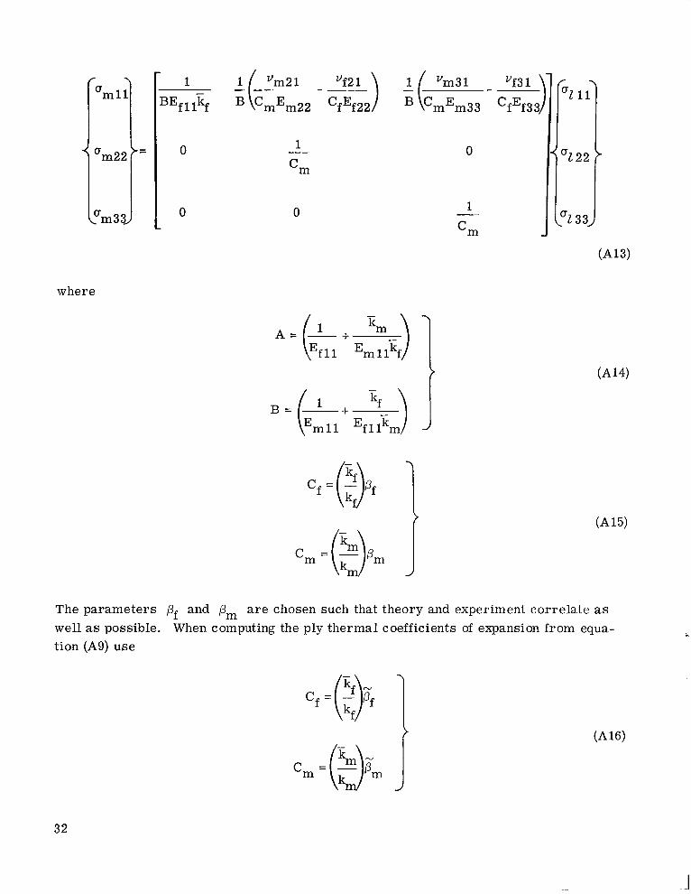
The parameters pf and pm a r e chosen such that theory and experiment correlate as well as possible. When computing the ply thermal coefficients of expansion from equa- tion (A9) use
32
N N
instead of equation (A15). ment correlate for the thermal coefficients of expansion.
Here pf and pm a r e chosen such that theory and experi-
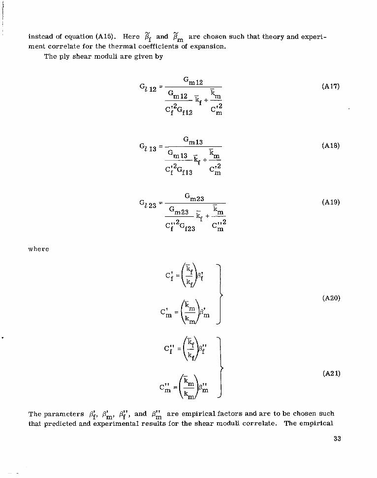
The ply shear moduli are given by
- Gm 12
Gm12 - km
Ci2Gf 12 'm
GL 12 =
kf +;
- tim 13
Gm13 - km GZ 13 =
k e +-
- tim23
Gm23 - km GL23 =
k, + - 2 I
Cf'2Gf 2 3 C;
where
c;= r m ) - pm t t J km
The parameters pf, Oh, p:', and p; are empirical factors and a r e to be chosen such that predicted and experimental resu l t s for the shear moduli correlate. The empirical
33
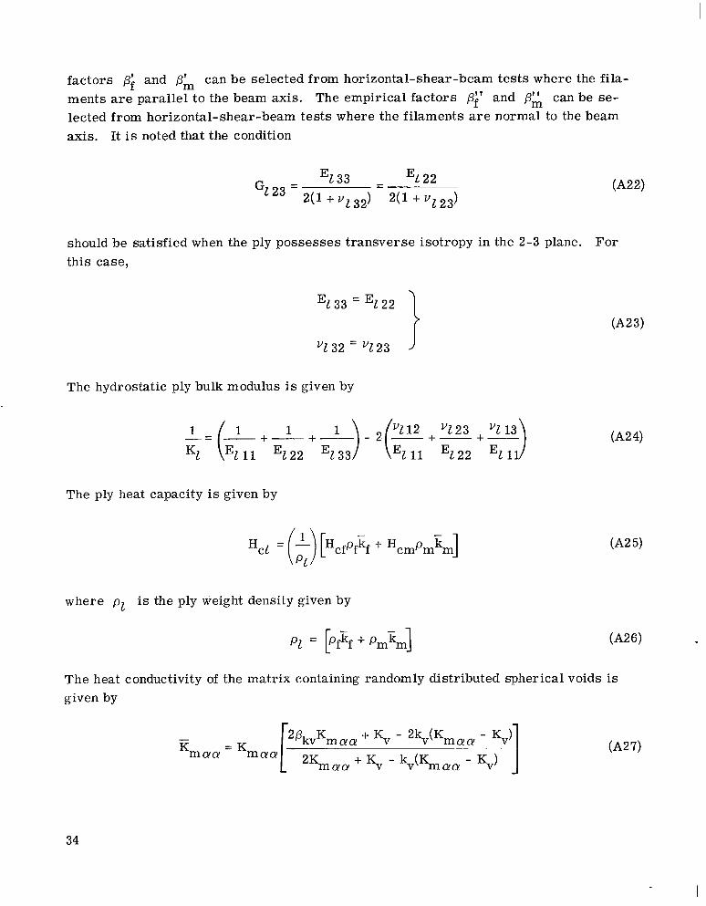
fac tors pi and pk can be selected from horizontal-shear-beam t e s t s where the f i l a - ments a r e parallel t o the beam axis. The empirical factors pi' and pk can be se- lected from horizontal-shear-beam tests where the filaments a r e normal to the beam axis. It is noted that the condition
should be satisfied when the ply possesses t ransverse isotropy in the 2-3 plane. For this case,
The hydrostatic ply bulk modulus is given by
1
The ply heat capacity is given by
where p z is the ply weight density given by
The heat conductivity of the matrix containing randomly distributed spherical voids is given by
34
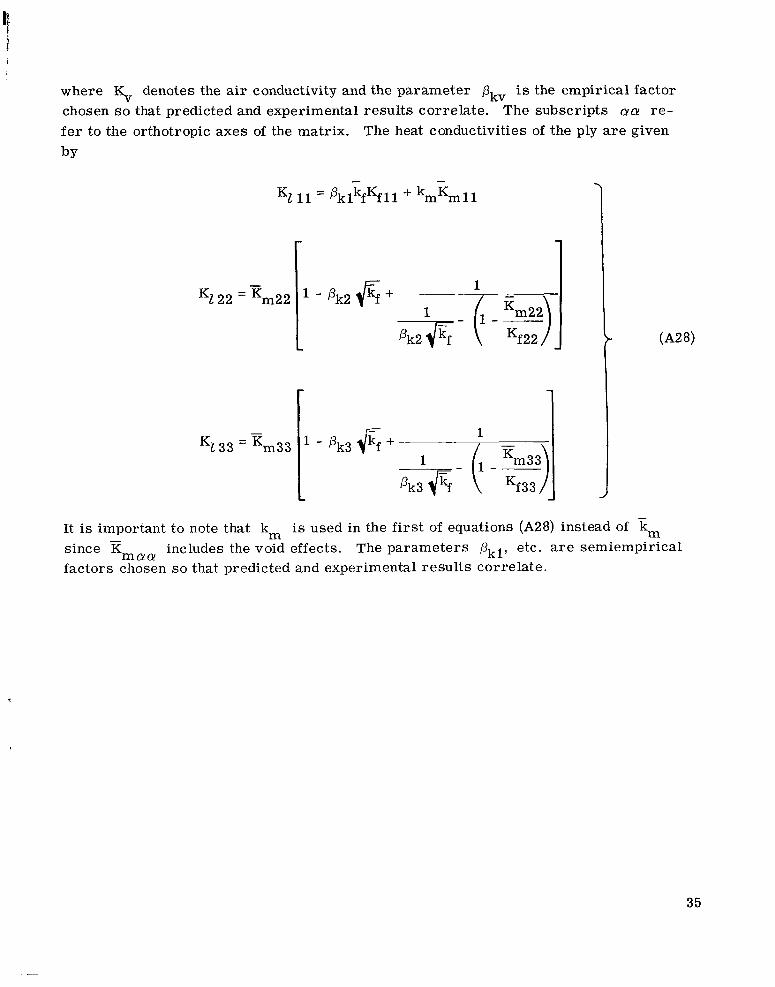
where denotes the air conductivity and the parameter 0, is the empirical factor chosen s o that predicted and experimental resul ts correlate. The subscripts aa r e - f e r to the orthotropic axes of the matrix. The heat conductivities of the ply a r e given by
- - KZ 11 = PklkfKfll + kmKml l
1
It is important to note that km is used in the first of equations (A28) instead of km since X factors chosen so that predicted and experimental resul ts correlate.
includes the void effects. The parameters Pkl, etc. a r e semiempirical m a a
35
I I I I . , , , , . _--.... - ..... .
APPENDIX B
EQUATIONS FOR FAILURE STRESSES (STRENGTHS) AND TRANSFORMATION
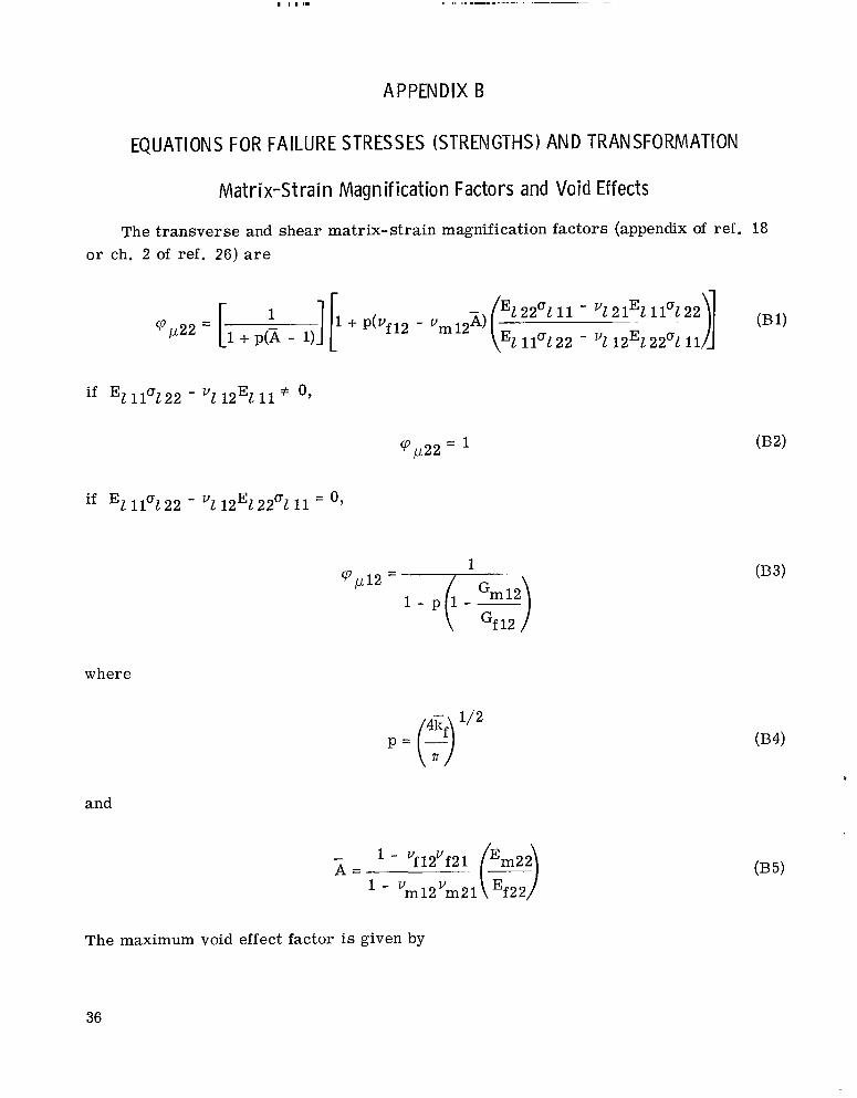
Mat r i x -S t ra in Magni f icat ion Factors and Void Effects
The transverse and shear matrix-strain magnification factors (appendix of ref. 18 o r ch. 2 of ref. 26) are
1 'p1-122 = [l + p(X - 1J
if 1 1 9 2 2 - "1 12E1 11 # O,
'pp22 =
if E1 1 1 9 2 2 - 12E122a1 11 = O,
'p1-112 =
where
/ E 1 2 2 9 11 - v1 21%
\"I 11O122 - "1 12% 2 2 9 11u!221 11
1
and
The maximum void effect factor is given by
36
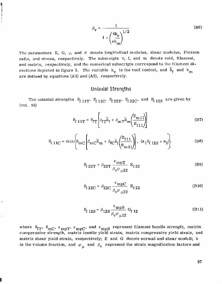
The parameters E, G, V , and a denote longitudinal modulus, shear modulus, Poisson ratio, and s t r e s s , respectively. The subscripts v, f , and m denote void, filament, and matrix, respectively, and the numerical subscripts correspond to the filament di- rections depicted in figure 1. a r e defined by equations (Al ) and (A2), respectively.
The variable kv is the void content, and kf and km
Un iaxial Strengths
‘mpT ‘1 22T = @22T El 22
pvq 1.1.22
E mpC E s1 22c = p22c 1 2 2
G1 12 E mPS
12s = 4 2 s cp v w12
represent filament bundle strength, matr ix mPS
where SfT, Smc, E mpT’ ‘mpC’ and E
compressive strength, matr ix tensile yield strain, matr ix compressive yield strain, and matr ix shear yield strain, respectively; E and G denote normal and shear moduli; k is the volume fraction, and cp and pv represent the strain magnification factors and
P
37
I
the maximum void effects, respectively; and the remaining p's denote the simple strength correlation c oeff ici ent s.
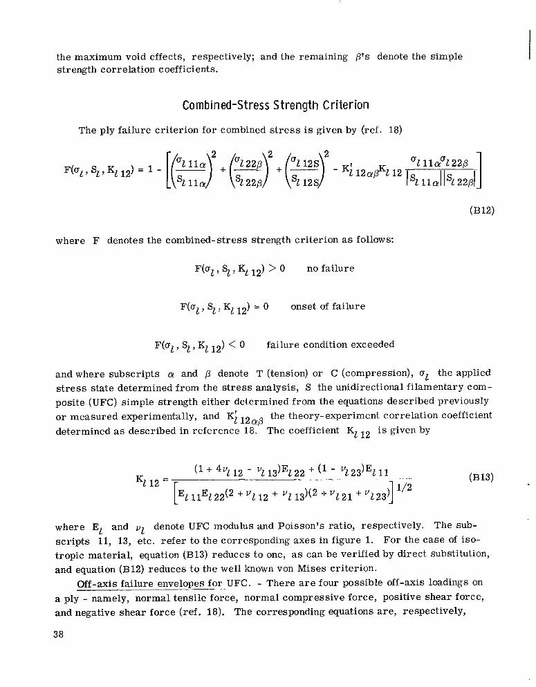
Combined-Stress S t r e n g t h Cr i t e r i on
The ply failure criterion for combined s t r e s s is given by (ref. 18)
1 Fb l , S l , Kl 12) = 1 - [(-I s1 11cr + (-7 Sl 22p + (-) sl 1 2 s - K t 12apK2 12 1 % l l a l l ~ l 2 2 p l
2 "1 l l c r "1 22p "2 1 2 s "2 l lCrol22p
where F denotes the combined-stress strength cri terion as follows:
F (a l , Si, Kl 12) > 0 no failure
F(al , Sl , Kl 12) = 0 onset of failure
F (a l , S l , Kl 12) < 0 failure condition exceeded
and where subscripts cr and p denote T (tension) or C (compression), a1 the applied stress state determined from the s t r e s s analysis, S the unidirectional filamentary com- posite (UFC) simple strength either determined from the equations described previously o r measured experimentally, and Ki 12 the theory-experiment correlation coefficient determined as described in reference 18. The coefficient K1 12 is given by
CUP
where El and v1 denote UFC modulus and Poisson's ratio, respectively. scr ipts 11, 13, etc. refer to the corresponding axes in figure 1. tropic material, equation (B13) reduces to one, as can be verified by direct substitution, and equation (B12) reduces to the well known von Mises criterion.
Off-axis failure - envelopes for UFC. - There a r e four possible off-axis loadings on a ply - namely, normal tensile force, normal compressive force, positive shear force, and negative shear force (ref. 18).
The sub- For the case of iso-
The corresponding equations are, respectively,
38
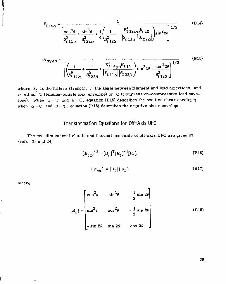
where SI is the failure strength, 0 the angle between filament and load directions, and a! either T (tension-tensile load envelope) or C (compression-compressive load enve- lope). When a = T and p = C, equation (B15) describes the positive shear envelope; when a = C and p = T, equation (B15) describes the negative shear envelope.
Transformat ion Equations f o r Off-Axis UFC
The two-dimensional elastic and thermal constants of off-axis UFC are given by (refs. 2 3 and 24)
[Ecx]- = ITPl 1- llR2 1
where -
1 - sin 20 2
sin 2 8
L- sin 2e sin 2e COS 2e
39
1 "221 ,- -- -El 11 El 22
"2 12 1 - - El 11 El 22
0 0 Gl 12,
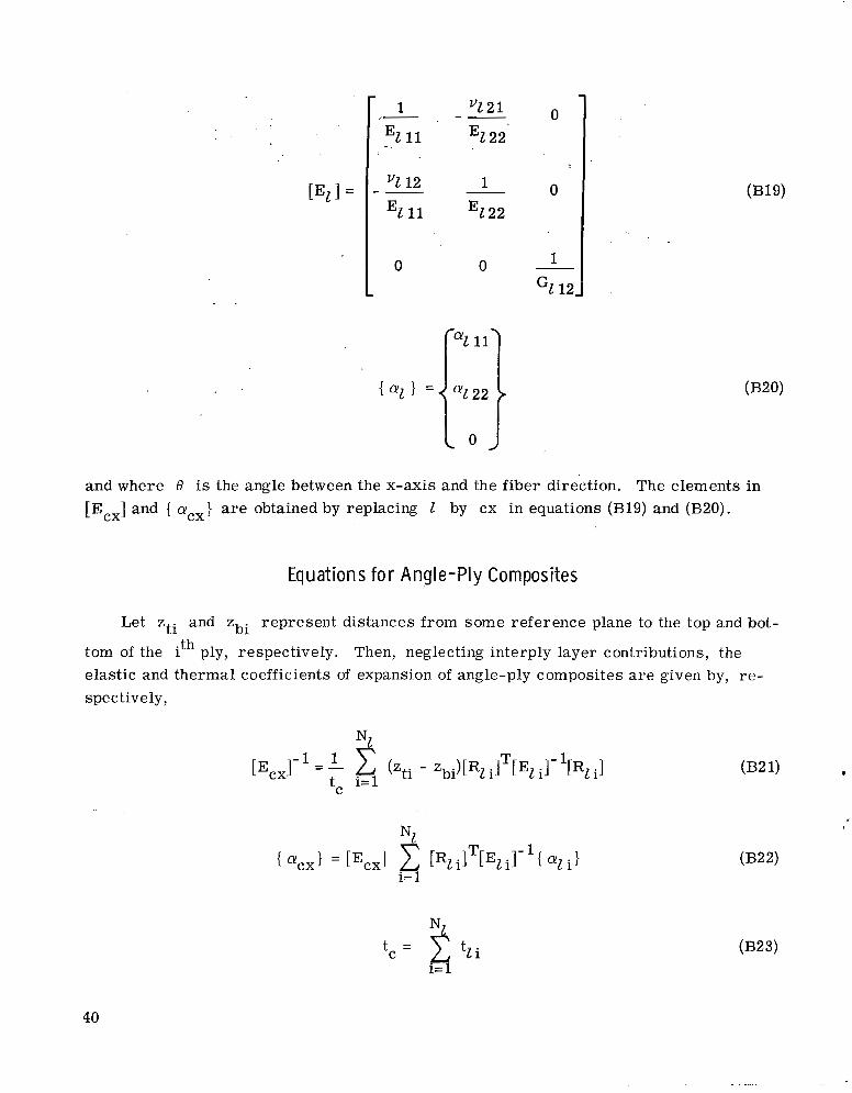
and where 0 is the angle between the x-axis and the fiber direction. The elements in [Ecx] and { oCx} are obtained by replacing I by cx in equations (B19) and (€320).
Equations for Angle-Ply Composites
Let zti and Zbi represent distances from some reference plane to the top and bot-
tom of the ith ply, respectively. Then, neglecting interply layer contributions, the elastic and thermal coefficients of expansion of angle-ply composites a r e given by, re- spec t ive ly,
40
. . . ... . . ..
where [Rl i], [ELi], and { al i} are matrices representing transformation (eq. (B18)), elastic constants (eq. (B19)), and thermal coefficients of expansion (eq. (B20)) for the ith ply, respectively.
41
1
REFERENCES
I 1. Kelly, A. ; and Davies, G. J. : The Principles of the Fiber Reinforcement of Metals.
Metallurg. Rev. , vol. 10, no. 37, 1965, pp. 1-78.
2. Weeton, John W. ; and Signorelli, Robert A. : Fiber-Metal Composite Materials. NASA TN D-3530, 1966.
3. Alexander, John A. ; Shaver, Robert G. ; and Withers, J a m e s C. : Critical Analysis of Accumulated Experimental Data on Filament-Reinforced Metal Matrix Compos- ites. General Technologies Corp. (NASA CR- 106490), June 1969.
4. Karpinos, D. M. ; and Tuchinskii, L. I. : Fiber Reinforced Metals (FRM) (A Review of Literature). Poroshkovaia Met. , vol. 8, July 1968, pp. 37-48.
5. Weeton, John W. : Fiber-Metal Matrix Composites. Machine Design, vol. 41, no. 4, Feb. 20, 1969, pp. 142-156.
6. Niese, D. E . ; Fleck, J. N.; Kistler, C. W., Jr.; and Machlin, I.: Carbon- Filament-Reinforced Cobalt and Nickel. Paper 68-338, AIAA, Apr. 1968.
7. Toy, Albert: Mechanical Properties of Beryllium Filament-Reinforced Aluminum Composites. J. Materials, vol. 3, no. 1, Mar. 1968, pp. 43-58.
8. Petrasek, D. W. ; and Signorelli, R. A. : Tungsten Alloy Fiber Reinforced Nickel Base Alloy Composites for High Temperature Turbojet Engine Applications. sented a t the ASTM Symposium on Composite Materials Testing and Design, New Orleans, La. , Feb. 10-14, 1969.
P re -
9. Anon. : Composite Materials: Testing and Design. Spec. Tech. Publ. 460, ASTM, 1969.
10. Metcalfe, A. G. ; and Schmitz, G. K. : Current Status of Titanium-Boron Com- posites for Gas Turbines. Paper 69-GT-1, ASME, Mar. 1969.
11. Sara, R. B. : Fabrication and Properties of Graphite Fiber, Nickel-Matrix Com- posite. Vol. 14. Western Periodicals Co. , 1968, paper II-4A-4.
Science of Advanced Materials and P rocess Engineering Proceedings.
12. Davis, L. W. : Characterization of Metal Matrix Composites. Paper 69-GT-23, ASME, Mar. 1969.
13. Jackson, Peter W. : Some Studies of the Compatibility of Graphite and Other Fibers with Metal Matrices. Paper W-9-20. 1, ASM, Mar. 1969.
14. Metzger, G. E. : Welding of Metal-Matrix Fiber-Reinforced Materials. Paper W-9-23.2, ASM, Mar. 1969.
42
1
..
15. Mangiapane, J. A.; Sattar, S. A.; Gray, D. F.; and Timoshenko, J. A.: Blading for Gas-Turbine Engines. J. Aircraft, vol. 6, no. 4, July-Aug. 1969, pp. 318- 325.
16. Chamis, C. C. ; and Sendeckyj, G. P. : Critique on Theories Predicting Thermo- elastic Propert ies of Fibrous Composites. J. Composite Mat. , vol. 2, no. 3, July 1968, pp. 332-358.
17. Chamis, C. C. : Thermoelastic Properties of Unidirectional Filamentary Com- posites by a Semiempirical Micromechanics Theory. terials and P rocess Engineering Proceedings. Vol. 14. Western Periodicals Co. , 1968, paper 1-4-5.
Science of Advanced Ma-
18. Chamis, Christos C. : Failure Cri ter ia fo r Filamentary Composites. NASA TN D-5367, 1969.
19. Chen, P. E. ; and Lin, J. M. : Transverse Propert ies of Fibrous Composites. Mat. Res. Standards, vol. 9, no. 8, Aug. 1969, pp. 29-33.
20. Antony, K. C. ; and Chang, W. H. : Mechanical Properties of Al-B Composites. Trans. ASM, vol. 61, no. 3, Sept. 1968, pp. 550-558.
21. Chamis, C. C. : Important Factors in Fiber Composite Design. Proceedings of the 24th Annual Conference Society of the Plastics Industry, 1969, pp. 18-E-1 to 18-E- 13.
22. Anon. : Advanced Composites Status Report. Conference Sponsered by the Air Force Materials Laboratory, Advanced Composites Division, hosted by Lockheed- Georgia, Sept. 25-26, 1968.
23. Lekhnit^ski< S. G. : Theory of Elasticity of an Anisotropic Elastic Body. Holden- Day, Inc., 1963.
24. Anon. : Structural Design Guide for Advanced Composite Applications. North American Rockwell Corp. , Aug. 1969. (Contract F336 15-69-C- 1368. )
25. Ashton, J. E. ; Halpin, J. C. ; and Petit, P. H. : P r i m e r on Composite Materials: Analysis. Technomic Publ. Co. , 1969.
26. Chamis, Christos C. : Design Oriented Analysis and Synthesis of Multilayered- Filamentary Structural Panels. Ph. D. Thesis, Case Western Reserve Univ. , 1967, Ch. 4.
27. Chamis, Christos C. : Buckling of Anisotropic Composite Plates. Journal of the Structural Division, ASCE, Vol. 95, No. ST10, Oct. 1969, pp. 2119-2139.
28. Anon. : Fiber-Strengthened Metallic Composites. Spec. Tech. Publ. 427, ASTM, 1967.
43
29. Anon. : Metal Matrix Composites. Spec. Tech. Publ. 438, ASTM, 1968.
30. Anon. : Interfaces in Composites. Spec. Tech. Publ. 452, ASTM, 1969.
31. Mullin, J. ; Berry, J. M. ; and Gatti, A. : Some Fundamental Fracture Mechanisms Applicable to Advanced Filament Reinforced Composites. J. Composite Mat. , vol. 2, no. 1, Jan. 1968, pp. 82-103.
32. Outwater, J. 0. ; and Murphy, M. C.: On the Frac ture Energy of Unidirectional Laminates. Proceedings of the 24th Annual Conference Society of the Plastics Industry, 1969, pp. 11-C-1 to 11-C-8.
33. Holister, G. S. ; and Thomas, C. : Fibre Reinforced Materials. Elsevier Publ. Co. , 1966.
34. Broutman, L. J. ; and Krock, R. H. : Modern Composite Materials. Addison- Wesley Publ. Co. , 1967.
35. Anon. : Metal-Matrix Composites. Rep. DMIC Memo-243, Battelle Memorial Inst. , May 1969.
36. Hanby, K. R. : Fiber-Reinforced Metal-Matrix Composites - 1968. Rep. DMIC- S-27, Battelle Memorial Institute, July 1, 1969. (Available from DDC or AD- 858351. )
44 NASA-Langley, 1970 - 17 E-5364
NATIONAL AERONAUTICS AND SPACE ADMINISTRATION WASHINGTON, D. C. 20546
OFFICIAL BUSINESS FIRST CLASS MAIL
POSTAGE AND FEES PAID NATIONAL AERONAUTICS AND
SPACE ADMINISTRATION
, , : ? I I ; / I : , 1, ' '. . f . i , l i i i . , 3
,IASTER: If Undeliverable (Section 158 Posral Manual ) Do Not Return
"The cierowiiiticnl nizd spnce nctit'ities of the United Strites shnll be coudiicted so as t o contribrite . . . t o the expnnsioiz of hi~itiniz kizozul- edge of pheizonieizn in the rrtitiospbere niad spnce. The Adnii~aistrntio~z shnlf proz'ide for the widest prncticdble nizd nppioprinte dissei~iiizntio?t of infositintion concerning its rlctii'ities nizd the resdts thereof."
-NATIONAL AERONAUTICS AND SPACE ACT OF 195s
NASA SCIENTIFIC AND TECHNICAL PUBLICATIONS
TECHNICAL REPORTS: Scientific and technical information considered important, complete, and a lasting contribution to existing knowledge. 1
TECHNICAL NOTES: information less broad in scope but nevertheless of importance as a contribution to existing knowledge.
TECHNICAL MEMORANDUMS: Information receiving limited distribution because of preliminary data, security classifica- tion, or other reasons.
CONTRACTOR REPORTS: Scientific and technical information generated under a NASA contract or grant and considered an important contribution to existing knowledge.
TECHNICAL TRANSLATIONS: Information published in a foreign language considered to merit NASA distribution in English.
SPECIAL PUBLICATIONS: Information derived from or of value to NASA activities. Publications include conference proceedings, monographs, data compilations, handbooks, sourcebooks, and special bibliographies.
TECHNOLOGY UTILIZATION PUBLICATIONS: Information on technology used by NASA that may be of particular interest in commercial and other non-aerospace .ipplications. Publications include Tech Briefs, Tcchnology Utiliz<ition Reports and Notes, and Technology Surveys.
Details on the availability of these publications may be obfained from:
SCIENTIFIC AND TECHNICAL INFORMATION DIVISION
NATIONAL AERONAUTICS AND SPACE ADMINISTRATION Washington, D.C. 20546
.-
I
i