chapter 8 system control
TRANSCRIPT
CHAPTER 8System ContrSystem Controlol
255
In 2D interfaces, UI elements such as pull-down menus, pop-up menus,toolboxes, palettes, toggles, radio buttons, and checkboxes are every-where. These elements are examples of system control techniques—theyallow us to send commands to an application, change a mode, or modifya parameter. Although we don’t think much about the design of suchtechniques in 2D UIs, system control interfaces for 3D UIs are not trivial.Simply adapting 2D desktop-based widgets is not the ultimate solution.In this chapter, we discuss and compare various system control solutionsfor 3D UIs.
8.1. Introduction
The issuing of commands is a critical way to access any computer system’sfunctionality. For example, with traditional desktop computers, we maywant to save a document or change from a brush tool to an eraser tool ina painting application. In order to perform such tasks, we use graphicaluser interface (GUI) system control techniques like menus or functionkeys on a keyboard. Research in desktop system control has provided uswith a wealth of techniques, such as those used in the WIMP (Windows,Icons, Menus, Pointers) metaphor (Preece et al. 2002).
Although much of the “real work” in a computer application consistsof interaction tasks like selection, manipulation, and symbolic input,
30706 08 pp255-286 r1jm.ps 5/13/04 5:51 PM Page 255
1234567890123456789012345678901234567890
system control is critical because it is the “glue” that allows the user tocontrol the interaction flow between the other key tasks in an application.For example, in writing this book with a word processor, the core activityis symbolic input, accomplished by typing on a keyboard. But this activ-ity is interspersed with many small system control tasks—saving the cur-rent document by clicking on a button, inserting a picture by choosing anitem from a menu, or underlining a piece of text by using a keyboardshortcut, just to name a few.
We can more precisely define system control as follows:
The key word in this definition is command. In selection, manipulation,and travel tasks, the user typically specifies not only what should be done,but also how it should be done, more or less directly controlling the ac-tion. In system control tasks, the user typically specifies only what shouldbe done and leaves it up to the system to determine the details. In part 1ofthe definition, the system has a self-contained piece of functionality (e.g.,for making plain text bold), and the user simply requests (commands)this function to be executed. Part 2 indicates a task such as choosing anew tool from a toolbox—nothing has changed besides the interactionmode. Changing the system state, part 3 of the definition, is exemplifiedby tasks such as clicking on a window to bring it to the front—that win-dow becomes the “current window” in the system state, and subsequentactions are applied to it.
How can system control tasks be performed in 3D UIs? In 2D inter-faces, system control is supported by the use of a specific interaction style,such as pull-down menus, text-based command lines, or tool palettes(Preece et al. 2002). Many of these interaction styles have also beenadapted to 3D UIs (see section 8.3), which is certainly appropriate fordesktop-based 3D UIs. In immersive and semi-immersive environments,however, WIMP-style interaction may not be effective in all situations.We cannot assume that simply transferring conventional interaction styleswill lead to usability. In immersive VEs, users have to deal with 6-DOFinput as opposed to 2 DOF on the desktop, and the input and outputdevices used in VEs differ considerably from the keyboard and mouse.
System control is the user task in which a command is issued to1. request the system to perform a particular function,2. change the mode of interaction, or3. change the system state.
256 Chapter 8 System Control
30706 08 pp255-286 r1jm.ps 5/13/04 5:51 PM Page 256
These differences create both new problems and new possibilities for sys-tem control. Therefore, in non-desktop 3D UIs, it may be more appropri-ate to use nonconventional system control techniques (Bullinger et al. 1997).
What determines the success (usability and performance) of a systemcontrol technique in a 3D UI? Before describing specific techniques, let’sconsider three sets of factors that influence the effectiveness of all tech-niques: human factors, input devices, and system- and application-levelfactors.
8.1.1. Human Factors of System Control
When designing system controls, we can learn much from the design ofmechanical systems (Bullinger et al. 1997). In mechanical systems, controlrefers to the transfer of mechanical energy or information to a system forperforming control actions. The interaction between the control deviceand the human’s body is called the control-body linkage. As with all otherinteraction techniques, the user’s physical characteristics, training, andexperience level affect the operating effectiveness of the control-bodylinkage. Other factors that often affect user performance in traditionalmechanical control systems include the shape and size of controls, theirvisual representation and labelling, methods of selection, and underlyingcontrol structures.
Many of these factors can be applied directly to the design of systemcontrol techniques for 3D UIs. For example, think about a menu in whichthe user rotates her hand to select an item (a “1 DOF menu,” see section8.3.1). When designing this menu technique, we need to consider howthe user can rotate her wrist and the placement and size of the menuitems that will lead to comfortable and efficient selection. When we de-sign the menu poorly (e.g., when the user needs to turn her wrist to anuncomfortable position to select the items at the edges of the menu), themenu will not be very usable.
8.1.2. Input Devices
Many of the system control techniques described in this chapter are con-nected to particular input devices; for example, voice commands requireuse of a microphone. Hence, the properties of input devices influence thedesign of many system control interaction techniques. Some techniques,however, are device-independent.
The input devices used for system control techniques in 3D UIs canalso have an effect on user performance and comfort. For example, a
8.1. Introduction 257
30706 08 pp255-286 r1jm.ps 5/13/04 5:51 PM Page 257
1234567890123456789012345678901234567890
menu can be placed on a tracked physical surface, and the menu itemscan be selected with a tracked physical pen (the pen-and-tablet tech-nique). The constraint provided by the physical surface will increase effi-ciency and accuracy. On the other hand, the user may tire more quicklywhen holding two physical devices.
The number and placement of buttons on input devices is a third fac-tor that may influence the usability of system control techniques in 3DUIs. Multiple buttons allow “lightweight” mode switching and moreflexibility of expression. The common context-sensitive menu in desktopinterfaces, for example, is usually accessed via the right mouse button.However, multiple buttons can also lead to user confusion and error, es-pecially if the mapping between buttons and functionality is inconsistentor unclear.
8.1.3. System- and Application-Level Factors
Factors related to the system’s implementation can also influence the ef-fectiveness of system control in a 3D UI. For example, recognition errorsin speech or gesture interfaces can significantly reduce user performanceand perceived usability.
The complexity of the application also plays an important role. Withan increase in functionality, issuing commands becomes more difficult,since the user needs to know how to access all the functionality of thesystem. The system can be structured to help the user in this task. In addi-tion, system control techniques that work well for accessing 10 commandsmay be completely unusable if the number of commands swells to 100.
8.1.4. Chapter Roadmap
We begin this chapter with a classification of system control for 3D UIs(section 8.2). Next, we describe each of the major categories in this classi-fication (sections 8.3–8.6). In each of these sections, we describe represen-tative techniques, discuss the relevant design and implementation issues,and provide guidance on the practical application of the techniques. Insection 8.7, we cover multimodal system control techniques, which com-bine multiple methods of input to improve usability and performance.Section 8.8 describes some important design guidelines and the specificinterrelationships between system control and other interaction tech-niques. Finally, a case study (section 8.9) serves a real-world example ofsystem control design in a 3D UI.
258 Chapter 8 System Control
30706 08 pp255-286 r1jm.ps 5/13/04 5:51 PM Page 258
Note that the techniques described in this chapter come mostly fromwork in immersive VEs. In many cases, however, the techniques or theprinciples they represent might also be used in augmented reality ordesktop 3D UIs.
8.2. Classification
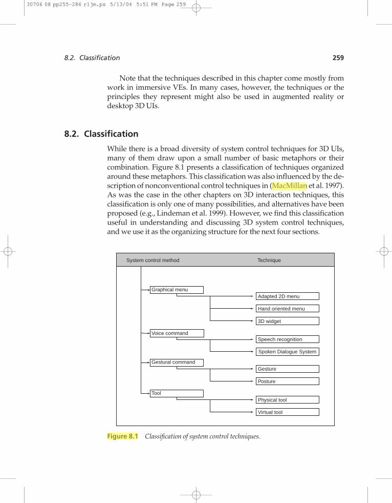
While there is a broad diversity of system control techniques for 3D UIs,many of them draw upon a small number of basic metaphors or theircombination. Figure 8.1 presents a classification of techniques organizedaround these metaphors. This classification was also influenced by the de-scription of nonconventional control techniques in (MacMillan et al. 1997).As was the case in the other chapters on 3D interaction techniques, thisclassification is only one of many possibilities, and alternatives have beenproposed (e.g., Lindeman et al. 1999). However, we find this classificationuseful in understanding and discussing 3D system control techniques,and we use it as the organizing structure for the next four sections.
8.2. Classification 259
System control method Technique
Graphical menu
Voice command
Gestural command
Tool
Hand oriented menu
Adapted 2D menu
3D widget
Speech recognition
Gesture
Posture
Physical tool
Virtual tool
Spoken Dialogue System
Figure 8.1 Classification of system control techniques.
30706 08 pp255-286 r1jm.ps 5/13/04 5:51 PM Page 259

1234567890123456789012345678901234567890
8.3. Graphical Menus
Graphical menus for 3D UIs are the 3D equivalent of the 2D menus thathave proven to be a successful system control technique in desktop UIs.Because of their success and familiarity to users, many developers havechosen to experiment with graphical menus for 3D UIs.
8.3.1. Techniques
In this section, we describe four techniques:
• adapted 2D menus• 1-DOF menus• TULIP menus• 3D widgets
Adapted 2D Menus
Menus that are simple adaptations of their 2D counterparts have, for ob-vious reasons, been the most popular group of 3D system control tech-niques. These menus basically function in the same way as they do on thedesktop. Some examples of adapted 2D menus are pull-down menus,pop-up menus, floating menus, and toolbars. Figure 8.2 shows an ex-ample of adapted 2D menu used in a Virtual Museum application in a
260 Chapter 8 System Control
Figure 8.2 A floating menu in the Virtual Museum application.(Photograph courtesyof Gerhard Eckel, Fraunhofer IMK)
30706 08 pp255-286 r1jm.ps 5/13/04 5:51 PM Page 260
surround-screen display. It allows a user to plan an exhibition by findingand selecting images of artwork available for the exhibition. The menu issemitransparent to reduce occlusion of the 3D environment.
One adaptation of 2D menus that has been successful in 3D UIs is toattach the menus to the user’s head—this way, the menu is always avail-able, no matter where the user is looking. Another powerful technique isto attach the menu to a tracked physical surface (a tablet). Finding themenu is then as easy as bringing the physical tablet into view. The physi-cal surface of the tablet also helps the user to select the menu items, andthe menu can easily be put away as well.
The main advantage of adapted 2D menus is their familiar interactionstyle. Almost all users will instantly recognize these elements as menusand will understand how to use them. On the other hand, these menus canocclude the environment, and users may have trouble finding the menuor selecting items within it using a 3D selection technique (see the sectionon placement issues below).
1-DOF Menus
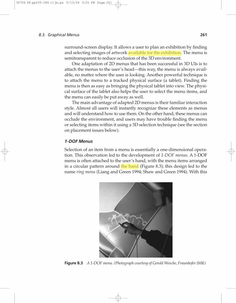
Selection of an item from a menu is essentially a one-dimensional opera-tion. This observation led to the development of 1-DOF menus. A 1-DOFmenu is often attached to the user’s hand, with the menu items arrangedin a circular pattern around the hand (Figure 8.3); this design led to thename ring menu (Liang and Green 1994; Shaw and Green 1994). With this
8.3. Graphical Menus 261
Figure 8.3 A 1-DOF menu. (Photograph courtesy of Gerold Wesche, Fraunhofer IMK)
30706 08 pp255-286 r1jm.ps 5/13/04 5:51 PM Page 261
1234567890123456789012345678901234567890
design, the user rotates his hand until the desired item falls within a “se-lection basket.” Of course, the hand rotation or movement can also bemapped onto a linear menu; it does not have to be circular. The perfor-mance of a ring menu depends on the physical movement of the handand wrist, and the primary axis of rotation should be carefully chosen.Of course, hand rotation is only one possible way to select an item in a1-DOF ring menu. For example, the user could rotate the desired iteminto position with the use of a button or buttons on the input device.
Handheld widgets are another type of 1-DOF menu. These do not userotation, but instead relative hand position (Mine et al. 1997). By movingthe hands closer together or further apart, different items in the menu canbe selected.
In general, 1-DOF menus are quite easy to use. Menu items can be se-lected quickly, as long as the number of items is relatively small. Due tothe strong placement cue, 1-DOF menus also afford rapid access anduse—the user does not have to find the menu if it is attached to his handand does not have to switch his focus away from the area in which he isperforming actions.
TULIP Menus
Another method of attaching a menu to the user’s hand in a 3D UI is toassign menu items to different fingers. Using Pinch Gloves (see Chap-ter 4), the system can interpret a pinch between a finger and the thumb onthe same hand as a menu selection. If there are no more than eight menuitems, this technique works very well. Up to 16 menu items can be ac-commodated if the items are organized into four menus with four itemseach—the non-dominant hand can be used to select a menu, and thedominant hand to select an item within the menu.
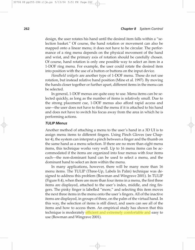
In many applications, however, there will be many more than 16menu items. The TULIP (Three-Up, Labels In Palm) technique was de-signed to address this problem (Bowman and Wingrave 2001). In TULIP(Figure 8.4), when there are more than four items in a menu, the first threeitems are displayed, attached to the user’s index, middle, and ring fin-gers. The pinky finger is labelled “more,” and selecting this item movesthe next three items in the menu onto the user’s fingers. All of the inactiveitems are displayed, in groups of three, on the palm of the virtual hand. Inthis way, the selection of items is still direct, and users can see all of theitems and how to access them. An empirical study has shown that thistechnique is moderately efficient and extremely comfortable and easy touse (Bowman and Wingrave 2001).
262 Chapter 8 System Control
30706 08 pp255-286 r1jm.ps 5/13/04 5:51 PM Page 262
3D Widgets
The most exotic group of graphical menu techniques for system controlare 3D widgets. They take advantage of the extra DOF available in a 3Denvironment to enable more complex menu structures or better visual af-fordances for menu entries. We distinguish between two kinds of 3Dwidgets: colocated (context-sensitive) widgets and non-context-sensitivewidgets.
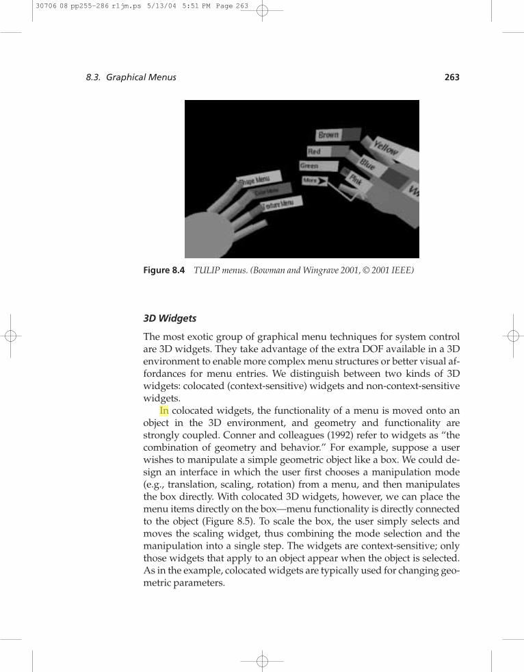
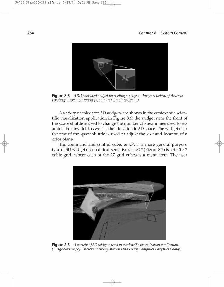
In colocated widgets, the functionality of a menu is moved onto anobject in the 3D environment, and geometry and functionality arestrongly coupled. Conner and colleagues (1992) refer to widgets as “thecombination of geometry and behavior.” For example, suppose a userwishes to manipulate a simple geometric object like a box. We could de-sign an interface in which the user first chooses a manipulation mode(e.g., translation, scaling, rotation) from a menu, and then manipulatesthe box directly. With colocated 3D widgets, however, we can place themenu items directly on the box—menu functionality is directly connectedto the object (Figure 8.5). To scale the box, the user simply selects andmoves the scaling widget, thus combining the mode selection and themanipulation into a single step. The widgets are context-sensitive; onlythose widgets that apply to an object appear when the object is selected.As in the example, colocated widgets are typically used for changing geo-metric parameters.
8.3. Graphical Menus 263
Figure 8.4 TULIP menus. (Bowman and Wingrave 2001, © 2001 IEEE)
30706 08 pp255-286 r1jm.ps 5/13/04 5:51 PM Page 263
1234567890123456789012345678901234567890
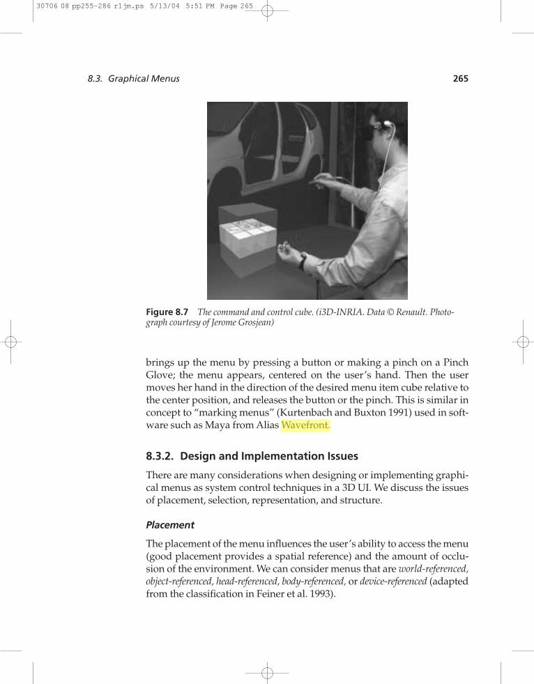
A variety of colocated 3D widgets are shown in the context of a scien-tific visualization application in Figure 8.6: the widget near the front ofthe space shuttle is used to change the number of streamlines used to ex-amine the flow field as well as their location in 3D space. The widget nearthe rear of the space shuttle is used to adjust the size and location of acolor plane.
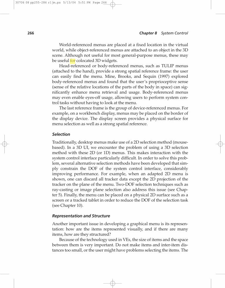
The command and control cube, or C3, is a more general-purposetype of 3D widget (non-context-sensitive). The C3 (Figure 8.7) is a 3 × 3 × 3cubic grid, where each of the 27 grid cubes is a menu item. The user
264 Chapter 8 System Control
Figure 8.5 A 3D colocated widget for scaling an object. (Image courtesy of AndrewForsberg, Brown University Computer Graphics Group)
Figure 8.6 A variety of 3D widgets used in a scientific visualization application.(Image courtesy of Andrew Forsberg, Brown University Computer Graphics Group)
30706 08 pp255-286 r1jm.ps 5/13/04 5:51 PM Page 264
brings up the menu by pressing a button or making a pinch on a PinchGlove; the menu appears, centered on the user’s hand. Then the usermoves her hand in the direction of the desired menu item cube relative tothe center position, and releases the button or the pinch. This is similar inconcept to “marking menus” (Kurtenbach and Buxton 1991) used in soft-ware such as Maya from Alias Wavefront.
8.3.2. Design and Implementation Issues
There are many considerations when designing or implementing graphi-cal menus as system control techniques in a 3D UI. We discuss the issuesof placement, selection, representation, and structure.
Placement
The placement of the menu influences the user’s ability to access the menu(good placement provides a spatial reference) and the amount of occlu-sion of the environment. We can consider menus that are world-referenced,object-referenced, head-referenced, body-referenced, or device-referenced (adaptedfrom the classification in Feiner et al. 1993).
8.3. Graphical Menus 265
Figure 8.7 The command and control cube. (i3D-INRIA. Data © Renault. Photo-graph courtesy of Jerome Grosjean)
30706 08 pp255-286 r1jm.ps 5/13/04 5:51 PM Page 265
1234567890123456789012345678901234567890
World-referenced menus are placed at a fixed location in the virtualworld, while object-referenced menus are attached to an object in the 3Dscene. Although not useful for most general-purpose menus, these maybe useful for colocated 3D widgets.
Head-referenced or body-referenced menus, such as TULIP menus(attached to the hand), provide a strong spatial reference frame: the usercan easily find the menu. Mine, Brooks, and Sequin (1997) exploredbody-referenced menus and found that the user’s proprioceptive sense(sense of the relative locations of the parts of the body in space) can sig-nificantly enhance menu retrieval and usage. Body-referenced menusmay even enable eyes-off usage, allowing users to perform system con-trol tasks without having to look at the menu.
The last reference frame is the group of device-referenced menus. Forexample, on a workbench display, menus may be placed on the border ofthe display device. The display screen provides a physical surface formenu selection as well as a strong spatial reference.
Selection
Traditionally, desktop menus make use of a 2D selection method (mouse-based). In a 3D UI, we encounter the problem of using a 3D selectionmethod with these 2D (or 1D) menus. This makes interaction with thesystem control interface particularly difficult. In order to solve this prob-lem, several alternative selection methods have been developed that sim-ply constrain the DOF of the system control interface, considerablyimproving performance. For example, when an adapted 2D menu isshown, one can discard all tracker data except the 2D projection of thetracker on the plane of the menu. Two-DOF selection techniques such asray-casting or image plane selection also address this issue (see Chap-ter 5). Finally, the menu can be placed on a physical 2D surface such as ascreen or a tracked tablet in order to reduce the DOF of the selection task(see Chapter 10).
Representation and Structure
Another important issue in developing a graphical menu is its represen-tation: how are the items represented visually, and if there are manyitems, how are they structured?
Because of the technology used in VEs, the size of items and the spacebetween them is very important. Do not make items and inter-item dis-tances too small, or the user might have problems selecting the items. The
266 Chapter 8 System Control
30706 08 pp255-286 r1jm.ps 5/13/04 5:51 PM Page 266
more complex the application gets, the more functions will be available.Make sure to structure the interface by using either functional grouping(items with similar function are clustered) or sequential grouping (usingthe natural sequence of operations to structure items), or by using con-text-sensitive menus so that only the applicable functions are displayedwhen the user accesses the menu (Salvendy 1997). Finally, control coding,which uses different colors, shapes, surfaces, textures, dimensions, posi-tions, text, and symbols to differentiate items, can give an extra cue aboutthe relations between different items and therefore make the structureand the hierarchy of the items more clear (Bullinger et al. 1997).
8.3.3. Practical Application
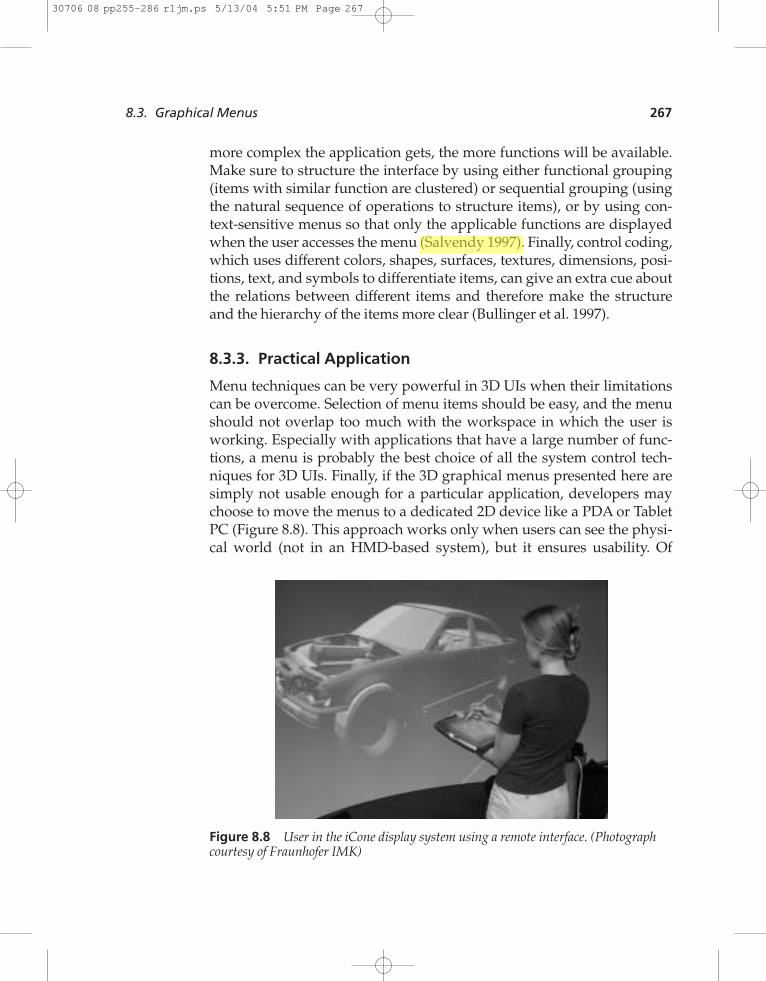
Menu techniques can be very powerful in 3D UIs when their limitationscan be overcome. Selection of menu items should be easy, and the menushould not overlap too much with the workspace in which the user isworking. Especially with applications that have a large number of func-tions, a menu is probably the best choice of all the system control tech-niques for 3D UIs. Finally, if the 3D graphical menus presented here aresimply not usable enough for a particular application, developers maychoose to move the menus to a dedicated 2D device like a PDA or TabletPC (Figure 8.8). This approach works only when users can see the physi-cal world (not in an HMD-based system), but it ensures usability. Of
8.3. Graphical Menus 267
Figure 8.8 User in the iCone display system using a remote interface. (Photographcourtesy of Fraunhofer IMK)
30706 08 pp255-286 r1jm.ps 5/13/04 5:51 PM Page 267
1234567890123456789012345678901234567890
course, this type of setup is also more expensive, more cumbersome, andperhaps more difficult to implement.
8.4. Voice Commands
The issuing of voice commands can be performed via simple speechrecognition or by means of spoken dialogue techniques. Speech recogni-tion techniques are typically used for issuing single commands to the sys-tem, while a spoken dialogue technique is actively focused on promotingdiscourse between the user and the system.
8.4.1. Techniques
A spoken dialogue system provides an interface between a user and acomputer-based application that permits spoken interaction with the ap-plication in a relatively natural manner (McTear 2002). The most criticalcomponent of a spoken dialogue system (and of simple speech recogni-tion techniques) is the speech recognition engine. A wide range of factors in-fluences the speech recognition rate, such as variability among speakersand background noise. The recognition engine can be speaker-depen-dent, requiring initial training of the system, or speaker-independent,which normally does not require training. Systems also differ in the sizeof their vocabulary. The response generated as output to the user can con-firm that an action has been performed or inform the user that more inputis needed so as to complete a control command. In a spoken dialogue sys-tem, the response should be adapted to the flow of discourse (requiring adialogue control mechanism) and generated as artificial speech.
Current speech recognition packages include IBM ViaVoice andHARK, while current spoken dialogue systems include CSLU toolkit, IBMvoice server, Speechworks, and NLSA. More information on these systems,including references to academic work, can be found in (McTear 2002).
Many 3D UIs that use speech recognition also include other comple-mentary input methods (e.g., Billinghurst 1998). These techniques are la-belled multimodal and are discussed in section 8.7.
8.4.2. Design and Implementation Issues
The development of a 3D UI using simplified speech recognition or themore complex spoken dialogue systems involves many factors. A devel-oper should start by defining which tasks need to be performed via voice
268 Chapter 8 System Control
30706 08 pp255-286 r1jm.ps 5/13/04 5:51 PM Page 268
interfaces. For an application with a limited number of functions, a nor-mal speech recognition system will probably work well. The task will de-fine the vocabulary size of the speech engine—the more complex the taskand the domain in which it is performed, the more likely it is that the vo-cabulary size will increase. Highly complex applications may need con-versational UIs via a spoken dialogue system in order to ensure that thefull functionality of voice input is accessible. In the case of a spoken dia-logue system, it should also be considered which input (vocal “informa-tion”) is needed in order to determine the user’s intentions.
Developers should be aware that voice interfaces are invisible to theuser. The user is normally not presented with an overview of the func-tions that can be performed via a speech interface. Therefore, in order tograsp the actual intentions of the user, one of the key factors is verifica-tion. Either by error-correction via semantic and syntactic filtering (pre-diction methods that use the semantics or syntax of a sentence to limit thepossible interpretation) or by a formal discourse model (question-and-answer mechanism), the system must ensure that it understands whatthe user wants.
Unlike other system control techniques, speech-based techniques ini-tialize, select, and issue a command “all at once.” Sometimes, anotherinput stream (like a button press) or a specific voice command should beused to initialize the speech system. This disambiguates the start of avoice input and is called a push-to-talk system (also see Chapter 4). Errorrates will increase when, for instance, the application involves directcommunication between multiple participants. Here, a comment to a col-league can easily be misunderstood as a voice command to a system.Therefore, one should separate human–human and human–computer in-teraction when designing speech interfaces. Syntactic differences be-tween personal communication and system interaction might be used todistinguish between voice streams (Shneiderman 2000).
8.4.3. Practical Application
Speech input as a system control technique in a 3D UI can be very power-ful—it is hands-free and natural. Still, continuous voice input is tiringand cannot be used in every environment.
The user first needs to learn the voice commands before they can beissued. A user can easily learn simple commands for a limited number offunctions. However, voice commands are probably not very useful in ap-plications that allow only short learning times or no learning at all.
8.4. Voice Commands 269
30706 08 pp255-286 r1jm.ps 5/13/04 5:51 PM Page 269
1234567890123456789012345678901234567890
Finally, we note that similar interface issues have been studied inmany different contexts. For example, speech commands for controlling asystem via a telephone poses many of the same problems as using voicecommands in a VE. Please refer to Brewster (1998) for a further discus-sion of issues involved in such communication streams.
8.5. Gestural Commands
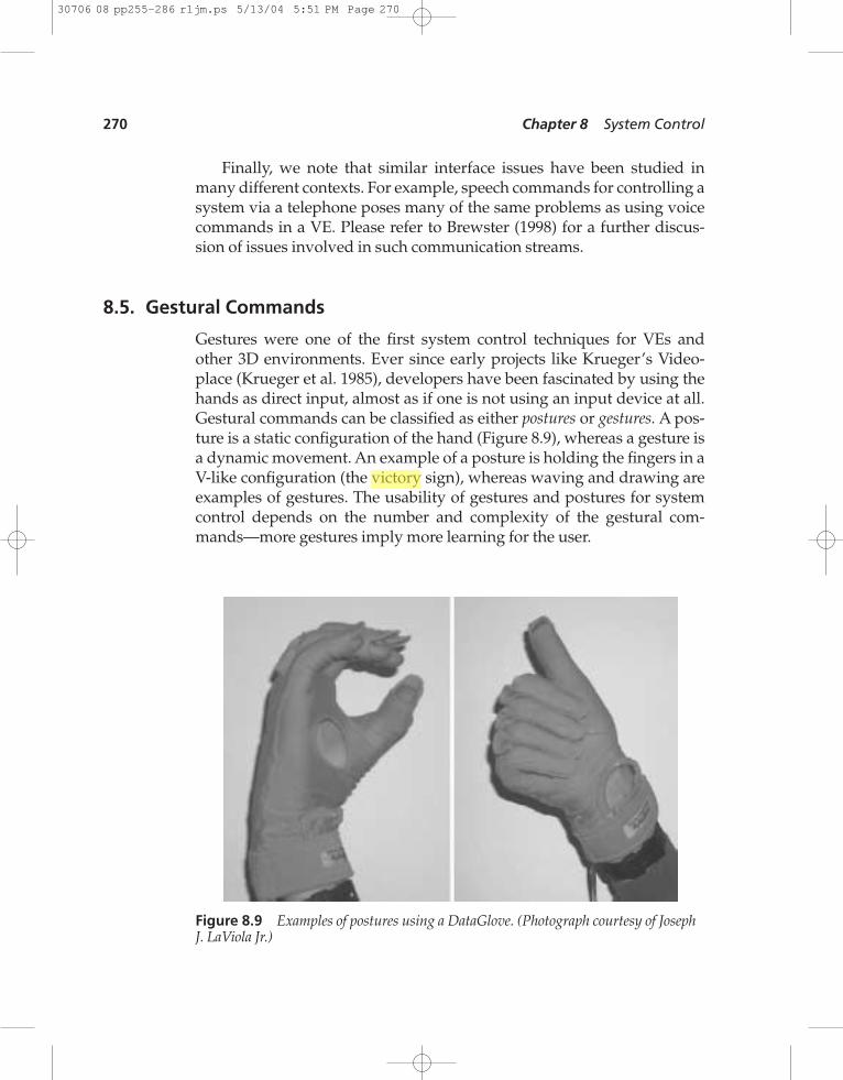
Gestures were one of the first system control techniques for VEs andother 3D environments. Ever since early projects like Krueger’s Video-place (Krueger et al. 1985), developers have been fascinated by using thehands as direct input, almost as if one is not using an input device at all.Gestural commands can be classified as either postures or gestures. A pos-ture is a static configuration of the hand (Figure 8.9), whereas a gesture isa dynamic movement. An example of a posture is holding the fingers in aV-like configuration (the victory sign), whereas waving and drawing areexamples of gestures. The usability of gestures and postures for systemcontrol depends on the number and complexity of the gestural com-mands—more gestures imply more learning for the user.
270 Chapter 8 System Control
Figure 8.9 Examples of postures using a DataGlove. (Photograph courtesy of JosephJ. LaViola Jr.)
30706 08 pp255-286 r1jm.ps 5/13/04 5:51 PM Page 270
8.5.1. Techniques
One of the best examples to illustrate the diversity of gestural commandsis Polyshop (later Multigen’s SmartScene; Mapes and Moshell 1995). Inthis VE application, all interaction was specified by postures and ges-tures, from navigation to the usage of menus. For example, the user couldmove forward by pinching an imaginary rope and pulling herself alongit (the “grabbing the air” technique—see Chapter 6). As this exampleshows, system control overlaps with manipulation and navigation in sucha 3D UI. Consider the definition of system control as being the “change ofmode of interaction.” In Polyshop, the switch to navigation mode is light-weight and effective, since no “active” change of mode is performed.
In everyday life, we use many different types of gestures , and thesecategories also apply to the use of gestures in 3D UIs:
• Speech-connected hand gestures: Spontaneous gesticulation per-formed unintentionally during speech or language-like gesturesthat are integrated in the speech performance. Speech-connectedgestures have been studied intensely in HCI and applied tomultimodal interfaces (e.g., Bolt 1980).
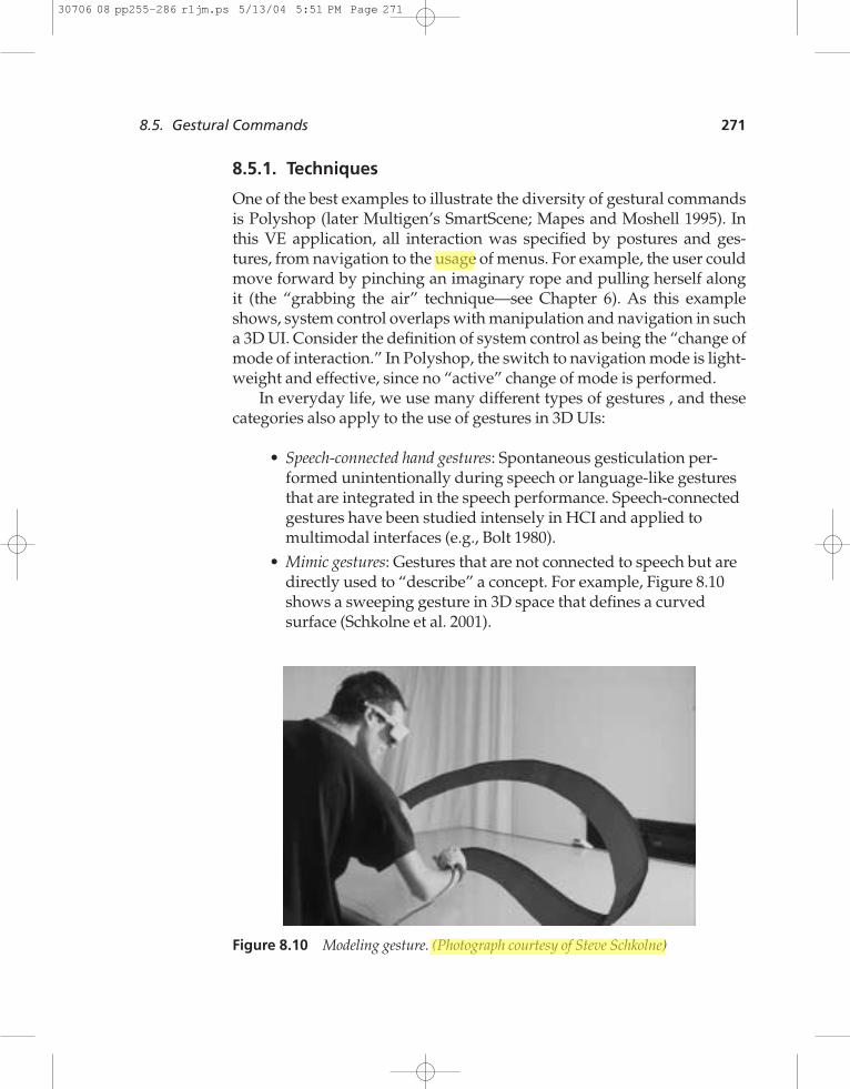
• Mimic gestures: Gestures that are not connected to speech but aredirectly used to “describe” a concept. For example, Figure 8.10shows a sweeping gesture in 3D space that defines a curvedsurface (Schkolne et al. 2001).
8.5. Gestural Commands 271
Figure 8.10 Modeling gesture. (Photograph courtesy of Steve Schkolne)
30706 08 pp255-286 r1jm.ps 5/13/04 5:51 PM Page 271
1234567890123456789012345678901234567890
• Symbolic gestures: Gestures as used in daily life to express thingslike insults or praise (e.g., “thumbs up”)
• Sign language: The use of a specified set of postures and gesturesin communicating with hearing-impaired people. At least one3D UI project has used sign-language-like gestures for commu-nication (Fels 1994).
8.5.2. Design and Implementation Issues
The implementation of gestural input is usually tied to the input deviceused. Here are the major types of gesture input techniques:
• Glove-based recognition: Glove-like devices (see Chapter 4) analyzethe raw data coming from their sensors with recognition algo-rithms such as hidden Markov models and neural networks. Thehand has been used as button, valuator, locator, and pick device(Zimmerman et al. 1987; Sturman et al. 1989). Pinch Gloves canbe used for limited postures, while DataGloves provide bothpostures and gestures using joint-angle measurements.
• Camera-based recognition: Video images of hand or finger gesturescan be analyzed by using feature-recognition methods (computervision methods) to recognize specific configurations of the hand(Starner et al. 1998).
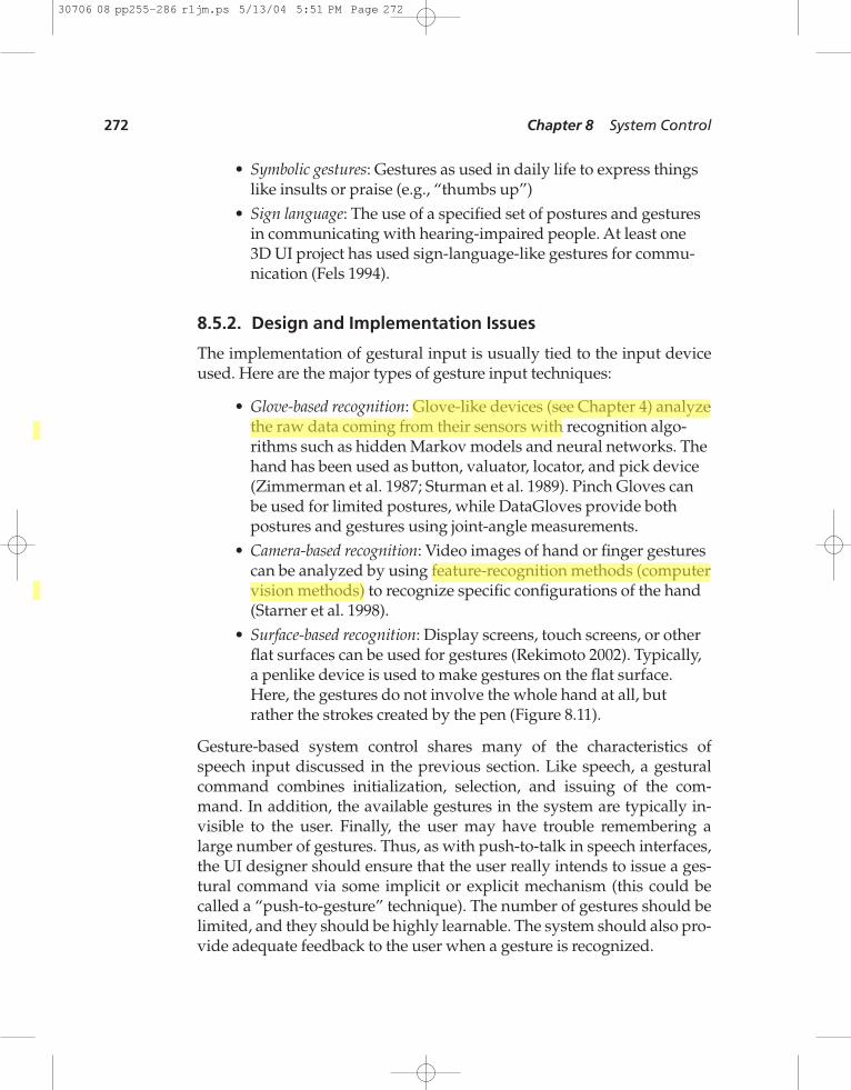
• Surface-based recognition: Display screens, touch screens, or otherflat surfaces can be used for gestures (Rekimoto 2002). Typically,a penlike device is used to make gestures on the flat surface.Here, the gestures do not involve the whole hand at all, butrather the strokes created by the pen (Figure 8.11).
Gesture-based system control shares many of the characteristics ofspeech input discussed in the previous section. Like speech, a gesturalcommand combines initialization, selection, and issuing of the com-mand. In addition, the available gestures in the system are typically in-visible to the user. Finally, the user may have trouble remembering alarge number of gestures. Thus, as with push-to-talk in speech interfaces,the UI designer should ensure that the user really intends to issue a ges-tural command via some implicit or explicit mechanism (this could becalled a “push-to-gesture” technique). The number of gestures should belimited, and they should be highly learnable. The system should also pro-vide adequate feedback to the user when a gesture is recognized.
272 Chapter 8 System Control
30706 08 pp255-286 r1jm.ps 5/13/04 5:51 PM Page 272
8.5.3. Practical Application
Gestural commands have significant appeal for system control in 3D UIsbecause of their important role in our day-to-day lives. However, with afew notable exceptions, such as the surface-based gestural interfaces ofTeddy (Igarashi et al. 1999) and SKETCH (Zeleznik 1996), purely gesturalsystem control interfaces have not been extremely successful. Choosegestural commands if the application domain already has a set of well-defined, natural, easy-to-understand, and easy-to-recognize gestures. Inaddition, gestures may be more useful in combination with another typeof input (see section 8.7). For further reading on gestural interaction,please refer to Bordegoni and Hemmje (1993), Mapes and Moshell (1995),and LaViola (1999a).
8.6. Tools
In many 3D applications, the use of familiar (real-world) devices for 3Dinteraction can lead to increased usability. These devices, often calledtools, provide directness of interaction due to their real-world correspon-dence. While individual tools may be used for selection, manipulation,travel, or other 3D interaction tasks, we consider a set of tools in a single
8.6. Tools 273
Figure 8.11 A C-gesture used to select the color picker in the SKETCH applicationimage courtesy of Brown University Computer Graphics Group)
30706 08 pp255-286 r1jm.ps 5/13/04 5:51 PM Page 273
1234567890123456789012345678901234567890
application to be a system control technique. Like the tool palettes inmany popular 2D drawing applications, tools in 3D UIs provide a simpleand intuitive technique for changing the mode of interaction: simply se-lect an appropriate tool.
We distinguish between two kinds of tools: physical tools and virtualtools. Physical tools are a collection of real physical objects (with corre-sponding virtual representations) that are also sometimes called props. Aphysical tool might be space-multiplexed (the tool only performs onefunction) or time-multiplexed (the tool performs multiple functions overtime). A user accesses a physical tool by simply picking it up and using it.
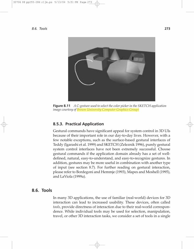
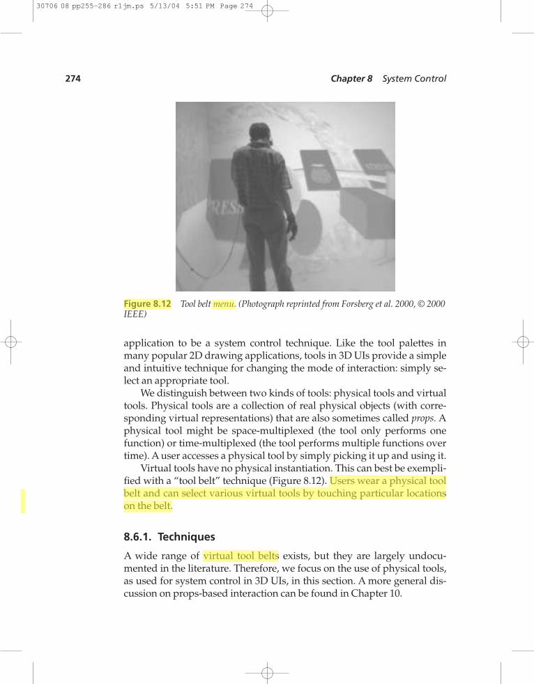
Virtual tools have no physical instantiation. This can best be exempli-fied with a “tool belt” technique (Figure 8.12). Users wear a physical toolbelt and can select various virtual tools by touching particular locationson the belt.
8.6.1. Techniques
A wide range of virtual tool belts exists, but they are largely undocu-mented in the literature. Therefore, we focus on the use of physical tools,as used for system control in 3D UIs, in this section. A more general dis-cussion on props-based interaction can be found in Chapter 10.
274 Chapter 8 System Control
Figure 8.12 Tool belt menu. (Photograph reprinted from Forsberg et al. 2000, © 2000IEEE)
30706 08 pp255-286 r1jm.ps 5/13/04 5:51 PM Page 274
Based on the idea of props, a whole range of tangible user interfaces(TUIs) has appeared. TUIs make use of real-world objects to perform ac-tions in a VE (Ullmer and Ishii 2001; Fitzmaurice et al. 1995). A TUI usesphysical elements that represent a specific kind of action in order to inter-act with an application. For example, the user could use a real eraser todelete virtual objects or a real pencil to draw in the virtual space.
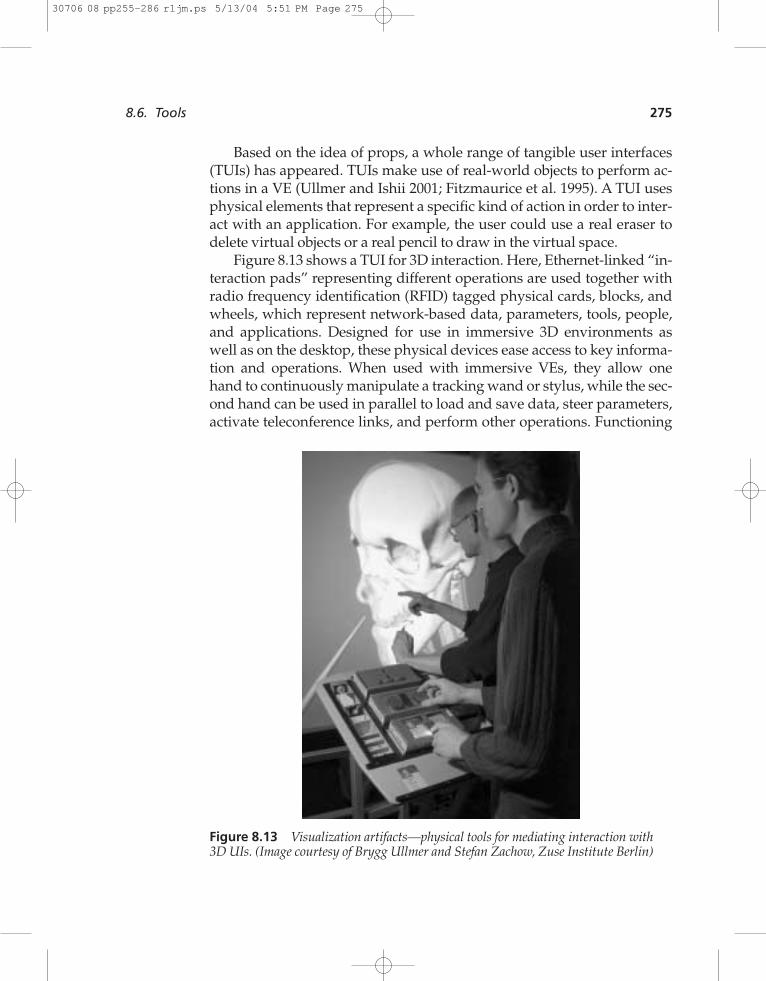
Figure 8.13 shows a TUI for 3D interaction. Here, Ethernet-linked “in-teraction pads” representing different operations are used together withradio frequency identification (RFID) tagged physical cards, blocks, andwheels, which represent network-based data, parameters, tools, people,and applications. Designed for use in immersive 3D environments aswell as on the desktop, these physical devices ease access to key informa-tion and operations. When used with immersive VEs, they allow onehand to continuously manipulate a tracking wand or stylus, while the sec-ond hand can be used in parallel to load and save data, steer parameters,activate teleconference links, and perform other operations. Functioning
8.6. Tools 275
Figure 8.13 Visualization artifacts—physical tools for mediating interaction with3D UIs. (Image courtesy of Brygg Ullmer and Stefan Zachow, Zuse Institute Berlin)
30706 08 pp255-286 r1jm.ps 5/13/04 5:51 PM Page 275
1234567890123456789012345678901234567890
prototypes of this sort are beginning to be used by physicians and astro-physicists.
A TUI takes the approach of combining representation and control.This implies the combination of both physical representations and digitalrepresentations, or the fusion of input and output in one mediator. TUIshave the following key characteristics (from Ullmer and Ishii 2001):
• Physical representations are computationally coupled to under-lying digital information.
• Physical representations embody mechanisms for interactivecontrol.
• Physical representations are perceptually coupled to actively me-diated digital representation.
These ideas can be applied to develop props-based “physical menus.” InHMD-based VEs, for example, a tracked pen can be used to select from avirtual menu placed on a tracked tablet . In a projection-based VE, atransparent physical tablet can be used to achieve the same effect—themenu is displayed on the visual output device (projection screen) but iscorrectly aligned with the tablet so that the user sees the menu appear onthe tablet. An example of this approach is the Personal Interaction Panel(Schmalsteig et al. 1999).
The principal advantage of displaying a menu on a tablet is the directhaptic feedback to the user who interacts with the menu. This results infar fewer selection problems compared to a menu that simply floats in theVE space.
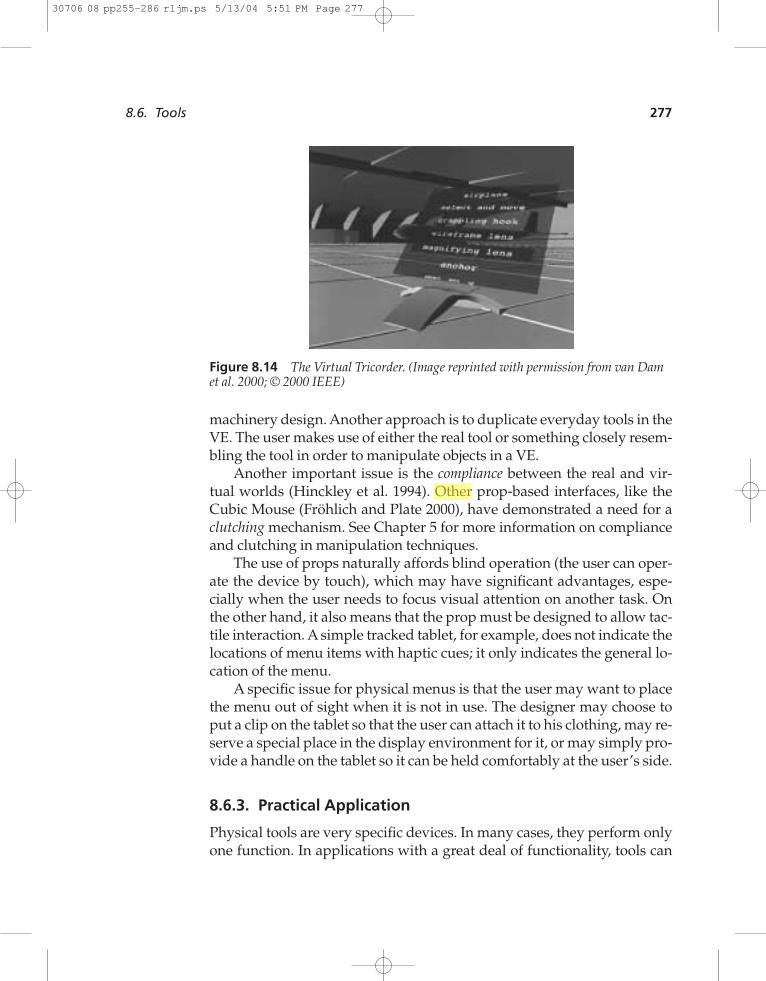
An example of a slightly more sophisticated approach to using propsand tools is the Virtual Tricorder (Wloka and Greenfield 1995). In thistechnique, a real physical 3D mouse is registered to its virtual copy insidethe VE (Figure 8.14). By pressing buttons on the mouse, the user can ac-cess the menu and choose the desired tool from it. The functionality andvirtual 3D appearance of the mouse then changes according to the se-lected tool. The strength of this approach is that it produces a single mul-tipurpose tool for 3D interaction.
8.6.2. Design and Implementation Issues
The form of the tool communicates the function the user can performwith the tool, so carefully consider the form when developing props. Ageneral approach is to imitate a traditional control design, for example, in
276 Chapter 8 System Control
30706 08 pp255-286 r1jm.ps 5/13/04 5:51 PM Page 276
machinery design. Another approach is to duplicate everyday tools in theVE. The user makes use of either the real tool or something closely resem-bling the tool in order to manipulate objects in a VE.
Another important issue is the compliance between the real and vir-tual worlds (Hinckley et al. 1994). Other prop-based interfaces, like theCubic Mouse (Fröhlich and Plate 2000), have demonstrated a need for aclutching mechanism. See Chapter 5 for more information on complianceand clutching in manipulation techniques.
The use of props naturally affords blind operation (the user can oper-ate the device by touch), which may have significant advantages, espe-cially when the user needs to focus visual attention on another task. Onthe other hand, it also means that the prop must be designed to allow tac-tile interaction. A simple tracked tablet, for example, does not indicate thelocations of menu items with haptic cues; it only indicates the general lo-cation of the menu.
A specific issue for physical menus is that the user may want to placethe menu out of sight when it is not in use. The designer may choose toput a clip on the tablet so that the user can attach it to his clothing, may re-serve a special place in the display environment for it, or may simply pro-vide a handle on the tablet so it can be held comfortably at the user’s side.
8.6.3. Practical Application
Physical tools are very specific devices. In many cases, they perform onlyone function. In applications with a great deal of functionality, tools can
8.6. Tools 277
Figure 8.14 The Virtual Tricorder. (Image reprinted with permission from van Damet al. 2000; © 2000 IEEE)
30706 08 pp255-286 r1jm.ps 5/13/04 5:51 PM Page 277
1234567890123456789012345678901234567890
still be useful, but they may not apply to all the user tasks. There is atradeoff between the specificity of the tool (a good affordance for itsfunction) and the amount of tool switching the user will have to do.Performing a simple user study will quickly reveal any problems withdevice switching.
Public installations of VEs (e.g., in museums) can greatly benefit fromthe use of tools. Users of public installations by definition must be ableto use the interface immediately. Tools tend to allow exactly this. A well-designed tool has a strong affordance, and users may draw from personalexperience with a similar device in real life. Many theme park installa-tions make use of props to allow the user to begin playing right away. Forexample, the Pirates of the Caribbean ride at DisneyQuest uses a physicalsteering wheel and cannons. This application has almost no learningcurve—including the vocal introduction, users can start interacting withthe environment in less than a minute.
8.7. Multimodal System Control Techniques
The classification of system control techniques presented in Figure 8.1does not contain the last group of system control techniques: multimodaltechniques, which combine multiple input streams. In certain situations,the use of multimodal system control techniques can significantly in-crease the effectiveness of system control tasks.
Multimodal interaction is the use of multiple input channels (e.g.,speech and gesture) to control a system. Following are some of the ad-vantages for using multimodal system control in VEs:
• Decoupling: Using an input channel that differs from the maininput channel used for interaction with the environment, andthus decreasing user cognitive load. If users do not have toswitch between manipulation and system control actions, theycan keep their attention focused on their main activity.
• Error reduction and correction: The use of multiple input channelscan be very effective when the input is ambiguous or noisy, espe-cially with recognition-based input like speech or gestures. Thecombination of input from several channels can significantlyincrease recognition rate (Oviatt 1999; Oviatt and Cohen 2000).
• Flexibility and complementary behavior: Control is more flexiblewhen users can use multiple input channels to perform the same
278 Chapter 8 System Control
30706 08 pp255-286 r1jm.ps 5/13/04 5:51 PM Page 278
task. In addition, different modalities can be used in a comple-mentary way based on the perceptual structure of the task(Grasso et al. 1998; Jacob and Siebert 1992).
• Control of mental resources: Multimodal interaction can be used toreduce cognitive load (Rosenfeld et al. 2001); on the other hand, itmay also lead to less effective interaction, since multiple mentalresources need to be accessed simultaneously. For example, asShneiderman (2000) observes, the part of the human brain usedfor speaking and listening is the same one as used for problemsolving—speaking consumes precious cognitive resources.
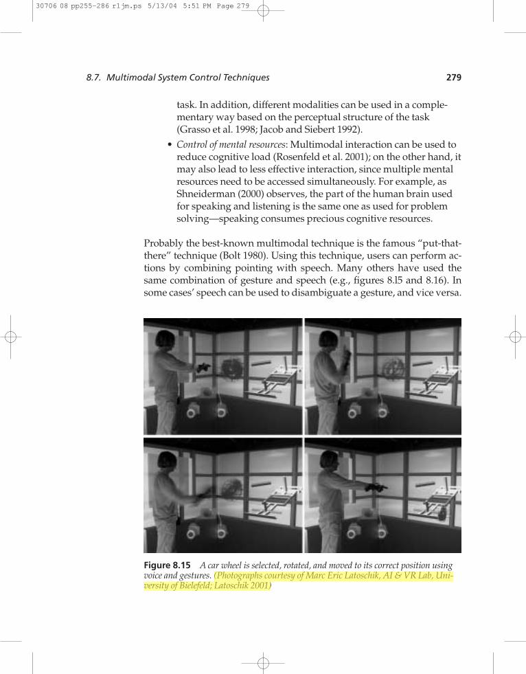
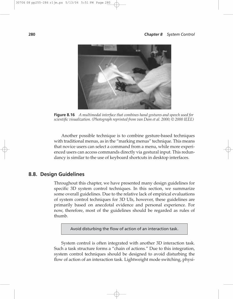
Probably the best-known multimodal technique is the famous “put-that-there” technique (Bolt 1980). Using this technique, users can perform ac-tions by combining pointing with speech. Many others have used thesame combination of gesture and speech (e.g., figures 8.l5 and 8.16). Insome cases’ speech can be used to disambiguate a gesture, and vice versa.
8.7. Multimodal System Control Techniques 279
Figure 8.15 A car wheel is selected, rotated, and moved to its correct position usingvoice and gestures. (Photographs courtesy of Marc Eric Latoschik, AI & VR Lab, Uni-versity of Bielefeld; Latoschik 2001)
30706 08 pp255-286 r1jm.ps 5/13/04 5:51 PM Page 279
1234567890123456789012345678901234567890
Another possible technique is to combine gesture-based techniqueswith traditional menus, as in the “marking menus” technique. This meansthat novice users can select a command from a menu, while more experi-enced users can access commands directly via gestural input. This redun-dancy is similar to the use of keyboard shortcuts in desktop interfaces.
8.8. Design Guidelines
Throughout this chapter, we have presented many design guidelines forspecific 3D system control techniques. In this section, we summarizesome overall guidelines. Due to the relative lack of empirical evaluationsof system control techniques for 3D UIs, however, these guidelines areprimarily based on anecdotal evidence and personal experience. Fornow, therefore, most of the guidelines should be regarded as rules ofthumb.
System control is often integrated with another 3D interaction task.Such a task structure forms a “chain of actions.” Due to this integration,system control techniques should be designed to avoid disturbing theflow of action of an interaction task. Lightweight mode switching, physi-
Avoid disturbing the flow of action of an interaction task.
280 Chapter 8 System Control
Figure 8.16 A multimodal interface that combines hand gestures and speech used forscientific visualization. (Photograph reprinted from van Dam et al. 2000; © 2000 IEEE)
30706 08 pp255-286 r1jm.ps 5/13/04 5:51 PM Page 280
cal tools, and multimodal techniques can all be used to maintain the flowof action.
One of the major interruptions to a flow of action is a change of atten-tional focus. This may occur when users have to cognitively and/orphysically switch between the actual working area and a system controltechnique, or even when they must look away to switch devices.
Always provide clear feedback to the user so that she knows whichinteraction mode is currently active.
Placing your system control technique in the “right position” canmake a big difference in its usability. Users often get distracted whensearching for a way to change the mode of interaction or issue a com-mand. If the controls are not visible at all, placed far away from the actualfocal area, or not oriented toward the user, the result will be wasted time.On the other hand, system controls attached to the user’s hand, body, or adevice are always available.
There are several good techniques for structuring the functionalityof an application, including hierarchical menu structures and context-sensitive system control. In cases where the number of functions is solarge that these techniques are not effective, it can make sense to placesome of the system control functionality on another device, such as aPDA, where resolution and selection accuracy are less of an issue.
Consider using multimodal input.
Structure the functions in an application.
Use an appropriate spatial reference frame.
Avoid mode errors.
Prevent unnecessary changes of the focus of attention.
8.8. Design Guidelines 281
30706 08 pp255-286 r1jm.ps 5/13/04 5:51 PM Page 281
1234567890123456789012345678901234567890
Using multimodal input can provide more fluid and efficient systemcontrol, but can also have its drawbacks.
8.9. Case Study: Mixing System Control Methods
System control in 3D UIs is a complex topic, and the techniques for it arewide ranging. Thus, it is useful to examine a case study of system controltechniques in a complex 3D application in order to illuminate some of theimportant issues involved in system control design for 3D UIs.
8.9.1. The ProViT Application
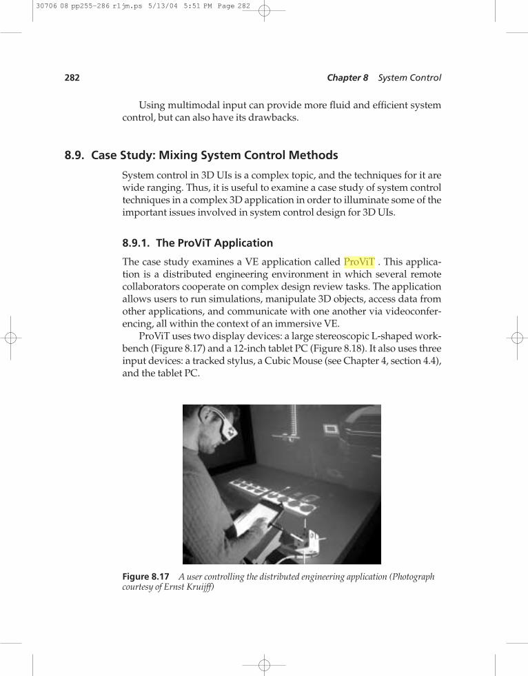
The case study examines a VE application called ProViT . This applica-tion is a distributed engineering environment in which several remotecollaborators cooperate on complex design review tasks. The applicationallows users to run simulations, manipulate 3D objects, access data fromother applications, and communicate with one another via videoconfer-encing, all within the context of an immersive VE.
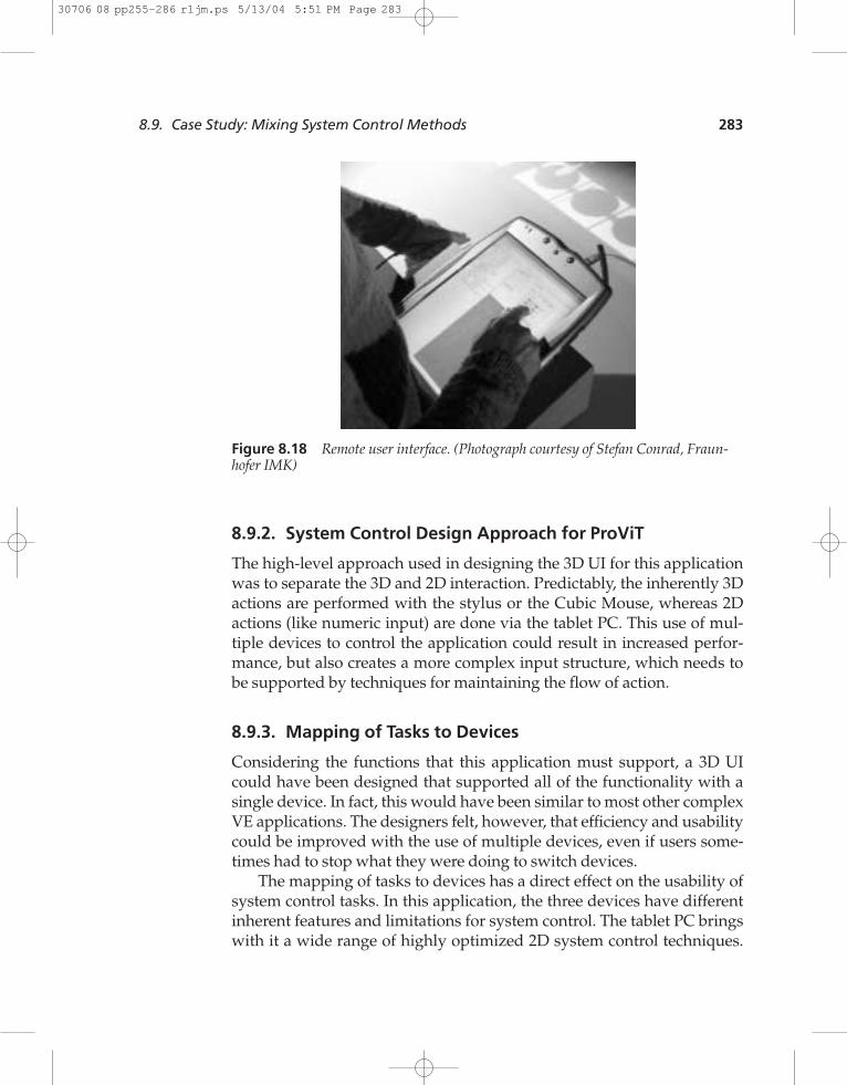
ProViT uses two display devices: a large stereoscopic L-shaped work-bench (Figure 8.17) and a 12-inch tablet PC (Figure 8.18). It also uses threeinput devices: a tracked stylus, a Cubic Mouse (see Chapter 4, section 4.4),and the tablet PC.
282 Chapter 8 System Control
Figure 8.17 A user controlling the distributed engineering application (Photographcourtesy of Ernst Kruijff)
30706 08 pp255-286 r1jm.ps 5/13/04 5:51 PM Page 282
8.9.2. System Control Design Approach for ProViT
The high-level approach used in designing the 3D UI for this applicationwas to separate the 3D and 2D interaction. Predictably, the inherently 3Dactions are performed with the stylus or the Cubic Mouse, whereas 2Dactions (like numeric input) are done via the tablet PC. This use of mul-tiple devices to control the application could result in increased perfor-mance, but also creates a more complex input structure, which needs tobe supported by techniques for maintaining the flow of action.
8.9.3. Mapping of Tasks to Devices
Considering the functions that this application must support, a 3D UIcould have been designed that supported all of the functionality with asingle device. In fact, this would have been similar to most other complexVE applications. The designers felt, however, that efficiency and usabilitycould be improved with the use of multiple devices, even if users some-times had to stop what they were doing to switch devices.
The mapping of tasks to devices has a direct effect on the usability ofsystem control tasks. In this application, the three devices have differentinherent features and limitations for system control. The tablet PC bringswith it a wide range of highly optimized 2D system control techniques.
8.9. Case Study: Mixing System Control Methods 283
Figure 8.18 Remote user interface. (Photograph courtesy of Stefan Conrad, Fraun-hofer IMK)
30706 08 pp255-286 r1jm.ps 5/13/04 5:51 PM Page 283
1234567890123456789012345678901234567890
The Cubic Mouse has a large number of physical buttons, but these but-tons have few natural mappings to functions. The stylus must make useof virtual system control techniques, since it has only a single button. Inthis application, the designers decided to use a hand-referenced 1-DOFmenu (section 8.3.1) with the stylus.
Two of the devices can be used together: the stylus can be used to in-teract directly with the tablet PC. This eliminates the need to put downthe stylus or pick up another device to access the 2D GUI.
Some functions, like navigation, were explicitly mapped to multipledevices to avoid device switching. For example, the user often needs tochange the viewpoint in between manipulation actions. If the navigationfunction were mapped only to one device, this would automatically re-sult in frequent device switching. In the current design, the user can useeither the Cubic Mouse or the stylus for 3D navigation.
8.9.4. Placement of System Control
The second main issue in this application is the placement of its visible el-ements. The main working area and main focus of attention is the centerof the workbench. In general, the designers wanted the user to be able tomaintain focus on this area. In addition, this area should not be highly oc-cluded by system control elements or widgets. These two goals are some-what in conflict.
The hand-referenced 1-DOF menu addresses the first goal. It appearsattached to the stylus, which is usually located in or near the workingarea. The user can always find the menu—no visual search is required—but this menu might occlude the VE content.
The GUI elements on the tablet PC meet the second goal. It placesmenus and complex information in one place (a display attached to thefront of the workbench), and this information does not occlude the VEcontent. However, to use the tablet PC, the user must shift focus fromone area to another, requiring significant head movements as the userperforms an action in the GUI and then verifies that action in the 3D envi-ronment.
8.9.5. System Control Feedback
Finally, it is of utmost importance that feedback to the user is robust andunderstandable. Due to the multiple input devices used in this applica-tion, the designers provide feedback that does not depend on the input
284 Chapter 8 System Control
30706 08 pp255-286 r1jm.ps 5/13/04 5:51 PM Page 284
device in use. Instead, the feedback is attached to one of the displays andis consistent no matter what device or function the user happens to beusing.
One very simple solution is a mode cue that is displayed in a smalltext bar in a corner of the workbench. The text bar shows the current in-teraction mode and is placed close to the user’s working area. The secondapproach is to use the GUI on the tablet PC as a feedback method. Sincethe GUI is constantly synchronized with the VE application, the user canalways look at the GUI in order to obtain a direct and detailed overviewof the state of the system.
8.10. Conclusions
System control for 3D UIs is only in its infancy as a research topic. Al-though we have discussed a wide range of techniques, the design spacefor such techniques is virtually limitless. We expect to see many new andinteresting 3D system control techniques, not only within the categoriesdescribed here, but also in new categories that have not yet been in-vented. There is also a lack of good empirical evidence for the usability ofvarious system control techniques at the present time—usability evalua-tions are desperately needed in order to validate the current designguidelines and develop new ones. Nevertheless, we hope this chapterhas served to demonstrate the importance and complexity of system con-trol interfaces and has provided some ideas for the design of novel 3DUIs for system control.
Recommended ReadingA general introduction to system control issues from a human factors back-ground can be found in the following:
Bullinger, H., P. Kern, and M. Braun (1997). Controls. Handbook of Human Fac-tors and Ergonomics. G. Salvendy (Ed.), John Wiley & Sons, 697–728.
Recommended Reading 285
30706 08 pp255-286 r1jm.ps 5/13/04 5:51 PM Page 285
30706 08 pp255-286 r1jm.ps 5/13/04 5:51 PM Page 286