chapter 2 introduction
TRANSCRIPT
Chapter 2
Introduction:
One of the main advantages of a.c transgression and distribution
is the ease with which an a Hernating voltage can be increase or
reduced. For instance the general practice is to generate at
voltages about 22 kv, then step up by means of transformers to
higher voltages for the transmission lines. At suitable point,
other transformers are introduced to step the voltage down to
values suitable for motors, lamps, heaters etc. a medium size
transformer has a full efficiency of about 97-98 percent cent, so
that the transformer loss at each point of transformation is
small (although 20% of 100 mw is not insignificant) since there
are no moving parts in a transformer, the amount of supprvision
is practically negligible.
Although transformers are generally associated with power system
applications, they also occur in many low – power applications
including electronic circuit. However it is best to consider the
common power system transformer.
2.1 WORLING PRINCIPLES OF A TRANSFORMER
A transformer is a static (or stationary) piece apparatus by
means of which electric power in one circuit is transformed to
electric power of the same frequency in another circuit. It can
raise or lower the voltage in a circuit but with a decreasing or
increase in current.
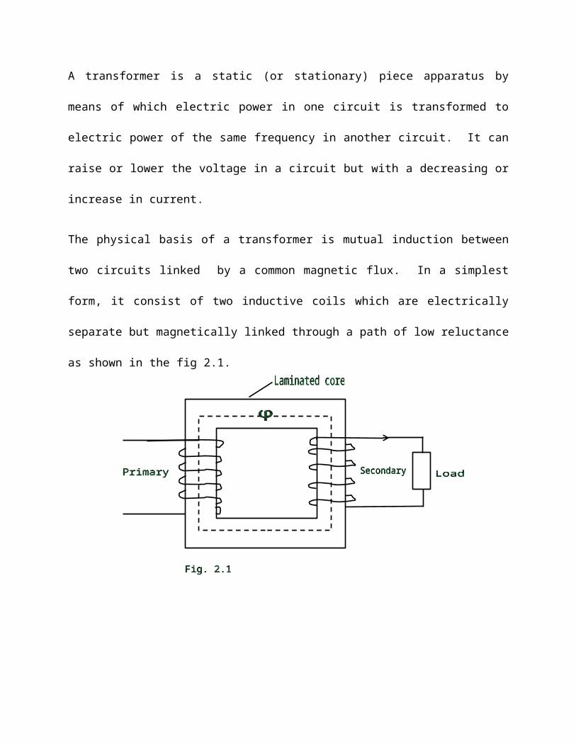
The physical basis of a transformer is mutual induction between
two circuits linked by a common magnetic flux. In a simplest
form, it consist of two inductive coils which are electrically
separate but magnetically linked through a path of low reluctance
as shown in the fig 2.1.
The two coils possess high mutual inductance. If one coil is
connected to the source of alternating voltage, an alternating
flux is set up in the laminated core, most of which is linked
with the other coil in which it produces mutually induce emf.
(according to faraday’s Law of electric magnetic induction ie e =
mdi/dt). If the second coil circuit energy is transferred
entirely magnetically from the first coil to the second coil.
The first coil, in which electric energy is fed from the a.c
supply mains, is called primary winding and the other, from which
energy is fed from which energy is drawn out, is called secondary
winding. In brief, a transformer is a device that
1. Transfers electric power from one circuit to another
2. Does so without change of frequency
3. Accomplishes this by electromagnetic induction and
4. Where the two electric circuit are linked by mutual induction.
2.2 TRANSFORMER CONSTRUCTION
The simple element of a transformer consist of two coils having
mutual inductance and a laminated core. The two coild are
insulated from each other and from the steel core. Other
necessary parts are: some suitable container for the assembled
core and winding: a suitable medium for insulating the core and
its windings and bringing out the terminals of the winding from.
Its container; suitable busting (either of porcelain, oil filled
or capacitor – type) for insulating and bringing out the terminal
of the winding from the tank. In all types of transformers, the
core is constructed of transformer sheet steel laminations
assembled to provide a continues magnetic path with minimum of
air-gap included. The steel used is of high silicon content heat
treated to produce high permeability and low hysteresis loss at
the usually operating flux density. The lamination being
insulated from each other by light coat of core plate varnish or
by an oxide layer on the surface. The thinness of laminations
varies from 0.35mm for a frequency of 50HZ to 0.5mm for a
frequency of 25HZ. The core laminations (in the form of strips)
are joined as shown in fig 2.2. It is seen that the joined in
the alternate layers are staggered in order to avoid the presence
of narrow gaps right through the section staggered joints are
said to be imbricate.
Constructional, the transformer are of
two general types,
distinguished from each other merely by
the manner in which the primary and
secondary coils are placed around the
laminated steel core. The two types are
known as (i) core-type and (ii) shell
type.
Another recent development is spiral core or wound – core type,
the trade name being spira kore transformer.
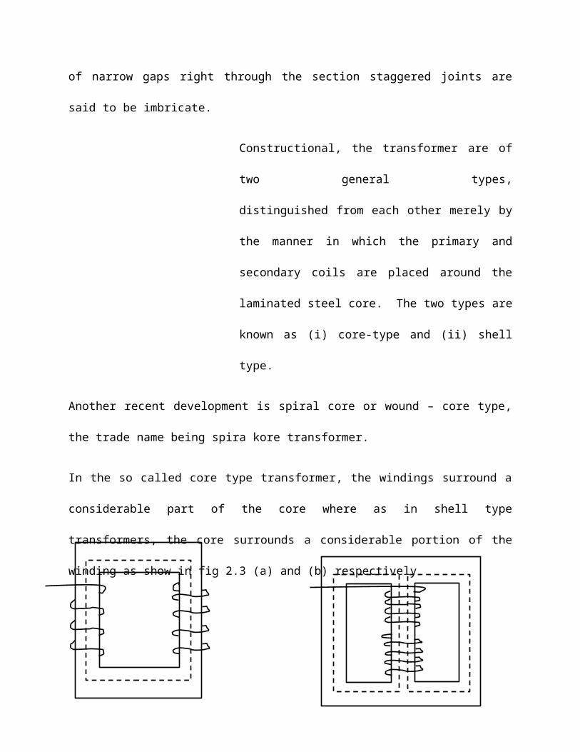
In the so called core type transformer, the windings surround a
considerable part of the core where as in shell type
transformers, the core surrounds a considerable portion of the
winding as show in fig 2.3 (a) and (b) respectively
In a simplified diagram for the core-type transformer, in fig 2.3
(a) the primary and secondary windings are shown located on the
opposite legs (or limbs) of the core, but in actual construction,
these are always inter leaved in order to reduce leakage flux.
As show in fig 2.3 (a) half the primary and half the secondary
windings have been placed side by side or concentrically on each
limb, not primary on one limb (or leg) and the secondary on the
other.
EMF EQUATION OF A TRANSFORMER
Let N1 = No. of turns in primary
N2 = No. of turns in secondary
Qm = Maximum flux in the core in webers = Bm
x A.
F = Frequency of a.c input in hertz (Hz)
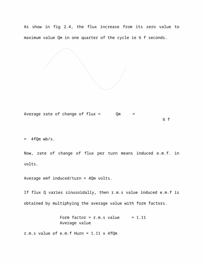
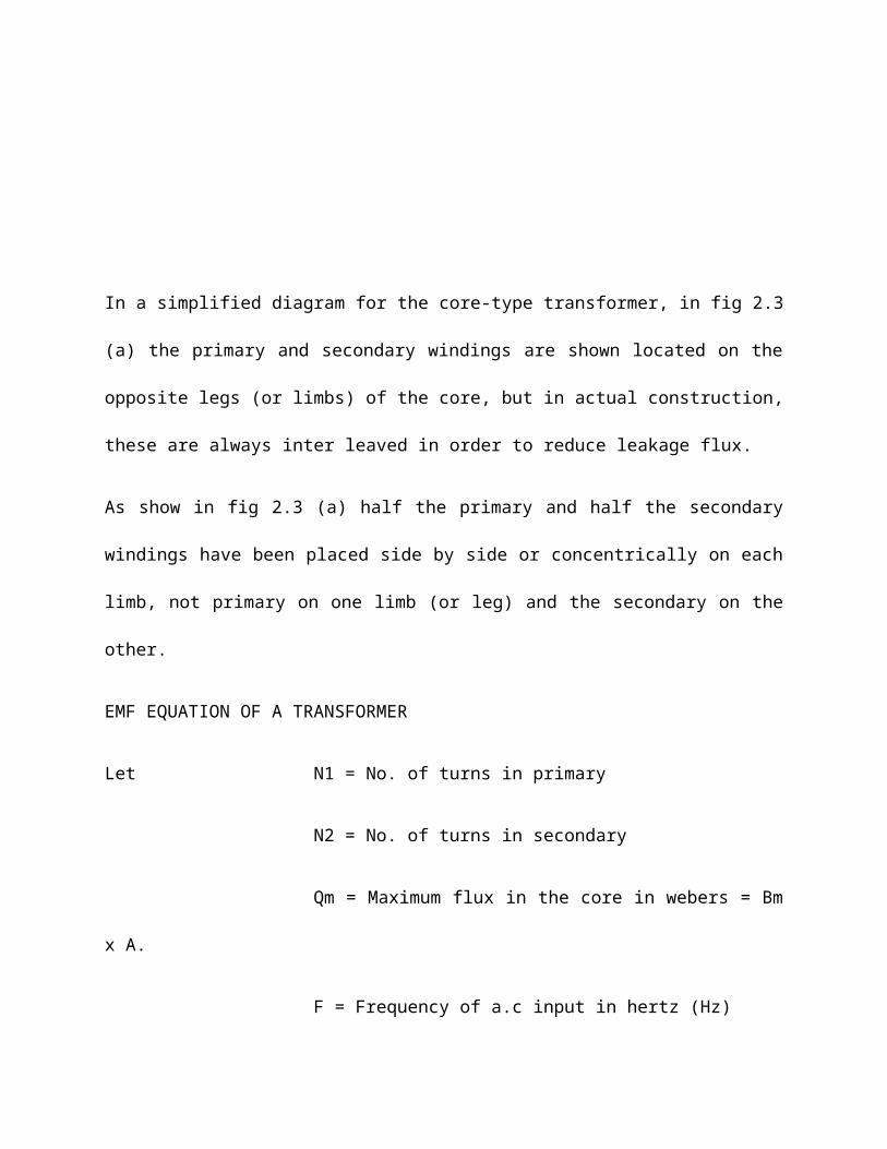
As show in fig 2.4, the flux increase from its zero value to
maximum value Qm in one quarter of the cycle ie ¼ f seconds.
Average rate of change of flux = Qm = ¼ f
= 4fQm wb/s.
Now, rate of change of flux per turn means induced e.m.f. in
volts.
Average emf induced/turn = 4Qm volts.
If flux Q varies sinusoidally, then r.m.s value induced e.m.f is
obtained by multiphying the average value with form factors.
Form factor = r.m.s value = 1.11Average value
r.m.s value of e.m.f Hurn = 1.11 x 4fQm
4.44fQm volts.
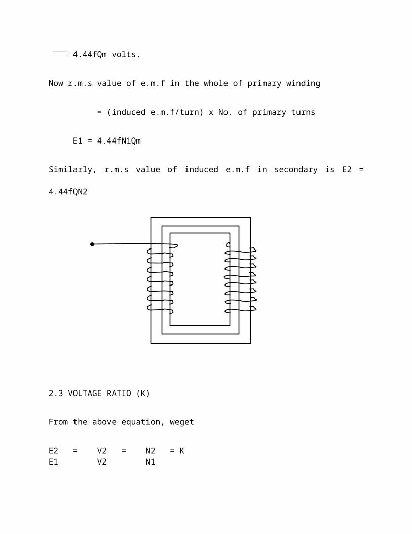
Now r.m.s value of e.m.f in the whole of primary winding
= (induced e.m.f/turn) x No. of primary turns
E1 = 4.44fN1Qm
Similarly, r.m.s value of induced e.m.f in secondary is E2 =
4.44fQN2
2.3 VOLTAGE RATIO (K)
From the above equation, weget
E2 = V2 = N2 = KE1 V2 N1
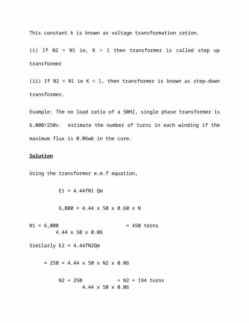
This constant k is known as voltage transformation ration.
(i) If N2 > N1 ie, K > 1 then transformer is called step up
transformer
(ii) If N2 < N1 ie K < 1, then transformer is known as step-down
transformer.
Example: The no load ratio of a 50HZ, single phase transformer is
6,000/250v. estimate the number of turns in each winding if the
maximum flux is 0.06wb in the core.
Solution
Using the transformer e.m.f equation,
E1 = 4.44fN1 Qm
6,000 = 4.44 x 50 x 0.60 x N
N1 = 6,000 = 450 terns 4.44 x 50 x 0.06
Similarly E2 = 4.44fN2Qm
= 250 = 4.44 x 50 x N2 x 0.06
N2 = 250 = N2 = 194 turns 4.44 x 50 x 0.06
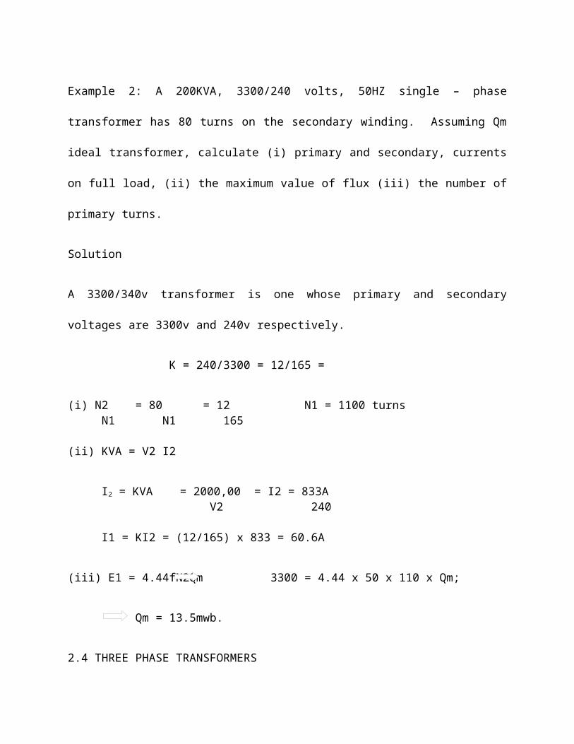
Example 2: A 200KVA, 3300/240 volts, 50HZ single – phase
transformer has 80 turns on the secondary winding. Assuming Qm
ideal transformer, calculate (i) primary and secondary, currents
on full load, (ii) the maximum value of flux (iii) the number of
primary turns.
Solution
A 3300/340v transformer is one whose primary and secondary
voltages are 3300v and 240v respectively.
K = 240/3300 = 12/165 =
(i) N2 = 80 = 12 N1 = 1100 turns N1 N1 165
(ii) KVA = V2 I2
I2 = KVA = 2000,00 = I2 = 833A V2 240
I1 = KI2 = (12/165) x 833 = 60.6A
(iii) E1 = 4.44fN2Qm 3300 = 4.44 x 50 x 110 x Qm;
Qm = 13.5mwb.
2.4 THREE PHASE TRANSFORMERS
Large Scale generation of electric power is usually 3-phase at
generated voltages of 132kv or some what higher. Transmission is
generally accomplished at higher voltage of 66, 110, 132, 220 and
a 275kv for which purpose 3-phase transformers are necessary to
step up the generated voltage to that of the transmission line.
Next at no load centers, transmission voltages are reduced to
distribution voltages or 6600, 4600 and 2300 volts. Further at
most of the consumers, the distribution voltages of 440, 220 or
110 volts.
Years ago, it was a common practice to use suitable
interconnected three single phase transformers instead of a
single 3-phase transformer. But these days, the single – phase
are gaining popularity partly because of improvement in design
and manufacture but principally because of butter aquitance of
operating men with three-phase type.
As compare to bank of 3 single phase transformers, the main
advantages of a single 3 – phase transformer are that it occupies
less floor space for equal ratings, weighs less, cost about 15%
less and further, that only one unit is to be handled and
connected. Like single phase transformer, the three phase
transformers are also of the core type or shell type.
PRINCIPLE OF OPERATIO
2.5 EQUIVALENT CIRCUIT
The behavior of a transformer may be conveniently considered by
assuming it to be equivalent to an ideal transformer, in a
transformer having no losses and no magnetic leakage and a
ferromagnetic core of infinite permeability requiring no
magnetizing current, and then allowing for the imperfections of
the actual transformer by means of additional circuits or
impedances inserted between the secondary and load. Thus in fig
2.5 P and S represent the primary and secondary windings of the
ideal transformer, R1 and R2 are resistance equal to the
resistance of the primary and secondary windings of the actual
transformer. Similarly, inductive reactance X1 and X2 represents
the reactance’s of the winding due to leakage flux in the actual
transformer.
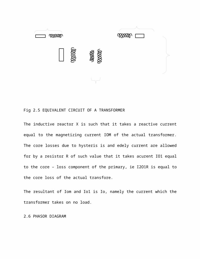
Fig 2.5 EQUIVALENT CIRCUIT OF A TRANSFORMER
The inductive reactor X is such that it takes a reactive current
equal to the magnetizing current IOM of the actual transformer.
The core losses due to hysteris is and edely current are allowed
for by a resistor R of such value that it takes acurent IO1 equal
to the core – loss component of the primary, ie I2O1R is equal to
the core loss of the actual transfore.
The resultant of Iom and Io1 is Io, namely the current which the
transformer takes on no load.
2.6 PHASOR DIAGRAM
For convenience let us assume an equal number of turns on the
primary and secondary windings, so that E1 = E2. As shown in the
Fig 2.7 E1 leads the flux by 900, and represents the voltage
across the primary of the ideal transformer.
Let us also assume the general case of a load having a lagging
power factor; consequently, in the fig 2.7 in has been drawn
lagging E2 by about 450.
Then
I2R2 = voltage drop due to secondary resistance
I2 X2 = voltage drop due to secondary
Leakage reactance
and I2Z2 = voltage drop due to secondary impedance
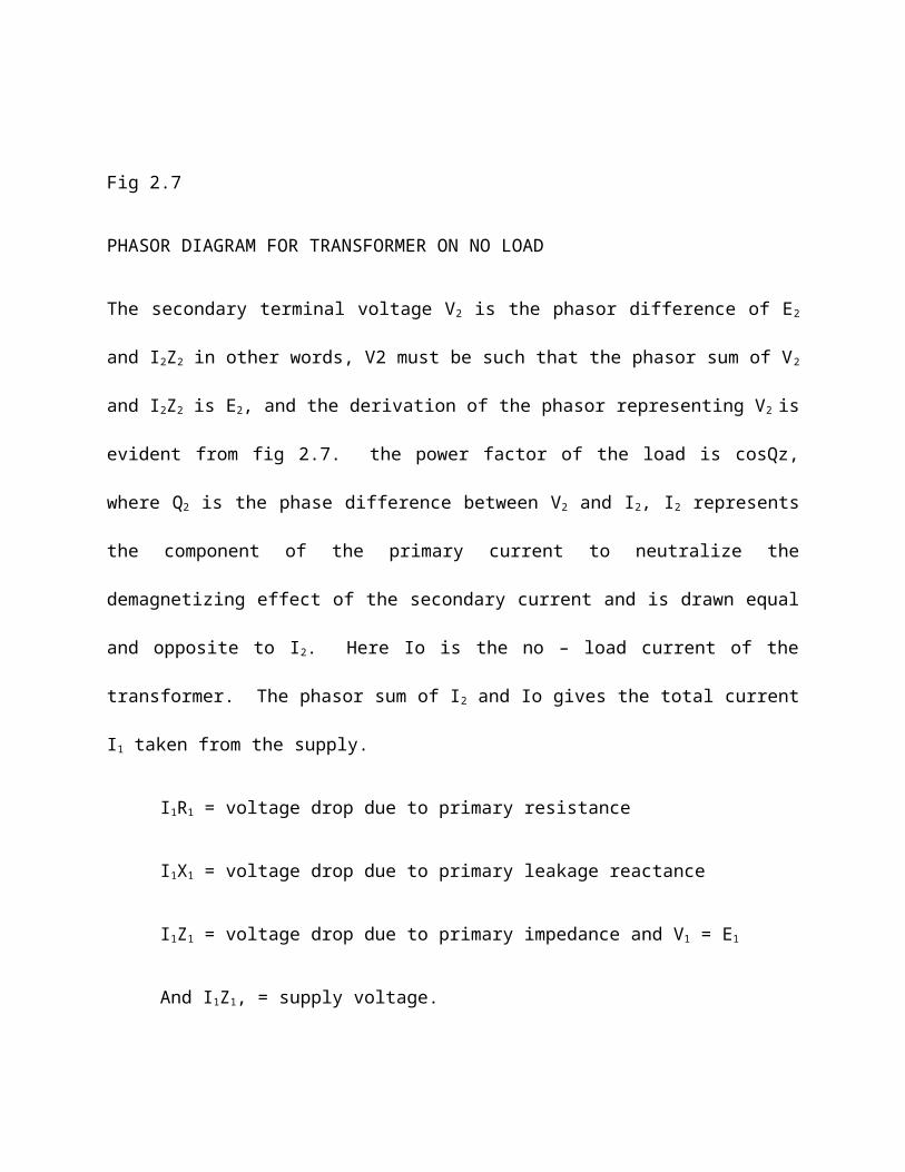
Fig 2.7
PHASOR DIAGRAM FOR TRANSFORMER ON NO LOAD
The secondary terminal voltage V2 is the phasor difference of E2
and I2Z2 in other words, V2 must be such that the phasor sum of V2
and I2Z2 is E2, and the derivation of the phasor representing V2 is
evident from fig 2.7. the power factor of the load is cosQz,
where Q2 is the phase difference between V2 and I2, I2 represents
the component of the primary current to neutralize the
demagnetizing effect of the secondary current and is drawn equal
and opposite to I2. Here Io is the no – load current of the
transformer. The phasor sum of I2 and Io gives the total current
I1 taken from the supply.
I1R1 = voltage drop due to primary resistance
I1X1 = voltage drop due to primary leakage reactance
I1Z1 = voltage drop due to primary impedance and V1 = E1
And I1Z1, = supply voltage.
If Q1 is the phase difference between V1 and I1, then cos Q1 is
the power factor on the primary side of the transformer. Fig 2.7
is the phasor representing the no load current and the primary
and secondary voltage drop are, for clearness, shown for larger
relative to the other phasors than they are in an actual
transformer.
2.7 VOLTAGE REGULATION
When a transformer is loaded, its secondary terminal voltage
falls (for lagging p.f) provided the applied primary voltage V1
is held constant. This variation in secondary terminal voltage
from no-load to full load (f.l) is called the (voltage)
regulation of the transformer and is usually expressed as a
percentage of the secondary no-load voltage.
Percentage regulation = Sec. volt. (Nol) – Sec. colt (f.l) x 100Sec. Volt (N.L)
V2 = Secondary terminal voltage on no load
V2 = Secondary terminal voltage on load
Then % regulation = oV2 – V2 x 100oV2
Since opV2 – V2 = I2 (Ro2 cosQ + Xoz sinQ)
% voltage regulation = I2 (Roz cosQ = Xo2 sinQ)oV2
example: A 100KVA transformer has 400 terns on the primary and 80
turns on the secondary. The primary and secondary resistance are
0.3π and 1.01π respectively, and the corresponding leakage
reactance are 1.1π and 0.035π respectively. The supply coltage
is 2200v. calculate:
(a) The equivalent impedance reffered to the primary
circuit;
(b) The voltage regulation and the secondary terminal
voltage for full load having a power factor of
(i) 0.8 lagging and (ii) 0.8 leading.
Solution
(a) equivalent resistance referred to the primary
Re = R2 +
Re = 0.3 + 0.01(40080 )2 = 0.55π
equivalent leakage reactance referred to primary is
Xe = X
Xe = 1.1 + 0.035 (40080 )2 = 1.975π
equivalent impedance referred to the primary
is Ze = √ℜ2+Xe2
= √¿¿ = 2.05π
(b) (i) since cos Q2 = 0.8
sinQ = 0.6
full load primary current = 100x10002200 = 45.45 A
voltage regulation for the power factor of 0.8 lagging
= I1 (Re cosQ2 + Xe cos Q2)
V1
= 45.45(0.5x0.8+1.975x0.6)2200 = 100
ANS = 3.36%
Secondary terminal voltage on no load is
V1 x N2N1
= 2200 x 80400 = 440v
Therefore decrease of secondary terminal voltage between no –
load and full load is
Secondary terminal voltage x per unit regulation
= 440 x 0.0336 = 14.8v
Therefore secondary terminal voltage on full load
440 – 14.8 = 425.2v
(ii) voltage regulation for power factor 0.8 leading
45.45 (0.55 x 0.8 – 1.975 x 0.6) 2200
= -0.0154 per unit
= -1.54%
Increase of secondary terminal voltage between no load and full
load is
440 x 0.0154 = 6.78v
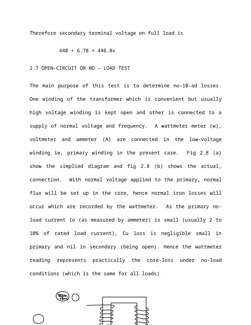
Therefore secondary terminal voltage on full load is
440 + 6.78 = 446.8v
2.7 OPEN-CIRCUIT OR NO – LOAD TEST
The main purpose of this test is to determine no-10-ad losses.
One winding of the transformer which is convenient but usually
high voltage winding is kept open and other is connected to a
supply of normal voltage and frequency. A wattmeter meter (w),
voltmeter and ammeter (A) are connected in the low-voltage
winding ie, primary winding in the present case. Fig 2.8 (a)
show the simplied diagram and fig 2.8 (b) shows the actual,
connection. With normal voltage applied to the primary, normal
flux will be set up in the core, hence normal iron losses will
occur which are recorded by the wattmeter. As the primary no-
load current Io (as measured by ammeter) is small (usually 2 to
10% of rated load current), Cu loss is negligible small in
primary and nil in secondary (being open). Hence the wattmeter
reading represents practically the core-loss under no-load
conditions (which is the same for all loads)
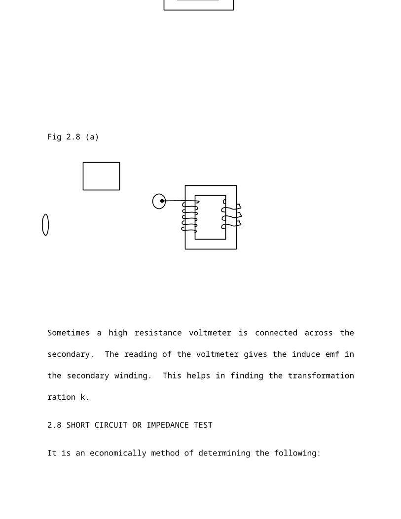
Fig 2.8 (a)
Sometimes a high resistance voltmeter is connected across the
secondary. The reading of the voltmeter gives the induce emf in
the secondary winding. This helps in finding the transformation
ration k.
2.8 SHORT CIRCUIT OR IMPEDANCE TEST
It is an economically method of determining the following:
1. Equivalent impedance (Zo1 or Zo2) leakage reactance (Xo1 or
Xo2) and resistance (Ro1 or Ro2) of the transformer as referred
to the winding in which the measuring instruments are placed.
2. Cu loss at full load (and at any desired load). This loss is
used in calculating the efficiency of the transformer.
3. Knowing Zo1 or Zo2 the total voltage drop in the transformer
as referred to the primary or secondary can be calculated and
hence regulation of the transformer determined.
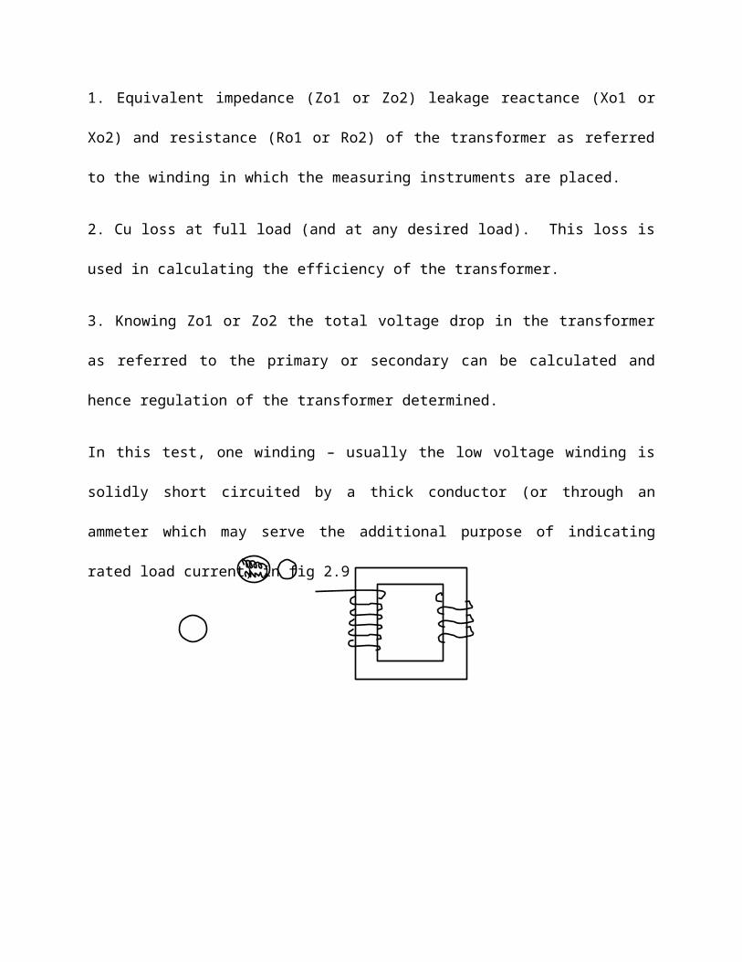
In this test, one winding – usually the low voltage winding is
solidly short circuited by a thick conductor (or through an
ammeter which may serve the additional purpose of indicating
rated load current) in fig 2.9
The low voltage (usually 5 to 10% of normal primary voltage) at
correct frequency (through for cu losses it is not essential) is
applied to the primary and is cautiously in creased till full-
load current are flowing both in primary and secondary (as
indicated by the respective ammeters).
Since in this test, the applied voltage is a small percentage of
the normal voltage, the mutual flux produced in the core is also
a small percentage of normal value (because flux is proportional
to the voltage. Hence, the core losses are very small with the
result that wattmeter reading represents the full-load cu loss or
I2R loss for the whole transformer ie, both primary cu loss and
secondary cu loss. If Vsc is the voltage required to calculate
rated load current on short circuit
Zo1 = VscI1
W = I12 Ro1 Ro1 = W/R1
2
Xo1 = √Zo1−Ro12
Example:
The ratio turns of a single-phase transformer is 8, the
resistance of the primary and secondary windings are 0.85π and
0.012π respectively and the leakage reactance of these winding
are 4.8π and 0.07π respectively. Determine the voltage to be
applied to the primary to obtain a current of 150A in the
secondary when the secondary terminals are short circuited.
Ignore the magnetizing current.
Solution
Turn ration = N1/N2 = : K = ⅛
Now Ro1 = R1 + R2K2 = 0.85 + 0.012 x 64
= 1.618π
X01 = X1 + X2K2 = 4.8 + 64 x 0.07
= 9.28π
Z01 = √(1.618)2+(9.28)2 = 9.419π
I1 = KI2 = 1508 =
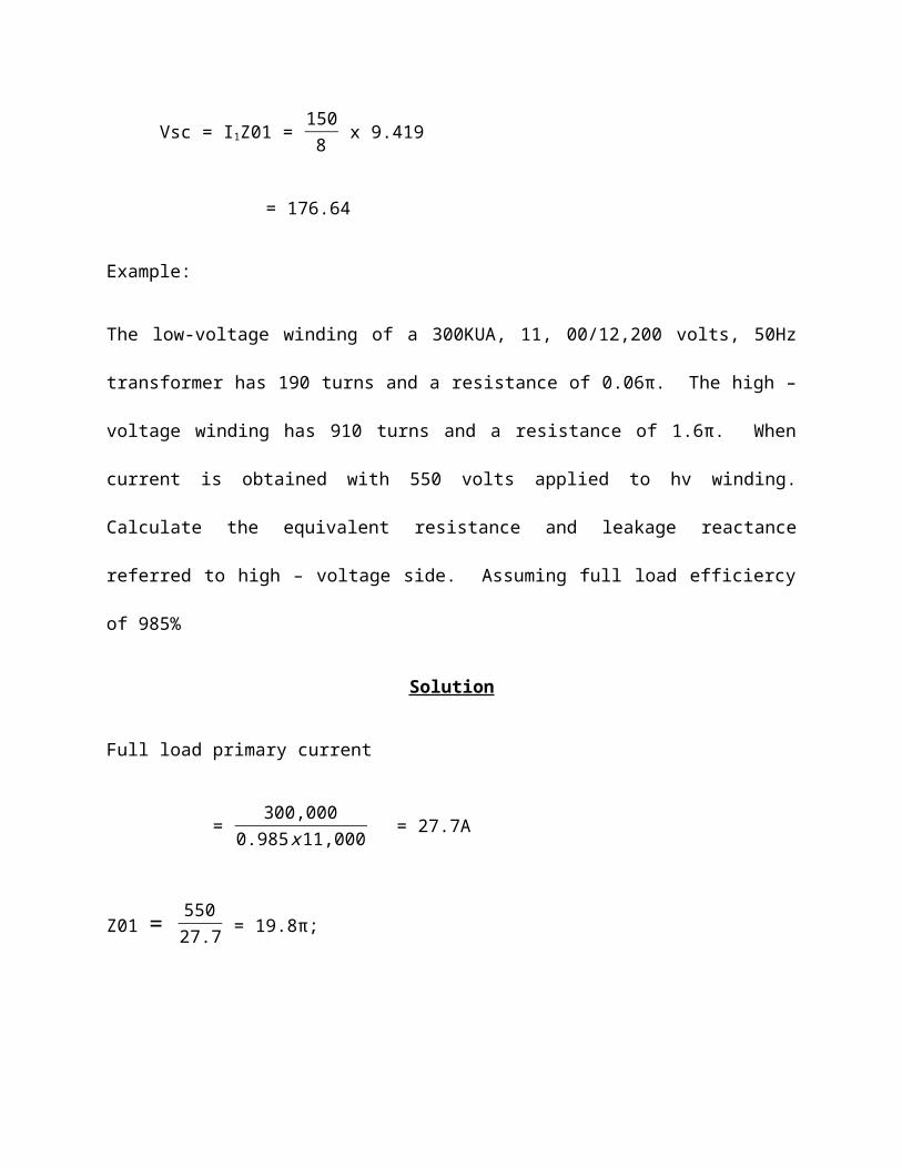
Vsc = I1Z01 = 1508 x 9.419
= 176.64
Example:
The low-voltage winding of a 300KUA, 11, 00/12,200 volts, 50Hz
transformer has 190 turns and a resistance of 0.06π. The high –
voltage winding has 910 turns and a resistance of 1.6π. When
current is obtained with 550 volts applied to hv winding.
Calculate the equivalent resistance and leakage reactance
referred to high – voltage side. Assuming full load efficiercy
of 985%
Solution
Full load primary current
= 300,0000.985x11,000 = 27.7A
Z01 = 55027.7 = 19.8π;
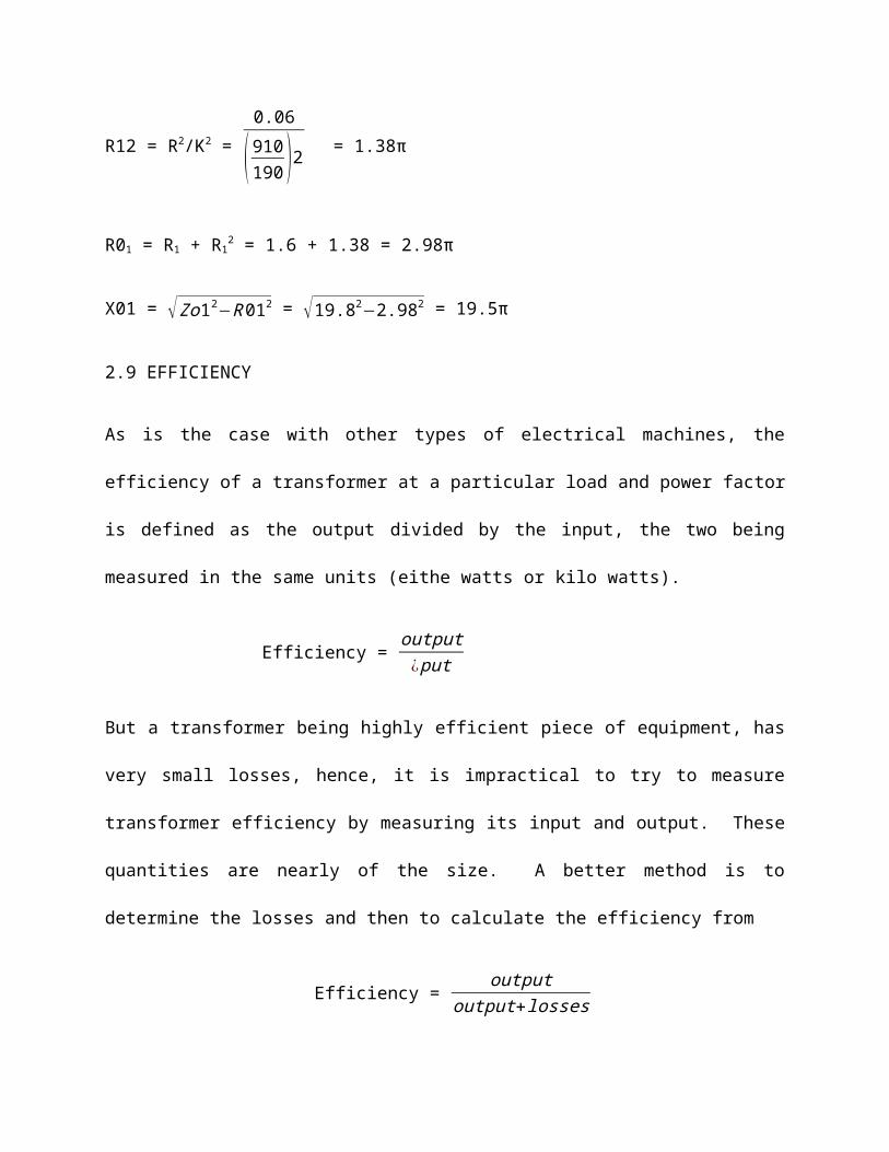
R12 = R2/K2 = 0.06
(910190 )2 = 1.38π
R01 = R1 + R12 = 1.6 + 1.38 = 2.98π
X01 = √Zo12−R012 = √19.82−2.982 = 19.5π
2.9 EFFICIENCY
As is the case with other types of electrical machines, the
efficiency of a transformer at a particular load and power factor
is defined as the output divided by the input, the two being
measured in the same units (eithe watts or kilo watts).
Efficiency = output¿put
But a transformer being highly efficient piece of equipment, has
very small losses, hence, it is impractical to try to measure
transformer efficiency by measuring its input and output. These
quantities are nearly of the size. A better method is to
determine the losses and then to calculate the efficiency from
Efficiency = outputoutput+losses
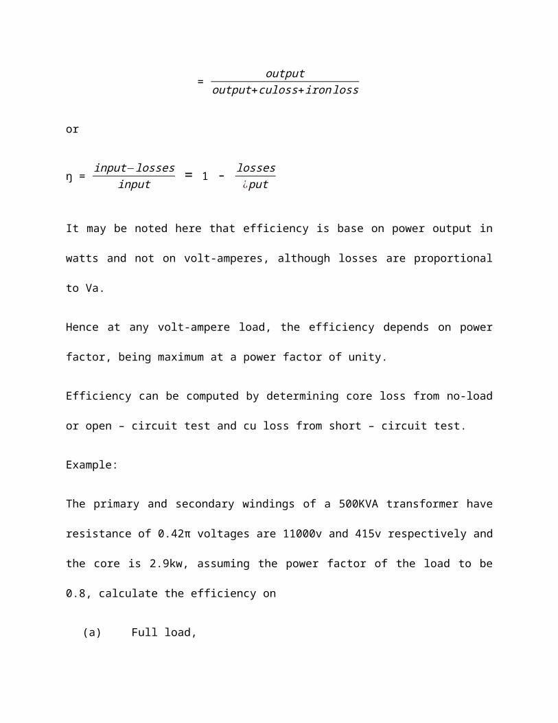
= outputoutput+culoss+ironloss
or
ŋ = input−lossesinput = 1 - losses
¿put
It may be noted here that efficiency is base on power output in
watts and not on volt-amperes, although losses are proportional
to Va.
Hence at any volt-ampere load, the efficiency depends on power
factor, being maximum at a power factor of unity.
Efficiency can be computed by determining core loss from no-load
or open – circuit test and cu loss from short – circuit test.
Example:
The primary and secondary windings of a 500KVA transformer have
resistance of 0.42π voltages are 11000v and 415v respectively and
the core is 2.9kw, assuming the power factor of the load to be
0.8, calculate the efficiency on
(a) Full load,
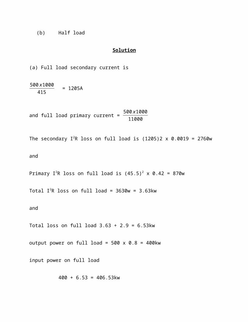
(b) Half load
Solution
(a) Full load secondary current is
500x1000415 = 1205A
and full load primary current = 500x100011000
The secondary I2R loss on full load is (1205)2 x 0.0019 = 2760w
and
Primary I2R loss on full load is (45.5)2 x 0.42 = 870w
Total I2R loss on full load = 3630w = 3.63kw
and
Total loss on full load 3.63 + 2.9 = 6.53kw
output power on full load = 500 x 0.8 = 400kw
input power on full load
400 + 6.53 = 406.53kw
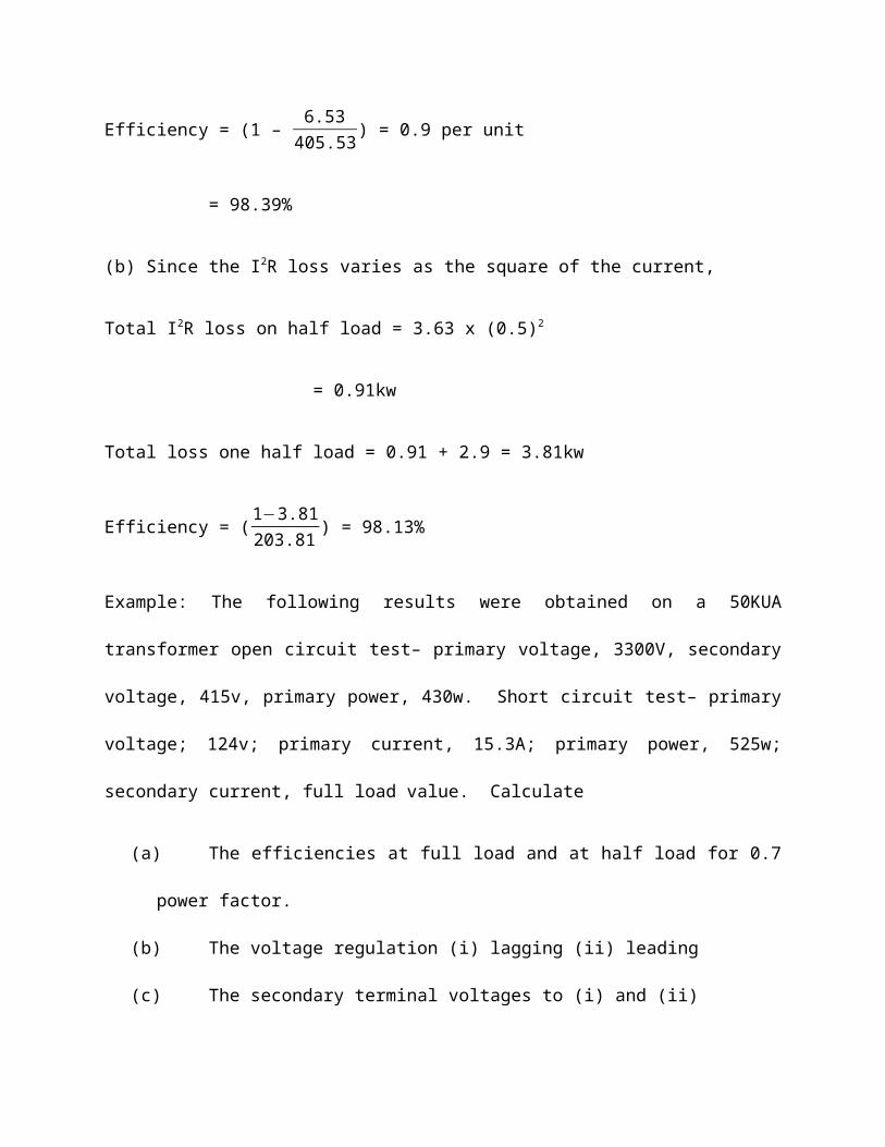
Efficiency = (1 – 6.53405.53) = 0.9 per unit
= 98.39%
(b) Since the I2R loss varies as the square of the current,
Total I2R loss on half load = 3.63 x (0.5)2
= 0.91kw
Total loss one half load = 0.91 + 2.9 = 3.81kw
Efficiency = (1−3.81203.81 ) = 98.13%
Example: The following results were obtained on a 50KUA
transformer open circuit test– primary voltage, 3300V, secondary
voltage, 415v, primary power, 430w. Short circuit test– primary
voltage; 124v; primary current, 15.3A; primary power, 525w;
secondary current, full load value. Calculate
(a) The efficiencies at full load and at half load for 0.7
power factor.
(b) The voltage regulation (i) lagging (ii) leading
(c) The secondary terminal voltages to (i) and (ii)
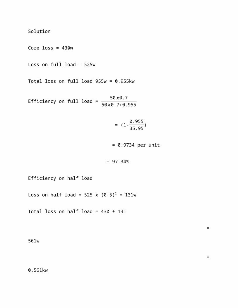
Solution
Core loss = 430w
Loss on full load = 525w
Total loss on full load 955w = 0.955kw
Efficiency on full load = 50x0.750x0.7+0.955
= (1-0.95535.95)
= 0.9734 per unit
= 97.34%
Efficiency on half load
Loss on half load = 525 x (0.5)2 = 131w
Total loss on half load = 430 + 131
=
561w
=
0.561kw
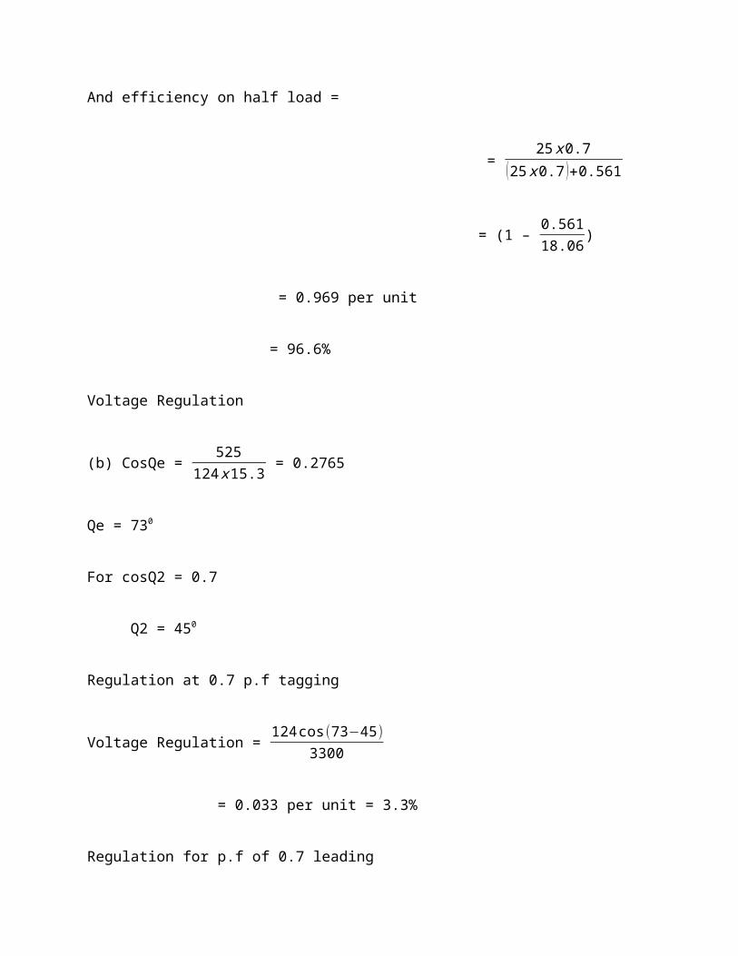
And efficiency on half load =
= 25x0.7
(25x0.7 )+0.561
= (1 – 0.56118.06)
= 0.969 per unit
= 96.6%
Voltage Regulation
(b) CosQe = 525124x15.3 = 0.2765
Qe = 730
For cosQ2 = 0.7
Q2 = 450
Regulation at 0.7 p.f tagging
Voltage Regulation = 124cos(73−45)3300
= 0.033 per unit = 3.3%
Regulation for p.f of 0.7 leading
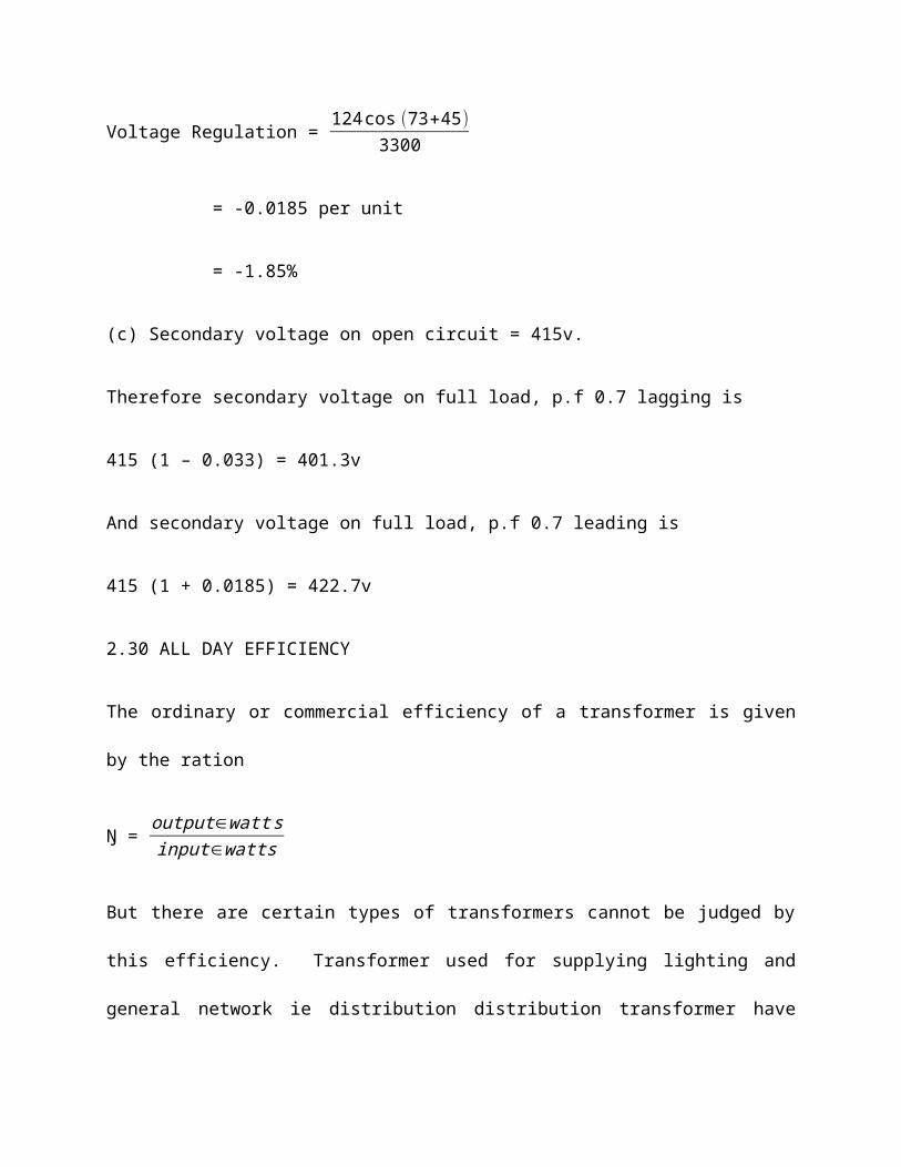
Voltage Regulation = 124cos (73+45)3300
= -0.0185 per unit
= -1.85%
(c) Secondary voltage on open circuit = 415v.
Therefore secondary voltage on full load, p.f 0.7 lagging is
415 (1 – 0.033) = 401.3v
And secondary voltage on full load, p.f 0.7 leading is
415 (1 + 0.0185) = 422.7v
2.30 ALL DAY EFFICIENCY
The ordinary or commercial efficiency of a transformer is given
by the ration
Ŋ = output∈wattsinput∈watts
But there are certain types of transformers cannot be judged by
this efficiency. Transformer used for supplying lighting and
general network ie distribution distribution transformer have
their primaries energized for all the twenty-four (24h), although
their secondary supplies little or no much of the time during the
day except during the house-lighting period. It means where as
core loss occurs through out the day, the cu loss occurs only
when the transformer is loaded. Hence, it is considered a good
practice to design such transformer so that core losses are very
low. The cu losses are relatively less importance of such a
transformer should be judged by all-day efficiency also known as
operational efficiency which is computed on the basis of energy
consumed during certain time period, usually a day of 24hours.
Ŋ all day =output∈kwhinput∈kwh (for 24 hours).
To find this all-day efficiency or (as it also so called) energy
efficiency, we have to know the load cycle on the transformer ie,
how much and how long the transformer is loaded during 24 hours.
Practical calculations are facilitated by making use of a load
factor.
Example:
A 100KVA lighting transformer has a full-load loss of 3kw, the
losses being equally divided between iron and copper. During a
day, the transformer operates on full-load for 3 hours, one half-
load for 4hours, the output being negligible for the remainder of
the day. Calculate the all-day efficiency.
Solution
It is usually assumed that lighting transformers have a load p.f
of unity.
Iron loss for 24hours = 1.5 x 24 = 36kwh
Full load – cu loss = 1.5kw
Cu loss for 3hours on full load = 3 x 1.5 = 4.5kwh
Cu loss at half full-load = 1.5/4kw
Cu loss for 4hours at half F.L = 4 x (1.5/4) =
1.5kwh
Total losses in 24hours = 36 + 4.5 + 15
= 42kwh
Total output in 24hours = (100 x 3) + (50 x 4)
= 500kwh
Ŋ all-day = 500x100500+42 = 92.25%
NOTE: used this above information to calculate ordinary
efficiency.
Example:
A 20kw distribution transformer has an efficiency of 0.95 at full
load. The copper losses at full-load equal the iron losses. The
transformer is kept connected to the mains all the time but is
loaded with full – load for 6hour a day the load during the
remaining time being zero. Find the all-day efficiency.
Solution
Input = outputefficiency =
200.95 = 21.052
Full-load loss = 21.052 – 20 = 1.052kw
Full-load cu loss = 1.052/2
= 0.526kw, iron loss = 0.526kw
The cu loss takes place only when transformer is fully or
partially loaded whereas iron loss takes place all time the
transformer is energized.
F.L. cu loss per day for 6 hours = 0.526 x 6 = 3.156kwh
Iron loss per day = 24 x 0.526
= 12.624kwh
Total loss in 24 hours = 3.156 + 12.624 =
15.780kwh
Output in 24 hours = 20 x 6 = 120kwh
All – day efficiency = ŋ = 120x100(120+15.78)
= 88.4%
2.31. PARALLEL OPERATION OF TRANSFORMERS
For supplying a load in excess of the rating of an existing
transformers, two or more transformers may be connected in
parallel with an existing transformer. The transformer are
connected when load on one of the transformers is more them its
capacity. The reliability is increased with parallel operation
than to have single larger unit. The cost associated with
maintain the spare is less when two transformer are connected in
parallel.
It is usually economically to install another in parallel
instead of replacing the existing transformer by a single
large unit. The cost of a spare in the case of two parallel
transformers (of equal rating) is also lower than that of a
single transformer. In addition, it is preferable to have a
parallel transformer for the reason of reliability. With is
this at least half the load can be supplied with one
transformer out of service.
2.32. CONDITION FOR PARALLEL OPERATION OF TRANSFORMER:
For parallel connection of transformers, primary winding of
a transformer are connected to source bus – bars and
secondary winding are connected to the load bus-bars.
Various condition that must be fulfilled for the successful
parallel operation of transformers.
1. Same voltage ration and turns Ration (both primary and
secondary voltage Ratings is same).
2. Same percentage impedance and transformer ration.
3. Identical position of tap changer.
4. Same KVA Ratings
5. Same phase angle shift (vector group are same)
6. Same frequency rating.
7. Same polarity
8. Same phase sequence
Some of these condition are convenient and some are mandatory.
The convenient are: same voltage ration and turn ration,
same percentage impedance, same KVA Rating, same position of
tap changer.
The ma ndary conditions are: same phase angle shift, same
polarity, same phase sequence, and same frequency.
When the convenient conditions are not met parallel
operation is possible but not optimal.
ADVANTAGES OF PARALLEL OPERATIONS
2.32. METHODS OF COOLING

2.33 TAP CHANGING
The simplest type of tap-changing mechanism is a rotary switch
which allows the distribution company to select one of several
tapping (connection) points on the high–voltages side of a
transformer. This enables the turn-ration.
