chapter 13 cellular wireless networks
TRANSCRIPT
Wireless Communication Networks and Systems
1st editionCory Beard, William Stallings
© 2016 Pearson Higher Education, Inc.
These slides are made available to faculty in PowerPoint form.Slides can be freely added, modified, and deleted to suit studentneeds. They represent substantial work on the part of the authors;therefore, we request the following.
If these slides are used in a class setting or posted on an internal orexternal www site, please mention the source textbook and noteour copyright of this material.
All material copyright 2016Cory Beard and William Stallings, All Rights Reserved
CHAPTER 13 CELLULAR WIRELESS
NETWORKS
Cellular Wireless Networks 13-1
CELLULAR NETWORKS
• Revolutionary development in data communications and telecommunications
• Foundation of mobile wireless– Telephones, smartphones, tablets, wireless Internet, wireless
applications• Supports locations not easily served by wireless networks
or WLANs• Five generations of standards
– 1G: Analog– 2G: Still used to carry voice– 3G: First with sufficient speeds for data networking, packets only– 4G: Truly broadband mobile data up to 1 Gbps– 5G
Cellular Wireless Networks 13-2
CELLULAR NETWORK ORGANIZATION
• Use multiple low-power transmitters (100 W or less)
• Areas divided into cells– Each served by its own antenna
– Served by base station consisting of transmitter, receiver, and control unit
– Band of frequencies allocated
– Cells set up such that antennas of all neighbors are equidistant (hexagonal pattern)
Cellular Wireless Networks 13-3
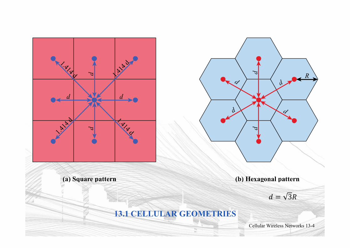
13.1 CELLULAR GEOMETRIESCellular Wireless Networks 13-4
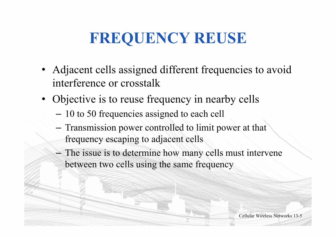
FREQUENCY REUSE
• Adjacent cells assigned different frequencies to avoid interference or crosstalk
• Objective is to reuse frequency in nearby cells– 10 to 50 frequencies assigned to each cell
– Transmission power controlled to limit power at that frequency escaping to adjacent cells
– The issue is to determine how many cells must intervene between two cells using the same frequency
Cellular Wireless Networks 13-5
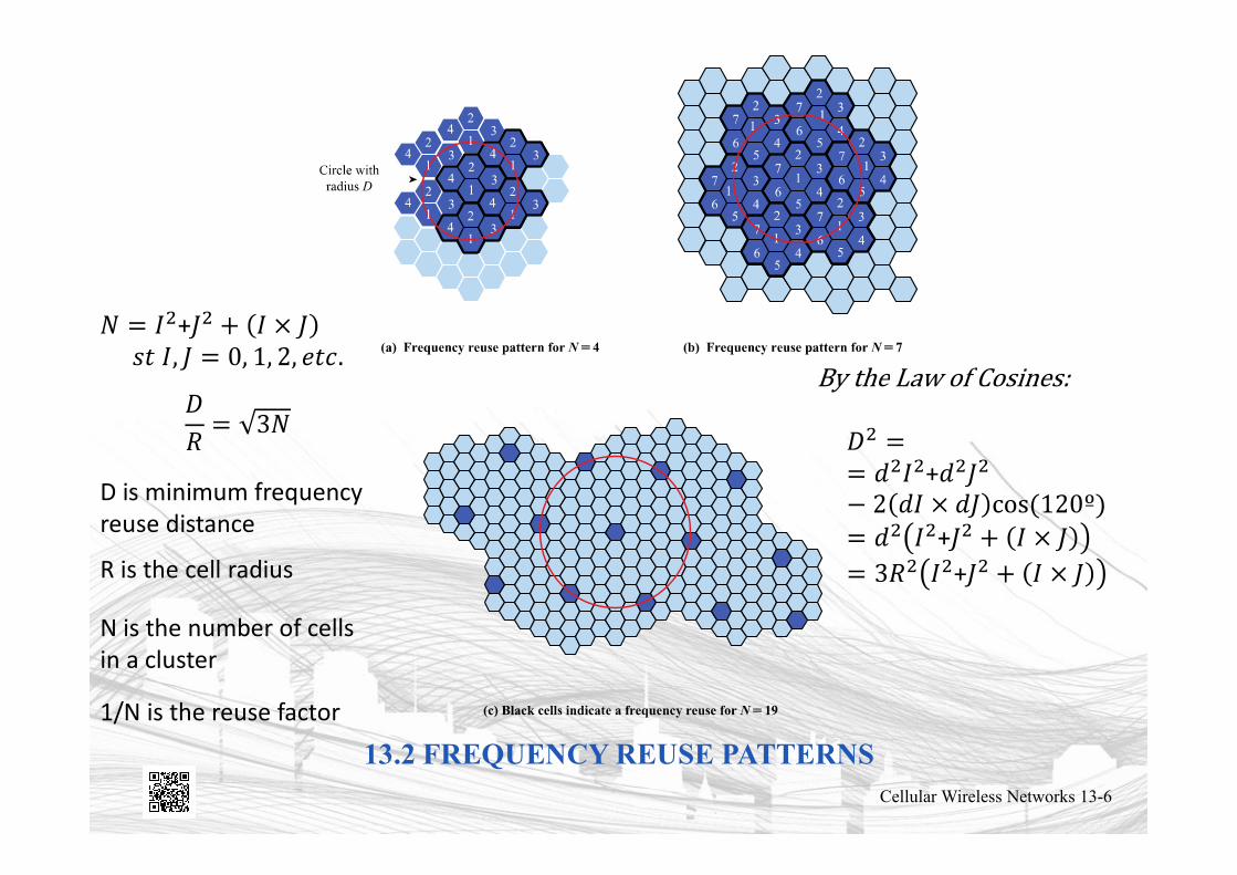
13.2 FREQUENCY REUSE PATTERNSCellular Wireless Networks 13-6
+
D is minimum frequencyreuse distance
R is the cell radius
N is the number of cellsin a cluster
1/N is the reuse factor
+
++
APPROACHES TO COPE WITH INCREASING CAPACITY
• Adding new channels• Frequency borrowing – frequencies are taken from adjacent
cells by congested cells• Cell splitting – cells in areas of high usage can be split into
smaller cells• Cell sectoring – cells are divided into a number of wedge-
shaped sectors, each with their own set of channels• Network densification – more cells and frequency reuse
– Microcells – antennas move to buildings, hills, and lamp posts– Femtocells – antennas to create small cells in buildings
• Interference coordination – tighter control of interference so frequencies can be reused closer to other base stations– Inter-cell interference coordination (ICIC)– Coordinated multipoint transmission (CoMP)
Cellular Wireless Networks 13-7
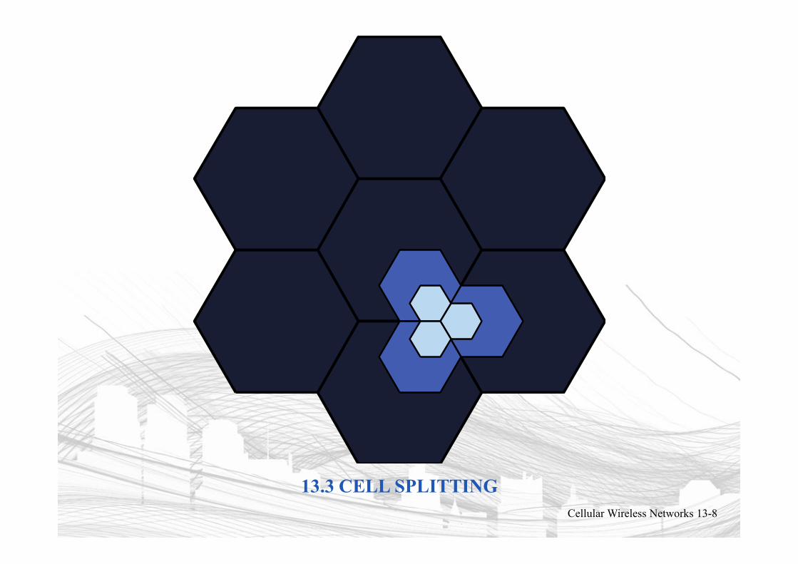
13.3 CELL SPLITTINGCellular Wireless Networks 13-8
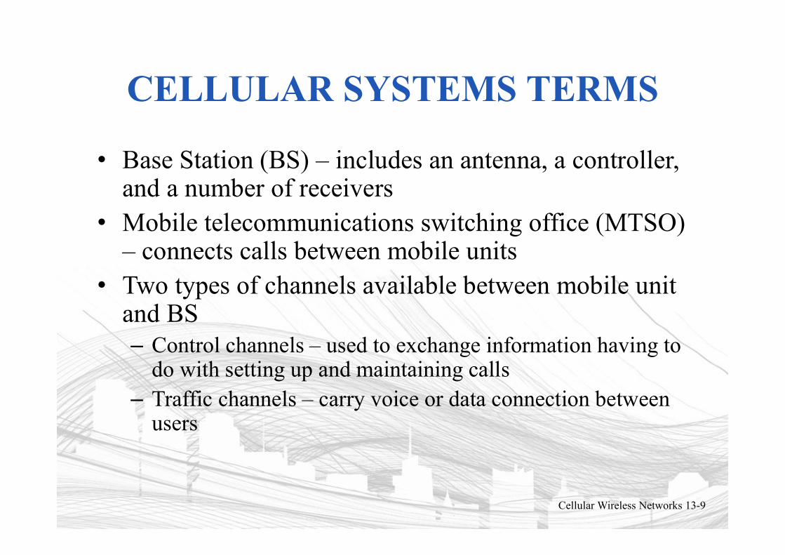
CELLULAR SYSTEMS TERMS
• Base Station (BS) – includes an antenna, a controller, and a number of receivers
• Mobile telecommunications switching office (MTSO) – connects calls between mobile units
• Two types of channels available between mobile unit and BS– Control channels – used to exchange information having to
do with setting up and maintaining calls– Traffic channels – carry voice or data connection between
users
Cellular Wireless Networks 13-9
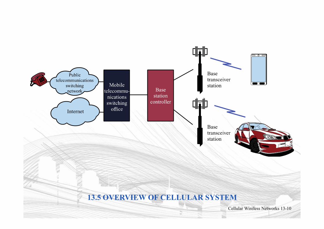
13.5 OVERVIEW OF CELLULAR SYSTEMCellular Wireless Networks 13-10
STEPS IN AN MTSO CONTROLLED CALL BETWEEN MOBILE USERS
• Mobile unit initialization
• Mobile-originated call
• Paging
• Call accepted
• Ongoing call
• Handoff
Cellular Wireless Networks 13-11
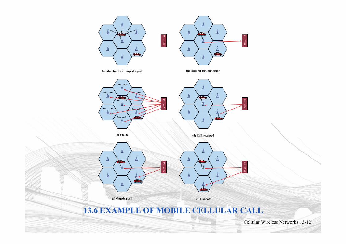
13.6 EXAMPLE OF MOBILE CELLULAR CALLCellular Wireless Networks 13-12
ADDITIONAL FUNCTIONS IN AN MTSO CONTROLLED CALL
• Call blocking
• Call termination
• Call drop
• Calls to/from fixed and remote mobile subscriber
Cellular Wireless Networks 13-13
MOBILE RADIO PROPAGATION EFFECTS
• Signal strength– Must be strong enough between base station and mobile
unit to maintain signal quality at the receiver– Must not be so strong as to create too much co-channel
interference with channels in another cell using the same frequency band
• Fading– Signal propagation effects may disrupt the signal and cause
errors
Cellular Wireless Networks 13-14
HANDOFF PERFORMANCE METRICS
• Call blocking probability – probability of a new call being blocked
• Call dropping probability – probability that a call is terminated due to a handoff
• Call completion probability – probability that an admitted call is not dropped before it terminates
• Probability of unsuccessful handoff – probability that a handoff is executed while the reception conditions are inadequate
Cellular Wireless Networks 13-15
HANDOFF PERFORMANCE METRICS
• Handoff blocking probability – probability that a handoff cannot be successfully completed
• Handoff probability – probability that a handoff occurs before call termination
• Rate of handoff – number of handoffs per unit time• Interruption duration – duration of time during a
handoff in which a mobile is not connected to either base station
• Handoff delay – distance the mobile moves from the point at which the handoff should occur to the point at which it does occur
Cellular Wireless Networks 13-16
HANDOFF STRATEGIES USED TO DETERMINE INSTANT OF HANDOFF
• Relative signal strength
• Relative signal strength with threshold
• Relative signal strength with hysteresis
• Relative signal strength with hysteresis and threshold
• Prediction techniques
Cellular Wireless Networks 13-17
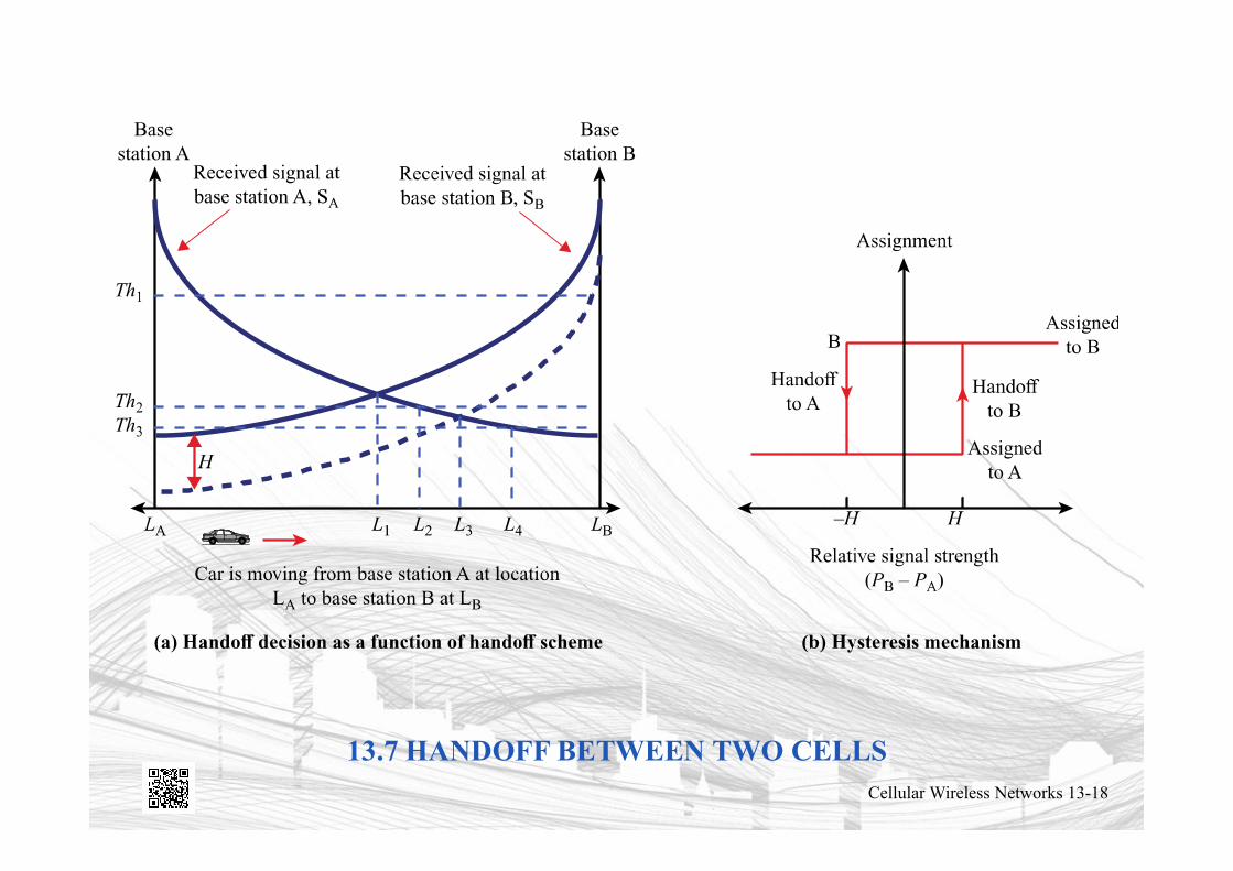
13.7 HANDOFF BETWEEN TWO CELLSCellular Wireless Networks 13-18
POWER CONTROL
• Reasons to include dynamic power control in a cellular system– Received power must be sufficiently above the background
noise for effective communication– Desirable to minimize power in the transmitted signal from
the mobile• Reduce co-channel interference, alleviate health concerns, save
battery power
– In SS systems using CDMA, it’s necessary to equalize the received power level from all mobile units at the BS
Cellular Wireless Networks 13-19
TYPES OF POWER CONTROL
• Open-loop power control– Depends solely on mobile unit– No feedback from BS– Not as accurate as closed-loop, but can react quicker to
fluctuations in signal strength
• Closed-loop power control– Adjusts signal strength in reverse channel based on metric
of performance– BS makes power adjustment decision and communicates to
mobile on control channel
Cellular Wireless Networks 13-20
TRAFFIC ENGINEERING
• Ideally, available channels would equal number of subscribers active at one time
• In practice, not feasible to have capacity handle all possible load
• For N simultaneous user capacity and L subscribers– L < N – nonblocking system
– L > N – blocking system
Cellular Wireless Networks 13-21
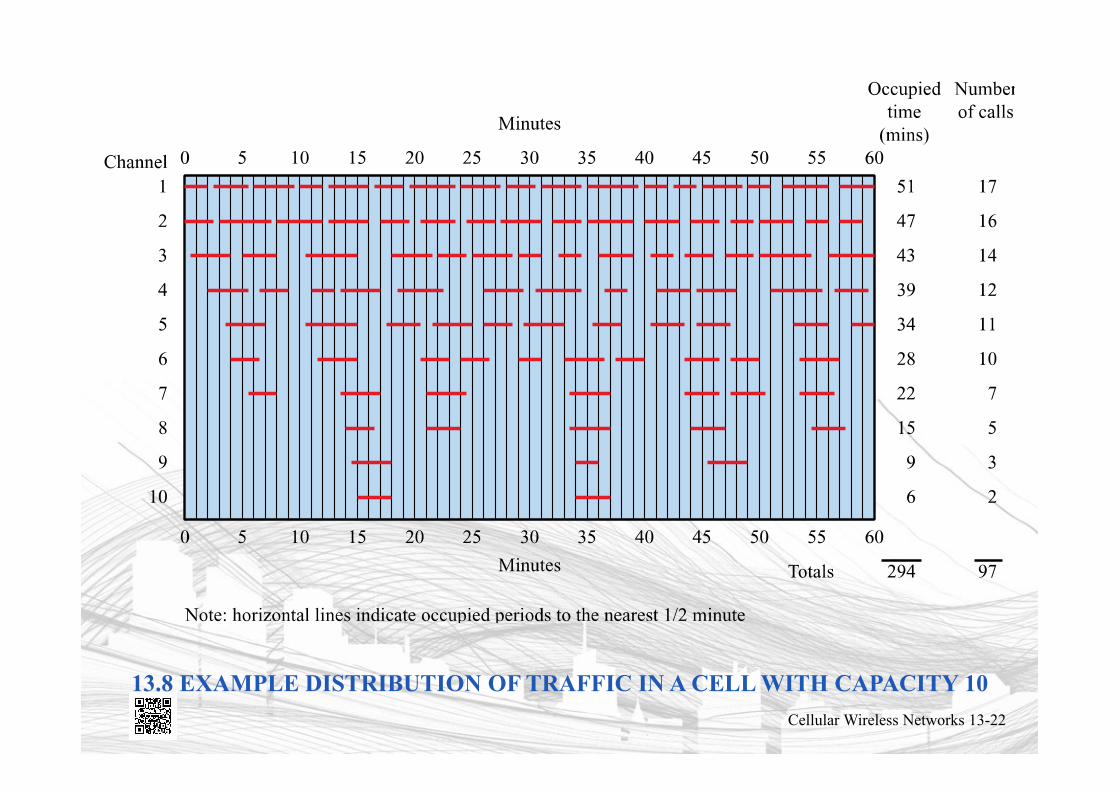
13.8 EXAMPLE DISTRIBUTION OF TRAFFIC IN A CELL WITH CAPACITY 10
Cellular Wireless Networks 13-22
BLOCKING SYSTEM PERFORMANCE QUESTIONS
• Probability that call request is blocked?
• What capacity is needed to achieve a certain upper bound on probability of blocking?
• What is the average delay?
• What capacity is needed to achieve a certain average delay?
Cellular Wireless Networks 13-23
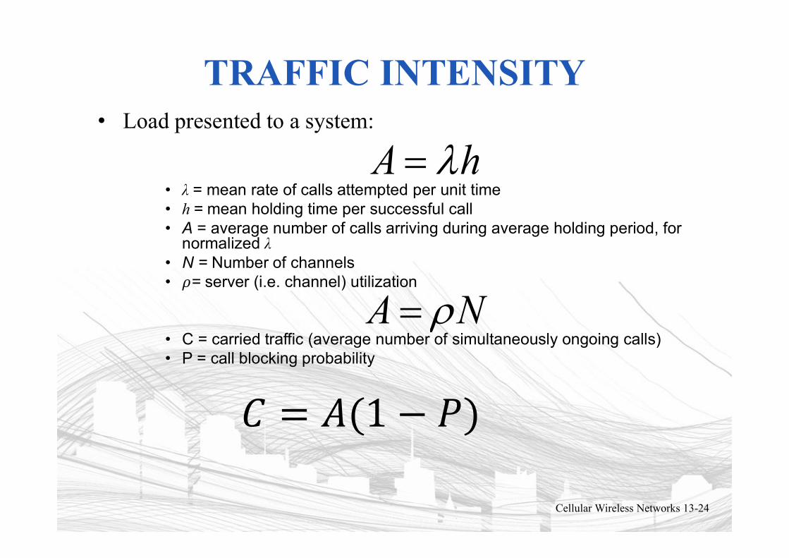
TRAFFIC INTENSITY• Load presented to a system:
• λ = mean rate of calls attempted per unit time• h = mean holding time per successful call• A = average number of calls arriving during average holding period, for
normalized λ• N = Number of channels• 𝜌= server (i.e. channel) utilization
• C = carried traffic (average number of simultaneously ongoing calls)• P = call blocking probability
A = lh
Cellular Wireless Networks 13-24
A = rN
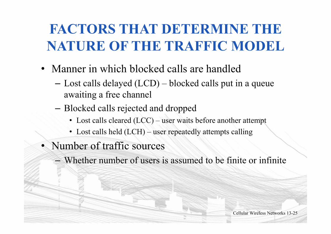
FACTORS THAT DETERMINE THE NATURE OF THE TRAFFIC MODEL
• Manner in which blocked calls are handled– Lost calls delayed (LCD) – blocked calls put in a queue
awaiting a free channel
– Blocked calls rejected and dropped• Lost calls cleared (LCC) – user waits before another attempt
• Lost calls held (LCH) – user repeatedly attempts calling
• Number of traffic sources– Whether number of users is assumed to be finite or infinite
Cellular Wireless Networks 13-25
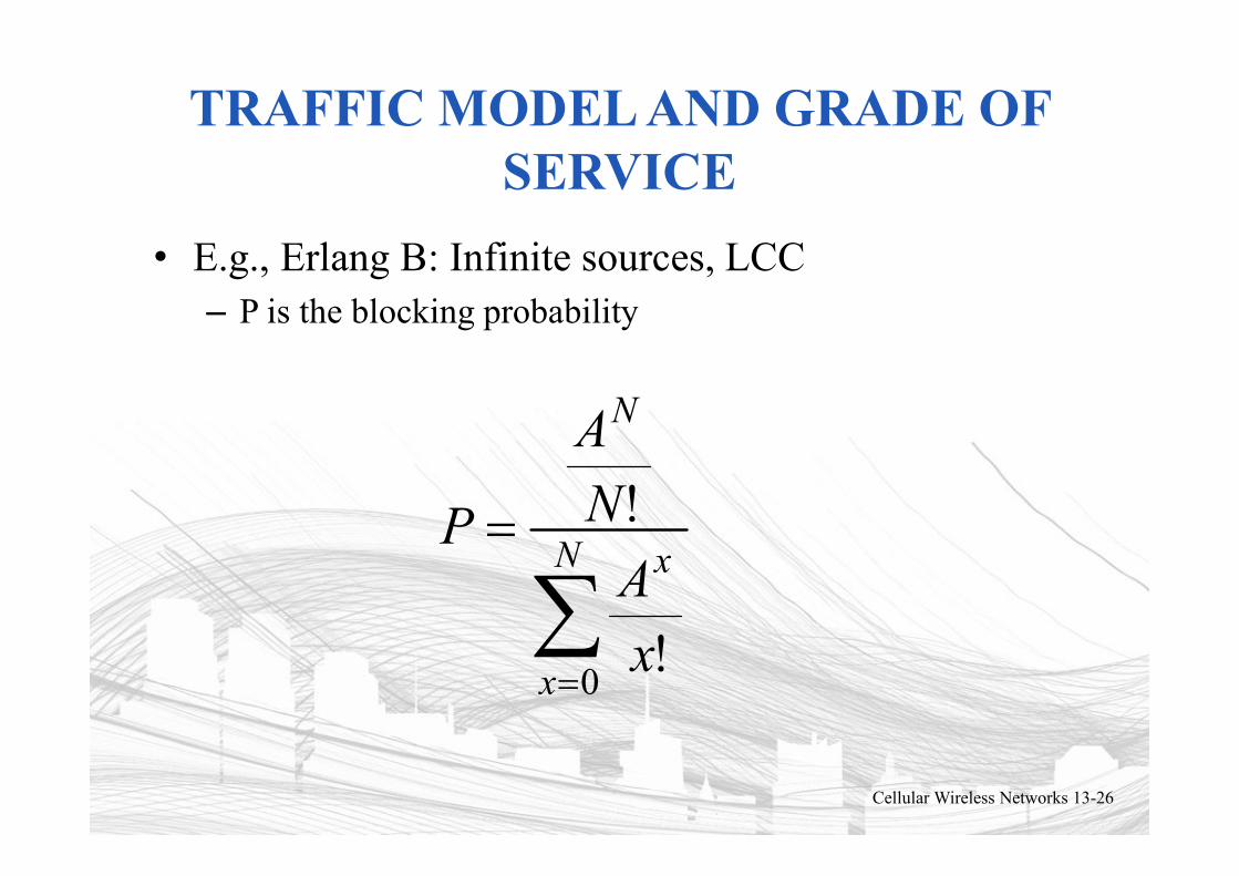
TRAFFIC MODEL AND GRADE OF SERVICE
• E.g., Erlang B: Infinite sources, LCC– P is the blocking probability
Cellular Wireless Networks 13-26
=
=N
x
x
N
x
A
N
A
P
0!
!
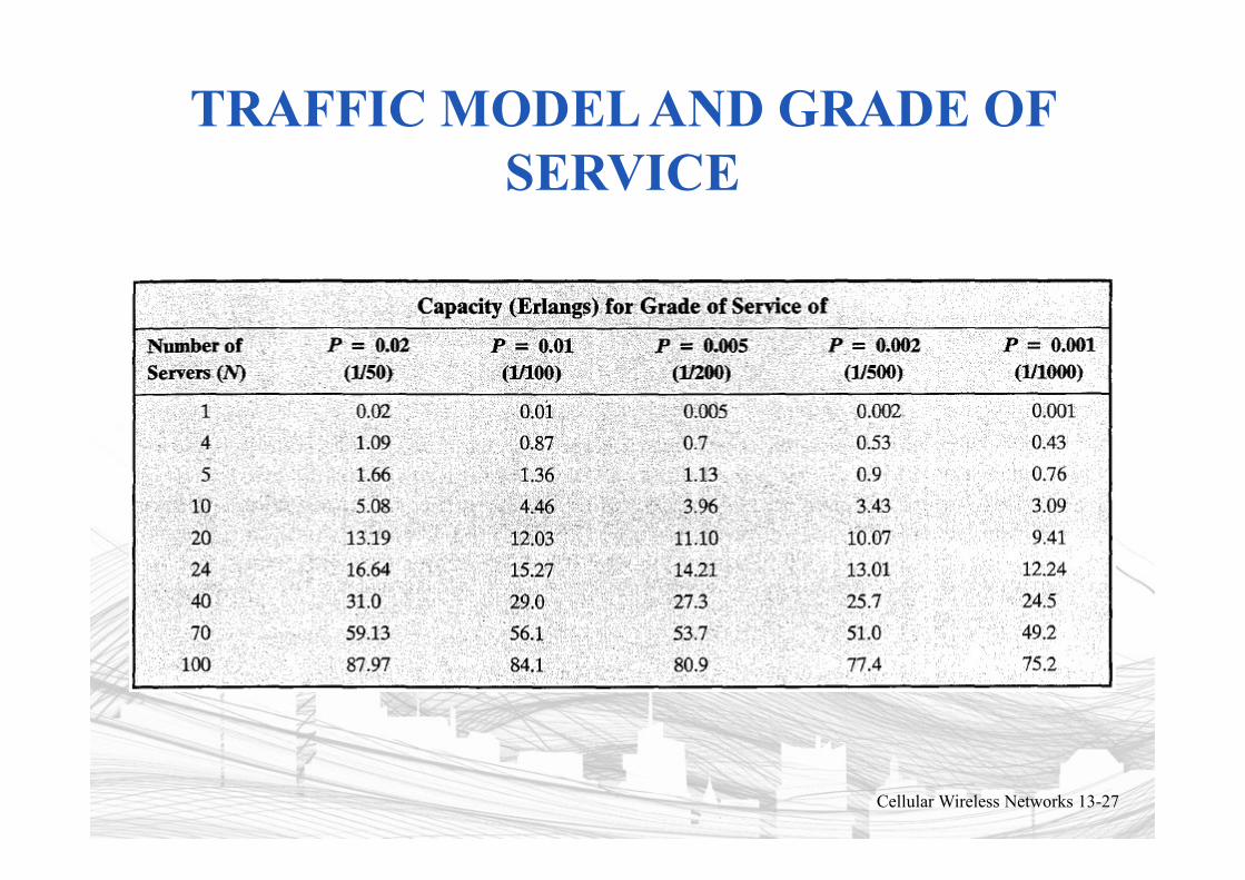
TRAFFIC MODEL AND GRADE OF SERVICE
Cellular Wireless Networks 13-27
FIRST-GENERATION ANALOG
• Advanced Mobile Phone Service (AMPS)– In North America, two 25-MHz bands allocated to
AMPS• One for transmission from base to mobile unit
• One for transmission from mobile unit to base
– Each band split in two to encourage competition
– Frequency reuse exploited
Cellular Wireless Networks 13-28
DIFFERENCES BETWEEN FIRST AND SECOND GENERATION SYSTEMS
• Digital traffic channels – first-generation systems are almost purely analog; second-generation systems are digital– Using FDMA/TDMA or CDMA
• Encryption – all second generation systems provide encryption to prevent eavesdropping
• Error detection and correction – second-generation digital traffic allows for detection and correction, giving clear voice reception
• Channel access – second-generation systems allow channels to be dynamically shared by a number of users
Cellular Wireless Networks 13-29
GLOBAL SYSTEM FOR MOBILE COMMUNICATIONS (GSM)
• FDMA/TDMA approach• Developed to provide a common second-generation
technology for Europe– Over 6.9 billion subscriber units by the end of 2013
• Mobile station communicates across the Um interface (air interface) with base station transceiver in the same cell as mobile unit
• Mobile equipment (ME) – physical terminal, such as a telephone or PCS– ME includes radio transceiver, digital signal processors and
subscriber identity module (SIM)• GSM subscriber units are generic until SIM is inserted
– SIMs roam, not necessarily the subscriber devices
Cellular Wireless Networks 13-30

13.9 OVERALL GSM ARCHITECTURECellular Wireless Networks 13-31
BASE STATION SUBSYSTEM (BSS)
• BSS consists of base station controller and one or more base transceiver stations (BTS)
• Each BTS defines a single cell– Includes radio antenna, radio transceiver and a link to a
base station controller (BSC)
• BSC reserves radio frequencies, manages handoff of mobile unit from one cell to another within BSS, and controls paging
Cellular Wireless Networks 13-32
NETWORK SUBSYSTEM (NS)
• NS provides link between cellular network and public switched telecommunications networks– Controls handoffs between cells in different BSSs
– Authenticates users and validates accounts
– Enables worldwide roaming of mobile users
• Central element of NS is the mobile switching center (MSC)
Cellular Wireless Networks 13-33
MOBILE SWITCHING CENTER (MSC) DATABASES
• Home location register (HLR) database – stores information about each subscriber that belongs to it
• Visitor location register (VLR) database – maintains information about subscribers currently physically in the region
• Authentication center database (AuC) – used for authentication activities, holds encryption keys
• Equipment identity register database (EIR) – keeps track of the type of equipment that exists at the mobile station
Cellular Wireless Networks 13-34
GSM RADIO LINK
• Combination of FDMA and TDMA• 200 kHz carriers• Each with a data rate of 270.833 kbps• 8 users share each carrier
Cellular Wireless Networks 13-35
GENERALIZED PACKET RADIO SERVICE (GPRS)
• Phase 2 of GSM• Provides a datagram switching capability to GSM
– Instead of sending data traffic over a voice connection which requires setup, sending data, and teardown
– GPRS allows users to open a persistent data connection
– Also has a new system architecture for data traffic– 21.4 kbps from a 22.8 kbps gross data rate– Can combine up to 8 GSM connections
• Overall throughputs up to 171.2 kbps
Cellular Wireless Networks 13-36
ENHANCED DATA RATES FOR GSM EVOLUTION (EDGE)
• The next generation of GSM– Not yet 3G, so called “2.G” by some
• Three-fold increase in data rate– Up to 3 bits/symbol for 8-PSK from 1 bit/symbol for
GMSK for GSM. – Max data rates per channel up to 22.8 × 3 = 68.4 kbps per
channel – Using all eight channels in a 200 kHz carrier, gross data
transmission rates up to 547.2 kbps became possible• Actual throughput up to 513.6 kbps.
• A later release of EDGE (3GPP Release 7) increased downlink data rates over 750 kbps and uplink data rates over 600 kbps
Cellular Wireless Networks 13-37
WCDMA AND UMTS
• WCDMA is part of a group of standards from– ITU-T IMT-2000 – ETSI Universal Mobile Telephone System (UMTS)– Third-Generation Partnership Project (3GPP) industry
organization
• 3GPP originally released GSM– Issued Release 99 in 1999 for WCDMA and UMTS– Subsequent releases were “Release 4” and onwards– Many higher layer network functions of GSM were carried
over to WCDMA
Cellular Wireless Networks 13-38
WCDMA AND UMTS
• 144 kbps to 2 Mbps, depending on mobility• High Speed Downlink Packet Access (HSDPA)
– Release 5– 1.8 to 14.4 Mbps downlink– Adaptive modulation and coding, hybrid ARQ, and fast scheduling
• High Speed Uplink Packet Access (HSUPA)– Release 6– Uplink rates up to 5.76 Mbps
• High Speed Packet Access Plus (HSPA+)– Release 7 and successively improved in releases through Release
11– Maximum data rates increased from 21 Mbps up to 336 Mbps– 64 QAM, 2×2 and 4×4 MIMO, and dual or multi-carrier
combinations• 3GPP Release 8 onwards introduced Long Term Evolution (LTE)
– Pathway to 4G, Chapter 14Cellular Wireless Networks 13-39
Prof. Dr.-Ing. Jochen H. Schiller www.jochenschiller.de MC - 2013
UTRAN ARCHITECTURE
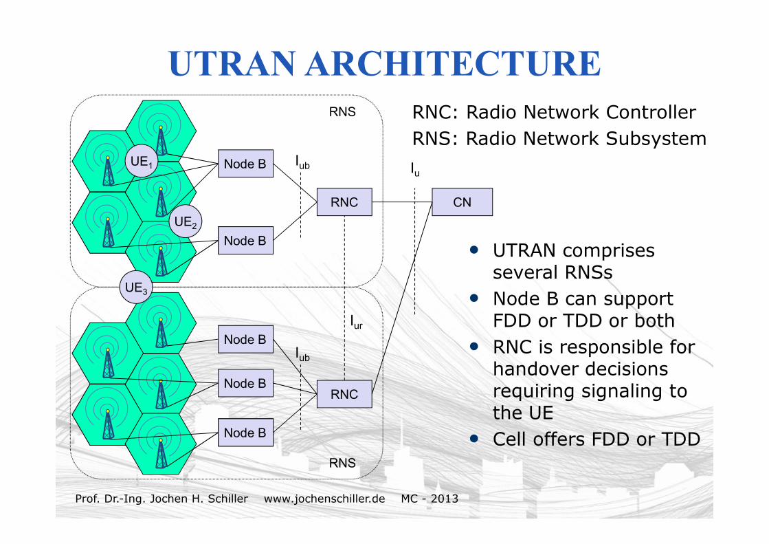
• UTRAN comprises several RNSs
• Node B can support FDD or TDD or both
• RNC is responsible for handover decisions requiring signaling to the UE
• Cell offers FDD or TDD
RNC: Radio Network ControllerRNS: Radio Network Subsystem
Node B
Node B
RNC
Iub
Node B
UE1
RNS
CN
Node B
Node B
RNC
Iub
Node B
RNS
Iur
Node B
UE2
UE3
Iu
Prof. Dr.-Ing. Jochen H. Schiller www.jochenschiller.de MC - 2013
UTRAN FUNCTIONS
• Admission control• Congestion control• System information broadcasting• Radio channel encryption• Handover• SRNS moving• Radio network configuration• Channel quality measurements• Macro diversity• Radio carrier control• Radio resource control• Data transmission over the radio interface• Outer loop power control (FDD and TDD)• Channel coding• Access control
Prof. Dr.-Ing. Jochen H. Schiller www.jochenschiller.de MC - 2013
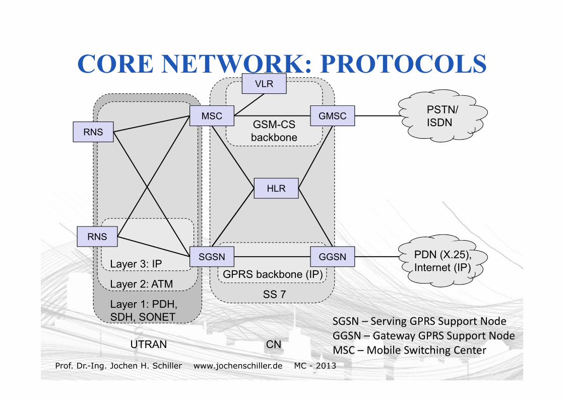
CORE NETWORK: PROTOCOLS
MSC
RNS
SGSN GGSN
GMSC
HLR
VLR
RNS
Layer 1: PDH, SDH, SONET
Layer 2: ATM
Layer 3: IPGPRS backbone (IP)
SS 7
GSM-CSbackbone
PSTN/ISDN
PDN (X.25),Internet (IP)
UTRAN CN
SGSN – Serving GPRS Support NodeGGSN – Gateway GPRS Support Node MSC – Mobile Switching Center
Prof. Dr.-Ing. Jochen H. Schiller www.jochenschiller.de MC - 2013
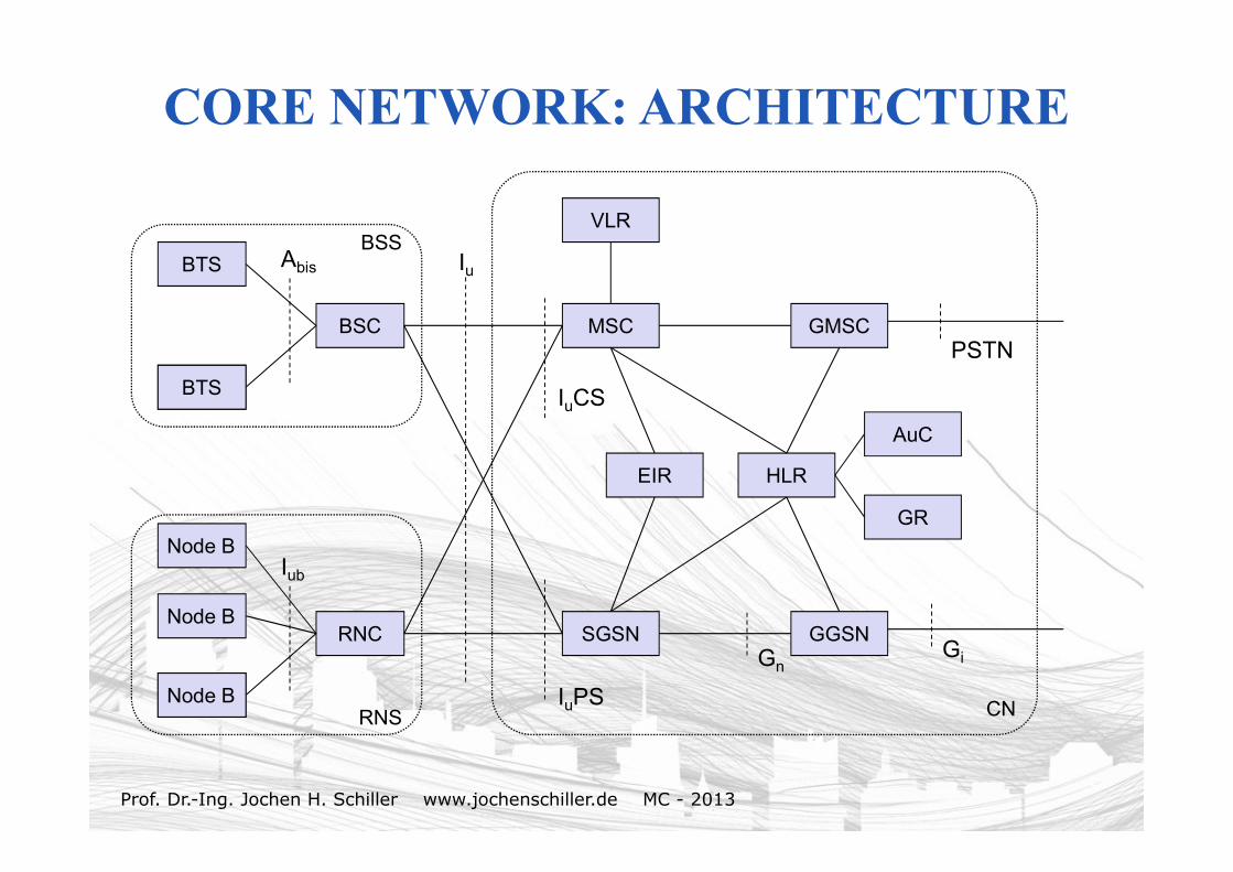
CORE NETWORK: ARCHITECTURE
BTS
Node B
BSC
Abis
BTS
BSS
MSC
Node B
Node B
RNC
Iub
Node BRNS
Node BSGSN GGSN
GMSC
HLR
VLR
IuPS
IuCS
Iu
CN
EIR
GnGi
PSTN
AuC
GR
Prof. Dr.-Ing. Jochen H. Schiller www.jochenschiller.de MC - 2013
CORE NETWORK
• The Core Network (CN) and thus the Interface Iu, too, are separated into two logical domains:
• Circuit Switched Domain (CSD)– Circuit switched service incl. signaling– Resource reservation at connection setup– GSM components (MSC, GMSC, VLR)– IuCS
• Packet Switched Domain (PSD)– GPRS components (SGSN, GGSN)– IuPS
• Release 99 uses the GSM/GPRS network and adds a new radio access!– Helps to save a lot of money …– Much faster deployment– Not as flexible as newer releases (5, 6, … 12)
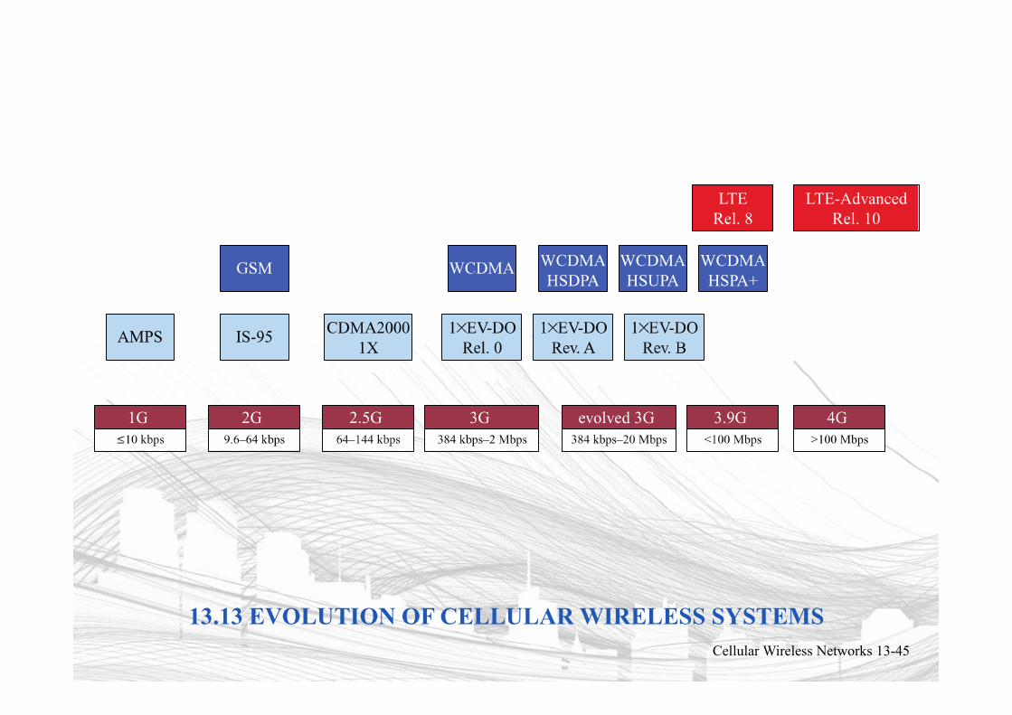
13.13 EVOLUTION OF CELLULAR WIRELESS SYSTEMSCellular Wireless Networks 13-45
Prof. Dr.-Ing. Jochen H. Schiller www.jochenschiller.de MC - 2013
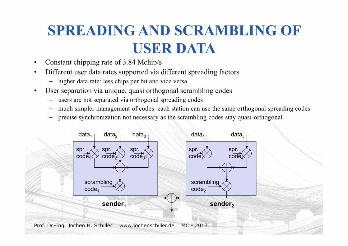
SPREADING AND SCRAMBLING OF USER DATA
• Constant chipping rate of 3.84 Mchip/s• Different user data rates supported via different spreading factors
– higher data rate: less chips per bit and vice versa
• User separation via unique, quasi orthogonal scrambling codes– users are not separated via orthogonal spreading codes– much simpler management of codes: each station can use the same orthogonal spreading codes– precise synchronization not necessary as the scrambling codes stay quasi-orthogonal
data1 data2 data3
scramblingcode1
spr.code3
spr.code2
spr.code1
data4 data5
scramblingcode2
spr.code4
spr.code1
sender1 sender2
Prof. Dr.-Ing. Jochen H. Schiller www.jochenschiller.de MC - 2013
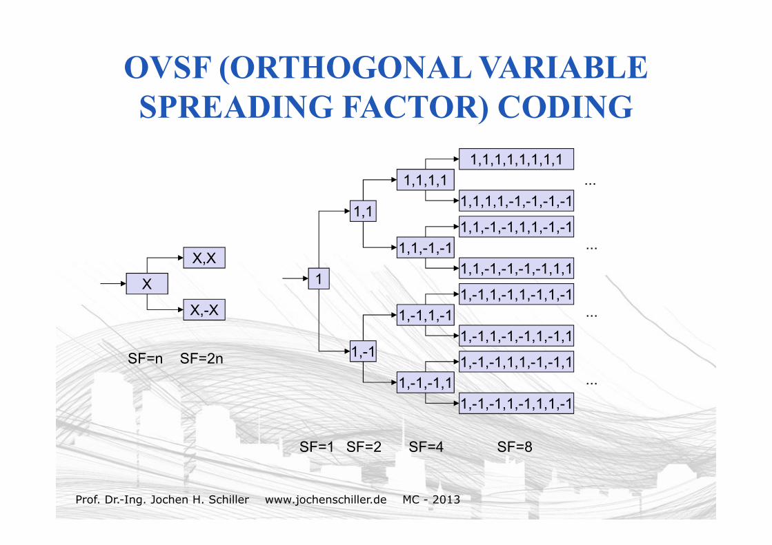
OVSF (ORTHOGONAL VARIABLE SPREADING FACTOR) CODING
1
1,1
1,-1
1,1,1,1
1,1,-1,-1
X
X,X
X,-X 1,-1,1,-1
1,-1,-1,1
1,-1,-1,1,1,-1,-1,1
1,-1,-1,1,-1,1,1,-1
1,-1,1,-1,1,-1,1,-1
1,-1,1,-1,-1,1,-1,1
1,1,-1,-1,1,1,-1,-1
1,1,-1,-1,-1,-1,1,1
1,1,1,1,1,1,1,1
1,1,1,1,-1,-1,-1,-1
SF=1 SF=2 SF=4 SF=8
SF=n SF=2n
...
...
...
...
Prof. Dr.-Ing. Jochen H. Schiller www.jochenschiller.de MC - 2013
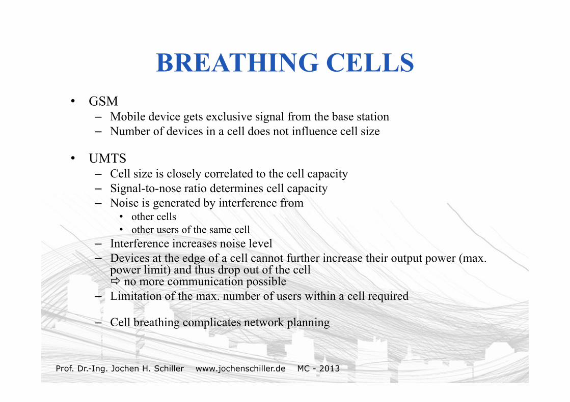
BREATHING CELLS• GSM
– Mobile device gets exclusive signal from the base station – Number of devices in a cell does not influence cell size
• UMTS– Cell size is closely correlated to the cell capacity– Signal-to-nose ratio determines cell capacity– Noise is generated by interference from
• other cells• other users of the same cell
– Interference increases noise level– Devices at the edge of a cell cannot further increase their output power (max.
power limit) and thus drop out of the cell no more communication possible
– Limitation of the max. number of users within a cell required
– Cell breathing complicates network planning