wireless profiled tcp performance over integrated wireless lans and cellular networks
TRANSCRIPT
2294 IEEE TRANSACTIONS ON WIRELESS COMMUNICATIONS, VOL. 6, NO. 6, JUNE 2007
Wireless Profiled TCP Performance overIntegrated Wireless LANs and Cellular Networks
Humphrey Rutagemwa, Student Member, IEEE, Minghui Shi,Xuemin (Sherman) Shen, Senior Member, IEEE, and Jon W. Mark, Life Fellow, IEEE
Abstract— An analytical framework for studying the per-formance of Wireless Profiled TCP (WP-TCP) flows over theintegrated wireless LAN and cellular networks is proposed. Theframework can be used to analyze the short-term performanceduring vertical handover and long-term performance of WP-TCP for a given set of network and protocol parameters. Itcaptures the WP-TCP behavior under the influence of wirelesschannel errors, step change in network parameters and excessivepacket losses due to vertical handovers. Extensive simulations areconducted to verify the accuracy of the analytical framework.The main findings in this study are: 1) when the network issubjected to hard handovers, increasing the maximum windowsize improves the efficiency in a high transmission error envi-ronment, but degrades the efficiency in a low transmission errorenvironment; 2) increasing the congestion window reduces thechances of premature timeouts during soft upward vertical han-dover; and 3) depending on duplicate ACK threshold, increasingthe congestion window can increase or reduce the chances offalse fast retransmit during soft upward vertical handover.
Index Terms— Integrated wireless networks, performanceanalysis, wireless application protocol, WP-TCP.
I. INTRODUCTION
THE increasing demand of versatile services by mobileusers has led to the integration of a variety of wireless
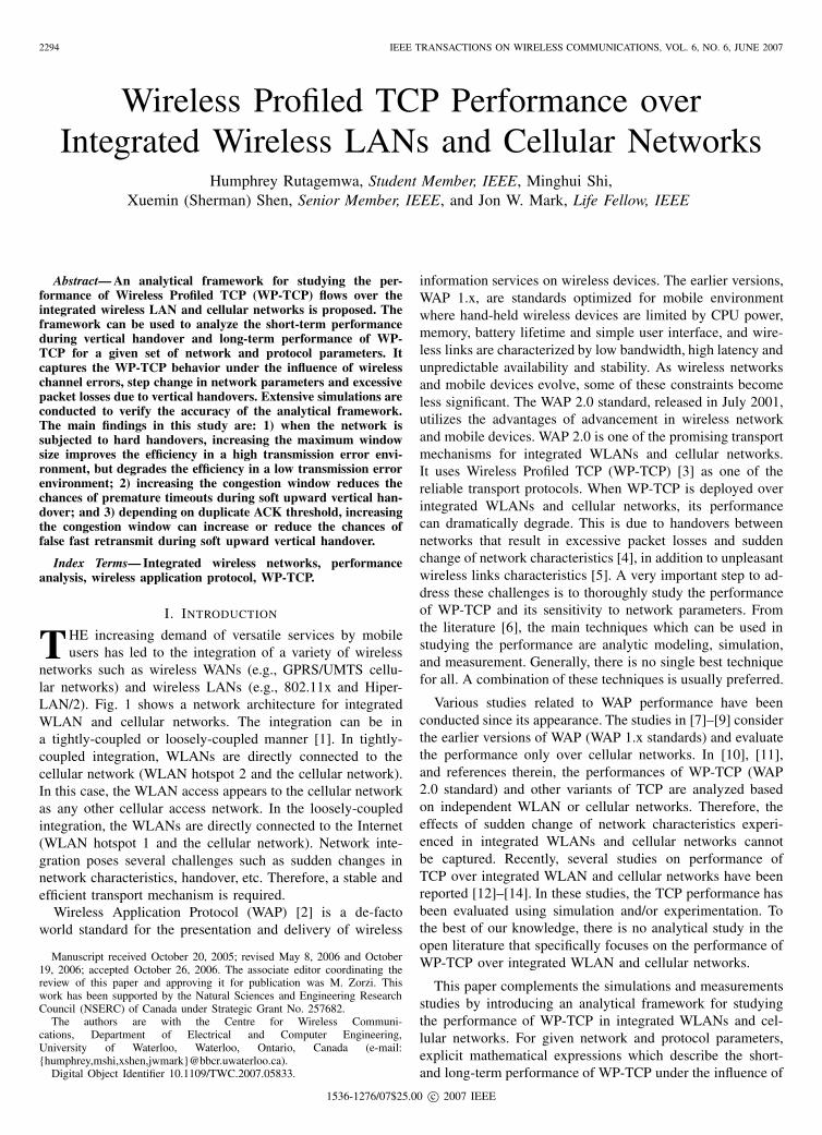
networks such as wireless WANs (e.g., GPRS/UMTS cellu-lar networks) and wireless LANs (e.g., 802.11x and Hiper-LAN/2). Fig. 1 shows a network architecture for integratedWLAN and cellular networks. The integration can be ina tightly-coupled or loosely-coupled manner [1]. In tightly-coupled integration, WLANs are directly connected to thecellular network (WLAN hotspot 2 and the cellular network).In this case, the WLAN access appears to the cellular networkas any other cellular access network. In the loosely-coupledintegration, the WLANs are directly connected to the Internet(WLAN hotspot 1 and the cellular network). Network inte-gration poses several challenges such as sudden changes innetwork characteristics, handover, etc. Therefore, a stable andefficient transport mechanism is required.
Wireless Application Protocol (WAP) [2] is a de-factoworld standard for the presentation and delivery of wireless
Manuscript received October 20, 2005; revised May 8, 2006 and October19, 2006; accepted October 26, 2006. The associate editor coordinating thereview of this paper and approving it for publication was M. Zorzi. Thiswork has been supported by the Natural Sciences and Engineering ResearchCouncil (NSERC) of Canada under Strategic Grant No. 257682.
The authors are with the Centre for Wireless Communi-cations, Department of Electrical and Computer Engineering,University of Waterloo, Waterloo, Ontario, Canada (e-mail:{humphrey,mshi,xshen,jwmark}@bbcr.uwaterloo.ca).
Digital Object Identifier 10.1109/TWC.2007.05833.
information services on wireless devices. The earlier versions,WAP 1.x, are standards optimized for mobile environmentwhere hand-held wireless devices are limited by CPU power,memory, battery lifetime and simple user interface, and wire-less links are characterized by low bandwidth, high latency andunpredictable availability and stability. As wireless networksand mobile devices evolve, some of these constraints becomeless significant. The WAP 2.0 standard, released in July 2001,utilizes the advantages of advancement in wireless networkand mobile devices. WAP 2.0 is one of the promising transportmechanisms for integrated WLANs and cellular networks.It uses Wireless Profiled TCP (WP-TCP) [3] as one of thereliable transport protocols. When WP-TCP is deployed overintegrated WLANs and cellular networks, its performancecan dramatically degrade. This is due to handovers betweennetworks that result in excessive packet losses and suddenchange of network characteristics [4], in addition to unpleasantwireless links characteristics [5]. A very important step to ad-dress these challenges is to thoroughly study the performanceof WP-TCP and its sensitivity to network parameters. Fromthe literature [6], the main techniques which can be used instudying the performance are analytic modeling, simulation,and measurement. Generally, there is no single best techniquefor all. A combination of these techniques is usually preferred.
Various studies related to WAP performance have beenconducted since its appearance. The studies in [7]–[9] considerthe earlier versions of WAP (WAP 1.x standards) and evaluatethe performance only over cellular networks. In [10], [11],and references therein, the performances of WP-TCP (WAP2.0 standard) and other variants of TCP are analyzed basedon independent WLAN or cellular networks. Therefore, theeffects of sudden change of network characteristics experi-enced in integrated WLANs and cellular networks cannotbe captured. Recently, several studies on performance ofTCP over integrated WLAN and cellular networks have beenreported [12]–[14]. In these studies, the TCP performance hasbeen evaluated using simulation and/or experimentation. Tothe best of our knowledge, there is no analytical study in theopen literature that specifically focuses on the performance ofWP-TCP over integrated WLAN and cellular networks.
This paper complements the simulations and measurementsstudies by introducing an analytical framework for studyingthe performance of WP-TCP in integrated WLANs and cel-lular networks. For given network and protocol parameters,explicit mathematical expressions which describe the short-and long-term performance of WP-TCP under the influence of
1536-1276/07$25.00 c© 2007 IEEE
RUTAGEMWA et al.: WIRELESS PROFILED TCP PERFORMANCE OVER INTEGRATED WIRELESS LANS AND CELLULAR NETWORKS 2295
Internet
WLAN hotspot 2
Cellular networkWLAN hotspot 1
Corresponding node
Mobile node
Fig. 1. An integrated WLAN and cellular networks architecture.
excessive packet losses and sudden change of network char-acteristics are derived. Extensive simulations are conducted toverify the reasonableness of the assumptions and the validityof the analytical expressions. The major contributions of thispaper are two-fold: 1) proposal of an analytical framework toevaluate the performance of WP-TCP in integrated WLANsand cellular networks, and 2) analysis of the short- and long-term performance of WP-TCP, which provides insights forfurther research.
The remainder of this paper is organized as follows: Thesystem description is given in Section II. Section III presentsthe theoretical analysis, and the performance is evaluated inSection IV. Finally, conclusions are drawn in Section V.
II. SYSTEM DESCRIPTION
We consider FTP traffic over the connection-oriented reli-able transport WP-TCP, which is assumed to be implementedwith all mandatory requirements (RFC 0793, RFC 1122 [15],RFC 2581 [16], and Selective Acknowledgement (SACK)RFC 2018 [17]) and some important optional requirements(Large Initial Window RFC 2414 [18] and Timestamps Option(RFC 1323) for Round Trip Time Measurement). We alsoconsider RFC 2988 [19] for computing retransmission timeand SACK extensions for loss recovery mechanism (RFC3517 [20]) and acknowledging the receipt of a duplicatepacket (D-SACK RFC 2883 [21]). WP-TCP has three transferstages: connection establishment, data transfer, and connectiontearing down. In this study, we are only interested in theperformance of WP-TCP during vertical handover and thelong-run average performance of long-lived WP-TCP flows.
Therefore, the connection establishment and tearing downstages are not considered.
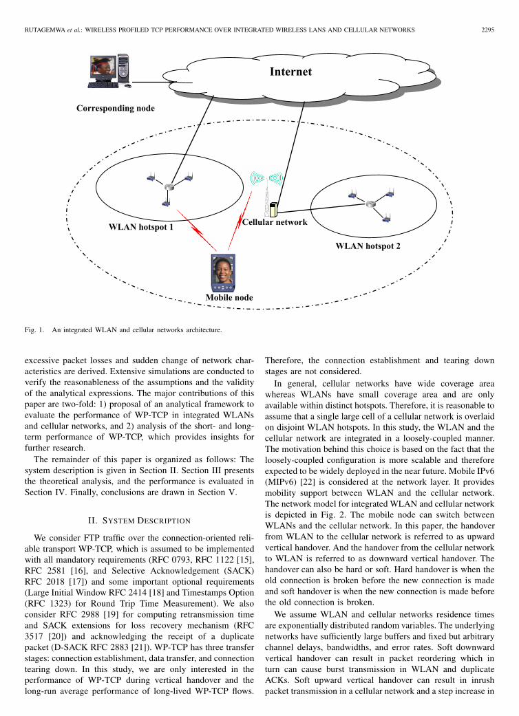
In general, cellular networks have wide coverage areawhereas WLANs have small coverage area and are onlyavailable within distinct hotspots. Therefore, it is reasonable toassume that a single large cell of a cellular network is overlaidon disjoint WLAN hotspots. In this study, the WLAN and thecellular network are integrated in a loosely-coupled manner.The motivation behind this choice is based on the fact that theloosely-coupled configuration is more scalable and thereforeexpected to be widely deployed in the near future. Mobile IPv6(MIPv6) [22] is considered at the network layer. It providesmobility support between WLAN and the cellular network.The network model for integrated WLAN and cellular networkis depicted in Fig. 2. The mobile node can switch betweenWLANs and the cellular network. In this paper, the handoverfrom WLAN to the cellular network is referred to as upwardvertical handover. And the handover from the cellular networkto WLAN is referred to as downward vertical handover. Thehandover can also be hard or soft. Hard handover is when theold connection is broken before the new connection is madeand soft handover is when the new connection is made beforethe old connection is broken.
We assume WLAN and cellular networks residence timesare exponentially distributed random variables. The underlyingnetworks have sufficiently large buffers and fixed but arbitrarychannel delays, bandwidths, and error rates. Soft downwardvertical handover can result in packet reordering which inturn can cause burst transmission in WLAN and duplicateACKs. Soft upward vertical handover can result in inrushpacket transmission in a cellular network and a step increase in
2296 IEEE TRANSACTIONS ON WIRELESS COMMUNICATIONS, VOL. 6, NO. 6, JUNE 2007
Sender
WLAN
Cellular networks
Receiver
Fixed node Mobile node
WLANs
Fig. 2. Network model for integrated WLANs and cellular networks.
round trip time. Since buffers in the networks are consideredto be sufficiently large, analysis of packet losses due to bursttransmissions or inrush packet transmission beyond the scopeof this paper.
III. PERFORMANCE ANALYSIS
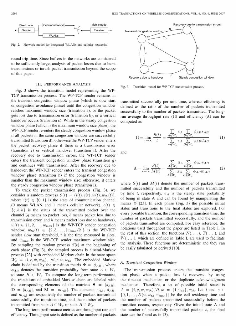
Fig. 3 shows the transition model representing the WP-TCP transmission process. The WP-TCP sender remains inthe transient congestion window phase (which is slow startor congestion avoidance phase) until the congestion windowreaches maximum window size (transition a), or the packetgets lost due to transmission error (transition b), or a verticalhandover occurs (transition c). While in the steady congestionwindow phase (which is the maximum window size phase), theWP-TCP sender re-enters the steady congestion window phaseif all packets in the same congestion window are successfullytransmitted (transition d); otherwise the WP-TCP sender entersthe packet recovery phase if there is a transmission error(transition e) or vertical handover (transition f). After therecovery due to transmission errors, the WP-TCP senderenters the transient congestion window phase (transition g)and continues with transmission. After the recovery due tohandover, the WP-TCP sender enters the transient congestionwindow phase (transition h) if the congestion window issmaller than the maximum window size; otherwise, it entersthe steady congestion window phase (transition i).
To track the packet transmission process (Fig. 3), weconsider a random process S(t) = (i(t), c(t), w(t), wth(t)),where i(t) ∈ {0, 1} is the state of communication channel(0 means WLAN and 1 means cellular network), c(t) ∈{g, b, h} is the status of the transmitted packet over thechannel (g means no packet loss, b means packet loss due totransmission error, and h means packet loss due to handover),w(t) ∈ {1, 2, . . . , wmax} is the WP-TCP sender congestionwindow, wth(t) ∈ {2, 3, . . . , �wmax/2�} is the WP-TCPsender slow start threshold, t is the time measured in slots,and wmax is the WP-TCP sender maximum window size.By sampling the random process S(t) at the beginning ofeach phase (Fig. 3), the sampled process is a semi-Markovprocess [23] with embedded Markov chain in the state spaceWs = (i, c, w, wth), ∀i, c, w, wth. The embedded Markovchain is defined by the transition matrix Φ = [φAB ], whereφAB denotes the transition probability from state A ∈ Ws
to state B ∈ Ws. To compute the long-term performance,the transitions of embedded Markov chain are labeled withthe corresponding elements of the matrices S = [sAB],D = [dAB ], and M = [mAB]. The elements sAB , dAB ,and mAB are respectively the number of packets transmittedsuccessfully, the transition time, and the number of packetstransmitted from state A ∈ Ws to state B ∈ Ws.
The long-term performance metrics are throughput rate andefficiency. Throughput rate is defined as the number of packets
T i i i d
Recovery due to transmission errorsg
Transient congestion window
b
ea
h c
i
Steady congestion window fd
Recovery due to handover
Fig. 3. Transition model for WP-TCP transmission process.
transmitted successfully per unit time, whereas efficiency isdefined as the ratio of the number of packets transmittedsuccessfully to the number of packets transmitted. The long-run average throughput rate (Ω) and efficiency (Λ) can becomputed as
Ω = limt→∞
S(t)t
=
∑A∈Ws
πA
∑B∈Ws
φABsAB∑A∈Ws
πA
∑B∈Ws
φABdAB(1)
and
Λ = limt→∞
S(t)M(t)
=
∑A∈Ws
πA
∑B∈Ws
φABsAB∑A∈Ws
πA
∑B∈Ws
φABmAB, (2)
where S(t) and M(t) denote the number of packets trans-mitted successfully and the number of packets transmittedby time t, respectively. πA is the steady state probabilityof being in state A and can be found by manipulating thematrix Φ [23]. In each phase (Fig. 3) the possible initialstates and transitions to the final states are explored. Forevery possible transition, the corresponding transition time, thenumber of packets transmitted successfully, and the numberof packets transmitted are computed. For easy reference, thenotations used throughout the paper are listed in Table I. Inthe rest of this section, the functions N(., ., .), T (., ., .), andW (., ., .), which are defined in Table I, are used to facilitatethe analysis. These functions are deterministic and they canbe easily tabulated or derived [10].
A. Transient Congestion Window
The transmission process enters the transient conges-tion phase when a packet loss is recovered by usingthe timeout mechanism or the duplicate acknowledgmentmechanism. Therefore, a set of possible initial states isA = (i, g, w, wth), ∀i, w = {1, wth}, wth. Let t and s ∈{0, 1, . . . , N(w, wth, wmax)} be the cell residency time andthe number of packets transmitted successfully before thetransition occurs, respectively. Given the initial state A andthe number of successfully transmitted packets s, the finalstate can be found as in (3).
RUTAGEMWA et al.: WIRELESS PROFILED TCP PERFORMANCE OVER INTEGRATED WIRELESS LANS AND CELLULAR NETWORKS 2297
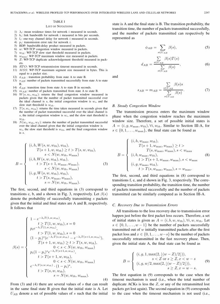
TABLE I
LIST OF NOTATIONS
1) λi: mean residence times for network i measured in seconds.2) bi: link bandwidth for network i measured in bits per seconds.3) li: one-way channel delay for network i measured in seconds.4) pi: transmission error rate for network i.5) BDP: bandwidth-delay product measured in packets.6) w: WP-TCP congestion window measured in packets.7) wth: WP-TCP slow start threshold measured in packets.8) wmax: WP-TCP maximum window size measured in packets.9) Z: WP-TCP duplicate acknowledgement threshold measured in pack-
ets.10) RTO: WP-TCP retransmission timeout measured in seconds.11) MSS: WP-TCP maximum segment size measured in bytes. This is
equal to a packet size.12) φAB : transition probability from state A to state B.13) sAB : number of packets transmitted successfully from state A to state
B.14) dAB : transition time from state A to state B in seconds.15) mAB : number of packets transmitted from state A to state B.16) W (s, wi, wth): returns the final congestion window measured in
packets given that the number of packet transmitted successful overthe ideal channel is s, the initial congestion window is wi, and theslow start threshold is wth.
17) T (s, wi, wth): returns the time taken measured in seconds given thatthe number of packet transmitted successful over the ideal channel iss, the initial congestion window is wi, and the slow start threshold iswth.
18) N(wi, wth, wf ): returns the number of packet transmitted successfulover the ideal channel given that the initial congestion window iswi, the slow start threshold is wth, and the final congestion windowis s.
B =
⎧⎪⎪⎪⎪⎪⎪⎪⎪⎪⎪⎪⎪⎨⎪⎪⎪⎪⎪⎪⎪⎪⎪⎪⎪⎪⎩
(i, h, W (s, w, wth), wth),T (s + 1, w, wth) ≥ t > T (s, w, wth),
s < N(w, wth, wmax)(i, b, W (s, w, wth), wth),
t > T (s + 1, wmax, wmax),s < N(w, wth, wmax)
(i, g, W (s, w, wth), wth),t > T (s, wmax, wmax),
s = N(w, wth, wmax).
(3)
The first, second, and third equations in (3) correspond totransitions c, b, and a shown in Fig. 3, respectively. Let β(s)denote the probability of successfully transmitting s packetsgiven that the initial and final states are A and B, respectively.It follows that
β(s) =
⎧⎪⎪⎪⎪⎪⎪⎪⎪⎪⎪⎪⎪⎪⎪⎪⎪⎪⎪⎪⎪⎨⎪⎪⎪⎪⎪⎪⎪⎪⎪⎪⎪⎪⎪⎪⎪⎪⎪⎪⎪⎪⎩
1 − e−λiT (1,w,wth),t ≥ T (1, w, wth), s = 0
pie−λiT (1,w,wth),
t > T (1, w, wth), s = 0(1 − pi)s(e−λiT (s,w,wth) − e−λiT (s+1,w,wth)),
T (s + 1, w, wth) ≥ t > T (s, w, wth),0 < s < N(w, wth, wmax)
pi(1 − pi)se−λiT (s+1,w,wth),t > T (s + 1, w, wth),
0 < s < N(w, wth, wmax)e−λiT (s,w,wth) · (1 − pi)s,
t > T (s, w, wth),s = N(w, wth, wmax).
(4)From (3) and (4) there are several values of s that can resultin the same final state B given that the initial state is A. LetUAB denote a set of possible values of s such that the initial
state is A and the final state is B. The transition probability, thetransition time, the number of packets transmitted successfully,and the number of packets transmitted can respectively berepresented as
φAB =∑
s∈UAB
β(s), (5)
dAB =
∑s∈UAB
β(s)T (s)∑s∈UAB
β(s), (6)
and
sAB = mAB =
∑s∈UAB
β(s)s∑s∈UAB
β(s). (7)
B. Steady Congestion Window
The transmission process enters the maximum windowphase when the congestion window reaches the maximumwindow size. Therefore, a set of possible initial states isA = (i, g, wmax, wth), ∀i, wth. Similar to Section III-A, fors ∈ {0, 1, . . . , wmax}, the final state can be found as
B =
⎧⎪⎪⎪⎪⎪⎪⎪⎪⎨⎪⎪⎪⎪⎪⎪⎪⎪⎩
(i, h, wmax, wth),T (s + 1, wmax, wmax) ≥ t >
T (s, wmax, wmax), s < wmax
(i, b, wmax, wth),t > T (s + 1, wmax, wmax), s < wmax
(i, g, wmax, wth),t > T (s, wmax, wmax), s = wmax.
(8)
The first, second, and third equations in (8) correspond totransitions f, e, and d shown in Fig. 3, respectively. The corre-sponding transition probability, the transition time, the numberof packets transmitted successfully and the number of packetstransmitted can be similarly computed as in Section III-A.
C. Recovery Due to Transmission Errors
All transitions to the loss recovery due to transmission errorhappen just before the first packet loss occurs. Therefore, a setof initial states is given as A = (i, b, w, wth), ∀i, w, wth. Lets ∈ {0, 1, . . . , w − 1} be the number of packets successfullytransmitted out of w initially transmitted packets after the firstpacket loss and x ∈ {0, 1, . . . , w−s} be the number of packetssuccessfully retransmitted in the fast recovery phase. Then,given the initial state A, the final state can be found as
B =
⎧⎪⎪⎨⎪⎪⎩
(i, g, 1, max(2, �(w − Z)/2�)),s < Z or s ≥ Z, x < w − s
(i, g, w/2, max(2, �(w − Z)/2�)),s ≥ Z, x = w − s.
(9)
The first equation in (9) corresponds to the case when thetimeout mechanism is used (i.e., when the total number ofduplicate ACKs is less the Z , or any of the retransmitted lostpackets get lost again). The second equation in (9) correspondsto the case when the timeout mechanism is not used (i.e.,
2298 IEEE TRANSACTIONS ON WIRELESS COMMUNICATIONS, VOL. 6, NO. 6, JUNE 2007
when there is enough duplicate ACKs and all retransmittedpackets are successful). Let α(s, w) be the probability ofhaving successfully transmitted s packets out of w transmittedpackets given that the packet transmission error rate is pi. Itfollows that
α(w, s) =(
ws
)pw−s
i (1 − pi)s. (10)
From (9) and (10) the probability that s ≥ Z and x = w−s is
found asw−1∑s=z
α(w − 1, s)(1 − pi)w−s. Given the initial state
is A and the final state is B, the transition probability can becomputed as
φAB =
⎧⎪⎪⎪⎪⎪⎪⎨⎪⎪⎪⎪⎪⎪⎩
1 −w−1∑s=z
α(w − 1, s)(1 − pi)w−s,
s < Z or s ≥ Z, x < w − sw−1∑s=z
α(w − 1, s)(1 − pi)w−s,
s ≥ Z, x = w − s.(11)
The transition time in this loss recovery phase is consideredto be an interval between a time slot when the ACK forthe lost packet is received (entering the loss recovery phase)and the time slot when the timeout is expired or when afull ACK of retransmitted packet is received (exiting the lossrecovery phase). When s < Z, the timeout mechanism is usedand the transition time is simply the retransmission timeout(RTO). To compute the transition time for s ≥ Z , we furtherconsider two time intervals: 1) the time interval betweenentering the loss recovery phase and starting fast retransmit,and 2) the time interval between starting fast retransmit andexiting the loss recovery phase. These time intervals can becomputed by conditioning the order and the number of packetssuccessfully transmitted before fast retransmit and successfullyretransmitted in fast retransmit and fast recovery. However,with this approach, the analysis can become extremely tediousand complex. In the following, we use the close bounds ofboth time intervals. We assume that lost packets from thewindow w are retransmitted and if all are successful the fastrecovery ends in a round-trip time RTT ; otherwise, if anyof them gets lost the retransmission timeout timer will expireafter the time interval RTO. Note that with approximation,the recovery time can be higher than approximated. However,the deviation is expected to be reasonable due to the fact thatby enabling the SACK option all lost packets in the samesender’s window are reported to the WP-TCP sender withinone round-trip time. The transition time can be estimated as
dAB =
⎧⎪⎪⎪⎪⎪⎪⎨⎪⎪⎪⎪⎪⎪⎩
z−1∑s=0
α(w − 1, s)RTO
+w−1∑s=z
α(w − 1, s)(RTT + RTO),
s < Z or s ≥ Z, x < w − s2RTT, s ≥ Z, x = w − s,
(12)
where RTO = max {RTOmin, wMSS/bi, 2li + MSS/bi}and RTT = max {wMSS/bi, 2li + MSS/bi}. The number
of packets transmitted successfully and the number of packetstransmitted can respectively be found as
sAB =
⎧⎪⎪⎪⎪⎪⎪⎪⎪⎨⎪⎪⎪⎪⎪⎪⎪⎪⎩
z−1∑s=0
α(w − 1, s)s
+w−1∑s=z
⎛⎝s +
w−s−1�
k=0α(w−s,k)k
w−s−1�
k=0α(w−s,k)
⎞⎠ α(w − 1, s),
s < Z or s ≥ Z, x < w − sw, s ≥ Z, x = w − s
(13)and
mAB =
⎧⎪⎪⎪⎪⎪⎪⎪⎪⎪⎪⎨⎪⎪⎪⎪⎪⎪⎪⎪⎪⎪⎩
z−1∑s=0
α(w − 1, s)w
+w−1∑s=z
α(w − 1, s)(w + (w − s)),
s < Z or s ≥ Z, x < w − sw−1�
s=z(w+(w−s))·α(w−1,s)
w−1�
s=zα(w−1,s)
, s ≥ Z, x = w − s.
(14)
D. Recovery Due to Handover
1) Soft Downward Vertical Handover: After observing thetransmission process during soft downward vertical handover,we find that fast transmit cannot occur if at least one ofthe following conditions is true: 1) If the number of burstdata packet injected in the new link, which can potentiallyovertake data packets in the old link, is less than duplicateACK threshold (Z); 2) If the number of data packets thatcan be transmitted from WLAN access point in the intervalof two consecutive data packet transmitted from the cellularnetwork base station is less than Z; and 3) If the transmissionof the last data packets in the old link is completed beforethe number duplicate ACKs generated by reorder data packetreaches duplicate ACK threshold. In order to compute theminimum duplicate ACK threshold (Zmin) over which fasttransmit cannot occur, we consider the above conditions inthe following cases.
• Case I: When wMSS/b1 > 2l1. Let Zi, i = 1, 2, 3,denote the minimum Z which satisfies the condition i.Since the burst data packet can only occur if ACK sentthrough upward WLAN overtakes the ones in cellularnetwork, condition 1 is satisfied when Z1MSS/b1+l2 >l1. For condition 2, the transmission time of Z2 reorderedpackets in WLAN must be greater than the transmissiontime of a packet in cellular network. Therefore, condition2 is satisfied if Z2MSS/b2 > MSS/b1. After initiatingthe handover, the time elapsed before the completion oftransmission of the last data packet in the cellular networkis given as (wMSS/b1 − l1). And the time needed forduplicate ACKs, generated by reordered data packets,to reach Z3 is given as (2l2 + Z3MSS/b2). There-fore, condition 3 is satisfied if (2l2 + Z3MSS/b2) >(wMSS/b1−l1). The minimum duplicate ACK thresholdis computed as Zmin = min{Z1, Z2, Z3, w}.
RUTAGEMWA et al.: WIRELESS PROFILED TCP PERFORMANCE OVER INTEGRATED WIRELESS LANS AND CELLULAR NETWORKS 2299
• Case II: When wMSS/b1 ≤ 2l1. In this case, the oc-currence of fast transmit further depends on the instancethat the handover occurs in a round trip time. Therefore,we consider a reasonable upper-bound. Since when Z isequal to or greater than w fast transmit cannot occur, theminimum duplicate ACK threshold is approximated asZmin = w.
Given the set of initial states before handover as A =(1, h, w, wth), ∀w, wth, the final state after handover can befound as
B =
{(0, g, W (w, w, wth), wth), Z ≥ Zmin
(0, g, (w−Z)2 , max(2,
⌊(w−Z)
2
⌋)), Z < Zmin,
(15)
The first equation in (15) corresponds to the case in whichduplicate ACK threshold is equal or greater than Zmin andtherefore fast transmit is not triggered. The second equation in(15) corresponds to the case in which duplicate ACK thresholdis less than Zmin, and therefore fast transmit is triggered.Note that when fast transmit is triggered, the slow startthreshold and congestion window are set to half of the pipe(number of unacknowledged packets (w−Z)). The transitionprobability and the number of packets transmitted successfullycan respectively be found as φAB = 1 and sAB = w.
The recovery process for soft downward vertical handoverwill start right after the handover initiation and end afterreceiving an ACK of the last packet sent before the handoverinitiation. Therefore, the transition time is approximately equalto a round trip time experienced by a data packet transmittedthrough the cellular network and ACK packet returned throughthe WLAN, which is given as dAB = max{wMSS/b1 −l1 + l0, MSS/b1 + l1 + l0}. Note that if the WLAN roundtrip time is extremely small compared to the cellular networkround trip time, fast transmit followed by fast recovery can endbefore the ACKs of packets sent through the cellular networkarrive at the WP-TCP sender. In this case, the proposedmodel slightly overestimates the transition time. The numberof packets transmitted includes all in-flight data packets justbefore handover (which is equal to w) plus unnecessaryretransmitted packets, if fast transmit is triggered. Becauseof the go-back-N retransmission behavior of WP-TCP, thenumber of unnecessary retransmissions is close to half of thepipe just before the fast transmit (i.e., (w−Z)/2). Therefore,the number of packets transmitted can be found as
mAB ={
w, wMSS/b1 ≤ 2l1w + (w − Z)/2, wMSS/b1 > 2l1.
(16)
2) Soft Upward Vertical Handover: Let RTO and Y denoteretransmission timeout set at the WP-TCP sender just beforethe initiation of the handover and the time difference betweenthe arrival of the last ACK from WLAN and the first ACKfrom cellular network at the WP-TCP sender, respectively.Note that the step increase in round trip time suddenlyincreases the magnitude of Y . During time interval Y , theretransmission timeout timer at the WP-TCP sender countsdown the clock. Therefore, false timeouts can occur if Y >
RTOn∑
k=1
2k−1 where n is the number of consecutive prema-
ture timeouts and it can be found as n = �log2(1 + Y/RTO)�.
Retransmission timeout can be approximated as RTO =max {RTOmin, wMSS/b0, 2l0 + MSS/b0}. In order tocompute Y , we consider the following cases.
• Case I: When 2l0b0/MSS < w. In this case, the WP-TCP receiver is always busy receiving data packet andsending ACK. Therefore, Y is approximately (l1 − l0).
• Case II: When l0b0/MSS < w ≤ 2l0b0/MSS. Ifhandover occurs when the WP-TCP receiver is busy onreceiving data packet and sending ACK packets, then Yis approximately equal to (l1−l0). Otherwise, if handoveroccurs when the WP-TCP receiver is idle waiting for in-flight data packets to arrive from the WP-TCP sender, Yis approximately (l0 − wMSS/b0 + l1).
• Case III: When w ≤ l0b0/MSS. If handover occurswhen the WP-TCP receiver is busy on receiving datapacket and sending ACK packets, then Y is approxi-mately equal to (l1 − l0). Or, if handover occurs whenthe WP-TCP receiver is idle waiting for in-flight datapackets to arrive from the WP-TCP sender, then Y isapproximately equal to (l0−wMSS/b0+ l1). Otherwise,if handover occurs when the WP-TCP receiver is idlewaiting for in-flight ACK packets to arrive to the WP-TCP sender, then Y is approximately (2l1−wMSS/b0).
From the above three cases, the value of Y correspondingto the worst, average, or best timeouts performance can becomputed. For the sake of brevity, only the worst timeoutperformance (i.e., consider the maximum value of Y for eachcase) is considered in this paper. Therefore, the maximumtime difference between the arrival of the last ACK from theWLAN and the first ACK from the cellular network at theWP-TCP sender is given as
Y =
⎧⎪⎪⎨⎪⎪⎩
l1 − l0, 2l0b0/MSS < wl0 − wMSS/b0 + l1,
l0b0/MSS < w ≤ 2l0b0/MSS2l1 − wMSS/b0, w ≤ l0b0/MSS.
(17)
Given the set of initial states before handover as A =(1, h, w, wth), ∀w, wth, the final state after handover can befound as
B =
⎧⎪⎪⎨⎪⎪⎩
(1, g, W (w, w, wth), wth), Y ≤ RTO(1, g, W (w, 1, w
2 , max(2,⌊
w2
⌋)),
RTO < Y ≤ 3RTO(1, g, W (w, 1, 2), 2), 3RTO < Y.
(18)
The first equation in (18) corresponds to the case wherethe timeout does not occur. The second equation in (18)corresponds to the case where a single timeout occurs. Thethird equation in (18) corresponds to the case where two ormore timeouts occur. Note that after a single timeout, theslow start threshold is set to half of the current congestionwindow and the congestion window is set to one. After twoor more timeouts slow start threshold is set to two (theminimum value) and the congestion window is set to one.The transition probability can be found as φAB = 1 and thenumber of packets transmitted successfully can be computedas sAB = w. The transition time can be written as
2300 IEEE TRANSACTIONS ON WIRELESS COMMUNICATIONS, VOL. 6, NO. 6, JUNE 2007
dAB =
⎧⎪⎪⎨⎪⎪⎩
max{wMSS/b0 − l0 + l1,MSS/b0 + l0 + l1}, Y ≤ RTO
(MSS/b1 + 2l1)+ (wMSS/b1 + 2l1), Y > RTO.
(19)
Equation (19) can be explained as follows. If there is notimeout during handover (i.e., when Y ≤ RTO), the transitiontime is equal to a round trip time, where the data packet issent through the WLAN and the corresponding ACK packetis returned through the cellular network. Otherwise, if thereis a single or multiple timeouts during handover (i.e., whenY > RTO) the transition time is found by summing two roundtrip times: a round trip time for a data packet sent through thecellular network after handover (MSS/b1+2l1) and the roundtrip time of the new packet sent through the cellular networkafter retransmitting the entire window (wMSS/b1+2l1). Notethat if there is a single or multiple timeouts, the transitiontime is considered to start right after the handover initiationand end after receiving an ACK of the new packet sentafter the timeout. The packets transmitted include all in-flightdata packets just before handover (which is equal to w) andunnecessarily retransmitted packets due to single or multipletimeouts. Because of the go-back-N retransmission behaviorof WP-TCP, the number of unnecessary retransmissions isapproximately (n + w − 1), where n is the number ofconsecutive premature timeouts. Therefore, the number ofpackets transmitted can be found as
mAB ={
w, Y ≤ RTOw + (n + w − 1), Y > RTO.
(20)
3) Hard Downward and Upward Vertical Handover: Afterhard downward or upward vertical handover all in-flight pack-ets get lost. Under this conjecture, a similar model for bothhard downward and upward vertical handovers is developed.Let i denote the network other than i (for example, if i = 1(cellular network) then i = 0 (WLAN)). Therefore, the roundtrip time experienced by the first packet retransmitted throughnetwork i (the new network) is RTT = (2li + MSS/bi)and the WP-TCP sender retransmission timeout is RTO =max {RTOmin, wMSS/bi, 2li + MSS/bi}. Given the set ofinitial states as A = (i, h, w, wth), ∀i, w, wth, the final statecan be deterministically found as
B ={
(i, g, 1, max(2, �w/2�)), RTT ≤ 2RTO(i, g, 1, 2), RTT > 2RTO
(21)
The transition probability, the transition time, and the numberof successfully transmitted packets can be found as φAB =1, dAB = RTO, and sAB = 0, respectively. Since thetimeout mechanism is only used to detect and recover lostpackets after handover, at least one timeout must occur.After the first timeout, k additional timeouts can occur if
RTT > RTOk∑
j=1
2j . The number of additional timeouts can
be found as k = �log2(1 + 0.5RTT/RTO)�. The numberof packets transmitted is the sum of all in-flight data packetsjust before handover (which equals to congestion window)and the number of retransmitted packets due to timeouts.
Therefore, the number of packets transmitted can be foundas mAB = w + 1 + �log2(1 + 0.5RTT/RTO)�.
IV. PERFORMANCE EVALUATION
The proposed analytical model is verified by simulationusing two different simulators - our network simulator test-bed [24] and ns-2 simulator [25]. The simulation topology isshown in Fig. 2. A single pair of wireless profiled TCP (WP-TCP) sender-receiver is configured to run over the integratedWLANs and cellular network. FTP is used as an applicationfor unidirectional downlink transfer. WP-TCP is simulatedaccording to the real protocol as described in Section II; theunderling network is simulated to capture the fundamentaleffects of the vertical handover. Therefore, the results fromsimulations may be slightly inflated compared to those ob-tained from the real network. However, the trends relatedto vertical handover are similar. Each simulation scenario isrepeated 200 times with different random seeds to arrive atthe average results. The simulation and analytical results areobtained by using the parameter values and units given inTable II. Note that the notation for ordered pair (cellularnetwork, WLAN) is consistently used to present networkparameters.
In the next subsections, we evaluate the short- and long-term performances of WP-TCP under the influence of verticalhandover. For short-term performance, we first analyze theoccurrence and the impact of falsely triggered fast retransmitsin 60 seconds after the soft upward vertical handover. Weanalyze the occurrence and impact of premature timeouts in60 seconds after the soft downward vertical handover. Forlong-term performance, we analyze the long-run efficiency andthroughput under the influence of the hard vertical handovers.In this case, each simulation is run for sufficiently long timeto obtain the average performance. Note that if not statedotherwise, BDP denotes the bandwidth-delay product of thenetwork in use before the vertical handover. It is measured inpackets and computed as BDP = 2lb/MSS + 1.
From Figs. 4–10, it can be seen that despite of approxi-mations introduced in Section III, the analytical results arein agreement with the simulation results. This verifies thereasonableness of our assumptions and correctness of theanalysis.
A. Short-Term Fast Retransmit Performance
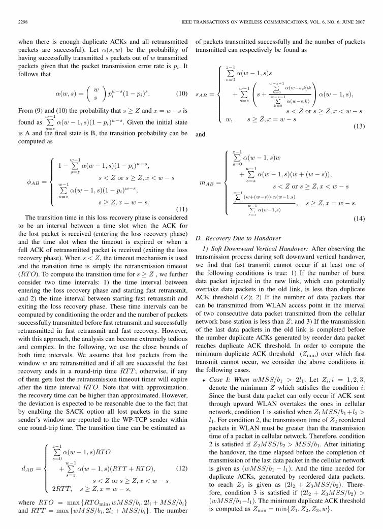
The percentage of false fast retransmits and the averagenumber of packets retransmitted after the soft downwardhandover are investigated at various values of duplicate ACKthreshold (Z) and congestion window (w). In each case, thecellular network and WLAN one-way channel delay are setto 0.5 sec and 0.1 sec, respectively. In Fig. 4a, the handoveris initiated when w = 6, 12, and 24 packets. It can be seenthat when the congestion window (w = 24 packets) is greaterthan the BDP, the occurrence of false fast retransmits changesfrom 100% to zero at Z = 8. On the other hand, when thecongestion window (w = 12, 6 packets) is less than BDP falsefast transmits occur for Z < w. To get more insight on thistrend, the relationship between the percentage of false fastretransmits and the congestion window is analyzed for Z =
RUTAGEMWA et al.: WIRELESS PROFILED TCP PERFORMANCE OVER INTEGRATED WIRELESS LANS AND CELLULAR NETWORKS 2301
TABLE II
SIMULATION PARAMETERS
Parameters RangeMean residence times (λ1, λ0) (200,200) sec
Link bandwidth (b1, b0) (144K,2M) bpsOne-way channel delay (11, 10) (0.01–1,0.01–0.1 secTransmission error rate (p1, p0) (0.00–0.15,0.00–0.02)Network buffer size (B1, B0) (2wmax, 2wmax)
WP-TCP maximum window size (wmax) 5–65 packetsWP-TCP duplicate acknowledgement threshold (Z) 1–15 packets
Minimum retransmission timeout (RTOmin) 0.2 secWP-TCP maximum segment size (MSS) 1 KB
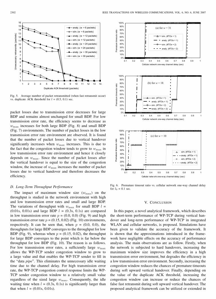
7 and 8. From Fig. 4b, it can be seen that when Z < 8, thepercentage of false fast retransmits increases to 100% as wapproaches the BDP. However, when 8 ≤ Z , the percentageof false fast retransmits increases and then decreases to zeroas w reaches the BDP. These results reveal unexpected trendof the minimum Z which prevents the occurrence of false fasttransmits as w increases. Fig. 5 presents the average numberof packet retransmitted (if fast transmit occurs) as a functionof duplicate ACK threshold. It is shown that the numberof retransmitted packets increases as the congestion windowincreases and decreases as Z decreases. This trend is explainedby the go-back-N retransmission behavior of WP-TCP, wherethe number of retransmitted packets is proportional to thenumber of outstanding unacknowledged packets (w − Z).
B. Short-Term Retransmission Timeout Performance
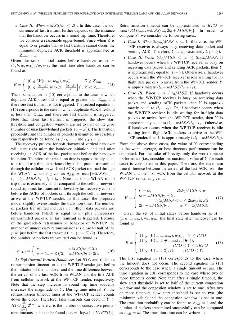
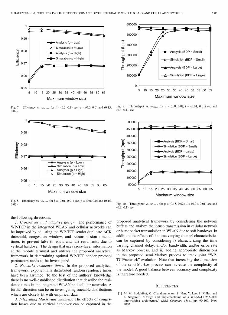
Premature timeouts that occur during the soft upward han-dover is studied. The duplicate ACK threshold is set to 3and the WLAN one-way channel delay is set to 0.1 sec. Thehandover is initiated when the size of congestion window is10, 18, and 30. Fig. 6 presents the percentage of single (#TO= 1) and two consecutive (#TO = 2) premature timeouts asa function of the cellular network one-way channel delay. Itcan be seen that the lowest cellular network one-way channeldelay that can result in single or two consecutive prematuretimeouts decreases as the congestion window decreases. Theobserved trend can be explained as follows. The timeoutscan occur when the retransmission timeout is less than themaximum time between the arrival of the last ACK from theWLAN and the first ACK from the cellular network. Whenthe congestion window is greater than the BDP, decrease incongestion window decreases the retransmission time but doesnot affect the maximum time between the arrivals of thetwo ACKs. And when the congestion window is less thanthe BDP, decrease in congestion window does not affect theretransmission time but increases the maximum time betweenthe arrivals of the two ACKs.
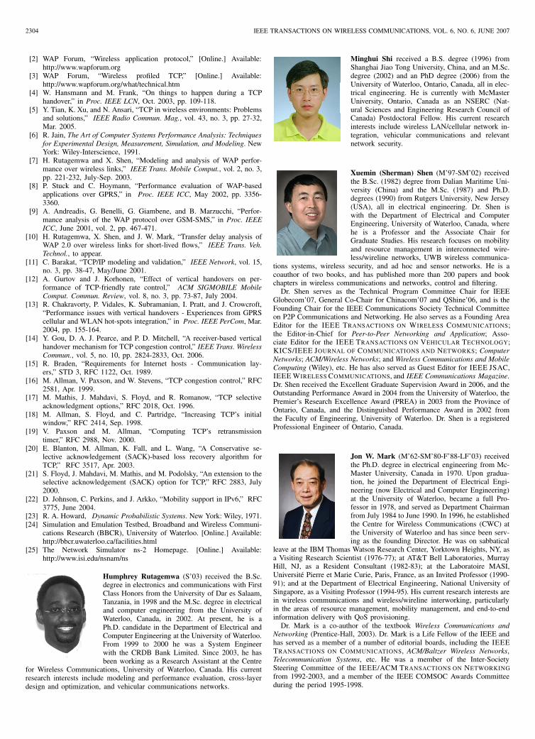
C. Long-Term Efficiency Performance
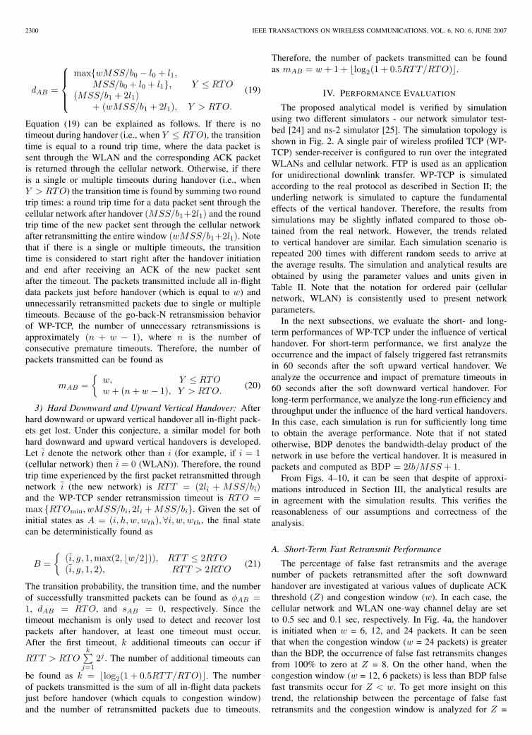
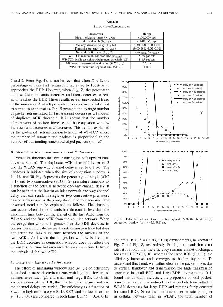
The effect of maximum window size (wmax) on efficiencyis studied in network environments with high and low trans-mission error rates (p), and small and large BDP. To obtainvarious values of the BDP, the link bandwidths are fixed andthe channel delays are varied. The efficiency as a function ofwmax for high error rate p = (0.15, 0.02) and for low error ratep = (0.0, 0.0) are compared in both large BDP l = (0.3s, 0.1s)
0%
10%
20%
30%
40%
50%
60%
70%
80%
90%
100%
1 2 3 4 5 6 7 8 9 10 11 12 13 14 15 16 17 18 19 20
Duplicate ACK threshold
Fals
e fa
st re
trans
mit
ratio
analy. (w = 6 packets)sim. (w = 6 packets)analy. (w = 12 packets)sim. (w = 12 packets)analy. (w = 24 packets)sim. (w = 24 packets)
0%
10%
20%
30%
40%
50%
60%
70%
80%
90%
100%
5 6 7 8 9 10 11 12 13 14 15 16 17 18 19 20 21
Congestion window (packets)
Fals
e fa
st re
trans
mit
ratio
analy. (Z = 7)sim. (Z = 7)analy. (Z = 8)sim. (Z = 8)
(a)
(b)
Fig. 4. False fast retransmit ratio vs. (a) duplicate ACK threshold and (b)congestion window for l = (0.5, 0.1) sec.
and small BDP l = (0.01s, 0.01s) environments, as shown inFig. 7 and Fig. 8, respectively. For high transmission errorrate, it is shown that the efficiency remains almost unchangedfor small BDP (Fig. 8), whereas for large BDP (Fig. 7), theefficiency increases and converges to the limiting point. Tounderstand this trend, we further observe the packet losses dueto vertical handover and transmission for high transmissionerror rate in small BDP and large BDP environments. It isfound that as wmax increases, the proportion of total packetstransmitted in cellular network to the packets transmitted inWLAN decreases for large BDP and remains fairly constantfor small BDP. Since the transmission error rate is higherin cellular network than in WLAN, the total number of
2302 IEEE TRANSACTIONS ON WIRELESS COMMUNICATIONS, VOL. 6, NO. 6, JUNE 2007
0123456789
10111213141516
1 2 3 4 5 6 7 8 9 10 11 12 13 14
Duplicate ACK threshold (packets)
Unn
eces
sary
retra
nsm
its (p
acke
ts)
analy. (w = 6 packets)
sim. (w = 6 packets)
analy. (w = 12 packets)
sim. (w = 12 packets)
analy. (w = 24 packets)
sim. (w = 24 packets)
analy. (w = 30 packets)
sim. (w = 30 packets)
Fig. 5. Average number of packet retransmitted (when fast retransmit occur)vs. duplicate ACK threshold for l = (0.5, 0.1) sec.
packet losses due to transmission error decreases for largeBDP and remains almost unchanged for small BDP. For lowtransmission error rate, the efficiency seems to decrease aswmax increases for both large BDP (Fig. 8) and small BDP(Fig. 7) environments. The number of packet losses in the lowtransmission error rate environment are observed. It is foundthat the number of packet losses due to vertical handoversignificantly increases when wmax increases. This is due tothe fact that the congestion window tends to grow to wmax inlow transmission error rate environment and hence it closelydepends on wmax. Since the number of packet losses afterthe vertical handover is equal to the size of the congestionwindow, the increase of wmax increases the number of packetlosses due to vertical handover and therefore decreases theefficiency.
D. Long-Term Throughput Performance
The impact of maximum window size (wmax) on thethroughput is studied in the network environment with highand low transmission error rates and small and large BDP.The variations of throughput with wmax for small BDP l =(0.01s, 0.01s) and large BDP l = (0.3s, 0.1s) are comparedin low transmission error rate p = (0.0, 0.0) (Fig. 9) and hightransmission error rate p = (0.15, 0.02) (Fig. 10) environments,respectively. It can be seen that, when p = (0.0, 0.0), thethroughputs for large BDP converges to the throughput for lowBDP (Fig. 9), whereas when p = (0.15, 0.02), the throughputfor large BDP converges to the point which is far below thethroughput for low BDP (Fig. 10). The reason is as follows.For low transmission error rates, a sufficiently large wmax
allows the WP-TCP sender congestion window to grow toa large value and that enables the WP-TCP sender to fill inthe “data pipe”. This eliminates the unnecessary idle waitingtime due to the channel delay. For high transmission errorrate, the WP-TCP congestion control response limits the WP-TCP sender congestion window to a relatively small valueregardless of the sized large wmax. Consequently, the idlewaiting time when l = (0.3s, 0.1s) is significantly larger thanthat when l = (0.01s, 0.01s).
0%
10%
20%
30%
40%
50%
60%
70%
80%
90%
100%
0.1 0.2 0.3 0.4 0.5 0.6 0.7 0.8 0.9 1
Cellular network one-way channel delay (sec)
Pre
mat
ure
timeo
uts
ratio
sim. (#TOs = 1)
analy. (#TOs = 1)
sim. (#TOs = 2)
analy. (#TOs = 2)
0%
10%
20%
30%
40%
50%
60%
70%
80%
90%
100%
0.1 0.2 0.3 0.4 0.5 0.6 0.7 0.8 0.9 1
Cellular network one-way channel delay (sec)P
rem
atur
e tim
eout
s ra
tio
sim. (#TOs = 1)
analy. (#TOs = 1)
sim. (#TOs = 2)
analy. (#TOs = 2)
0%
10%
20%
30%
40%
50%
60%
70%
80%
90%
100%
0.1 0.2 0.3 0.4 0.5 0.6 0.7 0.8 0.9 1
Cellular netw ork one-w ay channel delay (sec)
Prem
atur
e tim
eout
s ra
tio
sim. (#TOs = 1)
analy. (#TOs = 1)sim. (#TOs = 2)
analy. (#TOs = 2)
(a) for w = 31
(b) for w = 18
(c) for w = 10
Fig. 6. Premature timeout ratio vs. cellular network one-way channel delayfor l0 = 0.1 sec.
V. CONCLUSION
In this paper, a novel analytical framework, which describesthe short-term performance of WP-TCP during vertical han-dover and long-term performance of WP-TCP in integratedWLAN and cellular networks, is proposed. Simulations havebeen given to validate the accuracy of the framework. Itis shown that the approximations introduced in the frame-work have negligible effects on the accuracy of performanceanalysis. The main observations are as follow. Firstly, whenthe network is subjected to hard handovers, increasing themaximum window size improves the efficiency in a hightransmission error environment, but degrades the efficiency ina low transmission error environment. Secondly, increasing thecongestion window reduces the chances of premature timeoutsduring soft upward vertical handover. Finally, depending onthe value of the duplicate ACK threshold, increasing thecongestion window can increase or reduce the chances offalse fast retransmit during soft upward vertical handover. Theproposed analytical framework can be utilized or extended in
RUTAGEMWA et al.: WIRELESS PROFILED TCP PERFORMANCE OVER INTEGRATED WIRELESS LANS AND CELLULAR NETWORKS 2303
0.95
0.96
0.97
0.98
0.99
1
5 10 15 20 25 30 35 40 45 50 55 60 65
Maximum window size
Effi
cien
cy
Analysis (p = Low)
Simulation (p = Low)
Analysis (p = High)
Simulation (p = High)
Fig. 7. Efficiency vs. wmax for l = (0.3, 0.1) sec, p = (0.0, 0.0) and (0.15,0.02).
0.95
0.96
0.97
0.98
0.99
1
5 10 15 20 25 30 35 40 45 50 55 60 65
Maximum window size
Effi
cien
cy
Analysis (p = Low )Simulation (p = Low )Analysis (p = High)Simulation (p = High)
Fig. 8. Efficiency vs. wmax for l = (0.01, 0.01) sec, p = (0.0, 0.0) and (0.15,0.02).
the following directions.1. Cross-layer and adaptive design: The performance of
WP-TCP in the integrated WLAN and cellular networks canbe improved by adjusting the WP-TCP sender duplicate ACKthreshold, congestion window, and retransmission timeouttimer, to prevent false timeouts and fast retransmits due tovertical handover. The design that uses cross-layer informationat the mobile terminal and utilizes the proposed analyticalframework in determining optimal WP-TCP sender protocolparameters needs to be investigated.
2. Networks residence times: In the proposed analyticalframework, exponentially distributed random residence timeshave been assumed. To the best of the authors’ knowledgethere is no well-established distribution that describe the resi-dence times in the integrated WLAN and cellular networks. Afurther direction can be on investigating tractable distributionswhich are closely fit with empirical data.
3. Integrating Markovian channels: The effects of conges-tion losses due to vertical handover can be captured in the
0
100000
200000
300000
400000
500000
600000
5 10 15 20 25 30 35 40 45 50 55 60 65
Maximum window size
Thro
ughp
ut (b
ps)
Analysis (BDP = Small)
Simulation (BDP = Small)
Analysis (BDP = Large)
Simulation (BDP = Large)
Fig. 9. Throughput vs. wmax for p = (0.0, 0.0), l = (0.01, 0.01) sec and(0.3, 0.1) sec.
50000
100000
150000
200000
250000
300000
350000
400000
450000
500000
5 10 15 20 25 30 35 40 45 50 55 60 65
Maximum window size
Thro
ughp
ut (b
ps)
Analysis (BDP = Small)
Simulation (BDP = Small)
Analysis (BDP = Large)Simulation (BDP = Large)
Fig. 10. Throughput vs. wmax for p = (0.15, 0.02), l = (0.01, 0.01) sec and(0.3, 0.1) sec.
proposed analytical framework by considering the networkbuffers and analyze the inrush transmission in cellular networkor burst packet transmission in WLAN due to soft handover. Inaddition, the effects of the time varying channel characteristicscan be captured by considering i) characterizing the timevarying channel delay, and/or bandwidth, and/or error rateas Markov process, and ii) adding appropriate dimensionsin the proposed semi-Markov process to track joint “WP-TCP/network” evolution. Note that increasing the dimensionof the semi-Markov process can increase the complexity ofthe model. A good balance between accuracy and complexityis therefore needed.
REFERENCES
[1] M. M. Buddhikot, G. Chandranmenon, S. Han, Y. Lee, S. Miller, andL. Salgarelli, “Design and implementation of a WLAN/CDMA2000interworking architecture,” IEEE Commun. Mag., pp. 90-100, Nov.2003.
2304 IEEE TRANSACTIONS ON WIRELESS COMMUNICATIONS, VOL. 6, NO. 6, JUNE 2007
[2] WAP Forum, “Wireless application protocol,” [Online.] Available:http://www.wapforum.org
[3] WAP Forum, “Wireless profiled TCP,” [Online.] Available:http://www.wapforum.org/what/technical.htm
[4] W. Hansmann and M. Frank, “On things to happen during a TCPhandover,” in Proc. IEEE LCN, Oct. 2003, pp. 109-118.
[5] Y. Tian, K. Xu, and N. Ansari, “TCP in wireless environments: Problemsand solutions,” IEEE Radio Commun. Mag., vol. 43, no. 3, pp. 27-32,Mar. 2005.
[6] R. Jain, The Art of Computer Systems Performance Analysis: Techniquesfor Experimental Design, Measurement, Simulation, and Modeling. NewYork: Wiley-Interscience, 1991.
[7] H. Rutagemwa and X. Shen, “Modeling and analysis of WAP perfor-mance over wireless links,” IEEE Trans. Mobile Comput., vol. 2, no. 3,pp. 221-232, July-Sep. 2003.
[8] P. Stuck and C. Hoymann, “Performance evaluation of WAP-basedapplications over GPRS,” in Proc. IEEE ICC, May 2002, pp. 3356-3360.
[9] A. Andreadis, G. Benelli, G. Giambene, and B. Marzucchi, “Perfor-mance analysis of the WAP protocol over GSM-SMS,” in Proc. IEEEICC, June 2001, vol. 2, pp. 467-471.
[10] H. Rutagemwa, X. Shen, and J. W. Mark, “Transfer delay analysis ofWAP 2.0 over wireless links for short-lived flows,” IEEE Trans. Veh.Technol., to appear.
[11] C. Barakat, “TCP/IP modeling and validation,” IEEE Network, vol. 15,no. 3, pp. 38-47, May/June 2001.
[12] A. Gurtov and J. Korhonen, “Effect of vertical handovers on per-formance of TCP-friendly rate control,” ACM SIGMOBILE MobileComput. Commun. Review, vol. 8, no. 3, pp. 73-87, July 2004.
[13] R. Chakravorty, P. Vidales, K. Subramanian, I. Pratt, and J. Crowcroft,“Performance issues with vertical handovers - Experiences from GPRScellular and WLAN hot-spots integration,” in Proc. IEEE PerCom, Mar.2004, pp. 155-164.
[14] Y. Gou, D. A. J. Pearce, and P. D. Mitchell, “A receiver-based verticalhandover mechanism for TCP congestion control,” IEEE Trans. WirelessCommun., vol. 5, no. 10, pp. 2824-2833, Oct. 2006.
[15] R. Braden, “Requirements for Internet hosts - Communication lay-ers,” STD 3, RFC 1122, Oct. 1989.
[16] M. Allman, V. Paxson, and W. Stevens, “TCP congestion control,” RFC2581, Apr. 1999.
[17] M. Mathis, J. Mahdavi, S. Floyd, and R. Romanow, “TCP selectiveacknowledgment options,” RFC 2018, Oct. 1996.
[18] M. Allman, S. Floyd, and C. Partridge, “Increasing TCP’s initialwindow,” RFC 2414, Sep. 1998.
[19] V. Paxson and M. Allman, “Computing TCP’s retransmissiontimer,” RFC 2988, Nov. 2000.
[20] E. Blanton, M. Allman, K. Fall, and L. Wang, “A Conservative se-lective acknowledgement (SACK)-based loss recovery algorithm forTCP,” RFC 3517, Apr. 2003.
[21] S. Floyd, J. Mahdavi, M. Mathis, and M. Podolsky, “An extension to theselective acknowledgement (SACK) option for TCP,” RFC 2883, July2000.
[22] D. Johnson, C. Perkins, and J. Arkko, “Mobility support in IPv6,” RFC3775, June 2004.
[23] R. A. Howard, Dynamic Probabilistic Systems. New York: Wiley, 1971.[24] Simulation and Emulation Testbed, Broadband and Wireless Communi-
cations Research (BBCR), University of Waterloo. [Online.] Available:http://bbcr.uwaterloo.ca/facilities.html
[25] The Network Simulator ns-2 Homepage. [Online.] Available:http://www.isi.edu/nsnam/ns
Humphrey Rutagemwa (S’03) received the B.Sc.degree in electronics and communications with FirstClass Honors from the University of Dar es Salaam,Tanzania, in 1998 and the M.Sc. degree in electricaland computer engineering from the University ofWaterloo, Canada, in 2002. At present, he is aPh.D. candidate in the Department of Electrical andComputer Engineering at the University of Waterloo.From 1999 to 2000 he was a System Engineerwith the CRDB Bank Limited. Since 2003, he hasbeen working as a Research Assistant at the Centre
for Wireless Communications, University of Waterloo, Canada. His currentresearch interests include modeling and performance evaluation, cross-layerdesign and optimization, and vehicular communications networks.
Minghui Shi received a B.S. degree (1996) fromShanghai Jiao Tong University, China, and an M.Sc.degree (2002) and an PhD degree (2006) from theUniversity of Waterloo, Ontario, Canada, all in elec-trical engineering. He is currently with McMasterUniversity, Ontario, Canada as an NSERC (Nat-ural Sciences and Engineering Research Council ofCanada) Postdoctoral Fellow. His current researchinterests include wireless LAN/cellular network in-tegration, vehicular communications and relevantnetwork security.
Xuemin (Sherman) Shen (M’97-SM’02) receivedthe B.Sc. (1982) degree from Dalian Maritime Uni-versity (China) and the M.Sc. (1987) and Ph.D.degrees (1990) from Rutgers University, New Jersey(USA), all in electrical engineering. Dr. Shen iswith the Department of Electrical and ComputerEngineering, University of Waterloo, Canada, wherehe is a Professor and the Associate Chair forGraduate Studies. His research focuses on mobilityand resource management in interconnected wire-less/wireline networks, UWB wireless communica-
tions systems, wireless security, and ad hoc and sensor networks. He is acoauthor of two books, and has published more than 200 papers and bookchapters in wireless communications and networks, control and filtering.
Dr. Shen serves as the Technical Program Committee Chair for IEEEGlobecom’07, General Co-Chair for Chinacom’07 and QShine’06, and is theFounding Chair for the IEEE Communications Society Technical Committeeon P2P Communications and Networking. He also serves as a Founding AreaEditor for the IEEE TRANSACTIONS ON WIRELESS COMMUNICATIONS;the Editor-in-Chief for Peer-to-Peer Networking and Application; Asso-ciate Editor for the IEEE TRANSACTIONS ON VEHICULAR TECHNOLOGY;KICS/IEEE JOURNAL OF COMMUNICATIONS AND NETWORKS; ComputerNetworks; ACM/Wireless Networks; and Wireless Communications and MobileComputing (Wiley), etc. He has also served as Guest Editor for IEEE JSAC,IEEE WIRELESS COMMUNICATIONS, and IEEE Communications Magazine.Dr. Shen received the Excellent Graduate Supervision Award in 2006, and theOutstanding Performance Award in 2004 from the University of Waterloo, thePremier’s Research Excellence Award (PREA) in 2003 from the Province ofOntario, Canada, and the Distinguished Performance Award in 2002 fromthe Faculty of Engineering, University of Waterloo. Dr. Shen is a registeredProfessional Engineer of Ontario, Canada.
Jon W. Mark (M’62-SM’80-F’88-LF’03) receivedthe Ph.D. degree in electrical engineering from Mc-Master University, Canada in 1970. Upon gradua-tion, he joined the Department of Electrical Engi-neering (now Electrical and Computer Engineering)at the University of Waterloo, became a full Pro-fessor in 1978, and served as Department Chairmanfrom July 1984 to June 1990. In 1996, he establishedthe Centre for Wireless Communications (CWC) atthe University of Waterloo and has since been serv-ing as the founding Director. He was on sabbatical
leave at the IBM Thomas Watson Research Center, Yorktown Heights, NY, asa Visiting Research Scientist (1976-77); at AT&T Bell Laboratories, MurrayHill, NJ, as a Resident Consultant (1982-83); at the Laboratoire MASI,Université Pierre et Marie Curie, Paris, France, as an Invited Professor (1990-91); and at the Department of Electrical Engineering, National University ofSingapore, as a Visiting Professor (1994-95). His current research interests arein wireless communications and wireless/wireline interworking, particularlyin the areas of resource management, mobility management, and end-to-endinformation delivery with QoS provisioning.
Dr. Mark is a co-author of the textbook Wireless Communications andNetworking (Prentice-Hall, 2003). Dr. Mark is a Life Fellow of the IEEE andhas served as a member of a number of editorial boards, including the IEEETRANSACTIONS ON COMMUNICATIONS, ACM/Baltzer Wireless Networks,Telecommunication Systems, etc. He was a member of the Inter-SocietySteering Committee of the IEEE/ACM TRANSACTIONS ON NETWORKING
from 1992-2003, and a member of the IEEE COMSOC Awards Committeeduring the period 1995-1998.