cha sing a m a t e ur ra dio's history - simonthewizard
TRANSCRIPT
Spec t ru m Mon i torSpec t ru m Mon i tor®® Amateur, Shortwave, AM/FM/TV, WiFi, Scanning, Satellites, Vintage Radio and More
T h eT h e
Volume 8 Number 10 October 2021
P L U S :P L U S :A M B a n d DX ing To d a yA M B a n d DX ing To d a yF e r r i t e Sle e v e A n t e nn a s f o r M WF e r r i t e Sle e v e A n t e nn a s f o r M WA n t e n n a s f o r ELF a n d V L F B a n d sA n t e n n a s f o r ELF a n d V L F B a n d sC B R a d i o A f t e r 6 0 Y e a r sC B R a d i o A f t e r 6 0 Y e a r s
Cha singCha singA m a t e ur Ra dio’sA m a t e ur Ra dio’s
HistoryHistory

2 The Spectrum Monitor October 2021
Spec t ru m Mon i torSpec t ru m Mon i tor®® Amateur, Shortwave, AM/FM/TV, WiFi, Scanning, Satellites, Vintage Radio and More
T h eT h e
Volume 8 Number 10 Table of Contents October 2021
Dear TSM 4
R F Current 5
Amateur Radio’s Lost Tribe: The ‘Blue-Collar Scholars’ Who Started It All 7By Frank M. Howell PhD K4FMH
We all know the history of US amateur radio: Hiram Percy Maxim founded the American Radio Relay League, and the rest is history, right? Not quite, says Frank Howell, who takes a closer look at the origins of what he calls amateur radio’s ‘lost tribe of blue-collar scholars,’ the thousands of unlicensed wireless experimenters who learned radio science through the pages of Hugo Gernsback’s prolific wireless publications years before there was an ARRL or QST magazine.
AM Band DXing Today 13By David Yocis
With over one hundred years of listening to the AM band, you might think there’s nothing new to learn, but David shows that 21st Century technology has brought new life to the oldest radio hobby. From software defined radios to remote-con-trolled receivers to advances in antenna technology, there is almost no limit to what an average listener can hear today.
Ultralight MW DXing with Ferrite Sleeve Loop Antennas 17By Jock Elliot KB2GOM
Taking small, inexpensive portable radios into the outdoors and turning them into DX machines is what ultralight medi-um wave DXing is all about. And, thanks to DIY ferrite sleeve loop antennas, you can try your hand at the action. But it will be tough to top those already in the game who have logged medium wattage stations at 8,000 miles. Jock explains how it’s done and who’s doing it.
Feeling the Geomagnetic Pulse: Antennas for the ELF and VLF Bands 21By Georg Wiessala
There was a time when listening to Extremely Low Frequencies (3-30 Hz) and Very Low Frequencies (30 Hz to 30 kHz) required expensive laboratory equipment and acres of antenna installations. Georg reports that’s no longer the case as he dives deep into the receivers, antennas, and software you’ll need to explore this radio territory.
CB Radio: Six Decades of Utility and Fun 27By Cory GB Sickles WA3UVV
Citizens Band radio has the distinction of once being the leader as an American popular culture icon in its first three decades. From Top 40 records to network TV shows to feature films, millions of everyday Americans were ‘ratchet-jawing’ on their CB sets. But never count CB as dead—Cory reports that it’s still alive and now with FM modulation!
October 2021 The Spectrum Monitor 3
The Spectrum Monitor ® is published monthly by Ken Reitz KS4ZR at 1403 Holland Creek Road, Louisa, Virginia 23093. The entire contents of The Spectrum Monitor are copyright 2021 by Ken Reitz, Publisher. All rights reserved. The Spectrum Monitor is a registered trademark of the publisher. Copying or distribution of any part of this publication in any manner, electronic or paper, is prohibited without the express written permission of the publisher. Brief quotes used in reviews are permitted, provided that attribution is given. All subscriptions to The Spectrum Monitor begin with the January issue and end with the December issue (12 issues) and are $24 for one year, available from www.thespectrummonitor.com. If you are not satisfied with your purchase, you may receive a refund for the remaining issues on your subscription by contacting the pub-lisher: [email protected]. Your refund will be made in the manner in which the purchase was made. If you would like to write for The Spectrum Monitor please send an email to [email protected] and ask for our writer’s guidelines. The Spectrum Monitor makes every effort to ensure that the information it publishes is accurate. It cannot be held liable for the contents. The reader assumes all risk in performing modifications or construction projects published in The Spectrum Monitor. Opinions and conclusions expressed in The Spectrum Monitor are not necessarily those of the publisher.
Scanning America 32By Dan VeenemanA Tale of Two Counties: Branch and Hillsdale (MI)
Federal Wavelengths 37By Chris ParrisTSA UHF Update
Milcom 41By Larry Van Horn N5FPWMore Government Master File Diving
Utility Planet 45By Hugh StegmanKiwiSDR ALE Scanner Goes Live Online
Shortwave Utility Logs 48By Mike Chace-Ortiz and Hugh Stegman
VHF and Above 50By Joe Lynch N6CLARISS Space Station Contact Opportunity
Digitally Speaking 53By Cory GB Sickles WA3UVVVHF AM: The Rediscovered Country
Amateur Radio Insights 57By Kirk Kleinschmidt NT0ZShack Screens: BIG is Beautiful!
Radio 101 63By Ken Reitz KS4ZROTA-TV and FTA-TV Update
The World of Shortwave Listening 67By Andrew YoderHF Pirates Sail on the Shortwaves
The Shortwave Listener 71By Fred WatererFall Shortwave Programming
Adventures in Radio Restorations 74By Rich Post KB8TADThat Jukebox Sound: Wurlitzer 530 Audio Amp
Antenna Connections 79By Robert Gulley K4PKMAn Ounce of Prevention
TSM Bookshelf 82Books of Interest to TSM Readers
About Us 84The Spectrum Monitor Writers’ Group
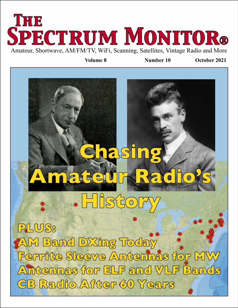
On the Cover:The two early leaders of American amateur radio:
Hugo Gernsback and Hiram Percy Maxim. Background map depicts the location of amateur radio stations in 1909. Map by Frank Howell K4FMH. Photo credits: (Left) Hugo Gernsback (1884-1967) photo by Fabian Bachrach (1917-2010) from the November 1967 issue of Radio-Electronics, a Gernsback publication. (Right) Hiram Percy Maxim photo created circa 1914 is from the US Library of Congress prints and photographs division via Wikimedia Commons in the public domain.

4 The Spectrum Monitor October 2021
Dear TSM:Comments, Advice, Kudos and Questions from Readers
Send your comments to [email protected] Spectrum Monitor reserves the right to edit comments from readers for clarity and space availability. Anonymous comments will not be published.
Tethered Aerostat Aids Ida Recovery Communications in Louisiana
“We went back to see our home in Raceland, Louisi-ana, days after the eye hurricane Ida passed over it. I am fortunate to say it has some damage but is at least intact and habitable. Unfortunately, we saw numerous other homes severely damaged or destroyed. In the distance we could see a tethered blimp. I did not want to approach and interfere with any emergency workers —we are thankful for all of them! Instead, I took this photo with maximum zoom on my camera. – Alvin N5VZH Raceland, Louisiana
We are happy that your home survived, Alvin, and thanks for the photo of the 55-foot long AT&T aerostat aka a blimp, part of that company’s 76 network assets that can be deployed in the aftermath of storms that can knock out wireless and landline communications. AT&T described the operation on their website,
“September 4, 2021, 6:00 p.m. CDT. Today, we launched FirstNet One in Raceland, LA. This aerostat blimp functions as an LTE tower in the sky to support first respond-ers and the extended public safety community by providing 100 square miles of coverage in the area. To aid in these recovery efforts, we have a total of 24 on-air mobile cell site solutions in areas impacted by the storm. We continue to refuel more than 200 generators at our facilities with more
than 100 crews working 24/7 to restore service in areas impacted by Hurricane Ida.” Two days later AT&T reported that their wireless network was working normally,“We have one of the industry’s largest and most advanced disaster re-sponse programs to help keep wireless communications run-ning during times of disaster.” By September 10, AT&T had restored service to 90 percent of their wireline customers.
According to AT&T, FirstNet One was first tested in 2019 and first deployed in action in Louisiana in 2020 in the aftermath of hurricane Laura.
AT&T’s tethered aerostat FirstNet One as photographed by TSM reader Alvin N5VZH whose home is in Raceland, Louisiana. (N5VZH photo)
Above: AT&T’s FirstNet One deployed in the aftermath of Hurri-cane Laura in 2020. (Courtesy: AT&T)
Another of AT&T’s 76 mobile communications assets (this one sporting a Ku-band antenna) that can quickly be deployed to major storm sites. (Courtesy: AT&T)
T S MT S M

October 2021 The Spectrum Monitor 5
R F Cur r entR F Cur r entNews from the World of Communications
RF Current is compiled and edited by Ken Reitz KS4ZR from various news sources and links supplied by TSM readers. If you find an interesting story pertaining to amateur, shortwave, scanning, broadcasting or satel-lites, send a link to [email protected]
Who’s Getting the Most News and Information to Latin America? Hint: It’s not the US
The US Agency for Global Media (USAGM), formerly the Broadcasting Board of Governors (BBG)—is a US feder-al agency overseeing the broadcast of news and information on behalf of the United States of America to the world via radio, television and internet for Voice of America (VOA), Radio Free Europe (RFE)/Radio Liberty (RL), Radio Free Asia (RFA), Office of Cuba Broadcasting (OCB) Middle East Broadcasting Networks (MBN) and the Open Technolo-gy Fund (OTF).
Over the last 15 years USAGM/BBG has slashed budgets and staff at its global shortwave transmitting sta-tions. On its website USAGM admits that their “legacy radio distribution” (shortwave and medium wave) continues with “aging equipment and inadequate maintenance budgets.” The agency has concentrated its legacy broadcasting efforts pri-marily on the expansion of its Kuwait Transmitting Station with the construction of a 600-kW medium wave transmitter targeting Iran.
In this hemisphere, through the Office of Cuba Broad-casting, USAGM has added shortwave and medium wave
transmitters to broadcast Radio Martí programming intended to cover Cuba from the Edward R. Murrow Transmitting Station in Greenville, North Carolina. OCB has an annual budget of $28 million and employs 117 people to achieve this objective. But the results are not easily quantified—in an on-air whack-a-mole game, Cuba jams most of USAGM’s 13 shortwave frequencies most of the time. Cuba also blocks what little internet its citizens might have access to.
You might imagine that the Voice of America would pick up the slack, but its $252 million annual budget is spent on nearly 1,000 employees supporting radio and television program production in 47 languages all over the world. There is little in its budget to attend to the information needs of Latin America outside of Cuba.
According to VOA, their Spanish language service each day is confined to four half-hour TV news programs; one 30-minute radio news magazine and a 3-minute “news brief focusing on US and global news of interest to the region.” VOA also provides over two dozen daily video and 10 audio packages available to affiliates via the internet.
This contrasts with the rest of the world which has a much greater footprint across all of Latin America, with 24/7 TV and radio broadcasting.
Free-to-Air satellite feeds in Spanish, French and Portuguese from legacy shortwave broadcasters that transmit 24/7 to all of Latin America. Top left to right: France 24 (France), Russia Today (Russia); HispanTV (Iran). Bottom left to right: Deutsche Welle TV (Germany); RTP América (Portugal), CGTN (China). Most use native speaking reporters, all report on world and regional news. In the CGTN photo, a Spanish speaking Chinese presenter explains marketplace Chinese cuisine. All channels feature extensive business, sports, fashion, politics and cultural stories. The USAGM is concentrating its shortwave efforts on Cuba alone and has no FTA satellite feeds for Latin America. (KS4ZR photos)
6 The Spectrum Monitor October 2021
On shortwave, the big players are: Cuba with 14 frequencies of Spanish language programming; China with 10 frequencies; Romania with 10 frequencies; Korea with five frequencies (four of which are transmitted from Korea and one of which is sent via Greenville, North Carolina); North Korea has a one-hour long program every day on five frequencies in Spanish, all from North Korea; Taiwan has three half-hour programs every day on three frequencies via WRMI; Turkey has three one-hour programs in Spanish from Turkey; Vietnam has two frequencies with a one-half hour program in Spanish from Hanoi; the Vatican has two pro-grams via Greenville, North Carolina; Japan has one daily program in Spanish via WRMI; Radio Slovakia has one 30 minute program each day in Spanish. Radio Martí signals are not received beyond Cuba as heard on Latin American based SDRs in the KiwiSDR system.
Satellite transmissions are found on C-band and Ku-band satellite utilizing the Atlantic Ocean Region satellites which cover all of Latin America. These are all unencrypted Free-to-Air and most channels operate 24/7.
Country 24/7 TV News LanguageRussia Russia Today (RT) Spanish/EnglishFrance France 24 Spanish/English/FrenchChina CGTN Spanish/EnglishIran Hispan TV SpanishKorea Arirang English/Spanish subtitlesTurkey TRT World EnglishJapan NHK World English/Spanish subtitlesGermany DW-TV Spanish/English/GermanPortugal RTP América PortugueseVenezuela TeleSUR SpanishCuba Cubavisión SpanishSpain RTE TV/Radio SpanishUSA None
In addition, China and the UK provide dozens of radio feeds in many languages via C and Ku-band satellites, all of which are easily received throughout Latin America.
As the biggest presence in this hemisphere, it may be a mistake for the US to surrender Latin America to the voic-es of the rest of the world. The mistake is compounded by hoping that those in Latin American who have access to the internet can reach American news and information when they want or may need it, because internet penetration in Latin America lags North America by a good margin.
According to Internetworldstats.com, as of December 31, 2020, 95 percent of North Americans (Canada, USA, Mexico) are internet users; 71.8 percent of South Americans use the internet; 61 percent of those living in the Central America use the internet and only 47.5 percent of those in the Caribbean use the internet. In addition access may only be through public internet cafes or computers at work or through smart phones. Such online time may be relatively expensive, limited by their local ISP and might not be avail-able 24/7.
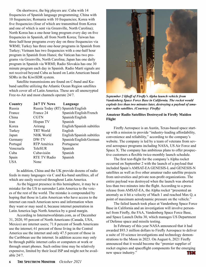
September 2 liftoff of Firefly’s Alpha launch vehicle from Vandenberg Space Force Base in California. The rocket would explode less than two minutes later, destroying a payload of ama-teur radio satellites. (Courtesy: Firefly)
Amateur Radio Satellites Destroyed in Firefly Maiden Flight
Firefly Aerospace is an Austin, Texas-based space start-up with a mission to provide “industry-leading affordability, convenience and reliability,” according to the company’s website. The company is led by a team of veterans from sev-eral aerospace programs including NASA, US Air Force and Space X. The company has ambitious plans to offer prospec-tive customers a flexible twice-monthly launch schedule.
The first test-flight for the company’s Alpha rocket occurred on September 2 with the launch of a payload that included Spain’s AMSAT-EA GENESIS-L and GENESIS-N satellites as well as five other amateur radio satellite projects from universities and private non-profit organizations. The entire payload was destroyed when the launch was aborted less than two minutes into the flight. According to a press release from AMSAT-EA, the Alpha rocket “presented an anomaly as it hit a velocity of Mach 1 and reached Max Q, a point of maximum aerodynamic pressure on the vehicle.”
The failed launch took place at Vandenberg Space Force Base in California and an investigation will involve person-nel from Firefly, the FAA, Vandenberg Space Force Base, and Space Launch Delta 30, which manages US Department of Defense space and missile testing.
In February of this year NASA announced that it had awarded $93.3 million dollars to Firefly Aerospace to deliver a suite of 10 science investigations and technology demon-strations to the Moon in 2023. On August 6, 2021 Firefly announced that it would become the “premier supplier of rocket engines and spaceflight components for the emerging new space industry.” T S MT S M

October 2021 The Spectrum Monitor 7
Map depicting locations of amateur radio’s ‘Lost Tribe,’ 1909. (Courtesy of the author)
Amateur Radio’s Lost Tribe:The ‘Blue-Collar Scholars’ Who Started it All
By Frank M. Howell PhD K4FMH
Amateur radio is nothing if not tradition laden. Tra-dition can be an effective part of a hobby or group because it maintains a sense of common history to
socialize newcomers into the hobby as well as providing a central focus on long-term group activities. The history of a hobby is a key and enduring part of this set of cultural tra-ditions. But if history as written and received is incomplete in important ways, this tradition misleads and misguides newcomers and veterans alike. Moreover, it may stifle future innovation due to the “thought police” behavior that tradi-tionalists ritualistically perform. (73s anyone?)
In this article, I recover some strategic lost history of US amateur radio. My focus is on the “lost tribe” of the ear-liest amateur radio operators who were in existence before there was an American Radio Relay League; before there were government issued licenses; and before there were strict guidelines as to “what” ham radio was. Then, ham radio was whatever ham operators did. It gave the foundation for what was to come as the federal government created a le-
gal basis for administering the radio waves as a public good. Yet, amateur radio operators in the US today hardly know anything about them because of the “Maxim Mythology” that exists and is perpetuated in our most common formal history of amateur radio in the US. This is why I characterize them as the important Lost Tribe. Let me tell you about them and how they got lost to our current history.
Folklore about the Early Organization of Amateur Radio
To illustrate, consider how the ARRL chooses to feature the history of amateur radio in the official timeline published during the 2014 Centennial celebration.(1) There is only a mention of the Junior Wireless Club being formed in 1909 (now Radio Club of America) followed by government licensing in 1912 and the formation by Maxim and Tuska of the League in 1914. The explicit narrative is ensconced in the Forward of the 50-year anniversary:
“In May, 1914, a small band of radio amateurs led by
8 The Spectrum Monitor October 2021
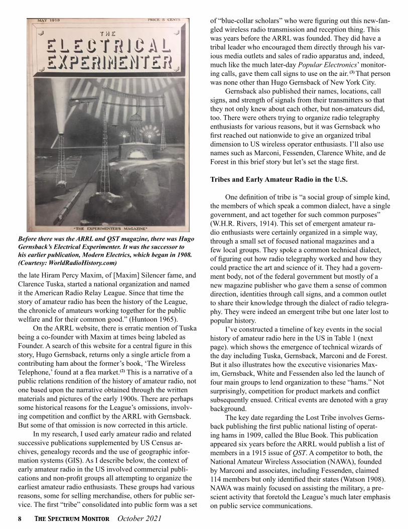
Before there was the ARRL and QST magazine, there was Hugo Gernsback’s Electrical Experimenter. It was the successor to his earlier publication, Modern Electrics, which began in 1908. (Courtesy: WorldRadioHistory.com)
the late Hiram Percy Maxim, of [Maxim] Silencer fame, and Clarence Tuska, started a national organization and named it the American Radio Relay League. Since that time the story of amateur radio has been the history of the League, the chronicle of amateurs working together for the public welfare and for their common good.” (Huntoon 1965).
On the ARRL website, there is erratic mention of Tuska being a co-founder with Maxim at times being labeled as Founder. A search of this website for a central figure in this story, Hugo Gernsback, returns only a single article from a contributing ham about the former’s book, ‘The Wireless Telephone,’ found at a flea market.(2) This is a narrative of a public relations rendition of the history of amateur radio, not one based upon the narrative obtained through the written materials and pictures of the early 1900s. There are perhaps some historical reasons for the League’s omissions, involv-ing competition and conflict by the ARRL with Gernsback. But some of that omission is now corrected in this article.
In my research, I used early amateur radio and related successive publications supplemented by US Census ar-chives, genealogy records and the use of geographic infor-mation systems (GIS). As I describe below, the context of early amateur radio in the US involved commercial publi-cations and non-profit groups all attempting to organize the earliest amateur radio enthusiasts. These groups had various reasons, some for selling merchandise, others for public ser-vice. The first “tribe” consolidated into public form was a set
of “blue-collar scholars” who were figuring out this new-fan-gled wireless radio transmission and reception thing. This was years before the ARRL was founded. They did have a tribal leader who encouraged them directly through his var-ious media outlets and sales of radio apparatus and, indeed, much like the much later-day Popular Electronics’ monitor-ing calls, gave them call signs to use on the air. (3) That person was none other than Hugo Gernsback of New York City.
Gernsback also published their names, locations, call signs, and strength of signals from their transmitters so that they not only knew about each other, but non-amateurs did, too. There were others trying to organize radio telegraphy enthusiasts for various reasons, but it was Gernsback who first reached out nationwide to give an organized tribal dimension to US wireless operator enthusiasts. I’ll also use names such as Marconi, Fessenden, Clarence White, and de Forest in this brief story but let’s set the stage first.
Tribes and Early Amateur Radio in the U.S.
One definition of tribe is “a social group of simple kind, the members of which speak a common dialect, have a single government, and act together for such common purposes” (W.H.R. Rivers, 1914). This set of emergent amateur ra-dio enthusiasts were certainly organized in a simple way, through a small set of focused national magazines and a few local groups. They spoke a common technical dialect, of figuring out how radio telegraphy worked and how they could practice the art and science of it. They had a govern-ment body, not of the federal government but mostly of a new magazine publisher who gave them a sense of common direction, identities through call signs, and a common outlet to share their knowledge through the dialect of radio telegra-phy. They were indeed an emergent tribe but one later lost to popular history.
I’ve constructed a timeline of key events in the social history of amateur radio here in the US in Table 1 (next page). which shows the emergence of technical wizards of the day including Tuska, Gernsback, Marconi and de Forest. But it also illustrates how the executive visionaries Max-im, Gernsback, White and Fessenden also led the launch of four main groups to lend organization to these “hams.” Not surprisingly, competition for product markets and conflict subsequently ensued. Critical events are denoted with a gray background.
The key date regarding the Lost Tribe involves Gerns-back publishing the first public national listing of operat-ing hams in 1909, called the Blue Book. This publication appeared six years before the ARRL would publish a list of members in a 1915 issue of QST. A competitor to both, the National Amateur Wireless Association (NAWA), founded by Marconi and associates, including Fessenden, claimed 114 members but only identified their states (Watson 1908). NAWA was mainly focused on assisting the military, a pre-scient activity that foretold the League’s much later emphasis on public service communications.

October 2021 The Spectrum Monitor 9
The Junior Wireless Club of New York, while in a hotbed of radio innovation, remained locally oriented until years later. Rebranded as the Radio Club of Amer-ica (Burghard), their history shows little competition with the ARRL. Many other local clubs, such as in San Francisco and the Bay Counties, also appeared. There were clearly numerous emergent organizations all vying to catalyze enthusiasts of wireless telegraphy as amateurs (DeSoto 1936). Yet is was Gernsback and his allies who provided the first successful “Pied Piper” effort to publicly meet the definition of a tribe. As we will see below, the Pied Piper metaphor fits very well.(4)
As a key element of this revisionist history, it’s clear that it was Tuska who was the technical wunderkind, not Maxim. From his own words as published on the ARRL website (Tuska 1937: 4):
“The Electrical Experimenter indicated that there were other wireless ex-perimenters in Hartford...Hadn’t Hartford heard of the famous E.I. electrolytic? [Author note: E.I. was Gernsback’s company]...A gentleman, Hiram Percy Maxim, had become interested in the wireless...Mr. Maxim had no experience but he was interested and wanted a good receiver...Mr. Maxim was then in the novice class. Ne {sic} needed some instruction. Tuska worked with him and spent many an evening instructing Mr. Maxim and his son. Hiram Percy Maxim learned quickly and was soon the owner and operator of a full-fledged amateur wireless station. His son
Hamilton Maxim was then about twelve years old. His younger mind outstripped his father’s in learning the code, and he was a joint operator of the station, which was known as SNY.”
Note that it was Gernsback’s electrolytic detector that constituted Maxim’s first receiver via Tuska. It was, in fact, Tuska’s technical understanding and craftsmanship that led Maxim and his son into amateur radio which Max-im subsequently mastered.
Maxim became the Executive, col-laborating with Tuska to visualize a Re-lay League of stations in 1914. He later worked with Charles Stewart to lobby Congress against the Navy’s insistence on keeping “amateur” transmitters off the air after WWI (Warner, 1936: 9). Maxim was married to the daughter of the former Governor of Maryland, an entree into political networks in the nation’s Capital. Undoubtedly, this gave Maxim some access to Herbert Hoover Jr., Secretary of Commerce, as noted in the ARRL memoir, ‘200 Meters and Down: The Story of Amateur Radio’ (1936), written by the ARRL Secretary, Clinton B. DeSoto. By then, “the” story of US amateur radio was that proffered by the League.
The ARRL asked in 1916 to ad-vertise in Gernsback’s widely popular magazine, The Electric Experimenter, but was denied as a “competitor” at least three times. Maxim published the correspondence in a 1916 issue of QST “without comment” for the reader to assess (Maxim and Tuska 1916). A let-ter in that same QST issue complained about “all the leagues being formed,” which were “unnecessary.” (Stanley 1916). Conflict between the ARRL and Gernsback ruled the day.
By contrast, Marconi’s group, focused on assisting the military Signal Corps, appeared largely out of the fray. No doubt the growing Marconi busi-ness enterprise captured most of his attention. Later, his affiliated magazine, The Wireless Age, did accept advertis-ing from the ARRL. But this conflict between the publications of the League and Hugo Gernsback, and the ensuing bad blood between the principals, may be one of the organizational memories
Table 1: Timeline of Key Events and the Historical Context of the Lost Tribe in U.S. Amateur Radio
Timeline of Key Events and the Historical Contest of the Lost Tribe in U.S. Amateur Radio Year Event (emphasis for critical elements) 1907 Amateur operators form the Bay Counties Wireless Telegraph Association (California) Hugo Gernsback is said to have sold the first "practical home radio and first amateur radio
kit" Clarence Tuska began experimenting with wireless telegraphy 1908 Gernsback publishes Modern Electrics magazine. Announces Wireless Registry (October) Rival magazine, Electrician and Mechanic, launched a Wireless Club, claiming 114
members (September) The Bay Counties Amateur Wireless Club in operation (California) 1909 First amateur radio organization the Junior Wireless Club, Ltd of New York City formed,
later becoming Radio Club of America (January) Gernsback of Modern Electrics started the Wireless Association of America Gernsback published the Wireless Blue Book of the Wireless Association of America, the
first nationwide public listing of amateur radio operators, constituting the Lost Tribe. Amateur operators form the San Francisco Radio Club, Inc. 1910 Clarence Tuska buys eletrolytic detecter from Gernsback's E.I. Importing Company. Tuska consigned crystal radio to toy store bought by Maxim who cannot get it to work.
Tuska tutors Maxim on the building of a better radio receiver. They form father-foster son bond and engage Maxim's son Hamilton in the radio hobby. "Tuska worked with him and spent many an evening instructing Mr. Maxim and his son." (Tuska 1937)
1911 Ship Act of 1911 requires licenses of maritime wireless operators 1912 Radio Act of 1912, all radio transmitters now were required to be licensed. Amateur radio
restricted to 200 meters. Charles Stewart, later ARRL VP and primary lobbyist in DC, gave testimony.
1913 Clarence Tuska received government issued call sign 1WD Hiram Percey Maxim received government issued call sign 1WH Gernsback started another magazine, The Electrical Experimenter (May). 1914 Hartford Radio Club formed on January 14, 1914. First President was David Moore, Age
21. American Radio Relay League was founded by Hiram Percy Maxim and Clarence D. Tuska 1915 QST first published with list of American Radio Relay League List of Stations (December) Gernsback's Modern Electrics magazine ended Wireless Association of America and formed
the Radio League of America with Tesla, Fessenden and de Forest as honorary members National Amateur Wireless Association founded, headed by Marconi with Clayton White,
Editor of The Wireless Age magazine, as managing secretary. Announcement in all major New York City papers. Emphasis on assisting military Signal Corps.
1916 ARRL requests advertising in The Electric Experimenter. Gernsback declines. Conflict between the ARRL, the Gernsback publication and Wireless Association of America ensues without immediate resolve.
1917 US ham operation ceased by government due to WW I 1919 Amateur radio returned in the US (November) Gernsback publishes first Radio Amateur News magazine 1923 Gernsback publishes first science-fiction articles in Science and Invention magazine. It
begins his eventual transformation to SciFi publishing and a writer’s award in his name 1929 Gernsback publishes Radio Craft, a magazine for the radio constructor.

10 The Spectrum Monitor October 2021
leading to the omission of the many undeniable contributions made by Gernsback in their narrative of amateur radio in the US.
The League subsequently won the war of who would eventually organize amateur radio in the United States. The National Amateur Wireless Association founded by Marconi (White 1915), announced prominently in most New York papers, largely disappeared from print within a decade. The transition by Gernsback from the WAA to the Radio League of America, clearly a competition of identity with the ARRL in the battles of 1915-16, also faded within a decade. This may have been due to Gernsback’s drift into science fiction publishing which would eventually lead to an award in his name for that genre.
Clearly, Hiram Percy Maxim was not only a brilliant inventor of the gun silencer and automotive mufflers but an astute and effective executive in the art of building and man-aging a large organization. But it was Gernsback who gave technical education to the masses (including both Tuska and Maxim!) a venue with which to identify (Wireless Associ-ation of America), and a public identity as a tribe through individual name, location and station details in the Blue Books.
Who were these “blue-collar scholars” who made am-ateur radio possible by getting their gear built and regularly on the air waves? Where were they? What was their back-ground?
The Lost Tribe of Blue-Collar Scholars
The members of the Tribe from the first Blue Book are listed in Table 2 (Gernsback 1909) at left. I’ve shown those not in the 1910 or subsequent Public Census records with a no information marker. A few were either a school or busi-ness. However, most (73 percent) were located to identify year of birth, race, sex, school attendance, and (household head or son’s) occupation. All were white boys or men. The majority were young men with an average age of 19.6 years (standard deviation of 7.2 years). The preponderance of boys and young men is striking as shown in Table 3 (above) as a histogram of age in 1909. It was a “kid’s game” of sorts, in large measure—very few adult men joined this tribe. That is ironic given the aging ham operator population in the U.S. today (Howell 2020).
Note that a couple of extremes are in these data. A 9-year-old, George Schmidt of New York City, and a 10-year-old, William Wilson, also of New York, were op-erators. Wilson became an engineer by age 40. Two older married men also were part of the Tribe. Thomas Shannon, age 49, resided in Los Angeles, working as a truck driver. A plumber, Jack Steurer of New York City, was also 49. Both were clearly “old timers” in the Tribe. One oddity was Dr. Caroll H. Fink, a physician near Jacksonville, Florida. He was not found in the public Census or genealogy files yet was prominently noted in the Blue Book. Young Bowden Washington, age 17, was to become a radio telegrapher by 1920 as was J.B. Hyatt in Ohio. Others were employed in electrical work as electricians (e.g., Charles Spinney, Maine).
Where the tribe member was a student and not em-ployed, I’ve included the household head’s occupation. With few exceptions (e.g., a couple of lawyers), all were employed in the retail, manufacturing trades, services, or farming: blue collar work. The professional influence by attorneys, the physician, the musician or art designer is exceptional. The dominance of blue-collar work by the household head on the radio amateur is unmistakable for those that were identified through public Census records. Hence, I’ve labeled the Tribe
Table 2: Members of the Lost Tribe of US Amateurs 1909
Table 3: Average age of amateurs in 1909
Members of the Lost Tribe of U.S. Amateur Radio Operators, 1909 Age Name City State Occupation of Father (F), Son (s) 22 Neat M. Tate Vacaville CA Farmer (F) 16 Melvin M. Bonham + Covina CA Cement work-sidewalks (F) 12 S. Conradi Vance + Los Angeles CA Manager of Gas & Electric (F) # Ozone Wireless Co. San Francisco CA # 29 Frank E. Daubenbiss + Capitola CA Employed in Livery Stable (F); 1930: electrician (S) # Geo. And Fred Taylor Susanville CA # 20 Max Wells Riverside CA Employed as electrician in power-house (F) 16 Ray Newby San Jose CA Employed as an apprentice electrical worker (S) 49 Thos. I.P. Shannon * Los Angeles CA Employed as a driver for a packing company (S) # A.W. Pratt Noroton CT # 15 Cromwell Gibbons Jr + Jacksonville FL Lawyer (F) # Dr. Carroll H. Fink Fernandina FL Physician (S) 18 Earl Vogel Ashton IL Father owns farm (F) Son farms there (S) 16 Edwin R. Willard * Chicago IL Works on railroad (S) 15 Melvin Getchell West Medford MA Carpenter (F) 15 L.S. Stevens + Marlboro MA Employed as a box maker in a box factory (F) 19 Newell A. Thompson + Brookline MA Aunt (Head) is unemployed (F) 16 Philip Wood + Arlington MA Employed in manufacturing (F) 16 Kendall Bushnell + Arlington MA Employed as clergyman (F) 17 Ralph Damon Whitman MA Employed in dyeing and blocking in shoe factory (S) 11 Allen Lee Whitman + Cambridge MA Lawyer (F) # John Joseph Roderick Veary Boston MA # 17 Earle L.M. Coolidge Everett MA Employed as a musician in an orchestra (F) 28 Chas. E. Spinney * Sanford ME Electrician at a mill (S) 21 Frederick Wommer Minneapolis MN Employed as a buyer at an automobile company (S) 20 David Marcus St. Louis MO Confection Store Owner (S) # J. Peters Jr. Florissant MO # # Meade N. Powell St. Louis MO # 27 E.D. Porter * Lewistown MT Employed as an electrician (S) # V. S. Ivey Lenoir NC # 16 Coke Flanagan Montclair NJ Lawyer (F) # L. Spangenberg Paterson NJ # 17 Jas. McNair Jr. Lakewood NJ Electrician (S) 18 Albert Higson + Jersey City NJ Employed as real estate salesman (F) # F.R. Breck Bayone NJ # # W.N. Broz Cape May NJ # 16 R.P. Wilson + Metuchen NJ Checker on railroad line # H. Bassett Shorthills NJ # # J.R. Carty Shorthills NJ # # Frank McGram Jersey City NJ # # R.S. Burtt North Paterson NJ # # B. Frank Rittenhouse N. Woodbury NJ # # W. Zimmerman Hasbrouck Heights NJ # 16 Fred Klingenschmidt + New York NY Restaurant Owner (F) 17 Bowden Washington New York NY 1920: Radio Engineer-Telegraphy (S) 15 John D. Kattenhorn Jr. New York NY Not employed-Brother is bartender (F) 17 Eric Leavens Brooklyn NY 920: Inspector at Insurance Co (S) 20 Ralph Jeffers Rochester NY Electrician in a shop (S) 24 J.O. Smith New York NY Owner, Art Design Business (S) 21 H.E. Sumner Brooklyn NY Clerk, Lumber Yard (S) 14 Maxwell P. Hellman New York NY Employed in Silk Factory
October 2021 The Spectrum Monitor 11
as blue-collar scholars who helped amateur radio become a social movement in the United States.
The Gernsback-as-Pied Piper in the Electrical Exper-imenter served to play to the imaginations that changed the succeeding generations through radio science as hobby. To understand this, the reader only needs to recall what Popular Electronics did for so many boys, and a few adult men, when it offered “short wave listener” call signs, run at the time by Tom Kneitel through Popular Electronics and the US Postal Service (Herkimer)—far less than what Gernsback did a half century before.
The map at the head of this article contains the tribe on a map display, illustrating the specific geographic con-centrations. The graph expresses these concentrations more succinctly as a count by state. They were located largely in the Northeast states of New York, New Jersey and Massa-chusetts and the West Coast of San Francisco’s Bay Area and Los Angeles. The key clusters in the greater New York area and in the Bay Area correspond to a few of the key events in the timeline. The early clubs were being formed on the West Coast simultaneously to those in the localized hotbed of greater New York City as noted in the timeline. This pat-tern, along with those scattered throughout parts of the US, reflects the impact that the Wireless Association of America, through The Electrical Experimenter and Modern Electrics magazines, had during this formative period.
Some Revised History: The Pied Piper and the Chief Executive
The official story of amateur radio offered by the ARRL through League Secretary DeSoto in ‘200 Meters and Down: The Story of Amateur Radio’ does give some note to Gerns-back’s efforts. On page 24, he writes of him as a “promoter” of amateur as follows:
“Another organization was also being formed in Janu-ary, 1909—one of much greater pretensions. The Wireless Association of America was a child of Hugo Gernsback, publisher of Modern Electrics. After the first few months of its existence, Gernsback announced a membership totaling 3200. By November, 1910, he claimed that this number had jumped to 10,000. It was easy to recruit members for such an organization; there were no dues and no obligations. Youth-ful electrical experimenters signed up in swarms, attracted by the famous names in the honorary membership group and the ease becoming a member. The membership represented a fairly accurate index of national interest in radio, although not, of course, of the number of active transmitters. Even so, the number of worthwhile amateur stations on the air had, according to conservative observers, increased from perhaps one hundred fifty in 1905 to five or six hundred.” (DeSoto 1936: 24).
The ARRL’s 1936 official story of amateur radio did indeed acknowledge Gernsback as Pied Piper of youthful experimenters, albeit characterizing his count as “claims” while giving full credit to the League’s “conservative obser-
vations.” And, moreover, it gave the WAA its due as a “fairly accurate index” of interest around the country in amateur radio. But by its 50-year anniversary, the League Secretary Huntoon stated that “Since that time the story of amateur radio has been the history of the League.” (Huntoon 1965). Having won the competition amongst the various groups seeking to organize amateur radio, the official public rela-tions story was changing.
In the 2014 Centennial celebration of the League, the ARRL’s timeline had indeed forgotten its own published re-cord of formative events (American Radio Relay League). In this official timeline, there is only a notation of the Wireless Club of New York followed by the formation of the ARRL by Maxim and Tuska in 1914. In Maxwell’s QST article on the 100th Anniversary of amateur radio itself, he notes the importance of recounting amateur radio history: “..as will be seen as we progress through the events of this past century, there is much to be learned from our history.” (Maxwell 2000). As he later writes in that article, however, there is only a mention of Hiram Percy Maxim, sans Clarence Tuska, in attributing organization to amateur radio in the US: “Some hams had extended their effective range by relaying messag-es through others, but it took a Hartford, Connecticut ham, Hiram Percy Maxim, 1WH (later 1AW) to recognize that messages could be sent more reliably over long distances if relay stations were organized.” The “Maxim Mythology” was by then complete.
From any careful and objective reading of the literature of that era, it is clear that Hugo Gernsback gave national identification to amateurs, publicizing a listing with call signs which gave them a public identity. His magazines and commercial company, Electro Importing, gave a venue through which members of the Lost Tribe (as well as those who did not join) could communicate with others using a common language of the day regarding amateur radio. These blue-collar scholars were the lifeblood of amateur radio’s rise in the United States. Even Maxim benefited from Gernsback’s electrical products through Tuska’s building of Maxim’s radio set and tutoring “novice” Maxim and his son, Hamilton, into the hobby.
What is also clear is that it was Hiram Percy Maxim who won the war over who was going to succeed in being the dominant organizational force in the ham world. Maxim and Tuska co-founded the ARRL but Tuska subsequently went into the military and then commercial radio to support his mother, grandmother and himself as “head of household” (Lee 2014). Maxim, the Executive, protected amateur radio from Navy objections with Secretary Hoover through Max-im’s political network, no doubt enhanced by his deceased father in-law, the former Governor of Maryland, and Charles Stewart’s effective lobbying in Washington, DC. He later became Vice President of the ARRL (Lee 2014).
My characterization of Gernsback as the Pied Piper who led young boys and men into the hobby reflects the historical facts from the existing literature of that era. Maxim was the Executive who learned the technical side from his

12 The Spectrum Monitor October 2021
young associate Tuska, partnering with him and giving fi-nancial assistance to form the League. Maxim powerfully led the ARRL to be the dominant organization that it ultimately became over the years. That, too, fits the existing literature but it is at variance with the “Maxim Mythology” created and perpetuated over the decades by the public relations arm of the League.
That is the mission of public relations professionals but not of historians. From the time of DeSoto to Huntoon to Maxwell in writing sequential official ARRL narratives of US amateur radio history for the League, the transference of the credit from a token mention of Gernsback’s 10,000 strong membership in WAA by DeSoo to Maxwell’s ren-dition of it taking Maxim to get amateur radio organized, with nary a mention of Tuska, the mythology was complete. Along the way, the Tribe and their leader got “lost” in the League narratives. Without the original amateur radio enthu-siasts, there would have been no need for a national organi-zation.
It’s unfortunate that those who got us here are not hon-ored in the official history narratives by the League or other associations. That is a public relations choice but not an accurate history. As Maxwell himself said in the QST article on the 100-year history: “there is much to be learned from our history.” I hope that this brief article does indeed reveal more about the blue-collar scholars that Hugo Gernsback led into the fold in the Lost Tribe.(5)
About the Author:Frank M. Howell K4FMH holds a PhD in sociolo-
gy and statistics and is Professor Emeritus at Mississippi State University. He received his amateur radio license in 2010 while serving on the Chancellor’s staff of the Board of Regents in Atlanta, GA. Frank is ARRL Assistant Director for the Delta Division and supports the Volunteer Monitor Program. He is a Presenter on the ICQ Podcast (icqpodcast.com). More about him can be found at k4fmh.com. This arti-cle continues his career-long research into social movements in the U.S.
Notes1 See electronic resource: http://www.arrl.org/files/file/
Centennial%202014/ARRL-Timeline-Final.pdf. Retrieved September 1, 2021.
2 See Bradshaw Lupton Jr, K1TE, “Radio Before Radio,” at http://www.arrl.org/radio-before-radio. Retrieved September 1, 2021.
3 For readers unfamiliar with the defunct magazine, Popular Electronics, and their “shortwave monitoring call sign program,” see John Herkimer, “The “WPE” Monitor Registration Program,” (http://www.ontheshortwaves.com/WPEhtml). Retrieved Sep-tember 2, 2021.
4 For the story of the Pied Piper, see Andrea Diamond, “The Legend of the Pied Piper,”
5 More information will be published at my website, fox-mikehotel.com, along with an interactive map of both the Lost Tribe and those listed in the 1915 QST of their members.
References
Amateur Radio Relay League. 2014. “Official Centennial Time-line.”ARRL-Timeline. Retrieved August 3, 2021.
George E. Burghard. “A History of the Radio Club of America Inc.” Electronic resource: https://www.radioclubofamerica.org/content.aspx?page_id=22&club_id=500767&module_id=470247. Retrieved August 18, 2021.
Hugo Gernsback. 1909. “The Wireless Association of America.” Modern Electrics, 1 (10, January): 69-72.
Hugo Gernsback. 1909. First Annual Official Wireless Blue Book of the Wireless Association of America. May. Modern Electrics Corporation.
Hugo Gernsback. 1910. The Wireless Telephone. New York: Mod-ern Electrics Publications.
John Herkimer: “The “WPE” Monitor Registration Program.” Retrieved September 6, 2021.
Frank M. Howell. 2020. “Aging and Radiosport-Part 1.” National Contesting Journal (July/August): 3-8.
John Huntoon. 1965. “Forward.” Fifty Years of ARRL. Newington, Connecticut: American Radio Relay League.
Hiram Percy Maxim and Clarence D. Tuska (eds.). “Editorials: QST and the American Radio Relay League.” QST 1 (8): 71-72.
Bart Lee. 2014. “Clarence D. Tuska: Radio Pioneer, ARRL Found-er” QST (July): 67-68.
Jim Maxwell. 2000. “Amateur Radio: 100 Years of Discovery.” QST (January): 28.
W. H. R. Rivers. 1914. History of Melanestan Society (Cambridge, Vol. 1, 1914): 150.
Charles. A. Stanley. “Leagues, Leagues, Leagues.” QST 1 (8): 181-2.
Clinton B. DeSoto. 1936. 200 Meters and Down: The Story of Amateur Radio. Newington, Connecticut: American Radio Relay League.
Clarence D. Tuska. 1937. “Reminiscent Radio Tales,” Tran-scription of talk delivered at the Olde Tymers’ Radio Banquet of Hartford County Amateur Radio Association February 27, 1937, at Hartford, CT. (Revised May 1, 2017).
Kenneth B. Warner. 1936. “The Editor’s Mill.” QST 20 (4): 9.
Arthur Eugene Watson. 1908. “The Wireless Club.” Electrician & Mechanic Vol 19 (No. 3): 138.
J. Andrew White. 1915. “National Amateur Wireless Association: Wireless Age (December): 164-190.
T S MT S M

October 2021 The Spectrum Monitor 13
The entire US broadcast band as seen on an SDR# software defined radio. (Photo by Larry Van Horn N5FPW)
AM Band DXing TodayBy David Yocis
It was just over a hundred years ago that radio listening first went mainstream through the reception of broadcast stations on standard AM radio. Many of us first discov-
ered the fascination of radio by hearing a baseball game or a news broadcast one evening from an AM station hundreds of miles away and wondering what else we might be able to hear. As listening for distant stations on the AM band moves into its second century, the hobby of AM radio DXing con-tinues to change and evolve and attract new participants.
The basics of DXing on the medium wave band – that is, on frequencies from 530 kHz to 1710 kHz or so – have not changed. The Earth’s ionosphere – a region of charged particles in the upper atmosphere – absorbs radio signals at these frequencies during daylight hours but reflects them at night. The range of AM broadcast stations is therefore limited to “line-of-sight” groundwave during the day, but nighttime skywave propagation allows for reception of sta-tions over hundreds and even thousands of miles. But with many stations operating on a limited number of channels, the biggest obstacle to receiving distant AM stations is often the presence of stronger, closer stations on the same frequency.
In North America, the basic structure of the AM band hasn’t changed since the 1930s. Stations are assigned to fixed frequencies separated by 10 kHz (540, 550, 560, etc.).
About half of all frequencies are designated as “clear” channels, with one or a handful of strong stations using up to 50 kilowatts (kW) of power broadcasting over large areas kept free from interference at night. Most other frequencies are “regional” channels with a dozen or so larger stations and perhaps 20 or 40 other lower-powered stations serving smaller areas.
Many stations on clear and regional channels, other than the handful of dominant stations, must reduce power or use directional antennas at night or even leave the air com-pletely, depending on the terms of their license. And a few frequencies are “local” channels with well over 100 stations mostly operating with 1 kW each. Outside the Western Hemisphere, stations are separated by only 9 kHz (540, 549, 558, 567, etc.), allowing for listeners worldwide with suffi-ciently selective equipment to listen for trans-Atlantic and trans-Pacific stations on the “in-between” channels without local interference.
But AM radio no longer has the monopoly on broad-casting that it once did. While AM “Top 40” stations ruled the airwaves in the 1950s and 1960s, listeners migrated first to the superior acoustical quality of FM, then to satellite and internet radio. Some countries have phased out AM radio entirely, and outside of a handful of large, successful
14 The Spectrum Monitor October 2021
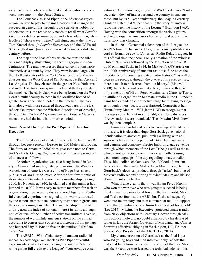
21st Century AM DXing: (Left) Wellbrook Active Loop ALA1530. https://www.loop-antennas.com/wellbrook/North_American/ALA1530LN (Courtesy: Wellbrook) (Right) ELAD FDM-DUO SDR receiver. https://www.eladit.com/en/software-defined-radio (Cour-tesy: ELAD)
AM broadcasters, most AM stations now serve smaller and narrower audiences. The increased use of electronic devices of all kinds has not only offered more (and often technically superior) alternatives to AM broadcasting but has also in-creased the background noise level on the AM band making even local AM signals harder to hear, especially in urban areas. Some stations have tried to improve their local signals with hybrid digital or even all-digital operations, but these have also added to the din of interference on the band.
In the United States, many AM stations now rebroad-cast on FM “translators” that account for most of their listeners. An increasing number of stations, especially those now also available locally on FM or on the internet, are de-creasing their power or simplifying often complex direction-al antenna patterns. The high cost of land in many areas no longer justifies keeping up large multi-tower directional AM stations. Once iconic AM stations like WMEX-1510 Boston, WFME-1560 New York (formerly WQXR and WQEW), and WFNI-1070 Indianapolis (formerly WIBC) have sold their tower sites and are reappearing, if at all, as low-powered nondirectional stations. But even as the universe of potential stations to hear on the AM band decreases, lower congestion on the band opens up new possibilities on many frequencies.
But not all trends in AM radio listening are negative. On the contrary, new digital receiver technology has opened up exciting new possibilities for DXers. Software-defined radios (SDRs) such as the Perseus (https://microtelecom.it/en) and SDRplay (https://www.sdrplay.com/) are now widespread in the AM DX community. These receivers are quite small and attach to a desktop or laptop computer with a USB cable, where they are operated with readily download-able software. Microchip technology has also allowed for the development of small, inexpensive portable receivers with
the selectivity and sensitivity that once were only available in communications receivers costing over $1,000. For more information on these “ultralight” receivers, check https://swling.com/blog/tag/gary-debock/.
One advantage of SDRs is their ability to capture and record the entire AM band simultaneously. This is incredibly useful as many stations tend to give their most detailed iden-tifications at the same time – such as at the top of the hour, or during a scheduled break in live sports coverage.
Before SDRs, one had to choose a single frequency to sit on and wait for IDs. Now, my SDRplayDX can save about six minutes of the whole AM band as a 2 GB digital file. So, if I record from 57 minutes after the hour to three minutes af-ter the hour, I can go through the file frequency by frequency and listen to as many station IDs as I can. Or if I’m hearing the same football game on 20 or 30 channels, I can find the time when the announcer says, “Now let’s pause 10 seconds for station identification on ESPN Monday Night Football,” and listen to those 10 seconds on all those channels looking for new stations. This function is also useful during periods of unusual propagation, or at sunrise and sunset when the changing patterns of daylight through the year create unique opportunities to hear unusual stations for very brief periods.
Designing a good antenna for AM DX is challenging for a couple of reasons. As many shortwave listeners know, a long-wire antenna works best when its length is designed for the specific wavelength of a broadcaster (or a multiple thereof). That’s why amateur radio antennas tend to focus on 10, 20, 40, and 80 meter wavelengths. The AM band, how-ever, covers a broad range of wavelengths – a signal at 1710 kHz has a wavelength of 175 meters, but at 530 kHz it is 566 meters. Optimizing a single antenna for such a diverse band is not easy. In addition, given the large number of stations
October 2021 The Spectrum Monitor 15
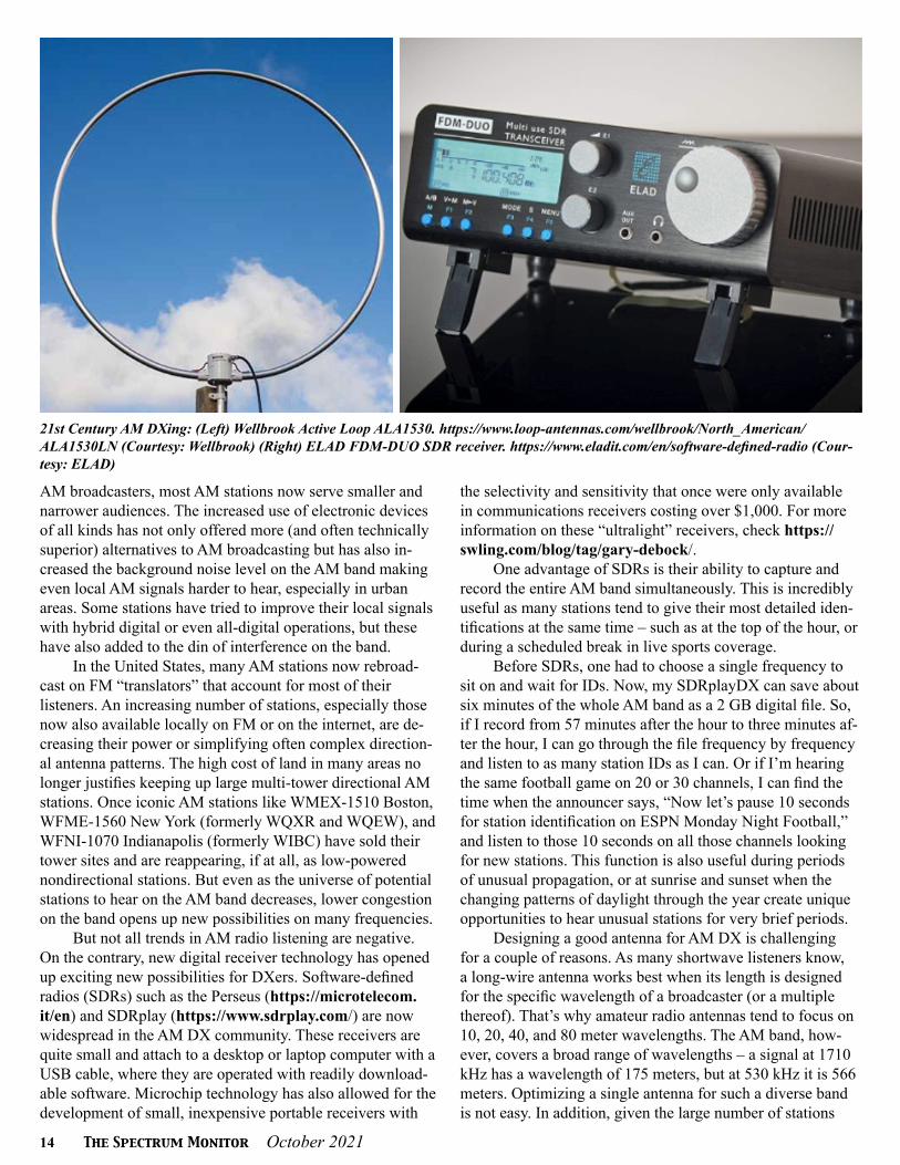
Coming in like a local: Crystal clear reception of RNZ National 819 kHz Paengaroa as received in the US via a remote SDR located in New Zealand courtesy of KiwiSDR. (KS4ZR grahic)
on the air, directional antennas that favor some signals and weakening or eliminating others are almost essential for serious DXing. Antennas that amplify unwanted interference just as much as the desired station aren’t much use!
At one time, large homemade loop antennas were the gold standard for AM DXers. Phasing units, that combine inputs from two independent antennas to null out unwanted stations, have also been quite popular. These antennas and phasers often worked best when tuned to a specific fre-quency, but this is less useful when recording the full band on a modern SDR. It has been also known for decades that extremely long terminated wires (300 meters and up), called “Beverage” antennas, are highly directional and pick up many weak signals, but few of us have the space for such long wires in any direction at all, let alone the directions that would be most useful for DX.
Fortunately, there are new antenna designs that address many of these concerns. Fueled largely by research among 160-meter ham band enthusiasts, new MW DX designs such as the “double Kaz” antenna provide Beverage-level gain and directionality with 40 meters or less in length. Well-brook (www.loop-antennas.com) in the UK has developed reasonably sized loop antennas that don’t require tuning to a specific frequency, and in the last year I’ve made a lot of new loggings with a Wellbrook 1530 loop.
Combining these technologies, many DXers with limited space and lots of noise at their home locations have found DX spots where they can set up ideal antennas, record the entire AM band over a longer period, then spend longer
periods at home going through their recordings and finding the gold nuggets at their leisure. Many of these spots are at coastal locations because proximity to salt water is well known to enhance distant, low-angle DX signals.
Another new dimension of the new technologies are SDRs that can be accessed online from anywhere. The University of Twente in Enschede, Netherlands, has had an SDR that anyone can access or tune from anywhere in the world at http://websdr.ewi.utwente.nl:8901/ and, while the site isn’t optimized for the medium wave band, I’ve heard a number of trans-Atlantic US and Canadian AM stations from the Netherlands, including my local WFED-1500 in Wash-ington, all from the comfort of my own home! Many other receivers, most of which allow for more limited access, have been placed online by DXers around the world, and can be accessed through sites like http://kiwisdr.com/. These sites are useful to see what DX looks like from another part of the world. Alternatively, they can help a listener confirm the identity of a distant station they’re hearing from their own location by checking what is being heard on a receiver much closer to the probable station that they’re hearing.
For those listening in “real time” and not to SDR recordings, the large number of stations that now relay their broadcasts on the internet can often provide assistance in identifying – or ruling out – an unknown station being heard on the radio. Sometimes one can hear the songs and pick out the cadence of an announcer’s voice but not hear the station well enough for a positive ID, but listening to the station’s internet feed might help with the ID.
16 The Spectrum Monitor October 2021
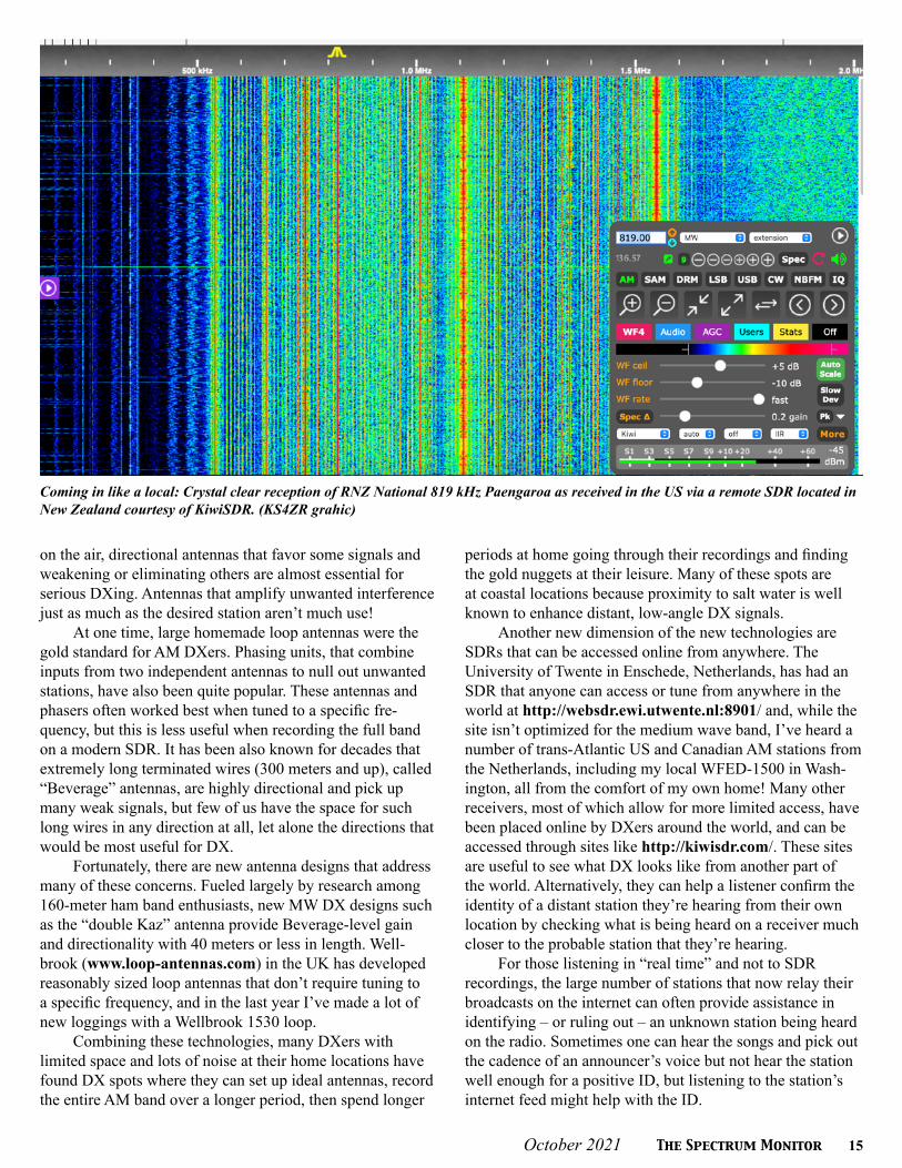
Hundreds of receivers have the AM band covered for you. Not everyone lives in a place that will allow an outdoor antenna or has an electrically quiet location condusive to AM band DX reception. But KiwiSDR does. Now, all you have to do to enjoy around the world DX on AM, no matter where you live, is log in:http://kiwisdr.com. (Courtesy: KiwiSDR.com)
All of these new opportunities have become part of the AM DXer’s arsenal in recent years and have revitalized the hobby even as the number of stations continues to retreat. Still, there are a few aspects of AM DXing that are much less important than they used to be. At one time, writing to sta-tions and getting a written verification (or QSL card, in ham lingo) was central for many DXers; collections of many old-time DXers have been digitized and can be found at https://nationalradioclub.org/qsls. Today, few stations have the personnel or interest to respond to letters from outside their immediate area, and those that do are more likely to respond by e-mail than to an old-fashioned letter with return postage. The number of stations running special “DX” programs has also dwindled, although there are still a few each year. These programs feature IDs using Morse code and other sound effects that really pierce through the noise, and some remark-able receptions are usually reported every time a station runs a test.
The radio world is constantly changing. AM DXers were pioneers in crowd-sourcing even in the days before electronic communication, and hobby clubs continue to collect and disseminate the latest information about what sta-tions are doing and what people are hearing. In North Amer-ica, the National Radio Club (https://nationalradioclub.org/) publishes an annual logbook packed with information on all North American AM stations and a bulletin (biweekly in winter) via print and e-mail with detailed station news, member loggings, articles about new equipment and DX techniques, and other items of interest, while the Internation-al Radio Club of America (https://www.ircaonline.org/) published an e-mail bulletin (weekly in winter) as well as directories of Mexican stations, low-power travel stations, and other useful information. Medium Wave Circle (https://mwcircle.org/) in the UK publishes a monthly electronic
bulletin from a European perspective. There are also a wide number of Facebook groups, Slack chat groups, and e-mail lists – some sponsored by clubs, others not – where DXers share their latest adventures, questions, and news.
If you haven’t listened to the AM radio band in a long time, come check out what’s happening! And if you have been bitten by the AM DX bug, definitely look into joining a club to keep up on the latest news, get your questions an-swered, and connect with some very fine people.
About the Author:David Yocis got his start as a medium wave DXer in
1976 and has served as the publisher of the National Radio Club bulletin “DX News” since 2009. You can contact him at [email protected].
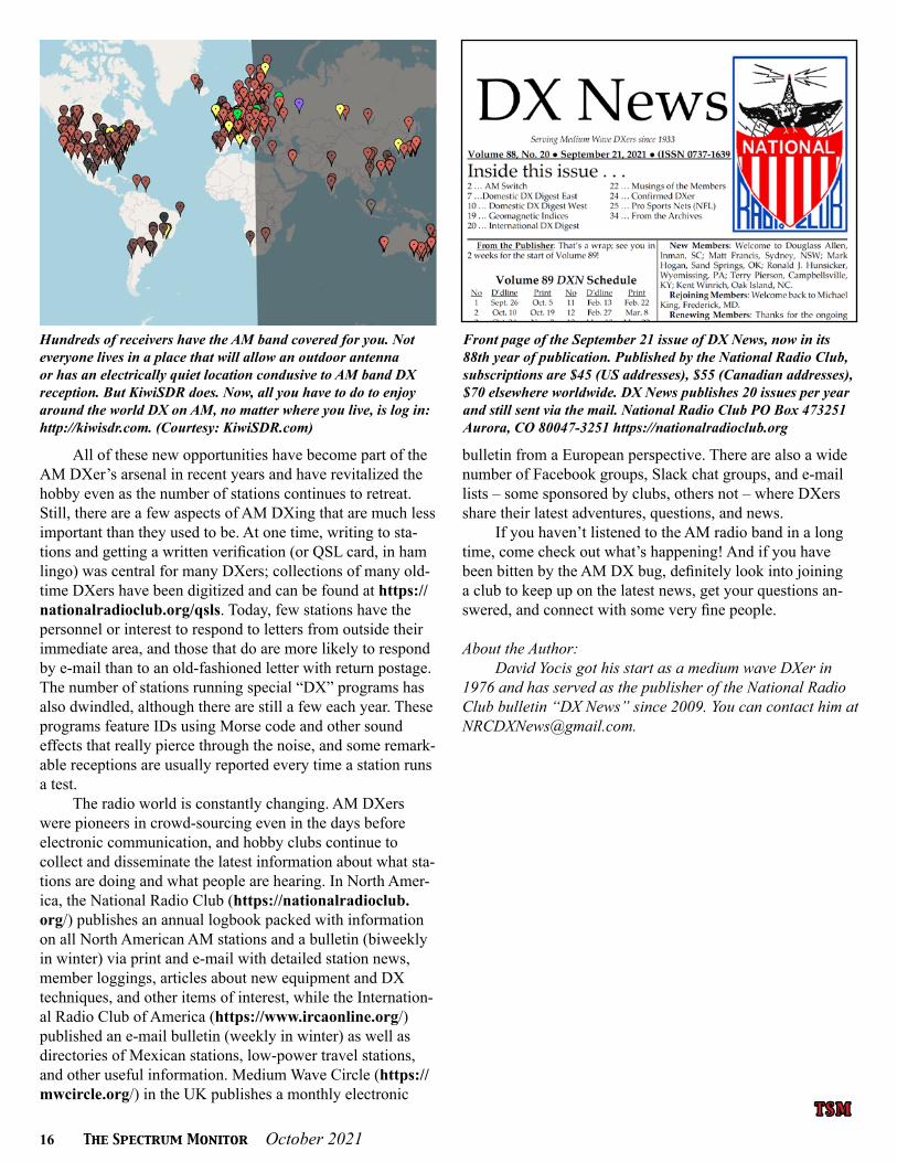
Front page of the September 21 issue of DX News, now in its 88th year of publication. Published by the National Radio Club, subscriptions are $45 (US addresses), $55 (Canadian addresses), $70 elsewhere worldwide. DX News publishes 20 issues per year and still sent via the mail. National Radio Club PO Box 473251 Aurora, CO 80047-3251 https://nationalradioclub.org
T S MT S M
October 2021 The Spectrum Monitor 17
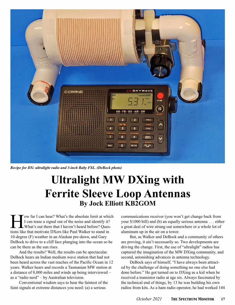
Recipe for DX: ultralight radio and 3-inch Baby FSL. (DeBock photo)
Ultralight MW DXing withFerrite Sleeve Loop Antennas
By Jock Elliott KB2GOM
How far I can hear? What’s the absolute limit at which I can tease a signal out of the noise and identify it? What’s out there that I haven’t heard before? Ques-
tions like that motivate DXers like Paul Walker to stand in 10-degree (F) weather in an Alaskan pre-dawn, and Gary DeBock to drive to a cliff face plunging into the ocean so he can be there as the sun rises.
And the results? Well, the results can be spectacular. DeBock hears an Indian medium wave station that had not been heard across the vast reaches of the Pacific Ocean in 12 years. Walker hears and records a Tasmanian MW station at a distance of 8,000 miles and winds up being interviewed – as a “radio nerd” – by Australian television.
Conventional wisdom says to hear the faintest of the faint signals at extreme distances you need: (a) a serious
communications receiver (you won’t get change back from your $1000 bill) and (b) an equally serious antenna . . . either a great deal of wire strung out somewhere or a whole lot of aluminum up in the air on a tower.
But, as Walker and DeBock and a community of others are proving, it ain’t necessarily so. Two developments are driving the change. First, the use of “ultralight” radios has captured the imagination of the MW DXing community, and second, astonishing advances in antenna technology.
DeBock says of himself, “I have always been attract-ed by the challenge of doing something no one else had done before.” He got turned on to DXing as a kid when he received a transistor radio at age six. Always fascinated by the technical end of things, by 13 he was building his own radios from kits. As a ham radio operator, he had worked 144

18 The Spectrum Monitor October 2021
Yes, size matters, but you won’t get this 17-inch FSL through airport security. (DeBock photo)
DeBock with two radios with transplanted loop-sticks. (DeBock photo)
countries using a Heathkit 1–2-Watt kit transmitter he had built. “You don’t do that without learning a great deal about propagation. If the propagation isn’t with you, you’re simply not going to get through.”
DeBock had a cheap pocket radio, a Sony Walkman SRS 59. In 2007, he thought: “Why not push my luck with this thing, this cheapy portable?” He knew exactly when to try for stations from Japan and Korea from his home in Washington State. At 1 am on an autumn night, he put prop-agation and operating skill to work and heard three distant medium-wave stations: a couple from Japan and one from Korea.
When he posted his results on the burgeoning internet in November 2007, he got a lot of push-back (including name calling), the gist of which was: “Oh, come-on, how could you possibly do this?”
To which he replied (in essence), “Anybody could try this for themselves.”
Then some people did try for themselves, and some succeeded. One DXer from Canada logged 300 stations in 30 days. Interest in MW DXing with cheap, pocket-sized consumer radios exploded, and ultralight DXing was born. It wasn’t long before mass enthusiasm for ultralight DXing hijacked the forum of the International Radio Club of Amer-ica (IRCA); most messages were related to ultralight. One of the leaders of the club asked DeBock to form his own Yahoo group, and he did, concentrating on medium wave because “medium wave is a target-rich environment.”
After a while, DXers started wondering what they could do to improve the performance of ultralight radios for hear-ing distant medium-wave stations. There are two main ways, DeBock says. One option is to replace the stock, tiny ferrite rod – called a loopstick – within the ultralight radio with a larger, external loopstick.
A little background is in order: in 2009 Silicon Labs first introduced their innovative Si4734 DSP chip, and the pocket radios empowered by this new component had amazing DSP-enhanced selectivity which delighted ultralight
radio enthusiasts. But the relatively lame stock loop-sticks designed by the radio companies Kchibo and Tecsun serious-ly limited MW sensitivity of the radios in which they were included. Fortunately, hobbyists began designing upgrade loop-sticks in an effort to improve sensitivity. The 7.5-inch loopstick transplant boosted MW sensitivity to a much-im-proved level, and it became the most popular modification in the Ultralight radio group.
There was, however, another way forward. Graham Maynard’s original “Spin Field Ferrite Sleeve” article was published in February of 2011, and is posted at The Spin Field Ferrite Sleeve Antenna. DeBock says, “He included a lot of questionable science, which essentially brought ridicule upon the entire article. However, as an experimenter I was fascinated by the concept of a cylindrical collection of ferrite rods wrapped by a Litz wire coil, and tuned by a variable cap.”
DeBock had enough ferrite rods on hand to try it for himself. After testing out this concept personally, he con-firmed that the gain performance of this compact antenna was astonishing. This kicked off three years of experimenta-tion with improved Litz wire, different shapes of ferrite, and different configurations, during which he discovered that he could greatly improve upon certain components that Graham was using in his design.
Two things really determine the performance of the FSL: the mass of ferrite rods and the number of turns of Litz wire wrapped around them. The number of turns of Litz wire determines the range of frequencies that the FSL will receive. (And, within that range of frequencies, the variable capacitor tunes the antenna for the frequency that the DXer is trying to hear.) The ferrite rods control the sensitivity of the antenna. If you double the length of the rods for an FSL of a given diameter, you double the sensitivity. If you keep the length of the rods the same but double the diameter of the FSL, so that you need more rods around the circumference,

October 2021 The Spectrum Monitor 19
you double the sensitivity. If you double both the length of the rods and the diameter of the FSL, you get a huge im-provement in sensitivity, but you also get a lot more weight, bulk, and expense.
One of the unusual aspects of an FSL antenna is that it does not have to be physically connected to the ultralight ra-dio; instead, the ferrite rods in the FSL are inductively-cou-pled to the loopstick inside the radio. The antenna just needs to be within a few inches of the radio to turn a white-noise hiss into a fully copyable signal.
For DeBock, 2015-1016 was phenomenal for DX, but at the same time he realized that there was a real need to shrink high-performance FSLs to portable size that would make them appealing to as many people as possible and practical to take them on planes around the world. DeBock has taken ultralight DXing with FSLs to the Cook Islands, Hawaii, and Hong Kong.
So, he worked on optimizing performance while reduc-ing size, and his latest creation is the Baby FSL. It’s only 3 inches in diameter, but it will outperform any loopstick transplant, greatly outperform the small air core loops that are common commercially and is competitive with air core loops up to about 3-feet on a side. One of the biggest advan-tages of these small FSLs is that you can easily set them up, DX for a while, and then put them away without a lot of fuss and bother.
And that brings us back around to Paul Walker. Walker got hooked on DXing in middle school, about 25 years ago. An Uncle told him about it and then set him up with an old National tabletop radio and a 100-foot long-wire that ran out his bedroom window to a tree.
He said, “Living in Connecticut, I thought hearing Cin-cinnati was just the coolest thing. I was hooked and fascinat-ed with how I could hear stations hundreds of miles away.”
Walker is an equal opportunity DXer; he will DX whatever is available. He lived in northwestern Pennsylva-
nia for a couple of years with not a lot of land to stretch out antennas, which limited his options for MW and SW, but his location had a lot of elevation. So, he got a Yagi antenna and a stereo tuner and started DXing distant FM stations.
Walker applied for the job of program manager at KSKO, an FM station that serves the village of McGrath, Alaska, in part because of the DX opportunities. The station where he works transmits 90 watts, 60 feet off the ground and serves as a lifeline for the community of 350 people on the shore of the Kuskokwim River. No roads lead to Mc-Grath, which is accessible by air, some 250 miles north of Anchorage. Some other villages in the bush nearby stream KSKO’s programming from “repeaters.” There isn’t another radio station within 200 miles of McGrath, which is a plus for a DXer like Walker.
“I do shortwave from mid-ish spring until early fall. There’s too much daylight for MW DX. That starts seriously in November,” he says.
He emphasizes that DXers have to know the DX ter-rain. “You have to know what is usual and regular because you will hear those often. Then you also have to know what is possible and not unlikely, and then you also have to know what is unusual and rare.”
So, on March 24, 2021, Walker was outside in pre-dawn early morning. It was 10 degrees F. He has his CCrane Sky-wave ultralight radio and two DeBock FSL antennas. One
Recipe for DX: ultralight radio and 3-inch Baby FSL. (DeBock Photo)
Where Paul Walker works: KSKO in McGrath, Alaska. (Walker photo)

20 The Spectrum Monitor October 2021
FSL is used to capture the signal and other is used to null interference from competing signals on the same frequency.
He was tuning across the dial. When he gets to 936, he hears a familiar theme. He thinks he knows what it is. He uses his smart phone to check. Yes! It is the ABC Hobart, Tasmania, news theme. What he is hearing is a 10-kilowatt medium-wave station some 8 thousand miles away. Walk-er is a careful DXer, emphasizing quality over quantity, so he records much of what he hears. He records the Hobart station, including the theme and the ID. It was a personal distance record, and it ably demonstrated the power of MW DXing with ultralight radios and FSL antennas.
The next day, Walker emails the station and attaches the audio file of his recording. As you might imagine, this caused a bit of excitement at the Hobart station and by April 5, Walker appeared on Australian television via Skype as “the radio nerd from Alaska.”
Walker notes that DXing is different in Alaska. Sun-rise in mid-winter is three hours later than the west coast. So once their skywave burns off, Walker is left with early morning darkness over the pole and to his west. He says, “What I have unscientifically discovered is that pre-sunset DX isn’t a thing here. It seems that, for DX to be worthwhile for me, the entire Pacific has to be dark, despite my evening DX being Canada and the lower 48 US States. What most everyone else hears at night, such as the transpacific sig-nals from Japan, China, Australia and so forth, I hear in the morning. Hearing anything from Asia or the Pacific at night is extremely rare.”
There have been other surprises as well. One early morning he was tuning around. “If I hear English with a Brit-ish-like accent, it’s probably Australia. If I hear English with another kind of accent, it’s probably Southeast Asia. Sudden-ly, this symphony orchestra comes booming in. I had look it up later; it was Hungary, and it was over-the-pole DX! I didn’t even know that was possible. It’s a good thing no one was wandering by at that time; they would have seen me standing in the dark and the cold, conducting the orchestra.”
Walker is already gearing up for the next DX season: extra batteries, extra audio cables (to go between the re-corder and the radio), another radio, and another recorder. And some hot hands hand warmers for both his hands and the digital recorder. Lots of alkaline batteries, too. It turns out that lithium-ion batteries hate the cold. They will turn themselves off abruptly in the cold and will not restart even when warmed up; they have to be recharged to be brought back to life.
With the help of the FSL antennas and his ultralight radios, Walker is planning to try for more over-the-pole DXing. He expects there will be more to learn with each new season.
If you would like to take a crack at MW DXing with an ultralight radio and a transplant loopstick or FSL anten-na, ultralight radios are readily and inexpensively avail-able, and DeBock has done a shootout article between several ultralights that is available here: https://swling.
com/blog/2021/05/gary-debocks-2021-ultralight-radio-shootout/. In addition, detailed instructions for the loop-stick transplant are here: https://swling.com/blog/2018/09/guest-post-supercharging-the-xhdata-d-808-with-a-7-5-loopstick/ A video demonstration of the Baby FSL can be found here: https://swling.com/blog/2019/06/video-demon-stration-of-gary-debocks-3-baby-fsl-antenna/ Complete instructions for constructing various ferrite sleeve loop antennas can be found here: https://ultralightdx.groups.io/g/main/files
About the Author:Jock Elliott first fell in love with radio when, as a
grade-schooler, he was given a germanium diode radio as a Christmas gift in the 1950s. His Dad bringing home a Zenith Transoceanic radio a few years later, with the magic of being able to hear stations from thousands of miles away, sealed the deal. Although Elliott’s main career was writing about science, tech, and medicine, he has also written for QST, Passport to World Band Radio, Popular Communications (CB editor), and Monitoring Times (The Gadget Guy). A ham for over 30 years, he is now in his 25th year of running the Commuter Assistance Net on 2 meters in the Capital District of New York State.
The setup Paul Walker used to DX an Australian MW station from Alaska, a distance of 8,000 miles. (Walker photo)
T S MT S M

October 2021 The Spectrum Monitor 21
Submarines to SFTS stations: signals and noise in the VLF Band in the UK (August 2021). (Courtesy of the author)
If you are a regular reader, you will, no doubt, have no-ticed my interest in the Extremely Low Frequency (ELF, 3-30Hz) and Very Low Frequency (30Hz-30 kHz) bands,
sometimes referred to as the ‘Basement-Bands’ of radio.Radio signals at these extremities are fascinating, not
just as physical phenomena in themselves, but primarily because they offer so much information about how our world – and the wider universe – are working.
0-3kHz Extremely Low Frequency (ELF)3-30kHz Very Low Frequency (VLF)30-300kHz Low Frequency (LF)300-3000kHz Medium Frequency (MF)Note: ‘LF’ includes the long wave (LW) broadcast band, and ‘MF’ includes the medium wave broadcast band.
It may be useful to remind ourselves of the basic separation of signals in these very low regions: First, here is what you may call ‘radio-before-radio-was-invented.’ These are the sounds from the natural environment, space and the Earth’s magnetosphere and ionosphere. Many of them have
their origins in lightning strikes which sub-divide into geo-physical and weather-related noises.
But all are natural sounds, not man-made signals – and they never cease to amaze me. The Earth’s own Schuman Resonance in the Earth-Ionosphere Wave Guide is a Stand-ing Wave at a frequency of 7.8 Hz (with harmonics on 14.3, 20.8, 27.3, and 33.8 Hz). It is a prime example of these sounds. Both Oliver Lodge (1851-1940) and Nikola Tesla (1856-1943) are known to have studied these emissions and related phenomena; the latter specifically at his laboratories at Colorado Springs and Wardenclyffe.
7.8 kHz Schumann Resonance17.2 kHz SAQ Grimeton (Special Occasions Only)60 kHz MSF Standard Frequency and Time Signal Station NPL, UK 77.5 kHz DCF77, PTA Germany 137 kHz (Europe) Amateur Radio147.3 kHz German Weather Service (DWD) DDH47198 kHz BBC 4 (Long Wave)472 kHz (Europe) Amateur Radio
Feeling the Geomagnetic Pulse: Antennas for the ELF and VLF Bands
By Georg Wiessala

22 The Spectrum Monitor October 2021
INSPIRE Journal, exploring VLF natural radio for 25 years. Offers VLF-3 receiver kit. (Courtesy: INSPIRE Project)
SAQ operator in action on 17.2 kHz on Alexanderson Day 2021. (Courtesy: Alexander Association)
In our time, Stephen P. McGreevy has made a de-cades-long, much-noticed study of the Whistlers, Sferics, Tweeks, Dawn Chorus, Hiss, Echo-Trains (around 1-30 kHz) and many other related sounds, recording them meticulously. Here in Europe, Renato Romero’s book on Radio Nature and the companion website, Radio Waves Below 22 kHz, are still, in my view, the top go-to resources if you wish to learn more about this fascinating field.
The Many Uses of VLF Monitoring
Next to Nature Radio, the VLF band reveals radio transmissions of human origin, which you may find between, approximately 15 and 80 kHz. There used to be a multitude of signals here, from transmissions to the submarines of the world’s navies to Frequency Standard and Time Signal (FSTS) transmissions (MSF, DCF77, WWVB, Russian Beta Chain, 25 kHz), including a range of global hyperbolic navi-gation signals (Decca, LORAN-A, LORAN-C, and so on).
Most of these are now of historical interest (e.g., the former [Russian] ALPHA [RSDN-20, ca 11-16 kHz] and (US) OMEGA (ca. 10-14 kHz) chains; Klawitter, G. 1991: 28).
The WWVB time signals on 60 kHz have also been monitored to study ionospheric changes. Moreover, some experimental radio amateurs operate here (below 9 kHz, 137 and 472 kHz), as do scientists and even artists.
The band is also widely used by cave- and mountain
rescuers, water-resource explorers, medics and many other users besides – lots to explore then. You might just get a piece of software like the audio spectrum analyzer Spectrum Lab (by W. Büscher DL4YHF) and explore these signals on their own merits, they are certainly very interesting for the radio hobbyist or citizen-scientist to view, analyze and mon-itor. And indeed, many radio enthusiasts are quite happy to leave it at that and marvel at the colourful displays of those signals. This is where signal analysis meets art (see graphic on previous page). Visit DL4YHF’s ham radio homepage on qsl.net.
A Litmus Paper on VLF
However, it gets really interesting if you do go a little further and treat VLF signals like electronic litmus paper, i.e., as indicators of wider phenomena, in the areas of geol-ogy, geodesy, space-weather, propagation, terrestrial earth-quakes, and a wide range of geomagnetic and geophysical phenomena.
One of the most popular applications of VLF monitor-ing among radio enthusiasts includes radio/solar astronomy, lightning-tracking, aurora-watching, and catching spe-cial-events stations. In this latter category Grimeton SAQ (on 17.2 kHz) is a regular; it once again transmitted messag-es on Alexanderson Day 2021 on July 4, 2021.
From what I hear, many hobbyists are interested in investigating how solar flares can translate into Sudden Ionospheric Disturbances (SID) here on Earth. Consequently, some recent publications have contained detailed instruc-tions and descriptions of a range of VLF projects. Prominent examples of those are the Stanford Solar Centre SuperSID Monitor, for the case of VLF monitoring, and the NASA INSPIRE Project.
There are very significant practical scientific applica-tions to this activity of (indirectly) monitoring the Sun-Earth connection by tracking variations in the reception of VLF signals. These ups and downs reflect the vagaries of space weather and demonstrate our star’s influence on all terrestrial infrastructure, satellites, communications systems, and so on.

October 2021 The Spectrum Monitor 23
The author’s portable ELF receiver/solar flare monitor. The author’s UK Radio VLF receiver.
As a result of this, many governments around the world are now much more aware of this and are developing appropri-ate preemptive strategies. The UK’s recent Space Weather Strategy is one example of this. The US and Australia, to name but just two, have issued similar blueprints.
Beginning with Suitable VLF Equipment
In terms of what you will need, in order to receive ELF and/ or VLF waves, much depends on your preferred ways of working. If you are into nature radio, then, of course, you need to be outdoors, away from any electrical interference. You may want to consider home-brewing or acquiring a por-table ELF receiver / Solar Flare monitor, such as the follow-ing models:
• Elettrofficina ELF-VLF PIC-RX04 (and its succes-sor-models)
• Kiwa Earth Monitor• NASA INSPIRE VLF-3• North Country ELF (Earth) Receiver• SE1 VLF-ELF-Spherics Receiver (by author and experi-
menter Wolfgang Friese).• Sistel Explorer E202• Stanford SuperSID• UKRAA VLF Receiver• WR-3 VLF Receiver (by Stephen McGreevy).
Furthermore, many hobbyists use dedicated hardware VLF receivers or level meters; among those, the Siemens D2008 continues to be a popular specialist model.
However, a suitable general HF receiver will do the job well; the AOR AR7030, for instance, goes down to 0 kHz, and many other HF receivers start at 30, 50 or 60 Hz.
Make sure you have a suitable (192 kHz sampling-rate) sound card, such as the popular E-MU 0204 USB or the more recent Behringer U-PHORIA UMC202HD 24 Bit/192kHz USB Audio Interface (for a 0-96 kHz range of signals). Connected to the right antenna, these can yield
excellent results.When monitoring solar flares using variations in VLF
signals, you could use the Stanford SuperSID, the NASA IN-SPIRE VLF-3 or, closer to home, the UKRAA VLF Receiver by the UK Radio Astronomy Association (above).
For many others, the flexibility and customization of Software-Defined Radio (SDR) offers the right way to explore ELF and VLF signals. I used to start by using the RF Space SDR-IQ. These days, receivers such as the ELAD, SDRplay and AirSpy models offer unmatched features like record-ability, which you might want to make use of.
In certain areas of interest, for instance, the SAQ trans-missions on 17.2 kHz, there are special pieces of software you can use, such as the (slightly older) SAQ Panoramic VLF Receiver (V. 0.94) by SM6LKM. This may require little more than a redundant laptop PC and LW antenna.
The Propagation of VLF Waves
When choosing your antenna, remember that VLF propagation is contingent on frequency, diurnal, annual and solar patterns, transmitter power and an aerial’s efficiency, among other things. VLF ground wave signals travel close to the Earth, following its curvature. They may be slowed down by the ground’s dielectric constant, and they are reaching significantly further over water, for instance.
Ground wave predominates, and is very stable by day, while after dark, LF signals travel strongly by both ground and skywave. Skywave VLF travels, worldwide, in the Earth-Ionosphere Waveguide (80-800 km). This sub-ion-ospheric propagation undergoes refraction, reflection or attenuation. Signals typically have skip distances between 1,000 and 2,000 km.
When both kinds of the wave arrive at the receiver at the same time, you will experience both constructive and destructive interference and fading, as happens in other fre-quency bands. The important thing to remember here is that VLF signals display predominantly vertical polarization.
Furthermore, by contrast to, say, shortwave radio

24 The Spectrum Monitor October 2021
signals, VLF propagation can be augmented by enhanced at-mospheric ionization, such as during solar storms or meteor scatter. However, astronomical events, such as solar eclipses, have been shown to have a dampening effect on signals lev-els. Therefore, a VLF receiver setup can be made to work as a monitor of Sudden Ionospheric Disturbances (SID) or simi-lar phenomena precisely because VLF signals get stronger as a result of solar flares.
They can circle the globe and penetrate water, to some degree (and vertically). But the key information content of any man-made radiated VLF signal here will be sparse, bandwidth is less than 200 Hz, transmitter antennas are very large and radiation efficiency is low.
For nature radio, your antenna must be able to receive the omnidirectional atmospheric impulse radiation at around 10 kHz from lightning strikes, auroras, sprites, jets and elves – which is why a simple telescopic antenna is often more than sufficient here.
You can find many useful resources on the prediction of VLF propagation conditions, both online and in print format.Most of those predictions are based on a phenomenon called the Equatorial Ring Current and on related geomagnetic activity, especially the measurement of the disturbance storm time index (DST Index).www.ngdc.noaa.gov/stp/GEOMAG/dst.html http://wdc.kugi.kyoto-u.ac.jp/dstdir http://lasp.colorado.edu/space_weather/dsttemerin/dstte-merin.html
Some Suitable Antennas for VLF
If you want to take a look at a truly huge VLF antenna (actually an antenna tuning inductor coil), you can visit the Science Museum in London. Find the (permanent) Informa-tion Age exhibit, to come face-to-face with the ‘Rugby-Mon-ster.’ This contraption was once part of the famous ‘GBR’ transmitter (16k Hz; Fig. 7; Hancock, M. [2017] The History of Rugby Radio Station, pp. 110/111). Only very few of us
have room for something as large as this!On a smaller scale, you might just connect a long wire
to your soundcard or radio, but this is prone to noise and interference from the environment. Therefore, many radio amateurs are coupling tuning loops to ferrites as secondary radiators. Others are recommending drums of a simple wire, connected serially, as a VLF antenna. If you do this, you ought to ensure you have as many turns of the wire as possi-ble, at least 400. Since VLF waves are vertically polarized, you must also be certain that the axis of your drum is always parallel to the ground.
In terms of antennas capturing the magnetic component of an electromagnetic wave, there are quite a few excellent models to choose from, if (like me) you are not a homebrew-er.
Ferrite bar aerials, as you may recall, represent a special variety of loop antenna, which stand out by their compact and varying sizes and their permeability, i.e., their ability to take in and focus magnetic field lines.
In my view, among the top ranges to try out are those by two German companies, BAZ and Grahn. From the range of their products, those especially suitable for ELF to MF are listed below.
Both firms also make customized and high-performance antennas (Hochleistungsantennen), which will often be a great solution, depending on what signals you are interested in. These are 1,050 mm long, have up to 55 ferrite bars in-side, are in widespread use in electronics laboratories. Some have been tested comprehensively (e.g.: Friese, 2007: 37ff.). For hobby (or even ‘semi-professional’) use, take a look at the following range:
• BAZ VLF S1-N (Spherics) Power Ferrite Module (15-70 kHz by // C: 20pF – 1.8 nF) seen above left.
• BAZ Power Ferrite Module for SFTS stations MSF60 |HBG 75 | DCF 77.5 (top left of next page).
• BAZ LFM/ZZ1-N (For Standard Frequency and Time Signals [SFTS] Stations).
• BAZ LFM/5-50 (5-50 kHz) ferrite module.• BAZ LFM 50/300 (50-300 kHz […].
http://www.spezialantennen.eu/ferritantennen/index.php
• Grahn VLF-2 Ferrite Bar (‘Alexanderson’; 10-300 kHz; €189)
• Grahn LW-1 (30-150 kHz) and Grahn LW-3 (75-400 kHz)
• Grahn ‘Nautic’ (100-600 kHz) • Grahn MW2-3 (switchable: 400-1800 and 850-4000
kHz)• Grahn Base Unit GS-5 (For all Grahn Loops and Ferrite
Bar aerials; €249-349) […].
http://www.grahn-spezialantennen.de/html/module.html Of excellent value but very hard to find these days
is the ADDX-AT-2BNC once manufactured by my fellow
BAZ VLF S1-N 15-70 kHz receiver. (Courtesy of the author)

October 2021 The Spectrum Monitor 25
‘Remscheider,’ the late Charlie H. Hardt, which came with a custom-made amplifier-module and could be switched to either 50-120 kHz or 90-300 kHz (above right).
In addition to these, many radio hobbyists I know swear by earth rods used as antennas, as is evident in the numerous Facebook Groups on this topic.
And, at the very top-end are the Aaronia MDF and MagnoTRACKER series. https://aaronia-shop.com/prod-ucts/antennas-sensors/magnetic-antenna
In the US, LF Engineering, I am told, is a popular choice for these antennas and their customization. https://www.lfengineering.com
Nature Radio, Weather and Other Utility Antennas
I am straying a little from the ‘pure-VLF’ path here: However, you may wish to receive and decode the signals from Standard Frequency and Time Signal (SFTS) stations, navigational (aeronautical and maritime) beacons, or the fascinating weather information still available in the VLF, LW or MW bands.
In the VLF band, the past and present activities and transmissions from Russian Time Stations around 25 kHz have been widely analyzed, for example by Nils Schiffhauer. In this context, you may find some of the models by Grahn or BAZ (see the previous paragraph) very handy indeed.https://dk8ok.org/2020/01/11/cis-time-signals-on-vlfBoth companies also make special, high quality, magnetic antennas to receive, for example, the regular weather fore-casts from the German Weather Service (Deutscher Wetter-dienst, DWD) from Hamburg on 147.3 kHz, and the global NAVTEX transmissions on 490 and 518 kHz.
Meanwhile, traders such as Mörer Schiffselektronik and NASA Marine produce self-contained receivers for the reception of the DWD on 147.3 kHz, like the NASA Target 147 and NASA Clipper 147, the Mörer Weather Info Boxes (‘Wetterinfobox’) models WIB1 and WIB3S, or the (older)
NAVCODE/ NaviCharT ‘weather-mouse’ (‘Wettermaus’).Most of those receivers have their (magnetic bar) antennas already built-in, but you can still get some smaller exter-nal antenna for LW and MW. These are the small Mörer desktop indoor magnetic aerial (WIBIAM, EAN No.: 4250327406610, Fig. 12) or the (outdoor) NASA N147S compact vertical by NASA Marine.
Check out the resources on the Radio Enthusiast web-site, where I have uploaded plenty of more information about suitable receivers, aerials and resources about these frequen-cy bands. I have used several simple telescopic antennas for the reception of ‘Nature Radio,’ and the simple ‘RH795’ type has proved to be particularly suitable with a range of ELF receivers. Just remember to go outdoors!
If you are a ‘homebrewer,’ take a look at this article by Hans Michlmayr, on ‘Magnetic Antennae [sic] for ULF.’ In the sources attached to his essay, you will find a good range of ideas for the construction of induction coils, ‘loop-stick’ aerials, variometers and antenna tuners to catch those elusive geomagnetic pulsations. http://www.vlf.it/inductor/induc-tor.htm. Happy hunting!
Going VLF with the Reuter RLA3B
There is one more tale to tell here: Several months ago, I acquired an RLA3A indoor crossed loop magnetic antenna (see next page), manufactured by Reuter Elektronik, a small company offering high-quality HF receivers and antennas. All RLA models are broadband, non-tuned, receiving an-tennas for the LW to SW range, based on the magnetic-loop principle. https://www.reuter-elektronik.com/index.htmlIt was sold, second-hand, and at a very good price, so I treat-ed myself.
The RLA3 does not have the same display front as the RLA4E, and the latter is a slightly improved version. The loops of the RLA are made of specific multilayered circuit board material with a good protective coating. They are small (14.17 in [36 cm]) but can achieve surprisingly good receiving levels in conjunction with low-noise amplifiers. For a while, I used this antenna for shortwave and medium wave broadcast DXing and utility signals reception up here in the Northwest of the UK, with very good results. If you do not have space for a large outdoor antenna, or if you are in a caravan, on holiday or otherwise mobile, the Reuter
BAZ power ferrite module for SFTS stations. (Courtesy of the author)
Custom made amplifier module for 50-120 kHz or 90-300 kHz. (Courtesy of the author)

26 The Spectrum Monitor October 2021
does a surprisingly good job. The best feature, in my view, is the optional RSW3B Control Unit (above). It provides power and permits you to have directional control over the unit, rotating it (electronically, as it were) in 45 degree steps, through 0-180 degrees.
The RLA3’s receiving specs indicate coverage of 50 kHz-54 MHz ‘solid’ (with ‘reduced-level coverage’ from 20 kHz-71 MHz. I was wondering how my little German friend would perform at the very low end of the spectrum, in the VLF sector. Connection to the PC was with my sound card offering a 192 kHz sampling rate. Mine was from Maplin, bought some time ago, but many VLF observers swear by something a little more serious, such as the Behringer U-PHORIA UMC202HD 24 Bit/192 kHz USB Audio Inter-face.
The results were respectable, given that I am not exact-ly in an electrically quiet situation at home, not even here in a small village. I saw some signals in the 10-80 kHz range, with VLF transmissions to the world’s navies on the left and nearby HMS Inskip (a UK Royal Navy landship) blasting in here at 81 kHz. I ‘rotated’ the antenna with the control unit, finding that some signals grew weaker or dropped out altogether, and some new ones would disappear.
Looking at the MSF 60 kHz time signal station in our neighbouring county of Cumbria (The Lake District). I switched the antenna through all four cardinal directions while receiving this, and I could discern the small varia-tions in signals strengths throughout. I switched in a Bonito GI1000 galvanic antenna isolator (right top), with the modest results shown in the upper half of the screen. The display just below that screen is the best overall result I could get with the Reuter RLA3 on the day of observation. You can spot some weak signals and some interference here and there.
You will see a difference in resolution and signal strengths, in most cases. However, this is only to be expect-ed and does not distract from the good performance of the Reuter RLA-3.
While the BAZ ferrite bar – and some of the other
antennas mentioned above – remain my main ‘go-to’ antenna for directional VLF reception from home, I was impressed with the Reuter RLA3, especially when away from the house and the attendant higher noise levels. For VLF enthusiasts, this is certainly a good performer. It is highly portable and lends itself to some experimentation with directionality if you are using the powered control unit.
It is recommended to always use any active antenna with a portable, rechargeable, battery; mine was a TalentCell Lithium-ion battery (model YB1203000-USB). And, I often use VLF Loop distributed by the United Kingdom Radio Astronomy Association as a stand-by antenna.
Georg Wiessala is the editor of RadioUser magazinewww.radioenthusiast.co.uk
RLA3A receiver and control. (Courtesy of the author)
Top chart: The day’s best results on the Reuter RLA-3. Bottom chart: Reception of the same range with the BAZ Ferrite Bar LFM/S1-N (Author’s graphics)
T S MT S M

October 2021 The Spectrum Monitor 27
CB Radio: Six Decades of Utility and FunBy Cory GB Sickles WA3UVV
One of the many pop culture highlights of the 1970s was CB (Citizens Band) radio, an inexpensive two-way radio for the masses. Its rapid growth was
spurred by a number of things, more memorably gasoline shortages, a lowered federal speed limit and a desire for people to communicate through a wireless means of social networking.
As much as it seemed that it exploded on the scene overnight, by the time CB radio hit its zenith, it was already more than a quarter century old. Conceived of in 1945, Citi-zens Band Radio was a package of different types of person-al radio services divided into classes.
Class A and Class B CB was assigned spectrum in the 460 – 470 MHz range. The emission type was FM (Frequen-cy Modulation). Class A allowed for higher power limits with very close (for the time) frequency standards. Class B offered lower power with slightly wider tolerances. Cost and availability of equipment were two factors that limited growth, in something of a feedback loop. Low demand, few-er manufacturers. Limited manufacturers, non-competitive pricing. You get the idea.
After the passage of much time, this allocation be-came what we now know as GMRS (General Mobile Radio Service) and a more distant cousin, FRS (Family Radio
Service). Improvements in technology, a robust land mo-bile radio market where transceivers can be reprogrammed for GMRS and the “blister pack” portable radios fed into GMRS’ increasing popularity. In many areas of the United States, repeaters make up for the shorter line of sight distanc-es involved with UHF and provide a hub for GMRS activity.
Class C CB was designated for remote control (RC) model cars, boats, airplanes and the like. As a cost saving measure, such toys used AM (Amplitude Modulation) as the emission type.
MURS (Multi-Use Radio Service), paging and tracking systems for those who might wander away from home or institutional healthcare settings, such as Project Lifesaver, round out some other services that are within CB’s figurative umbrella.
None of these have proven to be so popular, even today, as Class D CB. If you mention CB to the average person, this is the one they will most likely think of as the whole of CB. Initially allocated as 23 channels using AM in the 27 MHz region, CB was envisioned as a low-cost means for small businesses to stay in touch during workdays and for individ-uals to have some means for occasional communications.
The rules regarding operation required short times on the air, waiting periods until you could be on the air again,
Just a part of the wall of CB sets on display at the Museum of Radio and Technology, Huntington, West Virginia. (Photo courtesy: Rich Post KB8TAD)

28 The Spectrum Monitor October 2021
Left: March 1965 cover of S9 magazine shows characters from the popular US TV sitcom ‘The Munsters’ as radio hobbyists. S9 was edited by Tom Kneitel and was the forerunner to Popular Communications magazine which would begin almost 20 years later. Center: Popular Electronics’ Citizens Band Handbook 1977. Right: From the UK, the cover of the December 1980 issue of CB Citizens’ Band magazine. (Courtesy: WorldRadioHistory.com)
an arbitrary limit on communications distances, plus many more that were considered draconian by some. Human na-ture and HF (High Frequency) propagation being what it is, the rules were soon bent and some would be dropped. But let us not get ahead of the story.
In 1958, Class D CB went live with the first transceiv-ers offering a single, crystal-controlled transmit frequency and tunable receiver. Of course, vacuum tubes represented the technology of the day, with a power rating of 5 Watts input to the final amplifier.
As CB gained in popularity somewhat, it was being recognized as a lower-cost alternative to more conventional LMR options. Newly released transceivers offered more channels that could be selected, from individual crystals that you would purchase, and receivers were upgraded from tunable to crystal-controlled versions as well. As CB became even more popular (a more positive feedback loop than with Class A and B) radios were marketed with full 23 channel capabilities, although that meant having 46 crystals in the first models.
Eventually, a frequency mixing system of 37 and 10 MHz (as an example) crystals was employed by manufactur-ers, drastically reducing the crystal count and the cost of ma-terials, with the savings resulting in more attractive pricing.CB’s initial user base of small business operations expanded. With more channels available on transceivers - plumbers, electricians, carpenters and other associated tradespeople found it easier to stay in touch with each other. When the workday was over, many kept talking into the evening about hobbies and decidedly non-business topics.
Very low power, FCC Part 15 walkie talkies became more popular as a toy for kids. These shared certain chan-nels, most often channel 14. While the licensed CBers were
prohibited from talking with the unlicensed walkie talkie operators, this was often another rule that was ignored.
As with any growing segment or industry, publications became available that supported CB, including advertising for new radio models, antennas, pre-amplified desk micro-phones, lower loss coaxial cable and just about anything else you could think of. Coupled with the advertising was some very good editorial content that educated and entertained on various CB themed topics, as well as some other aspects of hobby communications.
Magazines such as CB Illustrated and CB Action offered covers featuring attractively posed female models interacting with radio equipment. Many such covers would draw a bristly response from some today, but again, this was during the sixties and seventies. S9 magazine was probably the most popular of all, driven by the prolific writings of Tom “Tomcat” Kneitel K2AES (SK).
Along with authoring an incredible number of articles across numerous publications, he served as editor of Popular Communications for over a decade. He also published books through his company, CRB Research Books.
Through the years of showing a steady growth curve, CB became more and more popular and was recognized by more and more people as a normal part of modern life. But nothing contributed to the popularity of CB in the collective zeitgeist as the gasoline shortages of 1973 (and again in 1979) and the stepped-up enforcement of a national speed limit that dropped from 60 to 55 (the “double nickel”) miles per hour.
With high profile and multi-location retailers such as Radio Shack, Lafayette Radio Electronics and a multitude of smaller operations to feed demand, CB grew exponen-tially as drivers shared information about what stations had

October 2021 The Spectrum Monitor 29
fuel and which ones did not. They also shared information regarding locations where the police were enforcing speed limits. To a lesser extent, traffic and weather conditions were also being shared, plus other items of general interest.
Soon, many adopted a faux backwoods accent as truck-ers’ lingo and 10-codes entered the North American lexicon. “Lord willin’ and the crick don’t rise,” “There’s a bear takin’ pictures,” “good lookin’ seat covers in the red convertible,” and the ever popular “10-4, good buddy” were phrases that were widely in use, at least on the air.
Licensed callsigns gave way to self-assigned handles, a sort of nickname, usually with a colorful flair or hint to someone’s occupation or other hobbies. On a given day, you might find yourself talking to “Barbie Doll,” “Salty Dog,” “Grindstone Cowboy,” “Crazy Daisy,” or something more exotic like “Little Zigni.”
At the same time, SSB (Single Side Band) capable transceivers were becoming more popular, with the offerings of 12-Watt PEP (Peak Envelope Power) for those who want-ed something a bit more “serious.” By the time the seventies came to a close, the EIA (Electronics Industry Association) had successfully lobbied the FCC to extend the CB band to 40 channels, in order to accommodate the additional radio traffic demands and also entice current CBers to invest in new equipment.
Like all things trendy, CB activity and interest levels began to wane in the eighties, as cellular telephone tech-nology was introduced, expanded and equipment became smaller and less expensive. With the introduction of flat-rate airtime plans (much better than $1 or $2 per minute rates) the national attention was drawn to this newer means of communications.
By no means did this mark the death of CB, however. Commercial truck drivers still use it every day and those “Smokey the Bear” advisories are still shared. If there is a traffic accident or bad weather ensues, you will probably hear something about it on channel 19 or channel 9, which
Small enough for the radio to be used as a speaker / microphone while mobile, or battery powered as a portable, the Midland 75-822 is a versatile radio and perhaps perfect in vehicles with little room for a transceiver. (Courtesy: Midland)
was set aside for emergencies and public information.SSB activity has moved mostly from channel 16 to
channels in the high 30s, especially 39 (lower sideband). Sidebanders, by the way, eschew handles and 10-codes, while preferring self-assigned “unit numbers” and Q-signals borrowed from the amateur radio world.
During the day and throughout the evening, you can still enjoy a way to make friends and talk about all sorts of topics, as a satisfying alternative to more modern forms of social media and the current barrage of advertising.
While the legal power limit of a CB radio is still 4 Watts (full carrier AM) or 12 Watts PEP for SSB), there are those who like to color within the lines and those who do not. Feeling constricted by 40 channels and low power, some have always ignored the rules and regulations, choos-ing to purchase linear amplifiers (as well as some that are not so linear) and expanded coverage amateur radio trans-ceivers, capable of generating 100 Watt SSB or 40-Watt AM signals.
Hams typically get their allocations in bands, not channels, so the use of a VFO (Variable Frequency Oscilla-tor) allows the operator to tune to the same frequency as an assigned channel or somewhere decidedly elsewhere. If you tune across the 26 to 28 MHz range, you will hear many ex-changes going on between “freebanders,” as well as regular CB traffic.
Almost all of these communications take place via SSB, although not all of it is voice. Further borrowing from amateur radio, SSTV (Slow Scan Television) pictures are being exchanged at times. Often, the picture is a QSL card image, just like ham radio. Or, it could be a slide show that gives viewers some idea of what it is like where that person lives.
I have also heard digital text signals like RTTY (Ra-dio Teletype), packet radio and even some occasional CW (Morse code). I suppose that low signal to noise digital modes such as PSK-31 or FT8 are also in use, but I have not
Timeless CB style: Lots of plasticized chrome on the classic Cobra 25 LTD ($100). (Courtesy: Cobra)

30 The Spectrum Monitor October 2021
bothered to find them.Listen for a few hours during a band opening, which
we will be experiencing more and more as sunspot cycle 25 heats up, and you will probably be amazed with the number of signals you can hear from a variety of foreign countries.
Those who experienced CB back in the seventies may remember the sounds of some misbehaved or generally im-mature operators and lots of heterodynes that made listening a chore. The freeband crowd is a rather well-behaved collec-tive of radio enthusiasts, so it is definitely a more enjoyable experience.
For those who do prefer to follow the rules, there is cer-tainly a variety of ways to enjoy CB just the way it is. Note that the rules about how long you could talk at a time, how far you could talk and the whole use of callsigns are now things of the past.
If you like to work DX (talk over long distances) I can assure you that the opportunities are there, even when you use low power. A good antenna coupled with low-loss coax-ial cable really helps with your coverage. Two times a day, when the rotation of the earth causes a dawn or dusk tran-sition to occur, a phenomenon known as “Gray Line DX” occurs that can stretch you signal in polar directions. During this transitional window it is amazing just how far you can go a “little pistol” signal, instead of a “big gun.”
As mentioned previously, another 11-year sunspot cycle is on the upswing. The more sunspots there are, the more that signals in the HF range (which includes CB) are enhanced through increased propagation. You can easily find yourself working DX into other faraway states or provinces and even more distant countries.
Because SSB is more efficient and allows for a bit more power, it is more likely to reward you with these contacts. However, AM can hold its own as well. Your acquired expe-rience and increased skills will show through.
Antennas are generally vertically oriented. A popular one is the Solarcon Antron A-99. I also happen to like the
Look inside the cab of most 18-wheelers and you will most likely find some variant of the Cobra 29. Among its many features, it offers plenty of audio power for noisy environments. (Courtesy: Cobra)
SPT-500, available from MFJ Enterprises and the amateur radio stores that are their dealers. The SPT-500 can also be tuned for the 10- and 12-meter ham bands, as an added bonus.
If you have a good amount of property available to you, then you can take advantage of longer and larger wire antenna designs with lower noise factors and even better DX possibilities. Antennas, of various designs, represent a won-derful way to experiment enjoy the rewards of homebrewing aspects of your station.
Perhaps you are more of a public service sort of indi-vidual. If so, CB has something to offer you, as well. Some decades back, there were two national organizations whose focus was on public service, ALERT and REACT. ALERT seems to have evaporated at some point, but REACT Inter-national is still alive and well, with teams throughout North America.
REACT successfully combines CB, GMRS and ham radio interests into well-coordinated communications assets. Through alignment with CERT (Community Emergency Response Team) volunteers, the results are typically well-trained and cohesive responders.
Over the years, I have witnessed REACT and CERT teams that performed well above the level of the local ARES (Amateur Radio Emergency Service) team. One of the big-gest reasons was training. Not simply classroom training, but active and frequent participation in training exercises, plus a desire to assist as “force multipliers” with events such as parades, marathons and searches.
This illustrates the important point that an effective response is more about the people, than the equipment. There are those who would dismiss the efficacy of CB technology out of hand, but that could be a mistake.
One more note about CB and public service. It is my belief that hams would be wise to include a CB transceiv-er as part of their Go Kit. After an event such as a tornado
Uniden is well known for scanners and CB radios, alike. The BC-980 is a well-designed AM and SSB mobile with clean lines and good performance. (Courtesy: Uniden)
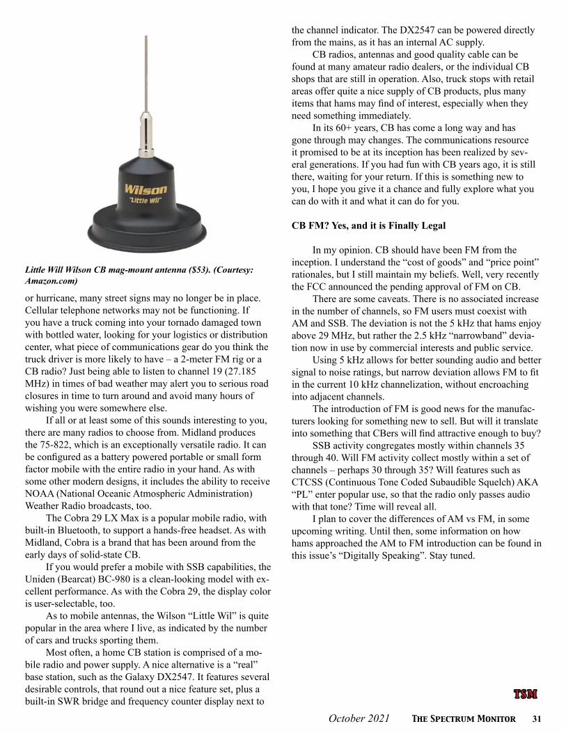
October 2021 The Spectrum Monitor 31
T S MT S M
or hurricane, many street signs may no longer be in place. Cellular telephone networks may not be functioning. If you have a truck coming into your tornado damaged town with bottled water, looking for your logistics or distribution center, what piece of communications gear do you think the truck driver is more likely to have – a 2-meter FM rig or a CB radio? Just being able to listen to channel 19 (27.185 MHz) in times of bad weather may alert you to serious road closures in time to turn around and avoid many hours of wishing you were somewhere else.
If all or at least some of this sounds interesting to you, there are many radios to choose from. Midland produces the 75-822, which is an exceptionally versatile radio. It can be configured as a battery powered portable or small form factor mobile with the entire radio in your hand. As with some other modern designs, it includes the ability to receive NOAA (National Oceanic Atmospheric Administration) Weather Radio broadcasts, too.
The Cobra 29 LX Max is a popular mobile radio, with built-in Bluetooth, to support a hands-free headset. As with Midland, Cobra is a brand that has been around from the early days of solid-state CB.
If you would prefer a mobile with SSB capabilities, the Uniden (Bearcat) BC-980 is a clean-looking model with ex-cellent performance. As with the Cobra 29, the display color is user-selectable, too.
As to mobile antennas, the Wilson “Little Wil” is quite popular in the area where I live, as indicated by the number of cars and trucks sporting them.
Most often, a home CB station is comprised of a mo-bile radio and power supply. A nice alternative is a “real” base station, such as the Galaxy DX2547. It features several desirable controls, that round out a nice feature set, plus a built-in SWR bridge and frequency counter display next to
the channel indicator. The DX2547 can be powered directly from the mains, as it has an internal AC supply.
CB radios, antennas and good quality cable can be found at many amateur radio dealers, or the individual CB shops that are still in operation. Also, truck stops with retail areas offer quite a nice supply of CB products, plus many items that hams may find of interest, especially when they need something immediately.
In its 60+ years, CB has come a long way and has gone through may changes. The communications resource it promised to be at its inception has been realized by sev-eral generations. If you had fun with CB years ago, it is still there, waiting for your return. If this is something new to you, I hope you give it a chance and fully explore what you can do with it and what it can do for you.
CB FM? Yes, and it is Finally Legal
In my opinion. CB should have been FM from the inception. I understand the “cost of goods” and “price point” rationales, but I still maintain my beliefs. Well, very recently the FCC announced the pending approval of FM on CB.
There are some caveats. There is no associated increase in the number of channels, so FM users must coexist with AM and SSB. The deviation is not the 5 kHz that hams enjoy above 29 MHz, but rather the 2.5 kHz “narrowband” devia-tion now in use by commercial interests and public service.
Using 5 kHz allows for better sounding audio and better signal to noise ratings, but narrow deviation allows FM to fit in the current 10 kHz channelization, without encroaching into adjacent channels.
The introduction of FM is good news for the manufac-turers looking for something new to sell. But will it translate into something that CBers will find attractive enough to buy?
SSB activity congregates mostly within channels 35 through 40. Will FM activity collect mostly within a set of channels – perhaps 30 through 35? Will features such as CTCSS (Continuous Tone Coded Subaudible Squelch) AKA “PL” enter popular use, so that the radio only passes audio with that tone? Time will reveal all.
I plan to cover the differences of AM vs FM, in some upcoming writing. Until then, some information on how hams approached the AM to FM introduction can be found in this issue’s “Digitally Speaking”. Stay tuned.
Little Will Wilson CB mag-mount antenna ($53). (Courtesy: Amazon.com)
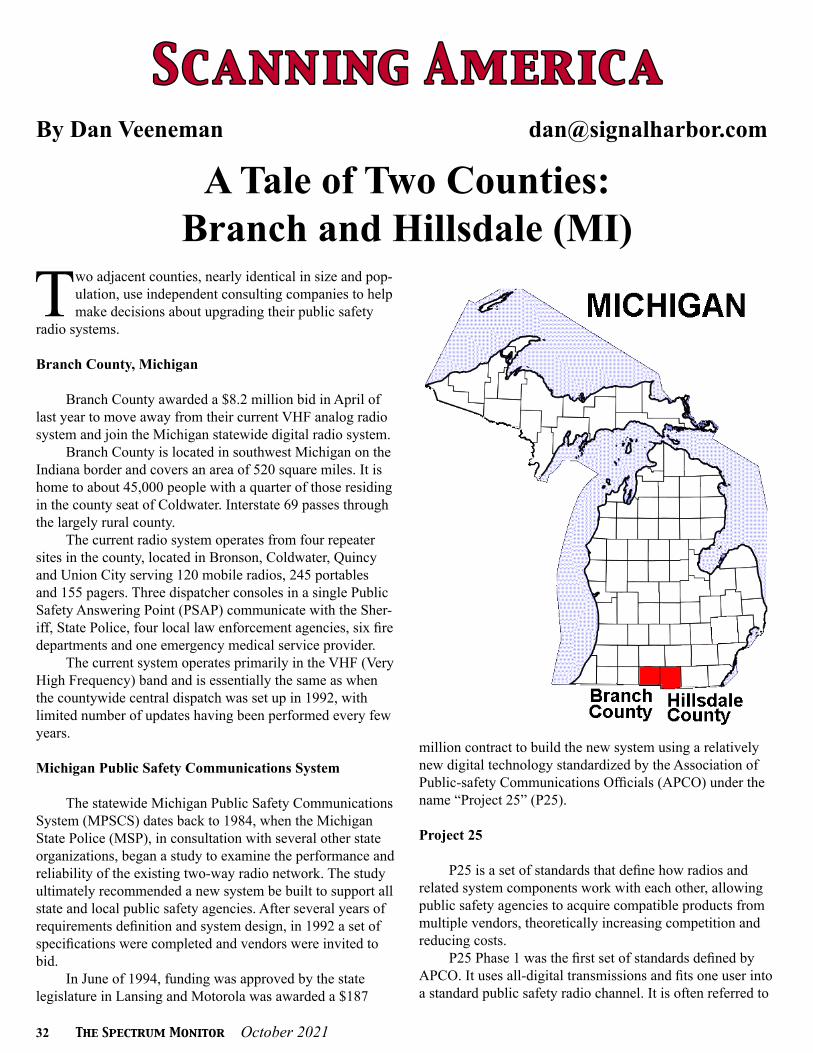
32 The Spectrum Monitor October 2021
S c a n n i ng A m e r i c aS c a n n i ng A m e r i c aBy Dan Veeneman [email protected]
A Tale of Two Counties:Branch and Hillsdale (MI)
Two adjacent counties, nearly identical in size and pop-ulation, use independent consulting companies to help make decisions about upgrading their public safety
radio systems.
Branch County, Michigan
Branch County awarded a $8.2 million bid in April of last year to move away from their current VHF analog radio system and join the Michigan statewide digital radio system.
Branch County is located in southwest Michigan on the Indiana border and covers an area of 520 square miles. It is home to about 45,000 people with a quarter of those residing in the county seat of Coldwater. Interstate 69 passes through the largely rural county.
The current radio system operates from four repeater sites in the county, located in Bronson, Coldwater, Quincy and Union City serving 120 mobile radios, 245 portables and 155 pagers. Three dispatcher consoles in a single Public Safety Answering Point (PSAP) communicate with the Sher-iff, State Police, four local law enforcement agencies, six fire departments and one emergency medical service provider.
The current system operates primarily in the VHF (Very High Frequency) band and is essentially the same as when the countywide central dispatch was set up in 1992, with limited number of updates having been performed every few years.
Michigan Public Safety Communications System
The statewide Michigan Public Safety Communications System (MPSCS) dates back to 1984, when the Michigan State Police (MSP), in consultation with several other state organizations, began a study to examine the performance and reliability of the existing two-way radio network. The study ultimately recommended a new system be built to support all state and local public safety agencies. After several years of requirements definition and system design, in 1992 a set of specifications were completed and vendors were invited to bid.
In June of 1994, funding was approved by the state legislature in Lansing and Motorola was awarded a $187
million contract to build the new system using a relatively new digital technology standardized by the Association of Public-safety Communications Officials (APCO) under the name “Project 25” (P25).
Project 25
P25 is a set of standards that define how radios and related system components work with each other, allowing public safety agencies to acquire compatible products from multiple vendors, theoretically increasing competition and reducing costs.
P25 Phase 1 was the first set of standards defined by APCO. It uses all-digital transmissions and fits one user into a standard public safety radio channel. It is often referred to
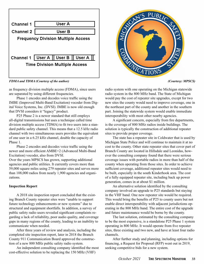
October 2021 The Spectrum Monitor 33
as frequency division multiple access (FDMA), since users are separated by using different frequencies.
Phase 1 encodes and decodes voice traffic using the IMBE (Improved Multi-Band Excitation) vocoder from Dig-ital Voice Systems, Inc. (DVSI). IMBE is now old enough that DVSI considers it “legacy” product.
P25 Phase 2 is a newer standard that still employs all-digital transmissions but uses a technique called time division multiple access (TDMA) to fit two users into a stan-dard public safety channel. This means that a 12.5 kHz radio channel with two simultaneous users provides the equivalent of one user in a 6.25 kHz channel, double the capacity of Phase 1.
Phase 2 encodes and decodes voice traffic using the newer and more efficient AMBE+2 (Advanced Multi-Band Excitation) vocoder, also from DVSI.Over the years MPSCS has grown, supporting additional agencies and public utilities. It currently covers more than 59,000 square miles using 279 repeater sites and serves more than 108,000 radios from nearly 1,900 agencies and organi-zations.
Inspection Report
A 2018 site inspection report concluded that the exist-ing Branch County repeater sites were “unable to support future technology enhancements or new systems” due to structural and equipment shortfalls. In addition, a survey of public safety radio users revealed significant complaints re-garding a lack of reliability, poor audio quality, and coverage gaps in many regions of the county, leading to an inability to communicate when needed.
After three years of review and analysis, including the completed site inspection report, later in 2018 the Branch County 911 Communication Board approved the construc-tion of a new 800 MHz public safety radio system.
An independent consulting company identified the most cost-effective solution to be replacing the 150 MHz (VHF)
radio system with one operating on the Michigan statewide radio system in the 800 MHz band. The State of Michigan would pay the cost of repeater site upgrades, except for two new sites the county would need to improve coverage, one in the northeast part of the county and another in the southern part. Joining the statewide system would enable immediate interoperability with most other nearby agencies.
A significant concern, especially from fire departments, is the coverage of 800 MHz radios inside buildings. The solution is typically the construction of additional repeater sites to provide proper coverage.
The state has a repeater site in Coldwater that is used by Michigan State Police and will continue to maintain it at no cost to the county. Other state repeater sites that cover part of Branch County are located in Hillsdale and Leonidas, how-ever the consulting company found that there were serious coverage issues with portable radios in more than half of the county when operating from those sites. In order to achieve sufficient coverage, additional repeater sites would need to be built, especially in the south Kinderhook area. The cost of a fully equipped repeater site, including back up power generation, comes in at about $1 million.
An alternative solution identified by the consulting company involved an upgrade to P25 standards but staying in the VHF band. One new repeater site would be required. This would bring the benefits of P25 to county users but not enable direct interoperability with adjacent jurisdictions op-erating in the 800 MHz band. The entire cost of the upgrade and future maintenance would be borne by the county.
The last solution, estimated by the consulting company to be the most expensive, is a standalone P25 Phase 1 system operating in 800 MHz. It would operate from five repeater sites, three existing and two new, and have at least four radio channels.
After further study and planning, including options for financing, a Request for Proposal (RFP) went out in 2019, seeking competitive bids for a new system.
FDMA and TDMA (Courtesy of the author) (Courtesy: MPSCS)

34 The Spectrum Monitor October 2021
Not Joining MPSCS
In a 3-to-2 vote in May of 2020, Branch County Com-missioners voted to upgrade the radio system to a standalone system for $8.2 million rather than join MPSCS. The bid from Motorola, which supplies the statewide system, came in $350,000 higher. For a jurisdiction the size of Branch Coun-ty, that difference was deemed too much money.
The bid from Motorola indicated that state had recent-ly upgraded MPSCS and planned to transition from APCO Phase 1 to Phase 2 in the near future. The bid anticipated that the state would pay most of the costs of bringing Branch County online, leaving the county to pay for two additional repeater sites at towers that the local system would own.
Motorola claimed that if Branch County did not join MPSCS they would be “an island” among the numerous oth-er state system users. At the time, only nine of 83 Michigan counties were not on the Motorola MPSCS system.
The chosen upgrade will install a Kenwood P25 system that will be Phase 2 compliant. This suggests that it will be directly interoperable with MPSCS users and other agencies using P25 standards, refuting Motorola’s “island” claim.
One significant cost issue with the Motorola bid was a requirement for the county to pay for extra channels on repeater sites located outside Branch County, an expense the county had not expected. MPSCS said this was necessary to prevent a possible overload of the existing channels on those repeater sites due to the additional transmissions expected from Branch County users operating within range of those sites.
A benefit of the proposed Kenwood system and the use of county-owned repeater sites would allow tower space to be rented to commercial wireless service providers, bringing in revenue to offset the cost of installation and maintenance.The new system is expected to be operational next year.
MPSCS in Branch County
The MPSCS repeater site in Coldwater operates on the following frequencies: 851.4000, 851.9000, 852.4000, 853.4000 and 853.8125 MHz. Assigned talkgroups on the system include the following:
Decimal Hex Description3060 BF4 Michigan Department of Correc - tions (Branch County)3142 C46 Branch County Police (Dispatch, also simulcast on 155.520 MHz)3143 C47 Branch County (Countywide Com- mon Mutual Aid)3604 E14 Community Health Center of Branch County3606 E16 Branch County Health Department13048 32F8 Branch County Fire (Dispatch)13135 334F Lifecare Emergency Medical Ser- vices (Branch County Dispatch)
Analog transmissions in Branch County take place on the following frequencies:
Frequency Description151.3850 County Jail153.7700 County Fire (Dispatch)154.0550 County Sheriff/Emergency Management (Common)154.0850 Coldwater (City Common)154.1000 Bronson Department of Public Works154.3400 Montgomery Fire (Dispatch)154.3850 Coldwater Fireground154.4450 Montgomery Fireground154.8750 Coldwater Police (Dispatch)155.3250 Lifecare Emergency Medical Services (Dis-
Motorola Solutions P-25 HT. (Courtesy: Motorola Solutions) Motorola Solutions APX Next XE P-25 HT. (Courtesy: Motorola Solutions)

October 2021 The Spectrum Monitor 35
patch)155.3400 Ambulance-to-Hospital 155.5200 County Central Dispatch155.7450 County Emergency Management155.7900 County Police (Law Enforcement Informa- tion Network)155.8350 Quincy Department of Public Works156.0600 Coldwater Public Utilities 1156.1800 County Road Commission156.2100 County Police (Tactical A)159.1050 Coldwater Public Utilities 2159.1350 Coldwater Public Utilities 3453.0500 Lifecare Emergency Medical Services (Re- mote Link 1)458.0500 Lifecare Emergency Medical Services (Re- mote Link 2)460.5125 Lifecare Emergency Medical Services (Mo- bile Extender 1)460.8250 Bronson Community Schools (Transporta- tion)462.9625 Lifecare Emergency Medical Services (Mo bile Extender 2)464.3750 Coldwater Community Schools (Secondary Transportation)464.5250 Bronson Community Schools (Operations 1)464.6750 Bronson Community Schools (Operations 2)464.7750 Coldwater Community Schools (Primary Transportation)464.8750 Union City Community Schools (Transpor- tation)
Hillsdale County, Michigan
In September, Hillsdale County awarded a contract to a consulting company to help in examining the issues and costs associated with moving their public safety radio
communications to MPSCS. The consulting company will work with county personnel to assess the existing VHF radio network, identify resources that could help complete a new system and work out a plan to minimize cost while maximiz-ing service and coverage.
Hillsdale County is located immediately west of Branch County, on the border with Indiana and Ohio. Like Branch County, the population of Hillsdale County is about 45,000 people, with about a fifth living in the county seat of Hills-dale. The county covers about 600 square miles of mostly rural rolling hills.
While the current Hillsdale radio system is working, county officials recognize that the older VHF and UHF (Ultra High Frequency) analog transmissions are not interop-erable with the newer digital radio systems in neighboring jurisdictions and are incompatible with MPSCS.
Frequency Description 151.0025 Emergency Management (Operations)151.1750 County Fireground 5151.2050 County Fireground 6151.4300 County Fireground 8151.8650 Camden-Frontier Schools (Transportation)153.8600 Hillsdale Fire/Police (Dispatch)154.2200 Hillsdale Rural Fireground154.2650 County Fireground154.2800 County Fireground 7154.2950 Statewide Department of Natural Resources Fireground154.3400 County Fire (Dispatch)155.1000 Hillsdale Public Works (Countywide)155.1750 Reading Emergency Unit (EMS Tactical)155.2050 Pittsford Area School (Transportation)155.2950 Reading Community Schools (Transporta- tion)155.2650 Reading Emergency Unit (Secondary EMS)155.2800 Reading Emergency Unit (Talk Around 1)155.3100 Sheriff (Dispatch)155.3400 Ambulance-to-Hospital (Hospital Emergen- cy Ambulance Radio Network)155.3925 County Fireground 9155.4525 Countywide Interoperability155.5650 Sheriff (Law Enforcement Information Net work)155.8200 Reading Emergency Unit (EMS Dispatch)155.8650 Sheriff (Statewide Emergency)156.0150 Hillsdale Water Department158.7600 Hillsdale Police (Secondary)158.9100 Sheriff (Tactical)158.9400 Reading Emergency Unit (Talk Around 2)159.5625 Jonesville Public Schools (Operations 1)159.6075 Jonesville Public Schools (Operations 2)159.6525 Jonesville Public Schools (Operations 3)159.7125 Jonesville Public Schools (Operations 4)159.8925 Jonesville Public Schools (Operations 5)173.2250 County Fireground 1
Motorola Solutions APX8000XE (Courtesy: Motorola Solutions)

36 The Spectrum Monitor October 2021
173.2500 County Fireground 2173.2750 County Fireground 3173.3750 County Fireground 4453.7500 Sheriff (Remote Link)453.8500 Sheriff (Remote Link)453.9000 County Road Commission (Dispatch)453.9625 County Road Commission (Talkaround 1)458.7500 Sheriff (Remote Link)458.8500 Sheriff (Remote Link)458.9625 County Road Commission (Talkaround 2)460.0375 Hillsdale Public Utilities Board461.7000 Hillsdale County Intermediate School Dis- trict (Transportation)462.9500 Ambulance-to-Hospital (MED-9)462.9750 Ambulance-to-Hospital (MED-10)463.0000 Ambulance-to-Hospital (MED-1)463.0250 Ambulance-to-Hospital (MED-2, Primary)463.0500 Ambulance-to-Hospital (MED-3)463.0750 Ambulance-to-Hospital (MED-4)463.1000 Ambulance-to-Hospital (MED-5)463.1250 Ambulance-to-Hospital (MED-6)463.1500 Ambulance-to-Hospital (MED-7)463.1750 Ambulance-to-Hospital (MED-8)463.7000 Hillsdale Community Schools
469.5000 Hillsdale Community Schools
The MPSCS repeater site in Hillsdale operates on the following frequencies: 851.4125, 851.9125, 852.4125, 852.6750 and 852.9125 MHz.
Assigned talkgroups on the system include the follow-ing:
Decimal Hex Description1535 5FF Michigan Department of Transpor- tation (Hillsdale County)1181 49D Hillsdale County Police (Dispatch, simulcast on 155.3100 MHz)1168 490 Hillsdale Countywide Narcotics Enforcement1179 49B Hillsdale County (Countywide Common Mutual Aid)1185 4A1 Hillsdale County Fire (Dispatch)11098 2B5A Hillsdale Community School Dis- trict (Transportation)14579 38F3 Hillsdale Sheriff (Emergency Re- sponse Team 1)14580 38F4 Hillsdale Sheriff (Emergency Re-sponse Team 2)
T S MT S M

October 2021 The Spectrum Monitor 37
F e de r a l Wav e l e ng t h sF e de r a l Wav e l e ng t h sBy Chris Parris [email protected]
TSA UHF Update
While traveling and flying for work, I often keep an ear on the frequencies assigned to the Transpor-tation Security Administration (TSA). Back in
2019, the TSA and Department of Homeland Security began looking into updating the radio systems used for their opera-tions. Since their inception, the TSA has been using a variety of VHF federal frequencies that originally came out of fre-quency assignments for the Federal Aviation Administration (FAA).This is because the TSA was first established as part of the FAA before joining the agencies under the Department of Homeland Security.
Over the last decade, the TSA has gone from a hand full of VHF frequencies to several new channels and even tried some analog radios at the security checkpoints and has tested DMR radios at some airport. They are now looking at mov-ing their operations from VHF channels to UHF channels full time. Radio systems designed for in-building coverage often use UHF frequencies, as they tend to penetrate build-ings and structures better than the longer wavelength VHF frequencies.
I received reports of the TSA testing UHF radios at the Denver International Airport (DEN) back in 2020 and presumed that they might be deploying new radios sometime in 2021. But so far, no changes in the field have been noted. It is quite possible that whoever won the contract for these new radios is suffering from the same COVID-related supply chain issues or radio manufacturer chip shortage issues. That might explain the slow movement to obtain and deploy the new radio systems.
According to the documentation I have seen, the new radios and repeaters will operate as a local standalone system and will not be trunked or networked nationwide. The TSA tends to operate locally at the commercial airports that serve commercial airlines. At each of these airports there is a TSA Coordination Center. These centers act as a clearing house for all the operations and incidents within the TSA’s respon-sibility. If an incident happens at a checkpoint or a baggage area, the TSA officers will call it in, as most uniformed TSA personnel do not have law enforcement or arrest powers. The Coordination Center will make the proper notifications to local or state law enforcement, our explosives specialists or regulatory inspectors if needed.
The TSA also has a national operations center in Wash-ington, DC, called the TSOC (Transportation Security Oper-
ations Center). The TSOC can interact with other DHS, FAA or Department of Justice agencies as the situation requires. I will continue to watch the TSA checkpoints for new radios and search the federal 406 to 420 MHz band when I am trav-eling and see if I can catch any new activity at the airports that I travel through.
Federal Use of LTE Radios
Over the past few years, I have mentioned the increased use by some federal agencies of radio-like applications for the smart phones that nearly everyone carries these days. There are a number of available apps that give the users the ability to talk to each other over the broadband data that the phone uses, as opposed to making a phone call. Applications such as Marco Polo and Zello, offer a push-to-talk system like a two-way radio, but the apps relay your voice over the internet to a server, then it sends it out to other users on your channel. And it is extremely secure.
Many federal agencies have been utilizing these apps for surveillance and general communications for some time. But the latest twist in this is that land-mobile radio hardware manufacturers have begun to offer voice over broadband data built into the radios. The user can select to communicate over the normal radio frequency system or use broadband data, either LTE or Wi-Fi, to communicate. This is part of the First Net concept of offering mobile phone and broadband
A typical TSA coordination Center. (Courtesy of TSA)

38 The Spectrum Monitor October 2021
data exclusively to public safety, law enforcement and first responders.
Some recent postings over on Radio Reference talked about new radios being deployed by the US Secret Service. Apparently, some field offices have been issued Motorola APX-8500 radios. These, as well as recent models from Har-ris and other manufacturers, offer the ability to communicate via LTE broadband data networks. This works similarly to using the “push-to-talk” apps on your smart phones and al-lows radios to communicate without using their normal VHF or UHF land mobile radio frequencies.
Will federal, state, or local public safety move entirely to LTE broadband communications? That remains to be seen. There are obvious concerns over depending entirely on an outside service company for mission critical communica-tions, but the overall plans for First Net continue to evolve. This trend towards using broadband for communications is not new and is not restricted to a few agencies. I think it’s safe to assume that any federal agency with LTE capable radios will use that option.
NYC Federal System Update
Back in July 2021, I mentioned the discovery of a new VHF trunking system in the New York City area that is reported to be used by the US Marshals Service. This VHF trunking system is likely part of a larger upgrade of the Department of Justice radio system in general. Some budget information on the internet seems to indicate that the DoJ is currently working towards a common radio system for all agencies in the Department of Justice. The communications system update is being called the Shared Land Mobile radio system.
There is good indication that the updated radio system will be a mix of trunking and conventional sites. Documents I have found indicate that these trunked radio sites will be operating using a common “system core,” the main computer
that controls the trunked system. That means many of these sites will likely have the same, or similar radio system IDs.
The reason that it is currently being called the Marshals radio system is due to the P-25 radio IDs that have been seen using the system so far. They appear to be some of the same radio IDs that have been seen on the conventional USMS frequencies in the New York City area previously. There will likely be other DoJ agencies utilizing this system once it becomes fully operational.
But a new twist has been added. After identifying 6 active trunked sites, a new trunked site became active on this system, and it is using UHF frequencies. Some of us old-tim-ers will probably wonder why this is. Aren’t trunked systems supposed to be one band of frequencies or another, not both mixed together? Generally, that is true. However, there are a couple of reasons this us being done. First, the current gen-eration of land mobile radio gear can do multiple frequency bands in one radio. Secondly, newer trunked systems don’t care about what frequency is being used on any of the trunk-ed sites. And these different sites can operate independently of each other while still being part of the same system core.
Since this new DoJ system will have various locations, all being controlled by the same core, some sites or facilities may need UHF over VHF for operational reasons. Since most all federal prison facilities utilize UHF radios at their facilities, it is a good guess that the UHF site is a federal prison. There are two federal prisons in New York City, the Metropolitan Correction Center New York, and the Met-ropolitan Detention Center Brooklyn. Both currently have UHF trunked systems, so moving these facilities to this new radio system makes some sense.
Looking at the threads on Radio Reference about this new trunked system, it seems to have sporadic use, and maynot be fully operational yet. Time will tell more as this new system continues to be expanded and updated. For more information on this system, you can follow this link to the system specifics: https://forums.radioreference.com/threads/u-s-marshals-service-p25-trs-bee00-4f0.427629
Chicago and ORD Update
One of the great monitoring locations I have encoun-tered in my travels is O’Hare airport in Chicago (ORD). There is so much going on there, not just with air traffic and airlines, but the public safety and federal operations are always busy. One of the ongoing mysteries for me is what frequencies are being used by which federal agencies at ORD? In particular, the Transportation Security Administra-tion (TSA). Since the TSA moved to their newer P-25 radios a few years ago, they seemed to be hard to catch at ORD.
Chicago usually has plenty of federal activity, and here is a listing of what I have caught over my last few visits:162.0625 NC02 CBP @ ORD Airport162.8250 NC02 CBP @ ORD Airport162.9500 NC02 CBP @ ORD Airport
The TSA agency logo has recently been redesigned with a more stylized look. (Courtesy of TSA)

October 2021 The Spectrum Monitor 39
163.1125 N496163.1375 N293163.4750 NC02 CBP @ ORD Airport163.6250 NC02 CBP @ ORD Airport163.6750 NC02163.7500 NC02 CBP @ ORD Airport163.7750 NC02164.2625 127.3 PL165.0750 N03D TSA at ORD Airport165.8500 NC02 166.7375 N03D TSA at ORD Airport 166.8125 N167 FBI167.5875 N167 FBI168.0875 NC02168.8875 N653 Chicago Tactical North (CG-TAC N)168.9125 N653 Chicago Tactical South (CG-TAC S)169.5750 N156 DEA170.3750 N156 DEA170.5625 N156 DEA170.6250 N167 FBI170.7250 N167 FBI170.8125 N653 Chicago Command North (CG-COM N)170.8500 N864170.8625 N167 FBI171.2875 N293171.4375 N653 Chicago Command South (CG-COM S)171.6125 N167 FBI171.6875 N653 Chicago Command Central (CG-COM C)172.2125 N653 Chicago Tactical Central (CG-TAC C)172.6625 NC02 CBP @ ORD Airport173.1875 N650 BATFE173.8625 N156 DEA
406.1125 DMR406.3375 N482 Postal Inspection Service (PIS)406.6625 DMR-CC1 Federal Reserve Bank Branch406.7000 N201 Federal Protective Service, Chicago407.0750 DMR 407.1250 N396 BoP Metropolitan Correc- tional Center407.7250 N482 Postal Inspection Service407.7750 N482 Postal Inspection Service407.8375 N293408.2500 N396 BoP Metropolitan Correc- tional Center409.9125 N396 BoP Metropolitan Correc- tional Center
409.9500 N396 BoP Metropolitan Correc- tional Center412.9750 N293
I still haven’t quite figured out all the CBP frequencies in use at O’Hare International Airport. Multiple frequencies seem to be linked together with a common input. Much of the traffic is encrypted, but some clear traffic is heard regularly. Many calls are heard about arriving international flights, passengers, and baggage from these flights. This activity indicates CBP Field Operations at the airport. Some listings of these frequencies seem to indicate that Immigra-tions and Customs Enforcement is using these channels as well, but I have no confirmation on this.
I started paying more attention to the P-25 radio identifica-tions that I was seeing in the recordings I gathered from my monitoring trips, and I discovered that some frequencies were showing a mix of what should be TSA radios and some CBP (CBP) radios. The TSA radios generally are in the 7xxxx range at airports I have monitored. I recently spent the night at the hotel located at the airport terminal and here is what I caught on my overnight stay at ORD:
163.7750 NC02 CBP radio IDs165.0750 N03D CBP/TSA radio IDs mixed166.7375 N03D CBP/TSA radio IDs mixed169.1625 N03D CBP radio IDs172.9000 NC02 CBP radio IDs
Some might suggest that the TSA and CBP were inter-acting in their day-to-day operations. But I’m not sure about that. The two agencies have different duties and would not normally need to interact that much. TSA is concerned with security of passengers and luggage entering the secured areas and getting on aircraft, while CBP is mainly concerned about passengers arriving from outside the United States. And I
The Motorola APX 8500 radio features the ability to communi-cate over LTE broadband. (Courtesy: Motorola Solutions)

40 The Spectrum Monitor October 2021
have not previously seen or heard that much interaction of these two agencies in other airports.
Now, it is certainly possible that I was getting images of each agency’s frequencies since I was so close to the radio sites. But I think there is more to it than that. Could the TSA simply be using some CBP radios in their mix? Maybe they were short and borrowed some? Could the TSA Coordination Center at ORD be co-located with CBP operations? Maybe there are a mix of agency radios being used? Whatever the reason, it is still a mystery to me on how these agency’s radi-os are interacting in Chicago.
Cleveland Update
I recently had some time in the downtown Cleveland, Ohio, area. I spent a few days there for work and had a chance to set up a radio and search for federal traffic. I did not use any large, high-gain antennas on the radios as I want-ed to see what was active nearby, in the downtown area, near the federal buildings.
I caught some clear traffic on some unknown repeaters, as well as the usual activities from the US Marshals that secure the federal courthouse. Here are the active channels I was able to log:
163.8500 N06D TSA operations at CLE airport165.2375 N301 CBP Field Operations165.7250 N293 U.S. Marshals167.5125 N167 FBI Cleveland Field Office167.6750 N167 FBI Cleveland Field Office167.7375 N167 FBI Cleveland Field Office168.5000 N100170.7500 N293 Federal Courthouse, U.S. Marshals170.8625 N167 FBI Cleveland Field Office171.3125 N293 US Coast Guard NET 131172.9000 N06D TSA operations at CLE airport
Dallas Update
And I was in Dallas, Texas, again for work over the Labor Day weekend. Not much federal activity over the hol-iday, but I thought I would share the loggings from my most recent visits:
168.9625 N00A TSA @ DFW Airport169.5750 N167 FBI, Dallas Field Office169.8875 N167 FBI, Dallas Field Office170.3750 N167 FBI, Dallas Field Office170.6625 N167 FBI, Dallas Field Office170.7250 N653 Federal Interoperability East171.6125 N167 FBI, Dallas Field Office172.9000 N022 TSA @ DFW – no explanation on the unusual NAC173.9500 N167 FBI, Dallas Field Office
Be sure and check back next month for some more up-
dates from my work travels that I’ve been making. See you next month!
Federal Wavelengths Frequency List Legend
Unless otherwise noted, frequencies listed are FM and frequencies are shown in Megahertz (MHz). Frequencies listed will show additional information as follows:PL CTCSS Tone SquelchD DCS Digital Coded SquelchRID APCO P25 Radio Identification NumberCSQ Carrier Squelch, no squelch toneN APCO P25 digital Network Access Code (NAC)NX NXDN digital, also known as IDAS and NexEdgeDMR Digital Mobile Radio, also called MotoTRBO
(Courtesy: US Marshals Service)
T S MT S M

October 2021 The Spectrum Monitor 41
M i lComM i lComBy Larry Van Horn N5FPW [email protected]
More Government Master File Diving
In last month’s column, I wrote about the partial release of the National Telecommunications and Information Administration (NTIA) Government Master File (GMF)
of radio frequencies by the U.S. Government posted to a civilian website in July 2021.
Since that release I have been slowly going over every page of data for the U.S. Armed Forces. While this public release of the GMF was nowhere near complete in scope and coverage, there have been enough interesting assignments in this document to warrant a deeper dive into the various frequencies that were released.
There are six service branches of the armed forces: Air Force, Army, Coast Guard, Marine Corps, Navy, and Space Force. There were no entries in this GMF file for Space Force, but there were for the other branches.
So starting with this month’s column, I will publish the results of my research starting with the largest listing of frequencies in this GMF release which was for the Air Force (almost 1100 pages of information). In some cases, I will present individual entries, and in other instances, I will provide the reader with the overall usage of a given fre-quency based on the all the entries we found for a particular frequency.
I will start this month with U.S. Air Force assignments in the 30-88 MHz Land Mobile Radio (LMR) band. Volume 1 of our Milcom Files that is available at Amazon in Kindle e-book format (https://www.amazon.com/dp/B07RN1ZGLJ/) has some additional background material on the Department of Defense (DoD) LMR spectrum. Table 1 is a list of emis-sion types, abbreviations, and acronyms used in our frequen-cy list below.
LMR 30-88 MHz
There are sub-bands that were carved out of the 30-88 MHz spectrum for Federal government assignments. Federal agencies and the military share these sub-bands.
The largest and most significant DoD operations supported in this part of the spectrum include tactical and tactical exercise communications as well as non-tactical communications. The band is used for air-to-air, air-to-sur-face-to-air, and surface-to-surface link configurations for communications with both U.S. and Allied forces.
If you examine the Federal Communications Commis-
The A-10 and OA-10 Thunderbolt IIs are the first Air Force aircraft specially designed for close air support of ground forces. They are simple, effective, and survivable twin-engine jet aircraft that can be used against all ground targets, including tanks and other armored vehicles. (U.S. Air Force photo by Staff Sgt. Steve Thurow)
sion frequency allocation table for this frequency range, the large amount of spectrum space devoted to government us-age is at once obvious. The U.S. military still supports quite a few operations in the low band. Below are the sub-bands, their general military usage, and U.S. Air Force assignments I found in the public GMF.
30.000-30.550 MHz: Used by the military services for tacti-cal and training operations to include tactical air-ground and air-air communications.
30.200 Davis Monthan AFB AZ: ACC A-10 Formation Interplane (A/A) 16K00F3E30.350 Nationwide Assignment: AFSOC Special Tactics Squadrons Intra-team, A/A, and A/G/A. Used for emergency/contingency response operations 16K00F3E
32.000-32.990 MHz: This sub-band is primarily for tactical and training operations by U.S. military units for combat net radio operations that supply command and control for combat, combat support, and combat service support units. Frequencies also used for air-ground communications for military close air support requirements including other tacti-

42 The Spectrum Monitor October 2021
cal air-ground and air-air communications.
32.025 Davis Monthan AFB AZ: ACC A-10 Formation Interplane (A/A) 16K00F3E32.350 Davis Monthan AFB AZ: ACC Close Air Support (CAS) Training (A/G/A) 16K00F3E32.350 Moody AFB GA: ACC Search and Rescue (SAR) Training A/G and Inter-team (MA/ML) 6K00F3E32.350 North AF Auxiliary Field SC: ACC Pararescue Teams Rescue Training (MA/ML)32.350 Joint Base Langley-Eustis VA: ACC Law Enforce-ment Contingency/Backup Communications Network (ML) 11K00F3E32.750 Eglin AFB FL: AFMC Range Operations/Test Range (MA/MLP) 16K00F3E32.850 Nationwide Assignment: AFSOC Special Tactics Squadrons Intra-team, A/A, and A/G/A. Used for emergency/contingency response operations 16K00F3E
34.000-34.990 MHz: This sub-band is primarily for tactical and training operations by the U.S. military for net radio operations that supply command and control for combat, combat support, and combat service support units. Frequen-cies also used for air-to-ground communications for military close air support requirements including other tactical air-ground and air-air communications.
34.100 Greater Peoria RAP IL: ANG 182 AW Air Training/Operations. Interstitial channel used due to transmit band-width. (MA/ML) 25K00F3E 34.110 Greater Peoria RAP IL: ANG 182 AW Air Training/Operations (ML/MA) 16K00F3E34.200 Greater Peoria RAP IL: ANG 182 AW ASOS Unit Training/Operations (MA/ML) 25K00F3E34.600 Greater Peoria RAP IL: ANG 182 AW ASOS Unit Training/Operations (MA/ML) 25K00F3E34.750 Eglin AFB FL: AFMC Range Ops/Test Range (MLP) 16K00F3E34.750 Camp Beauregard LA: ANG ASOS Unit Training with U.S. Army Units (FA/MA) Joint AR/AF assignment 26K00F3E
36.000-36.990 MHz: This sub-band is primarily for tactical and training operations by U.S. military units for combat net radio operations that supply command and control for combat, combat support, and combat service support units. Frequencies also used for air-to-ground communications for military close air support requirements including other tacti-cal air-ground and air-air communications.
36.350 Davis Monthan AFB AZ ACC Close Air Support (CAS) training (FA/MA) 38K00A2D 37K00F2D36.350 Avon Park FL: ACC Parachute Jump Rescue Train-ing. Supports pararescue teams and air drop missions. (FA/MA) 16K00F3E36.350 Fort Bragg/Pope Field NC: ACC ASOG Coordina-
tion of ground to air rotary wing aircraft and ground troop movements (MA/ML) 22K00F3E36.350 Nationwide Assignment: AFSOC Special Tactics Squadrons Intra-team, A/A, and A/G/A. Used for emergency/contingency response operations. (MLP) 16K00F3E36.450 Davis Monthan AFB AZ ACC Close Air Support (CAS) Training (FA/MA) 16K00F3E36.550 Eglin AFB FL: AFMC Test Range Support (MA/ML) 16K00F3E36.750 Eglin AFB FL: AFMC Range Operations/Test Range (MA/MLP) 16K00F3E36.830 Fort Bragg/Pope Field NC: ACC ASOG Coordina-tion of ground to air rotary wing aircraft and ground troop movements (MA/ML) 22K00F3E
38.000-39.000 MHz: This sub-band is primarily for tactical and training operations by U.S. military units for combat net radio operations that supply command and control for combat, combat support, and combat service support units. Frequencies also used for air-to-ground communications for military close air support requirements including other tacti-cal air-ground and air-air communications.
38.650 Avon Park FL: ACC Parachute jump rescue training in support of pararescue teams and air drop mission (FA/MA) 16K00F3E 38.650 Fort Bragg/Pope Field NC: ACC ASOG Coordina-tion of ground to air rotary wing aircraft and ground troop movements (MA/ML) 22K00F3E38.650 Nationwide Assignment: AFSOC Special Tactics Squadrons Intra-team, A/A, and A/G/A. Used for emergency/contingency response operations 16K00F3E
40.000-41.990 MHz: Frequencies in this sub-band used for meteor-burst communications. This sub-band is also used primarily for tactical and training operations by U.S. military units for combat net radio operations that supply command and control for combat, combat support, and combat service support units. Frequencies also used for air-ground commu-nications for military close air support requirements includ-ing other tactical air-ground and air-air communications.
40.150 Patrick SFB FL: ACC Training Pararescue Teams (C-130 Supply drops, helicopter jumps, ground defense, and retrieval/extraction of downed aircrews) Rescue Training (FA/MA) 16K00F3E40.150 Greater Peoria RAP IL: ANG 182 AW ASOS Unit Training/Operations (MA/ML) 25K00F3E40.150 Camp Beauregard LA: ANG ASOS Unit Training with U.S. Army Units (FA/MA) Joint AR/AF assignment 26K00F3E40.160 Moody AFB GA: AFSOC Combat SAR Communi-cations (ML) 16K00F3E40.450 Nationwide Assignment: AFSOC Special Tactics Squadrons Intra-team, A/A, and A/G/A. Used for emergency/contingency response operations 16K00F3E
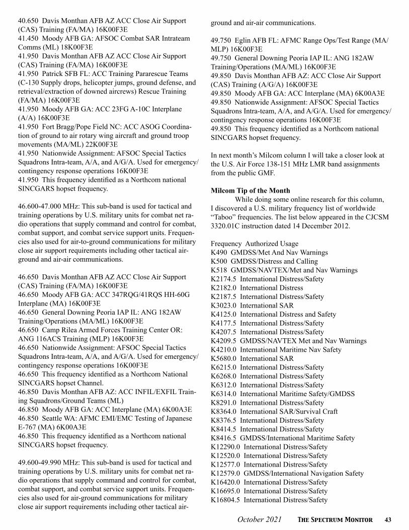
October 2021 The Spectrum Monitor 43
40.650 Davis Monthan AFB AZ ACC Close Air Support (CAS) Training (FA/MA) 16K00F3E41.450 Moody AFB GA: AFSOC Combat SAR Intrateam Comms (ML) 18K00F3E41.950 Davis Monthan AFB AZ ACC Close Air Support (CAS) Training (FA/MA) 16K00F3E41.950 Patrick SFB FL: ACC Training Pararescue Teams (C-130 Supply drops, helicopter jumps, ground defense, and retrieval/extraction of downed aircrews) Rescue Training (FA/MA) 16K00F3E41.950 Moody AFB GA: ACC 23FG A-10C Interplane (A/A) 16K00F3E 41.950 Fort Bragg/Pope Field NC: ACC ASOG Coordina-tion of ground to air rotary wing aircraft and ground troop movements (MA/ML) 22K00F3E41.950 Nationwide Assignment: AFSOC Special Tactics Squadrons Intra-team, A/A, and A/G/A. Used for emergency/contingency response operations 16K00F3E41.950 This frequency identified as a Northcom national SINCGARS hopset frequency.
46.600-47.000 MHz: This sub-band is used for tactical and training operations by U.S. military units for combat net ra-dio operations that supply command and control for combat, combat support, and combat service support units. Frequen-cies also used for air-to-ground communications for military close air support requirements including other tactical air-ground and air-air communications.
46.650 Davis Monthan AFB AZ ACC Close Air Support (CAS) Training (FA/MA) 16K00F3E46.650 Moody AFB GA: ACC 347RQG/41RQS HH-60G Interplane (MA) 16K00F3E46.650 General Downing Peoria IAP IL: ANG 182AW Training/Operations (MA/ML) 16K00F3E 46.650 Camp Rilea Armed Forces Training Center OR: ANG 116ACS Training (MLP) 16K00F3E 46.650 Nationwide Assignment: AFSOC Special Tactics Squadrons Intra-team, A/A, and A/G/A. Used for emergency/contingency response operations 16K00F3E46.650 This frequency identified as a Northcom National SINCGARS hopset Channel.46.850 Davis Monthan AFB AZ: ACC INFIL/EXFIL Train-ing Squadrons/Ground Teams (ML)46.850 Moody AFB GA: ACC Interplane (MA) 6K00A3E46.850 Seattle WA: AFMC EMI/EMC Testing of Japanese E-767 (MA) 6K00A3E46.850 This frequency identified as a Northcom national SINCGARS hopset frequency.
49.600-49.990 MHz: This sub-band is used for tactical and training operations by U.S. military units for combat net ra-dio operations that supply command and control for combat, combat support, and combat service support units. Frequen-cies also used for air-ground communications for military close air support requirements including other tactical air-
ground and air-air communications.
49.750 Eglin AFB FL: AFMC Range Ops/Test Range (MA/MLP) 16K00F3E49.750 General Downing Peoria IAP IL: ANG 182AW Training/Operations (MA/ML) 16K00F3E49.850 Davis Monthan AFB AZ: ACC Close Air Support (CAS) Training (A/G/A) 16K00F3E49.850 Moody AFB GA: ACC Interplane (MA) 6K00A3E49.850 Nationwide Assignment: AFSOC Special Tactics Squadrons Intra-team, A/A, and A/G/A. Used for emergency/contingency response operations 16K00F3E49.850 This frequency identified as a Northcom national SINCGARS hopset frequency.
In next month’s Milcom column I will take a closer look at the U.S. Air Force 138-151 MHz LMR band assignments from the public GMF. Milcom Tip of the Month While doing some online research for this column, I discovered a U.S. military frequency list of worldwide “Taboo” frequencies. The list below appeared in the CJCSM 3320.01C instruction dated 14 December 2012.
Frequency Authorized UsageK490 GMDSS/Met And Nav WarningsK500 GMDSS/Distress and CallingK518 GMDSS/NAVTEX/Met and Nav WarningsK2174.5 International Distress/SafetyK2182.0 International DistressK2187.5 International Distress/SafetyK3023.0 International SARK4125.0 International Distress and SafetyK4177.5 International Distress/SafetyK4207.5 International Distress/SafetyK4209.5 GMDSS/NAVTEX Met and Nav WarningsK4210.0 International Maritime Nav SafetyK5680.0 International SARK6215.0 International Distress/SafetyK6268.0 International Distress/SafetyK6312.0 International Distress/SafetyK6314.0 International Maritime Safety/GMDSSK8291.0 International Distress/SafetyK8364.0 International SAR/Survival CraftK8376.5 International Distress/SafetyK8414.5 International Distress/SafetyK8416.5 GMDSS/International Maritime SafetyK12290.0 International Distress/SafetyK12520.0 International Distress/SafetyK12577.0 International Distress/SafetyK12579.0 GMDSS/International Navigation SafetyK16420.0 International Distress/SafetyK16695.0 International Distress/SafetyK16804.5 International Distress/Safety

44 The Spectrum Monitor October 2021
K16806.5 GMDSS/International Maritime SafetyK19680.5 GMDSS/International Maritime SafetyK22376.0 GMDSS/International Maritime SafetyK26100.5 GMDSS/International Maritime Safety
M121.500 International Distress/Aeronautical EmergencyM123.100 International Emergency/SARM156.300 International Ship/Aircraft SARM156.525 International Distress/Safety/GMDSSM156.650 International Safety Of NavigationM156.800 International Distress/SafetyM243.000 Aero Emergency/International Distress/SARM406.050 Satellite EPIRBM1227.60 Satellite GPS DownlinkM1544.50 Satellite EPIRB Feeder LinksM1575.42 Satellite GPS DownlinkM1646.00 Satellite EPIRB
Finally, if you are looking for the latest Milcom fre-quencies, callsigns, and monitoring news be sure to check out my blog on the Internet: Milcom Monitoring Post at http://mt-milcom.blogspot.com/. You can also follow me on twitter: @MilcomMP for any late-breaking military news items of interest to military air monitors. I also have a YouTube video channel “From the Static” were I posted video/audio samples of various military voice and digital communications. Please be sure to ring the bell (subscribe) to receive updates as new material is posted to the channel. That will do it for this month. Until next time, 73 and good hunting.
Milcom Resource Guide
NTIA GMF pdf can be found athttps://www.governmentattic.org
NTIA website https://www.ntia.gov
NTIA Red Bookhttps://www.ntia.doc.gov/page/2011/manual-regula-tions-and-procedures-federal-radio-frequency-manage-ment-redbook
Table 1: Legend
EmissionsA2D Amplitude modulated (AM); ; digital modulation,
modulated subcarrier (2); data telemetry and telecommand (D).
F2D Frequency modulated (FM); digital modulation, modulated subcarrier (2); data telemetry and telecommand (D).
F3E Frequency modulated (FM) analog voice - various bandwidths
Abbreviations/Acronyms
A/A Air-to-Air (Interplane)A/G Air/GroundA/G/A Air/Ground/AirACC Air Combat CommandACS Air Control SquadronAF Air ForceAFB Air Force BaseAFMC Air Force Material CommandAFSOC Air Force Special Operations CommandANG Air National GuardAR ArmyASOG Air Support Operations GroupASOS Air Support Operations SquadronAW Air WingCAS Close Air SupportDoD Department of DefenseEMC Electromagnetic CompatibilityEMI Electromagnetic InterferenceEXFIL ExfiltrationFA Aeronautical Station: A land station in the aeronautical mobile service. In certain instances, an aeronautical station may be found, for example on board ship or on a platform at sea.FG Fighter GroupFM Frequency ModulationGMF Government Master FileIAP International AirportINFIL InfiltrateLMR Land Mobile RadioMA Aircraft Station: A mobile station in the aeronautical mobile service, other than a survival craft station, found on board an aircraft.ML Land Mobile Station: A mobile station in the land mo-bile service capable of surface movement within the geo-graphical limits of a country or continent. MLP Portable Land Mobile Station: A portable station oper-ating in the land mobile service.Northcom U.S> Northern CommandNTIA National Telecommunications and Information Ad-ministrationRAP Regional AirportRQG Rescue GroupRQS Rescue SquadronSAR Search and RescueSFB Space Force BaseSINCGARS Single Channel Ground and Airborne Radio SystemU.S. United States
T S MT S M

October 2021 The Spectrum Monitor 45
U t i l i t y P l a n e tU t i l i t y P l a n e tBy Hugh Stegman [email protected]
KiwiSDR ALE Scanner Goes Live Online
Sometimes I wonder whether this column is too much of a commercial for KiwiSDR. It’s hard not to be excited, though. Kiwi’s underlying technology is the biggest
thing to happen to this hobby in a very long time. It’s never going to replace DXing from home, but it does supplement it with very powerful tools. New ones appear yearly. A lot of this stuff used to be reserved for top-secret spy agencies with multi-billion-dollar budgets. We, the radio amateurs, garage tinkerers, and software experimenters of the world, have once again democratized technology.
On a more general level, the whole Web SDR phenom-enon is currently in a developmental phase that feels pretty big and exciting. It’s a lot like the rush we got when Auto-matic Link Establishment (ALE) scanning and decoding be-came available to hobbyists. By radio standards, that’s eons ago. At the time, though, big maritime stations were van-ishing pretty much daily, and the utility sub-hobby needed precisely the re-boot that ALE gave it. It certainly replaced the daily, “Look what’s gone now,” with the much happier, “Look what I just found.” ALE was more geeky than straight audio DXing, but it was and is good radio fun.
Ditto for KiwiSDR. It’s not the only online system, nor is it always the best one for, say, hams. Each Kiwi allows maybe four or eight users compared to the hundreds allowed on, say, the U of Twente WebSDR. It’s an apples vs oranges situation since each Kiwi user has hundreds of times more processing power.
Everyone’s finding new things to do with this sudden escalation of capability. Not all that long ago, a multilat-eration direction-finding extension gave hobbyists another tool previously reserved to the highest-end agencies. It’s called TDoA, for Time Difference of Arrival. The Kiwi implementation remains tricky, with a steep learning curve, but it works. It produces “heat maps,” with possible station locations.
TDoA has been instrumental in resolving a few very old arguments regarding possible transmitter locations. In a few cases, it’s put a quick end to what otherwise would have required months or years of e-mails and voice calls, looking for the one guy in some vast agency who has ever heard of HF radio. It’s helping us put an end to that same old refrain of, “Oh no, you must be mistaken, we got rid of that 20 years ago,” as we hold our cell phones up to speakers and their nonexistent signals blast forth for all to hear.
I’ve known for several months now that another exten-
sion would soon be adding 2G ALE capability to KiwiSDR. It’s true that 2G ALE, plus its refinement called AQC ALE, are legacy modes now, falling ever farther into the appendix portions of NATO and US military specs. It’s also true, how-ever, that they will still be in wide use by NGOs, emergency agencies, and even some hams, for at least another 15 years. This all seemed too good to be true.
In either July or August, I ran the undocumented exper-imental version, which decoded a single beacon transmitter on an amateur test frequency. It worked just fine. Publicly, I kept mum until more details came in. This happened in Sep-tember, when the extension went live across the whole Kiwi network. Since then, I have given it a pretty intense shake-out. It works. Let’s get down to nuts and bolts with it.
Things to Remember
There are something like 600 Kiwis available world-wide, usually clickable from online maps and lists. The key thing to remember is that you are using someone else’s equipment in a remote location. If one finds just the right one in just the right place, the tendency is to bookmark it and consider it to be one’s own resource. The catch here is that it’s not. It’s still a public service, like the freeway during a morning commute. Most Kiwis are now on timers, and they have other ways to limit hogging. No one, except sometimes the amateur WSPR project, just lets the gear and software run for hours, days, weeks, or months.
Also keep in mind that Kiwi sysops have invested
Screen grab of the ALE extension in operation. (Author)

46 The Spectrum Monitor October 2021
personal time and money to participate in a grand worldwide experiment in distributed radio monitoring. The underlying hobby-level gear is cheap, as these things go. Other require-ments, like antennas, are not. Some of these remotes have big TCIs or long wires. Maintenance is decidedly non-trivial. In addition, good high-speed Internet connections are still expensive in some places. Finally, another issue comes up when the sysops are active hams, as many of them are. They transmit, causing dropouts or QRN. This should serve as yet another reminder that we are still their guests. Let’s play nicely, OK?
First Impressions
The decoder is launched from the “extension” tab at top right of the tuning/control window on the bottom right of the screen. Several panels come up, over the existing main waterfall/FFT screen. It credits a gnuradio (“gnr”) project, with a link to its page on github.com. Advanced questions and bug reports go to [email protected].
Startup is easy. The ALE extension is operated the same way as any other. When everything’s right, though, the results are only slightly short of amazing. On a decent antenna, in a quiet spot, during a busy period, the thing sucks up COTHEN like a champ. You’ll see several hits in this month’s log.
Most of our readers already know about COTHEN. It’s the Cellular Over-The-Horizon Enforcement Network, as contracted to Collins Aerospace for (mostly) US Govern-ment agencies and the US Coast Guard. A few days with the Kiwis have given me a few real jaw-dropping moments from scanning this net.
Some users have reported confusion over the COTHEN scan list available from the extension’s menu. I’m sure it’ll change, but right now in late September, the user will want the first entry. The frequency list is almost identical to the one I’m using here, which is dead on. Their list says “US COTHEN,” and the scan option appears at the top of this list. Individual frequencies are below. Clicking one allows sitting on that channel.
Right now, and subject to change, the next system on the menu is labeled, “US COTHEN NOJ.” Here’s where the confusion starts. Scanning or monitoring this one actually puts you in an old US Coast Guard net with control at NOJ in Kodiak, Alaska. I’ve been wondering about activity on this one, and so I’ll be checking it out from any site that I can find up there. However, it is most certainly not part of COTHEN.
The scan works nicely. I couldn’t find a single-channel lockout, which would be good for coping with QRM. Maybe I just didn’t look in the right place. One can, however, rough-ly configure the particular HF sub-band being scanned, for daily propagation changes or whatever. I’ve also messed with the “record call est,” which presumably grabs follow-on comm. I haven’t done enough with it to say anything at present.
Given the buzz that I’ve seen regarding this new exten-sion, I would not be surprised if Kiwi network traffic has in-creased. At peak times, many of the better SDRs will assign most users to an audio FFT instead of the whole waterfall display. I have such a screen going right now. The waterfall’s absence is not a problem, and it may even be an advantage. The waterfall often cuts in and out during scans anyway.
Power users will want to check and see whether their favorite KiwiSDR has installed a currently undocumented update from around September 20. It allows the embedding of a personal frequency scan in the URL when the first con-nection is made. I haven’t tested this yet, so I can’t say much more than the fact that it exists. I’ve been told that uploading such a list will not affect the default that everyone else uses. Personal scans are destroyed on close.
I’ve found quite a few other undocumented things that will probably change, so I won’t discuss them here. I also have a few picky little quibbles. A magenta text background used on some orderwire entries is practically unreadable on my screen. That section would also be more helpful if one click would copy or download the entire orderwire log for editing offline. It’s just little stuff like that.
Happy ALE’ing!
Identifying UrgentLink Addresses
Way at the bottom of the ALE decoder’s “Utility” mode, one will find the ARINC UrgentLink that this column is always talking about. Casual users will likely run it once, see a few cryptic addresses, and then wonder why it’s even there.
People who read this column are more lucky. They know that it’s sort of a second COTHEN, by the same con-tractor, with a roughly similar design and mission. COTHEN was originally intended for a specific Federal law enforce-ment operation related to counter-smuggling and drug in-terdiction. Some emergency traffic came on later, especially after USCG adopted COTHEN for most of its other oceanic and aeronautical comm.
The menu’s first COTHEN list has the right frequencies. (Au-thor)

October 2021 The Spectrum Monitor 47
COTHEN’s proven robustness got everyone looking for something similar that could serve as a reliable last resort to interconnect many federal, state, and local emergency agen-cies in a robust comm backup for more localized disasters. Add business entrepreneurs and FCC rulings, and out came ARINC UrgentLink.
By design, UrgentLink won’t have much back-and-forth until the actual emergencies happen. FCC restrictions and the network design preclude idle chatter. It really is a last resort, and some good hurricane work has been done on it. For the users, it’s all worth it if one more life is saved. For us, it’s mostly a big fishing trip, finding new IDs as more agencies come aboard.
These initial catches, once confirmed by multiple loggings, bring endless online discussions. Quite a few very smart people try to make sense of it all, ultimately connect-ing the cryptic ALE addresses with agencies and locations. Guesses evolve into good ideas, but it’s slow and sometimes contentious.
Right around the time that the KiwiSDR ALE extension went live, I got a very interesting message from a reader and hobbyist named Steve Handler. He’s always been a go-to guy for good ideas regarding UrgentLink IDs. In his letter, he explains that he found them under an old ShipCom call sign, which is now also legally associated with the company running UrgentLink.
Once again, then, it all comes back to that arcane yet visionary “ShipCom Waiver.” This was originally a formal FCC authorization to use a few vacant maritime mobile frequencies for emergencies on land. Hurricane Katrina gave the whole country a lesson in national resiliency, and this waiver remains part of UrgentLink’s legal permission to exist at all.
I should have figured this out for myself since I’m familiar with UrgentLink’s convoluted legal authorization. It seems that I never connected the right dots, and I thank Steve for his tip. I now quote from his e-mail:
“To find these documents, go to the public FCC ULS Search site and enter the call sign ‘WRN.” When you get to the licensee page, click on the ‘Admin’ tab. At the bottom of the ‘Admin’ page you will see public attachments that have been filed. There are 12 of them to date, click on one at a time and all of the details of stations using the UrgentLink Network are provided. A review of all 12 filings will give you the complete list of network users.”
I just did this. It worked for me. The payload comes in copies of attorney’s letters, which have some detailed in-formation, including FCC call signs. These calls are not the same as the UrgentLink ALE IDs, which are neither autho-rized nor listed by the FCC’s Universal Licensing System. They’re assigned by UrgentLink itself, which isn’t telling.
Steve is definitely onto something here. It will deserve my further attention. For now, happy hunting to all. See you next month!
Resources:
Clickable KiwiSDR Map:http://rx.linkfanel.net
Larry Van Horn will maintain our hobby’s ongoing COTHEN list:http://mt-milcom.blogspot.com/p/us-cbp-cothen-net-up-dated-9302012.html
FCC ULS search for WRN, works here, then go to “Admin:”https://wireless2.fcc.gov/UlsApp/UlsSearch/license.jsp?licKey=3662857
Seal of the US FCC, as updated in 2020. (US Government)
T S MT S M

48 The Spectrum Monitor October 2021
Shor t wave Ut i l i t y Log sShor t wave Ut i l i t y Log sRecent Shortwave Utility Logs Compiled by Mike Chace-Ortiz
Frequency (kHz) Callsign Time
(UTC)User, Location System Details
3803.20 ??? 0126 UK MIL DHFCS, Inskip 600bps/L STANAG4285 HF Modem, crypto tfc (on USB)
4132.70 IDR 0100 Italian Navy, Rome 600bps/L STANAG4285 HF modem, crypto tfc (on USB)
4145.90 2STO1160***
0300 US MIL, ??? MIL-188-110A/B HF modem, FS1052DLP crypto tfc (on USB
4145.90 2BRE178***
0300 US MIL, ??? MIL-188-110A/B HF modem, FS1052DLP crypto tfc (on USB
4156.00 ??? 0100 US Navy, nr Washington NC Link-11 CLEW, 2 channels tfc (on DSB)
4448.00 ??? 0225 Swiss MIL, ??? VFT: 2ch of 100bd/170 FSK UNID System, secure (on USB)
5008.00 ??? 0215 Russian Navy, Moscow 75bd/250 FSK UNID system, sync, cont, ACF=0
5155.00 ??? 0120 US SHARES, ??? PacTOR-IV HF modem, tfc
5215.60 FUO 0123 French Navy, Toulon 1200bps/L STANAG4285 HF modem, crypto tfc (on USB)
5418.00 4206*** 0200 SONATRACH, Algeria 125bd/1750 MIL-188-141A, ALE sounding (on USB)
5418.00 4236*** 0200 SONATRACH, Algeria 125bd/1750 MIL-188-141A, ALE sounding (on USB)
5418.00 3127*** 0200 SONATRACH, Algeria 125bd/1750 MIL-188-141A, ALE sounding (on USB)
5454.00 RMP 0050 Russian Navy, Kaliningrad 75bd/250 FSK UNID System, sync, cont, ACF=0
5816.00 TBA 0050 Turkish Navy, Ankara 600bps/L STANAG4285 HF modem, crypto tfc (on USB)
5870.70 IDR 0040 Italian Navy, Rome 600bps/L STANAG4285 HF Modem, crypto tfc (on USB)
6199.00 ??? 0033 Russian Navy, ??? 50bd/200 BEE, tfc
6218.20 IDR 0200 Italian Navy, Rome 600bps/L STANAG4285 HF Modem, “nss3i(0) / ”in ITA2 (on USB)
6260.25 ??? 0114 ???, Marseille 100bd/170/I SITOR-A, simplex tfc no copy
6384.70 CFH 1600 Canadian Navy, Halifax 300bps/L STANAG4285 HF modem, crypto tfc (on USB)
6393.00 CFH 0040 Canadian Forces, Halifax 600bps/L STANAG4285 HF modem, tfc (on USB)
6507.00 VFF 2305 Canadian Coast Guard, Iqaluit USB, YL/FF with WX and sea conditions
6618.00 4XZ 0030 Israeli Navy, Haifa Hybrid PSK/FSK HF Modem, tfc (on USB)
7571.00 RCV 2350 Russian Navy, Sevastopol 50bd/250 BEE, tfc ACF=0
7643.50 RMP 2340 Russian Navy, Kaliningrad 50bd/200 BEE, tfc ACF=0
7757.00 BB1*** 0028 Israeli Air Force, ??? 125bd/1750 MIL-188-141A, ALE sounding (on USB)
7757.00 BB2*** 0028 Israeli Air Force, ??? 125bd/1750 MIL-188-141A, ALE sounding (on USB)
8133.00 ??? 0032 Swiss MIL, Berne 125bd/1750 MIL-188-141A, ALE link protected (on USB)
8203.90 ??? 0050 Greek Navy, Crete 1200bps/L STANAG4285 HF Modem, crypto tfc with carrier (on USB)
8457.00 BB1*** 0200 Israeli Air Force, ??? 125bd/1750 MIL-188-141A, ALE sounding (on USB)
8457.00 BB3*** 0200 Israeli Air Force, ??? 125bd/1750 MIL-188-141A, ALE sounding (on USB)
9077.50 ??? 2222 Russian Navy, ??? AT3004D 12 tone HF modem, tfc w/ full carrier (on USB)
9128.00 ??? 0044 Russian Intelligence, Moscow 200bd/1000 FSK UNID System, ACF=288 tfc
9147.00 MKD 2215 UK MIL DHFCS, Akrotiri 600bps/L STANAG4285 HF modem, crypto (on USB)
9248.00 RCV 2230 Russian Navy, Sevastopol AT3004D 12 tone HF modem, tfc (on USB)
9832.00 NSS 2143 US Navy, Davidsonville MD 50bd/850 FSK UNID System, sync, cont, ACF=0
10312.00 ??? 2230 Russian Navy, ??? 75bd/250 FSK UNID System, sync, cont, ACF=0
10894.00 RCV 0100 Russian Navy, Sevastopol 75bd/200 FSK UNID System, sync, cont, ACF=0
10965.00 AXAA 2333 Australian MHFCS, Bohle River MIL-188-110A HF modem, continuous mode idle (on USB)
12160.00 ??? 2240 Russian Navy, ??? 75bd/250 FSK UNID system, sync, cont, ACF=0
12585.50 WLO 2240 ShipCom, Mobile AL 100bd/170/E SITOR-B, news in EE
12590.00 ??? 2245 Russian Navy, Bishkek 50bd/200 BEE, idle on reversals
12665.20 JWT 2230 Norwegian Navy, Stavanger 600bps/L STANAG4285 HF modem, crypto tfc (on USB)
12695.50 KFS 2223 Global HF Net, Bolinas CA CW, news report in EE
13031.20 FUF 2231 French Navy, Fort de France 600bps/L STANAG4285 HF modem, “faaa de fuf zui” (on USB)
13411.60 FUE 2221 French Navy, Brest 1200bps/L STANAG4285 HF modem, crypto tfc (on USB)
14390.00 ??? 2244 UK MIL DHFCS, Ascension Isl 1200bps/L STANAG4285 HF Modem, crypto tfc (on USB)
16133.00 ZA1*** 2143 Swiss MFA, Berne MIL-188-110A HF modem, crypto tfc on USB

October 2021 The Spectrum Monitor 49
Shor t wave Ut i l i t y Log sShor t wave Ut i l i t y Log sRecent Shortwave Utility Logs Compiled by Hugh Stegman
Frequency Callsign User, Location Time System Details77.50 DCF77 German Mainflingen time stn 0621 Pulse, standard time signals and codes162.00 Unid French TDF time signals, Allouis 2023 PM, successful time decode, also weak Lux Effect voice294.00 428 German DGPS, Helgoland 0618 MSK (200), GPS corrections518.00 "J" Varna Radio (LZW), Bulgaria 2125 SITOR-B, Polish Nav Warning JA54 for Baltic Sea990.00 WGSO Commercial BC, New Orleans 2205 AM, live repeat of Weather Channel audio for Ida1230.00 WBOK Commercial BC, New Orleans 2212 AM, live from Ida emergency presser, sounded ominous1758.00 OXZ Lyngby Radio, Denmark 2245 USB, various machine voices with weather in Danish2187.50 258895000 Offshore vessel North Pomar 0631 DSC, calling unknown station2187.50 002470119 Olympia Radio, Greece 2109 DSC, calling 002470001, Roma Radio, Italy3622.50 JMH Japan Meteo Agency, Tokyo 1023 FAX (120/576), weather charts4490.00 CIS50 Likely US CBP or ICE 0433 ALE, sounding on SHARES frequency4505.00 366 Polish Intelligence (E11a) 1530 USB, English callup "366/35" & 5-figure-group message4882.00 WGY901 FEMA Region 9, Maynard, MA 1304 ALE, link & AMD chat with NH1FEM, NH state EOC5732.00 TCABP US Border Patrol, AZ 0327 ALE, sounding on COTHEN5909.50 001 USCG HC-130J #2001, NC 0330 ALE, sounding on COTHEN6190.00 265 Russian Intelligence (S06s) 1100 AM, callup "265 491 7" and 5-figure-group message6218.20 NSS NATO, unknown location 1923 STANAG 4285 (600L 5N1), repeating CARBs7044.00 TP4C Chinese Military (M89) 1147 CW, round slip "V BSA5 BSA5 BSA5 DE TP4C TP4C."7230.00 265 Russian Intelligence (S06s) 1100 AM, callup "265 491 7" and 5-figure-group message7268.00 AC0ML US amateur, MO 2148 LSB, Ida Advisory #10 on Natl. Hurricane Watch Net7600.00 Unid Afghanistan exile clandestine 2106 AM, political rhetoric in Pashto and Dari7602.00 RLO Russian Navy, general call 0759 CW, first of many priority "XXX" messages all day7633.00 BX63 Algerian Military 1740 ALE, calling WE508625.00 FUM French Navy, Papeete, Tahiti 1119 STANAG 4285 (600L 5N1), usual test loop with RY/SG8912.00 EPP USCGC Healy (WAGB-20), WA 2357 ALE, LQA link check with 17Z, unknown USCG; COTHEN9106.00 NNB4ES Unknown SHARES station 0429 ALE, sounding, heard here before10101.00 Unid Unknown SWBC pirate 2345 AM, anti-China diatribe in English, stepping onDDK910242.00 N17 USCG HC-144A #2317, TX 2300 ALE/voice, working LNT, USCG Commcom, VA; COTHEN11184.00 "03" ARINC, Reykjavik, Iceland 2205 HFDL, position from P4-KBM, Air Astana A32011253.00 Military One UK Royal Air Force, England 2040 USB, robot ID and aviation weather for "Time Slot 3"11494.00 TUG USCGC Aspen (WLB 208/NTUG) 1804 ALE/voice, with Z27, USCG San Francisco, on COTHEN12129.00 FC4FEM US FEMA, Thomasville, GA 0335 ALE, Region IV Communications, sounding12176.00 152 Russian Intelligence (E07) 1300 USB, English callup "152 1 765 43" & 5-fig-grp message12200.00 Unid North Korean Diplomatic 0824 DPRK-ARQ (600, LSB), usual encrypted messages12222.00 04M USCG on COTHEN 1927 ALE, Response Boat-Medium #45704, sounding12577.00 005741040 Hai Phong Radio, Vietnam 1742 DSC, calling 565110000, m/v Kota Salam13303.00 IGO900 IndiGo A320 reg VT-IER 1640 HFDL, reporting position13312.00 X11 USCG HC-27J #3711 1758 USB, sounding on COTHEN, possibly Ida related13431.00 Unid Russian Intelligence (XPA2) 1100 MFSK/20/10, Polytone, "05346 00001 00000 35661"13907.00 LNT USCG Commcom, VA 1854 ALE, working N15, USCG HC-144 ##2315, on COTHEN14325.00 Unk/missed Unknown amateur, NY 2145 USB, Ida Advisory #10 on Natl. Hurricane Watch Net14582.00 J38 USCG MH-65D #6538, LA 1923 ALE, calling CSK, USCG COMMSTA Kodiak, AK, COTHEN14972.00 917 Polish Intelligence (E11a) 1345 USB, English callup "917/31" & 5-figure-group message15867.00 713 USCG HC-130H #1713 1920 ALE, sounding on COTHEN16228.00 594 Russian Intelligence (E07) 1430 USB, English null-message callup "594 00" 18594.00 003 USCG HC-130J #2003, NC 1919 ALE, sounding on COTHEN20890.00 N15 USCG HC-144A #2315 1914 ALE, sounding on COTHEN22447.00 FUV French Navy, Djibouti 0454 STANAG 4285 (600L 5N1), usual test loop with RY/SG22461.00 FUJ French Navy, New Caledonia 0223 STANAG 4285 (600L 5N1), usual test loop with RY/SG25000.00 WWV US NIST, Ft. Collins, CO 2000 AM, still on-air, with standard time/frequency signals

50 The Spectrum Monitor October 2021
V H F a n d A bov eV H F a n d A bov eBy Joe Lynch N6CL [email protected]
ARISS Space Station Contact Opportunity
The International Space Station photographed by Expedition 56 crew members from a Soyuz spacecraft after undocking. (Courtesy: NASA)
The following is from https://www.ariss.org: New Proposal Window is October 1, 2021, to Novem-ber 24, 2021: The Amateur Radio on the International
Space Station (ARISS) Program is seeking formal and in-formal education institutions and organizations, individually or working together, to host an amateur radio contact with a crew member on board the ISS. ARISS anticipates that the contact would be held between July 1, 2022, and December 31, 2022. Crew scheduling and ISS orbits will determine the exact contact dates. To maximize these radio contact oppor-tunities, ARISS is looking for organizations that will draw large numbers of participants and integrate the contact into a well-developed education plan.
The deadline to submit a proposal is November 24, 2021. Proposal information and more details such as expec-tations, proposal guidelines and the proposal form can be found at https://ariss-usa.org/hosting-an-ariss-contact-in-the-usa. An ARISS Introductory Webinar session will be held on October 7, 2021, at 8 PM ET. The Eventbrite link to sign up is: https://ariss-proposal-webinar-fall-2021.eventbrite.com
The Opportunity
Crew members aboard the International Space Station will participate in scheduled amateur radio contacts. These radio contacts are approximately 10 minutes in length and allow students to interact with the astronauts through a ques-tion-and-answer session.
An ARISS contact is a voice-only communication opportunity via amateur radio between astronauts and cosmonauts aboard the space station and classrooms and communities. ARISS contacts afford education audiences the opportunity to learn firsthand from astronauts what it is like to live and work in space and to learn about space research conducted on the ISS. Students also will have an opportunity to learn about satellite communication, wireless technology, and radio science. Because of the nature of human space-flight and the complexity of scheduling activities aboard the ISS, organizations must demonstrate flexibility to accommo-date changes in dates and times of the radio contact.
Amateur Radio organizations around the world with the support of NASA and space agencies in Russia, Canada,

October 2021 The Spectrum Monitor 51
STEM on Station logo. (Courtesy: NASA)
Japan and Europe present educational organizations with this opportunity. The ham radio organizations’ volunteer efforts provide the equipment and operational support to enable communication between crew on the ISS and students around the world using amateur radio. Please direct any questions to [email protected].
NASA Recognizes ARISS for its STEM Accomplishments
The following is from ARISS: Kathryn Lueders, Asso-ciate Administrator for Human Exploration and Operations Mission Directorate at NASA has posted a statement recog-nizing Amateur Radio on The International Space Station (ARISS) for its accomplishments in promoting STEM initia-tives through amateur radio.
NASA’s Space Communications and Navigation (SCaN) networks enable NASA to inspire the next genera-tion of scientists, engineers, and explorers – even from 350 kilometers above Earth.
In addition to connecting the science community on Earth with the groundbreaking research studies and exper-iments aboard the International Space Station, SCaN en-ables the space station to act as a unique platform for global STEM outreach and education efforts.
For over 20 years, ARISS program, a non-profit sup-ported by SCaN, has connected classrooms on Earth with astronauts aboard the space station, allowing students to engage directly with astronauts in real-time. Using ham radio equipment installed on the space station and a ham radio station on the ground, students are able to establish a direct radio connection with the space station and ask the crew questions about living in space and what it takes to become an astronaut.
In preparation for their ARISS contact, the students explore a variety of STEM studies, including space explo-ration, radio communication, and wireless technologies. With tens of thousands of student participants each year, the ARISS program plays an important role in inspiring the Ar-
temis Generation and encouraging students to pursue STEM careers.
Learn more about the ARISS program and how you can bring space into your classroom here: https://www.ariss.org.
Virtual AMSAT Space Symposium and Annual General Meeting – Oct. 30, 2021
Because the COVID-19 pandemic remains a threat to the public, AMSAT has changed plans for its 39th Annual Symposium and General Meeting from an in-person event to a virtual event. The following is from AMSAT’s website: https://www.amsat.org/:
“AMSAT will host its 2021 AMSAT Virtual Space Symposium and Annual General Meeting on Zoom for its members on Saturday, October 30th from 9:00am CDT – 5:00pm CDT (UTC-5). The event will be a combination of pre-recorded video segments along with live question and answer sessions.
“Registration for members is required and is available on AMSAT’s Member Portal, launch.amsat.org. Registration is free and registered attendees will receive a digital copy of the AMSAT Symposium Proceedings, entered into the Sym-posium prize drawings, and be able to participate in discus-sions during each question-and-answer session.
“The 2021 AMSAT Virtual Space Symposium and An-nual General Meeting will be available to the general public on AMSAT’s YouTube channel, https://youtu.be/RTvcce-M7Tz0 at no cost.
“Final papers for the Symposium Proceedings must be submitted by October 18, 2021, to Dan Schultz N8FGV, [email protected]. Symposium presentations should be limited to
STEM activity aboard ISS: NASA Astronaut Shannon Walker tends to plants growing inside the Veggie plant growth facility on the International Space Station for the Veg-03J space botany study space botany study. The investigation is cultivating Extra Dwarf Pak Choi, Amara Mustard and Red Romaine Lettuce which are harvested on-orbit with samples returned to Earth for testing. (Credits: NASA)

52 The Spectrum Monitor October 2021
(Courtesy: QSO Today Virtual Ham Expo)
15 minutes of pre-recorded video. Video presentations must be submitted by October 18, 2021, to Paul Stoetzer N8HM, [email protected]. We ask that presenters be available to take questions via Zoom following the airing of their pre-record-ed video.
Tentative Schedule
9:00am CDT – Opening Remarks9:15am CDT – 2:00 pm CDT – General Presentations2:00pm CDT – 3:00 pm CDT – AMSAT Education / CubeSat Simulator3:00pm CDT – 4:00 pm CDT – AMSAT Engineering4:00pm CDT – 5:00 pm CDT – 2020 AMSAT Annual Gener- al Meeting.
QSO Today Virtual Ham Expo a Treasure Trove of Ama-teur Radio-related Resources
This past August the QSO Today Virtual Ham Expo ran its third event. In my estimation, the most important resource that has come out of these three events is the archive of pre-sentations available for viewing on its website: https://www.qsotodayhamexpo.com.
There are 250 videos available for viewing on the web-site. Currently, you can find the August 2021 videos linked on the main website. The archived videos from the past two Expos can be found under the Presentations tab. The next Virtual Ham Radio event will be held between March 13 and 14, 2022.
Southgate Amateur Radio News: A Treasure Trove of Daily Ham News
Concerning treasure troves, if you must have a daily dose of amateur radio news, the Southgate Amateur Radio News website: http://www.southgatearc.org. Along with links to the current stories, the website also includes links to Southgate’s podcast, the Space Weather Woman, and its
shortwave radio website: CQ-Serenade. Also included is a box for callsign lookup.
Repurposing the IC 7100 as an IF Receiver
Bob Atkins KA1GT contributed the following sugges-tion to the Moon-net listserv for repurposing ICOM’s IC 7100 as an IF receiver for EME communications: “It does not have the capability of locking to an external 10 MHz GPS reference. There’s no easy way to lock it to an exter-nal reference without performing surgery on the main PCB, which I’m not prepared to do at this point. However, it does have a voltage tuned TCXO which can be trimmed onto frequency via one of the internal menus.
“This feature is very useful. It seems to be very stable. Decoding is 100 percent fine, even when used as an IF for 10 GHz and more than good enough for 1296. Looking at beacon signals on both 10 GHz and 1296 (when they are op-erating), I see no drift which would affect decoding or even finding a signal. On 10 GHz I can get the desired frequency for the beacon and it’s always within a few Hz or where I expect it to be. On both 10 GHz (432 IF) and 1296 (144 IF) I use transverters which are locked to stable reference signals (GPS or GPS derived standards). I can’t speak about perfor-mance on other bands.”
Current Meteor Shower
This month’s sole meteor shower of note is the Orio-nids. So-called the Orionids because it seems to originate from the club of constellation Orion the Hunter. Look for them just before dawn on October 21, 2021.
Current Contests
Weekend 1 of the ARRL 2.3 GHz and Up EME contest will be October 23-24, between 0000 and 2359 UTC. For more information, go to: http://www.arrl.org/eme-contest.
Icom IC-7100 (Courtesy: DX Engineering)
T S MT S M

October 2021 The Spectrum Monitor 53
VHF AM: The Rediscovered Country
The recent news regarding the (legal) introduction of FM (Frequency Modulation) on CB, caused me to think back to my early experiences as a new ham in
the days when AM (Amplitude Modulation) was giving way to FM on the VHF bands. It is fair to say that most hams believe that AM is completely gone from our VHF bands. However, the reality is that it has remained as something of a niche mode. For those of us with multimode rigs, does it make sense to (re)explore AM and what it has to offer? Put-ting DV (Digital Voice) aside for the moment, read on and decide for yourself.
Although some would like to include the 10-meter band as VHF, since it is so close, this region of the spec-trum officially runs from 30 to 300 MHz. While Ireland has an 8-meter band around 40 MHz, North American hams’ first VHF allocation starts at 50 MHz. This was not always so. The 5-meter band used to start at 56 MHz, followed by 2½ meters at 112 MHz, then 1¼ meters where we find our current 222 MHz band. Today, 222 MHz seems out of place in harmonic relationships, but at its inception, it lined up just fine at 224 MHz.
When the United States actively entered World War II, amateur radio activity ceased. The ARRL (American Radio Relay League) petitioned the FCC to create a new radio service – WERS (War Emergency Radio Service). WERS li-censes were assigned to communities, not individuals. How-ever, only licensed radio amateurs could transmit on WERS radios, which occupied the 112 to 116 MHz of the 2½ meter ham band. The mode of choice continued to be AM.
This Civil Defense program allowed hams who re-mained stateside to serve their communities in a domestic capacity, while still encouraging operating and building skills. After the war, WERS ended, transitioning into what we now recognize as RACES (Radio Amateur Civil Emer-gency Service).
Television, having also hit a speed bump because of the war, was assigned channels. Amateur radio lost 5 meters, but picked up 6 meters, from 50 to 54 MHz. This also placed it squarely between what was assigned as TV channel 1 (44 to 50 MHz) and channel 2 (54 to 60 MHz). After additional considerations were explored, channel 1 was dropped and those frequencies were added into public service. FM broad-casting, originally starting at 42 MHz, was moved up to its current 88 to 108 MHz allocation.
Simple designs for 5 meters were easily tweaked down to 6 meters and AM returned to amateur radio’s VHF activ-ity. Likewise, designs for 2½ meters went up to 144 to 148 MHz, again with AM. Receivers, by the way, were typically super regenerative “rush boxes.”
Typical power levels were just a few Watts, into hori-zontally polarized antennas (which helped cut down on typ-ical noise sources) and range was fairly local, unless some propagation enhancement was occurring. When it was, those with better antennas could enjoy some nice DX across their state or across the country.
As time passed, military surplus gear was converted to amateur use, all the way into the 23-centimeter (then 1215 to 1300 MHz) band. Eventually, companies began offering kits or wired and tested products and activity in VHF+ further increased. Names like Clegg, Gonset, Heathkit, Lafayette and others became quite popular in ham shacks and cars. (Yes, small tube rigs like the Lunch Box fit nicely under the dashboards of the day and 12-volt inverters or dynamotors were used to generate a few hundred volts needed for the B+ requirements)
Nicknames like “Gooney Box” and Lunch Box,” were bantered about. Usually, the transmitter was crystal con-trolled for stability, while the receiver was tunable. Calling CQ (which was done in those days) meant you also had to listen to a return call a bit below and above your chosen frequency. In time, common calling frequency “watering
Yaesu’s FT-818ND and the FT-817 series that preceded it, are incredibly versatile and agile HF / VHF / UHF transceivers. Among the many modes offered is AM, with just enough power to make it interesting. (Courtesy: Yaesu)
Dig i ta l ly Spe a k i ngDig i ta l ly Spe a k i ngBy Cory GB Sickles WA3UVV [email protected]

54 The Spectrum Monitor October 2021
holes” were established, such as 50.4 MHz and 145.8 MHz. The former is still a good spot to scare up some AM activity on 6 meters.
Receiver designs improved as well, reflected in such radios as Heath’s HW-17 and the Gonset Communicator IV – with versions that included the 1¼ meter band. I once ownedboth of these and can tell you that their performance level was excellent for their time.
In some areas, AM enthusiasts installed repeaters with 2 meters being the most popular band for this. An audible tone encoder in the 2 kHz range was used to “wake up” the dormant machine. After a preset period of inactivity, the repeater would time out and go back to sleep. The technolo-gy of the day was still primarily tube based. Hams with good whistling skills did not need to use a tone encoder, they just puckered up.
During part of the heyday of AM activity on 2 meters, Novice license holders (then the introductory license class) were allowed voice operation on 2-meter AM. This further increased the level of activity.
When the FCC issued a narrow band mandate for public service and commercial bands, changing deviation standards from 15 kHz to 5 kHz, a lot of retired FM gear found its way to the amateur radio community. AM rigs usually offered no more than 10 Watts out. FM rigs could be anywhere from 30 to 100 Watts. FM receivers were ignition noise free, while AM receivers were not. FM represented something new, but not AM.
The transition was gradual at first. If a club installed an FM repeater on a hilltop, the adoption rate increased dramatically. A phenomenon we saw repeated with digital voice; AM was no longer the popular way to go. Late model radios, some with solid state receivers, could be converted into FM operation on transmit, with slope detection (tuning slightly off center of the signal) allowing AM receivers to receive FM. The Clegg 22’er was – to my knowledge – the last transceiver produced that offered AM and FM on 2 me-
ters. By the time the seventies came to a close, it seemed as though every ham with a Technician class license and higher was on 2 meter FM, with a shiny new radio, now with even narrower 5 kHz deviation.
If we ignore the FT and JT digital modes and CW (Morse code) for a moment, SSB (Single Sideband) rep-resents the mode with the greatest reach – Watt for Watt. Next up is AM, which can still offer better range than FM. This is one of several reasons that AM has not been replaced by FM in aviation.
When I lived in southern New Jersey, I was able to reg-ularly contact a number of AM enthusiasts is Maryland and Virginia. This was without any band openings. My rig was a 10 Watt HW-17A (with a solid-state pre-amp) and the anten-na I used was a 4-element horizontal Yagi. Since moving to southwestern Pennsylvania, I haven’t tried, but am thinking it could be fun to head up to a hilltop for some AM QSOs.
My new choice of radio would be one of the multimode rigs I own. I have a Yaesu FT-991A, FT-221R, FT-818ND and FT-817ND – in order of decreasing power levels. For the sake of nostalgia, the FT-221R would be my first choice. If I wanted to bring along an inverter, I could also try firing up a homebrew all-tube transmitter that I picked up at a recent hamfest. It probably outputs no more than 10 Watts and is crystal-controlled. My FT-817ND would make a fine companion receiver, with a suitable T/R switch that I have in storage.
More than a few amateur radio clubs host FM sim-plex contests and sprints with the idea of stimulating some non-repeater communications excitement. The same could be done with AM if sufficient publicity preceded the compe-tition.
If you already have a multimode 10-meter transceiv-er, such as the Uniden President Lincoln II, an older Radio Shack HTX-100 or a nice transverter, available from The Transverters Store (www.Transverters-Store.com) offers a ready to go model for just over $100. Of course, this could also be a good foundation for SSB, CW and digital keyboard
A recent hamfest find in this beautifully built homebrew AM transmitter for 2 meters. The seller said he did not know what it was. My older and more experienced eyes had a hunch and the 36 MHz crystals confirmed by suspicions. The top needs some cleaning, but a look at the underside reveals the excellent workmanship that went into the build and serves as a quick trip back in time concerning the parts used – popular in their day. (WA3UVV photo)
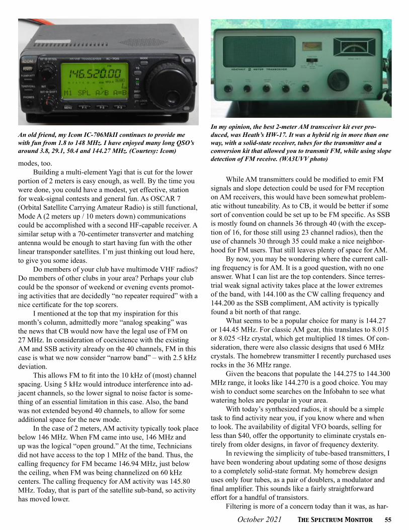
October 2021 The Spectrum Monitor 55
modes, too.Building a multi-element Yagi that is cut for the lower
portion of 2 meters is easy enough, as well. By the time you were done, you could have a modest, yet effective, station for weak-signal contests and general fun. As OSCAR 7 (Orbital Satellite Carrying Amateur Radio) is still functional, Mode A (2 meters up / 10 meters down) communications could be accomplished with a second HF-capable receiver. A similar setup with a 70-centimeter transverter and matching antenna would be enough to start having fun with the other linear transponder satellites. I’m just thinking out loud here, to give you some ideas.
Do members of your club have multimode VHF radios? Do members of other clubs in your area? Perhaps your club could be the sponsor of weekend or evening events promot-ing activities that are decidedly “no repeater required” with a nice certificate for the top scorers.
I mentioned at the top that my inspiration for this month’s column, admittedly more “analog speaking” was the news that CB would now have the legal use of FM on 27 MHz. In consideration of coexistence with the existing AM and SSB activity already on the 40 channels, FM in this case is what we now consider “narrow band” – with 2.5 kHz deviation.
This allows FM to fit into the 10 kHz of (most) channel spacing. Using 5 kHz would introduce interference into ad-jacent channels, so the lower signal to noise factor is some-thing of an essential limitation in this case. Also, the band was not extended beyond 40 channels, to allow for some additional space for the new mode.
In the case of 2 meters, AM activity typically took place below 146 MHz. When FM came into use, 146 MHz and up was the logical “open ground.” At the time, Technicians did not have access to the top 1 MHz of the band. Thus, the calling frequency for FM became 146.94 MHz, just below the ceiling, when FM was being channelized on 60 kHz centers. The calling frequency for AM activity was 145.80 MHz. Today, that is part of the satellite sub-band, so activity has moved lower.
While AM transmitters could be modified to emit FM signals and slope detection could be used for FM reception on AM receivers, this would have been somewhat problem-atic without tuneability. As to CB, it would be better if some sort of convention could be set up to be FM specific. As SSB is mostly found on channels 36 through 40 (with the excep-tion of 16, for those still using 23 channel radios), then the use of channels 30 through 35 could make a nice neighbor-hood for FM users. That still leaves plenty of space for AM.
By now, you may be wondering where the current call-ing frequency is for AM. It is a good question, with no one answer. What I can list are the top contenders. Since terres-trial weak signal activity takes place at the lower extremes of the band, with 144.100 as the CW calling frequency and 144.200 as the SSB compliment, AM activity is typically found a bit north of that range.
What seems to be a popular choice for many is 144.27 or 144.45 MHz. For classic AM gear, this translates to 8.015 or 8.025 <Hz crystal, which get multiplied 18 times. Of con-sideration, there were also classic designs that used 6 MHz crystals. The homebrew transmitter I recently purchased uses rocks in the 36 MHz range.
Given the beacons that populate the 144.275 to 144.300 MHz range, it looks like 144.270 is a good choice. You may wish to conduct some searches on the Infobahn to see what watering holes are popular in your area.
With today’s synthesized radios, it should be a simple task to find activity near you, if you know where and when to look. The availability of digital VFO boards, selling for less than $40, offer the opportunity to eliminate crystals en-tirely from older designs, in favor of frequency dexterity.
In reviewing the simplicity of tube-based transmitters, I have been wondering about updating some of those designs to a completely solid-state format. My homebrew design uses only four tubes, as a pair of doublers, a modulator and final amplifier. This sounds like a fairly straightforward effort for a handful of transistors.
Filtering is more of a concern today than it was, as har-
An old friend, my Icom IC-706MkII continues to provide me with fun from 1.8 to 148 MHz. I have enjoyed many long QSO’s around 3.8, 29.1, 50.4 and 144.27 MHz. (Courtesy: Icom)
In my opinion, the best 2-meter AM transceiver kit ever pro-duced, was Heath’s HW-17. It was a hybrid rig in more than one way, with a solid-state receiver, tubes for the transmitter and a conversion kit that allowed you to transmit FM, while using slope detection of FM receive. (WA3UVV photo)

56 The Spectrum Monitor October 2021
monic and spurious emission rules are tighter. Even so, it is a very doable task. Is there enough of a demand for a 10 Watt or less AM transmitter, that would encourage an individual designer or club – such as the 4 States QRP Club– to pro-duce such a thing? A ready to go transverter might cost less, but never dismiss the fun of building something along with the enjoyment of using your efforts to get on the air.
With further thought as I write this, we have the readily accessible technology to produce a 144 MHz signal with di-rect digital synthesis for the transmitter and use the same for a simple receiver. As anyone who still enjoys driving a car with a manual transmission knows, sometimes less is more.
If you happen to find something interesting at a hamfest near you, running in a classic genre at lower frequencies, then maybe 6-meter AM will be more for you. Again, most of the multimode transceivers of recent decades have includ-ed AM transmit capabilities. The widely agreed upon calling frequency of 50.400 MHz makes it a bit easier to scare up some random QSOs, but ask around your club, just to get something started.
For some of us, older equipment brings forth a warm nostalgia. For others, this is an opportunity to try something different. It is another amateur radio frontier, even if others have traveled it in years gone by.
For some more up to date technology, Yaesu started shipping their FT5DR within days after being announced.
Supplies have been keeping up well with demand, for the most part. RT Systems (www.RTSystemsInc.com), home of excellent programming software, has added this radio to their extensive product line. Yaesu’s ADMS title is also available.
For those who were looking to jump into System Fu-sion afresh, or upgrade from their FT2DR, the FT3DR – at a lower price than the FT5DR – has proven to be too good of a deal to pass up. By the time you read this, the discontinued FT3DR may be sold out at retailers.
Of course, Yaesu’s FT-70DR remains a popular portable for anyone wanting to try System Fusion or simply as a good choice for a new ham’s first radio. With a street price as low as $175, it represents a solid value that is hard to beat.
Next month, we will be back on back on a digital track, with more of interest in DV today. Until then, I will wish a Happy Thanksgiving (October 11) to my readers and friends in Canada.
The classic radio museum at the Uniontown ARC Clubhouse Annex takes many visitors on a trip back in time, courtesy of the numerous rigs that have been donated or are on loan. (Courtesy: W3PIE)
My first experience on 220 MHz was AM, courtesy of the mili-tary surplus AN/URC-4 and a conversion article that appeared in CQ magazine. Originally designed to operate on 121.5 MHz, for emergency use, it was convertible to 50, 144 and 200 MHz. A set of D cells for the pencil tube filaments and a stack of 9-Volt batteries for the high voltage, worked as a good replacement for the original and seemingly unobtainable battery pack. (Courtesy: Radio Museum.org)
T S MT S M
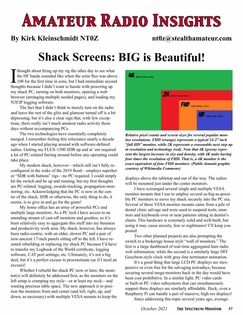
October 2021 The Spectrum Monitor 57
A m a t e u r R a d i o I n s ig h t sA m a t e u r R a d i o I n s ig h t sBy Kirk Kleinschmidt NT0Z [email protected]
Shack Screens: BIG is Beautiful!
I thought about firing up my rig the other day to see what the HF bands sounded like when the solar flux was above 100 for the first time in eons, but I had immediate second
thoughts because I didn’t want to hassle with powering up my shack PC, turning on both monitors, opening a web browser (arranging multiple needed pages), and loading my N3FJP logging software.
The fact that I didn’t think to merely turn on the radio and leave the rest of the glitz and glamour turned off is a bit depressing, but it’s also a clear sign that, with few excep-tions, there really isn’t much amateur radio activity these days without accompanying PCs.
The two technologies have essentially completely merged. I remember feeling this reluctance nearly a decade ago when I started playing around with software-defined radios. Getting my FLEX-1500 SDR up and at ‘em required a lot of PC-related futzing around before any operating could take place.
My modern shack, however—which still isn’t fully re-configured in the wake of the 2019 flood—employs superhet or “SDR with buttons” rigs—no PC required. I could simply hit the switch and be up and running, but my first thoughts are PC-related: logging, awards-tracking, propagation-mon-itoring, etc. Acknowledging that the PC is now in the cen-ter of the shack, SDR or otherwise, the only thing to do, it seems, is to give in and go for the gusto!
My home office has an array of powerful PCs and multiple large monitors. As a PC tech I have access to an unending stream of cast-off monitors and goodies, so it’s been relatively easy to aggregate this stuff into my business and productivity work area. My shack, however, has always been radio-centric, with an older, slower PC and a pair of now-ancient 17-inch panels sitting off to the left. I have re-sisted rebuilding or replacing my shack PC because I’d have to transfer my Logbook of the World certificate, logging software, CAT port settings, etc. Ultimately, it’s not a big deal, but it’s a perfect excuse to procrastinate (as if I need an excuse)!
Whether I rebuild the shack PC now or later, the moni-tor(s) will definitely be addressed first, as the monitors on the left setup is cramping my style—or at least my neck—and wasting precious table space. The new approach is to posi-tion the monitors front and center (and left, right, up, and down, as necessary) with multiple VESA mounts to keep the
displays above the tabletop and out of the way. The radios will be mounted just under the center monitors.
I have scrounged several single and multiple VESA monitor mounts that I use to employ several as-big-as-possi-ble PC monitors to move my shack securely into the PC era. Several of these VESA monitor mounts came from a pile of dental clinic salvage and were used to suspend tools, mon-itors and keyboards over or near patients sitting in dentist’s chairs. This hardware is extremely solid and well-built, but using it may cause anxiety, fear or nightmares! I’ll keep you posted.
Two other planned projects are also prompting the switch to a brokerage house style “wall of monitors.” The first is a large dashboard of real-time aggregated ham radio web information, while the second is a similarly large DIY Geochron-style clock with gray-line terminator animation.
It’s a good thing that large LCD PC displays are inex-pensive or even free for the salvaging nowadays, because securing several mega-monitors back in the day would have been cost prohibitive. In a similar light, PC video cards or built-in PC video subsystems that can simultaneously support three displays are similarly affordable. Heck, even a Raspberry Pi can handle a pair of massive, high-res displays!
Since addressing this topic several years ago, average
Relative pixel counts and screen sizes for several popular mon-itor resolutions. FHD (orange) represents a typical 24-27 inch “full HD” monitor, while 2K represents a reasonable next step up in resolution and technology (red). Note that 4K (green) repre-sent the largest increase in size and density, with 4K units having four times the resolution of FHD. That is, a 4K monitor is the exact equivalent of four FHD monitors. (Public domain graphic courtesy of Wikimedia Commons)

58 The Spectrum Monitor October 2021
PC displays have gotten larger and much more affordable. High-performance video cards are still unfortunately expensive—although not needed for ham ap-plications—but the typical video card’s ability to simultaneously handle multiple high-resolution displays has become a given. Even inexpensive or freebie video cards are now up to the task. Plus, modern versions of Windows and Linux can eas-ily support multiple video cards, unlike the good old days.
So, in that light, let’s take an up-to-date look at monitors, video cards, and VESA mounts to see how we can use them to great advantage in the shack.
Display Details
Older square LCD monitors are still useful and are mostly free for the taking now that most users have abandoned them, but most mainstream PC flat-panel dis-plays are widescreen LCDs in sizes ranging from 19 to 32 inches. Specialty models range from 24 to 42 inches or more and come in some very interesting aspect ratios, but they may not be suitable for use in your shack (more to come), as there are considerations other than sheer size:
Aspect ratio: Most CRT monitors from yesteryear (and a tiny subset of exist-ing LCD models) have aspect ratios of 4:3. That is, the screen is four units wide by three units tall—a mostly-square rectangle. Most modern LCDs have aspect ratios of 16:9 (with 16:10 having, unfortunately, fallen out of favor because of manu-facturing considerations)—a pronounced rectangle. Some of the newest monitors are “ultra wides,” with aspect ratios of 21:9. Hey, with the right resolution, 21:9 monitors might be just what the doctor ordered!
Many users prefer 4:3 monitors (or 2K/4K units with plenty of extra verti-cal pixels) for word processing and productivity apps (logging?), and widescreen monitors for watching movies. Depending on the screen’s resolution, aspect ratio differences can really help or hinder productivity.
For example, my main PC is a 28-inch HD model with an aspect ratio of 16:10 (1920 x 1200 pixels). I treat it with kid gloves because that ratio is now mostly unobtainium, with almost all new HD models in that size range coming in at 16:9 (1920 x 1080 pixels). The extra 120 pixels in the vertical dimension are priceless for any productivity application. The only practical solution is to upgrade, when necessary, to a 2K monitor with a resolution of 2560 x 1440 (2K monitors occupy a useful middle ground between HD and 4K, which has a resolution of 3840 x 2160).
Resolution: Aspect ratio broadly defines the shape of a monitor, while resolution roughly defines how much information it can display. My old 17-inch LCDs have a resolution of 1280 x 1024, which means that, in 17 diagonal inches, the screen’s image is 1280 pixels from left-to-right, and 1024 pixels from top-to-bottom. This resolu-tion is shared by most old-style 19-inch LCDs as well, so it’s important to note that, in this comparison, no additional information is being displayed on the larger monitor because the number of pixels that make up the image is the same. What’s changed is the size of each pixel, which can affect how sharp we perceive the image. This is a critical consideration with newer, super hi-def monitors (and older cast-offs).
For example, if we enlarged a 1280 x 1024 image to fit on the screen at a drive-in movie theater, each pixel would be the size of a basketball, making the image appear quite fuzzy unless we’re watching from 200 feet away. Similar-ly, some smart phones cram about the same number of pixels into tiny 5-inch screens, making each pixel too small to see unless you’re a 12-year-old kid with a magnifier (see Scaling, below)
Resolution without screen size is meaningless! Don’t be fooled. That’s why large HDTVs generally make great computer gaming and movie displays but poor text displays for PCs. They have the same number of pixels as a 20-inch display but are two to four times the size. Big pixels = fuzzy text.
Most widescreen 16:9 monitors have resolutions of 1366 x 768, 1600 x 900 or 1920 x 1080. Widescreen 16:10 monitors (if you can still find one) typ-ically use 1440 x 900, 1680 x 1050, or 1920 x 1200 pixels. Because flat-panel TVs use 16:9 displays, the industry has been focusing on this aspect ratio to the potential exclusion of all others.
Really big monitors: On a bang for the buck basis, 24-inch HD monitors (1920 x 1080) that regularly go on sale for about $80 are hard to beat if you’re buying new devices on a budget. With my particular eyesight, however, text on a 24-inch HD monitor is still a bit too small, which I why I prefer my 28-inch
The business end of two PC video cards. At the top is an older consumer card that took the Swiss Army Knife approach, sporting connectors for VGA, HDMI, and DVI (l-r, re-spectively). On the bottom is a high-end “workstation” card that simply has four Display-Port outputs, which can be adapted to work with almost all monitor types. With 8 GB of RAM, this card can support four simultaneous 4k monitors. (NT0Z photo)
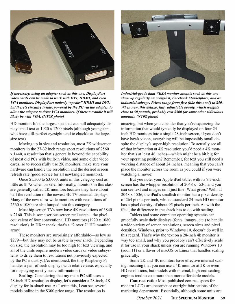
October 2021 The Spectrum Monitor 59
HD monitor. It’s the largest size that can still adequately dis-play small text at 1920 x 1200 pixels (although youngsters who have still-perfect eyesight tend to chuckle at the large-size text).
Moving up in size and resolution, most 2K widescreen monitors in the 27-32 inch range sport resolutions of 2560 x 1440, a resolution that’s generally beyond the capability of most old PCs with built-in video, and some older video cards, so to successfully use 2K monitors, make sure your hardware can handle the resolution and the desired screen refresh rate (good advice for all newfangled monitors).
Once $1,500 to $3,000, units in this category cost as little as $175 when on sale. Informally, monitors in this class are generally called 2K monitors because they have about half the resolution of the newest 4K TV-oriented displays. Many of the new ultra-wide monitors with resolutions of 2560 x 1080 are also lumped into this category.
Most big-screen TVs now have 4K resolutions of 3840 x 2160. This is some serious screen real estate—the pixel equivalent of four conventional HD monitors (1920 x 1080 resolution). In DXer speak, that’s a “2 over 2” HD monitor array!
These monitors are surprisingly affordable—as low as $279—but they may not be usable in your shack. Depending on size, the resolution may be too high for text viewing, and all of the units require modern video cards or video subsys-tems to drive them to resolutions not previously expected by the PC industry. (As mentioned, the tiny Raspberry Pi handles a pair of such displays with relative ease, especially for displaying mostly static information.)
Scaling: Considering that my main PC still uses a 28-inch HD-resolution display, let’s consider a 28-inch, 4K display for in-shack use. As I write this, I can see several models online in the $300 price range. The resolution is
amazing, but when you consider that you’re squeezing the information that would typically be displayed on four 24-inch HD monitors into a single 28-inch screen, if you don’t have hawk vision, everything will be impossibly small de-spite the display’s super-high resolution! To actually see all of that information at 4K resolution you’d need a 4K mon-itor that’s at least 46 inches—which might be a bit big for your operating position? Remember, for text you still need a working distance of about 24 inches, meaning that you can’t place the monitor across the room as you could if you were watching a movie!
But you note, your Apple iPad tablet with its 9.7-inch screen has the whopper resolution of 2048 x 1536, and you can see text and images on it just fine! What gives? Well, at 2048 x 1536, the iPad’s smallish monitor has a pixel density of 264 pixels per inch, while a standard 24-inch HD monitor has a pixel density of about 95 pixels per inch. As with the iPad, the difference in the shack has to do with scaling.
Tablets and some computer operating systems can gracefully scale their displays (fonts, images, etc.) to handle a wide variety of screen resolutions, screen sizes and pixel densities. Windows, prior to Windows 10, doesn’t do well in this regard. That’s why the text on a 28-inch 4k monitor is way too small, and why you probably can’t effectively scale it for use in your shack unless you are running Windows 10 (soon 11) or a flavor of macOS or Linux that handles scaling gracefully.
Some 2K and 4K monitors have effective internal scal-ing, meaning that you can use a 4K monitor at 2K or even HD resolutions, but models with internal, high-end scaling engines tend to cost more than more affordable models.
Contrast ratio: Most published contrast specs for modern LCDs are incorrect or outright fabrications of the marketing department! Essentially, although some units are
If necessary, using an adapter such as this one, DisplayPort video cards can be made to work with DVI, HDMI, and even VGA monitors. DisplayPort natively “speaks” HDMI and DVI, but there’s circuitry inside, powered by the PC via the adapter, to allow the adapter to drive VGA monitors. If there’s trouble it will likely be with VGA. (NT0Z photo)
Industrial-grade dual VESA monitor mounts such as this one show up regularly on craigslist, Facebook Marketplace, and as industrial salvage. Prices range from free (like this one!) to $50. When new, this deluxe, fully adjustable beauty, which weights close to 30 pounds, probably cost $500 (or some other ridiculous amount). (NT0Z photo)

60 The Spectrum Monitor October 2021
definitely better than others, it’s safe to assume that all mod-ern monitors, regardless of panel technology, have sufficient contrast ratios.
Brightness range: Not typically discussed back in the day, a flat-panel’s brightness range, rated in “nits,” is now a consideration, especially if you’re using a flat-panel screen in brightly lit spaces or in direct sunlight. A measurement of light intensity, one nit is equal to one candlepower per square meter (1cd/m2). Noontime sun measures a whopping 1.6 billion nits. Don’t stare at it!
A screen is considered to be “sunlight-readable” at 1,000 nits or more, even though most mobile displays never reach that lofty figure. Most desktop displays should be in the 300-500 nit range (or more). Consider avoiding panels, especially for laptops, that are rated at 250 nits or less. Many manufacturers don’t list their device’s intensity ratings, or they hide the figures in the fine print.
Backlights: Most LCD technologies don’t emit their own light, so they require a backlight to produce a visible image. Fluorescent backlights are now ancient, having given way almost exclusively to LED light sources. Regardless of what makes the light, however, the LCDs themselves are still the same, and they still fail (or not) at the same rates.
Now used in high-end cell phones and tablets—and in a few unspeakably expensive big-screen TVs—OLED tech-nology (organic light-emitting diode), which does not require a backlight and looks lush and contrasty all on its own, is sill
slowly trickling into the mainstream (but has not yet arrived in a big way). Other similar display technologies have been trickling into the luxury TV markets but have yet to make significant inroads into the PC monitor arena.
Screen finish: Glossy screens have a mirror-like reflec-tive surface, attract fingerprints like mad, and are somewhat easier to clean. Matte screens are much less reflective but are usually harder to clean. Take your pick. Clean LCD screens only with wipes and cleaning solutions designed for the task. Windex or Formula 409 will probably degrade or destroy your LCD screen, so beware!
Panel types: Most inexpensive LCDs are usually “TN” panels, while most expensive LCDs are usually “IPS” types. Technical details aside, TN panels are easy and inexpensive to manufacture, while IPS panels are difficult and more expensive. IPS panels tend to offer wider viewing angles and better color fidelity, while TN panels are “close enough for government work” (and can look quite nice). OLED panels, still crazy-expensive, win all viewing angle contests.
Connectors and video cards: Many PC-oriented mon-itors up to 28 inches still have old-style, analog, 15-pin VGA connectors, but newer, all-digital display technologies such as DVI, HDMI, and DisplayPort (which were mostly created for the HDTV market) are now common on PCs and video cards.
Some DVI ports (designated DVI-I) on PCs and video cards can also output analog VGA signals through inexpen-sive adapters, but newer DVI ports (designated DVI-D) are all digital, like DisplayPort and HDMI. Each can offer excel-lent image quality, but your video sources and your monitors have to “speak” the same languages. Be sure your PC can talk to your monitor before purchasing.
Still well supported in used equipment and many new business-oriented PCs, VGA monitors are still quite usable and can be easily adapted, but most consumer PCs have long since abandoned support for the venerable VGA connector.
If you’re buying a new PC or video card, choosing a model that has multiple DisplayPort outputs will allow you to talk to just about any new monitor, as DisplayPort can be adapted to speak DVI, HDMI, and even VGA. The only tricky translation is from DisplayPort to analog VGA, which requires a powered, active adapter/converter. These are now affordable and functional—a double win.
In 2021, HDMI tends to be the default video connector technology for most garden-variety PCs. For most monitor chores HDMI is just fine. It, too, can be adapted to speak DVI and VGA (with an active adapter), but not all flavors of HDMI can meet the bandwidth requirements of all 4K moni-tors (an article in itself). There were some workarounds over the years such as “dual DVI” and “dual HDMI,” but in the end, when talking to the newest monitors, DisplayPort can handle just about anything, so it’s probably the safest default for newer video cards or PCs.
When 4K monitors first hit the scene they required powerful PCs and similarly powerful video cards to drive them. Thankfully, that’s no longer the case. Video chips now
To simultaneously display your SDR screen, station log, digimode software, real-time propagation charts, a DX spotting site or two, your rotator controller, eHam.net, etc, you’ll probably need four monitors and, hence, a quad monitor mount such as this one, which I recently acquired in a pile of salvage. Beefy quad VESA mounts are best purchased used, as new ones that are suitably sturdy, are still expensive. (NT0Z photo)

October 2021 The Spectrum Monitor 61
enjoy built-in hardware acceleration for 4K video chores, so you probably won’t need to get a high-end gaming PC just to watch your SDR waterfall in all its glory.
Refresh rates: You do still need to worry about screen refresh rates with 2K and 4K monitors, however. Many in-expensive 4K monitors refresh the screen at only 30 frames per second (fine for TV and static displays), when 60 fps is pretty much the standard for PC monitors—especially those displaying things in motion.
Having a big, beautiful super high-resolution screen could still be a drag if anything in motion on it is jumpy or jittery! As you’d expect, 2K and 4K screens that are rated for at least 60 frames per second tend to be more expensive than those rated for only 30. The same goes for video cards and
the connector/cable systems that they use.There are two main solutions to this potential problem.
If possible, you can test a particular screen with your PC while running the software you’ll be using in the real world. I have brought my laptop PC (and an HDMI or DisplayPort cable) to my local Best Buy and connected it to several display-model 4K TVs to see what’s what. Sometimes it’s amazing—and sometimes it’s not! Even so, testing the actual hardware before you buy is still ideal.
You can also simply buy video cards, cables and mon-itors that are known to work well together or known to be functional at 60 fps. This is easier and much more affordable than it was just a few short years ago.
In my work with low-vision technology clients I can still remember being amazed when I first saw a Windows desktop displayed on a high-end, 65-inch 4K TV. The client was in a wheelchair, so he could sit back a few feet and still enjoy razor-sharp text, even on the monster display (using a wireless mouse and keyboard on his wheelchair-mounted work surface). It was amazing, and not just in resolution. The colors and the contrast were also fantastic. This was a stunning PC display in every way.
VESA mounts: Not too long ago, TV wall mounts and monitor support arms that conformed to VESA standards (Video Electronics Standards Association) were needlessly expensive. Now they’re almost free by comparison.
If you look on the back side of almost every modern monitor or TV, you’ll see a square pattern of four thread-ed mounting holes. A similar square plate on the monitor mount—fixed or articulated—matches these holes and allows you to attach the monitor to the mount (as long as you use the appropriate metric-threaded screws).
The bigger the monitor the bigger the screws and the bigger the space between the holes (and vice versa). Typical PC monitors have holes with 100- or 200-mm spacing, but if you’re going to mount a 50-inch 4k TV you’ll have to prepare for 400- or 600-mm sizes.
The important takeaways are that monitor mounting systems are now quite standard and, that because of econo-my of scale, they’re also quite affordable—even trivially so. Not too many years ago a wall mount or and articulated arm for a 32-inch TV might sell for $100 or more. Nowadays you can get a decent one for $10 to $20!
If you want to build something truly custom, you can simply buy metal VESA plates that are drilled appropriately so you can attach them by whatever means you choose to your custom creation. You can also download VESA drilling templates online. Just make sure that, after printing, the tem-plates measure up before drilling, just in case your printer driver was set for some kind of custom scaling factor. Don’t ask me how I know this!
Is a modern $10 articulated monitor arm as good as a $100 arm? Usually not, but sometimes they are. The point is, all of the inexpensive arms and mounts I’ve used over the past few years—as long as the online customer reviews were plentiful and positive—have been more than adequate, and
To use an inexpensive adjustable VESA mount to get my main PC monitor off the desktop I had to build this beefy support post out of scrap 2x8 pieces. The post screws into the table from the rear edge (not into the tabletop). The triangle pieces ensure that all force (heavy monitor) is transferred to the heavy, solid wood table. Even without the adjustable, screw-in table feet on top, the post doesn’t move at all, which is the idea. (NT0Z photo)
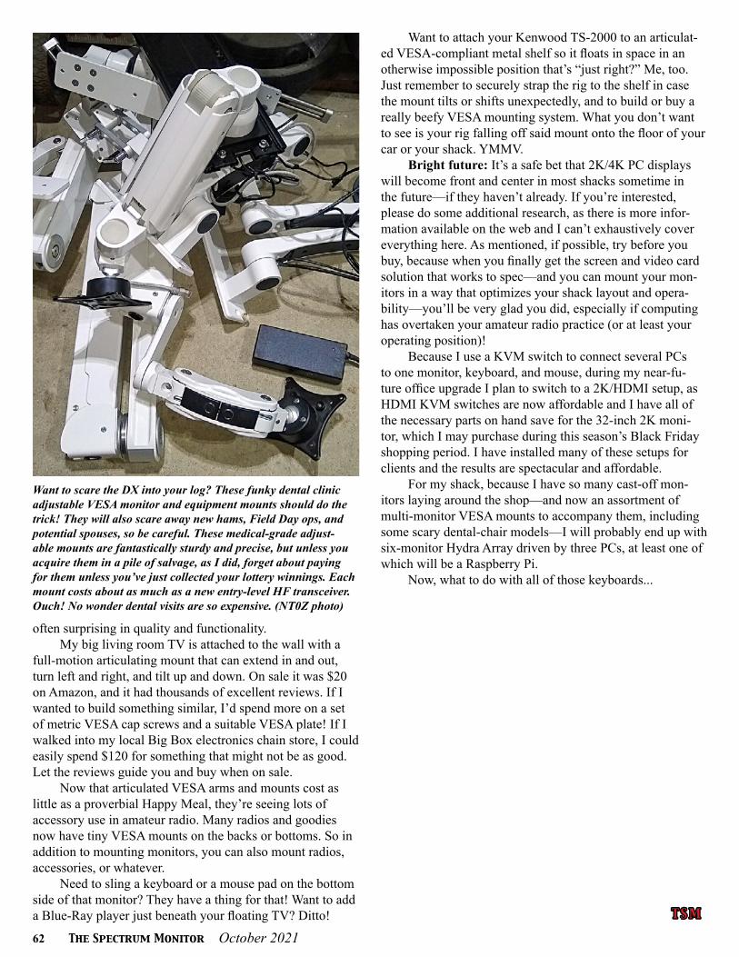
62 The Spectrum Monitor October 2021
often surprising in quality and functionality. My big living room TV is attached to the wall with a
full-motion articulating mount that can extend in and out, turn left and right, and tilt up and down. On sale it was $20 on Amazon, and it had thousands of excellent reviews. If I wanted to build something similar, I’d spend more on a set of metric VESA cap screws and a suitable VESA plate! If I walked into my local Big Box electronics chain store, I could easily spend $120 for something that might not be as good. Let the reviews guide you and buy when on sale.
Now that articulated VESA arms and mounts cost as little as a proverbial Happy Meal, they’re seeing lots of accessory use in amateur radio. Many radios and goodies now have tiny VESA mounts on the backs or bottoms. So in addition to mounting monitors, you can also mount radios, accessories, or whatever.
Need to sling a keyboard or a mouse pad on the bottom side of that monitor? They have a thing for that! Want to add a Blue-Ray player just beneath your floating TV? Ditto!
Want to attach your Kenwood TS-2000 to an articulat-ed VESA-compliant metal shelf so it floats in space in an otherwise impossible position that’s “just right?” Me, too. Just remember to securely strap the rig to the shelf in case the mount tilts or shifts unexpectedly, and to build or buy a really beefy VESA mounting system. What you don’t want to see is your rig falling off said mount onto the floor of your car or your shack. YMMV.
Bright future: It’s a safe bet that 2K/4K PC displays will become front and center in most shacks sometime in the future—if they haven’t already. If you’re interested, please do some additional research, as there is more infor-mation available on the web and I can’t exhaustively cover everything here. As mentioned, if possible, try before you buy, because when you finally get the screen and video card solution that works to spec—and you can mount your mon-itors in a way that optimizes your shack layout and opera-bility—you’ll be very glad you did, especially if computing has overtaken your amateur radio practice (or at least your operating position)!
Because I use a KVM switch to connect several PCs to one monitor, keyboard, and mouse, during my near-fu-ture office upgrade I plan to switch to a 2K/HDMI setup, as HDMI KVM switches are now affordable and I have all of the necessary parts on hand save for the 32-inch 2K moni-tor, which I may purchase during this season’s Black Friday shopping period. I have installed many of these setups for clients and the results are spectacular and affordable.
For my shack, because I have so many cast-off mon-itors laying around the shop—and now an assortment of multi-monitor VESA mounts to accompany them, including some scary dental-chair models—I will probably end up with six-monitor Hydra Array driven by three PCs, at least one of which will be a Raspberry Pi.
Now, what to do with all of those keyboards...
Want to scare the DX into your log? These funky dental clinic adjustable VESA monitor and equipment mounts should do the trick! They will also scare away new hams, Field Day ops, and potential spouses, so be careful. These medical-grade adjust-able mounts are fantastically sturdy and precise, but unless you acquire them in a pile of salvage, as I did, forget about paying for them unless you’ve just collected your lottery winnings. Each mount costs about as much as a new entry-level HF transceiver. Ouch! No wonder dental visits are so expensive. (NT0Z photo)
T S MT S M

October 2021 The Spectrum Monitor 63
Radio 101Radio 101By Ken Reitz KS4ZR [email protected]
OTA-TV and FTA-TV Update
Last month I wrote about restoring my flagging FTA satellite-TV system which was falling into disrepair. This month I’ll update the restoration process as well
as my now flagging OTA-TV system.Numbers for those US households that receive network
TV programming only through OTA-TV antenna reception in the US are hard to come by because most households that use OTA-TV antennas also connect to cable or satellite-TV for additional programming. We do know that about one-third of all US TV households (which total 121 million, ac-cording to the Nielsen survey organization) use an OTA-TV antenna for reception of local TV channels.
Those Pesky HDMI Ports
Thanks to multiple FTA-TV satellite dishes (four) and receivers (at least three) and OTA-TV antennas (VHF/UHF/FM), there appear to be miles of cables behind the stand that supports the 43-inch Samsung 4K TV, satellite receivers, DVD player, stereo, XM satellite radio receiver and big dish mover. What could go wrong? So, when the 18-month-old Samsung 4K TV started having issues, it was difficult to know where to start.
The TV had been behaving erratically lately—it was ap-parently unable to recognize the various HDMI inputs, eerily similar to my experience in 2019 (see this column March 2019, “OTA-TV and the Mystery of HDMI”).
In that column I wrote, “Now I wonder about the lon-gevity of the new TV I’ve just bought to replace the one that was 14 years old. When ATSC3 becomes a reality, sometime this year or next year, I’ll be required to buy a converter box to update the built-in OTA-TV tuner, which is working fine but will become obsolete with the new standard. I’ll also have to wonder how long the HDMI ports will last in the new TV as I plug and unplug various devices to test new receivers and other electronics.”
I found out exactly how long the HDMI ports (or TV receiver portion of the set for that matter) would last: Janu-ary 2019 to August 2021—just out of reach of the one-year warranty.
There are some believable data regarding the lifetime of USB ports—number of insertion/removal cycles—but what about HDMI ports? Well, anecdotal experiences have been shared online for ten years along with a lot of guesswork
All four HDMI ports on the Sony Bravia 4K TV are in use: HDMI 1 is the Amiko 4K FTA receiver; HDMI 2 is the Linkbox 9000; HDMI 3 is the Blu-ray DVD player and HDMI 4 is the Roku streaming stick. No more switching around! Maybe these ports will last longer than the late Samsung TV. Among the oth-er connectors on this set is a fiber optic audio output to go from the TV to a stereo; a headphone jack; an old-fashioned video input combining yellow (video) and red and white (stereo audio) into a single mini plug; LAN Ethernet connector; RS-232 input, infrared extender jack and RF input (OTA-TV antenna jack). The Roku stick gets its power from the USB port at the top. This TV has a built-in ATSC 3.0 tuner. (KS4ZR photo)
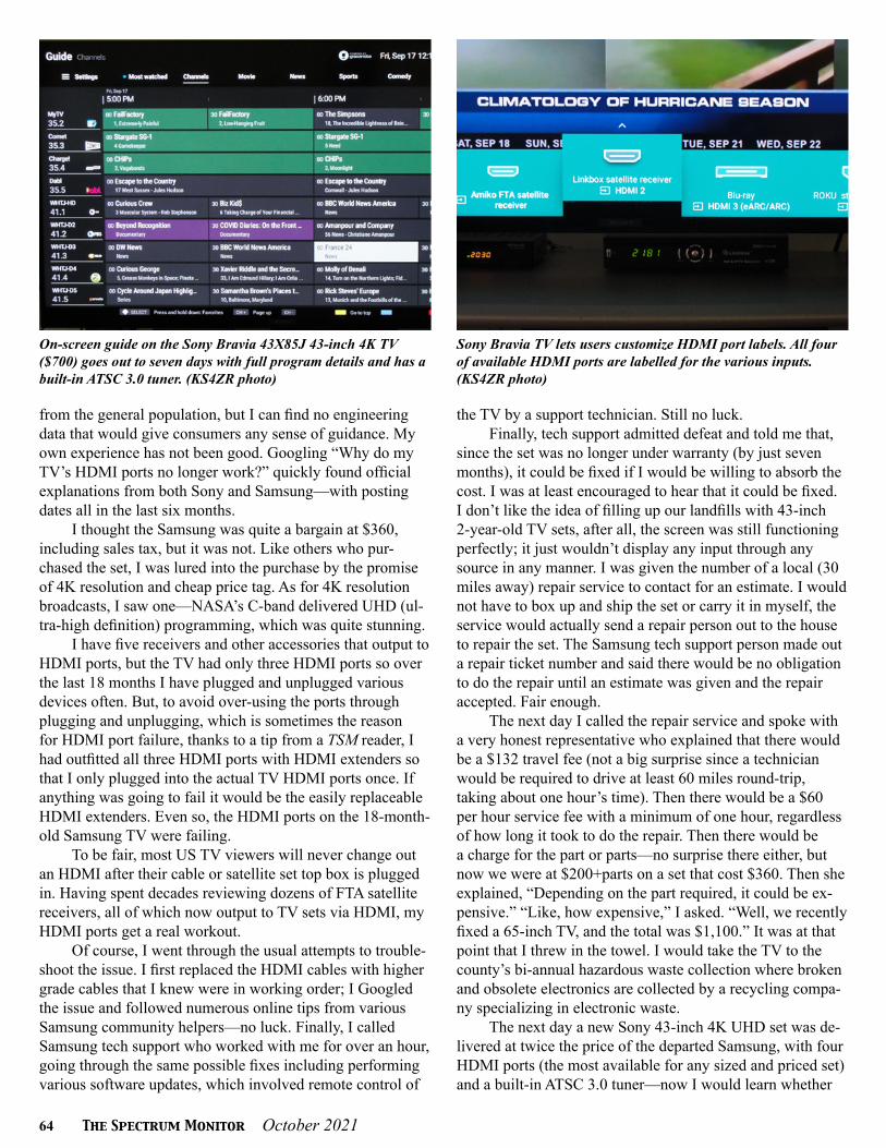
64 The Spectrum Monitor October 2021
On-screen guide on the Sony Bravia 43X85J 43-inch 4K TV ($700) goes out to seven days with full program details and has a built-in ATSC 3.0 tuner. (KS4ZR photo)
Sony Bravia TV lets users customize HDMI port labels. All four of available HDMI ports are labelled for the various inputs. (KS4ZR photo)
from the general population, but I can find no engineering data that would give consumers any sense of guidance. My own experience has not been good. Googling “Why do my TV’s HDMI ports no longer work?” quickly found official explanations from both Sony and Samsung—with posting dates all in the last six months.
I thought the Samsung was quite a bargain at $360, including sales tax, but it was not. Like others who pur-chased the set, I was lured into the purchase by the promise of 4K resolution and cheap price tag. As for 4K resolution broadcasts, I saw one—NASA’s C-band delivered UHD (ul-tra-high definition) programming, which was quite stunning.
I have five receivers and other accessories that output to HDMI ports, but the TV had only three HDMI ports so over the last 18 months I have plugged and unplugged various devices often. But, to avoid over-using the ports through plugging and unplugging, which is sometimes the reason for HDMI port failure, thanks to a tip from a TSM reader, I had outfitted all three HDMI ports with HDMI extenders so that I only plugged into the actual TV HDMI ports once. If anything was going to fail it would be the easily replaceable HDMI extenders. Even so, the HDMI ports on the 18-month-old Samsung TV were failing.
To be fair, most US TV viewers will never change out an HDMI after their cable or satellite set top box is plugged in. Having spent decades reviewing dozens of FTA satellite receivers, all of which now output to TV sets via HDMI, my HDMI ports get a real workout.
Of course, I went through the usual attempts to trouble-shoot the issue. I first replaced the HDMI cables with higher grade cables that I knew were in working order; I Googled the issue and followed numerous online tips from various Samsung community helpers—no luck. Finally, I called Samsung tech support who worked with me for over an hour, going through the same possible fixes including performing various software updates, which involved remote control of
the TV by a support technician. Still no luck.Finally, tech support admitted defeat and told me that,
since the set was no longer under warranty (by just seven months), it could be fixed if I would be willing to absorb the cost. I was at least encouraged to hear that it could be fixed. I don’t like the idea of filling up our landfills with 43-inch 2-year-old TV sets, after all, the screen was still functioning perfectly; it just wouldn’t display any input through any source in any manner. I was given the number of a local (30 miles away) repair service to contact for an estimate. I would not have to box up and ship the set or carry it in myself, the service would actually send a repair person out to the house to repair the set. The Samsung tech support person made out a repair ticket number and said there would be no obligation to do the repair until an estimate was given and the repair accepted. Fair enough.
The next day I called the repair service and spoke with a very honest representative who explained that there would be a $132 travel fee (not a big surprise since a technician would be required to drive at least 60 miles round-trip, taking about one hour’s time). Then there would be a $60 per hour service fee with a minimum of one hour, regardless of how long it took to do the repair. Then there would be a charge for the part or parts—no surprise there either, but now we were at $200+parts on a set that cost $360. Then she explained, “Depending on the part required, it could be ex-pensive.” “Like, how expensive,” I asked. “Well, we recently fixed a 65-inch TV, and the total was $1,100.” It was at that point that I threw in the towel. I would take the TV to the county’s bi-annual hazardous waste collection where broken and obsolete electronics are collected by a recycling compa-ny specializing in electronic waste.
The next day a new Sony 43-inch 4K UHD set was de-livered at twice the price of the departed Samsung, with four HDMI ports (the most available for any sized and priced set) and a built-in ATSC 3.0 tuner—now I would learn whether

October 2021 The Spectrum Monitor 65
Analog channel 3 on the Sony is actually my vintage 4DTV receiver which is used to steer the 10-foot dish around the Clarke Belt. Because the names of the satellite designators have changed so much over the last 20+ years that I have used this receiver, I had to make a cheat-sheet to let me know what the actual name of the satellite is. In this case, G4 is actually SES-3 at 103 de-grees W. (KS4ZR photo)
or not the Sony’s HDMI ports would fail before our local TV stations were broadcasting in the new ATSC 3.0 format. While my experience with Sony quality has been consider-ably better (10 years+ on a smaller set and 14 years on an older 43-inch set), I was disheartened to see that the new set had only a one-year warranty as well. But I also found that even the priciest high-end OLED sets from Sony, Samsung and LG have only a 1-year warranty—I think the manufac-turers know something we don’t. If your local retailer offers an extended warranty on a new ATSC 3.0 TV, it might be a good investment.
Making Connections
With the new TV on the shelf, it was time to reconnect everything and see how well it worked. First, to the OTA-TV antenna and the tuner in the new Sony appeared to be at least as good as the Samsung. Having seen analog TV DX from Canada, reported in the August edition of this column, I’ve become a rescanning fool—moving the amplified, roof-mounted VHF/UHF Yagi TV antenna through all points of the compass looking for TV (and FM) DX.
If you recall from last month’s review of the Amiko FTA satellite receiver, the old Samsung had to be coaxed into accepting the HDMI output from the Amiko. Same for the Sony. Again, it had to do with the output of the Amiko signaling to the Sony that it was a 4K HDMI output. I had to dive deep into the Sony on-screen menus to get the right port setup for the Amiko.
The other devices requiring HDMI connections—a Roku stick, a second FTA satellite receiver, a DVD player had no trouble connecting.
I have two RG/6 coax cables coming from the 10-foot dish—one bringing C-band signals and one bringing Ku-
band signals—both using the same C/Ku-band feed horn.The C-band side was working fine, but there was no apparent signal from the Ku-band side. After double-checking connec-tions and swapping out cables, it was clear that the Ku-band LNB needed to be replaced. It was a very old LNB, made in the US—but no longer in production. It had to be at least 15 years old.
These separate LNBs are more expensive than small-dish Ku-band LNBFs (where the feed horn is actually part of the LNB). And they’re getting a little harder to find. After looking around, I found one at Ricks Satellite https://www.rickssatelliteusa.com in North Carolina, which I had forgot-ten about, but which has been around for many years and has good prices on excellent products. Ricks carries the Norsat brand—a high quality name—in both C and Ku-band. The one I got was for 11.7-12.2 GHz with a .7 dB noise figure with +/- 150 kHz local oscillator stability for $129 (includes shipping). Universal Ku-band LNBs for big-dish installation are quite pricey. You can see how much more expensive a large-dish system is to maintain when you need to replace parts. A C-band LNB with similar specs will cost about the same. The new Ku-band LNB arrived a couple of days after ordering it and I quickly put it to work. It solved the problem of the missing Ku-band.
The new Sony has a single RF input for an outside TV antenna via a traditional F-connector. But I have two RF sources that need to get to the TV. One, the VHF/UHF OTA-TV antenna and the second, an analog channel 3 output from the 4DTV dish drive motor. This is how the 10-foot C/Ku-band dish is moved from one satellite to the next. The 4DTV output shows the satellite lineup and through the remote control the user chooses the satellite and, if needed, makes slight changes in the satellite location memory which is displayed on the TV screen through the channel 3 modu-
After at least 15 years of service, this nicely weathered Astrotel Ku-band LNB finally cratered. It took a little searching to find a replacement. The new Norsat Ku-band LNB, at $129, had a slightly higher noise figure (.7 dB) but greater stability at 150 kHz. Maintaining the old big dish C/Ku-band systems is not cheap, but to die-hard TVRO fans, so worth it. (KS4ZR photo)
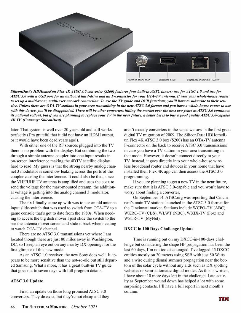
66 The Spectrum Monitor October 2021
T S MT S M
lator. That system is well over 20 years old and still works perfectly (I’m grateful that it did not have an HDMI output, or it would have been dead years ago!).
With either one of the RF sources plugged into the TV there is no problem with the display. But combining the two through a simple antenna coupler into one input results in on-screen interference making the 4DTV satellite display hard to read. My guess is that the strong nearby analog chan-nel 3 modulator is somehow leaking across the ports of the coupler causing the interference. It could also be that, since the VHF/UHF TV antenna is amplified and uses the coax to send the voltage for the mast-mounted preamp, the addition-al voltage is getting into the analog channel 3 modulator, causing the interference.
The fix I finally came up with was to use an old antenna input slide-switch that was used to switch from OTA-TV to a game console that’s got to date from the 1980s. When need-ing to access the big dish mover I just slide the switch to the see the antenna mover screen and slide it back when needing to watch OTA-TV channel.
There are no ATSC 3.0 transmissions yet where I am located though there are just 80 miles away in Washington, DC, so I keep an eye out on any nearby DX openings for the first glimpse of this new mode.
As an ATSC 1.0 receiver, the new Sony does well. It ap-pears to be more sensitive than the not-so-old but still depart-ed Samsung. What’s more, it has a great built-in TV guide that goes out to seven days with full program details.
ATSC 3.0 Update
First, an update on those long promised ATSC 3.0 converters. They do exist, but they’re not cheap and they
aren’t exactly converters in the sense we saw in the first great digital TV migration of 2009. The SiliconDust HDHomeR-un Flex 4K ATSC 3.0 box ($200) has an OTA-TV antenna F-connector on the back to receive ATSC 3.0 transmissions in case you have a TV station in your area transmitting in that mode. However, it doesn’t connect directly to your TV. Instead, it goes directly into your whole-house wire-less broadband router and devices in your home that have installed their Flex 4K app can then access the ATSC 3.0 programming.
If you are planning to get a new TV in the near future, make sure that it is ATSC 3.0-capable and you won’t have to worry about finding a converter.
On September 14, ATSC.org was reporting that Cincin-nati’s main TV stations launched in the ATSC 3.0 format for the Cincinnati market. Stations include WCPO-TV (ABC), WKRC-TV (CBS), WLWT (NBC), WXIX-TV (Fox) and WSTR-TV (MyNet).
DXCC in 100 Days Challenge Update
Time is running out on my DXCC-in-100-days chal-lenge but considering the shape HF propagation has been the last 60 days, I’m not too discouraged. I’ve logged 45 DXCC entities mostly on 20 meters using SSB with just 50 Watts and a wire during dismal summer propagation near the bot-tom of the solar cycle without any aids such as DX spotting websites or semi-automatic digital modes. As this is written, I have about 10 more days left in the challenge. Late activ-ity as September wound down has helped a lot with some surprising contacts. I’ll have a full report in next month’s column.
SiliconDust’s HDHomeRun Flex 4K ATSC 3.0 converter ($200) features four built-in ASTC tuners: two for ATSC 1.0 and two for ATSC 3.0 with a USB port for an outboard hard-drive and an F-connector for your OTA-TV antenna. It uses your whole-house router to set up a multi-room, multi-user network connection. To use the TV guide and DVR functions, you’ll have to subscribe to their ser-vice. Unless there are OTA-TV stations in your area transmitting in the new ATSC 3.0 format and you have a whole-house router to use with this device, you’ll be disappointed. There will be other converters hitting the market over the next two years as ATSC 3.0 continues its national rollout, but if you are planning to replace your TV in the near future, a better bet is to buy a good quality ATSC 3.0-capable 4K TV. (Courtesy: SiliconDust)

October 2021 The Spectrum Monitor 67
T h e Wor l d of Shor t wav e T h e Wor l d of Shor t wav e L i s t e n i ngL i s t e n i ng
I’m writing this column over Labor Day weekend as a number of pirates have been active. Sunday evening (September 6 UTC) culminated in a point when listeners
could choose among four or five stations that were broad-casting simultaneously.
The action really started on Saturday evening when Wolverine Radio aired a program centered around the color red; all songs played included the word “red” in the title and the ID SSTV image with 90 different swatches of red. Al-ways pumping out powerful signals, Wolverine was reported from coast to coast and directly to France and Ukraine.
WDOG aired one of its best-heard broadcasts starting at 0000 UTC and running for about 90 minutes on 6960 kHz USB. Many of the songs were dog related, including Led Zeppelin’s “Black Dog” and “Hot Dog,” Pete Townsend “Sleeping Dog,” and Elvis “Hound Dog.” The show was reported in at least 15 states and provinces and directly in France. HF Underground member ‘Molvanian Poacher’ re-ported that the announcer “mentions KDOG will stay on his side of the Mississippi, and we should have no issues.”
X-FM signed on 6925 kHz at 0118 UTC before switch-ing to 6285 kHz about 10 minutes later. About the sudden change, Redhat said “Sorry folks, had the wrong frequency selected on the synth. I wondered why the reflected power was off the scale!” The high SWR didn’t cause any per-manent problems and X-FM was reported by a number of listeners across the country with Redhat’s pro-sounding format of independent rock from about the past 20 years, pre-recorded IDs, and laid back talk about a variety of topics. The show lasted at least four hours and gave many—espe-cially those on the West Coast who are propagationally-hin-dered by the daylight broadcasts of many Eastern stations—a chance to tune in.
Some of the other stations on that evening that weren’t as widely reported included El Crapo Radio, The Final Countdown, Radio 48, Radio Genix, Radio Nowhere, Radio Olah, and Sycko Radio.
On the morning and early afternoon (at times between 1200 and 2200 UTC) of Sunday the 5th were programs from Radio Pushka, Truth Radio International, and Yeah Man
Radio.Mix Radio International started close to 0000 UTC on
6880 kHz USB. This station has a great signal and audio in North America. In fact, during past broadcasts, I’ve followed it on different SDRs around the world, so this is a station that readers in Europe can expect to hear. When it’s on the air with a good combination of time and frequency, I’m sure it could make it to Oceania and Japan as well. Like Wolver-ine Radio, the audio of the MRI transmitter is excellent and proves that SSB audio can be very listenable for broadcast-ing music. This particular show featured smooth jazz, but MRI has even played some all-classical programs recently.
Outhouse Radio started on 6925 kHz USB playing a recording of a talk show. The only ID was an SSTV image of “Пиратское радио” (“Pirate Radio”) in Russian. It moved to 6955 kHz USB, where it played a variety of ‘70s rock by Led Zeppelin, Black Sabbath, Rush, Supertramp, and the Who. The Outhouse Radio op doesn’t talk a lot on the air (often not at all), but he does send numerous SSTV images. During this show, he talked a few times and mentioned that
HF Pirates Sail on Shortwaves
Radiogenix has made dozens of broadcasts lasting hours apiece over the past few months. (Courtesy of Chris Smolinski)
By Andrew Yoder [email protected]

68 The Spectrum Monitor October 2021
he was being reported from Colorado to France . . . and he sent at least 12 different SSTV images (fig. 1).DJ Dick Weed of Radio Free Whatever aired two of the most notable programs of Labor Day weekend. Radio Free Whatever fits the general description of X-FM: pro-sounding format of independent rock from about the past 20 years, pre-record-ed IDs, and laid back talk about a variety of topics. It might be fair to say, though, that Dick tends to be more topical and excitable than Redhat. The icing on the cake was the bunker hot line, and some of the calls were patched in live. In fact, Sycko Radio was broadcasting on 6960 kHz USB and Mr. Sycko called in while going live on his station with the call. So, the call between the two ops was aired simul-taneously on both Sycko Radio and RFW. As Dick said, it’s kind of like an infinity mirror photograph. Radio Free Whatever was reported by a number of listeners in at least 15 states and France.
Some of the other stations reported from about 0000 to 0400 UTC on Sep-tember 6 (9/5, 8 PM to midnight EDT) included Ion Radio, Jihadi Pirates for War Radio (a parody), Nowhere Radio, Radio Genix, and Sycko Radio.
Radiogenix and Some Thoughts about Unattended Operation
HF Underground listener Flexoman first reported Radiogenix running a Morse Code ID loop on 9214 kHz for hours. I can’t imagine that most DXers would tune across a random Morse Code transmission and listen long enough to identify it as being from a pirate. So, just how many different hours or days or frequencies was this loop transmitted?
A month later, on June 13, Radiogenix began broadcasting: 6950 kHz AM with a variety of pop and rock music. Early in the broadcasts the operator said on the HF Underground that the station was using a Kenwood TS-850S transmitter, but that could change. It returned the next day, and the next, and the next—for hours at a time.
It switched to 6950 kHz USB on June 14, to 6875 kHz on July 10, to 6950 kHz USB on August 2, to 6935 kHz USB on August 15, to 6950 kHz USB on Au-gust 21, where it has remained (aside from a couple of single broadcasts on other frequencies).
One interesting aspect of Radiogenix is that when it’s running, it’s on most any time of day. Over the past few weeks, I’ve tuned in a number of times between 1130 and 1300 UTC and just listened for hours at a time. Most of the time, the sig-nals are solid and comfortable to listen to at my location. You can tell that it’s using an MP3 player with a playlist set to Shuffle or Random because after a while you start hearing songs that you’ve heard before.
After days of listening, the game is which songs haven’t you heard before. Another observation is that the ID files seem to be given about the same priority as any other song, which means that you might go a couple of hours without hearing an ID (fig. 2).
Two other stations have operations that remind me a bit of Radiogenix. Nowhere Radio has been on 6975 kHz since the evening of April Fool’s Day with instrumental music that sometimes tends toward the industrial. Several times, I’ve tuned through and wondered if the station was airing digital data before realizing that it was a Nowhere Radio song. Although not a morning station, Nowhere Radio is similar to Radiogenix in the sense that it’s made dozens of broadcasts this year, the shows run for hours, and the operator tends to avoid the mic.
Finally, an unidentified station that relays Fox Radio on 6970 kHz has been active since Memorial Day weekend 2020. Like Radiogenix and Nowhere Radio, this one has made dozens of broadcasts that last for hours. The Fox News unid unfortunately has weak modulation and seems to be difficult to copy for everyone. I seem to receive better signals than a lot of people do—but I still usually have a tough time copying even a few details.
Universal Radio752 N. State St. Unit 222Westerville, OH 43082◆ [email protected]◆ Phone: 614 866-4267www.universal-radio.com
By Fred Osterman. This huge 800 pagehard cover Fourth Edition includes over1700 shortwave and amateur com-munications receivers (plus 1200 variants)made from 1942 to 2013. Here is everythingyou need to know as a radio collector orinformed receiver buyer. Informationincludes: receiver type, date sold,photograph, size & weight, features,reviews, specifications, values (most),variants, rating and availability. 360worldwide manufacturers with 1800 photos.Become an instant receiver expert!List $59.95 $39.95 ($6.95 shipping).
2021 SHORTWAVEFREQUENCY GUIDEBy J. Klingenfuss.This guide has 4,279shortwave broadcastlistings by frequencyand includes 9,100 ab-breviated entries fromGuide to Utility Stations2021-22. You get greatcoverage of broadcastand utility stations in one up-to-date book!25TH Ed. 350 p.
Order #0056 ................... $47.95
WORLD RADIO TVHANDBOOK 2021
This long establishedpublication is filled withschedules, frequen-cies and addresses ofshortwave broadcaststations. Organizedprimarily by country.Also includes a by-frequency listing ofshortwave broadcast stations. Plus inter-esting articles, maps and reviews. 75TH Edi-tion. ©2020 672 p. List $49.95.
Order #2021 .................... $46.95
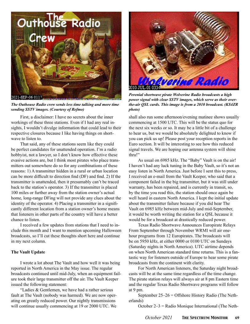
October 2021 The Spectrum Monitor 69
First, a disclaimer: I have no secrets about the inner workings of these three stations. Even if I had any real in-sights, I wouldn’t divulge information that could lead to their respective closures because I like having things on short-wave to listen to.
That said, any of these stations seem like they could be perfect candidates for unattended operation. I’m a radio hobbyist, not a lawyer, so I don’t know how effective these evasive actions are, but I think most pirates who place trans-mitters out somewhere do so for any combinations of these reasons: 1) A transmitter hidden in a rural or urban location can be more difficult to direction find (DF) and find. 2) If the transmitter is unattended, then it presumably can’t be traced back to the station’s operator. 3) If the transmitter is placed 100 miles or further away from the station owner’s actual home, long-range DFing will not provide any clues about the identity of the operator. 4) Placing a transmitter in a signifi-cantly different location from a station owner’s home means that listeners in other parts of the country will have a better chance to listen.
I received a few updates from stations that I need to in-clude this month and I want to mention upcoming Halloween broadcasts, so I’ll cut these thoughts short here and continue in my next column.
The Vault Update
I wrote a lot about The Vault and how well it was being reported in North America in the May issue. The regular broadcasts continued until mid-July, when an equipment fail-ure took their large transmitter off the air. The Vault Keeper issued the following statement:
“Ladies & Gentlemen, we have had a rather serious fault at The Vault (nobody was harmed). We are now oper-ating on greatly reduced power. Our nightly transmissions will continue usually commencing at 19 or 2000 UTC. We
shall also run some afternoon/evening matinee shows usually commencing at 1500 UTC. This will be the status quo for the next six weeks or so. It may be a little bit of a challenge to hear us, but we would be absolutely delighted to know if you can pick us up! Please post your reception reports in the Euro section. It will be interesting to see how this reduced signal travels. We are hoping our antenna system will shine thru!”
As usual on 6985 kHz. The “Baby” Vault is on the air!I haven’t had any luck tuning in the Baby Vault, so it’s not an easy listen in North America. Just before I sent this to press, I received an e-mail from the Vault Keeper, who said that a component failed in the big transmitter, but it was still under warranty, has been repaired, and is currently in transit, so, by the time you read this, the station should once again be well heard in eastern North America. I kept the initial update about the transmitter failure because if you did hear The Vault on 6985 kHz between mid-July and mid-September, it would be worth writing the station for a QSL because it would be for a broadcast at drastically reduced power.
Texas Radio Shortwave Announces Europirate Relays From September through November WRMI will air one-hour programs from 12 Europirates. The broadcasts will be on 5950 kHz, at either 0000 or 0100 UTC on Sundays (Saturday nights in North America). UTC airtime depends on when North American standard time returns. This is a fan-tastic way for listeners outside of Europe to hear some pirate broadcasts from the continent with clarity.
For North American listeners, the Saturday night broad-casts will be at the same time regardless of the time change. The pirate station relays will always air at 8 pm Eastern time and the regular Texas Radio Shortwave programs will follow at 9 pm.
September 25–26 = Offshore History Radio (The Neth-erlands)
October 2–3 = Radio Monique International (The Neth-
The Outhouse Radio crew sends less time talking and more time sending SSTV images. (Courtesy of Refmo)
Perenial shortwave pirate Wolverine Radio broadcasts a high power signal with clear SSTV images, which serve as their over-the-air QSL cards. This image is from a 2010 broadcast. (KS4ZR photo)

70 The Spectrum Monitor October 2021
T S MT S M
erlands) *October 9–10 = Radio Blackstone International (The
Netherlands)October 16–17 = Charleston International Radio (Ger-
many) *October 23–24 = KR1 (The Netherlands)October 30–31 = Cupid Radio (The Netherlands) *November 6–7 = Radio Pamela (UK)November 13–14 = Radio BZN (Germany)November 20–21 = Free Radio Service-Holland (The
Netherlands) *November 27–28 = The Vault (Somewhere in Europe).
(The first date is the North American Eastern time date, the second is the UTC date)
eQSLs will be available directly from each station. Listen for an email address during the broadcast.
The Upcoming Halloween
As described at the beginning of this column, the Labor Day weekend activity was excellent—possibly the best I’ve ever experienced. I would assume that this means that Hal-loween should be exceptional. I think the biggest issues will be crowded bands and just trying to hear everything that’s on the air.
A few years ago, we had problems with MUF and nearly every station tried to broadcast between about 2000
and 0000 UTC. It made for some frantic attempts to de-termine which stations you hadn’t heard before, and most listeners weren’t able to tune in a majority of the activity. By last year, many stations were using alternative frequencies for later broadcasts between 4065 and 4200 kHz and 5100 and 5200 kHz. This year, the MUF has bounced back, and I’ve been hearing a number of pirate broadcasts between 0000 and 0400 UTC. I’ve heard a lot fewer broadcasts from North American pirates below 6800 kHz this year, so I think this trend will continue through Halloween. I wouldn’t be surprised if a few broadcasts occur in one or both of those frequency ranges, possibly to avoid congestion on 43m.
Like last year, I also expect some stations to be broad-casting their Halloween show just before October 31. This year, I’d expect that Halloween shows will be aired the weekend before (10/22–24), but possibly also earlier. And with Halloween occurring on a Sunday, I think the whole weekend will be very active—and that Saturday evening local time might even be more active than Sunday evening local time (because it’s a weekend and some station opera-tors choose a 10/31 UTC broadcast over staying up late on Halloween evening local time and having to get up early the next day. Regardless, I’m anticipating some great radio. Happy listening!

October 2021 The Spectrum Monitor 71
T h e S h o r t wav e L i s t e n e rT h e S h o r t wav e L i s t e n e rBy Fred Waterer [email protected]
Fall Shortwave Programming
It’s October (already?). Its cooling off in the Northern Hemisphere and warming in the South as it usually does this time of year. The best thing about cooler weather
is that we have our radios to keep us company, entertained, informed, and (depending how old it is) warm!
This month we’ll take a look at the quirky, the eclectic and the tres cool. And we’ll take a deep dive into Africa and African music. Along the way, we’ll swing by Miami, Mon-ticello, Texas, Mexico City, Washington, DC, and numerous places in Africa. And we’ll even take a side trip to the Super-natural. Let’s go!
Some fairly new and occasionally quirky new program-ming can be heard on WRMI. Just one example is Whatever Happened to Pizza at McDonald’s Radio. Yes, that’s the name.
“Investigative journalist Brian Thompson will stop at nothing to answer one of the most pressing questions of our age: Why did McDonald’s stop serving pizza in the early 1990s? His quest has taken him across the globe; from the desolate wastes of rural Ohio to the nearly as desolate wastes of the Alaskan wilderness. In the process, he has encountered brave informants from parts unknown, he has run afoul of nefarious forces lurking in the shadows, and he has nearly been assaulted by the United States Secret Service.
“Gather your families around the radio every week for the latest chapter in the ongoing McDonald’s Pizza saga. Plus, music, trivia, listener interaction, and other forms of light entertainment suitable for curious audiences of all kinds.
“Listen on WRMI Thursday nights at midnight Eastern Time (0400 UTC Friday) on 5850 kHz. For questions, com-ments, or to share your own McDonald’s Pizza information, contact [email protected].”
As I told a friend, this is either really weird or pure genius. I’ll be tuning in to help me decide. Come to think of it I haven’t seen McDonalds Pizza in years either. I’d kill for a McRib though. Just sayin’.
Apparently not connected is another new WRMI pro-gram called Dr. Allen Presents.
“Christian psychologist Dr. Joe Allen answers your questions every weekday at 10:30 am Eastern Time on 9955 kHz (and live-streamed at www.wrmi.net) and 7:00 pm ET on 9395 kHz.
The third new program on WRMI is Greg Fishman - Audio: “Greg Fishman started exploring song writing by just
Whatever Happened to Pizza at McDonalds is the quirky name of a new show on WRMI (Photo courtesy WRMI.net)
jotting down ideas, thoughts and anything that came to mind in the early 90s. Eventually, so many handwritten pages of poems and lyrics became songs. Without lessons, he picked up a guitar and searched for those sounds by depending on power chords and shapes. He is also interested in various audio projects such as broadcasting, interviews, voice acting, and casual experiments related to sound creation.
“The show is called Greg Fishman – Audio. He talks about “music, bands and other stuff.” You can find out more at gregfishmanaudio.com
There are a number of opportunities to listen 5800 kHz at 0230 UTC Monday, 9955 kHz at 6:30 pm ET Tues-day (currently 2230 UTC Tuesday), 9395 kHz at 8:30 pm Wednesday (currently 0030 UTC Thursday), 5985 kHz at 0330 UTC Friday, 7730 kHz at 0030 UTC Sunday, and 5950 kHz at 6:00 pm ET Sunday (currently 2200 UTC Sunday). Music is a beautiful thing. More to follow.
There is much radio goodness coming in the next few months from Texas Radio Short Wave. Along with their usu-al programming, and EuroPirate specials, they recently made a really exciting announcement. “TRSW (has) acquired the extensive program library from Mystery Pirate Radio, a for-mer North American pirate radio station.
“The library contains the entire Radio London Fab 40 survey broadcasts from January 1965 through August 1967, Radio London air-checks, programs from defunct internet streaming site Rock-It Radio, and un-scoped air-checks from
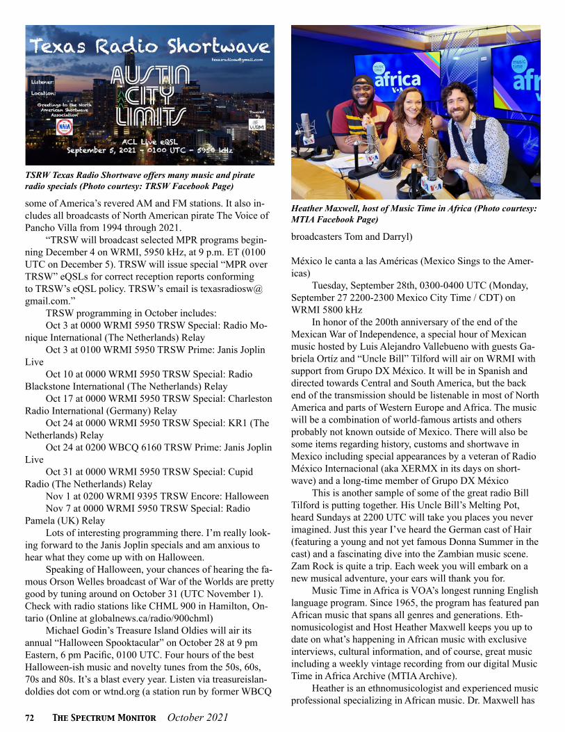
72 The Spectrum Monitor October 2021
TSRW Texas Radio Shortwave offers many music and pirate radio specials (Photo courtesy: TRSW Facebook Page)
some of America’s revered AM and FM stations. It also in-cludes all broadcasts of North American pirate The Voice of Pancho Villa from 1994 through 2021.
“TRSW will broadcast selected MPR programs begin-ning December 4 on WRMI, 5950 kHz, at 9 p.m. ET (0100 UTC on December 5). TRSW will issue special “MPR over TRSW” eQSLs for correct reception reports conforming to TRSW’s eQSL policy. TRSW’s email is [email protected].”
TRSW programming in October includes:Oct 3 at 0000 WRMI 5950 TRSW Special: Radio Mo-
nique International (The Netherlands) Relay Oct 3 at 0100 WRMI 5950 TRSW Prime: Janis Joplin
Live Oct 10 at 0000 WRMI 5950 TRSW Special: Radio
Blackstone International (The Netherlands) RelayOct 17 at 0000 WRMI 5950 TRSW Special: Charleston
Radio International (Germany) RelayOct 24 at 0000 WRMI 5950 TRSW Special: KR1 (The
Netherlands) RelayOct 24 at 0200 WBCQ 6160 TRSW Prime: Janis Joplin
Live Oct 31 at 0000 WRMI 5950 TRSW Special: Cupid
Radio (The Netherlands) RelayNov 1 at 0200 WRMI 9395 TRSW Encore: HalloweenNov 7 at 0000 WRMI 5950 TRSW Special: Radio
Pamela (UK) RelayLots of interesting programming there. I’m really look-
ing forward to the Janis Joplin specials and am anxious to hear what they come up with on Halloween.
Speaking of Halloween, your chances of hearing the fa-mous Orson Welles broadcast of War of the Worlds are pretty good by tuning around on October 31 (UTC November 1). Check with radio stations like CHML 900 in Hamilton, On-tario (Online at globalnews.ca/radio/900chml)
Michael Godin’s Treasure Island Oldies will air its annual “Halloween Spooktacular” on October 28 at 9 pm Eastern, 6 pm Pacific, 0100 UTC. Four hours of the best Halloween-ish music and novelty tunes from the 50s, 60s, 70s and 80s. It’s a blast every year. Listen via treasureislan-doldies dot com or wtnd.org (a station run by former WBCQ
broadcasters Tom and Darryl)
México le canta a las Américas (Mexico Sings to the Amer-icas)
Tuesday, September 28th, 0300-0400 UTC (Monday, September 27 2200-2300 Mexico City Time / CDT) on WRMI 5800 kHz
In honor of the 200th anniversary of the end of the Mexican War of Independence, a special hour of Mexican music hosted by Luis Alejandro Vallebueno with guests Ga-briela Ortíz and “Uncle Bill” Tilford will air on WRMI with support from Grupo DX México. It will be in Spanish and directed towards Central and South America, but the back end of the transmission should be listenable in most of North America and parts of Western Europe and Africa. The music will be a combination of world-famous artists and others probably not known outside of Mexico. There will also be some items regarding history, customs and shortwave in Mexico including special appearances by a veteran of Radio México Internacional (aka XERMX in its days on short-wave) and a long-time member of Grupo DX México
This is another sample of some of the great radio Bill Tilford is putting together. His Uncle Bill’s Melting Pot, heard Sundays at 2200 UTC will take you places you never imagined. Just this year I’ve heard the German cast of Hair (featuring a young and not yet famous Donna Summer in the cast) and a fascinating dive into the Zambian music scene. Zam Rock is quite a trip. Each week you will embark on a new musical adventure, your ears will thank you for.
Music Time in Africa is VOA’s longest running English language program. Since 1965, the program has featured pan African music that spans all genres and generations. Eth-nomusicologist and Host Heather Maxwell keeps you up to date on what’s happening in African music with exclusive interviews, cultural information, and of course, great music including a weekly vintage recording from our digital Music Time in Africa Archive (MTIA Archive).
Heather is an ethnomusicologist and experienced music professional specializing in African music. Dr. Maxwell has
Heather Maxwell, host of Music Time in Africa (Photo courtesy: MTIA Facebook Page)

October 2021 The Spectrum Monitor 73
T S MT S M
Gabon Africa Numero Un QSL (Photo courtesy the author’s collection)
published academic works on Malian music and the West African balafon. She is also a singer songwriter and has published recorded albums in Mali, Cote d’Ivoire, and the US. In addition to her regular weekend radio broadcasts, Heather curates the Music Time in Africa Facebook Page, YouTube Channel, and blog. Explore these platforms to engage with MTIA audiences and learn more about African music through exciting live performances, interviews with artists, in-depth reviews of music festivals, rare recordings and more.
Doing a deep dive, I checked out the MITA Archive and it is impressive.
“A journey from international shortwave to digital broadcast, the Music Time in Africa Archive takes audiences through an on-line experience of vintage Voice of Ameri-ca radio programs broadcast from 1966. The collaborative project with the University of Michigan digitized nearly 900 audio recordings and associated scripts of the weekly radio program. The archive now features 691 radio programs with a combination of program script and broadcast audio, with an additional 120 radio programs coming soon.
“The broadcasts feature show hosts playing a variety of African music and original field recordings by VOA ’s “Music Man for Africa,” ethnomusicologist Leo Sarkisian. Sarkisian recorded and collected music from the early 1960s through the late 1980s throughout the entire African conti-nent, including pre-independence regions and states such as Balundo, Upper Volta, and Rhodesia. Visitors can play digi-tized broadcasts with original sounds and scripts, searchable by location or performer. The portraits displayed for each show are Sarkisian’s original artwork, painted and sketched over the years. Listeners can listen to music ranging from iconic urban artists Fela Kuti or Franco to traditional perfor-mances by Karanga “Gawo” of Zimbabwe or griot music by kora master Sidiki Diabaté of the Republic of Mali. The site will soon allow the audience to explore 361 reels of Sark-isian’s original field recordings and engage with the music and scripts in a comment section
Launched in 1965 by Sarkisian, Music Time in Afri-ca is VOA’s longest running radio broadcast to the African continent. The program continues to feature traditional and contemporary music from musicians throughout Africa. Go to voanews.com/mtia-archive to find hundreds of programs, scripts and clips. Many past hosts including Leo Sarkisian and Rita Rochelle can be heard. Certainly a trip down mem-ory lane for long time VoA listeners.
Music Time in Africa continues to be heard on the shortwave bands at the following times and frequencies. Saturdays and Sundays at 1505-1600 UTC on 4930, 5940, 15580 and 17530 kHz. At 2005-2100 UTC try 4930, 6195 and 15580 kHz. And at 2105-2200 UTC tune to 6195 and 15580 kHz. (Hat tip: Alan Roe’s Music on Shortwave Guide. If you don’t have it you should get it. Downloadable in a number of places) One can also listen online and on demand. Go to https://www.voanews.com/z/1456 I often take advan-tage of this online opportunity to hear some fantastic music
from the African continent. It is a fabulous tribute to the work of Leo Sarkisian all those years ago, that this program continues to thrive in the second decade of the Twenty-first century. Music is timeless.
Heather Maxwell is an excellent broadcaster in her own right. I listened to a few episodes of MTIA and thoroughly enjoyed them and learned a great deal about the music. It’s gone to the top of my ‘listen regularly’ list.
Another old friend from the 80s and 90s was Africa Nu-mero Un, broadcasting on shortwave from Gabon in Africa. It played some of the liveliest music this correspondent ever listened to, mostly a fusion of African rhythms and electronic instruments, which resulted in the delightful African “High Life “sound. I spent many hours listening to them, especially on a cold January afternoon in Canada. It couldn’t help but make you feel warm. A few weeks back I posted the image of my Africa No. 1 QSL to my Facebook page. Radio friend Chrissy Brand pointed out that, although they are limited to FM in Africa now, they can still be heard online through mytuner-radio dot com. As this is being typed it’s blasting in my den.
Over the centuries...er...decades, I have developed quite an eclectic taste in music. One can probably blame this on all those Radio Moscow Folk Box programs, and dozens of other music programs and selections from around the world, as heard through the shortwave static. Music was honest-ly sometimes the only way to get listeners to stick around through the latest party line and such. But music tells you much more about a country than a hundred political com-mentaries.
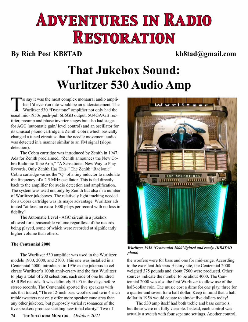
74 The Spectrum Monitor October 2021
A dv e n t u r e s i n R a dioA dv e n t u r e s i n R a dioR e stor at ion R e stor at ion
By Rich Post KB8TAD [email protected]
That Jukebox Sound:Wurlitzer 530 Audio Amp
To say it was the most complex monaural audio ampli-fier I’d ever run into would be an understatement. The Wurlitzer 530 “Dynatone” amplifier not only had the
usual mid-1950s push-pull 6L6GB output, 5U4GA/GB rec-tifier, preamp and phase inverter stages but also had stages for AGC (automatic gain/ level control) and an oscillator for its unusual phono cartridge, a Zenith Cobra which basically changed a tuned circuit so that the needle movement audio was detected in a manner similar to an FM signal (slope detection).
The Cobra cartridge was introduced by Zenith in 1947. Ads for Zenith proclaimed, “Zenith announces the New Co-bra Radionic Tone Arm,” “A Sensational New Way to Play Records, Only Zenith Has This.” The Zenith “Radionic” Cobra cartridge varies the “Q” of a tiny inductor to modulate the frequency of a 2.5 MHz oscillator. This is fed directly back to the amplifier for audio detection and amplification. The system was used not only by Zenith but also in a number of Wurlitzer jukeboxes. The relatively light tracking needed for a Cobra cartridge was its major advantage. Wurlitzer ads touted “at least an extra 1000 plays per record with no loss in fidelity.”
The Automatic Level - AGC circuit in a jukebox allowed for a reasonable volume regardless of the records being played, some of which were recorded at significantly higher volume than others.
The Centennial 2000
The Wurlitzer 530 amplifier was used in the Wurlitzer models 1900, 2000, and 2100. This one was installed in a Centennial 2000, introduced in 1956 as the jukebox to cel-ebrate Wurlitzer’s 100th anniversary and the first Wurlitzer to play a total of 200 selections, each side of one hundred 45 RPM records. It was definitely Hi-Fi in the days before stereo records. The Centennial sported five speakers with ads that touted, “Three 12-inch bass woofers and twin 4-inch treble tweeters not only offer more speaker cone area than any other jukebox, but purposely varied resonances of the five speakers produce startling new tonal clarity.” Two of
Wurlitzer 1956 ‘Centennial 2000’ lighted and ready. (KB8TAD photo)
the woofers were for bass and one for mid-range. According to the excellent Jukebox History site, the Centennial 2000 weighed 375 pounds and about 7500 were produced. Other sources indicate the number to be about 4000. The Cen-tennial 2000 was also the first Wurlitzer to allow use of the half-dollar coin. The music cost a dime for one play, three for a quarter and seven for a half dollar. Keep in mind that a half dollar in 1956 would equate to almost five dollars today!
The 530 amp itself had both treble and bass controls, but those were not fully variable. Instead, each control was actually a switch with four separate settings. Another control,
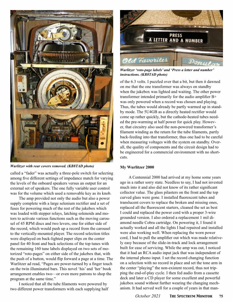
October 2021 The Spectrum Monitor 75
called a “fader” was actually a three-pole switch for selecting among five different settings of impedance match for varying the levels of the onboard speakers versus an output for an external set of speakers. The one fully variable user control was for the volume which used a removable key as its knob.
The amp provided not only the audio but also a power supply complete with a large selenium rectifier and a set of fuses for powering much of the rest of the jukebox which was loaded with stepper relays, latching solenoids and mo-tors to activate various functions such as the moving carou-sel of 45 RPM discs and two levers, one for either side of the record, which would push up a record from the carousel to the vertically-mounted player. The record selection titles were displayed on back-lighted paper slips on the center panel for 40 front and back selections of the top tunes with the remaining 160 tune labels displayed on two sets of mo-torized “roto-pages” on either side of the jukebox that, with the push of a button, would flip forward a page at a time. The Wurlitzer ad read, “Pages are power-turned by a finger touch on the twin illuminated bars. This novel ‘his’ and ‘her’ book arrangement enables two—or even more patrons to shop the program at the same time.”
I noticed that all the tube filaments were powered by two different power transformers with each supplying half
of the 6.3 volts. I puzzled over that a bit, but then it dawned on me that the one transformer was always on standby when the jukebox was lighted and waiting. The other power transformer intended primarily for the audio amplifier B+ was only powered when a record was chosen and playing. Thus, the tubes would already be partly warmed up in stand-by mode. The 5U4GB as a directly heated rectifier would come up rather quickly, but the cathode-heated tubes need-ed the pre-warming at half power for quick play. Howev-er, that circuitry also used the non-powered transformer’s filament winding as the return for the tube filaments, partly back-feeding into that transformer, thus one had to be careful when measuring voltages with the system on standby. Over-all, the quality of components and the circuit design had to be engineered for a commercial environment with no short-cuts.
My Wurlitzer 2000
A Centennial 2000 had arrived at my home some years ago in a rather sorry state. Needless to say, I had not invested much into it and also did not know of its rather significant collector value. The glass pilasters on the front and the top curved glass were gone. I installed fluorescent tubes and translucent covers to replace the broken and missing ones, replaced all the fluorescent starters, cleaned the set as best I could and replaced the power cord with a proper 3-wire grounded version. I also ordered a replacement 1 mil di-amond needle Cobra cartridge. On powering it, I found it actually worked and all the lights I had repaired and installed were also working well. When replacing the worn power cord, I had to pull the amplifier out which was made relative-ly easy because of the slide-in-track and lock arrangement built for ease of servicing. While the amp was out, I noticed that it had an RCA audio input jack that was independent of the internal phono input. I set the record changing function on a selection with no record in place and set the tone arm in the center “playing” the non-existent record, thus not trip-ping the end-of-play cycle. I then fed audio from a cassette deck and later a CD player for some excellent and powerful jukebox sound without further wearing the changing mech-anism. It had served well for a couple of years in that man-
Wurlitzer ‘roto-page labels’ and ‘Press a letter and number’ instructions. (KB8TAD photo)
Wurlitzer with rear covers removed. (KB8TAD photo)

76 The Spectrum Monitor October 2021
ner as a rec-room oddity, but then I noticed the aluminum electrolytics getting warm when it was next powered after a couple of weeks of not using it. At that point I stopped using it for fear of further damage. I also did not have a schematic. Because of the size of the amp and having other sources for Hi-Fi sound, I placed it on the “round ‘tuit” list.
The time had come to work on restoring the amp, per-haps this time using the jukebox as a powerful vacuum-tube audio playback system for the current crop of music sourc-es such as an MP3 player or Bluetooth-enabled device or streaming source, digital sources the engineers at Wurlitzer could never have imagined, as a combination of new tech-nologies and a potent 65-year-old system for providing real “rock-and roll” sound.
Schematic and Manual
I was able to find a poor quality schematic of the 530 amp and its parts list. However, I found that the Wurlitzer amp model 532 schematic for model 2250 was nearly iden-tical and a lot more legible. In fact, the entire manual for a Wurlitzer model 2250 was online and downloadable, includ-ing its 532 amp schematic. Most of the internals for model 2250 were identical or at least similar enough to serve as a reference for model 2000. The manual included a page with the printed circuit board pictorial and parts identification.
The schematic parts list showed 42 capacitors, more than in any monaural amp I had as yet repaired or restored. Of those, two were multi-section aluminum electrolytics and 31 were tubular types that would likely need to be replaced. Most of those were on an old-style phenolic printed circuit board covered by a steel shield with holes for the miniature tubes. The entire circuit board was shock mounted with grommets with additional shock mounting provided for the 12AU7 oscillator tube. The main shock mounting was in good shape, but I rebuilt the shock mounting supports for the 12AU7 and its socket. The steel shield cover for the board was labeled with the tube types, but the reverse side of that shield had printed instructions recommending the procedure for replacing soldered components so as to prevent damage
to the printed circuit board.With a good 11x17 inch schematic printout in hand as
well as the phenolic board pictorial, I studied the circuitry. Apparently, the RCA jack that I had thought was an auxiliary input was fed by a cathode-follower off the triode section of the 6AN8 preamp tube. That follower circuit led directly to the high-side of a tone-compensated dual volume control via a capacitor and then on to another capacitor for the next pre-amp stage, a 6AU6 pentode. That jack had been meant as an output to an external amplifier with its own volume control. However, it could also be directly used for audio input as I had found out since it also fed the high side of the internal amp volume control, exactly where I might have added an auxiliary audio input had I wished to add one. Since that point was designed for low impedance, a relatively long RCA cable could be used with little concern for losses.
Looking further, I noticed that six of the tubular ca-pacitors were used in a fixed negative feedback Baxandall tone-shaping network on the 6AU6 preamp tube. Those caps would never see any serious voltage, each one being shunted by relatively low resistances. Thus, I could leave them in place at least for now, with no harm after checking to make sure the network was properly functioning. At that point, I determined to make as few changes as needed to avoid possi-ble damage to the printed circuit board but ended up replac-ing all capacitors except those in that network and one other bridged by a 3900-ohm resistor.
Soldering to a Vintage Printed Circuit Board
The printed circuit board not only had component leads through the holes as might be expected, but those leads had been soldered at right-angles onto the printed traces making them somewhat difficult to remove without damage. I chose not to follow the directions printed on the back side of the shield for how to replace board components, opting instead for much later advice to simply cut the lead wires of the components about to be replaced, leaving a piece of each component wire as a little stud terminal for connection to the
Wurlitzer 530 printed circuit board in the process of replacing capacitors. (KB8TAD photo)
Wurlitzer 530 circuit board bottom. Notice that all of the compo-nent leads were bent at right angles before soldering. (KB8TAD photo)

October 2021 The Spectrum Monitor 77
leads of the replacements. That would allow soldering on the top of the board and limit the possibility of heat damage and separation of solder traces from the other side the board. For resistors with very short leads, it was easier to simply cut the resistor body and crush the end pieces, leaving the wires as connecting terminals.
Matching the Push-Pull
The 12AX7 phase-inverter circuit and schematic for the 532 amp was different than the 530. Since this is a circuit I needed to pay particular attention to, I opted to stay with the values of capacitors and resistors as found on the 530 schematic. In looking at replacement resistors for a split phase inverter, I generally try for very close matched pairs in the circuit, measuring and hand-selecting the resistors. I don’t mind if the resistors are a couple of percent higher or lower than the values called for, but I don’t want one of the resistors to be a couple of percent high while the other is a couple of percent low. I want them both to be the same value or as close as I can get for assuring that push and pull grid voltages are equal for both audio output tubes to minimize distortion. For most of the rest of the resistors, I checked to make sure they were still within tolerance.
After I was satisfied with the work on the printed circuit board, it was time to replace all the tubulars and electrolytic sections under the chassis. Eight new electrolyt-ics were mounted on two long terminal strips using existing mounting holes for one strip and soldering the other strip to the grounding tabs of the old aluminum electrolytics which were left on the chassis for appearance. The other tubular caps were mostly Sprague “Black Beauty” types known for
leakage. I didn’t even bother to check them before replacing. The toggle power switch had long ago been replaced
using friction-tape splices. The switch was good, but I re-placed the friction taped connections by soldering and using heat-shrink tubing. The controls were then given the DeoxIT treatment and checked for continuity.
Testing on the Bench
The schematic showed the points needed for clip leads in order to run the amp on the bench, outside of the jukebox. I clipped across pins 3 and 8 of the 11-pin main connector as well as the onboard power relay contacts to directly power the amp. I clipped the shop speaker onto the speaker con-nection jack and clipped the lead from the center tap of the power transformer to chassis ground at the speaker socket. Just to be sure of my speaker connection, I made a cold check from B+ to the 6L6GB plate connections with my ana-log VOM on Rx1. An unloaded audio output transformer in a tube amplifier can cause high fly-back voltages in that trans-former which can arc and destroy it and the output tubes. To prevent such an occurrence, the center tap of the power transformer had been wired to open its connection when the main speaker plug was pulled out. Since I was bypassing that safety feature, the satisfying crackle in the shop speaker from the VOM check told me the speaker connection was good. As usual when powering an amp with a tube rectifi-er, I temporarily substituted my octal-plug homebrew solid state rectifier made of 1N4007 diodes in a discarded tube base. That allowed me to power the set at low B+ voltages to double check all my new electrolytics and connections using a Variac at lower voltages.
Solving a Hum Puzzle
I powered the amp slowly, limiting the AC line to about 100 volts since I was temporarily using the more efficient solid state rectifier substitute. I was greeted with hum in
Testing the Wurlitzer 530 amp on the bench. Note clip leads. (KB8TAD photo)
Wurlitzer 530 amp back into place inside the ‘Centennial 2000’. (KB8TAD photo)

78 The Spectrum Monitor October 2021
the speaker that could be turned down completely with the volume control. I puzzled over that. The hum could be stopped by bridging the input grid at the 6AN8 triode section with a capacitor to ground, but the previous stage, the high gain pentode section of that 6AN8, was not similarly affect-ed. The only thing unique about that pentode stage was the separate AGC stage which was wired so as to vary the plate voltage relative to direct B+, thus affecting the gain. I won-dered if that could be the source of the hum.
Studying the circuit, I suspected that the 12AX7 AGC stage was actually doing its job with the gain cranked to maximum automatically in the absence of a signal. The AGC stage uses two non-polarized capacitors of 1 µF and 2 µF which if charged, have the effect on the AGC circuit of reducing the gain of the 6AN8 audio pentode. The jukebox has a set of muting contacts that not only temporarily ground the audio as records were changed but also connected a DC bias of about 40 volts to those caps from a resistive divider off B+. Momentarily bridging those muting contacts at the jack immediately cut the gain and eliminated the hum. Once the momentary voltage was disconnected, the capacitors took several seconds to discharge and the gain as well as the hum increased again. I connected a voltmeter to monitor the charge on those capacitors, observing the slow voltage drop as the gain increased. This was my first experience with an AGC circuit in a jukebox audio amp. That AGC time con-stant was chosen deliberately to assure that the noise from the needle drop was not overly noticeable and also designed so that the volume level would stay reasonable without pumping or other noticeable distortion.
However, the hum problem was limited just to the 6AN8 pentode stage. The symptoms behaved as if there was heater-to-cathode leakage, but the triode was not affected. I had replaced the cathode bypass, a small electrolytic. I took a closer look at it, and then it suddenly dawned on me. The grounded side of the original cap was a bit far away and not convenient, so I had chosen a closer ground point that—wasn’t ground! I had stupidly connected the cap “ground” to one side of the filament supply, thus building in that heater to cathode leakage! Fixing that solved the problem. On testing, the amp was very quiet even with AGC and volume turned all the way up. The only sound was the microphonics when I deliberately tapped the double shock-mounted 12AU7 oscil-lator. Further testing proved the amp was finally doing what it was designed to do and doing it well.
It was time to return the amp to the jukebox. I printed a new set of one-by-three-inch title strips to match some of my old music, created with free fill-in-the-blank PDF forms from cdadapter.com and then rocked the house again with music that was both from the mid-fifties when the Centennial 2000 was new and some more modern stuff. Free software (MP3gain) had been used on my MP3 tunes to provide the same audio gain leveling as was built into the jukebox amp, but I used an old-fashioned analog equalizer for a bit of control over the tone. For stereo, I used a separate amp and speakers for the missing channel as I had during the days
of cassettes and CDs but even in mono, that Jukebox hi-fi sound was excellent, a real blast-from-the-past.
Epilogue:
After working on the 530 amplifier, I found out about the Facebook site called “Jukebox Library” which is a Jukebox manual sharing site. I was able to download the complete PDF manual for my Wurlitzer 2000 jukebox. [email protected]
Resources:The Facebook “Jukebox Library” site, the best site for juke-box manualshttps://www.facebook.com/groups/JukeboxLibrary
Wurlitzer 2000 color brochure from American Jukebox Historywww.jukeboxhistory.info/wurlitzer/jukeboxes/wur-litzer_2000.pdf
Handy free title strip creator for Jukeboxes (fill-in-the-blank PDF forms and then print) http://www.cdadapter.com/tstrips.htm
“Jukebox addicts” online discussion forum https://jukeboxaddicts.proboards.com/
American Historic Juke Box Societyhttps://www.ahjbs-jukeboxsociety.com/
Wurlitzer 530 amp ready for re-installation (KB8TAD photo)
T S MT S M

October 2021 The Spectrum Monitor 79
A n t e n na C on n ec t ionsA n t e n na C on n ec t ions
An Ounce of Prevention
It’s hard to believe, but here we are back into fall in the northern hemisphere, which means it’s time for one of the least exciting, but very necessary aspects of the radio
hobby: checking antennas and radios for safety issues.Systems that work well for a long time are those which
are most likely to need repair. We hear often the phrase, “If it ain’t broke don’t fix it,” but this is not good advice for the amateur radio or shortwave operator. I prefer the adage “An ounce of prevention is worth a pound of cure!”
Fall, winter and spring represent the harshest weather conditions for antenna systems, and all the more so if there are heavy snows or icing events. Add to this the winds which come during peak tornado season and the spring storms, and we face about nine months of potentially damaging weather. Then there are the summer flash storms with lighting which pop up almost without warning, and now we face issues all year long! But our focus here will be on checks heading into winter, and to see how our systems fared through the sum-mer.
If antennas are at risk, so then are the radios which are connected to them, therefore safety checks should be made for grounding, feedline issues, lightning arrestors and gener-al upkeep as needed.
The more complex the antenna system the more likely it is we will wait for something to go wrong before we mess with things. I understand completely! However, cold weather is a terrible time to work on antennas mainly because if you are like me, the fingers just do not want to work. And forget about using gloves! I have yet to find a pair of gloves worth a hoot that will keep my fingers warm and still be able to use them in any significant way.
The simpler our antenna setup the easier it is to check, but often we have several antennas in place (or if like me, many!!), which means we will need to spend some signif-icant time checking things out. Let me see . . . at one time I had a scanner antenna, two 2m/440 antennas, a G5RV, a Air-Nav ADS-B antenna, a random wire shortwave antenna, a Gap Titan vertical, and a hexbeam all in a lot about 35’x 25.’ Crazy, right?! Oh, I almost forgot about the gutters I had wired for 160 meters!
The antenna system is a circuit in the most basic sense of the word. There is a route which the electrical impulses take from the transmitter to the radiating elements of the antenna, and the same is true in reverse. I know that sounds
Perfect example of the unexpected - Snow near the end of April this year, heavy and wet! (Image by the author)
basic, but it is easy to forget this axiom and to start treating segments of the system as discrete units.
Sometimes it helps to make up a visual, a drawing or flow chart, for purposes of troubleshooting and maintenance. I must do this with my radio/antenna configurations in the house to make sure the switches are set correctly, and when I had an amplifier for a short time, that it really was in line with the antenna I wanted to use. The same holds true for mapping out the antenna circuit system. Each element along the way, regardless of how seemingly trivial, can be the weak link in the process.
Antenna Supports
Something which can easily get overlooked is the importance of the antenna supports in an antenna system. Towers are obvious support structures, and likely will be checked more regularly than ropes and pulleys. Dipoles in trees are often overlooked because if they are not laying on the ground we assume they are OK. In fact, the very opposite may be the case. Sometimes our wires are so tightly laced through the trees (and covered up by limbs and leaves in the summer) we do not notice the absence of slack in our sup-porting ropes or in the antenna itself.
When the cold weather comes things contract, and the colder it gets the more contraction happens. An antenna wire or guy rope may be just fine in the heat of summer, but that
By Robert Gulley K4PKM [email protected]
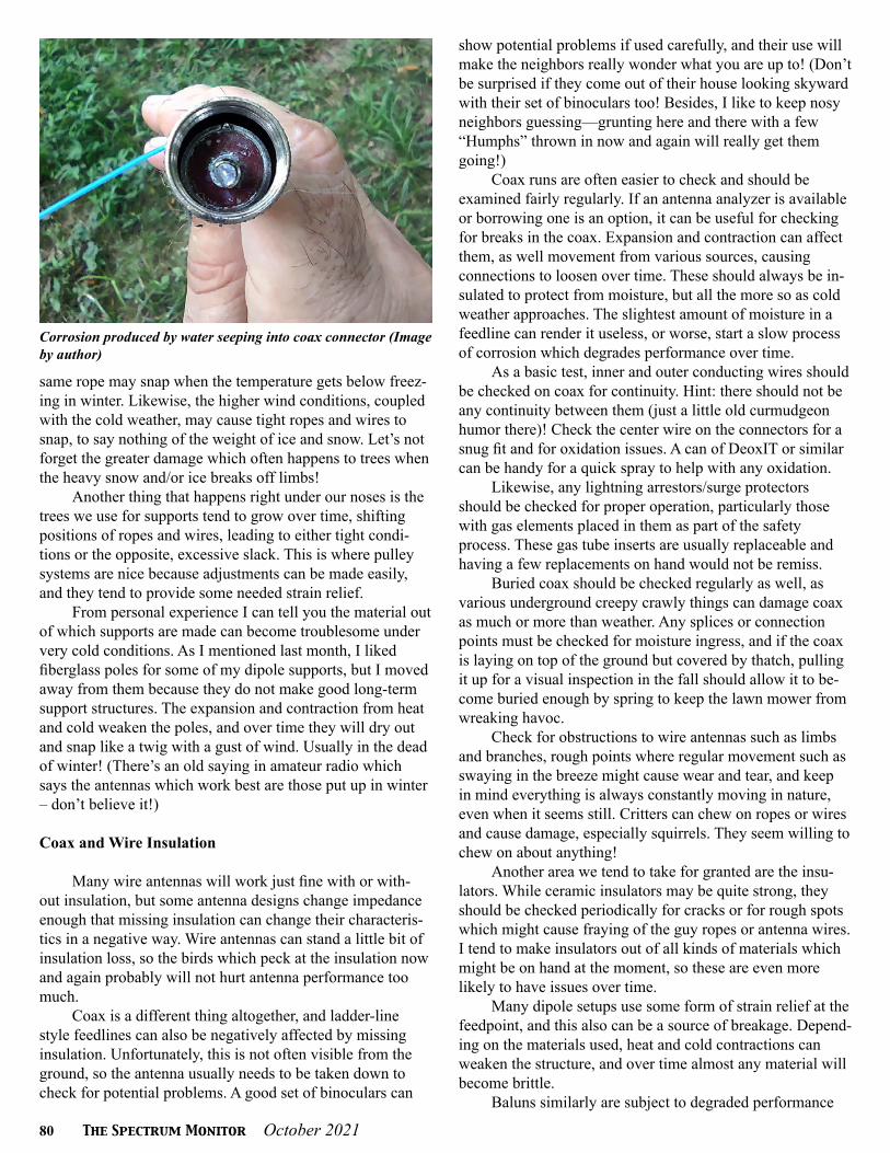
80 The Spectrum Monitor October 2021
Corrosion produced by water seeping into coax connector (Image by author)
same rope may snap when the temperature gets below freez-ing in winter. Likewise, the higher wind conditions, coupled with the cold weather, may cause tight ropes and wires to snap, to say nothing of the weight of ice and snow. Let’s not forget the greater damage which often happens to trees when the heavy snow and/or ice breaks off limbs!
Another thing that happens right under our noses is the trees we use for supports tend to grow over time, shifting positions of ropes and wires, leading to either tight condi-tions or the opposite, excessive slack. This is where pulley systems are nice because adjustments can be made easily, and they tend to provide some needed strain relief.
From personal experience I can tell you the material out of which supports are made can become troublesome under very cold conditions. As I mentioned last month, I liked fiberglass poles for some of my dipole supports, but I moved away from them because they do not make good long-term support structures. The expansion and contraction from heat and cold weaken the poles, and over time they will dry out and snap like a twig with a gust of wind. Usually in the dead of winter! (There’s an old saying in amateur radio which says the antennas which work best are those put up in winter – don’t believe it!)
Coax and Wire Insulation
Many wire antennas will work just fine with or with-out insulation, but some antenna designs change impedance enough that missing insulation can change their characteris-tics in a negative way. Wire antennas can stand a little bit of insulation loss, so the birds which peck at the insulation now and again probably will not hurt antenna performance too much.
Coax is a different thing altogether, and ladder-line style feedlines can also be negatively affected by missing insulation. Unfortunately, this is not often visible from the ground, so the antenna usually needs to be taken down to check for potential problems. A good set of binoculars can
show potential problems if used carefully, and their use will make the neighbors really wonder what you are up to! (Don’t be surprised if they come out of their house looking skyward with their set of binoculars too! Besides, I like to keep nosy neighbors guessing—grunting here and there with a few “Humphs” thrown in now and again will really get them going!)
Coax runs are often easier to check and should be examined fairly regularly. If an antenna analyzer is available or borrowing one is an option, it can be useful for checking for breaks in the coax. Expansion and contraction can affect them, as well movement from various sources, causing connections to loosen over time. These should always be in-sulated to protect from moisture, but all the more so as cold weather approaches. The slightest amount of moisture in a feedline can render it useless, or worse, start a slow process of corrosion which degrades performance over time.
As a basic test, inner and outer conducting wires should be checked on coax for continuity. Hint: there should not be any continuity between them (just a little old curmudgeon humor there)! Check the center wire on the connectors for a snug fit and for oxidation issues. A can of DeoxIT or similar can be handy for a quick spray to help with any oxidation.
Likewise, any lightning arrestors/surge protectors should be checked for proper operation, particularly those with gas elements placed in them as part of the safety process. These gas tube inserts are usually replaceable and having a few replacements on hand would not be remiss.
Buried coax should be checked regularly as well, as various underground creepy crawly things can damage coax as much or more than weather. Any splices or connection points must be checked for moisture ingress, and if the coax is laying on top of the ground but covered by thatch, pulling it up for a visual inspection in the fall should allow it to be-come buried enough by spring to keep the lawn mower from wreaking havoc.
Check for obstructions to wire antennas such as limbs and branches, rough points where regular movement such as swaying in the breeze might cause wear and tear, and keep in mind everything is always constantly moving in nature, even when it seems still. Critters can chew on ropes or wires and cause damage, especially squirrels. They seem willing to chew on about anything!
Another area we tend to take for granted are the insu-lators. While ceramic insulators may be quite strong, they should be checked periodically for cracks or for rough spots which might cause fraying of the guy ropes or antenna wires. I tend to make insulators out of all kinds of materials which might be on hand at the moment, so these are even more likely to have issues over time.
Many dipole setups use some form of strain relief at the feedpoint, and this also can be a source of breakage. Depend-ing on the materials used, heat and cold contractions can weaken the structure, and over time almost any material will become brittle.
Baluns similarly are subject to degraded performance

October 2021 The Spectrum Monitor 81
T S MT S M
Metal surfaces such as coax connectors, terminals, etc. can develop oxidation. These type of sprays can be useful as a pre-ventative or fix for oxidation issues (Image courtesy of CAIG Laboratories)
over time due to weather. A little oxidation on the outside of a connector may not hurt things, but over time there can be corrosion if differing metals react to one another. Com-mercial baluns are usually sealed quite well so breaking them open to check for moisture is usually not necessary but looking for possible problem points at the feedline/coax connectors is a good practice. I tend to go overboard when insulating these contacts, but I would rather be aggravated at how much insulation I used when taking it off rather than by not using enough and having the antenna malfunction when I am in the middle of a great DX QSO!
Verticals, Beams, and Towers
Verticals typically employ radials, and these are often buried along the ground. There is no real maintenance issue with these other than their connection point to the antenna. If a baseplate is used to anchor the radials, then just a quick check will do to make sure bolts are tight and that none of the radials have worked loose. The connection point to the antenna should be checked as well since, depending on de-sign, there may be strain relief points here also.
Yagis, log periodics, and other beam-type antennas add a significant amount of design complexity but checking them should not be too difficult except perhaps in terms of access. One area of potential difficulty for Yagis is the matching stub connector or match box, depending on the design. These are areas where moisture can cause problems, or where connec-tions can become weakened.
At the risk of sounding foolishly basic, wind damage will likely be more obvious and therefore easily seen—how-ever one must look up to see it. This is not something we all do regularly, particularly if we do not notice any problems while operating. Elements can get bent or caught, nearby antennas may interfere with one another, all the while going unnoticed because things seem normal while operating. At my previous location I had two antennas on my roof where, if strong wind conditions were just right, would get tangled up. I couldn’t move them farther apart given the setup, so I just had to remember to check them after any strong winds came through.
Besides structural integrity checks on towers (which should be done by professionals), the main things to check for are guy wires, grounding issues, and any mounting hard-ware which attach antennas to the tower. Again, these may seem obvious, but it is far too easy to fall into the “if it ain’t broke don’t fix it mentality” with towers, and an antenna coming down in a wind or ice storm could have far more damaging effects than just the loss of an antenna.
Proximity
One other thing to look for is what I like to call prox-imity checks – has anything moved closer to the antenna(s) which could cause problems, whether by conduction or by a potential safety hazard? Wires can droop and sway in the
wind, clearance/minimum safe distances can be compro-mised, or seemingly innocuous additions to the house or yard may have placed things too close to an antenna for safe operating. Even a piece of equipment added in the shack such as an amplifier could overload an existing antenna if the right wire/connectors are not used. These are simple, but important checks to make periodically.
An Ounce of Prevention
During a maintenance check everything may be work-ing just fine, and this is a good thing. However, even if nothing is broken, one is likely to find areas of improvement where a tweak here, a tweak there, and a bit of tidying up will optimize antenna system efficiency. This will result in better use of the energy, as well as better contacts over the air. A little bit of effort even when nothing appears wrong, will often reap small but noticeable benefits and is time well-spent.
Finally, just having the security of knowing we can en-ter into the harshest weather months with a good bit of con-fidence is well worth the time it takes to inspect the antenna system. Here’s to a safe, productive, warm and dry antenna experience through those long winter months!

82 The Spectrum Monitor October 2021
T S M B o o k s h e l fT S M B o o k s h e l fBooks of Interest to TSM Readers to Enhance your Radio Listening

October 2021 The Spectrum Monitor 83
T S M B o o k s h e l fT S M B o o k s h e l fBooks of Interest to TSM Readers to Enhance your Radio Listening
84 The Spectrum Monitor October 2021
A bou t UsA bou t UsThe Spectrum Monitor Writers’ Group
The Spectrum Monitor is edited and published by Ken Reitz KS4ZR, former managing editor, features editor, columnist and feature writer for Monitoring Times. Former feature writer and columnist for Satellite Times, Satellite Entertainment Guide, Satellite Orbit, Dish Entertainment Guide, Direct Guide; contributing editor on personal electronics for Consumers Digest. Author of the Kindle e-books “How to Listen to the World” and “Profiles in Amateur Radio.” E-mail: [email protected]
The Spectrum Monitor Writers’ Group consists of former columnists, editors and writers for Monitoring Times and Popu-lar Communications magazines. Below, in alphabetical order, are the columnists, their amateur radio call signs, the name of their column in The Spectrum Monitor, a brief bio and their websites and contact information.
Keith Baker KB1SF/VA3KSF, “Amateur Radio Satellites”Past president of the Radio Amateur Satellite Corporation (AMSAT). Freelance writer and photographer on amateur space tele-
communications since 1993. Columnist and feature writer for Monitoring Times, The Canadian Amateur and the AMSAT Journal. [email protected]
Kevin O’Hern Carey N2AFX, “The Longwave Zone”Reporting on radio’s lower extremes, where wavelengths can be measured in miles, and extending to the start of the AM broad-
cast band. Since 1991, editor of “Below 500 kHz” column for Monitoring Times. Author of “Listening to Longwave” (http://www.universal-radio.com/catalog/books/0024u.html). This link also includes information for ordering his CD, “VLF RADIO!,” a nar-rated tour of the longwave band from 0 to 530 kHz, with actual recordings of longwave stations. E-mail: [email protected]
Mike Chace-Ortiz AB1TZ/G6DHU “Digital HF: Intercept and Analyze”Author of the Monitoring Times “Digital Digest” column since 1997, which follows the habits o f embassies, aid organizations,
intelligence and military HF users, the digital data systems they use, and how to decode, breakdown and identify their traffic.
Dan Farber AC0LW, “Antenna Connections”Monitoring Times antenna columnist 2009-2013. Building ham and SWL antennas for over 40 years.
Richard Fisher KI6SNA veteran journalist with a 35-year career in daily newspapers, and an amateur radio operator living in Riverside, California,
Richard has been an editor and writer for Popular Communications, WorldRadio Online, and CQ Amateur Radio magazines. Among his previous responsibilities have been the monthly “Emergency Communications,” “Trail-Friendly Radio” and “Easy Does It” col-umns for CQ, and has written for several QRP publications, including QRP Quarterly and QRPp magazine. An avid homebrewer, he is a co-founder of The Adventure Radio Society. Write to him at [email protected].
Tomas Hood NW7US, “Radio Propagation”An Extra Class operator since 1990, Tomas enjoys CW and digital modes on all HF bands. He is a contributing editor to CQ
Amateur Radio, the former Popular Communications and CQ VHF magazines, an ARRL publication on QRP communications, and Monitoring Times.
Kirk Kleinschmidt NT0Z, “Amateur Radio Insight”Amateur radio operator since 1977 at age 15. Author of “Stealth Amateur Radio.” Former editor, “ARRL Handbook,”
former QST magazine assistant managing editor, columnist and feature writer for several radio-related magazines, technical editor for “Ham Radio for Dummies,” wrote “On the Ham Bands” column and numerous feature articles for Monitoring Times since 2009. Web site: www.stealthamateur.com. E-mail: [email protected]
Joe Lynch N6CL, “VHF and Above”Currently Director of Religious Education for the Army at West Point, New York. He holds a Doctor of Ministry, Master of
Divinity, an MBA and is an adjunct instructor for four colleges and universities and a retired United Methodist minister. He served as the editor of CQ VHF magazine for 12 years and the VHF editor for CQ magazine for 22 years. email: [email protected]

October 2021 The Spectrum Monitor 85
Stan Nelson KB5VL, “Amateur Radio Astronomy”Amateur radio operator since 1960. Retired after 40-plus years involved in mobile communications/electronics/computers/
automation. Active in radio astronomy for over twenty years, specializing in meteor monitoring. He wrote the “Amateur Radio Astronomy” column for Monitoring Times since 2010. A member of the Society of Amateur Radio Astronomers (SARA). www.RoswellMeteor.com. E-mail: [email protected]
Chris Parris, “Federal Wavelengths”Broadcast television engineer, avid scanner and shortwave listener, freelance writer on federal radio communications since
2004, wrote the “Fed Files” column for Monitoring Times. http://thefedfiles.com http://mt-fedfiles.blogspot.com Twitter: @TheFedFiles E-mail: [email protected]
Rich Post KB8TAD, “Adventures in Radio Restorations”As a teenager Rich Post repaired radios and TV sets. He passed the exam for a First Class FCC license when he was told he
needed one to repair his CB. He later received his amateur radio license as KB8TAD. Rich now holds a University Emeritus title having retired from Ohio University as Assistant Dean and Director of the Instructional Media and Technology Services. One of his hobbies is collecting and restoring “boat anchors.” He maintains the web site Boat Anchor Pix at https://people.ohio.edu/postr/bapix
Tony Roper, “Military Air and Naval Reception”
A Civil Air Traffic Controller in the UK as well as previously being in ATC in the Royal Air Force, totaling 25 years experience. He has worked as a part-time aviation photographer/writer and has been published worldwide. He also provides photos and research for IHS Jane’s, principally Jane’s Fighting Ships. His photography website and blog is http://planesandstuff.wordpress.com
Cory GB Sickles WA3UVV, “Digitally Speaking”First licensed as a Novice over 40 years ago, he enjoys exploring various facets of amateur radio, from the latest state of the
art technologies, to the elegant simplicity found with a one-tube transmitter and straight key. He has an extensive background with computers and likes to restore 8, 12 and 16-bit classics from the 1970s. He owns a television production company and creates series programming, as well as marketing and training videos. [email protected].
Hugh Stegman NV6H, “Utility Planet”Longtime DXer and writer on non-broadcast shortwave utility radio. Former “Utility World” columnist for Monitoring
Times magazine for more than ten years. Web site: www.ominous-valve.com/uteworld.html Blog: http://mt-utility.blogspot.com /email: [email protected] Twitter: @UtilityPlanet
Larry Van Horn N5FPW, “MilCom”Retired US Navy Chief Petty Officer. 43-year licensed amateur Extra class ham. Former Monitoring Times Assistant Editor,
Staff Journalist, Columnist. Former Satellite Times Managing Editor. Former Grove Enterprises Technical Support Technician. President Teak Publishing and author of dozens of print/e-Book radio hobby publications. EmaiL [email protected].
Dan Veeneman, “Scanning America”Software developer and satellite communications engineer writing about scanners and public service radio reception for Monitoring Times for 17 years. Web site: www.signalharbor.com E-mail: [email protected]
Ron Walsh VE3GO, “Maritime Monitoring”Retired career teacher, former president of the Canadian Amateur Radio Federation (now the Radio Amateurs of Canada),
retired ship’s officer, licensed captain, “Boats” columnist and maritime feature writer for Monitoring Times for eight years. Maritime Monitoring columnist for The Spectrum Monitor for seven years. Avid photographer of ships and race cars.
Fred Waterer, “The Shortwave Listener”Former “Programming Spotlight” columnist for Monitoring Times. Radio addict since 1969, freelance columnist
since 1986. Fascinated by radio programming and history. E-mail: [email protected]