cementing oil and gas wells using converted drilling fluid
TRANSCRIPT

J E u r o p a , s c h e s P _ MM M M II MM I I Ml II II II II I II European Patent Office _ _ _ _ _ _
* . . , © Publication number: 0 3 2 0 2 8 8 B 2 Office europeen des brevets
© NEW E U R O P E A N P A T E N T S P E C I F I C A T I O N
© Date of publication of the new patent specification: © Int. CI.6: E21 B 3 3 / 1 3 12.07.95
© Application number: 88311689.9
@ Date of filing: 09.12.88
© Cementing oil and gas wells using converted drilling fluid.
® Priority: 11.12.87 US 131878 © Proprietor: ATLANTIC RICHFIELD COMPANY 515 South Flower Street
@ Date of publication of application: Los Angeles 14.06.89 Bulletin 89/24 California 90071 (US)
© Publication of the grant of the patent: @ Inventor: Wilson, William N. 02.12.92 Bulletin 92/49 2513 Grandvlew
Piano © Mention of the opposition decision: Texas 75075 (US)
12.07.95 Bulletin 95/28 Inventor: Miles, Leon H. 2024 Westrldge
© Designated Contracting States: Piano DE FR GB NL Texas 75075 (US)
Inventor: Boyd, Brett H. © References cited: 3617 Yosemlte Drive
EP-A- 0 207 536 DE-A- 3 033 376 Piano GB-A- 2 120 708 US-A- 3 168 139 Texas 75023 (US) US-A- 3 557 876 US-A- 3 723 145 Inventor: Carpenter, Robert B. US-A- 3 748 159 US-A- 3 887 009 233 Billy Creek Drive US-A- 4 036 660 US-A- 4 176 720 Hurst US-A- 4 519 452 Texas 76053 (US)
Cementing, D.K. Smith, Second Printing, So- ciety of Petroleum Engineers of AIME, 1976, © Representative: Cropp, John Anthony David et pages 7,8,25,29,30 al
MATHYS & SQUIRE "factors to be considered In obtaining prop- 100 Grays Inn Road er cementing of casing", published In ce- London, WC1X 8AL (GB) mentlng considerations (pages 257-264), Halliburton Cement, Halliburton Services, 11.09.1987
CM 00
00 00 CM o CM 00
Rank Xerox (UK) Business Services (3. 10/3.09/3.3.3)
EP 0 320 288 B2
Description
The present invention pertains to cementing oil and gas wells with drilling fluid converted to a cementitious slurry which has been treated with a dispersant, is pumped into the space to be cemented
5 sufficiently to displace substantially all of the drilling fluid and which may use one or more basic cement mediums and other additives.
In the completion of oil and gas wells, it has been proposed to convert the drilling fluid or "mud" used during well drilling to a cement slurry for cementing casing or tubing in place or otherwise stabilizing or sealing the formation in the vicinity of the borehole. U.S. Patents 3,168,139 to H. T. Kennedy, et al;
w 3,499,491 to R. E. Wyant et al; 3,557,876 to A. Tregasser; 3,887,009 to G. L. Miller et al; and 4,176,720 to William N. Wilson disclose well cement compositions which have been formed at least in part by well drilling fluids.
US 3499491 discloses a process for cementing a string of pipe in a borehole by combining an aqueous drilling fluid with a mixture of hydraulic cement and powdered sodium silicate glass to form a mud concrete
75 which sets at the temperature of the borehole. Many prior art efforts to convert drilling fluid to cement materials have posed certain problems in
causing increased viscosity and flocculation of the drilling fluid as the cementitious material is added thereto and pumped into the wellbore. Converted drilling fluid compositions generally along the lines suggested in U.S. Patent 3,499,491, for example, exhibit some gellation and are particularly temperature sensitive. In
20 other words, if wellbore temperatures exceed a predetermined level, the cement composition has a tendency to set or harden rapidly. Since wellbore temperature conditions are difficult to control or predict in many instances, a reduced temperature sensitivity of the drilling fluid converted to cement is highly desirable.
Moreover, with prior art methods and compositions, the displacement of the drilling fluid has been 25 incomplete due to gellation and has often resulted in poor cement bonds or incomplete filling of the casing-
to-wellbore annulus with a homogeneous cement. In this regard, the present invention has been developed with a view to providing improved cement compositions through conversion of drilling fluids as well as an improved process for displacing drilling fluid from the wellbore and the casing-to-wellbore annulus so that a complete filling of the space to be cemented is accomplished with a homogeneous cement slurry.
30 In accordance with one aspect, the present invention provides A method for cementing a wellbore penetrating an earth formation into which a conduit extends, said wellbore having a space occupied by a fluid composition and said method comprising replacing said fluid composition by a cement composition for cementing said space to form a seal between spaced apart points in said formation and causing or allowing said cement composition to set in said space, wherein said cement composition is formed by adding
35 cement material and a dispersant to a quantity of fluid having the same or substantially the same composition as said fluid composition, and the method includes circulating the cement composition into said space characterised in that the method further includes recirculating said composition through said space, to thoroughly displace and convert to cement any drilling fluid in the region of the wellbore which is desired to be cemented.
40 In accordance with a second aspect, the present invention also provides A method for cementing a wellbore penetrating an earth formation into which a conduit extends, said wellbore having a space occupied by a fluid composition and said method comprising replacing said fluid composition by a cement composition for cementing said space to form a seal between spaced apart points in said formation and causing or allowing said cement composition to set in said space, wherein said cement composition is
45 formed by adding to a quantity of fluid having the same or substantially the same composition as said fluid composition, cement material and a dispersant characterised in that said dispersant comprises a sulfonated styrene copolymer selected from (a) sulfonated styrene maleic anhydride copolymer, (b) sulfonated styrene imide copolymer, and (c) a sulfonated styrene copolymer in combination with a polyacrylate, a partially hydrolysed co- or ter- polymer of acrylamide or a potassium salt or phosphonate of such a partially
50 hydrolysed co- or ter- polymer. The improved cement slurry is provided using drilling fluid which is converted by the addition of certain cementitious materials and a dispersant which minimizes the tendency for flocculation or gellation and the attendant viscosity increase to occur in the drilling fluid-cement mixture being formed and also to minimize the formation of gelled mixtures in the wellbore during displacement of nonconverted drilling fluid from the area to be cemented. The dispersant preferably comprises a sulfonated
55 styrene copolymer with or without an organic acid. In accordance with the first aspect of the invention sulfonated styrene -maleic anhydride (SSMA),
sulfonated styrene imide (SSI), sulfonated styrene itaconic acid or a combination of a sulfonated styrene copolymer with one or more compounds from the groups of polyacrylates, potassium salts, phosphonates
2
EP 0 320 288 B2
and other co- or ter- polymers of partially hydrolyzed polyacrylamides may be used as the dispersant and added to the drilling fluid in a mixture with a blended cementitious material to convert the fluid to an improved cement slurry.
Those skilled in the art will further appreciate the above described features of the present invention 5 together with other superior aspects thereof upon reading the detailed description which follows.
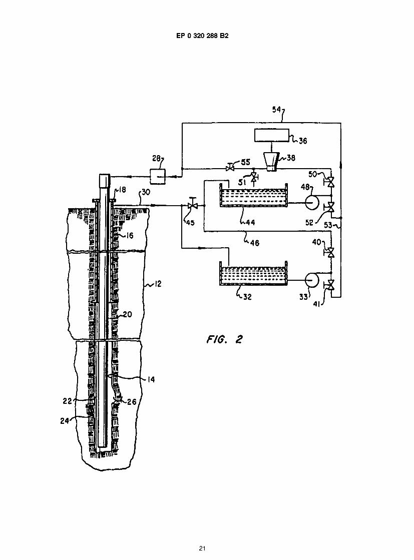
Figure 1 is a schematic diagram of a wellbore and a fluid circulation system for continuous mixing of cement for cementing the wellbore to casing annulus using converted drilling fluid; and Figure 2 is a schematic diagram of a cement mixing and circulation system adapted for batch mixing or continuous mixing of cement for converting drilling fluid.
io The conversion of well drilling fluids into cement slurries for cementing the wellbore to casing annulus and for performing other wellbore cementing operations is attractive for several reasons, namely, at least a major portion of the drilling fluid is not subject to waste disposal problems and regulations, the conversion of drilling fluid to a cement slurry minimizes the handling of the drilling fluid and the cement slurry, the cement slurry preparation time and expense is minimized and separation between the drilling fluid and the
is converted cementitious slurry is not required to be maintained, particularly when considering the process and compositions of the present invention.
The conversion of drilling fluid or "mud" to a cement slurry is not without some operational problems and undesirable compositional changes. For example, the addition of cementitious materials such as mixtures of lime, silica and alumina or lime and magnesia, silica and alumina and iron oxide, or cement
20 materials such as calcium sulphate and Portland cements to aqueous drilling fluids can substantially increase the viscosity of the fluid mixture and result in severe flocculation. Efforts to circulate such mixtures through a wellbore can result in a highly unsatisfactory circulation rate, plugging of the wellbore annulus, breakdown of the earth formation in the vicinity of the wellbore and a failure of the cement slurry to properly mix. Certain dispersants have been developed for use in drilling fluids during drilling operations including
25 lignite and lignosulfonates. One dispersant which has been commercially used in drilling fluid is a low molecular weight styrene
sulfonic acid-maleic anhydride copolymer and a water soluble salt thereof (sometimes known as "SSMA"). U.S. Patent 3,730,900 to A. C. Perricone, et a describes several drilling fluids which are treated with such a dispersant for stabilizing the rheological and fluid loss properties, particularly under high temperatures in the
30 wellbore and in the presence of fluid contaminants. U. S. Patents 4,476,029 to A.O. Sy et al., 4,581,147 to Homer Branch III, and 4,680,128 to R.C. Portnoy and European Patent Publication No. 0207536 P. Parcevaux et al. also disclose dispersants for drilling fluids and fluid spacer compositions. However, in spite of the state of the art as evidenced by the references cited herein and known to Applicants, there has remained the problem of effectively converting a drilling fluid to a suitable cement composition and
35 displacing the drilling fluid in the borehole, including an annular area between a casing and the borehole, in a manner which provides effective occupancy of the area to be cemented with a composition which will form an effective bond with the well casing and/or plug the well or the earth formation adjacent the well with a barrier of sufficient strength to prevent migration of fluids in unwanted directions and/or prevent collapse of the walls of the borehole or collapse of the casing.
40 Moreover, although the addition of certain proportions of a sulfonated styrene copolymer or similar dispersant substantially reduces the tendency for flocculation or gelling of the mud converted to cement mixture, further efforts to develop a composition having a reduced viscosity and less tendency to cause gelling or flocculation has led to the discovery that the addition of certain proportions of organic acids such as sodium citrate, citric acid, gluco delta lactone, tartaric acid, erthorbic acid and other organic acids and
45 long chain sugars in combination with the sulfonated styrene copolymer has a synergistic effect in reducing flocculation and viscosity of the mud converted to cement mixture. However, these organic acid additives may also retard the setting time of the cement slurry.
Referring briefly to Figure 1 , there is illustrated one system in accordance with the present invention for converting drilling fluid to a cement slurry for cementing a well casing in place in an earth formation 12 into
50 which a wellbore 14 has penetrated. In the system illustrated in FIGURE 1, a casing 16 has been extended into a portion of the formation from a wellhead 18 and a second casing 20 extends into the wellbore to forth an annulus 22 which may include washouts or void areas 24 and 26, for example. The casing 20 extends to the wellhead 18 and is adapted to be in communication with a pump 28 for circulating drilling fluid down through the interior of the casing 20 and up through the annulus 22 to a return conduit 30. Drilling fluid is
55 conducted through the return conduit 30 to a storage tank or pit 32 and is recirculated to the pump 28 through a pump 33 and a conduit 34 during normal drilling operations. Conventional drilling fluid treatment apparatus such as shale shakers, sand separators and related equipment have been eliminated from the diagrams of Figures 1 and 2 in the interest of conciseness.
3
EP 0 320 288 B2
One method for converting a drilling fluid to a cementitious slurry in accordance with this invention which is useful in wellbores requiring relatively large quantities of cement is to provide a premixed quantity of dry blended cement materials in suitable storage means 36 for conduction to a blending apparatus 38 of a type commercially available wherein the dry cement materials are blended with drilling fluid which is
5 circulated to the pump 28 through a conduit 39 and the blending unit 38. Valves 40, 41 and 42 are operated to control the fluid flow path during the conversion process. The materials added to the blending unit 38 will be described herein in regard to several examples of converting drilling fluid to a cement slurry in accordance with the present invention. Suitable means for adding water, not shown, should also be provided. In many instances, and it is preferred, water and dispersant are added to the fluid before the other
io materials. Figure 2 illustrates a system which provides increased flexibility in mixing processes in accordance with
the present invention. The storage means 36 discharges predetermined quantities of dry blended cement materials of the type to be described herein into the blending unit 38 and the batch mixing is carried out in one or more tanks or pits 44 which have received drilling fluid from the tank 32 and the pump 33 by way of
is a conduit 46. The drilling fluid in the tank 44 is recirculated through the blending unit 38 by a pump 48, valve 50 and valve 51 until the proper mixture and density is achieved whereupon valves 50 and 52 are adjusted to conduct the cement slurry to the pump 28 through a conduit 54. Of course, during normal drilling operations the drilling fluid is circulated to the pump 28 through the conduit 30, the tank 32, the pump 33 and conduit 53, 54. The cementitious slurry may be recirculated between the wellbore 14 and the
20 tank 44 by way of a connecting conduit having a valve 45 interposed therein. The system illustrated in Figure 2 may be used to continuously supply a cementitious slurry to the pump 28 by closing valve 51 and opening valve 55.
Accordingly, with the systems illustrated in Figures 1 and 2, drilling fluid is readily converted to a cement slurry on either a continuous or batch mixing basis. Certain compositions of cement slurry as set
25 forth herein may be held in one or more tanks 44, for example, for relatively long periods of time before injection into the wellbore. By continuous or batch mixing of the drilling fluid converted to cement only a small amount, if any, of the drilling fluid is subject to disposal requirements and all of the drilling fluid in the wellbore annulus 22 is eventually replaced with a cement composition which meets the requirements for cementing the casing in the wellbore 14 or for otherwise treating the formation 14 in the manner desired. In
30 other words, by means of the invention most or all of a drilling fluid which has occupied a well bore during drilling may be converted to a settable cement composition which can subsequently be pumped back into the annular space in the well bore to seal it, thereby obviating the need for disposing of the fluid, which would normally be the case.
As previously mentioned water, dispersant and other additives can be mixed into the fluid prior to 35 adding the larger quantities of dry materials.
It is contemplated that the improved cement composition and method of cementing a well in an earth formation by converting drilling fluid in accordance with the present invention can be carried out with compositions and methods generally along the lines described herein. Water based drilling fluids having densities of about 1.08 to 21.57 kg/I (9.0 pounds per gallon (ppg) to 18.0 ppg) may be converted to cement
40 and circulated through a wellbore such as the wellbore 14 by adding up to one hundred percent (100%) and preferably zero to fifty percent (0-50%) water, based on the original drilling fluid volume, together with a dispersant, comprising a sulfonated styrene copolymer, in the range of 0.0014 to 0.0285 kg/I (.50 to 10.0 pounds per original barrel of drilling fluid based on a 42 gallon barrel (hereinafter "ppb")) and preferably less than about 0.0143 kg/I (5.0 ppb). By adding the dispersant at the time of conversion of the drilling fluid
45 to a cement slurry, a surprising improvement in the mixing of the cement material into the drilling fluid has been realized. One source and specification of the sulfonated styrene copolymer may be a composition comprising a low molecular weight sulfonated styrene -maleic anhydride copolymer (SSMA) and commer- cially available under the trade name NARLEX D-72, from National Starch and Chemical Corporation, Bridgewater, New Jersey. The dispersant may be preblended with dry cement material and other additives
50 as set forth herein and stored in the storage means 36, for example, or it may be added to the drilling fluid during addition of diluting water. Moreover, the dispersant may also comprise selected quantities of sulfonated styrene imide copolymer (e.g. copolymer of sulfonated styrene and N-phenylmaleimide), sul- fonated styrene itaconic acid copolymer or a combination of a sulfonated styrene copolymer with one or more compounds selected from a group consisting of polyacrylates (i.e. polymers and copolymers of esters
55 of acrylic acid and derivatives of acrylic acid, such as methacrylic acid), partially hydrolysed co- or ter- polymers of acrylamide and potassium salts and phosphonates of said partially hydrolysed co- and ter- polymer. Moreover, it is contemplated that monomers such as maleic anhydride, maleimide and dimethyl- maleate may be added in combination with the selected copolymer.
4
EP 0 320 288 B2
Concurrent with or following the addition of the dispersant and diluting water to the former drilling fluid, Portland cement in a range of concentrations of from 0.285 to 1.71 kg/I (100.0 ppb to 600 ppb) is also added to the fluid. Hydration rate control compositions such as calcium sulphate and calcium aluminate may be used in the range of 0.0285 to 0.285 kg/I (10.0 ppb to 100.0 ppb) of drilling fluid. Moreover,
5 selected ones of several other additives such as setting retarders, accelerators, and fluid loss control compositions such as inorganic salts, calcium aluminate, lignosulfonates with or without organic acids, and polymers such as hydroxyethyl cellulose (HEC), carboxymethyl hydroxyethyl cellulose (CMHEC), 2- acrylamido-2-methylpropane sulfonic acid (AMPS) and acrylic acids may be premixed with the other materials. The above-described compositions may be further modified by the addition of silica sand in the
io amount of up to one hundred percent (100%) by weight of the Portland cement fraction of the cement slurry to increase the high temperature stability of the composition. Still further, the addition of other cementing mediums to the mix such as calcium aluminates and the abovementioned calcium sulphate can be added to control slurry thickening time, strength development rate and total compressive strength by changing the ratios of these mediums in the mix.
is In the development of the present invention, initially a well was cemented utilizing a cement material of a type described in U.S. Patent 3,499,491 and commercially available under the name "C-mix". This cement composition has been developed for use in converting drilling fluids to cement slurries. However, experience with this particular type of cement composition indicates still an abnormally high gellation of the drilling fluid upon adding the dry blended cement material (C-mix) to the drilling fluid. In pursuing the
20 present invention it was decided to test this cement composition with the addition of a dispersant in the form of SSMA utilizing a water based lignosulfonate drilling mud having a density of approximately 1 .47 kg/I (12.3 ppg).
A well was cemented having a 12.7 cm (5.0 inch) diameter casing with placement of the cement initially at a depth of 3048 m (10,000 feet) and an indicated bottomhole temperature of approximately 74 °C (166°
25 F). A batch of 37680 I (237 barrels) of cement slurry was mixed and placed at a pumping rate of approximately 11 to 12 l/sec (4.0 to 4.5 barrels per minute (bpm)) with pumping pressures below about 3450 kPa (500 psig). The cement slurry was found to be still particularly temperature sensitive as indicated by the thickening times specified in Table I below.
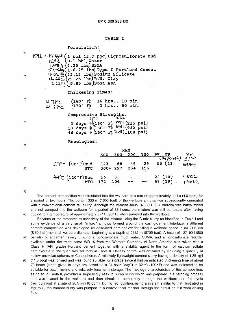
Table I, in addition to the formulation and thickening times, indicates compressive strength at wellbore 30 temperatures and certain rheological parameters at temperatures indicated for the drilling fluid or "mud"
alone and the mud to cement mixture (MTC) formed by the 0.556 kg/I (195 ppb) C-mix cement blend. The raw data indicated for the various speeds in RPM for each composition is that which is obtained by a rotational viscometer for determining shear stress and shear rate in accordance with API Specification No. 10. The rheological parameters indicated in the tables herein, including plastic viscosity (PV) indicated in
35 centipoises and the yield point (YP) indicated in g/m3 (pounds per hundred feet square (lbs/100 ft2)), were measured with a rotating sleeve-stationary bob viscometer, using a #1 spring and a #1 bob and sleeve, such as a type Chan 35 manufactured by E. G. & G. Chandler Engineering, Tulsa, Oklahoma. Without the increased dispersion provided by SSMA, the 0.556 kg/I (195 ppb) C-mix slurry was too viscous for the measurement range of the apparatus as equipped. The well was cemented utilizing a batch procedure
40 generally in accordance with the arrangement illustrated in Figure 2 of the drawings and following the general procedure for the batch mixing process described herein. The formulation quantities are per original barrel of drilling fluid. The resultant or final density of the drilling fluid converted to cement mixture was approximately 1.67 kg/I (13.9 ppg).
45
50
55
5
EP 0 320 288 B2
10
15
TABLE I
F o r m u l a t i o n :
1 .4-7 tf)l£ ( 1 bb l 12 .3 ppg) L i g n o s u l f o n a t e Mud t o . l bbl ) W a t e r ( .3.25 l b s ) SSMA
«T7.<tt*3(.126.75. lbs) Type I P o r t l a n d C e m e n t iS.01.te5 f 33 . 15 lbs ) Sodium S i l i c a t e l3. 2^*5 ( 2 9 . 2 5 l b s J R . W . C l a y
2.(,Sfcej(^5.85 l b s J S o d a A s h
T h i c k e n i n g T i m e s :
® 1 \ °C (160* F) 16 h r s . , 10 m i n . £> T7°C (170* F); 3 h r s . , 50 m i n .
20
25
C o m p r e s s i v e S t r e n g t h s :
20 3 days §^160* F) l s * V 2 1 5 p s i ) 13 days 8 (160* F> fctf31 (932 p s i ) 46 days § (160* F ) % H T ( l l 0 8 p s i )
R h e o l o g i e s : 25
RPM 600 300- 200 100 PV YP Y<° , (l^jjlOoff-^ 5 / iv\
d l ° C C80-F)Mud 123 68 49 29 55 (.13) f e i ^ 30 MTC 300+ 297 234 156 — —
( l 2 0 * F ) M u d 56 33 — - - 23 (.10 ) MTC 173 106 - - - - 67 ( 3 9 )
35 The cement composition was circulated into the wellbore at a rate of approximately 1 1 l/s (4.0 bpm) for
a period of two hours. The bottom 333 m (1000 feet) of the wellbore annulus was subsequently cemented with a conventional cement tail slurry. Although the cement slurry 37680 I (237 barrels) was batch mixed and not pumped into the wellbore for a period of 36 hours, the mixture was still pumpable after having
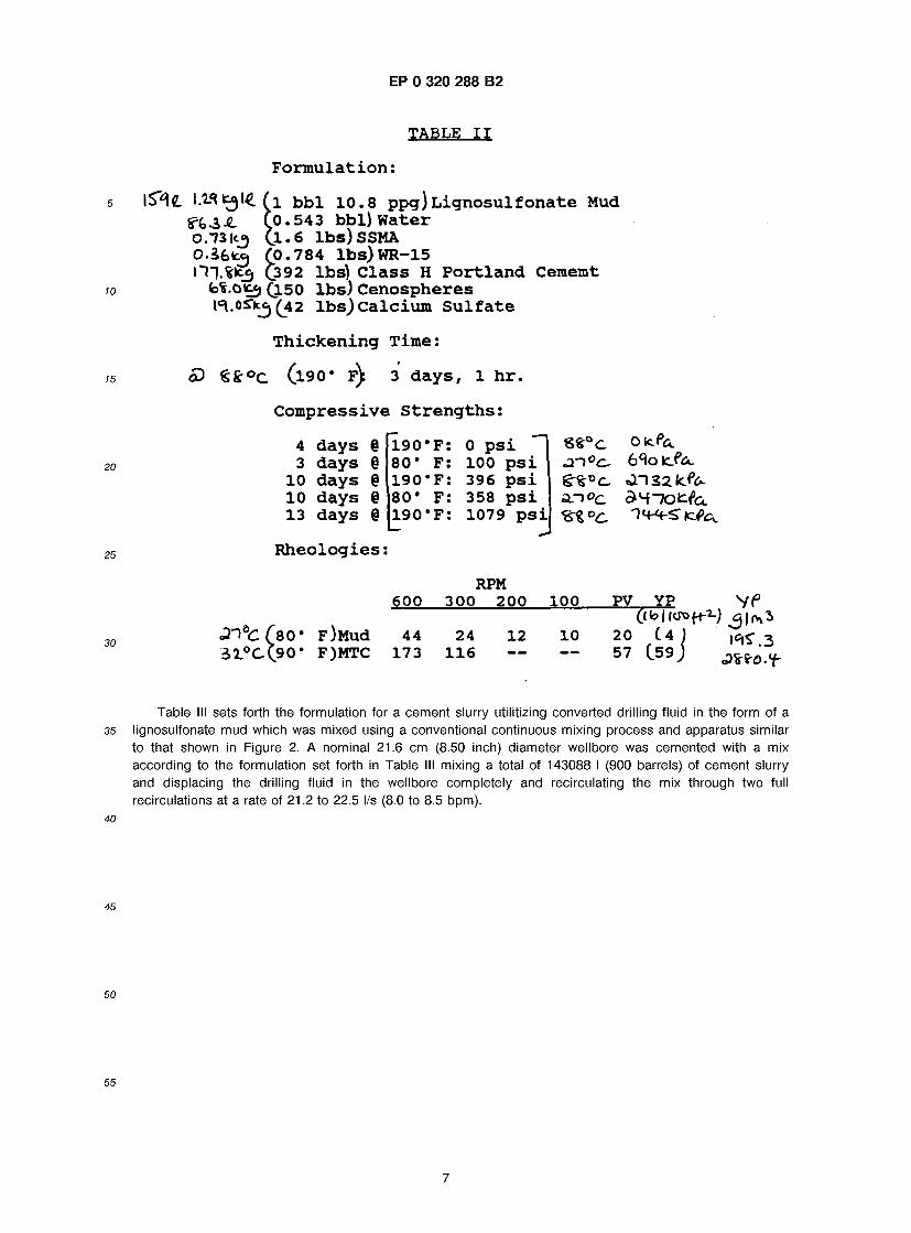
40 cooled to a temperature of approximately 32 0 C (90 0 F) when pumped into the wellbore. Because of the temperature sensitivity of the mixture using the C-mix slurry as identified in Table I and
some evidence of a very small "micro" annulus formed around the casing-cement interface, a different cement composition was developed as described hereinbelow for filling a wellbore space in an 21.6 cm (8.50 inch) nominal wellbore diameter beginning at a depth of 2652 m (8700 feet). A batch of 127190 I (800
45 barrels) of a cement slurry utilizing a lignosulfonate mud, water, SSMA, and a lignosulfonate retarder available under the trade name WR-15 from the Western Company of North America was mixed with a Class H (API grade) Portland cement together with a stability agent in the form of calcium sulfate hemihydrate in the quantities set forth in Table II. Density control was obtained by including a quantity of hollow pozzolan spheres or Cenospheres. A relatively lightweight cement slurry having a density of 1 ,35 kg/I
50 (1 1 .3 ppg) was formed and was found suitable for storage since it had an indicated thickening time of about 73 hours (times given in days are based on a 24 hour "day") at 32 °C (190°F) and was indicated to be suitable for batch mixing and relatively long term storage. The rheology characteristics of this composition, as noted in Table II, provided a surprisingly easy to pump slurry which was prepared in a batching process and was placed in the wellbore and then circulated completely through the wellbore one full cycle
55 (recirculation) at a rate of 26.5 l/s (10 bpm). During recirculation, using a system similar to that illustrated in Figure 2, the cement slurry was pumped in a conventional manner through the circuit as if it were drilling fluid.
6
EP 0 320 288 B2
TABLE I I
F o r m u l a t i o n :
\%<\q_ I.W £ 9 1 4 ( 1 b b l 1 0 . 8 ppg) L i g n o s u l f o n a t e Mud CO. 543 bb l ) W a t e r
o.73 ( 1 . 6 l b s ) SSMA O.Sfefce, ( 0 . 7 8 4 l b s ) W R - 1 5 iTj.^lcg (392 lbs) C l a s s H P o r t l a n d C e m e m t
fe*.Ofc«j (150 l b s ) C e n o s p h e r e s l^.oS'it^ (42 l b s ) c a l c i u m S u l f a t e
T h i c k e n i n g T i m e :
<P € £ ° c ( l 9 0 * f) 3 d a y s , 1 h r .
C o m p r e s s i v e S t r e n g t h s :
4 d a y s § f l 9 0 ' F : 0 p s i ~~| S S ° c OicP^ 3 d a y s § 80* F: 100 p s i - r i0c - 6^0 fc/a.
10 d a y s § 190 *F: 396 p s i o n z z l c f c * . 10 d a y s § 80 ' F: 358 p s i s n ° c & H T o £ ( u 13 d a y s § 190 'F : 1079 p s i l ^ ^ i c f t ^
R h e o l o g i e s :
4 d a y s § 3 d a y s §
10 d a y s § 10 d a y s § 13 d a y s §
1 9 0 * F : 0 p s i 80* F: 100 p s i 1 9 0 ' F : 396 p s i 80* F: 358 p s i 1 9 0 ' F : 1079 p s i
2 l - \ ° c
RPM 600 300 200 100 PV YP
2 r \Qc (Z0* F)Mud 44 24 12 10 20 (4 ) 3 i l .0cX?0m F)MTC 173 116 ~ — 57 (.59) ^
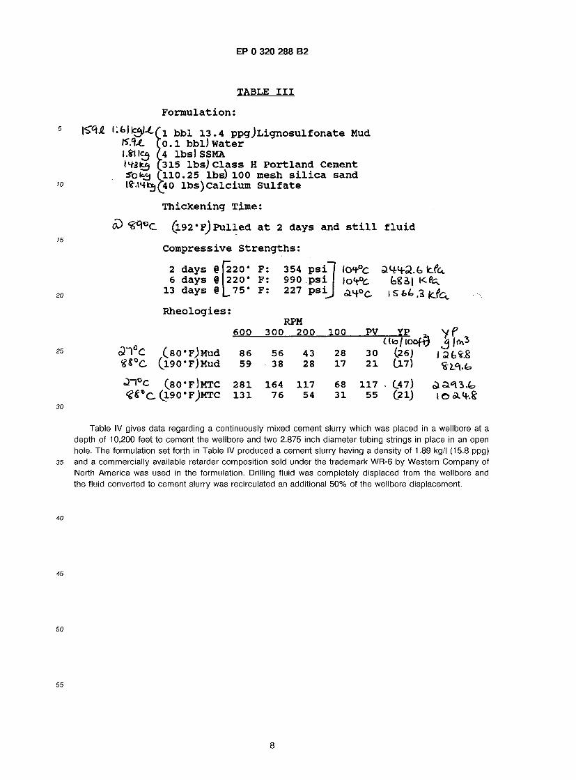
Table III sets forth the formulation for a cement slurry utilitizing converted drilling fluid in the form of a lignosulfonate mud which was mixed using a conventional continuous mixing process and apparatus similar to that shown in Figure 2. A nominal 21.6 cm (8.50 inch) diameter wellbore was cemented with a mix according to the formulation set forth in Table III mixing a total of 143088 I (900 barrels) of cement slurry and displacing the drilling fluid in the wellbore completely and recirculating the mix through two full recirculations at a rate of 21 .2 to 22.5 l/s (8.0 to 8.5 bpm).
EP 0 320 288 B2
TABLE I I I
F o r m u l a t i o n :
' .<>llc3M(i bbl 13 .4 ppg J L i g n o s u l f o n a t e Mud ,0.1 bbl) W a t e r 't lbs) SSMA � '315 lbs ) C l a s s H P o r t l a n d C e m e n t
3o<<£j CllO. 25 lbs) 100 mesh s i l i c a s a n d I?.l4fce,(j40 l b s ) C a l c i u m S u l f a t e
T h i c k e n i n g T i m e :
<£> ( l92*F) P u l l e d a t 2 days and s t i l l f l u i d
C o m p r e s s i v e S t r e n g t h s :
2 days @ 6 days @
13 days §
220* F : 220* F :
75* F :
R h e o l o g i e s :
354 p s i 990 p s i 227 p s i
RPM
^ n ° c ( 8 o * f ) m t c <?£°C ( 1 9 0 ' F ^ M T C
600 300 200 100 PV YP C Ko / lo<
86 56 43 28 30 (26) 59 38 28 17 21 (17)
281 164 117 68 117 . C47) 131 76 54 31 55 ( 21 ) 1 © AH-.S-
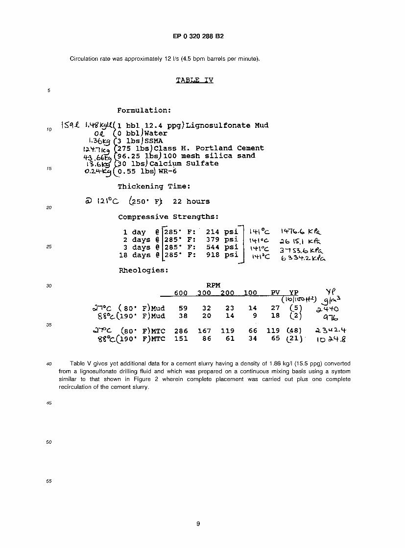
Table IV gives data regarding a continuously mixed cement slurry which was placed in a wellbore at a depth of 10,200 feet to cement the wellbore and two 2.875 inch diameter tubing strings in place in an open hole. The formulation set forth in Table IV produced a cement slurry having a density of 1.89 kg/I (15.8 ppg) and a commercially available retarder composition sold under the trademark WR-6 by Western Company of North America was used in the formulation. Drilling fluid was completely displaced from the wellbore and the fluid converted to cement slurry was recirculated an additional 50% of the wellbore displacement.
8
EP 0 320 288 B2
Circulation rate was approximately 12 l/s (4.5 bpm barrels per minute).
TABLE I V
F o r m u l a t i o n :
\S<\£ I.Stffc^Ltf 1 b b l 12 .4 ppg) L i g n o s u l f o n a t e Mud 04. Co bb l j W a t e r
I.Sfclcg (3 l b s ] SSMA I^-V.lko l275 l b s ) C l a s s H. P o r t l a n d C e m e n t 4-3> 6£Esj C96' 25 lfasJ 100 mesh s i l i c a s a n d
iV.bkgi (30 l b s ) C a l c i u m S u l f a t e 0.2.m£ej (o . 55 lbs) WR-6
T h i c k e n i n g T i m e :
<D 12\°C (250* F) 22 h o u r s
C o m p r e s s i v e S t r e n g t h s :
1 day @[285* F: 214 p s i l 4 - l °c 2 d a y s § 285* F: 379 p s i l4-(«c 3 days % 285* F: 544 p s i \h- \°c
18 days § 285* F: 918 p s i \h-\*c
R h e o l o g i e s :
285* F: 214 p s i 285* F: 379 p s i 285* F: 544 p s i 285* F: 918 p s i
RPM
c3""*°C ( 8 0 ' g & ° ^ ( l 9 0 '
«3"T°C ( 8 0 '
600 300 200 100 PV YP VP (ItolKTOtfiJ
F)Mud 59 32 23 14 27 C.5) ^ H ^ f O F)Mud 38 20 14 9 18 ^2) 4 - ^
F)MTC 286 167 119 66 119 C48) A 2> <J 2_- 4- F)MTC 151 86 61 34 65 (21) l O ^ H . g
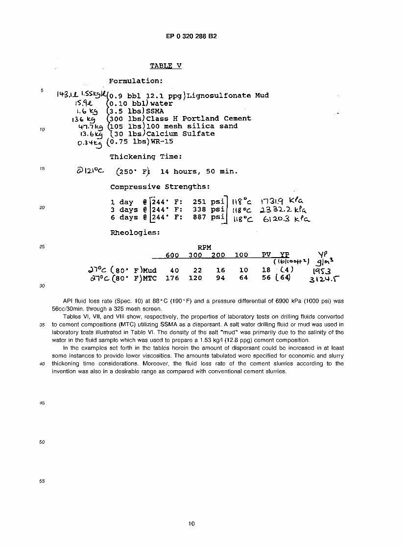
Table V gives yet additional data for a cement slurry having a density of 1.86 kg/I (15.5 ppg) converted from a lignosulfonate drilling fluid and which was prepared on a continuous mixing basis using a system similar to that shown in Figure 2 wherein complete placement was carried out plus one complete recirculation of the cement slurry.
EP 0 320 288 B2
TABLE V
F o r m u l a t i o n :
L l-SSfcfjl^/o . 9 bb l 12 .1 ppg) L i g n o s u l f o n a t e Mud 1*5 $4. ( 0 . 1 0 bb l ) w a t e r I. fa *i) ( 3 .5 l b s ) SSMA
ife *£) C300 l b s ^ c l a s s 11 P o r t l a n d C e m e n t 4--1-TIC5 u.05 l b s ) 100 mesh s i l i c a s a n d G.fefcg \ 3 0 l b s ) c a l c i u m S u l f a t e
O.JHt^ ( 0 . 7 5 l b s ) W R - 1 5
T h i c k e n i n g T i m e :
5>\X\°C (250* f) 14 h o u r s , 50 m i n .
C o m p r e s s i v e S t r e n g t h s :
1 day § 3 d a y s # 6 d a y s @
244* 244* 244*
R h e o l o g i e s :
F : F : F :
2 5 1 3 3 8 8 8 7
p s i p s i p s i U 8 ° C
\12\PI K ' a
( s o - 6 n ° c C 8 o *
F^Mud F)MTC
6 0 0 RPM
300 2 0 0
40 1 7 6
22 1 2 0
!00 100 PV YP V f
16 10 18 (.4) ^ 3 94 64 56 (.64) 3 l 2 M . r
API fluid loss rate (Spec. 10) at 88° C (190°F) and a pressure differential of 6900 kPa (1000 psi) was 56cc/30min. through a 325 mesh screen.
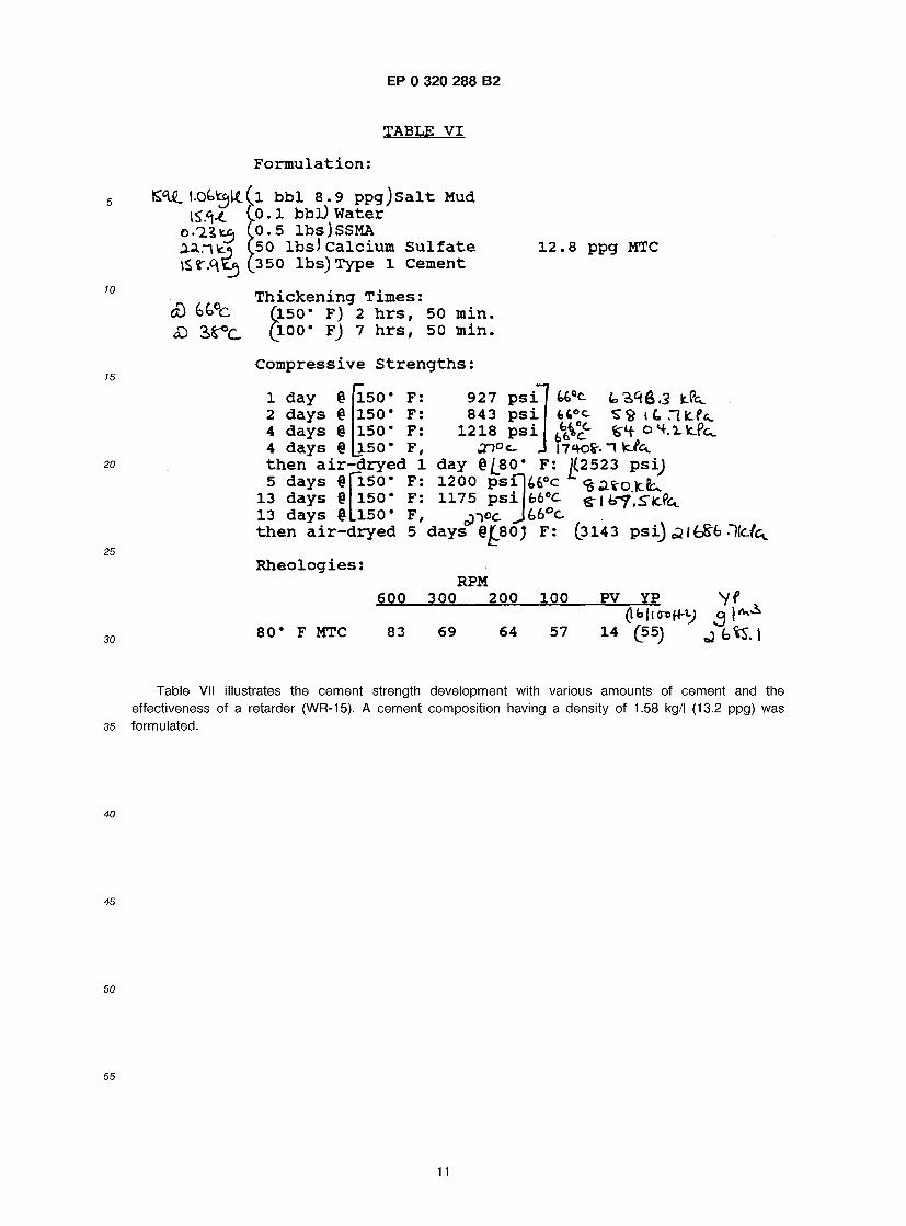
Tables VI, VII, and VIII show, respectively, the properties of laboratory tests on drilling fluids converted to cement compositions (MTC) utilizing SSMA as a dispersant. A salt water drilling fluid or mud was used in laboratory tests illustrated in Table VI. The density of the salt "mud" was primarily due to the salinity of the water in the fluid sample which was used to prepare a 1.53 kg/I (12.8 ppg) cement composition.
In the examples set forth in the tables herein the amount of dispersant could be increased in at least some instances to provide lower viscosities. The amounts tabulated were specified for economic and slurry thickening time considerations. Moreover, the fluid loss rate of the cement slurries according to the invention was also in a desirable range as compared with conventional cement slurries.
10
EP 0 320 288 B2
TABLE V I
F o r m u l a t i o n :
I.Okta)U.(r bb l 8.9 ppg) S a l t Mud IS'l-t Co . l bbl) W a t e r
o - d l t * L0.5 l b s ) S S M A a a . - i v ^
£> 3>r°c
50 lbs ) C a l c i u m S u l f a t e 350 lbs ) Type 1 C e m e n t
12 .8 ppg MTC
T h i c k e n i n g T i m e s : (150* F) 2 h r s , 50 m i n . £l00* F) 7 h r s , 50 m i n .
C o m p r e s s i v e S t r e n g t h s :
1 day § 150* F: 927 p s i 4fc°c k ' i q f c . : 2 days § 150* F: 843 p s i fc6°c 59 i t 4 days § 150* F: 1218 p s i 4 days § | 150* F, J-J°c_ J i7«K>fr."l fete, t h e n a i r - d r y e d 1 day § /80* F: J(2523 p s i ) 5 days §
13 days @ 13 days @Ll50# F ,
150* F: 1200 p s i 150* F: 1175 p s i
66°C Srltrf.JTicfe,.
t h e n a i r - d r y e d 5 days §£80) F: (3143 p s i ) <2lfc&fc He ld .
R h e o l o g i e s :
80* F MTC
RPM 600 300 200 100 PV YP Y f
83 69 64 57 14 (55) j f c t t . |
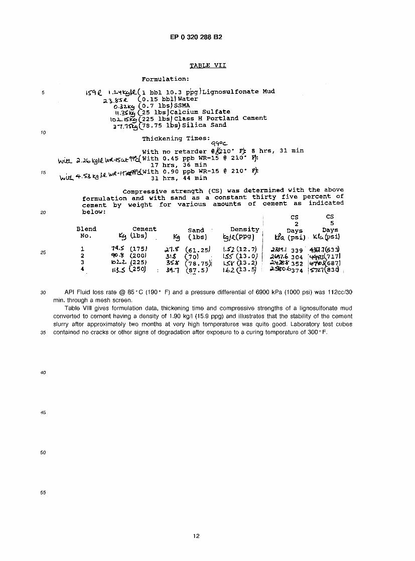
Table VII illustrates the cement strength development with various amounts of cement and the effectiveness of a retarder (WR-15). A cement composition having a density of 1.58 kg/I (13.2 ppg) was formulated.
11
EP 0 320 288 B2
TABLE VII
F o r m u l a t i o n :
\^<L Ll-'+lajKCl bbl 10.3 ppg) L i g n o s u l f o n a t e Mud 3.3, %se. (.0.15 b b l ) W a t e r
O.32.IC3 (0.7 lbs) SSMA »l.3£ta(_25 l b s j c a l c i u m S u l f a t e
loi. iSk£j(225 lbs) Class H Po r t l and Cement 3 - 7 . 1 ^ ( 7 8 . 7 5 lbs) S i l i c a Sand
Thickening Times:
With no r e t a r d e r 8^210* F): 8 hrs, 31 min Mi*. a.JfakqlAVii*-Ka*T»'c(with 0.45 ppb WR-15 § 210* Fj:
^ 17 hrs, 36 min *< i i r0U.V^- i r - t fn i .w i th 0.90 ppb WR-15 § 210* F>
VjUL * ^ 31 hrs, 44 min VjUL ^ 31 hrs, 44 m
Compressive s t r e n g t h (CS) was de te rmined with the above f o r m u l a t i o n and with sand as a c o n s t a n t t h i r t y f ive pe rcen t o f cement by weight for v a r i o u s amounts of cement as i n d i c a t e d be low:
CS CS
Blend No.
1 2 3 4
Cement &j ( lb s )
7«.S (175; (.200)
102-2- (225) U5.5 C250)
Sand »3 ( l b s )
(61.25) 3>\& (70) 2S# (78.75)! 34.1 ( 8 7 . 5 )
D e n s i t y ^ j ^ ( p p g )
ISl (12 . 7)
l i>2(13.5j
2 » Days Days
LPs. (psi) K.fa(psi)
JjBt-l 339 .24*17.6 304 ^ . 4 ^ 3 5 2
■43H.7C633) ; h^w( j i7 )
■57^7(830}
API Fluid loss rate @ 85 °C (190° F) and a pressure differential of 6900 kPa (1000 psi) was 112cc/30 min. through a mesh screen.
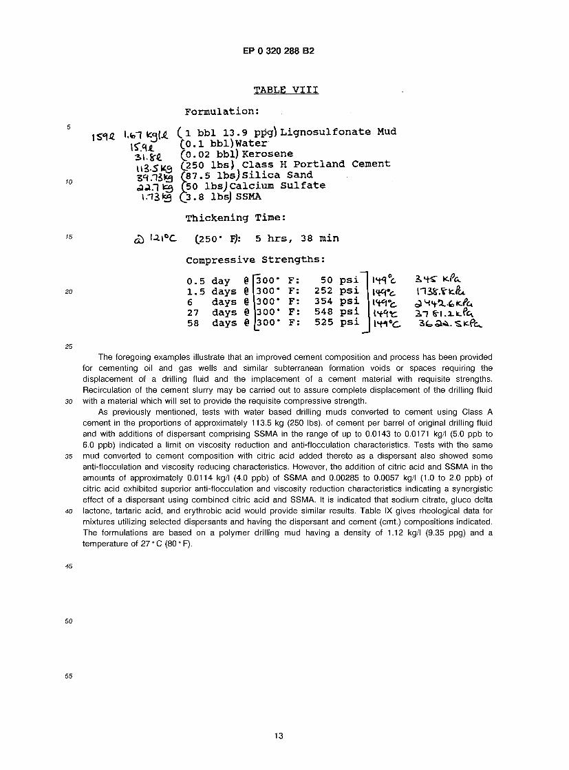
Table VIII gives formulation data, thickening time and compressive strengths of a lignosulfonate mud converted to cement having a density of 1.90 kg/I (15.9 ppg) and illustrates that the stability of the cement slurry after approximately two months at very high temperatures was quite good. Laboratory test cubes contained no cracks or other signs of degradation after exposure to a curing temperature of 300 0 F.
12
EP 0 320 288 B2
TABLE V I I I
F o r m u l a t i o n :
10
15
20
25
30
35
40
<«1jC l.fel kqU (.1 bb l 13 .9 ppg) L i g n o s u l f o n a t e Mud
I S * * 2>i.Sr4
Co . l b b l ) W a t e r ( 0 . 0 2 bbl) K e r o s e n e (250 l b s ) C l a s s H P o r t l a n d C e m e n t ( 8 7 . 5 l b s ) S i l i c a S a n d (50 l b s j C a l c i u m S u l f a t e (3 . 8 lbsj SSMA
T h i c k e n i n g T i m e :
Ul°C (250* F): 5 h r s , 38 m i n
C o m p r e s s i v e S t r e n g t h s :
0 . 5 1 . 5 6 27 58
day 6 days @ days § days § days e
300* F : 300* F : 300* F : 300* F : 300* F :
50 p s i 252 p s i 354 p s i 548 p s i 525 p s i
The foregoing examples illustrate that an improved cement composition and process has been provided for cementing oil and gas wells and similar subterranean formation voids or spaces requiring the displacement of a drilling fluid and the implacement of a cement material with requisite strengths. Recirculation of the cement slurry may be carried out to assure complete displacement of the drilling fluid with a material which will set to provide the requisite compressive strength.
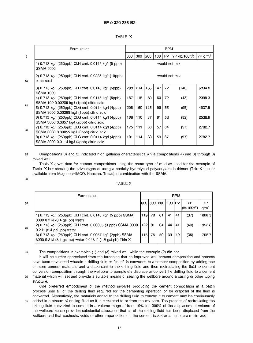
As previously mentioned, tests with water based drilling muds converted to cement using Class A cement in the proportions of approximately 113.5 kg (250 lbs), of cement per barrel of original drilling fluid and with additions of dispersant comprising SSMA in the range of up to 0.0143 to 0.0171 kg/I (5.0 ppb to 6.0 ppb) indicated a limit on viscosity reduction and anti-flocculation characteristics. Tests with the same mud converted to cement composition with citric acid added thereto as a dispersant also showed some anti-flocculation and viscosity reducing characteristics. However, the addition of citric acid and SSMA in the amounts of approximately 0.0114 kg/I (4.0 ppb) of SSMA and 0.00285 to 0.0057 kg/I (1.0 to 2.0 ppb) of citric acid exhibited superior anti-flocculation and viscosity reduction characteristics indicating a synergistic effect of a dispersant using combined citric acid and SSMA. It is indicated that sodium citrate, gluco delta lactone, tartaric acid, and erythrobic acid would provide similar results. Table IX gives rheological data for mixtures utilizing selected dispersants and having the dispersant and cement (cmt.) compositions indicated. The formulations are based on a polymer drilling mud having a density of 1.12 kg/I (9.35 ppg) and a temperature of 27 0 C (80 0 F).
45
50
55
13
EP 0 320 288 B2
TABLE IX
Formulation RPM
600 300 200 100 PV YP (lb/1 00ft2) YP g/m3
1) 0.713 kg/I (250ppb) CI.H cmt. 0.0143 kg/I (5 ppb) would not mix SSMA 3000
2) 0.713 kg/I (250ppb) CI.H cmt. 0.0285 kg/I (10ppb) would not mix citric acid
3) 0.713 kg/I (250ppb) CI.H cmt. 0.0143 kg/I (5ppb) 288 214 185 147 72 (140) 6834.8 SSMA 1000 4) 0.713 kg/I (250ppb) CI.H cmt. 0.0143 kg/I (5ppb) 187 115 89 60 72 (43) 2099.3 SSMA 100 0.00285 kg/I (1ppb) citric acid 5) 0.713 kg/I (250ppb) CI.G cmt. 0.0114 kg/I (4ppb) 205 150 125 96 55 (95) 4637.9 SSMA 3000 0.00285 kg/I (1 ppb) citric acid 6) 0.713 kg/I (250ppb) CI.G cmt. 0.0114 kg/I (4ppb) 168 110 87 61 58 (52) 2538.6 SSMA 3000 0.0057 kg/I (2ppb) citric acid 7) 0.713 kg/I (250ppb) CI.G cmt. 0.0114 kg/I (4ppb) 175 111 86 57 64 (57) 2782.7 SSMA 3000 0.00855 kg/I (3ppb) citric acid 8) 0.713 kg/I (250ppb) CI.G cmt. 0.0114 kg/I (4ppb) 181 114 88 59 67 (57) 2782.7 SSMA 3000 0.01 14 kg/I (4ppb) citric acid
25 Compositions 3) and 5) indicated high gellation characteristics while compositions 4) and 6) through 8) mixed well.
Table X gives data for cement compositions using the same type of mud as used for the example of Table IX but showing the advantages of using a partially hydrolysed polyacrylamide thinner (Thin-X thinner available from Magcobar-IMCO, Houston, Texas) in combination with the SSMA.
30 TABLE X
Formulation RPM
600 300 200 100 PV YP YP (lb/1 00ft2) g/m3
1) 0.713 kg/I (250ppb) CI.H cmt. 0.0143 kg/I (5 ppb) SSMA 119 78 61 41 41 (37) 1806.3 3000 0.2 l/l (8.4 gal.pb) water 2) 0.713 kg/I (250ppb) CI.H cmt. 0.00855 (3 ppb) SSMA 3000 122 81 64 44 41 (40) 1952.8 0.2 l/l (8.4 gal. pb) water 3) 0.713 kg/I (250ppb) CI.H cmt. 0.0057 kg/I (2ppb) SSMA 115 75 59 39 40 (35) 1708.7 3000 0.2 l/l (8.4 gal.pb) water 0.043 l/l (1.8 gal.pb) Thin-X
45 The compositions in examples (1) and (3) mixed well while the example (2) did not. It will be further appreciated from the foregoing that an improved well cement composition and process
have been developed wherein a drilling fluid or "mud" is converted to a cement composition by adding one or more cement materials and a dispersant to the drilling fluid and then recirculating the fluid to cement conversion composition through the wellbore to completely displace or convert the drilling fluid to a cement
50 material which will set and provide a suitable means of sealing the wellbore around a casing or other tubing structure.
One preferred embodiment of the method involves producing the cement composition in a batch process until all of the drilling fluid required for the cementing operation or for disposal of the fluid is converted. Alternatively, the materials added to the drilling fluid to convert it to cement may be continuously
55 added in a stream of drilling fluid as it is circulated to or from the wellbore. The process of recirculating the drilling fluid converted to cement in a volume range of from 10% to 1000% of the displacement volume of the wellbore space provides substantial assurance that all of the drilling fluid has been displaced from the wellbore and that washouts, voids or other imperfections in the cement jacket or annulus are minimized.
14
EP 0 320 288 B2
A desirable cement composition in accordance with the present invention is one which permits complete circulation of the fluid out of the wellbore and replacement with the cement composition itself. Since this circulation may normally comprise two, and as many as ten, complete displacements of the system volume, which includes the wellbore, the mixing tanks or pits and all of the interconnecting conduits,
5 it is desirable that the composition not commence setting or thickening until circulation is complete. In this respect, it has been determined that one or more cement materials may be utilized with or without setting retarders to control the hydration rate or commencement of thickening before which an insignificant change in the rheological properties of the composition occurs during mixing and circulation. Moreover, the fluid loss properties are in a desirable range, similar to the base drilling fluid.
io Although preferred embodiments of the present invention have been described in some detail herein, various substitutions and modifications may be made to the compositions and methods of the invention without departing from the scope of the appended claims. For example, the process may include the step of displacing drilling fluid from said space with a preflush composition according to claim 12 or use compositions according to claim 13.
15 Claims
1. A method for cementing a wellbore penetrating an earth formation into which a conduit extends, said wellbore having a space occupied by a fluid composition and said method comprising replacing said
20 fluid composition by a cement composition for cementing said space to form a seal between spaced apart points in said formation and causing or allowing said cement composition to set in said space, wherein said cement composition is formed by adding cement material and a dispersant to a quantity of fluid having the same or substantially the same composition as said fluid composition, and the method includes circulating the cement composition into said space characterised in that the method
25 further includes recirculating said composition through said space.
2. The method set forth in claim 1 wherein: said dispersant comprises a sulfonated styrene copolymer selected from (a) sulfonated styrene
maleic anhydride copolymer, (b) sulfonated styrene imide copolymer, and (c) a sulfonated styrene 30 copolymer in combination with a polyacrylate, a partially hydrolysed co- or ter- polymer of acrylamide
or a potassium salt or phosphonate of such a partially hydrolysed co- or ter- polymer.
3. A method for cementing a wellbore penetrating an earth formation into which a conduit extends, said wellbore having a space occupied by a fluid composition and said method comprising replacing said
35 fluid composition by a cement composition for cementing said space to form a seal between spaced apart points in said formation and causing or allowing said cement composition to set in said space, wherein said cement composition is formed by adding to a quantity of fluid having the same or substantially the same composition as said fluid composition, cement material and a dispersant characterised in that said dispersant comprises a sulfonated styrene copolymer selected from (a)
40 sulfonated styrene maleic anhydride copolymer, (b) sulfonated styrene imide copolymer, and (c) a sulfonated styrene copolymer in combination with a polyacrylate, a partially hydrolysed co- or ter- polymer of acrylamide or a potassium salt or phosphonate of such a partially hydrolysed co- or ter- polymer.
45 4. A method as set forth in any one of claims 1 to 3 wherein a fluid having the composition of said fluid composition is circulated around a circuit which includes said space and coment material and a dispersant are added to a quantity of said circulating composition to form a settable cement composition.
50 5. The method set forth in any one of claims 1 to 4 wherein: said dispersant comprises a low molecular weight sulfonated styrene maleic anhydride copolymer.
6. The method claimed in any one of claims 1 to 5 wherein said dispersant comprises sulfonated styrene maleic anhydride copolymer and said settable coment composition further includes at least one
55 compound selected from citric acid, sodium citrate, gluco delta lactone, tartaric acid and erythrobic acid.
15
EP 0 320 288 B2
7. The method set forth in any one of claims 1 to 6 wherein said dispersant is added to said fluid together with cement material at a rate such as to minimise the gelling of said fluid upon adding said cement material to said fluid.
5 8. The method set forth in any one of claims 1 to 7 wherein: said dispersant is added to said fluid in the amount of between 0.00143-0.0285 kg/I (.50 ppb and
10.0 ppb) of fluid and said cement material is added to said fluid in the amount of 0.285 to 1.71 kg/I (100 ppb of fluid to 600 ppb) of fluid.
io 9. The method set forth in any one of claims 1 to 8 wherein: said dispersant is mixed with said cement material before adding said cement material to said fluid.
10. The method sat forth in any one of claims 1 to 9 wherein: said cement composition is provided with a hydration rate control agent selected from calcium
is sulfate and calcium aluminate in the amount of from 0.0285 to 0.285 kg/I (10.0 ppb to 100.0 ppb).
11. The method set forth in any one of claims 1 to 9 including the step of: adding at least two cement materials to said fluid to control the hydration rate of said cement
composition and selected from Portland cement, calcium sulfate and calcium aluminate. 20
12. The method set forth in any one of claims 1 to 11 including the step of: displacing drilling fluid from said space with a preflush composition comprising water and a
sulfonated styrene copolymer to form a rheologically compatible material for displacing said drilling fluid prior to filling said wellbore space with said cement composition.
25 13. The method set forth in any one of claims 1 to 12 wherein said cement composition comprises:
a quantity of a water based drilling fluid; Portland cement in the range of concentrations of from 0.285 kg/I to 1.71 kg/I (100 pounds per
original 42 U.S. gallon barrel of drilling fluid (ppb) to about 600 ppb); 30 a dispersant comprising a low molecular weight sulfonated styrene maleic anhydride copolymer in
the range of less than about 0.0142 kg/I (5.0 ppb); calcium sulfate hemihydrate in the range of about 0.0285 to 0.285 kg/I (10.0 ppb to 100 ppb); and fine ground silica.
35 Patentanspruche
1. Verfahren zum Zementieren eines eine Erdformation durchdringenden Bohrlochs, in das sich ein Leitungsrohr erstreckt, wobei das Bohrloch einen Raum aufweist, der von einer Fluidzubereitung eingenommen wird, und wobei das Verfahren das Ersetzen der Fluidzubereitung durch eine Zementzu-
40 bereitung zum Zementieren des Raumes unter Ausbildung einer Abdichtung zwischen entfernt liegen- den Punkten in der Formation und das Zum-Ausharten-Bringen oder Ausharten-Lassen der Zementzu- bereitung in dem Raum umfaBt, wobei die Zementzubereitung dadurch hergestellt wird, dal3 man Zementmaterial und ein Dispergiermittel einer Menge der Fluidzubereitung zusetzt, die dieselbe oder im wesentlichen dieselbe Zusammensetzung wie die Fluidzubereitung aufweist und wobei das Verfah-
45 ren ein Zirkulieren der Zementzubereitung im Raum einschlieBt und dadurch gekennzeichnet ist, dal3 es auBerdem ein Rezirkulieren der Zubereitung durch den Raum einschlieBt.
2. Verfahren nach Anspruch 1, worin das Dispergiermittel ein sulfoniertes Styrol-Copolymer umfaBt, das gewahlt ist unter (a) sulfonierten Styrol-Maleinsaureanhydrid-Copolymeren, (b) sulfonierten Styrol-lmid-
50 Copolymeren und (c) sulfonierten Styrol-Copolymeren in Kombination mit einem Polyacrylat, einem partiell hydrolisierten Copolymer oder Terpolymer des Acrylamids oder einem Kaliumsalz oder Phosphonat eines derartigen partiell hydrolisierten Copolymers oder Terpolymers.
3. Verfahren zum Zementieren eines eine Erdformation durchdringenden Bohrlochs, in das sich ein 55 Leitungsrohr erstreckt, wobei das Bohrloch einen Raum aufweist, der von einer Fluidzubereitung
eingenommen wird, und wobei das Verfahren das Ersetzen der Fluidzubereitung durch eine Zementzu- bereitung zum Zementieren des Raumes unter Ausbildung einer Abdichtung zwischen entfernt liegen- den Punkten in der Formation und das Zum-Ausharten-Bringen oder Ausharten-Lassen der Zementzu-
16
EP 0 320 288 B2
bereitung in dem Raum umfaBt, wobei die Zementzubereitung dadurch hergestellt wird, dal3 man Zementmaterial und ein Dispergiermittel einer Menge der Fluidzubereitung zusetzt, die dieselbe oder im wesentlichen dieselbe Zusammensetzung wie die Fluidzubereitung aufweist, wobei das Verfahren dadurch gekennzeichnet ist, dal3 das Dispergiermittel ein sulfoniertes Styrol-Copolymer umfaBt, das
5 gewahlt ist unter (a) sulfonierten Styrol-Maleinsaureanhydrid-Copolymeren, (b) sulfonierten Styrol-lmid- Copolymeren und (c) sulfonierten Styrol-Copolymeren in Kombination mit einem Polyacrylat, einem partiell hydrolisierten Copolymer oder Terpolymer des Acrylamids oder einem Kaliumsalz oder Phosphonat eines derartigen partiell hydrolisierten Copolymers oder Terpolymers.
io 4. Verfahren gemaB einem der Anspruche 1 bis 3, worin ein fluides Medium, das die Zusammensetzung der Fluidzubereitung aufweist, in einem Kreislauf gefuhrt wird, der den Raum einschlieBt, und Zement- material und ein Dispergiermittel der im Kreislauf gefuhrten Zubereitung in einer Menge zugesetzt werden, urn eine hartbare Zementzubereitung zu bilden.
is 5. Verfahren nach einem der Anspruche 1 bis 4, worin das Dispergiermittel ein sulfoniertes Styrol- Maieinsaureanhydrid-Copolymer mit niedrigem Molekulargewicht umfaBt.
6. Verfahren nach irgendeinem der Anspruche 1 bis 5, worin das Dispergiermittel ein sulfoniertes Styrol- Maleinsaureanhydrid-CopoLymer umfaBt und die aushartbare Zementzubereitung auBerdem wenigstens
20 eine Verbindung einschlieBt, die gewahlt ist unter Citronensaure, Natriumcitrat, Gluco-delta-Lacton, Weinsaure und Isoascorbinsaure.
7. Verfahren nach irgendeinem der Anspruche 1 bis 6, worin das Dispergiermittel der Fluidzubereitung zusammen mit Zementmaterial in einer solchen Geschwindigkeit zugesetzt wird, dal3 das Gelieren der
25 Fluidzubereitung bei Zugabe des Zementmaterials zu der Fluidzubereitung minimiert wird.
8. Verfahren nach irgendeinem der Anspruche 1 bis 7, worin das Dispergiermittel der Fluidzubereitung in einer Menge zwischen 0,00143 und 0,0285 kg/I (0,5 ppb und 10,0 ppb) der Fluidzubereitung zugesetzt wird und das Zementmaterial der Fluidzubereitung in einer Menge von 0,285 bis 1,71 kg/I (100 ppb bis
30 600 ppb) der Fluidzubereitung zugesetzt wird.
9. Verfahren nach irgendeinem der Anspruche 1 bis 8, worin das Dispergiermittel mit dem Zementmaterial vor dem Zusetzen des Zementmaterials zu der Fluidzubereitung gemischt wird.
35 10. Verfahren nach irgendeinem der Anspruche 1 bis 9, worin die Zementzubereitung mit einem Mittel zur Einstellung der Hydratationsgeschwindigkeit in einer Menge von 0,0285 bis 0,285 kg/I (10,0 ppb bis 100,0 ppb) versetzt wird, welches gewahlt ist unter Calciumsulfat und Calciumaluminat.
11. Verfahren nach irgendeinem der Anspruche 1 bis 9, welches den folgenden Schritt einschlieBt: 40 Zusetzen wenigstens zweier Zementmaterialien zu der Fluidzubereitung zur Kontrolle der Hydratations-
geschwindigkeit der Zementzubereitung, wobei diese gewahlt sind unter Portlandzement, Calciumsulfat und Calciumaluminat.
12. Verfahren nach irgendeinem der Anspruche 1 bis 10, welches den folgenden zusatzlichen Schritt 45 einschlieBt:
Entfernen von Bohrflussigkeit aus dem Raum mit einer Wasser und ein sulfoniertes Styrol-Copolymer umfassenden Vorspulzubereitung unter Bildung eines rheologisch vertraglichen Materials zum Entfer- nen der Bohrflussigkeit vor dem Fullen des Bohrlochs mit der Zementzubereitung.
50 13. Verfahren nach irgendeinem der Anspruche 1 bis 12, worin die Zementzubereitung umfaBt: - eine Menge an Bohrfluid auf Wasserbasis; - Portlandzement in Konzentrationsbereichen von 0,285 bis 1,71 kg/I (100 pounds pro Original 42-
US-Gallonen-Barrel Bohrfluid (ppb) bis etwa 600 ppb); - ein ein sulfoniertes Styrol-Maleinsaureanhydrid-Copolymer mit niedrigem Molekulargewicht urn-
55 fassendes Dispergiermittel in einem Mengenbereich von weniger als etwa 0,0142 kg/I (5,0 ppb); - Calciumsulfat-Hemihydrat in einer Menge im Bereich von etwa 0,0285 bis 0,285 kg/I (10,0 ppb bis
100 ppb); und - fein gemahlenes Siliciumdioxid.
17
EP 0 320 288 B2
Revendicatlons
1. Precede pour cimenter un puits de forage penetrant dans un terrain dans lequel se prolonge un conduit, ce puits de forage ayant un espace occupe par une composition de fluide et ce procede
5 comprenant le remplacement de cette composition de fluide par une composition de ciment pour cimenter cet espace afin de former un joint entre des points espaces dans ce terrain et provoquer le durcissement ou laisser durcir cette composition de ciment dans cet espace, dans lequel cette composition de ciment est formee par addition d'un ciment et d'un dispersant a une quantite de fluide ayant la meme composition ou pratiquement la meme composition que cette composition de fluide et
io le procede comprend la circulation de la composition de ciment dans cet espace, caracterise en ce que le procede comprend de plus la remise en circulation de cette composition a travers cet espace.
2. Procede suivant la revendication 1, dans lequel ce dispersant comprend un copolymere de styrene sulfone choisi parmi (a) un copolymere d'anhydride maleique-styrene sulfone, (b) un copolymere
is d'imide-styrene sulfone et (c) un copolymere de styrene sulfone en combinaison avec un polyacrylate, un co- ou ter-polymere partiellement hydrolyse d'acrylamide ou un sel de potassium ou un phosphona- te d'un tel co- ou ter-polymere partiellement hydrolyse.
3. Procede pour cimenter un puits de forage penetrant dans un terrain dans lequel se prolonge un 20 conduit, ce puits de forage ayant un espace occupe par une composition de fluide et ce procede
comprenant le remplacement de cette composition de fluide par une composition de ciment pour cimenter cet espace afin de former un joint entre des points espaces dans ce terrain et provoquer le durcissement ou laisser durcir cette composition de ciment dans cet espace, dans lequel cette composition de ciment est formee par addition a une quantite de fluide ayant la meme composition ou
25 pratiquement la meme composition que cette composition de fluide, d'un ciment et d'un dispersant, caracterise en ce que ce dispersant comprend un copolymere de styrene sulfone choisi parmi (a) un copolymere d'anhydride maleique-styrene sulfone, (b) un copolymere d'imide-styrene sulfone et (c) un copolymere de styrene sulfone en combinaison avec un polyacrylate, un co- ou ter-polymere partielle- ment hydrolyse d'acrylamide ou un sel de potassium ou un phosphonate d'un tel co- ou ter-polymere
30 partiellement hydrolyse.
4. Procede suivant I'une quelconque des revendications 1 a 3, dans lequel on fait circuler un fluide ayant la composition de cette composition de fluide selon un circuit qui comprend cet espace et Ton ajoute le ciment et le dispersant a une quantite de cette composition en circulation de fagon a former une
35 composition de ciment durcissable.
5. Procede suivant I'une quelconque des revendications 1 a 4, dans lequel ce dispersant comprend un copolymere d'anhydride maleique-styrene sulfone de bas poids moleculaire.
40 6. Procede suivant I'une quelconque des revendications 1 a 5, dans lequel ce dispersant comprend un copolymere d'anhydride maleique-styrene sulfone et cette composition de ciment durcissable com- prend de plus au moins un compose choisi parmi I'acide citrique, le citrate de sodium, la gluco delta lactone, I'acide tartrique et I'acide erythrobique.
45 7. Procede suivant I'une quelconque des revendications 1 a 6, dans lequel ce dispersant est ajoute a ce fluide avec un ciment en une quantite telle qu'elle minimise la gelification de ce fluide lors de I'addition de ce ciment a ce fluide.
8. Procede suivant I'une quelconque des revendications 1 a 7, dans lequel ce dispersant est ajoute a ce 50 fluide en une quantite comprise entre 0,00143 et 0,0285 kg/I (0,50 ppb et 10,0 ppb) de fluide et ce
ciment est ajoute a ce fluide en une quantite de 0,285 a 1,71 kg/I (100 ppb a 600 ppb) de fluide.
9. Procede suivant I'une quelconque des revendications 1 a 8, dans lequel ce dispersant est melange a ce ciment avant addition de ce ciment a ce fluide.
55 10. Procede suivant I'une quelconque des revendications 1 a 9, dans lequel cette composition de ciment
est fournie avec un agent controlant le taux d'hydratation choisi parmi le sulfate de calcium et I'aluminate de calcium, en une quantite de 0,0285 a 0,285 kg/I (10,0 ppb a 100,0 ppb).
18
EP 0 320 288 B2
1. Procede suivant I'une quelconque des revendications 1 a 9, incluant I'etape d'addition d'au moins deux ciments a ce fluide pour controler le taux d'hydratation de cette composition de ciment et choisis parmi un ciment Portland, du sulfate de calcium et de I'aluminate de calcium.
2. Procede suivant I'une quelconque des revendications 1 a 1 1 , incluant I'etape de deplacement du fluide de forage de cet espace avec une composition de prenettoyage comprenant de I'eau et un copolymere de styrene sulfone pour former un materiau compatible du point de vue rheologique pour le deplace- ment de ce fluide de forage avant remplissage de cet espace de puits de forage avec cette composition de ciment.
3. Procede suivant I'une quelconque des revendications 1 a 12, dans lequel cette composition de ciment comprend :
une quantite de fluide de forage a base d'eau; du ciment Portland dans la gamme de concentrations de 0,285 a 1,71 kg/I (100 pounds par baril de
42 gallons US (ppb) a environ 600 ppb) de fluide de forage; un dispersant comprenant un copolymere d'anhydride maleique-styrene sulfone a bas poids
moleculaire dans la gamme de moins d'environ 0,0142 kg/I (5,0 ppb); du sulfate de calcium hemihydrate dans la gamme d'environ 0,0285 a 0,285 kg/I (10,0 ppb a 100
ppb); et une silice finement broyee.
19

EP 0 320 288 B2
A- 3 6
20
EP 0 320 288 B2
>1