catalog2.pdf - Каталог dana brevini
TRANSCRIPT

А рхангельск (8182)63-90-72 Астана (7172)727-132 Астрахань (8512)99-46-04 Барнаул (3852)73-04-60 Белгород (4722)40-23-64 Брянск (4832)59-03-52 Владивосток (423)249-28-31 Волгоград (844)278-03-48 Вологда (8172)26-41-59 Воронеж (473)204-51-73 Екатеринбург (343)384-55-89
Иж евск (3412)26-03-58 Иркутск (395)279-98-46 Казань (843)206-01-48 Кал инин град (4012)72-03-81 Калуга (4842)92-23-67 Кемерово (3842)65-04-62 Киров (8332)68-02-04 Краснодар (861 )203-40-90 Красноярск (391)204-63-61 Курск (4712)77-13-04 Л ипецк (4742)52-20-81
Магнитогорск (3519)55-03-13 Москва (495)268-04-70 Мурманск (8152)59-64-93 Набережные Челны (8552)20-53-41 Нижний Новгород (831)429-08-12 Новокузнецк (3843)20-46-81 Новосибирск (383)227-86-73 О мск (3812)21-46-40 Орел (4862)44-53-42 Оренбург (3532)37-68-04 Пенза (8412)22-31-16
Пермь (342)205-81-47 Ростов-на-Дону (863)308-18-15 Рязань (4912)46-61-64 Самара (846)206-03-16 Санкт-Петербург (812)309-46-40 Саратов (845)249-38-78 Севастополь (8692)22-31 -93 Симф ерополь (3652)67-13-56 С моленск (4812)29-41-54 Сочи (862)225-72-31 Ставрополь (8652)20-65-13
Иваново (4932)77-34-06 Киргизия (996)312-96-26-47 Казахстан (772)734-952-31 Таджикистан (992)427-82-92-69
Сургут (3462)77-98-35 Тверь (4822)63-31-35 Томск (3822)98-41-53 Тула (4872)74-02-29 Тюмень (3452)66-21-18 Ульяновск (8422)24-23-59 Уфа (347)229-48-12 Хабаровск (4212)92-98-04 Челябинск (351)202-03-61 Череповец (8202)49-02-64 Ярославль (4852)69-52-93
https://danabrevini.nt-rt.ru || [email protected]
КАТАЛОГ

e SERIES
© ® ©NUOVA SERIE E
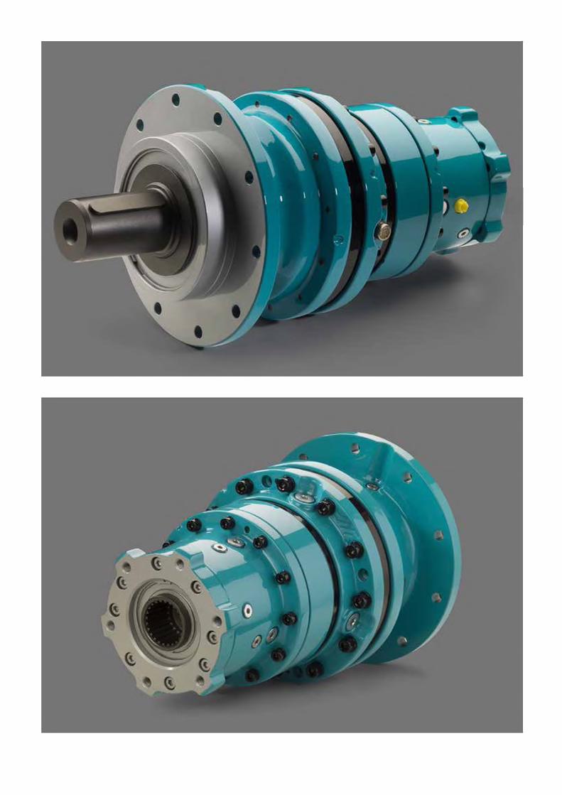
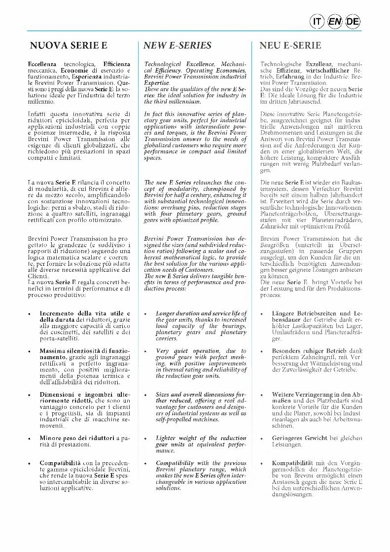
Eccellenza tecnologica, Efficienzameccanica, Economie di esercizio e funzionamento, Esperienza industria- le Brevini Power Transmission. Que- sti sono i pregi della nuova Serie E: la so- luzione ideale per l’industria del terzo millennio.
Infatti questa innovativa serie di riduttori epicicloidali, perfetta per applicazioni industriali con coppie e potenze intermedie, e la risposta Brevini Power Transmission alle esigenze di clienti globalizzati, che richiedono piu prestazioni in spazi compatti e limitati.
La nuova Serie E rilancia il concetto di modularity, di cui Brevini e alfie- re da mezzo secolo, amplificandolo con sostanziose innovazioni tecno- logiche: perni a sbalzo, stadi di ridu- zione a quattro satelliti, ingranaggi rettificati con profilo ottimizzato.
Brevini Power Transmission ha pro- gettato le grandezze (e suddiviso i rapporti di riduzione) seguendo una logica matematica scalare e coeren- te, per fornire la soluzione piu adatta alle diverse necessity applicative dei Clienti.La nuova Serie E regala concreti be- nefici in termini di performance e di processo produttivo:
• Incremento della vita utile e della durata dei riduttori, grazie alla maggiore capacity di carico dei cuscinetti, dei satelliti e dei porta-satelliti.
• Massima silenziosita di funzio- namento, grazie agli ingranaggi rettificati a perfetto ingrana- mento, con positivi migliora- menti della potenza termica e dell’affidability dei riduttori.
• Dimensioni e ingombri ulte- riormente ridotti, che sono un vantaggio concreto per i clienti e i progettisti, sia di impianti industriali che di macchine se- moventi.
• Minore peso dei riduttori a parity di prestazioni.
• Compatibility con la preceden- te gamma epicicloidale Brevini, che rende la nuova Serie E spes- so intercambiabile in diverse so- luzioni applicative.
NEW E-SERIES
Technological Excellence, Mechanical Efficiency, Operating Economies, Brevini Power Transmission industrial Expertise.These are the qualities of the new E Series: the ideal solution for industry in the third millennium.
In fact this innovative series of planetary gear units, perfect for industrial applications with intermediate powers and torques, is the Brevini Power Transmission answer to the needs of globalized customers who require more performance in compact and limited spaces.
The new E Series relaunches the concept of modularity, championed by Brevini for half a century, enhancing it with substantial technological innovations: overhung pins, reduction stages with four planetary gears, ground gears with optimized profile.
Brevini Power Transmission has designed the sizes (and subdivided reduction ratios) following a scalar and coherent mathematical logic, to provide the best solution for the various application needs of Customers.The new E Series delivers tangible benefits in terms of performance and production process:
• Longer duration and service life of the gear units, thanks to increased load capacity of the bearings, planetary gears and planetary carriers.
• Very quiet operation, due to ground gears with perfect meshing, with positive improvements in thermal rating and reliability of the reduction gear units.
• Sizes and overall dimensions fu rther reduced, offering a real advantage for customers and designers of industrial systems as well as self-propelled machines.
• Lighter weight of the reduction gear units at equivalent performance.
• Compatibility with the previous Brevini planetary range, which makes the new ESeries often interchangeable in various application solutions.
NEU E-SERIE
Technologische Exzellenz, mechani- sche Effizienz, wirtschaftlicher Be- trieb, Erfahrung in der Industrie: Bre- vini Power Transmission.Das sind die Vorzuge der neuen Serie E : Die ideale Losung fur die Industrie im dritten Jahrtausend.
Diese innovative Serie Planetengetrie- be, ausgezeichnet geeignet fur indus- trielle Anwendungen mit mittleren Drehmomenten und Leistungen ist die Antwort von Brevini Power Transmission auf die Anforderungen der Kun- den in einer globalisierten Welt, die hohere Leistung, kompaktere Ausfuh- rungen mit wenig Platzbedarf verlan- gen.
Die neue Serie E ist wieder ein Baukas- tensystem, dessen Verfechter Brevini bereits seit einem halben Jahrhundert ist. Erweitert wird die Serie durch we- sentliche technologische Innovationen: Planetentragerbolzen, Ubersetzungs- stufen mit vier Planetenradradern, Zahnrader mit optimiertem Profil.
Brevini Power Transmission hat die BaugroBen (unterteilt in Uberset- zungsstufen) in passende Gruppen ausgelegt, um den Kunden fur die un- terschiedlich benotigten Anwendun- gen besser geignete Losungen anbieten zu konnen.Die neue Serie E bringt Vorteile bei der Leistung und fur den Produktions- prozess:
• Langere Betriebszeiten und Le- bensdauer der Getriebe dank er- hohter Lastkapazitaten bei Lager, Umlaufradern und Planeteradtra- ger.
• Besonders ruhiger Betrieb dank perfektem Zahneingriff, mit Ver- besserung der Warmeleistung und der Zuverlassigkeit der Getriebe.
• Weitere Verringerung in den Ab- mafien und des Platzbedarfs sind konkrete Vorteile fur die Kunden und die Planer, sowohl bei Indust- rieanlagen als auch bei Arbeitsma- schinen.
• Geringeres Gewicht bei gleichen Leistungen.
• Kompatibilitat mit den Vorgan- ermodellen der Planetengetrie- e von Brevini ermoglicht einen
Austausch gegen die neue Serie E bei den unterschiedlichen Anwen- dungslosungen.
• Integrazione con la Serie S Brevi- ni per applicazioni “heavy duty” e cicli di lavoro gravosi.
• Tempi di consegna veloci, grazie a razionali processi manifatturieri e di logistica industriale.
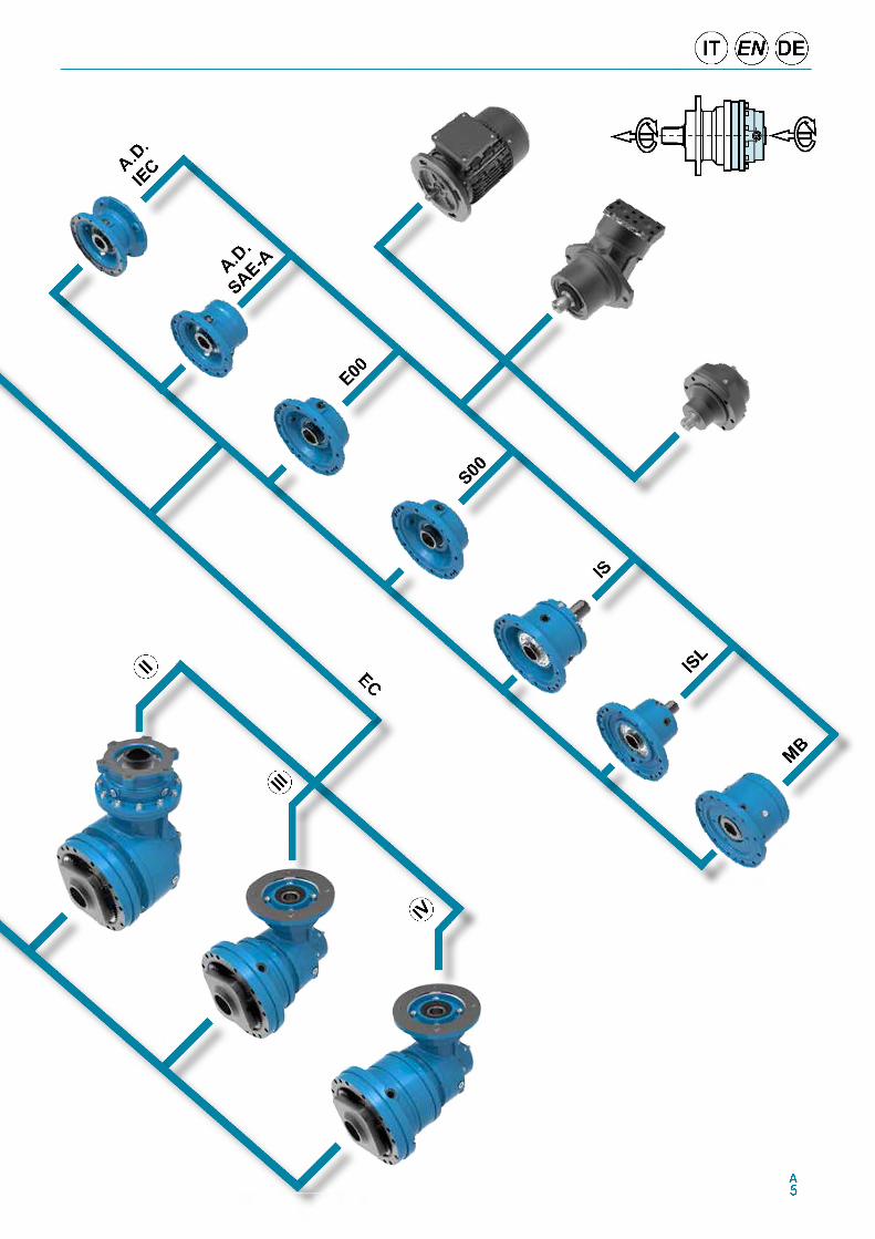
In dettaglio, la Serie E e articolata su 9 grandezze armonicamente scalari, con una coppia che si sviluppa da 1'200 Nm a 26'000 Nm.
Disponibile sia in esecuzione in linea che in esecuzione ortogonale, offre a catalogo fino a 4 stadi di riduzione (su richiesta del cliente puo salire fino a 6 stadi). I rapporti di riduzione coprono un orizzonte molto ampio, da 1:3 fino a 1:3'000 ed oltre.
La flessibile e modulare struttura del riduttore si abbina a numerose versioni in uscita: flangiato ad albero femmina, con femmina pendolare, flangiato ad albero maschio, supporto con piedi.
La nuova Serie E offre le versatili confi- gurazioni in ingresso con albero veloce ed e predisposta per motori elettrici e oleodinamici. Ci sono ampie disponi- bilita di freni, per le piu svariate necessity applicative. Inoltre e dotata di una completa gamma di accessori, sia in ingresso che in uscita.
• Integration with the Brevini S Series for “heavy duty” applications and heavy work cycles.
• Prompt delivery times, thanks to rational manufacturing processes and industrial logistics.
In detail, the E Series comprises 9 harmonically developed sizes, with torque from 1 2 0 0 Nm to 26 000 Nm.
Available in in-line and right-angle execution, and up to 4 reduction stages (up to 6 stages on customer request). The reduction ratios cover a very wide range, from 1:3 to 1:3 000 and over.
The gear unit’s flexible and modular structure comes with many output versions: flanged shaft female, with hollow shaft mounting, flanged male shaft, support with feet.
The new E Series offers versatile input configurations with input shaft and is arranged for electric and hydraulic motors. Wide availability of brakes, for the most varied application needs. There is also a complete range of input and output accessories.
• Integrierung in die Serie S von Brevini fur „Heavy-Duty-Anwen- dungen“ und bei erschwerten Ar- beitszyklen.
• Kurze Lieferzeiten, dank rationel- ler Fertigungsprozesse und indust- rieller Logistik.
Im Detail, die Serie E besteht aus 9 aufeinander stufenweise abgestimmten GroBen, mit einem Drehmoment zwi- schen 1'200 Nm und 26'000 Nm.
Erhaltlich sowohl als In-Line-Ausfuh- rung als auch als Winkelgetriebe mit dem Katalog bis zu 4 angebotenen Ubersetzungsstufen (auf Kunden- wunsch bis zu 6 Stufen moglich). Die Ubersetzungsverhaltnisse decken ei- nen groBen Bereich ab, von 1:3 fino bis 1:3'000 und mehr.
Zum flexiblen und modularen Aufbau des Getriebes kommen noch zahlreiche Abtriebsausfuhrungen hinzu: Flansch- getriebe mit Hohlwelle, Aufsteckhohl- welle, Flanschgetriebe mit Vollwelle, FuBleisten montierte Getriebe.
Die neue Serie E bietet zahlreiche Kon- figurationen fur Ausfuhrungen mit antriebseitiger schnell laufender Welle und Vorrustung fur Elektro- und Hy- draulikmotoren. Angeboten wird ein breites Angebot an Bremsen, fur die unterschiedlichsten Anwendungsan- forderungen. Daruber hinaus bieten wir sowohl antriebs- als auch abtriebs- seitig ein weit gefachertes Angebot an Zubehor.
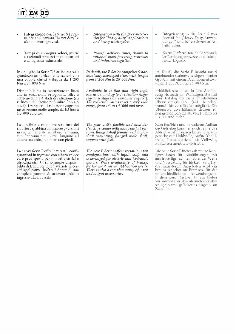
Energie rinnovabili / Green Energy / Erneuerbare Energie
Settore Minerario / Mining Quarrying / Bergbau Gewinnung Impianti Industriali / Industrial Equipment / Industrieanlagen
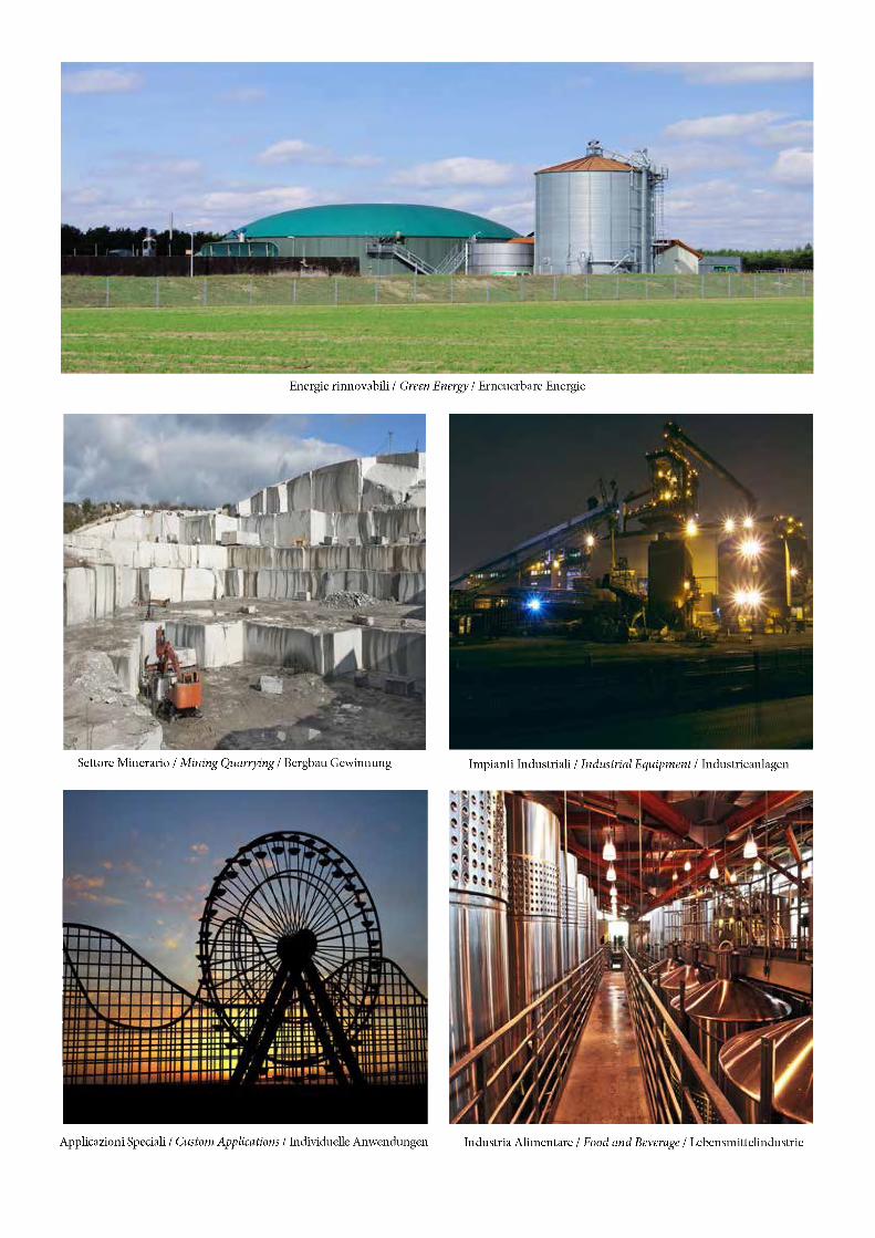
Applicazioni Speciali / Custom Applications / Individuelle Anwendungen Industria Alimentare / Food and Beverage / Lebensmittelindustrie
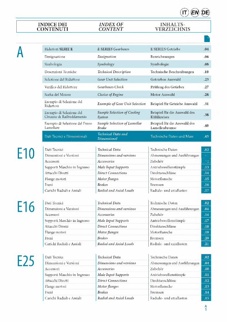
IN D ICE DEI IN D EX O F INH ALTS-CO N TEN U TI C O N TEN T VERZEICH N IS
ASimbologia Symbology Symbologie .08
Descrizioni Tecniche Technical Description Technische Beschreibungen .10
Selezione del Riduttore Gear Unit Selection Getrieben Auswahl .23
Verifica del Riduttore Gearboxes Check Prufung des Getiebes .27
Scelta del Motore Choice of Engine Motor Auswahl .28
Esempio di Selezione del Riduttore Example of Gear Unit Selection Beispiel fur Getriebe Auswahl .31
Esempio di Selezione del Circuito di Raffreddamento
Sample Selection of Cooling System
Beispiel fur die Auswahl des Kuhlkreises .38
Esempio di Selezione del Freno Lamellare
Sample Selection of Lamellar Brake
Beispiel fur die Auswahl des Lamellenbremse .40
Dati Tecnici e Dimensionali Technical Data and Dimensional Technische Daten und Mass .43
Riduttori SERIE E E SERIES Gearboxes E SERIES Getriebe .04
Designazione Designation Bezeichnungen .06
E10 Dati Tecnici Technical DataDimensioni e Versioni Dimensions and versionsAccessori AccessoriesSupporti Maschio in Ingresso Male Input SupportsAttacchi Diretti Direct ConnectionsFlange motori Motor flangesFreni BrakesCarichi Radiali e Assiali Radial and Axial Loads
Technische Daten .02Abmessungen und Ausfuhrungen
Zubehor
.04ITAntriebswellenstumpfe .13Direktanschlusse .14
Motorflansche .15
Bremsen .16Radiale- und axiallasten .17
Dati Tecnici Technical Data Technische Daten .02
Dimensioni e Versioni Dimensions and versions Abmessungen und Ausfuhrungen .04Accessori Accessories Zubehor .14
Supporti Maschio in Ingresso Male Input Supports Antriebswellenstumpfe .17
Attacchi Diretti Direct Connections Direktanschlusse .18Flange motori Motor flanges Motorflansche .19
Freni Brakes Bremsen .20Carichi Radiali e Assiali Radial and Axial Loads Radiale- und axiallasten .21
Dati Tecnici Technical Data Technische Daten .02
Dimensioni e Versioni Dimensions and versions Abmessungen und Ausfuhrungen .04Accessori Accessories Zubehor .10
Supporti Maschio in Ingresso Male Input Supports Antriebswellenstumpfe .11
Attacchi Diretti Direct Connections Direktanschlusse .12Flange motori Motor flanges Motorflansche .13
Freni Brakes Bremsen .14
Carichi Radiali e Assiali Radial and Axial Loads Radiale- und axiallasten .15
A1
® 0
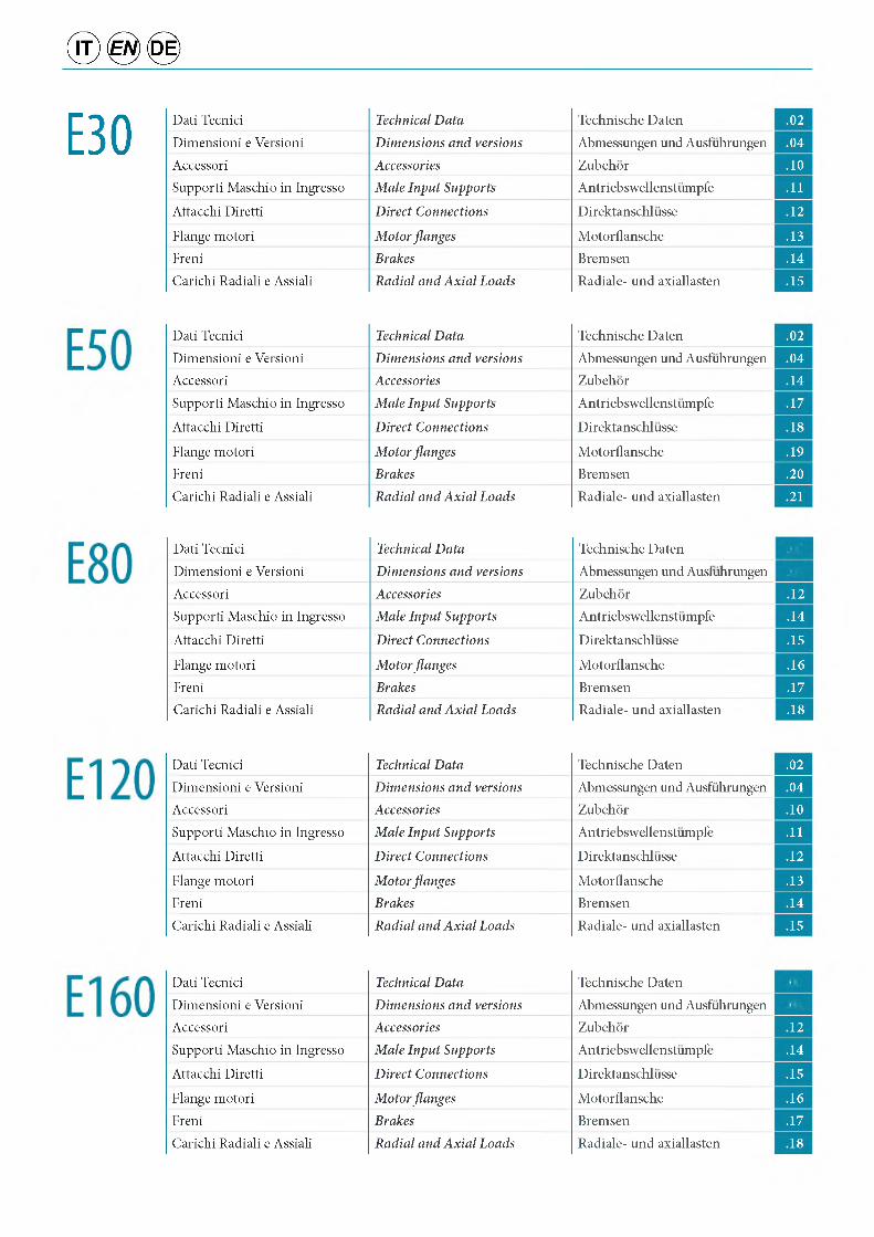
E30 Dati Tecnici Technical Data Technische Daten .02
Dimensioni e Versioni Dimensions and versions Abmessungen und Ausfuhrungen .04
Accessori Accessories Zubehor .10Supporti Maschio in Ingresso Male Input Supports Antriebswellenstumpfe .11
Attacchi Diretti Direct Connections Direktanschlusse .12
Flange motori Motor flanges Motorflansche .13Freni Brakes Bremsen .14
Carichi Radiali e Assiali Radial and Axial Loads Radiale- und axiallasten .15
Dati Tecnici Technical Data Technische Daten .02
Dimensioni e Versioni Dimensions and versions Abmessungen und Ausfuhrungen .04Accessori Accessories Zubehor .14
Supporti Maschio in Ingresso Male Input Supports Antriebswellenstumpfe .17
Attacchi Diretti Direct Connections Direktanschlusse .18
Flange motori Motor flanges Motorflansche .19Freni Brakes Bremsen .20
Carichi Radiali e Assiali Radial and Axial Loads Radiale- und axiallasten .21
Dati Tecnici Technical Data Technische Daten .02Dimensioni e Versioni Dimensions and versions Abmessungen und Ausfuhrungen .04Accessori Accessories Zubehor .12Supporti Maschio in Ingresso Male Input Supports Antriebswellenstumpfe .14
Attacchi Diretti Direct Connections Direktanschlusse .15
Flange motori Motor flanges Motorflansche .16
Freni Brakes Bremsen .17Carichi Radiali e Assiali Radial and Axial Loads Radiale- und axiallasten .18
Dati Tecnici Technical Data Technische Daten .02
Dimensioni e Versioni Dimensions and versions Abmessungen und Ausfuhrungen .04Accessori Accessories Zubehor .10
Supporti Maschio in Ingresso Male Input Supports Antriebswellenstumpfe .11
Attacchi Diretti Direct Connections Direktanschlusse .12
Flange motori Motor flanges Motorflansche .13Freni Brakes Bremsen .14
Carichi Radiali e Assiali Radial and Axial Loads Radiale- und axiallasten .15
Dati Tecnici Technical Data Technische Daten .02
Dimensioni e Versioni Dimensions and versions Abmessungen und Ausfuhrungen .04Accessori Accessories Zubehor .12
Supporti Maschio in Ingresso Male Input Supports Antriebswellenstumpfe .14
Attacchi Diretti Direct Connections Direktanschlusse .15
Flange motori Motor flanges Motorflansche .16
Freni Brakes Bremsen .17
Carichi Radiali e Assiali Radial and Axial Loads Radiale- und axiallasten .18
Dati Tecnici Technical Data Technische Daten .02Dimensioni e Versioni Dimensions and versions Abmessungen und Ausfuhrungen .04
Accessori Accessories Zubehor .10
Supporti Maschio in Ingresso Male Input Supports Antriebswellenstumpfe .11
Attacchi Diretti Direct Connections Direktanschlusse .12
Flange motori Motor flanges Motorflansche .13
Freni Brakes Bremsen .14Carichi Radiali e Assiali Radial and Axial Loads Radiale- und axiallasten .15
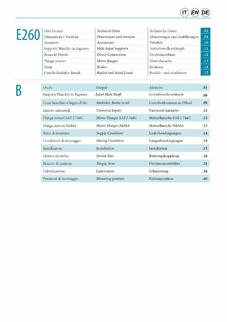
B Uscite Output Abtriebe .01
Supporti Maschio in Ingresso Input Male Shaft Antriebswellenstumpfe .08
Freni lamellari a bagno dolio Multidisc Brake in oil Lamellenbremsen in Olbad .09
Entrate universali Universal Inputs Universal Antriebe .11
Flange motori SAE J 744C Motor Flanges SAE J 744C Motorflansche SAE J 744C .12
Flange motori NEMA Motor Flanges NEMA Motorflansche NEMA .13
Stato di fornitura Supply Condition Lieferbendingungen .14
Condizioni di stoccaggio Storing Condition Langerbendingungen .14
Installazione Installation Installation .15
Giunto ad attrito Shrink Disc Reibungskupplung .18
Braccio di reazione Torque Arm Drehmomentstutze .21
Lubrificazione Lubrication Schmierung .24
Posizioni di montaggio Mounting position Einbauposition .40
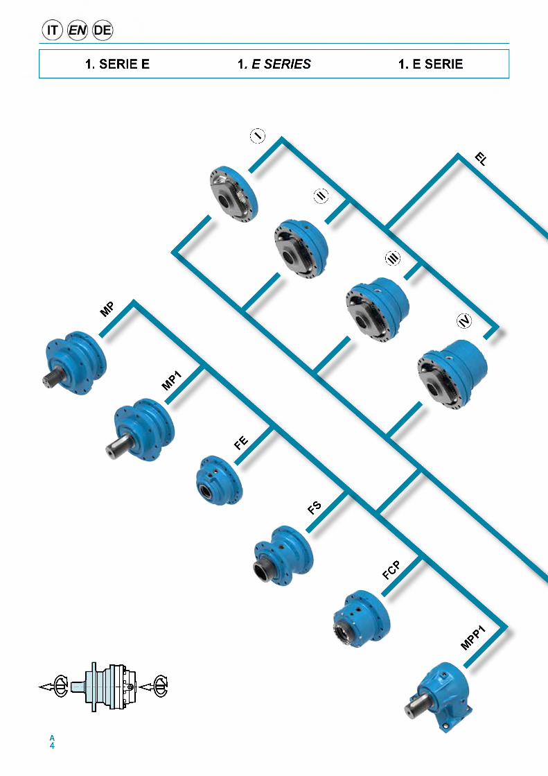
1. SERIE E 1. E SERIES 1.E SERIE
© ® ©
'VV* о
оT V
у
A5
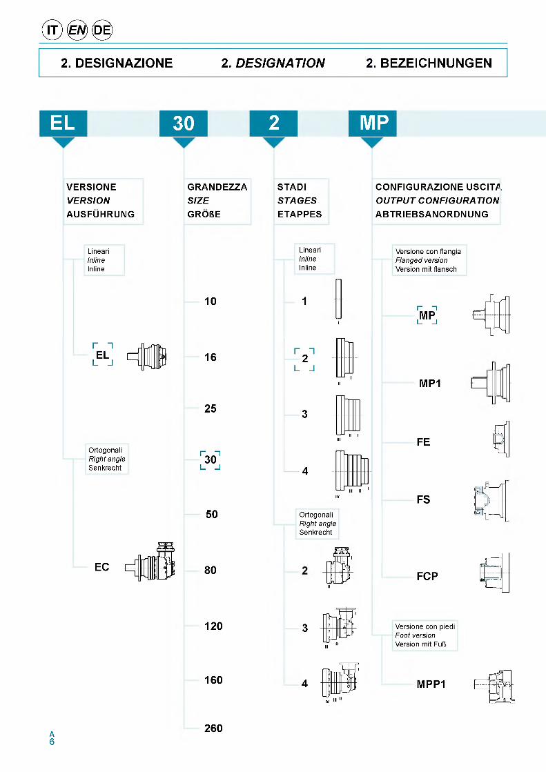
2. DESIGNAZIONE 2. DESIGNATION 2. BEZEICHNUNGEN
EL 30 2 MP
VERSIONEVERSIONAUSFUHRUNG
GRANDEZZASIZEGRORE
STADISTAGESETAPPES
CONFIGURAZIONE USCITA OUTPUT CONFIGURATION ABTRIEBSANORDNUNG
LineariInlineInline
LineariInlineInline
Versione con flangia Flanged version Version mit flansch
10
r “ IEL
L J 16
25
Ortogonali Right angle Senkrecht
Г H30
L _l
50
EC 80
1
I
Ortogonali Right angle Senkrecht
II
Г иMP
l_ _l
MP1
FE
FS
FCP
120 3III
Versione con piedi Foot version Version mit FuR
160 4IV III I
MPP1
A6
260
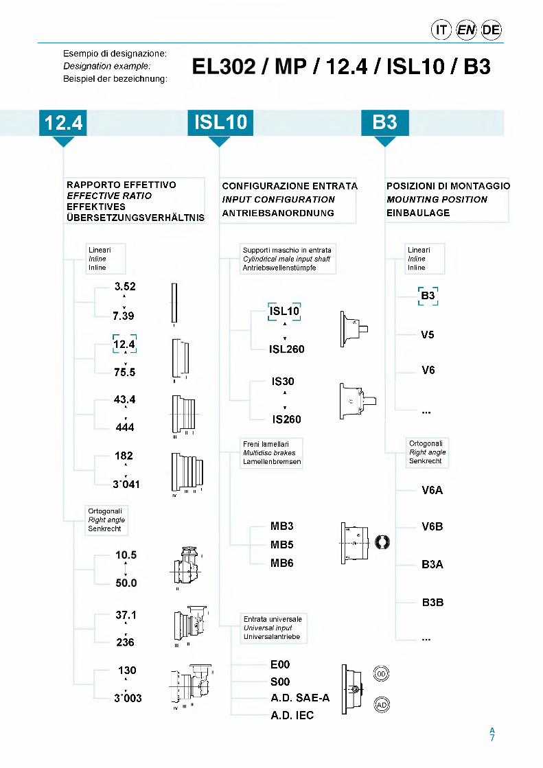
Esempio di designazione:
Designation exam ple: IP / 12.4 / ISL10 / B3Beispiel der bezeichnung:
12.4 ISL10
RAPPORTO EFFETTIVO EFFECTIVE RATIO EFFEKTIVESUBERSETZUNGSVERHALTNIS
CONFIGURAZIONE ENTRATA INPUT CONFIGURATION ANTRIEBSANORDNUNG
POSIZIONI DI MONTAGGIO MOUNTING POSITION EINBAULAGE
LineariInlineInline
Supporti maschio in entrata Cylindrical male input shaft Antriebswellenstumpfe
LineariInlineInline
3.52
I7.39
r n12.4
75.5
43.4I
444
182
I3041
I
II
ISL10i _ _ i
1ISL260
IS30
1IS260
Freni lamellari Multidisc brakes Lamellenbremsen
r_ HB3
L J
V5
V6
Ortogonali Right angle Senkrecht
V6A
Ortogonali Right angle Senkrecht
II
MB3
MB5
MB6
37.1
I236 III
Entrata universale Universal input Universalantriebe
V6B
B3A
B3B
130
I3 003
IIIIV
E00S00A.D. SAE-A
A.D. IECA7
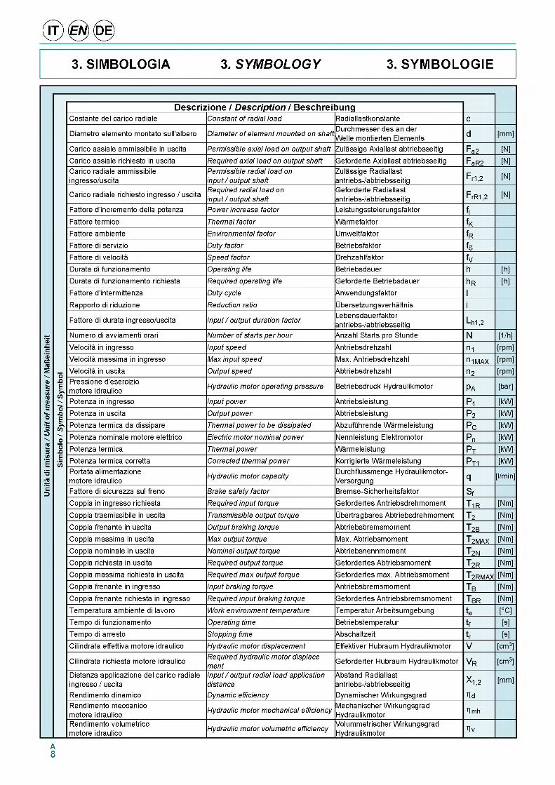
3. SIMBOLOGIA 3. SYMBOLOGY 3. SYMBOLOGIEU
nita
di m
isur
a /
Un
it o
f mea
sure
/ M
afte
inhe
it
Sim
bolo
/ S
ymbo
l / S
ymbo
l
Descrizione / Description / BeschreibungCostante del carico radiale Constant of radial load Radiallastkonstante c
Diametro elemento montato sull'albero Diameter of element mounted on shaftDurchmesser des an der Welle montierten Elements d [mm]
Carico assiale ammissibile in uscita Permissible axial load on output shaft Zulassige Axiallast abtriebsseitig Fa2 [N]Carico assiale richiesto in uscita Required axial load on output shaft Geforderte Axiallast abtriebsseitig FaR2 [N]Carico radiale ammissibile ingresso/uscita
Permissible radial load on input / output shaft
Zulassige Radiallast antriebs-/abtriebsseitig F r1,2 [N]
Carico radiale richiesto ingresso / uscitaRequired radial load on input / output shaft
Geforderte Radiallast antriebs-/abtriebsseitig F rR1,2 [N]
Fattore d'incremento della potenza Power increase factor Leistungssteierungsfaktor fIFattore termico Thermal factor Warmefaktor fKFattore ambiente Environmental factor Umweltfaktor fRFattore di servizio Duty factor Betriebsfaktor fSFattore di velocita Speed factor Drehzahlfaktor fVDurata di funzionamento Operating life Betriebsdauer h [h]Durata di funzionamento richiesta Required operating life Geforderte Betriebsdauer h R [h]Fattore d'intermittenza Duty cycle Anwendungsfaktor IRapporto di riduzione Reduction ratio Ubersetzungsverhaltnis i
Fattore di durata ingresso/uscita Input / output duration factorLebensdauerfaktorantriebs-/abtriebsseitig Lh1,2
Numero di avviamenti orari Number of starts per hour Anzahl Starts pro Stunde N [1/h]
Velocita in ingresso Input speed Antriebsdrehzahl n1 [rpm]
Velocita massima in ingresso Max input speed Max. Antriebsdrehzahl n 1MAX [rpm]Velocita in uscita Output speed Abtriebsdrehzahl n2 [rpm]Pressione d'esercizio motore idraulico Hydraulic motor operating pressure Betriebsdruck Hydraulikmotor pa [bar]
Potenza in ingresso Input power Antriebsleistung P1 [kW]
Potenza in uscita Output power Abtriebsleistung P2 [kW]
Potenza termica da dissipare Thermal power to be dissipated Abzufuhrende Warmeleistung Pc [kW]
Potenza nominale motore elettrico Electric motor nominal power Nennleistung Elektromotor Pn [kW]
Potenza termica Thermal power Warmeleistung Pt [kW]
Potenza termica corretta Corrected thermal power Korrigierte Warmeleistung PT1 [kW]Portata alimentazione motore idraulico
Hydraulic motor capacity Durchflussmenge Hydraulikmotor- Versorgung q [l/min]
Fattore di sicurezza sul freno Brake safety factor Bremse-Sicherheitsfaktor SfCoppia in ingresso richiesta Required input torque Gefordertes Antriebsdrehmoment T 1R [Nm]
Coppia trasmissibile in uscita Transmissible output torque Ubertragbares Abtriebsdrehmoment T2 [Nm]
Coppia frenante in uscita Output braking torque Abtriebsbremsmoment T 2B [Nm]
Coppia massima in uscita Max output torque Max. Abtriebsmoment T 2MAX [Nm]
Coppia nominale in uscita Nominal output torque Abtriebsnennmoment T 2N [Nm]
Coppia richiesta in uscita Required output torque Gefordertes Abtriebsmoment T 2R [Nm]
Coppia massima richiesta in uscita Required max output torque Gefordertes max. Abtriebsmoment T 2RMAX [Nm]
Coppia frenante in ingresso Input braking torque Antriebsbremsmoment Tb [Nm]
Coppia frenante richiesta in ingresso Required input braking torque Gefordertes Antriebsbremsmoment T BR [Nm]
Temperatura ambiente di lavoro Work environment temperature Temperatur Arbeitsumgebung ta [°C]
Tempo di funzionamento Operating time Betriebstemperatur tf [s]Tempo di arresto Stopping time Abschaltzeit tr [s]Cilindrata effettiva motore idraulico Hydraulic motor displacement Effektiver Hubraum Hydraulikmotor V [cm3]
Cilindrata richiesta motore idraulico Required hydraulic motor displace ment
Geforderter Hubraum Hydraulikmotor Vr [cm3]
Distanza applicazione del carico radiale ingresso / uscita
Input / output radial load application distance
Abstand Radiallast antriebs-/abtriebsseitig X 1,2 [mm]
Rendimento dinamico Dynamic efficiency Dynamischer Wirkungsgrad hdRendimento meccanico motore idraulico Hydraulic motor mechanical efficiency
Mechanischer Wirkungsgrad Hydraulikmotor hmh
Rendimento volumetrico motore idraulico Hydraulic motor volumetric efficiency
Volummetrischer Wirkungsgrad Hydraulikmotor hv
A8
© ® ©
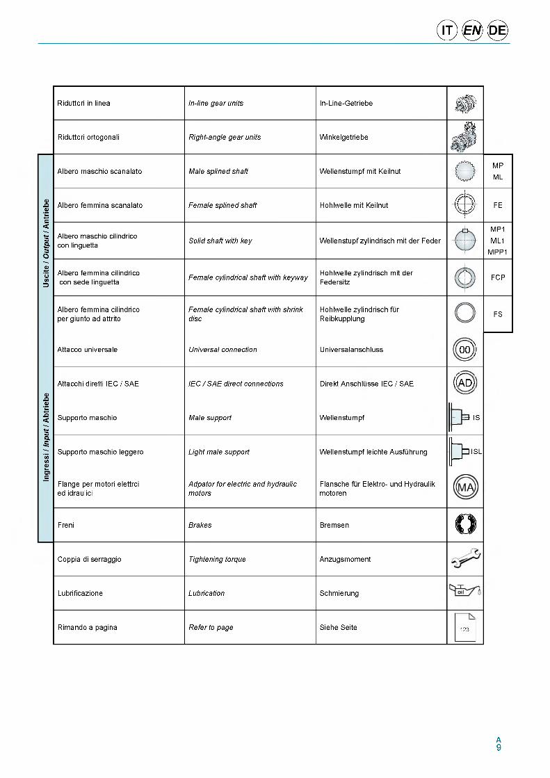
Riduttori in linea In-line gear units In-Line-GetriebeФ
Riduttori ortogonali Right-angle gear units Winkelgetriebel8§
Ф
Usc
ite /
Out
put /
Ant
riebe
Albero maschio scanalato Male splined shaft Wellenstumpf mit Keilnut£ 3
MP
ML
Albero femmina scanalato Female splined shaft Hohlwelle mit Keilnut< 5
FE
Albero maschio cilindrico con linguetta Solid shaft with key Wellenstupf zylindrisch mit der Feder
MP1
ML1MPP1
Albero femmina cilindrico con sede linguetta
Female cylindrical shaft with keyway Hohlwelle zylindrisch mit der Federsitz
FCP
Albero femmina cilindrico per giunto ad attrito
Female cylindrical shaft with shrink disc
Hohlwelle zylindrisch fur Reibkupplung FS
Ingr
essi
/ In
put
/ A
btrie
be
Attacco universale Universal connection Universalanschluss o o j
Attacchi diretti IEC / SAE IEC / SAE direct connections Direkt Anschlusse IEC / SAE ( S d )
Supporto maschio Male support Wellenstumpf 3 IS
Supporto maschio leggero Light male support Wellenstumpf leichte Ausfuhrungf }
Э ISL
Flange per motori elettrci ed idraulici
Adpator for electric and hydraulic motors
Flansche fur Elektro- und Hydraulik motoren
Freni Brakes BremsenO
Coppia di serraggio Tightening torque Anzugsmoment
Lubrificazione Lubrication Schmierung
Rimando a pagina Refer to page Siehe Seite 123
A9
® 0 <0 >4. DESCRIZIONI
TECNICHE4. TECHNICAL
DESCRIPTION4. TECHNISCHE
BESCHREIBUNGEN
Coppia nominale in uscitaT2N [Nm]Rappresenta la coppia in uscita conven- zionale che identifica la grandezza del riduttore.
Coppia trasmissibile in uscitaT2 [Nm]Rappresenta la coppia trasmissibile in uscita dal riduttore con carico continuo e uniforme (fattore di servizio fs=1), per diversi valori del fattore di durata n2xh.
I valori di T2 sono calcolati secondo gli standard ISO 6336 per gli ingranaggi e ISO 281 per i cuscinetti e sono riportati nelle tabelle di selezione delle grandez- ze.
Coppia massima in uscitaT2MAX [Nm]Rappresenta la coppia massima trasmis- sibile in uscita dal riduttore come valore di punta o per brevi durate. Per aziona- menti che comportano un elevato nume- ro di avviamenti o inversioni, anche la coppia massima di impiego deve essere opportunamente limitata in relazione alla resistenza degli ingranaggi o degli alberi.I valori di T2MAX sono riportati nelle tabel- le di selezione delle grandezze.
Coppia richiesta in uscitaT2R [Nm]Rappresenta la coppia richiesta in uscita dall'applicazione e dovra essere sempre inferiore alla coppia trasmissibile T2 in uscita del riduttore selezionato.
Coppia massima richiesta in uscitaT2RMAX [Nm]Rappresenta la coppia in uscita massima richiesta dall'applicazione e dovra essere sempre inferiore alla coppia massima in uscita trasmissibile T2MAX del riduttore selezionato.
Coppia frenante in ingressoTB [Nm]Rappresenta la coppia frenante statica erogata dal freno lamellare che puo essere installato in ingresso al riduttore.I valori di TB sono riportati, per le varie configurazioni di freno, al capitolo “Freni lamellari a bagno d'olio”.
Nominale output torqueT2N [N m ]
The conventional output torque that identifies the size of the gear unit.
Transmissible output torqueT2 [N m ]The transmissible gear unit output torque with uniform and continuous load (duty factor fs=1), for different values of the duration factor n2xh.
The T2 values are calculated according to ISO 6336 standards for the gears and ISO 281 for the bearings, and are given in the size selection tables.
Max output torqueT2MAX [N m ]The transmissible gear unit output torque as the peak value or for short periods. For drives involving a high number of starts or reversals, also the max. operational torque must be opportunely limited according to the fatigue resistance of the gears or shafts.The T2MAX values are given in the size selection tables.
Required output torqueT2R [N m ]The output torque required by the application; it must always be less than the transmissible output torque T2 of the selected gear unit.
Required max. output torqueT2RMAX [N m ]
The maximum output torque required by the application; it must always be less than the maximum transmissible output torque T2MAX of the selected gear unit.
Input braking torqueTb [N m ]The static braking torque delivered by the multi-disc brake that can be installed on the gear unit input.The TB values, for the various brake configurations, are given in the section “Oil bath multi-disc brakes”.
AbtriebsnennmomentT2N [Nm]Ist das konventionelle Abtriebsmomentals Kennezichnung der GroUe.
Ubertragbares AbtriebsdrehmomentT2 [Nm]Ist das Qbertragbare Abtriebsdrehmoment bei kontinuierlicher und uniformer Last (Betriebsfaktor fs=1), bei verschie- denen Werten des Lebensdauerfaktors n2xh.Die Werte T2 werden nach dem Standards ISO 6336 fQr Getriebe und ISO 281 fQr Lager berechnet. Sie sind in der Tabelle fQr die GroUenauswahl angege- ben.
Max. AbtriebsmomentT2MAX [Nm]Ist das maximal Qbertragbare Abtriebsmoment des Getriebesals Spitze und kurzzeitig. Bei Antrieben mit einer hohen Anzahl von Starts oder Umsteuerungen muss auch das maximale Betriebsdreh- moment entsprechend der ErmQdungs- bestandigkeit der Zahnrader oder Wellen begrenzt werden.Die Werte fQr T2MAX sind in der Tabelle fQr die Auswahl der GroUe aufgefQhrt.
Gefordertes AbtriebsmomentT2R [Nm]Ist das erforderliche Abtriebsmoment fQr die Anwendung. Muss immer unter dem Qbertragbaren Abtriebsmoment T2 des ausgewahlten Getriebes liegen.
Gefordertes max. AbtriebsmomentT2RMAX [Nm]
Ist das erforderliche maximale Abtriebsmoment fQr die Anwendung.Muss immer unter dem Qbertragbaren max. Abtriebsmoment T2MAX des ausgewahlten Getrie- bes liegen.
AntriebsbremsmomentTB [Nm]Ist das statische Bremsmoment der La- mellenbremse, die antriebsseitig am Getriebe eingebaut werden kann.Die Werte fQr TB sind fQr die unterschied- lichen Breimskonfigurationen unter dem Abschnitt „Olbad-Lamellenbremsen" an- gegeben.
A10
Coppia frenante richiesta in ingressoTbr [Nm]Rappresenta la coppia frenante richiesta in ingresso al riduttore qualora l'appli- cazione preveda I'utilizzo di un freno in ingresso.E' calcolabile con la seguente relazione:
in cui
• Sf rappresenta un fattore di sicu-rezza sul freno
• T2R la coppia richiesta in uscita• i il rapporto di riduzione
Il fattore di sicurezza sul freno Sf dipen- de dal tipo di applicazione e deve essere indicato dal Cliente: talvolta il suo valore minimo e indicato da regolamenti specifi- ci rilevanti per l'applicazione.
Velocita in ingressoni [rpm]
Rappresenta la velocita del motore col- legato al riduttore o, in generale, la velocita dell'organo in ingresso al riduttore: nel caso di azionamenti con pulegge e cinghie, ad esempio, il valore deve tener conto del relativo rapporto di riduzione.
Velocita massima in ingresson1MAX [rpm]
Rappresenta la velocita massima in in- gresso al riduttore per brevi periodi oppu- re in condizioni di servizio intermittente. E' consentita la permanenza alla velocita n1MAX per un tempo massimo di 1 minuto seguito da un periodo di raffreddamento del riduttore. Nel caso in cui siano pre- visti periodi di permanenza piu lunghi a tale velocita, si consiglia di contattare il Servizio Tecnico Commerciale Brevini.I valori di n1MAX sono riportati nelle tabel- le di selezione.
Velocita in uscitan2 [rpm]
Rappresenta la velocita in uscita al riduttore. E' calcolabile con la seguente formula:
in cui n1 rappresenta la velocita in ingresso e i il rapporto di riduzione del riduttore.
Required input braking torquetbr [N m ]
The required gear unit input braking torque if the application involves the use of an input brake.It can be calculated with the following equation:
T br =Sf x T2R
i[Nm]
where
• Sf a brake safety factor
• T2R the required output torque• i the reduction ratio
The brake safety factor Sf depends on the type of application and must be specified by the Customer: sometimes its minimum value is indicated by the specific regulations relevant to the application.
Input speedn i [rpm ]The speed of the motor connected to the gear unit or, in general, the speed of the gear unit input part: in case of drives with pulleys and belts, for example, the value must take into account the relevant reduction ratio.
Max input speedn 1MAX [rpm ]The maximum gear unit input speed for short periods or in conditions of intermittent duty. Staying at the speed n1MAX for a maximum time of 1 minute followed by a gear unit cooling period is allowed. If longer periods at that speed are foreseen, it is advisable to contact the Brevini Sales Dept.
The n1MAX values are given in the selection tables.
Output speedn2 [rpm ]The gear unit output speed. It can be calculated with the following formula:
[rpm]
where n1 is the input speed and i the gear unit reduction ratio.
GefordertesAntriebsbremsmomentT br [Nm]1st das geforderte Antriebsbremsmoment fur das Getriebe, wenn die Anwendung den Einsatz einer Antriebsbremse for- dert.Kann mit folgender Formel berechnet werden:
(1)
Dabei ist
• Sf Sicherheitsfaktor der Bremse
• T2R Gefordertes Abtriebsmoment• i Ubersetzungsverhaltnis
Der Sicherheitsfaktor der Bremse Sf ist abhangig von der Anwendung und ist vom Kunden anzugeben: Manchmal wird der Mindestwert in spezifischen Vor- schriften der Anwendung angegeben.
Antriebsdrehzahln1 [rpm]Ist die Drehzahl des an das Getriebe an- geschlossenen Motors oder allgemein, Drehzahl des antriebsseitigen Organs: Bei Antrieben mit Scheiben oder Riemen zum Beispiel muss der Wert die entspre- chende Ubersetzung berucksichtigen.
Max. Antriebsdrehzahln1MAX [rpm]
Ist die maximale Antriebsdrehzahl des Getriebes fQr kurze Zeitraume oder bei Aussetzbetrieb. Erlaubt ist die Laufzeit mit der Drehzahl n1MAX fQr maximal 1 Minute mit nachfolgender AbkQhlzeit des Getriebes. Sollten langere Laufzeiten mit dieser Drehzahl vorgesehen sein, raten wir, Kontakt mit dem Technischen Ver- triebsinnendienst von Brevini aufzuneh- men.Die Werte fQr n1MAX sind in der Auswahl- tabelle aufgefuhrt.
Abtriebsdrehzahln2 [rpm]
Ist die Abtriebsdrehzahl am Getriebe. Kann mit folgender Formel berechnet werden:
(2)
dabei ist n1 die Antriebsdrehzahl und i das Ubersetzungsverhaltnis des Getrie- bes.
A11
Rapporto di riduzionei
Rappresenta la relazione fra la velocita in ingresso n-i ed uscita n2.
Potenza in ingressoP1 [kW]
Rappresenta la potenza applicata all'in- gresso del riduttore. E' calcolabile con la seguente formula:
in cui• P2 rappresenta la potenza in uscita• hd rappresenta il rendimento dinami-
co del riduttore, il cui valore e ripor- tato nella tabella (4)
Potenza in uscitaP2 [kW
Rappresenta la potenza trasmessa all'u- scita del riduttore. E' calcolabile con la seguente formula:
in cui T2R rappresenta la coppia richiesta in uscita e n2 la velocita in uscita.
Potenza termicaPT [kW]
Rappresenta la potenza che il riduttore puo trasmettere in modo continuativo nelle seguenti condizioni:
• con lubrificazione a sbattimento e in as- senza di un circuito ausiliario di raffred- damento
• con montaggio in posizione orizzontale• ad una velocita di ingresso di 1500 rpm• per una temperatura massima dell'olio
di 80 °C (olio con viscosita ISO VG150)• ad una temperatura ambiente di 20 °C• nella condizione di impiego “ambiente
grande”
I valori di PT sono riportati nelle tabelle di selezione delle varie grandezze.
Qualora il tipo di funzionamento, la posizione di montaggio, la velocita in in- gresso, la temperatura ambiente oppure l'ambiente di impiego siano diversi da quelli sopra indicati, e opportuno correg- gere il valore della potenza termica attra- verso i fattori fK, fV e fR di seguito indicati.
Reduction ratioi
The ratio between the input speed n1 and output speed n2.
n .П2
Input powerP1 [kW ]The power applied at the input of the gear unit. It can be calculated with the following formula:
P _ P21 =
hd[kW]
where• P2 is the output power• h d is the dynamic efficiency of the
gear unit, whose value is given in the table (4)
Output powerP2 [kW ]The power transmitted at the output of the gear unit. It can be calculated with the following formula:
T2R x n2P2 “
2 9 550[kW]
where T2R is the required output torque and n2 the output speed.
Thermal powerP T [kW ]The power that the gear unit can transmit continuously in the following conditions:
• with splash lubrication and in the absence of an auxiliary cooling circuit
• with mounting in a horizontal position• at an input speed of 1500 rpm• for a max. oil temperature of 80 °C
(oil with viscosity ISO VG150)• at an ambient temperature of 20 °C• in the “large environment” condition of
use
The PT values are given in the tables forselection of the various sizes.
If the type of operation, the mounting position, the input speed, the ambient temperature or the operating environment are different from those indicated above, it is advisable to correct the thermal power value through the factors fK fV and fR indicated below.
Ubersetzungsverhaltnisi
Stellt das Verhaltnis zwischen Antriebs- drehzahl n1 und Abtriebsdrehzahl n2 dar.
(3)
AntriebsleistungP1 [kW]
Ist die angelegte Leistung antriebsseitig vom Getriebe. Kann mit folgender Formel berechnet werden:
(4)
Dabei ist• P2 die Abtriebsleistung• hd ist der dynamische Wirkungsgrad
des Getriebes, dessen Wert in der Tabelle (4) angegeben ist
AbtriebsleistungP2 [kW]
Ist die abtriebsseitig vom Getriebe Qber- tragene Leistung. Kann mit folgender Formel berechnet werden:
(5)
dabei ist T2R das geforderter Abtriebs- nennmoment und n2 die Abtriebsdreh- zahl.
WarmeleistungPT [kW]
Ist die Leistung, die vom Getriebe konti- nuierlich unter folgenden Bedingungen Qbertragen werden kann:
• mit Tauchschmierung und ohne zusatzliche KQhlkreis
• waagerecht montiert• Antriebsdrehzahl 1500 rpm• Hochsttemperatur des Ols 80 °C
(Viskositat des Ols ISO VG150)• Umgebungstemperatur von 20 °C• Einsatzbedingug „groUe Halle”
Die Werte fQr PT sind in der Tabelle fQr die Auswahl bei den verschiedenen GroUen aufgefQhrt.
Sind der Betriebstyp, die Einbauposition, die Antriebsdrehzahl, die Umgebungs- temperatur oder die Einsatz Umgebung anders als oben angegeben, sollten die Werte fQr die Warmeleistung mittels der Faktoren fK, fV und fR, die nachstehend angegeben sind, korrigiert werden.
A12
© ® ©
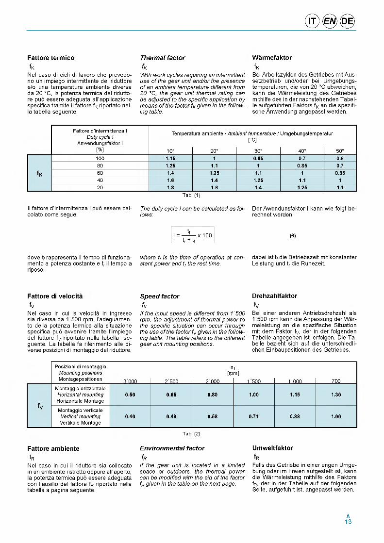
Fattore termicofK
Nel caso di cicli di lavoro che prevedo- no un impiego intermittente del riduttore e/o una temperatura ambiente diversa da 20 °C, la potenza termica del riduttore puo essere adeguata all'applicazione specifica tramite il fattore fK riportato nel- la tabella seguente.
Thermal factorfK
With work cycles requiring an intermittent use of the gear unit and/or the presence of an ambient temperature different from 20 °C, the gear unit thermal rating can be adjusted to the specific application by means of the factor fK given in the following table.
Warmefaktorf K
Bei Arbeitszyklen des Getriebes mit Aus- setzbetrieb und/oder bei Umgebungs- temperaturen, die von 20 °C abweichen, kann die Warmeleistung des Getriebes mithilfe des in der nachstehenden Tabel- le aufgefQhrten Faktors fK an die spezifi- sche Anwendung angepasst werden.
Fattore d’intermittenza I Duty cycle I
Anwendungsfaktor I [%]
Tempera
10°
ura ambiente / Am
20°
bient temperature / [°C]
30°
Umgebungstemper
40°
atur
50°100 1.15 1 0.85 0.7 0.680 1.25 1.1 1 0.85 0.7
fK 60 1.4 1.25 1.1 1 0.8540 1.6 1.4 1.25 1.1 120 1.8 1.6 1.4 1.25 1.1
Tab. (1)
Il fattore d'intermittenza I puo essere cal- colato come segue:
dove tf rappresenta il tempo di funziona- mento a potenza costante e tr il tempo a riposo.
Fattore di velocitafV
Nel caso in cui la velocita in ingresso sia diversa da 1'500 rpm, l’adeguamen- to della potenza termica alla situazione specifica puo avvenire tramite l'impiego del fattore fV riportato nella tabella seguente. La tabella fa riferimento alle diverse posizioni di montaggio del riduttore.
The duty cycle I can be calculated as follows:
tfI = — — x 100 ___tr + tf
where tf is the time of operation at constant power and tr the rest time.
Speed factorfV
If the input speed is different from 1500 rpm, the adjustment of thermal power to the specific situation can occur through the use of the factor fV given in the following table. The table refers to the different gear unit mounting positions.
Der Awendunsfaktor I kann wie folgt be- rechnet werden:
(6)
dabei ist tf die Betriebszeit mit konstanter Leistung und tr die Ruhezeit.
DrehzahlfaktorfV
Bei einer anderen Antriebsdrehzahl als 1500 rpm kann die Anpassung der Warmeleistung an die spezifische Situation mit dem Faktor fV, der in der folgenden Tabelle angegeben ist, erfolgen. Die Ta- belle bezieht sich auf die unterschiedli- chen Einbaupositionen des Getriebes.
Posizioni di montaggio Mounting positions Montagepositionen 3'000 2'500
n[rp
2'000
1m]
1 '500 1'000 700
fV
Montaggio orizzontale Horizontal mounting Horizontale Montage
0.50 0.65 0.80 1.00 1.15 1.30
Montaggio verticale Vertical mounting Vertikale Montage
0.40 0.48 0.58 0.71 0.88 1.00
Fattore ambientefR
Nel caso in cui il riduttore sia collocato in un ambiente ristretto oppure all'aperto, la potenza termica puo essere adeguata con l'ausilio del fattore fR riportato nella tabella a pagina seguente.
Tab. (2)
Environmental factorfR
If the gear unit is located in a limited space or outdoors, the thermal power can be modified with the aid of the factor fR given in the table on the next page.
UmweltfaktorfRFalls das Getriebe in einer engen Umge- bung oder im Freien aufgestellt ist, kann die Warmeleistung mithilfe des Faktors fR, der in der Tabelle auf der folgenden Seite, aufgefQhrt ist, angepasst werden.
A13
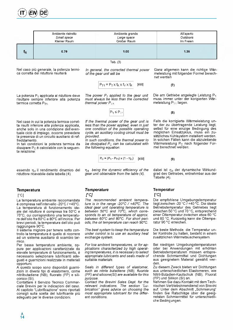
Ambiente ristretto Ambiente grande All'apertoSmall space Large space Outdoors
Kleiner Raum Grower Raum Im Freien
f R 0.70 1.00 1.35
Tab. (3)
Nel caso piii generale, la potenza termi- ca corretta del riduttore risultera
La potenza P-i applicata al riduttore deve risultare sempre inferiore alla potenza termica corretta PT1.
Nel caso in cui la potenza termica corretta risulti inferiore alla potenza applicata, anche solo in una condizione dell'even- tuale ciclo di impiego, occorre prevedere la presenza di un circuito ausiliario di raf- freddamento.In tali condizioni la potenza termica da dissipare PC e calcolabile con la seguen- te relazione:
In general, the corrected thermal power Ganz allgemein kann die richtige War- of the gear unit will be meleistung mit folgender Formel berech-
net werden
PT1 - PT x fK x fV x fR [kW] (7)
The power P1 applied to the gear unit must always be less than the corrected thermal power PT1.
P1 ^ PT1
If the thermal power of the gear unit is less than the power applied, even in just one condition of the possible operating cycle, an auxiliary cooling circuit must be provided.In such conditions, the thermal power to be dissipated PC can be calculated with the following equation:
Die am Getriebe angelegte Leistung P1 muss immer unter der korigierten War- meleistung PT- liegen.
(8)
Falls die korrigierte Warmeleistung unter der zu libertragende Leistung liegt, selbst flir eine einzige Bedingung des moglichen Einsatzyklus, muss ein zu- satzliches Klihlsystem installiert werden. In solchen Fallen kann die abzuleitende Warmeleistung PC nach folgender Formel berechnet werden:
pc - (P1 - PT1) x (1 - hd ) [kW] (9)
essendo h d il rendimento dinamico del riduttore ricavabile dalla tabella (4).
h d being the dynamic efficiency of the gear unit obtainable from the table (4).
dabei ist h d der dynamische Wirkund- grad des Getriebes, entnehmbar aus der Tabelle (4).
Temperature[°C]
La temperatura ambiente raccomandata e compresa nell'intervallo -20°C / +40°C. La temperatura di funzionamento ide- ale del riduttore e compresa tra 50°C e 70°C, cui corrispondono una temperatura dell'olio fra 60°C e 80°C all'incirca. Per brevi periodi, la temperatura dell'olio puo raggiungere 90°C.Il sistema migliore per tenere sotto con- trollo la temperatura e quello di ricorrere ad un sistema ausiliario di scambio ter- mico.Per basse temperature ambiente, op- pure per applicazioni caratterizzate da elevate temperature di funzionamento, e necessario selezionare lubrificanti ade- guati e guarnizioni realizzate in materiali opportuni.A questo scopo sono disponibili guarnizioni in diversi tipi di elastomero, come nitrilbutadiene (NB), fluorato (FP) e sili- conico (SI).Contattare il Servizio Tecnico Commer- ciale Brevini per le indicazioni del caso. Al capitolo “Lubrificazione” sono riportati consigli sulla scelta del lubrificante piu adeguato per le diverse condizioni.
Temperature[°C]The recommended ambient temperature is in the range -20°C / +40°C. The ideal gear unit operating temperature is between 50°C and 70°C, which corresponds to an oil temperature of approx. between 60°C and 80°C. For short periods, the oil temperature can reach 90°C.
The best system to keep the temperature under control is to use an auxiliary heat exchange system.
For low ambient temperatures, or for applications characterized by high operating temperatures, it is necessary to select appropriate lubricants and seals made of suitable materials.
Seals in different types of elastomer, such as nitrile butadiene (NB), fluoride (PF) and silicone(SI) are available for this purpose.Contact the Brevini Sales Dept. for the relevant indications. The section “Lubrication” gives advice on choosing the most appropriate lubricant for the different conditions.
Temperatur[°C]
Die empfohlene Umgebungstemperatur liegt zwischen -20 °C / +40 °C. Die ideale Betriebstemperatur des Getriebes liegt zwischen 50 °C und 70 °C, entsprechend einer Oltemperatur zwischen etwa 60 °C und 80 °C. Kurzzeitig kann die Oltemperatur 90 °C erreichen.
Die beste Methode, die Temperatur unter Kontrolle zu halten, besteht in einem zusatzlichen Warmetauschersystem.
Bei niedrigen Umgebungstemperaturen oder bei Anwendungen mit erhohten Betriebstemperaturen mlissen entspre- chende Schmiermittel und Dichtungen aus geeignetem Material gewahlt wer- den.Zu diesem Zweck bieten wir Dichtungen aus unterschiedlichen Elastomeren, wie Nitril-Butadien-Kautschuk (NB), Fluorat (FP) und Silikon (SI) an.Nehmen Sie dazu Kontakt mit dem Tech- nischen Vertriebsinnendienst von Brevini auf. Unter dem Abschnitt „Schmierung“ finden Sie Ratschlage liber die geeig- netsten Schmiermittel flir unterschiedli- che Bedingungen.
A14
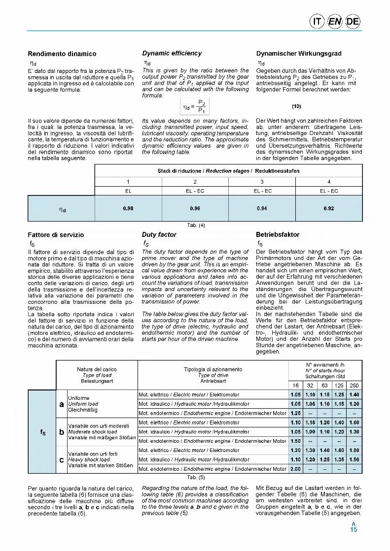
Rendimento dinamico Dynamic efficiency Dynamischer Wirkungsgradhd
E' dato dal rapporto fra la potenza P2 tra- smessa in uscita dal riduttore e quella P-i applicata in ingresso ed e calcolabile con la seguente formula:
Il suo valore dipende da numerosi fattori, fra i quali: la potenza trasmessa, la velocity in ingresso, la viscosita del lubrifi- cante, la temperatura di funzionamento e il rapporto di riduzione. I valori indicativi del rendimento dinamico sono riportati nella tabella seguente.
hdThis is given by the ratio between the output power P2 transmitted by the gear unit and that of P1 applied at the input and can be calculated with the following formula:
h dPPi
hdGegeben durch das Verhaltnis von Ab- triebsleistung P2 des Getriebes zu P-i, antriebsseitig angelegt. Er kann mit folgender Formel berechnet werden:
(10)
Its value depends on many factors, including: transmitted power, input speed, lubricant viscosity, operating temperature and the reduction ratio. The approximate dynamic efficiency values are given in the following table.
Der Wert hangt von zahlreichen Faktoren ab, unter anderem: Qbertragene Leis- tung, antriebseitige Drehzahl, Viskositat des Schmiermittels, Betriebstemperatur und Ubersetzungsverhaltnis. Richtwerte des dynamischen Wirkungsgrades sind in der folgenden Tabelle angegeben.
Stadi di riduzione / Reduction stages / Reduktionsstufen
1 2 3 4
ELОLU_lLU ОLU_lLU ОLU_lLU
hd 0.98 0.96 0.94 0.92
Tab. (4)
Fattore di serviziofSIl fattore di servizio dipende dal tipo di motore primo e dal tipo di macchina azio- nata dal riduttore. Si tratta di un valore empirico, stabilito attraverso l'esperienza storica delle diverse applicazioni e tiene conto delle variazioni di carico, degli urti della trasmissione e dell'incertezza re- lativa alla variazione dei parametri che concorrono alla trasmissione della po- tenza.La tabella sotto riportata indica i valori del fattore di servizio in funzione della natura del carico, del tipo di azionamento (motore elettrico, idraulico ed endotermi- co) e del numero di avviamenti orari della macchina azionata.
Duty factorfSThe duty factor depends on the type of prime mover and the type of machine driven by the gear unit. This is an empirical value drawn from experience with the various applications and takes into account the variations of load, transmission impacts and uncertainty relevant to the variation of parameters involved in the transmission of power.
The table below gives the duty factor values according to the nature of the load, the type of drive (electric, hydraulic and endothermic motor) and the number of starts per hour of the driven machine.
BetriebsfaktorfSDer Betriebsfaktor hangt vom Typ des Primarmotors und der Art der vom Ge- triebe angetriebenen Maschine ab. Es handelt sich um einen empirischen Wert, der auf der Erfahrung mit verschiedenen Anwendungen beruht und der die La- standerungen, die Ubertragungswucht und die Ungewissheit der Parameteran- derung bei der LeistungsQbertragung einbezieht.In der nachstehenden Tabelle sind die Werte fOr den Betriebsfaktor entspre- chend der Lastart, der Antriebsart (Elek- tro-, Hydraulik- und endothermischer Motor) und der Anzahl der Starts pro Stunde der angetriebenen Maschine, an- gegeben.
Natura del carico Type of load
Belastungsart
Tipologia di azionamento Type of drive Antriebsart
N° avviamenti /h N° of starts /hour Schaltungen /Std
16 32 63 125 250
f S
aUniforme Uniform load GleichmaUig
Mot. elettrico / Electric motor / Elektromotor 1.05 1.10 1.15 1.25 1.40
Mot. idraulico / Hydraulic motor /Hydraulikmotor 1.05 1.05 1.10 1.15 1.20
Mot. endotermico / Endothermic engine / Endotermischer Motor 1.25 -- -- -- --
bVariabile con urti moderati Moderate shock load Variable mit maliigen Stolen
Mot. elettrico / Electric motor / Elektromotor 1.10 1.15 1.20 1.40 1.60
Mot. idraulico / Hydraulic motor /Hydraulikmotor 1.05 1.00 1.10 1.20 1.30
Mot. endotermico / Endothermic engine / Endotermischer Motor 1.50 -- -- -- --
cVariabile con urti forti Heavy shock load Variable mit starken Stolien
Mot. elettrico / Electric motor / Elektromotor 1.20 1.30 1.40 1.60 1.80
Mot. idraulico / Hydraulic motor /Hydraulikmotor 1.10 1.20 1.25 1.35 1.50
Mot. endotermico / Endothermic engine / Endotermischer Motor 2.00 -- -- -- --Tab. (5)
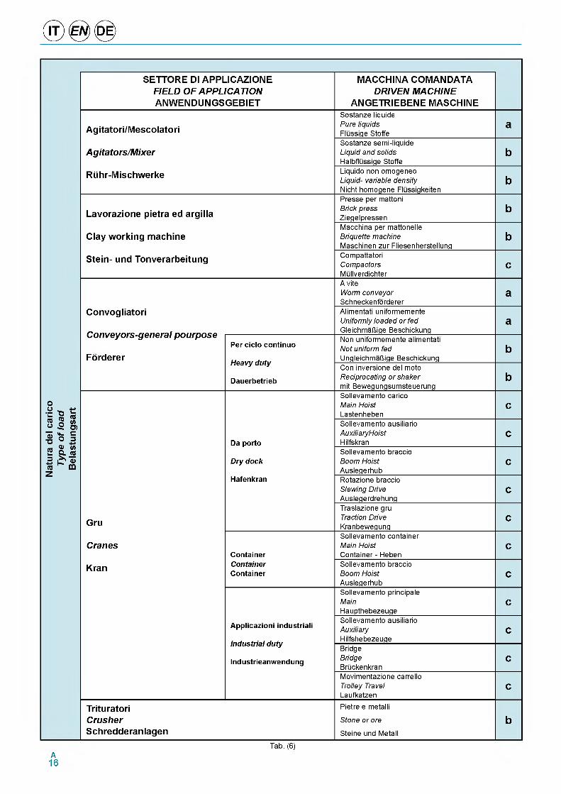
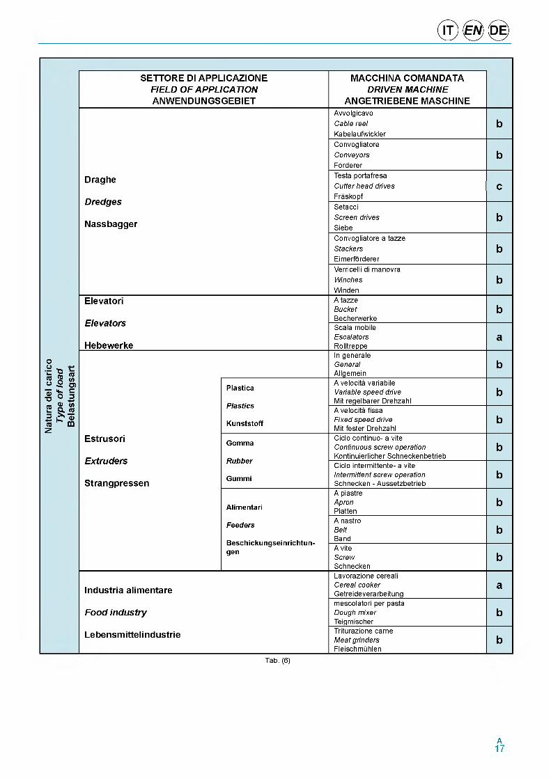
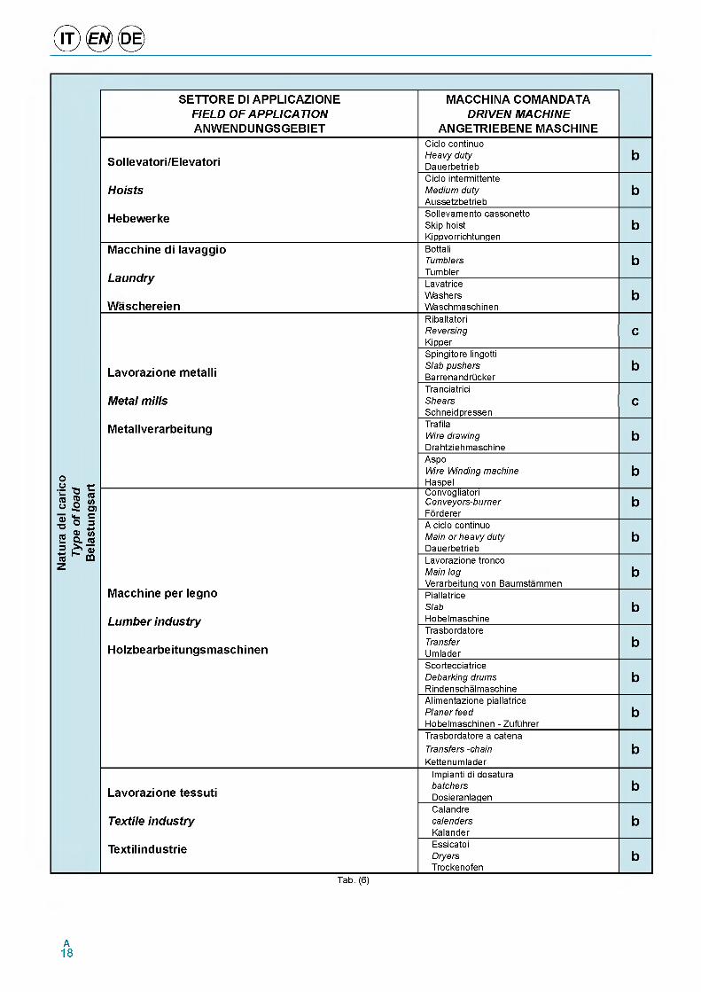
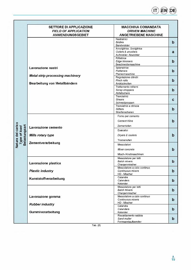
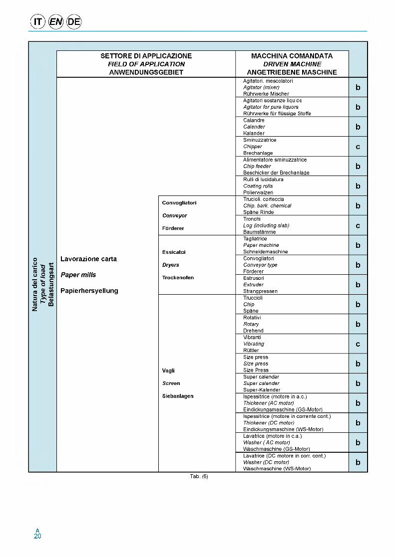
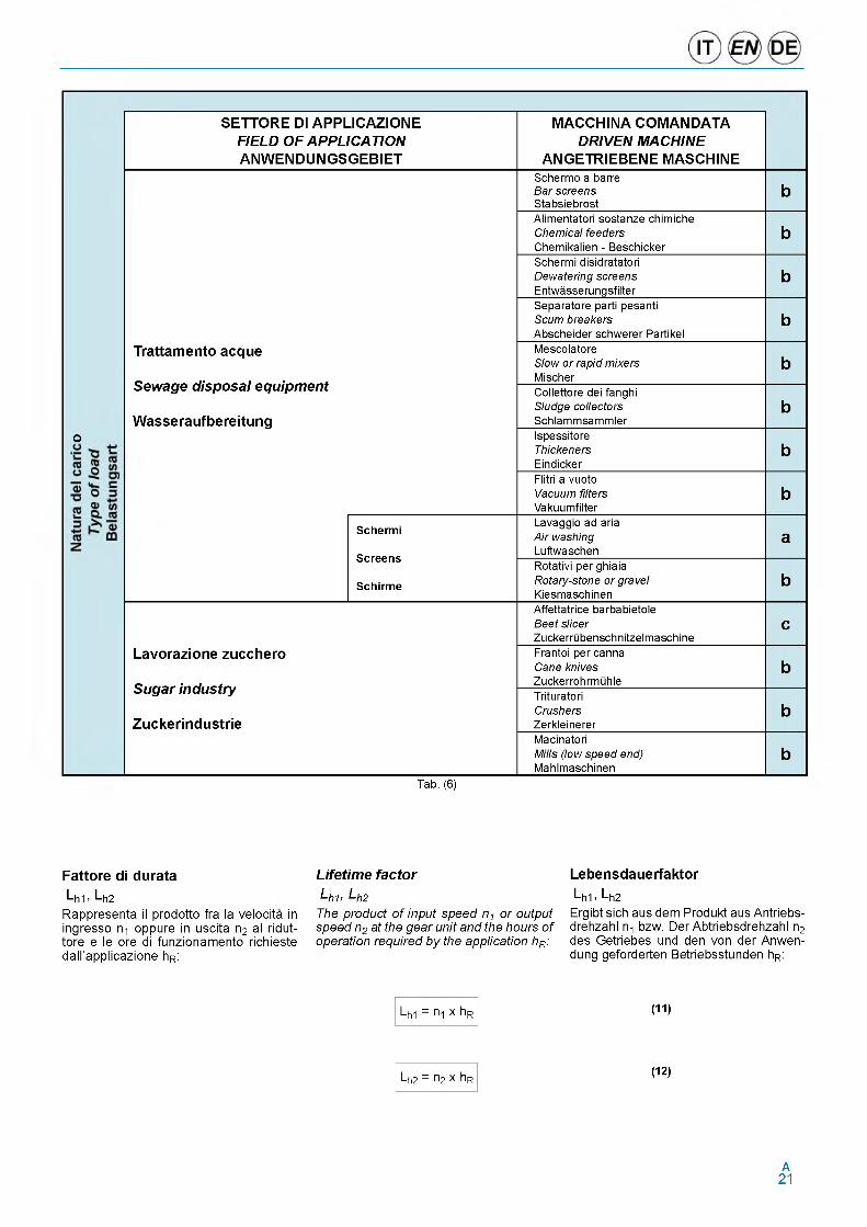
Per quanto riguarda la natura del carico, la seguente tabella (6) fornisce una clas- sificazione delle macchine piii diffuse secondo i tre livelli a, b e c indicati nella precedente tabella (5).
Regarding the nature of the load, the following table (6) provides a classification of the most common machines according to the three levels a, b and c given in the previous table (5).
Mit Bezug auf die Lastart werden in fol- gender Tabelle (6) die Maschinen, die am weitesten verbreitet sind, in drei Gruppen eingeteilt a, b e c , wie in der vorausgehenden Tabelle (5) angegeben.
A15
SETTORE DI APPLICAZIONE MACCHINA COMANDATAFIELD OF APPLICATION DRIVEN MACHINEANWENDUNGSGEBIET ANGETRIEBENE MASCHINE
Agitatori/MescolatoriSostanze liquide Pure liquids Flussige Stoffe
a
Agitators/MixerSostanze semi-liquide Liquid and solids Halbflussige Stoffe
b
Ruhr-Mischwerke Liquido non omogeneo Liquid- variable density Nicht homogene Flussigkeiten
bPresse per mattoni
Lavorazione pietra ed argilla Brick press Ziegelpressen
bMacchina per mattonelle
Clay working machine Briquette machine Maschinen zur Fliesenherstellung
b
Stein- und Tonverarbeitung CompattatoriCompactorsMullverdichter
cA viteWorm conveyor Schneckenforderer
a
Convogliatori
Conveyors-general pourpose
Alimentati uniformemente Uniformly loaded or fed GleichmaUige Beschickung
a
Per ciclo continuoNon uniformemente alimentati Not uniform fed b
FordererHeavy duty
UngleichmaUige BeschickungCon inversione del moto
Dauerbetrieb Reciprocating or shaker mit Bewegungsumsteuerung
b
Nat
ure
del c
aric
o Ty
pe o
f loa
d B
elas
tung
sart
Sollevamento carico Main Hoist Lastenheben
c
Da porto
Sollevamento ausiliarioAuxiliaryHoistHilfskran
cSollevamento braccio
Dry dock Boom Hoist Auslegerhub
cHafenkran Rotazione braccio
Slewing Drive Auslegerdrehung
c
GruTraslazione gru Traction Drive Kranbewegung
cSollevamento container
CranesContainer
Main Hoist Container - Heben
c
Kran Container Sollevamento braccioContainer Boom Hoist
Auslegerhubc
Sollevamento principale MainHaupthebezeuge
c
Applicazioni industriali
Industria l du ty
Industrieanwendung
Sollevamento ausiliarioAuxiliaryHilfshebezeuge
cBridgeBridgeBruckenkran
cMovimentazione carrello Trolley Travel Laufkatzen
c
Trituratori Pietre e metalli
Crusher Stone or ore bSchredderanlagen Steine und Metall
Tab. (6) A 16
SETTORE DI APPLICAZIONE MACCHINA COMANDATAFIELD OF APPLICATION DRIVEN MACHINEANWENDUNGSGEBIET ANGETRIEBENE MASCHINE
Avvolgicavo Cable reel Kabelaufwickler
b
ConvogliatoreConveyorsForderer
b
Draghe
Dredges
Testa portafresa Cutter head drives Fraskopf
c
Setacci
NassbaggerScreen drives Siebe
b
Convogliatore a tazzeStackersEimerforderer
b
Verricelli di manovraWinchesWinden
b
Elevatori
Elevators
A tazze Bucket Becherwerke
bScala mobile
HebewerkeEscalatorsRolltreppe
a
Nat
ure
del c
aric
o Ty
pe o
f loa
d B
elas
tung
sart
In generaleGeneralAllgemein
b
Plastica
Plastics
A velocita variabile Variable speed drive Mit regelbarer Drehzahl
bA velocita fissa
Kunststoff Fixed speed drive Mit fester Drehzahl
b
Estrusori
Extruders
Gomma
Rubber
Ciclo continuo- a vite Continuous screw operation Kontinuierlicher Schneckenbetrieb
bCiclo intermittente- a vite
Strangpressen Gummi Intermittent screw operation Schnecken - Aussetzbetrieb
b
Alimentari
A piastreApronPlatten
b
Feeders
Beschickungseinrichtun-gen
A nastroBeltBand
bA viteScrewSchnecken
bLavorazione cereali
Industria alimentare Cereal cooker Getreideverarbeitung
a
Food industrymescolatori per pasta Dough mixer Teigmischer
b
Lebensmittelindustrie Triturazione carne Meat grinders Fleischmuhlen
b
Tab. (6)
A17
SETTORE DI APPLICAZIONE FIELD OF APPLICATION ANWENDUNGSGEBIET
MACCHINA COMANDATA DRIVEN MACHINE
ANGETRIEBENE MASCHINE
Sollevatori/Elevatori
Hoists
Hebewerke
Ciclo continuo Heavy duty Dauerbetrieb
b
Nat
ure
del c
aric
o Ty
pe o
f loa
d B
elas
tung
sart
Ciclo intermittente Medium duty Aussetzbetrieb
bSollevamento cassonetto Skip hoist Kippvorrichtungen
b
Macchine di lavaggio
Laundry
Waschereien
BottaliTumblersTumbler
bLavatriceWashersWaschmaschinen
b
Lavorazione metalli
Metal mills
Metallverarbeitung
RibaltatoriReversingKipper
cSpingitore lingotti Slab pushers Barrenandrucker
bTranciatriciShearsSchneidpressen
cTrafilaWire drawing Drahtziehmaschine
bAspoWire Winding machine Haspel
b
Macchine per legno
Lumber industry
Holzbearbeitungsmaschinen
ConvogliatoriConveyors-burnerForderer
bA ciclo continuo Main or heavy duty Dauerbetrieb
bLavorazione tronco Main logVerarbeitung von Baumstammen
bPiallatriceSlabHobelmaschine
bTrasbordatoreTransferUmlader
bScortecciatrice Debarking drums Rindenschalmaschine
bAlimentazione piallatrice Planer feedHobelmaschinen - Zufuhrer
bTrasbordatore a catena Transfers -chain Kettenumlader
b
Lavorazione tessuti
Textile industry
Textilindustrie
Impianti di dosaturabatchersDosieranlagen
bCalandrecalendersKalander
bEssicatoiDryersTrockenofen
bTab. (6)
A18
(DE)
SETTORE DI APPLICAZIONE FIELD OF APPLICATION ANWENDUNGSGEBIET
MACCHINA COMANDATA DRIVEN MACHINE
ANGETRIEBENE MASCHINENastratriciBridlesBandwickler
bAvvolgitrice. Svolgitrice Coilers & uncoilers Aufwickler. Abwickler
aRifilatriceEdge trimmersBeschneidemaschine
b
Lavorazione nastri
Metal strip processing machinery
Bearbeitung von Metallbandern
SpianatriceFlattenersPlaniermaschine
bRegolazione cilindri Pinch rolls Andruckrollen
bTrattamento rottami Scrap choppers Abfallschere
bTranciatriciShearsSchneidpressen
cTranciatrici a striscia SlittersStreifenscheren
b
Forno per cemento
Cement Kilns b
Type
of l
oad
Bel
astu
ngsa
rt Lavorazione cemento Zementofen
Essicatoi
Dryers & coolers
Trockenofen
bMills rotary type
Zementverarbeitung Mescolatori
Mixer concrete bMisch-/Knetmaschinen
Lavorazione plasticaMescolatore per lotti Batch mixers Chargenmischer
b
Plastic industryMescolatore a ciclo continuo Continuous mixers HD - Mischer
b
Kunststoffverarbeitung CalandreCalendersKalander
bMescolatore per lotti Batch mixers Chargenmischer
b
Lavorazione gomma
Rubber industry
Gummiverarbeitung
Mescolatore a ciclo continuo Continuous mixers HD - Mischer
bCalandreCalendersKalander
bRiscaldamento sabbia Sand muller Formsandaufbereiter
b
Оо
<D"ОСО3ч—• СО
Tab. (6)
A19
SETTORE DI APPLICAZIONE MACCHINA COMANDATAFIELD OF APPLICATION DRIVEN MACHINEANWENDUNGSGEBIET ANGETRIEBENE MASCHINE
Agitatori. mescolatori Agitator (mixer) Ruhrwerke Mischer
bAgitatori sostanze liquide Agitator for pure liquors Ruhrwerke fur flussige Stoffe
bCalandreCalenderKalander
bSminuzzatriceChipperBrechanlage
cAlimentatore sminuzzatriceChip feederBeschicker der Brechanlage
bRulli di lucidatura Coating rolls Polierwalzen
b
Convogliatori
Conveyor
Trucioli. corteccia Chip. bark. chemical Spane Rinde
bTronchi
Forderer Log (including slab) Baumstamme
c
Essicatoi
Tagliatrice Paper machine Schneidemaschine
b
Nat
ure
del c
aric
o Ty
pe o
f loa
d B
elas
tung
sart
Lavorazione carta
Paper mills
Papierhersyellung
DryersConvogliatori Conveyor type Forderer
bTrockenofen Estrusori
ExtruderStrangpressen
bTruccioliChipSpane
bRotativiRotaryDrehend
bVibrantiVibratingRuttler
c
Vagli
Size press Size press Size Press
b
ScreenSuper calendar Super calender Super-Kalender
bSiebanlagen Ispessitrice (motore in a.c.)
Thickener (AC motor) Eindickungsmaschine (GS-Motor)
bIspessitrice (motore in corrente cont.) Thickener (DC motor) Eindickungsmaschine (WS-Motor)
bLavatrice (motore in c.a.) Washer (AC motor) Waschmaschine (GS-Motor)
bLavatrice (DC motore in corr. cont.) Washer (DC motor) Waschmaschine (WS-Motor)
b
Tab. (6)
A20
о
SETTORE DI APPLICAZIONE FIELD OF APPLICATION ANWENDUNGSGEBIET
MACCHINA COMANDATA DRIVEN MACHINE
ANGETRIEBENE MASCHINE
Trattamento acque
Sewage disposal equipment
Wasseraufbereitung
Schermo a barre Bar screens Stabsiebrost
bAlimentatori sostanze chimiche Chemical feeders Chemikalien - Beschicker
bSchermi disidratatori Dewatering screens Entwasserungsfilter
bSeparatore parti pesanti Scum breakers Abscheider schwerer Partikel
bMescolatoreSlow or rapid mixersMischer
bCollettore dei fanghi Sludge collectors Schlammsammler
bIspessitoreThickenersEindicker
bFlitri a vuoto Vacuum filters Vakuumfilter
b
Schermi
Screens
Schirme
Lavaggio ad aria Air washing Luftwaschen
aRotativi per ghiaia Rotary-stone or gravel Kiesmaschinen
b
Lavorazione zucchero
Sugar industry
Zuckerindustrie
Affettatrice barbabietole Beet slicerZuckerrubenschnitzelmaschine
cFrantoi per canna Cane knives Zuckerrohrmuhle
bTrituratoriCrushersZerkleinerer
bMacinatoriMills (low speed end) Mahlmaschinen
b
Tab. (6)
Fattore di durataL h1 > L h2
Rappresenta il prodotto fra la velocita in ingresso n-i oppure in uscita n2 al ridut- tore e le ore di funzionamento richieste dall'applicazione hR:
Lifetime factorLhb Lh2The product of input speed n1 or output speed n2 at the gear unit and the hours of operation required by the application hR:
LebensdauerfaktorLh1 L h2
Ergibt sich aus dem Produkt aus Antriebs- drehzahl n bzw. Der Abtriebsdrehzahl n2 des Getriebes und den von der Anwen- dung geforderten Betriebsstunden hR:
Lh1 = ni x hR
Lh2 = П2 x hR
(11)
(12)
A21
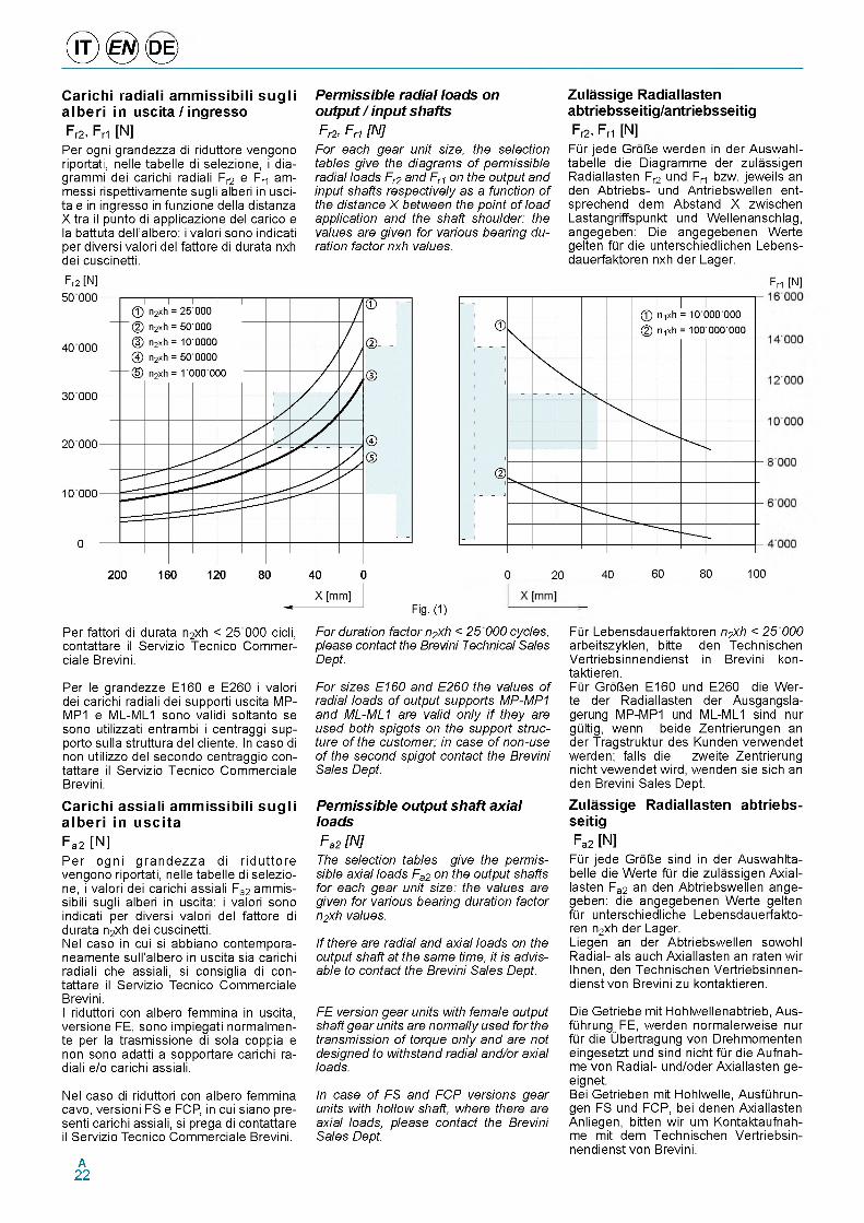
® 0 <0 >Carichi radiali ammissibili sugli alberi in uscita / ingressoFr2, Fr1 [N]
Per ogni grandezza di riduttore vengono riportati, nelle tabelle di selezione, i dia- grammi dei carichi radiali Fr2 e Fr1 am- messi rispettivamente sugli alberi in uscita e in ingresso in funzione della distanza X tra il punto di applicazione del carico e la battuta dell'albero: i valori sono indicati per diversi valori del fattore di durata nxh dei cuscinetti.
Permissible radial loads on output / input shaftsFr2, Fri [N ]
For each gear unit size, the selection tables give the diagrams of permissible radial loads Fr2 and Fr1 on the output and input shafts respectively as a function of the distance X between the point of load application and the shaft shoulder: the values are given for various bearing duration factor nxh values.
Zulassige Radiallasten abtriebsseitig/antriebsseitigFr2, Fri [N]
FQr jede GroUe werden in der Auswahl- tabelle die Diagramme der zulassigen Radiallasten Fr2 und Fr1 bzw. jeweils an den Abtriebs- und Antriebswellen ent- sprechend dem Abstand X zwischen Lastangriffspunkt und Wellenanschlag, angegeben: Die angegebenen Werte gelten fQr die unterschiedlichen Lebens- dauerfaktoren nxh der Lager.
Fr2 [N] Fri [N]
Per fattori di durata n2xh < 25 000 cicli, contattare il Servizio Tecnico Commer- ciale Brevini.
Per le grandezze E160 e E260 i valori dei carichi radiali dei supporti uscita MP- MP1 e ML-ML1 sono validi soltanto se sono utilizzati entrambi i centraggi sup- porto sulla struttura del cliente. In caso di non utilizzo del secondo centraggio con- tattare il Servizio Tecnico Commerciale Brevini.
Carichi assiali ammissibili sugli alberi in uscitaFa2 [N]Per ogni grandezza di riduttore vengono riportati, nelle tabelle di selezione, i valori dei carichi assiali Fa2 ammissibili sugli alberi in uscita: i valori sono indicati per diversi valori del fattore di durata n2xh dei cuscinetti.Nel caso in cui si abbiano contempora- neamente sull'albero in uscita sia carichi radiali che assiali, si consiglia di con- tattare il Servizio Tecnico Commerciale Brevini.I riduttori con albero femmina in uscita, versione FE, sono impiegati normalmen- te per la trasmissione di sola coppia e non sono adatti a sopportare carichi radiali e/o carichi assiali.
Nel caso di riduttori con albero femmina cavo, versioni FS e FCP, in cui siano pre- senti carichi assiali, si prega di contattare il Servizio Tecnico Commerciale Brevini.
For duration factor n2xh < 25 000 cycles, please contact the Brevini Technical Sales Dept.
For sizes E160 and E260 the values of radial loads of output supports MP-MPi and ML-MLi are valid only i f they are used both spigots on the support structure of the customer; in case of non-use of the second spigot contact the Brevini Sales Dept.
Permissible output shaft axial loadsFa2 [N ]
The selection tables give the permissible axial loads Fa2 on the output shafts for each gear unit size: the values are given for various bearing duration factor n2xh values.
If there are radial and axial loads on the output shaft at the same time, it is advisable to contact the Brevini Sales Dept.
FE version gear units with female output shaft gear units are normally used for the transmission of torque only and are not designed to withstand radial and/or axial loads.
In case of FS and FCP versions gear units with hollow shaft, where there are axial loads, please contact the Brevini Sales Dept.
FQr Lebensdauerfaktoren n2xh < 25 000 arbeitszyklen, bitte den Technischen Vertriebsinnendienst in Brevini kon- taktieren.FQr GroUen E160 und E260 die Wer- te der Radiallasten der Ausgangsla- gerung MP-MP1 und ML-ML1 sind nur gQltig, wenn beide Zentrierungen an der Tragstruktur des Kunden verwendet werden; falls die zweite Zentrierung nicht vewendet wird, wenden sie sich an den Brevini Sales Dept.
Zulassige Radiallasten abtriebs- seitigFa2 [N]
FQr jede GroUe sind in der Auswahlta- belle die Werte fQr die zulassigen Axial- lasten Fa2 an den Abtriebswellen ange- geben: die angegebenen Werte gelten fQr unterschiedliche Lebensdauerfakto- ren n2xh der Lager.Liegen an der Abtriebswellen sowohl Radial- als auch Axiallasten an raten wir Ihnen, den Technischen Vertriebsinnen- dienst von Brevini zu kontaktieren.
Die Getriebe mit Hohlwellenabtrieb, Aus- fQhrung^FE, werden normalerweise nur fQr die Ubertragung von Drehmomenten eingesetzt und sind nicht fQr die Aufnah- me von Radial- und/oder Axiallasten ge- eignet.Bei Getrieben mit Hohlwelle, AusfQhrun- gen FS und FCP, bei denen Axiallasten Anliegen, bitten wir um Kontaktaufnah- me mit dem Technischen Vertriebsin- nendienst von Brevini.
A22
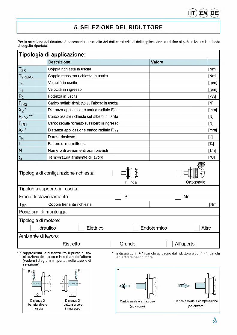
5. SELEZIONE DEL RIDUTTORE
Per la selezione del riduttore e necessaria la raccolta dei dati caratteristici dell'applicazione: a tal fine si puo utilizzare la scheda di seguito riportata.
Tipologia di applicazione:
T 2R
T 2RMAX
П2
П1
P2
F rR2
X 2F
aR2
F rR1
X i *
h R
N
ta
Descrizione
Coppia richiesta in uscita
Coppia massima richiesta in uscita
Velocita in uscita
Velocita in ingresso
Potenza in uscita
Carico radiale richiesto sull’albero in uscita
Distanza applicazione carico radiale FrR2
Carico assiale richiesto sull’albero in uscita
Carico radiale richiesto sull’albero in ingresso
Distanza applicazione carico radiale FrR1
Durata richiesta
Fattore d ’intermittenza
Numero di avviamenti orari previsti
Temperatura ambiente di lavoro
Valore
Tipologia di configurazione richiesta:
In linea
[Nm]
[Nm]
[rpm]
[rpm]
[kW]
[N]
[mm]
[N]
[N]
[mm]
[h]
[%]
[1/h]
[°C]
Ortogonale
Tipologia supporto in uscita:
Freno di stazionamento:
TiBR Coppia frenante richiesta:
Posizione di montaggio:
Tipologia di motore:
| Idraulico
Am biente di lavoro:
Elettrico
Ristretto
Si No
[Nm]
Endoterm ico Altro
Grande A ll’aperto
* X rappresenta la distanza fra il punto di ap- ** indicare con “ + ” i carichi ad uscire dal riduttore e con “ - ” i carichiplicazione del carico e la battuta dell'albero ad entrare nel riduttore.(vedere i diagrammi riportati nelle tabelle di selezione)
A23
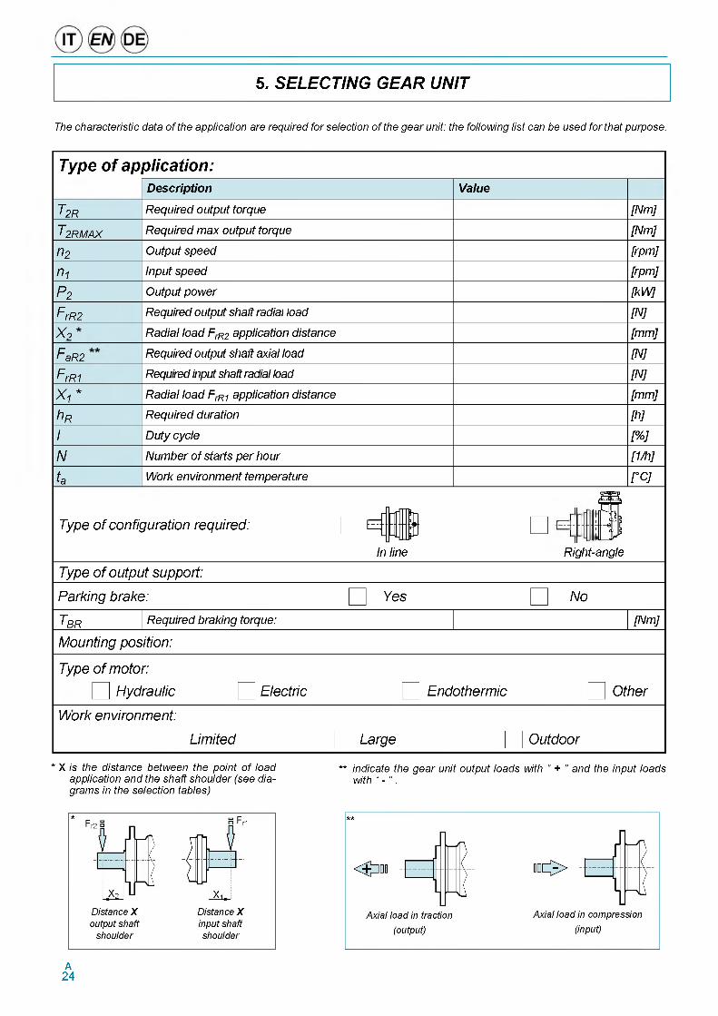
5. SELECTING GEAR UNIT
The characteristic data of the application are required for selection of the gear unit: the following list can be used for that purpose.
Type of application:
T2R
T2RMAX
П2
n 1
P2FrR2X o
FaR2
F rR1X i *
h RI
N
ta
Description
Required output torque
Required m ax output torque
O utput speed
Input speed
O utput pow er
Required output shaft radial load
Radial load FrR2 application distance
Required output shaft axial load
Required input shaft radial load
Radial load FrR1 application distance
Required duration
Duty cycle
Num ber o f starts pe r hour
W ork environment temperature
Value
T ype o f c o n fig u ra tio n re q u ire d :
In line
[N m ]
[N m ]
[rpm ]
[rpm ]
[kW ]
[N ]
[m m ]
[N ]
[N ]
[m m ]
[h ]
%%]
[1/h]_
°C ]
Right-angle
T ype o f o u tp u t su p p o rt:
P a rk in g b ra ke :
T bBR Required braking torque:
M o u n tin g p o s itio n :
T ype o f m o to r:
I H y d ra u lic
W o rk e n v iro n m e n t:
E le c tr ic
L im ite d
Yes N o
[N m ]
E n d o th e rm ic O th e r
L a rg e O u td o o r
* X is the distance between the point of load ** indicate the gear unit output loads with “ + ” and the input loadsapplication and the shaft shoulder (see dia- with “ - ” .grams in the selection tables)
A24
5. GETRIEBEAUSWAHL
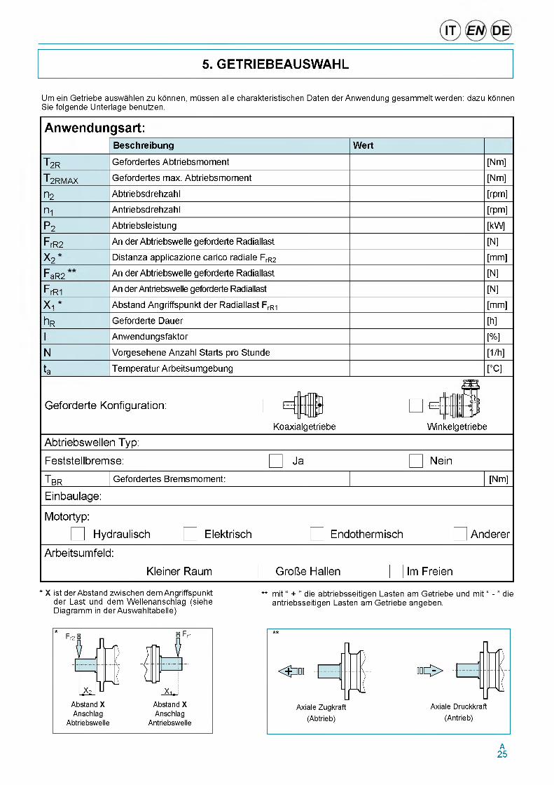
Um ein Getriebe auswahlen zu konnen, mdssen alle charakteristischen Daten der Anwendung gesammelt werden: dazu konnen Sie folgende Unterlage benutzen.
Anwendungsart:
T 2R
T 2RMAX
П2
П1
P2
F rR2
X 2F
aR2
F rR1
X i *
h R
N
ta
Beschreibung
Gefordertes Abtriebsmoment
Gefordertes max. Abtriebsmoment
Abtriebsdrehzahl
Antriebsdrehzahl
Abtriebsleistung
An der Abtriebswelle geforderte Radiallast
Distanza applicazione carico radiale FrR2
An der Abtriebswelle geforderte Radiallast
An der Antriebswelle geforderte Radiallast
Abstand Angriffspunkt der Radiallast FrR1
Geforderte Dauer
Anwendungsfaktor
Vorgesehene Anzahl Starts pro Stunde
Temperatur Arbeitsumgebung
Wert
Geforderte Konfiguration:
Koaxialgetriebe
[Nm]
[Nm]
[rpm]
[rpm]
[kW]
_____________[N]
[mm]
____________ J N ]_
_____________[N]
[mm]
____________ _ [h ]_
_________ J%]_____________ J1h]_
___ [°C]
E
Winkelgetriebe
Abtriebswellen Typ:
Feststellbremse:
TiBR Gefordertes Bremsmoment:
Einbaulage:
Ja Nein
[Nm]
Motortyp:
I Hydraulisch
Arbeitsumfeld:
Elektrisch Endothermisch Anderer
Kleiner Raum Grofte Hallen Im Freien
* X ist der Abstand zwischen dem Angriffspunkt ** mit “ + ” die abtriebsseitigen Lasten am Getriebe und mit “ - ” dieder Last und dem Wellenanschlag (siehe antriebsseitigen Lasten am Getriebe angeben.Diagramm in der Auswahltabelle)
A25
Procedere alia selezione come di segui- to indicato:
• sulla base dell'applicazione, del tipo di azionamento e del numero di av- viamenti previsti, selezionare, dalle precedenti tabelle (5) e (6), il fattore di servizio adeguato fS;
• dalla durata richiesta hR e dalla velocity in uscita n2, calcolare il fattore di durata richiesto;
• calcolare il rapporto di riduzione richiesto;
• dalle tabelle di selezione, sceglie- re il riduttore nella configurazione desiderata (in linea o angolare), le cui caratteristiche soddisfino alle re- lazioni;
Il riduttore prescelto dovra avere un rapporto di riduzione il piu prossimo possibi- le al rapporto di riduzione richiesto.
Si consideri che questo tipo di selezione e adeguato quando la coppia richiesta e la velocita di rotazione sono presso- che costanti durante l'impiego: qualora si disponesse di un ciclo di impiego con carichi e velocita fortemente variabili, e necessario effettuare una selezione che consenta di individuare la taglia di riduttore piu adeguata per l'applicazione.A tale fine, si consiglia di contattare il Servizio Tecnico Commerciale Brevini.
Qualora sia necessario un freno lamel- lare in ingresso al riduttore, procedere come segue:
1. calcolare la coppia frenante richiesta TBR secondo la formula (1) di pag. A11:
2. dalle tabelle di selezione dei freni (vedere capitolo “Freni lamellari a bagno d'olio”), scegliere il freno con coppia frenante TB tale da soddisfa- re la relazione:
Make the selection as indicated below:
• on the basis of the application, the type of drive and the number of starts foreseen, select the appropriate duty factor fS from the above tables (5) and (6);
• from the required duration hR and the output speed nz calculate the required duration factor required;
Lh2 = П2 x hR
• calculate the required reduction ratio;
П2
• from the selection tables, choose the gear unit in the desired configuration (in-line or angle), whose characteristics satisfy the equations;
T2R x fs - T2
Lh2 - n2 x h
The gear unit chosen must have a reduction ratio as close as possible to that required.
This type of selection is suitable when the required torque and the rotation speed are almost constant during use: for a cycle of use with highly variable loads and speeds, it is necessary to make a selection allowing the identification of a gear unit size best for the application.
For this purpose, it is advisable to contact the Brevini Sales Dept.
If a gear unit input multi-disc brake is necessary, proceed as follows:
1. calculate the required braking torque TBR according to the formula (1) pag. A11:
2. from the brake selection tables (see the section “Oil bath multi-disc brakes”), choose the brake with braking torque TB that satisfies the equation:
TBR - TB
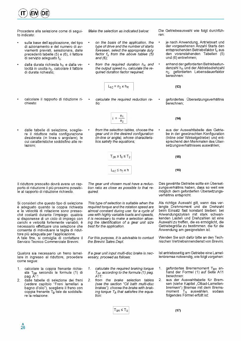
Die Getriebeauswahl wie folgt durchfQh- ren:
• je nach Anwendung, Antriebsart und der vorgesehenen Anzahl Starts den entsprechenden Betriebsfaktor fs aus den voranstehenden Tabellen (5) und (6) entnehmen;
• anhand der geforderten Betriebsstun- denzahl hR und der Abtriebsdrehzahl n2, geforderten Lebensdauerfaktor berechnen;
(13)
• gefordertes Ubersetzungsverhaltnis berechnen;
(14)
• aus der Auswahltabelle das Getrie- be in der gewQnschten Konfiguration (Inline oder Winkelgetriebe) und ent- sprechend den Merkmalen des Uber- setzungsverhaltnisses auswahlen;
(15)
(16)
Das gewahlte Getriebe sollte ein Ubersetzungsverhaltnis haben, dass so weit wie moglich dem geforderten Ubersetzungsverhaltnis entspricht.
Als richtige Auswahl gilt, wenn das ver- langte Drehmoment und die Drehzahl beim Einsatz fast konstant bleiben: bei Anwendungszyklen mit stark schwan- kenden Lasten und Drehzahlen ist eine Auswahl zu treffen, die es ermoglicht, die GetriebegroUe zu bestimmen, die fQr die Anwendung am geeignetsten ist.
Wenden Sie sich dafQr bitte an den Tech- nischen Vertriebsinnendienst von Brevini.
Ist antriebsseitig am Getriebe eine Lamel- lenbremse notwendig, wie folgt vorgehen:
1. gefordertes Bremsmoment TBR anhand der Formel (1) auf Seite A11 berechnen:
2. aus der Auswahltabelle fQr Brem- sen (siehe Kapitel „Olbad-Lamellen- bremsen“) Bremse mit dem Brems- moment TB auswahlen, sodass folgendes Formel erfQllt ist:
(17)
A26
6. VERIFICA DEL RIDUTTORE
6. VERIFICATION GEAR UNIT
6. GETRIEBEAUSWAHL
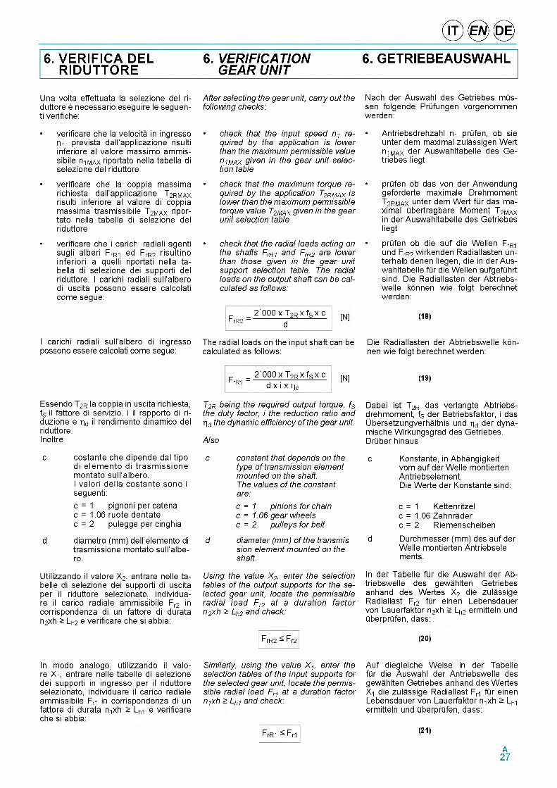
Una volta effettuata la selezione del ri- duttore e necessario eseguire le seguen- ti verifiche:
• verificare che la velocita in ingresso Пт prevista dall'applicazione risulti inferiore al valore massimo ammis- sibile n1MAX riportato nella tabella di selezione del riduttore
• verificare che la coppia massima richiesta dall'applicazione T2RMAX risulti inferiore al valore di coppia massima trasmissibile T2MAX ripor- tato nella tabella di selezione del riduttore
• verificare che i carichi radiali agenti sugli alberi FrR1 ed FrR2 risultino inferiori a quelli riportati nella tabella di selezione dei supporti del riduttore. I carichi radiali sull'albero di uscita possono essere calcolati come segue:
I carichi radiali sull'albero di ingresso possono essere calcolati come segue:
After selecting the gear unit, carry out the following checks:
• check that the input speed n1 required by the application is lower than the maximum permissible value n1MAX given in the gear unit selection table
• check that the maximum torque required by the application T2RMAX is lower than the maximum permissible torque value T2MAX given in the gear unit selection table
• check that the radial loads acting on the shafts FrR1 and FrR2 are lower than those given in the gear unit support selection table. The radial loads on the output shaft can be calculated as follows:
_ 2'000 x T2R x fS x cFrR2 = d
The radial loads on the input shaft can be calculated as follows:
Nach der Auswahl des Getriebes mQs- sen folgende PrQfungen vorgenommen werden:
• Antriebsdrehzahl n-i prQfen, ob sie unter dem maximal zulassigen Wert n-iMAX der Auswahltabelle des Ge- triebes liegt
• prQfen ob das von der Anwendung geforderte maximale Drehmoment T2RMAX unter dem Wert fQr das maximal Qbertragbare Moment T2MAX in der Auswahltabelle des Getriebes liegt
• prQfen ob die auf die Wellen FrR1 und FrR2 wirkenden Radiallasten un- terhalb denen liegen, die in der Aus- wahltabelle fQr die Wellen aufgefQhrt sind. Die Radiallasten der Abtriebs- welle konnen wie folgt berechnet werden:
(18)
Die Radiallasten der Abtriebswelle konnen wie folgt berechnet werden:
FrR- =2'000 x T2R x fS x c
d x i x hd[N] (19)
Essendo T2R la coppia in uscita richiesta, fS il fattore di servizio, i il rapporto di ri- duzione e hd il rendimento dinamico del riduttore.Inoltre
c costante che dipende dal tipo di elemento di trasm issione montato sull'albero.I valori della costante sono i seguenti:c = 1 pignoni per catena c = 1.06 ruote dentate c = 2 pulegge per cinghia
d diametro (mm) dell'elemento di trasmissione montato sull'albe- ro.
T2R being the required output torque, fS the duty factor, i the reduction ratio and hd the dynamic efficiency of the gear unit.
Also
c constant that depends on the type of transmission element mounted on the shaft.The values of the constant
Dabei ist T2R das verlangte Abtriebs- drehmoment, fS der Betriebsfaktor, i das Ubersetzungverhaltnis und hd der dyna- mische Wirkungsgrad des Getriebes. DrQber hinaus
c Konstante, in Abhangigkeitvom auf der Welle montierten Antriebselement.Die Werte der Konstante sind:
are:c = 1 pinions for chain c = 1.06 gear wheels c = 2 pulleys for belt
d diameter (mm) of the transmission element mounted on the shaft.
c = 1 Kettenritzel c = 1.06 Zahnrader c = 2 Riemenscheiben
d Durchmesser (mm) des auf der Welle montierten Antriebsele ments.
Utilizzando il valore X2, entrare nelle ta- belle di selezione dei supporti di uscita per il riduttore selezionato, individua- re il carico radiale ammissibile Fr2 in corrispondenza di un fattore di durata n2xh > Lh2 e verificare che si abbia:
Using the value X2, enter the selection tables of the output supports for the selected gear unit, locate the permissible radial load Fr2 at a duration factor n2xh > Lh2 and check:
FrR2 - Fr2
In der Tabelle fQr die Auswahl der Abtriebswelle des gewahlten Getriebes anhand des Wertes X2 die zulassige Radiallast Fr2 fQr einen Lebensdauer von Lauerfaktor n2xh > Lh2 ermitteln und QberprQfen, dass:
(20)
In modo analogo, utilizzando il valore X1, entrare nelle tabelle di selezione dei supporti in ingresso per il riduttore selezionato, individuare il carico radiale ammissibile Fr1 in corrispondenza di un fattore di durata n1xh e verificareche si abbia:
Similarly, using the value X 1, enter the selection tables of the input supports for the selected gear unit, locate the permissible radial load Fr1 at a duration factor n1xh > Lh1 and check:
FrR1 - Fr1
Auf diegleiche Weise in der Tabelle fQr die Auswahl der Antriebswelle des gewahlten Getriebes anhand des Wertes X1 die zulassige Radiallast Fr1 fQr einen Lebensdauer von Lauerfaktor n1xh > Lhi ermitteln und QberprQfen, dass:
(21)
A27
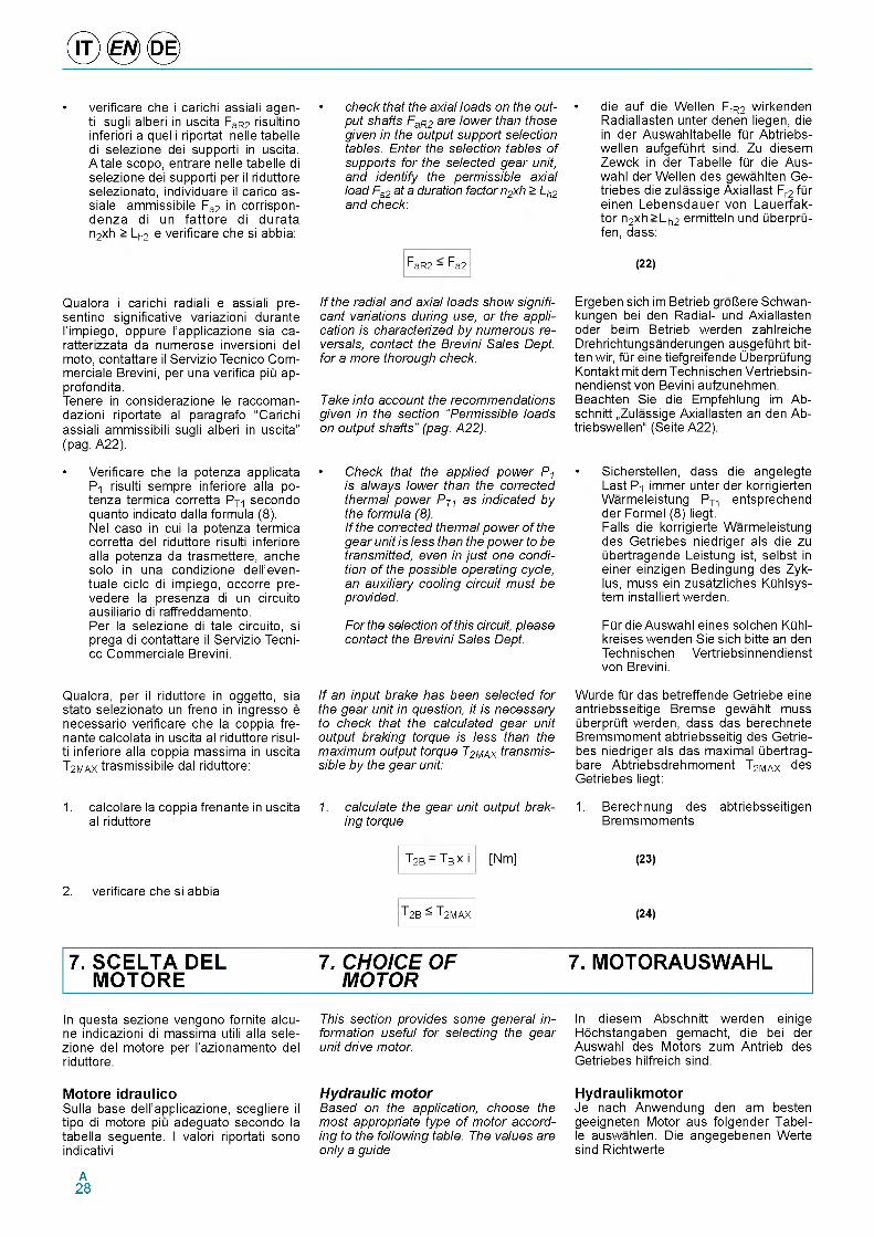
• verificare che i carichi assiali agen-ti sugli alberi in uscita FaR2 risultino inferiori a quelli riportati nelle tabelle di selezione dei supporti in uscita. A tale scopo, entrare nelle tabelle di selezione dei supporti per il riduttore selezionato, individuare il carico as- siale ammissibile Fa2 in corrispon- denza di un fattore di durata n2xh > Lh2 e verificare che si abbia:
Qualora i carichi radiali e assiali pre- sentino significative variazioni durante l'impiego, oppure l'applicazione sia ca- ratterizzata da numerose inversioni del moto, contattare il Servizio Tecnico Com- merciale Brevini, per una verifica piu ap- profondita.Tenere in considerazione le raccoman- dazioni riportate al paragrafo “Carichi assiali ammissibili sugli alberi in uscita” (pag. A22).
• Verificare che la potenza applicata P-i risulti sempre inferiore alla potenza termica corretta PT1 secondo quanto indicato dalla formula (8).Nel caso in cui la potenza termica corretta del riduttore risulti inferiore alla potenza da trasmettere, anche solo in una condizione dell'even- tuale ciclo di impiego, occorre pre- vedere la presenza di un circuito ausiliario di raffreddamento.Per la selezione di tale circuito, si prega di contattare il Servizio Tecni- co Commerciale Brevini.
Qualora, per il riduttore in oggetto, sia stato selezionato un freno in ingresso e necessario verificare che la coppia fre- nante calcolata in uscita al riduttore risulti inferiore alla coppia massima in uscita T2MAX trasmissibile dal riduttore:
1. calcolare la coppia frenante in uscita al riduttore
• check that the axial loads on the output shafts FaR2 are lower than those given in the output support selection tables. Enter the selection tables of supports for the selected gear unit, and identify the permissible axial load Fa2 at a duration factor n2xh > Lh2 and check:
FaR2 - F a2
If the radial and axial loads show significant variations during use, or the application is characterized by numerous reversals, contact the Brevini Sales Dept. for a more thorough check.
Take into account the recommendations given in the section “Permissible loads on output shafts” (pag. A22).
• die auf die Wellen FrR2 wirkenden Radiallasten unter denen liegen, die in der Auswahltabelle fQr Abtriebs- wellen aufgefQhrt sind. Zu diesem Zewck in der Tabelle fQr die Aus- wahl der Wellen des gewahlten Ge- triebes die zulassige Axiallast Fr2 fQr einen Lebensdauer von Lauerfak- tor n2xh> Lh2 ermitteln und QberprQ- fen, dass:
(22)
Ergeben sich im Betrieb grolJere Schwan- kungen bei den Radial- und Axiallasten oder beim Betrieb werden zahlreiche Drehrichtungsanderungen ausgefQhrt bitten wir, fQr eine tiefgreifende UberprQfung Kontakt mit dem Technischen Vertriebsin- nendienst von Bevini aufzunehmen. Beachten Sie die Empfehlung im Ab- schnitt „Zulassige Axiallasten an den Ab- triebswellen“ (Seite A22).
• Check that the applied power P1 is always lower than the corrected thermal power PT1 as indicated by the formula (8).If the corrected thermal power of the gear unit is less than the power to be transmitted, even in just one condition of the possible operating cycle, an auxiliary cooling circuit must be provided.
For the selection of this circuit, please contact the Brevini Sales Dept.
If an input brake has been selected for the gear unit in question, it is necessary to check that the calculated gear unit output braking torque is less than the maximum output torque T2MAX transmissible by the gear unit:
1. calculate the gear unit output braking torque
• Sicherstellen, dass die angelegte Last P-i immer unter der korrigierten Warmeleistung PT- entsprechend der Formel (8) liegt.Falls die korrigierte Warmeleistung des Getriebes niedriger als die zu Qbertragende Leistung ist, selbst in einer einzigen Bedingung des Zyk- lus, muss ein zusatzliches KQhlsys- tem installiert werden.
FQr die Auswahl eines solchen KQhl- kreises wenden Sie sich bitte an den Technischen Vertriebsinnendienst von Brevini.
Wurde fQr das betreffende Getriebe eine antriebsseitige Bremse gewahlt muss QberprQft werden, dass das berechnete Bremsmoment abtriebsseitig des Getrie- bes niedriger als das maximal Qbertrag- bare Abtriebsdrehmoment T2MAX des Getriebes liegt:
1. Berechnung des abtriebsseitigen Bremsmoments
T2B - Tb x i [Nm] (23)
2. verificare che si abbia
T2B - T2MAX (24)
7. SCELTA DEL 7. CHOICE OF 7. MOTORAUSWAHLMOTORE MOTOR
In questa sezione vengono fornite alcu- ne indicazioni di massima utili alla sele- zione del motore per l'azionamento del riduttore.
Motore idraulicoSulla base dell'applicazione, scegliere il tipo di motore piu adeguato secondo la tabella seguente. I valori riportati sono indicativi
This section provides some general information useful for selecting the gear unit drive motor.
Hydraulic motorBased on the application, choose the most appropriate type of motor according to the following table. The values are only a guide
In diesem Abschnitt werden einige Hochstangaben gemacht, die bei der Auswahl des Motors zum Antrieb des Getriebes hilfreich sind.
HydraulikmotorJe nach Anwendung den am besten geeigneten Motor aus folgender Tabelle auswahlen. Die angegebenen Werte sind Richtwerte
A28
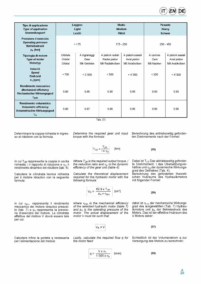
Tipo di applicazione Type o f application
Anwendungsart
LeggeroLight
Leicht
MedioMedium
Mittel
PesanteHeavy
Schwer
Pressione d’esercizio Operating pressure
Betriebsdruck Pa [bar]
< 175 175 - 250 250 - 450
Tipologia di motore Type o f m otor
Motortyp
OrbitaleOrbitalOrbital
A ingranaggi Gear
Mit Getriebe
A pistoni radiali Radial piston
Mit Radialkolben
A pistoni assiali Axial piston
Mit Axialkolben
A camme Cam
Mit Nacken
A pistoni assiali Axial piston
Mit Axialkolben
Velocita Speed
Drehzahl ni [rpm]
< 700 < 3 000 < 500 < 4 000 < 200 < 4 ’000
Rendimento meccanico Mechanical efficiency
Mechanischer Wirkungsgradhmh
0.80 0.85 0.95 0.93 0.93 0.93
Rendimento volumetrico Volumetric efficiency
Volumetrischer Wirkungsgradhv
0.90 0.87 0.95 0.95 0.95 0.95
Tab. (7)
Determinare la coppia richiesta in ingres- so al riduttore con la formula:
Determine the required gear unit input torque with the formula:
Berechnung des antriebsseitig geforder- ten Drehmoments nach der Formel:
T2Ri x hd
[Nm] (25)
In cui T2R rappresenta la coppia in uscita richiesta, i il rapporto di riduzione e hd il rendimento dinamico del riduttore (tab. 4).
Calcolare la cilindrata teorica richiesta per il motore idraulico con la seguente formula:
Where T2R is the required output torque, i the reduction ratio and hd is the dynamic efficiency of the gear unit (table 4).
Calculate the theoretical displacement required for the hydraulic motor with the following formula:
Dabei ist T2R Das abtriebsseitig geforder- te Drehmoment, i das Ubersetzungver- haltnis und hd der dynamische Wirkungs- grad des Getriebes (Tab. 4).Berechnung des geforderten theoreti- schen Hubraums des Hydraulikmotors mit folgender Formel:
62.8 x T ir
Pa x hmh[cm3] (26)
in cui hmh rappresenta il rendimento meccanico del motore idraulico prescel- to (tab. 7) e pA rappresenta la pressio- ne d'esercizio del motore. La cilindrata effettiva del motore V dovra essere tale per cui:
where hmh is the mechanical efficiency of the selected hydraulic motor (table 7) and pA is the operating pressure of the motor. The actual displacement of the motor V must be such that:
Vr ^ V
dabei ist hmh der mechanische Wirkungs- grad des ausgewahlten (Tab. 7) Hydraulikmotors und pA der Betriebsdruck des Motors. Das ist der effektive Hubraum des V Motors daher:
(27)
Calcolare infine la portata q necessaria per l'alimentazione del motore:
Lastly, calculate the required flow q for the motor feed:
SchlieUlich ist der Volumenstrom q zur Versorgung des Motors zu berechnen:
V x Пт 1 000 x hv
[l/min] (28)
A29
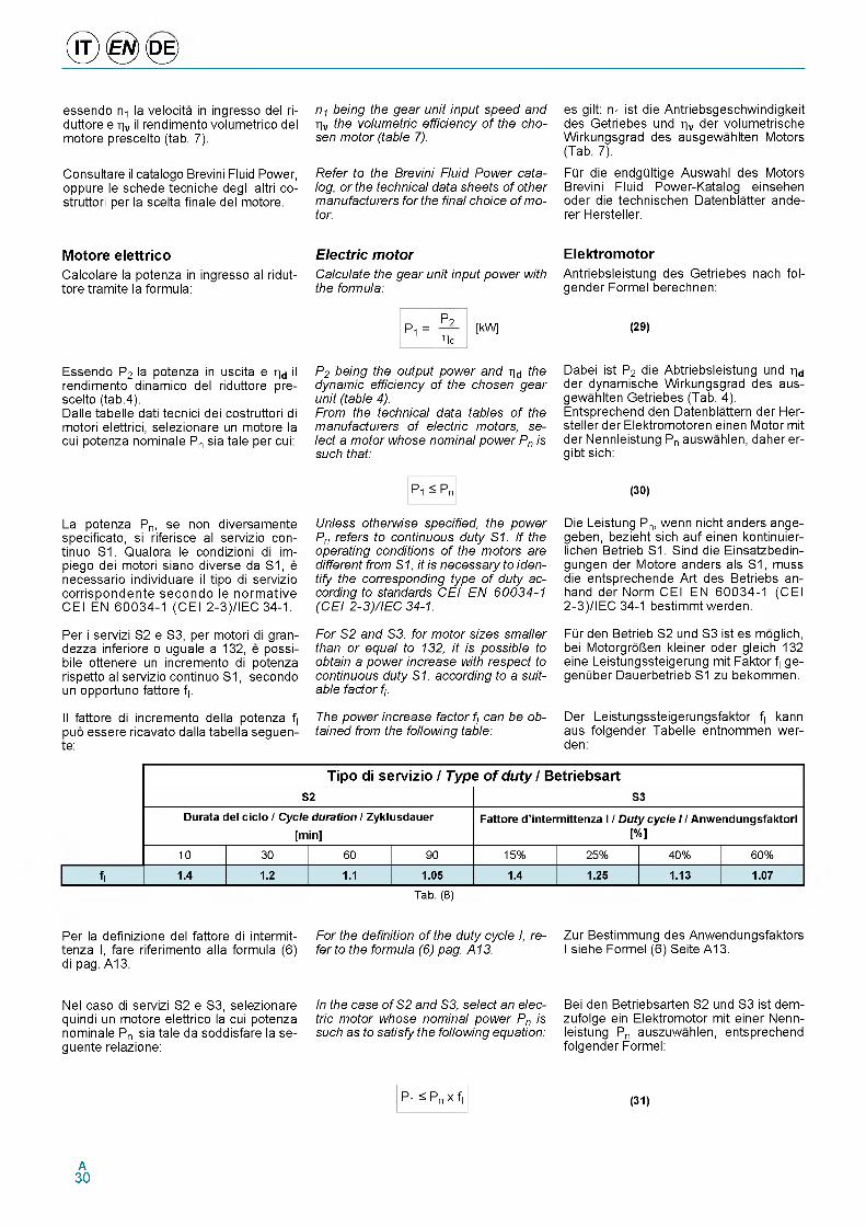
® 0 <0 >essendo n la velocita in ingresso del ri- duttore e hv il rendimento volumetrico del motore prescelto (tab. 7).
Consultare il catalogo Brevini Fluid Power, oppure le schede tecniche degli altri co- struttori per la scelta finale del motore.
n1 being the gear unit input speed and hv the volumetric efficiency of the chosen motor (table 7).
Refer to the Brevini Fluid Power catalog, or the technical data sheets of other manufacturers for the final choice of motor.
es gilt: n-i ist die Antriebsgeschwindigkeit des Getriebes und % der volumetrische Wirkungsgrad des ausgewahlten Motors (Tab. 7).
FQr die endgQltige Auswahl des Motors Brevini Fluid Power-Katalog einsehen oder die technischen Datenblatter ande- rer Hersteller.
Motore elettricoCalcolare la potenza in ingresso al ridut- tore tramite la formula:
Electric motorCalculate the gear unit input power with the formula:
ElektromotorAntriebsleistung des Getriebes nach fol- gender Formel berechnen:
Pi =P2hd
[kW] (29)
Essendo P2 la potenza in uscita e hd il rendimento dinamico del riduttore prescelto (tab.4).Dalle tabelle dati tecnici dei costruttori di motori elettrici, selezionare un motore la cui potenza nominale Pn sia tale per cui:
P2 being the output power and hd the dynamic efficiency of the chosen gear unit (table 4).From the technical data tables of the manufacturers of electric motors, select a motor whose nominal power Pn is such that:
Dabei ist P2 die Abtriebsleistung und hd der dynamische Wirkungsgrad des ausgewahlten Getriebes (Tab. 4). Entsprechend den Datenblattern der Hersteller der Elektromotoren einen Motor mit der Nennleistung Pn auswahlen, daher er- gibt sich:
La potenza Pn, se non diversamente specificato, si riferisce al servizio con- tinuo S1. Qualora le condizioni di im- piego dei motori siano diverse da S1, e necessario individuare il tipo di servizio corrispondente secondo le normative CEI EN 60034-1 (CEI 2-3)/IEC 34-1.
Per i servizi S2 e S3, per motori di gran- dezza inferiore o uguale a 132, e possi- bile ottenere un incremento di potenza rispetto al servizio continuo S1, secondo un opportuno fattore fI.
Il fattore di incremento della potenza fI puo essere ricavato dalla tabella seguen- te:
P1 ^ Pn
Unless otherwise specified, the power Pn refers to continuous duty S1. If the operating conditions of the motors are different from S1, it is necessary to identify the corresponding type of duty according to standards CEI EN 60034-1 (CEI 2-3)/IEC 34-1.
For S2 and S3, for motor sizes smaller than or equal to 132, it is possible to obtain a power increase with respect to continuous duty S1, according to a suitable factor fI.
The power increase factor fI can be obtained from the following table:
(30)
Die Leistung Pn, wenn nicht anders ange- geben, bezieht sich auf einen kontinuier- lichen Betrieb S1. Sind die Einsatzbedin- gungen der Motore anders als S1, muss die entsprechende Art des Betriebs an- hand der Norm CEI EN 60034-1 (CEI 2-3)/IEC 34-1 bestimmt werden.
FQr den Betrieb S2 und S3 ist es moglich, bei MotorgroUen kleiner oder gleich 132 eine Leistungssteigerung mit Faktor fI ge- genQber Dauerbetrieb S1 zu bekommen.
Der Leistungssteigerungsfaktor fI kann aus folgender Tabelle entnommen wer- den:
Tipo di servizio / Type of duty / BetriebsartS2 S3
Durata del ciclo / Cycle duration / Zyklusdauer
[min]Fattore d ’intermittenza I / Duty cycle I / AnwendungsfaktorI
[%]
10 30 60 90 15% 25% 40% 60%
fI 1.4 1.2 1.1 1.05 1.4 1.25 1.13 1.07
Tab. (8)
Per la definizione del fattore di intermit- tenza I, fare riferimento alla formula (6) di pag. A13.
Nel caso di servizi S2 e S3, selezionare quindi un motore elettrico la cui potenza nominale Pn sia tale da soddisfare la se- guente relazione:
For the definition of the duty cycle I, refer to the formula (6) pag. A13.
In the case of S2 and S3, select an electric motor whose nominal power Pn is such as to satisfy the following equation:
Zur Bestimmung des Anwendungsfaktors I siehe Formel (6) Seite A13.
Bei den Betriebsarten S2 und S3 ist dem- zufolge ein Elektromotor mit einer Nennleistung Pn auszuwahlen, entsprechend folgender Formel:
P1 ^ Pn x fI (31)
A30
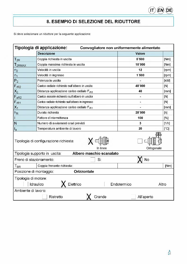
8. ESEMPIO DI SELEZIONE DEL RIDUTTORE
© ® ©
Si deve selezionare un riduttore per la seguente applicazione:
Tipologia di applicazione: Convogliatore non uniformemente alimentatoDescrizione Valore
T 2R Coppia richiesta in uscita 5500 [Nm]
T2RMAX Coppia massima richiesta in uscita 10000 [Nm]
П2 Velocita in uscita 12 [rpm]
n i Velocita in ingresso 1 500 [rpm]
P2 Potenza in uscita [kW]
FrR2 Carico radiale richiesto sull’albero in uscita 40 000 [N]
X 2 Distanza applicazione carico radiale FrR2 40 [mm]
FaR2 Carico assiale richiesto sull’albero in uscita [N]
FrRi Carico radiale richiesto sull’albero in ingresso [N]
X i Distanza applicazione carico radiale FrRi [mm]
h R Durata richiesta 25 000 [h]
Fattore d’intermittenza 100 [%]
N Numero di avviamenti orari previsti 3 [1/h]
Temperatura ambiente di lavoro 20 [°C]
Tipologia di configurazione richiesta:
In linea
r~ :. nil1— IIPOrtogonale
Tipologia supporto in uscita: Albero maschio scanalato
Freno di stazionamento: Si X No
T BR Coppia frenante richiesta: [Nm]
Posizione di montaggio: Orizzontale
wоCLi- gi a di motore:
Idraulico X Elettrico Endoterm ico Altro
Am biente di lavo ro:
Ristretto X Grande A ll’aperto
I
ta
A31
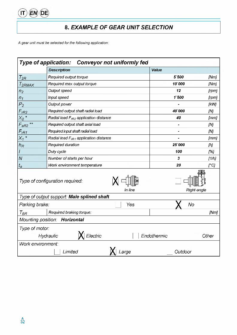
8. EXAMPLE OF GEAR UNIT SELECTION
A gear unit must be selected for the following application:
Type of application: Conveyor not uniformly fedDescription Value
T2R Required output torque 5 500 [Nm]
T2RMAX Required m ax output torque 10 000 [Nm]
n2 Output speed 12 [rpm]
n1 Input speed 1500 [rpm]
P2 Output pow er - [kW ]
F rR2 Required output shaft radial load 40 000 [N]
*X" Radial load FrR2 application distance 40 [mm]
n **F aR2 Required output shaft axial load - [N]
F rR1 Required input shaft radial load - [N]
X 1 * Radial load FrR1 application distance - [mm]
h R Required duration 25 000 [h]
I Duty cycle 100 [% ]
N Num ber o f starts per hour 3 [1/h]
ta Work environment temperature 20 [°C]
T ype o f c o n fig u ra tio n re q u ire d : XIn lir e
EL
Righ
f i tt-angle
T ype o f o u tp u t su p p o rt: M ale s p lin e d shaft
P a rk in g b ra k e : Y es X N o
TBR Required braking torque: [Nm]
M o u n tin g p o s it io n : H orizon ta l
T ype o f m o to r:
H y d ra u lic X E le c tr ic E n d o th e rm ic O th e r
W o rk e n v iro n m e n t:
L im ite d X L a rg e O u td o o r
A32
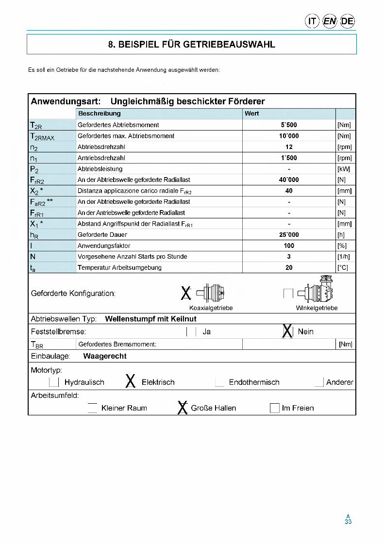
8. BEISPIEL FUR GETRIEBEAUSWAHL
© ® ©
Es soil ein Getriebe fQr die nachstehende Anwendung ausgewahlt werden:
Anwendungsart: Ungleichmaftig beschickter Forderer
T 2R
T 2RMAX
П2
П1
P2
F rR2
X 2
FaR2
F rR1
X 1
h R
N
ta
Beschreibung
Gefordertes Abtriebsmoment
Gefordertes max. Abtriebsmoment
Abtriebsdrehzahl
Antriebsdrehzahl
Abtriebsleistung
An der Abtriebswelle geforderte Radiallast
Distanza applicazione carico radiale FrR2
An der Abtriebswelle geforderte Radiallast
An der Antriebswelle geforderte Radiallast
Abstand Angriffspunkt der Radiallast FrR1
Geforderte Dauer
Anwendungsfaktor
Vorgesehene Anzahl Starts pro Stunde
Temperatur Arbeitsumgebung
Wert
Geforderte Konfiguration: XKoaxialgetriebe
5500
10000
12
1500
40 000
40
25 000
100
3
20
[Nm]
[Nm]
[rpm]
[rpm]
[kW]
[N]
[mm]
[N]
[N]
[mm]
[h]
[%]
[1/h]_
[°C]
Winkelgetriebe
Abtriebswellen Typ: Wellenstumpf mit Keilnut
Feststellbremse: Ja Nein
T,BR Gefordertes Bremsmoment: [Nm]
Einbaulage: Waagerecht
Motortyp:
Hydraulisch X Elektrisch Endothermisch Anderer
Arbeitsumfeld:
Kleiner Raum X Grofte Hallen Im Freien
A33
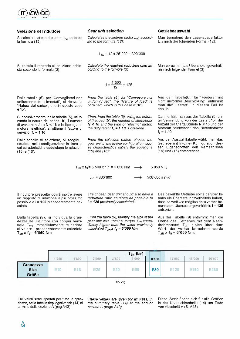
® 0 <0 >Selezione del riduttoreSi calcola il fattore di durata Lh2 secondo la formula (12):
Si calcola il rapporto di riduzione richie- sto secondo la formula (3)
Gear unit selectionCalculates the lifetime factor Lh2 according to the formula (12):
Lh2 = 12 x 25 000 = 300 000
Calculate the required reduction ratio according to the formula (3)
GetriebeauswahlMan berechnet den Lebensdauerfaktor Lh2 nach der folgenden Formel (12):
Man berechnet das Ubersetzungsverhalt- nis nach folgender Formel (3)
. _ 1500 ' 1 2
= 125
Dalla tabella (6), per “Convogliatori non uniformemente alimentati”, si ricava la “Natura del carico”, che in questo caso e “b”.
Successivamente, dalla tabella (5), utiliz- zando la natura del carico “b”, il numero di avviamenti/ora N < 16 e la tipologia di motore “elettrico”, si ottiene il fattore di servizio, fs = 1.10
Dalle tabelle di selezione, si sceglie il riduttore nella configurazione in linea le cui caratteristiche soddisfano le relazioni (15) e (16):
From the table (6), for “Conveyors not uniformly fed", the “Nature of load” is obtained, which in this case is “b ”.
Then, from the table (5), using the nature of the load “b ”, the number of starts/hour N < 16 and the type of “electric” motor, the duty factor fs = 1.10 is obtained
From the selection tables, choose the gear unit in the in-line configuration whose characteristics satisfy the equations (15) and (16):
Aus der Tabelle(6), flir “Forderer mit nicht uniformer Beschickung”, entnimmt man die“ Lastart“, in diesem Fall ist das “b”.
Dann erhalt man aus der Tabelle (5) un- ter Verwendung von der Lastart “b”, die Anzahl der Starts/Stunde N < 16 und der Motorart “elektrisch“ den Betriebsfaktor fs = 1.10
Aus der Auswahltabelle wahlt man das Getriebe mit In-Line- Konfiguration des- sen Eigenschaften den Verhaltnissen (15) und (16) entsprechen:
T2R x fS = 5500 x 1.1 = 6 050 Nm 6 050 < T2
Lh2 = 300 000 300 000 < n2xh
Il riduttore prescelto dovra inoltre avere un rapporto di riduzione il piu prossimo possibile a i = 125 precedentemente cal- colato.
Dalla tabella (9), si individua la gran- dezza del riduttore con coppia nomi- nale T2N immediatamente superiore al valore precedentemente calcolato T2R x fS = 6 050 Nm:
The chosen gear unit should also have a reduction ratio as close as possible to i = 125 previously calculated.
From the table (9), identify the size of the gear unit with nominal torque T2N immediately higher than the value previously calculated T2R x fS = 6 050 Nm:
Das gewahlte Getriebe sollte darliber hi- naus ein Ubersetzungsverhaltnis haben, dass so weit wie moglich dem vorher be- rechneten Ubersetzungsverhaltnis i = 125 entspricht.
Aus der Tabelle (9) entnimmt man die GroUe des Getriebes mit dem Nenn- drehmoment T2N gleich liber dem Wert, der vorher berechnet wurde T2R x fS = 6 050 Nm:
I1200 1800 2900 3800
T2N [Nm] 5 000 8500 13 000 18 000 26 000
GrandezzaSize
GrofteE10 E16 E25 E30 E50 E80 E120 E160 E260
Tab. (9)
Tali valori sono riportati per tutte le gran- dezze, nella tabella riepilogativa tab.(14) al termine della sezione A (pag.A43).
These values are given for all sizes, in the summary table (14) at the end of section A (page A43).
Diese Werte finden sich flir alle GroUen in der Ubersichtstabelle (14) am Ende von Abschnitt A (S. A43).
A34
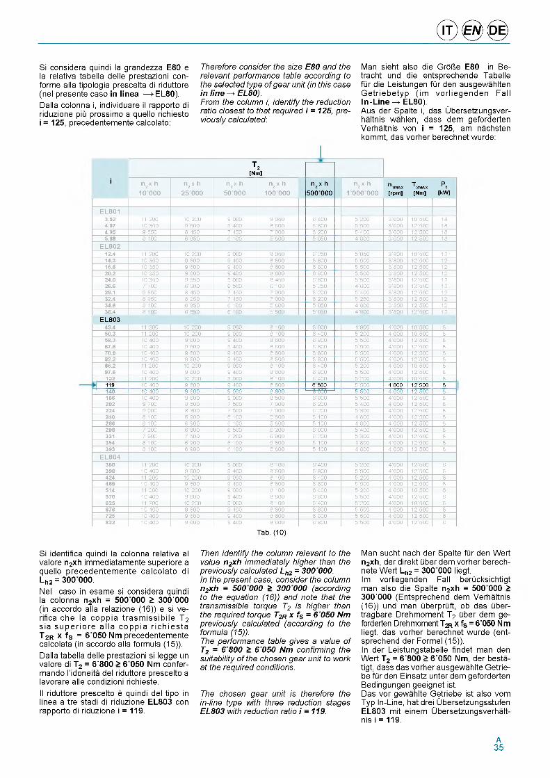
© ® ©Si considera quindi la grandezza E80 e la relativa tabella delle prestazioni con- forme alia tipologia prescelta di riduttore (nel presente caso in linea ^ EL80). Dalla colonna i, individuare il rapporto di riduzione piu prossimo a quello richiesto i = 125, precedentemente calcolato:
Therefore consider the size E80 and the relevant performance table according to the selected type of gear unit (in this case in line ^ EL80).From the column i, identify the reduction ratio closest to that required i = 125, previously calculated:
Man sieht also die GroUe E80 in Be- tracht und die entsprechende Tabelle fQr die Leistungen fQr den ausgewahlten Getriebetyp (im vorliegenden Fall In-Line ^ EL80).Aus der Spalte i, das Ubersetzungsver- haltnis wahlen, dass dem geforderten Verhaltnis von i = 125, am nachsten kommt, das vorher berechnet wurde:
T 2[Nm]
n 2 x h 10 000
n2 x h 2 5 0 0 0
n 2 x h 50 000
n2 x h 100 000
n 2 x h 500 000
n2 x h 1 000 000
n T P1МАЖ 2МАЖ t[rpm ] [Nm] [kW]
E L8 0 13.52 1 1 2 0 0 10 200 9 000 . 0 ( 0 6 | 400 ( | 200 3 | 000 10 | (0 0 184.07 1 0 3 ( 0 9 600 9 Г 0 0 . 1 0 0 6 1 .0 0 ( 1 (0 0 3 1 000 12 | (0 0 184.95 9 6 (0 . 4 ( 0 7 4 (0 7 000 6 1 200 ( | 400 3 1 000 12 | (0 0 185.88 i i r r 1 . ( 0 6 1 0 0 ( . 0 0 ( | 0 (0 4 | .0 0 3 1 000 12 | (0 0 18
E L8 0 212.4 11200 10 200 9 000 . 0 ( 0 6 | 2 (0 ( | 0 (0 3 1 .0 0 10 | (0 0 1214.3 113(0 9 600 9 Г 0 0 . 1 0 0 6 | .0 0 ( | (0 0 3 1 .0 0 12 | (0 0 1216.6 1 0 3 ( 0 9 600 9 Г 0 0 . 1 0 0 6 | .0 0 ( | (0 0 3 1 .0 0 12 | (0 0 1220.2 1 0 3 ( 0 9 600 9 Г 0 0 . 1 0 0 6 | .0 0 ( | (0 0 3 1 .0 0 12 | (0 0 1224.0 1 0 3 ( 0 9 ( ( 0 9 000 . 4 ( 0 6 | .0 0 ( | (0 0 3 1 .0 0 12 | (0 0 1226.6 7 700 6 9 0 0 6 ( 0 0 6 1 0 0 ( | 2 (0 4 | 600 3 1 .0 0 12 | (0 0 1229.1 9 6 (0 . 4 ( 0 7 4 (0 7 000 6 | 200 ( | 400 3 1 .0 0 12 | (0 0 1232.4 . 9 ( 0 . 2 ( 0 7 4 (0 7 000 6 | 200 ( | 2 (0 3 1 .0 0 12 | (0 0 1234.6 . 1 0 0 1 . ( 0 6 1 0 0 ( . 0 0 ( | 0 (0 4 | .0 0 3 1 .0 0 12 | (0 0 1238.4 . 1 0 0 1 . ( 0 6 1 0 0 ( . 0 0 ( | 0 (0 4 | .0 0 3 1 .0 0 12 | (0 0 12
EL80343.4 1 1 2 0 0 10 200 9 000 . 1 0 0 6 | 000 4 | 900 4 1 000 10 | (0 0 850.3 1 1 2 0 0 10 200 9 000 . 1 0 0 6 | 400 ( | 200 4 1 000 10 | (0 0 858.3 1 0 4 0 0 9 600 9 400 . 1 0 0 6 | .0 0 ( | (0 0 4 1 000 12 | (0 0 867.6 1 0 4 0 0 9 600 9 400 . 1 0 0 6 | .0 0 ( | (0 0 4 1 000 12 | (0 0 870.9 1 0 4 0 0 9 600 9 400 . 1 0 0 6 | .0 0 ( | (0 0 4 1 000 12 | (0 0 882.2 1 0 4 0 0 9 600 9 400 . 1 0 0 6 | .0 0 ( | (0 0 4 | 000 12 | (0 0 886.2 1 1 2 0 0 10 200 9 000 . 1 0 0 6 | 400 ( | 200 4 | 000 10 | (0 0 897.6 1 0 4 0 0 9 600 9 400 . 1 0 0 6 | .0 0 ( | (0 0 4 | 000 12 | (0 0 8102 1 1 2 0 0 10 200 9 000 . 1 0 0 6 | 400 ( | 200 4 | 000 10 | (0 0 8119 1 0 4 0 0 9 600 9 400 . 1 0 0 6 800 ( | (0 0 4 000 1 2 5 0 0 8
' 140 10 Г00 9 100 9 000 . 600 6 .0 0 ( (0 0 4 000 12 (0 0 8166 1 0 4 0 0 9 600 9 000 . 1 (0 0 6 1 .0 0 ( | (0 0 4 | 000 12 | (0 0 8202 9 700 . | ( 0 0 7 ( 0 0 7 1 000 6 1 200 ( 1 400 4 | 000 12 | (0 0 8224 9 000 . 3 0 0 7 ( 0 0 7 | 000 6 1 200 ( | 300 4 | 000 12 | (0 0 8240 . 1 0 0 6 900 6 1 0 0 ( 1 .0 0 ( 1 100 4 | .0 0 4 | 000 12 | (0 0 8266 . 1 0 0 6 900 6 1 0 0 ( 1 .0 0 ( 1 100 4 | .0 0 4 | 000 12 | (0 0 8298 7 200 1 . 0 0 6 ( 0 0 6 1 200 6 1 000 ( | 400 4 | 000 12 | (0 0 8331 7 900 7 ( 0 0 7 200 6 | 900 6 1 200 ( | 300 4 | 000 12 | (0 0 8354 . 1 0 0 6 900 6 1 0 0 ( | .0 0 ( 1 100 4 | .0 0 4 | 000 12 | (0 0 8393 . 1 0 0 6 900 6 1 0 0 ( | .0 0 ( 1 100 4 | .0 0 4 | 000 12 | (0 0 8
EL804360 1 1 2 0 0 10 200 9 000 . | 100 6 1 400 ( | 200 4 | 000 12 | (0 0 6398 1 0 4 0 0 9 600 9 400 . 1 600 6 | .0 0 ( | (0 0 4 | 000 12 | (0 0 6424 1 1 2 0 0 10 200 9 000 . 1 100 6 1 400 ( | 200 4 | 000 12 | (0 0 6469 1 0 4 0 0 9 600 9 400 . 1 600 6 | .0 0 ( | (0 0 4 | 000 12 | (0 0 6514 1 1 2 0 0 10 200 9 000 . 1 100 6 | 400 ( | 200 4 | 000 10 | (0 0 6570 1 0 4 0 0 9 600 9 400 . 1 600 6 | .0 0 ( | (0 0 4 | 000 12 | (0 0 6625 1 1 2 0 0 10 200 9 000 . 1 100 6 | 400 ( | 200 4 | 000 10 | (0 0 6676 1 0 4 0 0 9 600 9 400 . 1 600 6 | .0 0 ( | (0 0 4 | 000 12 | (0 0 6725 1 0 4 0 0 9 600 9 400 . 1 600 6 | .0 0 ( | (0 0 4 | 000 12 | (0 0 6822 1 0 4 0 0 9 600 9 400 . 1 600 6 | .0 0 ( | (0 0 4 | 000 12 | (0 0 6
Tab. (10)
Si identifica quindila colonna relativa al valore n2xh immediatamente superiore a quello precedentem ente calc olato di Lh2 = 300 000.Nel caso in esamesi considera quindi la colonna n2xh = 500 000 > 300'000(in accordo alla relazione (16)| e si ve- rifica che la coppia trasm iss ib ile T2 sia supe rio re a lla copp ia rich ies ta T2R x fS = 6 050 Nm precedentemente calcolata (in accordo alla formula (15)).Dalla tabella delle prestazioni si legge un valore di T2 = 6'800 > 6 050 Nm confer- mando l'idoneita del riduttore prescelto a lavorare alle condizioni richieste.Il riduttore prescelto e quindi del tipo in linea a tre stadi di riduzione EL803 con rapporto di riduzione i = 119.
Then identify the column relevant to the value n2xh immediately higher than the previously calculated Lh2 = 300 000.In the present case, consider the column n2xh = 500 000 > 300 000 (according to the equation (16)) and note tit at the transmissible torque T2 is higher than the required torque T2R x fS = 6 050 Nm previously calculated (according to the formula (15)).The performance table gives a value of T2 = 6 800 > 6 050 Nm confirming the suitability of the chosen gear unit to work at the required conditions.
The chosen gear unit is therefore the in-line type with three reduction stages EL803 with reduction ratio i = 119.
M an sucht nach d er Spalte fQr den Wert n2xh, der direkt Qber dem vorher berech- nete Wert Lh2 = 300 000 liegt.Im vorliegenden Fall berQcksichtigt man also die Spalte n2xh = 500 000 > 300'000 (Entsprechend dem Verhaltnis (16)) und man QberprQft, ob das Qber- tragbare Drehmoment T2 Qber dem geforderten Drehmoment T2R x fS = 6'050 Nm liegt, das vorher berechnet wurde (entsprechend der Formel (15)).In der Leistungstabelle findet man den Wert T2 = 6'800 > 6'050 Nm, der besta- tigt, dass das vorher ausgewahlte Getrie- be fQr den Einsatz unter dem geforderten Bedingungen geeignet ist.Das vor gewahlte Getriebe ist also vom Typ In-Line, hat drei Ubersetzungsstufen EL803 mit einem Ubersetzungsverhalt- nis i = 119.
A35
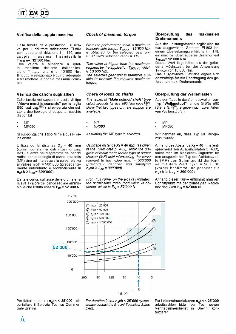
® 0 <0 >
Verifica della coppia massima
Dalla tabella delle prestazioni, si rica- va per il riduttore selezionato EL803 con rapporto di riduzione i = 119, una copp ia m ass im a tra s m is s ib ile T 2MAX= 12 500 Nm.Tale valore e superiore a quel-10 massimo richiesto dall'applica- zione T2rmax. che e di 10 000 Nm.11 riduttore selezionato e quindi adeguato a trasmettere la coppia massima richie- sta.
Check of maximum torque
From the performance table, a maximum transmissible torque T2MAX= 12 500 Nm is obtained for the selected gear unit EL803 with reduction ratio i = 119.
This value is higher than the maximum required by the application T2RMAX, which is 10 000 Nm.The selected gear unit is therefore suitable to transmit the required maximum torque.
Uberprufung des maximalen DrehmomentsAus der Leistungstabelle ergibt sich fQr das ausgewahlte Getriebe EL803 bei einem Ubersetzungsverhaltnis i = 119, ein maximal Qbertragbares Drehmoment T2MAX= 12 500 Nm.Dieser Wert liegt hoher als der gefor- derte Hochstwert bei der Anwendung T2RMAX von 10.000 Nm.Das ausgewahlte Getriebe eignet sich demzufolge fQr die Ubertragung des ge- forderten max. Drehmoments.
Verifica dei carichi sugli alberiDalle tabelle dei supporti in uscita di tipo “Albero maschio scanalato” per la taglia E80 (vedi pag. E80), si evidenzia che esi- stono due tipologie di supporto maschio disponibili:
• MP• MP090
Si supponga che il tipo MP sia quello se- lezionato.
Utilizzando la distanza X2 = 40 mm (come riportata nei dati iniziali di pag. A31), si entra nel diagramma dei carichi radiali per la tipologia di uscita prescelta (MP) sino ad intersecare la curva relativa al valore n2xh = 500 000 (precedente- mente individuato e soddisfacente la n2xh > Lh2 = 300 000).
Da tale curva, sull'asse delle ordinate, si ricava il valore del carico radiale ammis- sibile che risulta essere Fr2 = 52 000 N.
Check of loads on shaftsThe tables of “ Male sp lined sha ft" type output supports for size E80 (see page E80), show that two types of male support are available:
• MP• MP090
Assuming the MP type is selected.
Using the distance X2 = 40 mm (as given in the initial data p. A32), enter the diagram of radial loads for the type of output chosen (MP) until intersecting the curve relevant to the value n2xh = 500 000 (previously identified and satisfying n2xh > Lh2 = 300 000).
From this curve, on the axis of ordinates, the permissible radial load value is obtained, which is F2 = 52 000 N.
Uberprufung der WellenlastenAus den Tabelle der Abtriebswellen vom Typ “Wellenstupf” fQr die GrOUe E80 (Siehe S. E80), ergeben sich zwei Arten von WellenstQpfen:
• MP• MP090
Wir nehmen an, dass Typ MP ausge- wahlt wurde.
Anhand des Abstands X2 = 40 mm (ent- sprechend den Ausgangsdaten S. A33), sucht man im Radiallast-Diagramm fQr den ausgewahlten Typ der Abtriebswel- le (MP) den S chn ittpunk t der Kur- ve m it dem W ert n2xh = 500 000 (vo rhe r bestim m t und passend fQr n2 xh > Lh2 = 300 000).
Anhand dieser Kurve entnimmt man am Schnittpunkt mit der zulassigen Radial- last den Wert Fr2 = 52 000 N.
Fr2 [N]
TFig. (2)
Per fattori di durata n2xh < 25 000 cicli, For duration factor n2xh < 25 000 cycles, FQr Lebensdauerfaktoren n2xh < 25 000contattare il Servizio Tecnico Commer- please contact the Brevini Technical Sales arbeitszyklen, bitte den Technischenciale Brevini. Dept. Vertriebsinnendienst in Brevini kon-
taktieren.A36
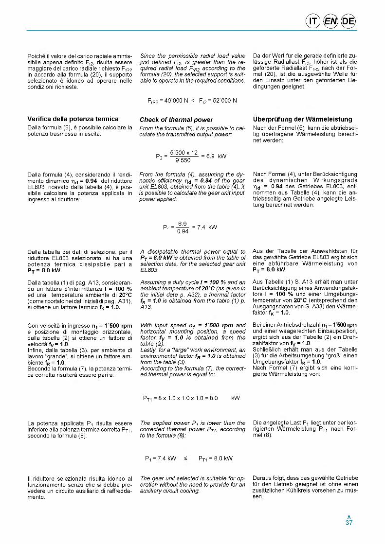
Poiche il valore del carico radiale ammis- sibile appena definito Fr2, risulta essere maggiore del carico radiale richiesto FrR2 in accordo alla formula (20), il supporto selezionato e idoneo ad operare nelle condizioni richieste.
Verifica della potenza termicaDalla formula (5), e possibile calcolare la potenza trasmessa in uscita:
Dalla formula (4), considerando il rendi- mento dinamico hd = 0-94 del riduttore EL803, ricavato dalla tabella (4), e possibile calcolare la potenza applicata in ingresso al riduttore:
Dalla tabella dei dati di selezione, per il riduttore EL803 selezionato, si ha una potenza term ica dissipabile pari a PT = 8.0 kW.
Dalla tabella (1) di pag. A13, considerando un fattore d'intermittenza I = 100 % ed una temperatura ambiente di 20°C (come riportato nei dati iniziali di pag. A31), si ottiene un fattore termico fK = 1.0.
Con velocita in ingresso n1 = 1500 rpm e posizione di montaggio orizzontale, dalla tabella (2) si ottiene un fattore di velocita fV = 1.0.Infine, dalla tabella (3), per ambiente di lavoro “grande”, si ottiene un fattore ambiente fR = 1.0.Secondo la formula (7), la potenza termica corretta risultera essere pari a:
La potenza applicata P1 risulta essere inferiore alla potenza termica corretta PT1, secondo la formula (8):
Il riduttore selezionato risulta idoneo al funzionamento senza che si debba pre- vedere un circuito ausiliario di raffredda- mento.
Since the permissible radial load value just defined Fr2, is greater than the required radial load FrR2 according to the formula (20), the selected support is suitable to operate in the required conditions.
FrR2 = 40 000 N < Fr2 = 52 000 N
Check of thermal powerFrom the formula (5), it is possible to calculate the transmitted output power:
P2 =5 500x 12
9550= 6.9 kW
From the formula (4), assuming the dynamic efficiency hd = 0.94 of the gear unit EL803, obtained from the table (4), it is possible to calculate the gear unit input power applied:
6.9Pi = 167T7 = 7.4 kW 1 0.94
A dissipatable thermal power equal to PT = 8.0 kW is obtained from the table of selection data, for the selected gear unit EL803.
Assuming a duty cycle I = 100 % and an ambient temperature of 20°C (as given in the initial data p. A32), a thermal factor fK = 1.0 is obtained from the table (1) p. A13.
With input speed n1 = 1 500 rpm and horizontal mounting position, a speed factor fV = 1.0 is obtained from the table (2).Lastly, for a “large” work environment, an environmental factor fR = 1.0 is obtained from the table (3).According to the formula (7), the corrected thermal power is equal to:
PT1 = 8 x 1.0 x 1.0 x 1.0 = 8.0 kW
The applied power P1 is lower than the corrected thermal power PT1, according to the formula (8):
P1 = 7.4 kW < PT1 = 8.0 kW
The gear unit selected is suitable for operation without the need to provide for an auxiliary circuit cooling.
Da der Wert fQr die gerade definierte zu- lassige Radiallast Fr2, hoher ist als die geforderte Radiallast FrR2 nach der For- mel (20), ist die ausgewahlte Welle fQr den Einsatz unter den geforderten Be- dingungen geeignet.
Uberprufung der WarmeleistungNach der Formel (5), kann die abtriebsei- tig Qbertragene Warmeleistung berech- net werden:
Nach Formel (4), unter BerQcksichtigung des dynamischen W irkungsgrads h d = 0.94 des Getriebes EL803, ent- nommen aus Tabelle (4), kann die an- triebsseitig am Getriebe angelegte Leis- tung berechnet werden:
Aus der Tabelle der Auswahldaten fQr das gewahlte Getriebe EL803 ergibt sich eine abfQhrbare Warmeleistung von PT = 8.0 kW.
Aus Tabelle (1) S. A13 erhalt man unter BerQcksichtigung eines Anwendungsfak- tors I = 100 % und einer Umgebungs- temperatur von 20°C (entsprechend den Ausgangsdaten von S. A33) den Warme- faktor fK = 1.0.
Bei einer Antriebsdrehzahl n1 = 1500 rpm und einer waagerechten Einbauposition, ergibt sich aus der Tabelle (2) ein Dreh- zahlfaktor von fV = 1.0.SchlieUlich erhalt man aus der Tabelle (3) fQr die Arbeitsumgebung “groU“ einen Umgebungsfaktor fR = 1.0.Nach Formel (7) ergibt sich eine korri- gierte Warmeleistung von:
Die angelegte Last P1 liegt unter der kor- rigierten Warmeleistung PT1 nach For- mel (8):
Daraus folgt, dass das gewahlte Getriebe fQr den Betrieb geeignet ist ohne einen zusatzlichen KQhlkreis vorsehen zu mQs- sen.
A37
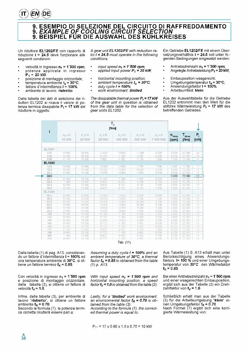
® 0 <0 >9. ESEMPIO DI SELEZIONE DEL CIRCUITO DI RAFFREDDAMENTO 9. EXAMPLE OF COOLING CIRCUIT SELECTION 9. BEISPIEL FUR DIE AUSWAHL DES KUHLKREISES
Un riduttore EL1202/FE con rapporto di riduzione i = 24.5 deve funzionare alle seguenti condizioni:
• velocita in ingresso n 1 = 1 5 0 0 rpm ;• p o te n z a a p p lic a ta in in g re s s o
P 1 = 20 kW;• posizione di montaggio orizzontale;• tem peratura am biente t a = 30°C;• fattore d 'in term ittenza I = 100%• am biente di lavoro: r is tre tto
Dalla tabella dei dati di selezione dei ri- duttori EL1202 si ricava il va lore di potenza term ica dissipabile Pt = 17 kW del riduttore in oggetto.
A gear unit EL1202/FE with reduction ratio i = 24.5 must operate in the following conditions:
• input speed n1 = 1500 rpm;• applied input power P1 = 20 kW;
• horizontal mounting position;• ambient temperature ta = 30°C;• duty cycle I = 100%• work environment: limited
The dissipatable thermal power Pt = 17 kW of the gear unit in question is obtained from the data table for the selection of gear units EL1202.
Ein Getriebe EL1202/FE mit einem Uber- setzungsverhaltnis i = 24.5 soil unter fol- genden Bedingungen eingesetzt werden:
• Antriebsdrehzahl n1 = 1 5 0 0 rpm;• Angelegte Antriebsleistung P1 = 20 kW;
• Einbauposition waagerecht;• Um gebungstem peratur t a = 30°C;• Anwendungsfaktor I = 100%• Arbeitsumfeld: k le in
Aus der Auswahltabelle fQr die Getriebe EL1202 entnim m t man den W ert fQr die abfQhre W arm eleistung Pt = 17 kW des betreffenden Getriebes.
T2[Nm] 4
n2 x h
10 000
n2 х h
25 000
n2 х h
50 000
n2 х h
100 000
n2 х h
500 000
n2 х h
1 000 000
n T n imax T2max[rpm] [Nm]
Pt[kW]
E L I2 0 Ig .07 16800 15600 1f ' 8ГГ 13 ' 6ГГ 1 1 ' fro 9'2ГГ 2 ' ГГГ 20 ' ГГГ 23g .95 1Г'600 13 200 11'7ГГ 11'ГГГ 9'8ГГ 9 ' ГГГ 2 ' ГГГ 20 ' ГГГ 235 .8 8 127ГГ 10800 9 ' 6ГГ 9'1ГГ 8'1ГГ 7'6ГГ 2 ' ГГГ 20 ' ГГГ 23
E L 12 0 2r g . r 16800 15600 1f ' 8ГГ 13 ' 6ГГ 9'7ГГ 7'9ГГ 3'8ГГ 20 ' ГГГ 171 6 .6 16800 15600 1f ' 8ГГ 13 ' 6ГГ 1Г ' ГГГ 8'2ГГ 3'8ГГ 20 ' ГГГ 172 0 .2 16800 15600 1f ' 8ГГ 13 ' 6ГГ 9'8ГГ 8 ' ГГГ 3'8ГГ 20'000 17
» 2 4 .5 3 800 20 000 1729.1 15600 13'200 11'7ГГ 11'ГГГ 9'8ГГ 9 ' ГГГ 3'8ГГ 20'000 17r 2 .g 11400 1 Г ' rrr 9'9ГГ 9'3ГГ 8 ' ГГГ 6'7ГГ 3'8ГГ 20'000 17r g .6 12'700 1Г ' 8ГГ 9'6ГГ 9'1ГГ 8'1ГГ 7'6ГГ 3 ' 8ГГ 20'000 17r 8 .g 12'700 1Г ' 8ГГ 9'6ГГ 9'1ГГ 8'1ГГ 7 ' ГГГ 3 ' 8ГГ 20'000 17
E L I2 0 35 0 .3 16800 1Г ' 6ГГ 1f ' 8ГГ 13 ' ГГГ 8'3ГГ 6'8ГГ 4 ' ГГГ 20'000 115 8 .3 16800 1Г ' 6ГГ 1f ' 8ГГ 13 ' 6ГГ 9'2ГГ 7 ' ГГГ 4 ' ГГГ 20'000 116 7 .6 16800 1Г ' 6ГГ 1f ' 8ГГ 13 ' 6ГГ 1Г ' ГГГ 8'2ГГ 4 ' ГГГ 20'000 118 2 .2 16800 1Г ' 6ГГ 1f ' 8ГГ 13 ' 6ГГ 1Г ' ГГГ 8'1ГГ 4 ' ГГГ 20'000 118 8 .6 15700 1 f ' f r r 13 ' ГГГ 12 ' 7ГГ 8'9ГГ 7'2ГГ 4 ' ГГГ 20'000 119 9 .9 16800 1Г ' 6ГГ 1f ' 8ГГ 13 ' 6ГГ 9'8ГГ 8 ' ГГГ 4 ' ГГГ 20'000 11108 15600 13 ' 2ГГ 11'7ГГ 11'ГГГ 9'8ГГ 8'3ГГ 4 ' ГГГ 20'000 11119 15600 13 ' 2ГГ 11'7ГГ 11'ГГГ 9'8ГГ 9 ' ГГГ 4 ' ГГГ 20'000 11125 16800 1Г ' 6ГГ 1f ' 8ГГ 13'6ГГ 9'8ГГ 8 ' ГГГ 4 ' ГГГ 20'000 11rg g 15600 13 ' 2ГГ 11' 7ГГ 11'ГГГ 9'8ГГ 9 ' ГГГ 4 ' ГГГ 20'000 11152 15600 13 ' 2ГГ 11' 7ГГ 11'ГГГ 9'8ГГ 9 ' ГГГ 4 ' ГГГ 20'000 11171 12700 1Г ' 8ГГ 9'6ГГ 9'1ГГ 8'1ГГ 7'6ГГ 4 ' ГГГ 20'000 11180 15600 13 ' 2ГГ 11' 7ГГ 11'ГГГ 9'8ГГ 9 ' ГГГ 4 ' ГГГ 20'000 11200 11400 1 Г ' rrr 9'9ГГ 9'3ГГ 8 ' ГГГ 6'7ГГ 4 ' ГГГ 20'000 11215 15600 13 ' tor 11' 7ГГ 11' ГГГ 9'8ГГ 9 ' ГГГ 4 ' ГГГ 20'000 11
Tab. (11)
Dalla tabella (1) di pag. A13, consideran- do un fattore d ’interm ittenza 1 = 100% ed una tem peratura am biente di 30°C, si ot- tiene un fattore term ico f K = 0.85.
Con velocita in ingresso n 1 = 0 500 rpm e posizione di m ontaggio orizzontale, dalla tabella (2), si ottiene un fattore di velocita fV = 1.0.
Infine, dalla tabella (3), per am biente di lavoro “ r is t re t to ” , si ottiene un fattore am biente f R = 0.70.Secondo la form ula (7), la poten za term ica corretta risultera essere pari a:
Assuming a duty cycle I = 100% and an ambient temperature of 30°C, a thermal factor fK = 0.85 is obtained from the table (1) p. A1 3.
With input speed n. = 1 500 rpm and horizontar mounting position, a speed factor fV = 1.0 is obiained from 0he table (2).
Lastly, for a “limrted” work environment, an environmental factor fR = 0070 is obtained from the table (3).According to the formula (7), the corrected thermal power is equal to:
Aus Tabelle (1) S. A13 erhalt man unter BerQcksichtigung eines A nw endungs- faktors I= 100 % und einer Um gebungs- tem pe ratur vo n 30°C den W arm efaktor f K = 0.85.
Bei einer Antriebsdrehzahl n1 = 1 5 0 0 rpm und ei n er waa gerechten Einbauposition, erg ib t s i ch aus der Tabelle (2) ein Dreh- zah lfaktor von fV = 1.0.
S ch lieГГ. i ch erh alt man aus der Tabelle (3) fQr die A rbeitsum gebung “ k le in “ ei- nen Um gebu n gsfakto r fR = 0.70.Nach Forme l ( 7) erg ibt sich eine korri- gierte W arm el e . stunc. von:
PT1 = 17 x 0.85 x 1.0 x 0.70 = 10 kW
A38
La potenza applicata P1 risulta non esse- re inferiore alia potenza termica corretta PT1, secondo la formula (8):
The applied power P1 is not lower than the corrected thermal power PT1, according to the formula (8):
(DE)
Die angelegte Last P-i liegt nicht unter der korrigierten Warmeleistung PT1 nach Formel (8):
Condizione non verificata!Pt = 20 kW < PT1 = 10 kW ----- - Condition not verified!
Bedingung wird nicht uberpruft!
Pertanto, per il riduttore in oggetto, e necessario prevedere un circuito au- siMario di raffreddamento.
Si calcola quindi la potenza termica da dissipare, secondo la formula (9). Per fare questo e necessario ricavare, dalla tabella (4), per il riduttore EL1202, il ren- dimento dinamico hd = 0.96.
Si ha quindi che la potenza termica da dissipare e
Definita la potenza termica da dissipare PC, contattare il Servizio Tecnico Comm ercia l Brevini per la selezione del circuito di raffreddamento piii adeguato fra quelli a disposizione.
Therefore, fo r the gear unit in question, it is necessary to provide for an auxiliary circuit cooling.
Then calculate the thermal power to be dissipated, according to the formula (9). To do this, the dynamic efficiency hd = 0.96 must be obtained from the table (4), for the gear unit EL1202.
The thermal power to be dissipated is
PC = (20 - 10) x (1 - 0.96) = 0.4 kW
After establishing the thermal power to be dissipated PC, contact the Brevini Sales Dept. to select the most suitable cooling circuit from those available.
Daher ist fur das betreffende Getriebe ein zusatzlicher Kuhlkreis notwendig.
Man berechnet also die abzufiihrende Warmeleistung nach der Formel (9). Dazu muss man aus der Tabelle (4) fiir das Getriebe EL1202, den dynamischen Wirkungsgrad hd = 0.96 entnehmen.
Daraus ergibt sich die abzufiihrende Warmeleistung von
Nach der Bestimmung der abzufiihren- den Warmeleistung PC, Bitten wir Sie, fQr die Auswahl des geeigneten Kiihlkreis- laufs aus dem Angebot Kontakt mit dem Technischen Vertriebsinnendienst von Brevini aufzunehmen.
A39
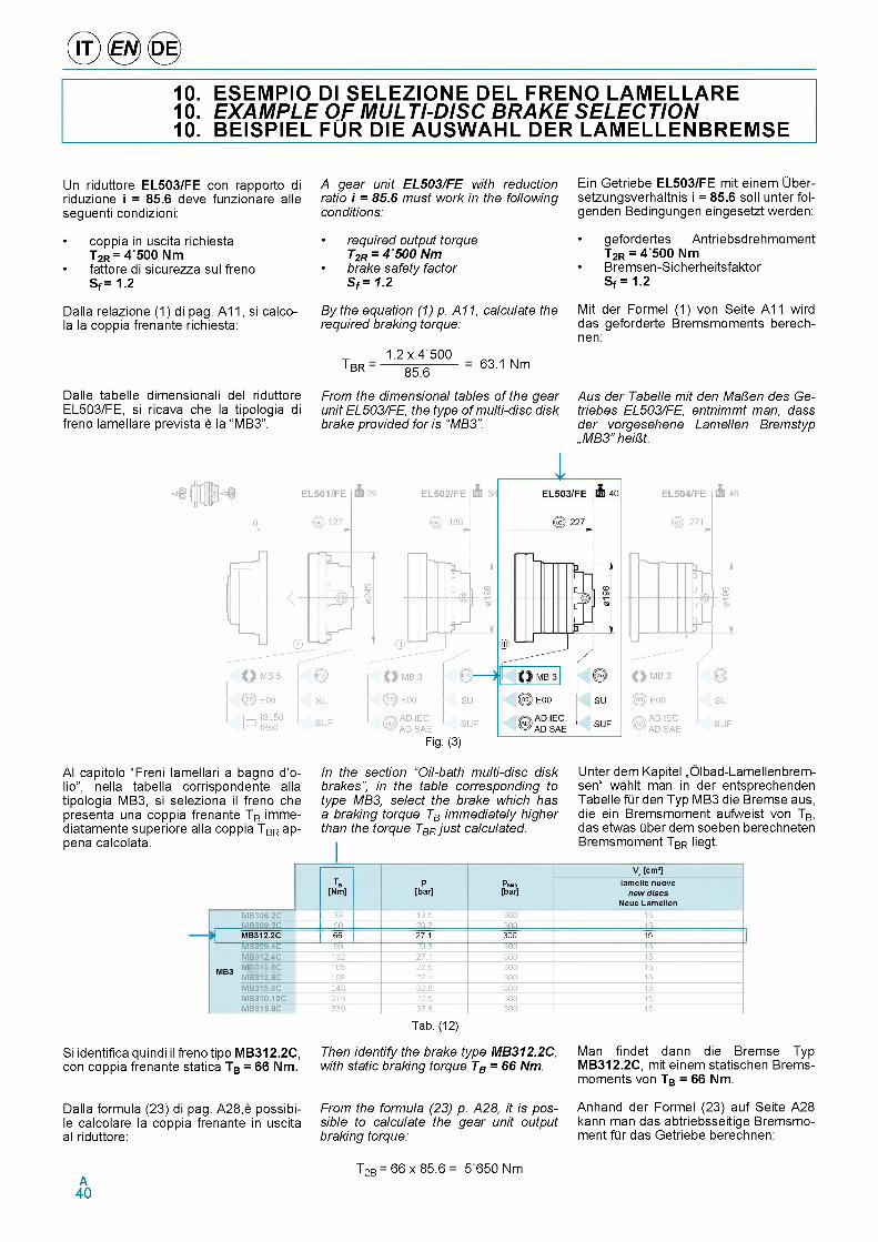
® 0 <0 >10. ESEMPIO DI SELEZIONE DEL FRENO LAMELLARE10. EXAMPLE OF MULTI-DISC BRAKE SELECTION10. BEISPIEL FUR DIE AUSWAHL DER LAMELLENBREMSE
Un riduttore EL503/FE con rapporto di riduzione i = 85.6 deve funzionare alle seguenti condizioni:
• coppia in uscita richiesta T2R = 4500 Nm
• fattore di sicurezza sul freno Sf = 1.2
A gear unit EL503/FE with reduction ratio i = 85.6 must work in the following conditions:
• required output torque T2R = 4 500 Nm
• brake safety factor Sf = 1.2
Ein Getriebe EL503/FE mit einem Uber- setzungsverhaltnis i = 85.6 soil unter fol- genden Bedingungen eingesetzt werden:
• gefordertes Antriebsdrehmoment T2R = 4500 Nm
• Bremsen-Sicherheitsfaktor Sf = 1.2
Dalla relazione (1) di pag. A11, si calco- la la coppia frenante richiesta:
By the equation (1) p. A11, calculate the required braking torque:
1.2 x 4500 T br = 85.6
63.1 Nm
Mit der Formel (1) von Seite A11 wird das geforderte Bremsmoments berech- nen:
Dalle tabelle dimensionali del riduttore EL503/FE, si ricava che la tipologia di freno lamellare prevista e la “MB3”.
From the dimensional tables of the gear unit EL503/FE, the type of multi-disc disk brake provided for is “MB3".
Aus der Tabelle mit den MaRen des Ge- triebes EL503/FE, entnimmt man, dass der vorgesehene Lamellen Bremstyp „MB3" heiRt.
Fig. (3)
Al capitolo “Freni lamellari a bagno d'o- lio”, nella tabella corrispondente alla tipologia MB3, si seleziona il freno che presenta una coppia frenante TB imme- diatamente superiore alla coppia TBR ap- pena calcolata.
Si identifica quindi il freno tipo MB312.2C, con coppia frenante statica TB = 66Nm.
In the section “Oil-bath multi-disc disk brakes”, in the table corresponding to type MB3, select the brake which has a braking torque TB immediately higher than the torque TBR just calculated.
Unter dem Kapitel „Olbad-Lamellenbrem- sen“ wahlt man in der entsprechenden Tabelle flir den Typ MB3 die Bremse aus, die ein Bremsmoment aufweist von TB, das etwas liber dem soeben berechneten Bremsmoment TBR liegt.
TB[Nm]
P[bar]
PMAX[bar]
Va [cm3]lamelle nuove
new discs Neue Lamellen
MB306.2C 33 13.5 3tt 15MB309.2C 5t rt3 3tt 15 ,MB312.2C 66 27.1 300 15MB309.4C ---------99--------- rt.3 3tt 15MB312.4C 13Г Г7.1 3tt 15
MB3 M 165 ГГ.5 3tt 15MB3 MB312.6C 198 Г7.1 3tt 15
MB315.6C Г48 33.8 3tt 15MB310.10C Г75 ГГ.5 3tt 15MB315.8C 33t 33.8 3tt 15
Tab. (12)
Then identify the brake type MB312.2C, with static braking torque TB = 66 Nm.
Man findet dann die Bremse Typ MB312.2C, in it einem statischen Bremsmoments von TB = 66 Nm.
Dalla formula (23) di pag. A28,e possibi- le calcolare la coppia frenante in uscita al riduttore:
From the formula (23) p. A28, it is possible to calculate the gear unit output braking torque:
Anhand derFormel (23) auf Seite A28 kann man das abtriebsseitige Bremsmoment flir das Getriebe berechnen:
T2B = 66 x 8 5 .6 = 5 650 NmA40
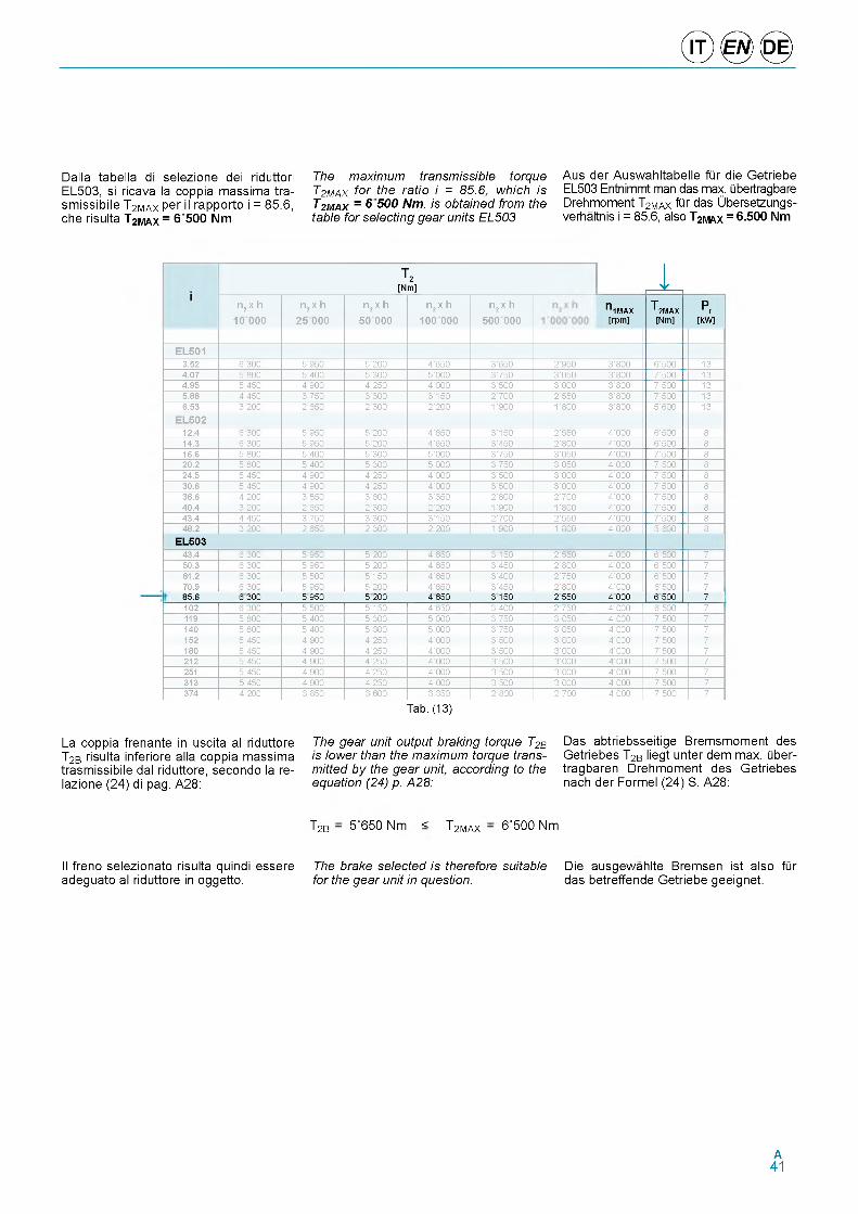
© ® ©
Dalla tabella di selezione dei riduttori EL503, si ricava la coppia massima tra- smissibile T2MAX per il rapporto i = 85.6, che risulta T2MAX = 6500 Nm
The maximum transmissible torque T2MAX for the ratio i = 85.6, which is T2MAX = 6 500 Nm, is obtained from the table for selecting gear units EL503
Aus der Auswahltabelle fQr die Getriebe EL503 Entnimmt man das max. Qbertragbare Drehmoment T2MAX fQr das Ubersetzungs- verhaltnis i = 85.6, also T2MAX = 6.500 Nm
t 2[Nm] 1
n2 x h
10 000
n2 x h
25 000
n2 x h
50 000
n2 x h
100 000
n2 x h
500 000П 1МАХ[rpm]
T 2MAX[Nm]
P t[kW]
EL50 13.52 i r r r t ' 9tr t ' 2rr 4 ' i t r r ' i t r 2'9tr r ' r rr i ' t r r i r4.07 t r r r t ' 4rr t ' r rr t ' r rr r ' 7tr r ' r tr r ' r rr 7 ' tr r i r4.95 t'4tr 4'9rr 4'2tr 4 ' r rr r ' tr r r ' r rr r ' r rr 7 ' tr r i r5.88 4'4tr r ' 7tr r ' r rr r ' i t r 2'7rr 2 ' t tr r ' r rr 7 ' tr r i r6.53 i'2 f f 2 ' i t r 2 ' r rr 2'2rr 1' 9rr i' r rr r ' r rr t ' i r r i r
EL50212.4 i r r r t ' 9tr t ' 2rr 4 ' i t r r ' i t r 2 ' t tr 4 ' r rr i ' t r r r14.3 i ' i f f t ' 9tr t ' 2rr 4 ' i t r r ' 4tr 2 ' r rr 4 ' r rr i ' t r r r16.6 t r r r t ' 4rr t ' r rr t ' r rr r ' 7tr r ' r tr 4 ' r rr 7 ' tr r r20.2 t r r r t ' 4rr t ' r rr t ' r rr r ' 7tr r ' r tr 4 ' r rr 7 ' tr r r24.5 t'4tr 4'9rr 4'2tr 4 ' r rr r ' tr r r ' r rr 4 ' r rr 7 ' tr r r30.6 t'4tr 4'9rr 4'2tr 4 ' r rr r ' tr r r ' r rr 4 ' r rr 7 ' tr r r36.6 4'2rr r ' r tr r ' i r r r ' r tr 2 ' r rr 2'7rr 4 ' r rr 7 ' tr r r40.4 i ' 2rr 2 ' i t r 2 ' r rr 2'2rr i' 9rr i' r rr 4 ' r rr 7 ' tr r r43.4 4'4tr r ' 7tr r ' r rr r ' i t r 2'7rr 2 ' t tr 4 ' r rr 7 ' tr r r48.2 Г ' 2rr 2 ' i t r 2 ' r rr 2'2rr i' 9rr i' r rr 4 ' r rr t ' i r r r
EL50343.4 i ' r rr t ' 9tr t ' 2rr 4 ' i t r r ' i t r 2 ' t tr 4 ' r rr i ' trr 750.3 i ' r rr t ' 9tr t ' 2rr 4 ' i t r r ' 4tr 2 ' r rr 4 ' r rr i ' trr 761.2 i ' r rr t ' tr r t ' i t r 4 ' i t r r ' 4rr 2'7tr 4 ' r rr i ' trr 770.9 i ' r rr t ' 9tr t ' 2rr 4 ' i t r r ' 4tr 2 ' r rr 4 ' rrr i ' trr 785.6 6 300 5 950 5 200 4 650 3 150 2 550 4 000 6 500 7102 i ' r rr t ' tr r t ' i t r 4 ' i t r r ' 4rr 2'7tr 4 ' rrr i ' trr 7119 t ' r rr t ' 4rr t ' r rr t ' r rr r ' 7tr r ' rtr 4 ' rrr 7 ' trr 7140 t ' r rr t ' 4rr t ' rrr t ' rrr r ' 7tr r ' rtr 4 ' rrr 7 ' trr 7152 t ' 4tr 4'9rr 4'2tr 4 ' rrr r ' trr r ' rrr 4 ' rrr 7 ' trr 7180 t ' 4tr 4'9rr 4'2tr 4 ' rrr r ' trr r ' rrr 4 ' rrr 7 ' trr 7212 t ' 4tr 4'9rr 4'2tr 4 ' rrr r ' trr r ' rrr 4 ' rrr 7 ' trr 7251 t ' 4tr 4 ' 9rr 4 ' 2tr 4 ' rrr r ' trr r ' rrr 4 ' rrr 7 ' trr 7313 t ' 4tr 4 ' 9rr 4 ' 2tr 4 ' rrr r ' trr r ' rrr 4 ' rrr 7 ' trr 7374 4 ' 2rr r ' rtr r ' i r r r ' rtr 2 ' rrr 2 ' 7rr 4 ' rrr 7 ' tr r 7
Tab. (13)
La coppia frenante in u scita al riduttore T2B risulta inferiore alla coppia massima trasmissibile dal riduttore, secondo la re- lazione (24) di pag. A28:
Il freno selezionato risulta quindi essere adeguato al riduttore in oggetto.
The gear unit output braking torque T2B is lower than the maximum torque transmitted by the gear unit according to the equation (24) p. A28:
T2B - 5 650 Nm < T2max -
The brake selected is therefore suitable for the gear unit in question.
Das abtriebsseitige Bremsmoment des Getriebes T2B liegt unter dem max. Qber- ttagbaren Drehmoment des Getriebes nach der Formel (24) S. A28:
Die ausgewahlte Bremsen ist also fQr das betreffende Getriebe geeignet.
6'500 Nm
A41
Questa pagina e lasciata intenzionalmente bianca
Page is in tentiona lly le ft blank Seite wurde absichtlich leer gelassen
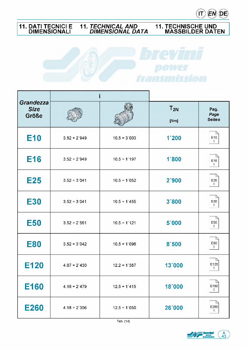
11. DATI TECNICI E DIMENSIONAL!
11. TECHNICAL AND DIMENSIONAL DATA
11. TECHNISCHE UND MASSBILDER DATEN
GrandezzaSize
GroBe
i
j s T2N Pag.Page
Seiteni p [Nm]
E10 3.52 + 2949 10.5 + 3 003 1200 E101
E16 3.52 + 2949 10.5 + 1197 1800 E161
E25 3.52 + 3 041 10.5 + 1052 2900 E251
E30 3.52 + 3 041 10.5 + 1455 3800 E301
E50 3.52 + 2561 10.5 + 1121 5 000 E501
E80 3.52 + 3 042 10.5 + 1096 8500 E801
E120 4.07 + 2430 12.2 + 1387 13 000 E1201
E160 4.18 + 2479 12.5 + 1415 18 000 E1601
E260 4.18 + 2356 12.5 + 1050 26 000 E2601
Tab. (14)

Questa pagina e lasciata intenzionalmente bianca
Page is in tentiona lly le ft blank Seite wurde absichtlich leer gelassen
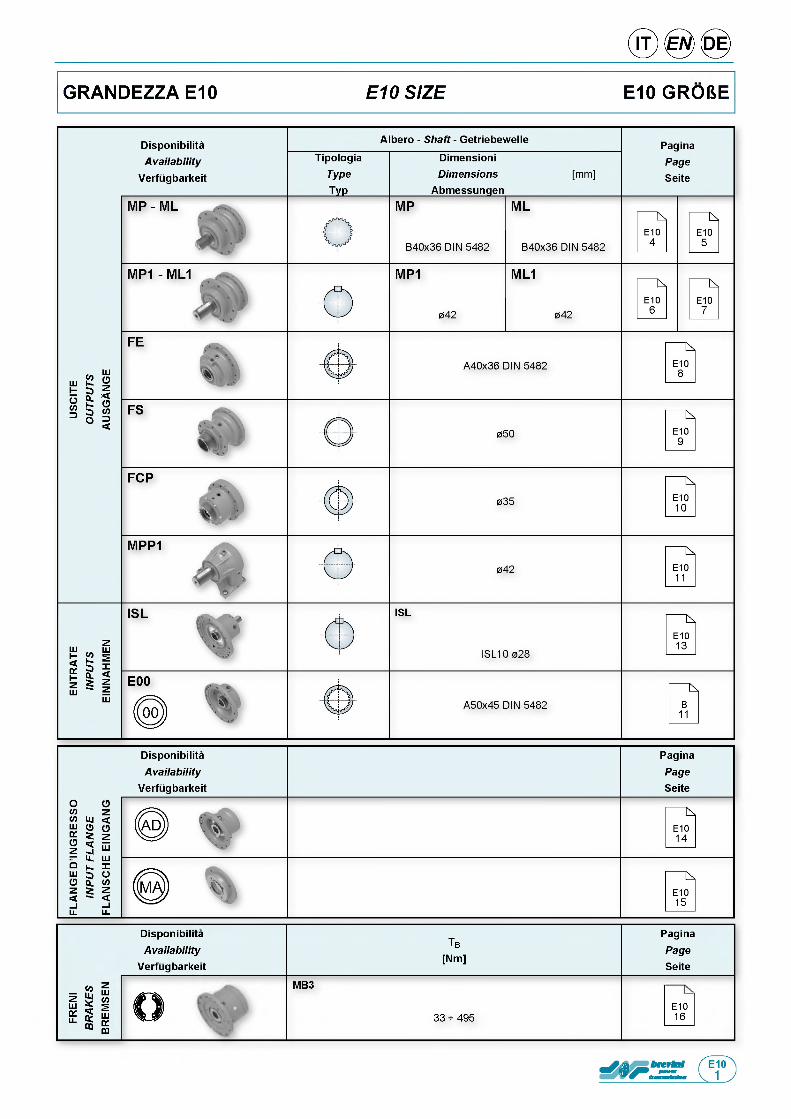
GRANDEZZA E10 E10 SIZE E10 GR06E
DisponibilitaAvailab ility
Verfugbarkeit
Tb
[Nm]
PaginaPageSeite
FRE
NI
BR
AK
ES
BR
EM
SE
N
О■. ,
MB3
33 - 495E1016
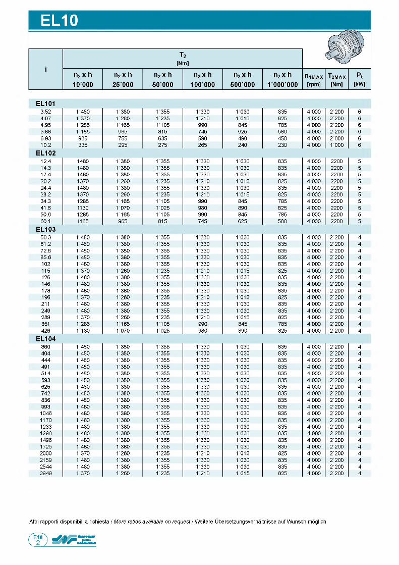
EL10
EL1013.52 1480 1380 1355 1330 1030 835 4 000 2 200 64.07 1370 1260 1235 1210 1015 825 4 000 2 200 64.95 1285 1165 1105 990 845 785 4 000 2 200 65.88 1185 965 815 745 625 580 4 000 2 200 66.93 935 755 635 590 490 450 4 000 2 000 610.2 335 295 275 265 240 230 4 000 1000 6
EL10212.4 1480 1380 1355 1330 1030 835 4 000 2200 514.3 1480 1380 1355 1330 1030 835 4 000 2200 517.4 1480 1380 1355 1330 1030 835 4 000 2200 520.2 1370 1260 1235 1210 1015 825 4 000 2200 524.4 1480 1380 1355 1330 1030 835 4 000 2200 528.2 1370 1260 1235 1210 1015 825 4 000 2200 534.3 1285 1165 1105 990 845 785 4 000 2200 541.6 1130 1070 1025 980 890 825 4 000 2200 550.6 1285 1165 1105 990 845 785 4 000 2200 560.1 1185 965 815 745 625 580 4 000 2200 5
EL10350.3 1480 1380 1355 1330 1030 835 4 000 2'200 461.2 1480 1380 1355 1330 1030 835 4 000 2'200 472.6 1480 1380 1355 1330 1030 835 4 000 2'200 485.6 1480 1380 1355 1330 1030 835 4 000 2'200 4102 1480 1380 1355 1330 1030 835 4 000 2'200 4115 1370 1260 1235 1210 1015 825 4 000 2'200 4126 1480 1380 1355 1330 1030 835 4 000 2'200 4146 1480 1380 1355 1330 1030 835 4000 2'200 4178 1480 1380 1355 1330 1030 835 4000 2'200 4196 1370 1260 1235 1210 1015 825 4000 2'200 4211 1480 1380 1355 1330 1030 835 4000 2'200 4249 1480 1380 1355 1330 1030 835 4000 2'200 4289 1370 1260 1235 1210 1015 825 4000 2'200 4351 1285 1165 1105 990 845 785 4000 2'200 4426 1130 1070 1025 980 890 825 4000 2'200 4
EL104360 1' 480 1' 380 1' 355 1' 330 1 030 835 4'000 2'200 4404 1' 480 1' 380 1' 355 1' 330 1 030 835 4'000 2'200 4444 1' 480 1' 380 1' 355 1' 330 1' 030 835 4'000 2'200 4491 1' 480 1' 380 1' 355 1' 330 1 030 835 4'000 2'200 4514 1' 480 1' 380 1' 355 1' 330 1' 030 835 4'000 2'200 4593 1' 480 1' 380 1' 355 1' 330 1 030 835 4'000 2'200 4625 1' 480 1' 380 1' 355 1' 330 1 030 835 4'000 2'200 4742 1' 480 1' 380 1' 355 1 330 1' 030 835 4'000 2'200 4836 1' 480 1' 380 1' 355 1 330 1 030 835 4'000 2'200 4993 1' 480 1' 380 1' 355 1' 330 1' 030 835 4'000 2'200 41046 1' 480 1' 380 1' 355 1 330 1 030 835 4'000 2'200 41170 1' 480 1' 380 1' 355 1 330 1 030 835 4'000 2'200 41233 1' 480 1' 380 1' 355 1' 330 1' 030 835 4'000 2'200 41290 1' 480 1' 380 1' 355 1 330 1 030 835 4'000 2'200 41496 1' 480 1' 380 1' 355 1' 330 1' 030 835 4'000 2'200 41725 1' 480 1' 380 1' 355 1 330 1 030 835 4'000 2'200 42000 1' 370 1' 260 1' 235 1 210 1 015 825 4'000 2'200 42159 1' 480 1' 380 1' 355 1' 330 1' 030 835 4'000 2'200 42544 1' 480 1' 380 1' 355 1 330 1 030 835 4'000 2'200 42949 1' 370 1' 260 1' 235 1' 210 1' 015 825 4'000 2'200 4
Altri rapporti disponibili a richiesta / More ratios available on request / Weitere Ubersetzungsverhaltnisse auf Wunsch moglich
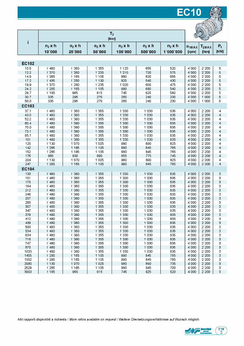
EC10210.5 1480 1380 1355 1120 655 520 4 000 2 200 512.2 1370 1260 1235 1210 720 575 4 000 2 200 514.9 1285 1165 1105 990 820 655 4 000 2 200 517.2 1435 1250 1130 925 540 430 4 000 2 200 519.9 1370 1260 1235 1020 600 475 4 000 2 200 524.2 1285 1165 1105 990 680 540 4 000 2 200 528.7 1185 965 815 745 625 580 4 000 2'200 530.7 335 295 275 265 240 230 4 000 1' 000 550.0 335 295 275 265 240 230 4 000 1' 000 5
EC10337.1 1480 1380 1355 1330 1030 835 4 000 2'200 443.0 1480 1380 1355 1330 1030 835 4 000 2'200 452.2 1480 1380 1355 1330 1030 835 4 000 2'200 460.4 1480 1380 1355 1330 1030 835 4 000 2'200 470.0 1480 1380 1355 1330 1030 835 4 000 2'200 473.1 1480 1380 1355 1330 1030 835 4 000 2'200 485.1 1480 1380 1355 1330 1030 835 4 000 2'200 4101 1480 1380 1355 1330 1030 835 4000 2'200 4125 1130 1070 1025 980 890 825 4000 2'200 4142 1285 1165 1105 990 845 785 4000 2'200 4152 1285 1165 1105 990 845 785 4000 2'200 4176 985 930 890 855 775 745 4000 2'200 4204 1130 1070 1025 980 890 825 4000 2'200 4247 1285 1165 1105 990 845 785 4000 2'200 4
EC104130 1' 480 1' 380 1' 355 1' 330 1 030 835 4'000 2'200 3151 1' 480 1' 380 1' 355 1 330 1 030 835 4'000 2'200 3175 1' 480 1' 380 1' 355 1' 330 1 030 835 4'000 2'200 3184 1' 480 1' 380 1' 355 1 330 1 030 835 4'000 2'200 3212 1' 480 1' 380 1' 355 1 330 1 030 835 4'000 2'200 3246 1' 480 1' 380 1' 355 1' 330 1' 030 835 4'000 2'200 3257 1' 480 1' 380 1 355 1 330 1 030 835 4'000 2'200 3285 1' 480 1' 380 1' 355 1' 330 1' 030 835 4'000 2'200 3307 1' 480 1' 380 1 355 1 330 1 030 835 4'000 2'200 3347 1' 480 1' 380 1' 355 1 330 1 030 835 4'000 2'200 3379 1' 480 1' 380 1 355 1 330 1' 030 835 4'000 2'200 3412 1' 480 1' 380 1 355 1 330 1 030 835 4'000 2'200 3439 1' 480 1' 380 1' 355 1' 330 1' 030 835 4'000 2'200 3500 1' 480 1' 380 1 355 1 330 1 030 835 4'000 2'200 3534 1' 480 1' 380 1' 355 1 330 1 030 835 4'000 2'200 3634 1' 480 1' 380 1 355 1 330 1' 030 835 4'000 2'200 3716 1' 480 1' 380 1 355 1 330 1 030 835 4'000 2'200 3747 1' 480 1' 380 1' 355 1' 330 1' 030 835 4'000 2'200 3870 1' 480 1' 380 1 355 1 330 1 030 835 4'000 2'200 31033 1' 480 1' 380 1' 355 1 330 1 030 835 4'000 2'200 31455 1' 285 1' 165 1 105 990 845 785 4'000 2'200 31552 1' 285 1' 165 1 105 990 845 785 4'000 2'200 32080 1' 130 1' 070 1' 025 980 890 735 4'000 2'200 32529 1' 285 1' 165 1 105 990 845 700 4'000 2'200 33003 1' 185 965 815 745 625 520 4'000 2'200 3
Altri rapporti disponibili a richiesta / More ratios available on request / Weitere Ubersetzungsverhaltnisse auf Wunsch moglich
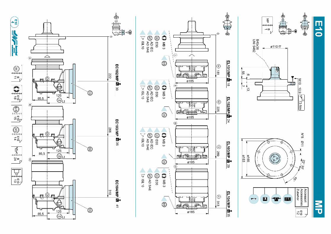
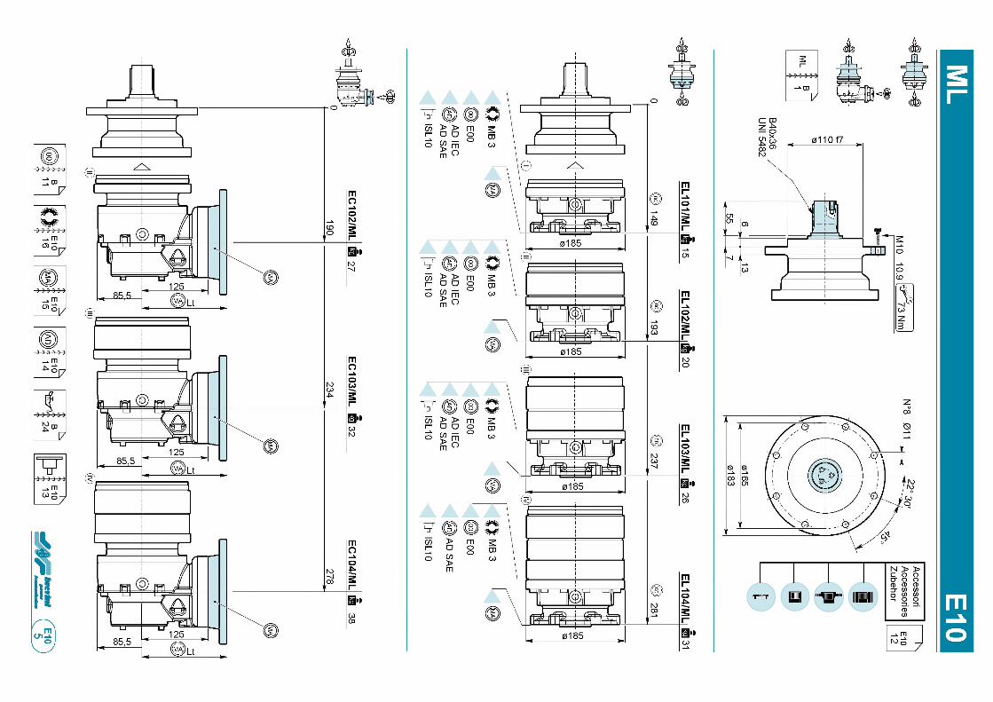
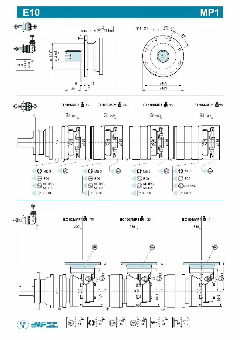
E10 MP1
!-----MP1 B
2
M10 10.9 73 Nm
35
Lt
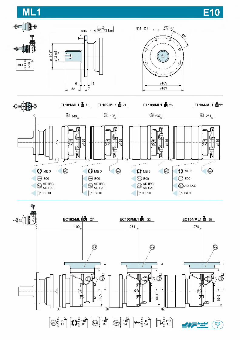
ML1 E10
^ р : в з
ML1 B2
M10 10.9 73 Nm
32
т
П,
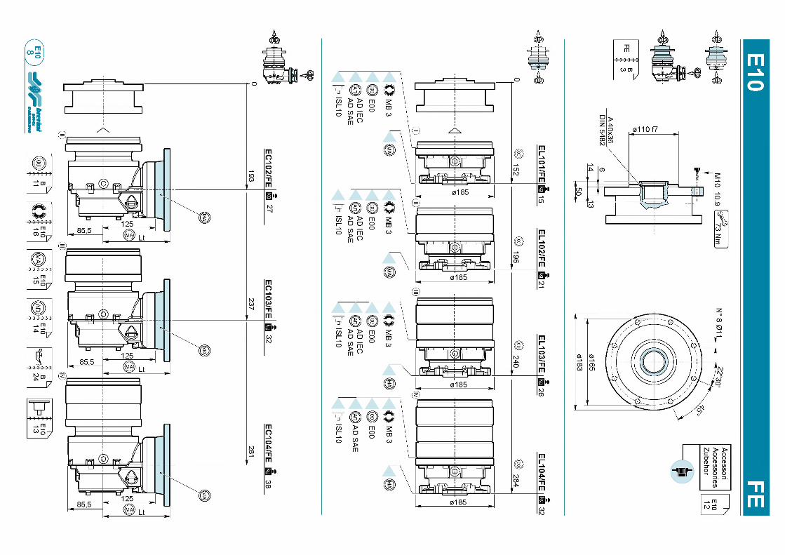
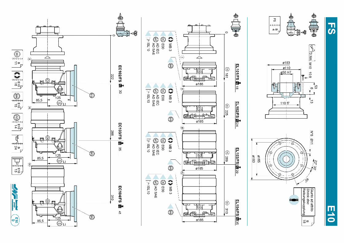
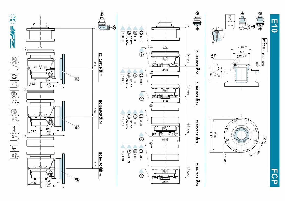
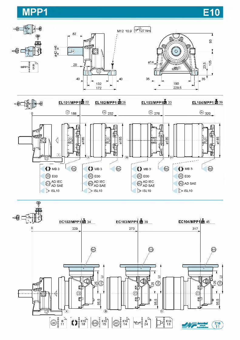
E10
m pp1 B5
о
EC102/MPP1
229
kg 34 EC103/MPP1
273
г а з а EC104/MPP1
317
@ 4 5
П
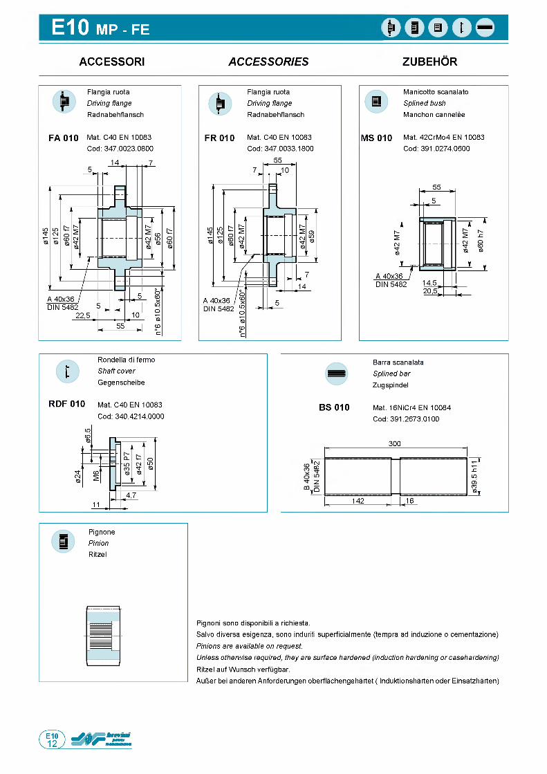
E10 MP - FE
ACCESSORI A C C E S S O R IE S ZUBEHOR
Manicotto scanalato Splined bush Manchon cannelee
MS 010 Mat. 42CrMo4 EN 10083 Cod: 391.0274.0600
Rondella di fermo Shaft cover Gegenscheibe
RDF 010 Mat. C40 EN 10083
Cod: 340.4214.0000
Barra scanalata Splined bar Zugspindel
BS 010 Mat. 16NiCr4 EN 10084 Cod: 391.2673.0100
300
CMCO JZL9O)COSt«r
и„О
142 , .16
Pignoni sono disponibili a richiesta.Salvo diversa esigenza, sono induriti superficialmente (tempra ad induzione o cementazione)
Pinions are available on request.Unless otherwise required, they are surface hardened (induction hardening or casehardening) Ritzel auf Wunsch verfugbar.
AulJer bei anderen Anforderungen oberflachengehartet ( Induktionsharten oder Einsatzharten)
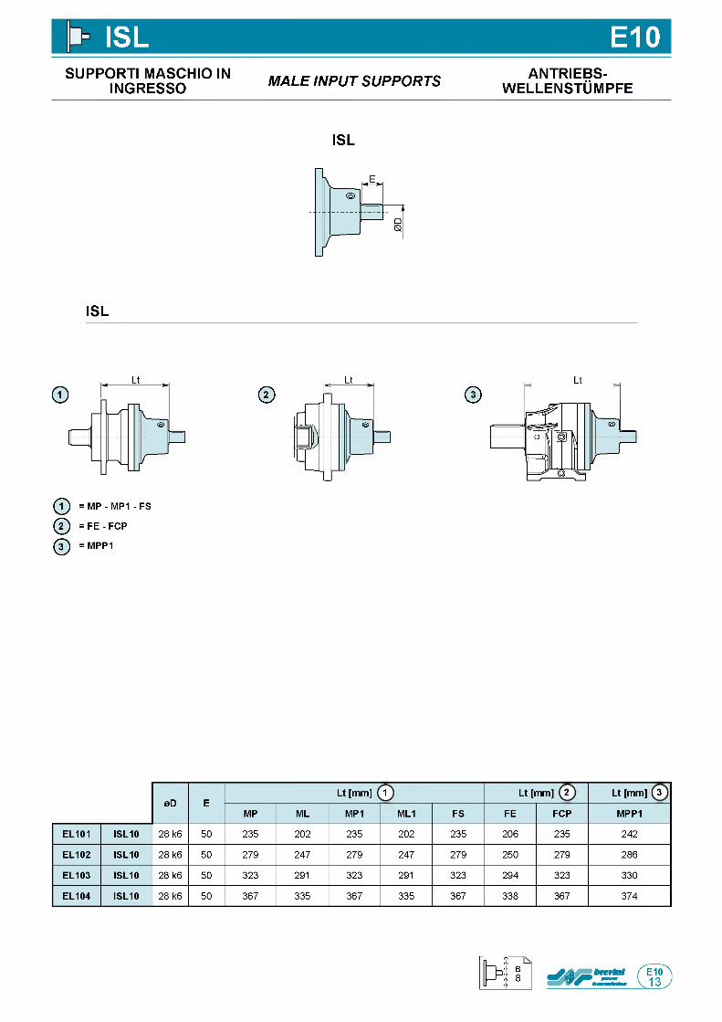
ISL E10SUPPORTI MASCHIO IN
INGRESSO M A L E IN P U T S U P P O R T S ANTRIEBS-w e l l e n s t Om p f e
ISL
ISL
©Lt
r -
ЧС---
N ©— i
j )1_J
ф = MP - MP1 - FS
@ = F E - FCP
ф = MPP1
©Lt
0D ELt [mm] 1 Lt [mm] 2 Lt [mm] 3
MP ML MP1 ML1 FS FE FCP MPP1
EL101 ISL10 28 k6 50 235 202 235 202 235 206 235 242
EL102 ISL10 28 k6 50 279 247 279 247 279 250 279 286
EL103 ISL10 28 k6 50 323 291 323 291 323 294 323 330
EL104 ISL10 28 k6 50 367 335 367 335 367 338 367 374
B8
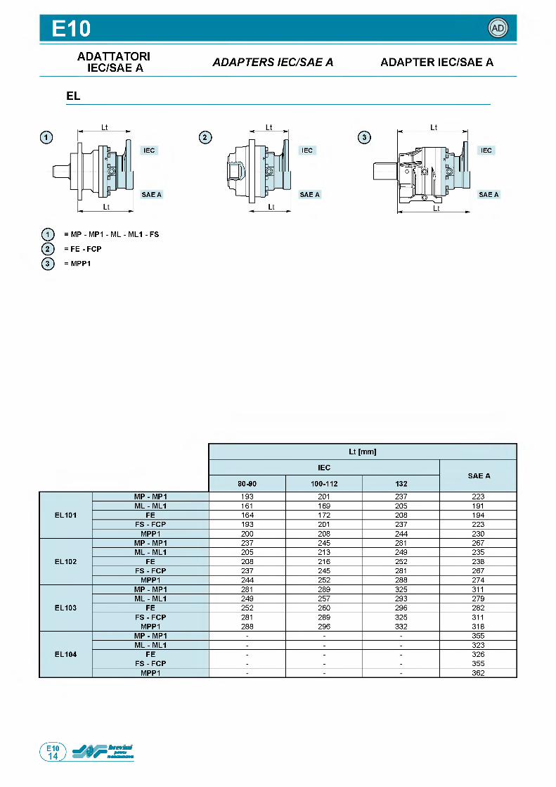
E10ADATTATORI
IEC/SAE A A D A P T E R S IE C /S A E A ADAPTER IEC/SAE A
EL
IEC
S A E A
ф = MP - MP1 - ML - ML1 - FS
@ = FE - FCP
ф = MPP1
IEC
S A E A
©IEC
S A E A
Lt [mm]
IECSAE A
80-90 100-112 132
EL101
MP - MP1 193 201 237 223ML - ML1 161 169 205 191
FE 164 172 208 194FS - FCP 193 201 237 223
MPP1 200 208 244 230
EL102
MP - MP1 237 245 281 267ML - ML1 205 213 249 235
FE 208 216 252 238FS - FCP 237 245 281 267
MPP1 244 252 288 274
EL103
MP - MP1 281 289 325 311ML - ML1 249 257 293 279
FE 252 260 296 282FS - FCP 281 289 325 311
MPP1 288 296 332 318
EL104
MP - MP1 - - - 355ML - ML1 - - - 323
FE - - - 326FS - FCP - - - 355
MPP1 - - - 362
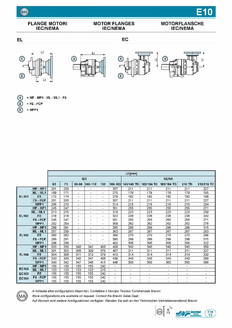
E10FLANGE MOTORI MOTOR FLANGES MOTORFLANSCHE
IEC/NEMA IEC/NEMA IEC/NEMA
EL EC
ф = MP - MP1 - ML - ML1 - FS
@ = F E - FCP
ф = MPP1
Lt [mm]
IEC NEMA
63 71 80-90 100-112 132 160-180 143/145 TD 182/184 TC 182/184 TD 210 TD 213/215 TC
EL101
MP - MP1 201 203 - - - 307 211 211 211 211 227ML - ML1 169 171 - - - 275 179 179 179 179 195
FE 172 174 - - - 278 182 182 182 182 198FS - FCP 201 203 - - - 307 211 211 211 211 227
MPP1 208 210 - - - 314 218 218 218 218 234
EL102
MP - MP1 245 247 - - - 351 255 255 255 255 271ML - ML1 213 215 - - - 319 223 223 223 223 239
FE 216 218 - - - 322 226 226 226 226 242FS - FCP 245 247 - - - 351 255 255 255 255 271
MPP1 252 254 - - - 358 262 262 262 262 278
EL103
MP - MP1 289 291 - - - 395 299 299 299 299 315ML - ML1 257 259 - - - 363 267 267 267 267 283
FE 260 262 - - - 366 270 270 270 270 286FS - FCP 289 291 - - - 395 299 299 299 299 315
MPP1 296 298 - - - 402 306 306 306 306 322
EL104
MP - MP1 333 335 340 341 408 439 343 343 343 343 359ML - ML1 301 303 308 309 376 407 311 311 311 311 327
FE 304 306 311 312 379 410 314 314 314 314 330FS - FCP 333 335 340 341 408 439 343 343 343 343 359
MPP1 340 342 347 348 415 446 350 350 350 350 366
EC102EC103EC104
MP - MP1 155 155 155 155 242 - - - - - -ML - ML1 123 123 123 123 210 - - - - - -
FE 155 155 155 155 242 - - - - - -F S - FCP 155 155 155 155 242 - - - - - -
MPP1 155 155 155 155 242 - - - - - -
A richiesta altre configurazioni disponibili. Contattare il Servizio Tecnico Commerciale Brevini
More configurations are available on request. Contact the Brevini Sales Dept.Auf Wunsch sind weitere Konfigurationen verfugbar. Wenden Sie sich an den Technischen Vertriebsinnendienst Brevini
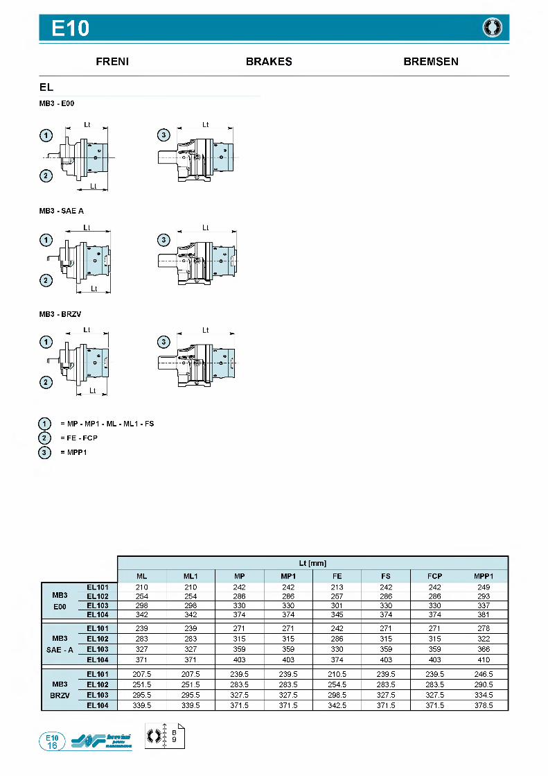
E10FRENI BRAKES BREMSEN
ELM B 3- E00
ф = MP - MP1 - ML - ML1 - FS
@ = FE - FCP
ф = MPP1
Lt [mm]
ML ML1 MP MP1 FE FS FCP MPP1
MB3E00
EL101 210 210 242 242 213 242 242 249EL102 254 254 286 286 257 286 286 293EL103 298 298 330 330 301 330 330 337EL104 342 342 374 374 345 374 374 381
MB3 SAE - A
EL101 239 239 271 271 242 271 271 278EL102 283 283 315 315 286 315 315 322EL103 327 327 359 359 330 359 359 366EL104 371 371 403 403 374 403 403 410
MB3BRZV
EL101 207.5 207.5 239.5 239.5 210.5 239.5 239.5 246.5EL102 251.5 251.5 283.5 283.5 254.5 283.5 283.5 290.5EL103 295.5 295.5 327.5 327.5 298.5 327.5 327.5 334.5EL104 339.5 339.5 371.5 371.5 342.5 371.5 371.5 378.5
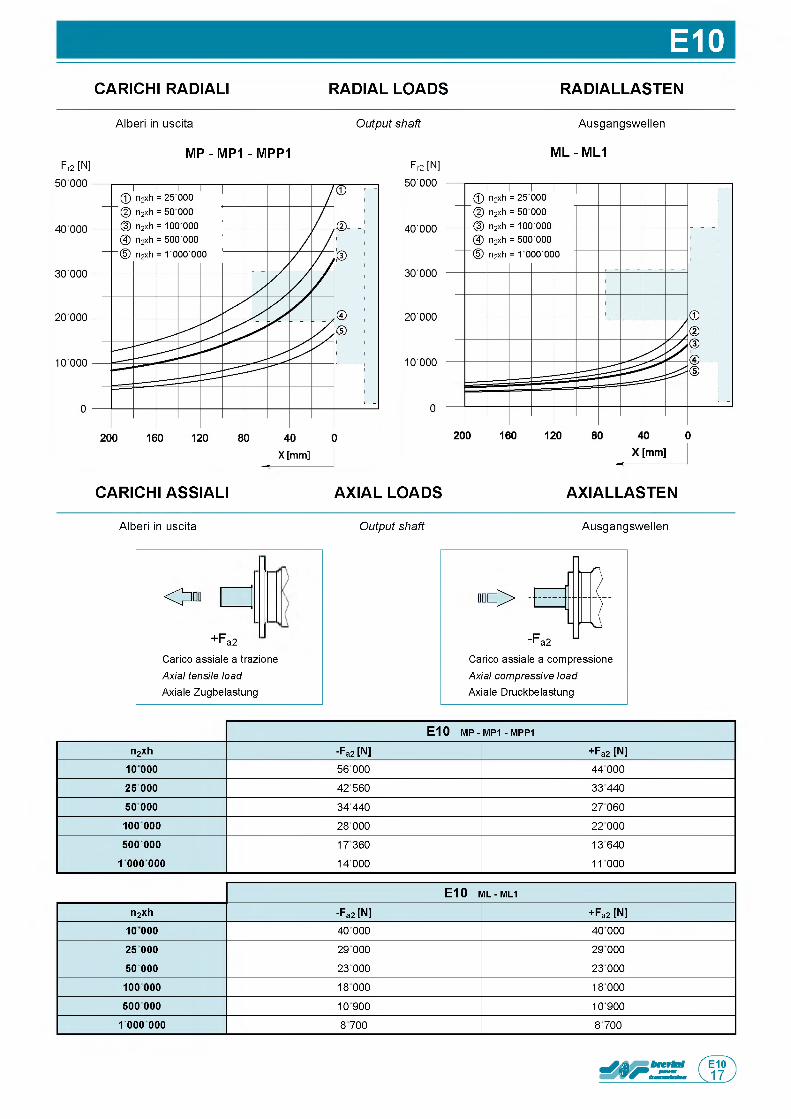
E10CARICHI RADIALI RADIAL LOADS RADIALLASTEN
Alberi in uscita Output shaft Ausgangswellen
MP - MP1 - MPP1Fr2 [N] Fr2 [N]
ML - ML1
CARICHI ASSIALI AXIAL LOADS AXIALLASTEN
Alberi in uscita Output shaft Ausgangswellen
О+Fa2
Carico assiale a trazione Axial tensile load Axiale Zugbelastung
I 0 ^ >
Carico assiale a compressione Axial compressive load Axiale Druckbelastung
E10 m p - MP1 - m p p 1
n2xh -Fa 2 [N] +Fa2 [N]10 000 56 000 4 4 0 0 0
25 000 4 2 560 3 3 440
50 000 3 4 4 4 0 2 7 060
100 000 28 000 2 2 000
500 000 1 7 3 6 0 1 3 6 4 0
1 000 000 1 4 0 0 0 1 1 000
E10 ML - ML1
n2xh -Fa 2 [N] + Fa2 [N]10 000 40 000 40 000
25 000 29 000 29 000
50 000 2 3 000 2 3 000
100 000 18 000 18 000
500 000 1 0 9 0 0 1 0 9 0 0
1 000 000 8 700 8 700
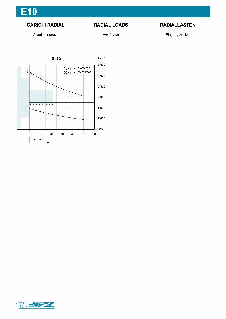
E10CARICHI RADIALI RADIAL LOADS RADIALLASTEN
Alberi in ingresso Input shaft Eingangswellen
ISL10 Fri [N]
3 500
3 000
2 500
2 000
1 500
1000
500
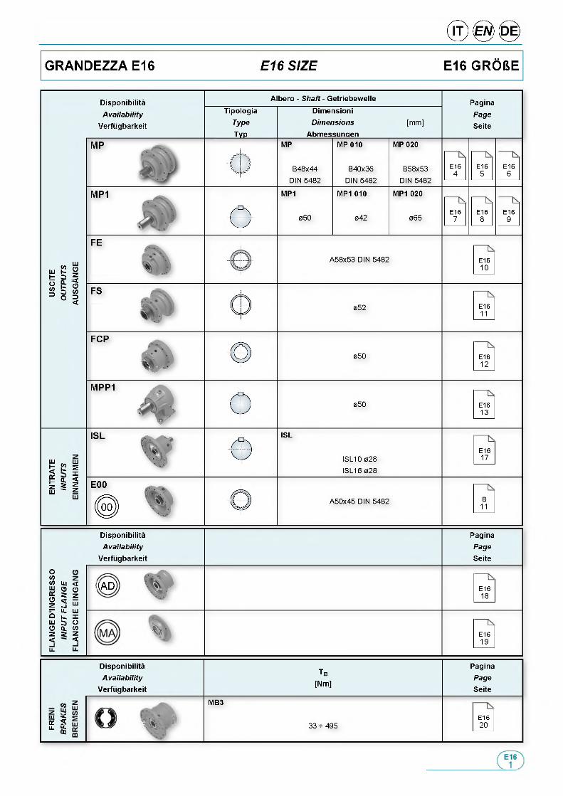
DisponibilitaAvailab ility
Verfugbarkeit
Albero - Shaft - GetriebewelleTipologia
Type
___ТУР___
DimensioniDimensions
Abmessungen[mm]
PaginaPageSeite
MP
e B48x44 DIN 5482
MP 010
B40x36 DIN 5482
MP 020
B58x53 DIN 5482
E164
E165
E166
MP1
e 050
MP1 010
042
MP1 020
065E167
E168
E169
<oш к t 3оw b 3 o
ШОz■<о«я3<
A58x53 DIN 5482 E1610
FS
052 E1611
050 E1612
050 E1613
ШH2
f2
5 1Ш
ШsX<zzШ
ISL
ISL10 028 ISL16 028
E1617
A50x45 DIN 5482 B11
DisponibilitaAvailab ility
Verfugbarkeit
PaginaPageSeite
О0w _W Ui <
% S 21 2 *— Ц . Ш° к X ш з о О о. <яz г z < <
XAD) E1618
'2> ■ E1619
DisponibilitaAvailab ility
Verfugbarkeit
Tb[Nm]
PaginaPageSeite
«оm ■*.€C SLL. £CQ
MB3
m l I 33 - 495E1620
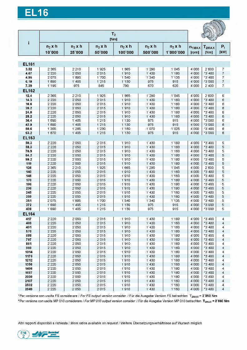
EL16
T2[Nm]
)}) о у
in2 x h n2 x h n2 x h n2 x h n2 x h n2 x h n1MAX T2MAX Pt10 000 25 000 50 000 100 000 500 000 1 000 000 [rpm] [Nm] [kW]
EL1613.52 2 365 2210 1 925 1 665 1 290 1 045 4 ■ 000 2 600 74.07 2 220 2 050 2 ■ 015 1 910 1 430 1 160 4 ■ 000 *3■400 74.95 2 075 1895 1 700 1 540 1 340 1 135 4 ■ 000 *3■400 76.19 1690 1405 1 215 1 130 975 915 4 ■ 000 *3 ■ 000 77.39 1195 975 845 790 670 620 4 ■ 000 2 400 7
EL16212.4 2 365 2210 1 925 1 665 1 290 1 045 4 ■ 000 2 600 614.3 2 220 2 050 2 ■ 015 1 910 1 430 1 160 4 ■ 000 *3 400 616.6 2 220 2 ■ 050 2 ■ 015 1 910 1 430 1 160 4 ■ 000 *3 400 620.2 2220 2 ■ 050 2 ■ 015 1 910 1 430 1 160 4 ■ 000 *3 400 624.0 2220 2 ■ 050 2 ■ 015 1 910 1 430 1 160 4 ■ 000 *3 400 628.2 2 220 2 ■ 050 2 ■ 015 1 910 1 430 1 160 4 ■ 000 *3 400 636.4 1690 1 405 1 215 1 130 975 915 4 ■ 000 *3 000 642.9 1690 1 405 1 215 1 130 975 915 4 ■ 000 *3 000 650.6 1355 1 285 1 230 1 180 1 070 1 025 4 ■ 000 *3■400 663.2 1670 1 405 1 215 1 130 975 915 4 ■ 000 *3 ■ 000 6
EL163
EL164
50.3 2 ■ 220 2 ■ 050 2 ■ 015 1 910 1 430 1 160 4 ■ 000 *3■400 558.3 2 ■ 220 2 ■ 050 2 ■ 015 1 910 1 430 1 160 4 ■ 000 *3■400 570.9 2 ■ 220 2 ■ 050 2 ■ 015 1 910 1 430 1 160 4 ■ 000 *3■400 584.2 2 ■ 220 2 ■ 050 2 ■ 015 1 910 1 430 1 160 4 ■ 000 *3■400 599.2 2 ■ 220 2 ■ 050 2 ■ 015 1 910 1 430 1 160 4 ■ 000 *3■400 5119 2 ■ 220 2 ■ 050 2 ■ 015 1 910 1 430 1 160 4 ■ 000 *3■400 5126 2 ■ 365 2 ■ 210 1 925 1 665 1 290 1 045 4 ■ 000 2 600 5140 2 ■ 220 2 ■ 050 2 ■ 015 1 910 1 430 1 160 4 ■ 000 *3 400 5146 2 ■ 220 2 ■ 050 2 ■ 015 1 910 1 430 1 160 4 ■ 000 *3 400 5170 2 ■ 220 2 ■ 050 2 ■ 015 1 910 1 430 1 160 4 ■ 000 *3 400 5196 2 ■ 220 2 ■ 050 2 ■ 015 1 910 1 430 1 160 4 ■ 000 *3 ■ 400 5206 2 ■ 220 2 ■ 050 2 ■ 015 1 910 1 430 1 160 4 ■ 000 *3 ■ 400 5245 2 ■ 220 2 ■ 050 2 ■ 015 1 910 1 430 1 160 4 ■ 000 *3 ■ 400 5289 2 ■ 220 2 ■ 050 2 ■ 015 1 910 1 430 1 160 4 ■ 000 *3 ■ 400 5351 2 ■ 075 1 895 1 700 1 540 1 340 1 135 4 ■ 000 *3 ■ 400 5372 1 690 1 405 1 215 1 130 975 915 4 ■ 000 *3 ■ 000 5438 1 690 1 405 1 215 1 130 975 915 4 ■ 000 *3 ■ 000 5
417 2 ■ 220 2 ■ 050 2 ■ 015 1 910 1 430 1 160 4 ■ 000 *3■400 4469 2 ■ 220 2 ■ 050 2 ■ 015 1 910 1 430 1 160 4 ■ 000 *3■400 4491 2 ■ 220 2 ■ 050 2 ■ 015 1 910 1 430 1 160 4 ■ 000 *3■400 4570 2 ■ 220 2 ■ 050 2 ■ 015 1 910 1 430 1 160 4 ■ 000 *3■400 4688 2 ■ 220 2 ■ 050 2 ■ 015 1 910 1 430 1 160 4 ■ 000 *3■400 4797 2 ■ 220 2 ■ 050 2 ■ 015 1 910 1 430 1 160 4 ■ 000 *3■400 4861 2 ■ 220 2 ■ 050 2 ■ 015 1 910 1 430 1 160 4 ■ 000 *3■400 4969 2 ■ 220 2 ■ 050 2 ■ 015 1 910 1 430 1 160 4 ■ 000 *3■400 41014 2 ■ 220 2 ■ 050 2 ■ 015 1 910 1 430 1 160 4 ■ 000 *3■400 41176 2 ■ 220 2 ■ 050 2 ■ 015 1 910 1 430 1 160 4 ■ 000 *3■400 41212 2 ■ 220 2 ■ 050 2 ■ 015 1 910 1 430 1 160 4 ■ 000 *3■400 41356 2 ■ 220 2 ■ 050 2 ■ 015 1 910 1 430 1 160 4 ■ 000 *3■400 41496 2 ■ 220 2 ■ 050 2 ■ 015 1 910 1 430 1 160 4 ■ 000 *3 ■ 400 41697 2 ■ 220 2 ■ 050 2 ■ 015 1 910 1 430 1 160 4 ■ 000 *3 ■ 400 42000 2 ■ 220 2 ■ 050 2 ■ 015 1 910 1 430 1 160 4 ■ 000 *3 ■ 400 42107 2 ■ 220 2 ■ 050 2 ■ 015 1 910 1 430 1 160 4 ■ 000 *3 ■ 400 42502 2 ■ 220 2 ■ 050 2 ■ 015 1 910 1 430 1 160 4 ■ 000 *3 ■ 400 42949 2 ■ 220 2 ■ 050 2 ■ 015 1 910 1 430 1 160 4 ■ 000 *3 ■ 400 4
*Per versione con uscita FS considerare / For FS output version consider / Fur die Ausgabe Version FS betrachten T2MAX = 2'850 Nm
*Per versione con uscita MP 010 considerare / For MP 010 output version consider / Fur die Ausgabe Version MP 010 betrachten T2MAX = 2'600 Nm
Altri rapporti disponibili a richiesta / More ratios available on request / Weitere Ubersetzungsverhaltnisse auf Wunsch moglich
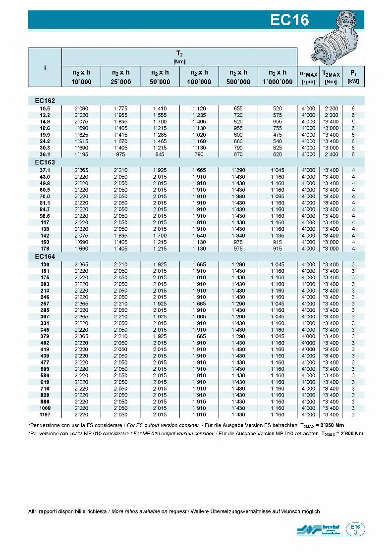
EC16
T2[Nm]
n2 x h 10000
n2 x h n2 x h n2 x h n2 x h n2 x h n1MAX T2MAX Pt25 000 50 000 100 000 500 000 1 000 000 [rpm] [Nm] [kW]
EC16210.5 2 090 1 775 1 410 1 120 655 520 4 ■ 000 2 200 612.2 2 220 1 955 1 555 1 235 720 575 4 ■ 000 2 200 614.9 2 075 1 895 1 700 1 405 820 655 4 ■ 000 *3 400 618.6 1690 1 405 1 215 1 130 955 755 4 ■ 000 *3 000 619.9 1625 1 415 1 285 1 020 600 475 4 ■ 000 *3 ■ 400 624.2 1915 1 670 1 465 1 160 680 540 4 ■ 000 *3 ■ 400 630.3 1 690 1 405 1 215 1 130 790 625 4 ■ 000 *3 ■ 000 636.1 1 195 975 845 790 670 620 4 ■ 000 2 ■ 400 6
EC16337.1 2 ■ 365 2 ■ 210 1 925 1 665 1 290 1 045 4 ■ 000 *3■400 443.0 2 ■ 220 2 ■ 050 2 ■ 015 1 910 1 430 1 160 4 ■ 000 *3■400 449.8 2 ■ 220 2 ■ 050 2 ■ 015 1 910 1 430 1 160 4 ■ 000 *3■400 460.5 2 ■ 220 2 ■ 050 2 ■ 015 1 910 1 430 1 160 4 ■ 000 *3■400 470.0 2 ■ 220 2 ■ 050 2 ■ 015 1 910 1 380 1 095 4 ■ 000 *3■400 481.1 2 ■ 220 2 ■ 050 2 ■ 015 1 910 1 430 1 160 4 ■ 000 *3■400 484.7 2 ■ 220 2 ■ 050 2 ■ 015 1 910 1 430 1 160 4 ■ 000 *3■400 498.6 2 ■ 220 2 ■ 050 2 ■ 015 1 910 1 430 1 160 4 ■ 000 *3■400 4117 2 ■ 220 2 ■ 050 2 ■ 015 1 910 1 430 1 160 4 ■ 000 *3■400 4138 2 ■ 220 2 ■ 050 2 ■ 015 1 910 1 430 1 160 4 ■ 000 *3■400 4142 2 ■ 075 1 895 1 700 1 540 1 340 1 135 4 ■ 000 *3■400 4150 1 690 1 405 1 215 1 130 975 915 4 ■ 000 *3 ■ 000 4178 1 690 1 405 1 215 1 130 975 915 4 ■ 000 *3 ■ 000 4
EC164130 2 ■ 365 2 ■ 210 1 925 1 665 1 290 1 045 4 ■ 000 *3■400 3151 2 ■ 220 2 ■ 050 2 ■ 015 1 910 1 430 1 160 4 ■ 000 *3■400 3175 2 ■ 220 2 ■ 050 2 ■ 015 1 910 1 430 1 160 4 ■ 000 *3■400 3203 2 ■ 220 2 ■ 050 2 ■ 015 1 910 1 430 1 160 4 ■ 000 *3■400 3213 2 ■ 220 2 ■ 050 2 ■ 015 1 910 1 430 1 160 4 ■ 000 *3■400 3246 2 ■ 220 2 ■ 050 2 ■ 015 1 910 1 430 1 160 4 ■ 000 *3■400 3257 2 ■ 365 2 ■ 210 1 925 1 665 1 290 1 045 4 ■ 000 *3■400 3285 2 ■ 220 2 ■ 050 2 ■ 015 1 910 1 430 1 160 4 ■ 000 *3■400 3307 2 ■ 365 2 ■ 210 1 925 1 665 1 290 1 045 4 ■ 000 *3■400 3331 2 ■ 220 2 ■ 050 2 ■ 015 1 910 1 430 1 160 4 ■ 000 *3■400 3345 2 ■ 220 2 ■ 050 2 ■ 015 1 910 1 430 1 160 4 ■ 000 *3■400 3379 2 ■ 365 2 ■ 210 1 925 1 665 1 290 1 045 4 ■ 000 *3■400 3402 2 ■ 220 2 ■ 050 2 ■ 015 1 910 1 430 1 160 4 ■ 000 *3■400 3419 2 ■ 220 2 ■ 050 2 ■ 015 1 910 1 430 1 160 4 ■ 000 *3■400 3439 2 ■ 220 2 ■ 050 2 ■ 015 1 910 1 430 1 160 4 ■ 000 *3■400 3477 2 ■ 220 2 ■ 050 2 ■ 015 1 910 1 430 1 160 4 ■ 000 *3■400 3509 2 ■ 220 2 ■ 050 2 ■ 015 1 910 1 430 1 160 4 ■ 000 *3■400 3580 2 ■ 220 2 ■ 050 2 ■ 015 1 910 1 430 1 160 4 ■ 000 *3■400 3619 2 ■ 220 2 ■ 050 2 ■ 015 1 910 1 430 1 160 4 ■ 000 *3■400 3716 2 ■ 220 2 ■ 050 2 ■ 015 1 910 1 430 1 160 4 ■ 000 *3■400 3829 2 ■ 220 2 ■ 050 2 ■ 015 1 910 1 430 1 160 4 ■ 000 *3■400 3866 2 ■ 220 2 ■ 050 2 ■ 015 1 910 1 430 1 160 4 ■ 000 *3■400 31008 2 ■ 220 2 ■ 050 2 ■ 015 1 910 1 430 1 160 4 ■ 000 *3■400 31197 2 ■ 220 2 ■ 050 2 ■ 015 1 910 1 430 1 160 4 ■ 000 *3■400 3
*Per versione con uscita FS considerare / ForFS output version consider / Fur die Ausgabe Version FS betrachten T2MAX = 2'850 Nm
*Per versione con uscita MP 010 considerare / For MP 010 output version consider / Fur die Ausgabe Version MP 010 betrachten T2MAX = 2'600 Nm
Altri rapporti disponibili a richiesta / More ratios available on request / Weitere Ubersetzungsverhaltnisse auf Wunsch moglich
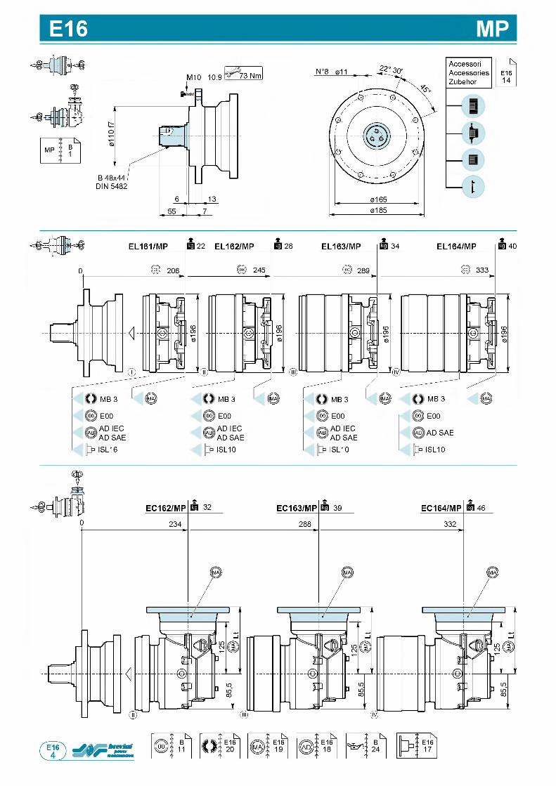
E16
; k.mp : B
1
M10 10.9 73 Nm
AccessoriAccessoriesZubehor
40
MB 3 IP MB 3 0 ) MB 3 IP
op E00 op E00 op E00
AD AD ie c AD a d ie c AD a d ie c^ AD SAE AD AD SAE AD AD SAE
ISL16 ISL10 ISL10
MB 3
op E00
AD SAE
ISL10
t
П
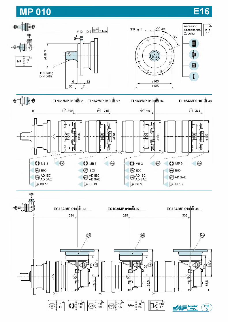
E16
IMP
M10 10.9 773 Nm
AccessoriAccessoriesZubehor
MB 3 IP MB 3 Ц ) MB 3 IP
op E00 op E00 op E00
AD AD ie c AD a d ie c Ad AD IEC^ AD SAE AD AD SAE AD AD SAE
ISL16 ISL10 ISL10
MB 3
op E00
AD SAE
ISL10
П,
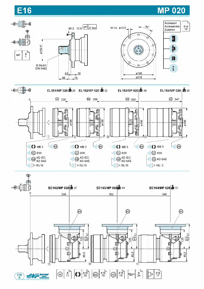
E16 MP 020
1; k.
mp : B1
M12 10.9 127 Nm
Accessori Accessories Zubehor
E1616
MB 3 0 MB 3 MA О MB 3 1!)
§ E00 ( 0 E00 0 E00
AD AD ie c AD a d ie c AD a d ie c^ AD SAE ^ AD SAE AD AD SAE
ISL16 pp ISL10 ISL10
MB 3
© E00
@ AD SAE
ISL10
0
EC162/MP 020 |kg 37
248
EC163/MP 020[kg 44
302
EC164/MP 020 [kg 51
346
П
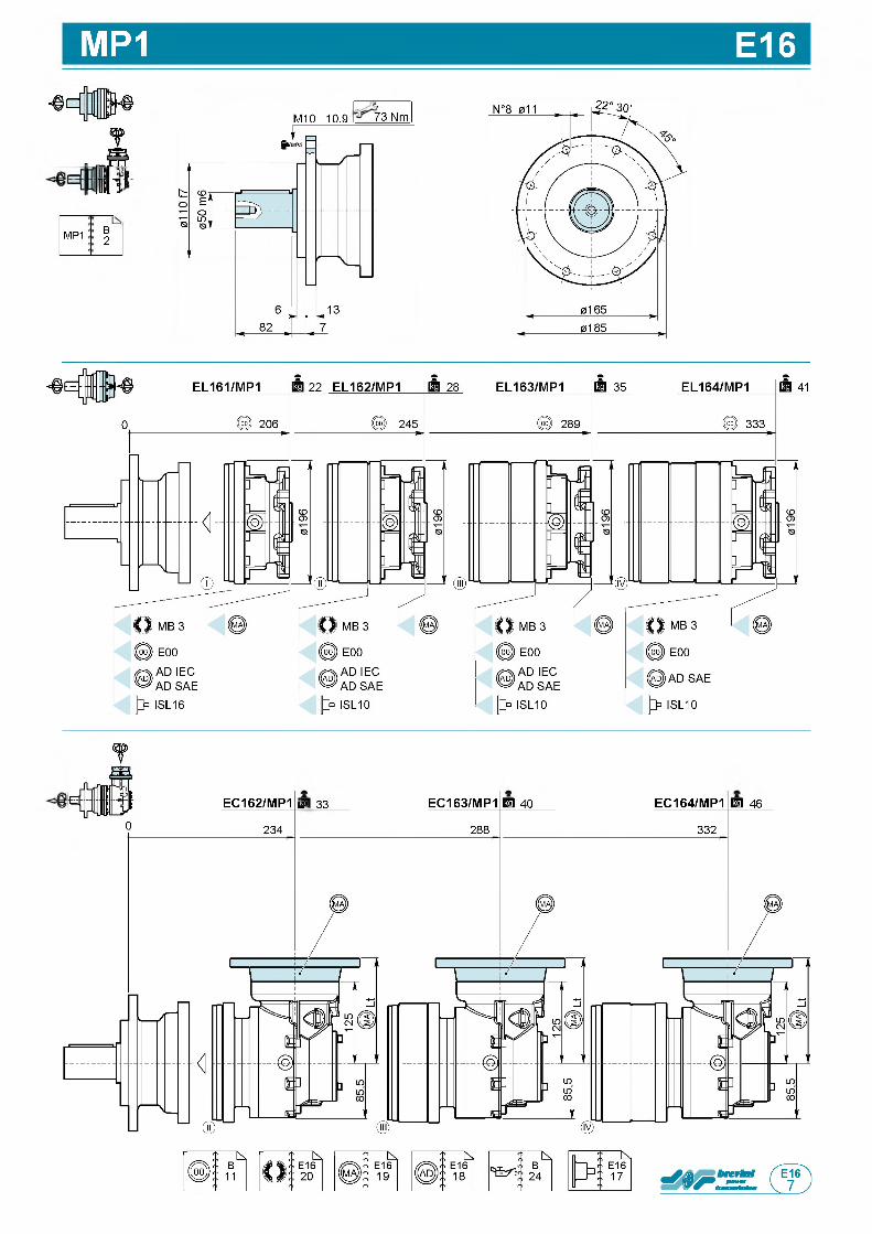
MP1 E16
: в з
MP1 B2
M10 10.9 73 Nm
EC162/MP1 L a 33 EC163/MP1 га 40 EC164/MP1 га 46
0 234 288 332
П
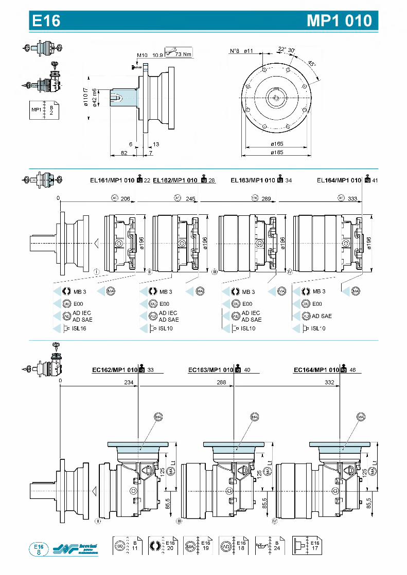
E16
f,= n t v
MP1 B2
M10 10.9 73 Nm
▼
П
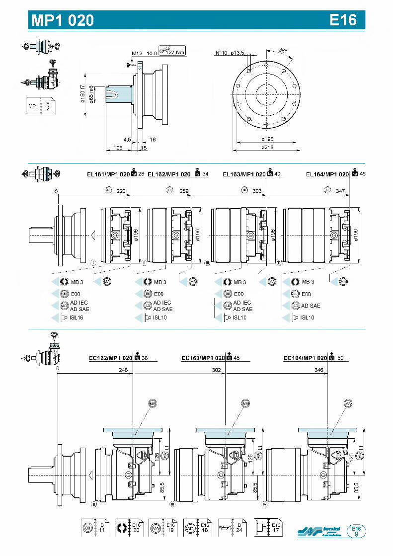
MP1 020 E16
Ш
MP1! ^
B 2
M12 10.9 ?227 Nm
46
оо E00
© AD IEC AD SAE ISL16
оо E00
© AD IEC AD SAE
J> ISL10
оо E00
© AD IEC AD SAE
|> ISL10
MB 3
@ ) E00
@ ) AD SAE
|> ISL10
t
П
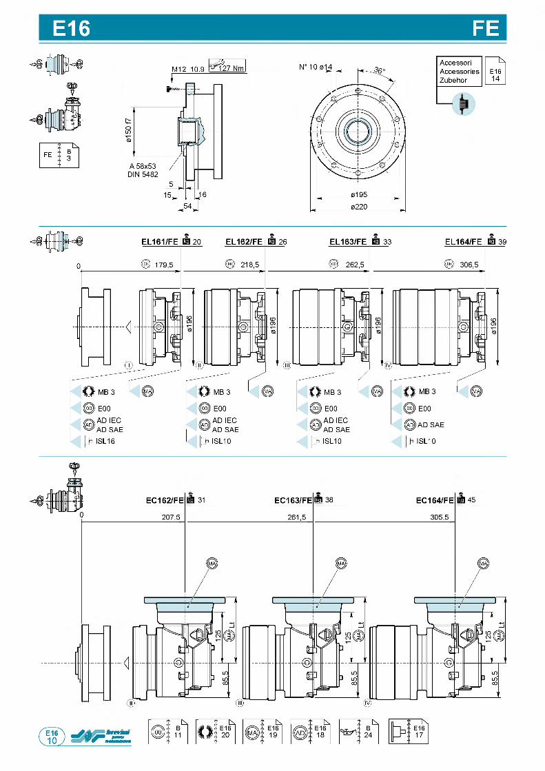
E16 FEM12 10.9 ?227 Nm
Accessori КAccessories E16Zubehor 14
J
1<
EC162/FE kg 31
207,5
EC163/FE ra 38
261,5
EC164/FE kg 45
305,5
П
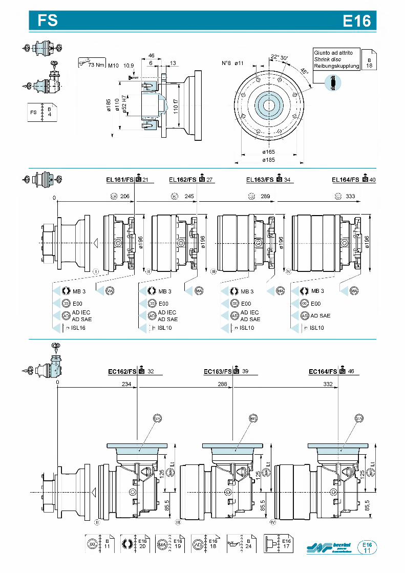
FS E16
46
f
П
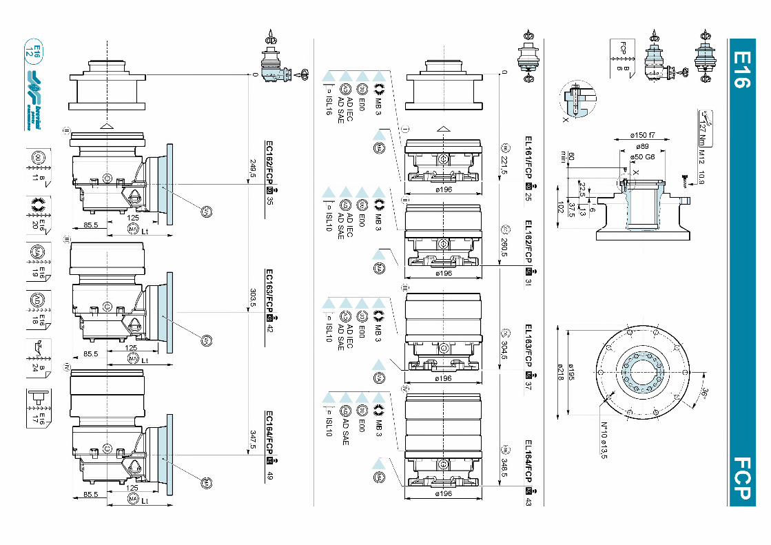
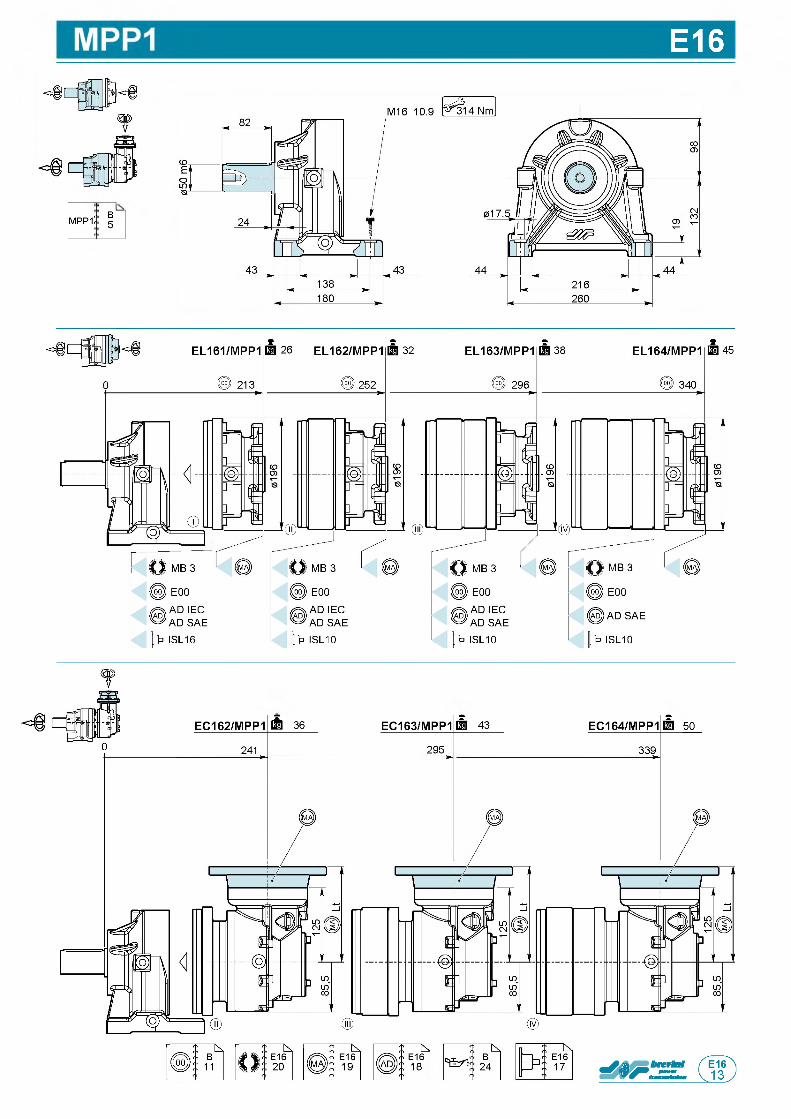
E16
MPP1 B5
о
50
П
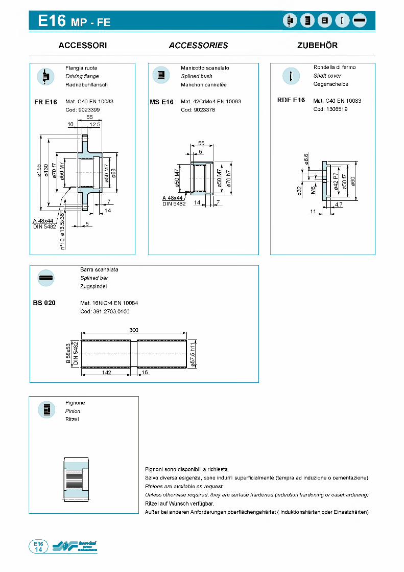
E16 MP - FE
ACCESSORI A C C E S S O R IE S ZUBEHOR
Rondella di fermo Shaft cover Gegenscheibe
RDF E16 Mat. C40 EN 10083 Cod: 1306519
Pignoni sono disponibili a richiesta.Salvo diversa esigenza, sono induriti superficialmente (tempra ad induzione o cementazione) Pinions are available on request.Unless otherwise required, they are surface hardened (induction hardening or casehardening) Ritzel auf Wunsch verfugbar.AulJer bei anderen Anforderungen oberflachengehartet ( Induktionsharten oder Einsatzharten)
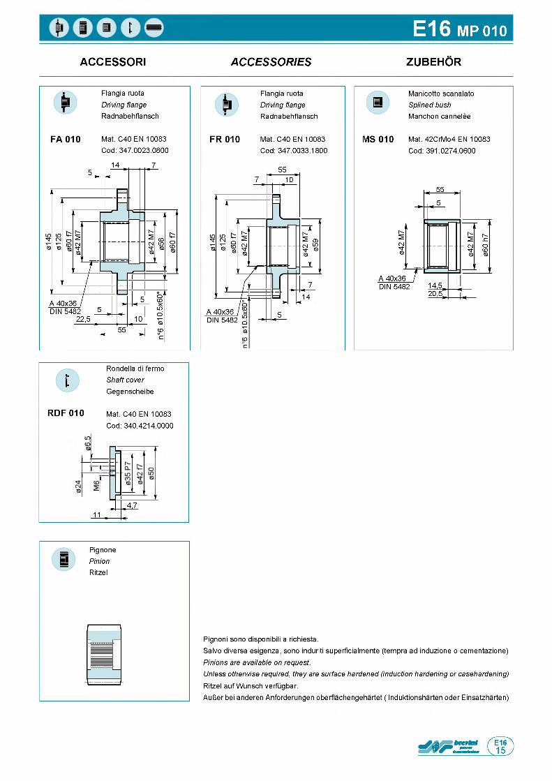
E16 MP 010
ACCESSORI A C C E S S O R IE S ZUBEHOR
MS 010
Manicotto scanalato Splined bush Manchon cannelee
Mat. 42CrMo4 EN 10083 Cod: 391.0274.0600
Rondella di fermo Shaft cover Gegenscheibe
RDF 010 Mat. C40 EN 10083 Cod: 340.4214.0000
Pignoni sono disponibili a richiesta.Salvo diversa esigenza, sono induriti superficialmente (tempra ad induzione o cementazione) Pinions are available on request.Unless otherwise required, they are surface hardened (induction hardening or casehardening) Ritzel auf Wunsch verfugbar.AulJer bei anderen Anforderungen oberflachengehartet ( Induktionsharten oder Einsatzharten)
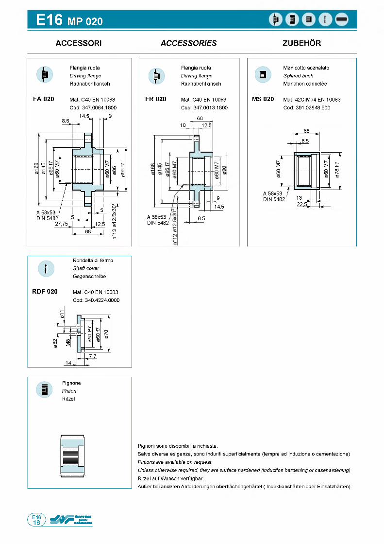
E16 MP 020
ACCESSORI A C C E S S O R IE S ZUBEHOR
FR 020
Flangia ruota Driving flange Radnabehflansch
Mat. C40 EN 10083 Cod: 347.0013.1800
1068
CDA 58x53 DIN 5482
12,5
14.5
8.5
MS 020
Manicotto scanalato Splined bush Manchon cannelee
Mat. 42CrMo4 EN 10083 Cod: 391.02848.500
9
Rondella di fermo Shaft cover Gegenscheibe
RDF 020 Mat. C40 EN 10083 Cod: 340.4224.0000
Pignoni sono disponibili a richiesta.Salvo diversa esigenza, sono induriti superficialmente (tempra ad induzione o cementazione) Pinions are available on request.Unless otherwise required, they are surface hardened (induction hardening or casehardening) Ritzel auf Wunsch verfugbar.AulJer bei anderen Anforderungen oberflachengehartet ( Induktionsharten oder Einsatzharten)
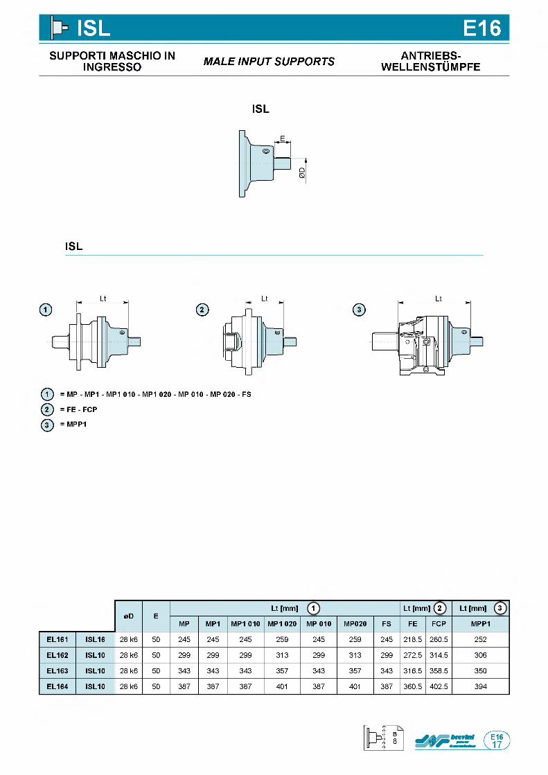
ISL E16SUPPORTI MASCHIO IN
INGRESSO M A L E IN P U T S U P P O R T S ANTRIEBS-w e l l e n s t Om p f e
ISL
ISL
©Lt
j-
— ►
N@
— ij)
/
1_J
ф = MP - MP1 - MP1 010 - MP1 020 - MP 010 - MP 020 - FS
ф = FE - FCP
ф = MPP1
©
0D ELt [mm] 1 Lt [mm] 2 Lt [mm] 3
MP MP1 MP1 010 MP1 020 MP 010 MP020 FS FE FCP MPP1
EL161 ISL16 28 k6 50 245 245 245 259 245 259 245 218.5 260.5 252
EL162 ISL10 28 k6 50 299 299 299 313 299 313 299 272.5 314.5 306
EL163 ISL10 28 k6 50 343 343 343 357 343 357 343 316.5 358.5 350
EL164 ISL10 28 k6 50 387 387 387 401 387 401 387 360.5 402.5 394
B8
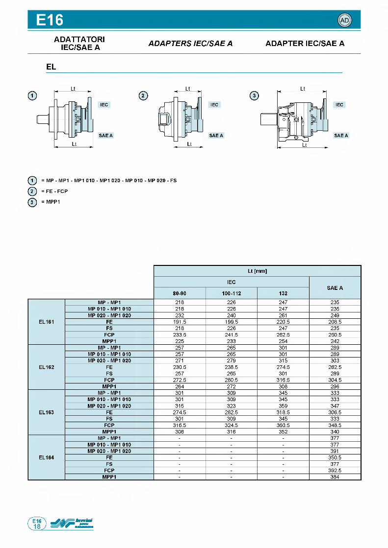
E16ADATTATORI
IEC/SAE A A D A P T E R S IE C /S A E A ADAPTER IEC/SAE A
EL
IEC
S A E A
IEC
S A E A
IEC
S A E A
ф = MP - MP1 - MP1 010 - MP1 020 - MP 010 - MP 020 - FS
ф = F E - FCP
ф = MPP1
Lt [mm]
IECSAE A
80-90 100-112 132
EL161
MP - MP1 218 226 247 235MP 010 - MP1 010 218 226 247 235MP 020 - MP1 020 232 240 261 249
FE 191.5 199.5 220.5 208.5FS 218 226 247 235
FCP 233.5 241.5 262.5 250.5MPP1 225 233 254 242
EL162
MP - MP1 257 265 301 289MP 010 - MP1 010 257 265 301 289MP 020 - MP1 020 271 279 315 303
FE 230.5 238.5 274.5 262.5FS 257 265 301 289
FCP 272.5 280.5 316.5 304.5MPP1 264 272 308 296
EL163
MP - MP1 301 309 345 333MP 010 - MP1 010 301 309 345 333MP 020 - MP1 020 315 323 359 347
FE 274.5 282.5 318.5 306.5FS 301 309 345 333
FCP 316.5 324.5 360.5 348.5MPP1 308 316 352 340
EL164
MP - MP1 - - - 377MP 010 - MP1 010 - - - 377MP 020 - MP1 020 - - - 391
FE - - - 350.5FS - - - 377
FCP - - - 392.5MPP1 - - - 384
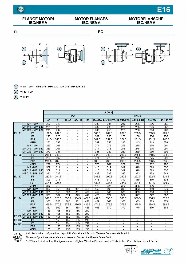
0 ) E16FLANGE MOTORI MOTOR FLANGES MOTORFLANSCHE
IEC/NEMA IEC/NEMA IEC/NEMA
EL EC
ф = MP - MP1 - MP1 010 - MP1 020 - MP 010 - MP 020 - FS
ф = FE - FCP
ф = MPP1
Lt [mm]IEC NEMA
63 71 80-90 100-112 132 160-180 143/145 TD 182/184 TC 182/184 TD 210 TD 213/215 TC
EL161
MP - MP1 226 228 - - - 332 236 236 236 236 252MP 010 - MP1 010 226 228 - - - 332 236 236 236 236 252MP 020 - MP1 020 240 242 - - - 346 250 250 250 250 266
FE 199.5 201.5 - - - 305.5 209.5 209.5 209.5 209.5 225.5FS 226 228 - - - 332 236 236 236 236 252
FCP 241.5 243.5 - - - 347.5 251.5 251.5 251.5 251.5 267.5MPP1 233 235 - - - 339 243 243 243 243 259
EL162
MP - MP1 265 267 - - - 371 275 275 275 275 291MP 010 - MP1 010 265 267 - - - 371 275 275 275 275 291MP 020 - MP1 020 279 281 - - - 385 289 289 289 289 305
FE 238.5 240.5 - - - 344.5 248.5 248.5 248.5 248.5 264.5FS 265 267 - - - 371 275 275 275 275 291
FCP 280.5 282.5 - - - 386.5 290.5 290.5 290.5 290.5 306.5MPP1 272 274 - - - 378 282 282 282 282 298
EL163
MP - MP1 309 311 - - - 415 319 319 319 319 335MP 010 - MP1 010 309 311 - - - 415 319 319 319 319 335MP 020 - MP1 020 323 325 - - - 429 333 333 333 333 349
FE 282.5 284.5 - - - 388.5 292.5 292.5 292.5 292.5 308.5FS 309 311 - - - 415 319 319 319 319 335
FCP 324.5 326.5 - - - 430.5 334.5 334.5 334.5 334.5 350.5MPP1 316 318 - - - 422 326 326 326 326 342
EL164
MP - MP1 353 355 360 361 428 459 363 363 363 363 379MP 010 - MP1 010 353 355 360 361 428 459 363 363 363 363 379MP 020 - MP1 020 367 369 374 375 442 473 377 377 377 377 393
FE 326.5 328.5 333.5 334.5 401.5 432.5 336.5 336.5 336.5 336.5 352.5FS 353 355 360 361 428 459 363 363 363 363 379
FCP 368.5 370.5 375.5 376.5 443.5 474.5 378.5 378.5 378.5 378.5 394.5MPP1 360 362 367 368 435 466 370 370 370 370 386
EC162EC163EC164
MP - MP1 155 155 155 155 242 - - - - - -MP 010 - MP1 010 155 155 155 155 242 - - - - - -MP 020 - MP1 020 155 155 155 155 242 - - - - - -
FE 155 155 155 155 242 - - - - - -FS 155 155 155 155 242 - - - - - -
FCP 155 155 155 155 242 - - - - - -MPP1 155 155 155 155 242 - - - - - -
A richiesta altre configurazioni disponibili. Contattare il Servizio Tecnico Commerciale Brevini More configurations are available on request. Contact the Brevini Sales Dept.Auf Wunsch sind weitere Konfigurationen verfugbar. Wenden Sie sich an den Technischen Vertriebsinnendienst Brevini
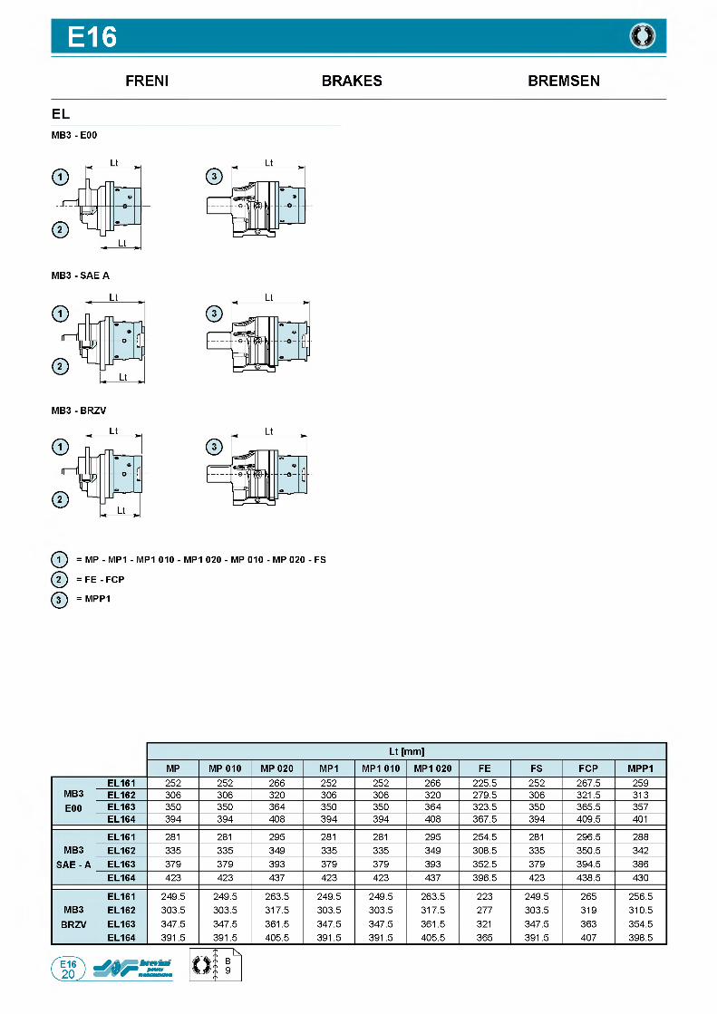
E16FRENI BRAKES BREMSEN
ELM B 3- E00
ф = MP - MP1 - MP1 010 - MP1 020 - MP 010 - MP 020 - FS
ф = FE - FCP
ф = MPP1
Lt [mm]
MP MP 010 MP 020 MP1 MP1 010 MP1 020 FE FS FCP MPP1
MB3E00
EL161 252 252 266 252 252 266 225.5 252 267.5 259EL162 306 306 320 306 306 320 279.5 306 321.5 313EL163 350 350 364 350 350 364 323.5 350 365.5 357EL164 394 394 408 394 394 408 367.5 394 409.5 401
MB3 SAE - A
EL161 281 281 295 281 281 295 254.5 281 296.5 288EL162 335 335 349 335 335 349 308.5 335 350.5 342EL163 379 379 393 379 379 393 352.5 379 394.5 386EL164 423 423 437 423 423 437 396.5 423 438.5 430
MB3BRZV
EL161 249.5 249.5 263.5 249.5 249.5 263.5 223 249.5 265 256.5EL162 303.5 303.5 317.5 303.5 303.5 317.5 277 303.5 319 310.5EL163 347.5 347.5 361.5 347.5 347.5 361.5 321 347.5 363 354.5EL164 391.5 391.5 405.5 391.5 391.5 405.5 365 391.5 407 398.5
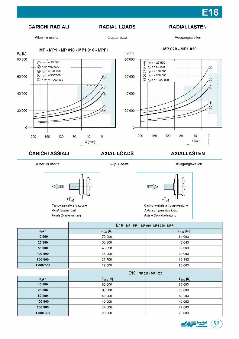
E16CARICHI RADIALI RADIAL LOADS RADIALLASTEN
Alberi in uscita Output shaft Ausgangswellen
MP - MP1 - MP 010 - MP1 010 - MPP1 MP 020 - MP1 020Fr2 [N] Fr2 [N]
CARICHI ASSIALI AXIAL LOADS AXIALLASTEN
Alberi in uscita Output shaft Ausgangswellen
Carico assiale a trazione Axial tensile load Axiale Zugbelastung
E16 m p - MP1 - m p 010 - MP1 010 - m p p 1n2xh -Fa2 [N] + Fa2 [N]
1 0 0 0 0 70 000 64 000
25 000 53 200 48 640
50 000 43 050 39 360
10 0 000 35 000 32 000
500 000 21700 19840
1 000 000 17500 16 000
E16 MP 020 - MP1 020
n2xh -Faa2 [N] + Faa2 [N]10 000 80 000 80 000
25 000 60 800 60 800
50 000 49 200 49 200
10 0 000 40 000 40 000
500 000 24800 24 800
1 000 000 20 000 20 000
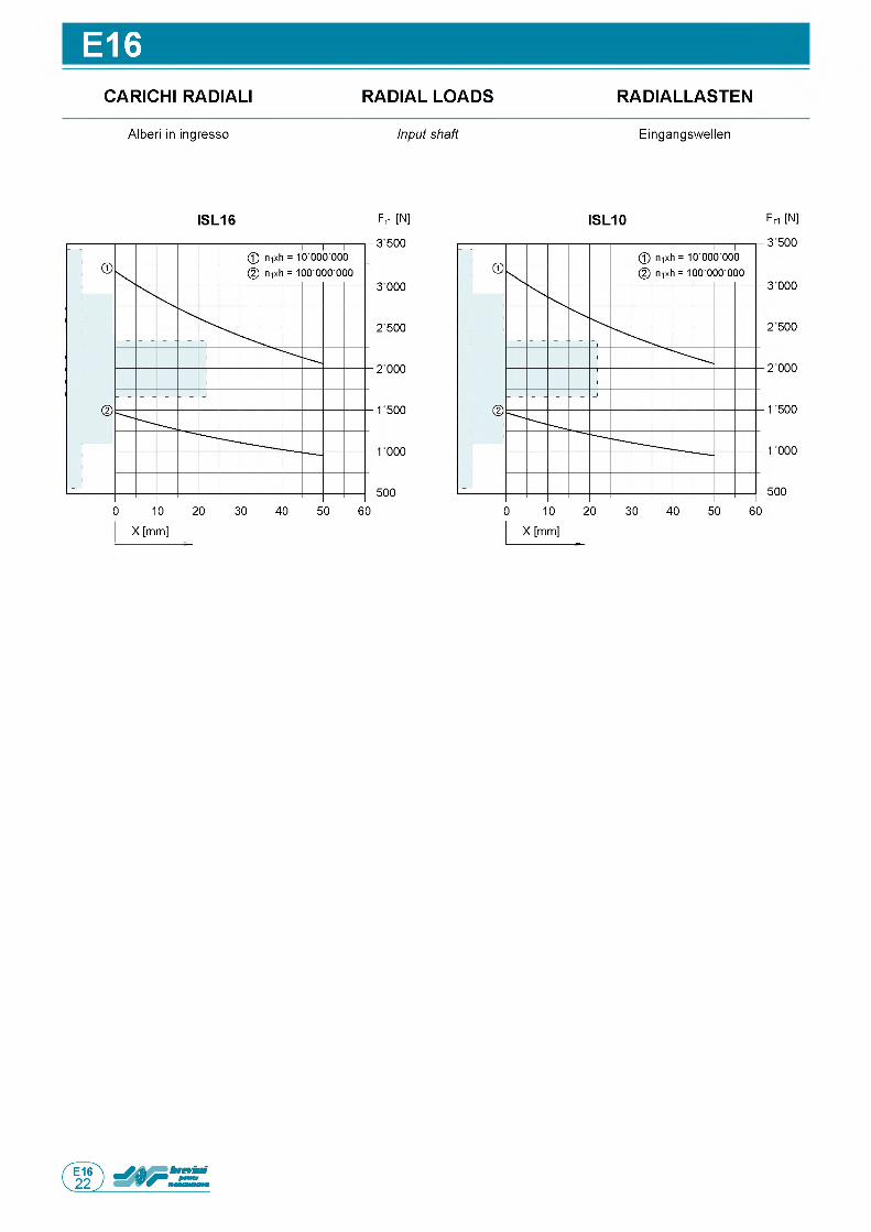
E16CARICHI RADIALI RADIAL LOADS RADIALLASTEN
Alberi in ingresso Input shaft Eingangswellen
Fn [N]
3 500
3 000
2 500
2 000
1 500
1000
500
0 10 20 30 40 50 60
X [mm]
ISL16 ISL10 Fri [N]
3 500
3 000
2 500
2 000
1 500
1000
500
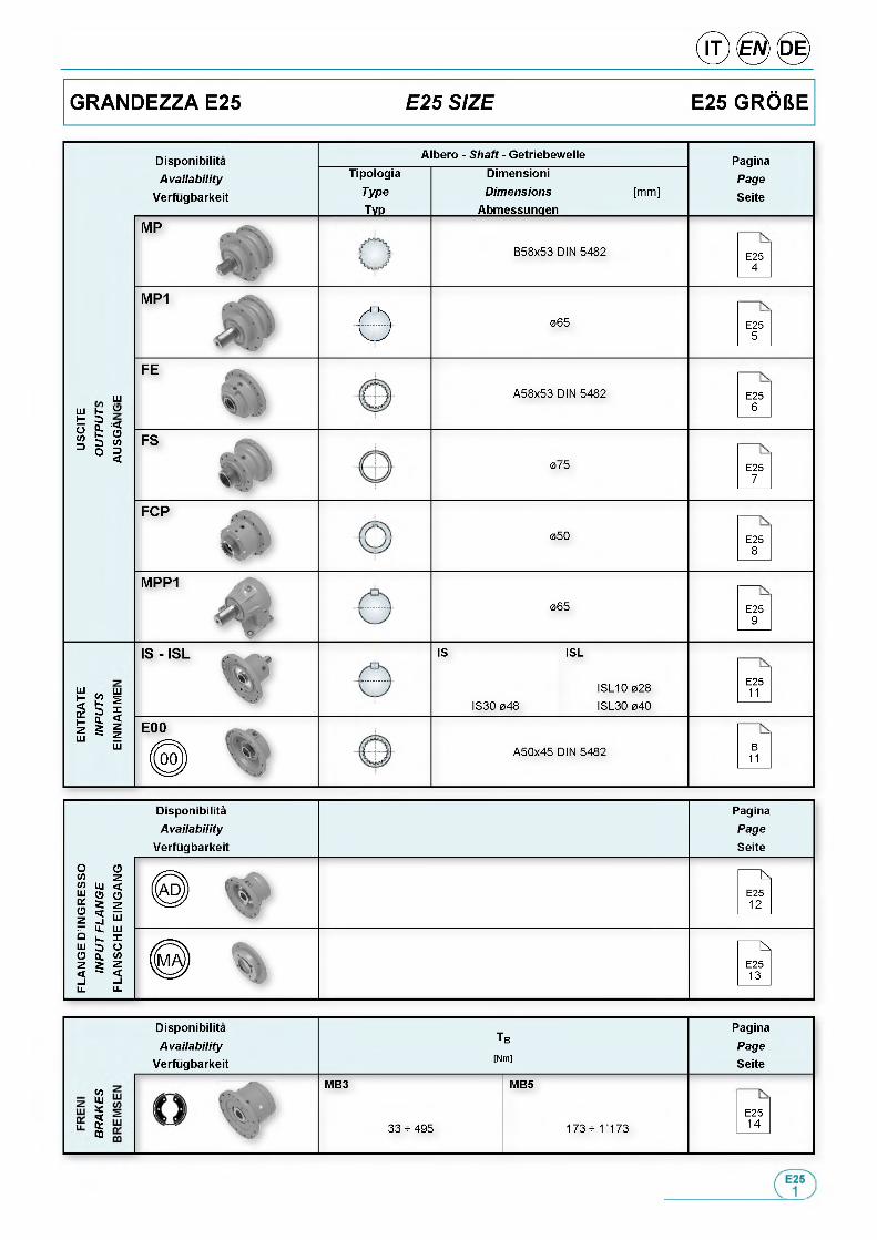
DisponibilitaAvailab ility
Verfugbarkeit
Albero - Shaft - Getriebewelle
TipologiaType
___ Typ___
DimensioniDimensions
Abmessungen[mm]
PaginaPage
Seite
B58x53 DIN 5482 E254
065 E255
шш к У t 3 о fcSM
:<О
A58x53 DIN 5482 E256
075 E257
050 E258
065 E259
ш шн £ s
illШ _ Ш
IS
IS30 048
ISL
ISL10 028 ISL30 040
E2511
A50x45 DIN 5482 B11
Tb
[Nm]
PaginaPageSeite
MB3 MB5
E2533 - 495 173 - 1173 14
DisponibilitaAvailab ility
Verfugbarkeit
«оUiУ§CQ
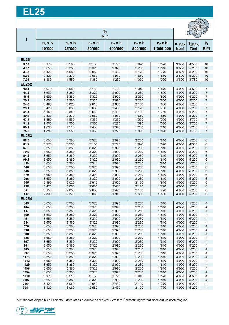
EL25
Altri rapporti disponibili a richiesta / More ratios available on request / Weitere Ubersetzungsverhaltnisse auf Wunsch moglich

EC25
T2[Nm]
n2 x h 10000
n2 x h n2 x h n2 x h n2 x h n2 x h n1MAX T2MAX Pt25 000 50 000 100 000 500 000 1 000 000 [rpm] [Nm] [kW]
EC25210.5 3970 3'580 3'130 2'720 1 935 1 570 3'000 4 ■ 500 812.2 3 650 3'380 3'320 2'985 2'225 1 805 3'000 5 ■ 200 814.9 3 420 3'060 2'675 2'425 2'120 1 765 3'000 5 ■ 200 816.0 3 970 3'580 3'130 2'720 1 935 1 570 3'000 4 ■ 500 818.6 3 650 3'380 3'320 2'985 2'225 1 805 3'000 5 ■ 200 822.6 3 420 3'060 2'675 2'425 2'120 1 765 3'000 5 ■ 200 826.8 2 830 2'365 2'055 1 905 1 655 1 555 3'000 5 ■ 200 833.6 1' 880 1 550 1 355 1 270 1 085 1 015 3 ■ 000 3 ■ 750 8
EC25337.1 3 ■ 970 3 ■ 580 3 ■ 130 2 ■ 580 1 510 1 200 4 ■ 000 4 ■ 500 543.0 3 ■ 970 3 ■ 580 3 ■ 130 2 ■ 720 1 665 1 325 4 ■ 000 4 ■ 500 549.8 3 ■ 650 3 ■ 380 3 ■ 320 2 ■ 985 1 840 1 460 4 ■ 000 5 ■ 200 560.5 3 ■ 650 3 ■ 380 3 ■ 320 2 ■ 985 2 ■ 095 1 660 4 ■ 000 5 ■ 200 571.9 3 ■ 490 3 ■ 020 2 ■ 805 2 ■ 600 2 ■ 155 1 805 4 ■ 000 5 ■ 200 581.1 3 ■ 650 3 ■ 380 3 ■ 280 2 ■ 600 1 520 1 205 4 ■ 000 5 ■ 200 585.1 3 ■ 970 3 ■ 510 3 ■ 130 2 ■ 680 1 570 1 245 4 ■ 000 4 ■ 500 598.6 3 ■ 650 3 ■ 380 3 ■ 320 2 ■ 960 1 730 1 375 4 ■ 000 5 ■ 200 5103 3 ■ 150 2 ■ 845 2 ■ 630 2 ■ 420 2 ■ 095 1 765 4 ■ 000 5 ■ 200 5117 3 ■ 490 3 ■ 020 2 ■ 805 2 ■ 600 1 940 1 540 4 ■ 000 5 ■ 200 5142 3 ■ 420 3 ■ 060 2 ■ 675 2 ■ 425 2 ■ 120 1 755 4 ■ 000 5 ■ 200 5168 3 ■ 150 2 ■ 845 2 ■ 630 2 ■ 420 2 ■ 095 1 765 4 ■ 000 5 ■ 200 5212 1 880 1 550 1 355 1 270 1 085 1 015 4 ■ 000 3 ■ 750 5
EC254130 3 ■ 970 3 ■ 580 3 ■ 130 2 ■ 720 1 935 1 570 4 ■ 000 4 ■ 500 4151 3 ■ 650 3 ■ 380 3 ■ 320 2 ■ 985 2 ■ 225 1 805 4 ■ 000 5 ■ 200 4175 3 ■ 650 3 ■ 380 3 ■ 320 2 ■ 985 2 ■ 225 1 805 4 ■ 000 5 ■ 200 4184 3 ■ 970 3 ■ 580 3 ■ 130 2 ■ 720 1 935 1 570 4 ■ 000 4 ■ 500 4203 3 ■ 650 3 ■ 380 3 ■ 320 2 ■ 985 2 ■ 225 1 805 4 ■ 000 5 ■ 200 4213 3 ■ 650 3 ■ 380 3 ■ 320 2 ■ 985 2 ■ 225 1 805 4 ■ 000 5 ■ 200 4218 3 ■ 970 3 ■ 580 3 ■ 130 2 ■ 720 1 935 1 570 4 ■ 000 4 ■ 500 4247 3 ■ 650 3 ■ 380 3 ■ 320 2 ■ 985 2 ■ 225 1 805 4 ■ 000 5 ■ 200 4253 3 ■ 650 3 ■ 380 3 ■ 320 2 ■ 985 2 ■ 225 1 805 4 ■ 000 5 ■ 200 4285 3 ■ 650 3 ■ 380 3 ■ 320 2 ■ 985 2 ■ 225 1 805 4 ■ 000 5 ■ 200 4298 3 ■ 650 3 ■ 380 3 ■ 320 2 ■ 985 2 ■ 225 1 805 4 ■ 000 5 ■ 200 4307 3 ■ 970 3 ■ 510 3 ■ 130 2 ■ 720 1 935 1 570 4 ■ 000 4 ■ 500 4331 3 ■ 650 3 ■ 380 3 ■ 320 2 ■ 985 2 ■ 225 1 805 4 ■ 000 5 ■ 200 4362 3 ■ 970 3 ■ 510 3 ■ 130 2 ■ 720 1 935 1 570 4 ■ 000 4 ■ 500 4402 3 ■ 650 3 ■ 380 3 ■ 320 2 ■ 985 2 ■ 225 1 805 4 ■ 000 5 ■ 200 4419 3 ■ 650 3 ■ 380 3 ■ 320 2 ■ 985 2 ■ 225 1 805 4 ■ 000 5 ■ 200 4439 3 ■ 650 3 ■ 380 3 ■ 320 2 ■ 985 2 ■ 225 1 805 4 ■ 000 5 ■ 200 4477 3 ■ 650 3 ■ 380 3 ■ 320 2 ■ 985 2 ■ 225 1 805 4 ■ 000 5 ■ 200 4509 3 ■ 650 3 ■ 380 3 ■ 320 2 ■ 985 2 ■ 225 1 805 4 ■ 000 5 ■ 200 4534 3 ■ 970 3 ■ 510 3 ■ 130 2 ■ 720 1 935 1 570 4 ■ 000 4 ■ 500 4580 3 ■ 650 3 ■ 380 3 ■ 320 2 ■ 985 2 ■ 225 1 805 4 ■ 000 5 ■ 200 4619 3 ■ 650 3 ■ 380 3 ■ 320 2 ■ 985 2 ■ 225 1 805 4 ■ 000 5 ■ 200 4716 3 ■ 650 3 ■ 380 3 ■ 320 2 ■ 985 2 ■ 225 1 805 4 ■ 000 5 ■ 200 4752 3 ■ 420 3 ■ 060 2 ■ 675 2 ■ 425 2 ■ 120 1 765 4 ■ 000 5 ■ 200 4829 3 ■ 650 3 ■ 380 3 ■ 320 2 ■ 985 2 ■ 225 1 805 4 ■ 000 5 ■ 200 4870 3 ■ 970 3 ■ 510 3 ■ 130 2 ■ 720 1 935 1 570 4 ■ 000 5 ■ 200 41008 3 ■ 650 3 ■ 380 3 ■ 320 2 ■ 985 2 ■ 225 1 805 4 ■ 000 5 ■ 200 41052 3 ■ 150 2 ■ 845 2 ■ 630 2 ■ 420 2 ■ 095 1 765 4 ■ 000 5 ■ 200 4
Altri rapporti disponibili a richiesta / More ratios available on request / Weitere Ubersetzungsverhaltnisse auf Wunsch moglich
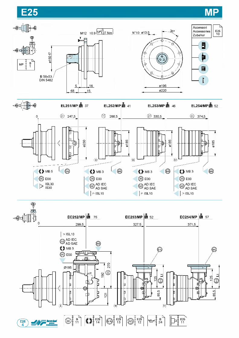
E25
M12 10.9 127 Nm
t
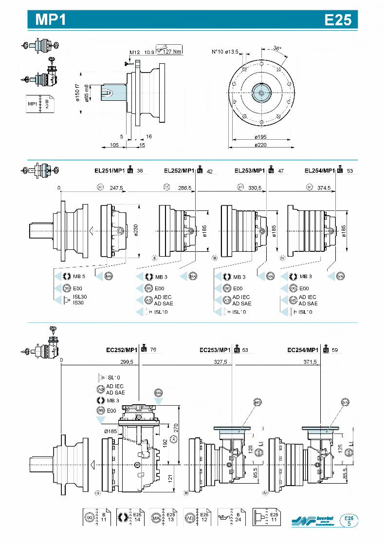
MP1 E25
;—MP1 B
2
M12 10.9 127 Nm
EC252/MP1
299,5
ISL10
Had AD IEC ^ AD SAE
MB 3
oo E00
76 EC253/MP1
327,5
53 EC254/MP1
J
LOCM
1
LO
i i d
CO
(IV)nr
371,5,
59
0
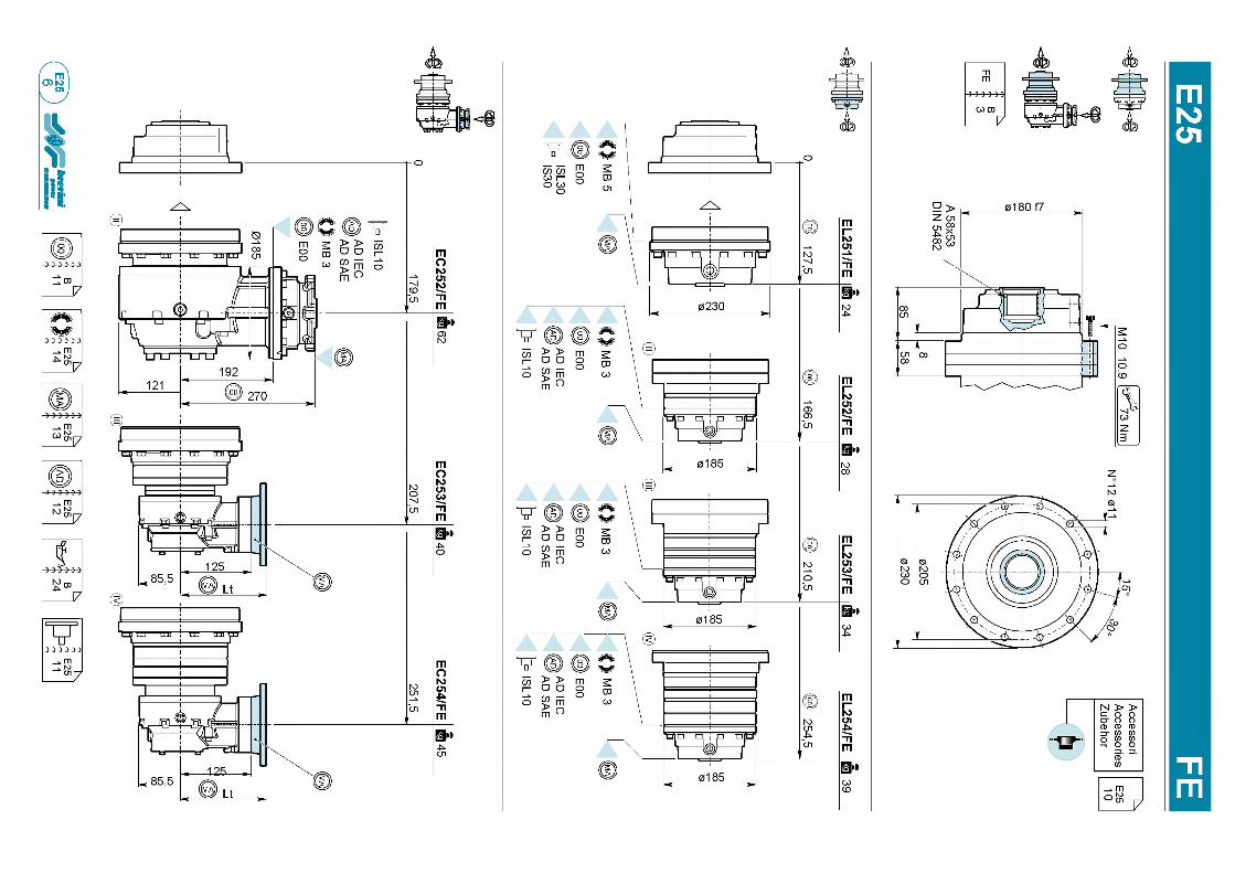
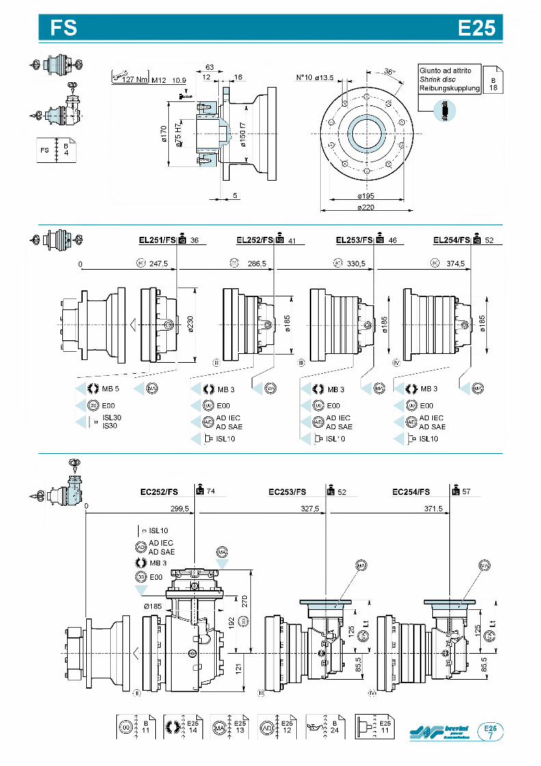
FS E25
FS B4
f
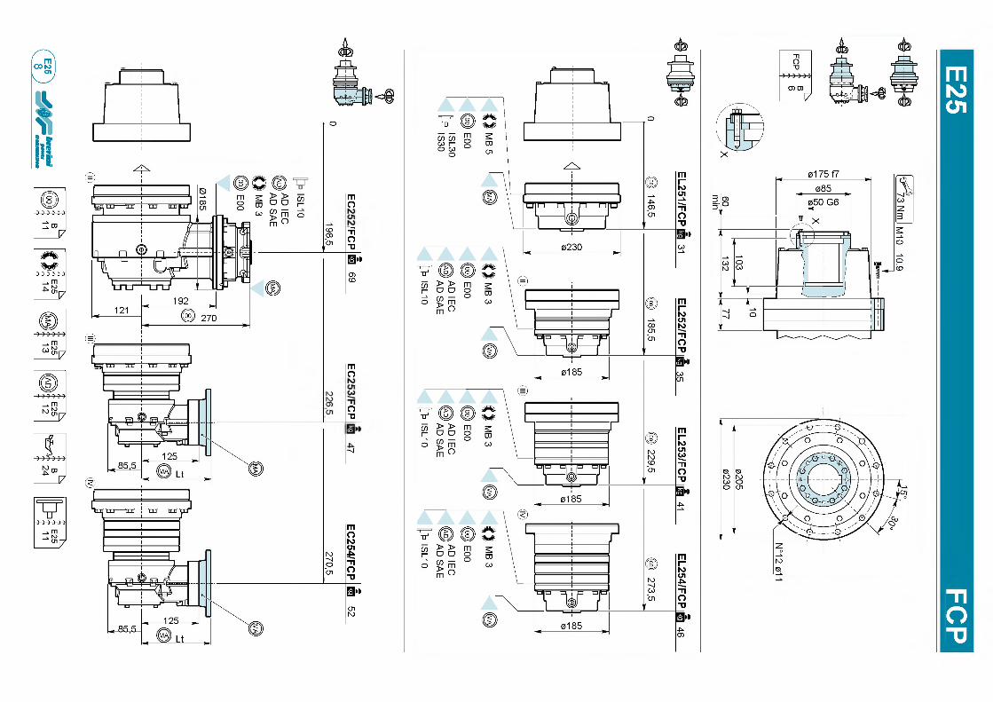
mК З
O l
1
слI-
о
гпо
mо
о"О
■ч
mо
<sfe
73 Nm
I М10
10.9

E25
m p p i: B5
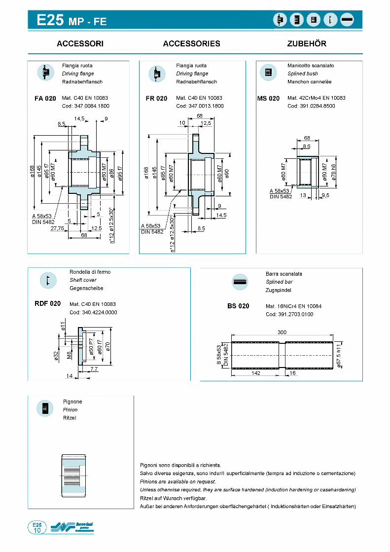
E25 m p - fe
ACCESSORI ACCESSORIES ZUBEHOR
MS 020
Manicotto scanalato Splined bush Manchon cannelee
Mat. 42CrMo4 EN 10083 Cod: 391.0284.8500
Rondella di fermo Shaft cover Gegenscheibe
RDF 020 Mat. C40 EN 10083Cod: 340.4224.0000
Barra scanalata Splined bar Zugspindel
BS 020 Mat. 16NiCr4 EN 10084 Cod: 391.2703.0100
300
i i ( NCO
LO .S Z
■ LO
h -' LO
~ Z .
, fO
, 142 , .16
Pignoni sono disponibili a richiesta.Salvo diversa esigenza, sono induriti superficialmente (tempra ad induzione o cementazione) Pinions are available on request.Unless otherwise required, they are surface hardened (induction hardening or casehardening) Ritzel auf Wunsch verfugbar.AulJer bei anderen Anforderungen oberflachengehartet ( Induktionsharten oder Einsatzharten)

IS/ISL E25SUPPORTI MASCHIO IN
INGRESSO M A L E IN P U T S U P P O R T S ANTRIEBS-w e l l e n s t Om p f e
ISL IS
ELISL
IS
ф = MP - MP1 - FS
ф = F E - FCP
ф = MPP1
EC
0D ELt [mm] 1 Lt [mm] 2 Lt [mm] 3
MP MP1 FS FE FCP MPP1
EL251 IS30 48 k6 82 326 326 326 206 225 348
EL251 ISL30 40 k6 58 286.5 286.5 286.5 166.5 185.5 308.5
EL252 ISL10 28 k6 50 340.5 340.5 340.5 220.5 239.5 362.5
EL253 ISL10 28 k6 50 384.5 384.5 384.5 264.5 283.5 406.5
EL254 ISL10 28 k6 50 428.5 428.5 428.5 308.5 327.5 450.5
EC252 ISL10 28 k6 50 311 311 311 311 311 311
n

ADATTATORI IEC/SAE A A D A P T E R S IE C /S A E A ADAPTER IEC/SAE A
EL
IEC
S A E A
IEC
S A E A
IEC
S A E A
ECS A E A IEC S A E A IEC S A E A IEC
ф = MP - M P1- FS
Q = F E - FCP
ф = MPP1
Lt [mm]
IECSAE A
80-90 100-112 132
EL252
MP 298.5 306.5 342.5 328.5MP1 298.5 306.5 342.5 328.5FE 178.5 186.5 222.5 208.5FS 298.5 306.5 342.5 328.5
FCP 197.5 205.5 241.5 227.5MPP1 320.5 328.5 364.5 350.5
EL253
MP 342.5 350.5 386.5 372.5MP1 342.5 350.5 386.5 372.5FE 222.5 230.5 266.5 252.5FS 342.5 350.5 386.5 372.5
FCP 241.5 249.5 285.5 271.5MPP1 364.5 372.5 408.5 394.5
EL254
MP 386.5 394.5 430.5 416.5MP1 386.5 394.5 430.5 416.5FE 266.5 274.5 310.5 296.5FS 386.5 394.5 430.5 416.5
FCP 285.5 293.5 329.5 315.5MPP1 408.5 416.5 452.5 438.5
EC252
MP 282 290 313 301MP1 282 290 313 301FE 282 290 313 301FS 282 290 313 301
FCP 282 290 313 301MPP1 282 290 313 301
П
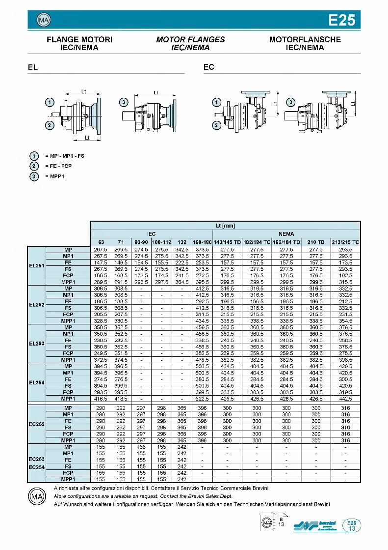
E25FLANGE MOTORI M O T O R F L A N G E S MOTORFLANSCHE
IEC/NEMA IE C /N E M A IEC/NEMA
EL EC
ф = MP - MP1 - FS
@ = F E - FCP
ф = MPP1
Lt [mm]IEC NEMA
63 71 80-90 100-112 132 160-180 143/145 TD 182/184 TC 182/184 TD 210 TD 213/215 TC
EL251
MP 267.5 269.5 274.5 275.5 342.5 373.5 277.5 277.5 277.5 277.5 293.5MP1 267.5 269.5 274.5 275.5 342.5 373.5 277.5 277.5 277.5 277.5 293.5FE 147.5 149.5 154.5 155.5 222.5 253.5 157.5 157.5 157.5 157.5 173.5FS 267.5 269.5 274.5 275.5 342.5 373.5 277.5 277.5 277.5 277.5 293.5
FCP 166.5 168.5 173.5 174.5 241.5 272.5 176.5 176.5 176.5 176.5 192.5MPP1 289.5 291.5 296.5 297.5 364.5 395.5 299.5 299.5 299.5 299.5 315.5
EL252
MP 306.5 308.5 - - - 412.5 316.5 316.5 316.5 316.5 332.5MP1 306.5 308.5 - - - 412.5 316.5 316.5 316.5 316.5 332.5FE 186.5 188.5 - - - 292.5 196.5 196.5 196.5 196.5 212.5FS 306.5 308.5 - - - 412.5 316.5 316.5 316.5 316.5 332.5
FCP 205.5 207.5 - - - 311.5 215.5 215.5 215.5 215.5 231.5MPP1 328.5 330.5 - - - 434.5 338.5 338.5 338.5 338.5 354.5
EL253
MP 350.5 352.5 - - - 456.5 360.5 360.5 360.5 360.5 376.5MP1 350.5 352.5 - - - 456.5 360.5 360.5 360.5 360.5 376.5FE 230.5 232.5 - - - 336.5 240.5 240.5 240.5 240.5 256.5FS 350.5 352.5 - - - 456.5 360.5 360.5 360.5 360.5 376.5
FCP 249.5 251.5 - - - 355.5 259.5 259.5 259.5 259.5 275.5MPP1 372.5 374.5 - - - 478.5 382.5 382.5 382.5 382.5 398.5
EL254
MP 394.5 396.5 - - - 500.5 404.5 404.5 404.5 404.5 420.5MP1 394.5 396.5 - - - 500.5 404.5 404.5 404.5 404.5 420.5FE 274.5 276.5 - - - 380.5 284.5 284.5 284.5 284.5 300.5FS 394.5 396.5 - - - 500.5 404.5 404.5 404.5 404.5 420.5
FCP 293.5 295.5 - - - 399.5 303.5 303.5 303.5 303.5 319.5MPP1 416.5 418.5 - - - 522.5 426.5 426.5 426.5 426.5 442.5
EC252
MP 290 292 297 298 365 396 300 300 300 300 316MP1 290 292 297 298 365 396 300 300 300 300 316FE 290 292 297 298 365 396 300 300 300 300 316FS 290 292 297 298 365 396 300 300 300 300 316
FCP 290 292 297 298 365 396 300 300 300 300 316MPP1 290 292 297 298 365 396 300 300 300 300 316
EC253EC254
MP 155 155 155 155 242 - - - - - -MP1 155 155 155 155 242 - - - - - -FE 155 155 155 155 242 - - - - - -FS 155 155 155 155 242 - - - - - -
FCP 155 155 155 155 242 - - - - - -MPP1 155 155 155 155 242 - - - - - -
A richiesta altre configurazioni disponibili. Contattare il Servizio Tecnico Commerciale Brevini More configurations are available on request. Contact the Brevini Sales Dept.Auf Wunsch sind weitere Konfigurationen verfugbar. Wenden Sie sich an den Technischen Vertriebsinnendienst Brevini
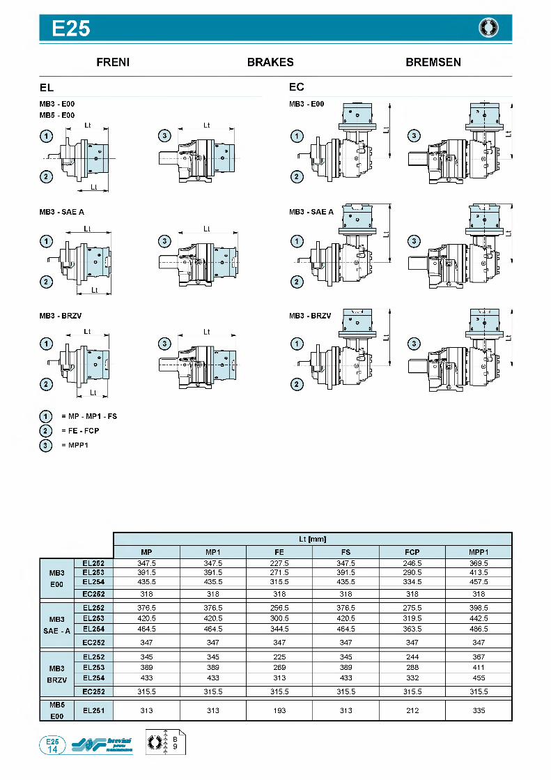
E25FRENI
ELM B 3- E00 M B 5- E00
ф = MP - MP1 - FS
ф = FE - FCP
ф = MPP1
BRAKES
EC
BREMSEN
Lt [mm]
MP MP1 FE FS FCP MPP1
MB3E00
EL252 347.5 347.5 227.5 347.5 246.5 369.5EL253 391.5 391.5 271.5 391.5 290.5 413.5EL254 435.5 435.5 315.5 435.5 334.5 457.5EC252 318 318 318 318 318 318
MB3 SAE - A
EL252 376.5 376.5 256.5 376.5 275.5 398.5EL253 420.5 420.5 300.5 420.5 319.5 442.5EL254 464.5 464.5 344.5 464.5 363.5 486.5
EC252 347 347 347 347 347 347
MB3BRZV
EL252 345 345 225 345 244 367EL253 389 389 269 389 288 411EL254 433 433 313 433 332 455
EC252 315.5 315.5 315.5 315.5 315.5 315.5
MB5E00
EL251 313 313 193 313 212 335
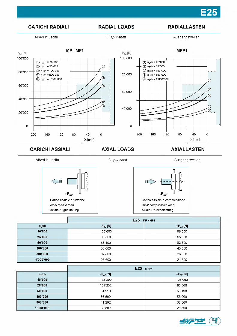
E25CARICHI RADIALI RADIAL LOADS RADIALLASTEN
Alberi in uscita Output shaft Ausgangswellen
Fr2 [N]M P - M P1
CARICHI ASSIALI AXIAL LOADS AXIALLASTEN
Alberi in uscita Output shaft Ausgangswellen
<>n
+Fa2Carico assiale a trazione Axial tensile load Axiale Zugbelastung
E 2 5 m p - MP1
n2xh -Fa2[N] + Fa2 [N]10 0 0 0 106 000 86 0002 5 000 80 560 6536050 000 65190 52890
10 0 000 53 000 43 000500 000 32 860 26660
1 000 000 26 500 21500
E 2 5 m p p 1
n2xh -F a2[N] +Fa2 [N]10 000 133 200 106 0002 5 000 101232 80 56050 000 81918 65190
10 0 000 66600 53 000
500 000 41292 32860
1 000 000 33300 26500
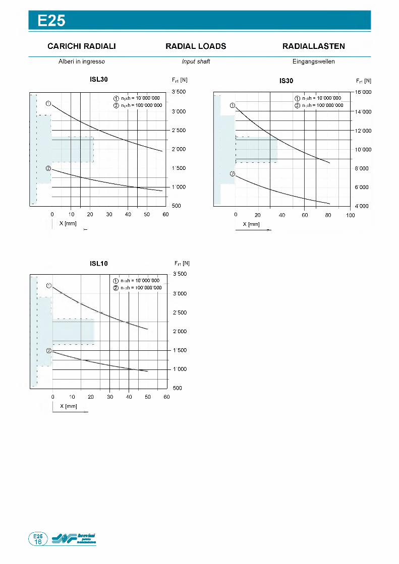
E25CARICHI RADIALI RADIAL LOADS RADIALLASTEN
EingangswellenA lberi in ingresso Input shaft
Fri [N]
3500
3 000
25500
2 000
1500
1000
500
0 10 20 30 40 50 60
X [mm]
IS 3 0 Fri [N]IS L 3 0
Fri [N]
3 500
3 000
2 500
2 000
1 500
1000
500
0 10 20 30 40 50 60
X [mm]
IS L 1 0
d@ mxh = 10 000 000_ 2 rnxh = 100 000 000
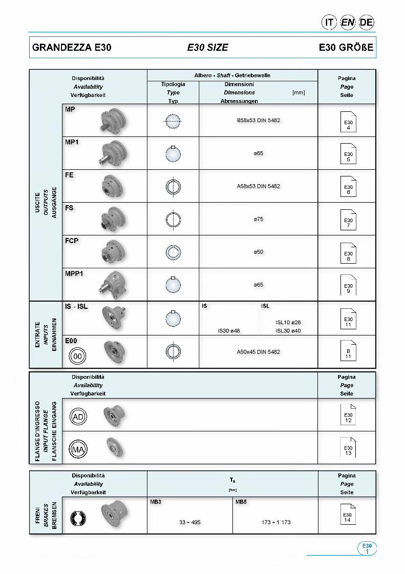
GRANDEZZA E30 E30 SIZE E30 GR06E
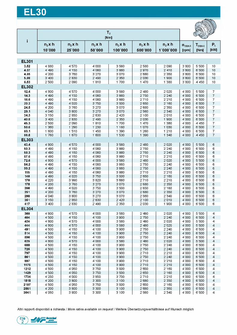
EL30
Altri rapporti disponibili a richiesta / More ratios available on request / Weitere Ubersetzungsverhaltnisse auf Wunsch moglich
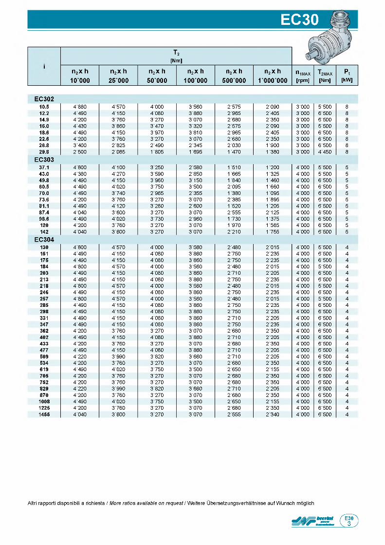
EC30
т 2[Nm]
n2 x h 10000
n2 x h n2 x h n2 x h n2 x h n2 x h niMAX T2MAX Pt25 000 50 000 100 000 500 000 1 000 000 [rpm] [Nm] [kW]
EC30210.5 4 880 4 570 4'000 3'560 2'575 2'090 3'000 5 ■ 500 812.2 4 490 4150 4'080 3'860 2'965 2'405 3'000 6 ■ 500 814.9 4 200 3 760 3'270 3'070 2'680 2'350 3'000 6 ■ 500 816.0 4 430 3 860 3'470 3'320 2'575 2'090 3'000 5 ■ 500 818.6 4 490 4150 3'970 3'810 2'965 2'405 3'000 6 ■ 500 822.6 4 200 3 760 3'270 3'070 2'680 2'350 3 ■ 000 6 ■ 500 826.8 3 400 2 825 2'490 2'345 2'030 1 900 3 ■ 000 6 ■ 500 829.8 2 500 2 085 1 805 1 695 1 470 1 380 3 ■ 000 4 ■ 450 8
EC303
EC304
37.1 4 ■ 800 4 ■ 100 3 ■ 250 2 ■ 580 1 510 1 200 4 ■ 000 5 ■ 500 543.0 4 ■ 380 4 ■ 270 3 ■ 590 2 ■ 850 1 665 1 325 4 ■ 000 5 ■ 500 549.8 4 ■ 490 4 ■ 150 3 ■ 960 3 ■ 150 1 840 1 460 4 ■ 000 6 ■ 500 560.5 4 ■ 490 4 ■ 020 3 ■ 750 3 ■ 500 2 ■ 095 1 660 4 ■ 000 6 ■ 500 570.0 4 ■ 490 3 ■ 740 2 ■ 965 2 ■ 355 1 380 1 095 4 ■ 000 6 ■ 500 573.6 4 ■ 200 3 ■ 760 3 ■ 270 3 ■ 070 2 ■ 385 1 895 4 ■ 000 6 ■ 500 581.1 4 ■ 490 4 ■ 120 3 ■ 280 2 ■ 600 1 520 1 205 4 ■ 000 6 ■ 500 587.4 4 ■ 040 3 ■ 600 3 ■ 270 3 ■ 070 2 ■ 555 2 ■ 125 4 ■ 000 6 ■ 500 598.6 4 ■ 490 4 ■ 020 3 ■ 730 2 ■ 960 1 730 1 375 4 ■ 000 6 ■ 500 5120 4 ■ 200 3 ■ 760 3 ■ 270 3 ■ 070 1 970 1 565 4 ■ 000 6 ■ 500 5142 4 ■ 040 3 ■ 600 3 ■ 270 3 ■ 070 2 ■ 210 1 755 4 ■ 000 6 ■ 500 5
130 4 ■ 800 4 ■ 570 4 ■ 000 3 ■ 560 2 ■ 480 2 ■ 015 4 ■ 000 5 ■ 500 4151 4 ■ 490 4 ■ 150 4 ■ 080 3 ■ 860 2 ■ 750 2 ■ 235 4 ■ 000 6 ■ 500 4175 4 ■ 490 4 ■ 150 4 ■ 080 3 ■ 860 2 ■ 750 2 ■ 235 4 ■ 000 6 ■ 500 4184 4 ■ 800 4 ■ 570 4 ■ 000 3 ■ 560 2 ■ 480 2 ■ 015 4 ■ 000 5 ■ 500 4203 4 ■ 490 4 ■ 150 4 ■ 080 3 ■ 860 2 ■ 710 2 ■ 205 4 ■ 000 6 ■ 500 4213 4 ■ 490 4 ■ 150 4 ■ 080 3 ■ 860 2 ■ 750 2 ■ 235 4 ■ 000 6 ■ 500 4218 4 ■ 800 4 ■ 570 4 ■ 000 3 ■ 560 2 ■ 480 2 ■ 015 4 ■ 000 5 ■ 500 4246 4 ■ 490 4 ■ 150 4 ■ 080 3 ■ 860 2 ■ 750 2 ■ 235 4 ■ 000 6 ■ 500 4257 4 ■ 800 4 ■ 570 4 ■ 000 3 ■ 560 2 ■ 480 2 ■ 015 4 ■ 000 5 ■ 500 4285 4 ■ 490 4 ■ 150 4 ■ 080 3 ■ 860 2 ■ 750 2 ■ 235 4 ■ 000 6 ■ 500 4298 4 ■ 490 4 ■ 150 4 ■ 080 3 ■ 860 2 ■ 750 2 ■ 235 4 ■ 000 6 ■ 500 4331 4 ■ 490 4 ■ 150 4 ■ 080 3 ■ 860 2 ■ 710 2 ■ 205 4 ■ 000 6 ■ 500 4347 4 ■ 490 4 ■ 150 4 ■ 080 3 ■ 860 2 ■ 750 2 ■ 235 4 ■ 000 6 ■ 500 4362 4 ■ 200 3 ■ 760 3 ■ 270 3 ■ 070 2 ■ 680 2 ■ 350 4 ■ 000 6 ■ 500 4402 4 ■ 490 4 ■ 150 4 ■ 080 3 ■ 860 2 ■ 710 2 ■ 205 4 ■ 000 6 ■ 500 4433 4 ■ 200 3 ■ 760 3 ■ 270 3 ■ 070 2 ■ 680 2 ■ 350 4 ■ 000 6 ■ 500 4477 4 ■ 490 4 ■ 150 4 ■ 080 3 ■ 860 2 ■ 710 2 ■ 205 4 ■ 000 6 ■ 500 4509 4 ■ 220 3 ■ 990 3 ■ 820 3 ■ 660 2 ■ 710 2 ■ 205 4 ■ 000 6 ■ 500 4534 4 ■ 200 3 ■ 760 3 ■ 270 3 ■ 070 2 ■ 680 2 ■ 350 4 ■ 000 6 ■ 500 4619 4 ■ 490 4 ■ 020 3 ■ 750 3 ■ 500 2 ■ 650 2 ■ 155 4 ■ 000 6 ■ 500 4705 4 ■ 200 3 ■ 760 3 ■ 270 3 ■ 070 2 ■ 680 2 ■ 350 4 ■ 000 6 ■ 500 4752 4 ■ 200 3 ■ 760 3 ■ 270 3 ■ 070 2 ■ 680 2 ■ 350 4 ■ 000 6 ■ 500 4829 4 ■ 220 3 ■ 990 3 ■ 820 3 ■ 660 2 ■ 710 2 ■ 205 4 ■ 000 6 ■ 500 4870 4 ■ 200 3 ■ 760 3 ■ 270 3 ■ 070 2 ■ 680 2 ■ 350 4 ■ 000 6 ■ 500 41008 4 ■ 490 4 ■ 020 3 ■ 750 3 ■ 500 2 ■ 650 2 ■ 155 4 ■ 000 6 ■ 500 41225 4 ■ 200 3 ■ 760 3 ■ 270 3 ■ 070 2 ■ 680 2 ■ 350 4 ■ 000 6 ■ 500 41455 4 ■ 040 3 ■ 600 3 ■ 270 3 ■ 070 2 ■ 555 2 ■ 340 4 ■ 000 6 ■ 500 4
Altri rapporti disponibili a richiesta / More ratios available on request / Weitere Ubersetzungsverhaltnisse auf Wunsch moglich
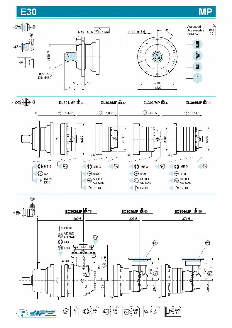
E30
; k.mp : B
1
M12 10.9 127 Nm
68
AccessoriAccessoriesZubehor
f
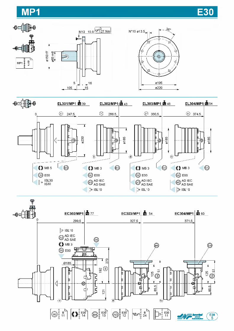
MP1 E30
!-----MP1 B
2
M12 10.9 127 Nm
т
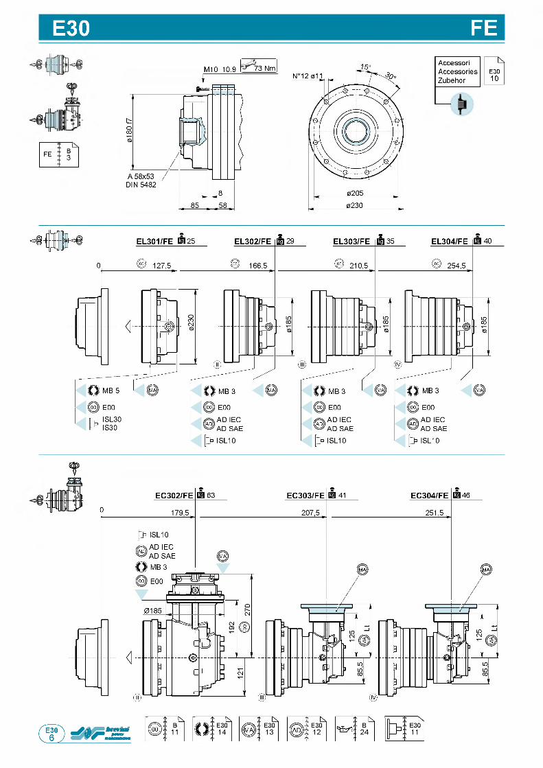
E30 FE
Ц 1 ij lf l I j j |Hn rffih nl
FE
M10 10.9 773 Nm
fAccessoriAccessoriesZubehor
f
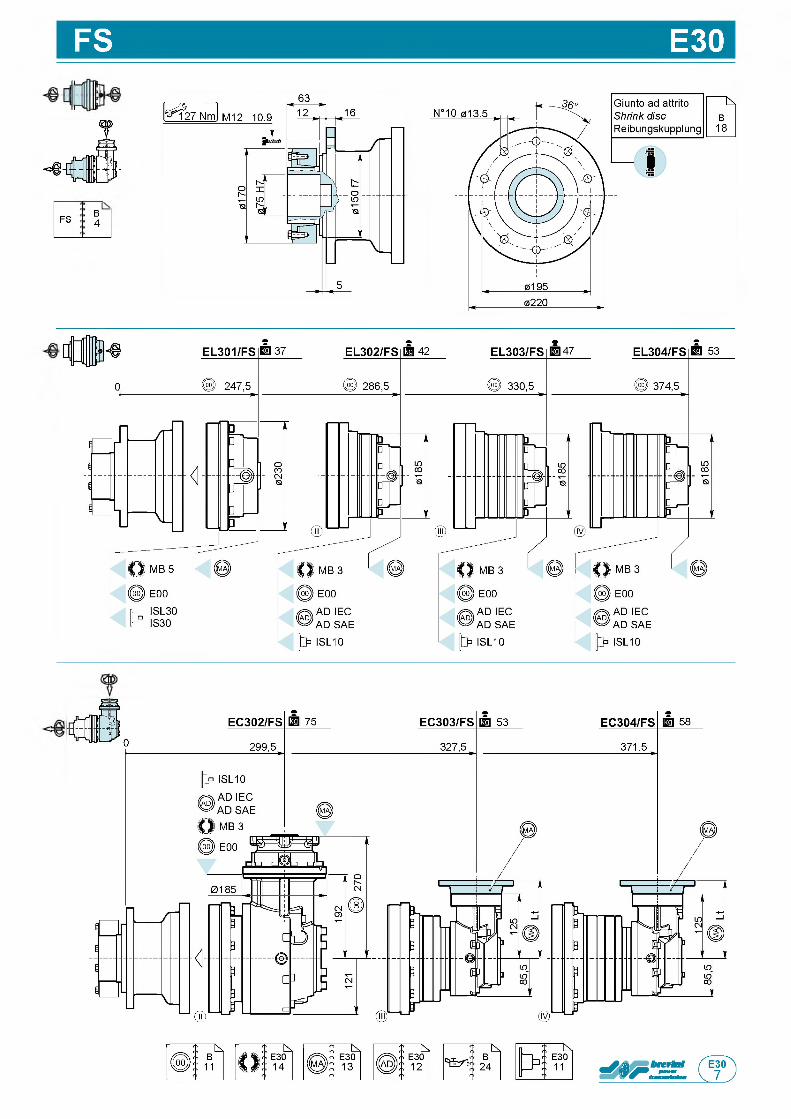
FS E30
FS B4
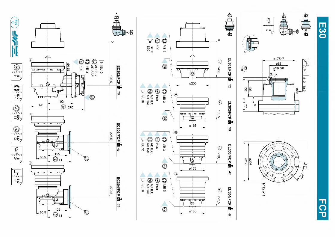
mСл>
l
Yсяi-о
Щ*ь
Щ*со
1 «
<sfe
601-
0И
Л1ГШ
мё7
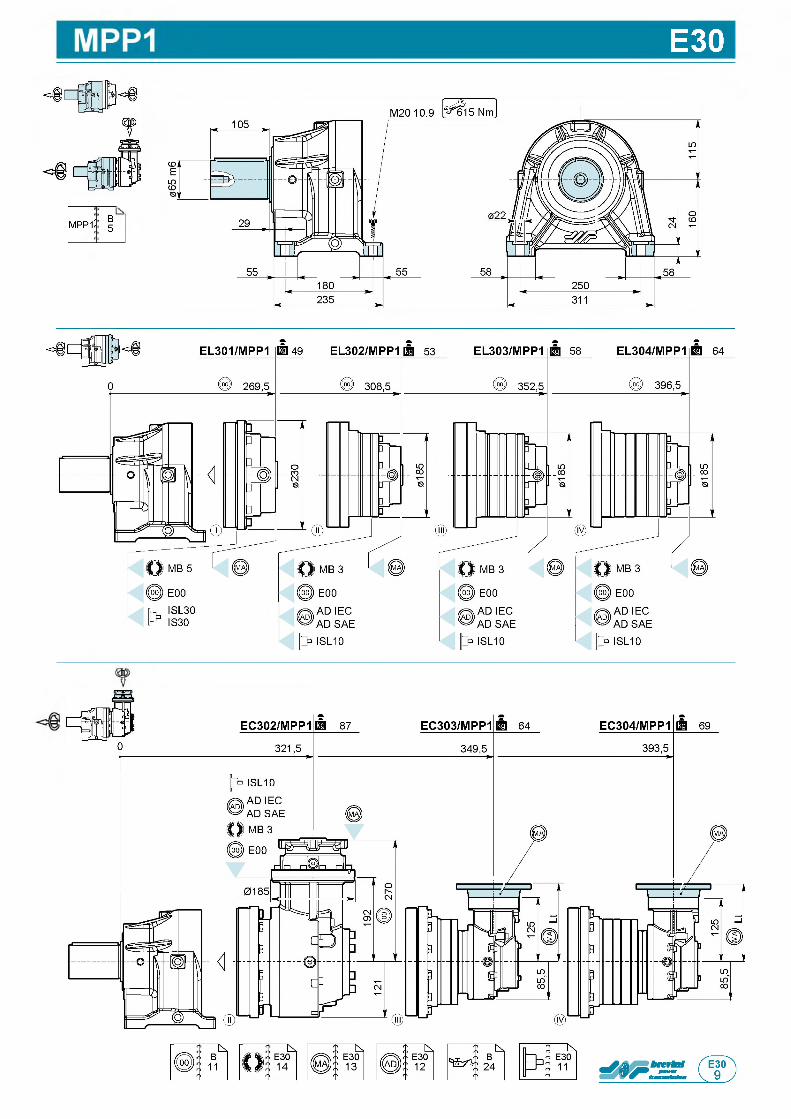
E30
m p p i: B5
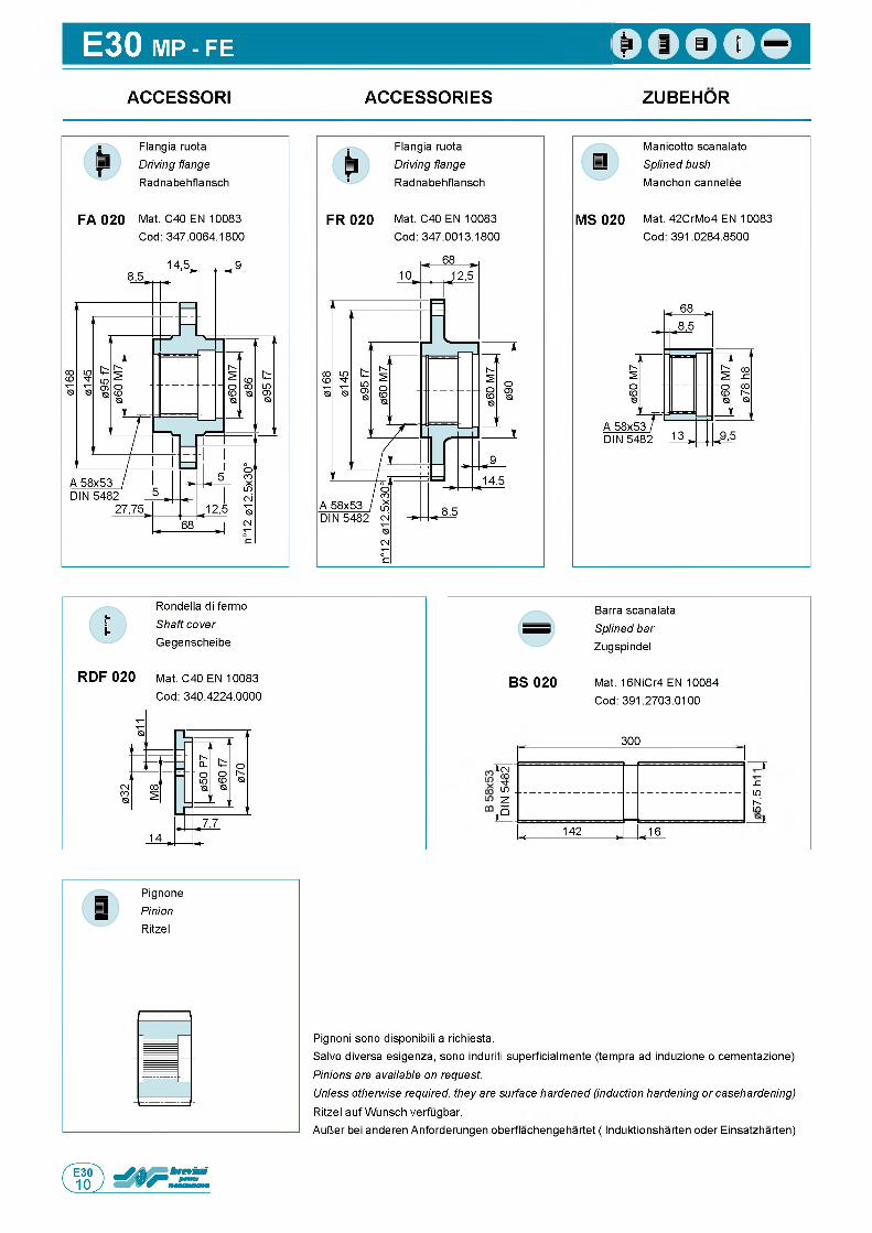
E30 MP - FE
ACCESSORI ACCESSORIES ZUBEHOR
MS 020
Manicotto scanalato Splined bush Manchon cannelee
Mat. 42CrMo4 EN 10083 Cod: 391.0284.8500
Rondella di fermo
Shaft cover Gegenscheibe
RDF 020 Mat. C40 EN 10083
Cod: 340.4224.0000
Barra scanalata Splined bar Zugspindel
BS 020 Mat. 16NiCr4 EN 10084 Cod: 391.2703.0100
300
i(NCOLO SZ
■ L.OКLO
~Z.G
< 142 , «16
Pignoni sono disponibili a richiesta.Salvo diversa esigenza, sono induriti superficialmente (tempra ad induzione o cementazione)
Pinions are available on request.Unless otherwise required, they are surface hardened (induction hardening or casehardening) Ritzel auf Wunsch verfugbar.AulJer bei anderen Anforderungen oberflachengehartet ( Induktionsharten oder Einsatzharten)
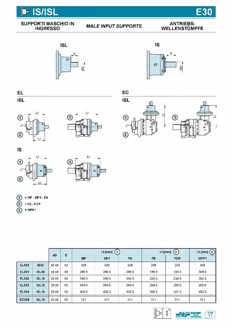
IS/ISL E30SUPPORTI MASCHIO IN
INGRESSO M A L E IN P U T S U P P O R T S ANTRIEBS-w e l l e n s t Om p f e
ISL IS
ELISL
IS
ф = MP - MP1 - FS
ф = F E - FCP
ф = MPP1
EC
0D ELt [mm] 1 Lt [mm] 2 Lt [mm] 3
MP MP1 FS FE FCP MPP1
EL301 IS30 48 k6 82 326 326 326 206 225 348
EL301 ISL30 40 k6 58 286.5 286.5 286.5 166.5 185.5 308.5
EL302 ISL10 28 k6 50 340.5 340.5 340.5 220.5 239.5 362.5
EL303 ISL10 28 k6 50 384.5 384.5 384.5 264.5 283.5 406.5
EL304 ISL10 28 k6 50 428.5 428.5 428.5 308.5 327.5 450.5
EC302 ISL10 28 k6 50 311 311 311 311 311 311
n
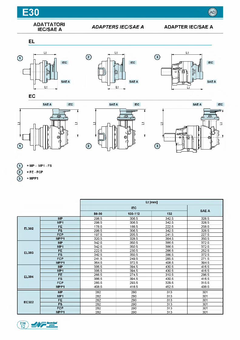
E30ADATTATORI
IEC/SAE A A D A P T E R S IE C /S A E A ADAPTER IEC/SAE A
EL
IEC
S A E A
IEC
S A E A
IEC
S A E A
ECS A E A IEC S A E A IEC S A E A IEC
ф = MP - M P1- FS
ф = FE - FCP
ф = MPP1
Lt [mm]
IECSAE A
80-90 100-112 132
EL302
MP 298.5 306.5 342.5 328.5MP1 298.5 306.5 342.5 328.5FE 178.5 186.5 222.5 208.5FS 298.5 306.5 342.5 328.5
FCP 197.5 205.5 241.5 227.5MPP1 320.5 328.5 364.5 350.5
EL303
MP 342.5 350.5 386.5 372.5MP1 342.5 350.5 386.5 372.5FE 222.5 230.5 266.5 252.5FS 342.5 350.5 386.5 372.5
FCP 241.5 249.5 285.5 271.5MPP1 364.5 372.5 408.5 394.5
EL304
MP 386.5 394.5 430.5 416.5MP1 386.5 394.5 430.5 416.5FE 266.5 274.5 310.5 296.5FS 386.5 394.5 430.5 416.5
FCP 285.5 293.5 329.5 315.5MPP1 408.5 416.5 452.5 438.5
EC302
MP 282 290 313 301MP1 282 290 313 301FE 282 290 313 301FS 282 290 313 301
FCP 282 290 313 301MPP1 282 290 313 301
П
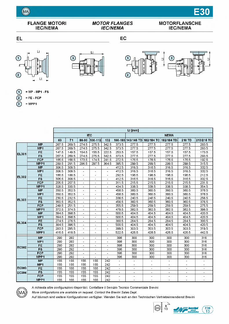
E30FLANGE MOTORI M O T O R F L A N G E S MOTORFLANSCHE
IEC/NEMA IE C /N E M A IEC/NEMA
EL EC
ф = MP - MP1 - FS
@ = FE - FCP
ф = MPP1
Lt [mm]IEC NEMA
63 71 80-90 100-112 132 160-180 143/145 TD 182/184 TC 182/184 TD 210 TD 213/215 TC
EL301
MP 267.5 269.5 274.5 275.5 342.5 373.5 277.5 277.5 277.5 277.5 293.5MP1 267.5 269.5 274.5 275.5 342.5 373.5 277.5 277.5 277.5 277.5 293.5FE 147.5 149.5 154.5 155.5 222.5 253.5 157.5 157.5 157.5 157.5 173.5FS 267.5 269.5 274.5 275.5 342.5 373.5 277.5 277.5 277.5 277.5 293.5
FCP 166.5 168.5 173.5 174.5 241.5 272.5 176.5 176.5 176.5 176.5 192.5MPP1 289.5 291.5 296.5 297.5 364.5 395.5 299.5 299.5 299.5 299.5 315.5
EL302
MP 306.5 308.5 - - - 412.5 316.5 316.5 316.5 316.5 332.5MP1 306.5 308.5 - - - 412.5 316.5 316.5 316.5 316.5 332.5FE 186.5 188.5 - - - 292.5 196.5 196.5 196.5 196.5 212.5FS 306.5 308.5 - - - 412.5 316.5 316.5 316.5 316.5 332.5
FCP 205.5 207.5 - - - 311.5 215.5 215.5 215.5 215.5 231.5MPP1 328.5 330.5 - - - 434.5 338.5 338.5 338.5 338.5 354.5
EL303
MP 350.5 352.5 - - - 456.5 360.5 360.5 360.5 360.5 376.5MP1 350.5 352.5 - - - 456.5 360.5 360.5 360.5 360.5 376.5FE 230.5 232.5 - - - 336.5 240.5 240.5 240.5 240.5 256.5FS 350.5 352.5 - - - 456.5 360.5 360.5 360.5 360.5 376.5
FCP 249.5 251.5 - - - 355.5 259.5 259.5 259.5 259.5 275.5MPP1 372.5 374.5 - - - 478.5 382.5 382.5 382.5 382.5 398.5
EL304
MP 394.5 396.5 - - - 500.5 404.5 404.5 404.5 404.5 420.5MP1 394.5 396.5 - - - 500.5 404.5 404.5 404.5 404.5 420.5FE 274.5 276.5 - - - 380.5 284.5 284.5 284.5 284.5 300.5FS 394.5 396.5 - - - 500.5 404.5 404.5 404.5 404.5 420.5
FCP 293.5 295.5 - - - 399.5 303.5 303.5 303.5 303.5 319.5MPP1 416.5 418.5 - - - 522.5 426.5 426.5 426.5 426.5 442.5
EC302
MP 290 292 - - - 396 300 300 300 300 316MP1 290 292 - - - 396 300 300 300 300 316FE 290 292 - - - 396 300 300 300 300 316FS 290 292 - - - 396 300 300 300 300 316
FCP 290 292 - - - 396 300 300 300 300 316MPP1 290 292 - - - 396 300 300 300 300 316
EC303EC304
MP 155 155 155 155 242 - - - - - -MP1 155 155 155 155 242 - - - - - -FE 155 155 155 155 242 - - - - - -FS 155 155 155 155 242 - - - - - -
FCP 155 155 155 155 242 - - - - - -MPP1 155 155 155 155 242 - - - - - -
A richiesta altre configurazioni disponibili. Contattare il Servizio Tecnico Commerciale Brevini
More configurations are available on request. Contact the Brevini Sales Dept.Auf Wunsch sind weitere Konfigurationen verfugbar. Wenden Sie sich an den Technischen Vertriebsinnendienst Brevini
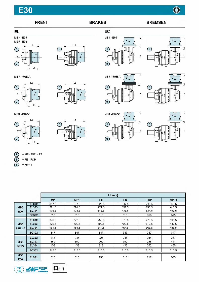
E30FRENI BRAKES BREMSEN
EL ECM B 3- E00 M B 5- E00
ф = MP - MP1 - FS
@ = FE - FCP
ф = MPP1
Lt [mm]
MP MP1 FE FS FCP MPP1
MB3E00
EL302 347.5 347.5 227.5 347.5 246.5 369.5EL303 391.5 391.5 271.5 391.5 290.5 413.5EL304 435.5 435.5 315.5 435.5 334.5 457.5EC302 318 318 318 318 318 318
MB3
SAE - A
EL302 376.5 376.5 256.5 376.5 275.5 398.5EL303 420.5 420.5 300.5 420.5 319.5 442.5EL304 464.5 464.5 344.5 464.5 363.5 486.5
EC302 347 347 347 347 347 347
MB3BRZV
EL302 345 345 225 345 244 367EL303 389 389 269 389 288 411EL304 433 433 313 433 332 455
EC302 315.5 315.5 315.5 315.5 315.5 315.5
MB5E00
EL301 313 313 193 313 212 335
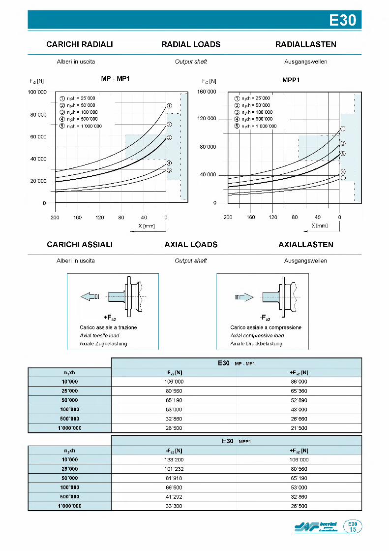
E30CARICHI RADIALI RADIAL LOADS RADIALLASTEN
Alberi in uscita Output shaft Ausgangswellen
Fr2 [N] M P - M P1 Fr2 [N] M P P 1
CARICHI ASSIALI AXIAL LOADS AXIALLASTEN
Alberi in uscita Output shaft Ausgangswellen
Carico assiale a trazione Axial tensile load Axiale Zugbelastung
О
Carico assiale a compressione Axial compressive load Axiale Druckbelastung
E 3 0 m p - MP1
n2xh -Fa2 [N] + Fa2 [N]1 0 0 0 0 106 000 86 000
25 000 80 560 65 360
50 000 65190 52 890
10 0 000 53 000 43 000
500 000 32860 26 660
1 000 000 26500 21500
E 3 0 m p p 1
n2xh -Fa2 [N] + Fa2 [N]10 000 133 200 106 000
25 000 101232 80 560
50 000 81918 65190
10 0 000 66 600 53 000
500 000 41292 32 860
1 000 000 33300 26 500
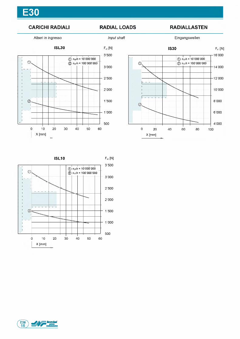
E30CARICHI RADIALI RADIAL LOADS RADIALLASTEN
E i n g a n g s w e l l e nA l b e r i in i n g r e s s o Input shaft
F rt [N]
3 500
3 000
2 500
2 000
1500
1000
5 0 0
0 10 20 30 40 50 60
X [mm]
IS30 F M [N ]ISL30
© n,xh = 10 000 000 (2 n,xh = 100 000 000
F rt [N]
3 500
3 000
2 500
2 000
1 500
1000
5 0 0
0 10 20 30 40 50 60
X [mm]
ISL10
d© n,xh = 10 000 000_ 2 n,xh = 100 000 000
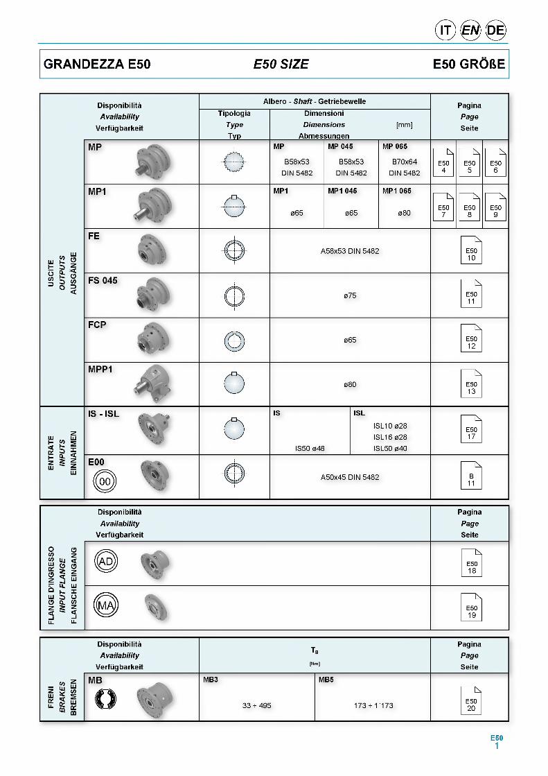
GRANDEZZA E50 E50 SIZE E50 GR06E
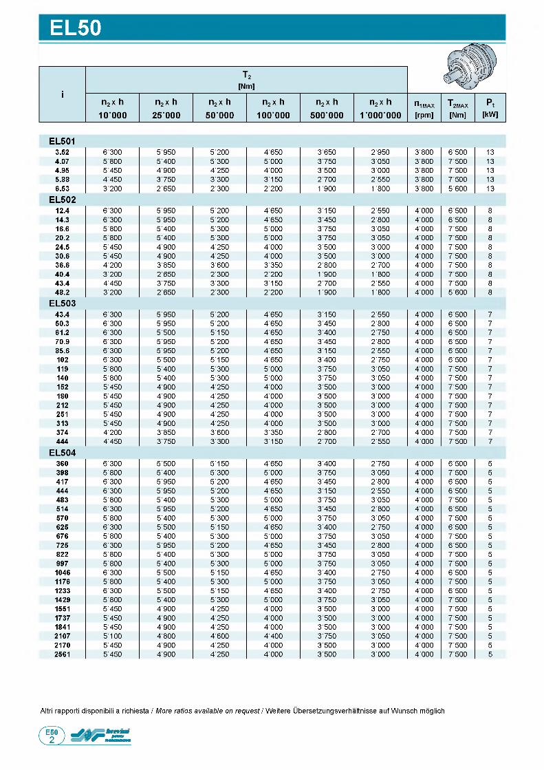
EL50
EL5013.52 6 300 5'950 5'200 4'650 3'650 2'950 3'800 6'500 134.07 5 800 5'400 5'300 5'000 3'750 3'050 3'800 7'500 134.95 5 450 4'900 4'250 4'000 3'500 3'000 3'800 7'500 135.88 4 450 3'750 3'300 3'150 2'700 2'550 3'800 7'500 136.53 3 200 2'650 2'300 2'200 1' 900 1' 800 3'800 5'600 13
EL50212.4 6 300 5'950 5'200 4'650 3'150 2'550 4'000 6'500 814.3 6 300 5'950 5'200 4'650 3'450 2'800 4'000 6'500 816.6 5 800 5'400 5'300 5'000 3'750 3'050 4'000 7'500 820.2 5 800 5'400 5'300 5'000 3'750 3'050 4'000 7'500 824.5 5'450 4'900 4'250 4'000 3'500 3'000 4'000 7'500 830.6 5'450 4'900 4'250 4'000 3'500 3'000 4'000 7'500 836.6 4'200 3'850 3'600 3'350 2'800 2'700 4'000 7'500 840.4 3'200 2'650 2'300 2'200 1' 900 1' 800 4'000 7'500 843.4 4'450 3'750 3'300 3'150 2'700 2'550 4'000 7'500 848.2 3'200 2'650 2'300 2'200 1' 900 1' 800 4'000 5'600 8
EL50343.4 6'300 5'950 5'200 4'650 3'150 2'550 4'000 6'500 750.3 6'300 5'950 5'200 4'650 3'450 2'800 4'000 6'500 761.2 6'300 5'500 5'150 4'650 3'400 2'750 4'000 6'500 770.9 6'300 5'950 5'200 4'650 3'450 2'800 4'000 6'500 785.6 6'300 5'950 5'200 4'650 3'150 2'550 4'000 6'500 7102 6'300 5'500 5'150 4'650 3'400 2'750 4'000 6'500 7119 5'800 5'400 5'300 5'000 3'750 3'050 4'000 7'500 7140 5'800 5'400 5'300 5'000 3'750 3'050 4'000 7'500 7152 5'450 4'900 4'250 4'000 3'500 3'000 4'000 7'500 7180 5'450 4'900 4'250 4'000 3'500 3'000 4'000 7'500 7212 5'450 4'900 4'250 4'000 3'500 3'000 4'000 7'500 7251 5'450 4'900 4'250 4'000 3'500 3'000 4'000 7'500 7313 5'450 4'900 4'250 4'000 3'500 3'000 4'000 7'500 7374 4'200 3'850 3'600 3'350 2'800 2'700 4'000 7'500 7444 4'450 3'750 3'300 3'150 2'700 2'550 4'000 7'500 7
EL504360 6'300 5'500 5'150 4'650 3'400 2'750 4'000 6'500 5398 5'800 5'400 5'300 5'000 3'750 3'050 4'000 7'500 5417 6'300 5'950 5'200 4'650 3'450 2'800 4'000 6'500 5444 6'300 5'950 5'200 4'650 3'150 2'550 4'000 6'500 5483 5'800 5'400 5'300 5'000 3'750 3'050 4'000 7'500 5514 6'300 5'950 5'200 4'650 3'450 2'800 4'000 6'500 5570 5'800 5'400 5'300 5'000 3'750 3'050 4'000 7'500 5625 6'300 5'500 5'150 4'650 3'400 2'750 4'000 6'500 5676 5'800 5'400 5'300 5'000 3'750 3'050 4'000 7'500 5725 6'300 5'950 5'200 4'650 3'450 2'800 4'000 6'500 5822 5'800 5'400 5'300 5'000 3'750 3'050 4'000 7'500 5997 5'800 5'400 5'300 5'000 3'750 3'050 4'000 7'500 51046 6'300 5'500 5'150 4'650 3'400 2'750 4'000 6'500 51176 5'800 5'400 5'300 5'000 3'750 3'050 4'000 7'500 51233 6'300 5'500 5'150 4'650 3'400 2'750 4'000 6'500 51429 5'800 5'400 5'300 5'000 3'750 3'050 4'000 7'500 51551 5'450 4'900 4'250 4'000 3'500 3'000 4'000 7'500 51737 5'450 4'900 4'250 4'000 3'500 3'000 4'000 7'500 51841 5'450 4'900 4'250 4'000 3'500 3'000 4'000 7'500 52107 5'100 4'800 4'600 4'400 3'750 3'050 4'000 7'500 52170 5'450 4'900 4'250 4'000 3'500 3'000 4'000 7'500 52561 5'450 4'900 4'250 4'000 3'500 3'000 4'000 7'500 5
Altri rapporti disponibili a richiesta / More ratios available on request / Weitere Ubersetzungsverhaltnisse auf Wunsch moglich
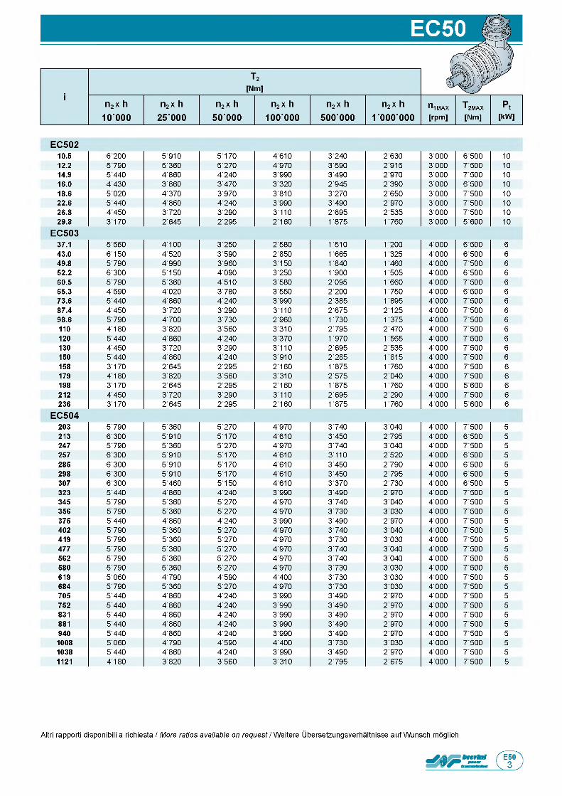
EC50210.5 6 200 5'910 5'170 4'610 3'240 2'630 3'000 6'500 1012.2 5 790 5'360 5'270 4'970 3'590 2'915 3'000 7'500 1014.9 5 440 4'860 4'240 3'990 3'490 2'970 3'000 7'500 1016.0 4 430 3'860 3'470 3'320 2'945 2'390 3'000 6'500 1018.6 5 020 4'370 3'970 3'810 3'270 2'650 3'000 7'500 1022.6 5 440 4'860 4'240 3'990 3'490 2'970 3'000 7'500 1026.8 4 450 3'720 3'290 3'110 2'695 2'535 3'000 7'500 1029.8 3170 2'645 2'295 2'160 1' 875 1' 760 3'000 5'600 10
EC50337.1 5'560 4'100 3'250 2'580 1' 510 1' 200 4'000 6'500 643.0 6'150 4'520 3'590 2'850 1' 665 1' 325 4'000 6'500 649.8 5'790 4'990 3'960 3'150 1' 840 1' 460 4'000 7'500 652.2 6'300 5'150 4'090 3'250 1' 900 1' 505 4'000 6'500 660.5 5'790 5'360 4'510 3'580 2'095 1' 660 4'000 7'500 665.3 4'590 4'020 3'780 3'550 2'200 1' 750 4'000 6'500 673.6 5'440 4'860 4'240 3'990 2'385 1' 895 4'000 7'500 687.4 4'450 3'720 3'290 3'110 2'675 2'125 4'000 7'500 698.6 5'790 4'700 3'730 2'960 1' 730 1' 375 4'000 7'500 6110 4 ' 180 3'820 3'560 3'310 2'795 2'470 4'000 7'500 6120 5'440 4'860 4'240 3'370 1' 970 1' 565 4'000 7'500 6130 4'450 3'720 3'290 3 ' 110 2'695 2'535 4'000 7'500 6150 5'440 4'860 4'240 3'910 2'285 1' 815 4'000 7'500 6158 3'170 2'645 2'295 2 ' 160 1' 875 1' 760 4'000 7'500 6179 4 ' 180 3'820 3'560 3'310 2'575 2'040 4'000 7'500 6198 3'170 2'645 2'295 2'160 1' 875 1' 760 4'000 5'600 6212 4'450 3'720 3'290 3'110 2'695 2'290 4'000 7'500 6236 3'170 2'645 2'295 2'160 1' 875 1' 760 4'000 5'600 6
EC504203 5'790 5'360 5'270 4'970 3'740 3'040 4'000 7'500 5213 6'300 5'910 5'170 4'610 3'450 2'795 4'000 6'500 5247 5'790 5'360 5'270 4'970 3'740 3'040 4'000 7'500 5257 6'300 5'910 5'170 4'610 3 ' 110 2'520 4'000 6'500 5285 6'300 5'910 5'170 4'610 3'450 2'790 4'000 6'500 5298 6'300 5'910 5'170 4'610 3'450 2'795 4'000 6'500 5307 6'300 5'460 5'150 4'610 3'370 2'730 4'000 6'500 5323 5'440 4'860 4'240 3'990 3'490 2'970 4'000 7'500 5345 5'790 5'360 5'270 4'970 3'740 3'040 4'000 7'500 5356 5'790 5'360 5'270 4'970 3'730 3'030 4'000 7'500 5375 5'440 4'860 4'240 3'990 3'490 2'970 4'000 7'500 5402 5'790 5'360 5'270 4'970 3'740 3'040 4'000 7'500 5419 5'790 5'360 5'270 4'970 3'730 3'030 4'000 7'500 5477 5'790 5'360 5'270 4'970 3'740 3'040 4'000 7'500 5562 5'790 5'360 5'270 4'970 3'740 3'040 4'000 7'500 5580 5'790 5'360 5'270 4'970 3'730 3'030 4'000 7'500 5619 5'060 4'790 4'590 4'400 3'730 3'030 4'000 7'500 5684 5'790 5'360 5'270 4'970 3'730 3'030 4'000 7'500 5705 5'440 4'860 4'240 3'990 3'490 2'970 4'000 7'500 5752 5'440 4'860 4'240 3'990 3'490 2'970 4'000 7'500 5831 5'440 4'860 4'240 3'990 3'490 2'970 4'000 7'500 5881 5'440 4'860 4'240 3'990 3'490 2'970 4'000 7'500 5940 5'440 4'860 4'240 3'990 3'490 2'970 4'000 7'500 51008 5'060 4'790 4'590 4'400 3'730 3'030 4'000 7'500 51038 5'440 4'860 4'240 3'990 3'490 2'970 4'000 7'500 51121 4 ' 180 3'820 3'560 3'310 2'795 2'675 4'000 7'500 5
Altri rapporti disponibili a richiesta / More ratios available on request / Weitere Ubersetzungsverhaltnisse auf Wunsch moglich
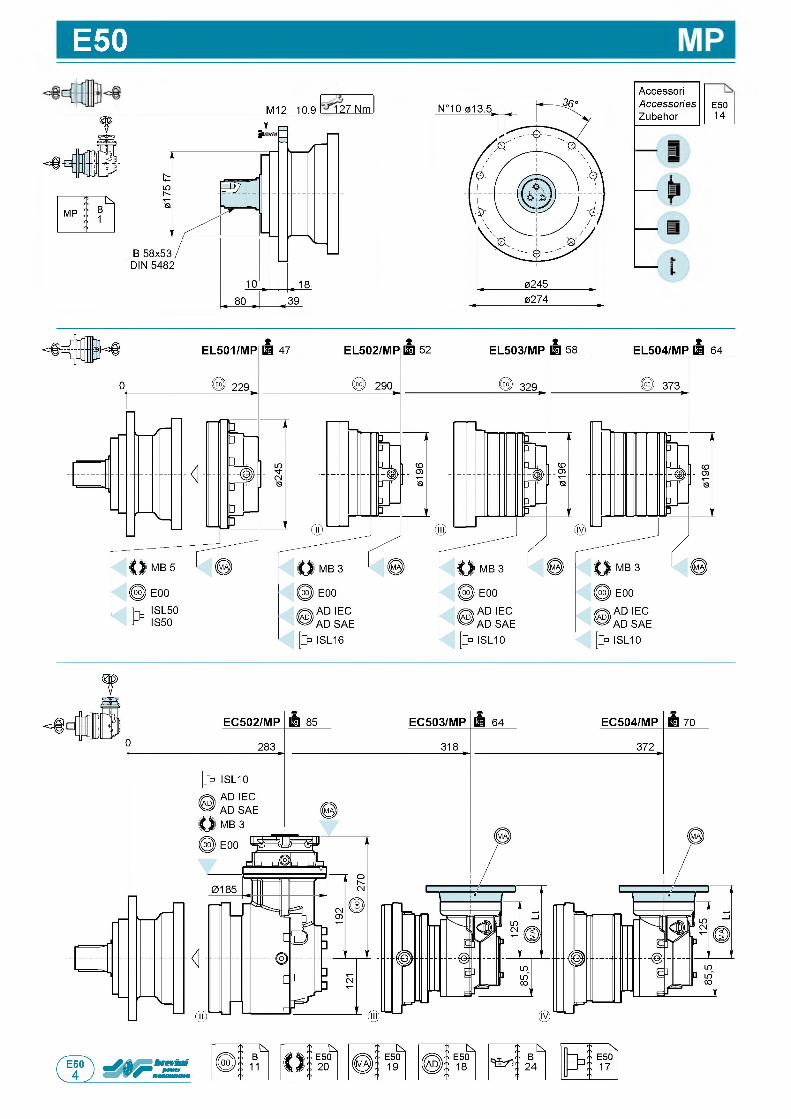
E50
M12 10.9 127 Nmгг,AccessoriAccessoriesZubehor
E5014
f
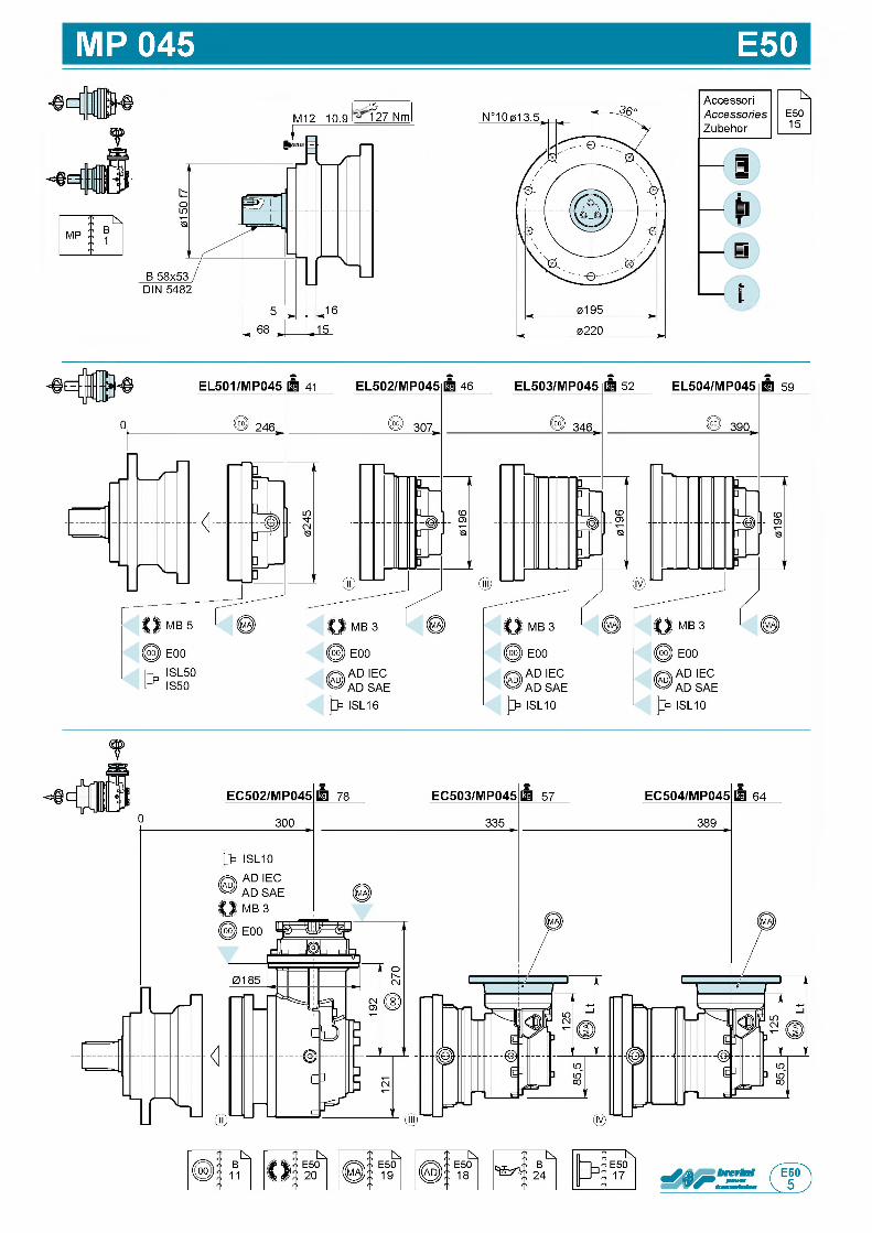
MP 045 E50
M12 10.9 127 Nm
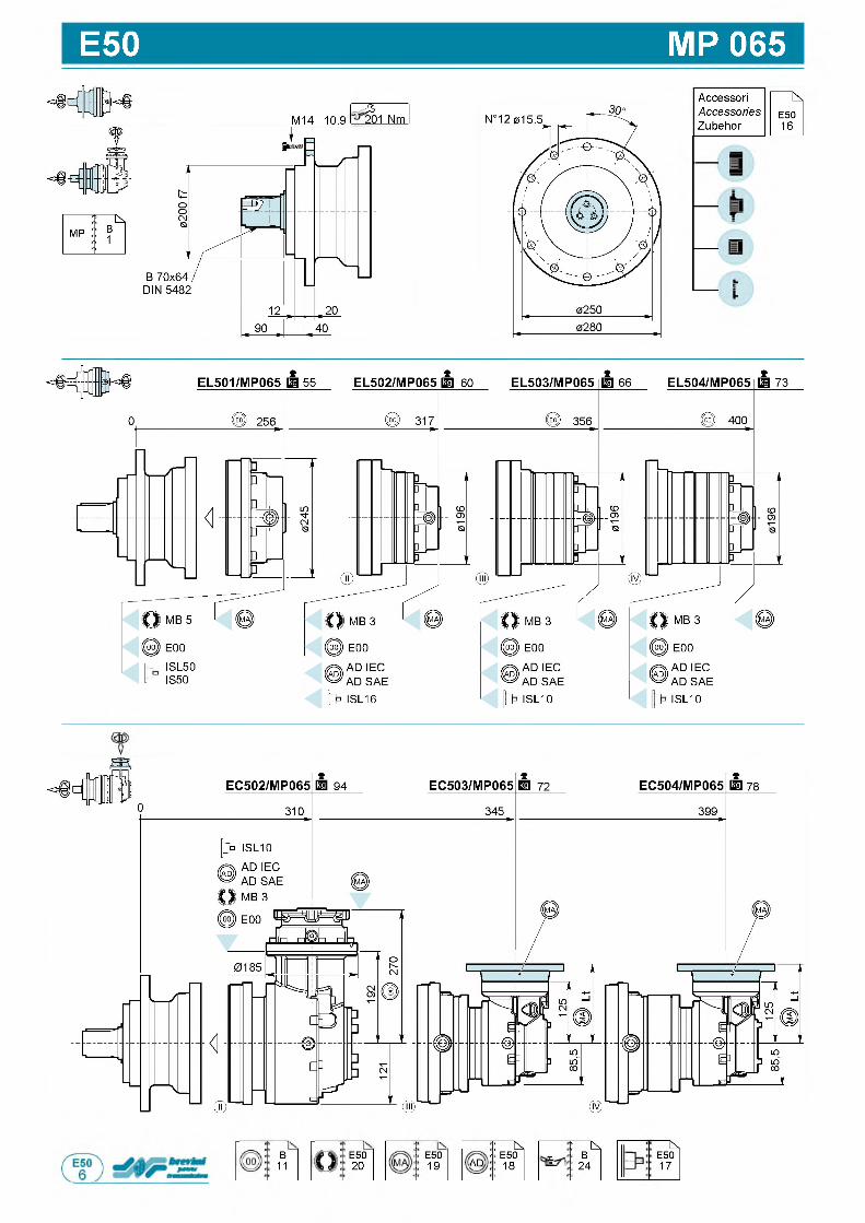
E50 MP 065
M14 10.9 20201 Nm
в11
E5020
E5019
: ^<• E50
AD 18
: ^5 B
24
bs,E5017
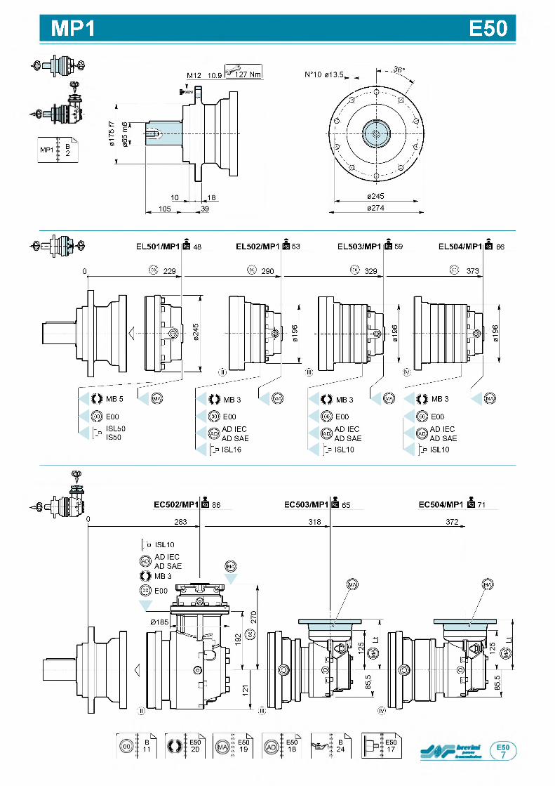
MP1 E50
;—MP1 в
2
M12 10.9 127 Nm
■ъ,в11
E5020
: ь .E5019
E5018
: ^S B
24
"Ь,E5017
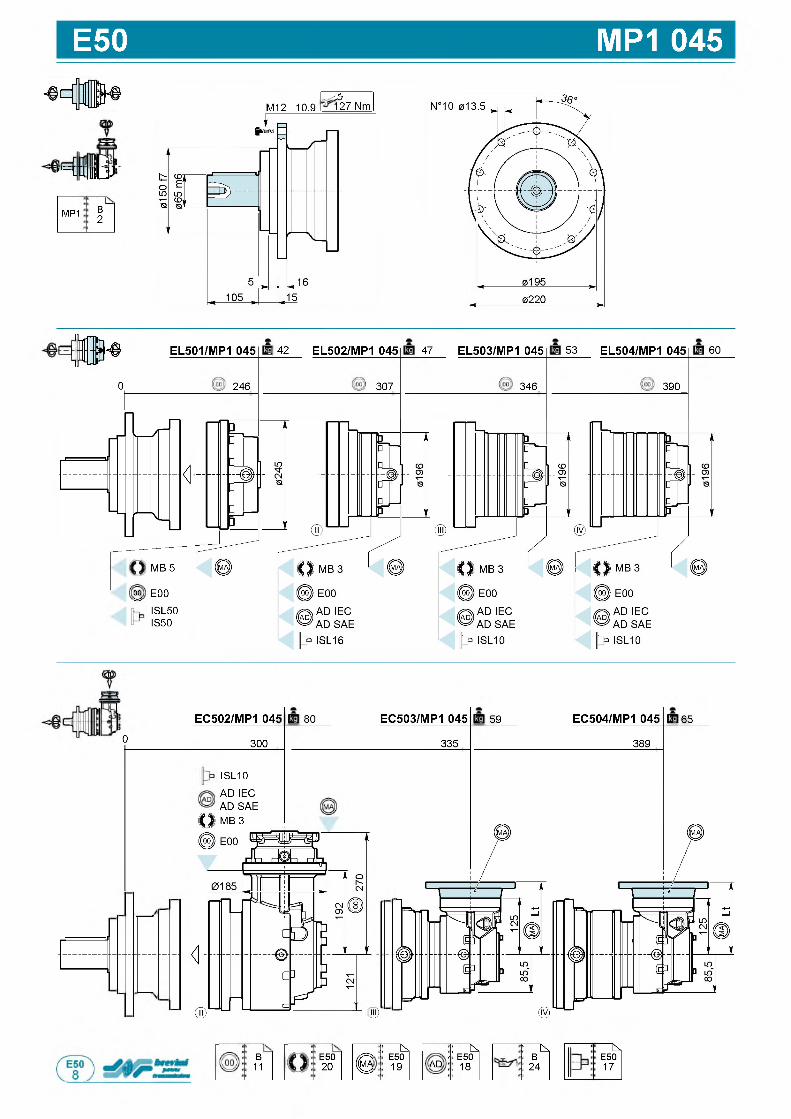
E50 MP1 045
f,= n B J J
MP1 B2
M12 10.9 12127 Nm
(ШИ EL501/MP1 045
246
I 42 EL502/MP1 045
307
47 EL503/MP1 045
346
53 EL504/MP1 045
390
60
0
<
MB 5
00 E00
ISL50IS50
EC502/MP1 045
300
ISL10
AD IEC AD SAE MB 3
80 EC503/MP1 045
335
59 EC504/MP1 045
389
65
B11
E5020
Щ)
( g: i^,
E5019
: ^t E50AD 18
: ^B
24
bs,E5017
0
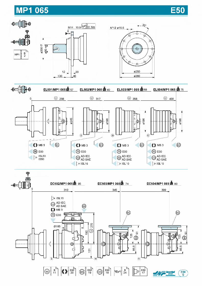
MP1 065 E50
!-----MP1 B
2
M14 10.9 201 Nm
(ШИ EL501/MP1 065
256
I 57 EL502/MP1 065
317
62 EL503/MP1 065
356
I 68 EL504/MP1 065
400
75
0
MB 5
oo E00
ISL50IS50
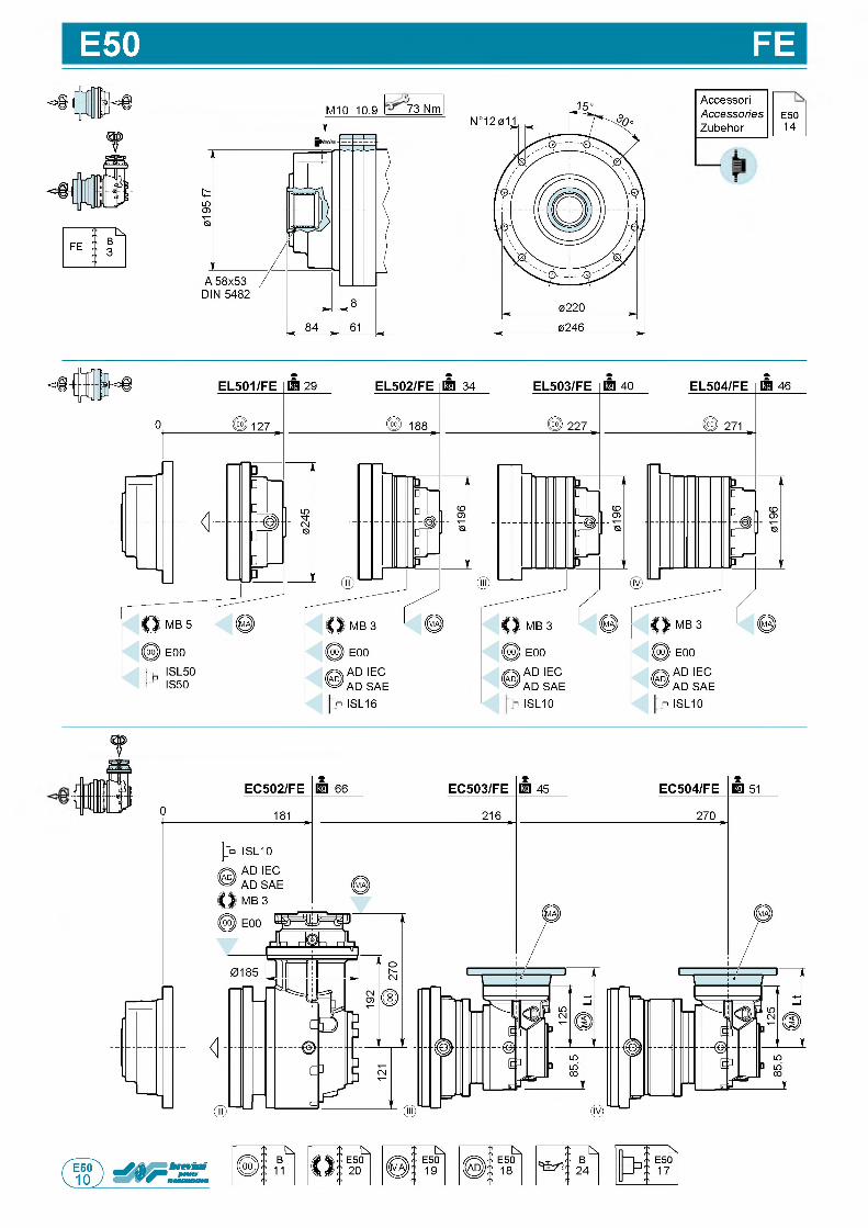
E50 FEM10 10.9 773 Nmf
AccessoriAccessories E50Zubehor 14
f
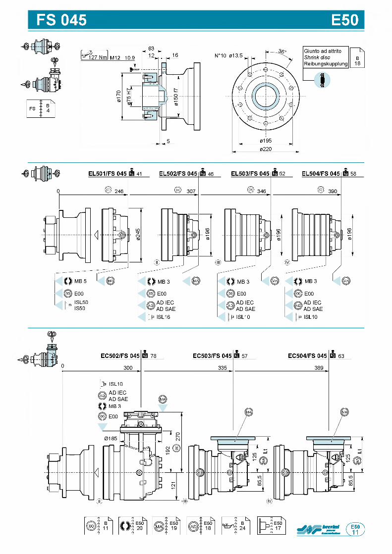
FS 045 E50
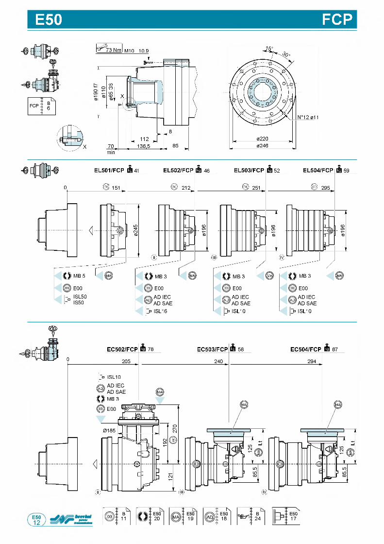
E50 FCP
- в Л
trin гВп rbj
fcp : О) ОТ
73 Nm M10 10.9
CDO ,
s lQ L
г
X. Ы
min
"k,B11
E5020
E5019
i N* E50
AD 18
:it B
24
fcs,E5017
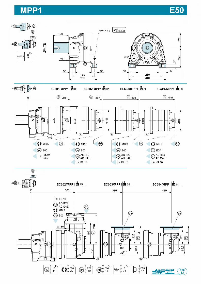
E50
MPP1 B5
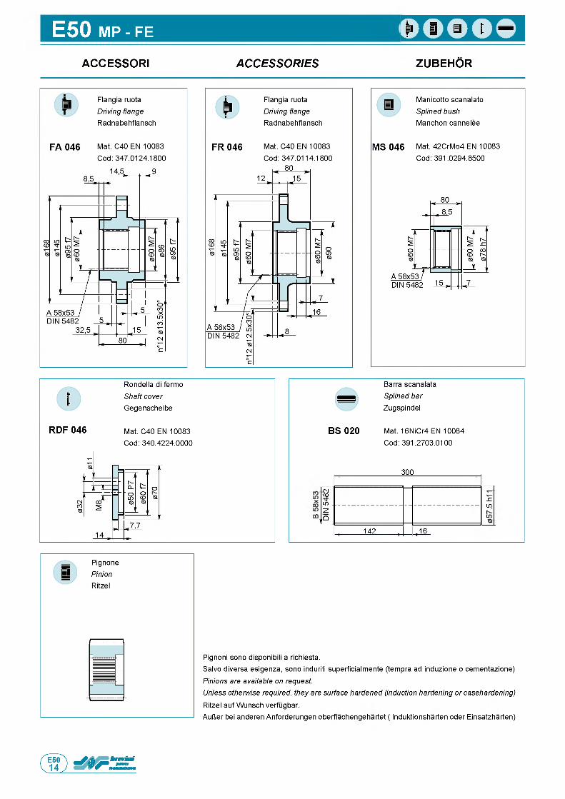
E50 MP - FE
ACCESSORI A C C E S S O R IE S ZUBEHOR
Manicotto scanalato Splined bush Manchon cannelee
MS 046 Mat. 42CrMo4 EN 10083 Cod: 391.0294.8500
Rondella di fermo Shaft cover Gegenscheibe
RDF 046 Mat. C40 EN 10083Cod: 340.4224.0000
Barra scanalata Splined bar Zugspindel
BS 020 Mat. 16NiCr4 EN 10084 Cod: 391.2703.0100
300
( 4CO
LO .S Z
■ LO
LO~ Z .
UQ
l 142 , ,16
Pignoni sono disponibili a richiesta.Salvo diversa esigenza, sono induriti superficialmente (tempra ad induzione o cementazione) Pinions are available on request.Unless otherwise required, they are surface hardened (induction hardening or casehardening) Ritzel auf Wunsch verfugbar.AulJer bei anderen Anforderungen oberflachengehartet ( Induktionsharten oder Einsatzharten)
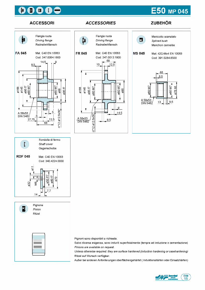
E50 MP 045
ACCESSORI A C C E S S O R IE S ZUBEHOR
FA 045
Flangia ruota Driving flange Radnabehflansch
Mat. C40 EN 10083 Cod: 347.0064.1800
MS 045
Manicotto scanalato Splined bush Manchon cannelee
Mat. 42CrMo4 EN 10083 Cod: 391.0284.8500
RDF 045
Rondella di fermo Shaft cover Gegenscheibe
Mat. C40 EN 10083 Cod: 340.4224.0000
Pignoni sono disponibili a richiesta.Salvo diversa esigenza, sono induriti superficialmente (tempra ad induzione o cementazione) Pinions are available on request.Unless otherwise required, they are surface hardened (induction hardening or casehardening) Ritzel auf Wunsch verfugbar.AulJer bei anderen Anforderungen oberflachengehartet ( Induktionsharten oder Einsatzharten)
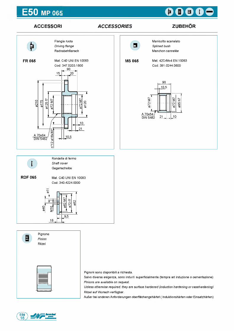
E50 MP 065
ACCESSORI A C C E S S O R IE S ZUBEHOR
FR 065
Flangia ruota Driving flange Radnabehflansch
Mat. C40 UNI EN 10083 Cod: 347.0203.1800
MS 065
Manicotto scanalato Splined bush Manchon cannelee
Mat. 42CrMo4 EN 10083 Cod: 391.0244.0600
90
A 70x64T
10,5
DIN 5482 21 10
Rondella di fermo Shaft cover Gegenscheibe
RDF 065 Mat. C40 UNI EN 10083 Cod: 340.4224.0000
Pignoni sono disponibili a richiesta.Salvo diversa esigenza, sono induriti superficialmente (tempra ad induzione o cementazione) Pinions are available on request.Unless otherwise required, they are surface hardened (induction hardening or casehardening) Ritzel auf Wunsch verfugbar.AulJer bei anderen Anforderungen oberflachengehartet ( Induktionsharten oder Einsatzharten)
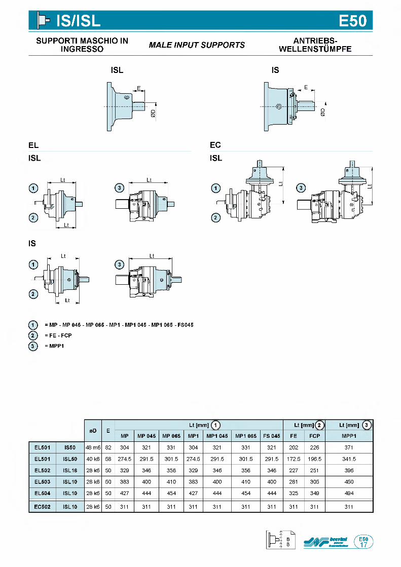
IS/ISL E50SUPPORTI MASCHIO IN
INGRESSO M A L E IN P U T S U P P O R T S ANTRIEBS-w e l l e n s t Om p f e
ISL IS
EL EC
IS
ф = MP - MP 045 - MP 065 - MP1 - MP1 045 - MP1 065 - FS045
ф = FE - FCP
ф = MPP1
0D ELt [mm] 1 Lt [mm] 2 Lt [mm] 3
MP MP 045 MP 065 MP1 MP1 045 MP1 065 FS 045 FE FCP MPP1
EL501 IS50 48 m6 82 304 321 331 304 321 331 321 202 226 371
EL501 ISL50 40 k6 58 274.5 291.5 301.5 274.5 291.5 301.5 291.5 172.5 196.5 341.5
EL502 ISL16 28 k6 50 329 346 356 329 346 356 346 227 251 396
EL503 ISL10 28 k6 50 383 400 410 383 400 410 400 281 305 450
EL504 ISL10 28 k6 50 427 444 454 427 444 454 444 325 349 494
EC502 ISL10 28 k6 50 311 311 311 311 311 311 311 311 311 311
B8
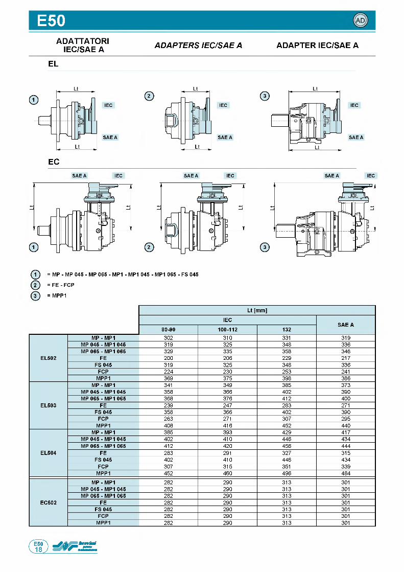
E50ADATTATORI
IEC/SAE A A D A P T E R S IE C /S A E A ADAPTER IEC/SAE A
EL
IEC
S A E A
IEC
S A E A
IEC
S A E A
ECS A E A IEC S A E A IEC S A E A IEC
ф = MP - MP 045 - MP 065 - MP1 - MP1 045 - MP1 065 - FS 045
Q = F E - FCP
ф = MPP1
Lt [mm]
IECSAE A
80-90 100-112 132
EL502
MP - MP1 302 310 331 319MP 045 - MP1 045 319 325 348 336MP 065 - MP1 065 329 335 358 346
FE 200 206 229 217FS 045 319 325 348 336
FCP 224 230 253 241MPP1 369 375 398 386
EL503
MP - MP1 341 349 385 373MP 045 - MP1 045 358 366 402 390MP 065 - MP1 065 368 376 412 400
FE 239 247 283 271FS 045 358 366 402 390
FCP 263 271 307 295MPP1 408 416 452 440
EL504
MP - MP1 385 393 429 417MP 045 - MP1 045 402 410 446 434MP 065 - MP1 065 412 420 456 444
FE 283 291 327 315FS 045 402 410 446 434
FCP 307 315 351 339MPP1 452 460 496 484
EC502
MP - MP1 282 290 313 301MP 045 - MP1 045 282 290 313 301MP 065 - MP1 065 282 290 313 301
FE 282 290 313 301FS 045 282 290 313 301
FCP 282 290 313 301MPP1 282 290 313 301
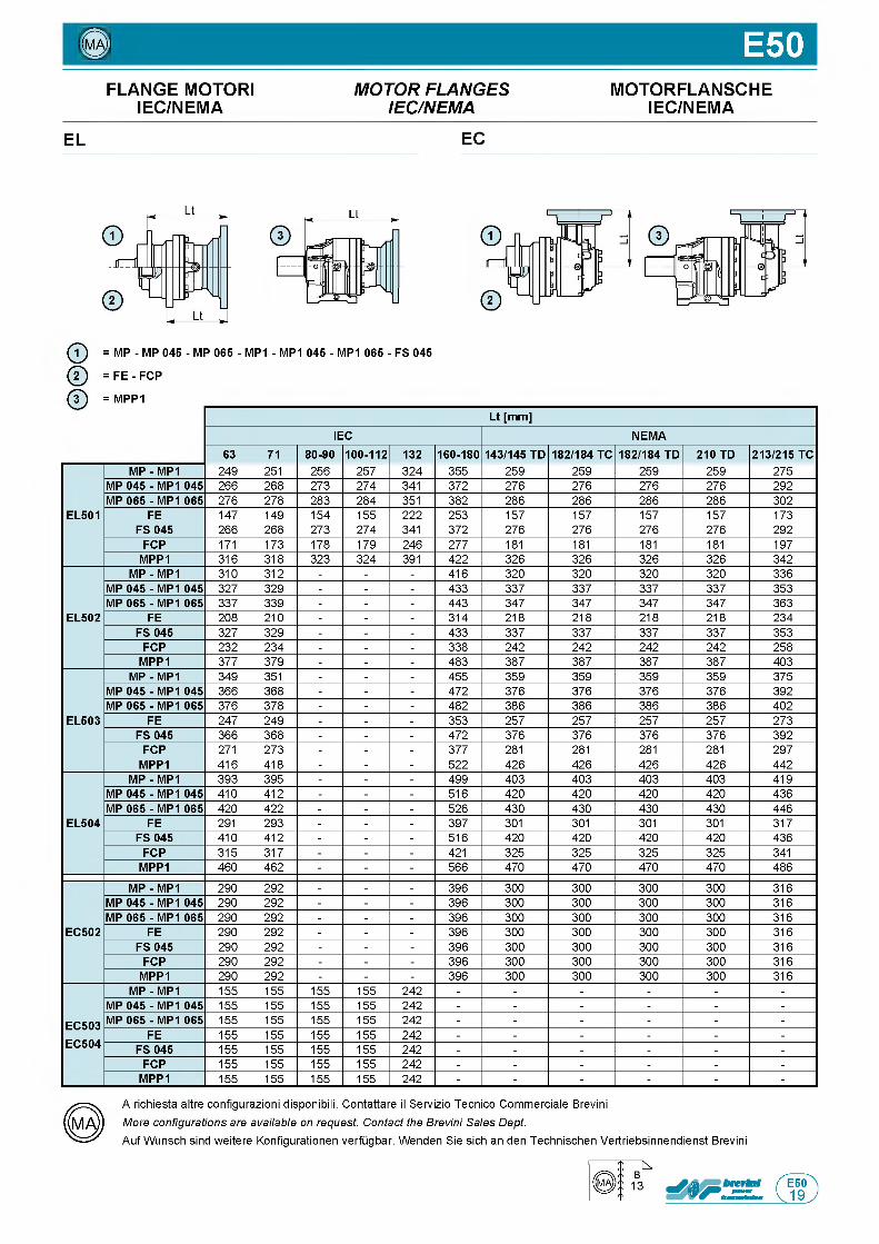
© E50FLANGE MOTORI M O T O R F L A N G E S MOTORFLANSCHE
IEC/NEMA IE C /N E M A IEC/NEMA
EL EC
ф = MP - MP 045 - MP 065 - MP1 - MP1 045 - MP1 065 - FS 045
@ = F E - FCP
ф = MPP1Lt [mm]
IEC NEMA63 71 80-90 100-112 132 160-180 143/145 TD 182/184 TC 182/184 TD 210 TD 213/215 TC
EL501
MP - MP1 249 251 256 257 324 355 259 259 259 259 275MP 045 - MP1 045 266 268 273 274 341 372 276 276 276 276 292MP 065 - MP1 065 276 278 283 284 351 382 286 286 286 286 302
FE 147 149 154 155 222 253 157 157 157 157 173FS 045 266 268 273 274 341 372 276 276 276 276 292
FCP 171 173 178 179 246 277 181 181 181 181 197MPP1 316 318 323 324 391 422 326 326 326 326 342
EL502
MP - MP1 310 312 - - - 416 320 320 320 320 336MP 045 - MP1 045 327 329 - - - 433 337 337 337 337 353MP 065 - MP1 065 337 339 - - - 443 347 347 347 347 363
FE 208 210 - - - 314 218 218 218 218 234FS 045 327 329 - - - 433 337 337 337 337 353
FCP 232 234 - - - 338 242 242 242 242 258MPP1 377 379 - - - 483 387 387 387 387 403
EL503
MP - MP1 349 351 - - - 455 359 359 359 359 375MP 045 - MP1 045 366 368 - - - 472 376 376 376 376 392MP 065 - MP1 065 376 378 - - - 482 386 386 386 386 402
FE 247 249 - - - 353 257 257 257 257 273FS 045 366 368 - - - 472 376 376 376 376 392
FCP 271 273 - - - 377 281 281 281 281 297MPP1 416 418 - - - 522 426 426 426 426 442
EL504
MP - MP1 393 395 - - - 499 403 403 403 403 419MP 045 - MP1 045 410 412 - - - 516 420 420 420 420 436MP 065 - MP1 065 420 422 - - - 526 430 430 430 430 446
FE 291 293 - - - 397 301 301 301 301 317FS 045 410 412 - - - 516 420 420 420 420 436
FCP 315 317 - - - 421 325 325 325 325 341MPP1 460 462 - - - 566 470 470 470 470 486
EC502
MP - MP1 290 292 - - - 396 300 300 300 300 316MP 045 - MP1 045 290 292 - - - 396 300 300 300 300 316MP 065 - MP1 065 290 292 - - - 396 300 300 300 300 316
FE 290 292 - - - 396 300 300 300 300 316FS 045 290 292 - - - 396 300 300 300 300 316
FCP 290 292 - - - 396 300 300 300 300 316MPP1 290 292 - - - 396 300 300 300 300 316
EC503
MP - MP1 155 155 155 155 242 - - - - - -MP 045 - MP1 045 155 155 155 155 242 - - - - - -MP 065 - MP1 065 155 155 155 155 242 - - - - - -
EC504FE 155 155 155 155 242 - - - - - -
FS 045 155 155 155 155 242 - - - - - -FCP 155 155 155 155 242 - - - - - -
MPP1 155 155 155 155 242 - - - - - -
A richiesta altre configurazioni disponibili. Contattare il Servizio Tecnico Commerciale Brevini More configurations are available on request. Contact the Brevini Sales Dept.Auf Wunsch sind weitere Konfigurationen verfugbar. Wenden Sie sich an den Technischen Vertriebsinnendienst Brevini
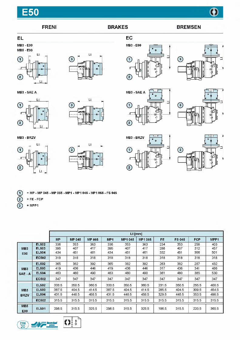
E50FRENI
ELM B 3- E00 M B 5- E00
Lt
dA l l
© ! d
„ Lt ,
MB3 - SAE A
Lt
a
tr1 !
© r !Lt— ,
M B 3- BRZV
Lt
G.-ГГТStr1©
L L _
BRAKES
EC
BREMSEN
© = MP - MP 045 - MP 065 - MP1 - MP1 045 - MP1 065 - FS 045
© = FE - FCP
© = MPP1
Lt [mm]
MP MP 045 MP 065 MP1 MP1 045 M P1065 FE FS 045 FCP MPP1
MB3E00
EL502 336 353 363 336 353 363 234 353 258 403EL503 390 407 417 390 407 417 288 407 312 457EL504 434 451 461 434 451 461 332 451 356 501EC502 318 318 318 318 318 318 318 318 318 318
MB3 SAE - A
EL502 365 382 392 365 382 392 263 382 287 432EL503 419 436 446 419 436 446 317 436 341 486EL504 463 480 490 463 480 490 361 480 385 530
EC502 347 347 347 347 347 347 347 347 347 347
MB3BRZV
EL502 333.5 350.5 360.5 333.5 350.5 360.5 231.5 350.5 255.5 400.5EL503 387.5 404.5 414.5 387.5 404.5 414.5 285.5 404.5 309.5 454.5EL504 431.5 448.5 458.5 431.5 448.5 458.5 329.5 448.5 353.5 498.5
EC502 315.5 315.5 315.5 315.5 315.5 315.5 315.5 315.5 315.5 315.5
MB5E00
EL501 298.5 315.5 325.5 298.5 315.5 325.5 196.5 315.5 220.5 365.5
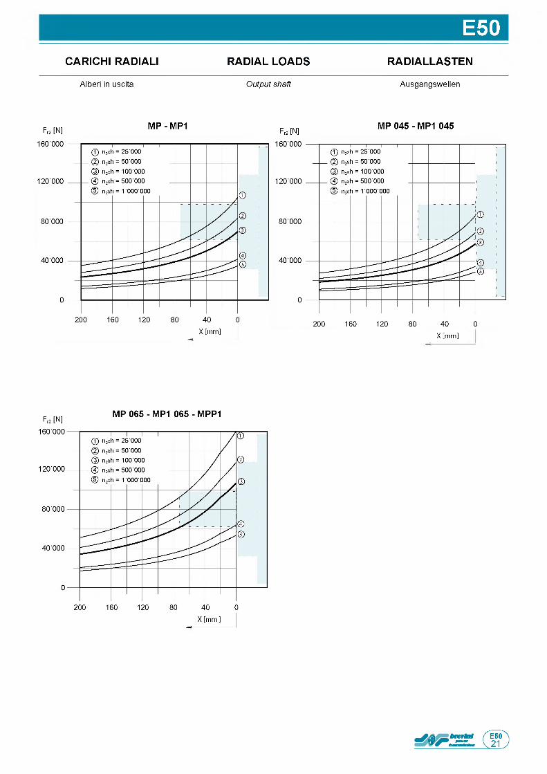
E50CARICHI RADIALI RADIAL LOADS RADIALLASTEN
Alberi in uscita Output shaft Ausgangswellen
Fr2 [N] MP - MP1Fr2 [IN]
MP 045 - MP1 045
X [mm]
F [|N] MP 065 - MP1 065 - MPP1
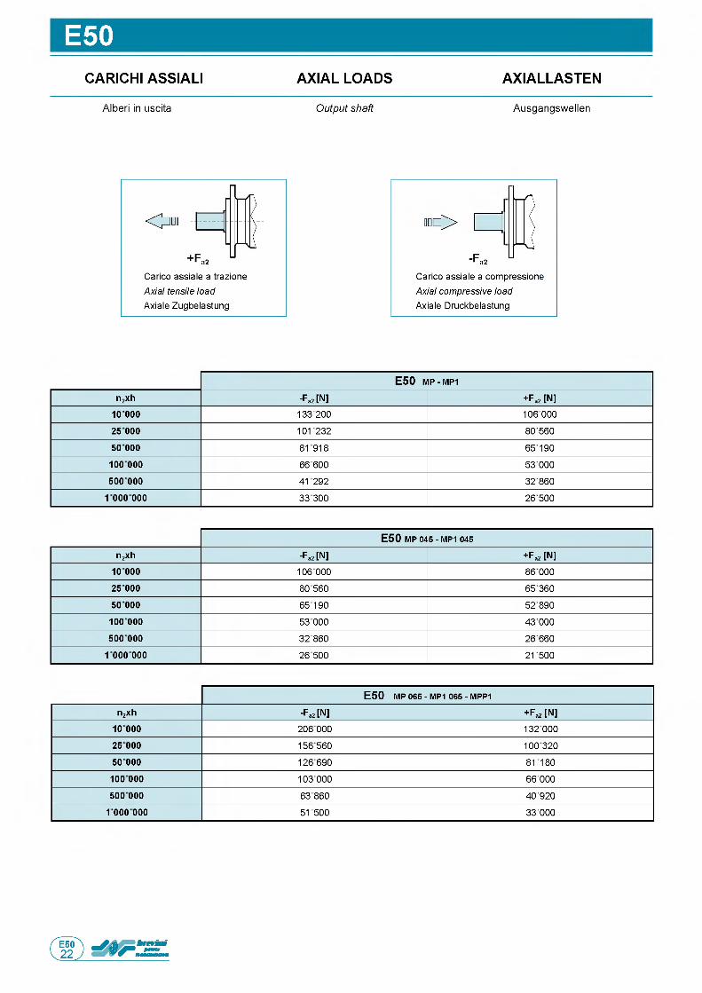
E50CARICHI ASSIALI AXIAL LOADS AXIALLASTEN
Alberi in uscita Output shaft Ausgangswellen
Carico assiale a trazione Axial tensile load Axiale Zugbelastung
О
-Fa2 UCarico assiale a compressione Axial compressive load Axiale Druckbelastung
E 5 0 m p - m p i
n2xh -Fa2 [N] + Fa2 [N]1 0 0 0 0 133 200 106 00025 000 101232 80 560
50 000 81918 6519010 0 000 66 600 53 000500 000 41292 32 860
1 000 000 33300 26 500
E 5 0 MP 045 - MP1 045
n2xh -Fa2 [N] + Fa2 [N]10 000 106 000 86 00025 000 80 560 65 36050 000 65190 52 890
10 0 000 53 000 43 000500 000 32860 26 660
1 000 000 26500 21500
E 5 0 MP 065 - MP1 065 - MPP1
n2xh -Fa2 [N] + Fa2 [N]10 000 206 000 132 00025 000 156560 10032050 000 126690 81180
10 0 000 103 000 66 000500 000 63 860 40 920
1 000 000 51500 33 000
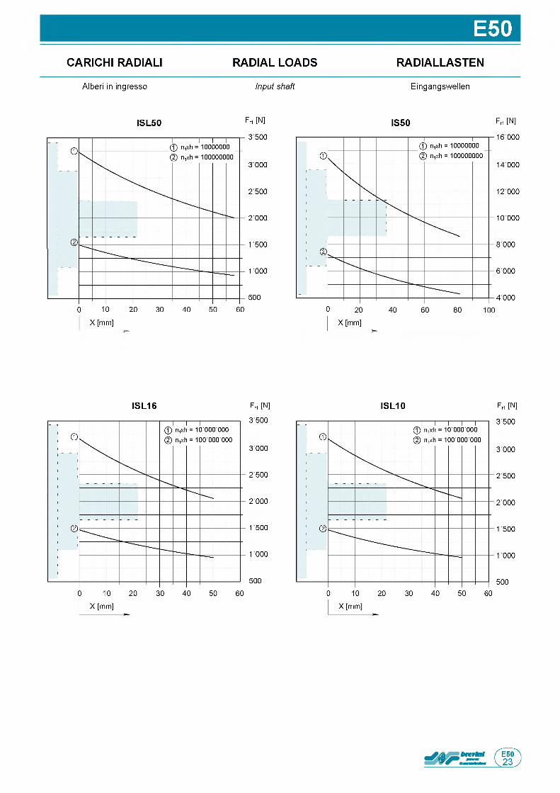
E50CARICHI RADIALI RADIAL LOADS RADIALLASTEN
Alberi in ingresso Input shaft Eingangswellen
Frt [N]
3 500
3 000
2 1500
2000
1 500
1 5500
5005 15 25 35 45 55 65
X [mm]
ISL50 IS50 Fri [N]
16 000
14 000
12 000
10 000
8 000
6 000
4 000
ISL16 Frt [N]
3 500
3 000
2 500
2 000
1 500
1000
500
ISL10 Frt [N]
3 500
3 000
2 500
2 000
1 500
1 000
500

Questa pagina e lasciata intenzionalmente bianca
Page is intentionally left blank Seite wurde absichtlich leer gelassen
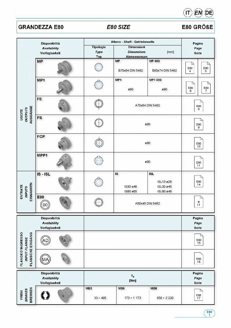
DisponibilitaA vailab ility
\/o r f i in h a r U o it
Albero - Shaft - Getriebewelle
Tipologia
Type
___ ТУР___
Dimensioni
DimensionsAbmessungen
[ m m ]
PaginaPage
Seite
MP
B 7 0 x 6 4 D I N 5 4 8 2
MP 090
B 8 0 x 7 4 D I N 5 4 8 2E80
4E80
5
MP1 MP1 090
0 8 0 090 E806
E807
Шй о? ■<с о
° 5
A 7 0 x 6 4 D IN 5 4 8 2 E808
FS
090 E809
F C P
0 8 0 E801 0
M P P 1
Ф 090 E8011
2
IS - IS L
*ш LLI
g <M i
Ш
IS
I S 3 0 0 4 8
I S 8 0 0 6 5
ISL
I S L 1 0 0 2 8
I S L 3 0 0 4 0
I S L 8 0 0 4 8
E801 4
E 00
00 j) A 5 0 x 4 5 D IN 5 4 8 2B
11
Disponibilita
A vailab ilityVerfugbarkeit
Tb
[Nm]
MB3 MB5
О 3 3 * 4 9 5 1 7 3 * 1 1 7 3
Pagina
PageSeite
«оШ 5вс Su- КCQ
MB6
6 5 8 * 2 2 2 0E801 7
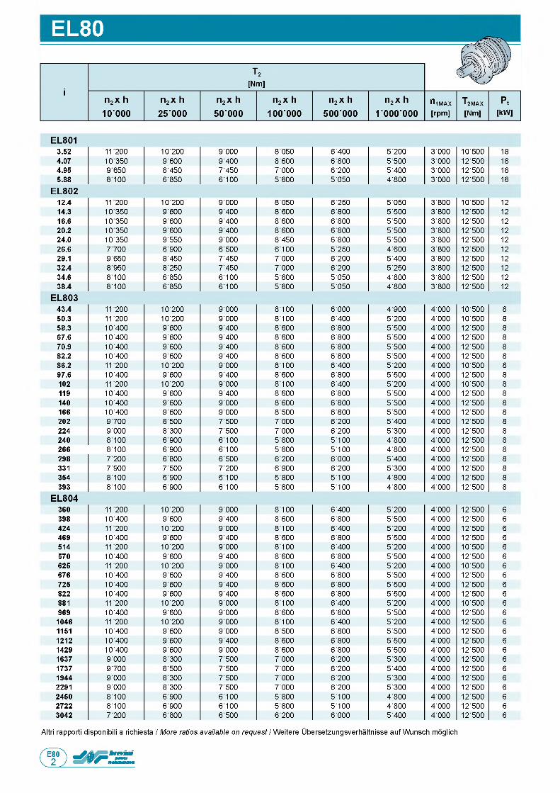
EL80
E L 8013.52 1 1 2 0 0 1 0 ' 2 0 0 9 ' 0 0 0 8 ' 0 5 0 6 ' 4 0 0 5 ' 2 0 0 3 ' 0 0 0 1 0 ' 5 0 0 1 8
4.07 1 0 3 5 0 9 ' 6 0 0 9 ' 4 0 0 8 ' 6 0 0 6 ' 8 0 0 5 ' 5 0 0 3 ' 0 0 0 1 2 ' 5 0 0 1 8
4.95 9 6 5 0 8 ' 4 5 0 7 ' 4 5 0 7 ' 0 0 0 6 ' 2 0 0 5 ' 4 0 0 3 ' 0 0 0 1 2 ' 5 0 0 1 8
5.88 8 1 0 0 6 ' 8 5 0 6 ' 1 0 0 5 ' 8 0 0 5 ' 0 5 0 4 ' 8 0 0 3 ' 0 0 0 1 2 ' 5 0 0 1 8
E L 8 0 212.4 1 1 2 0 0 1 0 ' 2 0 0 9 ' 0 0 0 8 ' 0 5 0 6 ' 2 5 0 5 ' 0 5 0 3 ' 8 0 0 1 0 ' 5 0 0 1 2
14.3 1 0 3 5 0 9 ' 6 0 0 9 ' 4 0 0 8 ' 6 0 0 6 ' 8 0 0 5 ' 5 0 0 3 ' 8 0 0 1 2 ' 5 0 0 1 2
16.6 1 0 3 5 0 9 ' 6 0 0 9 ' 4 0 0 8 ' 6 0 0 6 ' 8 0 0 5 ' 5 0 0 3 ' 8 0 0 1 2 ' 5 0 0 1 2
20.2 1 0 3 5 0 9 ' 6 0 0 9 ' 4 0 0 8 ' 6 0 0 6 ' 8 0 0 5 ' 5 0 0 3 ' 8 0 0 1 2 ' 5 0 0 1 2
24.0 1 0 3 5 0 9 ' 5 5 0 9 ' 0 0 0 8 ' 4 5 0 6 ' 8 0 0 5 ' 5 0 0 3 ' 8 0 0 1 2 ' 5 0 0 1 2
26.6 7 7 0 0 6 ' 9 0 0 6 ' 5 0 0 6 ' 1 0 0 5 ' 2 5 0 4 ' 6 0 0 3 ' 8 0 0 1 2 ' 5 0 0 1 2
29.1 9 6 5 0 8 ' 4 5 0 7 ' 4 5 0 7 ' 0 0 0 6 ' 2 0 0 5 ' 4 0 0 3 ' 8 0 0 1 2 ' 5 0 0 1 2
32.4 8 9 5 0 8 ' 2 5 0 7 ' 4 5 0 7 ' 0 0 0 6 ' 2 0 0 5 ' 2 5 0 3 ' 8 0 0 1 2 ' 5 0 0 1 2
34.6 8 1 0 0 6 ' 8 5 0 6 ' 1 0 0 5 ' 8 0 0 5 ' 0 5 0 4 ' 8 0 0 3 ' 8 0 0 1 2 ' 5 0 0 1 2
38.4 8 ' 1 0 0 6 ' 8 5 0 6 ' 1 0 0 5 ' 8 0 0 5 ' 0 5 0 4 ' 8 0 0 3 ' 8 0 0 1 2 ' 5 0 0 1 2
E L 8 0 343.4 1 1 2 0 0 1 0 ' 2 0 0 9 ' 0 0 0 8 ' 1 0 0 6 ' 0 0 0 4 ' 9 0 0 4 ' 0 0 0 1 0 ' 5 0 0 8
50.3 1 1 2 0 0 1 0 ' 2 0 0 9 ' 0 0 0 8 ' 1 0 0 6 ' 4 0 0 5 ' 2 0 0 4 ' 0 0 0 1 0 ' 5 0 0 8
58.3 1 0 ' 4 0 0 9 ' 6 0 0 9 ' 4 0 0 8 ' 6 0 0 6 ' 8 0 0 5 ' 5 0 0 4 ' 0 0 0 1 2 ' 5 0 0 8
67.6 1 0 ' 4 0 0 9 ' 6 0 0 9 ' 4 0 0 8 ' 6 0 0 6 ' 8 0 0 5 ' 5 0 0 4 ' 0 0 0 1 2 ' 5 0 0 8
70.9 1 0 ' 4 0 0 9 ' 6 0 0 9 ' 4 0 0 8 ' 6 0 0 6 ' 8 0 0 5 ' 5 0 0 4 ' 0 0 0 1 2 ' 5 0 0 8
82.2 1 0 ' 4 0 0 9 ' 6 0 0 9 ' 4 0 0 8 ' 6 0 0 6 ' 8 0 0 5 ' 5 0 0 4 ' 0 0 0 1 2 ' 5 0 0 8
86.2 1 1 2 0 0 1 0 ' 2 0 0 9 ' 0 0 0 8 ' 1 0 0 6 ' 4 0 0 5 ' 2 0 0 4 ' 0 0 0 1 0 ' 5 0 0 8
97.6 1 0 ' 4 0 0 9 ' 6 0 0 9 ' 4 0 0 8 ' 6 0 0 6 ' 8 0 0 5 ' 5 0 0 4 ' 0 0 0 1 2 ' 5 0 0 8
102 1 1 2 0 0 1 0 ' 2 0 0 9 ' 0 0 0 8 ' 1 0 0 6 ' 4 0 0 5 ' 2 0 0 4 ' 0 0 0 1 0 ' 5 0 0 8
119 1 0 ' 4 0 0 9 ' 6 0 0 9 ' 4 0 0 8 ' 6 0 0 6 ' 8 0 0 5 ' 5 0 0 4 ' 0 0 0 1 2 ' 5 0 0 8
140 1 0 ' 4 0 0 9 ' 6 0 0 9 ' 0 0 0 8 ' 6 0 0 6 ' 8 0 0 5 ' 5 0 0 4 ' 0 0 0 1 2 ' 5 0 0 8
166 1 0 ' 4 0 0 9 ' 6 0 0 9 ' 0 0 0 8 ' 5 0 0 6 ' 8 0 0 5 ' 5 0 0 4 ' 0 0 0 1 2 ' 5 0 0 8
202 9 ' 7 0 0 8 ' 5 0 0 7 ' 5 0 0 7 ' 0 0 0 6 ' 2 0 0 5 ' 4 0 0 4 ' 0 0 0 1 2 ' 5 0 0 8
224 9 ' 0 0 0 8 ' 3 0 0 7 ' 5 0 0 7 ' 0 0 0 6 ' 2 0 0 5 ' 3 0 0 4 ' 0 0 0 1 2 ' 5 0 0 8
240 8 ' 1 0 0 6 ' 9 0 0 6 ' 1 0 0 5 ' 8 0 0 5 ' 1 0 0 4 ' 8 0 0 4 ' 0 0 0 1 2 ' 5 0 0 8
266 8 ' 1 0 0 6 ' 9 0 0 6 ' 1 0 0 5 ' 8 0 0 5 ' 1 0 0 4 ' 8 0 0 4 ' 0 0 0 1 2 ' 5 0 0 8
298 7 ' 2 0 0 6 ' 8 0 0 6 ' 5 0 0 6 ' 2 0 0 6 ' 0 0 0 5 ' 4 0 0 4 ' 0 0 0 1 2 ' 5 0 0 8
331 7 ' 9 0 0 7 ' 5 0 0 7 ' 2 0 0 6 ' 9 0 0 6 ' 2 0 0 5 ' 3 0 0 4 ' 0 0 0 1 2 ' 5 0 0 8
354 8 ' 1 0 0 6 ' 9 0 0 6 ' 1 0 0 5 ' 8 0 0 5 ' 1 0 0 4 ' 8 0 0 4 ' 0 0 0 1 2 ' 5 0 0 8
393 8 ' 1 0 0 6 ' 9 0 0 6 ' 1 0 0 5 ' 8 0 0 5 ' 1 0 0 4 ' 8 0 0 4 ' 0 0 0 1 2 ' 5 0 0 8
E L 8 0 4360 1 1 2 0 0 1 0 ' 2 0 0 9 ' 0 0 0 8 ' 1 0 0 6 ' 4 0 0 5 ' 2 0 0 4 ' 0 0 0 1 2 ' 5 0 0 6
398 1 0 ' 4 0 0 9 ' 6 0 0 9 ' 4 0 0 8 ' 6 0 0 6 ' 8 0 0 5 ' 5 0 0 4 ' 0 0 0 1 2 ' 5 0 0 6
424 1 1 2 0 0 1 0 ' 2 0 0 9 ' 0 0 0 8 ' 1 0 0 6 ' 4 0 0 5 ' 2 0 0 4 ' 0 0 0 1 2 ' 5 0 0 6
469 1 0 ' 4 0 0 9 ' 6 0 0 9 ' 4 0 0 8 ' 6 0 0 6 ' 8 0 0 5 ' 5 0 0 4 ' 0 0 0 1 2 ' 5 0 0 6
514 1 1 2 0 0 1 0 ' 2 0 0 9 ' 0 0 0 8 ' 1 0 0 6 ' 4 0 0 5 ' 2 0 0 4 ' 0 0 0 1 0 ' 5 0 0 6
570 1 0 ' 4 0 0 9 ' 6 0 0 9 ' 4 0 0 8 ' 6 0 0 6 ' 8 0 0 5 ' 5 0 0 4 ' 0 0 0 1 2 ' 5 0 0 6
625 1 1 2 0 0 1 0 ' 2 0 0 9 ' 0 0 0 8 ' 1 0 0 6 ' 4 0 0 5 ' 2 0 0 4 ' 0 0 0 1 0 ' 5 0 0 6
676 1 0 ' 4 0 0 9 ' 6 0 0 9 ' 4 0 0 8 ' 6 0 0 6 ' 8 0 0 5 ' 5 0 0 4 ' 0 0 0 1 2 ' 5 0 0 6
725 1 0 ' 4 0 0 9 ' 6 0 0 9 ' 4 0 0 8 ' 6 0 0 6 ' 8 0 0 5 ' 5 0 0 4 ' 0 0 0 1 2 ' 5 0 0 6
822 1 0 ' 4 0 0 9 ' 6 0 0 9 ' 4 0 0 8 ' 6 0 0 6 ' 8 0 0 5 ' 5 0 0 4 ' 0 0 0 1 2 ' 5 0 0 6
881 1 1 2 0 0 1 0 ' 2 0 0 9 ' 0 0 0 8 ' 1 0 0 6 ' 4 0 0 5 ' 2 0 0 4 ' 0 0 0 1 0 ' 5 0 0 6
969 1 0 ' 4 0 0 9 ' 6 0 0 9 ' 0 0 0 8 ' 6 0 0 6 ' 8 0 0 5 ' 5 0 0 4 ' 0 0 0 1 2 ' 5 0 0 6
1046 1 1 2 0 0 1 0 ' 2 0 0 9 ' 0 0 0 8 ' 1 0 0 6 ' 4 0 0 5 ' 2 0 0 4 ' 0 0 0 1 2 ' 5 0 0 6
1151 1 0 ' 4 0 0 9 ' 6 0 0 9 ' 0 0 0 8 ' 5 0 0 6 ' 8 0 0 5 ' 5 0 0 4 ' 0 0 0 1 2 ' 5 0 0 6
1212 1 0 ' 4 0 0 9 ' 6 0 0 9 ' 4 0 0 8 ' 6 0 0 6 ' 8 0 0 5 ' 5 0 0 4 ' 0 0 0 1 2 ' 5 0 0 6
1429 1 0 ' 4 0 0 9 ' 6 0 0 9 ' 0 0 0 8 ' 6 0 0 6 ' 8 0 0 5 ' 5 0 0 4 ' 0 0 0 1 2 ' 5 0 0 6
1637 9 ' 0 0 0 8 ' 3 0 0 7 ' 5 0 0 7 ' 0 0 0 6 ' 2 0 0 5 ' 3 0 0 4 ' 0 0 0 1 2 ' 5 0 0 6
1737 9 ' 7 0 0 8 ' 5 0 0 7 ' 5 0 0 7 ' 0 0 0 6 ' 2 0 0 5 ' 4 0 0 4 ' 0 0 0 1 2 ' 5 0 0 6
1944 9 ' 0 0 0 8 ' 3 0 0 7 ' 5 0 0 7 ' 0 0 0 6 ' 2 0 0 5 ' 3 0 0 4 ' 0 0 0 1 2 ' 5 0 0 6
2291 9 ' 0 0 0 8 ' 3 0 0 7 ' 5 0 0 7 ' 0 0 0 6 ' 2 0 0 5 ' 3 0 0 4 ' 0 0 0 1 2 ' 5 0 0 6
2450 8 ' 1 0 0 6 ' 9 0 0 6 ' 1 0 0 5 ' 8 0 0 5 ' 1 0 0 4 ' 8 0 0 4 ' 0 0 0 1 2 ' 5 0 0 6
2722 8 ' 1 0 0 6 ' 9 0 0 6 ' 1 0 0 5 ' 8 0 0 5 ' 1 0 0 4 ' 8 0 0 4 ' 0 0 0 1 2 ' 5 0 0 6
3042 7 ' 2 0 0 6 ' 8 0 0 6 ' 5 0 0 6 ' 2 0 0 6 ' 0 0 0 5 ' 4 0 0 4 ' 0 0 0 1 2 ' 5 0 0 6
Altri rapporti disponibili a richiesta / More ratios available on request / Weitere Ubersetzungsverhaltnisse auf Wunsch moglich
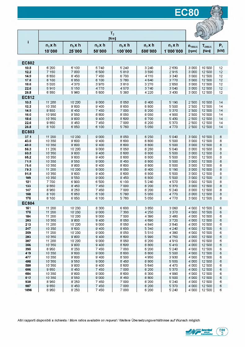
EC80
T 2[Nm] Jf
in 2 x h
1 0 0 0 0
n 2 x h
25 0 0 0
n 2 x h
5 0 0 0 0
n 2 x h
1 0 0 00 0
n 2 x h
5 0 0 00 0
n 2 x h
1 0 0 0 0 0 0n iMAX[rpm]
T 2MAX[Nm]
P t[kW]
E C 8 0 210.5 6 2 0 0 6 1 0 0 5 7 4 0 5 ' 2 4 0 3 ' 2 4 0 2 ' 6 3 0 3 ' 0 0 0 1 0 ' 5 0 0 1 2
12.2 7 1 5 0 7 0 0 0 6 5 0 0 5 ' 8 1 0 3 ' 5 9 0 2 ' 9 1 5 3 ' 0 0 0 1 2 ' 5 0 0 1 2
14.9 8 650 8 4 5 0 7 4 5 0 6 ' 7 0 0 4 ' 1 1 0 3 ' 3 4 0 3 ' 0 0 0 1 2 ' 5 0 0 1 2
17.6 8 1 0 0 6 8 5 0 6 1 0 0 5 ' 7 6 0 4 ' 6 4 0 3 ' 7 7 0 3 ' 0 0 0 1 2 ' 5 0 0 1 2
18.6 5 0 2 0 4 3 7 0 3 9 7 0 3 ' 8 1 0 3 ' 2 7 0 2 ' 6 5 0 3 ' 0 0 0 1 2 ' 5 0 0 1 2
22.6 5 9 1 0 5 1 5 0 4 7 7 0 4 ' 5 7 0 3 ' 7 4 0 3 ' 0 4 0 3 ' 0 0 0 1 2 ' 5 0 0 1 2
26.8 6 8 5 0 5 9 6 0 5 6 0 0 5 ' 3 6 0 4 ' 2 2 0 3 ' 4 3 0 3 ' 0 0 0 1 2 ' 5 0 0 1 2
E C 8 1 210.5 1 1 2 0 0 1 0 2 0 0 9 ' 0 0 0 8 ' 0 5 0 6 ' 4 0 0 5 ' 1 9 0 2 ' 5 0 0 1 0 ' 5 0 0 1 4
12.2 1 0 3 5 0 9 6 0 0 9 ' 4 0 0 8 ' 6 0 0 6 ' 8 0 0 5 ' 5 0 0 2 ' 5 0 0 1 2 ' 5 0 0 1 4
14.9 9 6 5 0 8 4 5 0 7 ' 4 5 0 7 ' 0 0 0 6 ' 2 0 0 5 ' 3 7 0 2 ' 5 0 0 1 2 ' 5 0 0 1 4
16.0 1 0 9 5 0 9 5 5 0 8 ' 6 0 0 8 ' 0 5 0 6 ' 0 5 0 4 ' 9 0 0 2 ' 5 0 0 1 0 ' 5 0 0 1 4
18.6 1 0 3 5 0 9 6 0 0 9 ' 4 0 0 8 ' 6 0 0 6 ' 7 0 0 5 ' 4 3 0 2 ' 5 0 0 1 2 ' 5 0 0 1 4
22.6 9 6 5 0 8 4 5 0 7 ' 4 5 0 7 ' 0 0 0 6 ' 2 0 0 5 ' 3 7 0 2 ' 5 0 0 1 2 ' 5 0 0 1 4
26.8 8 1 0 0 6 8 5 0 6 ' 1 0 0 5 ' 7 6 0 5 ' 0 5 0 4 ' 7 7 0 2 ' 5 0 0 1 2 ' 5 0 0 1 4
E C 8 0 337.1 1 1 ' 2 0 0 1 0 ' 2 0 0 9 ' 0 0 0 8 ' 0 5 0 6 ' 2 5 0 5 ' 0 4 0 3 ' 0 0 0 1 0 ' 5 0 0 8
43.0 1 0 ' 3 5 0 9 ' 6 0 0 9 ' 4 0 0 8 ' 6 0 0 6 ' 8 0 0 5 ' 5 0 0 3 ' 0 0 0 1 2 ' 5 0 0 8
49.8 1 0 ' 3 5 0 9 ' 6 0 0 9 ' 4 0 0 8 ' 6 0 0 6 ' 8 0 0 5 ' 5 0 0 3 ' 0 0 0 1 2 ' 5 0 0 8
56.3 1 1 ' 2 0 0 1 0 ' 2 0 0 9 ' 0 0 0 8 ' 0 5 0 6 ' 2 5 0 5 ' 0 4 0 3 ' 0 0 0 1 0 ' 5 0 0 8
60.5 1 0 ' 3 5 0 9 ' 6 0 0 9 ' 4 0 0 8 ' 6 0 0 6 ' 8 0 0 5 ' 5 0 0 3 ' 0 0 0 1 2 ' 5 0 0 8
65.2 1 0 ' 3 5 0 9 ' 6 0 0 9 ' 4 0 0 8 ' 6 0 0 6 ' 8 0 0 5 ' 5 0 0 3 ' 0 0 0 1 2 ' 5 0 0 8
71.9 1 0 ' 3 5 0 9 ' 5 5 0 9 ' 0 0 0 8 ' 4 5 0 6 ' 8 0 0 5 ' 5 0 0 3 ' 0 0 0 1 2 ' 5 0 0 8
75.6 1 0 ' 3 5 0 9 ' 6 0 0 9 ' 4 0 0 8 ' 6 0 0 6 ' 8 0 0 5 ' 5 0 0 3 ' 0 0 0 1 2 ' 5 0 0 8
79.3 1 1 ' 2 0 0 1 0 ' 2 0 0 9 ' 0 0 0 8 ' 0 5 0 6 ' 4 0 0 5 ' 1 9 0 3 ' 0 0 0 1 0 ' 5 0 0 8
91.9 1 0 ' 3 5 0 9 ' 6 0 0 9 ' 4 0 0 8 ' 6 0 0 6 ' 8 0 0 5 ' 5 0 0 3 ' 0 0 0 1 2 ' 5 0 0 8
109 1 0 ' 3 5 0 9 ' 5 5 0 9 ' 0 0 0 8 ' 4 5 0 6 ' 8 0 0 5 ' 5 0 0 3 ' 0 0 0 1 2 ' 5 0 0 8
121 7 ' 7 0 0 6 ' 9 0 0 6 ' 5 0 0 6 ' 1 0 0 5 ' 2 4 0 4 ' 5 7 0 3 ' 0 0 0 1 2 ' 5 0 0 8
133 9 ' 6 5 0 8 ' 4 5 0 7 ' 4 5 0 7 ' 0 0 0 6 ' 2 0 0 5 ' 3 7 0 3 ' 0 0 0 1 2 ' 5 0 0 8
147 8 ' 9 5 0 8 ' 2 5 0 7 ' 4 5 0 7 ' 0 0 0 6 ' 2 0 0 5 ' 2 4 0 3 ' 0 0 0 1 2 ' 5 0 0 8
158 8 ' 1 0 0 6 ' 8 5 0 6 ' 1 0 0 5 ' 7 6 0 5 ' 0 5 0 4 ' 7 7 0 3 ' 0 0 0 1 2 ' 5 0 0 8
175 8 ' 1 0 0 6 ' 8 5 0 6 ' 1 0 0 5 ' 7 6 0 5 ' 0 5 0 4 ' 7 7 0 3 ' 0 0 0 1 2 ' 5 0 0 8
E C 8 0 4151 1 1 ' 2 0 0 1 0 ' 2 0 0 8 ' 3 0 0 6 ' 6 0 0 3 ' 8 5 0 3 ' 0 6 0 4 ' 0 0 0 1 0 ' 5 0 0 6
175 1 1 ' 2 0 0 1 0 ' 2 0 0 9 ' 0 0 0 7 ' 3 0 0 4 ' 2 5 0 3 ' 3 7 0 4 ' 0 0 0 1 0 ' 5 0 0 6
184 1 1 ' 2 0 0 1 0 ' 2 0 0 9 ' 0 0 0 7 ' 5 0 0 4 ' 3 9 0 3 ' 4 8 0 4 ' 0 0 0 1 0 ' 5 0 0 6
203 1 0 ' 3 5 0 9 ' 6 0 0 9 ' 4 0 0 8 ' 0 5 0 4 ' 6 9 0 3 ' 7 2 0 4 ' 0 0 0 1 2 ' 5 0 0 6
213 1 1 ' 2 0 0 1 0 ' 2 0 0 9 ' 0 0 0 8 ' 0 5 0 4 ' 8 4 0 3 ' 8 4 0 4 ' 0 0 0 1 0 ' 5 0 0 6
247 1 0 ' 3 5 0 9 ' 6 0 0 9 ' 4 0 0 8 ' 6 0 0 5 ' 3 4 0 4 ' 2 4 0 4 ' 0 0 0 1 2 ' 5 0 0 6
259 1 1 ' 2 0 0 1 0 ' 2 0 0 9 ' 0 0 0 8 ' 0 5 0 5 ' 5 1 0 4 ' 3 8 0 4 ' 0 0 0 1 0 ' 5 0 0 6
293 1 0 ' 3 5 0 9 ' 6 0 0 9 ' 4 0 0 8 ' 6 0 0 5 ' 9 9 0 4 ' 7 5 0 4 ' 0 0 0 1 2 ' 5 0 0 6
307 1 1 ' 2 0 0 1 0 ' 2 0 0 9 ' 0 0 0 8 ' 0 5 0 6 ' 2 0 0 4 ' 9 1 0 4 ' 0 0 0 1 0 ' 5 0 0 6
356 1 0 ' 3 5 0 9 ' 6 0 0 9 ' 4 0 0 8 ' 6 0 0 6 ' 8 0 0 5 ' 4 1 0 4 ' 0 0 0 1 2 ' 5 0 0 6
395 8 ' 9 5 0 8 ' 2 5 0 7 ' 4 5 0 7 ' 0 0 0 6 ' 2 0 0 5 ' 2 4 0 4 ' 0 0 0 1 2 ' 5 0 0 6
419 1 0 ' 3 5 0 9 ' 6 0 0 9 ' 0 0 0 8 ' 6 0 0 6 ' 8 0 0 5 ' 5 0 0 4 ' 0 0 0 1 2 ' 5 0 0 6
477 1 0 ' 3 5 0 9 ' 6 0 0 9 ' 4 0 0 8 ' 5 0 0 4 ' 9 5 0 3 ' 9 3 0 4 ' 0 0 0 1 2 ' 5 0 0 6
498 1 0 ' 3 5 0 9 ' 5 5 0 9 ' 0 0 0 8 ' 4 5 0 6 ' 8 0 0 5 ' 5 0 0 4 ' 0 0 0 1 2 ' 5 0 0 6
580 1 0 ' 3 5 0 9 ' 6 0 0 9 ' 4 0 0 8 ' 6 0 0 5 ' 6 4 0 4 ' 4 7 0 4 ' 0 0 0 1 2 ' 5 0 0 6
606 9 ' 6 5 0 8 ' 4 5 0 7 ' 4 5 0 7 ' 0 0 0 6 ' 2 0 0 5 ' 3 7 0 4 ' 0 0 0 1 2 ' 5 0 0 6
684 1 0 ' 3 5 0 9 ' 6 0 0 9 ' 0 0 0 8 ' 6 0 0 6 ' 3 0 0 4 ' 9 9 0 4 ' 0 0 0 1 2 ' 5 0 0 6
812 1 0 ' 3 5 0 9 ' 5 5 0 9 ' 0 0 0 8 ' 4 5 0 6 ' 8 0 0 5 ' 5 0 0 4 ' 0 0 0 1 2 ' 5 0 0 6
930 8 ' 9 5 0 8 ' 2 5 0 7 ' 4 5 0 7 ' 0 0 0 6 ' 2 0 0 5 ' 2 4 0 4 ' 0 0 0 1 2 ' 5 0 0 6
987 9 ' 6 5 0 8 ' 4 5 0 7 ' 4 5 0 7 ' 0 0 0 6 ' 2 0 0 5 ' 3 7 0 4 ' 0 0 0 1 2 ' 5 0 0 6
1096 8 ' 9 5 0 8 ' 2 5 0 7 ' 4 5 0 7 ' 0 0 0 6 ' 2 0 0 5 ' 2 4 0 4 ' 0 0 0 1 2 ' 5 0 0 6
Altri rapporti disponibili a richiesta / More ratios available on request / Weitere Ubersetzungsverhaltnisse auf Wunsch moglich
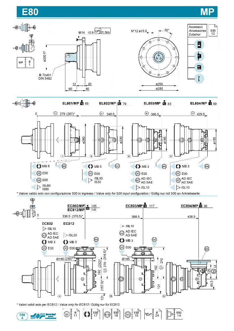
E80
M14 10.9 2 0201 Nm
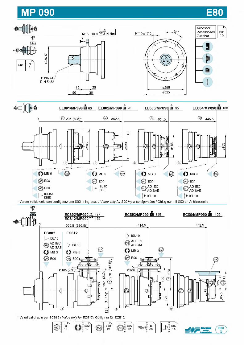
MP 090 E80
M16 10.9 314 Nm3 1
Accessori NAccessories E80Zubehor 13
||В||
r
i= l
jU
(IV
' Valori validi solo per EC812 / Value only for EC812 / Gultig nur fur EC812
■ъ,B
11E8017
:<■ E80
16
1 К' E80
AD 15'
: ^£ B
24 3 *E8014 b rtr
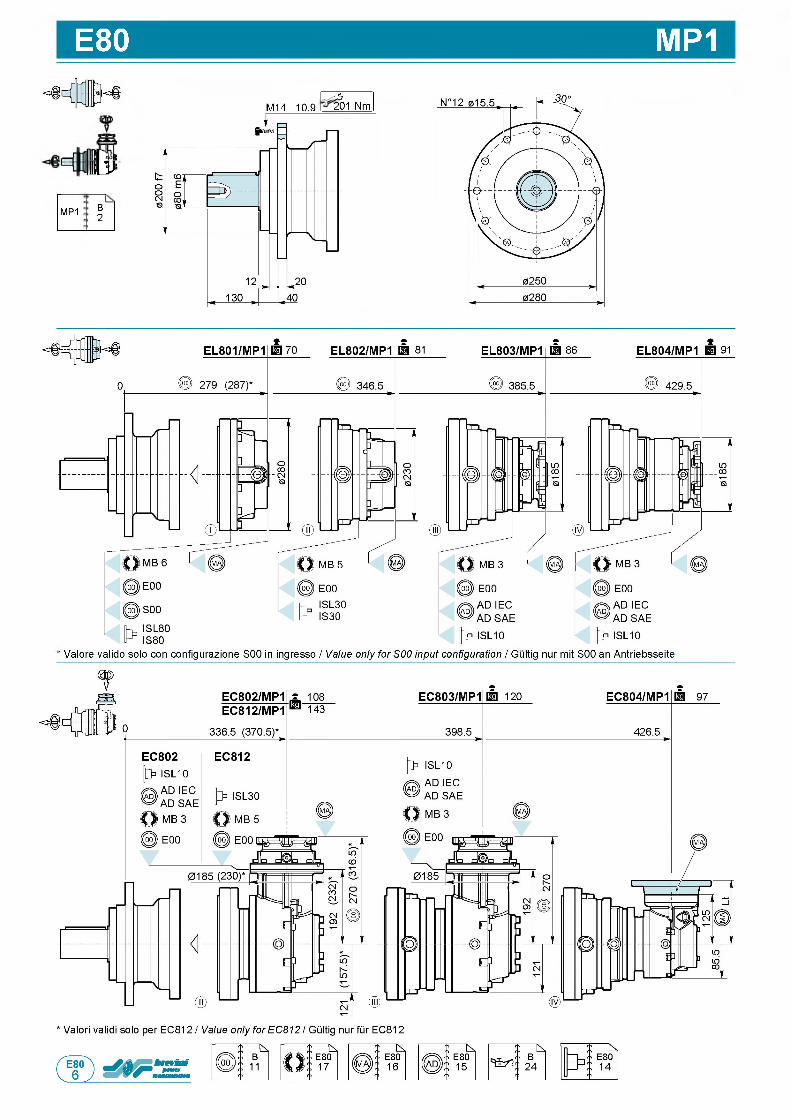
E80 MP1
I V
MP1 B2
M 1 4 1 0 . 9 2 02 0 1 N m
91
' V a l o r e v a l i d o s o l o c o n c o n f i g u r a z i o n e S 0 0 in i n g r e s s o / Value only for S00 input configuration / G u l t i g n u r m i t S 0 0 a n A n t r i e b s s e i t e
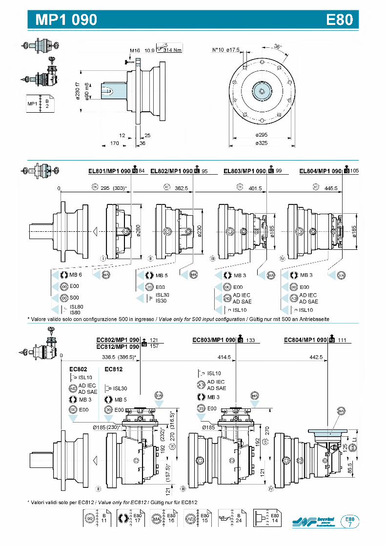
MP1 090 E80
1 ■
MP1 B2
M16 10.9 31314 Nm
* Valori validi solo per EC812 / Value only for EC812 / Gultig nur fur EC812
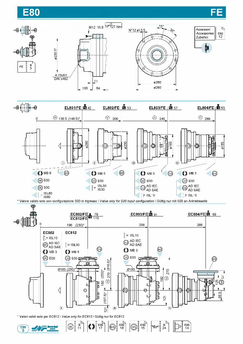
E80 FEM 1 2 1 0 . 9 1 2 7 N m
f A c c e s s o r i NAccessories E 8 0
Z u b e h o r 1 2
* V a l o r e v a l i d o s o l o c o n c o n f i g u r a z i o n e S 0 0 in i n g r e s s o / Value only for S00 input configuration / G u l t i g n u r m i t S 0 0 a n A n t r i e b s s e i t e
* V a l o r i v a l i d i s o l o p e r E C 8 1 2 / Value only for EC812 / G u l t i g n u r f u r E C 8 1 2
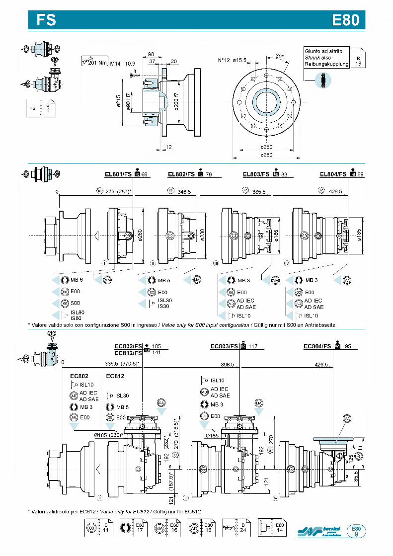
FS E80
Giunto ad attrito NShrink disc BReibungskupplung 18
— V
* Valori validi solo per EC812 / Value only for EC812 / Gultig nur fur EC812
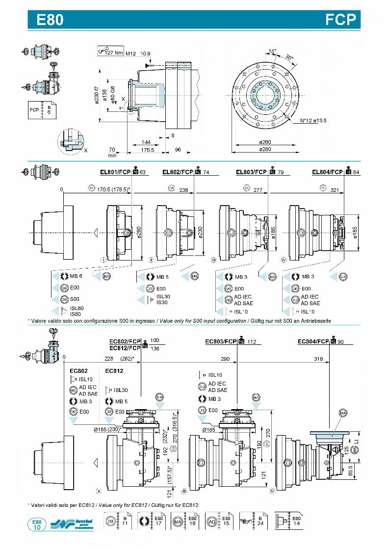
E80 FCP
-вЛ
fcp : О) ГО
I S L 8 0 I S 8 0
' V a l o r e v a l i d o s o l o c o n c o n f i g u r a z i o n e S 0 0 in i n g r e s s o / Value only for S00 input configuration / G u l t i g n u r m i t S 0 0 a n A n t r i e b s s e i t e
EC804/FCPB 9 0
' V a l o r i v a l i d i s o l o p e r E C 8 1 2 / Value only for EC812 / G u l t i g n u r f u r E C 8 1 2
"k,B
11E801 7
1E8016
! N* E80
AD 15
:
itB
2 4
fcs,E801 4
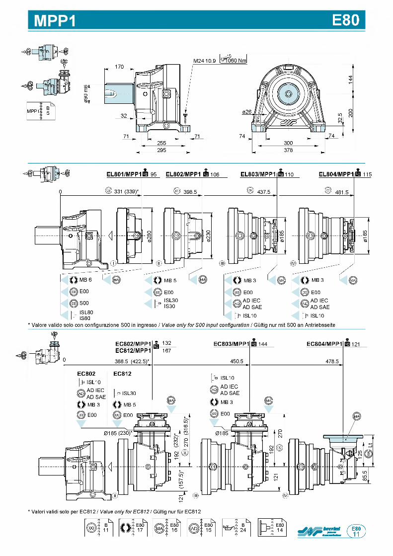
E80
B5m pp1
M24 10.9
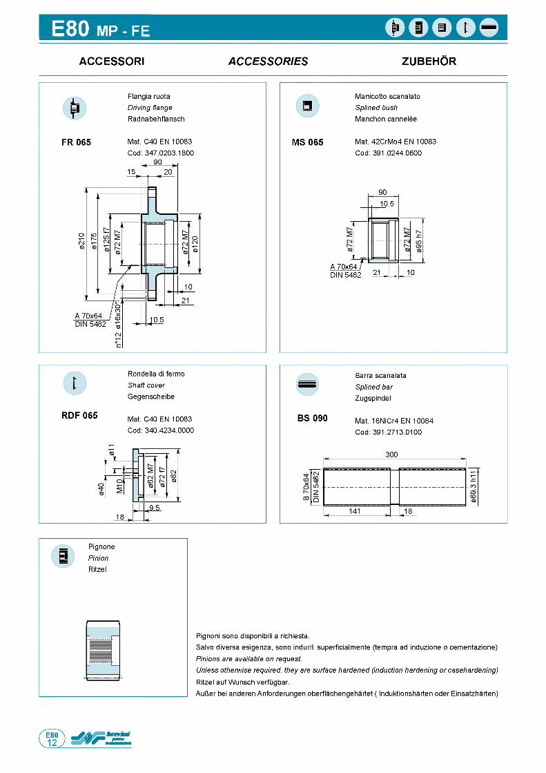
E80 MP - FE
ACCESSORI A C C E S S O R IE S ZUBEHOR
F R 06 5
F l a n g i a r u o t a
Driving flange R a d n a b e h f l a n s c h
M a t . C 4 0 E N 1 0 0 8 3
C o d : 3 4 7 . 0 2 0 3 . 1 8 0 0
M S 0 6 5
M a n i c o t t o s c a n a l a t o
Splined bush M a n c h o n c a n n e l e e
M a t . 4 2 C r M o 4 E N 1 0 0 8 3
C o d : 3 9 1 . 0 2 4 4 . 0 6 0 0
9 0
A 7 0 x 6 4 ,D IN 5 4 8 2 2 1
T
1 0 . 5
1 0
R D F 06 5
R o n d e l l a di f e r m o
Shaft cover G e g e n s c h e i b e
M a t . C 4 0 E N 1 0 0 8 3
C o d : 3 4 0 . 4 2 3 4 . 0 0 0 0
B S 09 0
B a r r a s c a n a l a t a
Splined bar Z u g s p i n d e l
M a t . 1 6 N i C r 4 E N 1 0 0 8 4
C o d : 3 9 1 . 2 7 1 3 . 0 1 0 0
3 0 0
l ( NCO
06
9.3
h11
и
, f Q
< 1 4 1 , . 1 8
P i g n o n i s o n o d i s p o n i b i l i a r i c h i e s t a .
S a l v o d i v e r s a e s i g e n z a , s o n o induri ti s u p e r f i c i a l m e n t e ( t e m p r a a d i n d u z i o n e o c e m e n t a z i o n e )
Pinions are available on request.Unless otherwise required, they are surface hardened (induction hardening or casehardening) R i t z e l a u f W u n s c h v e r f u g b a r .
A u l J e r b e i a n d e r e n A n f o r d e r u n g e n o b e r f l a c h e n g e h a r t e t ( I n d u k t i o n s h a r t e n o d e r E i n s a t z h a r t e n )
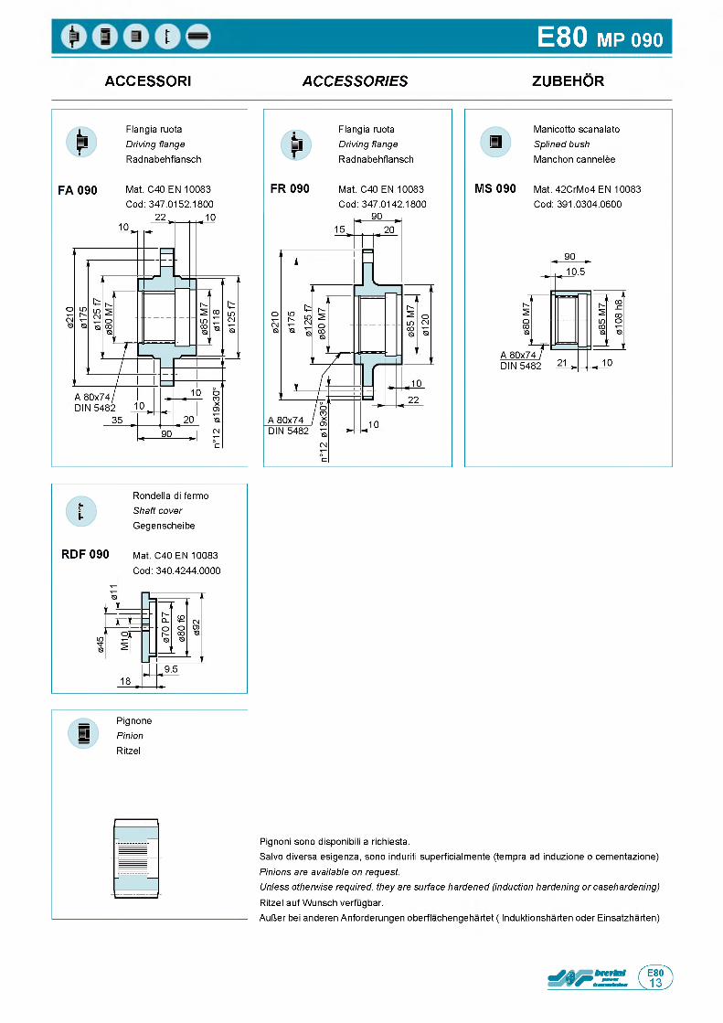
E80 MP 090
ACCESSORI A C C E S S O R IE S ZUBEHOR
F l a n g i a r u o t a
Driving flange R a d n a b e h f l a n s c h
F l a n g i a r u o t a
Driving flange R a d n a b e h f l a n s c h
M a n i c o t t o s c a n a l a t o
Splined bush M a n c h o n c a n n e l e e
F A 0 9 0 M a t . C 4 0 E N 1 0 0 8 3 F R 0 9 0 M a t . C 4 0 E N 1 0 0 8 3 M S 0 9 0 M a t . 4 2 C r M o 4 E N 1 0 0 8 3
C o d : 3 4 7 . 0 1 5 2 . 1 8 0 0 C o d : 3 4 7 . 0 1 4 2 . 1 8 0 0 C o d : 3 9 1 . 0 3 0 4 . 0 6 0 0
R o n d e l l a di f e r m o
Shaft cover G e g e n s c h e i b e
R D F 0 9 0 M a t . C 4 0 E N 1 0 0 8 3
C o d : 3 4 0 . 4 2 4 4 . 0 0 0 0
P i g n o n i s o n o d i s p o n i b i l i a r i c h i e s t a .
S a l v o d i v e r s a e s i g e n z a , s o n o induri ti s u p e r f i c i a l m e n t e ( t e m p r a a d i n d u z i o n e o c e m e n t a z i o n e )
Pinions are available on request.Unless otherwise required, they are surface hardened (induction hardening or casehardening) R i t z e l a u f W u n s c h v e r f u g b a r .
A u U e r b e i a n d e r e n A n f o r d e r u n g e n o b e r f l a c h e n g e h a r t e t ( I n d u k t i o n s h a r t e n o d e r E i n s a t z h a r t e n )
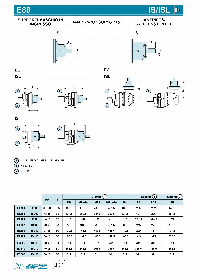
E80 IS/ISLSUPPORTI MASCHIO IN
INGRESSO M A L E IN P U T S U P P O R T S ANTRIEBS-w e l l e n s t Om p f e
ISL IS
ELISL
IS
EC
ф = MP - MP090 - MP1 - MP1 090 - FS
ф = F E - FCP
ф = MPP1
0D ELt [mm] 1 Lt [mm] 2 Lt [mm] 3
MP MP 090 MP1 MP1 090 FS FE FCP MPP1
EL801 IS80 6 5 m 6 1 0 5 4 0 0 . 5 4 1 6 . 5 4 0 0 . 5 4 1 6 . 5 4 0 0 . 5 2 6 0 2 9 2 4 4 7 . 5
EL801 ISL80 4 8 k 6 8 2 3 3 4 . 5 3 5 0 . 5 3 3 4 . 5 3 5 0 . 5 3 3 4 . 5 1 9 4 2 2 6 3 8 1 . 5
EL802 IS30 4 8 k 6 8 2 4 2 5 4 4 1 4 2 5 4 4 1 4 2 5 2 8 4 . 5 3 1 6 . 5 4 7 2
EL802 ISL30 4 0 k 6 5 8 3 8 5 . 5 4 0 1 . 5 3 8 5 . 5 4 0 1 . 5 3 8 5 . 5 2 4 5 2 7 7 4 3 2 . 5
EL803 ISL10 2 8 k 6 5 0 4 3 9 . 5 4 5 5 . 5 4 3 9 . 5 4 5 5 . 5 4 3 9 . 5 2 9 9 3 3 1 4 9 1 . 5
EL804 ISL10 2 8 k 6 5 0 4 8 3 . 5 4 9 9 . 5 4 8 3 . 5 4 9 9 . 5 4 8 3 . 5 3 4 3 3 7 5 5 3 5 . 5
EC802 ISL10 2 8 k 6 5 0 3 1 1 3 1 1 3 1 1 3 1 1 3 1 1 3 1 1 3 1 1 3 1 1
EC812 ISL30 4 0 k 6 5 8 3 5 5 . 5 3 5 5 . 5 3 5 5 . 5 3 5 5 . 5 3 5 5 . 5 3 5 5 . 5 3 5 5 . 5 3 5 5 . 5
EC803 ISL10 2 8 k 6 5 0 3 1 1 3 1 1 3 1 1 3 1 1 3 1 1 3 1 1 3 1 1 3 1 1
П
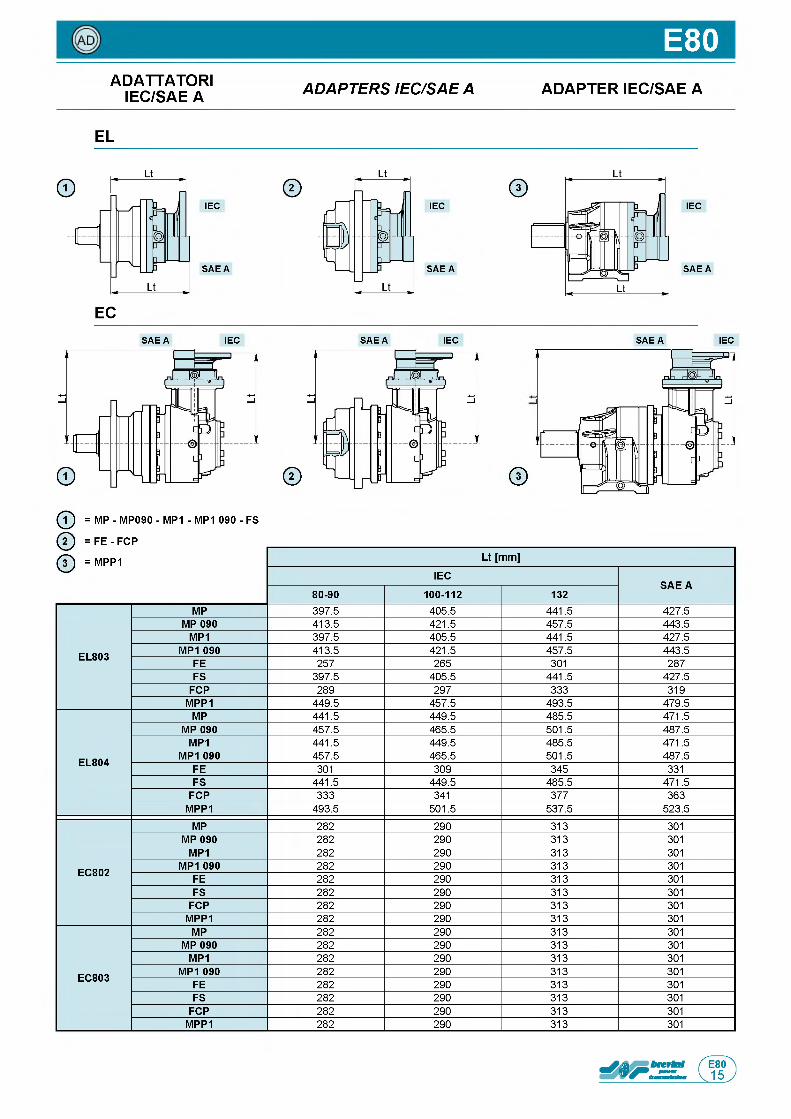
E80ADATTATORI
IEC/SAE A A D A P T E R S IE C /S A E A ADAPTER IEC/SAE A
EL
IEC
S A E A
EC
IEC
S A E A
IEC
S A E A
S A E A IEC S A E A IEC
©
S A E A IEC
ф = MP - MP090 - MP1 - MP1 090 - FS
@ = F E - FCP
ф = MPP1 Lt [mm]
IECSAE A
80-90 100-112 132
EL803
MP 3 9 7 . 5 4 0 5 . 5 4 4 1 . 5 4 2 7 . 5
MP 090 4 1 3 . 5 4 2 1 . 5 4 5 7 . 5 4 4 3 . 5
MP1 3 9 7 . 5 4 0 5 . 5 4 4 1 . 5 4 2 7 . 5
MP1 090 4 1 3 . 5 4 2 1 . 5 4 5 7 . 5 4 4 3 . 5
FE 2 5 7 2 6 5 3 0 1 2 8 7
FS 3 9 7 . 5 4 0 5 . 5 4 4 1 . 5 4 2 7 . 5
FCP 2 8 9 2 9 7 3 3 3 3 1 9
MPP1 4 4 9 . 5 4 5 7 . 5 4 9 3 . 5 4 7 9 . 5
EL804
MP 4 4 1 . 5 4 4 9 . 5 4 8 5 . 5 4 7 1 . 5
MP 090 4 5 7 . 5 4 6 5 . 5 5 0 1 . 5 4 8 7 . 5
MP1 4 4 1 . 5 4 4 9 . 5 4 8 5 . 5 4 7 1 . 5
MP1 090 4 5 7 . 5 4 6 5 . 5 5 0 1 . 5 4 8 7 . 5
FE 3 0 1 3 0 9 3 4 5 3 3 1
FS 4 4 1 . 5 4 4 9 . 5 4 8 5 . 5 4 7 1 . 5
FCP 3 3 3 3 4 1 3 7 7 3 6 3
MPP1 4 9 3 . 5 5 0 1 . 5 5 3 7 . 5 5 2 3 . 5
EC802
MP 2 8 2 2 9 0 3 1 3 3 0 1
MP 090 2 8 2 2 9 0 3 1 3 3 0 1
MP1 2 8 2 2 9 0 3 1 3 3 0 1
MP1 090 2 8 2 2 9 0 3 1 3 3 0 1
FE 2 8 2 2 9 0 3 1 3 3 0 1
FS 2 8 2 2 9 0 3 1 3 3 0 1
FCP 2 8 2 2 9 0 3 1 3 3 0 1
MPP1 2 8 2 2 9 0 3 1 3 3 0 1
EC803
MP 2 8 2 2 9 0 3 1 3 3 0 1
MP 090 2 8 2 2 9 0 3 1 3 3 0 1
MP1 2 8 2 2 9 0 3 1 3 3 0 1
MP1 090 2 8 2 2 9 0 3 1 3 3 0 1
FE 2 8 2 2 9 0 3 1 3 3 0 1
FS 2 8 2 2 9 0 3 1 3 3 0 1
FCP 2 8 2 2 9 0 3 1 3 3 0 1
MPP1 2 8 2 2 9 0 3 1 3 3 0 1
П
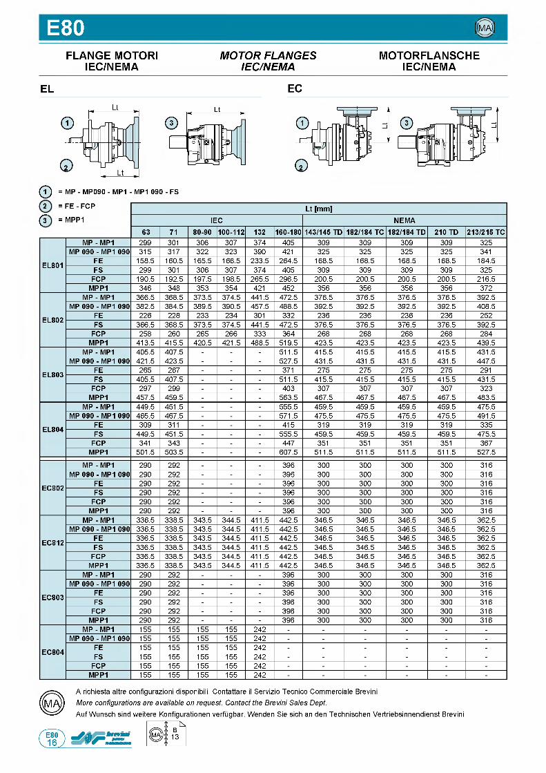
E80 ((ma))
FLANGE MOTORI M O T O R F L A N G E S MOTORFLANSCHEIEC/NEMA IE C /N E M A IEC/NEMA
EL EC
ф = MP - MP090 - MP1 - MP1 090 - FS
2 = F E - FCP
(3 = MPP1Lt [mm]
IEC NEMA63 71 80-90 100-112 132 160-180 143/145 TD 182/184 TC 182/184 TD 210 TD 213/215 TC
EL801
MP - MP1 2 9 9 3 0 1 3 0 6 3 0 7 3 7 4 4 0 5 3 0 9 3 0 9 3 0 9 3 0 9 3 2 5
MP 090 - MP1 090 3 1 5 3 1 7 3 2 2 3 2 3 3 9 0 4 2 1 3 2 5 3 2 5 3 2 5 3 2 5 3 4 1
FE 1 5 8 . 5 1 6 0 . 5 1 6 5 . 5 1 6 6 . 5 2 3 3 . 5 2 6 4 . 5 1 6 8 . 5 1 6 8 . 5 1 6 8 . 5 1 6 8 . 5 1 8 4 . 5
FS 2 9 9 3 0 1 3 0 6 3 0 7 3 7 4 4 0 5 3 0 9 3 0 9 3 0 9 3 0 9 3 2 5
FCP 1 9 0 . 5 1 9 2 . 5 1 9 7 . 5 1 9 8 . 5 2 6 5 . 5 2 9 6 . 5 2 0 0 . 5 2 0 0 . 5 2 0 0 . 5 2 0 0 . 5 2 1 6 . 5
MPP1 3 4 6 3 4 8 3 5 3 3 5 4 4 2 1 4 5 2 3 5 6 3 5 6 3 5 6 3 5 6 3 7 2
EL802
MP - MP1 3 6 6 . 5 3 6 8 . 5 3 7 3 . 5 3 7 4 . 5 4 4 1 . 5 4 7 2 . 5 3 7 6 . 5 3 7 6 . 5 3 7 6 . 5 3 7 6 . 5 3 9 2 . 5
MP 090 - MP1 090 3 8 2 . 5 3 8 4 . 5 3 8 9 . 5 3 9 0 . 5 4 5 7 . 5 4 8 8 . 5 3 9 2 . 5 3 9 2 . 5 3 9 2 . 5 3 9 2 . 5 4 0 8 . 5
FE 2 2 6 2 2 8 2 3 3 2 3 4 3 0 1 3 3 2 2 3 6 2 3 6 2 3 6 2 3 6 2 5 2
FS 3 6 6 . 5 3 6 8 . 5 3 7 3 . 5 3 7 4 . 5 4 4 1 . 5 4 7 2 . 5 3 7 6 . 5 3 7 6 . 5 3 7 6 . 5 3 7 6 . 5 3 9 2 . 5
FCP 2 5 8 2 6 0 2 6 5 2 6 6 3 3 3 3 6 4 2 6 8 2 6 8 2 6 8 2 6 8 2 8 4
MPP1 4 1 3 . 5 4 1 5 . 5 4 2 0 . 5 4 2 1 . 5 4 8 8 . 5 5 1 9 . 5 4 2 3 . 5 4 2 3 . 5 4 2 3 . 5 4 2 3 . 5 4 3 9 . 5
EL803
MP - MP1 4 0 5 . 5 4 0 7 . 5 - - - 5 1 1 . 5 4 1 5 . 5 4 1 5 . 5 4 1 5 . 5 4 1 5 . 5 4 3 1 . 5
MP 090 - MP1 090 4 2 1 . 5 4 2 3 . 5 - - - 5 2 7 . 5 4 3 1 . 5 4 3 1 . 5 4 3 1 . 5 4 3 1 . 5 4 4 7 . 5
FE 2 6 5 2 6 7 - - - 3 7 1 2 7 5 2 7 5 2 7 5 2 7 5 2 9 1
FS 4 0 5 . 5 4 0 7 . 5 - - - 5 1 1 . 5 4 1 5 . 5 4 1 5 . 5 4 1 5 . 5 4 1 5 . 5 4 3 1 . 5
FCP 2 9 7 2 9 9 - - - 4 0 3 3 0 7 3 0 7 3 0 7 3 0 7 3 2 3
MPP1 4 5 7 . 5 4 5 9 . 5 - - - 5 6 3 . 5 4 6 7 . 5 4 6 7 . 5 4 6 7 . 5 4 6 7 . 5 4 8 3 . 5
EL804
MP - MP1 4 4 9 . 5 4 5 1 . 5 - - - 5 5 5 . 5 4 5 9 . 5 4 5 9 . 5 4 5 9 . 5 4 5 9 . 5 4 7 5 . 5
MP 090 - MP1 090 4 6 5 . 5 4 6 7 . 5 - - - 5 7 1 . 5 4 7 5 . 5 4 7 5 . 5 4 7 5 . 5 4 7 5 . 5 4 9 1 . 5
FE 3 0 9 3 1 1 - - - 4 1 5 3 1 9 3 1 9 3 1 9 3 1 9 3 3 5
FS 4 4 9 . 5 4 5 1 . 5 - - - 5 5 5 . 5 4 5 9 . 5 4 5 9 . 5 4 5 9 . 5 4 5 9 . 5 4 7 5 . 5
FCP 3 4 1 3 4 3 - - - 4 4 7 3 5 1 3 5 1 3 5 1 3 5 1 3 6 7
MPP1 5 0 1 . 5 5 0 3 . 5 - - - 6 0 7 . 5 5 1 1 . 5 5 1 1 . 5 5 1 1 . 5 5 1 1 . 5 5 2 7 . 5
EC802
MP - MP1 2 9 0 2 9 2 - - - 3 9 6 3 0 0 3 0 0 3 0 0 3 0 0 3 1 6
MP 090 - MP1 090 2 9 0 2 9 2 - - - 3 9 6 3 0 0 3 0 0 3 0 0 3 0 0 3 1 6
FE 2 9 0 2 9 2 - - - 3 9 6 3 0 0 3 0 0 3 0 0 3 0 0 3 1 6
FS 2 9 0 2 9 2 - - - 3 9 6 3 0 0 3 0 0 3 0 0 3 0 0 3 1 6
FCP 2 9 0 2 9 2 - - - 3 9 6 3 0 0 3 0 0 3 0 0 3 0 0 3 1 6
MPP1 2 9 0 2 9 2 - - - 3 9 6 3 0 0 3 0 0 3 0 0 3 0 0 3 1 6
EC812
MP - MP1 3 3 6 . 5 3 3 8 . 5 3 4 3 . 5 3 4 4 . 5 4 1 1 . 5 4 4 2 . 5 3 4 6 . 5 3 4 6 . 5 3 4 6 . 5 3 4 6 . 5 3 6 2 . 5
MP 090 - MP1 090 3 3 6 . 5 3 3 8 . 5 3 4 3 . 5 3 4 4 . 5 4 1 1 . 5 4 4 2 . 5 3 4 6 . 5 3 4 6 . 5 3 4 6 . 5 3 4 6 . 5 3 6 2 . 5
FE 3 3 6 . 5 3 3 8 . 5 3 4 3 . 5 3 4 4 . 5 4 1 1 . 5 4 4 2 . 5 3 4 6 . 5 3 4 6 . 5 3 4 6 . 5 3 4 6 . 5 3 6 2 . 5
FS 3 3 6 . 5 3 3 8 . 5 3 4 3 . 5 3 4 4 . 5 4 1 1 . 5 4 4 2 . 5 3 4 6 . 5 3 4 6 . 5 3 4 6 . 5 3 4 6 . 5 3 6 2 . 5
FCP 3 3 6 . 5 3 3 8 . 5 3 4 3 . 5 3 4 4 . 5 4 1 1 . 5 4 4 2 . 5 3 4 6 . 5 3 4 6 . 5 3 4 6 . 5 3 4 6 . 5 3 6 2 . 5
MPP1 3 3 6 . 5 3 3 8 . 5 3 4 3 . 5 3 4 4 . 5 4 1 1 . 5 4 4 2 . 5 3 4 6 . 5 3 4 6 . 5 3 4 6 . 5 3 4 6 . 5 3 6 2 . 5
EC803
MP - MP1 2 9 0 2 9 2 - - - 3 9 6 3 0 0 3 0 0 3 0 0 3 0 0 3 1 6
MP 090 - MP1 090 2 9 0 2 9 2 - - - 3 9 6 3 0 0 3 0 0 3 0 0 3 0 0 3 1 6
FE 2 9 0 2 9 2 - - - 3 9 6 3 0 0 3 0 0 3 0 0 3 0 0 3 1 6
FS 2 9 0 2 9 2 - - - 3 9 6 3 0 0 3 0 0 3 0 0 3 0 0 3 1 6
FCP 2 9 0 2 9 2 - - - 3 9 6 3 0 0 3 0 0 3 0 0 3 0 0 3 1 6
MPP1 2 9 0 2 9 2 - - - 3 9 6 3 0 0 3 0 0 3 0 0 3 0 0 3 1 6
EC804
MP - MP1 1 5 5 1 5 5 1 5 5 1 5 5 2 4 2 - - - - - -
MP 090 - MP1 090 1 5 5 1 5 5 1 5 5 1 5 5 2 4 2 - - - - - -
FE 1 5 5 1 5 5 1 5 5 1 5 5 2 4 2 - - - - - -
FS 1 5 5 1 5 5 1 5 5 1 5 5 2 4 2 - - - - - -
FCP 1 5 5 1 5 5 1 5 5 1 5 5 2 4 2 - - - - - -
MPP1 1 5 5 1 5 5 1 5 5 1 5 5 2 4 2 - - - - - -
A r i c h i e s t a a l t r e c o n f i g u r a z i o n i d i s p o n i b i l i . C o n t a t t a r e il S e r v i z i o T e c n i c o C o m m e r c i a l e B r e v i n i
More configurations are available on request. Contact the Brevini Sales Dept.A u f W u n s c h s i n d w e i t e r e K o n f i g u r a t i o n e n v e r f u g b a r . W e n d e n S i e s i c h a n d e n T e c h n i s c h e n V e r t r i e b s i n n e n d i e n s t B r e v i n i
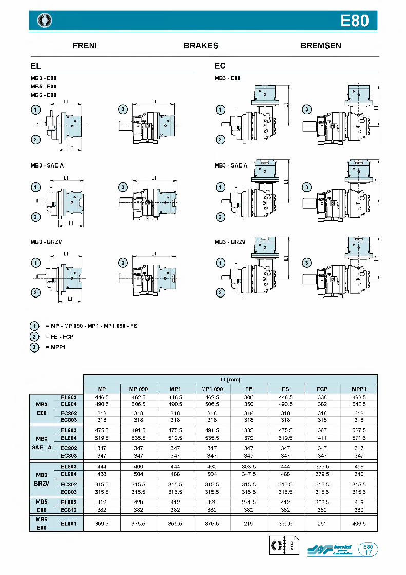
E80FRENI BRAKES BREMSEN
EL ECM B 3- E00
M B 5- E00 M B 6- E00
MB3 - E00
ф = MP - MP 090 - MP1 - MP1 090 - FS
ф = FE - FCP
ф = MPP1
Lt [mm]
MP MP 090 MP1 MP1 090 FE FS FCP MPP1
MB3E00
EL803 4 4 6 . 5 4 6 2 . 5 4 4 6 . 5 4 6 2 . 5 3 0 6 4 4 6 . 5 3 3 8 4 9 8 . 5
EL804 4 9 0 . 5 5 0 6 . 5 4 9 0 . 5 5 0 6 . 5 3 5 0 4 9 0 . 5 3 8 2 5 4 2 . 5
EC802 3 1 8 3 1 8 3 1 8 3 1 8 3 1 8 3 1 8 3 1 8 3 1 8
EC803 3 1 8 3 1 8 3 1 8 3 1 8 3 1 8 3 1 8 3 1 8 3 1 8
MB3 SAE - A
EL803 4 7 5 . 5 4 9 1 . 5 4 7 5 . 5 4 9 1 . 5 3 3 5 4 7 5 . 5 3 6 7 5 2 7 . 5
EL804 5 1 9 . 5 5 3 5 . 5 5 1 9 . 5 5 3 5 . 5 3 7 9 5 1 9 . 5 4 1 1 5 7 1 . 5
EC802 3 4 7 3 4 7 3 4 7 3 4 7 3 4 7 3 4 7 3 4 7 3 4 7
EC803 3 4 7 3 4 7 3 4 7 3 4 7 3 4 7 3 4 7 3 4 7 3 4 7
MB3BRZV
EL803 4 4 4 4 6 0 4 4 4 4 6 0 3 0 3 . 5 4 4 4 3 3 5 . 5 4 9 6
EL804 4 8 8 5 0 4 4 8 8 5 0 4 3 4 7 . 5 4 8 8 3 7 9 . 5 5 4 0
EC802 3 1 5 . 5 3 1 5 . 5 3 1 5 . 5 3 1 5 . 5 3 1 5 . 5 3 1 5 . 5 3 1 5 . 5 3 1 5 . 5
EC803 3 1 5 . 5 3 1 5 . 5 3 1 5 . 5 3 1 5 . 5 3 1 5 . 5 3 1 5 . 5 3 1 5 . 5 3 1 5 . 5
MB5E00
EL802 4 1 2 4 2 8 4 1 2 4 2 8 2 7 1 . 5 4 1 2 3 0 3 . 5 4 5 9
EC812 3 8 2 3 8 2 3 8 2 3 8 2 3 8 2 3 8 2 3 8 2 3 8 2
MB6E00
EL801 3 5 9 . 5 3 7 5 . 5 3 5 9 . 5 3 7 5 . 5 2 1 9 3 5 9 . 5 2 5 1 4 0 6 . 5
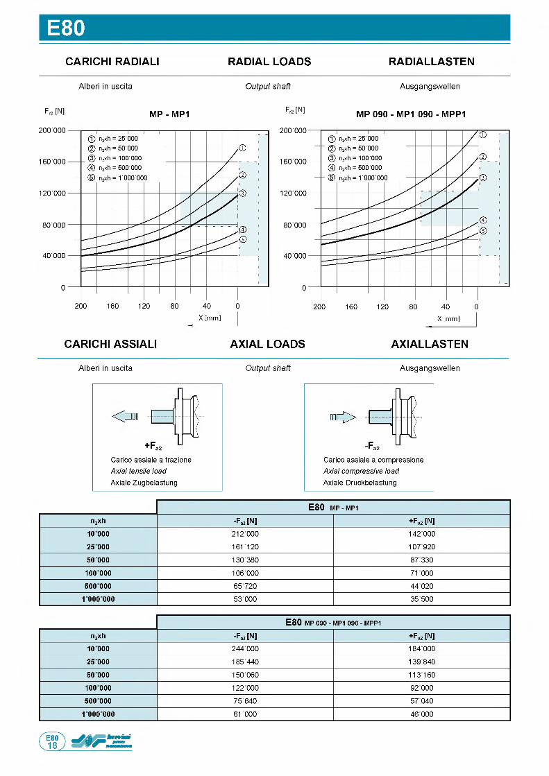
E80CARICHI RADIALI RADIAL LOADS RADIALLASTEN
Alberi in uscita Output shaft Ausgangswellen
M P - M P1 Fr2 [N] M P 0 9 0 - M P1 0 9 0 - M P P 1
CARICHI ASSIALI AXIAL LOADS AXIALLASTEN
Alberi in uscita Output shaft Ausgangswellen
О
+ Fa2C a r i c o a s s i a l e a t r a z i o n e
Axial tensile load A x i a l e Z u g b e l a s t u n g
" О
C a r i c o a s s i a l e a c o m p r e s s i o n e
Axial compressive load A x i a l e D r u c k b e l a s t u n g
E 8 0 m p - MP1
n2xh -Fa2 [N] + Fa2 [N]
1 0 0 0 0 2 1 2 0 0 0 1 4 2 0 0 0
2 5 000 1 6 1 1 2 0 1 0 7 9 2 0
50 000 1 3 0 3 8 0 8 7 3 3 0
10 0 000 1 0 6 0 0 0 7 1 0 0 0
500 000 6 5 7 2 0 4 4 0 2 0
1 000 000 5 3 0 0 0 3 5 5 0 0
E 8 0 MP 090 - MP1 090 - MPP1
n2xh -Fa2 [N] + Fa2 [N]
10 000 2 4 4 0 0 0 1 8 4 0 0 0
2 5 000 1 8 5 4 4 0 1 3 9 8 4 0
50 000 1 5 0 0 6 0 1 1 3 1 6 0
10 0 000 1 2 2 0 0 0 9 2 0 0 0
500 000 7 5 6 4 0 5 7 0 4 0
1 000 000 6 1 0 0 0 4 6 0 0 0
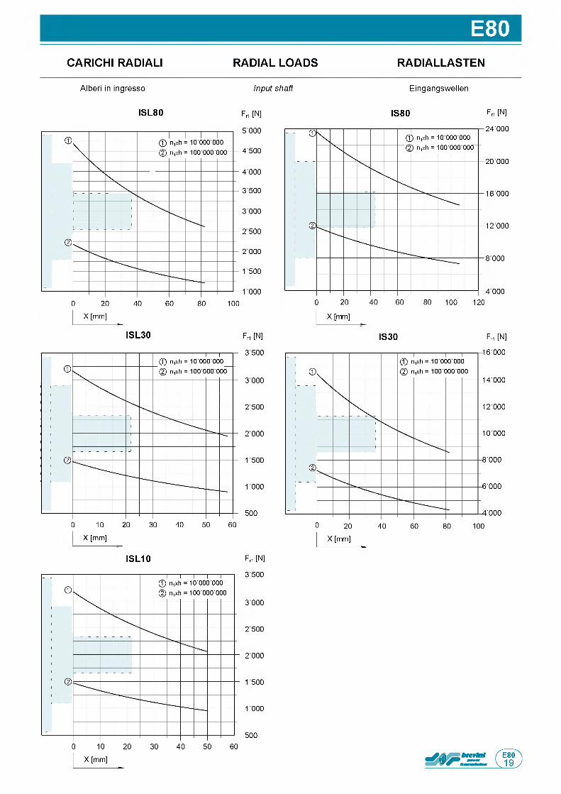
E80CARICHI RADIALI RADIAL LOADS RADIALLASTEN
A l b e r i in i n g r e s s o Input shaft E i n g a n g s w e l l e n
IS L 8 0 F r1 [N] IS 8 0 F ri [N]
5 0 0 0
4 5 0 0
4 0 0 0
3 5 0 0
3 0 0 0
2 5 0 0
2 0 0 0
1 5 0 0
1 0 0 0
IS L 3 0 F r1 [N]
3 ' 5 0 0
3 0 0 0
2 ' 5 0 0
3 0 0 0
2 5 0 0
1 0 0 0
5 0 0
3 1 3 2 3 3 3 4 3 2 3 6 3
X [ m m ]
IS L 1 0 F ri [N]
3 5 0 0
3 0 0 0
2 5 0 0
2 0 0 0
1 5 0 0
1 0 0 0
5 0 0
2 4 ' 0 0 0
2 0 0 0 0
1 6 0 0 0
1 2 0 0 0
8 0 0 0
4 0 0 0
IS 3 0 Fri [N]

Questa pagina e lasciata intenzionalmente bianca
Page is in tentiona lly le ft blank Seite wurde absichtlich leer gelassen
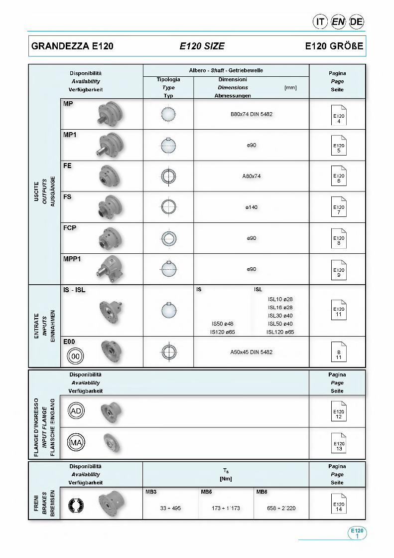
DisponibilitaAvailab ility
Verfugbarkeit
Albero - Shaft - Getriebewelle
TipologiaType
___ Typ___
DimensioniDimensions
Abmessungen[ m m ]
PaginaPage
Seite
B 8 0 x 7 4 D IN 5 4 8 2 E 1 2 04
0 9 0 E 1 2 05
ШШ Й %t 5 |$ & О3 § |
A 8 0 x 7 4 E 1 2 06
0 1 4 0 E 1 2 07
0 9 0 E 1 2 08
0 9 0 E 1 2 09
IS - IS L
ш ш£ £ s
illLU LU
IS
I S 5 0 0 4 8
I S 1 2 0 0 6 5
ISL
I S L 1 0 0 2 8
I S L 1 6 0 2 8
I S L 3 0 0 4 0
I S L 5 0 0 4 0
I S L 1 2 0 0 6 5
E 1 2 011
E 00
00A 5 0 x 4 5 D IN 5 4 8 2 B
11
DisponibilitaAvailab ility
Verfugbarkeit
PaginaPageSeite
О Оw zl/l LU <
g § 2<2 ч mAAD E 1 2 0
1 2
ш э оО Q. W z г z < - < Ц .
E 1 2 01 3
DisponibilitaAvailab ility
Verfugbarkeit
Tb
[Nm]
MB3 MB5
O ) r ' 3 3 * 4 9 5 1 7 3 * 1 1 7 3
PaginaPageSeite
MB6
6 5 8 * 2 2 2 0E 1 2 0
1 4

EL120
E L 12014.07 1 6 8 0 0 1 5 6 0 0 1 4 8 0 0 1 3 6 0 0 1 1 4 0 0 9 2 0 0 2 ' 5 0 0 2 0 ' 0 0 0 2 3
4.95 1 5 6 0 0 1 3 2 0 0 1 1 7 0 0 1 1 0 0 0 9 8 0 0 9 0 0 0 2 ' 5 0 0 2 0 ' 0 0 0 2 3
5.88 1 2 7 0 0 1 0 8 0 0 9 6 0 0 9 1 0 0 8 1 0 0 7 6 0 0 2 ' 5 0 0 2 0 ' 0 0 0 2 3
E L 1 2 0 214.3 1 6 8 0 0 1 5 6 0 0 1 4 8 0 0 1 3 6 0 0 9 7 0 0 7 9 0 0 3 ' 8 0 0 2 0 ' 0 0 0 1 7
16.6 1 6 8 0 0 1 5 6 0 0 1 4 8 0 0 1 3 6 0 0 1 0 0 0 0 8 2 0 0 3 ' 8 0 0 2 0 ' 0 0 0 1 7
20.2 1 6 8 0 0 1 5 6 0 0 1 4 8 0 0 1 3 6 0 0 9 8 0 0 8 0 0 0 3 ' 8 0 0 2 0 ' 0 0 0 1 7
24.5 1 5 6 0 0 1 3 2 0 0 1 1 7 0 0 1 1 0 0 0 9 8 0 0 9 0 0 0 3 ' 8 0 0 2 0 ' 0 0 0 1 7
29.1 1 5 6 0 0 1 3 2 0 0 1 1 7 0 0 1 1 0 0 0 9 8 0 0 9 0 0 0 3 ' 8 0 0 2 0 ' 0 0 0 1 7
32.4 1 1 4 0 0 1 0 5 0 0 9 9 0 0 9 3 0 0 8 0 0 0 6 7 0 0 3 ' 8 0 0 2 0 ' 0 0 0 1 7
34.6 1 2 7 0 0 1 0 8 0 0 9 6 0 0 9 1 0 0 8 1 0 0 7 6 0 0 3 ' 8 0 0 2 0 ' 0 0 0 1 7
38.4 1 2 7 0 0 1 0 8 0 0 9 6 0 0 9 1 0 0 8 1 0 0 7 5 0 0 3 ' 8 0 0 2 0 ' 0 0 0 1 7
E L 1 2 0 350.3 1 6 ' 8 0 0 1 5 ' 6 0 0 1 4 ' 8 0 0 1 3 ' 5 0 0 8 ' 3 0 0 6 ' 8 0 0 4 ' 0 0 0 2 0 ' 0 0 0 11
58.3 1 6 ' 8 0 0 1 5 ' 6 0 0 1 4 ' 8 0 0 1 3 ' 6 0 0 9 ' 2 0 0 7 ' 5 0 0 4 ' 0 0 0 2 0 ' 0 0 0 11
67.6 1 6 ' 8 0 0 1 5 ' 6 0 0 1 4 ' 8 0 0 1 3 ' 6 0 0 1 0 ' 0 0 0 8 ' 2 0 0 4 ' 0 0 0 2 0 ' 0 0 0 11
82.2 1 6 ' 8 0 0 1 5 ' 6 0 0 1 4 ' 8 0 0 1 3 ' 6 0 0 1 0 ' 0 0 0 8 ' 1 0 0 4 ' 0 0 0 2 0 ' 0 0 0 11
88.6 1 5 ' 7 0 0 1 4 ' 4 0 0 1 3 ' 5 0 0 1 2 ' 7 0 0 8 ' 9 0 0 7 ' 2 0 0 4 ' 0 0 0 2 0 ' 0 0 0 11
99.9 1 6 ' 8 0 0 1 5 ' 6 0 0 1 4 ' 8 0 0 1 3 ' 6 0 0 9 ' 8 0 0 8 ' 0 0 0 4 ' 0 0 0 2 0 ' 0 0 0 11
108 1 5 ' 6 0 0 1 3 ' 2 0 0 1 1 7 0 0 1 1 0 0 0 9 ' 8 0 0 8 ' 3 0 0 4 ' 0 0 0 2 0 ' 0 0 0 11
119 1 5 ' 6 0 0 1 3 ' 2 0 0 1 1 7 0 0 1 1 0 0 0 9 ' 8 0 0 9 ' 0 0 0 4 ' 0 0 0 2 0 ' 0 0 0 11
125 1 6 ' 8 0 0 1 5 ' 6 0 0 1 4 ' 8 0 0 1 3 ' 6 0 0 9 ' 8 0 0 8 ' 0 0 0 4 ' 0 0 0 2 0 ' 0 0 0 11
144 1 5 ' 6 0 0 1 3 ' 2 0 0 1 1 7 0 0 1 1 0 0 0 9 ' 8 0 0 9 ' 0 0 0 4 ' 0 0 0 2 0 ' 0 0 0 11
152 1 5 ' 6 0 0 1 3 ' 2 0 0 1 1 7 0 0 1 1 0 0 0 9 ' 8 0 0 9 ' 0 0 0 4 ' 0 0 0 2 0 ' 0 0 0 11
171 1 2 ' 7 0 0 1 0 ' 8 0 0 9 ' 6 0 0 9 ' 1 0 0 8 ' 1 0 0 7 ' 6 0 0 4 ' 0 0 0 2 0 ' 0 0 0 11
180 1 5 ' 6 0 0 1 3 ' 2 0 0 1 1 7 0 0 1 1 0 0 0 9 ' 8 0 0 9 ' 0 0 0 4 ' 0 0 0 2 0 ' 0 0 0 11
200 1 1 4 0 0 1 0 ' 5 0 0 9 ' 9 0 0 9 ' 3 0 0 8 ' 0 0 0 6 ' 7 0 0 4 ' 0 0 0 2 0 ' 0 0 0 11
215 1 5 ' 6 0 0 1 3 ' 2 0 0 1 1 7 0 0 1 1 0 0 0 9 ' 8 0 0 9 ' 0 0 0 4 ' 0 0 0 2 0 ' 0 0 0 11
238 1 2 ' 7 0 0 1 0 ' 8 0 0 9 ' 6 0 0 9 ' 1 0 0 8 ' 1 0 0 7 ' 5 0 0 4 ' 0 0 0 2 0 ' 0 0 0 11
256 1 2 ' 7 0 0 1 0 ' 8 0 0 9 ' 6 0 0 9 ' 1 0 0 8 ' 1 0 0 7 ' 6 0 0 4 ' 0 0 0 2 0 ' 0 0 0 11
284 1 2 ' 7 0 0 1 0 ' 8 0 0 9 ' 6 0 0 9 ' 1 0 0 8 ' 1 0 0 7 ' 5 0 0 4 ' 0 0 0 2 0 ' 0 0 0 11
E L 1 2 0 4249 1 6 ' 8 0 0 1 5 ' 6 0 0 1 4 ' 8 0 0 1 3 ' 6 0 0 9 ■ 8 0 0 8 ■ 0 0 0 4 ■ 0 0 0 2 0 ■ 0 0 0 7
275 1 6 ' 8 0 0 1 5 ' 6 0 0 1 4 ' 8 0 0 1 3 ' 6 0 0 1 0 ■ 0 0 0 8 ■ 2 0 0 4 ■ 0 0 0 2 0 ■ 0 0 0 7
296 1 6 ' 8 0 0 1 5 ' 6 0 0 1 4 ' 8 0 0 1 3 ' 5 0 0 8 ■ 3 0 0 6 ■ 8 0 0 4 ■ 0 0 0 2 0 ■ 0 0 0 7
335 1 6 ' 8 0 0 1 5 ' 6 0 0 1 4 ' 8 0 0 1 3 ' 6 0 0 1 0 ■ 0 0 0 8 ■ 2 0 0 4 ■ 0 0 0 2 0 ■ 0 0 0 7
361 1 6 ' 8 0 0 1 5 ' 6 0 0 1 4 ' 8 0 0 1 3 ' 6 0 0 9 ■ 8 0 0 8 ■ 0 0 0 4 ■ 0 0 0 2 0 ■ 0 0 0 7
398 1 6 ' 8 0 0 1 5 ' 6 0 0 1 4 ' 8 0 0 1 3 ' 6 0 0 1 0 ■ 0 0 0 8 ■ 2 0 0 4 ■ 0 0 0 2 0 ■ 0 0 0 7
417 1 6 ' 8 0 0 1 5 ' 6 0 0 1 4 ' 8 0 0 1 3 ' 6 0 0 9 ■ 8 0 0 8 ■ 0 0 0 4 ■ 0 0 0 2 0 ■ 0 0 0 7
439 1 6 ' 8 0 0 1 5 ' 6 0 0 1 4 ' 8 0 0 1 3 ■ 6 0 0 9 ■ 8 0 0 8 ■ 0 0 0 4 ■ 0 0 0 2 0 ■ 0 0 0 7
469 1 6 ' 8 0 0 1 5 ' 6 0 0 1 4 ' 8 0 0 1 3 ■ 6 0 0 1 0 ■ 0 0 0 8 ■ 2 0 0 4 ■ 0 0 0 2 0 ■ 0 0 0 7
509 1 6 ' 8 0 0 1 5 ' 6 0 0 1 4 ' 8 0 0 1 3 ■ 6 0 0 9 ■ 8 0 0 8 ■ 0 0 0 4 ■ 0 0 0 2 0 ■ 0 0 0 7
570 1 6 ' 8 0 0 1 5 ' 6 0 0 1 4 ' 8 0 0 1 3 ■ 6 0 0 1 0 ■ 0 0 0 8 ■ 1 0 0 4 ■ 0 0 0 2 0 ■ 0 0 0 7
618 1 6 ' 8 0 0 1 5 ' 6 0 0 1 4 ' 8 0 0 1 3 ■ 6 0 0 9 ■ 8 0 0 8 ■ 0 0 0 4 ■ 0 0 0 2 0 ■ 0 0 0 7
692 1 6 ' 8 0 0 1 5 ' 6 0 0 1 4 ' 8 0 0 1 3 ■ 6 0 0 9 ■ 8 0 0 8 ■ 0 0 0 4 ■ 0 0 0 2 0 ■ 0 0 0 7
734 1 6 ' 8 0 0 1 5 ' 6 0 0 1 4 ' 8 0 0 1 3 ■ 6 0 0 9 ■ 8 0 0 8 ■ 0 0 0 4 ■ 0 0 0 2 0 ■ 0 0 0 7
840 1 6 ' 8 0 0 1 5 ' 6 0 0 1 4 ' 8 0 0 1 3 ■ 6 0 0 1 0 ■ 0 0 0 8 ■ 1 0 0 4 ■ 0 0 0 2 0 ■ 0 0 0 7
906 1 5 ' 7 0 0 1 4 ' 4 0 0 1 3 ' 5 0 0 1 2 ■ 7 0 0 8 ■ 9 0 0 7 ■ 2 0 0 4 ■ 0 0 0 2 0 ■ 0 0 0 7
1021 1 6 ' 8 0 0 1 5 ' 6 0 0 1 4 ' 8 0 0 1 3 ■ 6 0 0 9 ■ 8 0 0 8 ■ 0 0 0 4 ■ 0 0 0 2 0 ■ 0 0 0 7
1101 1 5 ' 6 0 0 1 3 ' 2 0 0 1 1 7 0 0 1 1 0 0 0 9 ■ 8 0 0 8 ■ 3 0 0 4 ■ 0 0 0 2 0 ■ 0 0 0 7
1213 1 5 ' 6 0 0 1 3 ' 2 0 0 1 1 7 0 0 1 1 0 0 0 9 ■ 8 0 0 9 ■ 0 0 0 4 ■ 0 0 0 2 0 ■ 0 0 0 7
1314 1 3 ' 0 0 0 1 1 8 0 0 1 1 0 0 0 1 0 ■ 1 0 0 9 ■ 1 0 0 8 ■ 1 0 0 4 ■ 0 0 0 2 0 ■ 0 0 0 7
1474 1 5 ' 6 0 0 1 3 ' 2 0 0 1 1 7 0 0 1 1 0 0 0 9 ■ 8 0 0 9 ■ 0 0 0 4 ■ 0 0 0 2 0 ■ 0 0 0 7
1551 1 5 ' 6 0 0 1 3 ' 2 0 0 1 1 7 0 0 1 1 0 0 0 9 ■ 8 0 0 9 ■ 0 0 0 4 ■ 0 0 0 2 0 ■ 0 0 0 7
1809 1 3 ' 8 0 0 1 2 ' 7 0 0 1 1 9 0 0 1 1 2 0 0 9 ■ 6 0 0 7 ■ 8 0 0 4 ■ 0 0 0 2 0 ■ 0 0 0 7
2198 1 5 ' 6 0 0 1 3 ' 2 0 0 1 1 7 0 0 1 1 0 0 0 9 ■ 8 0 0 9 ■ 0 0 0 4 ■ 0 0 0 2 0 ■ 0 0 0 7
2430 1 2 ' 7 0 0 1 0 ' 8 0 0 9 ' 6 0 0 9 ■ 1 0 0 8 ■ 1 0 0 7 ■ 5 0 0 4 ■ 0 0 0 2 0 ■ 0 0 0 7
Altri r a p p o r t i d i s p o n i b i l i a r i c h i e s t a / More ratios available on request / W e i t e r e U b e r s e t z u n g s v e r h a l t n i s s e a u f W u n s c h m o g l i c h
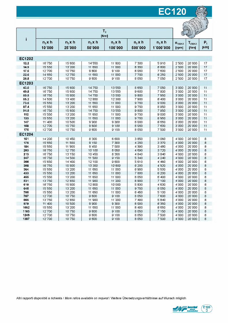
E C 1 2 0 212.2 1 6 7 5 0 1 5 6 0 0 1 4 5 5 0 1 1 8 0 0 7 3 0 0 5 ' 9 1 0 2 ' 5 0 0 2 0 ' 0 0 0 1 7
14.9 1 5 5 5 0 1 3 2 0 0 1 1 6 5 0 1 1 0 0 0 8 3 5 0 6 ' 8 0 0 2 ' 5 0 0 2 0 ' 0 0 0 1 7
17.6 1 2 7 0 0 1 0 7 5 0 9 6 0 0 9 1 0 0 8 0 5 0 7 ' 6 0 0 2 ' 5 0 0 2 0 ' 0 0 0 1 7
22.6 1 4 6 5 0 1 2 7 5 0 1 1 6 5 0 1 1 0 0 0 7 7 0 0 6 ' 2 5 0 2 ' 5 0 0 2 0 ' 0 0 0 1 7
26.8 1 2 7 0 0 1 0 7 5 0 9 6 0 0 9 1 0 0 8 0 5 0 7 ' 0 5 0 2 ' 5 0 0 2 0 ' 0 0 0 1 7
E C 1 2 0 343.0 1 6 ' 7 5 0 1 5 ' 6 0 0 1 4 ' 7 5 0 1 3 ' 5 5 0 8 ' 6 5 0 7 ' 0 5 0 3 ' 0 0 0 2 0 ■ 0 0 0 11
49.8 1 6 ' 7 5 0 1 5 ' 6 0 0 1 4 ' 7 5 0 1 3 ' 5 5 0 9 ' 6 0 0 7 ' 8 0 0 3 ' 0 0 0 2 0 ■ 0 0 0 11
60.5 1 6 ' 7 5 0 1 5 ' 6 0 0 1 4 ' 7 5 0 1 3 ' 5 5 0 9 ' 8 0 0 7 ' 9 5 0 3 ' 0 0 0 2 0 ■ 0 0 0 11
65.2 1 4 ' 5 0 0 1 3 ' 4 0 0 1 2 ' 8 5 0 1 2 ' 3 0 0 7 ' 9 0 0 6 ' 4 0 0 3 ' 0 0 0 2 0 ■ 0 0 0 11
73.6 1 5 ' 5 5 0 1 3 ' 2 0 0 1 1 6 5 0 1 1 0 0 0 9 ' 7 5 0 9 ' 0 0 0 3 ' 0 0 0 2 0 ■ 0 0 0 11
87.4 1 5 ' 5 5 0 1 3 ' 2 0 0 1 1 6 5 0 1 1 0 0 0 9 ' 7 5 0 8 ' 9 5 0 3 ■ 0 0 0 2 0 ■ 0 0 0 11
91.9 1 6 ' 7 5 0 1 5 ' 6 0 0 1 4 ' 7 5 0 1 3 ' 5 5 0 9 ' 8 0 0 7 ' 9 5 0 3 ■ 0 0 0 2 0 ■ 0 0 0 11
112 1 5 ' 5 5 0 1 3 ' 2 0 0 1 1 6 5 0 1 1 0 0 0 9 ' 7 5 0 9 ' 0 0 0 3 ■ 0 0 0 2 0 ■ 0 0 0 11
133 1 5 ' 5 5 0 1 3 ' 2 0 0 1 1 6 5 0 1 1 0 0 0 9 ' 7 5 0 8 ' 9 5 0 3 ■ 0 0 0 2 0 ■ 0 0 0 11
147 1 1 4 0 0 1 0 ' 5 0 0 9 ' 9 0 0 9 ' 3 0 0 8 ' 0 0 0 6 ' 6 5 0 3 ■ 0 0 0 2 0 ■ 0 0 0 11
158 1 2 ' 7 0 0 1 0 ' 7 5 0 9 ' 6 0 0 9 ' 1 0 0 8 ' 0 5 0 7 ' 6 0 0 3 ■ 0 0 0 2 0 ■ 0 0 0 11
175 1 2 ' 7 0 0 1 0 ' 7 5 0 9 ' 6 0 0 9 ' 1 0 0 8 ' 0 5 0 7 ' 5 0 0 3 ■ 0 0 0 2 0 ■ 0 0 0 11
E C 1 2 0 4151 1 4 ' 2 0 0 1 0 ' 4 5 0 8 ' 3 0 0 6 ' 6 0 0 3 ' 8 5 0 3 ' 0 6 0 4 ■ 0 0 0 2 0 ■ 0 0 0 8
175 1 5 ' 6 5 0 1 1 5 5 0 9 ' 1 5 0 7 ' 3 0 0 4 ' 2 5 0 3 ' 3 7 0 4 ■ 0 0 0 2 0 ■ 0 0 0 8
184 1 5 ' 5 5 0 1 1 9 0 0 9 ' 4 5 0 7 ' 5 0 0 4 ' 3 9 0 3 ' 4 8 0 4 ■ 0 0 0 2 0 ■ 0 0 0 8
203 1 6 ' 7 5 0 1 2 ' 7 5 0 1 0 ' 1 0 0 8 ' 0 5 0 4 ' 6 9 0 3 ' 7 2 0 4 ■ 0 0 0 2 0 ■ 0 0 0 8
213 1 6 ' 7 5 0 1 3 ' 1 5 0 1 0 ' 4 5 0 8 ' 3 0 0 4 ' 8 4 0 3 ' 8 4 0 4 ■ 0 0 0 2 0 ■ 0 0 0 8
247 1 6 ' 7 5 0 1 4 ' 5 0 0 1 1 5 0 0 9 ' 1 5 0 5 ' 3 4 0 4 ' 2 4 0 4 ■ 0 0 0 2 0 ■ 0 0 0 8
266 1 5 ' 6 5 0 1 4 ' 4 0 0 1 2 ' 1 0 0 9 ' 6 0 0 5 ' 6 1 0 4 ' 4 6 0 4 ■ 0 0 0 2 0 ■ 0 0 0 8
308 1 6 ' 7 5 0 1 5 ' 6 0 0 1 3 ' 3 5 0 1 0 ' 6 0 0 6 ' 2 0 0 4 ' 9 2 0 4 ■ 0 0 0 2 0 ■ 0 0 0 8
364 1 5 ' 5 5 0 1 3 ' 2 0 0 1 1 6 5 0 1 1 0 0 0 6 ' 9 5 0 5 ' 5 0 0 4 ■ 0 0 0 2 0 ■ 0 0 0 8
433 1 5 ' 5 5 0 1 3 ' 2 0 0 1 1 6 5 0 1 1 0 0 0 7 ' 8 0 0 6 ' 2 0 0 4 ■ 0 0 0 2 0 ■ 0 0 0 8
455 1 5 ' 5 5 0 1 3 ' 2 0 0 1 1 6 5 0 1 1 0 0 0 8 ' 0 5 0 6 ' 4 0 0 4 ■ 0 0 0 2 0 ■ 0 0 0 8
531 1 3 ' 7 5 0 1 2 ' 6 5 0 1 1 9 0 0 1 1 2 0 0 8 ' 9 0 0 7 ' 1 0 0 4 ■ 0 0 0 2 0 ■ 0 0 0 8
610 1 6 ' 7 5 0 1 5 ' 6 0 0 1 2 ' 6 0 0 1 0 ' 0 0 0 5 ' 8 3 0 4 ' 6 3 0 4 ■ 0 0 0 2 0 ■ 0 0 0 8
645 1 5 ' 5 5 0 1 3 ' 2 0 0 1 1 6 5 0 1 1 0 0 0 9 ' 7 5 0 8 ' 0 5 0 4 ■ 0 0 0 2 0 ■ 0 0 0 8
705 1 5 ' 5 5 0 1 3 ' 2 0 0 1 1 6 5 0 1 1 0 0 0 6 ' 4 5 0 5 ' 1 0 0 4 ■ 0 0 0 2 0 ■ 0 0 0 8
767 1 2 ' 7 0 0 1 0 ' 7 5 0 9 ' 6 0 0 9 ' 1 0 0 8 ' 0 5 0 7 ' 6 0 0 4 ■ 0 0 0 2 0 ■ 0 0 0 8
865 1 3 ' 7 5 0 1 2 ' 6 5 0 1 1 9 0 0 1 1 2 0 0 7 ' 4 0 0 5 ' 8 4 0 4 ■ 0 0 0 2 0 ■ 0 0 0 8
979 1 1 4 0 0 1 0 ' 5 0 0 9 ' 9 0 0 9 ' 3 0 0 8 ' 0 0 0 6 ' 3 5 0 4 ■ 0 0 0 2 0 ■ 0 0 0 8
1052 1 5 ' 5 5 0 1 3 ' 2 0 0 1 1 6 5 0 1 1 0 0 0 8 ' 4 0 0 6 ' 6 5 0 4 ■ 0 0 0 2 0 ■ 0 0 0 8
1163 1 2 ' 7 0 0 1 0 ' 7 5 0 9 ' 6 0 0 9 ' 1 0 0 8 ' 0 5 0 7 ' 1 5 0 4 ■ 0 0 0 2 0 ■ 0 0 0 8
1249 1 2 ' 7 0 0 1 0 ' 7 5 0 9 ' 6 0 0 9 ' 1 0 0 8 ' 0 5 0 7 ' 5 0 0 4 ■ 0 0 0 2 0 ■ 0 0 0 8
1387 1 2 ' 7 0 0 1 0 ' 7 5 0 9 ' 6 0 0 9 ' 1 0 0 8 ' 0 5 0 7 ' 5 0 0 4 ■ 0 0 0 2 0 ■ 0 0 0 8
Altri r a p p o r t i d i s p o n i b i l i a r i c h i e s t a / More ratios available on request / W e i t e r e U b e r s e t z u n g s v e r h a l t n i s s e a u f W u n s c h m o g l i c h
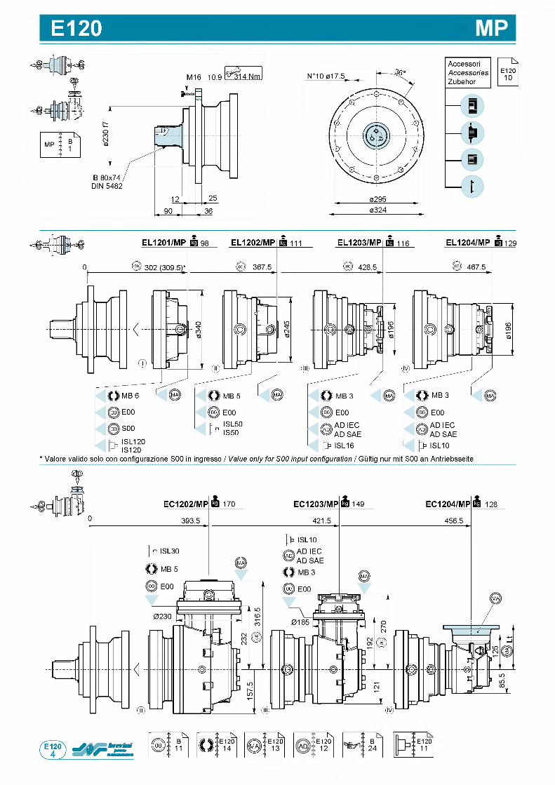
E120
t
i Nt ■ E 1 2 0AD 1 2
:
itB
2 4E 1 2 0
11
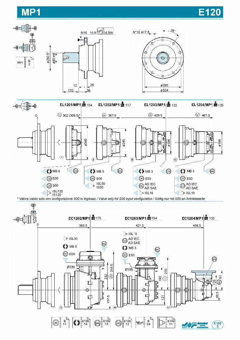
MP1 E120
: ^
MP1B2
M 1 6 1 0 . 9 3 1 4 N m31.
IS ,B
11E 1 2 0
1 4
<■E 1 2 0MA 1 3
i К' • E 1 2 0
AD 1 2'
: k .
iB
2 4 3 *E 1 2 0
11 b rtr
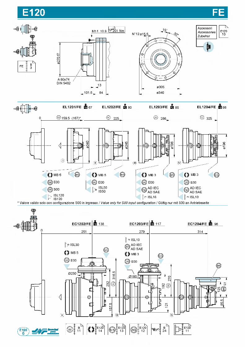
E120 FE
: N
f e :B3
M 1 4 1 0 . 9 2 02 0 1 N m
fA c c e s s o r i
AccessoriesZ u b e h o r
* V a l o r e v a l i d o s o l o c o n c o n f i g u r a z i o n e S 0 0 in i n g r e s s o / Value only for S00 input configuration / G u l t i g n u r m i t S 0 0 a n A n t r i e b s s e i t e
i N* ■ E 1 2 0
AD 1 2
:
itB
2 4E 1 2 0
11
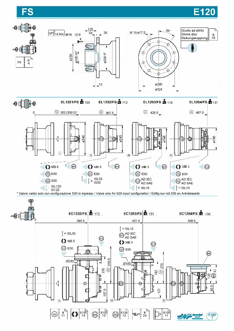
FS E120
* V a l o r e v a l i d o s o l o c o n c o n f i g u r a z i o n e S 0 0 in i n g r e s s o / Value only for S00 input configuration / G u l t i g n u r m i t S 0 0 a n A n t r i e b s s e i t e
! Кt • E 1 2 0
AD 1 2'
: ^
£B
2 4E 1 2 0
11
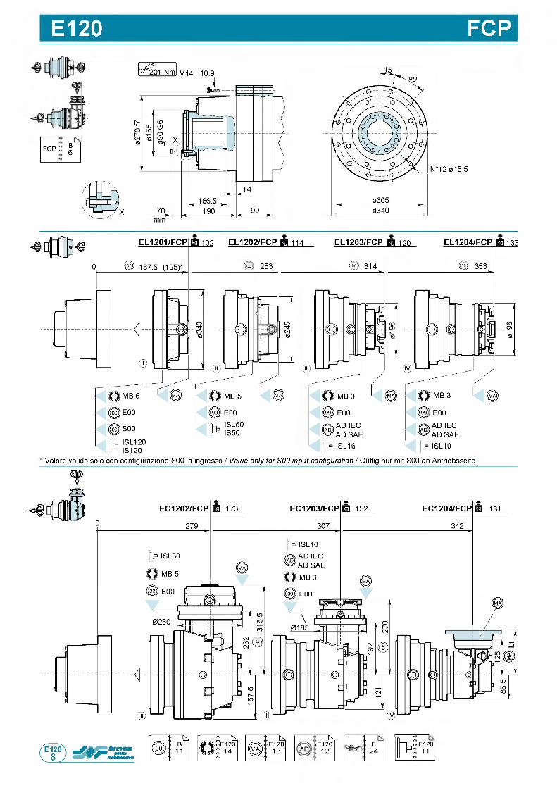
E120 FCP
f c p :
О)
ГО
N ° 1 2 0 1 5 . 5
' 0 3 4 0 '
EL1203/FCP F g 1 2 0EL1201/FCPE3 10 2 EL1202/FCPp j | 11 4
00 2 5 3
EL1204/FCP | | 1 3 3
ЦJ
02
45
1 Г*
ISL50IS50
0 0 E00
AD IEC AD SAE
|> ISL10
' Valore valido solo con configurazione S00 in ingresso / Value only for S00 input configuration / Gultig nur mit S00 an Antriebsseite
i Nt ■ E 1 2 0AD 1 2
:
itB
2 4E 1 2 0
11
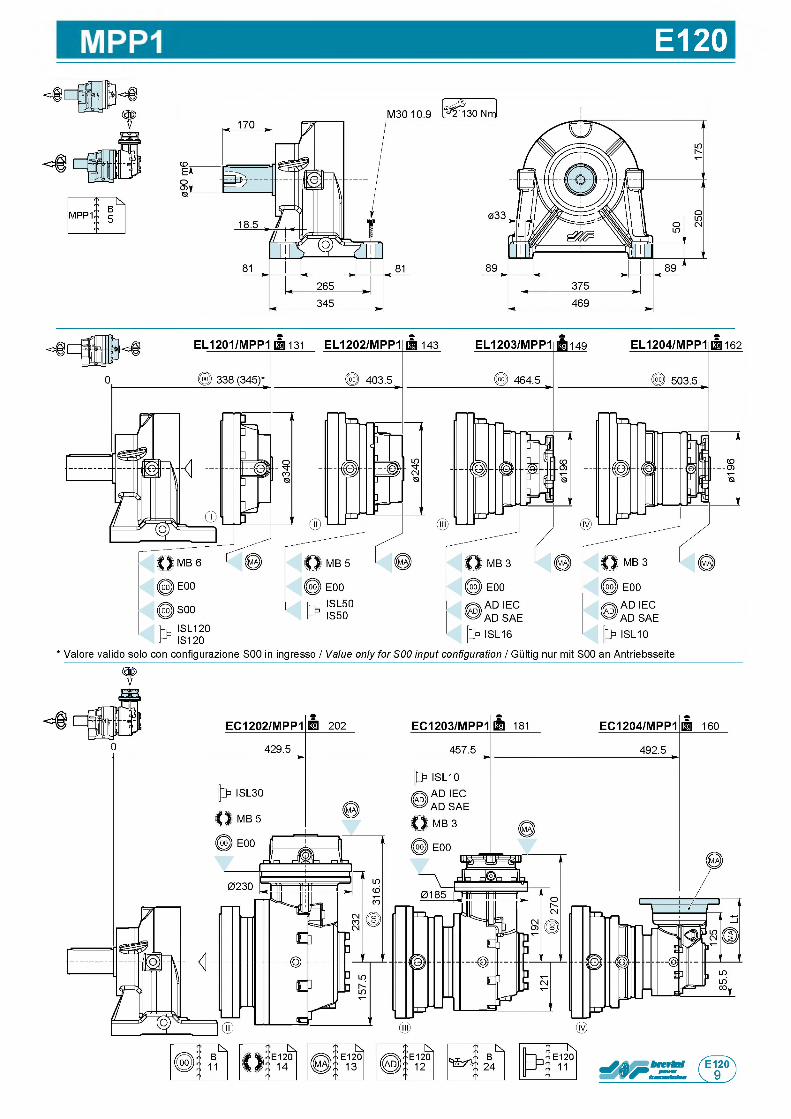
E120
?
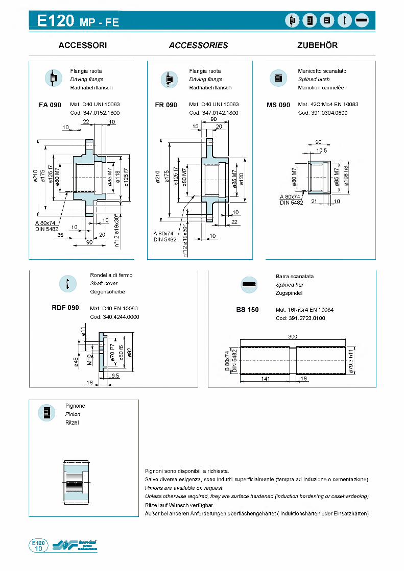
E120 MP - FE
ACCESSORI A C C E S S O R IE S ZUBEHOR
F A 0 9 0
F l a n g i a r u o t a
Driving flange R a d n a b e h f l a n s c h
M a t . C 4 0 U N I 1 0 0 8 3
C o d : 3 4 7 . 0 1 5 2 . 1 8 0 0
M S 0 9 0
M a n i c o t t o s c a n a l a t o
Splined bush M a n c h o n c a n n e l e e
M a t . 4 2 C r M o 4 E N 1 0 0 8 3
C o d : 3 9 1 . 0 3 0 4 . 0 6 0 0
9 0
A 8 0 x 7 4 .D I N 5 4 8 2 2 1
r
1 0 . 5
1 0
R o n d e l l a d i f e r m o
Shaft cover G e g e n s c h e i b e
R D F 0 9 0 M a t . C 4 0 E N 1 0 0 8 3
C o d : 3 4 0 . 4 2 4 4 . 0 0 0 0
B a r r a s c a n a l a t a
Splined bar Z u g s p i n d e l
B S 15 0 M a t . 1 6 N i C r 4 E N 1 0 0 8 4
C o d : 3 9 1 . 2 7 2 3 . 0 1 0 0
3 0 0
(NCO
J Z
- CO
O ) h -
и
H Q
. 1 4 1 . . 1 8
P i g n o n i s o n o d i s p o n i b i l i a r i c h i e s t a .
S a l v o d i v e r s a e s i g e n z a , s o n o induri ti s u p e r f i c i a l m e n t e ( t e m p r a a d i n d u z i o n e o c e m e n t a z i o n e )
Pinions are available on request.Unless otherwise required, they are surface hardened (induction hardening or casehardening) R i t z e l a u f W u n s c h v e r f u g b a r .
A u l J e r b e i a n d e r e n A n f o r d e r u n g e n o b e r f l a c h e n g e h a r t e t ( I n d u k t i o n s h a r t e n o d e r E i n s a t z h a r t e n )
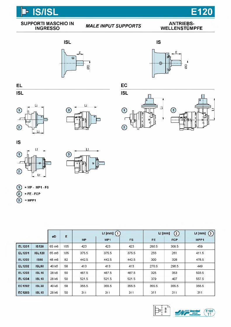
IS/ISL E120SUPPORTI MASCHIO IN
INGRESSO M A L E IN P U T S U P P O R T S ANTRIEBS-w e l l e n s t Om p f e
ISL IS
EL
ISL
IS
ф = MP - M P1- FS
ф = F E - FCP
ф = MPP1
EC
0D ELt [mm] 1 Lt [mm] 2 Lt [mm] 3
MP MP1 FS FE FCP MPP1
EL1201 IS120 6 5 m 6 1 0 5 4 2 3 4 2 3 4 2 3 2 8 0 . 5 3 0 8 . 5 4 5 9
EL1201 ISL120 6 5 m 6 1 0 5 3 7 5 . 5 3 7 5 . 5 3 7 5 . 5 2 3 3 2 6 1 4 1 1 . 5
EL1202 IS50 4 8 m 6 8 2 4 4 2 . 5 4 4 2 . 5 4 4 2 . 5 3 0 0 3 2 8 4 7 8 . 5
EL1202 ISL50 4 0 k 6 5 8 4 1 3 4 1 3 4 1 3 2 7 0 . 5 2 9 8 . 5 4 4 9
EL1203 ISL16 2 8 k 6 5 0 4 6 7 . 5 4 6 7 . 5 4 6 7 . 5 3 2 5 3 5 3 5 0 3 . 5
EL1204 ISL10 2 8 k 6 5 0 5 2 1 . 5 5 2 1 . 5 5 2 1 . 5 3 7 9 4 0 7 5 5 7 . 5
EC1202 ISL30 4 0 k 6 5 8 3 5 5 . 5 3 5 5 . 5 3 5 5 . 5 3 5 5 . 5 3 5 5 . 5 3 5 5 . 5
EC1203 ISL10 2 8 k 6 5 0 3 1 1 3 1 1 3 1 1 3 1 1 3 1 1 3 1 1
B8
П
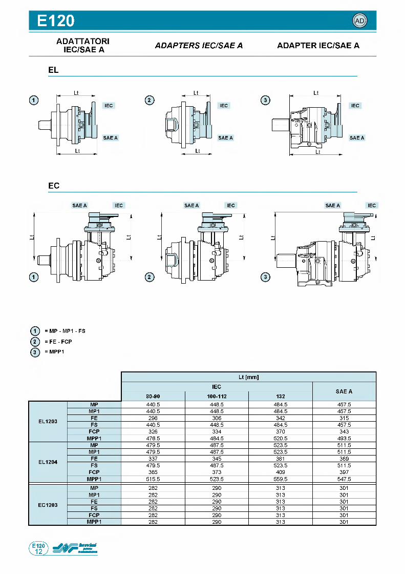
E120ADATTATORI
IEC/SAE A A D A P T E R S IE C /S A E A ADAPTER IEC/SAE A
EL
IEC
S A E A
IEC
S A E A
© IEC
S A E A
EC
S A E A IEC S A E A IEC S A E A IEC
ф = MP - MP1 - FS
ф = FE - FCP
(3 = MPP1
Lt [mm]
IECSAE A
80-90 100-112 132
EL1203
MP 4 4 0 . 5 4 4 8 . 5 4 8 4 . 5 4 5 7 . 5
MP1 4 4 0 . 5 4 4 8 . 5 4 8 4 . 5 4 5 7 . 5
FE 2 9 8 3 0 6 3 4 2 3 1 5
FS 4 4 0 . 5 4 4 8 . 5 4 8 4 . 5 4 5 7 . 5
FCP 3 2 6 3 3 4 3 7 0 3 4 3
MPP1 4 7 6 . 5 4 8 4 . 5 5 2 0 . 5 4 9 3 . 5
EL1204
MP 4 7 9 . 5 4 8 7 . 5 5 2 3 . 5 5 1 1 . 5
MP1 4 7 9 . 5 4 8 7 . 5 5 2 3 . 5 5 1 1 . 5
FE 3 3 7 3 4 5 3 8 1 3 6 9
FS 4 7 9 . 5 4 8 7 . 5 5 2 3 . 5 5 1 1 . 5
FCP 3 6 5 3 7 3 4 0 9 3 9 7
MPP1 5 1 5 . 5 5 2 3 . 5 5 5 9 . 5 5 4 7 . 5
EC1203
MP 2 8 2 2 9 0 3 1 3 3 0 1
MP1 2 8 2 2 9 0 3 1 3 3 0 1
FE 2 8 2 2 9 0 3 1 3 3 0 1
FS 2 8 2 2 9 0 3 1 3 3 0 1
FCP 2 8 2 2 9 0 3 1 3 3 0 1
MPP1 2 8 2 2 9 0 3 1 3 3 0 1
П
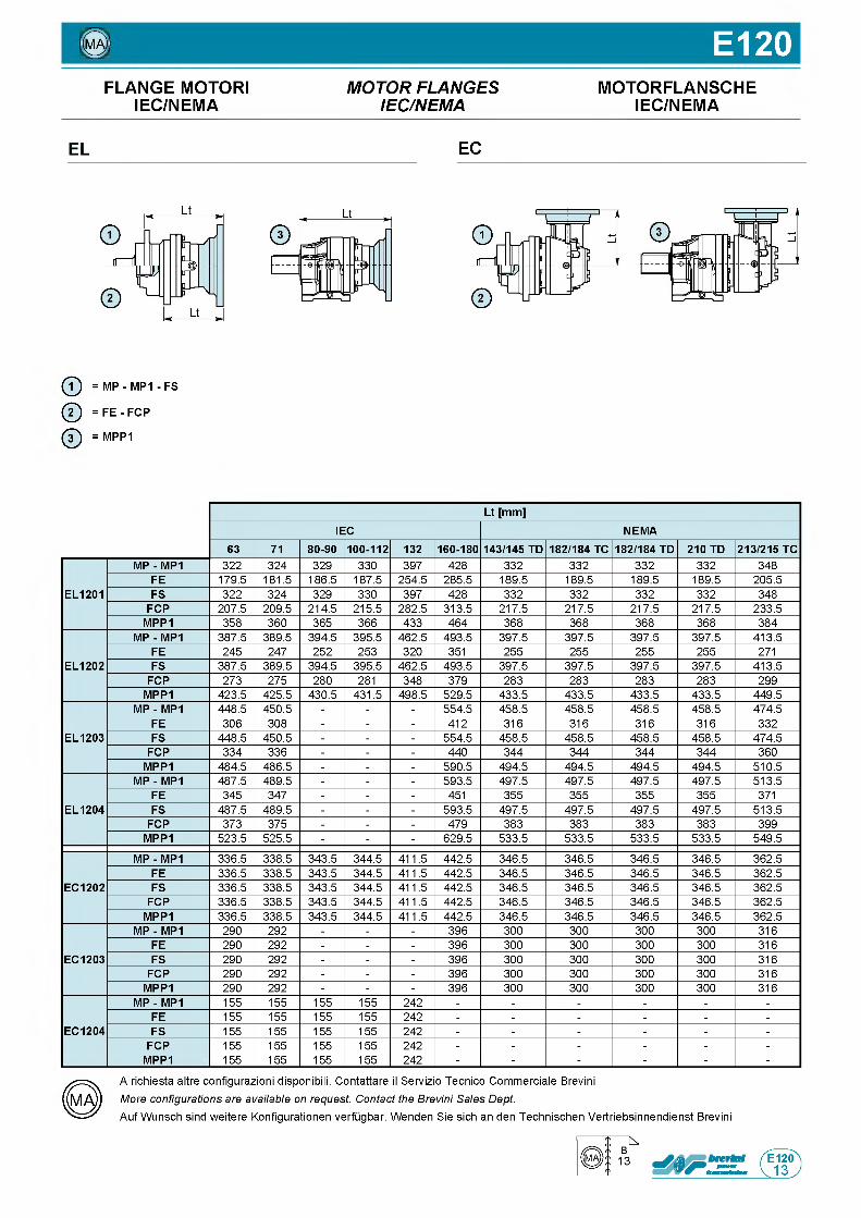
0 E120FLANGE MOTOR! M O T O R F L A N G E S MOTORFLANSCHE
IEC/NEMA IE C /N E M A IEC/NEMA
EL EC
ф = MP - MP1 - FS
ф = F E - FCP
ф = MPP1
Lt [mm]IEC NEMA
63 71 80-90 100-112 132 160-180 143/145 TD 182/184 TC 182/184 TD 210 TD 213/215 TC
EL1201
MP - MP1 3 2 2 3 2 4 3 2 9 3 3 0 3 9 7 4 2 8 3 3 2 3 3 2 3 3 2 3 3 2 3 4 8
FE 1 7 9 . 5 1 8 1 . 5 1 8 6 . 5 1 8 7 . 5 2 5 4 . 5 2 8 5 . 5 1 8 9 . 5 1 8 9 . 5 1 8 9 . 5 1 8 9 . 5 2 0 5 . 5
FS 3 2 2 3 2 4 3 2 9 3 3 0 3 9 7 4 2 8 3 3 2 3 3 2 3 3 2 3 3 2 3 4 8
FCP 2 0 7 . 5 2 0 9 . 5 2 1 4 . 5 2 1 5 . 5 2 8 2 . 5 3 1 3 . 5 2 1 7 . 5 2 1 7 . 5 2 1 7 . 5 2 1 7 . 5 2 3 3 . 5
MPP1 3 5 8 3 6 0 3 6 5 3 6 6 4 3 3 4 6 4 3 6 8 3 6 8 3 6 8 3 6 8 3 8 4
EL1202
MP - MP1 3 8 7 . 5 3 8 9 . 5 3 9 4 . 5 3 9 5 . 5 4 6 2 . 5 4 9 3 . 5 3 9 7 . 5 3 9 7 . 5 3 9 7 . 5 3 9 7 . 5 4 1 3 . 5
FE 2 4 5 2 4 7 2 5 2 2 5 3 3 2 0 3 5 1 2 5 5 2 5 5 2 5 5 2 5 5 2 7 1
FS 3 8 7 . 5 3 8 9 . 5 3 9 4 . 5 3 9 5 . 5 4 6 2 . 5 4 9 3 . 5 3 9 7 . 5 3 9 7 . 5 3 9 7 . 5 3 9 7 . 5 4 1 3 . 5
FCP 2 7 3 2 7 5 2 8 0 2 8 1 3 4 8 3 7 9 2 8 3 2 8 3 2 8 3 2 8 3 2 9 9
MPP1 4 2 3 . 5 4 2 5 . 5 4 3 0 . 5 4 3 1 . 5 4 9 8 . 5 5 2 9 . 5 4 3 3 . 5 4 3 3 . 5 4 3 3 . 5 4 3 3 . 5 4 4 9 . 5
EL1203
MP - MP1 4 4 8 . 5 4 5 0 . 5 - - - 5 5 4 . 5 4 5 8 . 5 4 5 8 . 5 4 5 8 . 5 4 5 8 . 5 4 7 4 . 5
FE 3 0 6 3 0 8 - - - 4 1 2 3 1 6 3 1 6 3 1 6 3 1 6 3 3 2
FS 4 4 8 . 5 4 5 0 . 5 - - - 5 5 4 . 5 4 5 8 . 5 4 5 8 . 5 4 5 8 . 5 4 5 8 . 5 4 7 4 . 5
FCP 3 3 4 3 3 6 - - - 4 4 0 3 4 4 3 4 4 3 4 4 3 4 4 3 6 0
MPP1 4 8 4 . 5 4 8 6 . 5 - - - 5 9 0 . 5 4 9 4 . 5 4 9 4 . 5 4 9 4 . 5 4 9 4 . 5 5 1 0 . 5
EL1204
MP - MP1 4 8 7 . 5 4 8 9 . 5 - - - 5 9 3 . 5 4 9 7 . 5 4 9 7 . 5 4 9 7 . 5 4 9 7 . 5 5 1 3 . 5
FE 3 4 5 3 4 7 - - - 4 5 1 3 5 5 3 5 5 3 5 5 3 5 5 3 7 1
FS 4 8 7 . 5 4 8 9 . 5 - - - 5 9 3 . 5 4 9 7 . 5 4 9 7 . 5 4 9 7 . 5 4 9 7 . 5 5 1 3 . 5
FCP 3 7 3 3 7 5 - - - 4 7 9 3 8 3 3 8 3 3 8 3 3 8 3 3 9 9
MPP1 5 2 3 . 5 5 2 5 . 5 - - - 6 2 9 . 5 5 3 3 . 5 5 3 3 . 5 5 3 3 . 5 5 3 3 . 5 5 4 9 . 5
EC1202
MP - MP1 3 3 6 . 5 3 3 8 . 5 3 4 3 . 5 3 4 4 . 5 4 1 1 . 5 4 4 2 . 5 3 4 6 . 5 3 4 6 . 5 3 4 6 . 5 3 4 6 . 5 3 6 2 . 5
FE 3 3 6 . 5 3 3 8 . 5 3 4 3 . 5 3 4 4 . 5 4 1 1 . 5 4 4 2 . 5 3 4 6 . 5 3 4 6 . 5 3 4 6 . 5 3 4 6 . 5 3 6 2 . 5
FS 3 3 6 . 5 3 3 8 . 5 3 4 3 . 5 3 4 4 . 5 4 1 1 . 5 4 4 2 . 5 3 4 6 . 5 3 4 6 . 5 3 4 6 . 5 3 4 6 . 5 3 6 2 . 5
FCP 3 3 6 . 5 3 3 8 . 5 3 4 3 . 5 3 4 4 . 5 4 1 1 . 5 4 4 2 . 5 3 4 6 . 5 3 4 6 . 5 3 4 6 . 5 3 4 6 . 5 3 6 2 . 5
MPP1 3 3 6 . 5 3 3 8 . 5 3 4 3 . 5 3 4 4 . 5 4 1 1 . 5 4 4 2 . 5 3 4 6 . 5 3 4 6 . 5 3 4 6 . 5 3 4 6 . 5 3 6 2 . 5
EC1203
MP - MP1 2 9 0 2 9 2 - - - 3 9 6 3 0 0 3 0 0 3 0 0 3 0 0 3 1 6
FE 2 9 0 2 9 2 - - - 3 9 6 3 0 0 3 0 0 3 0 0 3 0 0 3 1 6
FS 2 9 0 2 9 2 - - - 3 9 6 3 0 0 3 0 0 3 0 0 3 0 0 3 1 6
FCP 2 9 0 2 9 2 - - - 3 9 6 3 0 0 3 0 0 3 0 0 3 0 0 3 1 6
MPP1 2 9 0 2 9 2 - - - 3 9 6 3 0 0 3 0 0 3 0 0 3 0 0 3 1 6
EC1204
MP - MP1 1 5 5 1 5 5 1 5 5 1 5 5 2 4 2 - - - - - -
FE 1 5 5 1 5 5 1 5 5 1 5 5 2 4 2 - - - - - -
FS 1 5 5 1 5 5 1 5 5 1 5 5 2 4 2 - - - - - -
FCP 1 5 5 1 5 5 1 5 5 1 5 5 2 4 2 - - - - - -
MPP1 1 5 5 1 5 5 1 5 5 1 5 5 2 4 2 - - - - - -
A richiesta altre configurazioni disponibili. Contattare il Servizio Tecnico Commerciale Brevini More configurations are available on request. Contact the Brevini Sales Dept.Auf Wunsch sind weitere Konfigurationen verfugbar. Wenden Sie sich an den Technischen Vertriebsinnendienst Brevini
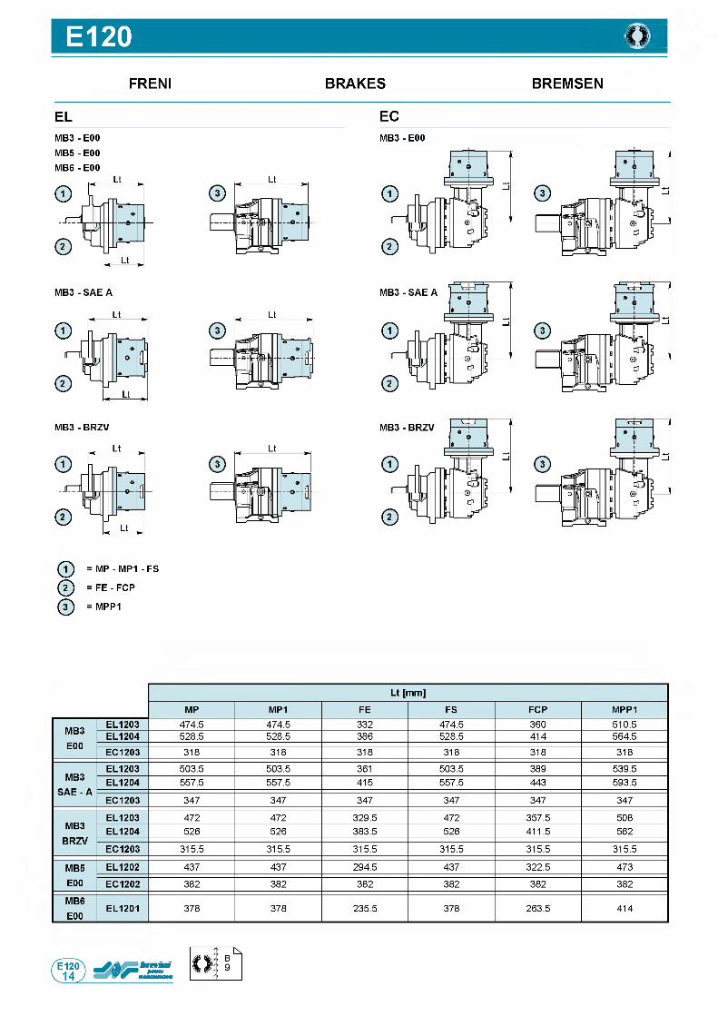
E120 ШFRENI BRAKES BREMSEN
EL ECM B 3- E00
M B 5- E00 M B 6- E00
MB3 - E00
ф = MP - MP1 - FS
Q = FE - FCP
ф = MPP1
Lt [mm]
MP MP1 FE FS FCP MPP1
MB3E00
EL1203 4 7 4 . 5 4 7 4 . 5 3 3 2 4 7 4 . 5 3 6 0 5 1 0 . 5
EL1204 5 2 8 . 5 5 2 8 . 5 3 8 6 5 2 8 . 5 4 1 4 5 6 4 . 5
EC1203 3 1 8 3 1 8 3 1 8 3 1 8 3 1 8 3 1 8
MB3 SAE - A
EL1203 5 0 3 . 5 5 0 3 . 5 3 6 1 5 0 3 . 5 3 8 9 5 3 9 . 5
EL1204 5 5 7 . 5 5 5 7 . 5 4 1 5 5 5 7 . 5 4 4 3 5 9 3 . 5
EC1203 3 4 7 3 4 7 3 4 7 3 4 7 3 4 7 3 4 7
MB3BRZV
EL1203 4 7 2 4 7 2 3 2 9 . 5 4 7 2 3 5 7 . 5 5 0 8
EL1204 5 2 6 5 2 6 3 8 3 . 5 5 2 6 4 1 1 . 5 5 6 2
EC1203 3 1 5 . 5 3 1 5 . 5 3 1 5 . 5 3 1 5 . 5 3 1 5 . 5 3 1 5 . 5
MB5E00
EL1202 4 3 7 4 3 7 2 9 4 . 5 4 3 7 3 2 2 . 5 4 7 3
EC1202 3 8 2 3 8 2 3 8 2 3 8 2 3 8 2 3 8 2
MB6E00
EL1201 3 7 8 3 7 8 2 3 5 . 5 3 7 8 2 6 3 . 5 4 1 4
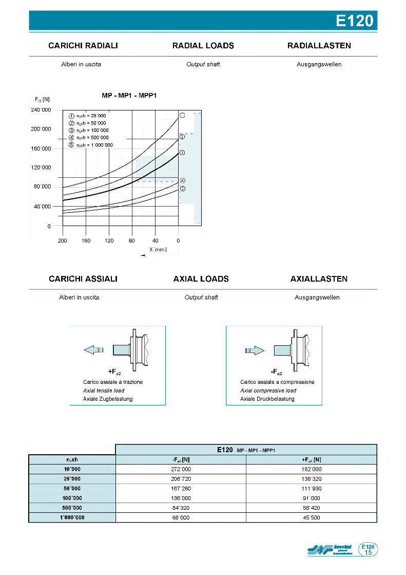
E120CARICHI RADIALI RADIAL LOADS RADIALLASTEN
A l b e r i in u s c i t a Output shaft A u s g a n g s w e l l e n
M P - M P1 - M P P 1
CARICHI ASSIALI AXIAL LOADS AXIALLASTEN
A l b e r i in u s c i t a Output shaft A u s g a n g s w e l l e n
C a r i c o a s s i a l e a t r a z i o n e
Axial tensile load A x i a l e Z u g b e l a s t u n g
О
-F a2 UC a r i c o a s s i a l e a c o m p r e s s i o n e
Axial compressive load A x i a l e D r u c k b e l a s t u n g
E 1 2 0 m p - MP1 - m p p 1
n2xh -Fa2 [N] + Fa2 [N]1 0 0 0 0 272 000 182 00025 000 206 720 13832050 000 167280 111930
10 0 000 136 000 91000500 000 84 320 56 420
1 000 000 68 000 45 500
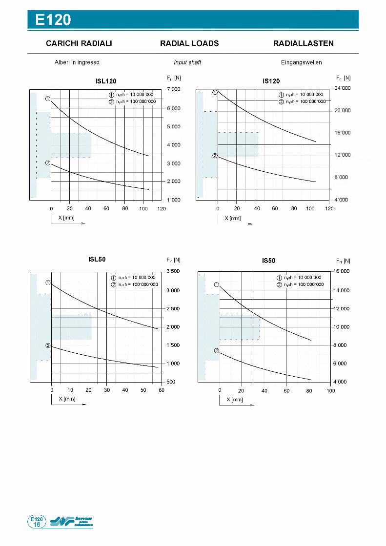
E120CARICHI RADIALI RADIAL LOADS RADIALLASTEN
A l b e r i in i n g r e s s o Input shaft E i n g a n g s w e l l e n
IS L 1 2 0 Fr1 [N] IS 1 2 0 Fr1 [N]7 0 0 0 2 4 0 0 0
IS L 5 0 F r1 [N]
3 5 0 0
3 0 0 0
2 5 0 0
2 0 0 0
1 5 0 0
1 0 0 0
5 0 0
IS 5 0 F r1 [N ]
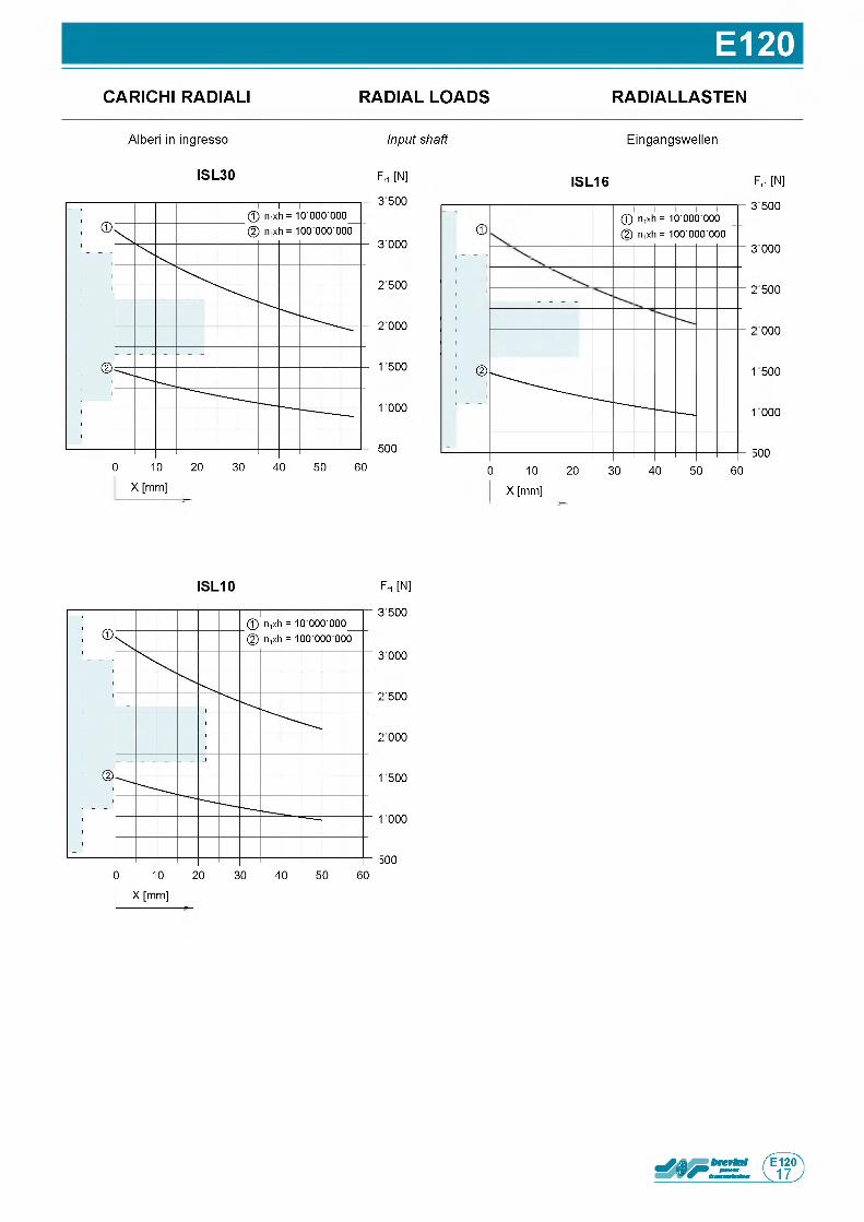
E120CARICHI RADIALI RADIAL LOADS RADIALLASTEN
A l b e r i in i n g r e s s o Input shaft E i n g a n g s w e l l e n
Frt [N]
3 500
3 ■ 0 0 0
25 500
20 000
1500
1000
1500
0 10 20 30 40 50 60
X [mm]
IS L 3 0 Fri [N]
3 500
3 000
2 500
2 000
1 500
1 000
5000 10 20 30 40 50 60
X [mm]
IS L 1 6
d© nixh = 10 ■ 000■ 000_ © n1xh = 100 ■ 000 ■ 000
©
IS L 1 0 Fri [N]
3 500
3 000
2 500
2 000
1 500
1 000
500

Questa pagina e lasciata intenzionalmente bianca
Page is in tentiona lly le ft blank Seite wurde absichtlich leer gelassen
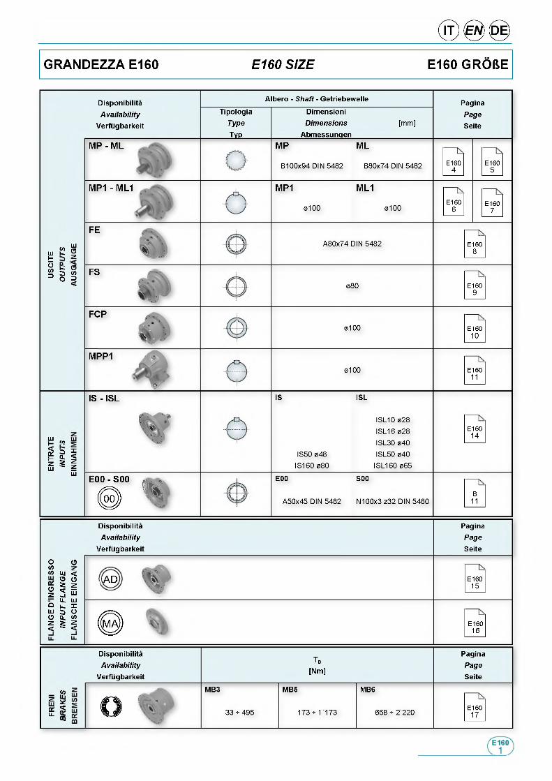
Disponibilita
Availab ilityVerfugbarkeit
Albero - Shaft - Getriebewelle
TipologiaType
___ Typ___
DimensioniDimensions
Abmessungen
[ m m ]
Pagina
PageSeite
M P - M L M P
B 1 0 0 x 9 4 D I N 5 4 8 2
M L
B 8 0 x 7 4 D IN 5 4 8 2 E 1 6 04
E 1 6 05
M P1 - M L1 M P1 M L1
0 1 0 0 0 1 0 0E 1 6 0
6E 1 6 0
7
Ш СО (П
Ш К Уto 0
н |
FE
A 8 0 x 7 4 D IN 5 4 8 2 E 1 6 08
FS
0 8 0 E 1 6 09
F C P
0 1 0 0 E 1 6 01 0
M P P 1
о
0 1 0 0 E 1 6 011
ш ь , Ш
s„ 8 1 S § I
Ш
IS - IS L IS
I S 5 0 0 4 8
I S 1 6 0 0 8 0
ISL
I S L 1 0 0 2 8
I S L 1 6 0 2 8
I S L 3 0 0 4 0
I S L 5 0 0 4 0
I S L 1 6 0 0 6 5
E 1 6 01 4
E 0 0 - S 0 0
<4E00
A 5 0 x 4 5 D I N 5 4 8 2
S00
N 1 0 0 x 3 z 3 2 D I N 5 4 8 0B
11
DisponibilitaA vailab ility
Verfugbarkeit
PaginaPage
Seite
0w _w Ui <
% § 21 2 e— Ц. Ш° к X ш э о О Q. W z г z < " <
о
,A D E 1 6 01 5
E 1 6 01 6
DisponibilitaA vailab ility
Verfugbarkeit
Tb
[Nm]
MB3 MB5 MB6Л f l ) h 4
% ф) 3 3 * 4 9 5 1 7 3 * 1 1 7 3 6 5 8 * 2 2 2 0
■
PaginaPage
Seite
«оz Игк Su. CQ
E 1 6 01 7
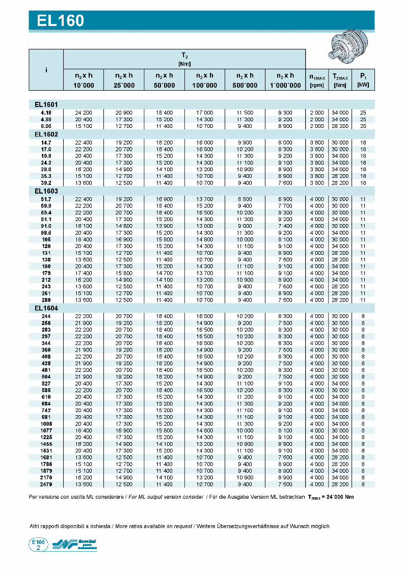
EL160
E L 16014.18 2 4 2 0 0 2 0 ■ 9 0 0 1 8 ■ 4 0 0 1 7 ■ 0 0 0 1 1 5 0 0 9 ■ 3 0 0 2 ■ 0 0 0 3 4 ■ 0 0 0 2 5
4.89 2 0 4 0 0 1 7 ■ 3 0 0 1 5 ■ 2 0 0 1 4 ■ 3 0 0 1 1 3 0 0 9 ■ 2 0 0 2 ■ 0 0 0 3 4 ■ 0 0 0 2 5
6.00 1 5 1 0 0 1 2 ■ 7 0 0 1 1 4 0 0 1 0 ■ 7 0 0 9 ■ 4 0 0 8 ■ 9 0 0 2 ■ 0 0 0 2 8 ■ 2 0 0 2 5
E L 1 6 0 214.7 2 2 4 0 0 1 9 ■ 2 0 0 1 8 ■ 2 0 0 1 6 ■ 0 0 0 9 ■ 9 0 0 8 ■ 0 0 0 3 ■ 8 0 0 3 0 ■ 0 0 0 1 8
17.0 22 200 2 0 ■ 7 0 0 1 8 ■ 4 0 0 1 6 ■ 5 0 0 1 0 ■ 2 0 0 8 ■ 3 0 0 3 ■ 8 0 0 3 0 ■ 0 0 0 1 8
19.9 20 400 1 7 ■ 3 0 0 1 5 ■ 2 0 0 1 4 ■ 3 0 0 1 1 3 0 0 9 ■ 2 0 0 3 ■ 8 0 0 3 4 ■ 0 0 0 1 8
24.2 2 0 4 0 0 1 7 ■ 3 0 0 1 5 ■ 2 0 0 1 4 ■ 3 0 0 1 1 1 0 0 9 ■ 1 0 0 3 ■ 8 0 0 3 4 ■ 0 0 0 1 8
28.8 1 6 2 0 0 1 4 ■ 9 0 0 1 4 ■ 1 0 0 1 3 ■ 2 0 0 1 0 ■ 9 0 0 8 ■ 9 0 0 3 ■ 8 0 0 3 4 ■ 0 0 0 1 8
35.3 1 5 ■ 1 0 0 1 2 ■ 7 0 0 1 1 4 0 0 1 0 ■ 7 0 0 9 ■ 4 0 0 8 ■ 9 0 0 3 ■ 8 0 0 2 8 ■ 2 0 0 1 8
39.2 1 3 ■ 6 0 0 1 2 ■ 5 0 0 1 1 4 0 0 1 0 ■ 7 0 0 9 ■ 4 0 0 7 ■ 6 0 0 3 ■ 8 0 0 2 8 ■ 2 0 0 1 8
E L 1 6 0 351.7 2 2 ■ 4 0 0 1 9 ■ 2 0 0 1 6 ■ 9 0 0 1 3 ■ 7 0 0 8 ■ 5 0 0 6 ■ 9 0 0 4 ■ 0 0 0 3 0 ■ 0 0 0 11
59.9 2 2 ■ 2 0 0 2 0 ■ 7 0 0 1 8 ■ 4 0 0 1 5 ■ 2 0 0 9 ■ 4 0 0 7 ■ 7 0 0 4 ■ 0 0 0 3 0 ■ 0 0 0 11
69.4 2 2 ■ 2 0 0 2 0 ■ 7 0 0 1 8 ■ 4 0 0 1 6 ■ 5 0 0 1 0 ■ 2 0 0 8 ■ 3 0 0 4 ■ 0 0 0 3 0 ■ 0 0 0 11
81.1 2 0 ■ 4 0 0 1 7 ■ 3 0 0 1 5 ■ 2 0 0 1 4 ■ 3 0 0 1 1 3 0 0 9 ■ 2 0 0 4 ■ 0 0 0 3 4 ■ 0 0 0 11
91.0 1 6 ■ 1 0 0 1 4 ■ 8 0 0 1 3 ■ 9 0 0 1 3 ■ 0 0 0 9 ■ 0 0 0 7 ■ 4 0 0 4 ■ 0 0 0 3 0 ■ 0 0 0 11
98.6 2 0 ■ 4 0 0 1 7 ■ 3 0 0 1 5 ■ 2 0 0 1 4 ■ 3 0 0 1 1 3 0 0 9 ■ 2 0 0 4 ■ 0 0 0 3 4 ■ 0 0 0 11
105 1 8 ■ 4 0 0 1 6 ■ 9 0 0 1 5 ■ 8 0 0 1 4 ■ 8 0 0 1 0 ■ 0 0 0 8 ■ 1 0 0 4 ■ 0 0 0 3 0 ■ 0 0 0 11
120 2 0 ■ 4 0 0 1 7 ■ 3 0 0 1 5 ■ 2 0 0 1 4 ■ 3 0 0 1 1 1 0 0 9 ■ 1 0 0 4 ■ 0 0 0 3 4 ■ 0 0 0 11
131 1 5 ■ 1 0 0 1 2 ■ 7 0 0 1 1 4 0 0 1 0 ■ 7 0 0 9 ■ 4 0 0 8 ■ 9 0 0 4 ■ 0 0 0 2 8 ■ 2 0 0 11
138 1 3 ■ 6 0 0 1 2 ■ 5 0 0 1 1 4 0 0 1 0 ■ 7 0 0 9 ■ 4 0 0 7 ■ 6 0 0 4 ■ 0 0 0 2 8 ■ 2 0 0 11
150 2 0 ■ 4 0 0 1 7 ■ 3 0 0 1 5 ■ 2 0 0 1 4 ■ 3 0 0 1 1 1 0 0 9 ■ 1 0 0 4 ■ 0 0 0 3 4 ■ 0 0 0 11
179 1 7 ■ 4 0 0 1 5 ■ 8 0 0 1 4 ■ 7 0 0 1 3 ■ 7 0 0 1 1 1 0 0 9 ■ 1 0 0 4 ■ 0 0 0 3 4 ■ 0 0 0 11
212 1 6 ■ 2 0 0 1 4 ■ 9 0 0 1 4 ■ 1 0 0 1 3 ■ 2 0 0 1 0 ■ 9 0 0 8 ■ 9 0 0 4 ■ 0 0 0 3 4 ■ 0 0 0 11
243 1 3 ■ 6 0 0 1 2 ■ 5 0 0 1 1 4 0 0 1 0 ■ 7 0 0 9 ■ 4 0 0 7 ■ 6 0 0 4 ■ 0 0 0 2 8 ■ 2 0 0 11
261 1 5 ■ 1 0 0 1 2 ■ 7 0 0 1 1 4 0 0 1 0 ■ 7 0 0 9 ■ 4 0 0 8 ■ 9 0 0 4 ■ 0 0 0 2 8 ■ 2 0 0 11
289 1 3 ■ 6 0 0 1 2 ■ 5 0 0 1 1 4 0 0 1 0 ■ 7 0 0 9 ■ 4 0 0 7 ■ 6 0 0 4 ■ 0 0 0 2 8 ■ 2 0 0 11
E L 1 6 0 4244 2 2 ■ 2 0 0 2 0 ■ 7 0 0 1 8 ■ 4 0 0 1 6 ■ 5 0 0 1 0 ■ 2 0 0 8 ■ 3 0 0 4 ■ 0 0 0 3 0 ■ 0 0 0 8
256 2 1 9 0 0 1 9 ■ 2 0 0 1 8 ■ 2 0 0 1 4 ■ 9 0 0 9 ■ 2 0 0 7 ■ 5 0 0 4 ■ 0 0 0 3 0 ■ 0 0 0 8
283 2 2 ■ 2 0 0 2 0 ■ 7 0 0 1 8 ■ 4 0 0 1 6 ■ 5 0 0 1 0 ■ 2 0 0 8 ■ 3 0 0 4 ■ 0 0 0 3 0 ■ 0 0 0 8
297 2 2 ■ 2 0 0 2 0 ■ 7 0 0 1 8 ■ 4 0 0 1 6 ■ 5 0 0 1 0 ■ 2 0 0 8 ■ 3 0 0 4 ■ 0 0 0 3 0 ■ 0 0 0 8
344 2 2 ■ 2 0 0 2 0 ■ 7 0 0 1 8 ■ 4 0 0 1 6 ■ 5 0 0 1 0 ■ 2 0 0 8 ■ 3 0 0 4 ■ 0 0 0 3 0 ■ 0 0 0 8
360 2 1 9 0 0 1 9 ■ 2 0 0 1 8 ■ 2 0 0 1 4 ■ 9 0 0 9 ■ 2 0 0 7 ■ 5 0 0 4 ■ 0 0 0 3 0 ■ 0 0 0 8
408 2 2 ■ 2 0 0 2 0 ■ 7 0 0 1 8 ■ 4 0 0 1 6 ■ 5 0 0 1 0 ■ 2 0 0 8 ■ 3 0 0 4 ■ 0 0 0 3 0 ■ 0 0 0 8
428 2 1 9 0 0 1 9 ■ 2 0 0 1 8 ■ 2 0 0 1 4 ■ 9 0 0 9 ■ 2 0 0 7 ■ 5 0 0 4 ■ 0 0 0 3 0 ■ 0 0 0 8
481 2 2 ■ 2 0 0 2 0 ■ 7 0 0 1 8 ■ 4 0 0 1 6 ■ 5 0 0 1 0 ■ 2 0 0 8 ■ 3 0 0 4 ■ 0 0 0 3 0 ■ 0 0 0 8
504 2 1 9 0 0 1 9 ■ 2 0 0 1 8 ■ 2 0 0 1 4 ■ 9 0 0 9 ■ 2 0 0 7 ■ 5 0 0 4 ■ 0 0 0 3 0 ■ 0 0 0 8
527 2 0 ■ 4 0 0 1 7 ■ 3 0 0 1 5 ■ 2 0 0 1 4 ■ 3 0 0 1 1 1 0 0 9 ■ 1 0 0 4 ■ 0 0 0 3 4 ■ 0 0 0 8
585 2 2 ■ 2 0 0 2 0 ■ 7 0 0 1 8 ■ 4 0 0 1 6 ■ 5 0 0 1 0 ■ 2 0 0 8 ■ 3 0 0 4 ■ 0 0 0 3 0 ■ 0 0 0 8
610 2 0 ■ 4 0 0 1 7 ■ 3 0 0 1 5 ■ 2 0 0 1 4 ■ 3 0 0 1 1 2 0 0 9 ■ 1 0 0 4 ■ 0 0 0 3 4 ■ 0 0 0 8
684 2 0 ■ 4 0 0 1 7 ■ 3 0 0 1 5 ■ 2 0 0 1 4 ■ 3 0 0 1 1 3 0 0 9 ■ 2 0 0 4 ■ 0 0 0 3 4 ■ 0 0 0 8
742 2 0 ■ 4 0 0 1 7 ■ 3 0 0 1 5 ■ 2 0 0 1 4 ■ 3 0 0 1 1 1 0 0 9 ■ 1 0 0 4 ■ 0 0 0 3 4 ■ 0 0 0 8
881 2 0 ■ 4 0 0 1 7 ■ 3 0 0 1 5 ■ 2 0 0 1 4 ■ 3 0 0 1 1 1 0 0 9 ■ 1 0 0 4 ■ 0 0 0 3 4 ■ 0 0 0 8
1008 2 0 ■ 4 0 0 1 7 ■ 3 0 0 1 5 ■ 2 0 0 1 4 ■ 3 0 0 1 1 3 0 0 9 ■ 2 0 0 4 ■ 0 0 0 3 4 ■ 0 0 0 8
1077 1 8 ■ 4 0 0 1 6 ■ 9 0 0 1 5 ■ 8 0 0 1 4 ■ 8 0 0 1 0 ■ 0 0 0 8 ■ 1 0 0 4 ■ 0 0 0 3 0 ■ 0 0 0 8
1225 2 0 ■ 4 0 0 1 7 ■ 3 0 0 1 5 ■ 2 0 0 1 4 ■ 3 0 0 1 1 1 0 0 9 ■ 1 0 0 4 ■ 0 0 0 3 4 ■ 0 0 0 8
1455 1 6 ■ 2 0 0 1 4 ■ 9 0 0 1 4 ■ 1 0 0 1 3 ■ 2 0 0 1 0 ■ 9 0 0 8 ■ 9 0 0 4 ■ 0 0 0 3 4 ■ 0 0 0 8
1531 2 0 ■ 4 0 0 1 7 ■ 3 0 0 1 5 ■ 2 0 0 1 4 ■ 3 0 0 1 1 1 0 0 9 ■ 1 0 0 4 ■ 0 0 0 3 4 ■ 0 0 0 8
1681 1 3 ■ 6 0 0 1 2 ■ 5 0 0 1 1 4 0 0 1 0 ■ 7 0 0 9 ■ 4 0 0 7 ■ 6 0 0 4 ■ 0 0 0 2 8 ■ 2 0 0 8
1786 1 5 ■ 1 0 0 1 2 ■ 7 0 0 1 1 4 0 0 1 0 ■ 7 0 0 9 ■ 4 0 0 8 ■ 9 0 0 4 ■ 0 0 0 2 8 ■ 2 0 0 8
1879 1 5 ■ 1 0 0 1 2 ■ 7 0 0 1 1 4 0 0 1 0 ■ 7 0 0 9 ■ 4 0 0 8 ■ 9 0 0 4 ■ 0 0 0 3 4 ■ 0 0 0 8
2170 1 6 ■ 2 0 0 1 4 ■ 9 0 0 1 4 ■ 1 0 0 1 3 ■ 2 0 0 1 0 ■ 9 0 0 8 ■ 9 0 0 4 ■ 0 0 0 3 4 ■ 0 0 0 8
2479 1 3 ■ 6 0 0 1 2 ■ 5 0 0 1 1 4 0 0 1 0 ■ 7 0 0 9 ■ 4 0 0 7 ■ 6 0 0 4 ■ 0 0 0 2 8 ■ 2 0 0 8
P e r v e r s i o n e c o n u s c i t a M L c o n s i d e r a r e / For ML output version consider / F u r d i e A u s g a b e V e r s i o n M L b e t r a c h t e n Т ^ л = 24'000 Nm
Altri r a p p o r t i d i s p o n i b i l i a r i c h i e s t a / More ratios available on request / W e i t e r e U b e r s e t z u n g s v e r h a l t n i s s e a u f W u n s c h m o g l i c h
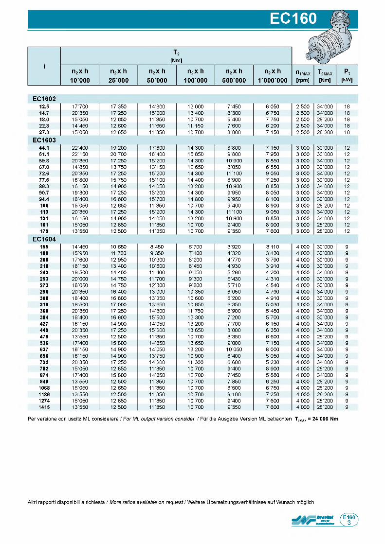
E C 1 6 0 212.5 1 7 7 0 0 1 7 ■ 3 5 0 1 4 ■ 8 0 0 1 2 ■ 0 0 0 7 ■ 4 5 0 6 ■ 0 5 0 2 ■ 5 0 0 3 4 ■ 0 0 0 1 8
14.7 2 0 3 5 0 1 7 ■ 2 5 0 1 5 ■ 2 0 0 1 3 ■ 4 0 0 8 ■ 3 0 0 6 ■ 7 5 0 2 ■ 5 0 0 3 4 ■ 0 0 0 1 8
18.0 1 5 0 5 0 1 2 ■ 6 5 0 1 1 3 5 0 1 0 ■ 7 0 0 9 ■ 4 0 0 7 ■ 7 5 0 2 ■ 5 0 0 2 8 ■ 2 0 0 1 8
22.3 1 4 4 5 0 1 2 ■ 6 0 0 1 1 6 5 0 1 1 1 5 0 7 ■ 6 0 0 6 ■ 2 0 0 2 ■ 5 0 0 3 4 ■ 0 0 0 1 8
27.3 1 5 0 5 0 1 2 ■ 6 5 0 1 1 3 5 0 1 0 ■ 7 0 0 8 ■ 8 0 0 7 ■ 1 5 0 2 ■ 5 0 0 2 8 ■ 2 0 0 1 8
E C 1 6 0 344.1 2 2 4 0 0 1 9 ■ 2 0 0 1 7 ■ 6 0 0 1 4 ■ 3 0 0 8 ■ 8 0 0 7 ■ 1 5 0 3 ■ 0 0 0 3 0 ■ 0 0 0 1 2
51.1 2 2 1 5 0 2 0 ■ 7 0 0 1 8 ■ 4 0 0 1 5 ■ 8 5 0 9 ■ 8 0 0 7 ■ 9 5 0 3 ■ 0 0 0 3 0 ■ 0 0 0 1 2
59.8 2 0 3 5 0 1 7 ■ 2 5 0 1 5 ■ 2 0 0 1 4 ■ 3 0 0 1 0 ■ 9 0 0 8 ■ 8 5 0 3 ■ 0 0 0 3 4 ■ 0 0 0 1 2
67.0 1 4 8 5 0 1 3 ■ 7 5 0 1 3 ■ 1 5 0 1 2 ■ 6 5 0 8 ■ 0 5 0 6 ■ 5 5 0 3 ■ 0 0 0 3 0 ■ 0 0 0 1 2
72.6 2 0 3 5 0 1 7 ■ 2 5 0 1 5 ■ 2 0 0 1 4 ■ 3 0 0 1 1 1 0 0 9 ■ 0 5 0 3 ■ 0 0 0 3 4 ■ 0 0 0 1 2
77.6 1 6 8 0 0 1 5 ■ 7 5 0 1 5 ■ 1 0 0 1 4 ■ 4 0 0 8 ■ 9 0 0 7 ■ 2 5 0 3 ■ 0 0 0 3 0 ■ 0 0 0 1 2
86.3 1 6 ■ 1 5 0 1 4 ■ 9 0 0 1 4 ■ 0 5 0 1 3 ■ 2 0 0 1 0 ■ 9 0 0 8 ■ 8 5 0 3 ■ 0 0 0 3 4 ■ 0 0 0 1 2
90.7 1 9 ■ 3 0 0 1 7 ■ 2 5 0 1 5 ■ 2 0 0 1 4 ■ 3 0 0 9 ■ 9 5 0 8 ■ 0 5 0 3 ■ 0 0 0 3 4 ■ 0 0 0 1 2
94.4 1 8 ■ 4 0 0 1 6 ■ 6 0 0 1 5 ■ 7 0 0 1 4 ■ 8 0 0 9 ■ 9 5 0 8 ■ 1 0 0 3 ■ 0 0 0 3 0 ■ 0 0 0 1 2
106 1 5 ■ 0 5 0 1 2 ■ 6 5 0 1 1 3 5 0 1 0 ■ 7 0 0 9 ■ 4 0 0 8 ■ 9 0 0 3 ■ 0 0 0 2 8 ■ 2 0 0 1 2
110 2 0 ■ 3 5 0 1 7 ■ 2 5 0 1 5 ■ 2 0 0 1 4 ■ 3 0 0 1 1 1 0 0 9 ■ 0 5 0 3 ■ 0 0 0 3 4 ■ 0 0 0 1 2
131 1 6 ■ 1 5 0 1 4 ■ 9 0 0 1 4 ■ 0 5 0 1 3 ■ 2 0 0 1 0 ■ 9 0 0 8 ■ 8 5 0 3 ■ 0 0 0 3 4 ■ 0 0 0 1 2
161 1 5 ■ 0 5 0 1 2 ■ 6 5 0 1 1 3 5 0 1 0 ■ 7 0 0 9 ■ 4 0 0 8 ■ 9 0 0 3 ■ 0 0 0 2 8 ■ 2 0 0 1 2
179 1 3 ■ 5 5 0 1 2 ■ 5 0 0 1 1 3 5 0 1 0 ■ 7 0 0 9 ■ 3 5 0 7 ■ 6 0 0 3 ■ 0 0 0 2 8 ■ 2 0 0 1 2
E C 1 6 0 4155 1 4 ■ 4 5 0 1 0 ■ 6 5 0 8 ■ 4 5 0 6 ■ 7 0 0 3 ■ 9 2 0 3 ■ 1 1 0 4 ■ 0 0 0 3 0 ■ 0 0 0 9
180 1 5 ■ 9 5 0 1 1 7 5 0 9 ■ 3 5 0 7 ■ 4 0 0 4 ■ 3 2 0 3 ■ 4 3 0 4 ■ 0 0 0 3 0 ■ 0 0 0 9
208 1 7 ■ 6 0 0 1 2 ■ 9 5 0 1 0 ■ 3 0 0 8 ■ 2 0 0 4 ■ 7 7 0 3 ■ 7 9 0 4 ■ 0 0 0 3 0 ■ 0 0 0 9
218 1 8 ■ 1 5 0 1 3 ■ 4 0 0 1 0 ■ 6 0 0 8 ■ 4 5 0 4 ■ 9 3 0 3 ■ 9 1 0 4 ■ 0 0 0 3 0 ■ 0 0 0 9
243 1 9 ■ 5 0 0 1 4 ■ 4 0 0 1 1 4 0 0 9 ■ 0 5 0 5 ■ 2 9 0 4 ■ 2 0 0 4 ■ 0 0 0 3 4 ■ 0 0 0 9
253 2 0 ■ 0 0 0 1 4 ■ 7 5 0 1 1 7 0 0 9 ■ 3 0 0 5 ■ 4 3 0 4 ■ 3 1 0 4 ■ 0 0 0 3 0 ■ 0 0 0 9
273 1 6 ■ 0 5 0 1 4 ■ 7 5 0 1 2 ■ 3 0 0 9 ■ 8 0 0 5 ■ 7 1 0 4 ■ 5 4 0 4 ■ 0 0 0 3 0 ■ 0 0 0 9
296 2 0 ■ 3 5 0 1 6 ■ 4 0 0 1 3 ■ 0 0 0 1 0 ■ 3 5 0 6 ■ 0 5 0 4 ■ 7 9 0 4 ■ 0 0 0 3 4 ■ 0 0 0 9
308 1 8 ■ 4 0 0 1 6 ■ 6 0 0 1 3 ■ 3 5 0 1 0 ■ 6 0 0 6 ■ 2 0 0 4 ■ 9 1 0 4 ■ 0 0 0 3 0 ■ 0 0 0 9
319 1 8 ■ 5 0 0 1 7 ■ 0 0 0 1 3 ■ 6 5 0 1 0 ■ 8 5 0 6 ■ 3 5 0 5 ■ 0 3 0 4 ■ 0 0 0 3 4 ■ 0 0 0 9
360 2 0 ■ 3 5 0 1 7 ■ 2 5 0 1 4 ■ 8 0 0 1 1 7 5 0 6 ■ 9 0 0 5 ■ 4 5 0 4 ■ 0 0 0 3 4 ■ 0 0 0 9
384 1 8 ■ 4 0 0 1 6 ■ 6 0 0 1 5 ■ 5 0 0 1 2 ■ 3 0 0 7 ■ 2 0 0 5 ■ 7 0 0 4 ■ 0 0 0 3 0 ■ 0 0 0 9
427 1 6 ■ 1 5 0 1 4 ■ 9 0 0 1 4 ■ 0 5 0 1 3 ■ 2 0 0 7 ■ 7 0 0 6 ■ 1 5 0 4 ■ 0 0 0 3 4 ■ 0 0 0 9
449 2 0 ■ 3 5 0 1 7 ■ 2 5 0 1 5 ■ 2 0 0 1 3 ■ 6 5 0 8 ■ 0 0 0 6 ■ 3 5 0 4 ■ 0 0 0 3 4 ■ 0 0 0 9
479 1 3 ■ 5 5 0 1 2 ■ 5 0 0 1 1 3 5 0 1 0 ■ 7 0 0 8 ■ 3 5 0 6 ■ 6 0 0 4 ■ 0 0 0 2 8 ■ 2 0 0 9
536 1 7 ■ 4 0 0 1 5 ■ 8 0 0 1 4 ■ 6 5 0 1 3 ■ 6 5 0 9 ■ 0 0 0 7 ■ 1 5 0 4 ■ 0 0 0 3 4 ■ 0 0 0 9
637 1 6 ■ 1 5 0 1 4 ■ 9 0 0 1 4 ■ 0 5 0 1 3 ■ 2 0 0 1 0 ■ 0 5 0 8 ■ 0 0 0 4 ■ 0 0 0 3 4 ■ 0 0 0 9
696 1 6 ■ 1 5 0 1 4 ■ 9 0 0 1 3 ■ 7 5 0 1 0 ■ 9 0 0 6 ■ 4 0 0 5 ■ 0 5 0 4 ■ 0 0 0 3 4 ■ 0 0 0 9
732 2 0 ■ 3 5 0 1 7 ■ 2 5 0 1 4 ■ 2 0 0 1 1 3 0 0 6 ■ 6 0 0 5 ■ 2 3 0 4 ■ 0 0 0 3 4 ■ 0 0 0 9
782 1 5 ■ 0 5 0 1 2 ■ 6 5 0 1 1 3 5 0 1 0 ■ 7 0 0 9 ■ 4 0 0 8 ■ 9 0 0 4 ■ 0 0 0 2 8 ■ 2 0 0 9
874 1 7 ■ 4 0 0 1 5 ■ 8 0 0 1 4 ■ 6 5 0 1 2 ■ 7 0 0 7 ■ 4 5 0 5 ■ 8 8 0 4 ■ 0 0 0 3 4 ■ 0 0 0 9
949 1 3 ■ 5 5 0 1 2 ■ 5 0 0 1 1 3 5 0 1 0 ■ 7 0 0 7 ■ 8 5 0 6 ■ 2 5 0 4 ■ 0 0 0 2 8 ■ 2 0 0 9
1068 1 5 ■ 0 5 0 1 2 ■ 6 5 0 1 1 3 5 0 1 0 ■ 7 0 0 8 ■ 5 0 0 6 ■ 7 5 0 4 ■ 0 0 0 2 8 ■ 2 0 0 9
1186 1 3 ■ 5 5 0 1 2 ■ 5 0 0 1 1 3 5 0 1 0 ■ 7 0 0 9 ■ 1 0 0 7 ■ 2 5 0 4 ■ 0 0 0 2 8 ■ 2 0 0 9
1274 1 5 ■ 0 5 0 1 2 ■ 6 5 0 1 1 3 5 0 1 0 ■ 7 0 0 9 ■ 4 0 0 7 ■ 6 0 0 4 ■ 0 0 0 2 8 ■ 2 0 0 9
1415 1 3 ■ 5 5 0 1 2 ■ 5 0 0 1 1 3 5 0 1 0 ■ 7 0 0 9 ■ 3 5 0 7 ■ 6 0 0 4 ■ 0 0 0 2 8 ■ 2 0 0 9
P e r v e r s i o n e c o n u s c i t a M L c o n s i d e r a r e / For ML output version consider / F u r d i e A u s g a b e V e r s i o n M L b e t r a c h t e n T2MAX = 24'000 Nm
Altri r a p p o r t i d i s p o n i b i l i a r i c h i e s t a / More ratios available on request / W e i t e r e U b e r s e t z u n g s v e r h a l t n i s s e a u f W u n s c h m o g l i c h
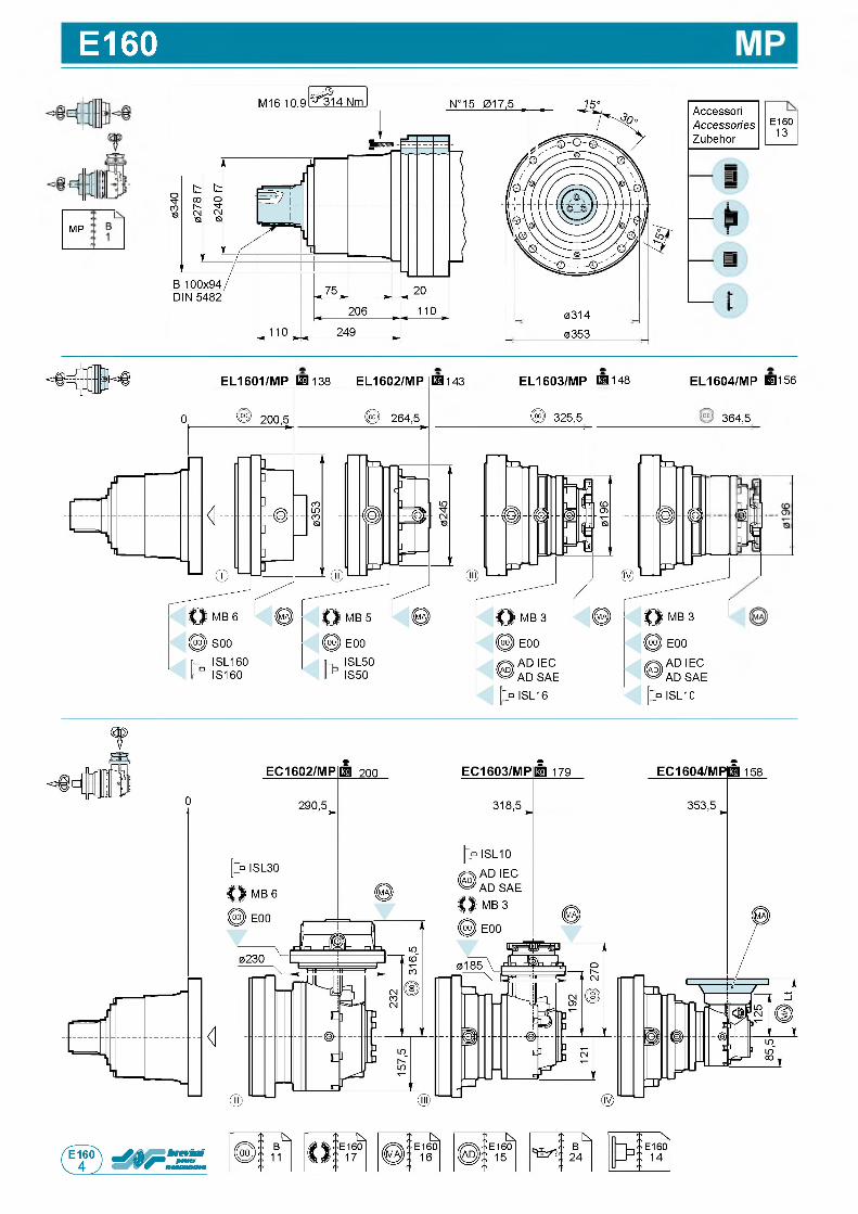
E160
M P
AccessoriAccessoriesZubehor
E 1 6 01 3
I I
0 3 1 4
0 3 5 3
EL1603/MP r a 1 4 8
© 3 2 5 , 5
EL1601/MP E l 1 3 8 EL1602/MP E l 1 4 3 EL1604/MP Eg 1 5 6
3 6 4 , 5
1
AD SAE
ISL10
t
П
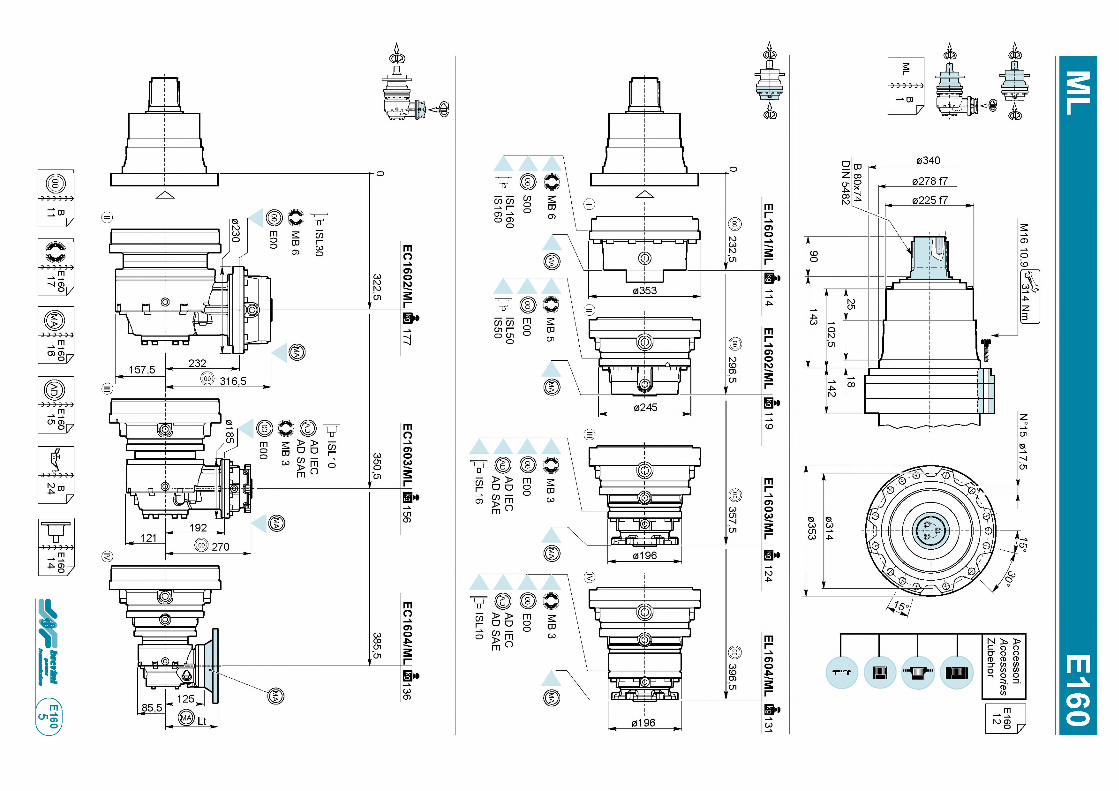
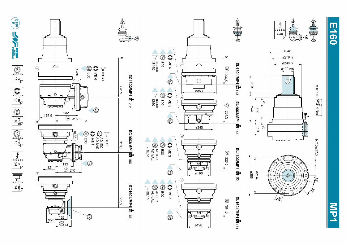
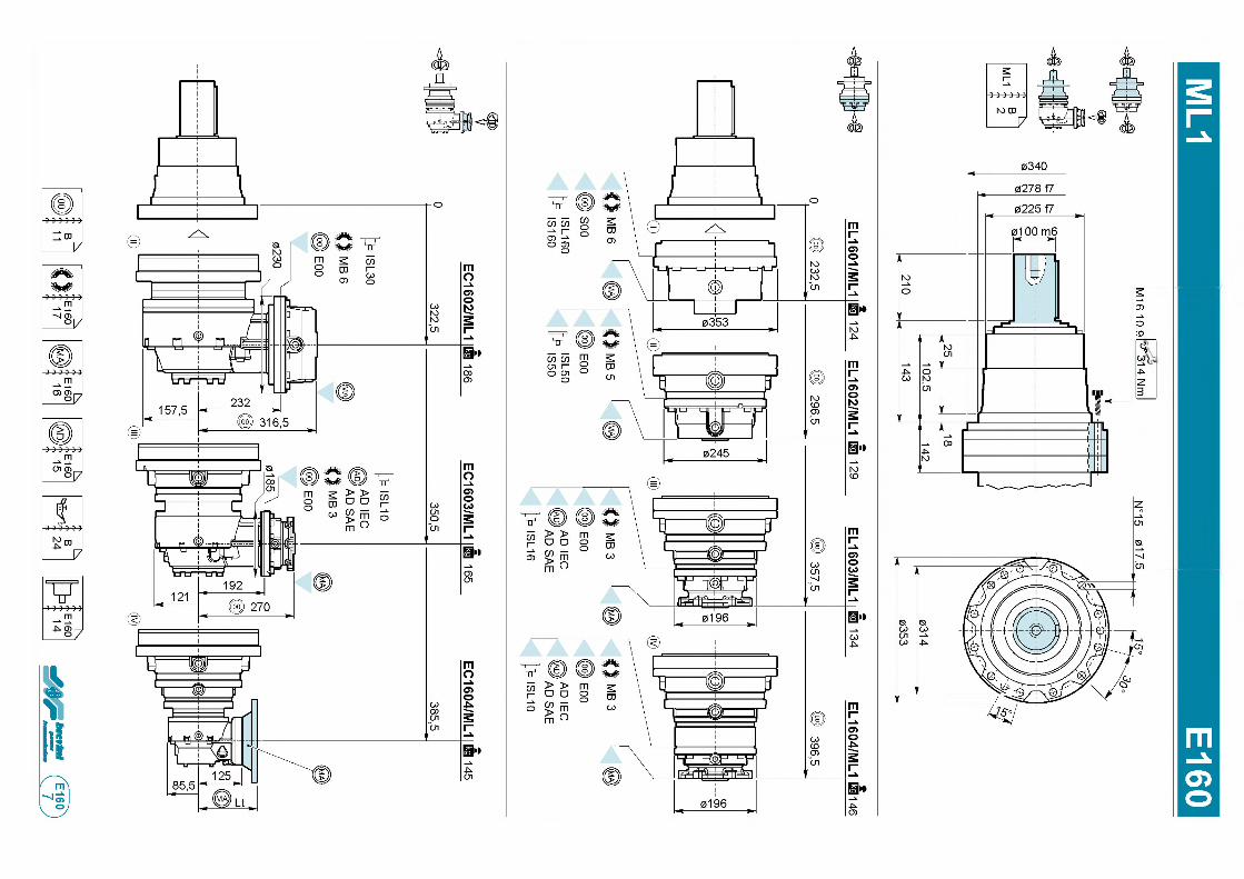
М16 10.91=^314 Nm
l №
15 017.5
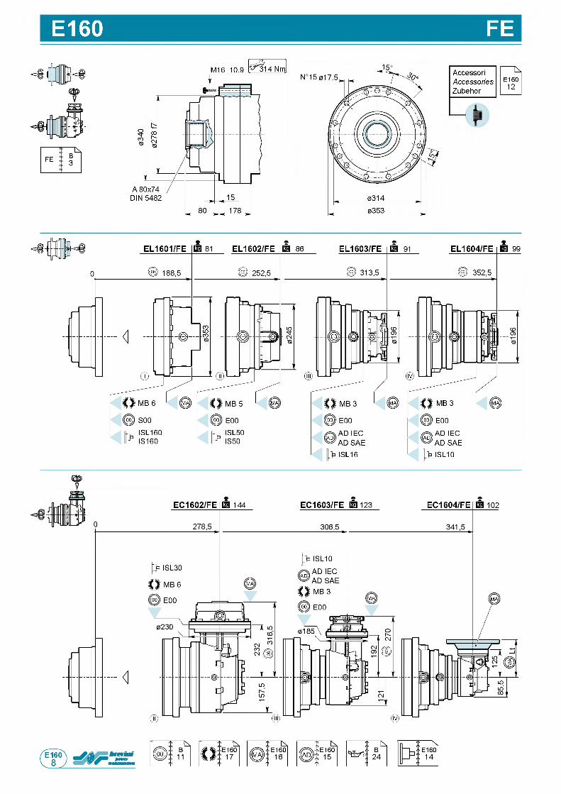
E160 FE
: N
F EB3
A c c e s s o r i
AccessoriesZ u b e h o r
f
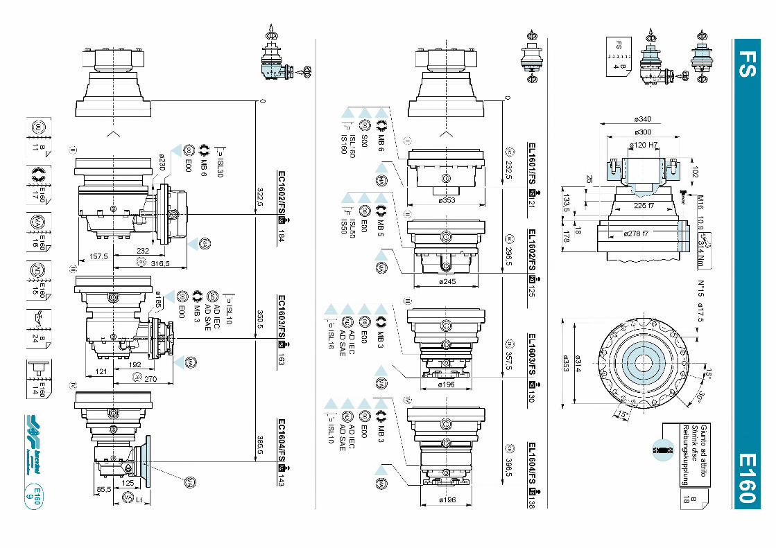
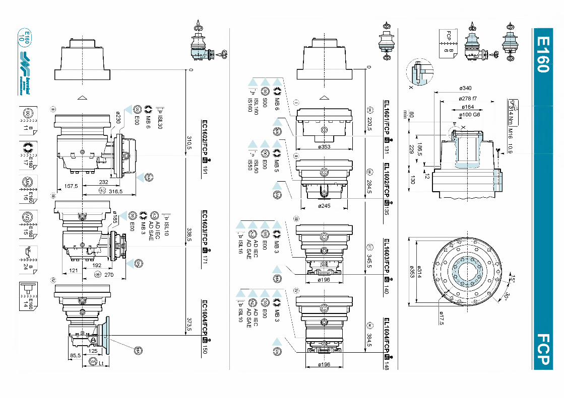
mО)
314 Nm I M
16 10.9
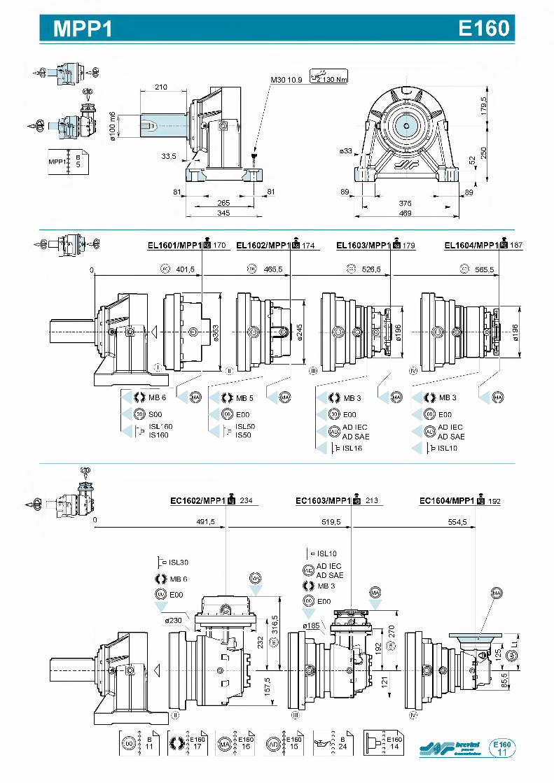
E160
M P P 1B5
Ьо о .
2 1 0
3 3 , 5
81
п
W ______m
- 2 6 5 _
3 4 5
81
f
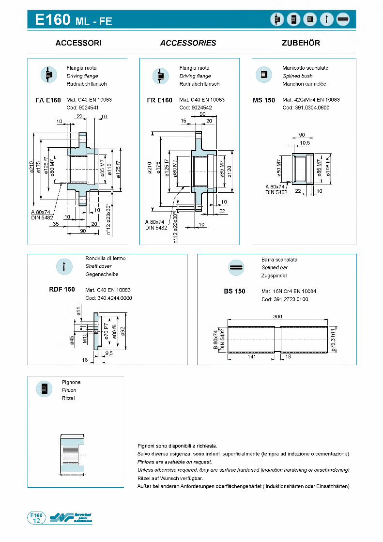
E160 ML - FE
ACCESSORI A C C E S S O R IE S ZUBEHOR
F l a n g i a r u o t a
Driving flange R a d n a b e h f l a n s c h
F l a n g i a r u o t a
Driving flange R a d n a b e h f l a n s c h
M a n i c o t t o s c a n a l a t o
Splined bush M a n c h o n c a n n e l e e
F A E 1 6 0 M a t . C 4 0 E N 1 0 0 8 3 F R E 1 6 0 M a t . C 4 0 E N 1 0 0 8 3 M S 1 5 0 M a t . 4 2 C r M o 4 E N 1 0 0 8 3
C o d : 9 0 2 4 5 4 1 C o d : 9 0 2 4 5 4 2 C o d : 3 9 1 . 0 3 0 4 . 0 6 0 0
9 0
i 1 0 , 5
Is-
ОCOQ
Is-с о "szCOо
QЮ<a
A 8 0 x 7 4 D IN 5 4 8 2 2 2 , 1 0
R o n d e l l a d i f e r m o
Shaft cover G e g e n s c h e i b e
R D F 1 5 0 M a t . C 4 0 E N 1 0 0 8 3
C o d : 3 4 0 . 4 2 4 4 . 0 0 0 0
1 8
B a r r a s c a n a l a t a
Splined bar Z u g s p i n d e l
B S 15 0 M a t . 1 6 N i C r 4 E N 1 0 0 8 4
C o d : 3 9 1 . 2 7 2 3 . 0 1 0 0
3 0 0
n CMCO
-C- CO
O ) Is-
и
i f Q
1 4 1 , . 1 8
P ig n o n i s o n o d i s p o n ib i l i a r i c h i e s t a .
S a l v o d i v e r s a e s i g e n z a , s o n o in d u riti s u p e r f i c i a l m e n t e ( t e m p r a a d in d u z io n e o c e m e n t a z i o n e )
Pinions are available on request.Unless otherwise required, they are surface hardened (induction hardening or casehardening) R it z e l a u f W u n s c h v e r f u g b a r .
A u U e r b e i a n d e r e n A n f o r d e r u n g e n o b e r f l a c h e n g e h a r t e t ( I n d u k t i o n s h a r t e n o d e r E i n s a t z h a r t e n )
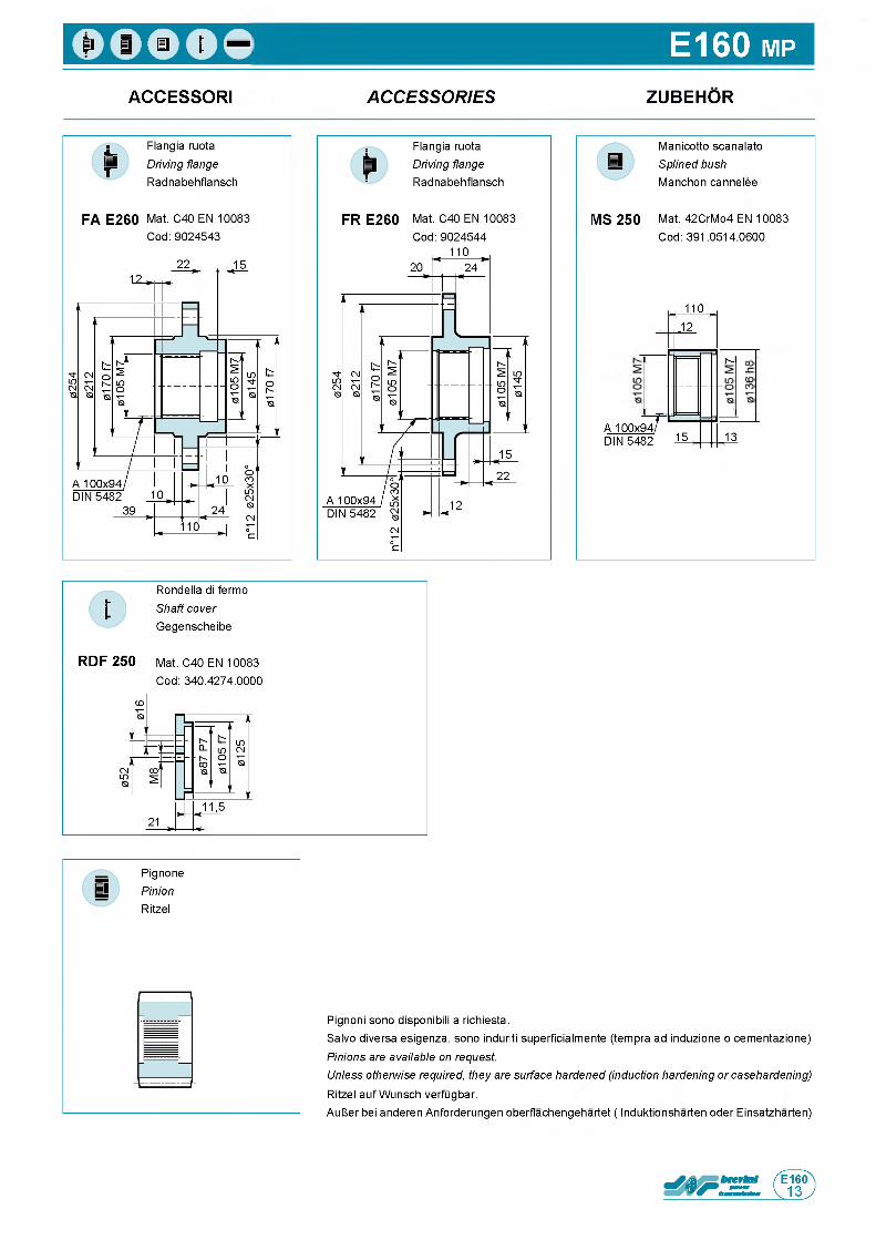
E160 m p
ACCESSORI A C C E S S O R IE S ZUBEHOR
M a n i c o t t o s c a n a l a t o
Splined bush M a n c h o n c a n n e l e e
M S 2 5 0 M a t . 4 2 C r M o 4 E N 1 0 0 8 3
C o d : 3 9 1 . 0 5 1 4 . 0 6 0 0
A 1 0 0 x 9 4 .D IN 5 4 8 2 l 5
T
1 1 0
.1 2
м
1 3
R o n d e l l a d i f e r m o
Shaft cover G e g e n s c h e i b e
R D F 2 5 0 M a t . C 4 0 E N 1 0 0 8 3
C o d : 3 4 0 . 4 2 7 4 . 0 0 0 0
P ig n o n i s o n o d i s p o n ib i l i a r i c h i e s t a .
S a l v o d i v e r s a e s i g e n z a , s o n o in d u riti s u p e r f i c i a l m e n t e ( t e m p r a a d in d u z io n e o c e m e n t a z i o n e )
Pinions are available on request.Unless otherwise required, they are surface hardened (induction hardening or casehardening) R it z e l a u f W u n s c h v e r f u g b a r .
A u l J e r b e i a n d e r e n A n f o r d e r u n g e n o b e r f l a c h e n g e h a r t e t ( I n d u k t i o n s h a r t e n o d e r E i n s a t z h a r t e n )
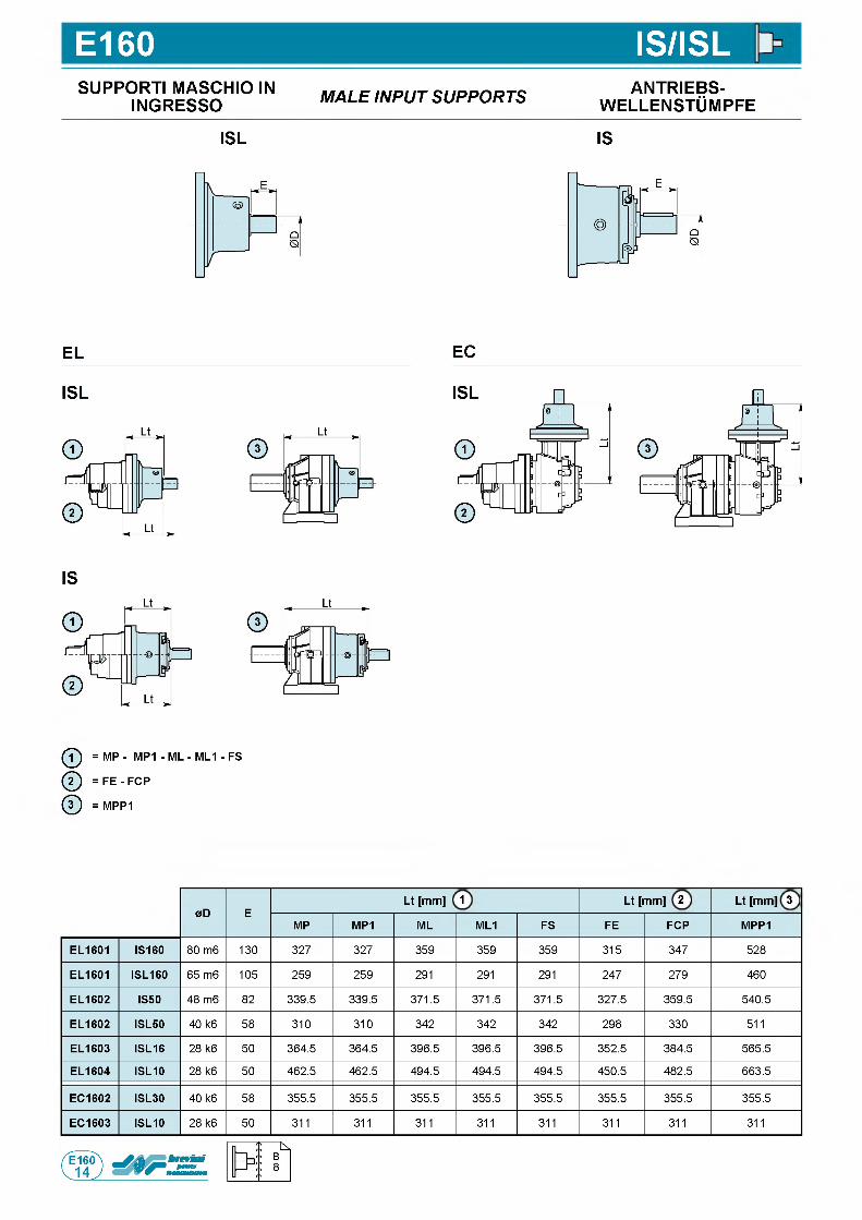
E160 IS/ISLSUPPORTI MASCHIO IN
INGRESSO M A L E IN P U T S U P P O R T S ANTRIEBS-w e l l e n s t Om p f e
ISL IS
EL
ISL
EC
IS
ф = MP - MP1 - ML - ML1 - FS
ф = F E - FCP
@ = MPP1
0D ELt [mm] 1 Lt [mm] 2 Lt [mm] 3
MP MP1 ML ML1 FS FE FCP MPP1
EL1601 IS160 80 m6 130 327 327 359 359 359 315 347 528
EL1601 ISL160 65 m6 105 259 259 291 291 291 247 279 460
EL1602 IS50 48 m6 82 339.5 339.5 371.5 371.5 371.5 327.5 359.5 540.5
EL1602 ISL50 40 k6 58 310 310 342 342 342 298 330 511
EL1603 ISL16 28 k6 50 364.5 364.5 396.5 396.5 396.5 352.5 384.5 565.5
EL1604 ISL10 28 k6 50 462.5 462.5 494.5 494.5 494.5 450.5 482.5 663.5
EC1602 ISL30 40 k6 58 355.5 355.5 355.5 355.5 355.5 355.5 355.5 355.5
EC1603 ISL10 28 k6 50 311 311 311 311 311 311 311 311
П
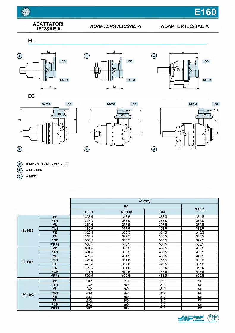
© E160ADATTATORI
IEC/SAE A A D A P T E R S IE C /S A E A ADAPTER IEC/SAE A
EL
IEC
S A E A
EC
IEC
S A E A
IEC
S A E A
S A E A IEC S A E A IEC S A E A IEC
ф = MP - MP1 - ML - ML1 - FS
ф = FE - FCP
ф = MPP1
Lt [mm]
IECSAE A
80-90 100-112 132
EL1603
MP 3 3 7 . 5 3 4 5 . 5 3 6 6 . 5 3 5 4 . 5
MP1 3 3 7 . 5 3 4 5 . 5 3 6 6 . 5 3 5 4 . 5
ML 3 6 9 . 5 3 7 7 . 5 3 9 8 . 5 3 8 6 . 5
ML1 3 6 9 . 5 3 7 7 . 5 3 9 8 . 5 3 8 6 . 5
FE 3 2 5 . 5 3 3 3 . 5 3 5 4 . 5 3 4 2 . 5
FS 3 6 9 . 5 3 7 7 . 5 3 9 8 . 5 3 8 6 . 5
FCP 3 5 7 . 5 3 6 5 . 5 3 8 6 . 5 3 7 4 . 5
MPP1 5 3 8 . 5 5 4 8 . 5 5 6 7 . 5 5 5 5 . 5
EL1604
MP 3 9 1 . 5 3 9 9 . 5 4 3 5 . 5 4 0 8 . 5
MP1 3 9 1 . 5 3 9 9 . 5 4 3 5 . 5 4 0 8 . 5
ML 4 2 3 . 5 4 3 1 . 5 4 6 7 . 5 4 4 0 . 5
ML1 4 2 3 . 5 4 3 1 . 5 4 6 7 . 5 4 4 0 . 5
FE 3 7 9 . 5 3 8 7 . 5 4 2 3 . 5 3 9 6 . 5
FS 4 2 3 . 5 4 3 1 . 5 4 6 7 . 5 4 4 0 . 5
FCP 4 1 1 . 5 4 1 9 . 5 4 5 5 . 5 4 2 8 . 5
MPP1 5 9 2 . 5 6 0 0 . 5 6 3 6 . 5 6 0 9 . 5
EC1603
MP 2 8 2 2 9 0 3 1 3 3 0 1
MP1 2 8 2 2 9 0 3 1 3 3 0 1
ML 2 8 2 2 9 0 3 1 3 3 0 1
ML1 2 8 2 2 9 0 3 1 3 3 0 1
FE 2 8 2 2 9 0 3 1 3 3 0 1
FS 2 8 2 2 9 0 3 1 3 3 0 1
FCP 2 8 2 2 9 0 3 1 3 3 0 1
MPP1 2 8 2 2 9 0 3 1 3 3 0 1
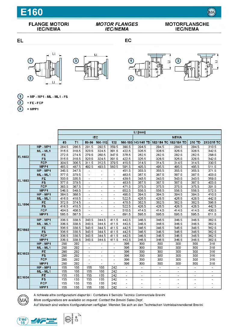
E160 ©FLANGE MOTORI
IEC/NEMAM O T O R F L A N G E S
IE C /N E M AMOTORFLANSCHE
IEC/NEMA
EL EC
G1=1
©/ г
© = MP - MP1 - ML - ML1 - FS
@ = FE - FCP
@ = MPP1
Lt [mm]IEC NEMA
63 71 80-90 100-112 132 160-180 143/145 TD 182/184 TC 182/184 TD 210 TD 213/215 TC
EL1602
MP - MP1 2 8 4 . 5 2 8 6 . 5 2 9 1 . 5 2 9 2 . 5 3 5 9 . 5 3 9 0 . 5 2 9 4 . 5 2 9 4 . 5 2 9 4 . 5 2 9 4 . 5 3 1 0 . 5
ML - ML1 3 1 6 . 5 3 1 8 . 5 3 2 3 . 5 3 2 4 . 5 3 9 1 . 5 4 2 2 . 5 3 2 6 . 5 3 2 6 . 5 3 2 6 . 5 3 2 6 . 5 3 4 2 . 5
FE 2 7 2 . 5 2 7 4 . 5 2 7 9 . 5 2 8 0 . 5 3 4 7 . 5 3 7 8 . 5 2 8 2 . 5 2 8 2 . 5 2 8 2 . 5 2 8 2 . 5 2 9 8 . 5
FS 3 1 6 . 5 3 1 8 . 5 3 2 3 . 5 3 2 4 . 5 3 9 1 . 5 4 2 2 . 5 3 2 6 . 5 3 2 6 . 5 3 2 6 . 5 3 2 6 . 5 3 4 2 . 5
FCP 3 0 4 . 5 3 0 6 . 5 3 1 1 . 5 3 1 2 . 5 3 7 9 . 5 4 1 0 . 5 3 1 4 . 5 3 1 4 . 5 3 1 4 . 5 3 1 4 . 5 3 3 0 . 5
MPP1 4 8 5 . 5 4 8 7 . 5 4 9 2 . 5 4 9 3 . 5 5 6 0 . 5 5 9 1 . 5 4 9 5 . 5 4 9 5 . 5 4 9 5 . 5 4 9 5 . 5 5 1 1 . 5
EL1603
MP - MP1 3 4 5 . 5 3 4 7 . 5 - - - 4 5 1 . 5 3 5 5 . 5 3 5 5 . 5 3 5 5 . 5 3 5 5 . 5 3 7 1 . 5
ML - ML1 3 7 7 . 5 3 7 9 . 5 - - - 4 8 3 . 5 3 8 7 . 5 3 8 7 . 5 3 8 7 . 5 3 8 7 . 5 4 0 3 . 5
FE 3 3 3 . 5 3 3 5 . 5 - - - 4 3 9 . 5 3 4 3 . 5 3 4 3 . 5 3 4 3 . 5 3 4 3 . 5 3 5 9 . 5
FS 3 7 7 . 5 3 7 9 . 5 - - - 4 8 3 . 5 3 8 7 . 5 3 8 7 . 5 3 8 7 . 5 3 8 7 . 5 4 0 3 . 5
FCP 3 6 5 . 5 3 6 7 . 5 - - - 4 7 1 . 5 3 7 5 . 5 3 7 5 . 5 3 7 5 . 5 3 7 5 . 5 3 9 1 . 5
MPP1 5 4 6 . 5 5 4 8 . 5 - - - 6 5 2 . 5 5 5 6 . 5 5 5 6 . 5 5 5 6 . 5 5 5 6 . 5 5 7 2 . 5
EL1604
MP - MP1 3 8 4 . 5 3 8 6 . 5 - - - 4 9 0 . 5 3 9 4 . 5 3 9 4 . 5 3 9 4 . 5 3 9 4 . 5 4 1 0 . 5
ML - ML1 4 1 6 . 5 4 1 8 . 5 - - - 5 2 2 . 5 4 2 6 . 5 4 2 6 . 5 4 2 6 . 5 4 2 6 . 5 4 4 2 . 5
FE 3 7 2 . 5 3 7 4 . 5 - - - 4 7 8 . 5 3 8 2 . 5 3 8 2 . 5 3 8 2 . 5 3 8 2 . 5 3 9 8 . 5
FS 4 1 6 . 5 4 1 8 . 5 - - - 5 2 2 . 5 4 2 6 . 5 4 2 6 . 5 4 2 6 . 5 4 2 6 . 5 4 4 2 . 5
FCP 4 0 4 . 5 4 0 6 . 5 - - - 5 1 0 . 5 4 1 4 . 5 4 1 4 . 5 4 1 4 . 5 4 1 4 . 5 4 3 0 . 5
MPP1 5 8 5 . 5 5 8 7 . 5 - - - 6 9 1 . 5 5 9 5 . 5 5 9 5 . 5 5 9 5 . 5 5 9 5 . 5 6 1 1 . 5
EC1602
MP - MP1 3 3 6 . 5 3 3 8 . 5 3 4 3 . 5 3 4 4 . 5 4 1 1 . 5 4 4 2 . 5 3 4 6 . 5 3 4 6 . 5 3 4 6 . 5 3 4 6 . 5 3 6 2 . 5
ML - ML1 3 3 6 . 5 3 3 8 . 5 3 4 3 . 5 3 4 4 . 5 4 1 1 . 5 4 4 2 . 5 3 4 6 . 5 3 4 6 . 5 3 4 6 . 5 3 4 6 . 5 3 6 2 . 5
FE 3 3 6 . 5 3 3 8 . 5 3 4 3 . 5 3 4 4 . 5 4 1 1 . 5 4 4 2 . 5 3 4 6 . 5 3 4 6 . 5 3 4 6 . 5 3 4 6 . 5 3 6 2 . 5
FS 3 3 6 . 5 3 3 8 . 5 3 4 3 . 5 3 4 4 . 5 4 1 1 . 5 4 4 2 . 5 3 4 6 . 5 3 4 6 . 5 3 4 6 . 5 3 4 6 . 5 3 6 2 . 5
FCP 3 3 6 . 5 3 3 8 . 5 3 4 3 . 5 3 4 4 . 5 4 1 1 . 5 4 4 2 . 5 3 4 6 . 5 3 4 6 . 5 3 4 6 . 5 3 4 6 . 5 3 6 2 . 5
MPP1 3 3 6 . 5 3 3 8 . 5 3 4 3 . 5 3 4 4 . 5 4 1 1 . 5 4 4 2 . 5 3 4 6 . 5 3 4 6 . 5 3 4 6 . 5 3 4 6 . 5 3 6 2 . 5
EC1603
MP - MP1 2 9 0 2 9 2 - - - 3 9 6 3 0 0 3 0 0 3 0 0 3 0 0 3 1 6
ML - ML1 2 9 0 2 9 2 - - - 3 9 6 3 0 0 3 0 0 3 0 0 3 0 0 3 1 6
FE 2 9 0 2 9 2 - - - 3 9 6 3 0 0 3 0 0 3 0 0 3 0 0 3 1 6
FS 2 9 0 2 9 2 - - - 3 9 6 3 0 0 3 0 0 3 0 0 3 0 0 3 1 6
FCP 2 9 0 2 9 2 - - - 3 9 6 3 0 0 3 0 0 3 0 0 3 0 0 3 1 6
MPP1 2 9 0 2 9 2 - - - 3 9 6 3 0 0 3 0 0 3 0 0 3 0 0 3 1 6
EC1604
MP - MP1 1 5 5 1 5 5 1 5 5 1 5 5 2 4 2 - - - - - -
ML - ML1 1 5 5 1 5 5 1 5 5 1 5 5 2 4 2 - - - - - -
FE 1 5 5 1 5 5 1 5 5 1 5 5 2 4 2 - - - - - -
FS 1 5 5 1 5 5 1 5 5 1 5 5 2 4 2 - - - - - -
FCP 1 5 5 1 5 5 1 5 5 1 5 5 2 4 2 - - - - - -
MPP1 1 5 5 1 5 5 1 5 5 1 5 5 2 4 2 - - - - - -
A r i c h i e s t a a l t r e c o n f i g u r a z i o n i d is p o n ib i l i . C o n t a t t a r e il S e r v i z i o T e c n i c o C o m m e r c i a l e B r e v in i
More configurations are available on request. Contact the Brevini Sales Dept.A u f W u n s c h s i n d w e i t e r e K o n f i g u r a t io n e n v e r f u g b a r . W e n d e n S i e s i c h a n d e n T e c h n i s c h e n V e r t r i e b s i n n e n d i e n s t B r e v in i
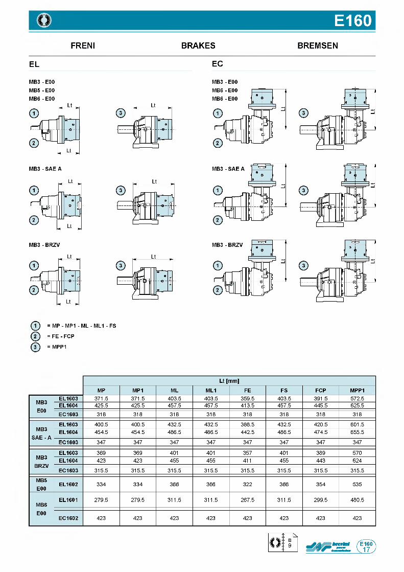
E160FRENI BRAKES BREMSEN
EL EC
M B 3- E00
M B 5- E00MB6 - E00
MB3 - E00
ф = MP - MP1 - ML - ML1 - FS
ф = F E - FCP
ф = MPP1
Lt [mm]
MP MP1 ML ML1 FE FS FCP MPP1
MB3E00
EL1603 3 7 1 . 5 3 7 1 . 5 4 0 3 . 5 4 0 3 . 5 3 5 9 . 5 4 0 3 . 5 3 9 1 . 5 5 7 2 . 5
EL1604 4 2 5 . 5 4 2 5 . 5 4 5 7 . 5 4 5 7 . 5 4 1 3 . 5 4 5 7 . 5 4 4 5 . 5 6 2 5 . 5
EC1603 3 1 8 3 1 8 3 1 8 3 1 8 3 1 8 3 1 8 3 1 8 3 1 8
MB3 SAE - A
EL1603 4 0 0 . 5 4 0 0 . 5 4 3 2 . 5 4 3 2 . 5 3 8 8 . 5 4 3 2 . 5 4 2 0 . 5 6 0 1 . 5
EL1604 4 5 4 . 5 4 5 4 . 5 4 8 6 . 5 4 8 6 . 5 4 4 2 . 5 4 8 6 . 5 4 7 4 . 5 6 5 5 . 5
EC1603 3 4 7 3 4 7 3 4 7 3 4 7 3 4 7 3 4 7 3 4 7 3 4 7
MB3BRZV
EL1603 3 6 9 3 6 9 4 0 1 4 0 1 3 5 7 4 0 1 3 8 9 5 7 0
EL1604 4 2 3 4 2 3 4 5 5 4 5 5 4 1 1 4 5 5 4 4 3 6 2 4
EC1603 3 1 5 . 5 3 1 5 . 5 3 1 5 . 5 3 1 5 . 5 3 1 5 . 5 3 1 5 . 5 3 1 5 . 5 3 1 5 . 5
MB5E00
EL1602 3 3 4 3 3 4 3 6 6 3 6 6 3 2 2 3 6 6 3 5 4 5 3 5
MB6E00
EL1601 2 7 9 . 5 2 7 9 . 5 3 1 1 . 5 3 1 1 . 5 2 6 7 . 5 3 1 1 . 5 2 9 9 . 5 4 8 0 . 5
EC1602 4 2 3 4 2 3 4 2 3 4 2 3 4 2 3 4 2 3 4 2 3 4 2 3
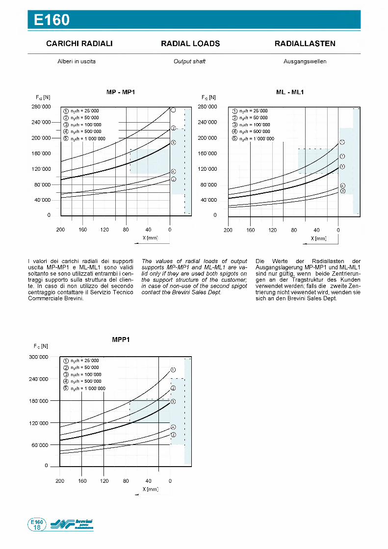
E160CARICHI RADIALI RADIAL LOADS RADIALLASTEN
A l b e r i in u s c i t a Output shaft A u s g a n g s w e l l e n
M P - M P1Fr2 [N ]
M L - M L1Fr2 [N ]
I v a l o r i d e i c a r i c h i r a d i a l i d e i s u p p o r t i
u s c i t a M P - M P 1 e M L - M L 1 s o n o v a l i d i
s o l t a n t o s e s o n o u t i l i z z a t i e n t r a m b i i c e n -
t r a g g i s u p p o r t o s u l l a s t r u t t u r a d e l c l i e n -
t e . In c a s o d i n o n u t i l i z z o d e l s e c o n d o
c e n t r a g g i o c o n t a t t a r e il S e r v i z i o T e c n i c o
C o m m e r c i a l e B r e v i n i .
The values of radial loads of output supports MP-MP1 and ML-ML1 are valid only i f they are used both spigots on the support structure of the customer; in case of non-use of the second spigot contact the Brevini Sales Dept.
D i e W e r t e d e r R a d i a l l a s t e n d e r
A u s g a n g s l a g e r u n g M P - M P 1 u n d M L - M L 1
s i n d n u r g Q l t i g , w e n n b e i d e Z e n t r i e r u n -
g e n a n d e r T r a g s t r u k t u r d e s K u n d e n
v e r w e n d e t w e r d e n ; f a l l s d i e z w e i t e Z e n -
t r i e r u n g n i c h t v e w e n d e t w i r d , w e n d e n s i e
s i c h a n d e n B r e v i n i S a l e s D e p t .
Fr2 [N ]
M P P 1
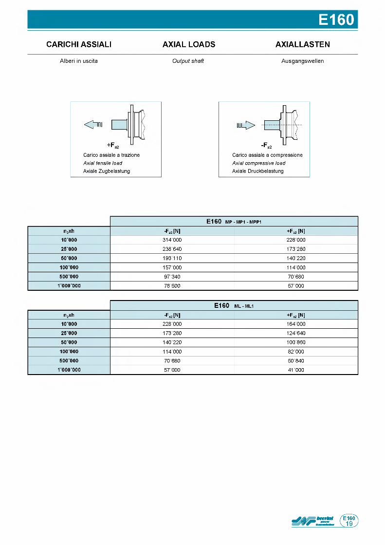
E160CARICHIASSIALI AXIAL LOADS AXIALLASTEN
A l b e r i in u s c i t a Output shaft A u s g a n g s w e l l e n
О
+ Fa
C a r i c o a s s i a l e a t r a z i o n e
Axial tensile load A x ia le Z u g b e l a s t u n g
" О
C a r i c o a s s i a l e a c o m p r e s s i o n e
Axial compressive load A x ia le D r u c k b e l a s t u n g
E 1 6 0 mp - MP1 - m pp1
n2xh -Fa2 [N] +Fa2 [N]
10000 3 1 4 0 0 0 2 2 8 0 0 0
25 000 2 3 8 6 4 0 1 7 3 2 8 0
50 000 1 9 3 1 1 0 1 4 0 2 2 0
100 000 1 5 7 0 0 0 1 1 4 0 0 0
500 000 9 7 3 4 0 7 0 6 8 0
1 000 000 7 8 5 0 0 5 7 0 0 0
E 1 6 0 ML - ML1
n2xh -Fa2 [N] + Fa2 [N]
10 000 2 2 8 0 0 0 1 6 4 0 0 0
25 000 1 7 3 2 8 0 1 2 4 6 4 0
50 000 1 4 0 2 2 0 1 0 0 8 6 0
100 000 1 1 4 0 0 0 8 2 0 0 0
500 000 7 0 6 8 0 5 0 8 4 0
1 000 000 5 7 0 0 0 4 1 0 0 0
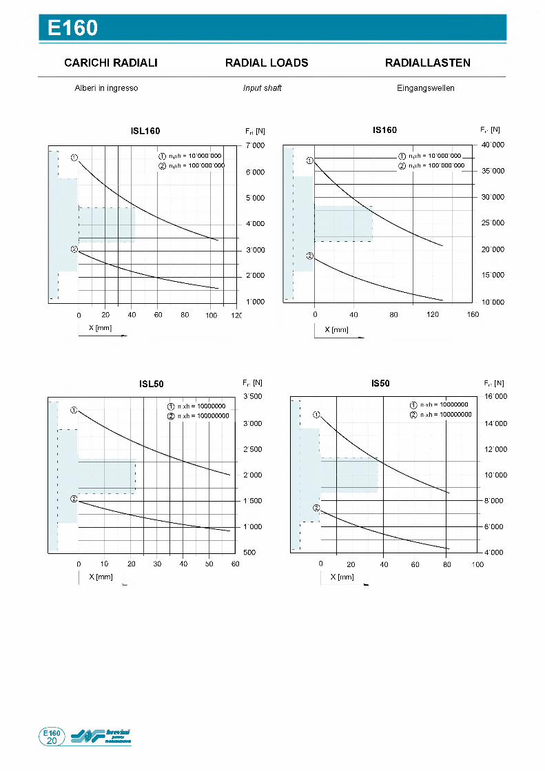
E160CARICHI RADIALI RADIAL LOADS RADIALLASTEN
A l b e r i in i n g r e s s o Input shaft E i n g a n g s w e l l e n
IS L 1 6 0 F rt [N ]
7 0 0 0
6 0 0 0
5 0 0 0
4 0 0 0
3 0 0 0
2 ' 0 0 0
1 0 0 0
IS 1 6 0 F rt [N ]
4 0 ' 0 0 0
3 5 0 0 0
3 0 0 0 0
2 5 0 0 0
2 0 0 0 0
1 5 0 0 0
1 0 0 0 0
Fri [N ]
3 ' 5 0 0
3 0 0 0
2 ' 5 0 0
2 0 0 0
1 5 0 0
1 0 0 0
5 0 0
0 1 0 2 0 3 0 4 0 5 0 6 0
X [m m ]
IS L 5 0
© nixh = 10000000 (2 n1xh = 100000000
IS 50 F r1 [N ]
1 6 ■ 0 0 0
1 4 ■ 0 0 0
1 2 ■ 0 0 0
1 0 ■ 0 0 0
8 ■ 0 0 0
6 ■ 0 0 0
4 ' 0 0 0
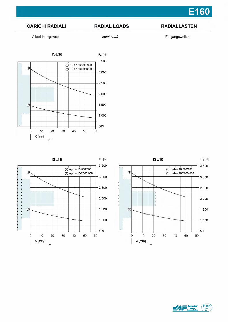
E160CARICHI RADIALI RADIAL LOADS
A l b e r i in i n g r e s s o Input shaft
IS L 3 0 F rt [N ]
3 5 0 0
3 0 0 0
2 5 0 0
2 0 0 0
1 5 0 0
1 0 0 0
5 0 0
RADIALLASTEN
E i n g a n g s w e l l e n
IS L 1 6 F rt [N ]
3 5 0 0
3 0 0 0
2 5 0 0
2 0 0 0
1 5 0 0
1 0 0 0
5 0 0
F rt [N ]
3 5 0 0
3 0 0 0
2 5 0 0
2 0 0 0
1 5 0 0
1 0 0 0
5 0 0
0 1 0 2 0 3 0 4 0 5 0 6 0
X [m m ]
IS L 1 0
а© n,xh = 10 ■ 000■ 000_ @ n,xh = 100 ■ 000 ■ 000

Questa pagina e lasciata intenzionalmente bianca
Page is in tentiona lly le ft blank Seite wurde absichtlich leer gelassen
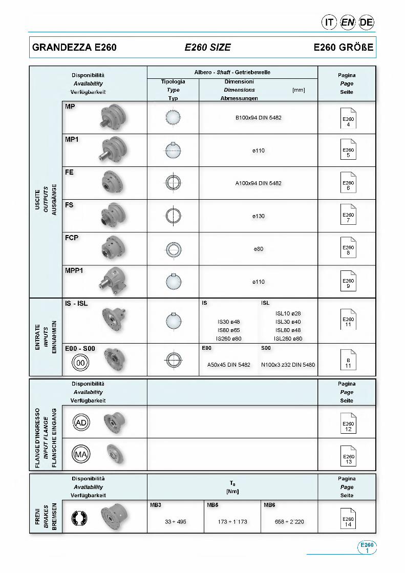
DisponibilitaAvailab ility
Albero - Shaft - Getriebewelle
TipologiaType
___ ТУР___
DimensioniDimensions
Abmessungen[m m ]
PaginaPage
Seite
B 1 0 0 x 9 4 D IN 5 4 8 2 E 2 6 04
0 1 1 0 E 2 6 05
Ш«О (П
Ш К XtO (П
A 1 0 0 x 9 4 D IN 5 4 8 2 E 2 6 06
FS
0 1 3 0 E 2 6 07
F C P
0 8 0 E 2 6 08
M P P 1
0 1 1 0 E 2 6 09
IS - IS L
' *
ш Ш5 й s
111LU LU
IS
I S 3 0 0 4 8
I S 8 0 0 6 5
I S 2 6 0 0 8 0
ISL
I S L 1 0 0 2 8
I S L 3 0 0 4 0
I S L 8 0 0 4 8
I S L 2 6 0 0 8 0
E 2 6 011
E 0 0 - S 0 0
\E00
A 5 0 x 4 5 D IN 5 4 8 2
S00
N 1 0 0 x 3 z 3 2 D IN 5 4 8 0B
11
DisponibilitaAvailab ility
Verfugbarkeit
PaginaPage
Seite
О Оw zw uj <ё § o2 2 и— u. ш ° Xш э о О Q. <Я z г z < " <
AAD E 2 6 01 2
ь \ E 2 6 01 3
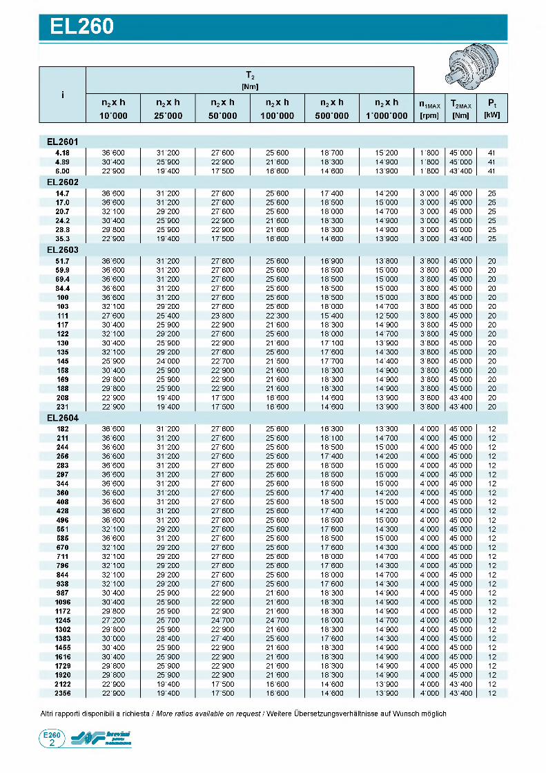
EL260
E L 26014.18 36 600 31200 27'600 25'600 18'700 15'200 1 800 45 ■ 000 414.89 30 400 25900 22'900 21 600 18'300 14'900 1 800 45 ■ 000 416.00 22 900 19400 17'500 16'600 14'600 13'900 1 800 43 ■ 400 41
E L 2 6 0 214.7 36 600 31200 27'600 25'600 17'400 14'200 3'000 45 ■ 000 2517.0 36600 31200 27'600 25'600 18'500 15'000 3'000 45 ■ 000 2520.7 32100 29200 27'600 25'600 18'000 14'700 3'000 45 ■ 000 2524.2 30 400 25900 22'900 21 600 18'300 14'900 3'000 45 ■ 000 2528.8 29800 25900 22'900 21 600 18'300 14'900 3 ■ 000 45 ■ 000 2535.3 22900 19400 17'500 16'600 14'600 13'900 3 ■ 000 43 ■ 400 25
E L 2 6 0 351.7 36 ■ 600 31 200 27 ■ 600 25 ■ 600 16 ■ 900 13 ■ 800 3 ■ 800 45 ■ 000 2059.9 36 ■ 600 31 200 27 ■ 600 25 ■ 600 18 ■ 500 15 ■ 000 3 ■ 800 45 ■ 000 2069.4 36 ■ 600 31 200 27 ■ 600 25 ■ 600 18 ■ 500 15 ■ 000 3 ■ 800 45 ■ 000 2084.4 36 ■ 600 31 200 27 ■ 600 25 ■ 600 18 ■ 500 15 ■ 000 3 ■ 800 45 ■ 000 20100 36 ■ 600 31 200 27 ■ 600 25 ■ 600 18 ■ 500 15 ■ 000 3 ■ 800 45 ■ 000 20103 32 ■ 100 29 ■ 200 27 ■ 600 25 ■ 600 18 ■ 000 14 ■ 700 3 ■ 800 45 ■ 000 20111 27 ■ 600 25 ■ 400 23 ■ 800 22 ■ 300 15 ■ 400 12 ■ 500 3 ■ 800 45 ■ 000 20117 30 ■ 400 25 ■ 900 22 ■ 900 21 600 18 ■ 300 14 ■ 900 3 ■ 800 45 ■ 000 20122 32 ■ 100 29 ■ 200 27 ■ 600 25 ■ 600 18 ■ 000 14 ■ 700 3 ■ 800 45 ■ 000 20130 30 ■ 400 25 ■ 900 22 ■ 900 21 600 17 ■ 100 13 ■ 900 3 ■ 800 45 ■ 000 20135 32 ■ 100 29 ■ 200 27 ■ 600 25 ■ 600 17 ■ 600 14 ■ 300 3 ■ 800 45 ■ 000 20145 25 ■ 900 24 ■ 000 22 ■ 700 21 500 17 ■ 700 14 ■ 400 3 ■ 800 45 ■ 000 20158 30 ■ 400 25 ■ 900 22 ■ 900 21 600 18 ■ 300 14 ■ 900 3 ■ 800 45 ■ 000 20169 29 ■ 800 25 ■ 900 22 ■ 900 21 600 18 ■ 300 14 ■ 900 3 ■ 800 45 ■ 000 20188 29 ■ 800 25 ■ 900 22 ■ 900 21 600 18 ■ 300 14 ■ 900 3 ■ 800 45 ■ 000 20208 22 ■ 900 19 ■ 400 17 ■ 500 16 ■ 600 14 ■ 600 13 ■ 900 3 ■ 800 43 ■ 400 20231 22 ■ 900 19 ■ 400 17 ■ 500 16 ■ 600 14 ■ 600 13 ■ 900 3 ■ 800 43 ■ 400 20
E L 2 6 0 4182 36 ■ 600 31 200 27 ■ 600 25 ■ 600 16 ■ 300 13 ■ 300 4 ■ 000 45 ■ 000 12211 36 ■ 600 31 200 27 ■ 600 25 ■ 600 18 ■ 100 14 ■ 700 4 ■ 000 45 ■ 000 12244 36 ■ 600 31 200 27 ■ 600 25 ■ 600 18 ■ 500 15 ■ 000 4 ■ 000 45 ■ 000 12256 36 ■ 600 31 200 27 ■ 600 25 ■ 600 17 ■ 400 14 ■ 200 4 ■ 000 45 ■ 000 12283 36 ■ 600 31 200 27 ■ 600 25 ■ 600 18 ■ 500 15 ■ 000 4 ■ 000 45 ■ 000 12297 36 ■ 600 31 200 27 ■ 600 25 ■ 600 18 ■ 500 15 ■ 000 4 ■ 000 45 ■ 000 12344 36 ■ 600 31 200 27 ■ 600 25 ■ 600 18 ■ 500 15 ■ 000 4 ■ 000 45 ■ 000 12360 36 ■ 600 31 200 27 ■ 600 25 ■ 600 17 ■ 400 14 ■ 200 4 ■ 000 45 ■ 000 12408 36 ■ 600 31 200 27 ■ 600 25 ■ 600 18 ■ 500 15 ■ 000 4 ■ 000 45 ■ 000 12428 36 ■ 600 31 200 27 ■ 600 25 ■ 600 17 ■ 400 14 ■ 200 4 ■ 000 45 ■ 000 12496 36 ■ 600 31 200 27 ■ 600 25 ■ 600 18 ■ 500 15 ■ 000 4 ■ 000 45 ■ 000 12551 32 ■ 100 29 ■ 200 27 ■ 600 25 ■ 600 17 ■ 600 14 ■ 300 4 ■ 000 45 ■ 000 12585 36 ■ 600 31 200 27 ■ 600 25 ■ 600 18 ■ 500 15 ■ 000 4 ■ 000 45 ■ 000 12670 32 ■ 100 29 ■ 200 27 ■ 600 25 ■ 600 17 ■ 600 14 ■ 300 4 ■ 000 45 ■ 000 12711 32 ■ 100 29 ■ 200 27 ■ 600 25 ■ 600 18 ■ 000 14 ■ 700 4 ■ 000 45 ■ 000 12796 32 ■ 100 29 ■ 200 27 ■ 600 25 ■ 600 17 ■ 600 14 ■ 300 4 ■ 000 45 ■ 000 12844 32 ■ 100 29 ■ 200 27 ■ 600 25 ■ 600 18 ■ 000 14 ■ 700 4 ■ 000 45 ■ 000 12938 32 ■ 100 29 ■ 200 27 ■ 600 25 ■ 600 17 ■ 600 14 ■ 300 4 ■ 000 45 ■ 000 12987 30 ■ 400 25 ■ 900 22 ■ 900 21 600 18 ■ 300 14 ■ 900 4 ■ 000 45 ■ 000 121096 30 ■ 400 25 ■ 900 22 ■ 900 21 600 18 ■ 300 14 ■ 900 4 ■ 000 45 ■ 000 121172 29 ■ 800 25 ■ 900 22 ■ 900 21 600 18 ■ 300 14 ■ 900 4 ■ 000 45 ■ 000 121245 27 ■ 200 25 ■ 700 24 ■ 700 24 ■ 700 18 ■ 000 14 ■ 700 4 ■ 000 45 ■ 000 121302 29 ■ 800 25 ■ 900 22 ■ 900 21 600 18 ■ 300 14 ■ 900 4 ■ 000 45 ■ 000 121383 30 ■ 000 28 ■ 400 27 ■ 400 25 ■ 600 17 ■ 600 14 ■ 300 4 ■ 000 45 ■ 000 121455 30 ■ 400 25 ■ 900 22 ■ 900 21 600 18 ■ 300 14 ■ 900 4 ■ 000 45 ■ 000 121616 30 ■ 400 25 ■ 900 22 ■ 900 21 600 18 ■ 300 14 ■ 900 4 ■ 000 45 ■ 000 121729 29 ■ 800 25 ■ 900 22 ■ 900 21 600 18 ■ 300 14 ■ 900 4 ■ 000 45 ■ 000 121920 29 ■ 800 25 ■ 900 22 ■ 900 21 600 18 ■ 300 14 ■ 900 4 ■ 000 45 ■ 000 122122 22 ■ 900 19 ■ 400 17 ■ 500 16 ■ 600 14 ■ 600 13 ■ 900 4 ■ 000 43 ■ 400 122356 22 ■ 900 19 ■ 400 17 ■ 500 16 ■ 600 14 ■ 600 13 ■ 900 4 ■ 000 43 ■ 400 12
A ltri r a p p o r t i d i s p o n ib i l i a r i c h i e s t a / More ratios available on request / W e i t e r e U b e r s e t z u n g s v e r h a l t n i s s e a u f W u n s c h m o g l ic h
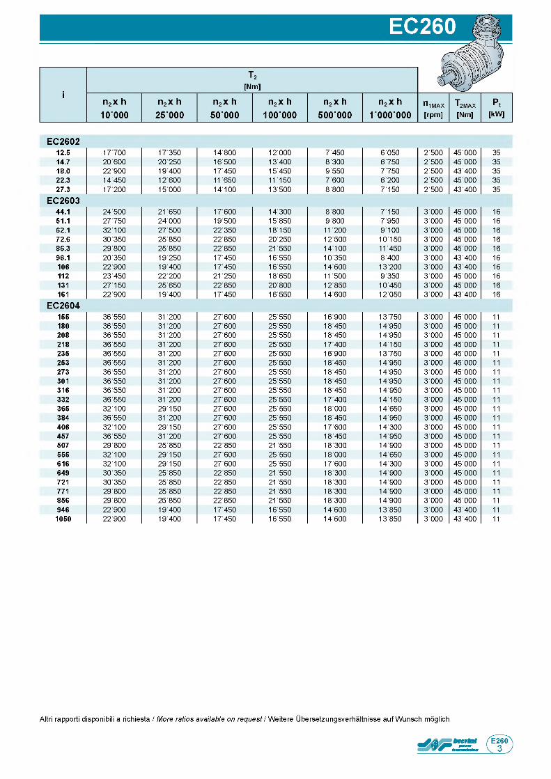
E C 2 6 0 212.5 17700 17350 14'800 12'000 7'450 6'050 2'500 45'000 3514.7 20 600 20 250 16'500 13'400 8'300 6'750 2'500 45'000 3518.0 22 900 19 400 17'450 15'450 9'550 7'750 2'500 43'400 3522.3 14450 12 600 11 650 11 150 7'600 6'200 2'500 45'000 3527.3 17200 15 000 14 ' 100 13'500 8'800 7'150 2'500 43'400 35
E C 2 6 0 344.1 24'500 21 650 17'600 14'300 8'800 7'150 3'000 45'000 1651.1 27'750 24'000 19'500 15'850 9'800 7'950 3'000 45'000 1662.1 32'100 27'500 22'350 18'150 11' 200 9'100 3'000 45'000 1672.6 30'350 25'850 22'850 20'250 12'500 10'150 3'000 45'000 1686.3 29'800 25'850 22'850 21' 550 14 ' 100 11' 450 3'000 45'000 1696.1 20'350 19'250 17'450 16'550 10'350 8'400 3'000 43'400 16106 22'900 19'400 17'450 16'550 14'600 13'200 3'000 43'400 16112 23'450 22'200 21' 250 18'650 11' 500 9'350 3'000 45'000 16131 27'150 25'650 22'850 20'800 12'850 10'450 3'000 45'000 16161 22'900 19'400 17'450 16'550 14'600 12'050 3'000 43'400 16
E C 2 6 0 4155 36'550 31' 200 27'600 25'550 16'900 13'750 3'000 45'000 11180 36'550 31' 200 27'600 25'550 18'450 14'950 3'000 45'000 11208 36'550 31' 200 27'600 25'550 18'450 14'950 3'000 45'000 11218 36'550 31' 200 27'600 25'550 17'400 14 ' 150 3'000 45'000 11235 36'550 31' 200 27'600 25'550 16'900 13'750 3'000 45'000 11253 36'550 31' 200 27'600 25'550 18'450 14'950 3'000 45'000 11273 36'550 31' 200 27'600 25'550 18'450 14'950 3'000 45'000 11301 36'550 31' 200 27'600 25'550 18'450 14'950 3'000 45'000 11316 36'550 31' 200 27'600 25'550 18'450 14'950 3'000 45'000 11332 36'550 31' 200 27'600 25'550 17'400 14' 150 3'000 45'000 11365 32'100 29'150 27'600 25'550 18'000 14'650 3'000 45'000 11384 36'550 31' 200 27'600 25'550 18'450 14'950 3'000 45'000 11406 32'100 29 ' 150 27'600 25'550 17'600 14'300 3'000 45'000 11457 36'550 31' 200 27'600 25'550 18'450 14'950 3'000 45'000 11507 29'800 25'850 22'850 21' 550 18'300 14'900 3'000 45'000 11555 32 ' 100 29'150 27'600 25'550 18'000 14'650 3'000 45'000 11616 32'100 29'150 27'600 25'550 17'600 14'300 3'000 45'000 11649 30'350 25'850 22'850 21' 550 18'300 14'900 3'000 45'000 11721 30'350 25'850 22'850 21' 550 18'300 14'900 3'000 45'000 11771 29'800 25'850 22'850 21' 550 18'300 14'900 3'000 45'000 11856 29'800 25'850 22'850 21' 550 18'300 14'900 3'000 45'000 11946 22'900 19'400 17'450 16'550 14'600 13'850 3'000 43'400 111050 22'900 19'400 17'450 16'550 14'600 13'850 3'000 43'400 11
A ltri r a p p o r t i d i s p o n ib i l i a r i c h i e s t a / More ratios available on request / W e i t e r e U b e r s e t z u n g s v e r h a l t n i s s e a u f W u n s c h m o g l ic h
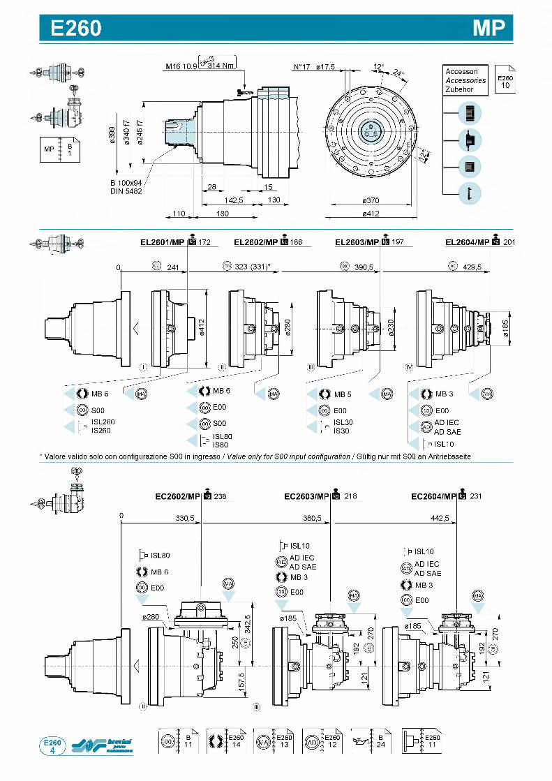
E260
1
: ^M P B
1
AccessoriAccessoriesZubehor
E 2 6 01 0
I I
0412
EL2603/MP Eg 197EL2601/MP Eg 172 EL2602/MP P§ 186
'A D SAE
ISL10
' Valore valido solo con configurazione S00 in ingresso / Value only for S00 input configuration / Gultig nur mit S00 an Antriebsseite
f
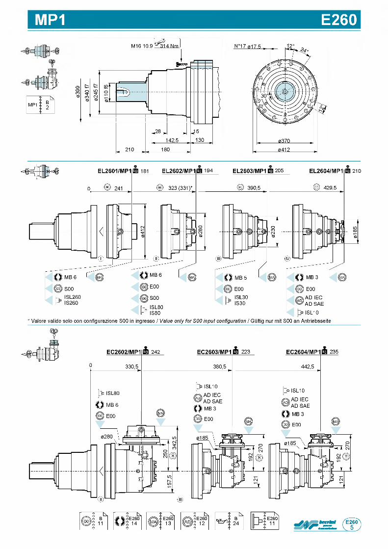
MP1 E260
1
1: ь .
m p i :B2
2 1 0
'A D SAE
ISL10
' Valore valido solo con configurazione S00 in ingresso / Value only for S00 input configuration / Gultig nur mit S00 an Antriebsseite
f
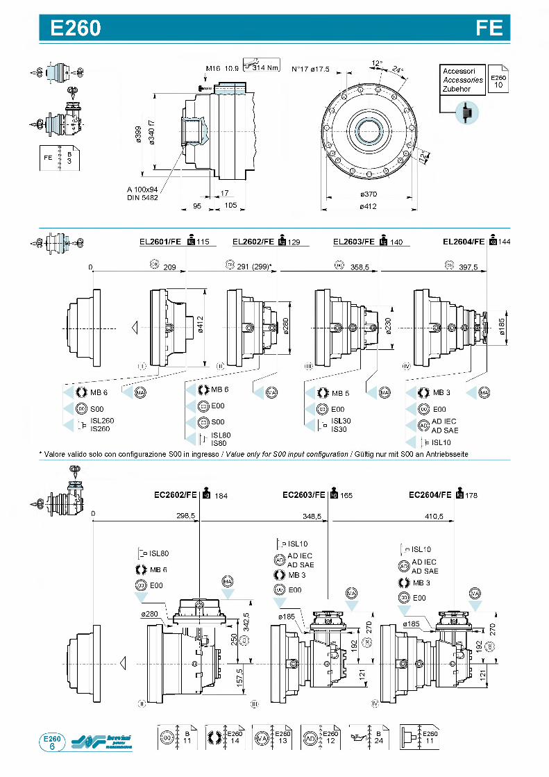
E260 FE
: Nfe : B
3
M16 10.9 3 1314 Nm AccessoriAccessoriesZubehor
E 2 6 01 0
* Valore valido solo con configurazione S00 in ingresso / Value only for S00 input configuration / Gultig nur mit S00 an Antriebsseite
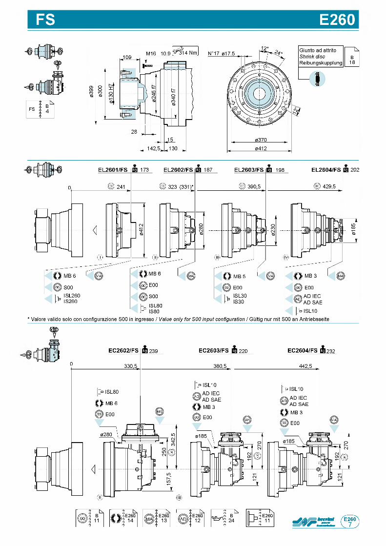
FS E260
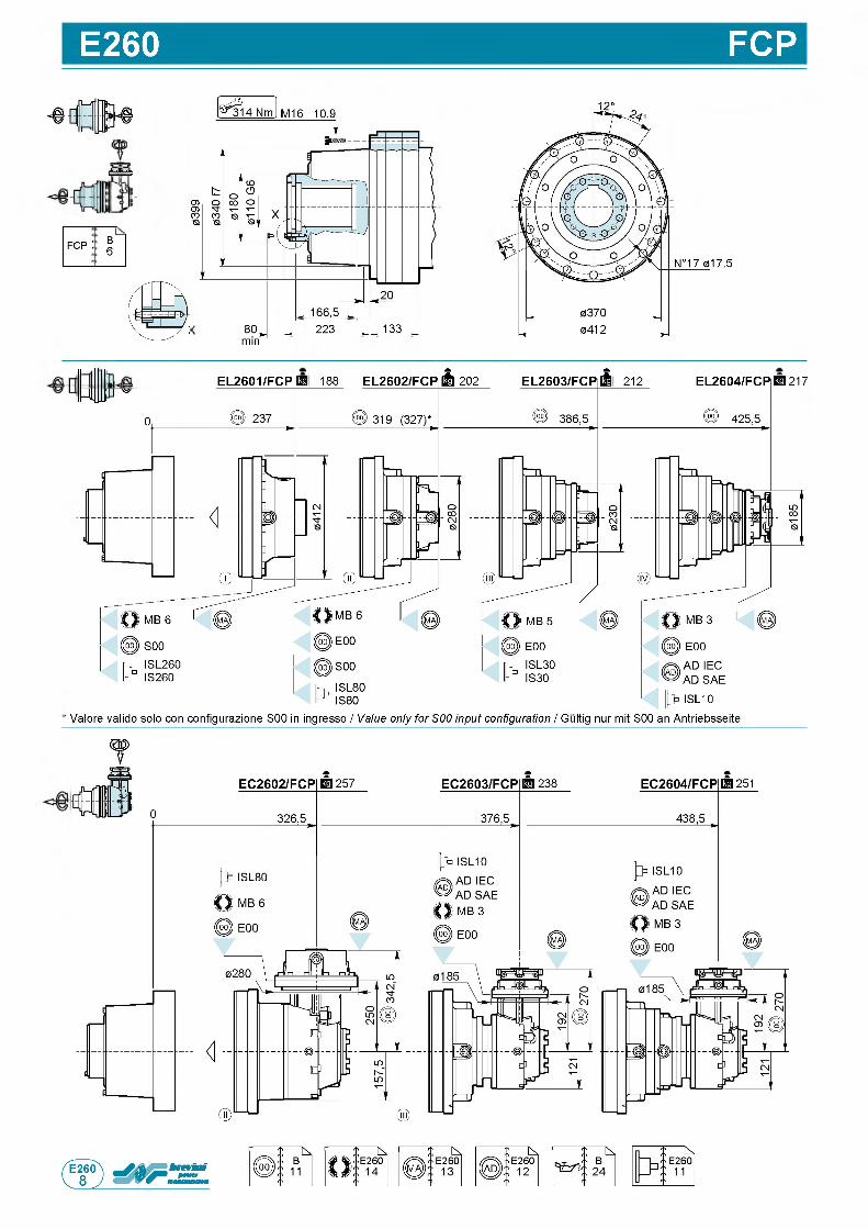
E260 FCP
- в Л
fin rgb nfy
f c p ;
О)
ГО
N°17 017.5
80, . 223 . 133 , 0412 ,min
EL2601/FCP S 188 EL2602/FCP[§ 202 EL2603/FCP Hi 212 EL2604/FCPP i 217
' AD SAE ISL10
' Valore valido solo con configurazione S00 in ingresso / Value only for S00 input configuration / Gultig nur mit S00 an Antriebsseite
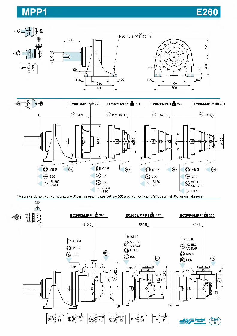
E260
o f
M P P 1B5
' Valore valido solo con configurazione S00 in ingresso / Value only for S00 input configuration / Gultig nur mit S00 an Antriebsseite
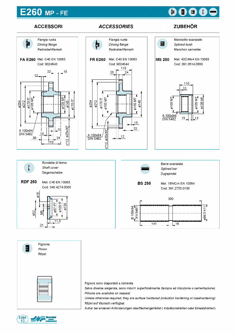
E260 MP - FE
ACCESSORI A C C E S S O R IE S ZUBEHOR
Rondella di fermo Shaft cover Gegenscheibe
R D F 2 5 0 Mat. C40 EN 10083 Cod: 340.4274.0000
Barra scanalata Splined bar Zugspindel
B S 2 5 0 Mat. 16NiCr4 EN 10084 Cod: 391.2733.0100
300
d(NCO
S Z
COO)O)<av
~Z.VQ
i 1 4 1 , . 1 8
Pignoni sono disponibili a richiesta.Salvo diversa esigenza, sono induriti superficialmente (tempra ad induzione o cementazione) Pinions are available on request.Unless otherwise required, they are surface hardened (induction hardening or casehardening) Ritzel auf Wunsch verfugbar.AulJer bei anderen Anforderungen oberflachengehartet ( Induktionsharten oder Einsatzharten)
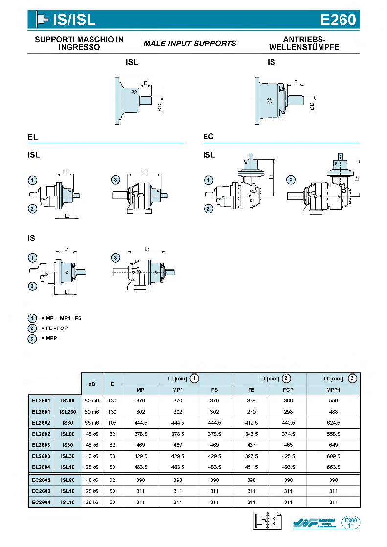
IS/ISL E260SUPPORTI MASCHIO IN
INGRESSO M A L E IN P U T S U P P O R T S ANTRIEBS-w e l l e n s t Om p f e
ISL IS
EL
ISL
IS
ф = MP - M P1- FS
@ = F E - FCP
ф = MPP1
EC
0D ELt [mm] 1 Lt [mm] 2 Lt [mm] 3
MP MP1 FS FE FCP MPP1
EL2601 IS260 8 0 m 6 1 3 0 3 7 0 3 7 0 3 7 0 3 3 8 3 6 6 5 5 6
EL2601 ISL260 8 0 m 6 1 3 0 3 0 2 3 0 2 3 0 2 2 7 0 2 9 8 4 8 8
EL2602 IS80 6 5 m 6 1 0 5 4 4 4 . 5 4 4 4 . 5 4 4 4 . 5 4 1 2 . 5 4 4 0 . 5 6 2 4 . 5
EL2602 ISL80 4 8 k 6 8 2 3 7 8 . 5 3 7 8 . 5 3 7 8 . 5 3 4 6 . 5 3 7 4 . 5 5 5 8 . 5
EL2603 IS30 4 8 k 6 8 2 4 6 9 4 6 9 4 6 9 4 3 7 4 6 5 6 4 9
EL2603 ISL30 4 0 k 6 5 8 4 2 9 . 5 4 2 9 . 5 4 2 9 . 5 3 9 7 . 5 4 2 5 . 5 6 0 9 . 5
EL2604 ISL10 2 8 k 6 5 0 4 8 3 . 5 4 8 3 . 5 4 8 3 . 5 4 5 1 . 5 4 9 6 . 5 6 6 3 . 5
EC2602 ISL80 4 8 k 6 8 2 3 9 8 3 9 8 3 9 8 3 9 8 3 9 8 3 9 8
EC2603 ISL10 2 8 k 6 5 0 3 1 1 3 1 1 3 1 1 3 1 1 3 1 1 3 1 1
EC2604 ISL10 2 8 k 6 5 0 3 1 1 3 1 1 3 1 1 3 1 1 3 1 1 3 1 1
n
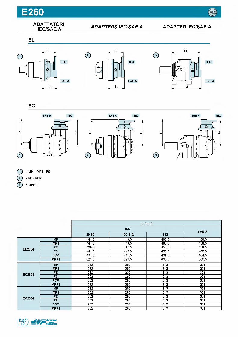
E260ADATTATORI
IEC/SAE A A D A P T E R S IE C /S A E A ADAPTER IEC/SAE A
EL
IEC
S A E A
IEC
S A E A
IEC
S A E A
EC
S A E A IEC S A E A IEC S A E A IEC
ф = MP - M P1- FS
ф = F E - FCP
ф = MPP1
Lt [mm]
IECSAE A
80-90 100-112 132
EL2604
MP 4 4 1 . 5 4 4 9 . 5 4 8 5 . 5 4 8 8 . 5
MP1 4 4 1 . 5 4 4 9 . 5 4 8 5 . 5 4 8 8 . 5
FE 4 0 9 . 5 4 1 7 . 5 4 5 3 . 5 4 3 9 . 5
FS 4 4 1 . 5 4 4 9 . 5 4 8 5 . 5 4 8 8 . 5
FCP 4 3 7 . 5 4 4 5 . 5 4 8 1 . 5 4 8 4 . 5
MPP1 6 2 1 . 5 6 2 9 . 5 6 6 5 . 5 6 6 6 . 5
EC2603
MP 2 8 2 2 9 0 3 1 3 3 0 1
MP1 2 8 2 2 9 0 3 1 3 3 0 1
FE 2 8 2 2 9 0 3 1 3 3 0 1
FS 2 8 2 2 9 0 3 1 3 3 0 1
FCP 2 8 2 2 9 0 3 1 3 3 0 1
MPP1 2 8 2 2 9 0 3 1 3 3 0 1
EC2604
MP 2 8 2 2 9 0 3 1 3 3 0 1
MP1 2 8 2 2 9 0 3 1 3 3 0 1
FE 2 8 2 2 9 0 3 1 3 3 0 1
FS 2 8 2 2 9 0 3 1 3 3 0 1
FCP 2 8 2 2 9 0 3 1 3 3 0 1
MPP1 2 8 2 2 9 0 3 1 3 3 0 1
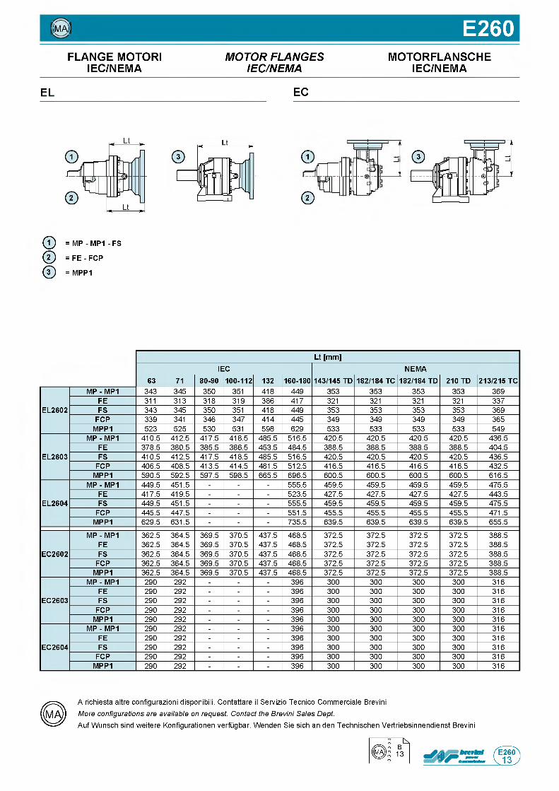
((ma)) E260FLANGE MOTORI M O T O R F L A N G E S MOTORFLANSCHE
IEC/NEMA IE C /N E M A IEC/NEMA
EL EC
d
®
t = j
-------/ a ------- *
JHJ_Jr
© = MP - MP1 - FS
@ = F E - FCP
@ = MPP1
Lt [mm]IEC NEMA
63 71 80-90 100-112 132 160-180 143/145 TD 182/184 TC 182/184 TD 210 TD 213/215 TC
EL2602
MP - MP1 3 4 3 3 4 5 3 5 0 3 5 1 4 1 8 4 4 9 3 5 3 3 5 3 3 5 3 3 5 3 3 6 9
FE 3 1 1 3 1 3 3 1 8 3 1 9 3 8 6 4 1 7 3 2 1 3 2 1 3 2 1 3 2 1 3 3 7
FS 3 4 3 3 4 5 3 5 0 3 5 1 4 1 8 4 4 9 3 5 3 3 5 3 3 5 3 3 5 3 3 6 9
FCP 3 3 9 3 4 1 3 4 6 3 4 7 4 1 4 4 4 5 3 4 9 3 4 9 3 4 9 3 4 9 3 6 5
MPP1 5 2 3 5 2 5 5 3 0 5 3 1 5 9 8 6 2 9 5 3 3 5 3 3 5 3 3 5 3 3 5 4 9
EL2603
MP - MP1 4 1 0 . 5 4 1 2 . 5 4 1 7 . 5 4 1 8 . 5 4 8 5 . 5 5 1 6 . 5 4 2 0 . 5 4 2 0 . 5 4 2 0 . 5 4 2 0 . 5 4 3 6 . 5
FE 3 7 8 . 5 3 8 0 . 5 3 8 5 . 5 3 8 6 . 5 4 5 3 . 5 4 8 4 . 5 3 8 8 . 5 3 8 8 . 5 3 8 8 . 5 3 8 8 . 5 4 0 4 . 5
FS 4 1 0 . 5 4 1 2 . 5 4 1 7 . 5 4 1 8 . 5 4 8 5 . 5 5 1 6 . 5 4 2 0 . 5 4 2 0 . 5 4 2 0 . 5 4 2 0 . 5 4 3 6 . 5
FCP 4 0 6 . 5 4 0 8 . 5 4 1 3 . 5 4 1 4 . 5 4 8 1 . 5 5 1 2 . 5 4 1 6 . 5 4 1 6 . 5 4 1 6 . 5 4 1 6 . 5 4 3 2 . 5
MPP1 5 9 0 . 5 5 9 2 . 5 5 9 7 . 5 5 9 8 . 5 6 6 5 . 5 6 9 6 . 5 6 0 0 . 5 6 0 0 . 5 6 0 0 . 5 6 0 0 . 5 6 1 6 . 5
EL2604
MP - MP1 4 4 9 . 5 4 5 1 . 5 - - - 5 5 5 . 5 4 5 9 . 5 4 5 9 . 5 4 5 9 . 5 4 5 9 . 5 4 7 5 . 5
FE 4 1 7 . 5 4 1 9 . 5 - - - 5 2 3 . 5 4 2 7 . 5 4 2 7 . 5 4 2 7 . 5 4 2 7 . 5 4 4 3 . 5
FS 4 4 9 . 5 4 5 1 . 5 - - - 5 5 5 . 5 4 5 9 . 5 4 5 9 . 5 4 5 9 . 5 4 5 9 . 5 4 7 5 . 5
FCP 4 4 5 . 5 4 4 7 . 5 - - - 5 5 1 . 5 4 5 5 . 5 4 5 5 . 5 4 5 5 . 5 4 5 5 . 5 4 7 1 . 5
MPP1 6 2 9 . 5 6 3 1 . 5 - - - 7 3 5 . 5 6 3 9 . 5 6 3 9 . 5 6 3 9 . 5 6 3 9 . 5 6 5 5 . 5
EC2602
MP - MP1 3 6 2 . 5 3 6 4 . 5 3 6 9 . 5 3 7 0 . 5 4 3 7 . 5 4 6 8 . 5 3 7 2 . 5 3 7 2 . 5 3 7 2 . 5 3 7 2 . 5 3 8 8 . 5
FE 3 6 2 . 5 3 6 4 . 5 3 6 9 . 5 3 7 0 . 5 4 3 7 . 5 4 6 8 . 5 3 7 2 . 5 3 7 2 . 5 3 7 2 . 5 3 7 2 . 5 3 8 8 . 5
FS 3 6 2 . 5 3 6 4 . 5 3 6 9 . 5 3 7 0 . 5 4 3 7 . 5 4 6 8 . 5 3 7 2 . 5 3 7 2 . 5 3 7 2 . 5 3 7 2 . 5 3 8 8 . 5
FCP 3 6 2 . 5 3 6 4 . 5 3 6 9 . 5 3 7 0 . 5 4 3 7 . 5 4 6 8 . 5 3 7 2 . 5 3 7 2 . 5 3 7 2 . 5 3 7 2 . 5 3 8 8 . 5
MPP1 3 6 2 . 5 3 6 4 . 5 3 6 9 . 5 3 7 0 . 5 4 3 7 . 5 4 6 8 . 5 3 7 2 . 5 3 7 2 . 5 3 7 2 . 5 3 7 2 . 5 3 8 8 . 5
EC2603
MP - MP1 2 9 0 2 9 2 - - - 3 9 6 3 0 0 3 0 0 3 0 0 3 0 0 3 1 6
FE 2 9 0 2 9 2 - - - 3 9 6 3 0 0 3 0 0 3 0 0 3 0 0 3 1 6
FS 2 9 0 2 9 2 - - - 3 9 6 3 0 0 3 0 0 3 0 0 3 0 0 3 1 6
FCP 2 9 0 2 9 2 - - - 3 9 6 3 0 0 3 0 0 3 0 0 3 0 0 3 1 6
MPP1 2 9 0 2 9 2 - - - 3 9 6 3 0 0 3 0 0 3 0 0 3 0 0 3 1 6
EC2604
MP - MP1 2 9 0 2 9 2 - - - 3 9 6 3 0 0 3 0 0 3 0 0 3 0 0 3 1 6
FE 2 9 0 2 9 2 - - - 3 9 6 3 0 0 3 0 0 3 0 0 3 0 0 3 1 6
FS 2 9 0 2 9 2 - - - 3 9 6 3 0 0 3 0 0 3 0 0 3 0 0 3 1 6
FCP 2 9 0 2 9 2 - - - 3 9 6 3 0 0 3 0 0 3 0 0 3 0 0 3 1 6
MPP1 2 9 0 2 9 2 - - - 3 9 6 3 0 0 3 0 0 3 0 0 3 0 0 3 1 6
A richiesta altre configurazioni disponibili. Contattare il Servizio Tecnico Commerciale Brevini More configurations are available on request. Contact the Brevini Sales Dept.Auf Wunsch sind weitere Konfigurationen verfugbar. Wenden Sie sich an den Technischen Vertriebsinnendienst Brevini
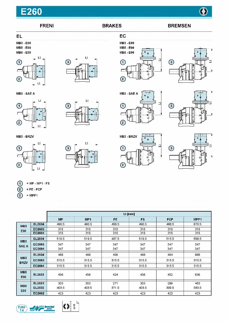
E260FRENI BRAKES BREMSEN
EL ECM B 3- E00 M B 5- E00
MB6 - E00
MB3 - E00
ф = MP - MP1 - FS
@ = F E - FCP
ф = MPP1
Lt [mm]
MP MP1 FE FS FCP MPP1
MB3E00
EL2604 4 9 0 . 5 4 9 0 . 5 4 5 8 . 5 4 9 0 . 5 4 8 6 . 5 6 7 0 . 5
EC2603 3 1 8 3 1 8 3 1 8 3 1 8 3 1 8 3 1 8
EC2604 3 1 8 3 1 8 3 1 8 3 1 8 3 1 8 3 1 8
MB3 SAE A
EL2604 5 1 9 . 5 5 1 9 . 5 4 8 7 . 5 5 1 9 . 5 5 1 5 . 5 6 9 9 . 5
EC2603 3 4 7 3 4 7 3 4 7 3 4 7 3 4 7 3 4 7
EC2604 3 4 7 3 4 7 3 4 7 3 4 7 3 4 7 3 4 7
MB3BRZV
EL2604 4 8 8 4 8 8 4 5 6 4 8 8 4 8 4 6 6 8
EC2603 3 1 5 . 5 3 1 5 . 5 3 1 5 . 5 3 1 5 . 5 3 1 5 . 5 3 1 5 . 5
EC2604 3 1 5 . 5 3 1 5 . 5 3 1 5 . 5 3 1 5 . 5 3 1 5 . 5 3 1 5 . 5
MB5E00
EL2603 4 5 6 4 5 6 4 2 4 4 5 6 4 5 2 6 3 6
MB6E00
EL2601 3 0 3 3 0 3 2 7 1 3 0 3 2 9 9 4 8 3
EL2602 4 0 3 . 5 4 0 3 . 5 3 7 1 . 5 4 0 3 . 5 3 9 9 . 5 5 8 3 . 5
EC2602 4 2 3 4 2 3 4 2 3 4 2 3 4 2 3 4 2 3
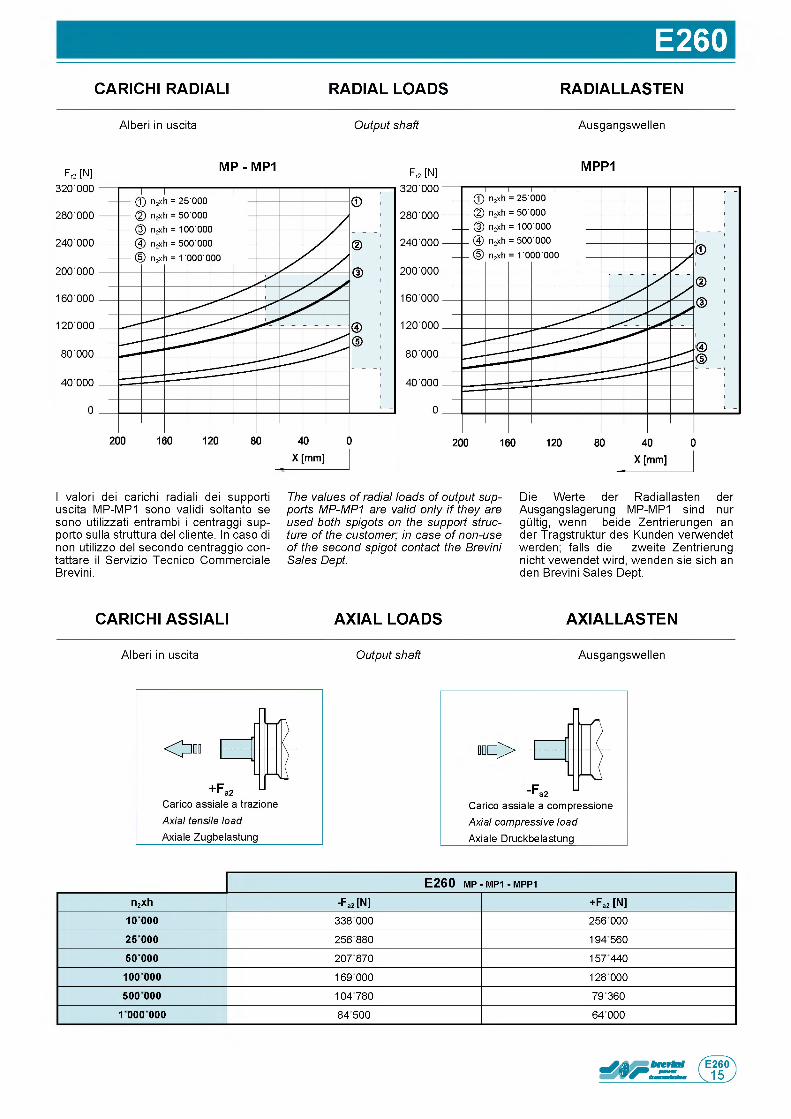
E260CARICHI RADIALI RADIAL LOADS RADIALLASTEN
A l b e r i in u s c i t a Output shaft A u s g a n g s w e l l e n
Fr2 [N ]M P - M P1
Fr2 [N ]M P P 1
I v a l o r i d e i c a r i c h i r a d i a l i d e i s u p p o r t i
u s c i t a M P - M P 1 s o n o v a l i d i s o l t a n t o s e
s o n o u t i l i z z a t i e n t r a m b i i c e n t r a g g i s u p -
p o r t o s u l l a s t r u t t u r a d e l c l i e n t e . In c a s o d i
n o n u t i l i z z o d e l s e c o n d o c e n t r a g g i o c o n -
t a t t a r e il S e r v i z i o T e c n i c o C o m m e r c i a l e
B r e v i n i .
The values of radial loads of output supports MP-MP1 are valid only i f they are used both spigots on the support structure of the customer; in case of non-use of the second spigot contact the Brevini Sales Dept.
D i e W e r t e d e r R a d i a l l a s t e n d e r
A u s g a n g s l a g e r u n g M P - M P 1 s i n d n u r
g Q l t i g , w e n n b e i d e Z e n t r i e r u n g e n a n
d e r T r a g s t r u k t u r d e s K u n d e n v e r w e n d e t
w e r d e n ; f a l l s d i e z w e i t e Z e n t r i e r u n g
n i c h t v e w e n d e t w i r d , w e n d e n s i e s i c h a n
d e n B r e v i n i S a l e s D e p t .
CARICHI ASSIALI AXIAL LOADS AXIALLASTEN
A l b e r i in u s c i t a Output shaft A u s g a n g s w e l l e n
ю ф >
C a r i c o a s s i a l e a c o m p r e s s i o n e
Axial compressive load A x ia le D r u c k b e l a s t u n g
E 2 6 0 m p - MP1 - m p p 1
n2xh -Fa2 [N] + Fa2 [N]1 0 0 0 0 338 000 256 0002 5 000 256 880 194 56050 000 207 870 157 440
10 0 000 169 000 128 000500 000 104 780 79360
1 000 000 84500 64 000
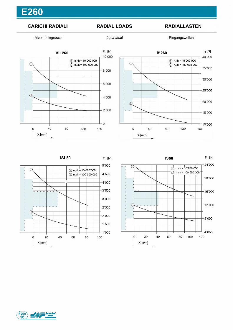
E260CARICHI RADIALI RADIAL LOADS RADIALLASTEN
A l b e r i in i n g r e s s o Input shaft E i n g a n g s w e l l e n
IS L 2 6 0 [N] IS 2 6 0 Fr1 [N]
IS L 8 0 F r1 [N ] IS 8 0 Fri [N ]
24000
20 000
16 000
12 000
8 000
4 000
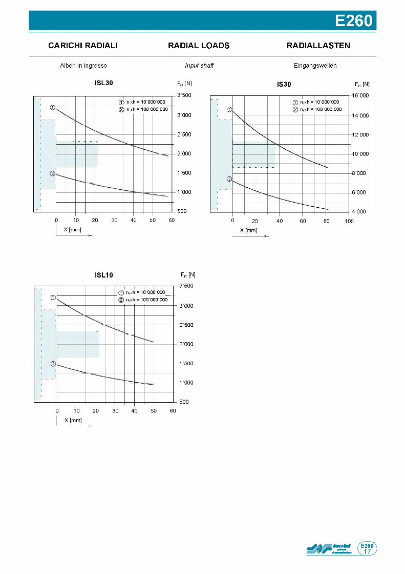
E260CARICHI RADIALI RADIAL LOADS RADIALLASTEN
A l b e r i in i n g r e s s o Input shaft E i n g a n g s w e l l e n
F rt [N ]
3 500
3 000
2 500
2 000
1 500
1000
5 0 0
0 10 20 30 40 50 60
X [mm]
IS L 3 0
d© n,xh = 10 000 000 2 n,xh = 100 000 000
IS 3 0 F n [N ]
F rt [N ]
3 500
3 000
2 500
2 000
1 500
1000
5 0 0
0 10 20 30 40 50 60
X [mm]
IS L 1 0
d(f n,xh = 10 000 000_ 2 n,xh = 100 000 000

Questa pagina e lasciata intenzionalmente bianca
Page is in tentiona lly le ft blank Seite wurde absichtlich leer gelassen
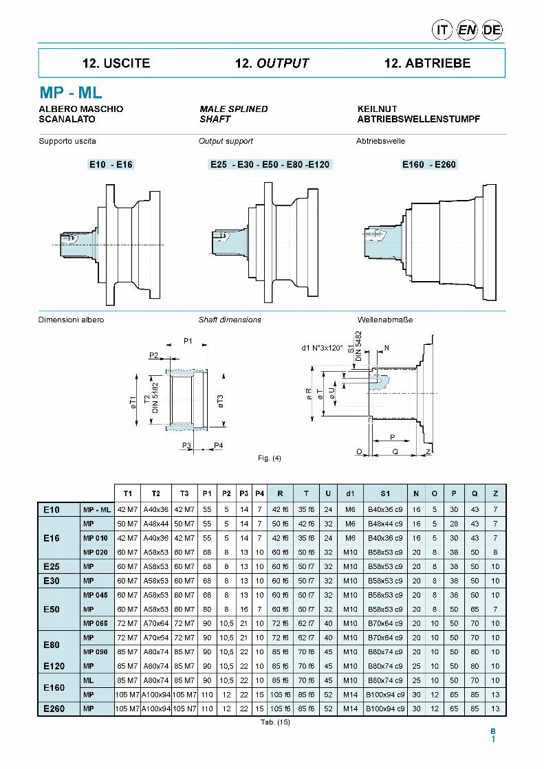
12. USCITE 12. OUTPUT 12. ABTRIEBE
MP - MLK E IL N U TA B T R IE B S W E L L E N S T U M P F
A L B E R O M A S C H IO MALE SPLINEDS C A N A L A T O SHAFT
Supporto uscita Output support Abtriebswelle
E 1 0 - E 16 E 2 5 - E 3 0 - E 5 0 - E 8 0 -E 1 2 0 E 1 6 0 - E 2 6 0
Dimensioni albero Shaft dimensions WellenabmaUe
Fig. (4)
T1 T2 T3 P1 P2 P3 P4 R T U d1 S1 N O P Q Z
E 10 MP - ML 42 M7 A40x36 42 M7 55 5 14 7 42 f6 35 f6 24 M6 B40x36 c9 16 5 30 43 7
E 16
MP 50 M7 A48x44 50 M7 55 5 14 7 50 f6 42 f6 32 M6 B48x44 c9 16 5 28 43 7
MP 010 42 M7 A40x36 42 M7 55 5 14 7 42 f6 35 f6 24 M6 B40x36 c9 16 5 30 43 7
MP 020 60 M7 A58x53 60 M7 68 8 13 10 60 f6 50 f6 32 M10 B58x53 c9 20 8 38 50 8
E 25 MP 60 M7 A58x53 60 M7 68 8 13 10 60 f6 50 f7 32 M10 B58x53 c9 20 8 38 50 10
E 30 MP 60 M7 A58x53 60 M7 68 8 13 10 60 f6 50 f7 32 M10 B58x53 c9 20 8 38 50 10
E 50
MP 045 60 M7 A58x53 60 M7 68 8 13 10 60 f6 50 f7 32 M10 B58x53 c9 20 8 38 50 10
MP 60 M7 A58x53 60 M7 80 8 16 7 60 f6 50 f7 32 M10 B58x53 c9 20 8 50 65 7
MP 065 72 M7 A70x64 72 M7 90 10,5 21 10 72 f6 62 f7 40 M10 B70x64 c9 20 10 50 70 10
E 80MP 72 M7 A70x64 72 M7 90 10,5 21 10 72 f6 62 f7 40 M10 B70x64 c9 20 10 50 70 10
MP 090 85 M7 A80x74 85 M7 90 10,5 22 10 85 f6 70 f6 45 M10 B80x74 c9 20 10 50 80 10
E 1 2 0 MP 85 M7 A80x74 85 M7 90 10,5 22 10 85 f6 70 f6 45 M10 B80x74 c9 25 10 50 80 10
E 1 6 0ML 85 M7 A80x74 85 M7 90 10,5 22 10 85 f6 70 f6 45 M10 B80x74 c9 25 10 50 70 10
MP 105 M7 A100x94 105 M7 110 12 22 15 105 f6 85 f6 52 M14 B100x94 c9 30 12 65 85 13
E 2 6 0 MP 105 M7 A100x94 105 N7 110 12 22 15 105 f6 85 f6 52 M14 B100x94 c9 30 12 65 85 13
Tab. (15)B1
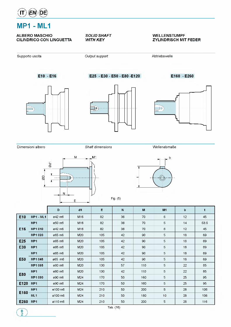
MP1 - ML1ALBERO MASCHIO SOLID SHAFT WELLENSTUMPFCILINDRICO CON LINGUETTA WITH KEY ZYLINDRISCH MIT FEDER
Supporto uscita Output support Abtriebswelle
E10 - E16 E25 - E30 - E50 - E80 -E120 E160 - E260
Dimensioni albero Shaft dimensions WellenabmaUe
Fig. (5)
D d1 E N M M1 b t
E 10 MP1 - ML1 042 m6 M16 82 36 70 6 12 45
MP1 050 m6 M16 82 36 70 5 14 53.5
E 16 M P1010 042 m6 M16 82 36 70 6 12 45
M P1020 065 m6 M20 105 42 90 5 18 69
E 25 MP1 065 m6 M20 105 42 90 5 18 69
E 30 MP1 065 m6 M20 105 42 90 5 18 69
MP1 065 m6 M20 105 42 90 5 18 69
E 50 M P1045 065 m6 M20 105 42 90 5 18 69
M P1065 080 m6 M20 130 57 110 5 22 85
c a nMP1 080 m6 M20 130 42 110 5 22 85
E 80M P1090 090 m6 M24 170 50 160 5 25 95
E 1 2 0 MP1 090 m6 M24 170 50 160 5 25 95
С Л cn MP1 0100 m6 M24 210 50 200 5 28 106E I6 0
ML1 0100 m6 M24 210 50 180 10 28 106
E 2 6 0 MP1 0110 m6 M24 210 50 200 5 28 116
Tab. (16)
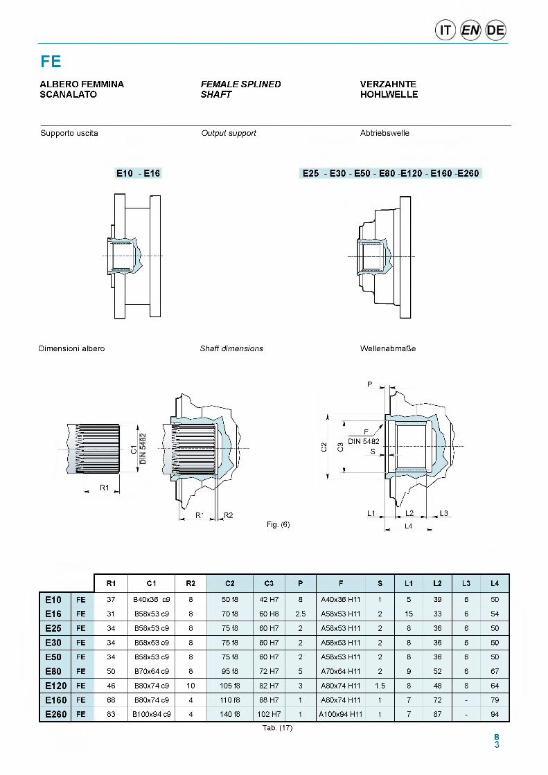
FEALBERO FEMMINA FEMALE SPLINED VERZAHNTESCANALATO SHAFT HOHLWELLE
Supporto uscita Output support Abtriebswelle
E10 - E16 E25 - E30 - E50 - E80 -E120 - E160 -E260
Dimensioni albero Shaft dimensions WellenabmaUe
Fig. (6)
p
R1 C1 R2 C2 C3 P F S L1 L2 L3 L4
E10 FE 37 B40x36 c9 8 50 f8 42 H7 8 A40x36 H11 1 5 39 6 50
E16 FE 31 B58x53 c9 8 70 f8 60 H8 2.5 A58x53 H11 2 15 33 6 54
E25 FE 34 B58x53 c9 8 75 f8 60 H7 2 A58x53 H11 2 8 36 6 50
E30 FE 34 B58x53 c9 8 75 f8 60 H7 2 A58x53 H11 2 8 36 6 50
E50 FE 34 B58x53 c9 8 75 f8 60 H7 2 A58x53 H11 2 8 36 6 50
E80 FE 50 B70x64 c9 8 95 f8 72 H7 5 A70x64 H11 2 9 52 6 67
E120 FE 46 B80x74 c9 10 105 f8 82 H7 3 A80x74 H11 1.5 8 48 8 64
E160 FE 68 B80x74 c9 4 110 f8 88 H7 1 A80x74 H11 1 7 72 - 79
E260 FE 83 B100x94 c9 4 140 f8 102 H7 1 A100x94 H11 1 7 87 - 94
Tab. (17)B3
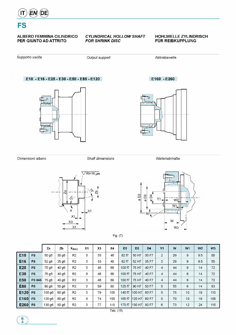
FSALBERO FEMMINA CILINDRICO CYLINDRICAL HOLLOW SHAFT HOHLWELLE ZYLINDRISCHPER GIUNTO AD ATTRITO FOR SHRINK DISC FUR REIBKUPPLUNG
Supporto uscita Output support Abtriebswelle
E10 - E16 - E25 - E30 - E50 - E80 - E120 E160 - E260
Dimensioni albero Shaft dimensions WellenabmaUe
Fig. (7)
Za Zb XM A X X1 X3 X4 D2 D3 D4 Y1 W W1 W2 W3
E10 FS 50 g6 30 g6 R2 3 33 48 62 f7 50 H7 30 F7 2 29 9 9.5 50
E16 FS 52 g6 35 g6 R2 3 33 48 62 f7 52 H7 35 F7 2 29 9 9.5 50
E25 FS 75 g6 40 g6 R2 3 48 69 100 f7 75 H7 40 F7 4 44 8 14 72
E30 FS 75 g6 40 g6 R2 3 48 69 100 f7 75 H7 40 F7 4 44 8 14 72
E50 FS 045 75 g6 40 g6 R2 3 48 69 100 f7 75 H7 40 F7 4 44 8 14 72
E80 FS 90 g6 50 g6 R2 3 59 80 125 f7 90 H7 50 F7 5 55 8 14 83
E120 FS 100 g6 60 g6 R2 3 79 105 140 f7 100 H7 60 F7 5 75 10 19 110
E160 FS 120 g6 80 g6 R2 3 74 100 165 f7 120 H7 80 F7 5 70 10 19 105
E260 FS 130 g6 80 g6 R2 3 77 110 175 f7 130 H7 80 F7 6 73 12 24 115
Tab. (18)
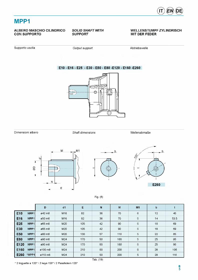
MPP1ALBERO MASCHIO CILINDRICO SOLID SHAFT WITH WELLENSTUMPF ZYLINDRISCHCON SUPPORTO SUPPORT MIT DER FEDER
Supporto uscita Output support Abtriebswelle
E10 - E16 - E25 - E30 - E50 - E80 -E120 - E160 -E260
Dimensioni albero Shaft dimensions WellenabmaUe
b
Fig. (8)
D d1 E N M M1 b t
E10 MPP1 042 m6 M16 82 36 70 6 12 45
E16 MPP1 050 m6 M16 82 36 70 5 14 53.5
E25 MPP1 065 m6 M20 105 42 90 5 18 69
E30 MPP1 065 m6 M20 105 42 90 5 18 69
E50 MPP1 080 m6 M20 130 57 110 5 22 85
E80 MPP1 090 m6 M24 170 50 160 5 25 95
E120 MPP1 090 m6 M24 170 50 160 5 25 95
E160 MPP1 0100 m6 M24 210 50 200 5 28 106
E260 *MPP1 0110 m6 M24 210 50 200 5 28 116
* 2 linguette a 120° / 2 keys 120° / 2 Passfedern 120°Tab. (19)
B5
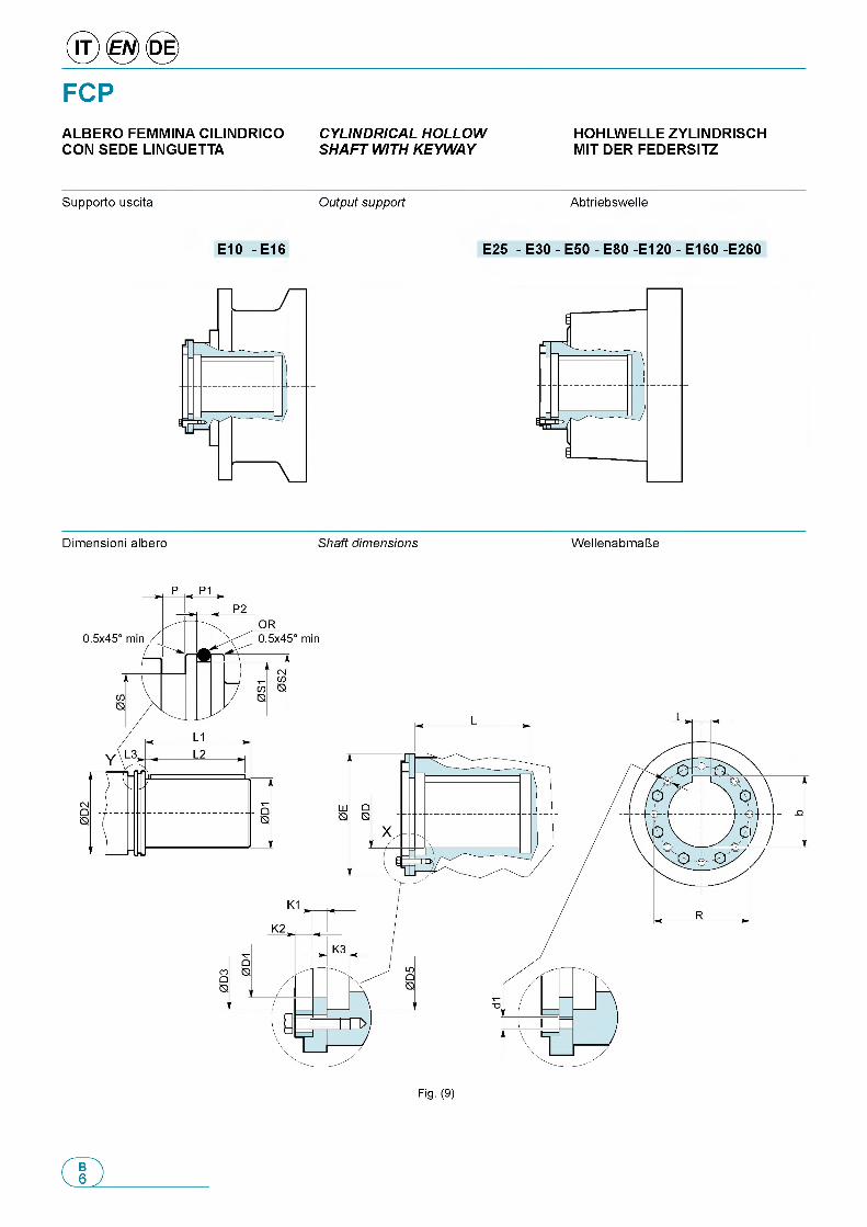
FCPALBERO FEMMINA CILINDRICO CYLINDRICAL HOLLOWCON SEDE LINGUETTA SHAFT WITH KEYWAY
HOHLWELLE ZYLINDRISCH MIT DER FEDERSITZ
Supporto uscita Output support Abtriebswelle
E10 - E16 E25 - E30 - E50 - E80 -E120 - E160 -E260
Fig. (9)
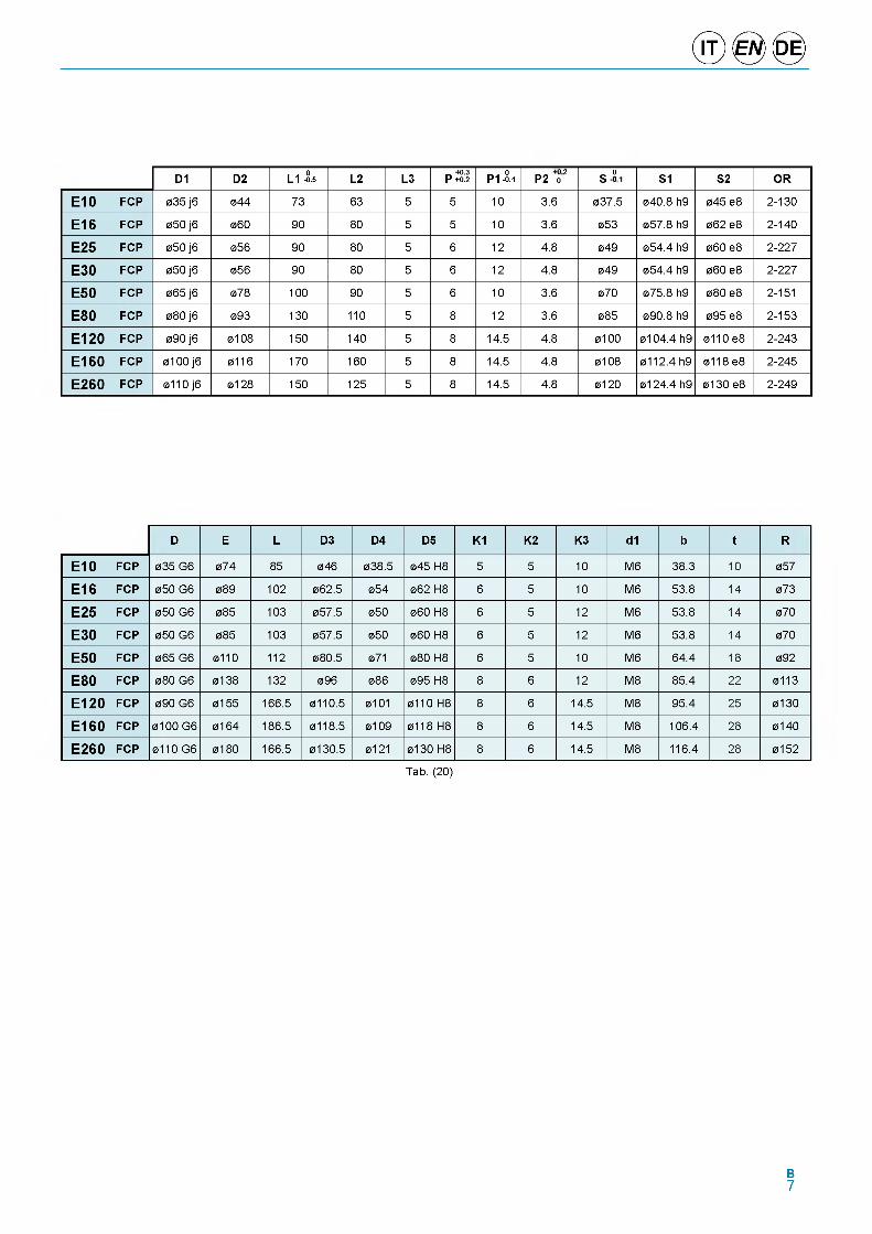
D1 D2 L1 -0.5 L2 L3 _ +0.3 P +0.2 P1 -0.1
CMo°CM0_ CO oo S1 S2 OR
E 10 FCP 035 j6 044 73 63 5 5 10 3.6 037.5 040.8 h9 045 e8 2-130
E 16 FCP 050 j6 060 90 80 5 5 10 3.6 053 057.8 h9 062 e8 2-140
E 25 FCP 050 j6 056 90 80 5 6 12 4.8 049 054.4 h9 060 e8 2-227
E 30 FCP 050 j6 056 90 80 5 6 12 4.8 049 054.4 h9 060 e8 2-227
E 50 FCP 065 j6 078 100 90 5 6 10 3.6 070 075.8 h9 080 e8 2-151
E 80 FCP 080 j6 093 130 110 5 8 12 3.6 085 090.8 h9 095 e8 2-153
E 1 2 0 FCP 090 j6 0108 150 140 5 8 14.5 4.8 0100 0104.4 h9 0110 e8 2-243
E 1 6 0 FCP 0100 j6 0116 170 160 5 8 14.5 4.8 0108 0112.4 h9 0118 e8 2-245
E 2 6 0 FCP 0110 j6 0128 150 125 5 8 14.5 4.8 0120 0124.4 h9 0130 e8 2-249
D E L D3 D4 D5 K1 K2 K3 d1 b t R
E 10 FCP 035 G6 074 85 046 038.5 045 H8 5 5 10 M6 38.3 10 057
E 16 FCP 050 G6 089 102 062.5 054 062 H8 6 5 10 M6 53.8 14 073
E 25 FCP 050 G6 085 103 057.5 050 060 H8 6 5 12 M6 53.8 14 070
E 30 FCP 050 G6 085 103 057.5 050 060 H8 6 5 12 M6 53.8 14 070
E 50 FCP 065 G6 0110 112 080.5 071 080 H8 6 5 10 M6 64.4 18 092
E 80 FCP 080 G6 0138 132 096 086 095 H8 8 6 12 M8 85.4 22 0113
E 1 2 0 FCP 090 G6 0155 166.5 0110.5 0101 0110 H8 8 6 14.5 M8 95.4 25 0130
E 1 6 0 FCP 0100 G6 0164 186.5 0118.5 0109 0118 H8 8 6 14.5 M8 106.4 28 0140
E 2 6 0 FCP 0110 G6 0180 166.5 0130.5 0121 0130 H8 8 6 14.5 M8 116.4 28 0152
Tab. (20)
B7
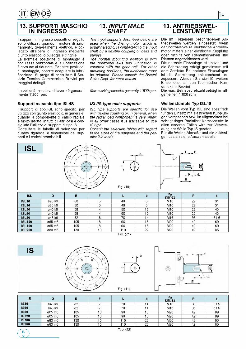
® @ ® >
13. SUPPORTI MASCHIO IN INGRESSO
13. INPUT MALE SHAFT
13. ANTRIEBSWEL- LENSTUMPFE
I supporti in ingresso descritti di seguito sono utilizzati quando il motore di azio- namento, generalmente elettrico, e col- legato all'albero di ingresso mediante giunto elastico, o puleggia e cinghie.La normale posizione di montaggio e con I'asse orizzontale e la lubrificazione e comune al riduttore. Per altre posizioni di montaggio, occorre adeguare la lubrificazione. Si prega di consultare il Ser- vizio Tecnico Commerciale Brevini per maggiori dettagli.
La velocita massima di lavoro e generalmente 1800 rpm.
S u p p o rt i m a s c h io t ip o IS L /ISI supporti di tipo ISL sono specifici per utilizzo con giunto elastico o, in generale, quando la componente di carico radiale e molto ridotta: in tutti gli altri casi e con- sigliato l'utilizzo di supporti di tipo IS. Consultare le tabelle di selezione per quanto riguarda le dimensioni dei supporti e i carichi ammissibili.
The input supports described below are used when the driving motor, which is usually electric, is connected to the input shaft by a flexible coupling or belts and pulleys.The normal mounting position is with the horizontal axis and lubrication is common with the gear unit. For other mounting positions, the lubrication must be adapted. Please consult the Brevini Sales Dept. for more details.
Max. working speed is generally 1800 rpm.
ISL/IS type male supportsISL type supports are specific for use with flexible coupling or, in general, when the radial load component is very small: in all other cases it is advisable to use IS type.Consult the selection tables with regard to the sizes of the supports and the permissible loads.
Die im Folgenden beschriebenen An- triebswellen werden eingesetzt, wenn der normalerweise elektrische Antriebs- motor mittels einer elastische Kupplung oder mithilfe von Riemenscheiben und Riemen angeschlossen wird.Die normale Einbaulage ist koaxial und die Schmierung erfolgt gemeinsam mit dem Getriebe. Bei anderen Einbaulagen ist die Schmierung entsprechend an- zupassen. Wenden Sie sich fQr weitere Einzelheiten an den Technischen Kun- dendienst Brevini.Die max. Betriebsdrehzahl betragt im all- gemeinen 1800 rpm.
W e lle n s tu m p fe T yp IS L /ISDie Wellen vom Typ ISL sind spezifisch fQr den Einsatz mit elastischen Kupplun- gen vorgesehen bzw. im Allgemeinen bei sehr geringer Radiallast-Komponente: in allen anderen Fallen wird zur Verwen- dung der Welle Typ IS geraten.FQr die Wellen AbmaUe und die zulassi- gen Lasten siehe Auswahltabelle.
ISL
Fig. (10)
(q)
ISL D E F L b d2DIN332 P t
ISL10 028 k6 50 5 40 8 M10 22 31ISL16 028 k6 50 5 40 8 M10 22 31ISL30 040 k6 58 4 50 12 M10 22 43ISL50 040 k6 58 4 50 12 M10 22 43ISL80 048 k6 82 6 70 14 M16 36 51.5ISL120 065 m6 105 8 90 18 M20 42 69ISL160 065 m6 105 8 90 18 M20 42 69ISL260 080 m6 130 10 110 22 M20 42 85
Tab. (21)
IS
Fig. (11)
L F
P, E
d2
IS D E F L b d2DIN332 P t
IS30 048 k6 82 7 70 14 M16 36 51.5IS50 048 k6 82 7 70 14 M16 36 51.5IS80 065 m6 105 10 90 18 M20 42 69IS120 065 m6 105 10 90 18 M20 42 69IS160 080 m6 130 10 110 22 M20 42 85IS260 080 m6 130 10 110 22 M20 42 85
Tab. (22)
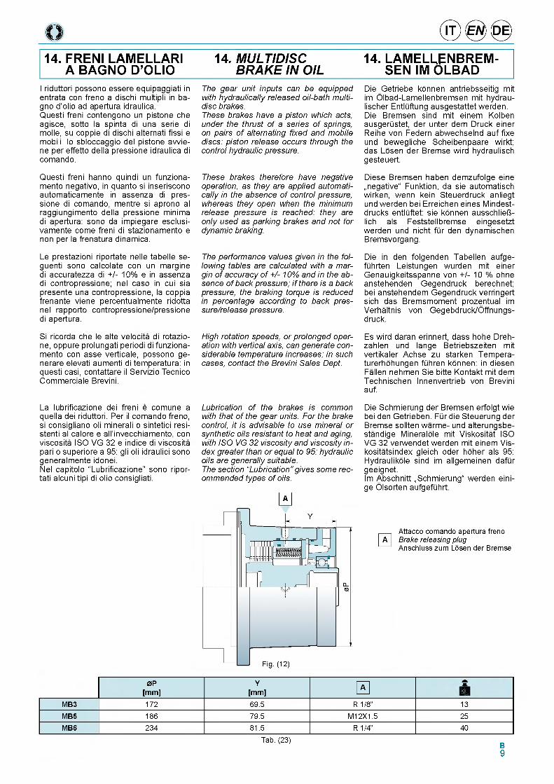
14. FRENI LAMELLAR! 14. MULTIDISC 14. LAMELLENBREM-A BAGNO D’OLIO BRAKE IN OIL SEN IM OLBAD
I riduttori possono essere equipaggiati in entrata con freno a dischi multipli in bagno d'olio ad apertura idraulica.Questi freni contengono un pistone che agisce, sotto la spinta di una serie di molle, su coppie di dischi alternati fissi e mobili: lo sbloccaggio del pistone avvie- ne per effetto della pressione idraulica di comando.
Questi freni hanno quindi un funziona- mento negativo, in quanto si inseriscono automaticamente in assenza di pressione di comando, mentre si aprono al raggiungimento della pressione minima di apertura: sono da impiegare esclusi- vamente come freni di stazionamento e non per la frenatura dinamica.
Le prestazioni riportate nelle tabelle se- guenti sono calcolate con un margine di accuratezza di +/- 10% e in assenza di contropressione; nel caso in cui sia presente una contropressione, la coppia frenante viene percentualmente ridotta nel rapporto contropressione/pressione di apertura.
Si ricorda che le alte velocita di rotazio- ne, oppure prolungati periodi di funziona- mento con asse verticale, possono ge- nerare elevati aumenti di temperatura: in questi casi, contattare il Servizio Tecnico Commerciale Brevini.
The gear unit inputs can be equipped with hydraulically released oil-bath multidisc brakes.These brakes have a piston which acts, under the thrust of a series of springs, on pairs of alternating fixed and mobile discs: piston release occurs through the control hydraulic pressure.
These brakes therefore have negative operation, as they are applied automatically in the absence of control pressure, whereas they open when the minimum release pressure is reached: they are only used as parking brakes and not for dynamic braking.
The performance values given in the following tables are calculated with a margin of accuracy of + /-10% and in the absence of back pressure; i f there is a back pressure, the braking torque is reduced in percentage according to back pres- sure/release pressure.
High rotation speeds, or prolonged operation with vertical axis, can generate considerable temperature increases; in such cases, contact the Brevini Sales Dept.
Die Getriebe konnen antriebsseitig mit im Olbad-Lamellenbremsen mit hydrau- lischer EntlQftung ausgestattet werden. Die Bremsen sind mit einem Kolben ausgerQstet, der unter dem Druck einer Reihe von Federn abwechselnd auf fixe und bewegliche Scheibenpaare wirkt; das Losen der Bremse wird hydraulisch gesteuert.
Diese Bremsen haben demzufolge eine „negative" Funktion, da sie automatisch wirken, wenn kein Steuerdruck anliegt und werden bei Erreichen eines Mindest- drucks entlQftet: sie konnen ausschliei- lich als Feststellbremse eingesetzt werden und nicht fQr den dynamischen Bremsvorgang.
Die in den folgenden Tabellen aufge- fQhrten Leistungen wurden mit einer Genauigkeitsspanne von +/- 10 % ohne anstehenden Gegendruck berechnet; bei anstehendem Gegendruck verringert sich das Bremsmoment prozentual im Verhaltnis von Gegebdruck/Offnungs- druck.
Es wird daran erinnert, dass hohe Dreh- zahlen und lange Betriebszeiten mit vertikaler Achse zu starken Tempera- turerhohungen fQhren konnen: in diesen Fallen nehmen Sie bitte Kontakt mit dem Technischen Innenvertrieb von Brevini auf.
La lubrificazione dei freni e comune a quella dei riduttori. Per il comando freno, si consigliano oli minerali o sintetici resi- stenti al calore e all'invecchiamento, con viscosita ISO VG 32 e indice di viscosita pari o superiore a 95: gli oli idraulici sono generalmente idonei.Nel capitolo “Lubrificazione” sono ripor- tati alcuni tipi di olio consigliati.
Lubrication of the brakes is common with that of the gear units. For the brake control, it is advisable to use mineral or synthetic oils resistant to heat and aging, with ISO VG 32 viscosity and viscosity index greater than or equal to 95: hydraulic oils are generally suitable.The section “Lubrication” gives some recommended types of oils.
A
Die Schmierung der Bremsen erfolgt wie bei den Getrieben. FQr die Steuerung der Bremse sollten warme- und alterungsbe- standige Mineralole mit Viskositat ISO VG 32 verwendet werden mit einem Vis- kositatsindex gleich oder hoher als 95: Hydraulikole sind im allgemeinen dafQr geeignet.Im Abschnitt „Schmierung" werden eini- ge Olsorten aufgefQhrt.
Attacco comando apertura freno Brake releasing plug Anschluss zum Losen der Bremse
0 P Y As
[m m ] [mm] kgM B3 172 69.5 R 1/8” 13M B5 186 79.5 M12X1.5 25MB6 234 81.5 R 1/4” 40
Tab. (23)B9
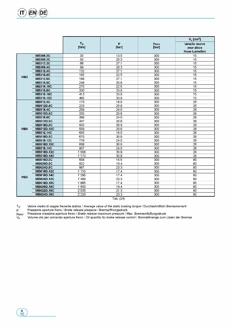
Tb
[Nm]P
[bar]pMAX[bar]
Va [cm3]lamelle nuove
new discs Neue Lamellen
MB306.2C 33 13.5 300 15MB309.2C 50 20.3 300 15MB312.2C 66 27.1 300 15MB309.4C 99 20.3 300 15MB312.4C 132 27.1 300 15MB310.6C 165 22.5 300 15
MB3 MB312.6C 198 27.1 300 15MB315.6C 248 33.8 300 15MB310.10C 275 22.5 300 15MB315.8C 330 33.8 300 15MB315.10C 413 33.8 300 15MB315.12C 495 33.8 300 15MB512.4C 173 16.0 300 26MB512D.4C 223 20.6 300 26MB518.4C 259 24.0 300 26MB512D.6C 335 20.6 300 26MB518.6C 389 24.0 300 26MB512D.8C 447 20.6 300 26MB518D.6C 503 30.9 300 26
MB5 MB512D.10C 559 20.6 300 26MB512.14C 605 16.0 300 26MB518D.8C 670 30.9 300 26MB518.12C 778 24.0 300 26MB518D.10C 838 30.9 300 26MB518.14C 907 24.0 300 26MB518D.12C 1006 30.9 300 26MB518D.14C 1173 30.9 300 26MB616D.8C 658 15.5 300 60MB620D.8C 822 19.4 300 60MB624D.8C 987 23.3 300 60MB618D.12C 1110 17.4 300 60MB618D.14C 1295 17.4 300 60
MB6 MB624D.12C 1480 23.3 300 60MB618D.18C 1665 17.4 300 60MB620D.18C 1850 19.4 300 60MB622D.18C 2 035 21.3 300 60MB624D.18C 2 220 23.3 300 60
Tab. (24)
TB: Valore medio di coppia frenante statica / Average value of the static braking torque / Durchschnittlich Bremsmomentp: Pressione apertura freno / Brake release pressure / BremsoffnungsdruckPmax: Pressione massima apertura freno / Brake release maximum pressure / Max. BremsentluftungsdruckVa: Volume olio per comando apertura freno / Oil quantity for brake release control / Bremsolmenge zum Losen der Bremse
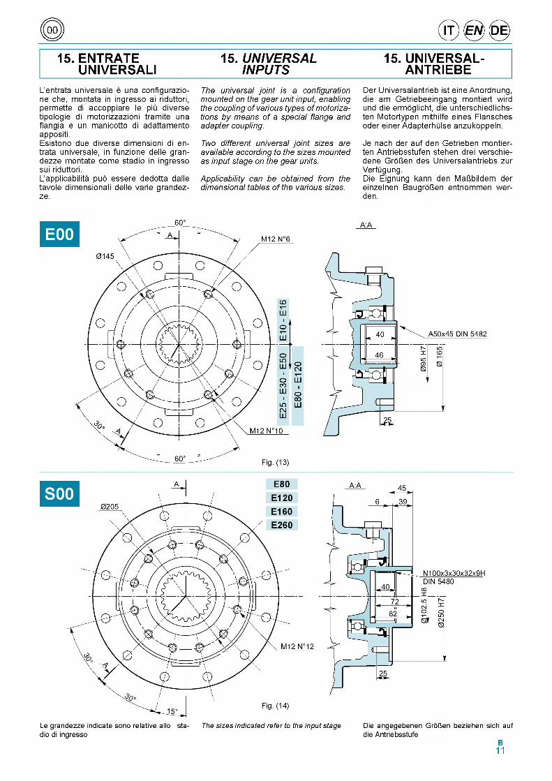
C 0 i) © ® ©
15. ENTRATE UNIVERSAL!
15. UNIVERSAL INPUTS
15. UNIVERSAL- ANTRIEBE
L'entrata universale e una configurazio- ne che, montata in ingresso ai riduttori, permette di accoppiare le piii diverse tipologie di motorizzazioni tramite una flangia e un manicotto di adattamento appositi.Esistono due diverse dimensioni di en- trata universale, in funzione delle gran- dezze montate come stadio in ingresso sui riduttori.L'applicabilita puo essere dedotta dalle tavole dimensionali delle varie grandez- ze.
The universal joint is a configuration mounted on the gear unit input, enabling the coupling of various types of motorizations by means of a special flange and adapter coupling.
Two different universal joint sizes are available according to the sizes mounted as input stage on the gear units.
Applicability can be obtained from the dimensional tables of the various sizes.
Der Universalantrieb ist eine Anordnung, die am Getriebeeingang montiert wird und die ermoglicht, die unterschiedlichs- ten Motortypen mithilfe eines Flansches oder einer AdapterhOlse anzukoppeln.
Je nach der auf den Getrieben montier- ten Antriebsstufen stehen drei verschie- dene GroUen des Universalantriebs zur VerfOgung.Die Eignung kann den MaUbildern der einzelnen BaugroUen entnommen wer- den.
Le grandezze indicate sono relative allo sta- The sizes indicated refer to the input stage Die angegebenen GroUen beziehen sich auf dio di ingresso die Antriebsstufe
B11
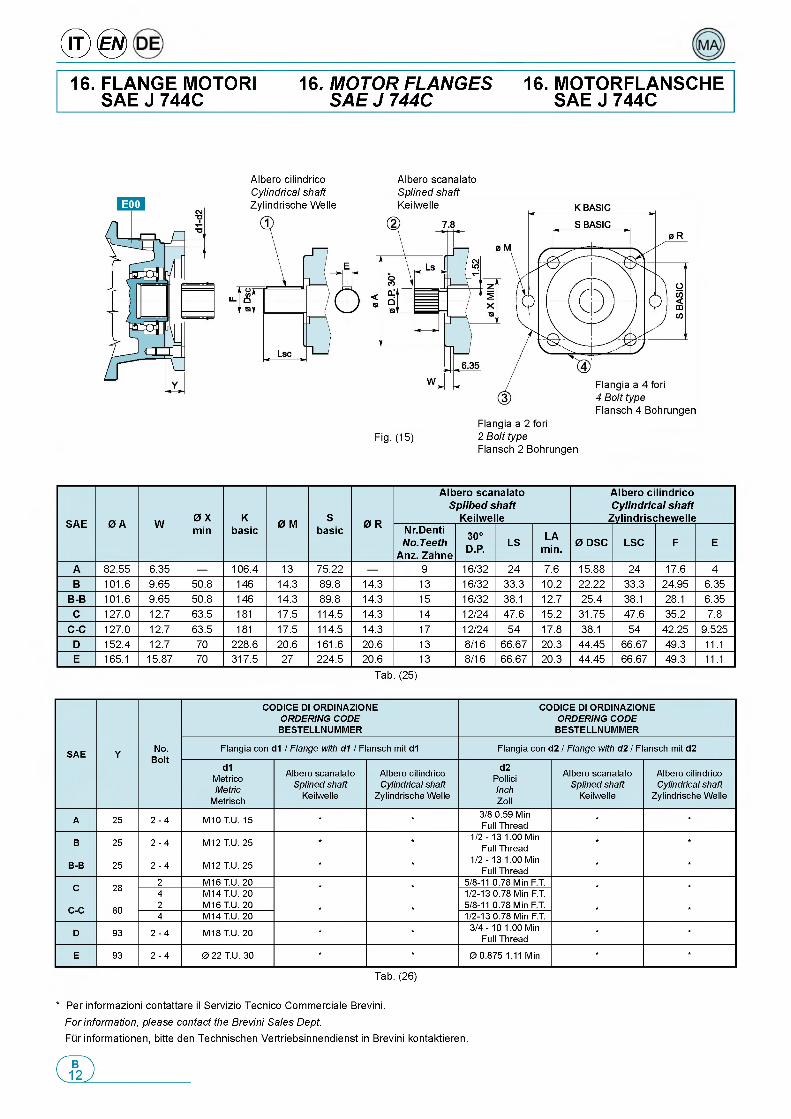
® @16. FLANGE MOTORI
SAE J 744C16. MOTOR FLANGES
SAE J 744C16. MOTORFLANSCHE
SAE J 744C
Albero cilindrico Cylindrical shaft Zylindrische Welle
Albero scanalato Splined shaft
Fig. (15) 2 Bolt typeFlansch 2 Bohrungen
SAE 0 A W 0 X min
Kbasic 0 M S
basic 0 R
Albero scanalato Splibed shaft
Keilwelle
Albero cilindrico Cylindrical shaft
ZylindrischewelleNr.Denti No.Teeth
Anz. Zahne
30°D.P. LS LA
min. 0 DSC LSC F E
A 82.55 6.35 — 106.4 13 75.22 — 9 16/32 24 7.6 15.88 24 17.6 4B 101.6 9.65 50.8 146 14.3 89.8 14.3 13 16/32 33.3 10.2 22.22 33.3 24.95 6.35
B-B 101.6 9.65 50.8 146 14.3 89.8 14.3 15 16/32 38.1 12.7 25.4 38.1 28.1 6.35C 127.0 12.7 63.5 181 17.5 114.5 14.3 14 12/24 47.6 15.2 31.75 47.6 35.2 7.8
C-C 127.0 12.7 63.5 181 17.5 114.5 14.3 17 12/24 54 17.8 38.1 54 42.25 9.525D 152.4 12.7 70 228.6 20.6 161.6 20.6 13 8/16 66.67 20.3 44.45 66.67 49.3 11.1E 165.1 15.87 70 317.5 27 224.5 20.6 13 8/16 66.67 20.3 44.45 66.67 49.3 11.1
Tab. (25)
S A E Y No.Bolt
CO D ICE DI ORDINAZIONE ORDERING CODE
BESTELLNUM M ER
CO D ICE DI ORDINAZIONE ORDERING CODE
BESTELLNUM M ER
Flangia con d1 / Flange with d1 / Flansch mit d1 Flangia con d2 / Flange with d2 / Flansch mit d2
d1MetricoMetric
Metrisch
Albero scanalato Splined shaft
Keilwelle
Albero cilindrico Cylindrical shaft
Zylindrische Welle
d2PolliciInchZoll
Albero scanalato Splined shaft
Keilwelle
Albero cilindrico Cylindrical shaft
Zylindrische Welle
A 25 2 - 4 M10 T.U. 15 * * 3/8 0.59 Min Full Thread
* *
B 25 2 - 4 M12 T.U. 25 * * 1/2 - 13 1.00 Min Full Thread
* *
B-B 25 2 - 4 M12 T.U. 25 * * 1/2 - 13 1.00 Min Full Thread
* *
C 28 2 M16 T.U. 20 * * 5/8-11 0.78 Min F.T. * *4 M14 T.U. 20 1/2 -13 0.78 Min F.T.
C -C 80 2 M16 T.U. 20 * * 5/8-11 0.78 Min F.T. * *4 M14 T.U. 20 1/2 -13 0.78 Min F.T.
D 93 2 - 4 M18 T.U. 20 * * 3/4 - 10 1.00 Min Full Thread
* *
E 93 2 - 4 0 22 T.U. 30 * * 0 0.875 1.11 Min * *
Tab. (26)
* Per informazioni contattare il Servizio Tecnico Commerciale Brevini.For information, please contact the Brevini Sales Dept.Fur informationen, bitte den Technischen Vertriebsinnendienst in Brevini kontaktieren.
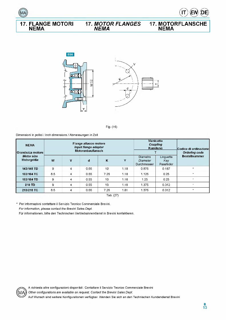
® ® ®17. FLANGE MOTORI
NEMA17. MOTOR FLANGES
NEMA17. MOTORFLANSCHE
NEMA
:
: l H r
Fig. (16)
Dimensioni in pollici / Inch dimensions/ Abmessungen in Zoll
NEMA
Grandezza motore Motor size MotorgroBe
Flange attacco motore Input flange adapter Motoranbauflansch
ManicottoCouplingKupplung Codice di ordinazione
Ordering code Bestellnummer
T
W V d K YDiametroDiameter
Durchmesser
LinguettaKey
Passfeder143/145 TD 9 4 0.55 10 1.18 0.875 0.187 *
182/184 TC 8.5 4 0.55 7.25 1.18 1.125 0.25 *
182/184 TD 9 4 0.55 10 1.18 1.25 0.25 *
210 TD 9 4 0.55 10 1.18 1.375 0.312 *
213/215 TC 8.5 4 0.55 7.25 1.81 1.375 0.312 *
Tab. (27)
* Per informazioni contattare il Servizio Tecnico Commerciale Brevini.For information, please contact the Brevini Sales Dept.Fur informationen, bitte den Technischen Vertriebsinnendienst in Brevini kontaktieren.
A richiesta altre configurazioni disponibili. Contattare il Servizio Tecnico Commerciale Brevini Other configurations are available on request. Contact the Brevini Sales Dept.Auf Wunsch sind weitere Konfigurationen verfugbar. Wenden Sie sich an den Technischen Kundendienst Brevini
B13
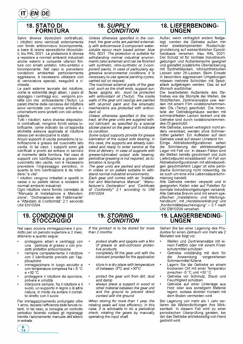
® 0 <0 >18. STATO DI
FORNITURA18. SUPPLY
CONDITION18. LIEFERBENDING-
UNGENSalvo diverse diposizioni contrattuali, i riduttori sono verniciati esternamente con fondo anticorrosivo bicomponente, a base di resine epossidiche idrosolubi- li, blu RAL 5021. La protezione e idonea a resistere a normali ambienti industriali anche esterni e consente ulteriori fini- ture con smalti sintetici, nitro-sintetici o bicomponente. Nel caso si prevedano condizioni ambientali particolarmente aggressive, e necessario utilizzare cicli di verniciatura speciali, eseguibili a ri- chiesta.Le parti esterne lavorate del riduttore, come le estremita degli alberi, i piani di appoggio i centraggi ecc., vengono pro- tette con olio antiossidante (Tectyl). Le pareti interne delle carcasse del riduttore sono verniciate con vernice antiolio e i cinematismi sono protetti con olio antiossidante.Tutti i riduttori, salvo diverse disposizio- ni contrattuali, vengono forniti senza lu- brificante, come indicato da un'apposita etichetta adesiva applicata al riduttore stesso per evidenziarne lo stato.Alcuni supporti di uscita prevedono la lu- brificazione a grasso del cuscinetto lato uscita: in tal caso, i supporti sono gia lubrificati e pronti ad entrare in servizio al momento della fornitura. Nel caso di supporti con lubrificazione a grasso del cuscinetto lato uscita, non e necessario prevedere l'ingrassaggio periodico, in quanto la loro lubrificazione e da inten- dersi “a vita”.I riduttori vengono imballati e spediti in casse o su pallets idonei a resistere in normali ambienti industriali.Ogni riduttore viene fornito corredato di “Manuale di Installazione e Manuten- zione”, “Dichiarazione del Fabbricante” e “Attestato di Conformita” 2.1 secondo UNI EN10204.
Nel caso occorra immagazzinare il pro- dotto per un periodo superiore a 2 mesi, attenersi a quanto segue:• proteggere alberi e centraggi con
una pellicola di grasso o con prodotti protettivi anticorrosione
• riempire completamente il riduttore con il lubrificante previsto per l'ap- plicazione
• immagazzinare in luogo asciutto e con temperatura compresa fra i -5 °C e +30 °C
• proteggere il riduttore da sporcizia, polvere e umidita
• interporre sempre, fra il riduttore e il suolo, un supporto in legno o di altra natura, in modo da evitare il contat- to diretto con il suolo
Per immagazzinamento prolungato oltre 1 anno, decade l’efficienza delle tenute ro- tanti. In tal caso, si consiglia un controllo periodico facendo ruotare gli ingranaggi tramite l'azionamento manuale dell'albero in entrata.
Unless otherwise specified in the contract, the gear units are painted externally with anticorrosive 2-component water- soluble epoxy resin based primer, blue RAL 5021. The protection is suitable for withstanding normal industrial environments (also external) and can be finished with synthetic, nitro-synthetic or 2-component paints. In case of particularly aggressive environmental conditions, it is necessary to use special painting cycles, carried out on request.The machined external parts of the gear unit, such as the shaft ends, support surfaces, spigots, etc., must be protected with antioxidant oil (Tectyl). The inside walls of the gear unit casings are painted with oil-proof paint and the kinematic mechanisms are protected with antioxidant oil.Unless otherwise specified in the contract, all the gear units are supplied without lubricant: as specified by a special sticker placed on the gear unit to indicate its condition.Some output supports provide for grease lubrication of the output side bearing: in this case, the supports are already lubricated and ready to enter service at the time of delivery. In case of supports with grease-lubricated output side bearing, periodical greasing is not required, as lubrication is long-life.The gear units are packed and shipped in crates or on pallets suitable to withstand normal industrial environments. Each gear unit comes with an “Installation and Maintenance Manual”, “Manufacturer’s Declaration” and “Certificate of Conformity” 2.1 according to UNI EN10204.
If the product is to be stored for more than 2 months:
• protect shafts and spigots with a film of grease or anti-corrosion protective products
• completely fill the gear unit with the lubricant provided for the application
• store in a dry place with temperature of between -5°C and +30°C
• protect the gear unit from dirt, dust and damp
• always place a support in wood or other material between the gear unit and the ground to prevent direct contact with the ground
When storing for more than 1 year, the rotating seals will lose efficiency. In this case, it is advisable to do a periodical check, rotating the gears by manually operating the input shaft.
Auier, wenn vertraglich anders festge- legt, werden die Getriebe auien min einer zweikomponenten Rostschutz- grundierung auf wasserloslicher Epoxid- harzbasis versehen, blau RAL 5021. Der Schutz ist fQr normale Industrieum- gebungen und Aulienbereiche geeignet und gestattet zusatzliche Uberlackierung mit Synthetiklacken, nitrosynthetischen Lacken oder 2K-Lacken. Beim Einsatz in besonders aggressiven Umgebungen mQssen mehrere Schichten mit Spezi- allack aufgetragen werden. Das ist auf Wunsch ausfQhrbar.Die bearbeiteten Auienteile des Ge- triebes wie die StQmpfe der Wellen, die StQtzflachen, Zentrieransatze usw. werden mit einem Film oxidationshemmen- den Ols (Tectyl) geschQtzt. Die Innen- teile der Getriebegehause werden mit schmierolfesten Lacken lackiert und die Getriebe sind durch oxidationshemmen- des Ol geschQtzt.Alle Getriebe, soweit vertraglich nicht anders vereinbart, werden ohne Schmier- mittel geliefert. Ein Aufkleber auf dem Getriebe weist auf diesen Umstand hin. Einige Abtriebskonfigurationen sehen die Schmierung der abtriebsseitigen Lager mit Fett vor: in diesen Fallen sind die Wellen bereits geschmiert und zum Lieferzeitpunkt einsatzbereit. Im Fall von Abtriebskonfigurationen mit abtriebsseiti- gen geschmiertem Lager ist eine perio- dische Schmierung nicht notwendig, da es such um eine eine Lebensdauerschn- mierung handelt.Alle Getriebe werden verpackt und in geeigneten Kisten oder auf Paletten fQr normale Industrieumgebungen versandt. Alle Getriebe Brevini sind mit einem spe- zifischen „Installations- und Wartungs- handbuch”, mit „Herstellererklarung“ und „Konformitatsbescheinigung“ - 2.1 nach UNI EM10204 versehen.
Gehen Sie bei einer Lagerung des Pro- duktes fQr einen Zeitraum von mehr als 2 Monaten wie folgt vor:• Wellen und Zentrieransatze mit ei
nem Fettfilm oder mit einem Frost- schutzmittel schQtzen
• Getriebe vollstandig mit dem fQr die Anwendung vorgesehenen Schmiermittel fQllene
• Lagern Sie die Getriebe an einem trockenen Ort mit einer Temperatur zwischen -5 °C und +30 °C
• Getriebe vor Schmutz, Staub und Feuchtigkeit schQtzen
• Getriebe auf einer Unterlage aus Holz oder aus sonstigem Material lagern, sodass direkter Kontakt mit dem Boden vermieden wird
Bei Lagerung von mehr als 1 Jahr ver- lieren die Wellendichtungen ihre Wirk- samkeit. In diesem Fall wird zu einer periodischen UberprQfung geraten, bei der das Getriebe antriebsseitig von Hand gedreht wird.
19. CONDIZIONI DI 19. STORING 19. LANGERBENDING-STOCCAGGIO CONDITION UNGEN
© ® ©In presenza di freno lamellare negativo, e necessario sbloccare il freno con pom- pa idraulica o similare (per pressione di apertura freno vedere capitolo “Freni lamellari a bagno d'olio”). All'atto dell'av- viamento e consigliata la sostituzione delle guarnizioni.
In case of negative multi-disc brake, it is necessary to release the brake with hydraulic pump or similar (for brake opening pressure, see the section “Oil bath multi-disc brakes”). On starting, it is advisable to replace the seals.
Ist eine Lamellenbremse eingebaut, muss diese mithilfe einer Hydraulik- pumpe oder ahnlichem entlQftet werden (fQr den EntlQftungsdruck siehe Kapitel „Olbad-Lamellenbremsen"). Bei der In- betriebnahme sollten die Dichtungen er- setzt werden.
20. INSTALLAZIONE 20. INSTALLATION 20. INSTALLATION
G e n e ra leL'installazione dei riduttori deve esse- re effettuata con cura e professionals, impiegando personale adeguatamente istruito e tecnicamente preparato.La predisposizione al funzionamento deve avvenire rispettando tutte le indi- cazioni tecniche contenute nel Disegno Dimensionale di riferimento.Tutte le operazioni di installazione deb- bono essere ispirate ai massimi livelli di sicurezza:
1 . nei confronti dell'incolumita degli operatori e di terzi
2 . nei confronti del corretto funziona- mento del riduttore
3. nei confronti della sicurezza di eser- cizio
A questo proposito ricordiamo che:
• e assolutamente vietata ogni ma- nipolazione arbitraria al riduttore e a tutti gli accessori eventualmente predisposti all'origine
• tutte le operazioni di sollevamento e trasporto debbono essere effettuate evitando gli urti alle estremita d'albe- ro ed utilizzando apposite cinghie di sospensione o i golfari opportuna- mente predisposti e verificando che i mezzi di sollevamento siano dotati di sufficiente portata
• e assolutamente vietato eseguire la- vori di saldatura sui riduttori
• qualsiasi lavoro di installazione o manutenzione deve essere esegui- to con il riduttore fermo. Quindi e buona norma assicurarsi che non possano verificarsi inserimenti non intenzionali della forza motrice
• per quanto riguarda l'entrata del riduttore, i motori elettrici od idraulici sono frequentemente applicati con il sistema di flangiatura Universale E00 Brevini (vedere il capitolo "En- trate Universali”). Si ricorda che la flangiatura E00 viene normalmente impiegata per motori di massa fino a 100 kg circa e coppia di 1 000 Nm massimo. Nel caso di motori piii pe- santi si puo ricorrere a flangiature specifiche: a tal fine si prega di con- tattare il Servizio Tecnico Commer- ciale Brevini
• nel caso di collegamenti che impli- cano l'impiego di parti rotanti come alberi, giunti o pulegge con cinghie, e obbligatorio prevedere adeguate protezioni antinfortunistiche
GeneralThe gear units must be carefully installed by suitably trained technical personnel.
Preparation for operation must occur in compliance with all the technical specifications given on the reference Dimensional Drawing.All installation operations must ensure:
1. safety of operators and third parties
2. correct operation of the gear unit
3. safe operation
In this respect:
• any arbitrary tampering with the gear unit and with any accessories originally arranged is strictly prohibited
• all lifting and carrying operations must be carried out avoiding impacts on the shaft ends, using special lifting straps or the specially arranged eye-bolts, making sure that the lifting equipment is of adequate capacity
• welding work on the gear units is absolutely prohibited
• any installation or maintenance work must be carried out with the gear unit stopped. Therefore it is advisable to ensure the prevention of unintentional activation of the driving force
• regarding the gear unit input, the electric or hydraulic motors are often mounted with the Brevini E00 Universal adapter system (see the section “Universal Joint”). It should be noted that the adapter E00 is normally used for motors weighing up to approx. 100 kg and 1 000 Nm max. torque. With heavier motors, specific adapters can be used: please contact the Brevini Sales Dept
• with connections involving the use of revolving parts such as shafts, couplings or pulleys with belts, adequate accident-prevention devices must be provided
A llg e m e in e H in w e is eDie Installation der Getriebe muss sorg- faltig und professionell durch technisch ausgebildete Fachkrafte ausgefQhrt wer- den.Die Vorbereitung zur Inbetriebnahme muss entsprechend den technischen Angaben der betreffenden MaUbilder er- folgen.Bei allen Installationsarbeiten sind immer die erforderlichen SicherheitsmaUnah- men zu ergreifen:
1. Sicherheit fQr Techniker und Dritte
2. ordentlicher Betrieb des Getriebes
3. Betriebssicherheit
DiesbezQglich wird daran erinnert, dass:
• jede willkQrliche Veranderung der Getriebe und des eventuell werk- seitig vorgerQsteten Zubehors ist strengstens untersagt
• Beim Anheben und Transport sind StoUe gegen die WellenstQmpfe zu vermeiden und Transportgur- te oder die eigens vorgerQsteten Osenschrauben zu verwenden. Kontrollieren Sie immer, dass das Hebezeug eine ausreichende Trag- fahigkeit aufweist
• Es ist strengsten verboten, an den Getrieben SchweiUarbeiten auszu- fQhren
• Samtliche Installations- oder In- standhaltungsarbeiten sind bei ste- hendem Getriebe durchzufQhren. Es hat sich daher bewahrt, sich zuvor immer zu vergewissern, dass der Antrieb nicht unvorhergesehen an- laufen kann
• Antriebsseitig werden die Elektro- oder Hydraulikmotoren oft mit dem Brevini - der Universalsystem fQr Flanschverbindungen E00 angebaut (siehe Kapitel “Universalantriebe”). Es wird daran erinnert, dass die Flanschverbindung E00 gewohnlich fQr Motoren bis zu einem Gewicht von ca. 100 kg und mit maximalem Drehmoment von 1 000 Nm einge- setzt wird. Bei schwereren Motoren stehen spezielle Flanschverbindun- gen zur VerfQgung: wenden Sie sich diesbezQglich an den Technischen Innenvertrieb von Brevini
• Bei Verbindung mithilfe von rotieren- den Teilen wie Wellen, Kupplungen und Riemenscheiben ist die Installation von Unfallschutzverkleidungen gesetzlich vorgeschrieben
B15
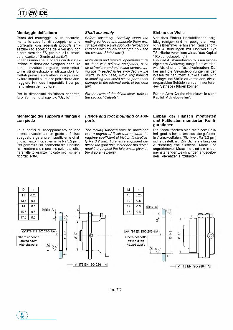
® 0 <0 >
M o n ta g g io d e ll ’a lb e ro
Prima del montaggio, pulire accurata- mente le superfici di accoppiamento e lubrificarle con adeguati prodotti antiseizure (ad eccezione delle versioni con albero cavo tipo FS, per le quali si riman- da al capitolo “Giunto ad attrito”).E' necessario che le operazioni di instal- lazione e rimozione vengano eseguire con attrezzature adeguate, come estrat- tori e viti di estrazione, utilizzando i fori filettati previsti sugli alberi: in ogni caso, evitare impatti o urti che potrebbero dan- neggiare in modo irreparabile i component interni del riduttore.
Per le dimensioni dell'albero condotto, fare riferimento al capitolo “Uscite”.
M o n ta g g io d e i s u p p o rti a f la n g ia e c o n p ie d e
Le superfici di accoppiamento devono essere lavorate con un grado di finitura adeguato a garantire il coefficiente di attrito richiesto (indicativamente Ra 3.2 |mm). Per garantire l'allineamento fra il riduttore, il motore e la macchina azionata, atte- nersi alle tolleranze indicate negli schemi riportati sotto.
Shaft assemblyBefore assembly, carefully clean the mating surfaces and lubricate them with suitable anti-seizure products (except for versions with hollow shaft type FS - see the section “Shrink disc”).
Installation and removal operations must be done with suitable equipment, such as extractors and extraction screws, using the threaded holes provided on the shafts: in any case, avoid any impacts or knocking that could cause permanent damage to the internal parts of the gear unit.
For the sizes of the driven shaft, refer to the section “Outputs”.
Flange and foot mounting of supports
The mating surfaces must be machined with a degree of finish that ensures the required coefficient of friction (indicatively Ra 3.2 p,m). To ensure alignment between the gear unit, motor and the driven machine, respect the tolerances given in the diagrams below.
E in b a u d e r W e lleVor dem Einbau Kontaktflachen sorg- faltig reinigen und mit geeignetem Ver- schleiUhemmer schmieren (ausgenom- men AusfQhrungen mit Hohlwelle Typ TS. HierfQr verweisen wir auf das Kapitel “ Reibungskupplung“).Ein- und Ausbauarbeiten mQssen mit geeignetem Werkzeug ausgefQhrt werden, wie Abzieher und Abziehschrauben. Da- bei sind die Gewindebohrungen in den Wellen zu benutzen: auf alle Falle sind Schlage und StoUe zu vermeiden, die zu irreparablen Schaden an den Innenteilen des Getriebes fiihren konnen.
FQr die AbmaUe der Abtriebswelle siehe Kapitel “Abtriebswellen“.
E in b a u d e r F la n s c h m o n tie rte n u n d F u B le is te n m o n tie r te n K o n fi- g u ra tio n e nDie Kontaktflachen sind mit einem Fein- heitsgrad zu bearbeiten, dass der geforder- te Abriebkoeffizient (Richtwert Ra 3.2 mm) sichergestellt ist. Zur Sicherstellung der Ausrichtung von Getriebe, Motor und angetriebener Maschine sind die in den nachstehenden Zeichnungen angegebe- nen Toleranzen einzuhalten.
D x
11 0.25
13.5 0.5
14 0.5
15.5 0.5
17.5 0.5
0 x At
IT8 EN ISO 286-1A
albero condottodriven shaft
Abtriebswelle AT
IT8 EN ISO 286-11A
M x
10 0.25
12 0.5
14 0.5
16 0.50 x At
IT8 EN ISO 286-
albero condotto driven shaft
Abtriebswelle3.2,
S
m .
IT8 EN ISO 286-1A
A
Fig. (17)
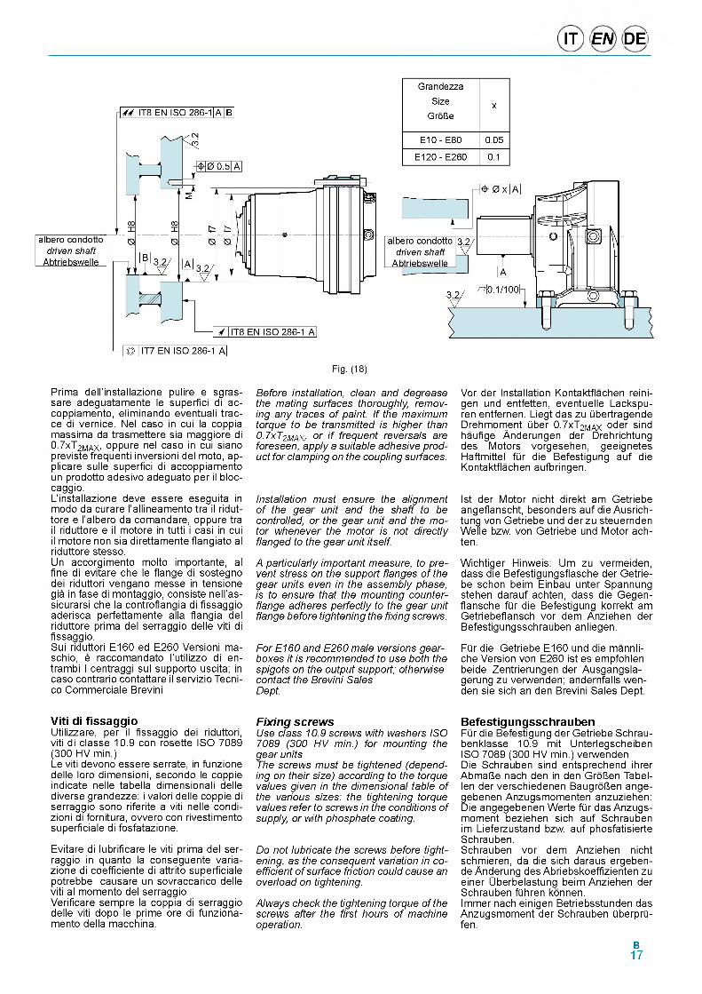
IT EN DE
GrandezzaSize
GroUex
E10 - E80 0.05
E120 - E260 0.1
Prima dell'installazione pulire e sgras- sare adeguatamente le superfid di ac- coppiamento, eliminando eventuali trac- ce di vernice. Nel caso in cui la coppia massima da trasmettere sia maggiore di 07xT2MAX, oppure nel caso in cui siano previste frequenti inversioni del moto, ap- plicare sulle superfid di accoppiamento un prodotto adesivo adeguato per il bloc- caggio.L'installazione deve essere eseguita in modo da curare l'allineamento tra il ridut- tore e l'albero da comandare, oppure tra il riduttore e il motore in tutti i casi in cui il motore non sia direttamente flangiato al riduttore stesso.Un accorgimento molto importante, al fine di evitare che le flange di sostegno dei riduttori vengano messe in tensione gia in fase di montaggio, consiste nell'as- sicurarsi che la controflangia di fissaggio aderisca perfettamente alla flangia del riduttore prima del serraggio delle viti di fissaggio.Sui riduttori E160 ed E260 Versioni ma- schio, e raccomandato l'utilizzo di en- trambi I centraggi sul supporto uscita; in caso contrario contattare il servizio Tecni- co Commerciale Brevini
Before installation, clean and degrease the mating surfaces thoroughly, removing any traces of paint. If the maximum torque to be transmitted is higher than0.7xT2MAX, or i f frequent reversals are foreseen, apply a suitable adhesive product for clamping on the coupling surfaces.
Installation must ensure the alignment of the gear unit and the shaft to be controlled, or the gear unit and the motor whenever the motor is not directly flanged to the gear unit itself.
A particularly important measure, to prevent stress on the support flanges of the gear units even in the assembly phase, is to ensure that the mounting counterflange adheres perfectly to the gear unit flange before tightening the fixing screws.
For E160 and E260 male versions gearboxes it is recommended to use both the spigots on the output support; otherwise contact the Brevini Sales Dept.
Vor der Installation Kontaktflachen reini- gen und entfetten, eventuelle Lackspu- ren entfernen. Liegt das zu libertragende Drehmom.ent liber 0.7xT2MAX oder sind haufige Anderungen der Drehrichtung des Motors vorgesehen, geeignetes Haftmittel flir die Befestigung auf die Kontaktflachen aufbringen.
1st der Motor nicht direkt am Getriebe angeflanscht, besonders auf die Ausrich- tung von Getriebe und der zu steuernden Welle bzw. von Getriebe und Motor ach- ten.
Wichtiger Hinweis: Um zu vermeiden, dass die Befestigungsflasche der Getriebe schon beim Einbau unter Spannung stehen darauf achten, dass die Gegen- flansche flir die Befestigung korrekt am Getriebeflansch vor dem Anziehen der Befestigungsschrauben anliegen.
Flir die Getriebe E160 und die mannli- che Version von E260 ist es empfohlen beide Zentrierungen der Ausgangsla- gerung zu verwenden; andernfalls wen- den sie sich an den Brevini Sales Dept.
V iti di f is s a g g ioUtilizzare, per il fissaggio dei riduttori, viti di classe 10.9 con rosette ISO 7089 (300 HV min.)Le viti devono essere serrate, in funzione delle loro dimensioni, secondo le coppie indicate nelle tabella dimensionali delle diverse grandezze: i valori delle coppie di serraggio sono riferite a viti nelle condi- zioni di fornitura, ovvero con rivestimento superficiale di fosfatazione.
Evitare di lubrificare le viti prima del serraggio in quanto la conseguente varia- zione di coefficiente di attrito superficiale potrebbe causare un sovraccarico delle viti al momento del serraggio Verificare sempre la coppia di serraggio delle viti dopo le prime ore di funziona- mento della macchina.
Fixing screwsUse class 10.9 screws with washers ISO 7089 (300 HV min.) for mounting the gear unitsThe screws must be tightened (depending on their size) according to the torque values given in the dimensional table of the various sizes: the tightening torque values refer to screws in the conditions of supply, or with phosphate coating.
Do not lubricate the screws before tightening, as the consequent variation in coefficient of surface friction could cause an overload on tightening.
Always check the tightening torque of the screws after the first hours of machine operation.
B e fe s tig u n g s s c h ra u b e nFlir die Befestigung der Getriebe Schrau- benklasse 10.9 mit Unterlegscheiben ISO 7089 (300 HV min.) verwenden Die Schrauben sind entsprechend ihrer AbmaUe nach den in den GroUen Tabel- len der verschiedenen BaugroUen ange- gebenen Anzugsmomenten anzuziehen: Die angegebenen Werte flir das Anzugs- moment beziehen sich auf Schrauben im Lieferzustand bzw. auf phosfatisierte Schrauben.Schrauben vor dem Anziehen nicht schmieren, da die sich daraus ergeben- de Anderung des Abriebskoeffizienten zu einer Uberbelastung beim Anziehen der Schrauben flihren konnen.Immer nach einigen Betriebsstunden das Anzugsmoment der Schrauben liberprli- fen.
B17
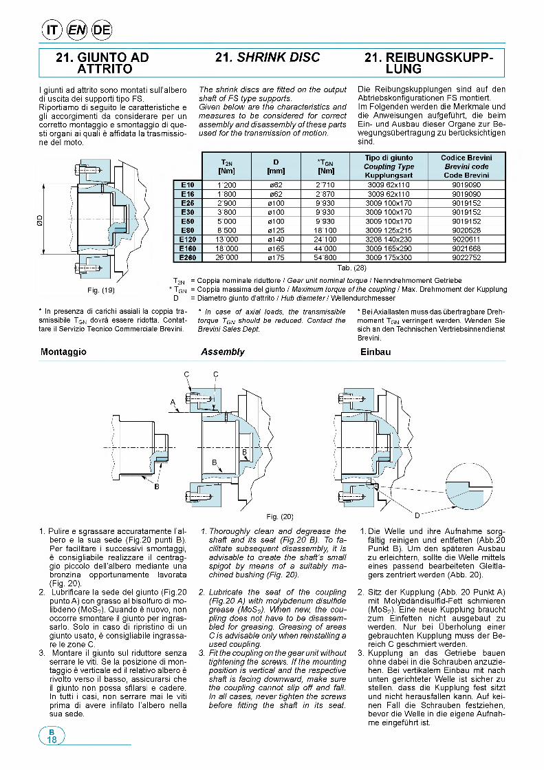
21. GIUNTO AD ATTRITO
21. SHRINK DISC 21. REIBUNGSKUPP- LUNG
I giunti ad attrito sono montati sull'albero di uscita dei supporti tipo FS.Riportiamo di seguito le caratteristiche e gli accorgimenti da considerare per un corretto montaggio e smontaggio di que- sti organi ai quali e affidata la trasmissio- ne del moto.
The shrink discs are fitted on the output shaft of FS type supports.Given below are the characteristics and measures to be considered for correct assembly and disassembly of these parts used for the transmission of motion.
Die Reibungskupplungen sind auf den Abtriebskonfigurationen FS montiert.Im Folgenden werden die Merkmale und die Anweisungen aufgefiihrt, die beim Ein- und Ausbau dieser Organe zur Be- wegungsUbertragung zu berUcksichtigen sind.
T2N
[Nm]D
[mm]*TG N
[Nm]
Tipo di giunto Coupling Type Kupplungsart
Codice Brevini Brevini code Code Brevini
E10 1200 062 2710 3009 62x110 9019090E16 1800 062 2 870 3009 62x110 9019090E25 2900 0100 9 930 3009 100x170 9019152E30 3800 0100 9 930 3009 100x170 9019152E50 5 000 0100 9 930 3009 100x170 9019152E80 8500 0125 18100 3009 125x215 9020528
E120 13 000 0140 24100 3208 140x230 9020611E160 18 000 0165 44000 3009 165x290 9021668E260 26 000 0175 54800 3009 175x300 9022752
Tab. (28)T2N = Coppia nominale riduttore / Gear unit nominal torque / Nenndrehmoment GetriebeTGN = Coppia massima del giunto / Maximum torque of the coupling / Max. Drehmoment der KupplungD = Diametro giunto d’attrito / Hub diameter/ Wellendurchmesser
* In presenza di carichi assiali la coppia tra- smissibile TGN dovra essere ridotta. Contat- tare il Servizio Tecnico Commerciale Brevini.
* In case of axial loads, the transmissible torque TGN should be reduced. Contact the Brevini Sales Dept.
* Bei Axiallasten muss das ubertragbare Drehmoment TGN verringert werden. Wenden Sie sich an den Technischen Vertriebsinnendienst Brevini.
M o n ta g g io Assembly E in b a u
C C
D
1. Pulire e sgrassare accuratamente l’al- bero e la sua sede (Fig.20 punti B). Per facilitare i successivi smontaggi, e consigliabile realizzare il centrag- gio piccolo dell’albero mediante una bronzina opportunamente lavorata (Fig. 20).
2. Lubrificare la sede del giunto (Fig.20 punto A) con grasso al bisolfuro di mo- libdeno (MoS2). Quando e nuovo, non occorre smontare il giunto per ingras- sarlo. Solo in caso di ripristino di un giunto usato, e consigliabile ingrassa- re le zone C.
3. Montare il giunto sul riduttore senza serrare le viti. Se la posizione di montaggio e verticale ed il relativo albero e rivolto verso il basso, assicurarsi che il giunto non possa sfilarsi e cadere. In tutti i casi, non serrare mai le viti prima di avere infilato l'albero nella sua sede.
1. Thoroughly clean and degrease the shaft and its seat (Fig.20 B). To facilitate subsequent disassembly, it is advisable to create the shaft’s small spigot by means of a suitably machined bushing (Fig. 20).
2. Lubricate the seat of the coupling (Fig.20 A) with molybdenum disulfide grease (MoS2). When new, the coupling does not have to be disassembled for greasing. Greasing of areas C is advisable only when reinstalling a used coupling.
3. Fit the coupling on the gear unit without tightening the screws. If the mounting position is vertical and the respective shaft is facing downward, make sure the coupling cannot slip off and fall. In all cases, never tighten the screws before fitting the shaft in its seat.
1. Die Welle und ihre Aufnahme sorg- faltig reinigen und entfetten (Abb.20 Punkt B). Um den spateren Ausbau zu erleichtern, sollte die Welle mittels eines passend bearbeiteten Gleitla- gers zentriert werden (Abb. 20).
2. Sitz der Kupplung (Abb. 20 Punkt A) mit Molybdandisulfid-Fett schmieren (MoS2). Eine neue Kupplung braucht zum Einfetten nicht ausgebaut zu werden. Nur bei Uberholung einer gebrauchten Kupplung muss der Be- reich C geschmiert werden.
3. Kupplung an das Getriebe bauen ohne dabei in die Schrauben anzuzie- hen. Bei vertikalem Einbau mit nach unten gerichteter Welle ist sicher zu stellen, dass die Kupplung fest sitzt und nicht herausfallen kann. Auf kei- nen Fall die Schrauben festziehen, bevor die Welle in die eigene Aufnahme eingefuhrt ist.
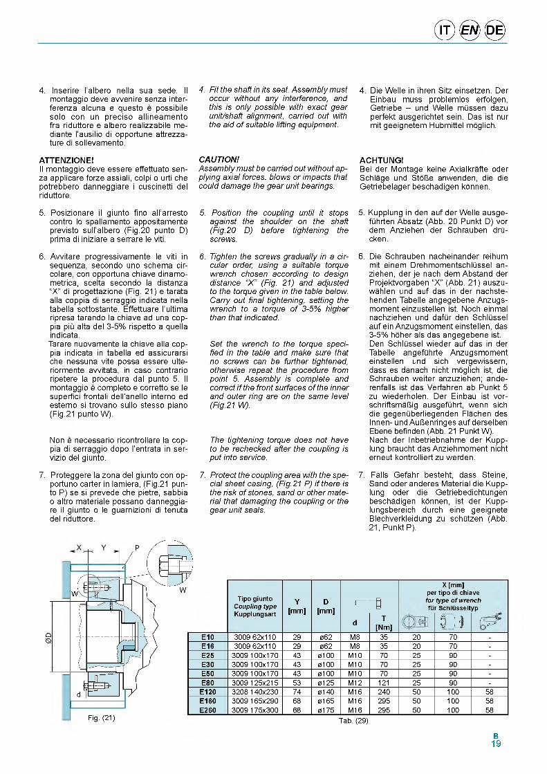
© ® ©
4. Inserire I'albero nella sua sede. Il montaggio deve avvenire senza inter- ferenza alcuna e questo e possibile solo con un preciso allineamento fra riduttore e albero realizzabile me- diante l'ausilio di opportune attrezza- ture di sollevamento.
ATTENZIONE!Il montaggio deve essere effettuato senza applicare forze assiali, colpi o urti che potrebbero danneggiare i cuscinetti del riduttore.
4. Fit the shaft in its seat. Assembly must occur without any interference, and this is only possible with exact gear unit/shaft alignment, carried out with the aid of suitable lifting equipment.
CAUTION!Assembly must be carried out without applying axial forces, blows or impacts that could damage the gear unit bearings.
4. Die Welle in ihren Sitz einsetzen. Der Einbau muss problemlos erfolgen, Getriebe - und Welle mQssen dazu perfekt ausgerichtet sein. Das ist nur mit geeignetem Hubmittel moglich.
ACHTUNG !Bei der Montage keine Axialkrafte oder Schlage und StoUe anwenden, die die Getriebelager beschadigen konnen.
5. Posizionare il giunto fino all'arresto contro lo spallamento appositamente previsto sull'albero (Fig.20 punto D) prima di iniziare a serrare le viti.
6. Avvitare progressivamente le viti in sequenza, secondo uno schema cir- colare, con opportuna chiave dinamo- metrica, scelta secondo la distanza “X” di progettazione (Fig. 21) e tarata alla coppia di serraggio indicata nella tabella sottostante. Effettuare l'ultima ripresa tarando la chiave ad una coppia piii alta del 3-5% rispetto a quella indicata.Tarare nuovamente la chiave alla coppia indicata in tabella ed assicurarsi che nessuna vite possa essere ulte- riormente avvitata, in caso contrario ripetere la procedura dal punto 5. Il montaggio e completo e corretto se le superfici frontali dell'anello interno ed esterno si trovano sullo stesso piano (Fig.21 punto W).
Non e necessario ricontrollare la coppia di serraggio dopo l'entrata in ser- vizio del giunto.
7. Proteggere la zona del giunto con op- portuno carter in lamiera, (Fig.21 punto P) se si prevede che pietre, sabbia o altro materiale possano danneggiare il giunto o le guarnizioni di tenuta del riduttore.
5. Position the coupling until it stops against the shoulder on the shaft (Fig.20 D) before tightening the screws.
6. Tighten the screws gradually in a circular order, using a suitable torque wrench chosen according to design distance “X ” (Fig. 21) and adjusted to the torque given in the table below. Carry out final tightening, setting the wrench to a torque of 3-5% higher than that indicated.
Set the wrench to the torque specified in the table and make sure that no screws can be further tightened, otherwise repeat the procedure from point 5. Assembly is complete and correct i f the front surfaces of the inner and outer ring are on the same level (Fig.21 W).
The tightening torque does not have to be rechecked after the coupling is put into service.
7. Protect the coupling area with the special sheet casing, (Fig.21 P) if there is the risk of stones, sand or other material that damaging the coupling or the gear unit seals.
5. Kupplung in den auf der Welle ausge- fQhrten Absatz (Abb. 20 Punkt D) vor dem Anziehen der Schrauben drQ- cken.
6. Die Schrauben nacheinander reihum mit einem DrehmomentschlQssel anziehen, der je nach dem Abstand der Projektvorgaben “X” (Abb. 21) auszu- wahlen und auf das in der nachste- henden Tabelle angegebene Anzugs- moment einzustellen ist. Noch einmal nachziehen und dafQr den SchlQssel auf ein Anzugsmoment einstellen, das 3-5% hoher als das angegebene ist. Den SchlQssel wieder auf das in der Tabelle angefQhrte Anzugsmoment einstellen und sich vergewissern, dass es danach nicht moglich ist, die Schrauben weiter anzuziehen; ande- renfalls ist das Verfahren ab Punkt 5 zu wiederholen. Der Einbau ist vor- schriftsmaUig ausgefQhrt, wenn sich die gegenQberliegenden Flachen des Innen- und AuUenringes auf derselben Ebene befinden (Abb. 21 Punkt W). Nach der Inbetriebnahme der Kupplung braucht das Anziehmoment nicht erneut kontrolliert zu werden.
7. Falls Gefahr besteht, dass Steine, Sand oder anderes Material die Kupplung oder die Getriebedichtungen beschadigen konnen, ist der Kupp- lungsbereich durch eine geeignete Blechverkleidung zu schQtzen (Abb. 21, Punkt P).
QS
J
( £ ГW
Fig. (21)
Tipo giunto Coupling type Kupplungsart
Y[mm]
D[mm]
Г— Г 0
X [mm]per tipo di chiave for type of wrench fur Schlusseltyp
d T[Nm] 0J3
E10 3009 62x110 29 062 M8 35 20 70 -E16 3009 62x110 29 062 M8 35 20 70 -E25 3009 100x170 43 0100 M10 70 25 90 -E30 3009 100x170 43 0100 M10 70 25 90 -E50 3009 100x170 43 0100 M10 70 25 90 -E80 3009 125x215 53 0125 M12 121 25 90 -
E120 3208 140x230 74 0140 M16 240 50 100 58E160 3009 165x290 68 0165 M16 295 50 100 58E260 3009 175x300 68 0175 M16 295 50 100 58
Tab. (29)
B19
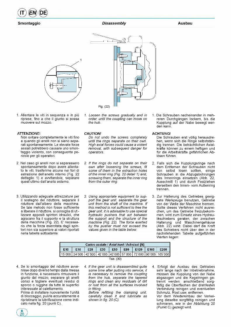
S m on tag g io Disassembly A usbau
1
Fig. (22) -
1. Allentare le viti in sequenza e in piii riprese, fino a che il giunto si possa muovere sul mozzo.
ATTENZIONE!Non svitare completamente le viti fino a quando gli anelli non si siano sepa- rati spontaneamente. Le elevate forze assiali potrebbero causare uno smontaggio violento, con conseguente pe- ricolo per gli operatori.
2 . Nel caso gli anelli non si separassero spontaneamente dopo avere allenta- to le viti, trasferirne alcune nei fori di estrazione dell'anello interno (Fig. 22 dettaglio 1 ) e avvitandole, separare quest'ultimo dall'anello esterno.
3. Utilizzando adeguate attrezzature per il sostegno del riduttore, separare il riduttore dall'albero della macchina. Se tale metodo non fosse sufficiente a liberare il riduttore, si consiglia di uti- lizzare appositi spintori idraulici, che agiscano fra il supporto e la struttura della macchina (Fig. 22). E' necessa- rio che la forza esercitata dagli spin- tori non sia superiore ai valori riportati nella tabella sottostante:
1. Loosen the screws gradually and in order, until the coupling can move on the hub.
CAUTION!Do not undo the screws completely until the rings separate on their own. High axial forces could cause a violent removal, with subsequent danger for operators.
2. If the rings do not separate on their own after loosening the screws, fit some of them in the extraction holes of the inner ring (Fig. 22 detail 1) and, screwing them, separate the inner ring from the outer ring.
3. Using appropriate equipment to support the gear unit, separate the gear unit from the shaft of the machine. If this method is not sufficient to free the gear unit, it is advisable to use special hydraulic pushers that act between the support and the structure of the machine (Fig. 22). The force exerted by the pusher must not exceed the values given in the table below:
1. Die Schrauben nacheinander in meh- reren Durchgangen lockern, bis die Kupplung auf der Nabe bewegt wer- den kann.
ACHTUNG!Die Schrauben erst vollig herausdre- hen, wenn sich die Ringe selbststan- dig trennen. Die betrachtlichen Axial- krafte konnen zu einem heftigen und flir die Arbeitskrafte gefahrlichen Ab- losen flihren.
2. Falls sich die Kupplungsringe nach dem Entfernen der Schrauben nicht von selbst losen sollten, einige Schrauben in die Abzugsbohrungen des Innenrings einsetzen (Abb. 22, Ausschnitt 1) und durch Festziehen derselben den Innen- vom AuUenring trennen.
3. Zur Halterung des Getriebes geeig- nete Werkzeuge benutzen, Getriebe von der Welle der Maschine trennen. Sollte dieses Verfahren nicht ausrei- chen, um das Getriebe freizubekom- men, wird zum Einsatz eines Hydrau- likschiebers geraten, der zwischen Halterung und Maschinengehause (Abb. 22) wirkt. Dabei darf die Kraft des Schiebers nicht liber den in der nachstehenden Tabelle aufgefiihrten Werten liegen:
Carico assiale / Axial load / Achslast [N]E10 E16 E25 E30 E50 E80 E120 E160 E260
15 000 24000 42 000 42 000 42 000 57 000 72 000 90 000 105 000Tab. (30)
4. Se lo smontaggio del riduttore avve- nisse dopo diverso tempo dalla messa in funzione, e necessario rimuovere il giunto dal mozzo, separare gli anelli conici e togliere eventuali residui di sporco o ruggine da tutte le superfici interessate al calettamento.Prima di installare nuovamente l'unita di bloccaggio, pulirla accuratamente e ripristinare la lubrificazione come indi- cato nella fig. 20 (punti C).
4. If the gear unit is disassembled quite some time after putting into service, it is necessary to remove the coupling from the hub, separate the tapered rings and clean any residuals of dirt or rust from all the surfaces involved in fitting.Before refitting the clamping unit, carefully clean it and lubricate as shown in fig. 20 (C).
4. Erfolgt der Ausbau des Getriebes sehr lange nach der Inbetriebnahme, mlissen die Kupplung von der Nabe abgezogen und die Kegelringen ge- trennt werden; anschlieUend sorg- faltig die Oberflachen der drehfesten Verbindung reinigen und eventuellen Schmutz, Rost usw. entfernen.Vor dem Wiedereinbau der Verkei- lung dieselbe sorgfaltig reinigen und schmieren, wie in der Abbildung 20 (Punkt C) gezeigt wird.
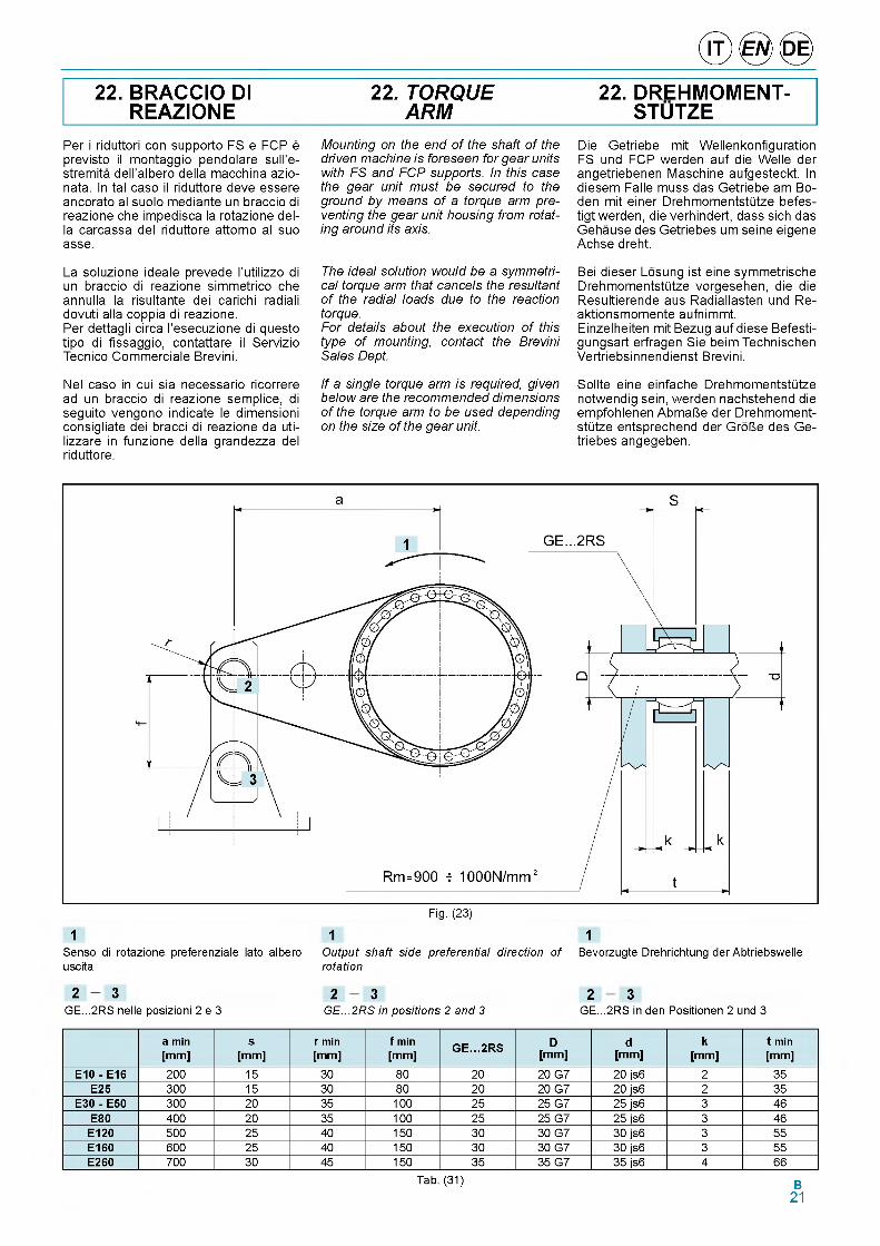
22. BRACCIO DI REAZIONE
22. TORQUE ARM
22. DREHMOMENT- STUTZE
Per i riduttori con supporto FS e FCP e previsto il montaggio pendolare sull'e- stremita dell'albero della macchina azio- nata. In tal caso il riduttore deve essere ancorato al suolo mediante un braccio di reazione che impedisca la rotazione della carcassa del riduttore attorno al suo asse.
La soluzione ideale prevede l'utilizzo di un braccio di reazione simmetrico che annulla la risultante dei carichi radiali dovuti alla coppia di reazione.Per dettagli circa l'esecuzione di questo tipo di fissaggio, contattare il Servizio Tecnico Commerciale Brevini.
Nel caso in cui sia necessario ricorrere ad un braccio di reazione semplice, di seguito vengono indicate le dimensioni consigliate dei bracci di reazione da uti- lizzare in funzione della grandezza del riduttore.
Mounting on the end of the shaft of the driven machine is foreseen for gear units with FS and FCP supports. In this case the gear unit must be secured to the ground by means of a torque arm preventing the gear unit housing from rotating around its axis.
The ideal solution would be a symmetrical torque arm that cancels the resultant of the radial loads due to the reaction torque.For details about the execution of this type of mounting, contact the Brevini Sales Dept.
If a single torque arm is required, given below are the recommended dimensions of the torque arm to be used depending on the size of the gear unit.
Die Getriebe mit Wellenkonfiguration FS und FCP werden auf die Welle der angetriebenen Maschine aufgesteckt. In diesem Falle muss das Getriebe am Bo- den mit einer DrehmomentstQtze befes- tigt werden, die verhindert, dass sich das Gehause des Getriebes um seine eigene Achse dreht.
Bei dieser Losung ist eine symmetrische DrehmomentstQtze vorgesehen, die die Resultierende aus Radiallasten und Re- aktionsmomente aufnimmt.Einzelheiten mit Bezug auf diese Befesti- gungsart erfragen Sie beim Technischen Vertriebsinnendienst Brevini.
Sollte eine einfache DrehmomentstQtze notwendig sein, werden nachstehend die empfohlenen AbmaUe der DrehmomentstQtze entsprechend der GrolJe des Ge- triebes angegeben.
1 1 1Senso di rotazione preferenziale lato albero Output shaft side preferential direction of Bevorzugte Drehrichtung der Abtriebswelle uscita rotation
2 3 2 3 2 3GE...2RS nelle posizioni 2 e 3 GE...2RS in positions 2 and 3 GE...2RS in den Positionen 2 und 3
a min [m m ]
s[m m ]
r min [m m ]
f min [m m ]
G E . . . 2 R S D[m m ]
d[m m ]
k[mm]
t min [m m ]
E 1 0 - E 16 200 15 30 80 20 20 G7 20 js6 2 35E 2 5 300 15 30 80 20 20 G7 20 js6 2 35
E 30 - E50 300 20 35 100 25 25 G7 25 js6 3 46E80 400 20 35 100 25 25 G7 25 js6 3 46
E 1 2 0 500 25 40 150 30 30 G7 30 js6 3 55E 16 0 600 25 40 150 30 30 G7 30 js6 3 55E260 700 30 45 150 35 35 G7 35 js6 4 66
Tab. (31) B21
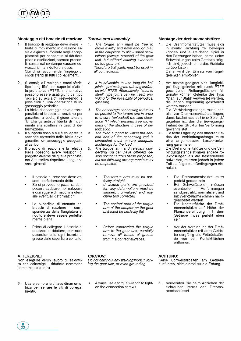
® 0 <0 >
M o n ta g g io d e l b ra c c io d i re a z io n e1 . Il braccio di reazione deve avere li-
berta di movimento in direzione as- siale e gioco sufficiente negli accop- piamenti per consentire al riduttore piccole oscillazioni, sempre presen- ti, senza nel contempo causare so- vraccarichi al riduttore stesso. Quindi si raccomanda l'impiego di snodi sferici in tutti i collegamenti.
2. Si consiglia l'impiego di snodi sferici tipo “ long life” con superfid d'attri- to protette con PTFE. In alternativa possono essere usati giunti del tipo “acciaio su acciaio”, prevedendo la possibilita di una operazione di in- grassaggio periodica.
3. La biella di ancoraggio deve essere parallela al braccio di reazione per garantire, a vuoto, il gioco laterale “k” che garantisce liberta di movimento alla struttura in caso di de- formazione.
4. Il supporto fisso a cui e collegata la seconda estremita della biella deve garantire un ancoraggio adeguato al carico.
5. Il braccio di reazione e la relativa biella possono avere soluzioni di progetto diverse da quelle proposte, ma e tassativo rispettare i seguenti accorgimenti:
• Il braccio di reazione deve essere perfettamente dritto
• Se si prevedono pezzi saldati, occorre sabbiare, normalizzare e correggere di macchina uten- sile eventuali deformazioni
• La superficie di contatto del braccio di reazione in corri- spondenza della flangiatura al riduttore deve essere perfetta- mente piana
• Prima di collegare il braccio di reazione al riduttore, eliminare accuratamente ogni traccia di grasso dalle superfici a contatto.
ATTENZIONE!Non eseguire alcun lavoro di saldatu- ra che coinvolga il riduttore nemmeno come messa a terra.
6. Usare sempre la chiave dinamome- trica per serrare le viti di collega- mento.
Torque arm assembly1. The torque arm must be free to
move axially and have enough play in the couplings to allow small oscillations (always present) of the gear unit, but without causing overloads on the gear unit.
Therefore ball joints must be used in all connections.
2. It is advisable to use long-life ball jo in ts , protecting the rubbing surfaces with PTFE. Alternatively, “steel to steel” type joints can be used, providing for the possibility of periodical greasing.
3. The anchorage connecting rod must be parallel to the torque arm in order to ensure (unloaded) the side clearance “k” which ensures free movement of the structure in case of deformation.
4. The fixed support to which the second end of the connecting rod is connected must ensure adequate anchorage for the load.
5. The torque arm and relevant connecting rod can have different design solutions from those proposed, but the following arrangements must be respected:
• The torque arm must be perfectly straight
• If welded parts are provided for, any deformations must be sanded, normalized and machine tool corrected
• The contact area of the torque arm at the adapter on the gear unit must be perfectly flat
• Before connecting the torque arm to the gear unit, carefully remove all traces of grease from the contact surfaces.
CAUTION!Do not carry out any welding work involving the gear unit, or even grounding.
6. Always use a torque wrench to tighten the connection screws.
M o n ta g e d e r d re h m o m e n ts tu tz e1. Die Drehmomentstutze muss sich
in axialer Richtung frei bewegen konnen und ausreichend Spiel in den Passungen haben, damit kleine Schwankungen beim Getriebe mog- lich sind, jedoch ohne das Getriebe zu uberlasten.Daher wird der Einsatz von Kugel- gelenken empfohlen.
2. Am besten geeignet sind “langlebi- ge” Kugelgelenke mit durch PTFE geschUtzten Reibungsflachen. Al- ternativ konnen Gelenke des Typs “Stahl auf Stahl” verwendet werden, die jedoch regelmaUig geschmiert werden mussen.
3. Die Verbindungsstange muss parallel zur Drehmomentstutze liegen, damit lastfrei das seitliche Spiel „k“ gegeben ist, das die Bewegungs- freiheit der Struktur bei Verformung gewahrleistet.
4. Die feste Lagerung des anderen En- des der Verbindungsstange muss eine angemessene Lastveranke- rung garantieren.
5. Die Drehmomentstutze und die Verbindungsstange konnen andere ro- jektlosungen als die beschriebene aufweisen, mussen jedoch in jedem Fall die folgenden Bedingungen ein- halten:
• Die Drehmomentstutze mussperfekt gerade sein
• Bei SchweiUstellen mUsseneventuelle Verformungen sandgestrahlt, normalisiert und mit Werkzeugmaschinen nach- gearbeitet werden
• Die Kontaktflache der Drehmomentstutze auf Hohe der Flanschverbindung mit dem Getriebe muss perfekt eben sein
• Vor der Verbindung der Dreh-momentstutze mit dem Getrie- be sorgfaltig alle Fettruckstan- de von den Kontaktflachen entfernen.
ACHTUNG!Keine SchweiUarbeiten am Getriebe ausfuhren, nicht einmal fur die Erdung.
6. Verwenden Sie beim Anziehen der Schrauben immer den Drehmo- mentschlussel.
© ® ©
7. La fig. 23 fornisce un esempio indi- cativo, poiche la configurazione cor- retta dipende dal senso di rotazione del riduttore. Infatti, durante il lavo- ro, e consigliabile che la biella risulti in trazione e non in compressione: la figura di pag. B21 indica, a tale proposito, il senso di rotazione pre- ferenziale affinche tale condizione sia verificata.Se necessario, eseguire il montag- gio del braccio di reazione dal lato opposto a quello riportato in Fig. 23.
In caso di necessita, a causa di in- gombri specifici, la biella puo essere montata verso l'alto.
8. Quando si esegue un montaggio di tipo pendolare, occorre ricordare che i pesi del riduttore, del braccio di reazione e di tutti gli elementi ad essi collegati, inducono carichi e momenti ribaltanti che vengono sopportati dai cuscinetti del sup- porto d'uscita.Quindi la posizione relativa di tutte le masse che concorrono alla tra- smissione della potenza deve es- sere valutata in sede di progetto al fine di rendere minimo il valore delle risultanti su detti cuscinetti.Per le stesse ragioni e chiaro che si deve limitare al massimo il peso dei componenti collegati al riduttore, valutando accuratamente gli spes- sori delle strutture effettivamente necessarie a reggere gli sforzi e de- centrando tutti gli elementi che non sono funzionali alla trasmissione di potenza.
Una progettazione impropria, puo ridurre la vita dei riduttori causando cedimenti prematuri dei cuscinetti e degli ingranaggi a causa di eccessi- ve deformazioni elastiche degli stadi e determinare la possibilita di slit- tamento e grippaggio del giunto ad attrito.
7. Fig. 23 is given only by way of example, since the correct configuration depends on the gear unit rotation direction. In fact, during the work, it is advisable for the connecting rod to be in traction and not compression: the figure on p. B21 shows the preferential direction of rotation so that this condition is met.
If necessary, mount the torque arm on the opposite side to that shown in Fig. 23.
If necessary, due to specific encumbrance, the connecting rod can be assembled upward.
8. When doing a shaft mounting type assembly, remember that the weights of the gear unit, the torque arm and all the elements connected to them create loads and tipping moments that are supported by the output support bearings.
Therefore the relative position of all the masses involved in transmitting power must be appraised in the design phase, in order to minimize the resultant value on the bearings.
Likewise, the weight of the components connected to the gear unit must be limited as much as possible, carefully appraising the thicknesses of the structures actually necessary for supporting the stresses, and decentralizing all the elements not involved in power transmission.
An incorrect design can shorten the life of the gear units, causing early giving of the bearings and gears due to excessive elastic deformation of the stages, with the possibility of the shrink disc slipping and seizing.
7. Abb. 23 stellt nur ein Beispiel vor, da die genaue Konfiguration immer von der Drehrichtung des Getriebes abhangt. Bei der AusfQhrung der Ar- beiten sollte die Verbindungsstange immer zugbelastet und nicht druck- belastet sein: die Abbildung auf Seite B21 gibt in diesem Zusammenhang die bevorzugte Drehrichtung an, da- mit sich diese Bedingung einstellt. Notigenfalls die DrehmomentstQtze auf der gegenQberliegenden Seite der in Abb. 23 gezeigten Position anbringen Abb.23.Bei Bedarf infolge besonderer Abmessungen kann die Schubstre- be in nach oben gerichteter Stellung montiert werden.
8. In der AufsteckausfQhrung darf nicht vergessen werden, dass das Gewicht des Getriebes, der Dreh- momentstQtze und aller damit ver- bundenen Bauteile Lasten und Kippmomente verursachen, die ab- triebseitig auf den Lagern lasten.
Die Anordnung aller Gewichte, die an der LeistungsQbertragung betei- ligt sind, muss daher bei der Pla- nung genau bewertet werden, um die Auswirkungen auf die genann- ten Lager zu minimieren.Aus denselben GrQnden muss das Gewicht der mit dem Getriebe ver- bundenen Bauteile so weit wie mog- lich begrenzt werden; dabei ist die Starke der Strukturen, die effektiv erforderlich ist, um den anfallenden Kraften standzuhalten, zu berQck- sichtigen und sind alle Elemente, die fdr die LeistungsQbertragung nicht unerlasslich sind, zu verlagern.Eine schlechte Planung kann die Lebensdauer der Getriebe verkQr- zen, zu frQhzeitigem Nachgeben der Lager und Zahnrader fQhren infolge von auUergewohnlichen Verformungen der Stufen und das Durchrutschen und Festfressen der Reibungskupplung verursachen.
B23
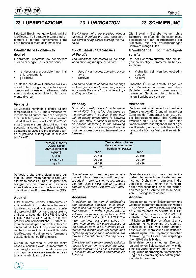
23. LUBRIFICAZIONE 23. LUBRICATION 23. SCHMIERUNG
I riduttori Brevini vengono forniti privi di lubrificante; I'utilizzatore e tenuto ad ef- fettuare il corretto riempimento prima della messa in moto della macchina.
C aratteristiche fo nd am en ta li degli oli
I parametri importanti da considerare quando si sceglie il tipo di olio sono:
• la viscosita alle condizioni nominali di funzionamento
• gli additivi
Lo stesso olio deve lubrificare sia i cu- scinetti che gli ingranaggi e tutti questi componenti coesistono all'interno della stessa scatola, in condizioni di funzionamento diverse.
V is c o s itaLa viscosita nominale e riferita ad una temperatura di 40 °C, ma diminuisce ve- locemente all'aumentare della temperatura. Se la temperatura di funzionamento del riduttore e compresa tra 50 °C e 70 °C, si puo scegliere una viscosita nominale secondo la seguente tabella indicativa, adottando la viscosita piii elevata quan- do si prevede la temperatura di lavoro piii elevata.
Particolare attenzione bisogna fare agli stadi in uscita molto caricati e con velo- cita molto basse (< 1 rpm). In questi casi bisogna ricorrere sempre ad oli con vi- scosita elevata e con una buona carica di additivazione Extreme Pressure (EP).
A d d it iv iOltre ai normali additivi antischiuma ed antiossidanti, e importante utilizzare oli lubrificanti con additivi in grado di confe- rire proprieta EP (extreme pressure) ed anti-usura, secondo ISO 6743-6 L-CKC o DIN 51517-3 CLP Occorre ricercare prodotti con caratteristiche EP tanto piii marcate quanto p ii ridotta e la velocita in uscita del riduttore. E opportuno ricorda- re che i composti chimici sostitutivi della lubrificazione idrodinamica si formano a scapito della carica EP originale.
Quindi, in presenza di velocita molto basse e carichi elevati, e importante ri- spettare gli intervalli di manutenzione per non deprimere eccessivamente le carat- teristiche lubrificanti dell'olio.
Brevini gear units are supplied without lubricant; therefore the user must carry out correct filling before starting the machine.
Fundamental characteristics of the oilsThe important parameters to consider when choosing the type of oil are:
• viscosity at nominal operating conditions
• additives
The same oil must lubricate the bearings and the gears and all these components work inside the same box, in different operating conditions.
ViscosityNominal viscosity refers to a temperature of 40°C, but rapidly decreases as the temperature increases. If the gear unit operating temperature is between 50°C and 70°C, a nominal viscosity can be chosen according to the following guide table, choosing the highest viscosity i f the highest operating temperature is foreseen.
Special attention must be paid to very loaded output stages and with very low speeds (<1 rpm). In such cases, always use high viscosity oils and with a good amount of Extreme Pressure (EP) additive.
AdditivesIn addition to the normal antifoaming and antioxidant additives, it is important to use lubricating oils with additives that provide EP (extreme pressure) and antiwear properties, according to ISO 6743-6 L-CKC or DIN 51517-3 CLP. The lower the gear unit output speed the more marked the EP characteristics of the products have to be. It should be remembered that the chemical compounds replacing hydrodynamic lubrication are formed to the detriment of the original EP load.Therefore, with very low speeds and high loads it is important to respect the maintenance intervals so as not to excessively diminish the lubricating characteristics of the oil.
Die Brevini - Getriebe werden ohne Schmierol geliefert; der Benutzer muss dieselben vor der Inbetriebnahme der Maschine mit der vorschriftmaUgen Schmierolmenge fOllen.G ru n d le g e n d e S c h m ie ro le ig e n -
s c h a fte n
Bei der Schmierolauswahl sind die fol- genden wichtige Parameter zu berOck- sichtigen:
• Viskositat bei Nennbetriebsbedin- gungen
• Additive
Dasselbe Ol muss sowohl Lager wie auch Zahnrader schmieren und diese Bauteile funktionieren zusammen in demselben Gehause unter unterschied- lichen Betriebsbedingungen.
V is k o s ita t
Die Nennviskositat bezieht sich auf eine Temperatur von 40 °C und nimmt mit der Zunahme der Temperatur rasch ab. Liegt die Betriebstemperatur des Getriebes zwischen 50 °C und 70 °C, kann eine Nennviskositat laut folgender Tabelle ge- wahlt werden, wobei bei sehr hoher Temperatur die hochste Viskositat zu wahlen ist.
Besonders vorsichtig muss man bei Ab- triebsstufen unter hohen Lasten und mit niedriger Drehzahl (<1 rpm) sein. In die- sen Fallen muss immer Schmierol mit hoher Viskositat und einer ausreichen- den Menge an Extreme-Pressure-Additi- ven (EP) eingesetzt werden.A d d it iv e
Neben den normalen Entschaumern und Oxidationshemmern mOssen Schmierole EP-Additive (Extrem-Pressure) und ver- schleiUhemmende Wirkstoffe laut ISO 6743-6 L-CKC oder DIN 51517-3 CLP enthalten. Der Einsatz von Produkten mit hoheren EP-Eigenschaften ist umso wichtiger, je niedriger die Drehzahl ab- triebseitig ist. Es wird daran erinnert, dass sich die chemischen Substitutions- verbindungen der hydrodynamischen Schmierung zu Lasten des ursprOngli- chen EP-Gehalts bilden.Es ist daher bei sehr niedrigen Drehzah- len und hohen Belastungen sehr wichtig, dass die Wartungszeitraume zur Vermei- dung einer ObermaUigen Verschlechte- rung der Schmieroleigenschaften genau eingehalten werden.
Velocita in uscita Output speed
Abtriebsdrehzahl n2 [rpm]
Temperatu Operating t
Betriebste50° C
ra di lavoro emperature ;mperatur
70° Cn2 > 20 VG 150 VG 220
5 < n2 < 20 VG 220 VG 320n2 < 5 VG 320 VG 460
Tab. (32)
© ® ©
T ip i d i o liGli oli disponibili appartengono general- mente a tre grandi famiglie.
• Oli minerali• Oli sintetici a base di Poli-Alfa-Ole-
fine (PAO)• Oli sintetici a base di Poli-Alchilen-
Glicole (PAG)
La scelta piii appropriata e generalmente legata alle condizioni di impiego.
I riduttori non particolarmente caricati, con un ciclo di impiego discontinuo sen- za escursioni termiche importanti, pos- sono essere lubrificati con olio minerale. Nei casi di impiego gravoso, quando i riduttori saranno prevedibilmente caricati molto ed in modo continuativo, con con- seguente prevedibile innalzamento della temperature, e bene utilizzare lubrificanti sintetici a base di Poli-Alfa-Olefine.
Non e consentito l'uso di oli a base di Poli-Alchilen-Glicole in quanto non sono compatibili con gli altri oli e sono invece spesso completamente miscibili con l'ac- qua: questo fenomeno e particolarmente pericoloso poiche non si nota, ma deprime velocemente le caratteristiche lubrificanti dell’olio. Inoltre, questi lubrificanti possono essere chimicamente attivi nei confronti delle tenute olio e delle vernici interne del riduttore.
Oltre a questi gia menzionati, ricordiamo che esistono gli oli idraulici e gli oli per l'industria alimentare.I primi vengono usati per il comando dei freni negativi.I secondi trovano specifico impiego nell'industria alimentare in quanto sono prodotti speciali non nocivi alla salute.A seguire vengono riportate tabelle di lubrificanti, proposti dai produttori piu noti, con caratteristiche adeguate alla lubrifi- cazione dei riduttori Brevini.
C o n ta m in a z io n eDurante il normale funzionamento, a causa del rodaggio delle superfici, e ine- vitabile che si trasferiscano nell'olio delle microparticelle metalliche.Questa contaminazione puo ridurre la vita dei cuscinetti, mandando in avaria prematura il riduttore.Per limitare e controllare il fenomeno, senza ricorrere a frequenti e costosi cambi d'olio, occorre prevedere l'impie- go di un opportuno sistema ausiliario di circolazione con filtrazione e raffredda- mento dell'olio.Con questo sistema, si ottiene il doppio vantaggio di controllare il livello di contaminazione attraverso l'impiego di appo- siti filtri e di stabilizzare la temperature di funzionamento al livello piu adeguato per garantire la viscosita voluta.
Types of oilsThe oils available generally belong to three large families.
• Mineral oils• Polyalphaolefin (PAO) synthetic oils
• Polyalkylene glycol (PAG) synthetic oils
The most suitable choice is generally tied to the conditions of use.
Gear units that are not particularly loaded and with a discontinuous operating cycle, without considerable temperature ranges, can be lubricated with mineral oil.In cases of heavy use, when the gear units are very loaded and in a continuous way, with resultant temperature increase, it is best to use polyalphaolefin synthetic lubricants.
The use of polyalkylene glycol oils is not allowed as they are not compatible with other oils and are often completely mixable with water: this phenomenon is particularly dangerous because it is not noticed, but rapidly diminishes the lubricating properties of the oil. Moreover, these lubricants can be chemically active against the oil seals and paint inside the gear unit.
In addition to the above, there are also hydraulic oils and oils for the food industry.The former are used for the command of negative brakes.The latter have a specific use in the food industry since they are special products that are not harmful to the health.Given below are tables of lubricants, proposed by the best-known producers, with characteristics suitable for the lubrication of Brevini gear units.
ContaminationDuring normal operation, due to running- in of the surfaces, metallic microparticles will inevitably form in the oil.This contamination can shorten the life of the bearings, resulting in early breakdown of the gear unit.
To limit and control this phenomenon, without resorting to frequent and costly oil changes, a suitable auxiliary oil circulation system with filtering and cooling of the oil must be provided.
This system offers the dual advantage of controlling the level of contamination through the use o f special filters and stabilizing the operating temperature at a level more suitable for ensuring the required viscosity.
S c h m ie ro ls o r te nDie verfugbaren Olsorten gehoren allge- mein zu drei grolien Familien.
• Mineralole• Synthetische Ole auf der Basis von
Polyalphaolefinen (PAO)• Synthetische Ole auf der Basis von
Polyalkylenglykolen (PAG)
Die Auswahl hangt im Allgemeinen von den Einsatzbedingungen ab.
Getriebe, die nicht im Dauerbetrieb lau- fen und keinen grolien Belastungen und grolien Temperaturschwankungen aus- gesetzt sind, konnen mit Mineralolen ge- schmiert werden.Bei Einsatz unter erschwerten Bedin- gungen, bei denen die Getriebe voraus- sichtlich hohen Lasten im Dauerbetrieb mit der entsprechenden voraussehbaren Temperaturerhohung ausgesetzt sind, ist es angebracht, synthetische Polyalphao- lefin-Ole zu verwenden.
Verboten ist die Verwendung von Olen auf der Basis von Polyalkylenglykolen, da sie nicht mit anderen Olen kompati- bel sind, aber oft mit Wasser gemischt werden konnen: dieses Phanomen ist besonders gefahrlich, da es nicht festge- stellt werden kann, verschlechtert aber schnell die Schmiereigenschaften des Ols. Daruber hinaus konnen diese Ole zu chemische Reaktionen bei Oldichtungen und den Innenanstrichen des Getriebes fuhren.
Neben den erwahnten Olen gibt es noch Hydraulikol und Ole fur die Lebensmittel- industrie.Die ersteren werden auf Negativbremsen eingesetzt.Letztere werden von der Lebensmittelin- dustrie verwendet, da sie nicht gesund- heitsschadlich sind.Im Folgenden finden Sie Schmiermittel- tabellen der bekanntesten Hersteller mit entsprechenden Eigenschaften fQr die Schmierung von Brevini-Getrieben.
V e rs c h m u tz u n gWahrend des normalen Betriebs entste- hen durch den Abrieb der Oberflachen Mikrometallpartikel im Ol.Diese Verschmutzung kann die Lebens- dauer der Lager verkurzen und zu einem Ausfall des Getriebes fuhren.
Zur Einschrankung dieser Erscheinung ohne haufigen und kostspieligen Olwech- sel ist der Einbau einer zusatzlichen Fil- teranlage fQr das Schmierol mit Olfilter- und OlkQhlvorrichtung empfehlenswert.
Diese Anlage bietet den doppelten Vor- teil, einserseits den Grad der Olver- schmutzung zu reduzieren und anderer- seits die Betriebstemperatur auf einer fQr die gewunschte Viskositat geigneten Temperaturstufe zu stabilisieren.
B25
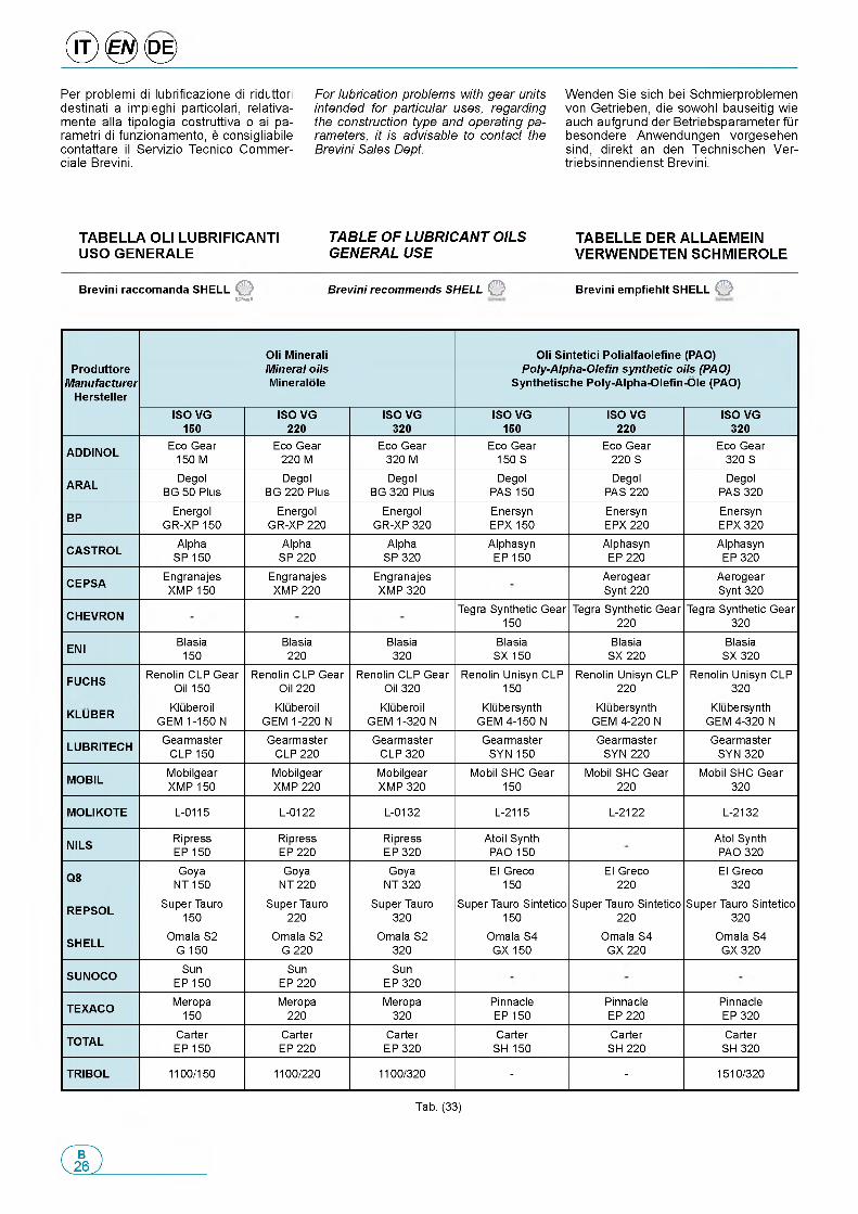
® 0 <0 >Per problemi di lubrificazione di riduttori destinati a impieghi particolari, relativa- mente alia tipologia costruttiva o ai pa- rametri di funzionamento, e consigliabile contattare il Servizio Tecnico Commer- ciale Brevini.
For lubrication problems with gear units intended for particular uses, regarding the construction type and operating parameters, it is advisable to contact the Brevini Sales Dept.
Wenden Sie sich bei Schmierproblemen von Getrieben, die sowohl bauseitig wie auch aufgrund der Betriebsparameter fur besondere Anwendungen vorgesehen sind, direkt an den Technischen Ver- triebsinnendienst Brevini.
T A B E L L A O L I L U B R IF IC A N T I U S O G E N E R A L E
TABLE OF LUBRICANT OILS GENERAL USE
T A B E L L E D E R A L L A E M E IN V E R W E N D E T E N S C H M IE R O L E
Brevini raccomanda SHELL ( 3H h a ll
Brevini recommends SHELL o Brevini empfiehlt SHELL О
Oli Minerali Oli Sintetici Polialfaolefine (PAO)Produttore Mineral oils Poly-Alpha-Olefin synthetic oils (PAO)
Manufacturer Mineralole Synthetische Poly-Alpha-Olefin-Ole (PAO)Hersteller
ISO VG ISO VG ISO VG ISO VG ISO VG ISO VG150 220 320 150 220 320
ADDINOL Eco Gear Eco Gear Eco Gear Eco Gear Eco Gear Eco Gear150 M 220 M 320 M 150 S 220 S 320 S
ARAL Degol Degol Degol Degol Degol DegolBG 50 Plus BG 220 Plus BG 320 Plus PAS 150 PAS 220 PAS 320
BP Energol Energol Energol Enersyn Enersyn EnersynGR-XP 150 GR-XP 220 GR-XP 320 EPX 150 EPX 220 EPX 320
CASTROL Alpha Alpha Alpha Alphasyn Alphasyn AlphasynSP 150 SP 220 SP 320 EP 150 EP 220 EP 320
CEPSA Engranajes Engranajes Engranajes Aerogear AerogearXMP 150 XMP 220 XMP 320 Synt 220 Synt 320
CHEVRON Tegra Synthetic Gear Tegra Synthetic Gear Tegra Synthetic Gear150 220 320
ENI Blasia Blasia Blasia Blasia Blasia Blasia150 220 320 SX 150 SX 220 SX 320
FUCHS Renolin CLP Gear Renolin CLP Gear Renolin CLP Gear Renolin Unisyn CLP Renolin Unisyn CLP Renolin Unisyn CLPOil 150 Oil 220 Oil 320 150 220 320
KLUBER Kluberoil Kluberoil Kluberoil Klubersynth Klubersynth KlubersynthGEM 1-150 N GEM 1-220 N GEM 1-320 N GEM 4-150 N GEM 4-220 N GEM 4-320 N
LUBRITECH Gearmaster Gearmaster Gearmaster Gearmaster Gearmaster GearmasterCLP 150 CLP 220 CLP 320 SYN 150 SYN 220 SYN 320
MOBIL Mobilgear Mobilgear Mobilgear Mobil SHC Gear Mobil SHC Gear Mobil SHC GearXMP 150 XMP 220 XMP 320 150 220 320
MOLIKOTE L-0115 L-0122 L-0132 L-2115 L-2122 L-2132
NILS Ripress Ripress Ripress Atoil Synth Atol SynthEP 150 EP 220 EP 320 PAO 150 PAO 320
Q8 Goya Goya Goya EI Greco EI Greco EI GrecoNT 150 NT 220 NT 320 150 220 320
REPSOL Super Tauro Super Tauro Super Tauro Super Tauro Sintetico Super Tauro Sintetico Super Tauro Sintetico150 220 320 150 220 320
SHELL Omala S2 Omala S2 Omala S2 Omala S4 Omala S4 Omala S4G 150 G 220 320 GX 150 GX 220 GX 320
SUNOCO Sun Sun SunEP 150 EP 220 EP 320
TEXACO Meropa Meropa Meropa Pinnacle Pinnacle Pinnacle150 220 320 EP 150 EP 220 EP 320
TOTAL Carter Carter Carter Carter Carter CarterEP 150 EP 220 EP 320 SH 150 SH 220 SH 320
TRIBOL 1100/150 1100/220 1100/320 - - 1510/320
Tab. (33)
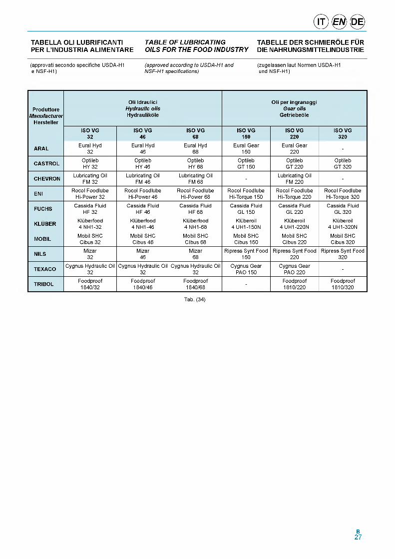
TABELLA OLI LUBRIFICANTI TABLE OF LUBRICATING TABELLE DER SCHMIEROLE FURPER L’INDUSTRIA ALIMENTARE OILS FOR THE FOOD INDUSTRY DIE NAHRUNGSMITTELINDUSTRIE
(approvati secondo specifiche USDA-H1 e NSF-H1)
(approved according to USDA-H1 and NSF-H1 specifications)
(zugelassen laut Normen USDA-H1 und NSF-H1)
ProduttoreManufacturer
Hersteller
Oli Idraulici Hydraulic oils Hydraulikole
Oli per ingranaggi Gear oils
Getriebeole
ISO VG 32
ISO VG 46
ISO VG 68
ISO VG 150
ISO VG 220
ISO VG 320
ARAL Eural Hyd 32
Eural Hyd 46
Eural Hyd 68
Eural Gear 150
Eural Gear 220 -
CASTROL Optileb HY 32
Optileb HY 46
Optileb HY 68
Optileb GT 150
Optileb GT 220
Optileb GT 320
CHEVRON Lubricating Oil FM 32
Lubricating Oil FM 46
Lubricating Oil FM 68 - Lubricating Oil
FM 220 -
ENI Rocol Foodlube Hi-Power 32
Rocol Foodlube Hi-Power 46
Rocol Foodlube Hi-Power 68
Rocol Foodlube Hi-Torque 150
Rocol Foodlube Hi-Torque 220
Rocol Foodlube Hi-Torque 320
FUCHS Cassida Fluid HF 32
Cassida Fluid HF 46
Cassida Fluid HF 68
Cassida Fluid GL 150
Cassida Fluid GL 220
Cassida Fluid GL 320
KLUBER Kluberfood 4 NH1-32
Kluberfood 4 NH1-46
Kluberfood 4 NH1-68
Kluberoil 4 UH1-150N
Kluberoil 4 UH1-220N
Kluberoil 4 UH1-320N
MOBIL Mobil SHC Cibus 32
Mobil SHC Cibus 46
Mobil SHC CIbus 68
Mobil SHC Cibus 150
Mobil SHC CIbus 220
Mobil SHC Cibus 320
NILS Mizar32
Mizar46
Mizar68
Ripress Synt Food 150
Ripress Synt Food 220
Ripress Synt Food 320
TEXACO Cygnus Hydraulic Oil 32
Cygnus Hydraulic Oil 32
Cygnus Hydraulic Oil 32
Cygnus Gear PAO 150
Cygnus Gear PAO 220 -
TRIBOL Foodproof1840/32
Foodproof1840/46
Foodproof1840/68 - Foodproof
1810/220Foodproof1810/320
Tab. (34)
B27
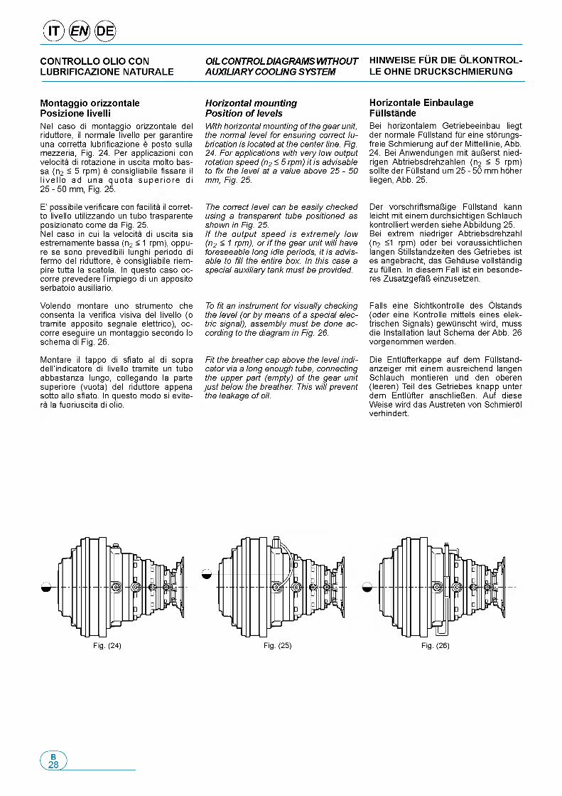
C O N T R O L L O O L IO C O N OIL CONTROL DIAGRAMS WITHOUT H IN W E IS E F U R D IE O L K O N T R O L -L U B R IF IC A Z IO N E N A T U R A L E AUXILIARY COOLING SYSTEM L E O H N E D R U C K S C H M IE R U N G
M o n ta g g io o r iz z o n ta le P o s iz io n e liv e lli
Nel caso di montaggio orizzontale del riduttore, il normale livello per garantire una corretta lubrificazione e posto sulla mezzeria, Fig. 24. Per applicazioni con velocita di rotazione in uscita molto bas- sa (n2 ^ 5 rpm) e consigliabile fissare il live llo ad una quota superio re di 25 - 50 mm, Fig. 25.
E' possibile verificare con facilita il corret- to livello utilizzando un tubo trasparente posizionato come da Fig. 25.Nel caso in cui la velocita di uscita sia estremamente bassa (n2 < 1 rpm), oppu- re se sono prevedibili lunghi periodo di fermo del riduttore, e consigliabile riem- pire tutta la scatola. In questo caso oc- corre prevedere l'impiego di un apposito serbatoio ausiliario.
Volendo montare uno strumento che consenta la verifica visiva del livello (o tramite apposito segnale elettrico), oc- corre eseguire un montaggio secondo lo schema di Fig. 26.
Montare il tappo di sfiato al di sopra dell'indicatore di livello tramite un tubo abbastanza lungo, collegando la parte superiore (vuota) del riduttore appena sotto allo sfiato. In questo modo si evite- ra la fuoriuscita di olio.
Horizontal mounting Position of levelsWith horizontal mounting of the gear unit, the normal level for ensuring correct lubrication is located at the center line. Fig. 24. For applications with very low output rotation speed (n2 < 5 rpm) it is advisable to fix the level at a value above 25 - 50 mm, Fig. 25.
The correct level can be easily checked using a transparent tube positioned as shown in Fig. 25.If the output speed is extremely low (n2 < 1 rpm), or i f the gear unit will have foreseeable long idle periods, it is advisable to fill the entire box. In this case a special auxiliary tank must be provided.
To fit an instrument for visually checking the level (or by means of a special electric signal), assembly must be done according to the diagram in Fig. 26.
Fit the breather cap above the level indicator via a long enough tube, connecting the upper part (empty) of the gear unit just below the breather. This will prevent the leakage of oil.
H o riz o n ta le E in b a u la g e F u lls ta n d eBei horizontalem Getriebeeinbau liegt der normale FQllstand fQr eine storungs- freie Schmierung auf der Mittellinie, Abb. 24. Bei Anwendungen mit auUerst nied- rigen Abtriebsdrehzahlen (n2 < 5 rpm) sollte der FQllstand um 25 - 50 mm hoher liegen, Abb. 25.
Der vorschriftsmaUige FQllstand kann leicht mit einem durchsichtigen Schlauch kontrolliert werden siehe Abbildung 25. Bei extrem niedriger Abtriebsdrehzahl (n2 <1 rpm) oder bei voraussichtlichen langen Stillstandzeiten des Getriebes ist es angebracht, das Gehause vollstandig zu fQllen. In diesem Fall ist ein besonde- res ZusatzgefaU einzusetzen.
Falls eine Sichtkontrolle des Olstands (oder eine Kontrolle mittels eines elek- trischen Signals) gewQnscht wird, muss die Installation laut Schema der Abb. 26 vorgenommen werden.
Die EntlQfterkappe auf dem FQllstand- anzeiger mit einem ausreichend langen Schlauch montieren und den oberen (leeren) Teil des Getriebes knapp unter dem EntlQfter anschlieUen. Auf diese Weise wird das Austreten von Schmierol verhindert.
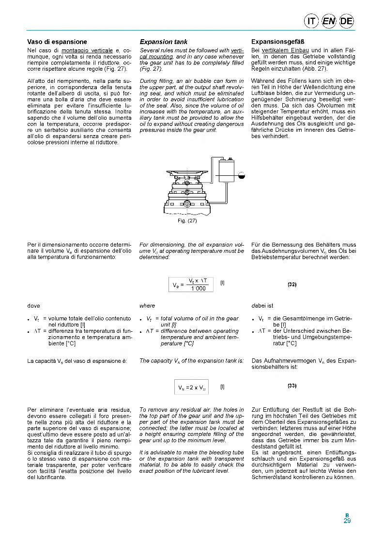
V a s o di e s p a n s io n eNel caso di montaggio verticale e, co- munque, ogni volta si renda necessario riempire completamente il riduttore, oc- corre rispettare alcune regole (Fig. 27).
All'atto del riempimento, nella parte su- periore, in corrispondenza della tenuta rotante dell'albero di uscita, si pug for- mare una bolla d'aria che deve essere eliminata per evitare l'insufficiente lu- brificazione della tenuta stessa. Inoltre sapendo che il volume dell'olio aumenta con la temperatura, occorre predispor- re un serbatoio ausiliario che consenta all'olio di espandersi senza creare peri- colose pressioni interne al riduttore.
Per il dimensionamento occorre determi- nare il volume Ve di espansione dell'olio alla temperatura di funzionamento:
dove
о Vt = volume totale dell'olio contenuto nel riduttore [l]
о AT = differenza tra temperatura di funzionamento e temperatura am- biente [°C]
La capacita Vs del vaso di espansione e:
Per eliminare l'eventuale aria residua, devono essere collegati il foro presente nella zona piu alta del riduttore e la parte superiore del vaso di espansione; quest'ultimo deve essere posto ad un'al- tezza tale da garantire il pieno riempimento del riduttore al livello minimo.Si consiglia di realizzare il tubo di spurgo o lo stesso vaso di espansione con ma- teriale trasparente, per poter verificare con facilita l'esatta posizione del livello del lubrificante.
Expansion tankSeveral rules must be followed with vertical mounting, and in any case whenever the gear unit has to be completely filled (Fig. 27).
During filling, an air bubble can form in the upper part, at the output shaft revolving seal, and which must be eliminated in order to avoid insufficient lubrication of the seal. Also, since the volume of oil increases with the temperature, an auxiliary tank must be provided to allow the oil to expand without creating dangerous pressures inside the gear unit.
For dimensioning, the oil expansion volume Ve at operating temperature must be determined:
V e
Vt x AT 1000
[l]
where
- Vt = total volume o f oil in the gear unit [l]
о AT = difference between operating temperature and ambient temperature [°C]
The capacity Vs of the expansion tank is:
Vs = 2 x Ve [l]
To remove any residual air, the holes in the top part of the gear unit and the upper part of the expansion tank must be connected; the latter must be located at a height ensuring complete filling of the gear unit up to the minimum level.
It is advisable to make the bleeding tube or the expansion tank with transparent material, to be able to easily check the exact position of the lubricant level.
E x p a n s io n s g e fa ftBei vertikalem Einbau und in allen Fallen, in denen das Getriebe vollstandig gefQllt werden muss, sind einige wichtige Regeln einzuhalten (Abb. 27).
Wahrend des FQllens kann sich im obe- ren Teil in Hdhe der Wellendichtung eine Luftblase bilden, die zur Vermeidung un- genQgender Schmierung beseitigt werden muss. Da sich das Olvolumen mit steigender Temperatur erhdht, muss ein Hilfsbehalter eingebaut werden, der die Ausdehnung des Ols ausgleicht und ge- fahrliche DrQcke im Inneren des Getrie- bes verhindert.
FQr die Bemessung des Behalters muss das Ausdehnungsvolumen Ve des Ols bei Betriebstemperatur berechnet werden:
(32)
dabei ist
о Vt = die Gesamtdlmenge im Getriebe [l]
о AT = der Unterschied zwischen Be- triebs- und Umgebungstempe- ratur [°C]
Das Aufnahmevermagen Vs des Expan- sionsbehalters ist:
(33)
Zur EntlQftung der Restluft ist die Boh- rung im hdchsten Teil des Getriebes mit dem Oberteil des ExpansionsgefaUes zu verbinden; letzteres muss auf einer Hdhe angeordnet werden, die gewahrleistet, dass das Getriebe immer bis zum Min- deststand gefQllt ist.Es ist angebracht, einen EntlQftungs- schlauch und ein ExpansionsgefaU aus durchsichtigem Material zu verwen- den, um jederzeit auf leichte Weise den Schmieralstand kontrollieren zu kannen.
B29
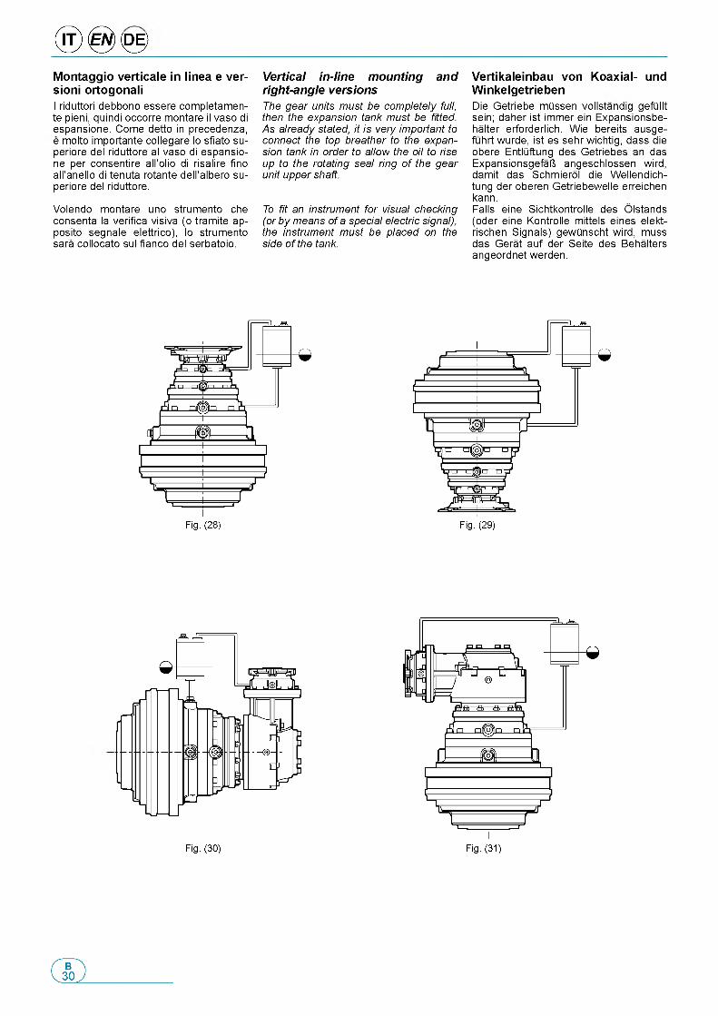
® 0 <0 >M o n ta g g io v e r t ic a le in lin e a e v e r - s io n i o rto g o n a liI riduttori debbono essere completamen- te pieni, quindi occorre montare il vaso di espansione. Come detto in precedenza, e molto importante collegare lo sfiato su- periore del riduttore al vaso di espansione per consentire all'olio di risalire fino all'anello di tenuta rotante dell'albero su- periore del riduttore.
Volendo montare uno strumento che consenta la verifica visiva (o tramite ap- posito segnale elettrico), lo strumento sara collocato sul fianco del serbatoio.
Vertical in-line mounting and right-angle versionsThe gear units must be completely full, then the expansion tank must be fitted. As already stated, it is very important to connect the top breather to the expansion tank in order to allow the oil to rise up to the rotating seal ring of the gear unit upper shaft.
To fit an instrument for visual checking (or by means of a special electric signal), the instrument must be placed on the side of the tank.
V e r t ik a le in b a u v o n K o a x ia l- u n d W in k e lg e tr ie b e nDie Getriebe mOssen vollstandig gefQllt sein; daher ist immer ein Expansionsbe- halter erforderlich. Wie bereits ausge- fiihrt wurde, ist es sehr wichtig, dass die obere EntlQftung des Getriebes an das ExpansionsgefaU angeschlossen wird, damit das Schmierol die Wellendich- tung der oberen Getriebewelle erreichen kann.Falls eine Sichtkontrolle des Olstands (oder eine Kontrolle mittels eines elekt- rischen Signals) gewdnscht wird, muss das Gerat auf der Seite des Behalters angeordnet werden.
Fig. (28)
Fig. (30) Fig. (31)
C O N T R O L L O O L IO C O N S IS T E M A OIL CHECK WITH AUXILIARY COO- O L K O N T R O L L E BEI Z U S A T Z L I- A U S IL IA R IO DI R A F F R E D D A M E N T O LING SYSTEM C H E M K U H L S Y S TE M
S is te m i a u s ilia r i d i ra ffre d d a m e n to e filtra z io n e
Nel caso la potenza applicata sia supe- riore alia potenza termica dissipabile dal riduttore, e necessario l'impiego di un sistema ausiliario di raffreddamento aria- olio, in grado di smaltire la potenza termica in eccedenza e di mantenere anche un buon livello di pulizia dell'olio lubrifi- cante, attraverso la filtrazione continua.
Per assolvere questa funzione Brevini offre diverse tipologie di centraline di raffreddamento: contattare il Servizio Tec- nico Commerciale Brevini per i dettagli. Le centraline sono composte da uno scambiatore di calore aria-olio, un filtro, un motore elettrico, una pompa idraulica con valvola di sicurezza e una ventola coassiale e solidale alla pompa.
Volendo montare un sistema ausiliario di tipo diverso diverso, ricordiamo che e assolutamente sconsigliato l'impiego di impianti con serbatoio esterno.Nel caso in cui si renda necessario un serbatoio ausiliario (per es. per raffred- dare piii riduttori con un unico impianto) consigliamo di contattare il Servizio Tec- nico Commerciale della Brevini Riduttori.
Progettando un circuito di circolazione dell'olio e consigliabile aspirare nel punto piii basso, cosl questo ramo del circuito puo servire anche a vuotare il riduttore.In ogni caso i punti di aspirazione e man- data dell'olio debbono essere sufficien- temente lontani tra loro per garantire l'attraversamento del riduttore da parte dell'olio fresco.
Il diametro dei fori di passaggio dell'o- lio, soprattutto in aspirazione, e molto importante. Infatti, in presenza di fori troppo stretti, la pompa tende a cavitare. Non potendo modificare la portata della pompa, che e funzione della potenza da smaltire, occorre verificare la capacita dei fori.
Quando si aspira l'olio dai supporti in entrata o dalle flange delle riduzioni ve- loci, l'impiego di un solo foro puo essere insufficiente a smaltire tutta la portata: pertanto occorre collegare 2 o 3 fori me- diante un collettore collegato al tubo di aspirazione.
La mandata e solitamente meno proble- matica poiche, nel caso di portata natu- rale insufficiente, si genera una piccola pressione che garantisce il flusso.
Per un corretto dimensionamento del circuito, si consiglia di seguire le seguenti regole.
Auxiliary cooling and filtering systemsIf the power applied is greater than the thermal power that can be dissipated by the gear unit, an auxiliary cooling system (air-oil) able to dissipate the excess thermal power and also maintain a good level of cleanness of the lubricating oil through constant filtering, must be used.
To fulfill this function, Brevini offers different types of cooling units: contact the Brevini Sales Dept. for details.The control units consist of an air-oil heat exchanger, a filter, an electric motor, a hydraulic pump with safety valve and a coaxial fan integral with the pump.
If a different type of auxiliary system is to be fitted, make sure not to use systems with an external tank.If an auxiliary tank is required (e.g. for cooling several gear units with a single system) it is advisable to contact the Brevini Riduttori Sales Dept.
In designing an oil circulating circuit it is advisable for suction to be in the lowest point, so that this branch of the circuit can also be used to drain the gear unit.In any case, the oil suction and delivery points must be far enough apart to ensure fresh oil crossing the gear unit.
The diameter of the oil passage is very important, above all in suction. In fact, with too narrow holes, the pump tends to cavitate. Not being able to change the pump delivery, which is a function of the power to be dissipated, the capacity of the holes must be verified.
When sucking oil from input supports or the flanges of the fast gear units, the use of one hole may be insufficient for all the flow: therefore 2 or 3 holes must be connected by means of a manifold connected to the suction pipe.
Delivery is usually less problematic since, in the event of an insufficient natural rate, a small pressure is generated which ensures the flow.
For correct dimensioning of the circuit, it is advisable to follow these rules.
Z u s a tz lic h e k u h l- u n d f ilte ra n la g e
Falls die angelegte Leistung hoher ist als die vom Getriebe abfohrbare Warmeleis- tung muss ein zusatzliches KOhlsystem (LOft-Ol) installiert werden, das in der Lage ist, die Oberschossige Warmeleis- tung abzufiihren und durch Dauerfilte- rung das Schmierol auf einem ausrei- chend sauberen Niveau zu halten.
Zur Losung dieser Funktion bietet Brevini verschiedene KOhlaggregate an: neh- men Sie for Einzehleiten dazu Kontakt mit dem Technischen Vertriebsinnen- dienst von Brevini auf.Die Aggregate haben einen Luft-Ol-War- metauscher, einen Filter, einen Elektro- motor, eine Hydraulikpumpe mit Uber- druckventil und einen Koaxiallofter, der fest mit der Pumpe verbunden ist.
Falls der Einbau eines anderen Hilfssys- tems gewonscht wird, weisen wir darauf hin, dass auf keinen Fall Anlagen mit externem Behalter eingesetzt werden dorfen.Falls ein Zusatztank erforderlich sein sollte (um z. B. mehrere Getriebe mit ei- ner einzigen Anlage zu kohlen), wenden Sie sich bitte zuvor an die technische Verkaufsberatung Brevini Riduttori.
Bei der Planung einer Olumlaufschmie- rung sollte die Ansaugung am niedrigs- ten Punkt des Kreislaufs angeordnet werden, so dass derselbe auch zum Ent- leeren des Getriebes dient.Die Rock- und Vorlaufpunkte des Schmierols mOssen in jedem Fall in ei- nem ausreichenden Abstand von einan- der angeordnet sein, damit das Frischol das gesamte Getriebe durchstromen kann.
Der Durchmesser der Bohrungen des Ol- durchflusses, extrem wichtig. Bei zu en- gen Bohrungen tendiert die Pumpe zum Kavitieren. Da die Pumpenfordermen- ge, die eine Funktion der abzufOhren- den Leistung ist, nicht geandert werden kann, ist die Kapazitat der Durchlasse zu kontrollieren.
Wenn Ol von den Antriebswellen oder den Flanschverbindungen der Schnell- getriebe angesaugt wird, kann die Ver- wendung einer einzigen Bohrung unzu- reichend sein, um die gesamte Leistung abzufOhren; es ist daher erforderlich, 2 oder 3 Bohrungen mit einer Sammellei- tung an das Saugrohr anzuschlieUen.
Die Druckseite weist weniger Schwierig- keiten auf, da bei unzureichender For- dermenge ein kleiner Druck entsteht, der fdr den notwendigen Durchfluss sorgt.
Befolgen Sie for eine korrekte Bemes- sung des Kreislaufs die folgenden Hin- weise.
B31
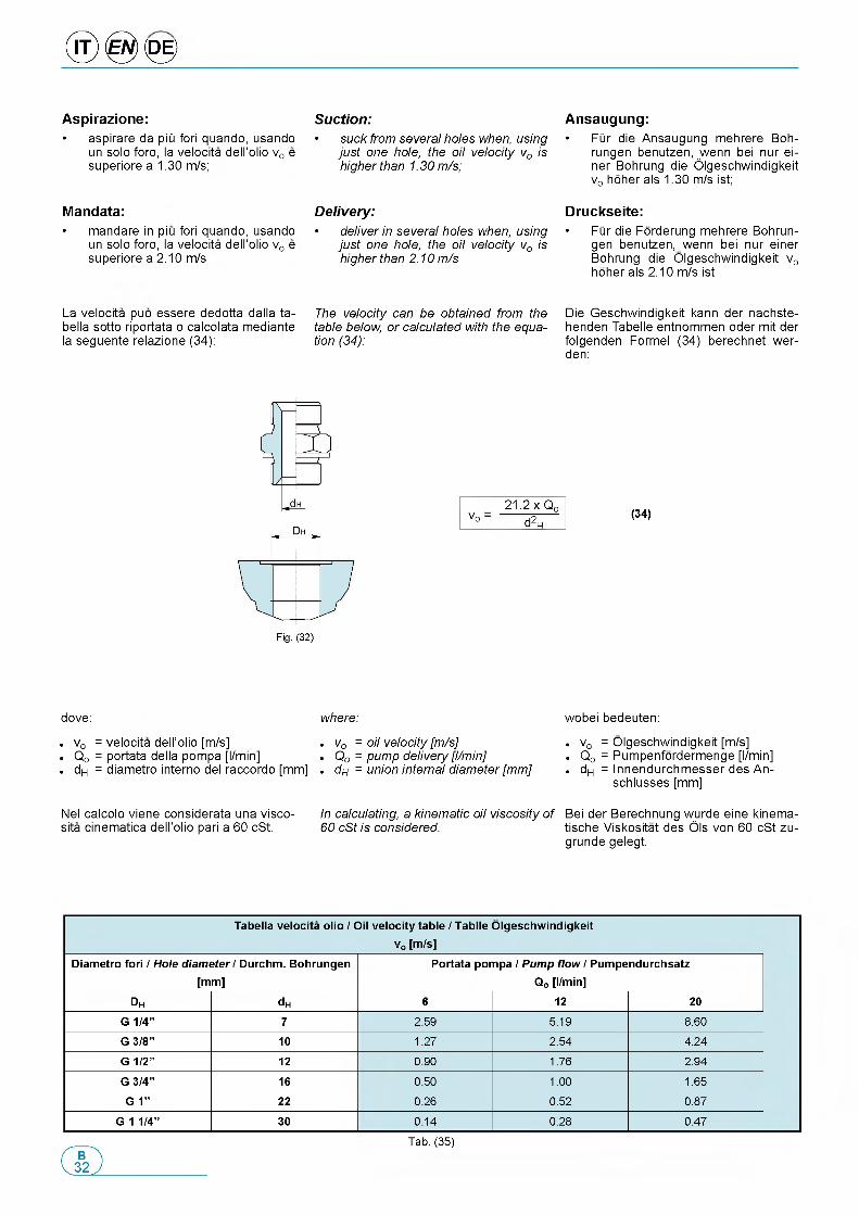
® 0 <0 >
A s p ira z io n e :• aspirare da piii fori quando, usando
un solo foro, la velocita dell'olio vo e superiore a 1.30 m/s;
M a n d a ta :• mandare in piu fori quando, usando
un solo foro, la velocita dell'olio vo e superiore a 2.10 m/s
La velocita puo essere dedotta dalla ta- bella sotto riportata o calcolata mediante la seguente relazione (34):
dove:
о vo = velocita dell'olio [m/s] о Qo = portata della pompa [l/min] о dH = diametro interno del raccordo [mm]
Nel calcolo viene considerata una visco- sita cinematica dell'olio pari a 60 cSt.
Suction:• suck from several holes when, using
just one hole, the oil velocity vo is higher than 1.30 m/s;
Delivery:• deliver in several holes when, using
just one hole, the oil velocity vo is higher than 2.10 m/s
The velocity can be obtained from the table below, or calculated with the equation (34):
where:
о vo = oil velocity [m/s]„ Qo = pump delivery [l/min]„ dH = union internal diameter [mm]
In calculating, a kinematic oil viscosity of 60 cSt is considered.
A n s a u g u n g :• FQr die Ansaugung mehrere Boh-
rungen benutzen, wenn bei nur ei- ner Bohrung die Olgeschwindigkeit vo hoher als 1.30 m/s ist;
D ru c k s e ite :• FQr die Forderung mehrere Bohrun-
gen benutzen, wenn bei nur einer Bohrung die Olgeschwindigkeit vo hoher als 2.10 m/s ist
Die Geschwindigkeit kann der nachste- henden Tabelle entnommen oder mit der folgenden Formel (34) berechnet wer- den:
(34)
wobei bedeuten:
о vo = Olgeschwindigkeit [m/s] о Qo = Pumpenfordermenge [l/min] о dH = Innendurchmesser des An-
schlusses [mm]
Bei der Berechnung wurde eine kinema- tische Viskositat des Ols von 60 cSt zu- grunde gelegt.
v o
21.2 x Qod2H
Tabella velocita olio / Oil velocity table / Tablle OlgeschwindigkeitVo [m/s]
Diametro fori / Hole diami [m
Dh
iter / Durchm. Bohrungen
m]
dH
Portata pom
6
npa / Pump flow / Pumpe
Qo [l/min]
12
ndurchsatz
20
G 1/4” 7 2.59 5.19 8.60G 3/8” 10 1.27 2.54 4.24G 1/2” 12 0.90 1.76 2.94G 3/4” 16 0.50 1.00 1.65G 1” 22 0.26 0.52 0.87
G 1 1/4” 30 0.14 0.28 0.47Tab. (35)
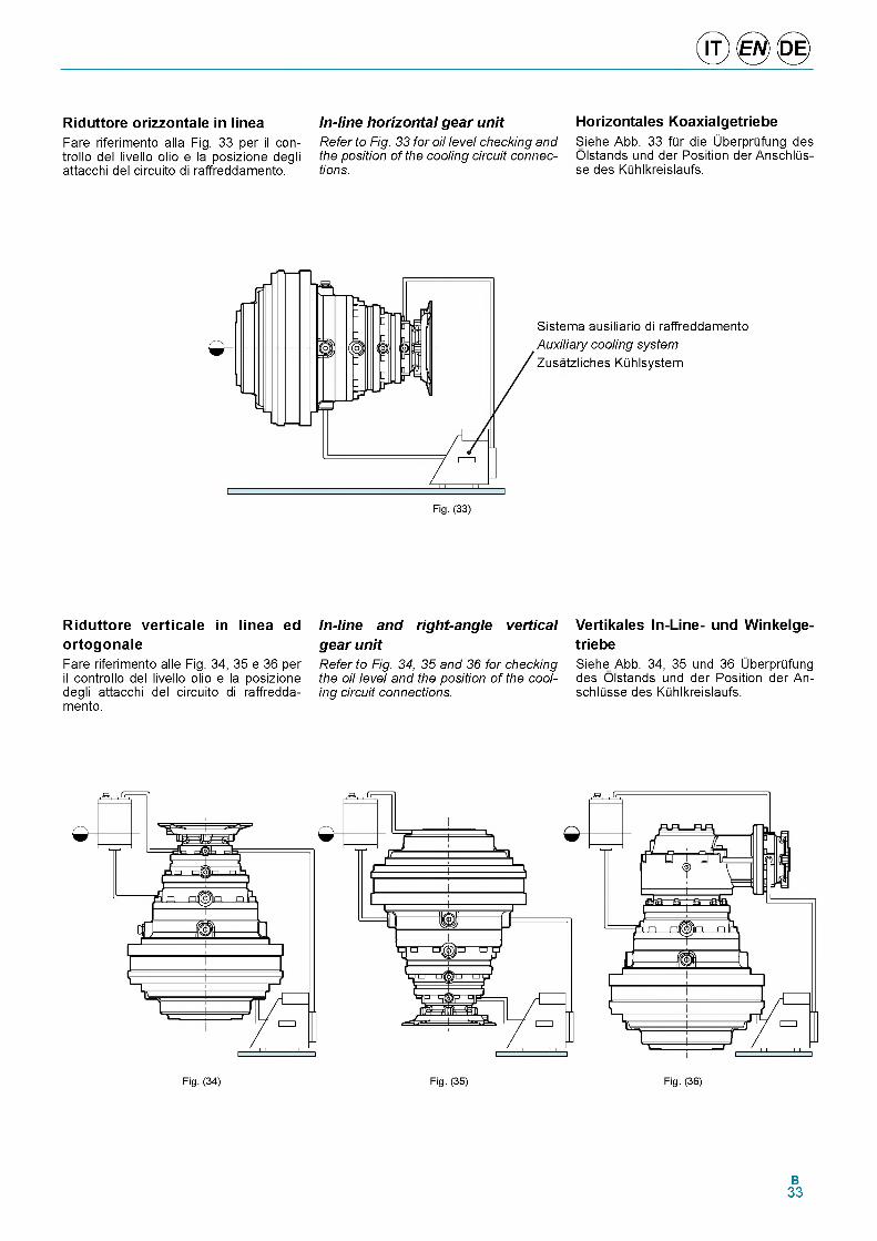
© ® ©
R id u tto re o r iz z o n ta le in lin e aFare riferimento alla Fig. 33 per il con- trollo del livello olio e la posizione degli attacchi del circuito di raffreddamento.
In-line horizontal gear unitRefer to Fig. 33 for oil level checking and the position of the cooling circuit connections.
H o riz o n ta le s K o a x ia lg e tr ie b e
Siehe Abb. 33 fQr die UberprQfung des Olstands und der Position der AnschlQs- se des KQhlkreislaufs.
Sistema ausiliario di raffreddamento Auxiliary cooling system Zusatzliches KQhlsystem
R id u t to r e v e r t ic a le in l in e a ed
o r to g o n a leFare riferimento alle Fig. 34, 35 e 36 per il controllo del livello olio e la posizione degli attacchi del circuito di raffredda- mento.
In-line and right-angle vertical gear unitRefer to Fig. 34, 35 and 36 for checking the oil level and the position of the cooling circuit connections.
V e rtik a le s In -L in e - u n d W in k e lg e -
tr ie b eSiehe Abb. 34, 35 und 36 UberprQfung des Olstands und der Position der An- schlQsse des KQhlkreislaufs.
B33
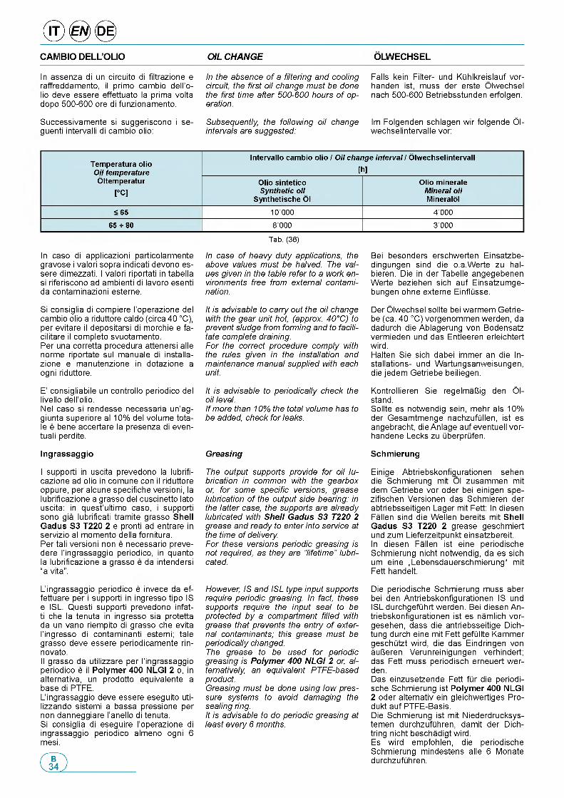
CAMBIO DELL’OLIO OIL CHANGE OLWECHSEL
In assenza di un circuito di filtrazione e raffreddamento, il primo cambio dell'o- io deve essere effettuato la prima volta
dopo 500-600 ore di funzionamento.
In the absence of a filtering and cooling circuit, the first oil change must be done the first time after 500-600 hours of operation.
Falls kein Filter- und Kiihlkreislauf vor- handen ist, muss der erste Olwechsel nach 500-600 Betriebsstunden erfolgen.
Successivamente si suggeriscono i se- guenti intervalli di cambio olio:
Subsequently, the following oil change intervals are suggested:
Im Folgenden schlagen wir folgende Ol- wechselintervalle vor:
Temperatura olio Oil temperature
Intervallo cambio olio / Oil change interval / Olwechselintervall
[h]Oltemperatur
[°C]Olio sintetico Synthetic oil
Synthetische Ol
Olio minerale Mineral oil Mineralol
< 65 10 000 400065 ^ 80 8 000 3 000
Tab. (36)
In caso di applicazioni particolarmente gravose i valori sopra indicati devono es- sere dimezzati. I valori riportati in tabella si riferiscono ad ambienti di lavoro esenti da contaminazioni esterne.
Si consiglia di compiere l'operazione del cambio olio a riduttore caldo (circa 40 °C), per evitare il depositarsi di morchie e fa- cilitare il completo svuotamento.Per una corretta procedura attenersi alle norme riportate sul manuale di installa- zione e manutenzione in dotazione a ogni riduttore.
E' consigliabile un controllo periodico del livello dell'olio.Nel caso si rendesse necessaria un'ag- giunta superiore al 10% del volume tota- le e bene accertare la presenza di even- tuali perdite.
Ingrassaggio
I supporti in uscita prevedono la lubrifi- cazione ad olio in comune con il riduttore oppure, per alcune specifiche versioni, la lubrificazione a grasso del cuscinetto lato uscita: in quest'ultimo caso, i supporti sono gia lubrificati tramite grasso Shell G adus S3 T220 2 e pronti ad entrare in servizio al momento della fornitura.Per tali versioni non e necessario preve- dere l'ingrassaggio periodico, in quanto la lubrificazione a grasso e da intendersi “a vita”.
L'ingrassaggio periodico e invece da ef- fettuare per i supporti in ingresso tipo IS e ISL. Questi supporti prevedono infatti che la tenuta in ingresso sia protetta da un vano riempito di grasso che evita l'ingresso di contaminanti esterni; tale grasso deve essere periodicamente rin- novato.II grasso da utilizzare per l'ingrassaggio periodico e il Polym er 400 NLGI 2 o, in alternativa, un prodotto equivalente a base di PTFE.L'ingrassaggio deve essere eseguito uti- lizzando sistemi a bassa pressione per non danneggiare l'anello di tenuta.Si consiglia di eseguire l'operazione di ingrassaggio periodico almeno ogni 6 mesi.
In case of heavy duty applications, the above values must be halved. The values given in the table refer to a work environments free from external contamination.
It is advisable to carry out the oil change with the gear unit hot, (approx. 40°C) to prevent sludge from forming and to facilitate complete draining.For the correct procedure comply with the rules given in the installation and maintenance manual supplied with each unit.
It is advisable to periodically check the oil level.If more than 10% the total volume has to be added, check for leaks.
Greasing
The output supports provide for oil lubrication in common with the gearbox or, for some specific versions, grease lubrication of the output side bearing: in the latter case, the supports are already lubricated with Shell Gadus S3 T220 2 grease and ready to enter into service at the time of delivery.For these versions periodic greasing is not required, as they are “lifetime" lubricated.
However, IS and ISL type input supports require periodic greasing. In fact, these supports require the input seal to be protected by a compartment filled with grease that prevents the entry of external contaminants; this grease must be periodically changed.The grease to be used for periodic greasing is Polymer 400 NLGI 2 or, alternatively, an equivalent PTFE-based product.Greasing must be done using low pressure systems to avoid damaging the sealing ring.It is advisable to do periodic greasing at least every 6 months.
Bei besonders erschwerten Einsatzbe- dingungen sind die o.a.Werte zu hal- bieren. Die in der Tabelle angegebenen Werte beziehen sich auf Einsatzumge- bungen ohne externe EinflQsse.
Der Olwechsel sollte bei warmem Getrie- be (ca. 40 °C) vorgenommen werden, da dadurch die Ablagerung von Bodensatz vermieden und das Entleeren erleichtert wird.Halten Sie sich dabei immer an die Installations- und Wartungsanweisungen, die jedem Getriebe beiliegen.
Kontrollieren Sie regelmaUig den Ol- stand.Sollte es notwendig sein, mehr als 10% der Gesamtmenge nachzufiillen, ist es angebracht, die Anlage auf eventuell vor- handene Lecks zu iiberpriifen.
Schm ierung
Einige Abtriebskonfigurationen sehen die Schmierung mit Ol zusammen mit dem Getriebe vor oder bei einigen spe- zifischen Versionen das Schmieren der abtriebsseitigen Lager mit Fett: In diesen Fallen sind die Wellen bereits mit Shell G adus S3 T220 2 grease geschmiert und zum Lieferzeitpunkt einsatzbereit.In diesen Fallen ist eine periodische Schmierung nicht notwendig, da es sich um eine „Lebensdauerschmierung“ mit Fett handelt.
Die periodische Schmierung muss aber bei den Antriebskonfigurationen IS und ISL durchgefiihrt werden. Bei diesen Antriebskonfigurationen ist es namlich vor- gesehen, dass die antriebsseitige Dich- tung durch eine mit Fett gefiillte Kammer geschiitzt wird, die das Eindringen von auUeren Verunreinigungen verhindert; das Fett muss periodisch erneuert wer- den.Das einzusetzende Fett fiir die periodi- sche Schmierung ist Polym er 400 NLGI 2 oder alternativ ein gleichwertiges Pro- dukt auf PTFE-Basis.Die Schmierung ist mit Niederdrucksys- temen durchzufiihren, damit der Dich- tring nicht beschadigt wird.Es wird empfohlen, die periodische Schmierung mindestens alle 6 Monate durchzufiihren.
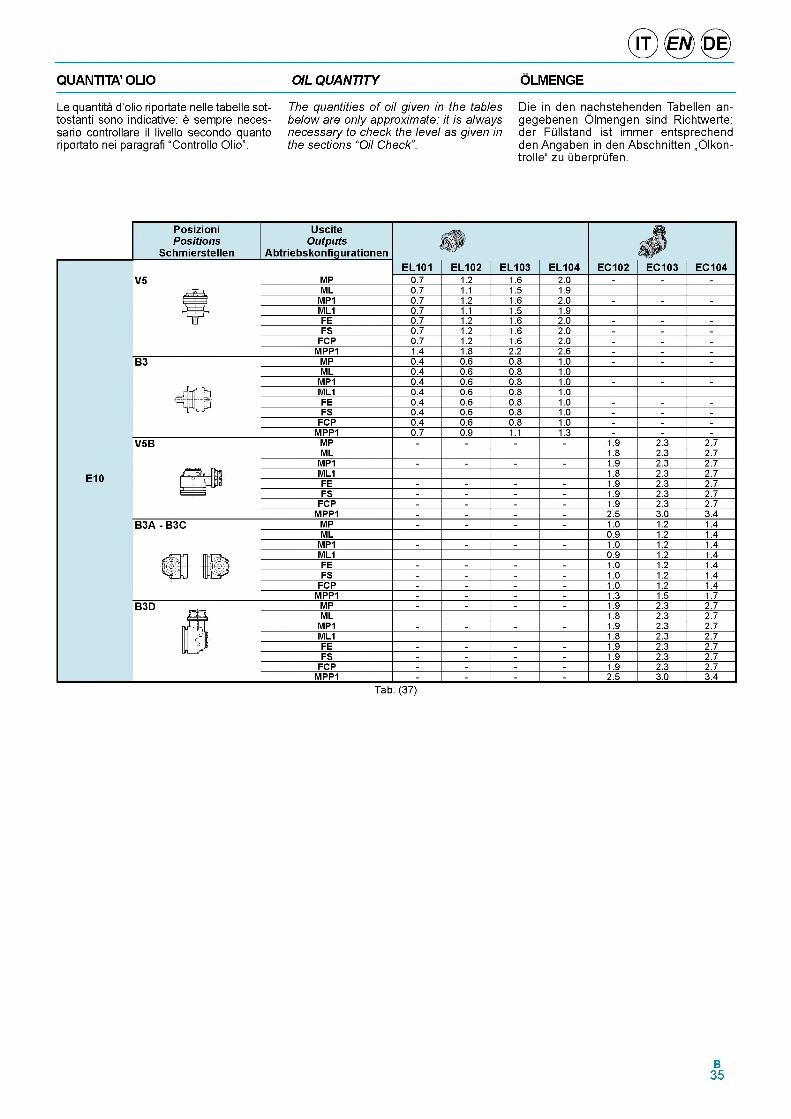
QUANTITA’ OLIO OIL QUANTITY OLMENGE
Le quantita d'olio riportate nelle tabelle sot- tostanti sono indicative: e sempre neces- sario controllare il livello secondo quanto riportato nei paragrafi “Controllo Olio”.
The quantities of oil given in the tables below are only approximate: it is always necessary to check the level as given in the sections “Oil Check”.
Die in den nachstehenden Tabellen an- gegebenen Olmengen sind Richtwerte: der FQllstand ist immer entsprechend den Angaben in den Abschnitten „Olkon- trolle“ zu QberprQfen.
Tab. (37)
B35
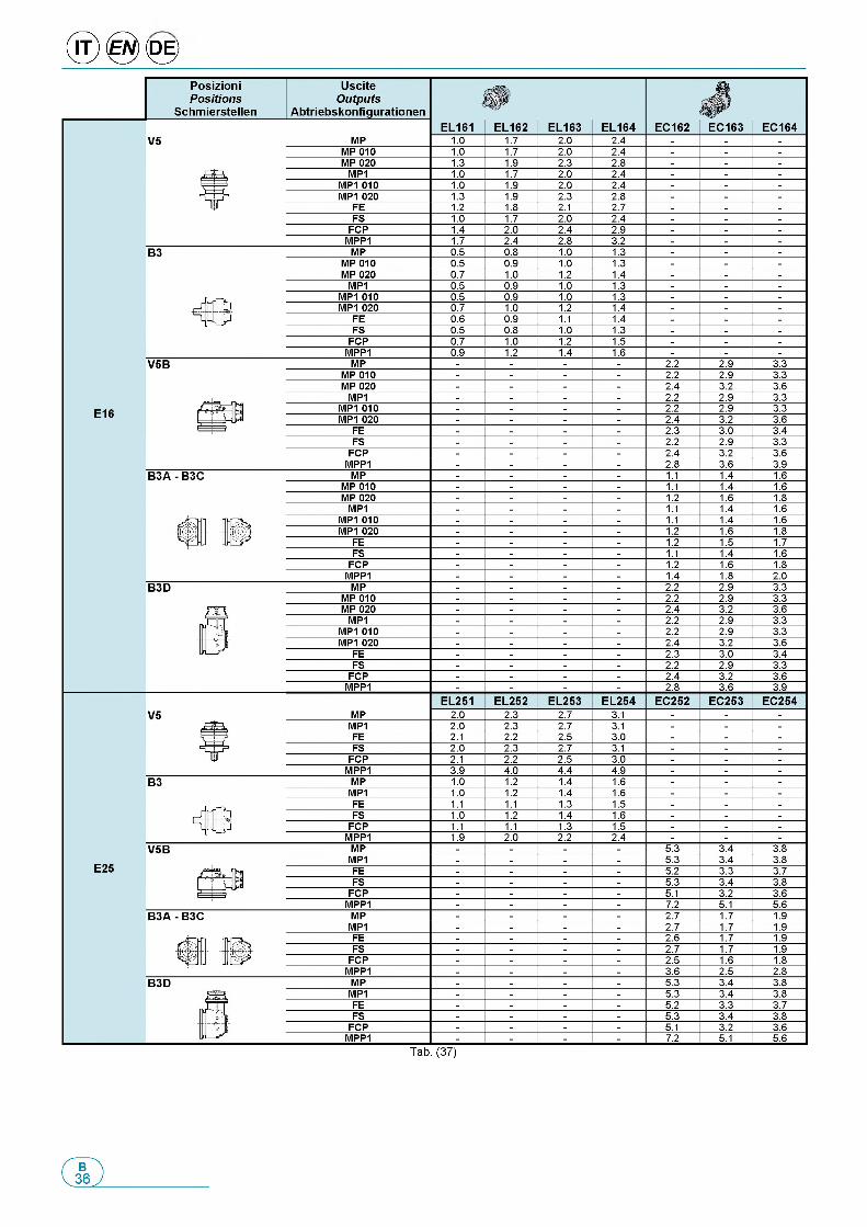
® 0 <0 >
Tab. (37)
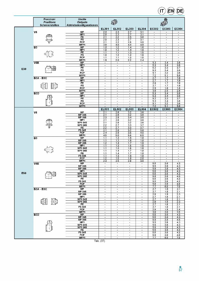
Tab. (37)
B37
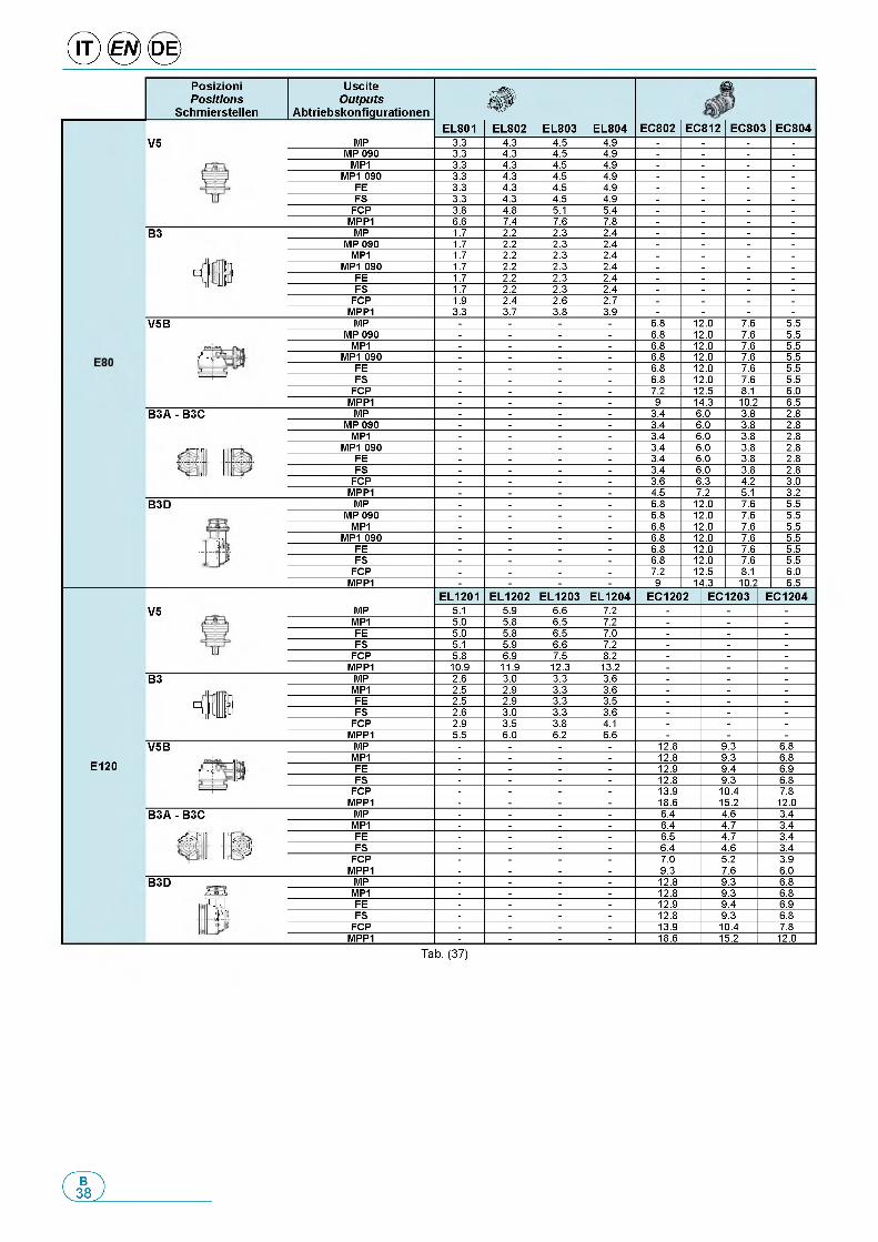
® 0 <0 >PosizioniPositions
Schmierstellen
UsciteOutputs
AbtriebskonfigurationenФ
ЛЦг
V5 MPEL801 EL802 EL803 EL804 EC802 EC812 EC803 EC804
3.3 4.3 4.5 4.9 - - - -
MP 090 3.3 4.3 4.5 4.9 - - - -
MP1 3.3 4.3 4.5 4.9 - - - -
MP1 090 3.3 4.3 4.5 4.9 - - - -
FE 3.3 4.3 4.5 4.9 - - - -
FS 3.3 4.3 4.5 4.9 - - - -FCP 3.8 4.8 5.1 5.4 - - - -
MPP1 6.6 7.4 7.6 7.8 - - - -B3 MP 1.7 2.2 2.3 2.4 - - - -
MP 090 1.7 2.2 2.3 2.4 - - - -MP1 1.7 2.2 2.3 2.4 - - - -
■ff t l MP1 090 1.7 2.2 2.3 2.4 - - - -3 .1 I f ff FE 1.7 2.2 2.3 2.4 - - - -
FS 1.7 2.2 2.3 2.4 - - - -FCP 1.9 2.4 2.6 2.7 - - - -
MPP1 3.3 3.7 3.8 3.9 - - - -V5B MP - - - - 6.8 12.0 7.6 5.5
MP 090 - - - - 6.8 12.0 7.6 5.5MP1 - - - - 6.8 12.0 7.6 5.5
/ “Ф MP1 090 - - - - 6.8 12.0 7.6 5.5FE - - - - 6.8 12.0 7.6 5.5
' 1 FS - - - - 6.8 12.0 7.6 5.5FCP - - - - 7.2 12.5 8.1 6.0
MPP1 - - - - 9 14.3 10.2 6.5B3A - B3C MP - - - - 3.4 6.0 3.8 2.8
MP 090 - - - - 3.4 6.0 3.8 2.8MP1 - - - - 3.4 6.0 3.8 2.8
j - j i r MP1 090 - - - - 3.4 6.0 3.8 2.8FE - - - - 3.4 6.0 3.8 2.8FS - - - - 3.4 6.0 3.8 2.8
FCP - - - - 3.6 6.3 4.2 3.0MPP1 - - - - 4.5 7.2 5.1 3.2
B3D MP - - - - 6.8 12.0 7.6 5.5MP 090 - - - - 6.8 12.0 7.6 5.5
MP1 - - - - 6.8 12.0 7.6 5.5V MP1 090 - - - - 6.8 12.0 7.6 5.5cl) FE - - - - 6.8 12.0 7.6 5.5
FS - - - - 6.8 12.0 7.6 5.5FCP - - - - 7.2 12.5 8.1 6.0
MPP1 - - - - 9 14.3 10.2 6.5EL1201 EL1202 EL1203 EL1204 EC1202 EC1203 EC1204
V5 MP 5.1 5.9 6.6 7.2 - - -
MP1 5.0 5.8 6.5 7.2 - - -
FE 5.0 5.8 6.5 7.0 - - -
FS 5.1 5.9 6.6 7.2 - - -
FCP 5.8 6.9 7.5 8.2 - - -
MPP1 10.9 11.9 12.3 13.2 - - -
B3 MP 2.6 3.0 3.3 3.6 - - -
MP1 2.5 2.9 3.3 3.6 - - -
E3 i ft FE 2.5 2.9 3.3 3.5 - - -
n лJff FS 2.6 3.0 3.3 3.6 - - -
FCP 2.9 3.5 3.8 4.1 - - -
MPP1 5.5 6.0 6.2 6.6 - - -
V5B MP - - - - 12.8 9.3 6.8MP1 - - - - 12.8 9.3 6.8
E120 p FE - - - - 12.9 9.4 6.9FS - - - - 12.8 9.3 6.8
FCP - - - - 13.9 10.4 7.8MPP1 - - - - 18.6 15.2 12.0
B3A - B3C MP - - - - 6.4 4.6 3.4MP1 - - - - 6.4 4.7 3.4
^ 3 ''js1
FE - - - - 6.5 4.7 3.4FS - - - - 6.4 4.6 3.4
FCP - - - - 7.0 5.2 3.9MPP1 - - - - 9.3 7.6 6.0
B3D MP - - - - 12.8 9.3 6.8Л ' гфп "K MP1 - - - - 12.8 9.3 6.8Д , FE - - - - 12.9 9.4 6.9
t l FS - - - - 12.8 9.3 6.8FCP - - - - 13.9 10.4 7.8
MPP1 - - - - 18.6 15.2 12.0
Tab. (37)
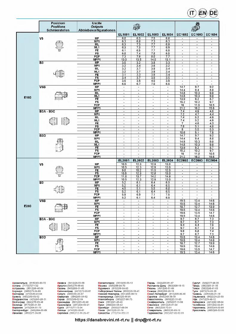
PosizioniPositions
Schmierstellen
V5
B3
4
V5B
E160
B3A - B3C
B3D
UsciteOutputs
Abtriebskonfigurationen Ф £
MPEL1601 EL1602 EL1603 EL1604 EC1602 EC1603 EC1604
6.0 6.5 7.5 6.6 - - -
MP1 6.3 6.8 7.3 6.3 - - -
ML 6.3 7.3 7.7 6.9 - - -
ML1 6.3 7.3 7.7 6.9 - - -
FE 6.1 6.5 7.7 6.8 - - -
FS 6.8 7.4 7.8 6.0 - - -FCP 7.3 7.6 8.0 7.7 - - -
MPP1 13.0 13.5 14.0 13.1 - - -MP 3.0 3.2 3.8 3.3 - - -MP1 3.2 3.4 3.6 3.2 - - -ML 3.2 3.7 3.9 3.4 - - -ML1 3.2 3.7 3.9 3.4 - - -FE 3.1 3.3 3.9 3.4 - - -FS 3.4 3.7 3.9 3.5 - - -
FCP 3.6 3.8 4.0 3.8 - - -MPP1 6.5 6.7 7.0 6.5 - - -MP - - - - 14.7 9.7 9.2MP1 - - - - 14.4 9.4 8.8ML - - - - 14.8 10.3 9.8ML1 - - - - 14.8 10.3 9.8FE - - - - 13.9 9.2 8.7FS - - - - 15.2 10.2 9.7
FCP - - - - 16 11.0 10.5MPP1 - - - - 21.2 16.2 15.6MP - - - - 7.4 4.9 4.6MP1 - - - - 7.2 4.7 4.4ML - - - - 7.4 5.2 4.9ML1 - - - - 7.4 5.2 4.9FE - - - - 7 4.6 4.3FS - - - - 7.6 5.1 4.8
FCP - - - - 8 5.5 5.3MPP1 - - - - 10.6 8.1 7.8MP - - - - 14.7 9.7 9.2MP1 - - - - 14.4 9.4 8.8ML - - - - 14.8 10.3 9.8ML1 - - - - 14.8 10.3 9.8FE - - - - 13.9 9.2 8.7FS - - - - 15.2 10.2 9.7
FCP - - - - 16 11.0 10.5MPP1 - - - - 21.2 16.2 15.6
MPEL2601 EL2602 EL2603 EL2604 EC2602 EC2603 EC2604
10.5 12.3 12.8 13.0 - - -
MP1 10.5 12.3 12.8 13.0 - - -
FE 9.0 10.2 11.0 12.0 - - -
FS 10.5 12.3 12.8 13.0 - - -FCP 11.8 13.7 14.2 14.9 - - -
MPP1 10.5 12.3 12.8 13.0 - - -MP 5.2 6.1 6.4 6.5 - - -MP1 5.2 6.1 6.4 6.5 - - -FE 4.5 5.1 5.5 6.0 - - -FS 5.2 6.1 6.4 6.5 - - -
FCP 5.9 6.9 7.1 7.5 - - -MPP1 5.2 6.1 6.4 6.5 - - -MP - - - - 19.5 13.4 14.6MP1 - - - - 19.5 13.4 14.6FE - - - - 18.7 12.7 13.9FS - - - - 19.5 13.4 14.6
FCP - - - - 19.6 13.5 14.7MPP1 - - - - 19.5 13.4 14.6MP - - - - 9.7 6.7 7.3MP1 - - - - 9.7 6.7 7.3FE - - - - 9.4 6.4 7.0FS - - - - 9.7 6.7 7.3
FCP - - - - 9.8 6,8 7.4MPP1 - - - - 9.7 6.7 7.3MP - - - - 19.5 13.4 14.6MP1 - - - - 19.5 13.4 14.6FE - - - - 18.7 12.7 13.9FS - - - - 19.5 13.4 14.6
FCP - - - - 19.6 13.5 14.7MPP1 - - - - 19.5 13.4 14.6
V5
B3
4
V5B
E260
B3A - B3C
B3D
M
А рхангельск (8182)63-90-72 А стана (7172)727-132 А страхань (8512)99-46-04 Барнаул (3852)73-04-60 Белгород (4722)40-23-64 Брянск (4832)59-03-52 Владивосток (423)249-28-31 Волгоград (844)278-03-48 Вологда (8172)26-41-59 Воронеж (473)204-51-73 Екатеринбург (343)384-55-89 Иваново (4932)77-34-06
Иж евск (3412)26-03-58 Иркутск (395)279-98-46 Казань (843)206-01-48 Калининград (4012)72-03-81 Калуга (4842)92-23-67 Кемерово (3842)65-04-62 Киров (8332)68-02-04 Краснодар (861 )203-40-90 Красноярск (391)204-63-61 Курск (4712)77-13-04 Л ипецк (4742)52-20-81 Киргизия (996)312-96-26-47
Магнитогорск (3519)55-03-13 Москва (495)268-04-70 Мурм анск (8152)59-64-93 Набережные Челны (8552)20-53-41 Нижний Новгород (831)429-08-12 Новокузнецк (3843)20-46-81 Новосибирск (383)227-86-73 О мск (3812)21-46-40 Орел (4862)44-53-42 Оренбург (3532)37-68-04 Пенза (8412)22-31-16 Казахстан (772)734-952-31
Пермь (342)205-81-47 Ростов-на-Дону (863)308-18-15 Рязань (4912)46-61-64 Самара (846)206-03-16 Санкт-Петербург (812)309-46-40 Саратов (845)249-38-78 Севастополь (8692)22-31 -93 Симф ерополь (3652)67-13-56 С моленск (4812)29-41-54 Сочи (862)225-72-31 Ставрополь (8652)20-65-13 Таджикистан (992)427-82-92-69
Сургут (3462)77-98-35 Тверь (4822)63-31-35 Томск (3822)98-41-53 Тула (4872)74-02-29 Тюмень (3452)66-21-18 Ульяновск (8422)24-23-59 Уфа (347)229-48-12 Хабаровск (4212)92-98-04 Челябинск (351)202-03-61 Череповец (8202)49-02-64 Ярославль (4852)69-52-93
https://danabrevini.nt-rt.ru || [email protected]