cargo and deck operating manual document section 1
TRANSCRIPT
Issue: Final Draft
Document Title: Cargo and Deck Operating Manual
Document Section 1: British Innovator
Revision: x
Date: xxxxx
CARGO AND DECK OPERATING MANUAL
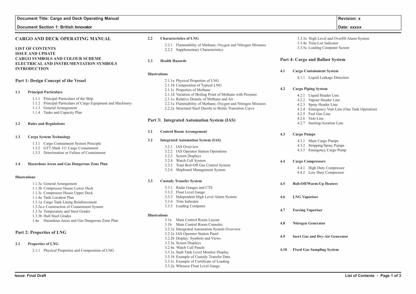
LIST OF CONTENTSISSUE AND UPDATECARGO SYMBOLS AND COLOUR SCHEME ELECTRICAL AND INSTRUMENTATION SYMBOLSINTRODUCTION
Part 1: Design Concept of the Vessel
1.1 Principal Particulars
1.1.1 Principal Particulars of the Ship 1.1.2 Principal Particulars of Cargo Equipment and Machinery 1.1.3 General Arrangement 1.1.4 Tanks and Capacity Plan
1.2 Rules and Regulations
1.3 Cargo System Technology
1.3.1 Cargo Containment System Principle 1.3.2 GTT Mark 111 Cargo Containment 1.3.3 Deterioration or Failure of Containment
1.4 Hazardous Areas and Gas Dangerous Zone Plan
Illustrations
1.1.3a General Arrangement 1.1.3b Compressor House Lower Deck 1.1.3c Compressor House Upper Deck 1.1.4a Tank Location Plan 1.3.1a Cargo Tank Lining Reinforcement 1.3.2a-c Construction of Containment System 1.3.3a Temperature and Steel Grades 1.3.3b Hull Steel Grades 1.4a Hazardous Areas and Gas Dangerous Zone Plan
Part 2: Properties of LNG
2.1 Properties of LNG
2.1.1 Physical Properties and Composition of LNG
2.2 Characteristics of LNG
2.2.1 Flammability of Methane, Oxygen and Nitrogen Mixtures 2.2.2 Supplementary Characteristics
2.3 Health Hazards
Illustrations
2.1.1a Physical Properties of LNG 2.1.1b Composition of Typical LNG 2.1.1c Properties of Methane 2.1.1d Variation of Boiling Point of Methane with Pressure 2.1.1e Relative Density of Methane and Air 2.2.1a Flammability of Methane, Oxygen and Nitrogen Mixtures 2.2.2a Structural Steel Ductile to Brittle Transition Curve
Part 3: Integrated Automation System (IAS)
3.1 Control Room Arrangement
3.2 Integrated Automation System (IAS)
3.2.1 IAS Overview 3.2.2 IAS Operator Station Operations 3.2.3 Screen Displays 3.2.4 Watch Call System 3.2.5 Total Boil-Off Gas Control System 3.2.6 Shipboard Management System
3.3 Custody Transfer System
3.3.1 Radar Gauges and CTS 3.3.2 Float Level Gauge 3.3.3 Independent High Level Alarm System 3.3.4 Trim Indicator 3.3.5 Loading Computer
Illustrations 3.1a Main Control Room Layout 3.1b Main Control Room Consoles 3.2.1a Intergrated Automation System Overview 3.2.2a IAS Operator Station Panel 3.2.2b Display: Symbols and Views 3.2.3a Screen Displays 3.2.4a Watch Call Panels 3.3.1a Saab Tank Level Monitor Display 3.3.1b Example of Custody Transfer Data 3.3.1c Example of Certificate of Loading 3.3.2a Whessoe Float Level Gauge
3.3.3a High Level and Overfill Alarm System 3.3.4a Trim-List Indicator 3.3.5a Loading Computer Screen
Part 4: Cargo and Ballast System
4.1 Cargo Containment System
4.1.1 Liquid Leakage Detection
4.2 Cargo Piping System
4.2.1 Liquid Header Line 4.2.2 Vapour Header Line 4.2.3 Spray Header Line 4.2.4 Emergency Vent Line (One Tank Operation) 4.2.5 Fuel Gas Line 4.2.6 Vent Line 4.2.7 Inerting/Aeration Line
4.3 Cargo Pumps
4.3.1 Main Cargo Pumps 4.3.2 Stripping/Spray Pumps 4.3.3 Emergency Cargo Pump
4.4 Cargo Compressors
4.4.1 High Duty Compressor 4.4.2 Low Duty Compressor
4.5 Boil-Off/Warm-Up Heaters
4.6 LNG Vaporiser
4.7 Forcing Vaporiser
4.8 Nitrogen Generator
4.9 Inert Gas and Dry-Air Generator
4.10 Fixed Gas Sampling System
List of Contents - Page 1 of 3
Issue: Final Draft
Document Title: Cargo and Deck Operating Manual
Document Section 1: British Innovator
Revision: x
Date: xxxxx
4.11 Valve Remote Control and Emergency Shutdown System
4.11.1 Cargo and Ballast Valve Remote Control System 4.11.2 Emergency Shutdown and Cargo Tank Protection Scheme
4.12 Ship-Shore Link and Mooring Load Monitoring System
4.12.1 Ship Shore Link - Fibre Optic 4.12.2 Ship Shore Link - Electrical 4.12.3 Mooring Load Monitor System
4.13 Relief Systems
4.13.1 Cargo Tank Relief Valves 4.13.2 Insulation Space Relief Valves 4.13.3 Pipeline Relief Valves
4.14 Remote Sounding and Draught Gauging System 4.14.1 Ballast Piping System 4.14.2 Ballast Level and Draught Indicating System 4.14.3 Ballast Water Management
4.15 Vacuum Pumps
Illustrations
4.1a Leakage Pipe 4.2a Cargo Piping System 4.3.1a Main Cargo Pumps 4.3.1b Main Cargo Pump Start Sequence 4.3.2a Stripping/Spray Pumps 4.3.2b Spray Pump Start Sequence 4.3.3a Emergency Cargo Pump 4.4.1a High Duty Compressor 4.4.2a Low Duty Compressor 4.4.2b Low Duty Compressor Set Point List 4.5a Boil-Off/Warm-Up Heaters 4.6a LNG Vaporiser 4.7a Forcing Vaporiser 4.8a Nitrogen Generator 4.9a Inert Gas and Dry-Air Generator 4.9b Inert Gas Generator Gas Oil System 4.10a Fixed Gas Sampling System 4.10b Fixed Gas Sampling System 4.11.1a Cargo Valve Hydraulic Pipelines 4.11.1b Ballast Valve Hydraulic Pipelines 4.12.1a Ship Shore Link 4.13.1a Operation of Cargo Tank Relief Valves 4.13.2a Interbarrier Space / Insulation Space Relief Valve Layout 4.13.2b Cargo Tank Pressure Table
4.14.1a Ballast Piping System 4.14.2a Ballast Level Gauge 4.14.2b Draught and Tank Level Indicating System 4.14.3a Ballast Exchange Flowchart
Part 5: Cargo Auxiliary and Deck System
5.1 Temperature Monitoring System
5.2 Primary and Secondary Insulation Space Nitrogen Pressurising and Control System
5.3 Cofferdam Heating System
5.3.1 Glycol Water Heater 5.3.2 Cofferdam Heating and Control 5.3.3 Hull Ventilation
5.4 Fire Fighting Systems
5.4.1 Fire and Wash Deck System 5.4.2 Water Spray System 5.4.3 Dry Powder System 5.4.4 CO2 System 5.4.5 Fire Detection System 5.4.6 Emergency Fire Pump Operation 5.4.7 Quick-Closing Valves and Fire Dampers System 5.4.8 Water Mist System
5.5 Cargo Machinery Fresh Water Cooling System
5.6 Forward Bilge System
5.7 Incinerator and Garbage Disposal
Illustrations
5.1a Cargo Tank Temperature Monitoring System 5.2a Nitrogen Pressurisation and Control System 5.2b IBS Pressure Control 5.3.1a Glycol Water Heater 5.3.2a Cofferdam Heating System 5.3.3a Hull Ventilation 5.3.3b Marine Safety Card 5.4.1a Emergency Stop List 5.4.1b Fire and Wash Deck System 5.4.1c Engine Room Fire Main System
5.4.1d Accommodation Fire Main System 5.4.2a Water Spray System 5.4.3a Dry Powder Tank Units 5.4.3b Dry Powder System on Deck 5.4.4a CO2 System 5.4.4b Cargo Area CO2 System 5.4.4c CO2 System in Engine Room 5.4.5a Fire Detection Panel 5.4.6a Emergency Fire Pump Operation 5.4.7a Quick-Closing Valves and Fire Dampers System 5.4.8a Water Mist System 5.5a Cargo Machinery Fresh Water Cooling System 5.6a Forward Bilge System 5.7a Incinerator Fuel Oil Service System 5.7b Garbage Treatment Procedure 5.7c Garbage Treatment Procedure for Oil 5.7d Garbage Treatment Procedure for Hotel Service 5.7e Garbage Treatment Procedure for Solid Waste 5.7f Garbage Treatment Procedure Caution Plate
Part 6: Cargo Operations
6.1 Insulation Space Pressurising
6.1.1 Insulation Space Inerting 6.1.2 In Service Test
6.2 Post Dry Dock Operation
6.2.1 Initial Insulation Space Inerting 6.2.2 Drying Cargo Tanks 6.2.3 Inerting Cargo Tanks 6.2.4 Gassing-Up Cargo Tanks 6.2.5 Cooling Down Cargo Tanks
6.3 Ballast Passage
6.3.1 Cooling Down Cargo Tanks Prior to Arrival 6.3.2 Spraying During Ballast Voyage, Single Tank
List of Contents - Page 2 of 3
Issue: Final Draft
Document Title: Cargo and Deck Operating Manual
Document Section 1: British Innovator
Revision: x
Date: xxxxx
6.4 Loading
6.4.1 Preparations for Loading 6.4.2 Cargo Lines Cooldown 6.4.3 To Load Cargo with Vapour Return to Shore via High Duty Compressor 6.4.4 Deballasting
6.5 Loaded Voyage With Boil-Off Gas Burning
6.5.1 Loaded Voyage with Normal Boil-Off Gas Burning 6.5.2 Loaded Voyage with Forced Boil-Off Gas Burning
6.6 Discharging with Vapour Return from Shore
6.6.1 Preparation for Discharging 6.6.2 Liquid Line Cooldown Before Discharging 6.6.3 Arm Cooldown Before Discharging 6.6.4 Discharging with Vapour Return from Shore 6.6.5 Ballasting
6.7 Pre Dry Dock Operations
6.7.1 Stripping and Line Draining 6.7.2 Tank Warm-Up 6.7.3 Inerting 6.7.4 Aerating
6.8 One Tank Operation
6.8.1 Warm-Up 6.8.2 Gas Freeing 6.8.3 Aerating One Cargo Tank 6.8.4 One Tank Drying/Inerting 6.8.5 One Tank Gassing Up and Cooling Down
Illustrations
6.1.1a Initial Insulation Space Inerting 6.1.2a In Service Test 6.2.1a Filling From Shore Nitrogen Supply 6.2.2a Drying Cargo Tanks 6.2.3a Inerting Cargo Tanks Prior to Gas Filling 6.2.4a Displacing Inert Gas (Gas Filling) with LNG Vapour 6.2.4b Displacing Inert Gas with LNG Vapour Discharging to Shore 6.2.5a Tank Cooldown with Return through Vapour Header 6.3.1a Cooling Down Cargo Tanks Prior to Arrival on Ballast Voyage 6.3.2a Cooling Down One Cargo Tank Prior to Arrival on Ballast Voyage 6.4.1a Preparations for Loading
6.4.2a Cargo Lines Cooldown 6.4.3a Loading With Vapour Return to Shore via High Duty Compressor 6.4.3b Nitrogen Setting Up During Loading 6.4.4a Deballasting 6.5.1a Loaded Voyage with Normal Boil-Off Gas Burning 6.5.2a Loaded Voyage with Forced Boil-Off Gas Burning 6.6.1a Preparation for Discharging 6.6.2a Liquid Line and Arm Cooldown before Discharging 6.6.4a Discharging with Vapour Return from Shore 6.6.5a Ballasting 6.7.1a Stripping and Line Draining 6.7.1b Stripping to No.4 Cargo Tank 6.7.2a Tank Warm-Up (Stage 1) 6.7.2b Tank Warm-Up (Stage 2) 6.7.1a Stripping and Line Draining 6.7.1b Stripping to No.4 Cargo Tank 6.7.2a Tank Warm-Up (Stage 1) 6.7.2b Tank Warm-Up (Stage 2) 6.7.3a Inerting Cargo Tanks 6.7.3b Inerting Liquid Line 6.7.3c Inerting Spray Line 6.7.3d Inerting Manifolds and Machinery Space 6.7.4a Aeration of Cargo Tanks 6.7.4b Aeration of Spray Line 6.7.4c Aeration of Manifolds and Machinery Space 6.8.1a One Tank Warm-Up (Stage 1) 6.8.1b One Tank Warm-Up (Stage 2) 6.8.2a One Tank Inerting 6.8.3a One Tank Aeration 6.8.4a One Tank Drying 6.8.4b One Tank Inerting 6.8.5a One Tank Gassing Up 6.8.5b One Tank Cooldown
Part 7: Emergency Procedures
7.1 LNG Vapour Leakage to Barrier
7.2 LNG Liquid Leakage to Barrier
7.3 Water Leakage to Barrier
7.4 Failure of Cargo Pumps - Emergency Cargo Pump Installation
7.5 Fire and Emergency Breakaway
7.6 Ship to Ship Transfer
7.6.1 General Safety 7.6.2 Pre-mooring Preparations 7.6.3 Mooring 7.6.4 Transfer Operations 7.6.5 Un-mooring
7.7 LNG Jettison
7.8 Running One Cargo Pump from the Emergency Generator
Illustrations
7.2a LNG Liquid Leakage to Barrier 7.3a Water Evacuation from Insulation Space 7.4a Emergency Cargo Pump Installation Sequence 7.8a Running one Cargo Pump from the Emergency Generator
List of Contents - Page 3 of 3
Issue: Final Draft
Document Title: Cargo and Deck Operating Manual
Document Section 1: British Innovator
Revision: x
Date: xxxxx
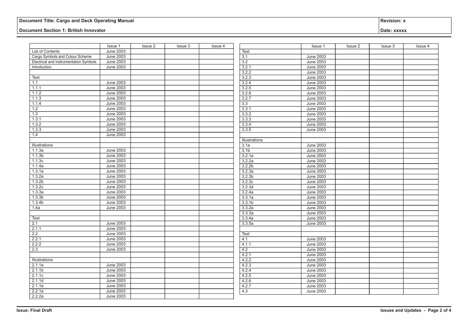
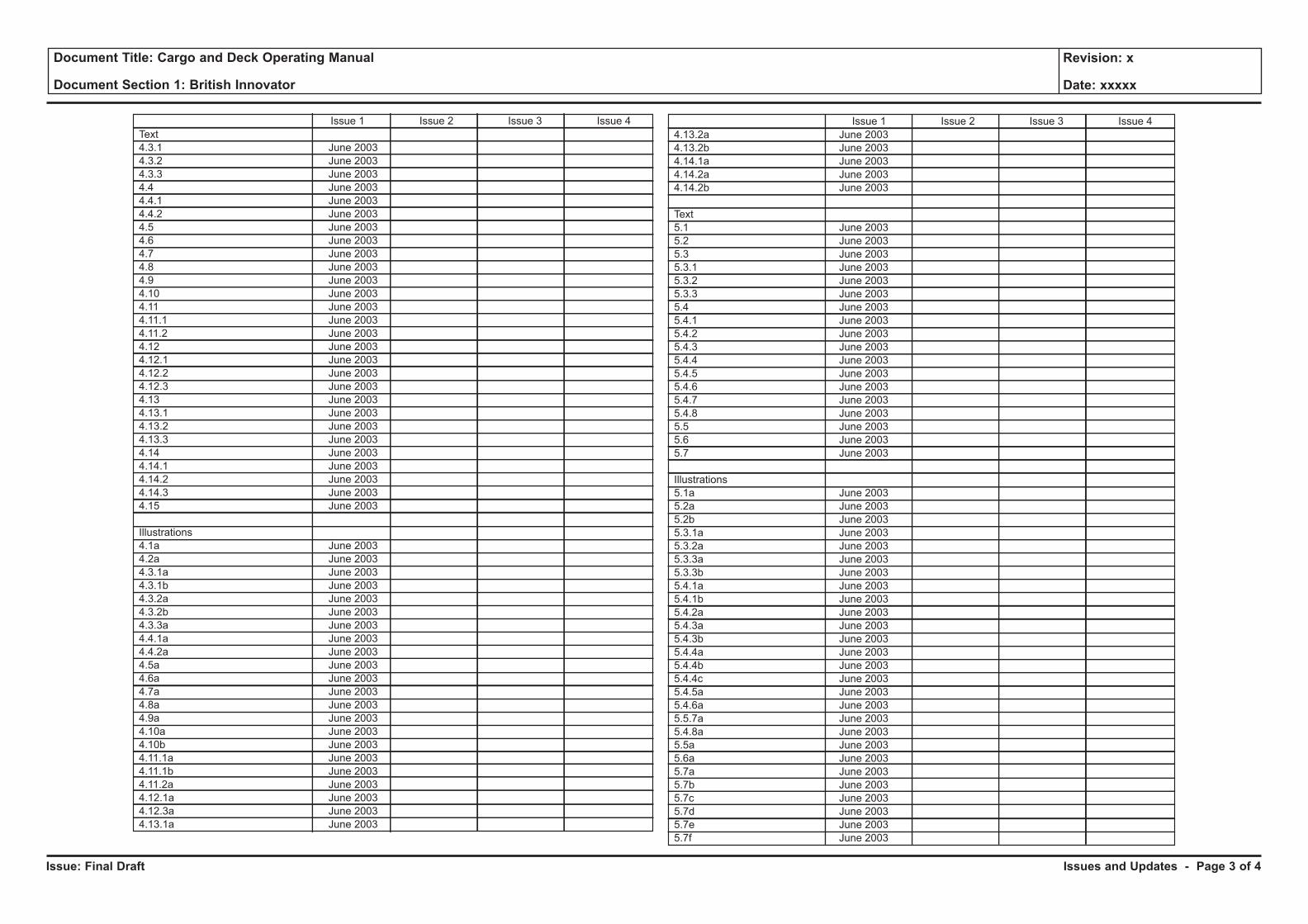
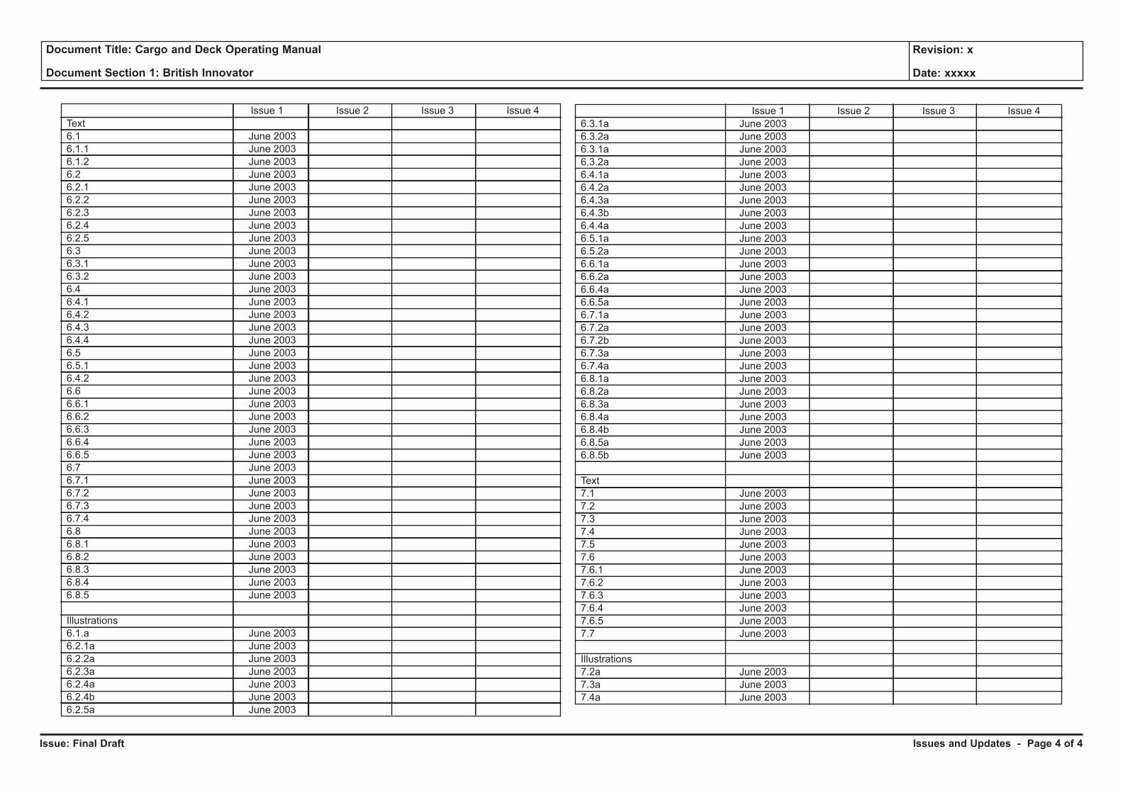
Issue and Update Control
This manual is provided with a system of issue and update control.
Controlling documents ensures that:
• Documents conform to a standard format;
• Amendments are carried out by relevant personnel;
• Each document or update to a document is approved before issue;
• A history of updates is maintained;
• Updates are issued to all registered holders of documents;
• Sections are removed from circulation when obsolete.
Document control is achieved by the use of the footer provided on every page and the issue and update table below.
In the right hand corner of each footer are details of the pages section number and title followed by the page number of the section. In the left hand corner of each footer is the issue number.
Details of each section are given in the first column of the issue and update control table. The table thus forms a matrix into which the dates of issue of the original document and any subsequent updated sections are located.
The information and guidance contained herein is produced for the assistance of certificated officers who by virtue of such certification are deemed competent to operate the vessel to which such information and guidance refers. Any conflict arising between the information and guidance provided herein and the professional judgement of such competent officers must be immediately resolved by reference to BP Shipping Technical Operations Office.
This manual was produced by:
WORLDWIDE MARINE TECHNOLOGY LTD.
For any new issue or update contact:
The Technical Director WMT Technical Office The Court House 15 Glynne Way Hawarden Deeside, Flintshire CH5 3NS, UK
E-Mail: [email protected]
Issues and Updates - Page 1 of 4
Issue: Final Draft
Document Title: Cargo and Deck Operating Manual
Document Section 1: British Innovator
Revision: x
Date: xxxxx
Issue 1 Issue 2 Issue 3 Issue 4
List of Contents
Cargo Symbols and Colour Scheme
Electrical and Instrumentation Symbols
Introduction
Text
1.1
1.1.1
1.1.2
1.1.3
1.1.4
1.2
1.3
1.3.1
1.3.2
1.3.3
1.4
Illustrations
1.1.3a
1.1.3b
1.1.3c
1.1.4a
1.3.1a
1.3.2a
1.3.2b
1.3.2c
1.3.3a
1.3.3b
1.3.4b
1.4a
Text
2.1
2.1.1
2.2
2.2.1
2.2.2
2.3
Illustrations
2.1.1a
2.1.1b
2.1.1c
2.1.1d
2.1.1e
2.2.1a
2.2.2a
June 2003
June 2003
June 2003
June 2003
June 2003
June 2003
June 2003
June 2003
June 2003
June 2003
June 2003
June 2003
June 2003
June 2003
June 2003
June 2003
June 2003
June 2003
June 2003
June 2003
June 2003
June 2003
June 2003
June 2003
June 2003
June 2003
June 2003
June 2003
June 2003
June 2003
June 2003
June 2003
June 2003
June 2003
June 2003
June 2003
June 2003
June 2003
June 2003
June 2003
Issue 1 Issue 2 Issue 3 Issue 4
Text
3.1
3.2
3.2.1
3.2.2
3.2.3
3.2.4
3.2.5
3.2.6
3.2.7
3.3
3.3.1
3.3.2
3.3.3
3.3.4
3.3.5
Illustrations
3.1a
3.1b
3.2.1a
3.2.2a
3.2.2b
3.2.3a
3.2.3b
3.2.3c
3.2.3d
3.2.4a
3.3.1a
3.3.1b
3.3.2a
3.3.3a
3.3.4a
3.3.5a
Text
4.1
4.1.1
4.2
4.2.1
4.2.2
4.2.3
4.2.4
4.2.5
4.2.6
4.2.7
4.3
June 2003
June 2003
June 2003
June 2003
June 2003
June 2003
June 2003
June 2003
June 2003
June 2003
June 2003
June 2003
June 2003
June 2003
June 2003
June 2003
June 2003
June 2003
June 2003
June 2003
June 2003
June 2003
June 2003
June 2003
June 2003
June 2003
June 2003
June 2003
June 2003
June 2003
June 2003
June 2003
June 2003
June 2003
June 2003
June 2003
June 2003
June 2003
June 2003
June 2003
June 2003
June 2003
Issues and Updates - Page 2 of 4
Issue: Final Draft
Document Title: Cargo and Deck Operating Manual
Document Section 1: British Innovator
Revision: x
Date: xxxxx
Issue 1 Issue 2 Issue 3 Issue 4
Text
4.3.1
4.3.2
4.3.3
4.4
4.4.1
4.4.2
4.5
4.6
4.7
4.8
4.9
4.10
4.11
4.11.1
4.11.2
4.12
4.12.1
4.12.2
4.12.3
4.13
4.13.1
4.13.2
4.13.3
4.14
4.14.1
4.14.2
4.14.3
4.15
Illustrations
4.1a
4.2a
4.3.1a
4.3.1b
4.3.2a
4.3.2b
4.3.3a
4.4.1a
4.4.2a
4.5a
4.6a
4.7a
4.8a
4.9a
4.10a
4.10b
4.11.1a
4.11.1b
4.11.2a
4.12.1a
4.12.3a
4.13.1a
June 2003
June 2003
June 2003
June 2003
June 2003
June 2003
June 2003
June 2003
June 2003
June 2003
June 2003
June 2003
June 2003
June 2003
June 2003
June 2003
June 2003
June 2003
June 2003
June 2003
June 2003
June 2003
June 2003
June 2003
June 2003
June 2003
June 2003
June 2003
June 2003
June 2003
June 2003
June 2003
June 2003
June 2003
June 2003
June 2003
June 2003
June 2003
June 2003
June 2003
June 2003
June 2003
June 2003
June 2003
June 2003
June 2003
June 2003
June 2003
June 2003
June 2003
Issue 1 Issue 2 Issue 3 Issue 4
4.13.2a
4.13.2b
4.14.1a
4.14.2a
4.14.2b
Text
5.1
5.2
5.3
5.3.1
5.3.2
5.3.3
5.4
5.4.1
5.4.2
5.4.3
5.4.4
5.4.5
5.4.6
5.4.7
5.4.8
5.5
5.6
5.7
Illustrations
5.1a
5.2a
5.2b
5.3.1a
5.3.2a
5.3.3a
5.3.3b
5.4.1a
5.4.1b
5.4.2a
5.4.3a
5.4.3b
5.4.4a
5.4.4b
5.4.4c
5.4.5a
5.4.6a
5.5.7a
5.4.8a
5.5a
5.6a
5.7a
5.7b
5.7c
5.7d
5.7e
5.7f
June 2003
June 2003
June 2003
June 2003
June 2003
June 2003
June 2003
June 2003
June 2003
June 2003
June 2003
June 2003
June 2003
June 2003
June 2003
June 2003
June 2003
June 2003
June 2003
June 2003
June 2003
June 2003
June 2003
June 2003
June 2003
June 2003
June 2003
June 2003
June 2003
June 2003
June 2003
June 2003
June 2003
June 2003
June 2003
June 2003
June 2003
June 2003
June 2003
June 2003
June 2003
June 2003
June 2003
June 2003
June 2003
June 2003
June 2003
June 2003
June 2003
June 2003
Issues and Updates - Page 3 of 4
Issue: Final Draft
Document Title: Cargo and Deck Operating Manual
Document Section 1: British Innovator
Revision: x
Date: xxxxx
Issue 1 Issue 2 Issue 3 Issue 4
Text
6.1
6.1.1
6.1.2
6.2
6.2.1
6.2.2
6.2.3
6.2.4
6.2.5
6.3
6.3.1
6.3.2
6.4
6.4.1
6.4.2
6.4.3
6.4.4
6.5
6.5.1
6.4.2
6.6
6.6.1
6.6.2
6.6.3
6.6.4
6.6.5
6.7
6.7.1
6.7.2
6.7.3
6.7.4
6.8
6.8.1
6.8.2
6.8.3
6.8.4
6.8.5
Illustrations
6.1.a
6.2.1a
6.2.2a
6.2.3a
6.2.4a
6.2.4b
6.2.5a
June 2003
June 2003
June 2003
June 2003
June 2003
June 2003
June 2003
June 2003
June 2003
June 2003
June 2003
June 2003
June 2003
June 2003
June 2003
June 2003
June 2003
June 2003
June 2003
June 2003
June 2003
June 2003
June 2003
June 2003
June 2003
June 2003
June 2003
June 2003
June 2003
June 2003
June 2003
June 2003
June 2003
June 2003
June 2003
June 2003
June 2003
June 2003
June 2003
June 2003
June 2003
June 2003
June 2003
June 2003
Issue 1 Issue 2 Issue 3 Issue 4
6.3.1a
6.3.2a
6.3.1a
6.3.2a
6.4.1a
6.4.2a
6.4.3a
6.4.3b
6.4.4a
6.5.1a
6.5.2a
6.6.1a
6.6.2a
6.6.4a
6.6.5a
6.7.1a
6.7.2a
6.7.2b
6.7.3a
6.7.4a
6.8.1a
6.8.2a
6.8.3a
6.8.4a
6.8.4b
6.8.5a
6.8.5b
Text
7.1
7.2
7.3
7.4
7.5
7.6
7.6.1
7.6.2
7.6.3
7.6.4
7.6.5
7.7
Illustrations
7.2a
7.3a
7.4a
June 2003
June 2003
June 2003
June 2003
June 2003
June 2003
June 2003
June 2003
June 2003
June 2003
June 2003
June 2003
June 2003
June 2003
June 2003
June 2003
June 2003
June 2003
June 2003
June 2003
June 2003
June 2003
June 2003
June 2003
June 2003
June 2003
June 2003
June 2003
June 2003
June 2003
June 2003
June 2003
June 2003
June 2003
June 2003
June 2003
June 2003
June 2003
June 2003
June 2003
June 2003
June 2003
Issues and Updates - Page 4 of 4
Issue: Final Draft
Document Title: Cargo and Deck Operating Manual
Document Section 1: British Innovator
Revision: x
Date: xxxxx
Deck Stand (Manual)
Deck Stand (Hydraulic)
Manometer
Filter Regulating Valve
With Strainer
Air Horn
Fire Hose Box
Not Connected
Crossing Pipe
Connected Crossing Pipe
Branch Pipe
Blind (Blank) Flange
Spectacle Flange
( Open Shut)
Orifice
Flexible Hose Joint
Regulating Valve
Float Type Air Vent
(With Flame Screen)
Suction Bellmouth
Discharge/Drain
Rose Box
Mud Box
Air Motor Driven
Solenoid Actuator
Needle Valve / 'V' Port Valve
Spring
Float
Reciprocating Pump
Centrifugal Pump
Eductor (Ejector)
Hand Pump
Simplex Strainer
Duplex Strainer With
Changeover Cock
Rotary (Gear, Screw,
Mono) Type Pump
Y-Type Strainer
Hopper Without Cover
Air Vent Pipe
Sounding Head With
Self - Closing Sampling Cock
Steam Trap With Strainer
and Drain Cock
Sounding Head With
Filling Cap
Flow Meter
Observation Glass
Water Line
Stop Valve
Gate Valve
Butterfly Valve
Swing Check Valve
Hose Valve
3-Way Valve
Self-Closing Valve
Safety / Relief Valve
Pressure Reducing Valve
2-Way Cock
3-Way Cock
(L-Type/T-Type)
Emergency Shut-off Valve
Screw Down Non-Return
Valve
Lift Check Non-Return
Valve
H B
Foam BoxF B
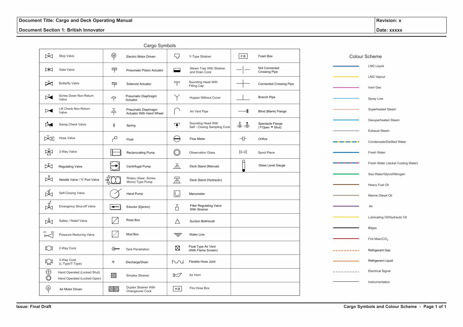
Cargo Symbols
Pneumatic Piston Actuator
Pneumatic Diaphragm
Actuator
Pneumatic Diaphragm
Actuator With Hand Wheel
Spool Piece
P2P1
Colour Scheme
LNG Liquid
Fresh Water
LNG Vapour
Inert Gas
Superheated Steam
Exhaust Steam
Desuperheated Steam
Condensate/Distilled Water
Fresh Water (Jacket Cooling Water)
Sea Water/Glycol/Nitrogen
Air
Heavy Fuel Oil
Marine Diesel Oil
Lubricating Oil/Hydraulic Oil
Bilges
Fire Main/CO2
Refrigerant Gas
Refrigerant Liquid
Spray Line
Electrical Signal
Instrumentation
A
Electric Motor DrivenM
Tank Penetration
Glass Level Gauge
Hand Operated (Locked Open)
Hand Operated (Locked Shut)
Cargo Symbols and Colour Scheme - Page 1 of 1
Issue: Final Draft
Document Title: Cargo and Deck Operating Manual
Document Section 1: British Innovator
Revision: x
Date: xxxxx
Resistor
Group junction box xx
(xx = location)
Whistle relay box
Governor motor
Alarm monitoring
system
Water transducer
Humidistat
WT joint box
2 glands (4 glands)
NWT joint box
Solenoid valve
Variable resistor
Fuse
Normally Closed switch
Indicator lamp
Relay coil
Buzzer
Bell
110 Central meter
Rectifier equipment
Making contact
Making contact
Making contact
Breaking
Breaking
Breaking
Making contact
Breaking
Pushbutton switch
(alternative)
Pushbutton switch
(alternative)
Power supply unit
Zener barrier box
Limit switch
CP
Control panel
IP
Current to pressure
converter
IP
Pressure to current
converter
Normally Open switch
Rectifier
Uninterruptible Power
Supply
Battery
Pushbutton (start/stop)
Pushbutton
(start/stop/running)
Emergency stop
pushbutton box
Overcurrent relay
Diesel generator
Liquid sensor
Transformer
J
HS
( )J J
10A
RL
D-D
BZ
BL
XXXXXXX
ZBK
LM
AC induction motorM
LD
Emergency generatorEG
DG
Turbine generatorTG
WT
AMS
GM
S I GR B
GJB/XX
Function is Locally
Available
Functions are Available
in Control Room
XXXXXXX
Functions are Available
on a Local Panel
Letters outside the circle
of an instrument symbol
indicate whether high (H),
high-high (HH), low (L)
or low-low (LL) function
is involved
O = Open
C = Closed
CP Capacitance
CI Compound Indication
CO2
CO2Meter
O2
O2Meter
DP Differential Pressure
DPAH Differential Pressure Alarm (High)
DPS Differential Pressure Switch
DPX Differential Pressure Transmitter
DPI Differential Pressure Indicator
DTAH Differential Temperature Alarm (High)
EM Electromagnetic Flow Meter
FAL Flow Alarm (Low/Non)
FOC Flow Controller
FX Flow Transmitter
FI Flow/Frequency Indication
FS Flow Switch
FSL Flow Slowdown (Low/Non)
FLG Float Type Level Gauge
HY Hydrazine Detector/Meter
H2O Hydrometer
LAH Level Alarm (High)
LAVH Level Alarm (Very High)
LAEH Level Alarm (Extremely High)
LAHH Level Alarm (High High)
LAL Level Alarm (Low)
LOC Level Controller
LCH Level Controller (High Alarm)
LCL Level Controller (Low Level)
LCG Local Content Gauge
LI Level Indication
LIAL Level Alarm/Indicator (Low )
LIAH Level Alarm/Indicator (High)
LIAHL Level Alarm/Indicator (High/Low)
LR Level Recorder
LS Level Switch
MS Microswitch
MC Motor Control and Indication
MI Motor Indication (Run/Normal)
OAH Oil Content Alarm (High)
OI Oil Content / O2Indicator
PAH Pressure Alarm (High)
PAL Pressure Alarm (Low)
PIAL Pressure Alarm/Indicator (Low)
PIAH Pressure Alarm/Indicator (High)
PIAHL Pressure Alarm High/Low Indicator
PICAHL Pressure Alarm High/Low Indicator/Control
POT Proportional Position Indicator
PX Pressure Transmitter
POC Pressure Controller
PR Pressure Recorder
PI Pressure Indication
PS Pressure Switch
PSH Pressure Shutdown
PSL Pressure Slowdown
PH PH Detector/Meter
Space heater
(element type)
Earth
With time
limit in
closing
With time
limit in
opening
Flicker
relay
XXX
Auxiliary
relay
contact
H
L
XXXXXXX
Trip Automatic Trip
Motor operated valveM
RI RPM Indicator
RCO RPM Counter
RX Revolution Transmitter
RC Revolution Controller
SAH Salinity Alarm (High)
SI Salinity Indication
SX Salinity Transmitter
SM Smoke Indication
SMX Smoke Transmitter
TR Temperature Recorder
TOC Temperature Control
TI Temperature Indication
TIAH Temperature Alarm/Indicator (High)
TIAL Temperature Alarm/Indicator (Low)
TIAHL Temperature Alarm High/Low Indicator
TS Temperature Switch
TT Temperature Transmitter
TSH Temperature Shutdown (High)
TSL Temperature Shutdown (Low)
VX Vacuum Transmitter
VS Vacuum Switch
VA Vacuum Alarm
VSH Vibration Shutdown
VI Viscosity Indication
VC Valve Control
VAH Viscosity Alarm (High)
VAHL Viscosity Alarm (High/Low)
VAL Viscosity Alarm (Low)
XA Binary Contact
XSH Other Shutdown
XSL Other Slowdown
ZI Position Indication
ZS Limit Switch
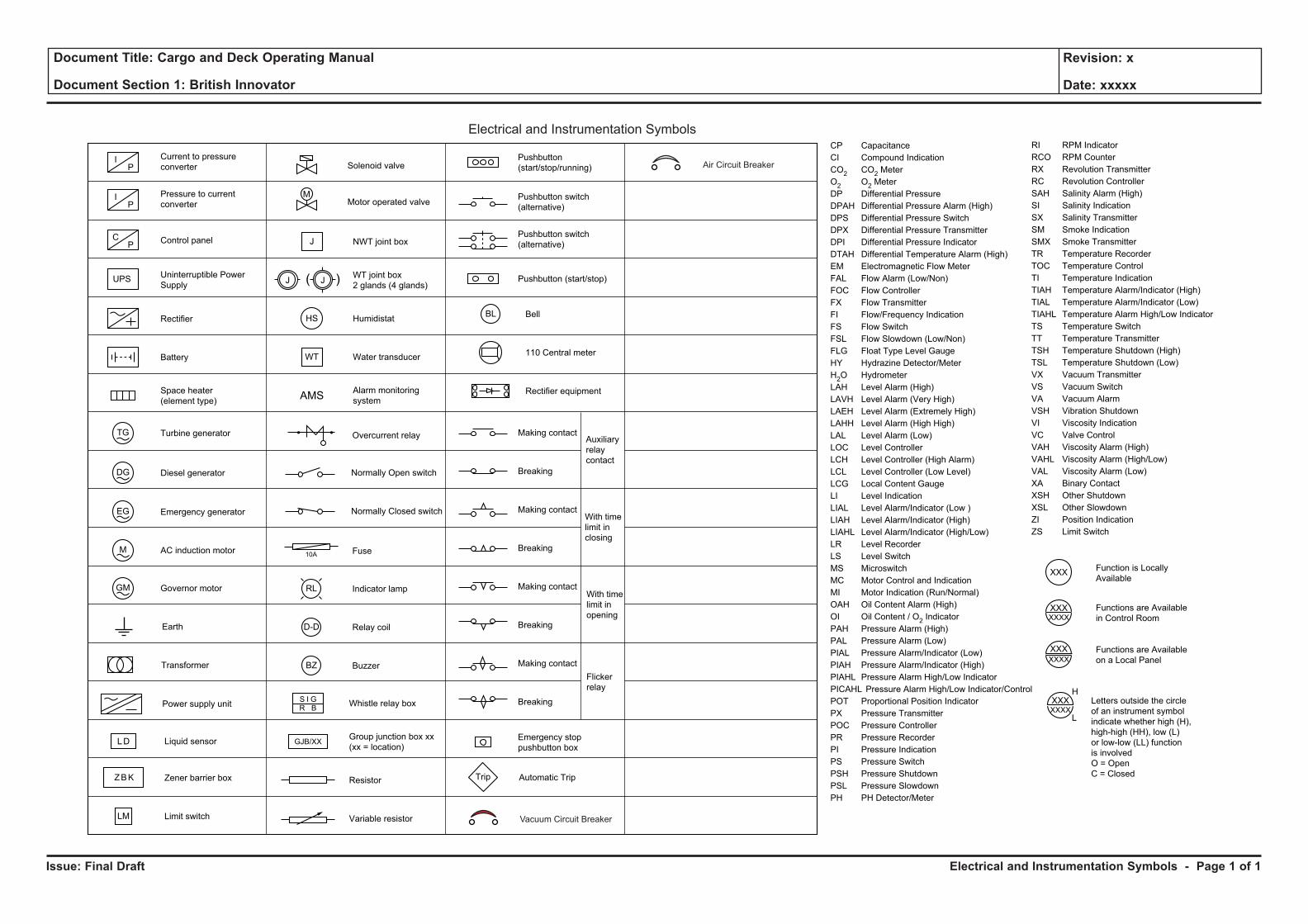
Electrical and Instrumentation Symbols
Vacuum Circuit Breaker
Air Circuit Breaker
UPS
Electrical and Instrumentation Symbols - Page 1 of 1
Issue: Final Draft
Document Title: Cargo and Deck Operating Manual
Document Section 1: British Innovator
Revision: x
Date: xxxxx
Introduction
General
Although the ship is supplied with shipbuilder's plans and manufacturer’s instruction books, there is no single handbook which gives guidance on operating complete systems as installed on board, as distinct from individual items of machinery.
The purpose of this manual is to fill some of the gaps and to provide the ship’s officers with additional information not otherwise available on board. It is intended to be used in conjunction with the other plans and instruction books already on board and in no way replaces or supersedes them.
Information pertinent to the operation of the vessel has been carefully collated in relation to the systems of the vessel and is presented in three on board volumes consisting of CARGO and DECK OPERATING MANUAL, MARINE OPERATIONS MANUAL and MACHINERY OPERATING MANUAL.
The Cargo Operating Manual and the Machinery Operating Manual are designed to complement MARPOL 73/78, ISGOTT and Company Regulations.
The vessel is constructed to comply with MARPOL 73/78. These regulations can be found in the Consolidated Edition, 1991 and in the Amendments dated 1992, 1994 and 1995.
Officers should familiarise themselves with the contents of the International Convention for the Prevention of Pollution from Ships
Particular attention is drawn to Appendix IV of MARPOL 73/78, the form of Ballast Record Book. It is essential that a record of relevant ballast operations are kept in the Ballast Record Book and duly signed by the officer in charge.
In many cases the best operating practice can only be learned by experience. Where the information in this manual is found to be inadequate or incorrect, details should be sent to the BP Shipping Technical Operations Office so that revisions may be made to manuals of other ships of the same class.
Safe Operation
The safety of the ship depends on the care and attention of all on board. Most safety precautions are a matter of common sense and good housekeeping and are detailed in the various manuals available onboard. However, records show that even experienced operators sometimes neglect safety precautions through over-familiarity and the following basic rules must be remembered at all times.
1 Never continue to operate any machine or equipment which appears to be potentially unsafe or dangerous and always report such a condition immediately.
2 Make a point of testing all safety equipment and devices regularly. Always test safety trips before starting any equipment. In particular, overspeed trips on auxiliary turbines must be tested before putting the unit into operation.
3 Never ignore any unusual or suspicious circumstances, no matter how trivial. Small symptoms often appear before a major failure occurs.
4 Never underestimate the fire hazard of petroleum products, whether fuel oil or cargo vapour.
In the design of equipment and machinery, devices are included to ensure that, as far as possible, in the event of a fault occurring, whether on the part of the equipment or the operator, the equipment concerned will cease to function without danger to personnel or damage to the machine. If these safety devices are neglected, the operation of any machine is potentially dangerous.
Description
The concept of this Operating Manual is based on the presentation of operating procedures in the form of one general sequential chart (algorithm) which gives a step-by-step procedure for performing operations.
The manual consists of introductory sections which describe the systems and equipment fitted and their method of operation related to a schematic diagram where applicable. This is then followed where required by detailed operating procedures for the system or equipment involved.
Each machinery operation consists of a detailed introductory section which describes the objectives and methods of performing the operation related to the appropriate flow sheet which shows pipelines in use and directions of flow within the pipelines.
Details of valves which are OPEN during the different operations are provided in-text for reference.
The ‘valves’ and ‘fittings’ identifications used in this manual are the same as those used by BP Shipping.
Illustrations
All illustrations are referred to in the text and are located either in-text where sufficiently small or above the text, so that both the text and illustration are accessible when the manual is laid face up. When text concerning an illustration covers several pages the illustration is duplicated above each page of text.
Where flows are detailed in an illustration these are shown in colour. A key of all colours and line styles used in an illustration is provided on the illustration. Details of colour coding used in the illustrations are given in the colour scheme.
Symbols given in the manual adhere to international standards and keys to the symbols used throughout the manual are given on the following pages.
Notices
The following notices occur throughout this manual:
WARNINGWarnings are given to draw reader’s attention to operations where
DANGER TO LIFE OR LIMB MAY OCCUR.
CAUTIONCautions are given to draw reader’s attention to operations where
DAMAGE TO EQUIPMENT MAY OCCUR.
(Note: Notes are given to draw reader’s attention to points of interest or to supply supplementary information.)
Introduction - Page 1 of 1
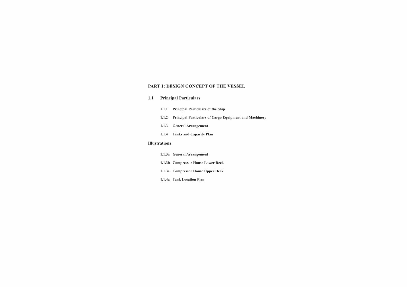
PART 1: DESIGN CONCEPT OF THE VESSEL
1.1 Principal Particulars
1.1.1 Principal Particulars of the Ship
1.1.2 Principal Particulars of Cargo Equipment and Machinery
1.1.3 General Arrangement
1.1.4 Tanks and Capacity Plan
Illustrations
1.1.3a General Arrangement
1.1.3b Compressor House Lower Deck
1.1.3c Compressor House Upper Deck
1.1.4a Tank Location Plan
Issue: Final Draft
Document Title: Cargo and Deck Operating Manual
Document Section 1: British Innovator
Revision: x
Date: xxxxx
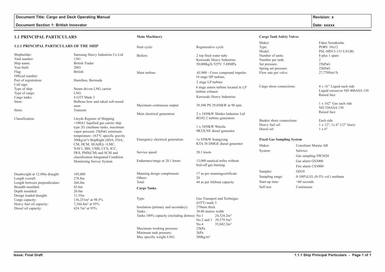
1.1 PRINCIPAL PARTICULARS
1.1.1 PRINCIPAL PARTICULARS OF THE SHIP
Shipbuilder: Samsung Heavy Industries Co LtdYard number: 1381Ship name: British TraderYear built: 2003Flag: BritishOfficial number: Port of registration: Hamilton, BermudaCall sign: Type of ship: Steam driven LNG carrierType of cargo: LNGCargo tanks: 4 GTT Mark 3 Stem: Bulbous bow and raked soft-nosed stemStern: Transom
Classification: Lloyds Register of Shipping +100A1 liquified gas carrier ship type 2G (methane tanks, maximum vapor pressure 25kPaG minimum temperature -163°C specific gravity 500kg/m3) ShipRight (SDA, FDA, CM, HCM, SEA(R)) +LMC, NAV1, IBS, UMS, CCS, ICC, IWS, PMS(CM) and SCM and classification Integrated Condition Monitoring Survey System
Deadweight at 12.09m draught: 105,000Length overall: 278.8mLength between perpendiculars: 266.0mBreadth moulded: 42.6mDepth moulded: 26.0mDesign loaded draught: 11.35mCargo capacity: 136,251m3 at 98.5% Heavy fuel oil capacity: 7,344.4m3 at 95% Diesel oil capacity: 424.7m3 at 95%
Main Machinery
Heat cycle: Regenerative cycle
Boilers: 2 top fired water tube Kawasaki Heavy Industries 50,000kg/h 525ºC 5.88MPa
Main turbine: AU400 - Cross compound impulse 10 stage HP turbine, 2 stage LP turbine 4 stage astern turbine located in LP
turbine exhaust Kawasaki Heavy Industries
Maximum continuous output: 39,500 PS 29,050kW at 90 rpm
Main electrical generation: 2 x 3450kW Shinko Industies Ltd RG92-2 turbine generators
1 x 3450kW Watsila 9R32LNE diesel generator
Emergency electrical generation: 1x 850kW Ssangyong KTA 38 DMGE diesel generator
Service speed: 20.1 knots
Endurance/range at 20.1 knots: 13,000 nautical miles without boil-off gas burning
Manning design complement: 17 as per manningcertificateOthers: 28 Total: 44 as per lifeboat capacity
Cargo Tanks
Type: Gaz Transport and Technigaz (GTT) mark 3Insulation (primary and secondary): 270mm thickTanks : 38.00 metres widthTanks 100% capacity (including domes): No.1 24,524.2m3
No.2 and 3 39,379.5m3
No.4 35,042.2m3
Maximum working pressure: 25kPaMinimum tank pressure: 3kPaMax specific weight LNG: 500kg/m3
Cargo Tank Safety Valves
Maker: Fukui SeisakushoType: PORV 10x12Model: PSL-MD13-131-LS1(B)Number of units: 8 plus 1 spareNumber per tank: 2Set pressure: 25kPaGSpring set pressure: 25kPaGFlow rate per valve: 27,770Nm3/h
Cargo shore connections: 4 x 16’’ Liquid each side Liquid crossover ND 400ASA 150 Raised face
1 x 162” Gas each side ND 350ASA 150 Raised face
Bunker shore connections: Each sideHeavy fuel oil: 1 x 12", 1x 6" (12" lines)Diesel oil: 1 x 6"
Fixed Gas Sampling System
Maker: Consilium Marine ABSystem: Salwico Gas sampling SW2020 Gas alarm GS3000 Fire alarm CS3000/Sampler: GD10Sampling range: 0-100%LEL (0-5% vol.) methaneStart-up time: <60 secondsSelf test: Continuous
1.1.1 Ship Principal Particulars - Page 1 of 1
Issue: Final Draft
Document Title: Cargo and Deck Operating Manual
Document Section 1: British Innovator
Revision: x
Date: xxxxx
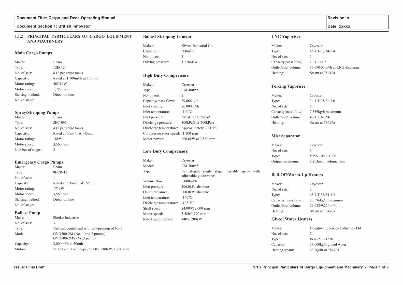
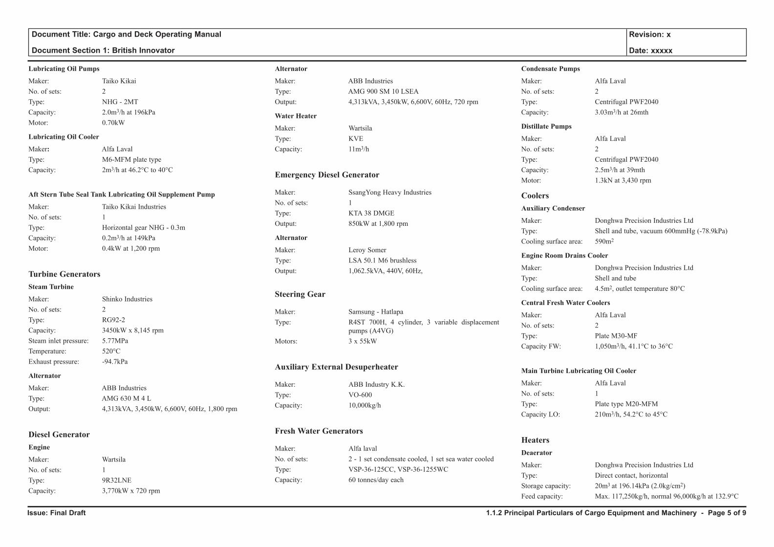
1.1.2 PRINCIPAL PARTICULARS OF CARGO EQUIPMENT AND MACHINERY
Main Cargo Pumps
Maker: Ebara Type: 12EC-24No. of sets: 8 (2 per cargo tank)Capacity: Rated at 1,700m3/h at 155mthMotor rating: 465.1kWMotor speed: 1,780 rpmStarting method: Direct on lineNo. of stages: 1
Spray/Stripping PumpsMaker: EbaraType: 2EC-092No. of sets: 4 (1 per cargo tank)Capacity: Rated at 50m3/h at 145mthMotor rating: 18kWMotor speed: 3,560 rpmNumber of stages: 2
Emergency Cargo PumpsMaker: EbaraType: 8ECR-12No. of sets: 1Capacity: Rated at 550m3/h at 155mthMotor rating: 171kWMotor speed: 3,560 rpmStarting method: Direct on lineNo. of stages: 1
Ballast PumpMaker: Shinko IndustriesNo. of sets: 3Type: Vertical, centrifugal with self-priming of No.3 Model: GVD500-2M (No. 1 and 2 pumps)
GVD500-2MS (No.3 pump) Capacity: 3,000m3/h at 50mthMotors: NTIKE-FCT5-6P type, 6,600V, 580kW, 1,200 rpm
Ballast Stripping Eductor
Maker: Kiwon Industrial Co.Capacity: 300m3/hNo. of sets: 1Driving pressure: 1.176MPa
High Duty Compressors
Maker: CryostarType: CM 400/55No. of sets: 2Capacity(mass flow): 39,666kg/hInlet volume: 26,000m3/hInlet temperature: -140°CInlet pressure: 3kPaG or 103kPaADischarge pressure: 100kPaG or 200kPaADischarge temperature: Approximately -111.5°CCompressor rotor speed: 11,200 rpmMotor power: 666.6kW at 3,580 rpm
Low Duty Compressors
Maker: CryostarModel: CM 300/55Type: Centrifugal, single stage, variable speed with
adjustable guide vanesVolume flow: 8,000m3/hInlet pressure: 106.0kPa absoluteOutlet pressure: 200.0kPa absoluteInlet temperature: -140°CDischarge temperature: -105.5°CShaft speed: 24,000/12,000 rpmMotor speed: 3,580/1,790 rpmRated motor power: 440V, 280kW
LNG Vaporiser
Maker: CryostarType: 65-UT-38/34-5.4No. of sets: 1Capacity(mass flow): 23,111kg/hOutlet/inlet volume: 13,090/51m3/h at LNG dischargeHeating: Steam at 784kPa
Forcing Vaporiser
Maker: CryostarType: 34-UT-25/21-3.6No. of sets: 1Capacity(mass flow): 7,356kg/h maximumOutlet/inlet volume: 4,211/16m3/hHeating: Steam at 784kPa
Mist Separator
Maker: CryostarNo. of sets: 1Type: VMS-10/12-1000Output maximum: 8,203m3/h volume flow
Boil-Off/Warm-Up Heaters
Maker: CryostarNo. of sets: 2Type: 65-UT-38/34-3.2Capacity mass flow: 23,596kg/h maximumOutlet/inlet volume: 29,022/9,224m3/hHeating: Steam at 784kPa
Glycol Water Heaters
Maker: Donghwa Precision Industries LtdNo. of sets: 2Type: Beu 250 - 1530Capacity: 23,000kg/h glycol waterHeating steam: 630kg/hr at 784kPa
1.1.2 Principal Particulars of Cargo Equipment and Machinery - Page 1 of 9
Issue: Final Draft
Document Title: Cargo and Deck Operating Manual
Document Section 1: British Innovator
Revision: x
Date: xxxxx
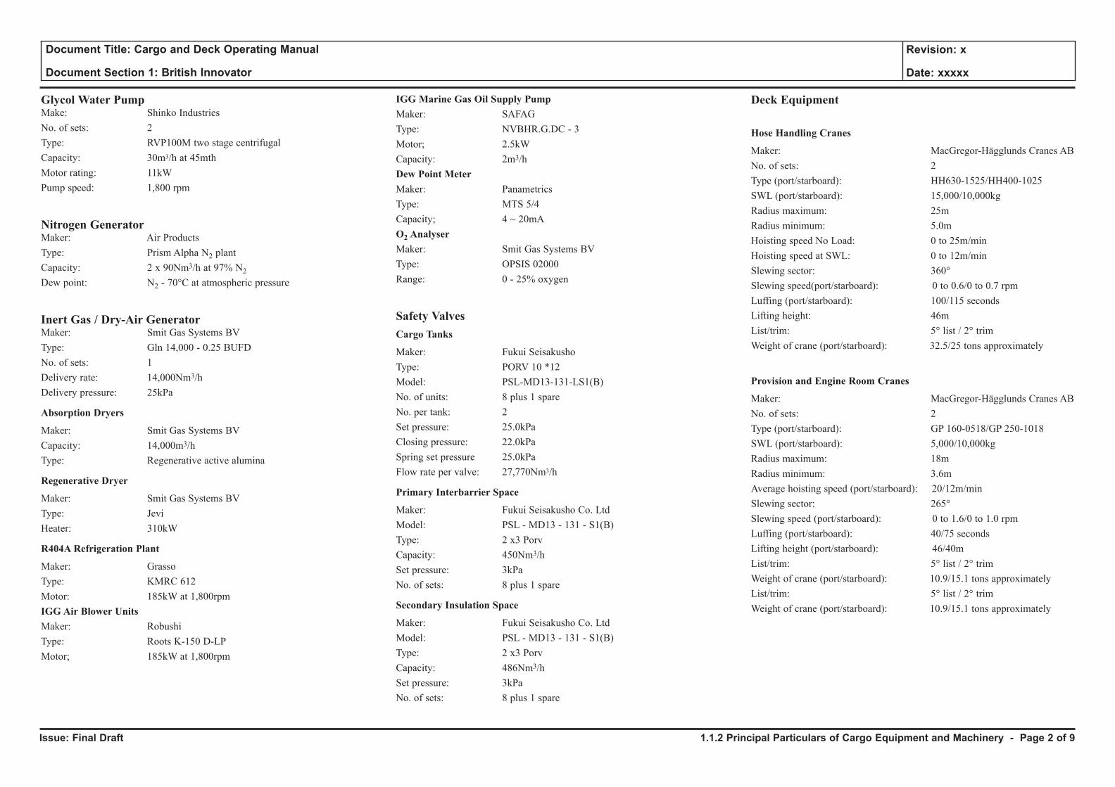
Glycol Water PumpMake: Shinko Industries No. of sets: 2Type: RVP100M two stage centrifugalCapacity: 30m3/h at 45mthMotor rating: 11kWPump speed: 1,800 rpm
Nitrogen GeneratorMaker: Air ProductsType: Prism Alpha N2 plantCapacity: 2 x 90Nm3/h at 97% N2
Dew point: N2 - 70°C at atmospheric pressure
Inert Gas / Dry-Air GeneratorMaker: Smit Gas Systems BVType: Gln 14,000 - 0.25 BUFDNo. of sets: 1Delivery rate: 14,000Nm3/hDelivery pressure: 25kPa
Absorption Dryers
Maker: Smit Gas Systems BVCapacity: 14,000m3/hType: Regenerative active alumina
Regenerative Dryer
Maker: Smit Gas Systems BVType: JeviHeater: 310kW
R404A Refrigeration Plant
Maker: Grasso Type: KMRC 612 Motor: 185kW at 1,800rpmIGG Air Blower UnitsMaker: Robushi Type: Roots K-150 D-LPMotor; 185kW at 1,800rpm
IGG Marine Gas Oil Supply PumpMaker: SAFAG Type: NVBHR.G.DC - 3Motor; 2.5kW Capacity: 2m3/hDew Point MeterMaker: Panametrics Type: MTS 5/4Capacity; 4 ~ 20mAO2 AnalyserMaker: Smit Gas Systems BVType: OPSIS 02000Range: 0 - 25% oxygen
Safety ValvesCargo Tanks
Maker: Fukui SeisakushoType: PORV 10 *12Model: PSL-MD13-131-LS1(B)No. of units: 8 plus 1 spareNo. per tank: 2Set pressure: 25.0kPaClosing pressure: 22.0kPaSpring set pressure 25.0kPaFlow rate per valve: 27,770Nm3/h
Primary Interbarrier Space
Maker: Fukui Seisakusho Co. LtdModel: PSL - MD13 - 131 - S1(B)Type: 2 x3 PorvCapacity: 450Nm3/hSet pressure: 3kPaNo. of sets: 8 plus 1 spare
Secondary Insulation Space
Maker: Fukui Seisakusho Co. LtdModel: PSL - MD13 - 131 - S1(B)Type: 2 x3 PorvCapacity: 486Nm3/hSet pressure: 3kPaNo. of sets: 8 plus 1 spare
Deck Equipment
Hose Handling Cranes
Maker: MacGregor-Hägglunds Cranes ABNo. of sets: 2Type (port/starboard): HH630-1525/HH400-1025SWL (port/starboard): 15,000/10,000kgRadius maximum: 25mRadius minimum: 5.0mHoisting speed No Load: 0 to 25m/minHoisting speed at SWL: 0 to 12m/minSlewing sector: 360° Slewing speed(port/starboard): 0 to 0.6/0 to 0.7 rpmLuffing (port/starboard): 100/115 secondsLifting height: 46mList/trim: 5° list / 2° trimWeight of crane (port/starboard): 32.5/25 tons approximately
Provision and Engine Room Cranes
Maker: MacGregor-Hägglunds Cranes ABNo. of sets: 2Type (port/starboard): GP 160-0518/GP 250-1018SWL (port/starboard): 5,000/10,000kgRadius maximum: 18mRadius minimum: 3.6mAverage hoisting speed (port/starboard): 20/12m/minSlewing sector: 265° Slewing speed (port/starboard): 0 to 1.6/0 to 1.0 rpmLuffing (port/starboard): 40/75 secondsLifting height (port/starboard): 46/40mList/trim: 5° list / 2° trimWeight of crane (port/starboard): 10.9/15.1 tons approximatelyList/trim: 5° list / 2° trimWeight of crane (port/starboard): 10.9/15.1 tons approximately
1.1.2 Principal Particulars of Cargo Equipment and Machinery - Page 2 of 9
Issue: Final Draft
Document Title: Cargo and Deck Operating Manual
Document Section 1: British Innovator
Revision: x
Date: xxxxx
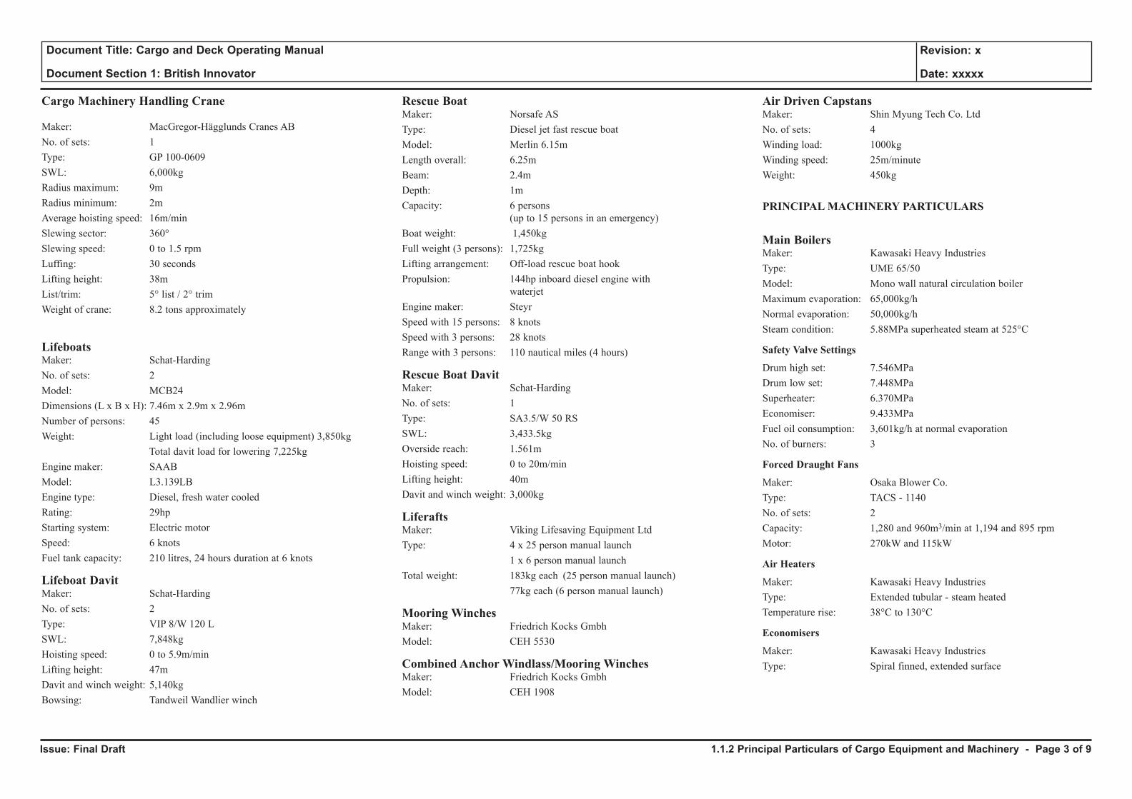
Cargo Machinery Handling Crane
Maker: MacGregor-Hägglunds Cranes ABNo. of sets: 1Type: GP 100-0609SWL: 6,000kgRadius maximum: 9mRadius minimum: 2mAverage hoisting speed: 16m/minSlewing sector: 360° Slewing speed: 0 to 1.5 rpmLuffing: 30 secondsLifting height: 38mList/trim: 5° list / 2° trimWeight of crane: 8.2 tons approximately
Lifeboats Maker: Schat-HardingNo. of sets: 2Model: MCB24Dimensions (L x B x H): 7.46m x 2.9m x 2.96mNumber of persons: 45 Weight: Light load (including loose equipment) 3,850kg Total davit load for lowering 7,225kgEngine maker: SAABModel: L3.139LB Engine type: Diesel, fresh water cooled Rating: 29hp Starting system: Electric motorSpeed: 6 knotsFuel tank capacity: 210 litres, 24 hours duration at 6 knots
Lifeboat DavitMaker: Schat-HardingNo. of sets: 2Type: VIP 8/W 120 LSWL: 7,848kgHoisting speed: 0 to 5.9m/minLifting height: 47mDavit and winch weight: 5,140kgBowsing: Tandweil Wandlier winch
Rescue Boat Maker: Norsafe ASType: Diesel jet fast rescue boatModel: Merlin 6.15mLength overall: 6.25mBeam: 2.4mDepth: 1mCapacity: 6 persons
(up to 15 persons in an emergency)Boat weight: 1,450kgFull weight (3 persons): 1,725kgLifting arrangement: Off-load rescue boat hookPropulsion: 144hp inboard diesel engine with
waterjetEngine maker: SteyrSpeed with 15 persons: 8 knotsSpeed with 3 persons: 28 knots Range with 3 persons: 110 nautical miles (4 hours)
Rescue Boat DavitMaker: Schat-HardingNo. of sets: 1Type: SA3.5/W 50 RSSWL: 3,433.5kgOverside reach: 1.561mHoisting speed: 0 to 20m/minLifting height: 40mDavit and winch weight: 3,000kg
LiferaftsMaker: Viking Lifesaving Equipment LtdType: 4 x 25 person manual launch 1 x 6 person manual launchTotal weight: 183kg each (25 person manual launch) 77kg each (6 person manual launch)
Mooring WinchesMaker: Friedrich Kocks GmbhModel: CEH 5530
Combined Anchor Windlass/Mooring WinchesMaker: Friedrich Kocks GmbhModel: CEH 1908
Air Driven CapstansMaker: Shin Myung Tech Co. LtdNo. of sets: 4Winding load: 1000kgWinding speed: 25m/minuteWeight: 450kg
PRINCIPAL MACHINERY PARTICULARS
Main BoilersMaker: Kawasaki Heavy IndustriesType: UME 65/50Model: Mono wall natural circulation boilerMaximum evaporation: 65,000kg/hNormal evaporation: 50,000kg/hSteam condition: 5.88MPa superheated steam at 525°C
Safety Valve Settings
Drum high set: 7.546MPaDrum low set: 7.448MPaSuperheater: 6.370MPaEconomiser: 9.433MPaFuel oil consumption: 3,601kg/h at normal evaporationNo. of burners: 3
Forced Draught Fans
Maker: Osaka Blower Co.Type: TACS - 1140No. of sets: 2 Capacity: 1,280 and 960m3/min at 1,194 and 895 rpmMotor: 270kW and 115kW
Air Heaters
Maker: Kawasaki Heavy IndustriesType: Extended tubular - steam heatedTemperature rise: 38°C to 130°C
Economisers
Maker: Kawasaki Heavy IndustriesType: Spiral finned, extended surface
1.1.2 Principal Particulars of Cargo Equipment and Machinery - Page 3 of 9
Issue: Final Draft
Document Title: Cargo and Deck Operating Manual
Document Section 1: British Innovator
Revision: x
Date: xxxxx
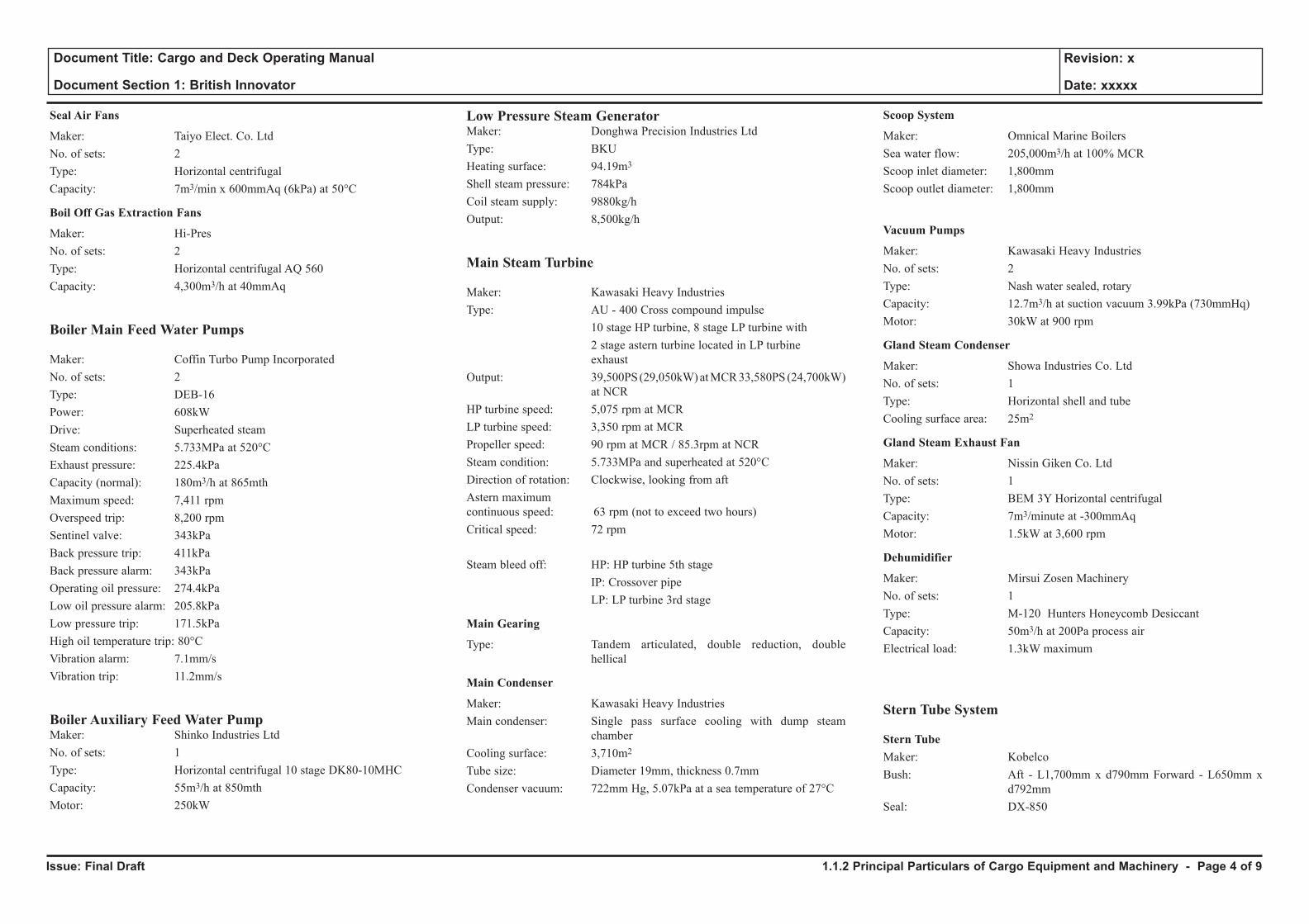
Seal Air Fans
Maker: Taiyo Elect. Co. LtdNo. of sets: 2Type: Horizontal centrifugalCapacity: 7m3/min x 600mmAq (6kPa) at 50°C
Boil Off Gas Extraction Fans
Maker: Hi-PresNo. of sets: 2Type: Horizontal centrifugal AQ 560Capacity: 4,300m3/h at 40mmAq
Boiler Main Feed Water Pumps
Maker: Coffin Turbo Pump IncorporatedNo. of sets: 2Type: DEB-16Power: 608kWDrive: Superheated steamSteam conditions: 5.733MPa at 520°CExhaust pressure: 225.4kPaCapacity (normal): 180m3/h at 865mth Maximum speed: 7,411 rpmOverspeed trip: 8,200 rpmSentinel valve: 343kPaBack pressure trip: 411kPaBack pressure alarm: 343kPaOperating oil pressure: 274.4kPaLow oil pressure alarm: 205.8kPaLow pressure trip: 171.5kPaHigh oil temperature trip: 80°CVibration alarm: 7.1mm/sVibration trip: 11.2mm/s
Boiler Auxiliary Feed Water PumpMaker: Shinko Industries LtdNo. of sets: 1Type: Horizontal centrifugal 10 stage DK80-10MHCCapacity: 55m3/h at 850mthMotor: 250kW
Low Pressure Steam GeneratorMaker: Donghwa Precision Industries LtdType: BKUHeating surface: 94.19m3
Shell steam pressure: 784kPa
Coil steam supply: 9880kg/hOutput: 8,500kg/h
Main Steam Turbine
Maker: Kawasaki Heavy IndustriesType: AU - 400 Cross compound impulse 10 stage HP turbine, 8 stage LP turbine with 2 stage astern turbine located in LP turbine
exhaustOutput: 39,500PS (29,050kW) at MCR 33,580PS (24,700kW)
at NCRHP turbine speed: 5,075 rpm at MCRLP turbine speed: 3,350 rpm at MCRPropeller speed: 90 rpm at MCR / 85.3rpm at NCRSteam condition: 5.733MPa and superheated at 520°CDirection of rotation: Clockwise, looking from aftAstern maximum continuous speed: 63 rpm (not to exceed two hours)Critical speed: 72 rpm
Steam bleed off: HP: HP turbine 5th stage IP: Crossover pipe LP: LP turbine 3rd stage
Main Gearing
Type: Tandem articulated, double reduction, double hellical
Main Condenser
Maker: Kawasaki Heavy IndustriesMain condenser: Single pass surface cooling with dump steam
chamberCooling surface: 3,710m2
Tube size: Diameter 19mm, thickness 0.7mmCondenser vacuum: 722mm Hg, 5.07kPa at a sea temperature of 27°C
Scoop System
Maker: Omnical Marine BoilersSea water flow: 205,000m3/h at 100% MCRScoop inlet diameter: 1,800mmScoop outlet diameter: 1,800mm
Vacuum Pumps
Maker: Kawasaki Heavy IndustriesNo. of sets: 2Type: Nash water sealed, rotaryCapacity: 12.7m3/h at suction vacuum 3.99kPa (730mmHq)Motor: 30kW at 900 rpm
Gland Steam Condenser
Maker: Showa Industries Co. LtdNo. of sets: 1Type: Horizontal shell and tubeCooling surface area: 25m2
Gland Steam Exhaust Fan
Maker: Nissin Giken Co. LtdNo. of sets: 1Type: BEM 3Y Horizontal centrifugalCapacity: 7m3/minute at -300mmAqMotor: 1.5kW at 3,600 rpm
Dehumidifier
Maker: Mirsui Zosen MachineryNo. of sets: 1Type: M-120 Hunters Honeycomb DesiccantCapacity: 50m3/h at 200Pa process airElectrical load: 1.3kW maximum
Stern Tube System
Stern TubeMaker: KobelcoBush: Aft - L1,700mm x d790mm Forward - L650mm x
d792mmSeal: DX-850
1.1.2 Principal Particulars of Cargo Equipment and Machinery - Page 4 of 9
Issue: Final Draft
Document Title: Cargo and Deck Operating Manual
Document Section 1: British Innovator
Revision: x
Date: xxxxx
Lubricating Oil Pumps
Maker: Taiko KikaiNo. of sets: 2 Type: NHG - 2MTCapacity: 2.0m3/h at 196kPaMotor: 0.70kW
Lubricating Oil Cooler
Maker: Alfa LavalType: M6-MFM plate typeCapacity: 2m3/h at 46.2°C to 40°C
Aft Stern Tube Seal Tank Lubricating Oil Supplement Pump
Maker: Taiko Kikai IndustriesNo. of sets: 1Type: Horizontal gear NHG - 0.3mCapacity: 0.2m3/h at 149kPaMotor: 0.4kW at 1,200 rpm
Turbine GeneratorsSteam Turbine
Maker: Shinko IndustriesNo. of sets: 2Type: RG92-2Capacity: 3450kW x 8,145 rpmSteam inlet pressure: 5.77MPaTemperature: 520°CExhaust pressure: -94.7kPa
Alternator
Maker: ABB IndustriesType: AMG 630 M 4 LOutput: 4,313kVA, 3,450kW, 6,600V, 60Hz, 1,800 rpm
Diesel GeneratorEngine
Maker: WartsilaNo. of sets: 1Type: 9R32LNECapacity: 3,770kW x 720 rpm
Alternator
Maker: ABB IndustriesType: AMG 900 SM 10 LSEAOutput: 4,313kVA, 3,450kW, 6,600V, 60Hz, 720 rpm
Water Heater
Maker: WartsilaType: KVECapacity: 11m3/h
Emergency Diesel Generator
Maker: SsangYong Heavy IndustriesNo. of sets: 1Type: KTA 38 DMGEOutput: 850kW at 1,800 rpm
Alternator
Maker: Leroy SomerType: LSA 50.1 M6 brushlessOutput: 1,062.5kVA, 440V, 60Hz,
Steering Gear
Maker: Samsung - HatlapaType: R4ST 700H, 4 cylinder, 3 variable displacement
pumps (A4VG)Motors: 3 x 55kW
Auxiliary External Desuperheater
Maker: ABB Industry K.K.Type: VO-600Capacity: 10,000kg/h
Fresh Water Generators
Maker: Alfa lavalNo. of sets: 2 - 1 set condensate cooled, 1 set sea water cooledType: VSP-36-125CC, VSP-36-1255WCCapacity: 60 tonnes/day each
Condensate Pumps
Maker: Alfa LavalNo. of sets: 2Type: Centrifugal PWF2040Capacity: 3.03m3/h at 26mth
Distillate Pumps
Maker: Alfa LavalNo. of sets: 2Type: Centrifugal PWF2040Capacity: 2.5m3/h at 39mthMotor: 1.3kN at 3,430 rpm
CoolersAuxiliary Condenser
Maker: Donghwa Precision Industries LtdType: Shell and tube, vacuum 600mmHg (-78.9kPa)Cooling surface area: 590m2
Engine Room Drains Cooler
Maker: Donghwa Precision Industries LtdType: Shell and tubeCooling surface area: 4.5m2, outlet temperature 80°C
Central Fresh Water Coolers
Maker: Alfa LavalNo. of sets: 2Type: Plate M30-MF Capacity FW: 1,050m3/h, 41.1°C to 36°C
Main Turbine Lubricating Oil Cooler
Maker: Alfa LavalNo. of sets: 1Type: Plate type M20-MFM Capacity LO: 210m3/h, 54.2°C to 45°C
HeatersDeaerator
Maker: Donghwa Precision Industries LtdType: Direct contact, horizontalStorage capacity: 20m3 at 196.14kPa (2.0kg/cm2) Feed capacity: Max. 117,250kg/h, normal 96,000kg/h at 132.9°C
1.1.2 Principal Particulars of Cargo Equipment and Machinery - Page 5 of 9
Issue: Final Draft
Document Title: Cargo and Deck Operating Manual
Document Section 1: British Innovator
Revision: x
Date: xxxxx
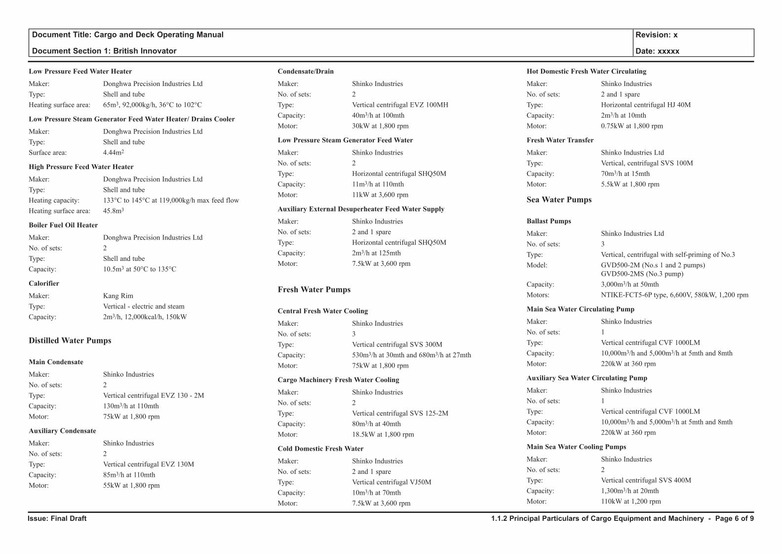
Low Pressure Feed Water Heater
Maker: Donghwa Precision Industries LtdType: Shell and tubeHeating surface area: 65m3, 92,000kg/h, 36°C to 102°C
Low Pressure Steam Generator Feed Water Heater/ Drains Cooler
Maker: Donghwa Precision Industries LtdType: Shell and tubeSurface area: 4.44m2
High Pressure Feed Water Heater
Maker: Donghwa Precision Industries LtdType: Shell and tubeHeating capacity: 133°C to 145°C at 119,000kg/h max feed flowHeating surface area: 45.8m3
Boiler Fuel Oil Heater
Maker: Donghwa Precision Industries LtdNo. of sets: 2Type: Shell and tubeCapacity: 10.5m3 at 50°C to 135°C
Calorifier
Maker: Kang RimType: Vertical - electric and steamCapacity: 2m3/h, 12,000kcal/h, 150kW
Distilled Water Pumps
Main Condensate
Maker: Shinko IndustriesNo. of sets: 2Type: Vertical centrifugal EVZ 130 - 2MCapacity: 130m3/h at 110mthMotor: 75kW at 1,800 rpm
Auxiliary Condensate
Maker: Shinko IndustriesNo. of sets: 2Type: Vertical centrifugal EVZ 130MCapacity: 85m3/h at 110mthMotor: 55kW at 1,800 rpm
Condensate/Drain
Maker: Shinko IndustriesNo. of sets: 2Type: Vertical centrifugal EVZ 100MHCapacity: 40m3/h at 100mthMotor: 30kW at 1,800 rpm
Low Pressure Steam Generator Feed Water
Maker: Shinko IndustriesNo. of sets: 2Type: Horizontal centrifugal SHQ50MCapacity: 11m3/h at 110mthMotor: 11kW at 3,600 rpm
Auxiliary External Desuperheater Feed Water Supply
Maker: Shinko IndustriesNo. of sets: 2 and 1 spareType: Horizontal centrifugal SHQ50MCapacity: 2m3/h at 125mthMotor: 7.5kW at 3,600 rpm
Fresh Water Pumps
Central Fresh Water Cooling
Maker: Shinko IndustriesNo. of sets: 3Type: Vertical centrifugal SVS 300MCapacity: 530m3/h at 30mth and 680m3/h at 27mthMotor: 75kW at 1,800 rpm
Cargo Machinery Fresh Water Cooling
Maker: Shinko IndustriesNo. of sets: 2Type: Vertical centrifugal SVS 125-2MCapacity: 80m3/h at 40mthMotor: 18.5kW at 1,800 rpm
Cold Domestic Fresh Water
Maker: Shinko IndustriesNo. of sets: 2 and 1 spareType: Vertical centrifugal VJ50MCapacity: 10m3/h at 70mthMotor: 7.5kW at 3,600 rpm
Hot Domestic Fresh Water Circulating
Maker: Shinko IndustriesNo. of sets: 2 and 1 spareType: Horizontal centrifugal HJ 40MCapacity: 2m3/h at 10mthMotor: 0.75kW at 1,800 rpm
Fresh Water Transfer
Maker: Shinko Industries LtdType: Vertical, centrifugal SVS 100MCapacity: 70m3/h at 15mthMotor: 5.5kW at 1,800 rpm
Sea Water Pumps
Ballast Pumps
Maker: Shinko Industries LtdNo. of sets: 3Type: Vertical, centrifugal with self-priming of No.3 Model: GVD500-2M (No.s 1 and 2 pumps)
GVD500-2MS (No.3 pump) Capacity: 3,000m3/h at 50mthMotors: NTIKE-FCT5-6P type, 6,600V, 580kW, 1,200 rpm
Main Sea Water Circulating Pump
Maker: Shinko IndustriesNo. of sets: 1Type: Vertical centrifugal CVF 1000LMCapacity: 10,000m3/h and 5,000m3/h at 5mth and 8mthMotor: 220kW at 360 rpm
Auxiliary Sea Water Circulating Pump
Maker: Shinko IndustriesNo. of sets: 1Type: Vertical centrifugal CVF 1000LMCapacity: 10,000m3/h and 5,000m3/h at 5mth and 8mthMotor: 220kW at 360 rpm
Main Sea Water Cooling Pumps
Maker: Shinko IndustriesNo. of sets: 2Type: Vertical centrifugal SVS 400MCapacity: 1,300m3/h at 20mthMotor: 110kW at 1,200 rpm
1.1.2 Principal Particulars of Cargo Equipment and Machinery - Page 6 of 9
Issue: Final Draft
Document Title: Cargo and Deck Operating Manual
Document Section 1: British Innovator
Revision: x
Date: xxxxx
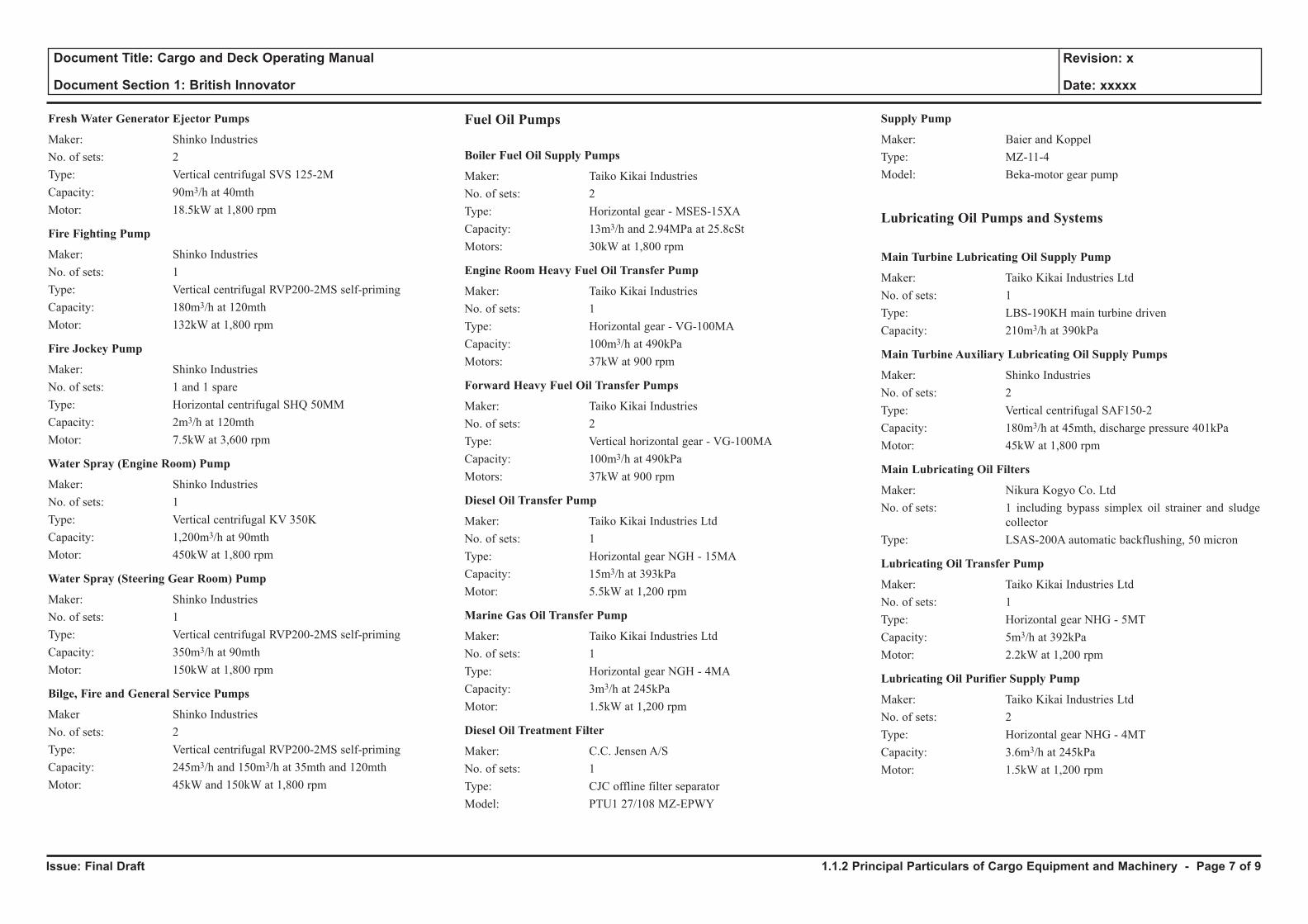
Fresh Water Generator Ejector Pumps
Maker: Shinko IndustriesNo. of sets: 2Type: Vertical centrifugal SVS 125-2MCapacity: 90m3/h at 40mthMotor: 18.5kW at 1,800 rpm
Fire Fighting Pump
Maker: Shinko IndustriesNo. of sets: 1Type: Vertical centrifugal RVP200-2MS self-primingCapacity: 180m3/h at 120mthMotor: 132kW at 1,800 rpm
Fire Jockey Pump
Maker: Shinko IndustriesNo. of sets: 1 and 1 spareType: Horizontal centrifugal SHQ 50MMCapacity: 2m3/h at 120mthMotor: 7.5kW at 3,600 rpm
Water Spray (Engine Room) Pump
Maker: Shinko IndustriesNo. of sets: 1Type: Vertical centrifugal KV 350KCapacity: 1,200m3/h at 90mthMotor: 450kW at 1,800 rpm
Water Spray (Steering Gear Room) Pump
Maker: Shinko IndustriesNo. of sets: 1Type: Vertical centrifugal RVP200-2MS self-primingCapacity: 350m3/h at 90mthMotor: 150kW at 1,800 rpm
Bilge, Fire and General Service Pumps
Maker Shinko IndustriesNo. of sets: 2Type: Vertical centrifugal RVP200-2MS self-primingCapacity: 245m3/h and 150m3/h at 35mth and 120mthMotor: 45kW and 150kW at 1,800 rpm
Fuel Oil Pumps
Boiler Fuel Oil Supply Pumps
Maker: Taiko Kikai IndustriesNo. of sets: 2Type: Horizontal gear - MSES-15XACapacity: 13m3/h and 2.94MPa at 25.8cStMotors: 30kW at 1,800 rpm
Engine Room Heavy Fuel Oil Transfer Pump
Maker: Taiko Kikai IndustriesNo. of sets: 1Type: Horizontal gear - VG-100MACapacity: 100m3/h at 490kPa Motors: 37kW at 900 rpm
Forward Heavy Fuel Oil Transfer Pumps
Maker: Taiko Kikai IndustriesNo. of sets: 2Type: Vertical horizontal gear - VG-100MACapacity: 100m3/h at 490kPa Motors: 37kW at 900 rpm
Diesel Oil Transfer Pump
Maker: Taiko Kikai Industries LtdNo. of sets: 1Type: Horizontal gear NGH - 15MACapacity: 15m3/h at 393kPaMotor: 5.5kW at 1,200 rpm
Marine Gas Oil Transfer Pump
Maker: Taiko Kikai Industries LtdNo. of sets: 1Type: Horizontal gear NGH - 4MACapacity: 3m3/h at 245kPaMotor: 1.5kW at 1,200 rpm
Diesel Oil Treatment Filter
Maker: C.C. Jensen A/SNo. of sets: 1Type: CJC offline filter separatorModel: PTU1 27/108 MZ-EPWY
Supply Pump
Maker: Baier and KoppelType: MZ-11-4Model: Beka-motor gear pump
Lubricating Oil Pumps and Systems
Main Turbine Lubricating Oil Supply Pump
Maker: Taiko Kikai Industries LtdNo. of sets: 1Type: LBS-190KH main turbine drivenCapacity: 210m3/h at 390kPa
Main Turbine Auxiliary Lubricating Oil Supply Pumps
Maker: Shinko Industries No. of sets: 2Type: Vertical centrifugal SAF150-2Capacity: 180m3/h at 45mth, discharge pressure 401kPaMotor: 45kW at 1,800 rpm
Main Lubricating Oil Filters
Maker: Nikura Kogyo Co. Ltd No. of sets: 1 including bypass simplex oil strainer and sludge
collectorType: LSAS-200A automatic backflushing, 50 micron
Lubricating Oil Transfer Pump
Maker: Taiko Kikai Industries LtdNo. of sets: 1Type: Horizontal gear NHG - 5MTCapacity: 5m3/h at 392kPaMotor: 2.2kW at 1,200 rpm
Lubricating Oil Purifier Supply Pump
Maker: Taiko Kikai Industries LtdNo. of sets: 2Type: Horizontal gear NHG - 4MTCapacity: 3.6m3/h at 245kPaMotor: 1.5kW at 1,200 rpm
1.1.2 Principal Particulars of Cargo Equipment and Machinery - Page 7 of 9
Issue: Final Draft
Document Title: Cargo and Deck Operating Manual
Document Section 1: British Innovator
Revision: x
Date: xxxxx
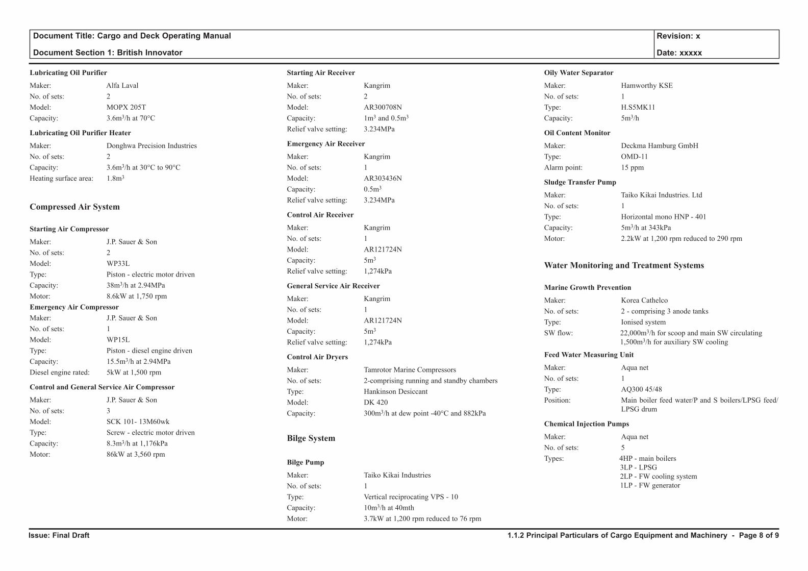
Lubricating Oil Purifier
Maker: Alfa LavalNo. of sets: 2Model: MOPX 205TCapacity: 3.6m3/h at 70°C
Lubricating Oil Purifier Heater
Maker: Donghwa Precision IndustriesNo. of sets: 2Capacity: 3.6m3/h at 30°C to 90°CHeating surface area: 1.8m3
Compressed Air System
Starting Air Compressor
Maker: J.P. Sauer & SonNo. of sets: 2Model: WP33LType: Piston - electric motor drivenCapacity: 38m3/h at 2.94MPaMotor: 8.6kW at 1,750 rpmEmergency Air CompressorMaker: J.P. Sauer & SonNo. of sets: 1Model: WP15LType: Piston - diesel engine drivenCapacity: 15.5m3/h at 2.94MPaDiesel engine rated: 5kW at 1,500 rpm
Control and General Service Air Compressor
Maker: J.P. Sauer & SonNo. of sets: 3Model: SCK 101- 13M60wkType: Screw - electric motor drivenCapacity: 8.3m3/h at 1,176kPaMotor: 86kW at 3,560 rpm
Starting Air Receiver
Maker: KangrimNo. of sets: 2Model: AR300708NCapacity: 1m3 and 0.5m3
Relief valve setting: 3.234MPa
Emergency Air Receiver
Maker: KangrimNo. of sets: 1Model: AR303436NCapacity: 0.5m3
Relief valve setting: 3.234MPa
Control Air Receiver
Maker: KangrimNo. of sets: 1Model: AR121724NCapacity: 5m3
Relief valve setting: 1,274kPa
General Service Air Receiver
Maker: KangrimNo. of sets: 1Model: AR121724NCapacity: 5m3
Relief valve setting: 1,274kPa
Control Air Dryers
Maker: Tamrotor Marine CompressorsNo. of sets: 2-comprising running and standby chambersType: Hankinson Desiccant Model: DK 420Capacity: 300m3/h at dew point -40°C and 882kPa
Bilge System
Bilge Pump
Maker: Taiko Kikai IndustriesNo. of sets: 1Type: Vertical reciprocating VPS - 10Capacity: 10m3/h at 40mthMotor: 3.7kW at 1,200 rpm reduced to 76 rpm
Oily Water Separator
Maker: Hamworthy KSENo. of sets: 1Type: H.S5MK11Capacity: 5m3/h
Oil Content Monitor
Maker: Deckma Hamburg GmbHType: OMD-11Alarm point: 15 ppm
Sludge Transfer Pump
Maker: Taiko Kikai Industries. LtdNo. of sets: 1Type: Horizontal mono HNP - 401Capacity: 5m3/h at 343kPaMotor: 2.2kW at 1,200 rpm reduced to 290 rpm
Water Monitoring and Treatment Systems
Marine Growth Prevention
Maker: Korea CathelcoNo. of sets: 2 - comprising 3 anode tanksType: Ionised systemSW flow: 22,000m3/h for scoop and main SW circulating 1,500m3/h for auxiliary SW cooling
Feed Water Measuring Unit
Maker: Aqua netNo. of sets: 1Type: AQ300 45/48Position: Main boiler feed water/P and S boilers/LPSG feed/
LPSG drum
Chemical Injection Pumps
Maker: Aqua netNo. of sets: 5Types: 4HP - main boilers 3LP - LPSG 2LP - FW cooling system 1LP - FW generator
1.1.2 Principal Particulars of Cargo Equipment and Machinery - Page 8 of 9
Issue: Final Draft
Document Title: Cargo and Deck Operating Manual
Document Section 1: British Innovator
Revision: x
Date: xxxxx
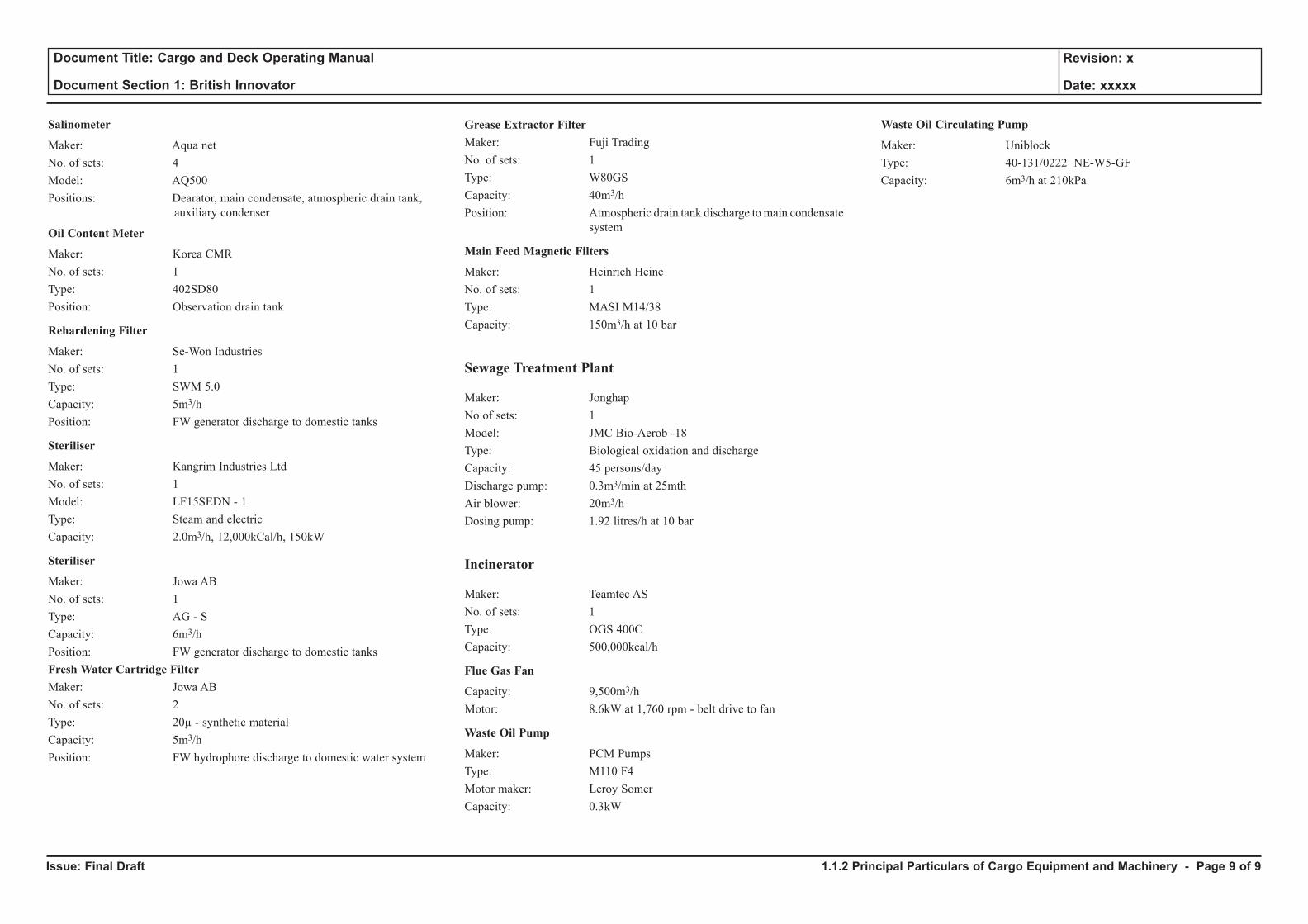
Salinometer
Maker: Aqua netNo. of sets: 4Model: AQ500Positions: Dearator, main condensate, atmospheric drain tank, auxiliary condenser
Oil Content Meter
Maker: Korea CMRNo. of sets: 1Type: 402SD80Position: Observation drain tank
Rehardening Filter
Maker: Se-Won IndustriesNo. of sets: 1Type: SWM 5.0Capacity: 5m3/hPosition: FW generator discharge to domestic tanks
Steriliser
Maker: Kangrim Industries LtdNo. of sets: 1Model: LF15SEDN - 1Type: Steam and electricCapacity: 2.0m3/h, 12,000kCal/h, 150kW
Steriliser
Maker: Jowa ABNo. of sets: 1Type: AG - SCapacity: 6m3/hPosition: FW generator discharge to domestic tanksFresh Water Cartridge FilterMaker: Jowa ABNo. of sets: 2Type: 20µ - synthetic materialCapacity: 5m3/hPosition: FW hydrophore discharge to domestic water system
Grease Extractor FilterMaker: Fuji TradingNo. of sets: 1Type: W80GSCapacity: 40m3/hPosition: Atmospheric drain tank discharge to main condensate
system
Main Feed Magnetic Filters
Maker: Heinrich HeineNo. of sets: 1Type: MASI M14/38Capacity: 150m3/h at 10 bar
Sewage Treatment Plant
Maker: JonghapNo of sets: 1Model: JMC Bio-Aerob -18Type: Biological oxidation and dischargeCapacity: 45 persons/dayDischarge pump: 0.3m3/min at 25mthAir blower: 20m3/hDosing pump: 1.92 litres/h at 10 bar
Incinerator
Maker: Teamtec ASNo. of sets: 1Type: OGS 400CCapacity: 500,000kcal/h
Flue Gas Fan
Capacity: 9,500m3/hMotor: 8.6kW at 1,760 rpm - belt drive to fan
Waste Oil Pump
Maker: PCM PumpsType: M110 F4Motor maker: Leroy SomerCapacity: 0.3kW
Waste Oil Circulating Pump
Maker: UniblockType: 40-131/0222 NE-W5-GFCapacity: 6m3/h at 210kPa
1.1.2 Principal Particulars of Cargo Equipment and Machinery - Page 9 of 9
Issue: Final Draft
Document Title: Cargo and Deck Operating Manual
Document Section 1: British Innovator
Revision: x
Date: xxxxx
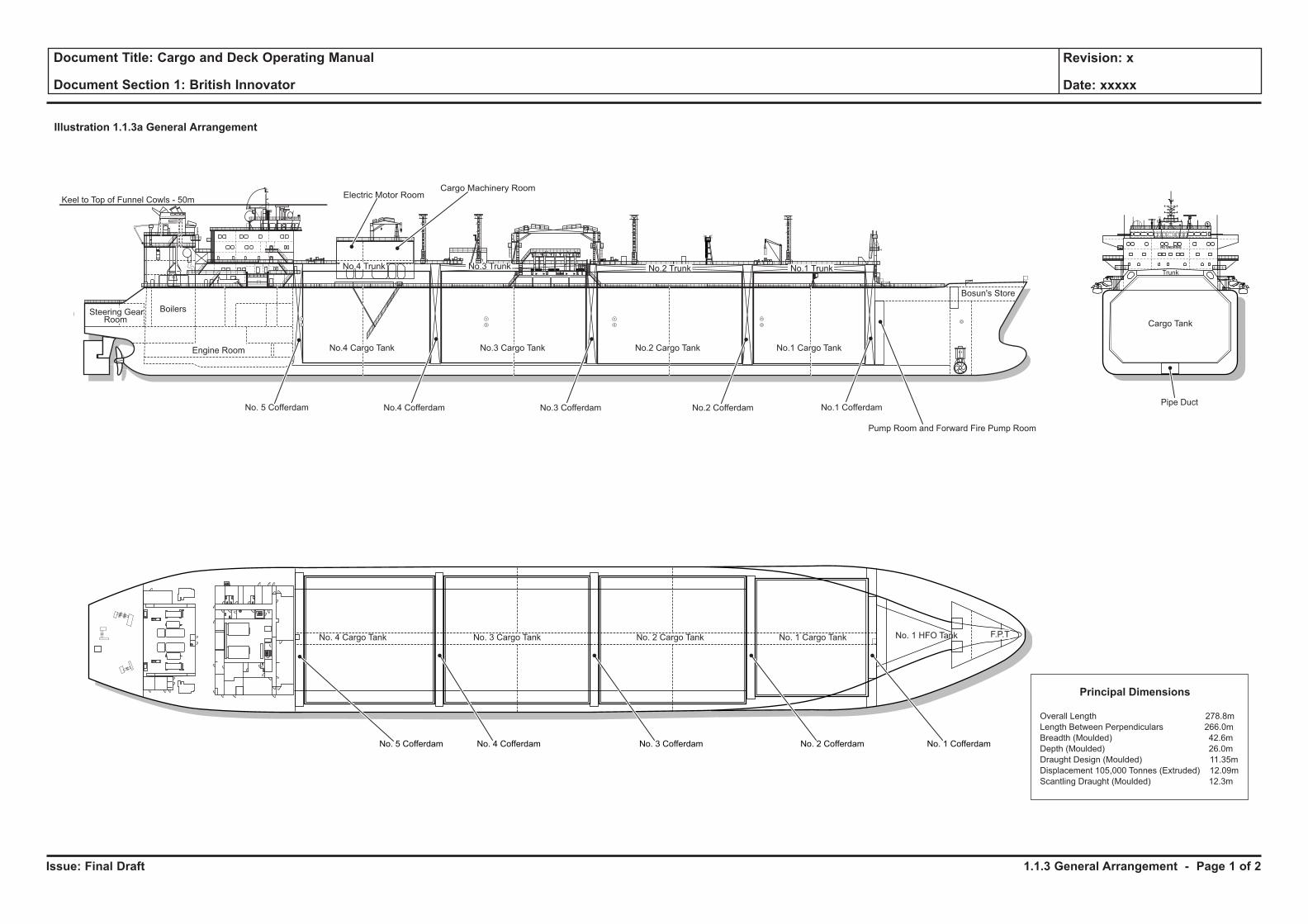
Illustration 1.1.3a General Arrangement
No.1 Cofferdam
NO SMOKING
No.3 Cargo TankNo.4 Cargo Tank No.2 Cargo Tank No.1 Cargo Tank
Bosun's Store
No.2 Trunk No.1 TrunkNo.3 TrunkNo.4 Trunk
Steering GearRoom
Engine Room
Boilers
Pump Room and Forward Fire Pump Room
No. 5 Cofferdam
Keel to Top of Funnel Cowls - 50m
No.4 Cofferdam
Electric Motor RoomCargo Machinery Room
No.3 Cofferdam No.2 CofferdamPipe Duct
No. 2 Cargo TankNo. 3 Cargo TankNo. 4 Cargo Tank No. 1 Cargo Tank
No. 5 Cofferdam No. 4 Cofferdam No. 3 Cofferdam No. 2 Cofferdam No. 1 Cofferdam
No. 1 HFO Tank F.P.T
Principal Dimensions
Overall Length 278.8m
Length Between Perpendiculars 266.0m
Breadth (Moulded) 42.6m
Depth (Moulded) 26.0m
Draught Design (Moulded) 11.35m
Displacement 105,000 Tonnes (Extruded) 12.09m
Scantling Draught (Moulded) 12.3m
Trunk
Cargo Tank
WC
1.1.3 General Arrangement - Page 1 of 2
Issue: Final Draft
Document Title: Cargo and Deck Operating Manual
Document Section 1: British Innovator
Revision: x
Date: xxxxx
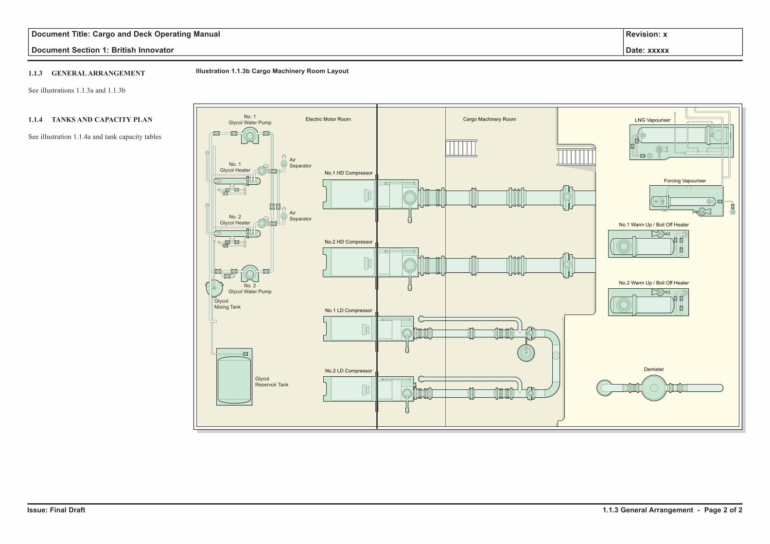
1.1.3 GENERAL ARRANGEMENT
See illustrations 1.1.3a and 1.1.3b
1.1.4 TANKS AND CAPACITY PLAN
See illustration 1.1.4a and tank capacity tables
1.1.3 General Arrangement - Page 2 of 2
Illustration 1.1.3b Cargo Machinery Room Layout
No. 1
Glycol Water Pump
No. 2
Glycol Water Pump
Glycol
Mixing Tank
Glycol
Reservoir Tank
No.2 LD Compressor Demister
No.2 Warm Up / Boil Off Heater
Cargo Machinery RoomElectric Motor Room
No.1 Warm Up / Boil Off Heater
Forcing Vapouriser
LNG Vapouriser
No.1 LD Compressor
No.2 HD Compressor
No.1 HD Compressor
No. 1
Glycol Heater
No. 2
Glycol Heater
Air
Separator
Air
Separator
Issue: Final Draft
Document Title: Cargo and Deck Operating Manual
Document Section 1: British Innovator
Revision: x
Date: xxxxx
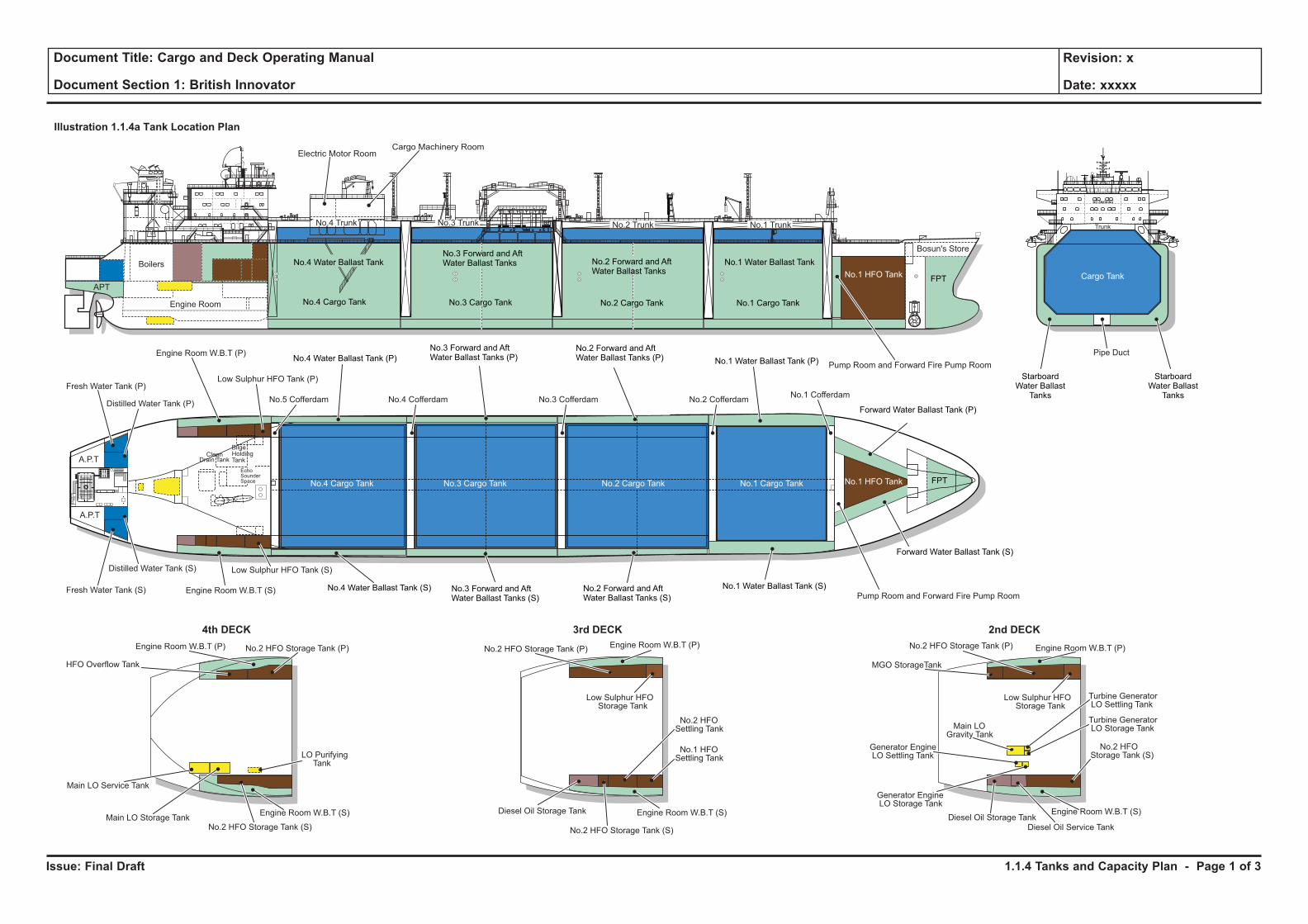
Illustration 1.1.4a Tank Location Plan
NO SMOKING
Diesel Oil Storage TankDiesel Oil Storage Tank
Diesel Oil Service Tank
No.3 Cargo TankNo.4 Cargo Tank No.2 Cargo Tank No.1 Cargo Tank
Bosun's Store
No.2 Trunk No.1 TrunkNo.3 TrunkNo.4 Trunk
Engine Room
Boilers
Pump Room and Forward Fire Pump Room
Pump Room and Forward Fire Pump Room
No.4 Cofferdam
Electric Motor RoomCargo Machinery Room
No.5 Cofferdam No.3 Cofferdam No.2 CofferdamNo.1 Cofferdam
Pipe Duct
No.2 Cargo TankNo.3 Cargo TankNo.4 Cargo Tank No.1 Cargo Tank
Fresh Water Tank (P)
Fresh Water Tank (S)
Engine Room W.B.T (P)
A.P.T
A.P.T
Engine Room W.B.T (S)
Engine Room W.B.T (P)
Engine Room W.B.T (S) Engine Room W.B.T (S) Engine Room W.B.T (S)
Engine Room W.B.T (P)Engine Room W.B.T (P)
Distilled Water Tank (S)
Distilled Water Tank (P)
EchoSounderSpace
CleanDrain Tank
BilgeHoldingTank
Low Sulphur HFO Tank (P)
Low Sulphur HFO Tank (S)
No.1 Water Ballast Tank (S)
No.1 Water Ballast Tank (P)
No.1 Water Ballast Tank
No.2 Forward and AftWater Ballast Tanks (S)
No.2 Forward and AftWater Ballast Tanks (P)
No.3 Forward and AftWater Ballast Tanks (S)
No.3 Forward and AftWater Ballast Tanks (P)
No.3 Forward and AftWater Ballast Tanks No.2 Forward and Aft
Water Ballast Tanks
No.4 Water Ballast Tank (S)
No.4 Water Ballast Tank (P)
No.4 Water Ballast Tank
Forward Water Ballast Tank (S)
Forward Water Ballast Tank (P)
StarboardWater Ballast
Tanks
StarboardWater Ballast
Tanks
No.1 HFO Tank
No.1 HFO Tank
FPT
Trunk
Cargo Tank
APTFPT
Main LO Service Tank
Main LO Storage Tank
HFO Overflow Tank
No.2 HFO Storage Tank (S) No.2 HFO Storage Tank (S)
No.2 HFOStorage Tank (S)
No.2 HFOSettling Tank
No.1 HFOSettling Tank
No.2 HFO Storage Tank (P) No.2 HFO Storage Tank (P) No.2 HFO Storage Tank (P)
LO PurifyingTank
Low Sulphur HFOStorage Tank
Low Sulphur HFOStorage Tank
MGO StorageTank
Main LOGravity Tank
2nd DECK3rd DECK4th DECK
Turbine GeneratorLO Settling Tank
Turbine GeneratorLO Storage Tank
Generator EngineLO Settling Tank
Generator EngineLO Storage Tank
1.1.4 Tanks and Capacity Plan - Page 1 of 3
Issue: Final Draft
Document Title: Cargo and Deck Operating Manual
Document Section 1: British Innovator
Revision: x
Date: xxxxx
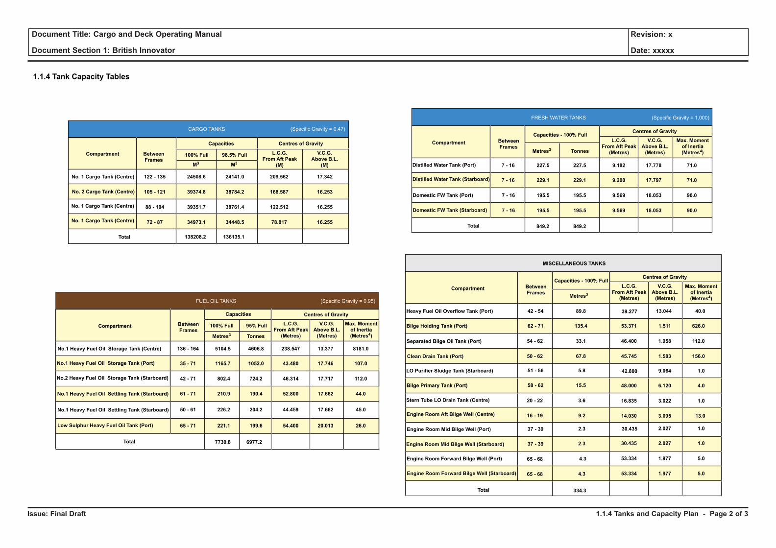
1.1.4 Tank Capacity Tables
Capacities
FUEL OIL TANKS (Specific Gravity = 0.95)
No.1 Heavy Fuel Oil Storage Tank (Centre)
No.1 Heavy Fuel Oil Storage Tank (Port)
136 - 164
35 - 71
42 - 71
100% Full 95% FullCompartment Between
FramesMetres3 Tonnes
No.2 Heavy Fuel Oil Storage Tank (Starboard)
Total
Centres of Gravity
L.C.G.
From Aft Peak
(Metres)
V.C.G.
Above B.L.
(Metres)
No.1 Heavy Fuel Oil Settling Tank (Starboard)
No.1 Heavy Fuel Oil Settling Tank (Starboard)
Low Sulphur Heavy Fuel Oil Tank (Port)
61 - 71
50 - 61
65 - 71
5104.5
1165.7
802.4
210.9
226.2
221.1
7730.8
4606.8
1052.0
724.2
190.4
204.2
199.6
6977.2
238.547
43.480
46.314
52.800
44.459
54.400
13.377
17.746
17.717
17.662
17.662
20.013
Max. Moment
of Inertia
(Metres4)
8181.0
107.0
112.0
44.0
45.0
26.0
Capacities - 100% Full
FRESH WATER TANKS (Specific Gravity = 1.000)
Distilled Water Tank (Starboard)
Domestic FW Tank (Port)
7 - 16
7 - 16
7 - 16
Compartment Between
FramesMetres3 Tonnes
Total
Centres of Gravity
L.C.G.
From Aft Peak
(Metres)
V.C.G.
Above B.L.
(Metres)
7 - 16
227.5
229.1
195.5
195.5
227.5
229.1
195.5
195.5
849.2849.2
9.182
9.200
9.569
9.569
17.778
17.797
18.053
18.053
71.0
71.0
90.0
90.0
Distilled Water Tank (Port)
Capacities - 100% Full
MISCELLANEOUS TANKS
Heavy Fuel Oil Overflow Tank (Port)
Separated Bilge Oil Tank (Port)
Bilge Holding Tank (Port)
42 - 54
62 - 71
54 - 62
Compartment Between
FramesMetres3
Total
Centres of Gravity
L.C.G.
From Aft Peak
(Metres)
V.C.G.
Above B.L.
(Metres)
50 - 62
51 - 56
58 - 62
20 - 22
16 - 19
37 - 39
37 - 39
65 - 68
65 - 68
89.8
135.4
33.1
67.8
5.8
15.5
3.6
9.2
2.3
2.3
4.3
4.3
334.3
39.277
53.371
46.400
45.745
13.044
1.511
1.958
1.583
40.0
626.0
112.0
156.0
42.800
48.000
16.835
14.030
9.064
6.120
3.022
3.095
1.0
4.0
1.0
13.0
30.435
30.435
53.334
53.334
2.027
2.027
1.977
1.977
1.0
1.0
5.0
5.0
Clean Drain Tank (Port)
LO Purifier Sludge Tank (Starboard)
Bilge Primary Tank (Port)
Stern Tube LO Drain Tank (Centre)
Engine Room Aft Bilge Well (Centre)
Engine Room Mid Bilge Well (Port)
Engine Room Mid Bilge Well (Starboard)
Engine Room Forward Bilge Well (Port)
Engine Room Forward Bilge Well (Starboard)
Compartment Between
Frames
CARGO TANKS
100% Full 98.5% Full
No. 1 Cargo Tank (Centre)
No. 2 Cargo Tank (Centre)
No. 1 Cargo Tank (Centre)
No. 1 Cargo Tank (Centre)
24508.6
39374.8
39351.7
34973.1
122 - 135
105 - 121
88 - 104
72 - 87
138208.2
24141.0
38784.2
38761.4
34448.5
136135.1
209.562
168.587
122.512
78.817
17.342
16.253
16.255
16.255
Total
L.C.G.
From Aft Peak
(M)
V.C.G.
Above B.L.
(M)
Capacities Centres of Gravity
(Specific Gravity = 0.47)
M3 M3
Domestic FW Tank (Starboard)
Max. Moment
of Inertia
(Metres4)
Max. Moment
of Inertia
(Metres4)
1.1.4 Tanks and Capacity Plan - Page 2 of 3
Issue: Final Draft
Document Title: Cargo and Deck Operating Manual
Document Section 1: British Innovator
Revision: x
Date: xxxxx
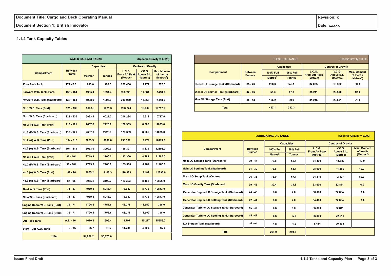
1.1.4 Tank Capacity Tables
Compartment
WATER BALLAST TANKS (Specific Gravity = 1.025)
Fore Peak Tank
Forward W.B. Tank (Port)
172 - F.E.
136 - 164
136 - 164
Between
FrameMetres3 Tonnes
Forward W.B. Tank (Starboard)
121 - 136
113 - 121
113 - 121
121 - 136
104 - 113
96 - 104
96 - 104
104 - 113
87 - 96
87 - 96
71 - 87
71 - 87
35 - 71
35 - 71
A.E. - 16
9 - 16
913.0
1965.4
1968.9
5933.8
2687.0
2687.0
5933.8
3053.9
2719.9
2719.9
3053.9
3055.2
3055.2
4969.8
4969.8
1726.1
1726.1
1670.8
56.7
926.5
1994.4
1997.9
6021.3
2726.6
2726.3
6021.3
3099.0
2760.0
2760.0
3099.0
3100.3
3100.3
5043.1
5043.3
1751.6
1751.6
1695.4
57.6
262.436
239.095
239.079
206.224
179.359
179.359
206.224
156.397
133.360
133.360
156.397
110.323
110.323
78.032
78.032
43.275
43.275
3.797
11.285
12.279
11.681
11.665
10.317
8.565
8.565
10.317
8.479
8.482
8.482
8.479
8.482
8.482
8.772
8.772
14.552
14.552
15.277
4.209
777.0
1418.0
1418.0
10717.0
11035.0
11035.0
10717.0
12893.0
11480.0
11480.0
12893.0
12896.0
12896.0
19843.0
19843.0
398.0
398.0
15956.0
15.0
54,866.2 55,675.6Total
No.1 W.B. Tank (Starboard)
No.2 (F) W.B. Tank (Port)
No.2 (F) W.B. Tank (Starboard)
No.2 (A) W.B. Tank (Port)
No.2 (A) W.B. Tank (Starboard)
No.3 (F) W.B. Tank (Port)
No.3 (F) W.B. Tank (Starboard)
No.3 (A) W.B. Tank (Port)
No.3 (A) W.B. Tank (Starboard)
No.4 W.B. Tank (Port)
No.4 W.B. Tank (Starboard)
Engine Room W.B. Tank (Port)
Engine Room W.B. Tank (Stbd)
Aft Peak Tank
Stern Tube C.W. Tank
No.1 W.B. Tank (Port)
L.C.G.
From Aft Peak
(Metres)
Max. Moment
of Inertia
(Metres4)
V.C.G.
Above B.L.
(Metres)
Centres of GravityCapacities
Compartment Between
Frames
DIESEL OIL TANKS
100% Full 95% Full
Diesel Oil Storage Tank (Starboard)
Diesel Oil Service Tank (Starboard)
Gas Oil Storage Tank (Port)
286.6
55.3
105.2
35 - 46
42 - 46
35 - 43
447.1
245.1
47.3
89.9
32.035
35.211
31.245
19.382
23.500
23.501
30.0
12.0
21.0
382.3Total
L.C.G.
From Aft Peak
(Metres)
V.C.G.
Above B.L.
(Metres)
Capacities Centres of Gravity
(Specific Gravity = 0.90)
Metres3 Tonnes
Compartment Between
Frames
LUBRICATING OIL TANKS
100% Full 98% Full
Main LO Sump Tank (Centre)
Main LO Storage Tank (Starboard)
Main LO Settling Tank (Starboard)
Main LO Gravity Tank (Starboard)
Generator Engine LO Storage Tank (Starboard)
Generator Engine LO Settling Tank (Starboard)
Generator Turbine LO Storage Tank (Starboard)
Generator Turbine LO Settling Tank (Starboard)
LO Storage Tank (Starboard)
73.8
73.8
76.0
39.4
8.0
8.0
6.6
6.6
1.8
294.0
65.1
65.1
67.1
34.8
7.0
7.0
5.8
5.8
1.6
259.3
39 - 47
31 - 39
26 - 36
39 - 45
44 - 46
42 - 44
45 - 47
45 - 47
-6 - -4
34.400
28.000
24.810
33.600
36.000
34.400
36.800
36.800 22.811
-5.414
11.880
11.880
2.497
22.811
22.664
22.664
22.811
20.598
19.0
19.0
82.0
6.0
1.0
1.0
Total
L.C.G.
From Aft Peak
(Metres)
V.C.G.
Above B.L.
(Metres)
Capacities Centres of Gravity
(Specific Gravity = 0.900)
Metres3 Tonnes
Max. Moment
of Inertia
(Metres4)
Max. Moment
of Inertia
(Metres4)
1.1.4 Tanks and Capacity Plan - Page 3 of 3

1.2 Rules and Regulations
Issue: Final Draft
Document Title: Cargo and Deck Operating Manual
Document Section 1: British Innovator
Revision: x
Date: xxxxx
1.2 Rules and Regulations
Since the introduction of liquefied gas carriers into the shipping field, it was recognised that there was a need for an international code for the carriage of liquefied gases in bulk.
At the beginning of the 1970’s, the Marine Safety Committee (MSC) of the International Maritime Organisation (IMO), known then as the International Consultative Maritime Organisation (ICMO), started work on a gas carrier code with the participation of the major country delegations representing gas carrier owners, the International Association of Classification Societies, the United States Coast Guard and several other international associations.
The result of this work was the ‘Code for the Construction and Equipment of Ships Carrying Liquefied Gases in Bulk’ introduced under assembly resolution A328 (IX) in November 1975.
This was the first code developed by the IMO having direct applicability to gas carriers.
The intention was to provide ‘a standard for the safe bulk carriage of liquefied gases (and certain other substances) by sea by prescribing design and constructional features of ships and their equipment, so as to minimise risks to ships, their crew and the environment’.
The GC code has been adopted by most countries interested by the transport of liquefied gases by sea, as well as all classification societies, and is now part of SOLAS.
The USCG have added some extra requirements to the GC code for ships trading in the USA’s waters.
The applicability of the code is as follows :
Gas carriers built after June 1986 (the IGC code)The code which applies to new gas carriers (built after June 1986) is the ‘International Code for the Construction and Equipment of Ships carrying Liquefied Gases in Bulk’ known as the IGC code.
At a meeting of the MSC in 1983 approving the second set of amendments to SOLAS, the requirements of the IGC Code become mandatory with almost immediate effect.
Gas Carriers built between 1976 and 1986 (the GC code)
The regulations covering gas carriers built after 1976 but before 1st July 1986 is the ‘Code for the Construction and Equipment of Ships Carrying Liquefied Gases in Bulk’ known as the Gas Carrier Code or GC Code and adopted under assembly resolution A328 (IX).
Since 1975 the MSC has approved four sets of amendments to the GC Code, the latest in June 1993.
Gas Carriers built before 1977 (the Existing Ship Code)
The regulations covering gas carriers built before 1977 are contained in the ‘Code for Existing Ships Carrying Liquefied Gases in Bulk’ first advertised under assembly resolution A 329 (IX). Its content is similar to the GC code, though less extensive.
The existing ship code was completed in 1976 and remains as an IMO recommendation for all gas carriers in this fleet of ships.
The IGC code requires that a certificate (International Certificate of Fitness for the Carriage of Liquefied Gases in Bulk) must be issued to all new gas carriers. The certificate should comply to a pro-forma, as set out in ‘Model Form’ attached as an appendix to the code and should be available on board all new gas carriers.
The basic philosophy behind the code is summarised in the International Code for the Construction and Equipment of ships Carrying Liquefied Gases in Bulk which is readily available on board in the ship’s library.
Preamble
Most of the provisions in the IMO code are covered by the Classification Society’s rules and regulations, however, attention must be drawn to the fact that it contains requirements that are not within the scope of classification as defined in the society’s rules, for example, chapter II Ship Survival Capability, chapter XIV Personnel Protection and chapter XVII Operating Requirements.
However, where the societies are authorised to issue the International Certificate of Fitness, these requirements, together with any amendments or interpretations adopted by the appropriate national authority, will be applied where applicable.
Since the IMO recommendations defer some matters to the discretion of each administration, and in other matters are not specific enough for Coast Guard regulatory purpose, several major changes have been introduced from the code in the proposed Coast Guard rules. These changes are discussed in the following paragraphs.
‘Liquefied gas’ is changed from the codes definition of ‘a product having a vapour pressure of 2.8 bar abs at 37.8°C’ to the proposed definition of ‘a product having a vapour pressure of 1.76 bar abs at 37.8°C’. This is a change in the definition from a Reid vapour pressure of 40 psi abs. to 25 psi abs. The change in the Reid vapour pressure includes the ‘certain other substances’ referred to in para. 1.2 of the Code, but does not include any product in IMO’s Chemical Code except ethylene, which is presently listed in the Code and the Chemical Code. The change in the Reid vapour pressure was proposed by the U.S. delegation to the IMO but the change was not adopted, although there was apparently no objection to it. The change, however, does not affect the list of regulated cargoes.
The rate of air change between the air lock door is not specified in the Code (para 3.6.1) but is proposed at 12 changes per hour.
Chapter 4 of the Code includes a provision for the evaluation of the insulation and hull steel assuming, for the purpose of design calculations, that the cargo tanks are at the design temperature and the ambient outside air and sea design temperatures as follows:
General Worldwide
Still air: +5°C (41°F)
Sea water: 0°C (32°F)
Chapter 4 also provides that each administration may set higher or lower ambient design temperatures. This document proposed the following temperatures:
Any Waters in the World, Except Alaskan Waters
Air (at 5 knots): -18°C (0°F)
Still sea water: 0°C (32°F)
Alaskan Waters
Air (at 5 knots): -29°C (–20°F)
Still sea water: - 2°C (28°F)
1.2 Rules and Regulations - Page 1 of 2
Issue: Final Draft
Document Title: Cargo and Deck Operating Manual
Document Section 1: British Innovator
Revision: x
Date: xxxxx
The proposed regulations specify enhanced grades of steel for crack arresting purposes in the deck stringer, sheer strake and bilge strake. The minimum acceptable grade for the deck stringer and the sheer strake is Grade E or an equivalent steel that is specially approved by the Commandant (G-MMT). The minimum acceptable grades for the bilge strake are Grade D, or Grade E or an equivalent steel that is specially approved by the Commandant (G-MMT).
The Code allows pressure and temperature control of cargoes by venting cargo vapours to the atmosphere when the vessel is at sea and in port if accepted by the receiving administration. It is proposed to prohibit normal venting of cargo into the atmosphere in many ports.
The Code requires the cargo system to be designed to withstand the full vapour pressure of the cargo under conditions of the upper ambient design temperature, or have other means to maintain the cargo tank pressure below the maximum allowable relief valve setting (MARVS) of the tank. These regulations propose that when the cargo carried is a liquefied gas, the cargo tank pressure must be maintained below the design vapour pressure indefinitely, the pressure on the LNG tank would be maintained below the design pressure for a period of not less than 21 days. Cargo tank pressure may be maintained below the design pressure by several methods including refrigeration systems, burning boil-off in waste heat or catalytic furnaces, using boil-off as fuel, or a combination of these methods. Using the boil-off as a fuel for propulsion is limited to a vessel carrying LNG.
The proposed regulations also include the following:
1. Transfer requirements for vinyl chloride.
2. Loading requirements for methyl acetylene propadiene mixture.
3. Additional operating requirements.
4. Requirements for inspection or re-inspection of US flag vessels at intervals that are the same as for vessels inspected under Sub-chapter D. Inspection for certification would be required every 2 years and re-inspection would be required between the 10th and 14th month following the issue of a Certificate of Inspection.
5. Requirements for the initial and periodic inspections and tests of the cargo containment system, cargo and process piping, and hull heating and cold spots.
The proposed Coast Guard regulations and the Classification Society’s rules have cross references showing the corresponding IMO code numbers to allow identification of the required paragraph.
The latest version of the following regulations and recommendations incorporating all subsequent additions and amendments currently in force, or agreed between the owner and the builder, but awaiting ratification, enactment or implementation at the time of signing of the contract shall be applied.
a) Maritime Rules and Regulations of Korea, Indonesia, Malaysia, Oman, Australia, Japan and Qatar for entry into those ports.
b) International Convention on Loadlines, 1966, amendments 1971,1975, 1979 and 1983 and Protocol of 1988 as amended by Resolution A513(XIII) / A514(XIII).
c) International Convention for the Safety of Life at Sea, 1974 with Protocol of 1978 and Amendments of 1981, 1983, 1989, 1990, 1991, 1992 and 1994 and 1998. GMDSS amendments including International Code for the Construction and Equipment of Ships Carrying Liquefied Gases in Bulk (IGC-code) (herein called ‘SOLAS’).
d) International Convention for the Prevention of Pollution from Ships, 1973 (Annex I, IV &V), as modified by the Protocol 1978 relating thereto (herein called ‘MARPOL 73/78’) and amendment 1987, 1989, 1991 and 1992.
e) Convention on the International Regulations for Preventing Collisions at Sea, 1972 with Amendments of 1981, 1987 and 1989 as amended by resolution A493(XII) and A494(XII).
f) International Convention on Tonnage Measurement of Ships, 1969, as amended by IMO Resolution A493(XII) and A494(XII).
g) International Telecommunication convention, 1973 with annex and revisions 1974, 1982 and 1983/87.
h) IMO Resolution A343(IX) Recommendation on method of measuring noise levels at listening posts.
i) IMO Resolution A468(XII) Code on Noise Levels Onboard Ships.
j) USGG for foreign flag vessels operating in the navigable waters of the United States except Alaskan waters (CFR Title 33-Navigation and Navigable Waters, Part 155, 156, 159 and 164 and CFR Title 46-Shipping, Part 154) and Public Law 95-474, 1978 ‘Port and Tanker Safety Act 1979’.
k) ISO draft proposal No.6954 ‘Guidelines for Overall Evaluation of Vibration in Merchant Ships, 1984’.
l) ILO convention concerning crew accommodation on board ships, No.92 and 133.
m) ILO Guide to Safety and Health in Dock Work, 1977 and 1979.
n) SOLAS 1994 Chapter V, Emergency Towing Arrangements for Tankers.
o) ICS guide to helicopter / ship operations.
p) OCIMF Recommendations on Equipment for the Towing of Disabled Tankers, September 1981.
q) OCIMF Standardisation of Manifold for Refrigerated Liquefied Gas Carriers (LNG).
r) OCIMF Guidelines and Recommendations for the Safe Mooring of Large Ship’s at Piers and Sea Islands (except special conditions of the intended terminal).
s) OCIMF Ship to Ship Transfer Guide (Liquefied Gases) 1995.
t) SIGTTO Recommendations for Emergency Shut Down Systems 1997.
u) SIGTTO Recommendations for the Installation of Cargo Strainers.
v) IMO Resolution A708(17) Navigation Bridge Visibility and Function.
w) International Electro-technical Commission (IEC).
x) IMO Publication No.978 Performance Standards for Navigational Equipment (1988 edition).
y) ISO 8309-1991 Refrigeration Light Hydrocarbon Fluids. Measurement of liquid levels in tanks containing liquefied gases electric capacitance gauges.
z) IMO Resolution A601(15) Provision and display of manoeuvring information on board ships.
1.2 Rules and Regulations - Page 2 of 2
1.3 Cargo System Technology
1.3.1 Cargo Containment System Principle
1.3.2 GTT Mark 111 Cargo Containment
1.3.3 Deterioration or Failure of Containment
Illustrations
1.3.1a Cargo Tank Lining Reinforcement
1.3.2a IBS IS Section of Longitudinal Corner
1.3.2b IBS IS Flat Panel Junction
1.3.2c Membrane Cargo Containment (GTT Mark III)
1.3.3a Temperature and Steel Grades
1.3.3b Hull Steel Grades
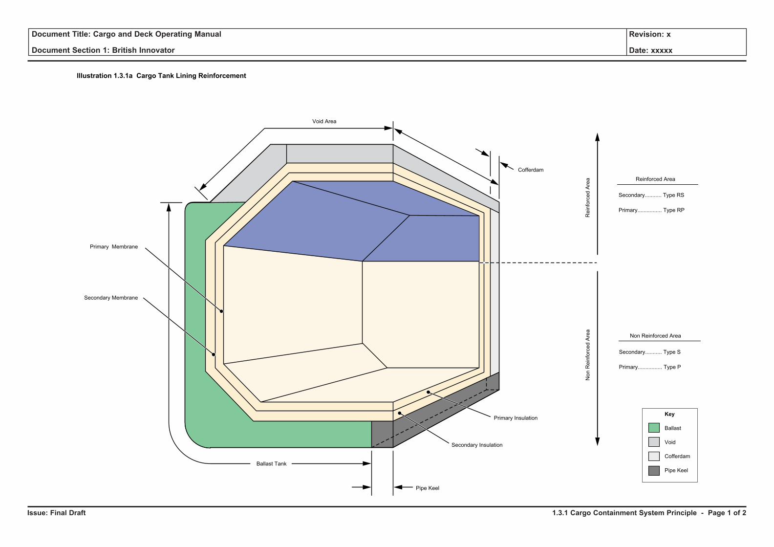
Issue: Final Draft
Document Title: Cargo and Deck Operating Manual
Document Section 1: British Innovator
Revision: x
Date: xxxxx
Key
Ballast
Void
Cofferdam
Pipe Keel
ReinforcedArea
NonReinforcedArea
Reinforced Area
Non Reinforced Area
Secondary........... Type RS
Primary................ Type RP
Secondary........... Type S
Primary................ Type P
Primary Insulation
Secondary Insulation
Secondary Membrane
Illustration 1.3.1a Cargo Tank Lining Reinforcement
Primary Membrane
Cofferdam
Void Area
Ballast Tank
Pipe Keel
1.3.1 Cargo Containment System Principle - Page 1 of 2
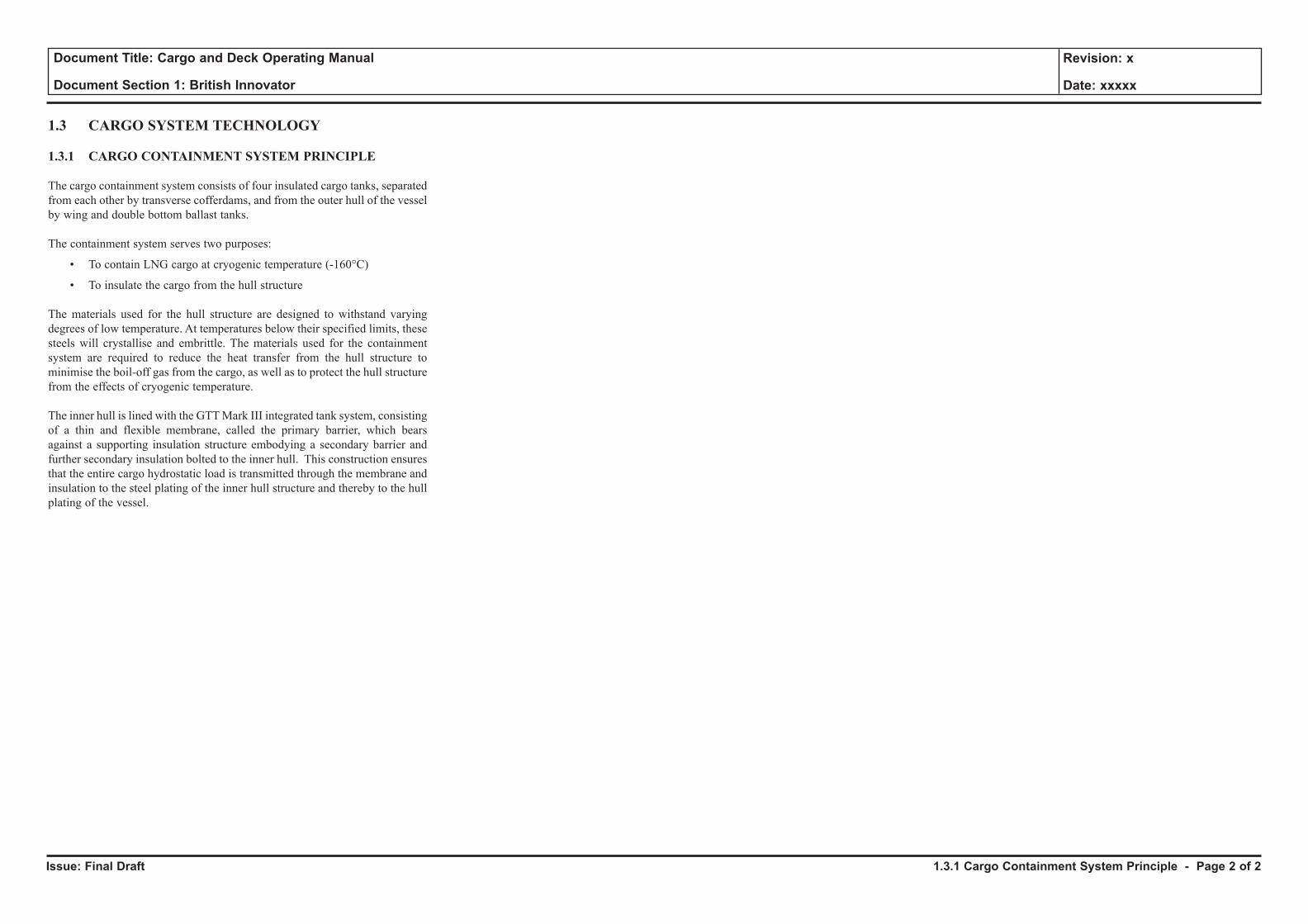
Issue: Final Draft
Document Title: Cargo and Deck Operating Manual
Document Section 1: British Innovator
Revision: x
Date: xxxxx
1.3 CARGO SYSTEM TECHNOLOGY
1.3.1 CARGO CONTAINMENT SYSTEM PRINCIPLE
The cargo containment system consists of four insulated cargo tanks, separated from each other by transverse cofferdams, and from the outer hull of the vessel by wing and double bottom ballast tanks.
The containment system serves two purposes:
• To contain LNG cargo at cryogenic temperature (-160°C)
• To insulate the cargo from the hull structure
The materials used for the hull structure are designed to withstand varying degrees of low temperature. At temperatures below their specified limits, these steels will crystallise and embrittle. The materials used for the containment system are required to reduce the heat transfer from the hull structure to minimise the boil-off gas from the cargo, as well as to protect the hull structure from the effects of cryogenic temperature.
The inner hull is lined with the GTT Mark III integrated tank system, consisting of a thin and flexible membrane, called the primary barrier, which bears against a supporting insulation structure embodying a secondary barrier and further secondary insulation bolted to the inner hull. This construction ensures that the entire cargo hydrostatic load is transmitted through the membrane and insulation to the steel plating of the inner hull structure and thereby to the hull plating of the vessel.
1.3.1 Cargo Containment System Principle - Page 2 of 2
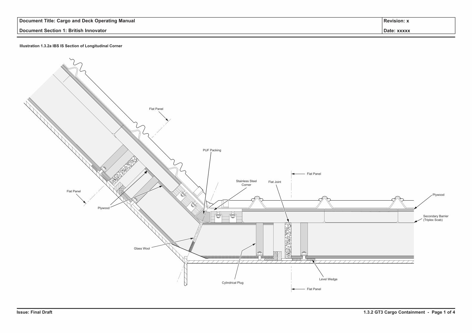
Issue: Final Draft
Document Title: Cargo and Deck Operating Manual
Document Section 1: British Innovator
Revision: x
Date: xxxxx
Stainless Steel
Corner
Level WedgeCylindrical Plug
Flat Joint
Glass Wool
PUF Packing
Plywood
Secondary Barrier
(Triplex Scab)
Plywood
Flat Panel
Flat Panel
Flat Panel
Flat Panel
Illustration 1.3.2a IBS IS Section of Longitudinal Corner
1.3.2 GT3 Cargo Containment - Page 1 of 4
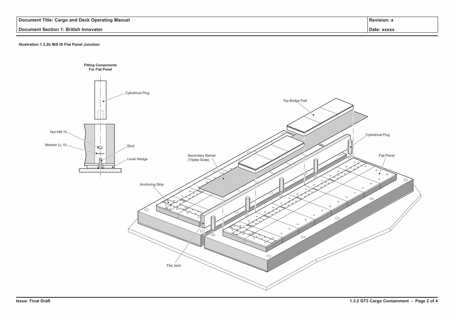
Issue: Final Draft
Document Title: Cargo and Deck Operating Manual
Document Section 1: British Innovator
Revision: x
Date: xxxxx
Fitting Components
For Flat Panel
Cylindrical Plug
Stud
Level Wedge
Nut HM 10
Washer LL 10
Anchoring Strip
Flat Joint
Secondary Barrier
(Triplex Scab)
Top Bridge Pad
Cylindrical Plug
Flat Panel
Illustration 1.3.2b IBS IS Flat Panel Junction
1.3.2 GT3 Cargo Containment - Page 2 of 4
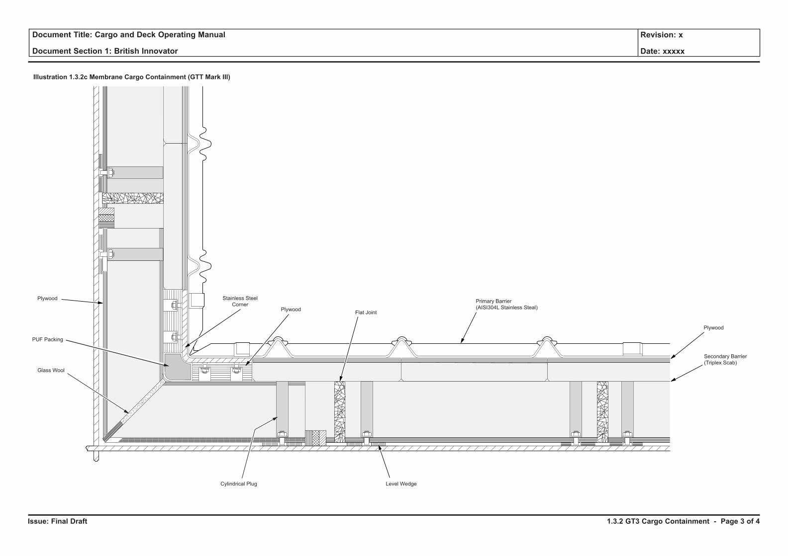
Issue: Final Draft
Document Title: Cargo and Deck Operating Manual
Document Section 1: British Innovator
Revision: x
Date: xxxxx
Illustration 1.3.2c Membrane Cargo Containment (GTT Mark III)
Level WedgeCylindrical Plug
Flat Joint
Primary Barrier
(AISI304L Stainless Steal)
Glass Wool
PUF Packing
Plywood
Secondary Barrier
(Triplex Scab)
Plywood Stainless Steel
CornerPlywood
1.3.2 GT3 Cargo Containment - Page 3 of 4
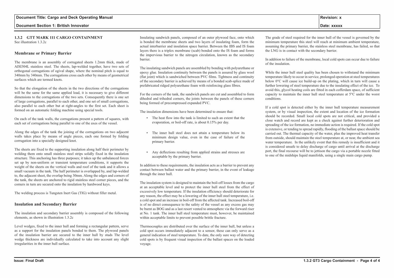
Issue: Final Draft
Document Title: Cargo and Deck Operating Manual
Document Section 1: British Innovator
Revision: x
Date: xxxxx
1.3.2 GTT MARK 111 CARGO CONTAINMENT See illustration 1.3.2c
Membrane or Primary Barrier
The membrane is an assembly of corrugated sheets 1.2mm thick, made of AISI304L stainless steel. The sheets, lap-welded together, have two sets of orthogonal corrugations of ogival shape, where the nominal pitch is equal to 340mm by 340mm. The corrugations cross each other by means of geometrical surfaces which are termed knots.
So that the elongation of the sheets in the two directions of the corrugations will be the same for the same applied load, it is necessary to give different dimensions to the corrugations of the two sets. Consequently there is one set of large corrugations, parallel to each other, and one set of small corrugations, also parallel to each other but at right-angles to the first set. Each sheet is formed on an automatic folding machine using special tools.
On each of the tank walls, the corrugations present a pattern of squares, with each set of corrugations being parallel to one of the axes of the vessel.
Along the edges of the tank the joining of the corrugations on two adjacent walls takes place by means of angle pieces, each one formed by folding corrugation into a specially designed knot.
The sheets are fixed to the supporting insulation along half their perimeter by welding them onto small stainless steel strips solidly fixed in the insulation structure. This anchoring has three purposes; it takes up the unbalanced forces set up by non-uniform or transient temperature conditions, it supports the weight of the sheets on the vertical walls and roof of the tank and it allows a small vacuum in the tank. The half perimeter is overlapped by, and lap-welded to, the adjacent sheet, the overlap being 30mm. Along the edges and corners of the tank, the sheets are anchored to rigid stainless steel corner pieces, and the corners in turn are secured onto the insulation by hardwood keys.
The welding process is Tungsten Inert Gas (TIG) without filler metal.
Insulation and Secondary Barrier
The insulation and secondary barrier assembly is composed of the following elements, as shown in illustration 1.3.2c
Level wedges, fixed to the inner hull and forming a rectangular pattern, serve as a support for the insulation panels bonded to them. The plywood panels of the insulation barrier are secured to the inner hull by studs The level wedge thickness are individually calculated to take into account any slight irregularities in the inner hull surface.
Insulating sandwich panels, composed of an outer plywood face, onto which is bonded the membrane sheets and two layers of insulating foam, form the actual interbarrier and insulation space barrier. Between the IBS and IS foam layers there is a triplex membrane (scab) bonded onto the IS foam and forms the impervious barrier to the nitrogen circulation, known as the secondary barrier.
The insulating sandwich panels are assembled by bonding with polyurethane or epoxy glue. Insulation continuity between the panels is assured by glass wool (flat joint) which is sandwiched between PVC films. Tightness and continuity of the secondary barrier is achieved by means of a bonded scab-splice made of prefabricated ridged polyurethane foam with reinforcing glass fibres.
For the corners of the tank, the sandwich panels are cut and assembled to form dihedral and trihedral corners, the joints between the panels of these corners being formed of precompressed expanded PVC.
The insulation dimensions have been determined to ensure that:
• The heat flow into the tank is limited to such an extent that the evaporation, or boil-off rate, is about 0.15% per day.
• The inner hull steel does not attain a temperature below its minimum design value, even in the case of failure of the primary barrier.
• Any deflections resulting from applied strains and stresses are acceptable by the primary barrier.
In addition to these requirements, the insulation acts as a barrier to prevent any contact between ballast water and the primary barrier, in the event of leakage through the inner hull.
The insulation system is designed to maintain the boil-off losses from the cargo at an acceptable level and to protect the inner hull steel from the effect of excessively low temperature. If the insulation efficiency should deteriorate for any reason, the effect may be a lowering of the inner hull steel temperature, i.e. a cold spot and an increase in boil-off from the affected tank. Increased boil-off is of no direct consequence to the safety of the vessel as any excess gas may be burnt as BOG and as a last resort vented to atmosphere via the forward riser at No. 1 tank. The inner hull steel temperature must, however, be maintained within acceptable limits to prevent possible brittle fracture.
Thermocouples are distributed over the surface of the inner hull, but unless a cold spot occurs immediately adjacent to a sensor, these can only serve as a general indication of steel temperature. To date, the only sure way of detecting cold spots is by frequent visual inspection of the ballast spaces on the loaded voyage.
The grade of steel required for the inner hull of the vessel is governed by the minimum temperature this steel will reach at minimum ambient temperature, assuming the primary barrier, the stainless steel membrane, has failed, so that the LNG is in contact with the secondary barrier.
In addition to failure of the membrane, local cold spots can occur due to failure of the insulation.
While the inner hull steel quality has been chosen to withstand the minimum temperature likely to occur in service, prolonged operation at steel temperatures below 0°C will cause ice build-up on the plating, which in turn will cause a further lowering of steel temperature due to the insulating effect of the ice. To avoid this, glycol heating coils are fitted in each cofferdam space, of sufficient capacity to maintain the inner hull steel temperature at 5°C under the worst conditions.
If a cold spot is detected either by the inner hull temperature measurement system, or by visual inspection, the extent and location of the ice formation should be recorded. Small local cold spots are not critical, and provided a close watch and record are kept as a check against further deterioration and spreading of the ice formation, no immediate action is required. If the cold spot is extensive, or tending to spread rapidly, flooding of the ballast space should be carried out. The thermal capacity of the water, plus the improved heat transfer from outside, should maintain the steel temperature at, or near, the ambient sea water temperature. In the unlikely event that this remedy is insufficient and it is considered unsafe to delay discharge of cargo until arrival at the discharge port, the final recourse will be to jettison the cargo via a portable nozzle fitted to one of the midships liquid manifolds, using a single main cargo pump.
1.3.2 GT3 Cargo Containment - Page 4 of 4
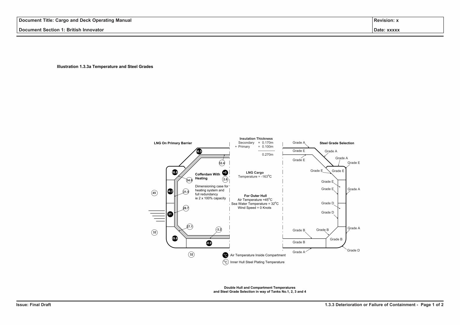
Issue: Final Draft
Document Title: Cargo and Deck Operating Manual
Document Section 1: British Innovator
Revision: x
Date: xxxxx
Illustration 1.3.3a Temperature and Steel Grades
Double Hull and Compartment Temperatures
and Steel Grade Selection in way of Tanks No.1, 2, 3 and 4
LNG On Primary Barrier
For Outer Hull
Air Temperature =45oC
Sea Water Temperature = 32oC
Wind Speed = 0 Knots
Air Temperature Inside Compartment
Inner Hull Steel Plating Temperature
29.6
-0.9
oC
38.8
36.5
31
34.2
27.1
34.9
-3.2
oC
32.4
28.7
31.5
Cofferdam With
Heating
Dimensioning case for
heating system and
full redundancy
ie 2 x 100% capacity
+5
2.6
Insulation Thickness
Secondary = 0.170m
+ Primary = 0.100m
---------------
0.270m
LNG Cargo
Temperature = -163oC
Grade B
Grade B
Grade AGrade D
Grade A
Grade A
Grade E
Grade E
Grade A
Grade AGrade E
Grade A
Grade E
Grade E
Grade E
Grade E
Grade D
Grade D
Grade B
Grade B
Steel Grade Selection
45
32
32
1.3.3 Deterioration or Failure of Containment - Page 1 of 2
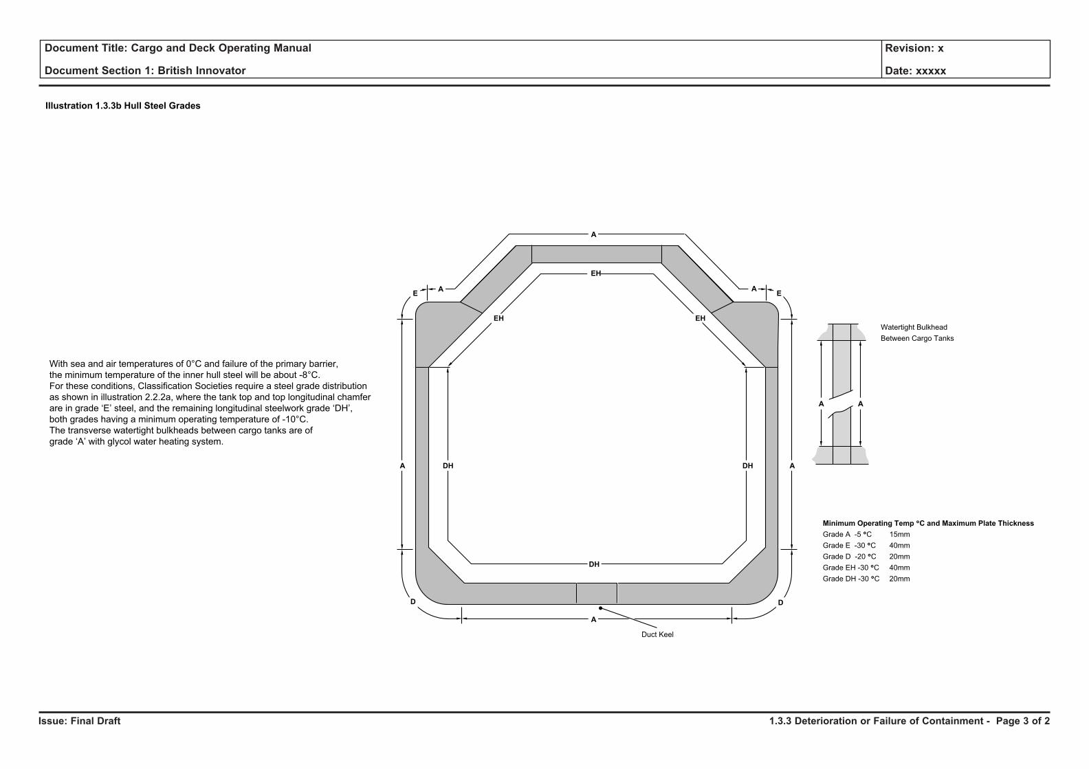
Issue: Final Draft
Document Title: Cargo and Deck Operating Manual
Document Section 1: British Innovator
Revision: x
Date: xxxxx
E
D
EH
A
A
A
DH
DH
AE
EH
DH A
D
EH
A
Minimum Operating Temp °C and Maximum Plate Thickness
Grade A -5 °C 15mm
Grade E -30 °C 40mm
Grade D -20 °C 20mm
Grade EH -30 °C 40mm
Grade DH -30 °C 20mm
Watertight Bulkhead
Between Cargo Tanks
With sea and air temperatures of 0°C and failure of the primary barrier,
the minimum temperature of the inner hull steel will be about -8°C.
For these conditions, Classification Societies require a steel grade distribution
as shown in illustration 2.2.2a, where the tank top and top longitudinal chamfer
are in grade ‘E’ steel, and the remaining longitudinal steelwork grade ‘DH’,
both grades having a minimum operating temperature of -10°C.
The transverse watertight bulkheads between cargo tanks are of
grade ‘A’ with glycol water heating system.
A A
Illustration 1.3.3b Hull Steel Grades
Duct Keel
1.3.3 Deterioration or Failure of Containment - Page 3 of 2
1.4 Hazardous Areas and Gas Dangerous Zone Plan
Illustrations
1.4a Hazardous Areas and Gas Dangerous Zone Plan
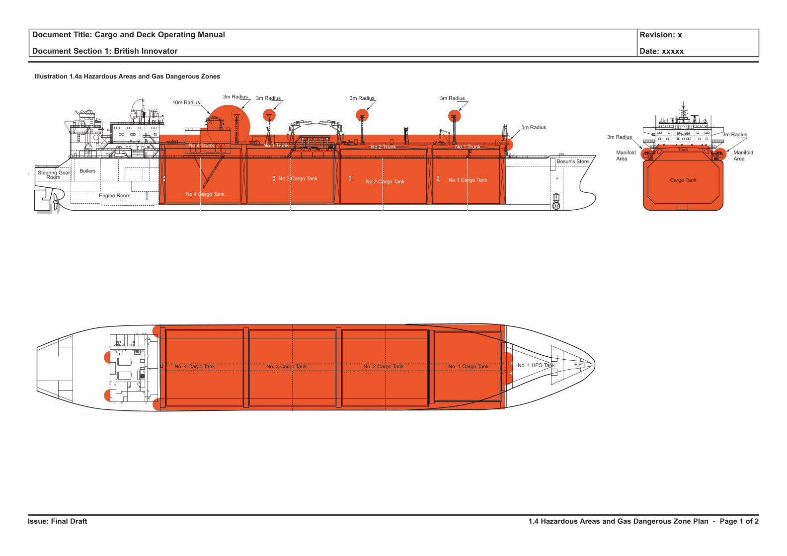
Issue: Final Draft
Document Title: Cargo and Deck Operating Manual
Document Section 1: British Innovator
Revision: x
Date: xxxxx
3m Radius 3m Radius 3m Radius
3m Radius
3m Radius3m Radius
3m Radius10m Radius
Illustration 1.4a Hazardous Areas and Gas Dangerous Zones
No.3 Cargo Tank
No.4 Cargo Tank
No.2 Cargo Tank No.1 Cargo Tank
Bosun's Store
No.2 Trunk No.1 TrunkNo.3 TrunkNo.4 Trunk
Steering GearRoom
Engine Room
Boilers
No. 2 Cargo TankNo. 3 Cargo TankNo. 4 Cargo Tank No. 1 Cargo Tank No. 1 HFO Tank F.P.T
NO SMOKING
Trunk
Cargo Tank
Manifold
Area
Manifold
Area
1.4 Hazardous Areas and Gas Dangerous Zone Plan - Page 1 of 2
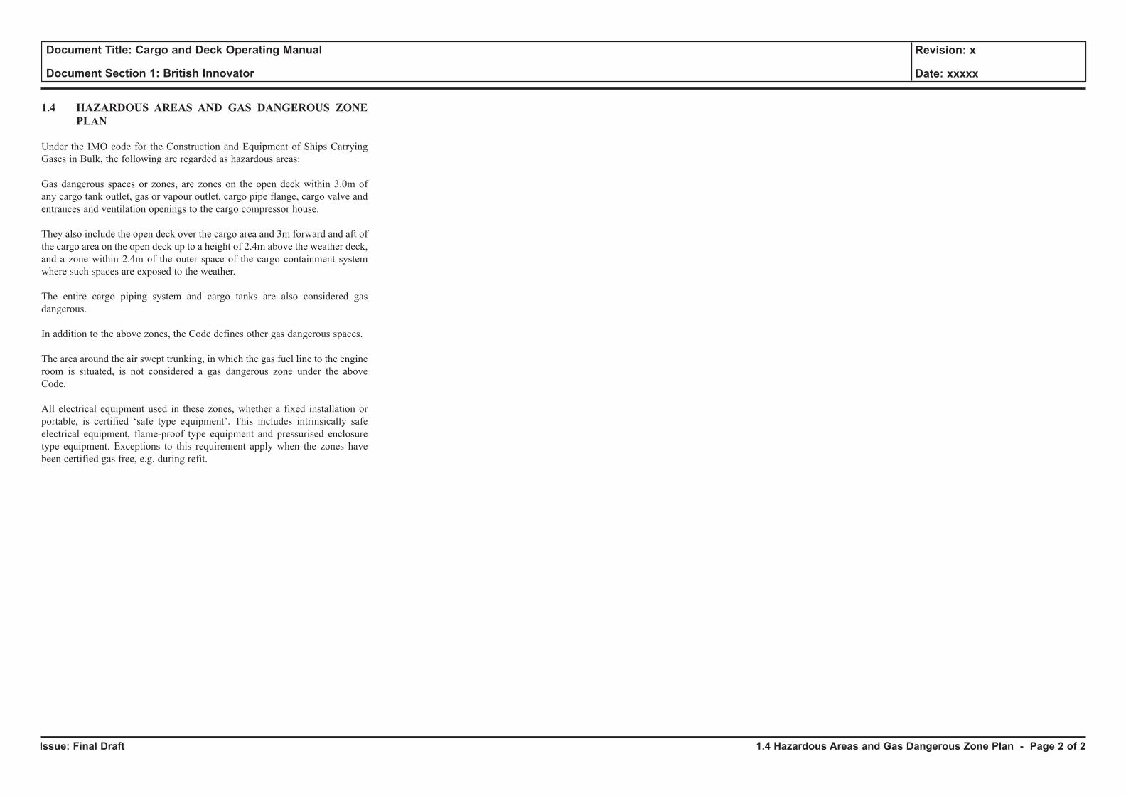
Issue: Final Draft
Document Title: Cargo and Deck Operating Manual
Document Section 1: British Innovator
Revision: x
Date: xxxxx
1.4 HAZARDOUS AREAS AND GAS DANGEROUS ZONE PLAN
Under the IMO code for the Construction and Equipment of Ships Carrying Gases in Bulk, the following are regarded as hazardous areas:
Gas dangerous spaces or zones, are zones on the open deck within 3.0m of any cargo tank outlet, gas or vapour outlet, cargo pipe flange, cargo valve and entrances and ventilation openings to the cargo compressor house.
They also include the open deck over the cargo area and 3m forward and aft of the cargo area on the open deck up to a height of 2.4m above the weather deck, and a zone within 2.4m of the outer space of the cargo containment system where such spaces are exposed to the weather.
The entire cargo piping system and cargo tanks are also considered gas dangerous.
In addition to the above zones, the Code defines other gas dangerous spaces.
The area around the air swept trunking, in which the gas fuel line to the engine room is situated, is not considered a gas dangerous zone under the above Code.
All electrical equipment used in these zones, whether a fixed installation or portable, is certified ‘safe type equipment’. This includes intrinsically safe electrical equipment, flame-proof type equipment and pressurised enclosure type equipment. Exceptions to this requirement apply when the zones have been certified gas free, e.g. during refit.
1.4 Hazardous Areas and Gas Dangerous Zone Plan - Page 2 of 2
PART 2: PROPERTIES OF LNG
2.1 Properties of LNG
2.1.1 Physical Properties and Composition of LNG
Illustrations
2.1.1a Physical Properties of LNG
2.1.1b Composition of Typical LNG
2.1.1c Properties of Methane
2.1.1d Variation of Boiling Point of Methane with Pressure
2.1.1e Relative Density of Methane and Air
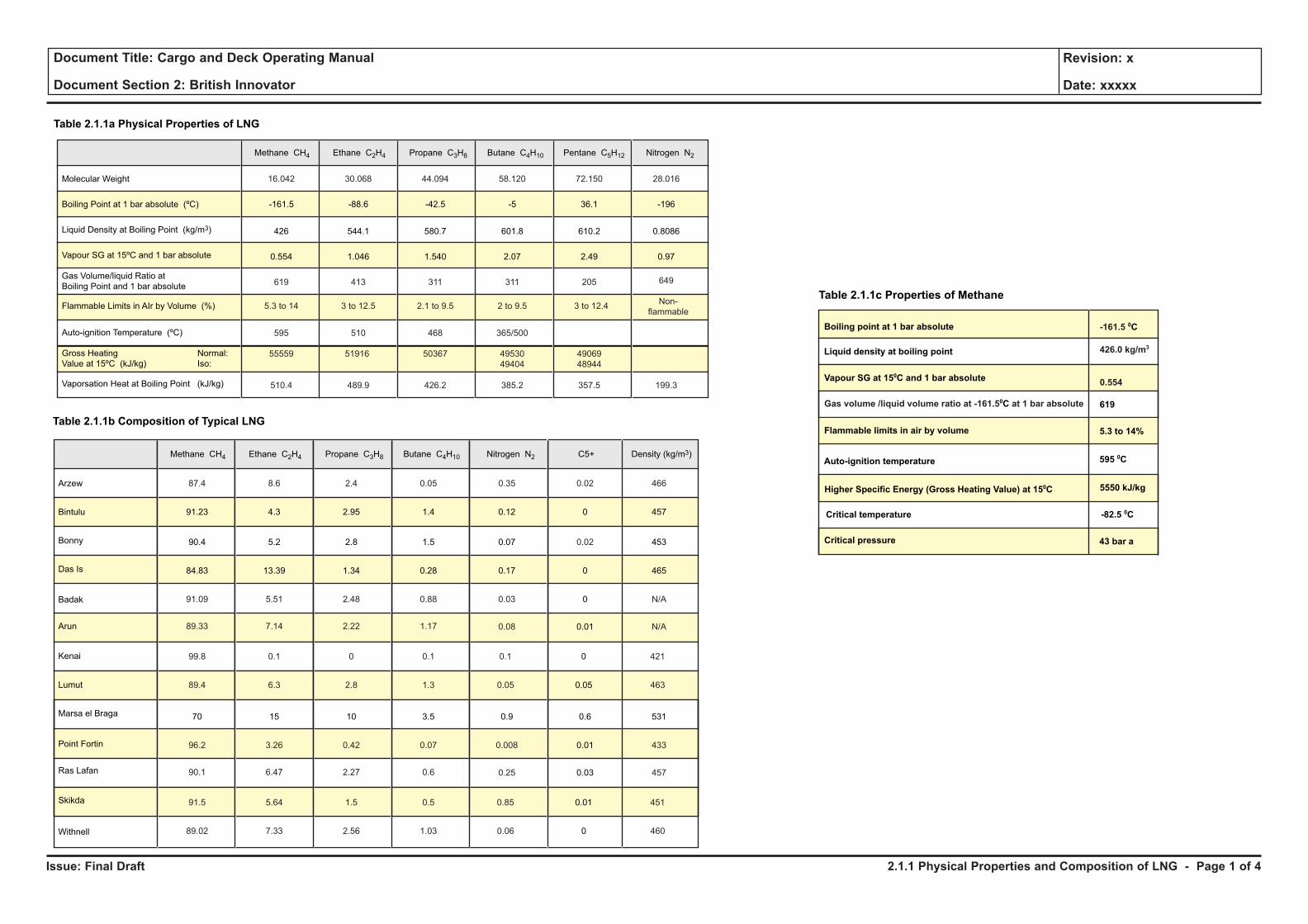
Issue: Final Draft
Document Title: Cargo and Deck Operating Manual
Document Section 2: British Innovator
Revision: x
Date: xxxxx
Molecular Weight 16.042
-161.5
426
0.554
619
5.3 to 14
30.068
-88.6
544.1
1.046
413
3 to 12.5
44.094
-42.5
580.7
1.540
311
2.1 to 9.5
58.120
-5
601.8
2.07
311
2 to 9.5 3 to 12.4Non-
flammable
72.150
36.1
610.2
2.49
205
28.016
-196
0.8086
0.97
649
595 510 468 365/500
55559 51916 50367 49530
49404
49069
48944
510.4 489.9 426.2 385.2 357.5 199.3
Boiling Point at 1 bar absolute (ºC)
Liquid Density at Boiling Point (kg/m3)
Vapour SG at 15ºC and 1 bar absolute
Gas Volume/liquid Ratio at
Boiling Point and 1 bar absolute
Flammable Limits in AIr by Volume (%)
Gross Heating Normal:
Value at 15ºC (kJ/kg) Iso:
Auto-ignition Temperature (ºC)
Vaporsation Heat at Boiling Point (kJ/kg)
Methane CH4 Ethane C2H4 Propane C3H8 Butane C4H10 Pentane C5H12 Nitrogen N2
Table 2.1.1a Physical Properties of LNG
Arzew 87.4
91.23
90.4
84.83
91.09
89.33
8.6
4.3
5.2
13.39
5.51
7.14
2.4
2.95
2.8
1.34
2.48
2.22
0.05
1.4
1.5
0.28
0.88
1.17
0.35
0.12
0.07
0.17
0.03
99.8 0.1 0 0.1 0.1
89.4 6.3 2.8 1.3 0.05
0.02
0
0.02
0
0
0
0.05
466
457
453
465
N/A
0.08 0.01 N/A
421
463
Bintulu
Bonny
Das Is
Arun
Badak
Kenai
Methane CH4 Ethane C2H4 Propane C3H8 Butane C4H10 Nitrogen N2 C5+ Density (kg/m3)
Lumut
Marsa el Braga
Ras Lafan
Point Fortin
Skikda
Withnell
70
96.2
90.1
15
3.26
6.47
10
0.42
2.27
3.5
0.07
0.6
0.9
0.008
91.5 5.64 1.5 0.5 0.85
89.02 7.33 2.56 1.03 0.06
0.6
0.01
0.01
0
531
433
0.25 0.03 457
451
460
Table 2.1.1b Composition of Typical LNG
Table 2.1.1c Properties of Methane
Liquid density at boiling point
Boiling point at 1 bar absolute
Vapour SG at 150C and 1 bar absolute
619
Flammable limits in air by volume
Auto-ignition temperature
Higher Specific Energy (Gross Heating Value) at 150C
Critical temperature
Critical pressure
5.3 to 14%
595 0C
5550 kJ/kg
-82.5 0C
43 bar a
Gas volume /liquid volume ratio at -161.50C at 1 bar absolute
-161.5 0C
426.0 kg/m3
0.554
2.1.1 Physical Properties and Composition of LNG - Page 1 of 4
Issue: Final Draft
Document Title: Cargo and Deck Operating Manual
Document Section 2: British Innovator
Revision: x
Date: xxxxx
2.1 PROPERTIES OF LNG
2.1.1 PHYSICAL PROPERTIES AND COMPOSITION OF LNG
Natural gas is a mixture of hydrocarbons which, when liquefied, form a clear colourless and odourless liquid; this LNG is usually transported and stored at a temperature very close to its boiling point at atmospheric pressure (approximately –160°C).
The actual composition of Qatar, Oman, Indonesia or Malaysia LNG will vary depending on its source and on the liquefaction process, but the main constituent will always be methane; other constituents will be small percentages of heavier hydrocarbons, e.g. ethane, propane, butane, pentane, and possibly a small percentage of nitrogen. A typical composition of LNG is given in Table 2.1.1b, and the physical properties of the major constituent gases are given in Table 2.1.1a.
For most engineering calculations (e.g. piping pressure losses) it can be assumed that the physical properties of pure methane represent those of LNG. However, for custody transfer purposes when accurate calculation of the heating value and density is required, the specific properties based on actual component analysis must be used.
During a normal sea voyage, heat is transferred to the LNG cargo through the cargo tank insulation, causing part of the cargo to vaporise, i.e. boil-off. The composition of the LNG is changed by this boil-off because the lighter components, having lower boiling points at atmospheric pressure, vaporise first. Therefore, the discharged LNG has a lower percentage content of nitrogen and methane than the LNG as loaded, and a slightly higher percentage of ethane, propane and butane, due to methane and nitrogen boiling off in preference to the heavier gases.
The flammability range of methane in air (21% oxygen) is approximately 5.3 to 14% (by volume). To reduce this range the oxygen content is reduced to 2%, using inert gas from the inert gas generators, prior to loading after dry dock. In theory, an explosion cannot occur if the O2 content of the mixture is below 13% regardless of the percentage of methane, but for practical safety reasons, purging is continued until the O2 content is below 2%. This safety aspect is explained in detail later in this section.
The boil-off vapour from LNG is lighter than air at vapour temperatures above -110°C or higher depending on LNG composition, therefore when vapour is vented to atmosphere, the vapour will tend to rise above the vent outlet and will be rapidly dispersed. When cold vapour is mixed with ambient air the vapour-air mixture will appear as a readily visible white cloud due to the condensation of the moisture in the air. It is normally safe to assume that the flammable range of vapour-air mixture does not extend significantly beyond the perimeter of the white cloud. The auto-ignition temperature of methane, i.e. the lowest temperature to which the gas needs to be heated to cause self-sustained combustion without ignition by a spark or flame, is 595°C.
2.1.1 Physical Properties and Composition of LNG - Page 2 of 4
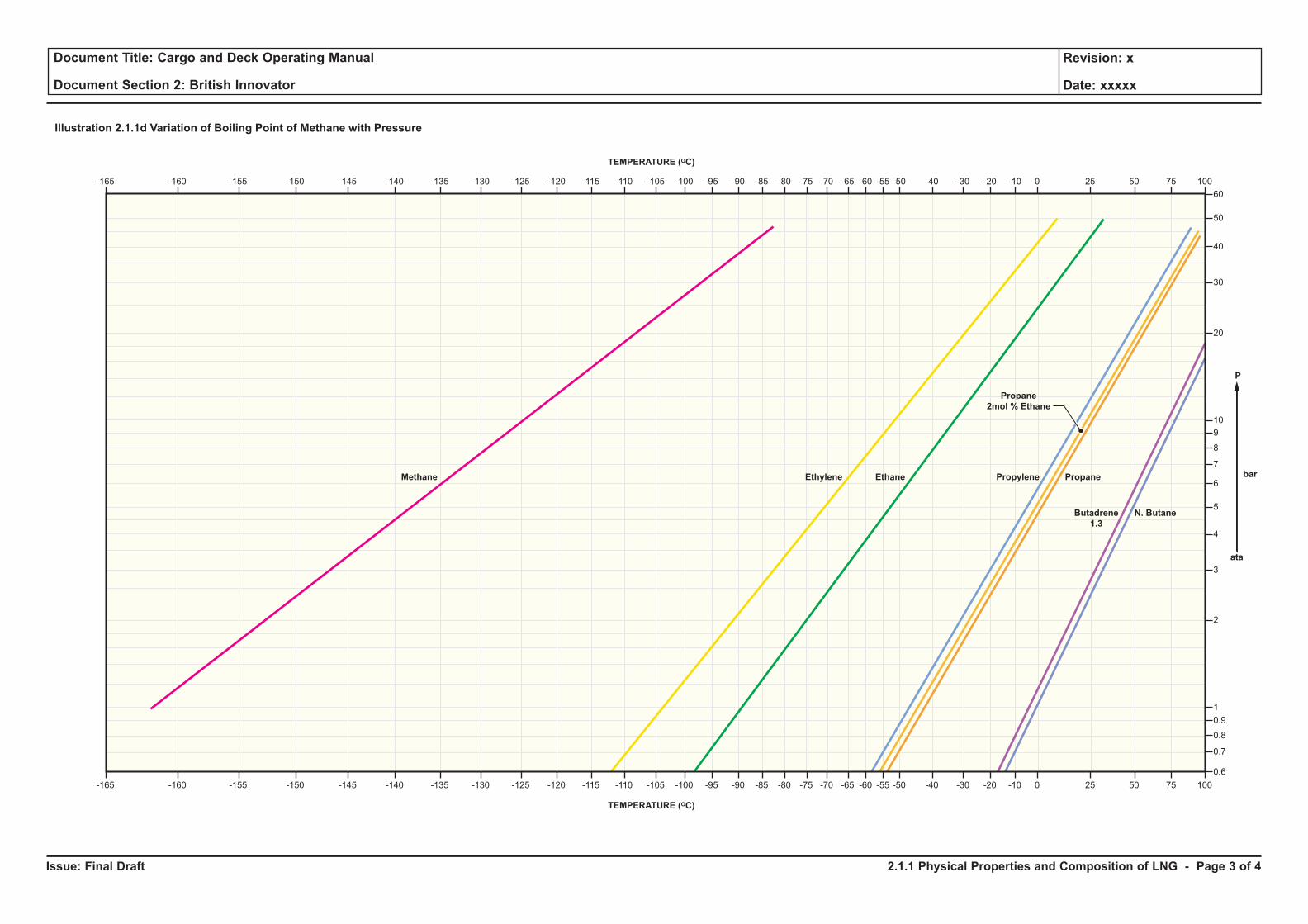
Issue: Final Draft
Document Title: Cargo and Deck Operating Manual
Document Section 2: British Innovator
Revision: x
Date: xxxxx
Illustration 2.1.1d Variation of Boiling Point of Methane with Pressure
-165 -160 -155 -150 -145 -140 -135 -130 -125 -120 -115 -110 -105 -100 -95 -90 -85 -80 -75 -70 -65 -60 -55 -50 -40 -30 -20 -10 0 25 50 75 100
-165 -160 -155 -150 -145 -140 -135 -130 -125 -120 -115 -110 -105 -100 -95 -90 -85 -80 -75 -70 -65 -60 -55 -50 -40 -30 -20 -10 0 25 50 75 100
60
50
40
30
20
10
9
8
7
6
5
4
3
2
1
0.9
0.8
0.7
0.6
Methane Ethylene Ethane Propylene Propane
Propane
2mol % Ethane
Butadrene
1.3
N. Butane
TEMPERATURE (OC)
TEMPERATURE (OC)
ata
P
bar
2.1.1 Physical Properties and Composition of LNG - Page 3 of 4
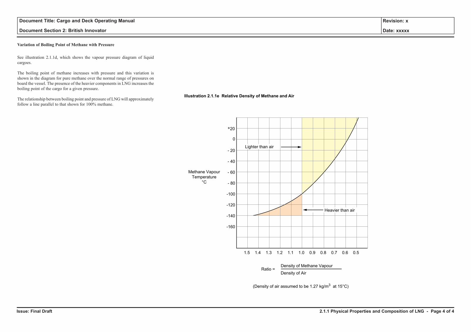
Issue: Final Draft
Document Title: Cargo and Deck Operating Manual
Document Section 2: British Innovator
Revision: x
Date: xxxxx
Variation of Boiling Point of Methane with Pressure
See illustration 2.1.1d, which shows the vapour pressure diagram of liquid cargoes.
The boiling point of methane increases with pressure and this variation is shown in the diagram for pure methane over the normal range of pressures on board the vessel. The presence of the heavier components in LNG increases the boiling point of the cargo for a given pressure.
The relationship between boiling point and pressure of LNG will approximately follow a line parallel to that shown for 100% methane.
+20
0
- 20
- 40
- 60
1.5 1.4 1.3 1.2 1.1 1.0 0.9 0.8 0.7 0.6 0.5
- 80
-100
-120
-140
-160
Lighter than air
Ratio =Density of Methane Vapour
Density of Air
(Density of air assumed to be 1.27 kg/m3 at 15°C)
Methane Vapour
Temperature
°C
Illustration 2.1.1e Relative Density of Methane and Air
Heavier than air
2.1.1 Physical Properties and Composition of LNG - Page 4 of 4
2.2 Characteristics of LNG
2.2.1 Flammability of Methane, Oxygen and Nitrogen Mixtures
2.2.2 Supplementary Characteristics
Illustrations
2.2.1a Flammability of Methane, Oxygen and Nitrogen Mixtures
2.2.2a Structural Steel Ductile to Brittle Transition Curve
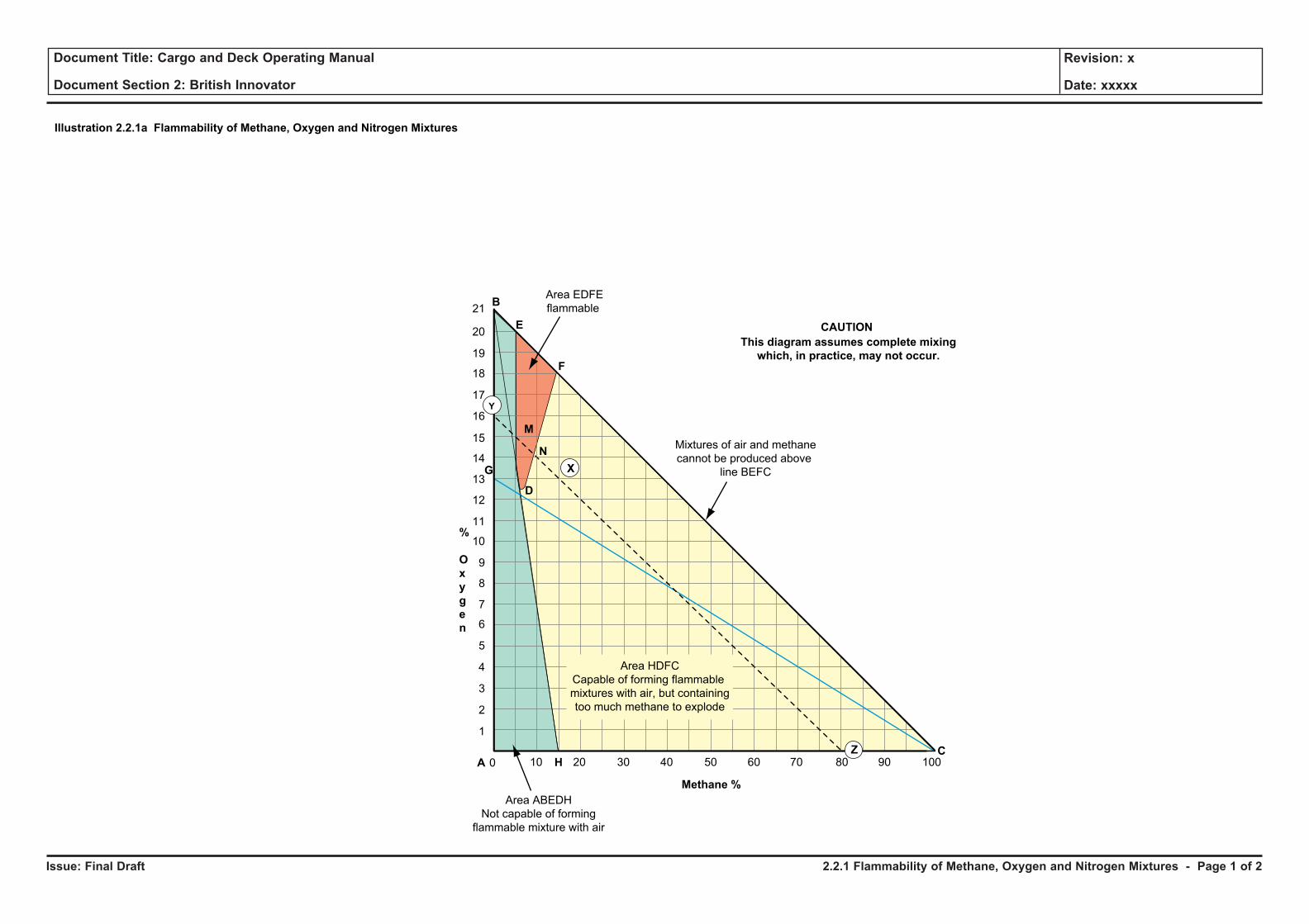
Issue: Final Draft
Document Title: Cargo and Deck Operating Manual
Document Section 2: British Innovator
Revision: x
Date: xxxxx
M
%
O
x
y
g
e
n
Area ABEDH
Not capable of forming
flammable mixture with air
Mixtures of air and methane
cannot be produced above
line BEFC
0 10
1
2
3
4
5
6
7
8
9
10
11
12
13
14
15
16
17
18
19
20
21B
E
F
20 30 40 50 60 70 80 90 100C
Methane %
A H
X
N
Area EDFE
flammable
D
G
Area HDFC
Capable of forming flammable
mixtures with air, but containing
too much methane to explode
This diagram assumes complete mixing
which, in practice, may not occur.
CAUTION
Illustration 2.2.1a Flammability of Methane, Oxygen and Nitrogen Mixtures
Y
Z
2.2.1 Flammability of Methane, Oxygen and Nitrogen Mixtures - Page 1 of 2
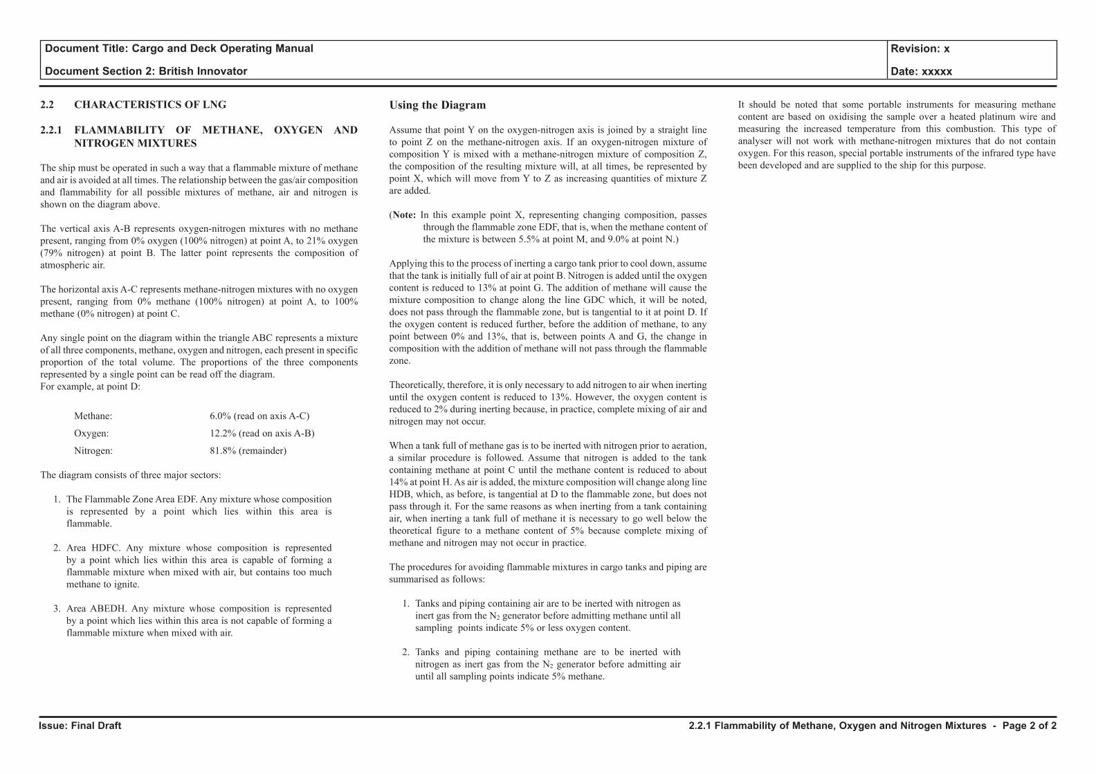
Issue: Final Draft
Document Title: Cargo and Deck Operating Manual
Document Section 2: British Innovator
Revision: x
Date: xxxxx
2.2 CHARACTERISTICS OF LNG
2.2.1 FLAMMABILITY OF METHANE, OXYGEN AND NITROGEN MIXTURES
The ship must be operated in such a way that a flammable mixture of methane and air is avoided at all times. The relationship between the gas/air composition and flammability for all possible mixtures of methane, air and nitrogen is shown on the diagram above.
The vertical axis A-B represents oxygen-nitrogen mixtures with no methane present, ranging from 0% oxygen (100% nitrogen) at point A, to 21% oxygen (79% nitrogen) at point B. The latter point represents the composition of atmospheric air.
The horizontal axis A-C represents methane-nitrogen mixtures with no oxygen present, ranging from 0% methane (100% nitrogen) at point A, to 100% methane (0% nitrogen) at point C.
Any single point on the diagram within the triangle ABC represents a mixture of all three components, methane, oxygen and nitrogen, each present in specific proportion of the total volume. The proportions of the three components represented by a single point can be read off the diagram.For example, at point D:
Methane: 6.0% (read on axis A-C)
Oxygen: 12.2% (read on axis A-B)
Nitrogen: 81.8% (remainder)
The diagram consists of three major sectors:
1. The Flammable Zone Area EDF. Any mixture whose composition is represented by a point which lies within this area is flammable.
2. Area HDFC. Any mixture whose composition is represented by a point which lies within this area is capable of forming a flammable mixture when mixed with air, but contains too much methane to ignite.
3. Area ABEDH. Any mixture whose composition is represented by a point which lies within this area is not capable of forming a flammable mixture when mixed with air.
Using the Diagram
Assume that point Y on the oxygen-nitrogen axis is joined by a straight line to point Z on the methane-nitrogen axis. If an oxygen-nitrogen mixture of composition Y is mixed with a methane-nitrogen mixture of composition Z, the composition of the resulting mixture will, at all times, be represented by point X, which will move from Y to Z as increasing quantities of mixture Z are added.
(Note: In this example point X, representing changing composition, passes through the flammable zone EDF, that is, when the methane content of the mixture is between 5.5% at point M, and 9.0% at point N.)
Applying this to the process of inerting a cargo tank prior to cool down, assume that the tank is initially full of air at point B. Nitrogen is added until the oxygen content is reduced to 13% at point G. The addition of methane will cause the mixture composition to change along the line GDC which, it will be noted, does not pass through the flammable zone, but is tangential to it at point D. If the oxygen content is reduced further, before the addition of methane, to any point between 0% and 13%, that is, between points A and G, the change in composition with the addition of methane will not pass through the flammable zone.
Theoretically, therefore, it is only necessary to add nitrogen to air when inerting until the oxygen content is reduced to 13%. However, the oxygen content is reduced to 2% during inerting because, in practice, complete mixing of air and nitrogen may not occur.
When a tank full of methane gas is to be inerted with nitrogen prior to aeration, a similar procedure is followed. Assume that nitrogen is added to the tank containing methane at point C until the methane content is reduced to about 14% at point H. As air is added, the mixture composition will change along line HDB, which, as before, is tangential at D to the flammable zone, but does not pass through it. For the same reasons as when inerting from a tank containing air, when inerting a tank full of methane it is necessary to go well below the theoretical figure to a methane content of 5% because complete mixing of methane and nitrogen may not occur in practice.
The procedures for avoiding flammable mixtures in cargo tanks and piping are summarised as follows:
1. Tanks and piping containing air are to be inerted with nitrogen as inert gas from the N2 generator before admitting methane until all sampling points indicate 5% or less oxygen content.
2. Tanks and piping containing methane are to be inerted with nitrogen as inert gas from the N2 generator before admitting air until all sampling points indicate 5% methane.
It should be noted that some portable instruments for measuring methane content are based on oxidising the sample over a heated platinum wire and measuring the increased temperature from this combustion. This type of analyser will not work with methane-nitrogen mixtures that do not contain oxygen. For this reason, special portable instruments of the infrared type have been developed and are supplied to the ship for this purpose.
2.2.1 Flammability of Methane, Oxygen and Nitrogen Mixtures - Page 2 of 2
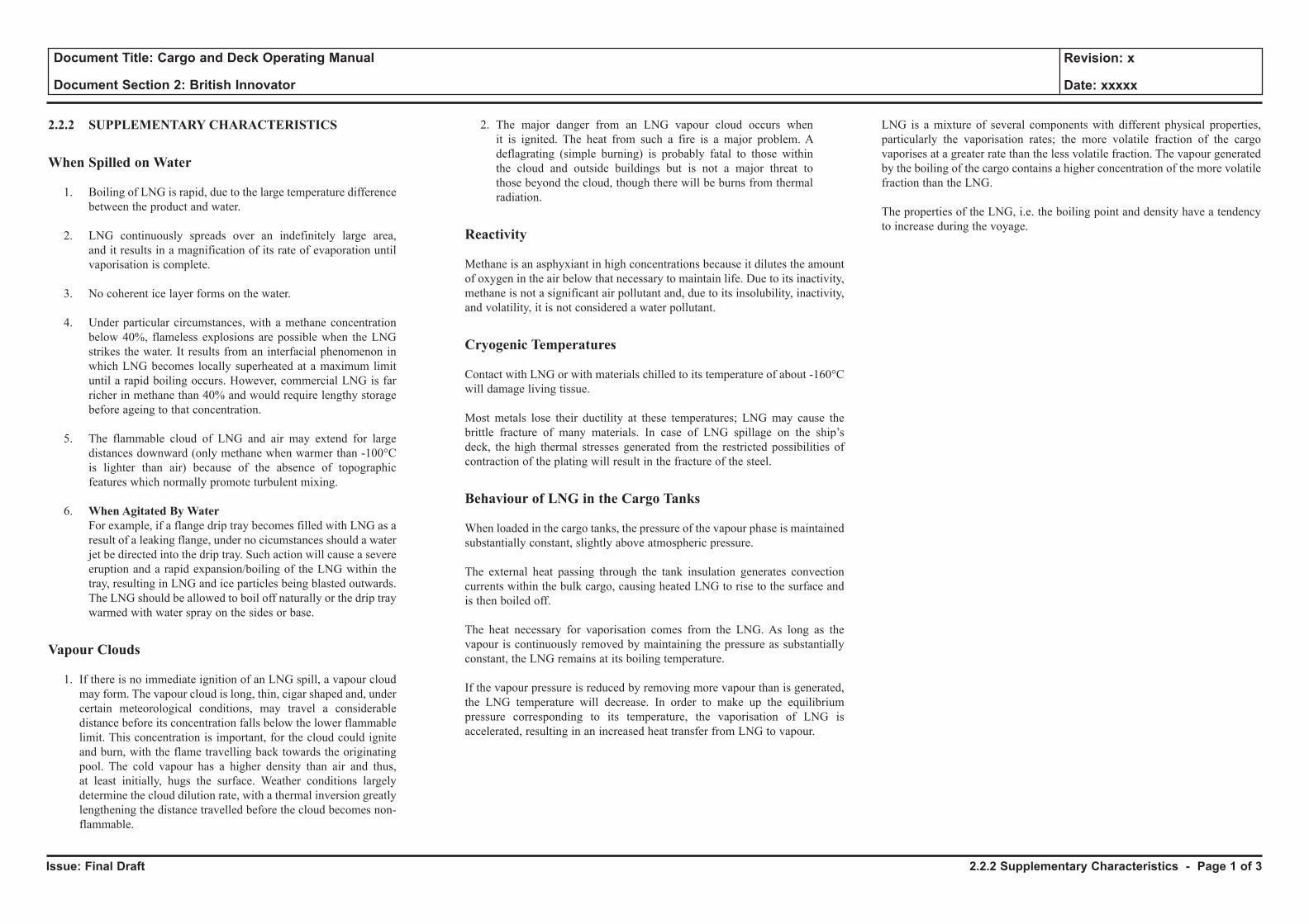
Issue: Final Draft
Document Title: Cargo and Deck Operating Manual
Document Section 2: British Innovator
Revision: x
Date: xxxxx
2.2.2 SUPPLEMENTARY CHARACTERISTICS
When Spilled on Water
1. Boiling of LNG is rapid, due to the large temperature difference between the product and water.
2. LNG continuously spreads over an indefinitely large area, and it results in a magnification of its rate of evaporation until vaporisation is complete.
3. No coherent ice layer forms on the water.
4. Under particular circumstances, with a methane concentration below 40%, flameless explosions are possible when the LNG strikes the water. It results from an interfacial phenomenon in which LNG becomes locally superheated at a maximum limit until a rapid boiling occurs. However, commercial LNG is far richer in methane than 40% and would require lengthy storage before ageing to that concentration.
5. The flammable cloud of LNG and air may extend for large distances downward (only methane when warmer than -100°C is lighter than air) because of the absence of topographic features which normally promote turbulent mixing.
6. When Agitated By Water For example, if a flange drip tray becomes filled with LNG as a
result of a leaking flange, under no cicumstances should a water jet be directed into the drip tray. Such action will cause a severe eruption and a rapid expansion/boiling of the LNG within the tray, resulting in LNG and ice particles being blasted outwards. The LNG should be allowed to boil off naturally or the drip tray warmed with water spray on the sides or base.
Vapour Clouds
1. If there is no immediate ignition of an LNG spill, a vapour cloud may form. The vapour cloud is long, thin, cigar shaped and, under certain meteorological conditions, may travel a considerable distance before its concentration falls below the lower flammable limit. This concentration is important, for the cloud could ignite and burn, with the flame travelling back towards the originating pool. The cold vapour has a higher density than air and thus, at least initially, hugs the surface. Weather conditions largely determine the cloud dilution rate, with a thermal inversion greatly lengthening the distance travelled before the cloud becomes non-flammable.
2. The major danger from an LNG vapour cloud occurs when it is ignited. The heat from such a fire is a major problem. A deflagrating (simple burning) is probably fatal to those within the cloud and outside buildings but is not a major threat to those beyond the cloud, though there will be burns from thermal radiation.
Reactivity
Methane is an asphyxiant in high concentrations because it dilutes the amount of oxygen in the air below that necessary to maintain life. Due to its inactivity, methane is not a significant air pollutant and, due to its insolubility, inactivity, and volatility, it is not considered a water pollutant.
Cryogenic Temperatures
Contact with LNG or with materials chilled to its temperature of about -160°C will damage living tissue.
Most metals lose their ductility at these temperatures; LNG may cause the brittle fracture of many materials. In case of LNG spillage on the ship’s deck, the high thermal stresses generated from the restricted possibilities of contraction of the plating will result in the fracture of the steel.
Behaviour of LNG in the Cargo Tanks
When loaded in the cargo tanks, the pressure of the vapour phase is maintained substantially constant, slightly above atmospheric pressure.
The external heat passing through the tank insulation generates convection currents within the bulk cargo, causing heated LNG to rise to the surface and is then boiled off.
The heat necessary for vaporisation comes from the LNG. As long as the vapour is continuously removed by maintaining the pressure as substantially constant, the LNG remains at its boiling temperature.
If the vapour pressure is reduced by removing more vapour than is generated, the LNG temperature will decrease. In order to make up the equilibrium pressure corresponding to its temperature, the vaporisation of LNG is accelerated, resulting in an increased heat transfer from LNG to vapour.
LNG is a mixture of several components with different physical properties, particularly the vaporisation rates; the more volatile fraction of the cargo vaporises at a greater rate than the less volatile fraction. The vapour generated by the boiling of the cargo contains a higher concentration of the more volatile fraction than the LNG.
The properties of the LNG, i.e. the boiling point and density have a tendency to increase during the voyage.
2.2.2 Supplementary Characteristics - Page 1 of 3
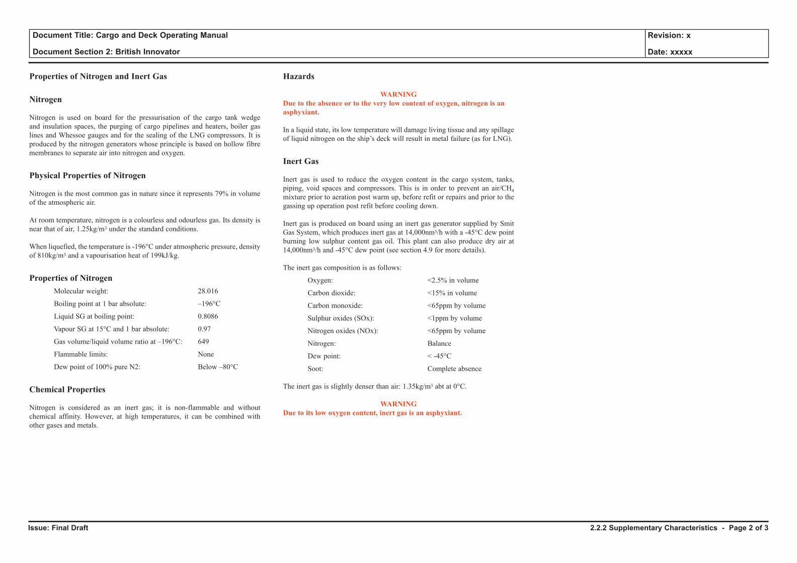
Issue: Final Draft
Document Title: Cargo and Deck Operating Manual
Document Section 2: British Innovator
Revision: x
Date: xxxxx
Properties of Nitrogen and Inert Gas
Nitrogen
Nitrogen is used on board for the pressurisation of the cargo tank wedge and insulation spaces, the purging of cargo pipelines and heaters, boiler gas lines and Whessoe gauges and for the sealing of the LNG compressors. It is produced by the nitrogen generators whose principle is based on hollow fibre membranes to separate air into nitrogen and oxygen.
Physical Properties of Nitrogen
Nitrogen is the most common gas in nature since it represents 79% in volume of the atmospheric air.
At room temperature, nitrogen is a colourless and odourless gas. Its density is near that of air, 1.25kg/m3 under the standard conditions.
When liquefied, the temperature is -196°C under atmospheric pressure, density of 810kg/m3 and a vapourisation heat of 199kJ/kg.
Properties of Nitrogen Molecular weight: 28.016
Boiling point at 1 bar absolute: –196°C
Liquid SG at boiling point: 0.8086
Vapour SG at 15°C and 1 bar absolute: 0.97
Gas volume/liquid volume ratio at –196°C: 649
Flammable limits: None
Dew point of 100% pure N2: Below –80°C
Chemical Properties
Nitrogen is considered as an inert gas; it is non-flammable and without chemical affinity. However, at high temperatures, it can be combined with other gases and metals.
Hazards
WARNING Due to the absence or to the very low content of oxygen, nitrogen is an asphyxiant.
In a liquid state, its low temperature will damage living tissue and any spillage of liquid nitrogen on the ship’s deck will result in metal failure (as for LNG).
Inert Gas
Inert gas is used to reduce the oxygen content in the cargo system, tanks, piping, void spaces and compressors. This is in order to prevent an air/CH4 mixture prior to aeration post warm up, before refit or repairs and prior to the gassing up operation post refit before cooling down.
Inert gas is produced on board using an inert gas generator supplied by Smit Gas System, which produces inert gas at 14,000nm3/h with a -45°C dew point burning low sulphur content gas oil. This plant can also produce dry air at 14,000nm3/h and -45°C dew point (see section 4.9 for more details).
The inert gas composition is as follows:
Oxygen: <2.5% in volume
Carbon dioxide: <15% in volume
Carbon monoxide: <65ppm by volume
Sulphur oxides (SOx): <1ppm by volume
Nitrogen oxides (NOx): <65ppm by volume
Nitrogen: Balance
Dew point: < -45°C
Soot: Complete absence
The inert gas is slightly denser than air: 1.35kg/m3 abt at 0°C.
WARNING Due to its low oxygen content, inert gas is an asphyxiant.
2.2.2 Supplementary Characteristics - Page 2 of 3
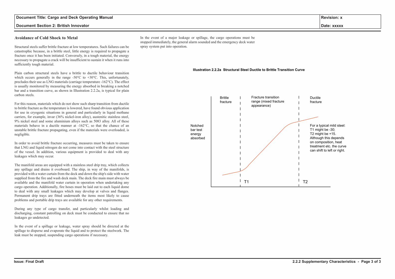
Issue: Final Draft
Document Title: Cargo and Deck Operating Manual
Document Section 2: British Innovator
Revision: x
Date: xxxxx
Avoidance of Cold Shock to Metal
Structural steels suffer brittle fracture at low temperatures. Such failures can be catastrophic because, in a brittle steel, little energy is required to propagate a fracture once it has been initiated. Conversely, in a tough material, the energy necessary to propagate a crack will be insufficient to sustain it when it runs into sufficiently tough material.
Plain carbon structural steels have a brittle to ductile behaviour transition which occurs generally in the range -50°C to +30°C. This, unfortunately, precludes their use as LNG materials (carriage temperature -162°C). The effect is usually monitored by measuring the energy absorbed in breaking a notched bar and a transition curve, as shown in Illustration 2.2.2a, is typical for plain carbon steels.
For this reason, materials which do not show such sharp transition from ductile to brittle fracture as the temperature is lowered, have found obvious application for use in cryogenic situations in general and particularly in liquid methane carriers, for example, invar (36% nickel-iron alloy), austenitic stainless steel, 9% nickel steel and some aluminium alloys such as 5083 alloy. All of these materials behave in a ductile manner at -162°C, so that the chance of an unstable brittle fracture propagating, even if the materials were overloaded, is negligible.
In order to avoid brittle fracture occurring, measures must be taken to ensure that LNG and liquid nitrogen do not come into contact with the steel structure of the vessel. In addition, various equipment is provided to deal with any leakages which may occur.
The manifold areas are equipped with a stainless steel drip tray, which collects any spillage and drains it overboard. The ship, in way of the manifolds, is provided with a water curtain from the deck and down the ship's side with water supplied from the fire and wash deck main. The deck fire main must always be available and the manifold water curtain in operation when undertaking any cargo operation. Additionally, fire hoses must be laid out to each liquid dome to deal with any small leakages which may develop at valves and flanges. Permanent drip trays are fitted underneath the items most likely to cause problems and portable drip trays are available for any other requirements.
During any type of cargo transfer, and particularly whilst loading and discharging, constant patrolling on deck must be conducted to ensure that no leakages go undetected.
In the event of a spillage or leakage, water spray should be directed at the spillage to disperse and evaporate the liquid and to protect the steelwork. The leak must be stopped, suspending cargo operations if necessary.
In the event of a major leakage or spillage, the cargo operations must be stopped immediately, the general alarm sounded and the emergency deck water spray system put into operation.
Notched
bar test
energy
absorbed
T1 T2
Brittle
fracture
Ductile
fracture
For a typical mild steel:
T1 might be -30;
T2 might be +15.
Although this depends
on composition, heat
treatment etc. the curve
can shift to left or right.
Fracture transition
range (mixed fracture
appearance)
Illustration 2.2.2a Structural Steel Ductile to Brittle Transition Curve
2.2.2 Supplementary Characteristics - Page 3 of 3

2.3 Health Hazards
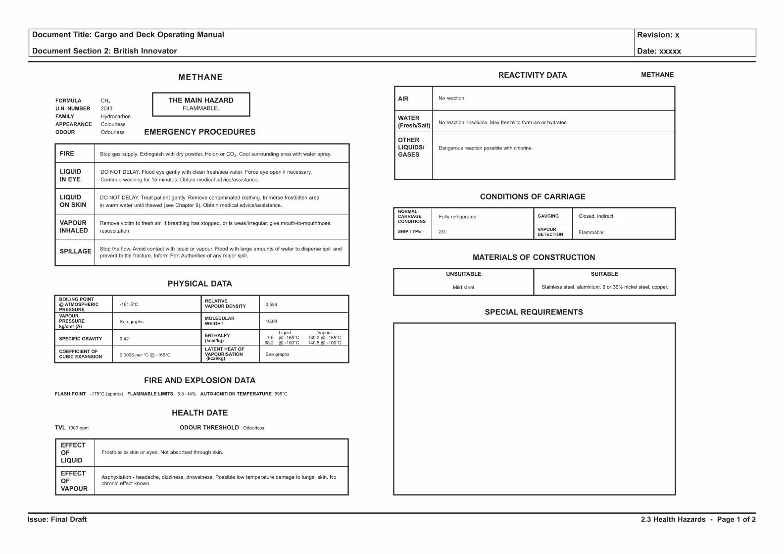
Issue: Final Draft
Document Title: Cargo and Deck Operating Manual
Document Section 2: British Innovator
Revision: x
Date: xxxxx
THE MAIN HAZARDFLAMMABLE.
METHANE
FORMULA CH4
U.N. NUMBER 2043
FAMILY Hydrocarbon
APPEARANCE Colourless
ODOUR Odourless EMERGENCY PROCEDURES
FIRE Stop gas supply. Extinguish with dry powder, Halon or CO2. Cool surrounding area with water spray.
LIQUID DO NOT DELAY. Flood eye gently with clean fresh/sea water. Force eye open if necessary.
IN EYE Continue washing for 15 minutes. Obtain medical advice/assistance.
LIQUID DO NOT DELAY. Treat patient gently. Remove contaminated clothing. Immerse frostbitten area
ON SKIN in warm water until thawed (see Chapter 9). Obtain medical advice/assistance.
VAPOUR Remove victim to fresh air. If breathing has stopped, or is weak/irregular, give mouth-to-mouth/nose
INHALED resuscitation.
SPILLAGE Stop the flow. Avoid contact with liquid or vapour. Flood with large amounts of water to disperse spill and
prevent brittle fracture. Inform Port Authorities of any major spill.
EFFECT
OF
LIQUID
EFFECT
OF
VAPOUR
Frostbite to skin or eyes. Not absorbed through skin.
Asphyxiation - headache, dizziness, drowsiness. Possible low temperature damage to lungs, skin. No
chronic effect known.
PHYSICAL DATA
FIRE AND EXPLOSION DATA
BOILING POINT@ ATMOSPHERIC -161.5°CPRESSURE
VAPOURPRESSURE See graphskg/cm2 (A)
SPECIFIC GRAVITY 0.42
COEFFICIENT OFCUBIC EXPANSION 0.0026 per °C @ -165°C
RELATIVEVAPOUR DENSITY 0.554
MOLECULAR16.04
WEIGHT
ENTHALPYLiquid Vapour
(kcal/kg)7.0 @ -165°C 130.2 @ -165°C68.2 @ -100°C 140.5 @ -100°C
LATENT HEAT OFVAPOURISATION See graphs(kcal/kg)
FLASH POINT -175°C (approx) FLAMMABLE LIMITS 5.3 -14% AUTO-IGNITION TEMPERATURE 595°C
HEALTH DATE
TVL 1000 ppm ODOUR THRESHOLD Odourless
REACTIVITY DATA METHANE
AIR
WATER
(Fresh/Salt)
OTHER
LIQUIDS/
GASES
No reaction.
No reaction. Insoluble. May freeze to form ice or hydrates.
Dangerous reaction possible with chlorine.
CONDITIONS OF CARRIAGE
NORMALCARRIAGECONDITIONS
SHIP TYPE
Fully refrigerated.
2G.
GAUGING
VAPOURDETECTION
Closed, indirect.
Flammable.
MATERIALS OF CONSTRUCTION
UNSUITABLE SUITABLE
Stainless steel, aluminium, 9 or 36% nickel steel, copper.
SPECIAL REQUIREMENTS
Mild steel.
2.3 Health Hazards - Page 1 of 2
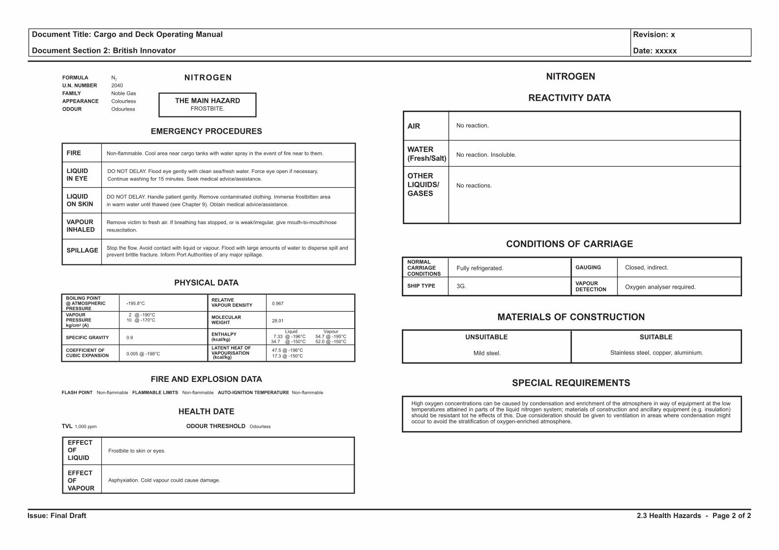
Issue: Final Draft
Document Title: Cargo and Deck Operating Manual
Document Section 2: British Innovator
Revision: x
Date: xxxxx
THE MAIN HAZARDFROSTBITE.
NITROGENFORMULA N2
U.N. NUMBER 2040
FAMILY Noble Gas
APPEARANCE Colourless
ODOUR Odourless
EMERGENCY PROCEDURES
FIRE Non-flammable. Cool area near cargo tanks with water spray in the event of fire near to them.
LIQUID DO NOT DELAY. Flood eye gently with clean sea/fresh water. Force eye open if necessary.
IN EYE Continue washing for 15 minutes. Seek medical advice/assistance.
LIQUID DO NOT DELAY. Handle patient gently. Remove contaminated clothing. Immerse frostbitten area
ON SKIN in warm water until thawed (see Chapter 9). Obtain medical advice/assistance.
VAPOUR Remove victim to fresh air. If breathing has stopped, or is weak/irregular, give mouth-to-mouth/nose
INHALED resuscitation.
SPILLAGE Stop the flow. Avoid contact with liquid or vapour. Flood with large amounts of water to disperse spill and
prevent brittle fracture. Inform Port Authorities of any major spillage.
EFFECT
OF
LIQUID
EFFECT
OF
VAPOUR
Frostbite to skin or eyes.
Asphyxiation. Cold vapour could cause damage.
PHYSICAL DATA
FIRE AND EXPLOSION DATA
BOILING POINT@ ATMOSPHERIC -195.8°CPRESSURE
VAPOUR 2 @ -190°CPRESSURE 10 @ -170°Ckg/cm2 (A)
SPECIFIC GRAVITY 0.9
COEFFICIENT OFCUBIC EXPANSION 0.005 @ -198°C
RELATIVEVAPOUR DENSITY 0.967
MOLECULAR28.01WEIGHT
ENTHALPYLiquid Vapour
(kcal/kg)7.33 @ -196°C 54.7 @ -195°C34.7 @ -150°C 52.0 @ -150°C
LATENT HEAT OFVAPOURISATION
47.5 @ -196°C
(kcal/kg) 17.3 @ -150°C
FLASH POINT Non-flammable FLAMMABLE LIMITS Non-flammable AUTO-IGNITION TEMPERATURE Non-flammable
HEALTH DATE
TVL 1,000 ppm ODOUR THRESHOLD Odourless
REACTIVITY DATA
NITROGEN
AIR
WATER
(Fresh/Salt)
OTHER
LIQUIDS/
GASES
No reaction.
No reaction. Insoluble.
No reactions.
CONDITIONS OF CARRIAGE
NORMALCARRIAGECONDITIONS
SHIP TYPE
Fully refrigerated.
3G.
GAUGING
VAPOURDETECTION
Closed, indirect.
Oxygen analyser required.
MATERIALS OF CONSTRUCTION
UNSUITABLE SUITABLE
Stainless steel, copper, aluminium.
SPECIAL REQUIREMENTS
High oxygen concentrations can be caused by condensation and enrichment of the atmosphere in way of equipment at the lowtemperatures attained in parts of the liquid nitrogen system; materials of construction and ancillary equipment (e.g. insulation)should be resistant tot he effects of this. Due consideration should be given to ventilation in areas where condensation mightoccur to avoid the stratification of oxygen-enriched atmosphere.
Mild steel.
2.3 Health Hazards - Page 2 of 2
PART 3: INTEGRATED AUTOMATION SYSTEM (IAS)
3.1 Control Room Arrangement
Illustrations
3.1a Main Control Room Layout
3.1b Main Control Room Consoles
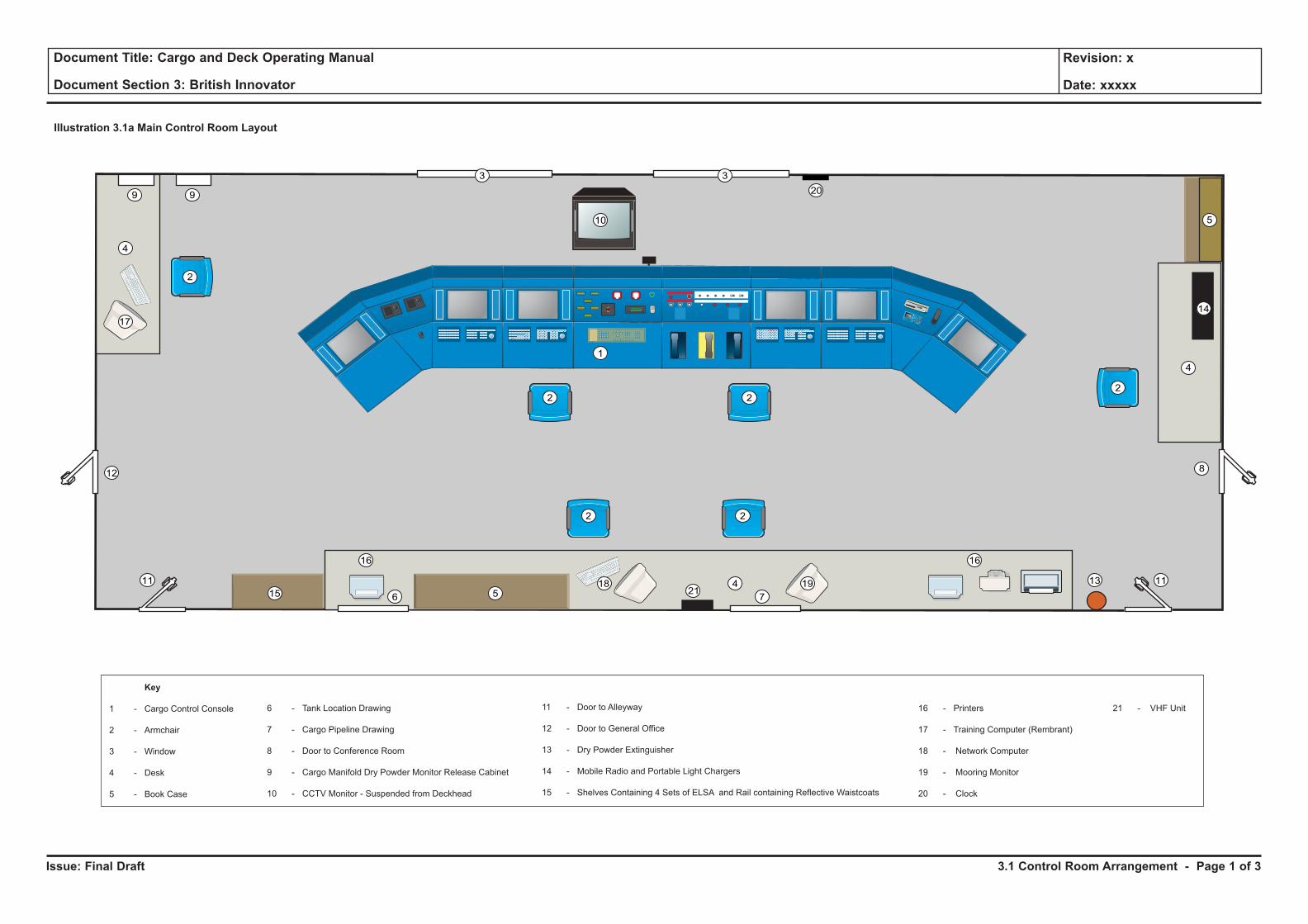
Issue: Final Draft
Document Title: Cargo and Deck Operating Manual
Document Section 3: British Innovator
Revision: x
Date: xxxxx
Illustration 3.1a Main Control Room Layout
10
2
33
22
8
111311
12
4
14
418 1921
1616
4
17
5
5615
2
99
2 2
1
Key
1 - Cargo Control Console
2 - Armchair
3 - Window
4 - Desk
5 - Book Case
6 - Tank Location Drawing
7 - Cargo Pipeline Drawing
8 - Door to Conference Room
9 - Cargo Manifold Dry Powder Monitor Release Cabinet
10 - CCTV Monitor - Suspended from Deckhead
11 - Door to Alleyway
12 - Door to General Office
13 - Dry Powder Extinguisher
14 - Mobile Radio and Portable Light Chargers
15 - Shelves Containing 4 Sets of ELSA and Rail containing Reflective Waistcoats
16 - Printers
17 - Training Computer (Rembrant)
18 - Network Computer
19 - Mooring Monitor
20 - Clock
21 - VHF Unit
20
7
3.1 Control Room Arrangement - Page 1 of 3
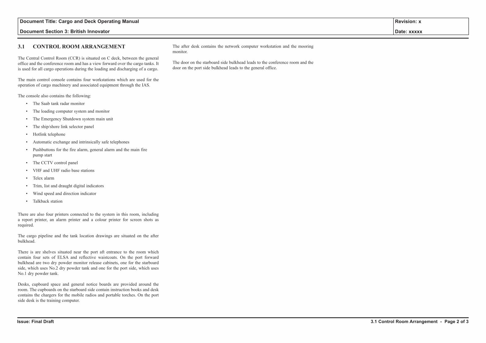
Issue: Final Draft
Document Title: Cargo and Deck Operating Manual
Document Section 3: British Innovator
Revision: x
Date: xxxxx
3.1 CONTROL ROOM ARRANGEMENT
The Central Control Room (CCR) is situated on C deck, between the general office and the conference room and has a view forward over the cargo tanks. It is used for all cargo operations during the loading and discharging of a cargo.
The main control console contains four workstations which are used for the operation of cargo machinery and associated equipment through the IAS.
The console also contains the following:
• The Saab tank radar monitor
• The loading computer system and monitor
• The Emergency Shutdown system main unit
• The ship/shore link selector panel
• Hotlink telephone
• Automatic exchange and intrinsically safe telephones
• Pushbuttons for the fire alarm, general alarm and the main fire pump start
• The CCTV control panel
• VHF and UHF radio base stations
• Telex alarm
• Trim, list and draught digital indicators
• Wind speed and direction indicator
• Talkback station
There are also four printers connected to the system in this room, including a report printer, an alarm printer and a colour printer for screen shots as required.
The cargo pipeline and the tank location drawings are situated on the after bulkhead.
There is are shelves situated near the port aft entrance to the room which contain four sets of ELSA and reflective waistcoats. On the port forward bulkhead are two dry powder monitor release cabinets, one for the starboard side, which uses No.2 dry powder tank and one for the port side, which uses No.1 dry powder tank.
Desks, cupboard space and general notice boards are provided around the room. The cupboards on the starboard side contain instruction books and desk contains the chargers for the mobile radios and portable torches. On the port side desk is the training computer.
The after desk contains the network computer workstation and the mooring monitor.
The door on the starboard side bulkhead leads to the conference room and the door on the port side bulkhead leads to the general office.
3.1 Control Room Arrangement - Page 2 of 3
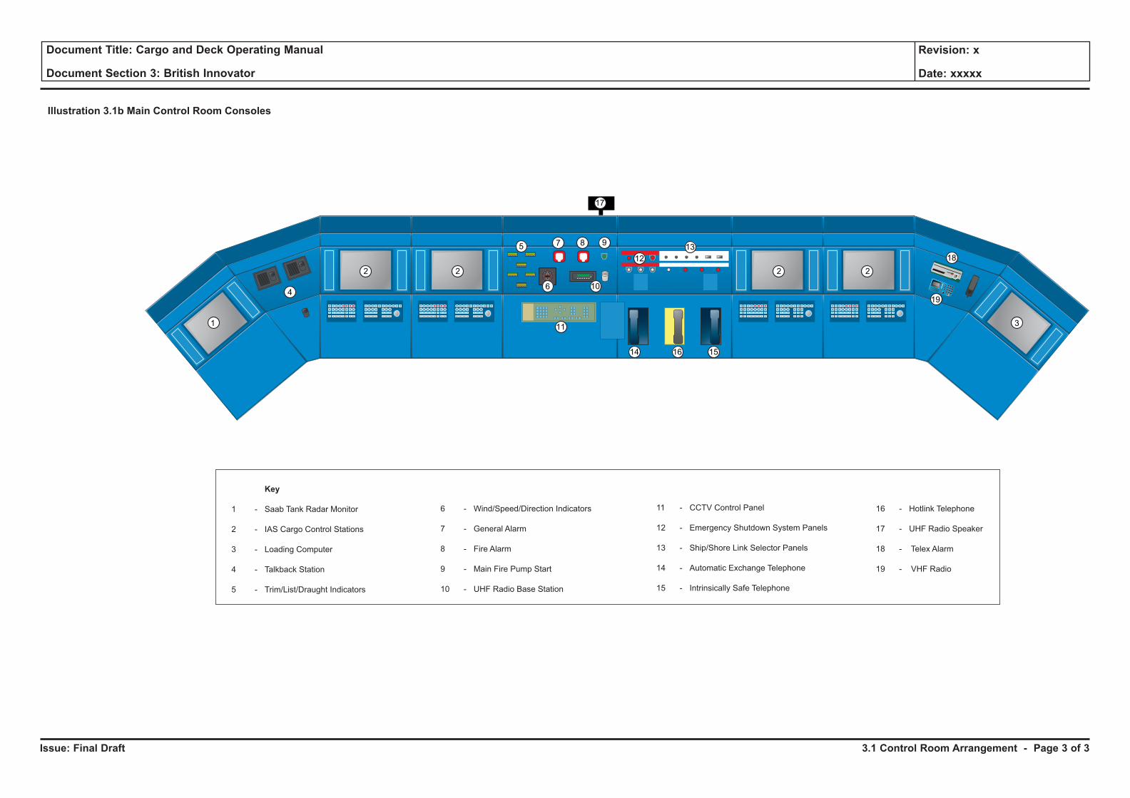
Issue: Final Draft
Document Title: Cargo and Deck Operating Manual
Document Section 3: British Innovator
Revision: x
Date: xxxxx
Key
1 - Saab Tank Radar Monitor
2 - IAS Cargo Control Stations
3 - Loading Computer
4 - Talkback Station
5 - Trim/List/Draught Indicators
6 - Wind/Speed/Direction Indicators
7 - General Alarm
8 - Fire Alarm
9 - Main Fire Pump Start
10 - UHF Radio Base Station
11 - CCTV Control Panel
12 - Emergency Shutdown System Panels
13 - Ship/Shore Link Selector Panels
14 - Automatic Exchange Telephone
15 - Intrinsically Safe Telephone
16 - Hotlink Telephone
17 - UHF Radio Speaker
18 - Telex Alarm
19 - VHF Radio
1
4
2 2
6
7 8 9
10
11
12
135
2 2
18
19
3
14 1516
17
Illustration 3.1b Main Control Room Consoles
3.1 Control Room Arrangement - Page 3 of 3
3.2 Integrated Automation System (IAS)
3.2.1 IAS Overview
3.2.2 IAS Operator Station Operations
3.2.3 Screen Displays
3.2.4 Watch Call System
3.2.5 Total Boil Off Gas Control System
3.2.6 Shipboard Management System
Illustrations
3.2.1a IAS Overview
3.2.2a IAS Operator Station Panel
3.2.2b Display Symbols and Views
3.2.3a Screen Displays
3.2.4a Watch Call Panels
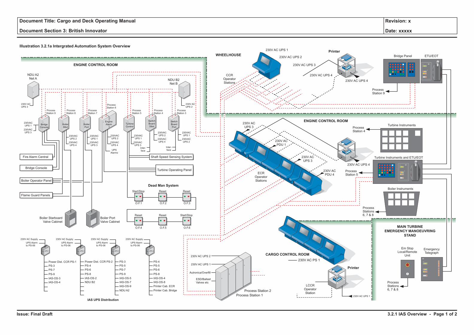
Issue: Final Draft
Document Title: Cargo and Deck Operating Manual
Document Section 3: British Innovator
Revision: x
Date: xxxxx
Illustration 3.2.1a Intergrated Automation System Overview
Autronica/Overfill
ESD/Ballast
Valves etc
Printer
Printer
ENGINE CONTROL ROOM
ENGINE CONTROL ROOM
WHEELHOUSE
MAIN TURBINE
EMERGENCY MANOEUVRING
STAND
CARGO CONTROL ROOM
230V AC UPS 4
230V AC UPS 4
230V AC UPS 1
230V AC
UPS 3
230V AC UPS 2
230V AC UPS 3
230V AC UPS 4
Bridge Panel
Turbine Instruments
NDU B2
Net B
NDU A2
Net A
230V ACUPS 3
230V ACUPS 2
230VACUPS 2
ProcessStation 9
ProcessStation 8
ProcessStation 7
ProcessStation 5
ProcessStation 4
ProcessStation 3
ProcessStation 6
230VACUPS 4
230VACUPS 1
230VACUPS 3
230VACUPS 1
230VACUPS 3
230VACUPS 2
230VACUPS 4
230VACUPS 1
230VACUPS 3
230VACUPS 2
230VACUPS 4
230VACUPS 1
230VACUPS 2
Inter-face
Inter-face
230V AC Supply
UPS Alarmto PS-06
230V AC Supply
UPS Alarmto PS-06
PS-3
PS-7
PS-9
IAS-OS-3
IAS-OS-4
Power Dist. CCR PS-1
PS-4
PS-6
PS-8
IAS-OS-2
NDU B2
Power Dist. CCR PS-2
PS-5
PS-7
PS-9
IAS-OS-5
IAS-OS-7
IAS-OS-9
NDU A2
PS-3
PS-5
PS-6
PS-8
IAS-OS-4
IAS-OS-8
Printer Cab. ECR
Printer Cab. Bridge
PS-4
230V AC Supply
UPS Alarmto PS-06
230V AC Supply
Start/Stop
Start/StopReset Reset
Reset Reset
UPS Alarmto PS-06
UPSAlarms
Fire Alarm Central Shaft Speed Sensing System
Turbine Operating Panel
Dead Man System
Bridge Console
Boiler Operator Panel
Flame Guard Panels
Boiler Starboard
Valve Cabinet
IAS UPS Distribution
Boiler Port
Valve Cabinet
ECR
Operator
Stations
LCCR
Operator
Station
CCR
Operator
Stations
Boiler Instruments
Turbine Instruments and ETU/EOT
ETU/EOT
BoilerStbd
BoilerPort
TurbineControl
EngineAlarm
UPS 1 UPS 2 UPS 3 UPS 4
O.F.1 O.F.2 O.F.3
O.F.4 O.F.5 O.F.6
230V AC UPS 2
230V AC UPS 1
Process Station 1
Process Station 2
230V AC PS 1
230V AC UPS 1
ProcessStations6, 7 & 8
ProcessStations6, 7 & 8
Em StopLocal/Remote
Unit
EmergencyTelegraph
ProcessStation 5
ProcessStation 4
ProcessStation 9
SwitchBoardStbd
SwitchBoardPort
BridgeConsole
230V AC
PDU 1
230V AC
UPS 3
230V AC
PDU 4
3.2.1 IAS Overview - Page 1 of 2
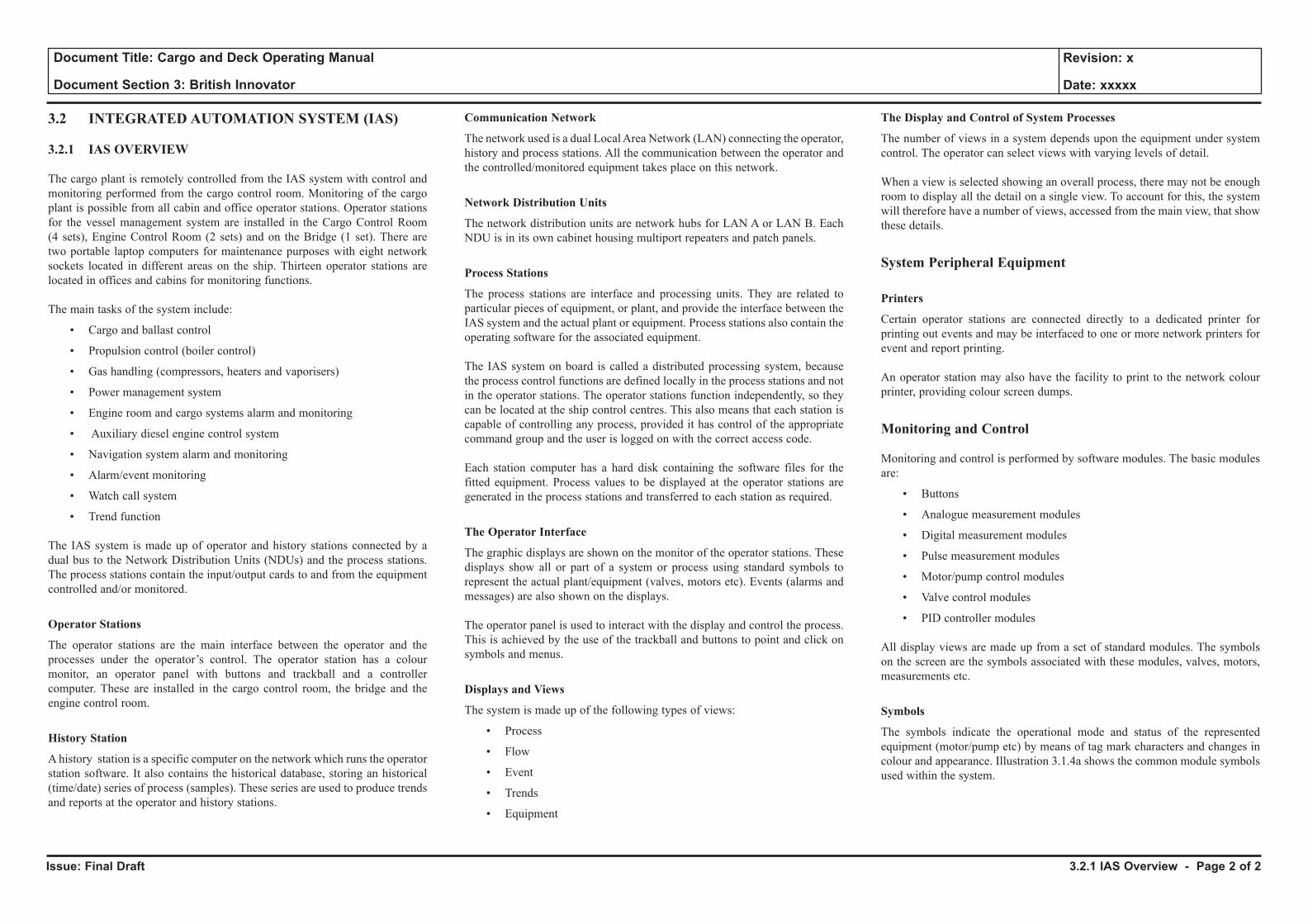
Issue: Final Draft
Document Title: Cargo and Deck Operating Manual
Document Section 3: British Innovator
Revision: x
Date: xxxxx
3.2 INTEGRATED AUTOMATION SYSTEM (IAS)
3.2.1 IAS OVERVIEW
The cargo plant is remotely controlled from the IAS system with control and monitoring performed from the cargo control room. Monitoring of the cargo plant is possible from all cabin and office operator stations. Operator stations for the vessel management system are installed in the Cargo Control Room (4 sets), Engine Control Room (2 sets) and on the Bridge (1 set). There are two portable laptop computers for maintenance purposes with eight network sockets located in different areas on the ship. Thirteen operator stations are located in offices and cabins for monitoring functions.
The main tasks of the system include:
• Cargo and ballast control
• Propulsion control (boiler control)
• Gas handling (compressors, heaters and vaporisers)
• Power management system
• Engine room and cargo systems alarm and monitoring
• Auxiliary diesel engine control system
• Navigation system alarm and monitoring
• Alarm/event monitoring
• Watch call system
• Trend function
The IAS system is made up of operator and history stations connected by a dual bus to the Network Distribution Units (NDUs) and the process stations. The process stations contain the input/output cards to and from the equipment controlled and/or monitored.
Operator Stations
The operator stations are the main interface between the operator and the processes under the operator’s control. The operator station has a colour monitor, an operator panel with buttons and trackball and a controller computer. These are installed in the cargo control room, the bridge and the engine control room.
History Station
A history station is a specific computer on the network which runs the operator station software. It also contains the historical database, storing an historical (time/date) series of process (samples). These series are used to produce trends and reports at the operator and history stations.
Communication Network
The network used is a dual Local Area Network (LAN) connecting the operator, history and process stations. All the communication between the operator and the controlled/monitored equipment takes place on this network.
Network Distribution Units
The network distribution units are network hubs for LAN A or LAN B. Each NDU is in its own cabinet housing multiport repeaters and patch panels.
Process Stations
The process stations are interface and processing units. They are related to particular pieces of equipment, or plant, and provide the interface between the IAS system and the actual plant or equipment. Process stations also contain the operating software for the associated equipment.
The IAS system on board is called a distributed processing system, because the process control functions are defined locally in the process stations and not in the operator stations. The operator stations function independently, so they can be located at the ship control centres. This also means that each station is capable of controlling any process, provided it has control of the appropriate command group and the user is logged on with the correct access code.
Each station computer has a hard disk containing the software files for the fitted equipment. Process values to be displayed at the operator stations are generated in the process stations and transferred to each station as required.
The Operator Interface
The graphic displays are shown on the monitor of the operator stations. These displays show all or part of a system or process using standard symbols to represent the actual plant/equipment (valves, motors etc). Events (alarms and messages) are also shown on the displays.
The operator panel is used to interact with the display and control the process. This is achieved by the use of the trackball and buttons to point and click on symbols and menus.
Displays and Views
The system is made up of the following types of views:
• Process
• Flow
• Event
• Trends
• Equipment
The Display and Control of System Processes
The number of views in a system depends upon the equipment under system control. The operator can select views with varying levels of detail.
When a view is selected showing an overall process, there may not be enough room to display all the detail on a single view. To account for this, the system will therefore have a number of views, accessed from the main view, that show these details.
System Peripheral Equipment
Printers
Certain operator stations are connected directly to a dedicated printer for printing out events and may be interfaced to one or more network printers for event and report printing.
An operator station may also have the facility to print to the network colour printer, providing colour screen dumps.
Monitoring and Control
Monitoring and control is performed by software modules. The basic modules are:
• Buttons
• Analogue measurement modules
• Digital measurement modules
• Pulse measurement modules
• Motor/pump control modules
• Valve control modules
• PID controller modules
All display views are made up from a set of standard modules. The symbols on the screen are the symbols associated with these modules, valves, motors, measurements etc.
Symbols
The symbols indicate the operational mode and status of the represented equipment (motor/pump etc) by means of tag mark characters and changes in colour and appearance. Illustration 3.1.4a shows the common module symbols used within the system.
3.2.1 IAS Overview - Page 2 of 2

Issue: Final Draft
Document Title: Cargo and Deck Operating Manual
Document Section 3: British Innovator
Revision: x
Date: xxxxx
BOILERCOMMON
MAINTURBINE
GAS
HANDLING
PATROL
MAN
AUX
CARGO
FIRE SYSTEMNAVI-
GATOR
NGP IGS
BALLAST
TAKE
ACK.
GIVE STATUS
- 0 .
7 8 9 SPACE
4 5 6 BKSP HOME END PGUP
PGDNTAB
1
F1 F2 F3 F4 F5 F6 F7 F8
2 3 ESCBILGE
BOILER
P
POWER
BOILER
S
STEAM
SYSCOMPUTER POWER ALARM
ALARM
VIEW
Views Alarms Keypad Trackball
Command
ViewSection
Illustration 3.2.2a IAS Operator Station Panel
Kongsberg Panel
3.2.2 IAS Operator Station Operations - Page 1 of 6
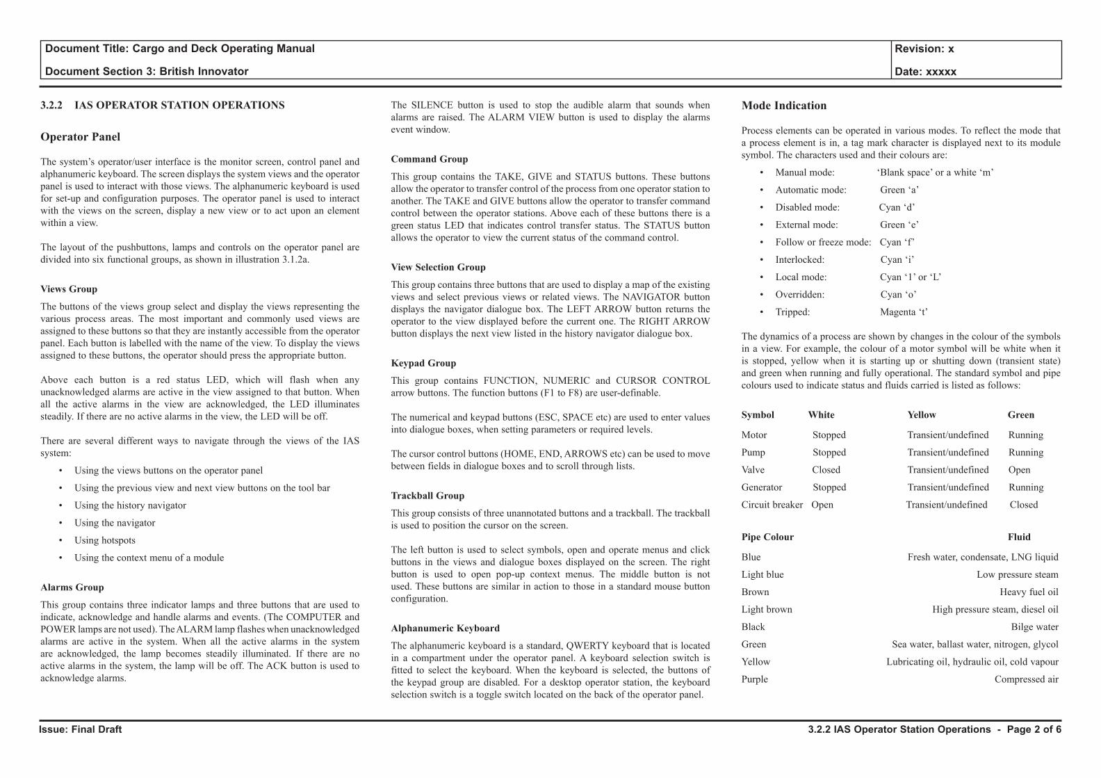
Issue: Final Draft
Document Title: Cargo and Deck Operating Manual
Document Section 3: British Innovator
Revision: x
Date: xxxxx
3.2.2 IAS OPERATOR STATION OPERATIONS
Operator Panel
The system’s operator/user interface is the monitor screen, control panel and alphanumeric keyboard. The screen displays the system views and the operator panel is used to interact with those views. The alphanumeric keyboard is used for set-up and configuration purposes. The operator panel is used to interact with the views on the screen, display a new view or to act upon an element within a view.
The layout of the pushbuttons, lamps and controls on the operator panel are divided into six functional groups, as shown in illustration 3.1.2a.
Views Group
The buttons of the views group select and display the views representing the various process areas. The most important and commonly used views are assigned to these buttons so that they are instantly accessible from the operator panel. Each button is labelled with the name of the view. To display the views assigned to these buttons, the operator should press the appropriate button.
Above each button is a red status LED, which will flash when any unacknowledged alarms are active in the view assigned to that button. When all the active alarms in the view are acknowledged, the LED illuminates steadily. If there are no active alarms in the view, the LED will be off.
There are several different ways to navigate through the views of the IAS system:
• Using the views buttons on the operator panel
• Using the previous view and next view buttons on the tool bar
• Using the history navigator
• Using the navigator
• Using hotspots
• Using the context menu of a module
Alarms Group
This group contains three indicator lamps and three buttons that are used to indicate, acknowledge and handle alarms and events. (The COMPUTER and POWER lamps are not used). The ALARM lamp flashes when unacknowledged alarms are active in the system. When all the active alarms in the system are acknowledged, the lamp becomes steadily illuminated. If there are no active alarms in the system, the lamp will be off. The ACK button is used to acknowledge alarms.
The SILENCE button is used to stop the audible alarm that sounds when alarms are raised. The ALARM VIEW button is used to display the alarms event window.
Command Group
This group contains the TAKE, GIVE and STATUS buttons. These buttons allow the operator to transfer control of the process from one operator station to another. The TAKE and GIVE buttons allow the operator to transfer command control between the operator stations. Above each of these buttons there is a green status LED that indicates control transfer status. The STATUS button allows the operator to view the current status of the command control.
View Selection Group
This group contains three buttons that are used to display a map of the existing views and select previous views or related views. The NAVIGATOR button displays the navigator dialogue box. The LEFT ARROW button returns the operator to the view displayed before the current one. The RIGHT ARROW button displays the next view listed in the history navigator dialogue box.
Keypad Group
This group contains FUNCTION, NUMERIC and CURSOR CONTROL arrow buttons. The function buttons (F1 to F8) are user-definable.
The numerical and keypad buttons (ESC, SPACE etc) are used to enter values into dialogue boxes, when setting parameters or required levels.
The cursor control buttons (HOME, END, ARROWS etc) can be used to move between fields in dialogue boxes and to scroll through lists.
Trackball Group
This group consists of three unannotated buttons and a trackball. The trackball is used to position the cursor on the screen.
The left button is used to select symbols, open and operate menus and click buttons in the views and dialogue boxes displayed on the screen. The right button is used to open pop-up context menus. The middle button is not used. These buttons are similar in action to those in a standard mouse button configuration.
Alphanumeric Keyboard
The alphanumeric keyboard is a standard, QWERTY keyboard that is located in a compartment under the operator panel. A keyboard selection switch is fitted to select the keyboard. When the keyboard is selected, the buttons of the keypad group are disabled. For a desktop operator station, the keyboard selection switch is a toggle switch located on the back of the operator panel.
Mode Indication
Process elements can be operated in various modes. To reflect the mode that a process element is in, a tag mark character is displayed next to its module symbol. The characters used and their colours are:
• Manual mode: ‘Blank space’ or a white ‘m’
• Automatic mode: Green ‘a’
• Disabled mode: Cyan ‘d’
• External mode: Green ‘e’
• Follow or freeze mode: Cyan ‘f’
• Interlocked: Cyan ‘i’
• Local mode: Cyan ‘1’ or ‘L’
• Overridden: Cyan ‘o’
• Tripped: Magenta ‘t’
The dynamics of a process are shown by changes in the colour of the symbols in a view. For example, the colour of a motor symbol will be white when it is stopped, yellow when it is starting up or shutting down (transient state) and green when running and fully operational. The standard symbol and pipe colours used to indicate status and fluids carried is listed as follows:
Symbol White Yellow Green
Motor Stopped Transient/undefined Running
Pump Stopped Transient/undefined Running
Valve Closed Transient/undefined Open
Generator Stopped Transient/undefined Running
Circuit breaker Open Transient/undefined Closed
Pipe Colour Fluid
Blue Fresh water, condensate, LNG liquid
Light blue Low pressure steam
Brown Heavy fuel oil
Light brown High pressure steam, diesel oil
Black Bilge water
Green Sea water, ballast water, nitrogen, glycol
Yellow Lubricating oil, hydraulic oil, cold vapour
Purple Compressed air
3.2.2 IAS Operator Station Operations - Page 2 of 6
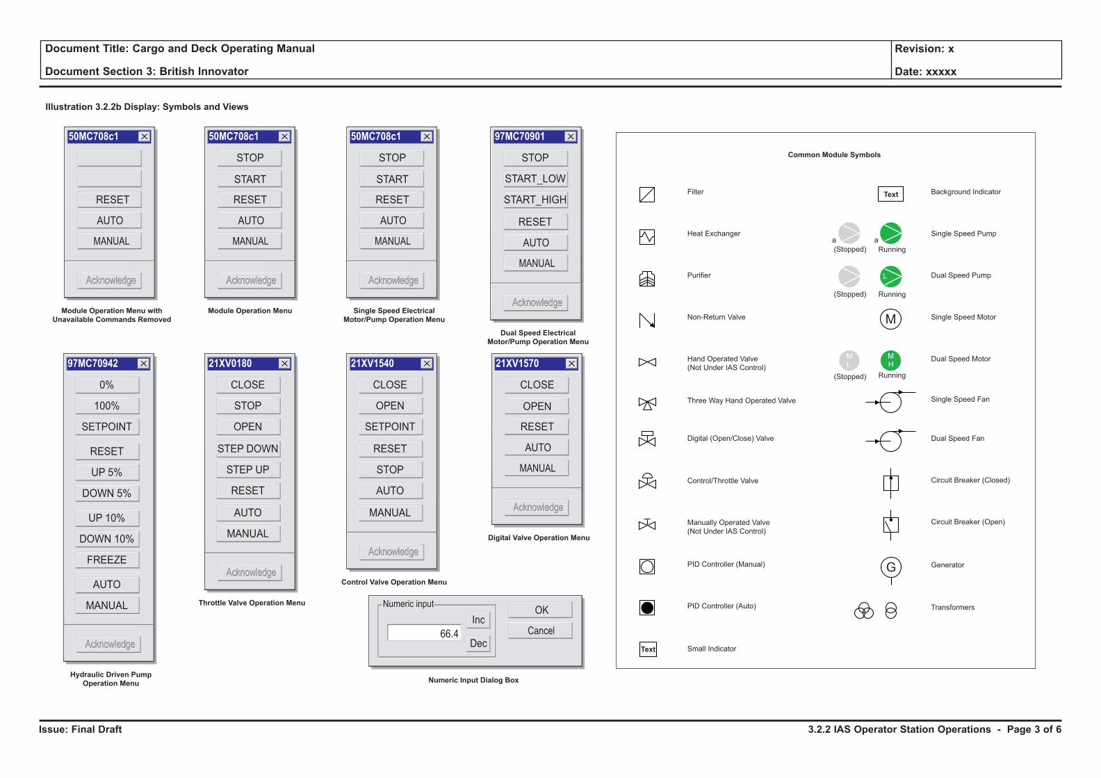
Issue: Final Draft
Document Title: Cargo and Deck Operating Manual
Document Section 3: British Innovator
Revision: x
Date: xxxxx
Manually Operated Valve
(Not Under IAS Control)
M
G
M
Filter
Heat Exchanger
Purifier
Non-Return Valve
Hand Operated Valve
(Not Under IAS Control)
Three Way Hand Operated Valve
Transformers
Digital (Open/Close) Valve
Control/Throttle Valve
PID Controller (Manual)
PID Controller (Auto)
Single Speed Pump
Running(Stopped)
Running
Running
(Stopped)
(Stopped)
Dual Speed Pump
Single Speed Motor
Dual Speed Motor
Single Speed Fan
Dual Speed Fan
Circuit Breaker (Closed)
Circuit Breaker (Open)
Generator
Small IndicatorText
Background Indicator
aa
H
HML
Text
L
Common Module Symbols
Illustration 3.2.2b Display: Symbols and Views
Acknowledge
X50MC708c1
RESET
AUTO
MANUAL
AcknowledgeAcknowledge Acknowledge
X50MC708c1
RESET
START
STOP
AUTO
MANUAL
AcknowledgeAcknowledge
Module Operation Menu with
Unavailable Commands Removed
Acknowledge
X97MC70901
RESET
STOP
START_LOW
START_HIGH
AUTO
MANUAL
AcknowledgeAcknowledge
Dual Speed Electrical
Motor/Pump Operation Menu
Acknowledge
X97MC70942
0%
100%
SETPOINT
RESET
UP 5%
DOWN 5%
UP 10%
DOWN 10%
FREEZE
AUTO
MANUAL
AcknowledgeAcknowledge
Hydraulic Driven Pump
Operation Menu
Acknowledge
X21XV0180
CLOSE
STOP
OPEN
STEP DOWN
STEP UP
RESET
AUTO
MANUAL
AcknowledgeAcknowledge
Throttle Valve Operation Menu
Acknowledge
X21XV1540
CLOSE
OPEN
SETPOINT
RESET
STOP
AUTO
MANUAL
AcknowledgeAcknowledge
Control Valve Operation Menu
Numeric Input Dialog Box
Module Operation Menu
Acknowledge
X50MC708c1
RESET
START
STOP
AUTO
MANUAL
AcknowledgeAcknowledge
Single Speed Electrical
Motor/Pump Operation Menu
Acknowledge
X21XV1570
RESET
OPEN
CLOSE
AUTO
MANUAL
AcknowledgeAcknowledge
Digital Valve Operation Menu
OKInc
66.4
Numeric input
DecCancel
3.2.2 IAS Operator Station Operations - Page 3 of 6
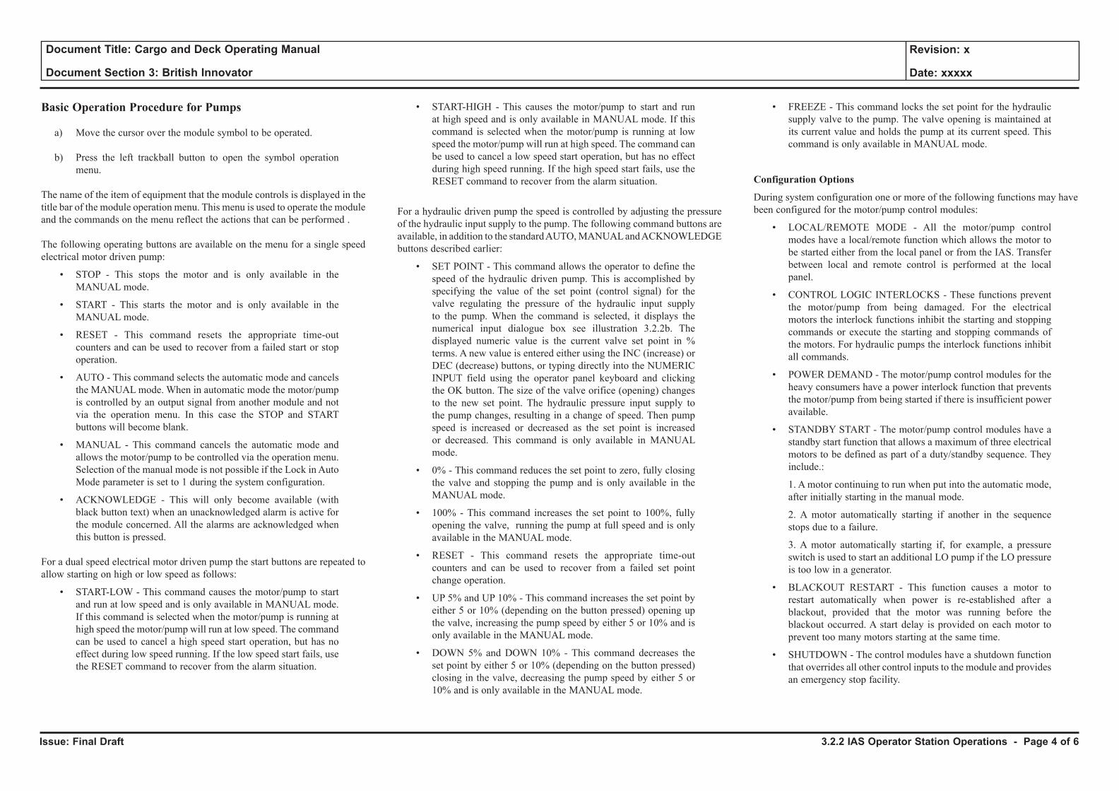
Issue: Final Draft
Document Title: Cargo and Deck Operating Manual
Document Section 3: British Innovator
Revision: x
Date: xxxxx
Basic Operation Procedure for Pumps
a) Move the cursor over the module symbol to be operated.
b) Press the left trackball button to open the symbol operation menu.
The name of the item of equipment that the module controls is displayed in the title bar of the module operation menu. This menu is used to operate the module and the commands on the menu reflect the actions that can be performed .
The following operating buttons are available on the menu for a single speed electrical motor driven pump:
• STOP - This stops the motor and is only available in the MANUAL mode.
• START - This starts the motor and is only available in the MANUAL mode.
• RESET - This command resets the appropriate time-out counters and can be used to recover from a failed start or stop operation.
• AUTO - This command selects the automatic mode and cancels the MANUAL mode. When in automatic mode the motor/pump is controlled by an output signal from another module and not via the operation menu. In this case the STOP and START buttons will become blank.
• MANUAL - This command cancels the automatic mode and allows the motor/pump to be controlled via the operation menu. Selection of the manual mode is not possible if the Lock in Auto Mode parameter is set to 1 during the system configuration.
• ACKNOWLEDGE - This will only become available (with black button text) when an unacknowledged alarm is active for the module concerned. All the alarms are acknowledged when this button is pressed.
For a dual speed electrical motor driven pump the start buttons are repeated to allow starting on high or low speed as follows:
• START-LOW - This command causes the motor/pump to start and run at low speed and is only available in MANUAL mode. If this command is selected when the motor/pump is running at high speed the motor/pump will run at low speed. The command can be used to cancel a high speed start operation, but has no effect during low speed running. If the low speed start fails, use the RESET command to recover from the alarm situation.
• START-HIGH - This causes the motor/pump to start and run at high speed and is only available in MANUAL mode. If this command is selected when the motor/pump is running at low speed the motor/pump will run at high speed. The command can be used to cancel a low speed start operation, but has no effect during high speed running. If the high speed start fails, use the RESET command to recover from the alarm situation.
For a hydraulic driven pump the speed is controlled by adjusting the pressure of the hydraulic input supply to the pump. The following command buttons are available, in addition to the standard AUTO, MANUAL and ACKNOWLEDGE buttons described earlier:
• SET POINT - This command allows the operator to define the speed of the hydraulic driven pump. This is accomplished by specifying the value of the set point (control signal) for the valve regulating the pressure of the hydraulic input supply to the pump. When the command is selected, it displays the numerical input dialogue box see illustration 3.2.2b. The displayed numeric value is the current valve set point in % terms. A new value is entered either using the INC (increase) or DEC (decrease) buttons, or typing directly into the NUMERIC INPUT field using the operator panel keyboard and clicking the OK button. The size of the valve orifice (opening) changes to the new set point. The hydraulic pressure input supply to the pump changes, resulting in a change of speed. Then pump speed is increased or decreased as the set point is increased or decreased. This command is only available in MANUAL mode.
• 0% - This command reduces the set point to zero, fully closing the valve and stopping the pump and is only available in the MANUAL mode.
• 100% - This command increases the set point to 100%, fully opening the valve, running the pump at full speed and is only available in the MANUAL mode.
• RESET - This command resets the appropriate time-out counters and can be used to recover from a failed set point change operation.
• UP 5% and UP 10% - This command increases the set point by either 5 or 10% (depending on the button pressed) opening up the valve, increasing the pump speed by either 5 or 10% and is only available in the MANUAL mode.
• DOWN 5% and DOWN 10% - This command decreases the set point by either 5 or 10% (depending on the button pressed) closing in the valve, decreasing the pump speed by either 5 or 10% and is only available in the MANUAL mode.
• FREEZE - This command locks the set point for the hydraulic supply valve to the pump. The valve opening is maintained at its current value and holds the pump at its current speed. This command is only available in MANUAL mode.
Configuration Options
During system configuration one or more of the following functions may have been configured for the motor/pump control modules:
• LOCAL/REMOTE MODE - All the motor/pump control modes have a local/remote function which allows the motor to be started either from the local panel or from the IAS. Transfer between local and remote control is performed at the local panel.
• CONTROL LOGIC INTERLOCKS - These functions prevent the motor/pump from being damaged. For the electrical motors the interlock functions inhibit the starting and stopping commands or execute the starting and stopping commands of the motors. For hydraulic pumps the interlock functions inhibit all commands.
• POWER DEMAND - The motor/pump control modules for the heavy consumers have a power interlock function that prevents the motor/pump from being started if there is insufficient power available.
• STANDBY START - The motor/pump control modules have a standby start function that allows a maximum of three electrical motors to be defined as part of a duty/standby sequence. They include.:
1. A motor continuing to run when put into the automatic mode, after initially starting in the manual mode.
2. A motor automatically starting if another in the sequence stops due to a failure.
3. A motor automatically starting if, for example, a pressure switch is used to start an additional LO pump if the LO pressure is too low in a generator.
• BLACKOUT RESTART - This function causes a motor to restart automatically when power is re-established after a blackout, provided that the motor was running before the blackout occurred. A start delay is provided on each motor to prevent too many motors starting at the same time.
• SHUTDOWN - The control modules have a shutdown function that overrides all other control inputs to the module and provides an emergency stop facility.
3.2.2 IAS Operator Station Operations - Page 4 of 6
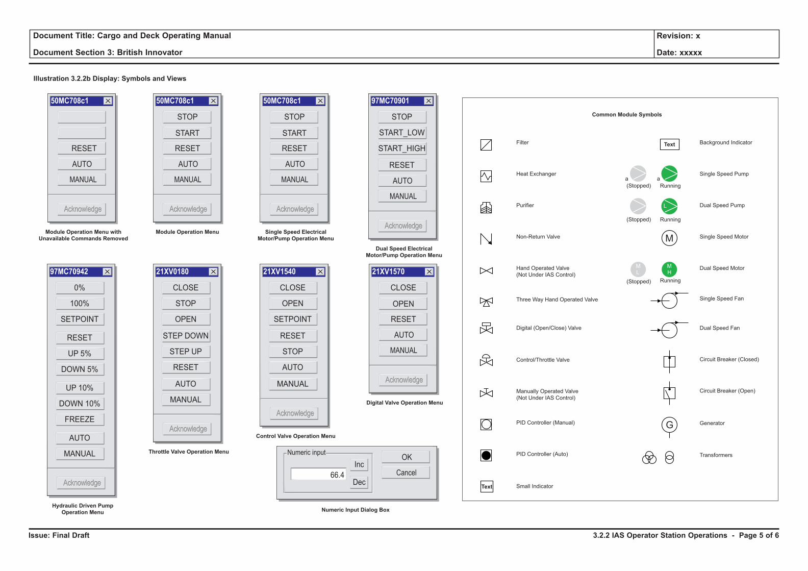
Issue: Final Draft
Document Title: Cargo and Deck Operating Manual
Document Section 3: British Innovator
Revision: x
Date: xxxxx
Manually Operated Valve
(Not Under IAS Control)
M
G
M
Filter
Heat Exchanger
Purifier
Non-Return Valve
Hand Operated Valve
(Not Under IAS Control)
Three Way Hand Operated Valve
Transformers
Digital (Open/Close) Valve
Control/Throttle Valve
PID Controller (Manual)
PID Controller (Auto)
Single Speed Pump
Running(Stopped)
Running
Running
(Stopped)
(Stopped)
Dual Speed Pump
Single Speed Motor
Dual Speed Motor
Single Speed Fan
Dual Speed Fan
Circuit Breaker (Closed)
Circuit Breaker (Open)
Generator
Small IndicatorText
Background Indicator
aa
H
HML
Text
L
Common Module Symbols
Illustration 3.2.2b Display: Symbols and Views
Acknowledge
X50MC708c1
RESET
AUTO
MANUAL
AcknowledgeAcknowledge Acknowledge
X50MC708c1
RESET
START
STOP
AUTO
MANUAL
AcknowledgeAcknowledge
Module Operation Menu with
Unavailable Commands Removed
Acknowledge
X97MC70901
RESET
STOP
START_LOW
START_HIGH
AUTO
MANUAL
AcknowledgeAcknowledge
Dual Speed Electrical
Motor/Pump Operation Menu
Acknowledge
X97MC70942
0%
100%
SETPOINT
RESET
UP 5%
DOWN 5%
UP 10%
DOWN 10%
FREEZE
AUTO
MANUAL
AcknowledgeAcknowledge
Hydraulic Driven Pump
Operation Menu
Acknowledge
X21XV0180
CLOSE
STOP
OPEN
STEP DOWN
STEP UP
RESET
AUTO
MANUAL
AcknowledgeAcknowledge
Throttle Valve Operation Menu
Acknowledge
X21XV1540
CLOSE
OPEN
SETPOINT
RESET
STOP
AUTO
MANUAL
AcknowledgeAcknowledge
Control Valve Operation Menu
Numeric Input Dialog Box
Module Operation Menu
Acknowledge
X50MC708c1
RESET
START
STOP
AUTO
MANUAL
AcknowledgeAcknowledge
Single Speed Electrical
Motor/Pump Operation Menu
Acknowledge
X21XV1570
RESET
OPEN
CLOSE
AUTO
MANUAL
AcknowledgeAcknowledge
Digital Valve Operation Menu
OKInc
66.4
Numeric input
DecCancel
3.2.2 IAS Operator Station Operations - Page 5 of 6
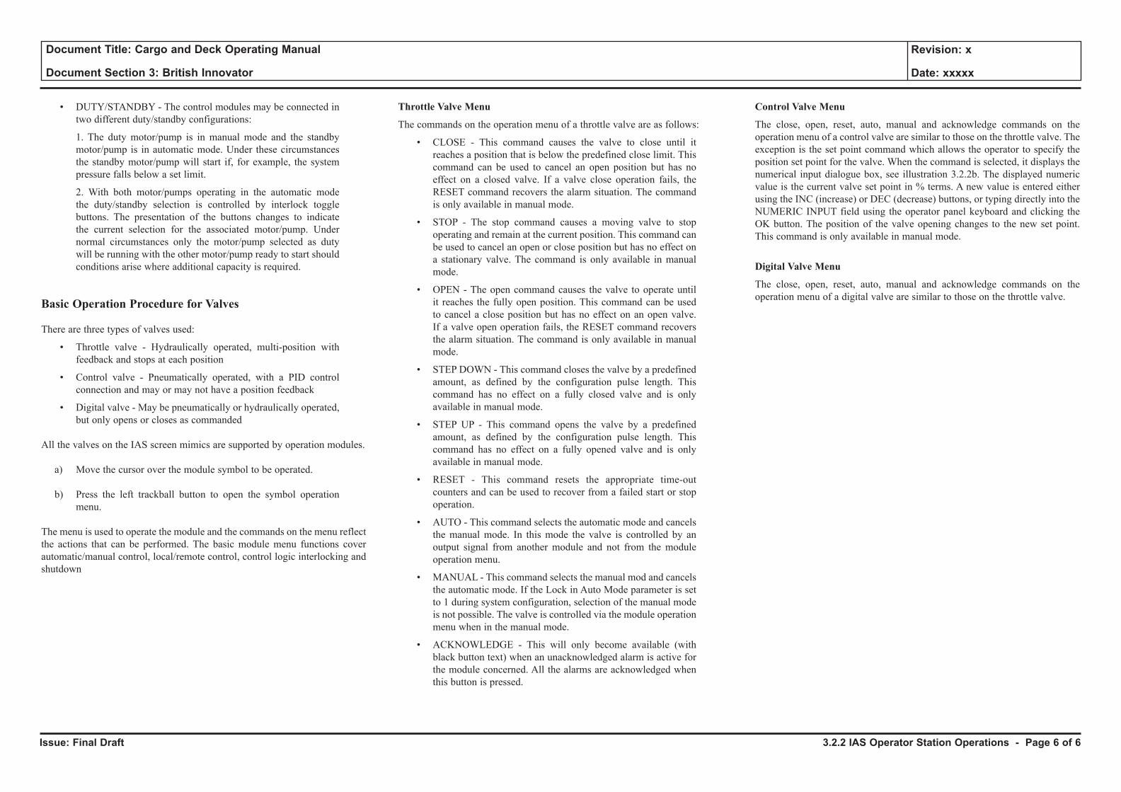
Issue: Final Draft
Document Title: Cargo and Deck Operating Manual
Document Section 3: British Innovator
Revision: x
Date: xxxxx
• DUTY/STANDBY - The control modules may be connected in two different duty/standby configurations:
1. The duty motor/pump is in manual mode and the standby motor/pump is in automatic mode. Under these circumstances the standby motor/pump will start if, for example, the system pressure falls below a set limit.
2. With both motor/pumps operating in the automatic mode the duty/standby selection is controlled by interlock toggle buttons. The presentation of the buttons changes to indicate the current selection for the associated motor/pump. Under normal circumstances only the motor/pump selected as duty will be running with the other motor/pump ready to start should conditions arise where additional capacity is required.
Basic Operation Procedure for Valves
There are three types of valves used:
• Throttle valve - Hydraulically operated, multi-position with feedback and stops at each position
• Control valve - Pneumatically operated, with a PID control connection and may or may not have a position feedback
• Digital valve - May be pneumatically or hydraulically operated, but only opens or closes as commanded
All the valves on the IAS screen mimics are supported by operation modules.
a) Move the cursor over the module symbol to be operated.
b) Press the left trackball button to open the symbol operation menu.
The menu is used to operate the module and the commands on the menu reflect the actions that can be performed. The basic module menu functions cover automatic/manual control, local/remote control, control logic interlocking and shutdown
Throttle Valve Menu
The commands on the operation menu of a throttle valve are as follows:
• CLOSE - This command causes the valve to close until it reaches a position that is below the predefined close limit. This command can be used to cancel an open position but has no effect on a closed valve. If a valve close operation fails, the RESET command recovers the alarm situation. The command is only available in manual mode.
• STOP - The stop command causes a moving valve to stop operating and remain at the current position. This command can be used to cancel an open or close position but has no effect on a stationary valve. The command is only available in manual mode.
• OPEN - The open command causes the valve to operate until it reaches the fully open position. This command can be used to cancel a close position but has no effect on an open valve. If a valve open operation fails, the RESET command recovers the alarm situation. The command is only available in manual mode.
• STEP DOWN - This command closes the valve by a predefined amount, as defined by the configuration pulse length. This command has no effect on a fully closed valve and is only available in manual mode.
• STEP UP - This command opens the valve by a predefined amount, as defined by the configuration pulse length. This command has no effect on a fully opened valve and is only available in manual mode.
• RESET - This command resets the appropriate time-out counters and can be used to recover from a failed start or stop operation.
• AUTO - This command selects the automatic mode and cancels the manual mode. In this mode the valve is controlled by an output signal from another module and not from the module operation menu.
• MANUAL - This command selects the manual mod and cancels the automatic mode. If the Lock in Auto Mode parameter is set to 1 during system configuration, selection of the manual mode is not possible. The valve is controlled via the module operation menu when in the manual mode.
• ACKNOWLEDGE - This will only become available (with black button text) when an unacknowledged alarm is active for the module concerned. All the alarms are acknowledged when this button is pressed.
Control Valve Menu
The close, open, reset, auto, manual and acknowledge commands on the operation menu of a control valve are similar to those on the throttle valve. The exception is the set point command which allows the operator to specify the position set point for the valve. When the command is selected, it displays the numerical input dialogue box, see illustration 3.2.2b. The displayed numeric value is the current valve set point in % terms. A new value is entered either using the INC (increase) or DEC (decrease) buttons, or typing directly into the NUMERIC INPUT field using the operator panel keyboard and clicking the OK button. The position of the valve opening changes to the new set point. This command is only available in manual mode.
Digital Valve Menu
The close, open, reset, auto, manual and acknowledge commands on the operation menu of a digital valve are similar to those on the throttle valve.
3.2.2 IAS Operator Station Operations - Page 6 of 6
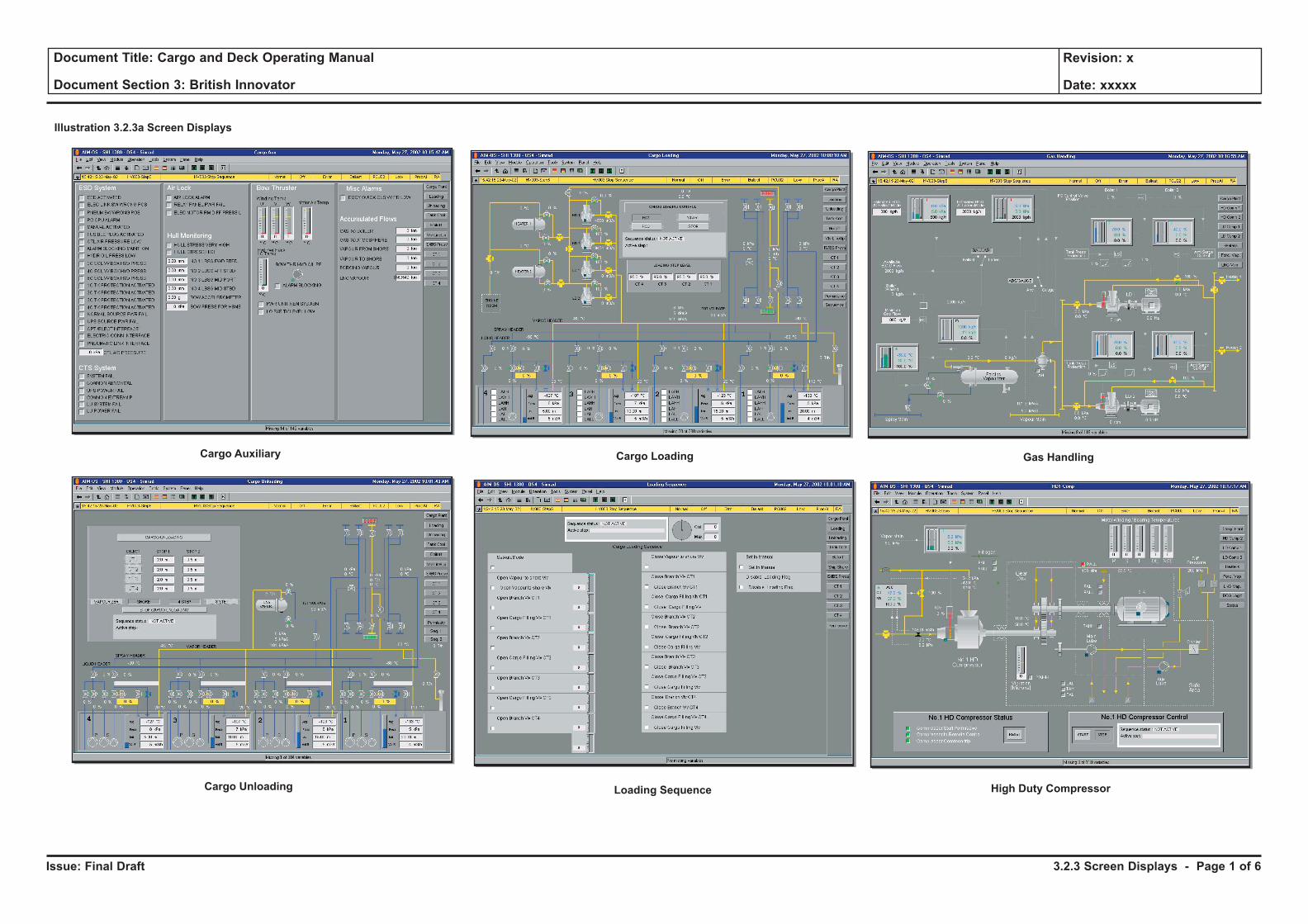
Issue: Final Draft
Document Title: Cargo and Deck Operating Manual
Document Section 3: British Innovator
Revision: x
Date: xxxxx
Illustration 3.2.3a Screen Displays
Cargo Auxiliary
Cargo Unloading
Cargo Loading
Loading Sequence High Duty Compressor
Gas Handling
3.2.3 Screen Displays - Page 1 of 6
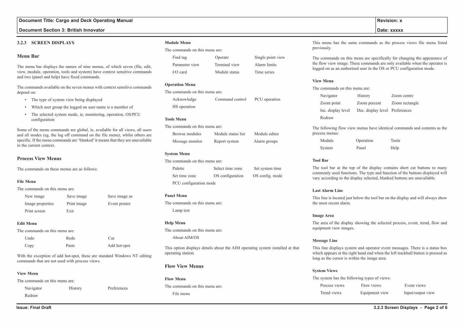
Issue: Final Draft
Document Title: Cargo and Deck Operating Manual
Document Section 3: British Innovator
Revision: x
Date: xxxxx
3.2.3 SCREEN DISPLAYS
Menu Bar
The menu bar displays the names of nine menus, of which seven (file, edit, view, module, operation, tools and system) have context sensitive commands and two (panel and help) have fixed commands.
The commands available on the seven menus with context sensitive commands depend on:
• The type of system view being displayed
• Which user group the logged on user name is a member of
• The selected system mode, ie, monitoring, operation, OS/PCU configuration
Some of the menu commands are global, ie, available for all views, all users and all modes (eg, the log off command on the file menu), whilst others are specific. If the menu commands are ‘blanked’ it means that they are unavailable in the current context.
Process View Menus
The commands on these menus are as follows:
File Menu
The commands on this menu are:
New image Save image Save image as
Image properties Print image Event printer
Print screen Exit
Edit Menu
The commands on this menu are:
Undo Redo Cut
Copy Paste Add hot-spot
With the exception of add hot-spot, these are standard Windows NT editing commands that are not used with process views.
View Menu
The commands on this menu are:
Navigator History Preferences
Redraw
Module Menu
The commands on this menu are:
Find tag Operate Single point view
Parameter view Terminal view Alarm limits
I/O card Module status Time series
Operation Menu
The commands on this menu are:
Acknowledge Command control PCU operation
HS operation
Tools Menu
The commands on this menu are:
Browse modules Module status list Module editor
Message monitor Report system Alarm groups
System Menu
The commands on this menu are:
Palette Select time zone Set system time
Set time zone OS configuration OS config. mode
PCU configuration mode
Panel Menu
The commands on this menu are:
Lamp test
Help Menu
The commands on this menu are:
About AIM/OS
This option displays details about the AIM operating system installed at that operating station.
Flow View Menus
Flow Menu
The commands on this menu are:
File menu
This menu has the same commands as the process views file menu listed previously.
The commands on this menu are specifically for changing the appearance of the flow view image. These commands are only available when the operator is logged on as an authorised user in the OS or PCU configuration mode.
View Menu
The commands on this menu are:
Navigator History Zoom centre
Zoom point Zoom percent Zoom rectangle
Inc. display level Dec. display level Preferences
Redraw
The following flow view menus have identical commands and contents as the process menus:
Module Operation Tools
System Panel Help
Tool Bar
The tool bar at the top of the display contains short cut buttons to many commonly used functions. The type and function of the buttons displayed will vary according to the display selected, blanked buttons are unavailable.
Last Alarm Line
This line is located just below the tool bar on the display and will always show the most recent alarm.
Image Area
The area of the display showing the selected process, event, trend, flow and equipment view images.
Message Line
This line displays system and operator event messages. There is a status box which appears at the right hand end when the left trackball button is pressed as long as the cursor is within the image area.
System Views
The system has the following types of views:
Process views Flow views Event views
Trend views Equipment view Input/output view
3.2.3 Screen Displays - Page 2 of 6
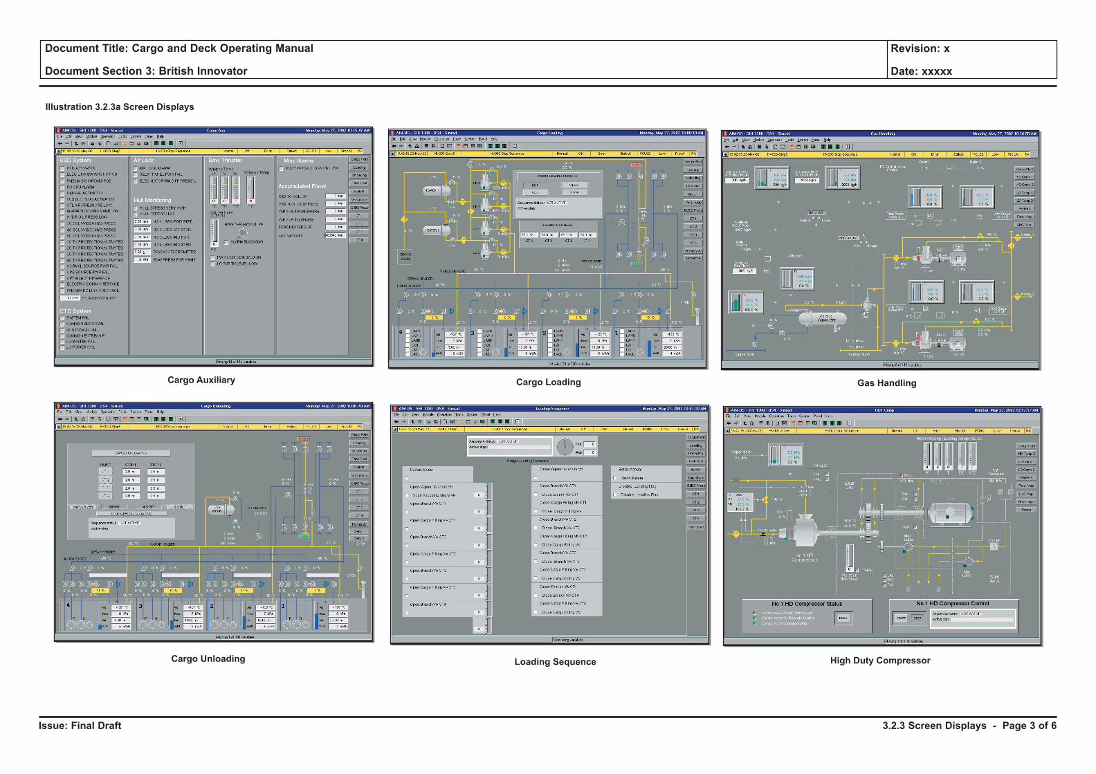
Issue: Final Draft
Document Title: Cargo and Deck Operating Manual
Document Section 3: British Innovator
Revision: x
Date: xxxxx
Illustration 3.2.3a Screen Displays
Cargo Auxiliary
Cargo Unloading
Cargo Loading
Loading Sequence High Duty Compressor
Gas Handling
3.2.3 Screen Displays - Page 3 of 6
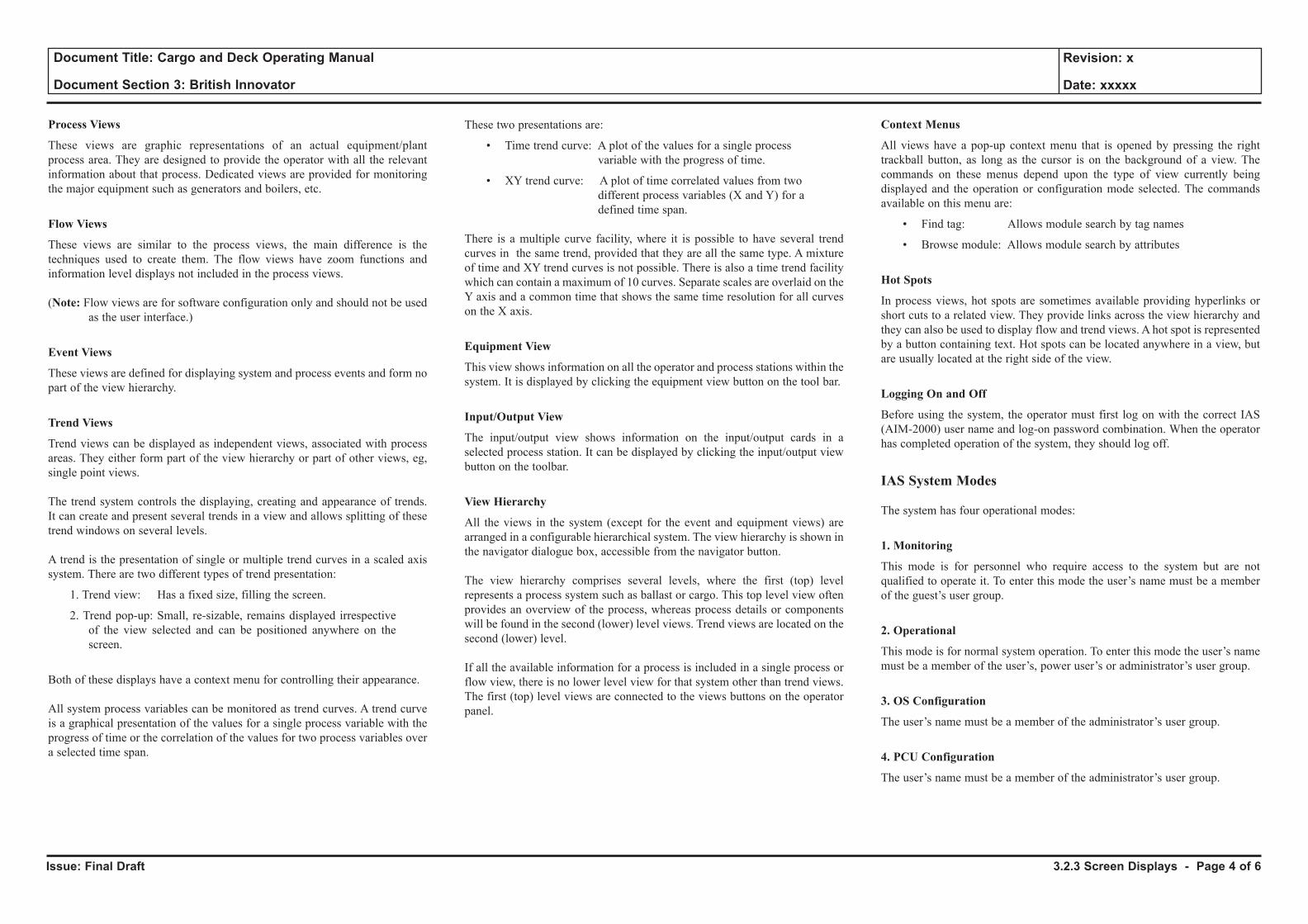
Issue: Final Draft
Document Title: Cargo and Deck Operating Manual
Document Section 3: British Innovator
Revision: x
Date: xxxxx
Process Views
These views are graphic representations of an actual equipment/plant process area. They are designed to provide the operator with all the relevant information about that process. Dedicated views are provided for monitoring the major equipment such as generators and boilers, etc.
Flow Views
These views are similar to the process views, the main difference is the techniques used to create them. The flow views have zoom functions and information level displays not included in the process views.
(Note: Flow views are for software configuration only and should not be used as the user interface.)
Event Views
These views are defined for displaying system and process events and form no part of the view hierarchy.
Trend Views
Trend views can be displayed as independent views, associated with process areas. They either form part of the view hierarchy or part of other views, eg, single point views.
The trend system controls the displaying, creating and appearance of trends. It can create and present several trends in a view and allows splitting of these trend windows on several levels.
A trend is the presentation of single or multiple trend curves in a scaled axis system. There are two different types of trend presentation:
1. Trend view: Has a fixed size, filling the screen.
2. Trend pop-up: Small, re-sizable, remains displayed irrespective of the view selected and can be positioned anywhere on the screen.
Both of these displays have a context menu for controlling their appearance.
All system process variables can be monitored as trend curves. A trend curve is a graphical presentation of the values for a single process variable with the progress of time or the correlation of the values for two process variables over a selected time span.
These two presentations are:
• Time trend curve: A plot of the values for a single process variable with the progress of time.
• XY trend curve: A plot of time correlated values from two different process variables (X and Y) for a defined time span.
There is a multiple curve facility, where it is possible to have several trend curves in the same trend, provided that they are all the same type. A mixture of time and XY trend curves is not possible. There is also a time trend facility which can contain a maximum of 10 curves. Separate scales are overlaid on the Y axis and a common time that shows the same time resolution for all curves on the X axis.
Equipment View
This view shows information on all the operator and process stations within the system. It is displayed by clicking the equipment view button on the tool bar.
Input/Output View
The input/output view shows information on the input/output cards in a selected process station. It can be displayed by clicking the input/output view button on the toolbar.
View Hierarchy
All the views in the system (except for the event and equipment views) are arranged in a configurable hierarchical system. The view hierarchy is shown in the navigator dialogue box, accessible from the navigator button.
The view hierarchy comprises several levels, where the first (top) level represents a process system such as ballast or cargo. This top level view often provides an overview of the process, whereas process details or components will be found in the second (lower) level views. Trend views are located on the second (lower) level.
If all the available information for a process is included in a single process or flow view, there is no lower level view for that system other than trend views. The first (top) level views are connected to the views buttons on the operator panel.
Context Menus
All views have a pop-up context menu that is opened by pressing the right trackball button, as long as the cursor is on the background of a view. The commands on these menus depend upon the type of view currently being displayed and the operation or configuration mode selected. The commands available on this menu are:
• Find tag: Allows module search by tag names
• Browse module: Allows module search by attributes
Hot Spots
In process views, hot spots are sometimes available providing hyperlinks or short cuts to a related view. They provide links across the view hierarchy and they can also be used to display flow and trend views. A hot spot is represented by a button containing text. Hot spots can be located anywhere in a view, but are usually located at the right side of the view.
Logging On and Off
Before using the system, the operator must first log on with the correct IAS (AIM-2000) user name and log-on password combination. When the operator has completed operation of the system, they should log off.
IAS System Modes
The system has four operational modes:
1. Monitoring
This mode is for personnel who require access to the system but are not qualified to operate it. To enter this mode the user’s name must be a member of the guest’s user group.
2. Operational
This mode is for normal system operation. To enter this mode the user’s name must be a member of the user’s, power user’s or administrator’s user group.
3. OS Configuration
The user’s name must be a member of the administrator’s user group.
4. PCU Configuration
The user’s name must be a member of the administrator’s user group.
3.2.3 Screen Displays - Page 4 of 6
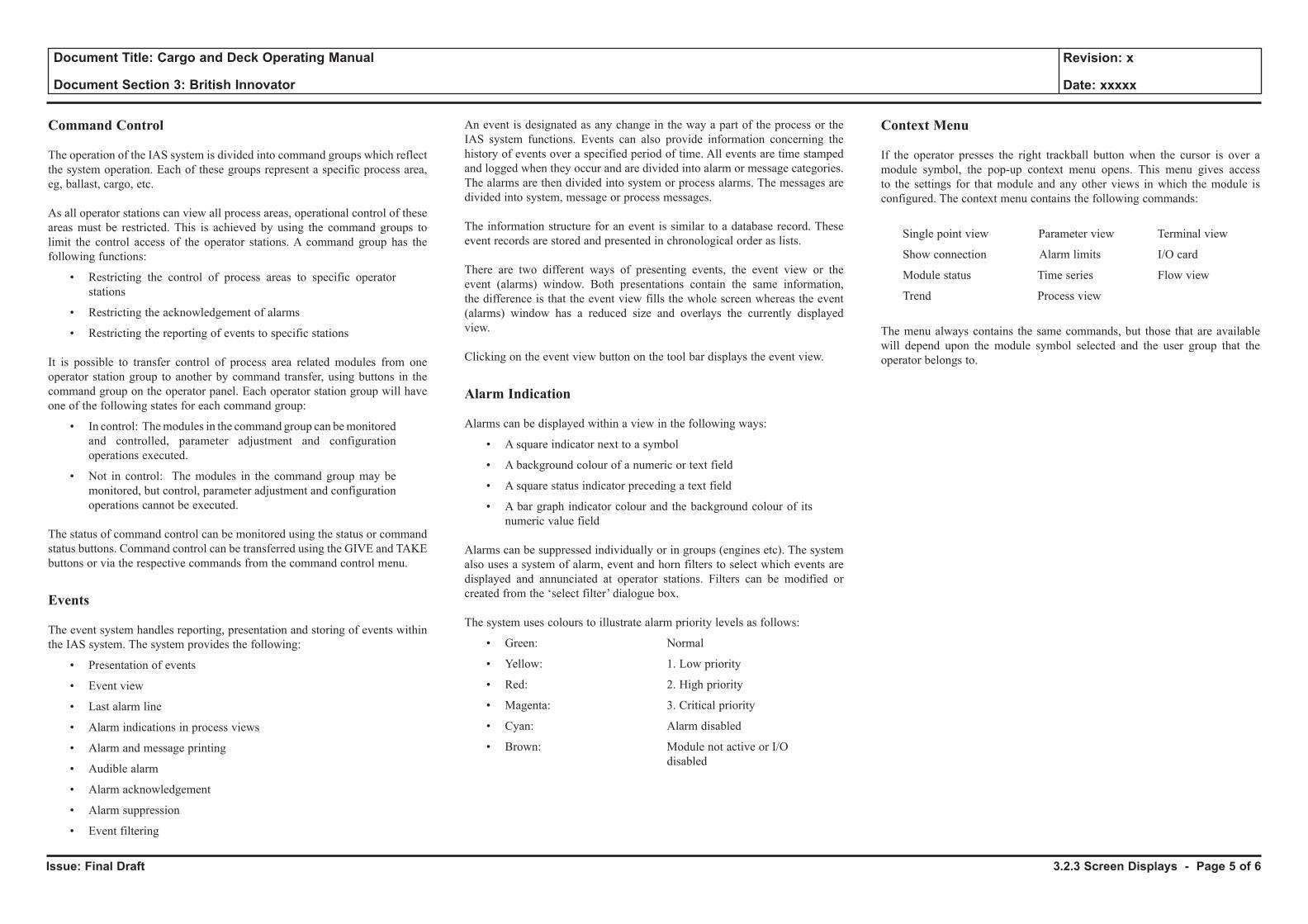
Issue: Final Draft
Document Title: Cargo and Deck Operating Manual
Document Section 3: British Innovator
Revision: x
Date: xxxxx
Command Control
The operation of the IAS system is divided into command groups which reflect the system operation. Each of these groups represent a specific process area, eg, ballast, cargo, etc.
As all operator stations can view all process areas, operational control of these areas must be restricted. This is achieved by using the command groups to limit the control access of the operator stations. A command group has the following functions:
• Restricting the control of process areas to specific operator stations
• Restricting the acknowledgement of alarms
• Restricting the reporting of events to specific stations
It is possible to transfer control of process area related modules from one operator station group to another by command transfer, using buttons in the command group on the operator panel. Each operator station group will have one of the following states for each command group:
• In control: The modules in the command group can be monitored and controlled, parameter adjustment and configuration operations executed.
• Not in control: The modules in the command group may be monitored, but control, parameter adjustment and configuration operations cannot be executed.
The status of command control can be monitored using the status or command status buttons. Command control can be transferred using the GIVE and TAKE buttons or via the respective commands from the command control menu.
Events
The event system handles reporting, presentation and storing of events within the IAS system. The system provides the following:
• Presentation of events
• Event view
• Last alarm line
• Alarm indications in process views
• Alarm and message printing
• Audible alarm
• Alarm acknowledgement
• Alarm suppression
• Event filtering
An event is designated as any change in the way a part of the process or the IAS system functions. Events can also provide information concerning the history of events over a specified period of time. All events are time stamped and logged when they occur and are divided into alarm or message categories. The alarms are then divided into system or process alarms. The messages are divided into system, message or process messages.
The information structure for an event is similar to a database record. These event records are stored and presented in chronological order as lists.
There are two different ways of presenting events, the event view or the event (alarms) window. Both presentations contain the same information, the difference is that the event view fills the whole screen whereas the event (alarms) window has a reduced size and overlays the currently displayed view.
Clicking on the event view button on the tool bar displays the event view.
Alarm Indication
Alarms can be displayed within a view in the following ways:
• A square indicator next to a symbol
• A background colour of a numeric or text field
• A square status indicator preceding a text field
• A bar graph indicator colour and the background colour of its numeric value field
Alarms can be suppressed individually or in groups (engines etc). The system also uses a system of alarm, event and horn filters to select which events are displayed and annunciated at operator stations. Filters can be modified or created from the ‘select filter’ dialogue box.
The system uses colours to illustrate alarm priority levels as follows:
• Green: Normal
• Yellow: 1. Low priority
• Red: 2. High priority
• Magenta: 3. Critical priority
• Cyan: Alarm disabled
• Brown: Module not active or I/O disabled
Context Menu
If the operator presses the right trackball button when the cursor is over a module symbol, the pop-up context menu opens. This menu gives access to the settings for that module and any other views in which the module is configured. The context menu contains the following commands:
Single point view Parameter view Terminal view
Show connection Alarm limits I/O card
Module status Time series Flow view
Trend Process view
The menu always contains the same commands, but those that are available will depend upon the module symbol selected and the user group that the operator belongs to.
3.2.3 Screen Displays - Page 5 of 6
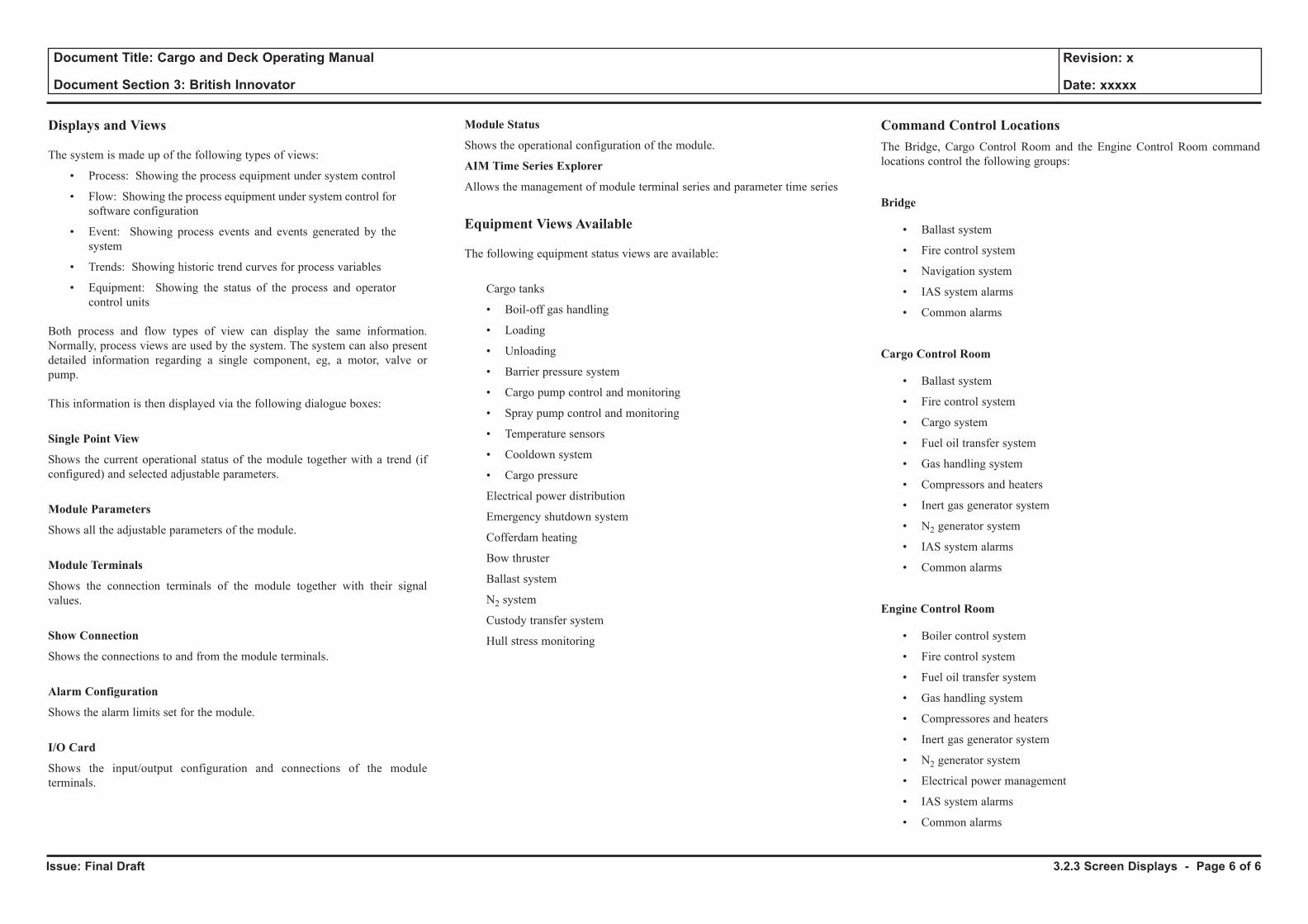
Issue: Final Draft
Document Title: Cargo and Deck Operating Manual
Document Section 3: British Innovator
Revision: x
Date: xxxxx
Displays and Views
The system is made up of the following types of views:
• Process: Showing the process equipment under system control
• Flow: Showing the process equipment under system control for software configuration
• Event: Showing process events and events generated by the system
• Trends: Showing historic trend curves for process variables
• Equipment: Showing the status of the process and operator control units
Both process and flow types of view can display the same information. Normally, process views are used by the system. The system can also present detailed information regarding a single component, eg, a motor, valve or pump.
This information is then displayed via the following dialogue boxes:
Single Point View
Shows the current operational status of the module together with a trend (if configured) and selected adjustable parameters.
Module Parameters
Shows all the adjustable parameters of the module.
Module Terminals
Shows the connection terminals of the module together with their signal values.
Show Connection
Shows the connections to and from the module terminals.
Alarm Configuration
Shows the alarm limits set for the module.
I/O Card
Shows the input/output configuration and connections of the module terminals.
Module Status
Shows the operational configuration of the module.
AIM Time Series Explorer
Allows the management of module terminal series and parameter time series
Equipment Views Available
The following equipment status views are available:
Cargo tanks
• Boil-off gas handling
• Loading
• Unloading
• Barrier pressure system
• Cargo pump control and monitoring
• Spray pump control and monitoring
• Temperature sensors
• Cooldown system
• Cargo pressure
Electrical power distribution
Emergency shutdown system
Cofferdam heating
Bow thruster
Ballast system
N2 system
Custody transfer system
Hull stress monitoring
Command Control LocationsThe Bridge, Cargo Control Room and the Engine Control Room command locations control the following groups:
Bridge
• Ballast system
• Fire control system
• Navigation system
• IAS system alarms
• Common alarms
Cargo Control Room
• Ballast system
• Fire control system
• Cargo system
• Fuel oil transfer system
• Gas handling system
• Compressors and heaters
• Inert gas generator system
• N2 generator system
• IAS system alarms
• Common alarms
Engine Control Room
• Boiler control system
• Fire control system
• Fuel oil transfer system
• Gas handling system
• Compressores and heaters
• Inert gas generator system
• N2 generator system
• Electrical power management
• IAS system alarms
• Common alarms
3.2.3 Screen Displays - Page 6 of 6
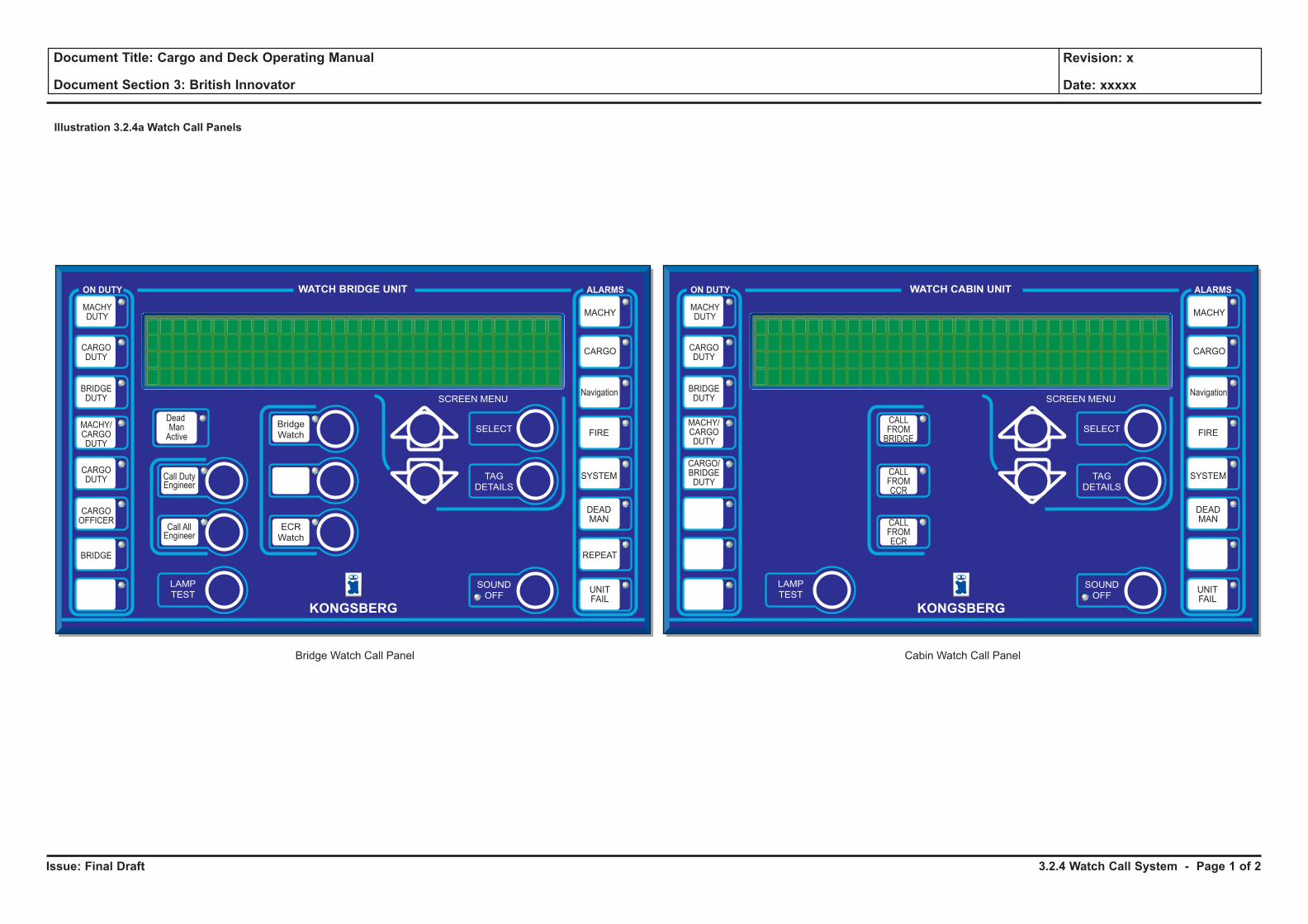
Issue: Final Draft
Document Title: Cargo and Deck Operating Manual
Document Section 3: British Innovator
Revision: x
Date: xxxxx
Illustration 3.2.4a Watch Call Panels
WATCH BRIDGE UNIT
SCREEN MENU
ON DUTY ALARMS
MACHYDUTY
CARGODUTY
BRIDGEDUTY
MACHY/CARGODUTY
CARGODUTY
CARGOOFFICER
REPEAT
CARGO
SYSTEM
DEADMAN
FIRE
MACHY
UNITFAIL
BRIDGE
SELECTBridgeWatch
LAMPTEST
ECRWatch
Call DutyEngineer
Navigation
Call AllEngineer
DeadManActive
TAGDETAILS
SOUNDOFF
KONGSBERG
Bridge Watch Call Panel
WATCH CABIN UNIT
SCREEN MENU
ON DUTY ALARMS
MACHYDUTY
CARGODUTY
BRIDGEDUTY
MACHY/CARGODUTY
CARGO/BRIDGEDUTY
UNITFAIL
SELECT
LAMPTEST
TAGDETAILS
SOUNDOFF
KONGSBERG
Cabin Watch Call Panel
CALLFROMBRIDGE
CALLFROMCCR
CALLFROMECR
CARGO
SYSTEM
DEADMAN
FIRE
MACHY
Navigation
3.2.4 Watch Call System - Page 1 of 2
Issue: Final Draft
Document Title: Cargo and Deck Operating Manual
Document Section 3: British Innovator
Revision: x
Date: xxxxx
3.2.4 WATCH CALL SYSTEM
Introduction
The watch call system is an IAS application that monitors the cargo and engine room during Unmanned Machinery Space (UMS) operations. The system comprises eighteen self-contained, wall mounted watch call panels that are installed at selected locations in the bridge, engineer cabins and day rooms. The panels are controlled from operator stations and are used to warn the bridge and on-duty officers of alarm conditions. The system has two main functions:
1. Alarm extension. This is a group alarm status and on-duty officer indication facility with a built-in on-duty acceptance, fault indication and test facilities.
2. Officer call. This is an individual and general calling facility for officers that can be activated from selected vessel control locations.
The reset interval period is 30 minutes, with a prewarning alarm activated 5 minutes before the deadman alarm is set.
Watch Call Panels
There are two types of watch call panels:
• Watch bridge unit (WBU) - for use on the bridge
• Watch cabin unit (WCU) - for use in cabins and public places
Operation control and configuration of the watch call system can be performed using the WATCH CALL command on the OPERATION menu on the operator station.
Clicking on this command displays the WATCH CALL dialogue box which has three pages, OPERATION, CONFIGURATION and CAN NETWORK.
The operation page mimic contains the following:
• ON DUTY indicators with buttons that show and select on-duty officers. When the green LED in the top right-hand corner is lit it indicates that the officer on the label is on duty.
• ALARM indicators that show in which process area there are active alarms.
• A REPEATER ALARM indicator that shows if there is a repeat of a previous alarm.
• An indicator that shows if the dead dan system is active. It has a green LED in the top right corner that lights when the system is active.
• Call buttons for calling on-duty or off-duty officers (cargo or engine). They have a green LED located next to the top right corner of the button label that flashes to indicate that a call has been made. When the call is accepted the flashing LED changes to a steady light.
• Watch buttons that transfer watch responsibility between the bridge and the engine control room. They have a yellow LED located next to the top right corner of the button label that flashes to indicate a responsibility transfer request has been made. When the transfer request is accepted, by pressing the BRIDGE WATCH or ECR WATCH button, the transfer is made and the flashing LED changes to a steady light.
• An LCD screen with a 40 character by 4 line display, which is used to show the date and time or an alarm summary.
• A LAMP TEST button which is used to check the serviceability of the indicator, button LEDs and the buzzer. It is also used, in conjuction with the up and down and SELECT buttons, to adjust the light intensity of the LCD screen, indicator and button LEDs and the background lighting.
• When an alarm summary is displayed, the up and down buttons are used to scroll the list shown on lines two to four on the LCD screen.
• The SELECT button is used to choose the type of information shown on the LCD screen. Pressing the button for the first time displays the Alarm Summary. Repeated pressing of the button cyclically displays the Alarm Summary and the date and time.
• When the Alarm Summary is displayed on the LCD screen, the TAG DETAILS button is pressed to show (on lines three and four) the details of the alarm shown on line two.
• The SOUND OFF button is pressed to stop the buzzer from sounding and acknowledging group alarms and officer calls.
3.2.4 Watch Call System - Page 2 of 2
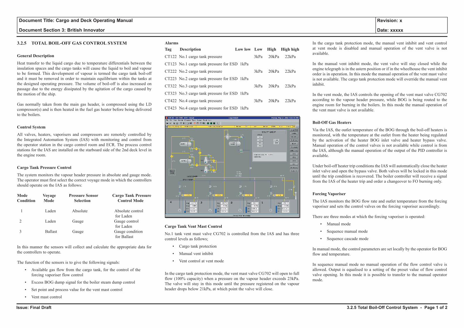
Issue: Final Draft
Document Title: Cargo and Deck Operating Manual
Document Section 3: British Innovator
Revision: x
Date: xxxxx
3.2.5 TOTAL BOIL-OFF GAS CONTROL SYSTEM
General Description
Heat transfer to the liquid cargo due to temperature differentials between the insulation spaces and the cargo tanks will cause the liquid to boil and vapour to be formed. This development of vapour is termed the cargo tank boil-off and it must be removed in order to maintain equilibrium within the tanks at the designed operating pressure. The volume of boil-off is also increased on passage due to the energy dissipated by the agitation of the cargo caused by the motion of the ship.
Gas normally taken from the main gas header, is compressed using the LD compressor(s) and is then heated in the fuel gas heater before being delivered to the boilers.
Control System
All valves, heaters, vaporisers and compressors are remotely controlled by the Integrated Automation System (IAS) with monitoring and control from the operator station in the cargo control room and ECR. The process control stations for the IAS are installed on the starboard side of the 2nd deck level in the engine room.
Cargo Tank Pressure Control
The system monitors the vapour header pressure in absolute and gauge mode. The operator must first select the correct voyage mode in which the controllers should operate on the IAS as follows:
Mode Voyage Pressure Sensor Cargo Tank PressureCondition Mode Selection Control Mode
1 Laden Absolute Absolute control for Laden 2 Laden Gauge Gauge control for Laden 3 Ballast Gauge Gauge condition for Ballast
In this manner the sensors will collect and calculate the appropriate data for the controllers to operate.
The function of the sensors is to give the following signals:
• Available gas flow from the cargo tank, for the control of the forcing vaporiser flow control
• Excess BOG dump signal for the boiler steam dump control
• Set point and process value for the vent mast control
• Vent mast control
AlarmsTag Description Low low Low High High high
CT122 No.1 cargo tank pressure 3kPa 20kPa 22kPa
CT123 No.1 cargo tank pressure for ESD 1kPa
CT222 No.2 cargo tank pressure 3kPa 20kPa 22kPa
CT223 No.2 cargo tank pressure for ESD 1kPa
CT322 No.3 cargo tank pressure 3kPa 20kPa 22kPa
CT323 No.3 cargo tank pressure for ESD 1kPa
CT422 No.4 cargo tank pressure 3kPa 20kPa 22kPa
CT423 No.4 cargo tank pressure for ESD 1kPa
Cargo Tank Vent Mast Control
No.1 tank vent mast valve CG702 is controlled from the IAS and has three control levels as follows;
• Cargo tank protection
• Manual vent inhibit
• Vent control at vent mode
In the cargo tank protection mode, the vent mast valve CG702 will open to full flow (100% capacity) when a pressure on the vapour header exceeds 23kPa. The valve will stay in this mode until the pressure registered on the vapour header drops below 21kPa, at which point the valve will close.
In the cargo tank protection mode, the manual vent inhibit and vent control at vent mode is disabled and manual operation of the vent valve is not available.
In the manual vent inhibit mode, the vent valve will stay closed while the engine telegraph is in the astern position or if in the wheelhouse the vent inhibit order is in operation. In this mode the manual operation of the vent mast valve is not available. The cargo tank protection mode will override the manual vent inhibit.
In the vent mode, the IAS controls the opening of the vent mast valve CG702 according to the vapour header pressure, while BOG is being routed to the engine room for burning in the boilers. In this mode the manual operation of the vent mast valve is not available.
Boil-Off Gas Heaters
Via the IAS, the outlet temperature of the BOG through the boil-off heaters is monitored, with the temperature at the outlet from the heater being regulated by the activation of the heater BOG inlet valve and heater bypass valve. Manual operation of the control valves is not available while control is from the IAS, although the manual operation of the output of the PID controller is available.
Under boil-off heater trip conditions the IAS will automatically close the heater inlet valve and open the bypass valve. Both valves will be locked in this mode until the trip condition is recovered. The boiler controller will receive a signal from the IAS of the heater trip and order a changeover to FO burning only.
Forcing Vaporiser
The IAS monitors the BOG flow rate and outlet temperature from the forcing vaporiser and sets the control valves on the forcing vaporiser accordingly.
There are three modes at which the forcing vaporiser is operated:
• Manual mode
• Sequence manual mode
• Sequence cascade mode
In manual mode, the control parameters are set locally by the operator for BOG flow and temperature.
In sequence manual mode no manual operation of the flow control valve is allowed. Output is equalised to a setting of the preset value of flow control valve opening. In this mode it is possible to transfer to the manual operator mode.
3.2.5 Total Boil-Off Control System - Page 1 of 2
Issue: Final Draft
Document Title: Cargo and Deck Operating Manual
Document Section 3: British Innovator
Revision: x
Date: xxxxx
The sequence cascade mode does not allow any intervention by the operator apart from being able to select a mode transfer. In this mode, the demand from the boiler and the cargo tank pressure are matched automatically.
Low Duty Compressor Control
The LD compressors receive a control signal corresponding to the fuel gas control valve position and the vapour header pressure, which acts upon the inlet vain guides position and regulates the output from the LD compressor accordingly in order to give the optimum output as demanded.
3.2.5 Total Boil-Off Control System - Page 2 of 2
Issue: Final Draft
Document Title: Cargo and Deck Operating Manual
Document Section 3: British Innovator
Revision: x
Date: xxxxx
3.2.6 SHIPBOARD MANAGEMENT SYSTEM
Introduction
The shipboard management system (SMS) is a computerised management system designed to assist ship's personnel in managing the vessel in a safe and efficient manner. The system has the following main modules, each with a password protection:
1. Spare parts inventory management system.
2. Planned maintenance system.
3. Word processing and data filling system.
4. Compilation system of voyage abstract.
5. Vibration monitoring analysis system.
6. Guidance of cargo handling and trend data system.
7. Ship operation report system (SORS).
8. Ship performance management system.
9. Utilities and back-up of the SMS.
10. Data transmission system of the SMS.
11. Lubricating oil analysis record system.
12. Compilation of dry dock repair specifications.
13. Ship personnel management system.
.
3.2.6 Shipboard Management System - Page 1 of 1
3.3 Custody Transfer System
3.3.1 Radar Gauges and CTS
3.3.2 Float Level Gauge
3.3.3 Independent High Level Alarm System
3.3.4 Trim Indicator
3.3.5 Loading Computer
Illustrations
3.3.1a Saab Tank Level Monitor Display
3.3.1b Example of Custody Transfer Data
3.3.1c Example of Certificate of Loading
3.3.2b Whessoe Float Level Gauge
3.3.3a High Level and Overfill Alarm System
3.3.4a Trim-List Indicator
3.3.5a Loading Computer Screen
Issue: Final Draft
Document Title: Cargo and Deck Operating Manual
Document Section 3: British Innovator
Revision: x
Date: xxxxx
3.3. CUSTODY TRANSFER SYSTEM (CTS)
3.3.1 RADAR GAUGES AND CTS
LNG is bought and sold on its calorific content, normally expressed in BTUs, rather than on a volume or weight basis. However, at the present time there are no practical instruments available to determine the net calorific content transferred during loading and discharge. The value is determined partly by measurement and partly by analysis of cargo calculation by means of the following formula:
Total energy transferred (Q) = Vd HL - VTsPvHv ------------ TvPs
Where :
V = Cargo volume loaded or discharged at an average temperature TL (m3)
d = Density of cargo at temperature TL (kg/m3)
HL = Gross heating value of the cargo (kCal/kg)
Ts = Standard temperature (°K)
Tv = Average temperature of gas in the cargo tanks (°K) TL = Average temperature of liquid in cargo tanks (°K)
Pv = The absolute pressure of the gas in the cargo tanks, ie, gauge pressure of gas + barometric pressure (kPa)
Hv = The gross heating value of gas vapour at 15.6°C and 101.3kPa. This value is assumed to be a constant 90718.5kCal/kg based on pure methane.
In establishing the value of the cargo transferred to and from the ship, the vessel’s responsibility is limited to the measurements and calculations of the following values: V, Tv and Pv. These measurements and calculations are made by ship and shore representatives and are normally verified by an independent surveyor. The values HL and d are determined ashore at the loading and discharge ports and the calculations are completed by the buyers and sellers.
The quantity of cargo delivery is expressed in cubic metres (m3).
SAAB TANK LEVEL MEASUREMENT SYSTEM
Maker: Saab Marine ElectronicsType: Saab Tank Radar
General Description of the Saab Tank Radar System
The radar transmitters on the top of the tank emit microwaves, directed by an antenna, towards the surface of the tank contents. The antenna picks up the echo from the surface. The difference in frequency between the transmitted and reflected signal is directly proportional to the measured distance i.e. ullage.
The Saab Tank Radar system, which is the main part of the cargo tank control system, is made up of the following units:
• Level unit
• Transmitters
• Workstation
Level Unit
The level unit contains terminals for the intrinsically safe connection of the transmitters. It contains the electronics used for processing the signals from the transmitters for calculating the tank parameters, such as a trim/list corrected ullage, average cargo temperature and for communicating with the workstation.
The system automatically measures the ullage more frequently on cargo tanks that are either being loaded or discharged.
Gauges
The gauges measure the distance to the product surface, using a frequency modulated continuous wave (FMCW) radar signal, and have an electronic box that generates and processes the radar signal.The gauges used for LNG incorporates a cone antenna as an adaptor for a full length steel pipe in the tank.
Additional equipment for each tank, such as temperature sensors and a vapour pressure sensor are connected to a wire terminal inside the gauge housing. The vapour pressure ssensor is situated inside the gauge housing.
Workstation
The workstation is used by the operator for monitoring the tank liquid levels (ullage), liquid and vapour average temperatures, cargo volumes at average temperatures and all the other data that is handled by the Saab Tank Radar. The workstation takes care of the alarm handling of the measured values. It also communicates with other systems, such as load calculators and electric-pneumatic level gauging systems (such as ballast) and supervises the transmitter and level unit computers.
The workstation is operated with a light pen, which the operator points directly on the screen to activate various functions.
The display works under the Windows environment. Different windows can be opened up and displayed simultaneously. The windows can be moved on the screen by pointing at the top, on the title bar, of the window and dragging them to a new position. All the windows have a BACK button, which places the window behind the other windows and an EXIT button, which closes the window.
The overview window is the main window to work from, as it shows the layout of the tanks of the vessel. If the overview window is not displayed touch the EXIT ALL button or the OVERVIEW button. Touch a tank area on the mimic figure to open the tank data window, which displays the basic information on one tank. When loading or discharging, the tank data windows of all the active tanks can be opened and placed beside each other.
To display the channel menu touch a value (for example an ullage value). Select one of the items on the menu or touch outside the menu to close it. The tank set up window shows more information on one tank than the tank data window.
OperationLight Pen
a) Move the pen to the area on the screen to be activated or selected.
b) Hold the light pen close to the screen and move the cursor to the area to be activated, press the tip of the light pen against the surface of the screen. The pen registers a ‘hit’ and activates the function of the area where the cursor was positioned.
c) If the light pen (or mouse) should fail, it is possible to move the cursor with the arrow keys on the keyboard.
d) Press an arrow key once to move it just slightly, or keep it pressed to move the cursor quickly.
3.3.1 Radar Gauges and CTS - Page 1 of 8
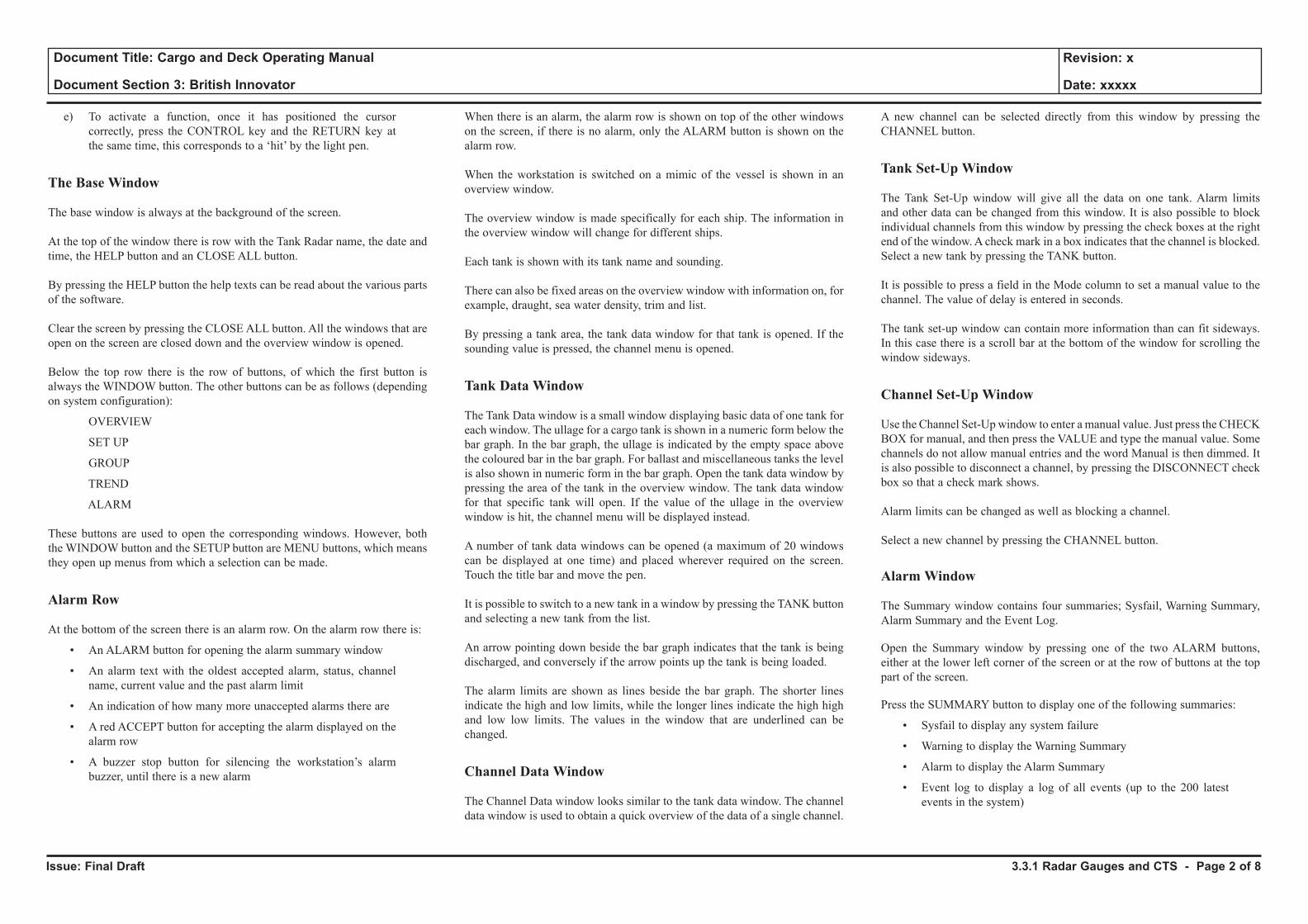
Issue: Final Draft
Document Title: Cargo and Deck Operating Manual
Document Section 3: British Innovator
Revision: x
Date: xxxxx
e) To activate a function, once it has positioned the cursor correctly, press the CONTROL key and the RETURN key at the same time, this corresponds to a ‘hit’ by the light pen.
The Base Window
The base window is always at the background of the screen.
At the top of the window there is row with the Tank Radar name, the date and time, the HELP button and an CLOSE ALL button.
By pressing the HELP button the help texts can be read about the various parts of the software.
Clear the screen by pressing the CLOSE ALL button. All the windows that are open on the screen are closed down and the overview window is opened.
Below the top row there is the row of buttons, of which the first button is always the WINDOW button. The other buttons can be as follows (depending on system configuration):
OVERVIEW
SET UP
GROUP
TREND
ALARM
These buttons are used to open the corresponding windows. However, both the WINDOW button and the SETUP button are MENU buttons, which means they open up menus from which a selection can be made.
Alarm Row
At the bottom of the screen there is an alarm row. On the alarm row there is:
• An ALARM button for opening the alarm summary window
• An alarm text with the oldest accepted alarm, status, channel name, current value and the past alarm limit
• An indication of how many more unaccepted alarms there are
• A red ACCEPT button for accepting the alarm displayed on the alarm row
• A buzzer stop button for silencing the workstation’s alarm buzzer, until there is a new alarm
When there is an alarm, the alarm row is shown on top of the other windows on the screen, if there is no alarm, only the ALARM button is shown on the alarm row.
When the workstation is switched on a mimic of the vessel is shown in an overview window.
The overview window is made specifically for each ship. The information in the overview window will change for different ships.
Each tank is shown with its tank name and sounding.
There can also be fixed areas on the overview window with information on, for example, draught, sea water density, trim and list.
By pressing a tank area, the tank data window for that tank is opened. If the sounding value is pressed, the channel menu is opened.
Tank Data Window
The Tank Data window is a small window displaying basic data of one tank for each window. The ullage for a cargo tank is shown in a numeric form below the bar graph. In the bar graph, the ullage is indicated by the empty space above the coloured bar in the bar graph. For ballast and miscellaneous tanks the level is also shown in numeric form in the bar graph. Open the tank data window by pressing the area of the tank in the overview window. The tank data window for that specific tank will open. If the value of the ullage in the overview window is hit, the channel menu will be displayed instead.
A number of tank data windows can be opened (a maximum of 20 windows can be displayed at one time) and placed wherever required on the screen. Touch the title bar and move the pen.
It is possible to switch to a new tank in a window by pressing the TANK button and selecting a new tank from the list.
An arrow pointing down beside the bar graph indicates that the tank is being discharged, and conversely if the arrow points up the tank is being loaded.
The alarm limits are shown as lines beside the bar graph. The shorter lines indicate the high and low limits, while the longer lines indicate the high high and low low limits. The values in the window that are underlined can be changed.
Channel Data Window
The Channel Data window looks similar to the tank data window. The channel data window is used to obtain a quick overview of the data of a single channel.
A new channel can be selected directly from this window by pressing the CHANNEL button.
Tank Set-Up Window
The Tank Set-Up window will give all the data on one tank. Alarm limits and other data can be changed from this window. It is also possible to block individual channels from this window by pressing the check boxes at the right end of the window. A check mark in a box indicates that the channel is blocked. Select a new tank by pressing the TANK button.
It is possible to press a field in the Mode column to set a manual value to the channel. The value of delay is entered in seconds.
The tank set-up window can contain more information than can fit sideways. In this case there is a scroll bar at the bottom of the window for scrolling the window sideways.
Channel Set-Up Window
Use the Channel Set-Up window to enter a manual value. Just press the CHECK BOX for manual, and then press the VALUE and type the manual value. Some channels do not allow manual entries and the word Manual is then dimmed. It is also possible to disconnect a channel, by pressing the DISCONNECT check box so that a check mark shows.
Alarm limits can be changed as well as blocking a channel.
Select a new channel by pressing the CHANNEL button.
Alarm Window
The Summary window contains four summaries; Sysfail, Warning Summary, Alarm Summary and the Event Log.
Open the Summary window by pressing one of the two ALARM buttons, either at the lower left corner of the screen or at the row of buttons at the top part of the screen.
Press the SUMMARY button to display one of the following summaries:
• Sysfail to display any system failure
• Warning to display the Warning Summary
• Alarm to display the Alarm Summary
• Event log to display a log of all events (up to the 200 latest events in the system)
3.3.1 Radar Gauges and CTS - Page 2 of 8
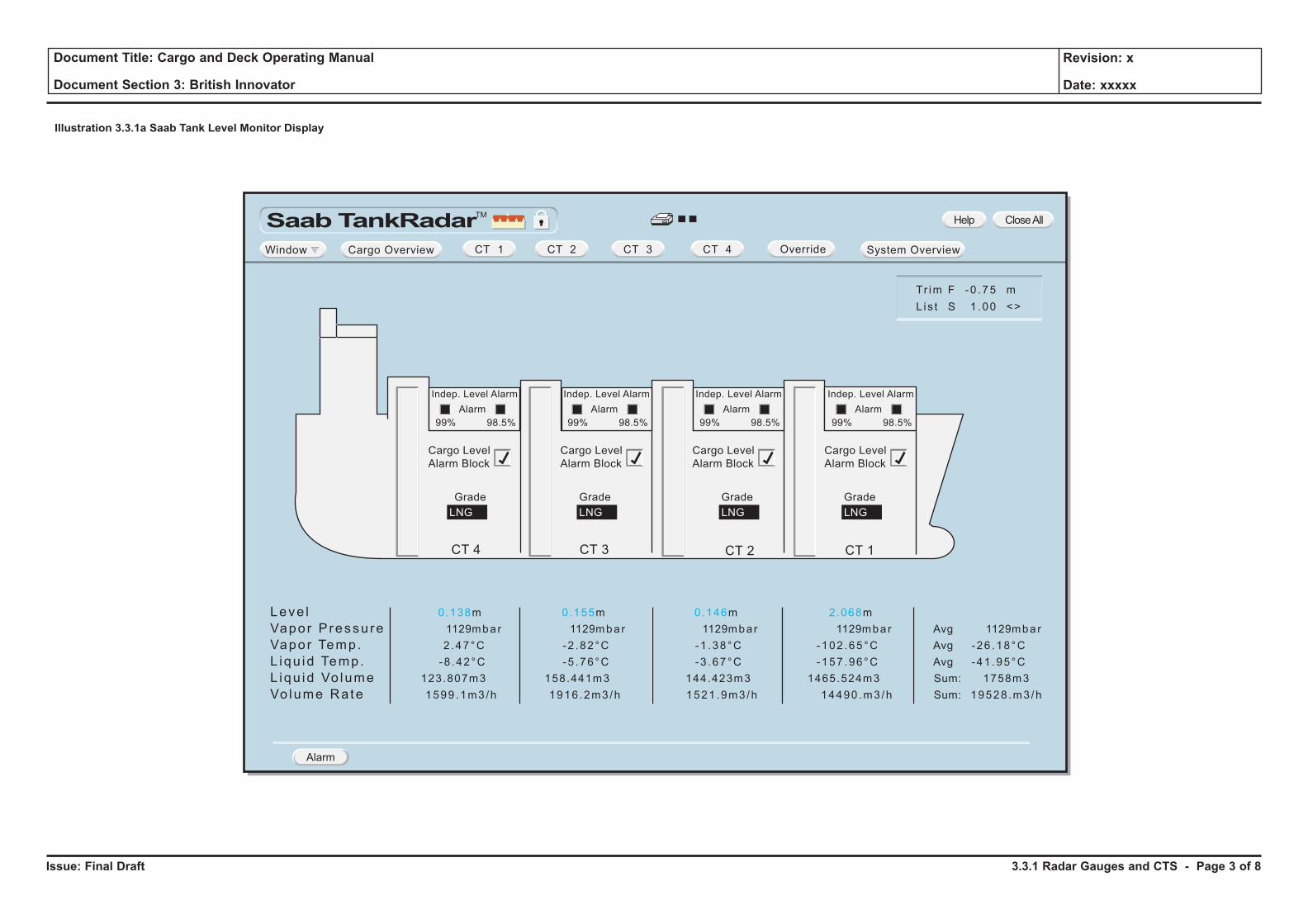
Issue: Final Draft
Document Title: Cargo and Deck Operating Manual
Document Section 3: British Innovator
Revision: x
Date: xxxxx
Illustration 3.3.1a Saab Tank Level Monitor Display
Saab TankRadarTM
Window Cargo Overview System OverviewOverride
Leve l
Vapor Pressu re
Vapor Temp.
L iqu id Temp.
L iqu id Vo lume
Vo lume Rate
0.138m
1129mbar
2 .47°C
-8 .42°C
123.807m3
1599 .1m3/h
0.155m
1129mbar
-2 .82°C
-5 .76°C
158.441m3
1916 .2m3/h
0.146m
1129mbar
-1 .38°C
-3 .67°C
144.423m3
1521 .9m3/h
2.068m
1129mbar
-102 .65°C
-157 .96°C
1465.524m3
14490 .m3 /h
Avg 1129mbar
Avg -26 .18°C
Avg -41 .95°C
Sum: 1758m3
Sum: 19528 .m3 /h
Tr im F -0 .75 m
L is t S 1 .00 <>
Alarm
CT 1 CT 2 CT 3 CT 4
Help CloseAll
Grade
Cargo Level
Alarm Block
LNG
Grade
LNG
CT 4 CT 3 CT 2
Grade
LNG
CT 1
Grade
LNG
Indep. Level Alarm
Alarm
99% 98.5%
Cargo Level
Alarm Block
Indep. Level Alarm
Alarm
99% 98.5%
Cargo Level
Alarm Block
Indep. Level Alarm
Alarm
99% 98.5%
Cargo Level
Alarm Block
Indep. Level Alarm
Alarm
99% 98.5%
3.3.1 Radar Gauges and CTS - Page 3 of 8
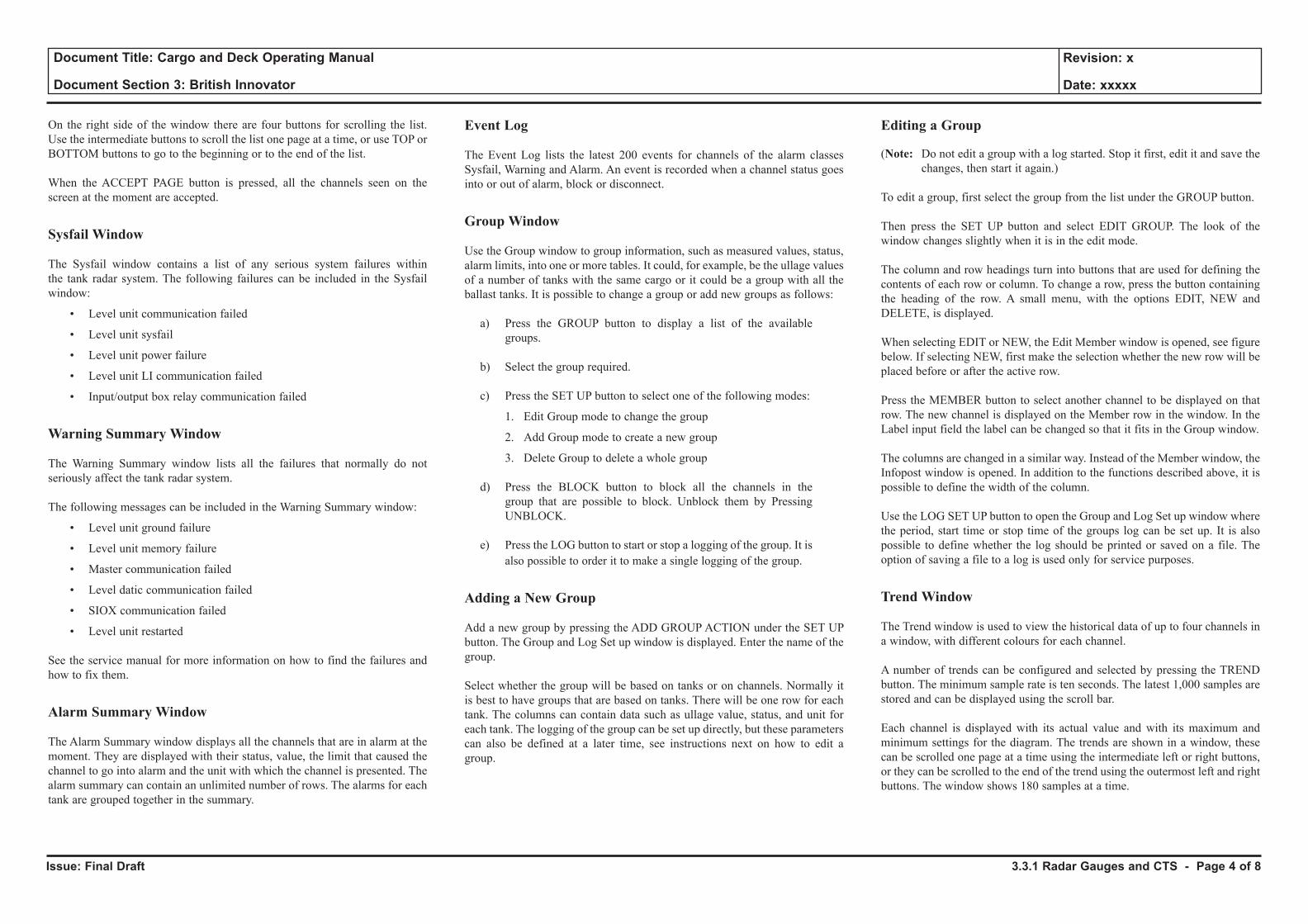
Issue: Final Draft
Document Title: Cargo and Deck Operating Manual
Document Section 3: British Innovator
Revision: x
Date: xxxxx
On the right side of the window there are four buttons for scrolling the list. Use the intermediate buttons to scroll the list one page at a time, or use TOP or BOTTOM buttons to go to the beginning or to the end of the list.
When the ACCEPT PAGE button is pressed, all the channels seen on the screen at the moment are accepted.
Sysfail Window
The Sysfail window contains a list of any serious system failures within the tank radar system. The following failures can be included in the Sysfail window:
• Level unit communication failed
• Level unit sysfail
• Level unit power failure
• Level unit LI communication failed
• Input/output box relay communication failed
Warning Summary Window
The Warning Summary window lists all the failures that normally do not seriously affect the tank radar system.
The following messages can be included in the Warning Summary window:
• Level unit ground failure
• Level unit memory failure
• Master communication failed
• Level datic communication failed
• SIOX communication failed
• Level unit restarted
See the service manual for more information on how to find the failures and how to fix them.
Alarm Summary Window
The Alarm Summary window displays all the channels that are in alarm at the moment. They are displayed with their status, value, the limit that caused the channel to go into alarm and the unit with which the channel is presented. The alarm summary can contain an unlimited number of rows. The alarms for each tank are grouped together in the summary.
Event Log
The Event Log lists the latest 200 events for channels of the alarm classes Sysfail, Warning and Alarm. An event is recorded when a channel status goes into or out of alarm, block or disconnect.
Group Window
Use the Group window to group information, such as measured values, status, alarm limits, into one or more tables. It could, for example, be the ullage values of a number of tanks with the same cargo or it could be a group with all the ballast tanks. It is possible to change a group or add new groups as follows:
a) Press the GROUP button to display a list of the available groups.
b) Select the group required.
c) Press the SET UP button to select one of the following modes:
1. Edit Group mode to change the group
2. Add Group mode to create a new group
3. Delete Group to delete a whole group
d) Press the BLOCK button to block all the channels in the group that are possible to block. Unblock them by Pressing UNBLOCK.
e) Press the LOG button to start or stop a logging of the group. It is also possible to order it to make a single logging of the group.
Adding a New Group
Add a new group by pressing the ADD GROUP ACTION under the SET UP button. The Group and Log Set up window is displayed. Enter the name of the group.
Select whether the group will be based on tanks or on channels. Normally it is best to have groups that are based on tanks. There will be one row for each tank. The columns can contain data such as ullage value, status, and unit for each tank. The logging of the group can be set up directly, but these parameters can also be defined at a later time, see instructions next on how to edit a group.
Editing a Group
(Note: Do not edit a group with a log started. Stop it first, edit it and save the changes, then start it again.)
To edit a group, first select the group from the list under the GROUP button.
Then press the SET UP button and select EDIT GROUP. The look of the window changes slightly when it is in the edit mode.
The column and row headings turn into buttons that are used for defining the contents of each row or column. To change a row, press the button containing the heading of the row. A small menu, with the options EDIT, NEW and DELETE, is displayed.
When selecting EDIT or NEW, the Edit Member window is opened, see figure below. If selecting NEW, first make the selection whether the new row will be placed before or after the active row.
Press the MEMBER button to select another channel to be displayed on that row. The new channel is displayed on the Member row in the window. In the Label input field the label can be changed so that it fits in the Group window.
The columns are changed in a similar way. Instead of the Member window, the Infopost window is opened. In addition to the functions described above, it is possible to define the width of the column.
Use the LOG SET UP button to open the Group and Log Set up window where the period, start time or stop time of the groups log can be set up. It is also possible to define whether the log should be printed or saved on a file. The option of saving a file to a log is used only for service purposes.
Trend Window
The Trend window is used to view the historical data of up to four channels in a window, with different colours for each channel.
A number of trends can be configured and selected by pressing the TREND button. The minimum sample rate is ten seconds. The latest 1,000 samples are stored and can be displayed using the scroll bar.
Each channel is displayed with its actual value and with its maximum and minimum settings for the diagram. The trends are shown in a window, these can be scrolled one page at a time using the intermediate left or right buttons, or they can be scrolled to the end of the trend using the outermost left and right buttons. The window shows 180 samples at a time.
3.3.1 Radar Gauges and CTS - Page 4 of 8

Issue: Final Draft
Document Title: Cargo and Deck Operating Manual
Document Section 3: British Innovator
Revision: x
Date: xxxxx
Illustration 3.3.1b Example of Custody Transfer Data
TRIM (METRES)
LIST (DEGREES)
AVERAGE TEMP. LIQUID
AVERAGE TEMP. VAPOR
AVERAGE PRESS. VAPOR
TRIM (METRES)
LIST (DEGREES)
AVERAGE TEMP. LIQUID
AVERAGE TEMP. VAPOR
AVERAGE PRESS. VAPOR
1.17 BY HEAD
0.36 PORT
-158.31 DEG. C
-151.83 DEG. C
1.152 mBar (a)
0.28 BY HEAD
0.06 PORT
-159.07 DEG. C
-138.37 DEG. C
1.181 mbar (a)
SHIP NAME BRITISH INNOVATOR
DATE
TIME
PORT NAME
VOYAGE NO.
CARGO/CHIEF OFFICER
SHIP NAME BRITISH INNOVATOR
DATE
TIME
PORT NAME
VOYAGE NO.
CARGO/CHIEF OFFICER
SHIP'S MASTER
COMPANY NAME
BUYER(S)
SELLER(S)
TANK 1 TANK 2 TANK 3 TANK 4
-0.003
-0.068
2.327 0.207
0.204
0.208
0.214
0.212
0.209
0.221
0.226
0.229
0.222
0.219
0.223
0.212
0.214
0.216
0.214
0.212
0.214
2.327
2.333
2.329
2.328
2.329
2.258
-0.003
-0.089
0.177
-0.003
-0.089
0.131
-0.003
-0.080
0.131
-152.59 V
-154.36 V
-154.97 V
-158.37 L
-148.09 V
-150.66 V
-152.69 V
-153.56 V
-158.40 L
-146.29 V
-152.09 V
-153.59 V
-154.29 V
-158.29 L
-147.79 V
-152.06 V
-154.08 V
-154.59 V
-158.18 L
-147.66 V -137.40 V -134.49 V
15.5 V
-140.28 V -141.69 V
15.5 V
LIST CORRECTION (M)
CORRECTED LEVEL (M)
TRIM CORRECTION (M)
LIST CORRECTION (M)
CORRECTED LEVEL (M)
TRIM CORRECTION (M)
AVERAGE LEVEL (M)
LEVEL MEASUREMENT (M)
NO. 1
NO. 2
NO. 3
NO. 4
NO. 5
TEMPERATURE (DEG. C)
T5
T4
T3
T2
T1
-152.50
-158.37
1,152
1,629.053
-150.80
-158.40
1,152
135.469
-151.94
-158.29
1,152
153.321
-152.09
-158.18
1,152
136.317
2,054.160
AVG. VAPOR TEMP. (DEG. C)
AVG. LIQUID TEMP. (DEG. C)
VAPOR PRESS. (mBar(a))
VOLUME (CUB. M)
VOLUME SUMMED (CUB. M) (B)
23,725.442 38,398.605 38,303.015 34,083.212
134,510.274
VOLUME (CUB. M)
VOLUME SUMMED (CUB. M) (A)
SURVEYOR
CUSTOMS
SHIP'S MASTER
COMPANY NAME
BUYER(S)
SELLER(S)
TANK 1 TANK 2 TANK 3 TANK 4
-0.000
0.016
25.739 26.178
26.175
26.170
26.169
26.165
26.171
25.737
25.737
25.742
25.743
25.740
25.756
-0.000
0.022
26.222
26.219
26.212
26.211
26.208
26.214
25.810
-0.000
0.022
25.726
-0.000
0.019
26.207
26.204
26.201
26.201
26.197
26.202
25.769
AVERAGE LEVEL (M)
LEVEL MEASUREMENT (M)
NO. 1
NO. 2
NO. 3
NO. 4
NO. 5
TEMPERATURE (DEG. C)
T5
T4
T3
T2
T1
1,181 1,181 1,181 1,181
AVG. VAPOR TEMP. (DEG. C)
AVG. LIQUID TEMP. (DEG. C)
VAPOR PRESS. (mBar(a))
SURVEYOR
CUSTOMS
After Unloading Before Unloading
-158.06 L
-158.08 L
-158.06 L
-157.99 L
-158.06 L
-158.06 L
-158.16 L
-157.99 L
-158.07 L
-158.08 L
-158.07 L
-158.18 L
-158.19 L
-158.08 L
-158.06 L
-157.97 L
-137.40 -134.49 -140.28 -141.69
-158.08 -158.06 -158.09 -158.07
3.3.1 Radar Gauges and CTS - Page 5 of 8
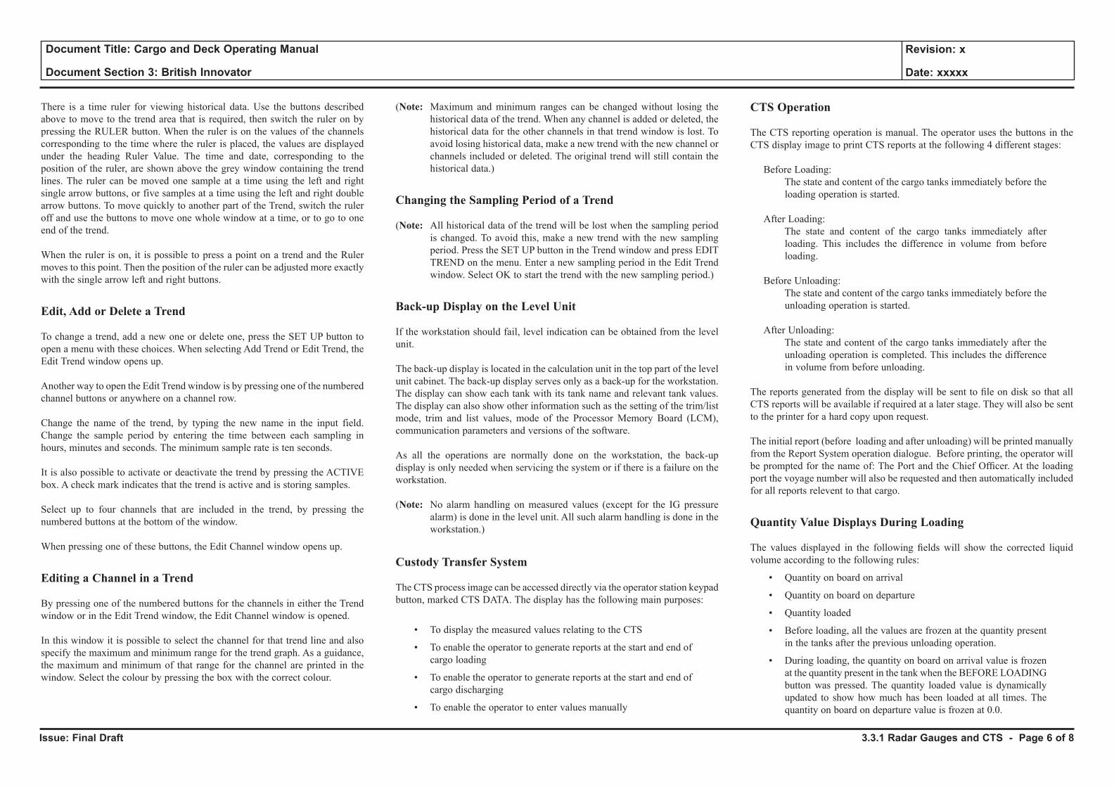
Issue: Final Draft
Document Title: Cargo and Deck Operating Manual
Document Section 3: British Innovator
Revision: x
Date: xxxxx
There is a time ruler for viewing historical data. Use the buttons described above to move to the trend area that is required, then switch the ruler on by pressing the RULER button. When the ruler is on the values of the channels corresponding to the time where the ruler is placed, the values are displayed under the heading Ruler Value. The time and date, corresponding to the position of the ruler, are shown above the grey window containing the trend lines. The ruler can be moved one sample at a time using the left and right single arrow buttons, or five samples at a time using the left and right double arrow buttons. To move quickly to another part of the Trend, switch the ruler off and use the buttons to move one whole window at a time, or to go to one end of the trend.
When the ruler is on, it is possible to press a point on a trend and the Ruler moves to this point. Then the position of the ruler can be adjusted more exactly with the single arrow left and right buttons.
Edit, Add or Delete a Trend
To change a trend, add a new one or delete one, press the SET UP button to open a menu with these choices. When selecting Add Trend or Edit Trend, the Edit Trend window opens up.
Another way to open the Edit Trend window is by pressing one of the numbered channel buttons or anywhere on a channel row.
Change the name of the trend, by typing the new name in the input field. Change the sample period by entering the time between each sampling in hours, minutes and seconds. The minimum sample rate is ten seconds.
It is also possible to activate or deactivate the trend by pressing the ACTIVE box. A check mark indicates that the trend is active and is storing samples.
Select up to four channels that are included in the trend, by pressing the numbered buttons at the bottom of the window.
When pressing one of these buttons, the Edit Channel window opens up.
Editing a Channel in a Trend
By pressing one of the numbered buttons for the channels in either the Trend window or in the Edit Trend window, the Edit Channel window is opened.
In this window it is possible to select the channel for that trend line and also specify the maximum and minimum range for the trend graph. As a guidance, the maximum and minimum of that range for the channel are printed in the window. Select the colour by pressing the box with the correct colour.
(Note: Maximum and minimum ranges can be changed without losing the historical data of the trend. When any channel is added or deleted, the historical data for the other channels in that trend window is lost. To avoid losing historical data, make a new trend with the new channel or channels included or deleted. The original trend will still contain the historical data.)
Changing the Sampling Period of a Trend
(Note: All historical data of the trend will be lost when the sampling period is changed. To avoid this, make a new trend with the new sampling period. Press the SET UP button in the Trend window and press EDIT TREND on the menu. Enter a new sampling period in the Edit Trend window. Select OK to start the trend with the new sampling period.)
Back-up Display on the Level Unit
If the workstation should fail, level indication can be obtained from the level unit.
The back-up display is located in the calculation unit in the top part of the level unit cabinet. The back-up display serves only as a back-up for the workstation. The display can show each tank with its tank name and relevant tank values. The display can also show other information such as the setting of the trim/list mode, trim and list values, mode of the Processor Memory Board (LCM), communication parameters and versions of the software.
As all the operations are normally done on the workstation, the back-up display is only needed when servicing the system or if there is a failure on the workstation.
(Note: No alarm handling on measured values (except for the IG pressure alarm) is done in the level unit. All such alarm handling is done in the workstation.)
Custody Transfer System
The CTS process image can be accessed directly via the operator station keypad button, marked CTS DATA. The display has the following main purposes:
• To display the measured values relating to the CTS
• To enable the operator to generate reports at the start and end of cargo loading
• To enable the operator to generate reports at the start and end of cargo discharging
• To enable the operator to enter values manually
CTS Operation
The CTS reporting operation is manual. The operator uses the buttons in the CTS display image to print CTS reports at the following 4 different stages:
Before Loading: The state and content of the cargo tanks immediately before the
loading operation is started.
After Loading: The state and content of the cargo tanks immediately after
loading. This includes the difference in volume from before loading.
Before Unloading: The state and content of the cargo tanks immediately before the
unloading operation is started.
After Unloading: The state and content of the cargo tanks immediately after the
unloading operation is completed. This includes the difference in volume from before unloading.
The reports generated from the display will be sent to fi le on disk so that all CTS reports will be available if required at a later stage. They will also be sent to the printer for a hard copy upon request.
The initial report (before loading and after unloading) will be printed manually from the Report System operation dialogue. Before printing, the operator will be prompted for the name of: The Port and the Chief Offi cer. At the loading port the voyage number will also be requested and then automatically included for all reports relevent to that cargo.
Quantity Value Displays During Loading
The values displayed in the following fi elds will show the corrected liquid volume according to the following rules:
• Quantity on board on arrival
• Quantity on board on departure
• Quantity loaded
• Before loading, all the values are frozen at the quantity present in the tanks after the previous unloading operation.
• During loading, the quantity on board on arrival value is frozen at the quantity present in the tank when the BEFORE LOADING button was pressed. The quantity loaded value is dynamically updated to show how much has been loaded at all times. The quantity on board on departure value is frozen at 0.0.
3.3.1 Radar Gauges and CTS - Page 6 of 8
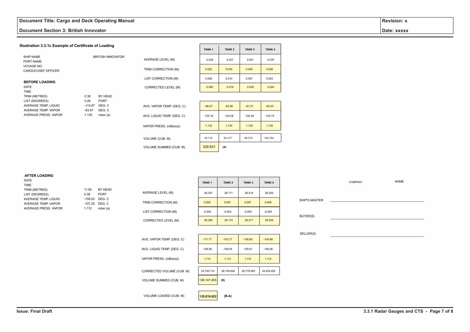
Issue: Final Draft
Document Title: Cargo and Deck Operating Manual
Document Section 3: British Innovator
Revision: x
Date: xxxxx
Illustration 3.3.1c Example of Certificate of Loading
DATE
TIME
TRIM (METRES)
LIST (DEGREES)
AVERAGE TEMP. LIQUID
AVERAGE TEMP. VAPOR
AVERAGE PRESS. VAPOR
0.38 BY HEAD
0.26 PORT
-115.87 DEG. C
-83.67 DEG. C
1.135 mbar (a)
LIST CORRECTION (M)
TRIM CORRECTION (M)
AVERAGE LEVEL (M)
CORRECTED LEVEL (M)
AVG. VAPOR TEMP. (DEG. C)
AVG. LIQUID TEMP. (DEG. C)
VAPOR PRESS. (mBar(a))
VOLUME (CUB. M)
VOLUME SUMMED (CUB. M)
SHIP NAME BRITISH INNOVATOR
PORT NAME
VOYAGE NO.
CARGO/CHIEF OFFICER
DATE
TIME
TRIM (METRES)
LIST (DEGREES)
AVERAGE TEMP. LIQUID
AVERAGE TEMP. VAPOR
AVERAGE PRESS. VAPOR
11:50 BY HEAD
0.38 PORT
-159.03 DEG. C
-107.25 DEG. C
1.112 mbar (a)
135,818.822VOLUME LOADED (CUB. M)
SHIP'S MASTER
COMPANY NAME
BUYER(S)
SELLER(S)
(B-A)
AFTER LOADING
BEFORE LOADING
TANK 1 TANK 2 TANK 3 TANK 4
0.006
0.022
0.038
0.060
-86.27
-155.16
1,135
0.010
0.030
0.037
0.018
-83.99
-103.08
1,134
0.007
0.030
0.051
0.026
-81.37
-100.48
1,135
0.003
0.026
0.076
0.024
-83.03
-104.74
1,135
328.631 (A)
LIST CORRECTION (M)
TRIM CORRECTION (M)
AVERAGE LEVEL (M)
CORRECTED LEVEL (M)
AVG. VAPOR TEMP. (DEG. C)
AVG. LIQUID TEMP. (DEG. C)
VAPOR PRESS. (mBar(a))
CORRECTED VOLUME (CUB. M)
VOLUME SUMMED (CUB. M)
TANK 1 TANK 2 TANK 3 TANK 4
-0.004
0.005
26.357
26.358
-111.77
-158.99
1,112
24,165.114
-0.004
0.007
26.171
26.174
-103.77
-159.05
1,112
38,749.694
-0.004
0.007
26.214
26.217
-108.60
-159.01
1,112
38,776.963
-0.004
0.006
26.202
26.204
-104.86
-159.06
1,112
34,455.682
136,147.453 (B)
39.116 84.377 98.374 106.764
3.3.1 Radar Gauges and CTS - Page 7 of 8
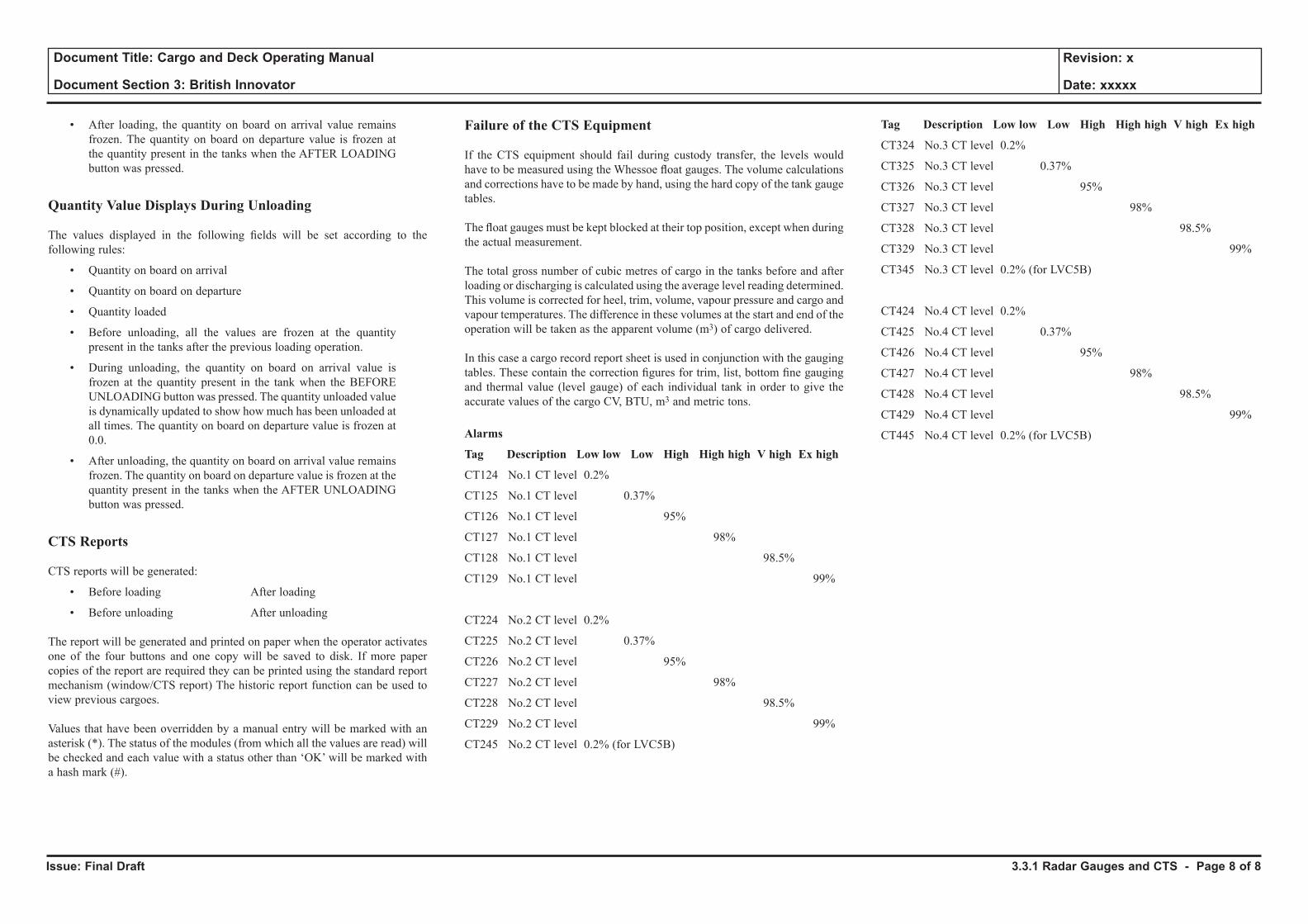
Issue: Final Draft
Document Title: Cargo and Deck Operating Manual
Document Section 3: British Innovator
Revision: x
Date: xxxxx
• After loading, the quantity on board on arrival value remains frozen. The quantity on board on departure value is frozen at the quantity present in the tanks when the AFTER LOADING button was pressed.
Quantity Value Displays During Unloading
The values displayed in the following fi elds will be set according to the following rules:
• Quantity on board on arrival
• Quantity on board on departure
• Quantity loaded
• Before unloading, all the values are frozen at the quantity present in the tanks after the previous loading operation.
• During unloading, the quantity on board on arrival value is frozen at the quantity present in the tank when the BEFORE UNLOADING button was pressed. The quantity unloaded value is dynamically updated to show how much has been unloaded at all times. The quantity on board on departure value is frozen at 0.0.
• After unloading, the quantity on board on arrival value remains frozen. The quantity on board on departure value is frozen at the quantity present in the tanks when the AFTER UNLOADING button was pressed.
CTS Reports
CTS reports will be generated:
• Before loading After loading
• Before unloading After unloading
The report will be generated and printed on paper when the operator activates one of the four buttons and one copy will be saved to disk. If more paper copies of the report are required they can be printed using the standard report mechanism (window/CTS report) The historic report function can be used to view previous cargoes.
Values that have been overridden by a manual entry will be marked with an asterisk (*). The status of the modules (from which all the values are read) will be checked and each value with a status other than ‘OK’ will be marked with a hash mark (#).
Failure of the CTS Equipment
If the CTS equipment should fail during custody transfer, the levels would have to be measured using the Whessoe fl oat gauges. The volume calculations and corrections have to be made by hand, using the hard copy of the tank gauge tables.
The fl oat gauges must be kept blocked at their top position, except when during the actual measurement.
The total gross number of cubic metres of cargo in the tanks before and after loading or discharging is calculated using the average level reading determined. This volume is corrected for heel, trim, volume, vapour pressure and cargo and vapour temperatures. The difference in these volumes at the start and end of the operation will be taken as the apparent volume (m3) of cargo delivered.
In this case a cargo record report sheet is used in conjunction with the gauging tables. These contain the correction fi gures for trim, list, bottom fi ne gauging and thermal value (level gauge) of each individual tank in order to give the accurate values of the cargo CV, BTU, m3 and metric tons.
Alarms
Tag Description Low low Low High High high V high Ex high
CT124 No.1 CT level 0.2%
CT125 No.1 CT level 0.37%
CT126 No.1 CT level 95%
CT127 No.1 CT level 98%
CT128 No.1 CT level 98.5%
CT129 No.1 CT level 99%
CT224 No.2 CT level 0.2%
CT225 No.2 CT level 0.37%
CT226 No.2 CT level 95%
CT227 No.2 CT level 98%
CT228 No.2 CT level 98.5%
CT229 No.2 CT level 99%
CT245 No.2 CT level 0.2% (for LVC5B)
Tag Description Low low Low High High high V high Ex high
CT324 No.3 CT level 0.2%
CT325 No.3 CT level 0.37%
CT326 No.3 CT level 95%
CT327 No.3 CT level 98%
CT328 No.3 CT level 98.5%
CT329 No.3 CT level 99%
CT345 No.3 CT level 0.2% (for LVC5B)
CT424 No.4 CT level 0.2%
CT425 No.4 CT level 0.37%
CT426 No.4 CT level 95%
CT427 No.4 CT level 98%
CT428 No.4 CT level 98.5%
CT429 No.4 CT level 99%
CT445 No.4 CT level 0.2% (for LVC5B)
3.3.1 Radar Gauges and CTS - Page 8 of 8
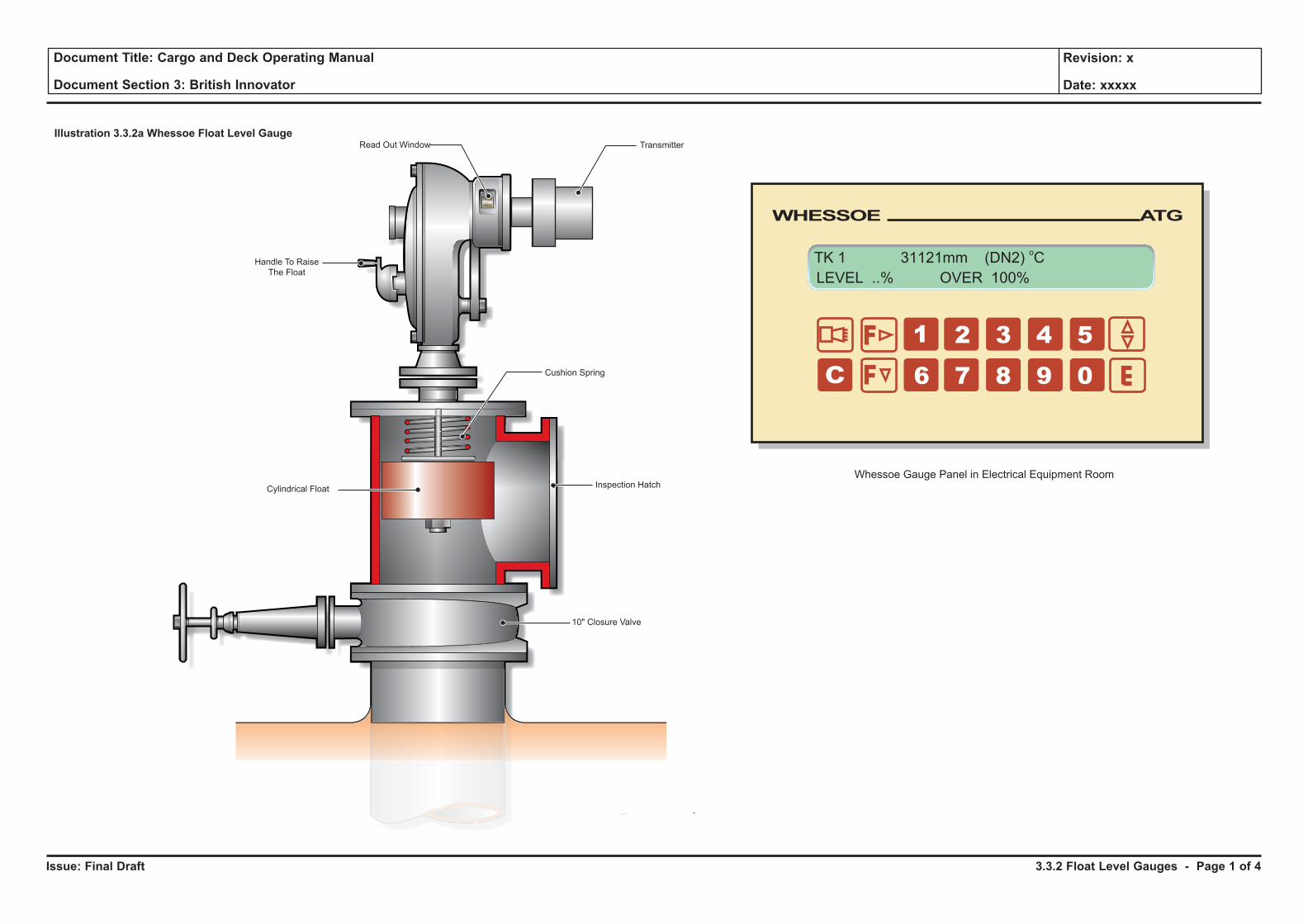
Issue: Final Draft
Document Title: Cargo and Deck Operating Manual
Document Section 3: British Innovator
Revision: x
Date: xxxxx
Illustration 3.3.2a Whessoe Float Level GaugeRead Out Window Transmitter
Cushion Spring
Inspection HatchCylindrical Float
Handle To RaiseThe Float
10" Closure Valve
WHESSOE ATG
TK 1 31121mm (DN2) oCLEVEL ..% OVER 100%
Whessoe Gauge Panel in Electrical Equipment Room
3.3.2 Float Level Gauges - Page 1 of 4
Issue: Final Draft
Document Title: Cargo and Deck Operating Manual
Document Section 3: British Innovator
Revision: x
Date: xxxxx
3.3.2 FLOAT LEVEL GAUGE
Make: WhessoeType: Figure 3304
The Whessoe Figure 3304 Marine Liquid level gauge has been designed and developed specifically for low temperature liquified gas carriers to measure accurately and consistently product liquid levels in marine cargo tanks during loading and discharging.
Each gauge is fitted with a 1319 type intrinsically safe transmitter, each transmitter is contolled by its own onboard microprocesser. Information regarding the cargo level is passed from the transmitters to a mini receiver located in the electrical equipment room by means of a 20mA current loop.
The receiver functions as a mini tank gauging system and the data is displayed on an LCD panel on the front of the instrument. Command entry is by means of a spashproof membrane key pad.
The 1097 mini receiver is interfaced with the IAS workstation and the tank levels are displayed on the IAS tank screen as a digital read out.
There is the facility, if required, for the transmitter to be fitted with microswitches to activate alarms at the following predetermined levels, normally very high level 98.5%, high level 95% and low level at 0.37m. When activated the alarms sound on the IAS alarm system.
The gauge is float actuated and employs a tensator spring as a counter balancing mechanism which maintains a constant tape tension at the float. This ensures that the float maintains the same level of immersion irrespective of the amount and weight of the tape paid out.
The accurately perforated tape transmits float movement to a sprocket wheel, which in turn drives a counter mechanism providing local digital read out, visible through a window in the counter housing.
The shrinkage of the float in LNG is 15mm and the minimum level which can be read from the gauge is 145mm.
CAUTION To reduce the risk of tape failure and wear on the gauging mechanism, the floats should be fully stowed at all times, except when taking a sounding. Care should be taken when stowing the float as excessive tension may cause tape breakage. It is possible for a failed tape to foul the capacitance column, resulting in the loss of gauging facilities for that tank.
To obtain the liquid level, the float is released from its stowage position using the release lever located at the base of the gauge head. The float descends under control to the liquid surface. The rate of descent is an automatic function made possible by the inclusion of a viscous damper within the gauge head.
The tank sounding may then be taken by observation of the local mechanical read outs to provide level indication. The Whessoe gauges should be checked against the Custody Transfer System (CTS) during each alternate loading.
Each cargo tank is provided with a Whessoe gauge as an approved secondary level measurement system. This secondary system provides an alternative means of cargo level measurement in the event of the failure of the primary radar gauges system.
12" Float Well
The float well comprises a 12" (305mm) nominal bore float well tube installed vertically within the cargo pump tower. The upper end of the float well penetrates the top of the tank dome where it terminates in a flange.
The lower end extends to within 75mm of the bottom of the tank where it is closed by a perforated plate. The lower end of the float well is provided with a bolted inspection cover. Expansion is allowed for by a sliding connection just below the dome penetration. To avoid level errors caused by the ‘till well’ effect, there is a 25mm diameter hole spaced every 300mm below the sliding connection.
Isolating Valve and Float Inspection Chamber
A 300mm gate valve, bolted to the top of the float well, allows the gauge head to be isolated for maintenance. A stainless steel inspection chamber is mounted above the isolating valve to provide access to the float and for the connection of special float recovery tools in the event of tape breakage.
Level Gauge Assembly
The level gauge assembly comprises the gauge head and float assembly. The float is clamped to an accurately perforated tape manufactured from stainless steel, a viscous damper to control the rate of descent of the float to the cargo level, a crank for raising the float to the storage position and a mechanical read out which is observed through the counter window. A float lock-up arrangement provides removal of the level gauge float from the tank when in the stored position. It also provides a gauge datum reference and a means of locking the float in the storage position.
Operation: Gauging
a) Open the gauge isolating valve fully; normally it is left open.
b) Put the crank handle in the STORED position, ie, with the handle towards the gauge cover.
c) Put the spring-loaded automatic float lock-up and the datum plunger up to release the float and allow it to descend at a controlled rate to the liquid level.
To Return the Gauge to the Stored Position
a) Put the crank to the CRANKING position, i.e., with the handle outwards.
(Note: The cranking handle is designed to drive in one direction only and is spring loaded by a cam arrangement so that it is not in motion during normal gauging.)
b) Carefully raise the float by turning the crank slowly in a counter clockwise direction, as indicated by the arrow on the main cover inspection plate.
c) Watch the read out counter, which will indicate when the float nears the top. When resistance is felt by the float touching the cushion spring, continue cranking until the plunger is seated and the automatic float lock-up and datum plunger spring fully inward, securing the float.
d) Check that the counter reads exactly the same before and after use.
e) Move the crank handle to its STORAGE position.
CAUTION Do not attempt to turn the crank clockwise or to interfere with the free fall of the float. To do so will severely damage the tape or the tensator spring.
3.3.2 Float Level Gauges - Page 2 of 4

Issue: Final Draft
Document Title: Cargo and Deck Operating Manual
Document Section 3: British Innovator
Revision: x
Date: xxxxx
Illustration 3.3.2a Whessoe Float Level GaugeRead Out Window Transmitter
Cushion Spring
Inspection HatchCylindrical Float
Handle To RaiseThe Float
10" Closure Valve
WHESSOE ATG
TK 1 31121mm (DN2) oCLEVEL ..% OVER 100%
Whessoe Gauge Panel in Electrical Equipment Room
3.3.2 Float Level Gauges - Page 3 of 4
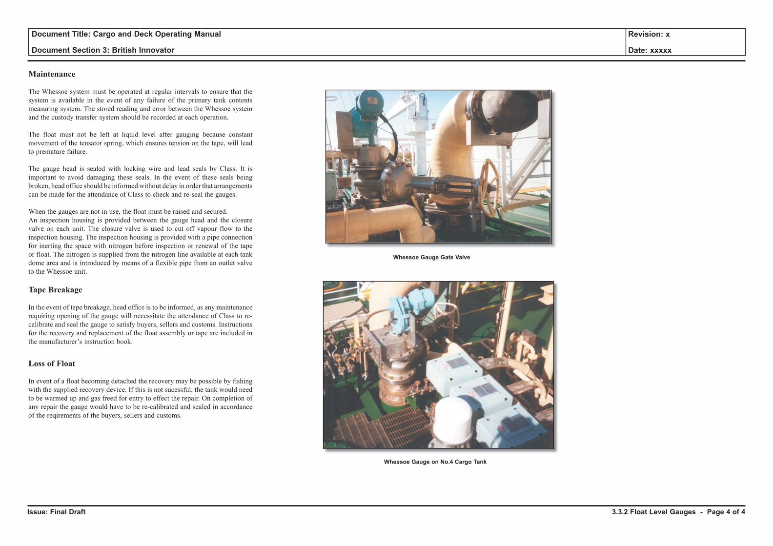
Issue: Final Draft
Document Title: Cargo and Deck Operating Manual
Document Section 3: British Innovator
Revision: x
Date: xxxxx
Maintenance
The Whessoe system must be operated at regular intervals to ensure that the system is available in the event of any failure of the primary tank contents measuring system. The stored reading and error between the Whessoe system and the custody transfer system should be recorded at each operation.
The float must not be left at liquid level after gauging because constant movement of the tensator spring, which ensures tension on the tape, will lead to premature failure.
The gauge head is sealed with locking wire and lead seals by Class. It is important to avoid damaging these seals. In the event of these seals being broken, head office should be informed without delay in order that arrangements can be made for the attendance of Class to check and re-seal the gauges.
When the gauges are not in use, the float must be raised and secured.An inspection housing is provided between the gauge head and the closure valve on each unit. The closure valve is used to cut off vapour flow to the inspection housing. The inspection housing is provided with a pipe connection for inerting the space with nitrogen before inspection or renewal of the tape or float. The nitrogen is supplied from the nitrogen line available at each tank dome area and is introduced by means of a flexible pipe from an outlet valve to the Whessoe unit.
Tape Breakage
In the event of tape breakage, head office is to be informed, as any maintenance requiring opening of the gauge will necessitate the attendance of Class to re-calibrate and seal the gauge to satisfy buyers, sellers and customs. Instructions for the recovery and replacement of the float assembly or tape are included in the manufacturer’s instruction book.
Loss of Float
In event of a float becoming detached the recovery may be possible by fishing with the supplied recovery device. If this is not sucessful, the tank would need to be warmed up and gas freed for entry to effect the repair. On completion of any repair the gauge would have to be re-calibrated and sealed in accordance of the reqirements of the buyers, sellers and customs.
3.3.2 Float Level Gauges - Page 4 of 4
Whessoe Gauge Gate Valve
Whessoe Gauge on No.4 Cargo Tank
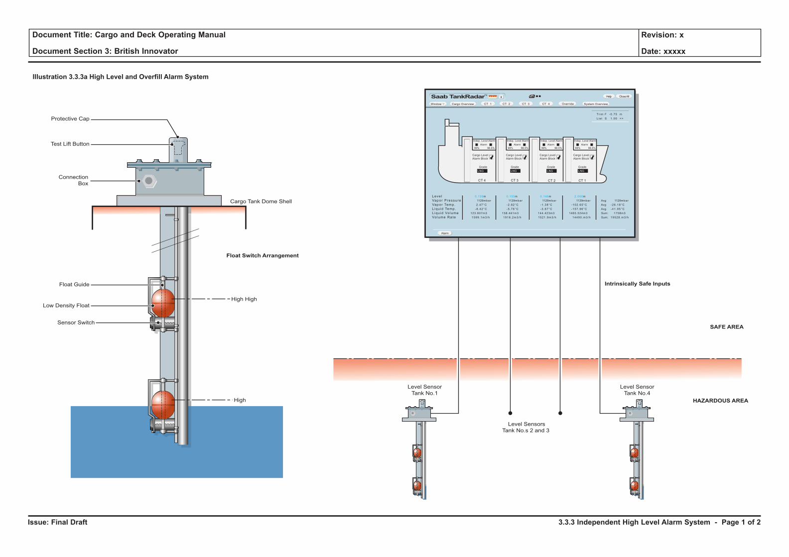
Issue: Final Draft
Document Title: Cargo and Deck Operating Manual
Document Section 3: British Innovator
Revision: x
Date: xxxxx
Illustration 3.3.3a High Level and Overfill Alarm System
Level Sensor
Tank No.4
Level Sensors
Tank No.s 2 and 3
Float Switch Arrangement
Level Sensor
Tank No.1
HAZARDOUS AREA
SAFE AREA
Protective Cap
Test Lift Button
Connection
Box
Float Guide
Low Density Float
Sensor Switch
High High
Cargo Tank Dome Shell
High
Intrinsically Safe Inputs
SaabTankRadarTM
Window Cargo Overview System OverviewOverride
Leve l
Vapor Pressu re
Vapor Temp.
L iqu id Temp.
L iqu id Vo lume
Vo lume Rate
0.138m
1129mbar
2 .47°C
-8 .42°C
123.807m3
1599 .1m3/h
0.155m
1129mbar
-2 .82°C
-5 .76°C
158.441m3
1916 .2m3/h
0.146m
1129mbar
-1 .38°C
-3 .67°C
144.423m3
1521 .9m3/h
2.068m
1129mbar
-102 .65°C
-157 .96°C
1465.524m3
14490 .m3 /h
Avg 1129mbar
Avg -26 .18°C
Avg -41 .95°C
Sum: 1758m3
Sum: 19528 .m3 /h
Tr im F -0 .75 m
L is t S 1 .00 <>
Alarm
CT 1 CT 2 CT 3 CT 4
Help CloseAll
Grade
Cargo Level
Alarm Block
LNG
Grade
LNG
CT 4 CT 3 CT 2
Grade
LNG
CT 1
Grade
LNG
Indep. Level Alarm
Alarm
99% 98.5%
Cargo Level
Alarm Block
Indep. Level Alarm
Alarm
99% 98.5%
Cargo Level
Alarm Block
Indep. Level Alarm
Alarm
99% 98.5%
Cargo Level
Alarm Block
Indep. Level Alarm
Alarm
99% 98.5%
3.3.3 Independent High Level Alarm System - Page 1 of 2
Issue: Final Draft
Document Title: Cargo and Deck Operating Manual
Document Section 3: British Innovator
Revision: x
Date: xxxxx
3.3.3 INDEPENDENT HIGH LEVEL ALARM SYSTEM
Make: OmicronType: HHL - 8903
The vessel’s cargo tank high level alarm system is fitted to comply with the IMO, DNV and USCG etc societies’ requirements. To comply with these requirements the very high level alarm and extremely high alarms are completely separate.
The level switches are of the float type and can be tested independently from the top of the tank.
All the inputs from the level switches are connected directly to the input side of the ESDS control panel then by relay to the ESDS overide (99% level), filling valve overide (98.5% level), the common alarm system and the IAS cargo system.
The 98.5% very high level alarm will activate the tank protection system (TPS) to close the individual tank loading valve. The 99% extremely high alarm will activate the ESDS system.
The level switch has two floats with built-in permanent magnets in each float. As the float moves upwards, a reed switch inside the housing is deactivated and an alarm is raised. When the float moves downward, the reed switch is closed again.
Two resistors are connected to the reed switch inside the sensor. One is in series and one is in parallel with the switch contacts. This enables the detection of broken or shorted alarm circuits.
Testing
Each level switch is equipped with a mechanical testing device. The testing device is located under a protective screw cap on top of the level switch’s junction box. By lifting the testing device slowly, the VERY HIGH LEVEL alarm (98.5%) for that particular tank will be raised. Lifting the device further up will cause the EXTREMELY HIGH alarm (99%) to be raised.
When testing is complete, the test device should be pressed back down and the protective screw cap replaced.
(Note: The very high level and extremely high alarm are to be tested prior to each loading.)
Operation
When a cargo tank float moves upwards and activates the alarm, the horn on deck as well as the buzzer on the CTS workstation will start. The corresponding alarm will also be raised via the IAS system.
Pressing the SILENCE ALARM pushbutton on the IAS control panel will cause the common alarms to stop. The alarms are accepted at the CTS workstation by using the light pen on the ALARM indicator.
The common alarm unit is configured to raise alarms for either the 98.5% VERY HIGH LEVEL or 99% EXTREMELY HIGH alarm. This unit pulses the exterior horn.
3.3.3 Independent High Level Alarm System - Page 2 of 2
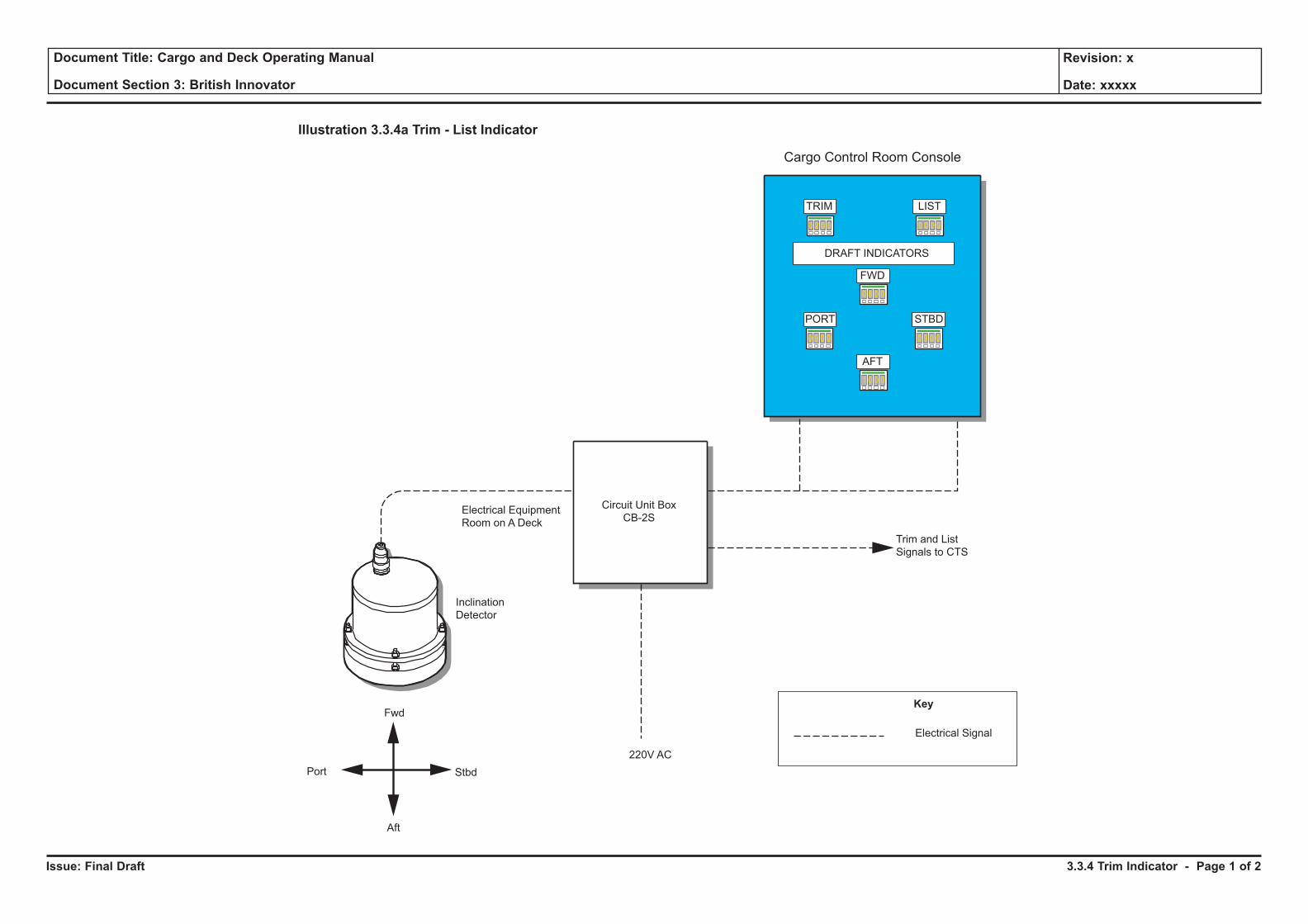
Issue: Final Draft
Document Title: Cargo and Deck Operating Manual
Document Section 3: British Innovator
Revision: x
Date: xxxxx
Inclination
Detector
Electrical Equipment
Room on A Deck
Port Stbd
Aft
Fwd
Cargo Control Room Console
Trim and List
Signals to CTS
220V AC
Circuit Unit Box
CB-2S
Illustration 3.3.4a Trim - List Indicator
Electrical Signal
DRAFT INDICATORS
TRIM
FWD
AFT
LIST
STBDPORT
0 2 0 0 0 0 0 0
0 9 0 0 0 9 0 0
0 8 0 0
1 0 0 0
Key
3.3.4 Trim Indicator - Page 1 of 2
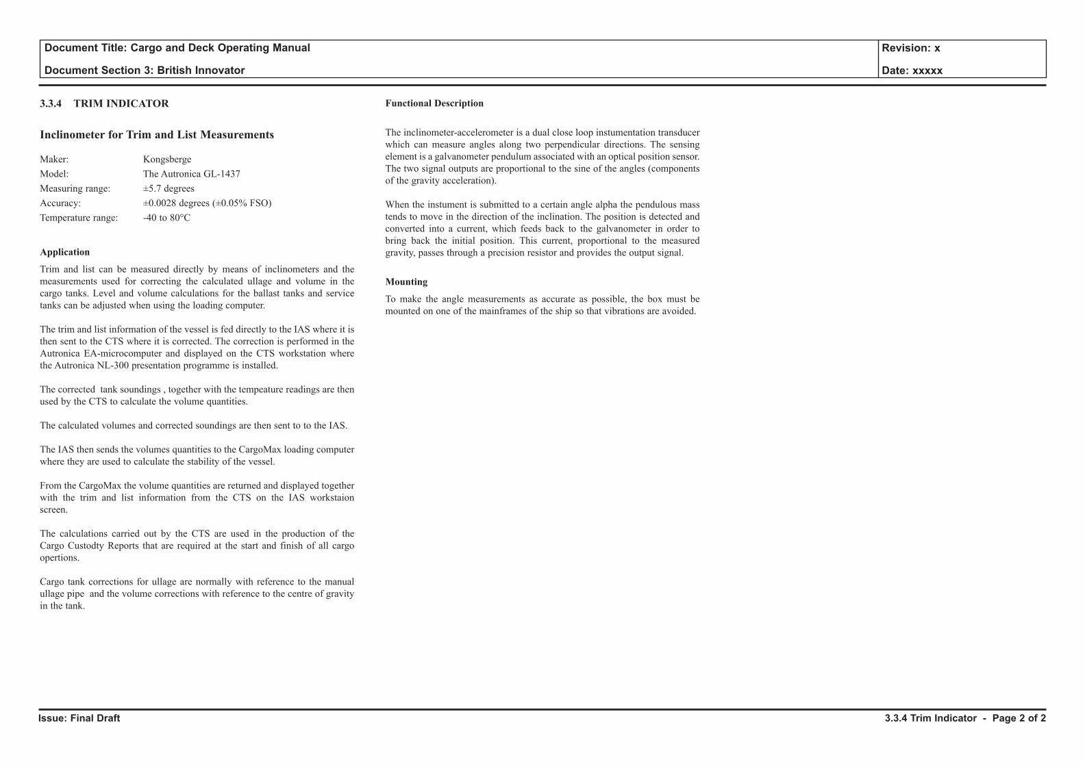
Issue: Final Draft Heading - Page x of x
Document Title: Cargo and Deck Operating Manual
Document Section 3: British Innovator
Revision: x
Date: xxxxx
3.3.4 TRIM INDICATOR
Inclinometer for Trim and List Measurements
Maker: Kongsberge Model: The Autronica GL-1437Measuring range: ±5.7 degreesAccuracy: ±0.0028 degrees (±0.05% FSO)Temperature range: -40 to 80°C
Application
Trim and list can be measured directly by means of inclinometers and the measurements used for correcting the calculated ullage and volume in the cargo tanks. Level and volume calculations for the ballast tanks and service tanks can be adjusted when using the loading computer.
The trim and list information of the vessel is fed directly to the IAS where it is then sent to the CTS where it is corrected. The correction is performed in the Autronica EA-microcomputer and displayed on the CTS workstation where the Autronica NL-300 presentation programme is installed.
The corrected tank soundings , together with the tempeature readings are then used by the CTS to calculate the volume quantities.
The calculated volumes and corrected soundings are then sent to to the IAS.
The IAS then sends the volumes quantities to the CargoMax loading computer where they are used to calculate the stability of the vessel.
From the CargoMax the volume quantities are returned and displayed together with the trim and list information from the CTS on the IAS workstaion screen.
The calculations carried out by the CTS are used in the production of the Cargo Custodty Reports that are required at the start and finish of all cargo opertions.
Cargo tank corrections for ullage are normally with reference to the manual ullage pipe and the volume corrections with reference to the centre of gravity in the tank.
Functional Description
The inclinometer-accelerometer is a dual close loop instumentation transducer which can measure angles along two perpendicular directions. The sensing element is a galvanometer pendulum associated with an optical position sensor. The two signal outputs are proportional to the sine of the angles (components of the gravity acceleration).
When the instument is submitted to a certain angle alpha the pendulous mass tends to move in the direction of the inclination. The position is detected and converted into a current, which feeds back to the galvanometer in order to bring back the initial position. This current, proportional to the measured gravity, passes through a precision resistor and provides the output signal.
Mounting
To make the angle measurements as accurate as possible, the box must be mounted on one of the mainframes of the ship so that vibrations are avoided.
3.3.4 Trim Indicator - Page 2 of 2
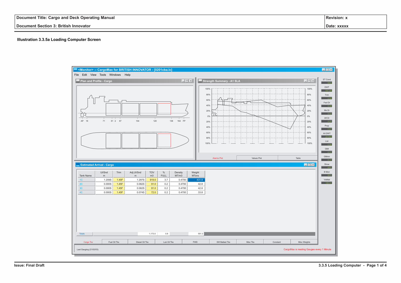
Issue: Final Draft
Document Title: Cargo and Deck Operating Manual
Document Section 3: British Innovator
Revision: x
Date: xxxxx
X
X
X
X
<Monitor> -- CargoMax for BRITISH INNOVATOR - [0201cba.lc]
File Edit View Tools Windows Help
Plan and Profile - Cargo
Estimated Arrival - Cargo
Strength Summary - A1 SLA
AP 16 71 61 2 67 104 120 136 164
100%
SEA
ST Cond
597.48
DWT
Trim
Fwd Dr
Ms Dr
Aft Dr
Prop
AV.DWT
List
GMt
GMmn
Show
0.06
B Mon
VisMat
80%
60%
40%
20%
0%
20%
40%
60%
80%
100%
100%
80%
60%
40%
20%
0%
20%
40%
60%
80%
100%
FP
TableValues PlotAlarms Plot
Cargo Tks
CargoMax is reading Gauges every 1 MinuteLast Gauging (21/02/03)
Fuel Oil Tks Diesel Oil Tks Lub Oil Tks FWD SW Ballast Tks Misc Tks Constant Misc Weights
Tank Name
1C
2C
3C
4C
1.209S
0.000S
0.000S
0.000S
1.45F
1.45F
1.45F
1.45F
UI/Snd
m
Trim
0.4700
0.4700
0.4700
0.4700
Density
MT/m3
431.9
42.8
42.8
33.8
Weight
MTons
1.297S
0.082S
0.082S
0.074S
Adj.UI/Snd
m
919.0
91.0
91.0
72.0
TOV
m3
3.7
0.2
0.2
0.2
%
FULL
Totals 1,173.0 0.8 551.3
9.48
9.52
9.55
1127
24.563
6.51
8.37
48%
56%
189.41
0.66
Illustration 3.3.5a Loading Computer Screen
3.3.5 Loading Computer - Page 1 of 4
Issue: Final Draft
Document Title: Cargo and Deck Operating Manual
Document Section 3: British Innovator
Revision: x
Date: xxxxx
3.3.5 LOADING COMPUTER
Specification
Maker: Loadmaster International Inc.Program: CargoMax for WindowsVersion: 1.21
General
The CargoMax program is a computerised system for planning and evaluating ship loading and discharge. It quickly calculates ship stability and stress characteristics based on any loading condition specified by the user.
The program is developed from the technical information supplied by the builders that reflects the physical characteristics of the ship. The information includes the following data:
• Principal particulars
• Operating lightship
• Load line data
• Draught mark locations
• Visibility restriction data
• Hydrostatic tables
• Cross curves of stability
• Bonjean tables
• Required GM curve
• Capacity tables
• Variable centre/freesurface tables
• Lightship weight distribution
• Allowable bending moments and shear Forces
The program allows for the loading condition information to be stored to disk. These stored conditions can be recalled at any time for modification or re-evaluation. In addition stored loading conditions can be sent ashore for review on a shore based computer.
The CargoMax system is an on-line stand alone computer with a direct interface to the various tank and draught gauge systems and linked to the vessel's IAS system. The CargoMax system automatically reads the gauge system data at specified intervals and calculates all the tank and vessel characteristics.
It is possible to vary the time of each update from 1 minute intervals to 30 minutes.
Determination of load/discharge rates and projections of time to finish are possible.
During cargo operations the CargoMax program constantly upgrades the information. Prior to or during cargo operations the operator can check, using manual inputs, that the sequence of loading or discharge will always remain within the acceptable limits.
The CargoMax program is run from Windows and as such is accessed via the Windows menu bar at the top of the screen. In addition to the menu bar there are two fixed display areas which cannot be changed or hidden, the Results Bar and Status Bar.
The Results Bar provides information on the current loading condition. This bar is always visible on the far right hand side of the main window and is continuously updated to reflect any changes in the loading condition.
The Status Bar is a single text line located at the bottom of the main window. The program uses this space to display messages about the current status and warnings about data entry.
In addition to the above there is the Workspace, the area of the screen where the different views of the load condition are displayed.
General Program Operation
Main Menu Bar
The layout of the main menu bar follows Windows conventions. The File, Edit, Windows and Help items all provide selections consistent with other Windows programs. The View and Tools items contain special features for CargoMax.
View
This allows the operator to select which displays and entry windows are open. When CargoMax first starts up, the default set of windows are opened up and arranged for easy use. These are Plan, Profile, Strength Summary and Deadweight.
In the View menu they are shown with a check mark, at any time to user can change to other windows listed on this menu. To close a window, click with the mouse on the name in the view menu, the window and the check mark against the name will disappear.
Window
Controls the display of currently open windows, allows the user to change the window arrangement and switch between open windows. If a window is closed it will not appear in the Window menu.
Tools
This menu contains special CargoMax calculation options, such as Damage Stability and Observed Draught Entry, it also contains the Options menu for setting units, criteria and load lines.
Context Menus
Context menus are small pop-up menus which appear at the cursor location and contain options to efficiently change CargoMax options or formats. A context menu can be used to change units , change the strength allowable, change an entry table , change the load lines etc.
Context menus only appear when clicking on areas of the CargoMax workspace or the Results Bar with the right mouse button. Only items for the area selected are included in these menus.
It is not possible to get to the Context menu via the Main Menu Bar, but the options offered by the Context Menus are available through other menu items on the main menu.
Options for Data Entry and Program Configuration
There are a number of data entry and program configurations that can be selected by the user. All of the program options are accessible from the Tools / Options Menu on the main menu bar.
Units
The units for display and printed output may be selected as US or SI units. Units may be selected separately for temperature and volume.
Temperature Units
The temperature units may be specified as Centigrade or Fahrenheit.
Specific Gravity of Sea Water
The sea water specific gravity may be changed for operations in brackish or fresh water. The default value is 1.025.
3.3.5 Loading Computer - Page 2 of 4
Issue: Final Draft
Document Title: Cargo and Deck Operating Manual
Document Section 3: British Innovator
Revision: x
Date: xxxxx
Draughts
Draughts displayed in the Result Bar are those calculated at the forward and aft perpendiculars (default) or at the forward and aft draught marks. The trim and stability summaries always display both sets of draughts.
Trim
The trim displayed in the Results Bar can be calculated between the perpendiculars (default) or between the draught marks. The trim and stability summaries always show the trim between the perpendiculars.
Longitudinal Reference
The reference point for longitudinal dimensions may be selected as the aft perpendicular, midships or the forward perpendicular.
Volume Units
Volume units can be selected ,as M3, ft3, bbls or gallons. The default unit is as used in the Trim and Stability Book.
% Full Alarm (High and Low)
Levels for high and low alarms can be entered as a percentage full of the maximum tank capacity. The program will beep and highlight the percent full value of any tank which exceeds the specified limit.
Ullage/Weight Entry
Each tank weight group has a weight entry window and an ullage entry window, the active window can be selected from the deadweight entry window using a context menu. The ullage/weight can be changed using the keyboard.
Ullage/Sounding Units
The ullage units for each group may be specified here, the default units are matched to those used in the Trim and Stability book.
Strength Allowables
When calculating the bending moment and sheer force the calculated values are compared with the allowable values assigned by the Classification Society. The calculated strength are then displayed as a percentage of the allowables.
There are normally two sets of allowables assigned, corresponding to the In Harbour and At Sea conditions.
To select the condition to be used, click on the arrow to display the choices and then click on the choice.
Load Condition Entry
Where a new cargo is to be loaded the operator can select either a previous cargo condition to amend or create a new file.
To select a previous cargo
• Click on file on the main menu bar
• Click on OPEN LOAD CASE
• In the box under the words File Name enter the name of the file required, or click on the name listed
• Press the OK button
• The selected file is now displayed
• Click on SAVE AS and give the file a new name
• Press the SAVE button. The file has now been saved under the new name and can be amended as required.
• Select DEADWEIGHT ENTRY from the Views menu
CargoMax has a single window which is used to enter all deadweight data. This window has been designed to allow entry of load case information in various different, convenient formats.
The window has tabs along the bottom edge which are used to switch between groups of weights. These groups are used to organise the weight items into logical categories like Cargo Tanks, SW Ballast Tanks, Fuel Oil Tanks and Miscellaneous Weights etc.
To enter cargo into a cargo tank, for example, select the cargo tank tab with the mouse and then enter the weight on the line corresponding to the appropriate tank. This entry screen can be used for direct input of weight or volume.
Because the vessel only ever carries one grade, LNG, the main changes of weight are fuel oil, ballast and stores. Changes would also occur in the event of damage and the damage stability function would be used.
By entering the changes of weight during the proposed loading or discharge sequence, the operator can check that the vessel will remain within the acceptable limits of trim, stress and stability at all times.
As each change in weight is entered the Results bar of the CargoMax on the right side of the window displays the updated conditions of draught, trim and Stability values. Should the stability values exceed the allowable limits they will be displayed in red. To change options or allowable limits, use the context menu accessible with a right click on the label of the results bar.
During cargo operations or planning the following summary windows can be viewed at any time, displaying the latest condition of the vessel.
From the View menu select Trim and Stability Summary. This will display a summary of the Stability Calculation, Trim Calculation and Draughts.
From the View menu select Plan and Profile. This will display a picture of the present loading of the ship including all tanks and cargo.
Each tank is colour coded according to its contents, Cargo tanks - black, SW ballast- green etc. The full list of colours is listed in the CargoMax operating manual.
From the View menu select Weight Summary. This displays the displacement, centre of gravity and free surface effect.
From the View menu select Statical Stability Summary. This displays the Righting Arm Curve.
From the View menu select Strength. This will display the bending and sheer force graphs, both the allowable and present. It is possible to change from sea to harbour condition.
A variety of printed reports are available to completely document any load case. The printing options are accessed by choosing PRINT from the File menu. This brings up the print selection box, there are two print options, Load Case Summary will print all the reports. Alternatively if only one report is required, using the mouse, click on the report name listed in the print box.
Press PRINT to start printing
CargoMax provides an optional set of calculation in the TOOLs menu which can be used to help the vessel's operations. The three tools are Observed Draught Entry, Direct Calculation of required GMt and the Damage Stability Mode.
Observed Draught Entry
The Observed Draught Entry is normally used when it is necessary to confirm the deadweight by use of the observed draught readings.
Direct Calculation of GMt
Direct Calculation of GMt can be used to calculate the actual GMt required to meet the damage criteria for a specific condition.
3.3.5 Loading Computer - Page 3 of 4
Issue: Final Draft
Document Title: Cargo and Deck Operating Manual
Document Section 3: British Innovator
Revision: x
Date: xxxxx
Both of the above functions would only be used in unusual situations, the operator should practice with them in order to gain a knowledge of their functions.
Damage Stability Module
This is the third of the options and is designed to show the operator the effects of sustaining damage to a compartment or compartments and what results it has on the stability of the vessel, including the effects of remedial action. The operators should familiarise themselves with its operation and functions.
3.3.5 Loading Computer - Page 4 of 4
PART 4: CARGO AND BALLAST SYSTEM
4.1 Cargo Containment System
4.1.1 Liquid Leakage Detection
Illustrations
4.1a Leakage Pipe
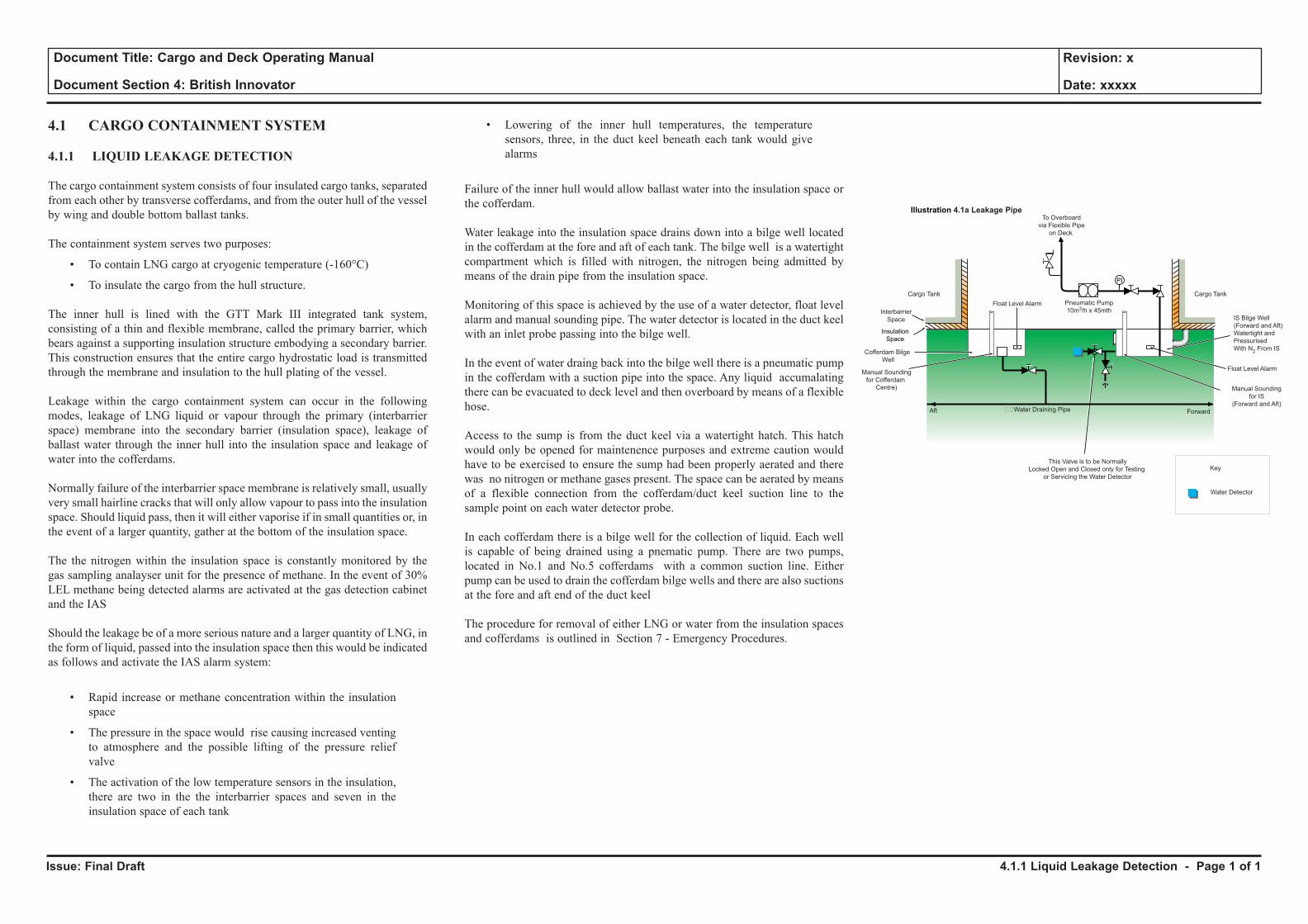
Issue: Final Draft
Document Title: Cargo and Deck Operating Manual
Document Section 4: British Innovator
Revision: x
Date: xxxxx
4.1 CARGO CONTAINMENT SYSTEM
4.1.1 LIQUID LEAKAGE DETECTION
The cargo containment system consists of four insulated cargo tanks, separated from each other by transverse cofferdams, and from the outer hull of the vessel by wing and double bottom ballast tanks.
The containment system serves two purposes:
• To contain LNG cargo at cryogenic temperature (-160°C)
• To insulate the cargo from the hull structure.
The inner hull is lined with the GTT Mark III integrated tank system, consisting of a thin and flexible membrane, called the primary barrier, which bears against a supporting insulation structure embodying a secondary barrier. This construction ensures that the entire cargo hydrostatic load is transmitted through the membrane and insulation to the hull plating of the vessel.
Leakage within the cargo containment system can occur in the following modes, leakage of LNG liquid or vapour through the primary (interbarrier space) membrane into the secondary barrier (insulation space), leakage of ballast water through the inner hull into the insulation space and leakage of water into the cofferdams.
Normally failure of the interbarrier space membrane is relatively small, usually very small hairline cracks that will only allow vapour to pass into the insulation space. Should liquid pass, then it will either vaporise if in small quantities or, in the event of a larger quantity, gather at the bottom of the insulation space.
The the nitrogen within the insulation space is constantly monitored by the gas sampling analayser unit for the presence of methane. In the event of 30% LEL methane being detected alarms are activated at the gas detection cabinet and the IAS
Should the leakage be of a more serious nature and a larger quantity of LNG, in the form of liquid, passed into the insulation space then this would be indicated as follows and activate the IAS alarm system:
• Rapid increase or methane concentration within the insulation space
• The pressure in the space would rise causing increased venting to atmosphere and the possible lifting of the pressure relief valve
• The activation of the low temperature sensors in the insulation, there are two in the the interbarrier spaces and seven in the insulation space of each tank
• Lowering of the inner hull temperatures, the temperature sensors, three, in the duct keel beneath each tank would give alarms
Failure of the inner hull would allow ballast water into the insulation space or the cofferdam.
Water leakage into the insulation space drains down into a bilge well located in the cofferdam at the fore and aft of each tank. The bilge well is a watertight compartment which is filled with nitrogen, the nitrogen being admitted by means of the drain pipe from the insulation space.
Monitoring of this space is achieved by the use of a water detector, float level alarm and manual sounding pipe. The water detector is located in the duct keel with an inlet probe passing into the bilge well.
In the event of water draing back into the bilge well there is a pneumatic pump in the cofferdam with a suction pipe into the space. Any liquid accumalating there can be evacuated to deck level and then overboard by means of a flexible hose.
Access to the sump is from the duct keel via a watertight hatch. This hatch would only be opened for maintenence purposes and extreme caution would have to be exercised to ensure the sump had been properly aerated and there was no nitrogen or methane gases present. The space can be aerated by means of a flexible connection from the cofferdam/duct keel suction line to the sample point on each water detector probe.
In each cofferdam there is a bilge well for the collection of liquid. Each well is capable of being drained using a pnematic pump. There are two pumps, located in No.1 and No.5 cofferdams with a common suction line. Either pump can be used to drain the cofferdam bilge wells and there are also suctions at the fore and aft end of the duct keel
The procedure for removal of either LNG or water from the insulation spaces and cofferdams is outlined in Section 7 - Emergency Procedures.
4.1.1 Liquid Leakage Detection - Page 1 of 1
Key
Insulation
Space
PI
Interbarrier
Space
Cargo Tank Cargo Tank
Pneumatic Pump
10m3/h x 45mth
Manual Sounding
for IS
(Forward and Aft)
This Valve is to be Normally
Locked Open and Closed only for Testing
or Servicing the Water Detector
Manual Sounding
for Cofferdam
Centre)
Cofferdam Bilge
Well
IS Bilge Well
(Forward and Aft)
Watertight and
Pressurised
With N2
From IS
Float Level Alarm
Float Level Alarm
��Water Draining Pipe
To Overboard
via Flexible Pipe
on Deck
ForwardAft
Water Detector
Illustration 4.1a Leakage Pipe
4.2 Cargo Piping System
4.2.1 Liquid Header Line
4.2.2 Vapour Header Line
4.2.3 Spray Header Line
4.2.4 Emergency Vent Line (One Tank Operation)
4.2.5 Fuel Gas Line
4.2.6 Vent Line
4.2.7 Inerting/Aeration Line
Illustrations
4.2a Cargo Piping System
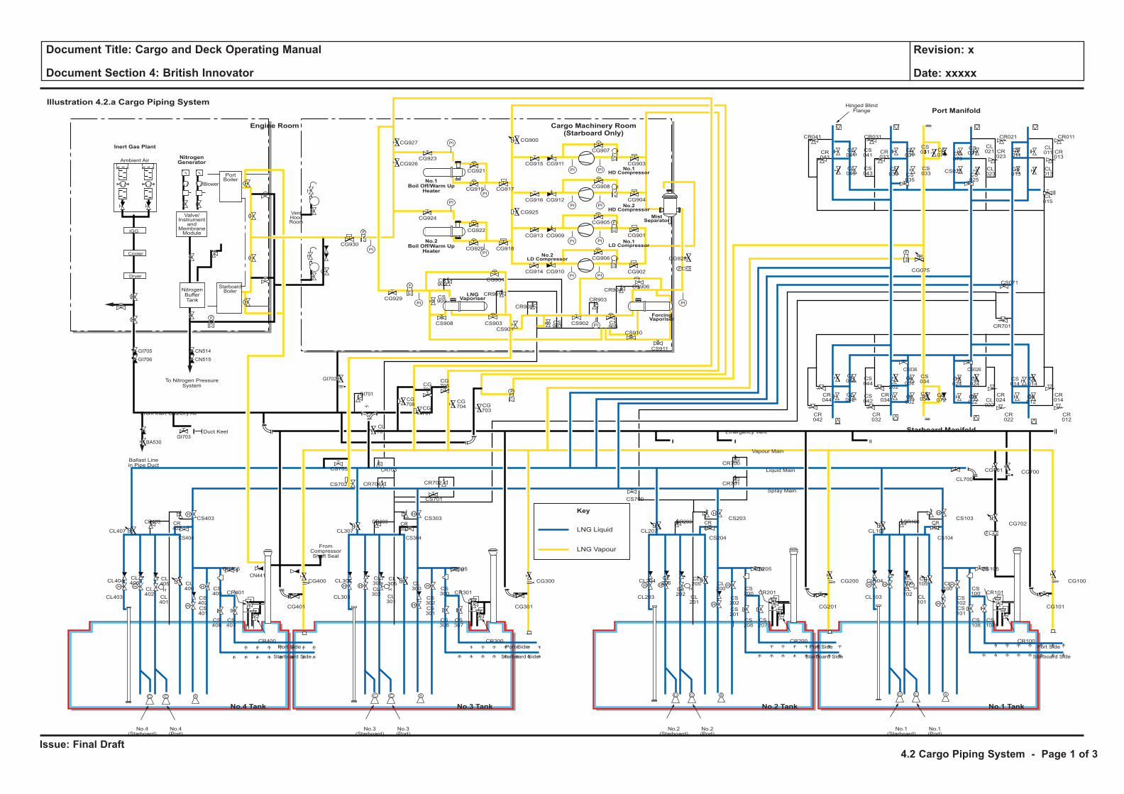
Issue: Final Draft
Document Title: Cargo and Deck Operating Manual
Document Section 4: British Innovator
Revision: x
Date: xxxxx
LNG Liquid
Key
LNG Vapour
H H
H
H
F
C C S
H
HH H
H
H
C C S
H
HH H
H
H
C C S
H
HH H
H
H
C C S
H
H
F
PI PI
F
PI PI
PI
PI
PI
PI
PI PI
PI PI
F
F
PI
PI
PI
PI
F
F
F
CL106
CL102
CL101
CL100
CS102
CS100
CS103
CS101
CS108
CS107
CR101
CR100
CL105
CL104
CL700
CG700
CG702
CG101
CS105
CS104
CR103 CR102
CG701
CL103
Port Side
Starboard Side
CL107
No.1(Starboard)
No.1(Port)
CL206
CL202
CL201
CL200
CS202
CS200
CS203
CR701
CR700
CS201
CS208
CS207
CR201
CR200
CL205
CL204
CG201
CG200 CG100
CS205
CS204
CR203 CR202
CL203
Port Side
Ambient Air
Blower
PortBoiler
VentHoodRoom
StarboardBoiler
Inert Gas Plant
NitrogenGenerator
Engine Room
No.3 TankNo.4 Tank No.1 TankNo.2 Tank
Cargo Machinery Room(Starboard Only)
Starboard Side
CL207
CS700
No.2(Starboard)
No.2(Port)
CL306
CL302
CL301
CL300
CS302
CS300
CS303
CS701
CS301
CS308
CS307
CR301
CR300
CL305
CL304
CG301
CS305
CS304
CR303 CR302
CL303
Port Side
Starboard Side
CL307
CG927
CG926CG923
CG921
CG917CG919
CG924
CG930
CG929
CG904
CR901
CR905
CR903
CR904
CS909
CS907
CS905
CS908 CS903
CS901
CS902
CS910
CS911
CR902
CG922
CG918
CG928
CG902
CG906
CG905
CG908
CG907
CR041
CR043
CL041
CL043
CS041
CS043
CL031
CS031 CS
011
CL011 CR
013
CG071 CG
073
CS021
CL021
CL023CS
025
CS023 CL013
CL015
CS013
CR023
CR033
CR021CR031 CR011
CS035
CL033
CS033
CG915
CG900
CG925
CG911
CG916 CG912
CG913 CG909
CG914 CG910
CG901
CG904
CG903
CG920
No.3(Starboard)
No.3(Port)
CL406
CL402
CL401
CL400
CS402
CS400
CS403
CS702 CR704 CR702
CR703
CG708
CG707
CG706
CG705
CG704 CG
703
CS703
CL701
CS401
CS408
CS407
CR401
CR400
CL405
CL404
CG401
CG400 CG300
CS405
FromCompressorShaft Seal
CS404
CR403
GI705
GI706
GI703
GI702
GI701
BA530
CN514
CN515
CR402
CL403
Port Side
Starboard Side
CL407
No.4(Starboard)
No.4(Port)
CL044
CS044
CS042
CS034
CS024
CL024
CS034
CR044
CR034
CR024
CR042
CR032
CR022
CS036 CS026
CL042
CL034CL
202
CL032
CG072
CS022 CL
022
CS014
CR701
CS071
CL014
CR014
CR012
CS012
F
F
F
Cooler
Dryer
IGG
Valve/Instrument
andMembraneModule
NitrogenBufferTank
To Nitrogen PressureSystem
Hinged BlindFlange
Ballast Linein Pipe Duct
Duct Keel
From Inert Gas/Dry Air
Emergency Vent
Vapour Main
Liquid Main
Spray Main
No.1Boil Off/Warm Up
Heater
No.2Boil Off/Warm Up
Heater
ForcingVaporiser
MistSeparator
No.1HD Compressor
No.2HD Compressor
No.1LD Compressor
LNGVaporiser
No.2LD Compressor
Illustration 4.2.a Cargo Piping SystemPort Manifold
Starboard Manifold
CG075
CN441
CS906
4.2 Cargo Piping System - Page 1 of 3
Issue: Final Draft
Document Title: Cargo and Deck Operating Manual
Document Section 4: British Innovator
Revision: x
Date: xxxxx
4.2 CARGO PIPING SYSTEM
Description
The cargo piping system is illustrated in a simplified perspective drawing showing only the principal features of the system.
Liquid cargo is loaded and discharged via the two crossover lines at midships and is delivered to and from each cargo tank liquid dome via the liquid header which runs fore and aft along the trunk deck. Each crossover line at midships separates into two loading/discharging connections, port and starboard, making a total of four loading/discharge connections on each side of the ship.
The cargo tank vapour domes are maintained in communication with each other by the vapour header running fore and aft along the trunk deck. The vapour main also has a cross-connection at the midship manifold for use in regulating tank pressures when loading and discharging.
When loading, the vapour header and crossover, together with the HD compressors, are used to return the displaced gas from the tanks back to the shore installation. When discharging, the vapour header is used in conjunction with either the vapour crossover, or a vaporiser, to supply gas to the tanks to replace the outgoing liquid cargo.
The stripping/spray line can be connected to the liquid crossover lines and can be used to drain or to cool down each cargo tank, and also to spray during discharging if the return vapour is insufficient.
The vapour header and stripping/spray headers are both connected to the vapour dome of each tank. The vapour domes also house the tank safety valves, pressure pick up and three sample points. The spray line on each tank consists of two spray assemblies inside the tank at the top to distribute the incoming liquid into several spray nozzles in order to assist in evaporation and thus achieve a better cooldown rate.
The stripping/spray, liquid and vapour headers have branches to and from the cargo auxiliaries room with connections to the compressors, heaters and vaporiser for various auxiliary functions. Removable bends are supplied for fitting where necessary to allow cross-connection between the various pipework for infrequent uses, such as preparing for dry dock and recommissioning after dry dock.
The vapour header connects the vapour domes to each other for the venting of boil-off gas, which discharges to atmosphere through vent mast riser No.1. The vapour main also directs the boil-off gas to the engine room for gas burning, via the LD compressors and boil-off/warm-up gas heaters.
The Inert Gas and Dry-Air System (section 4.10), located in the engine room, is used to supply inert gas or dry air to the cargo tanks via piping which connects with the main cargo system through a double, non-return valve to avoid gas returning to the engine room.
All of the cargo piping is welded to reduce the possibility of joint leakage. Flanged connections are electrically bonded by means of straps provided between flanges to ensure that differences in potential, due to static electricity between cargo and other deck piping, tanks, valves and other equipment, are avoided.
Both liquid and vapour systems have been designed in such a way that expansion and contraction are absorbed in the piping configuration. This is done by means of expansion loops and bellows on liquid and vapour piping respectively.
Fixed and sliding pipe supports and guides are provided to ensure that pipe stresses are kept within acceptable limits.
All sections of liquid piping that can be isolated, and thus possibly trap liquid between closed valves, are provided with safety valves which relieve excess pressure to the nearest vapour dome. This is a safety measure, although normal working practice is to allow any remaining liquid to warm up and boil off before closing any such valves.
All major valves such as the midships manifold (port and starboard) valves, also called ESD Manifold Valves, and individual tank loading and discharge valves, are remotely power operated from the IAS, so that all normal cargo operations can be carried out from the cargo control room.
When an ESD is activated, the manifold valves are closed, discontinuing loading or unloading operations.
A non-return valve is fitted at the discharge flange of each cargo pump. A 6mm hole is drilled in the valve disc to allow the tank discharge lines to drain down and be gas freed. Non-return valves are also fitted at the discharge flange of the compressors. The spray/stripping and emergency cargo pump discharge lines have non-return valves located directly after the hydraulically operated discharge valves.
A small 6mm diameter spray nozzle is also fitted at the top of each cargo pump discharge line inside the tank to cool down the auxiliary pump tower leg in order to maintain a cold temperature through the complete discharge.
(Note: Electrical bonding by means of straps is provided between bolted flanges. Whenever a section of pipe or piece of equipment is unbolted, the bonding straps MUST be replaced when the flanged joint is re-made.)
4.2.1 LIQUID HEADER LINE
The system comprises a 600/400mm butt welded, cryogenic stainless steel pipeline connecting each of the four cargo tanks to the loading/discharge manifolds at the ship’s side by means of a common line.
At each tank liquid dome there is a manifold which connects to the loading and discharge lines from the tank to allow for the loading and discharge of cargo.
This manifold on the liquid dome connects to the tank discharge lines from the port and starboard cargo pumps, the loading line, emergency pump well and spray line
At certain points along the liquid line, blank flanges and sample points are fitted to facilitate inerting and aeration of system during refit.
All sections of the liquid line outside the cargo tanks are insulated with a rigid polyurethane foam, covered with a moulded GRP cover to act as a tough water and vapour tight barrier
4.2 Cargo Piping System - Page 2 of 3
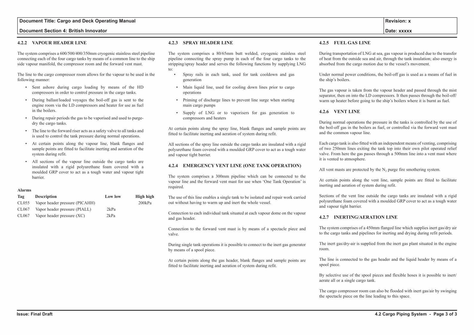
Issue: Final Draft
Document Title: Cargo and Deck Operating Manual
Document Section 4: British Innovator
Revision: x
Date: xxxxx
4.2.2 VAPOUR HEADER LINE
The system comprises a 600/500/400/350mm cryogenic stainless steel pipeline connecting each of the four cargo tanks by means of a common line to the ship side vapour manifold, the compressor room and the forward vent mast.
The line to the cargo compressor room allows for the vapour to be used in the following manner:
• Sent ashore during cargo loading by means of the HD compressors in order to control pressure in the cargo tanks.
• During ballast/loaded voyages the boil-off gas is sent to the engine room via the LD compressors and heater for use as fuel in the boilers.
• During repair periods the gas to be vaporised and used to purge-dry the cargo tanks.
• The line to the forward riser acts as a safety valve to all tanks and is used to control the tank pressure during normal operations.
• At certain points along the vapour line, blank flanges and sample points are fitted to facilitate inerting and aeration of the system during refit.
• All sections of the vapour line outside the cargo tanks are insulated with a rigid polyurethane foam covered with a moulded GRP cover to act as a tough water and vapour tight barrier.
AlarmsTag Description Low low High highCL055 Vapor header pressure (PICAHH) 200kPaCL067 Vapor header pressure (PIALL) 2kPaCL067 Vapor header pressure (XC) 2kPa
4.2.3 SPRAY HEADER LINE
The system comprises a 80/65mm butt welded, cryogenic stainless steel pipeline connecting the spray pump in each of the four cargo tanks to the stripping/spray header and serves the following functions by supplying LNG to:
• Spray rails in each tank, used for tank cooldown and gas generation
• Main liquid line, used for cooling down lines prior to cargo operations
• Priming of discharge lines to prevent line surge when starting main cargo pumps
• Supply of LNG or to vaporisers for gas generation to compressors and heaters
At certain points along the spray line, blank flanges and sample points are fitted to facilitate inerting and aeration of system during refit.
All sections of the spray line outside the cargo tanks are insulated with a rigid polyurethane foam covered with a moulded GRP cover to act as a tough water and vapour tight barrier.
4.2.4 EMERGENCY VENT LINE (ONE TANK OPERATION)
The system comprises a 300mm pipeline which can be connected to the vapour line and the forward vent mast for use when ‘One Tank Operation’ is required.
The use of this line enables a single tank to be isolated and repair work carried out without having to warm up and inert the whole vessel.
Connection to each individual tank situated at each vapour dome on the vapour and gas header.
Connection to the forward vent mast is by means of a spectacle piece and valve.
During single tank operations it is possible to connect to the inert gas generator by means of a spool piece.
At certain points along the gas header, blank flanges and sample points are fitted to facilitate inerting and aeration of system during refit.
4.2.5 FUEL GAS LINE
During transportation of LNG at sea, gas vapour is produced due to the transfer of heat from the outside sea and air, through the tank insulation; also energy is absorbed from the cargo motion due to the vessel’s movement.
Under normal power conditions, the boil-off gas is used as a means of fuel in the ship’s boilers.
The gas vapour is taken from the vapour header and passed through the mist separator, then on into the LD compressors. It then passes through the boil-off/warm up heater before going to the ship’s boilers where it is burnt as fuel.
4.2.6 VENT LINE
During normal operations the pressure in the tanks is controlled by the use of the boil-off gas in the boilers as fuel, or controlled via the forward vent mast and the common vapour line.
Each cargo tank is also fitted with an independent means of venting, comprising of two 250mm lines exiting the tank top into their own pilot operated relief valve. From here the gas passes through a 500mm line into a vent mast where it is vented to atmosphere.
All vent masts are protected by the N2 purge fire smothering system.
At certain points along the vent line, sample points are fitted to facilitate inerting and aeration of system during refit.
Sections of the vent line outside the cargo tanks are insulated with a rigid polyurethane foam covered with a moulded GRP cover to act as a tough water and vapour tight barrier.
4.2.7 INERTING/AERATION LINE
The system comprises of a 450mm flanged line which supplies inert gas/dry air to the cargo tanks and pipelines for inerting and drying during refit periods.
The inert gas/dry-air is supplied from the inert gas plant situated in the engine room.
The line is connected to the gas header and the liquid header by means of a spool piece.
By selective use of the spool pieces and flexible hoses it is possible to inert/ aerate all or a single cargo tank.
The cargo compressor room can also be flooded with inert gas/air by swinging the spectacle piece on the line leading to this space.
4.2 Cargo Piping System - Page 3 of 3
4.3 Cargo Pumps
4.3.1 Main Cargo Pumps
4.3.2 Stripping/Spray Pump
4.3.3 Emergency Cargo Pump
Illustrations
4.3.1a Main Cargo Pump
4.3.1b Main Cargo Pump Start Sequence
4.3.2a Stripping/Spray Pump
4.3.2b Spray Pump Start Sequence
4.3.3a Emergency Cargo Pump
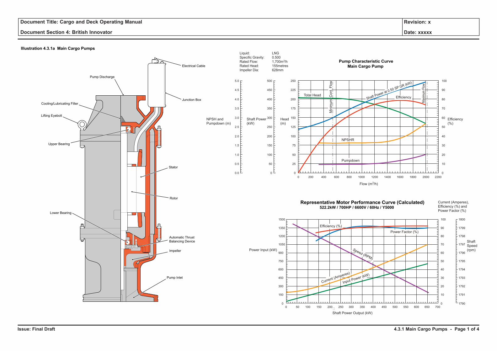
Issue: Final Draft
Document Title: Cargo and Deck Operating Manual
Document Section 4: British Innovator
Revision: x
Date: xxxxx
Pump Characteristic Curve
Main Cargo Pump
Representative Motor Performance Curve (Calculated)522.2kW / 700HP / 6600V / 60Hz / Y5000
100
90
80
70
60
50
40
30
20
10
0
1500
1350
1200
1050
900
750
600
450
300
150
00 50 100 150 200 250 300 350 400 450 500 550 600 650 700
�
Shaft Power Output (kW)
Efficiency (%)
Speed (RPM)
Current (Amperes)
Input Power (kW)
Flow (m3/h)
0 200 400 600 800 1000 1200 1400 1600 1800 2000 2200
0.0
0.5
1.0
1.5
2.0
2.5
3.0
3.5
4.0
4.5
5.0
0
50
100
150
200
250
300
350
400
450
500
0
25
50
75
100
125
150
175
200
225
250
0
10
20
30
40
50
60
70
80
90
100
Liquid: LNG
Specific Gravity: 0.500
Rated Flow: 1,700m3/h
Rated Head: 155metres
Impeller Dia: 628mm
Total HeadShaft Power at 0.50 SP GR (kW)
Efficiency
Pumpdown
NPSHR
Min
imu
mC
on
t.F
low
Max
imum
Flo
w
Shaft
Speed
(rpm)
1800
1799
1798
1797
1796
1795
1794
1793
1792
1791
1790
Current (Amperes),
Efficiency (%) and
Power Factor (%)
Power Input (kW)
Efficiency
(%)
NPSH and
Pumpdown (m)
Shaft Power
(kW)
Head
(m)
Power Factor (%)
Electrical Cable
Lifting Eyebolt
Pump Discharge
Junction BoxCooling/Lubricating Filter
Stator
Rotor
Impeller
Automatic Thrust
Balancing Device
Pump Inlet
Lower Bearing
Upper Bearing
Illustration 4.3.1a Main Cargo Pumps
4.3.1 Main Cargo Pumps - Page 1 of 4
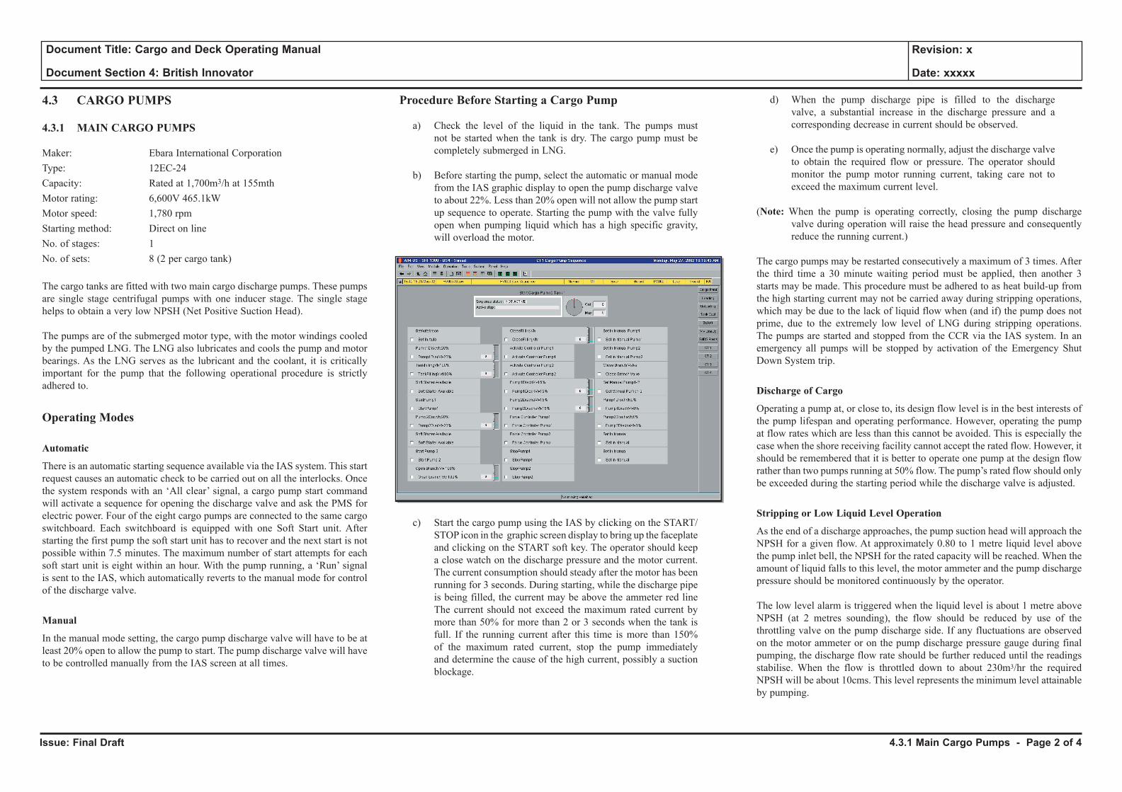
Issue: Final Draft
Document Title: Cargo and Deck Operating Manual
Document Section 4: British Innovator
Revision: x
Date: xxxxx
4.3 CARGO PUMPS
4.3.1 MAIN CARGO PUMPS
Maker: Ebara International Corporation Type: 12EC-24Capacity: Rated at 1,700m3/h at 155mthMotor rating: 6,600V 465.1kWMotor speed: 1,780 rpmStarting method: Direct on lineNo. of stages: 1No. of sets: 8 (2 per cargo tank)
The cargo tanks are fitted with two main cargo discharge pumps. These pumps are single stage centrifugal pumps with one inducer stage. The single stage helps to obtain a very low NPSH (Net Positive Suction Head).
The pumps are of the submerged motor type, with the motor windings cooled by the pumped LNG. The LNG also lubricates and cools the pump and motor bearings. As the LNG serves as the lubricant and the coolant, it is critically important for the pump that the following operational procedure is strictly adhered to.
Operating Modes
Automatic
There is an automatic starting sequence available via the IAS system. This start request causes an automatic check to be carried out on all the interlocks. Once the system responds with an ‘All clear’ signal, a cargo pump start command will activate a sequence for opening the discharge valve and ask the PMS for electric power. Four of the eight cargo pumps are connected to the same cargo switchboard. Each switchboard is equipped with one Soft Start unit. After starting the first pump the soft start unit has to recover and the next start is not possible within 7.5 minutes. The maximum number of start attempts for each soft start unit is eight within an hour. With the pump running, a ‘Run’ signal is sent to the IAS, which automatically reverts to the manual mode for control of the discharge valve.
Manual
In the manual mode setting, the cargo pump discharge valve will have to be at least 20% open to allow the pump to start. The pump discharge valve will have to be controlled manually from the IAS screen at all times.
Procedure Before Starting a Cargo Pump
a) Check the level of the liquid in the tank. The pumps must not be started when the tank is dry. The cargo pump must be completely submerged in LNG.
b) Before starting the pump, select the automatic or manual mode from the IAS graphic display to open the pump discharge valve to about 22%. Less than 20% open will not allow the pump start up sequence to operate. Starting the pump with the valve fully open when pumping liquid which has a high specific gravity, will overload the motor.
c) Start the cargo pump using the IAS by clicking on the START/STOP icon in the graphic screen display to bring up the faceplate and clicking on the START soft key. The operator should keep a close watch on the discharge pressure and the motor current. The current consumption should steady after the motor has been running for 3 seconds. During starting, while the discharge pipe is being filled, the current may be above the ammeter red line The current should not exceed the maximum rated current by more than 50% for more than 2 or 3 seconds when the tank is full. If the running current after this time is more than 150% of the maximum rated current, stop the pump immediately and determine the cause of the high current, possibly a suction blockage.
d) When the pump discharge pipe is filled to the discharge valve, a substantial increase in the discharge pressure and a corresponding decrease in current should be observed.
e) Once the pump is operating normally, adjust the discharge valve to obtain the required flow or pressure. The operator should monitor the pump motor running current, taking care not to exceed the maximum current level.
(Note: When the pump is operating correctly, closing the pump discharge valve during operation will raise the head pressure and consequently reduce the running current.)
The cargo pumps may be restarted consecutively a maximum of 3 times. After the third time a 30 minute waiting period must be applied, then another 3 starts may be made. This procedure must be adhered to as heat build-up from the high starting current may not be carried away during stripping operations, which may be due to the lack of liquid flow when (and if) the pump does not prime, due to the extremely low level of LNG during stripping operations. The pumps are started and stopped from the CCR via the IAS system. In an emergency all pumps will be stopped by activation of the Emergency Shut Down System trip.
Discharge of Cargo
Operating a pump at, or close to, its design flow level is in the best interests of the pump lifespan and operating performance. However, operating the pump at flow rates which are less than this cannot be avoided. This is especially the case when the shore receiving facility cannot accept the rated flow. However, it should be remembered that it is better to operate one pump at the design flow rather than two pumps running at 50% flow. The pump’s rated flow should only be exceeded during the starting period while the discharge valve is adjusted.
Stripping or Low Liquid Level Operation
As the end of a discharge approaches, the pump suction head will approach the NPSH for a given flow. At approximately 0.80 to 1 metre liquid level above the pump inlet bell, the NPSH for the rated capacity will be reached. When the amount of liquid falls to this level, the motor ammeter and the pump discharge pressure should be monitored continuously by the operator.
The low level alarm is triggered when the liquid level is about 1 metre above NPSH (at 2 metres sounding), the flow should be reduced by use of the throttling valve on the pump discharge side. If any fluctuations are observed on the motor ammeter or on the pump discharge pressure gauge during final pumping, the discharge flow rate should be further reduced until the readings stabilise. When the flow is throttled down to about 230m3/hr the required NPSH will be about 10cms. This level represents the minimum level attainable by pumping.
4.3.1 Main Cargo Pumps - Page 2 of 4
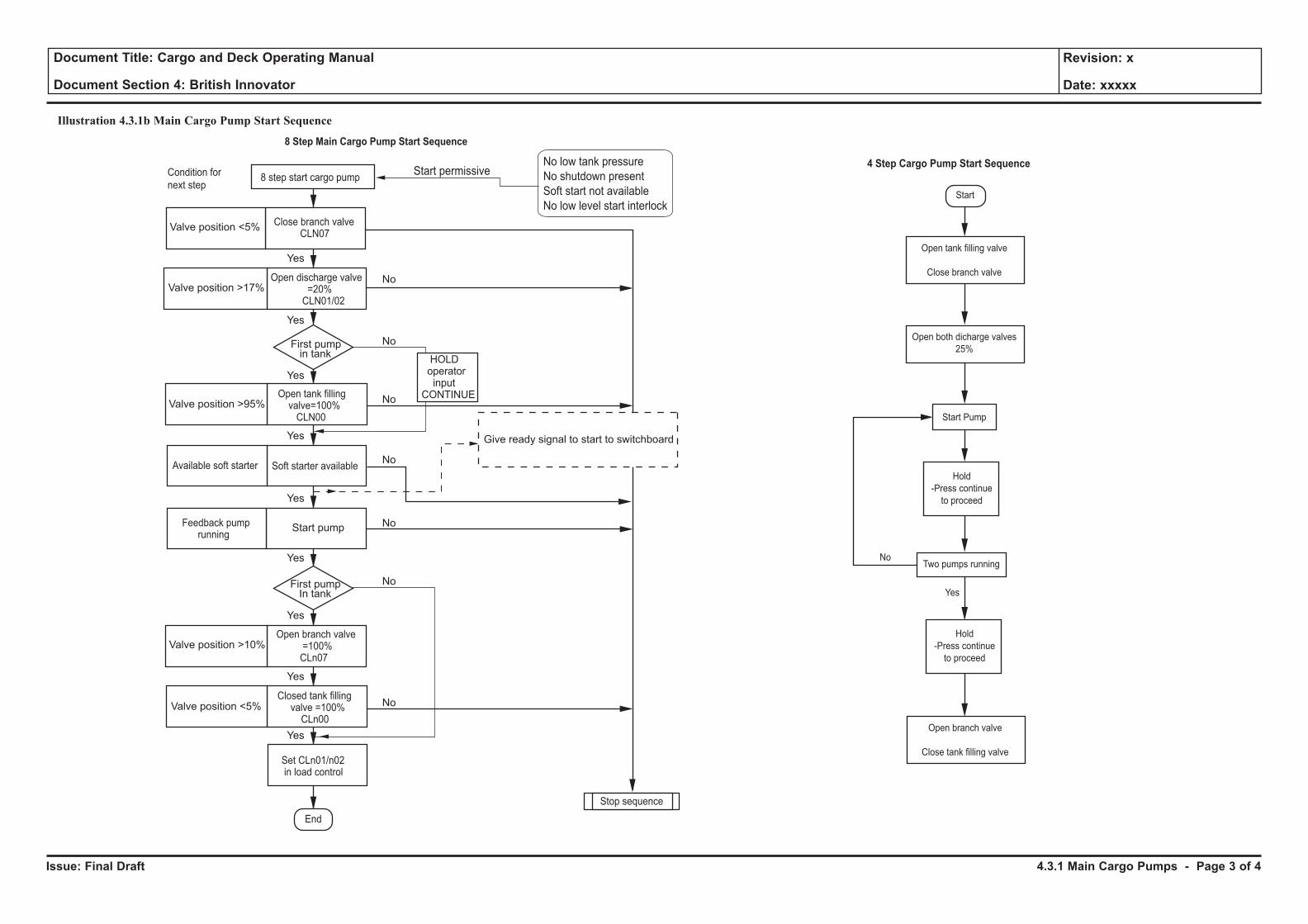
Issue: Final Draft
Document Title: Cargo and Deck Operating Manual
Document Section 4: British Innovator
Revision: x
Date: xxxxx
8 Step Main Cargo Pump Start Sequence
End
Valve position <5%
Valve position >17%
Valve position >95%
Valve position >10%
Valve position <5%
Start pump
Give ready signal to start to switchboard
HOLDoperatorinput
CONTINUE
Open branch valve=100%CLn07
Open discharge valve=20%CLN01/02
Soft starter availableAvailable soft starter
Close branch valveCLN07
Feedback pumprunning
Closed tank fillingvalve =100%CLn00
Stop sequence
Set CLn01/n02in load control
Open tank fillingvalve=100%CLN00
8 step start cargo pump
First pumpin tank
First pumpIn tank
No
No
No
No
No
No
No
Yes
Yes
Yes
Yes
Yes
Yes
Yes
Yes
Yes
No low tank pressure
No shutdown present
Soft start not available
No low level start interlock
Start permissiveCondition for
next stepStart
4 Step Cargo Pump Start Sequence
No
Yes
Open tank filling valve
Close branch valve
Open branch valve
Close tank filling valve
Open both dicharge valves
25%
Start Pump
Two pumps running
Hold
-Press continue
to proceed
Hold
-Press continue
to proceed
4.3.1 Main Cargo Pumps - Page 3 of 4
Illustration 4.3.1b Main Cargo Pump Start Sequence
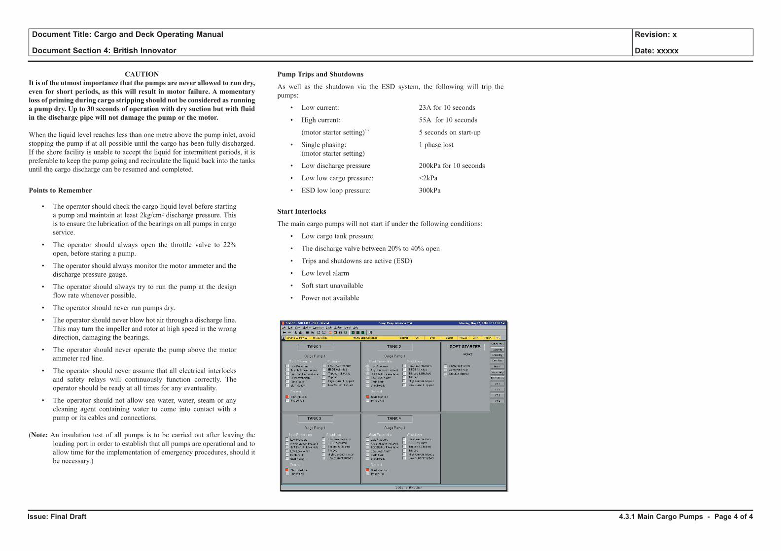
Issue: Final Draft
Document Title: Cargo and Deck Operating Manual
Document Section 4: British Innovator
Revision: x
Date: xxxxx
CAUTIONIt is of the utmost importance that the pumps are never allowed to run dry, even for short periods, as this will result in motor failure. A momentary loss of priming during cargo stripping should not be considered as running a pump dry. Up to 30 seconds of operation with dry suction but with fluid in the discharge pipe will not damage the pump or the motor.
When the liquid level reaches less than one metre above the pump inlet, avoid stopping the pump if at all possible until the cargo has been fully discharged. If the shore facility is unable to accept the liquid for intermittent periods, it is preferable to keep the pump going and recirculate the liquid back into the tanks until the cargo discharge can be resumed and completed.
Points to Remember
• The operator should check the cargo liquid level before starting a pump and maintain at least 2kg/cm2 discharge pressure. This is to ensure the lubrication of the bearings on all pumps in cargo service.
• The operator should always open the throttle valve to 22% open, before staring a pump.
• The operator should always monitor the motor ammeter and the discharge pressure gauge.
• The operator should always try to run the pump at the design flow rate whenever possible.
• The operator should never run pumps dry.
• The operator should never blow hot air through a discharge line. This may turn the impeller and rotor at high speed in the wrong direction, damaging the bearings.
• The operator should never operate the pump above the motor ammeter red line.
• The operator should never assume that all electrical interlocks and safety relays will continuously function correctly. The operator should be ready at all times for any eventuality.
• The operator should not allow sea water, water, steam or any cleaning agent containing water to come into contact with a pump or its cables and connections.
(Note: An insulation test of all pumps is to be carried out after leaving the loading port in order to establish that all pumps are operational and to allow time for the implementation of emergency procedures, should it be necessary.)
Pump Trips and Shutdowns
As well as the shutdown via the ESD system, the following will trip the pumps:
• Low current: 23A for 10 seconds
• High current: 55A for 10 seconds
(motor starter setting)`` 5 seconds on start-up
• Single phasing: 1 phase lost (motor starter setting)
• Low discharge pressure 200kPa for 10 seconds
• Low low cargo pressure: <2kPa
• ESD low loop pressure: 300kPa
Start Interlocks
The main cargo pumps will not start if under the following conditions:
• Low cargo tank pressure
• The discharge valve between 20% to 40% open
• Trips and shutdowns are active (ESD)
• Low level alarm
• Soft start unavailable
• Power not available
4.3.1 Main Cargo Pumps - Page 4 of 4
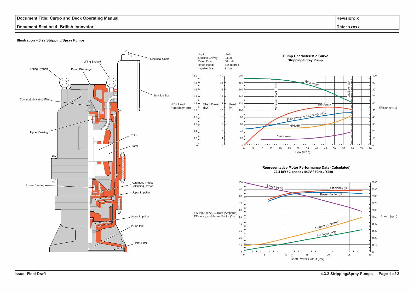
Issue: Final Draft
Document Title: Cargo and Deck Operating Manual
Document Section 4: British Innovator
Revision: x
Date: xxxxx
Pump Characteristic Curve
Stripping/Spray Pump
Representative Motor Performance Data (Calculated)
22.4 kW / 3 phase / 440V / 60Hz / Y250
100
90
80
70
60
50
40
30
20
10
0
2.0
1.8
1.6
1.4
1.2
1.0
0.8
0.6
0.4
0.2
0
40
36
32
28
24
20
16
12
8
4
0
200
180
160
140
120
100
80
60
40
20
00 5 10 15 20 25 30 35 40 45 50 55 60 65 70
Liquid: LNG
Specific Gravity: 0.500
Rated Flow: 50m3/h
Rated Head: 145 metres
Impeller Dia: 214mm
Flow (m3/h)
Total Head
Efficiency
Pumpdown
NPSHR
Shaft Power at 0.50 SP GR (kW)
Min
imu
mC
on
t.F
low
Max
imum
Flo
w
3600
3590
3580
3570
3560
3550
3540
3530
3520
3510
0
100
90
80
70
60
50
40
30
20
10
00 5 10 15 20 25 30�
Shaft Power Output (kW)
Speed (rpm) Efficiency (%)
Power Factor (%)
kW Input (kW)
Current (Amperes)
kW Input (kW), Current (Amperes)
Efficiency and Power Factor (%) Speed (rpm)
Efficiency (%)
NPSH and
Pumpdown (m)
Shaft Power
(kW)
Head
(m)
Electrical Cable
Lifting Eyebolt Pump Discharge
Junction Box
Cooling/Lubricating Filter
Rotor
Stator
Upper Impeller
Automatic Thrust
Balancing Device
Lower Impeller
Pump Inlet
Inlet Filter
Lower Bearing
Upper Bearing
Lifting Eyebolt
Illustration 4.3.2a Stripping/Spray Pumps
4.3.2 Stripping/Spray Pumps - Page 1 of 2
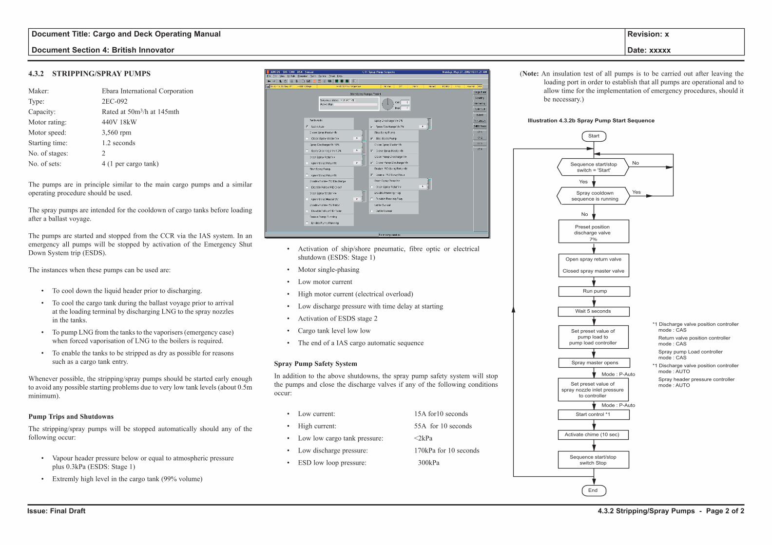
Issue: Final Draft
Document Title: Cargo and Deck Operating Manual
Document Section 4: British Innovator
Revision: x
Date: xxxxx
4.3.2 STRIPPING/SPRAY PUMPS
Maker: Ebara International CorporationType: 2EC-092Capacity: Rated at 50m3/h at 145mthMotor rating: 440V 18kWMotor speed: 3,560 rpmStarting time: 1.2 secondsNo. of stages: 2No. of sets: 4 (1 per cargo tank)
The pumps are in principle similar to the main cargo pumps and a similar operating procedure should be used.
The spray pumps are intended for the cooldown of cargo tanks before loading after a ballast voyage.
The pumps are started and stopped from the CCR via the IAS system. In an emergency all pumps will be stopped by activation of the Emergency Shut Down System trip (ESDS).
The instances when these pumps can be used are:
• To cool down the liquid header prior to discharging.
• To cool the cargo tank during the ballast voyage prior to arrival at the loading terminal by discharging LNG to the spray nozzles in the tanks.
• To pump LNG from the tanks to the vaporisers (emergency case) when forced vaporisation of LNG to the boilers is required.
• To enable the tanks to be stripped as dry as possible for reasons such as a cargo tank entry.
Whenever possible, the stripping/spray pumps should be started early enough to avoid any possible starting problems due to very low tank levels (about 0.5m minimum).
Pump Trips and Shutdowns
The stripping/spray pumps will be stopped automatically should any of the following occur:
• Vapour header pressure below or equal to atmospheric pressure plus 0.3kPa (ESDS: Stage 1)
• Extremly high level in the cargo tank (99% volume)
• Activation of ship/shore pneumatic, fibre optic or electrical shutdown (ESDS: Stage 1)
• Motor single-phasing
• Low motor current
• High motor current (electrical overload)
• Low discharge pressure with time delay at starting
• Activation of ESDS stage 2
• Cargo tank level low low
• The end of a IAS cargo automatic sequence
Spray Pump Safety System
In addition to the above shutdowns, the spray pump safety system will stop the pumps and close the discharge valves if any of the following conditions occur:
• Low current: 15A for10 seconds
• High current: 55A for 10 seconds
• Low low cargo tank pressure: <2kPa
• Low discharge pressure: 170kPa for 10 seconds
• ESD low loop pressure: 300kPa
(Note: An insulation test of all pumps is to be carried out after leaving the loading port in order to establish that all pumps are operational and to allow time for the implementation of emergency procedures, should it be necessary.)
Start
Illustration 4.3.2b Spray Pump Start Sequence
No
No
Mode : P-Auto
Mode : P-Auto
Yes
Yes
End
Sequence start/stop
switch = 'Start'
Spray cooldown
sequence is running
Activate chime (10 sec)
Run pump
Spray master opens
Wait 5 seconds
Start control *1
*1 Discharge valve position controller
mode : CAS
Return valve position controller
mode : CAS
Spray pump Load controller
mode : CAS
*1 Discharge valve position controller
mode : AUTO
Spray header pressure controller
mode : AUTO
Preset position
discharge valve
Open spray return valve
Closed spray master valve
Set preset value of
spray nozzle inlet pressure
to controller
Set preset value of
pump load to
pump load controller
Sequence start/stop
switch Stop
7%
4.3.2 Stripping/Spray Pumps - Page 2 of 2
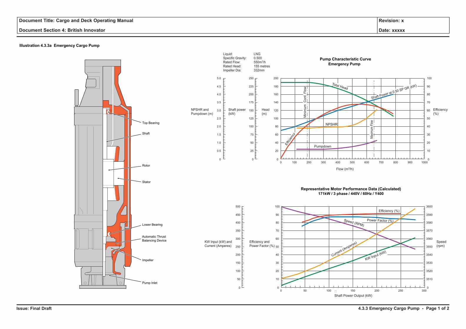
Issue: Final Draft
Document Title: Cargo and Deck Operating Manual
Document Section 4: British Innovator
Revision: x
Date: xxxxx
Pump Characteristic Curve
Emergency Pump
Representative Motor Performance Data (Calculated)171kW / 3 phase / 440V / 60Hz / Y400
100
90
80
70
60
50
40
30
20
10
0
200
180
160
140
120
100
80
60
40
20
00 100 200 300 400 500 600 700 800 900 1000
250
225
200
175
150
125
100
75
50
25
0
5.0
4.5
4.0
3.5
3.0
2.5
2.0
1.5
1.0
0.5
0
Flow (m3/h)
Liquid: LNG
Specific Gravity: 0.500
Rated Flow: 550m3/h
Rated Head: 155 metres
Impeller Dia: 332mm
NPSHR
Total Head
Effi
cien
cy
Pumpdown
Min
imu
mC
on
t.F
low
Max
imum
Flo
w
Shaft Power at 0.50 SP GR (kW)
3600
3590
3580
3570
3560
3550
3540
3530
3520
3510
0
100
90
80
70
60
50
40
30
20
10
0
500
450
400
350
300
250
200
150
100
50
00 50 100 150 200 250 300�
Shaft Power Output (kW)
Efficiency (%)
Power Factor (%)Speed (RPM)
KW Input (kW)Curre
nt (Amperes)
NPSHR and
Pumpdown (m)
Shaft power
(kW)
Head
(m)
Efficiency
(%)
KW Input (kW) and
Current (Amperes)
Efficiency and
Power Factor (%)
Speed
(rpm)
Top Bearing
Shaft
Rotor
Stator
Lower Bearing
Automatic Thrust
Balancing Device
Impeller
Pump Inlet
Illustration 4.3.3a Emergency Cargo Pump
4.3.3 Emergency Cargo Pump - Page 1 of 2
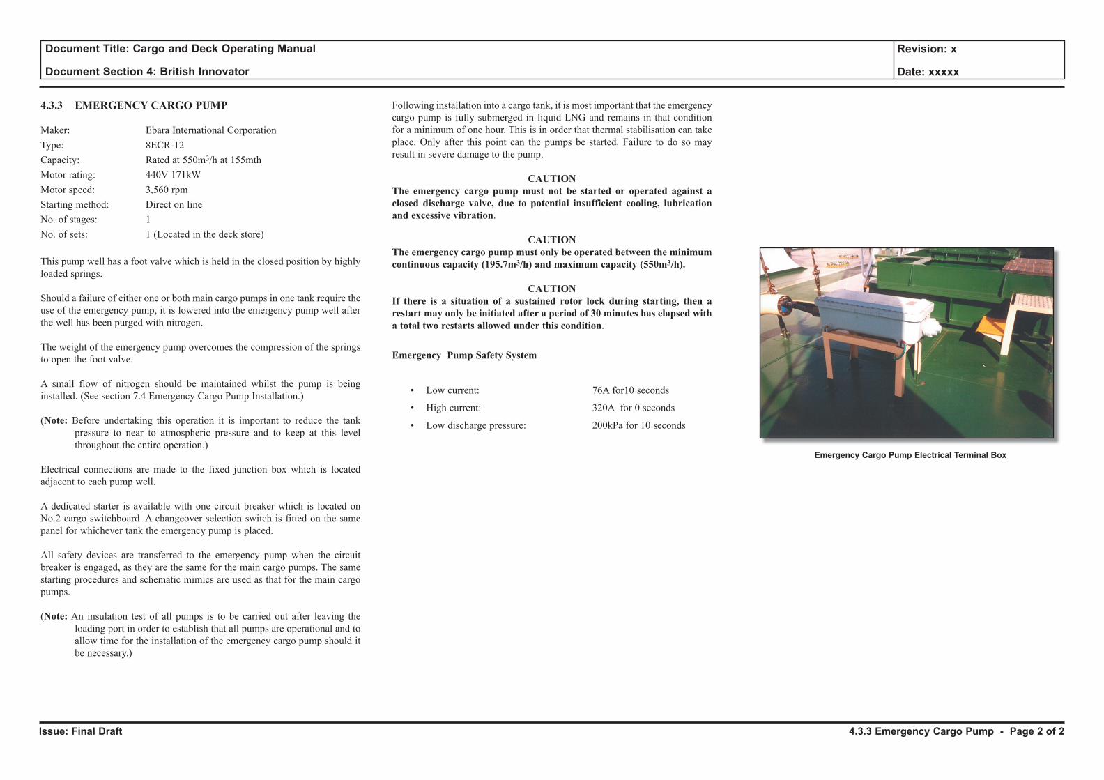
Issue: Final Draft
Document Title: Cargo and Deck Operating Manual
Document Section 4: British Innovator
Revision: x
Date: xxxxx
4.3.3 EMERGENCY CARGO PUMP
Maker: Ebara International CorporationType: 8ECR-12Capacity: Rated at 550m3/h at 155mthMotor rating: 440V 171kWMotor speed: 3,560 rpmStarting method: Direct on lineNo. of stages: 1No. of sets: 1 (Located in the deck store)
This pump well has a foot valve which is held in the closed position by highly loaded springs.
Should a failure of either one or both main cargo pumps in one tank require the use of the emergency pump, it is lowered into the emergency pump well after the well has been purged with nitrogen.
The weight of the emergency pump overcomes the compression of the springs to open the foot valve.
A small flow of nitrogen should be maintained whilst the pump is being installed. (See section 7.4 Emergency Cargo Pump Installation.)
(Note: Before undertaking this operation it is important to reduce the tank pressure to near to atmospheric pressure and to keep at this level throughout the entire operation.)
Electrical connections are made to the fixed junction box which is located adjacent to each pump well.
A dedicated starter is available with one circuit breaker which is located on No.2 cargo switchboard. A changeover selection switch is fitted on the same panel for whichever tank the emergency pump is placed.
All safety devices are transferred to the emergency pump when the circuit breaker is engaged, as they are the same for the main cargo pumps. The same starting procedures and schematic mimics are used as that for the main cargo pumps.
(Note: An insulation test of all pumps is to be carried out after leaving the loading port in order to establish that all pumps are operational and to allow time for the installation of the emergency cargo pump should it be necessary.)
Following installation into a cargo tank, it is most important that the emergency cargo pump is fully submerged in liquid LNG and remains in that condition for a minimum of one hour. This is in order that thermal stabilisation can take place. Only after this point can the pumps be started. Failure to do so may result in severe damage to the pump.
CAUTIONThe emergency cargo pump must not be started or operated against a closed discharge valve, due to potential insufficient cooling, lubrication and excessive vibration.
CAUTIONThe emergency cargo pump must only be operated between the minimum continuous capacity (195.7m3/h) and maximum capacity (550m3/h).
CAUTIONIf there is a situation of a sustained rotor lock during starting, then a restart may only be initiated after a period of 30 minutes has elapsed with a total two restarts allowed under this condition.
Emergency Pump Safety System
• Low current: 76A for10 seconds
• High current: 320A for 0 seconds
• Low discharge pressure: 200kPa for 10 seconds
4.3.3 Emergency Cargo Pump - Page 2 of 2
Emergency Cargo Pump Electrical Terminal Box
4.4 Cargo Compressors
4.4.1 High Duty Compressor
4.4.2 Low Duty Compressor
Illustrations
4.4.1a High Duty Compressor
4.4.2a Low Duty Compressor
4.4.2b Low Duty Compressor Setpoint List

Issue: Final Draft
Document Title: Cargo and Deck Operating Manual
Document Section 4: British Innovator
Revision: x
Date: xxxxx
4.4.1 High Duty Compressor - Page 1 of 3
Illustration 4.4.1a High Duty Compressor
A
LubricatingOil Tank
AuxiliaryLubricatingOil Pump
Oil Cooler
MainLubricatingOil Pump
ElectricMotor
MOTOR�ROOM COMPRESSOR�
ROOM
Compressor
GearboxDemister
ZI
ZLL1
ZLH ZLL LAL TAH TAL YAH YI YAHH
PDI
A
PDAH
TI
PDI FI FIC
PI
PI TI
TI
HIC ZS HS
YLHHYSH9
YT9
YSHH9
HSH
PI
PI
Nitrogen Seal Gas
Instrument Air
Vent
Surge Control by IAS
LNG ProcessVapour Out
LNG ProcessVapour In
T
1212
PI
PI
PI
Closed Open RemoteStart
RemoteStop
Auxiliary LO PumpRunning
Oil PumpRunning
Auxiliary LOPump Motor
Failure
Ready to Start AuxiliaryLO Pump
To/From CargoMachinery FreshWater Cooling SystemAuxiliary LO Pump
Overload
Start LOPump
Stop LOPump
From DesuperheatedSteam SystemRemote Control Signal To Condensate System
LockedOpen
LockedOpen
P
I/P
L/R
ZL
11
A A A TA11 Ready to
Start AuxiliaryLO Pump
Reset
HornSilence
CompressorMotor
Abnormal
Control SystemTrouble
EMLH
1
3 3 3
1 3 3 5 5 5 9 9 9
6
YI9
69
PCV3A
DAC3
FE1
1
1
2 2
PCV3B
PCV3C
TE1
FTI1
FY1
PTI1
PT1A
PT1B
PTI2
TE2A
TE2B
PCV3D
3A 1 13
ZSH1
ZSL1
ZE3
ZI3
DV1
DV5
LSL5
TSH5
TCV5
H5
HY3
TSL5
LG5
YET9
V6A
V6B
V6C
DV6
CV6A
F7
TI8
PDTI7
EM6
CV6B
TCV6
PDI7A
PDI7B
V6F
C6
TI6B
YE9
TI5A
ZSH3
TT1
ZT3
PCV11
FI11
EMY6
TI6A
PI6A
PI6B
HSL6 L
6 HS15.3
L15.8
ControlSystemAbnormal
Horn
L15.9
CA15
HS15.5
Lamp/HornTest
HS15.4
HS15.1
EMS15
L15.5
HSL15.2
Compressor MotorAbnormal
CompressorRunning
Remote StopCompressor
StopCompressor
HSH15.2
StartCompressor
Local/Remote
EmergencyStop
EmergencyStop
CommonAlarm
Remote StartCompressor
Ready to StartCompressor
Remote
ExternalShutdown
Ready to StartMotor
CommonTrip
A
EMS15
Ready to StartAuxiliary LOPump
L15.2
Power On
L15.1
Power On
L
Ready to StartCompressor
L15.3
EmergencyStop
L15.6
TLHH10
CompressorRunning
L15.4
TT
A
T
TAHH10
TSHH10
PLLL8C
TLHH9A
PI8B
T
PALL8C
TI9F
TAH9F
TAL9F
TAHH9A
TI8
TAH8
TAL8
PSLL10PSLL
8APTI8
PSLL11
PSL11
TPLLL8A
TLHH2A
T
T A12 11
A
PLLL11
TA
PAL
PSL8C
AAA 12
12
8C
TE9F
PCV8
TE9A
TE8
TT9F
TT9A
PT8A
TT2A
TSHH2A
TT2B
TSH2B
PSL8A
TT8
TSH8
TSL8
TSL9F
TSHH9A
TSH9F
PALL8A
TI2B
TAH2B
TAHH2A
PI2A
PI1A
PAL1
PAL11
PALL11
PAL8
PI8
Bulkhead Seal
Fresh Water
Desuperheated Steam
Nitrogen
AirKey
Lubricating Oil/LNG Vapour
T
A
11
12
Electrical Signal
Instrumentation
Cargo Control Room
Local Instrument
Local Panel Instrument
Local Panel Instrument
Trip Circuit
Alarm Circuit
Start-Up InterlockLO PumpStart-Up InterlockMachine
InletGuideVane
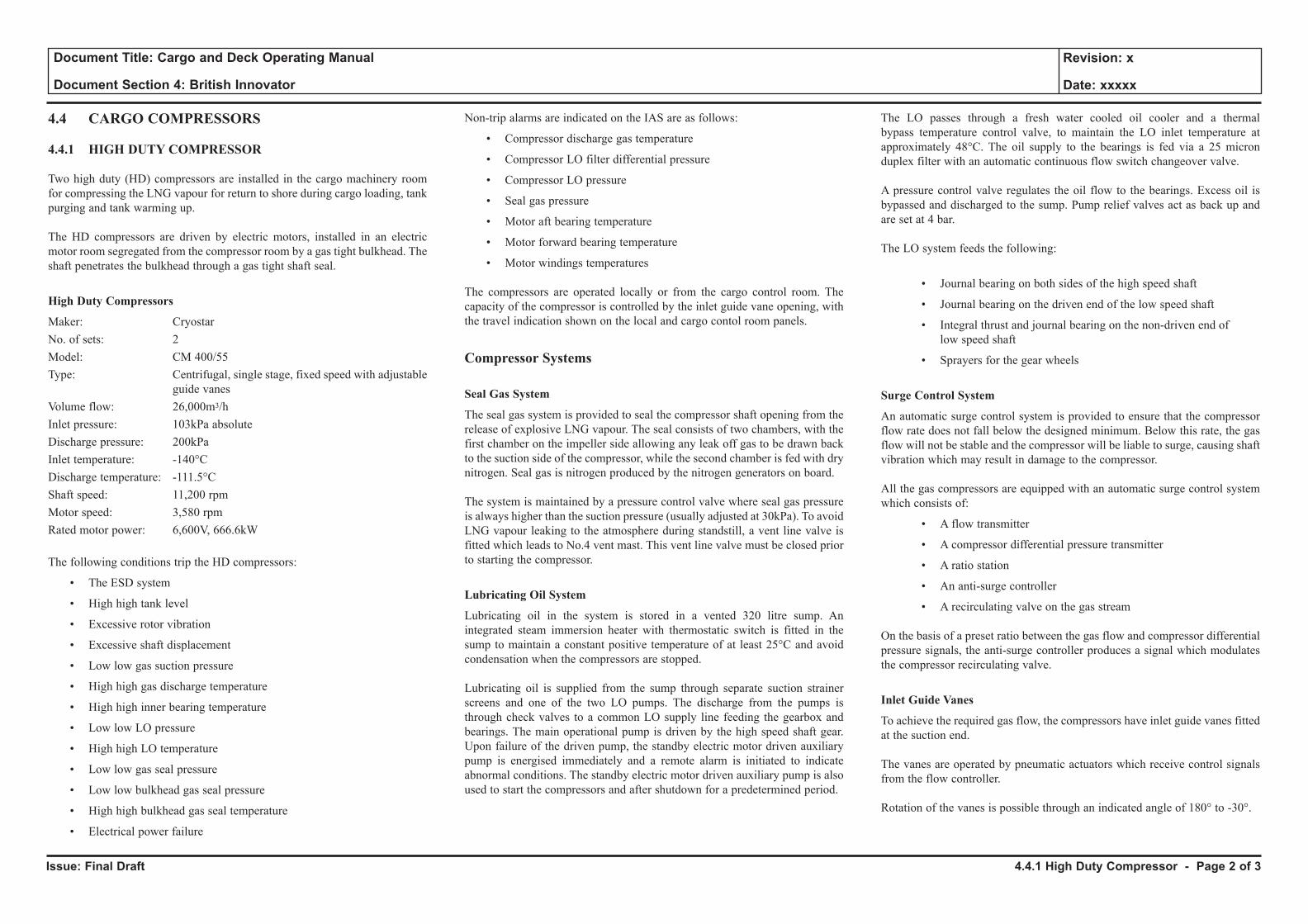
Issue: Final Draft
Document Title: Cargo and Deck Operating Manual
Document Section 4: British Innovator
Revision: x
Date: xxxxx
4.4 CARGO COMPRESSORS
4.4.1 HIGH DUTY COMPRESSOR
Two high duty (HD) compressors are installed in the cargo machinery room for compressing the LNG vapour for return to shore during cargo loading, tank purging and tank warming up.
The HD compressors are driven by electric motors, installed in an electric motor room segregated from the compressor room by a gas tight bulkhead. The shaft penetrates the bulkhead through a gas tight shaft seal.
High Duty Compressors
Maker: CryostarNo. of sets: 2Model: CM 400/55Type: Centrifugal, single stage, fixed speed with adjustable
guide vanesVolume flow: 26,000m3/hInlet pressure: 103kPa absoluteDischarge pressure: 200kPa Inlet temperature: -140°CDischarge temperature: -111.5°CShaft speed: 11,200 rpmMotor speed: 3,580 rpmRated motor power: 6,600V, 666.6kW
The following conditions trip the HD compressors:
• The ESD system
• High high tank level
• Excessive rotor vibration
• Excessive shaft displacement
• Low low gas suction pressure
• High high gas discharge temperature
• High high inner bearing temperature
• Low low LO pressure
• High high LO temperature
• Low low gas seal pressure
• Low low bulkhead gas seal pressure
• High high bulkhead gas seal temperature
• Electrical power failure
Non-trip alarms are indicated on the IAS are as follows:
• Compressor discharge gas temperature
• Compressor LO filter differential pressure
• Compressor LO pressure
• Seal gas pressure
• Motor aft bearing temperature
• Motor forward bearing temperature
• Motor windings temperatures
The compressors are operated locally or from the cargo control room. The capacity of the compressor is controlled by the inlet guide vane opening, with the travel indication shown on the local and cargo contol room panels.
Compressor Systems
Seal Gas System
The seal gas system is provided to seal the compressor shaft opening from the release of explosive LNG vapour. The seal consists of two chambers, with the first chamber on the impeller side allowing any leak off gas to be drawn back to the suction side of the compressor, while the second chamber is fed with dry nitrogen. Seal gas is nitrogen produced by the nitrogen generators on board.
The system is maintained by a pressure control valve where seal gas pressure is always higher than the suction pressure (usually adjusted at 30kPa). To avoid LNG vapour leaking to the atmosphere during standstill, a vent line valve is fitted which leads to No.4 vent mast. This vent line valve must be closed prior to starting the compressor.
Lubricating Oil System
Lubricating oil in the system is stored in a vented 320 litre sump. An integrated steam immersion heater with thermostatic switch is fitted in the sump to maintain a constant positive temperature of at least 25°C and avoid condensation when the compressors are stopped.
Lubricating oil is supplied from the sump through separate suction strainer screens and one of the two LO pumps. The discharge from the pumps is through check valves to a common LO supply line feeding the gearbox and bearings. The main operational pump is driven by the high speed shaft gear. Upon failure of the driven pump, the standby electric motor driven auxiliary pump is energised immediately and a remote alarm is initiated to indicate abnormal conditions. The standby electric motor driven auxiliary pump is also used to start the compressors and after shutdown for a predetermined period.
The LO passes through a fresh water cooled oil cooler and a thermal bypass temperature control valve, to maintain the LO inlet temperature at approximately 48°C. The oil supply to the bearings is fed via a 25 micron duplex filter with an automatic continuous flow switch changeover valve.
A pressure control valve regulates the oil flow to the bearings. Excess oil is bypassed and discharged to the sump. Pump relief valves act as back up and are set at 4 bar.
The LO system feeds the following:
• Journal bearing on both sides of the high speed shaft
• Journal bearing on the driven end of the low speed shaft
• Integral thrust and journal bearing on the non-driven end of low speed shaft
• Sprayers for the gear wheels
Surge Control System
An automatic surge control system is provided to ensure that the compressor flow rate does not fall below the designed minimum. Below this rate, the gas flow will not be stable and the compressor will be liable to surge, causing shaft vibration which may result in damage to the compressor.
All the gas compressors are equipped with an automatic surge control system which consists of:
• A flow transmitter
• A compressor differential pressure transmitter
• A ratio station
• An anti-surge controller
• A recirculating valve on the gas stream
On the basis of a preset ratio between the gas flow and compressor differential pressure signals, the anti-surge controller produces a signal which modulates the compressor recirculating valve.
Inlet Guide Vanes
To achieve the required gas flow, the compressors have inlet guide vanes fitted at the suction end.
The vanes are operated by pneumatic actuators which receive control signals from the flow controller.
Rotation of the vanes is possible through an indicated angle of 180° to -30°.
4.4.1 High Duty Compressor - Page 2 of 3
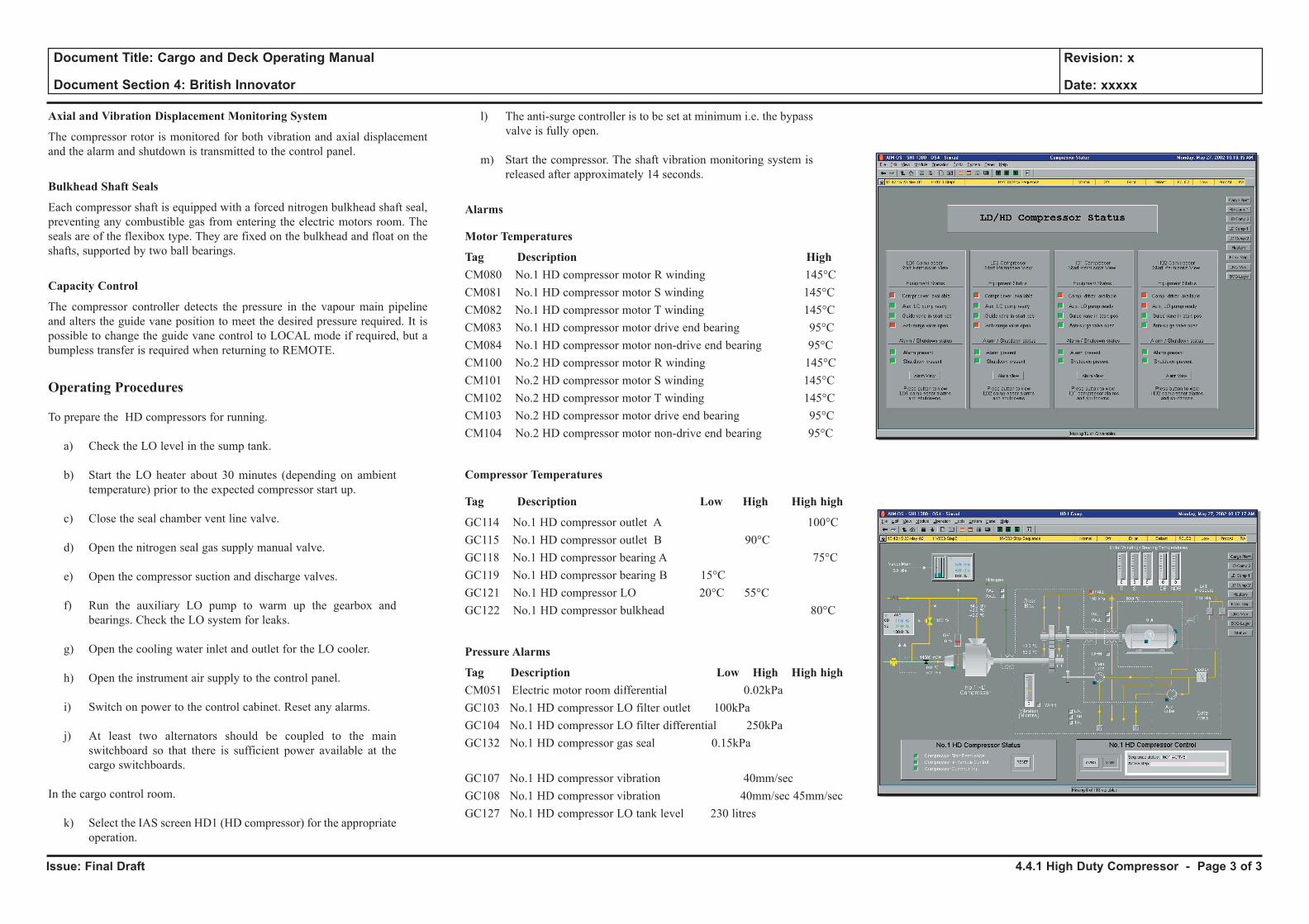
Issue: Final Draft
Document Title: Cargo and Deck Operating Manual
Document Section 4: British Innovator
Revision: x
Date: xxxxx
Axial and Vibration Displacement Monitoring System
The compressor rotor is monitored for both vibration and axial displacement and the alarm and shutdown is transmitted to the control panel.
Bulkhead Shaft Seals
Each compressor shaft is equipped with a forced nitrogen bulkhead shaft seal, preventing any combustible gas from entering the electric motors room. The seals are of the flexibox type. They are fixed on the bulkhead and float on the shafts, supported by two ball bearings.
Capacity Control
The compressor controller detects the pressure in the vapour main pipeline and alters the guide vane position to meet the desired pressure required. It is possible to change the guide vane control to LOCAL mode if required, but a bumpless transfer is required when returning to REMOTE.
Operating Procedures
To prepare the HD compressors for running.
a) Check the LO level in the sump tank.
b) Start the LO heater about 30 minutes (depending on ambient temperature) prior to the expected compressor start up.
c) Close the seal chamber vent line valve.
d) Open the nitrogen seal gas supply manual valve.
e) Open the compressor suction and discharge valves.
f) Run the auxiliary LO pump to warm up the gearbox and bearings. Check the LO system for leaks.
g) Open the cooling water inlet and outlet for the LO cooler.
h) Open the instrument air supply to the control panel.
i) Switch on power to the control cabinet. Reset any alarms.
j) At least two alternators should be coupled to the main switchboard so that there is sufficient power available at the cargo switchboards.
In the cargo control room.
k) Select the IAS screen HD1 (HD compressor) for the appropriate operation.
l) The anti-surge controller is to be set at minimum i.e. the bypass valve is fully open.
m) Start the compressor. The shaft vibration monitoring system is released after approximately 14 seconds.
Alarms
Motor Temperatures
Tag Description High CM080 No.1 HD compressor motor R winding 145°CCM081 No.1 HD compressor motor S winding 145°CCM082 No.1 HD compressor motor T winding 145°CCM083 No.1 HD compressor motor drive end bearing 95°CCM084 No.1 HD compressor motor non-drive end bearing 95°CCM100 No.2 HD compressor motor R winding 145°CCM101 No.2 HD compressor motor S winding 145°CCM102 No.2 HD compressor motor T winding 145°CCM103 No.2 HD compressor motor drive end bearing 95°CCM104 No.2 HD compressor motor non-drive end bearing 95°C
Compressor Temperatures
Tag Description Low High High high
GC114 No.1 HD compressor outlet A 100°CGC115 No.1 HD compressor outlet B 90°CGC118 No.1 HD compressor bearing A 75°CGC119 No.1 HD compressor bearing B 15°CGC121 No.1 HD compressor LO 20°C 55°CGC122 No.1 HD compressor bulkhead 80°C
Pressure Alarms
Tag Description Low High High highCM051 Electric motor room differential 0.02kPaGC103 No.1 HD compressor LO filter outlet 100kPaGC104 No.1 HD compressor LO filter differential 250kPaGC132 No.1 HD compressor gas seal 0.15kPa
GC107 No.1 HD compressor vibration 40mm/secGC108 No.1 HD compressor vibration 40mm/sec 45mm/secGC127 No.1 HD compressor LO tank level 230 litres
4.4.1 High Duty Compressor - Page 3 of 3
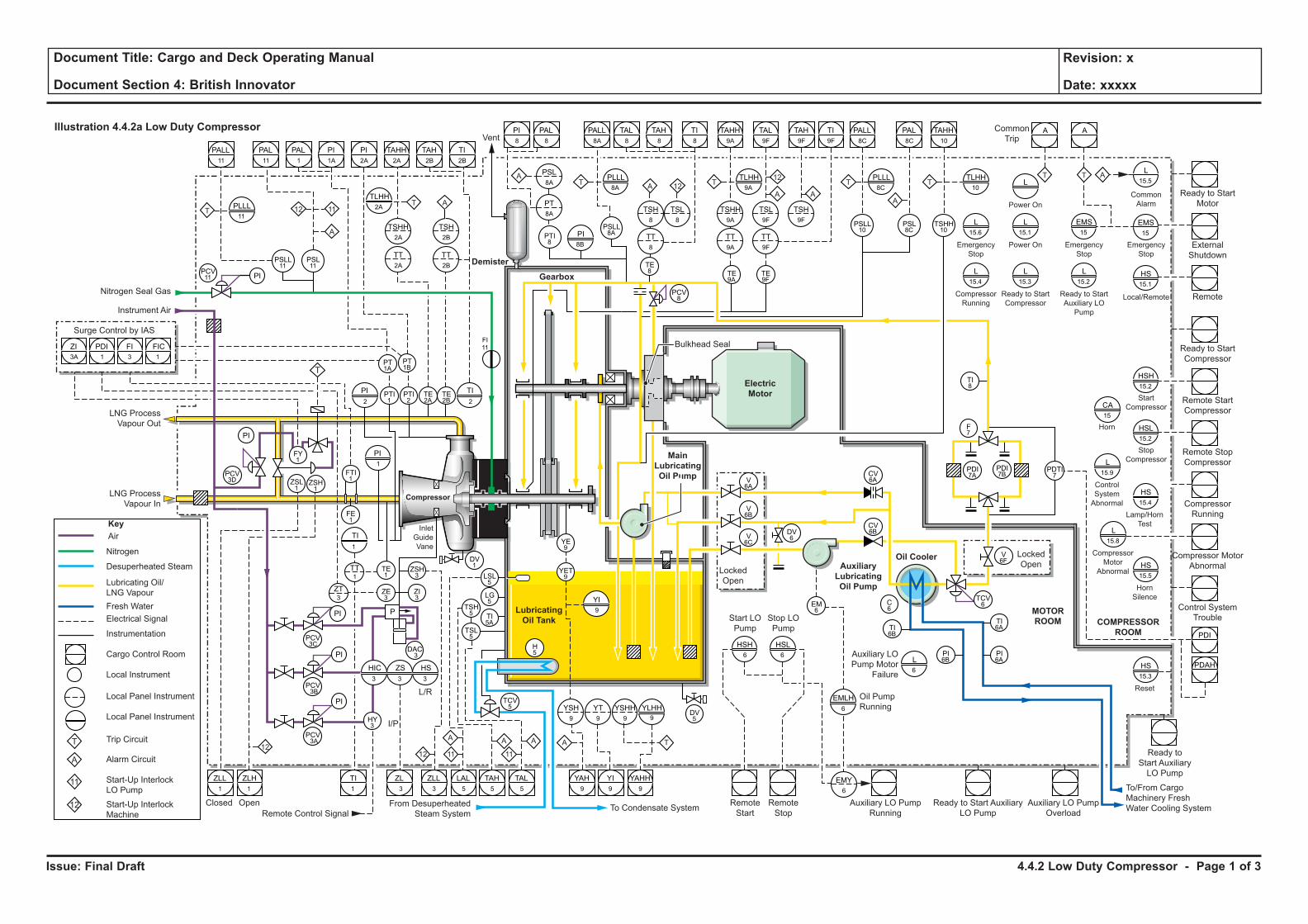
Issue: Final Draft
Document Title: Cargo and Deck Operating Manual
Document Section 4: British Innovator
Revision: x
Date: xxxxx
4.4.2 Low Duty Compressor - Page 1 of 3
Illustration 4.4.2a Low Duty Compressor
A
LubricatingOil Tank
AuxiliaryLubricatingOil Pump
Oil Cooler
MainLubricatingOil Pump
ElectricMotor
MOTOR�ROOM COMPRESSOR�
ROOM
Compressor
GearboxDemister
ZI
ZLL1
ZLH ZLL LAL TAH TAL YAH YI YAHH
PDI
A
PDAH
TI
PDI FI FIC
PI
PI TI
TI
HIC ZS HS
YLHHYSH9
YT9
YSHH9
HSH
PI
PI
Nitrogen Seal Gas
Instrument Air
Vent
Surge Control by IAS
LNG ProcessVapour Out
LNG ProcessVapour In
T
1212
PI
PI
PI
Closed Open RemoteStart
RemoteStop
Auxiliary LO PumpRunning
Oil PumpRunning
Auxiliary LOPump Motor
Failure
Ready to Start AuxiliaryLO Pump
To/From CargoMachinery FreshWater Cooling SystemAuxiliary LO Pump
Overload
Start LOPump
Stop LOPump
From DesuperheatedSteam SystemRemote Control Signal To Condensate System
LockedOpen
LockedOpen
P
I/P
L/R
ZL
11
A A A TA11 Ready to
Start AuxiliaryLO Pump
Reset
HornSilence
CompressorMotor
Abnormal
Control SystemTrouble
EMLH
1
3 3 3
1 3 3 5 5 5 9 9 9
6
YI9
69
PCV3A
DAC3
FE1
1
1
2 2
PCV3B
PCV3C
TE1
FTI1
FY1
PTI1
PT1A
PT1B
PTI2
TE2A
TE2B
PCV3D
3A 1 13
ZSH1
ZSL1
ZE3
ZI3
DV1
DV5
LSL5
TSH5
TCV5
H5
HY3
TSL5
LG5
YET9
V6A
V6B
V6C
DV6
CV6A
F7
TI8
PDTI7
EM6
CV6B
TCV6
PDI7A
PDI7B
V6F
C6
TI6B
YE9
TI5A
ZSH3
TT1
ZT3
PCV11
FI11
EMY6
TI6A
PI6A
PI6B
HSL6 L
6 HS15.3
L15.8
ControlSystemAbnormal
Horn
L15.9
CA15
HS15.5
Lamp/HornTest
HS15.4
HS15.1
EMS15
L15.5
HSL15.2
Compressor MotorAbnormal
CompressorRunning
Remote StopCompressor
StopCompressor
HSH15.2
StartCompressor
Local/Remote
EmergencyStop
EmergencyStop
CommonAlarm
Remote StartCompressor
Ready to StartCompressor
Remote
ExternalShutdown
Ready to StartMotor
CommonTrip
A
EMS15
Ready to StartAuxiliary LOPump
L15.2
Power On
L15.1
Power On
L
Ready to StartCompressor
L15.3
EmergencyStop
L15.6
TLHH10
CompressorRunning
L15.4
TT
A
T
TAHH10
TSHH10
PLLL8C
TLHH9A
PI8B
T
PALL8C
TI9F
TAH9F
TAL9F
TAHH9A
TI8
TAH8
TAL8
PSLL10PSLL
8APTI8
PSLL11
PSL11
TPLLL8A
TLHH2A
T
T A12 11
A
PLLL11
TA
PAL
PSL8C
AAA 12
12
8C
TE9F
PCV8
TE9A
TE8
TT9F
TT9A
PT8A
TT2A
TSHH2A
TT2B
TSH2B
PSL8A
TT8
TSH8
TSL8
TSL9F
TSHH9A
TSH9F
PALL8A
TI2B
TAH2B
TAHH2A
PI2A
PI1A
PAL1
PAL11
PALL11
PAL8
PI8
Bulkhead Seal
Fresh Water
Desuperheated Steam
Nitrogen
AirKey
Lubricating Oil/LNG Vapour
T
A
11
12
Electrical Signal
Instrumentation
Cargo Control Room
Local Instrument
Local Panel Instrument
Local Panel Instrument
Trip Circuit
Alarm Circuit
Start-Up InterlockLO PumpStart-Up InterlockMachine
InletGuideVane
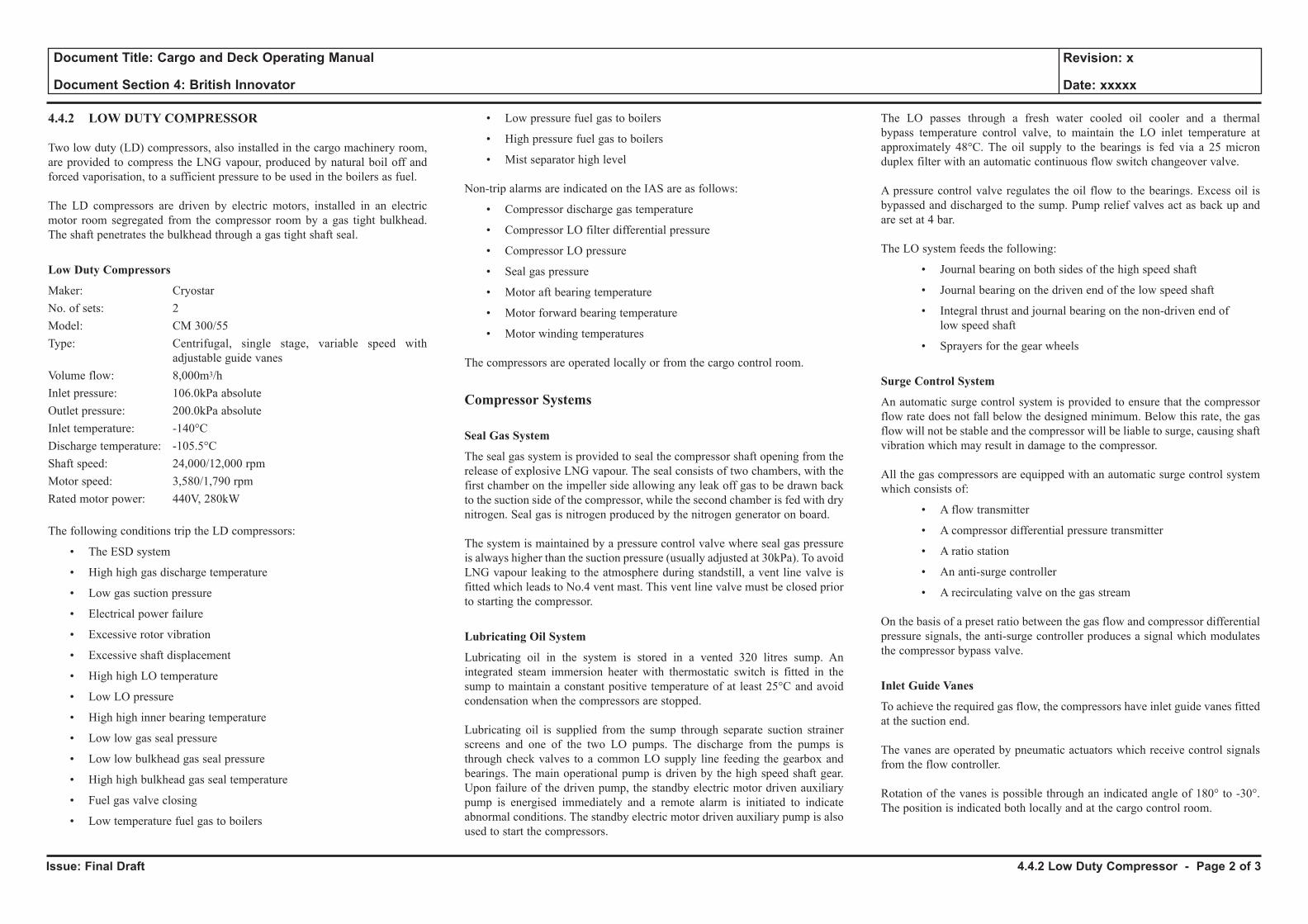
Issue: Final Draft
Document Title: Cargo and Deck Operating Manual
Document Section 4: British Innovator
Revision: x
Date: xxxxx
4.4.2 LOW DUTY COMPRESSOR
Two low duty (LD) compressors, also installed in the cargo machinery room, are provided to compress the LNG vapour, produced by natural boil off and forced vaporisation, to a sufficient pressure to be used in the boilers as fuel.
The LD compressors are driven by electric motors, installed in an electric motor room segregated from the compressor room by a gas tight bulkhead. The shaft penetrates the bulkhead through a gas tight shaft seal.
Low Duty Compressors
Maker: CryostarNo. of sets: 2Model: CM 300/55Type: Centrifugal, single stage, variable speed with
adjustable guide vanesVolume flow: 8,000m3/hInlet pressure: 106.0kPa absoluteOutlet pressure: 200.0kPa absoluteInlet temperature: -140°CDischarge temperature: -105.5°CShaft speed: 24,000/12,000 rpmMotor speed: 3,580/1,790 rpmRated motor power: 440V, 280kW
The following conditions trip the LD compressors:
• The ESD system
• High high gas discharge temperature
• Low gas suction pressure
• Electrical power failure
• Excessive rotor vibration
• Excessive shaft displacement
• High high LO temperature
• Low LO pressure
• High high inner bearing temperature
• Low low gas seal pressure
• Low low bulkhead gas seal pressure
• High high bulkhead gas seal temperature
• Fuel gas valve closing
• Low temperature fuel gas to boilers
• Low pressure fuel gas to boilers
• High pressure fuel gas to boilers
• Mist separator high level
Non-trip alarms are indicated on the IAS are as follows:
• Compressor discharge gas temperature
• Compressor LO filter differential pressure
• Compressor LO pressure
• Seal gas pressure
• Motor aft bearing temperature
• Motor forward bearing temperature
• Motor winding temperatures
The compressors are operated locally or from the cargo control room.
Compressor Systems
Seal Gas System
The seal gas system is provided to seal the compressor shaft opening from the release of explosive LNG vapour. The seal consists of two chambers, with the first chamber on the impeller side allowing any leak off gas to be drawn back to the suction side of the compressor, while the second chamber is fed with dry nitrogen. Seal gas is nitrogen produced by the nitrogen generator on board.
The system is maintained by a pressure control valve where seal gas pressure is always higher than the suction pressure (usually adjusted at 30kPa). To avoid LNG vapour leaking to the atmosphere during standstill, a vent line valve is fitted which leads to No.4 vent mast. This vent line valve must be closed prior to starting the compressor.
Lubricating Oil System
Lubricating oil in the system is stored in a vented 320 litres sump. An integrated steam immersion heater with thermostatic switch is fitted in the sump to maintain a constant positive temperature of at least 25°C and avoid condensation when the compressors are stopped.
Lubricating oil is supplied from the sump through separate suction strainer screens and one of the two LO pumps. The discharge from the pumps is through check valves to a common LO supply line feeding the gearbox and bearings. The main operational pump is driven by the high speed shaft gear. Upon failure of the driven pump, the standby electric motor driven auxiliary pump is energised immediately and a remote alarm is initiated to indicate abnormal conditions. The standby electric motor driven auxiliary pump is also used to start the compressors.
The LO passes through a fresh water cooled oil cooler and a thermal bypass temperature control valve, to maintain the LO inlet temperature at approximately 48°C. The oil supply to the bearings is fed via a 25 micron duplex filter with an automatic continuous flow switch changeover valve.
A pressure control valve regulates the oil flow to the bearings. Excess oil is bypassed and discharged to the sump. Pump relief valves act as back up and are set at 4 bar.
The LO system feeds the following:
• Journal bearing on both sides of the high speed shaft
• Journal bearing on the driven end of the low speed shaft
• Integral thrust and journal bearing on the non-driven end of low speed shaft
• Sprayers for the gear wheels
Surge Control System
An automatic surge control system is provided to ensure that the compressor flow rate does not fall below the designed minimum. Below this rate, the gas flow will not be stable and the compressor will be liable to surge, causing shaft vibration which may result in damage to the compressor.
All the gas compressors are equipped with an automatic surge control system which consists of:
• A flow transmitter
• A compressor differential pressure transmitter
• A ratio station
• An anti-surge controller
• A recirculating valve on the gas stream
On the basis of a preset ratio between the gas flow and compressor differential pressure signals, the anti-surge controller produces a signal which modulates the compressor bypass valve.
Inlet Guide Vanes
To achieve the required gas flow, the compressors have inlet guide vanes fitted at the suction end.
The vanes are operated by pneumatic actuators which receive control signals from the flow controller.
Rotation of the vanes is possible through an indicated angle of 180° to -30°. The position is indicated both locally and at the cargo control room.
4.4.2 Low Duty Compressor - Page 2 of 3
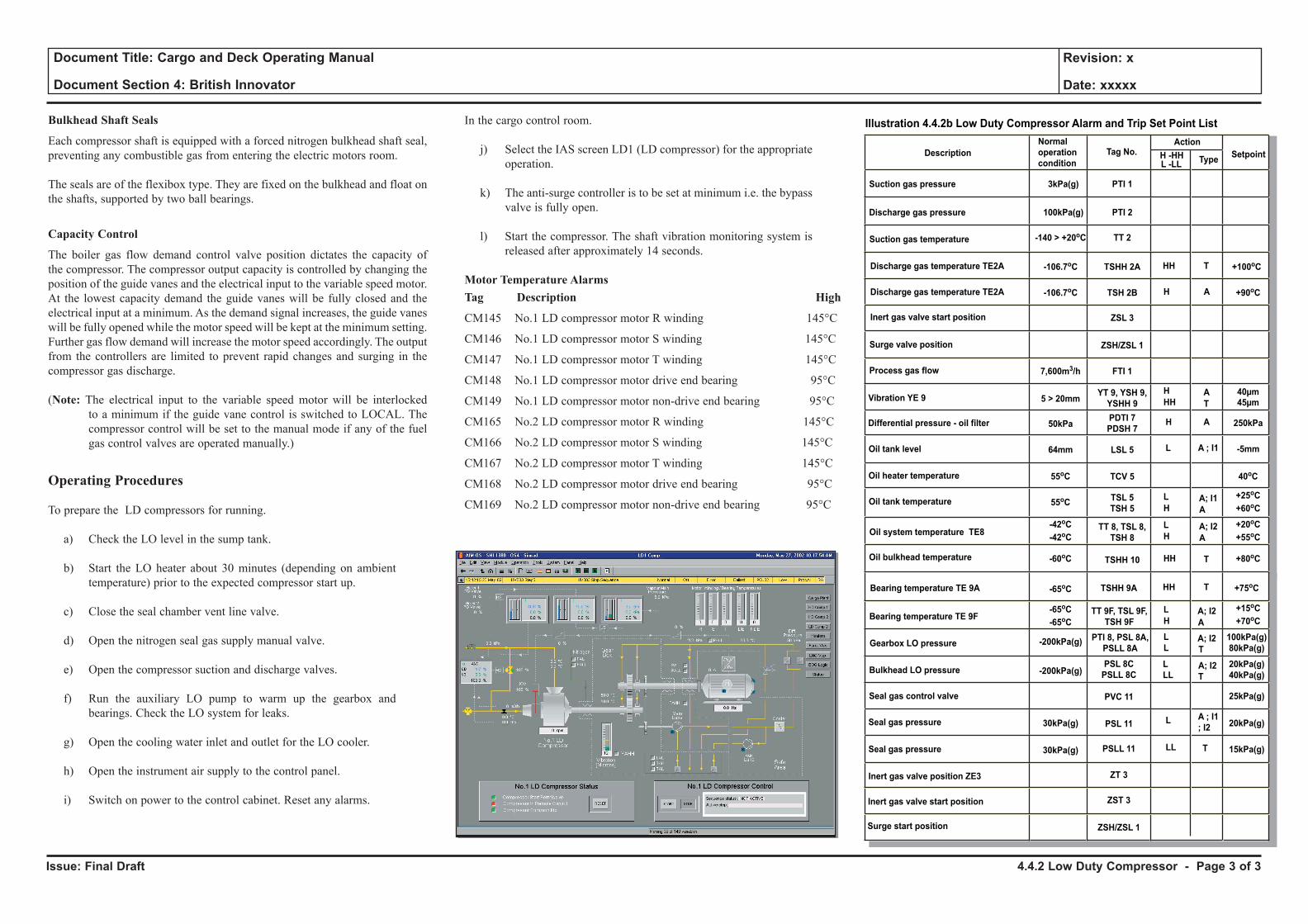
Issue: Final Draft
Document Title: Cargo and Deck Operating Manual
Document Section 4: British Innovator
Revision: x
Date: xxxxx
Bulkhead Shaft Seals
Each compressor shaft is equipped with a forced nitrogen bulkhead shaft seal, preventing any combustible gas from entering the electric motors room.
The seals are of the flexibox type. They are fixed on the bulkhead and float on the shafts, supported by two ball bearings.
Capacity Control
The boiler gas flow demand control valve position dictates the capacity of the compressor. The compressor output capacity is controlled by changing the position of the guide vanes and the electrical input to the variable speed motor. At the lowest capacity demand the guide vanes will be fully closed and the electrical input at a minimum. As the demand signal increases, the guide vanes will be fully opened while the motor speed will be kept at the minimum setting. Further gas flow demand will increase the motor speed accordingly. The output from the controllers are limited to prevent rapid changes and surging in the compressor gas discharge.
(Note: The electrical input to the variable speed motor will be interlocked to a minimum if the guide vane control is switched to LOCAL. The compressor control will be set to the manual mode if any of the fuel gas control valves are operated manually.)
Operating Procedures
To prepare the LD compressors for running.
a) Check the LO level in the sump tank.
b) Start the LO heater about 30 minutes (depending on ambient temperature) prior to the expected compressor start up.
c) Close the seal chamber vent line valve.
d) Open the nitrogen seal gas supply manual valve.
e) Open the compressor suction and discharge valves.
f) Run the auxiliary LO pump to warm up the gearbox and bearings. Check the LO system for leaks.
g) Open the cooling water inlet and outlet for the LO cooler.
h) Open the instrument air supply to the control panel.
i) Switch on power to the control cabinet. Reset any alarms.
In the cargo control room.
j) Select the IAS screen LD1 (LD compressor) for the appropriate operation.
k) The anti-surge controller is to be set at minimum i.e. the bypass valve is fully open.
l) Start the compressor. The shaft vibration monitoring system is released after approximately 14 seconds.
Motor Temperature AlarmsTag Description High
CM145 No.1 LD compressor motor R winding 145°C
CM146 No.1 LD compressor motor S winding 145°C
CM147 No.1 LD compressor motor T winding 145°C
CM148 No.1 LD compressor motor drive end bearing 95°C
CM149 No.1 LD compressor motor non-drive end bearing 95°C
CM165 No.2 LD compressor motor R winding 145°C
CM166 No.2 LD compressor motor S winding 145°C
CM167 No.2 LD compressor motor T winding 145°C
CM168 No.2 LD compressor motor drive end bearing 95°C
CM169 No.2 LD compressor motor non-drive end bearing 95°C
4.4.2 Low Duty Compressor - Page 3 of 3
Illustration 4.4.2b Low Duty Compressor Alarm and Trip Set Point List
SetpointType
Tag No.Action
L -LLH -HH
HH T
T
Normal
operation
conditionDescription
Suction gas pressure
Suction gas temperature
PTI 13kPa(g)
Discharge gas pressure
Discharge gas temperature TE2A
PTI 2100kPa(g)
TT 2-140 > +20oC
TSHH 2A-106.7oC +100oC
H ADischarge gas temperature TE2A TSH 2B-106.7oC
55oC
Process gas flow FTI 17,600m3/h
+90oC
40oC
H
HHA
A
L
HA; I1
Vibration YE 9YT 9, YSH 9,
YSHH 95 > 20mm
40µm
H ADifferential pressure - oil filterPDTI 7
PDSH 750kPa 250kPa
L A ; I1Oil tank level LSL 564mm -5mm
Oil heater temperature TCV 5
55oC+25oC
+60oC
+20oC
+55oC
-42oC
-42oC
Oil tank temperature TSL 5
TSH 5
45µm
A
L
HA; I2
Oil system temperature TE8TT 8, TSL 8,
TSH 8
+80oC-60oC THHOil bulkhead temperature TSHH 10
Inert gas valve start position ZSL 3
Surge valve position ZSH/ZSL 1
L
LLA; I2
T
Bearing temperature TE 9A
Gearbox LO pressure
TSHH 9A
Bearing temperature TE 9F
Bulkhead LO pressure
PTI 8, PSL 8A,
PSLL 8A-200kPa(g)
PSL 8C
PSLL 8C-200kPa(g)
30kPa(g)
100kPa(g)
80kPa(g)
20kPa(g)
40kPa(g)
25kPa(g)
20kPa(g)
15kPa(g)
HH T +75oC
Seal gas control valve
Seal gas pressure
PVC 11
PSL 11
TT 9F, TSL 9F,
TSH 9F
L A ; I1
; I2
30kPa(g)Seal gas pressure
Inert gas valve position ZE3
PSLL 11
ZT 3
Inert gas valve start position ZST 3
Surge start position ZSH/ZSL 1
LL T
A
L
HA; I2 +15oC
+70oC
-65oC
-65oC
-65oC
L A; I2L T

4.5 Boil-Off/Warm-Up Heaters
Illustrations
4.5a Boil-Off/Warm-Up Heaters
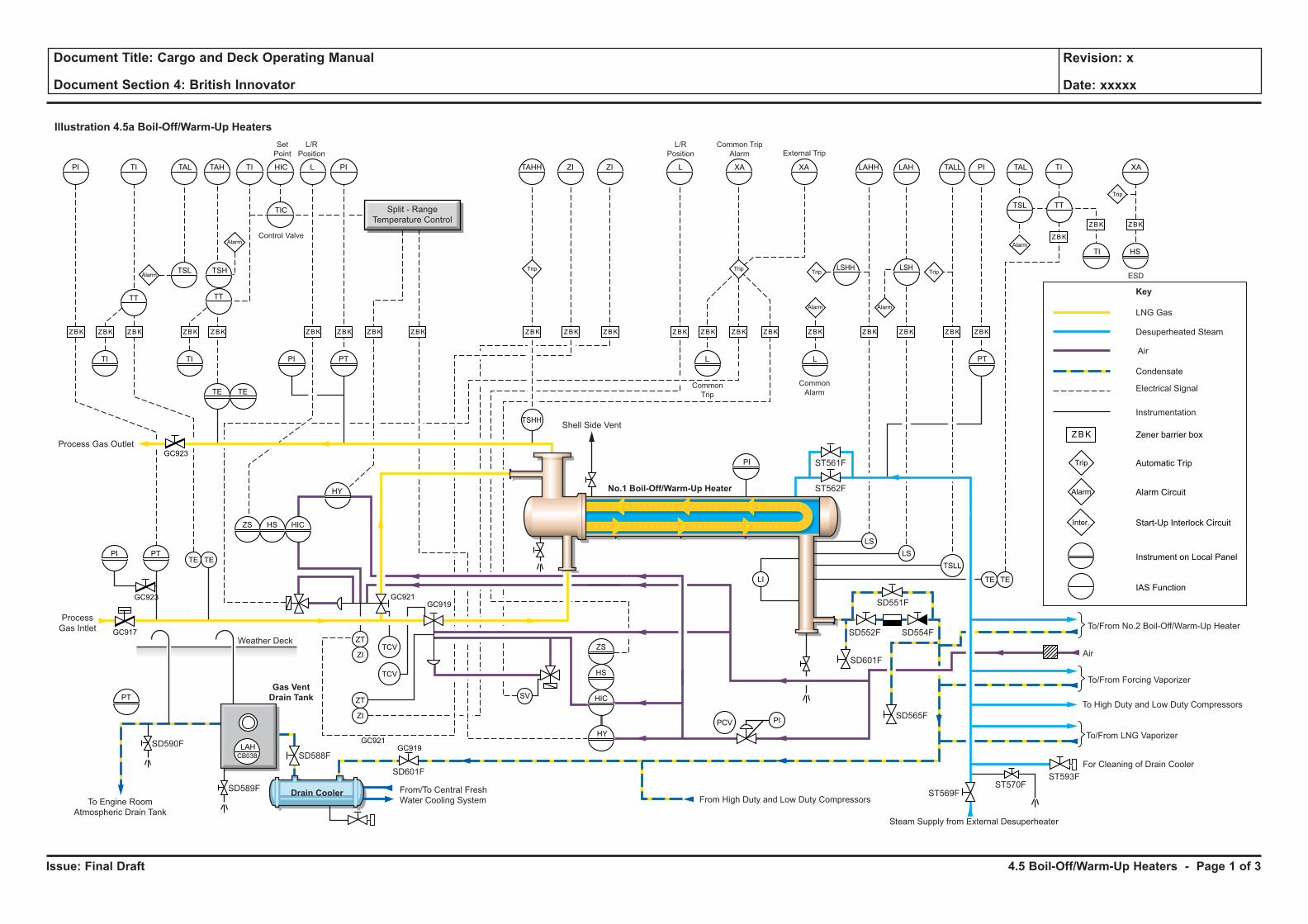
Issue: Final Draft
Document Title: Cargo and Deck Operating Manual
Document Section 4: British Innovator
Revision: x
Date: xxxxx
4.5 Boil-Off/Warm-Up Heaters - Page 1 of 3
Illustration 4.5a Boil-Off/Warm-Up Heaters
Weather Deck
LNG Gas
Key
Desuperheated Steam
Air
Electrical Signal
Instrumentation
Condensate
LS
LSTE TE
ZT
ZI
ZT
ZI
SV
LI
TSLL
TCV
PCV
TCV
TSHH
TETE
TI TI PI PT L L
PI
HSTI
PT
TE TE
PT
GC921
GC923
GC917
GC919
ZS HS HIC
HY
HIC
HS
ZS
HY
PI
PI TI
TT TT
TSH
TIC
LSHH LSH
TSL TT
TSL
TAL TAH TI HIC L PI TAHH ZI ZI L XA XA LAHH LAH TALL PI TAL TI XA
Zener barrier boxZBK
ZBKZBK ZBK ZBK ZBK ZBK ZBK ZBK ZBK ZBK ZBK ZBK ZBK ZBK ZBK ZBK ZBK ZBK ZBK ZBK ZBK
ZBK
ZBK ZBK
Trip
TripTrip Trip
Trip
Trip
Automatic Trip
Alarm
Alarm
Alarm Alarm
Alarm
Alarm
Alarm Circuit
Inter. Start-Up Interlock Circuit
Instrument on Local Panel
IAS Function
Control Valve
Process Gas Outlet
Process
Gas Intlet
Shell Side Vent
Split - Range
Temperature Control
PI
ESD
Common
Alarm
No.1 Boil-Off/Warm-Up Heater
Gas Vent
Drain Tank
To/From No.2 Boil-Off/Warm-Up Heater
SD551F
SD552F
SD601F
SD601F
SD588F
SD590F
SD554F
Air
To/From Forcing Vaporizer
To/From LNG Vaporizer
For Cleaning of Drain Cooler
Steam Supply from External Desuperheater
To High Duty and Low Duty Compressors
From High Duty and Low Duty Compressors
L/R
Position
L/R
Position
Common Trip
Alarm External TripSet
Point
Common
Trip
ST561F
ST562F
ST593FST570F
SD565F
From/To Central Fresh
Water Cooling SystemTo Engine Room
Atmospheric Drain Tank
Drain Cooler
LAHCB038
SD589FST569F
PT
GC921
GC923
GC919
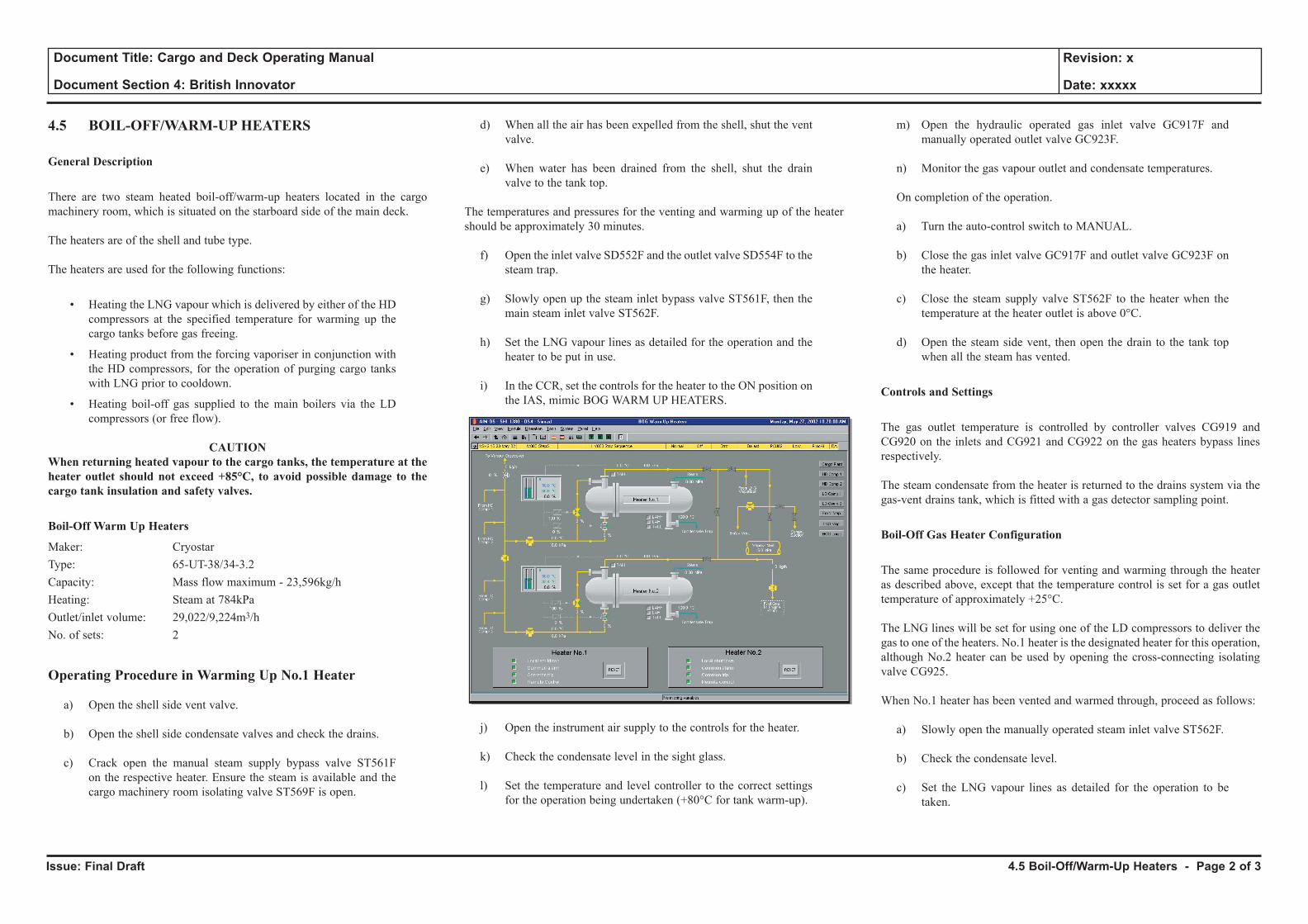
Issue: Final Draft
Document Title: Cargo and Deck Operating Manual
Document Section 4: British Innovator
Revision: x
Date: xxxxx
4.5 BOIL-OFF/WARM-UP HEATERS
General Description
There are two steam heated boil-off/warm-up heaters located in the cargo machinery room, which is situated on the starboard side of the main deck.
The heaters are of the shell and tube type.
The heaters are used for the following functions:
• Heating the LNG vapour which is delivered by either of the HD compressors at the specified temperature for warming up the cargo tanks before gas freeing.
• Heating product from the forcing vaporiser in conjunction with the HD compressors, for the operation of purging cargo tanks with LNG prior to cooldown.
• Heating boil-off gas supplied to the main boilers via the LD compressors (or free flow).
CAUTIONWhen returning heated vapour to the cargo tanks, the temperature at the heater outlet should not exceed +85°C, to avoid possible damage to the cargo tank insulation and safety valves.
Boil-Off Warm Up Heaters
Maker: Cryostar Type: 65-UT-38/34-3.2Capacity: Mass flow maximum - 23,596kg/hHeating: Steam at 784kPaOutlet/inlet volume: 29,022/9,224m3/hNo. of sets: 2
Operating Procedure in Warming Up No.1 Heater
a) Open the shell side vent valve.
b) Open the shell side condensate valves and check the drains.
c) Crack open the manual steam supply bypass valve ST561F on the respective heater. Ensure the steam is available and the cargo machinery room isolating valve ST569F is open.
d) When all the air has been expelled from the shell, shut the vent valve.
e) When water has been drained from the shell, shut the drain valve to the tank top.
The temperatures and pressures for the venting and warming up of the heater should be approximately 30 minutes.
f) Open the inlet valve SD552F and the outlet valve SD554F to the steam trap.
g) Slowly open up the steam inlet bypass valve ST561F, then the main steam inlet valve ST562F.
h) Set the LNG vapour lines as detailed for the operation and the heater to be put in use.
i) In the CCR, set the controls for the heater to the ON position on the IAS, mimic BOG WARM UP HEATERS.
j) Open the instrument air supply to the controls for the heater.
k) Check the condensate level in the sight glass.
l) Set the temperature and level controller to the correct settings for the operation being undertaken (+80°C for tank warm-up).
m) Open the hydraulic operated gas inlet valve GC917F and manually operated outlet valve GC923F.
n) Monitor the gas vapour outlet and condensate temperatures.
On completion of the operation.
a) Turn the auto-control switch to MANUAL.
b) Close the gas inlet valve GC917F and outlet valve GC923F on the heater.
c) Close the steam supply valve ST562F to the heater when the temperature at the heater outlet is above 0°C.
d) Open the steam side vent, then open the drain to the tank top when all the steam has vented.
Controls and Settings
The gas outlet temperature is controlled by controller valves CG919 and CG920 on the inlets and CG921 and CG922 on the gas heaters bypass lines respectively.
The steam condensate from the heater is returned to the drains system via the gas-vent drains tank, which is fitted with a gas detector sampling point.
Boil-Off Gas Heater Configuration
The same procedure is followed for venting and warming through the heater as described above, except that the temperature control is set for a gas outlet temperature of approximately +25°C.
The LNG lines will be set for using one of the LD compressors to deliver the gas to one of the heaters. No.1 heater is the designated heater for this operation, although No.2 heater can be used by opening the cross-connecting isolating valve CG925.
When No.1 heater has been vented and warmed through, proceed as follows:
a) Slowly open the manually operated steam inlet valve ST562F.
b) Check the condensate level.
c) Set the LNG vapour lines as detailed for the operation to be taken.
4.5 Boil-Off/Warm-Up Heaters - Page 2 of 3
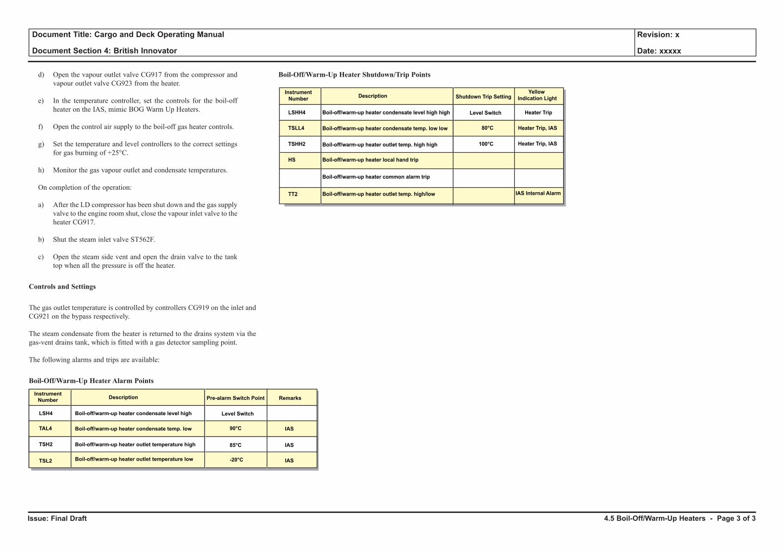
Issue: Final Draft
Document Title: Cargo and Deck Operating Manual
Document Section 4: British Innovator
Revision: x
Date: xxxxx
d) Open the vapour outlet valve CG917 from the compressor and vapour outlet valve CG923 from the heater.
e) In the temperature controller, set the controls for the boil-off heater on the IAS, mimic BOG Warm Up Heaters.
f) Open the control air supply to the boil-off gas heater controls.
g) Set the temperature and level controllers to the correct settings for gas burning of +25°C.
h) Monitor the gas vapour outlet and condensate temperatures.
On completion of the operation:
a) After the LD compressor has been shut down and the gas supply valve to the engine room shut, close the vapour inlet valve to the heater CG917.
b) Shut the steam inlet valve ST562F.
c) Open the steam side vent and open the drain valve to the tank top when all the pressure is off the heater.
Controls and Settings
The gas outlet temperature is controlled by controllers CG919 on the inlet and CG921 on the bypass respectively.
The steam condensate from the heater is returned to the drains system via the gas-vent drains tank, which is fitted with a gas detector sampling point.
The following alarms and trips are available:
Boil-Off/Warm-Up Heater Alarm Points
Boil-Off/Warm-Up Heater Shutdown/Trip Points
LSH4
TAL4
TAL4
TSH2
TAL4TAtsL4
Instrument
NumberDescription Pre-alarm Switch Point Remarks
Boil-off/warm-up heater condensate level high
Boil-off/warm-up heater condensate temp. low
Boil-off/warm-up heater outlet temperature high
Boil-off/warm-up heater outlet temperature low
Level Switch
90°C
85°C
-20°C
IAS
IAS
IASTSL2
LSHH4
TSLL4
Instrument
NumberDescription Shutdown Trip Setting
Yellow
Indication Light
Boil-off/warm-up heater condensate level high high
Boil-off/warm-up heater condensate temp. low low
Boil-off/warm-up heater outlet temp. high high
Boil-off/warm-up heater local hand trip
Boil-off/warm-up heater common alarm trip
Boil-off/warm-up heater outlet temp. high/low
Level Switch
80°C
100°C
Heater Trip
Heater Trip, IAS
Heater Trip, IAS
TSHH2
HS
TT2 IAS Internal Alarm
4.5 Boil-Off/Warm-Up Heaters - Page 3 of 3

4.6 LNG Vaporiser
Illustrations
4.6a LNG Vaporiser
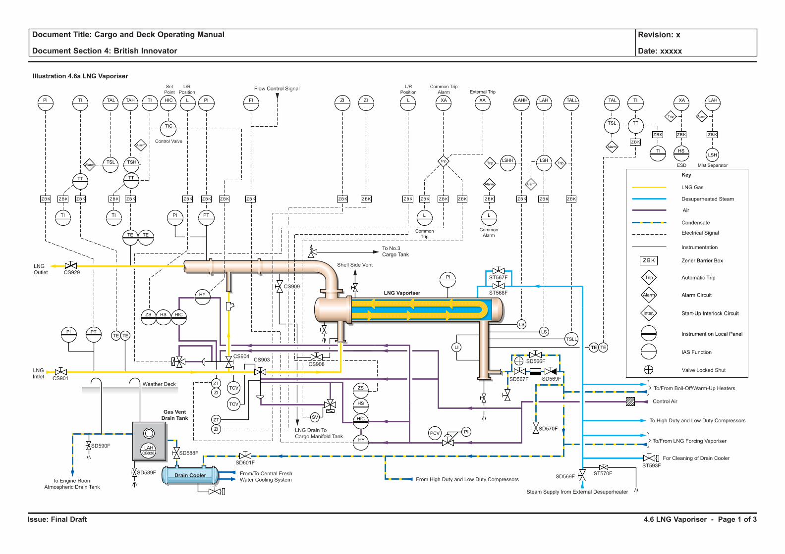
Issue: Final Draft
Document Title: Cargo and Deck Operating Manual
Document Section 4: British Innovator
Revision: x
Date: xxxxx
4.6 LNG Vaporiser - Page 1 of 3
Illustration 4.6a LNG Vaporiser
Weather Deck
LNG Gas
Key
Desuperheated Steam
Air
Electrical Signal
Instrumentation
Condensate
LS
LSTE TE
ZT
ZI
ZT
ZI
SV
LI
TSLL
TCV
PCV
TCV
TETE
TI TI PI PT L L
PI
HSTI
TE TE
PT
ZS HS HIC
HY
HIC
HS
ZS
HY
PI
PI TI
TT TT
TSH
TIC
LSHH LSH
TSL TT
TSL
TAL TAH TI HIC L PI ZI ZIFI L XA XA LAHH LAH TALL TAL TI XA
Zener Barrier BoxZBK
ZBKZBK ZBK ZBK ZBK ZBK ZBK ZBK ZBK ZBK ZBK ZBK ZBK ZBK ZBK ZBK ZBK ZBK
ZBK
ZBK ZBK
Trip
TripTrip Trip
Trip
Automatic Trip
Alarm
Alarm
Alarm Alarm
Alarm
Alarm
Alarm Circuit
Inter. Start-Up Interlock Circuit
Instrument on Local Panel
IAS Function
Control Valve
LNG
Outlet
LNG
Intlet
Flow Control Signal
PI
ESD
LAH
ZBK
Alarm
Mist Separator
Common
Alarm
Gas Vent
Drain Tank
To/From Boil-Off/Warm-Up Heaters
SD566F
SD567F
SD601F
SD588F
SD590F
SD569F
Control Air
To/From LNG Forcing Vaporiser
For Cleaning of Drain Cooler
Steam Supply from External Desuperheater
To High Duty and Low Duty Compressors
From High Duty and Low Duty Compressors
L/R
Position
L/R
Position
Common Trip
Alarm External TripSet
Point
Common
Trip
ST567F
ST568F
ST593F
ST570F
CS908CS903
CS904
CS929
CS901
From/To Central Fresh
Water Cooling System
LNG Drain To
Cargo Manifold Tank
To Engine Room
Atmospheric Drain Tank
Drain Cooler
LAHCB038
SD589F
ZBK
LSH
SD570F
SD569F
Valve Locked Shut
CS909
Shell Side Vent
To No.3
Cargo Tank
LNG Vaporiser
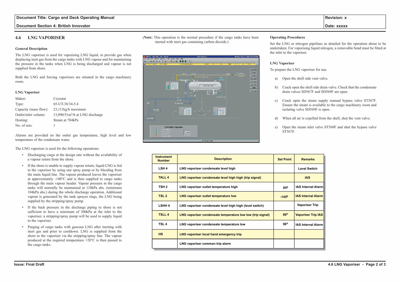
Issue: Final Draft
Document Title: Cargo and Deck Operating Manual
Document Section 4: British Innovator
Revision: x
Date: xxxxx
4.6 LNG VAPORISER
General Description
The LNG vaporiser is used for vaporising LNG liquid, to provide gas when displacing inert gas from the cargo tanks with LNG vapour and for maintaining the pressure in the tanks when LNG is being discharged and vapour is not supplied from shore.
Both the LNG and forcing vaporisers are situated in the cargo machinery room.
LNG Vaporiser
Maker: CryostarType: 65-UT-38/34-5.4Capacity (mass flow): 23,111kg/h maximumOutlet/inlet volume: 13,090/51m3/h at LNG dischargeHeating: Steam at 784kPaNo. of sets: 1
Alarms are provided on the outlet gas temperature, high level and low temperature of the condensate water.
The LNG vaporiser is used for the following operations:
• Discharging cargo at the design rate without the availability of a vapour return from the shore.
• If the shore is unable to supply vapour return, liquid LNG is fed to the vaporiser by using one spray pump or by bleeding from the main liquid line. The vapour produced leaves the vaporiser at approximately -140°C and is then supplied to cargo tanks through the main vapour header. Vapour pressure in the cargo tanks will normally be maintained at 110kPa abs. (minimum 104kPa abs.) during the whole discharge operation. Additional vapour is generated by the tank sprayer rings, the LNG being supplied by the stripping/spray pump.
• If the back pressure in the discharge piping to shore is not sufficient to have a minimum of 300kPa at the inlet to the vaporiser, a stripping/spray pump will be used to supply liquid to the vaporiser.
• Purging of cargo tanks with gaseous LNG after inerting with inert gas and prior to cooldown. LNG is supplied from the shore to the vaporiser via the stripping/spray line. The vapour produced at the required temperature +20°C is then passed to the cargo tanks.
(Note: This operation is the normal procedure if the cargo tanks have been inerted with inert gas containing carbon dioxide.)
Operating Procedures
Set the LNG or nitrogen pipelines as detailed for the operation about to be undertaken. For vaporising liquid nitrogen, a removable bend must be fitted at the inlet to the vaporiser.
LNG Vaporiser
To prepare the LNG vaporiser for use.
a) Open the shell side vent valve.
b) Crack open the shell side drain valve. Check that the condensate drain valves SD567F and SD569F are open.
c) Crack open the steam supply manual bypass valve ST567F. Ensure the steam is available to the cargo machinery room and isolating valve SD569F is open.
d) When all air is expelled from the shell, shut the vent valve.
e) Open the steam inlet valve ST568F and shut the bypass valve ST567F.
LSH 4
TSH 2
TALL 4
Instrument
NumberDescription Set Point Remarks
LNG vaporiser condensate level high
LNG vaporiser condensate level high high (trip signal)
Level Switch
IAS
-1450
-1450
850
850850
LSHH 4
TSLL 4 80o
HS
LNG vaporiser condensate level high high (level switch)
LNG vaporiser condensate temperature low low (trip signal)
TSL 4 90oLNG vaporiser condensate temperature low
LNG vaporiser local hand emergency trip
LNG vaporiser common trip alarm
Vaporiser Trip
Vaporiser Trip IAS
LNG vaporiser outlet temperature high IAS Internal Alarm
TSL 2 LNG vaporiser outlet temperature low IAS Internal Alarm
IAS Internal Alarm
4.6 LNG Vaporiser - Page 2 of 3
Issue: Final Draft
Document Title: Cargo and Deck Operating Manual
Document Section 4: British Innovator
Revision: x
Date: xxxxx
After about 30 minutes when pressures and temperatures have stabilised on the vaporiser:
f) Slowly open fully the steam inlet manual valve ST568F.
g) Open the instrument air supply to the vaporiser controls.
h) In the CCR, set the controls for the LNG vaporiser on the IAS mimic LNG Vaporiser.
i) Fill up the vaporiser with liquid by opening the inlet valves
CS901 and CS903 and outlet valve CG929, using manual control. Check all flanges and joints for any signs of leakage.
j) When vapour is produced switch the control for liquid valve CS903 to REMOTE and AUTOMATIC.
CAUTION
Thorough checks around the LNG vaporiser and associated flange connections must be conducted during operation.
On completion of operations.
a) Shut the liquid valve CS901.
b) Shut the steam supply valve SD568F when no LNG remains.
c) Open the steam side vent and then open the drain when all steam has been vented.
d) Keep the vapour side valve open to the system until the vaporiser reaches ambient temperature.
Control
Process control is on the outlet temperature from vaporiser, with high and low temperature alarms, which is controlled on the temperature control valve (TCV) CG904.
The steam condensate from the vaporiser is returned to the drains system via the gas-vent drains tank, which is fitted with a gas detector sampling point.
4.6 LNG Vaporiser - Page 3 of 3

4.7 Forcing Vaporiser
llustrations
4.7a Forcing Vaporiser
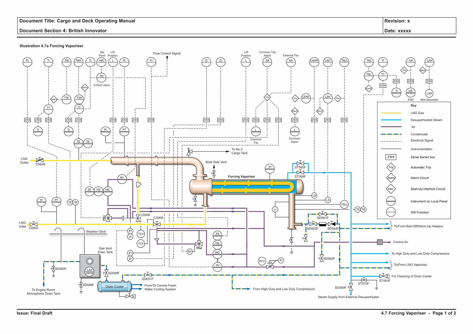
Issue: Final Draft
Document Title: Cargo and Deck Operating Manual
Document Section 4: British Innovator
Revision: x
Date: xxxxx
4.7 Forcing Vaporiser - Page 1 of 2
Illustration 4.7a Forcing Vaporiser
Weather Deck
LNG Gas
Key
Desuperheated Steam
Air
Electrical Signal
Instrumentation
Condensate
LS
LSTE TE
ZT
ZI
ZT
ZI
SV
LI
TSLL
TCV
PCV
TCV
TETE
TI TI PI PT L L
PI
HSTI
TE TE
PT
ZS HS HIC
HY
HIC
HS
ZS
HY
PI
PI TI
TT TT
TSH
TIC
LSHH LSH
TSL TT
TSL
TAL TAH TI HIC L PI ZI ZIFI L XA XA LAHH LAH TALL TAL TI XA
Zener barrier boxZBK
ZBKZBK ZBK ZBK ZBK ZBK ZBK ZBK ZBK ZBK ZBK ZBK ZBK ZBK ZBK ZBK ZBK ZBK
ZBK
ZBK ZBK
Trip
TripTrip Trip
Trip
Automatic Trip
Alarm
Alarm
Alarm Alarm
Alarm
Alarm
Alarm Circuit
Inter. Start-Up Interlock Circuit
Instrument on Local Panel
IAS Function
Control Valve
LNG
Outlet
LNG
Intlet
Flow Control Signal
PI
ESD
LAH
ZBK
Alarm
Mist Separator
Common
Alarm
Gas Vent
Drain Tank
To/From Boil-Off/Warm-Up Heaters
SD561F
SD562F
SD601F
SD588F
SD590F
SD564F
Control Air
To/From LNG Vaporiser
For Cleaning of Drain Cooler
To High Duty and Low Duty Compressors
From High Duty and Low Duty Compressors
L/R
Position
L/R
Position
Common Trip
Alarm External TripSet
Point
Common
Trip
ST565F
ST566F
ST593FST570F
From/To Central Fresh
Water Cooling SystemTo Engine Room
Atmospheric Drain Tank
Drain Cooler
LAHCB038
SD589F
ZBK
LSH
SD565F
Shell Side VentCS928
CS906CS905
CS902
To No.3
Cargo Tank
Steam Supply from External Desuperheater
SD569F
Forcing Vaporiser
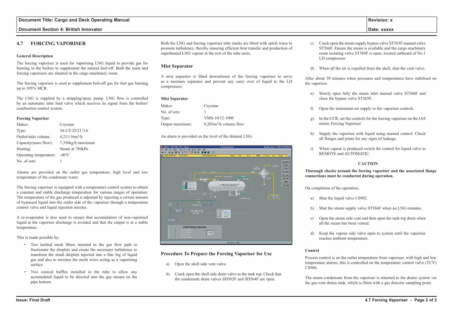
Issue: Final Draft
Document Title: Cargo and Deck Operating Manual
Document Section 4: British Innovator
Revision: x
Date: xxxxx
4.7 FORCING VAPORISER
General Description
The forcing vaporiser is used for vaporising LNG liquid to provide gas for burning in the boilers to supplement the natural boil-off. Both the main and forcing vaporisers are situated in the cargo machinery room.
The forcing vaporiser is used to supplement boil-off gas for fuel gas burning up to 105% MCR.
The LNG is supplied by a stripping/spray pump. LNG flow is controlled by an automatic inlet feed valve which receives its signal from the boilers' combustion control system.
Forcing VaporiserMaker: CryostarType: 34-UT-25/21-3.6Outlet/inlet volume: 4,211/16m3/hCapacity(mass flow): 7,356kg/h maximumHeating: Steam at 784kPaOperating temperature: -40°CNo. of sets: 1 Alarms are provided on the outlet gas temperature, high level and low temperature of the condensate water.
The forcing vaporiser is equipped with a temperature control system to obtain a constant and stable discharge temperature for various ranges of operation. The temperature of the gas produced is adjusted by injecting a certain amount of bypassed liquid into the outlet side of the vaporiser through a temperature control valve and liquid injection nozzles.
A re-evaporator is also used to ensure that accumulation of non-vaporised liquid at the vaporiser discharge is avoided and that the output is at a stable temperature.
This is made possible by:
• Two knitted mesh filters inserted in the gas flow path to fractionate the droplets and create the necessary turbulence to transform the small droplets injected into a fine fog of liquid gas and also to moisten the mesh wires acting as a vaporising surface.
• Two conical baffles installed in the tube to allow any accumulated liquid to be directed into the gas stream on the pipe bottom.
Both the LNG and forcing vaporiser tube stacks are fitted with spiral wires to promote turbulence, thereby ensuring efficient heat transfer and production of superheated LNG vapour at the exit of the tube nests.
Mist Separator
A mist separator is fitted downstream of the forcing vaporiser to serve as a moisture separator and prevent any carry over of liquid to the LD compressors.
Mist Separator
Maker: CryostarNo. of sets: 1Type: VMS-10/12-1000Output maximum: 8,203m3/h volume flow An alarm is provided on the level of the drained LNG.
Procedure To Prepare the Forcing Vaporiser for Use
a) Open the shell side vent valve.
b) Crack open the shell side drain valve to the tank top. Check that the condensate drain valves SD562F and SD564F are open.
c) Crack open the steam supply bypass valve ST565F manual valve ST566F. Ensure the steam is available and the cargo machinery room isolating valve ST569F is open, located outboard of No.1 LD compressor.
d) When all the air is expelled from the shell, shut the vent valve.
After about 30 minutes when pressures and temperatures have stabilised on the vaporiser.
e) Slowly open fully the steam inlet manual valve ST566F and close the bypass valve ST565F.
f) Open the instrument air supply to the vaporiser controls.
g) In the CCR, set the controls for the forcing vaporiser on the IAS mimic Forcing Vaporiser
h) Supply the vaporiser with liquid using manual control. Check all flanges and joints for any signs of leakage.
i) When vapour is produced switch the control for liquid valve to REMOTE and AUTOMATIC.
CAUTION
Thorough checks around the forcing vaporiser and the associated flange connections must be conducted during operation.
On completion of the operation.
a) Shut the liquid valve CS902.
b) Shut the steam supply valve ST566F when no LNG remains.
c) Open the steam side vent and then open the tank top drain when all the steam has been vented.
d) Keep the vapour side valve open to system until the vaporiser reaches ambient temperature.
Control
Process control is on the outlet temperature from vaporiser, with high and low temperature alarms, this is controlled on the temperature control valve (TCV) CS906.
The steam condensate from the vaporiser is returned to the drains system via the gas-vent drains tank, which is fitted with a gas detector sampling point.
4.7 Forcing Vaporiser - Page 2 of 2

4.8 Nitrogen Generator
Illustrations
4.8a Nitrogen Generator
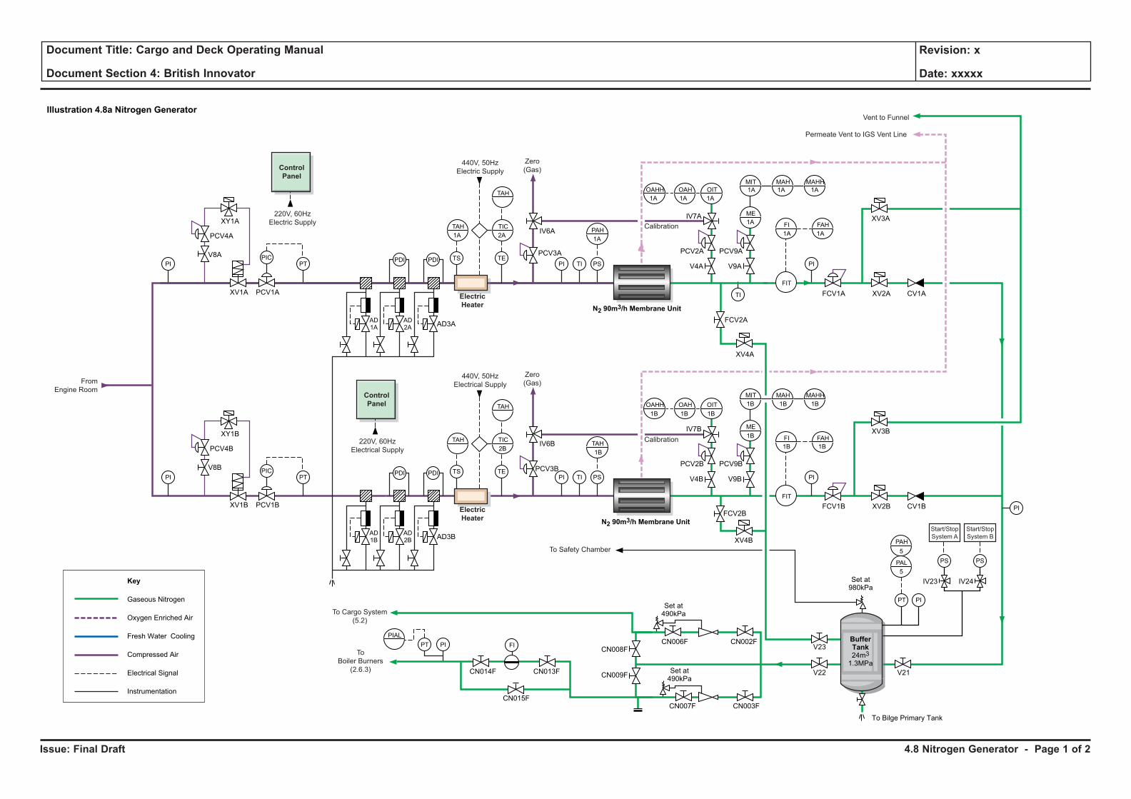
Issue: Final Draft
Document Title: Cargo and Deck Operating Manual
Document Section 4: British Innovator
Revision: x
Date: xxxxx
4.8 Nitrogen Generator - Page 1 of 2
Illustration 4.8a Nitrogen Generator
PI TI PSTS
440V, 50Hz
Electrical Supply
Zero
(Gas)
TAHTAH
PIAL
PIPT
TE
TIC
TAH
PIPIC
PT PI TI PI
PI
PSTS
Key
Gaseous Nitrogen
Oxygen Enriched Air
Fresh Water Cooling
Compressed Air
Electrical Signal
Instrumentation
N2 90m3/h Membrane Unit
Control
Panel
Electric
Heater
FI
PDIPDI
220V, 60Hz
Electrical Supply
To Safety Chamber
Calibration
N2 90m3/h Membrane Unit
Control
Panel
Electric
Heater
TI
PDIPDI
220V, 60Hz
Electric Supply
From
Engine Room
440V, 50Hz
Electric Supply
Permeate Vent to IGS Vent Line
Vent to Funnel
Zero
(Gas)
Calibration
BufferTank24m3
1.3MPa
Set at490kPa
Set at980kPa
To Bilge Primary Tank
V21
CV1B
IV23
V9BV4B
IV24
XV2B
XV4B
FCV2B
XV3B
XV4A
FCV1B
PCV9BPCV2B
IV7B
FCV2A
IV6B
PCV3B
PCV1BXV1B
V8B
PCV4B
XY1B
AD3BAD2B
AD1B
CV1A
V9AV4A
XV2A
XV3A
FCV1A
PCV9APCV2A
IV7A
IV6A
PCV3A
PCV1AXV1A
V8A
PCV4A
XY1A
AD3AAD2A
AD1A
V22
CN003FCN015F
CN014F CN013F
CN007F
CN008F
CN009F
CN002FCN006FV23
Start/Stop
System A
Start/Stop
System B
To Cargo System
(5.2)
To
Boiler Burners
(2.6.3) Set at490kPa
TAHPAH
PIPIC
PT
TE
TIC
TAHOIT
FI FAH
FIT
OAHOAHH
OITOAHOAHH
ME
MIT MAH MAHH
PI
PS
PIPT
PS
FI FAH
PAL
PAH
FIT
ME
MIT MAH MAHH
2B1B
1B 1B 1B
1B
1B
1B 1B
1B 1B
1A 2A1A
1A 1A 1A
1A
1A
1A 1A
1A 1A
5
5
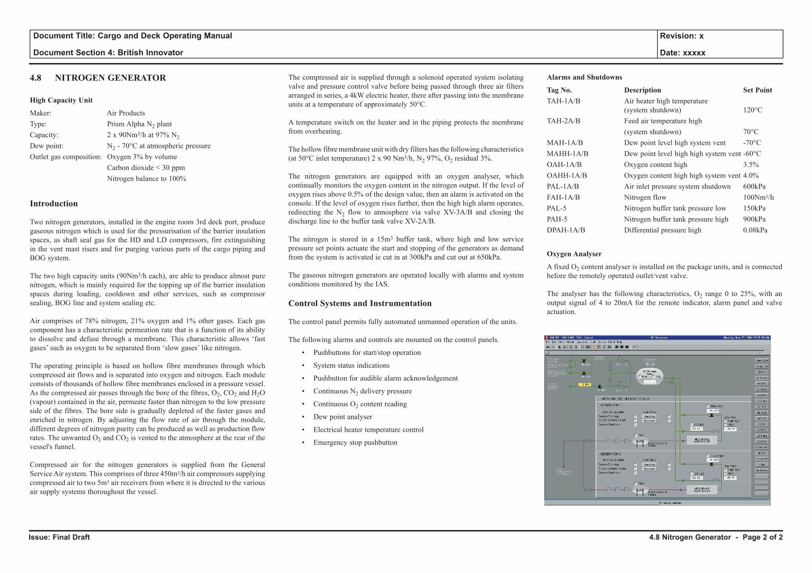
Issue: Final Draft
Document Title: Cargo and Deck Operating Manual
Document Section 4: British Innovator
Revision: x
Date: xxxxx
4.8 NITROGEN GENERATOR
High Capacity Unit
Maker: Air ProductsType: Prism Alpha N2 plantCapacity: 2 x 90Nm3/h at 97% N2
Dew point: N2 - 70°C at atmospheric pressure
Outlet gas composition: Oxygen 3% by volume Carbon dioxide < 30 ppm Nitrogen balance to 100%
Introduction
Two nitrogen generators, installed in the engine room 3rd deck port, produce gaseous nitrogen which is used for the pressurisation of the barrier insulation spaces, as shaft seal gas for the HD and LD compressors, fire extinguishing in the vent mast risers and for purging various parts of the cargo piping and BOG system.
The two high capacity units (90Nm3/h each), are able to produce almost pure nitrogen, which is mainly required for the topping up of the barrier insulation spaces during loading, cooldown and other services, such as compressor sealing, BOG line and system sealing etc.
Air comprises of 78% nitrogen, 21% oxygen and 1% other gases. Each gas component has a characteristic permeation rate that is a function of its ability to dissolve and defuse through a membrane. This characteristic allows ‘fast gases’ such as oxygen to be separated from ‘slow gases’ like nitrogen.
The operating principle is based on hollow fibre membranes through which compressed air flows and is separated into oxygen and nitrogen. Each module consists of thousands of hollow fibre membranes enclosed in a pressure vessel. As the compressed air passes through the bore of the fibres, O2, CO2 and H2O (vapour) contained in the air, permeate faster than nitrogen to the low pressure side of the fibres. The bore side is gradually depleted of the faster gases and enriched in nitrogen. By adjusting the flow rate of air through the module, different degrees of nitrogen purity can be produced as well as production flow rates. The unwanted O2 and CO2 is vented to the atmosphere at the rear of the vessel's funnel.
Compressed air for the nitrogen generators is supplied from the General Service Air system. This comprises of three 450m3/h air compressors supplying compressed air to two 5m3 air receivers from where it is directed to the various air supply systems thoroughout the vessel.
The compressed air is supplied through a solenoid operated system isolating valve and pressure control valve before being passed through three air filters arranged in series, a 4kW electric heater, there after passing into the membrane units at a temperature of approximately 50°C.
A temperature switch on the heater and in the piping protects the membrane from overheating.
The hollow fibre membrane unit with dry filters has the following characteristics (at 50°C inlet temperature) 2 x 90 Nm3/h, N2 97%, O2 residual 3%.
The nitrogen generators are equipped with an oxygen analyser, which continually monitors the oxygen content in the nitrogen output. If the level of oxygen rises above 0.5% of the design value, then an alarm is activated on the console. If the level of oxygen rises further, then the high high alarm operates, redirecting the N2 flow to atmosphere via valve XV-3A/B and closing the discharge line to the buffer tank valve XV-2A/B.
The nitrogen is stored in a 15m3 buffer tank, where high and low service pressure set points actuate the start and stopping of the generators as demand from the system is activated ie cut in at 300kPa and cut out at 650kPa.
The gaseous nitrogen generators are operated locally with alarms and system conditions monitored by the IAS.
Control Systems and Instrumentation
The control panel permits fully automated unmanned operation of the units.
The following alarms and controls are mounted on the control panels.
• Pushbuttons for start/stop operation
• System status indications
• Pushbutton for audible alarm acknowledgement
• Continuous N2 delivery pressure
• Continuous O2 content reading
• Dew point analyser
• Electrical heater temperature control
• Emergency stop pushbutton
Alarms and Shutdowns
Tag No. Description Set PointTAH-1A/B Air heater high temperature
(system shutdown) 120°CTAH-2A/B Feed air temperature high (system shutdown) 70°CMAH-1A/B Dew point level high system vent -70°CMAHH-1A/B Dew point level high high system vent -60°C OAH-1A/B Oxygen content high 3.5%OAHH-1A/B Oxygen content high high system vent 4.0%PAL-1A/B Air inlet pressure system shutdown 600kPaFAH-1A/B Nitrogen flow 100Nm3/hPAL-5 Nitrogen buffer tank pressure low 150kPaPAH-5 Nitrogen buffer tank pressure high 900kPaDPAH-1A/B Differential pressure high 0.08kPa
Oxygen Analyser
A fixed O2 content analyser is installed on the package units, and is connected before the remotely operated outlet/vent valve.
The analyser has the following characteristics, O2 range 0 to 25%, with an output signal of 4 to 20mA for the remote indicator, alarm panel and valve actuation.
4.8 Nitrogen Generator - Page 2 of 2

4.9 Inert Gas and Dry-Air Generator
Illustrations
4.9a Inert Gas and Dry-Air Generator
4.9b Inert Gas Generator Gas Oil System
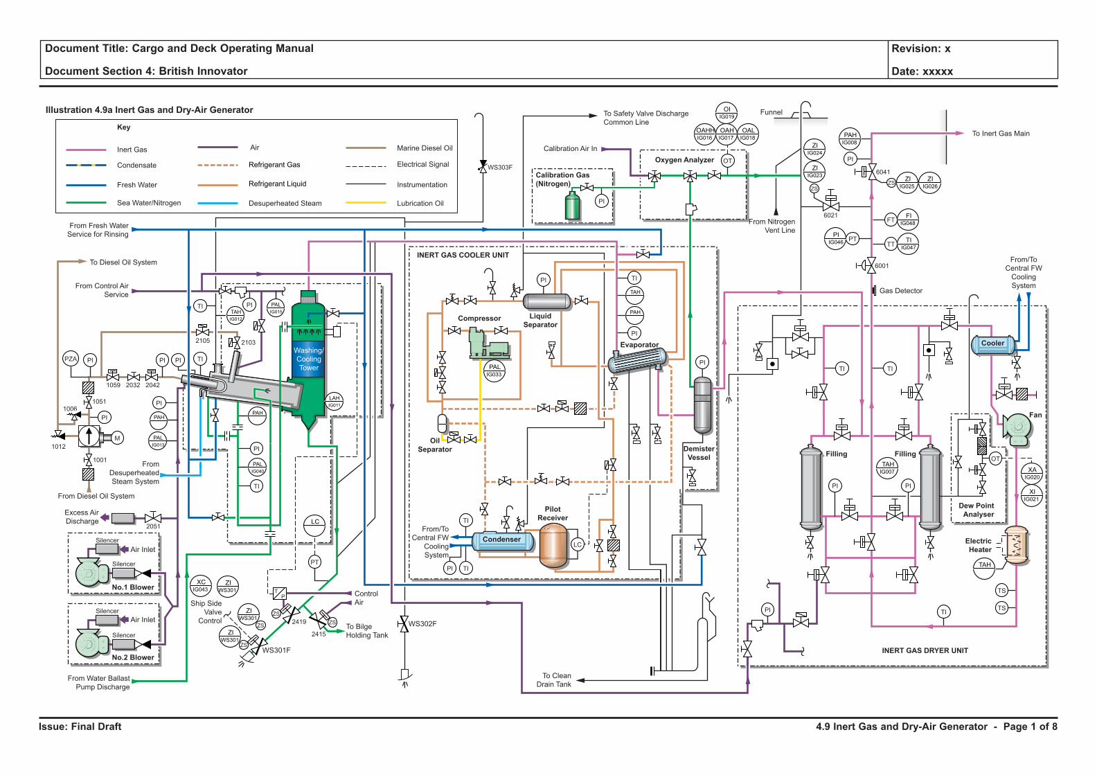
Issue: Final Draft
Document Title: Cargo and Deck Operating Manual
Document Section 4: British Innovator
Revision: x
Date: xxxxx
4.9 Inert Gas and Dry-Air Generator - Page 1 of 8
Illustration 4.9a Inert Gas and Dry-Air Generator
TI
PI
TI
TI TS
TS
OT
OT
PI
PI
PT
LC
PI
PI
PI
PI
TI
TI
PI PIPI
TI
ZS
ZS
ZSZS
Fresh Water
Desuperheated Steam
Key
Condensate
Sea Water/Nitrogen
Air
Refrigerant Gas
Refrigerant Liquid
Electrical Signal
Instrumentation
Lubrication Oil
Inert Gas
Air Inlet
Ship SideValve
Control
ControlAir
2415
2051
1001
1012
10061051
1059 2032 2042
21032105
2419
WS301F
WS302F
Washing/CoolingTower
To BilgeHolding Tank
To CleanDrain Tank
From/ToCentral FW
CoolingSystem
From Water BallastPump Discharge
Excess AirDischarge
From Diesel Oil System
FromDesuperheatedSteam System
To Diesel Oil System
From Control AirService
From Fresh WaterService for Rinsing
No.1 Blower
Calibration Air In
From NitrogenVent Line
Funnel
Gas Detector
ElectricHeater
Dew PointAnalyser
Fan
FillingFilling
To Inert Gas Main
Calibration Gas(Nitrogen)
Oxygen Analyzer
To Safety Valve DischargeCommon Line
Air Inlet
Silencer
Silencer
Silencer
Silencer
No.2 Blower
ZIWS301
LC
PI
TI
PZA
TIPI
PI
PAH
ZIWS301
XCIG043
ZIWS301
PALIG033
OAHHIG016
OAHIG017
OIIG019
OALIG018
PAHPAH
PALIG040
LAHIG011
PALIG013
PALIG015TAH
IG012
Marine Diesel Oil
WS303F
TP
Condenser
PilotReceiver
Compressor
Evaporator
LiquidSeparator
INERT GAS COOLER UNIT
INERT GAS DRYER UNIT
OilSeparator Demister
Vessel
TI
TAH
PI
FT
PT
ZSZS
PAHIG008
ZIIG025
FIIG048
TTTI
IG047
PIIG046
ZIIG026
ZIIG023
ZIIG024
6041
6021
6001
PIPI
TAHIG007 XA
IG020
XIIG021
TAH
Cooler
M
From/ToCentral FWCoolingSystem
Issue: Final Draft
Document Title: Cargo and Deck Operating Manual
Document Section 4: British Innovator
Revision: x
Date: xxxxx
4.9 INERT GAS AND DRY-AIR GENERATOR
DESCRIPTION
Maker: Smit Gas Systems BVType: Gln 14,000 - 0.25 BUFDNo. of sets: 1Delivery rate: 14,000Nm3/hDelivery pressure: 25kPa
Absorption Dryers
Maker: Smit Gas Systems BVCapacity: 14,000m3/hType: Regenerative active alumina
Regenerative Dryer
Maker: Smit Gas Systems BVType: JeviHeater: 310kW
R404A Refrigeration Plant
Maker: Grasso Type: KMRC 612 Motor: 185kW at 1,800rpm
IGG Air Blower UnitsMaker: Robushi Type: Roots K-150 D-LPMotor; 185kW at 1,800rpm
IGG Marine Gas Oil Supply PumpMaker: SAFAG Type: NVBHR.G.DC - 3Motor; 2.5kW Capacity: 2m3/h
Dew Point MeterMaker: Panametrics Type: MTS 5/4Capacity; 4 ~ 20mA
O2 AnalyserMaker: Smit Gas Systems BVType: OPSIS 02000Range: 0 - 25% oxygen
Inert Gas CompositionOxygen (O2): 0.5% (by vol)Carbon dioxide (CO2): 15% (by vol)Carbon monoxide (CO): 100ppm maximumSulphur oxides (SOx): 10ppm maximumNitrogen oxides (NOx): 100ppm maximumNitrogen (N2): Remainder
Sea water consumption: 1,060m3/h at 196kPaFresh water consumption: 25m3/hDiesel oil consumption: 1,335kg/h at design capacitySteam to burner: 784kPa
Sea water cooling is supplied by No.2 water ballast pump.
Water Ballast Pumps
Maker: Shinko Industries LtdNo. of sets: 3Type: Vertical, centrifugal with self-priming of No.3 Model: GVD500-2M (No.s 1 and 2 pumps)
GVD500-2MS (No.3 pump) Capacity: 3,000m3/h at 50mthMotors: NTIKE-FCT5-6P type, 6,600V, 580kW, 1,200 rpm
Fresh water cooling of the IG cooler and dryer units are supplied by the central FW cooling pumps.
Central Fresh Water Cooling Pumps
Maker: Shinko Industries LtdNo. of sets: 3Type: SVS 300MCapacity: 530m3/h at 30mth and 680m3/h at 27mthMotor: 75kW at 1,800rpm
General
The inert gas system is used for the inerting and gas freeing of cargo tanks, cargo pipes and void spaces when required. The inert gas is produced by a combustion process, which takes place in a combustion chamber where gas oil is used as the fuel.
The inert gas contains approximately 85% N2, 15% CO2 and about 0.5% O2 and is at a temperature approximately 5ºC above the sea water temperature.
After combustion, the inert gas has a level of corrosive sulphur oxides from the combustion process which have to be removed. The inert gas enters a sea water cooling tower and water separator where the gas is scrubbed and cooled with a sea water spray.
The inert gas is then dehumidified to a dew point of about +5ºC in the inert gas refrigeration cooler where an R404A refrigerant is used as the cooling medium.
The gas is further dried in one of two regenerative desiccant drying chambers, using electrically heated air in the regeneration process, before passing into the discharge line.
The generator is manually started from the control panels mounted locally and the operation can be monitored and various valves controlled from the IAS graphic display.
The inert gas generator contains an O2 analyser for the indication of oxygen content in the inert gas. The analyser is fitted with maximum and minimum setting alarms.
The gas is led to the deck main via pressure control valve 6001 and delivery valve 6041 depending on the gas analysis. The valve is normally controlled by the O2 and dew point analysers and the gas is led to the deck line only when the gas analysis meets with the set requirements. High O2 levels result in the delivery valve closing and purge valve 6021 opening to vent the IG to atmosphere at the funnel.
Working Principle
Inert gas is produced by the combustion of gas oil supplied by the fuel oil pump with air, provided by the blowers, in the combustion chamber of the inert gas generator. Good combustion is essential for the production of a good quality, soot free, low oxygen inert gas.
The products of the combustion are mainly CO2, water and small quantities of oxygen, carbon monoxide, sulphur oxides and hydrogen. The nitrogen content is generally unchanged during the combustion process and the inert gas produced consists mainly of 85% nitrogen and 15% CO2.
4.9 Inert Gas and Dry-Air Generator - Page 2 of 8
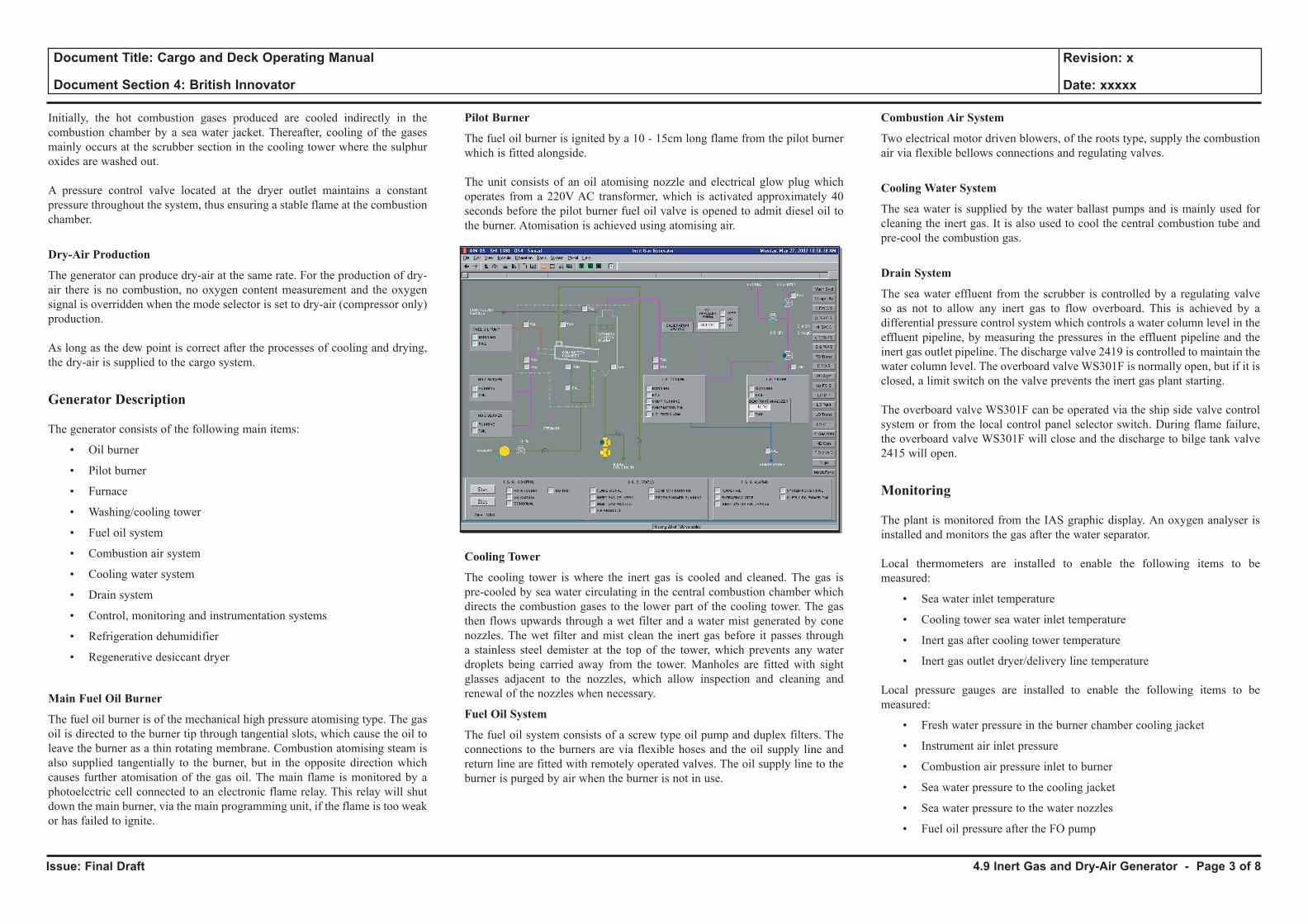
Issue: Final Draft
Document Title: Cargo and Deck Operating Manual
Document Section 4: British Innovator
Revision: x
Date: xxxxx
Initially, the hot combustion gases produced are cooled indirectly in the combustion chamber by a sea water jacket. Thereafter, cooling of the gases mainly occurs at the scrubber section in the cooling tower where the sulphur oxides are washed out.
A pressure control valve located at the dryer outlet maintains a constant pressure throughout the system, thus ensuring a stable flame at the combustion chamber.
Dry-Air Production
The generator can produce dry-air at the same rate. For the production of dry-air there is no combustion, no oxygen content measurement and the oxygen signal is overridden when the mode selector is set to dry-air (compressor only) production.
As long as the dew point is correct after the processes of cooling and drying, the dry-air is supplied to the cargo system.
Generator Description
The generator consists of the following main items:
• Oil burner
• Pilot burner
• Furnace
• Washing/cooling tower
• Fuel oil system
• Combustion air system
• Cooling water system
• Drain system
• Control, monitoring and instrumentation systems
• Refrigeration dehumidifier
• Regenerative desiccant dryer
Main Fuel Oil Burner
The fuel oil burner is of the mechanical high pressure atomising type. The gas oil is directed to the burner tip through tangential slots, which cause the oil to leave the burner as a thin rotating membrane. Combustion atomising steam is also supplied tangentially to the burner, but in the opposite direction which causes further atomisation of the gas oil. The main flame is monitored by a photoelcctric cell connected to an electronic flame relay. This relay will shut down the main burner, via the main programming unit, if the flame is too weak or has failed to ignite.
Pilot Burner
The fuel oil burner is ignited by a 10 - 15cm long flame from the pilot burner which is fitted alongside.
The unit consists of an oil atomising nozzle and electrical glow plug which operates from a 220V AC transformer, which is activated approximately 40 seconds before the pilot burner fuel oil valve is opened to admit diesel oil to the burner. Atomisation is achieved using atomising air.
Cooling Tower
The cooling tower is where the inert gas is cooled and cleaned. The gas is pre-cooled by sea water circulating in the central combustion chamber which directs the combustion gases to the lower part of the cooling tower. The gas then flows upwards through a wet filter and a water mist generated by cone nozzles. The wet filter and mist clean the inert gas before it passes through a stainless steel demister at the top of the tower, which prevents any water droplets being carried away from the tower. Manholes are fitted with sight glasses adjacent to the nozzles, which allow inspection and cleaning and renewal of the nozzles when necessary.
Fuel Oil System
The fuel oil system consists of a screw type oil pump and duplex filters. The connections to the burners are via flexible hoses and the oil supply line and return line are fitted with remotely operated valves. The oil supply line to the burner is purged by air when the burner is not in use.
Combustion Air System
Two electrical motor driven blowers, of the roots type, supply the combustion air via flexible bellows connections and regulating valves.
Cooling Water System
The sea water is supplied by the water ballast pumps and is mainly used for cleaning the inert gas. It is also used to cool the central combustion tube and pre-cool the combustion gas.
Drain System
The sea water effluent from the scrubber is controlled by a regulating valve so as not to allow any inert gas to flow overboard. This is achieved by a differential pressure control system which controls a water column level in the effluent pipeline, by measuring the pressures in the effluent pipeline and the inert gas outlet pipeline. The discharge valve 2419 is controlled to maintain the water column level. The overboard valve WS301F is normally open, but if it is closed, a limit switch on the valve prevents the inert gas plant starting.
The overboard valve WS301F can be operated via the ship side valve control system or from the local control panel selector switch. During flame failure, the overboard valve WS301F will close and the discharge to bilge tank valve 2415 will open.
Monitoring
The plant is monitored from the IAS graphic display. An oxygen analyser is installed and monitors the gas after the water separator.
Local thermometers are installed to enable the following items to be measured:
• Sea water inlet temperature
• Cooling tower sea water inlet temperature
• Inert gas after cooling tower temperature
• Inert gas outlet dryer/delivery line temperature
Local pressure gauges are installed to enable the following items to be measured:
• Fresh water pressure in the burner chamber cooling jacket
• Instrument air inlet pressure
• Combustion air pressure inlet to burner
• Sea water pressure to the cooling jacket
• Sea water pressure to the water nozzles
• Fuel oil pressure after the FO pump
4.9 Inert Gas and Dry-Air Generator - Page 3 of 8
Issue: Final Draft
Document Title: Cargo and Deck Operating Manual
Document Section 4: British Innovator
Revision: x
Date: xxxxx
• Fuel oil nozzle return pressure
• Inert gas pressure at the cooling tower outlet
• Inert gas pressure at the dryer outlet
• Inert gas delivery pressure
Plant Safety Interlocks
The following circumstances will cause an alarm and subsequent shutdown of the inert gas generator:
• High temperature in the cooling jacket
• High inert gas temperature at the cooling tower outlet
• High sea water level in the cooling tower
• Burner flame failure
• High/low combustion air pressure
• Low instrumentation air pressure
• High/low sea water pressure to the cooling tower
• Low fuel oil pressure to the burner
• High inert gas pressure at the cooling tower outlet
Alarms and Trips
The system has alarm outputs to the IAS system which will cause the atmospheric valve 6021 to open.
Pressure Switch SettingsTag No. Description Setting
1053 Fuel oil pressure low 10 bar
1505 Control air pressure low 6.0 bar
1634 Atomising steam pressure low 1.8 bar
2010 Combustion air pressure high 0.45 bar
2011 Combustion air pressure low 0.05 bar
2320 Cooling water pressure low 1.5 bar
2321 Jacket water pressure high 1.0 bar
4003 R404A suction pressure low 1.0 bar
4006 R404A suction pressure high 21 bar
4024 Oil differential low 1.5 bar
Tag No. Description Setting
4328 R404A condenser cooling water pressure low 1.0 bar
4410 IG pressure high 0.4 bar
5305 Dryer control air pressure low 5.0 bar
6053 Delivery pressure high 0.25 bar
Pressure Relief Valve settings
Tag No. Description Setting
1006 Fuel line pressure 25 bar
1012 Fuel oil pump 20.5 bar
4125 Cooling unit evaporator pressure 22.4 bar
4309 Cooling unit condenser pressure 22.4 bar
Temperature Switch settings
Tag No. Description Setting
2312 Jacket outlet high 55ºC
4004 R404A discharge high 120ºC
4402 Inert gas outlet high from scrubber tower 7ºC
4403 Inert gas outlet low from scrubber tower 0ºC
4407 Inert gas/evaporator inlet high 35ºC
5216 Dry inert gas outlet high 60ºC
5409 Fan inlet high 75ºC
5413 Regenerated inert gas low 140ºC
5414 Regenerated inert gas high 170ºC
5416 Main heater high 300ºC
5417 Spare heater high 300ºC
Thermal Overload Relays settings
Tag No. Description Setting
Q1-panel 7 R404 295 amps
F4 panel 8 Dryer fan 57 amps
Q1 panel 10 No.1 blower 301 amps
Q1 panel 11 No.2 blower 301 amps
F1 panel 12 Fuel oil pump 4.9 amps
Flow Indicators
Tag No. Setting
7024 90 litres/minute
7105 60 litres/minute
Control Panel Description
The control panel contains the programmable controller which takes care of the starting, stopping, alarm/trip functions and the running mode of the plant. On the front of the panel the IG plant is in the form of a mimic diagram, with motor running lights and automatic valve open/closed indicating lights. All alarm initiators are displayed on the mimic diagram and acted upon as follows:
• At normal running all alarm LEDs are unlit
• An alarm is indicated by an audible signal from a horn and a flashing light on the mimic diagram
• Upon accepting an alarm by a pushbutton, the audible alarm will stop
• When resetting an alarm by a pushbutton, the light will stop flashing and remain lit until the cause of the alarm is corrected, then the light will go out
• Alarm acknowledge
• Alarm reset
• Lamp test
Below the mimic display is the generator control pushbuttons which include the following:
• Manual start
• Automatic start
• Air purge
• Remote control
• Emergency stop
• Manual stop
R404A Refrigeration Plant
Maker: Grasso Type: KMRC 612 Motor: 185kW at 1,800rpm
4.9 Inert Gas and Dry-Air Generator - Page 4 of 8
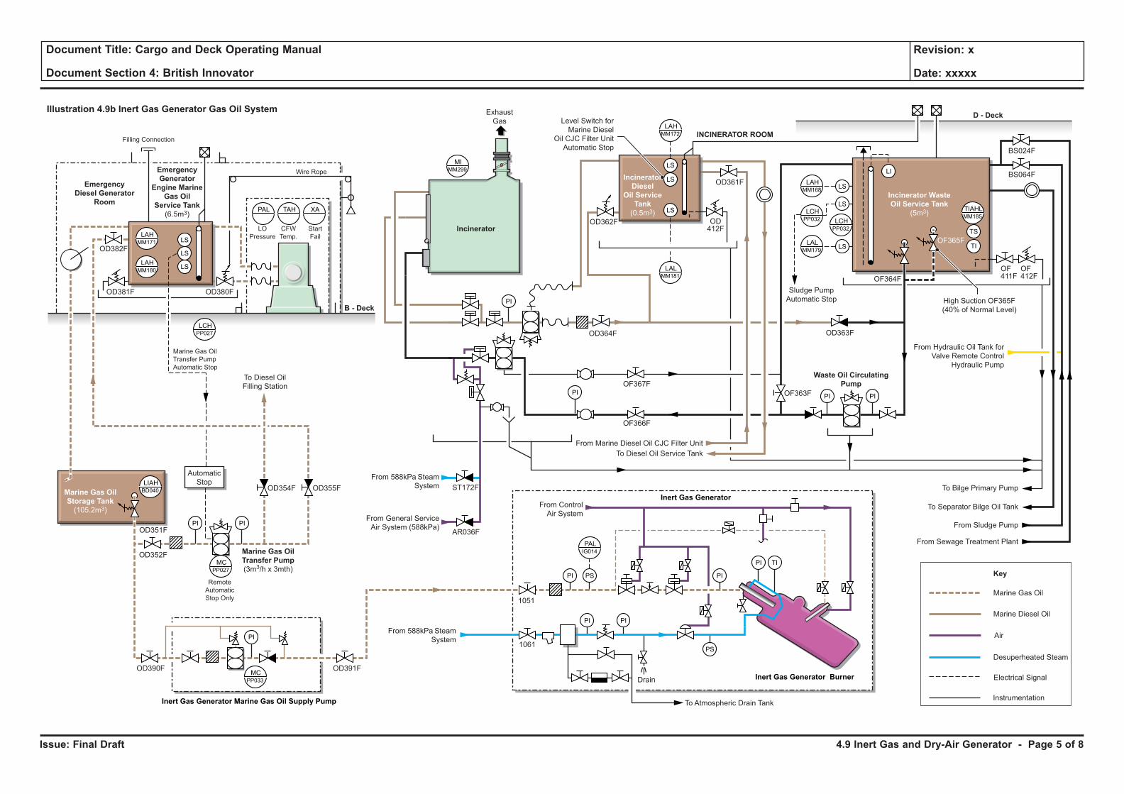
Issue: Final Draft
Document Title: Cargo and Deck Operating Manual
Document Section 4: British Innovator
Revision: x
Date: xxxxx
Illustration 4.9b Inert Gas Generator Gas Oil System
PI
PI
PIPI
PI PI
PI
LS
LS
LS
PI
PI
PI PS
PI
PI TI
PS
MIMM299
LAHMM172
LALMM181
MCPP033
PALIG014
LI
LS
LS
LAHMM168
LCHPP032
LALMM179
LCHPP032
TIAHLMM185
LS TI
TS
Sludge Pump
Automatic Stop
D - Deck
From Hydraulic Oil Tank for
Valve Remote Control
Hydraulic Pump
To Bilge Primary Pump
To Separator Bilge Oil Tank
To Atmospheric Drain Tank
Drain
1051
1061
From Marine Diesel Oil CJC Filter Unit
To Diesel Oil Service Tank
From Sludge Pump
From Sewage Treatment Plant
Level Switch for
Marine Diesel
Oil CJC Filter Unit
Automatic Stop
Exhaust
Gas
Waste Oil Circulating
Pump
Inert Gas Generator Marine Gas Oil Supply Pump
Inert Gas Generator
Inert Gas Generator Burner
Incinerator Waste
Oil Service Tank
(5m3)
Incinerator
Diesel
Oil Service
Tank
(0.5m3)
Marine Gas Oil
Storage Tank
(105.2m3)
Emergency
Generator
Engine Marine
Gas Oil
Service Tank
(6.5m3)
Emergency
Diesel Generator
Room
B - Deck
Incinerator
From 588kPa Steam
System
From 588kPa Steam
System
From General Service
Air System (588kPa)
From Control
Air System
Remote
Automatic
Stop Only
To Diesel Oil
Filling Station
Automatic
Stop
High Suction OF365F
(40% of Normal Level)
ST172FOD355F
OD382F
OD381F OD380F
OD354F
OD352F
OD390F OD391F
AR036F
OF366F
OF367F
OD364F
OD362F
OD361F
OF411FOF364F
OF365F
OF412F
OD363F
OF363F
BS024F
BS064F
OD412F
INCINERATOR ROOM
Marine Diesel Oil
Marine Gas Oil
Key
Desuperheated Steam
Electrical Signal
Instrumentation
Air
Marine Gas Oil
Transfer Pump
(3m3/h x 3mth)
Marine Gas Oil
Transfer Pump
Automatic Stop
Filling Connection
Wire Rope
LO
Pressure
CFW
Temp.
Start
Fail
MCPP027
LAHMM171
LCHPP027
PAL TAH XA
LAHMM180
LS
LS
LS
LIAHBD040
OD351F
4.9 Inert Gas and Dry-Air Generator - Page 5 of 8
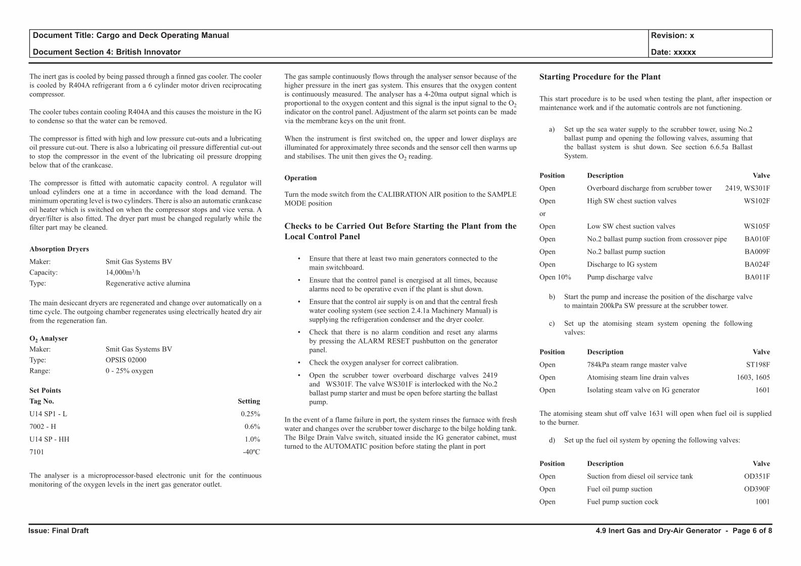
Issue: Final Draft
Document Title: Cargo and Deck Operating Manual
Document Section 4: British Innovator
Revision: x
Date: xxxxx
The inert gas is cooled by being passed through a finned gas cooler. The cooler is cooled by R404A refrigerant from a 6 cylinder motor driven reciprocating compressor.
The cooler tubes contain cooling R404A and this causes the moisture in the IG to condense so that the water can be removed.
The compressor is fitted with high and low pressure cut-outs and a lubricating oil pressure cut-out. There is also a lubricating oil pressure differential cut-out to stop the compressor in the event of the lubricating oil pressure dropping below that of the crankcase.
The compressor is fitted with automatic capacity control. A regulator will unload cylinders one at a time in accordance with the load demand. The minimum operating level is two cylinders. There is also an automatic crankcase oil heater which is switched on when the compressor stops and vice versa. A dryer/filter is also fitted. The dryer part must be changed regularly while the filter part may be cleaned.
Absorption Dryers
Maker: Smit Gas Systems BVCapacity: 14,000m3/hType: Regenerative active alumina
The main desiccant dryers are regenerated and change over automatically on a time cycle. The outgoing chamber regenerates using electrically heated dry air from the regeneration fan.
O2 AnalyserMaker: Smit Gas Systems BVType: OPSIS 02000Range: 0 - 25% oxygen
Set PointsTag No. Setting
U14 SP1 - L 0.25%
7002 - H 0.6%
U14 SP - HH 1.0%
7101 -40ºC
The analyser is a microprocessor-based electronic unit for the continuous monitoring of the oxygen levels in the inert gas generator outlet.
The gas sample continuously flows through the analyser sensor because of the higher pressure in the inert gas system. This ensures that the oxygen content is continuously measured. The analyser has a 4-20ma output signal which is proportional to the oxygen content and this signal is the input signal to the O2 indicator on the control panel. Adjustment of the alarm set points can be made via the membrane keys on the unit front.
When the instrument is first switched on, the upper and lower displays are illuminated for approximately three seconds and the sensor cell then warms up and stabilises. The unit then gives the O2 reading.
Operation
Turn the mode switch from the CALIBRATION AIR position to the SAMPLE MODE position
Checks to be Carried Out Before Starting the Plant from the Local Control Panel
• Ensure that there at least two main generators connected to the main switchboard.
• Ensure that the control panel is energised at all times, because alarms need to be operative even if the plant is shut down.
• Ensure that the control air supply is on and that the central fresh water cooling system (see section 2.4.1a Machinery Manual) is supplying the refrigeration condenser and the dryer cooler.
• Check that there is no alarm condition and reset any alarms by pressing the ALARM RESET pushbutton on the generator panel.
• Check the oxygen analyser for correct calibration.
• Open the scrubber tower overboard discharge valves 2419 and WS301F. The valve WS301F is interlocked with the No.2 ballast pump starter and must be open before starting the ballast pump.
In the event of a flame failure in port, the system rinses the furnace with fresh water and changes over the scrubber tower discharge to the bilge holding tank. The Bilge Drain Valve switch, situated inside the IG generator cabinet, must turned to the AUTOMATIC position before stating the plant in port
Starting Procedure for the Plant
This start procedure is to be used when testing the plant, after inspection or maintenance work and if the automatic controls are not functioning.
a) Set up the sea water supply to the scrubber tower, using No.2 ballast pump and opening the following valves, assuming that the ballast system is shut down. See section 6.6.5a Ballast System.
Position Description Valve
Open Overboard discharge from scrubber tower 2419, WS301F
Open High SW chest suction valves WS102F
or
Open Low SW chest suction valves WS105F
Open No.2 ballast pump suction from crossover pipe BA010F
Open No.2 ballast pump suction BA009F
Open Discharge to IG system BA024F
Open 10% Pump discharge valve BA011F
b) Start the pump and increase the position of the discharge valve to maintain 200kPa SW pressure at the scrubber tower.
c) Set up the atomising steam system opening the following valves:
Position Description Valve
Open 784kPa steam range master valve ST198F
Open Atomising steam line drain valves 1603, 1605
Open Isolating steam valve on IG generator 1601
The atomising steam shut off valve 1631 will open when fuel oil is supplied to the burner.
d) Set up the fuel oil system by opening the following valves:
Position Description Valve
Open Suction from diesel oil service tank OD351F
Open Fuel oil pump suction OD390F
Open Fuel pump suction cock 1001
4.9 Inert Gas and Dry-Air Generator - Page 6 of 8
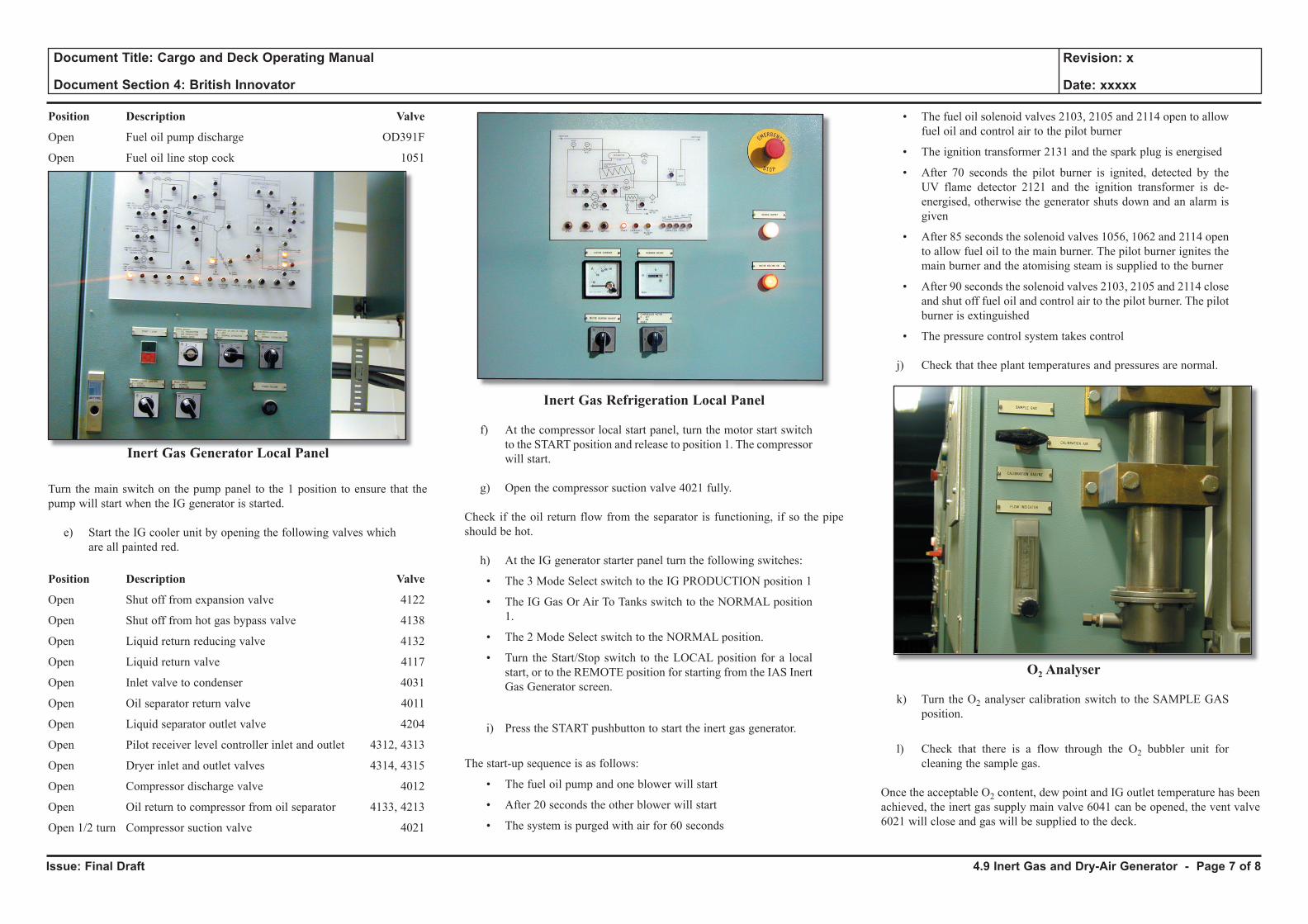
Issue: Final Draft
Document Title: Cargo and Deck Operating Manual
Document Section 4: British Innovator
Revision: x
Date: xxxxx
Position Description Valve
Open Fuel oil pump discharge OD391F
Open Fuel oil line stop cock 1051
Inert Gas Generator Local Panel
Turn the main switch on the pump panel to the 1 position to ensure that the pump will start when the IG generator is started.
e) Start the IG cooler unit by opening the following valves which are all painted red.
Position Description Valve
Open Shut off from expansion valve 4122
Open Shut off from hot gas bypass valve 4138
Open Liquid return reducing valve 4132
Open Liquid return valve 4117
Open Inlet valve to condenser 4031
Open Oil separator return valve 4011
Open Liquid separator outlet valve 4204
Open Pilot receiver level controller inlet and outlet 4312, 4313
Open Dryer inlet and outlet valves 4314, 4315
Open Compressor discharge valve 4012
Open Oil return to compressor from oil separator 4133, 4213
Open 1/2 turn Compressor suction valve 4021
Inert Gas Refrigeration Local Panel
f) At the compressor local start panel, turn the motor start switch to the START position and release to position 1. The compressor will start.
g) Open the compressor suction valve 4021 fully.
Check if the oil return flow from the separator is functioning, if so the pipe should be hot.
h) At the IG generator starter panel turn the following switches:
• The 3 Mode Select switch to the IG PRODUCTION position 1
• The IG Gas Or Air To Tanks switch to the NORMAL position 1.
• The 2 Mode Select switch to the NORMAL position.
• Turn the Start/Stop switch to the LOCAL position for a local start, or to the REMOTE position for starting from the IAS Inert Gas Generator screen.
i) Press the START pushbutton to start the inert gas generator.
The start-up sequence is as follows:
• The fuel oil pump and one blower will start
• After 20 seconds the other blower will start
• The system is purged with air for 60 seconds
• The fuel oil solenoid valves 2103, 2105 and 2114 open to allow fuel oil and control air to the pilot burner
• The ignition transformer 2131 and the spark plug is energised
• After 70 seconds the pilot burner is ignited, detected by the UV flame detector 2121 and the ignition transformer is de-energised, otherwise the generator shuts down and an alarm is given
• After 85 seconds the solenoid valves 1056, 1062 and 2114 open to allow fuel oil to the main burner. The pilot burner ignites the main burner and the atomising steam is supplied to the burner
• After 90 seconds the solenoid valves 2103, 2105 and 2114 close and shut off fuel oil and control air to the pilot burner. The pilot burner is extinguished
• The pressure control system takes control
j) Check that thee plant temperatures and pressures are normal.
O2 Analyser
k) Turn the O2 analyser calibration switch to the SAMPLE GAS position.
l) Check that there is a flow through the O2 bubbler unit for cleaning the sample gas.
Once the acceptable O2 content, dew point and IG outlet temperature has been achieved, the inert gas supply main valve 6041 can be opened, the vent valve 6021 will close and gas will be supplied to the deck.
4.9 Inert Gas and Dry-Air Generator - Page 7 of 8
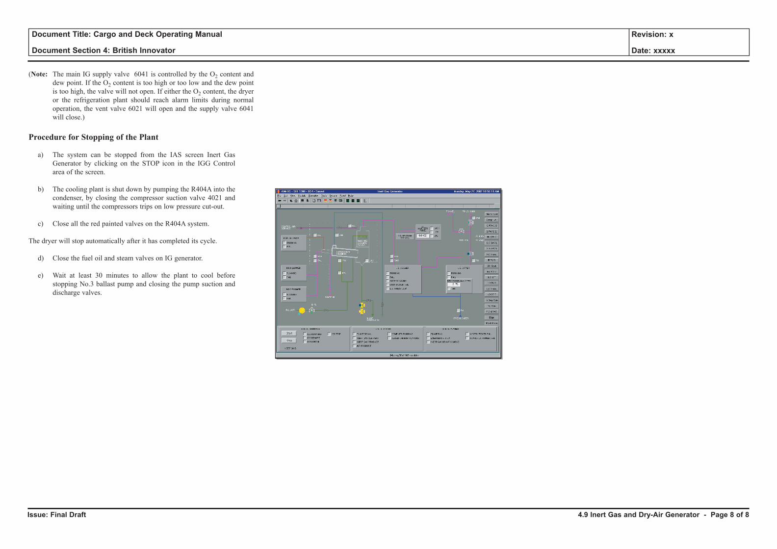
Issue: Final Draft
Document Title: Cargo and Deck Operating Manual
Document Section 4: British Innovator
Revision: x
Date: xxxxx
(Note: The main IG supply valve 6041 is controlled by the O2 content and dew point. If the O2 content is too high or too low and the dew point is too high, the valve will not open. If either the O2 content, the dryer or the refrigeration plant should reach alarm limits during normal operation, the vent valve 6021 will open and the supply valve 6041 will close.)
Procedure for Stopping of the Plant
a) The system can be stopped from the IAS screen Inert Gas Generator by clicking on the STOP icon in the IGG Control area of the screen.
b) The cooling plant is shut down by pumping the R404A into the condenser, by closing the compressor suction valve 4021 and waiting until the compressors trips on low pressure cut-out.
c) Close all the red painted valves on the R404A system.
The dryer will stop automatically after it has completed its cycle.
d) Close the fuel oil and steam valves on IG generator.
e) Wait at least 30 minutes to allow the plant to cool before stopping No.3 ballast pump and closing the pump suction and discharge valves.
4.9 Inert Gas and Dry-Air Generator - Page 8 of 8

4.10 Fixed Gas Sampling System
Illustrations
4.10a Fixed Gas Sampling System
4.10b Fixed Gas Sampling System
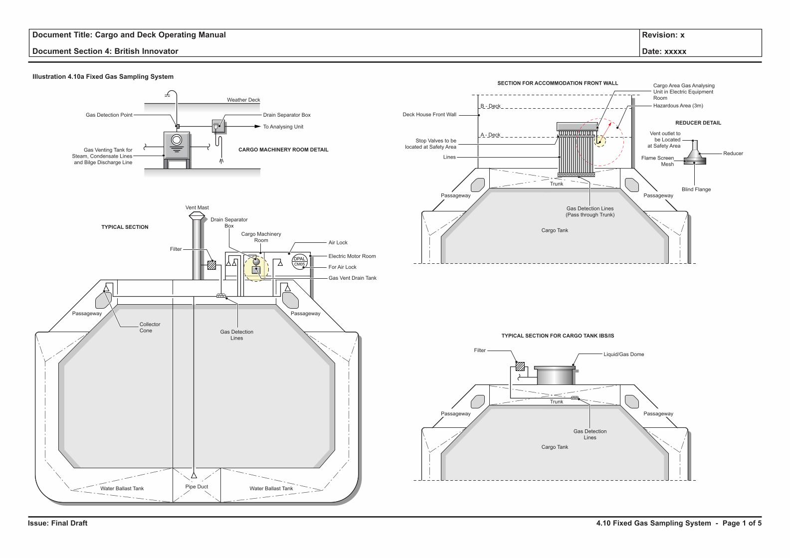
Issue: Final Draft
Document Title: Cargo and Deck Operating Manual
Document Section 4: British Innovator
Revision: x
Date: xxxxx
Illustration 4.10a Fixed Gas Sampling System
Water Ballast TankWater Ballast Tank Pipe Duct
Passageway Passageway
Vent Mast
Cargo MachineryRoom
FilterElectric Motor Room
Liquid/Gas Dome
For Air Lock
Gas DetectionLines
CollectorCone
TYPICAL SECTION
CARGO MACHINERY ROOM DETAIL
REDUCER DETAIL
Gas DetectionLines
Drain SeparatorBox
Gas Vent Drain Tank
Air Lock
Lines
Stop Valves to belocated at Safety Area
Deck House Front Wall
A - Deck
B - Deck
To Analysing Unit
Drain Separator Box
DPALCM05
Weather Deck
Gas Detection Point
Gas Venting Tank forSteam, Condensate Linesand Bilge Discharge Line
Trunk
Trunk
Cargo Tank
Filter
Gas DetectionLines
TYPICAL SECTION FOR CARGO TANK IBS/IS
SECTION FOR ACCOMMODATION FRONT WALL
Gas DetectionLines
Cargo Tank
Gas Detection Lines(Pass through Trunk)
Cargo Area Gas AnalysingUnit in Electric EquipmentRoomHazardous Area (3m)
Blind Flange
Flame ScreenMesh
Reducer
Vent outlet tobe Located
at Safety Area
Passageway Passageway
Passageway Passageway
4.10 Fixed Gas Sampling System - Page 1 of 5
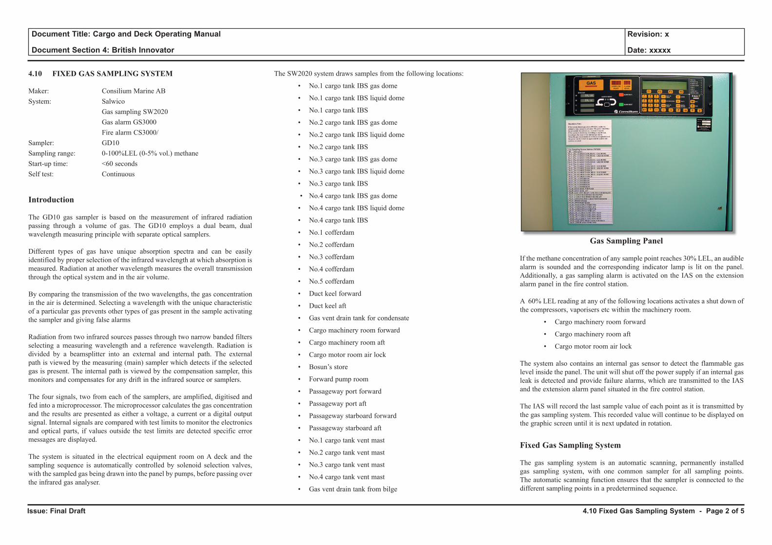
Issue: Final Draft
Document Title: Cargo and Deck Operating Manual
Document Section 4: British Innovator
Revision: x
Date: xxxxx
4.10 FIXED GAS SAMPLING SYSTEM
Maker: Consilium Marine ABSystem: Salwico Gas sampling SW2020 Gas alarm GS3000 Fire alarm CS3000/Sampler: GD10Sampling range: 0-100%LEL (0-5% vol.) methaneStart-up time: <60 secondsSelf test: Continuous
Introduction
The GD10 gas sampler is based on the measurement of infrared radiation passing through a volume of gas. The GD10 employs a dual beam, dual wavelength measuring principle with separate optical samplers.
Different types of gas have unique absorption spectra and can be easily identified by proper selection of the infrared wavelength at which absorption is measured. Radiation at another wavelength measures the overall transmission through the optical system and in the air volume.
By comparing the transmission of the two wavelengths, the gas concentration in the air is determined. Selecting a wavelength with the unique characteristic of a particular gas prevents other types of gas present in the sample activating the sampler and giving false alarms
Radiation from two infrared sources passes through two narrow banded filters selecting a measuring wavelength and a reference wavelength. Radiation is divided by a beamsplitter into an external and internal path. The external path is viewed by the measuring (main) sampler which detects if the selected gas is present. The internal path is viewed by the compensation sampler, this monitors and compensates for any drift in the infrared source or samplers.
The four signals, two from each of the samplers, are amplified, digitised and fed into a microprocessor. The microprocessor calculates the gas concentration and the results are presented as either a voltage, a current or a digital output signal. Internal signals are compared with test limits to monitor the electronics and optical parts, if values outside the test limits are detected specific error messages are displayed.
The system is situated in the electrical equipment room on A deck and the sampling sequence is automatically controlled by solenoid selection valves, with the sampled gas being drawn into the panel by pumps, before passing over the infrared gas analyser.
The SW2020 system draws samples from the following locations:
• No.1 cargo tank IBS gas dome
• No.1 cargo tank IBS liquid dome
• No.1 cargo tank IBS
• No.2 cargo tank IBS gas dome
• No.2 cargo tank IBS liquid dome
• No.2 cargo tank IBS
• No.3 cargo tank IBS gas dome
• No.3 cargo tank IBS liquid dome
• No.3 cargo tank IBS
• No.4 cargo tank IBS gas dome
• No.4 cargo tank IBS liquid dome
• No.4 cargo tank IBS
• No.1 cofferdam
• No.2 cofferdam
• No.3 cofferdam
• No.4 cofferdam
• No.5 cofferdam
• Duct keel forward
• Duct keel aft
• Gas vent drain tank for condensate
• Cargo machinery room forward
• Cargo machinery room aft
• Cargo motor room air lock
• Bosun’s store
• Forward pump room
• Passageway port forward
• Passageway port aft
• Passageway starboard forward
• Passageway starboard aft
• No.1 cargo tank vent mast
• No.2 cargo tank vent mast
• No.3 cargo tank vent mast
• No.4 cargo tank vent mast
• Gas vent drain tank from bilge
Gas Sampling Panel
If the methane concentration of any sample point reaches 30% LEL, an audible alarm is sounded and the corresponding indicator lamp is lit on the panel. Additionally, a gas sampling alarm is activated on the IAS on the extension alarm panel in the fire control station.
A 60% LEL reading at any of the following locations activates a shut down of the compressors, vaporisers etc within the machinery room.
• Cargo machinery room forward
• Cargo machinery room aft
• Cargo motor room air lock
The system also contains an internal gas sensor to detect the flammable gas level inside the panel. The unit will shut off the power supply if an internal gas leak is detected and provide failure alarms, which are transmitted to the IAS and the extension alarm panel situated in the fire control station.
The IAS will record the last sample value of each point as it is transmitted by the gas sampling system. This recorded value will continue to be displayed on the graphic screen until it is next updated in rotation.
Fixed Gas Sampling System
The gas sampling system is an automatic scanning, permanently installed gas sampling system, with one common sampler for all sampling points. The automatic scanning function ensures that the sampler is connected to the different sampling points in a predetermined sequence.
4.10 Fixed Gas Sampling System - Page 2 of 5
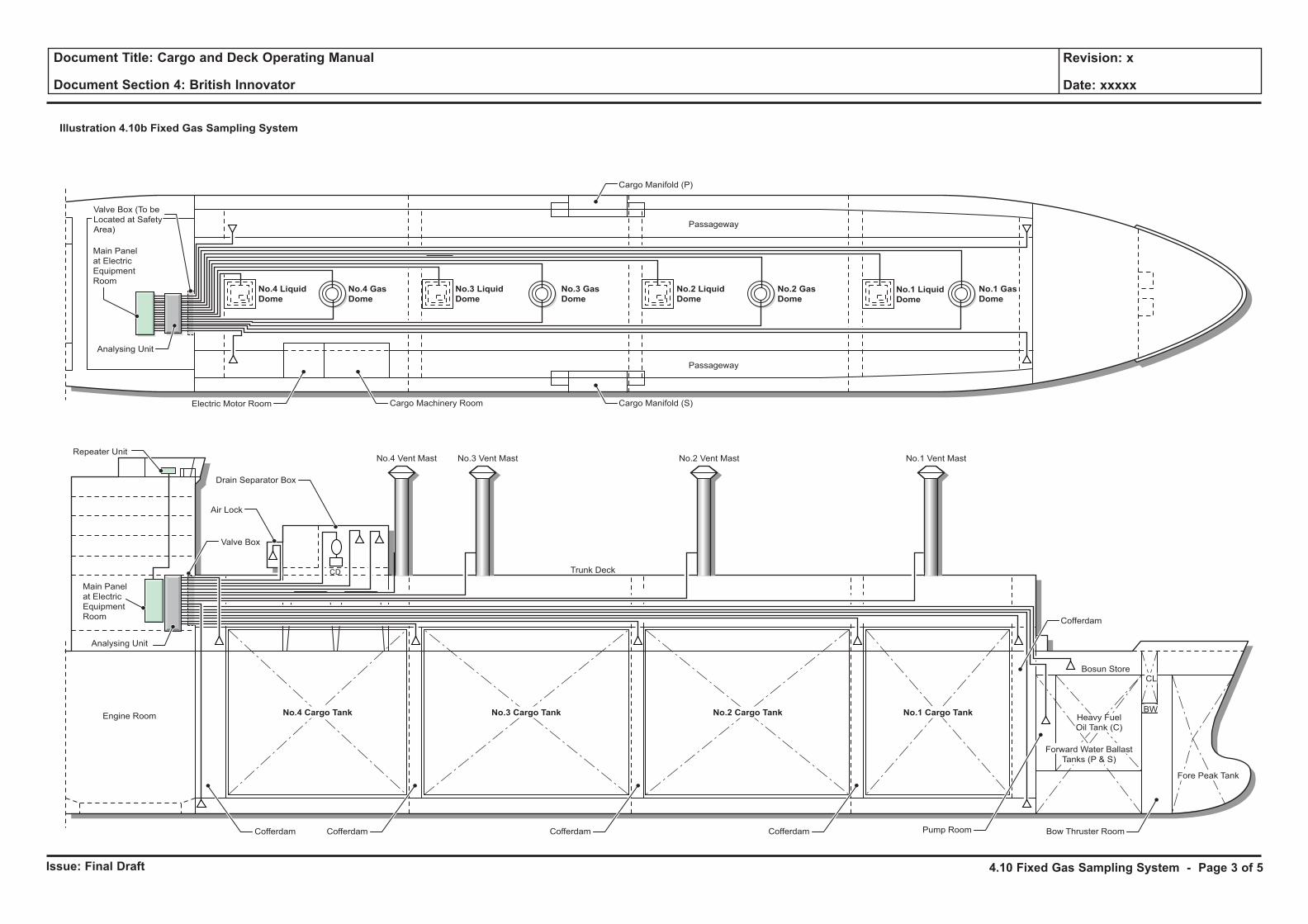
Issue: Final Draft
Document Title: Cargo and Deck Operating Manual
Document Section 4: British Innovator
Revision: x
Date: xxxxx
Illustration 4.10b Fixed Gas Sampling System
No.4 Liquid
Dome
No.4 Gas
Dome
No.3 Liquid
Dome
No.3 Gas
Dome
No.2 Liquid
Dome
No.2 Gas
DomeNo.1 Liquid
Dome
No.1 Gas
Dome
Cargo Machinery Room Cargo Manifold (S)
Passageway
Passageway
Cargo Manifold (P)
Electric Motor Room
Analysing Unit
Main Panel
at Electric
Equipment
Room
Main Panel
at Electric
Equipment
Room
Valve Box (To be
Located at Safety
Area)
No.4 Cargo Tank No.3 Cargo Tank No.2 Cargo Tank No.1 Cargo Tank
Trunk Deck
Engine Room
Analysing Unit
Repeater Unit
Valve Box
Air Lock
Drain Separator Box
Fore Peak Tank
Bow Thruster Room
Heavy Fuel
Oil Tank (C)
Bosun Store
Forward Water Ballast
Tanks (P & S)
Pump Room
Cofferdam
BW
CL
CofferdamCofferdam
CD
CofferdamCofferdam
No.4 Vent Mast No.3 Vent Mast No.2 Vent Mast No.1 Vent Mast
4.10 Fixed Gas Sampling System - Page 3 of 5
Issue: Final Draft
Document Title: Cargo and Deck Operating Manual
Document Section 4: British Innovator
Revision: x
Date: xxxxx
An actual test sample from the sampling point connection is obtained through the sampling pipe being pre-evacuated before the sampler is connected. Pre-evacuation takes place only in the sampling pipe which is next to be connected for sampling. This avoids unnecessary quantities of dust, dirt, salt and moisture being sucked into the filters, which are fitted to every individual pipe in the system.
The entire internal pipe system in the analysing unit is purged automatically with clean air between the pre-suction and sampling phase.
In order to avoid water or any other liquid being sucked into the pipe system and reaching the sampler, an automatic pump stop function is included.
A gas cylinder, with a gas mixture of known composition, is connected to the system for regular calibration of the gas alarm instrument, as well as checks on the operation of the system.
The gas sampling system consists of four primary units:
1. Control Unit
The control unit contains all control and checking functions of the system and is located in the cargo control room.
2. Analysing Unit
The analysing unit contains all functions for gas sampling and transportation of the test samples. A measuring point for internal monitoring of leakage is also installed in the analysing unit.
3. Repeater Unit
The function of this panel is to indicate alarms/faults visually and audibly to the duty watch on the bridge.
4. Pipe System
The pipe system transports the test samples from sampling points to the analysing unit. The pipe system includes filters, shut off valves and flame traps.
Procedure for the Operation of the Gas Sampling SystemControl Unit
The control unit of the GS3000 Gas Sampling System is divided into two separate parts.
The left-hand side consists of only three keys: ALARM MUTE, ALARM RESET and ALARM IN QUEUE. The ALARM IN QUEUE key is used to find a gas alarm in the gas alarm list and the two other keys to either mute or to reset an alarm. The gas level is measured again to see if the alarm condition has disappeared.
The right-hand side is used for operation of the system. Press one of the six LIST and SET UP keys to operate and monitor the system. All six keys will open a list of items (sampling points, alarms etc.).
Use the four arrow keys to find the item required and use the function keys to select an action to perform.
For example, it is possible to make a manual measurement on sampling point number 5 (SP5) by first pressing LIST SAMPLING POINTS, then choose SP5 with the arrow keys and finally press F3 (Measure) to start measuring on SP5. The sampling point details will be shown on the display.
Some menus require a numerical input; manual measurement is one of them. Enter a new value with the numerical keyboard. Press ENTER to change the new value into the current value and press F1 to start measuring.
Press F1 to start measuring using the default value (5 per minute).
StandbyThe control unit is in standby mode most of the time. The display shows that the measurement sequence is running. The system always displays the last measurement.
The standby menu displays the system status. The standby mode can be identified by the clock in the upper right corner and can be reached by pressing the HOME key. The control unit will automatically return to standby mode 30 minutes after the last keyboard entry.
ListsAll manipulations required by the average user can be performed from the four lists in the system.
Alarm ListThe left hand side of the control unit always displays the sampling point in alarm and the alarm level (high or low).
Mute any gas alarms by pressing ALARM MUTE and reset gas alarms by pressing ALARM RESET. Press ALARM IN QUEUE to display the next gas alarm (if any).
When more detailed information about an alarm is required, press LIST ALARMS on the right hand side of the control unit. This list is opened automatically when a new gas alarm is detected. Use the arrow keys to display the next and previous alarms.
Fault ListPress LIST FAULTS, on the right hand side of the control unit, to display the faults in the system. This list is automatically opened when the system detects a fault.
Mute faults by pressing the FAULT MUTE key and reset faults by pressing the FAULT RESET key.
Sampling Point ListPress LIST SAMPLING POINTS to enter the sampling point list.
Select a sampling point with the arrow keys and use the function keys to perform an action.
The following actions can be performed on a sampling point:
Value - Display the value of the last gas measurement.
Measure - Start measuring the gas concentration. With this function it is possible to make a prompt check of the actual gas concentration of the selected sampling point. The sampling time can be set in minutes though never below the set up time. The gas value is updated and continuously shown in the display. The possible alarm (low or high) will be decided when the gas reading is stable. The remaining measurement time is continuously shown.
Purge - Clean the pipe for that particular sampling point for 30 seconds. Before connection to the analysing flow an automatic decompression is made through the internal sampling point for 10 seconds in order to protect the pressure switch and pump membrane.
Actions such as ‘purge’ and ‘manual measure’ cannot be performed on disconnected sampling points. The only allowed action on a disconnected sampling point is Reconnect.
After a measure or purge manoeuvre, the normal measurement sequence starts at the sampling point that was interrupted.
Disconnection ListPress LIST DISCONNECTION to open the disconnection list.
Disconnected sampling points are displayed one by one by using the arrow keys. Reconnect a sampling point by pressing Fl (Reconnect).
Set up - General SettingsThe system changes the access level and enters Configuration Mode when the correct access code for level 2, 3 or 4 is entered. The system will not start until the user chooses to start the system again (the access level is automatically changed back to 1) or the user time-out expires after 30 minutes.
4.10 Fixed Gas Sampling System - Page 4 of 5
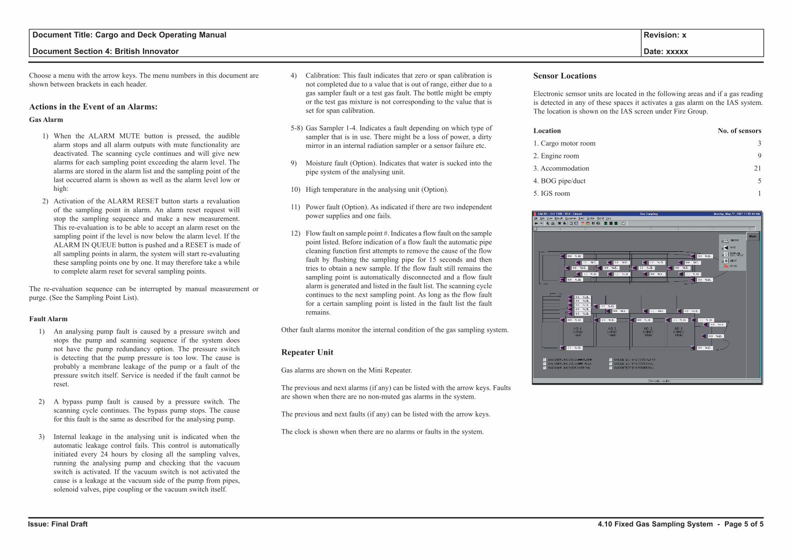
Issue: Final Draft
Document Title: Cargo and Deck Operating Manual
Document Section 4: British Innovator
Revision: x
Date: xxxxx
Choose a menu with the arrow keys. The menu numbers in this document are shown between brackets in each header.
Actions in the Event of an Alarms:Gas Alarm
1) When the ALARM MUTE button is pressed, the audible alarm stops and all alarm outputs with mute functionality are deactivated. The scanning cycle continues and will give new alarms for each sampling point exceeding the alarm level. The alarms are stored in the alarm list and the sampling point of the last occurred alarm is shown as well as the alarm level low or high:
2) Activation of the ALARM RESET button starts a revaluation of the sampling point in alarm. An alarm reset request will stop the sampling sequence and make a new measurement. This re-evaluation is to be able to accept an alarm reset on the sampling point if the level is now below the alarm level. If the ALARM IN QUEUE button is pushed and a RESET is made of all sampling points in alarm, the system will start re-evaluating these sampling points one by one. It may therefore take a while to complete alarm reset for several sampling points.
The re-evaluation sequence can be interrupted by manual measurement or purge. (See the Sampling Point List).
Fault Alarm
1) An analysing pump fault is caused by a pressure switch and stops the pump and scanning sequence if the system does not have the pump redundancy option. The pressure switch is detecting that the pump pressure is too low. The cause is probably a membrane leakage of the pump or a fault of the pressure switch itself. Service is needed if the fault cannot be reset.
2) A bypass pump fault is caused by a pressure switch. The scanning cycle continues. The bypass pump stops. The cause for this fault is the same as described for the analysing pump.
3) Internal leakage in the analysing unit is indicated when the automatic leakage control fails. This control is automatically initiated every 24 hours by closing all the sampling valves, running the analysing pump and checking that the vacuum switch is activated. If the vacuum switch is not activated the cause is a leakage at the vacuum side of the pump from pipes, solenoid valves, pipe coupling or the vacuum switch itself.
4) Calibration: This fault indicates that zero or span calibration is not completed due to a value that is out of range, either due to a gas sampler fault or a test gas fault. The bottle might be empty or the test gas mixture is not corresponding to the value that is set for span calibration.
5-8) Gas Sampler 1-4. Indicates a fault depending on which type of sampler that is in use. There might be a loss of power, a dirty mirror in an internal radiation sampler or a sensor failure etc.
9) Moisture fault (Option). Indicates that water is sucked into the pipe system of the analysing unit.
10) High temperature in the analysing unit (Option).
11) Power fault (Option). As indicated if there are two independent power supplies and one fails.
12) Flow fault on sample point #. Indicates a flow fault on the sample point listed. Before indication of a flow fault the automatic pipe cleaning function first attempts to remove the cause of the flow fault by flushing the sampling pipe for 15 seconds and then tries to obtain a new sample. If the flow fault still remains the sampling point is automatically disconnected and a flow fault alarm is generated and listed in the fault list. The scanning cycle continues to the next sampling point. As long as the flow fault for a certain sampling point is listed in the fault list the fault remains.
Other fault alarms monitor the internal condition of the gas sampling system.
Repeater Unit
Gas alarms are shown on the Mini Repeater.
The previous and next alarms (if any) can be listed with the arrow keys. Faults are shown when there are no non-muted gas alarms in the system.
The previous and next faults (if any) can be listed with the arrow keys.
The clock is shown when there are no alarms or faults in the system.
Sensor Locations
Electronic semsor units are located in the following areas and if a gas reading is detected in any of these spaces it activates a gas alarm on the IAS system. The location is shown on the IAS screen under Fire Group.
Location No. of sensors
1. Cargo motor room 3
2. Engine room 9
3. Accommodation 21
4. BOG pipe/duct 5
5. IGS room 1
4.10 Fixed Gas Sampling System - Page 5 of 5
4.11 Valve Remote Control and Emergency Shutdown System
4.11.1 Cargo and Ballast Valve Remote Control System
4.11.2 Emergency Shutdown and Cargo Tank Protection Scheme
Illustrations
4.11.1a Cargo Valve Hydraulic Pipelines
4.11.1b Ballast Valve Hydraulic Pipelines
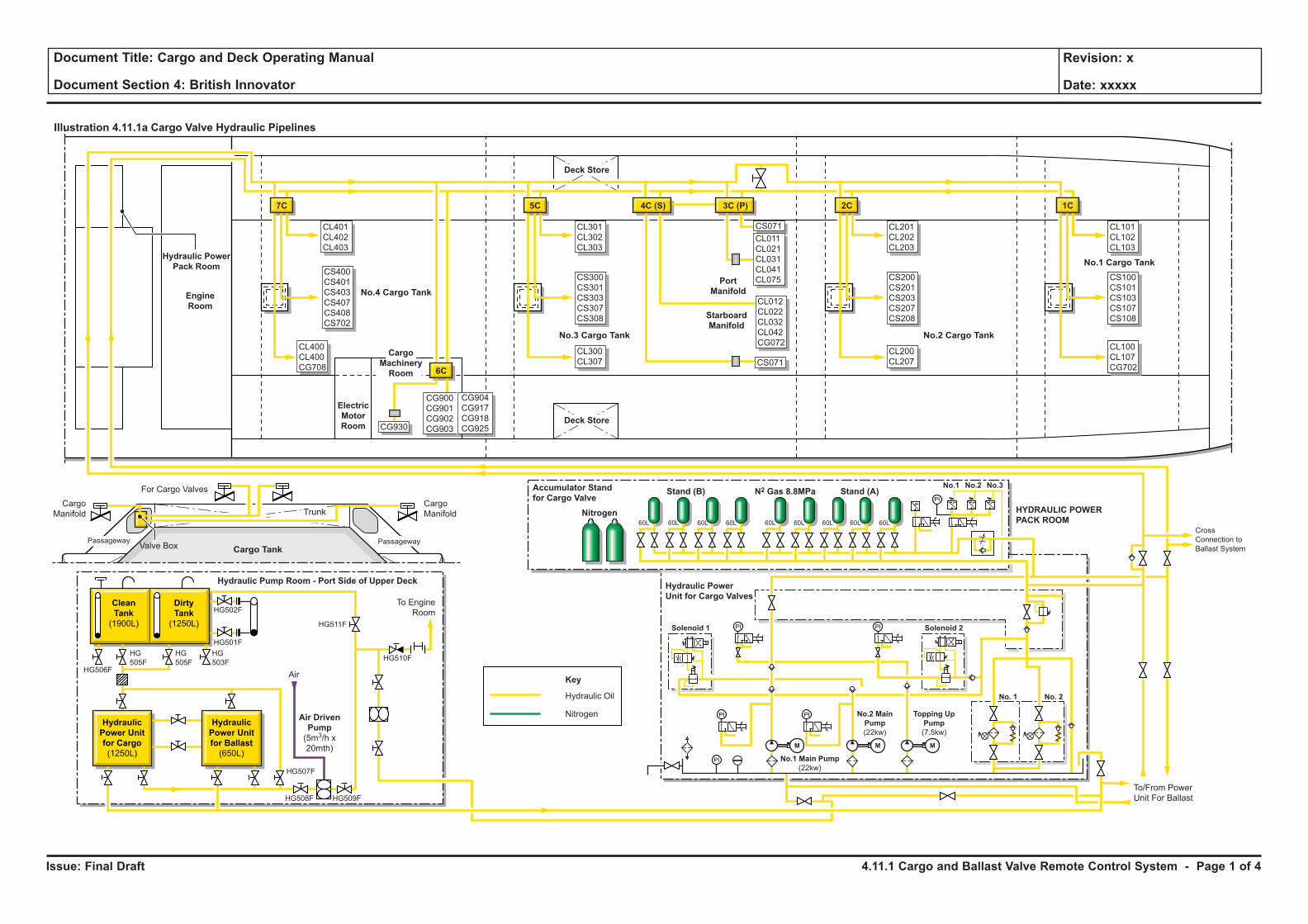
Issue: Final Draft
Document Title: Cargo and Deck Operating Manual
Document Section 4: British Innovator
Revision: x
Date: xxxxx
Illustration 4.11.1a Cargo Valve Hydraulic Pipelines
PI
Cargo Tank
Trunk
Clean
Tank
(1900L)
Dirty
Tank
(1250L)
1C
CL101
CL102
CL103
CL100
CL107
CG702
CS100
CS101
CS103
CS107
CS108
1C
CL101
CL102
CL103
CL100
CL107
CG702
CS100
CS101
CS103
CS107
CS108
2C
CL201
CL202
CL203
CL200
CL207
CS200
CS201
CS203
CS207
CS208
5C
6C
7C
CL301
CL302
CL303
CL300
CL307
CS300
CS301
CS303
CS307
CS308
CS400
CS401
CS403
CS407
CS408
CS702
CS071
CL011
CL021
CL031
CL041
CL075Port
Manifold
Starboard
Manifold
Hydraulic Pump Room - Port Side of Upper Deck
3C (P)
CS071
CG930
CL012
CL022
CL032
CL042
CG072
4C (S)
CL401
CL402
CL403
CL400
CL400
CG708
Deck Store
Stand (B)
Nitrogen
Hydraulic Power
Unit for Cargo Valves
Accumulator Stand
for Cargo ValveStand (A)
HYDRAULIC POWER
PACK ROOM
No.1 No.2 No.3N2 Gas 8.8MPa
Electric
Motor
Room
Deck Store
Cargo
Machinery
Room
Engine
Room
Cross
Connection to
Ballast System
Hydraulic Power
Pack Room
Cargo
Manifold
To/From Power
Unit For Ballast
For Cargo Valves
Valve Box
Cargo
Manifold
Air
To Engine
Room
Air Driven
Pump
(5m3/h x
20mth)
HG506F
HG502F
HG501F
HG511F
HG510F
HG507F
HG508F HG509F
HG
505F
HG
505F
HG
503F
No.1 Main Pump
(22kw)
No.2 Main
Pump
(22kw)
Topping Up
Pump
(7.5kw)
Solenoid 1 Solenoid 2
No. 2No. 1
Nitrogen
60L 60L 60L 60L 60L 60L 60L 60L 60L
PI
PI PI
PI
PI
M M M
Hydraulic
Power Unit
for Cargo
(1250L)
Hydraulic
Power Unit
for Ballast
(650L)
CG900
CG901
CG902
CG903
CG904
CG917
CG918
CG925
Hydraulic Oil
Key
No.3 Cargo Tank
No.4 Cargo Tank
No.2 Cargo Tank
No.1 Cargo Tank
Passageway Passageway
4.11.1 Cargo and Ballast Valve Remote Control System - Page 1 of 4
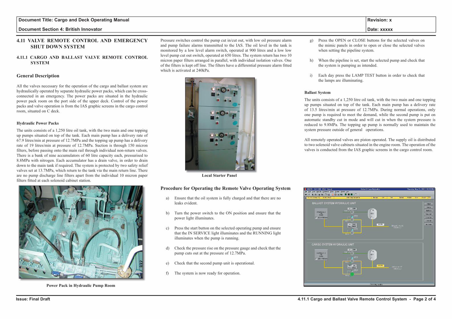
Issue: Final Draft
Document Title: Cargo and Deck Operating Manual
Document Section 4: British Innovator
Revision: x
Date: xxxxx
4.11 VALVE REMOTE CONTROL AND EMERGENCY SHUT DOWN SYSTEM
4.11.1 CARGO AND BALLAST VALVE REMOTE CONTROL SYSTEM
General Description
All the valves necessary for the operation of the cargo and ballast system are hydraulically operated by separate hydraulic power packs, which can be cross-connected in an emergency. The power packs are situated in the hydraulic power pack room on the port side of the upper deck. Control of the power packs and valve operation is from the IAS graphic screens in the cargo control room, situated on C deck.
Hydraulic Power Packs
The units consists of a 1,250 litre oil tank, with the two main and one topping up pumps situated on top of the tank. Each main pump has a delivery rate of 67.9 litres/min at pressure of 12.7MPa and the topping up pump has a delivery rate of 19 litres/min at pressure of 12.7MPa. Suction is through 150 micron filters, before passing onto the main rail through individual non-return valves. There is a bank of nine accumulators of 60 litre capacity each, pressurised to 8.8MPa with nitrogen. Each accumulator has a drain valve, in order to drain down to the main tank if required. The system is protected by two safety relief valves set at 13.7MPa, which return to the tank via the main return line. There are no pump discharge line filters apart from the individual 10 micron paper filters fitted at each solenoid cabinet station.
Power Pack in Hydraulic Pump Room
Pressure switches control the pump cut in/cut out, with low oil pressure alarm and pump failure alarms transmitted to the IAS. The oil level in the tank is monitored by a low level alarm switch, operated at 900 litres and a low low level pump cut out switch, operated at 650 litres. The system return has two 10 micron paper filters arranged in parallel, with individual isolation valves. One of the filters is kept off line. The filters have a differential pressure alarm fitted which is activated at 240kPa.
Local Starter Panel
Procedure for Operating the Remote Valve Operating System
a) Ensure that the oil system is fully charged and that there are no leaks evident.
b) Turn the power switch to the ON position and ensure that the power light illuminates.
c) Press the start button on the selected operating pump and ensure that the IN SERVICE light illuminates and the RUNNING light illuminates when the pump is running.
d) Check the pressure rise on the pressure gauge and check that the pump cuts out at the pressure of 12.7MPa.
e) Check that the second pump unit is operational.
f) The system is now ready for operation.
g) Press the OPEN or CLOSE buttons for the selected valves on the mimic panels in order to open or close the selected valves when setting the pipeline system.
h) When the pipeline is set, start the selected pump and check that the system is pumping as intended.
i) Each day press the LAMP TEST button in order to check that the lamps are illuminating.
Ballast System
The units consists of a 1,250 litre oil tank, with the two main and one topping up pumps situated on top of the tank. Each main pump has a delivery rate of 13.5 litres/min at pressure of 12.7MPa. During normal operations, only one pump is required to meet the demand, while the second pump is put on automatic standby cut in mode and will cut in when the system pressure is reduced to 9.8MPa. The topping up pump is normally used to maintain the system pressure outside of general operations.
All remotely operated valves are piston operated. The supply oil is distributed to two solenoid valve cabinets situated in the engine room. The operation of the valves is conducted from the IAS graphic screens in the cargo control room.
4.11.1 Cargo and Ballast Valve Remote Control System - Page 2 of 4
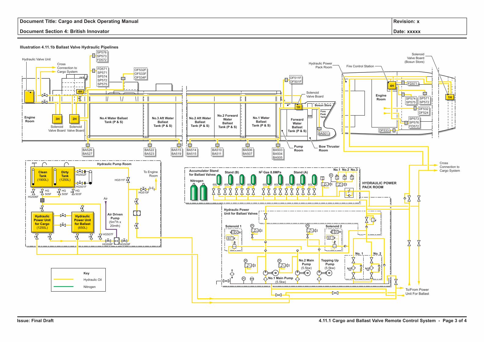
Issue: Final Draft
Document Title: Cargo and Deck Operating Manual
Document Section 4: British Innovator
Revision: x
Date: xxxxx
Illustration 4.11.1b Ballast Valve Hydraulic Pipelines
PI
Stand (B)
Nitrogen
Hydraulic Power
Unit for Ballast Valves
Accumulator Stand
for Ballast ValvesStand (A)
HYDRAULIC POWER
PACK ROOM
No.1 No.2 No.3N2 Gas 8.8MPa
Engine
RoomNo.4 Water Ballast
Tank (P & S)
No.3 Aft Water
Ballast
Tank (P & S)
No.2 Aft Water
Ballast
Tank (P & S)
No.2 Forward
Water
Ballast
Tank (P & S)
No.1 Water
Ballast
Tank (P & S)
Engine
Room
Forward
Water
Ballast
Tank (P & S)
Cross
Connection to
Cargo System
Cross
Connection to
Cargo System
Hydraulic Valve Unit
Solenoid
Valve Board
Solenoid
Valve Board
Solenoid
Valve Board
ForePeakTank
Bosun Store
BW
Bow Thruster
Room
To/From Power
Unit For Ballast
No.1 Main Pump
(5.5kw)
No.2 Main
Pump
(5.5kw)
Topping Up
Pump
(5.5kw)
Solenoid 1 Solenoid 2
No. 2No. 1
Nitrogen
60L 60L 60L 60L 60L 60L 60L 60L 60L
PI
PI PI
PI
PI
M M M
Clean
Tank
(1900L)
Dirty
Tank
(1250L)
Hydraulic Pump Room
Air
To Engine
Room
Air Driven
Pump
(5m3/h x
20mth)
HG506F
HG502F
HG501F
HG511F
HG510F
HG507F
HG508F HG509F
HG
505F
HG
505F
HG
503F
Hydraulic
Power Unit
for Cargo
(1250L)
Hydraulic
Power Unit
for Ballast
(650L)
Hydraulic Oil
Key
4H
2H
4H
3H
1H
BA526
BA527
OF532F
OF533F
OF534F
FD571
SP571
SP574
SP572
SP575
SP576
SP573
FD572
BA522
BA523
BA515
BA519
BA514
BA515
BA510
BA511
BA506
BA507
DF532
DF524
SP574
SP575
SP571
SP572
OF511F
OF501F
BA501
FD571
DF533
BA503
BA504
BA505
SP573
SP576
FD572
1H
Pump
Room
Fire Control StationHydraulic Power
Pack Room
Solenoid
Valve Board
(Bosun Store)
4.11.1 Cargo and Ballast Valve Remote Control System - Page 3 of 4
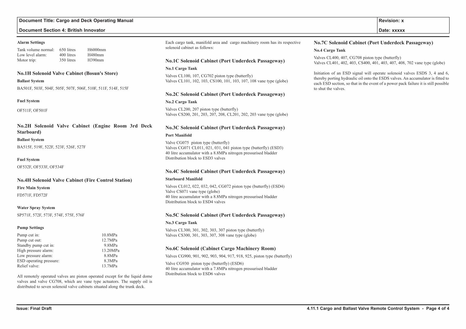
Issue: Final Draft
Document Title: Cargo and Deck Operating Manual
Document Section 4: British Innovator
Revision: x
Date: xxxxx
Alarm Settings
Tank volume normal: 650 litres H6000mmLow level alarm: 400 litres H480mmMotor trip: 350 litres H390mm
No.1H Solenoid Valve Cabinet (Bosun's Store)Ballast System
BA501F, 503F, 504F, 505F, 507F, 506F, 510F, 511F, 514F, 515F
Fuel System
OF511F, OF501F
No.2H Solenoid Valve Cabinet (Engine Room 3rd Deck Starboard)Ballast System
BA515F, 519F, 522F, 523F, 526F, 527F
Fuel System
OF532F, OF533F, OF534F
No.4H Solenoid Valve Cabinet (Fire Control Station)Fire Main System
FD571F, FD572F
Water Spray System
SP571F, 572F, 573F, 574F, 575F, 576F
Pump Settings
Pump cut in: 10.8MPaPump cut out: 12.7MPaStandby pump cut in: 9.8MPaHigh pressure alarm: 13.20MPaLow pressure alarm: 8.8MPaESD operating pressure: 8.3MPaRelief valve: 13.7MPa
All remotely operated valves are piston operated except for the liquid dome valves and valve CG708, which are vane type actuators. The supply oil is distributed to seven solenoid valve cabinets situated along the trunk deck.
Each cargo tank, manifold area and cargo machinery room has its respective solenoid cabinet as follows:
No.1C Solenoid Cabinet (Port Underdeck Passageway)No.1 Cargo Tank
Valves CL100, 107, CG702 piston type (butterfly)Valves CL101, 102, 103, CS100, 101, 103, 107, 108 vane type (globe)
No.2C Solenoid Cabinet (Port Underdeck Passageway)No.2 Cargo Tank
Valves CL200, 207 piston type (butterfly)Valves CS200, 201, 203, 207, 208, CL201, 202, 203 vane type (globe)
No.3C Solenoid Cabinet (Port Underdeck Passageway)Port Manifold
Valve CG075 piston type (butterfly)Valves CG071 CL011, 021, 031, 041 piston type (butterfly) (ESD3)40 litre accumulator with a 8.8MPa nitrogen pressurised bladderDistribution block to ESD3 valves
No.4C Solenoid Cabinet (Port Underdeck Passageway)Starboard Manifold
Valves CL012, 022, 032, 042, CG072 piston type (butterfly) (ESD4)Valve CS071 vane type (globe)40 litre accumulator with a 8.8MPa nitrogen pressurised bladderDistribution block to ESD4 valves
No.5C Solenoid Cabinet (Port Underdeck Passageway)No.3 Cargo Tank
Valves CL300, 301, 302, 303, 307 piston type (butterfly)Valves CS300, 301, 303, 307, 308 vane type (globe)
No.6C Solenoid (Cabinet Cargo Machinery Room)Valves CG900, 901, 902, 903, 904, 917, 918, 925, piston type (butterfly)
Valve CG930 piston type (butterfly) (ESD6)40 litre accumulator with a 7.8MPa nitrogen pressurised bladderDistribution block to ESD6 valves
No.7C Solenoid Cabinet (Port Underdeck Passageway)No.4 Cargo Tank
Valves CL400, 407, CG708 piston type (butterfly)Valves CL401, 402, 403, CS400, 401, 403, 407, 408, 702 vane type (globe)
Initiation of an ESD signal will operate solenoid valves ESDS 3, 4 and 6, thereby porting hydraulic oil onto the ESDS valves. An accumulator is fitted to each ESD section, so that in the event of a power pack failure it is still possible to shut the valves.
4.11.1 Cargo and Ballast Valve Remote Control System - Page 4 of 4
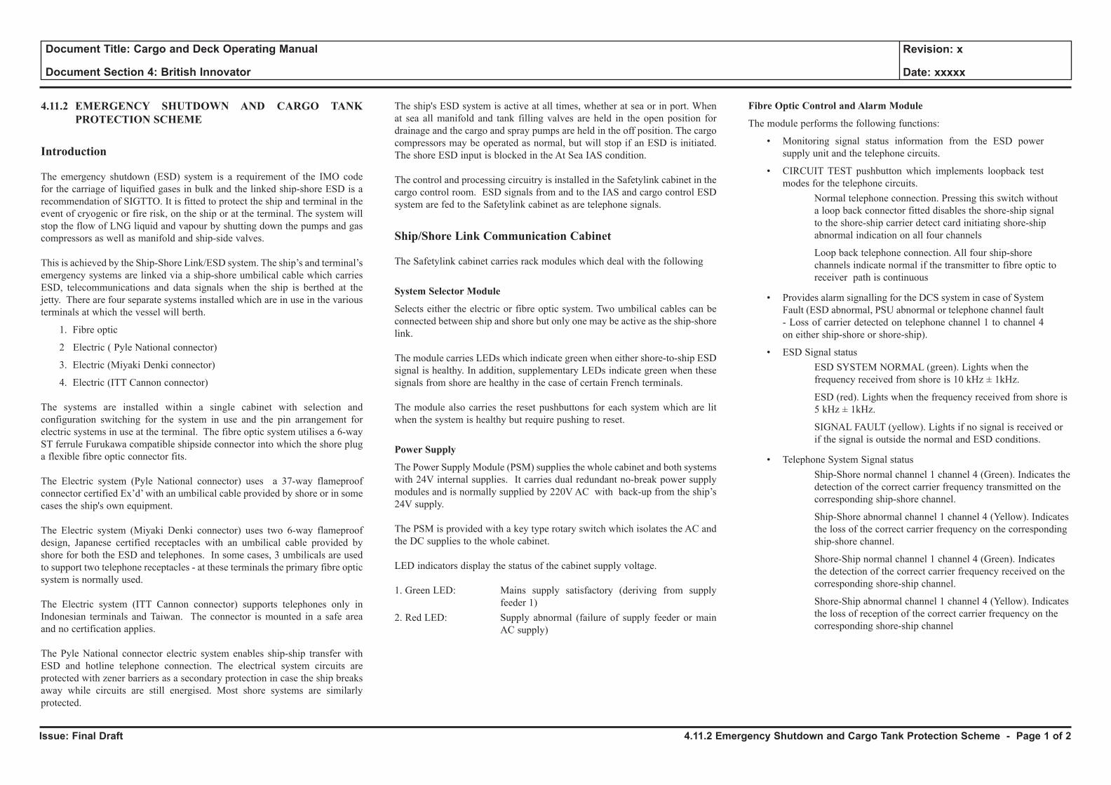
Issue: Final Draft
Document Title: Cargo and Deck Operating Manual
Document Section 4: British Innovator
Revision: x
Date: xxxxx
4.11.2 EMERGENCY SHUTDOWN AND CARGO TANK PROTECTION SCHEME
Introduction
The emergency shutdown (ESD) system is a requirement of the IMO code for the carriage of liquified gases in bulk and the linked ship-shore ESD is a recommendation of SIGTTO. It is fitted to protect the ship and terminal in the event of cryogenic or fire risk, on the ship or at the terminal. The system will stop the flow of LNG liquid and vapour by shutting down the pumps and gas compressors as well as manifold and ship-side valves.
This is achieved by the Ship-Shore Link/ESD system. The ship’s and terminal’s emergency systems are linked via a ship-shore umbilical cable which carries ESD, telecommunications and data signals when the ship is berthed at the jetty. There are four separate systems installed which are in use in the various terminals at which the vessel will berth.
1. Fibre optic
2 Electric ( Pyle National connector)
3. Electric (Miyaki Denki connector)
4. Electric (ITT Cannon connector)
The systems are installed within a single cabinet with selection and configuration switching for the system in use and the pin arrangement for electric systems in use at the terminal. The fibre optic system utilises a 6-way ST ferrule Furukawa compatible shipside connector into which the shore plug a flexible fibre optic connector fits.
The Electric system (Pyle National connector) uses a 37-way flameproof connector certified Ex’d’ with an umbilical cable provided by shore or in some cases the ship's own equipment.
The Electric system (Miyaki Denki connector) uses two 6-way flameproof design, Japanese certified receptacles with an umbilical cable provided by shore for both the ESD and telephones. In some cases, 3 umbilicals are used to support two telephone receptacles - at these terminals the primary fibre optic system is normally used.
The Electric system (ITT Cannon connector) supports telephones only in Indonesian terminals and Taiwan. The connector is mounted in a safe area and no certification applies.
The Pyle National connector electric system enables ship-ship transfer with ESD and hotline telephone connection. The electrical system circuits are protected with zener barriers as a secondary protection in case the ship breaks away while circuits are still energised. Most shore systems are similarly protected.
The ship's ESD system is active at all times, whether at sea or in port. When at sea all manifold and tank filling valves are held in the open position for drainage and the cargo and spray pumps are held in the off position. The cargo compressors may be operated as normal, but will stop if an ESD is initiated. The shore ESD input is blocked in the At Sea IAS condition.
The control and processing circuitry is installed in the Safetylink cabinet in the cargo control room. ESD signals from and to the IAS and cargo control ESD system are fed to the Safetylink cabinet as are telephone signals.
Ship/Shore Link Communication Cabinet
The Safetylink cabinet carries rack modules which deal with the following
System Selector Module
Selects either the electric or fibre optic system. Two umbilical cables can be connected between ship and shore but only one may be active as the ship-shore link.
The module carries LEDs which indicate green when either shore-to-ship ESD signal is healthy. In addition, supplementary LEDs indicate green when these signals from shore are healthy in the case of certain French terminals.
The module also carries the reset pushbuttons for each system which are lit when the system is healthy but require pushing to reset.
Power Supply
The Power Supply Module (PSM) supplies the whole cabinet and both systems with 24V internal supplies. It carries dual redundant no-break power supply modules and is normally supplied by 220V AC with back-up from the ship’s 24V supply.
The PSM is provided with a key type rotary switch which isolates the AC and the DC supplies to the whole cabinet.
LED indicators display the status of the cabinet supply voltage.
1. Green LED: Mains supply satisfactory (deriving from supply feeder 1)
2. Red LED: Supply abnormal (failure of supply feeder or main AC supply)
Fibre Optic Control and Alarm Module
The module performs the following functions:
• Monitoring signal status information from the ESD power supply unit and the telephone circuits.
• CIRCUIT TEST pushbutton which implements loopback test modes for the telephone circuits.
Normal telephone connection. Pressing this switch without a loop back connector fitted disables the shore-ship signal to the shore-ship carrier detect card initiating shore-ship abnormal indication on all four channels
Loop back telephone connection. All four ship-shore channels indicate normal if the transmitter to fibre optic to receiver path is continuous
• Provides alarm signalling for the DCS system in case of System Fault (ESD abnormal, PSU abnormal or telephone channel fault - Loss of carrier detected on telephone channel 1 to channel 4 on either ship-shore or shore-ship).
• ESD Signal status ESD SYSTEM NORMAL (green). Lights when the
frequency received from shore is 10 kHz ± 1kHz.
ESD (red). Lights when the frequency received from shore is 5 kHz ± 1kHz.
SIGNAL FAULT (yellow). Lights if no signal is received or if the signal is outside the normal and ESD conditions.
• Telephone System Signal status Ship-Shore normal channel 1 channel 4 (Green). Indicates the
detection of the correct carrier frequency transmitted on the corresponding ship-shore channel.
Ship-Shore abnormal channel 1 channel 4 (Yellow). Indicates the loss of the correct carrier frequency on the corresponding ship-shore channel.
Shore-Ship normal channel 1 channel 4 (Green). Indicates the detection of the correct carrier frequency received on the corresponding shore-ship channel.
Shore-Ship abnormal channel 1 channel 4 (Yellow). Indicates the loss of reception of the correct carrier frequency on the corresponding shore-ship channel
4.11.2 Emergency Shutdown and Cargo Tank Protection Scheme - Page 1 of 2

Issue: Final Draft
Document Title: Cargo and Deck Operating Manual
Document Section 4: British Innovator
Revision: x
Date: xxxxx
Fibre Optic ESD Module
The volt-free contacts in the ship's ESD system are connected to this module if fibre optic is selected. The module generates a tone signal which is transmitted down the ship-shore fibre. When healthy, this tone is 10kHz when an alarm situation occurs and the shipside ESD system contact is open circuit, the signal reverts to 5kHz and the shoreside ESD is activated. The same function is implemented for the signals coming from the terminal.
Telephone Interface (TEL/IF) Module
(See section 4.12.1)
Port or Starboard Side Connection Box Selector
Pushbuttons are used to select the fibre optic shipside connector in use. They have no effect on the electrical system.
CAUTIONIf the system is in operation on the port connection box, port is selected and the red pushbutton is lit. In abnormal an ESD signal fault will occur if the starboard pushbutton is pressed and vice versa.
Electrical System Configuration Module
The electrical system carries three telephone channels, ship-shore ESD and shore-ship ESD. Various systems are implemented differently at different terminals. These non-standard implementations by most terminals require this module to configure the system for the terminal in use or ship-ship transfer duty. As certain switch positions will activate trips used in certain terminals only, or reverse the trip connection in case of ship to ship transfer, red LEDs are lit if these positions are selected. The switches should be preconfigured before arrival.
Ship Side Connection Boxes
Stainless steel shipside boxes and connectors are provided port and starboard midships. These carry :
1.A Furukawa-compatible 6-way connector with a 6-way ST type connector patch panel. These are normally connected 1-1, 2-2, etc. In the event of problems with ship or shore, the 2 spare cores 5, 6 can be used in place of the defective core, ship or shore. The complete ship connector, if defective, can be transferred from port to starboard and vice versa. For fault finding, a patch lead may be used to loop-back 1-2, 3-4 to test the cable as opposed to the connector.
2. A 37-way Pyle National connector is fitted for signal transmission to shore and 4 way earthing connectors are installed with local earthing to enable shore-ship bonding by local rules in French terminals. The connectors are spring loaded and the plugs disconnect while the barrel is still connected to the receptacle.
3. A 6-way Miyaki Denki Receptacles for ESD and TEL use. These are isolated and interlocked so that the plug can only be inserted when the circuit isolator is off and vice versa.
4. A Strainstall Mooring Load Monitor socket. (See 4.12.3. )
The ITT cannon sockets are fitted in stainless steel shipside boxes, fitted on the main deck level accommodation aft.
Operation
The ESD is activated from the following sources:
• Deck trip system which includes eight sets of fusible links located at the manifolds and at the domes. Any one of the links will initiate an ESD.
• Manual emergency pushbuttons at various locations around the deck including in the cargo control room, in the fire control station and in the wheelhouse.
• Each cargo tank has a low-low pressure switch which is set at 1kPa.
• A high-high differential pressure switch is fitted between each cargo tank and hold. The switches are set to operate when the difference between the cargo tank pressure and the hold pressure reaches 4kPa.
• When a 99% level signal is received from the cargo level detection system. This system has a 45 seconds delay when in the AT SEA condition, to prevent spurious alarms and trips occurring due to the ship movement. If it is necessary to operate a cargo or spray pump at sea, the signal is overridden.
• If a low hydraulic oil pressure is detected in the manifold valve actuators when in port. At sea, the topping up hydraulic pumps are run at all times, except during cargo operations. The ESD trips at 8.3MPa
• Low control air pressure, active only in port, when the DCS is set to CARGO operations or when any override is not in use.
• An ESD signal from the terminal during cargo operations and when the IAS is set to CARGO operations.
• When the CO2 fire extinguishing system is operated. This may not involve cargo operations, but indicates a serious problem on the vessel and causes the ESD to be activated.
• Pneumatic link trips ESD at 300kPa.
The ESD will activate the following on the ship:
• Stop the high and low duty compressors (4 sets)
• Stop the main cargo pumps in each tank (8 sets)
• Stop the spray pumps in each tank (4 sets)
• Close all the manifold valves (10 sets)
• Signal to the terminal to stop operations
• Activate the ESD alarm
• Stops inert gas generator blower
• Closes BOG master valve
The IAS graphic screens will indicate the reason for the ESD situation by a change of colour, from green to red, of the item causing the ESD. Cargo pump and spray pump symbols will change colour, indicating that there is a block on their operation and further operations are not permissible.
Once the cause of the ESD has been cleared, the ESD system can be enabled by activating the RESET icon on the DCS ESD graphic screen. Symbols will change from red to green, indicating that further operations are permissible.
4.11.2 Emergency Shutdown and Cargo Tank Protection Scheme - Page 2 of 2
4.12 Ship-shore Link and Mooring Load Monitoring System
4.12.1 Ship Shore Link - Fibre Optic
4.12.2 Ship Shore Link - Electrical
4.12.3 Mooring Load Monitor System
Illustrations
4.12.1a Ship Shore Link
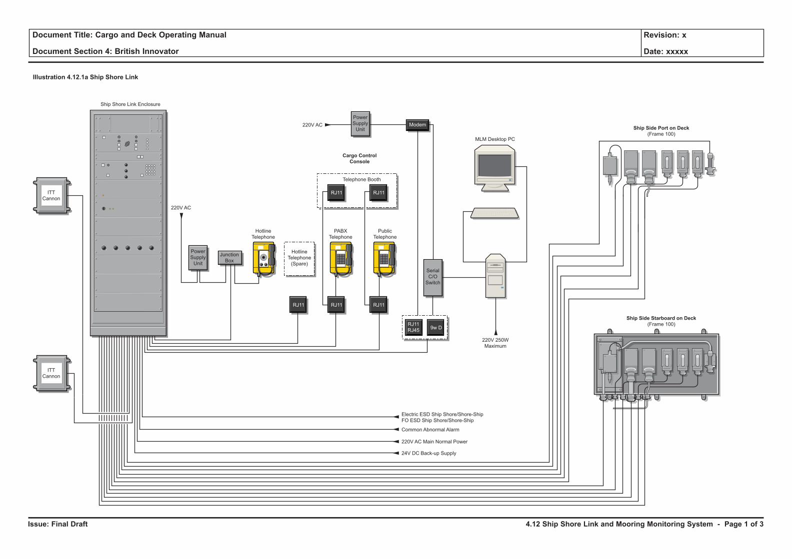
Issue: Final Draft
Document Title: Cargo and Deck Operating Manual
Document Section 4: British Innovator
Revision: x
Date: xxxxx
Illustration 4.12.1a Ship Shore Link
MLM Desktop PC
Ship Side Starboard on Deck
(Frame 100)
Ship Side Port on Deck
(Frame 100)
Cargo Control
Console
ITT
Cannon
ITT
Cannon
220V AC
220V AC
Hotline
Telephone
Ship Shore Link Enclosure
Hotline
Telephone
(Spare)
PABX
Telephone
Telephone Booth
Public
Telephone
Power
Supply
Unit
24V DC Back-up Supply
220V 250W
Maximum
220V AC Main Normal Power
Common Abnormal Alarm
Electric ESD Ship Shore/Shore-Ship
FO ESD Ship Shore/Shore-Ship
Power
Supply
Unit
Junction
Box
RJ11 RJ11 RJ11
RJ11 RJ11
Modem
Serial
C/O
Switch
9w DRJ11
RJ45
0
10- 10+
0
10- 10+
0
10- 10+
0
10- 10+
0
10- 10+
4.12 Ship Shore Link and Mooring Monitoring System - Page 1 of 3
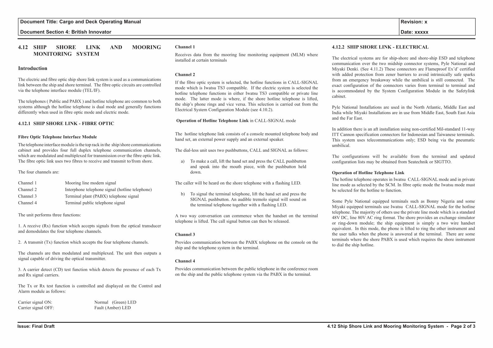
Issue: Final Draft
Document Title: Cargo and Deck Operating Manual
Document Section 4: British Innovator
Revision: x
Date: xxxxx
4.12 SHIP SHORE LINK AND MOORING MONITORING SYSTEM
Introduction
The electric and fibre optic ship shore link system is used as a communications link between the ship and shore terminal. The fibre optic circuits are controlled via the telephone interface module (TEL/IF).
The telephones ( Public and PABX ) and hotline telephone are common to both systems although the hotline telephone is dual mode and generally functions differently when used in fibre optic mode and electric mode.
4.12.1 SHIP SHORE LINK - FIBRE OPTIC
Fibre Optic Telephone Interface Module
The telephone interface module is the top rack in the ship/shore communications cabinet and provides four full duplex telephone communication channels, which are modulated and multiplexed for transmission over the fibre optic link. The fibre optic link uses two fibres to receive and transmit to/from shore.
The four channels are:
Channel 1 Mooring line modem signalChannel 2 Interphone telephone signal (hotline telephone)Channel 3 Terminal plant (PABX) telephone signalChannel 4 Terminal public telephone signal
The unit performs three functions:
1. A receive (Rx) function which accepts signals from the optical transducer and demodulates the four telephone channels.
2. A transmit (Tx) function which accepts the four telephone channels.
The channels are then modulated and multiplexed. The unit then outputs a signal capable of driving the optical transmitter.
3. A carrier detect (CD) test function which detects the presence of each Tx and Rx signal carriers.
The Tx or Rx test function is controlled and displayed on the Control and Alarm module as follows:
Carrier signal ON: Normal (Green) LEDCarrier signal OFF: Fault (Amber) LED
Channel 1
Receives data from the mooring line monitoring equipment (MLM) where installed at certain terminals
Channel 2
If the fibre optic system is selected, the hotline functions in CALL-SIGNAL mode which is Iwatsu TS3 compatible. If the electric system is selected the hotline telephone functions in either Iwatsu TS3 compatible or private line mode. The latter mode is where, if the shore hotline telephone is lifted, the ship’s phone rings and vice versa. This selection is carried out from the Electrical System Configuration Module (see 4.10.2).
Operation of Hotline Telephone Link in CALL-SIGNAL mode
The hotline telephone link consists of a console mounted telephone body and hand set, an external power supply and an external speaker.
The dial-less unit uses two pushbuttons, CALL and SIGNAL as follows:
a) To make a call, lift the hand set and press the CALL pushbutton and speak into the mouth piece, with the pushbutton held down.
The caller will be heard on the shore telephone with a flashing LED.
b) To signal the terminal telephone, lift the hand set and press the SIGNAL pushbutton. An audible tremolo signal will sound on the terminal telephone together with a flashing LED.
A two way conversation can commence when the handset on the terminal telephone is lifted. The call signal button can then be released.
Channel 3
Provides communication between the PABX telephone on the console on the ship and the telephone system in the terminal.
Channel 4
Provides communication between the public telephone in the conference room on the ship and the public telephone system via the PABX in the terminal.
4.12.2 SHIP SHORE LINK - ELECTRICAL
The electrical systems are for ship-shore and shore-ship ESD and telephone communication over the two midship connector systems, Pyle National and Miyaki Denki. (See 4.11.2) These connectors are Flameproof Ex’d’ certified with added protection from zener barriers to avoid intrinsically safe sparks from an emergency breakaway while the umbilical is still connected. The exact configuration of the connectors varies from terminal to terminal and is accommodated by the System Configuration Module in the Safetylink cabinet.
Pyle National Installations are used in the North Atlantic, Middle East and India while Miyaki Installations are in use from Middle East, South East Asia and the Far East.
In addition there is an aft installation using non-certified Mil-standard 11-way ITT Cannon specification connectors for Indonesian and Taiwanese terminals. This system uses telecommunications only; ESD being via the pneumatic umbilical.
The configurations will be available from the terminal and updated configuration lists may be obtained from Seatechnik or SIGTTO.
Operation of Hotline Telephone LinkThe hotline telephone operates in Iwatsu CALL-SIGNAL mode and in private line mode as selected by the SCM. In fibre optic mode the Iwatsu mode must be selected for the hotline to function.
Some Pyle National equipped terminals such as Bonny Nigeria and some Miyaki equipped terminals use Iwatsu CALL-SIGNAL mode for the hotline telephone. The majority of others use the private line mode which is a standard 48V DC, line 80V AC ring format. The shore provides an exchange simulator or ring-down module; the ship equipment is simply a two wire handset equivalent. In this mode, the phone is lifted to ring the other instrument and the user talks when the phone is answered at the terminal. There are some terminals where the shore PABX is used which requires the shore instrument to dial the ship hotline.
4.12 Ship Shore Link and Mooring Monitoring System - Page 2 of 3
Issue: Final Draft
Document Title: Cargo and Deck Operating Manual
Document Section 4: British Innovator
Revision: x
Date: xxxxx
4.12.3 MOORING LOAD MONITORING SYSTEM
Two Mooring Load Monitor Systems are in use.
The repeater applications can run on a dedicated PC in the cargo control room. These display mooring line tension as measured by load-cells on shore. The operator can configure the MLM software to match the mooring line configuration in use on shore.
A Harbour and Marine MLM is compatible with both the Strainstall and Yokugawa YEWMAC systems on shore. The Strainstall signals are transmitted via a separate dedicated connector in the shipside boxes while the YEWMAC signals are transmitted via Channel 1 of the ship shore link
Alternatively a Marimatech UHF LAN system for the portable units is in use in Oman and some other terminals. The portable unit is brought on board by the berthing master or pilot and receives 2.4GHz data to display MLM and berthing speed of approach. The portable system normally functions by receiving UHF LAN data from shore but in accordance with Marimatech recommendations a repeater with LAN socket outlet for a portable laptop repeater is installed. This comprises a bridge repeater and UHF antenna and a hub unit in the CCR.
4.12 Ship Shore Link and Mooring Monitoring System - Page 3 of 3
4.13 Relief Systems
4.13.1 Cargo Tank Relief Valves
4.13.2 Insulation Space Relief Valves
4.13.3 Pipeline Relief Valves
Illustrations
4.13.2a IBS / IS Relief Valve Layout
4.13.2b Cargo Tank Pressure Table
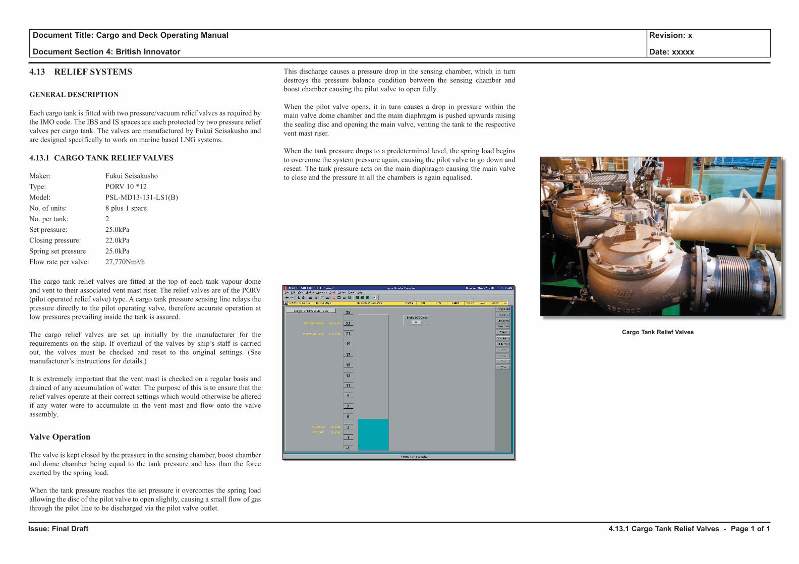
Issue: Final Draft
Document Title: Cargo and Deck Operating Manual
Document Section 4: British Innovator
Revision: x
Date: xxxxx
4.13 RELIEF SYSTEMS
GENERAL DESCRIPTION
Each cargo tank is fitted with two pressure/vacuum relief valves as required by the IMO code. The IBS and IS spaces are each protected by two pressure relief valves per cargo tank. The valves are manufactured by Fukui Seisakusho and are designed specifically to work on marine based LNG systems.
4.13.1 CARGO TANK RELIEF VALVES
Maker: Fukui SeisakushoType: PORV 10 *12Model: PSL-MD13-131-LS1(B)No. of units: 8 plus 1 spareNo. per tank: 2Set pressure: 25.0kPaClosing pressure: 22.0kPaSpring set pressure 25.0kPaFlow rate per valve: 27,770Nm3/h
The cargo tank relief valves are fitted at the top of each tank vapour dome and vent to their associated vent mast riser. The relief valves are of the PORV (pilot operated relief valve) type. A cargo tank pressure sensing line relays the pressure directly to the pilot operating valve, therefore accurate operation at low pressures prevailing inside the tank is assured.
The cargo relief valves are set up initially by the manufacturer for the requirements on the ship. If overhaul of the valves by ship’s staff is carried out, the valves must be checked and reset to the original settings. (See manufacturer’s instructions for details.)
It is extremely important that the vent mast is checked on a regular basis and drained of any accumulation of water. The purpose of this is to ensure that the relief valves operate at their correct settings which would otherwise be altered if any water were to accumulate in the vent mast and flow onto the valve assembly.
Valve Operation
The valve is kept closed by the pressure in the sensing chamber, boost chamber and dome chamber being equal to the tank pressure and less than the force exerted by the spring load.
When the tank pressure reaches the set pressure it overcomes the spring load allowing the disc of the pilot valve to open slightly, causing a small flow of gas through the pilot line to be discharged via the pilot valve outlet.
This discharge causes a pressure drop in the sensing chamber, which in turn destroys the pressure balance condition between the sensing chamber and boost chamber causing the pilot valve to open fully.
When the pilot valve opens, it in turn causes a drop in pressure within the main valve dome chamber and the main diaphragm is pushed upwards raising the sealing disc and opening the main valve, venting the tank to the respective vent mast riser.
When the tank pressure drops to a predetermined level, the spring load begins to overcome the system pressure again, causing the pilot valve to go down and reseat. The tank pressure acts on the main diaphragm causing the main valve to close and the pressure in all the chambers is again equalised.
4.13.1 Cargo Tank Relief Valves - Page 1 of 1
Cargo Tank Relief Valves
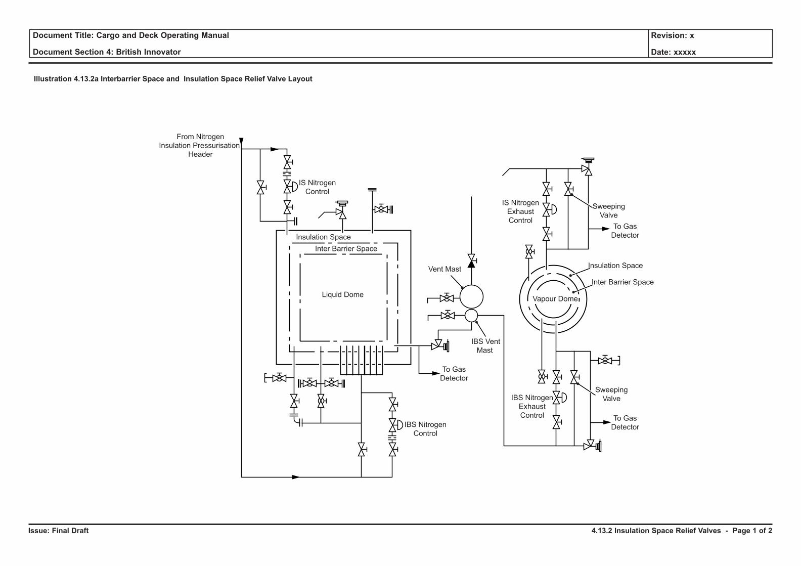
Issue: Final Draft
Document Title: Cargo and Deck Operating Manual
Document Section 4: British Innovator
Revision: x
Date: xxxxx
Liquid Dome
Illustration 4.13.2a Interbarrier Space and Insulation Space Relief Valve Layout
Vent Mast
IBS Nitrogen
Exhaust
Control
IS Nitrogen
Exhaust
Control
IBS Vent
Mast
Sweeping
Valve
To Gas
Detector
To Gas
Detector
Inter Barrier Space
Inter Barrier Space
Insulation Space
Insulation Space
IS Nitrogen
Control
IBS Nitrogen
Control
From Nitrogen
Insulation Pressurisation
Header
Vapour Dome
Sweeping
Valve
To Gas
Detector
4.13.2 Insulation Space Relief Valves - Page 1 of 2
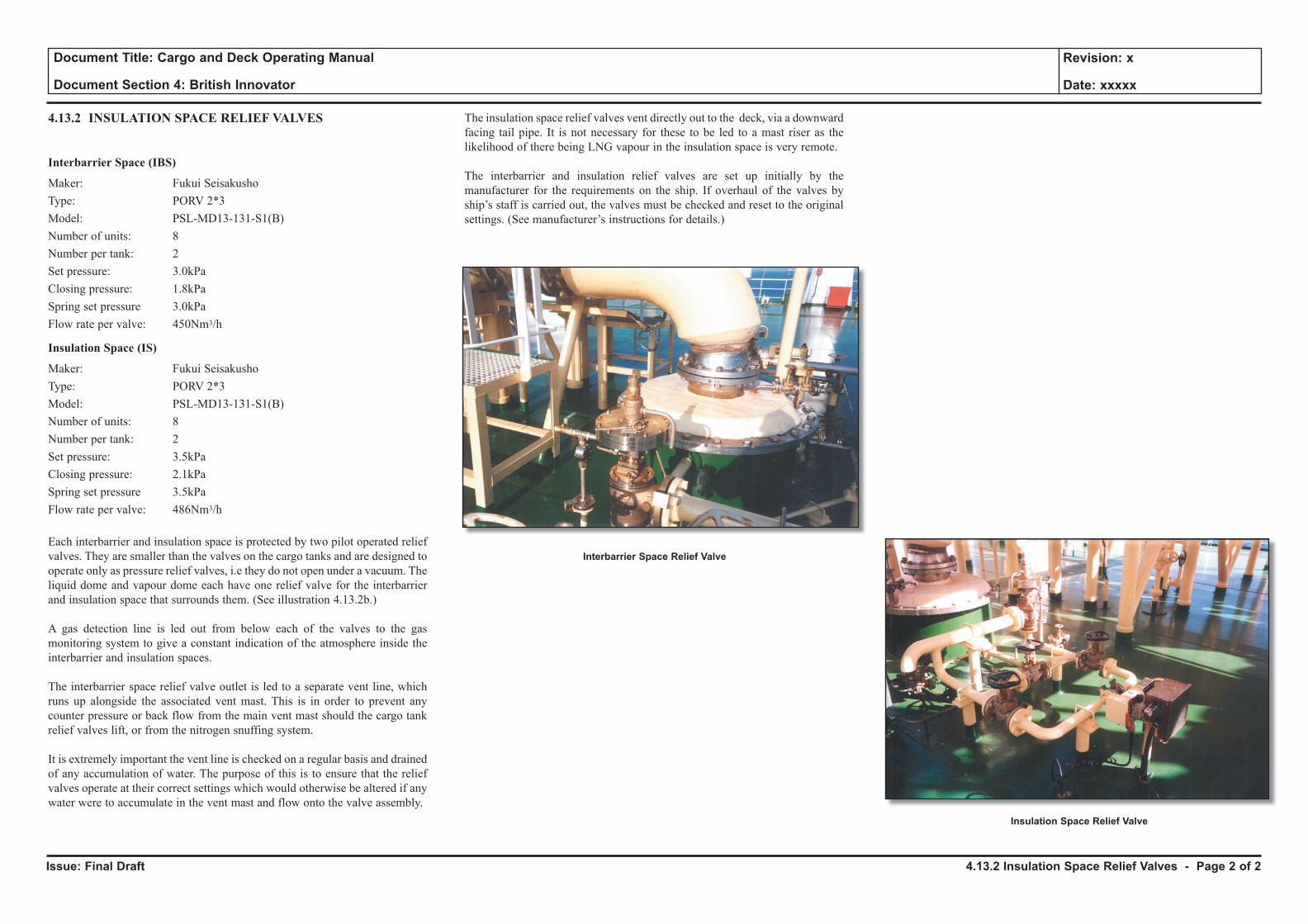
Issue: Final Draft
Document Title: Cargo and Deck Operating Manual
Document Section 4: British Innovator
Revision: x
Date: xxxxx
4.13.2 INSULATION SPACE RELIEF VALVES
Interbarrier Space (IBS)
Maker: Fukui SeisakushoType: PORV 2*3Model: PSL-MD13-131-S1(B)Number of units: 8 Number per tank: 2Set pressure: 3.0kPaClosing pressure: 1.8kPaSpring set pressure 3.0kPaFlow rate per valve: 450Nm3/h
Insulation Space (IS)
Maker: Fukui SeisakushoType: PORV 2*3Model: PSL-MD13-131-S1(B)Number of units: 8 Number per tank: 2Set pressure: 3.5kPaClosing pressure: 2.1kPaSpring set pressure 3.5kPaFlow rate per valve: 486Nm3/h
Each interbarrier and insulation space is protected by two pilot operated relief valves. They are smaller than the valves on the cargo tanks and are designed to operate only as pressure relief valves, i.e they do not open under a vacuum. The liquid dome and vapour dome each have one relief valve for the interbarrier and insulation space that surrounds them. (See illustration 4.13.2b.)
A gas detection line is led out from below each of the valves to the gas monitoring system to give a constant indication of the atmosphere inside the interbarrier and insulation spaces.
The interbarrier space relief valve outlet is led to a separate vent line, which runs up alongside the associated vent mast. This is in order to prevent any counter pressure or back flow from the main vent mast should the cargo tank relief valves lift, or from the nitrogen snuffing system.
It is extremely important the vent line is checked on a regular basis and drained of any accumulation of water. The purpose of this is to ensure that the relief valves operate at their correct settings which would otherwise be altered if any water were to accumulate in the vent mast and flow onto the valve assembly.
The insulation space relief valves vent directly out to the deck, via a downward facing tail pipe. It is not necessary for these to be led to a mast riser as the likelihood of there being LNG vapour in the insulation space is very remote.
The interbarrier and insulation relief valves are set up initially by the manufacturer for the requirements on the ship. If overhaul of the valves by ship’s staff is carried out, the valves must be checked and reset to the original settings. (See manufacturer’s instructions for details.)
4.13.2 Insulation Space Relief Valves - Page 2 of 2
Interbarrier Space Relief Valve
Insulation Space Relief Valve
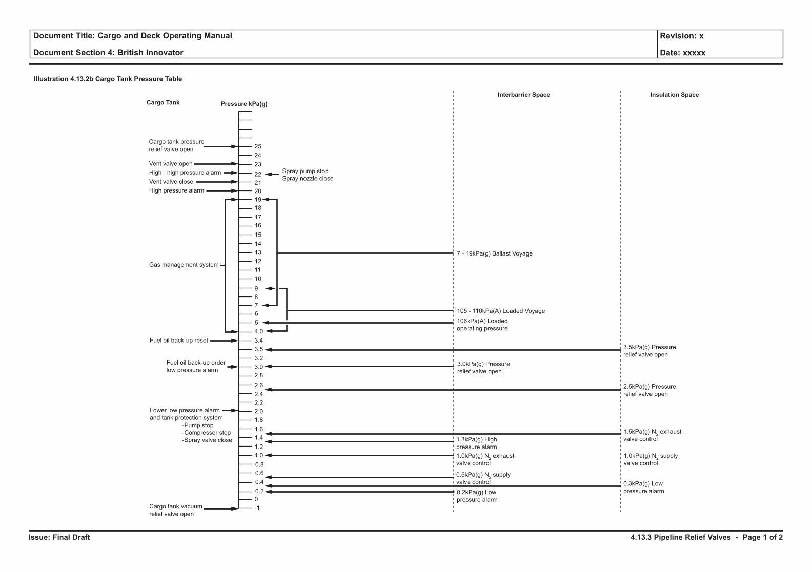
Issue: Final Draft
Document Title: Cargo and Deck Operating Manual
Document Section 4: British Innovator
Revision: x
Date: xxxxx
Illustration 4.13.2b Cargo Tank Pressure Table
Cargo tank pressure
relief valve open
Spray pump stop
Spray nozzle close
7 - 19kPa(g) Ballast Voyage
Pressure kPa(g)
Interbarrier Space
Cargo Tank
0
-1
0.2
0.4
0.6
0.8
1.0
1.2
1.4
1.6
1.8
2.0
2.2
2.4
2.6
2.8
3.0
3.2
3.4
3.5
4.0
5
6
7
8
9
10
11
12
13
14
15
16
17
18
19
20
21
22
23
24
25
High - high pressure alarm
High pressure alarm
Gas management system
Fuel oil back-up reset
Cargo tank vacuum
relief valve open
Fuel oil back-up order
low pressure alarm
Lower low pressure alarm
and tank protection system
-Pump stop
-Compressor stop
-Spray valve close
Vent valve open
Vent valve close
105 - 110kPa(A) Loaded Voyage
106kPa(A) Loaded
operating pressure
Insulation Space
3.0kPa(g) Pressure
relief valve open
1.3kPa(g) High
pressure alarm
1.0kPa(g) N2exhaust
valve control
1.0kPa(g) N2supply
valve control
0.5kPa(g) N2supply
valve control
0.2kPa(g) Low
pressure alarm
3.5kPa(g) Pressure
relief valve open
2.5kPa(g) Pressure
relief valve open
1.5kPa(g) N2exhaust
valve control
0.3kPa(g) Low
pressure alarm
4.13.3 Pipeline Relief Valves - Page 1 of 2
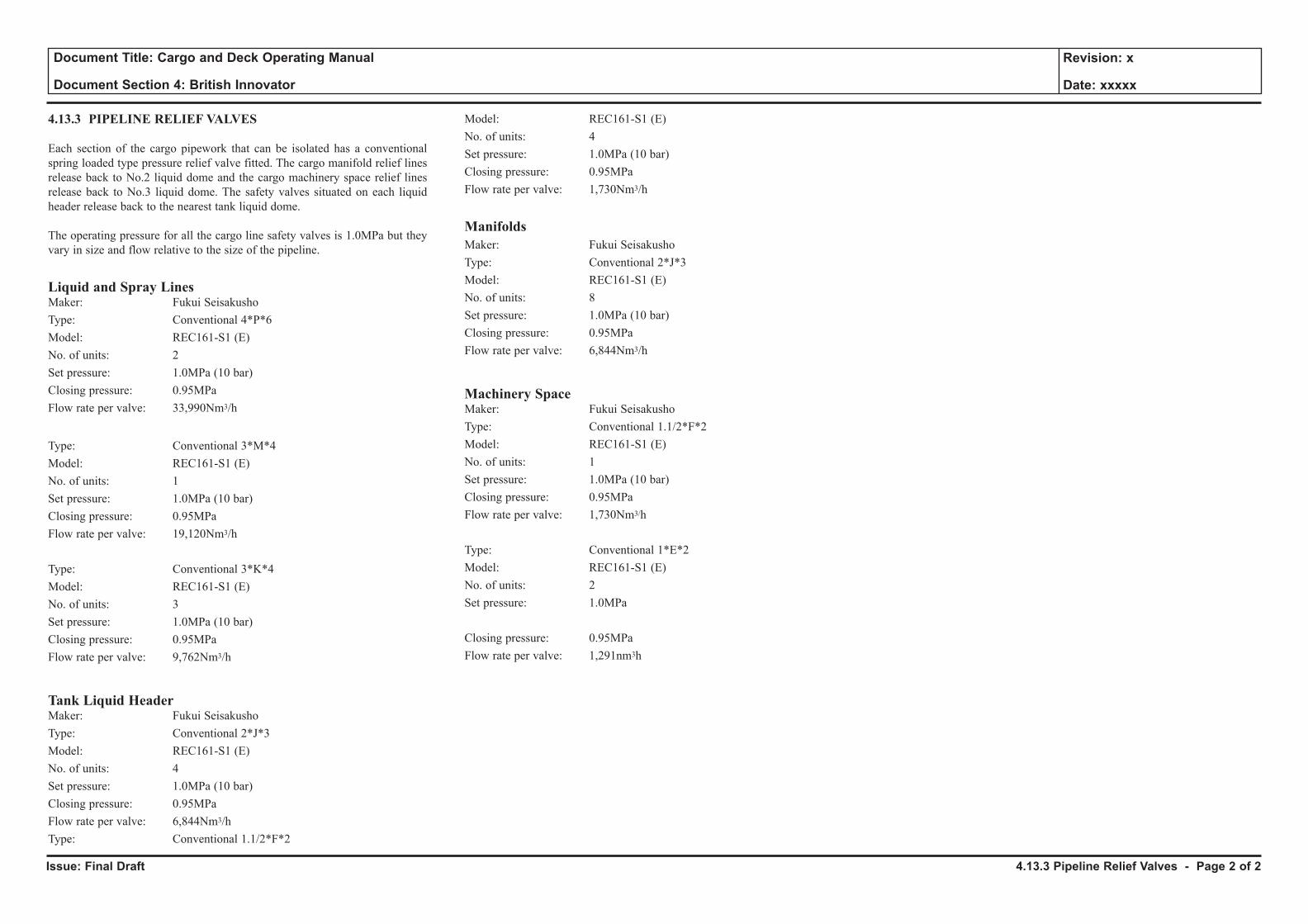
Issue: Final Draft
Document Title: Cargo and Deck Operating Manual
Document Section 4: British Innovator
Revision: x
Date: xxxxx
4.13.3 PIPELINE RELIEF VALVES
Each section of the cargo pipework that can be isolated has a conventional spring loaded type pressure relief valve fitted. The cargo manifold relief lines release back to No.2 liquid dome and the cargo machinery space relief lines release back to No.3 liquid dome. The safety valves situated on each liquid header release back to the nearest tank liquid dome.
The operating pressure for all the cargo line safety valves is 1.0MPa but they vary in size and flow relative to the size of the pipeline.
Liquid and Spray LinesMaker: Fukui SeisakushoType: Conventional 4*P*6Model: REC161-S1 (E)No. of units: 2Set pressure: 1.0MPa (10 bar)Closing pressure: 0.95MPaFlow rate per valve: 33,990Nm3/h
Type: Conventional 3*M*4Model: REC161-S1 (E)No. of units: 1Set pressure: 1.0MPa (10 bar)Closing pressure: 0.95MPaFlow rate per valve: 19,120Nm3/h
Type: Conventional 3*K*4Model: REC161-S1 (E)No. of units: 3Set pressure: 1.0MPa (10 bar)Closing pressure: 0.95MPa Flow rate per valve: 9,762Nm3/h
Tank Liquid HeaderMaker: Fukui SeisakushoType: Conventional 2*J*3Model: REC161-S1 (E)No. of units: 4Set pressure: 1.0MPa (10 bar)Closing pressure: 0.95MPa Flow rate per valve: 6,844Nm3/hType: Conventional 1.1/2*F*2
Model: REC161-S1 (E)No. of units: 4Set pressure: 1.0MPa (10 bar)Closing pressure: 0.95MPaFlow rate per valve: 1,730Nm3/h
ManifoldsMaker: Fukui SeisakushoType: Conventional 2*J*3Model: REC161-S1 (E)No. of units: 8Set pressure: 1.0MPa (10 bar)Closing pressure: 0.95MPaFlow rate per valve: 6,844Nm3/h
Machinery SpaceMaker: Fukui SeisakushoType: Conventional 1.1/2*F*2Model: REC161-S1 (E)No. of units: 1Set pressure: 1.0MPa (10 bar)Closing pressure: 0.95MPa Flow rate per valve: 1,730Nm3/h
Type: Conventional 1*E*2Model: REC161-S1 (E)No. of units: 2Set pressure: 1.0MPa
Closing pressure: 0.95MPaFlow rate per valve: 1,291nm3h
4.13.3 Pipeline Relief Valves - Page 2 of 2
4.14 Remote Sounding and Draught Gauging System
4.14.1 Ballast Piping System
4.14.2 Ballast Level and Draught Indicating System
4.14.3 Ballast Water Management
Illustrations
4.14.1a Ballast Piping System
4.14.2a Ballast Level Gauge
4.14.2b Draught and Tank Indicating System
4.14.3a Ballast Exchange Flowchart

Issue: Final Draft
Document Title: Cargo and Deck Operating Manual
Document Section 4: British Innovator
Revision: x
Date: xxxxx
Illustration 4.14.1a Ballasting Piping System
No.1,2 & 3 Ballast Pumps
(3,000m3/h x 50mth)
BA028F
BA027FBA
024F
BA014F
BA011F BA009F
BA006F
BA033F
BA007F
BA025F
No.1
No.2
No.3
Emergency
Bilge Suction
BA004F BA005F
Floor
WBT WBT
Cargo Tank
Ballast
Position Controlled
Hydraulic Valve
Locked Closed
Key
From Inert Gas Line
From Inert Gas Line
Stationary
Hand PumpProcess Plant
(Port Only)
No.4 WBT
(P)
No.4 WBT
(S)
No.3A WBT
(P)
No.3A WBT
(S)
No.2A WBT
(P)
No.2A WBT
(S)
No.3F WBT
(P)
No.3F WBT
(S)
No.2F WBT
(P)
No.2F WBT
(S)
No.1 WBT
(P)
No.1 WBT
(S)
Fore
Peak
Tank
BA
501F
BA506F
BA507F
BA510F
BA511F
BA514F
BA515F
BA518F
BA519FBA523F
BA531F
BA532F
BA534FBA036F
BA533F
BA526F
BA527F
BA
535F
BA522F
BA530F
BA504F
BA503F
BA505F
Trunk
Pipe
Duct
Pipe Duct
To Inert Gas
Generator
Discharge From
Water Spray/Bilge,
Fire and GS Pump
NOTE: Ring Main Valves BA531F and BA532F are fitted on the British Trader and the British Merchant but NOT on the British InnovatorDischarge From
Bilge, Fire and GS
Pump
Engine Room
Water Ballast
Tank
(Starboard)
Engine Room
Water Ballast
Tank (Port)
Ballast
Stripping
Eductor
BA
026F
BA018F
BA035F
BA021F
BA008F
BA010F
BA001F
BA002F
BA003F
BA012F
BA013F
BA020F
BA016F
BA017F
BA022F
BA023F
BA019F
BA
029F BA032F
WS101F
WS105F
WS106F
WS102F
Low Sea Chest
(Central)
BA030F
BA015F
ENGINE ROOM
Aft
Peak
Tank
High Sea
Chest
(Port)
BA
031F
Passageway Passageway
4.14.1 Ballast Piping - Page 1 of 4
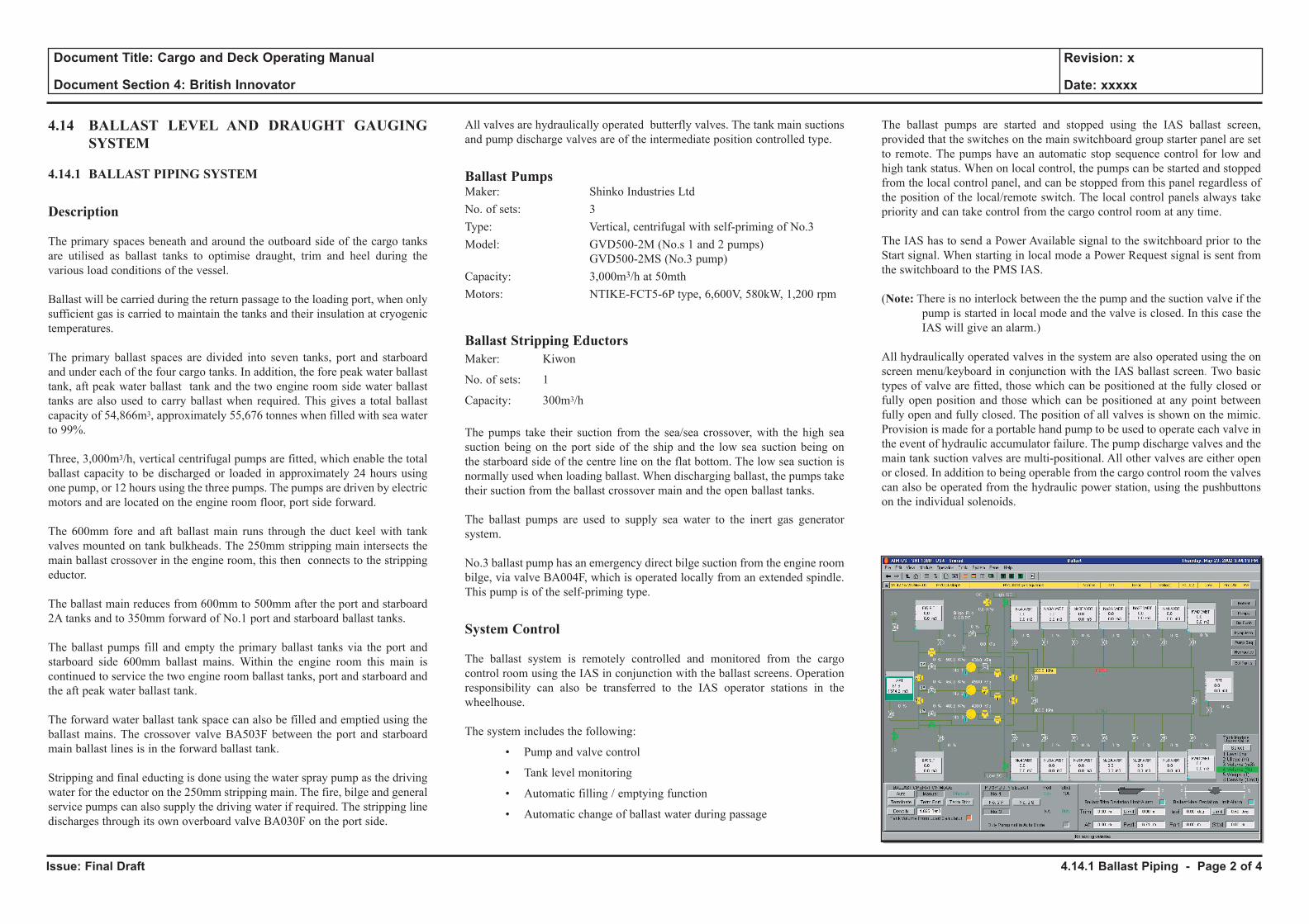
Issue: Final Draft
Document Title: Cargo and Deck Operating Manual
Document Section 4: British Innovator
Revision: x
Date: xxxxx
4.14 BALLAST LEVEL AND DRAUGHT GAUGING SYSTEM
4.14.1 BALLAST PIPING SYSTEM
Description
The primary spaces beneath and around the outboard side of the cargo tanks are utilised as ballast tanks to optimise draught, trim and heel during the various load conditions of the vessel.
Ballast will be carried during the return passage to the loading port, when only sufficient gas is carried to maintain the tanks and their insulation at cryogenic temperatures.
The primary ballast spaces are divided into seven tanks, port and starboard and under each of the four cargo tanks. In addition, the fore peak water ballast tank, aft peak water ballast tank and the two engine room side water ballast tanks are also used to carry ballast when required. This gives a total ballast capacity of 54,866m3, approximately 55,676 tonnes when filled with sea water to 99%.
Three, 3,000m3/h, vertical centrifugal pumps are fitted, which enable the total ballast capacity to be discharged or loaded in approximately 24 hours using one pump, or 12 hours using the three pumps. The pumps are driven by electric motors and are located on the engine room floor, port side forward.
The 600mm fore and aft ballast main runs through the duct keel with tank valves mounted on tank bulkheads. The 250mm stripping main intersects the main ballast crossover in the engine room, this then connects to the stripping eductor.
The ballast main reduces from 600mm to 500mm after the port and starboard 2A tanks and to 350mm forward of No.1 port and starboard ballast tanks.
The ballast pumps fill and empty the primary ballast tanks via the port and starboard side 600mm ballast mains. Within the engine room this main is continued to service the two engine room ballast tanks, port and starboard and the aft peak water ballast tank.
The forward water ballast tank space can also be filled and emptied using the ballast mains. The crossover valve BA503F between the port and starboard main ballast lines is in the forward ballast tank.
Stripping and final educting is done using the water spray pump as the driving water for the eductor on the 250mm stripping main. The fire, bilge and general service pumps can also supply the driving water if required. The stripping line discharges through its own overboard valve BA030F on the port side.
All valves are hydraulically operated butterfly valves. The tank main suctions and pump discharge valves are of the intermediate position controlled type.
Ballast PumpsMaker: Shinko Industries LtdNo. of sets: 3Type: Vertical, centrifugal with self-priming of No.3 Model: GVD500-2M (No.s 1 and 2 pumps)
GVD500-2MS (No.3 pump) Capacity: 3,000m3/h at 50mthMotors: NTIKE-FCT5-6P type, 6,600V, 580kW, 1,200 rpm
Ballast Stripping EductorsMaker: Kiwon
No. of sets: 1
Capacity: 300m3/h
The pumps take their suction from the sea/sea crossover, with the high sea suction being on the port side of the ship and the low sea suction being on the starboard side of the centre line on the flat bottom. The low sea suction is normally used when loading ballast. When discharging ballast, the pumps take their suction from the ballast crossover main and the open ballast tanks.
The ballast pumps are used to supply sea water to the inert gas generator system.
No.3 ballast pump has an emergency direct bilge suction from the engine room bilge, via valve BA004F, which is operated locally from an extended spindle. This pump is of the self-priming type.
System Control
The ballast system is remotely controlled and monitored from the cargo control room using the IAS in conjunction with the ballast screens. Operation responsibility can also be transferred to the IAS operator stations in the wheelhouse.
The system includes the following:
• Pump and valve control
• Tank level monitoring
• Automatic filling / emptying function
• Automatic change of ballast water during passage
The ballast pumps are started and stopped using the IAS ballast screen, provided that the switches on the main switchboard group starter panel are set to remote. The pumps have an automatic stop sequence control for low and high tank status. When on local control, the pumps can be started and stopped from the local control panel, and can be stopped from this panel regardless of the position of the local/remote switch. The local control panels always take priority and can take control from the cargo control room at any time.
The IAS has to send a Power Available signal to the switchboard prior to the Start signal. When starting in local mode a Power Request signal is sent from the switchboard to the PMS IAS.
(Note: There is no interlock between the the pump and the suction valve if the pump is started in local mode and the valve is closed. In this case the IAS will give an alarm.)
All hydraulically operated valves in the system are also operated using the on screen menu/keyboard in conjunction with the IAS ballast screen. Two basic types of valve are fitted, those which can be positioned at the fully closed or fully open position and those which can be positioned at any point between fully open and fully closed. The position of all valves is shown on the mimic. Provision is made for a portable hand pump to be used to operate each valve in the event of hydraulic accumulator failure. The pump discharge valves and the main tank suction valves are multi-positional. All other valves are either open or closed. In addition to being operable from the cargo control room the valves can also be operated from the hydraulic power station, using the pushbuttons on the individual solenoids.
4.14.1 Ballast Piping - Page 2 of 4
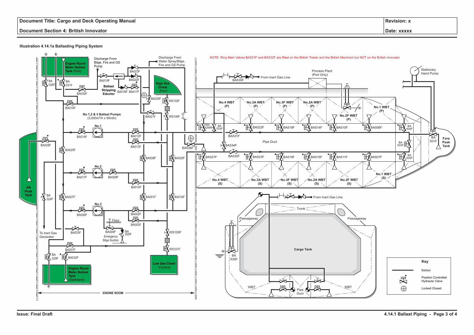
Issue: Final Draft
Document Title: Cargo and Deck Operating Manual
Document Section 4: British Innovator
Revision: x
Date: xxxxx
Illustration 4.14.1a Ballasting Piping System
No.1,2 & 3 Ballast Pumps
(3,000m3/h x 50mth)
BA028F
BA027FBA
024F
BA014F
BA011F BA009F
BA006F
BA033F
BA007F
BA025F
No.1
No.2
No.3
Emergency
Bilge Suction
BA004F BA005F
Floor
WBT WBT
Cargo Tank
Ballast
Position Controlled
Hydraulic Valve
Locked Closed
Key
From Inert Gas Line
From Inert Gas Line
Stationary
Hand PumpProcess Plant
(Port Only)
No.4 WBT
(P)
No.4 WBT
(S)
No.3A WBT
(P)
No.3A WBT
(S)
No.2A WBT
(P)
No.2A WBT
(S)
No.3F WBT
(P)
No.3F WBT
(S)
No.2F WBT
(P)
No.2F WBT
(S)
No.1 WBT
(P)
No.1 WBT
(S)
Fore
Peak
Tank
BA
501F
BA506F
BA507F
BA510F
BA511F
BA514F
BA515F
BA518F
BA519FBA523F
BA531F
BA532F
BA534FBA036F
BA533F
BA526F
BA527F
BA
535F
BA522F
BA530F
BA504F
BA503F
BA505F
Trunk
Pipe
Duct
Pipe Duct
To Inert Gas
Generator
Discharge From
Water Spray/Bilge,
Fire and GS Pump
NOTE: Ring Main Valves BA531F and BA532F are fitted on the British Trader and the British Merchant but NOT on the British InnovatorDischarge From
Bilge, Fire and GS
Pump
Engine Room
Water Ballast
Tank
(Starboard)
Engine Room
Water Ballast
Tank (Port)
Ballast
Stripping
Eductor
BA
026F
BA018F
BA035F
BA021F
BA008F
BA010F
BA001F
BA002F
BA003F
BA012F
BA013F
BA020F
BA016F
BA017F
BA022F
BA023F
BA019F
BA
029F BA032F
WS101F
WS105F
WS106F
WS102F
Low Sea Chest
(Central)
BA030F
BA015F
ENGINE ROOM
Aft
Peak
Tank
High Sea
Chest
(Port)
BA
031F
Passageway Passageway
4.14.1 Ballast Piping - Page 3 of 4
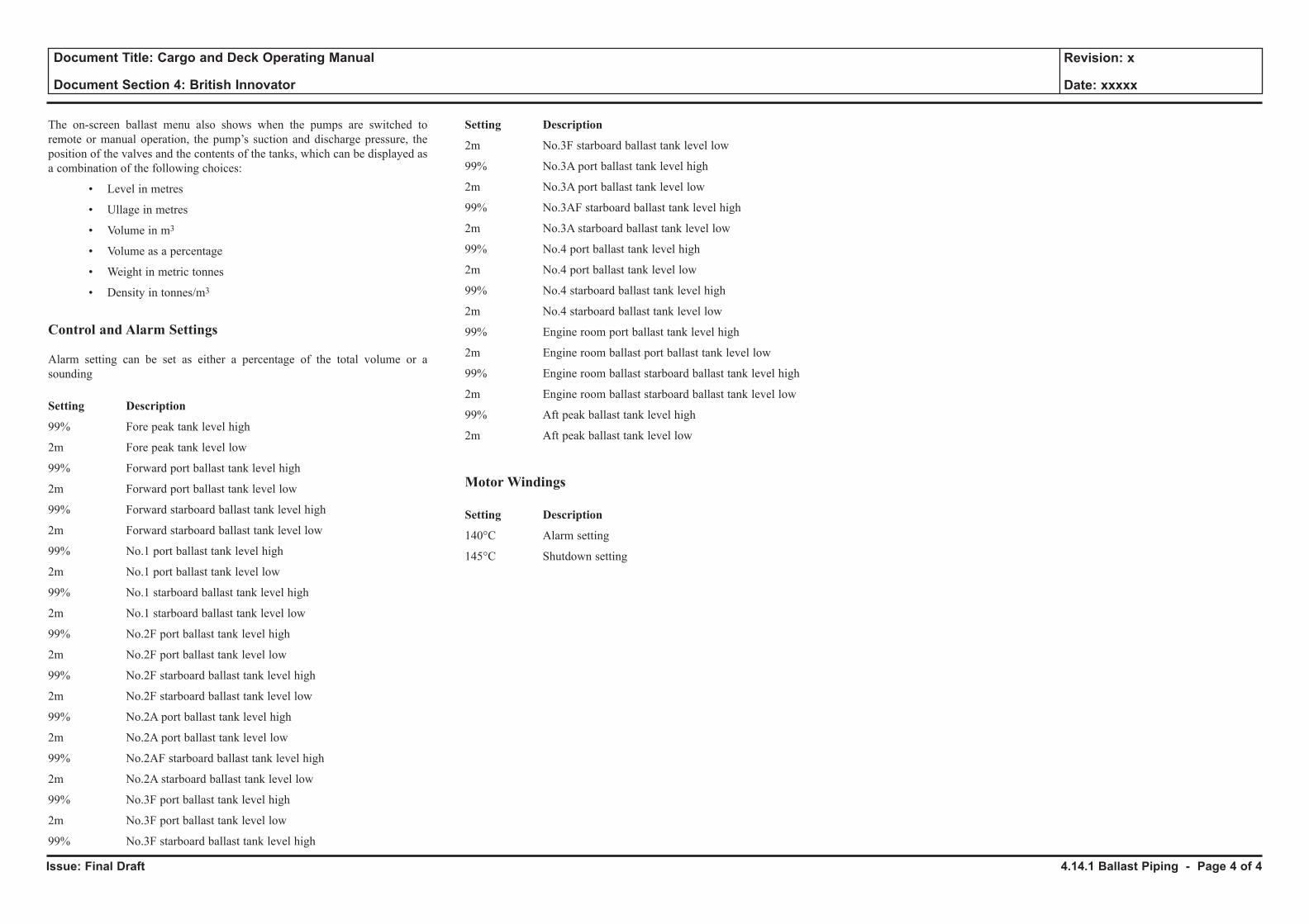
Issue: Final Draft
Document Title: Cargo and Deck Operating Manual
Document Section 4: British Innovator
Revision: x
Date: xxxxx
The on-screen ballast menu also shows when the pumps are switched to remote or manual operation, the pump’s suction and discharge pressure, the position of the valves and the contents of the tanks, which can be displayed as a combination of the following choices:
• Level in metres
• Ullage in metres
• Volume in m3
• Volume as a percentage
• Weight in metric tonnes
• Density in tonnes/m3
Control and Alarm Settings
Alarm setting can be set as either a percentage of the total volume or a sounding
Setting Description
99% Fore peak tank level high
2m Fore peak tank level low
99% Forward port ballast tank level high
2m Forward port ballast tank level low
99% Forward starboard ballast tank level high
2m Forward starboard ballast tank level low
99% No.1 port ballast tank level high
2m No.1 port ballast tank level low
99% No.1 starboard ballast tank level high
2m No.1 starboard ballast tank level low
99% No.2F port ballast tank level high
2m No.2F port ballast tank level low
99% No.2F starboard ballast tank level high
2m No.2F starboard ballast tank level low
99% No.2A port ballast tank level high
2m No.2A port ballast tank level low
99% No.2AF starboard ballast tank level high
2m No.2A starboard ballast tank level low
99% No.3F port ballast tank level high
2m No.3F port ballast tank level low
99% No.3F starboard ballast tank level high
Setting Description
2m No.3F starboard ballast tank level low
99% No.3A port ballast tank level high
2m No.3A port ballast tank level low
99% No.3AF starboard ballast tank level high
2m No.3A starboard ballast tank level low
99% No.4 port ballast tank level high
2m No.4 port ballast tank level low
99% No.4 starboard ballast tank level high
2m No.4 starboard ballast tank level low
99% Engine room port ballast tank level high
2m Engine room ballast port ballast tank level low
99% Engine room ballast starboard ballast tank level high
2m Engine room ballast starboard ballast tank level low
99% Aft peak ballast tank level high
2m Aft peak ballast tank level low
Motor Windings
Setting Description
140°C Alarm setting
145°C Shutdown setting
4.14.1 Ballast Piping - Page 4 of 4
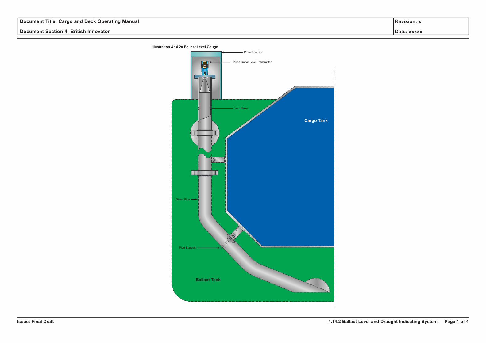
Issue: Final Draft
Document Title: Cargo and Deck Operating Manual
Document Section 4: British Innovator
Revision: x
Date: xxxxx
Pulse Radar Level Transmitter
Vent Holes
Pipe Support
Ballast Tank
Cargo Tank
Stand Pipe
Protection Box
Illustration 4.14.2a Ballast Level Gauge
4.14.2 Ballast Level and Draught Indicating System - Page 1 of 4
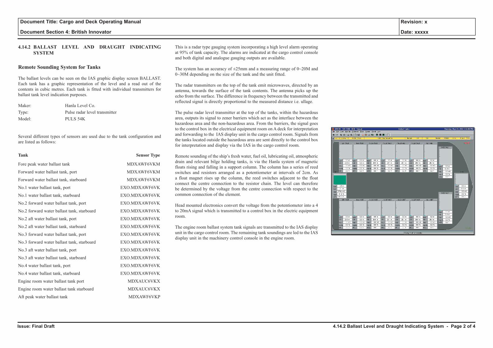
Issue: Final Draft
Document Title: Cargo and Deck Operating Manual
Document Section 4: British Innovator
Revision: x
Date: xxxxx
4.14.2 BALLAST LEVEL AND DRAUGHT INDICATING SYSTEM
Remote Sounding System for Tanks
The ballast levels can be seen on the IAS graphic display screen BALLAST. Each tank has a graphic representation of the level and a read out of the contents in cubic metres. Each tank is fitted with individual transmitters for ballast tank level indication purposes.
Maker: Hanla Level Co.Type: Pulse radar level transmitterModel: PULS 54K
Several different types of sensors are used due to the tank configuration and are listed as follows:
Tank Sensor Type
Fore peak water ballast tank MDXAWF6VKM
Forward water ballast tank, port MDXAWF6VKM
Forward water ballast tank, starboard MDXAWF6VKM
No.1 water ballast tank, port EXO.MDXAWF6VK
No.1 water ballast tank, starboard EXO.MDXAWF6VK
No.2 forward water ballast tank, port EXO.MDXAWF6VK
No.2 forward water ballast tank, starboard EXO.MDXAWF6VK
No.2 aft water ballast tank, port EXO.MDXAWF6VK
No.2 aft water ballast tank, starboard EXO.MDXAWF6VK
No.3 forward water ballast tank, port EXO.MDXAWF6VK
No.3 forward water ballast tank, starboard EXO.MDXAWF6VK
No.3 aft water ballast tank, port EXO.MDXAWF6VK
No.3 aft water ballast tank, starboard EXO.MDXAWF6VK
No.4 water ballast tank, port EXO.MDXAWF6VK
No.4 water ballast tank, starboard EXO.MDXAWF6VK
Engine room water ballast tank port MDXAUC6VKX
Engine room water ballast tank starboard MDXAUC6VKX
Aft peak water ballast tank MDXAWF6VKP
This is a radar type gauging system incorporating a high level alarm operating at 95% of tank capacity. The alarms are indicated at the cargo control console and both digital and analogue gauging outputs are available.
The system has an accuracy of ±25mm and a measuring range of 0~20M and 0~30M depending on the size of the tank and the unit fitted.
The radar transmitters on the top of the tank emit microwaves, directed by an antenna, towards the surface of the tank contents. The antenna picks up the echo from the surface. The difference in frequency between the transmitted and reflected signal is directly proportional to the measured distance i.e. ullage.
The pulse radar level transmitter at the top of the tanks, within the hazardous area, outputs its signal to zener barriers which act as the interface between the hazardous area and the non-hazardous area. From the barriers, the signal goes to the control box in the electrical equipment room on A deck for interpretation and forwarding to the IAS display unit in the cargo control room. Signals from the tanks located outside the hazardous area are sent directly to the control box for interpretation and display via the IAS in the cargo control room.
Remote sounding of the ship’s fresh water, fuel oil, lubricating oil, atmospheric drain and relevant bilge holding tanks, is via the Hanla system of magnetic floats rising and falling in a support column. The column has a series of reed switches and resistors arranged as a potentiometer at intervals of 2cm. As a float magnet rises up the column, the reed switches adjacent to the float connect the centre connection to the resistor chain. The level can therefore be determined by the voltage from the centre connection with respect to the common connection of the element.
Head mounted electronics convert the voltage from the potentiometer into a 4 to 20mA signal which is transmitted to a control box in the electric equipment room.
The engine room ballast system tank signals are transmitted to the IAS display unit in the cargo control room. The remaining tank soundings are led to the IAS display unit in the machinery control console in the engine room.
4.14.2 Ballast Level and Draught Indicating System - Page 2 of 4

Issue: Final Draft
Document Title: Cargo and Deck Operating Manual
Document Section 4: British Innovator
Revision: x
Date: xxxxx
Illustration 4.14.2b Draught and Tank Level Indicating System
Safety Barrier Power supply AC 220V
HAZARDOUS AREASAFETY AREA
Safety Area - El. Equipment Room (Accomodation A-Deck
Cargo PS Number 4 For Intergrated Automation System
1 Main LO Sump Tank Level
2 Bilge Holding Tank Level
3 Separated Bilge Oil Tank
Level
4 FO Drain Tank Level
5 Stern Tube LO Drain Tank
Level
1 HFO Overflow Level
2 MGO Sorage Tank (P) Level
3 Fresh and Drinking Water (P)
4 Fresh and Drinking Water Tank (S)
5 Distilled Water Tank (P) Level
6 Distilled Water Tank (S) Level
7 Main LO Gravity Tank Level
8 DO Storage Tank For Emergency
Fire Pump Diesel Engine
1 Aft Draught 1 Forward Water Ballast
Tank Level (P)
2 Forward Water Ballast
Tank Level (S)
1 Aft Peak Tank Level
2 Engine Room Water
Ballast Tank Level (P)
3 Engine Room Water
Ballast Tank Level (S)
1 DO Storage Tank (S) Level
2 DO Service Tanks (S) Level
3 Low Sulphur HFO Storage
Tank (P) Level
4 No.2 HFO Storage
Tank (P) Level
5 No.2 HFO Storage
Tank (S) Level
6 No.1 HFO Settling
Tank (S)
6 No.2 HFO Settling
Tank (S)
1 No.1 Water Ballast
Tank Level (P)
2 No.1 Water Ballast
Tank Level (S)
3 No.2 Forward Water
Ballast Tank Level (P)
4 No.2 Forward Water
Ballast Tank Level (S)
5 No.2 Aft Water
Ballast Tank Level (P)
6 No.2 Aft Water
Ballast Tank Level (S)
7 No.3 Forward Water
Ballast Tank Level (P)
8 No.3 Forward Water
Ballast Tank Level (S)
9 No.3 Aft Water
Ballast Tank Level (P)
9 No.3 Aft Water
Ballast Tank Level (S)
1 No.4 Aft Water
Ballast Tank Level (P)
1 No.4 Aft Water
Ballast Tank Level (S)
1 Mid Draught (P)
1 Mid Draught (S)
1 Atmospheric Drain Tank Level
2 LO Purifier Sludge Tank Level
1 Fore Peak Tank Level
2 No.1 HFO Storage Tank
1 Forward Draught
Local Indicator
4.14.2 Ballast Level and Draught Indicating System - Page 3 of 4
Issue: Final Draft
Document Title: Cargo and Deck Operating Manual
Document Section 4: British Innovator
Revision: x
Date: xxxxx
Draught Indicating System
The vessel is fitted with four pulse radar transmitters to measure the vessel’s draught and display this on the IAS console in the cargo control room. These are located fore and aft of the vessel and midships, port and starboard.
Maker: Hanla Level Co.Type: Pulse radar level transmitterModel: PULS 54K Location Sensor TypeForward draught MDXAWF6VKM
Midships draught, port EXO.MDXAWF6VK
Midships draught, starboard EXO.MDXAWF6VK
Aft draught MDXAUCF6VM
The system consists of a pulse transmitter mounted above the deck level with a standpipe connected from the transmitter to near the bottom of the vessel.
An open branch pipe passing through the ship’s side with a shut off valve is connected to the base of the standpipe. As the vessel changes its draught the level in the standpipe changes accordingly.
The radar transmitter on the top of the standpipe emit microwaves, directed by an antenna, towards the surface of the pipe contents. The antenna picks up the echo from the surface. The difference in frequency between the transmitted and reflected signal is directly proportional to the measured distance i.e. draught.
The pulse radar level transmitters for the forward and midships draught gauges, which are located within the hazardous area, outputs their signal to zener barriers which act as the interface between the hazardous area and the non-hazardous area. From the barriers, the signal goes to the control box in the electrical equipment room on A deck for interpretation and forwarding to the IAS display unit in the cargo control room. Signals from the aft draught gauge, located outside the hazardous area, are sent directly to the control box for interpretation and display via the IAS in the cargo control room.
4.14.2 Ballast Level and Draught Indicating System - Page 4 of 4
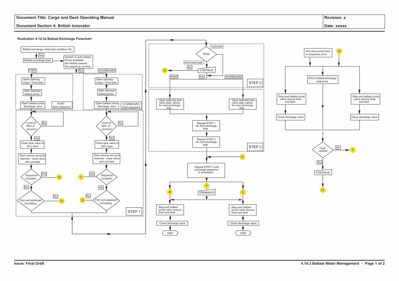
Issue: Final Draft
Document Title: Cargo and Deck Operating Manual
Document Section 4: British Innovator
Revision: x
Date: xxxxx
Illustration 4.14.3a Ballast Exchange Flowchart
Ballast exchange initial start condition OK
Ballast exchange start
Valve opening
Lines + First tank
Valve opening
Lines + First tank
System in auto ballast
Pump available
No inhibits present
No sequence running
PORT
PORT
PORT
Start sequence
Start selected
ballast pump
Start selected
ballast pump
Open ballast pump
discharge valve
Open ballast pump
discharge valve
STARBOARD
STARBOARD
STARBOARD
Start sequence
Close tank valve to
20% open
Tank volume set point
reached - close valve
and circulate
Tank volume set point
reached - close valve
and circulate
Sequence
complete
Sequence
complete
Port and starboard
circulatingPort and starboard
circulating
B
D
C
F
F
D
No No
No
No
No
NoNo
No
Yes Yes
Yes Yes
Yes
Yes
Yes
Yes
TERMINATE
CONTINUE
CONTINUE
END END
Close discharge valve Close discharge valve
Stop port ballastpump valve closurelines and tank
Stop port ballastpump valve closurelines and tank
D
C
G
G
D
STEP 1
STEP 3
STEP 2
Repeat STEP 3 untilexchange sequenceis completed
Repeat STEP 2for next exchange
step
Repeat STEP 1for next exchange
step
Open selected tankvalve align valvesfor next exchange
step
Open selected tankvalve align valvesfor next exchange
step
Mode
Automatic
Semi-automatic
Any duty pump/valve
or sequence error
HOLD ballast exchange
sequence
Stop port ballast pumpvalve closure lines
and tank
Stop port ballast pumpvalve closure lines
and tank
Close discharge valve Close discharge valve
Faultcleared
B
Close tank valve to
20% open
Level at
98% of
set point
Level at
98% of
set point
4.14.3 Ballast Water Management - Page 1 of 2
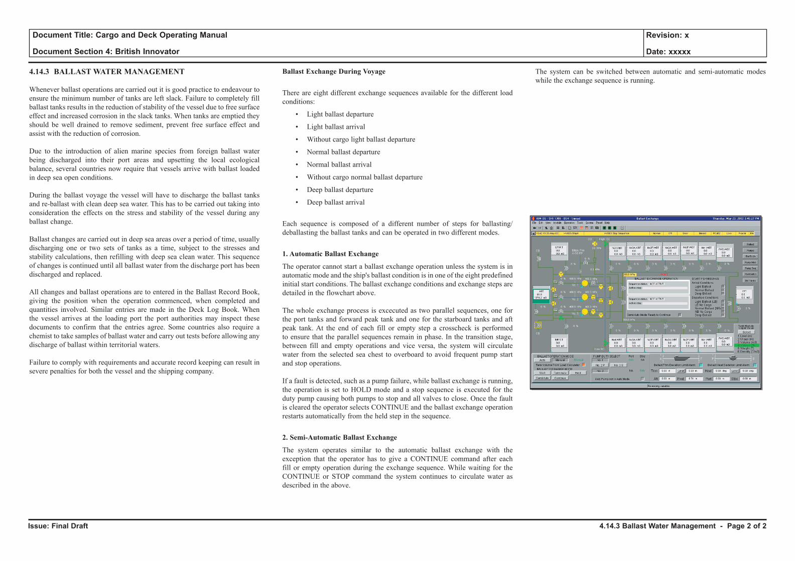
Issue: Final Draft
Document Title: Cargo and Deck Operating Manual
Document Section 4: British Innovator
Revision: x
Date: xxxxx
4.14.3 BALLAST WATER MANAGEMENT
Whenever ballast operations are carried out it is good practice to endeavour to ensure the minimum number of tanks are left slack. Failure to completely fill ballast tanks results in the reduction of stability of the vessel due to free surface effect and increased corrosion in the slack tanks. When tanks are emptied they should be well drained to remove sediment, prevent free surface effect and assist with the reduction of corrosion.
Due to the introduction of alien marine species from foreign ballast water being discharged into their port areas and upsetting the local ecological balance, several countries now require that vessels arrive with ballast loaded in deep sea open conditions.
During the ballast voyage the vessel will have to discharge the ballast tanks and re-ballast with clean deep sea water. This has to be carried out taking into consideration the effects on the stress and stability of the vessel during any ballast change.
Ballast changes are carried out in deep sea areas over a period of time, usually discharging one or two sets of tanks as a time, subject to the stresses and stability calculations, then refilling with deep sea clean water. This sequence of changes is continued until all ballast water from the discharge port has been discharged and replaced.
All changes and ballast operations are to entered in the Ballast Record Book, giving the position when the operation commenced, when completed and quantities involved. Similar entries are made in the Deck Log Book. When the vessel arrives at the loading port the port authorities may inspect these documents to confirm that the entries agree. Some countries also require a chemist to take samples of ballast water and carry out tests before allowing any discharge of ballast within territorial waters.
Failure to comply with requirements and accurate record keeping can result in severe penalties for both the vessel and the shipping company.
Ballast Exchange During Voyage
There are eight different exchange sequences available for the different load conditions:
• Light ballast departure
• Light ballast arrival
• Without cargo light ballast departure
• Normal ballast departure
• Normal ballast arrival
• Without cargo normal ballast departure
• Deep ballast departure
• Deep ballast arrival
Each sequence is composed of a different number of steps for ballasting/deballasting the ballast tanks and can be operated in two different modes.
1. Automatic Ballast Exchange
The operator cannot start a ballast exchange operation unless the system is in automatic mode and the ship's ballast condition is in one of the eight predefined initial start conditions. The ballast exchange conditions and exchange steps are detailed in the flowchart above.
The whole exchange process is excecuted as two parallel sequences, one for the port tanks and forward peak tank and one for the starboard tanks and aft peak tank. At the end of each fill or empty step a crosscheck is performed to ensure that the parallel sequences remain in phase. In the transition stage, between fill and empty operations and vice versa, the system will circulate water from the selected sea chest to overboard to avoid frequent pump start and stop operations.
If a fault is detected, such as a pump failure, while ballast exchange is running, the operation is set to HOLD mode and a stop sequence is executed for the duty pump causing both pumps to stop and all valves to close. Once the fault is cleared the operator selects CONTINUE and the ballast exchange operation restarts automatically from the held step in the sequence.
2. Semi-Automatic Ballast Exchange
The system operates similar to the automatic ballast exchange with the exception that the operator has to give a CONTINUE command after each fill or empty operation during the exchange sequence. While waiting for the CONTINUE or STOP command the system continues to circulate water as described in the above.
The system can be switched between automatic and semi-automatic modes while the exchange sequence is running.
4.14.3 Ballast Water Management - Page 2 of 2

4.15 Vacuum Pumps
Issue: Final Draft
Document Title: Cargo and Deck Operating Manual
Document Section 4: British Innovator
Revision: x
Date: xxxxx
4.15 VACUUM PUMPS
Introduction
Vacuum pumps are used as part of a global Tightness Test of the secondary barrier. It is conducted initially to establish reference data for comparison during the ship’s life.
Subsequent tests will be carried out as required by the classification society and compared to the initial data to check for deterioration.
Basically a partial vacuum is drawn in the secondary (insulation) space and as the contents of the primary interbarrier space are drawn across the secondary barrier membrane, the vacuum decay is recorded over a period of time.
There is a detailed 11 page document which is part of the ship's finished drawings, though it is not a normal operating procedure.
The ship will not be supplied with a vacuum pump but any type of vacuum pump could be used as long as it meets the minimum capacity requirements.
There is another requirement that the ship must be able to drain the primary interbarrier space of liquid cargo in case of a failure of the primary barrier.
In this case the LD compressor is used as a vacuum pump to draw the liquid up dip tubes. The liquid partially vaporises in the tubes on deck and is fully vaporised in the forcing vaporiser before entering the LD compressor.
There is a 7 page document describing this which will be in the finished drawings section in the ship's office.
Vacuum Pumps - Page 1 of 1
PART 5: CARGO AUXILIARY AND DECK SYSTEM
5.1 Temperature Monitoring System
Illustrations
5.1a Cargo Tank Temperature Monitoring System
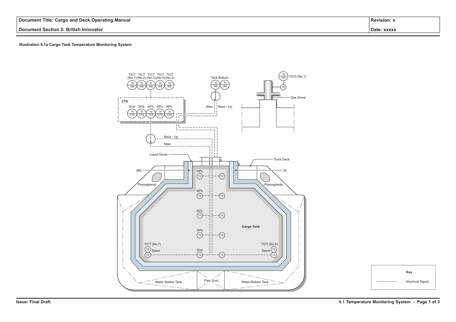
Issue: Final Draft
Document Title: Cargo and Deck Operating Manual
Document Section 5: British Innovator
Revision: x
Date: xxxxx
Illustration 5.1a Cargo Tank Temperature Monitoring System
TIIAS TICG (No.1)
TE
Water Ballast TankWater Ballast Tank Pipe Duct
Passageway Passageway
Cargo Tank
TE TE
TE
TE
TE
TE
TE Spare
TE
TESpareEnd
30%
60%
95%
99%
TIIAS
TIIAS
TIIAS
TIIAS
TIIAS
TIIAS
TIIAS
TICT(No.1)
TICT(No.2)
TICT(No.3)
TICT(No.4) Tank Bottom
TICT(No.5)
Back - Up
Back - Up
Gas Dome
Main
Main
TE
TE
TE
TE
TE
TICT (No.7) TICT (No.8)
TICTS
End
TICTS
30%
TICTS
60%
TICTS
95%
CTS
TICTS
99%
Trunk Deck
Liquid Dome
IBS IS
Electrical Signal
Key
5.1 Temperature Monitoring System - Page 1 of 3
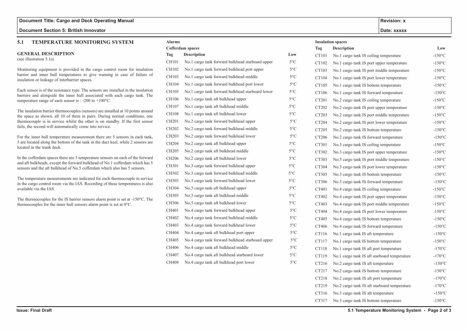
Issue: Final Draft
Document Title: Cargo and Deck Operating Manual
Document Section 5: British Innovator
Revision: x
Date: xxxxx
5.1 TEMPERATURE MONITORING SYSTEM
GENERAL DESCRIPTION(see illustration 5.1a)
Monitoring equipment is provided in the cargo control room for insulation barrier and inner hull temperatures to give warning in case of failure of insulation or leakage of interbarrier spaces.
Each sensor is of the resistance type. The sensors are installed in the insulation barriers and alongside the inner hull associated with each cargo tank. The temperature range of each sensor is : -200 to +100°C.
The insulation barrier thermocouples (sensors) are installed at 10 points around the space as shown, all 10 of them in pairs. During normal conditions, one thermocouple is in service whilst the other is on standby. If the first sensor fails, the second will automatically come into service.
For the inner hull temperature measurement there are 5 sensors in each tank, 3 are located along the bottom of the tank in the duct keel, while 2 sensors are located in the trunk deck.
In the cofferdam spaces there are 3 temperature sensors on each of the forward and aft bulkheads, except the forward bulkhead of No.1 cofferdam which has 5 sensors and the aft bulkhead of No.5 cofferdam which also has 5 sensors.
The temperature measurements are indicated for each thermocouple in service in the cargo control room via the IAS. Recording of these temperatures is also available via the IAS.
The thermocouples for the IS barrier sensors alarm point is set at -150°C. The thermocouples for the inner hull sensors alarm point is set at 0°C.
AlarmsCofferdam spacesTag Description Low
CH101 No.1 cargo tank forward bulkhead starboard upper 5°C
CH102 No.1 cargo tank forward bulkhead port upper 5°C
CH103 No.1 cargo tank forward bulkhead middle 5°C
CH104 No.1 cargo tank forward bulkhead port lower 5°C
CH105 No.1 cargo tank forward bulkhead starboard lower 5°C
CH106 No.1 cargo tank aft bulkhead upper 5°C
CH107 No.1 cargo tank aft bulkhead middle 5°C
CH108 No.1 cargo tank aft bulkhead lower 5°C
CH201 No.2 cargo tank forward bulkhead upper 5°C
CH202 No.2 cargo tank forward bulkhead middle 5°C
CH203 No.2 cargo tank forward bulkhead lower 5°C
CH204 No.2 cargo tank aft bulkhead upper 5°C
CH205 No.2 cargo tank aft bulkhead middle 5°C
CH206 No.2 cargo tank aft bulkhead lower 5°C
CH301 No.3 cargo tank forward bulkhead upper 5°C
CH302 No.3 cargo tank forward bulkhead middle 5°C
CH303 No.3 cargo tank forward bulkhead lower 5°C
CH304 No.3 cargo tank aft bulkhead upper 5°C
CH305 No.3 cargo tank aft bulkhead middle 5°C
CH306 No.3 cargo tank aft bulkhead lower 5°C
CH401 No.4 cargo tank forward bulkhead upper 5°C
CH402 No.4 cargo tank forward bulkhead middle 5°C
CH403 No.4 cargo tank forward bulkhead lower 5°C
CH404 No.4 cargo tank aft bulkhead port upper 5°C
CH405 No.4 cargo tank forward bulkhead starboard upper 5°C
CH406 No.4 cargo tank aft bulkhead middle 5°C
CH407 No.4 cargo tank aft bulkhead starboard lower 5°C
CH408 No.4 cargo tank aft bulkhead port lower 5°C
Insulation spacesTag Description Low
CT101 No.1 cargo tank IS ceiling temperature -150°C
CT102 No.1 cargo tank IS port upper temperature -150°C
CT103 No.1 cargo tank IS port middle temperature -150°C
CT104 No.1 cargo tank IS port lower temperature -150°C
CT105 No.1 cargo tank IS bottom temperature -150°C
CT106 No.1 cargo tank IS forward temperature -150°C
CT201 No.2 cargo tank IS ceiling temperature -150°C
CT202 No.2 cargo tank IS port upper temperature -150°C
CT203 No.2 cargo tank IS port middle temperature -150°C
CT204 No.2 cargo tank IS port lower temperature -150°C
CT205 No.2 cargo tank IS bottom temperature -150°C
CT206 No.2 cargo tank IS forward temperature -150°C
CT301 No.3 cargo tank IS ceiling temperature -150°C
CT302 No.3 cargo tank IS port upper temperature -150°C
CT303 No.3 cargo tank IS port middle temperature -150°C
CT304 No.3 cargo tank IS port lower temperature -150°C
CT305 No.3 cargo tank IS bottom temperature -150°C
CT306 No.3 cargo tank IS forward temperature -150°C
CT401 No.4 cargo tank IS ceiling temperature -150°C
CT402 No.4 cargo tank IS port upper temperature -150°C
CT403 No.4 cargo tank IS port middle temperature -150°C
CT404 No.4 cargo tank IS port lower temperature -150°C
CT405 No.4 cargo tank IS bottom temperature -150°C
CT406 No.4 cargo tank IS forward temperature -150°C
CT116 No.1 cargo tank IS aft temperature -150°C
CT117 No.1 cargo tank IS bottom temperature -150°C
CT118 No.1 cargo tank IS aft port temperature -170°C
CT119 No.1 cargo tank IS aft starboard temperature -170°C
CT216 No.2 cargo tank IS aft temperature -150°C
CT217 No.2 cargo tank IS bottom temperature -150°C
CT218 No.2 cargo tank IS aft port temperature -170°C
CT219 No.2 cargo tank IS aft starboard temperature -170°C
CT316 No.3 cargo tank IS aft temperature -150°C
CT317 No.3 cargo tank IS bottom temperature -150°C
5.1 Temperature Monitoring System - Page 2 of 3
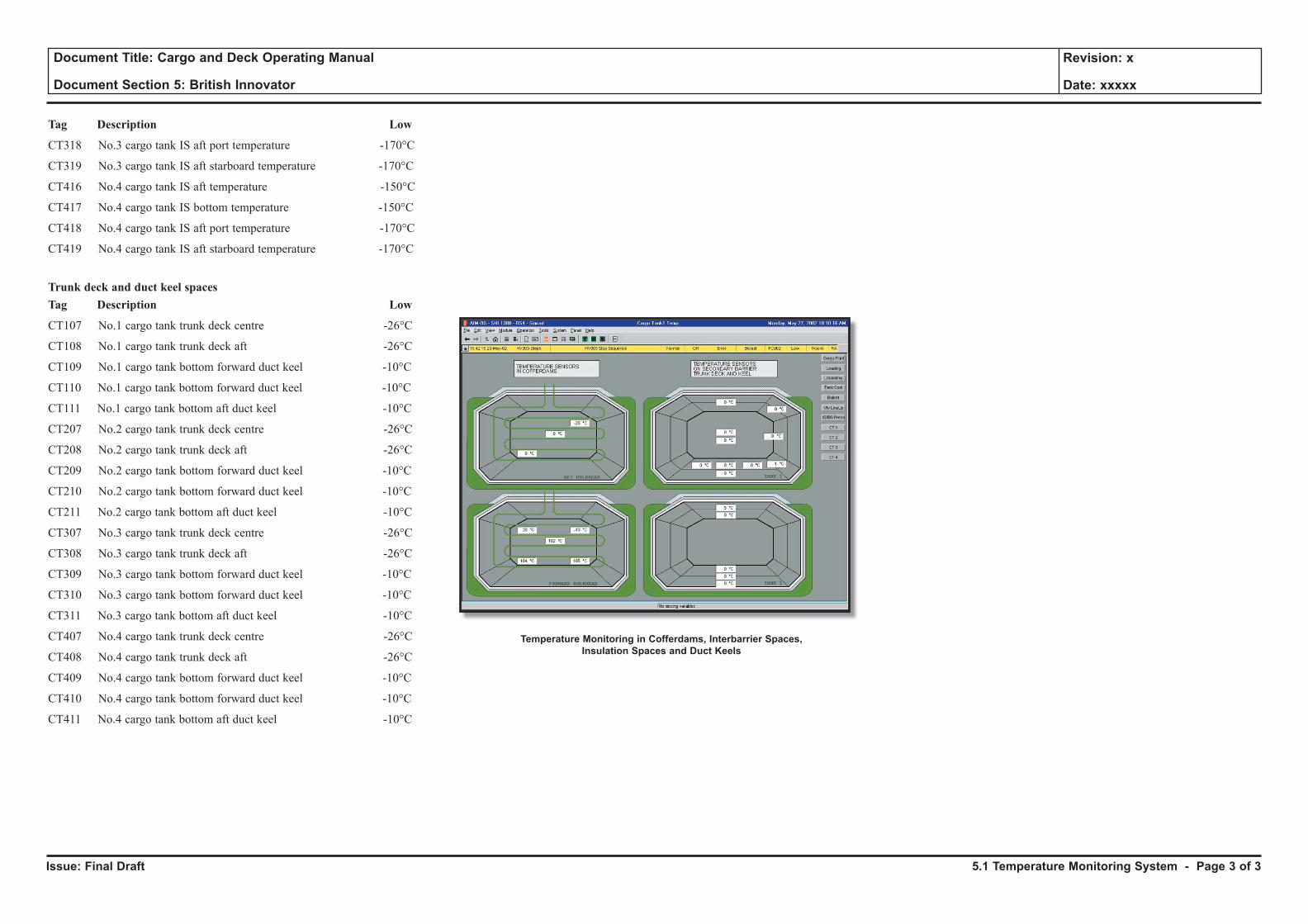
Issue: Final Draft
Document Title: Cargo and Deck Operating Manual
Document Section 5: British Innovator
Revision: x
Date: xxxxx
5.1 Temperature Monitoring System - Page 3 of 3
Tag Description Low
CT318 No.3 cargo tank IS aft port temperature -170°C
CT319 No.3 cargo tank IS aft starboard temperature -170°C
CT416 No.4 cargo tank IS aft temperature -150°C
CT417 No.4 cargo tank IS bottom temperature -150°C
CT418 No.4 cargo tank IS aft port temperature -170°C
CT419 No.4 cargo tank IS aft starboard temperature -170°C
Trunk deck and duct keel spacesTag Description Low
CT107 No.1 cargo tank trunk deck centre -26°C
CT108 No.1 cargo tank trunk deck aft -26°C
CT109 No.1 cargo tank bottom forward duct keel -10°C
CT110 No.1 cargo tank bottom forward duct keel -10°C
CT111 No.1 cargo tank bottom aft duct keel -10°C
CT207 No.2 cargo tank trunk deck centre -26°C
CT208 No.2 cargo tank trunk deck aft -26°C
CT209 No.2 cargo tank bottom forward duct keel -10°C
CT210 No.2 cargo tank bottom forward duct keel -10°C
CT211 No.2 cargo tank bottom aft duct keel -10°C
CT307 No.3 cargo tank trunk deck centre -26°C
CT308 No.3 cargo tank trunk deck aft -26°C
CT309 No.3 cargo tank bottom forward duct keel -10°C
CT310 No.3 cargo tank bottom forward duct keel -10°C
CT311 No.3 cargo tank bottom aft duct keel -10°C
CT407 No.4 cargo tank trunk deck centre -26°C
CT408 No.4 cargo tank trunk deck aft -26°C
CT409 No.4 cargo tank bottom forward duct keel -10°C
CT410 No.4 cargo tank bottom forward duct keel -10°C
CT411 No.4 cargo tank bottom aft duct keel -10°C
Temperature Monitoring in Cofferdams, Interbarrier Spaces,Insulation Spaces and Duct Keels
5.2 Primary and Secondary Insulation Space Nitrogen Pressurising and Control System
Illustrations
5.2a Nitrogen Pressurisation and Control System
5.2b IBS Pressure Control
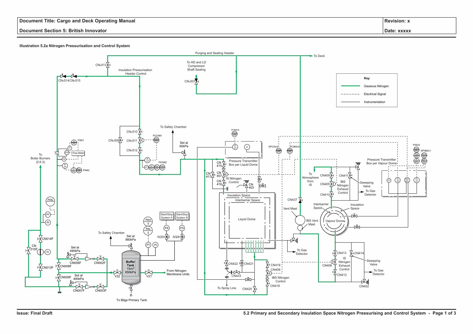
Issue: Final Draft
Document Title: Cargo and Deck Operating Manual
Document Section 5: British Innovator
Revision: x
Date: xxxxx
Liquid Dome
Illustration 5.2a Nitrogen Pressurisation and Control System
Vent Mast
IBS
Nitrogen
Exhaust
Control
To
Atmosphere
from
IS
IS
Nitrogen
Exhaust
Control
IBS Vent
Mast
Sweeping
Valve
To Gas
Detector
To Gas
Detector
Pressure Transmitter
Box per Vapour Dome
To Deck
Pressure Transmitter
Box per Liquid Dome
Interbarrier Space
Interbarrier
Space
Insulation Space
CNn515
CNn510
CNn511
CNn512
CNn509
CNn507
CN411
CN414
CN412
CN419
CN408
CN418
CN433
CN420CN402
CN421CN422
CN413
CN406
CN437
CN409
CN405
CN410
To HD and LD
Compressor
Shaft Sealing
CNn514
Insulation
Space
IS Nitrogen
Control
IBS Nitrogen
Control
To Spray Line
Insulation Pressurisation
Header Control
Purging and Sealing Header
Vapour Dome
Sweeping
Valve
To Gas
Detector
PIN62
FIN01
PICN82
CN417
CN415
CN416 CN
403
CN407
PCCN81
Flow Meter
PALIAS
FIIAS
PIIAS
CNn513
PTPALIAS
PAHIAS
PACIAS
PIIAS
PIPT
PIPT
PI
PIPT
TE
FI
DTP
PIISn5
DPIIBSn1
PCIBSn0
PCIBSn8
DPCISn4PAHIAS
DPIIAS
DPAL
IAS
PAHIAS
PAHIAS
PAHIAS
PALIAS
PIPT
PIPT
DPIDPI
PIIAS
PT
PIAL
PI
PT
Key
Gaseous Nitrogen
Electrical Signal
Instrumentation
FI
To Safety Chamber
BufferTank15m3
650kPa
Set at490kPa
Set at980kPa
To Safety Chamber
Set at60kPa
To Bilge Primary Tank
From NitrogenMembrane Units
V21
IV23 IV24
V22
CN003F
CN015F
CN014F
CN013F
CN007F
CN008F
CN009F
CN002FCN006F
Start/Stop
System A
Start/Stop
System B
To
Boiler Burners
(2.6.3)
Set at490kPa
PS
PIPT
PSPAL
PAH
5
5
5.2 Primary and Secondary Insulation Space Nitrogen Pressurising and Control System - Page 1 of 3
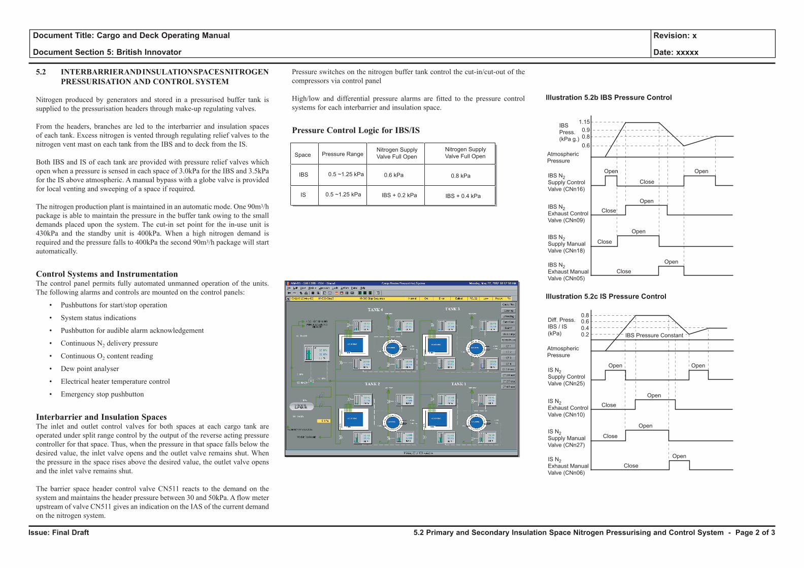
Issue: Final Draft
Document Title: Cargo and Deck Operating Manual
Document Section 5: British Innovator
Revision: x
Date: xxxxx
5.2 INTERBARRIER AND INSULATION SPACES NITROGEN PRESSURISATION AND CONTROL SYSTEM
Nitrogen produced by generators and stored in a pressurised buffer tank is supplied to the pressurisation headers through make-up regulating valves.
From the headers, branches are led to the interbarrier and insulation spaces of each tank. Excess nitrogen is vented through regulating relief valves to the nitrogen vent mast on each tank from the IBS and to deck from the IS.
Both IBS and IS of each tank are provided with pressure relief valves which open when a pressure is sensed in each space of 3.0kPa for the IBS and 3.5kPa for the IS above atmospheric. A manual bypass with a globe valve is provided for local venting and sweeping of a space if required.
The nitrogen production plant is maintained in an automatic mode. One 90m3/h package is able to maintain the pressure in the buffer tank owing to the small demands placed upon the system. The cut-in set point for the in-use unit is 430kPa and the standby unit is 400kPa. When a high nitrogen demand is required and the pressure falls to 400kPa the second 90m3/h package will start automatically.
Control Systems and InstrumentationThe control panel permits fully automated unmanned operation of the units. The following alarms and controls are mounted on the control panels:
• Pushbuttons for start/stop operation
• System status indications
• Pushbutton for audible alarm acknowledgement
• Continuous N2 delivery pressure
• Continuous O2 content reading
• Dew point analyser
• Electrical heater temperature control
• Emergency stop pushbutton
Interbarrier and Insulation SpacesThe inlet and outlet control valves for both spaces at each cargo tank are operated under split range control by the output of the reverse acting pressure controller for that space. Thus, when the pressure in that space falls below the desired value, the inlet valve opens and the outlet valve remains shut. When the pressure in the space rises above the desired value, the outlet valve opens and the inlet valve remains shut.
The barrier space header control valve CN511 reacts to the demand on the system and maintains the header pressure between 30 and 50kPa. A flow meter upstream of valve CN511 gives an indication on the IAS of the current demand on the nitrogen system.
Pressure switches on the nitrogen buffer tank control the cut-in/cut-out of the compressors via control panel
High/low and differential pressure alarms are fitted to the pressure control systems for each interbarrier and insulation space.
Pressure Control Logic for IBS/IS
Space Pressure RangeNitrogen Supply
Valve Full Open
Nitrogen Supply
Valve Full Open
IBS
0.5 ~1.25 kPa
0.5 ~1.25 kPa 0.6 kPa 0.8 kPa
IBS + 0.2 kPa IBS + 0.4 kPaIS
IBS
Press.
(kPa g.)
IBS N2Supply Control
Valve (CNn16)
IBS N2Exhaust Control
Valve (CNn09)
IBS N2Supply Manual
Valve (CNn18)
IBS N2Exhaust Manual
Valve (CNn05)
Atmospheric
Pressure
Illustration 5.2b IBS Pressure Control
Open
1.15
0.8
0.9
0.6
0.80.60.40.2
Open
Close
Close
Close
Close
Open
Open
Open
Diff. Press.
IBS / IS
(kPa)
IS N2Supply Control
Valve (CNn25)
IS N2Exhaust Control
Valve (CNn10)
IS N2Supply Manual
Valve (CNn27)
IS N2Exhaust Manual
Valve (CNn06)
Atmospheric
Pressure
Illustration 5.2c IS Pressure Control
Open
Open
Close
Close
Close
Open
Open
Open
IBS Pressure Constant
5.2 Primary and Secondary Insulation Space Nitrogen Pressurising and Control System - Page 2 of 3
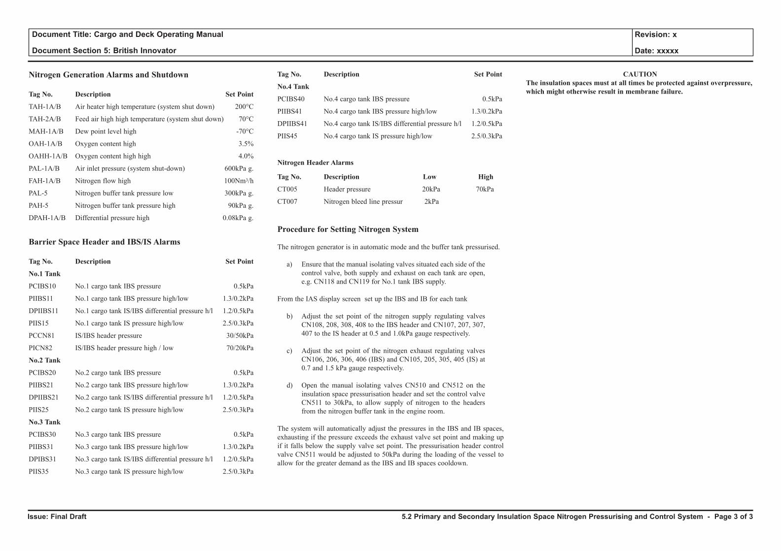
Issue: Final Draft
Document Title: Cargo and Deck Operating Manual
Document Section 5: British Innovator
Revision: x
Date: xxxxx
Nitrogen Generation Alarms and Shutdown
Tag No. Description Set Point
TAH-1A/B Air heater high temperature (system shut down) 200°C
TAH-2A/B Feed air high high temperature (system shut down) 70°C
MAH-1A/B Dew point level high -70°C
OAH-1A/B Oxygen content high 3.5%
OAHH-1A/B Oxygen content high high 4.0%
PAL-1A/B Air inlet pressure (system shut-down) 600kPa g.
FAH-1A/B Nitrogen flow high 100Nm3/h
PAL-5 Nitrogen buffer tank pressure low 300kPa g.
PAH-5 Nitrogen buffer tank pressure high 90kPa g.
DPAH-1A/B Differential pressure high 0.08kPa g.
Barrier Space Header and IBS/IS Alarms
Tag No. Description Set Point
No.1 Tank
PCIBS10 No.1 cargo tank IBS pressure 0.5kPa
PIIBS11 No.1 cargo tank IBS pressure high/low 1.3/0.2kPa
DPIIBS11 No.1 cargo tank IS/IBS differential pressure h/l 1.2/0.5kPa
PIIS15 No.1 cargo tank IS pressure high/low 2.5/0.3kPa
PCCN81 IS/IBS header pressure 30/50kPa
PICN82 IS/IBS header pressure high / low 70/20kPa
No.2 Tank
PCIBS20 No.2 cargo tank IBS pressure 0.5kPa
PIIBS21 No.2 cargo tank IBS pressure high/low 1.3/0.2kPa
DPIIBS21 No.2 cargo tank IS/IBS differential pressure h/l 1.2/0.5kPa
PIIS25 No.2 cargo tank IS pressure high/low 2.5/0.3kPa
No.3 Tank
PCIBS30 No.3 cargo tank IBS pressure 0.5kPa
PIIBS31 No.3 cargo tank IBS pressure high/low 1.3/0.2kPa
DPIBS31 No.3 cargo tank IS/IBS differential pressure h/l 1.2/0.5kPa
PIIS35 No.3 cargo tank IS pressure high/low 2.5/0.3kPa
Tag No. Description Set Point
No.4 Tank
PCIBS40 No.4 cargo tank IBS pressure 0.5kPa
PIIBS41 No.4 cargo tank IBS pressure high/low 1.3/0.2kPa
DPIIBS41 No.4 cargo tank IS/IBS differential pressure h/l 1.2/0.5kPa
PIIS45 No.4 cargo tank IS pressure high/low 2.5/0.3kPa
Nitrogen Header Alarms
Tag No. Description Low High
CT005 Header pressure 20kPa 70kPa
CT007 Nitrogen bleed line pressur 2kPa
Procedure for Setting Nitrogen System
The nitrogen generator is in automatic mode and the buffer tank pressurised.
a) Ensure that the manual isolating valves situated each side of the control valve, both supply and exhaust on each tank are open, e.g. CN118 and CN119 for No.1 tank IBS supply.
From the IAS display screen set up the IBS and IB for each tank
b) Adjust the set point of the nitrogen supply regulating valves CN108, 208, 308, 408 to the IBS header and CN107, 207, 307, 407 to the IS header at 0.5 and 1.0kPa gauge respectively.
c) Adjust the set point of the nitrogen exhaust regulating valves CN106, 206, 306, 406 (IBS) and CN105, 205, 305, 405 (IS) at 0.7 and 1.5 kPa gauge respectively.
d) Open the manual isolating valves CN510 and CN512 on the insulation space pressurisation header and set the control valve CN511 to 30kPa, to allow supply of nitrogen to the headers from the nitrogen buffer tank in the engine room.
The system will automatically adjust the pressures in the IBS and IB spaces, exhausting if the pressure exceeds the exhaust valve set point and making up if it falls below the supply valve set point. The pressurisation header control valve CN511 would be adjusted to 50kPa during the loading of the vessel to allow for the greater demand as the IBS and IB spaces cooldown.
CAUTIONThe insulation spaces must at all times be protected against overpressure, which might otherwise result in membrane failure.
5.2 Primary and Secondary Insulation Space Nitrogen Pressurising and Control System - Page 3 of 3
5.3 Cofferdam Heating System
5.3.1 Glycol Water Heater
5.3.2 Cofferdam Heating and Control
5.3.3 Hull Ventilation
Illustrations
5.3.1a Glycol Water Heater
5.3.2a Cofferdam Heating System
5.3.3a Hull Ventilation
5.3.3b Marine Safety Card
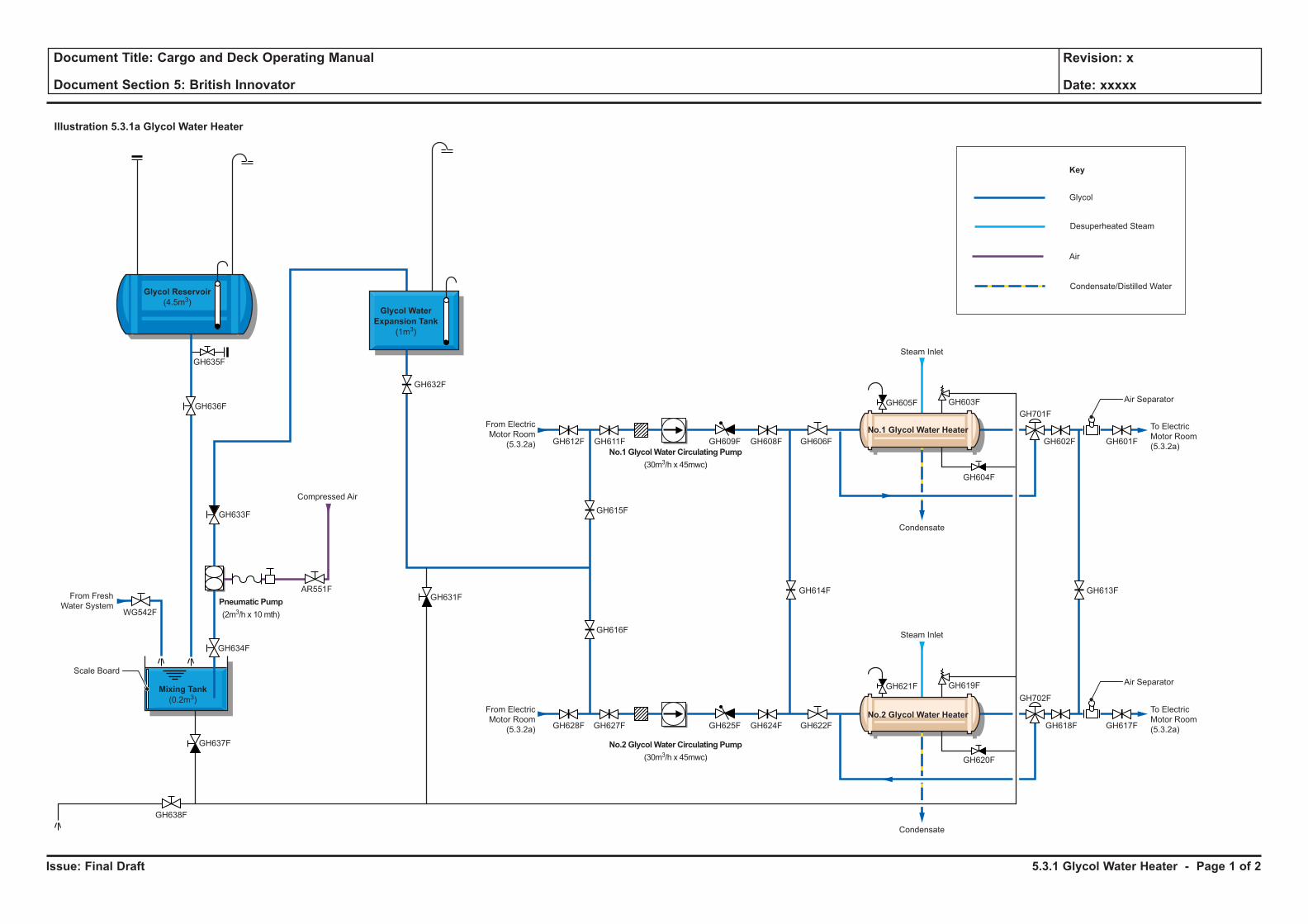
Issue: Final Draft
Document Title: Cargo and Deck Operating Manual
Document Section 5: British Innovator
Revision: x
Date: xxxxx
Illustration 5.3.1a Glycol Water Heater
Glycol
Key
Desuperheated Steam
Condensate/Distilled Water
Air
Steam Inlet
Condensate
To Electric
Motor Room
(5.3.2a)
To Electric
Motor Room
(5.3.2a)
From Electric
Motor Room
(5.3.2a)
From Electric
Motor Room
(5.3.2a)
From Fresh
Water System
Compressed Air
Steam Inlet
Condensate
Air Separator
Air Separator
No.1 Glycol Water Heater
No.2 Glycol Water Heater
Glycol Water
Expansion Tank
(1m3)
Glycol Reservoir
(4.5m3)
Mixing Tank
(0.2m3)
No.2 GlycolWater Circulating Pump
(30m3/h x 45mwc)
Pneumatic Pump
(2m3/h x 10mth)
No.1 GlycolWater Circulating Pump
(30m3/h x 45mwc)
Scale Board
GH635F
GH636F
GH633F
GH634F
GH631F
GH628F GH627F GH625F GH624F
GH612F GH611F GH609F GH608F
GH622F
GH606F
GH621F GH619F
GH605F GH603F
GH620F
GH604F
GH702F
GH618F GH617F
GH701F
GH602F GH601F
GH613FGH614F
GH615F
GH616F
GH632F
GH637F
GH638F
WG542F
AR551F
5.3.1 Glycol Water Heater - Page 1 of 2
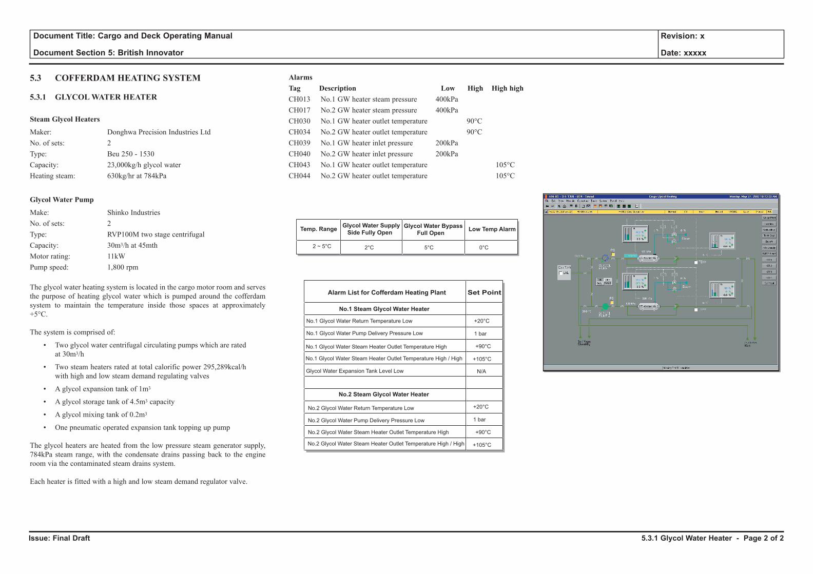
Issue: Final Draft
Document Title: Cargo and Deck Operating Manual
Document Section 5: British Innovator
Revision: x
Date: xxxxx
5.3 COFFERDAM HEATING SYSTEM
5.3.1 GLYCOL WATER HEATER
Steam Glycol Heaters
Maker: Donghwa Precision Industries LtdNo. of sets: 2Type: Beu 250 - 1530Capacity: 23,000kg/h glycol waterHeating steam: 630kg/hr at 784kPa
Glycol Water Pump
Make: Shinko IndustriesNo. of sets: 2Type: RVP100M two stage centrifugalCapacity: 30m3/h at 45mthMotor rating: 11kWPump speed: 1,800 rpm
The glycol water heating system is located in the cargo motor room and serves the purpose of heating glycol water which is pumped around the cofferdam system to maintain the temperature inside those spaces at approximately +5°C.
The system is comprised of:
• Two glycol water centrifugal circulating pumps which are rated at 30m3/h
• Two steam heaters rated at total calorific power 295,289kcal/h with high and low steam demand regulating valves
• A glycol expansion tank of 1m3
• A glycol storage tank of 4.5m3 capacity
• A glycol mixing tank of 0.2m3
• One pneumatic operated expansion tank topping up pump
The glycol heaters are heated from the low pressure steam generator supply, 784kPa steam range, with the condensate drains passing back to the engine room via the contaminated steam drains system.
Each heater is fitted with a high and low steam demand regulator valve.
AlarmsTag Description Low High High highCH013 No.1 GW heater steam pressure 400kPaCH017 No.2 GW heater steam pressure 400kPaCH030 No.1 GW heater outlet temperature 90°CCH034 No.2 GW heater outlet temperature 90°CCH039 No.1 GW heater inlet pressure 200kPaCH040 No.2 GW heater inlet pressure 200kPaCH043 No.1 GW heater outlet temperature 105°CCH044 No.2 GW heater outlet temperature 105°C
Temp. RangeGlycol Water Supply
Side Fully OpenGlycol Water Bypass
Full OpenLow Temp Alarm
Alarm List for Cofferdam Heating Plant Set Point
No.1 Glycol Water Return Temperature Low
No.1 Glycol Water Pump Delivery Pressure Low
No.1 Glycol Water Steam Heater Outlet Temperature High
No.1 Glycol Water Steam Heater Outlet Temperature High / High
Glycol Water Expansion Tank Level Low
No.2 Glycol Water Return Temperature Low
No.2 Glycol Water Pump Delivery Pressure Low
No.2 Glycol Water Steam Heater Outlet Temperature High
No.2 Glycol Water Steam Heater Outlet Temperature High / High
No.1 Steam Glycol Water Heater
No.2 Steam Glycol Water Heater
+20°C
1 bar
+90°C
+105°C
+20°C
1 bar
+90°C
+105°C
N/A
2°C2 ~ 5°C 5°C 0°C
5.3.1 Glycol Water Heater - Page 2 of 2

Issue: Final Draft
Document Title: Cargo and Deck Operating Manual
Document Section 5: British Innovator
Revision: x
Date: xxxxx
Illustration 5.3.2a Cofferdam Heating System
No.5 Cofferdam
Electric Motor Room
No.4 Cofferdam No.3 Cofferdam No.2 Cofferdam No.1 Cofferdam
No.1 Return (Main)
No.2 Return (Standby)
No.2 Return (Standby)
No.1 Return (Main)
GH508F
Passageway
30mm Rock Wool withFibreglass Cloth
Glycol Water Pipe
CofferdamHeating Coil
GH522F
GH534F
GH532F
GH533F
GH531F
GH546F
GH544F
GH545F
GH543F
GH570F
GH568F
GH569F
GH567F
GH558F
GH556F
GH557F
GH555F
GH521F
GH519F
GH509F
GH511F
GH529F
GH530F
GH523F
GH525F
GH535F
GH537F
GH547F
GH549F
GH566F
GH565F
GH541F
GH542F
GH561F
GH559F
GH553F
GH554F
GH512F
GH510FGH
538F
GH536FGH
562F
GH560F GH
550F
GH548F GH
526F
GH524F
GH518F
GH520FGH
517F
GH515F
GH516F
GH507F GH506F
GH514FGH703F GH704FGH707F GH708FGH709F GH710FGH711F GH712F GH705F GH706F
GH513F
GH528F
GH527F
GH540F
GH539F
GH552F
GH551F
GH564F
GH563F
GH505FGlycol
KeyTo/From ElectricMotor Room(5.3.1a)
PENETRATION DETAIL
INSULATION DETAILBulkhead
Sleeve
Glycol WaterHeating Pipe
5.3.2 Cofferdam Heating and Control - Page 1 of 4
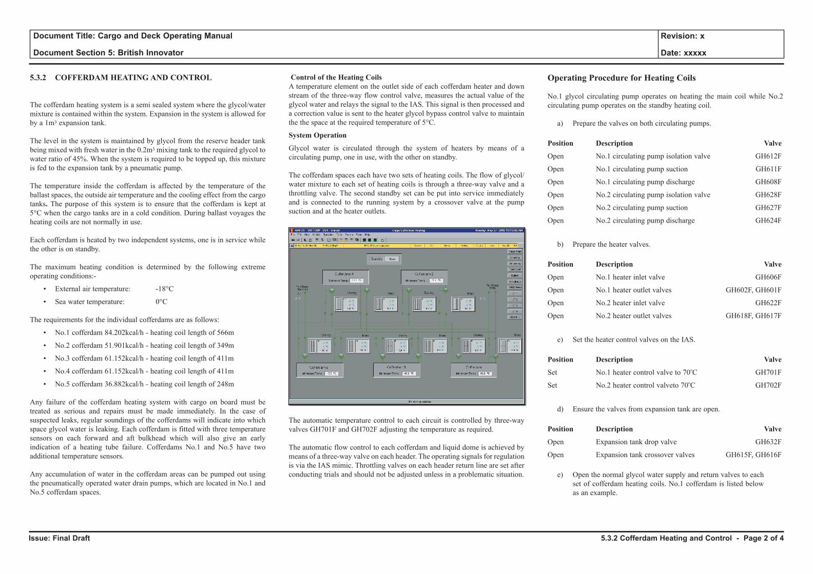
Issue: Final Draft
Document Title: Cargo and Deck Operating Manual
Document Section 5: British Innovator
Revision: x
Date: xxxxx
5.3.2 COFFERDAM HEATING AND CONTROL
The cofferdam heating system is a semi sealed system where the glycol/water mixture is contained within the system. Expansion in the system is allowed for by a 1m3 expansion tank.
The level in the system is maintained by glycol from the reserve header tank being mixed with fresh water in the 0.2m3 mixing tank to the required glycol to water ratio of 45%. When the system is required to be topped up, this mixture is fed to the expansion tank by a pneumatic pump.
The temperature inside the cofferdam is affected by the temperature of the ballast spaces, the outside air temperature and the cooling effect from the cargo tanks. The purpose of this system is to ensure that the cofferdam is kept at 5°C when the cargo tanks are in a cold condition. During ballast voyages the heating coils are not normally in use.
Each cofferdam is heated by two independent systems, one is in service while the other is on standby.
The maximum heating condition is determined by the following extreme operating conditions:-
• External air temperature: -18°C
• Sea water temperature: 0°C
The requirements for the individual cofferdams are as follows:
• No.1 cofferdam 84.202kcal/h - heating coil length of 566m
• No.2 cofferdam 51.901kcal/h - heating coil length of 349m
• No.3 cofferdam 61.152kcal/h - heating coil length of 411m
• No.4 cofferdam 61.152kcal/h - heating coil length of 411m
• No.5 cofferdam 36.882kcal/h - heating coil length of 248m
Any failure of the cofferdam heating system with cargo on board must be treated as serious and repairs must be made immediately. In the case of suspected leaks, regular soundings of the cofferdams will indicate into which space glycol water is leaking. Each cofferdam is fitted with three temperature sensors on each forward and aft bulkhead which will also give an early indication of a heating tube failure. Cofferdams No.1 and No.5 have two additional temperature sensors.
Any accumulation of water in the cofferdam areas can be pumped out using the pneumatically operated water drain pumps, which are located in No.1 and No.5 cofferdam spaces.
Control of the Heating CoilsA temperature element on the outlet side of each cofferdam heater and down stream of the three-way flow control valve, measures the actual value of the glycol water and relays the signal to the IAS. This signal is then processed and a correction value is sent to the heater glycol bypass control valve to maintain the the space at the required temperature of 5°C.
System Operation
Glycol water is circulated through the system of heaters by means of a circulating pump, one in use, with the other on standby.
The cofferdam spaces each have two sets of heating coils. The flow of glycol/ water mixture to each set of heating coils is through a three-way valve and a throttling valve. The second standby set can be put into service immediately and is connected to the running system by a crossover valve at the pump suction and at the heater outlets.
The automatic temperature control to each circuit is controlled by three-way valves GH701F and GH702F adjusting the temperature as required.
The automatic flow control to each cofferdam and liquid dome is achieved by means of a three-way valve on each header. The operating signals for regulation is via the IAS mimic. Throttling valves on each header return line are set after conducting trials and should not be adjusted unless in a problematic situation.
Operating Procedure for Heating Coils
No.1 glycol circulating pump operates on heating the main coil while No.2 circulating pump operates on the standby heating coil.
a) Prepare the valves on both circulating pumps.
Position Description Valve
Open No.1 circulating pump isolation valve GH612F
Open No.1 circulating pump suction GH611F
Open No.1 circulating pump discharge GH608F
Open No.2 circulating pump isolation valve GH628F
Open No.2 circulating pump suction GH627F
Open No.2 circulating pump discharge GH624F
b) Prepare the heater valves.
Position Description Valve
Open No.1 heater inlet valve GH606F
Open No.1 heater outlet valves GH602F, GH601F
Open No.2 heater inlet valve GH622F
Open No.2 heater outlet valves GH618F, GH617F
e) Set the heater control valves on the IAS.
Position Description Valve
Set No.1 heater control valve to 70oC GH701F
Set No.2 heater control valveto 70oC GH702F
d) Ensure the valves from expansion tank are open.
Position Description Valve
Open Expansion tank drop valve GH632F
Open Expansion tank crossover valves GH615F, GH616F
e) Open the normal glycol water supply and return valves to each set of cofferdam heating coils. No.1 cofferdam is listed below as an example.
5.3.2 Cofferdam Heating and Control - Page 2 of 4
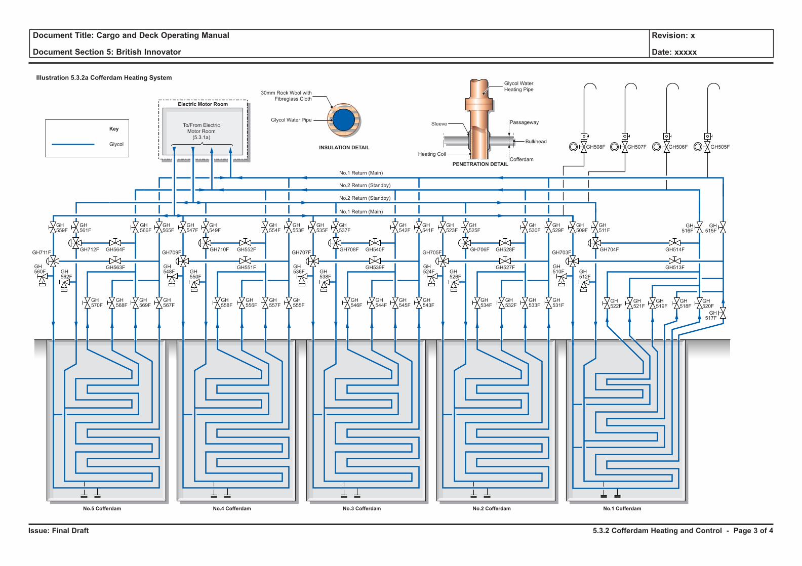
Issue: Final Draft
Document Title: Cargo and Deck Operating Manual
Document Section 5: British Innovator
Revision: x
Date: xxxxx
Illustration 5.3.2a Cofferdam Heating System
No.5 Cofferdam
Electric Motor Room
No.4 Cofferdam No.3 Cofferdam No.2 Cofferdam No.1 Cofferdam
No.1 Return (Main)
No.2 Return (Standby)
No.2 Return (Standby)
No.1 Return (Main)
GH508F
Passageway
30mm Rock Wool withFibreglass Cloth
Glycol Water Pipe
CofferdamHeating Coil
GH522F
GH534F
GH532F
GH533F
GH531F
GH546F
GH544F
GH545F
GH543F
GH570F
GH568F
GH569F
GH567F
GH558F
GH556F
GH557F
GH555F
GH521F
GH519F
GH509F
GH511F
GH529F
GH530F
GH523F
GH525F
GH535F
GH537F
GH547F
GH549F
GH566F
GH565F
GH541F
GH542F
GH561F
GH559F
GH553F
GH554F
GH512F
GH510FGH
538F
GH536FGH
562F
GH560F GH
550F
GH548F GH
526F
GH524F
GH518F
GH520FGH
517F
GH515F
GH516F
GH507F GH506F
GH514FGH703F GH704FGH707F GH708FGH709F GH710FGH711F GH712F GH705F GH706F
GH513F
GH528F
GH527F
GH540F
GH539F
GH552F
GH551F
GH564F
GH563F
GH505FGlycol
KeyTo/From ElectricMotor Room(5.3.1a)
PENETRATION DETAIL
INSULATION DETAILBulkhead
Sleeve
Glycol WaterHeating Pipe
5.3.2 Cofferdam Heating and Control - Page 3 of 4
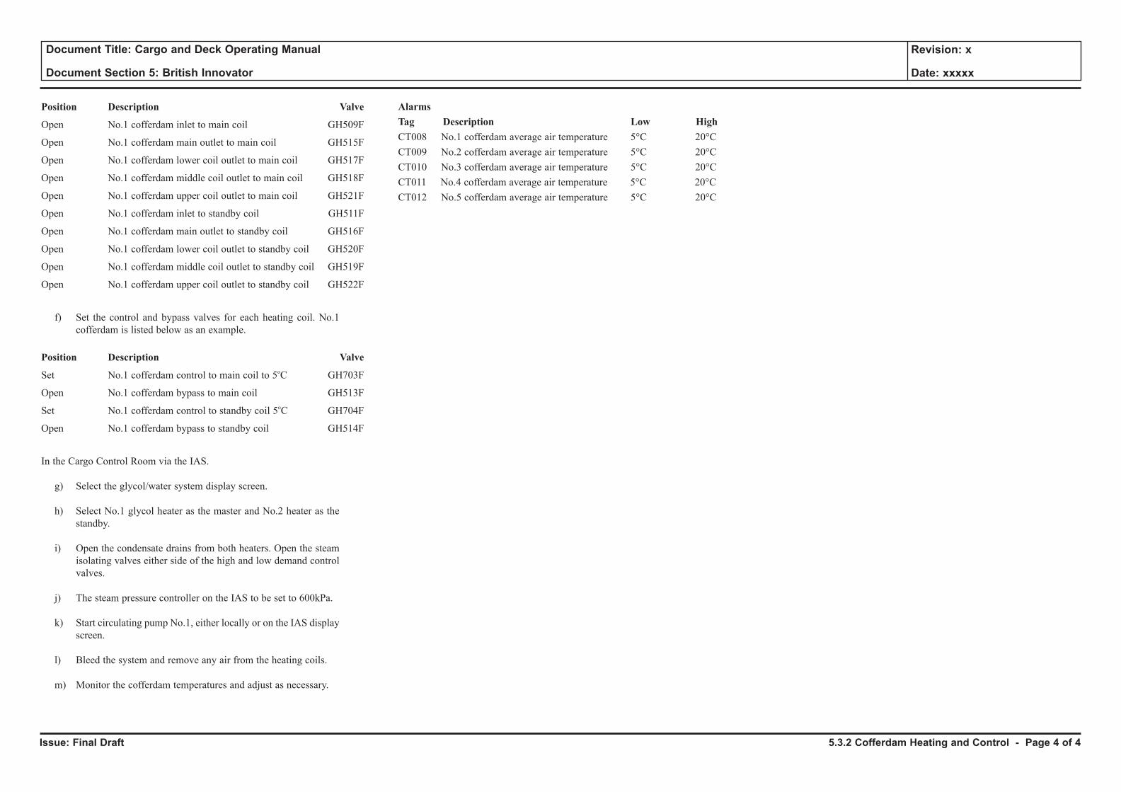
Issue: Final Draft
Document Title: Cargo and Deck Operating Manual
Document Section 5: British Innovator
Revision: x
Date: xxxxx
Position Description Valve
Open No.1 cofferdam inlet to main coil GH509F
Open No.1 cofferdam main outlet to main coil GH515F
Open No.1 cofferdam lower coil outlet to main coil GH517F
Open No.1 cofferdam middle coil outlet to main coil GH518F
Open No.1 cofferdam upper coil outlet to main coil GH521F
Open No.1 cofferdam inlet to standby coil GH511F
Open No.1 cofferdam main outlet to standby coil GH516F
Open No.1 cofferdam lower coil outlet to standby coil GH520F
Open No.1 cofferdam middle coil outlet to standby coil GH519F
Open No.1 cofferdam upper coil outlet to standby coil GH522F
f) Set the control and bypass valves for each heating coil. No.1 cofferdam is listed below as an example.
Position Description Valve
Set No.1 cofferdam control to main coil to 5oC GH703F
Open No.1 cofferdam bypass to main coil GH513F
Set No.1 cofferdam control to standby coil 5oC GH704F
Open No.1 cofferdam bypass to standby coil GH514F
In the Cargo Control Room via the IAS.
g) Select the glycol/water system display screen.
h) Select No.1 glycol heater as the master and No.2 heater as the standby.
i) Open the condensate drains from both heaters. Open the steam isolating valves either side of the high and low demand control valves.
j) The steam pressure controller on the IAS to be set to 600kPa.
k) Start circulating pump No.1, either locally or on the IAS display screen.
l) Bleed the system and remove any air from the heating coils.
m) Monitor the cofferdam temperatures and adjust as necessary.
AlarmsTag Description Low HighCT008 No.1 cofferdam average air temperature 5°C 20°CCT009 No.2 cofferdam average air temperature 5°C 20°CCT010 No.3 cofferdam average air temperature 5°C 20°CCT011 No.4 cofferdam average air temperature 5°C 20°CCT012 No.5 cofferdam average air temperature 5°C 20°C
5.3.2 Cofferdam Heating and Control - Page 4 of 4
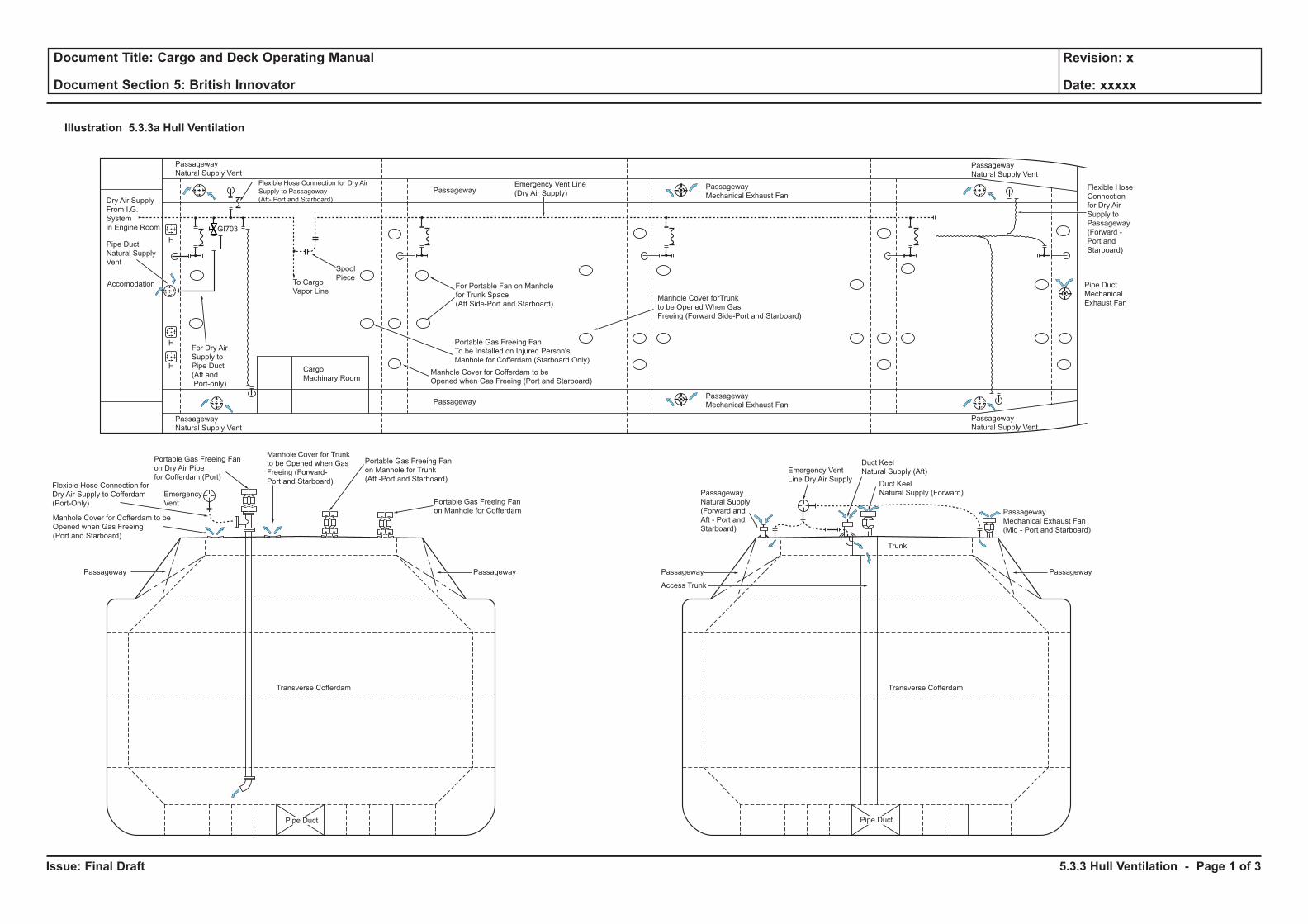
Issue: Final Draft
Document Title: Cargo and Deck Operating Manual
Document Section 5: British Innovator
Revision: x
Date: xxxxx
Passageway
Mechanical Exhaust Fan
(Mid - Port and Starboard)
Trunk
Duct Keel
Natural Supply (Aft)
Duct Keel
Natural Supply (Forward)
Emergency Vent
Line Dry Air Supply
Passageway
Natural Supply
(Forward and
Aft - Port and
Starboard)
Pipe DuctPipe Duct
PassagewayPassageway PassagewayPassageway
Access Trunk
Portable Gas Freeing Fan
on Manhole for Cofferdam
Portable Gas Freeing Fan
on Manhole for Trunk
(Aft -Port and Starboard)
Manhole Cover for Trunk
to be Opened when Gas
Freeing (Forward-
Port and Starboard)
Portable Gas Freeing Fan
on Dry Air Pipe
for Cofferdam (Port)
Emergency
Vent
Flexible Hose Connection for
Dry Air Supply to Cofferdam
(Port-Only)
Manhole Cover for Cofferdam to be
Opened when Gas Freeing
(Port and Starboard)
Passageway
Mechanical Exhaust Fan
Passageway
Natural Supply Vent
Passageway
Natural Supply Vent
Pipe Duct
Mechanical
Exhaust Fan
Cargo
Machinary Room
Passageway
Passageway
H
H
H
Passageway
Mechanical Exhaust Fan
Flexible Hose
Connection
for Dry Air
Supply to
Passageway
(Forward -
Port and
Starboard)
Flexible Hose Connection for Dry Air
Supply to Passageway
(Aft- Port and Starboard)
Manhole Cover forTrunk
to be Opened When Gas
Freeing (Forward Side-Port and Starboard)
For Portable Fan on Manhole
for Trunk Space
(Aft Side-Port and Starboard)
Portable Gas Freeing Fan
To be Installed on Injured Person's
Manhole for Cofferdam (Starboard Only)
Manhole Cover for Cofferdam to be
Opened when Gas Freeing (Port and Starboard)
Emergency Vent Line
(Dry Air Supply)
To Cargo
Vapor Line
Spool
Piece
Dry Air Supply
From I.G.
System
in Engine Room
Pipe Duct
Natural Supply
Vent
For Dry Air
Supply to
Pipe Duct
(Aft and
Port-only)
Passageway
Natural Supply Vent
Passageway
Natural Supply Vent
GI703
Accomodation
Transverse Cofferdam Transverse Cofferdam
Illustration 5.3.3a Hull Ventilation
5.3.3 Hull Ventilation - Page 1 of 3
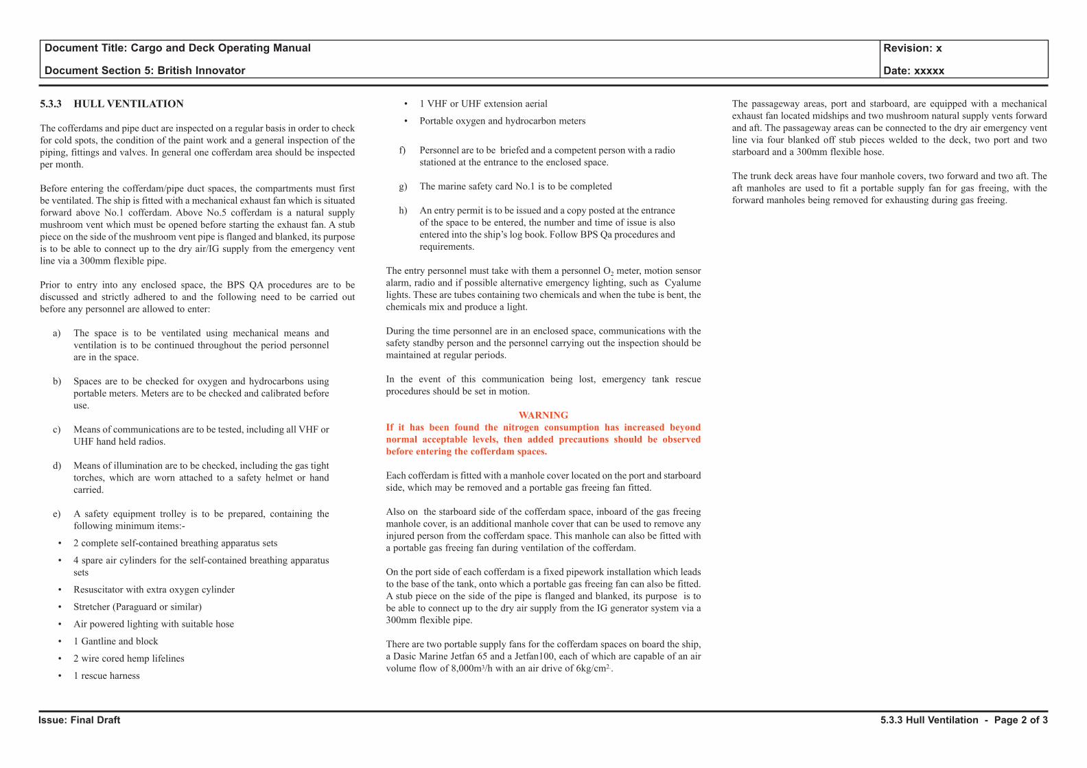
Issue: Final Draft
Document Title: Cargo and Deck Operating Manual
Document Section 5: British Innovator
Revision: x
Date: xxxxx
5.3.3 HULL VENTILATION
The cofferdams and pipe duct are inspected on a regular basis in order to check for cold spots, the condition of the paint work and a general inspection of the piping, fittings and valves. In general one cofferdam area should be inspected per month.
Before entering the cofferdam/pipe duct spaces, the compartments must first be ventilated. The ship is fitted with a mechanical exhaust fan which is situated forward above No.1 cofferdam. Above No.5 cofferdam is a natural supply mushroom vent which must be opened before starting the exhaust fan. A stub piece on the side of the mushroom vent pipe is flanged and blanked, its purpose is to be able to connect up to the dry air/IG supply from the emergency vent line via a 300mm flexible pipe.
Prior to entry into any enclosed space, the BPS QA procedures are to be discussed and strictly adhered to and the following need to be carried out before any personnel are allowed to enter:
a) The space is to be ventilated using mechanical means and ventilation is to be continued throughout the period personnel are in the space.
b) Spaces are to be checked for oxygen and hydrocarbons using portable meters. Meters are to be checked and calibrated before use.
c) Means of communications are to be tested, including all VHF or UHF hand held radios.
d) Means of illumination are to be checked, including the gas tight torches, which are worn attached to a safety helmet or hand carried.
e) A safety equipment trolley is to be prepared, containing the following minimum items:-
• 2 complete self-contained breathing apparatus sets
• 4 spare air cylinders for the self-contained breathing apparatus sets
• Resuscitator with extra oxygen cylinder
• Stretcher (Paraguard or similar)
• Air powered lighting with suitable hose
• 1 Gantline and block
• 2 wire cored hemp lifelines
• 1 rescue harness
• 1 VHF or UHF extension aerial
• Portable oxygen and hydrocarbon meters
f) Personnel are to be briefed and a competent person with a radio stationed at the entrance to the enclosed space.
g) The marine safety card No.1 is to be completed
h) An entry permit is to be issued and a copy posted at the entrance of the space to be entered, the number and time of issue is also entered into the ship’s log book. Follow BPS Qa procedures and requirements.
The entry personnel must take with them a personnel O2 meter, motion sensor alarm, radio and if possible alternative emergency lighting, such as Cyalume lights. These are tubes containing two chemicals and when the tube is bent, the chemicals mix and produce a light.
During the time personnel are in an enclosed space, communications with the safety standby person and the personnel carrying out the inspection should be maintained at regular periods.
In the event of this communication being lost, emergency tank rescue procedures should be set in motion.
WARNINGIf it has been found the nitrogen consumption has increased beyond normal acceptable levels, then added precautions should be observed before entering the cofferdam spaces.
Each cofferdam is fitted with a manhole cover located on the port and starboard side, which may be removed and a portable gas freeing fan fitted.
Also on the starboard side of the cofferdam space, inboard of the gas freeing manhole cover, is an additional manhole cover that can be used to remove any injured person from the cofferdam space. This manhole can also be fitted with a portable gas freeing fan during ventilation of the cofferdam.
On the port side of each cofferdam is a fixed pipework installation which leads to the base of the tank, onto which a portable gas freeing fan can also be fitted. A stub piece on the side of the pipe is flanged and blanked, its purpose is to be able to connect up to the dry air supply from the IG generator system via a 300mm flexible pipe.
There are two portable supply fans for the cofferdam spaces on board the ship, a Dasic Marine Jetfan 65 and a Jetfan100, each of which are capable of an air volume flow of 8,000m3/h with an air drive of 6kg/cm2..
The passageway areas, port and starboard, are equipped with a mechanical exhaust fan located midships and two mushroom natural supply vents forward and aft. The passageway areas can be connected to the dry air emergency vent line via four blanked off stub pieces welded to the deck, two port and two starboard and a 300mm flexible hose.
The trunk deck areas have four manhole covers, two forward and two aft. The aft manholes are used to fit a portable supply fan for gas freeing, with the forward manholes being removed for exhausting during gas freeing.
5.3.3 Hull Ventilation - Page 2 of 3
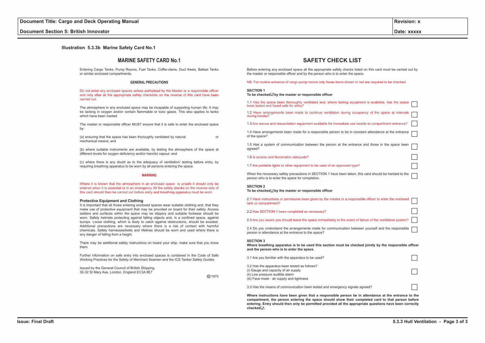
Issue: Final Draft
Document Title: Cargo and Deck Operating Manual
Document Section 5: British Innovator
Revision: x
Date: xxxxx
MARINE SAFETY CARD No.1
Entering Cargo Tanks, Pump Rooms, Fuel Tanks, Coffer-dams, Duct Keels, Ballast Tanks
or similar enclosed compartments.
GENERAL PRECAUTIONS
Do not enter any enclosed spaces unless authorised by the Master or a responsible officer
and only after all the appropriate safety checklists on the reverse of this card have been
carried out.
The atmosphere in any enclosed space may be incapable of supporting human life. It may
be lacking in oxygen and/or contain flammable or toxic gases. This also applies to tanks
which have been inerted.
The master or responsible officer MUST ensure that it is safe to enter the enclosed space
by:
(a) ensuring that the space has been thoroughly ventilated by natural or
mechanical means; and
(b) where suitable instruments are available, by testing the atmosphere of the space at
different levels for oxygen deficiency and/or harmful vapour; and
(c) where there is any doubt as to the adequacy of ventilation/ testing before entry, by
requiring breathing apparatus to be worn by all persons entering the space.
WARNING
Where it is known that the atmosphere in an enclosed space is unsafe it should only be
entered when it is essential or in an emergency. All the safety checks on the reverse side of
this card should then be carried out before entry and breathing apparatus must be worn.
Protective Equipment and ClothingIt is important that all those entering enclosed spaces wear suitable clothing and, that they
make use of protective equipment that may be provided on board for their safety. Access
ladders and surfaces within the space may be slippery and suitable footwear should be
worn. Safety helmets protecting against falling objects and, in a confined space, against
bumps. Loose clothing, which is likely to catch against obstructions, should be avoided.
Additional precautions are necessary where there is a risk of contact with harmful
chemicals. Safety harnesses/belts and lifelines should be worn and used where there is
any danger of falling from a height.
There may be additional safety instructions on board your ship, make sure that you know
them.
Further information on safe entry into enclosed spaces is contained in the Code of Safe
Working Practices for the Safety of Merchant Seamen and the ICS Tanker Safety Guides.
Issued by the General Council of British Shipping,
30-32 St Mary Axe, London, England EC3A 8ET
1975c
SAFETY CHECK LIST
Before entering any enclosed space all the appropriate safety checks listed on this card must be carried out by
the master or responsible officer and by the person who is to enter the space.
NB. For routine entrance of cargo pump rooms only those items shown in red are required to be checked.
SECTION 1
To be checked by the master or responsible officer
1.1 Has the space been thoroughly ventilated and, where testing equipment is available, has the spacebeen tested and found safe for entry?
1.2 Have arrangements been made to continue ventilation during occupancy of the space at intervalsduring breaks?
1.3 Are rescue and resuscitation equipment available for immediate use beside to compartment entrance?
1.4 Have arrangements been made for a responsible person to be in constant attendance at the entrance
of the space?
1.5 Has a system of communication between the person at the entrance and those in the space been
agreed?
1.6 Is access and illumination adequate?
1.7 Are portable lights or other equipment to be used of an approved type?
When the necessary safety precautions in SECTION 1 have been taken, this card should be handed to the
person who is to enter the space for completion.
SECTION 2
To be checked by the master or responsible officer
2.1 Have instructions or permission been given by the master or a responsible officer to enter the enclosed
tank or compartment?
2.2 Has SECTION 1 been completed as necessary?
2.3 Are you aware you should leave the space immediately in the event of failure of the ventilation system?
2.4 Do you understand the arrangements made for communication between yourself and the responsible
person in attendance at the entrance to the space?
SECTION 3
Where breathing apparatus is to be used this section must be checked jointly by the responsible officer
and the person who is to enter the space.
3.1 Are you familiar with the apparatus to be used?
3.2 Has the apparatus been tested as follows?
(i) Gauge and capacity of air supply
(ii) Low pressure audible alarm
(iii) Face mask - air supply and tightness
3.3 Has the means of communication been tested and emergency signals agreed?
Where instructions have been given that a responsible person be in attendance at the entrance to the
compartment, the person entering the space should show their completed card to that person before
entering. Entry should then only be permitted provided all the appropriate questions have been correctly
checked .
Illustration 5.3.3b Marine Safety Card No.1
5.3.3 Hull Ventilation - Page 3 of 3
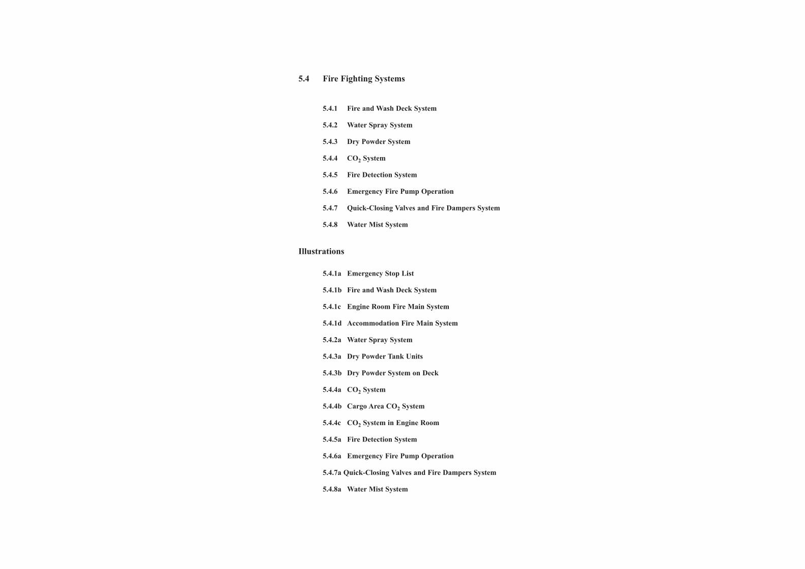
5.4 Fire Fighting Systems
5.4.1 Fire and Wash Deck System
5.4.2 Water Spray System
5.4.3 Dry Powder System
5.4.4 CO2 System
5.4.5 Fire Detection System
5.4.6 Emergency Fire Pump Operation
5.4.7 Quick-Closing Valves and Fire Dampers System
5.4.8 Water Mist System
Illustrations
5.4.1a Emergency Stop List
5.4.1b Fire and Wash Deck System
5.4.1c Engine Room Fire Main System
5.4.1d Accommodation Fire Main System
5.4.2a Water Spray System
5.4.3a Dry Powder Tank Units
5.4.3b Dry Powder System on Deck
5.4.4a CO2 System
5.4.4b Cargo Area CO2 System
5.4.4c CO2 System in Engine Room
5.4.5a Fire Detection System
5.4.6a Emergency Fire Pump Operation
5.4.7a Quick-Closing Valves and Fire Dampers System
5.4.8a Water Mist System
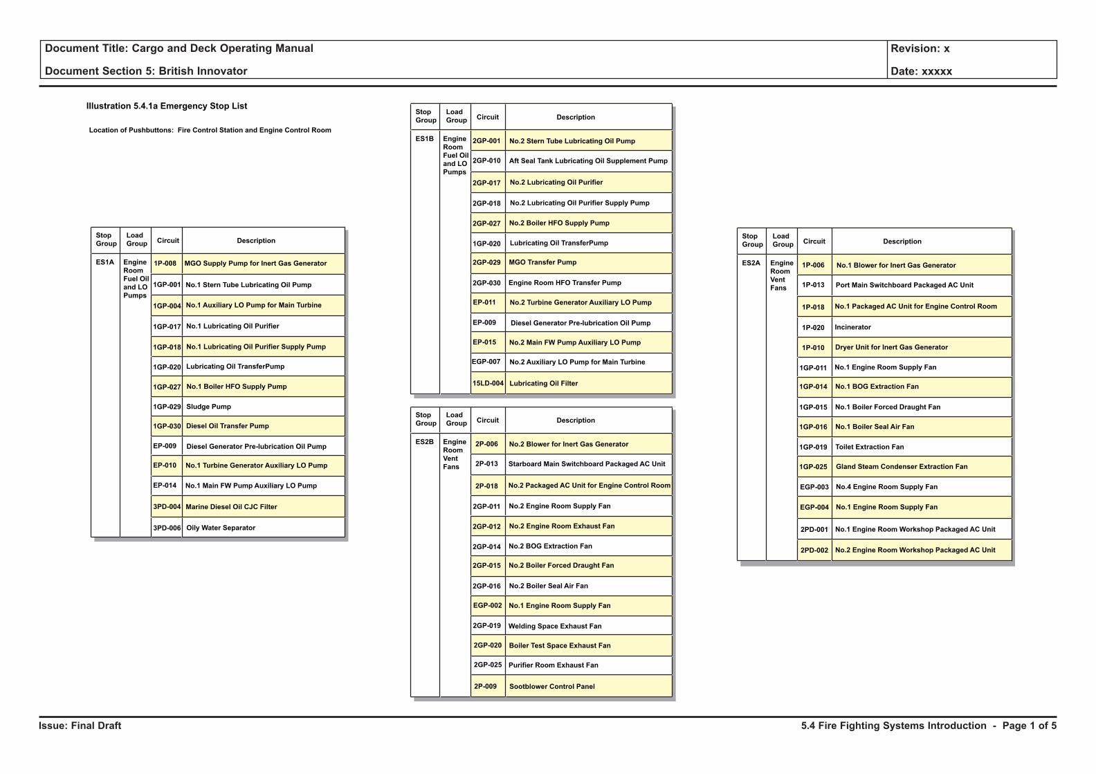
Issue: Final Draft
Document Title: Cargo and Deck Operating Manual
Document Section 5: British Innovator
Revision: x
Date: xxxxx
Illustration 5.4.1a Emergency Stop List
Stop
Group
Load
Group Circuit Description
No.1 Stern Tube Lubricating Oil Pump
MGO Supply Pump for Inert Gas Generator1P-008
1GP-001
1GP-004
1GP-017
1GP-018
1GP-020
1GP-027
1GP-029
1GP-030
EP-009
EP-010
EP-014
3PD-004
3PD-006
ES1A Engine
Room
Fuel Oil
and LO
Pumps
No.1 Lubricating Oil Purifier
No.1 Auxiliary LO Pump for Main Turbine
No.1 Lubricating Oil Purifier Supply Pump
Lubricating Oil TransferPump
No.1 Boiler HFO Supply Pump
Sludge Pump
Diesel Oil Transfer Pump
Diesel Generator Pre-lubrication Oil Pump
No.1 Turbine Generator Auxiliary LO Pump
No.1 Main FW Pump Auxiliary LO Pump
Marine Diesel Oil CJC Filter
Oily Water Separator
Stop
Group
Load
Group Circuit Description
Location of Pushbuttons: Fire Control Station and Engine Control Room
No.2 Stern Tube Lubricating Oil Pump2GP-001
Aft Seal Tank Lubricating Oil Supplement Pump2GP-010
EGP-007
2GP-017
2GP-018
1GP-020
2GP-027
2GP-030
EP-009
EP-011
EP-015
15LD-004
ES1B Engine
Room
Fuel Oil
and LO
Pumps
No.2 Lubricating Oil Purifier
No.2 Auxiliary LO Pump for Main Turbine
No.2 Lubricating Oil Purifier Supply Pump
Lubricating Oil TransferPump
No.2 Boiler HFO Supply Pump
2GP-029 MGO Transfer Pump
Engine Room HFO Transfer Pump
Diesel Generator Pre-lubrication Oil Pump
No.2 Turbine Generator Auxiliary LO Pump
No.2 Main FW Pump Auxiliary LO Pump
Lubricating Oil Filter
Stop
Group
Load
Group Circuit Description
No.1 Blower for Inert Gas Generator1P-006
Port Main Switchboard Packaged AC Unit
No.1 Packaged AC Unit for Engine Control Room
1P-013
1P-018
1P-020
1GP-011
1P-010
1GP-015
ES2A Engine
Room
Vent
Fans
Incinerator
No.1 Engine Room Supply Fan
Dryer Unit for Inert Gas Generator
1GP-014 No.1 BOG Extraction Fan
No.1 Boiler Forced Draught Fan
1GP-016 No.1 Boiler Seal Air Fan
1GP-019 Toilet Extraction Fan
1GP-025 Gland Steam Condenser Extraction Fan
EGP-003 No.4 Engine Room Supply Fan
EGP-004 No.1 Engine Room Supply Fan
2PD-001 No.1 Engine Room Workshop Packaged AC Unit
2PD-002 No.2 Engine Room Workshop Packaged AC Unit
Stop
Group
Load
Group Circuit Description
No.2 Blower for Inert Gas Generator2P-006
Starboard Main Switchboard Packaged AC Unit2P-013
2GP-025
2P-018
2GP-011
2GP-014
2GP-012
2GP-016
2GP-019
EGP-002
2GP-020
2P-009
ES2B Engine
Room
Vent
Fans
No.2 Packaged AC Unit for Engine Control Room
Purifier Room Exhaust Fan
No.2 Engine Room Supply Fan
No.2 BOG Extraction Fan
No.2 Engine Room Exhaust Fan
2GP-015 No.2 Boiler Forced Draught Fan
No.2 Boiler Seal Air Fan
Welding Space Exhaust Fan
No.1 Engine Room Supply Fan
Boiler Test Space Exhaust Fan
Sootblower Control Panel
5.4 Fire Fighting Systems Introduction - Page 1 of 5
Issue: Final Draft
Document Title: Cargo and Deck Operating Manual
Document Section 5: British Innovator
Revision: x
Date: xxxxx
5.4 FIRE FIGHTING SYSTEMS
INTRODUCTION
The vessel’s fire fighting capacity is enhanced by the inclusion of systems that can detect and fight the types of fires which might occur due to the ignition of fuel oil, lubricating oil and cargo. The choice of fire fighting system to use will depend on the location and nature of the fire. Initially any fire is attacked using portable extinguishers and if that method fails the following systems are considered. The use of fire fighting equipment and fire fighting techniques are discussed fully in the SOLAS FIRE TRAINING MANUAL which is available in the ship's general office.
Portable Fire Extinguishers
There are three types on board:
1. Carbon Dioxide - CO2
• Suitable for class A and B fires and for class C fires when in a liquid state, such as liquid gas leak.
• Safe for use in fighting electrical fires.
• May not be effective when used outside, especially in a breeze.
Identification Colour Code
The extinguisher is red with a black horizontal band and has CO2 written in white bold lettering.
Dangers in Use
• Hold only the insulated parts of the discharge hose and horn. With the expansion and evaporation of the CO2 there are cooling processes and a danger of frost burn if the discharge horn comes into contact with the skin.
• When using a CO2 extinguisher in an explosive atmosphere, stand on the ground to ensure that any electrostatic charge is dissipated.
• Do not use without a discharge horn as the discharge will then entrain air and cause an increase in the intensity of the fire.
• Do not remain in the area after the discharge as CO2 is asphyxiating.
Operating Procedure
a) Remove the safety pin.
b) Direct the horn at the base of the fire.
c) Press the lever down fully.
d) Direct the CO2 at the base of the fire.
2. Foam
• Suitable for use on liquid spills and contained liquid fire of oils, paints, cleaning fluids and fires involving liquified solids such as fats and waxes (Class B fires).
Identification Colour Code
The extinguisher is red with a yellow horizontal band and has FOAM written in white bold lettering.
Dangers in Use
• Do not use on fires where there is live electricity in the vicinity.
Operating Procedure
a) Remove the safety pin.
b) Press the operating handle.
c) Squeeze the trigger.
d) Point the spray at the base of the fire.
3. Dry Powder
• Suitable for use on fires involving liquids and liquified solids.
• Suitable for use, with the correct techique, on extinuishing a high pressure gas flame (Class C Fires).
• Suitable for use against carbonaceous fires (Class A fires).
• Dry powder gives a fast flame knock-down and may be used on fires involving live electrical equipment.
Identification Colour Code
The extinguisher is red with a blue horizontal band and has POWDER written in white bold lettering.
Dangers in Use
• May not be effective against a deep seated fire.
• Avoid inhalation of the powder.
Operating Procedure
a) Remove the safety pin.
b) Press the operating handle.
c) Squeeze the trigger.
b) Point the spray at the base of the fire.
Fire Main System (see section 5.4.1)
This system is continually pressurised by a sea water hydrophore tank and fire jockey pump (7.5kW). The jockey pump only supplies a limited number of 20mm accommodation hoses so the fire pump is started at the earliest opportunity to ensure that a sufficient amount of sea water is available. The automatic start facility, due to a low firemain pressure, is not used because the pump will run without a fire hydrant outlet available and may damage the pump seals. The system can also be supplied by the bilge, fire and GS pumps, the water spray pump and the emergency fire pump.
The suction and discharge valves of the fire pump and one bilge, fire and GS pump are locked in the open position and the pumps can be started locally, at the fire control station, cargo control room, at No.2 group starter panel or at the bridge emergency console.
The pipelines and fittings are painted red and fire hoses and hydrants are startegically positioned in the engine room, accommodation and on deck.
5.4 Fire Fighting Systems Introduction - Page 2 of 5
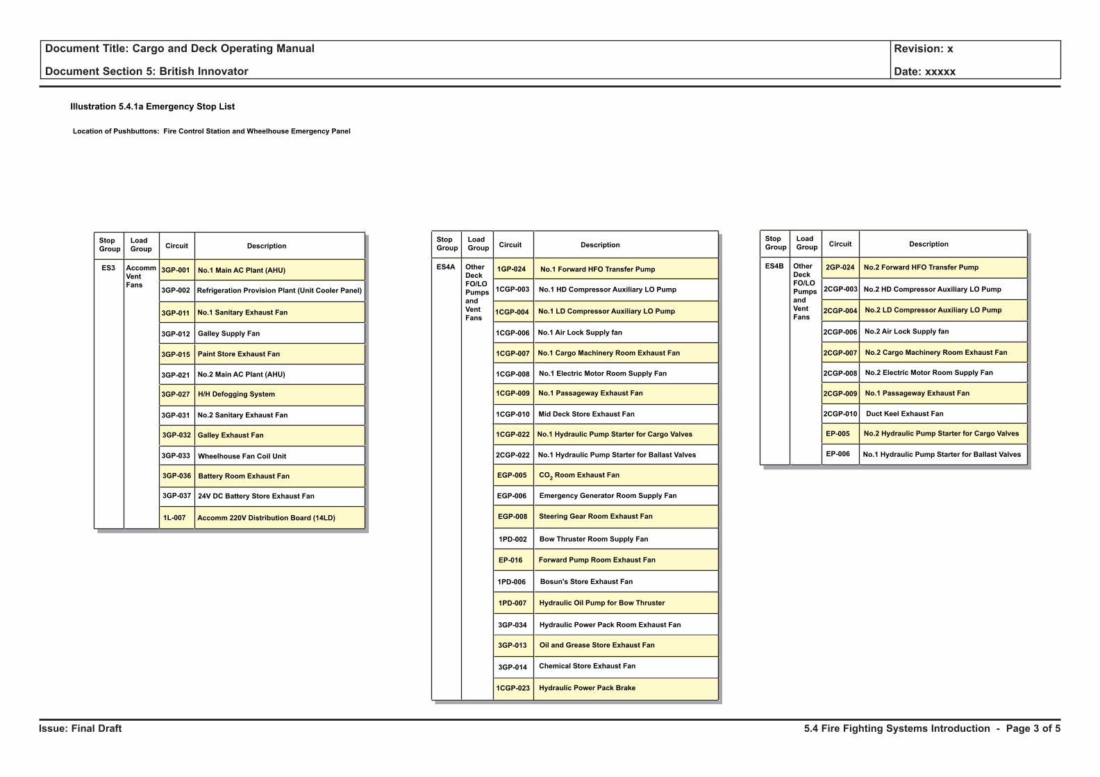
Issue: Final Draft
Document Title: Cargo and Deck Operating Manual
Document Section 5: British Innovator
Revision: x
Date: xxxxx
Illustration 5.4.1a Emergency Stop List
Stop
Group
Load
Group Circuit Description
No.2 HD Compressor Auxiliary LO Pump
No.2 Forward HFO Transfer Pump2GP-024
2CGP-003
2CGP-004
2CGP-006
2CGP-007
2CGP-008
2CGP-009
2CGP-010
EP-005
EP-006
ES4B Other
Deck
FO/LO
Pumps
and
Vent
Fans
No.2 Air Lock Supply fan
No.2 LD Compressor Auxiliary LO Pump
No.2 Cargo Machinery Room Exhaust Fan
No.2 Electric Motor Room Supply Fan
No.1 Passageway Exhaust Fan
Duct Keel Exhaust Fan
No.2 Hydraulic Pump Starter for Cargo Valves
No.1 Hydraulic Pump Starter for Ballast Valves
Location of Pushbuttons: Fire Control Station and Wheelhouse Emergency Panel
Stop
Group
Load
Group Circuit Description
No.1 Forward HFO Transfer Pump1GP-024
No.1 HD Compressor Auxiliary LO Pump
No.1 LD Compressor Auxiliary LO Pump
1CGP-003
1CGP-004
1CGP-006
1CGP-008
1CGP-007
1CGP-010
ES4A Other
Deck
FO/LO
Pumps
and
Vent
Fans
No.1 Air Lock Supply fan
No.1 Electric Motor Room Supply Fan
No.1 Cargo Machinery Room Exhaust Fan
1CGP-009 No.1 Passageway Exhaust Fan
Mid Deck Store Exhaust Fan
1CGP-022 No.1 Hydraulic Pump Starter for Cargo Valves
2CGP-022 No.1 Hydraulic Pump Starter for Ballast Valves
EGP-005 CO2Room Exhaust Fan
EGP-006 Emergency Generator Room Supply Fan
EGP-008 Steering Gear Room Exhaust Fan
1PD-002 Bow Thruster Room Supply Fan
EP-016 Forward Pump Room Exhaust Fan
1PD-006 Bosun's Store Exhaust Fan
1PD-007 Hydraulic Oil Pump for Bow Thruster
3GP-034 Hydraulic Power Pack Room Exhaust Fan
3GP-013 Oil and Grease Store Exhaust Fan
3GP-014 Chemical Store Exhaust Fan
1CGP-023 Hydraulic Power Pack Brake
Stop
Group
Load
Group Circuit Description
No.1 Main AC Plant (AHU)3GP-001
Refrigeration Provision Plant (Unit Cooler Panel)3GP-002
3GP-037
3GP-011
3GP-012
3GP-021
3GP-015
3GP-031
3GP-033
3GP-032
3GP-036
1L-007
ES3 Accomm
Vent
Fans
No.1 Sanitary Exhaust Fan
24V DC Battery Store Exhaust Fan
Galley Supply Fan
No.2 Main AC Plant (AHU)
Paint Store Exhaust Fan
3GP-027 H/H Defogging System
No.2 Sanitary Exhaust Fan
Wheelhouse Fan Coil Unit
Galley Exhaust Fan
Battery Room Exhaust Fan
Accomm 220V Distribution Board (14LD)
5.4 Fire Fighting Systems Introduction - Page 3 of 5
Issue: Final Draft
Document Title: Cargo and Deck Operating Manual
Document Section 5: British Innovator
Revision: x
Date: xxxxx
Water Spray System (see section 5.4.2)
In the event of a fire on deck, the water spray system is used for cooling and drenching the effected areas. A water spray pump situated in the engine room, with a back-up pump situated in the steering gear room for the lifeboat area, supplies sea water to the spray nozzles at the following group locations:
• Group 1 - accommodation exterior bulkheads and lifeboat stations
• Group 2 - cargo machinery and electric motor room exterior bulkheads
• Group 3 - cargo manifold area
• Group 4 - cargo tank liquid and gas domes
Dry Powder System (see Section 5.4.3)
The cargo manifold areas are protected by dry powder monitors which are situated just aft of the cargo discharge manifold and aligned to face and cover the liquid and vapour lines and valves at either the port or starboard manifold.
The monitors are supplied by two tanks containing the sodium bicarbarbonate connected to a battery of N2 cylinders which are operated by CO2 cylinders from either the cargo control room, the fire control station or locally.
The N2 cylinders can be opened either manually or remotely from six positions, they can also be cross-connected. Activation of any CO2 bottle and operation of the ball valve will open the N2 battery bank and start the fire fighting operation.
This system also comprises of two tanks containing the dry powder feeding 4 hose reels each. Operation is the same as for the monitors; on opening the CO2 cylinders and ball valves the N2 cylinders are opened and fire fighting begins.
CO2 Flooding System for the Engine Room (see section 5.4.4)
A central bank of 576 cylinders each containing 45kg of CO2 located in the CO2 room, is situated on the starboard side of the engine casing on A deck. The system protects the engine room, No.1 and No.2 main switchboard rooms, purifier room, diesel generator room and the inert gas generator room.
Outlets for CO2 are located in the protected spaces so as to give an even spread of CO2 quickly throughout the compartment when the gas is released.The system can be operated from the following positions:
• Engine room - fire control station or the CO2 room
• No.1 and No.2 main switchbaord rooms - fire control station or at the entrance to the rooms
• Purifier room - fire control station or at the entrance to the room
• Diesel generator room - fire control station or at the entrance to the room
• Inert gas generator room - fire control station or at the entrance to the room
CO2 Flooding System for the Cargo Area (see section 5.4.4)
A central bank of 22 cylinders each containing 45kg of CO2 located in the CO2 room, is situated on the starboard side of the engine casing on A deck. The system protects the port and starboard cargo switchboard, cargo machinery room, electric motor room, emergency generator room and the emergency switchboard room.
CO2 Flooding System for the Deck Stores (see section 5.4.4)
Each store has a cylinder containing 45kg of CO2 located outside the store room. The system protects the paint store, chemical store and the oil/grease store.
Emergency Fire Pump (see Section 5.4.6)
A self-contained emergency fire pump is fitted in the bosun's store. The drive unit consists of a diesel engine, which drives the main pump, and the hydraulic pump which powers the hydraulic motor driving the feeding pump. The diesel engine, main fire pump, hydraulic pump and oil tank are located in the bosun’s store.
The feeding pump and its hydraulic drive motor are located at the bottom of the forward pump room below the waterline. The feeding pump is driven by the hydraulic motor operated by the oil from the hydraulic pump.
The feeding pump ensures that the main fire pump is supplied with water no matter what the draught of the ship.
The emergency fire pump may be started locally or remotely from the fire control station and the bridge emergency console.
Water Mist System (see section 5.4.8)
This system consists of fresh water at high pressure injected into the protected machinery space through special spray heads which break down the water stream into very fine mist-like particles.
The basic principle of the water mist system is that the very fine droplets of water tend to exclude oxygen from the area of the fire, thereby starving the burning material of oxygen. When the fine water droplets come into contact with the flames they are rapidly evaporated because of their large surface area for a small mass and this has a rapid cooling effect on the fire.
The steam produced by the evaporation acts to further reduce the space available for oxygen. Because the water is in mist form the system is effective for oil fires.
The system protects the incinerator room, hydraulic power pack room, port and starboard boiler burner platforms, inert gas generator room, the steering gear room, diesel generator room and the purifier room.
The system is self-contained and consists of a pump driven by an air motor, supplied by the control air system, which takes suction from the fresh water tanks and maintains the system pressure at 2.45MPa up to the control valves. From the control valves a set of piston type pumps driven by pressurised N2 cylinders, supply the fresh water at a rate of 11 litres/minute through each of the spray heads.
The system control valves can be activated locally or by pressing the operating pushbutton at each location.
Quick-Closing Valves and Fire Dampers System (see section 5.4.7)
This system is used, in the event of a major fire in the machinery spaces, to close the ventilation dampers and the outlet valves on the tanks containing fuel oil and lubricating oil. The system is operated from the fire control station where valves are positioned to direct the air, contained in a pressurised tank, to the quick-closing valves and to vent the damper cylinders. The pressurised tank is maintained at 9kg/cm2 by the control air system.
The emergency generator room fuel oil tank outlet valve is operated by wire rope and handle from outside the rooms.
A similar arrangement for the incinerator room DO tank and waste oil tank outlet valves is installed as a local back-up to the pneumatic system.
Fire Detection System (see section 5.4.5)
This system will raise an alarm to alert the ship’s staff and has a direct input into the IAS for recording any alarms, faults and disconnections. The operating panel, control unit and power supply are contained in a central cabinet in the fire control station on the port side of the accommodation on the upper deck. The system uses 8 detector loops, connected to a 7.2Ah battery system back-up in the event of a power failure and detects any source of smoke, heat or flames in the protected spaces.
The digital outputs of the system are used to stop the ventilation fans, release the fire doors and operate the water mist system. The system is looped to the gas sampling and alarm system and to the IAS cabinet in the electrical equipment room on A deck.
5.4 Fire Fighting Systems Introduction - Page 4 of 5
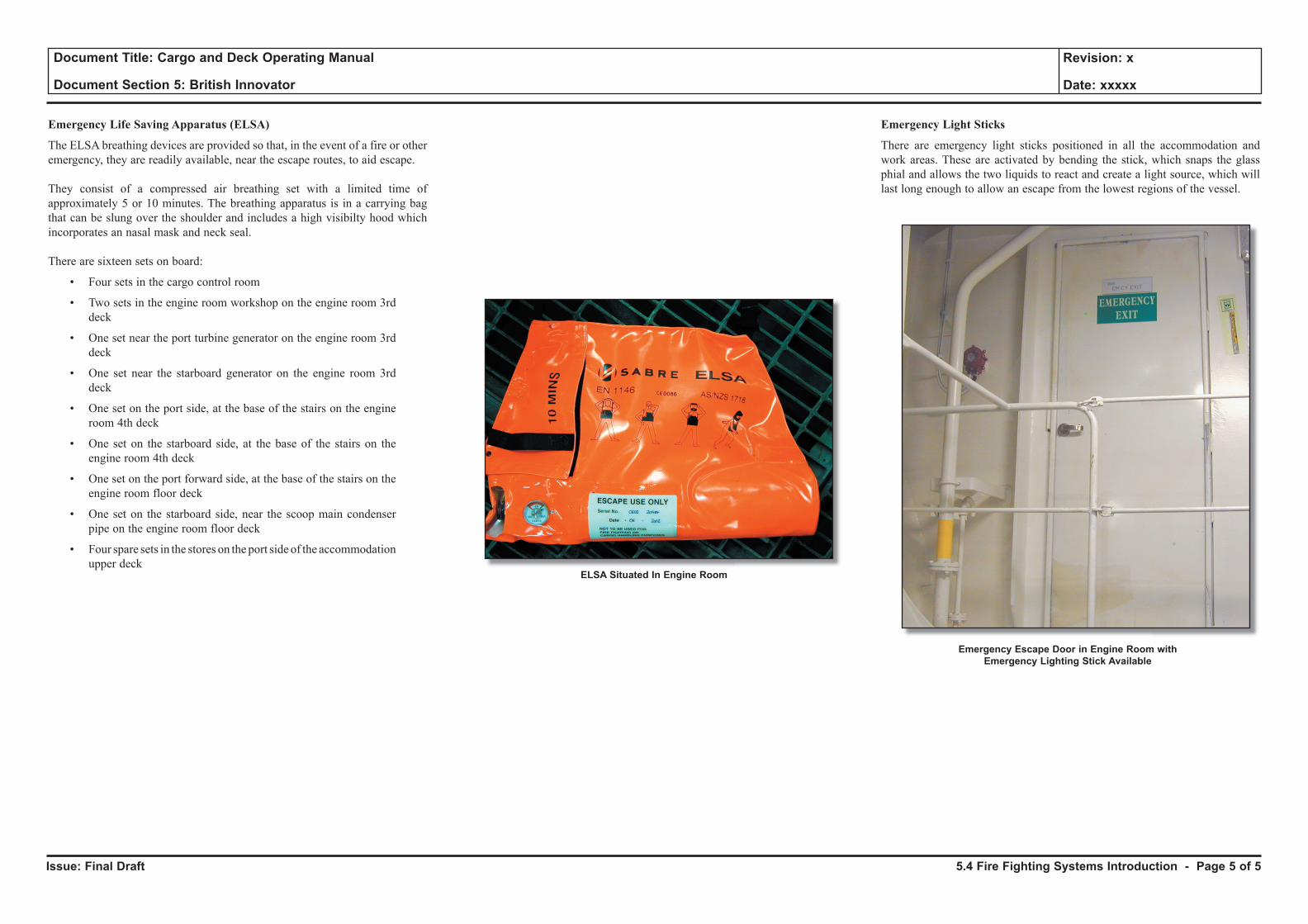
Issue: Final Draft
Document Title: Cargo and Deck Operating Manual
Document Section 5: British Innovator
Revision: x
Date: xxxxx
Emergency Life Saving Apparatus (ELSA)
The ELSA breathing devices are provided so that, in the event of a fire or other emergency, they are readily available, near the escape routes, to aid escape.
They consist of a compressed air breathing set with a limited time of approximately 5 or 10 minutes. The breathing apparatus is in a carrying bag that can be slung over the shoulder and includes a high visibilty hood which incorporates an nasal mask and neck seal.
There are sixteen sets on board:
• Four sets in the cargo control room
• Two sets in the engine room workshop on the engine room 3rd deck
• One set near the port turbine generator on the engine room 3rd deck
• One set near the starboard generator on the engine room 3rd deck
• One set on the port side, at the base of the stairs on the engine room 4th deck
• One set on the starboard side, at the base of the stairs on the engine room 4th deck
• One set on the port forward side, at the base of the stairs on the engine room floor deck
• One set on the starboard side, near the scoop main condenser pipe on the engine room floor deck
• Four spare sets in the stores on the port side of the accommodation upper deck
ELSA Situated In Engine Room
Emergency Light Sticks
There are emergency light sticks positioned in all the accommodation and work areas. These are activated by bending the stick, which snaps the glass phial and allows the two liquids to react and create a light source, which will last long enough to allow an escape from the lowest regions of the vessel.
Emergency Escape Door in Engine Room with Emergency Lighting Stick Available
5.4 Fire Fighting Systems Introduction - Page 5 of 5
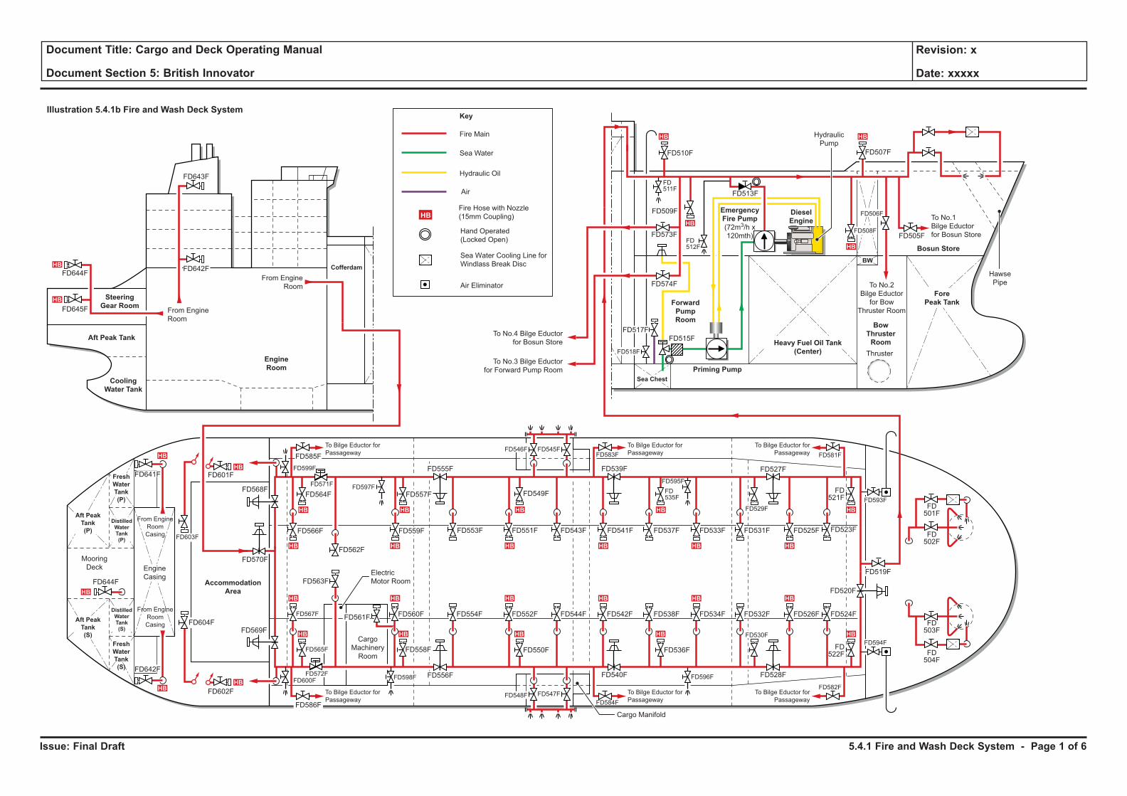
Issue: Final Draft
Document Title: Cargo and Deck Operating Manual
Document Section 5: British Innovator
Revision: x
Date: xxxxx
Illustration 5.4.1b Fire and Wash Deck System
HB HB
HBHB
HB HB
HB
HB
HBHBHB
HB
HB
HBHBHB
HB HBHBHBHBHB
HB
HB
HB
HB
HB
HB HBHBHBHBHB
From Engine
Room
From Engine
Room
Engine
Room
Cofferdam
Cooling
Water Tank
Aft Peak Tank
Accommodation
Area
Mooring
Deck
Steering
Gear Room
Fresh
Water
Tank
(P)
Fresh
Water
Tank
(S)
Aft Peak
Tank
(S)
Aft Peak
Tank
(P)
DistilledWaterTank(S)
DistilledWaterTank(P)
Engine
CasingElectric
Motor Room
Cargo
Machinery
Room
Cargo Manifold
To Bilge Eductor for
Passageway
To Bilge Eductor for
Passageway
To Bilge Eductor for
Passageway
To Bilge Eductor for
Passageway
To Bilge Eductor for
Passageway
To Bilge Eductor for
Passageway
Hydraulic
Pump
To No.4 Bilge Eductor
for Bosun Store
To No.1
Bilge Eductor
for Bosun Store
To No.2
Bilge Eductor
for Bow
Thruster Room
To No.3 Bilge Eductor
for Forward Pump Room
Hawse
Pipe
Thruster
Fore
Peak Tank
Bosun Store
Bow
Thruster
Room
Diesel
Engine
Heavy Fuel Oil Tank
(Center)
Forward
Pump
Room
Priming Pump
Sea Chest
BW
Emergency
Fire Pump
(72m3/h x
120mth)
Fire Main
Key
Fire Hose with Nozzle
(15mm Coupling)HB
Sea Water
Hydraulic Oil
Air
Hand Operated
(Locked Open)
Sea Water Cooling Line for
Windlass Break Disc
Air Eliminator
From Engine
Room
Casing
From Engine
Room
Casing
FD644F
FD645F
FD644F
FD643F
FD642F
FD641F
FD642F
FD603F
FD568F
FD604F
FD570F
FD602F
FD601F
FD585F
FD586F
FD565F
FD569F
FD567F
FD563F
FD564F
FD566F
FD562F
FD572F
FD571F
FD600F
FD599F
FD598F
FD597F
FD559F
FD557F
FD555F
FD556F
FD554F FD552F
FD551FFD553F
FD544F FD542F FD538F
FD537FFD541F
FD534F
FD533F
FD540F
FD539F
FD550F
FD549F
FD536FFD558F
FD560FFD561F
FD548F FD547F
FD584F
FD583F
FD596F
FD595F
FD535F
FD526F
FD525F
FD532F
FD531F
FD524F
FD522F
FD521F
FD503F
FD501F
FD502F
FD504F
FD530F
FD528F
FD527F
FD582F
FD581F
FD505F
FD507F
FD513F
FD573F
FD509F
FD574F
FD510F
FD594F
FD520F
FD519F
FD593F
FD523F
FD529F
FD543F
FD545FFD546F
FD506F
FD508F
FD511F
FD512F
FD517F
FD515F
FD518F
5.4.1 Fire and Wash Deck System - Page 1 of 6
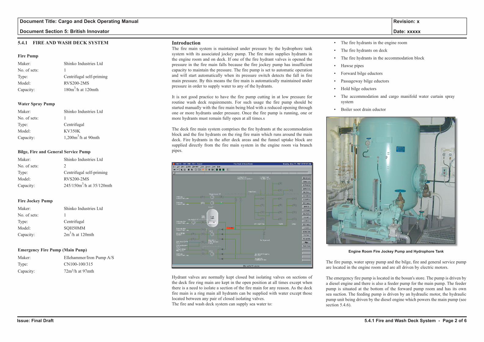
Issue: Final Draft
Document Title: Cargo and Deck Operating Manual
Document Section 5: British Innovator
Revision: x
Date: xxxxx
5.4.1 FIRE AND WASH DECK SYSTEM
Fire Pump
Maker: Shinko Industries LtdNo. of sets: 1Type: Centrifugal self-primingModel: RVS200-2MSCapacity: 180m3/h at 120mth
Water Spray Pump
Maker: Shinko Industries LtdNo. of sets: 1Type: CentrifugalModel: KV350KCapacity: 1,200m3/h at 90mth
Bilge, Fire and General Service Pump
Maker: Shinko Industries LtdNo. of sets: 2Type: Centrifugal self-primingModel: RVS200-2MSCapacity: 245/150m3/h at 35/120mth
Fire Jockey Pump
Maker: Shinko Industries LtdNo. of sets: 1Type: CentrifugalModel: SQH50MMCapacity: 2m3/h at 120mth
Emergency Fire Pump (Main Punp)
Maker: Ellehammer/Iron Pump A/SType: CN100-100/315Capacity: 72m3/h at 97mth
IntroductionThe fire main system is maintained under pressure by the hydrophore tank system with its associated jockey pump. The fire main supplies hydrants in the engine room and on deck. If one of the fire hydrant valves is opened the pressure in the fire main falls because the fire jockey pump has insufficient capacity to maintain the pressure. The fire pump is set to automatic operation and will start automatically when its pressure switch detects the fall in fire main pressure. By this means the fire main is automatically maintained under pressure in order to supply water to any of the hydrants.
It is not good practice to have the fire pump cutting in at low pressure for routine wash deck requirements. For such usage the fire pump should be started manually with the fire main being bled with a reduced opening through one or more hydrants under pressure. Once the fire pump is running, one or more hydrants must remain fully open at all times.s
The deck fire main system comprises the fire hydrants at the accommodation block and the fire hydrants on the ring fire main which runs around the main deck. Fire hydrants in the after deck areas and the funnel uptake block are supplied directly from the fire main system in the engine room via branch pipes.
Hydrant valves are normally kept closed but isolating valves on sections of the deck fire ring main are kept in the open position at all times except when there is a need to isolate a section of the fire main for any reason. As the deck fire main is a ring main all hydrants can be supplied with water except those located between any pair of closed isolating valves.The fire and wash deck system can supply sea water to:
• The fire hydrants in the engine room
• The fire hydrants on deck
• The fire hydrants in the accommodation block
• Hawse pipes
• Forward bilge eductors
• Passageway bilge eductors
• Hold bilge eductors
• The accommodation and cargo manifold water curtain spray system
• Boiler soot drain eductor
Engine Room Fire Jockey Pump and Hydrophore Tank
The fire pump, water spray pump and the bilge, fire and general service pump are located in the engine room and are all driven by electric motors.
The emergency fire pump is located in the bosun's store. The pump is driven by a diesel engine and there is also a feeder pump for the main pump. The feeder pump is situated at the bottom of the forward pump room and has its own sea suction. The feeding pump is driven by an hydraulic motor, the hydraulic pump unit being driven by the diesel engine which powers the main pump (see section 5.4.6).
5.4.1 Fire and Wash Deck System - Page 2 of 6
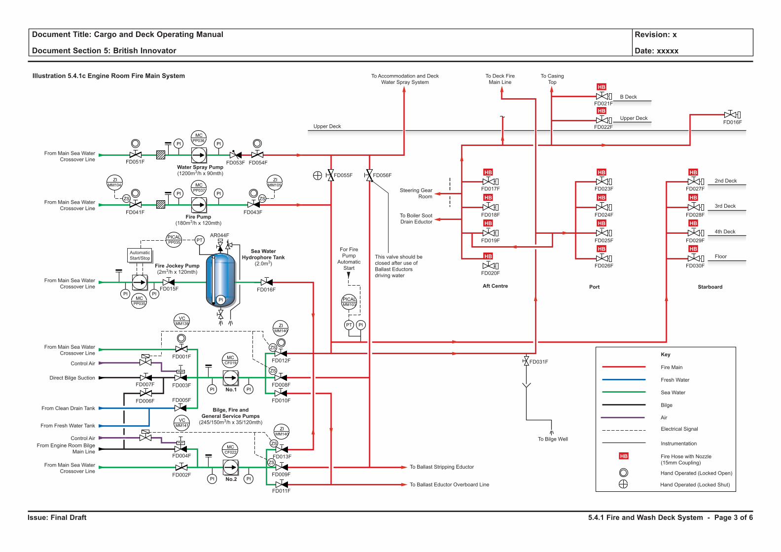
Issue: Final Draft
Document Title: Cargo and Deck Operating Manual
Document Section 5: British Innovator
Revision: x
Date: xxxxx
Illustration 5.4.1c Engine Room Fire Main System
PI
PI PI
PI
PI PI
PI
PI PI
PIPT
ZS
MCPP037
MCPP035
MCCF022
VCMM141
VCMM139
ZIMM140
Fire Main
Fresh Water
Sea Water
Bilge
Key
Electrical Signal
Instrumentation
Hand Operated (Locked Open)
MCCF019
PI
MCPP036
PICALPP035
PICALMM103
ZIMM105
ZS
ZIMM104
ZS
ZS
ZIMM140
ZS
ZS
Sea WaterHydrophore Tank
(2.0m3)
PT
PI
AutomaticStart/Stop
Water Spray Pump(1200m3/h x 90mth)
Fire Pump(180m3/h x 120mth)
Bilge, Fire andGeneral Service Pumps(245/150m3/h x 35/120mth)
Fire Jockey Pump(2m3/h x 120mth)
Air
Fire Hose with Nozzle(15mm Coupling)
No.1
No.2
For FirePump
AutomaticStart
Upper Deck
To Accommodation and DeckWater Spray System
Steering GearRoom
To Boiler SootDrain Eductor
This valve should beclosed after use ofBallast Eductorsdriving water
FD051F
FD041F
FD015F
FD007F
FD006F
FD001F
FD003F
FD012F FD031F
FD030F
FD029F
FD028F
FD027F
FD026F
FD025F
FD024F
FD023F
FD020F
FD019F
FD018F
FD017F
FD016FFD022F
FD021F
FD008F
FD010F
FD013F
FD009F
FD011F
FD004F
FD005F
FD002F
FD016F
FD055F FD056F
FD043F
AR044F
From Main Sea WaterCrossover Line
From Main Sea WaterCrossover Line
From Main Sea WaterCrossover Line
From Main Sea WaterCrossover Line
From Main Sea WaterCrossover Line
Control Air
Control Air
Direct Bilge Suction
From Clean Drain Tank
From Fresh Water Tank
From Engine Room BilgeMain Line
To Bilge Well
To Ballast Stripping Eductor
To Ballast Eductor Overboard Line
To Deck FireMain Line
To CasingTop
2nd Deck
B Deck
Upper Deck
3rd Deck
4th Deck
Floor
Starboard
HB
HB
HB
HB
HB
HB
HB
HB
HB
HB
HB
HB
HB
HB
HB
PortAft Centre
FD054FFD053F
Hand Operated (Locked Shut)
5.4.1 Fire and Wash Deck System - Page 3 of 6
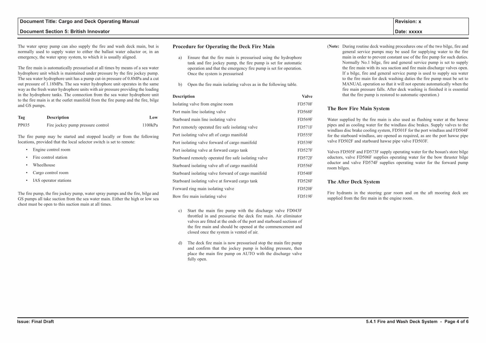
Issue: Final Draft
Document Title: Cargo and Deck Operating Manual
Document Section 5: British Innovator
Revision: x
Date: xxxxx
The water spray pump can also supply the fire and wash deck main, but is normally used to supply water to either the ballast water eductor or, in an emergency, the water spray system, to which it is usually aligned.
The fire main is automatically pressurised at all times by means of a sea water hydrophore unit which is maintained under pressure by the fire jockey pump. The sea water hydrophore unit has a pump cut-in pressure of 0.8MPa and a cut out pressure of 1.18MPa. The sea water hydrophore unit operates in the same way as the fresh water hydrophore units with air pressure providing the loading in the hydrophore tanks. The connection from the sea water hydrophore unit to the fire main is at the outlet manifold from the fire pump and the fire, bilge and GS pumps.
Tag Description Low
PP035 Fire jockey pump pressure control 1100kPa
The fire pump may be started and stopped locally or from the following locations, provided that the local selector switch is set to remote:
• Engine control room
• Fire control station
• Wheelhouse
• Cargo control room
• IAS operator stations
The fire pump, the fire jockey pump, water spray pumps and the fire, bilge and GS pumps all take suction from the sea water main. Either the high or low sea chest must be open to this suction main at all times.
Procedure for Operating the Deck Fire Main
a) Ensure that the fire main is pressurised using the hydrophore tank and fire jockey pump, the fire pump is set for automatic operation and that the emergency fire pump is set for operation. Once the system is pressurised
b) Open the fire main isolating valves as in the following table.
Description Valve
Isolating valve from engine room FD570F
Port main line isolating valve FD568F
Starboard main line isolating valve FD569F
Port remotely operated fire safe isolating valve FD571F
Port isolating valve aft of cargo manifold FD555F
Port isolating valve forward of cargo manifold FD539F
Port isolating valve at forward cargo tank FD527F
Starboard remotely operated fire safe isolating valve FD572F
Starboard isolating valve aft of cargo manifold FD556F
Starboard isolating valve forward of cargo manifold FD540F
Starboard isolating valve at forward cargo tank FD528F
Forward ring main isolating valve FD520F
Bow fire main isolating valve FD519F
c) Start the main fire pump with the discharge valve FD043F throttled in and pressurise the deck fire main. Air eliminator valves are fitted at the ends of the port and starboard sections of the fire main and should be opened at the commencement and closed once the system is vented of air.
d) The deck fire main is now pressurised stop the main fire pump and confirm that the jockey pump is holding pressure, then place the main fire pump on AUTO with the discharge valve fully open.
(Note: During routine deck washing procedures one of the two bilge, fire and general service pumps may be used for supplying water to the fire main in order to prevent constant use of the fire pump for such duties. Normally No.1 bilge, fire and general service pump is set to supply the fire main with its sea suction and fire main discharge valves open. If a bilge, fire and general service pump is used to supply sea water to the fire main for deck washing duties the fire pump must be set to MANUAL operation so that it will not operate automatically when the fire main pressure falls. After deck washing is finished it is essential that the fire pump is restored to automatic operation.)
The Bow Fire Main System
Water supplied by the fire main is also used as flushing water at the hawse pipes and as cooling water for the windlass disc brakes. Supply valves to the windlass disc brake cooling system, FD501F for the port windlass and FD504F for the starboard windlass, are opened as required, as are the port hawse pipe valve FD502F and starboard hawse pipe valve FD503F.
Valves FD505F and FD573F supply operating water for the bosun's store bilge eductors, valve FD506F supplies operating water for the bow thruster bilge eductor and valve FD574F supplies operating water for the forward pump room bilges.
The After Deck System
Fire hydrants in the steering gear room and on the aft mooring deck are supplied from the fire main in the engine room.
5.4.1 Fire and Wash Deck System - Page 4 of 6
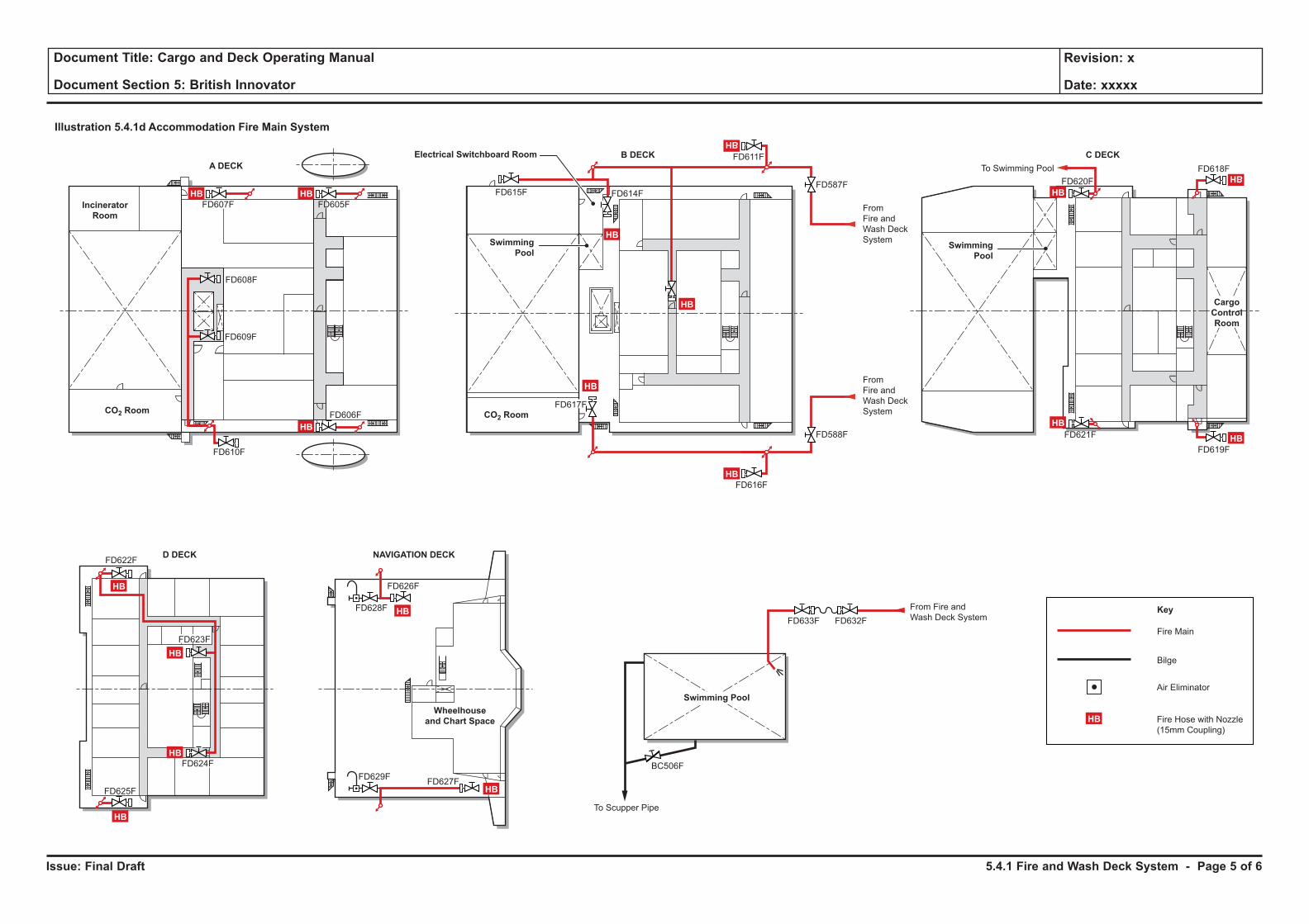
Issue: Final Draft
Document Title: Cargo and Deck Operating Manual
Document Section 5: British Innovator
Revision: x
Date: xxxxx
Illustration 5.4.1d Accommodation Fire Main System
A DECK
D DECK NAVIGATION DECK
B DECK C DECKElectrical Switchboard Room
Incinerator
Room
CO2 Room CO2 Room
Wheelhouse
and Chart Space
Fire Main
Bilge
Key
Air Eliminator
Fire Hose with Nozzle
(15mm Coupling)
HB
HB
HB
HB
HB
HB
HB
HB
HB
HB
HB
FD607F FD605F
FD608F
FD609F
FD610F
FD622F
FD606F
FD615F
FD611F
FD614F
FD617F
FD616F
FD633F FD632F
BC506F
From Fire and
Wash Deck System
From
Fire and
Wash Deck
System
From
Fire and
Wash Deck
System
To Scupper Pipe
FD626F
FD629FFD627F
FD628F
To Swimming Pool FD618F
FD619F
FD621F
FD620F
FD588F
FD587F
Swimming
Pool
HB
HB
HB
Swimming
Pool
Cargo
Control
Room
HB
HB
HB
FD623F
FD624F
FD625F HB
HB
Swimming Pool
5.4.1 Fire and Wash Deck System - Page 5 of 6
Issue: Final Draft
Document Title: Cargo and Deck Operating Manual
Document Section 5: British Innovator
Revision: x
Date: xxxxx
The Accommodation Block
Fire hydrants on the port and starboard sides of the accommodation block are supplied with water from the fire main and are used as required. The swimming pool is filled from the fire main. Air eliminator valves are fitted at the uppermost parts of the fire main at the accommodation block.
(Note: All hydrant valves should be opened at frequent intervals in order to ensure that they will be free should they be required in an emergency. Use of all deck valves should take place at least once every two months and this can be achieved during fire drills and normal deck washing procedures.)
With the accommodation, 20mm diameter hose reels, with attached spray/jet nozzles are strategically placed and can be served by the jockey pump hydrophore system in the first instance of accommodation fire fighting.
Cargo Manifold Water Curtains
The port and starboard cargo manifold side shell water curtains are supplied with water from the fire main. Each water curtain is supplied by means of two valves, one at each end of each water curtain. The valves are manually operated and the water curtains may also be supplied with fresh water.
Port Water Curtain ValvesFD546F and FD545F
Starboard Water Curtain ValvesFD548F and FD547F
The water curtain valves from the fire main are operated as required but the fire main must be pressurised as described above.
Hose Boxes
Hose boxes are located close to each fire hydrant. The hose box contains a fire hose with nozzle and standard fixture to the fire hydrant. Hoses and nozzles must be stored correctly after use.
The water spray pump may be controlled locally be setting its selector switch to LOCAL but it is normally operated from the central control room mimic panel and to allow for this the selector switch must be turned to the REMOTE position.
5.4.1 Fire and Wash Deck System - Page 6 of 6

Issue: Final Draft
Document Title: Cargo and Deck Operating Manual
Document Section 5: British Innovator
Revision: x
Date: xxxxx
Illustration 5.4.2a Water Spray System
Spray Line
Key
No.4
Cargo Tank
Steering Gear
Room
Cooling Water Tank
Cargo Machinery
Room
Electric
Motor
Room
From Main
Cross-over Line
Upper Deck
A - Deck
B - Deck
C - Deck
From Fire Pump
From Bilge, Fire
and General
Service Pump
No.3
Cargo Tank
No.2
Cargo TankNo.1
Cargo Tank
ACCOMMODATION FRONT WALL
TYPICAL SECTION
Air
Aft Peak Tank
No.4 Cargo TankEngine Room
Engine Room
Engine Room
PI
PI
PI
PI
Air
PORT SIDE
SP561F
SP562F
SP563F
SP564F
SP574F
SP575F SP609F
SP610FSP576F
FD053F FD054F
FD055F
FD056F
FD051F SP577F
SP551F
SP573F
SP607F
SP552F
Hand Operated (Locked Open)
Area protected by rundown from
higher spray areas.
Hand Operated (Locked Shut)
To No.1 Group for
Accommodation
From Water Spray
Pump in Engine Room
Nozzles for
Cargo Domes
Water Spray Pump
(350m3/h x 90mth)
Water
Spray Pump
(1200m3/h x
90mth)
SP591F
Cargo Manifold
(Port and Starboard)
For Cargo Manifold
For Cargo Manifold
For Cargo
Machinery Room
Cargo Machinery
Room
For Cargo Domes
Mooring Deck
Cofferdam
Cofferdam
To No.3 & 4 GroupFrom
Engine Room
Sea Chest
SP608F
SP551F SP552F
SP592F
SP594F
SP596F
SP595F
Bilge Hat
SP572F
SP571F SP605F
SP606F
SP541FSP531F
SP501F
SP502F
SP532FSP521F
SP522F
SP511F
SP512FSP542F
SP603FSP604F
SP601FSP602F
D - Deck
Navigation and
Bridge Deck
PassagewayPassageway
5.4.2 Water Spray System - Page 1 of 4
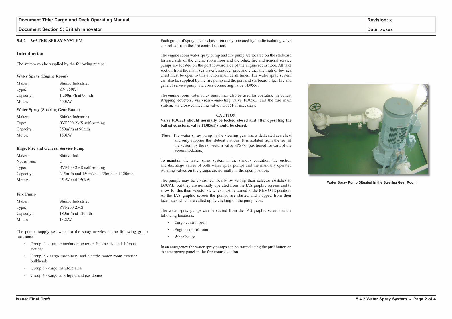
Issue: Final Draft
Document Title: Cargo and Deck Operating Manual
Document Section 5: British Innovator
Revision: x
Date: xxxxx
5.4.2 WATER SPRAY SYSTEM
Introduction
The system can be supplied by the following pumps:
Water Spray (Engine Room)
Maker: Shinko IndustriesType: KV 350KCapacity: 1,200m3/h at 90mthMotor: 450kW
Water Spray (Steering Gear Room)
Maker: Shinko IndustriesType: RVP200-2MS self-primingCapacity: 350m3/h at 90mthMotor: 150kW
Bilge, Fire and General Service Pump
Maker: Shinko Ind.No. of sets: 2Type: RVP200-2MS self-primingCapacity: 245m3/h and 150m3/h at 35mth and 120mthMotor: 45kW and 150kW
Fire Pump
Maker: Shinko IndustriesType: RVP200-2MSCapacity: 180m3/h at 120mthMotor: 132kW
The pumps supply sea water to the spray nozzles at the following group locations:
• Group 1 - accommodation exterior bulkheads and lifeboat stations
• Group 2 - cargo machinery and electric motor room exterior bulkheads
• Group 3 - cargo manifold area
• Group 4 - cargo tank liquid and gas domes
Each group of spray nozzles has a remotely operated hydraulic isolating valve controlled from the fire control station.
The engine room water spray pump and fire pump are located on the starboard forward side of the engine room floor and the bilge, fire and general service pumps are located on the port forward side of the engine room floor. All take suction from the main sea water crossover pipe and either the high or low sea chest must be open to this suction main at all times. The water spray system can also be supplied by the fire pump and the port and starboard bilge, fire and general service pump, via cross-connecting valve FD055F.
The engine room water spray pump may also be used for operating the ballast stripping eductors, via cross-connecting valve FD056F and the fire main system, via cross-connecting valve FD055F if necessary.
CAUTIONValve FD055F should normally be locked closed and after operating the ballast eductors, valve FD056F should be closed.
(Note: The water spray pump in the steering gear has a dedicated sea chest and only supplies the lifeboat stations. It is isolated from the rest of the system by the non-return valve SP577F positioned forward of the accommodation.)
To maintain the water spray system in the standby condition, the suction and discharge valves of both water spray pumps and the manually operated isolating valves on the groups are normally in the open position.
The pumps may be controlled locally by setting their selector switches to LOCAL, but they are normally operated from the IAS graphic screens and to allow for this their selector switches must be turned to the REMOTE position. At the IAS graphic screen the pumps are started and stopped from their faceplates which are called up by clicking on the pump icon.
The water spray pumps can be started from the IAS graphic screens at the following locations:
• Cargo control room
• Engine control room
• Wheelhouse
In an emergency the water spray pumps can be started using the pushbutton on the emergency panel in the fire control station.
5.4.2 Water Spray System - Page 2 of 4
Water Spray Pump Situated in the Steering Gear Room
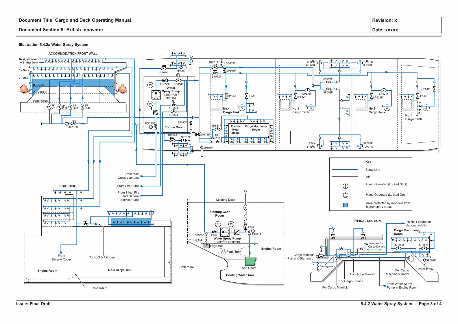
Issue: Final Draft
Document Title: Cargo and Deck Operating Manual
Document Section 5: British Innovator
Revision: x
Date: xxxxx
Illustration 5.4.2a Water Spray System
Spray Line
Key
No.4
Cargo Tank
Steering Gear
Room
Cooling Water Tank
Cargo Machinery
Room
Electric
Motor
Room
From Main
Cross-over Line
Upper Deck
A - Deck
B - Deck
C - Deck
From Fire Pump
From Bilge, Fire
and General
Service Pump
No.3
Cargo Tank
No.2
Cargo TankNo.1
Cargo Tank
ACCOMMODATION FRONT WALL
TYPICAL SECTION
Air
Aft Peak Tank
No.4 Cargo TankEngine Room
Engine Room
Engine Room
PI
PI
PI
PI
Air
PORT SIDE
SP561F
SP562F
SP563F
SP564F
SP574F
SP575F SP609F
SP610FSP576F
FD053F FD054F
FD055F
FD056F
FD051F SP577F
SP551F
SP573F
SP607F
SP552F
Hand Operated (Locked Open)
Area protected by rundown from
higher spray areas.
Hand Operated (Locked Shut)
To No.1 Group for
Accommodation
From Water Spray
Pump in Engine Room
Nozzles for
Cargo Domes
Water Spray Pump
(350m3/h x 90mth)
Water
Spray Pump
(1200m3/h x
90mth)
SP591F
Cargo Manifold
(Port and Starboard)
For Cargo Manifold
For Cargo Manifold
For Cargo
Machinery Room
Cargo Machinery
Room
For Cargo Domes
Mooring Deck
Cofferdam
Cofferdam
To No.3 & 4 GroupFrom
Engine Room
Sea Chest
SP608F
SP551F SP552F
SP592F
SP594F
SP596F
SP595F
Bilge Hat
SP572F
SP571F SP605F
SP606F
SP541FSP531F
SP501F
SP502F
SP532FSP521F
SP522F
SP511F
SP512FSP542F
SP603FSP604F
SP601FSP602F
D - Deck
Navigation and
Bridge Deck
PassagewayPassageway
5.4.2 Water Spray System - Page 3 of 4
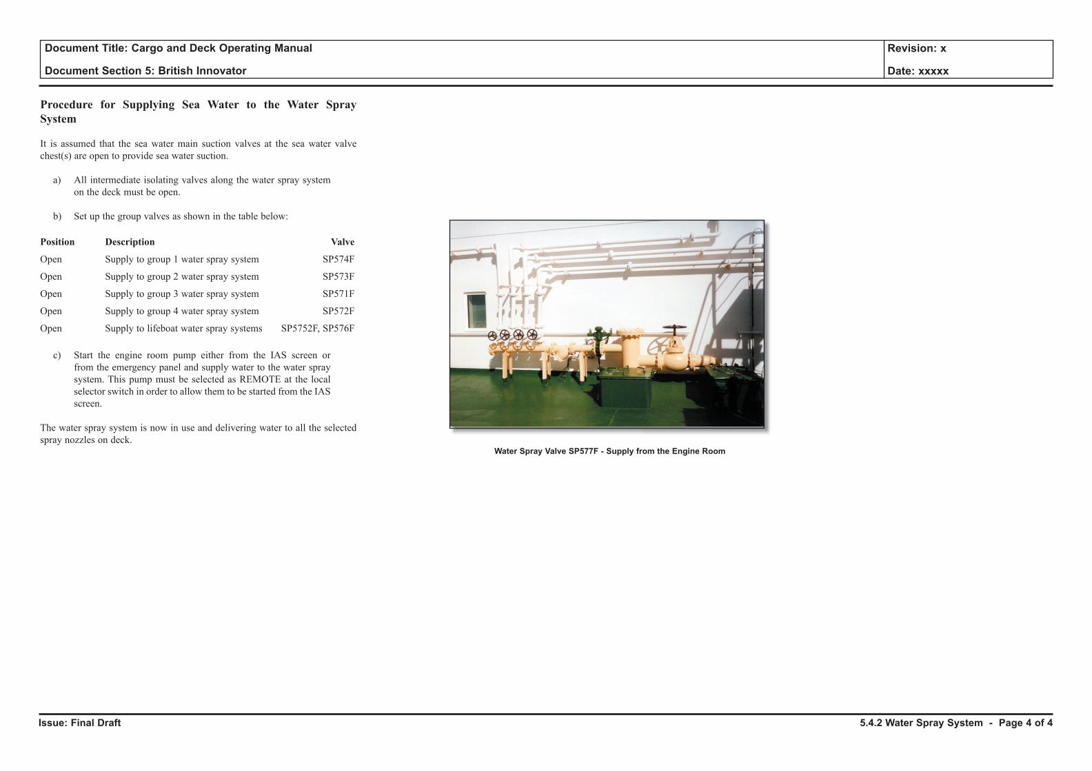
Issue: Final Draft
Document Title: Cargo and Deck Operating Manual
Document Section 5: British Innovator
Revision: x
Date: xxxxx
Procedure for Supplying Sea Water to the Water Spray System
It is assumed that the sea water main suction valves at the sea water valve chest(s) are open to provide sea water suction.
a) All intermediate isolating valves along the water spray system on the deck must be open.
b) Set up the group valves as shown in the table below:
Position Description Valve
Open Supply to group 1 water spray system SP574F
Open Supply to group 2 water spray system SP573F
Open Supply to group 3 water spray system SP571F
Open Supply to group 4 water spray system SP572F
Open Supply to lifeboat water spray systems SP5752F, SP576F
c) Start the engine room pump either from the IAS screen or from the emergency panel and supply water to the water spray system. This pump must be selected as REMOTE at the local selector switch in order to allow them to be started from the IAS screen.
The water spray system is now in use and delivering water to all the selected spray nozzles on deck.
Water Spray Valve SP577F - Supply from the Engine Room
5.4.2 Water Spray System - Page 4 of 4
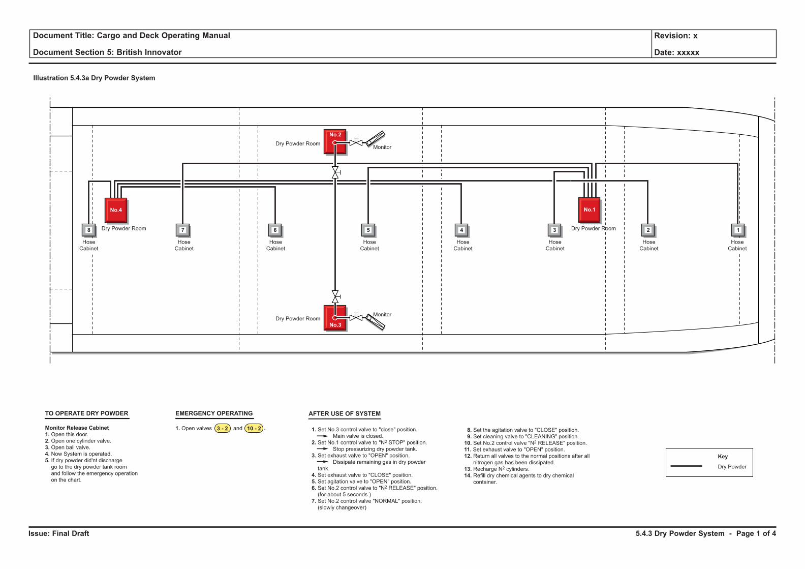
Issue: Final Draft
Document Title: Cargo and Deck Operating Manual
Document Section 5: British Innovator
Revision: x
Date: xxxxx
Illustration 5.4.3a Dry Powder System
TO OPERATE DRY POWDER
Monitor Release Cabinet
1. Open this door.
2. Open one cylinder valve.
3. Open ball valve.
4. Now System is operated.
5. If dry powder did'nt discharge
go to the dry powder tank room
and follow the emergency operation
on the chart.
1. Set No.3 control valve to "close" position.
Main valve is closed.
2. Set No.1 control valve to "N2 STOP" position.
Stop pressurizing dry powder tank.
3. Set exhaust valve to "OPEN" position.
Dissipate remaining gas in dry powder
tank.
4. Set exhaust valve to "CLOSE" position.
5. Set agitation valve to "OPEN" position.
6. Set No.2 control valve to "N2 RELEASE" position.
(for about 5 seconds.)
7. Set No.2 control valve "NORMAL" position.
(slowly changeover)
1. Open valves and
AFTER USE OF SYSTEMEMERGENCY OPERATING
3 - 2 10 - 2 .
Dry Powder
Key
8 7 6 5 4 3 12
No.4
No.2
No.3
No.1
Dry Powder Room Dry Powder Room
Dry Powder Room
Hose
Cabinet
Hose
Cabinet
Hose
Cabinet
Hose
Cabinet
Hose
Cabinet
Hose
Cabinet
Hose
Cabinet
Dry Powder Room
Hose
Cabinet
Monitor
Monitor
8. Set the agitation valve to "CLOSE" position.
9. Set cleaning valve to "CLEANING" position.
10. Set No.2 control valve "N2 RELEASE" position.
11. Set exhaust valve to "OPEN" position.
12. Return all valves to the normal positions after all
nitrogen gas has been dissipated.
13. Recharge N2 cylinders.
14. Refill dry chemical agents to dry chemical
container.
5.4.3 Dry Powder System - Page 1 of 4
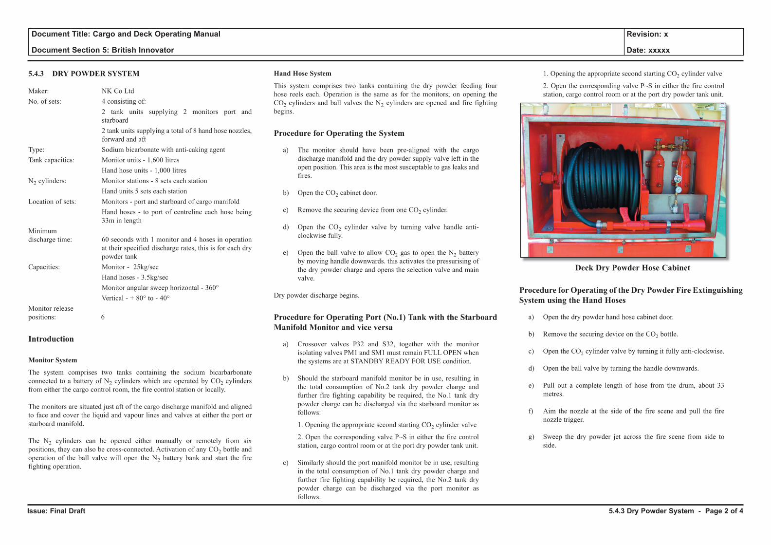
Issue: Final Draft
Document Title: Cargo and Deck Operating Manual
Document Section 5: British Innovator
Revision: x
Date: xxxxx
5.4.3 DRY POWDER SYSTEM
Maker: NK Co LtdNo. of sets: 4 consisting of: 2 tank units supplying 2 monitors port and
starboard 2 tank units supplying a total of 8 hand hose nozzles,
forward and aftType: Sodium bicarbonate with anti-caking agentTank capacities: Monitor units - 1,600 litres Hand hose units - 1,000 litresN2 cylinders: Monitor stations - 8 sets each station Hand units 5 sets each stationLocation of sets: Monitors - port and starboard of cargo manifold Hand hoses - to port of centreline each hose being
33m in length Minimumdischarge time: 60 seconds with 1 monitor and 4 hoses in operation
at their specified discharge rates, this is for each dry powder tank
Capacities: Monitor - 25kg/sec Hand hoses - 3.5kg/sec Monitor angular sweep horizontal - 360° Vertical - + 80° to - 40°Monitor releasepositions: 6
Introduction
Monitor System
The system comprises two tanks containing the sodium bicarbarbonate connected to a battery of N2 cylinders which are operated by CO2 cylinders from either the cargo control room, the fire control station or locally.
The monitors are situated just aft of the cargo discharge manifold and aligned to face and cover the liquid and vapour lines and valves at either the port or starboard manifold.
The N2 cylinders can be opened either manually or remotely from six positions, they can also be cross-connected. Activation of any CO2 bottle and operation of the ball valve will open the N2 battery bank and start the fire fighting operation.
Hand Hose System
This system comprises two tanks containing the dry powder feeding four hose reels each. Operation is the same as for the monitors; on opening the CO2 cylinders and ball valves the N2 cylinders are opened and fire fighting begins.
Procedure for Operating the System
a) The monitor should have been pre-aligned with the cargo discharge manifold and the dry powder supply valve left in the open position. This area is the most susceptable to gas leaks and fires.
b) Open the CO2 cabinet door.
c) Remove the securing device from one CO2 cylinder.
d) Open the CO2 cylinder valve by turning valve handle anti-clockwise fully.
e) Open the ball valve to allow CO2 gas to open the N2 battery by moving handle downwards. this activates the pressurising of the dry powder charge and opens the selection valve and main valve.
Dry powder discharge begins.
Procedure for Operating Port (No.1) Tank with the Starboard Manifold Monitor and vice versa
a) Crossover valves P32 and S32, together with the monitor isolating valves PM1 and SM1 must remain FULL OPEN when the systems are at STANDBY READY FOR USE condition.
b) Should the starboard manifold monitor be in use, resulting in the total consumption of No.2 tank dry powder charge and further fire fighting capability be required, the No.1 tank dry powder charge can be discharged via the starboard monitor as follows:
1. Opening the appropriate second starting CO2 cylinder valve
2. Open the corresponding valve P~S in either the fire control station, cargo control room or at the port dry powder tank unit.
c) Similarly should the port manifold monitor be in use, resulting in the total consumption of No.1 tank dry powder charge and further fire fighting capability be required, the No.2 tank dry powder charge can be discharged via the port monitor as follows:
1. Opening the appropriate second starting CO2 cylinder valve
2. Open the corresponding valve P~S in either the fire control station, cargo control room or at the port dry powder tank unit.
Deck Dry Powder Hose Cabinet
Procedure for Operating of the Dry Powder Fire Extinguishing System using the Hand Hoses
a) Open the dry powder hand hose cabinet door.
b) Remove the securing device on the CO2 bottle.
c) Open the CO2 cylinder valve by turning it fully anti-clockwise.
d) Open the ball valve by turning the handle downwards.
e) Pull out a complete length of hose from the drum, about 33 metres.
f) Aim the nozzle at the side of the fire scene and pull the fire nozzle trigger.
g) Sweep the dry powder jet across the fire scene from side to side.
5.4.3 Dry Powder System - Page 2 of 4
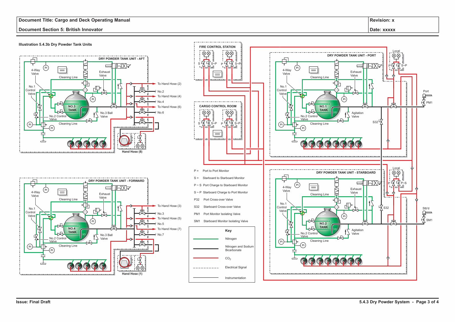
Issue: Final Draft
Document Title: Cargo and Deck Operating Manual
Document Section 5: British Innovator
Revision: x
Date: xxxxx
Illustration 5.4.3b Dry Powder Tank Units
CARGO CONTROL ROOM
FIRE CONTROL STATION
Local
Stb'd
NO.2
TANK
4-Way
ValveCleaning Line
Cleaning Line
S32
No.1
Control
Valve
No.2 ControlValve
Agitation
Valve
Exhaust
Valve
PI
PI
PI
PI
DRY POWDER TANK UNIT - STARBOARD
Local
Port
Nitrogen and Sodium
Bicarbonate
Nitrogen
Key
NO.3
TANK
4-Way
ValveCleaning Line
Hand Hose (8)
Cleaning Line
To Hand Hose (2)
To Hand Hose (4)
To Hand Hose (6)
No.6
No.4
No.2
S PS~P S~PP S~P
S PS~P S~P
No.1
Control
Valve
No.2 ControlValve
No.3 Ball
Valve
Exhaust
Valve
PI
PI
PI
PI
DRY POWDER TANK UNIT - AFT
NO.1
TANK
4-Way
ValveCleaning Line
Cleaning Line
No.1
Control
Valve
No.2 ControlValve
Agitation
Valve
Exhaust
Valve
PI
PI
PI
PI
DRY POWDER TANK UNIT - PORT
NO.4
TANK
4-Way
ValveCleaning Line
Hand Hose (1)
Cleaning Line
To Hand Hose (3)
P = Port to Port Monitor
S = Starboard to Starboard Monitor
P ~ S Port Charge to Starboard Monitor
S ~ P Starboard Charge to Port Monitor
P32 Port Cross-over Valve
S32 Starboard Cross-over Valve
PM1 Port Monitor Isolating Valve
SM1 Starboard Monitor Isolating ValveTo Hand Hose (5)
To Hand Hose (7)
No.7
No.5
No.3
No.1
Control
Valve
No.2 ControlValve
No.3 Ball
Valve
Exhaust
Valve
PI
PI
PI
PI
DRY POWDER TANK UNIT - FORWARD
CO2
Electrical Signal
Instrumentation
P P~S
S32
PM1
SM1
5.4.3 Dry Powder System - Page 3 of 4
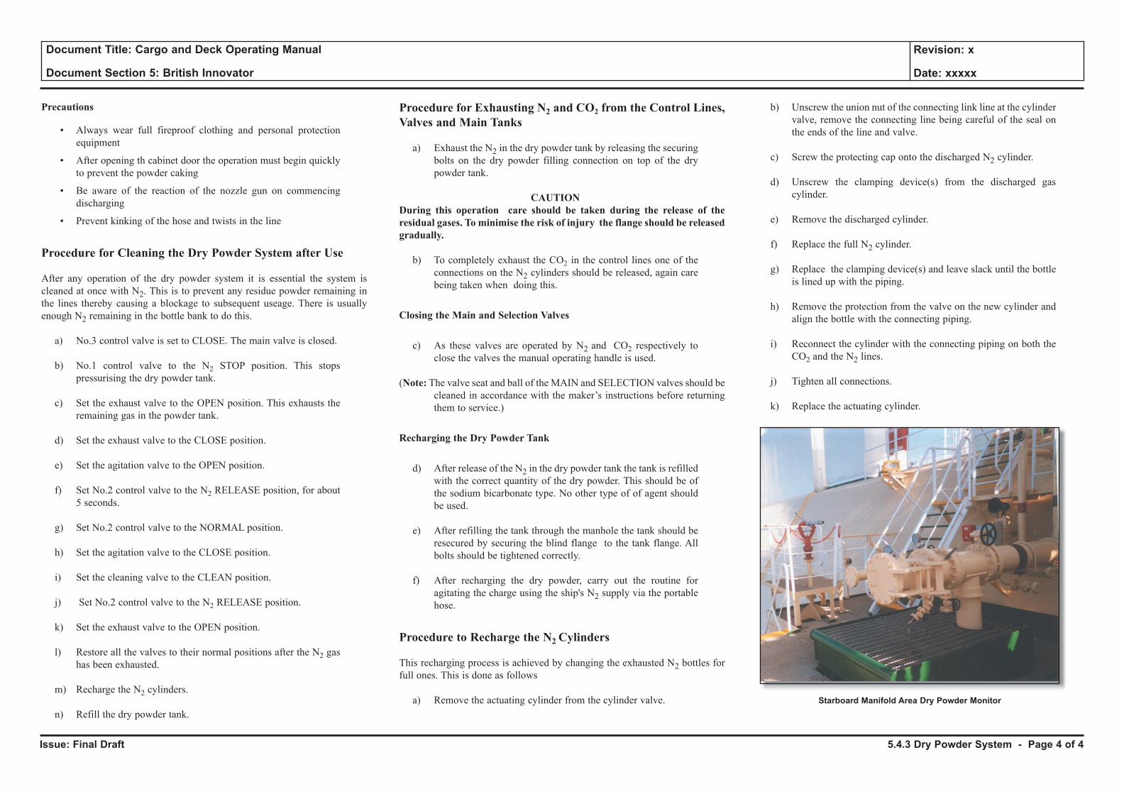
Issue: Final Draft
Document Title: Cargo and Deck Operating Manual
Document Section 5: British Innovator
Revision: x
Date: xxxxx
Precautions
• Always wear full fireproof clothing and personal protection equipment
• After opening th cabinet door the operation must begin quickly to prevent the powder caking
• Be aware of the reaction of the nozzle gun on commencing discharging
• Prevent kinking of the hose and twists in the line
Procedure for Cleaning the Dry Powder System after Use
After any operation of the dry powder system it is essential the system is cleaned at once with N2. This is to prevent any residue powder remaining in the lines thereby causing a blockage to subsequent useage. There is usually enough N2 remaining in the bottle bank to do this.
a) No.3 control valve is set to CLOSE. The main valve is closed.
b) No.1 control valve to the N2 STOP position. This stops pressurising the dry powder tank.
c) Set the exhaust valve to the OPEN position. This exhausts the remaining gas in the powder tank.
d) Set the exhaust valve to the CLOSE position.
e) Set the agitation valve to the OPEN position.
f) Set No.2 control valve to the N2 RELEASE position, for about 5 seconds.
g) Set No.2 control valve to the NORMAL position.
h) Set the agitation valve to the CLOSE position.
i) Set the cleaning valve to the CLEAN position.
j) Set No.2 control valve to the N2 RELEASE position.
k) Set the exhaust valve to the OPEN position.
l) Restore all the valves to their normal positions after the N2 gas has been exhausted.
m) Recharge the N2 cylinders.
n) Refill the dry powder tank.
Procedure for Exhausting N2 and CO2 from the Control Lines, Valves and Main Tanks
a) Exhaust the N2 in the dry powder tank by releasing the securing bolts on the dry powder filling connection on top of the dry powder tank.
CAUTIONDuring this operation care should be taken during the release of the residual gases. To minimise the risk of injury the flange should be released gradually.
b) To completely exhaust the CO2 in the control lines one of the connections on the N2 cylinders should be released, again care being taken when doing this.
Closing the Main and Selection Valves
c) As these valves are operated by N2 and CO2 respectively to close the valves the manual operating handle is used.
(Note: The valve seat and ball of the MAIN and SELECTION valves should be cleaned in accordance with the maker’s instructions before returning them to service.)
Recharging the Dry Powder Tank
d) After release of the N2 in the dry powder tank the tank is refilled with the correct quantity of the dry powder. This should be of the sodium bicarbonate type. No other type of of agent should be used.
e) After refilling the tank through the manhole the tank should be resecured by securing the blind flange to the tank flange. All bolts should be tightened correctly.
f) After recharging the dry powder, carry out the routine for agitating the charge using the ship's N2 supply via the portable hose.
Procedure to Recharge the N2 Cylinders
This recharging process is achieved by changing the exhausted N2 bottles for full ones. This is done as follows
a) Remove the actuating cylinder from the cylinder valve.
b) Unscrew the union nut of the connecting link line at the cylinder valve, remove the connecting line being careful of the seal on the ends of the line and valve.
c) Screw the protecting cap onto the discharged N2 cylinder.
d) Unscrew the clamping device(s) from the discharged gas cylinder.
e) Remove the discharged cylinder.
f) Replace the full N2 cylinder.
g) Replace the clamping device(s) and leave slack until the bottle is lined up with the piping.
h) Remove the protection from the valve on the new cylinder and align the bottle with the connecting piping.
i) Reconnect the cylinder with the connecting piping on both the CO2 and the N2 lines.
j) Tighten all connections.
k) Replace the actuating cylinder.
5.4.3 Dry Powder System - Page 4 of 4
Starboard Manifold Area Dry Powder Monitor
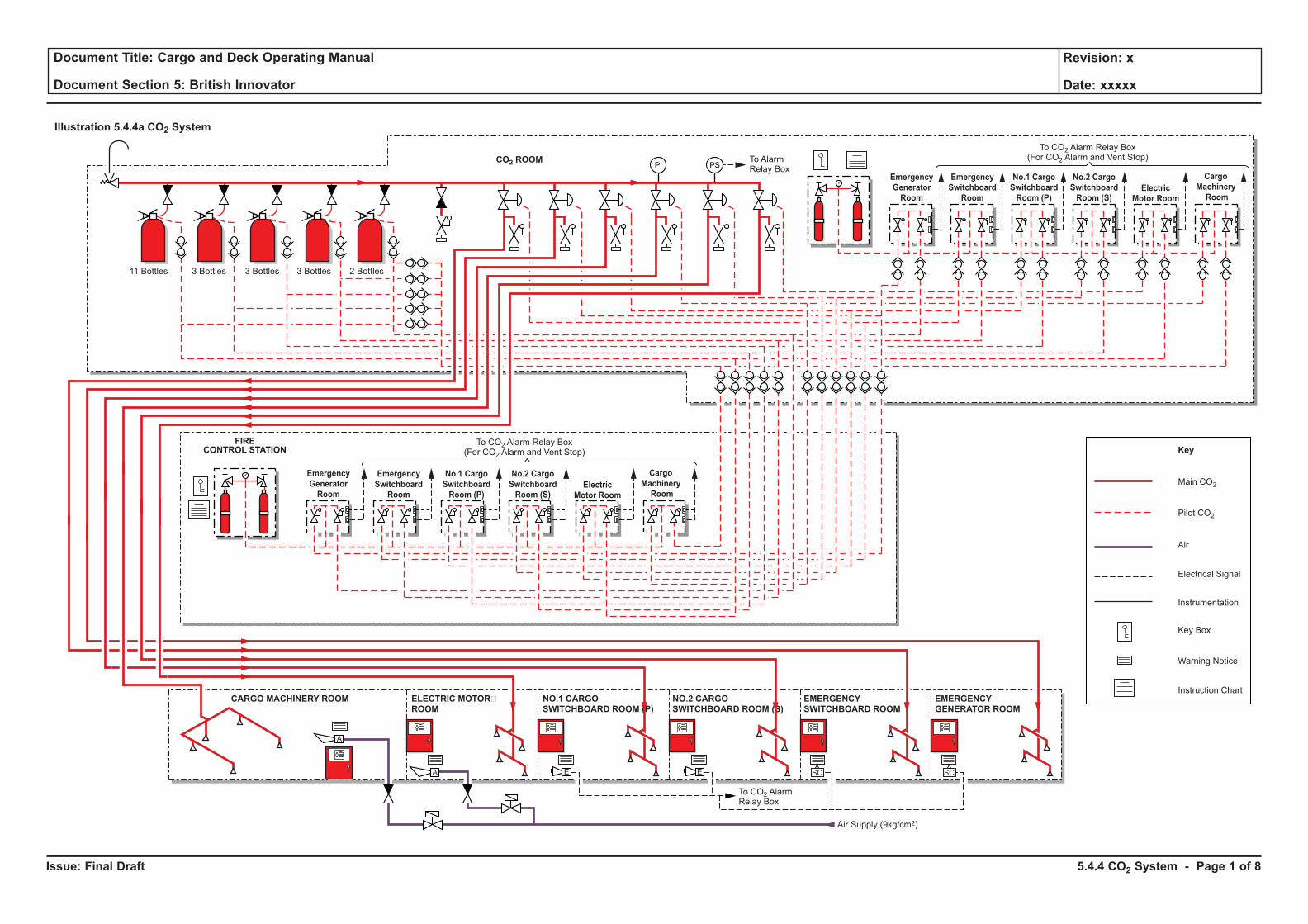
Issue: Final Draft
Document Title: Cargo and Deck Operating Manual
Document Section 5: British Innovator
Revision: x
Date: xxxxx
Illustration 5.4.4a CO2 System
Pilot CO2
Main CO2
SC SC
Electrical Signal
Air
Instrumentation
Key Box
Warning Notice
Instruction Chart
Key
CO2 ROOM
FIRECONTROL STATION
To CO2 Alarm Relay Box(For CO2 Alarm and Vent Stop)
To CO2 Alarm Relay Box(For CO2 Alarm and Vent Stop)
To CO2 AlarmRelay Box
ELECTRIC MOTOR�
ROOM
CARGO MACHINERY ROOM NO.1 CARGO
SWITCHBOARD ROOM (P)
NO.2 CARGO
SWITCHBOARD ROOM (S)
EMERGENCY
SWITCHBOARD ROOM
EMERGENCY
GENERATOR ROOM
A
A E E
11 Bottles 3 Bottles 3 Bottles 3 Bottles 2 Bottles
Emergency
Generator
Room
Emergency
Switchboard
Room
No.1 Cargo
Switchboard
Room (P)
No.2 Cargo
Switchboard
Room (S)Electric
Motor Room
Cargo
Machinery
Room
Emergency
Switchboard
Room
No.1 Cargo
Switchboard
Room (P)
No.2 Cargo
Switchboard
Room (S)Electric
Motor Room
Cargo
Machinery
Room
Emergency
Generator
Room
To AlarmRelay Box
PI PS
Air Supply (9kg/cm2)
5.4.4 CO2 System - Page 1 of 8
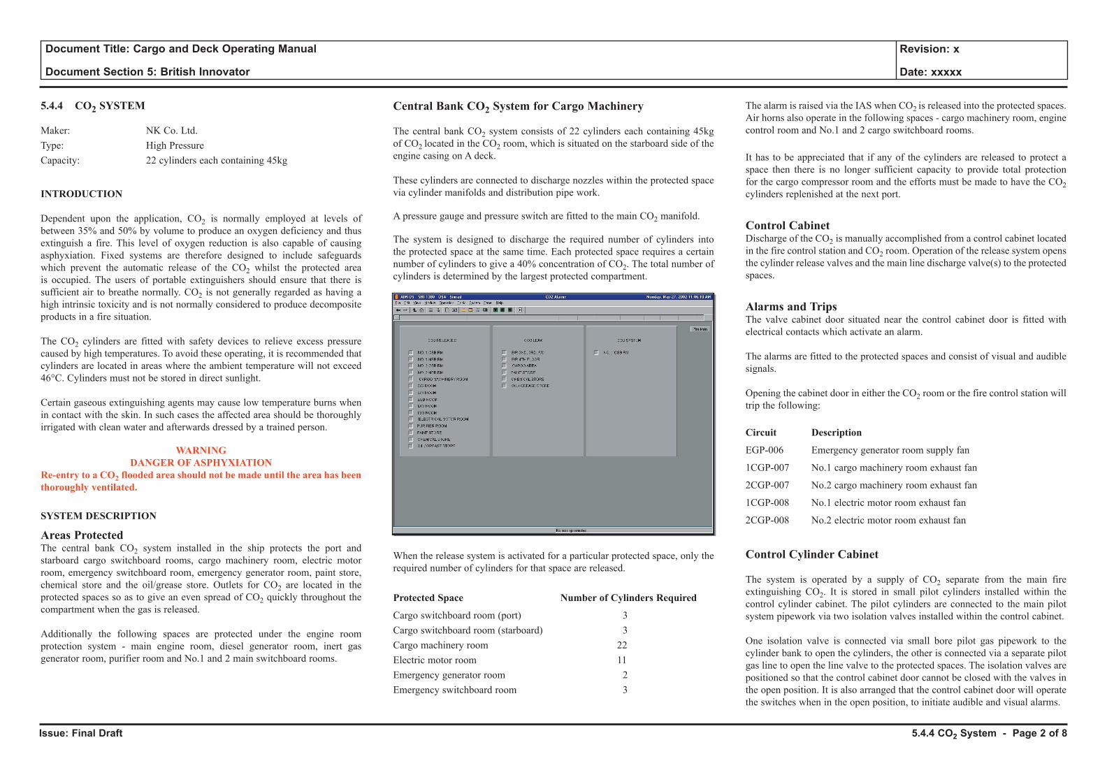
Issue: Final Draft
Document Title: Cargo and Deck Operating Manual
Document Section 5: British Innovator
Revision: x
Date: xxxxx
5.4.4 CO2 SYSTEM
Maker: NK Co. Ltd.Type: High PressureCapacity: 22 cylinders each containing 45kg
INTRODUCTION
Dependent upon the application, CO2 is normally employed at levels of between 35% and 50% by volume to produce an oxygen deficiency and thus extinguish a fire. This level of oxygen reduction is also capable of causing asphyxiation. Fixed systems are therefore designed to include safeguards which prevent the automatic release of the CO2 whilst the protected area is occupied. The users of portable extinguishers should ensure that there is sufficient air to breathe normally. CO2 is not generally regarded as having a high intrinsic toxicity and is not normally considered to produce decomposite products in a fire situation.
The CO2 cylinders are fitted with safety devices to relieve excess pressure caused by high temperatures. To avoid these operating, it is recommended that cylinders are located in areas where the ambient temperature will not exceed 46°C. Cylinders must not be stored in direct sunlight.
Certain gaseous extinguishing agents may cause low temperature burns when in contact with the skin. In such cases the affected area should be thoroughly irrigated with clean water and afterwards dressed by a trained person.
WARNING DANGER OF ASPHYXIATION
Re-entry to a CO2 flooded area should not be made until the area has been thoroughly ventilated.
SYSTEM DESCRIPTION
Areas ProtectedThe central bank CO2 system installed in the ship protects the port and starboard cargo switchboard rooms, cargo machinery room, electric motor room, emergency switchboard room, emergency generator room, paint store, chemical store and the oil/grease store. Outlets for CO2 are located in the protected spaces so as to give an even spread of CO2 quickly throughout the compartment when the gas is released.
Additionally the following spaces are protected under the engine room protection system - main engine room, diesel generator room, inert gas generator room, purifier room and No.1 and 2 main switchboard rooms.
Central Bank CO2 System for Cargo Machinery
The central bank CO2 system consists of 22 cylinders each containing 45kg of CO2 located in the CO2 room, which is situated on the starboard side of the engine casing on A deck. These cylinders are connected to discharge nozzles within the protected space via cylinder manifolds and distribution pipe work.
A pressure gauge and pressure switch are fitted to the main CO2 manifold.
The system is designed to discharge the required number of cylinders into the protected space at the same time. Each protected space requires a certain number of cylinders to give a 40% concentration of CO2. The total number of cylinders is determined by the largest protected compartment.
When the release system is activated for a particular protected space, only the required number of cylinders for that space are released.
Protected Space Number of Cylinders Required
Cargo switchboard room (port) 3Cargo switchboard room (starboard) 3Cargo machinery room 22Electric motor room 11Emergency generator room 2Emergency switchboard room 3
The alarm is raised via the IAS when CO2 is released into the protected spaces. Air horns also operate in the following spaces - cargo machinery room, engine control room and No.1 and 2 cargo switchboard rooms.
It has to be appreciated that if any of the cylinders are released to protect a space then there is no longer sufficient capacity to provide total protection for the cargo compressor room and the efforts must be made to have the CO2 cylinders replenished at the next port.
Control CabinetDischarge of the CO2 is manually accomplished from a control cabinet located in the fire control station and CO2 room. Operation of the release system opens the cylinder release valves and the main line discharge valve(s) to the protected spaces.
Alarms and TripsThe valve cabinet door situated near the control cabinet door is fitted with electrical contacts which activate an alarm.
The alarms are fitted to the protected spaces and consist of visual and audible signals.
Opening the cabinet door in either the CO2 room or the fire control station will trip the following:
Circuit Description
EGP-006 Emergency generator room supply fan
1CGP-007 No.1 cargo machinery room exhaust fan
2CGP-007 No.2 cargo machinery room exhaust fan
1CGP-008 No.1 electric motor room exhaust fan
2CGP-008 No.2 electric motor room exhaust fan
Control Cylinder Cabinet
The system is operated by a supply of CO2 separate from the main fire extinguishing CO2. It is stored in small pilot cylinders installed within the control cylinder cabinet. The pilot cylinders are connected to the main pilot system pipework via two isolation valves installed within the control cabinet.
One isolation valve is connected via small bore pilot gas pipework to the cylinder bank to open the cylinders, the other is connected via a separate pilot gas line to open the line valve to the protected spaces. The isolation valves are positioned so that the control cabinet door cannot be closed with the valves in the open position. It is also arranged that the control cabinet door will operate the switches when in the open position, to initiate audible and visual alarms.
5.4.4 CO2 System - Page 2 of 8
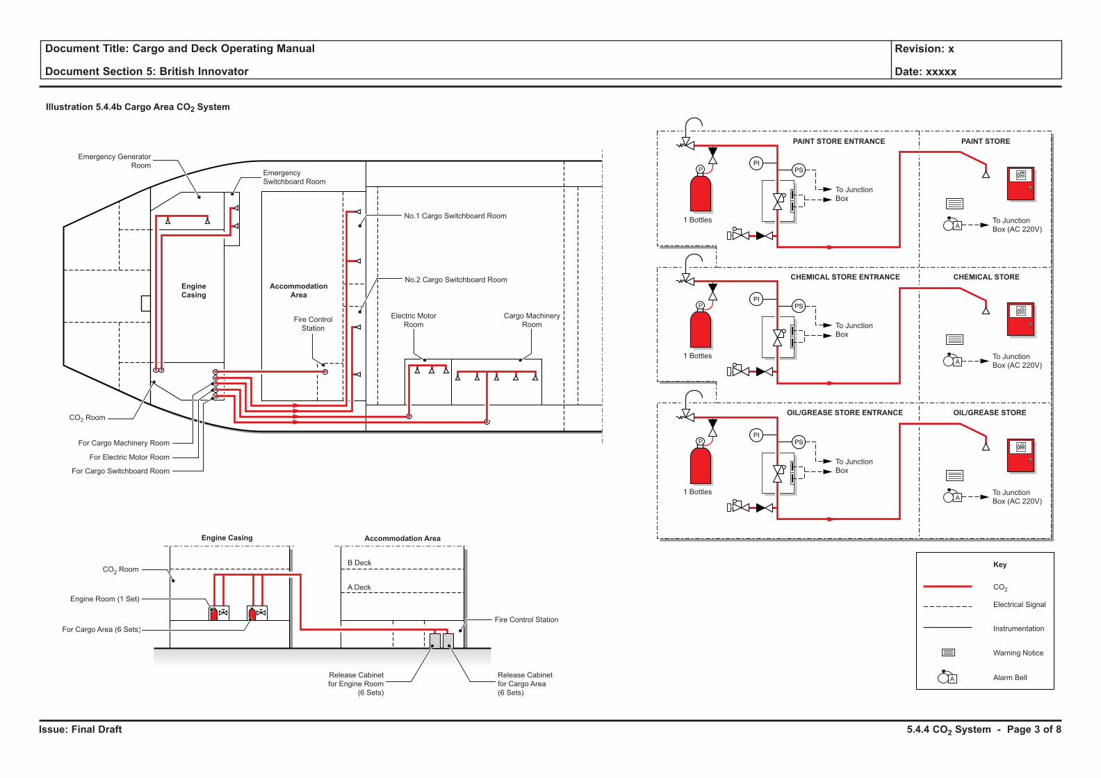
Issue: Final Draft
Document Title: Cargo and Deck Operating Manual
Document Section 5: British Innovator
Revision: x
Date: xxxxx
Illustration 5.4.4b Cargo Area CO2 System
PSPI
CO2
Electrical Signal
Instrumentation
Warning Notice
Alarm Bell
KeyB DeckCO2 Room
Engine Room (1 Set)
For Cargo Area (6 Sets)
A Deck
1 Bottles
To Junction
Box
P
To Junction
Box (AC 220V)A
A
PSPI
1 Bottles
To Junction
Box
P
To Junction
Box (AC 220V)A
PSPI
1 Bottles
To Junction
Box
P
To Junction
Box (AC 220V)A
PAINT STORE
CHEMICAL STORE
OIL/GREASE STORE
PAINT STORE ENTRANCE
CHEMICAL STORE ENTRANCE
OIL/GREASE STORE ENTRANCE
Electric Motor
Room
No.1 Cargo Switchboard Room
Emergency
Switchboard Room
No.2 Cargo Switchboard Room
Fire Control
Station
Engine
Casing
Engine Casing
Accommodation
Area
Accommodation Area
Emergency Generator
Room
CO2 Room
For Cargo Machinery Room
For Electric Motor Room
For Cargo Switchboard Room
Release Cabinet
for Engine Room
(6 Sets)
Release Cabinet
for Cargo Area
(6 Sets)
Fire Control Station
Cargo Machinery
Room
5.4.4 CO2 System - Page 3 of 8
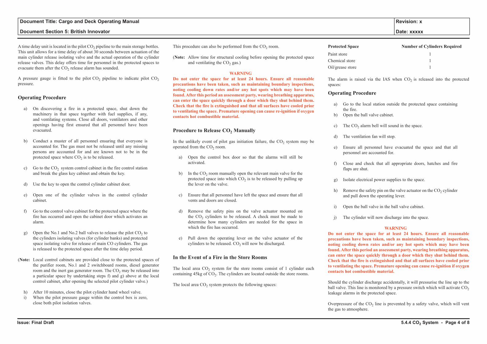
Issue: Final Draft
Document Title: Cargo and Deck Operating Manual
Document Section 5: British Innovator
Revision: x
Date: xxxxx
A time delay unit is located in the pilot CO2 pipeline to the main storage bottles. This unit allows for a time delay of about 30 seconds between actuation of the main cylinder release isolating valve and the actual operation of the cylinder release valves. This delay offers time for personnel in the protected spaces to evacuate them after the CO2 release alarm has sounded.
A pressure gauge is fitted to the pilot CO2 pipeline to indicate pilot CO2 pressure.
Operating Procedure
a) On discovering a fire in a protected space, shut down the machinery in that space together with fuel supplies, if any, and ventilating systems. Close all doors, ventilators and other openings having first ensured that all personnel have been evacuated.
b) Conduct a muster of all personnel ensuring that everyone is accounted for. The gas must not be released until any missing persons are accounted for and are known not to be in the protected space where CO2 is to be released.
c) Go to the CO2 system control cabinet in the fire control station and break the glass key cabinet and obtain the key.
d) Use the key to open the control cylinder cabinet door.
e) Open one of the cylinder valves in the control cylinder cabinet.
f) Go to the control valve cabinet for the protected space where the fire has occurred and open the cabinet door which activates an alarm.
g) Open the No.1 and No.2 ball valves to release the pilot CO2 to the cylinders isolating valves (for cylinder banks) and protected space isolating valve for release of main CO cylinders. The gas is released to the protected space after the time delay period.
(Note: Local control cabinets are provided close to the protected spaces of the purifier room, No.1 and 2 switchboard rooms, diesel generator room and the inert gas generator room. The CO2 may be released into a particular space by undertaking steps f) and g) above at the local control cabinet, after opening the selected pilot cylinder valve.)
h) After 10 minutes, close the pilot cylinder hand wheel valve.i) When the pilot pressure gauge within the control box is zero,
close both pilot isolation valves.
This procedure can also be performed from the CO2 room.
(Note: Allow time for structural cooling before opening the protected space and ventilating the CO2 gas.)
WARNINGDo not enter the space for at least 24 hours. Ensure all reasonable precautions have been taken, such as maintaining boundary inspections, noting cooling down rates and/or any hot spots which may have been found. After this period an assessment party, wearing breathing apparatus, can enter the space quickly through a door which they shut behind them. Check that the fire is extinguished and that all surfaces have cooled prior to ventilating the space. Premature opening can cause re-ignition if oxygen contacts hot combustible material.
Procedure to Release CO2 Manually
In the unlikely event of pilot gas initiation failure, the CO2 system may be operated from the CO2 room.
a) Open the control box door so that the alarms will still be activated.
b) In the CO2 room manually open the relevant main valve for the protected space into which CO2 is to be released by pulling up the lever on the valve.
c) Ensure that all personnel have left the space and ensure that all vents and doors are closed.
d) Remove the safety pins on the valve actuator mounted on the CO2 cylinders to be released. A check must be made to determine how many cylinders are needed for the space in which the fire has occurred.
e) Pull down the operating lever on the valve actuator of the cylinders to be released. CO2 will now be discharged.
In the Event of a Fire in the Store Rooms
The local area CO2 system for the store rooms consist of 1 cylinder each containing 45kg of CO2. The cylinders are located outside the store rooms.
The local area CO2 system protects the following spaces:
Protected Space Number of Cylinders Required
Paint store 1Chemical store 1Oil/grease store 1
The alarm is raised via the IAS when CO2 is released into the protected spaces:
Operating Procedure
a) Go to the local station outside the protected space containing the fire.
b) Open the ball valve cabinet.
c) The CO2 alarm bell will sound in the space.
d) The ventilation fan will stop.
e) Ensure all personnel have evacuated the space and that all personnel are accounted for.
f) Close and check that all appropriate doors, hatches and fire flaps are shut.
g) Isolate electrical power supplies to the space.
h) Remove the safety pin on the valve actuator on the CO2 cylinder and pull down the operating lever.
i) Open the ball valve in the ball valve cabinet.
j) The cylinder will now discharge into the space.
WARNINGDo not enter the space for at least 24 hours. Ensure all reasonable precautions have been taken, such as maintaining boundary inspections, noting cooling down rates and/or any hot spots which may have been found. After this period an assessment party, wearing breathing apparatus, can enter the space quickly through a door which they shut behind them. Check that the fire is extinguished and that all surfaces have cooled prior to ventilating the space. Premature opening can cause re-ignition if oxygen contacts hot combustible material.
Should the cylinder discharge accidentally, it will pressurise the line up to the ball valve. This line is monitored by a pressure switch which will activate CO2 leakage alarms in the protected space.
Overpressure of the CO2 line is prevented by a safety valve, which will vent the gas to atmosphere.
5.4.4 CO2 System - Page 4 of 8

Issue: Final Draft
Document Title: Cargo and Deck Operating Manual
Document Section 5: British Innovator
Revision: x
Date: xxxxx
Illustration 5.4.4c CO2 System in Engine Room
To AlarmRelay Box
PI PS
PI PS
M M
M M
Pilot CO2
Main CO2
SC
SC
To CO2 AlarmRelay Box
To CO2 AlarmRelay Box
PURIFIER
ROOM
ENGINE ROOM
FIRE CONTROL STATION
Engine Room Area
CO2 ROOM
NO.1 MAIN
SWITCHBOARD ROOM
Purifier RoomNo.1 Main
Switchboard Room
No.2 Main
Switchboard Room
Diesel
Generator Room
Engine Room
Inert Gas
Generator Room
Purifier
Room
No.1 Main
Switchboard
Room
No.2 Main
Switchboard
Room
Diesel
Generator
Room
Inert Gas
Generator
Room
Engine Room
NO.2 MAIN
SWITCHBOARD ROOM
To CO2 AlarmRelay Box
To CO2 AlarmRelay Box
To CO2 Alarm Relay Box(For CO2 Alarm and Vent Stop)
To CO2 AlarmRelay Box
DIESEL GENERATOR
ROOM
INERT GAS
GENERATOR ROOM
M M M M M M M MM M
SC
To CO2 AlarmRelay Box
SC
To CO2 AlarmRelay Box
SC
To CO2 AlarmRelay Box
SC
To CO2 AlarmRelay Box
To CO2 AlarmRelay Box
To CO2 AlarmRelay Box
To CO2 AlarmRelay Box
Cap Storage BoxSpare Parts Trolley Level Indicator Beam Scale
To CO2 AlarmRelay Box
196 Bottles
322 Bottles
23 Bottles 11 Bottles 10 Bottles 9 Bottles 6 Bottles
Electrical Signal
Power Supply AC 220V
(Main and Emergency)
Valve Control Cabinets
Junction
Box
Instrumentation
Key Box
Warning Notice
Instruction Chart
Key
5.4.4 CO2 System - Page 5 of 8
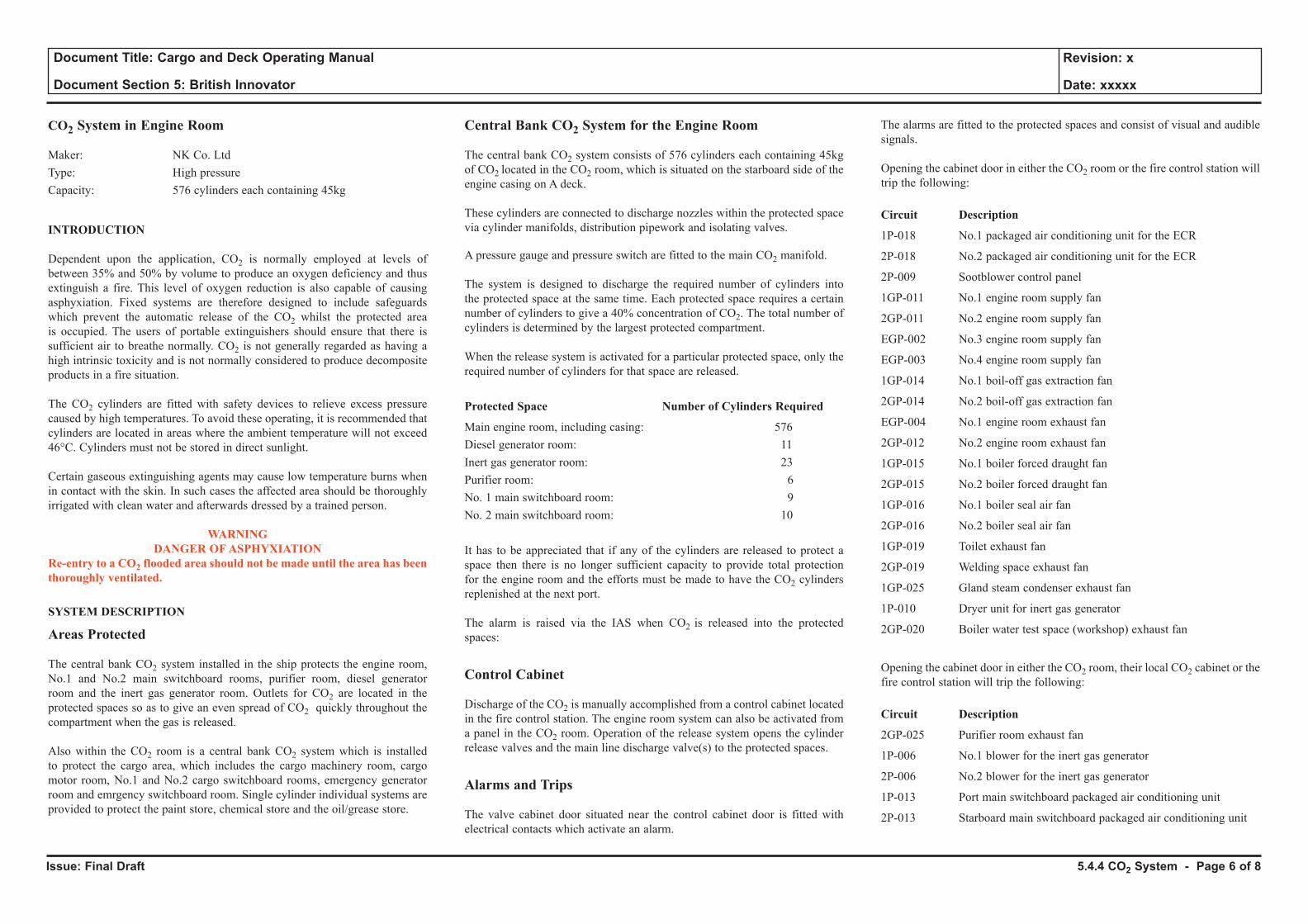
Issue: Final Draft
Document Title: Cargo and Deck Operating Manual
Document Section 5: British Innovator
Revision: x
Date: xxxxx
CO2 System in Engine Room
Maker: NK Co. LtdType: High pressureCapacity: 576 cylinders each containing 45kg
INTRODUCTION
Dependent upon the application, CO2 is normally employed at levels of between 35% and 50% by volume to produce an oxygen deficiency and thus extinguish a fire. This level of oxygen reduction is also capable of causing asphyxiation. Fixed systems are therefore designed to include safeguards which prevent the automatic release of the CO2 whilst the protected area is occupied. The users of portable extinguishers should ensure that there is sufficient air to breathe normally. CO2 is not generally regarded as having a high intrinsic toxicity and is not normally considered to produce decomposite products in a fire situation.
The CO2 cylinders are fitted with safety devices to relieve excess pressure caused by high temperatures. To avoid these operating, it is recommended that cylinders are located in areas where the ambient temperature will not exceed 46°C. Cylinders must not be stored in direct sunlight.
Certain gaseous extinguishing agents may cause low temperature burns when in contact with the skin. In such cases the affected area should be thoroughly irrigated with clean water and afterwards dressed by a trained person.
WARNING DANGER OF ASPHYXIATION
Re-entry to a CO2 flooded area should not be made until the area has been thoroughly ventilated.
SYSTEM DESCRIPTION
Areas Protected
The central bank CO2 system installed in the ship protects the engine room, No.1 and No.2 main switchboard rooms, purifier room, diesel generator room and the inert gas generator room. Outlets for CO2 are located in the protected spaces so as to give an even spread of CO2 quickly throughout the compartment when the gas is released.
Also within the CO2 room is a central bank CO2 system which is installed to protect the cargo area, which includes the cargo machinery room, cargo motor room, No.1 and No.2 cargo switchboard rooms, emergency generator room and emrgency switchboard room. Single cylinder individual systems are provided to protect the paint store, chemical store and the oil/grease store.
Central Bank CO2 System for the Engine Room
The central bank CO2 system consists of 576 cylinders each containing 45kg of CO2 located in the CO2 room, which is situated on the starboard side of the engine casing on A deck. These cylinders are connected to discharge nozzles within the protected space via cylinder manifolds, distribution pipework and isolating valves.
A pressure gauge and pressure switch are fitted to the main CO2 manifold.
The system is designed to discharge the required number of cylinders into the protected space at the same time. Each protected space requires a certain number of cylinders to give a 40% concentration of CO2. The total number of cylinders is determined by the largest protected compartment.
When the release system is activated for a particular protected space, only the required number of cylinders for that space are released.
Protected Space Number of Cylinders Required
Main engine room, including casing: 576Diesel generator room: 11Inert gas generator room: 23Purifier room: 6No. 1 main switchboard room: 9No. 2 main switchboard room: 10
It has to be appreciated that if any of the cylinders are released to protect a space then there is no longer sufficient capacity to provide total protection for the engine room and the efforts must be made to have the CO2 cylinders replenished at the next port.
The alarm is raised via the IAS when CO2 is released into the protected spaces:
Control Cabinet
Discharge of the CO2 is manually accomplished from a control cabinet located in the fire control station. The engine room system can also be activated from a panel in the CO2 room. Operation of the release system opens the cylinder release valves and the main line discharge valve(s) to the protected spaces.
Alarms and Trips
The valve cabinet door situated near the control cabinet door is fitted with electrical contacts which activate an alarm.
The alarms are fitted to the protected spaces and consist of visual and audible signals.
Opening the cabinet door in either the CO2 room or the fire control station will trip the following:
Circuit Description
1P-018 No.1 packaged air conditioning unit for the ECR
2P-018 No.2 packaged air conditioning unit for the ECR
2P-009 Sootblower control panel
1GP-011 No.1 engine room supply fan
2GP-011 No.2 engine room supply fan
EGP-002 No.3 engine room supply fan
EGP-003 No.4 engine room supply fan
1GP-014 No.1 boil-off gas extraction fan
2GP-014 No.2 boil-off gas extraction fan
EGP-004 No.1 engine room exhaust fan
2GP-012 No.2 engine room exhaust fan
1GP-015 No.1 boiler forced draught fan
2GP-015 No.2 boiler forced draught fan
1GP-016 No.1 boiler seal air fan
2GP-016 No.2 boiler seal air fan
1GP-019 Toilet exhaust fan
2GP-019 Welding space exhaust fan
1GP-025 Gland steam condenser exhaust fan
1P-010 Dryer unit for inert gas generator
2GP-020 Boiler water test space (workshop) exhaust fan
Opening the cabinet door in either the CO2 room, their local CO2 cabinet or the fire control station will trip the following:
Circuit Description
2GP-025 Purifier room exhaust fan
1P-006 No.1 blower for the inert gas generator
2P-006 No.2 blower for the inert gas generator
1P-013 Port main switchboard packaged air conditioning unit
2P-013 Starboard main switchboard packaged air conditioning unit
5.4.4 CO2 System - Page 6 of 8
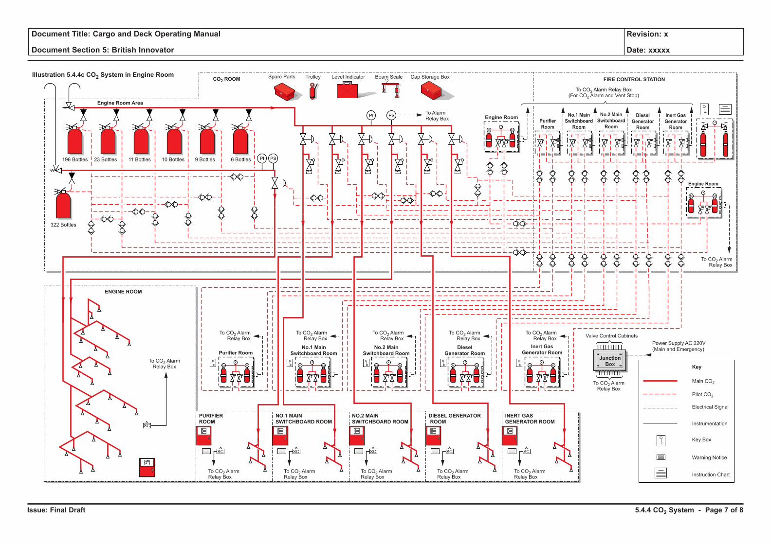
Issue: Final Draft
Document Title: Cargo and Deck Operating Manual
Document Section 5: British Innovator
Revision: x
Date: xxxxx
Illustration 5.4.4c CO2 System in Engine Room
To AlarmRelay Box
PI PS
PI PS
M M
M M
Pilot CO2
Main CO2
SC
SC
To CO2 AlarmRelay Box
To CO2 AlarmRelay Box
PURIFIER
ROOM
ENGINE ROOM
FIRE CONTROL STATION
Engine Room Area
CO2 ROOM
NO.1 MAIN
SWITCHBOARD ROOM
Purifier RoomNo.1 Main
Switchboard Room
No.2 Main
Switchboard Room
Diesel
Generator Room
Engine Room
Inert Gas
Generator Room
Purifier
Room
No.1 Main
Switchboard
Room
No.2 Main
Switchboard
Room
Diesel
Generator
Room
Inert Gas
Generator
Room
Engine Room
NO.2 MAIN
SWITCHBOARD ROOM
To CO2 AlarmRelay Box
To CO2 AlarmRelay Box
To CO2 Alarm Relay Box(For CO2 Alarm and Vent Stop)
To CO2 AlarmRelay Box
DIESEL GENERATOR
ROOM
INERT GAS
GENERATOR ROOM
M M M M M M M MM M
SC
To CO2 AlarmRelay Box
SC
To CO2 AlarmRelay Box
SC
To CO2 AlarmRelay Box
SC
To CO2 AlarmRelay Box
To CO2 AlarmRelay Box
To CO2 AlarmRelay Box
To CO2 AlarmRelay Box
Cap Storage BoxSpare Parts Trolley Level Indicator Beam Scale
To CO2 AlarmRelay Box
196 Bottles
322 Bottles
23 Bottles 11 Bottles 10 Bottles 9 Bottles 6 Bottles
Electrical Signal
Power Supply AC 220V
(Main and Emergency)
Valve Control Cabinets
Junction
Box
Instrumentation
Key Box
Warning Notice
Instruction Chart
Key
5.4.4 CO2 System - Page 7 of 8
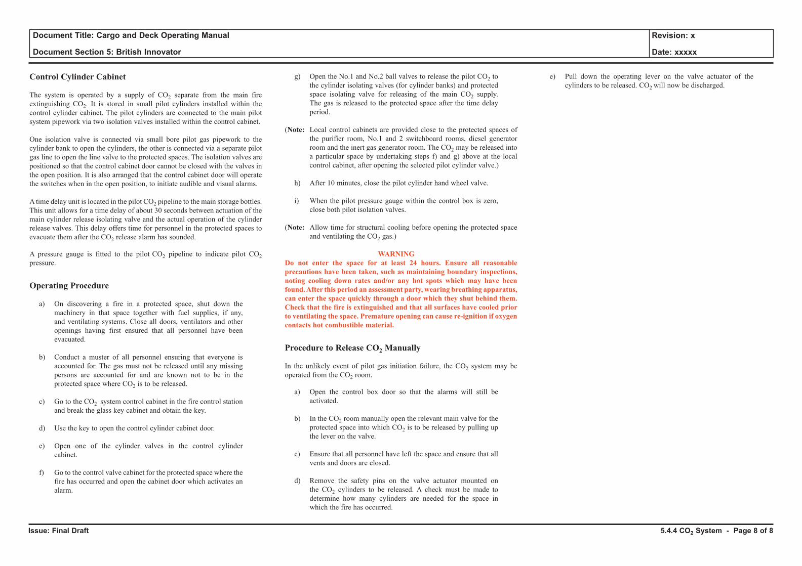
Issue: Final Draft
Document Title: Cargo and Deck Operating Manual
Document Section 5: British Innovator
Revision: x
Date: xxxxx
Control Cylinder Cabinet
The system is operated by a supply of CO2 separate from the main fire extinguishing CO2. It is stored in small pilot cylinders installed within the control cylinder cabinet. The pilot cylinders are connected to the main pilot system pipework via two isolation valves installed within the control cabinet.
One isolation valve is connected via small bore pilot gas pipework to the cylinder bank to open the cylinders, the other is connected via a separate pilot gas line to open the line valve to the protected spaces. The isolation valves are positioned so that the control cabinet door cannot be closed with the valves in the open position. It is also arranged that the control cabinet door will operate the switches when in the open position, to initiate audible and visual alarms.
A time delay unit is located in the pilot CO2 pipeline to the main storage bottles. This unit allows for a time delay of about 30 seconds between actuation of the main cylinder release isolating valve and the actual operation of the cylinder release valves. This delay offers time for personnel in the protected spaces to evacuate them after the CO2 release alarm has sounded.
A pressure gauge is fitted to the pilot CO2 pipeline to indicate pilot CO2 pressure.
Operating Procedure
a) On discovering a fire in a protected space, shut down the machinery in that space together with fuel supplies, if any, and ventilating systems. Close all doors, ventilators and other openings having first ensured that all personnel have been evacuated.
b) Conduct a muster of all personnel ensuring that everyone is accounted for. The gas must not be released until any missing persons are accounted for and are known not to be in the protected space where CO2 is to be released.
c) Go to the CO2 system control cabinet in the fire control station and break the glass key cabinet and obtain the key.
d) Use the key to open the control cylinder cabinet door.
e) Open one of the cylinder valves in the control cylinder cabinet.
f) Go to the control valve cabinet for the protected space where the fire has occurred and open the cabinet door which activates an alarm.
g) Open the No.1 and No.2 ball valves to release the pilot CO2 to the cylinder isolating valves (for cylinder banks) and protected space isolating valve for releasing of the main CO2 supply. The gas is released to the protected space after the time delay period.
(Note: Local control cabinets are provided close to the protected spaces of the purifier room, No.1 and 2 switchboard rooms, diesel generator room and the inert gas generator room. The CO2 may be released into a particular space by undertaking steps f) and g) above at the local control cabinet, after opening the selected pilot cylinder valve.)
h) After 10 minutes, close the pilot cylinder hand wheel valve.
i) When the pilot pressure gauge within the control box is zero, close both pilot isolation valves.
(Note: Allow time for structural cooling before opening the protected space and ventilating the CO2 gas.)
WARNINGDo not enter the space for at least 24 hours. Ensure all reasonable precautions have been taken, such as maintaining boundary inspections, noting cooling down rates and/or any hot spots which may have been found. After this period an assessment party, wearing breathing apparatus, can enter the space quickly through a door which they shut behind them. Check that the fire is extinguished and that all surfaces have cooled prior to ventilating the space. Premature opening can cause re-ignition if oxygen contacts hot combustible material.
Procedure to Release CO2 Manually
In the unlikely event of pilot gas initiation failure, the CO2 system may be operated from the CO2 room.
a) Open the control box door so that the alarms will still be activated.
b) In the CO2 room manually open the relevant main valve for the protected space into which CO2 is to be released by pulling up the lever on the valve.
c) Ensure that all personnel have left the space and ensure that all vents and doors are closed.
d) Remove the safety pins on the valve actuator mounted on the CO2 cylinders to be released. A check must be made to determine how many cylinders are needed for the space in which the fire has occurred.
e) Pull down the operating lever on the valve actuator of the cylinders to be released. CO2 will now be discharged.
5.4.4 CO2 System - Page 8 of 8
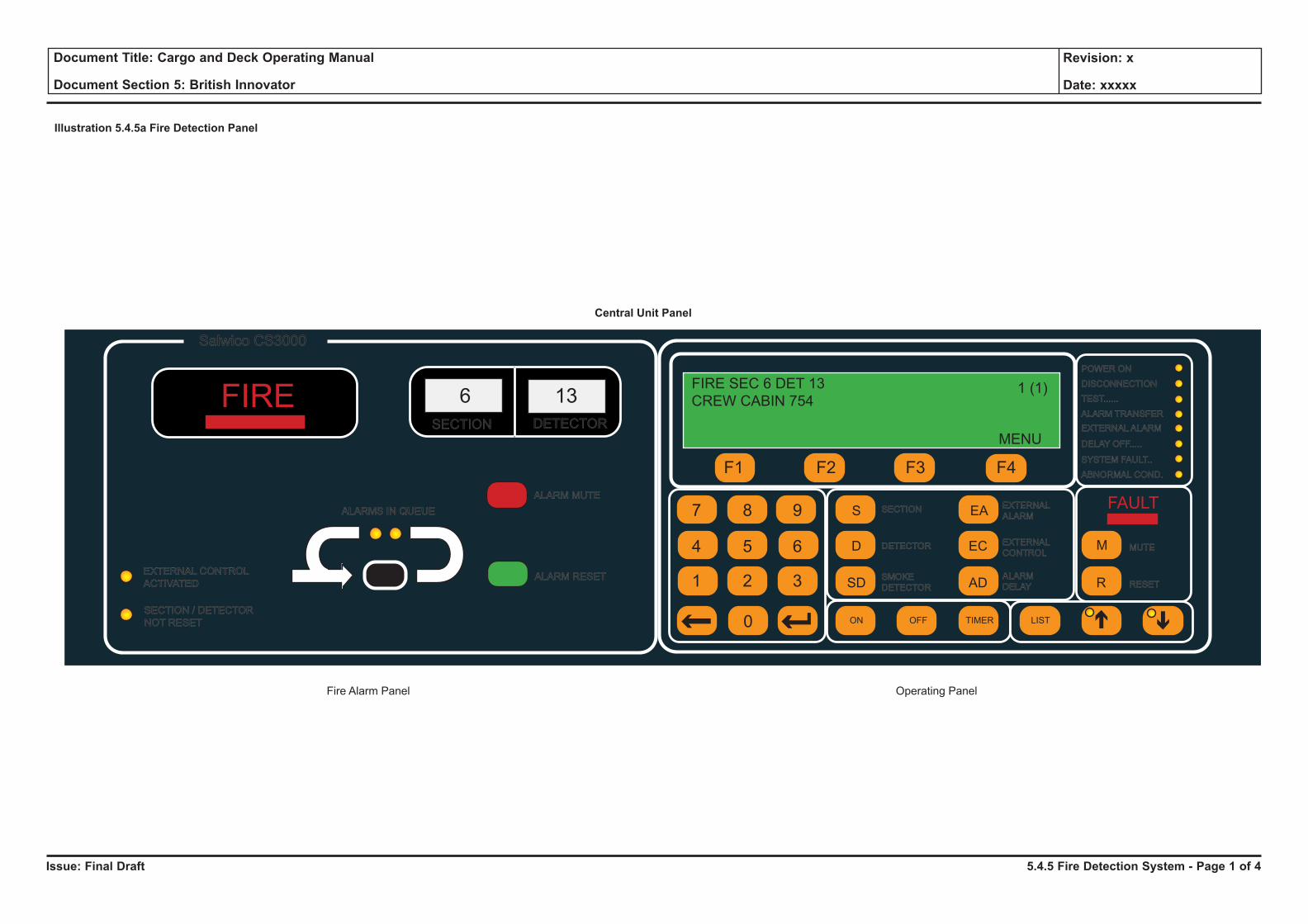
Issue: Final Draft
Document Title: Cargo and Deck Operating Manual
Document Section 5: British Innovator
Revision: x
Date: xxxxx
Salwico CS3000
ALARMS IN QUEUE
EXTERNAL CONTROL
ACTIVATED
SECTION / DETECTOR
NOT RESET
ALARM MUTE
ALARM RESET
SECTION DETECTOR
6 13FIREPOWER ON
DISCONNECTION
TEST......
ALARM TRANSFER
EXTERNALALARM
DELAY OFF.....
SYSTEM FAULT..
ABNORMAL COND.
MUTE
RESET
SECTION
DETECTOR
SMOKE
DETECTOR
EXTERNAL
ALARM
EXTERNAL
CONTROL
ALARM
DELAY
ON OFF TIMER LIST
M
R
S EA
D EC
SD AD
FAULT
F1 F2 F3 F4
1 2 3
4 5 6
7 8 9
0
FIRE SEC 6 DET 13
CREW CABIN 7541 (1)
MENU
Illustration 5.4.5a Fire Detection Panel
Central Unit Panel
Fire Alarm Panel Operating Panel
5.4.5 Fire Detection System - Page 1 of 4
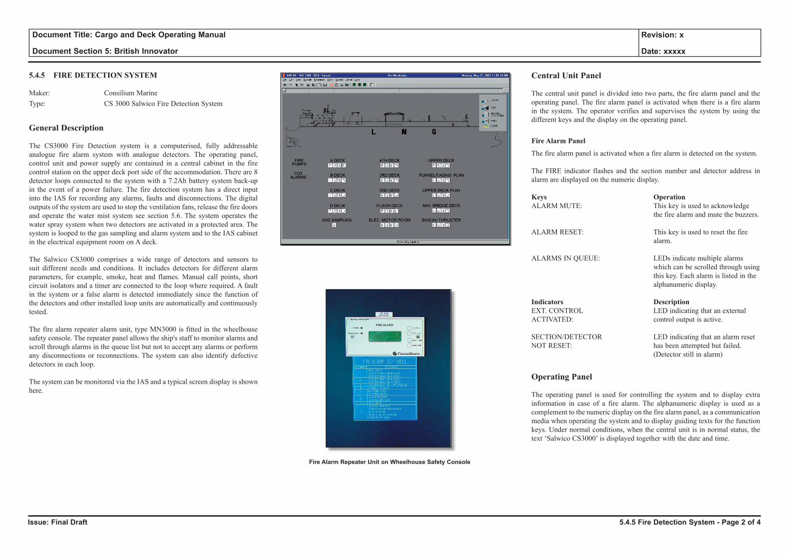
Issue: Final Draft
Document Title: Cargo and Deck Operating Manual
Document Section 5: British Innovator
Revision: x
Date: xxxxx
5.4.5 FIRE DETECTION SYSTEM
Maker: Consilium MarineType: CS 3000 Salwico Fire Detection System
General Description
The CS3000 Fire Detection system is a computerised, fully addressable analogue fire alarm system with analogue detectors. The operating panel, control unit and power supply are contained in a central cabinet in the fire control station on the upper deck port side of the accommodation. There are 8 detector loops connected to the system with a 7.2Ah battery system back-up in the event of a power failure. The fire detection system has a direct input into the IAS for recording any alarms, faults and disconnections. The digital outputs of the system are used to stop the ventilation fans, release the fire doors and operate the water mist system see section 5.6. The system operates the water spray system when two detectors are activated in a protected area. The system is looped to the gas sampling and alarm system and to the IAS cabinet in the electrical equipment room on A deck.
The Salwico CS3000 comprises a wide range of detectors and sensors to suit different needs and conditions. It includes detectors for different alarm parameters, for example, smoke, heat and flames. Manual call points, short circuit isolators and a timer are connected to the loop where required. A fault in the system or a false alarm is detected immediately since the function of the detectors and other installed loop units are automatically and continuously tested.
The fire alarm repeater alarm unit, type MN3000 is fitted in the wheelhouse safety console. The repeater panel allows the ship's staff to monitor alarms and scroll through alarms in the queue list but not to accept any alarms or perform any disconnections or reconnections. The system can also identify defective detectors in each loop.
The system can be monitored via the IAS and a typical screen display is shown here.
Central Unit Panel
The central unit panel is divided into two parts, the fire alarm panel and the operating panel. The fire alarm panel is activated when there is a fire alarm in the system. The operator verifies and supervises the system by using the different keys and the display on the operating panel.
Fire Alarm Panel
The fire alarm panel is activated when a fire alarm is detected on the system.
The FIRE indicator flashes and the section number and detector address in alarm are displayed on the numeric display.
Keys OperationALARM MUTE: This key is used to acknowledge the fire alarm and mute the buzzers.
ALARM RESET: This key is used to reset the fire alarm.
ALARMS IN QUEUE: LEDs indicate multiple alarms which can be scrolled through using this key. Each alarm is listed in the alphanumeric display.
Indicators DescriptionEXT. CONTROL LED indicating that an external ACTIVATED: control output is active.
SECTION/DETECTOR LED indicating that an alarm reset NOT RESET: has been attempted but failed. (Detector still in alarm)
Operating Panel
The operating panel is used for controlling the system and to display extra information in case of a fire alarm. The alphanumeric display is used as a complement to the numeric display on the fire alarm panel, as a communication media when operating the system and to display guiding texts for the function keys. Under normal conditions, when the central unit is in normal status, the text ‘Salwico CS3000’ is displayed together with the date and time.
5.4.5 Fire Detection System - Page 2 of 4
Fire Alarm Repeater Unit on Wheelhouse Safety Console
Issue: Final Draft
Document Title: Cargo and Deck Operating Manual
Document Section 5: British Innovator
Revision: x
Date: xxxxx
Keys OperationF1, F2, F3, F4: Function keys, used for choosing functions from the menus in the display and for entering certain characters with no keys of their own.
0-9: Numeric keys.
Correction key: The last key stroke is erased.
Return key: The system returns to normal status, ‘Salwico CS30000’ is displayed.
S, D, SD, EA, AD: Command keys used to choose the unit (section/detector no. etc) to operate.
MUTE: Fault handling key used to acknowledge faults and to mute the buzzers.
RESET: Fault handling key used to reset the faults.
ON, OFF, TIMER: Operation keys used to choose the operation to perform.
LIST: List handling keys, the LIST key is used to open the list function. The arrow keys are used to scroll through the lists.
Indicators DescriptionPOWER ON: Illuminated when the power is on.
DISCONNECTION: General disconnection of detectors indicator.
TEST: Is lit when the central unit is in test mode.
ALARM TRANSFER: Is lit when the dedicated fire output is activated (steady light) and is flashing when the door is open, the fire output is deactivated.
EXTERNAL ALARM: Is lit when an external alarm output is disconnected or faulty.
DELAY OFF: Is lit when the time delay is deactivated.
SYSTEM FAULT: Is lit when a fault occurs in the system.
ABNORMAL COND: Is lit when an abnormal condition has occurred.
System OperationDetection of a Fire Alarm
FIRE lamp is flashing: A fire alarm is detected in the system.
a) Press ALARM MUTE, to mute and acknowledge the fire alarm.
b) The FIRE indicator stops blinking and becomes steady red. The audible fire alarm, including the internal buzzer is permanently silenced when the ALARM MUTE is pressed.
c) The section number and detector address in alarm are displayed on the fire alarm panel and on the alphanumerical display on the operating panel.
d) The section number and the detector address are displayed on the first line and additional information about the location is displayed on the second line, if provided.
ALARMS IN QUEUE Lamp is flashingThere is more than one fire alarm in the system.
a) Press ALARM MUTE repeatedly, to mute and acknowledge all the fire alarms.
b) The FIRE and ALARMS IN QUEUE indicators stop flashing and become steady red when all the fire alarms are muted. The audible fire alarm is permanently silenced when the ALARM MUTE is pressed.
c) The section number and detector address in alarm are displayed on the fire alarm panel and on the alphanumerical display on the operating panel.
d) The address of the first fire alarm is displayed on the first line and additional information about the alarming unit is displayed on the second line, if provided. The address of the latest fire alarm is displayed on the third line and additional information about this unit is displayed on the fourth line. The total number of fire alarms is shown to the right on line one.
e) Press the ALARMS IN QUEUE button to display the next fire alarm.
f) The second fire alarm address is displayed both on the fire alarm panel and on the alphanumerical display. The fire alarm is presented on the two first lines on the display. Five seconds after pressing ALARMS IN QUEUE, the first fire alarm is displayed again.
g) If ALARMS IN QUEUE is pressed when the last fire alarm is displayed, the first fire alarm is displayed again and the ALARMS IN QUEUE indicator goes out for 5 seconds.
Reset Fire Alarm
Only one fire alarm can be reset at a time, i.e. the displayed fire alarm.
a) Press the ALARMS IN QUEUE button repeatedly to select the appropriate fire alarm.
b) Press ALARM RESET to reset the fire alarm. The system tries to reset the fire alarm.
c) When a fire alarm is reset it disappears from the display and the fire alarm is moved to the fire alarm history list. The next fire alarm is then displayed or if there are no more fire alarms the system returns to normal status, ‘Salwico CS3004’ is displayed with date and time.
d) If the fire alarm does not reset, the reason is displayed on line three. The indicator SECTION/DET NOT RESET is displayed. This could be because the detector still detects high levels of smoke, fumes and/or ionisation etc. The actual detector may also be faulty and should be investigated.
5.4.5 Fire Detection System - Page 3 of 4
Issue: Final Draft
Document Title: Cargo and Deck Operating Manual
Document Section 5: British Innovator
Revision: x
Date: xxxxx
Fire Alarms That Do Not Reset
A detector that cannot be reset can be listed in two ways. Press the LIST or ALARMS IN QUEUE key.
The ALARMS IN QUEUE key can only list the non-resettable fire alarms if all fire alarms are acknowledged and reset (ie the ALARMS IN QUEUE LEDs are not lit) and if all faults are acknowledged. If this is not the case, the ALARMS IN QUEUE key will only list the fire alarms that are not reset.
a) Press ALARMS IN QUEUE repeatedly to select the appropriate fire alarm. The fire alarm address is displayed on the fire alarm panel and the operating panel alphanumerical display.
b) Press ALARM RESET. The system tries to reset the fire alarm.
If no key is depressed for about 60 seconds the display returns to the first non-resettable fire alarm. If the fire alarm is reset it disappears from the display and from the fire alarm list. The display then returns to the next fire alarm or if there are no more fire alarms it returns to normal status, ‘Salwico CS3004’ is displayed. If the alarm does not reset, the reason is displayed on line three. The problem should be investigated. The non-resettable fire alarm is displayed again.
The LIST key can always be used regardless of system status. Pressing LIST shows the fire alarms one by one on the first line of the alphanumerical display. They can then be reset in the normal way one by one. If the alarm does not reset, the reason is displayed on line three. The problem should be investigated. The not resettable fire alarm is displayed again.
Fault Indication
The FAULT indicator is flashing and the internal buzzer is sounding. One or more faults are detected in the system and the latest fault is displayed on the alphanumeric display. The first line displays the word FAULT, a fault code followed by the section number, the detector address, and a fault message. Additional text is displayed on line two, if provided The fault codes are listed in the manufacturer's manual. Only one fault can be acknowledged at a time. Press M in the FAULT field to acknowledge the fault and mute the buzzer.
The FAULT indication stops flashing and becomes steady yellow. The internal buzzer is permanently silenced. The fault is placed in a fault list and the alphanumeric display is erased. The next fault is displayed if there are more faults. Otherwise the display is erased and it returns to its previous status. The number of faults in the system and the order they occurred is displayed on line three. The fault list can be scrolled through by using the up and down arrow keys.
To Reset Faults
a) Press LIST to open the list function, Faults can only be reset from the fault list.
b) Press F2 to select the fault list. The latest fault is always displayed first. The fault list can be scrolled through using the list key. The LED on the arrow key is lit if there are more faults to be listed.
c) Press the arrow keys until the appropriate fault is displayed.
d) Press R in the FAULT field to reset the fault. The system attempts to reset the fault.
e) The fault is reset if it disappears from the list. The next fault is displayed after about 5 seconds. If the fault list is empty, the text LIST EMPTY is displayed, and the system returns to normal status, ‘Salwico CS3004’ is displayed. If the fault is not reset, the reason is displayed on line three. Investigation is required.
Disconnections
Different parts of the fire alarm system can be disconnected for instance, sections, detectors, manual call points, section units, alarm devices, external control devices and loops. This can be useful when there is welding in a particular section or removal of detectors is required due to structural shipboard work etc. A whole section can be disconnected permanently or for a defined time interval using the timer function. The disconnected section can only be reconnected from the ‘Disconnections’ list.
When operating the system a mistake can be corrected using the BACK key to erase one step at a time backwards. To interrupt the disconnection function and return to normal status, press the RETURN key . The system returns to normal status and ‘Salwico CS3000’ is indicated.
Disconnection Process
a) Press S to select the section.
b) Enter a section number and the section menu is displayed.
c) Press OFF to disconnect the section.
d) When the section is disconnected the text on line three is changed to ORDER DONE.
e) The DISCONNECTION LED is lit if this is the first active disconnection in the system.
f) A message is displayed on line three, for about five seconds, if the system cannot disconnect the section. The system then returns to the previous menu.
g) Continue to define the next disconnection or, if finished, return to normal by pressing RETURN.
Further in-depth operations are available from the manufacturer’s manual.
5.4.5 Fire Detection System - Page 4 of 4
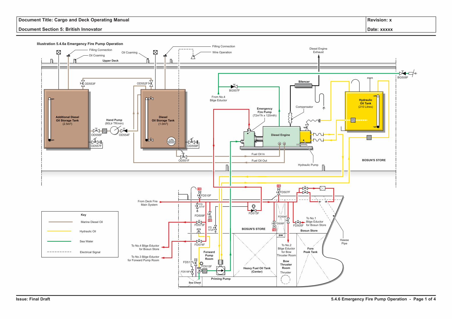
Issue: Final Draft
Document Title: Cargo and Deck Operating Manual
Document Section 5: British Innovator
Revision: x
Date: xxxxx
Illustration 5.4.6a Emergency Fire Pump Operation
From No.4
Bilge Eductor
Hydraulic Oil
Electrical Signal
Hydraulic
Oil Tank
(210 Litres)
Silencer
Marine Diesel Oil
Key
Additional Diesel
Oil Storage Tank
(2.5m3)
Diesel
Oil Storage Tank
(1.0m3)
Upper Deck
BOSUN'S STORE
BOSUN'S STORE
OD557F OD558F
Hydraulic Pump
Diesel Engine
Compensator
Diesel Engine
Exhaust
Fuel Oil In
Fuel Oil Out
Wire Operation
Filling Connection
Oil CoamingOil Coaming
OD551F
OD556F
BG507F
BG508F
OD554F
OD553F OD552F
Filling Connection
LIALBD055
Hand Pump
(80Ltr TR/min)
Emergency
Fire Pump
(72m3/h x 120mth)
Sea Water
HB
HB
HB
HB
To No.4 Bilge Eductor
for Bosun Store
From Deck Fire
Main System
To No.1
Bilge Eductor
for Bosun Store
To No.2
Bilge Eductor
for Bow
Thruster RoomTo No.3 Bilge Eductor
for Forward Pump Room
Hawse
Pipe
Thruster
Fore
Peak Tank
Bosun Store
Bow
Thruster
RoomHeavy Fuel Oil Tank
(Center)
Forward
Pump
Room
Priming Pump
Sea Chest
BW
FD505F
FD507F
FD513F
FD573F
FD509F
FD574F
FD510F
FD506F
FD508F
FD511F
FD512F
FD515F
FD518F
FD517F
5.4.6 Emergency Fire Pump Operation - Page 1 of 4
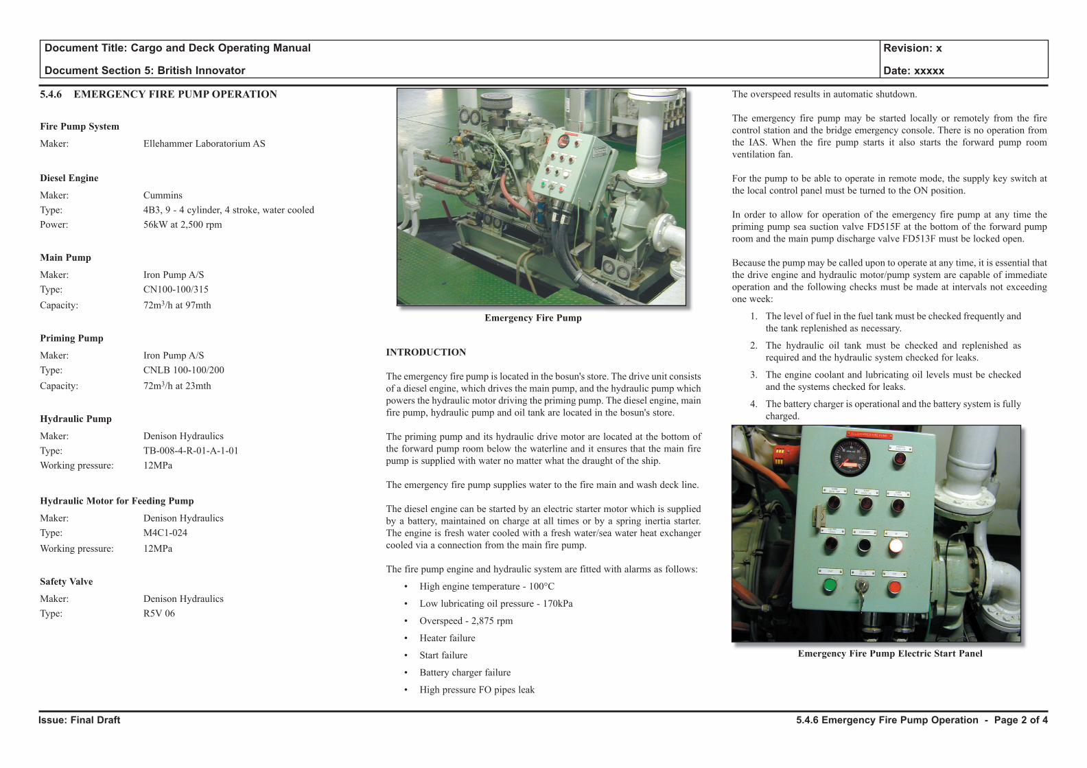
Issue: Final Draft
Document Title: Cargo and Deck Operating Manual
Document Section 5: British Innovator
Revision: x
Date: xxxxx
5.4.6 EMERGENCY FIRE PUMP OPERATION
Fire Pump System
Maker: Ellehammer Laboratorium AS
Diesel Engine
Maker: CumminsType: 4B3, 9 - 4 cylinder, 4 stroke, water cooledPower: 56kW at 2,500 rpm
Main Pump
Maker: Iron Pump A/SType: CN100-100/315Capacity: 72m3/h at 97mth
Priming Pump
Maker: Iron Pump A/SType: CNLB 100-100/200Capacity: 72m3/h at 23mth
Hydraulic Pump
Maker: Denison HydraulicsType: TB-008-4-R-01-A-1-01Working pressure: 12MPa
Hydraulic Motor for Feeding Pump
Maker: Denison HydraulicsType: M4C1-024Working pressure: 12MPa
Safety Valve
Maker: Denison HydraulicsType: R5V 06
Emergency Fire Pump
INTRODUCTION
The emergency fire pump is located in the bosun's store. The drive unit consists of a diesel engine, which drives the main pump, and the hydraulic pump which powers the hydraulic motor driving the priming pump. The diesel engine, main fire pump, hydraulic pump and oil tank are located in the bosun's store.
The priming pump and its hydraulic drive motor are located at the bottom of the forward pump room below the waterline and it ensures that the main fire pump is supplied with water no matter what the draught of the ship.
The emergency fire pump supplies water to the fire main and wash deck line.
The diesel engine can be started by an electric starter motor which is supplied by a battery, maintained on charge at all times or by a spring inertia starter. The engine is fresh water cooled with a fresh water/sea water heat exchanger cooled via a connection from the main fire pump.
The fire pump engine and hydraulic system are fitted with alarms as follows:
• High engine temperature - 100°C
• Low lubricating oil pressure - 170kPa
• Overspeed - 2,875 rpm
• Heater failure
• Start failure
• Battery charger failure
• High pressure FO pipes leak
The overspeed results in automatic shutdown.
The emergency fire pump may be started locally or remotely from the fire control station and the bridge emergency console. There is no operation from the IAS. When the fire pump starts it also starts the forward pump room ventilation fan.
For the pump to be able to operate in remote mode, the supply key switch at the local control panel must be turned to the ON position.
In order to allow for operation of the emergency fire pump at any time the priming pump sea suction valve FD515F at the bottom of the forward pump room and the main pump discharge valve FD513F must be locked open.
Because the pump may be called upon to operate at any time, it is essential that the drive engine and hydraulic motor/pump system are capable of immediate operation and the following checks must be made at intervals not exceeding one week:
1. The level of fuel in the fuel tank must be checked frequently and the tank replenished as necessary.
2. The hydraulic oil tank must be checked and replenished as required and the hydraulic system checked for leaks.
3. The engine coolant and lubricating oil levels must be checked and the systems checked for leaks.
4. The battery charger is operational and the battery system is fully charged.
Emergency Fire Pump Electric Start Panel
5.4.6 Emergency Fire Pump Operation - Page 2 of 4

Issue: Final Draft
Document Title: Cargo and Deck Operating Manual
Document Section 5: British Innovator
Revision: x
Date: xxxxx
Illustration 5.4.6a Emergency Fire Pump Operation
From No.4
Bilge Eductor
Hydraulic Oil
Electrical Signal
Hydraulic
Oil Tank
(210 Litres)
Silencer
Marine Diesel Oil
Key
Additional Diesel
Oil Storage Tank
(2.5m3)
Diesel
Oil Storage Tank
(1.0m3)
Upper Deck
BOSUN'S STORE
BOSUN'S STORE
OD557F OD558F
Hydraulic Pump
Diesel Engine
Compensator
Diesel Engine
Exhaust
Fuel Oil In
Fuel Oil Out
Wire Operation
Filling Connection
Oil CoamingOil Coaming
OD551F
OD556F
BG507F
BG508F
OD554F
OD553F OD552F
Filling Connection
LIALBD055
Hand Pump
(80Ltr TR/min)
Emergency
Fire Pump
(72m3/h x 120mth)
Sea Water
HB
HB
HB
HB
To No.4 Bilge Eductor
for Bosun Store
From Deck Fire
Main System
To No.1
Bilge Eductor
for Bosun Store
To No.2
Bilge Eductor
for Bow
Thruster RoomTo No.3 Bilge Eductor
for Forward Pump Room
Hawse
Pipe
Thruster
Fore
Peak Tank
Bosun Store
Bow
Thruster
RoomHeavy Fuel Oil Tank
(Center)
Forward
Pump
Room
Priming Pump
Sea Chest
BW
FD505F
FD507F
FD513F
FD573F
FD509F
FD574F
FD510F
FD506F
FD508F
FD511F
FD512F
FD515F
FD518F
FD517F
5.4.6 Emergency Fire Pump Operation - Page 3 of 4
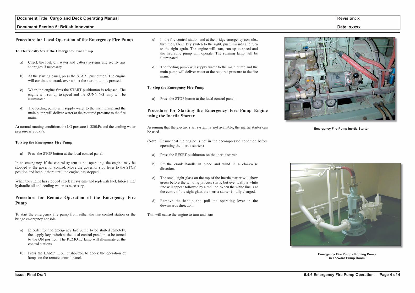
Issue: Final Draft
Document Title: Cargo and Deck Operating Manual
Document Section 5: British Innovator
Revision: x
Date: xxxxx
Procedure for Local Operation of the Emergency Fire Pump
To Electrically Start the Emergency Fire Pump
a) Check the fuel, oil, water and battery systems and rectify any shortages if necessary.
b) At the starting panel, press the START pushbutton. The engine will continue to crank over whilst the start button is pressed
c) When the engine fires the START pushbutton is released. The engine will run up to speed and the RUNNING lamp will be illuminated.
d) The feeding pump will supply water to the main pump and the main pump will deliver water at the required pressure to the fire main.
At normal running conditions the LO pressure is 380kPa and the cooling water pressure is 200kPa.
To Stop the Emergency Fire Pump
a) Press the STOP button at the local control panel.
In an emergency, if the control system is not operating, the engine may be stopped at the governor control. Move the governor stop lever to the STOP position and keep it there until the engine has stopped.
When the engine has stopped check all systems and replenish fuel, lubricating/hydraulic oil and cooling water as necessary.
Procedure for Remote Operation of the Emergency Fire Pump
To start the emergency fire pump from either the fire control station or the bridge emergency console.
a) In order for the emergency fire pump to be started remotely, the supply key switch at the local control panel must be turned to the ON position. The REMOTE lamp will illuminate at the control stations.
b) Press the LAMP TEST pushbutton to check the operation of lamps on the remote control panel.
c) In the fire control station and at the bridge emergency console., turn the START key switch to the right, push inwards and turn to the right again. The engine will start, run up to speed and the hydraulic pump will operate. The running lamp will be illuminated.
d) The feeding pump will supply water to the main pump and the main pump will deliver water at the required pressure to the fire main.
To Stop the Emergency Fire Pump
a) Press the STOP button at the local control panel.
Procedure for Starting the Emergency Fire Pump Engine using the Inertia Starter
Assuming that the electric start system is not available, the inertia starter can be used.
(Note: Ensure that the engine is not in the decompressed condition before operating the inertia starter.)
a) Press the RESET pushbutton on the inertia.starter.
b) Fit the crank handle in place and wind in a clockwise direction.
c) The small sight glass on the top of the inertia starter will show green before the winding process starts, but eventually a white line will appear followed by a red line. When the white line is at the centre of the sight glass the inertia starter is fully charged.
d) Remove the handle and pull the operating lever in the downwards direction.
This will cause the engine to turn and start
5.4.6 Emergency Fire Pump Operation - Page 4 of 4
Emergency Fire Pump Inertia Starter
Emergency Fire Pump - Priming Pumpin Forward Pump Room
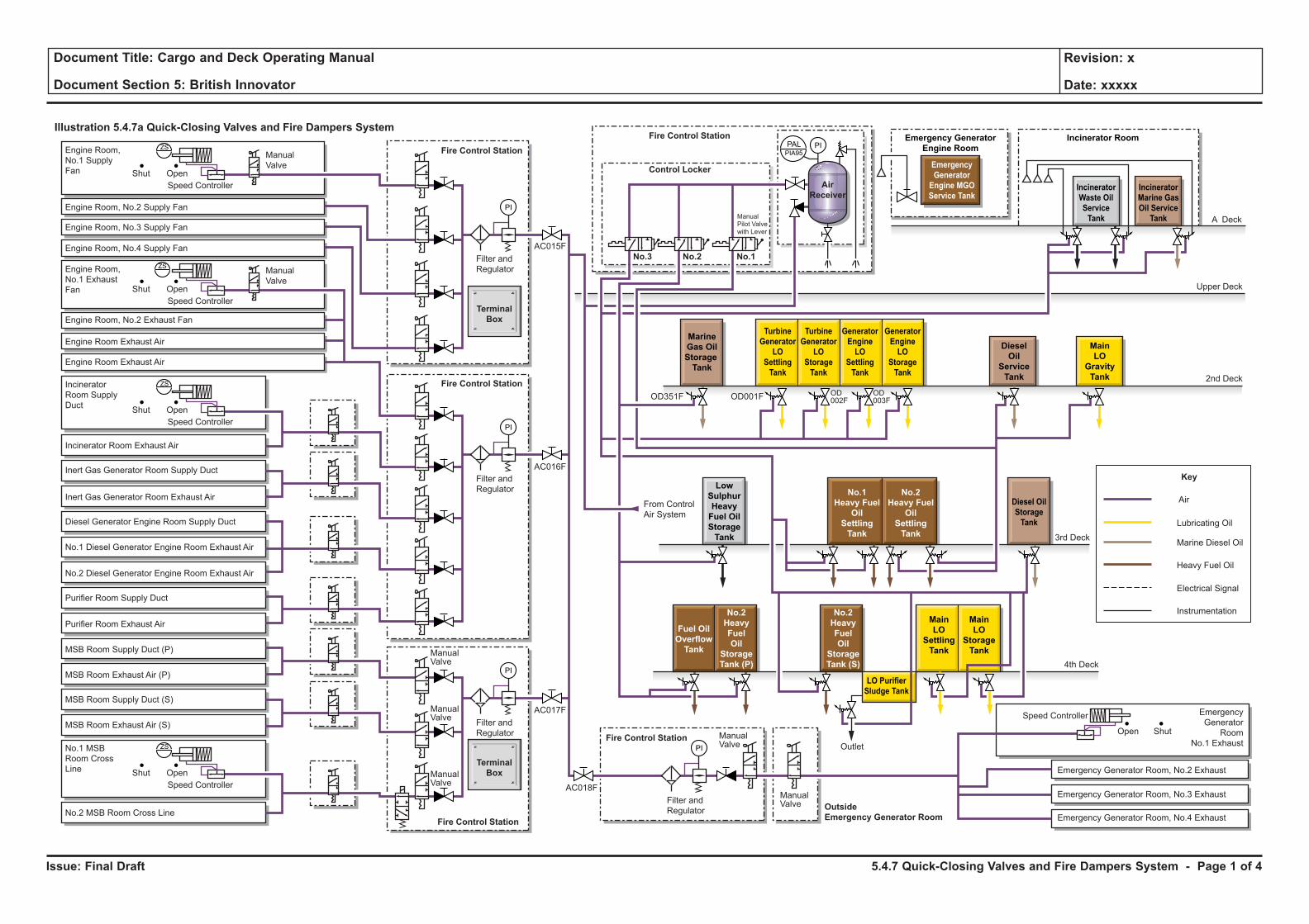
Issue: Final Draft
Document Title: Cargo and Deck Operating Manual
Document Section 5: British Innovator
Revision: x
Date: xxxxx
Illustration 5.4.7a Quick-Closing Valves and Fire Dampers SystemPI
Air
Key
Marine Diesel Oil
Heavy Fuel Oil
Electrical Signal
Instrumentation
Lubricating Oil
MarineGas OilStorageTank
TurbineGenerator
LOSettlingTank
TurbineGenerator
LOStorageTank
GeneratorEngineLO
SettlingTank
GeneratorEngineLO
StorageTank
DieselOil
ServiceTank
IncineratorWaste OilServiceTank
EmergencyGeneratorEngine MGOService Tank
Emergency GeneratorEngine Room
IncineratorMarine GasOil ServiceTank
Diesel OilStorageTank
LowSulphurHeavyFuel OilStorageTank
No.2Heavy Fuel
OilSettlingTank
No.2HeavyFuelOil
StorageTank (P)
No.2HeavyFuelOil
StorageTank (S)
No.1Heavy Fuel
OilSettlingTank
Fuel OilOverflowTank
MainLO
GravityTank
MainLO
SettlingTank
MainLO
StorageTank
LO PurifierSludge Tank
A Deck
Upper Deck
2nd Deck
3rd Deck
4th Deck
Emergency Generator Room, No.4 Exhaust
Emergency Generator Room, No.3 Exhaust
Engine Room,No.1 SupplyFan Shut Open
Speed Controller
ManualValve
Engine Room, No.3 Supply Fan
Engine Room, No.4 Supply Fan
Engine Room,No.1 ExhaustFan
Engine Room, No.2 Exhaust Fan
Engine Room Exhaust Air
Engine Room Exhaust Air
IncineratorRoom SupplyDuct
Incinerator Room Exhaust Air
Inert Gas Generator Room Supply Duct
Inert Gas Generator Room Exhaust Air
Diesel Generator Engine Room Supply Duct
No.1 Diesel Generator Engine Room Exhaust Air
No.2 Diesel Generator Engine Room Exhaust Air
Purifier Room Supply Duct
Purifier Room Exhaust Air
MSB Room Supply Duct (P)
MSB Room Exhaust Air (P)
MSB Room Supply Duct (S)
MSB Room Exhaust Air (S)
No.2 MSB Room Cross Line
No.1 MSBRoom CrossLine
Engine Room, No.2 Supply Fan
Emergency Generator Room, No.2 Exhaust
Fire Control Station
Fire Control Station
OutsideEmergency Generator Room
Fire Control Station
Fire Control Station
Control Locker
No.3 No.2 No.1
Fire Control Station
From ControlAir System
Filter andRegulator
Filter andRegulator
Filter andRegulator
ManualPilot Valvewith Lever
EmergencyGenerator
RoomNo.1 Exhaust
Incinerator Room
AirReceiver
PI
Filter andRegulator
Outlet
ManualValve
ManualValve
ManualValve
ManualValve
ManualValve
PI
PI
PI
PALZSPIA95
TerminalBox
TerminalBox
Shut OpenSpeed Controller
ZS
Shut OpenSpeed Controller
ZS
Shut OpenSpeed Controller
ManualValve
ZS
AC017F
AC018F
AC016F
AC015F
OD351F OD001F OD002F
OD003F
ShutOpen
Speed Controller
5.4.7 Quick-Closing Valves and Fire Dampers System - Page 1 of 4
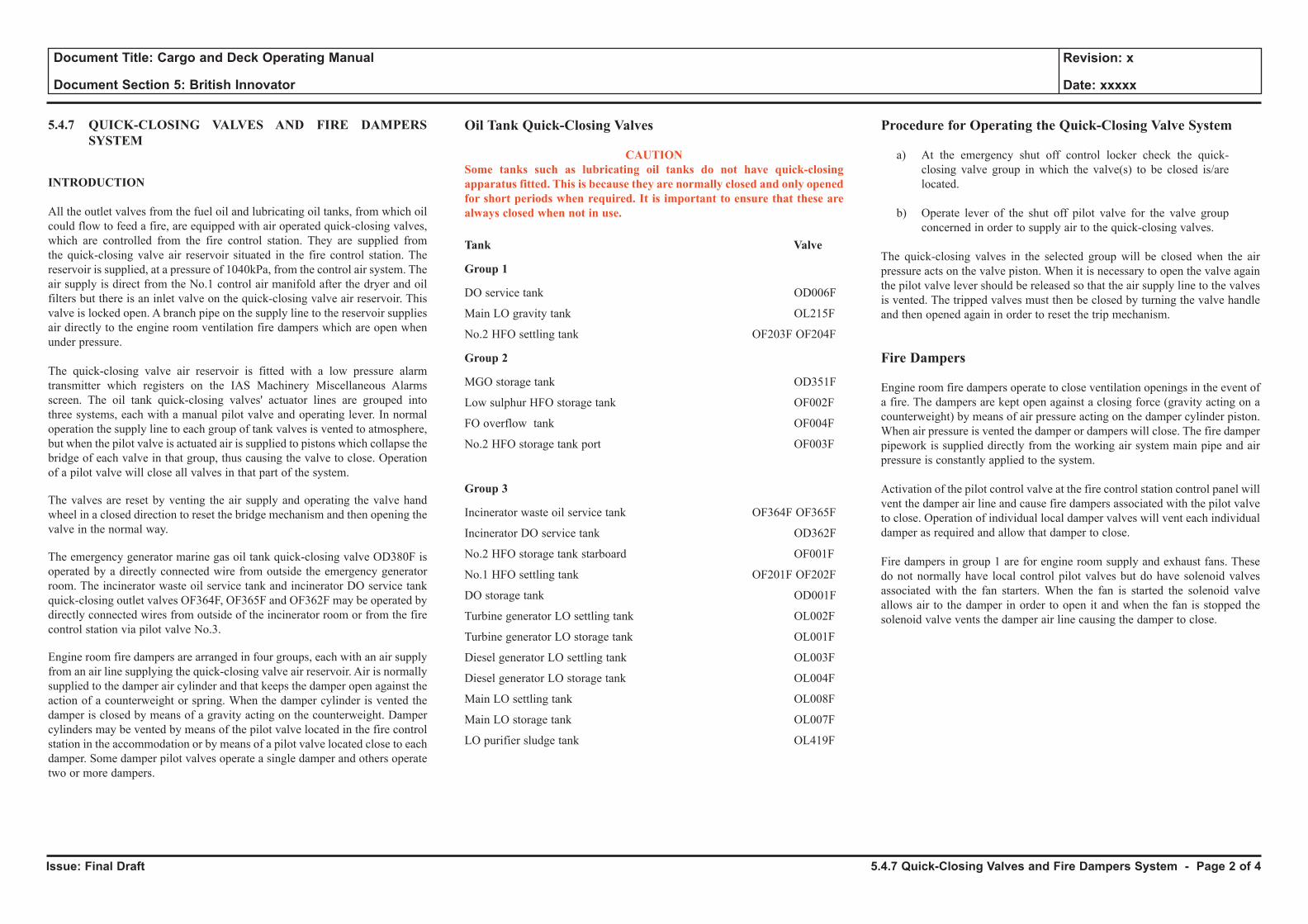
Issue: Final Draft
Document Title: Cargo and Deck Operating Manual
Document Section 5: British Innovator
Revision: x
Date: xxxxx
5.4.7 QUICK-CLOSING VALVES AND FIRE DAMPERS SYSTEM
INTRODUCTION
All the outlet valves from the fuel oil and lubricating oil tanks, from which oil could flow to feed a fire, are equipped with air operated quick-closing valves, which are controlled from the fire control station. They are supplied from the quick-closing valve air reservoir situated in the fire control station. The reservoir is supplied, at a pressure of 1040kPa, from the control air system. The air supply is direct from the No.1 control air manifold after the dryer and oil filters but there is an inlet valve on the quick-closing valve air reservoir. This valve is locked open. A branch pipe on the supply line to the reservoir supplies air directly to the engine room ventilation fire dampers which are open when under pressure.
The quick-closing valve air reservoir is fitted with a low pressure alarm transmitter which registers on the IAS Machinery Miscellaneous Alarms screen. The oil tank quick-closing valves' actuator lines are grouped into three systems, each with a manual pilot valve and operating lever. In normal operation the supply line to each group of tank valves is vented to atmosphere, but when the pilot valve is actuated air is supplied to pistons which collapse the bridge of each valve in that group, thus causing the valve to close. Operation of a pilot valve will close all valves in that part of the system.
The valves are reset by venting the air supply and operating the valve hand wheel in a closed direction to reset the bridge mechanism and then opening the valve in the normal way.
The emergency generator marine gas oil tank quick-closing valve OD380F is operated by a directly connected wire from outside the emergency generator room. The incinerator waste oil service tank and incinerator DO service tank quick-closing outlet valves OF364F, OF365F and OF362F may be operated by directly connected wires from outside of the incinerator room or from the fire control station via pilot valve No.3.
Engine room fire dampers are arranged in four groups, each with an air supply from an air line supplying the quick-closing valve air reservoir. Air is normally supplied to the damper air cylinder and that keeps the damper open against the action of a counterweight or spring. When the damper cylinder is vented the damper is closed by means of a gravity acting on the counterweight. Damper cylinders may be vented by means of the pilot valve located in the fire control station in the accommodation or by means of a pilot valve located close to each damper. Some damper pilot valves operate a single damper and others operate two or more dampers.
Oil Tank Quick-Closing Valves
CAUTIONSome tanks such as lubricating oil tanks do not have quick-closing apparatus fitted. This is because they are normally closed and only opened for short periods when required. It is important to ensure that these are always closed when not in use.
Tank Valve
Group 1
DO service tank OD006F
Main LO gravity tank OL215F
No.2 HFO settling tank OF203F OF204F
Group 2
MGO storage tank OD351F
Low sulphur HFO storage tank OF002F
FO overflow tank OF004F
No.2 HFO storage tank port OF003F
Group 3
Incinerator waste oil service tank OF364F OF365F
Incinerator DO service tank OD362F
No.2 HFO storage tank starboard OF001F
No.1 HFO settling tank OF201F OF202F
DO storage tank OD001F
Turbine generator LO settling tank OL002F
Turbine generator LO storage tank OL001F
Diesel generator LO settling tank OL003F
Diesel generator LO storage tank OL004F
Main LO settling tank OL008F
Main LO storage tank OL007F
LO purifier sludge tank OL419F
Procedure for Operating the Quick-Closing Valve System
a) At the emergency shut off control locker check the quick-closing valve group in which the valve(s) to be closed is/are located.
b) Operate lever of the shut off pilot valve for the valve group concerned in order to supply air to the quick-closing valves.
The quick-closing valves in the selected group will be closed when the air pressure acts on the valve piston. When it is necessary to open the valve again the pilot valve lever should be released so that the air supply line to the valves is vented. The tripped valves must then be closed by turning the valve handle and then opened again in order to reset the trip mechanism.
Fire Dampers
Engine room fire dampers operate to close ventilation openings in the event of a fire. The dampers are kept open against a closing force (gravity acting on a counterweight) by means of air pressure acting on the damper cylinder piston. When air pressure is vented the damper or dampers will close. The fire damper pipework is supplied directly from the working air system main pipe and air pressure is constantly applied to the system.
Activation of the pilot control valve at the fire control station control panel will vent the damper air line and cause fire dampers associated with the pilot valve to close. Operation of individual local damper valves will vent each individual damper as required and allow that damper to close.
Fire dampers in group 1 are for engine room supply and exhaust fans. These do not normally have local control pilot valves but do have solenoid valves associated with the fan starters. When the fan is started the solenoid valve allows air to the damper in order to open it and when the fan is stopped the solenoid valve vents the damper air line causing the damper to close.
5.4.7 Quick-Closing Valves and Fire Dampers System - Page 2 of 4

Issue: Final Draft
Document Title: Cargo and Deck Operating Manual
Document Section 5: British Innovator
Revision: x
Date: xxxxx
Illustration 5.4.7a Quick-Closing Valves and Fire Dampers SystemPI
Air
Key
Marine Diesel Oil
Heavy Fuel Oil
Electrical Signal
Instrumentation
Lubricating Oil
MarineGas OilStorageTank
TurbineGenerator
LOSettlingTank
TurbineGenerator
LOStorageTank
GeneratorEngineLO
SettlingTank
GeneratorEngineLO
StorageTank
DieselOil
ServiceTank
IncineratorWaste OilServiceTank
EmergencyGeneratorEngine MGOService Tank
Emergency GeneratorEngine Room
IncineratorMarine GasOil ServiceTank
Diesel OilStorageTank
LowSulphurHeavyFuel OilStorageTank
No.2Heavy Fuel
OilSettlingTank
No.2HeavyFuelOil
StorageTank (P)
No.2HeavyFuelOil
StorageTank (S)
No.1Heavy Fuel
OilSettlingTank
Fuel OilOverflowTank
MainLO
GravityTank
MainLO
SettlingTank
MainLO
StorageTank
LO PurifierSludge Tank
A Deck
Upper Deck
2nd Deck
3rd Deck
4th Deck
Emergency Generator Room, No.4 Exhaust
Emergency Generator Room, No.3 Exhaust
Engine Room,No.1 SupplyFan Shut Open
Speed Controller
ManualValve
Engine Room, No.3 Supply Fan
Engine Room, No.4 Supply Fan
Engine Room,No.1 ExhaustFan
Engine Room, No.2 Exhaust Fan
Engine Room Exhaust Air
Engine Room Exhaust Air
IncineratorRoom SupplyDuct
Incinerator Room Exhaust Air
Inert Gas Generator Room Supply Duct
Inert Gas Generator Room Exhaust Air
Diesel Generator Engine Room Supply Duct
No.1 Diesel Generator Engine Room Exhaust Air
No.2 Diesel Generator Engine Room Exhaust Air
Purifier Room Supply Duct
Purifier Room Exhaust Air
MSB Room Supply Duct (P)
MSB Room Exhaust Air (P)
MSB Room Supply Duct (S)
MSB Room Exhaust Air (S)
No.2 MSB Room Cross Line
No.1 MSBRoom CrossLine
Engine Room, No.2 Supply Fan
Emergency Generator Room, No.2 Exhaust
Fire Control Station
Fire Control Station
OutsideEmergency Generator Room
Fire Control Station
Fire Control Station
Control Locker
No.3 No.2 No.1
Fire Control Station
From ControlAir System
Filter andRegulator
Filter andRegulator
Filter andRegulator
ManualPilot Valvewith Lever
EmergencyGenerator
RoomNo.1 Exhaust
Incinerator Room
AirReceiver
PI
Filter andRegulator
Outlet
ManualValve
ManualValve
ManualValve
ManualValve
ManualValve
PI
PI
PI
PALZSPIA95
TerminalBox
TerminalBox
Shut OpenSpeed Controller
ZS
Shut OpenSpeed Controller
ZS
Shut OpenSpeed Controller
ManualValve
ZS
AC017F
AC018F
AC016F
AC015F
OD351F OD001F OD002F
OD003F
ShutOpen
Speed Controller
5.4.7 Quick-Closing Valves and Fire Dampers System - Page 3 of 4
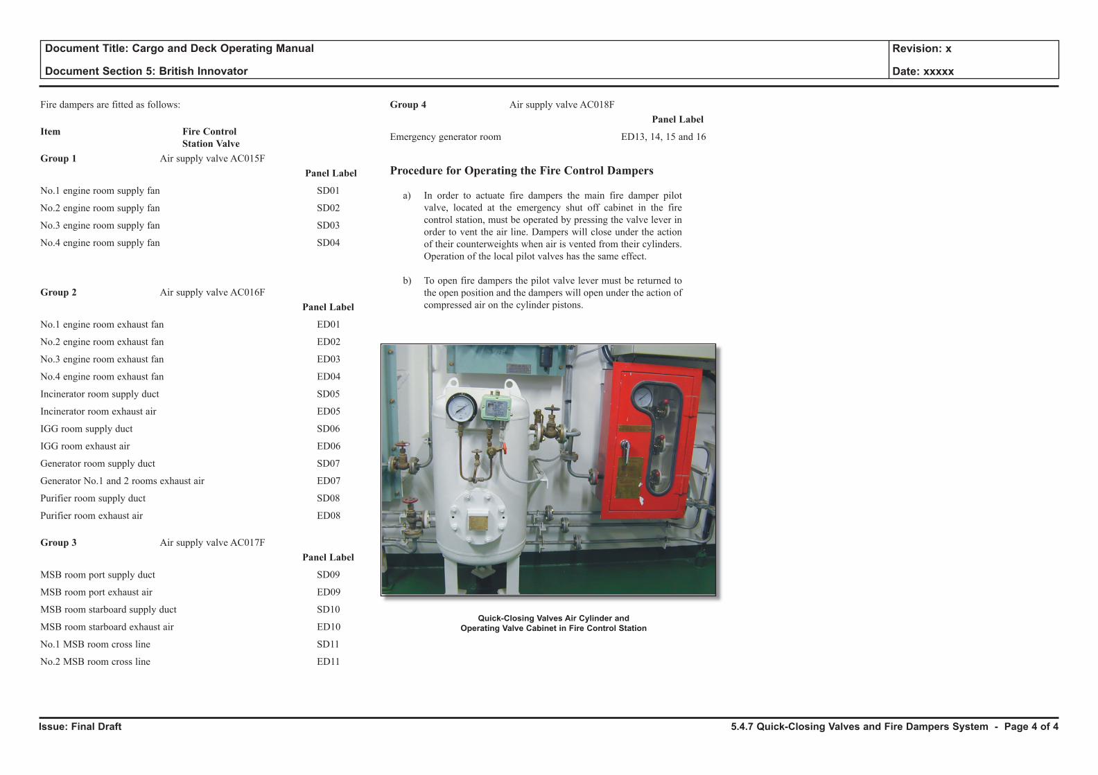
Issue: Final Draft
Document Title: Cargo and Deck Operating Manual
Document Section 5: British Innovator
Revision: x
Date: xxxxx
Fire dampers are fitted as follows:
Item Fire Control Station Valve
Group 1 Air supply valve AC015F Panel Label
No.1 engine room supply fan SD01
No.2 engine room supply fan SD02
No.3 engine room supply fan SD03
No.4 engine room supply fan SD04
Group 2 Air supply valve AC016F Panel Label
No.1 engine room exhaust fan ED01
No.2 engine room exhaust fan ED02
No.3 engine room exhaust fan ED03
No.4 engine room exhaust fan ED04
Incinerator room supply duct SD05
Incinerator room exhaust air ED05
IGG room supply duct SD06
IGG room exhaust air ED06
Generator room supply duct SD07
Generator No.1 and 2 rooms exhaust air ED07
Purifier room supply duct SD08
Purifier room exhaust air ED08
Group 3 Air supply valve AC017F Panel Label
MSB room port supply duct SD09
MSB room port exhaust air ED09
MSB room starboard supply duct SD10
MSB room starboard exhaust air ED10
No.1 MSB room cross line SD11
No.2 MSB room cross line ED11
Group 4 Air supply valve AC018F Panel Label
Emergency generator room ED13, 14, 15 and 16
Procedure for Operating the Fire Control Dampers
a) In order to actuate fire dampers the main fire damper pilot valve, located at the emergency shut off cabinet in the fire control station, must be operated by pressing the valve lever in order to vent the air line. Dampers will close under the action of their counterweights when air is vented from their cylinders. Operation of the local pilot valves has the same effect.
b) To open fire dampers the pilot valve lever must be returned to the open position and the dampers will open under the action of compressed air on the cylinder pistons.
5.4.7 Quick-Closing Valves and Fire Dampers System - Page 4 of 4
Quick-Closing Valves Air Cylinder and Operating Valve Cabinet in Fire Control Station
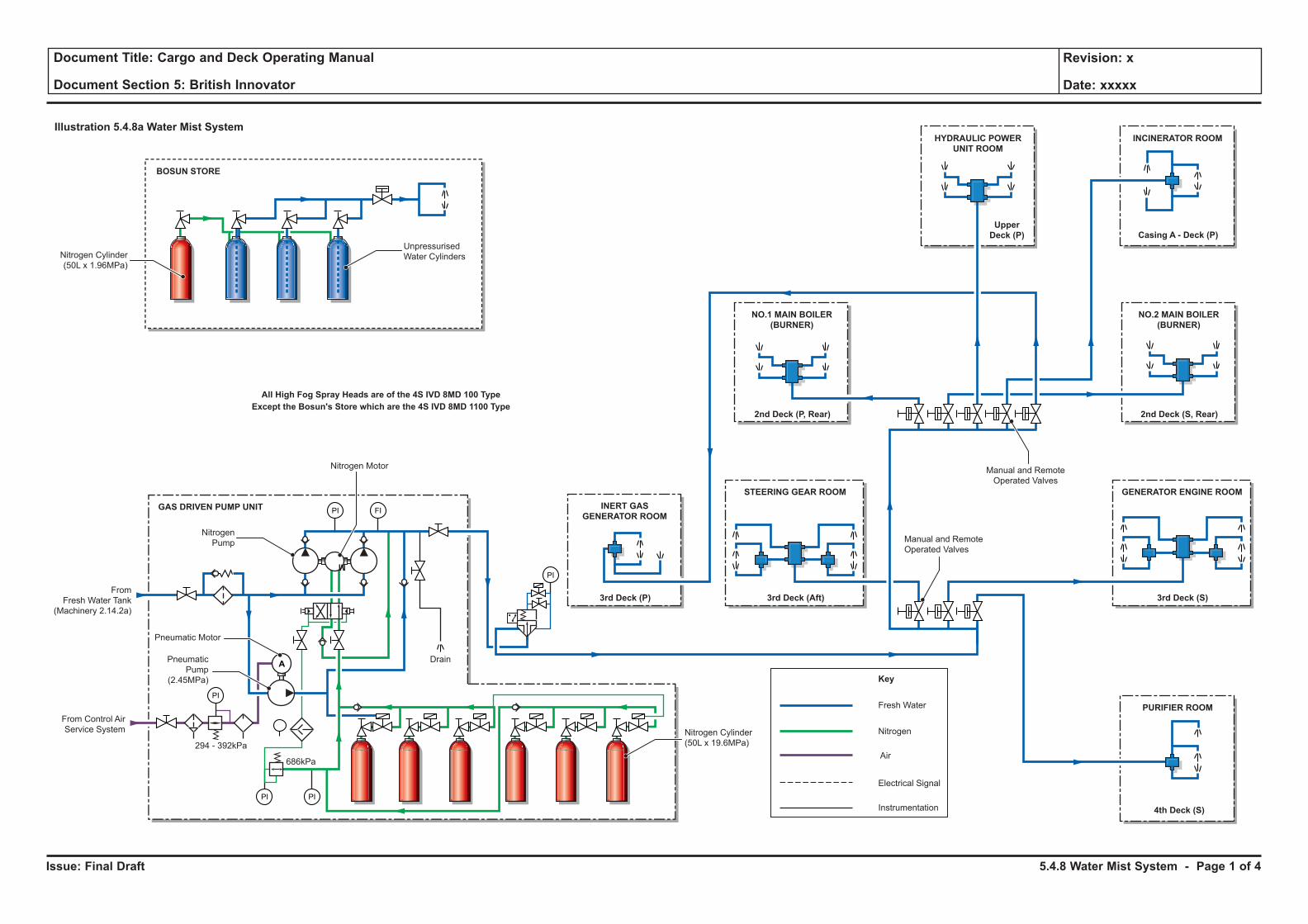
Issue: Final Draft
Document Title: Cargo and Deck Operating Manual
Document Section 5: British Innovator
Revision: x
Date: xxxxx
Illustration 5.4.8a Water Mist System
PURIFIER ROOM
4th Deck (S)
INCINERATOR ROOM
Casing A - Deck (P)
GENERATOR ENGINE ROOM
3rd Deck (S)
NO.2 MAIN BOILER(BURNER)
2nd Deck (S, Rear)
HYDRAULIC POWERUNIT ROOM
UpperDeck (P)
STEERING GEAR ROOM
3rd Deck (Aft)
NO.1 MAIN BOILER(BURNER)
2nd Deck (P, Rear)
PI PI
PI FI
Fresh Water
Manual and RemoteOperated Valves
Nitrogen Motor
Nitrogen Cylinder(50L x 19.6MPa)294 - 392kPa
686kPa
Pneumatic Motor
PneumaticPump
(2.45MPa)
NitrogenPump
Manual and RemoteOperated Valves
Drain
Key
Nitrogen
Air
Electrical Signal
Instrumentation
M
PI
PI
FromFresh Water Tank
(Machinery 2.14.2a)
From Control AirService System
GAS DRIVEN PUMP UNIT
BOSUN STORE
All High Fog Spray Heads are of the 4S IVD 8MD 100 TypeExcept the Bosun's Store which are the 4S IVD 8MD 1100 Type
INERT GASGENERATOR ROOM
3rd Deck (P)
Nitrogen Cylinder(50L x 1.96MPa)
UnpressurisedWater Cylinders
A
5.4.8 Water Mist System - Page 1 of 4
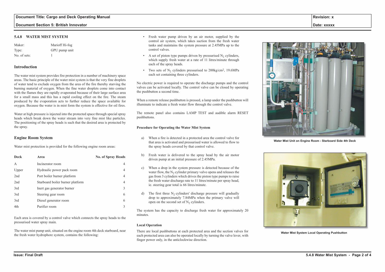
Issue: Final Draft
Document Title: Cargo and Deck Operating Manual
Document Section 5: British Innovator
Revision: x
Date: xxxxx
5.4.8 WATER MIST SYSTEM
Maker: Marioff Hi-fogType: GPU pump unit No. of sets: 1
Introduction
The water mist system provides fire protection in a number of machinery space areas. The basic principle of the water mist system is that the very fine droplets of water tend to exclude oxygen from the area of the fire thereby starving the burning material of oxygen. When the fine water droplets come into contact with the flames they are rapidly evaporated because of their large surface area for a small mass and this has a rapid cooling effect on the fire. The steam produced by the evaporation acts to further reduce the space available for oxygen. Because the water is in mist form the system is effective for oil fires.
Water at high pressure is injected into the protected space through special spray heads which break down the water stream into very fine mist like particles. The positioning of the spray heads is such that the desired area is protected by the spray.
Engine Room System
Water mist protection is provided for the following engine room areas:
Deck Area No. of Spray Heads
A Incinerator room 4
Upper Hydraulic power pack room 4
2nd Port boiler burner platform 4
2nd Starboard boiler burner platform 4
3rd Inert gas generator burner 3
3rd Steering gear room 6
3rd Diesel generator room 6
4th Purifier room 3
Each area is covered by a control valve which connects the spray heads to the pressurised water spray main.
The water mist pump unit, situated on the engine room 4th deck starboard, near the fresh water hydrophore system, contains the following:
• Fresh water pump driven by an air motor, supplied by the control air system, which takes suction from the fresh water tanks and maintains the system pressure at 2.45MPa up to the control valves.
• A set of piston type pumps driven by pressurised N2 cylinders, which supply fresh water at a rate of 11 litres/minute through each of the spray heads.
• Two sets of N2 cylinders pressurised to 200kg/cm2, 19.6MPa each set containing three cylinders.
No electric power is required to operate the discharge pumps and the control valves can be activated locally. The control valve can be closed by operating the pushbutton a second time.
When a remote release pushbutton is pressed, a lamp under the pushbutton will illuminate to indicate a fresh water flow through the control valve.
The remote panel also contains LAMP TEST and audible alarm RESET pushbuttons.
Procedure for Operating the Water Mist System
a) When a fire is detected in a protected area the control valve for that area is activated and pressurised water is allowed to flow to the spray heads covered by that control valve.
b) Fresh water is delivered to the spray head by the air motor driven pump at an initial pressure of 2.45MPa.
c) When a drop in the system pressure is detected because of the water flow, the N2 cylinder primary valve opens and releases the gas from 3 cylinders which drives the piston type pumps to raise the fresh water discharge rate to 11 litres/minute per spray head, ie. steering gear total is 66 litres/minute.
d) The first three N2 cylinders' discharge pressure will gradually drop to approximately 7.84MPa when the primary valve will open on the second set of N2 cylinders.
The system has the capacity to discharge fresh water for approximately 20 minutes.
Local Operation
There are local pushbuttons at each protected area and the section valves for each protected area can also be operated locally by turning the valve lever, with finger power only, in the anticlockwise direction.
Water Mist Unit on Engine Room - Starboard Side 4th Deck
Water Mist System Local Operating Pushbutton
5.4.8 Water Mist System - Page 2 of 4

Issue: Final Draft
Document Title: Cargo and Deck Operating Manual
Document Section 5: British Innovator
Revision: x
Date: xxxxx
Illustration 5.4.8a Water Mist System
PURIFIER ROOM
4th Deck (S)
INCINERATOR ROOM
Casing A - Deck (P)
GENERATOR ENGINE ROOM
3rd Deck (S)
NO.2 MAIN BOILER(BURNER)
2nd Deck (S, Rear)
HYDRAULIC POWERUNIT ROOM
UpperDeck (P)
STEERING GEAR ROOM
3rd Deck (Aft)
NO.1 MAIN BOILER(BURNER)
2nd Deck (P, Rear)
PI PI
PI FI
Fresh Water
Manual and RemoteOperated Valves
Nitrogen Motor
Nitrogen Cylinder(50L x 19.6MPa)294 - 392kPa
686kPa
Pneumatic Motor
PneumaticPump
(2.45MPa)
NitrogenPump
Manual and RemoteOperated Valves
Drain
Key
Nitrogen
Air
Electrical Signal
Instrumentation
M
PI
PI
FromFresh Water Tank
(Machinery 2.14.2a)
From Control AirService System
GAS DRIVEN PUMP UNIT
BOSUN STORE
All High Fog Spray Heads are of the 4S IVD 8MD 100 TypeExcept the Bosun's Store which are the 4S IVD 8MD 1100 Type
INERT GASGENERATOR ROOM
3rd Deck (P)
Nitrogen Cylinder(50L x 1.96MPa)
UnpressurisedWater Cylinders
A
5.4.8 Water Mist System - Page 3 of 4
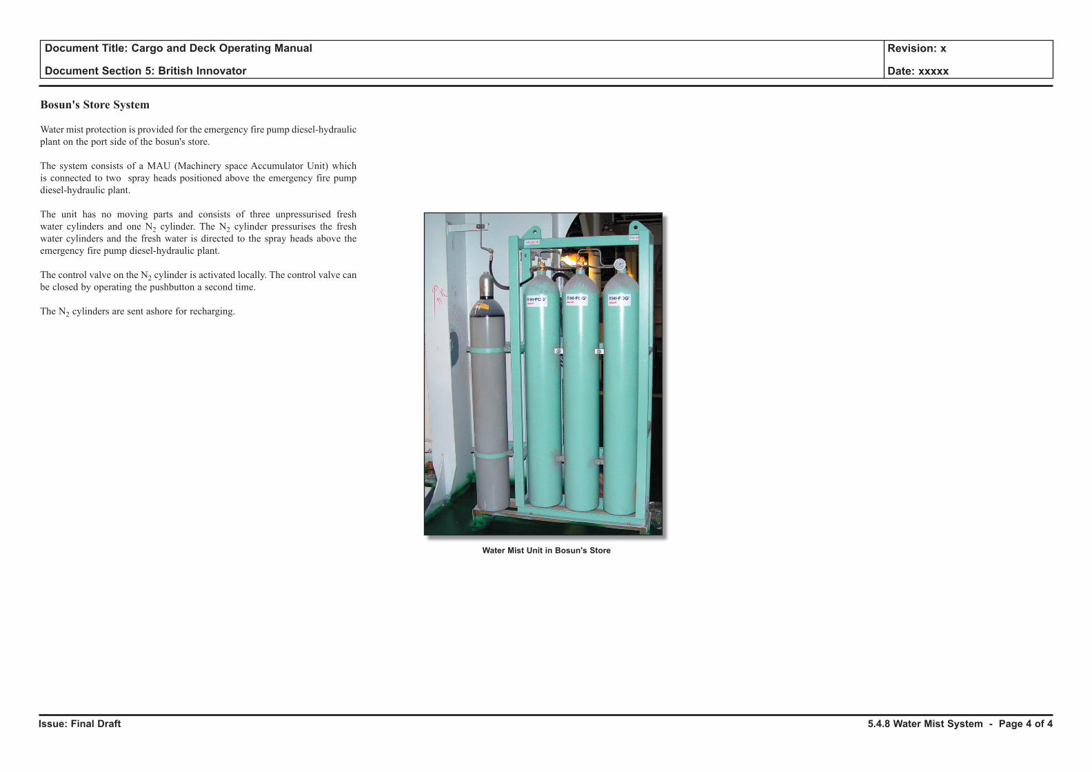
Issue: Final Draft
Document Title: Cargo and Deck Operating Manual
Document Section 5: British Innovator
Revision: x
Date: xxxxx
Bosun's Store System
Water mist protection is provided for the emergency fire pump diesel-hydraulic plant on the port side of the bosun's store.
The system consists of a MAU (Machinery space Accumulator Unit) which is connected to two spray heads positioned above the emergency fire pump diesel-hydraulic plant.
The unit has no moving parts and consists of three unpressurised fresh water cylinders and one N2 cylinder. The N2 cylinder pressurises the fresh water cylinders and the fresh water is directed to the spray heads above the emergency fire pump diesel-hydraulic plant.
The control valve on the N2 cylinder is activated locally. The control valve can be closed by operating the pushbutton a second time.
The N2 cylinders are sent ashore for recharging.
Water Mist Unit in Bosun's Store
5.4.8 Water Mist System - Page 4 of 4
5.5 Cargo Machinery Fresh Water Cooling System
Illustrations
5.5a Cargo Machinery Fresh Water Cooling System
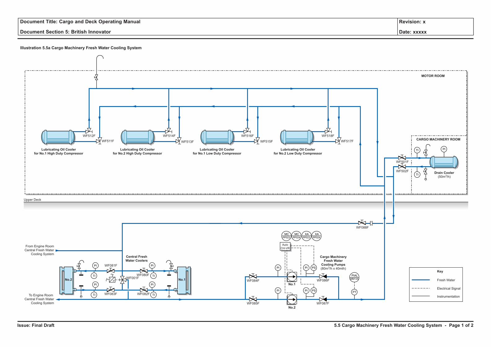
Issue: Final Draft
Document Title: Cargo and Deck Operating Manual
Document Section 5: British Innovator
Revision: x
Date: xxxxx
Illustration 5.5a Cargo Machinery Fresh Water Cooling System
TI
TI
PT
PI PI PS
Upper Deck
From Engine Room
Central Fresh Water
Cooling System
To Engine Room
Central Fresh Water
Cooling System
PI
TI
PI
TI
PI
TI
PI
TI
PI PI PS
No.2
No.1
MCPP023
MCPP024
XAPP024
PIALMM135I
P
Auto
CH-VR
XAPP023
Cargo Machinery
Fresh Water
Cooling Pumps
(80m3/h x 40mth)
Central Fresh
Water Coolers
Lubricating Oil Cooler
for No.1 High Duty Compressor
Lubricating Oil Cooler
for No.2 High Duty Compressor
Lubricating Oil Cooler
for No.1 Low Duty Compressor
Lubricating Oil Cooler
for No.2 Low Duty Compressor
Drain Cooler
(50m3/h)
No.2 No.1
WF088F
WF501F
WF517F
WF518F
WF515F
WF516F
WF513F
WF514F
WF511F
WF512F
WF502F
WF086F
WF087F
WF084F
WF085F
WF080F
WF081F
WF082FWF083F
WF001F
CARGO MACHINERY ROOM
MOTOR ROOM
PI
Key
Electrical Signal
Fresh Water
Instrumentation
5.5 Cargo Machinery Fresh Water Cooling System - Page 1 of 2
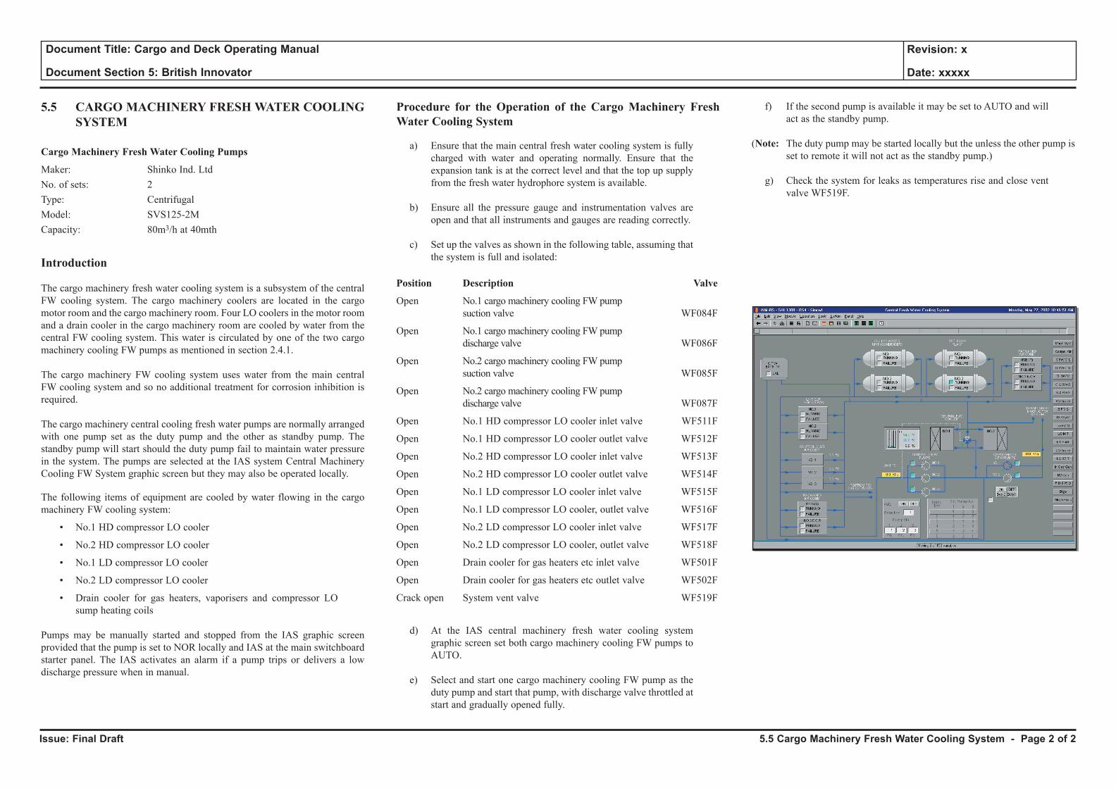
Issue: Final Draft
Document Title: Cargo and Deck Operating Manual
Document Section 5: British Innovator
Revision: x
Date: xxxxx
5.5 CARGO MACHINERY FRESH WATER COOLING SYSTEM
Cargo Machinery Fresh Water Cooling Pumps
Maker: Shinko Ind. LtdNo. of sets: 2Type: CentrifugalModel: SVS125-2MCapacity: 80m3/h at 40mth
Introduction
The cargo machinery fresh water cooling system is a subsystem of the central FW cooling system. The cargo machinery coolers are located in the cargo motor room and the cargo machinery room. Four LO coolers in the motor room and a drain cooler in the cargo machinery room are cooled by water from the central FW cooling system. This water is circulated by one of the two cargo machinery cooling FW pumps as mentioned in section 2.4.1.
The cargo machinery FW cooling system uses water from the main central FW cooling system and so no additional treatment for corrosion inhibition is required.
The cargo machinery central cooling fresh water pumps are normally arranged with one pump set as the duty pump and the other as standby pump. The standby pump will start should the duty pump fail to maintain water pressure in the system. The pumps are selected at the IAS system Central Machinery Cooling FW System graphic screen but they may also be operated locally.
The following items of equipment are cooled by water flowing in the cargo machinery FW cooling system:
• No.1 HD compressor LO cooler
• No.2 HD compressor LO cooler
• No.1 LD compressor LO cooler
• No.2 LD compressor LO cooler
• Drain cooler for gas heaters, vaporisers and compressor LO sump heating coils
Pumps may be manually started and stopped from the IAS graphic screen provided that the pump is set to NOR locally and IAS at the main switchboard starter panel. The IAS activates an alarm if a pump trips or delivers a low discharge pressure when in manual.
Procedure for the Operation of the Cargo Machinery Fresh Water Cooling System
a) Ensure that the main central fresh water cooling system is fully charged with water and operating normally. Ensure that the expansion tank is at the correct level and that the top up supply from the fresh water hydrophore system is available.
b) Ensure all the pressure gauge and instrumentation valves are open and that all instruments and gauges are reading correctly.
c) Set up the valves as shown in the following table, assuming that the system is full and isolated:
Position Description Valve
Open No.1 cargo machinery cooling FW pump suction valve WF084F
Open No.1 cargo machinery cooling FW pump discharge valve WF086F
Open No.2 cargo machinery cooling FW pump suction valve WF085F
Open No.2 cargo machinery cooling FW pump discharge valve WF087F
Open No.1 HD compressor LO cooler inlet valve WF511F
Open No.1 HD compressor LO cooler outlet valve WF512F
Open No.2 HD compressor LO cooler inlet valve WF513F
Open No.2 HD compressor LO cooler outlet valve WF514F
Open No.1 LD compressor LO cooler inlet valve WF515F
Open No.1 LD compressor LO cooler, outlet valve WF516F
Open No.2 LD compressor LO cooler inlet valve WF517F
Open No.2 LD compressor LO cooler, outlet valve WF518F
Open Drain cooler for gas heaters etc inlet valve WF501F
Open Drain cooler for gas heaters etc outlet valve WF502F
Crack open System vent valve WF519F
d) At the IAS central machinery fresh water cooling system graphic screen set both cargo machinery cooling FW pumps to AUTO.
e) Select and start one cargo machinery cooling FW pump as the duty pump and start that pump, with discharge valve throttled at start and gradually opened fully.
f) If the second pump is available it may be set to AUTO and will act as the standby pump.
(Note: The duty pump may be started locally but the unless the other pump is set to remote it will not act as the standby pump.)
g) Check the system for leaks as temperatures rise and close vent valve WF519F.
5.5 Cargo Machinery Fresh Water Cooling System - Page 2 of 2
5.6 Forward Bilge System
Illustrations
5.6a Forward Bilge System
5.6b Passage Way Bilge System
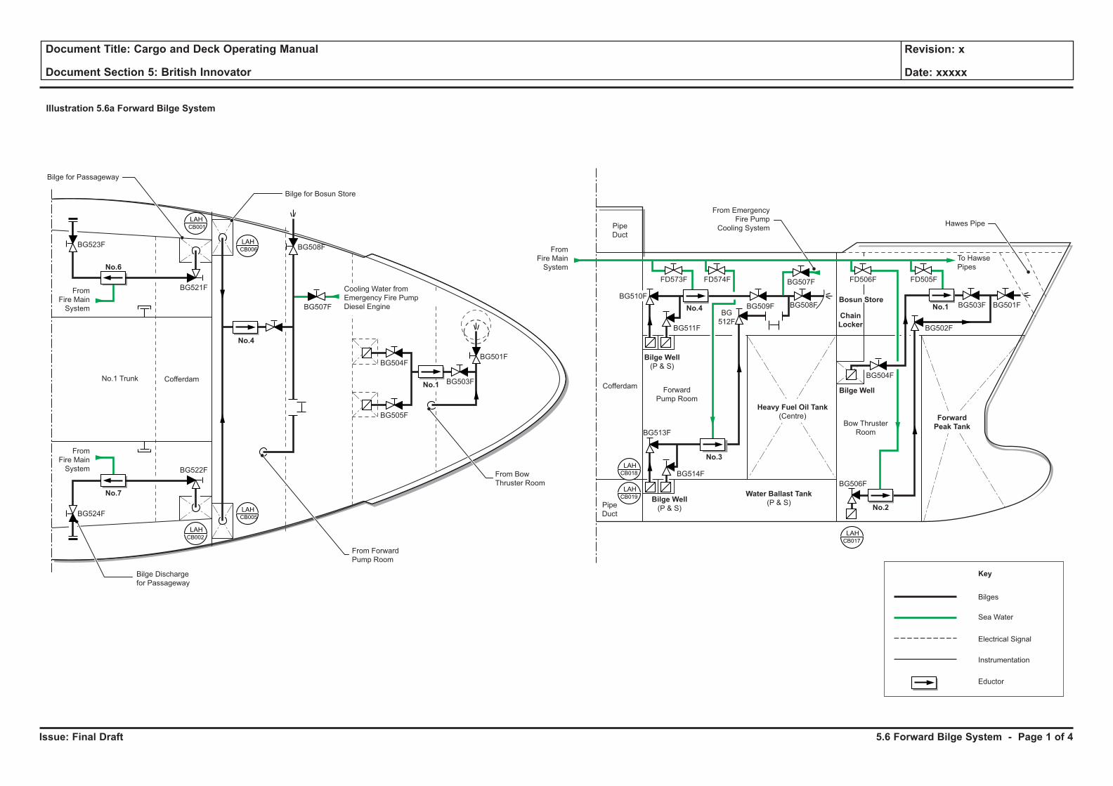
Issue: Final Draft
Document Title: Cargo and Deck Operating Manual
Document Section 5: British Innovator
Revision: x
Date: xxxxx
5.6 Forward Bilge System - Page 1 of 4
Illustration 5.6a Forward Bilge System
Forward
Peak Tank
No.1
No.2
No.3
No.4
No.1
No.4
No.6
No.7 Water Ballast Tank
(P & S)
Forward
Pump Room
Bow Thruster
Room
Bosun Store
Chain
Locker
Pipe
Duct
Pipe
Duct
From Bow
Thruster Room
From Forward
Pump Room
Bilge Discharge
for Passageway
Bilge for Bosun Store
Bilge for Passageway
CofferdamCofferdamNo.1 Trunk
Bilge Well
Bilge Well
(P & S)
Bilge Well
(P & S)
Hawes Pipe
BG501FBG503F
BG502F
BG504F
BG506F
BG508F
BG507F
BG509F
BG511F
BG501F
BG503F
BG504F
BG505F
BG507F
BG508F
BG521F
BG523F
BG524F
BG522F
BG513F
BG514F
LAHCB017
LAHCB019
LAHCB018
LAHCB002
LAHCB001
LAHCB006
LAHCB005
Cooling Water from
Emergency Fire Pump
Diesel Engine
Sea Water
Bilges
Key
Electrical Signal
Instrumentation
Eductor
From
Fire Main
System
From
Fire Main
System
From
Fire Main
System
To Hawse
Pipes
From Emergency
Fire Pump
Cooling System
BG510F
FD573F FD574F FD506F FD505F
Heavy Fuel Oil Tank
(Centre)
BG
512F
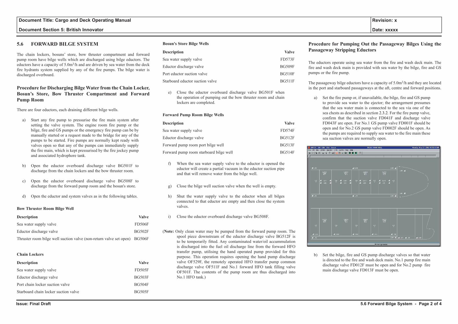
Issue: Final Draft
Document Title: Cargo and Deck Operating Manual
Document Section 5: British Innovator
Revision: x
Date: xxxxx
5.6 FORWARD BILGE SYSTEM
The chain lockers, bosuns’ store, bow thruster compartment and forward pump room have bilge wells which are discharged using bilge eductors. The eductors have a capacity of 5.0m3/h and are driven by sea water from the deck fire hydrants system supplied by any of the fire pumps. The bilge water is discharged overboard.
Procedure for Discharging Bilge Water from the Chain Locker, Bosun’s Store, Bow Thruster Compartment and Forward Pump Room
There are four eductors, each draining different bilge wells.
a) Start any fire pump to pressurise the fire main system after setting the valve system. The engine room fire pump or the bilge, fire and GS pumps or the emergency fire pump can be by manually started or a request made to the bridge for any of the pumps to be started. Fire pumps are normally kept ready with valves open so that any of the pumps can immediately supply the fire main, which is kept pressurised by the fire jockey pump and associated hydrophore tank.
b) Open the eductor overboard discharge valve BG501F to discharge from the chain lockers and the bow thruster room.
c) Open the eductor overboard discharge valve BG508F to discharge from the forward pump room and the bosun's store.
d) Open the eductor and system valves as in the following tables.
Bow Thruster Room Bilge Well
Description Valve
Sea water supply valve FD506F
Eductor discharge valve BG502F
Thruster room bilge well suction valve (non-return valve set open) BG506F
Chain Lockers
Description Valve
Sea water supply valve FD505F
Eductor discharge valve BG503F
Port chain locker suction valve BG504F
Starboard chain locker suction valve BG505F
Bosun's Store Bilge Wells
Description Valve
Sea water supply valve FD573F
Eductor discharge valve BG509F
Port eductor suction valve BG510F
Starboard eductor suction valve BG511F
e) Close the eductor overboard discharge valve BG501F when the operation of pumping out the bow thruster room and chain lockers are completed.
Forward Pump Room Bilge Wells
Description Valve
Sea water supply valve FD574F
Eductor discharge valve BG512F
Forward pump room port bilge well BG513F
Forward pump room starboard bilge well BG514F
f) When the sea water supply valve to the eductor is opened the eductor will create a partial vacuum in the eductor suction pipe and that will remove water from the bilge well.
g) Close the bilge well suction valve when the well is empty.
h) Shut the water supply valve to the eductor when all bilges connected to that eductor are empty and then close the system valves.
i) Close the eductor overboard discharge valve BG508F.
(Note: Only clean water may be pumped from the forward pump room. The spool piece downstream of the eductor discharge valve BG512F is to be temporarily fitted. Any contaminated water/oil accummulation is discharged into the fuel oil discharge line from the forward HFO transfer pump, utilising the hand operated pump provided for this purpose. This operation requires opening the hand pump discharge valve OF529F, the remotely operated HFO transfer pump common discharge valve OF511F and No.1 forward HFO tank filling valve OF501F. The contents of the pump room are thus discharged into No.1 HFO tank.)
Procedure for Pumping Out the Passageway Bilges Using the Passageway Stripping Eductors
The eductors operate using sea water from the fire and wash deck main. The fire and wash deck main is provided with sea water by the bilge, fire and GS pumps or the fire pump.
The passageway bilge eductors have a capacity of 5.0m3/h and they are located in the port and starboard passageways at the aft, centre and forward positions.
a) Set the fire pump or, if unavailable, the bilge, fire and GS pump to provide sea water to the ejector; the arrangement presumes that the sea water main is connected to the sea via one of the sea chests as described in section 2.3.2. For the fire pump valve, confirm that the suction valve FD041F and discharge valve FD043F are open. For No.1 GS pump valve FD001F should be open and for No.2 GS pump valve FD002F should be open. As the pumps are required to supply sea water to the fire main these sea suction valves are normally open.
b) Set the bilge, fire and GS pump discharge valves so that water is directed to the fire and wash deck main. No.1 pump fire main discharge valve FD012F must be open and for No.2 pump fire main discharge valve FD013F must be open.
5.6 Forward Bilge System - Page 2 of 4
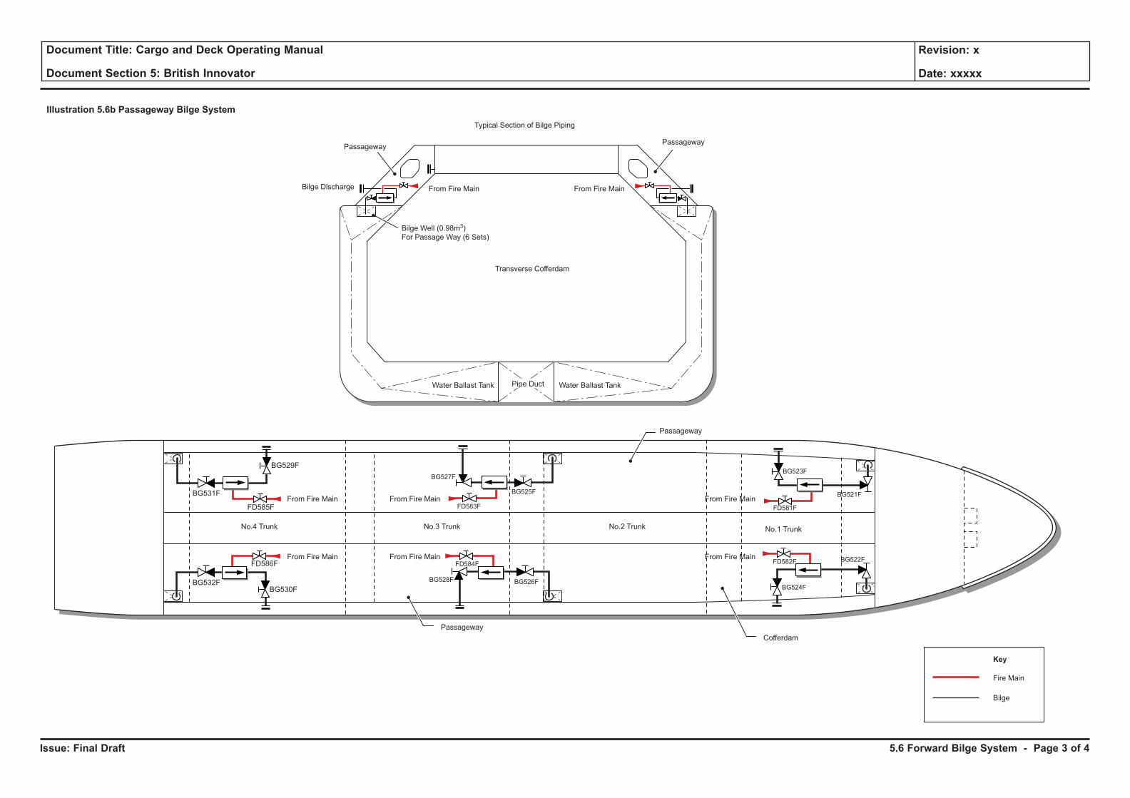
Issue: Final Draft
Document Title: Cargo and Deck Operating Manual
Document Section 5: British Innovator
Revision: x
Date: xxxxx
Illustration 5.6b Passageway Bilge System
Water Ballast Tank Water Ballast TankPipe Duct
Passageway
Bilge Discharge
Passageway
Transverse Cofferdam
From Fire Main From Fire Main
Bilge Well (0.98m3)
For Passage Way (6 Sets)
Typical Section of Bilge Piping
Passageway
Cofferdam
No.4 Trunk No.3 Trunk No.2 Trunk No.1 Trunk
Passageway
FD585F
FD586F
BG532F
BG531F
BG529F
BG530F
FD584F
FD583F
BG527F
BG525F
BG526FBG528F
FD582F
FD581F
BG522F
BG521F
BG524F
BG523F
Fire Main
Key
Bilge
From Fire Main
From Fire Main
From Fire Main
From Fire Main
From Fire Main
From Fire Main
5.6 Forward Bilge System - Page 3 of 4
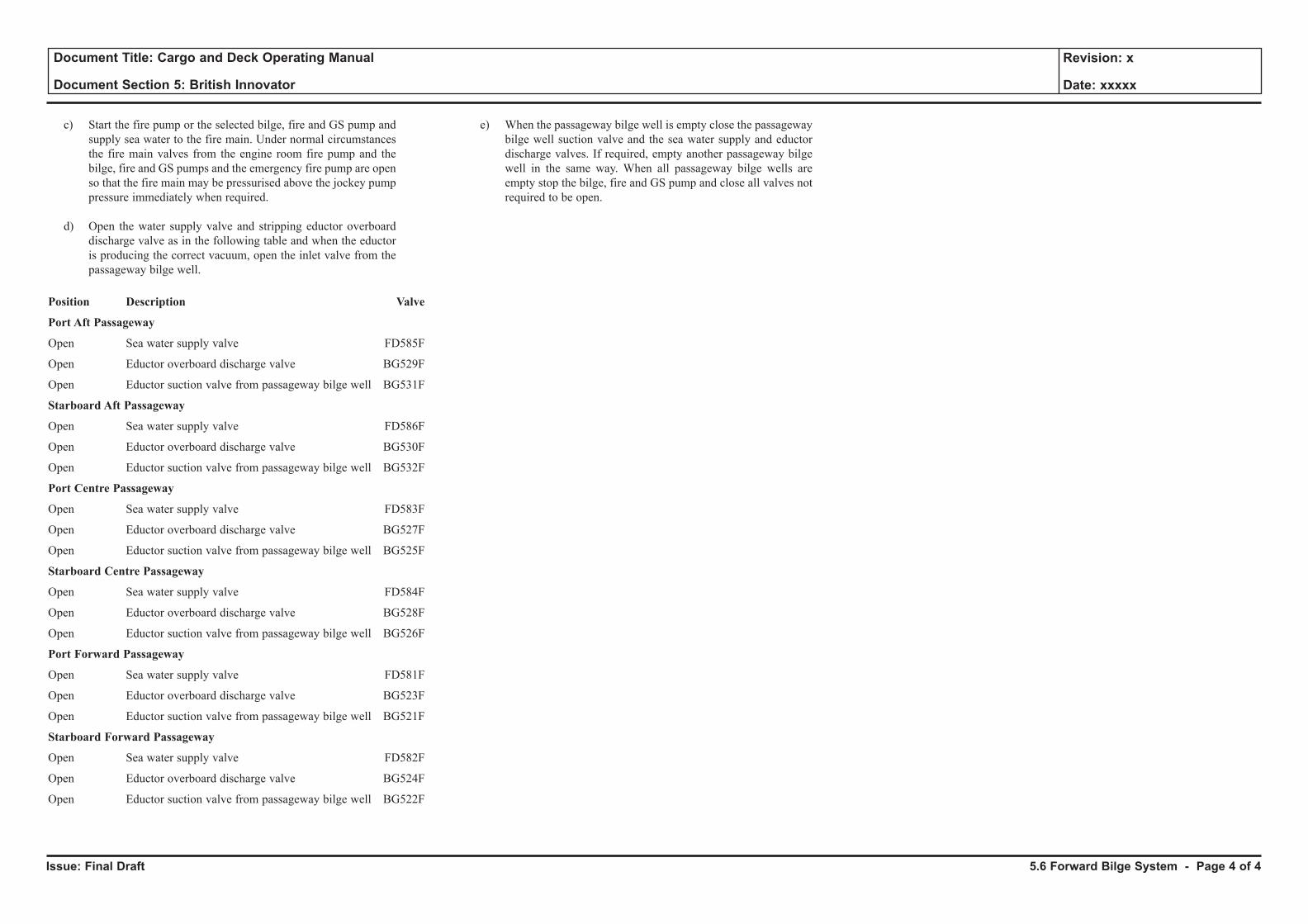
Issue: Final Draft
Document Title: Cargo and Deck Operating Manual
Document Section 5: British Innovator
Revision: x
Date: xxxxx
c) Start the fire pump or the selected bilge, fire and GS pump and supply sea water to the fire main. Under normal circumstances the fire main valves from the engine room fire pump and the bilge, fire and GS pumps and the emergency fire pump are open so that the fire main may be pressurised above the jockey pump pressure immediately when required.
d) Open the water supply valve and stripping eductor overboard discharge valve as in the following table and when the eductor is producing the correct vacuum, open the inlet valve from the passageway bilge well.
Position Description Valve
Port Aft Passageway
Open Sea water supply valve FD585F
Open Eductor overboard discharge valve BG529F
Open Eductor suction valve from passageway bilge well BG531F
Starboard Aft Passageway
Open Sea water supply valve FD586F
Open Eductor overboard discharge valve BG530F
Open Eductor suction valve from passageway bilge well BG532F
Port Centre Passageway
Open Sea water supply valve FD583F
Open Eductor overboard discharge valve BG527F
Open Eductor suction valve from passageway bilge well BG525F
Starboard Centre Passageway
Open Sea water supply valve FD584F
Open Eductor overboard discharge valve BG528F
Open Eductor suction valve from passageway bilge well BG526F
Port Forward Passageway
Open Sea water supply valve FD581F
Open Eductor overboard discharge valve BG523F
Open Eductor suction valve from passageway bilge well BG521F
Starboard Forward Passageway
Open Sea water supply valve FD582F
Open Eductor overboard discharge valve BG524F
Open Eductor suction valve from passageway bilge well BG522F
e) When the passageway bilge well is empty close the passageway bilge well suction valve and the sea water supply and eductor discharge valves. If required, empty another passageway bilge well in the same way. When all passageway bilge wells are empty stop the bilge, fire and GS pump and close all valves not required to be open.
5.6 Forward Bilge System - Page 4 of 4
5.7 Incinerator and Garbage Disposal
Illustrations
5.7a Incinerator Fuel Oil Service System
5.7b Garbage Treatment Procedure
5.7c Garbage Treatment Procedure for Oil
5.7d Garbage Treatment Procedure for Hotel Service
5.7e Garbage Treatment Procedure for Solid
5.7f Garbage Treatment Procedure Caution Plate
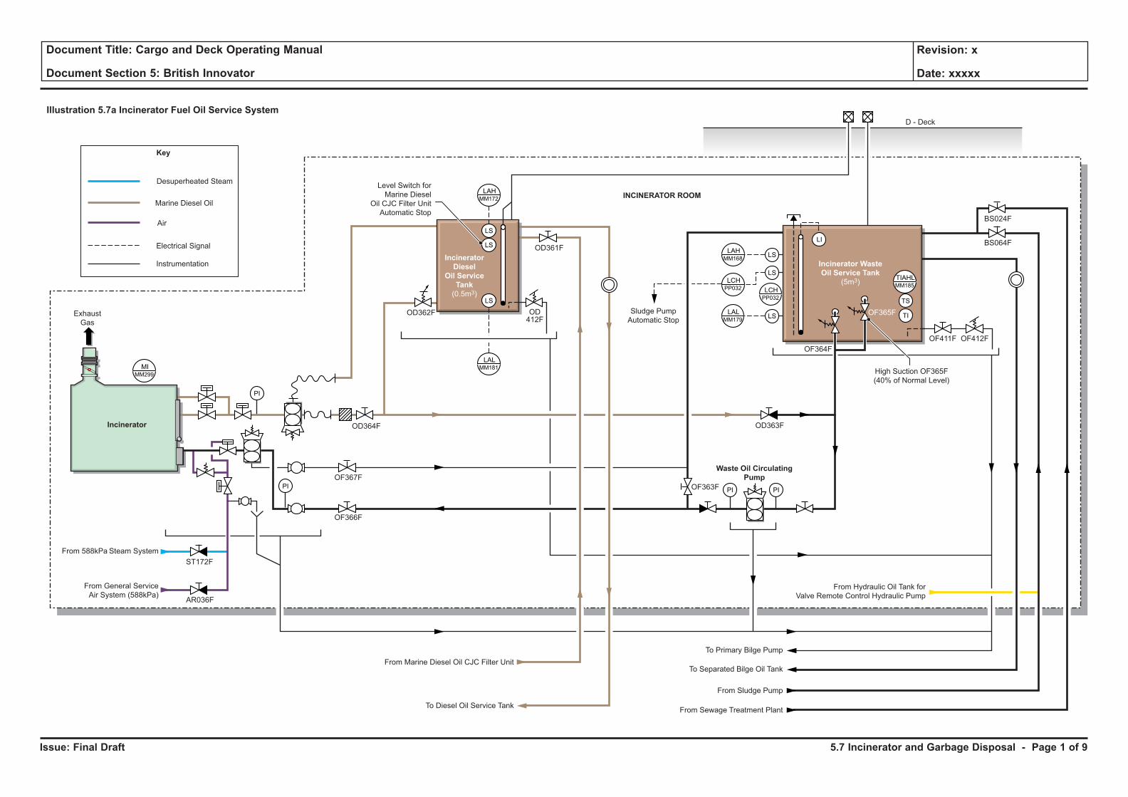
Issue: Final Draft
Document Title: Cargo and Deck Operating Manual
Document Section 5: British Innovator
Revision: x
Date: xxxxx
Illustration 5.7a Incinerator Fuel Oil Service System
PI PI
Desuperheated Steam
Marine Diesel Oil
Air
Electrical Signal
Instrumentation
Key
PI
LS
LS
LS
PI
MIMM299
LAHMM172
LALMM181
LI
LS
LS
LAHMM168
LCHPP032
LALMM179
LCHPP032
TIAHLMM185
LS TI
TS
Sludge Pump
Automatic Stop
D - Deck
From Hydraulic Oil Tank for
Valve Remote Control Hydraulic Pump
To Primary Bilge Pump
To Separated Bilge Oil TankFrom Marine Diesel Oil CJC Filter Unit
To Diesel Oil Service Tank
From Sludge Pump
From Sewage Treatment Plant
Level Switch for
Marine Diesel
Oil CJC Filter Unit
Automatic Stop
Exhaust
Gas
Waste Oil Circulating
Pump
Incinerator Waste
Oil Service Tank
(5m3)
Incinerator
Diesel
Oil Service
Tank
(0.5m3)
Incinerator
From 588kPa Steam System
From General Service
Air System (588kPa)
High Suction OF365F
(40% of Normal Level)
ST172F
AR036F
OF366F
OF367F
OD364F
OD362F
OD361F
OF411F
OF364F
OF365F
OF412F
OD363F
OF363F
BS024F
BS064F
OD412F
INCINERATOR ROOM
5.7 Incinerator and Garbage Disposal - Page 1 of 9
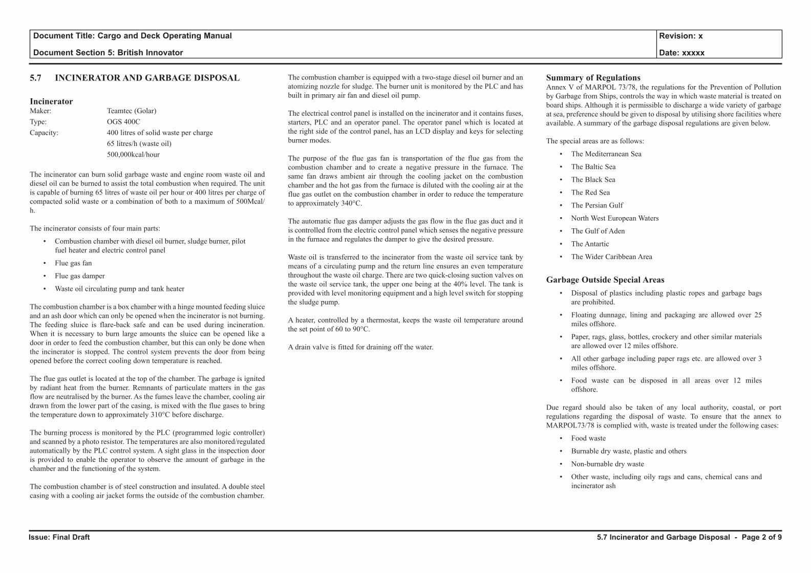
Issue: Final Draft
Document Title: Cargo and Deck Operating Manual
Document Section 5: British Innovator
Revision: x
Date: xxxxx
5.7 INCINERATOR AND GARBAGE DISPOSAL
IncineratorMaker: Teamtec (Golar) Type: OGS 400CCapacity: 400 litres of solid waste per charge 65 litres/h (waste oil) 500,000kcal/hour
The incinerator can burn solid garbage waste and engine room waste oil and diesel oil can be burned to assist the total combustion when required. The unit is capable of burning 65 litres of waste oil per hour or 400 litres per charge of compacted solid waste or a combination of both to a maximum of 500Mcal/h.
The incinerator consists of four main parts:
• Combustion chamber with diesel oil burner, sludge burner, pilot fuel heater and electric control panel
• Flue gas fan
• Flue gas damper
• Waste oil circulating pump and tank heater
The combustion chamber is a box chamber with a hinge mounted feeding sluice and an ash door which can only be opened when the incinerator is not burning. The feeding sluice is flare-back safe and can be used during incineration. When it is necessary to burn large amounts the sluice can be opened like a door in order to feed the combustion chamber, but this can only be done when the incinerator is stopped. The control system prevents the door from being opened before the correct cooling down temperature is reached.
The flue gas outlet is located at the top of the chamber. The garbage is ignited by radiant heat from the burner. Remnants of particulate matters in the gas flow are neutralised by the burner. As the fumes leave the chamber, cooling air drawn from the lower part of the casing, is mixed with the flue gases to bring the temperature down to approximately 310°C before discharge.
The burning process is monitored by the PLC (programmed logic controller) and scanned by a photo resistor. The temperatures are also monitored/regulated automatically by the PLC control system. A sight glass in the inspection door is provided to enable the operator to observe the amount of garbage in the chamber and the functioning of the system.
The combustion chamber is of steel construction and insulated. A double steel casing with a cooling air jacket forms the outside of the combustion chamber.
The combustion chamber is equipped with a two-stage diesel oil burner and an atomizing nozzle for sludge. The burner unit is monitored by the PLC and has built in primary air fan and diesel oil pump.
The electrical control panel is installed on the incinerator and it contains fuses, starters, PLC and an operator panel. The operator panel which is located at the right side of the control panel, has an LCD display and keys for selecting burner modes.
The purpose of the flue gas fan is transportation of the flue gas from the combustion chamber and to create a negative pressure in the furnace. The same fan draws ambient air through the cooling jacket on the combustion chamber and the hot gas from the furnace is diluted with the cooling air at the flue gas outlet on the combustion chamber in order to reduce the temperature to approximately 340°C.
The automatic flue gas damper adjusts the gas flow in the flue gas duct and it is controlled from the electric control panel which senses the negative pressure in the furnace and regulates the damper to give the desired pressure.
Waste oil is transferred to the incinerator from the waste oil service tank by means of a circulating pump and the return line ensures an even temperature throughout the waste oil charge. There are two quick-closing suction valves on the waste oil service tank, the upper one being at the 40% level. The tank is provided with level monitoring equipment and a high level switch for stopping the sludge pump.
A heater, controlled by a thermostat, keeps the waste oil temperature around the set point of 60 to 90°C.
A drain valve is fitted for draining off the water.
Summary of RegulationsAnnex V of MARPOL 73/78, the regulations for the Prevention of Pollution by Garbage from Ships, controls the way in which waste material is treated on board ships. Although it is permissible to discharge a wide variety of garbage at sea, preference should be given to disposal by utilising shore facilities where available. A summary of the garbage disposal regulations are given below.
The special areas are as follows:
• The Mediterranean Sea
• The Baltic Sea
• The Black Sea
• The Red Sea
• The Persian Gulf
• North West European Waters
• The Gulf of Aden
• The Antartic
• The Wider Caribbean Area
Garbage Outside Special Areas• Disposal of plastics including plastic ropes and garbage bags
are prohibited.
• Floating dunnage, lining and packaging are allowed over 25 miles offshore.
• Paper, rags, glass, bottles, crockery and other similar materials are allowed over 12 miles offshore.
• All other garbage including paper rags etc. are allowed over 3 miles offshore.
• Food waste can be disposed in all areas over 12 miles offshore.
Due regard should also be taken of any local authority, coastal, or port regulations regarding the disposal of waste. To ensure that the annex to MARPOL73/78 is complied with, waste is treated under the following cases:
• Food waste
• Burnable dry waste, plastic and others
• Non-burnable dry waste
• Other waste, including oily rags and cans, chemical cans and incinerator ash
5.7 Incinerator and Garbage Disposal - Page 2 of 9
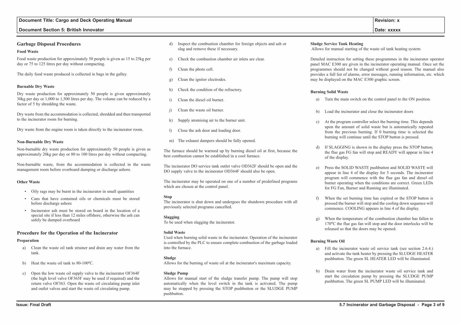
Issue: Final Draft
Document Title: Cargo and Deck Operating Manual
Document Section 5: British Innovator
Revision: x
Date: xxxxx
Garbage Disposal ProceduresFood Waste
Food waste production for approximately 50 people is given as 15 to 25kg per day or 75 to 125 litres per day without compacting.
The daily food waste produced is collected in bags in the galley.
Burnable Dry Waste
Dry waste production for approximately 50 people is given approximately 30kg per day or 1,000 to 1,500 litres per day. The volume can be reduced by a factor of 5 by shredding the waste.
Dry waste from the accommodation is collected, shredded and then transported to the incinerator room for burning.
Dry waste from the engine room is taken directly to the incinerator room.
Non-Burnable Dry Waste
Non-burnable dry waste production for approximately 50 people is given as approximately 20kg per day or 80 to 100 litres per day without compacting.
Non-burnable waste, from the accommodation is collected in the waste management room before overboard dumping or discharge ashore.
Other Waste
• Oily rags may be burnt in the incinerator in small quantities
• Cans that have contained oils or chemicals must be stored before discharge ashore
• Incinerator ash must be stored on board in the location of a special site if less than 12 miles offshore, otherwise the ash can safely be dumped overboard
Procedure for the Operation of the IncineratorPreparation
a) Clean the waste oil tank strainer and drain any water from the tank.
b) Heat the waste oil tank to 80-100ºC.
c) Open the low waste oil supply valve to the incinerator OF364F (the high level valve OF365F may be used if required) and the return valve OF363. Open the waste oil circulating pump inlet and outlet valves and start the waste oil circulating pump.
d) Inspect the combustion chamber for foreign objects and ash or slag and remove these if necessary.
e) Check the combustion chamber air inlets are clear.
f) Clean the photo cell.
g) Clean the ignitor electrodes.
h) Check the condition of the refractory.
i) Clean the diesel oil burner.
j) Clean the waste oil burner.
k) Supply atomising air to the burner unit.
l) Close the ash door and loading door.
m) The exhaust dampers should be fully opened.
The furnace should be warmed up by burning diesel oil at first, because the best combustion cannot be established in a cool furnace.
The incinerator DO service tank outlet valve OD362F should be open and the DO supply valve to the incinerator OD364F should also be open.
The incinerator may be operated on one of a number of predefined programs which are chosen at the control panel.
StopThe incinerator is shut down and undergoes the shutdown procedure with all previously selected programs cancelled.
SlaggingTo be used when slagging the incinerator.
Solid WasteUsed when burning solid waste in the incinerator. Operation of the incinerator is controlled by the PLC to ensure complete combustion of the garbage loaded into the furnace.
SludgeAllows for the burning of waste oil at the incinerator's maximum capacity.
Sludge PumpAllows for manual start of the sludge transfer pump. The pump will stop automatically when the level switch in the tank is activated. The pump may be stopped by pressing the STOP pushbutton or the SLUDGE PUMP pushbutton.
Sludge Service Tank Heating Allows for manual starting of the waste oil tank heating system.
Detailed instruction for setting these programmes in the incinerator operator panel MAC E300 are given in the incinerator operating manual. Once set the programmes should not be changed without good reason. The manual also provides a full list of alarms, error messages, running information, etc. which may be displayed on the MAC E300 graphic screen.
Burning Solid Waste
a) Turn the main switch on the control panel to the ON position.
b) Load the incinerator and close the incinerator doors
c) At the program controller select the burning time. This depends upon the amount of solid waste but is automatically repeated from the previous burning. If 0 burning time is selected the burning will continue until the STOP button is pressed.
d) If SLAGGING is shown in the display press the STOP button; the flue gas FG fan will stop and READY will appear in line 4 of the display.
e) Press the SOLID WASTE pushbutton and SOLID WASTE will appear in line 4 of the display for 5 seconds. The incinerator program will commence with the flue gas fan and diesel oil burner operating when the conditions are correct. Green LEDs for FG Fan, Burner and Running are illuminated.
f) When the set burning time has expired or the STOP button is pressed the burner will stop and the cooling down sequence will commence. COOLING appears in line 4 of the display.
g) When the temperature of the combustion chamber has fallen to 170oC the flue gas fan will stop and the door interlocks will be released so that the doors may be opened.
Burning Waste Oil
a) Fill the incinerator waste oil service tank (see section 2.6.4.) and activate the tank heater by pressing the SLUDGE HEATER pushbutton. The green SL HEATER LED will be illuminated.
b) Drain water from the incinerator waste oil service tank and start the circulation pump by pressing the SLUDGE PUMP pushbutton. The green SL PUMP LED will be illuminated.
5.7 Incinerator and Garbage Disposal - Page 3 of 9
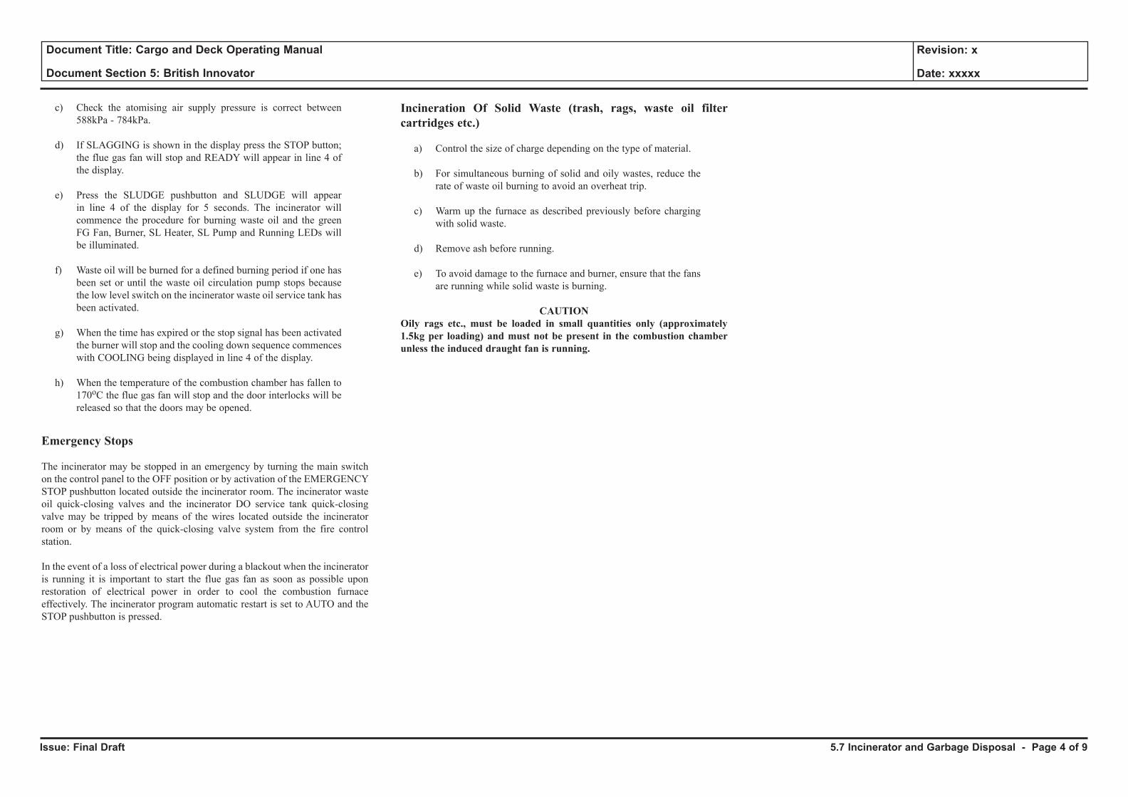
Issue: Final Draft
Document Title: Cargo and Deck Operating Manual
Document Section 5: British Innovator
Revision: x
Date: xxxxx
c) Check the atomising air supply pressure is correct between 588kPa - 784kPa.
d) If SLAGGING is shown in the display press the STOP button; the flue gas fan will stop and READY will appear in line 4 of the display.
e) Press the SLUDGE pushbutton and SLUDGE will appear in line 4 of the display for 5 seconds. The incinerator will commence the procedure for burning waste oil and the green FG Fan, Burner, SL Heater, SL Pump and Running LEDs will be illuminated.
f) Waste oil will be burned for a defined burning period if one has been set or until the waste oil circulation pump stops because the low level switch on the incinerator waste oil service tank has been activated.
g) When the time has expired or the stop signal has been activated the burner will stop and the cooling down sequence commences with COOLING being displayed in line 4 of the display.
h) When the temperature of the combustion chamber has fallen to 170oC the flue gas fan will stop and the door interlocks will be released so that the doors may be opened.
Emergency Stops
The incinerator may be stopped in an emergency by turning the main switch on the control panel to the OFF position or by activation of the EMERGENCY STOP pushbutton located outside the incinerator room. The incinerator waste oil quick-closing valves and the incinerator DO service tank quick-closing valve may be tripped by means of the wires located outside the incinerator room or by means of the quick-closing valve system from the fire control station.
In the event of a loss of electrical power during a blackout when the incinerator is running it is important to start the flue gas fan as soon as possible upon restoration of electrical power in order to cool the combustion furnace effectively. The incinerator program automatic restart is set to AUTO and the STOP pushbutton is pressed.
Incineration Of Solid Waste (trash, rags, waste oil filter cartridges etc.)
a) Control the size of charge depending on the type of material.
b) For simultaneous burning of solid and oily wastes, reduce the rate of waste oil burning to avoid an overheat trip.
c) Warm up the furnace as described previously before charging with solid waste.
d) Remove ash before running.
e) To avoid damage to the furnace and burner, ensure that the fans are running while solid waste is burning.
CAUTIONOily rags etc., must be loaded in small quantities only (approximately 1.5kg per loading) and must not be present in the combustion chamber unless the induced draught fan is running.
5.7 Incinerator and Garbage Disposal - Page 4 of 9
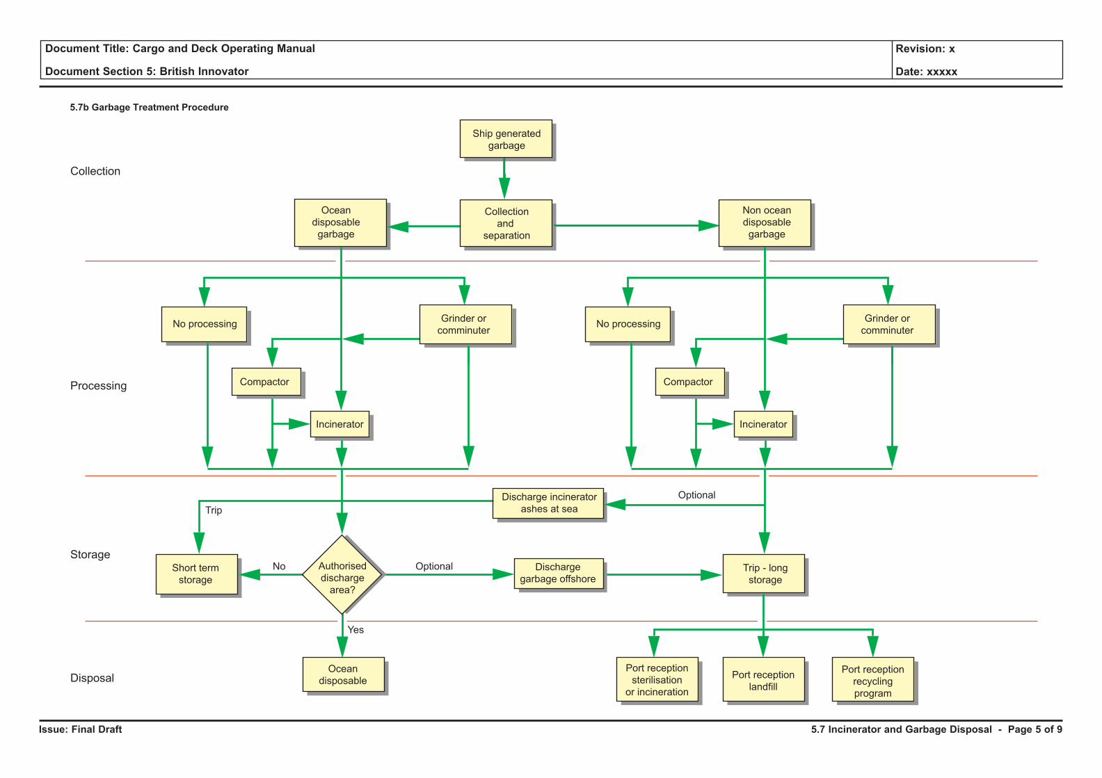
Issue: Final Draft
Document Title: Cargo and Deck Operating Manual
Document Section 5: British Innovator
Revision: x
Date: xxxxx
5.7b Garbage Treatment Procedure
Ship generated
garbage
Ocean
disposable
garbage
Collection
and
separation
Non ocean
disposable
garbage
No processingGrinder or
comminuter
Compactor
Incinerator
No processingGrinder or
comminuter
Compactor
Incinerator
Authorised
discharge
area?
Discharge
garbage offshore
Discharge incinerator
ashes at sea
OptionalNo
Trip
Yes
Optional
Short term
storage
Trip - long
storage
Ocean
disposablePort reception
landfill
Port reception
recycling
program
Port reception
sterilisation
or incineration
Collection
Processing
Storage
Disposal
5.7 Incinerator and Garbage Disposal - Page 5 of 9
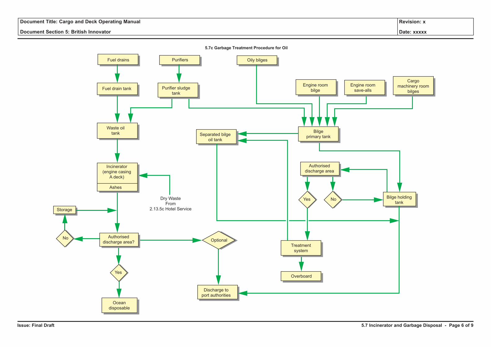
Issue: Final Draft
Document Title: Cargo and Deck Operating Manual
Document Section 5: British Innovator
Revision: x
Date: xxxxx
5.7c Garbage Treatment Procedure for Oil
Fuel drains Purifiers
Overboard
Oily bilges
Fuel drain tank
Waste oil
tank
Incinerator
(engine casing
A deck)
Dry Waste
From
2.13.5c Hotel Service
Ashes
Separated bilge
oil tank
Discharge to
port authorities
Bilge
primary tank
Treatment
system
Purifier sludge
tank
Engine room
bilge
Engine room
save-alls
Cargo
machinery room
bilges
Bilge holding
tankYes
Optional
Yes
No
No
Authorised
discharge area
Authorised
discharge area?
Storage
Ocean
disposable
5.7 Incinerator and Garbage Disposal - Page 6 of 9
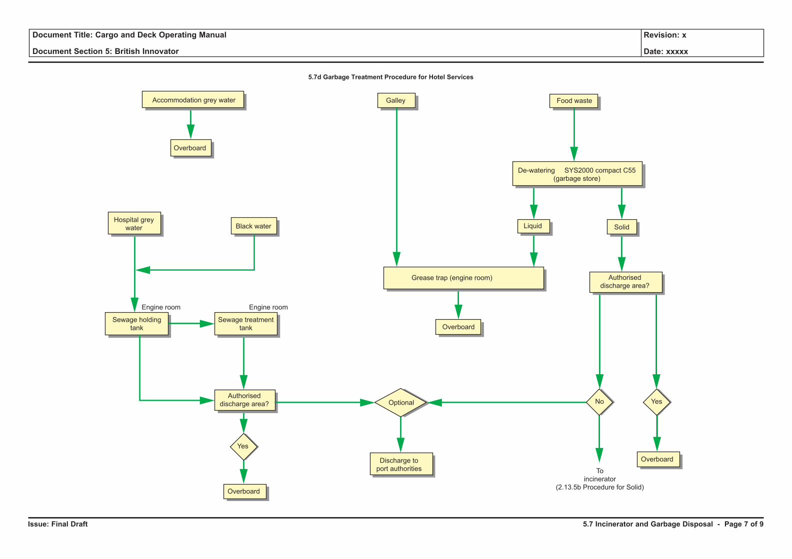
Issue: Final Draft
Document Title: Cargo and Deck Operating Manual
Document Section 5: British Innovator
Revision: x
Date: xxxxx
5.7d Garbage Treatment Procedure for Hotel Services
Accommodation grey water Galley
Overboard
To
incinerator
(2.13.5b Procedure for Solid)
Engine room Engine room
Overboard
Overboard
Food waste
Overboard
Hospital grey
water Black water
Discharge to
port authorities
Sewage holding
tank
Sewage treatment
tank
Grease trap (engine room)
De-watering SYS2000 compact C55
(garbage store)
Liquid Solid
Yes
Optional NoAuthorised
discharge area?
Authorised
discharge area?
Yes
5.7 Incinerator and Garbage Disposal - Page 7 of 9
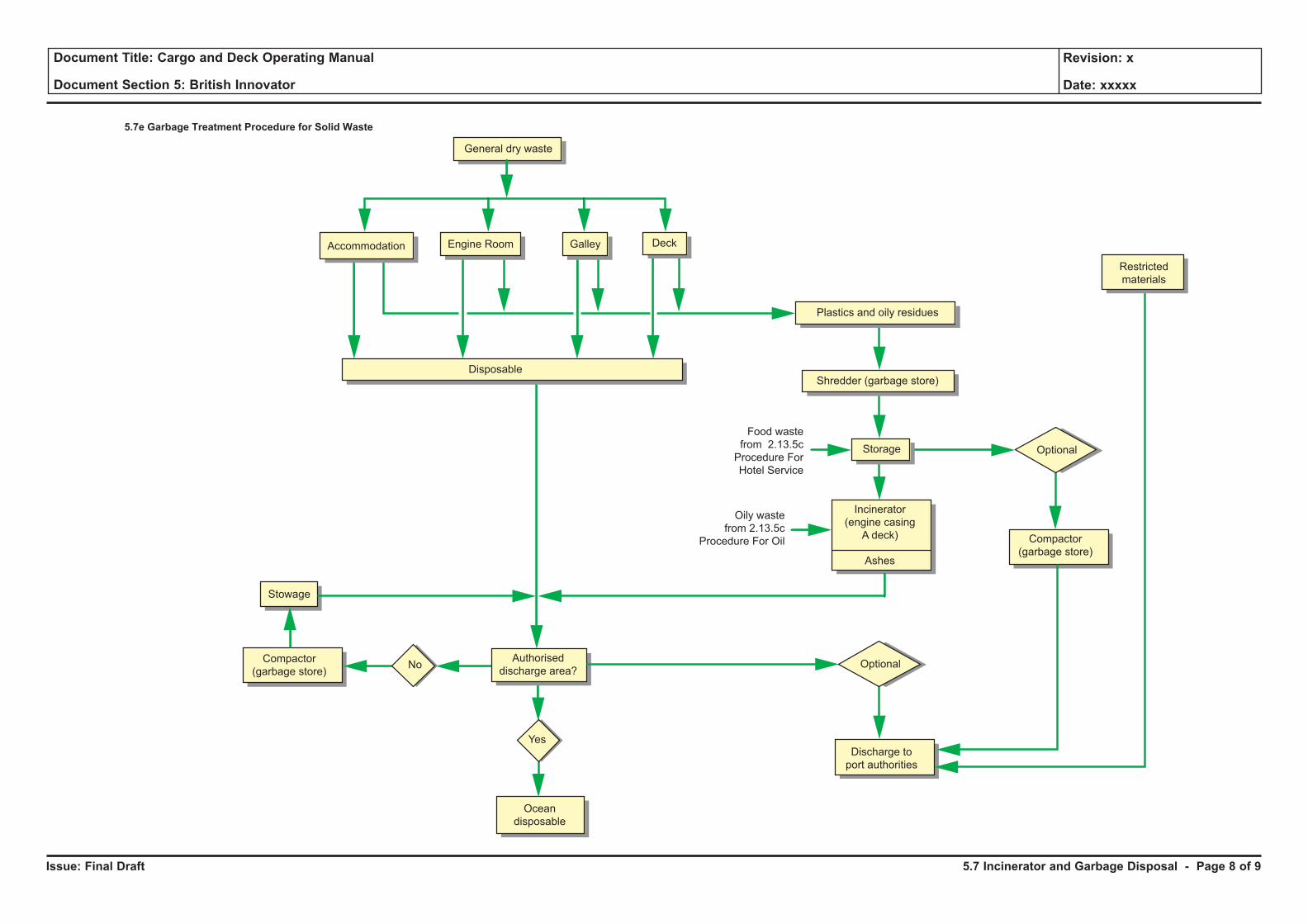
Issue: Final Draft
Document Title: Cargo and Deck Operating Manual
Document Section 5: British Innovator
Revision: x
Date: xxxxx
5.7e Garbage Treatment Procedure for Solid Waste
Accommodation Engine Room Galley
General dry waste
Deck
Plastics and oily residues
Shredder (garbage store)
Storage
Disposable
Incinerator
(engine casing
A deck)
Food waste
from 2.13.5c
Procedure For
Hotel Service
Oily waste
from 2.13.5c
Procedure For Oil
Ashes
Compactor
(garbage store)
Stowage
Compactor
(garbage store)
Discharge to
port authorities
Restricted
materials
Optional
OptionalNo
Yes
Authorised
discharge area?
Ocean
disposable
5.7 Incinerator and Garbage Disposal - Page 8 of 9
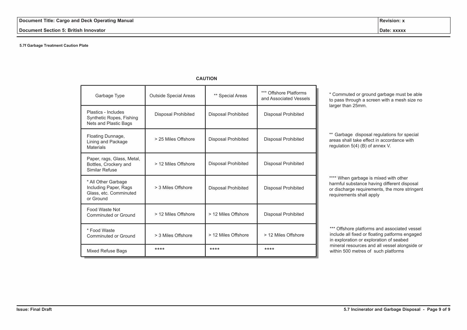
Issue: Final Draft
Document Title: Cargo and Deck Operating Manual
Document Section 5: British Innovator
Revision: x
Date: xxxxx
5.7f Garbage Treatment Caution Plate
Garbage Type Outside Special Areas ** Special Areas*** Offshore Platforms
and Associated Vessels
**** When garbage is mixed with other
harmful substance having different disposal
or discharge requirements, the more stringent
requirements shall apply
*** Offshore platforms and associated vessel
include all fixed or floating patforms engaged
in exploration or exploration of seabed
mineral resources and all vessel alongside or
within 500 metres of such platforms
** Garbage disposal regulations for special
areas shall take effect in accordance with
regulation 5(4) (B) of annex V.
* Commuted or ground garbage must be able
to pass through a screen with a mesh size no
larger than 25mm.
Disposal Prohibited Disposal Prohibited
Disposal Prohibited
Disposal Prohibited
Disposal Prohibited
> 25 Miles Offshore
> 12 Miles Offshore
> 12 Miles Offshore > 12 Miles Offshore
> 12 Miles Offshore
> 3 Miles Offshore
> 3 Miles Offshore
**** ****
Disposal Prohibited
Disposal Prohibited
Disposal Prohibited
Disposal Prohibited
Disposal Prohibited
> 12 Miles Offshore
****
Plastics - Includes
Synthetic Ropes, Fishing
Nets and Plastic Bags
Paper, rags, Glass, Metal,
Bottles, Crockery and
Similar Refuse
Floating Dunnage,
Lining and Package
Materials
* All Other Garbage
Including Paper, Rags
Glass, etc. Comminuted
or Ground
Food Waste Not
Comminuted or Ground
* Food Waste
Comminuted or Ground
Mixed Refuse Bags
CAUTION
5.7 Incinerator and Garbage Disposal - Page 9 of 9
PART 6: CARGO OPERATIONS
6.1 Insulation Space Pressurising
6.1.1 Insulation Space Inerting
6.1.2 In Service Test
Illustrations
6.1.1a Initial Insulation Space Inerting
6.1.2a Insulation Space Arrangement
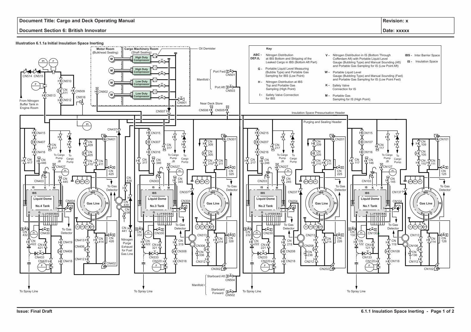
Issue: Final Draft
Document Title: Cargo and Deck Operating Manual
Document Section 6: British Innovator
Revision: x
Date: xxxxx
Illustration 6.1.1a Initial Insulation Space Inerting
M
M
M
To Spray Line
Nitrogen
Purge
Exhaust
for Fuel
Gas Line
From Nitrogen
Buffer Tank in
Engine Room
Manifold
Oil Demister
Port Fwd
Port Aft
Near Deck Store
Cargo Machinery Room
(Shaft Sealing)Motor Room
(Bulkhead Sealing)
Insulation Space Pressurisation Header
Purging and Sealing Header
To Gas
Detector
To Gas
Detector
To
Cargo
Pump
To Cargo
Pump
JB
F
PI
PI
F
PI
PI
PI PT PT
DPT PT PI
DPT
F
To Spray Line
To Gas
Detector
To Gas
Detector
To
Cargo
Pump
To Cargo
Pump
JB
PI
PI
PI PT PT
DPT PT PI
DPT
F
Liquid Dome
Gas LineNo.3 Tank
To Spray Line
To Gas
Detector
To Gas
Detector
To
Cargo
Pump
To Cargo
Pump
JB
PI
PI
PI PT PT
DPT PT PI
DPT
F
Liquid Dome
Gas LineNo.2 Tank
To Spray Line
To Gas
Detector
To Gas
Detector
To
Cargo
Pump
To Cargo
Pump
JB
PI
PI
PI PT PT
DPT PT PI
DPT
F
Liquid Dome
Gas LineNo.1 Tank
Liquid Dome
Gas LineNo.4 Tank
Manifold
Starboard
Forward
Starboard Aft
CN418
CN408
CN402
CN419
CN416
CN401
CN437
CN507
CN901
CN902
CN337
CN403
CN427 CN327 CN227
CN407
CN415
CN514 CN515
CN513
CN510
CN512
CN509
CN516
CN413
CN404 CN304 CN204
CN412
CN406
CN430
CN433
CN420
CN432
CN422
CN417
CN417
CN511
CN446
CN445
CN441
CN436
CN439
CN438
CN410
CN411
CN425
CN325
CN405
CN409
CN316
CN301
CN505
CN501
CN503
CN506
CN303
CN307
CN315
CN317
CN317
CN346
CN345
CN237
CN216
CN203
CN207
CN215
CN217
CN217
CN246
CN245
CN310
CN311
CN305
CN309
CN225
CN201
CN210
CN211
CN205
CN209
CN127
CN137
CN116
CN103
CN107
CN115
CN117
CN117
CN146
CN145
CN125
CN101
CN110
CN111
CN105
CN109
CN421
CN318
CN308
CN302
CN
319
CN330
CN333
CN320
CN332
CN322 CN
321
CN218
CN208
CN
219
CN230
CN233
CN220
CN232
CN222 CN
221
CN414
CN313
CN312
CN502
CN504
CN306
CN314
CN336
CN426
CN326
CN202
CN213
CN212
CN206
CN214
CN236
CN226
CN104
CN118
CN108
CN
119
CN130
CN133
CN120
CN132
CN122 CN
121
CN102
CN113
CN112
CN106
CN114
CN136
CN126
IS
IS
IBS IBS
IS
IS
IBS IBS
IS
IS
IBS IBS
IS
IS
IBS IBS
K
I
M
H
T S
OL J F EDCBA RG
K
I
M
H
T S
OL J F EDCBA RG
K
I
M
H
T S
OL J F EDCBA RG
K
I
M
H
T S
OL J F EDCBA RG
High DutyCompressor
High DutyCompressor
Low DutyCompressor
Low DutyCompressor
M
Nitrogen Distribution
at IBS Bottom and Stripping of the
Leaked Cargo in IBS (Bottom Aft Part)
Key
Safety Valve
Connection for IS
Safety Valve Connection
for IBSPortable Gas
Sampling for IS (High Point)
Portable Liquid Level Measuring
(Bubble Type) and Portable Gas
Sampling for IBS (Low Point)
Nitrogen Distribution in IS (Bottom Through
Cofferdam Aft) with Portable Liquid Level
Gauge (Bubbling Type) and Manual Sounding (Aft)
and Portable Gas Sampling for IS (Low Point Aft)
Portable Liquid Level
Gauge (Bubbling Type) and Manual Sounding (Fwd)
and Portable Gas Sampling for IS (Low Point Fwd)
Inter Barrier Space
Insulation Space
Nitrogen Distribution at IBS
Top and Portable Gas
Sampling (High Point)
ABC -
DEFJLV - IBS -
IS -
W -
K -
M -
G -
H -
I -
6.1.1 Insulation Space Inerting - Page 1 of 2
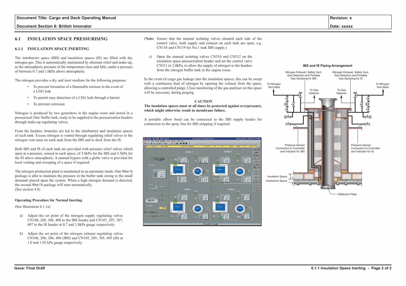
Issue: Final Draft
Document Title: Cargo and Deck Operating Manual
Document Section 6: British Innovator
Revision: x
Date: xxxxx
6.1 INSULATION SPACE PRESSURISING
6.1.1 INSULATION SPACE INERTING
The interbarrier space (IBS) and insulation spaces (IS) are filled with dry nitrogen gas. This is automatically maintained by alternate relief and make-up, as the atmospheric pressure of the temperature rises and falls, under a pressure of between 0.7 and 1.0kPa above atmospheric.
The nitrogen provides a dry and inert medium for the following purposes:
• To prevent formation of a flammable mixture in the event of a LNG leak
• To permit easy detection of a LNG leak through a barrier
• To prevent corrosion
Nitrogen is produced by two generators in the engine room and stored in a pressurised 24m3 buffer tank, ready to be supplied to the pressurisation headers through make-up regulating valves.
From the headers, branches are led to the interbarrier and insulation spaces of each tank. Excess nitrogen is vented through regulating relief valves to the nitrogen vent mast on each tank from the IBS and to deck from the IS.
Both IBS and IS of each tank are provided with pressure relief valves which open at a pressure, sensed in each space, of 3.0kPa for the IBS and 3.5kPa for the IS above atmospheric. A manual bypass with a globe valve is provided for local venting and sweeping of a space if required.
The nitrogen production plant is maintained in an automatic mode. One 90m3/h package is able to maintain the pressure in the buffer tank owing to the small demands placed upon the system. When a high nitrogen demand is detected, the second 90m3/h package will start automatically. (See section 4.8)
Operating Procedure for Normal Inerting
(See illustration 6.1.1a)
a) Adjust the set point of the nitrogen supply regulating valves CN108, 208, 308, 408 to the IBS header and CN107, 207, 307, 407 to the IS header at 0.7 and 1.0kPa gauge respectively.
b) Adjust the set point of the nitrogen exhaust regulating valves CN106, 206, 306, 406 (IBS) and CN105, 205, 305, 405 (IS) at 1.0 and 1.95 kPa gauge respectively.
(Note: Ensure that the manual isolating valves situated each side of the control valve, both supply and exhaust on each tank are open, e.g. CN118 and CN119 for No.1 tank IBS supply.)
c) Open the manual isolating valves CN510 and CN512 on the insulation space pressurisation header and set the control valve CN511 to 2.0kPa, to allow the supply of nitrogen to the headers from the nitrogen buffer tank in the engine room.
In the event of cargo gas leakage into the insulation spaces, this can be swept with a continuous feed of nitrogen by opening the exhaust from the space, allowing a controlled purge. Close monitoring of the gas analyser on this space will be necessary during purging.
CAUTIONThe insulation spaces must at all times be protected against overpressure, which might otherwise result in membrane failure.
A portable elbow bend can be connected to the IBS supply header for connection to the spray line for IBS stripping if required.
6.1.1 Insulation Space Inerting - Page 2 of 2
To GasDetector
To NitrogenVent Mast
Nitrogen Exhaust, Safety Vent,Gas Detection and PortableGas Sampling for IBS
Interbarrier SpaceInsulation Space
Pressure SensorConnection to Controllerand Indicator for IS
Nitrogen Exhaust, Safety Vent,Gas Detection and Portable
Gas Sampling for IS
To GasDetector
To NitrogenVent Mast
Deflection Plate
Pressure SensorConnection to Controller
and Indicator for IBS
IBS and IS Piping Arrangement
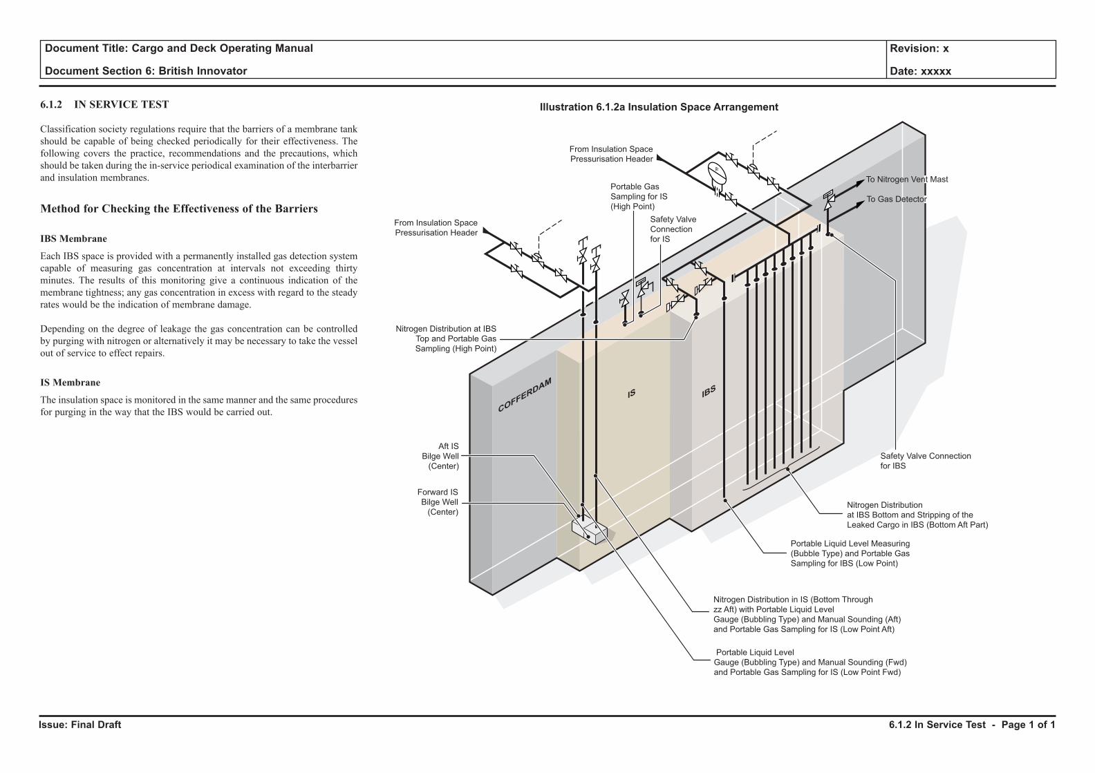
Issue: Final Draft
Document Title: Cargo and Deck Operating Manual
Document Section 6: British Innovator
Revision: x
Date: xxxxx
6.1.2 IN SERVICE TEST
Classification society regulations require that the barriers of a membrane tank should be capable of being checked periodically for their effectiveness. The following covers the practice, recommendations and the precautions, which should be taken during the in-service periodical examination of the interbarrier and insulation membranes.
Method for Checking the Effectiveness of the Barriers
IBS Membrane
Each IBS space is provided with a permanently installed gas detection system capable of measuring gas concentration at intervals not exceeding thirty minutes. The results of this monitoring give a continuous indication of the membrane tightness; any gas concentration in excess with regard to the steady rates would be the indication of membrane damage.
Depending on the degree of leakage the gas concentration can be controlled by purging with nitrogen or alternatively it may be necessary to take the vessel out of service to effect repairs.
IS Membrane
The insulation space is monitored in the same manner and the same procedures for purging in the way that the IBS would be carried out.
6.1.2 In Service Test - Page 1 of 1
To Nitrogen Vent Mast
To Gas Detector
Nitrogen Distribution
at IBS Bottom and Stripping of the
Leaked Cargo in IBS (Bottom Aft Part)
Safety Valve
Connection
for IS
Safety Valve Connection
for IBS
Portable Gas
Sampling for IS
(High Point)
From Insulation Space
Pressurisation Header
From Insulation Space
Pressurisation Header
Portable Liquid Level Measuring
(Bubble Type) and Portable Gas
Sampling for IBS (Low Point)
Nitrogen Distribution in IS (Bottom Through
zz Aft) with Portable Liquid Level
Gauge (Bubbling Type) and Manual Sounding (Aft)
and Portable Gas Sampling for IS (Low Point Aft)
COFFERDAM
IS IBS
Portable Liquid Level
Gauge (Bubbling Type) and Manual Sounding (Fwd)
and Portable Gas Sampling for IS (Low Point Fwd)
Forward IS
Bilge Well
(Center)
Aft IS
Bilge Well
(Center)
Nitrogen Distribution at IBS
Top and Portable Gas
Sampling (High Point)
F
Illustration 6.1.2a Insulation Space Arrangement
6.2 Post Dry Dock Operation
6.2.1 Initial Insulation Space Inerting
6.2.2 Drying Cargo Tanks
6.2.3 Inerting Cargo Tanks
6.2.4 Gassing-Up Cargo Tanks
6.2.5 Cooling Down Cargo Tanks
Illustrations
6.2.1a Filling From Shore Nitrogen Supply
6.2.2a Drying Cargo Tanks
6.2.3a Inerting Cargo Tanks Prior to Gas Filling
6.2.4a Displacing Inert Gas (Gas Filling) with LNG Vapour
6.2.4a Displacing Inert Gas with LNG Vapour Discharging to Shore
6.2.5a Tank Cooldown with Return through Vapour Header
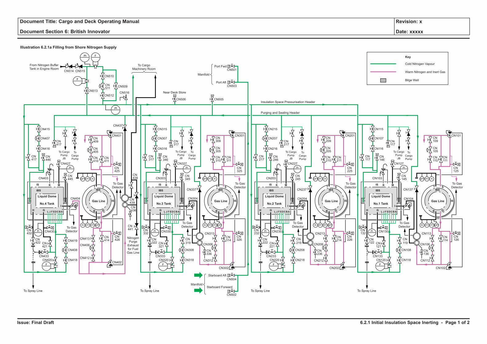
Issue: Final Draft
Document Title: Cargo and Deck Operating Manual
Document Section 6: British Innovator
Revision: x
Date: xxxxx
Illustration 6.2.1a Filling from Shore Nitrogen Supply
To Spray Line
Nitrogen
Purge
Exhaust
for Fuel
Gas Line
From Nitrogen Buffer
Tank in Engine Room
Manifold
To Cargo
Machinery RoomPort Fwd
Port Aft
Near Deck Store
Insulation Space Pressurisation Header
Purging and Sealing Header
To Gas
Detector
To Gas
Detector
To
Cargo
Pump
To Cargo
Pump
JB
F
PI
PI
F
PI
PI
PI PT PT
DPT PT PI
DPT
F
To Spray Line
To Gas
Detector
To Gas
Detector
To
Cargo
Pump
To Cargo
Pump
JB
PI
PI
PI PT PT
DPT PT PI
DPT
F
Liquid Dome
Gas LineNo.3 Tank
To Spray Line
To Gas
Detector
To Gas
Detector
To
Cargo
Pump
To Cargo
Pump
JB
PI
PI
PI PT PT
DPT PT PI
DPT
F
Liquid Dome
Gas LineNo.2 Tank
To Spray Line
To Gas
Detector
To Gas
Detector
To
Cargo
Pump
To Cargo
Pump
JB
PI
PI
PI PT PT
DPT PT PI
DPT
F
Liquid Dome
Gas LineNo.1 Tank
Liquid Dome
Gas LineNo.4 Tank
ManifoldStarboard Forward
Starboard Aft
Cold Nitrogen Vapour
Key
Warm Nitrogen and Inert Gas
Bilge Well
CN418
CN408
CN402
CN419
CN416
CN401
CN437
CN337
CN403
CN427 CN327 CN227
CN407
CN415
CN514 CN515
CN513
CN510
CN512
CN509
CN516
CN413
CN404 CN304 CN204
CN412
CN406
CN430
CN433
CN420
CN432
CN422
CN417
CN417
CN511
CN446
CN445
CN441
CN436
CN439
CN438
CN410
CN411
CN425
CN325
CN405
CN409
CN316
CN301
CN505
CN501
CN503
CN506
CN303
CN307
CN315
CN317
CN317
CN346
CN345
CN237
CN216
CN203
CN207
CN215
CN217
CN217
CN246
CN245
CN310
CN311
CN305
CN309
CN225
CN201
CN210
CN211
CN205
CN209
CN127
CN137
CN116
CN103
CN107
CN115
CN117
CN117
CN146
CN145
CN125
CN101
CN110
CN111
CN105
CN109
CN421
CN318
CN308
CN302
CN
319
CN330
CN333
CN320
CN332
CN322 CN
321
CN218
CN208
CN
219
CN230
CN233
CN220
CN232
CN222 CN
221
CN414
CN313
CN312
CN502
CN504
CN306
CN314
CN336
CN426
CN326
CN202
CN213
CN212
CN206
CN214
CN236
CN226
CN104
CN118
CN108
CN
119
CN130
CN133
CN120
CN132
CN122 CN
121
CN102
CN113
CN112
CN106
CN114
CN136
CN126
IS
IS
IBS IBS
IS
IS
IBS IBS
IS
IS
IBS IBS
IS
IS
IBS IBS
K
I
M
H
T S
OL J F EDCBA RG
K
I
M
H
T S
OL J F EDCBA RG
K
I
M
H
T S
OL J F EDCBA RG
K
I
M
H
T S
OL J F EDCBA RG
6.2.1 Initial Insulation Space Inerting - Page 1 of 2
Issue: Final Draft
Document Title: Cargo and Deck Operating Manual
Document Section 6: British Innovator
Revision: x
Date: xxxxx
6.2 POST DRY DOCK OPERATION
6.2.1 INITIAL INSULATION SPACE INERTING
On completion of a dry dock period the insulation and interbarrier spaces may require inerting and this can be carried out either by using the on board nitrogen generator or having the nitrogen supplied from ashore.
Prior to any inerting of these spaces, either with the nitrogen being supplied from ashore or on board, great care has to be taken to ensure all sampling and control systems are fully operational and personnel are fully conversed in the operation.
Where the nitrogen is supplied from ashore it is usually supplied from road tankers to the ship’s nitrogen manifold and distributed via the purging and sealing header to the insulation pressurisation header and then to the spaces.
Both the interbarrier space (IBS) and insulation space (IS) of each tank are provided with pressure relief valves which open at a preset pressure. This is set at 3.0kPa for the interbarrier space and 3.5kPa for the insulation space above atmospheric. A manual bypass with a globe valve is provided for local venting and sweeping of a space if required.
Operating Procedure for Inerting with Nitrogen from Ashore
(See illustration 6.2.1a)
a) Adjust the set point of the nitrogen supply regulating valves CN108, 208, 308, 408 to the interbarrier space header and CN107, 207, 307, 407 to the insulation space header at 0.7 and 1.0kPa gauge respectively.
b) Adjust the set point of the nitrogen exhaust regulating valves CN106, 206, 306, 406 (IBS) and CN105, 205, 305, 405 (IS) at 1.3 and 2.5kPa gauge respectively.
(Note: Ensure that the manual isolating valves situated each side of the control valve, both supply and exhaust on each tank are open, e.g. CN118 and CN119 for No.1 tank IBS supply.)
c) Open the manual exhaust bypass valve for both the interbarrier and insulation spaces on each tank, e.g. CN114 and CN111 for No.1 tank.
d) Open the manual isolating valves CN510 and CN512 on the insulation space pressurisation header and set the control valve CN511 to 2.5kPa, to allow supply of nitrogen to the headers.
CAUTIONThe insulation spaces must at all times be protected against overpressure, which might otherwise result in membrane failure.
e) Crack open a manifold supply valve on the purging and sealing header, e.g. CN504 starboard aft, and request shore to supply nitrogen at a slow rate.
The supply of nitrogen is controlled by the rate of flow from ashore and use of the bypass valves.
(Note: In the event of pressure build up in the purging and sealing header it may be necessary to open the manual vent valve to one or more of the tank vent mast risers, e.g. CN137 on No.1 tank.)
f) Monitor the nitrogen content at the exhaust sample points, e.g. CN126 and CN125 for No.1 tank, using a portable meter.
g) When the nitrogen content in the samples is within the required limits adjust the flow rate and close the manual bypass valves on the exhaust systems.
h) When insulation and interbarrier spaces reach the required pressure, stop supply of nitrogen from ashore and set up system for automatic make up from the on board nitrogen generator.
6.2.1 Initial Insulation Space Inerting - Page 2 of 2
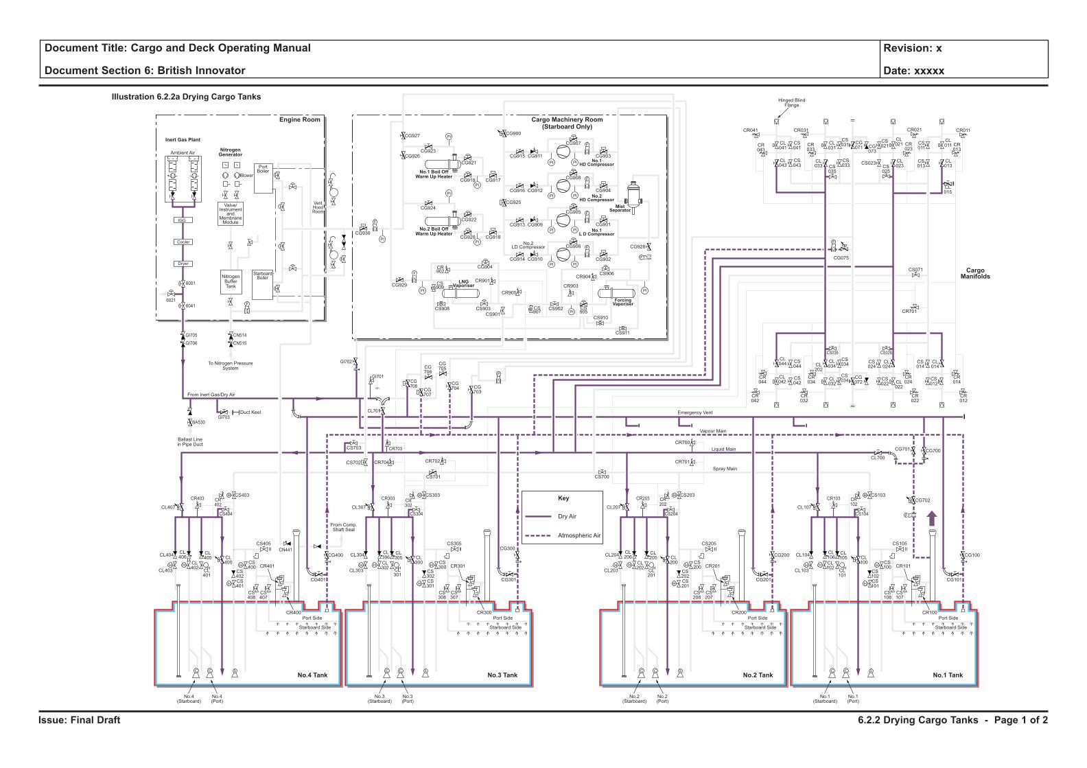
Issue: Final Draft
Document Title: Cargo and Deck Operating Manual
Document Section 6: British Innovator
Revision: x
Date: xxxxx
Dry Air
Key
Atmospheric Air
H H
H
H
F
C C S
H
HH H
H
H
C C S
H
HH H
H
H
C C S
H
HH H
H
H
C C S
H
H
F
PI PI
F
PI PI
PI
PI
PI
PI
PI PI
PI PI
F
F
PI
PI
PI
PI
F
F
F
CL106
CL102
CL101
CL100
CS102
CS100
CS103
CS101
CS108
CS107
CR101
CR100
CL105
CL104
CL700
CG700
CG702
CG101
CS105
CS104
CR103 CR102
CG701
CL103
Port Side
Starboard Side
CL107
No.1(Starboard)
No.1(Port)
CL206
CL202
CL201
CL200
CS202
CS200
CS203
CR701
CR700
CS201
CS208
CS207
CR201
CR200
CL205
CL204
CG201
CG200 CG100
CS205
CS204
CR203 CR202
CL203
Port Side
Ambient Air
Blower
PortBoiler
VentHoodRoom
StarboardBoiler
Inert Gas Plant
NitrogenGenerator
Engine Room
No.3 TankNo.4 Tank No.1 TankNo.2 Tank
Cargo Machinery Room(Starboard Only)
Starboard Side
CL207
CS700
No.2(Starboard)
No.2(Port)
CL306
CL302
CL301
CL300
CS302
CS300
CS303
CS701
CS301
CS308
CS307
CR301
CR300
CL305
CL304
CG301
CS305
CS304
CR303 CR302
CL303
Port Side
Starboard Side
CL307
CG927
CG926CG923
CG921
CG917CG919
CG924
CG930
CG929
CG904
CR901
CR905
CR903
CR904
CS909
CS907
CS905
CS908 CS903
CS901
CS902
CS906
CS910
CS911
CR902
CG922
CG918
CG928
CG902
CG906
CG905
CG908
CG907
CR041
CR043
CL041
CL043
CS041
CS043
CL031
CS031 CS
011
CL011 CR
013
CG071 CG
073
CS021
CL021
CL023CS
025
CS023 CL013
CL015
CS013
CR023
CR033
CR021CR031 CR011
CS035
CL033
CS033
CG915
CG900
CG925
CG911
CG916 CG912
CG913 CG909
CG914 CG910
CG901
CG904
CG903
CG920
No.3(Starboard)
No.3(Port)
CL406
CL402
CL401
CL400
CS402
CS400
CS403
CS702 CR704 CR702
CR703
CG708
CG707
CG706
CG705
CG704 CG
703
CS703
CL701
CS401
CS408
CS407
CR401
CR400
CL405
CL404
CG401
CG400
CG300CS405
From Comp.Shaft Seal
CS404
CR403
GI705
6001
60416021
GI706
GI703
GI702
GI701
BA530
CN514
CN515
CR402
CL403
Port Side
Starboard Side
CL407
No.4(Starboard)
No.4(Port)
CL044
CS044
CS042
CS034
CS024
CL024
CS034
CR044
CR034
CR024
CR042
CR032
CR022
CS036 CS026
CL042
CL034CL
202
CL032
CG072
CS022 CL
022
CS014
CR701
CS071
CL014
CR014
CR012
CS012
F
F
F
Cooler
Dryer
IGG
Valve/Instrument
andMembraneModule
NitrogenBufferTank
To Nitrogen PressureSystem
Hinged BlindFlange
Ballast Linein Pipe Duct
Duct Keel
From Inert Gas/Dry Air
Emergency Vent
Vapour Main
Liquid Main
Spray Main
No.1 Boil OffWarm Up Heater
No.2 Boil OffWarm Up Heater
ForcingVaporiser
MistSeparator
No.1HD Compressor
No.2HD Compressor
No.1L D Compressor
LNGVaporiser
No.2LD Compressor
Illustration 6.2.2a Drying Cargo Tanks
CargoManifolds
CG075
CN441
6.2.2 Drying Cargo Tanks - Page 1 of 2
Issue: Final Draft
Document Title: Cargo and Deck Operating Manual
Document Section 6: British Innovator
Revision: x
Date: xxxxx
6.2.2 DRYING CARGO TANKS
During a dry docking or inspection, cargo tanks which have been opened and contain wet air must be dried primarily to avoid the formation of ice when they are cooled down and secondly the formation of corrosive agents if the humidity combines with the sulphur and nitrogen oxides which might be contained in excess in the inert gas. The tanks are inerted in order to prevent the possibility of any flammable air/LNG mixture. Normal humid air is displaced by dry-air. Dry-air is displaced by inert gas produced from the dry-air/inert gas plant.
The inert gas is primarily nitrogen and carbon dioxide, containing less than 1% oxygen with a dew point of -45°C or below.
WARNINGInert gas from this generator and pure nitrogen will not sustain life. Great care must be exercised to ensure the safety of all personnel involved with any operation using inert gas of any description to avoid asphyxiation due to oxygen depletion.
Dry-air is introduced at the bottom of the tanks through the filling piping. The air is displaced from the top of each tank through the dome and the vapour header, and is discharged from the vent mast at No.1 tank.
The operation can be carried out at shore or at sea and it will take approximately 40 hours to reduce the oxygen content to less than 2% and the final dew point to -40°C.
During the time that the inert gas plant is in operation for drying and inerting the tanks, the inert gas is also used to dry (below -40°C ) and to inert all other LNG and vapour pipework. Before introduction of LNG or vapour, pipework not purged with inert gas must be purged with nitrogen.
Operating Procedure for Drying Tanks
(see illustration 6.2.2a)
Dry-air, with a dew point of -45°C, is produced by the dry-air/inert gas plant at a flow rate of 14,000Nm3/h.
a) Prepare the dry-air/inert gas plant for use in the dry-air mode.
b) Install the elbow to connect the discharge line from the dry-air/inert gas dryer with the liquid header.
c) Open the valves CL701, CL407, CL307, CL207 and CL107 to supply dry-air to the liquid header.
d) Open tank filling valves CL400, CL300, Cl200 and CL100.
e) Open tank vapour valves CG400, CG300, CG200, CG100.
f) Open valve CG701 to vent through the No.1 mast.
g) Start the inert gas generator to produce dry-air, discharging to the funnel until the correct dew point is obtained. When the dew point is -45°C, open valve to deck 6041, upstream of the two non-return valves, GI705 and GI706 on the dry-air/inert gas discharge line.
h) Monitor the dew point of each tank by taking a reading with a portable meter at the vapour dome sample valves, eg SA460, SA461 at No.4 tank. When the dew point is -25°C or less, close the filling and vapour valves of the tank.
(Note: No.1 tank should be the final tank to ensure the system is always full of dry air.)
i) Wet air which may be contained in the discharge lines from the cargo pumps, float level piping and any associated pipework in the cargo compressor room must be purged with dry air. This is normally carried out in conjunction with the drying of the cargo tanks.
j) When all the tanks are dried, stop the inert gas plant. Close the supply valve CL701 to the LNG header and close valve CG702 to the venting system at the mast riser No.1. Valve CG701 is to be left open at all times, except for isolation or maintenance.
(Note: It is necessary to lower the tank’s dew point by dry-air to at least -25°C, before feeding tanks with inert gas in order to avoid the formation of corrosive agents.)
(Note: The N2 supply to the IS/IBS is to be started as soon as drying is started. Keep the cargo tank pressure approximately 3kPa until the IS/IBS N2 System is fully operational.)
6.2.2 Drying Cargo Tanks - Page 2 of 2
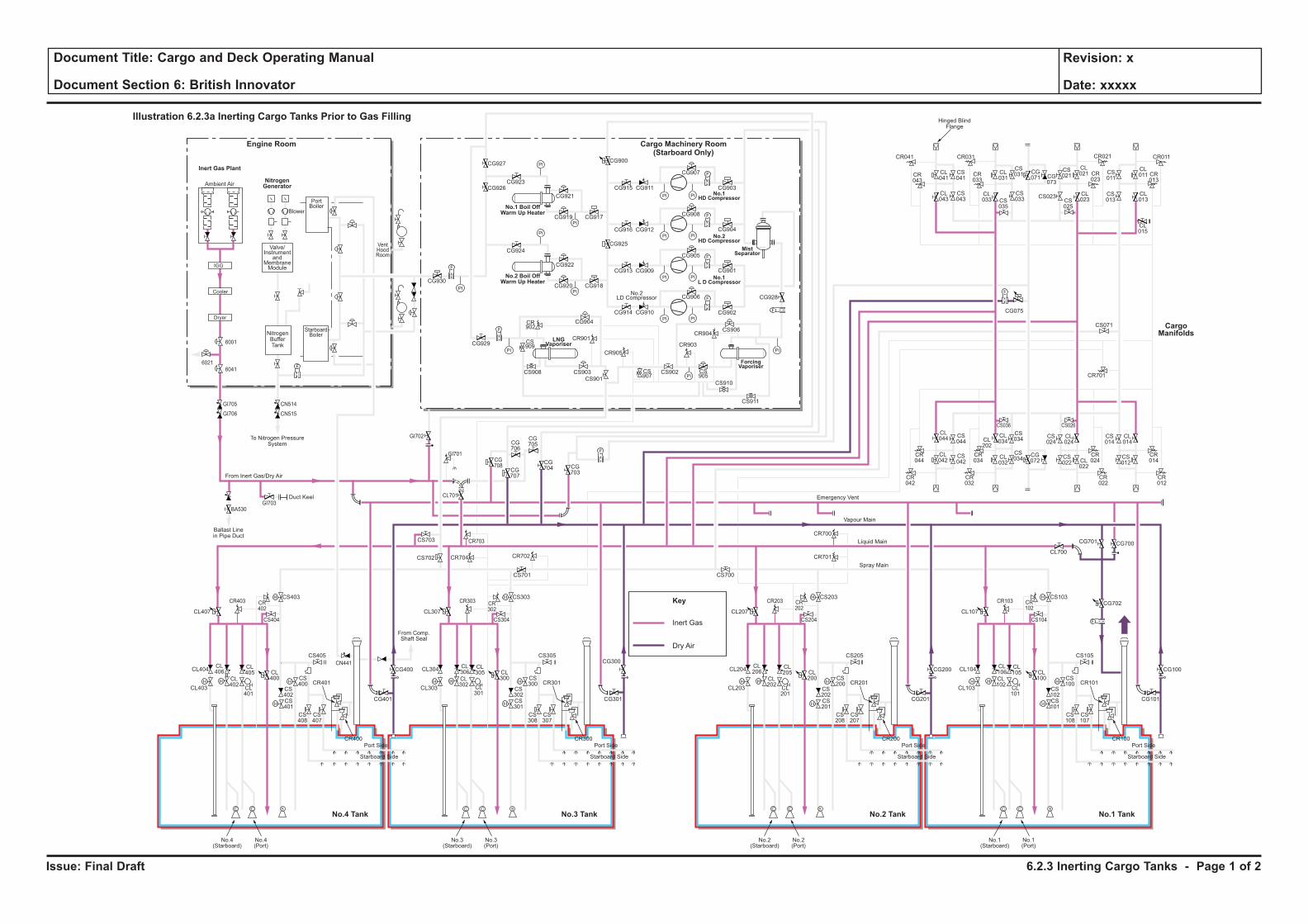
Issue: Final Draft
Document Title: Cargo and Deck Operating Manual
Document Section 6: British Innovator
Revision: x
Date: xxxxx
Inert Gas
Key
Dry Air
H H
H
H
F
C C S
H
HH H
H
H
C C S
H
HH H
H
H
C C S
H
HH H
H
H
C C S
H
H
F
PI PI
F
PI PI
PI
PI
PI
PI
PI PI
PI PI
F
F
PI
PI
PI
PI
F
F
F
CL106
CL102
CL101
CL100
CS102
CS100
CS103
CS101
CS108
CS107
CR101
CR100
CL105
CL104
CL700
CG700
CG702
CG101
CS105
CS104
CR103 CR102
CG701
CL103
Port Side
Starboard Side
CL107
No.1(Starboard)
No.1(Port)
CL206
CL202
CL201
CL200
CS202
CS200
CS203
CR701
CR700
CS201
CS208
CS207
CR201
CR200
CL205
CL204
CG201
CG200 CG100
CS205
CS204
CR203 CR202
CL203
Port Side
Ambient Air
Blower
PortBoiler
VentHoodRoom
StarboardBoiler
Inert Gas Plant
NitrogenGenerator
Engine Room
No.3 TankNo.4 Tank No.1 TankNo.2 Tank
Cargo Machinery Room(Starboard Only)
Starboard Side
CL207
CS700
No.2(Starboard)
No.2(Port)
CL306
CL302
CL301
CL300
CS302
CS300
CS303
CS701
CS301
CS308
CS307
CR301
CR300
CL305
CL304
CG301
CS305
CS304
CR303 CR302
CL303
Port Side
Starboard Side
CL307
CG927
CG926CG923
CG921
CG917CG919
CG924
CG930
CG929
CG904
CR901
CR905
CR903
CR904
CS909
CS907
CS905
CS908 CS903
CS901
CS902
CS906
CS910
CS911
CR902
CG922
CG918
CG928
CG902
CG906
CG905
CG908
CG907
CR041
CR043
CL041
CL043
CS041
CS043
CL031
CS031 CS
011
CL011 CR
013
CG071 CG
073
CS021
CL021
CL023CS
025
CS023 CL013
CL015
CS013
CR023
CR033
CR021CR031 CR011
CS035
CL033
CS033
CG915
CG900
CG925
CG911
CG916 CG912
CG913 CG909
CG914 CG910
CG901
CG904
CG903
CG920
No.3(Starboard)
No.3(Port)
CL406
CL402
CL401
CL400
CS402
CS400
CS403
CS702 CR704 CR702
CR703
CG708
CG707
CG706
CG705
CG704 CG
703
CS703
CL701
CS401
CS408
CS407
CR401
CR400
CL405
CL404
CG401
CG400
CG300CS405
From Comp.Shaft Seal
CS404
CR403
GI705
GI706
GI703
GI702
GI701
BA530
CN514
CN515
CR402
CL403
Port Side
Starboard Side
CL407
No.4(Starboard)
No.4(Port)
CL044
CS044
CS042
CS034
CS024
CL024
CS034
CR044
CR034
CR024
CR042
CR032
CR022
CS036 CS026
CL042
CL034CL
202
CL032
CG072
CS022 CL
022
CS014
CR701
CS071
CL014
CR014
CR012
CS012
F
F
F
Cooler
Dryer
IGG
Valve/Instrument
andMembraneModule
NitrogenBufferTank
To Nitrogen PressureSystem
Hinged BlindFlange
Ballast Linein Pipe Duct
Duct Keel
From Inert Gas/Dry Air
Emergency Vent
Vapour Main
Liquid Main
Spray Main
No.1 Boil OffWarm Up Heater
No.2 Boil OffWarm Up Heater
ForcingVaporiser
MistSeparator
No.1HD Compressor
No.2HD Compressor
No.1L D Compressor
LNGVaporiser
No.2LD Compressor
Illustration 6.2.3a Inerting Cargo Tanks Prior to Gas Filling
CargoManifolds
CG075
CN441
6001
60416021
6.2.3 Inerting Cargo Tanks - Page 1 of 2
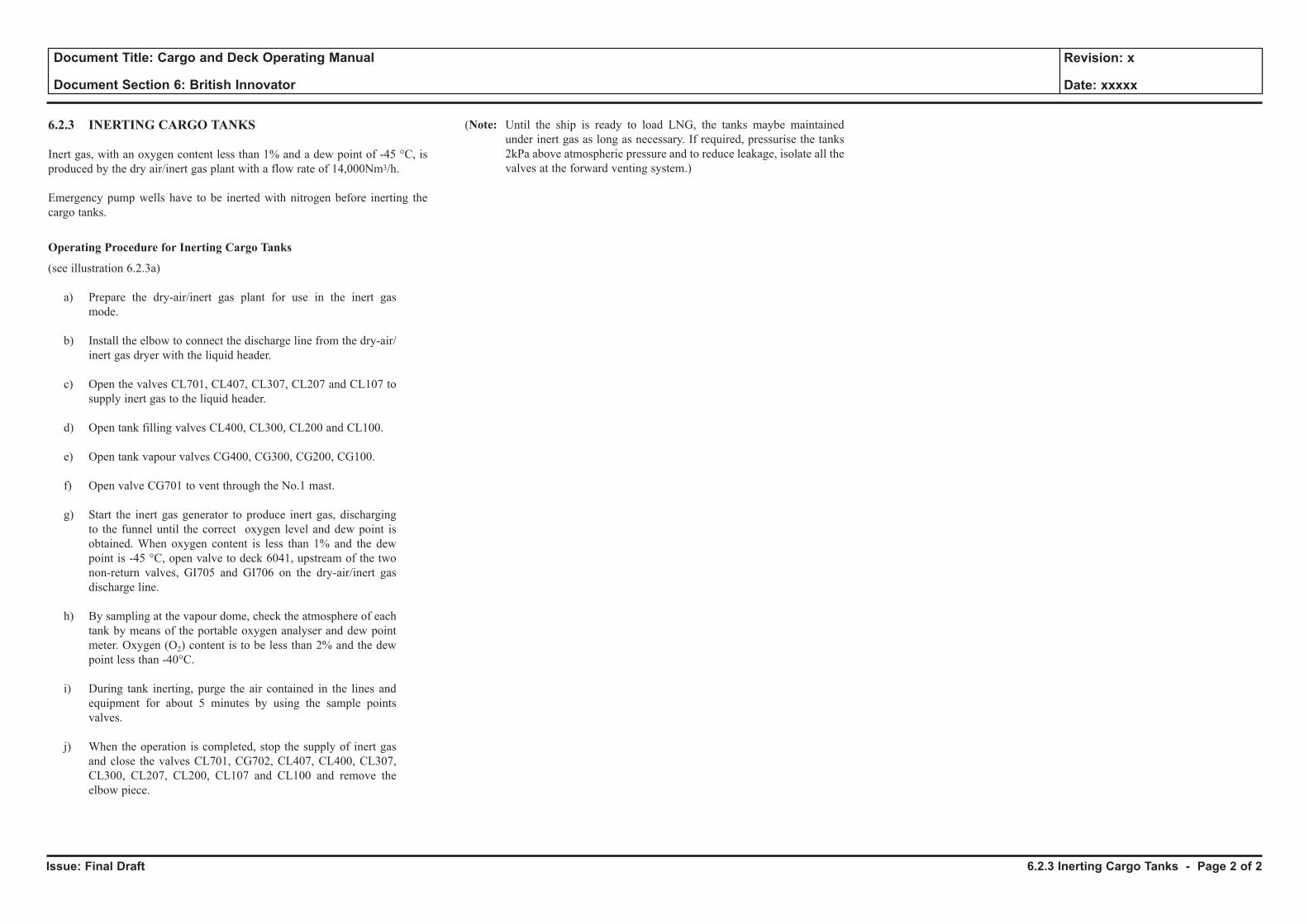
Issue: Final Draft
Document Title: Cargo and Deck Operating Manual
Document Section 6: British Innovator
Revision: x
Date: xxxxx
6.2.3 INERTING CARGO TANKS
Inert gas, with an oxygen content less than 1% and a dew point of -45 °C, is produced by the dry air/inert gas plant with a flow rate of 14,000Nm3/h.
Emergency pump wells have to be inerted with nitrogen before inerting the cargo tanks.
Operating Procedure for Inerting Cargo Tanks
(see illustration 6.2.3a)
a) Prepare the dry-air/inert gas plant for use in the inert gas mode.
b) Install the elbow to connect the discharge line from the dry-air/inert gas dryer with the liquid header.
c) Open the valves CL701, CL407, CL307, CL207 and CL107 to supply inert gas to the liquid header.
d) Open tank filling valves CL400, CL300, CL200 and CL100.
e) Open tank vapour valves CG400, CG300, CG200, CG100.
f) Open valve CG701 to vent through the No.1 mast.
g) Start the inert gas generator to produce inert gas, discharging to the funnel until the correct oxygen level and dew point is obtained. When oxygen content is less than 1% and the dew point is -45 °C, open valve to deck 6041, upstream of the two non-return valves, GI705 and GI706 on the dry-air/inert gas discharge line.
h) By sampling at the vapour dome, check the atmosphere of each tank by means of the portable oxygen analyser and dew point meter. Oxygen (O2) content is to be less than 2% and the dew point less than -40°C.
i) During tank inerting, purge the air contained in the lines and equipment for about 5 minutes by using the sample points valves.
j) When the operation is completed, stop the supply of inert gas and close the valves CL701, CG702, CL407, CL400, CL307, CL300, CL207, CL200, CL107 and CL100 and remove the elbow piece.
(Note: Until the ship is ready to load LNG, the tanks maybe maintained under inert gas as long as necessary. If required, pressurise the tanks 2kPa above atmospheric pressure and to reduce leakage, isolate all the valves at the forward venting system.)
6.2.3 Inerting Cargo Tanks - Page 2 of 2
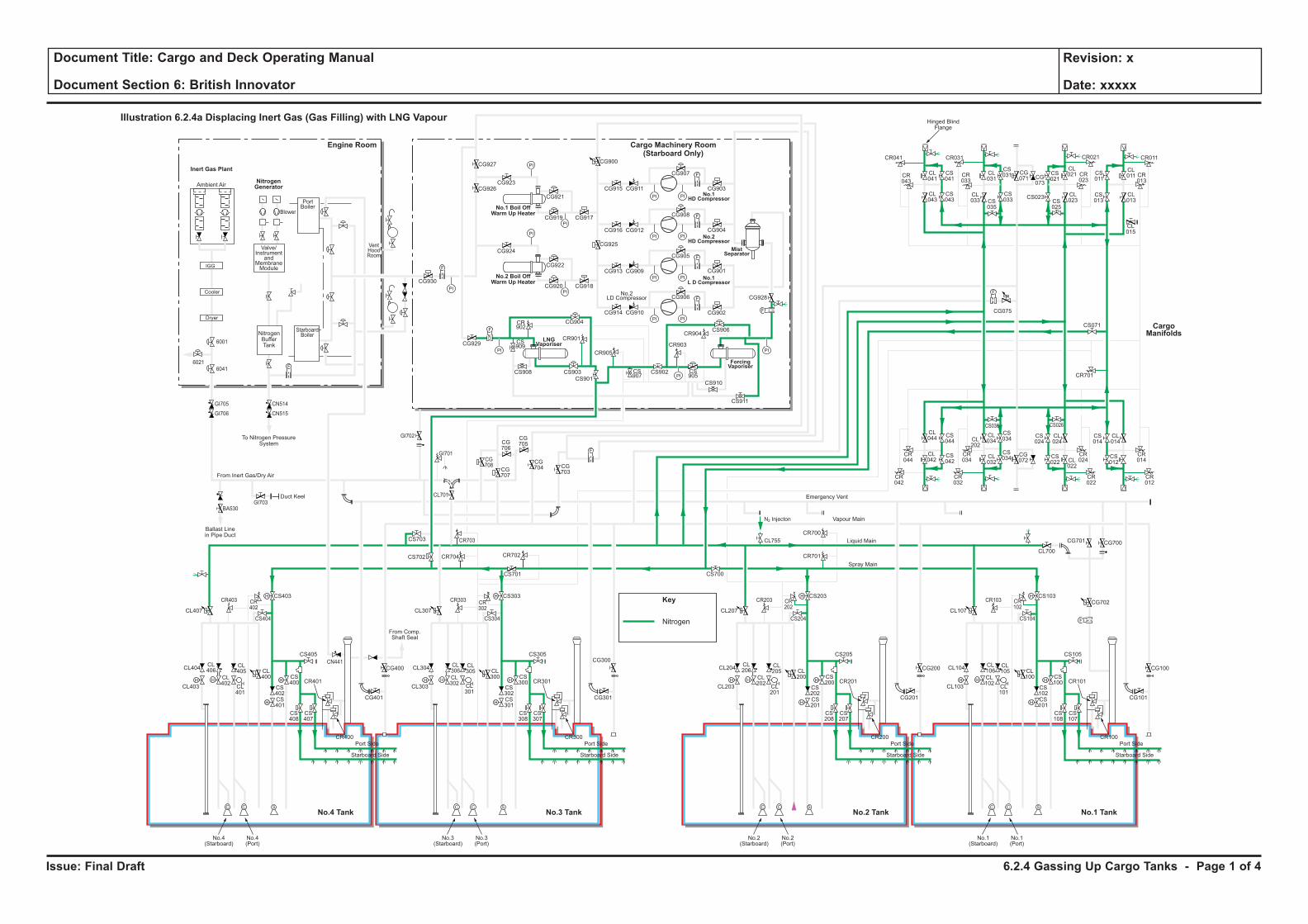
Issue: Final Draft
Document Title: Cargo and Deck Operating Manual
Document Section 6: British Innovator
Revision: x
Date: xxxxx
Nitrogen
Key
N2 Injecton
CL755
H H
H
H
F
C C S
H
HH H
H
H
C C S
H
HH H
H
H
C C S
H
HH H
H
H
C C S
H
H
F
PI PI
F
PI PI
PI
PI
PI
PI
PI PI
PI PI
F
F
PI
PI
PI
PI
F
F
F
CL106
CL102
CL101
CL100
CS102
CS100
CS103
CS101
CS108
CS107
CR101
CR100
CL105
CL104
CL700
CG700
CG702
CG101
CS105
CS104
CR103 CR102
CG701
CL103
Port Side
Starboard Side
CL107
No.1(Starboard)
No.1(Port)
CL206
CL202
CL201
CL200
CS202
CS200
CS203
CR701
CR700
CS201
CS208
CS207
CR201
CR200
CL205
CL204
CG201
CG200 CG100
CS205
CS204
CR203 CR202
CL203
Port Side
Ambient Air
Blower
PortBoiler
VentHoodRoom
StarboardBoiler
Inert Gas Plant
NitrogenGenerator
Engine Room
No.3 TankNo.4 Tank No.1 TankNo.2 Tank
Cargo Machinery Room(Starboard Only)
Starboard Side
CL207
CS700
No.2(Starboard)
No.2(Port)
CL306
CL302
CL301
CL300
CS302
CS300
CS303
CS701
CS301
CS308
CS307
CR301
CR300
CL305
CL304
CG301
CS305
CS304
CR303 CR302
CL303
Port Side
Starboard Side
CL307
CG927
CG926CG923
CG921
CG917CG919
CG924
CG930
CG929
CG904
CR901
CR905
CR903
CR904
CS909
CS907
CS905
CS908 CS903
CS901
CS902
CS906
CS910
CS911
CR902
CG922
CG918
CG928
CG902
CG906
CG905
CG908
CG907
CR041
CR043
CL041
CL043
CS041
CS043
CL031
CS031 CS
011
CL011 CR
013
CG071 CG
073
CS021
CL021
CL023CS
025
CS023 CL013
CL015
CS013
CR023
CR033
CR021CR031 CR011
CS035
CL033
CS033
CG915
CG900
CG925
CG911
CG916 CG912
CG913 CG909
CG914 CG910
CG901
CG904
CG903
CG920
No.3(Starboard)
No.3(Port)
CL406
CL402
CL401
CL400
CS402
CS400
CS403
CS702 CR704 CR702
CR703
CG708
CG707
CG706
CG705
CG704 CG
703
CS703
CL701
CS401
CS408
CS407
CR401
CR400
CL405
CL404
CG401
CG400
CG300CS405
From Comp.Shaft Seal
CS404
CR403
GI705
GI706
GI703
GI702
GI701
BA530
CN514
CN515
CR402
CL403
Port Side
Starboard Side
CL407
No.4(Starboard)
No.4(Port)
CL044
CS044
CS042
CS034
CS024
CL024
CS034
CR044
CR034
CR024
CR042
CR032
CR022
CS036 CS026
CL042
CL034CL
202
CL032
CG072
CS022 CL
022
CS014
CR701
CS071
CL014
CR014
CR012
CS012
F
F
F
Cooler
Dryer
IGG
Valve/Instrument
andMembraneModule
NitrogenBufferTank
To Nitrogen PressureSystem
Hinged BlindFlange
Ballast Linein Pipe Duct
Duct Keel
From Inert Gas/Dry Air
Emergency Vent
Vapour Main
Liquid Main
Spray Main
No.1 Boil OffWarm Up Heater
No.2 Boil OffWarm Up Heater
ForcingVaporiser
MistSeparator
No.1HD Compressor
No.2HD Compressor
No.1L D Compressor
LNGVaporiser
No.2LD Compressor
Illustration 6.2.4a Displacing Inert Gas (Gas Filling) with LNG Vapour
CargoManifolds
CG075
CN441
6001
60416021
6.2.4 Gassing Up Cargo Tanks - Page 1 of 4
Issue: Final Draft
Document Title: Cargo and Deck Operating Manual
Document Section 6: British Innovator
Revision: x
Date: xxxxx
6.2.4 GASSING-UP CARGO TANKS
Introduction
After lay up or dry dock, the cargo tanks are filled with inert gas or nitrogen. If the purging has been carried out with inert gas, the cargo tanks have to be purged with LNG vapour and cooled down when the vessel arrives at the loading terminal.
This is because, unlike nitrogen, inert gas contains 15% of carbon dioxide (CO2) which will freeze at around -60°C and produces a white powder which can block valves, filters and nozzles.
During purging, the inert gas in the cargo tanks is replaced with warm LNG vapour.
This is done to remove any freezable gases such as CO2 and to complete the drying of the tanks.
Operation
LNG liquid is supplied from the terminal to the liquid manifold where it passes to the stripping/spray header via the appropriate ESDS liquid valve.
It is then fed to the main vaporiser and the LNG vapour produced is passed at +20°C to the vapour header and then into each tank via the vapour domes.
At the start of the operation, the piping system and main vaporiser are vapour locked. The stripping/spray header can be purged into the cargo tanks via the vapour dome through the arrangement of spray valves containing the control valve until liquid reaches the main vaporiser. The LNG vapour is lighter than the inert gas, which allows the inert gases in the cargo tanks to be exhausted up the tank loading column to the liquid header. The inert gas then vents to the atmosphere via the No.1 mast riser.
When 5% methane (% figure will be specified by the particular port authority) is detected at No.1 mast riser, the exhaust gas is directed ashore via the high duty compressors, or to the boilers through the gas burning line.
This operation can be done without the compressors, subject to existing back pressure, or with one or both HD compressors in service.
If possible, it is better not to use compressors to avoid creating turbulence inside the tanks.
The operation is considered complete when the methane content, as measured at the top of the cargo filling pipe, exceeds 80% by volume.
This normally entails approximately 1.5 changes of the volume of the atmosphere in the cargo tank.
On completion of warm LNG vapour purging, the cargo tanks will normally be cooled down.
There are exceptional cases where it may be necessary to undertake the purging of one or more tanks at sea using LNG liquid already on board.
In this case the liquid will be supplied to the main vaporiser via the stripping/spray header using the stripping/spray pump of a cargo tank containing LNG liquid.
Due to local regulations on venting methane gas to the atmosphere, some port authorities may require the entire operation to be carried out with the exhaust gases being returned to shore facilities.
Operating Procedures to Purge the Cargo Tanks with LNG Vapour
Stage One (See Illustration 6.2.4a)
It is assumed, though unlikely, that all valves are closed prior to use.
a) Install the following removable bend:
• Liquid header to compressors (only if compressors are required).
b) Prepare the main vaporiser for use.
c) Adjust the set point of temperature control valve to +20°C.
d) Using the IAS adjust the set point of the pressure control valve to 6kPa (or required value).
e) At No.1 mast riser open valve CL700.
f) Open valve CS071, the stripping/spray header crossover valve to the manifold.
g) Open valves CS701 and CS702 on the stripping/spray header to enable supply to reach the main vaporiser.
h) Open valves CS901 and CS903, the inlet valves to the main vaporiser.
i) In the cargo machinery room open the outlet from the main vaporiser valve CG929.
j) Open valve CG707 to allow supply to the vapour header.
k) Open header valves to the vapour domes.
Position Description Valve
Full open No.1 tank vapour valve CG100
Full open No.2 tank vapour valve CG200
Full open No.3 tank vapour valve CG300
Full open No.4 tank vapour valve CG400
(Note: For safety reasons, ensure that the hull water curtain on the connected side is in operation.)
l) Open valve CS013 (if using the forward liquid manifold on the port side), the isolating valve to the stripping/spray line.
m) Using the IAS open the individual tank loading valves.
Position Description Valve
Open No.1 tank loading valves CL100, CL107
Open No.2 tank loading valves CL200, CL207
Open No.3 tank loading valves CL300, CL307
Open No.4 tank loading valves CL400, CL407 n) Using the IAS, open valve CL011, the forward ESD manifold
valve on the port side, and request the terminal to commence supply of LNG liquid to the ship at a constant pressure of 500kPa.
o) Adjust No.1 mast riser pressure with valve CG702 at 23kPa or as required.
p) Monitor the inert exhausting gas at each liquid dome using the mid cargo tank sample cock initially, followed by the sample cock at the top of the loading line. Also monitor the inert exhausted gas at No.1 mast riser, using the sample cock.
q) When 5% methane, (or the quantity the port authority will allow) is detected at No.1 mast riser and each vapour dome, request permission from the terminal personnel to direct exhaust gas to the terminal facilities.
6.2.4 Gassing Up Cargo Tanks - Page 2 of 4
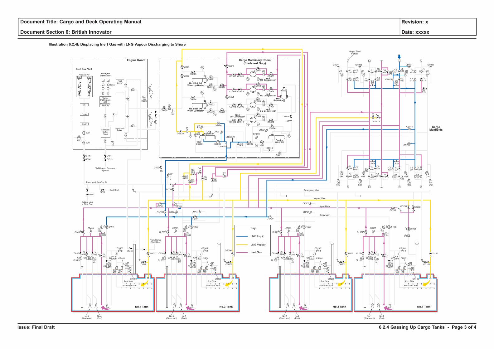
Issue: Final Draft
Document Title: Cargo and Deck Operating Manual
Document Section 6: British Innovator
Revision: x
Date: xxxxx
LNG Liquid
Key
LNG Vapour
Inert Gas
H H
H
H
F
C C S
H
HH H
H
H
C C S
H
HH H
H
H
C C S
H
HH H
H
H
C C S
H
H
F
PI PI
F
PI PI
PI
PI
PI
PI
PI PI
PI PI
F
F
PI
PI
PI
PI
F
F
F
CL106
CL102
CL101
CL100
CS102
CS100
CS103
CS101
CS108
CS107
CR101
CR100
CL105
CL104
CL700
CG700
CG702
CG101
CS105
CS104
CR103 CR102
CG701
CL103
Port Side
Starboard Side
CL107
No.1(Starboard)
No.1(Port)
CL206
CL202
CL201
CL200
CS202
CS200
CS203
CR701
CR700
CS201
CS208
CS207
CR201
CR200
CL205
CL204
CG201
CG200 CG100
CS205
CS204
CR203 CR202
CL203
Port Side
Ambient Air
Blower
PortBoiler
VentHoodRoom
StarboardBoiler
Inert Gas Plant
NitrogenGenerator
Engine Room
No.3 TankNo.4 Tank No.1 TankNo.2 Tank
Cargo Machinery Room(Starboard Only)
Starboard Side
CL207
CS700
No.2(Starboard)
No.2(Port)
CL306
CL302
CL301
CL300
CS302
CS300
CS303
CS701
CS301
CS308
CS307
CR301
CR300
CL305
CL304
CG301
CS305
CS304
CR303 CR302
CL303
Port Side
Starboard Side
CL307
CG927
CG926CG923
CG921
CG917CG919
CG924
CG930
CG929
CG904
CR901
CR905
CR903
CR904
CS909
CS907
CS905
CS908 CS903
CS901
CS902
CS906
CS910
CS911
CR902
CG922
CG918
CG928
CG902
CG906
CG905
CG908
CG907
CR041
CR043
CL041
CL043
CS041
CS043
CL031
CS031 CS
011
CL011 CR
013
CG071 CG
073
CS021
CL021
CL023CS
025
CS023 CL013
CL015
CS013
CR023
CR033
CR021CR031 CR011
CS035
CL033
CS033
CG915
CG900
CG925
CG911
CG916 CG912
CG913 CG909
CG914 CG910
CG901
CG904
CG903
CG920
No.3(Starboard)
No.3(Port)
CL406
CL402
CL401
CL400
CS402
CS400
CS403
CS702 CR704 CR702
CR703
CG708
CG707
CG706
CG705
CG704 CG
703
CS703
CL701
CS401
CS408
CS407
CR401
CR400
CL405
CL404
CG401
CG400
CG300CS405
From Comp.Shaft Seal
CS404
CR403
GI705
GI706
GI703
GI702
GI701
BA530
CN514
CN515
CR402
CL403
Port Side
Starboard Side
CL407
No.4(Starboard)
No.4(Port)
CL044
CS044
CS042
CS034
CS024
CL024
CS034
CR044
CR034
CR024
CR042
CR032
CR022
CS036 CS026
CL042
CL034CL
202
CL032
CG072
CS022 CL
022
CS014
CR701
CS071
CL014
CR014
CR012
CS012
F
F
F
Cooler
Dryer
IGG
Valve/Instrument
andMembraneModule
NitrogenBufferTank
To Nitrogen PressureSystem
Hinged BlindFlange
Ballast Linein Pipe Duct
Duct Keel
From Inert Gas/Dry Air
Emergency Vent
Vapour Main
Liquid Main
Spray Main
No.1 Boil OffWarm Up Heater
No.2 Boil OffWarm Up Heater
ForcingVaporiser
MistSeparator
No.1HD Compressor
No.2HD Compressor
No.1L D Compressor
LNGVaporiser
No.2LD Compressor
Illustration 6.2.4b Displacing Inert Gas with LNG Vapour Discharging to Shore
CargoManifolds
CG075
CN441
6001
60416021
6.2.4 Gassing Up Cargo Tanks - Page 3 of 4
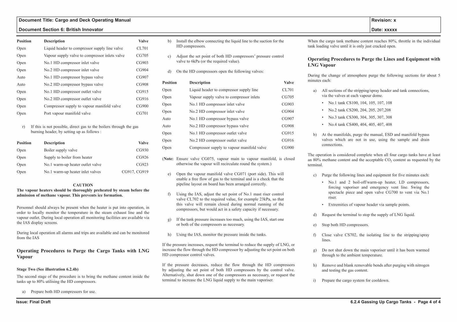
Issue: Final Draft
Document Title: Cargo and Deck Operating Manual
Document Section 6: British Innovator
Revision: x
Date: xxxxx
Position Description Valve
Open Liquid header to compressor supply line valve CL701
Open Vapour supply valve to compressor inlets valve CG705
Open No.1 HD compressor inlet valve CG903
Open No.2 HD compressor inlet valve CG904
Auto No.1 HD compressor bypass valve CG907
Auto No.2 HD compressor bypass valve CG908
Open No.1 HD compressor outlet valve CG915
Open No.2 HD compressor outlet valve CG916
Open Compressor supply to vapour manifold valve CG900
Open Port vapour manifold valve CG701
r) If this is not possible, direct gas to the boilers through the gas burning header, by setting up as follows :
Position Description Valve
Open Boiler supply valve CG930
Open Supply to boiler from heater CG926
Open No.1 warm-up heater outlet valve CG923
Open No.1 warm-up heater inlet valves CG917, CG919
CAUTION The vapour heaters should be thoroughly preheated by steam before the admission of methane vapour. This prevents ice formation.
Personnel should always be present when the heater is put into operation, in order to locally monitor the temperature in the steam exhaust line and the vapour outlet. During local operation all monitoring facilities are available via the IAS display screens.
During local operation all alarms and trips are available and can be monitored from the IAS
Operating Procedures to Purge the Cargo Tanks with LNG Vapour
Stage Two (See illustration 6.2.4b)
The second stage of the procedure is to bring the methane content inside the tanks up to 80% utilising the HD compressors.
a) Prepare both HD compressors for use.
b) Install the elbow connecting the liquid line to the suction for the HD compressors.
c) Adjust the set point of both HD compressors’ pressure control valve to 6kPa (or the required value).
d) On the HD compressors open the following valves:
Position Description Valve
Open Liquid header to compressor supply line CL701
Open Vapour supply valve to compressor inlets CG705
Open No.1 HD compressor inlet valve CG903
Open No.2 HD compressor inlet valve CG904
Auto No.1 HD compressor bypass valve CG907
Auto No.2 HD compressor bypass valve CG908
Open No.1 HD compressor outlet valve CG915
Open No.2 HD compressor outlet valve CG916
Open Compressor supply to vapour manifold valve CG900
(Note: Ensure valve CG075, vapour main to vapour manifold, is closed otherwise the vapour will recirculate round the system.)
e) Open the vapour manifold valve CG071 (port side). This will
enable a free flow of gas to the terminal and is a check that the pipeline layout on board has been arranged correctly.
f) Using the IAS, adjust the set point of No.1 mast riser control valve CL702 to the required value, for example 23kPa, so that this valve will remain closed during normal running of the compressors, but would act in a safety capacity if necessary.
g) If the tank pressure increases too much, using the IAS, start one or both of the compressors as necessary.
h) Using the IAS, monitor the pressure inside the tanks.
If the pressure increases, request the terminal to reduce the supply of LNG, or increase the flow through the HD compressor by adjusting the set point on both HD compressor control valves.
If the pressure decreases, reduce the flow through the HD compressors by adjusting the set point of both HD compressors by the control valve. Alternatively, shut down one of the compressors as necessary, or request the terminal to increase the LNG liquid supply to the main vaporiser.
When the cargo tank methane content reaches 80%, throttle in the individual tank loading valve until it is only just cracked open.
Operating Procedures to Purge the Lines and Equipment with LNG Vapour
During the change of atmosphere purge the following sections for about 5 minutes each:
a) All sections of the stripping/spray header and tank connections, via the valves at each vapour dome.
• No.1 tank CS100, 104, 105, 107, 108
• No.2 tank CS200, 204, 205, 207,208
• No.3 tank CS300, 304, 305, 307, 308
• No.4 tank CS400, 404, 405, 407, 408
b) At the manifolds, purge the manual, ESD and manifold bypass valves which are not in use, using the sample and drain connections.
The operation is considered complete when all four cargo tanks have at least an 80% methane content and the acceptable CO2 content as requested by the terminal.
c) Purge the following lines and equipment for five minutes each:
• No.1 and 2 boil-off/warm-up heater, LD compressors, forcing vaporiser and emergency vent line. Swing the spectacle piece and open valve CG700 to vent via No.1 riser.
• Extremities of vapour header via sample points.
d) Request the terminal to stop the supply of LNG liquid.
e) Stop both HD compressors.
f) Close valve CS702, the isolating line to the stripping/spray lines.
g) Do not shut down the main vaporiser until it has been warmed through to the ambient temperature.
h) Remove and blank removable bends after purging with nitrogen and testing the gas content.
i) Prepare the cargo system for cooldown.
6.2.4 Gassing Up Cargo Tanks - Page 4 of 4
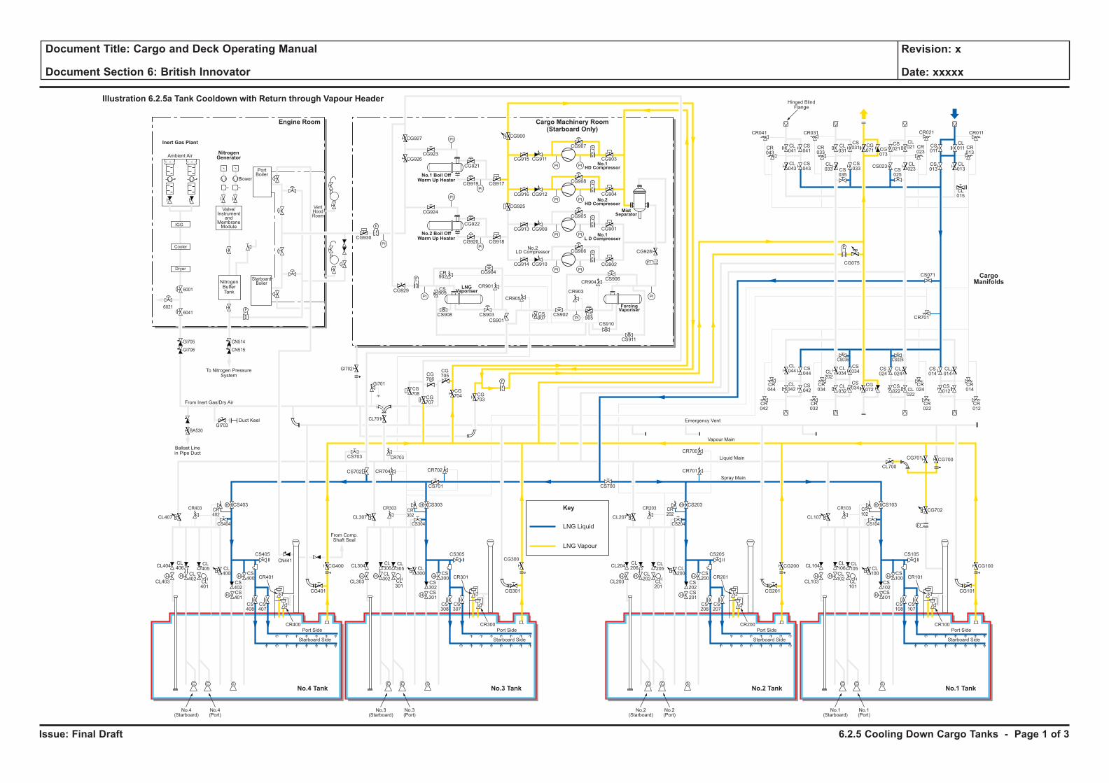
Issue: Final Draft
Document Title: Cargo and Deck Operating Manual
Document Section 6: British Innovator
Revision: x
Date: xxxxx
LNG Liquid
Key
LNG Vapour
H H
H
H
F
C C S
H
HH H
H
H
C C S
H
HH H
H
H
C C S
H
HH H
H
H
C C S
H
H
F
PI PI
F
PI PI
PI
PI
PI
PI
PI PI
PI PI
F
F
PI
PI
PI
PI
F
F
F
CL106
CL102
CL101
CL100
CS102
CS100
CS103
CS101
CS108
CS107
CR101
CR100
CL105
CL104
CL700
CG700
CG702
CG101
CS105
CS104
CR103 CR102
CG701
CL103
Port Side
Starboard Side
CL107
No.1(Starboard)
No.1(Port)
CL206
CL202
CL201
CL200
CS202
CS200
CS203
CR701
CR700
CS201
CS208
CS207
CR201
CR200
CL205
CL204
CG201
CG200 CG100
CS205
CS204
CR203 CR202
CL203
Port Side
Ambient Air
Blower
PortBoiler
VentHoodRoom
StarboardBoiler
Inert Gas Plant
NitrogenGenerator
Engine Room
No.3 TankNo.4 Tank No.1 TankNo.2 Tank
Cargo Machinery Room(Starboard Only)
Starboard Side
CL207
CS700
No.2(Starboard)
No.2(Port)
CL306
CL302
CL301
CL300
CS302
CS300
CS303
CS701
CS301
CS308
CS307
CR301
CR300
CL305
CL304
CG301
CS305
CS304
CR303 CR302
CL303
Port Side
Starboard Side
CL307
CG927
CG926CG923
CG921
CG917CG919
CG924
CG930
CG929
CG904
CR901
CR905
CR903
CR904
CS909
CS907
CS905
CS908 CS903
CS901
CS902
CS906
CS910
CS911
CR902
CG922
CG918
CG928
CG902
CG906
CG905
CG908
CG907
CR041
CR043
CL041
CL043
CS041
CS043
CL031
CS031 CS
011
CL011 CR
013
CG071 CG
073
CS021
CL021
CL023CS
025
CS023 CL013
CL015
CS013
CR023
CR033
CR021CR031 CR011
CS035
CL033
CS033
CG915
CG900
CG925
CG911
CG916 CG912
CG913 CG909
CG914 CG910
CG901
CG904
CG903
CG920
No.3(Starboard)
No.3(Port)
CL406
CL402
CL401
CL400
CS402
CS400
CS403
CS702 CR704 CR702
CR703
CG708
CG707
CG706
CG705
CG704 CG
703
CS703
CL701
CS401
CS408
CS407
CR401
CR400
CL405
CL404
CG401
CG400
CG300CS405
From Comp.Shaft Seal
CS404
CR403
GI705
GI706
GI703
GI702
GI701
BA530
CN514
CN515
CR402
CL403
Port Side
Starboard Side
CL407
No.4(Starboard)
No.4(Port)
CL044
CS044
CS042
CS034
CS024
CL024
CS034
CR044
CR034
CR024
CR042
CR032
CR022
CS036 CS026
CL042
CL034CL
202
CL032
CG072
CS022 CL
022
CS014
CR701
CS071
CL014
CR014
CR012
CS012
F
F
F
Cooler
Dryer
IGG
Valve/Instrument
andMembraneModule
NitrogenBufferTank
To Nitrogen PressureSystem
Hinged BlindFlange
Ballast Linein Pipe Duct
Duct Keel
From Inert Gas/Dry Air
Emergency Vent
Vapour Main
Liquid Main
Spray Main
No.1 Boil OffWarm Up Heater
No.2 Boil OffWarm Up Heater
ForcingVaporiser
MistSeparator
No.1HD Compressor
No.2HD Compressor
No.1L D Compressor
LNGVaporiser
No.2LD Compressor
Illustration 6.2.5a Tank Cooldown with Return through Vapour Header
CargoManifolds
CG075
CN441
6001
60416021
6.2.5 Cooling Down Cargo Tanks - Page 1 of 3
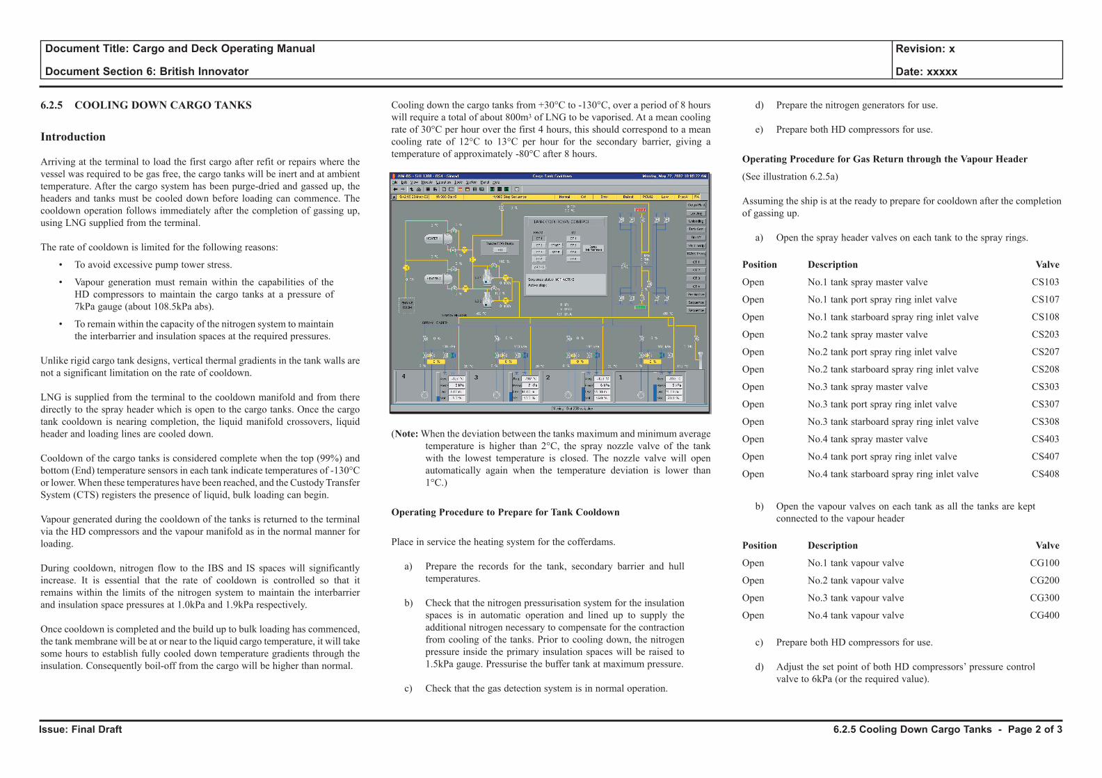
Issue: Final Draft
Document Title: Cargo and Deck Operating Manual
Document Section 6: British Innovator
Revision: x
Date: xxxxx
6.2.5 COOLING DOWN CARGO TANKS
Introduction
Arriving at the terminal to load the first cargo after refit or repairs where the vessel was required to be gas free, the cargo tanks will be inert and at ambient temperature. After the cargo system has been purge-dried and gassed up, the headers and tanks must be cooled down before loading can commence. The cooldown operation follows immediately after the completion of gassing up, using LNG supplied from the terminal.
The rate of cooldown is limited for the following reasons:
• To avoid excessive pump tower stress.
• Vapour generation must remain within the capabilities of the HD compressors to maintain the cargo tanks at a pressure of 7kPa gauge (about 108.5kPa abs).
• To remain within the capacity of the nitrogen system to maintain the interbarrier and insulation spaces at the required pressures.
Unlike rigid cargo tank designs, vertical thermal gradients in the tank walls are not a significant limitation on the rate of cooldown. LNG is supplied from the terminal to the cooldown manifold and from there directly to the spray header which is open to the cargo tanks. Once the cargo tank cooldown is nearing completion, the liquid manifold crossovers, liquid header and loading lines are cooled down. Cooldown of the cargo tanks is considered complete when the top (99%) and bottom (End) temperature sensors in each tank indicate temperatures of -130°C or lower. When these temperatures have been reached, and the Custody Transfer System (CTS) registers the presence of liquid, bulk loading can begin. Vapour generated during the cooldown of the tanks is returned to the terminal via the HD compressors and the vapour manifold as in the normal manner for loading.
During cooldown, nitrogen flow to the IBS and IS spaces will significantly increase. It is essential that the rate of cooldown is controlled so that it remains within the limits of the nitrogen system to maintain the interbarrier and insulation space pressures at 1.0kPa and 1.9kPa respectively.
Once cooldown is completed and the build up to bulk loading has commenced, the tank membrane will be at or near to the liquid cargo temperature, it will take some hours to establish fully cooled down temperature gradients through the insulation. Consequently boil-off from the cargo will be higher than normal.
Cooling down the cargo tanks from +30°C to -130°C, over a period of 8 hours will require a total of about 800m3 of LNG to be vaporised. At a mean cooling rate of 30°C per hour over the first 4 hours, this should correspond to a mean cooling rate of 12°C to 13°C per hour for the secondary barrier, giving a temperature of approximately -80°C after 8 hours.
(Note: When the deviation between the tanks maximum and minimum average temperature is higher than 2°C, the spray nozzle valve of the tank with the lowest temperature is closed. The nozzle valve will open automatically again when the temperature deviation is lower than 1°C.)
Operating Procedure to Prepare for Tank Cooldown
Place in service the heating system for the cofferdams.
a) Prepare the records for the tank, secondary barrier and hull temperatures.
b) Check that the nitrogen pressurisation system for the insulation spaces is in automatic operation and lined up to supply the additional nitrogen necessary to compensate for the contraction from cooling of the tanks. Prior to cooling down, the nitrogen pressure inside the primary insulation spaces will be raised to 1.5kPa gauge. Pressurise the buffer tank at maximum pressure.
c) Check that the gas detection system is in normal operation.
d) Prepare the nitrogen generators for use.
e) Prepare both HD compressors for use.
Operating Procedure for Gas Return through the Vapour Header
(See illustration 6.2.5a)
Assuming the ship is at the ready to prepare for cooldown after the completion of gassing up.
a) Open the spray header valves on each tank to the spray rings.
Position Description Valve
Open No.1 tank spray master valve CS103
Open No.1 tank port spray ring inlet valve CS107
Open No.1 tank starboard spray ring inlet valve CS108
Open No.2 tank spray master valve CS203
Open No.2 tank port spray ring inlet valve CS207
Open No.2 tank starboard spray ring inlet valve CS208
Open No.3 tank spray master valve CS303
Open No.3 tank port spray ring inlet valve CS307
Open No.3 tank starboard spray ring inlet valve CS308
Open No.4 tank spray master valve CS403
Open No.4 tank port spray ring inlet valve CS407
Open No.4 tank starboard spray ring inlet valve CS408
b) Open the vapour valves on each tank as all the tanks are kept connected to the vapour header
Position Description Valve
Open No.1 tank vapour valve CG100
Open No.2 tank vapour valve CG200
Open No.3 tank vapour valve CG300
Open No.4 tank vapour valve CG400
c) Prepare both HD compressors for use.
d) Adjust the set point of both HD compressors’ pressure control valve to 6kPa (or the required value).
6.2.5 Cooling Down Cargo Tanks - Page 2 of 3
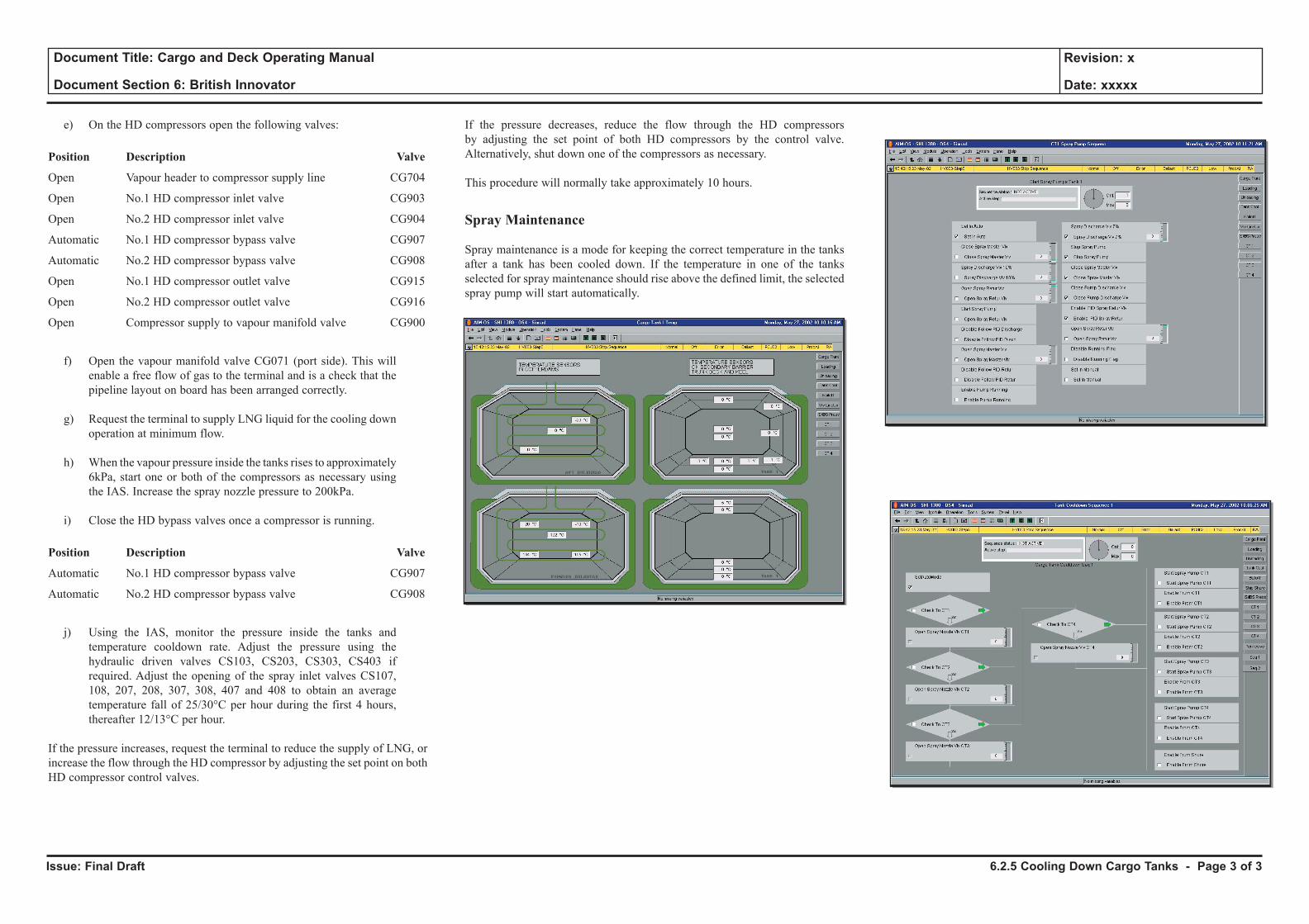
Issue: Final Draft
Document Title: Cargo and Deck Operating Manual
Document Section 6: British Innovator
Revision: x
Date: xxxxx
e) On the HD compressors open the following valves:
Position Description Valve
Open Vapour header to compressor supply line CG704
Open No.1 HD compressor inlet valve CG903
Open No.2 HD compressor inlet valve CG904
Automatic No.1 HD compressor bypass valve CG907
Automatic No.2 HD compressor bypass valve CG908
Open No.1 HD compressor outlet valve CG915
Open No.2 HD compressor outlet valve CG916
Open Compressor supply to vapour manifold valve CG900
f) Open the vapour manifold valve CG071 (port side). This will enable a free flow of gas to the terminal and is a check that the pipeline layout on board has been arranged correctly.
g) Request the terminal to supply LNG liquid for the cooling down operation at minimum flow.
h) When the vapour pressure inside the tanks rises to approximately 6kPa, start one or both of the compressors as necessary using the IAS. Increase the spray nozzle pressure to 200kPa.
i) Close the HD bypass valves once a compressor is running.
Position Description Valve
Automatic No.1 HD compressor bypass valve CG907
Automatic No.2 HD compressor bypass valve CG908
j) Using the IAS, monitor the pressure inside the tanks and temperature cooldown rate. Adjust the pressure using the hydraulic driven valves CS103, CS203, CS303, CS403 if required. Adjust the opening of the spray inlet valves CS107, 108, 207, 208, 307, 308, 407 and 408 to obtain an average temperature fall of 25/30°C per hour during the first 4 hours, thereafter 12/13°C per hour.
If the pressure increases, request the terminal to reduce the supply of LNG, or increase the flow through the HD compressor by adjusting the set point on both HD compressor control valves.
If the pressure decreases, reduce the flow through the HD compressors by adjusting the set point of both HD compressors by the control valve. Alternatively, shut down one of the compressors as necessary.
This procedure will normally take approximately 10 hours.
Spray Maintenance
Spray maintenance is a mode for keeping the correct temperature in the tanks after a tank has been cooled down. If the temperature in one of the tanks selected for spray maintenance should rise above the defined limit, the selected spray pump will start automatically.
6.2.5 Cooling Down Cargo Tanks - Page 3 of 3
6.3 Ballast Passage
6.3.1 Cooling Down Cargo Tanks Prior to Arrival
6.3.2 Spraying During Ballast Voyage, Single Tank
Illustrations
6.3.1a Cooling Down Cargo Tanks Prior to Arrival on Ballast Voyage
6.3.2a Cooling Down One Cargo Tank Prior to Arrival on Ballast Voyage
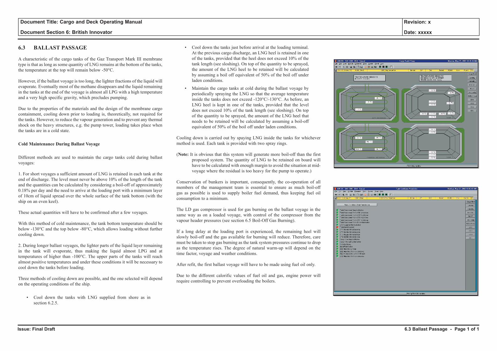
Issue: Final Draft
Document Title: Cargo and Deck Operating Manual
Document Section 6: British Innovator
Revision: x
Date: xxxxx
6.3 BALLAST PASSAGE
A characteristic of the cargo tanks of the Gaz Transport Mark III membrane type is that as long as some quantity of LNG remains at the bottom of the tanks, the temperature at the top will remain below -50°C.
However, if the ballast voyage is too long, the lighter fractions of the liquid will evaporate. Eventually most of the methane disappears and the liquid remaining in the tanks at the end of the voyage is almost all LPG with a high temperature and a very high specific gravity, which precludes pumping.
Due to the properties of the materials and the design of the membrane cargo containment, cooling down prior to loading is, theoretically, not required for the tanks. However, to reduce the vapour generation and to prevent any thermal shock on the heavy structures, e.g. the pump tower, loading takes place when the tanks are in a cold state.
Cold Maintenance During Ballast Voyage
Different methods are used to maintain the cargo tanks cold during ballast voyages:
1. For short voyages a sufficient amount of LNG is retained in each tank at the end of discharge. The level must never be above 10% of the length of the tank and the quantities can be calculated by considering a boil-off of approximately 0.18% per day and the need to arrive at the loading port with a minimum layer of 10cm of liquid spread over the whole surface of the tank bottom (with the ship on an even keel).
These actual quantities will have to be confirmed after a few voyages.
With this method of cold maintenance, the tank bottom temperature should be below -130°C and the top below -80°C, which allows loading without further cooling down.
2. During longer ballast voyages, the lighter parts of the liquid layer remaining in the tank will evaporate, thus making the liquid almost LPG and at temperatures of higher than -100°C. The upper parts of the tanks will reach almost positive temperatures and under these conditions it will be necessary to cool down the tanks before loading.
Three methods of cooling down are possible, and the one selected will depend on the operating conditions of the ship.
• Cool down the tanks with LNG supplied from shore as in section 6.2.5.
• Cool down the tanks just before arrival at the loading terminal. At the previous cargo discharge, an LNG heel is retained in one of the tanks, provided that the heel does not exceed 10% of the tank length (see sloshing). On top of the quantity to be sprayed, the amount of the LNG heel to be retained will be calculated by assuming a boil off equivalent of 50% of the boil off under laden conditions.
• Maintain the cargo tanks at cold during the ballast voyage by periodically spraying the LNG so that the average temperature inside the tanks does not exceed -120°C/-130°C. As before, an LNG heel is kept in one of the tanks, provided that the level does not exceed 10% of the tank length (see sloshing). On top of the quantity to be sprayed, the amount of the LNG heel that needs to be retained will be calculated by assuming a boil-off equivalent of 50% of the boil off under laden conditions.
Cooling down is carried out by spaying LNG inside the tanks for whichever method is used. Each tank is provided with two spray rings.
(Note: It is obvious that this system will generate more boil-off than the first proposed system. The quantity of LNG to be retained on board will have to be calculated with enough margin to avoid the situation at mid-voyage where the residual is too heavy for the pump to operate.)
Conservation of bunkers is important, consequently, the co-operation of all members of the management team is essential to ensure as much boil-off gas as possible is used to supply boiler fuel demand, thus keeping fuel oil consumption to a minimum.
The LD gas compressor is used for gas burning on the ballast voyage in the same way as on a loaded voyage, with control of the compressor from the vapour header pressures (see section 6.5 Boil-Off Gas Burning).
If a long delay at the loading port is experienced, the remaining heel will slowly boil-off and the gas available for burning will reduce. Therefore, care must be taken to stop gas burning as the tank system pressures continue to drop as the temperature rises. The degree of natural warm-up will depend on the time factor, voyage and weather conditions.
After refit, the first ballast voyage will have to be made using fuel oil only.
Due to the different calorific values of fuel oil and gas, engine power will require controlling to prevent overloading the boilers.
6.3 Ballast Passage - Page 1 of 1
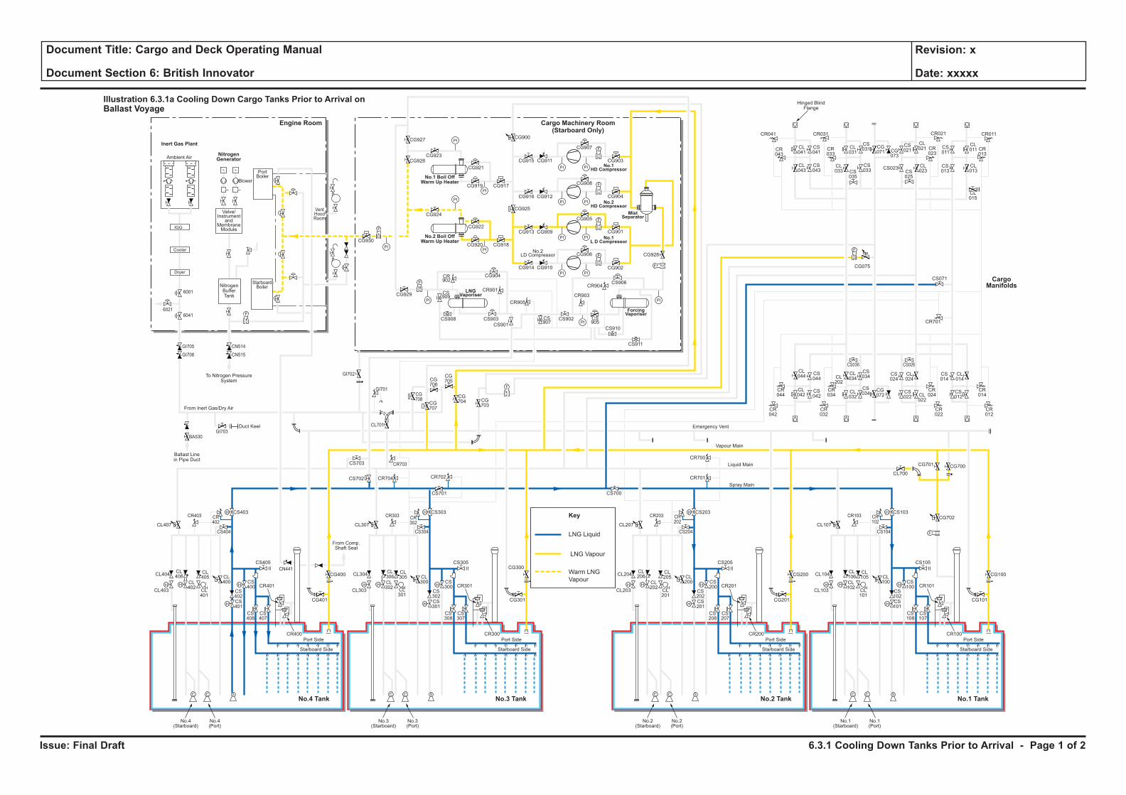
Issue: Final Draft
Document Title: Cargo and Deck Operating Manual
Document Section 6: British Innovator
Revision: x
Date: xxxxx
LNG Liquid
Key
LNG Vapour
Warm LNG
VapourH H
H
H
F
C C S
H
HH H
H
H
C C S
H
HH H
H
H
C C S
H
HH H
H
H
C C S
H
H
F
PI PI
F
PI PI
PI
PI
PI
PI
PI PI
PI PI
F
F
PI
PI
PI
PI
F
F
F
CL106
CL102
CL101
CL100
CS102
CS100
CS103
CS101
CS108
CS107
CR101
CR100
CL105
CL104
CL700
CG700
CG702
CG101
CS105
CS104
CR103 CR102
CG701
CL103
Port Side
Starboard Side
CL107
No.1(Starboard)
No.1(Port)
CL206
CL202
CL201
CL200
CS202
CS200
CS203
CR701
CR700
CS201
CS208
CS207
CR201
CR200
CL205
CL204
CG201
CG200 CG100
CS205
CS204
CR203 CR202
CL203
Port Side
Ambient Air
Blower
PortBoiler
VentHoodRoom
StarboardBoiler
Inert Gas Plant
NitrogenGenerator
Engine Room
No.3 TankNo.4 Tank No.1 TankNo.2 Tank
Cargo Machinery Room(Starboard Only)
Starboard Side
CL207
CS700
No.2(Starboard)
No.2(Port)
CL306
CL302
CL301
CL300
CS302
CS300
CS303
CS701
CS301
CS308
CS307
CR301
CR300
CL305
CL304
CG301
CS305
CS304
CR303 CR302
CL303
Port Side
Starboard Side
CL307
CG927
CG926CG923
CG921
CG917CG919
CG924
CG930
CG929
CG904
CR901
CR905
CR903
CR904
CS909
CS907
CS905
CS908 CS903
CS901
CS902
CS906
CS910
CS911
CR902
CG922
CG918
CG928
CG902
CG906
CG905
CG908
CG907
CR041
CR043
CL041
CL043
CS041
CS043
CL031
CS031 CS
011
CL011 CR
013
CG071 CG
073
CS021
CL021
CL023CS
025
CS023 CL013
CL015
CS013
CR023
CR033
CR021CR031 CR011
CS035
CL033
CS033
CG915
CG900
CG925
CG911
CG916 CG912
CG913 CG909
CG914 CG910
CG901
CG904
CG903
CG920
No.3(Starboard)
No.3(Port)
CL406
CL402
CL401
CL400
CS402
CS400
CS403
CS702 CR704 CR702
CR703
CG708
CG707
CG706
CG705
CG704 CG
703
CS703
CL701
CS401
CS408
CS407
CR401
CR400
CL405
CL404
CG401
CG400
CG300CS405
From Comp.Shaft Seal
CS404
CR403
GI705
GI706
GI703
GI702
GI701
BA530
CN514
CN515
CR402
CL403
Port Side
Starboard Side
CL407
No.4(Starboard)
No.4(Port)
CL044
CS044
CS042
CS034
CS024
CL024
CS034
CR044
CR034
CR024
CR042
CR032
CR022
CS036 CS026
CL042
CL034CL
202
CL032
CG072
CS022 CL
022
CS014
CR701
CS071
CL014
CR014
CR012
CS012
F
F
F
Cooler
Dryer
IGG
Valve/Instrument
andMembraneModule
NitrogenBufferTank
To Nitrogen PressureSystem
Hinged BlindFlange
Ballast Linein Pipe Duct
Duct Keel
From Inert Gas/Dry Air
Emergency Vent
Vapour Main
Liquid Main
Spray Main
No.1 Boil OffWarm Up Heater
No.2 Boil OffWarm Up Heater
ForcingVaporiser
MistSeparator
No.1HD Compressor
No.2HD Compressor
No.1L D Compressor
LNGVaporiser
No.2LD Compressor
Illustration 6.3.1a Cooling Down Cargo Tanks Prior to Arrival onBallast Voyage
CargoManifolds
CG075
CN441
6001
60416021
6.3.1 Cooling Down Tanks Prior to Arrival - Page 1 of 2
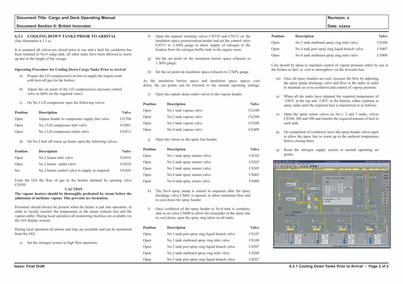
Issue: Final Draft
Document Title: Cargo and Deck Operating Manual
Document Section 6: British Innovator
Revision: x
Date: xxxxx
6.3.1 COOLING DOWN TANKS PRIOR TO ARRIVAL(See illustration 6.3.1.a)
It is assumed all valves are closed prior to use and a heel for cooldown has been retained in No.4 cargo tank, all other tanks have been allowed to warm up due to the length of the voyage.
Operating Procedure for Cooling Down Cargo Tanks Prior to Arrival
a) Prepare the LD compressor(s) on line to supply the engine room with boil-off gas for the boilers.
b) Adjust the set point of the LD compressor(s) pressure control valve to 6kPa (or the required value).
c) On No.1 LD compressor open the following valves:
Position Description Valve
Open Vapour header to compressor supply line valve CG704
Open No.1 LD compressor inlet valve CG901
Open No.1 LD compressor outlet valve CG913
d) On No.2 boil off warm up heater open the following valves:
Position Description Valve
Open No.2 heater inlet valve CG918
Open No.2 heater outlet valve CG924
Set No.2 heater control valve to supply as required CG920
From the IAS the flow of gas to the boilers initiated by opening valve CG930.
CAUTION The vapour heaters should be thoroughly preheated by steam before the admission of methane vapour. This prevents ice formation.
Personnel should always be present when the heater is put into operation, in order to locally monitor the temperature in the steam exhaust line and the vapour outlet. During local operation all monitoring facilities are available via the IAS display screens.
During local operation all alarms and trips are available and can be monitored from the IAS.
e) Set the nitrogen system to high flow operation.
f) Open the manual isolating valves CN510 and CN512 on the insulation space pressurisation header and set the control valve CN511 to 2.5kPa gauge to allow supply of nitrogen to the headers from the nitrogen buffer tank in the engine room.
g) Set the set point on the insulation barrier space exhausts to 1.3kPa gauge.
h) Set the set point on insulation space exhausts to 2.5kPa gauge.
As the insulation barrier space and insulation space spaces cool down, the set points can be lowered to the normal operating settings.
i) Open the vapour dome outlet valves to the vapour header.
Position Description Valve
Open No.1 tank vapour valve CG100
Open No.2 tank vapour valve CG200
Open No.3 tank vapour valve CG300
Open No.4 tank vapour valve CG400
j) Open the valves on the spray line header.
Position Description Valve
Open No.1 tank spray master valve CS103
Open No.2 tank spray master valve CS203
Open No.3 tank spray master valve CS303
Open No.4 tank spray master valve CS403
Open No.4 tank spray return valve CS400
k) The No.4 spray pump is started in sequence after the spray discharge valve CS401 is opened, to allow minimum flow and to cool down the spray header.
l) Once cooldown of the spray header to No.4 tank is complete, shut in on valve CS400 to allow the remainder of the spray line to cool down, open the spray ring inlets on all tanks.
Position Description Valve
Open No.1 tank port spray ring liquid branch valve CS107
Open No.1 tank starboard spray ring inlet valve CS108
Open No.2 tank port spray ring liquid branch valve CS207
Open No.2 tank starboard spray ring inlet valve CS208
Open No.3 tank port spray ring liquid branch valve CS307
Position Description Valve
Open No.3 tank starboard spray ring inlet valve CS308
Open No.4 tank port spray ring liquid branch valve CS407
Open No.4 tank starboard spray ring inlet valve CS408
Care should be taken to maintain control of vapour pressure either by use in the boilers as fuel, or vent to atmosphere via the forward riser.
m) Once all spray headers are cool, increase the flow by adjusting the spray pump discharge valve and flow to the tanks in order to maintain an even cooldown and control of vapour pressure.
n) When all the tanks have attained the required temperature of -100°C at the top and -130°C at the bottom, either continue to spray tanks until the required heel is transferred or as follows:
o) Open the spray return valves on No.1, 2 and 3 tanks, valves CS100, 200 and 300 and transfer the required amount of heel to each tank.
p) On completion of cooldown, leave the spray header valves open to allow the spray line to warm up to the ambient temperature before closing them.
q) Reset the nitrogen supply system to normal operating set points.
6.3.1 Cooling Down Tanks Prior to Arrival - Page 2 of 2
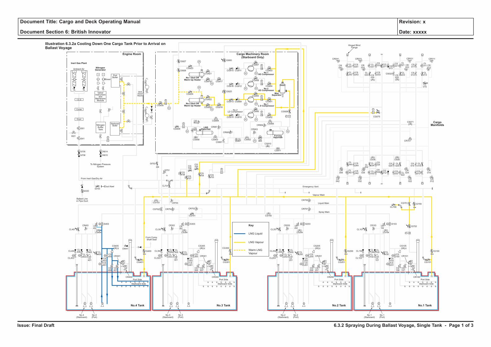
Issue: Final Draft
Document Title: Cargo and Deck Operating Manual
Document Section 6: British Innovator
Revision: x
Date: xxxxx
LNG Liquid
Key
LNG Vapour
Warm LNG
VapourH H
H
H
F
C C S
H
HH H
H
H
C C S
H
HH H
H
H
C C S
H
HH H
H
H
C C S
H
H
F
PI PI
F
PI PI
PI
PI
PI
PI
PI PI
PI PI
F
F
PI
PI
PI
PI
F
F
F
CL106
CL102
CL101
CL100
CS102
CS100
CS103
CS101
CS108
CS107
CR101
CR100
CL105
CL104
CL700
CG700
CG702
CG101
CS105
CS104
CR103 CR102
CG701
CL103
Port Side
Starboard Side
CL107
No.1(Starboard)
No.1(Port)
CL206
CL202
CL201
CL200
CS202
CS200
CS203
CR701
CR700
CS201
CS208
CS207
CR201
CR200
CL205
CL204
CG201
CG200 CG100
CS205
CS204
CR203 CR202
CL203
Port Side
Ambient Air
Blower
PortBoiler
VentHoodRoom
StarboardBoiler
Inert Gas Plant
NitrogenGenerator
Engine Room
No.3 TankNo.4 Tank No.1 TankNo.2 Tank
Cargo Machinery Room(Starboard Only)
Starboard Side
CL207
CS700
No.2(Starboard)
No.2(Port)
CL306
CL302
CL301
CL300
CS302
CS300
CS303
CS701
CS301
CS308
CS307
CR301
CR300
CL305
CL304
CG301
CS305
CS304
CR303 CR302
CL303
Port Side
Starboard Side
CL307
CG927
CG926CG923
CG921
CG917CG919
CG924
CG930
CG929
CG904
CR901
CR905
CR903
CR904
CS909
CS907
CS905
CS908 CS903
CS901
CS902
CS906
CS910
CS911
CR902
CG922
CG918
CG928
CG902
CG906
CG905
CG908
CG907
CR041
CR043
CL041
CL043
CS041
CS043
CL031
CS031 CS
011
CL011 CR
013
CG071 CG
073
CS021
CL021
CL023CS
025
CS023 CL013
CL015
CS013
CR023
CR033
CR021CR031 CR011
CS035
CL033
CS033
CG915
CG900
CG925
CG911
CG916 CG912
CG913 CG909
CG914 CG910
CG901
CG904
CG903
CG920
No.3(Starboard)
No.3(Port)
CL406
CL402
CL401
CL400
CS402
CS400
CS403
CS702 CR704 CR702
CR703
CG708
CG707
CG706
CG705
CG704 CG
703
CS703
CL701
CS401
CS408
CS407
CR401
CR400
CL405
CL404
CG401
CG400
CG300CS405
From Comp.Shaft Seal
CS404
CR403
GI705
GI706
GI703
GI702
GI701
BA530
CN514
CN515
CR402
CL403
Port Side
Starboard Side
CL407
No.4(Starboard)
No.4(Port)
CL044
CS044
CS042
CS034
CS024
CL024
CS034
CR044
CR034
CR024
CR042
CR032
CR022
CS036 CS026
CL042
CL034CL
202
CL032
CG072
CS022 CL
022
CS014
CR701
CS071
CL014
CR014
CR012
CS012
F
F
F
Cooler
Dryer
I.G.G
Valve/Instrument
andMembraneModule
NitrogenBufferTank
To Nitrogen PressureSystem
Hinged BlindFlange
Ballast Linein Pipe Duct
Duct Keel
From Inert Gas/Dry Air
Emergency Vent
Vapour Main
Liquid Main
Spray Main
No.1 Boil OffWarm Up Heater
No.2 Boil OffWarm Up Heater
ForcingVaporiser
MistSeparator
No.1HD Compressor
No.2HD Compressor
No.1L D Compressor
LNGVaporiser
No.2LD Compressor
Illustration 6.3.2a Cooling Down One Cargo Tank Prior to Arrival onBallast Voyage
CargoManifolds
CG075
CN441
6001
60416021
6.3.2 Spraying During Ballast Voyage, Single Tank - Page 1 of 3
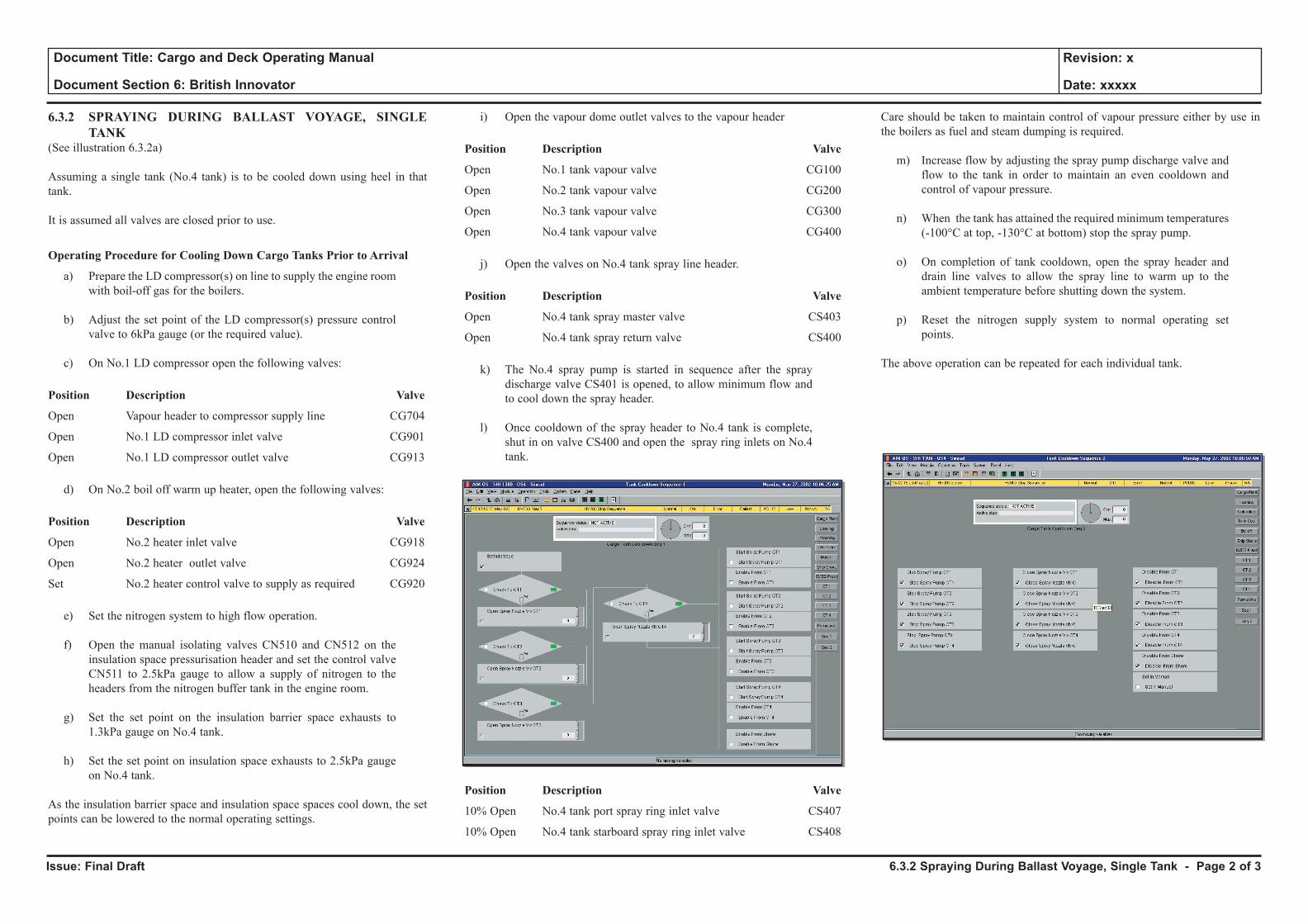
Issue: Final Draft
Document Title: Cargo and Deck Operating Manual
Document Section 6: British Innovator
Revision: x
Date: xxxxx
6.3.2 SPRAYING DURING BALLAST VOYAGE, SINGLE TANK
(See illustration 6.3.2a)
Assuming a single tank (No.4 tank) is to be cooled down using heel in that tank.
It is assumed all valves are closed prior to use.
Operating Procedure for Cooling Down Cargo Tanks Prior to Arrival
a) Prepare the LD compressor(s) on line to supply the engine room with boil-off gas for the boilers.
b) Adjust the set point of the LD compressor(s) pressure control valve to 6kPa gauge (or the required value).
c) On No.1 LD compressor open the following valves:
Position Description Valve
Open Vapour header to compressor supply line CG704
Open No.1 LD compressor inlet valve CG901
Open No.1 LD compressor outlet valve CG913
d) On No.2 boil off warm up heater, open the following valves:
Position Description Valve
Open No.2 heater inlet valve CG918
Open No.2 heater outlet valve CG924
Set No.2 heater control valve to supply as required CG920
e) Set the nitrogen system to high flow operation.
f) Open the manual isolating valves CN510 and CN512 on the insulation space pressurisation header and set the control valve CN511 to 2.5kPa gauge to allow a supply of nitrogen to the headers from the nitrogen buffer tank in the engine room.
g) Set the set point on the insulation barrier space exhausts to 1.3kPa gauge on No.4 tank.
h) Set the set point on insulation space exhausts to 2.5kPa gauge on No.4 tank.
As the insulation barrier space and insulation space spaces cool down, the set points can be lowered to the normal operating settings.
i) Open the vapour dome outlet valves to the vapour header
Position Description Valve
Open No.1 tank vapour valve CG100
Open No.2 tank vapour valve CG200
Open No.3 tank vapour valve CG300
Open No.4 tank vapour valve CG400
j) Open the valves on No.4 tank spray line header.
Position Description Valve
Open No.4 tank spray master valve CS403
Open No.4 tank spray return valve CS400
k) The No.4 spray pump is started in sequence after the spray discharge valve CS401 is opened, to allow minimum flow and to cool down the spray header.
l) Once cooldown of the spray header to No.4 tank is complete, shut in on valve CS400 and open the spray ring inlets on No.4 tank.
Position Description Valve
10% Open No.4 tank port spray ring inlet valve CS407
10% Open No.4 tank starboard spray ring inlet valve CS408
Care should be taken to maintain control of vapour pressure either by use in the boilers as fuel and steam dumping is required.
m) Increase flow by adjusting the spray pump discharge valve and flow to the tank in order to maintain an even cooldown and control of vapour pressure.
n) When the tank has attained the required minimum temperatures (-100°C at top, -130°C at bottom) stop the spray pump.
o) On completion of tank cooldown, open the spray header and drain line valves to allow the spray line to warm up to the ambient temperature before shutting down the system.
p) Reset the nitrogen supply system to normal operating set points.
The above operation can be repeated for each individual tank.
6.3.2 Spraying During Ballast Voyage, Single Tank - Page 2 of 3
Issue: Final Draft
Document Title: Cargo and Deck Operating Manual
Document Section 6: British Innovator
Revision: x
Date: xxxxx
Sloshing
From the experience gained on the first LNG ships put into service and from a large number of model tests and computer analyses, Gaz Transport have designed new tanks which are reasonably free from any sloshing risk.
The ship’s cargo tanks are designed to limit the impact forces and the safety margin has been considerably enlarged. However, operators should be always be aware of the potential risks to the cargo containment system and also on the tank equipment due to sloshing.
Precautions to Avoid Damage due to Sloshing
Cargo Tank Levels:
The first precaution is to maintain the level of the tanks within the required limits i.e.
• Lower than a level corresponding to 10% of the length of the tank
• Higher than a level corresponding to normally 80% of the height of the tank.
Ship’s Movement
The second precaution is to try to limit the ship’s movement, which would generate sloshing in the tanks.
The amplitude of sloshing depends on the condition of the sea (wave pattern), the trim and the speed of the ship.
6.3.2 Spraying During Ballast Voyage, Single Tank - Page 3 of 3
6.4 Loading
6.4.1 Preparations for Loading
6.4.2 Cargo Lines Cooldown
6.4.3 To Load Cargo with Vapour Return to Shore via High Duty Compressor
6.4.4 Deballasting
Illustrations
6.4.1a Preparations for Loading
6.4.2a Cargo Lines Cooldown
6.4.3a Loading With Vapour Return to Shore via the High Duty Compressor
6.4.4a Deballasting
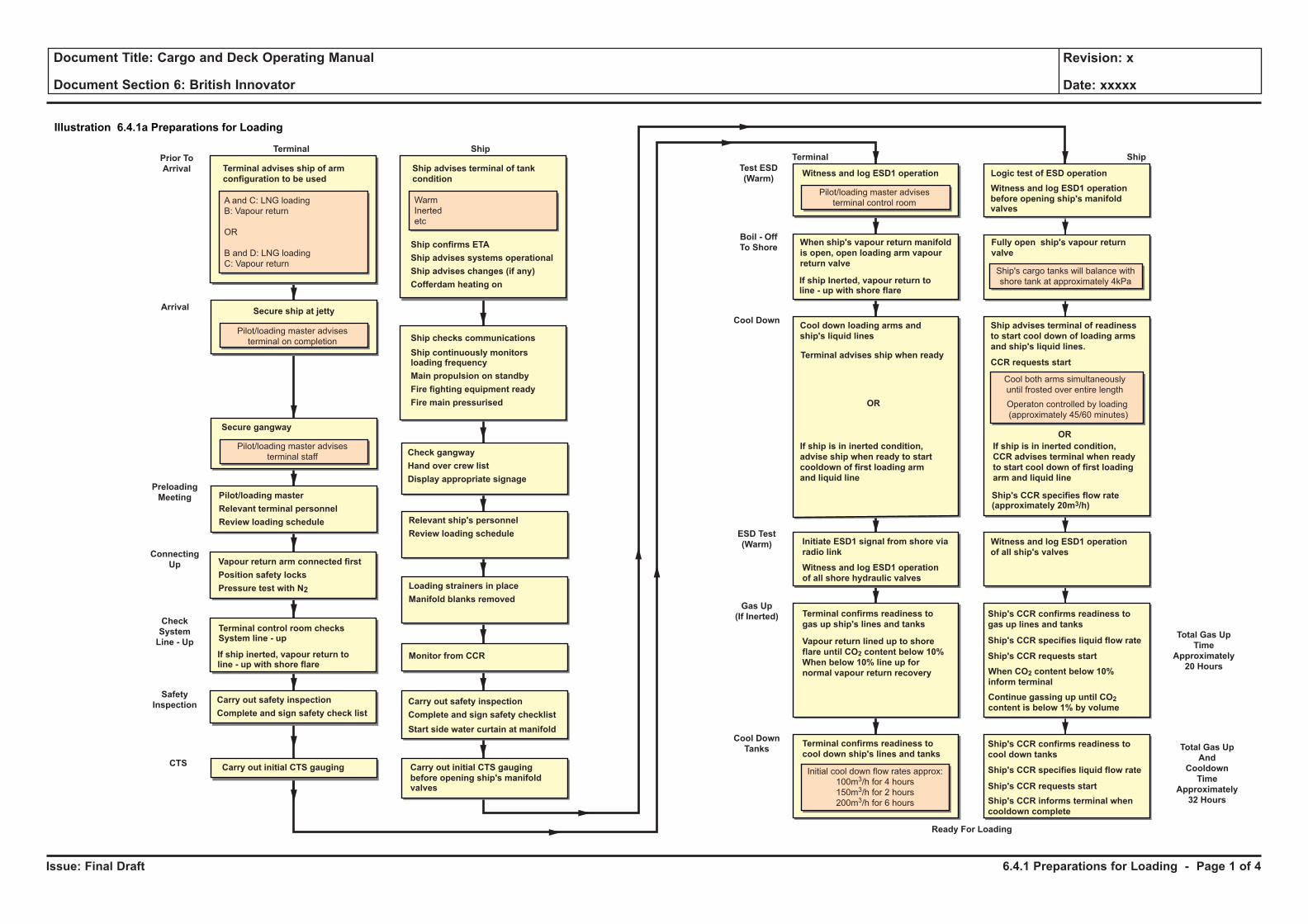
Issue: Final Draft
Document Title: Cargo and Deck Operating Manual
Document Section 6: British Innovator
Revision: x
Date: xxxxx
Illustration 6.4.1a Preparations for Loading
Prior To
Arrival
Arrival
Terminal Ship
Terminal advises ship of arm
configuration to be used
A and C: LNG loading
B: Vapour return
OR
B and D: LNG loading
C: Vapour return
Secure ship at jetty
Pilot/loading master advises
terminal on completion
Secure gangway
Pilot/loading master advises
terminal staff
Ship advises terminal of tank
condition
Ship confirms ETA
Ship advises systems operational
Ship advises changes (if any)
Cofferdam heating on
Warm
Inerted
etc
Ship checks communications
Ship continuously monitorsloading frequency
Main propulsion on standby
Fire fighting equipment ready
Fire main pressurised
Check gangway
Hand over crew list
Display appropriate signage
Pilot/loading master
Relevant terminal personnel
Review loading schedule
Preloading
Meeting
Relevant ship's personnel
Review loading schedule
Vapour return arm connected first
Position safety locks
Pressure test with N2
Connecting
Up
Check
System
Line - Up
Safety
Inspection
Loading strainers in place
Manifold blanks removed
Terminal control room checksSystem line - up
If ship inerted, vapour return toline - up with shore flare
Monitor from CCR
Carry out safety inspection
Complete and sign safety checklist
Test ESD
(Warm)
Boil - Off
To Shore
Terminal Ship
Witness and log ESD1 operation
Pilot/loading master advises
terminal control room
Cool Down
ESD Test
(Warm)
Terminal advises ship when readyCCR requests start
Ship's CCR specifies flow rate(approximately 20m3/h)
OR
OR
Carry out safety inspection
Complete and sign safety check list
before opening ship's manifoldvalves
When ship's vapour return manifold
is open, open loading arm vapour
return valve
Cool down loading arms and
ship's liquid lines
If ship is in inerted condition,
advise ship when ready to start
cooldown of first loading arm
and liquid line
If ship is in inerted condition,
CCR advises terminal when ready
to start cool down of first loading
arm and liquid line
Ship advises terminal of readiness
to start cool down of loading arms
and ship's liquid lines.
Fully open ship's vapour return
valve
Logic test of ESD operation
Witness and log ESD1 operation
Initiate ESD1 signal from shore via
radio link
Witness and log ESD1 operation
of all shore hydraulic valves
of all ship's valves
Witness and log ESD1 operation
Terminal confirms readiness to
cool down ship's lines and tanks
Gas Up
(If Inerted)
Cool Down
Tanks Total Gas Up
And
Cooldown
Time
Approximately
32 Hours
Total Gas Up
Time
Approximately
20 Hours
Ready For Loading
Terminal confirms readiness to
gas up ship's lines and tanks
Vapour return lined up to shore
flare until CO2 content below 10%
When below 10% line up for
normal vapour return recovery
Ship's CCR confirms readiness to
gas up lines and tanks
Ship's CCR confirms readiness to
cool down tanks
Ship's CCR specifies liquid flow rate
Ship's CCR specifies liquid flow rate
Ship's CCR requests start
Ship's CCR requests start
Ship's CCR informs terminal when
cooldown complete
If ship Inerted, vapour return toline - up with shore flare
Ship's cargo tanks will balance with
shore tank at approximately 4kPa
Cool both arms simultaneously
until frosted over entire length
Operaton controlled by loading
(approximately 45/60 minutes)
Start side water curtain at manifold
When CO2 content below 10%
inform terminal
Continue gassing up until CO2content is below 1% by volume
CTSCarry out initial CTS gauging Carry Out Initial CTS GaugingCarry out initial CTS gauging
before opening ship's manifoldvalves
Initial cool down flow rates approx:
100m3/h for 4 hours
150m3/h for 2 hours
200m3/h for 6 hours
6.4.1 Preparations for Loading - Page 1 of 4
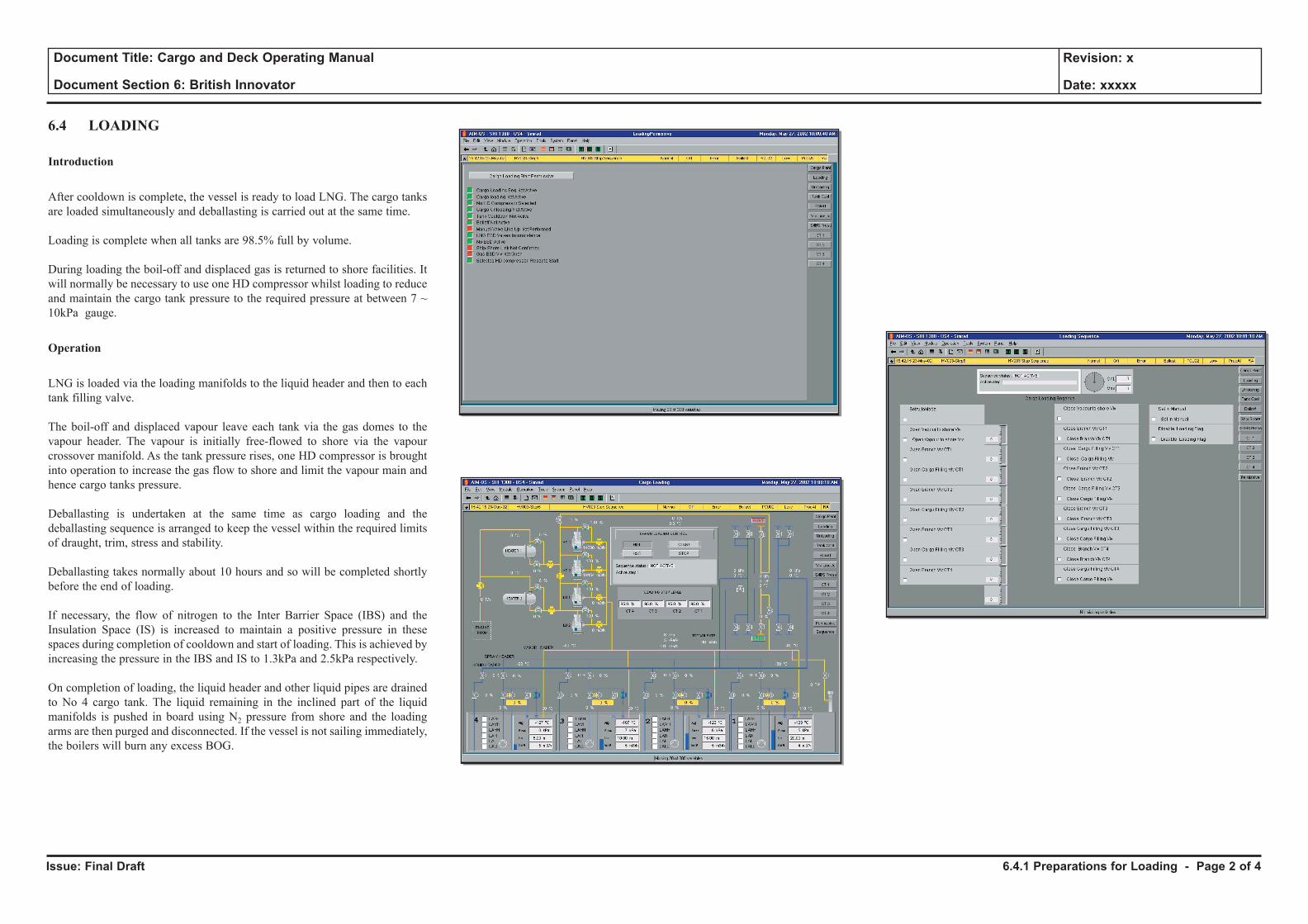
Issue: Final Draft
Document Title: Cargo and Deck Operating Manual
Document Section 6: British Innovator
Revision: x
Date: xxxxx
6.4 LOADING
Introduction
After cooldown is complete, the vessel is ready to load LNG. The cargo tanks are loaded simultaneously and deballasting is carried out at the same time.
Loading is complete when all tanks are 98.5% full by volume.
During loading the boil-off and displaced gas is returned to shore facilities. It will normally be necessary to use one HD compressor whilst loading to reduce and maintain the cargo tank pressure to the required pressure at between 7 ~ 10kPa gauge.
Operation
LNG is loaded via the loading manifolds to the liquid header and then to each tank filling valve.
The boil-off and displaced vapour leave each tank via the gas domes to the vapour header. The vapour is initially free-flowed to shore via the vapour crossover manifold. As the tank pressure rises, one HD compressor is brought into operation to increase the gas flow to shore and limit the vapour main and hence cargo tanks pressure.
Deballasting is undertaken at the same time as cargo loading and the deballasting sequence is arranged to keep the vessel within the required limits of draught, trim, stress and stability.
Deballasting takes normally about 10 hours and so will be completed shortly before the end of loading.
If necessary, the flow of nitrogen to the Inter Barrier Space (IBS) and the Insulation Space (IS) is increased to maintain a positive pressure in these spaces during completion of cooldown and start of loading. This is achieved by increasing the pressure in the IBS and IS to 1.3kPa and 2.5kPa respectively.
On completion of loading, the liquid header and other liquid pipes are drained to No 4 cargo tank. The liquid remaining in the inclined part of the liquid manifolds is pushed in board using N2 pressure from shore and the loading arms are then purged and disconnected. If the vessel is not sailing immediately, the boilers will burn any excess BOG.
6.4.1 Preparations for Loading - Page 2 of 4

Issue: Final Draft
Document Title: Cargo and Deck Operating Manual
Document Section 6: British Innovator
Revision: x
Date: xxxxx
Illustration 6.4.1a Preparations for Loading
Prior To
Arrival
Arrival
Terminal Ship
Terminal advises ship of arm
configuration to be used
A and C: LNG loading
B: Vapour return
OR
B and D: LNG loading
C: Vapour return
Secure ship at jetty
Pilot/loading master advises
terminal on completion
Secure gangway
Pilot/loading master advises
terminal staff
Ship advises terminal of tank
condition
Ship confirms ETA
Ship advises systems operational
Ship advises changes (if any)
Cofferdam heating on
Warm
Inerted
etc
Ship checks communications
Ship continuously monitorsloading frequency
Main propulsion on standby
Fire fighting equipment ready
Fire main pressurised
Check gangway
Hand over crew list
Display appropriate signage
Pilot/loading master
Relevant terminal personnel
Review loading schedule
Preloading
Meeting
Relevant ship's personnel
Review loading schedule
Vapour return arm connected first
Position safety locks
Pressure test with N2
Connecting
Up
Check
System
Line - Up
Safety
Inspection
Loading strainers in place
Manifold blanks removed
Terminal control room checksSystem line - up
If ship inerted, vapour return toline - up with shore flare
Monitor from CCR
Carry out safety inspection
Complete and sign safety checklist
Test ESD
(Warm)
Boil - Off
To Shore
Terminal Ship
Witness and log ESD1 operation
Pilot/loading master advises
terminal control room
Cool Down
ESD Test
(Warm)
Terminal advises ship when readyCCR requests start
Ship's CCR specifies flow rate(approximately 20m3/h)
OR
OR
Carry out safety inspection
Complete and sign safety check list
before opening ship's manifoldvalves
When ship's vapour return manifold
is open, open loading arm vapour
return valve
Cool down loading arms and
ship's liquid lines
If ship is in inerted condition,
advise ship when ready to start
cooldown of first loading arm
and liquid line
If ship is in inerted condition,
CCR advises terminal when ready
to start cool down of first loading
arm and liquid line
Ship advises terminal of readiness
to start cool down of loading arms
and ship's liquid lines.
Fully open ship's vapour return
valve
Logic test of ESD operation
Witness and log ESD1 operation
Initiate ESD1 signal from shore via
radio link
Witness and log ESD1 operation
of all shore hydraulic valves
of all ship's valves
Witness and log ESD1 operation
Terminal confirms readiness to
cool down ship's lines and tanks
Gas Up
(If Inerted)
Cool Down
Tanks Total Gas Up
And
Cooldown
Time
Approximately
32 Hours
Total Gas Up
Time
Approximately
20 Hours
Ready For Loading
Terminal confirms readiness to
gas up ship's lines and tanks
Vapour return lined up to shore
flare until CO2 content below 10%
When below 10% line up for
normal vapour return recovery
Ship's CCR confirms readiness to
gas up lines and tanks
Ship's CCR confirms readiness to
cool down tanks
Ship's CCR specifies liquid flow rate
Ship's CCR specifies liquid flow rate
Ship's CCR requests start
Ship's CCR requests start
Ship's CCR informs terminal when
cooldown complete
If ship Inerted, vapour return toline - up with shore flare
Ship's cargo tanks will balance with
shore tank at approximately 4kPa
Cool both arms simultaneously
until frosted over entire length
Operaton controlled by loading
(approximately 45/60 minutes)
Start side water curtain at manifold
When CO2 content below 10%
inform terminal
Continue gassing up until CO2content is below 1% by volume
CTSCarry out initial CTS gauging Carry Out Initial CTS GaugingCarry out initial CTS gauging
before opening ship's manifoldvalves
Initial cool down flow rates approx:
100m3/h for 4 hours
150m3/h for 2 hours
200m3/h for 6 hours
6.4.1 Preparations for Loading - Page 3 of 4
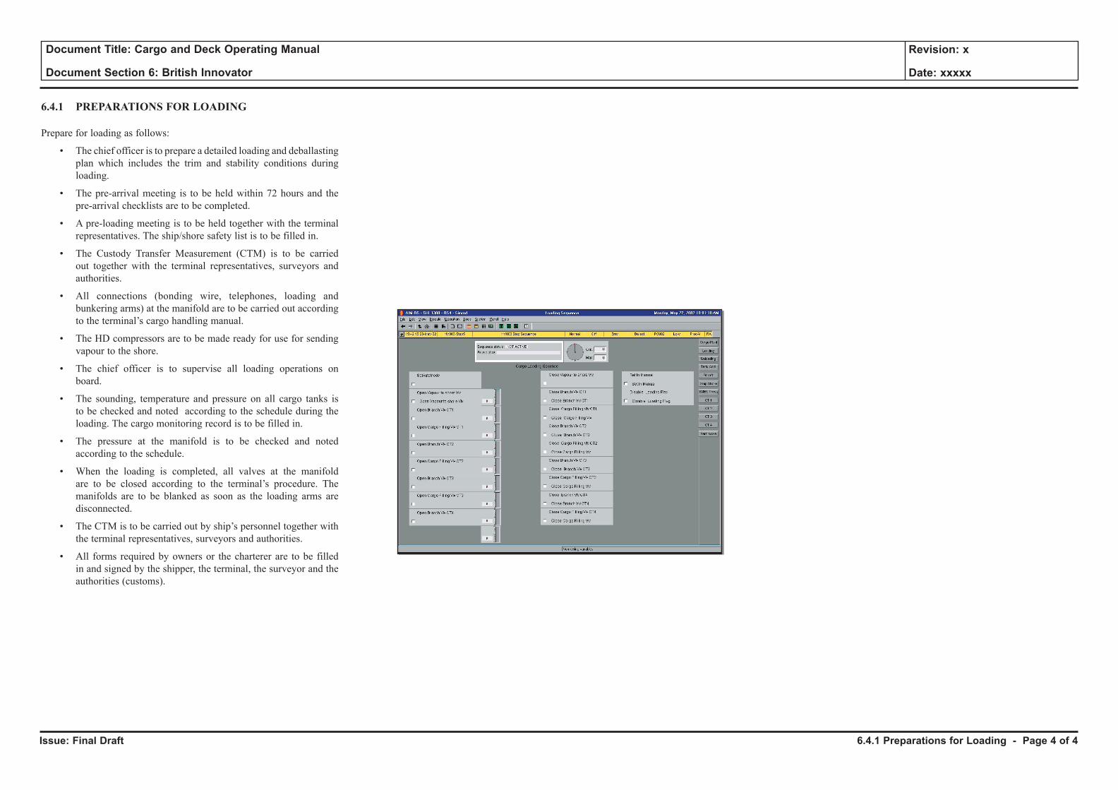
Issue: Final Draft
Document Title: Cargo and Deck Operating Manual
Document Section 6: British Innovator
Revision: x
Date: xxxxx
6.4.1 PREPARATIONS FOR LOADING
Prepare for loading as follows:
• The chief officer is to prepare a detailed loading and deballasting plan which includes the trim and stability conditions during loading.
• The pre-arrival meeting is to be held within 72 hours and the pre-arrival checklists are to be completed.
• A pre-loading meeting is to be held together with the terminal representatives. The ship/shore safety list is to be filled in.
• The Custody Transfer Measurement (CTM) is to be carried out together with the terminal representatives, surveyors and authorities.
• All connections (bonding wire, telephones, loading and bunkering arms) at the manifold are to be carried out according to the terminal’s cargo handling manual.
• The HD compressors are to be made ready for use for sending vapour to the shore.
• The chief officer is to supervise all loading operations on board.
• The sounding, temperature and pressure on all cargo tanks is to be checked and noted according to the schedule during the loading. The cargo monitoring record is to be filled in.
• The pressure at the manifold is to be checked and noted according to the schedule.
• When the loading is completed, all valves at the manifold are to be closed according to the terminal’s procedure. The manifolds are to be blanked as soon as the loading arms are disconnected.
• The CTM is to be carried out by ship’s personnel together with the terminal representatives, surveyors and authorities.
• All forms required by owners or the charterer are to be filled in and signed by the shipper, the terminal, the surveyor and the authorities (customs).
6.4.1 Preparations for Loading - Page 4 of 4
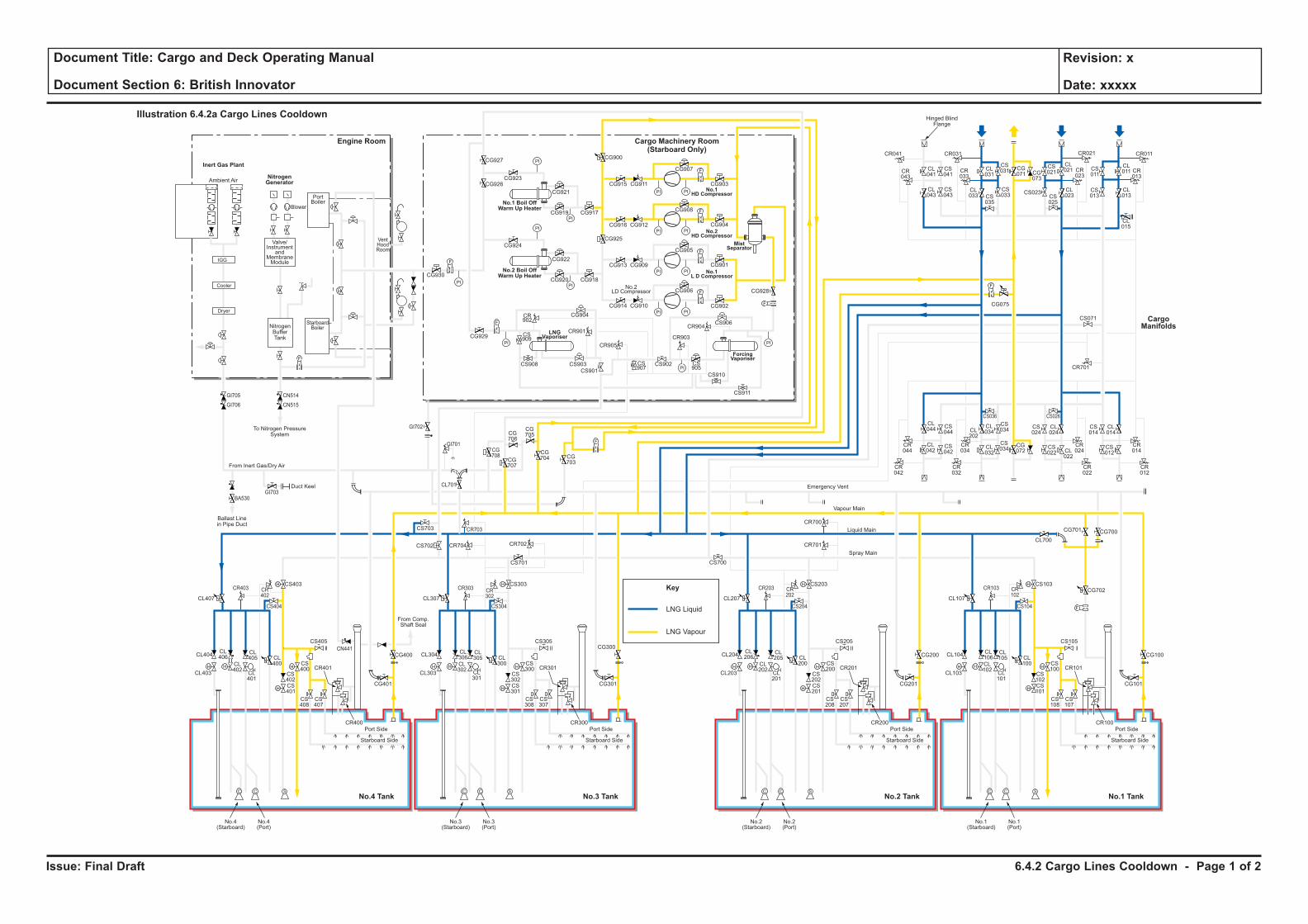
Issue: Final Draft
Document Title: Cargo and Deck Operating Manual
Document Section 6: British Innovator
Revision: x
Date: xxxxx
LNG Liquid
Key
LNG Vapour
H H
H
H
F
C C S
H
HH H
H
H
C C S
H
HH H
H
H
C C S
H
HH H
H
H
C C S
H
H
F
PI PI
F
PI PI
PI
PI
PI
PI
PI PI
PI PI
F
F
PI
PI
PI
PI
F
F
F
CL106
CL102
CL101
CL100
CS102
CS100
CS103
CS101
CS108
CS107
CR101
CR100
CL105
CL104
CL700
CG700
CG702
CG101
CS105
CS104
CR103 CR102
CG701
CL103
Port Side
Starboard Side
CL107
No.1(Starboard)
No.1(Port)
CL206
CL202
CL201
CL200
CS202
CS200
CS203
CR701
CR700
CS201
CS208
CS207
CR201
CR200
CL205
CL204
CG201
CG200 CG100
CS205
CS204
CR203 CR202
CL203
Port Side
Ambient Air
Blower
PortBoiler
VentHoodRoom
StarboardBoiler
Inert Gas Plant
NitrogenGenerator
Engine Room
No.3 TankNo.4 Tank No.1 TankNo.2 Tank
Cargo Machinery Room(Starboard Only)
Starboard Side
CL207
CS700
No.2(Starboard)
No.2(Port)
CL306
CL302
CL301
CL300
CS302
CS300
CS303
CS701
CS301
CS308
CS307
CR301
CR300
CL305
CL304
CG301
CS305
CS304
CR303 CR302
CL303
Port Side
Starboard Side
CL307
CG927
CG926CG923
CG921
CG917CG919
CG924
CG930
CG929
CG904
CR901
CR905
CR903
CR904
CS909
CS907
CS905
CS908 CS903
CS901
CS902
CS906
CS910
CS911
CR902
CG922
CG918
CG928
CG902
CG906
CG905
CG908
CG907
CR041
CR043
CL041
CL043
CS041
CS043
CL031
CS031 CS
011
CL011 CR
013
CG071 CG
073
CS021
CL021
CL023CS
025
CS023 CL013
CL015
CS013
CR023
CR033
CR021CR031 CR011
CS035
CL033
CS033
CG915
CG900
CG925
CG911
CG916 CG912
CG913 CG909
CG914 CG910
CG901
CG904
CG903
CG920
No.3(Starboard)
No.3(Port)
CL406
CL402
CL401
CL400
CS402
CS400
CS403
CS702 CR704 CR702
CR703
CG708
CG707
CG706
CG705
CG704 CG
703
CS703
CL701
CS401
CS408
CS407
CR401
CR400
CL405
CL404
CG401
CG400
CG300CS405
From Comp.Shaft Seal
CS404
CR403
GI705
GI706
GI703
GI702
GI701
BA530
CN514
CN515
CR402
CL403
Port Side
Starboard Side
CL407
No.4(Starboard)
No.4(Port)
CL044
CS044
CS042
CS034
CS024
CL024
CS034
CR044
CR034
CR024
CR042
CR032
CR022
CS036 CS026
CL042
CL034CL
202
CL032
CG072
CS022 CL
022
CS014
CR701
CS071
CL014
CR014
CR012
CS012
F
F
F
Cooler
Dryer
IGG
Valve/Instrument
andMembraneModule
NitrogenBufferTank
To Nitrogen PressureSystem
Hinged BlindFlange
Ballast Linein Pipe Duct
Duct Keel
From Inert Gas/Dry Air
Emergency Vent
Vapour Main
Liquid Main
Spray Main
No.1 Boil OffWarm Up Heater
No.2 Boil OffWarm Up Heater
ForcingVaporiser
MistSeparator
No.1HD Compressor
No.2HD Compressor
No.1L D Compressor
LNGVaporiser
No.2LD Compressor
Illustration 6.4.2a Cargo Lines Cooldown
CargoManifolds
CG075
CN441
6.4.2 Cargo Lines Cooldown - Page 1 of 2
Issue: Final Draft
Document Title: Cargo and Deck Operating Manual
Document Section 6: British Innovator
Revision: x
Date: xxxxx
6.4.2 CARGO LINES COOLDOWN
Pre-cooling of Liquid Pipes before Loading
The cargo tanks will normally be maintained at -120ºC or colder during a ballast voyage by drawing off the vapour and using it as fuel in the boilers. As long as the tanks are at this temperature, cooling down of the cargo liquid pipes may begin. The operation must be started in sufficient time before loading. (Approximately 90 minutes is required for this operation.)
(Note: Charterer's requirements may require tanks to be maintained at different temperatures from those stated.)
LNG is introduced into the liquid crossover and liquid header at a limited flow rate. The liquid flashes off immediately due to the high temperature within the pipes and the vapour that is generated is introduced to all tanks via the filling valves which are 10% open. The pre-cooling is then carried out as follows:
Operating Procedure for Cooling Liquid Lines
a) Check the connection of the liquid and vapour arms, communications with shore, ship/shore electrical and pneumatic connection and ESDS safety devices. Carry out safety tours.
b) Complete the relevant ship/shore safety checklist.
When shore is ready to purge the manifold connections with nitrogen:
c) Open liquid manifold ESDS valves CL011, 021, 031.
d) Pressure test them first and if tight, purge to atmosphere via the manifold drain valve until 1% O2. Then close the ESD valves.
• Purge the vapour manifold with CG071 shut
• Purge to atmosphere via manifold vent valves CG051/CG052
• Pressurise the manifold with nitrogen and leak test.
When it is agreed between ship and shore that the vessel is ready to cool down:
e) Set up the tank valves:
Position Description Valve
Open No.1 tank liquid branch valve CL107
Open No.2 tank liquid branch valve CL207
Open No.3 tank liquid branch valve CL307
Open No.4 tank liquid branch valve CL407
Position Description Valve
Open No.1 tank vapour valve CG100
Open No.2 tank vapour valve CG200
Open No.3 tank vapour valve CG300
Open No.4 tank vapour valve CG400
Open 10% No.1 tank filling valve CL100
Open 10% No.2 tank filling valve CL200
Open 10% No.3 tank filling valve CL300
Open 10% No.4 tank filling valve CL400
f) Prepare both HD compressors for use.
g) Adjust the set point of both HD compressors’ pressure control valve to 6kPa (or the required value).
h) On the HD compressors open the following valves:
Position Description Valve
Open Vapour header to compressor supply line CG704
Open No.1 HD compressor inlet valve CG903
Open No.2 HD compressor inlet valve CG904
Open No.1 HD compressor outlet valve CG915
Open No.2 HD compressor outlet valve CG916
Open Compressor supply valve to vapour manifold CG900
Ensure valve CG075 is closed, otherwise vapour tends to recirculate around the system.
i) Open the vapour manifold valve CG071 (port side). This will enable a free flow of gas to the terminal and is a check that the pipeline layout on board has been arranged correctly.
j) Using the IAS, adjust the set point of No.1 mast riser control valve CG702 to the required value, for example 19kPa, so that this valve will remain closed during normal running of the compressors, but would act in a safety capacity if necessary.
k) Set up the port manifold, numbered from forward to aft as follows:
Position Description Valve
Open No.1 port manifold stripping crossover valve CS011
Open No.2 port manifold stripping crossover valve CS021
Open No.3 port manifold stripping crossover valve CS031
Open No.1 port double shut valve CL013
Open No.2 port double shut valve CL023
Open No.3 port double shut valve CL033
l) Request shore to supply LNG at a slow rate through all three loading arms.
The pre-cooling must be thoroughly monitored by observation of the temperatures and pressures. Temperature monitoring at the liquid header crossover connection and at each cargo tank is available at the IAS.
As the filling valves are already open, bring the tank pressures up together. The pressure in the tank will start to rise. As the pressure rises the HD compressor(s) should be started and controlled from the IAS.
m) When the temperature at the liquid header for the tanks has fallen to approximately -100°C, the liquid manifolds can be opened.
Position Description Valve
Open No.1 port liquid manifold ESD valve CL011
Open No.2 port liquid manifold ESD valve CL021
Open No.3 port liquid manifold ESD valve CL031
Close No.1 port manifold stripping crossover valve CS011
Close No.2 port manifold stripping crossover valve CS021
Close No.3 port manifold stripping crossover valve CS031
Once the ship and shore pipelines have cooled down (about 90 minutes), open all tank filling valves full and commence loading at the agreed rate.
As the loading rate increases, it is important to monitor the evolution of the tank pressures and adjust the speed of the HD compressors in order to limit the pressure to 7~10kpa gauge. If the compressors are unable to cope with the volume of boil-off and displaced gas, it will be necessary to reduce the loading rate.
During the time of cooling down of the piping and the start of loading, it is important to patrol the whole deck area to monitor for all potential cargo leaks. All leaks, even the smallest one, must be corrected immediately even if this requires slowing down or even stopping the loading.
6.4.2 Cargo Lines Cooldown - Page 2 of 2
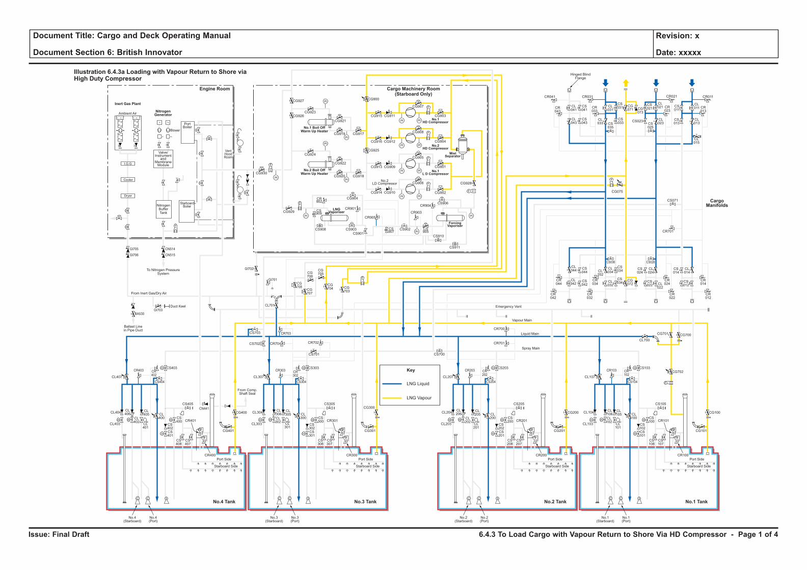
Issue: Final Draft
Document Title: Cargo and Deck Operating Manual
Document Section 6: British Innovator
Revision: x
Date: xxxxx
LNG Liquid
Key
LNG Vapour
H H
H
H
F
C C S
H
HH H
H
H
C C S
H
HH H
H
H
C C S
H
HH H
H
H
C C S
H
H
F
PI PI
F
PI PI
PI
PI
PI
PI
PI PI
PI PI
F
F
PI
PI
PI
PI
F
F
F
CL106
CL102
CL101
CL100
CS102
CS100
CS103
CS101
CS108
CS107
CR101
CR100
CL105
CL104
CL700
CG700
CG702
CG101
CS105
CS104
CR103 CR102
CG701
CL103
Port Side
Starboard Side
CL107
No.1(Starboard)
No.1(Port)
CL206
CL202
CL201
CL200
CS202
CS200
CS203
CR701
CR700
CS201
CS208
CS207
CR201
CR200
CL205
CL204
CG201
CG200 CG100
CS205
CS204
CR203 CR202
CL203
Port Side
Ambient Air
Blower
PortBoiler
VentHoodRoom
StarboardBoiler
Inert Gas Plant
NitrogenGenerator
Engine Room
No.3 TankNo.4 Tank No.1 TankNo.2 Tank
Cargo Machinery Room(Starboard Only)
Starboard Side
CL207
CS700
No.2(Starboard)
No.2(Port)
CL306
CL302
CL301
CL300
CS302
CS300
CS303
CS701
CS301
CS308
CS307
CR301
CR300
CL305
CL304
CG301
CS305
CS304
CR303 CR302
CL303
Port Side
Starboard Side
CL307
CG927
CG926CG923
CG921
CG917CG919
CG924
CG930
CG929
CG904
CR901
CR905
CR903
CR904
CS909
CS907
CS905
CS908 CS903
CS901
CS902
CS906
CS910
CS911
CR902
CG922
CG918
CG928
CG902
CG906
CG905
CG908
CG907
CR041
CR043
CL041
CL043
CS041
CS043
CL031
CS031 CS
011
CL011 CR
013
CG071 CG
073
CS021
CL021
CL023CS
025
CS023 CL013
CL015
CS013
CR023
CR033
CR021CR031 CR011
CS035
CL033
CS033
CG915
CG900
CG925
CG911
CG916 CG912
CG913 CG909
CG914 CG910
CG901
CG904
CG903
CG920
No.3(Starboard)
No.3(Port)
CL406
CL402
CL401
CL400
CS402
CS400
CS403
CS702 CR704 CR702
CR703
CG708
CG707
CG706
CG705
CG704 CG
703
CS703
CL701
CS401
CS408
CS407
CR401
CR400
CL405
CL404
CG401
CG400
CG300CS405
From Comp.Shaft Seal
CS404
CR403
GI705
GI706
GI703
GI702
GI701
BA530
CN514
CN515
CR402
CL403
Port Side
Starboard Side
CL407
No.4(Starboard)
No.4(Port)
CL044
CS044
CS042
CS034
CS024
CL024
CS034
CR044
CR034
CR024
CR042
CR032
CR022
CS036 CS026
CL042
CL034CL
202
CL032
CG072
CS022 CL
022
CS014
CR701
CS071
CL014
CR014
CR012
CS012
F
F
F
Cooler
Dryer
I.G.G
Valve/Instrument
andMembraneModule
NitrogenBufferTank
To Nitrogen PressureSystem
Hinged BlindFlange
Ballast Linein Pipe Duct
Duct Keel
From Inert Gas/Dry Air
Emergency Vent
Vapour Main
Liquid Main
Spray Main
No.1 Boil OffWarm Up Heater
No.2 Boil OffWarm Up Heater
ForcingVaporiser
MistSeparator
No.1HD Compressor
No.2HD Compressor
No.1L D Compressor
LNGVaporiser
No.2LD Compressor
Illustration 6.4.3a Loading with Vapour Return to Shore viaHigh Duty Compressor
CargoManifolds
CG075
CN441
6.4.3 To Load Cargo with Vapour Return to Shore Via HD Compressor - Page 1 of 4
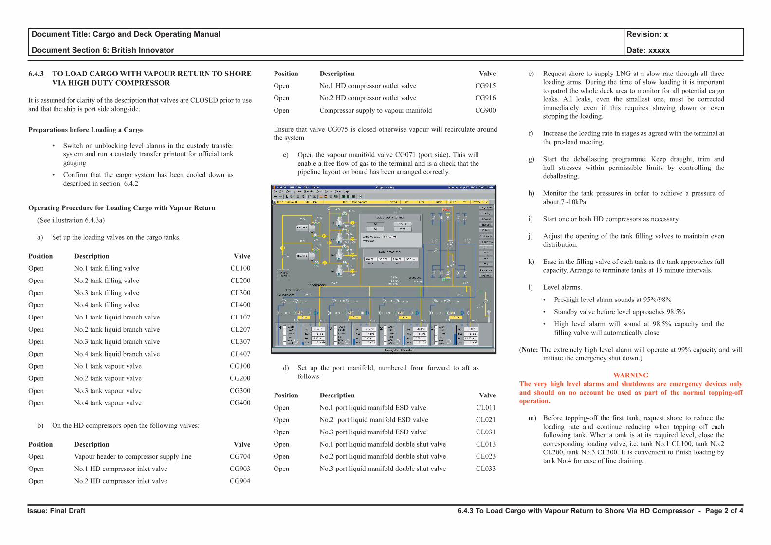
Issue: Final Draft
Document Title: Cargo and Deck Operating Manual
Document Section 6: British Innovator
Revision: x
Date: xxxxx
6.4.3 TO LOAD CARGO WITH VAPOUR RETURN TO SHORE VIA HIGH DUTY COMPRESSOR
It is assumed for clarity of the description that valves are CLOSED prior to use and that the ship is port side alongside.
Preparations before Loading a Cargo
• Switch on unblocking level alarms in the custody transfer system and run a custody transfer printout for official tank gauging
• Confirm that the cargo system has been cooled down as described in section 6.4.2
Operating Procedure for Loading Cargo with Vapour Return
(See illustration 6.4.3a)
a) Set up the loading valves on the cargo tanks.
Position Description Valve
Open No.1 tank filling valve CL100
Open No.2 tank filling valve CL200
Open No.3 tank filling valve CL300
Open No.4 tank filling valve CL400
Open No.1 tank liquid branch valve CL107
Open No.2 tank liquid branch valve CL207
Open No.3 tank liquid branch valve CL307
Open No.4 tank liquid branch valve CL407
Open No.1 tank vapour valve CG100
Open No.2 tank vapour valve CG200
Open No.3 tank vapour valve CG300
Open No.4 tank vapour valve CG400
b) On the HD compressors open the following valves:
Position Description Valve
Open Vapour header to compressor supply line CG704
Open No.1 HD compressor inlet valve CG903
Open No.2 HD compressor inlet valve CG904
Position Description Valve
Open No.1 HD compressor outlet valve CG915
Open No.2 HD compressor outlet valve CG916
Open Compressor supply to vapour manifold CG900
Ensure that valve CG075 is closed otherwise vapour will recirculate around the system
c) Open the vapour manifold valve CG071 (port side). This will enable a free flow of gas to the terminal and is a check that the pipeline layout on board has been arranged correctly.
d) Set up the port manifold, numbered from forward to aft as follows:
Position Description Valve
Open No.1 port liquid manifold ESD valve CL011
Open No.2 port liquid manifold ESD valve CL021
Open No.3 port liquid manifold ESD valve CL031
Open No.1 port liquid manifold double shut valve CL013
Open No.2 port liquid manifold double shut valve CL023
Open No.3 port liquid manifold double shut valve CL033
e) Request shore to supply LNG at a slow rate through all three loading arms. During the time of slow loading it is important to patrol the whole deck area to monitor for all potential cargo leaks. All leaks, even the smallest one, must be corrected immediately even if this requires slowing down or even stopping the loading.
f) Increase the loading rate in stages as agreed with the terminal at
the pre-load meeting.
g) Start the deballasting programme. Keep draught, trim and hull stresses within permissible limits by controlling the deballasting.
h) Monitor the tank pressures in order to achieve a pressure of about 7~10kPa.
i) Start one or both HD compressors as necessary.
j) Adjust the opening of the tank filling valves to maintain even distribution.
k) Ease in the filling valve of each tank as the tank approaches full
capacity. Arrange to terminate tanks at 15 minute intervals.
l) Level alarms.
• Pre-high level alarm sounds at 95%/98%
• Standby valve before level approaches 98.5%
• High level alarm will sound at 98.5% capacity and the filling valve will automatically close
(Note: The extremely high level alarm will operate at 99% capacity and will initiate the emergency shut down.)
WARNINGThe very high level alarms and shutdowns are emergency devices only and should on no account be used as part of the normal topping-off operation.
m) Before topping-off the first tank, request shore to reduce the loading rate and continue reducing when topping off each following tank. When a tank is at its required level, close the corresponding loading valve, i.e. tank No.1 CL100, tank No.2 CL200, tank No.3 CL300. It is convenient to finish loading by tank No.4 for ease of line draining.
6.4.3 To Load Cargo with Vapour Return to Shore Via HD Compressor - Page 2 of 4
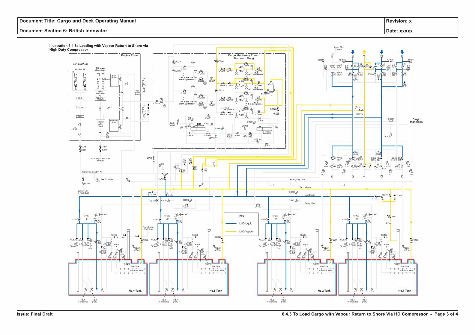
Issue: Final Draft
Document Title: Cargo and Deck Operating Manual
Document Section 6: British Innovator
Revision: x
Date: xxxxx
LNG Liquid
Key
LNG Vapour
H H
H
H
F
C C S
H
HH H
H
H
C C S
H
HH H
H
H
C C S
H
HH H
H
H
C C S
H
H
F
PI PI
F
PI PI
PI
PI
PI
PI
PI PI
PI PI
F
F
PI
PI
PI
PI
F
F
F
CL106
CL102
CL101
CL100
CS102
CS100
CS103
CS101
CS108
CS107
CR101
CR100
CL105
CL104
CL700
CG700
CG702
CG101
CS105
CS104
CR103 CR102
CG701
CL103
Port Side
Starboard Side
CL107
No.1(Starboard)
No.1(Port)
CL206
CL202
CL201
CL200
CS202
CS200
CS203
CR701
CR700
CS201
CS208
CS207
CR201
CR200
CL205
CL204
CG201
CG200 CG100
CS205
CS204
CR203 CR202
CL203
Port Side
Ambient Air
Blower
PortBoiler
VentHoodRoom
StarboardBoiler
Inert Gas Plant
NitrogenGenerator
Engine Room
No.3 TankNo.4 Tank No.1 TankNo.2 Tank
Cargo Machinery Room(Starboard Only)
Starboard Side
CL207
CS700
No.2(Starboard)
No.2(Port)
CL306
CL302
CL301
CL300
CS302
CS300
CS303
CS701
CS301
CS308
CS307
CR301
CR300
CL305
CL304
CG301
CS305
CS304
CR303 CR302
CL303
Port Side
Starboard Side
CL307
CG927
CG926CG923
CG921
CG917CG919
CG924
CG930
CG929
CG904
CR901
CR905
CR903
CR904
CS909
CS907
CS905
CS908 CS903
CS901
CS902
CS906
CS910
CS911
CR902
CG922
CG918
CG928
CG902
CG906
CG905
CG908
CG907
CR041
CR043
CL041
CL043
CS041
CS043
CL031
CS031 CS
011
CL011 CR
013
CG071 CG
073
CS021
CL021
CL023CS
025
CS023 CL013
CL015
CS013
CR023
CR033
CR021CR031 CR011
CS035
CL033
CS033
CG915
CG900
CG925
CG911
CG916 CG912
CG913 CG909
CG914 CG910
CG901
CG904
CG903
CG920
No.3(Starboard)
No.3(Port)
CL406
CL402
CL401
CL400
CS402
CS400
CS403
CS702 CR704 CR702
CR703
CG708
CG707
CG706
CG705
CG704 CG
703
CS703
CL701
CS401
CS408
CS407
CR401
CR400
CL405
CL404
CG401
CG400
CG300CS405
From Comp.Shaft Seal
CS404
CR403
GI705
GI706
GI703
GI702
GI701
BA530
CN514
CN515
CR402
CL403
Port Side
Starboard Side
CL407
No.4(Starboard)
No.4(Port)
CL044
CS044
CS042
CS034
CS024
CL024
CS034
CR044
CR034
CR024
CR042
CR032
CR022
CS036 CS026
CL042
CL034CL
202
CL032
CG072
CS022 CL
022
CS014
CR701
CS071
CL014
CR014
CR012
CS012
F
F
F
Cooler
Dryer
I.G.G
Valve/Instrument
andMembraneModule
NitrogenBufferTank
To Nitrogen PressureSystem
Hinged BlindFlange
Ballast Linein Pipe Duct
Duct Keel
From Inert Gas/Dry Air
Emergency Vent
Vapour Main
Liquid Main
Spray Main
No.1 Boil OffWarm Up Heater
No.2 Boil OffWarm Up Heater
ForcingVaporiser
MistSeparator
No.1HD Compressor
No.2HD Compressor
No.1L D Compressor
LNGVaporiser
No.2LD Compressor
Illustration 6.4.3a Loading with Vapour Return to Shore viaHigh Duty Compressor
CargoManifolds
CG075
CN441
6.4.3 To Load Cargo with Vapour Return to Shore Via HD Compressor - Page 3 of 4
Issue: Final Draft
Document Title: Cargo and Deck Operating Manual
Document Section 6: British Innovator
Revision: x
Date: xxxxx
n) Slow down and stop HD compressors as falling tank pressures require. When compressors are stopped, free flow vapour to shore via vapour crossover valve CG075. Close valve CG900.
o) Stop loading when the final tank reaches 98.5% capacity minus an allowance for line draining and leave the tank loading valve CL400 open. The final tank loading valve is put to MANUAL operation to prevent automatic closing at the 98.5% alarm.
Operating Procedure for Draining Lines
a) Liquid lines, including the horizontal part of the manifolds, will automatically drain to tank No.4. The inclined parts of the manifold are purged inboard with nitrogen.
b) On completion of draining loading arms close liquid manifold ESDS valves.
Position Description Valve
Close No.1 port liquid manifold ESD valve CL011
Close No.2 port liquid manifold ESD valve CL021
Close No.3 port liquid manifold ESD valve CL031
c) The shore lines are now pressurised at 300kPa with nitrogen.
d) Open the manifold ESD valves to let liquid return to the horizontal part of the lines.
e) Close the ESD valves and repeat pressurisation and purging through the liquid manifold valves CS011, 021, 031. Repeat this operation three or four times until no liquid remains in the manifold lines and loading arms.
f) Leave the manifold liquid double shut valves open. Close the liquid ESD valves and open the manifold stripping bypass valves and carry out a vapour purge until the HC content is below 1% by volume.
g) When gas readings obtained from a portable meter are less than 1.2% CH4 per volume at the vent cocks, all valves are closed and the loading arms are ready to be disconnected.
h) Return the nitrogen system to normal flow and in the CACC ensure that the set point is at 0.7kPa and 1.0kPa.
i) Inhibit the high level alarms prior to proceeding to sea.
j) Complete the deballasting operation to obtain an even keel situation for final measurement. When the measurement is completed adjust the ballast tank levels for sailing condition.
k) Stop the HD compressors just before closing the vapour manifold ESDS valve CG071 for nitrogen purging and disconnection of loading arms.
l) Close the vapour crossover valve CG079 and open the vapour manifold ESDS valve CG071. Purge the connection with nitrogen and then close the valve.
m) Disconnect the vapour arms.
n) Set up the LD compressor system for gas burning at sea.
o) Adjust the ballast for departure trim condition.
p) Open all valves to allow warming up. These are normally the loading valves, pump discharge valves and spray valves on the tank domes.
6.4.3 To Load Cargo with Vapour Return to Shore Via HD Compressor - Page 4 of 4
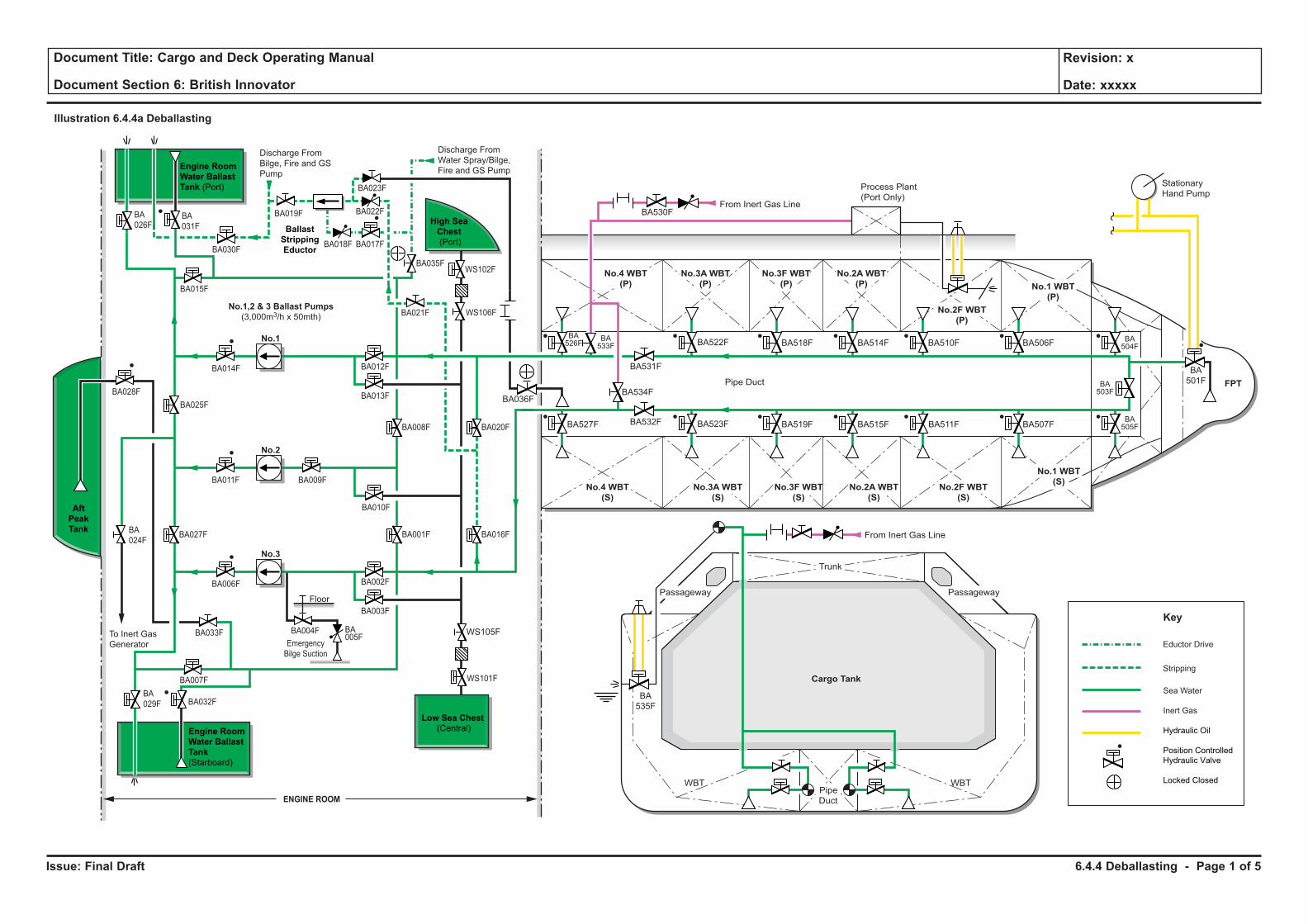
Issue: Final Draft
Document Title: Cargo and Deck Operating Manual
Document Section 6: British Innovator
Revision: x
Date: xxxxx
Illustration 6.4.4a Deballasting
No.1,2 & 3 Ballast Pumps
(3,000m3/h x 50mth)
BA028F
BA027FBA
024F
BA014F
BA011F BA009F
BA006F
BA033F
BA007F
BA025F
No.1
No.2
No.3
Emergency
Bilge Suction
BA004F BA005F
Floor
WBT WBT
Cargo Tank
Sea Water
Inert Gas
Hydraulic Oil
Position Controlled
Hydraulic Valve
Locked Closed
Key
From Inert Gas Line
From Inert Gas Line
Stationary
Hand PumpProcess Plant
(Port Only)
No.4 WBT
(P)
No.4 WBT
(S)
No.3A WBT
(P)
No.3A WBT
(S)
No.2A WBT
(P)
No.2A WBT
(S)
No.3F WBT
(P)
No.3F WBT
(S)
No.2F WBT
(P)
No.2F WBT
(S)
No.1 WBT
(P)
No.1 WBT
(S)
FPT
BA
501F
BA506F
BA507F
BA510F
BA511F
BA514F
BA515F
BA518F
BA519FBA523F
BA531F
BA532F
BA534FBA036F
BA533F
BA526F
BA527F
BA
535F
BA522F
BA530F
BA504F
BA503F
BA505F
Trunk
Pipe
Duct
Pipe Duct
To Inert Gas
Generator
Discharge From
Water Spray/Bilge,
Fire and GS Pump
Discharge From
Bilge, Fire and GS
Pump
Engine Room
Water Ballast
Tank
(Starboard)
Engine Room
Water Ballast
Tank (Port)
Ballast
Stripping
Eductor
BA
026F
BA018F
BA035F
BA021F
BA008F
BA010F
BA001F
BA002F
BA003F
BA012F
BA013F
BA020F
BA016F
BA017F
BA022F
BA023F
BA019F
BA
029F BA032F
WS101F
WS105F
WS106F
WS102F
Low Sea Chest
(Central)
BA030F
BA015F
ENGINE ROOM
Aft
Peak
Tank
High Sea
Chest
(Port)
BA
031F
Stripping
Eductor Drive
Passageway Passageway
6.4.4 Deballasting - Page 1 of 5
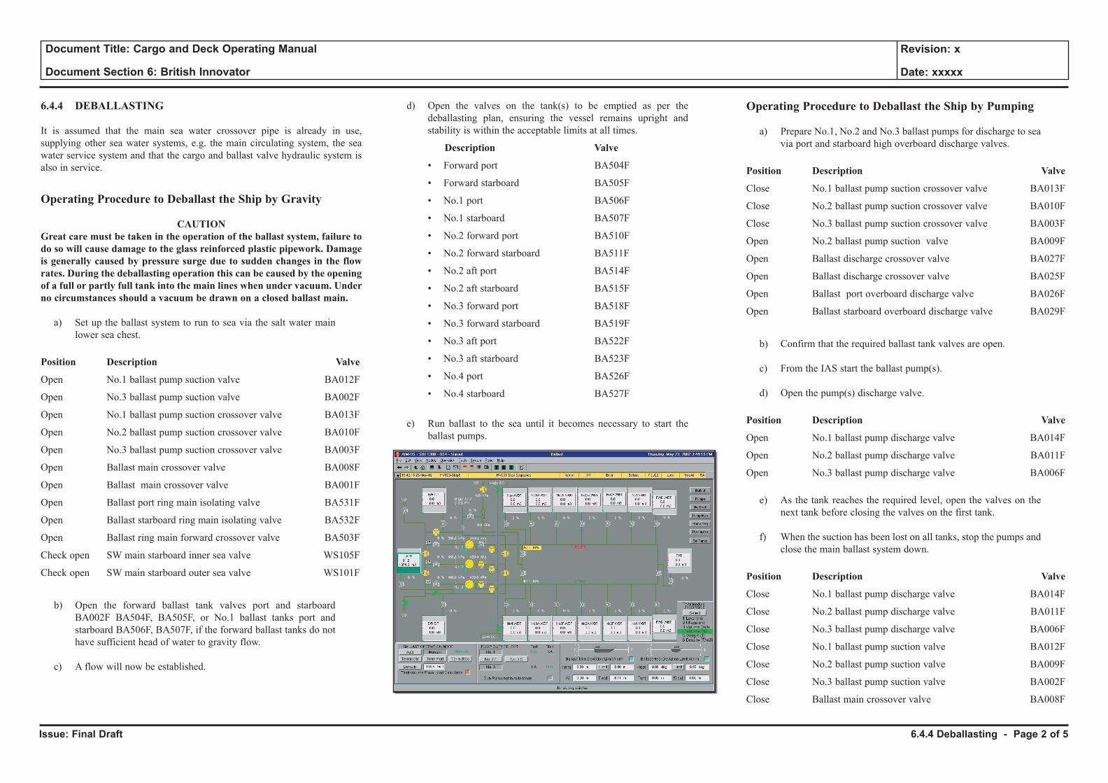
Issue: Final Draft
Document Title: Cargo and Deck Operating Manual
Document Section 6: British Innovator
Revision: x
Date: xxxxx
6.4.4 DEBALLASTING
It is assumed that the main sea water crossover pipe is already in use, supplying other sea water systems, e.g. the main circulating system, the sea water service system and that the cargo and ballast valve hydraulic system is also in service.
Operating Procedure to Deballast the Ship by Gravity
CAUTIONGreat care must be taken in the operation of the ballast system, failure to do so will cause damage to the glass reinforced plastic pipework. Damage is generally caused by pressure surge due to sudden changes in the flow rates. During the deballasting operation this can be caused by the opening of a full or partly full tank into the main lines when under vacuum. Under no circumstances should a vacuum be drawn on a closed ballast main.
a) Set up the ballast system to run to sea via the salt water main lower sea chest.
Position Description Valve
Open No.1 ballast pump suction valve BA012F
Open No.3 ballast pump suction valve BA002F
Open No.1 ballast pump suction crossover valve BA013F
Open No.2 ballast pump suction crossover valve BA010F
Open No.3 ballast pump suction crossover valve BA003F
Open Ballast main crossover valve BA008F
Open Ballast main crossover valve BA001F
Open Ballast port ring main isolating valve BA531F
Open Ballast starboard ring main isolating valve BA532F
Open Ballast ring main forward crossover valve BA503F
Check open SW main starboard inner sea valve WS105F
Check open SW main starboard outer sea valve WS101F
b) Open the forward ballast tank valves port and starboard BA002F BA504F, BA505F, or No.1 ballast tanks port and starboard BA506F, BA507F, if the forward ballast tanks do not have sufficient head of water to gravity flow.
c) A flow will now be established.
d) Open the valves on the tank(s) to be emptied as per the deballasting plan, ensuring the vessel remains upright and stability is within the acceptable limits at all times.
Description Valve
• Forward port BA504F
• Forward starboard BA505F
• No.1 port BA506F
• No.1 starboard BA507F
• No.2 forward port BA510F
• No.2 forward starboard BA511F
• No.2 aft port BA514F
• No.2 aft starboard BA515F
• No.3 forward port BA518F
• No.3 forward starboard BA519F
• No.3 aft port BA522F
• No.3 aft starboard BA523F
• No.4 port BA526F
• No.4 starboard BA527F
e) Run ballast to the sea until it becomes necessary to start the ballast pumps.
Operating Procedure to Deballast the Ship by Pumping
a) Prepare No.1, No.2 and No.3 ballast pumps for discharge to sea via port and starboard high overboard discharge valves.
Position Description Valve
Close No.1 ballast pump suction crossover valve BA013F
Close No.2 ballast pump suction crossover valve BA010F
Close No.3 ballast pump suction crossover valve BA003F
Open No.2 ballast pump suction valve BA009F
Open Ballast discharge crossover valve BA027F
Open Ballast discharge crossover valve BA025F
Open Ballast port overboard discharge valve BA026F
Open Ballast starboard overboard discharge valve BA029F
b) Confirm that the required ballast tank valves are open.
c) From the IAS start the ballast pump(s).
d) Open the pump(s) discharge valve.
Position Description Valve
Open No.1 ballast pump discharge valve BA014F
Open No.2 ballast pump discharge valve BA011F
Open No.3 ballast pump discharge valve BA006F
e) As the tank reaches the required level, open the valves on the next tank before closing the valves on the first tank.
f) When the suction has been lost on all tanks, stop the pumps and close the main ballast system down.
Position Description Valve
Close No.1 ballast pump discharge valve BA014F
Close No.2 ballast pump discharge valve BA011F
Close No.3 ballast pump discharge valve BA006F
Close No.1 ballast pump suction valve BA012F
Close No.2 ballast pump suction valve BA009F
Close No.3 ballast pump suction valve BA002F
Close Ballast main crossover valve BA008F
6.4.4 Deballasting - Page 2 of 5
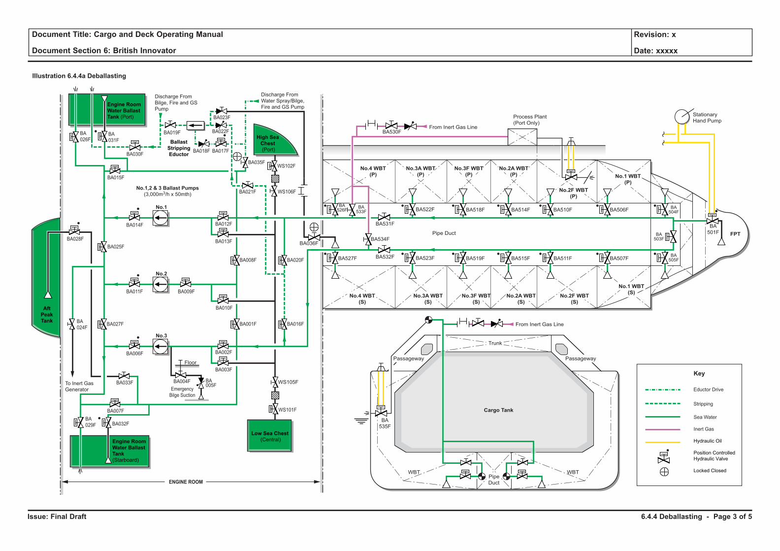
Issue: Final Draft
Document Title: Cargo and Deck Operating Manual
Document Section 6: British Innovator
Revision: x
Date: xxxxx
Illustration 6.4.4a Deballasting
No.1,2 & 3 Ballast Pumps
(3,000m3/h x 50mth)
BA028F
BA027FBA
024F
BA014F
BA011F BA009F
BA006F
BA033F
BA007F
BA025F
No.1
No.2
No.3
Emergency
Bilge Suction
BA004F BA005F
Floor
WBT WBT
Cargo Tank
Sea Water
Inert Gas
Hydraulic Oil
Position Controlled
Hydraulic Valve
Locked Closed
Key
From Inert Gas Line
From Inert Gas Line
Stationary
Hand PumpProcess Plant
(Port Only)
No.4 WBT
(P)
No.4 WBT
(S)
No.3A WBT
(P)
No.3A WBT
(S)
No.2A WBT
(P)
No.2A WBT
(S)
No.3F WBT
(P)
No.3F WBT
(S)
No.2F WBT
(P)
No.2F WBT
(S)
No.1 WBT
(P)
No.1 WBT
(S)
FPT
BA
501F
BA506F
BA507F
BA510F
BA511F
BA514F
BA515F
BA518F
BA519FBA523F
BA531F
BA532F
BA534FBA036F
BA533F
BA526F
BA527F
BA
535F
BA522F
BA530F
BA504F
BA503F
BA505F
Trunk
Pipe
Duct
Pipe Duct
To Inert Gas
Generator
Discharge From
Water Spray/Bilge,
Fire and GS Pump
Discharge From
Bilge, Fire and GS
Pump
Engine Room
Water Ballast
Tank
(Starboard)
Engine Room
Water Ballast
Tank (Port)
Ballast
Stripping
Eductor
BA
026F
BA018F
BA035F
BA021F
BA008F
BA010F
BA001F
BA002F
BA003F
BA012F
BA013F
BA020F
BA016F
BA017F
BA022F
BA023F
BA019F
BA
029F BA032F
WS101F
WS105F
WS106F
WS102F
Low Sea Chest
(Central)
BA030F
BA015F
ENGINE ROOM
Aft
Peak
Tank
High Sea
Chest
(Port)
BA
031F
Stripping
Eductor Drive
Passageway Passageway
6.4.4 Deballasting - Page 3 of 5
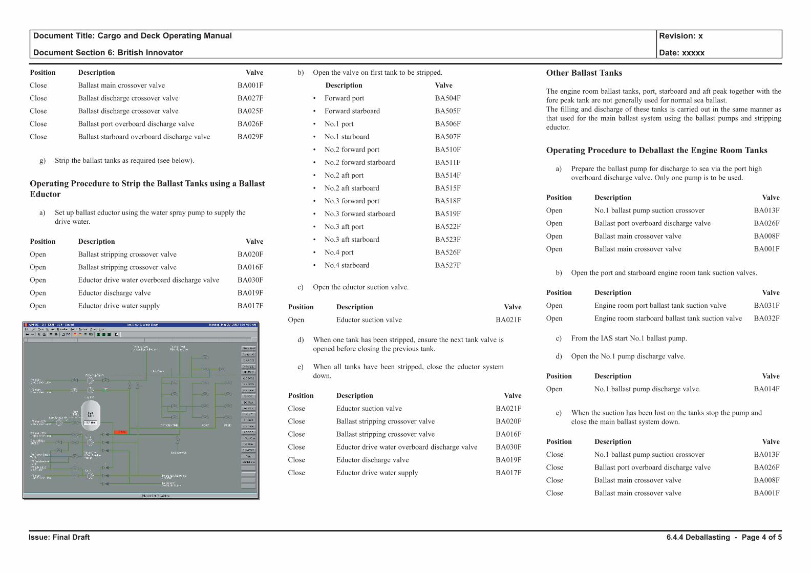
Issue: Final Draft
Document Title: Cargo and Deck Operating Manual
Document Section 6: British Innovator
Revision: x
Date: xxxxx
Position Description Valve
Close Ballast main crossover valve BA001F
Close Ballast discharge crossover valve BA027F
Close Ballast discharge crossover valve BA025F
Close Ballast port overboard discharge valve BA026F
Close Ballast starboard overboard discharge valve BA029F
g) Strip the ballast tanks as required (see below).
Operating Procedure to Strip the Ballast Tanks using a Ballast Eductor
a) Set up ballast eductor using the water spray pump to supply the drive water.
Position Description Valve
Open Ballast stripping crossover valve BA020F
Open Ballast stripping crossover valve BA016F
Open Eductor drive water overboard discharge valve BA030F
Open Eductor discharge valve BA019F
Open Eductor drive water supply BA017F
b) Open the valve on first tank to be stripped.
Description Valve
• Forward port BA504F
• Forward starboard BA505F
• No.1 port BA506F
• No.1 starboard BA507F
• No.2 forward port BA510F
• No.2 forward starboard BA511F
• No.2 aft port BA514F
• No.2 aft starboard BA515F
• No.3 forward port BA518F
• No.3 forward starboard BA519F
• No.3 aft port BA522F
• No.3 aft starboard BA523F
• No.4 port BA526F
• No.4 starboard BA527F
c) Open the eductor suction valve.
Position Description Valve
Open Eductor suction valve BA021F
d) When one tank has been stripped, ensure the next tank valve is opened before closing the previous tank.
e) When all tanks have been stripped, close the eductor system down.
Position Description Valve
Close Eductor suction valve BA021F
Close Ballast stripping crossover valve BA020F
Close Ballast stripping crossover valve BA016F
Close Eductor drive water overboard discharge valve BA030F
Close Eductor discharge valve BA019F
Close Eductor drive water supply BA017F
Other Ballast Tanks
The engine room ballast tanks, port, starboard and aft peak together with the fore peak tank are not generally used for normal sea ballast.The filling and discharge of these tanks is carried out in the same manner as that used for the main ballast system using the ballast pumps and stripping eductor.
Operating Procedure to Deballast the Engine Room Tanks
a) Prepare the ballast pump for discharge to sea via the port high overboard discharge valve. Only one pump is to be used.
Position Description Valve
Open No.1 ballast pump suction crossover BA013F
Open Ballast port overboard discharge valve BA026F
Open Ballast main crossover valve BA008F
Open Ballast main crossover valve BA001F
b) Open the port and starboard engine room tank suction valves.
Position Description Valve
Open Engine room port ballast tank suction valve BA031F
Open Engine room starboard ballast tank suction valve BA032F
c) From the IAS start No.1 ballast pump.
d) Open the No.1 pump discharge valve.
Position Description Valve
Open No.1 ballast pump discharge valve. BA014F
e) When the suction has been lost on the tanks stop the pump and close the main ballast system down.
Position Description Valve
Close No.1 ballast pump suction crossover BA013F
Close Ballast port overboard discharge valve BA026F
Close Ballast main crossover valve BA008F
Close Ballast main crossover valve BA001F
6.4.4 Deballasting - Page 4 of 5
Issue: Final Draft
Document Title: Cargo and Deck Operating Manual
Document Section 6: British Innovator
Revision: x
Date: xxxxx
f) Set up ballast eductor using water spray pump to supply drive water.
Position Description Valve
Open Ballast stripping crossover valve BA020F
Open Ballast stripping crossover valve BA016F
Open Eductor drive water overboard discharge valve BA030F
Open Eductor discharge valve BA019F
Open Eductor drive water supply BA017F
g) Open the eductor suction valve.
Position Description Valve
Open Eductor suction valve BA021F
h) When one tank has been stripped, ensure the next tank valve is opened before closing the previous tank.
i) When all tanks have been stripped, close the eductor system down.
Position Description Valve
Close Eductor suction valve BA021F
Close Ballast stripping crossover valve BA020F
Close Ballast stripping crossover valve BA016F
Close Eductor drive water overboard discharge valve BA030F
Close Eductor discharge valve BA019F
Close Eductor drive water supply BA017F
(Note: The same procedure is used for filling and discharging the aft peak and fore peak tanks.)
6.4.4 Deballasting - Page 5 of 5
6.5 Loaded Voyage With Boil-Off Gas Burning
6.5.1 Loaded Voyage with Normal Boil-Off Gas Burning
6.5.2 Loaded Voyage with Forced Boil-Off Gas Burning
Illustrations
6.5.1a Loaded Voyage with Normal Boil-Off Gas Burning
6.5.2a Loaded Voyage with Forced Boil-Off Gas Burning
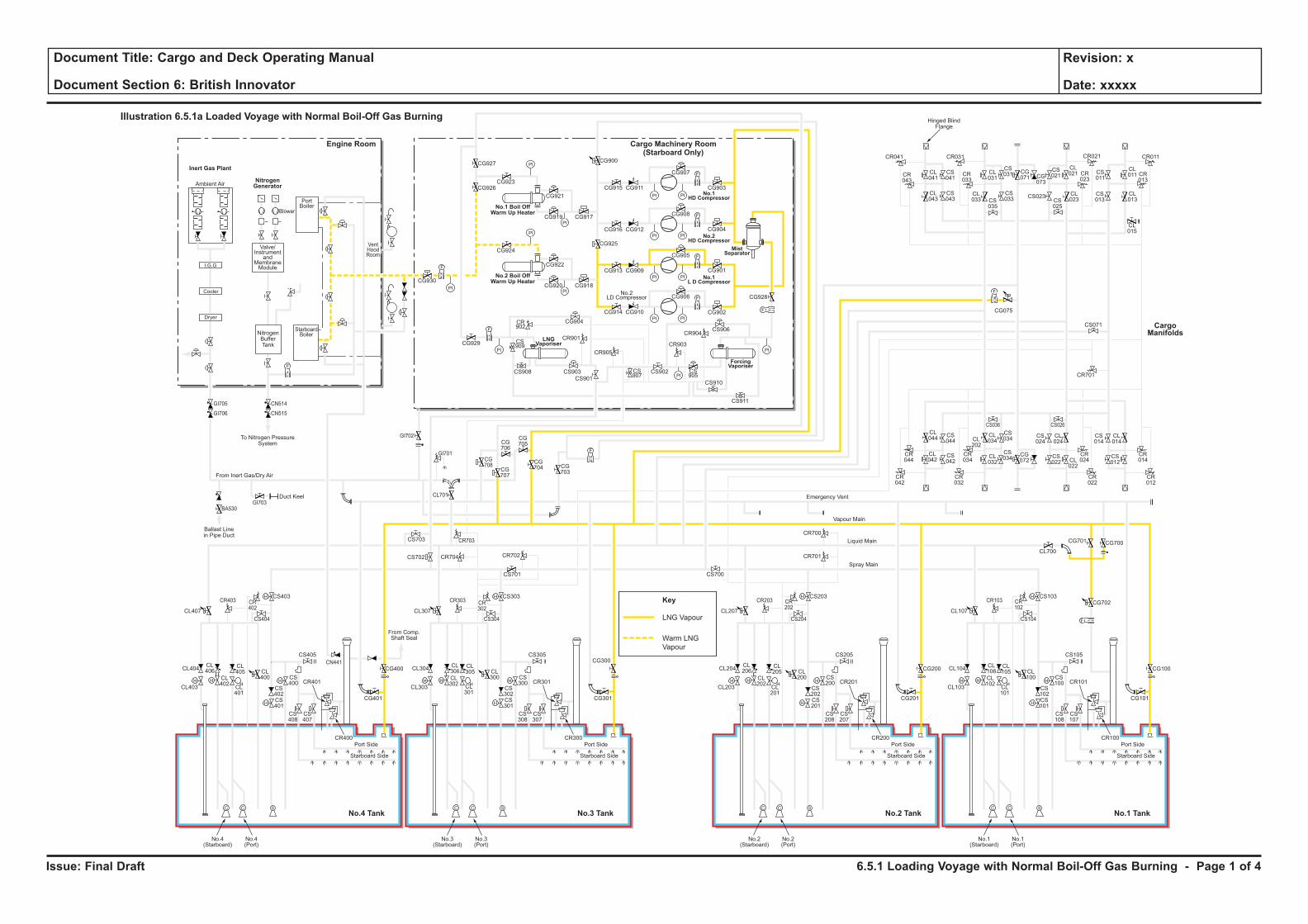
Issue: Final Draft
Document Title: Cargo and Deck Operating Manual
Document Section 6: British Innovator
Revision: x
Date: xxxxx
Key
LNG Vapour
Warm LNG
Vapour
H H
H
H
F
C C S
H
HH H
H
H
C C S
H
HH H
H
H
C C S
H
HH H
H
H
C C S
H
H
F
PI PI
F
PI PI
PI
PI
PI
PI
PI PI
PI PI
F
F
PI
PI
PI
PI
F
F
F
CL106
CL102
CL101
CL100
CS102
CS100
CS103
CS101
CS108
CS107
CR101
CR100
CL105
CL104
CL700
CG700
CG702
CG101
CS105
CS104
CR103 CR102
CG701
CL103
Port Side
Starboard Side
CL107
No.1(Starboard)
No.1(Port)
CL206
CL202
CL201
CL200
CS202
CS200
CS203
CR701
CR700
CS201
CS208
CS207
CR201
CR200
CL205
CL204
CG201
CG200 CG100
CS205
CS204
CR203 CR202
CL203
Port Side
Ambient Air
Blower
PortBoiler
VentHoodRoom
StarboardBoiler
Inert Gas Plant
NitrogenGenerator
Engine Room
No.3 TankNo.4 Tank No.1 TankNo.2 Tank
Cargo Machinery Room(Starboard Only)
Starboard Side
CL207
CS700
No.2(Starboard)
No.2(Port)
CL306
CL302
CL301
CL300
CS302
CS300
CS303
CS701
CS301
CS308
CS307
CR301
CR300
CL305
CL304
CG301
CS305
CS304
CR303 CR302
CL303
Port Side
Starboard Side
CL307
CG927
CG926CG923
CG921
CG917CG919
CG924
CG930
CG929
CG904
CR901
CR905
CR903
CR904
CS909
CS907
CS905
CS908 CS903
CS901
CS902
CS906
CS910
CS911
CR902
CG922
CG918
CG928
CG902
CG906
CG905
CG908
CG907
CR041
CR043
CL041
CL043
CS041
CS043
CL031
CS031 CS
011
CL011 CR
013
CG071 CG
073
CS021
CL021
CL023CS
025
CS023 CL013
CL015
CS013
CR023
CR033
CR021CR031 CR011
CS035
CL033
CS033
CG915
CG900
CG925
CG911
CG916 CG912
CG913 CG909
CG914 CG910
CG901
CG904
CG903
CG920
No.3(Starboard)
No.3(Port)
CL406
CL402
CL401
CL400
CS402
CS400
CS403
CS702 CR704 CR702
CR703
CG708
CG707
CG706
CG705
CG704 CG
703
CS703
CL701
CS401
CS408
CS407
CR401
CR400
CL405
CL404
CG401
CG400
CG300CS405
From Comp.Shaft Seal
CS404
CR403
GI705
GI706
GI703
GI702
GI701
BA530
CN514
CN515
CR402
CL403
Port Side
Starboard Side
CL407
No.4(Starboard)
No.4(Port)
CL044
CS044
CS042
CS034
CS024
CL024
CS034
CR044
CR034
CR024
CR042
CR032
CR022
CS036 CS026
CL042
CL034CL
202
CL032
CG072
CS022 CL
022
CS014
CR701
CS071
CL014
CR014
CR012
CS012
F
F
F
Cooler
Dryer
I.G.G
Valve/Instrument
andMembraneModule
NitrogenBufferTank
To Nitrogen PressureSystem
Hinged BlindFlange
Ballast Linein Pipe Duct
Duct Keel
From Inert Gas/Dry Air
Emergency Vent
Vapour Main
Liquid Main
Spray Main
No.1 Boil OffWarm Up Heater
No.2 Boil OffWarm Up Heater
ForcingVaporiser
MistSeparator
No.1HD Compressor
No.2HD Compressor
No.1L D Compressor
LNGVaporiser
No.2LD Compressor
Illustration 6.5.1a Loaded Voyage with Normal Boil-Off Gas Burning
CargoManifolds
CG075
CN441
6.5.1 Loading Voyage with Normal Boil-Off Gas Burning - Page 1 of 4
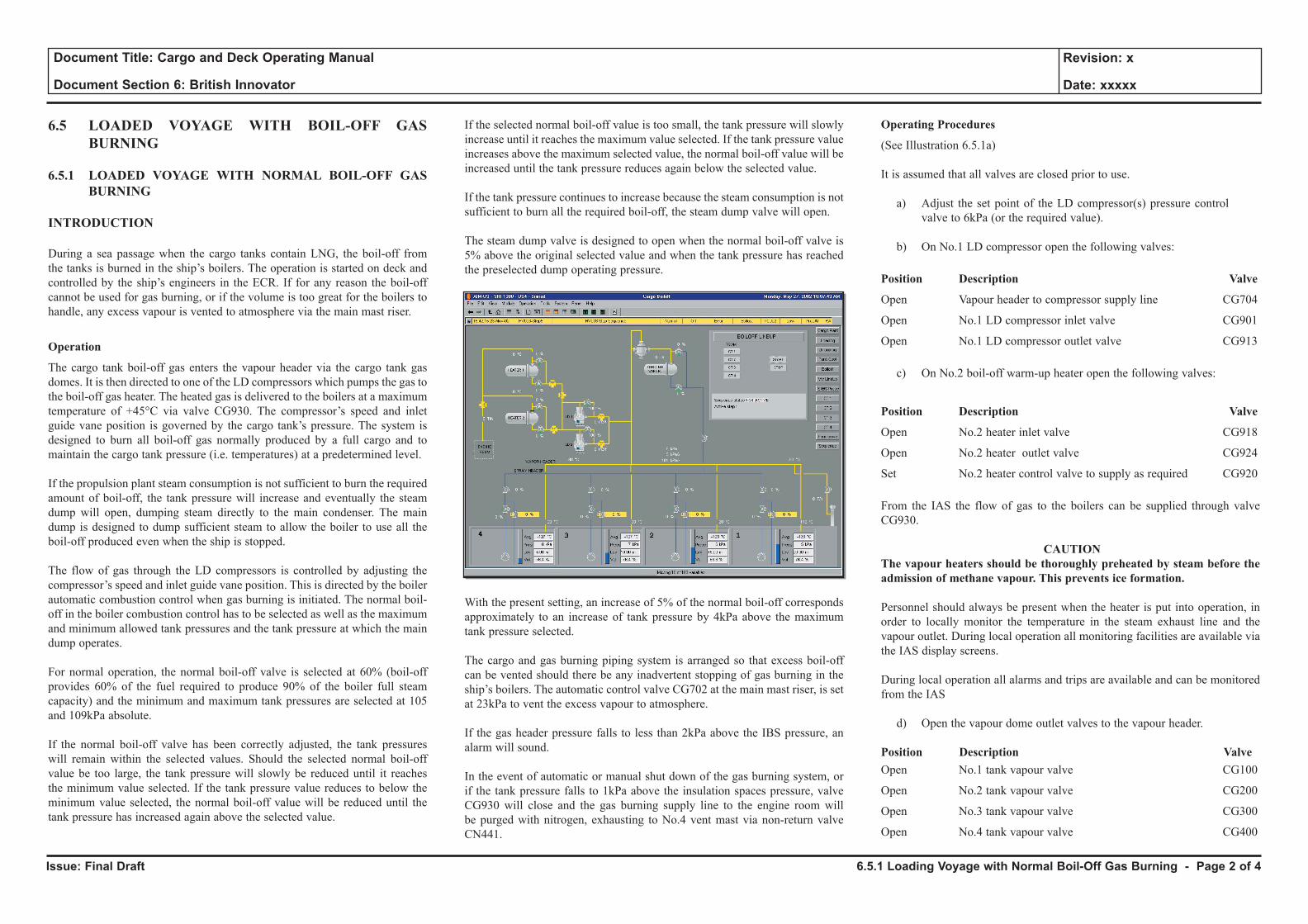
Issue: Final Draft
Document Title: Cargo and Deck Operating Manual
Document Section 6: British Innovator
Revision: x
Date: xxxxx
6.5 LOADED VOYAGE WITH BOIL-OFF GAS BURNING
6.5.1 LOADED VOYAGE WITH NORMAL BOIL-OFF GAS BURNING
INTRODUCTION
During a sea passage when the cargo tanks contain LNG, the boil-off from the tanks is burned in the ship’s boilers. The operation is started on deck and controlled by the ship’s engineers in the ECR. If for any reason the boil-off cannot be used for gas burning, or if the volume is too great for the boilers to handle, any excess vapour is vented to atmosphere via the main mast riser.
Operation
The cargo tank boil-off gas enters the vapour header via the cargo tank gas domes. It is then directed to one of the LD compressors which pumps the gas to the boil-off gas heater. The heated gas is delivered to the boilers at a maximum temperature of +45°C via valve CG930. The compressor’s speed and inlet guide vane position is governed by the cargo tank’s pressure. The system is designed to burn all boil-off gas normally produced by a full cargo and to maintain the cargo tank pressure (i.e. temperatures) at a predetermined level.
If the propulsion plant steam consumption is not sufficient to burn the required amount of boil-off, the tank pressure will increase and eventually the steam dump will open, dumping steam directly to the main condenser. The main dump is designed to dump sufficient steam to allow the boiler to use all the boil-off produced even when the ship is stopped.
The flow of gas through the LD compressors is controlled by adjusting the compressor’s speed and inlet guide vane position. This is directed by the boiler automatic combustion control when gas burning is initiated. The normal boil-off in the boiler combustion control has to be selected as well as the maximum and minimum allowed tank pressures and the tank pressure at which the main dump operates.
For normal operation, the normal boil-off valve is selected at 60% (boil-off provides 60% of the fuel required to produce 90% of the boiler full steam capacity) and the minimum and maximum tank pressures are selected at 105 and 109kPa absolute.
If the normal boil-off valve has been correctly adjusted, the tank pressures will remain within the selected values. Should the selected normal boil-off value be too large, the tank pressure will slowly be reduced until it reaches the minimum value selected. If the tank pressure value reduces to below the minimum value selected, the normal boil-off value will be reduced until the tank pressure has increased again above the selected value.
If the selected normal boil-off value is too small, the tank pressure will slowly increase until it reaches the maximum value selected. If the tank pressure value increases above the maximum selected value, the normal boil-off value will be increased until the tank pressure reduces again below the selected value.
If the tank pressure continues to increase because the steam consumption is not sufficient to burn all the required boil-off, the steam dump valve will open.
The steam dump valve is designed to open when the normal boil-off valve is 5% above the original selected value and when the tank pressure has reached the preselected dump operating pressure.
With the present setting, an increase of 5% of the normal boil-off corresponds approximately to an increase of tank pressure by 4kPa above the maximum tank pressure selected.
The cargo and gas burning piping system is arranged so that excess boil-off can be vented should there be any inadvertent stopping of gas burning in the ship’s boilers. The automatic control valve CG702 at the main mast riser, is set at 23kPa to vent the excess vapour to atmosphere.
If the gas header pressure falls to less than 2kPa above the IBS pressure, an alarm will sound.
In the event of automatic or manual shut down of the gas burning system, or if the tank pressure falls to 1kPa above the insulation spaces pressure, valve CG930 will close and the gas burning supply line to the engine room will be purged with nitrogen, exhausting to No.4 vent mast via non-return valve CN441.
Operating Procedures
(See Illustration 6.5.1a)
It is assumed that all valves are closed prior to use.
a) Adjust the set point of the LD compressor(s) pressure control valve to 6kPa (or the required value).
b) On No.1 LD compressor open the following valves:
Position Description Valve
Open Vapour header to compressor supply line CG704
Open No.1 LD compressor inlet valve CG901
Open No.1 LD compressor outlet valve CG913
c) On No.2 boil-off warm-up heater open the following valves:
Position Description Valve
Open No.2 heater inlet valve CG918
Open No.2 heater outlet valve CG924
Set No.2 heater control valve to supply as required CG920
From the IAS the flow of gas to the boilers can be supplied through valve CG930.
CAUTION The vapour heaters should be thoroughly preheated by steam before the admission of methane vapour. This prevents ice formation.
Personnel should always be present when the heater is put into operation, in order to locally monitor the temperature in the steam exhaust line and the vapour outlet. During local operation all monitoring facilities are available via the IAS display screens.
During local operation all alarms and trips are available and can be monitored from the IAS
d) Open the vapour dome outlet valves to the vapour header.
Position Description ValveOpen No.1 tank vapour valve CG100
Open No.2 tank vapour valve CG200
Open No.3 tank vapour valve CG300
Open No.4 tank vapour valve CG400
6.5.1 Loading Voyage with Normal Boil-Off Gas Burning - Page 2 of 4
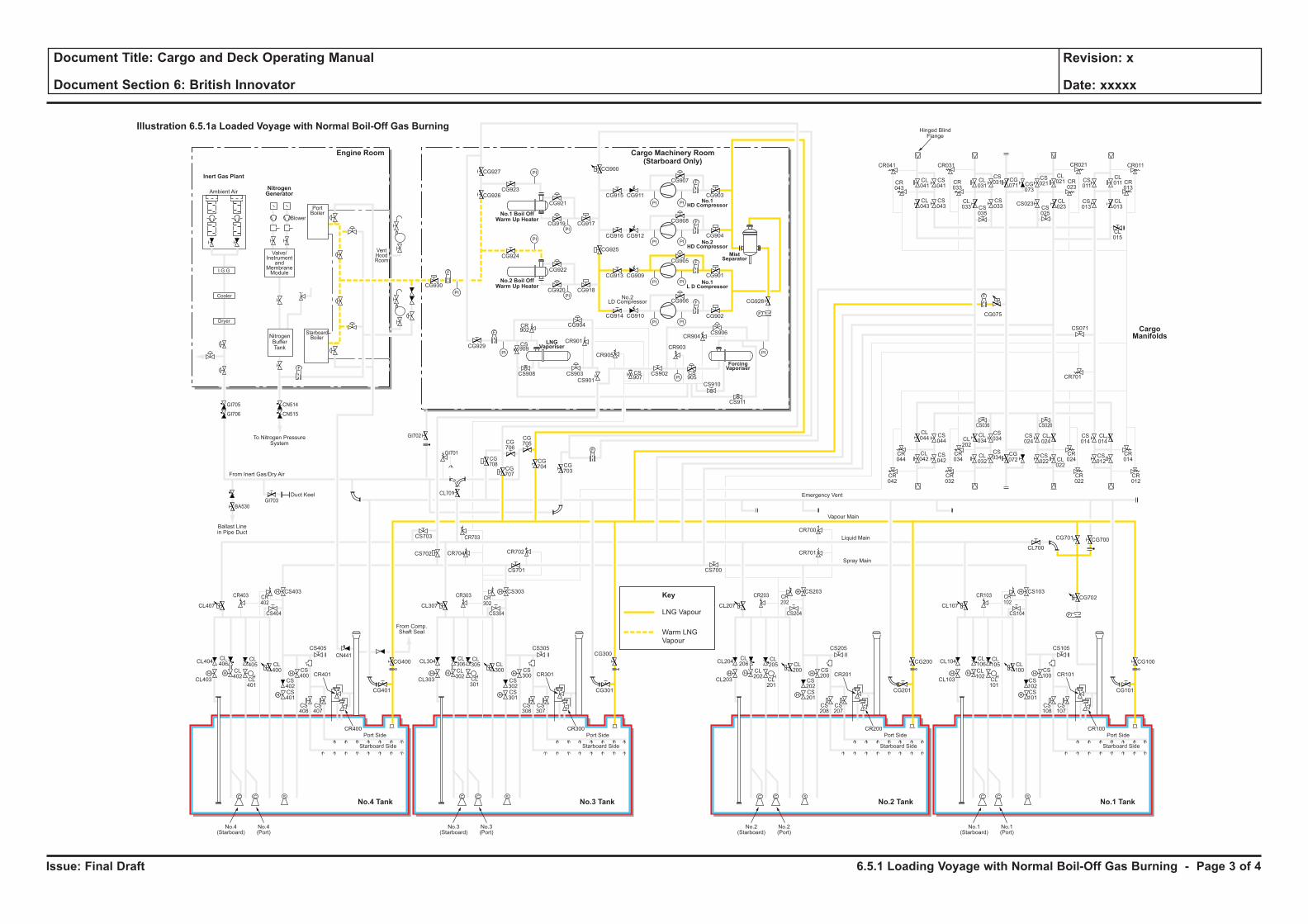
Issue: Final Draft
Document Title: Cargo and Deck Operating Manual
Document Section 6: British Innovator
Revision: x
Date: xxxxx
Key
LNG Vapour
Warm LNG
Vapour
H H
H
H
F
C C S
H
HH H
H
H
C C S
H
HH H
H
H
C C S
H
HH H
H
H
C C S
H
H
F
PI PI
F
PI PI
PI
PI
PI
PI
PI PI
PI PI
F
F
PI
PI
PI
PI
F
F
F
CL106
CL102
CL101
CL100
CS102
CS100
CS103
CS101
CS108
CS107
CR101
CR100
CL105
CL104
CL700
CG700
CG702
CG101
CS105
CS104
CR103 CR102
CG701
CL103
Port Side
Starboard Side
CL107
No.1(Starboard)
No.1(Port)
CL206
CL202
CL201
CL200
CS202
CS200
CS203
CR701
CR700
CS201
CS208
CS207
CR201
CR200
CL205
CL204
CG201
CG200 CG100
CS205
CS204
CR203 CR202
CL203
Port Side
Ambient Air
Blower
PortBoiler
VentHoodRoom
StarboardBoiler
Inert Gas Plant
NitrogenGenerator
Engine Room
No.3 TankNo.4 Tank No.1 TankNo.2 Tank
Cargo Machinery Room(Starboard Only)
Starboard Side
CL207
CS700
No.2(Starboard)
No.2(Port)
CL306
CL302
CL301
CL300
CS302
CS300
CS303
CS701
CS301
CS308
CS307
CR301
CR300
CL305
CL304
CG301
CS305
CS304
CR303 CR302
CL303
Port Side
Starboard Side
CL307
CG927
CG926CG923
CG921
CG917CG919
CG924
CG930
CG929
CG904
CR901
CR905
CR903
CR904
CS909
CS907
CS905
CS908 CS903
CS901
CS902
CS906
CS910
CS911
CR902
CG922
CG918
CG928
CG902
CG906
CG905
CG908
CG907
CR041
CR043
CL041
CL043
CS041
CS043
CL031
CS031 CS
011
CL011 CR
013
CG071 CG
073
CS021
CL021
CL023CS
025
CS023 CL013
CL015
CS013
CR023
CR033
CR021CR031 CR011
CS035
CL033
CS033
CG915
CG900
CG925
CG911
CG916 CG912
CG913 CG909
CG914 CG910
CG901
CG904
CG903
CG920
No.3(Starboard)
No.3(Port)
CL406
CL402
CL401
CL400
CS402
CS400
CS403
CS702 CR704 CR702
CR703
CG708
CG707
CG706
CG705
CG704 CG
703
CS703
CL701
CS401
CS408
CS407
CR401
CR400
CL405
CL404
CG401
CG400
CG300CS405
From Comp.Shaft Seal
CS404
CR403
GI705
GI706
GI703
GI702
GI701
BA530
CN514
CN515
CR402
CL403
Port Side
Starboard Side
CL407
No.4(Starboard)
No.4(Port)
CL044
CS044
CS042
CS034
CS024
CL024
CS034
CR044
CR034
CR024
CR042
CR032
CR022
CS036 CS026
CL042
CL034CL
202
CL032
CG072
CS022 CL
022
CS014
CR701
CS071
CL014
CR014
CR012
CS012
F
F
F
Cooler
Dryer
I.G.G
Valve/Instrument
andMembraneModule
NitrogenBufferTank
To Nitrogen PressureSystem
Hinged BlindFlange
Ballast Linein Pipe Duct
Duct Keel
From Inert Gas/Dry Air
Emergency Vent
Vapour Main
Liquid Main
Spray Main
No.1 Boil OffWarm Up Heater
No.2 Boil OffWarm Up Heater
ForcingVaporiser
MistSeparator
No.1HD Compressor
No.2HD Compressor
No.1L D Compressor
LNGVaporiser
No.2LD Compressor
Illustration 6.5.1a Loaded Voyage with Normal Boil-Off Gas Burning
CargoManifolds
CG075
CN441
6.5.1 Loading Voyage with Normal Boil-Off Gas Burning - Page 3 of 4
Issue: Final Draft
Document Title: Cargo and Deck Operating Manual
Document Section 6: British Innovator
Revision: x
Date: xxxxx
There is a starting interlock on all compressors, which prevents the compressors going on standby if the inlet guide vanes (IGV) are not in the fully closed position (to prevent an overcurrent trip). Start the compressor with the IGV closed, then adjust the set point to 60%.
When the engine room is ready to start gas burning, ensure that there is sufficient nitrogen to purge the lines to the boiler i.e. >500kPa in the buffer tank.
e) Ensure that the gas outlet temperature of the heater is approximately 25°C.
f) Open valve CG930, the gas supply to the engine room.
g) Start the LD compressor(s).
h) At the gas compressors adjust the IGV to 60% for loaded condition, the tank pressures minimum and maximum at 106kPa absolute and 109kPa absolute and the steam dump opening pressure at 113kPa absolute.
This operation will then be controlled and monitored from the ECR.
(Note: If the volume of boil-off exceeds demand in the boilers, the steam dump should be put into operation.)
Should the system shut down for any reason, valve CG930 will close automatically.
i) Stop the compressor.
j) Shut the steam off the boil-off heater.
When stopping gas burning for any reason.
• The LD compressor(s) will automatically stop in the event of the master gas valve CG930 closing
• Shut down the boil-off heater
• Master gas valve CG930 will automatically close if gas burning is stopped or fails for any reason
6.5.1 Loading Voyage with Normal Boil-Off Gas Burning - Page 4 of 4
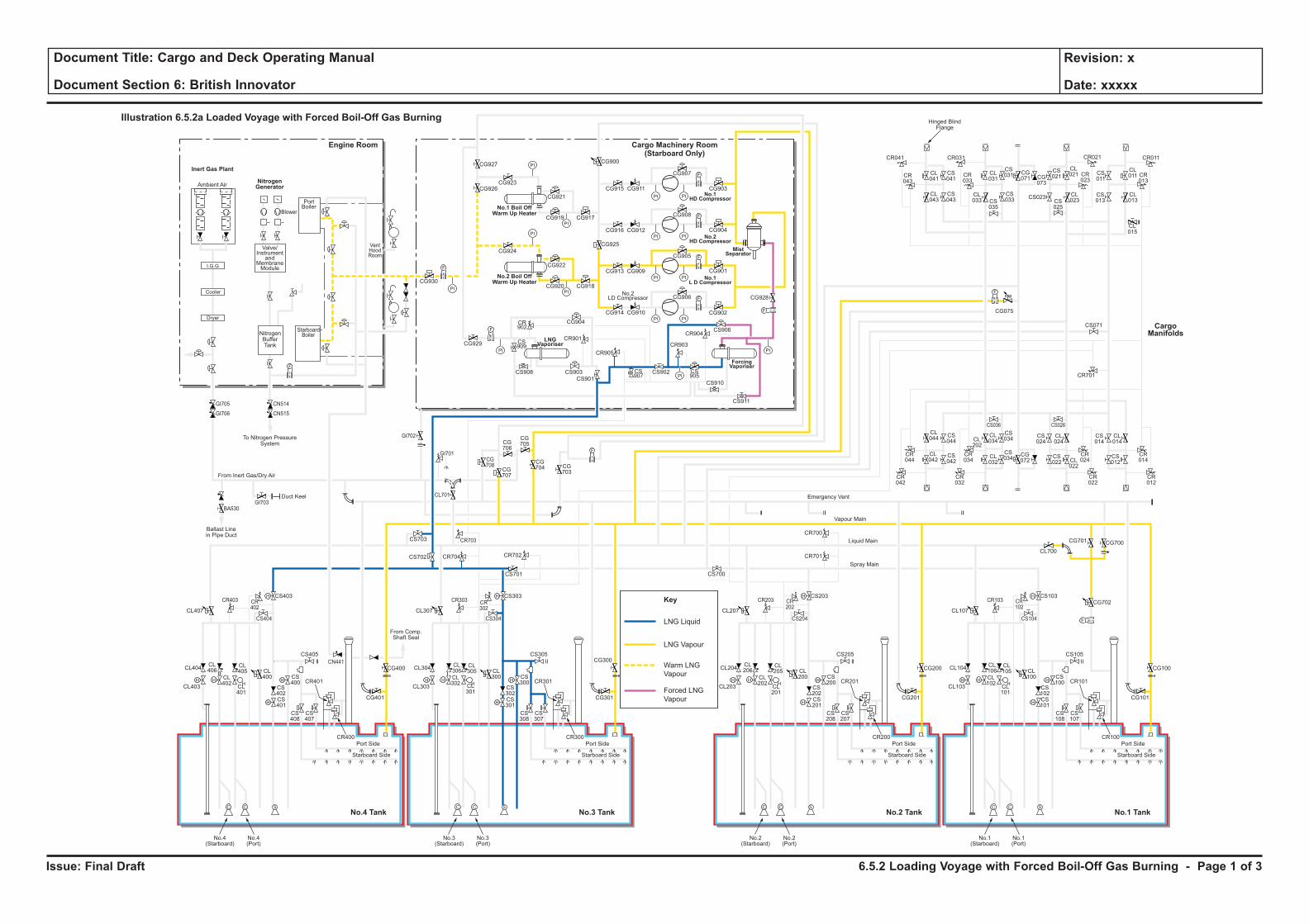
Issue: Final Draft
Document Title: Cargo and Deck Operating Manual
Document Section 6: British Innovator
Revision: x
Date: xxxxx
LNG Liquid
Key
LNG Vapour
Warm LNG
Vapour
Forced LNG
Vapour
H H
H
H
F
C C S
H
HH H
H
H
C C S
H
HH H
H
H
C C S
H
HH H
H
H
C C S
H
H
F
PI PI
F
PI PI
PI
PI
PI
PI
PI PI
PI PI
F
F
PI
PI
PI
PI
F
F
F
CL106
CL102
CL101
CL100
CS102
CS100
CS103
CS101
CS108
CS107
CR101
CR100
CL105
CL104
CL700
CG700
CG702
CG101
CS105
CS104
CR103 CR102
CG701
CL103
Port Side
Starboard Side
CL107
No.1(Starboard)
No.1(Port)
CL206
CL202
CL201
CL200
CS202
CS200
CS203
CR701
CR700
CS201
CS208
CS207
CR201
CR200
CL205
CL204
CG201
CG200 CG100
CS205
CS204
CR203 CR202
CL203
Port Side
Ambient Air
Blower
PortBoiler
VentHoodRoom
StarboardBoiler
Inert Gas Plant
NitrogenGenerator
Engine Room
No.3 TankNo.4 Tank No.1 TankNo.2 Tank
Cargo Machinery Room(Starboard Only)
Starboard Side
CL207
CS700
No.2(Starboard)
No.2(Port)
CL306
CL302
CL301
CL300
CS302
CS300
CS303
CS701
CS301
CS308
CS307
CR301
CR300
CL305
CL304
CG301
CS305
CS304
CR303 CR302
CL303
Port Side
Starboard Side
CL307
CG927
CG926CG923
CG921
CG917CG919
CG924
CG930
CG929
CG904
CR901
CR905
CR903
CR904
CS909
CS907
CS905
CS908 CS903
CS901
CS902
CS906
CS910
CS911
CR902
CG922
CG918
CG928
CG902
CG906
CG905
CG908
CG907
CR041
CR043
CL041
CL043
CS041
CS043
CL031
CS031 CS
011
CL011 CR
013
CG071 CG
073
CS021
CL021
CL023CS
025
CS023 CL013
CL015
CS013
CR023
CR033
CR021CR031 CR011
CS035
CL033
CS033
CG915
CG900
CG925
CG911
CG916 CG912
CG913 CG909
CG914 CG910
CG901
CG904
CG903
CG920
No.3(Starboard)
No.3(Port)
CL406
CL402
CL401
CL400
CS402
CS400
CS403
CS702 CR704 CR702
CR703
CG708
CG707
CG706
CG705
CG704 CG
703
CS703
CL701
CS401
CS408
CS407
CR401
CR400
CL405
CL404
CG401
CG400
CG300CS405
From Comp.Shaft Seal
CS404
CR403
GI705
GI706
GI703
GI702
GI701
BA530
CN514
CN515
CR402
CL403
Port Side
Starboard Side
CL407
No.4(Starboard)
No.4(Port)
CL044
CS044
CS042
CS034
CS024
CL024
CS034
CR044
CR034
CR024
CR042
CR032
CR022
CS036 CS026
CL042
CL034CL
202
CL032
CG072
CS022 CL
022
CS014
CR701
CS071
CL014
CR014
CR012
CS012
F
F
F
Cooler
Dryer
I.G.G
Valve/Instrument
andMembraneModule
NitrogenBufferTank
To Nitrogen PressureSystem
Hinged BlindFlange
Ballast Linein Pipe Duct
Duct Keel
From Inert Gas/Dry Air
Emergency Vent
Vapour Main
Liquid Main
Spray Main
No.1 Boil OffWarm Up Heater
No.2 Boil OffWarm Up Heater
ForcingVaporiser
MistSeparator
No.1HD Compressor
No.2HD Compressor
No.1L D Compressor
LNGVaporiser
No.2LD Compressor
Illustration 6.5.2a Loaded Voyage with Forced Boil-Off Gas Burning
CargoManifolds
CG075
CN441
6.5.2 Loading Voyage with Forced Boil-Off Gas Burning - Page 1 of 3
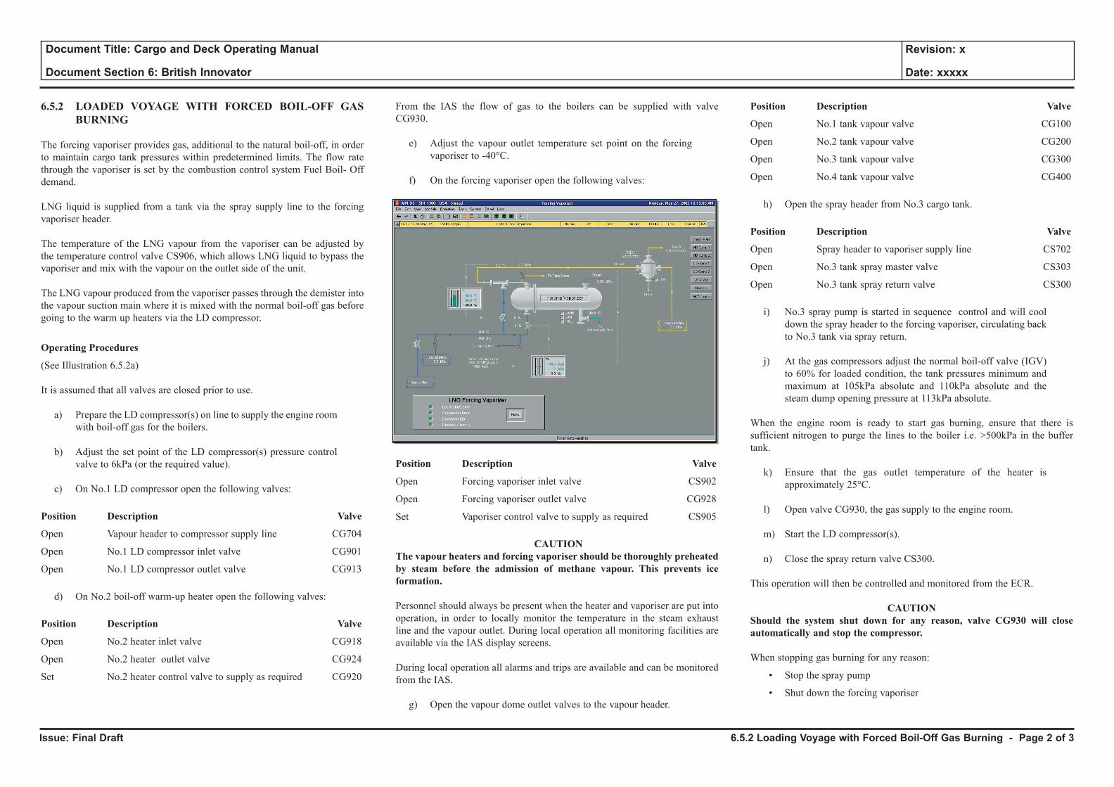
Issue: Final Draft
Document Title: Cargo and Deck Operating Manual
Document Section 6: British Innovator
Revision: x
Date: xxxxx
6.5.2 LOADED VOYAGE WITH FORCED BOIL-OFF GAS BURNING
The forcing vaporiser provides gas, additional to the natural boil-off, in order to maintain cargo tank pressures within predetermined limits. The flow rate through the vaporiser is set by the combustion control system Fuel Boil- Off demand.
LNG liquid is supplied from a tank via the spray supply line to the forcing vaporiser header.
The temperature of the LNG vapour from the vaporiser can be adjusted by the temperature control valve CS906, which allows LNG liquid to bypass the vaporiser and mix with the vapour on the outlet side of the unit.
The LNG vapour produced from the vaporiser passes through the demister into the vapour suction main where it is mixed with the normal boil-off gas before going to the warm up heaters via the LD compressor.
Operating Procedures
(See Illustration 6.5.2a)
It is assumed that all valves are closed prior to use.
a) Prepare the LD compressor(s) on line to supply the engine room with boil-off gas for the boilers.
b) Adjust the set point of the LD compressor(s) pressure control valve to 6kPa (or the required value).
c) On No.1 LD compressor open the following valves:
Position Description Valve
Open Vapour header to compressor supply line CG704
Open No.1 LD compressor inlet valve CG901
Open No.1 LD compressor outlet valve CG913
d) On No.2 boil-off warm-up heater open the following valves:
Position Description Valve
Open No.2 heater inlet valve CG918
Open No.2 heater outlet valve CG924
Set No.2 heater control valve to supply as required CG920
From the IAS the flow of gas to the boilers can be supplied with valve CG930.
e) Adjust the vapour outlet temperature set point on the forcing vaporiser to -40°C.
f) On the forcing vaporiser open the following valves:
Position Description Valve
Open Forcing vaporiser inlet valve CS902
Open Forcing vaporiser outlet valve CG928
Set Vaporiser control valve to supply as required CS905
CAUTION The vapour heaters and forcing vaporiser should be thoroughly preheated by steam before the admission of methane vapour. This prevents ice formation.
Personnel should always be present when the heater and vaporiser are put into operation, in order to locally monitor the temperature in the steam exhaust line and the vapour outlet. During local operation all monitoring facilities are available via the IAS display screens.
During local operation all alarms and trips are available and can be monitored from the IAS.
g) Open the vapour dome outlet valves to the vapour header.
Position Description Valve
Open No.1 tank vapour valve CG100
Open No.2 tank vapour valve CG200
Open No.3 tank vapour valve CG300
Open No.4 tank vapour valve CG400
h) Open the spray header from No.3 cargo tank.
Position Description Valve
Open Spray header to vaporiser supply line CS702
Open No.3 tank spray master valve CS303
Open No.3 tank spray return valve CS300
i) No.3 spray pump is started in sequence control and will cool down the spray header to the forcing vaporiser, circulating back to No.3 tank via spray return.
j) At the gas compressors adjust the normal boil-off valve (IGV) to 60% for loaded condition, the tank pressures minimum and maximum at 105kPa absolute and 110kPa absolute and the steam dump opening pressure at 113kPa absolute.
When the engine room is ready to start gas burning, ensure that there is sufficient nitrogen to purge the lines to the boiler i.e. >500kPa in the buffer tank.
k) Ensure that the gas outlet temperature of the heater is approximately 25°C.
l) Open valve CG930, the gas supply to the engine room.
m) Start the LD compressor(s).
n) Close the spray return valve CS300.
This operation will then be controlled and monitored from the ECR.
CAUTIONShould the system shut down for any reason, valve CG930 will close automatically and stop the compressor.
When stopping gas burning for any reason:
• Stop the spray pump
• Shut down the forcing vaporiser
6.5.2 Loading Voyage with Forced Boil-Off Gas Burning - Page 2 of 3
Issue: Final Draft
Document Title: Cargo and Deck Operating Manual
Document Section 6: British Innovator
Revision: x
Date: xxxxx
• The LD compressor(s) will stop automatically
• Shut down the boil-off heater
• Close valve CG930, the gas supply to the engine room
(Note: Ensure the heater, LD compressor and vaporiser are allowed to return to ambient temperature before fully closing the system down to avoid overpressurisation due to trapped vapour.)
6.5.2 Loading Voyage with Forced Boil-Off Gas Burning - Page 3 of 3
6.6 Discharging with Vapour Return from Shore
6.6.1 Preparation for Discharging
6.6.2 Liquid Line Cooldown Before Discharging
6.6.3 Arm Cooldown Before Discharging
6.6.4 Discharging with Vapour Return From Shore
6.6.5 Ballasting
Illustrations
6.6.1a Preparation for Discharging
6.6.2a Liquid Line Cooldown Before Discharging
6.6.3a Liquid Arm Cooldown Before Discharging
6.6.4a Discharging with Vapour Return From Shore
6.6.5a Ballasting
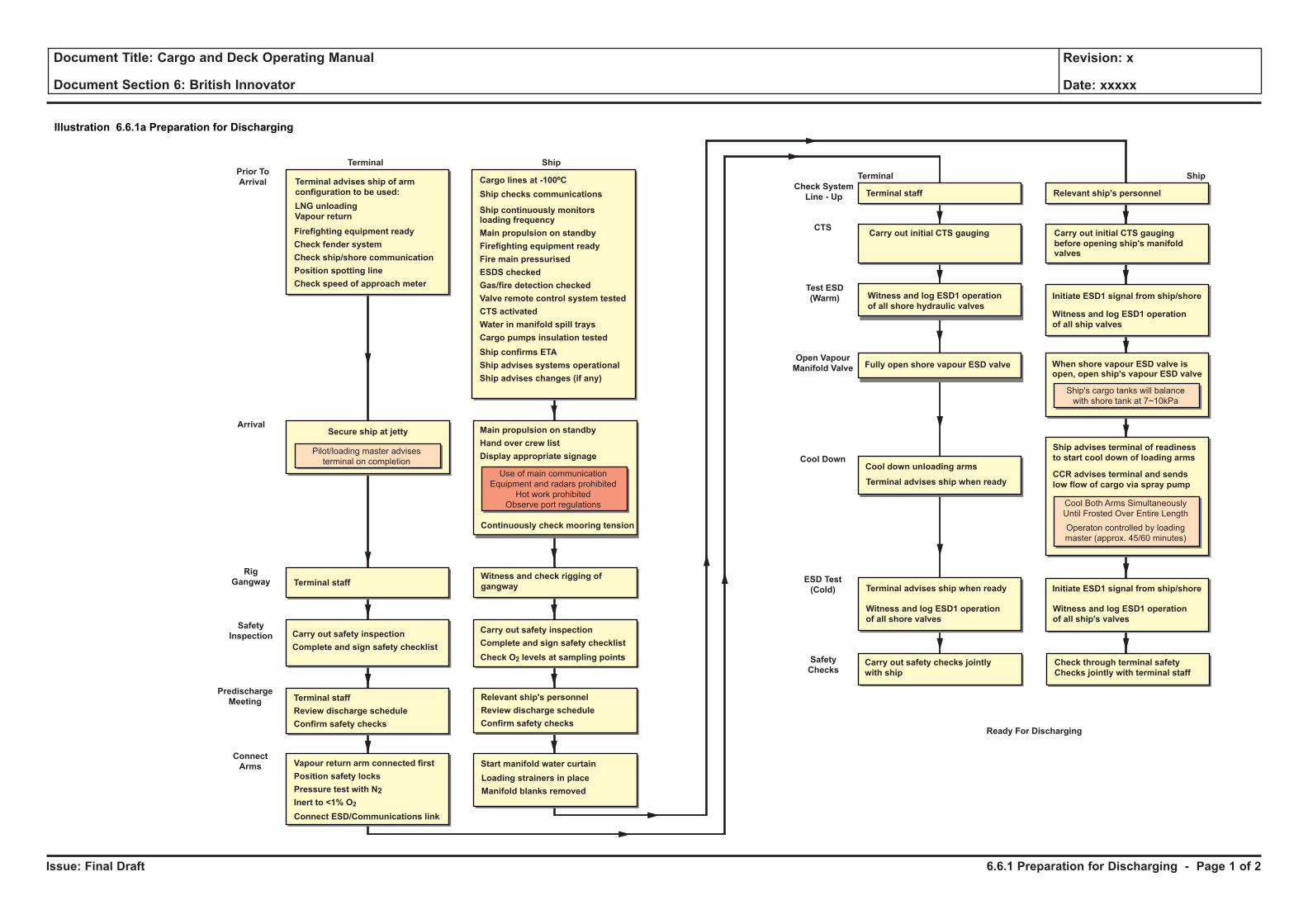
Issue: Final Draft
Document Title: Cargo and Deck Operating Manual
Document Section 6: British Innovator
Revision: x
Date: xxxxx
Illustration 6.6.1a Preparation for Discharging
Prior To
Arrival
Arrival
Terminal Ship
Terminal advises ship of arm
configuration to be used:
LNG unloading
Vapour return
Secure ship at jetty
Pilot/loading master advises
terminal on completion
Cargo lines at -100ºC
Ship checks communications
Ship continuously monitorsloading frequency
Main propulsion on standby
Firefighting equipment ready
Fire main pressurised
ESDS checked
Gas/fire detection checked
Valve remote control system tested
CTS activated
Water in manifold spill trays
Cargo pumps insulation tested
Firefighting equipment ready
Check fender system
Check ship/shore communication
Position spotting line
Check speed of approach meter
Main propulsion on standby
Hand over crew list
Display appropriate signage
Predischarge
Meeting
Rig
Gangway
Check System
Line - Up
Connect
Arms
Safety
Inspection
Terminal staff
Terminal staff
Review discharge schedule
Confirm safety checks
Witness and check rigging of
gangway
Continuously check mooring tension
Start manifold water curtain
Carry out safety inspection
Complete and sign safety checklist
Test ESD
(Warm)
Terminal Ship
Cool Down
Open Vapour
Manifold Valve
ESD Test
(Cold)
Terminal advises ship when readyCCR advises terminal and sends
low flow of cargo via spray pump
Carry out safety inspection
Complete and sign safety checklist
Cool down unloading arms
Ship advises terminal of readiness
to start cool down of loading arms
Relevant ship's personnelTerminal staff
Initiate ESD1 signal from ship/shoreWitness and log ESD1 operation
of all shore hydraulic valvesWitness and log ESD1 operation
of all ship valves
of all ship's valves
Witness and log ESD1 operation
of all shore valves
Witness and log ESD1 operation
Ready For Discharging
Fully open shore vapour ESD valve When shore vapour ESD valve isopen, open ship's vapour ESD valve
Ship's cargo tanks will balance
with shore tank at 7~10kPa
Cool Both Arms Simultaneously
Until Frosted Over Entire Length
Operaton controlled by loading
master (approx. 45/60 minutes)
Check O2 levels at sampling points
Use of main communication
Equipment and radars prohibited
Hot work prohibited
Observe port regulations
Relevant ship's personnel
Review discharge schedule
Confirm safety checks
Ship confirms ETA
Ship advises systems operational
Ship advises changes (if any)
Vapour return arm connected first
Position safety locks
Pressure test with N2
Inert to <1% O2
Connect ESD/Communications link
Loading strainers in place
Manifold blanks removed
CTSCarry out initial CTS gauging Carry Out Initial CTS GaugingCarry out initial CTS gauging
before opening ship's manifoldvalves
Terminal advises ship when ready Initiate ESD1 signal from ship/shore
Safety
ChecksCarry out safety checks jointly
with ship
Check through terminal safety
Checks jointly with terminal staff
6.6.1 Preparation for Discharging - Page 1 of 2
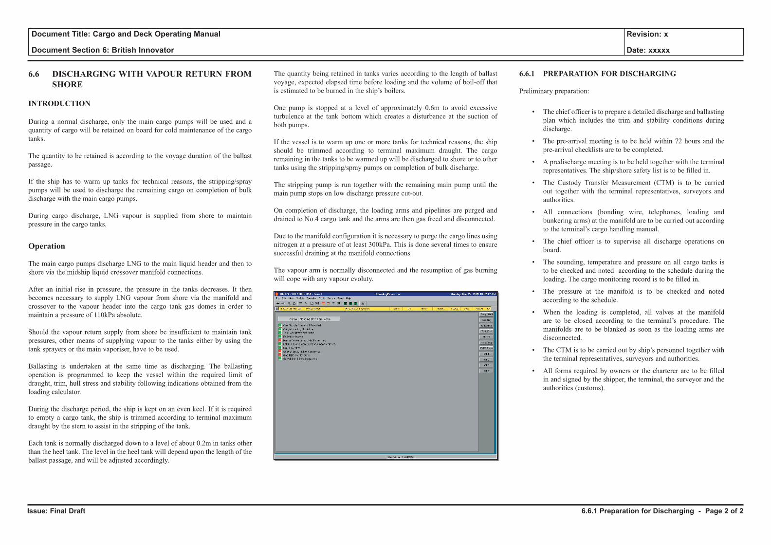
Issue: Final Draft
Document Title: Cargo and Deck Operating Manual
Document Section 6: British Innovator
Revision: x
Date: xxxxx
6.6 DISCHARGING WITH VAPOUR RETURN FROM SHORE
INTRODUCTION
During a normal discharge, only the main cargo pumps will be used and a quantity of cargo will be retained on board for cold maintenance of the cargo tanks.
The quantity to be retained is according to the voyage duration of the ballast passage.
If the ship has to warm up tanks for technical reasons, the stripping/spray pumps will be used to discharge the remaining cargo on completion of bulk discharge with the main cargo pumps.
During cargo discharge, LNG vapour is supplied from shore to maintain pressure in the cargo tanks.
Operation
The main cargo pumps discharge LNG to the main liquid header and then to shore via the midship liquid crossover manifold connections.
After an initial rise in pressure, the pressure in the tanks decreases. It then becomes necessary to supply LNG vapour from shore via the manifold and crossover to the vapour header into the cargo tank gas domes in order to maintain a pressure of 110kPa absolute.
Should the vapour return supply from shore be insufficient to maintain tank pressures, other means of supplying vapour to the tanks either by using the tank sprayers or the main vaporiser, have to be used.
Ballasting is undertaken at the same time as discharging. The ballasting operation is programmed to keep the vessel within the required limit of draught, trim, hull stress and stability following indications obtained from the loading calculator.
During the discharge period, the ship is kept on an even keel. If it is required to empty a cargo tank, the ship is trimmed according to terminal maximum draught by the stern to assist in the stripping of the tank.
Each tank is normally discharged down to a level of about 0.2m in tanks other than the heel tank. The level in the heel tank will depend upon the length of the ballast passage, and will be adjusted accordingly.
The quantity being retained in tanks varies according to the length of ballast voyage, expected elapsed time before loading and the volume of boil-off that is estimated to be burned in the ship’s boilers.
One pump is stopped at a level of approximately 0.6m to avoid excessive turbulence at the tank bottom which creates a disturbance at the suction of both pumps.
If the vessel is to warm up one or more tanks for technical reasons, the ship should be trimmed according to terminal maximum draught. The cargo remaining in the tanks to be warmed up will be discharged to shore or to other tanks using the stripping/spray pumps on completion of bulk discharge.
The stripping pump is run together with the remaining main pump until the main pump stops on low discharge pressure cut-out.
On completion of discharge, the loading arms and pipelines are purged and drained to No.4 cargo tank and the arms are then gas freed and disconnected.
Due to the manifold configuration it is necessary to purge the cargo lines using nitrogen at a pressure of at least 300kPa. This is done several times to ensure successful draining at the manifold connections.
The vapour arm is normally disconnected and the resumption of gas burning will cope with any vapour evoluty.
6.6.1 PREPARATION FOR DISCHARGING
Preliminary preparation:
• The chief officer is to prepare a detailed discharge and ballasting plan which includes the trim and stability conditions during discharge.
• The pre-arrival meeting is to be held within 72 hours and the pre-arrival checklists are to be completed.
• A predischarge meeting is to be held together with the terminal representatives. The ship/shore safety list is to be filled in.
• The Custody Transfer Measurement (CTM) is to be carried out together with the terminal representatives, surveyors and authorities.
• All connections (bonding wire, telephones, loading and bunkering arms) at the manifold are to be carried out according to the terminal’s cargo handling manual.
• The chief officer is to supervise all discharge operations on board.
• The sounding, temperature and pressure on all cargo tanks is to be checked and noted according to the schedule during the loading. The cargo monitoring record is to be filled in.
• The pressure at the manifold is to be checked and noted according to the schedule.
• When the loading is completed, all valves at the manifold are to be closed according to the terminal’s procedure. The manifolds are to be blanked as soon as the loading arms are disconnected.
• The CTM is to be carried out by ship’s personnel together with the terminal representatives, surveyors and authorities.
• All forms required by owners or the charterer are to be filled in and signed by the shipper, the terminal, the surveyor and the authorities (customs).
6.6.1 Preparation for Discharging - Page 2 of 2
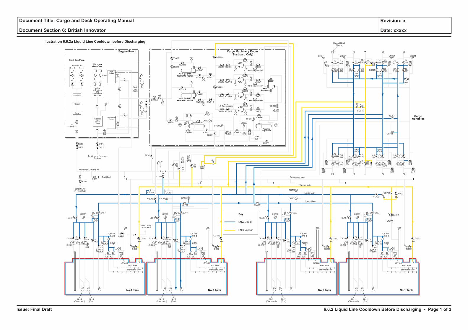
Issue: Final Draft
Document Title: Cargo and Deck Operating Manual
Document Section 6: British Innovator
Revision: x
Date: xxxxx
LNG Liquid
Key
LNG Vapour
H H
H
H
F
C C S
H
HH H
H
H
C C S
H
HH H
H
H
C C S
H
HH H
H
H
C C S
H
H
F
PI PI
F
PI PI
PI
PI
PI
PI
PI PI
PI PI
F
F
PI
PI
PI
PI
F
F
F
CL106
CL102
CL101
CL100
CS102
CS100
CS103
CS101
CS108
CS107
CR101
CR100
CL105
CL104
CL700
CG700
CG702
CG101
CS105
CS104
CR103 CR102
CG701
CL103
Port Side
Starboard Side
CL107
No.1(Starboard)
No.1(Port)
CL206
CL202
CL201
CL200
CS202
CS200
CS203
CR701
CR700
CS201
CS208
CS207
CR201
CR200
CL205
CL204
CG201
CG200 CG100
CS205
CS204
CR203 CR202
CL203
Port Side
Ambient Air
Blower
PortBoiler
VentHoodRoom
StarboardBoiler
Inert Gas Plant
NitrogenGenerator
Engine Room
No.3 TankNo.4 Tank No.1 TankNo.2 Tank
Cargo Machinery Room(Starboard Only)
Starboard Side
CL207
CS700
No.2(Starboard)
No.2(Port)
CL306
CL302
CL301
CL300
CS302
CS300
CS303
CS701
CS301
CS308
CS307
CR301
CR300
CL305
CL304
CG301
CS305
CS304
CR303 CR302
CL303
Port Side
Starboard Side
CL307
CG927
CG926CG923
CG921
CG917CG919
CG924
CG930
CG929
CG904
CR901
CR905
CR903
CR904
CS909
CS907
CS905
CS908 CS903
CS901
CS902
CS906
CS910
CS911
CR902
CG922
CG918
CG928
CG902
CG906
CG905
CG908
CG907
CR041
CR043
CL041
CL043
CS041
CS043
CL031
CS031 CS
011
CL011 CR
013
CG071 CG
073
CS021
CL021
CL023CS
025
CS023 CL013
CL015
CS013
CR023
CR033
CR021CR031 CR011
CS035
CL033
CS033
CG915
CG900
CG925
CG911
CG916 CG912
CG913 CG909
CG914 CG910
CG901
CG904
CG903
CG920
No.3(Starboard)
No.3(Port)
CL406
CL402
CL401
CL400
CS402
CS400
CS403
CS702 CR704 CR702
CR703
CG708
CG707
CG706
CG705
CG704 CG
703
CS703
CL701
CS401
CS408
CS407
CR401
CR400
CL405
CL404
CG401
CG400
CG300CS405
From Comp.Shaft Seal
CS404
CR403
GI705
GI706
GI703
GI702
GI701
BA530
CN514
CN515
CR402
CL403
Port Side
Starboard Side
CL407
No.4(Starboard)
No.4(Port)
CL044
CS044
CS042
CS034
CS024
CL024
CS034
CR044
CR034
CR024
CR042
CR032
CR022
CS036 CS026
CL042
CL034CL
202
CL032
CG072
CS022 CL
022
CS014
CR701
CS071
CL014
CR014
CR012
CS012
F
F
F
Cooler
Dryer
I.G.G
Valve/Instrument
andMembraneModule
NitrogenBufferTank
To Nitrogen PressureSystem
Hinged BlindFlange
Ballast Linein Pipe Duct
Duct Keel
From Inert Gas/Dry Air
Emergency Vent
Vapour Main
Liquid Main
Spray Main
No.1 Boil OffWarm Up Heater
No.2 Boil OffWarm Up Heater
ForcingVaporiser
MistSeparator
No.1HD Compressor
No.2HD Compressor
No.1L D Compressor
LNGVaporiser
No.2LD Compressor
Illustration 6.6.2a Liquid Line Cooldown before Discharging
CargoManifolds
CG075
CN441
6.6.2 Liquid Line Cooldown Before Discharging - Page 1 of 2
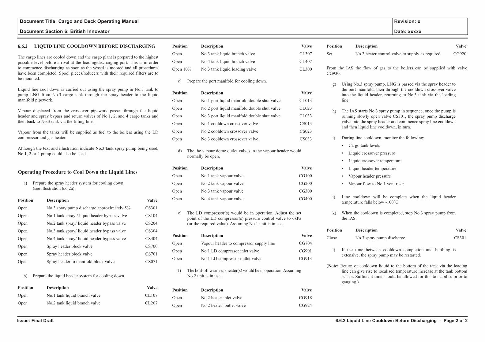
Issue: Final Draft
Document Title: Cargo and Deck Operating Manual
Document Section 6: British Innovator
Revision: x
Date: xxxxx
6.6.2 LIQUID LINE COOLDOWN BEFORE DISCHARGING
The cargo lines are cooled down and the cargo plant is prepared to the highest possible level before arrival at the loading/discharging port. This is in order to commence discharging as soon as the vessel is moored and all procedures have been completed. Spool pieces/reducers with their required filters are to be mounted.
Liquid line cool down is carried out using the spray pump in No.3 tank to pump LNG from No.3 cargo tank through the spray header to the liquid manifold pipework.
Vapour displaced from the crossover pipework passes through the liquid header and spray bypass and return valves of No.1, 2, and 4 cargo tanks and then back to No.3 tank via the filling line.
Vapour from the tanks will be supplied as fuel to the boilers using the LD compressor and gas heater.
Although the text and illustration indicate No.3 tank spray pump being used, No.1, 2 or 4 pump could also be used.
Operating Procedure to Cool Down the Liquid Lines
a) Prepare the spray header system for cooling down. (see illustration 6.6.2a)
Position Description Valve
Open No.3 spray pump discharge approximately 5% CS301
Open No.1 tank spray / liquid header bypass valve CS104
Open No.2 tank spray/ liquid header bypass valve CS204
Open No.3 tank spray/ liquid header bypass valve CS304
Open No.4 tank spray/ liquid header bypass valve CS404
Open Spray header block valve CS700
Open Spray header block valve CS701
Open Spray header to manifold block valve CS071
b) Prepare the liquid header system for cooling down.
Position Description Valve
Open No.1 tank liquid branch valve CL107
Open No.2 tank liquid branch valve CL207
Position Description Valve
Open No.3 tank liquid branch valve CL307
Open No.4 tank liquid branch valve CL407
Open 10% No.3 tank liquid loading valve CL300
c) Prepare the port manifold for cooling down.
Position Description Valve
Open No.1 port liquid manifold double shut valve CL013
Open No.2 port liquid manifold double shut valve CL023
Open No.3 port liquid manifold double shut valve CL033
Open No.1 cooldown crossover valve CS013
Open No.2 cooldown crossover valve CS023
Open No.3 cooldown crossover valve CS033
d) The the vapour dome outlet valves to the vapour header would normally be open.
Position Description Valve
Open No.1 tank vapour valve CG100
Open No.2 tank vapour valve CG200
Open No.3 tank vapour valve CG300
Open No.4 tank vapour valve CG400
e) The LD compressor(s) would be in operation. Adjust the set point of the LD compressor(s) pressure control valve to 6kPa (or the required value). Assuming No.1 unit is in use.
Position Description Valve
Open Vapour header to compressor supply line CG704
Open No.1 LD compressor inlet valve CG901
Open No.1 LD compressor outlet valve CG913
f) The boil-off warm-up heater(s) would be in operation. Assuming No.2 unit is in use.
Position Description Valve
Open No.2 heater inlet valve CG918
Open No.2 heater outlet valve CG924
Position Description Valve
Set No.2 heater control valve to supply as required CG920
From the IAS the flow of gas to the boilers can be supplied with valve CG930.
g) Using No.3 spray pump, LNG is passed via the spray header to the port manifold, then through the cooldown crossover valve into the liquid header, returning to No.3 tank via the loading line.
h) The IAS starts No.3 spray pump in sequence, once the pump is running slowly open valve CS301, the spray pump discharge valve into the spray header and commence spray line cooldown and then liquid line cooldown, in turn.
i) During line cooldown, monitor the following:
• Cargo tank levels
• Liquid crossover pressure
• Liquid crossover temperature
• Liquid header temperature
• Vapour header pressure
• Vapour flow to No.1 vent riser
j) Line cooldown will be complete when the liquid header temperature falls below -100°C.
k) When the cooldown is completed, stop No.3 spray pump from the IAS.
Position Description Valve
Close No.3 spray pump discharge CS301
l) If the time between cooldown completion and berthing is extensive, the spray pump may be restarted.
(Note: Return of cooldown liquid to the bottom of the tank via the loading line can give rise to localised temperature increase at the tank bottom sensor. Sufficient time should be allowed for this to stabilise prior to gauging.)
6.6.2 Liquid Line Cooldown Before Discharging - Page 2 of 2
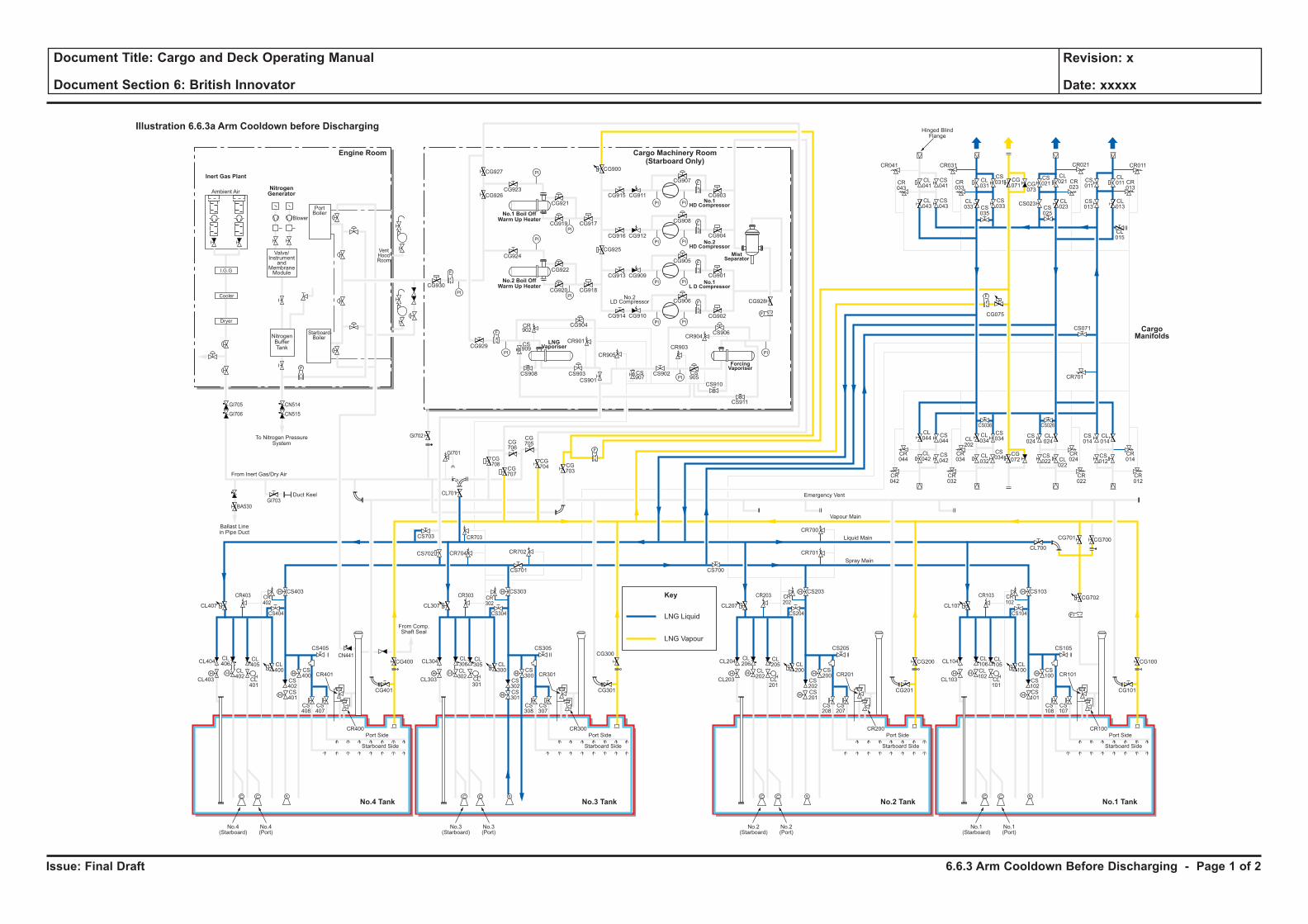
Issue: Final Draft
Document Title: Cargo and Deck Operating Manual
Document Section 6: British Innovator
Revision: x
Date: xxxxx
LNG Liquid
Key
LNG Vapour
H H
H
H
F
C C S
H
HH H
H
H
C C S
H
HH H
H
H
C C S
H
HH H
H
H
C C S
H
H
F
PI PI
F
PI PI
PI
PI
PI
PI
PI PI
PI PI
F
F
PI
PI
PI
PI
F
F
F
CL106
CL102
CL101
CL100
CS102
CS100
CS103
CS101
CS108
CS107
CR101
CR100
CL105
CL104
CL700
CG700
CG702
CG101
CS105
CS104
CR103 CR102
CG701
CL103
Port Side
Starboard Side
CL107
No.1(Starboard)
No.1(Port)
CL206
CL202
CL201
CL200
CS202
CS200
CS203
CR701
CR700
CS201
CS208
CS207
CR201
CR200
CL205
CL204
CG201
CG200 CG100
CS205
CS204
CR203 CR202
CL203
Port Side
Ambient Air
Blower
PortBoiler
VentHoodRoom
StarboardBoiler
Inert Gas Plant
NitrogenGenerator
Engine Room
No.3 TankNo.4 Tank No.1 TankNo.2 Tank
Cargo Machinery Room(Starboard Only)
Starboard Side
CL207
CS700
No.2(Starboard)
No.2(Port)
CL306
CL302
CL301
CL300
CS302
CS300
CS303
CS701
CS301
CS308
CS307
CR301
CR300
CL305
CL304
CG301
CS305
CS304
CR303 CR302
CL303
Port Side
Starboard Side
CL307
CG927
CG926CG923
CG921
CG917CG919
CG924
CG930
CG929
CG904
CR901
CR905
CR903
CR904
CS909
CS907
CS905
CS908 CS903
CS901
CS902
CS906
CS910
CS911
CR902
CG922
CG918
CG928
CG902
CG906
CG905
CG908
CG907
CR041
CR043
CL041
CL043
CS041
CS043
CL031
CS031 CS
011
CL011 CR
013
CG071 CG
073
CS021
CL021
CL023CS
025
CS023 CL013
CL015
CS013
CR023
CR033
CR021CR031 CR011
CS035
CL033
CS033
CG915
CG900
CG925
CG911
CG916 CG912
CG913 CG909
CG914 CG910
CG901
CG904
CG903
CG920
No.3(Starboard)
No.3(Port)
CL406
CL402
CL401
CL400
CS402
CS400
CS403
CS702 CR704 CR702
CR703
CG708
CG707
CG706
CG705
CG704 CG
703
CS703
CL701
CS401
CS408
CS407
CR401
CR400
CL405
CL404
CG401
CG400
CG300CS405
From Comp.Shaft Seal
CS404
CR403
GI705
GI706
GI703
GI702
GI701
BA530
CN514
CN515
CR402
CL403
Port Side
Starboard Side
CL407
No.4(Starboard)
No.4(Port)
CL044
CS044
CS042
CS034
CS024
CL024
CS034
CR044
CR034
CR024
CR042
CR032
CR022
CS036 CS026
CL042
CL034CL
202
CL032
CG072
CS022 CL
022
CS014
CR701
CS071
CL014
CR014
CR012
CS012
F
F
F
Cooler
Dryer
I.G.G
Valve/Instrument
andMembraneModule
NitrogenBufferTank
To Nitrogen PressureSystem
Hinged BlindFlange
Ballast Linein Pipe Duct
Duct Keel
From Inert Gas/Dry Air
Emergency Vent
Vapour Main
Liquid Main
Spray Main
No.1 Boil OffWarm Up Heater
No.2 Boil OffWarm Up Heater
ForcingVaporiser
MistSeparator
No.1HD Compressor
No.2HD Compressor
No.1L D Compressor
LNGVaporiser
No.2LD Compressor
Illustration 6.6.3a Arm Cooldown before Discharging
CargoManifolds
CG075
CN441
6.6.3 Arm Cooldown Before Discharging - Page 1 of 2
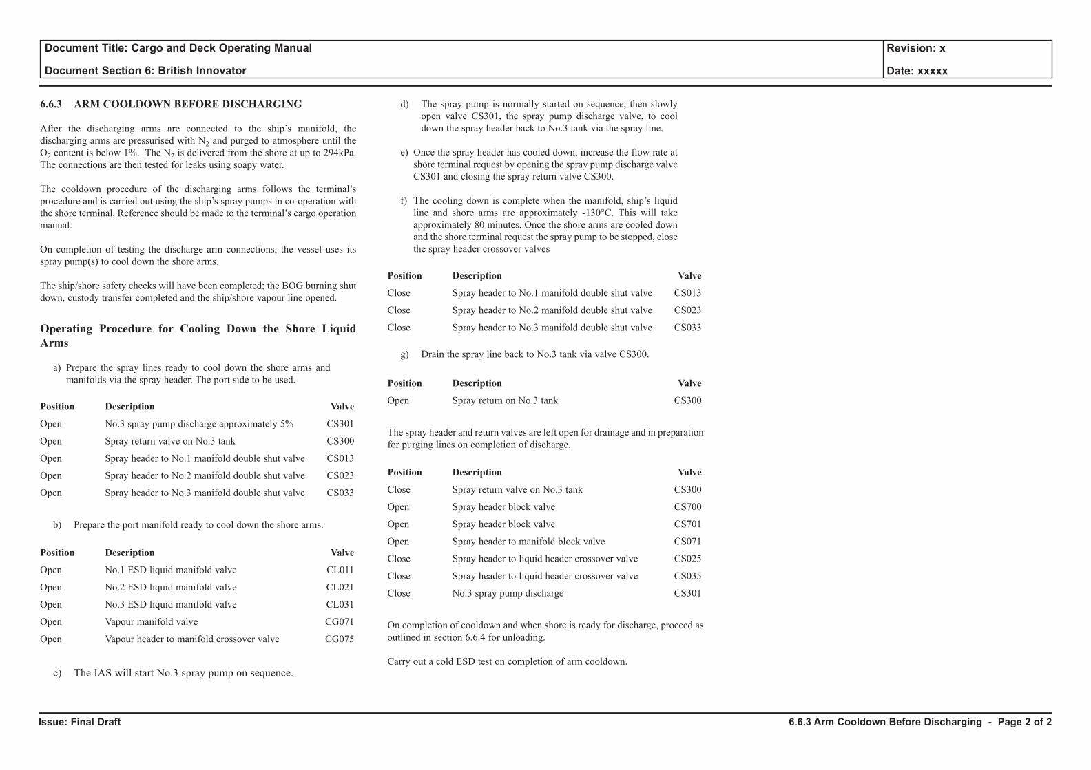
Issue: Final Draft
Document Title: Cargo and Deck Operating Manual
Document Section 6: British Innovator
Revision: x
Date: xxxxx
6.6.3 ARM COOLDOWN BEFORE DISCHARGING
After the discharging arms are connected to the ship’s manifold, the discharging arms are pressurised with N2 and purged to atmosphere until the O2 content is below 1%. The N2 is delivered from the shore at up to 294kPa. The connections are then tested for leaks using soapy water.
The cooldown procedure of the discharging arms follows the terminal’s procedure and is carried out using the ship’s spray pumps in co-operation with the shore terminal. Reference should be made to the terminal’s cargo operation manual.
On completion of testing the discharge arm connections, the vessel uses its spray pump(s) to cool down the shore arms.
The ship/shore safety checks will have been completed; the BOG burning shut down, custody transfer completed and the ship/shore vapour line opened.
Operating Procedure for Cooling Down the Shore Liquid Arms
a) Prepare the spray lines ready to cool down the shore arms and manifolds via the spray header. The port side to be used.
Position Description Valve
Open No.3 spray pump discharge approximately 5% CS301
Open Spray return valve on No.3 tank CS300
Open Spray header to No.1 manifold double shut valve CS013
Open Spray header to No.2 manifold double shut valve CS023
Open Spray header to No.3 manifold double shut valve CS033
b) Prepare the port manifold ready to cool down the shore arms.
Position Description Valve
Open No.1 ESD liquid manifold valve CL011
Open No.2 ESD liquid manifold valve CL021
Open No.3 ESD liquid manifold valve CL031
Open Vapour manifold valve CG071
Open Vapour header to manifold crossover valve CG075
c) The IAS will start No.3 spray pump on sequence.
d) The spray pump is normally started on sequence, then slowly open valve CS301, the spray pump discharge valve, to cool down the spray header back to No.3 tank via the spray line.
e) Once the spray header has cooled down, increase the flow rate at
shore terminal request by opening the spray pump discharge valve CS301 and closing the spray return valve CS300.
f) The cooling down is complete when the manifold, ship’s liquid line and shore arms are approximately -130°C. This will take approximately 80 minutes. Once the shore arms are cooled down and the shore terminal request the spray pump to be stopped, close the spray header crossover valves
Position Description Valve
Close Spray header to No.1 manifold double shut valve CS013
Close Spray header to No.2 manifold double shut valve CS023
Close Spray header to No.3 manifold double shut valve CS033
g) Drain the spray line back to No.3 tank via valve CS300.
Position Description Valve
Open Spray return on No.3 tank CS300
The spray header and return valves are left open for drainage and in preparation for purging lines on completion of discharge.
Position Description Valve
Close Spray return valve on No.3 tank CS300
Open Spray header block valve CS700
Open Spray header block valve CS701
Open Spray header to manifold block valve CS071
Close Spray header to liquid header crossover valve CS025
Close Spray header to liquid header crossover valve CS035
Close No.3 spray pump discharge CS301
On completion of cooldown and when shore is ready for discharge, proceed as outlined in section 6.6.4 for unloading.
Carry out a cold ESD test on completion of arm cooldown.
6.6.3 Arm Cooldown Before Discharging - Page 2 of 2
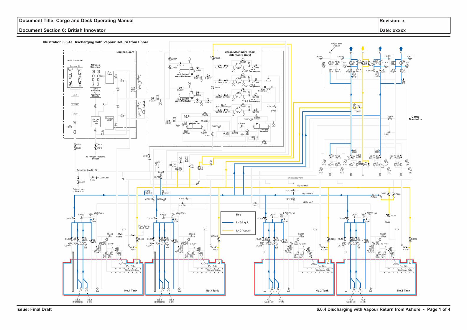
Issue: Final Draft
Document Title: Cargo and Deck Operating Manual
Document Section 6: British Innovator
Revision: x
Date: xxxxx
LNG Liquid
Key
LNG Vapour
H H
H
H
F
C C S
H
HH H
H
H
C C S
H
HH H
H
H
C C S
H
HH H
H
H
C C S
H
H
F
PI PI
F
PI PI
PI
PI
PI
PI
PI PI
PI PI
F
F
PI
PI
PI
PI
F
F
F
CL106
CL102
CL101
CL100
CS102
CS100
CS103
CS101
CS108
CS107
CR101
CR100
CL105
CL104
CL700
CG700
CG702
CG101
CS105
CS104
CR103 CR102
CG701
CL103
Port Side
Starboard Side
CL107
No.1(Starboard)
No.1(Port)
CL206
CL202
CL201
CL200
CS202
CS200
CS203
CR701
CR700
CS201
CS208
CS207
CR201
CR200
CL205
CL204
CG201
CG200 CG100
CS205
CS204
CR203 CR202
CL203
Port Side
Ambient Air
Blower
PortBoiler
VentHoodRoom
StarboardBoiler
Inert Gas Plant
NitrogenGenerator
Engine Room
No.3 TankNo.4 Tank No.1 TankNo.2 Tank
Cargo Machinery Room(Starboard Only)
Starboard Side
CL207
CS700
No.2(Starboard)
No.2(Port)
CL306
CL302
CL301
CL300
CS302
CS300
CS303
CS701
CS301
CS308
CS307
CR301
CR300
CL305
CL304
CG301
CS305
CS304
CR303 CR302
CL303
Port Side
Starboard Side
CL307
CG927
CG926CG923
CG921
CG917CG919
CG924
CG930
CG929
CG904
CR901
CR905
CR903
CR904
CS909
CS907
CS905
CS908 CS903
CS901
CS902
CS906
CS910
CS911
CR902
CG922
CG918
CG928
CG902
CG906
CG905
CG908
CG907
CR041
CR043
CL041
CL043
CS041
CS043
CL031
CS031 CS
011
CL011 CR
013
CG071 CG
073
CS021
CL021
CL023CS
025
CS023 CL013
CL015
CS013
CR023
CR033
CR021CR031 CR011
CS035
CL033
CS033
CG915
CG900
CG925
CG911
CG916 CG912
CG913 CG909
CG914 CG910
CG901
CG904
CG903
CG920
No.3(Starboard)
No.3(Port)
CL406
CL402
CL401
CL400
CS402
CS400
CS403
CS702 CR704 CR702
CR703
CG708
CG707
CG706
CG705
CG704 CG
703
CS703
CL701
CS401
CS408
CS407
CR401
CR400
CL405
CL404
CG401
CG400
CG300CS405
From Comp.Shaft Seal
CS404
CR403
GI705
GI706
GI703
GI702
GI701
BA530
CN514
CN515
CR402
CL403
Port Side
Starboard Side
CL407
No.4(Starboard)
No.4(Port)
CL044
CS044
CS042
CS034
CS024
CL024
CS034
CR044
CR034
CR024
CR042
CR032
CR022
CS036 CS026
CL042
CL034CL
202
CL032
CG072
CS022 CL
022
CS014
CR701
CS071
CL014
CR014
CR012
CS012
F
F
F
Cooler
Dryer
I.G.G
Valve/Instrument
andMembraneModule
NitrogenBufferTank
To Nitrogen PressureSystem
Hinged BlindFlange
Ballast Linein Pipe Duct
Duct Keel
From Inert Gas/Dry Air
Emergency Vent
Vapour Main
Liquid Main
Spray Main
No.1 Boil OffWarm Up Heater
No.2 Boil OffWarm Up Heater
ForcingVaporiser
MistSeparator
No.1HD Compressor
No.2HD Compressor
No.1L D Compressor
LNGVaporiser
No.2LD Compressor
Illustration 6.6.4a Discharging with Vapour Return from Shore
CargoManifolds
CG075
CN441
6.6.4 Discharging with Vapour Return from Ashore - Page 1 of 4
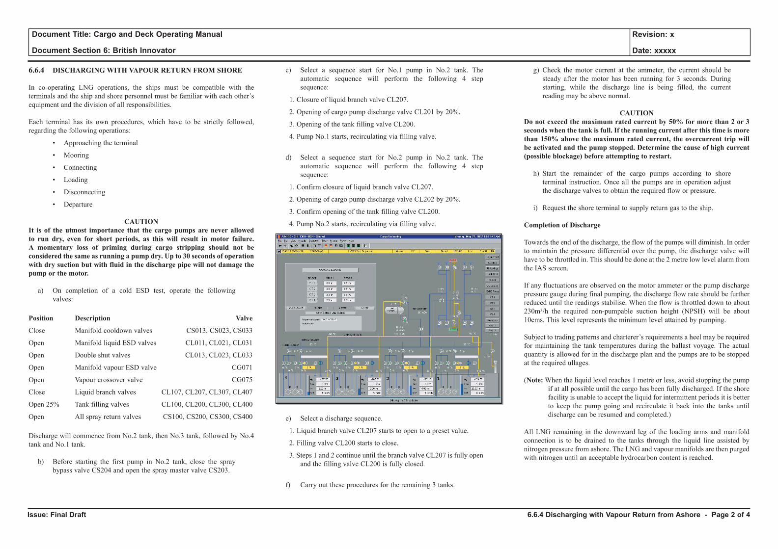
Issue: Final Draft
Document Title: Cargo and Deck Operating Manual
Document Section 6: British Innovator
Revision: x
Date: xxxxx
6.6.4 DISCHARGING WITH VAPOUR RETURN FROM SHORE
In co-operating LNG operations, the ships must be compatible with the terminals and the ship and shore personnel must be familiar with each other’s equipment and the division of all responsibilities.
Each terminal has its own procedures, which have to be strictly followed, regarding the following operations:
• Approaching the terminal
• Mooring
• Connecting
• Loading
• Disconnecting
• Departure
CAUTION It is of the utmost importance that the cargo pumps are never allowed to run dry, even for short periods, as this will result in motor failure. A momentary loss of priming during cargo stripping should not be considered the same as running a pump dry. Up to 30 seconds of operation with dry suction but with fluid in the discharge pipe will not damage the pump or the motor.
a) On completion of a cold ESD test, operate the following valves:
Position Description Valve
Close Manifold cooldown valves CS013, CS023, CS033
Open Manifold liquid ESD valves CL011, CL021, CL031
Open Double shut valves CL013, CL023, CL033
Open Manifold vapour ESD valve CG071
Open Vapour crossover valve CG075
Close Liquid branch valves CL107, CL207, CL307, CL407
Open 25% Tank filling valves CL100, CL200, CL300, CL400
Open All spray return valves CS100, CS200, CS300, CS400
Discharge will commence from No.2 tank, then No.3 tank, followed by No.4 tank and No.1 tank.
b) Before starting the first pump in No.2 tank, close the spray bypass valve CS204 and open the spray master valve CS203.
c) Select a sequence start for No.1 pump in No.2 tank. The automatic sequence will perform the following 4 step sequence:
1. Closure of liquid branch valve CL207.
2. Opening of cargo pump discharge valve CL201 by 20%.
3. Opening of the tank filling valve CL200.
4. Pump No.1 starts, recirculating via filling valve.
d) Select a sequence start for No.2 pump in No.2 tank. The automatic sequence will perform the following 4 step sequence:
1. Confirm closure of liquid branch valve CL207.
2. Opening of cargo pump discharge valve CL202 by 20%.
3. Confirm opening of the tank filling valve CL200.
4. Pump No.2 starts, recirculating via filling valve.
e) Select a discharge sequence.
1. Liquid branch valve CL207 starts to open to a preset value.
2. Filling valve CL200 starts to close.
3. Steps 1 and 2 continue until the branch valve CL207 is fully open and the filling valve CL200 is fully closed.
f) Carry out these procedures for the remaining 3 tanks.
g) Check the motor current at the ammeter, the current should be steady after the motor has been running for 3 seconds. During starting, while the discharge line is being filled, the current reading may be above normal.
CAUTIONDo not exceed the maximum rated current by 50% for more than 2 or 3 seconds when the tank is full. If the running current after this time is more than 150% above the maximum rated current, the overcurrent trip will be activated and the pump stopped. Determine the cause of high current (possible blockage) before attempting to restart.
h) Start the remainder of the cargo pumps according to shore terminal instruction. Once all the pumps are in operation adjust the discharge valves to obtain the required flow or pressure.
i) Request the shore terminal to supply return gas to the ship.
Completion of Discharge
Towards the end of the discharge, the flow of the pumps will diminish. In order to maintain the pressure differential over the pump, the discharge valve will have to be throttled in. This should be done at the 2 metre low level alarm from the IAS screen.
If any fluctuations are observed on the motor ammeter or the pump discharge pressure gauge during final pumping, the discharge flow rate should be further reduced until the readings stabilise. When the flow is throttled down to about 230m3/h the required non-pumpable suction height (NPSH) will be about 10cms. This level represents the minimum level attained by pumping.
Subject to trading patterns and charterer’s requirements a heel may be required for maintaining the tank temperatures during the ballast voyage. The actual quantity is allowed for in the discharge plan and the pumps are to be stopped at the required ullages.
(Note: When the liquid level reaches 1 metre or less, avoid stopping the pump if at all possible until the cargo has been fully discharged. If the shore facility is unable to accept the liquid for intermittent periods it is better to keep the pump going and recirculate it back into the tanks until discharge can be resumed and completed.)
All LNG remaining in the downward leg of the loading arms and manifold connection is to be drained to the tanks through the liquid line assisted by nitrogen pressure from ashore. The LNG and vapour manifolds are then purged with nitrogen until an acceptable hydrocarbon content is reached.
6.6.4 Discharging with Vapour Return from Ashore - Page 2 of 4
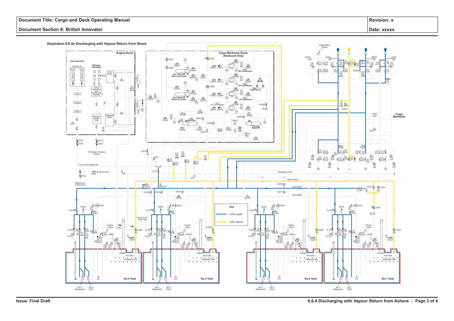
Issue: Final Draft
Document Title: Cargo and Deck Operating Manual
Document Section 6: British Innovator
Revision: x
Date: xxxxx
LNG Liquid
Key
LNG Vapour
H H
H
H
F
C C S
H
HH H
H
H
C C S
H
HH H
H
H
C C S
H
HH H
H
H
C C S
H
H
F
PI PI
F
PI PI
PI
PI
PI
PI
PI PI
PI PI
F
F
PI
PI
PI
PI
F
F
F
CL106
CL102
CL101
CL100
CS102
CS100
CS103
CS101
CS108
CS107
CR101
CR100
CL105
CL104
CL700
CG700
CG702
CG101
CS105
CS104
CR103 CR102
CG701
CL103
Port Side
Starboard Side
CL107
No.1(Starboard)
No.1(Port)
CL206
CL202
CL201
CL200
CS202
CS200
CS203
CR701
CR700
CS201
CS208
CS207
CR201
CR200
CL205
CL204
CG201
CG200 CG100
CS205
CS204
CR203 CR202
CL203
Port Side
Ambient Air
Blower
PortBoiler
VentHoodRoom
StarboardBoiler
Inert Gas Plant
NitrogenGenerator
Engine Room
No.3 TankNo.4 Tank No.1 TankNo.2 Tank
Cargo Machinery Room(Starboard Only)
Starboard Side
CL207
CS700
No.2(Starboard)
No.2(Port)
CL306
CL302
CL301
CL300
CS302
CS300
CS303
CS701
CS301
CS308
CS307
CR301
CR300
CL305
CL304
CG301
CS305
CS304
CR303 CR302
CL303
Port Side
Starboard Side
CL307
CG927
CG926CG923
CG921
CG917CG919
CG924
CG930
CG929
CG904
CR901
CR905
CR903
CR904
CS909
CS907
CS905
CS908 CS903
CS901
CS902
CS906
CS910
CS911
CR902
CG922
CG918
CG928
CG902
CG906
CG905
CG908
CG907
CR041
CR043
CL041
CL043
CS041
CS043
CL031
CS031 CS
011
CL011 CR
013
CG071 CG
073
CS021
CL021
CL023CS
025
CS023 CL013
CL015
CS013
CR023
CR033
CR021CR031 CR011
CS035
CL033
CS033
CG915
CG900
CG925
CG911
CG916 CG912
CG913 CG909
CG914 CG910
CG901
CG904
CG903
CG920
No.3(Starboard)
No.3(Port)
CL406
CL402
CL401
CL400
CS402
CS400
CS403
CS702 CR704 CR702
CR703
CG708
CG707
CG706
CG705
CG704 CG
703
CS703
CL701
CS401
CS408
CS407
CR401
CR400
CL405
CL404
CG401
CG400
CG300CS405
From Comp.Shaft Seal
CS404
CR403
GI705
GI706
GI703
GI702
GI701
BA530
CN514
CN515
CR402
CL403
Port Side
Starboard Side
CL407
No.4(Starboard)
No.4(Port)
CL044
CS044
CS042
CS034
CS024
CL024
CS034
CR044
CR034
CR024
CR042
CR032
CR022
CS036 CS026
CL042
CL034CL
202
CL032
CG072
CS022 CL
022
CS014
CR701
CS071
CL014
CR014
CR012
CS012
F
F
F
Cooler
Dryer
I.G.G
Valve/Instrument
andMembraneModule
NitrogenBufferTank
To Nitrogen PressureSystem
Hinged BlindFlange
Ballast Linein Pipe Duct
Duct Keel
From Inert Gas/Dry Air
Emergency Vent
Vapour Main
Liquid Main
Spray Main
No.1 Boil OffWarm Up Heater
No.2 Boil OffWarm Up Heater
ForcingVaporiser
MistSeparator
No.1HD Compressor
No.2HD Compressor
No.1L D Compressor
LNGVaporiser
No.2LD Compressor
Illustration 6.6.4a Discharging with Vapour Return from Shore
CargoManifolds
CG075
CN441
6.6.4 Discharging with Vapour Return from Ashore - Page 3 of 4
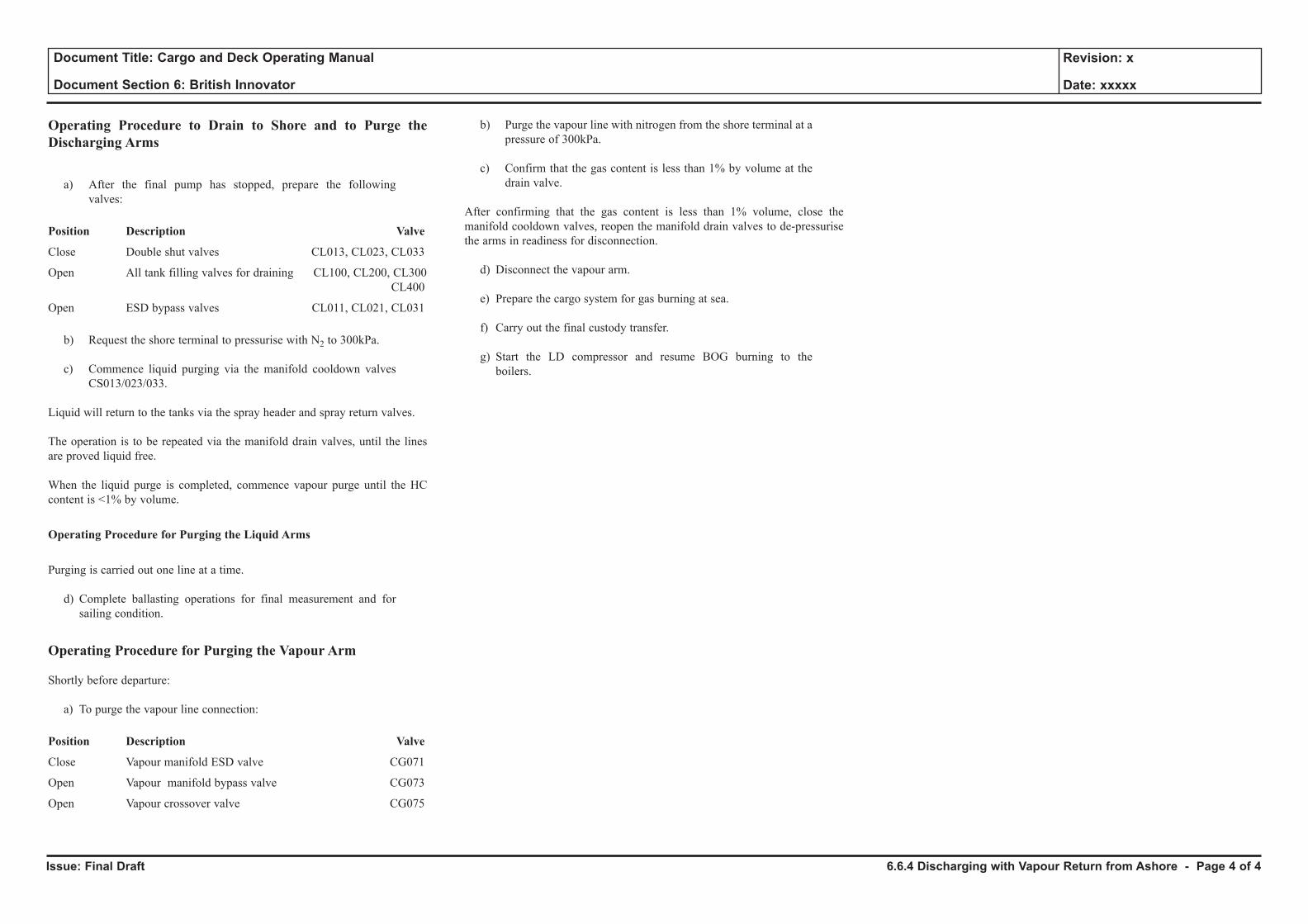
Issue: Final Draft
Document Title: Cargo and Deck Operating Manual
Document Section 6: British Innovator
Revision: x
Date: xxxxx
Operating Procedure to Drain to Shore and to Purge the Discharging Arms
a) After the final pump has stopped, prepare the following valves:
Position Description Valve
Close Double shut valves CL013, CL023, CL033
Open All tank filling valves for draining CL100, CL200, CL300 CL400
Open ESD bypass valves CL011, CL021, CL031
b) Request the shore terminal to pressurise with N2 to 300kPa.
c) Commence liquid purging via the manifold cooldown valves CS013/023/033.
Liquid will return to the tanks via the spray header and spray return valves.
The operation is to be repeated via the manifold drain valves, until the lines are proved liquid free.
When the liquid purge is completed, commence vapour purge until the HC content is <1% by volume.
Operating Procedure for Purging the Liquid Arms
Purging is carried out one line at a time.
d) Complete ballasting operations for final measurement and for sailing condition.
Operating Procedure for Purging the Vapour Arm
Shortly before departure:
a) To purge the vapour line connection:
Position Description Valve
Close Vapour manifold ESD valve CG071
Open Vapour manifold bypass valve CG073
Open Vapour crossover valve CG075
b) Purge the vapour line with nitrogen from the shore terminal at a pressure of 300kPa.
c) Confirm that the gas content is less than 1% by volume at the drain valve.
After confirming that the gas content is less than 1% volume, close the manifold cooldown valves, reopen the manifold drain valves to de-pressurise the arms in readiness for disconnection.
d) Disconnect the vapour arm.
e) Prepare the cargo system for gas burning at sea.
f) Carry out the final custody transfer.
g) Start the LD compressor and resume BOG burning to the boilers.
6.6.4 Discharging with Vapour Return from Ashore - Page 4 of 4
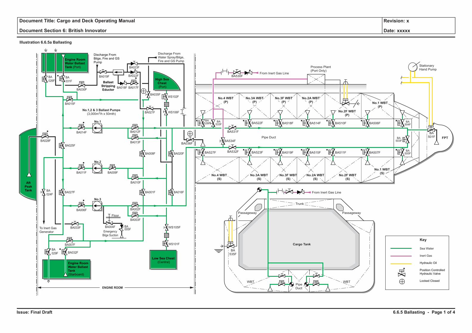
Issue: Final Draft
Document Title: Cargo and Deck Operating Manual
Document Section 6: British Innovator
Revision: x
Date: xxxxx
Illustration 6.6.5a Ballasting
No.1,2 & 3 Ballast Pumps
(3,000m3/h x 50mth)
BA028F
BA027FBA
024F
BA014F
BA011F BA009F
BA006F
BA033F
BA007F
BA025F
No.1
No.2
No.3
Emergency
Bilge Suction
BA004F BA005F
Floor
WBT WBT
Cargo Tank
Sea Water
Inert Gas
Hydraulic Oil
Position Controlled
Hydraulic Valve
Locked Closed
Key
From Inert Gas Line
From Inert Gas Line
Stationary
Hand PumpProcess Plant
(Port Only)
No.4 WBT
(P)
No.4 WBT
(S)
No.3A WBT
(P)
No.3A WBT
(S)
No.2A WBT
(P)
No.2A WBT
(S)
No.3F WBT
(P)
No.3F WBT
(S)
No.2F WBT
(P)
No.2F WBT
(S)
No.1 WBT
(P)
No.1 WBT
(S)
FPT
BA
501F
BA506F
BA507F
BA510F
BA511F
BA514F
BA515F
BA518F
BA519FBA523F
BA531F
BA532F
BA534FBA036F
BA533F
BA526F
BA527F
BA
535F
BA522F
BA530F
BA504F
BA503F
BA505F
Trunk
Pipe
Duct
Pipe Duct
To Inert Gas
Generator
Discharge From
Water Spray/Bilge,
Fire and GS Pump
Discharge From
Bilge, Fire and GS
Pump
Engine Room
Water Ballast
Tank
(Starboard)
Engine Room
Water Ballast
Tank (Port)
Ballast
Stripping
Eductor
BA
026F
BA018F
BA035F
BA021F
BA008F
BA010F
BA001F
BA002F
BA003F
BA012F
BA013F
BA020F
BA016F
BA017F
BA022F
BA023F
BA019F
BA
029F BA032F
WS101F
WS105F
WS106F
WS102F
Low Sea Chest
(Central)
BA030F
BA015F
ENGINE ROOM
Aft
Peak
Tank
High Sea
Chest
(Port)
BA
031F
Passageway Passageway
6.6.5 Ballasting - Page 1 of 4
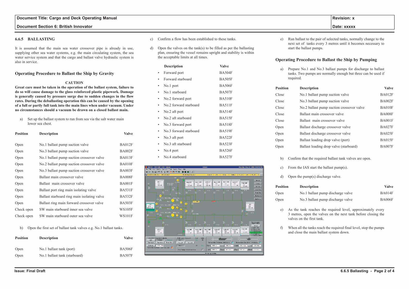
Issue: Final Draft
Document Title: Cargo and Deck Operating Manual
Document Section 6: British Innovator
Revision: x
Date: xxxxx
6.6.5 BALLASTING
It is assumed that the main sea water crossover pipe is already in use, supplying other sea water systems, e.g. the main circulating system, the sea water service system and that the cargo and ballast valve hydraulic system is also in service.
Operating Procedure to Ballast the Ship by Gravity
CAUTIONGreat care must be taken in the operation of the ballast system, failure to do so will cause damage to the glass reinforced plastic pipework. Damage is generally caused by pressure surge due to sudden changes in the flow rates. During the deballasting operation this can be caused by the opening of a full or partly full tank into the main lines when under vacuum. Under no circumstances should a vacuum be drawn on a closed ballast main.
a) Set up the ballast system to run from sea via the salt water main lower sea chest.
Position Description Valve
Open No.1 ballast pump suction valve BA012F
Open No.3 ballast pump suction valve BA002F
Open No.1 ballast pump suction crossover valve BA013F
Open No.2 ballast pump suction crossover valve BA010F
Open No.3 ballast pump suction crossover valve BA003F
Open Ballast main crossover valve BA008F
Open Ballast main crossover valve BA001F
Open Ballast port ring main isolating valve BA531F
Open Ballast starboard ring main isolating valve BA532F
Open Ballast ring main forward crossover valve BA503F
Check open SW main starboard inner sea valve WS105F
Check open SW main starboard outer sea valve WS101F
b) Open the first set of ballast tank valves e.g. No.1 ballast tanks.
Position Description Valve
Open No.1 ballast tank (port) BA506F
Open No.1 ballast tank (starboard) BA507F
c) Confirm a flow has been established to these tanks.
d) Open the valves on the tank(s) to be filled as per the ballasting plan, ensuring the vessel remains upright and stability is within the acceptable limits at all times.
Description Valve
• Forward port BA504F
• Forward starboard BA505F
• No.1 port BA506F
• No.1 starboard BA507F
• No.2 forward port BA510F
• No.2 forward starboard BA511F
• No.2 aft port BA514F
• No.2 aft starboard BA515F
• No.3 forward port BA518F
• No.3 forward starboard BA519F
• No.3 aft port BA522F
• No.3 aft starboard BA523F
• No.4 port BA526F
• No.4 starboard BA527F
e) Run ballast to the pair of selected tanks, normally change to the next set of tanks every 3 metres until it becomes necessary to start the ballast pumps.
Operating Procedure to Ballast the Ship by Pumping
a) Prepare No.1 and No.3 ballast pumps for discharge to ballast tanks. Two pumps are normally enough but three can be used if required.
Position Description Valve
Close No.1 ballast pump suction valve BA012F
Close No.3 ballast pump suction valve BA002F
Close No.2 ballast pump suction crossover valve BA010F
Close Ballast main crossover valve BA008F
Close Ballast main crossover valve BA001F
Open Ballast discharge crossover valve BA027F
Open Ballast discharge crossover valve BA025F
Open Ballast loading drop valve (port) BA015F
Open Ballast loading drop valve (starboard) BA007F
b) Confirm that the required ballast tank valves are open.
c) From the IAS start the ballast pump(s).
d) Open the pump(s) discharge valve.
Position Description Valve
Open No.1 ballast pump discharge valve BA014F
Open No.3 ballast pump discharge valve BA006F
e) As the tank reaches the required level, approximately every 3 metres, open the valves on the next tank before closing the valves on the first tank.
f) When all the tanks reach the required final level, stop the pumps and close the main ballast system down.
6.6.5 Ballasting - Page 2 of 4
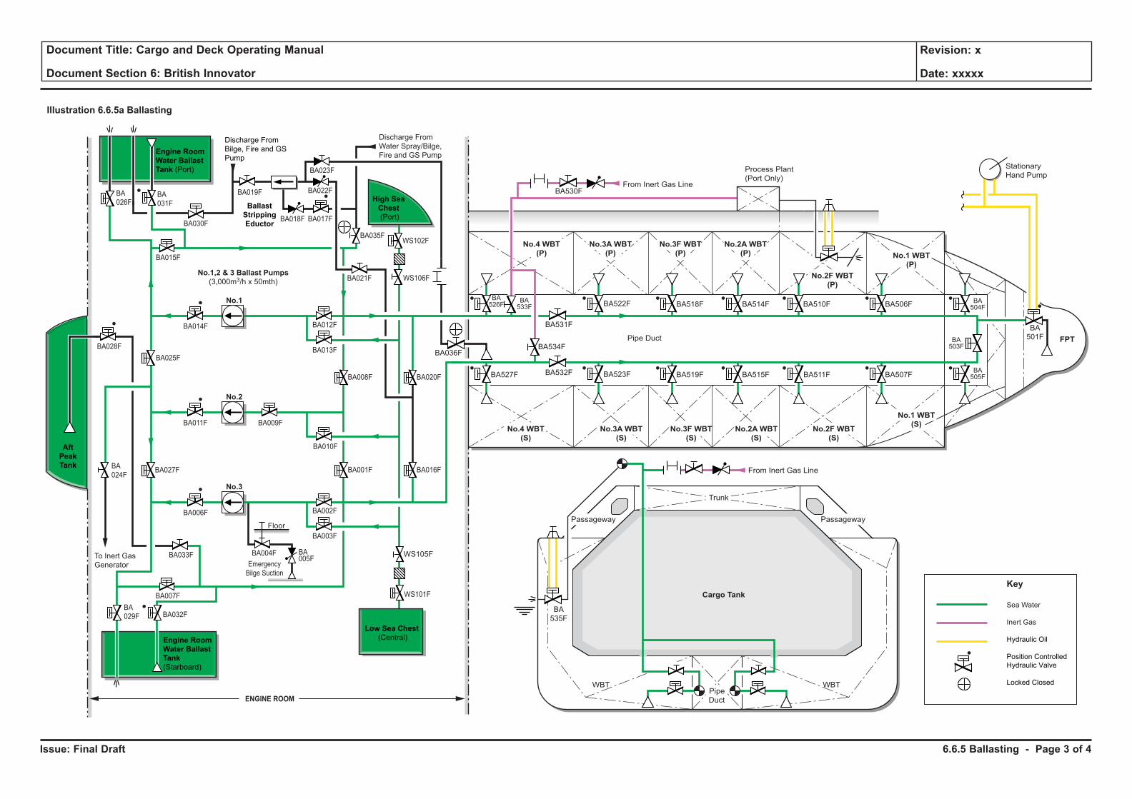
Issue: Final Draft
Document Title: Cargo and Deck Operating Manual
Document Section 6: British Innovator
Revision: x
Date: xxxxx
Illustration 6.6.5a Ballasting
No.1,2 & 3 Ballast Pumps
(3,000m3/h x 50mth)
BA028F
BA027FBA
024F
BA014F
BA011F BA009F
BA006F
BA033F
BA007F
BA025F
No.1
No.2
No.3
Emergency
Bilge Suction
BA004F BA005F
Floor
WBT WBT
Cargo Tank
Sea Water
Inert Gas
Hydraulic Oil
Position Controlled
Hydraulic Valve
Locked Closed
Key
From Inert Gas Line
From Inert Gas Line
Stationary
Hand PumpProcess Plant
(Port Only)
No.4 WBT
(P)
No.4 WBT
(S)
No.3A WBT
(P)
No.3A WBT
(S)
No.2A WBT
(P)
No.2A WBT
(S)
No.3F WBT
(P)
No.3F WBT
(S)
No.2F WBT
(P)
No.2F WBT
(S)
No.1 WBT
(P)
No.1 WBT
(S)
FPT
BA
501F
BA506F
BA507F
BA510F
BA511F
BA514F
BA515F
BA518F
BA519FBA523F
BA531F
BA532F
BA534FBA036F
BA533F
BA526F
BA527F
BA
535F
BA522F
BA530F
BA504F
BA503F
BA505F
Trunk
Pipe
Duct
Pipe Duct
To Inert Gas
Generator
Discharge From
Water Spray/Bilge,
Fire and GS Pump
Discharge From
Bilge, Fire and GS
Pump
Engine Room
Water Ballast
Tank
(Starboard)
Engine Room
Water Ballast
Tank (Port)
Ballast
Stripping
Eductor
BA
026F
BA018F
BA035F
BA021F
BA008F
BA010F
BA001F
BA002F
BA003F
BA012F
BA013F
BA020F
BA016F
BA017F
BA022F
BA023F
BA019F
BA
029F BA032F
WS101F
WS105F
WS106F
WS102F
Low Sea Chest
(Central)
BA030F
BA015F
ENGINE ROOM
Aft
Peak
Tank
High Sea
Chest
(Port)
BA
031F
Passageway Passageway
6.6.5 Ballasting - Page 3 of 4
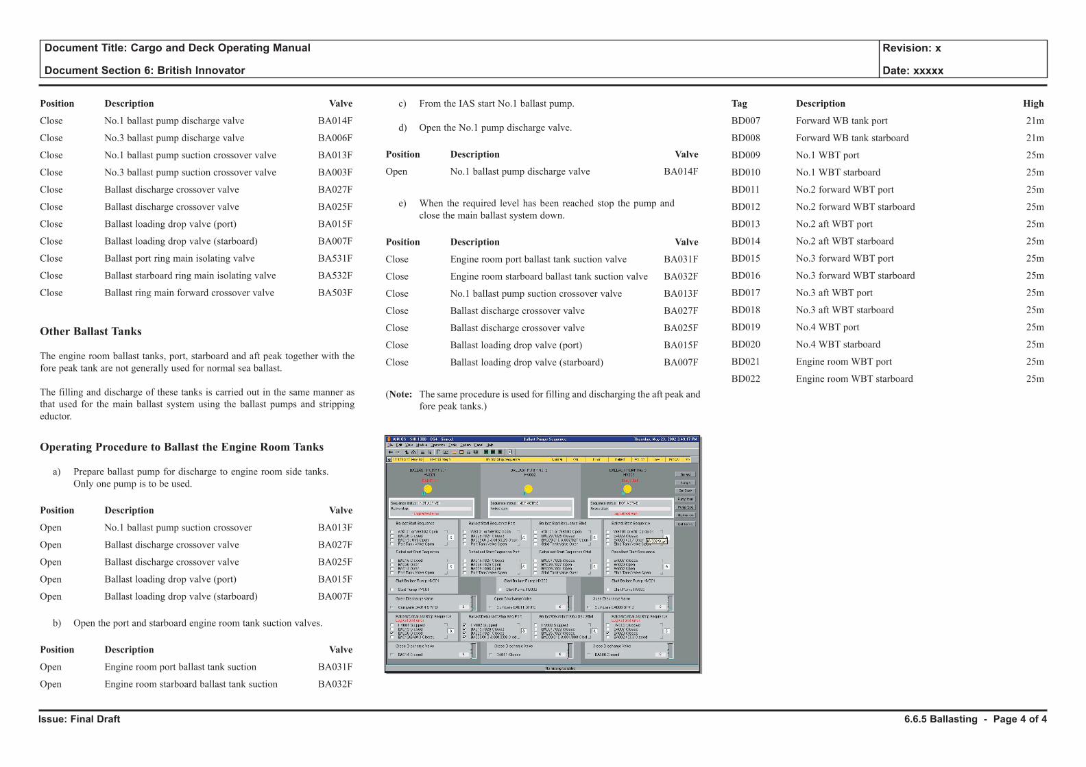
Issue: Final Draft
Document Title: Cargo and Deck Operating Manual
Document Section 6: British Innovator
Revision: x
Date: xxxxx
Position Description Valve
Close No.1 ballast pump discharge valve BA014F
Close No.3 ballast pump discharge valve BA006F
Close No.1 ballast pump suction crossover valve BA013F
Close No.3 ballast pump suction crossover valve BA003F
Close Ballast discharge crossover valve BA027F
Close Ballast discharge crossover valve BA025F
Close Ballast loading drop valve (port) BA015F
Close Ballast loading drop valve (starboard) BA007F
Close Ballast port ring main isolating valve BA531F
Close Ballast starboard ring main isolating valve BA532F
Close Ballast ring main forward crossover valve BA503F
Other Ballast Tanks
The engine room ballast tanks, port, starboard and aft peak together with the fore peak tank are not generally used for normal sea ballast.
The filling and discharge of these tanks is carried out in the same manner as that used for the main ballast system using the ballast pumps and stripping eductor.
Operating Procedure to Ballast the Engine Room Tanks
a) Prepare ballast pump for discharge to engine room side tanks. Only one pump is to be used.
Position Description Valve
Open No.1 ballast pump suction crossover BA013F
Open Ballast discharge crossover valve BA027F
Open Ballast discharge crossover valve BA025F
Open Ballast loading drop valve (port) BA015F
Open Ballast loading drop valve (starboard) BA007F
b) Open the port and starboard engine room tank suction valves.
Position Description Valve
Open Engine room port ballast tank suction BA031F
Open Engine room starboard ballast tank suction BA032F
c) From the IAS start No.1 ballast pump.
d) Open the No.1 pump discharge valve.
Position Description Valve
Open No.1 ballast pump discharge valve BA014F
e) When the required level has been reached stop the pump and close the main ballast system down.
Position Description Valve
Close Engine room port ballast tank suction valve BA031F
Close Engine room starboard ballast tank suction valve BA032F
Close No.1 ballast pump suction crossover valve BA013F
Close Ballast discharge crossover valve BA027F
Close Ballast discharge crossover valve BA025F
Close Ballast loading drop valve (port) BA015F
Close Ballast loading drop valve (starboard) BA007F
(Note: The same procedure is used for filling and discharging the aft peak and fore peak tanks.)
Tag Description High
BD007 Forward WB tank port 21m
BD008 Forward WB tank starboard 21m
BD009 No.1 WBT port 25m
BD010 No.1 WBT starboard 25m
BD011 No.2 forward WBT port 25m
BD012 No.2 forward WBT starboard 25m
BD013 No.2 aft WBT port 25m
BD014 No.2 aft WBT starboard 25m
BD015 No.3 forward WBT port 25m
BD016 No.3 forward WBT starboard 25m
BD017 No.3 aft WBT port 25m
BD018 No.3 aft WBT starboard 25m
BD019 No.4 WBT port 25m
BD020 No.4 WBT starboard 25m
BD021 Engine room WBT port 25m
BD022 Engine room WBT starboard 25m
6.6.5 Ballasting - Page 4 of 4
6.7 Pre Dry Dock Operations
6.7.1 Stripping and Line Draining
6.7.2 Tank Warm Up
6.7.3 Inerting
6.7.4 Aerating
Illustrations
6.7.1a Stripping and Line Draining
6.7.1b Stripping to No.4 Cargo Tank
6.7.2a Tank Warm Up (Stage 1)
6.7.2b Tank Warm Up (Stage 2)
6.7.3a Inerting Cargo Tanks
6.7.3b Inerting Liquid Line
6.7.3c Inerting Spray Line
6.7.3d Inerting Manifolds and Machinery Space
6.7.4a Aeration of Cargo Tanks
6.7.4b Aeration of Spray Line
6.7.4c Aeration of Manifolds and Machinery Space
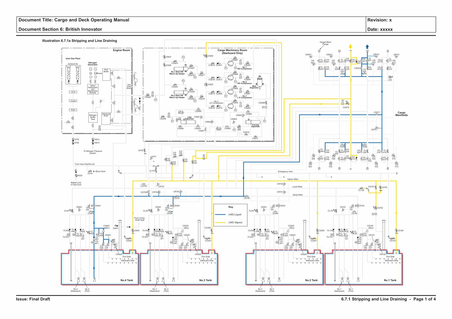
Issue: Final Draft
Document Title: Cargo and Deck Operating Manual
Document Section 6: British Innovator
Revision: x
Date: xxxxx
LNG Liquid
Key
LNG Vapour
H H
H
H
F
C C S
H
HH H
H
H
C C S
H
HH H
H
H
C C S
H
HH H
H
H
C C S
H
H
F
PI PI
F
PI PI
PI
PI
PI
PI
PI PI
PI PI
F
F
PI
PI
PI
PI
F
F
F
CL106
CL102
CL101
CL100
CS102
CS100
CS103
CS101
CS108
CS107
CR101
CR100
CL105
CL104
CL700
CG700
CG702
CG101
CS105
CS104
CR103 CR102
CG701
CL103
Port Side
Starboard Side
CL107
No.1(Starboard)
No.1(Port)
CL206
CL202
CL201
CL200
CS202
CS200
CS203
CR701
CR700
CS201
CS208
CS207
CR201
CR200
CL205
CL204
CG201
CG200 CG100
CS205
CS204
CR203 CR202
CL203
Port Side
Ambient Air
Blower
PortBoiler
VentHoodRoom
StarboardBoiler
Inert Gas Plant
NitrogenGenerator
Engine Room
No.3 TankNo.4 Tank No.1 TankNo.2 Tank
Cargo Machinery Room(Starboard Only)
Starboard Side
CL207
CS700
No.2(Starboard)
No.2(Port)
CL306
CL302
CL301
CL300
CS302
CS300
CS303
CS701
CS301
CS308
CS307
CR301
CR300
CL305
CL304
CG301
CS305
CS304
CR303 CR302
CL303
Port Side
Starboard Side
CL307
CG927
CG926CG923
CG921
CG917CG919
CG924
CG930
CG929
CG904
CR901
CR905
CR903
CR904
CS909
CS907
CS905
CS908 CS903
CS901
CS902
CS906
CS910
CS911
CR902
CG922
CG918
CG928
CG902
CG906
CG905
CG908
CG907
CR041
CR043
CL041
CL043
CS041
CS043
CL031
CS031 CS
011
CL011 CR
013
CG071 CG
073
CS021
CL021
CL023CS
025
CS023 CL013
CL015
CS013
CR023
CR033
CR021CR031 CR011
CS035
CL033
CS033
CG915
CG900
CG925
CG911
CG916 CG912
CG913 CG909
CG914 CG910
CG901
CG904
CG903
CG920
No.3(Starboard)
No.3(Port)
CL406
CL402
CL401
CL400
CS402
CS400
CS403
CS702 CR704 CR702
CR703
CG708
CG707
CG706
CG705
CG704 CG
703
CS703
CL701
CS401
CS408
CS407
CR401
CR400
CL405
CL404
CG401
CG400
CG300CS405
From Comp.Shaft Seal
CS404
CR403
GI705
GI706
GI703
GI702
GI701
BA530
CN514
CN515
CR402
CL403
Port Side
Starboard Side
CL407
No.4(Starboard)
No.4(Port)
CL044
CS044
CS042
CS034
CS024
CL024
CS034
CR044
CR034
CR024
CR042
CR032
CR022
CS036 CS026
CL042
CL034CL
202
CL042
CG072
CS022 CL
022
CS014
CR701
CS071
CL014
CR014
CR012
CS012
F
F
F
Cooler
Dryer
I.G.G
Valve/Instrument
andMembraneModule
NitrogenBufferTank
To Nitrogen PressureSystem
Hinged BlindFlange
Ballast Linein Pipe Duct
Duct Keel
From Inert Gas/Dry Air
Emergency Vent
Vapour Main
Liquid Main
Spray Main
No.1 Boil OffWarm Up Heater
No.2 Boil OffWarm Up Heater
ForcingVaporiser
MistSeparator
No.1HD Compressor
No.2HD Compressor
No.1L D Compressor
LNGVaporiser
No.2LD Compressor
Illustration 6.7.1a Stripping and Line Draining
CargoManifolds
CG075
CN441
6.7.1 Stripping and Line Draining - Page 1 of 4
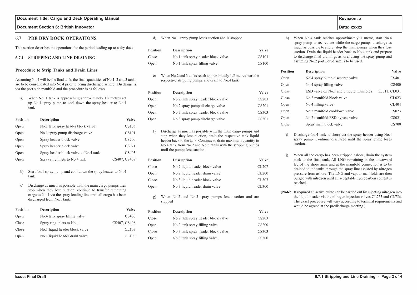
Issue: Final Draft
Document Title: Cargo and Deck Operating Manual
Document Section 6: British Innovator
Revision: x
Date: xxxxx
6.7 PRE DRY DOCK OPERATIONS
This section describes the operations for the period leading up to a dry dock.
6.7.1 STRIPPING AND LINE DRAINING
Procedure to Strip Tanks and Drain Lines
Assuming No.4 will be the final tank, the final quantities of No.1, 2 and 3 tanks are to be consolidated into No.4 prior to being discharged ashore. Discharge is via the port side manifold and the procedure is as follows.
a) When No. 1 tank is approaching approximately 1.5 metres set up No.1 spray pump to cool down the spray header to No.4 tank
Position Description Valve
Open No.1 tank spray header block valve CS103
Open No.1 spray pump discharge valve CS101
Open Spray header block valve CS700
Open Spray header block valve CS071
Open Spray header block valve to No.4 tank CS403
Open Spray ring inlets to No.4 tank CS407, CS408
b) Start No.1 spray pump and cool down the spray header to No.4 tank
c) Discharge as much as possible with the main cargo pumps then stop when they lose suction, continue to transfer remaining cargo to No.4 via the spray loading line until all cargo has been discharged from No.1 tank.
Position Description Valve
Open No.4 tank spray filling valve CS400
Close Spray ring inlets to No.4 CS407, CS408
Close No.1 liquid header block valve CL107
Open No.1 liquid header drain valve CL100
d) When No.1 spray pump loses suction and is stopped
Position Description Valve
Close No.1 tank spray header block valve CS103
Open No.1 tank spray filling valve CS100
e) When No.2 and 3 tanks reach approximately 1.5 metres start the respective stripping pumps and drain to No.4 tank.
Position Description Valve
Open No.2 tank spray header block valve CS203
Open No.2 spray pump discharge valve CS201
Open No.3 tank spray header block valve CS303
Open No.3 spray pump discharge valve CS301
f) Discharge as much as possible with the main cargo pumps and stop when they lose suction, drain the respective tank liquid header back to the tank. Continue to drain maximum quantity to No.4 tank from No.2 and No.3 tanks with the stripping pumps until the pumps lose suction.
Position Description Valve
Close No.2 liquid header block valve CL207
Open No.2 liquid header drain valve CL200
Close No.3 liquid header block valve CL307
Open No.3 liquid header drain valve CL300
g) When No.2 and No.3 spray pumps lose suction and are stopped
Position Description Valve
Close No.2 tank spray header block valve CS203
Open No.2 tank spray filling valve CS200
Close No.3 tank spray header block valve CS303
Open No.3 tank spray filling valve CS300
h) When No.4 tank reaches approximately 1 metre, start No.4 spray pump to recirculate while the cargo pumps discharge as much as possible to shore, stop the main pumps when they lose suction. Drain the liquid header back to No.4 tank and prepare to discharge final drainings ashore, using the spray pump and assuming No.2 port liquid arm is to be used.
Position Description Valve
Open No.4 spray pump discharge valve CS401
Open No.4 spray filling valve CS400
Close ESD valve on No.1 and 3 liquid manifolds CL011, CL031
Close No.2 manifold block valve CL023
Open No.4 filling valve CL404
Open No.2 manifold cooldown valve CS023
Open No.2 manifold ESD bypass valve CS021
Close Spray main block valve CS700
i) Discharge No.4 tank to shore via the spray header using No.4 spray pump. Continue discharge until the spray pump loses suction.
j) When all the cargo has been stripped ashore, drain the system back to the final tank. All LNG remaining in the downward leg of the shore arms and at the manifold connection is to be drained to the tanks through the spray line assisted by nitrogen pressure from ashore. The LNG and vapour manifolds are then purged with nitrogen until an acceptable hydrocarbon content is reached.
(Note: If required an active purge can be carried out by injecting nitrogen into the liquid header via the nitrogen injection valves CL755 and CL756. The exact procedure will vary according to terminal requirements and would be agreed at the predischarge meeting.)
6.7.1 Stripping and Line Draining - Page 2 of 4
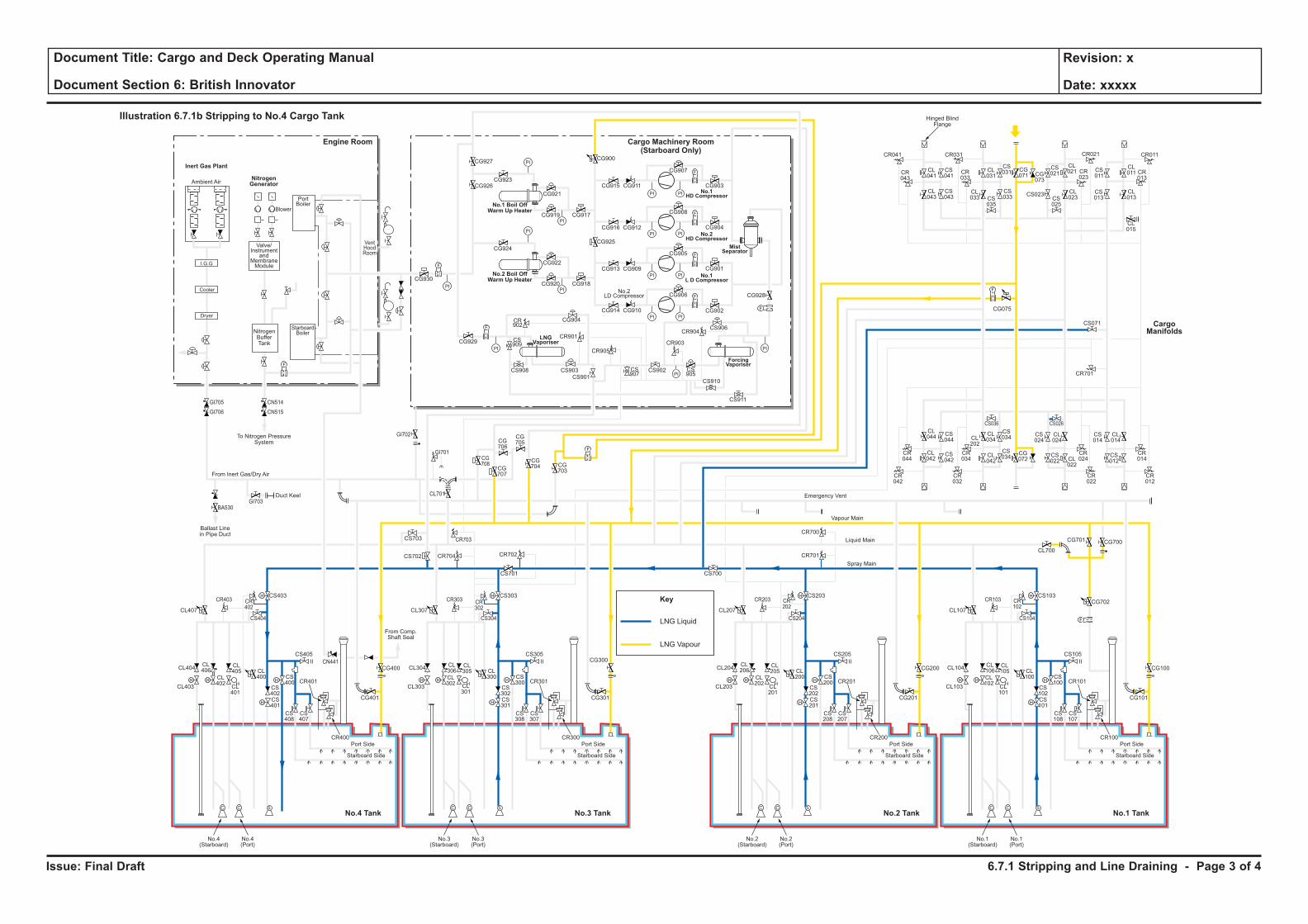
Issue: Final Draft
Document Title: Cargo and Deck Operating Manual
Document Section 6: British Innovator
Revision: x
Date: xxxxx
LNG Liquid
Key
LNG Vapour
H H
H
H
F
C C S
H
HH H
H
H
C C S
H
HH H
H
H
C C S
H
HH H
H
H
C C S
H
H
F
PI PI
F
PI PI
PI
PI
PI
PI
PI PI
PI PI
F
F
PI
PI
PI
PI
F
F
F
CL106
CL102
CL101
CL100
CS102
CS100
CS103
CS101
CS108
CS107
CR101
CR100
CL105
CL104
CL700
CG700
CG702
CG101
CS105
CS104
CR103 CR102
CG701
CL103
Port Side
Starboard Side
CL107
No.1(Starboard)
No.1(Port)
CL206
CL202
CL201
CL200
CS202
CS200
CS203
CR701
CR700
CS201
CS208
CS207
CR201
CR200
CL205
CL204
CG201
CG200 CG100
CS205
CS204
CR203 CR202
CL203
Port Side
Ambient Air
Blower
PortBoiler
VentHoodRoom
StarboardBoiler
Inert Gas Plant
NitrogenGenerator
Engine Room
No.3 TankNo.4 Tank No.1 TankNo.2 Tank
Cargo Machinery Room(Starboard Only)
Starboard Side
CL207
CS700
No.2(Starboard)
No.2(Port)
CL306
CL302
CL301
CL300
CS302
CS300
CS303
CS701
CS301
CS308
CS307
CR301
CR300
CL305
CL304
CG301
CS305
CS304
CR303 CR302
CL303
Port Side
Starboard Side
CL307
CG927
CG926CG923
CG921
CG917CG919
CG924
CG930
CG929
CG904
CR901
CR905
CR903
CR904
CS909
CS907
CS905
CS908 CS903
CS901
CS902
CS906
CS910
CS911
CR902
CG922
CG918
CG928
CG902
CG906
CG905
CG908
CG907
CR041
CR043
CL041
CL043
CS041
CS043
CL031
CS031 CS
011
CL011 CR
013
CG071 CG
073
CS021
CL021
CL023CS
025
CS023 CL013
CL015
CS013
CR023
CR033
CR021CR031 CR011
CS035
CL033
CS033
CG915
CG900
CG925
CG911
CG916 CG912
CG913 CG909
CG914 CG910
CG901
CG904
CG903
CG920
No.3(Starboard)
No.3(Port)
CL406
CL402
CL401
CL400
CS402
CS400
CS403
CS702 CR704 CR702
CR703
CG708
CG707
CG706
CG705
CG704 CG
703
CS703
CL701
CS401
CS408
CS407
CR401
CR400
CL405
CL404
CG401
CG400
CG300CS405
From Comp.Shaft Seal
CS404
CR403
GI705
GI706
GI703
GI702
GI701
BA530
CN514
CN515
CR402
CL403
Port Side
Starboard Side
CL407
No.4(Starboard)
No.4(Port)
CL044
CS044
CS042
CS034
CS024
CL024
CS034
CR044
CR034
CR024
CR042
CR032
CR022
CS036 CS026
CL042
CL034CL
202
CL042
CG072
CS022 CL
022
CS014
CR701
CS071
CL014
CR014
CR012
CS012
F
F
F
Cooler
Dryer
I.G.G
Valve/Instrument
andMembraneModule
NitrogenBufferTank
To Nitrogen PressureSystem
Hinged BlindFlange
Ballast Linein Pipe Duct
Duct Keel
From Inert Gas/Dry Air
Emergency Vent
Vapour Main
Liquid Main
Spray Main
No.1 Boil OffWarm Up Heater
No.2 Boil OffWarm Up Heater
ForcingVaporiser
MistSeparator
No.1HD Compressor
No.2HD Compressor
No.1L D Compressor
LNGVaporiser
No.2LD Compressor
Illustration 6.7.1b Stripping to No.4 Cargo Tank
CargoManifolds
CG075
CN441
6.7.1 Stripping and Line Draining - Page 3 of 4
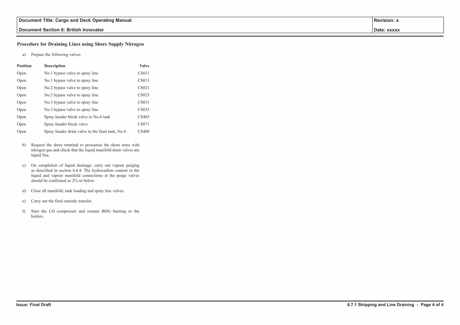
Issue: Final Draft
Document Title: Cargo and Deck Operating Manual
Document Section 6: British Innovator
Revision: x
Date: xxxxx
Procedure for Draining Lines using Shore Supply Nitrogen
a) Prepare the following valves:
Position Description Valve
Open No.1 bypass valve to spray line CS011
Open No.1 bypass valve to spray line CS013
Open No.2 bypass valve to spray line CS021
Open No.2 bypass valve to spray line CS023
Open No.3 bypass valve to spray line CS031
Open No.3 bypass valve to spray line CS033
Open Spray header block valve to No.4 tank CS403
Open Spray header block valve CS071
Open Spray header drain valve to the final tank, No.4 CS400
b) Request the shore terminal to pressurise the shore arms with nitrogen gas and check that the liquid manifold drain valves are liquid free.
c) On completion of liquid drainage, carry out vapour purging as described in section 6.6.4. The hydrocarbon content in the liquid and vapour manifold connections at the purge valves should be confirmed as 2% or below.
d) Close all manifold, tank loading and spray line valves.
e) Carry out the final custody transfer.
f) Start the LD compressor and resume BOG burning to the boilers.
6.7.1 Stripping and Line Draining - Page 4 of 4
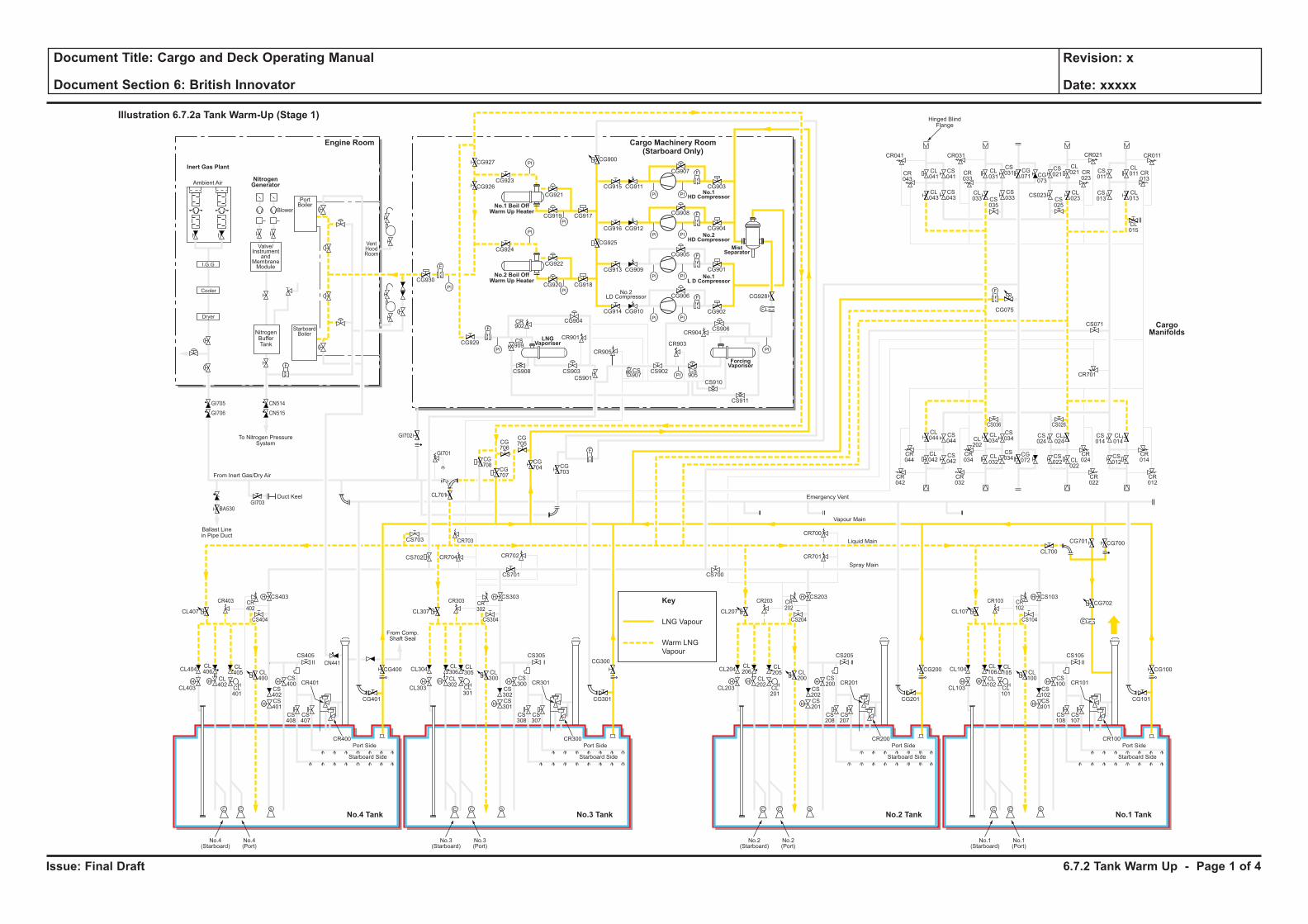
Issue: Final Draft
Document Title: Cargo and Deck Operating Manual
Document Section 6: British Innovator
Revision: x
Date: xxxxx
Key
LNG Vapour
Warm LNG
Vapour
H H
H
H
F
C C S
H
HH H
H
H
C C S
H
HH H
H
H
C C S
H
HH H
H
H
C C S
H
H
F
PI PI
F
PI PI
PI
PI
PI
PI
PI PI
PI PI
F
F
PI
PI
PI
PI
F
F
F
CL106
CL102
CL101
CL100
CS102
CS100
CS103
CS101
CS108
CS107
CR101
CR100
CL105
CL104
CL700
CG700
CG702
CG101
CS105
CS104
CR103 CR102
CG701
CL103
Port Side
Starboard Side
CL107
No.1(Starboard)
No.1(Port)
CL206
CL202
CL201
CL200
CS202
CS200
CS203
CR701
CR700
CS201
CS208
CS207
CR201
CR200
CL205
CL204
CG201
CG200 CG100
CS205
CS204
CR203 CR202
CL203
Port Side
Ambient Air
Blower
PortBoiler
VentHoodRoom
StarboardBoiler
Inert Gas Plant
NitrogenGenerator
Engine Room
No.3 TankNo.4 Tank No.1 TankNo.2 Tank
Cargo Machinery Room(Starboard Only)
Starboard Side
CL207
CS700
No.2(Starboard)
No.2(Port)
CL306
CL302
CL301
CL300
CS302
CS300
CS303
CS701
CS301
CS308
CS307
CR301
CR300
CL305
CL304
CG301
CS305
CS304
CR303 CR302
CL303
Port Side
Starboard Side
CL307
CG927
CG926CG923
CG921
CG917CG919
CG924
CG930
CG929
CG904
CR901
CR905
CR903
CR904
CS909
CS907
CS905
CS908 CS903
CS901
CS902
CS906
CS910
CS911
CR902
CG922
CG918
CG928
CG902
CG906
CG905
CG908
CG907
CR041
CR043
CL041
CL043
CS041
CS043
CL031
CS031 CS
011
CL011 CR
013
CG071 CG
073
CS021
CL021
CL023CS
025
CS023 CL013
CL015
CS013
CR023
CR033
CR021CR031 CR011
CS035
CL033
CS033
CG915
CG900
CG925
CG911
CG916 CG912
CG913 CG909
CG914 CG910
CG901
CG904
CG903
CG920
No.3(Starboard)
No.3(Port)
CL406
CL402
CL401
CL400
CS402
CS400
CS403
CS702 CR704 CR702
CR703
CG708
CG707
CG706
CG705
CG704 CG
703
CS703
CL701
CS401
CS408
CS407
CR401
CR400
CL405
CL404
CG401
CG400
CG300CS405
From Comp.Shaft Seal
CS404
CR403
GI705
GI706
GI703
GI702
GI701
BA530
CN514
CN515
CR402
CL403
Port Side
Starboard Side
CL407
No.4(Starboard)
No.4(Port)
CL044
CS044
CS042
CS034
CS024
CL024
CS034
CR044
CR034
CR024
CR042
CR032
CR022
CS036 CS026
CL042
CL034CL
202
CL032
CG072
CS022 CL
022
CS014
CR701
CS071
CL014
CR014
CR012
CS012
F
F
F
Cooler
Dryer
I.G.G
Valve/Instrument
andMembraneModule
NitrogenBufferTank
To Nitrogen PressureSystem
Hinged BlindFlange
Ballast Linein Pipe Duct
Duct Keel
From Inert Gas/Dry Air
Emergency Vent
Vapour Main
Liquid Main
Spray Main
No.1 Boil OffWarm Up Heater
No.2 Boil OffWarm Up Heater
ForcingVaporiser
MistSeparator
No.1HD Compressor
No.2HD Compressor
No.1L D Compressor
LNGVaporiser
No.2LD Compressor
Illustration 6.7.2a Tank Warm-Up (Stage 1)
CargoManifolds
CG075
CN441
6.7.2 Tank Warm Up - Page 1 of 4
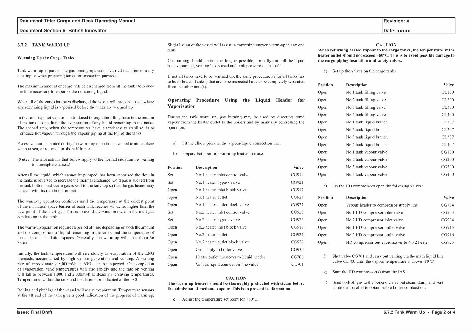
Issue: Final Draft
Document Title: Cargo and Deck Operating Manual
Document Section 6: British Innovator
Revision: x
Date: xxxxx
6.7.2 TANK WARM UP
Warming Up the Cargo Tanks
Tank warm up is part of the gas freeing operations carried out prior to a dry docking or when preparing tanks for inspection purposes.
The maximum amount of cargo will be discharged from all the tanks to reduce the time necessary to vaporise the remaining liquid.
When all of the cargo has been discharged the vessel will proceed to sea where any remaining liquid is vaporised before the tanks are warmed up.
In the first step, hot vapour is introduced through the filling lines to the bottom of the tanks to facilitate the evaporation of any liquid remaining in the tanks. The second step, when the temperatures have a tendency to stabilise, is to introduce hot vapour through the vapour piping at the top of the tanks.
Excess vapour generated during the warm-up operation is vented to atmosphere when at sea, or returned to shore if in port.
(Note: The instructions that follow apply to the normal situation i.e. venting to atmosphere at sea.)
After all the liquid, which cannot be pumped, has been vaporised the flow in the tanks is reversed to increase the thermal exchange. Cold gas is sucked from the tank bottom and warm gas is sent to the tank top so that the gas heater may be used with its maximum output.
The warm-up operation continues until the temperature at the coldest point of the insulation space barrier of each tank reaches +5°C. ie, higher than the dew point of the inert gas. This is to avoid the water content in the inert gas condensing in the tank.
The warm-up operation requires a period of time depending on both the amount and the composition of liquid remaining in the tanks, and the temperature of the tanks and insulation spaces. Generally, the warm-up will take about 36 hours.
Initially, the tank temperatures will rise slowly as evaporation of the LNG proceeds, accompanied by high vapour generation and venting. A venting rate of approximately 8,000m3/h at 60°C can be expected. On completion of evaporation, tank temperatures will rise rapidly and the rate on venting will fall to between 1,000 and 2,000m3/h at steadily increasing temperatures. Temperatures within the tank and insulation are indicated at the IAS.
Rolling and pitching of the vessel will assist evaporation. Temperature sensors at the aft end of the tank give a good indication of the progress of warm-up.
Slight listing of the vessel will assist in correcting uneven warm-up in any one tank.
Gas burning should continue as long as possible, normally until all the liquid has evaporated, venting has ceased and tank pressures start to fall.
If not all tanks have to be warmed up, the same procedure as for all tanks has to be followed. Tank(s) that are to be inspected have to be completely separated from the other tank(s).
Operating Procedure Using the Liquid Header for Vaporisation
During the tank warm up, gas burning may be used by directing some vapour from the heater outlet to the boilers and by manually controlling the operation.
a) Fit the elbow piece in the vapour/liquid connection line.
b) Prepare both boil-off warm-up heaters for use.
Position Description Valve
Set No.1 heater inlet control valve CG919
Set No.1 heater bypass valve CG921
Open No.1 heater inlet block valve CG917
Open No.1 heater outlet CG923
Open No.1 heater outlet block valve CG927
Set No.2 heater inlet control valve CG920
Set No.2 heater bypass valve CG922
Open No.2 heater inlet block valve CG918
Open No.2 heater outlet CG924
Open No.2 heater outlet block valve CG926
Open Gas supply to boiler valve CG930
Open Heater outlet crossover to liquid header CG706
Open Vapour/liquid connection line valve CL701
CAUTION The warm-up heaters should be thoroughly preheated with steam before the admission of methane vapour. This is to prevent ice formation.
c) Adjust the temperature set point for +80°C.
CAUTION When returning heated vapour to the cargo tanks, the temperature at the heater outlet should not exceed +80°C. This is to avoid possible damage to the cargo piping insulation and safety valves.
d) Set up the valves on the cargo tanks.
Position Description Valve
Open No.1 tank filling valve CL100
Open No.2 tank filling valve CL200
Open No.3 tank filling valve CL300
Open No.4 tank filling valve CL400
Open No.1 tank liquid branch CL107
Open No.2 tank liquid branch CL207
Open No.3 tank liquid branch CL307
Open No.4 tank liquid branch CL407
Open No.1 tank vapour valve CG100
Open No.2 tank vapour valve CG200
Open No.3 tank vapour valve CG300
Open No.4 tank vapour valve CG400
e) On the HD compressors open the following valves:
Position Description Valve
Open Vapour header to compressor supply line CG704
Open No.1 HD compressor inlet valve CG903
Open No.2 HD compressor inlet valve CG904
Open No.1 HD compressor outlet valve CG915
Open No.2 HD compressor outlet valve CG916
Open HD compressor outlet crossover to No.2 heater CG925
f) Shut valve CG701 and carry out venting via the main liquid line valve CL700 until the vapour temperature is above -80°C.
g) Start the HD compressor(s) from the IAS.
h) Send boil-off gas to the boilers. Carry out steam dump and vent control in parallel to obtain stable boiler combustion.
6.7.2 Tank Warm Up - Page 2 of 4
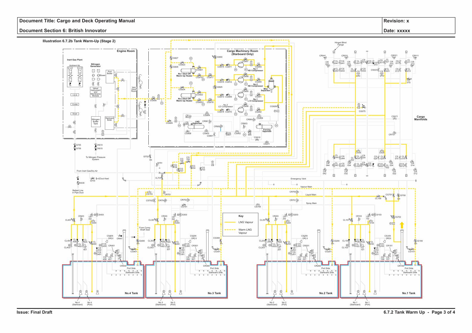
Issue: Final Draft
Document Title: Cargo and Deck Operating Manual
Document Section 6: British Innovator
Revision: x
Date: xxxxx
Key
LNG Vapour
Warm LNG
Vapour
H H
H
H
F
C C S
H
HH H
H
H
C C S
H
HH H
H
H
C C S
H
HH H
H
H
C C S
H
H
F
PI PI
F
PI PI
PI
PI
PI
PI
PI PI
PI PI
F
F
PI
PI
PI
PI
F
F
F
CL106
CL102
CL101
CL100
CS102
CS100
CS103
CS101
CS108
CS107
CR101
CR100
CL105
CL104
CL700
CG700
CG702
CG101
CS105
CS104
CR103 CR102
CG701
CL103
Port Side
Starboard Side
CL107
No.1(Starboard)
No.1(Port)
CL206
CL202
CL201
CL200
CS202
CS200
CS203
CR701
CR700
CS201
CS208
CS207
CR201
CR200
CL205
CL204
CG201
CG200 CG100
CS205
CS204
CR203 CR202
CL203
Port Side
Ambient Air
Blower
PortBoiler
VentHoodRoom
StarboardBoiler
Inert Gas Plant
NitrogenGenerator
Engine Room
No.3 TankNo.4 Tank No.1 TankNo.2 Tank
Cargo Machinery Room(Starboard Only)
Starboard Side
CL207
CS700
No.2(Starboard)
No.2(Port)
CL306
CL302
CL301
CL300
CS302
CS300
CS303
CS701
CS301
CS308
CS307
CR301
CR300
CL305
CL304
CG301
CS305
CS304
CR303 CR302
CL303
Port Side
Starboard Side
CL307
CG927
CG926CG923
CG921
CG917CG919
CG924
CG930
CG929
CG904
CR901
CR905
CR903
CR904
CS909
CS907
CS905
CS908 CS903
CS901
CS902
CS906
CS910
CS911
CR902
CG922
CG918
CG928
CG902
CG906
CG905
CG908
CG907
CR041
CR043
CL041
CL043
CS041
CS043
CL031
CS031 CS
011
CL011 CR
013
CG071 CG
073
CS021
CL021
CL023CS
025
CS023 CL013
CL015
CS013
CR023
CR033
CR021CR031 CR011
CS035
CL033
CS033
CG915
CG900
CG925
CG911
CG916 CG912
CG913 CG909
CG914 CG910
CG901
CG904
CG903
CG920
No.3(Starboard)
No.3(Port)
CL406
CL402
CL401
CL400
CS402
CS400
CS403
CS702 CR704 CR702
CR703
CG708
CG707
CG706
CG705
CG704 CG
703
CS703
CL701
CS401
CS408
CS407
CR401
CR400
CL405
CL404
CG401
CG400
CG300CS405
From Comp.Shaft Seal
CS404
CR403
GI705
GI706
GI703
GI702
GI701
BA530
CN514
CN515
CR402
CL403
Port Side
Starboard Side
CL407
No.4(Starboard)
No.4(Port)
CL044
CS044
CS042
CS034
CS024
CL024
CS034
CR044
CR034
CR024
CR042
CR032
CR022
CS036 CS026
CL042
CL034CL
202
CL032
CG072
CS022 CL
022
CS014
CR701
CS071
CL014
CR014
CR012
CS012
F
F
F
Cooler
Dryer
I.G.G
Valve/Instrument
andMembraneModule
NitrogenBufferTank
To Nitrogen PressureSystem
Hinged BlindFlange
Ballast Linein Pipe Duct
Duct Keel
From Inert Gas/Dry Air
Emergency Vent
Vapour Main
Liquid Main
Spray Main
No.1 Boil OffWarm Up Heater
No.2 Boil OffWarm Up Heater
ForcingVaporiser
MistSeparator
No.1HD Compressor
No.2HD Compressor
No.1L D Compressor
LNGVaporiser
No.2LD Compressor
Illustration 6.7.2b Tank Warm-Up (Stage 2)
CargoManifolds
CG075
CN441
6.7.2 Tank Warm Up - Page 3 of 4
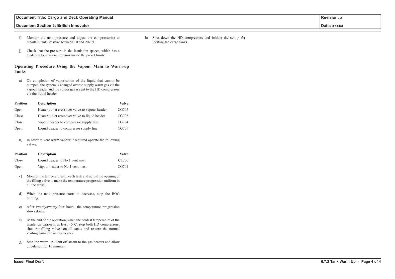
Issue: Final Draft
Document Title: Cargo and Deck Operating Manual
Document Section 6: British Innovator
Revision: x
Date: xxxxx
i) Monitor the tank pressure and adjust the compressor(s) to maintain tank pressure between 10 and 20kPa.
j) Check that the pressure in the insulation spaces, which has a tendency to increase, remains inside the preset limits.
Operating Procedure Using the Vapour Main to Warm-up Tanks
a) On completion of vaporisation of the liquid that cannot be pumped, the system is changed over to supply warm gas via the vapour header and the colder gas is sent to the HD compressors via the liquid header.
Position Description Valve
Open Heater outlet crossover valve to vapour header CG707
Close Heater outlet crossover valve to liquid header CG706
Close Vapour header to compressor supply line CG704
Open Liquid header to compressor supply line CG705
b) In order to vent warm vapour if required operate the following valves:
Position Description Valve
Close Liquid header to No.1 vent mast CL700
Open Vapour header to No.1 vent mast CG701
c) Monitor the temperatures in each tank and adjust the opening of the filling valve to make the temperature progression uniform in all the tanks.
d) When the tank pressure starts to decrease, stop the BOG burning.
e) After twenty/twenty-four hours, the temperature progression slows down.
f) At the end of the operation, when the coldest temperature of the insulation barrier is at least +5°C, stop both HD compressors, shut the filling valves on all tanks and restore the normal venting from the vapour header.
g) Stop the warm-up. Shut off steam to the gas heaters and allow circulation for 10 minutes.
h) Shut down the HD compressors and initiate the set-up for inerting the cargo tanks.
6.7.2 Tank Warm Up - Page 4 of 4
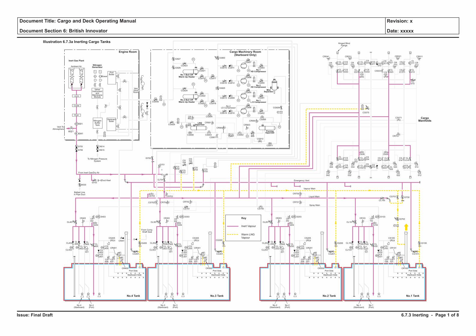
Issue: Final Draft
Document Title: Cargo and Deck Operating Manual
Document Section 6: British Innovator
Revision: x
Date: xxxxx
Inert Vapour
Key
Warm LNG
Vapour
6041
6001
H H
H
H
F
C C S
H
HH H
H
H
C C S
H
HH H
H
H
C C S
H
HH H
H
H
C C S
H
H
F
PI PI
F
PI PI
PI
PI
PI
PI
PI PI
PI PI
F
F
PI
PI
PI
PI
F
F
F
CL106
CL102
CL101
CL100
CS102
CS100
CS103
CS101
CS108
CS107
CR101
CR100
CL105
CL104
CL700
CG700
CG702
CG101
CS105
CS104
CR103 CR102
CG701
CL103
Port Side
Starboard Side
CL107
No.1(Starboard)
No.1(Port)
CL206
CL202
CL201
CL200
CS202
CS200
CS203
CR701
CR700
CS201
CS208
CS207
CR201
CR200
CL205
CL204
CG201
CG200 CG100
CS205
CS204
CR203 CR202
CL203
Port Side
Ambient Air
Blower
PortBoiler
VentHoodRoom
StarboardBoiler
Inert Gas Plant
NitrogenGenerator
Engine Room
No.3 TankNo.4 Tank No.1 TankNo.2 Tank
Cargo Machinery Room(Starboard Only)
Starboard Side
CL207
CS700
No.2(Starboard)
No.2(Port)
CL306
CL302
CL301
CL300
CS302
CS300
CS303
CS701
CS301
CS308
CS307
CR301
CR300
CL305
CL304
CG301
CS305
CS304
CR303 CR302
CL303
Port Side
Starboard Side
CL307
CG927
CG926CG923
CG921
CG917CG919
CG924
CG930
CG929
CG904
CR901
CR905
CR903
CR904
CS909
CS907
CS905
CS908 CS903
CS901
CS902
CS906
CS910
CS911
CR902
CG922
CG918
CG928
CG902
CG906
CG905
CG908
CG907
CR041
CR043
CL041
CL043
CS041
CS043
CL031
CS031 CS
011
CL011 CR
013
CG071 CG
073
CS021
CL021
CL023CS
025
CS023 CL013
CL015
CS013
CR023
CR033
CR021CR031 CR011
CS035
CL033
CS033
CG915
CG900
CG925
CG911
CG916 CG912
CG913 CG909
CG914 CG910
CG901
CG904
CG903
CG920
No.3(Starboard)
No.3(Port)
CL406
CL402
CL401
CL400
CS402
CS400
CS403
CS702 CR704 CR702
CR703
CG708
CG707
CG706
CG705
CG704 CG
703
CS703
CL701
CS401
CS408
CS407
CR401
CR400
CL405
CL404
CG401
CG400
CG300CS405
From Comp.Shaft Seal
CS404
CR403
GI705
GI706
GI703
GI702
GI701
BA530
CN514
CN515
CR402
CL403
Port Side
Starboard Side
CL407
No.4(Starboard)
No.4(Port)
CL044
CS044
CS042
CS034
CS024
CL024
CS034
CR044
CR034
CR024
CR042
CR032
CR022
CS036 CS026
CL042
CL034CL
202
CL032
CG072
CS022 CL
022
CS014
CR701
CS071
CL014
CR014
CR012
CS012
F
F
F
Cooler
Dryer
I.G.G
Valve/Instrument
andMembraneModule
NitrogenBufferTank
To Nitrogen PressureSystem
Vent ToAtmosphere
Hinged BlindFlange
Ballast Linein Pipe Duct
Duct Keel
From Inert Gas/Dry Air
Emergency Vent
Vapour Main
Liquid Main
Spray Main
No.1 Boil OffWarm Up Heater
No.2 Boil OffWarm Up Heater
ForcingVaporiser
MistSeparator
No.1HD Compressor
No.2HD Compressor
No.1L D Compressor
LNGVaporiser
No.2LD Compressor
Illustration 6.7.3a Inerting Cargo Tanks
CargoManifolds
CG075
CN441
6021
6.7.3 Inerting - Page 1 of 8
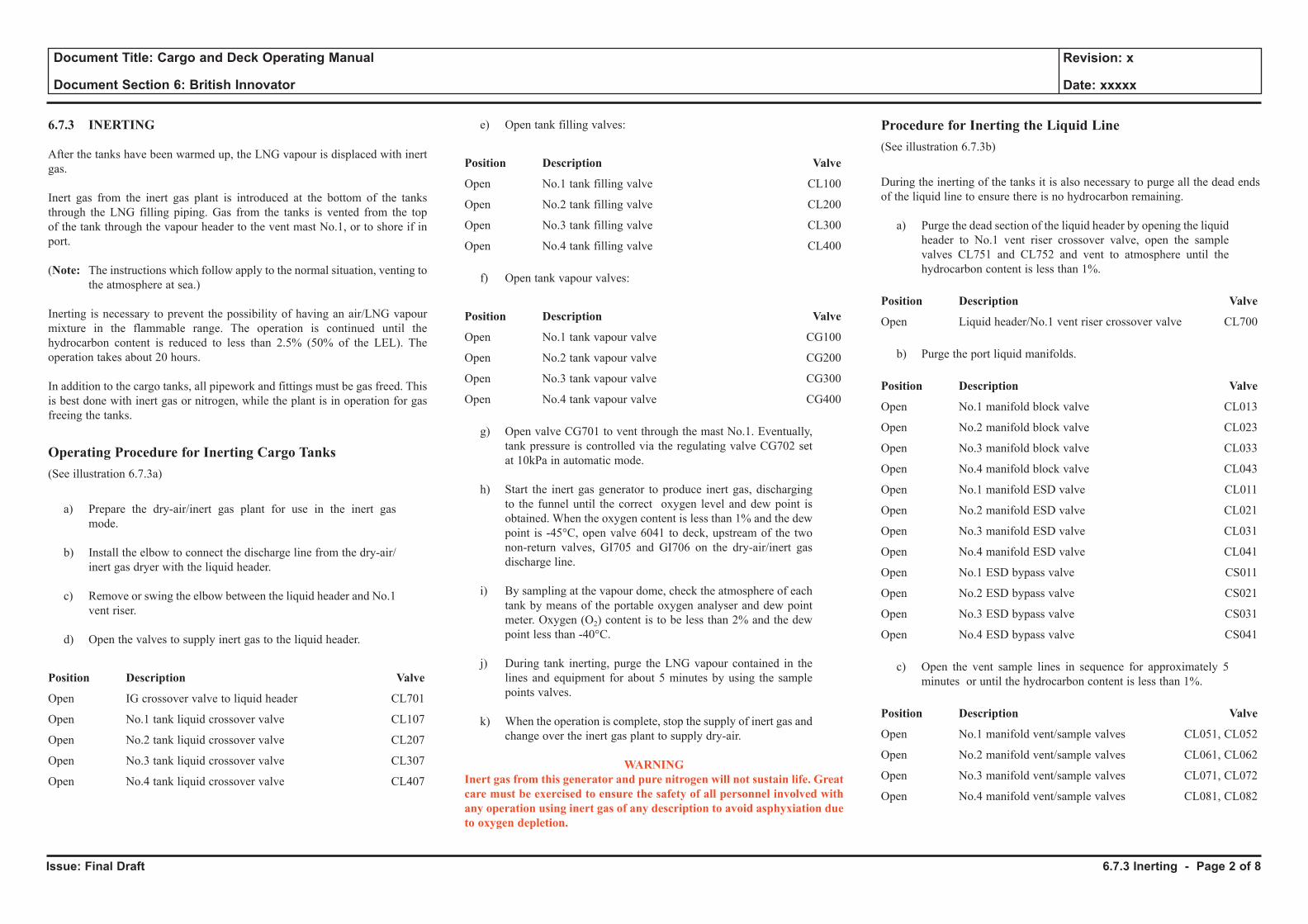
Issue: Final Draft
Document Title: Cargo and Deck Operating Manual
Document Section 6: British Innovator
Revision: x
Date: xxxxx
6.7.3 INERTING
After the tanks have been warmed up, the LNG vapour is displaced with inert gas.
Inert gas from the inert gas plant is introduced at the bottom of the tanks through the LNG filling piping. Gas from the tanks is vented from the top of the tank through the vapour header to the vent mast No.1, or to shore if in port.
(Note: The instructions which follow apply to the normal situation, venting to the atmosphere at sea.)
Inerting is necessary to prevent the possibility of having an air/LNG vapour mixture in the flammable range. The operation is continued until the hydrocarbon content is reduced to less than 2.5% (50% of the LEL). The operation takes about 20 hours.
In addition to the cargo tanks, all pipework and fittings must be gas freed. This is best done with inert gas or nitrogen, while the plant is in operation for gas freeing the tanks.
Operating Procedure for Inerting Cargo Tanks(See illustration 6.7.3a)
a) Prepare the dry-air/inert gas plant for use in the inert gas mode.
b) Install the elbow to connect the discharge line from the dry-air/inert gas dryer with the liquid header.
c) Remove or swing the elbow between the liquid header and No.1 vent riser.
d) Open the valves to supply inert gas to the liquid header.
Position Description Valve
Open IG crossover valve to liquid header CL701
Open No.1 tank liquid crossover valve CL107
Open No.2 tank liquid crossover valve CL207
Open No.3 tank liquid crossover valve CL307
Open No.4 tank liquid crossover valve CL407
e) Open tank filling valves:
Position Description Valve
Open No.1 tank filling valve CL100
Open No.2 tank filling valve CL200
Open No.3 tank filling valve CL300
Open No.4 tank filling valve CL400
f) Open tank vapour valves:
Position Description Valve
Open No.1 tank vapour valve CG100
Open No.2 tank vapour valve CG200
Open No.3 tank vapour valve CG300
Open No.4 tank vapour valve CG400
g) Open valve CG701 to vent through the mast No.1. Eventually, tank pressure is controlled via the regulating valve CG702 set at 10kPa in automatic mode.
h) Start the inert gas generator to produce inert gas, discharging to the funnel until the correct oxygen level and dew point is obtained. When the oxygen content is less than 1% and the dew point is -45°C, open valve 6041 to deck, upstream of the two non-return valves, GI705 and GI706 on the dry-air/inert gas discharge line.
i) By sampling at the vapour dome, check the atmosphere of each tank by means of the portable oxygen analyser and dew point meter. Oxygen (O2) content is to be less than 2% and the dew point less than -40°C.
j) During tank inerting, purge the LNG vapour contained in the lines and equipment for about 5 minutes by using the sample points valves.
k) When the operation is complete, stop the supply of inert gas and change over the inert gas plant to supply dry-air.
WARNINGInert gas from this generator and pure nitrogen will not sustain life. Great care must be exercised to ensure the safety of all personnel involved with any operation using inert gas of any description to avoid asphyxiation due to oxygen depletion.
Procedure for Inerting the Liquid Line(See illustration 6.7.3b)
During the inerting of the tanks it is also necessary to purge all the dead ends of the liquid line to ensure there is no hydrocarbon remaining.
a) Purge the dead section of the liquid header by opening the liquid header to No.1 vent riser crossover valve, open the sample valves CL751 and CL752 and vent to atmosphere until the hydrocarbon content is less than 1%.
Position Description Valve
Open Liquid header/No.1 vent riser crossover valve CL700
b) Purge the port liquid manifolds.
Position Description Valve
Open No.1 manifold block valve CL013
Open No.2 manifold block valve CL023
Open No.3 manifold block valve CL033
Open No.4 manifold block valve CL043
Open No.1 manifold ESD valve CL011
Open No.2 manifold ESD valve CL021
Open No.3 manifold ESD valve CL031
Open No.4 manifold ESD valve CL041
Open No.1 ESD bypass valve CS011
Open No.2 ESD bypass valve CS021
Open No.3 ESD bypass valve CS031
Open No.4 ESD bypass valve CS041
c) Open the vent sample lines in sequence for approximately 5 minutes or until the hydrocarbon content is less than 1%.
Position Description Valve
Open No.1 manifold vent/sample valves CL051, CL052
Open No.2 manifold vent/sample valves CL061, CL062
Open No.3 manifold vent/sample valves CL071, CL072
Open No.4 manifold vent/sample valves CL081, CL082
6.7.3 Inerting - Page 2 of 8
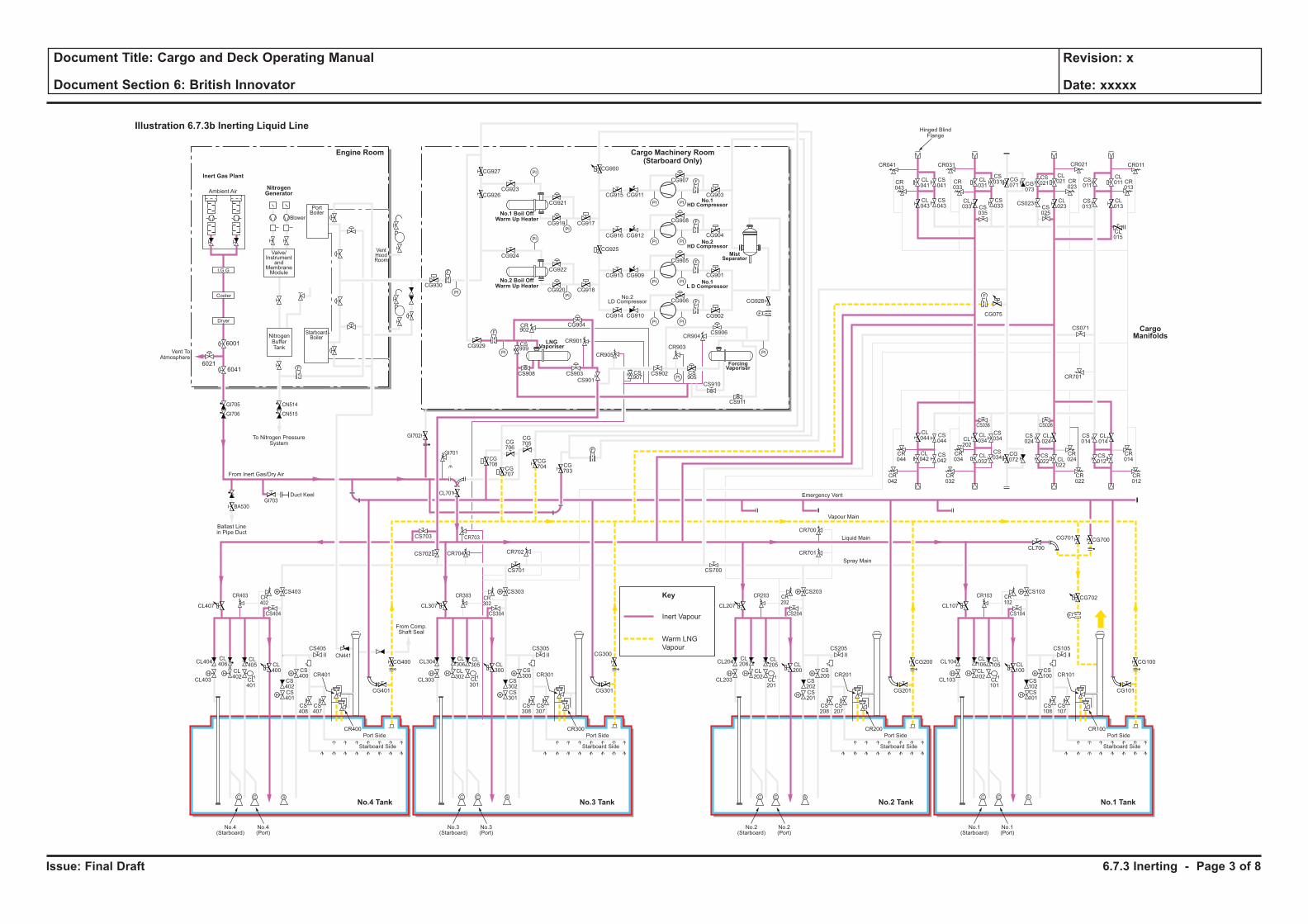
Issue: Final Draft
Document Title: Cargo and Deck Operating Manual
Document Section 6: British Innovator
Revision: x
Date: xxxxx
Inert Vapour
Key
Warm LNG
Vapour
H H
H
H
F
C C S
H
HH H
H
H
C C S
H
HH H
H
H
C C S
H
HH H
H
H
C C S
H
H
F
PI PI
F
PI PI
PI
PI
PI
PI
PI PI
PI PI
F
F
PI
PI
PI
PI
F
F
F
CL106
CL102
CL101
CL100
CS102
CS100
CS103
CS101
CS108
CS107
CR101
CR100
CL105
CL104
CL700
CG700
CG702
CG101
CS105
CS104
CR103 CR102
CG701
CL103
Port Side
Starboard Side
CL107
No.1(Starboard)
No.1(Port)
CL206
CL202
CL201
CL200
CS202
CS200
CS203
CR701
CR700
CS201
CS208
CS207
CR201
CR200
CL205
CL204
CG201
CG200 CG100
CS205
CS204
CR203 CR202
CL203
Port Side
Ambient Air
Blower
PortBoiler
VentHoodRoom
StarboardBoiler
Inert Gas Plant
NitrogenGenerator
Engine Room
No.3 TankNo.4 Tank No.1 TankNo.2 Tank
Cargo Machinery Room(Starboard Only)
Starboard Side
CL207
CS700
No.2(Starboard)
No.2(Port)
CL306
CL302
CL301
CL300
CS302
CS300
CS303
CS701
CS301
CS308
CS307
CR301
CR300
CL305
CL304
CG301
CS305
CS304
CR303 CR302
CL303
Port Side
Starboard Side
CL307
CG927
CG926CG923
CG921
CG917CG919
CG924
CG930
CG929
CG904
CR901
CR905
CR903
CR904
CS909
CS907
CS905
CS908 CS903
CS901
CS902
CS906
CS910
CS911
CR902
CG922
CG918
CG928
CG902
CG906
CG905
CG908
CG907
CR041
CR043
CL041
CL043
CS041
CS043
CL031
CS031 CS
011
CL011 CR
013
CG071 CG
073
CS021
CL021
CL023CS
025
CS023 CL013
CL015
CS013
CR023
CR033
CR021CR031 CR011
CS035
CL033
CS033
CG915
CG900
CG925
CG911
CG916 CG912
CG913 CG909
CG914 CG910
CG901
CG904
CG903
CG920
No.3(Starboard)
No.3(Port)
CL406
CL402
CL401
CL400
CS402
CS400
CS403
CS702 CR704 CR702
CR703
CG708
CG707
CG706
CG705
CG704 CG
703
CS703
CL701
CS401
CS408
CS407
CR401
CR400
CL405
CL404
CG401
CG400
CG300CS405
From Comp.Shaft Seal
CS404
CR403
GI705
GI706
GI703
GI702
GI701
BA530
CN514
CN515
CR402
CL403
Port Side
Starboard Side
CL407
No.4(Starboard)
No.4(Port)
CL044
CS044
CS042
CS034
CS024
CL024
CS034
CR044
CR034
CR024
CR042
CR032
CR022
CS036 CS026
CL042
CL034CL
202
CL032
CG072
CS022 CL
022
CS014
CR701
CS071
CL014
CR014
CR012
CS012
F
F
F
Cooler
Dryer
I.G.G
Valve/Instrument
andMembraneModule
NitrogenBufferTank
To Nitrogen PressureSystem
Hinged BlindFlange
Ballast Linein Pipe Duct
Duct Keel
From Inert Gas/Dry Air
Emergency Vent
Vapour Main
Liquid Main
Spray Main
No.1 Boil OffWarm Up Heater
No.2 Boil OffWarm Up Heater
ForcingVaporiser
MistSeparator
No.1HD Compressor
No.2HD Compressor
No.1L D Compressor
LNGVaporiser
No.2LD Compressor
Illustration 6.7.3b Inerting Liquid Line
CargoManifolds
CG075
CN441
6041
6001
Vent ToAtmosphere
6021
6.7.3 Inerting - Page 3 of 8
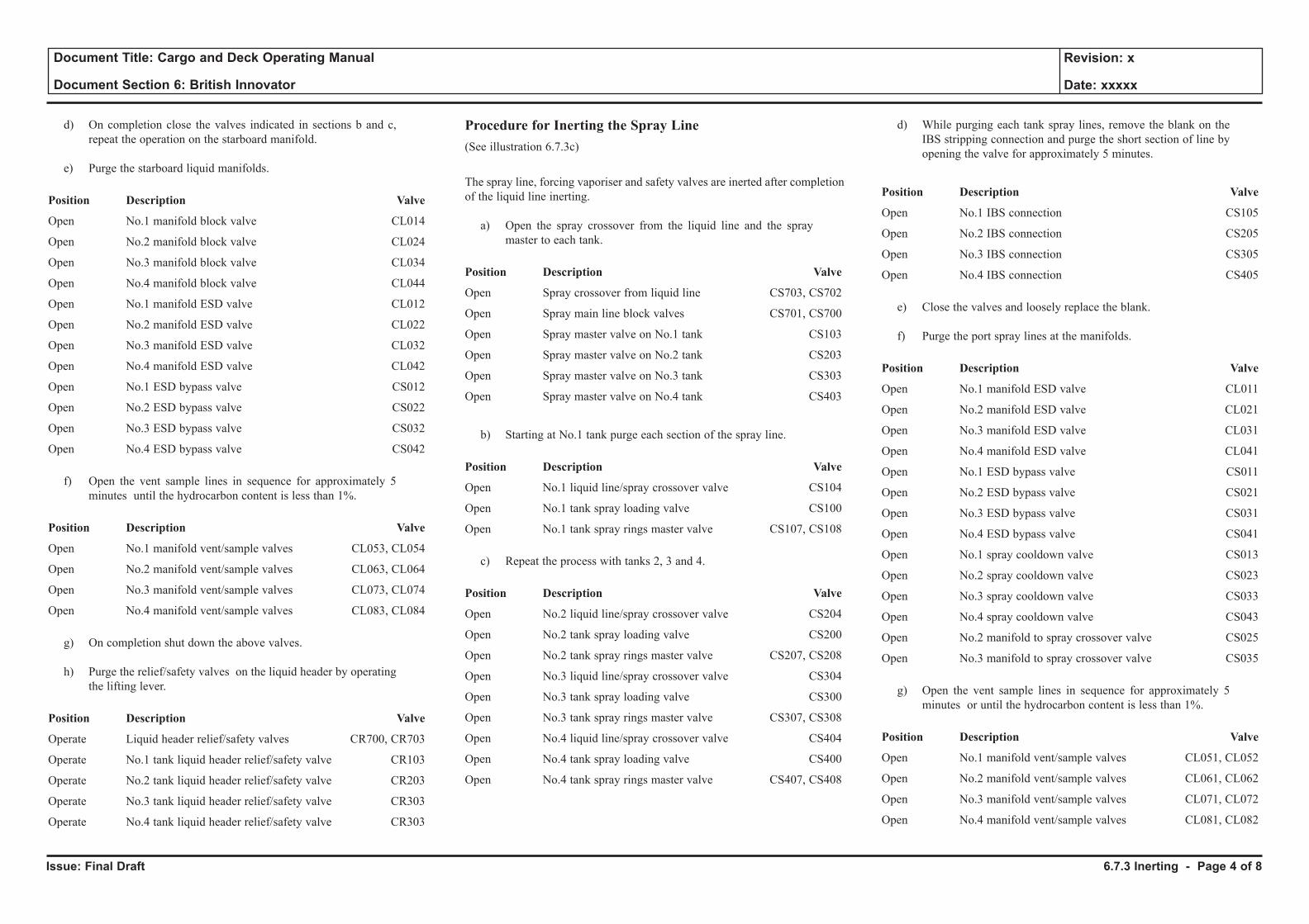
Issue: Final Draft
Document Title: Cargo and Deck Operating Manual
Document Section 6: British Innovator
Revision: x
Date: xxxxx
d) On completion close the valves indicated in sections b and c, repeat the operation on the starboard manifold.
e) Purge the starboard liquid manifolds.
Position Description Valve
Open No.1 manifold block valve CL014
Open No.2 manifold block valve CL024
Open No.3 manifold block valve CL034
Open No.4 manifold block valve CL044
Open No.1 manifold ESD valve CL012
Open No.2 manifold ESD valve CL022
Open No.3 manifold ESD valve CL032
Open No.4 manifold ESD valve CL042
Open No.1 ESD bypass valve CS012
Open No.2 ESD bypass valve CS022
Open No.3 ESD bypass valve CS032
Open No.4 ESD bypass valve CS042
f) Open the vent sample lines in sequence for approximately 5 minutes until the hydrocarbon content is less than 1%.
Position Description Valve
Open No.1 manifold vent/sample valves CL053, CL054
Open No.2 manifold vent/sample valves CL063, CL064
Open No.3 manifold vent/sample valves CL073, CL074
Open No.4 manifold vent/sample valves CL083, CL084
g) On completion shut down the above valves.
h) Purge the relief/safety valves on the liquid header by operating the lifting lever.
Position Description Valve
Operate Liquid header relief/safety valves CR700, CR703
Operate No.1 tank liquid header relief/safety valve CR103
Operate No.2 tank liquid header relief/safety valve CR203
Operate No.3 tank liquid header relief/safety valve CR303
Operate No.4 tank liquid header relief/safety valve CR303
Procedure for Inerting the Spray Line(See illustration 6.7.3c)
The spray line, forcing vaporiser and safety valves are inerted after completion of the liquid line inerting.
a) Open the spray crossover from the liquid line and the spray master to each tank.
Position Description Valve
Open Spray crossover from liquid line CS703, CS702
Open Spray main line block valves CS701, CS700
Open Spray master valve on No.1 tank CS103
Open Spray master valve on No.2 tank CS203
Open Spray master valve on No.3 tank CS303
Open Spray master valve on No.4 tank CS403
b) Starting at No.1 tank purge each section of the spray line.
Position Description Valve
Open No.1 liquid line/spray crossover valve CS104
Open No.1 tank spray loading valve CS100
Open No.1 tank spray rings master valve CS107, CS108
c) Repeat the process with tanks 2, 3 and 4.
Position Description Valve
Open No.2 liquid line/spray crossover valve CS204
Open No.2 tank spray loading valve CS200
Open No.2 tank spray rings master valve CS207, CS208
Open No.3 liquid line/spray crossover valve CS304
Open No.3 tank spray loading valve CS300
Open No.3 tank spray rings master valve CS307, CS308
Open No.4 liquid line/spray crossover valve CS404
Open No.4 tank spray loading valve CS400
Open No.4 tank spray rings master valve CS407, CS408
d) While purging each tank spray lines, remove the blank on the IBS stripping connection and purge the short section of line by opening the valve for approximately 5 minutes.
Position Description Valve
Open No.1 IBS connection CS105
Open No.2 IBS connection CS205
Open No.3 IBS connection CS305
Open No.4 IBS connection CS405
e) Close the valves and loosely replace the blank.
f) Purge the port spray lines at the manifolds.
Position Description Valve
Open No.1 manifold ESD valve CL011
Open No.2 manifold ESD valve CL021
Open No.3 manifold ESD valve CL031
Open No.4 manifold ESD valve CL041
Open No.1 ESD bypass valve CS011
Open No.2 ESD bypass valve CS021
Open No.3 ESD bypass valve CS031
Open No.4 ESD bypass valve CS041
Open No.1 spray cooldown valve CS013
Open No.2 spray cooldown valve CS023
Open No.3 spray cooldown valve CS033
Open No.4 spray cooldown valve CS043
Open No.2 manifold to spray crossover valve CS025
Open No.3 manifold to spray crossover valve CS035
g) Open the vent sample lines in sequence for approximately 5 minutes or until the hydrocarbon content is less than 1%.
Position Description Valve
Open No.1 manifold vent/sample valves CL051, CL052
Open No.2 manifold vent/sample valves CL061, CL062
Open No.3 manifold vent/sample valves CL071, CL072
Open No.4 manifold vent/sample valves CL081, CL082
6.7.3 Inerting - Page 4 of 8
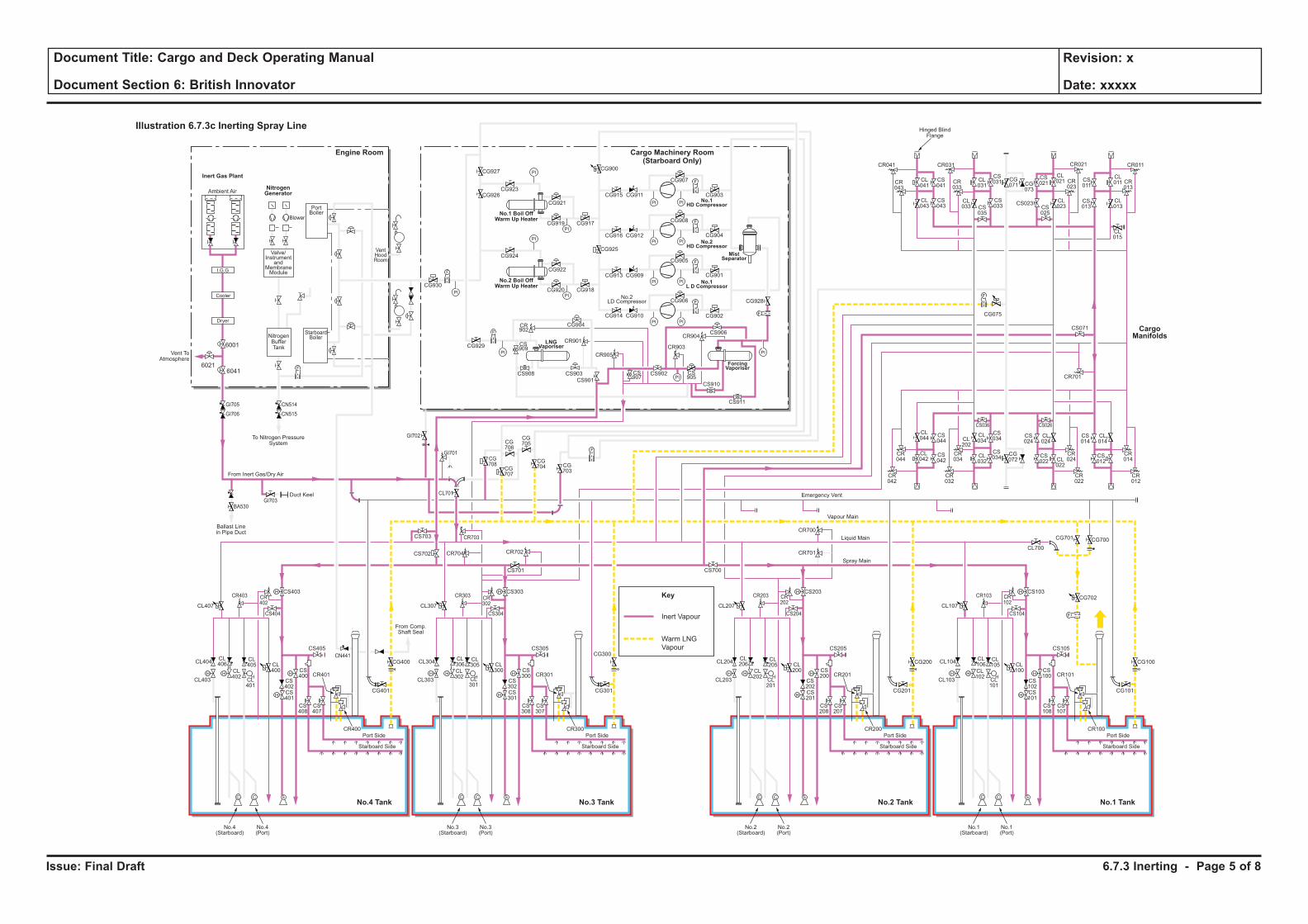
Issue: Final Draft
Document Title: Cargo and Deck Operating Manual
Document Section 6: British Innovator
Revision: x
Date: xxxxx
Inert Vapour
Key
Warm LNG
Vapour
H H
H
H
F
C C S
H
HH H
H
H
C C S
H
HH H
H
H
C C S
H
HH H
H
H
C C S
H
H
F
PI PI
F
PI PI
PI
PI
PI
PI
PI PI
PI PI
F
F
PI
PI
PI
PI
F
F
F
CL106
CL102
CL101
CL100
CS102
CS100
CS103
CS101
CS108
CS107
CR101
CR100
CL105
CL104
CL700
CG700
CG702
CG101
CS105
CS104
CR103 CR102
CG701
CL103
Port Side
Starboard Side
CL107
No.1(Starboard)
No.1(Port)
CL206
CL202
CL201
CL200
CS202
CS200
CS203
CR701
CR700
CS201
CS208
CS207
CR201
CR200
CL205
CL204
CG201
CG200 CG100
CS205
CS204
CR203 CR202
CL203
Port Side
Ambient Air
Blower
PortBoiler
VentHoodRoom
StarboardBoiler
Inert Gas Plant
NitrogenGenerator
Engine Room
No.3 TankNo.4 Tank No.1 TankNo.2 Tank
Cargo Machinery Room(Starboard Only)
Starboard Side
CL207
CS700
No.2(Starboard)
No.2(Port)
CL306
CL302
CL301
CL300
CS302
CS300
CS303
CS701
CS301
CS308
CS307
CR301
CR300
CL305
CL304
CG301
CS305
CS304
CR303 CR302
CL303
Port Side
Starboard Side
CL307
CG927
CG926CG923
CG921
CG917CG919
CG924
CG930
CG929
CG904
CR901
CR905
CR903
CR904
CS909
CS907
CS905
CS908 CS903
CS901
CS902
CS906
CS910
CS911
CR902
CG922
CG918
CG928
CG902
CG906
CG905
CG908
CG907
CR041
CR043
CL041
CL043
CS041
CS043
CL031
CS031 CS
011
CL011 CR
013
CG071 CG
073
CS021
CL021
CL023CS
025
CS023 CL013
CL015
CS013
CR023
CR033
CR021CR031 CR011
CS035
CL033
CS033
CG915
CG900
CG925
CG911
CG916 CG912
CG913 CG909
CG914 CG910
CG901
CG904
CG903
CG920
No.3(Starboard)
No.3(Port)
CL406
CL402
CL401
CL400
CS402
CS400
CS403
CS702 CR704 CR702
CR703
CG708
CG707
CG706
CG705
CG704 CG
703
CS703
CL701
CS401
CS408
CS407
CR401
CR400
CL405
CL404
CG401
CG400
CG300CS405
From Comp.Shaft Seal
CS404
CR403
GI705
GI706
GI703
GI702
GI701
BA530
CN514
CN515
CR402
CL403
Port Side
Starboard Side
CL407
No.4(Starboard)
No.4(Port)
CL044
CS044
CS042
CS034
CS024
CL024
CS034
CR044
CR034
CR024
CR042
CR032
CR022
CS036 CS026
CL042
CL034CL
202
CL032
CG072
CS022 CL
022
CS014
CR701
CS071
CL014
CR014
CR012
CS012
F
F
F
Cooler
Dryer
I.G.G
Valve/Instrument
andMembraneModule
NitrogenBufferTank
To Nitrogen PressureSystem
Hinged BlindFlange
Ballast Linein Pipe Duct
Duct Keel
From Inert Gas/Dry Air
Emergency Vent
Vapour Main
Liquid Main
Spray Main
No.1 Boil OffWarm Up Heater
No.2 Boil OffWarm Up Heater
ForcingVaporiser
MistSeparator
No.1HD Compressor
No.2HD Compressor
No.1L D Compressor
LNGVaporiser
No.2LD Compressor
Illustration 6.7.3c Inerting Spray Line
CargoManifolds
CG075
CN441
6041
6001
Vent ToAtmosphere
6021
6.7.3 Inerting - Page 5 of 8
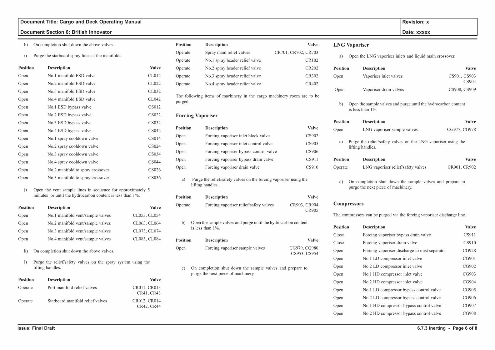
Issue: Final Draft
Document Title: Cargo and Deck Operating Manual
Document Section 6: British Innovator
Revision: x
Date: xxxxx
h) On completion shut down the above valves.
i) Purge the starboard spray lines at the manifolds.
Position Description Valve
Open No.1 manifold ESD valve CL012
Open No.2 manifold ESD valve CL022
Open No.3 manifold ESD valve CL032
Open No.4 manifold ESD valve CL042
Open No.1 ESD bypass valve CS012
Open No.2 ESD bypass valve CS022
Open No.3 ESD bypass valve CS032
Open No.4 ESD bypass valve CS042
Open No.1 spray cooldown valve CS014
Open No.2 spray cooldown valve CS024
Open No.3 spray cooldown valve CS034
Open No.4 spray cooldown valve CS044
Open No.2 manifold to spray crossover CS026
Open No.3 manifold to spray crossover CS036
j) Open the vent sample lines in sequence for approximately 5 minutes or until the hydrocarbon content is less than 1%.
Position Description Valve
Open No.1 manifold vent/sample valves CL053, CL054
Open No.2 manifold vent/sample valves CL063, CL064
Open No.3 manifold vent/sample valves CL073, CL074
Open No.4 manifold vent/sample valves CL083, CL084
k) On completion shut down the above valves.
l) Purge the relief/safety valves on the spray system using the lifting handles.
Position Description Valve
Operate Port manifold relief valves CR011, CR013 CR41, CR43
Operate Starboard manifold relief valves CR012, CR014 CR42, CR44
Position Description Valve
Operate Spray main relief valves CR701, CR702, CR703
Operate No.1 spray header relief valve CR102
Operate No.2 spray header relief valve CR202
Operate No.3 spray header relief valve CR302
Operate No.4 spray header relief valve CR402
The following items of machinery in the cargo machinery room are to be purged.
Forcing Vaporiser
Position Description Valve
Open Forcing vaporiser inlet block valve CS902
Open Forcing vaporiser inlet control valve CS905
Open Forcing vaporiser bypass control valve CS906
Open Forcing vaporiser bypass drain valve CS911
Open Forcing vaporiser drain valve CS910
a) Purge the relief/safety valves on the forcing vaporiser using the lifting handles.
Position Description Valve
Operate Forcing vaporiser relief/safety valves CR903, CR904 CR905
b) Open the sample valves and purge until the hydrocarbon content is less than 1%.
Position Description Valve
Open Forcing vaporiser sample valves CG979, CG980 CS953, CS954
c) On completion shut down the sample valves and prepare to purge the next piece of machinery.
LNG Vaporiser
a) Open the LNG vaporiser inlets and liquid main crossover.
Position Description Valve
Open Vaporiser inlet valves CS901, CS903 CS904
Open Vaporiser drain valves CS908, CS909
b) Open the sample valves and purge until the hydrocarbon content
is less than 1%.
Position Description Valve
Open LNG vaporiser sample valves CG977, CG978
c) Purge the relief/safety valves on the LNG vaporiser using the lifting handles.
Position Description Valve
Operate LNG vaporiser relief/safety valves CR901, CR902
d) On completion shut down the sample valves and prepare to purge the next piece of machinery.
Compressors
The compressors can be purged via the forcing vaporiser discharge line.
Position Description Valve
Close Forcing vaporiser bypass drain valve CS911
Close Forcing vaporiser drain valve CS910
Open Forcing vaporiser discharge to mist separator CG928
Open No.1 LD compressor inlet valve CG901
Open No.2 LD compressor inlet valve CG902
Open No.1 HD compressor inlet valve CG903
Open No.2 HD compressor inlet valve CG904
Open No.1 LD compressor bypass control valve CG905
Open No.2 LD compressor bypass control valve CG906
Open No.1 HD compressor bypass control valve CG907
Open No.2 HD compressor bypass control valve CG908
6.7.3 Inerting - Page 6 of 8
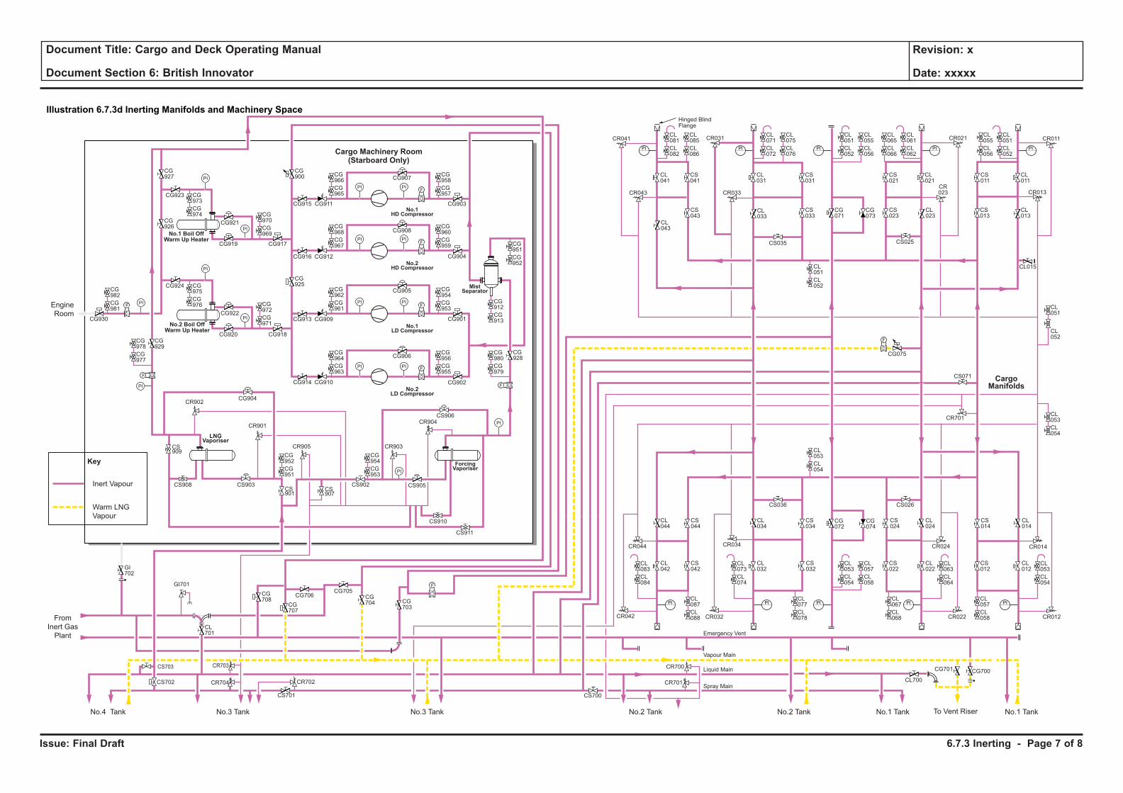
Issue: Final Draft
Document Title: Cargo and Deck Operating Manual
Document Section 6: British Innovator
Revision: x
Date: xxxxx
CR701 CL700
CR700
CG075
F
CR701
CS071
PI
PI
PI
PI
PI
CL053
CL054
CL057
CL058
PI
CL073
CL074
CL077
CL078
PI
CL063
CL064
CL067
CL068
PI
PI
CL071
CL072
CL075
CL076
PI
CL061
CL062
CL065
CL066
PI
CL051
CL052
CL055
CL056
PI
CL051
CL052
CL055
CL056
PI
CL053
CL054
CL057
CL058
CL051
CL052
CL053
CL054
PI
CL081
CL082
CL085
CL086
CG956
CG955
CG980
CG979
CG964
CG963
CG972
CG971
CG982
CG981
CG975
CG976
CG973
CG974 CG
970
CG969
CG954
CG953
CG952
CG951
CG978
CG977
CG954
CG953
CG912
CG913
CG951
CG952
CG962
CG961
CG960
CG959
CG968
CG967
CG958
CG957
CG966
CG965
CL083
CL084
CL087
CL088
CL051
CL052
CL053
CL054
CR041
CR043
CL041
CL043
CS041
CS043
CL031
CS031
CS011
CL011
CR013
CG071
CG073
CS021
CL021
CL023
CS025
CS023
CL013
CL015
CS013
CR023CR033
CR021CR031 CR011
CS035
CL033
CS033
CL044
CS044
CS042
CS034
CS024
CL024
CS032
CR044 CR034 CR024
CR042 CR032 CR022
CS036 CS026
CL042
CL034
CL032
CG072
CG074
CS022
CL022
CS014
CL014
CR014
CR012
CS012
CL012
Hinged BlindFlange
PI PI
FPI PI
PI PI
PI PI
F
F
PI
PI
PI
PI
F
F
Cargo Machinery Room(Starboard Only)
CG927
CG926
CG923
CG921
CG917CG919
CG924
CG930
CG929
CG904
CR901
CR905 CR903
CR904
CS909
CS907
CS905CS908 CS903CS901
CS902
CS906
CS910
CS911
CR902
CG922
CG918
CG928
CG902
CG906
CG905
CG908
CG907
CG915
CG900
CG925
CG911
CG916 CG912
CG913 CG909
CG914 CG910
CG901
CG904
CG903
CG920
Engine
Room
From
Inert Gas
Plant
No.4 Tank No.3 Tank No.3 Tank No.2 Tank No.2 Tank No.1 Tank No.1 TankTo Vent Riser
CG708
CG707
CG706CG705
CG704 CG
703
CL701
GI702
GI701
F
F
F
Emergency Vent
Liquid Main
Spray Main
Vapour Main
No.1 Boil OffWarm Up Heater
No.2 Boil OffWarm Up Heater
ForcingVaporiser
MistSeparator
No.1HD Compressor
No.2HD Compressor
No.1LD Compressor
LNGVaporiser
No.2LD Compressor
CargoManifolds
CG700CG701
CS702 CR704
CR703CS703
CS701
CR702
CS700
Key
Illustration 6.7.3d Inerting Manifolds and Machinery Space
Inert Vapour
Warm LNG
Vapour
6.7.3 Inerting - Page 7 of 8
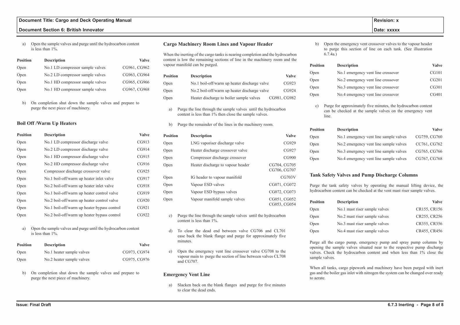
Issue: Final Draft
Document Title: Cargo and Deck Operating Manual
Document Section 6: British Innovator
Revision: x
Date: xxxxx
a) Open the sample valves and purge until the hydrocarbon content is less than 1%.
Position Description Valve
Open No.1 LD compressor sample valves CG961, CG962
Open No.2 LD compressor sample valves CG963, CG964
Open No.1 HD compressor sample valves CG965, CG966
Open No.1 HD compressor sample valves CG967, CG968
b) On completion shut down the sample valves and prepare to purge the next piece of machinery.
Boil Off /Warm Up Heaters
Position Description Valve
Open No.1 LD compressor discharge valve CG913
Open No.2 LD compressor discharge valve CG914
Open No.1 HD compressor discharge valve CG915
Open No.2 HD compressor discharge valve CG916
Open Compressor discharge crossover valve CG925
Open No.1 boil-off/warm up heater inlet valve CG917
Open No.2 boil-off/warm up heater inlet valve CG918
Open No.1 boil-off/warm up heater control valve CG919
Open No.2 boil-off/warm up heater control valve CG920
Open No.1 boil-off/warm up heater bypass control CG921
Open No.2 boil-off/warm up heater bypass control CG922
a) Open the sample valves and purge until the hydrocarbon content is less than 1%.
Position Description Valve
Open No.1 heater sample valves CG973, CG974
Open No.2 heater sample valves CG975, CG976
b) On completion shut down the sample valves and prepare to purge the next piece of machinery.
Cargo Machinery Room Lines and Vapour Header
When the inerting of the cargo tanks is nearing completion and the hydrocarbon content is low the remaining sections of line in the machinery room and the vapour manifold can be purged.
Position Description Valve
Open No.1 boil-off/warm up heater discharge valve CG923
Open No.2 boil-off/warm up heater discharge valve CG924
Open Heater discharge to boiler sample valves CG981, CG982
a) Purge the line through the sample valves until the hydrocarbon content is less than 1% then close the sample valves.
b) Purge the remainder of the lines in the machinery room.
Position Description Valve
Open LNG vaporiser discharge valve CG929
Open Heater discharge crossover valve CG927
Open Compressor discharge crossover CG900
Open Heater discharge to vapour header CG704, CG705 CG706, CG707
Open IG header to vapour manifold CG703V
Open Vapour ESD valves CG071, CG072
Open Vapour ESD bypass valves CG072, CG073
Open Vapour manifold sample valves CG051, CG052 CG053, CG054
c) Purge the line through the sample valves until the hydrocarbon content is less than 1%.
d) To clear the dead end between valve CG706 and CL701 ease back the blank flange and purge for approximately five minutes.
e) Open the emergency vent line crossover valve CG708 to the vapour main to purge the section of line between valves CL708 and CG707.
Emergency Vent Line
a) Slacken back on the blank flanges and purge for five minutes to clear the dead ends.
b) Open the emergency vent crossover valves to the vapour header to purge this section of line on each tank. (See illustration 6.7.4a.)
Position Description Valve
Open No.1 emergency vent line crossover CG101
Open No.2 emergency vent line crossover CG201
Open No.3 emergency vent line crossover CG301
Open No.4 emergency vent line crossover CG401
c) Purge for approximately five minutes, the hydrocarbon content can be checked at the sample valves on the emergency vent line.
Position Description Valve
Open No.1 emergency vent line sample valves CG759, CG760
Open No.2 emergency vent line sample valves CC761, CG762
Open No.3 emergency vent line sample valves CG765, CG766
Open No.4 emergency vent line sample valves CG767, CG768
Tank Safety Valves and Pump Discharge Columns
Purge the tank safety valves by operating the manual lifting device, the hydrocarbon content can be checked at the vent mast riser sample valves.
Position Description Valve
Open No.1 mast riser sample valves CR155, CR156
Open No.2 mast riser sample valves CR255, CR256
Open No.3 mast riser sample valves CR355, CR356
Open No.4 mast riser sample valves CR455, CR456
Purge all the cargo pump, emergency pump and spray pump columns by opening the sample valves situated near to the respective pump discharge valves. Check the hydrocarbon content and when less than 1% close the sample valves.
When all tanks, cargo pipework and machinery have been purged with inert gas and the boiler gas inlet with nitrogen the system can be changed over ready to aerate.
6.7.3 Inerting - Page 8 of 8
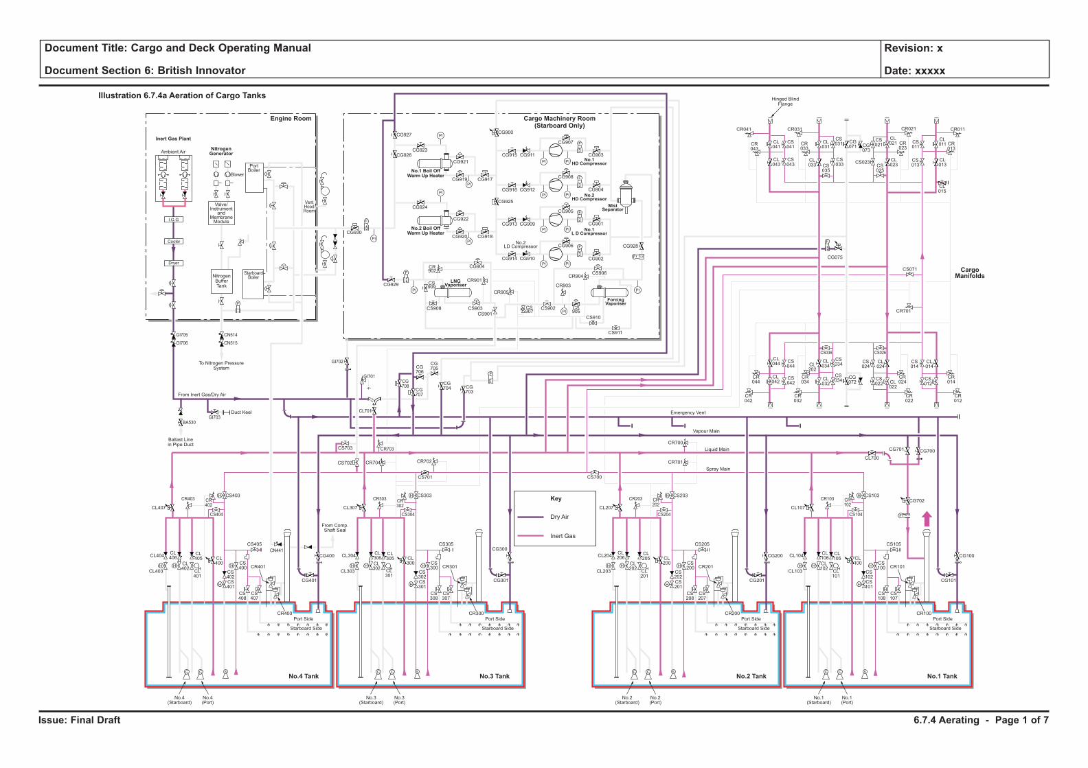
Issue: Final Draft
Document Title: Cargo and Deck Operating Manual
Document Section 6: British Innovator
Revision: x
Date: xxxxx
Dry Air
Key
Inert Gas
H H
H
H
F
C C S
H
HH H
H
H
C C S
H
HH H
H
H
C C S
H
HH H
H
H
C C S
H
H
F
PI PI
F
PI PI
PI
PI
PI
PI
PI PI
PI PI
F
F
PI
PI
PI
PI
F
F
F
CL106
CL102
CL101
CL100
CS102
CS100
CS103
CS101
CS108
CS107
CR101
CR100
CL105
CL104
CL700
CG700
CG702
CG101
CS105
CS104
CR103 CR102
CG701
CL103
Port Side
Starboard Side
CL107
No.1(Starboard)
No.1(Port)
CL206
CL202
CL201
CL200
CS202
CS200
CS203
CR701
CR700
CS201
CS208
CS207
CR201
CR200
CL205
CL204
CG201
CG200 CG100
CS205
CS204
CR203 CR202
CL203
Port Side
Ambient Air
Blower
PortBoiler
VentHoodRoom
StarboardBoiler
Inert Gas Plant
NitrogenGenerator
Engine Room
No.3 TankNo.4 Tank No.1 TankNo.2 Tank
Cargo Machinery Room(Starboard Only)
Starboard Side
CL207
CS700
No.2(Starboard)
No.2(Port)
CL306
CL302
CL301
CL300
CS302
CS300
CS303
CS701
CS301
CS308
CS307
CR301
CR300
CL305
CL304
CG301
CS305
CS304
CR303 CR302
CL303
Port Side
Starboard Side
CL307
CG927
CG926CG923
CG921
CG917CG919
CG924
CG930
CG929
CG904
CR901
CR905
CR903
CR904
CS909
CS907
CS905
CS908 CS903
CS901
CS902
CS906
CS910
CS911
CR902
CG922
CG918
CG928
CG902
CG906
CG905
CG908
CG907
CR041
CR043
CL041
CL043
CS041
CS043
CL031
CS031 CS
011
CL011 CR
013
CG071 CG
073
CS021
CL021
CL023CS
025
CS023 CL013
CL015
CS013
CR023
CR033
CR021CR031 CR011
CS035
CL033
CS033
CG915
CG900
CG925
CG911
CG916 CG912
CG913 CG909
CG914 CG910
CG901
CG904
CG903
CG920
No.3(Starboard)
No.3(Port)
CL406
CL402
CL401
CL400
CS402
CS400
CS403
CS702 CR704 CR702
CR703
CG708
CG707
CG706
CG705
CG704 CG
703
CS703
CL701
CS401
CS408
CS407
CR401
CR400
CL405
CL404
CG401
CG400
CG300CS405
From Comp.Shaft Seal
CS404
CR403
GI705
GI706
GI703
GI702
GI701
BA530
CN514
CN515
CR402
CL403
Port Side
Starboard Side
CL407
No.4(Starboard)
No.4(Port)
CL044
CS044
CS042
CS034
CS024
CL024
CS034
CR044
CR034
CR024
CR042
CR032
CR022
CS036 CS026
CL042
CL034CL
202
CL032
CG072
CS022 CL
022
CS014
CR701
CS071
CL014
CR014
CR012
CS012
F
F
F
Cooler
Dryer
I.G.G
Valve/Instrument
andMembraneModule
NitrogenBufferTank
To Nitrogen PressureSystem
Hinged BlindFlange
Ballast Linein Pipe Duct
Duct Keel
From Inert Gas/Dry Air
Emergency Vent
Vapour Main
Liquid Main
Spray Main
No.1 Boil OffWarm Up Heater
No.2 Boil OffWarm Up Heater
ForcingVaporiser
MistSeparator
No.1HD Compressor
No.2HD Compressor
No.1L D Compressor
LNGVaporiser
No.2LD Compressor
Illustration 6.7.4a Aeration of Cargo Tanks
CargoManifolds
CG075
CN441
6.7.4 Aerating - Page 1 of 7
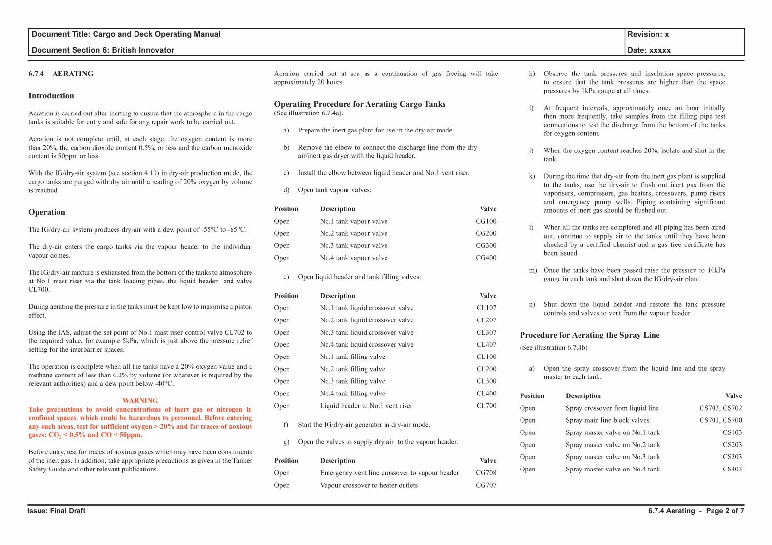
Issue: Final Draft
Document Title: Cargo and Deck Operating Manual
Document Section 6: British Innovator
Revision: x
Date: xxxxx
6.7.4 AERATING
Introduction
Aeration is carried out after inerting to ensure that the atmosphere in the cargo tanks is suitable for entry and safe for any repair work to be carried out.
Aeration is not complete until, at each stage, the oxygen content is more than 20%, the carbon dioxide content 0.5%, or less and the carbon monoxide content is 50ppm or less.
With the IG/dry-air system (see section 4.10) in dry-air production mode, the cargo tanks are purged with dry air until a reading of 20% oxygen by volume is reached.
Operation
The IG/dry-air system produces dry-air with a dew point of -55°C to -65°C.
The dry-air enters the cargo tanks via the vapour header to the individual vapour domes.
The IG/dry-air mixture is exhausted from the bottom of the tanks to atmosphere at No.1 mast riser via the tank loading pipes, the liquid header and valve CL700.
During aerating the pressure in the tanks must be kept low to maximise a piston effect.
Using the IAS, adjust the set point of No.1 mast riser control valve CL702 to the required value, for example 5kPa, which is just above the pressure relief setting for the interbarrier spaces.
The operation is complete when all the tanks have a 20% oxygen value and a methane content of less than 0.2% by volume (or whatever is required by the relevant authorities) and a dew point below -40°C.
WARNINGTake precautions to avoid concentrations of inert gas or nitrogen in confined spaces, which could be hazardous to personnel. Before entering any such areas, test for sufficient oxygen > 20% and for traces of noxious gases: CO2 < 0.5% and CO < 50ppm.
Before entry, test for traces of noxious gases which may have been constituents of the inert gas. In addition, take appropriate precautions as given in the Tanker Safety Guide and other relevant publications.
Aeration carried out at sea as a continuation of gas freeing will take approximately 20 hours.
Operating Procedure for Aerating Cargo Tanks(See illustration 6.7.4a).
a) Prepare the inert gas plant for use in the dry-air mode.
b) Remove the elbow to connect the discharge line from the dry-air/inert gas dryer with the liquid header.
c) Install the elbow between liquid header and No.1 vent riser.
d) Open tank vapour valves:
Position Description Valve
Open No.1 tank vapour valve CG100
Open No.2 tank vapour valve CG200
Open No.3 tank vapour valve CG300
Open No.4 tank vapour valve CG400
e) Open liquid header and tank filling valves:
Position Description Valve
Open No.1 tank liquid crossover valve CL107
Open No.2 tank liquid crossover valve CL207
Open No.3 tank liquid crossover valve CL307
Open No.4 tank liquid crossover valve CL407
Open No.1 tank filling valve CL100
Open No.2 tank filling valve CL200
Open No.3 tank filling valve CL300
Open No.4 tank filling valve CL400
Open Liquid header to No.1 vent riser CL700
f) Start the IG/dry-air generator in dry-air mode.
g) Open the valves to supply dry air to the vapour header.
Position Description Valve
Open Emergency vent line crossover to vapour header CG708
Open Vapour crossover to heater outlets CG707
h) Observe the tank pressures and insulation space pressures, to ensure that the tank pressures are higher than the space pressures by 1kPa gauge at all times.
i) At frequent intervals, approximately once an hour initially then more frequently, take samples from the filling pipe test connections to test the discharge from the bottom of the tanks for oxygen content.
j) When the oxygen content reaches 20%, isolate and shut in the tank.
k) During the time that dry-air from the inert gas plant is supplied to the tanks, use the dry-air to flush out inert gas from the vaporisers, compressors, gas heaters, crossovers, pump risers and emergency pump wells. Piping containing significant amounts of inert gas should be flushed out.
l) When all the tanks are completed and all piping has been aired out, continue to supply air to the tanks until they have been checked by a certified chemist and a gas free certificate has been issued.
m) Once the tanks have been passed raise the pressure to 10kPa gauge in each tank and shut down the IG/dry-air plant.
n) Shut down the liquid header and restore the tank pressure controls and valves to vent from the vapour header.
Procedure for Aerating the Spray Line(See illustration 6.7.4b)
a) Open the spray crossover from the liquid line and the spray master to each tank.
Position Description Valve
Open Spray crossover from liquid line CS703, CS702
Open Spray main line block valves CS701, CS700
Open Spray master valve on No.1 tank CS103
Open Spray master valve on No.2 tank CS203
Open Spray master valve on No.3 tank CS303
Open Spray master valve on No.4 tank CS403
6.7.4 Aerating - Page 2 of 7
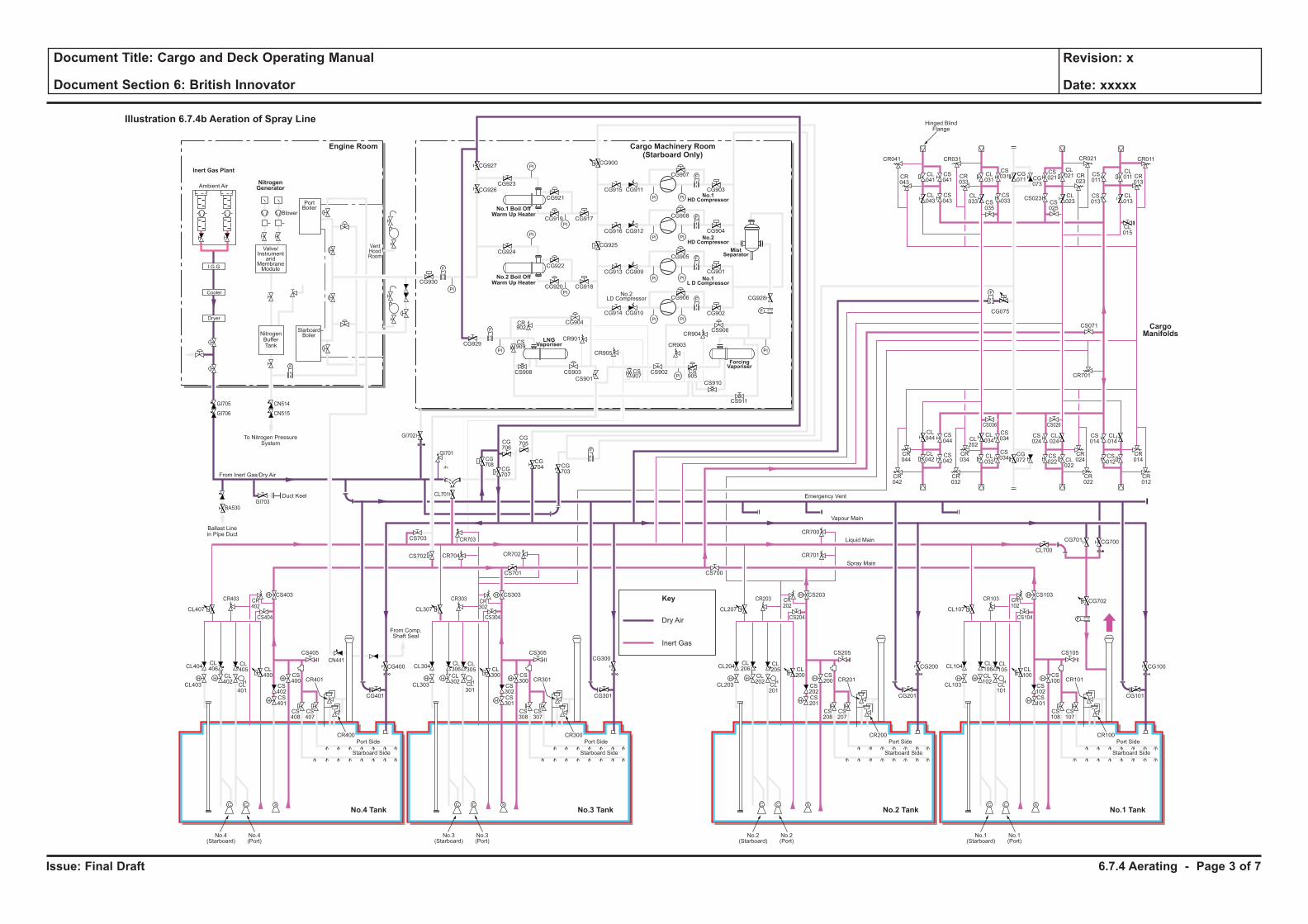
Issue: Final Draft
Document Title: Cargo and Deck Operating Manual
Document Section 6: British Innovator
Revision: x
Date: xxxxx
Dry Air
Key
Inert Gas
H H
H
H
F
C C S
H
HH H
H
H
C C S
H
HH H
H
H
C C S
H
HH H
H
H
C C S
H
H
F
PI PI
F
PI PI
PI
PI
PI
PI
PI PI
PI PI
F
F
PI
PI
PI
PI
F
F
F
CL106
CL102
CL101
CL100
CS102
CS100
CS103
CS101
CS108
CS107
CR101
CR100
CL105
CL104
CL700
CG700
CG702
CG101
CS105
CS104
CR103 CR102
CG701
CL103
Port Side
Starboard Side
CL107
No.1(Starboard)
No.1(Port)
CL206
CL202
CL201
CL200
CS202
CS200
CS203
CR701
CR700
CS201
CS208
CS207
CR201
CR200
CL205
CL204
CG201
CG200 CG100
CS205
CS204
CR203 CR202
CL203
Port Side
Ambient Air
Blower
PortBoiler
VentHoodRoom
StarboardBoiler
Inert Gas Plant
NitrogenGenerator
Engine Room
No.3 TankNo.4 Tank No.1 TankNo.2 Tank
Cargo Machinery Room(Starboard Only)
Starboard Side
CL207
CS700
No.2(Starboard)
No.2(Port)
CL306
CL302
CL301
CL300
CS302
CS300
CS303
CS701
CS301
CS308
CS307
CR301
CR300
CL305
CL304
CG301
CS305
CS304
CR303 CR302
CL303
Port Side
Starboard Side
CL307
CG927
CG926CG923
CG921
CG917CG919
CG924
CG930
CG929
CG904
CR901
CR905
CR903
CR904
CS909
CS907
CS905
CS908 CS903
CS901
CS902
CS906
CS910
CS911
CR902
CG922
CG918
CG928
CG902
CG906
CG905
CG908
CG907
CR041
CR043
CL041
CL043
CS041
CS043
CL031
CS031 CS
011
CL011 CR
013
CG071 CG
073
CS021
CL021
CL023CS
025
CS023 CL013
CL015
CS013
CR023
CR033
CR021CR031 CR011
CS035
CL033
CS033
CG915
CG900
CG925
CG911
CG916 CG912
CG913 CG909
CG914 CG910
CG901
CG904
CG903
CG920
No.3(Starboard)
No.3(Port)
CL406
CL402
CL401
CL400
CS402
CS400
CS403
CS702 CR704 CR702
CR703
CG708
CG707
CG706
CG705
CG704 CG
703
CS703
CL701
CS401
CS408
CS407
CR401
CR400
CL405
CL404
CG401
CG400
CG300CS405
From Comp.Shaft Seal
CS404
CR403
GI705
GI706
GI703
GI702
GI701
BA530
CN514
CN515
CR402
CL403
Port Side
Starboard Side
CL407
No.4(Starboard)
No.4(Port)
CL044
CS044
CS042
CS034
CS024
CL024
CS034
CR044
CR034
CR024
CR042
CR032
CR022
CS036 CS026
CL042
CL034CL
202
CL032
CG072
CS022 CL
022
CS014
CR701
CS071
CL014
CR014
CR012
CS012
F
F
F
Cooler
Dryer
I.G.G
Valve/Instrument
andMembraneModule
NitrogenBufferTank
To Nitrogen PressureSystem
Hinged BlindFlange
Ballast Linein Pipe Duct
Duct Keel
From Inert Gas/Dry Air
Emergency Vent
Vapour Main
Liquid Main
Spray Main
No.1 Boil OffWarm Up Heater
No.2 Boil OffWarm Up Heater
ForcingVaporiser
MistSeparator
No.1HD Compressor
No.2HD Compressor
No.1L D Compressor
LNGVaporiser
No.2LD Compressor
Illustration 6.7.4b Aeration of Spray Line
CargoManifolds
CG075
CN441
6.7.4 Aerating - Page 3 of 7
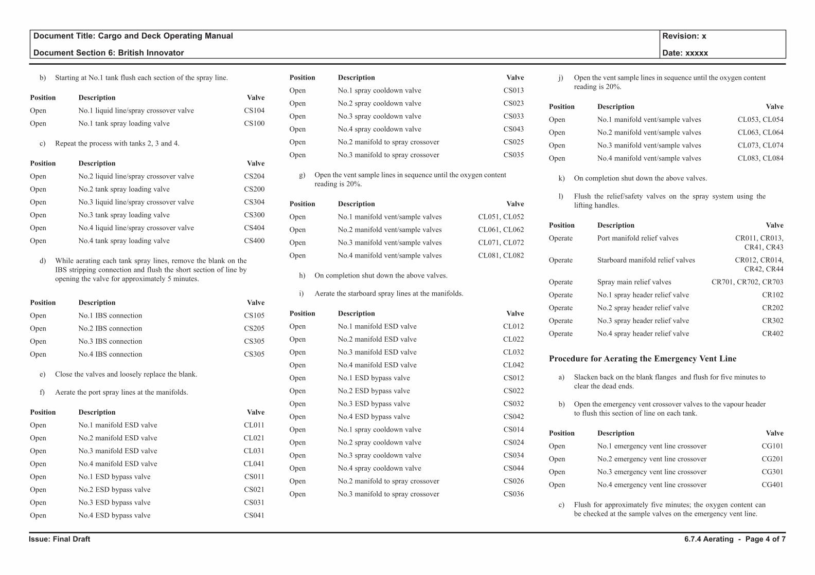
Issue: Final Draft
Document Title: Cargo and Deck Operating Manual
Document Section 6: British Innovator
Revision: x
Date: xxxxx
b) Starting at No.1 tank flush each section of the spray line.
Position Description Valve
Open No.1 liquid line/spray crossover valve CS104
Open No.1 tank spray loading valve CS100
c) Repeat the process with tanks 2, 3 and 4.
Position Description Valve
Open No.2 liquid line/spray crossover valve CS204
Open No.2 tank spray loading valve CS200
Open No.3 liquid line/spray crossover valve CS304
Open No.3 tank spray loading valve CS300
Open No.4 liquid line/spray crossover valve CS404
Open No.4 tank spray loading valve CS400
d) While aerating each tank spray lines, remove the blank on the IBS stripping connection and flush the short section of line by opening the valve for approximately 5 minutes.
Position Description Valve
Open No.1 IBS connection CS105
Open No.2 IBS connection CS205
Open No.3 IBS connection CS305
Open No.4 IBS connection CS305
e) Close the valves and loosely replace the blank.
f) Aerate the port spray lines at the manifolds.
Position Description Valve
Open No.1 manifold ESD valve CL011
Open No.2 manifold ESD valve CL021
Open No.3 manifold ESD valve CL031
Open No.4 manifold ESD valve CL041
Open No.1 ESD bypass valve CS011
Open No.2 ESD bypass valve CS021
Open No.3 ESD bypass valve CS031
Open No.4 ESD bypass valve CS041
Position Description Valve
Open No.1 spray cooldown valve CS013
Open No.2 spray cooldown valve CS023
Open No.3 spray cooldown valve CS033
Open No.4 spray cooldown valve CS043
Open No.2 manifold to spray crossover CS025
Open No.3 manifold to spray crossover CS035
g) Open the vent sample lines in sequence until the oxygen content reading is 20%.
Position Description Valve
Open No.1 manifold vent/sample valves CL051, CL052
Open No.2 manifold vent/sample valves CL061, CL062
Open No.3 manifold vent/sample valves CL071, CL072
Open No.4 manifold vent/sample valves CL081, CL082
h) On completion shut down the above valves.
i) Aerate the starboard spray lines at the manifolds.
Position Description Valve
Open No.1 manifold ESD valve CL012
Open No.2 manifold ESD valve CL022
Open No.3 manifold ESD valve CL032
Open No.4 manifold ESD valve CL042
Open No.1 ESD bypass valve CS012
Open No.2 ESD bypass valve CS022
Open No.3 ESD bypass valve CS032
Open No.4 ESD bypass valve CS042
Open No.1 spray cooldown valve CS014
Open No.2 spray cooldown valve CS024
Open No.3 spray cooldown valve CS034
Open No.4 spray cooldown valve CS044
Open No.2 manifold to spray crossover CS026
Open No.3 manifold to spray crossover CS036
j) Open the vent sample lines in sequence until the oxygen content reading is 20%.
Position Description Valve
Open No.1 manifold vent/sample valves CL053, CL054
Open No.2 manifold vent/sample valves CL063, CL064
Open No.3 manifold vent/sample valves CL073, CL074
Open No.4 manifold vent/sample valves CL083, CL084
k) On completion shut down the above valves.
l) Flush the relief/safety valves on the spray system using the lifting handles.
Position Description Valve
Operate Port manifold relief valves CR011, CR013, CR41, CR43
Operate Starboard manifold relief valves CR012, CR014, CR42, CR44
Operate Spray main relief valves CR701, CR702, CR703
Operate No.1 spray header relief valve CR102
Operate No.2 spray header relief valve CR202
Operate No.3 spray header relief valve CR302
Operate No.4 spray header relief valve CR402
Procedure for Aerating the Emergency Vent Line
a) Slacken back on the blank flanges and flush for five minutes to clear the dead ends.
b) Open the emergency vent crossover valves to the vapour header to flush this section of line on each tank.
Position Description Valve
Open No.1 emergency vent line crossover CG101
Open No.2 emergency vent line crossover CG201
Open No.3 emergency vent line crossover CG301
Open No.4 emergency vent line crossover CG401
c) Flush for approximately five minutes; the oxygen content can be checked at the sample valves on the emergency vent line.
6.7.4 Aerating - Page 4 of 7
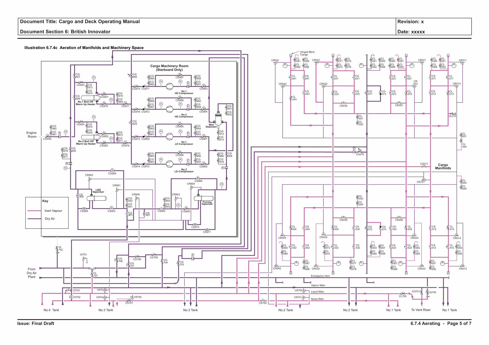
Issue: Final Draft
Document Title: Cargo and Deck Operating Manual
Document Section 6: British Innovator
Revision: x
Date: xxxxx
CR701 CL700
CR700
CG075
F
CR701
CS071
PI
PI
PI
PI
PI
CL053
CL054
CL057
CL058
PI
CL073
CL074
CL077
CL078
PI
CL063
CL064
CL067
CL068
PI
PI
CL071
CL072
CL075
CL076
PI
CL061
CL062
CL065
CL066
PI
CL051
CL052
CL055
CL056
PI
CL051
CL052
CL055
CL056
PI
CL053
CL054
CL057
CL058
CL051
CL052
CL053
CL054
PI
CL081
CL082
CL085
CL086
CG956
CG955
CG980
CG979
CG964
CG963
CG972
CG971
CG982
CG981
CG975
CG976
CG973
CG974 CG
970
CG969
CG954
CG953
CG952
CG951
CG978
CG977
CG954
CG953
CG912
CG913
CG951
CG952
CG962
CG961
CG960
CG959
CG968
CG967
CG958
CG957
CG966
CG965
CL083
CL084
CL087
CL088
CL051
CL052
CL053
CL054
CR041
CR043
CL041
CL043
CS041
CS043
CL031
CS031
CS011
CL011
CR013
CG071
CG073
CS021
CL021
CL023
CS025
CS023
CL013
CL015
CS013
CR023CR033
CR021CR031 CR011
CS035
CL033
CS033
CL044
CS044
CS042
CS034
CS024
CL024
CS032
CR044 CR034 CR024
CR042 CR032 CR022
CS036 CS026
CL042
CL034
CL032
CG072
CG074
CS022
CL022
CS014
CL014
CR014
CR012
CS012
CL012
Hinged BlindFlange
PI PI
FPI PI
PI PI
PI PI
F
F
PI
PI
PI
PI
F
F
Cargo Machinery Room(Starboard Only)
CG927
CG926
CG923
CG921
CG917CG919
CG924
CG930
CG929
CG904
CR901
CR905 CR903
CR904
CS909
CS907
CS905CS908 CS903CS901
CS902
CS906
CS910
CS911
CR902
CG922
CG918
CG928
CG902
CG906
CG905
CG908
CG907
CG915
CG900
CG925
CG911
CG916 CG912
CG913 CG909
CG914 CG910
CG901
CG904
CG903
CG920
EngineRoom
FromDry AirPlant
No.4 Tank No.3 Tank No.3 Tank No.2 Tank No.2 Tank No.1 Tank No.1 TankTo Vent Riser
CG708
CG707
CG706CG705
CG704 CG
703
CL701
GI702
GI701
F
F
F
Emergency Vent
Liquid Main
Spray Main
Vapour Main
No.1 Boil OffWarm Up Heater
No.2 Boil OffWarm Up Heater
ForcingVaporiser
MistSeparator
No.1HD Compressor
No.2HD Compressor
No.1LD Compressor
LNGVaporiser
No.2LD Compressor
CargoManifolds
CG700CG701
CS702 CR704
CR703CS703
CS701
CR702
CS700
Key
Illustration 6.7.4c Aeration of Manifolds and Machinery Space
Inert Vapour
Dry Air
6.7.4 Aerating - Page 5 of 7
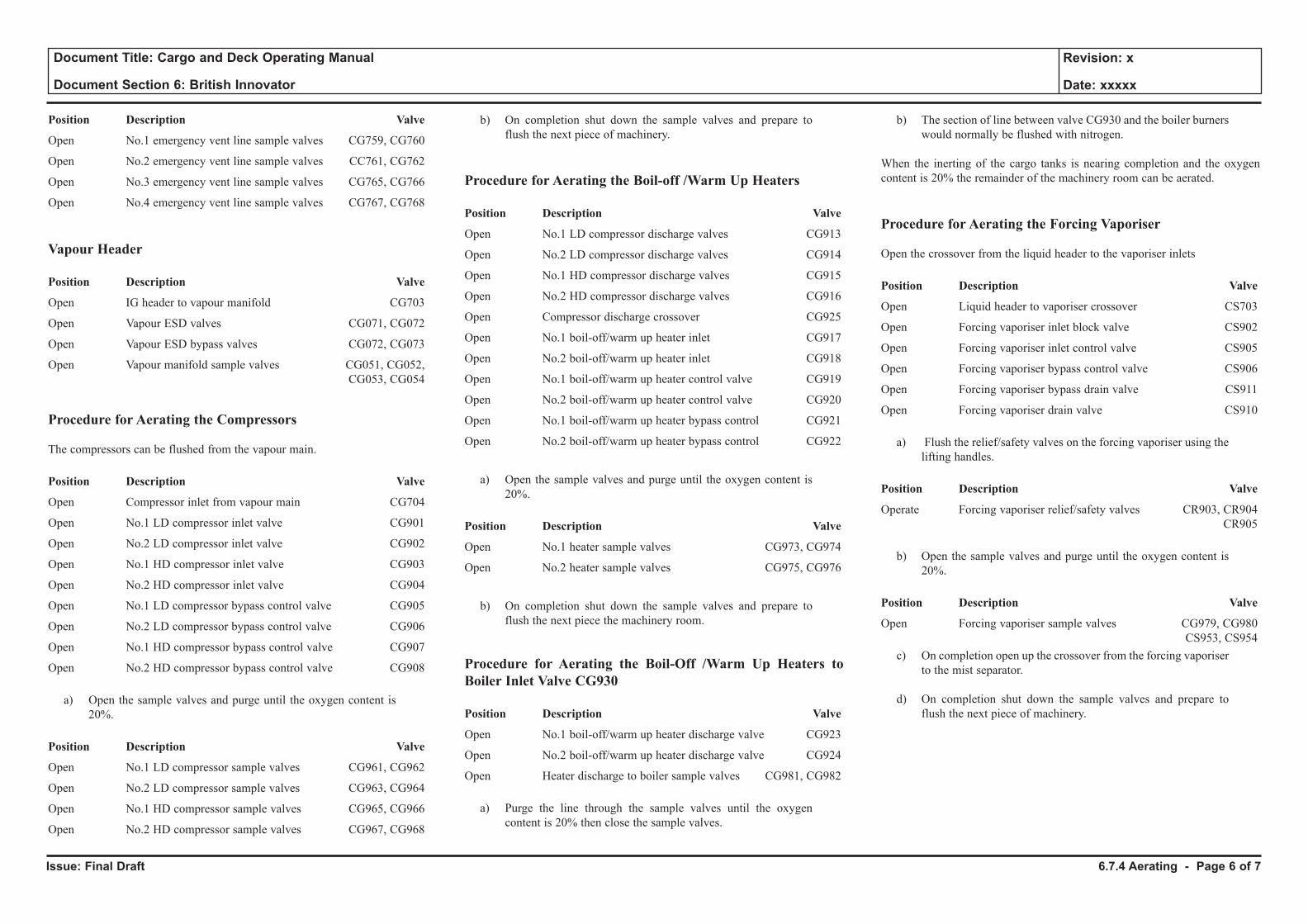
Issue: Final Draft
Document Title: Cargo and Deck Operating Manual
Document Section 6: British Innovator
Revision: x
Date: xxxxx
Position Description Valve
Open No.1 emergency vent line sample valves CG759, CG760
Open No.2 emergency vent line sample valves CC761, CG762
Open No.3 emergency vent line sample valves CG765, CG766
Open No.4 emergency vent line sample valves CG767, CG768
Vapour Header
Position Description Valve
Open IG header to vapour manifold CG703
Open Vapour ESD valves CG071, CG072
Open Vapour ESD bypass valves CG072, CG073
Open Vapour manifold sample valves CG051, CG052, CG053, CG054
Procedure for Aerating the Compressors
The compressors can be flushed from the vapour main.
Position Description Valve
Open Compressor inlet from vapour main CG704
Open No.1 LD compressor inlet valve CG901
Open No.2 LD compressor inlet valve CG902
Open No.1 HD compressor inlet valve CG903
Open No.2 HD compressor inlet valve CG904
Open No.1 LD compressor bypass control valve CG905
Open No.2 LD compressor bypass control valve CG906
Open No.1 HD compressor bypass control valve CG907
Open No.2 HD compressor bypass control valve CG908
a) Open the sample valves and purge until the oxygen content is 20%.
Position Description Valve
Open No.1 LD compressor sample valves CG961, CG962
Open No.2 LD compressor sample valves CG963, CG964
Open No.1 HD compressor sample valves CG965, CG966
Open No.2 HD compressor sample valves CG967, CG968
b) On completion shut down the sample valves and prepare to flush the next piece of machinery.
Procedure for Aerating the Boil-off /Warm Up Heaters
Position Description Valve
Open No.1 LD compressor discharge valves CG913
Open No.2 LD compressor discharge valves CG914
Open No.1 HD compressor discharge valves CG915
Open No.2 HD compressor discharge valves CG916
Open Compressor discharge crossover CG925
Open No.1 boil-off/warm up heater inlet CG917
Open No.2 boil-off/warm up heater inlet CG918
Open No.1 boil-off/warm up heater control valve CG919
Open No.2 boil-off/warm up heater control valve CG920
Open No.1 boil-off/warm up heater bypass control CG921
Open No.2 boil-off/warm up heater bypass control CG922
a) Open the sample valves and purge until the oxygen content is 20%.
Position Description Valve
Open No.1 heater sample valves CG973, CG974
Open No.2 heater sample valves CG975, CG976
b) On completion shut down the sample valves and prepare to flush the next piece the machinery room.
Procedure for Aerating the Boil-Off /Warm Up Heaters to Boiler Inlet Valve CG930
Position Description Valve
Open No.1 boil-off/warm up heater discharge valve CG923
Open No.2 boil-off/warm up heater discharge valve CG924
Open Heater discharge to boiler sample valves CG981, CG982
a) Purge the line through the sample valves until the oxygen content is 20% then close the sample valves.
b) The section of line between valve CG930 and the boiler burners would normally be flushed with nitrogen.
When the inerting of the cargo tanks is nearing completion and the oxygen content is 20% the remainder of the machinery room can be aerated.
Procedure for Aerating the Forcing Vaporiser
Open the crossover from the liquid header to the vaporiser inlets
Position Description Valve
Open Liquid header to vaporiser crossover CS703
Open Forcing vaporiser inlet block valve CS902
Open Forcing vaporiser inlet control valve CS905
Open Forcing vaporiser bypass control valve CS906
Open Forcing vaporiser bypass drain valve CS911
Open Forcing vaporiser drain valve CS910
a) Flush the relief/safety valves on the forcing vaporiser using the lifting handles.
Position Description Valve
Operate Forcing vaporiser relief/safety valves CR903, CR904 CR905
b) Open the sample valves and purge until the oxygen content is 20%.
Position Description Valve
Open Forcing vaporiser sample valves CG979, CG980 CS953, CS954
c) On completion open up the crossover from the forcing vaporiser to the mist separator.
d) On completion shut down the sample valves and prepare to flush the next piece of machinery.
6.7.4 Aerating - Page 6 of 7
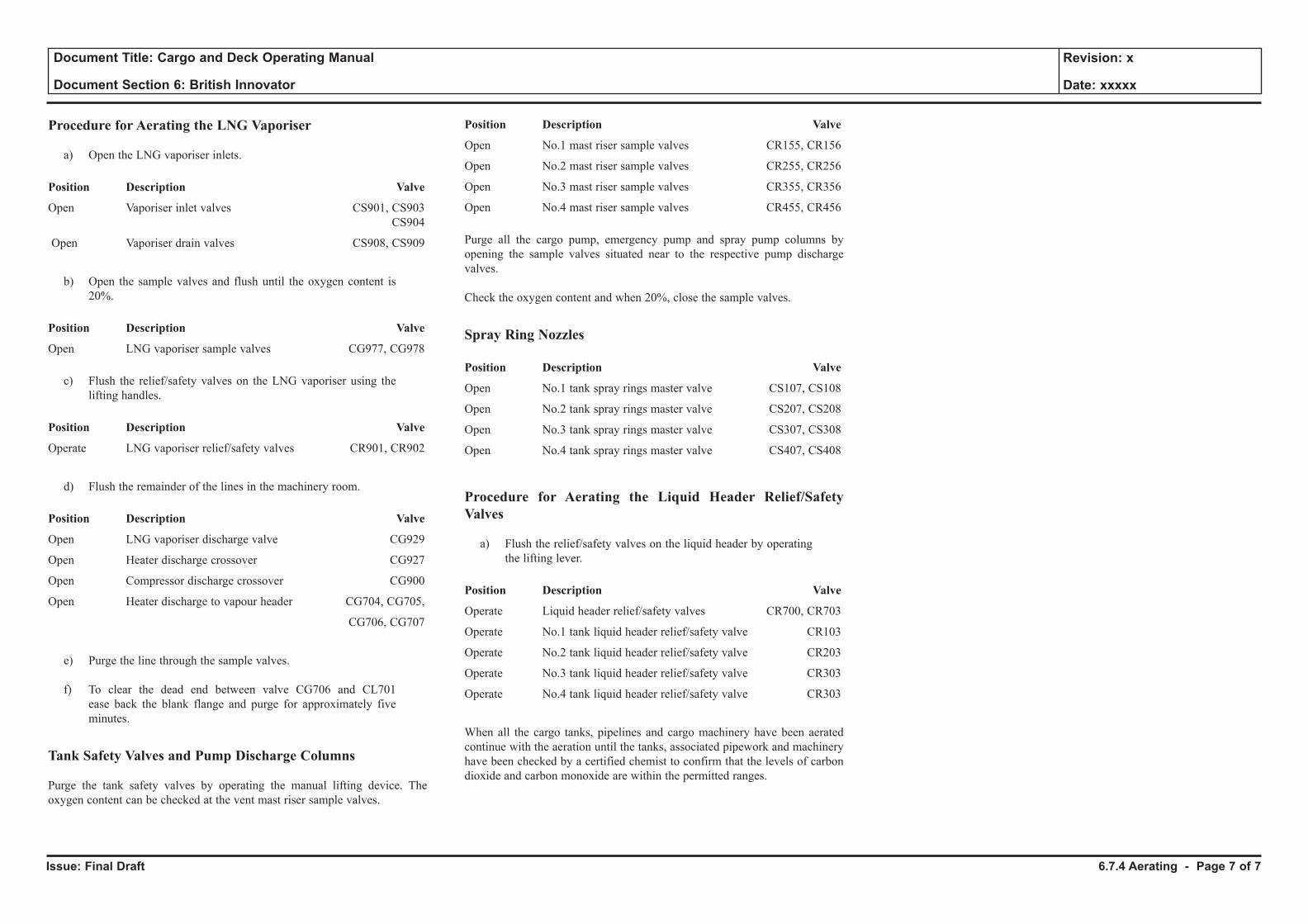
Issue: Final Draft
Document Title: Cargo and Deck Operating Manual
Document Section 6: British Innovator
Revision: x
Date: xxxxx
Procedure for Aerating the LNG Vaporiser
a) Open the LNG vaporiser inlets.
Position Description Valve
Open Vaporiser inlet valves CS901, CS903 CS904
Open Vaporiser drain valves CS908, CS909
b) Open the sample valves and flush until the oxygen content is
20%.
Position Description Valve
Open LNG vaporiser sample valves CG977, CG978
c) Flush the relief/safety valves on the LNG vaporiser using the lifting handles.
Position Description Valve
Operate LNG vaporiser relief/safety valves CR901, CR902
d) Flush the remainder of the lines in the machinery room.
Position Description Valve
Open LNG vaporiser discharge valve CG929
Open Heater discharge crossover CG927
Open Compressor discharge crossover CG900
Open Heater discharge to vapour header CG704, CG705,
CG706, CG707
e) Purge the line through the sample valves.
f) To clear the dead end between valve CG706 and CL701 ease back the blank flange and purge for approximately five minutes.
Tank Safety Valves and Pump Discharge Columns
Purge the tank safety valves by operating the manual lifting device. The oxygen content can be checked at the vent mast riser sample valves.
Position Description Valve
Open No.1 mast riser sample valves CR155, CR156
Open No.2 mast riser sample valves CR255, CR256
Open No.3 mast riser sample valves CR355, CR356
Open No.4 mast riser sample valves CR455, CR456
Purge all the cargo pump, emergency pump and spray pump columns by opening the sample valves situated near to the respective pump discharge valves.
Check the oxygen content and when 20%, close the sample valves.
Spray Ring Nozzles
Position Description Valve
Open No.1 tank spray rings master valve CS107, CS108
Open No.2 tank spray rings master valve CS207, CS208
Open No.3 tank spray rings master valve CS307, CS308
Open No.4 tank spray rings master valve CS407, CS408
Procedure for Aerating the Liquid Header Relief/Safety Valves
a) Flush the relief/safety valves on the liquid header by operating the lifting lever.
Position Description Valve
Operate Liquid header relief/safety valves CR700, CR703
Operate No.1 tank liquid header relief/safety valve CR103
Operate No.2 tank liquid header relief/safety valve CR203
Operate No.3 tank liquid header relief/safety valve CR303
Operate No.4 tank liquid header relief/safety valve CR303
When all the cargo tanks, pipelines and cargo machinery have been aerated continue with the aeration until the tanks, associated pipework and machinery have been checked by a certified chemist to confirm that the levels of carbon dioxide and carbon monoxide are within the permitted ranges.
6.7.4 Aerating - Page 7 of 7
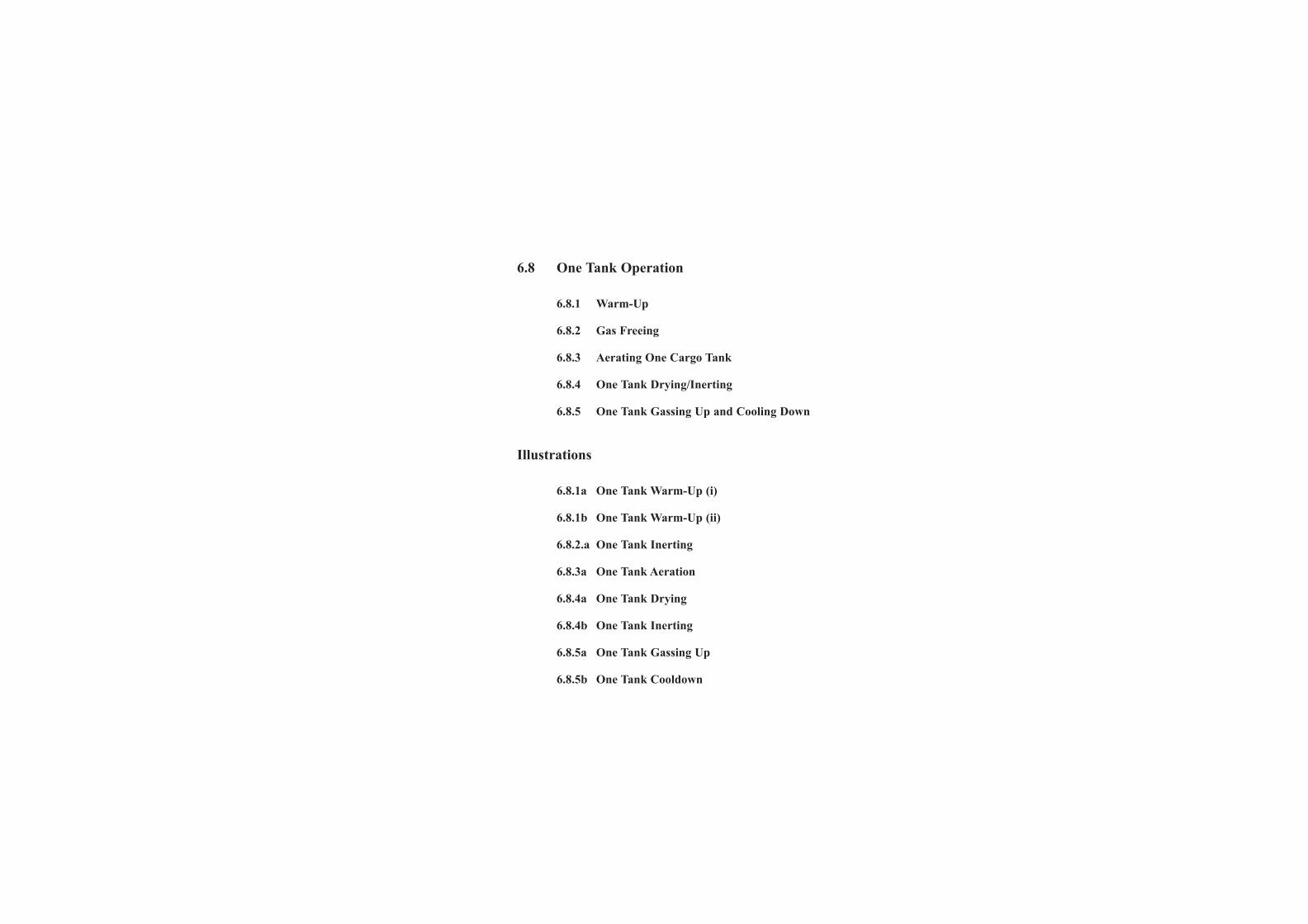
6.8 One Tank Operation
6.8.1 Warm-Up
6.8.2 Gas Freeing
6.8.3 Aerating One Cargo Tank
6.8.4 One Tank Drying/Inerting
6.8.5 One Tank Gassing Up and Cooling Down
Illustrations
6.8.1a One Tank Warm-Up (i)
6.8.1b One Tank Warm-Up (ii)
6.8.2.a One Tank Inerting
6.8.3a One Tank Aeration
6.8.4a One Tank Drying
6.8.4b One Tank Inerting
6.8.5a One Tank Gassing Up
6.8.5b One Tank Cooldown
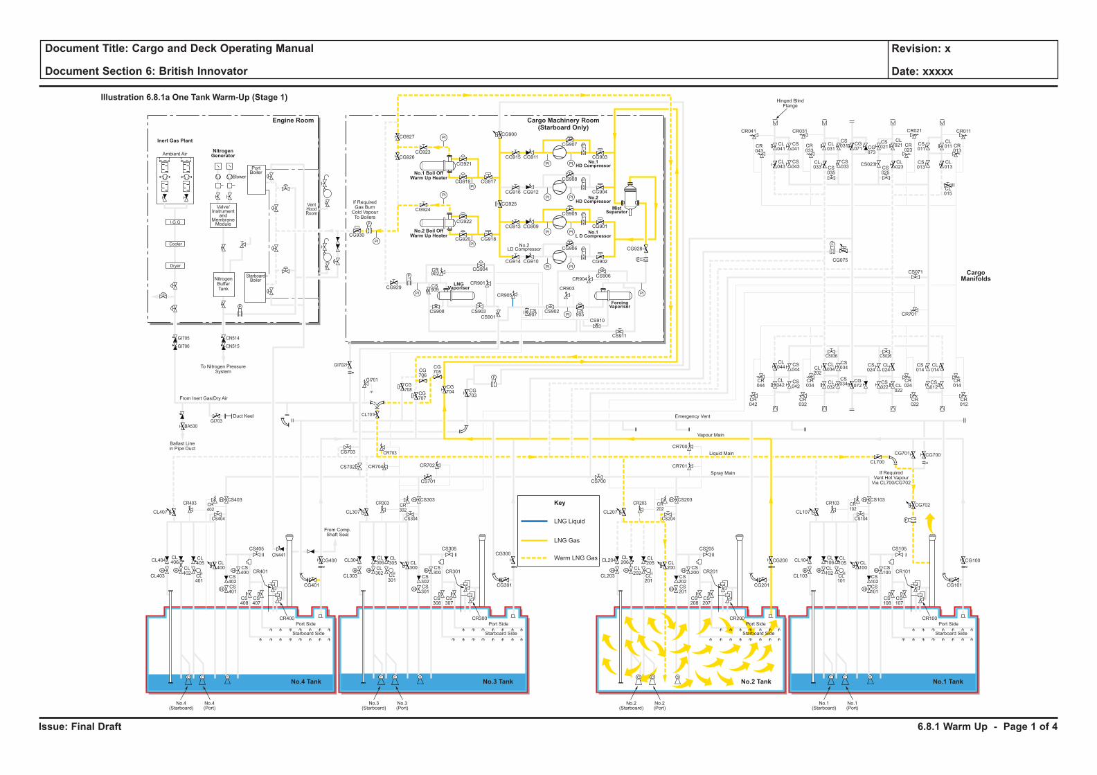
Issue: Final Draft
Document Title: Cargo and Deck Operating Manual
Document Section 6: British Innovator
Revision: x
Date: xxxxx
LNG Liquid
Key
LNG Gas
Warm LNG Gas
H H
H
H
F
C C S
H
HH H
H
H
C C S
H
HH H
H
H
C C S
H
HH H
H
H
C C S
H
H
F
PI PI
F
PI PI
PI
PI
PI
PI
PI PI
PI PI
F
F
PI
PI
PI
PI
F
F
F
CL106
CL102
CL101
CL100
CS102
CS100
CS103
CS101
CS108
CS107
CR101
CR100
CL105
CL104
CL700
CG700
CG702
CG101
CS105
CS104
CR103 CR102
CG701
CL103
Port Side
Starboard Side
CL107
No.1(Starboard)
No.1(Port)
CL206
CL202
CL201
CL200
CS202
CS200
CS203
CR701
CR700
CS201
CS208
CS207
CR201
CR200
CL205
CL204
CG201
CG200 CG100
CS205
CS204
CR203 CR202
CL203
Port Side
Ambient Air
Blower
PortBoiler
VentHoodRoom
StarboardBoiler
Inert Gas Plant
NitrogenGenerator
Engine Room
No.3 TankNo.4 Tank No.1 TankNo.2 Tank
Cargo Machinery Room(Starboard Only)
Starboard Side
CL207
CS700
No.2(Starboard)
No.2(Port)
CL306
CL302
CL301
CL300
CS302
CS300
CS303
CS701
CS301
CS308
CS307
CR301
CR300
CL305
CL304
CG301
CS305
CS304
CR303 CR302
CL303
Port Side
Starboard Side
CL307
CG927
CG926CG923
CG921
CG917CG919
CG924
CG930
CG929
CG904
CR901
CR905
CR903
CR904
CS909
CS907
CS905
CS908 CS903
CS901
CS902
CS906
CS910
CS911
CR902
CG922
CG918
CG928
CG902
CG906
CG905
CG908
CG907
CR041
CR043
CL041
CL043
CS041
CS043
CL031
CS031 CS
011
CL011 CR
013
CG071 CG
073
CS021
CL021
CL023CS
025
CS023 CL013
CL015
CS013
CR023
CR033
CR021CR031 CR011
CS035
CL033
CS033
CG915
CG900
CG925
CG911
CG916 CG912
CG913 CG909
CG914 CG910
CG901
CG904
CG903
CG920
No.3(Starboard)
No.3(Port)
CL406
CL402
CL401
CL400
CS402
CS400
CS403
CS702 CR704 CR702
CR703
CG708
CG707
CG706
CG705
CG704 CG
703
CS703
CL701
CS401
CS408
CS407
CR401
CR400
CL405
CL404
CG401
CG400
CG300CS405
From Comp.Shaft Seal
CS404
CR403
GI705
GI706
GI703
GI702
GI701
BA530
CN514
CN515
CR402
CL403
Port Side
Starboard Side
CL407
No.4(Starboard)
No.4(Port)
CL044
CS044
CS042
CS034
CS024
CL024
CS034
CR044
CR034
CR024
CR042
CR032
CR022
CS036 CS026
CL042
CL034CL
202
CL032
CG072
CS022 CL
022
CS014
CR701
CS071
CL014
CR014
CR012
CS012
F
F
F
Cooler
Dryer
I.G.G
Valve/Instrument
andMembraneModule
NitrogenBufferTank
To Nitrogen PressureSystem
If RequiredGas BurnCold VapourTo Boilers
Hinged BlindFlange
Ballast Linein Pipe Duct
Duct Keel
From Inert Gas/Dry Air
Emergency Vent
Vapour Main
Liquid Main
Spray Main
No.1 Boil OffWarm Up Heater
No.2 Boil OffWarm Up Heater
ForcingVaporiser
MistSeparator
No.1HD Compressor
No.2HD Compressor
No.1L D Compressor
LNGVaporiser
No.2LD Compressor
Illustration 6.8.1a One Tank Warm-Up (Stage 1)
CargoManifolds
CG075
CN441
If RequiredVent Hot VapourVia CL700/CG702
6.8.1 Warm Up - Page 1 of 4
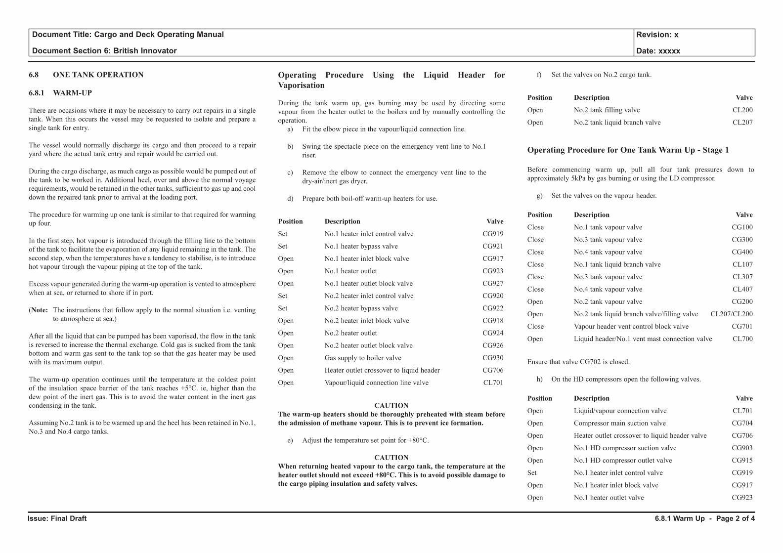
Issue: Final Draft
Document Title: Cargo and Deck Operating Manual
Document Section 6: British Innovator
Revision: x
Date: xxxxx
6.8 ONE TANK OPERATION
6.8.1 WARM-UP
There are occasions where it may be necessary to carry out repairs in a single tank. When this occurs the vessel may be requested to isolate and prepare a single tank for entry.
The vessel would normally discharge its cargo and then proceed to a repair yard where the actual tank entry and repair would be carried out.
During the cargo discharge, as much cargo as possible would be pumped out of the tank to be worked in. Additional heel, over and above the normal voyage requirements, would be retained in the other tanks, sufficient to gas up and cool down the repaired tank prior to arrival at the loading port.
The procedure for warming up one tank is similar to that required for warming up four.
In the first step, hot vapour is introduced through the filling line to the bottom of the tank to facilitate the evaporation of any liquid remaining in the tank. The second step, when the temperatures have a tendency to stabilise, is to introduce hot vapour through the vapour piping at the top of the tank.
Excess vapour generated during the warm-up operation is vented to atmosphere when at sea, or returned to shore if in port.
(Note: The instructions that follow apply to the normal situation i.e. venting to atmosphere at sea.)
After all the liquid that can be pumped has been vaporised, the flow in the tank is reversed to increase the thermal exchange. Cold gas is sucked from the tank bottom and warm gas sent to the tank top so that the gas heater may be used with its maximum output.
The warm-up operation continues until the temperature at the coldest point of the insulation space barrier of the tank reaches +5°C. ie, higher than the dew point of the inert gas. This is to avoid the water content in the inert gas condensing in the tank.
Assuming No.2 tank is to be warmed up and the heel has been retained in No.1, No.3 and No.4 cargo tanks.
Operating Procedure Using the Liquid Header for Vaporisation
During the tank warm up, gas burning may be used by directing some vapour from the heater outlet to the boilers and by manually controlling the operation.
a) Fit the elbow piece in the vapour/liquid connection line.
b) Swing the spectacle piece on the emergency vent line to No.1 riser.
c) Remove the elbow to connect the emergency vent line to the dry-air/inert gas dryer.
d) Prepare both boil-off warm-up heaters for use.
Position Description Valve
Set No.1 heater inlet control valve CG919
Set No.1 heater bypass valve CG921
Open No.1 heater inlet block valve CG917
Open No.1 heater outlet CG923
Open No.1 heater outlet block valve CG927
Set No.2 heater inlet control valve CG920
Set No.2 heater bypass valve CG922
Open No.2 heater inlet block valve CG918
Open No.2 heater outlet CG924
Open No.2 heater outlet block valve CG926
Open Gas supply to boiler valve CG930
Open Heater outlet crossover to liquid header CG706
Open Vapour/liquid connection line valve CL701
CAUTION The warm-up heaters should be thoroughly preheated with steam before the admission of methane vapour. This is to prevent ice formation.
e) Adjust the temperature set point for +80°C.
CAUTION When returning heated vapour to the cargo tank, the temperature at the heater outlet should not exceed +80°C. This is to avoid possible damage to the cargo piping insulation and safety valves.
f) Set the valves on No.2 cargo tank.
Position Description Valve
Open No.2 tank filling valve CL200
Open No.2 tank liquid branch valve CL207
Operating Procedure for One Tank Warm Up - Stage 1
Before commencing warm up, pull all four tank pressures down to approximately 5kPa by gas burning or using the LD compressor.
g) Set the valves on the vapour header.
Position Description Valve
Close No.1 tank vapour valve CG100
Close No.3 tank vapour valve CG300
Close No.4 tank vapour valve CG400
Close No.1 tank liquid branch valve CL107
Close No.3 tank vapour valve CL307
Close No.4 tank vapour valve CL407
Open No.2 tank vapour valve CG200
Open No.2 tank liquid branch valve/filling valve CL207/CL200
Close Vapour header vent control block valve CG701
Open Liquid header/No.1 vent mast connection valve CL700
Ensure that valve CG702 is closed.
h) On the HD compressors open the following valves.
Position Description Valve
Open Liquid/vapour connection valve CL701
Open Compressor main suction valve CG704
Open Heater outlet crossover to liquid header valve CG706
Open No.1 HD compressor suction valve CG903
Open No.1 HD compressor outlet valve CG915
Set No.1 heater inlet control valve CG919
Open No.1 heater inlet block valve CG917
Open No.1 heater outlet valve CG923
6.8.1 Warm Up - Page 2 of 4
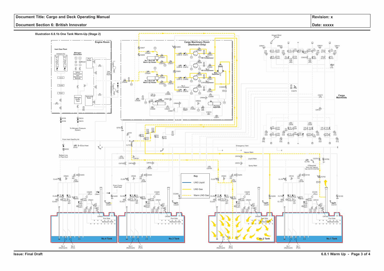
Issue: Final Draft
Document Title: Cargo and Deck Operating Manual
Document Section 6: British Innovator
Revision: x
Date: xxxxx
LNG Liquid
Key
LNG Gas
Warm LNG Gas
H H
H
H
F
C C S
H
HH H
H
H
C C S
H
HH H
H
H
C C S
H
HH H
H
H
C C S
H
H
F
PI PI
F
PI PI
PI
PI
PI
PI
PI PI
PI PI
F
F
PI
PI
PI
PI
F
F
F
CL106
CL102
CL101
CL100
CS102
CS100
CS103
CS101
CS108
CS107
CR101
CR100
CL105
CL104
CL700
CG700
CG702
CG101
CS105
CS104
CR103 CR102
CG701
CL103
Port Side
Starboard Side
CL107
No.1(Starboard)
No.1(Port)
CL206
CL202
CL201
CL200
CS202
CS200
CS203
CR701
CR700
CS201
CS208
CS207
CR201
CR200
CL205
CL204
CG201
CG200 CG100
CS205
CS204
CR203 CR202
CL203
Port Side
Ambient Air
Blower
PortBoiler
VentHoodRoom
StarboardBoiler
Inert Gas Plant
NitrogenGenerator
Engine Room
No.3 TankNo.4 Tank No.1 TankNo.2 Tank
Cargo Machinery Room(Starboard Only)
Starboard Side
CL207
CS700
No.2(Starboard)
No.2(Port)
CL306
CL302
CL301
CL300
CS302
CS300
CS303
CS701
CS301
CS308
CS307
CR301
CR300
CL305
CL304
CG301
CS305
CS304
CR303 CR302
CL303
Port Side
Starboard Side
CL307
CG927
CG926CG923
CG921
CG917CG919
CG924
CG930
CG929
CG904
CR901
CR905
CR903
CR904
CS909
CS907
CS905
CS908 CS903
CS901
CS902
CS906
CS910
CS911
CR902
CG922
CG918
CG928
CG902
CG906
CG905
CG908
CG907
CR041
CR043
CL041
CL043
CS041
CS043
CL031
CS031 CS
011
CL011 CR
013
CG071 CG
073
CS021
CL021
CL023CS
025
CS023 CL013
CL015
CS013
CR023
CR033
CR021CR031 CR011
CS035
CL033
CS033
CG915
CG900
CG925
CG911
CG916 CG912
CG913 CG909
CG914 CG910
CG901
CG904
CG903
CG920
No.3(Starboard)
No.3(Port)
CL406
CL402
CL401
CL400
CS402
CS400
CS403
CS702 CR704 CR702
CR703
CG708
CG707
CG706
CG705
CG704 CG
703
CS703
CL701
CS401
CS408
CS407
CR401
CR400
CL405
CL404
CG401
CG400
CG300CS405
From Comp.Shaft Seal
CS404
CR403
GI705
GI706
GI703
GI702
GI701
BA530
CN514
CN515
CR402
CL403
Port Side
Starboard Side
CL407
No.4(Starboard)
No.4(Port)
CL044
CS044
CS042
CS034
CS024
CL024
CS034
CR044
CR034
CR024
CR042
CR032
CR022
CS036 CS026
CL042
CL034CL
202
CL032
CG072
CS022 CL
022
CS014
CR701
CS071
CL014
CR014
CR012
CS012
F
F
F
Cooler
Dryer
I.G.G
Valve/Instrument
andMembraneModule
NitrogenBufferTank
To Nitrogen PressureSystem
Hinged BlindFlange
Ballast Linein Pipe Duct
Duct Keel
From Inert Gas/Dry Air
Emergency Vent
Vapour Main
Liquid Main
Spray Main
No.1 Boil OffWarm Up Heater
No.2 Boil OffWarm Up Heater
ForcingVaporiser
MistSeparator
No.1HD Compressor
No.2HD Compressor
No.1L D Compressor
LNGVaporiser
No.2LD Compressor
Illustration 6.8.1b One Tank Warm-Up (Stage 2)
CargoManifolds
CG075
CN441
If RequiredVent Hot VapourVia CG701/CG702
6.8.1 Warm Up - Page 3 of 4
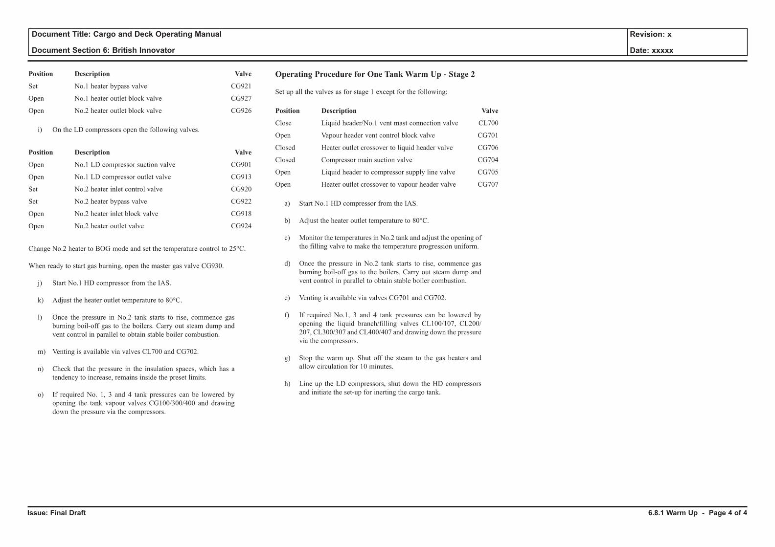
Issue: Final Draft
Document Title: Cargo and Deck Operating Manual
Document Section 6: British Innovator
Revision: x
Date: xxxxx
Position Description Valve
Set No.1 heater bypass valve CG921
Open No.1 heater outlet block valve CG927
Open No.2 heater outlet block valve CG926
i) On the LD compressors open the following valves.
Position Description Valve
Open No.1 LD compressor suction valve CG901
Open No.1 LD compressor outlet valve CG913
Set No.2 heater inlet control valve CG920
Set No.2 heater bypass valve CG922
Open No.2 heater inlet block valve CG918
Open No.2 heater outlet valve CG924
Change No.2 heater to BOG mode and set the temperature control to 25°C.
When ready to start gas burning, open the master gas valve CG930.
j) Start No.1 HD compressor from the IAS.
k) Adjust the heater outlet temperature to 80°C.
l) Once the pressure in No.2 tank starts to rise, commence gas burning boil-off gas to the boilers. Carry out steam dump and vent control in parallel to obtain stable boiler combustion.
m) Venting is available via valves CL700 and CG702.
n) Check that the pressure in the insulation spaces, which has a tendency to increase, remains inside the preset limits.
o) If required No. 1, 3 and 4 tank pressures can be lowered by opening the tank vapour valves CG100/300/400 and drawing down the pressure via the compressors.
Operating Procedure for One Tank Warm Up - Stage 2
Set up all the valves as for stage 1 except for the following:
Position Description Valve
Close Liquid header/No.1 vent mast connection valve CL700
Open Vapour header vent control block valve CG701
Closed Heater outlet crossover to liquid header valve CG706
Closed Compressor main suction valve CG704
Open Liquid header to compressor supply line valve CG705
Open Heater outlet crossover to vapour header valve CG707
a) Start No.1 HD compressor from the IAS.
b) Adjust the heater outlet temperature to 80°C.
c) Monitor the temperatures in No.2 tank and adjust the opening of the filling valve to make the temperature progression uniform.
d) Once the pressure in No.2 tank starts to rise, commence gas
burning boil-off gas to the boilers. Carry out steam dump and vent control in parallel to obtain stable boiler combustion.
e) Venting is available via valves CG701 and CG702.
f) If required No.1, 3 and 4 tank pressures can be lowered by opening the liquid branch/filling valves CL100/107, CL200/207, CL300/307 and CL400/407 and drawing down the pressure via the compressors.
g) Stop the warm up. Shut off the steam to the gas heaters and allow circulation for 10 minutes.
h) Line up the LD compressors, shut down the HD compressors and initiate the set-up for inerting the cargo tank.
6.8.1 Warm Up - Page 4 of 4
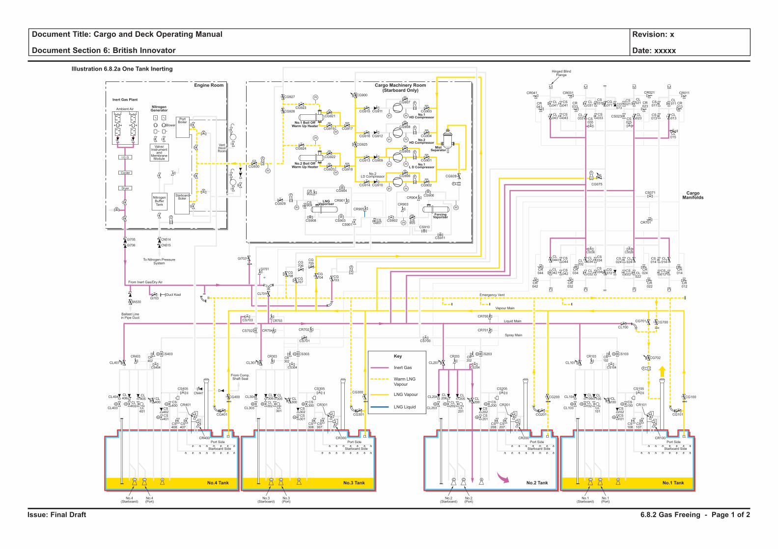
Issue: Final Draft
Document Title: Cargo and Deck Operating Manual
Document Section 6: British Innovator
Revision: x
Date: xxxxx
LNG Liquid
Inert Gas
Key
Warm LNG
Vapour
LNG Vapour
H H
H
H
F
C C S
H
HH H
H
H
C C S
H
HH H
H
H
C C S
H
HH H
H
H
C C S
H
H
F
PI PI
F
PI PI
PI
PI
PI
PI
PI PI
PI PI
F
F
PI
PI
PI
PI
F
F
F
CL106
CL102
CL101
CL100
CS102
CS100
CS103
CS101
CS108
CS107
CR101
CR100
CL105
CL104
CL700
CG700
CG702
CG101
CS105
CS104
CR103 CR102
CG701
CL103
Port Side
Starboard Side
CL107
No.1(Starboard)
No.1(Port)
CL206
CL202
CL201
CL200
CS202
CS200
CS203
CR701
CR700
CS201
CS208
CS207
CR201
CR200
CL205
CL204
CG201
CG200 CG100
CS205
CS204
CR203 CR202
CL203
Port Side
Ambient Air
Blower
PortBoiler
VentHoodRoom
StarboardBoiler
Inert Gas Plant
NitrogenGenerator
Engine Room
No.3 TankNo.4 Tank No.1 TankNo.2 Tank
Cargo Machinery Room(Starboard Only)
Starboard Side
CL207
CS700
No.2(Starboard)
No.2(Port)
CL306
CL302
CL301
CL300
CS302
CS300
CS303
CS701
CS301
CS308
CS307
CR301
CR300
CL305
CL304
CG301
CS305
CS304
CR303 CR302
CL303
Port Side
Starboard Side
CL307
CG927
CG926CG923
CG921
CG917CG919
CG924
CG930
CG929
CG904
CR901
CR905
CR903
CR904
CS909
CS907
CS905
CS908 CS903
CS901
CS902
CS906
CS910
CS911
CR902
CG922
CG918
CG928
CG902
CG906
CG905
CG908
CG907
CR041
CR043
CL041
CL043
CS041
CS043
CL031
CS031 CS
011
CL011 CR
013
CG071 CG
073
CS021
CL021
CL023CS
025
CS023 CL013
CL015
CS013
CR023
CR033
CR021CR031 CR011
CS035
CL033
CS033
CG915
CG900
CG925
CG911
CG916 CG912
CG913 CG909
CG914 CG910
CG901
CG904
CG903
CG920
No.3(Starboard)
No.3(Port)
CL406
CL402
CL401
CL400
CS402
CS400
CS403
CS702 CR704 CR702
CR703
CG708
CG707
CG706
CG705
CG704 CG
703
CS703
CL701
CS401
CS408
CS407
CR401
CR400
CL405
CL404
CG401
CG400
CG300CS405
From Comp.Shaft Seal
CS404
CR403
GI705
GI706
GI703
GI702
GI701
BA530
CN514
CN515
CR402
CL403
Port Side
Starboard Side
CL407
No.4(Starboard)
No.4(Port)
CL044
CS044
CS042
CS034
CS024
CL024
CS034
CR044
CR034
CR024
CR042
CR032
CR022
CS036 CS026
CL042
CL034CL
202
CL032
CG072
CS022 CL
022
CS014
CR701
CS071
CL014
CR014
CR012
CS012
F
F
F
Cooler
Dryer
I.G.G
Valve/Instrument
andMembraneModule
NitrogenBufferTank
To Nitrogen PressureSystem
Hinged BlindFlange
Ballast Linein Pipe Duct
Duct Keel
From Inert Gas/Dry Air
Emergency Vent
Vapour Main
Liquid Main
Spray Main
No.1 Boil OffWarm Up Heater
No.2 Boil OffWarm Up Heater
ForcingVaporiser
MistSeparator
No.1HD Compressor
No.2HD Compressor
No.1L D Compressor
LNGVaporiser
No.2LD Compressor
Illustration 6.8.2a One Tank Inerting
CargoManifolds
CG075
CN441
6.8.2 Gas Freeing - Page 1 of 2
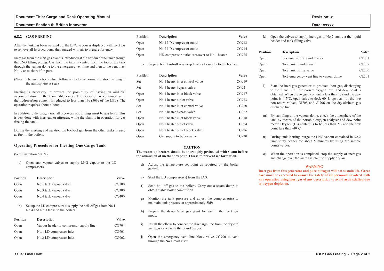
Issue: Final Draft
Document Title: Cargo and Deck Operating Manual
Document Section 6: British Innovator
Revision: x
Date: xxxxx
6.8.2 GAS FREEING
After the tank has been warmed up, the LNG vapour is displaced with inert gas to remove all hydrocarbons, then purged with air to prepare for entry.
Inert gas from the inert gas plant is introduced at the bottom of the tank through the LNG filling piping. Gas from the tank is vented from the top of the tank through the vapour dome to the emergency vent line and then to the vent mast No.1, or to shore if in port.
(Note: The instructions which follow apply to the normal situation, venting to the atmosphere at sea.)
Inerting is necessary to prevent the possibility of having an air/LNG vapour mixture in the flammable range. The operation is continued until the hydrocarbon content is reduced to less than 1% (50% of the LEL). The operation requires about 6 hours.
In addition to the cargo tank, all pipework and fittings must be gas freed. This is best done with inert gas or nitrogen, while the plant is in operation for gas freeing the tank.
During the inerting and aeration the boil-off gas from the other tanks is used as fuel in the boilers.
Operating Procedure for Inerting One Cargo Tank
(See illustration 6.8.2a)
a) Open tank vapour valves to supply LNG vapour to the LD compressors.
Position Description Valve
Open No.1 tank vapour valve CG100
Open No.3 tank vapour valve CG300
Open No.4 tank vapour valve CG400
b) Set up the LD compressors to supply the boil-off gas from No.1. No.4 and No.3 tanks to the boilers.
Position Description Valve
Open Vapour header to compressor supply line CG704
Open No.1 LD compressor inlet CG901
Open No.2 LD compressor inlet CG902
Position Description Valve
Open No.1 LD compressor outlet CG913
Open No.2 LD compressor outlet CG914
Open HD compressor outlet crossover to No.1 heater CG925
c) Prepare both boil-off warm-up heaters to supply to the boilers.
Position Description Valve
Set No.1 heater inlet control valve CG919
Set No.1 heater bypass valve CG921
Open No.1 heater inlet block valve CG917
Open No.1 heater outlet valve CG923
Set No.2 heater inlet control valve CG920
Set No.2 heater bypass valve CG922
Open No.2 heater inlet block valve CG918
Open No.2 heater outlet valve CG924
Open No.2 heater outlet block valve CG926
Open Gas supply to boiler valve CG930
CAUTION The warm-up heaters should be thoroughly preheated with steam before the admission of methane vapour. This is to prevent ice formation.
d) Adjust the temperature set point as required by the boiler control.
e) Start the LD compressor(s) from the IAS.
f) Send boil-off gas to the boilers. Carry out a steam dump to obtain stable boiler combustion.
g) Monitor the tank pressure and adjust the compressor(s) to maintain tank pressure at approximately 5kPa.
h) Prepare the dry-air/inert gas plant for use in the inert gas mode.
i) Install the elbow to connect the discharge line from the dry-air/inert gas dryer with the liquid header.
j) Open the emergency vent line block valve CG700 to vent through the No.1 mast riser.
k) Open the valves to supply inert gas to No.2 tank via the liquid header and tank filling valve.
Position Description Valve
Open IG crossover to liquid header CL701
Open No.2 tank liquid branch CL207
Open No.2 tank filling valve CL200
Open No.2 emergency vent line to vapour dome CL201
l) Start the inert gas generator to produce inert gas, discharging to the funnel until the correct oxygen level and dew point is obtained. When the oxygen content is less than 1% and the dew point is -45°C, open valve to deck 6041, upstream of the two non-return valves, GI705 and GI706 on the dry-air/inert gas discharge line.
m) By sampling at the vapour dome, check the atmosphere of the tank by means of the portable oxygen analyser and dew point meter. Oxygen (O2) content is to be less than 2% and the dew point less than -40°C.
n) During tank inerting, purge the LNG vapour contained in No.2 tank spray header for about 5 minutes by using the sample points valves.
o) When the operation is completed, stop the supply of inert gas and change over the inert gas plant to supply dry air.
WARNINGInert gas from this generator and pure nitrogen will not sustain life. Great care must be exercised to ensure the safety of all personnel involved with any operation using inert gas of any description to avoid asphyxiation due to oxygen depletion.
6.8.2 Gas Freeing - Page 2 of 2
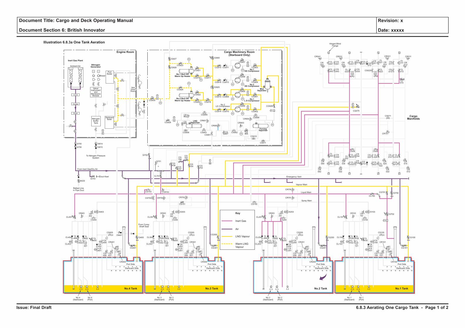
Issue: Final Draft
Document Title: Cargo and Deck Operating Manual
Document Section 6: British Innovator
Revision: x
Date: xxxxx
Inert Gas
Key
Air
LNG Vapour
Warm LNG
Vapour
H H
H
H
F
C C S
H
HH H
H
H
C C S
H
HH H
H
H
C C S
H
HH H
H
H
C C S
H
H
F
PI PI
F
PI PI
PI
PI
PI
PI
PI PI
PI PI
F
F
PI
PI
PI
PI
F
F
F
CL106
CL102
CL101
CL100
CS102
CS100
CS103
CS101
CS108
CS107
CR101
CR100
CL105
CL104
CL700
CG700
CG702
CG101
CS105
CS104
CR103 CR102
CG701
CL103
Port Side
Starboard Side
CL107
No.1(Starboard)
No.1(Port)
CL206
CL202
CL201
CL200
CS202
CS200
CS203
CR701
CR700
CS201
CS208
CS207
CR201
CR200
CL205
CL204
CG201
CG200 CG100
CS205
CS204
CR203 CR202
CL203
Port Side
Ambient Air
Blower
PortBoiler
VentHoodRoom
StarboardBoiler
Inert Gas Plant
NitrogenGenerator
Engine Room
No.3 TankNo.4 Tank No.1 TankNo.2 Tank
Cargo Machinery Room(Starboard Only)
Starboard Side
CL207
CS700
No.2(Starboard)
No.2(Port)
CL306
CL302
CL301
CL300
CS302
CS300
CS303
CS701
CS301
CS308
CS307
CR301
CR300
CL305
CL304
CG301
CS305
CS304
CR303 CR302
CL303
Port Side
Starboard Side
CL307
CG927
CG926CG923
CG921
CG917CG919
CG924
CG930
CG929
CG904
CR901
CR905
CR903
CR904
CS909
CS907
CS905
CS908 CS903
CS901
CS902
CS906
CS910
CS911
CR902
CG922
CG918
CG928
CG902
CG906
CG905
CG908
CG907
CR041
CR043
CL041
CL043
CS041
CS043
CL031
CS031 CS
011
CL011 CR
013
CG071 CG
073
CS021
CL021
CL023CS
025
CS023 CL013
CL015
CS013
CR023
CR033
CR021CR031 CR011
CS035
CL033
CS033
CG915
CG900
CG925
CG911
CG916 CG912
CG913 CG909
CG914 CG910
CG901
CG904
CG903
CG920
No.3(Starboard)
No.3(Port)
CL406
CL402
CL401
CL400
CS402
CS400
CS403
CS702 CR704 CR702
CR703
CG708
CG707
CG706
CG705
CG704 CG
703
CS703
CL701
CS401
CS408
CS407
CR401
CR400
CL405
CL404
CG401
CG400
CG300CS405
From Comp.Shaft Seal
CS404
CR403
GI705
GI706
GI703
GI702
GI701
BA530
CN514
CN515
CR402
CL403
Port Side
Starboard Side
CL407
No.4(Starboard)
No.4(Port)
CL044
CS044
CS042
CS034
CS024
CL024
CS034
CR044
CR034
CR024
CR042
CR032
CR022
CS036 CS026
CL042
CL034CL
202
CL032
CG072
CS022 CL
022
CS014
CR701
CS071
CL014
CR014
CR012
CS012
F
F
F
Cooler
Dryer
I.G.G
Valve/Instrument
andMembraneModule
NitrogenBufferTank
To Nitrogen PressureSystem
Hinged BlindFlange
Ballast Linein Pipe Duct
Duct Keel
From Inert Gas/Dry Air
Emergency Vent
Vapour Main
Liquid Main
Spray Main
No.1 Boil OffWarm Up Heater
No.2 Boil OffWarm Up Heater
ForcingVaporiser
MistSeparator
No.1HD Compressor
No.2HD Compressor
No.1L D Compressor
LNGVaporiser
No.2LD Compressor
Illustration 6.8.3a One Tank Aeration
CargoManifolds
CG075
CN441
6.8.3 Aerating One Cargo Tank - Page 1 of 2
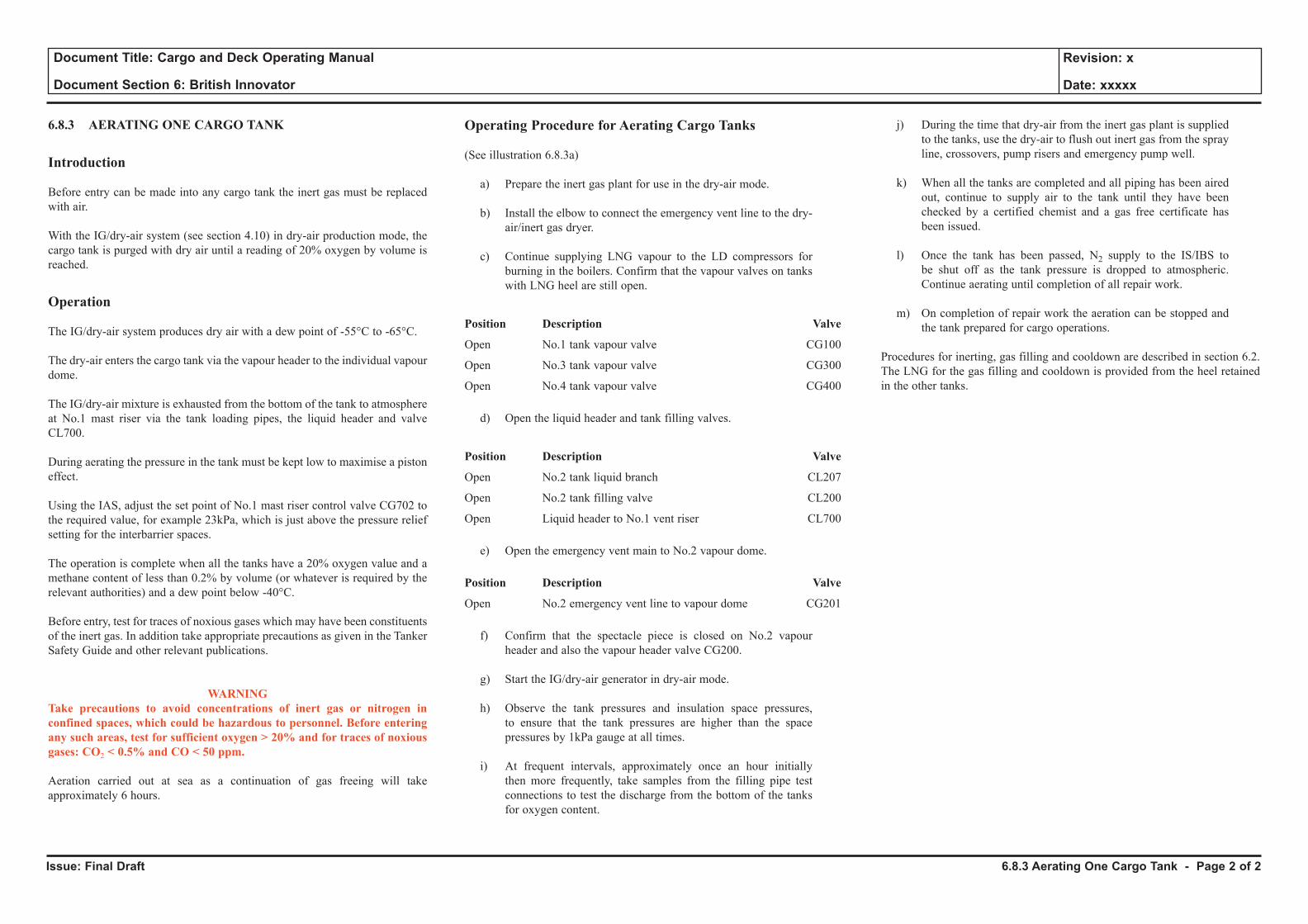
Issue: Final Draft
Document Title: Cargo and Deck Operating Manual
Document Section 6: British Innovator
Revision: x
Date: xxxxx
6.8.3 AERATING ONE CARGO TANK
Introduction
Before entry can be made into any cargo tank the inert gas must be replaced with air.
With the IG/dry-air system (see section 4.10) in dry-air production mode, the cargo tank is purged with dry air until a reading of 20% oxygen by volume is reached.
Operation
The IG/dry-air system produces dry air with a dew point of -55°C to -65°C.
The dry-air enters the cargo tank via the vapour header to the individual vapour dome.
The IG/dry-air mixture is exhausted from the bottom of the tank to atmosphere at No.1 mast riser via the tank loading pipes, the liquid header and valve CL700.
During aerating the pressure in the tank must be kept low to maximise a piston effect.
Using the IAS, adjust the set point of No.1 mast riser control valve CG702 to the required value, for example 23kPa, which is just above the pressure relief setting for the interbarrier spaces.
The operation is complete when all the tanks have a 20% oxygen value and a methane content of less than 0.2% by volume (or whatever is required by the relevant authorities) and a dew point below -40°C.
Before entry, test for traces of noxious gases which may have been constituents of the inert gas. In addition take appropriate precautions as given in the Tanker Safety Guide and other relevant publications.
WARNINGTake precautions to avoid concentrations of inert gas or nitrogen in confined spaces, which could be hazardous to personnel. Before entering any such areas, test for sufficient oxygen > 20% and for traces of noxious gases: CO2 < 0.5% and CO < 50 ppm.
Aeration carried out at sea as a continuation of gas freeing will take approximately 6 hours.
Operating Procedure for Aerating Cargo Tanks
(See illustration 6.8.3a)
a) Prepare the inert gas plant for use in the dry-air mode.
b) Install the elbow to connect the emergency vent line to the dry-air/inert gas dryer.
c) Continue supplying LNG vapour to the LD compressors for burning in the boilers. Confirm that the vapour valves on tanks with LNG heel are still open.
Position Description Valve
Open No.1 tank vapour valve CG100
Open No.3 tank vapour valve CG300
Open No.4 tank vapour valve CG400
d) Open the liquid header and tank filling valves.
Position Description Valve
Open No.2 tank liquid branch CL207
Open No.2 tank filling valve CL200
Open Liquid header to No.1 vent riser CL700
e) Open the emergency vent main to No.2 vapour dome.
Position Description Valve
Open No.2 emergency vent line to vapour dome CG201
f) Confirm that the spectacle piece is closed on No.2 vapour header and also the vapour header valve CG200.
g) Start the IG/dry-air generator in dry-air mode.
h) Observe the tank pressures and insulation space pressures, to ensure that the tank pressures are higher than the space pressures by 1kPa gauge at all times.
i) At frequent intervals, approximately once an hour initially then more frequently, take samples from the filling pipe test connections to test the discharge from the bottom of the tanks for oxygen content.
j) During the time that dry-air from the inert gas plant is supplied to the tanks, use the dry-air to flush out inert gas from the spray line, crossovers, pump risers and emergency pump well.
k) When all the tanks are completed and all piping has been aired out, continue to supply air to the tank until they have been checked by a certified chemist and a gas free certificate has been issued.
l) Once the tank has been passed, N2 supply to the IS/IBS to be shut off as the tank pressure is dropped to atmospheric. Continue aerating until completion of all repair work.
m) On completion of repair work the aeration can be stopped and the tank prepared for cargo operations.
Procedures for inerting, gas filling and cooldown are described in section 6.2. The LNG for the gas filling and cooldown is provided from the heel retained in the other tanks.
6.8.3 Aerating One Cargo Tank - Page 2 of 2
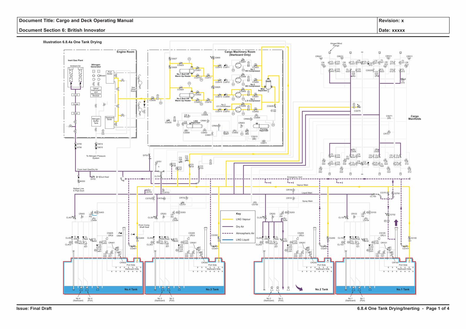
Issue: Final Draft
Document Title: Cargo and Deck Operating Manual
Document Section 6: British Innovator
Revision: x
Date: xxxxx
LNG Liquid
Key
LNG Vapour
Dry Air
Atmospheric Air
H H
H
H
F
C C S
H
HH H
H
H
C C S
H
HH H
H
H
C C S
H
HH H
H
H
C C S
H
H
F
PI PI
F
PI PI
PI
PI
PI
PI
PI PI
PI PI
F
F
PI
PI
PI
PI
F
F
F
CL106
CL102
CL101
CL100
CS102
CS100
CS103
CS101
CS108
CS107
CR101
CR100
CL105
CL104
CL700
CG700
CG702
CG101
CS105
CS104
CR103 CR102
CG701
CL103
Port Side
Starboard Side
CL107
No.1(Starboard)
No.1(Port)
CL206
CL202
CL201
CL200
CS202
CS200
CS203
CR701
CR700
CS201
CS208
CS207
CR201
CR200
CL205
CL204
CG201
CG200 CG100
CS205
CS204
CR203 CR202
CL203
Port Side
Ambient Air
Blower
PortBoiler
VentHoodRoom
StarboardBoiler
Inert Gas Plant
NitrogenGenerator
Engine Room
No.3 TankNo.4 Tank No.1 TankNo.2 Tank
Cargo Machinery Room(Starboard Only)
Starboard Side
CL207
CS700
No.2(Starboard)
No.2(Port)
CL306
CL302
CL301
CL300
CS302
CS300
CS303
CS701
CS301
CS308
CS307
CR301
CR300
CL305
CL304
CG301
CS305
CS304
CR303 CR302
CL303
Port Side
Starboard Side
CL307
CG927
CG926CG923
CG921
CG917CG919
CG924
CG930
CG929
CG904
CR901
CR905
CR903
CR904
CS909
CS907
CS905
CS908 CS903
CS901
CS902
CS906
CS910
CS911
CR902
CG922
CG918
CG928
CG902
CG906
CG905
CG908
CG907
CR041
CR043
CL041
CL043
CS041
CS043
CL031
CS031 CS
011
CL011 CR
013
CG071 CG
073
CS021
CL021
CL023CS
025
CS023 CL013
CL015
CS013
CR023
CR033
CR021CR031 CR011
CS035
CL033
CS033
CG915
CG900
CG925
CG911
CG916 CG912
CG913 CG909
CG914 CG910
CG901
CG904
CG903
CG920
No.3(Starboard)
No.3(Port)
CL406
CL402
CL401
CL400
CS402
CS400
CS403
CS702 CR704 CR702
CR703
CG708
CG707
CG706
CG705
CG704 CG
703
CS703
CL701
CS401
CS408
CS407
CR401
CR400
CL405
CL404
CG401
CG400
CG300CS405
From Comp.Shaft Seal
CS404
CR403
GI705
GI706
GI703
GI702
GI701
BA530
CN514
CN515
CR402
CL403
Port Side
Starboard Side
CL407
No.4(Starboard)
No.4(Port)
CL044
CS044
CS042
CS034
CS024
CL024
CS034
CR044
CR034
CR024
CR042
CR032
CR022
CS036 CS026
CL042
CL034CL
202
CL032
CG072
CS022 CL
022
CS014
CR701
CS071
CL014
CR014
CR012
CS012
F
F
F
Cooler
Dryer
I.G.G
Valve/Instrument
andMembraneModule
NitrogenBufferTank
To Nitrogen PressureSystem
Hinged BlindFlange
Ballast Linein Pipe Duct
Duct Keel
From Inert Gas/Dry Air
Emergency Vent
Vapour Main
Liquid Main
Spray Main
No.1 Boil OffWarm Up Heater
No.2 Boil OffWarm Up Heater
ForcingVaporiser
MistSeparator
No.1HD Compressor
No.2HD Compressor
No.1L D Compressor
LNGVaporiser
No.2LD Compressor
Illustration 6.8.4a One Tank Drying
CargoManifolds
CG075
CN441
6.8.4 One Tank Drying/Inerting - Page 1 of 4
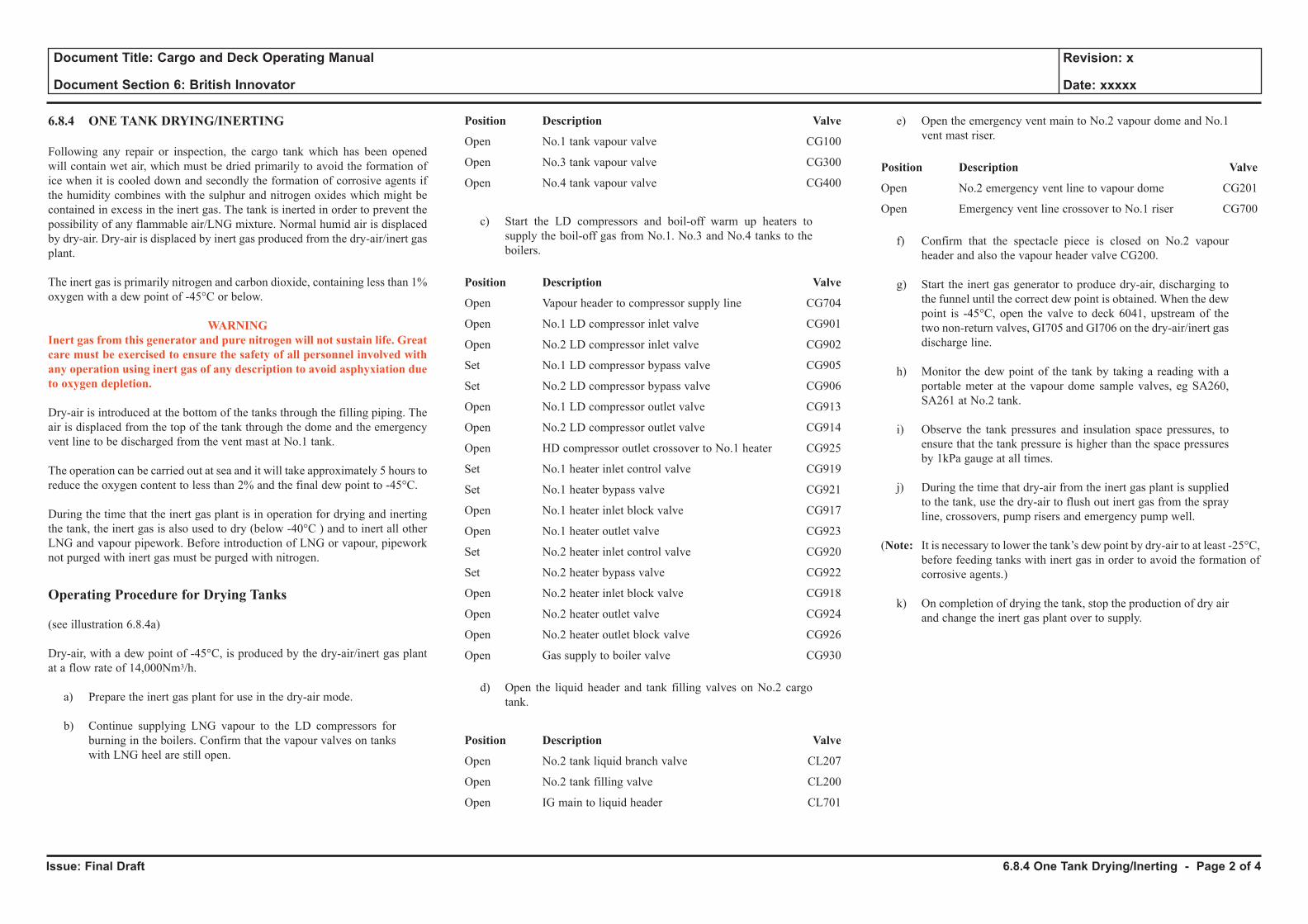
Issue: Final Draft
Document Title: Cargo and Deck Operating Manual
Document Section 6: British Innovator
Revision: x
Date: xxxxx
6.8.4 ONE TANK DRYING/INERTING
Following any repair or inspection, the cargo tank which has been opened will contain wet air, which must be dried primarily to avoid the formation of ice when it is cooled down and secondly the formation of corrosive agents if the humidity combines with the sulphur and nitrogen oxides which might be contained in excess in the inert gas. The tank is inerted in order to prevent the possibility of any flammable air/LNG mixture. Normal humid air is displaced by dry-air. Dry-air is displaced by inert gas produced from the dry-air/inert gas plant.
The inert gas is primarily nitrogen and carbon dioxide, containing less than 1% oxygen with a dew point of -45°C or below.
WARNINGInert gas from this generator and pure nitrogen will not sustain life. Great care must be exercised to ensure the safety of all personnel involved with any operation using inert gas of any description to avoid asphyxiation due to oxygen depletion.
Dry-air is introduced at the bottom of the tanks through the filling piping. The air is displaced from the top of the tank through the dome and the emergency vent line to be discharged from the vent mast at No.1 tank.
The operation can be carried out at sea and it will take approximately 5 hours to reduce the oxygen content to less than 2% and the final dew point to -45°C.
During the time that the inert gas plant is in operation for drying and inerting the tank, the inert gas is also used to dry (below -40°C ) and to inert all other LNG and vapour pipework. Before introduction of LNG or vapour, pipework not purged with inert gas must be purged with nitrogen.
Operating Procedure for Drying Tanks
(see illustration 6.8.4a)
Dry-air, with a dew point of -45°C, is produced by the dry-air/inert gas plant at a flow rate of 14,000Nm3/h.
a) Prepare the inert gas plant for use in the dry-air mode.
b) Continue supplying LNG vapour to the LD compressors for burning in the boilers. Confirm that the vapour valves on tanks with LNG heel are still open.
Position Description Valve
Open No.1 tank vapour valve CG100
Open No.3 tank vapour valve CG300
Open No.4 tank vapour valve CG400
c) Start the LD compressors and boil-off warm up heaters to supply the boil-off gas from No.1. No.3 and No.4 tanks to the boilers.
Position Description Valve
Open Vapour header to compressor supply line CG704
Open No.1 LD compressor inlet valve CG901
Open No.2 LD compressor inlet valve CG902
Set No.1 LD compressor bypass valve CG905
Set No.2 LD compressor bypass valve CG906
Open No.1 LD compressor outlet valve CG913
Open No.2 LD compressor outlet valve CG914
Open HD compressor outlet crossover to No.1 heater CG925
Set No.1 heater inlet control valve CG919
Set No.1 heater bypass valve CG921
Open No.1 heater inlet block valve CG917
Open No.1 heater outlet valve CG923
Set No.2 heater inlet control valve CG920
Set No.2 heater bypass valve CG922
Open No.2 heater inlet block valve CG918
Open No.2 heater outlet valve CG924
Open No.2 heater outlet block valve CG926
Open Gas supply to boiler valve CG930
d) Open the liquid header and tank filling valves on No.2 cargo tank.
Position Description Valve
Open No.2 tank liquid branch valve CL207
Open No.2 tank filling valve CL200
Open IG main to liquid header CL701
e) Open the emergency vent main to No.2 vapour dome and No.1 vent mast riser.
Position Description Valve
Open No.2 emergency vent line to vapour dome CG201
Open Emergency vent line crossover to No.1 riser CG700
f) Confirm that the spectacle piece is closed on No.2 vapour header and also the vapour header valve CG200.
g) Start the inert gas generator to produce dry-air, discharging to
the funnel until the correct dew point is obtained. When the dew point is -45°C, open the valve to deck 6041, upstream of the two non-return valves, GI705 and GI706 on the dry-air/inert gas discharge line.
h) Monitor the dew point of the tank by taking a reading with a portable meter at the vapour dome sample valves, eg SA260, SA261 at No.2 tank.
i) Observe the tank pressures and insulation space pressures, to ensure that the tank pressure is higher than the space pressures by 1kPa gauge at all times.
j) During the time that dry-air from the inert gas plant is supplied to the tank, use the dry-air to flush out inert gas from the spray line, crossovers, pump risers and emergency pump well.
(Note: It is necessary to lower the tank’s dew point by dry-air to at least -25°C, before feeding tanks with inert gas in order to avoid the formation of corrosive agents.)
k) On completion of drying the tank, stop the production of dry air and change the inert gas plant over to supply.
6.8.4 One Tank Drying/Inerting - Page 2 of 4
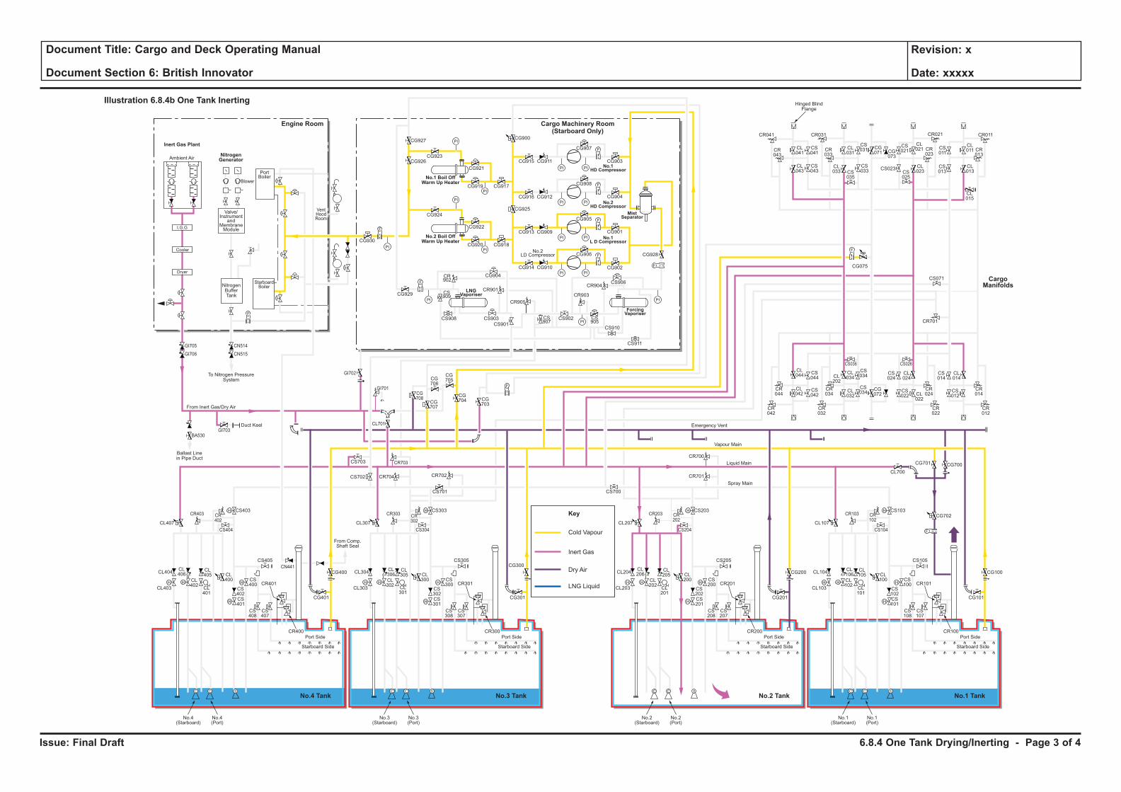
Issue: Final Draft
Document Title: Cargo and Deck Operating Manual
Document Section 6: British Innovator
Revision: x
Date: xxxxx
Cold Vapour
Key
Inert Gas
Dry Air
LNG LiquidH H
H
H
F
C C S
H
HH H
H
H
C C S
H
HH H
H
H
C C S
H
HH H
H
H
C C S
H
H
F
PI PI
F
PI PI
PI
PI
PI
PI
PI PI
PI PI
F
F
PI
PI
PI
PI
F
F
F
CL106
CL102
CL101
CL100
CS102
CS100
CS103
CS101
CS108
CS107
CR101
CR100
CL105
CL104
CL700
CG700
CG702
CG101
CS105
CS104
CR103 CR102
CG701
CL103
Port Side
Starboard Side
CL107
No.1(Starboard)
No.1(Port)
CL206
CL202
CL201
CL200
CS202
CS200
CS203
CR701
CR700
CS201
CS208
CS207
CR201
CR200
CL205
CL204
CG201
CG200 CG100
CS205
CS204
CR203 CR202
CL203
Port Side
Ambient Air
Blower
PortBoiler
VentHoodRoom
StarboardBoiler
Inert Gas Plant
NitrogenGenerator
Engine Room
No.3 TankNo.4 Tank No.1 TankNo.2 Tank
Cargo Machinery Room(Starboard Only)
Starboard Side
CL207
CS700
No.2(Starboard)
No.2(Port)
CL306
CL302
CL301
CL300
CS302
CS300
CS303
CS701
CS301
CS308
CS307
CR301
CR300
CL305
CL304
CG301
CS305
CS304
CR303 CR302
CL303
Port Side
Starboard Side
CL307
CG927
CG926CG923
CG921
CG917CG919
CG924
CG930
CG929
CG904
CR901
CR905
CR903
CR904
CS909
CS907
CS905
CS908 CS903
CS901
CS902
CS906
CS910
CS911
CR902
CG922
CG918
CG928
CG902
CG906
CG905
CG908
CG907
CR041
CR043
CL041
CL043
CS041
CS043
CL031
CS031 CS
011
CL011 CR
013
CG071 CG
073
CS021
CL021
CL023CS
025
CS023 CL013
CL015
CS013
CR023
CR033
CR021CR031 CR011
CS035
CL033
CS033
CG915
CG900
CG925
CG911
CG916 CG912
CG913 CG909
CG914 CG910
CG901
CG904
CG903
CG920
No.3(Starboard)
No.3(Port)
CL406
CL402
CL401
CL400
CS402
CS400
CS403
CS702 CR704 CR702
CR703
CG708
CG707
CG706
CG705
CG704 CG
703
CS703
CL701
CS401
CS408
CS407
CR401
CR400
CL405
CL404
CG401
CG400
CG300CS405
From Comp.Shaft Seal
CS404
CR403
GI705
GI706
GI703
GI702
GI701
BA530
CN514
CN515
CR402
CL403
Port Side
Starboard Side
CL407
No.4(Starboard)
No.4(Port)
CL044
CS044
CS042
CS034
CS024
CL024
CS034
CR044
CR034
CR024
CR042
CR032
CR022
CS036 CS026
CL042
CL034CL
202
CL032
CG072
CS022 CL
022
CS014
CR701
CS071
CL014
CR014
CR012
CS012
F
F
F
Cooler
Dryer
I.G.G
Valve/Instrument
andMembraneModule
NitrogenBufferTank
To Nitrogen PressureSystem
Hinged BlindFlange
Ballast Linein Pipe Duct
Duct Keel
From Inert Gas/Dry Air
Emergency Vent
Vapour Main
Liquid Main
Spray Main
No.1 Boil OffWarm Up Heater
No.2 Boil OffWarm Up Heater
ForcingVaporiser
MistSeparator
No.1HD Compressor
No.2HD Compressor
No.1L D Compressor
LNGVaporiser
No.2LD Compressor
Illustration 6.8.4b One Tank Inerting
CargoManifolds
CG075
CN441
6.8.4 One Tank Drying/Inerting - Page 3 of 4
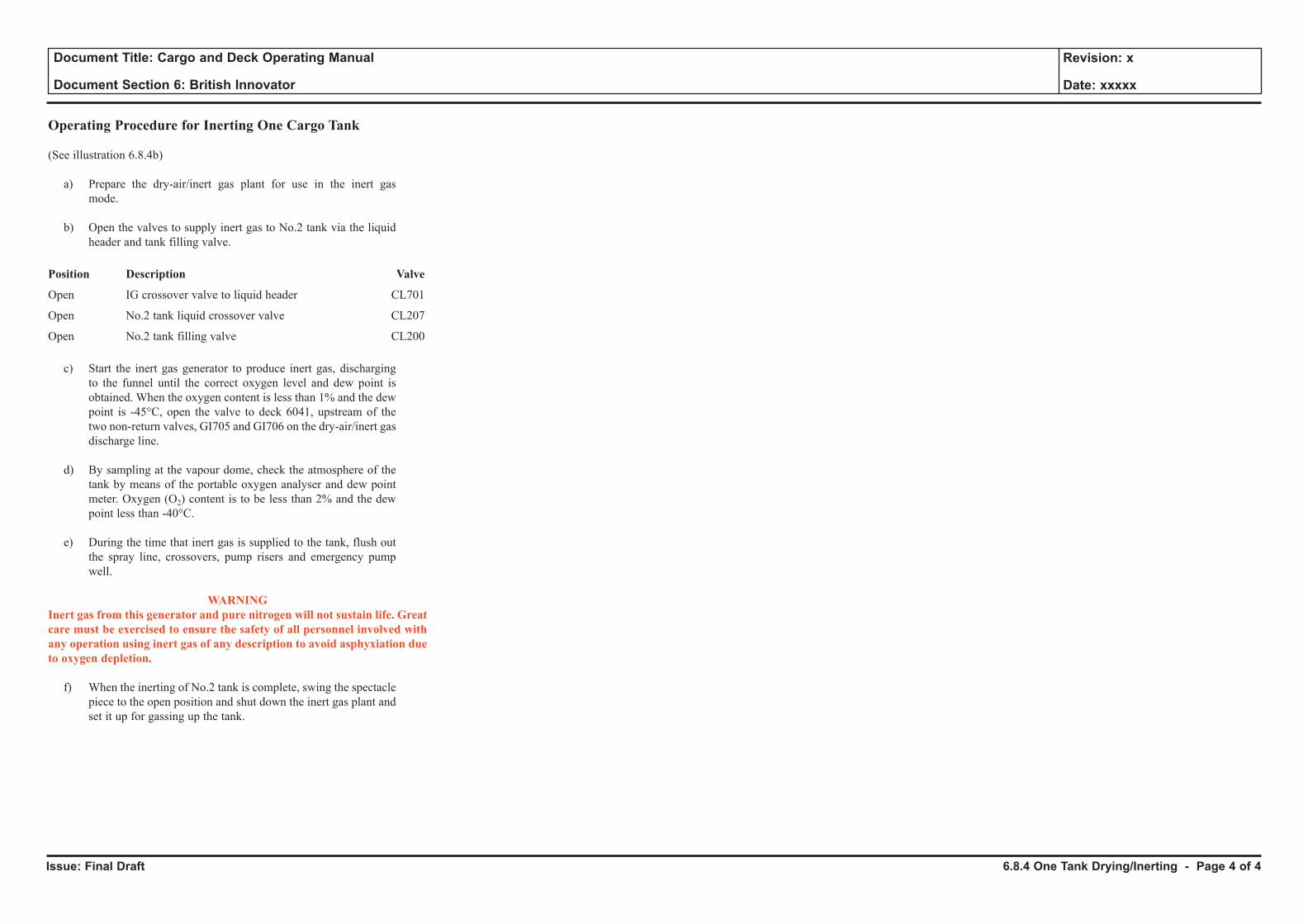
Issue: Final Draft
Document Title: Cargo and Deck Operating Manual
Document Section 6: British Innovator
Revision: x
Date: xxxxx
Operating Procedure for Inerting One Cargo Tank
(See illustration 6.8.4b)
a) Prepare the dry-air/inert gas plant for use in the inert gas mode.
b) Open the valves to supply inert gas to No.2 tank via the liquid header and tank filling valve.
Position Description Valve
Open IG crossover valve to liquid header CL701
Open No.2 tank liquid crossover valve CL207
Open No.2 tank filling valve CL200
c) Start the inert gas generator to produce inert gas, discharging to the funnel until the correct oxygen level and dew point is obtained. When the oxygen content is less than 1% and the dew point is -45°C, open the valve to deck 6041, upstream of the two non-return valves, GI705 and GI706 on the dry-air/inert gas discharge line.
d) By sampling at the vapour dome, check the atmosphere of the tank by means of the portable oxygen analyser and dew point meter. Oxygen (O2) content is to be less than 2% and the dew point less than -40°C.
e) During the time that inert gas is supplied to the tank, flush out the spray line, crossovers, pump risers and emergency pump well.
WARNINGInert gas from this generator and pure nitrogen will not sustain life. Great care must be exercised to ensure the safety of all personnel involved with any operation using inert gas of any description to avoid asphyxiation due to oxygen depletion.
f) When the inerting of No.2 tank is complete, swing the spectacle piece to the open position and shut down the inert gas plant and set it up for gassing up the tank.
6.8.4 One Tank Drying/Inerting - Page 4 of 4
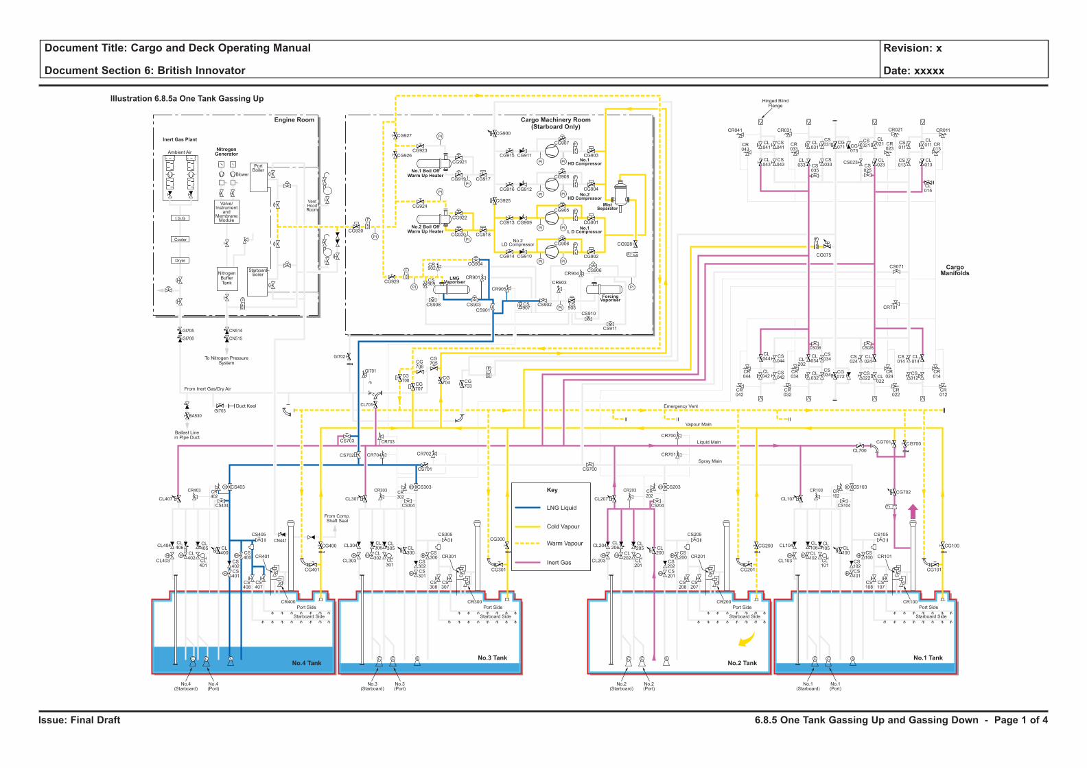
Issue: Final Draft
Document Title: Cargo and Deck Operating Manual
Document Section 6: British Innovator
Revision: x
Date: xxxxx
LNG Liquid
Key
Cold Vapour
Warm Vapour
Inert Gas
H H
H
H
F
C C S
H
HH H
H
H
C C S
H
HH H
H
H
C C S
H
HH H
H
H
C C S
H
H
F
PI PI
F
PI PI
PI
PI
PI
PI
PI PI
PI PI
F
F
PI
PI
PI
PI
F
F
F
CL106
CL102
CL101
CL100
CS102
CS100
CS103
CS101
CS108
CS107
CR101
CR100
CL105
CL104
CL700
CG700
CG702
CG101
CS105
CS104
CR103 CR102
CG701
CL103
Port Side
Starboard Side
CL107
No.1(Starboard)
No.1(Port)
CL206
CL202
CL201
CL200
CS202
CS200
CS203
CR701
CR700
CS201
CS208
CS207
CR201
CR200
CL205
CL204
CG201
CG200 CG100
CS205
CS204
CR203 CR202
CL203
Port Side
Ambient Air
Blower
PortBoiler
VentHoodRoom
StarboardBoiler
Inert Gas Plant
NitrogenGenerator
Engine Room
No.3 TankNo.4 Tank
No.1 TankNo.2 Tank
Cargo Machinery Room(Starboard Only)
Starboard Side
CL207
CS700
No.2(Starboard)
No.2(Port)
CL306
CL302
CL301
CL300
CS302
CS300
CS303
CS701
CS301
CS308
CS307
CR301
CR300
CL305
CL304
CG301
CS305
CS304
CR303 CR302
CL303
Port Side
Starboard Side
CL307
CG927
CG926CG923
CG921
CG917CG919
CG924
CG930
CG929
CG904
CR901
CR905
CR903
CR904
CS909
CS907
CS905
CS908 CS903
CS901
CS902
CS906
CS910
CS911
CR902
CG922
CG918
CG928
CG902
CG906
CG905
CG908
CG907
CR041
CR043
CL041
CL043
CS041
CS043
CL031
CS031 CS
011
CL011 CR
013
CG071 CG
073
CS021
CL021
CL023CS
025
CS023 CL013
CL015
CS013
CR023
CR033
CR021CR031 CR011
CS035
CL033
CS033
CG915
CG900
CG925
CG911
CG916 CG912
CG913 CG909
CG914 CG910
CG901
CG904
CG903
CG920
No.3(Starboard)
No.3(Port)
CL406
CL402
CL401
CL400
CS402
CS400
CS403
CS702 CR704 CR702
CR703
CG708
CG707
CG706
CG705
CG704 CG
703
CS703
CL701
CS401
CS408
CS407
CR401
CR400
CL405
CL404
CG401
CG400
CG300CS405
From Comp.Shaft Seal
CS404
CR403
GI705
GI706
GI703
GI702
GI701
BA530
CN514
CN515
CR402
CL403
Port Side
Starboard Side
CL407
No.4(Starboard)
No.4(Port)
CL044
CS044
CS042
CS034
CS024
CL024
CS034
CR044
CR034
CR024
CR042
CR032
CR022
CS036 CS026
CL042
CL034CL
202
CL032
CG072
CS022 CL
022
CS014
CR701
CS071
CL014
CR014
CR012
CS012
F
F
F
Cooler
Dryer
I.G.G
Valve/Instrument
andMembraneModule
NitrogenBufferTank
To Nitrogen PressureSystem
Hinged BlindFlange
Ballast Linein Pipe Duct
Duct Keel
From Inert Gas/Dry Air
Emergency Vent
Vapour Main
Liquid Main
Spray Main
No.1 Boil OffWarm Up Heater
No.2 Boil OffWarm Up Heater
ForcingVaporiser
MistSeparator
No.1HD Compressor
No.2HD Compressor
No.1L D Compressor
LNGVaporiser
No.2LD Compressor
Illustration 6.8.5a One Tank Gassing Up
CargoManifolds
CG075
CN441
6.8.5 One Tank Gassing Up and Gassing Down - Page 1 of 4
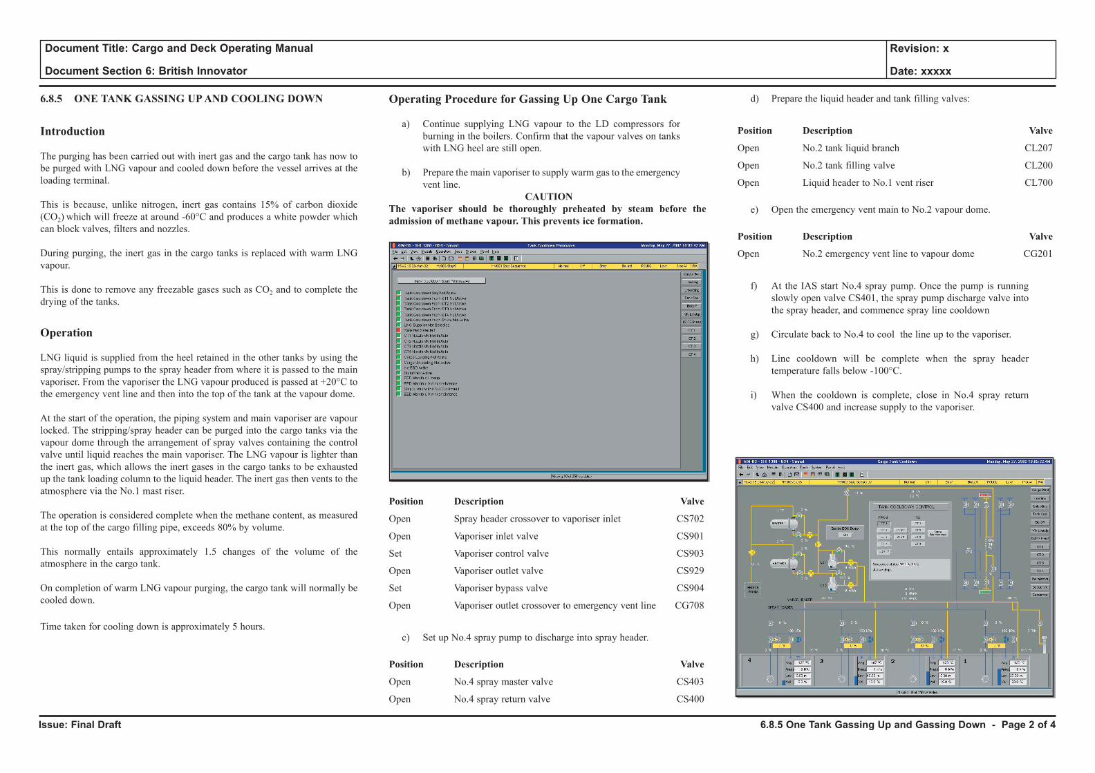
Issue: Final Draft
Document Title: Cargo and Deck Operating Manual
Document Section 6: British Innovator
Revision: x
Date: xxxxx
6.8.5 ONE TANK GASSING UP AND COOLING DOWN
Introduction
The purging has been carried out with inert gas and the cargo tank has now to be purged with LNG vapour and cooled down before the vessel arrives at the loading terminal.
This is because, unlike nitrogen, inert gas contains 15% of carbon dioxide (CO2) which will freeze at around -60°C and produces a white powder which can block valves, filters and nozzles.
During purging, the inert gas in the cargo tanks is replaced with warm LNG vapour.
This is done to remove any freezable gases such as CO2 and to complete the drying of the tanks.
Operation
LNG liquid is supplied from the heel retained in the other tanks by using the spray/stripping pumps to the spray header from where it is passed to the main vaporiser. From the vaporiser the LNG vapour produced is passed at +20°C to the emergency vent line and then into the top of the tank at the vapour dome.
At the start of the operation, the piping system and main vaporiser are vapour locked. The stripping/spray header can be purged into the cargo tanks via the vapour dome through the arrangement of spray valves containing the control valve until liquid reaches the main vaporiser. The LNG vapour is lighter than the inert gas, which allows the inert gases in the cargo tanks to be exhausted up the tank loading column to the liquid header. The inert gas then vents to the atmosphere via the No.1 mast riser.
The operation is considered complete when the methane content, as measured at the top of the cargo filling pipe, exceeds 80% by volume.
This normally entails approximately 1.5 changes of the volume of the atmosphere in the cargo tank.
On completion of warm LNG vapour purging, the cargo tank will normally be cooled down.
Time taken for cooling down is approximately 5 hours.
Operating Procedure for Gassing Up One Cargo Tank
a) Continue supplying LNG vapour to the LD compressors for burning in the boilers. Confirm that the vapour valves on tanks with LNG heel are still open.
b) Prepare the main vaporiser to supply warm gas to the emergency vent line.
CAUTION The vaporiser should be thoroughly preheated by steam before the admission of methane vapour. This prevents ice formation.
Position Description Valve
Open Spray header crossover to vaporiser inlet CS702
Open Vaporiser inlet valve CS901
Set Vaporiser control valve CS903
Open Vaporiser outlet valve CS929
Set Vaporiser bypass valve CS904
Open Vaporiser outlet crossover to emergency vent line CG708
c) Set up No.4 spray pump to discharge into spray header.
Position Description Valve
Open No.4 spray master valve CS403
Open No.4 spray return valve CS400
d) Prepare the liquid header and tank filling valves:
Position Description Valve
Open No.2 tank liquid branch CL207
Open No.2 tank filling valve CL200
Open Liquid header to No.1 vent riser CL700
e) Open the emergency vent main to No.2 vapour dome.
Position Description Valve
Open No.2 emergency vent line to vapour dome CG201
f) At the IAS start No.4 spray pump. Once the pump is running slowly open valve CS401, the spray pump discharge valve into the spray header, and commence spray line cooldown
g) Circulate back to No.4 to cool the line up to the vaporiser.
h) Line cooldown will be complete when the spray header temperature falls below -100°C.
i) When the cooldown is complete, close in No.4 spray return valve CS400 and increase supply to the vaporiser.
6.8.5 One Tank Gassing Up and Gassing Down - Page 2 of 4
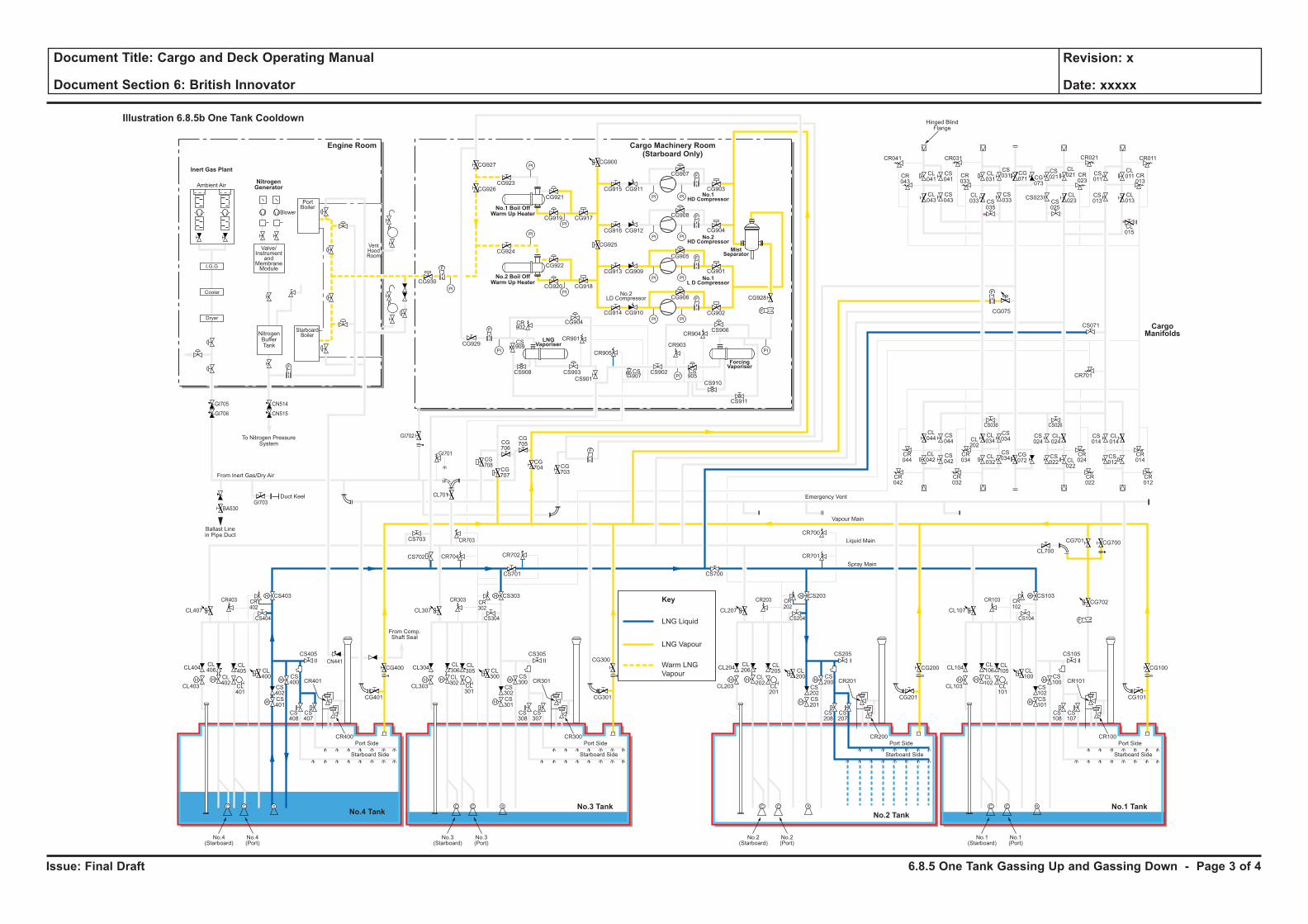
Issue: Final Draft
Document Title: Cargo and Deck Operating Manual
Document Section 6: British Innovator
Revision: x
Date: xxxxx
LNG Liquid
Key
LNG Vapour
Warm LNG
VapourH H
H
H
F
C C S
H
HH H
H
H
C C S
H
HH H
H
H
C C S
H
HH H
H
H
C C S
H
H
F
PI PI
F
PI PI
PI
PI
PI
PI
PI PI
PI PI
F
F
PI
PI
PI
PI
F
F
F
CL106
CL102
CL101
CL100
CS102
CS100
CS103
CS101
CS108
CS107
CR101
CR100
CL105
CL104
CL700
CG700
CG702
CG101
CS105
CS104
CR103 CR102
CG701
CL103
Port Side
Starboard Side
CL107
No.1(Starboard)
No.1(Port)
CL206
CL202
CL201
CL200
CS202
CS200
CS203
CR701
CR700
CS201
CS208
CS207
CR201
CR200
CL205
CL204
CG201
CG200 CG100
CS205
CS204
CR203 CR202
CL203
Port Side
Ambient Air
Blower
PortBoiler
VentHoodRoom
StarboardBoiler
Inert Gas Plant
NitrogenGenerator
Engine Room
No.3 TankNo.4 Tank
No.1 TankNo.2 Tank
Cargo Machinery Room(Starboard Only)
Starboard Side
CL207
CS700
No.2(Starboard)
No.2(Port)
CL306
CL302
CL301
CL300
CS302
CS300
CS303
CS701
CS301
CS308
CS307
CR301
CR300
CL305
CL304
CG301
CS305
CS304
CR303 CR302
CL303
Port Side
Starboard Side
CL307
CG927
CG926CG923
CG921
CG917CG919
CG924
CG930
CG929
CG904
CR901
CR905
CR903
CR904
CS909
CS907
CS905
CS908 CS903
CS901
CS902
CS906
CS910
CS911
CR902
CG922
CG918
CG928
CG902
CG906
CG905
CG908
CG907
CR041
CR043
CL041
CL043
CS041
CS043
CL031
CS031 CS
011
CL011 CR
013
CG071 CG
073
CS021
CL021
CL023CS
025
CS023 CL013
CL015
CS013
CR023
CR033
CR021CR031 CR011
CS035
CL033
CS033
CG915
CG900
CG925
CG911
CG916 CG912
CG913 CG909
CG914 CG910
CG901
CG904
CG903
CG920
No.3(Starboard)
No.3(Port)
CL406
CL402
CL401
CL400
CS402
CS400
CS403
CS702 CR704 CR702
CR703
CG708
CG707
CG706
CG705
CG704 CG
703
CS703
CL701
CS401
CS408
CS407
CR401
CR400
CL405
CL404
CG401
CG400
CG300CS405
From Comp.Shaft Seal
CS404
CR403
GI705
GI706
GI703
GI702
GI701
BA530
CN514
CN515
CR402
CL403
Port Side
Starboard Side
CL407
No.4(Starboard)
No.4(Port)
CL044
CS044
CS042
CS034
CS024
CL024
CS034
CR044
CR034
CR024
CR042
CR032
CR022
CS036 CS026
CL042
CL034CL
202
CL032
CG072
CS022 CL
022
CS014
CR701
CS071
CL014
CR014
CR012
CS012
F
F
F
Cooler
Dryer
I.G.G
Valve/Instrument
andMembraneModule
NitrogenBufferTank
To Nitrogen PressureSystem
Hinged BlindFlange
Ballast Linein Pipe Duct
Duct Keel
From Inert Gas/Dry Air
Emergency Vent
Vapour Main
Liquid Main
Spray Main
No.1 Boil OffWarm Up Heater
No.2 Boil OffWarm Up Heater
ForcingVaporiser
MistSeparator
No.1HD Compressor
No.2HD Compressor
No.1L D Compressor
LNGVaporiser
No.2LD Compressor
Illustration 6.8.5b One Tank Cooldown
CargoManifolds
CG075
CN441
6.8.5 One Tank Gassing Up and Gassing Down - Page 3 of 4
Issue: Final Draft
Document Title: Cargo and Deck Operating Manual
Document Section 6: British Innovator
Revision: x
Date: xxxxx
j) Monitor the inert exhausting gas at the liquid dome using the mid cargo tank sample cock initially, followed by the sample cock at the top of the loading line. Also monitor the inert exhausted gas at No.1 mast riser, using the sample cock.
The operation is considered complete when the cargo tank has at least an 80% methane content and the acceptable CO2 content, ≤1% volume.
k) Stop No.4 spray pump and close the discharge valve.
l) Shut the spray header to vaporiser inlet.
Position Description Valve
Close Spray header crossover to the vaporiser inlet CS702
(Note: Do not shut down the main vaporiser until it has been warmed through to the ambient temperature.)
Operating Procedure for Cooling Down One Cargo Tank
a) Prepare for cooling down the tank:
Position Description Valve
Open Spray header block valve CS700
Open Spray header block valve CS701
Open No.4 spray return valve CS400
Open No.2 spray master valve CS203
Open No.2 spray ring inlet, port side CS207
Open No.2 spray ring inlet, starboard side CS208
Open No.2 vapour header valve CG200
Open Vapour header to No.1 mast riser CG701
b) Check that the nitrogen pressurisation system for the insulation spaces is in automatic operation and lined up to supply the additional nitrogen necessary to compensate for the contraction from cooling of the tank. Prior to the cooling down, the nitrogen pressure inside the primary insulation spaces will be raised to 1.5kPa gauge. Pressurise the buffer tank at maximum pressure.
c) At the IAS start No.4 spray pump. Once the pump is running slowly open valve CS401, the spray pump discharge valve into the spray header, and commence spray line cooldown.
d) Circulate back to No.4 to cool the line up to No.2 tank.
e) Using the IAS, monitor the pressure inside the tank and temperature cooldown rate. Opening of the spray inlet valves to obtain an average temperature fall of 25/30°C per hour during the first 4 hours, thereafter 12/13°C per hour.
f) Cooldown of the cargo tank is considered complete when the top (99%) and bottom (End) temperature sensors in each tank indicate temperatures of -130°C or lower.
g) When a bottom temperature of -130°C is achieved, liquid can be transferred from the other tanks, using the spray pumps and discharging to the spray header into No.2 tank via the spray drain line.
6.8.5 One Tank Gassing Up and Gassing Down - Page 4 of 4
PART 7: EMERGENCY PROCEDURES
7.1 LNG Vapour Leakage to Barrier
7.2 LNG Liquid Leakage to Barrier
7.3 Water Leakage to Barrier
7.4 Failure of Cargo Pumps - Emergency Cargo Pump Installation
7.5 Fire and Emergency Breakaway
7.6 Ship To Ship Transfer
7.7 LNG Jettison
7.8 Running One Cargo Pump from the Emergency Generator
Illustrations
7.2a Liquid Leakage to Barrier
7.3a Water Evacuation from Insulation Space
7.4a Emergency Cargo Pump Installation Sequence
7.8a Running One Cargo Pump from the Emergency Generator
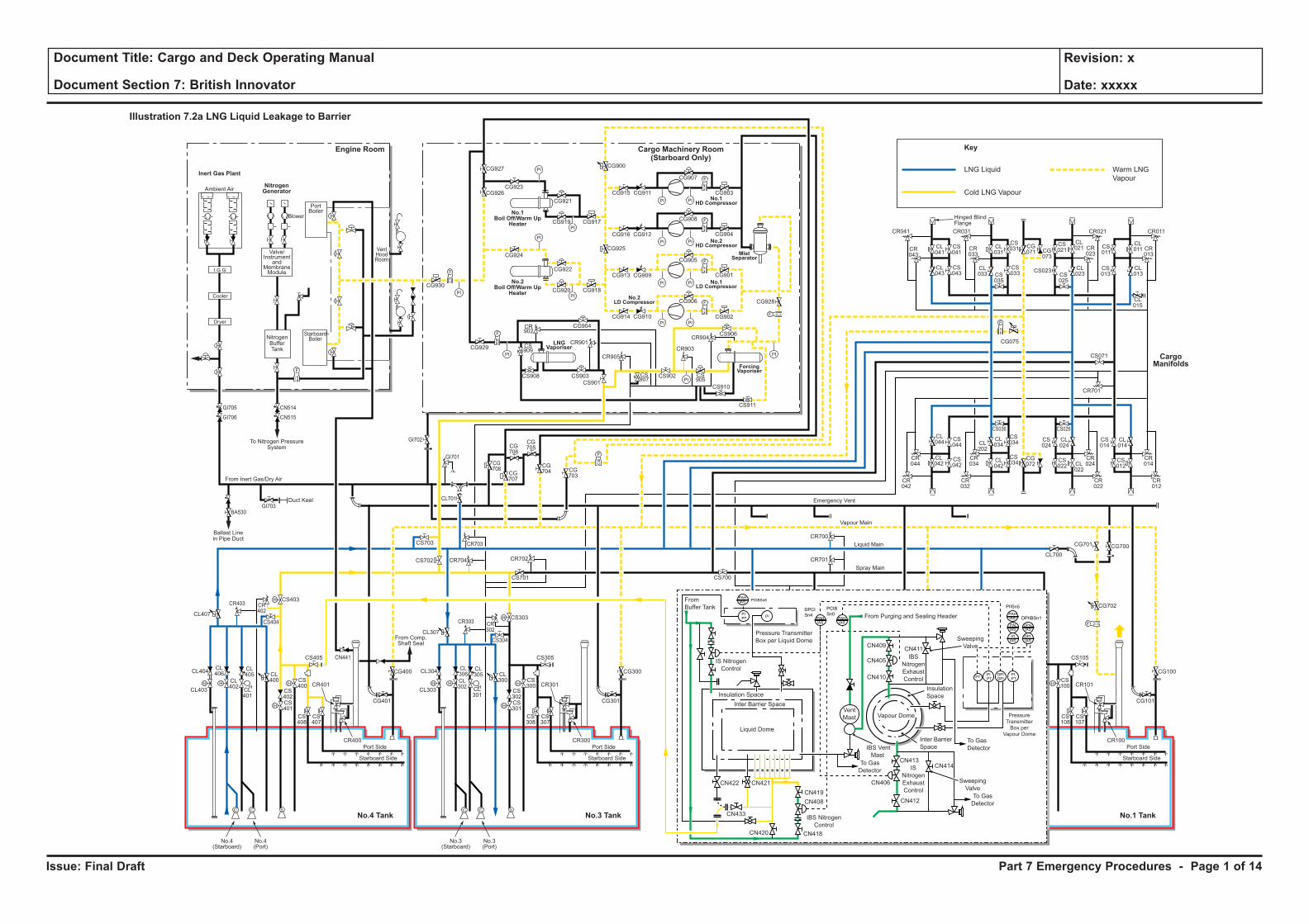
Issue: Final Draft
Document Title: Cargo and Deck Operating Manual
Document Section 7: British Innovator
Revision: x
Date: xxxxx
H H
H
H
F
C C
H
HH H
H
H
C C S
H
HH H
H
H
C C S
H
HH H
H
H
C C S
H
H
FPI PI
F
PI PI
PI
PI
PI
PI
PI PI
PI PI
F
F
PI
PI
PI
PI
F
F
F
CL106
CL102
CL101
CL100 CS
100
CS108
CS107
CR101
CR100
CL105
CL104
CL700
CG700
CG702
CG101
CS105
CS104
CR103 CR102
CG701
CL103
Port Side
Starboard Side
CL107
CL206
CL202
CL201
CL200
CS202
CS200
CS203
CR701
CR700
CS201
CS208
CS207
CR201
CR200
CL205
CL204
CG201
CG200 CG100
CS205
CS204
CR203 CR202
CL203
Port Side
Ambient Air
Blower
PortBoiler
VentHoodRoom
StarboardBoiler
Inert Gas Plant
NitrogenGenerator
Engine Room
No.3 TankNo.4 Tank No.1 TankNo.2 Tank
Cargo Machinery Room(Starboard Only)
Starboard Side
CL207
CS700
CL306
CL302
CL301
CL300
CS302
CS300
CS303
CS701
CS301
CS308
CS307
CR301
CR300
CL305
CL304
CG301
CS305
CS304
CR303 CR302
CL303
Port Side
Starboard Side
CL307
CG927
CG926CG923
CG921
CG917CG919
CG924
CG930
CG929
CG904
CR901
CR905
CR903
CR904
CS909
CS907
CS905
CS908 CS903
CS901
CS902
CS910
CS911
CR902
CG922
CG918
CG928
CG902
CG906
CG905
CG908
CG907
CR041
CR043
CL041
CL043
CS041
CS043
CL031
CS031 CS
011
CL011 CR
013
CG071 CG
073
CS021
CL021
CL023CS
025
CS023 CL013
CL015
CS013
CR023
CR033
CR021CR031 CR011
CS035
CL033
CS033
CG915
CG900
CG925
CG911
CG916 CG912
CG913 CG909
CG914 CG910
CG901
CG904
CG903
CG920
No.3(Starboard)
No.3(Port)
CL406
CL402
CL401
CL400
CS402
CS400
CS403
CS702 CR704 CR702
CR703
CG708
CG707
CG706
CG705
CG704 CG
703
CS703
CL701
CS401
CS408
CS407
CR401
CR400
CL405
CL404
CG401
CG400 CG300
CS405
From Comp.Shaft Seal
CS404
CR403
GI705
GI706
GI703
GI702
GI701
BA530
CN514
CN515
CR402
CL403
Port Side
Starboard Side
CL407
No.4(Starboard)
No.4(Port)
CL044
CS044
CS042
CS034
CS024
CL024
CS034
CR044
CR034
CR024
CR042
CR032
CR022
CS036 CS026
CL042
CL034CL
202
CL042
CG072
CS022 CL
022
CS014
CR701
CS071
CL014
CR014
CR012
CS012
F
F
F
Cooler
Dryer
I.G.G
Valve/Instrument
andMembraneModule
NitrogenBufferTank
To Nitrogen PressureSystem
Hinged BlindFlange
Ballast Linein Pipe Duct
Duct Keel
From Inert Gas/Dry Air
Emergency Vent
Vapour Main
Liquid Main
Spray Main
No.1Boil Off/Warm Up
Heater
No.2Boil Off/Warm Up
Heater
ForcingVaporiser
MistSeparator
No.1HD Compressor
No.2HD Compressor
No.1LD Compressor
LNGVaporiser
No.2LD Compressor
Illustration 7.2a LNG Liquid Leakage to Barrier
CargoManifolds
CG075
CN441
CS906
Liquid Dome
Vent
Mast
IBS
Nitrogen
Exhaust
Control
IS
Nitrogen
Exhaust
Control
IBS Vent
Mast
Sweeping
Valve
To Gas
Detector
To Gas
Detector
PressureTransmitterBox per
Vapour Dome
Pressure Transmitter
Box per Liquid Dome
From
Buffer Tank
Inter Barrier Space
Inter Barrier
Space
Insulation Space
CN411
CN414
CN412
CN419
CN408
CN418CN420
CN433
CN421CN422
CN413
CN406
CN409
CN405
CN410
Insulation
Space
IS Nitrogen
Control
IBS Nitrogen
Control
Vapour Dome
Sweeping
Valve
To Gas
Detector
PIPT
PI
PIISn5
DPIIBSn1
PCIB
Sn0
PCIBSn8
DPCI
Sn4 PAHIAS
DPIIAS
DPAL
IAS
PAHIAS
PAHIAS
PAHIAS
PALIAS
PIPT
PIPT
DPIDPI
PIIAS
PT
From Purging and Sealing Header
LNG Liquid
Key
Cold LNG Vapour
Warm LNG
Vapour
Part 7 Emergency Procedures - Page 1 of 14
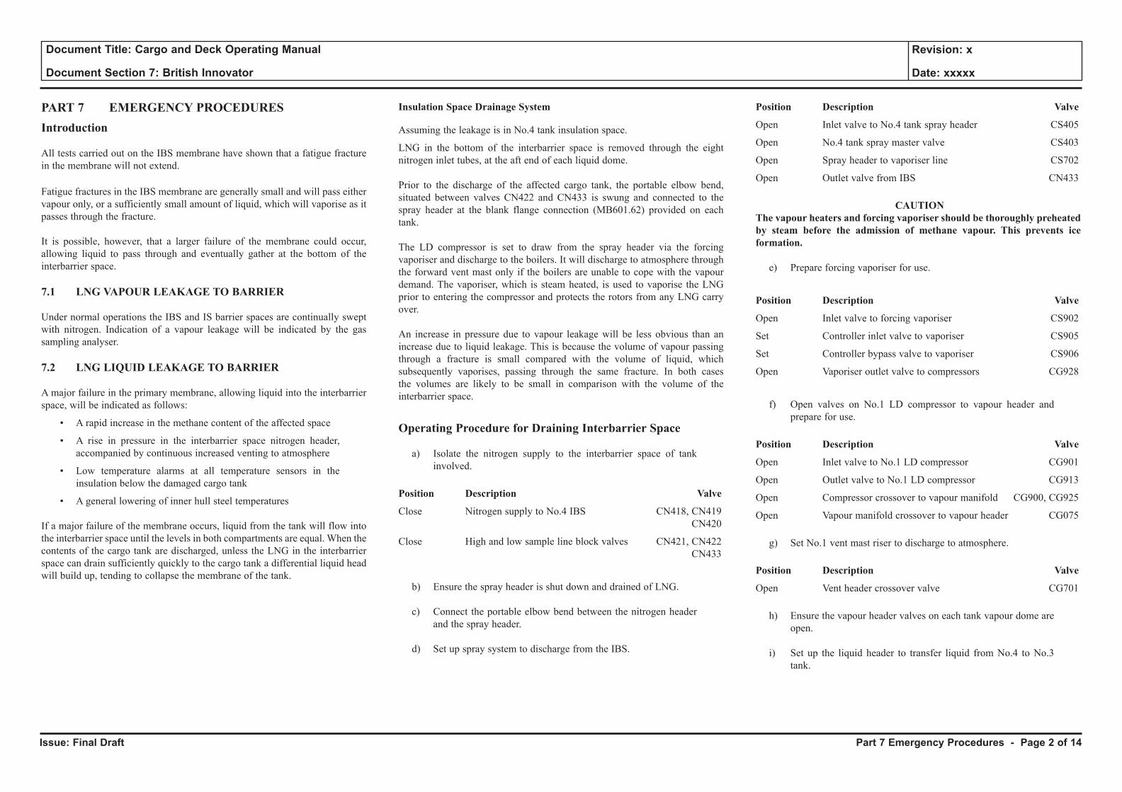
Issue: Final Draft
Document Title: Cargo and Deck Operating Manual
Document Section 7: British Innovator
Revision: x
Date: xxxxx
PART 7 EMERGENCY PROCEDURESIntroduction
All tests carried out on the IBS membrane have shown that a fatigue fracture in the membrane will not extend.
Fatigue fractures in the IBS membrane are generally small and will pass either vapour only, or a sufficiently small amount of liquid, which will vaporise as it passes through the fracture.
It is possible, however, that a larger failure of the membrane could occur, allowing liquid to pass through and eventually gather at the bottom of the interbarrier space.
7.1 LNG VAPOUR LEAKAGE TO BARRIER
Under normal operations the IBS and IS barrier spaces are continually swept with nitrogen. Indication of a vapour leakage will be indicated by the gas sampling analyser.
7.2 LNG LIQUID LEAKAGE TO BARRIER
A major failure in the primary membrane, allowing liquid into the interbarrier space, will be indicated as follows:
• A rapid increase in the methane content of the affected space
• A rise in pressure in the interbarrier space nitrogen header, accompanied by continuous increased venting to atmosphere
• Low temperature alarms at all temperature sensors in the insulation below the damaged cargo tank
• A general lowering of inner hull steel temperatures
If a major failure of the membrane occurs, liquid from the tank will flow into the interbarrier space until the levels in both compartments are equal. When the contents of the cargo tank are discharged, unless the LNG in the interbarrier space can drain sufficiently quickly to the cargo tank a differential liquid head will build up, tending to collapse the membrane of the tank.
Insulation Space Drainage System
Assuming the leakage is in No.4 tank insulation space.
LNG in the bottom of the interbarrier space is removed through the eight nitrogen inlet tubes, at the aft end of each liquid dome.
Prior to the discharge of the affected cargo tank, the portable elbow bend, situated between valves CN422 and CN433 is swung and connected to the spray header at the blank flange connection (MB601.62) provided on each tank.
The LD compressor is set to draw from the spray header via the forcing vaporiser and discharge to the boilers. It will discharge to atmosphere through the forward vent mast only if the boilers are unable to cope with the vapour demand. The vaporiser, which is steam heated, is used to vaporise the LNG prior to entering the compressor and protects the rotors from any LNG carry over.
An increase in pressure due to vapour leakage will be less obvious than an increase due to liquid leakage. This is because the volume of vapour passing through a fracture is small compared with the volume of liquid, which subsequently vaporises, passing through the same fracture. In both cases the volumes are likely to be small in comparison with the volume of the interbarrier space.
Operating Procedure for Draining Interbarrier Space
a) Isolate the nitrogen supply to the interbarrier space of tank involved.
Position Description Valve
Close Nitrogen supply to No.4 IBS CN418, CN419 CN420
Close High and low sample line block valves CN421, CN422 CN433
b) Ensure the spray header is shut down and drained of LNG.
c) Connect the portable elbow bend between the nitrogen header and the spray header.
d) Set up spray system to discharge from the IBS.
Position Description Valve
Open Inlet valve to No.4 tank spray header CS405
Open No.4 tank spray master valve CS403
Open Spray header to vaporiser line CS702
Open Outlet valve from IBS CN433
CAUTION The vapour heaters and forcing vaporiser should be thoroughly preheated by steam before the admission of methane vapour. This prevents ice formation.
e) Prepare forcing vaporiser for use.
Position Description Valve
Open Inlet valve to forcing vaporiser CS902
Set Controller inlet valve to vaporiser CS905
Set Controller bypass valve to vaporiser CS906
Open Vaporiser outlet valve to compressors CG928
f) Open valves on No.1 LD compressor to vapour header and prepare for use.
Position Description Valve
Open Inlet valve to No.1 LD compressor CG901
Open Outlet valve to No.1 LD compressor CG913
Open Compressor crossover to vapour manifold CG900, CG925
Open Vapour manifold crossover to vapour header CG075
g) Set No.1 vent mast riser to discharge to atmosphere.
Position Description Valve
Open Vent header crossover valve CG701
h) Ensure the vapour header valves on each tank vapour dome are open.
i) Set up the liquid header to transfer liquid from No.4 to No.3 tank.
Part 7 Emergency Procedures - Page 2 of 14
Issue: Final Draft
Document Title: Cargo and Deck Operating Manual
Document Section 7: British Innovator
Revision: x
Date: xxxxx
Illustration 7.3a Water Evacuation from Insulation Space
No.4
Cargo Tank
No.3
Cargo Tank
No.2
Cargo Tank
No.1
Cargo Tank
Air
IS
BW
IS
BW
IS
BW
CD
BW
CD
BW
IS
Bilge Well
IS
Bilge
Well
IS
Bilge
Well
IS
Bilge
Well
IS
Bilge
Well
IS
Bilge
Well
IS
Bilge
Well
IS
Bilge Well
No.1 CofferdamNo.2 CofferdamNo.3 Cofferdam
Cofferdam Cofferdam Cofferdam Cofferdam Cofferdam
No.4 CofferdamNo.5 Cofferdam
IS
BW
IS
BW
CD
BW
IS
BW
IS
BW
IS
BW
CD
BW
CD
BW
Pneumatic
Pump
Air
Chamber
Drain Water Overboard
Air SupplyBG555F
BG559F BG558F
BG583F
BG582F
BG
557F
BG584F
BG596FBG597F
AR610F
AR611FBG
556F
Pneumatic
Pump
Air
Chamber
Drain Water Overboard
Air SupplyBG550F
BG554F BG553F
BG580F
BG579FBG581F
BG594FBG595F
AR608F
AR609FBG
551F
Pneumatic
Pump
Air
Chamber
Drain Water Overboard
Air SupplyBG545F
BG549F BG548F
BG577F
BG576FBG578F
BG592FBG593F
BG574F
BG591F
AR606F
AR607FBG
540F
BG573F
BG572F
BG574F
Hand Operated (Locked Open)
IS Insulated Space
BW Bilge Well
CD CofferdamHand Operated (Locked Shut)
PI
BG
552F
PI
BG
547F
PI
Pneumatic
Pump
Air Chamber
Air Supply
BG541F
BG542F
AR602F
AR603F
AR601F
AR605F
BG544F
BG
543F
BG
571F
AR
604FPI
PI
Drain Water
Overboard
LAHCB007
Pneumatic
Pump
(20m3/h x
45kg/cm2)
BG588F
BG587F BG586F
Pneumatic
Pump
Air Chamber
Air Supply
BG560F
BG561F
AR613F
AR614F
AR612F
AR616F
BG563F
BG
562F
BG
589F
AR
615FPI
PI
Drain Water
Overboard
LAHCB008
Pneumatic
Pump
(20m3/h x
45kg/cm2)
CD
Bilge Well
CD
Bilge Well
CD
Bilge Well
CD
Bilge Well
CD
Bilge Well
Bilges
Key
LAHCB029
LAHCB027
LAHCB025
LAHCT415
XACT112
LAHCT413
XACT112
LAHCT315
XACT112
LAHCT313
XACT112
LAHCB023
LAHCT213
XACT112
LAHCB021
LAHCT113
XACT112
LAHCT115
XACT112
LAHCT215
XACT112
Flexible Hose for
Temporary Purging
Water Detector
Part 7 Emergency Procedures - Page 3 of 14
Issue: Final Draft
Document Title: Cargo and Deck Operating Manual
Document Section 7: British Innovator
Revision: x
Date: xxxxx
Position Description Valve
Open No.4 tank liquid header master valve CL407
Open No.3 tank liquid header master valve CL307
Open No.3 tank loading valve CL300
j) Set up the portable liquid level measuring unit to line G to the IBS low point.
k) Prepare No.4 tank main cargo pump (port or starboard) to discharge to the liquid header.
The gas lift LNG removal system is designed to discharge LNG from an interbarrier space, so that the level in this space will reduce at approximately the same rate as the level in a cargo tank where a singe pump is running at its design rate.
CAUTIONTo avoid damage to the membrane the MAXIMUM allowable differential head is 1metre LNG.
If the level in the interbarrier space is equal to that in the cargo tank, start the LD compressor first.
If the level in the interbarrier space is well below that in the cargo tank, the cargo pump may be started first.
The LD compressor is controlled manually to maintain a suction pressure of between 5 to 6kPa.
With both the cargo pump and compressor running, frequently check the level of the liquid in the interbarrier space. Adjust the discharge rate of the pump so that the level in the tank decreases at approximately the same rate as the level in the interbarrier space.
The portable liquid level gauge is designed to work even with a vacuum in the space, it is not necessary to stop the compressor before checking the level.
Continue discharging until both tank and interbarrier space are drained, then restore the nitrogen purge system to the affected space, shut down the compressor and vaporiser.
7.3 WATER LEAKAGE TO BARRIER
Inner Hull failure
Ballast water leakage from the wing tanks to the insulation spaces can occur through fractures in the inner hull plating. If the leakage remains undetected and water accumulates in these spaces, ice accumulation can occur and cause deformation and possible rupture of the insulation. The resultant cold conduction paths forming in the insulation will cause cold spots to form on the inner hull.
The pressure differential caused by the head of water building up in the insulation space may be sufficient to deform or even collapse the membrane into the cargo tank.
To reduce the risk of damage from leakage, each cargo insulation space has been provided with water detection units. A bilge piping system, connected to pneumatic pumps, is used for the removal of any water.
Leakage Detection
At the bottom of each cofferdam there are two bilge wells serving the forward and aft ends of each tank insulating space. Each of these wells is fitted with a water detection unit and a float level alarm.
Each detector is of the conductivity cell type, which causes a change in resistance due to the presence of humidity from the ingress of sea water and activates an alarm. The tank insulation space is connected to each of the fore and aft bilge wells by means of a 50mm drain pipe.
The aft bilge well serves as the inlet for the nitrogen 50mm supply pipe to the insulation space. This supply pipe also acts as a manual sounding pipe to the bilge well. It can also be connected to a portable liquid level gauge (bubbling type) as well as serving as a gas sampling line for the insulation space (low point aft).
The forward bilge well has a manual 50mm sounding pipe which can be connected to a portable liquid level gauge (bubbling type) and also serves as a gas sampling line for the insulation space (low point forward).
Insulation Space Water Discharge
Each bilge well is connected to a 50mm draining pipe system with a 10m3/h x 45mth pneumatic pump situated in each of the cofferdams for discharging the water to deck level and then overboard by means of a flexible hose.
Operating Procedure for Discharging Water from an Insulation Space
If ballast water is suspected of having leaked into No.3 insulation space.
a) Pump out the ballast water from adjacent wing tanks.
b) Ventilate the required transverse cofferdams No.3 and 4, as described in section 5.3.3 and carry out normal enclosed space safety procedures.
c) To discharge water from a bilge well it is necessary to fit a flexible hose between the compressed air supply and the required pneumatic pump(s).
d) Connect a flexible hose to the pump outlet valve in order to drain the water discharge overboard.
e) Open the bilge well suction valve on the selected tank insulation space.
Position Description Valve
Open No.3 aft insulation space bilge well suction BG558F
Open No.3 forward insulation space bilge well suction BG554F
f) Open the inlet and outlet valves on the selected pump(s).
Position Description Valve
Open No.3 cofferdam pump inlet BG552F
Open No.3 cofferdam pump discharge to deck BG550F
Open No.4 cofferdam pump inlet BG557F
Open No.4 cofferdam pump discharge to deck BG555F
g) Open the air supply to the pump(s), continue pumping until the maximum amount of water has been discharged.
Position Description Valve
Open No.3 cofferdam pump air supply AR609F
Open No.4 cofferdam pump air supply AR611F
h) Carry out an inner hull inspection to determine the cause of the leak, with particular reference to a safe atmosphere in the ballast tank space.
Part 7 Emergency Procedures - Page 4 of 14
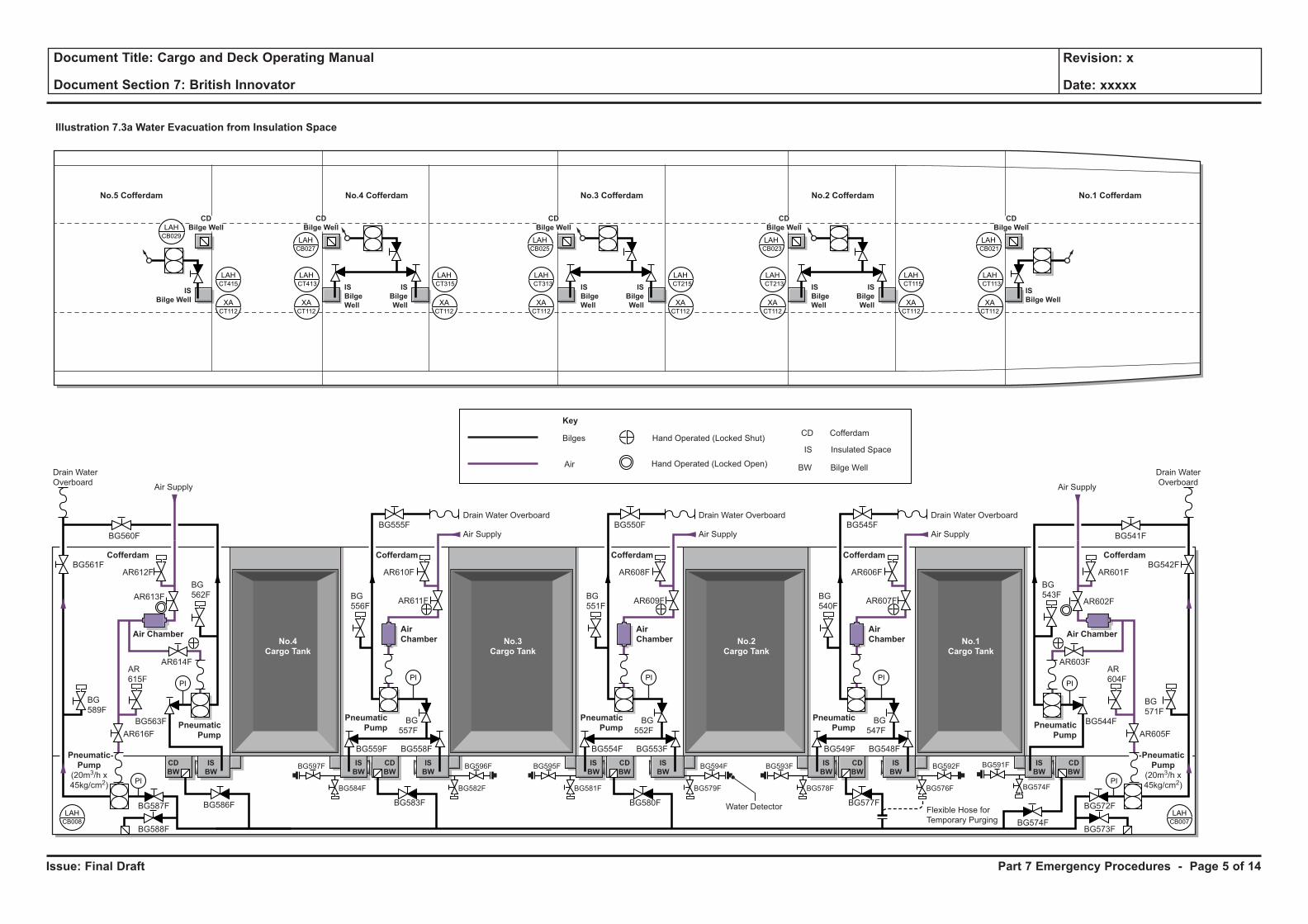
Issue: Final Draft
Document Title: Cargo and Deck Operating Manual
Document Section 7: British Innovator
Revision: x
Date: xxxxx
Illustration 7.3a Water Evacuation from Insulation Space
No.4
Cargo Tank
No.3
Cargo Tank
No.2
Cargo Tank
No.1
Cargo Tank
Air
IS
BW
IS
BW
IS
BW
CD
BW
CD
BW
IS
Bilge Well
IS
Bilge
Well
IS
Bilge
Well
IS
Bilge
Well
IS
Bilge
Well
IS
Bilge
Well
IS
Bilge
Well
IS
Bilge Well
No.1 CofferdamNo.2 CofferdamNo.3 Cofferdam
Cofferdam Cofferdam Cofferdam Cofferdam Cofferdam
No.4 CofferdamNo.5 Cofferdam
IS
BW
IS
BW
CD
BW
IS
BW
IS
BW
IS
BW
CD
BW
CD
BW
Pneumatic
Pump
Air
Chamber
Drain Water Overboard
Air SupplyBG555F
BG559F BG558F
BG583F
BG582F
BG
557F
BG584F
BG596FBG597F
AR610F
AR611FBG
556F
Pneumatic
Pump
Air
Chamber
Drain Water Overboard
Air SupplyBG550F
BG554F BG553F
BG580F
BG579FBG581F
BG594FBG595F
AR608F
AR609FBG
551F
Pneumatic
Pump
Air
Chamber
Drain Water Overboard
Air SupplyBG545F
BG549F BG548F
BG577F
BG576FBG578F
BG592FBG593F
BG574F
BG591F
AR606F
AR607FBG
540F
BG573F
BG572F
BG574F
Hand Operated (Locked Open)
IS Insulated Space
BW Bilge Well
CD CofferdamHand Operated (Locked Shut)
PI
BG
552F
PI
BG
547F
PI
Pneumatic
Pump
Air Chamber
Air Supply
BG541F
BG542F
AR602F
AR603F
AR601F
AR605F
BG544F
BG
543F
BG
571F
AR
604FPI
PI
Drain Water
Overboard
LAHCB007
Pneumatic
Pump
(20m3/h x
45kg/cm2)
BG588F
BG587F BG586F
Pneumatic
Pump
Air Chamber
Air Supply
BG560F
BG561F
AR613F
AR614F
AR612F
AR616F
BG563F
BG
562F
BG
589F
AR
615FPI
PI
Drain Water
Overboard
LAHCB008
Pneumatic
Pump
(20m3/h x
45kg/cm2)
CD
Bilge Well
CD
Bilge Well
CD
Bilge Well
CD
Bilge Well
CD
Bilge Well
Bilges
Key
LAHCB029
LAHCB027
LAHCB025
LAHCT415
XACT112
LAHCT413
XACT112
LAHCT315
XACT112
LAHCT313
XACT112
LAHCB023
LAHCT213
XACT112
LAHCB021
LAHCT113
XACT112
LAHCT115
XACT112
LAHCT215
XACT112
Flexible Hose for
Temporary Purging
Water Detector
Part 7 Emergency Procedures - Page 5 of 14
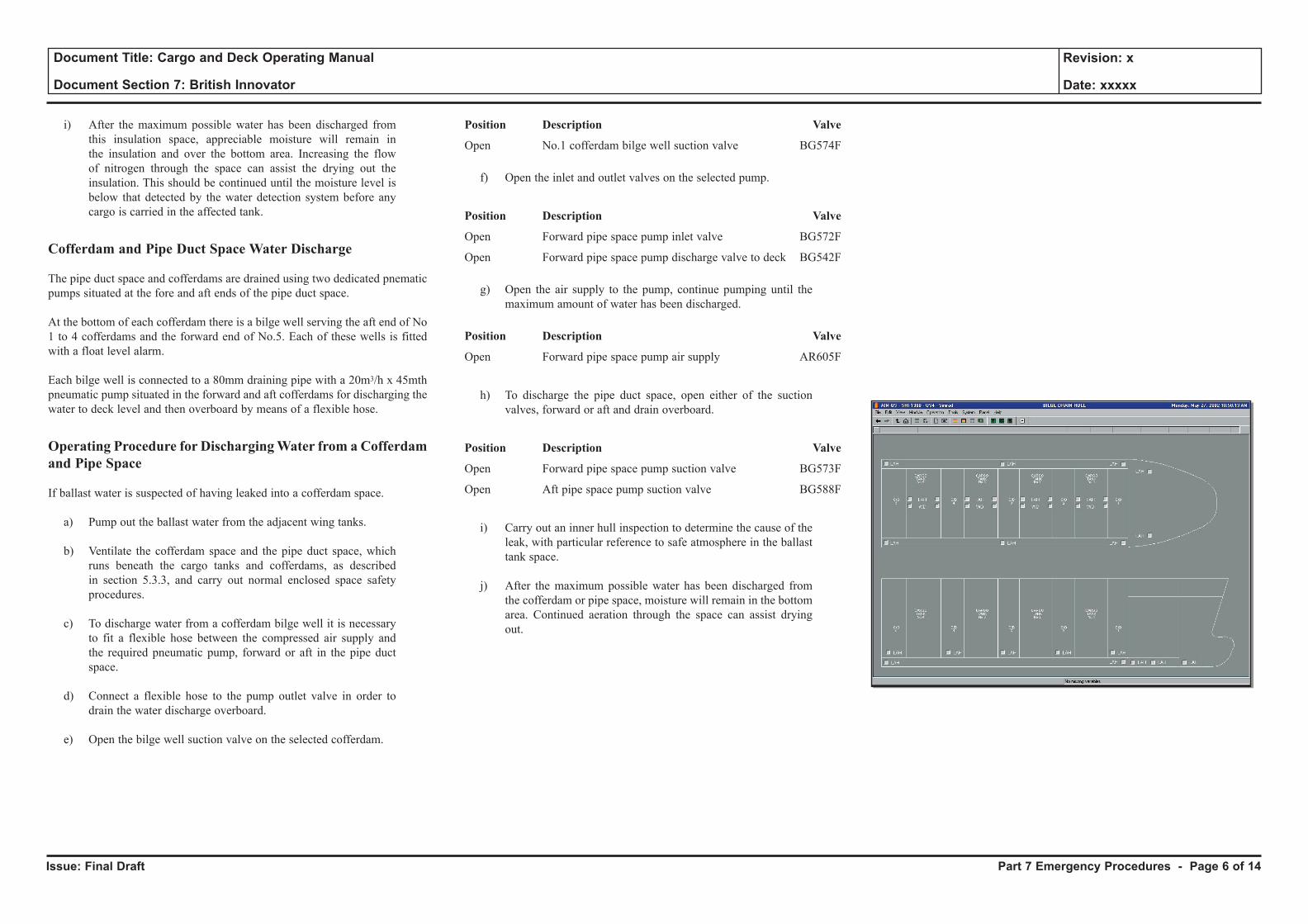
Issue: Final Draft
Document Title: Cargo and Deck Operating Manual
Document Section 7: British Innovator
Revision: x
Date: xxxxx
i) After the maximum possible water has been discharged from this insulation space, appreciable moisture will remain in the insulation and over the bottom area. Increasing the flow of nitrogen through the space can assist the drying out the insulation. This should be continued until the moisture level is below that detected by the water detection system before any cargo is carried in the affected tank.
Cofferdam and Pipe Duct Space Water Discharge
The pipe duct space and cofferdams are drained using two dedicated pnematic pumps situated at the fore and aft ends of the pipe duct space. At the bottom of each cofferdam there is a bilge well serving the aft end of No 1 to 4 cofferdams and the forward end of No.5. Each of these wells is fitted with a float level alarm.
Each bilge well is connected to a 80mm draining pipe with a 20m3/h x 45mth pneumatic pump situated in the forward and aft cofferdams for discharging the water to deck level and then overboard by means of a flexible hose.
Operating Procedure for Discharging Water from a Cofferdam and Pipe Space
If ballast water is suspected of having leaked into a cofferdam space.
a) Pump out the ballast water from the adjacent wing tanks.
b) Ventilate the cofferdam space and the pipe duct space, which runs beneath the cargo tanks and cofferdams, as described in section 5.3.3, and carry out normal enclosed space safety procedures.
c) To discharge water from a cofferdam bilge well it is necessary to fit a flexible hose between the compressed air supply and the required pneumatic pump, forward or aft in the pipe duct space.
d) Connect a flexible hose to the pump outlet valve in order to drain the water discharge overboard.
e) Open the bilge well suction valve on the selected cofferdam.
Position Description Valve
Open No.1 cofferdam bilge well suction valve BG574F
f) Open the inlet and outlet valves on the selected pump.
Position Description Valve
Open Forward pipe space pump inlet valve BG572F
Open Forward pipe space pump discharge valve to deck BG542F
g) Open the air supply to the pump, continue pumping until the maximum amount of water has been discharged.
Position Description Valve
Open Forward pipe space pump air supply AR605F
h) To discharge the pipe duct space, open either of the suction valves, forward or aft and drain overboard.
Position Description Valve
Open Forward pipe space pump suction valve BG573F
Open Aft pipe space pump suction valve BG588F
i) Carry out an inner hull inspection to determine the cause of the leak, with particular reference to safe atmosphere in the ballast tank space.
j) After the maximum possible water has been discharged from the cofferdam or pipe space, moisture will remain in the bottom area. Continued aeration through the space can assist drying out.
Part 7 Emergency Procedures - Page 6 of 14
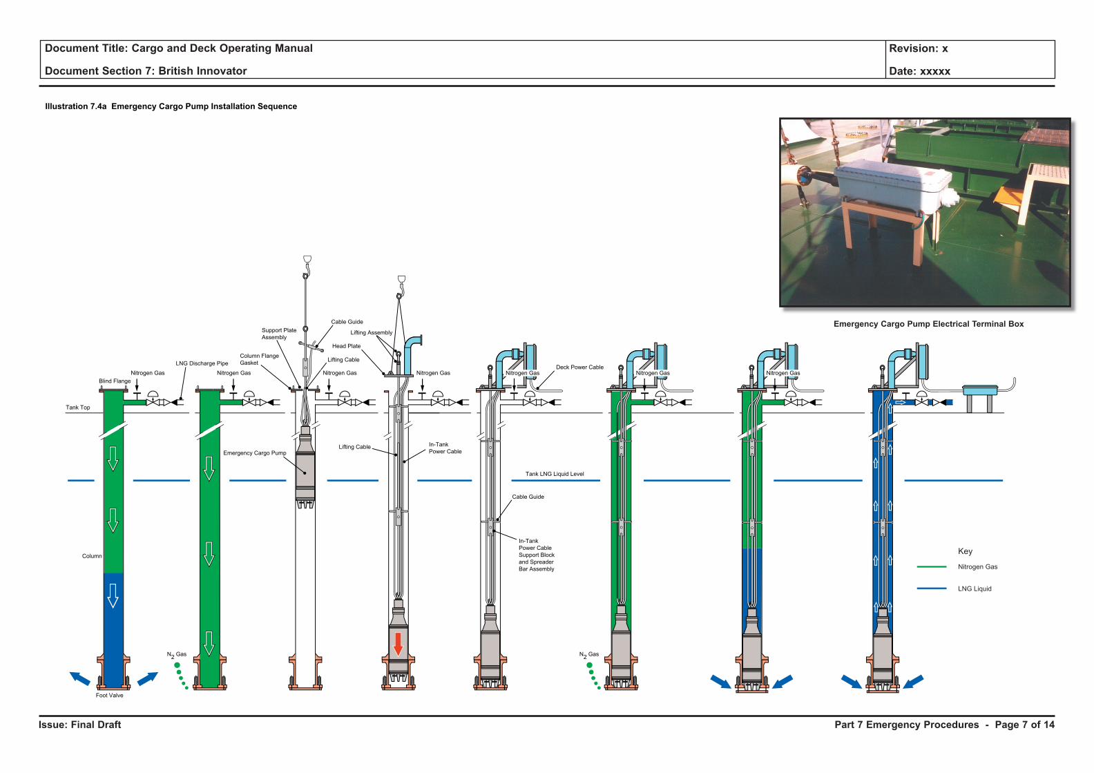
Issue: Final Draft
Document Title: Cargo and Deck Operating Manual
Document Section 7: British Innovator
Revision: x
Date: xxxxx
Tank Top
Blind Flange
Tank LNG Liquid Level
Cable Guide
Column FlangeGasket
Support PlateAssembly
LNG Discharge Pipe Lifting Cable
Emergency Cargo Pump
Lifting Assembly
Head Plate
In-TankPower Cable
Lifting Cable
N2 Gas
Foot Valve
Column
N2 Gas
In-TankPower CableSupport Blockand SpreaderBar Assembly
Cable Guide
Deck Power CableNitrogen Gas Nitrogen Gas Nitrogen GasNitrogen GasNitrogen GasNitrogen GasNitrogen Gas
Illustration 7.4a Emergency Cargo Pump Installation Sequence
Key
Nitrogen Gas
LNG Liquid
Part 7 Emergency Procedures - Page 7 of 14
Emergency Cargo Pump Electrical Terminal Box
Issue: Final Draft
Document Title: Cargo and Deck Operating Manual
Document Section 7: British Innovator
Revision: x
Date: xxxxx
7.4 FAILURE OF CARGO PUMP - EMERGENCY CARGO PUMP INSTALLATION
The emergency cargo pump is used in the unusual event that both main cargo pumps have failed in a cargo tank. The pump is lowered into the emergency cargo pump column for that tank. Cables and a connection to the local junction box are used to power the pump. The pump, when lowered to its final position, opens the foot valve in the column and the LNG can be pumped out.
Adjacent to each pump column is a terminal box for the cargo pump connection and a local start switch. The pump and delivery valve are controlled and started via the IAS mimic.
The emergency pump system includes:
• One submersible pump
• Four foot valves, one per tank
• One headplate assembly with gasket and bolts
• One lifting eye
• One lifting assembly for opening and closing the foot valve
• One lifting support cable with cable guides
• One flexible power feed cable
• Four electrical junction boxes, one per tank
• One deck flexible cable assembly
• One portable air winch
• Four fixed davits, one per tank
The pump is stored in a special preservation container and all the electrical equipment in a second container. These two containers are stored in the deck store.
The pump is suspended over the column into which it is being lowered by a 2.5 tonne SWL derrick.
Also fitted to the column are nitrogen purge/methanol injection points.
The pump discharges into the column and to the liquid line via a discharge connection and valve at the top of the column.
Procedure for Installing of the Emergency Cargo Pump(See illustration 7.4a)
CAUTIONWhen working near the open pump column all tools and equipment used must be attached to lanyards to avoid anything falling in the column. All personal items have to be removed from pockets and the column opening must be temporarily covered when the blind flange is removed. Use only brass tools.
When all equipment, pump, cables, electrical connection box and accessories are in position near the tank in which the pump is to be installed, prepare the derrick to lift the pump and start the pump installation.
a) The cargo tank will inevitably contain LNG, therefore the column into which the emergency pump is being lowered must be evacuated. This is achieved by injecting nitrogen into the column. In the case of a full cargo tank, a pressure of between 200 and 300kPa is required. The nitrogen forces the liquid out through the foot valve located at the bottom of the column.
b) On completion of the expulsion of the liquid, a check must be made at the purge cock to ensure complete inerting has taken place. The tank pressure must be reduced to just above atmospheric before removing the column top blank flange. Install a new column flange gasket, then begin to install the pump using the derrick.
c) Install the power cables on the pump. Ensure that power cables
are carefully laid out on deck and suitably protected to avoid any damage. The power cable ends are marked ‘A’, ‘B’ and ‘C’ and should coincide with the same markings on the pump to ensure correct phase rotation.
d) Attach the portable air winch to the mounting on the fixed davit.
e) Attach the lifting support cable to the pump lifting eye and lift the pump. Suspend above the column and lower the pump into the column.
e) As the pump is lowered into the column, carefully feed in the power cables and cable guides.
f) When the pump is near the tank bottom secure with the support plate assembly.
g) Fit the head plate lifting rod eye to the link-plate and fit the
derrick hook to the top eye. Lift the pump a few centimetres to remove the support pin. Take care not to lower the pump onto the foot valve.
h) Lower the head plate onto the column and install the head plate with the lifting assembly in the closed position, being very careful with the gasket.
i) Install the electrical assembly and support brackets. Install the deck power cable assembly making sure that ‘A’, ‘B’ and ‘C’ markings are matched at all connecting points.
Operating Procedure for Pump Cooldown and Operation of the Emergency Cargo Pump
a) Start the cooldown for the pump. The pump should be left suspended in the empty column for 10 to 12 hours for a correct cooldown.
b) After 10 to 12 hours, introduce nitrogen pressure in the column to open the suction foot valve with the lifting assembly in the closed position.
c) Decrease the nitrogen pressure slowly to let the liquid rise in the column at a speed of approximately 75 to 125mm/minute until it covers the pump completely (approximately 2m).
d) When the liquid level is above the pump, maintain the nitrogen gas pressure and lower the pump completely by adjusting the lifting assembly to the open position. Tighten the gland onto the lifting rod through the head plate.
e) Stop the nitrogen supply when the liquid is at the same level in the tank and column and bleed the nitrogen from the top of the column. The pump will have to stay immersed for one hour in the liquid before being started.
f) Before starting the pump, open the discharge valve to ensure that no pressure has built up at the top of the column when starting the pump. If necessary, excess pressure can be bled off via the purge cock.
g) When ready to start the pump, open the discharge valve 20% and start the pump normally.
h) Check its operation very carefully to ensure that there is no leakage at top of column or discharge piping. Fire hoses must be under pressure and ready in the vicinity before starting.
i) Adjust the opening of the discharge valve to have the required discharge flow and pressure within the pump capacity.
j) If the first start is not successful refer to Section 4.3.3 for the allowable number of starts.
Part 7 Emergency Procedures - Page 8 of 14
Issue: Final Draft
Document Title: Cargo and Deck Operating Manual
Document Section 7: British Innovator
Revision: x
Date: xxxxx
7.5 FIRE AND EMERGENCY BREAKAWAY
All terminals have their own requirements regarding when it is unsafe for a vessel to remain alongside a terminal. These are normally outlined in the terminal handbook.
In case of a fire or emergency developing, either on board or ashore the following basic procedures will be followed:
a) All cargo operations will be stopped and emergency signals sounded as per the terminal’s requirements (as detailed in the ship/shore checklist). Ship’s personnel should move away from the manifold areas immediately.
b) Ship and shore emergency procedures will be put into operation.
c) The ESD2 system will be activated, from ashore or if there is excessive arm movement, resulting in the cargo arms being disconnected.
d) In the event of fire, the IMO water spray system on ship/shore will be activated.
e) Fire parties will attempt to deal with the situation.
f) The vessel will prepare for departure from the berth.
g) Liaison with shore personnel to arrange for pilot and tugs and additional support.
h) A standby tug would assist with fire fighting/movement of the vessel from the berth.
i) The vessel would either move away from the berth to a safe area, under its own power with assistance of a standby tug or with additional tugs/pilot summoned from shore.
j) The owners/charterers and other interested parties would be informed of the situation.
Part 7 Emergency Procedures - Page 9 of 14
Issue: Final Draft
Document Title: Cargo and Deck Operating Manual
Document Section 7: British Innovator
Revision: x
Date: xxxxx
7.6 SHIP TO SHIP TRANSFER
This section is intended to complement the ICS Tanker Safety Guide, (Liquefied Gases) and the ICS Ship to Ship Transfer Guide, (Liquefied Gases) and should be supplemented by the Company’s own instructions and orders.
7.6.1 GENERAL SAFETY
The Master, or other person in overall control of the operation, should be clearly established before the operation commences and the actual transfer should be carried out in accordance with the wishes of the receiving ship.
The means of communication should also be well established before transfer and both ships must be in direct contact with each other during the whole operation. Radiotelephone contact should be established on VHF Channel 16 and thereafter on a mutually agreed working channel. Approach, mooring, transfer and unmooring should not be attempted until fully effective communications are established.
Should there be a breakdown in communications for whatever reason, either on approach, or during transfer, the operation should immediately be suspended.
CAUTIONThe ignition of gas vapours may be possible by direct or induced radio frequency energy and no radio transmissions, other than at very high frequency, should take place during transfer operations. Arrangements should be made with an appropriate coast station for blind transmissions which would allow reception of urgent messages.
7.6.2 PRE-MOORING PREPARATIONS
Prior to mooring, the organisers of the transfer should notify the local authorities of their intentions and obtain any necessary permits.
The two vessels should liaise with each other and exchange details of the ships, which side is to be used for mooring, the number of fairleads and bitts and their distance from the bow and stern of the ship to be used for mooring.
Information should also be exchanged on:
• The size and class of manifold flanges to be used.
• The anticipated maximum height differential of the manifolds for determining the hose length required.
• The type of hoses required and their supports to ensure that their allowable bending radius is not exceeded.
The weather conditions should be taken into consideration, as that will determine the type and number of fenders to be used and the type of mooring procedure to be used. Both Masters should be in agreement that conditions are suitable for berthing and cargo transfer before the operation takes place.
All equipment to be used should be thoroughly prepared and tested, and all safety equipment should be checked and be ready for use if required.
Cargo Equipment to be Tested
• Ventilation of compressor, pump and control room to be fully operational
• Gas detection systems to be correctly set, tested and operating
• Emergency shut down system to be tested and ready for use
• Pressure and temperature control units to be operational
• Cargo tanks to be cooled, if necessary
• Manifolds to be securely blanked
• Cargo hose reducers to be ready in place
• Hose purging equipment to be acceptable
Safety Precautions
• Fire main tested and kept under pressure
• Water spray system tested and ready
• Two additional fire hoses connected near the manifold and ready for use
• Dry powder system ready
• All access doors to the accommodation to be kept closed at all times during transfer
• No smoking
• Impressed current cathodic protection system, if fitted, to be switched off at least three hours before transfer
• First aid equipment etc. to be ready for use
Fenders should be positioned according to an agreed plan, taking into consideration the type and size of both ships, the weather conditions and the type of mooring that is to take place.
7.6.3 MOORING
The most successful method of berthing is with both ships underway. One ship, preferably the larger, maintains steerage way on a constant heading as requested by the manoeuvring ship, usually with the wind and sea dead ahead. The manoeuvring ship then comes alongside.
Successful operations have taken place with one ship at anchor in fine weather conditions, and this is not too difficult if there is an appreciable current and a steady wind from the same direction. If not, then tug assistance may be necessary.
Mooring should be rapid and efficient and can be achieved by good planning by the Masters of both ships.
In general, the following points should be noted.
• The wind and sea should be ahead or nearly ahead.
• The angle of approach should not be excessive.
The two ships should make parallel contact at the same speed with no astern movement being necessary.
The manoeuvring ship should position her manifold in line with that of the constant heading ship and match the speed as nearly as possible.
Contact is then made by the manoeuvring ship, reducing the distance between the two ships by rudder movements, until contact is made by the primary fenders.
(Note: Masters should be prepared to abort if necessary. The international regulations for preventing collisions at sea must be complied with.)
On completion of mooring, the constant heading ship will proceed to an anchoring position previously agreed. The manoeuvring ship will have its engines stopped and rudder amidships, or angled towards the constant heading ship. The constant heading ship should use the anchor on the opposite side to that on which the other ship is berthed.
From the time that the manoeuvring ship is all fast alongside, to the time the constant heading ship is anchored, the constant heading ship assumes responsibility for the navigation of the two ships.
Part 7 Emergency Procedures - Page 10 of 14
Issue: Final Draft
Document Title: Cargo and Deck Operating Manual
Document Section 7: British Innovator
Revision: x
Date: xxxxx
7.6.4 TRANSFER OPERATIONS
Transfer can begin when the two Masters have ensured that all the pre-transfer checks and precautions have been completed and agreed them. Both ships should be prepared to disconnect and unmoor at short notice should anything go wrong.
During transfer, ballast operations should be performed in order to keep the trim and list of both vessels constant. Listing of either vessel should be avoided except for proper tank draining. Checks should also be kept on the weather, traffic in the area and that all safety equipment is still in a state of readiness.
Transfer can take place whilst the two vessels are at anchor. This is the most common method. Transfer can also take place whilst the two vessels are under way, though this depends on there being adequate sea room, traffic conditions and the availability of large diameter, high absorption fenders.
Underway Transfer
After completion of mooring, the constant heading ship maintains steerage way and the manoeuvring ship adjusts its engine speed and rudder angle to minimise the towing load on the moorings. The course and speed should be agreed by the two Masters and this should result in the minimum movement between the two ships. The Master of the constant heading ship is responsible for the navigation and safety of the two vessels.
Drifting Transfer
This should only be attempted in ideal conditions.
Completion of Transfer
After transfer has been completed and before unmooring, all hoses should be purged, manifolds securely blanked and the relevant authorities informed that transfer is complete.
7.6.5 UNMOORING
This procedure will be carried out, under normal conditions, at anchor, though if both Masters agree, unmooring can take place underway.
Before unmooring begins, obstructions from the adjacent sides of both ships should be cleared and the sequence and timing of the event be agreed by both ships, and commenced at the request of the manoeuvring ship. Lines should be singled up fore and aft, then let go the remaining forward mooring allowing the ships to drift away from each other, at which time the remaining after moorings are let go and the ships drift clear of each other. Neither ship should, at this point, attempt to steam ahead or astern until their mid lengths are about two cables apart.
Part 7 Emergency Procedures - Page 11 of 14
Issue: Final Draft
Document Title: Cargo and Deck Operating Manual
Document Section 7: British Innovator
Revision: x
Date: xxxxx
7.7 LNG JETTISON
WARNING The jettisoning of cargo is an emergency operation. It should only be carried out to avoid serious damage to the cargo tank and/or inner hull steel structure.
A containment or insulation failure in one or more cargo tanks may necessitate the jettisoning of cargo from that particular cargo tank to the sea. This is carried out using a single main cargo pump, discharging LNG through a portable nozzle fitted at the ship’s manifold.
As jettisoning of LNG will create hazardous conditions:
• All the circumstances of the failure must be carefully evaluated before the decision to jettison cargo is taken.
• All relevant fire fighting equipment must be manned and maintained in a state of readiness during the entire operation.
• All accommodation and other openings and all vent fans must be secured.
• The NO SMOKING rule must be rigidly enforced.
• The water curtain on the side of the jettison is to be running to protect the ship’s structure.
Weather conditions, and the heading of the vessel relative to the wind, must be considered so that the jettisoned liquid and resultant vapour cloud will be carried away from the vessel. In addition, if possible, avoid blanketing the vapour with exhaust gases from the funnel.
The discharge rate must be limited to the capacity of one cargo pump only and, if necessary, reduced to allow acceptable dispersal within the limits of the prevailing weather conditions.
WARNING Too rapid a flow of LNG will result in rapid phase transfer (RPT) when the liquid hits the sea water. (Violent increase in gas vapour as liquid hits the sea water, producing a very cold cloud of vapour which does not dissipate readily from the immediate vicinity of the vessel.)
Part 7 Emergency Procedures - Page 12 of 14
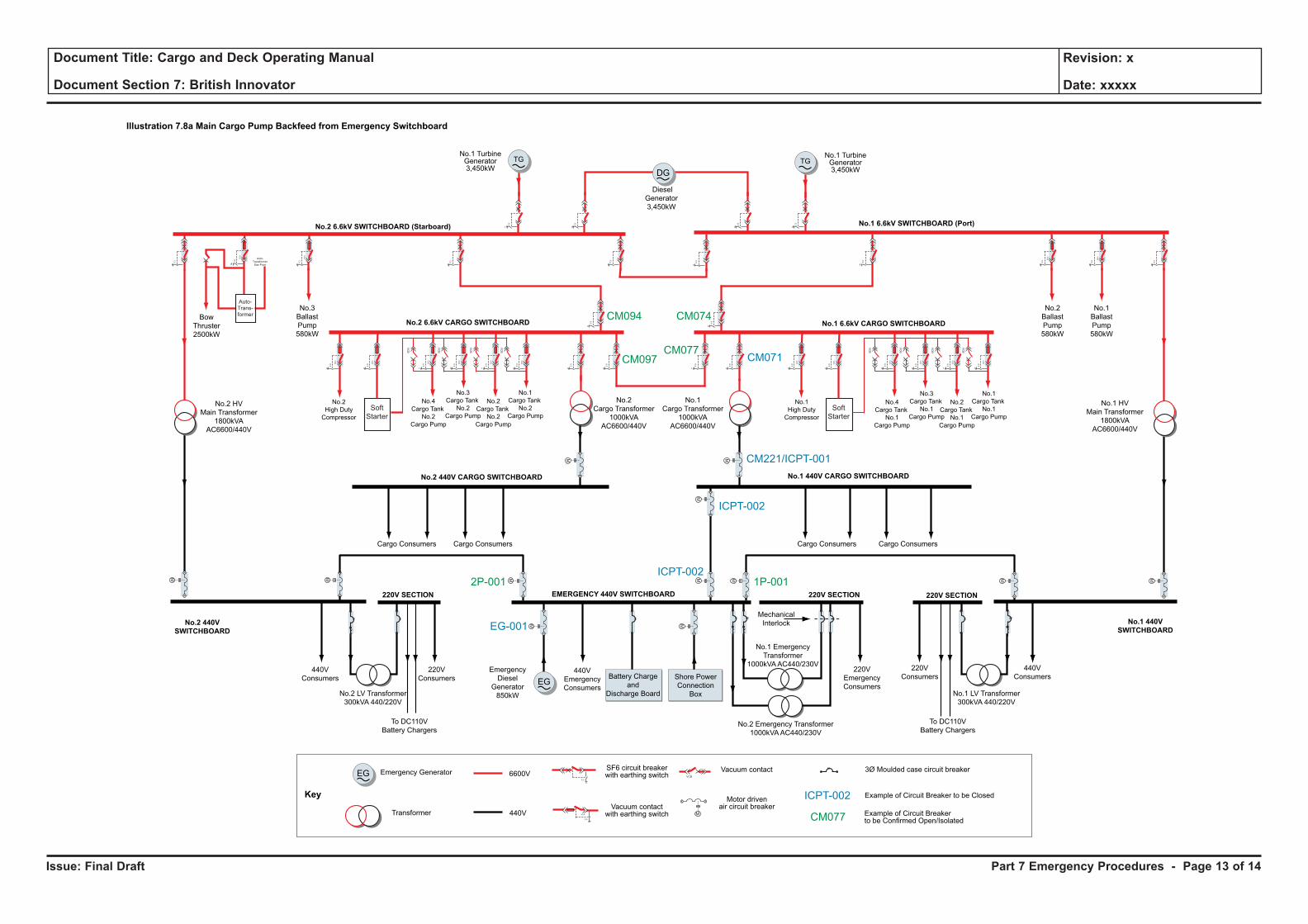
Issue: Final Draft
Document Title: Cargo and Deck Operating Manual
Document Section 7: British Innovator
Revision: x
Date: xxxxx
Part 7 Emergency Procedures - Page 13 of 14
EmergencyDiesel
Generator850kW
EMERGENCY 440V SWITCHBOARD
440VConsumers
220VConsumers
Cargo Consumers Cargo Consumers Cargo ConsumersCargo Consumers
440VEmergencyConsumers
220VEmergencyConsumers
440VConsumers
No.1
Cargo Tank
No.2
Cargo Pump
No.3
Cargo Tank
No.2
Cargo Pump
No.2
Cargo Tank
No.2
Cargo Pump
No.4
Cargo Tank
No.2
Cargo Pump
No.1
Cargo Tank
No.1
Cargo Pump
No.3
Cargo Tank
No.1
Cargo Pump
No.2
Cargo Tank
No.1
Cargo Pump
No.4
Cargo Tank
No.1
Cargo Pump
CM094
CM097CM077
2P-001 1P-001
CM074
CM071
CM221/ICPT-001
ICPT-002
ICPT-002
ICPT-002
EG-001
No.2
High Duty
Compressor
No.1
High Duty
Compressor
No.2Cargo Transformer
1000kVAAC6600/440V
No.1Cargo Transformer
1000kVAAC6600/440V
No.2 HVMain Transformer
1800kVAAC6600/440V
No.2 440V
SWITCHBOARD
220V SECTION 220V SECTION
No.1 440V
SWITCHBOARD
No.2 440V CARGO SWITCHBOARD No.1 440V CARGO SWITCHBOARD
No.2 LV Transformer300kVA 440/220V
No.1 LV Transformer300kVA 440/220V
220V SECTION
No.2 Emergency Transformer1000kVAAC440/230V
No.1 EmergencyTransformer
1000kVAAC440/230V220V
Consumers
To DC110VBattery Chargers
To DC110VBattery Chargers
Shore PowerConnection
Box
Battery Chargeand
Discharge Board
CM077
Illustration 7.8a Main Cargo Pump Backfeed from Emergency Switchboard
Key
TG TGNo.1 TurbineGenerator3,450kW
No.1 TurbineGenerator3,450kW
Emergency Generator 6600VSF6 circuit breakerwith earthing switch
Transformer 440VVacuum contact
with earthing switch
Vacuum contact 3Ø Moulded case circuit breaker
Example of Circuit Breaker to be Closed
Example of Circuit Breakerto be Confirmed Open/Isolated
Motor drivenair circuit breaker
BowThruster2500kW
No.2 6.6kV CARGO SWITCHBOARD No.1 6.6kV CARGO SWITCHBOARD
No.1 6.6kV SWITCHBOARD (Port)
DG
No.1BallastPump580kW
No.2BallastPump580kW
No.3BallastPump580kW
SoftStarter
Auto-TransformerStar Point
VCB
E.S
E.S
E.S
E.S
E.S
E.S
E.S
E.S
E.S
E.S
E.S
E.S
E.S
E.S
E.S
VCB
E.S
VCB
E.S
VCB
E.S
VCB
VCB
VCB
E.S
VCB
VCB
E.S
VCB
VCB
E.S
E.S
E.S
E.S
E.S
E.S
E.S
E.S
VCB
VCB
SoftStarter
E.S
VCB
E.S
VCB
E.S
VCB
VCB
E.S
VCB
VCB
E.S
VCB
VCB
E.S
VCB
VCB
VCB
VCB
VCB
Auto-Trans-former
M M
M M
M
M
MM
MM M
M M
DieselGenerator3,450kW
EG
EG
No.2 6.6kV SWITCHBOARD (Starboard)
No.1 HVMain Transformer
1800kVAAC6600/440V
MechanicalInterlock
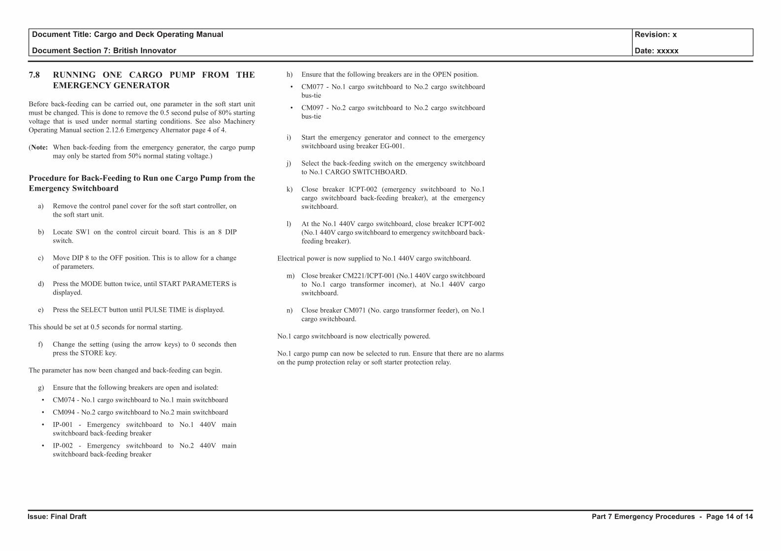
Issue: Final Draft
Document Title: Cargo and Deck Operating Manual
Document Section 7: British Innovator
Revision: x
Date: xxxxx
7.8 RUNNING ONE CARGO PUMP FROM THE EMERGENCY GENERATOR
Before back-feeding can be carried out, one parameter in the soft start unit must be changed. This is done to remove the 0.5 second pulse of 80% starting voltage that is used under normal starting conditions. See also Machinery Operating Manual section 2.12.6 Emergency Alternator page 4 of 4.
(Note: When back-feeding from the emergency generator, the cargo pump may only be started from 50% normal stating voltage.)
Procedure for Back-Feeding to Run one Cargo Pump from the Emergency Switchboard
a) Remove the control panel cover for the soft start controller, on the soft start unit.
b) Locate SW1 on the control circuit board. This is an 8 DIP switch.
c) Move DIP 8 to the OFF position. This is to allow for a change of parameters.
d) Press the MODE button twice, until START PARAMETERS is displayed.
e) Press the SELECT button until PULSE TIME is displayed.
This should be set at 0.5 seconds for normal starting.
f) Change the setting (using the arrow keys) to 0 seconds then press the STORE key.
The parameter has now been changed and back-feeding can begin.
g) Ensure that the following breakers are open and isolated:
• CM074 - No.1 cargo switchboard to No.1 main switchboard
• CM094 - No.2 cargo switchboard to No.2 main switchboard
• IP-001 - Emergency switchboard to No.1 440V main switchboard back-feeding breaker
• IP-002 - Emergency switchboard to No.2 440V main switchboard back-feeding breaker
h) Ensure that the following breakers are in the OPEN position.
• CM077 - No.1 cargo switchboard to No.2 cargo switchboard bus-tie
• CM097 - No.2 cargo switchboard to No.2 cargo switchboard bus-tie
i) Start the emergency generator and connect to the emergency switchboard using breaker EG-001.
j) Select the back-feeding switch on the emergency switchboard to No.1 CARGO SWITCHBOARD.
k) Close breaker ICPT-002 (emergency switchboard to No.1 cargo switchboard back-feeding breaker), at the emergency switchboard.
l) At the No.1 440V cargo switchboard, close breaker ICPT-002 (No.1 440V cargo switchboard to emergency switchboard back-feeding breaker).
Electrical power is now supplied to No.1 440V cargo switchboard.
m) Close breaker CM221/ICPT-001 (No.1 440V cargo switchboard to No.1 cargo transformer incomer), at No.1 440V cargo switchboard.
n) Close breaker CM071 (No. cargo transformer feeder), on No.1 cargo switchboard.
No.1 cargo switchboard is now electrically powered.
No.1 cargo pump can now be selected to run. Ensure that there are no alarms on the pump protection relay or soft starter protection relay.
Part 7 Emergency Procedures - Page 14 of 14