ca no: cenm - of 2017-18 serial page no - amazon aws
TRANSCRIPT
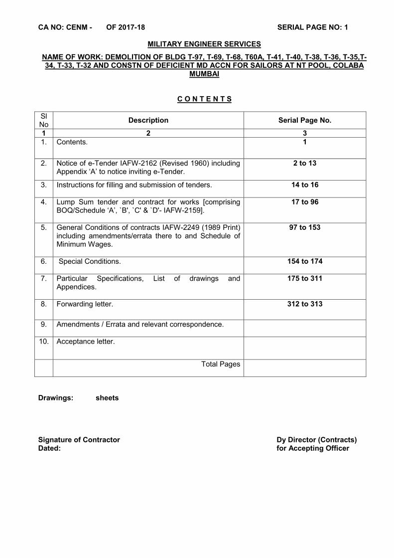
CA NO: CENM - OF 2017-18 SERIAL PAGE NO: 1
MILITARY ENGINEER SERVICES
NAME OF WORK: DEMOLITION OF BLDG T-97, T-69, T-68, T60A, T-41, T-40, T-38, T-36, T-35,T-34, T-33, T-32 AND CONSTN OF DEFICIENT MD ACCN FOR SAILORS AT NT POOL, COLABA
MUMBAI
C O N T E N T S
Sl No
Description Serial Page No.
1 2 3 1. Contents. 1
2. Notice of e-Tender IAFW-2162 (Revised 1960) including Appendix ‘A’ to notice inviting e-Tender.
2 to 13
3. Instructions for filling and submission of tenders.
14 to 16
4. Lump Sum tender and contract for works [comprising BOQ/Schedule ‘A’, `B', `C' & `D'- IAFW-2159].
17 to 96
5. General Conditions of contracts IAFW-2249 (1989 Print) including amendments/errata there to and Schedule of Minimum Wages.
97 to 153
6. Special Conditions.
154 to 174
7. Particular Specifications, List of drawings and Appendices.
175 to 311
8. Forwarding letter.
312 to 313
9. Amendments / Errata and relevant correspondence.
10. Acceptance letter.
Total Pages
Drawings: sheets Signature of Contractor Dy Director (Contracts) Dated: for Accepting Officer

CA NO: CENM - OF 2017-18 SERIAL PAGE NO: 2
MILITARY ENGINEER SERVICES
NOTICE INVITING TENDER (NIT) (IN LIEU OF IAFW-2162 (REVISED 1960)
1. A tender is invited for the work as mentioned in Appendix ‘A’ to this NOTICE INVITING TENDER (NIT).
2. The work is estimated to cost as indicated in aforesaid Appendix ‘A’. This estimate, however, is not a guarantee and is merely given as a rough guide and if the work costs more or less, a tenderer / bidder will have no claim on this account. The tender shall be based on as mentioned in aforesaid Appendix ‘A’.
3. The work is to be completed within the period as indicated in the aforesaid Appendix ‘A’ in accordance with the phasing, if any, indicated in the tender from the date of handing over site, which will be on or about two weeks after the date of Acceptance of tender.
4. Normally contractors whose names are on the MES approved list for the area in which the work lies, and within whose financial category the estimated amount would fall, may tender/bid but in case of term contracts, contractors of categories ‘SS’ to ‘E’ may tender/bid. In case ,where the tendered amount is in excess of the financial limit of the contractor and the Accepting Officer decides to accept the tender/bid, in which event the tenderer/bidder would be required to lodge additional security deposit as notified by the Accepting Officer in terms of conditions of contract. Contractors whose names are on the MES approved list of any MES formation and who have deposited standing security deposit and have executed standing security bond may also tender/bid without depositing Earnest money along with the tender/bid and if the tender/bid submitted by such a tenderer/bidder is accepted , contractor will be required to lodge with the Controller of Defence Accounts concerned the amount of ‘Individual Security Deposit’ within thirty days of the receipt by him of notification of acceptance of his tender/bid, failing which this sum will be recovered from 1st RAR payment or from the first final bill. In case of term/running contracts, remaining sum shall be recovered from subsequent bill(s) of the contractor. Not more than one tender/bid shall be submitted/uploaded by one contractor or one firm of contractors. Under no circumstances will a father and his son(s) or other close relations who have business dealing with one another will be allowed to tender/bid for the same contract as separate competitors. A breach of this condition will render the tenders/bids of both the parties liable for rejection.
5. The Office of Chief Engineer (Navy) Mumbai will be the Accepting Officer here-in-after referred to as such for the purpose of the contract.
6. The Technical Bid and Financial bid (Cover-1 and Cover-2) shall be uploaded by the tenderer/bidder on or before the date & time mentioned in NIT. A scanned copy of DD with enlistment details/ documents shall be uploaded as packet 1/ cover-1 (‘T’ bid) of the tender / bid on e-tendering portal. DD is refundable in case T bid is not accepted resulting in non-opening of ‘Q’ bid. The applicant contractor shall bear the cost of bank charges for procuring and encashing the DD and shall not have any claim from Government whatsoever on this account.
6.1 Tender forms and conditions of contracts and other necessary documents shall be available on eprocuremes.gov.in / defproc.gov.in eprocure.gov.in site for download and shall form part of contract agreement in case tender/bid is accepted be issued as per dates given in the aforesaid Appendix-‘A’ to notice inviting e-tender.
6.2 In case of contractor who has not executed the Standing Security Bond, the cover-I shall be accompanied with by Earnest Money of amount as mentioned Appendix ‘A’ in the form of deposit at Call receipt in favour of concerned CCE/GE/GE(I) / AGE(I) (see Appendix ‘A’) by a Scheduled Bank or in receipted treasury Challan, the amount being credited to the revenue deposit of the concerned CCE/GE/GE(I) / AGE(I) (see Appendix ‘A’).
CA NO: CENM - OF 2017-18 SERIAL PAGE NO: 3
NOTICE INVITING TENDER (NIT) (CONTD…)
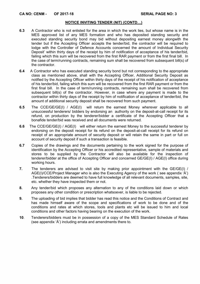
6.3 A Contractor who is not enlisted for the area in which the work lies, but whose name is in the MES approved list of any MES formation and who has deposited standing security and executed standing security bond may bid without depositing earnest money alongwith the tender but if the Accepting Officer accepts the tender/bid, the contractor will be required to lodge with the Controller of Defence Accounts concerned the amount of Individual Security Deposit’ within thirty days of the receipt by him of notification of acceptance of his tender/bid, failing which this sum will be recovered from the first RAR payment or from the first final bill. In the case of term/running contracts, remaining sum shall be recovered from subsequent bill(s) of the contractor.
6.4 A Contractor who has executed standing security bond but not corresponding to the appropriate class as mentioned above, shall with the Accepting Officer, Additional Security Deposit as notified by the Accepting Officer within thirty days of the receipt of his notification of acceptance of his tender/bid, failing which this sum will be recovered from the first RAR payment or from the first final bill. In the case of term/running contracts, remaining sum shall be recovered from subsequent bill(s) of the contractor. However, in case where any payment is made to the contractor within thirty days of the receipt by him of notification of acceptance of tender/bid, the amount of additional security deposit shall be recovered from such payment.
6.5 The CCE/GE/GE(I) / AGE(I) will return the earnest Money wherever applicable to all unsuccessful tenderers/ bidders by endorsing an authority on the deposit-at-call receipt for its refund, on production by the tenderer/bidder a certificate of the Accepting Officer that a bonafide tender/bid was received and all documents were returned.
6.6 The CCE/GE/GE(I) / AGE(I) will either return the earnest Money to the successful tenderer by endorsing on the deposit receipt for its refund on the deposit-at-call receipt for its refund on receipt of an appropriate amount of security deposit or will retain the same in part or full on account of security deposit if such a transaction is feasible.
6.7 Copies of the drawings and the documents pertaining to the work signed for the purpose of identification by the Accepting Officer or his accredited representative, sample of materials and stores to be supplied by the Contractor will also be available for the inspection of tenderer/bidder at the office of Accepting Officer and concerned GE/GE(I) / AGE(I) office during working hours.
7. The tenderers are advised to visit site by making prior appointment with the GE/GE(I) / AGE(I)/CCE/Project Manager who is also the Executing Agency of the work ( see appendix ‘Á’) .Tenderers/bidders are deemed to have full knowledge of all relevant documents, samples, site, etc. whether they have inspected them or not.
8. Any tender/bid which proposes any alternation to any of the conditions laid down or which proposes any other condition or prescription whatsoever, is liable to be rejected.
9. The uploading of bid implies that bidder has read this notice and the Conditions of Contract and has made himself aware of the scope and specifications of work to be done and of the conditions and rates at which stores, tools and plants etc will be issued to him and local conditions and other factors having bearing on the execution of the work.
10. Tenderers/bidders must be in possession of a copy of the MES Standard Schedule of Rates (see appendix ‘Á’) including errata and amendments there to.
CA NO: CENM - OF 2017-18 SERIAL PAGE NO: 4
NOTICE INVITING TENDER (NIT) (CONTD…)
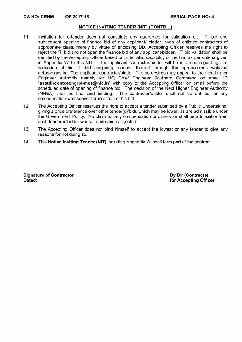
11. Invitation for e-tender does not constitute any guarantee for validation of. ’T’ bid and subsequent opening of finance bid of any applicant/ bidder, even of enlisted contractors of appropriate class, merely by virtue of enclosing DD. Accepting Officer reserves the right to reject the ‘T’ bid and not open the finance bid of any applicant/bidder. ‘T’ bid validation shall be decided by the Accepting Officer based on, inter alia, capability of the firm as per criteria given in Appendix ‘A’ to this NIT. The applicant contractor/bidder will be informed regarding non validation of his ‘T’ bid assigning reasons thereof through the eprocuremes website/ defproc.gov.in. The applicant contractor/bidder if he so desires may appeal to the next higher Engineer Authority namely viz HQ Chief Engineer Southern Command on email ID “[email protected]” with copy to the Accepting Officer on email before the scheduled date of opening of finance bid. The decision of the Next Higher Engineer Authority (NHEA) shall be final and binding. The contractor/bidder shall not be entitled for any compensation whatsoever for rejection of his bid.
12. The Accepting Officer reserves the right to accept a tender submitted by a Public Undertaking, giving a price preference over other tender(s)/bids which may be lower, as are admissible under the Government Policy. No claim for any compensation or otherwise shall be admissible from such tenderer/bidder whose tender/bid is rejected.
13. The Accepting Officer does not bind himself to accept the lowest or any tender to give any reasons for not doing so.
14. This Notice Inviting Tender (NIT) including Appendix ‘Á’ shall form part of the contract.
Signature of Contractor Dy Dir (Contracts) Dated: for Accepting Officer
CA NO: CENM - OF 2017-18 SERIAL PAGE NO: 5
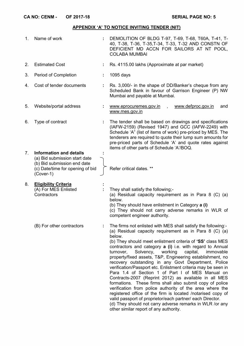
APPENDIX ‘A’ TO NOTICE INVITING TENDER (NIT)
1. Name of work : DEMOLITION OF BLDG T-97, T-69, T-68, T60A, T-41, T-
40, T-38, T-36, T-35,T-34, T-33, T-32 AND CONSTN OF DEFICIENT MD ACCN FOR SAILORS AT NT POOL, COLABA MUMBAI
2. Estimated Cost : Rs. 4115.00 lakhs (Approximate at par market)
3. Period of Completion : 1095 days
4. Cost of tender documents : Rs. 3,000/- in the shape of DD/Banker’s cheque from any Scheduled Bank in favour of Garrison Engineer (P) NW Mumbai and payable at Mumbai.
5. Website/portal address : www.eprocuremes.gov.in , www.defproc.gov.in and www.mes.gov.in
6. Type of contract
: The tender shall be based on drawings and specifications (IAFW-2159) (Revised 1947) and GCC (IAFW-2249) with Schedule ‘A” (list of items of work) pre-priced by MES. The tenderers are required to quote their lump sum amounts for pre-priced parts of Schedule ‘A’ and quote rates against items of other parts of Schedule ‘A’/BOQ.
7. Information and details : (a) Bid submission start date
(b) Bid submission end date (c) Date/time for opening of bid (Cover-1)
Refer critical dates. **
8. Eligibility Criteria : (A) For MES Enlisted
Contractors : They shall satisfy the following;-
(a) Residual capacity requirement as in Para 8 (C) (a) below. (b) They should have enlistment in Category a (i) (c) They should not carry adverse remarks in WLR of competent engineer authority.
(B) For other contractors
: The firms not enlisted with MES shall satisfy the following:- (a) Residual capacity requirement as in Para 8 (C) (a) below. (b) They should meet enlistment criteria of ‘SS’ class MES contractors and category a (i) i.e. with regard to Annual turnover, Solvency, working capital, immovable property/fixed assets, T&P, Engineering establishment, no recovery outstanding in any Govt Department, Police verification/Passport etc. Enlistment criteria may be seen in Para 1.4 of Section 1 of Part I of MES Manual on Contracts-2007 (Reprint 2012) as available in all MES formations. These firms shall also submit copy of police verification from police authority of the area where the registered office of the firm is located /notarised copy of valid passport of proprietor/each partner/ each Director. (d) They should not carry adverse remarks in WLR /or any other similar report of any authority.

CA NO: CENM - OF 2017-18 SERIAL PAGE NO: 6
APPENDIX ‘A’ TO NOTICE INVITING TENDER (CONTD…)
(C) For All Contractors : (a) Applicant’s residual capacity as worked out by following formula should be more than estimated cost of work:- Residual capacity = (2 x A x N) – B, Where ; A = Maximum turnover in last 5 financial years. N = Period of completion of contracted (Tendered) work (in years calculated till 2 decimal places) B = Value of balance work in all Govt. & Private works
(b) Contractor will not be allowed to execute the work by
subletting or through Power of Attorney holder on his behalf to a third party/another firm except sons/daughters of proprietor/ partner/Director and firm’s own employees, Director, Project Manager. This shall be subject to certain conditions which will be prescribed in the Notice of Tender forming part of the tender documents.
9. Tender issuing and Accepting Officer
: Chief Engineer (Navy) Mumbai
10. Executing agency : Garrison Engineer (P) NW Mumbai

CA NO: CENM - OF 2017-18 SERIAL PAGE NO: 7
APPENDIX ‘A’ TO NOTICE INVITING TENDER (CONTD…)
11. Earnest Money : Rs.15,00,000/- in favour of Garrison Engineer (P) NW Mumbai
**CRITICAL DATES
Para 7. Publishing date and time of tender documents
: 03 Feb 2018 at 1800 hrs
Starting date & time for downloading of tender documents
: 03 Feb 2018 at 1800 hrs
Starting date and time of bid submission (Cover No. 1 & 2)
: 05 Mar 2018 at 1200 hrs
Closing date and time of bid submission (Cover No. 1 & 2)
: 15 Mar 2018 at 1800 hrs
Date and time of bid opening (Cover No. 1)
: 21 Apr 2018 at 1200 hrs or subsequent
Date and time of bid opening (Cover No. 2)
: Will be intimated online after completion of evaluation of tech bids/applications (cover No. 1)
NOTES:- (a) Contractors enlisted with MES will upload following documents (scanned copy in pdf format) for checking eligibility:-
(i) Application for the tender on Tenderer’s Letter Head. In this, the contractor should explain with calculation details supported with documentary evidence as to how he is qualifying for this tender in terms of condition given in Para 8 (A) (a) above. Tenderer/bidder to note that if they do not submit their calculation details and/ or supporting documents correctly, Deptt will make calculation. If the firm does not qualify as a result of Deptt calculation, then bidder only will be responsible for the same. This is notwithstanding the fact that Deptt will check the details and calculations also in respect of the contractors who have given the calculations. (ii) Enlistment letter (iii) DD towards cost of tender (iv) Service Tax Registration Number documents (v) A copy of Power of Attorney in favour of the person uploading the bid using his/her DSC OR other documents as mentioned in Para 5.6 & 5.7 of ‘INSTRUCTIONS ON FILLING AND SUBMISSION OF TENDERS’.
(vi) Documents in support of residual capacity shall include:-
(aa) Copy of turn over certificate from CA for last 5 (Five) years (FY) notarised copy of relevant pages of balance sheet of those FYs showing the turn over (gross receipts). (ab) List of works in hand for contracts with Government department & private works, completed value thereof and residual work to be completed during completion period of subject work in a self-explanatory tabular form. This shall be submitted duly signed by proprietor / all partners / authorised Director of Pvt/ Public Ltd as applicable.
CA NO: CENM - OF 2017-18 SERIAL PAGE NO: 8
APPENDIX ‘A’ TO NOTICE INVITING TENDER (CONTD…)
(ac) Copies of completion certificates in three highest valued works (after adjusting the values as per para 8(C)(b)(iii) above) during last seven years. This will be in tabular form giving name of work, Accepting Officer’s details, viz, Address, Telephone, Fax No, E-mail ID etc, date of acceptance of tender and actual date of completion. This shall be duly signed by proprietor / all partners / authorised Director of Pvt / Public Ltd, as applicable. It should indicate whether extension was granted or compensation was levied. Attested copy of acceptance letter and completion certificate shall be enclosed of each work. In case performance report has been given by the client same shall also be submitted duly attested. (ad) Affidavit on non judicial stamp paper of Rs 100/- (minimum) in the form of hard copy declaring their turnover for last 5 (Five) Years and value of contracts I hand Government department & private and details of works completed and residual works to be completed.
(vii) Any other document as required.
Hard copy of these documents will be submitted within 7 (Seven) days of the last date & time of opening of ‘T’ bid.
(b) Contractors not enlisted with MES will be required to upload the following documents (scanned copy in pdf format) for checking eligibility:-
(i) Application for the tender on Tenderer’s Letter Head. In this, the contractor should explain with calculation details supported with documentary evidence as to how he is qualifying for this tender in terms of conditions given in Para 8 (A) (a) above. Tenderer/bidder to note that if they do not submit their calculation details and/ or supporting documents correctly, Deptt will make calculation. If the firm does not qualify as a result of Deptt calculation, then bidder only will be responsible for the same. This is notwithstanding the fact that Deptt will check the details and calculations also in respect of the contractors who have given the calculations.
(ii) Necessary documents to prove their eligibility for enlistment in required class & category of work, including Affidavit for no recovery outstanding. List of documents required for enlistment in MES has been given in Para 1.5 of section 1 of Part I of MES Manual on Contracts 2007 (reprint 2012). This will include the following amongst others:- (aa) Solvency certificate and Working Capital Certificate issued by schedule bank.
(ab) Affidavit for possession of movable & immovable properties by proprietor/ partner owning the immovable property along with Valuation Certificate from Regd Valuer in support of movable and immovable properties. In case of Limited Company, the immovable property is required to be in the name of Company.
(iii) Scanned copy of DD towards cost of tender.
(iv) Service Tax Registration Number documents (v) A copy of Power of Attorney in favour of the person uploading the bid using his/her DSC OR other documents as mentioned in Para 5.6 & 5.7 of ‘INSTRUCTIONS ON FILLING AND SUBMISSION OF TENDERS’.
(vi) Documents in support of residual capacity shall include:-
(aa) Copy of turn over certificate from CA for last 5 (Five) years (FY), notarised copy of relevant pages of balance sheet of those FYs showing the turn over (gross receipts).
CA NO: CENM - OF 2017-18 SERIAL PAGE NO: 9
APPENDIX ‘A’ TO NOTICE INVITING TENDER (CONTD…)
(ab) List of works in hand for contracts with Government department & private works, completed value thereof and residual work to be completed during completion period of subject work in a self-explanatory tabular form. This shall be submitted duly signed by proprietor / all partners / authorised Director of Pvt/ Public Ltd as applicable. (ac) Copies of completion certificates in three highest valued works (after adjusting the values as per para 8(C)(b)(iii) above) during last seven years. This will be in tabular form giving name of work, Accepting Officer’s details, viz, Address, Telephone, Fax No, E-mail ID etc, date of acceptance of tender and actual date of completion. This shall be duly signed by proprietor / all partners / authorised Director of Pvt / Public Ltd, as applicable. It should indicate whether extension was granted or compensation was levied. Attested copy of acceptance letter and completion certificate shall be enclosed of each work. In case performance report has been given by the client same shall also be submitted duly attested. (ad) Affidavit on non judicial stamp paper of Rs 100/- (minimum) in the form of hard copy declaring their turnover for last 5 (Five) Years and value of contracts I hand Government department & private and details of works completed and residual works to be completed.
(viii) Any other documents as required Also refer Annexure No. I. Hard copy of these documents will be submitted within 7 (Seven) days of the last date & time of opening of ‘T’ bid.
(c) (i) Applications/bids not accompanied by scanned copies of requisite DD/ Banker’s cheque
towards cost of tender and earnest money (as applicable) shall not be considered for validation of ‘T’ bid and their finance bids will not be opened.
(ii) Tenderers/ bidders to note that they should ensure that their original DDs and earnest money (as applicable) are received within 7 days of bid submission end date.
(iii) In case of Applications/bids from enlisted contractors of MES, where scanned copies of requisite DD/ Banker’s cheque towards cost of tender has been uploaded but physical copies are not received by the stipulated date, finance bids will be opened. However, non-submission of physical copies of cost of tender shall be considered as willful negligence of the bidder with ulterior motives and such bidder shall be banned from bidding for a period of 6 months commencing from the date of opening of finance bid. The amount of cost of tender will be recovered from any amount due to the MES enlisted contractor. (iv) In case of Applications/bids from unenlisted contractors, where scanned copies of requisite DD/ Banker’s cheque towards cost of tender and earnest money has been uploaded but physical copies are not received by the stipulated date, finance bids will not be opened. Name of such contractors alongwith complete address shall be circulated for not opening of their bids for a period of six months commencing from the date of opening of finance bid. (v) In case of Applications/bids from enlisted contractors as well as unenlisted contractors, where scanned copies of requisite earnest money (as applicable) were uploaded but the same are not received in physical form within the stipulated time, such bids shall not qualify for opening of finance bid.
(d) In case of rejection of technical/prequalification bid, contractor may appeal to next higher Engineer Authority i.e HQ Chief Engineer Southern Command, Pune on email ‘[email protected]’ against rejection, whose decision shall be final and binding. However contractor/bidder shall not be entitled to any compensation whatsoever for rejection of technical/prequalification bid.
CA NO: CENM - OF 2017-18 SERIAL PAGE NO: 10
APPENDIX ‘A’ TO NOTICE INVITING TENDER (CONTD…)
(e) Court of the place from where tender has been issued shall alone have jurisdiction to decide any dispute arising out of or in respect of this tender. After acceptance of tender, Condition 72 (Jurisdiction of Courts) of IAFW-2249 shall be applicable. (f) CLARIFICATION ON PROVIDENT FUND CODE NUMBER:
Before releasing the work order after finalization of the tender, it shall be ensured that the contractors shall have Provident Fund Code Number, if applicable.
(g) SERVICE TAX REGISTRATION NUMBER:
(a) Keeping in view the applicability of Service Tax on all contracts. It is mandatory for the contractors to upload their Service Tax Registration Number along with the ‘T’ bid. This will be one of the criteria for qualifying in ‘T’ bid. Contractor, who does not upload Service Tax Registration Number., shall be disqualified in the ‘T’ bid evaluation and his financial bid shall not be opened.
(b) The above documents in pdf format shall be uploaded in Cover No 1 of the bid
80000/NIT/492/E8 Military Engineer Services (M Arunachalam) Chief Engineer (Navy) Mumbai Dy Dir (Contracts) 26, Assaye Building for Accepting Officer Colaba, Mumbai – 400 005 Phone No: 022-22150513, 022-22151581, 022-22187549 Dated: 03 Feb 2018
CA NO: CENM - OF 2017-18 SERIAL PAGE NO: 11
Annexure No. I
ELIGIBILITY CRITERIA FOR UN-ENLISTED CONTRACTORS
1. Particulars of Contractors: Documents regarding Proprietorship/Partnership/Private Limited concern to be submitted. Also, affidavit regarding no sister concern in MES and no near relative in MES to be submitted.
2. No recovery of any kind is outstanding in any Government Department. Affidavit to this affect to be furnished. 3. Joint venture and subletting are not allowed. 4. Minimum Technical personnel on permanent payroll with details as given below shall be under employment with the firm:-
(i) Degree holders -03 Nos. having minimum experience of 05 years, (ii) Diploma holders -05 Nos. having minimum experience of 08 years and (iii) One of the Engineers should have capability to use Project Management Software like MS Projects/Primavera in all projects. (Affidavit from the firm as well as from the engineers along with experience certificates and CTC of degree/ diploma obtained from a Govt recognized institution to be furnished).
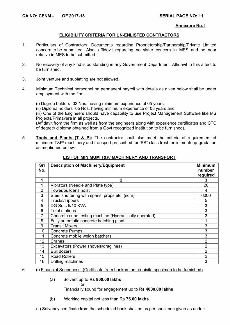
5. Tools and Plants (T & P): The contractor shall also meet the criteria of requirement of minimum T&P/ machinery and transport prescribed for ‘SS” class fresh enlistment/ up-gradation as mentioned below:-
LIST OF MINIMUM T&P/ MACHINERY AND TRANSPORT
6. (i) Financial Soundness: (Certificate from bankers on requisite specimen to be furnished)
(a) Solvent up to Rs 800.00 lakhs
or Financially sound for engagement up to Rs 4000.00 lakhs
(b) Working capital not less than Rs 75.00 lakhs
(ii) Solvency certificate from the scheduled bank shall be as per specimen given as under: -
Srl No.
Description of Machinery/Equipment Minimum number required
1 2 3 1 Vibrators (Needle and Plate type) 20 2 Tower/builder’s hoist 4 3 Steel shuttering with spans, props etc. (sqm) 6000 4 Trucks/Tippers 5 5 DG Sets 5/10 KVA 3 6 Total stations 3 7 Concrete cube testing machine (Hydraulically operated) 3 8 Fully automatic concrete batching plant 1 9 Transit Mixers 3
10 Concrete Pumps 3 11 Concrete mobile weigh batchers 3 12 Cranes 2 13 Excavators (Power shovels/draglines) 2 14 Bull dozers 2 15 Road Rollers 2 16 Drilling machines 3
CA NO: CENM - OF 2017-18 SERIAL PAGE NO: 12
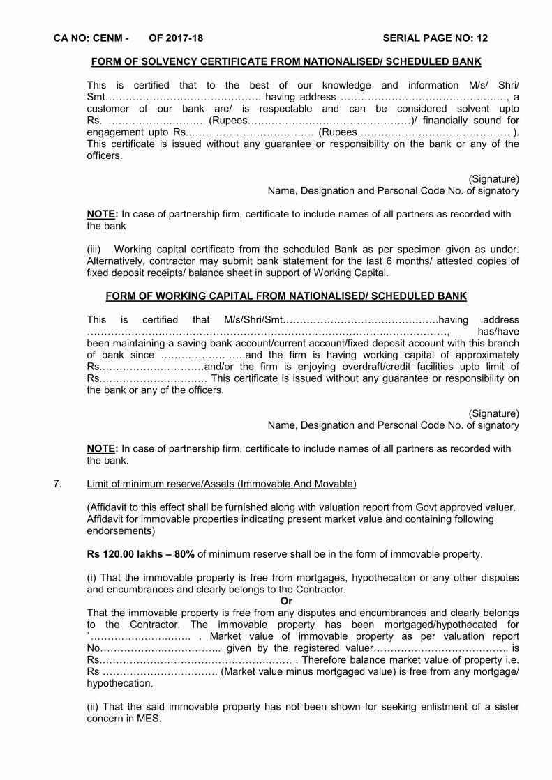
FORM OF SOLVENCY CERTIFICATE FROM NATIONALISED/ SCHEDULED BANK
This is certified that to the best of our knowledge and information M/s/ Shri/ Smt………………………………………. having address ……………………………………….…, a customer of our bank are/ is respectable and can be considered solvent upto Rs. ……………….……… (Rupees…………………………………………)/ financially sound for engagement upto Rs.………………………………. (Rupees……………………………………….). This certificate is issued without any guarantee or responsibility on the bank or any of the officers.
(Signature)
Name, Designation and Personal Code No. of signatory
NOTE: In case of partnership firm, certificate to include names of all partners as recorded with the bank (iii) Working capital certificate from the scheduled Bank as per specimen given as under. Alternatively, contractor may submit bank statement for the last 6 months/ attested copies of fixed deposit receipts/ balance sheet in support of Working Capital.
FORM OF WORKING CAPITAL FROM NATIONALISED/ SCHEDULED BANK
This is certified that M/s/Shri/Smt……………………………………….having address …………………………………………………………………………….………………, has/have been maintaining a saving bank account/current account/fixed deposit account with this branch of bank since …………………….and the firm is having working capital of approximately Rs.…………………………and/or the firm is enjoying overdraft/credit facilities upto limit of Rs.…………………………. This certificate is issued without any guarantee or responsibility on the bank or any of the officers.
(Signature)
Name, Designation and Personal Code No. of signatory NOTE: In case of partnership firm, certificate to include names of all partners as recorded with the bank.
7. Limit of minimum reserve/Assets (Immovable And Movable)
(Affidavit to this effect shall be furnished along with valuation report from Govt approved valuer. Affidavit for immovable properties indicating present market value and containing following endorsements) Rs 120.00 lakhs – 80% of minimum reserve shall be in the form of immovable property. (i) That the immovable property is free from mortgages, hypothecation or any other disputes and encumbrances and clearly belongs to the Contractor.
Or That the immovable property is free from any disputes and encumbrances and clearly belongs to the Contractor. The immovable property has been mortgaged/hypothecated for `…………….…….……. . Market value of immovable property as per valuation report No……………….…………….. given by the registered valuer………………………………… is Rs.………………………………………….……. . Therefore balance market value of property i.e. Rs ……………………………. (Market value minus mortgaged value) is free from any mortgage/ hypothecation.
(ii) That the said immovable property has not been shown for seeking enlistment of a sister concern in MES.

CA NO: CENM - OF 2017-18 SERIAL PAGE NO: 13
(iii) That the said immovable property will not be sold, transferred, gifted or otherwise disposed off without prior intimation to the registering authority in MES. While giving such prior intimation, new affidavit for alternate immovable property of value at least equal to minimum requirement as per scales along with valuation report from registered valuer shall also be submitted failing which the Registering Authority may declare the contractor un-enlisted or may take action as deemed fit till acquiring alternate immovable property by the contractor.
NOTE : In case of partnership firm, the partner having immovable property in his name, shall also endorse the following in addition to above : “Irrespective of my share in partnership firm, my whole property may be utilized by the Government for realising their dues/recovery, if the firm fails to deposit the same”.
(iv) Valuation report from Registered (with any Government body) valuer for immovable property clearly indicating ownership details. Alternatively, the Contractor may submit certificate from the Deputy commissioner/Collector/First calls Magistrate or assessment of wealth tax authorities.
(v) Affidavit for movable property (T & P machinery transport etc.) : If certain movable property is being considered towards requirements of minimum reserve, endorsements as required for immovable property shall also be given on affidavit for movable property and valuation report from Registered (with any Government body) valuer for movable property clearly indicating ownership details shall also be submitted.
8. Police verification
Copy of police verification certificate from police authority of the area where registered office is located. Alternatively notarized copy of valid passport of proprietor/each partner/each director can be submitted.
9. Affidavit from tenderer that he is not involved in any arbitration/litigation cases. 10. Affidavit that no near relative(s) of the tenderer or their employees/agents is/are working as
Gazetted commissioned Govt. Officer in MES/Corps of Engineers/Ministry of Defence. 11. Affidavit that no near relative(s) of the tenderer is/are working as Junior Engineer in MES/Corps
of Engineers.
12. Scanned copy of Service Tax Registration Number documents.
13. A scanned copy of Power of Attorney in favour of the person uploading the bid using his/her DSC OR other documents as mentioned in para 5.6 & 5.7 of ‘INSTRUCTIONS ON FILLING AND SUBMISSION OF TENDERS’. NOTE:- All applicant contractors (including enlisted MES contractors) shall upload copies of all the above mentioned documents (whichever is applicable) along with application, tender cost and EMD prior to closing date of bid submission .
(M arunachalam) Dy Dir (Contracts) For Accepting Officer
CA NO: CENM - OF 2017-18 SERIAL PAGE NO: 14
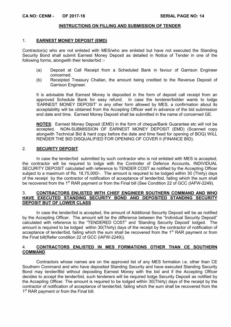
INSTRUCTIONS ON FILLING AND SUBMISSION OF TENDER
1. EARNEST MONEY DEPOSIT (EMD) Contractor(s) who are not enlisted with MES/who are enlisted but have not executed the Standing Security Bond shall submit Earnest Money Deposit as detailed in Notice of Tender in one of the following forms, alongwith their tender/bid :-
(a) Deposit at Call Receipt from a Scheduled Bank in favour of Garrison Engineer concerned.
(b) Receipted Treasury Challan, the amount being credited to the Revenue Deposit of Garrison Engineer.
It is advisable that Earnest Money is deposited in the form of deposit call receipt from an approved Schedule Bank for easy refund. In case the tenderer/bidder wants to lodge ‘EARNEST MONEY DEPOSIT’ in any other form allowed by MES, a confirmation about its acceptability will be obtained from the Accepting Officer well in advance of the bid submission end date and time. Earnest Money Deposit shall be submitted in the name of concerned GE. NOTES: Earnest Money Deposit (EMD) in the form of cheque/Bank Guarantee etc will not be accepted. NON-SUBMISSION OF EARNEST MONEY DEPOSIT (EMD) (Scanned copy alongwith Technical Bid & hard copy before the date and time fixed for opening of BOQ) WILL RENDER THE BID DISQUALIFIED FOR OPENING OF COVER II (FINANCE BID).
2. SECURITY DEPOSIT.
In case the tender/bid submitted by such contractor who is not enlisted with MES is accepted, the contractor will be required to lodge with the Controller of Defence Accounts, INDIVIDUAL SECURITY DEPOSIT calculated with reference to TENDER COST as notified by the Accepting Officer subject to a maximum of Rs. 18,75,000/-. The amount is required to be lodged within 30 (Thirty) days of the receipt by the contractor of notification of acceptance of tender/bid, failing which the sum shall be recovered from the 1st RAR payment or from the Final bill (See Condition 22 of GCC (IAFW-2249). 3. CONTRACTORS ENLISTED WITH CHIEF ENGINEER SOUTHERN COMMAND AND WHO HAVE EXECUTED STANDING SECURITY BOND AND DEPOSITED STANDING SECURITY DEPOSIT BUT OF LOWER CLASS In case the tender/bid is accepted, the amount of Additional Security Deposit will be as notified by the Accepting Officer. The amount will be the difference between the “Individual Security Deposit” calculated with reference to the “TENDERED COST” and ‘Standing Security Deposit’ lodged. The amount is required to be lodged within 30(Thirty) days of the receipt by the contractor of notification of acceptance of tender/bid, failing which the sum shall be recovered from the 1st RAR payment or from the Final bill(Refer condition 22 of GCC (IAFW-2249)). 4. CONTRACTORS ENLISTED IN MES FORMATIONS OTHER THAN CE SOUTHERN COMMAND Contractors whose names are on the approved list of any MES formation i.e. other than CE Southern Command and who have deposited Standing Security and have executed Standing Security Bond may tender/Bid without depositing Earnest Money with the bid and if the Accepting Officer decides to accept the tender/bid, such tenderers will be required lodge Security Deposit as notified by the Accepting Officer. The amount is required to be lodged within 30(Thirty) days of the receipt by the contractor of notification of acceptance of tender/bid, failing which the sum shall be recovered from the 1st RAR payment or from the Final bill.
CA NO: CENM - OF 2017-18 SERIAL PAGE NO: 15
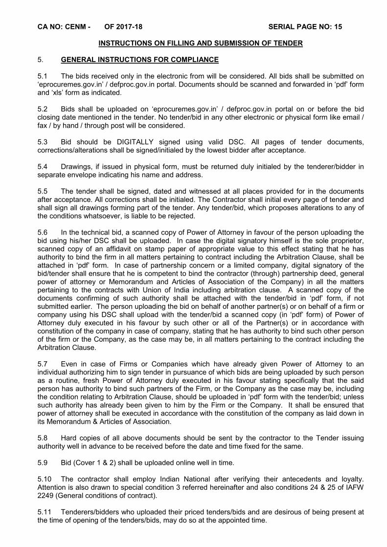
INSTRUCTIONS ON FILLING AND SUBMISSION OF TENDER 5. GENERAL INSTRUCTIONS FOR COMPLIANCE 5.1 The bids received only in the electronic from will be considered. All bids shall be submitted on ‘eprocuremes.gov.in’ / defproc.gov.in portal. Documents should be scanned and forwarded in ‘pdf’ form and ‘xls’ form as indicated. 5.2 Bids shall be uploaded on ‘eprocuremes.gov.in’ / defproc.gov.in portal on or before the bid closing date mentioned in the tender. No tender/bid in any other electronic or physical form like email / fax / by hand / through post will be considered. 5.3 Bid should be DIGITALLY signed using valid DSC. All pages of tender documents, corrections/alterations shall be signed/initialed by the lowest bidder after acceptance. 5.4 Drawings, if issued in physical form, must be returned duly initialed by the tenderer/bidder in separate envelope indicating his name and address. 5.5 The tender shall be signed, dated and witnessed at all places provided for in the documents after acceptance. All corrections shall be initialed. The Contractor shall initial every page of tender and shall sign all drawings forming part of the tender. Any tender/bid, which proposes alterations to any of the conditions whatsoever, is liable to be rejected. 5.6 In the technical bid, a scanned copy of Power of Attorney in favour of the person uploading the bid using his/her DSC shall be uploaded. In case the digital signatory himself is the sole proprietor, scanned copy of an affidavit on stamp paper of appropriate value to this effect stating that he has authority to bind the firm in all matters pertaining to contract including the Arbitration Clause, shall be attached in ‘pdf’ form. In case of partnership concern or a limited company, digital signatory of the bid/tender shall ensure that he is competent to bind the contractor (through) partnership deed, general power of attorney or Memorandum and Articles of Association of the Company) in all the matters pertaining to the contracts with Union of India including arbitration clause. A scanned copy of the documents confirming of such authority shall be attached with the tender/bid in ‘pdf’ form, if not submitted earlier. The person uploading the bid on behalf of another partner(s) or on behalf of a firm or company using his DSC shall upload with the tender/bid a scanned copy (in ‘pdf’ form) of Power of Attorney duly executed in his favour by such other or all of the Partner(s) or in accordance with constitution of the company in case of company, stating that he has authority to bind such other person of the firm or the Company, as the case may be, in all matters pertaining to the contract including the Arbitration Clause. 5.7 Even in case of Firms or Companies which have already given Power of Attorney to an individual authorizing him to sign tender in pursuance of which bids are being uploaded by such person as a routine, fresh Power of Attorney duly executed in his favour stating specifically that the said person has authority to bind such partners of the Firm, or the Company as the case may be, including the condition relating to Arbitration Clause, should be uploaded in ‘pdf’ form with the tender/bid; unless such authority has already been given to him by the Firm or the Company. It shall be ensured that power of attorney shall be executed in accordance with the constitution of the company as laid down in its Memorandum & Articles of Association. 5.8 Hard copies of all above documents should be sent by the contractor to the Tender issuing authority well in advance to be received before the date and time fixed for the same. 5.9 Bid (Cover 1 & 2) shall be uploaded online well in time. 5.10 The contractor shall employ Indian National after verifying their antecedents and loyalty. Attention is also drawn to special condition 3 referred hereinafter and also conditions 24 & 25 of IAFW 2249 (General conditions of contract). 5.11 Tenderers/bidders who uploaded their priced tenders/bids and are desirous of being present at the time of opening of the tenders/bids, may do so at the appointed time.
CA NO: CENM - OF 2017-18 SERIAL PAGE NO: 16
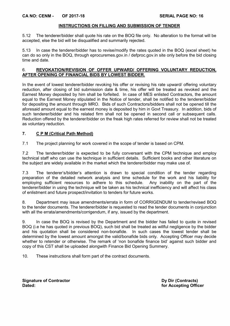
INSTRUCTIONS ON FILLING AND SUBMISSION OF TENDER 5.12 The tenderer/bidder shall quote his rate on the BOQ file only. No alteration to the format will be accepted, else the bid will be disqualified and summarily rejected. 5.13 In case the tenderer/bidder has to revise/modify the rates quoted in the BOQ (excel sheet) he can do so only in the BOQ, through eprocuremes.gov.in / defproc.gov.in site only before the bid closing time and date. 6. REVOKATION/REVISION OF OFFER UPWARD/ OFFERING VOLUNTARY REDUCTION, AFTER OPENING OF FINANCIAL BIDS BY LOWEST BIDDER. In the event of lowest tenderer/bidder revoking his offer or revising his rate upward/ offering voluntary reduction, after closing of bid submission date & time, his offer will be treated as revoked and the Earnest Money deposited by him shall be forfeited. In case of MES enlisted Contractors, the amount equal to the Earnest Money stipulated in the Notice of tender, shall be notified to the tenderer/bidder for depositing the amount through MRO. Bids of such Contractors/bidders shall not be opened till the aforesaid amount equal to the earnest money is deposited by him in Govt Treasury. In addition, bids of such tenderer/bidder and his related firm shall not be opened in second call or subsequent calls. Reduction offered by the tenderer/bidder on the freak high rates referred for review shall not be treated as voluntary reduction. 7. C P M (Critical Path Method) 7.1 The project planning for work covered in the scope of tender is based on CPM. 7.2 The tenderer/bidder is expected to be fully conversant with the CPM technique and employ technical staff who can use the technique in sufficient details. Sufficient books and other literature on the subject are widely available in the market which the tenderer/bidder may make use of. 7.3 The tenderer’s/bidder’s attention is drawn to special condition of the tender regarding preparation of the detailed network analysis and time schedule for the work and his liability for employing sufficient resources to adhere to this schedule. Any inability on the part of the tenderer/bidder in using the technique will be taken as his technical inefficiency and will affect his class of enlistment and future prospect/invitation to tenders for future works. 8. Department may issue amendments/errata in form of CORRIGENDUM to tender/revised BOQ to the tender documents. The tenderer/bidder is requested to read the tender documents in conjunction with all the errata/amendments/corrigendum, if any, issued by the department. 9. In case the BOQ is revised by the Department and the bidder has failed to quote in revised BOQ (i.e he has quoted in previous BOQ), such bid shall be treated as willful negligence by the bidder and his quotation shall be considered non-bonafide. In such cases the lowest tender shall be determined by the lowest amount amongst the valid/bonafide bids only. Accepting Officer may decide whether to retender or otherwise. The remark of ‘non bonafide finance bid’ against such bidder and copy of this CST shall be uploaded alongwith Finance Bid Opening Summery. 10. These instructions shall form part of the contract documents. Signature of Contractor Dy Dir (Contracts) Dated: for Accepting Officer

CA NO: CENM - OF 2017-18 SERIAL PAGE NO: 17
In lieu of IAFW-2159 (Revised 1947) [To be used in conjunction with General Conditions
of Contracts IAFW-2249) (1989Print)]
MILITARY ENGINEER SERVICES
Tel: 22185694 CHIEF ENGINEER (NAVY) MUMBAI, 26, ASSAYE BUILDINGS,
COLABA, MUMBAI - 400 005
87682/ 32 /E8 03 Feb 2018
LUMP SUM TENDER AND CONTRACT FOR WORKS REQUIRED IN THE EXECUTION OF DEMOLITION OF BLDG T-97, T-69, T-68, T60A, T-41, T-40, T-38, T-36, T-35,T-34, T-33, T-32 AND
CONSTN OF DEFICIENT MD ACCN FOR SAILORS AT NT POOL, COLABA MUMBAI
Shri / S`Shri _________________________________________of _______________is / are hereby
authorised to tender for the above work. The quoted e-Tender shall be uploaded at the MES website
www.eprocuremes.gov.in / www.defproc.gov.in upto 1800 hours on 03 Feb 2018 and shall be opened
on or after 21 Mar 2018 at 1200 Hours. All correspondence concerning this tender should be
addressed as indicated at the top of the sheet quoting reference as given.
THE PRESIDENT OF INDIA DOES NOT BIND HIMSELF TO ACCEPT THE LOWEST OR ANY TENDER Dy Director (Contracts) for Accepting Officer
CA NO: CENM - OF 2017-18 SERIAL PAGE NO: 18
SCHEDULE `A' NOTES (List of Works and Prices)
NAME OF WORK: DEMOLITION OF BLDG T-97, T-69, T-68, T60A, T-41, T-40, T-38, T-36, T-35,T-34, T-33, T-
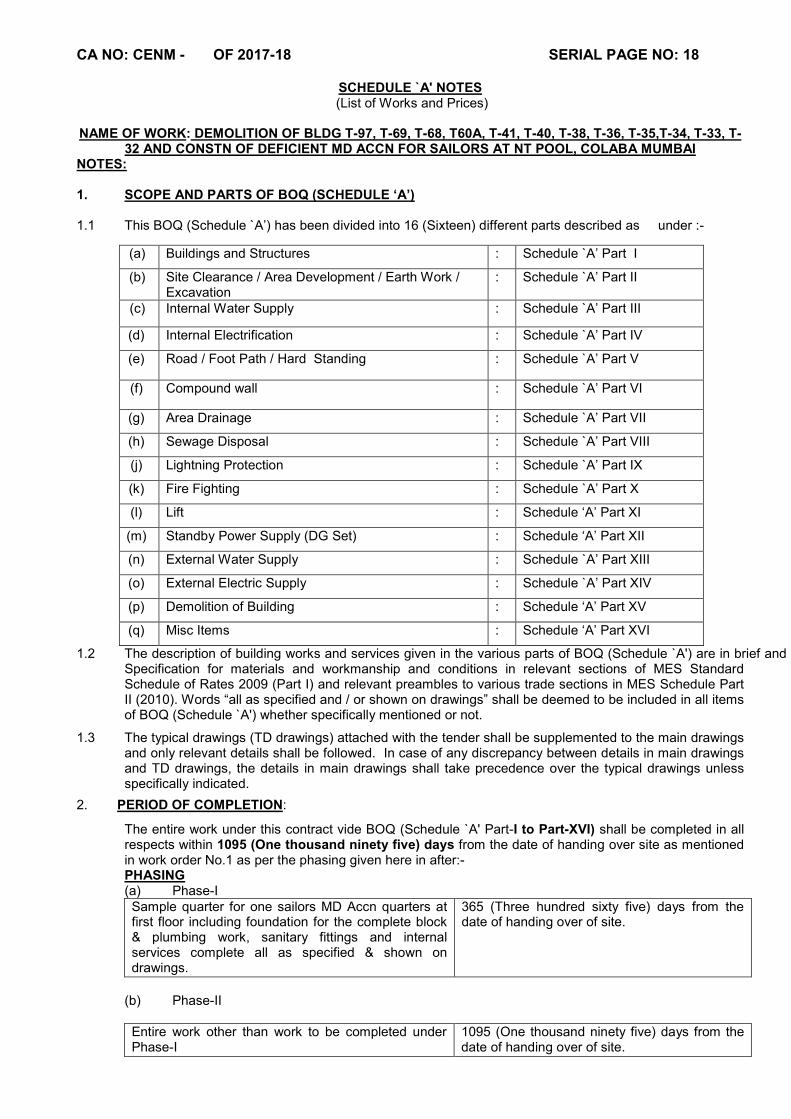
32 AND CONSTN OF DEFICIENT MD ACCN FOR SAILORS AT NT POOL, COLABA MUMBAI NOTES: 1. SCOPE AND PARTS OF BOQ (SCHEDULE ‘A’) 1.1 This BOQ (Schedule `A’) has been divided into 16 (Sixteen) different parts described as under :-
1.2 The description of building works and services given in the various parts of BOQ (Schedule `A') are in brief and include for complete materials and labours unless otherwise mentioned. Specification for materials and workmanship and conditions in relevant sections of MES Standard Schedule of Rates 2009 (Part I) and relevant preambles to various trade sections in MES Schedule Part II (2010). Words “all as specified and / or shown on drawings” shall be deemed to be included in all items of BOQ (Schedule `A') whether specifically mentioned or not.
1.3 The typical drawings (TD drawings) attached with the tender shall be supplemented to the main drawings and only relevant details shall be followed. In case of any discrepancy between details in main drawings and TD drawings, the details in main drawings shall take precedence over the typical drawings unless specifically indicated.
2. PERIOD OF COMPLETION:
The entire work under this contract vide BOQ (Schedule `A' Part-I to Part-XVI) shall be completed in all respects within 1095 (One thousand ninety five) days from the date of handing over site as mentioned in work order No.1 as per the phasing given here in after:- PHASING (a) Phase-I Sample quarter for one sailors MD Accn quarters at first floor including foundation for the complete block & plumbing work, sanitary fittings and internal services complete all as specified & shown on drawings.
365 (Three hundred sixty five) days from the date of handing over of site.
(b) Phase-II
Entire work other than work to be completed under Phase-I
1095 (One thousand ninety five) days from the date of handing over of site.
(a) Buildings and Structures : Schedule `A’ Part I
(b) Site Clearance / Area Development / Earth Work / Excavation
: Schedule `A’ Part II
(c) Internal Water Supply : Schedule `A’ Part III
(d) Internal Electrification : Schedule `A’ Part IV
(e) Road / Foot Path / Hard Standing : Schedule `A’ Part V
(f) Compound wall : Schedule `A’ Part VI
(g) Area Drainage : Schedule `A’ Part VII
(h) Sewage Disposal : Schedule `A’ Part VIII
(j) Lightning Protection : Schedule `A’ Part IX
(k) Fire Fighting : Schedule `A’ Part X
(l) Lift : Schedule ‘A’ Part XI
(m) Standby Power Supply (DG Set) : Schedule ‘A’ Part XII
(n) External Water Supply : Schedule `A’ Part XIII
(o) External Electric Supply : Schedule `A’ Part XIV
(p) Demolition of Building : Schedule ‘A’ Part XV
(q) Misc Items : Schedule ‘A’ Part XVI

CA NO: CENM - OF 2017-18 SERIAL PAGE NO: 19
SCHEDULE `A' NOTES (CONTD...)
(c) Works under Phase I and Phase II shall run concurrently and defects liability period shall start from completion of Phase II work. In case of delay in completion of Phase I work compensation in terms of condition 50 of IAFW- 2249 shall be charged to the contractor. Amount of Phase I shall be worked out including cost of internal services.
3. Site for execution of work will be available as soon as the work is awarded. In case, it is not possible for Department to make the entire site available on the award of work, the contractor will have to arrange his working program accordingly. No claim whatsoever for not giving the entire site on award of work and for giving the site gradually will be tenable.
4. UNIT RATES The unit rates inserted in Column 5 of BOQ (Schedule `A') Part- I to XV are deemed to be at par with rates contained in MES Schedule of Rates 2010 or rates analogous thereto. The contractor is required to quote his lump sum price in Column 6 of BOQ (Schedule `A') Part- I to XV and the percentage representing his lump sum price against relevant Parts of these BOQ (Schedule `A') on or off the total cost inserted by MES will be automatically indicated in Column 9 of BOQ (Schedule `A') of tender documents. The percentages and the amounts tendered by the contractor shall be deemed to have been calculated in the manner set out in Condition 6A (B) of General Conditions of Contracts IAFW-2249.
4.1 The contractor is required to quote his unit rates against each item of work given under BOQ (Schedule
`A') Part - XVI. The rates quoted shall include supply of material and labour and fixing etc. complete. 4.2 Unless otherwise specified in the description of items "Rate/Unit" (inserted by MES) of each items of
works includes supply of all materials and labours and fixing, fabricating, erecting, laying, testing, commissioning etc. as required for complete execution and completion of the work.
4.3 Works in respect of Schedules, which are Pre-Priced by the MES are carried over to BOQ. The tenderer
shall work out total amount against each of these sections of Sch ‘A’ based on his own calculations and insert the percentage at appropriate places on or off the total cost inserted by MES in BOQ of each section of Sch ‘A’ from the amount quoted by him. In the event of discrepancy between the lump sum quoted by the tenderer and percentages inserted by him, the amount shall be treated as firm and the percentage shall be amended accordingly. In this connection, tenderer attention is particularly invited to condition 6A sub Para ‘B’ (Lump sum contracts based on pre-priced Sch ‘A’) of IAFW-2249 forming part of the tender documents. The contractor shall have no claim what-so-ever on account of any errors in the unit rates/prices inserted by MES. Tenderer shall insert his percentage at appropriate place above or below the total cost inserted by MES for Provisional Sum.
4.4 Works in respect of Schedules, which are not Pre-Priced by the MES, tenderers are required to work out and quote their rates for each item of works as catered in these schedules in the manner set out in condition 6A of IAFW-2249 and quote their rates as per unit under column 6 in “figures” and extend the amount under ‘Col. 7’ based on the description of items, drawings, specifications, special conditions, general conditions and other conditions of the contract for each item separately and sum of the total amount so arrived is carried forward to the general summary at appropriate place provided for.
4.5 M&L or S&F wherever occurring shall be read as “Material and Labour” or “Supply and Fix” respectively.
5. All quantities given under column 5 of Schedule ‘A’ Part-II to XV & quantities given under column 3 of
BOQ (Schedule ‘A’) for Schedule ‘A’ Part –XVI are provisional. Probable layout of various items are indicated in drawings. The layout shown therein is intended for guidance only and may be varied where necessary at the discretion of the Engineer-in-Charge. The contractor shall not be entitled for any claim on account of such varied alignments.
5(A). All works for lift shall be carried out in accordance with the provisions contained in the particular
specifications, special conditions and general conditions forming part of this tenderer & Bombay Lift Act & Bye Laws 2939 and Bombay lift Rules 1958 respectively from time to time.
5(B). The unit rates quoted by the tenderer against BOQ (Lift work) shall also include for comprehensive
maintenance of installed lifts for 12 months from date of taking over the lifts by the department including replacement of any item as directed by GE during maintenance period.
CA NO: CENM - OF 2017-18 SERIAL PAGE NO: 20
SCHEDULE `A' NOTES (CONTD...)
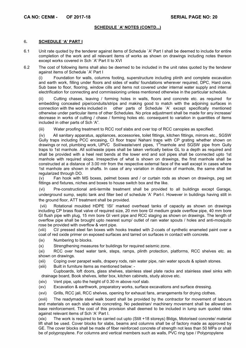
6. SCHEDULE ‘A’ PART I 6.1 Unit rate quoted by the tenderer against items of Schedule `A' Part I shall be deemed to include for entire
completion of the work and all relevant items of works as shown on drawings including notes thereon except works covered in Sch `A' Part II to XVI
6.2 The cost of following items shall also be deemed to be included in the unit rates quoted by the tenderer against items of Schedule `A' Part I
(i) Foundation for walls, columns footing, superstructure including plinth and complete excavation and earth work, filling under floors and sides of walls/ foundations wherever required, DPC, Hard core, Sub base to floor, flooring, window cills and items not covered under internal water supply and internal electrification for connecting and commissioning unless mentioned otherwise in the particular schedule.
(ii) Cutting chases, leaving / forming holes in walls, floors and concrete etc. as required for embedding concealed pipe/conduits/strips and making good to match with the adjoining surfaces in connection with the works included in other parts of Schedule ‘A’ except specifically mentioned otherwise under particular items of other Schedules. No price adjustment shall be made for any increase/ decrease in works of cutting / chase / forming holes etc. consequent to variation in quantities of items included in other parts of Sch ‘A”.
(iii) Water proofing treatment to RCC roof slabs and over top of RCC canopies as specified.
(iv) All sanitary apparatus, appliances, accessories, toilet fittings, kitchen fittings, mirrors etc., SGSW Gully traps including PCC encasing, CI floor traps/ Nahani traps with CP grating whether shown on drawings or not, plumbing work, UPVC Soil/waste/vent pipes, 1
stmanhole and SGSW pipe from Gully
traps to 1st manhole. All soil/waste pipes shall be taken vertically below GL to a depth as required and shall be provided with a heel rest bends at the lower end and soil pipes shall be connected upto 1st manhole with required slope. Irrespective of what is shown on drawings, the first manhole shall be constructed at a distance of 3.00 mtr from the respective external face of the wall except in cases where 1st manhole are shown in shafts. In case of any variation in distance of manhole, the same shall be regularized through DO. (v) Fan hook with MS boxes, pelmet boxes and / or curtain rods as shown on drawings, peg set fittings and fixtures, niches and boxes to house switch box and the like.
(vi) Pre-constructional anti-termite treatment shall be provided to all buildings except Garage,
underground sump, septic tank and filter bed of schedule ‘A’ Part-I. However in buildings having stilt in
the ground floor, ATT treatment shall be provided.
(vii) Rotational moulded HDPE ‘ISI’ marked overhead tanks of capacity as shown on drawings including CP brass float valve of required size, 20 mm bore GI medium grade overflow pipe, 40 mm bore GI flush pipe with plug, 15 mm bore GI vent pipe and RCC staging as shown on drawings. The length of overflow pipe shall be brought upto nearest sump/ outlet of rain water spouts / holes and anti-mosquito rose be provided with overflow & vent pipe. (viii) CI/ pressed steel fan boxes with hooks treated with 2-coats of synthetic enameled paint over a coat of red oxide primer on exposed surfaces and tarred on surfaces in contact with concrete.
(ix) Numbering to blocks.
(x) Strengthening measures for buildings for required seismic zone.
(xi) RCC over head water tank, steps, ramps, plinth protection, platforms, RCC shelves etc. as shown on drawings.
(xii) Coping over parapet walls, drapery rods, rain water pipe, rain water spouts & splash stones.
(xiii) Built in furniture items as mentioned below: - Cupboards, loft doors, glass shelves, stainless steel plate racks and stainless steel sinks with
drainage board, Book shelves, letter box, kitchen cabinets, study alcove etc.
(xiv) Vent pipe, upto the height of 0.30 m above roof slab.
(xv) Excavation & earthwork, preparatory works, surface excavations and surface dressing.
(xvi) Grills, RCC jali, RCC shelves, opening for exhaust fans, arrangements for drying clothes.
(xvii) The readymade steel walk board shall be provided by the contractor for movement of labours and materials on each slab while concreting. No pedestrian/ machinery movement shall be allowed on base reinforcement. The cost of this provision shall deemed to be included in lump sum quoted rates against relevant items of Sch ‘A’ Part I.
(xix) The work is required to be carried out upto (Stilt +18 storeys) Bldgs, Motorised concrete/ material lift shall be used. Cover blocks for slabs, beams and columns shall be of factory made as approved by GE. The cover blocks shall be made of fiber reinforced concrete of strength not less than 50 MPa or shall be of polypropylene. For columns and vertical members such as walls, PVC ring type / Polypropylene

CA NO: CENM - OF 2017-18 SERIAL PAGE NO: 21
SCHEDULE `A' NOTES (CONTD...)
blocks shall be used. The cost of all the above provisions shall deemed to be included in lump sum quoted rates against relevant items of Sch ‘A’ Part I.
(xx) The work is required to be carried out with necessary T&P like zip crane with boomer, winch trolleys, steel scaffolding, boom pneumatic pressure equipment for pumping RMC and all safety measures on site.
7. SCHEDULE ‘A’ PART II to PART XVI
7.1 All quantities given under column 5 of Schedule ‘A’ Part-II to XV & quantities given under column 3 of BOQ (Schedule ‘A’) for Schedule ‘A’ Part –XVI are provisional.
7.2 All excavation and earthwork required for BOQ (Schedule ‘A’) Part III to Part XVI shall be measured and
paid under respective items of Schedule ‘A’ Part II except where the description of BOQ (Schedule ‘A’)
Part III to Part XVI items specifically include work of excavation and earth work. However excavation &
earth work in strata as specified hereinafter for schedule ‘A’ Part I shall be included in lump sum quoted.
8. VALUATION OF DEVIATION
The percentage addition / deduction of MES Schedule of Rates for the purpose of pricing deviation vide sub clause C (c) or C (d) of Condition 62 of IAFW – 2249 shall be as follows:-
a) For works covered under
BOQ (Schedule ‘A’) Part- I to XV
Percentage above / below as automatically indicated in Column 9 of BOQ (Schedule `A') of tender documents comparing with the lump sum quoted by tenderer to the amount inserted by MES as stipulated in Condition 62 of IAFW – 2249.
b) For works covered under BOQ (Schedule ‘A’) Part -XVI
As per Condition 62 of IAFW 2249 (General Conditions of Contracts)
9. MINOR DETAILS
9.1 Lump sum quoted or the rate quoted for a particular item by the tenderer shall be deemed to include for all minor details / items of work and / or constructions which are obviously and fairly intended and which may not have been included in these documents but which are essential for the execution and entire completion of work and services in workman like manner and sound construction.
9.2 In case of difference of opinion between the contractor and Garrison Engineer as to whether or not certain item of work constitutes `Minor Constructional Details' which is deemed to have been included in the contractor's quoted lump sum, the decision of the Accepting Officer shall be final, conclusive and binding.
9.3 However some of the minor details / items which shall be deemed to be essential for execution and entire completion of work are described as under for guidance:-
(i) Reinforcement for any RCC member not indicated in the drawing but is a structural requirement.
(ii) Dwarf wall in situations like verandah, passage etc. not indicated in drawing.
(iii) Lintel over doors, windows and or opening not shown in drawing.
(iv) Builders hardware for doors / windows etc. though not indicated on drawing but essential for usage.
9.4 In all the above and similar cases, the details indicated elsewhere in the drawings which are similar or near similar to missed out items or works shall be followed. In the absence of any other similar or near similar details, minimum essential requirement for completion of the work from structural, architectural and utility point of view shall be deemed to be included in the lump sum quoted. In the event of any dispute, decision of the Accepting Officer shall be final, conclusive and binding.
10. (a) For structural details, structural drawings shall only be referred. If there is any discrepancy between architectural and structural drawings with regard to structural details, details shown on structural drawings shall prevail. Similarly, if there is discrepancy between architectural and structural drawings with regards to architectural details, details shown on architectural drawings shall prevail. The decision of the Accepting Officer as to what constitutes structural or architectural details shall be final, conclusive and binding. (b) For missing reinforcement details, if any, of RCC work, minimum reinforcement as required as per IS shall be adopted. (c) In case where type and size of beam, slab and column etc. are not indicated these shall be provided as decided by the Accepting Officer. (d) If there is any discrepancy regarding general notes on RCC works in TD (typical details)
drawings and structural drawings, structural drawings shall be followed. Similarly, details in main
drawings shall be followed in case of discrepancy in main drawing and TD drawings.
CA NO: CENM - OF 2017-18 SERIAL PAGE NO: 22
SCHEDULE `A' NOTES (CONTD...)
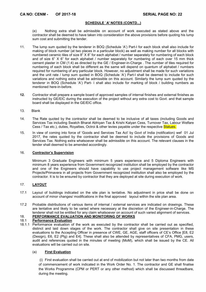
(e) Nothing extra shall be admissible on account of work executed as stated above and the contractor shall be deemed to have taken into consideration the above provisions before quoting his lump sum cost and submitting the tender.
11. The lump sum quoted by the tenderer in BOQ (Schedule ‘A’) Part-I for each block shall also include for
making of block number (at two places in a particular block) as well as making number for all blocks with numbered ceramic tiles of size 8” X 8” for each alphabet / number separately for numbering of each block and of size 6” X 6” for each alphabet / number separately for numbering of each over 15 mm thick cement plaster in CM (1:4) as directed by the GE / Engineer-in-Charge . The number of tiles required for numbering of each block shall be different as the same will depend on quantum of alphabet / numbers required for numbering of any particular block. However, no adjustment shall be made for such variations and the unit rate / lump sum quoted in BOQ (Schedule ‘A’) Part-I shall be deemed to include for such variations and nothing extra shall be admissible on this account. Similarly the lump sum quoted by the tenderer in BOQ (Schedule ‘A’) Part- I shall also include for marking of block / building numbers as mentioned here-in-before.
12. Contractor shall prepare a sample board of approved samples of internal finishes and external finishes as
instructed by GE/EIC during the execution of the project without any extra cost to Govt. and that sample board shall be displayed in the GE/EIC office.
13. Blank 14. The Rate quoted by the contractor shall be deemed to be inclusive of all taxes (including Goods and
Services Tax including Swatch Bharat Abhiyan Tax & Krishi Kalyan Cess, Turnover Tax, Labour Welfare Cess / Tax etc.), duties, Royalties, Octroi & other levies payable under the respective Statues.
15. In view of coming into force of ‘Goods and Services Tax Act’ by Govt of India (notification) wef 01 Jul 2017, the rates quoted by the contractor shall be deemed to include the provisions of Goods and Services Tax. Nothing extra whatsoever shall be admissible on this account. The relevant clauses in the tender shall deemed to be amended accordingly.
16. Contractor’s Supervision Minimum 3 Graduate Engineers with minimum 5 years experience and 5 Diploma Engineers with
minimum 8 years experience from Government recognized institution shall be employed by the contractor and one of the Engineers should have capability to use project management software like MS Projects/Primavera in all projects from Government recognized institution shall also be employed by the contractor. It is to be ensured by contractor that they are deployed at site during execution of work.
17. LAYOUT 17.1 Layout of buildings indicated on the site plan is tentative. No adjustment in price shall be done on
account of minor changes/ modifications in the final approved layout within the site plan area. 17.2 Probable distributions of various items of internal / external services are indicated on drawings. These
are tentative and likely to be varied where necessary at the discretion of the Engineer-in-Charge. The tenderer shall not be entitled for any claim whatsoever on account of such varied alignment of services.
18. PERFORMANCE EVALUATION AND MONITORING OF WORKS 18.1 Performance Evaluation 18.1.1 Performance evaluation of the work as executed by the contractor shall be carried out as specified,
distinct and laid down stages of the work. The contractor shall give on site presentation in these evaluations to the Accepting Officer in presence of CWE, GE, AGE, staff officers of CE’s Office [E8, E2 (Design), E6, E2 (Plg) and E4]. These shall also be attended by representatives of CFA, PMG, users, audit and references quoted in the minutes of meeting (MoM), which shall be issued by the CE. All evaluations will be carried out on site.
(a) First Evaluation
(i) First evaluation shall be carried out at end of mobilization but not later than two months from date
of commencement of work indicated in the Work Order No. 1. The contractor and GE shall finalise
the Works Programme (CPM or PERT or any other method) which shall be discussed threadbare,
during the meeting.
CA NO: CENM - OF 2017-18 SERIAL PAGE NO: 23
SCHEDULE `A' NOTES (CONTD...)
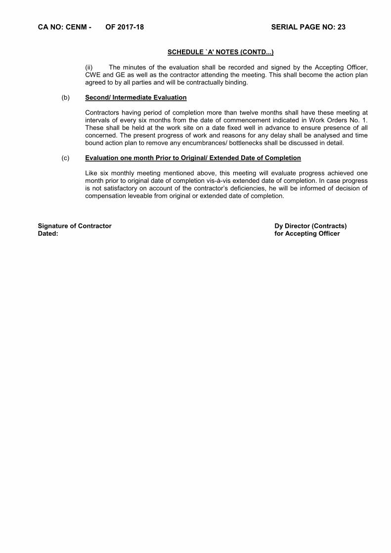
(ii) The minutes of the evaluation shall be recorded and signed by the Accepting Officer, CWE and GE as well as the contractor attending the meeting. This shall become the action plan agreed to by all parties and will be contractually binding.
(b) Second/ Intermediate Evaluation Contractors having period of completion more than twelve months shall have these meeting at intervals of every six months from the date of commencement indicated in Work Orders No. 1. These shall be held at the work site on a date fixed well in advance to ensure presence of all concerned. The present progress of work and reasons for any delay shall be analysed and time bound action plan to remove any encumbrances/ bottlenecks shall be discussed in detail.
(c) Evaluation one month Prior to Original/ Extended Date of Completion Like six monthly meeting mentioned above, this meeting will evaluate progress achieved one month prior to original date of completion vis-à-vis extended date of completion. In case progress is not satisfactory on account of the contractor’s deficiencies, he will be informed of decision of compensation leveable from original or extended date of completion.
Signature of Contractor Dy Director (Contracts) Dated: for Accepting Officer
CA NO: CENM - OF 2017-18 SERIAL PAGE NO: 92
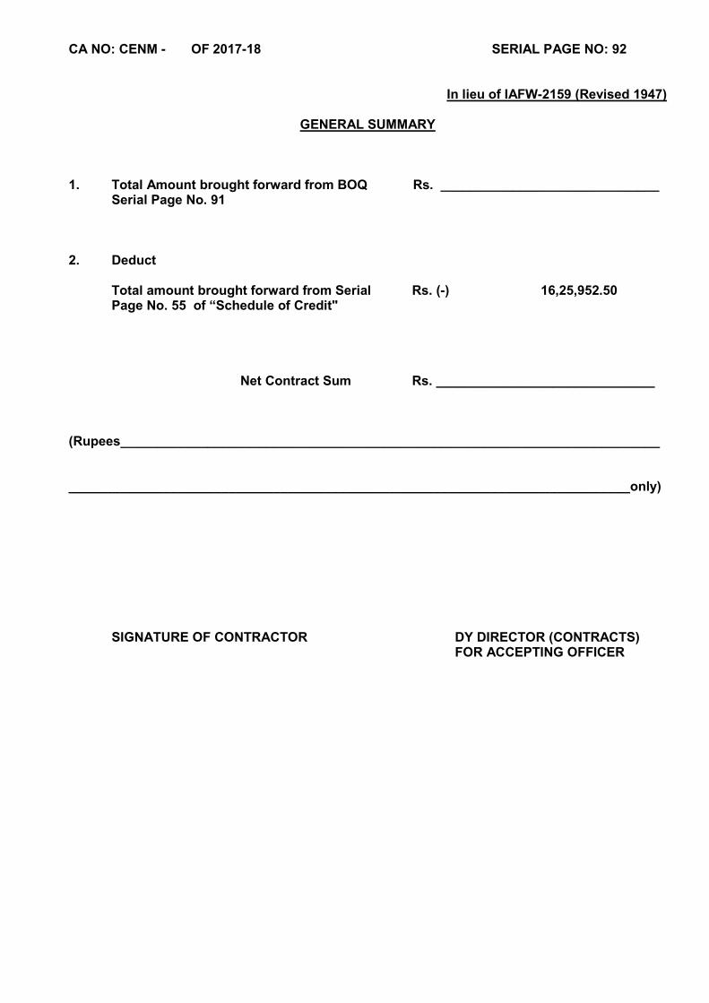
In lieu of IAFW-2159 (Revised 1947)
GENERAL SUMMARY
1. Total Amount brought forward from BOQ Rs. ______________________________
Serial Page No. 91
2. Deduct Total amount brought forward from Serial Rs. (-) 16,25,952.50
Page No. 55 of “Schedule of Credit"
Net Contract Sum Rs. ______________________________
(Rupees__________________________________________________________________________ _____________________________________________________________________________only)
SIGNATURE OF CONTRACTOR DY DIRECTOR (CONTRACTS) FOR ACCEPTING OFFICER
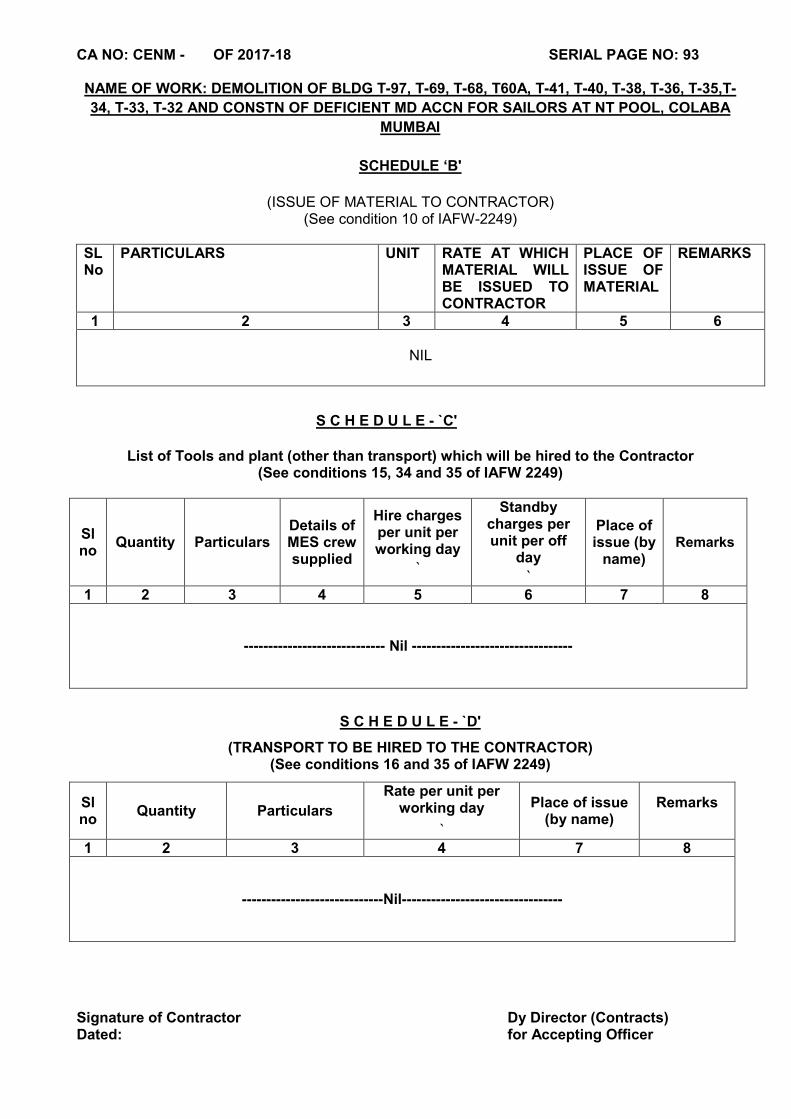
CA NO: CENM - OF 2017-18 SERIAL PAGE NO: 93 NAME OF WORK: DEMOLITION OF BLDG T-97, T-69, T-68, T60A, T-41, T-40, T-38, T-36, T-35,T-
34, T-33, T-32 AND CONSTN OF DEFICIENT MD ACCN FOR SAILORS AT NT POOL, COLABA
MUMBAI
SCHEDULE ‘B'
(ISSUE OF MATERIAL TO CONTRACTOR)
(See condition 10 of IAFW-2249)
SL No
PARTICULARS UNIT RATE AT WHICH MATERIAL WILL BE ISSUED TO CONTRACTOR
PLACE OF ISSUE OF MATERIAL
REMARKS
1 2 3 4 5 6
NIL
S C H E D U L E - `C'
List of Tools and plant (other than transport) which will be hired to the Contractor (See conditions 15, 34 and 35 of IAFW 2249)
Sl no
Quantity Particulars Details of MES crew supplied
Hire charges per unit per working day
`
Standby charges per unit per off
day
`
Place of issue (by
name) Remarks
1 2 3 4 5 6 7 8
----------------------------- Nil ---------------------------------
S C H E D U L E - `D'
(TRANSPORT TO BE HIRED TO THE CONTRACTOR) (See conditions 16 and 35 of IAFW 2249)
Sl no
Quantity Particulars
Rate per unit per working day
`
Place of issue (by name)
Remarks
1 2 3 4 7 8
-----------------------------Nil---------------------------------
Signature of Contractor Dy Director (Contracts) Dated: for Accepting Officer
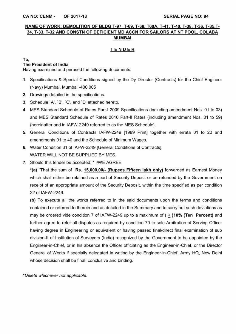
CA NO: CENM - OF 2017-18 SERIAL PAGE NO: 94 NAME OF WORK: DEMOLITION OF BLDG T-97, T-69, T-68, T60A, T-41, T-40, T-38, T-36, T-35,T-
34, T-33, T-32 AND CONSTN OF DEFICIENT MD ACCN FOR SAILORS AT NT POOL, COLABA
MUMBAI
T E N D E R
To, The President of India Having examined and perused the following documents: 1. Specifications & Special Conditions signed by the Dy Director (Contracts) for the Chief Engineer
(Navy) Mumbai, Mumbai -400 005
2. Drawings detailed in the specifications.
3. Schedule `A', `B', `C', and `D' attached hereto.
4. MES Standard Schedule of Rates Part-I 2009 Specifications (including amendment Nos. 01 to 03)
and MES Standard Schedule of Rates 2010 Part-II Rates (including amendment Nos. 01 to 59)
{hereinafter and in IAFW-2249 referred to as the MES Schedule}.
5. General Conditions of Contracts IAFW-2249 [1989 Print] together with errata 01 to 20 and
amendments 01 to 40 and the Schedule of Minimum Wages.
6. Water Condition 31 of IAFW-2249 [General Conditions of Contracts].
WATER WILL NOT BE SUPPLIED BY MES.
7. Should this tender be accepted, * I/WE AGREE
*(a) "That the sum of Rs. 15,000,00/- (Rupees Fifteen lakh only) forwarded as Earnest Money
which shall either be retained as a part of Security Deposit or be refunded by the Government on
receipt of an appropriate amount of the Security Deposit, within the time specified as per condition
22 of IAFW-2249.
(b) To execute all the works referred to in the said documents upon the terms and conditions
contained or referred to therein and as detailed in the Summary and to carry out such deviations as
may be ordered vide condition 7 of IAFW-2249 up to a maximum of ( + )10% (Ten Percent) and
further agree to refer all disputes as required by condition 70 to sole Arbitration of Serving Officer
having degree in Engineering or equivalent or having passed final/direct final examination of sub
division-II of Institution of Surveyors (India) recognized by the Government to be appointed by the
Engineer-in-Chief, or in his absence the Officer officiating as the Engineer-in-Chief, or the Director
General of Works if specially delegated in writing by the Engineer-in-Chief, Army HQ, New Delhi
whose decision shall be final, conclusive and binding.
*Delete whichever not applicable.
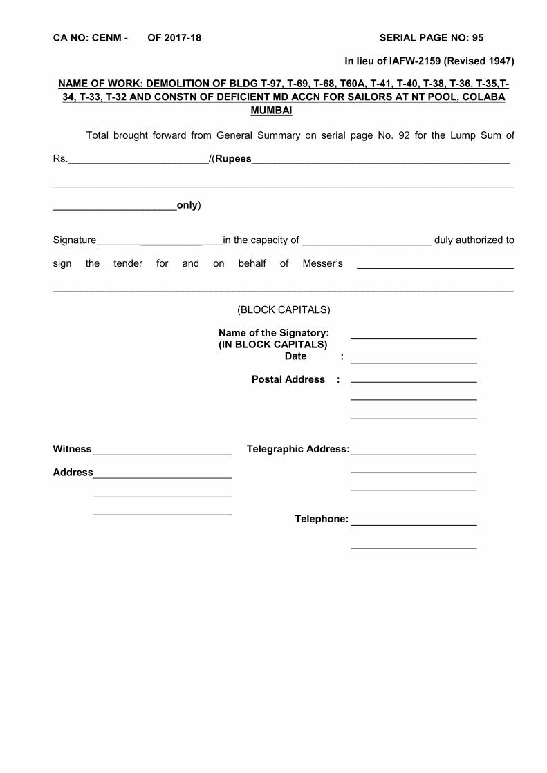
CA NO: CENM - OF 2017-18 SERIAL PAGE NO: 95
In lieu of IAFW-2159 (Revised 1947)
NAME OF WORK: DEMOLITION OF BLDG T-97, T-69, T-68, T60A, T-41, T-40, T-38, T-36, T-35,T-
34, T-33, T-32 AND CONSTN OF DEFICIENT MD ACCN FOR SAILORS AT NT POOL, COLABA
MUMBAI
Total brought forward from General Summary on serial page No. 92 for the Lump Sum of
Rs._________________________/(Rupees______________________________________________
__________________________________________________________________________________
______________________only)
Signature ___________ in the capacity of _______________________ duly authorized to
sign the tender for and on behalf of Messer’s ____________________________
__________________________________________________________________________________
(BLOCK CAPITALS)
Name of the Signatory: (IN BLOCK CAPITALS)
Date : Postal Address :
Witness Telegraphic Address: Address Telephone:
CA NO: CENM - OF 2017-18 SERIAL PAGE NO: 96
In lieu of IAFW-2159 (Revised 1947)
NAME OF WORK: DEMOLITION OF BLDG T-97, T-69, T-68, T60A, T-41, T-40, T-38, T-36, T-35,T-
34, T-33, T-32 AND CONSTN OF DEFICIENT MD ACCN FOR SAILORS AT NT POOL, COLABA
MUMBAI
A C C E P T A N C E
____________ Alterations have been made in these documents and as evidence that these alterations
were made before the execution of the Contract Agreement these have been initialled by the
Contractor and S'Shri/Shri ____________________________________________________________
The said Officer/Officers is/are hereby authorized to sign and initial on my behalf the documents
forming part of this contract.
The above tender was accepted by me on behalf of the President of India for the Contract Sum of (Rupees__________________________________________________ _________________________________________________________only) on the day of . Signature dated this day of . (FOR AND ON BEHALF OF THE PRESIDENT OF INDIA) The Chief Engineer (Navy) Mumbai Mumbai - 400 005 Accepting Officer
CA NO: CENM - OF 2017-18 SERIAL PAGE NO: 97 TO 145 NAME OF WORK: DEMOLITION OF BLDG T-97, T-69, T-68, T60A, T-41, T-40, T-38, T-36, T-35,T-
34, T-33, T-32 AND CONSTN OF DEFICIENT MD ACCN FOR SAILORS AT NT POOL, COLABA
MUMBAI
GENERAL CONDITIONS OF CONTRACTS - IAFW 2249 (1989 PRINT) FOR LUMP SUM CONTRACT -IN LIEU OF IAFW-2159 (REVISED 1947)
A copy of the GENERAL CONDITIONS OF CONTRACTS - IAFW 2249 (1989 Print) with errata 1 to 20 and amendment No. 1 to 40 has been supplied to me/us, has been perused by me/us and is in my/our possession. I/We have read and understood the provisions contained in the aforesaid GENERAL CONDITIONS OF CONTRACTS before submission of this tender and I/We shall abide by the terms and conditions thereof, as modified if any, elsewhere in these tender documents. It is hereby further agreed and declared by me/us, that the GENERAL CONDITIONS OF CONTRACTS, IAFW-2249 (1989 Print) including condition 70 thereof pertaining to settlement of disputes by arbitration, containing 33 pages (serial page Nos. 97 to 129) with errata 1 to 20 and amendment Nos. 1 to 40 (serial page Nos. 130 to 145) form part of these tender documents. Note: In case of difference in interpretation due to wordings of English and Hindi versions of the General Conditions of Contracts (IAFW-2249) (1989 Print), the English version will prevail.
Director (Contracts) Signature of Contractor for Accepting Officer Dated:
CA NO: CENM - OF 2017-18 SERIAL PAGE NO: 146 TO 153 NAME OF WORK: DEMOLITION OF BLDG T-97, T-69, T-68, T60A, T-41, T-40, T-38, T-36, T-35,T-
34, T-33, T-32 AND CONSTN OF DEFICIENT MD ACCN FOR SAILORS AT NT POOL, COLABA
MUMBAI
SCHEDULE OF MINIMUM FAIR WAGES
It is hereby agreed that the `Schedule of Minimum Fair Wages' as published vide Government
of India / State Govt. / Union Territory latest Notification forms part of these tender documents. My/Our
signature hereunder amounts to my/our having read and understood the provisions contained therein
and I/we agree that I/we shall abide by the same and that aforesaid documents form part of this tender.
Director (Contracts) Signature of Contractor for Accepting Officer Dated:

CA NO: CENM - OF 2017-18 SERIAL PAGE NO: 154
PARTICULAR SPECIFICATIONS (SPECIAL CONDITION) Part-I
1.1 GENERAL
1.1.1 The following conditions shall be read in conjunction with General Conditions of Contracts IAFW-2249 (1989 Print) and IAFW-2159 (Revised 1947) including errata and amendments thereto.
1.1.2 If any provision in these special conditions is at variance with the provisions of the above mentioned documents, provisions in these special conditions shall be deemed to take precedence there over.
1.2 VISIT TO SITE
The tenderer is advised to inspect the site, by prior appointment with Garrison Engineer, to ascertain the nature of site, access thereto, local facilities for procurement of materials, working hours and labour rates prevalent in the area and all other matters affecting his price in the tender for execution and the completion of the work. The tenderer shall be deemed to have full knowledge of the site (s) whether or not he actually visits it/these. For the purpose of collection of materials and execution of the works, the site will be considered as lying in area as mentioned in clauses hereinafter.
1.3 SECURITY AND PASSES
1.3.1 Tenderers attention is invited to condition 25 of IAFW-2249. He shall employ only Indian Nationals after verifying their antecedents and loyalty. He shall ensure that no person of doubtful antecedents and nationality is, in any way, associated with work. If for reasons of technical collaboration or other consideration, the employment of any foreign national is unavoidable, the Contractor shall furnish full particulars to this effect to the Accepting Officer at the time of submission of his tender. The Contractor shall on demand by the Engineer-in-Charge, submit a list of his agents, employees and work people concerned and shall satisfy the Engineer-in-Charge as to the bonafide of such people.
1.3.2 The Engineer-in-Charge shall, at his discretion has the right to issue passes, as per rules and regulations of the installation/area in force, to control the admission of the Contractor, his agents, and employees and work people to the site of the work or any part thereof. Passes shall be returned on any time on demand by the Engineer-in-Charge or the authorities concerned and in any case on completion of work.
1.3.3 The Contractor and his agents, employees and work people shall observe all the rules promulgated by the authority controlling the installation/area in which the work is to be carried out e.g. prohibition of smoking and lighting, fire precautions, search of persons at entry and exit, keeping to specific routes, observing specified timings etc. Nothing extra shall be admissible for any man hours etc lost on this account.
1.4 MATERIALS AND SAMPLES
1.4.1 Refer condition 10 of IAFW-2249 and clause 1.6 & 1.7 of MES Schedule.
1.4.2 Materials provided by the Contractor for incorporation in the works shall, unless otherwise specified in the particular specifications be ISI marked. IS means Indian Standards as issued by the Bureau of Indian Standards. Wherever in the specifications `IS' is referred to, it means the edition with all amendments, current on the due date of receipt of the tender documents.
1.4.3 The tenderer is advised to inspect other materials, which are displayed in the office of the GE, before submitting his tender. The tenderer shall be deemed to have inspected the samples and satisfied himself as to the nature and quality of materials, he is required to incorporate in the work irrespective of whether he has actually inspected them or not. The materials to be incorporated in the work by the Contractor shall be ISI marked or shall be equal or superior in quality to sample displayed and shall comply with the specifications given hereinafter.
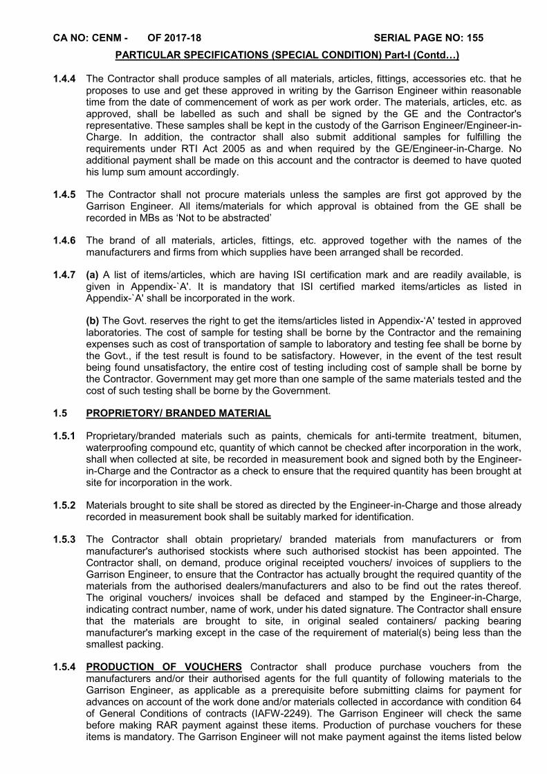
CA NO: CENM - OF 2017-18 SERIAL PAGE NO: 155
PARTICULAR SPECIFICATIONS (SPECIAL CONDITION) Part-I (Contd…)
1.4.4 The Contractor shall produce samples of all materials, articles, fittings, accessories etc. that he proposes to use and get these approved in writing by the Garrison Engineer within reasonable time from the date of commencement of work as per work order. The materials, articles, etc. as approved, shall be labelled as such and shall be signed by the GE and the Contractor's representative. These samples shall be kept in the custody of the Garrison Engineer/Engineer-in-Charge. In addition, the contractor shall also submit additional samples for fulfilling the requirements under RTI Act 2005 as and when required by the GE/Engineer-in-Charge. No additional payment shall be made on this account and the contractor is deemed to have quoted his lump sum amount accordingly.
1.4.5 The Contractor shall not procure materials unless the samples are first got approved by the Garrison Engineer. All items/materials for which approval is obtained from the GE shall be recorded in MBs as ‘Not to be abstracted’
1.4.6 The brand of all materials, articles, fittings, etc. approved together with the names of the manufacturers and firms from which supplies have been arranged shall be recorded.
1.4.7 (a) A list of items/articles, which are having ISI certification mark and are readily available, is given in Appendix-`A'. It is mandatory that ISI certified marked items/articles as listed in Appendix-`A' shall be incorporated in the work.
(b) The Govt. reserves the right to get the items/articles listed in Appendix-‘A' tested in approved laboratories. The cost of sample for testing shall be borne by the Contractor and the remaining expenses such as cost of transportation of sample to laboratory and testing fee shall be borne by the Govt., if the test result is found to be satisfactory. However, in the event of the test result being found unsatisfactory, the entire cost of testing including cost of sample shall be borne by the Contractor. Government may get more than one sample of the same materials tested and the cost of such testing shall be borne by the Government.
1.5 PROPRIETORY/ BRANDED MATERIAL
1.5.1 Proprietary/branded materials such as paints, chemicals for anti-termite treatment, bitumen, waterproofing compound etc, quantity of which cannot be checked after incorporation in the work, shall when collected at site, be recorded in measurement book and signed both by the Engineer-in-Charge and the Contractor as a check to ensure that the required quantity has been brought at site for incorporation in the work.
1.5.2 Materials brought to site shall be stored as directed by the Engineer-in-Charge and those already recorded in measurement book shall be suitably marked for identification.
1.5.3 The Contractor shall obtain proprietary/ branded materials from manufacturers or from manufacturer's authorised stockists where such authorised stockist has been appointed. The Contractor shall, on demand, produce original receipted vouchers/ invoices of suppliers to the Garrison Engineer, to ensure that the Contractor has actually brought the required quantity of the materials from the authorised dealers/manufacturers and also to be find out the rates thereof. The original vouchers/ invoices shall be defaced and stamped by the Engineer-in-Charge, indicating contract number, name of work, under his dated signature. The Contractor shall ensure that the materials are brought to site, in original sealed containers/ packing bearing manufacturer's marking except in the case of the requirement of material(s) being less than the smallest packing.
1.5.4 PRODUCTION OF VOUCHERS Contractor shall produce purchase vouchers from the manufacturers and/or their authorised agents for the full quantity of following materials to the Garrison Engineer, as applicable as a prerequisite before submitting claims for payment for advances on account of the work done and/or materials collected in accordance with condition 64 of General Conditions of contracts (IAFW-2249). The Garrison Engineer will check the same before making RAR payment against these items. Production of purchase vouchers for these items is mandatory. The Garrison Engineer will not make payment against the items listed below
CA NO: CENM - OF 2017-18 SERIAL PAGE NO: 156
PARTICULAR SPECIFICATIONS (SPECIAL CONDITION) Part-I (Contd…) in RARs unless the purchase vouchers for the same have been produced to him and verified by him:-
(a) Water proofing compound (b) Chemicals for anti-termite treatment (c) Paints (d) CI Pipes and fittings (e) GI Pipes and fittings (f) Sanitary fittings (g) Aluminium Windows/ Ventilators (h) Tarfelt / Bituminous products (j) Iron mongery (k) SGSW pipes (l) All proprietary articles (m) Bitumen for road work (n) Air blown grade bitumen for water proofing work (o) Floor/ wall tiles (p) Factory made door shutters (q) Electrical and Water Supply fittings/fixtures where names of manufacturers/brands are specified or approved (r) Cables/wires (s) Cement (t) Steel
1.5.5 The vouchers shall be endorsed, dated and initialled by the Engineer-in-Charge giving the contract number and name of work. A certified copy of each of such vouchers signed both by the Engineer-in-Charge and the Contractor shall be kept on record.
1.5.6 When the cost of each category of material is less than Rs.1000/- production of voucher may not be insisted upon, if the Garrison Engineer is otherwise satisfied with the quality & quantity of material brought by the Contractor.
1.6 TIME AND PROGRESS (CPM CHART)
1.6.1 The CPM Chart to be prepared as per Condition 11 of IAFW-2249 (General Conditions of Contracts) shall consist of detailed net work analysis and a time Schedule. The critical path net work will be drawn jointly by the Garrison Engineer and the Contractor soon after acceptance of the tender. The Contractor so as to finish the work within the stipulated time will do the time scheduling of the activities. On completion of the time schedule, firm calendar date Schedule will be prepared and submitted by the Contractor to the Garrison Engineer who will approve it after due scrutiny. The Schedule will be submitted in four copies within two weeks from the date of handing over the site.
1.6.2 During the currency of the contract, the Contractor is expected to adhere to the time schedule and this adherence will be a part of the Contractor's performance under this contract. During the execution of work, the Contractor is expected to participate in the reviews and updating of the net work undertaken by the GE. These reviews may be undertaken at the discretion of the Garrison Engineer either as a periodic appraisal measure or when the quantum of work ordered on the Contractor is substantially changed through deviation orders or amendments. Any revision of the time schedule as a result of the review will be submitted by the Contractor to the Garrison Engineer within a week for his approval after due scrutiny. The Contractor will adhere to the revised schedule thereafter. In case of the Contractor disagreeing with the revised schedule the same will be referred to the Accepting Officer, whose decision will be final, conclusive and binding. Garrison Engineer's approval to the revised schedule resulting in a completion date beyond the stipulated date of completion shall not automatically amount to a grant of extension of time.
CA NO: CENM - OF 2017-18 SERIAL PAGE NO: 157
PARTICULAR SPECIFICATIONS (SPECIAL CONDITION) Part-I (Contd…) 1.6.3 Extension of time shall be considered and decided by the appropriate authority mentioned in
condition 11 of IAFW-2249 and separately regulated.
1.6.4 The Contractor shall mobilise and employ sufficient resources to achieve the detailed schedule within the broad frame work of the accepted methods of working and safety.
1.6.5 No additional payment will be made to the Contractor for any multiple shift work or other intensive methods contemplated by him in his work schedule, even though the department approves the time schedule.
1.7 SECURITY OF CLASSIFIED DOCUMENTS
The Contractor's special attention is drawn to condition 2-A and 3 of General Conditions of Contracts (IAFW-2249). The Contractor shall not communicate any classified information regarding the works either to sub-Contractors or others without prior approval of the Engineer-in-Charge. The Contractor shall also not make copies of the design/drawings and other documents furnished to him in respect of the works and he should return all documents furnished to him in respect of the works on completion of the work or earlier termination of the contract. The Contractor shall along with the final bill, attach a receipt from the Engineer-in-Charge in respect of his having returned the classified documents as per condition 3 of General Conditions of Contracts (IAFW-2249).
1.8 FAIR WAGES
The Contractor shall have no claims, whatsoever if on account of any rules and regulation or otherwise he is required to pay wages in excess of the fair wages shown in the schedule of wages under condition 58 of General Conditions of Contracts IAFW-2249.
1.9 PERIOD FOR KEEPING TENDER OPEN
The tender shall remain open for acceptance for a period of 90 (Ninety) days from the next date subsequent to last date of bid submission.
1.10 RECORD OF CONSUMPTION OF CEMENT
1.10.1 For purpose of keeping record of cement brought by the Contractor and consumed in works, the Contractor shall maintain a pucca bound register, with serially numbered pages with all pages initialled by the Engineer-in-Charge against numbering, in the form approved by the Engineer-in-Charge showing daily receipts of cement brought by the Contractor, quantity used in works and balance in hand. The register shall be signed daily by representative of MES and the Contractor in token of their verification of its correctness and will be checked by the Engineer-in-Charge, at least once a week and on the days cement is brought by the Contractor.
1.10.2 The aforesaid provision will not however, absolve the Contractor of his responsibility to justify the consumption of cement at the time of finalisation of his accounts.
1.10.3 The register shall be kept at site in the safe custody of the Contractor during progress of the work and he shall on demand produce the same for verification by inspecting officers. On completion of the works cement register shall be handed over to the Engineer-in-Charge for record with MES.
1.11 ROYALTIES Delete the existing condition 14 of IAFW-2249 and insert the word "BLANK" in lieu.
CA NO: CENM - OF 2017-18 SERIAL PAGE NO: 158
PARTICULAR SPECIFICATIONS (SPECIAL CONDITION) Part-I (Contd…)
1.12 LAND AND LABOUR ACCOMMODATION, AND STORES AND WORKSHOP ETC.
1.12.1 Delete lines 5 to 9 of Para 1 of Condition 24 of General Conditions of Contracts IAFW-2249 i.e. from "In the event of area of land" to "land allotted to him" and insert as under: "The Contractor shall be allotted, the area as marked on the layout plan for the purpose of erection of temporary workshop, stores for which he shall pay the nominal rent of Re.1/- per year or part of a year. No MD land is available for accommodation of labour and canteen in restricted area for which the Contractor shall make his own arrangement at his own expense.”
1.12.2 The Contractor will not be allowed to quarry/ win earth from MD land.
1.13 CO-OPERATION WITH OTHER AGENCIES
1.13.1 The Contractor shall permit free access and generally afford reasonable facilities to other agencies or departmental workmen engaged by Government to carry out their part of the work, if any, under separate arrangements.
1.13.2 The Contractor's prices shall be deemed to cater for all the above contingencies and nothing extra shall be admissible on this account.
1.14 LABOUR (REGULATION & ABOLITION) ACT
1.14.1 Contract labour (Regulation & Abolition) Act 1970 is applicable to MES Contractors. Rates quoted by the tenderer shall be deemed to take into account the cost, etc., required to comply with the provisions contained in the said act and the rules framed under the said act.
1.14.2 Refer Condition 58 of IAFW-2249. The "Schedule of Minimum Wages" as published vide Govt. Of India Notifications, as available on date of receipt of tender forms part of these tender documents. However, the Contractor shall not pay wages lower than minimum wages for labour as fixed by the Govt. Of India/ State Govt/ Union territory under Minimum Wages Act or Contract Labour (Abolition and Regulation Act), whichever is higher.
1.14.3 The fair wages referred to in condition 58 of IAFW-2249 will be deemed to be the same as the minimum wages payable as referred to above.
1.14.4 The Contractor shall have no claim whatsoever, if on account of local factors and/or regulations, he is required to pay the wages in excess of minimum wages as described above during the execution of work.
1.15 WATER SUPPLY
1.15.1 Refer condition 31 of General Conditions of Contracts (IAFW-2249) and clause 1.13 of MES Schedule.
1.15.2 Water will NOT be supplied by the MES & the Contractor shall make his own arrangements for water for the entire work. However, the Contractor if he so desires, will be permitted to drill bore well(s) in the area at his own cost. The well(s) dug/drilled by the Contractor shall become the property of the Govt. without any extra cost. The Contractor shall at his own cost, get the water tested from recognised Govt. Laboratory about the potability of water and produce the certificate to the GE. Obtaining all statutory permission for digging the bore well, its safe custody and disposal will be the responsibility of the contractor.
1.15.3 Water used for mixing and curing shall be generally potable water, clean and free from impurities viz. oils, acids, alkaline salts, sugar, organic materials or other substance that may be deleterious to concrete or steel and also conform to IS-456.
CA NO: CENM - OF 2017-18 SERIAL PAGE NO: 159
PARTICULAR SPECIFICATIONS (SPECIAL CONDITION) Part-I (Contd…)
1.16 ELECTRIC SUPPLY
1.16.1 In the case the Contractor desires to buy electricity from the MES and if the same is available for supply with the department he shall be charged for the electric energy consumed at the following rates:
(a) At Rs. 16.59 per unit for lighting and
(b) At Rs. 16.59 per unit for power
1.16.2 Electric supply required for works shall be made available by the MES at the points marked on site plan. The main switch and KWH meter to register the electric energy supplied shall be provided and installed by the MES. The Contractor shall provide all necessary connections, cables, fittings etc. from main switch in order to ensure a proper and suitable supply of electricity for the execution of work.
1.16.3 MES do not guarantee availability/continuity or supply of full quantity of electricity as required/demanded by the Contractor. The electricity shall be supplied to the extent available with the department. No compensation whatsoever shall be allowed for supply becoming intermittent or for break down in the system.
1.16.4 The GE or his representative shall be free to inspect all the power consuming devices or any electric lines provided by the Contractor. Any devices or electric lines provided by the Contractor, which are not to the satisfaction of the GE shall be disconnected from the supply, if so directed by the GE.
1.17 RELEASE OF ADDITIONAL SECURITY DEPOSIT
Additional security deposit when deposited by the Contractor as per clause 22 of IAFW-2249 shall be released in two stages as under:
.(a) 50% additional security deposit shall be released on payment of final bill provided there are no claims outstanding against the Contractor in respect of the contract in which the additional security is lodged and the final bill is not minus. In the event of Department's claims against the Contractor and/or the final bill being minus, the amount of the security deposit shall be adjusted against the claims due to Government and the balance, if any, will be released to the Contractor.
(b) Balance 50% of the additional security deposit will be released to the Contractor after the expiry of defect liability period as per condition 68 of IAFW-2249.
(c) In order to implement the above procedure the Contractor is advised to deposit the additional security in two equal parts so as to facilitate its release.
(d) The above clause is not applicable for release of Earnest Money/Security Deposit deposited by a Contractor who has not executed the Standing Security Bond with the department.
1.18 MINOR CONSTRUCTIONAL DETAILS
Lump sum quoted by the Contractor shall be deemed to allow for all minor constructional details which are not specifically shown on drawings or given in the Particular Specifications but are essential for the execution of work and services in workman like manner and sound construction. In case of difference of opinion between the Contractor and the Garrison Engineer as to whether or not certain item of work constitutes `Minor Constructional Details' which is deemed to have been included in the Contractor's quoted lump sum, the decision of the Accepting Officer shall be final, conclusive and binding.

CA NO: CENM - OF 2017-18 SERIAL PAGE NO: 160
PARTICULAR SPECIFICATIONS (SPECIAL CONDITION) Part-I (Contd…)
1.19 STACK MEASUREMENTS
1.19.1 Refer Special Conditions 20A.1.2 of MES Schedule Part II.
1.19.2 Soling, Stone chipping for premixed carpet, etc. shall be stacked at suitable level places and their measurements recorded in measurement book and signed and dated by the MES representative and the Contractor as a check to ensure that the required quantities have been brought at site for incorporation in the work. No deductions shall be made in the stack measurement for unevenness of ground.
1.19.3 This provision, however, shall not absolve the Contractor from providing more materials required to complete the work to the required specification and to repair potholes, cracks, etc. that may occur during rolling.
1.20 OUTPUT OF ROAD ROLLER
1.20.1 Reference Condition 15 of General Conditions of Contacts IAFW-2249 (1989 Print) where road rollers are hired by the department to the Contractor, log book for each road roller shall be maintained by the department for recording hours of working of the road roller. In case however, when the Contractor procures road rollers from sources other than the department a log book for each road roller shall be maintained by him for recording hours of working of the road roller. Entries in the log book shall be signed by the Contractor or his authorised representative and by the Engineer-in-Charge.
1.20.2 To ensure proper consolidation, roller must work for at-least the number of days assessed on the basis of output given hereinafter. If the roller has not worked for the number of days so assessed, recovery shall be affected from the Contractor for the number of days falling short of the days assessed on the basis of output stipulated. The recovery shall be affected as under:
(a) Where road roller is hired out only by the department to the Contractor, at rates given in Schedule-`C'.
(b) Where road roller is hired by the Contractor only from sources other than the department, at Rs.1000/- net per working day (8 hours).
(c) Where road roller is hired by the Contractor from the department and also from sources other than the department, at higher of the two rates given in Schedule `C' of contract and sub para (b) above.
1.20.3 Output of Road Roller per day of eight hours (8 to 10tonne rollers):
Sl No
Description Out put per day of 8 hours work
1 2 3
(i) Consolidation of formation surfaces/sub grade - 1850sqm
(ii) Consolidation of stone soling 23cm spread thickness with 8 to 10 tone roller - 518sqm
(iii) -do- but 15cm thickness - 800sqm
(iv) Consolidation of water bound macadam stone metal 11cm thickness including spreading and consolidation with binding material
- 248sqm
(v) -do- but 7.5cm - 372sqm
(vi) Consolidation of single coat surface dressing - 774sqm
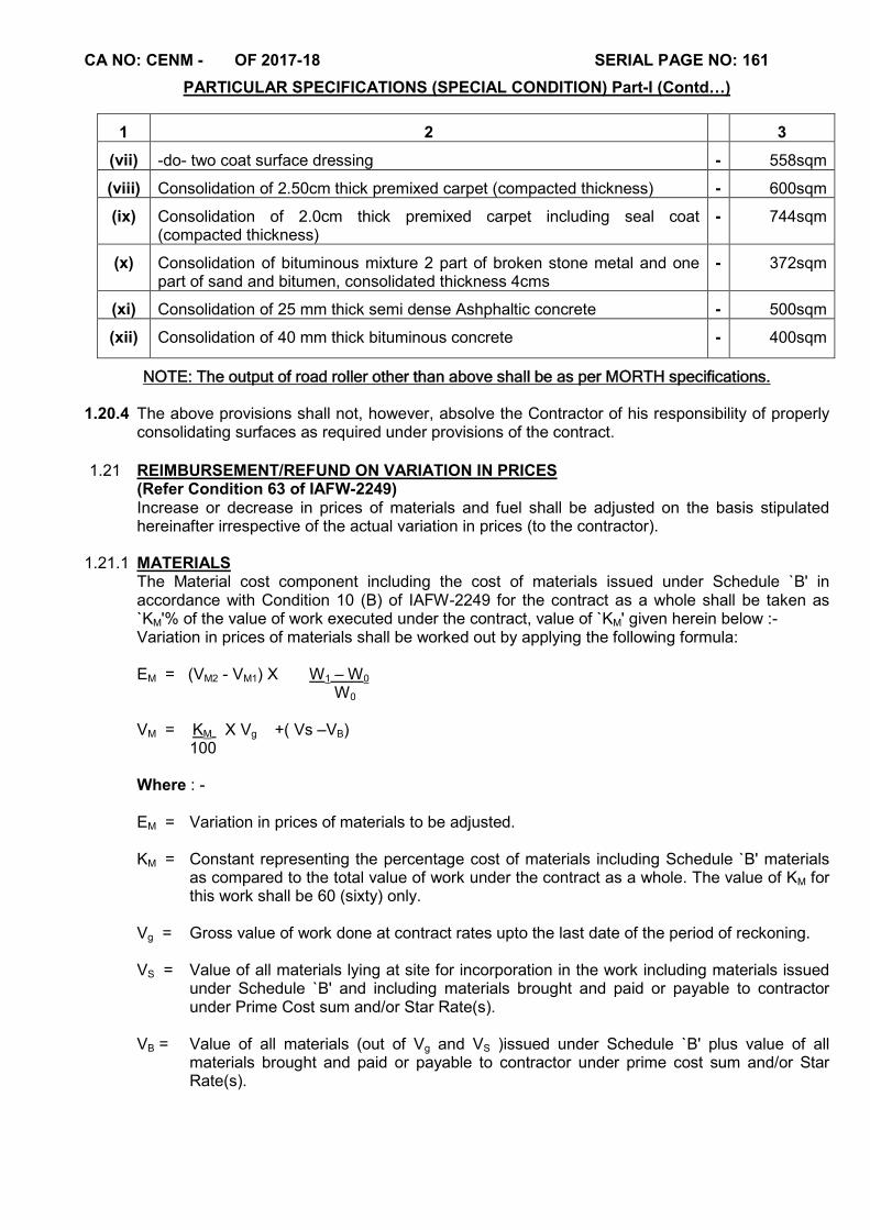
CA NO: CENM - OF 2017-18 SERIAL PAGE NO: 161
PARTICULAR SPECIFICATIONS (SPECIAL CONDITION) Part-I (Contd…)
1 2 3
(vii) -do- two coat surface dressing - 558sqm
(viii) Consolidation of 2.50cm thick premixed carpet (compacted thickness) - 600sqm
(ix) Consolidation of 2.0cm thick premixed carpet including seal coat (compacted thickness)
- 744sqm
(x) Consolidation of bituminous mixture 2 part of broken stone metal and one part of sand and bitumen, consolidated thickness 4cms
- 372sqm
(xi) Consolidation of 25 mm thick semi dense Ashphaltic concrete - 500sqm
(xii) Consolidation of 40 mm thick bituminous concrete - 400sqm
NOTE: The output of road roller other than above shall be as per MORTH specifications.
1.20.4 The above provisions shall not, however, absolve the Contractor of his responsibility of properly consolidating surfaces as required under provisions of the contract.
1.21 REIMBURSEMENT/REFUND ON VARIATION IN PRICES (Refer Condition 63 of IAFW-2249) Increase or decrease in prices of materials and fuel shall be adjusted on the basis stipulated hereinafter irrespective of the actual variation in prices (to the contractor).
1.21.1 MATERIALS
The Material cost component including the cost of materials issued under Schedule `B' in accordance with Condition 10 (B) of IAFW-2249 for the contract as a whole shall be taken as `KM'% of the value of work executed under the contract, value of `KM' given herein below :- Variation in prices of materials shall be worked out by applying the following formula:
EM = (VM2 - VM1) X W1 – W0 W0
VM = KM X Vg +( Vs –VB) 100
Where : - EM = Variation in prices of materials to be adjusted. KM = Constant representing the percentage cost of materials including Schedule `B' materials
as compared to the total value of work under the contract as a whole. The value of KM for this work shall be 60 (sixty) only.
Vg = Gross value of work done at contract rates upto the last date of the period of reckoning. VS = Value of all materials lying at site for incorporation in the work including materials issued
under Schedule `B' and including materials brought and paid or payable to contractor under Prime Cost sum and/or Star Rate(s).
VB = Value of all materials (out of Vg and VS )issued under Schedule `B' plus value of all
materials brought and paid or payable to contractor under prime cost sum and/or Star Rate(s).

CA NO: CENM - OF 2017-18 SERIAL PAGE NO: 162
PARTICULAR SPECIFICATIONS (SPECIAL CONDITION) Part-I (Contd…) W1 = Whole sale price index for all commodities (base year 2011-12=100) published by the
Economic Adviser to the Government of India, as on the date of commencement of the period of reckoning. In case the original contract period is extended under condition 11 of IAFW-2249, the price index as applicable on the date of commencement of the last period of reckoning before the original completion date(s) (phase wise except where phasing has been done only for sample quarter/block) shall only be applicable during the extended period. If phasing has been done for only sample quarter/sample block, the price index as applicable on the date of commencement of the last reckoning period before the original completion date of the project as a whole shall only be applicable during the extended period.
W0 = As for W1 but the index as on the last due date for receipt of tenders. VM2 = Value of materials upto the last date of the period of reckoning, for which price variation is
adjustable as worked out as per formula for VM. VM1 = -Do- but as on date of immediate preceding period of reckoning.
1.21.2 FUEL
Fuel cost component for the contract as a whole shall be taken as KP% of the value of work. EP = KP x V g l X F1 – F0
100 F0 Where : - EP = Variation in price of fuel to be adjusted.
KP = Constant representing the percentage cost of fuel as compared to the total value of work
under the contract as a whole. The value of KP for this work shall be 1.5 (One point Five) only.
Vgl = Gross value of work done during the period of reckoning, using value of Vg for calculating
VM1 and VM2 under 1.21.1 above. F1 = Whole sale price index for sub group for fuel, power, light and lubricant (base year 2011-
2012=100) published by Economic Adviser to Government of India as on the date of commencement of the period of reckoning.
F0 = As for F1 but the Index as on the last due date for receipt of tenders. NOTES :- 1. No adjustment, whatsoever, due to variation in prices of materials and fuel on account of coming into force of any fresh law or statutory rule of order as provided in condition 63 of IAFW-2249 or otherwise than provided in this condition shall be made. 2. (a) Material : No adjustment in prices shall be made for any work done with materials
brought at site after the stipulated date of completion of the work under contract except as contemplated under definition of W1.
(b) No adjustment in prices shall be made for any work done with material brought at
site after the due date of completion or extension of time granted under Condition 11 of IAFW-2249 (whichever is later) for the work under the contract).
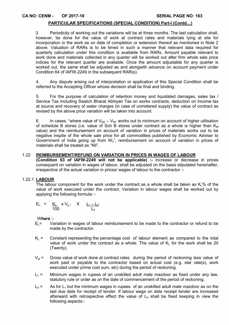
CA NO: CENM - OF 2017-18 SERIAL PAGE NO: 163
PARTICULAR SPECIFICATIONS (SPECIAL CONDITION) Part-I (Contd…) 3. Periodicity of working out the variations will be at three months. The last calculation shall, however, be done for the value of work at contract rates and materials lying at site for incorporation in the work as on date of completion or extension thereof as mentioned in Note 2 above. Valuation of RARs is to be timed in such a manner that relevant data required for quarterly calculation under this condition is available from RARs. Amount payable relevant to work done and materials collected in any quarter will be worked out after firm whole sale price indices for the relevant quarter are available. Once the amount adjustable for any quarter is worked out, the same shall be adjusted as and alongwith advance on account payment under Condition 64 of IAFW-2249 in the subsequent RAR(s).
4. Any dispute arising out of interpretation or application of this Special Condition shall be referred to the Accepting Officer whose decision shall be final and binding. 5. For the purpose of calculation of retention money and liquidated damages, sales tax / Service Tax including Swatch Bharat Abhiyan Tax on works contracts, deduction on income tax at source and recovery of water charges (in case of unmetered supply) the value of contract as revised by the above price variation will be taken into account. 6. In cases, “where value of VM2 – VM1 works out to minimum on account of higher utilisation of schedule B stores (i.e. value of Sch B stores under contract as a whole is higher than KM value) and the reimbursement on account of variation in prices of materials works out to be negative inspite of the whole sale price for all commodities published by Economic Adviser to Government of India going up from W0”, reimbursement on account of variation in prices of materials shall be treated as “Nil”.
1.22 REIMBURSEMENT/REFUND ON VARIATION IN PRICES IN WAGES OF LABOUR
(Condition 63 of IAFW-2249 will not be applicable) :- Increase or decrease in prices consequent on variation in wages of labour, shall be adjusted on the basis stipulated hereinafter, irrespective of the actual variation in prices/ wages of labour to the contractor :-
1.22.1 LABOUR
The labour component for the work under the contract as a whole shall be taken as KL% of the value of work executed under the contract. Variation in labour wages shall be worked out by applying the following formula: -
EL = KL x Vg l X L1 – L0 100 L0
Where :-
EL= Variation in wages of labour reimbursement to be made to the contractor or refund to be made by the contractor.
KL = Constant representing the percentage cost of labour element as compared to the total
value of work under the contract as a whole. The value of KL for the work shall be 20 (Twenty).
Vgl = Gross value of work done at contract rates during the period of reckoning less value of
work paid or payable to the contractor based on actual cost (e.g. star rate(s), work executed under prime cost sum, etc) during the period of reckoning.
L1 = Minimum wages in rupees of an unskilled adult male mazdoor as fixed under any law, statutory rule or order as on the date of commencement of the period of reckoning.
L0 = As for L1 but the minimum wages in rupees of an unskilled adult male mazdoor as on the last due date for receipt of tender. If labour wage on date receipt tender are increased afterward with retrospective effect the value of L0 shall be fixed keeping in view the following aspects:-
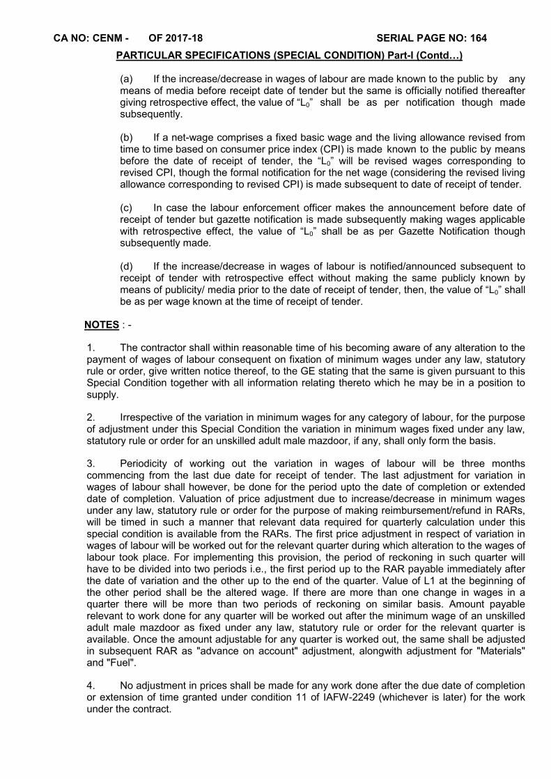
CA NO: CENM - OF 2017-18 SERIAL PAGE NO: 164
PARTICULAR SPECIFICATIONS (SPECIAL CONDITION) Part-I (Contd…) (a) If the increase/decrease in wages of labour are made known to the public by any
means of media before receipt date of tender but the same is officially notified thereafter giving retrospective effect, the value of “L0” shall be as per notification though made subsequently.
(b) If a net-wage comprises a fixed basic wage and the living allowance revised from
time to time based on consumer price index (CPI) is made known to the public by means before the date of receipt of tender, the “L0” will be revised wages corresponding to revised CPI, though the formal notification for the net wage (considering the revised living allowance corresponding to revised CPI) is made subsequent to date of receipt of tender.
(c) In case the labour enforcement officer makes the announcement before date of
receipt of tender but gazette notification is made subsequently making wages applicable with retrospective effect, the value of “L0” shall be as per Gazette Notification though subsequently made.
(d) If the increase/decrease in wages of labour is notified/announced subsequent to
receipt of tender with retrospective effect without making the same publicly known by means of publicity/ media prior to the date of receipt of tender, then, the value of “L0” shall be as per wage known at the time of receipt of tender.
NOTES : -
1. The contractor shall within reasonable time of his becoming aware of any alteration to the payment of wages of labour consequent on fixation of minimum wages under any law, statutory rule or order, give written notice thereof, to the GE stating that the same is given pursuant to this Special Condition together with all information relating thereto which he may be in a position to supply.
2. Irrespective of the variation in minimum wages for any category of labour, for the purpose of adjustment under this Special Condition the variation in minimum wages fixed under any law, statutory rule or order for an unskilled adult male mazdoor, if any, shall only form the basis.
3. Periodicity of working out the variation in wages of labour will be three months commencing from the last due date for receipt of tender. The last adjustment for variation in wages of labour shall however, be done for the period upto the date of completion or extended date of completion. Valuation of price adjustment due to increase/decrease in minimum wages under any law, statutory rule or order for the purpose of making reimbursement/refund in RARs, will be timed in such a manner that relevant data required for quarterly calculation under this special condition is available from the RARs. The first price adjustment in respect of variation in wages of labour will be worked out for the relevant quarter during which alteration to the wages of labour took place. For implementing this provision, the period of reckoning in such quarter will have to be divided into two periods i.e., the first period up to the RAR payable immediately after the date of variation and the other up to the end of the quarter. Value of L1 at the beginning of the other period shall be the altered wage. If there are more than one change in wages in a quarter there will be more than two periods of reckoning on similar basis. Amount payable relevant to work done for any quarter will be worked out after the minimum wage of an unskilled adult male mazdoor as fixed under any law, statutory rule or order for the relevant quarter is available. Once the amount adjustable for any quarter is worked out, the same shall be adjusted in subsequent RAR as "advance on account" adjustment, alongwith adjustment for "Materials" and "Fuel".
4. No adjustment in prices shall be made for any work done after the due date of completion or extension of time granted under condition 11 of IAFW-2249 (whichever is later) for the work under the contract.
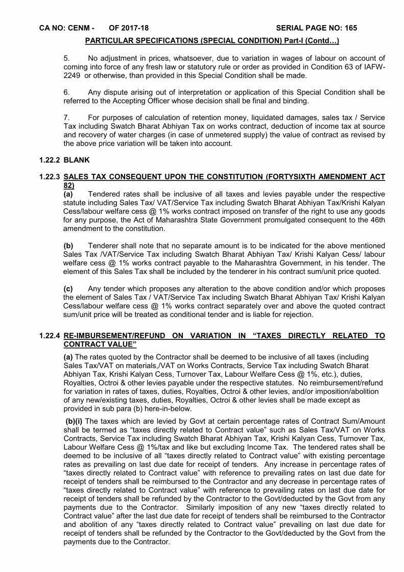
CA NO: CENM - OF 2017-18 SERIAL PAGE NO: 165
PARTICULAR SPECIFICATIONS (SPECIAL CONDITION) Part-I (Contd…)
5. No adjustment in prices, whatsoever, due to variation in wages of labour on account of coming into force of any fresh law or statutory rule or order as provided in Condition 63 of IAFW-2249 or otherwise, than provided in this Special Condition shall be made.
6. Any dispute arising out of interpretation or application of this Special Condition shall be referred to the Accepting Officer whose decision shall be final and binding.
7. For purposes of calculation of retention money, liquidated damages, sales tax / Service Tax including Swatch Bharat Abhiyan Tax on works contract, deduction of income tax at source and recovery of water charges (in case of unmetered supply) the value of contract as revised by the above price variation will be taken into account.
1.22.2 BLANK
1.22.3 SALES TAX CONSEQUENT UPON THE CONSTITUTION (FORTYSIXTH AMENDMENT ACT 82) (a) Tendered rates shall be inclusive of all taxes and levies payable under the respective statute including Sales Tax/ VAT/Service Tax including Swatch Bharat Abhiyan Tax/Krishi Kalyan Cess/labour welfare cess @ 1% works contract imposed on transfer of the right to use any goods for any purpose, the Act of Maharashtra State Government promulgated consequent to the 46th amendment to the constitution.
(b) Tenderer shall note that no separate amount is to be indicated for the above mentioned Sales Tax /VAT/Service Tax including Swatch Bharat Abhiyan Tax/ Krishi Kalyan Cess/ labour welfare cess @ 1% works contract payable to the Maharashtra Government, in his tender. The element of this Sales Tax shall be included by the tenderer in his contract sum/unit price quoted.
(c) Any tender which proposes any alteration to the above condition and/or which proposes the element of Sales Tax / VAT/Service Tax including Swatch Bharat Abhiyan Tax/ Krishi Kalyan Cess/labour welfare cess @ 1% works contract separately over and above the quoted contract sum/unit price will be treated as conditional tender and is liable for rejection.
1.22.4 RE-IMBURSEMENT/REFUND ON VARIATION IN “TAXES DIRECTLY RELATED TO CONTRACT VALUE”
(a) The rates quoted by the Contractor shall be deemed to be inclusive of all taxes (including Sales Tax/VAT on materials,/VAT on Works Contracts, Service Tax including Swatch Bharat Abhiyan Tax, Krishi Kalyan Cess, Turnover Tax, Labour Welfare Cess @ 1%, etc.), duties, Royalties, Octroi & other levies payable under the respective statutes. No reimbursement/refund for variation in rates of taxes, duties, Royalties, Octroi & other levies, and/or imposition/abolition of any new/existing taxes, duties, Royalties, Octroi & other levies shall be made except as provided in sub para (b) here-in-below.
(b)(i) The taxes which are levied by Govt at certain percentage rates of Contract Sum/Amount shall be termed as “taxes directly related to Contract value” such as Sales Tax/VAT on Works Contracts, Service Tax including Swatch Bharat Abhiyan Tax, Krishi Kalyan Cess, Turnover Tax, Labour Welfare Cess @ 1%/tax and like but excluding Income Tax. The tendered rates shall be deemed to be inclusive of all “taxes directly related to Contract value” with existing percentage rates as prevailing on last due date for receipt of tenders. Any increase in percentage rates of “taxes directly related to Contract value” with reference to prevailing rates on last due date for receipt of tenders shall be reimbursed to the Contractor and any decrease in percentage rates of “taxes directly related to Contract value” with reference to prevailing rates on last due date for receipt of tenders shall be refunded by the Contractor to the Govt/deducted by the Govt from any payments due to the Contractor. Similarly imposition of any new “taxes directly related to Contract value” after the last due date for receipt of tenders shall be reimbursed to the Contractor and abolition of any “taxes directly related to Contract value” prevailing on last due date for receipt of tenders shall be refunded by the Contractor to the Govt/deducted by the Govt from the payments due to the Contractor.
CA NO: CENM - OF 2017-18 SERIAL PAGE NO: 166
PARTICULAR SPECIFICATIONS (SPECIAL CONDITION) Part-I (Contd…)
(ii) The Contractor shall, within a reasonable time of his becoming aware of variation in percentage rates and/or imposition of any further “taxes directly related to Contract value”, give written notice thereof to the GE stating that the same is given pursuant to this Special Condition, together with all information relating there to which he may be in a position to supply. The Contractor shall submit the other documentary proof/information’s as the GE may require.
(iii) The Contractor shall, for the purpose of this condition keep such books of account and other documents as are necessary and shall allow inspection of the same by a duly authorized representative of Govt, and shall further, at the request of the GE furnish, verified in such a manner as the GE may require, any documents so kept and such other information as the GE may require.
(iv) Reimbursement for increase in percentage rates/imposition of “taxes directly related to Contract value” shall be made only if the Contractor necessarily & properly pays additional “taxes directly related to Contract value” to the Govt, without getting the same adjusted against any other tax liability or without getting the same refunded from the concerned Govt Authority and submits documentary proof for the same as the GE may require”.
1.23 ADVANCES ON ACCOUNT OF NON-PERISHABLE MATERIALS WHICH DO NOT LOOSE
IDENTITY AFTER INCORPORATION IN WORK
The Contractor may be paid advance on account to the full value of the under mentioned materials only, brought on the site, on his furnishing guarantee bond(s) from a scheduled bank for the amount of the retention money, should otherwise be recoverable from him under the contract:
(i) Factory made panelled shutters
(ii) Factory made Aluminium windows/ ventilators
(iii) Sanitary fittings
(iv) Builders hardware fittings (iron mongery)
(v) Electrical cables/ wires/ fittings/ fixtures
(vi) Water supply pipes, fittings/ fixtures
(vii) All other non-perishable materials as decided by the GE
The Bank Guarantee Bonds shall be executed for a period and on a form as directed by the Accepting Officer. The Contractor shall further arrange to extend the period of Guarantee Bond if and when necessary, as directed by the Accepting Officer or shall furnish fresh guarantee bond of similar value. It will be noted that advance on account to the full value to materials brought on the site is permissible only in respect of fittings and fixtures and other manufactured items which do not lose their identity after incorporation in the work. Materials like bricks, aggregate, precast concrete and similar items shall not be taken in the list.
1.24 CLEANING DOWN (Refer Condition 49 of IAFW-2249)
The Contractor shall clean all floors, walls, remove cement, lime, paint marks/drops etc clean the joinery, glass panes etc, touch up all painters work and carry out all other necessary items of work in connection therewith and leave the whole premises clean and tidy before handing over the building. No extra payment shall be claimed by the Contractor for this operation.
1.25 LABEL OF ARTICLES
The Contractor shall provide aluminium LABEL of not less than 75mmx25mm and of adequate gauge with brass screws on articles like transformer, panel board, generating set etc indicating there on the names of the firm, the contract No. and year as directed by the GE. The cost of such aluminium labels shall be deemed to be included in the quoted rates against respective item of Schedule-`A'.
CA NO: CENM - OF 2017-18 SERIAL PAGE NO: 167
PARTICULAR SPECIFICATIONS (SPECIAL CONDITION) Part-I (Contd…) 1.26 DAMAGE TO STRUCTURE
Any damage done to the structure built or being built by other agency during execution of work shall be made good by the Contractor at his own cost and the site of work left clean and tidy on completion. Rectification, reinstatement, making good etc shall conform to the standard of materials originally used in the work and finished work shall match with existing work in all respect to the entire satisfaction of the GE. In case of any dispute on this account the matter shall be referred to the CWE whose decision in writing shall be final, conclusive and binding.
1.27 CONDITIONS OF WORKING:
1.27.1 CONDITIONS OF WORKING IN RESTRICTED AREA
The entire work under this contract lies in "RESTRICTED AREA". The conditions of working in restricted area are stipulated as under:
(a) Definition: Restricted area(s) for the purpose of this contract means the area(s) declared as such by the units as shown in site plan/described in Special Condition.
(b) Verification of antecedents: Verification of antecedents of Contractor’s representatives / labours deployed at site in connection with execution of work under the contract, as per security requirement of User Unit/installation shall be the responsibility of the Contractor and all expenses in connection with verification of antecedent by Police Authority / Security Agency shall be borne by the Contractor.
(c) Visit to site within the Restricted Area: Permission to enter the restricted area(s) at time of submission of tenders can be obtained, through the Garrison Engineer. Tenderers are advised to send prior intimation to the Garrison Engineer about the particulars of the agents, representative etc., if any, the date and the time of their proposed visits so that necessary arrangement may be made by the GE, to secure admission. Whether tenderers visit the site or not they shall be deemed to have full knowledge of the restrictions on entering in, exit from and working within the restricted area.
(d) Entry and Exit: The Contractor/ his agent(s)/ representative(s)/ workmen etc., and his materials carts, trucks or other means of transport, etc., will be allowed to enter through and leave from only such gate or gates and at such times as the GE or Authorities in charge of the restricted area may at their sole discretion permit to be used. The Contractor's authorised representative is required to be present at the places of entry and exit for the purpose of identifying his carts, trucks, etc, to the personnel-in-charge of the security of the restricted area.
(e) Identity Cards or Passes:
(i) The Contractor, his agents and representatives are required individually to be in possession of an identity card or pass duly verified by the GE. The identity card or pass will be examined by the security staff at the time of entry into or exit from the restricted area, and also any time or number of times inside restricted area.
(ii) Identity of Workmen Every workman shall be in possession of an Identity Card. The identity cards shall be issued after a thorough investigation of the antecedents of the labourers, by the Contractor and attested by the officer-in-charge of the units concerned in accordance with the standing rules and regulations of the unit.
(iii) The Contractor shall be responsible for conduct of his workmen, agents or Representatives.
(f) Search Thorough search of all persons and transport shall be carried out at each gate and for as many times as gate is used for entry or exit and may also be carried out any time or any number of times at the work site within the restricted area.
CA NO: CENM - OF 2017-18 SERIAL PAGE NO: 168
PARTICULAR SPECIFICATIONS (SPECIAL CONDITION) Part-I (Contd…)
(g) Female Searcher If the Contractor desires to employ female labour on works to be carried-out inside the area of factory, depot, park, unit, etc and a female searcher is not borne on the authorised strength of the factory, depot, park, unit, etc, at the time of submission of tender, he shall be deemed to have allowed in his tender for pay and allowances etc. for a Female Searcher (Class IV servant/ GP`D' servant) calculated for the period, female labours are employed by him inside the area. If more than one Contractor employs female labour during any month and female searcher(s) has/have to be employed in addition to the authorised strength of the factory, depot, park, unit, etc, the salary and allowances paid to the additional female searcher(s) shall be distributed on equitable basis between the Contractors employing female labour taking into consideration the values and periods of completion of their contracts. The GE's decision in regard to the amount recoverable on this account from any Contractor shall be final and binding.
(h) Working Hours The units controlling restricted area, usually work during six days in a week and remain closed on the 7th day. The working hours available to the Contractor's labour/staff are however accordingly get reduced because of the time taken in security checks observed at the time of entry and exit and during working hours. The exact working hours, working days and non working days observed for these restricted area(s), where works are to be carried out shall be deemed have been ascertained by the Contractor before submitting his tender. The tenderers' attention is invited to the fact that total number of working hours for a unit, are prescribed in regulations and that they cannot be increased by the Garrison Engineer. The definition of "Working Day" as given under condition 1(t) of IAFW-2249 does not apply in case where the works are carried out in restricted area.
(j) Work on Holidays The Contractor shall not carry out any work on gazetted holidays, weekly holidays and other non-working days except when he is expressly authorised in writing to do so by the Garrison Engineer. The GE may at his sole discretion declare any day as holiday or non-working day without assigning any reason for such declaration.
(k) Access to restricted area after completion After the works are completed and surplus stores etc. removed, the Contractor, his agents, representatives or workmen etc., will not be allowed any access to the restricted area except for attending to any rectification of defects pointed out to him by the GE.
(l) Fire precautions
(i) The Contractor, his agents, representatives, workmen etc., shall strictly observe the orders pertaining to fire precautions prevailing within the restricted area.
(ii) Motor transport vehicle, if allowed by the authorities to enter the restricted area must be fitted with serviceable fire extinguishers.
1.27A SAMPLE QUARTER
1.27A.1To determine the acceptable standard of materials and workmanship/ final finishes and layout of fittings etc. the contractor shall execute stages of work viz. excavation, foundation concrete, walling upto plinth/ lintel/ roof levels, roofing, flooring, joinery, built-in items, finishes, all fittings & fixtures and the like and services i.e. Internal Electrification, Water Supply, Plumbing, Sanitary Fittings as described in Schedule `A’, specified in Particular Specifications & as shown on drawings under the close supervision of Engineer-in-Charge and shall got it approved from the GE. The quarter shall be labelled as `SAMPLE QUARTER’. The workmanship of various trades and finishes of sample quarter shall serve as guiding samples for the work in remaining quarters.
1.27A.2Approval of the stages and workmanship of sample quarter shall be separately entered and approved in stage passing register giving reference to block and quarter number for easy identification even at a later date.
CA NO: CENM - OF 2017-18 SERIAL PAGE NO: 169
PARTICULAR SPECIFICATIONS (SPECIAL CONDITION) Part-I (Contd…)
1.28 METHOD STATEMENT
1.28.1 The Contractor shall plan for execution and completion of work with foresight to ensure timely execution with the quality of work desired.
1.28.2 Period of completion shall be divided into months/ fortnights/ weeks and plan for each months/fortnights/weeks by preparing schedule for every months/ fortnights/weeks with following details, even before commencement of work.
(a) Items of work to be executed with quantity
(b) Labour to be deployed trade wise,
(c) T & P to be deployed
(d) Material to be brought to site for works to be executed next week
(e) Type and number of engineers to be employed.
1.28.3 Any special item of work to be executed alongwith description of method as to how the Contractor intends to execute. It must be submitted in advance.
1.28.4 The Contractor shall also plan in advance and make available all the requisite safety equipment for the labour. A list of the same shall be given.
1.28.5 The Contractor shall produce test certificate of T&P being deployed at site. The test certificates shall indicate the present capacity of the T&P and shall not be more than 6months old.
1.28.6 The above details shall be furnished by Contractor within 10days of commencement of work. Work will be not allowed to be executed without these details. However, date of commencement of work will be within one month of acceptance as per contract.
1.28.7 Delay on account of non-submission of these details /test certificate will be attributable to Contractor and no extension of time will be granted on this account.
**MONTH/FORTNIGHT/WEEK NO_____
From ___________ To _____________
EXECUTION
Sl No
Item of work Quantity Sl
No No of Engineers to be employed
Nos
1 1 Civil
( a ) Graduates
( b ) Diploma Holders
2 2 Electrical
( a )
(b )
3 3 Mechanical
( a )
(b )
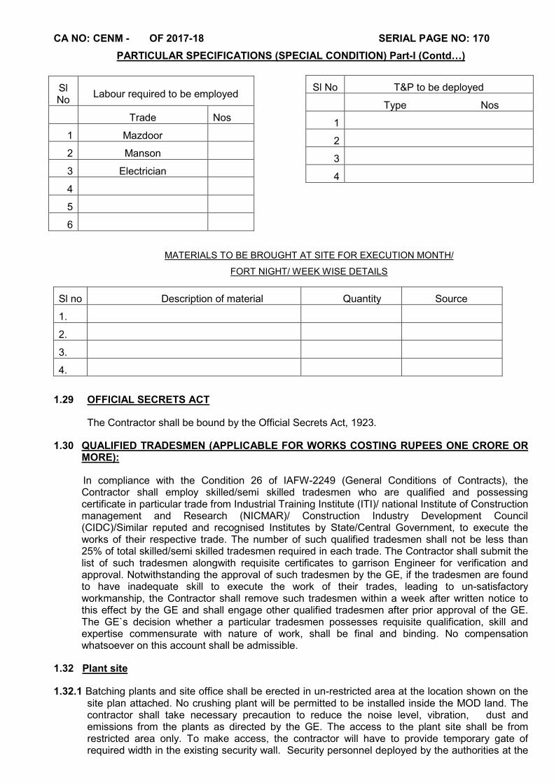
CA NO: CENM - OF 2017-18 SERIAL PAGE NO: 170
PARTICULAR SPECIFICATIONS (SPECIAL CONDITION) Part-I (Contd…)
MATERIALS TO BE BROUGHT AT SITE FOR EXECUTION MONTH/
FORT NIGHT/ WEEK WISE DETAILS
Sl no Description of material Quantity Source
1.
2.
3.
4.
1.29 OFFICIAL SECRETS ACT
The Contractor shall be bound by the Official Secrets Act, 1923.
1.30 QUALIFIED TRADESMEN (APPLICABLE FOR WORKS COSTING RUPEES ONE CRORE OR MORE):
In compliance with the Condition 26 of IAFW-2249 (General Conditions of Contracts), the Contractor shall employ skilled/semi skilled tradesmen who are qualified and possessing certificate in particular trade from Industrial Training Institute (ITI)/ national Institute of Construction management and Research (NICMAR)/ Construction Industry Development Council (CIDC)/Similar reputed and recognised Institutes by State/Central Government, to execute the works of their respective trade. The number of such qualified tradesmen shall not be less than 25% of total skilled/semi skilled tradesmen required in each trade. The Contractor shall submit the list of such tradesmen alongwith requisite certificates to garrison Engineer for verification and approval. Notwithstanding the approval of such tradesmen by the GE, if the tradesmen are found to have inadequate skill to execute the work of their trades, leading to un-satisfactory workmanship, the Contractor shall remove such tradesmen within a week after written notice to this effect by the GE and shall engage other qualified tradesmen after prior approval of the GE. The GE`s decision whether a particular tradesmen possesses requisite qualification, skill and expertise commensurate with nature of work, shall be final and binding. No compensation whatsoever on this account shall be admissible.
1.32 Plant site
1.32.1 Batching plants and site office shall be erected in un-restricted area at the location shown on the site plan attached. No crushing plant will be permitted to be installed inside the MOD land. The contractor shall take necessary precaution to reduce the noise level, vibration, dust and emissions from the plants as directed by the GE. The access to the plant site shall be from restricted area only. To make access, the contractor will have to provide temporary gate of required width in the existing security wall. Security personnel deployed by the authorities at the
Sl No T&P to be deployed
Type Nos
1
2
3
4
Sl No
Labour required to be employed
Trade Nos
1 Mazdoor
2 Manson
3 Electrician
4
5
6
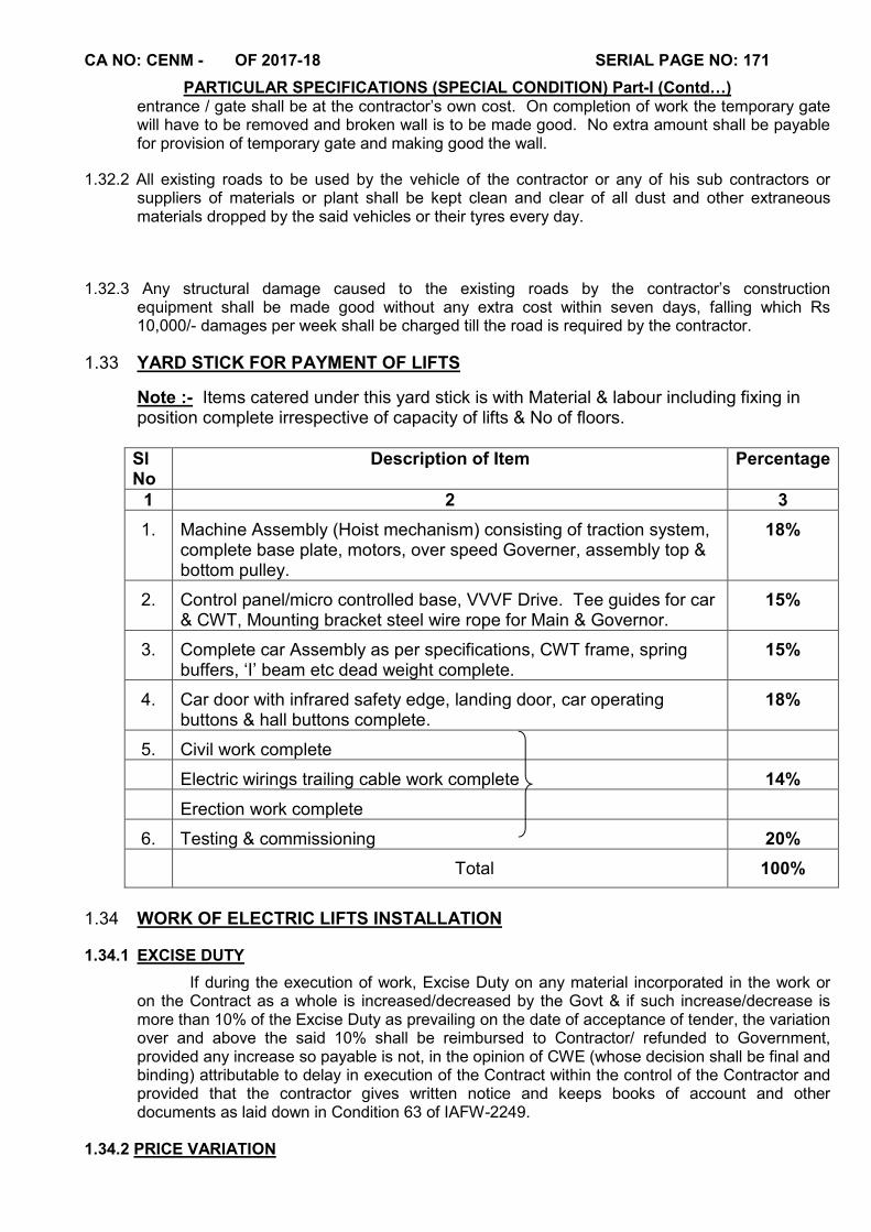
CA NO: CENM - OF 2017-18 SERIAL PAGE NO: 171
PARTICULAR SPECIFICATIONS (SPECIAL CONDITION) Part-I (Contd…) entrance / gate shall be at the contractor’s own cost. On completion of work the temporary gate will have to be removed and broken wall is to be made good. No extra amount shall be payable for provision of temporary gate and making good the wall.
1.32.2 All existing roads to be used by the vehicle of the contractor or any of his sub contractors or suppliers of materials or plant shall be kept clean and clear of all dust and other extraneous materials dropped by the said vehicles or their tyres every day.
1.32.3 Any structural damage caused to the existing roads by the contractor’s construction equipment shall be made good without any extra cost within seven days, falling which Rs 10,000/- damages per week shall be charged till the road is required by the contractor.
1.33 YARD STICK FOR PAYMENT OF LIFTS
Note :- Items catered under this yard stick is with Material & labour including fixing in position complete irrespective of capacity of lifts & No of floors.
Sl No
Description of Item Percentage
1 2 3
1. Machine Assembly (Hoist mechanism) consisting of traction system, complete base plate, motors, over speed Governer, assembly top & bottom pulley.
18%
2. Control panel/micro controlled base, VVVF Drive. Tee guides for car & CWT, Mounting bracket steel wire rope for Main & Governor.
15%
3. Complete car Assembly as per specifications, CWT frame, spring buffers, ‘I’ beam etc dead weight complete.
15%
4. Car door with infrared safety edge, landing door, car operating buttons & hall buttons complete.
18%
5. Civil work complete
Electric wirings trailing cable work complete 14%
Erection work complete
6. Testing & commissioning 20%
Total 100%
1.34 WORK OF ELECTRIC LIFTS INSTALLATION
1.34.1 EXCISE DUTY
If during the execution of work, Excise Duty on any material incorporated in the work or on the Contract as a whole is increased/decreased by the Govt & if such increase/decrease is more than 10% of the Excise Duty as prevailing on the date of acceptance of tender, the variation over and above the said 10% shall be reimbursed to Contractor/ refunded to Government, provided any increase so payable is not, in the opinion of CWE (whose decision shall be final and binding) attributable to delay in execution of the Contract within the control of the Contractor and provided that the contractor gives written notice and keeps books of account and other documents as laid down in Condition 63 of IAFW-2249.
1.34.2 PRICE VARIATION

CA NO: CENM - OF 2017-18 SERIAL PAGE NO: 172
PARTICULAR SPECIFICATIONS (SPECIAL CONDITION) Part-I (Contd…) The price quoted shall be deemed to be based on the cost of raw materials, components and labour as on the date of submission of tender and the same shall be deemed to be related to whole sale Price Index for metal Products and all India Average Consumer Price Index Number for Industrial Workers (General Index) as specified below. In case of any variation in these index number the price shall be subject to adjustment up or down in accordance with the following formula:

CA NO: CENM - OF 2017-18 SERIAL PAGE NO: 173
PARTICULAR SPECIFICATIONS (SPECIAL CONDITION) Part-I (Contd…) P = Po [15+ 55MP + 15Wo(D) + 55Wo(I) ]
100 MPo Wo Wo
Wherein,
P≈ Total amount payable, i.e. amount of contract as accepted including variation in prices in accordance with the above price variation formula
Po≈ Amount of Contract as accepted for BOQ Item Nos ( for Lift)
MPo≈ Wholesale Price Index Number for Metal Products as published by the Office of the Economic Adviser, Ministry of Industry, Government of India, in their weekly bulletins (revised Index Number of Wholesale Prices in India-base year as 2011-12=100) for the week ending 1st Saturday relevant calendar month.
Wo≈All India Average Consumer Price Index Number for Industrial Workers (base 2001=100) (General Index), as published by Labour Bureau, Ministry of Labour, Govt of India.
The above index numbers i.e MP0 and W0 are those published by Govt, as prevailing on the first working day of the calendar month three months prior to the last date for receipt of tender e.g. when the last due date for receipt of tenders is in Jun 2005, then the applicable index MP0, will be as prevailing on the first Saturday of March 2005, and W0- All India Average Consumer Price Index Number would be that for the month of March 2005.
MP≈ Wholesale Price Index Number for Metal Products as published by the office of Economic Advisor, Ministry of Industry, Govt. of India, in their weekly Bulletin Revised Index Number of Whole Sale Price, (base 2011-12=100).
The applicable wholesale Price Index Number for Metal Products would be that prevailing on the 1st Saturday of the month covering the date three months prior to the date of delivery, of first lot of manufactured materials for each elevator separately.
W0 (D) ≈All India Average Consumer Price Index number for Industrial workers (base 2001=100) (General Index) as published by labour Bureau, Ministry of Labour, Government of India.
Applicable all India Average Consumer Price Index Number for Industrial Workers as published by the Labour Bureau, Ministry of Labour, Government of India, would be for the month, three months prior to the date of delivery of first lot of manufactured materials.
W0 (I)= All India Average Consumer Price Index Number for Industrial Workers (base 2001= 100) (General Index) as published by Labour Bureau, Ministry of Labour, Government of India.
The applicable All India, Average Consumer Price Index number for Industrial Workers as published by Labour Bureau Ministry of Labour, Government of India, would be for the month, three months prior to the date of completion of installation. e.g. if the date of delivery in terms of clause given below falls, in December 2005 the applicable index ‘MP’ would be as prevailing on the week ending 1st Saturday of September, 2005, and W0 (D), will be for the month of September 2005. If the date of completion of each elevator/installation is June 2012 the applicable ‘W0 (I)’ will be for the month of March 2012.
(a) The date of delivery shall be the date on which the first lot of manufactured materials for each elevator is notified as being ready for inspection, despatch (in the absence of such notification, the date of manufacturer’s despatch note shall be considered as the date of delivery).
(b) The date of completion of each elevator installation shall be the date on which the work is certified as completed and is available for inspection (in the absence of such notification the date of manufacturer’s note intimating such installation or part of installation (including any agreed extension thereto), whichever shall be earlier.
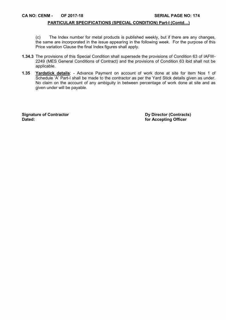
CA NO: CENM - OF 2017-18 SERIAL PAGE NO: 174
PARTICULAR SPECIFICATIONS (SPECIAL CONDITION) Part-I (Contd…)
(c) The Index number for metal products is published weekly, but if there are any changes, the same are incorporated in the issue appearing in the following week. For the purpose of this Price variation Clause the final Index figures shall apply.
1.34.3 The provisions of this Special Condition shall supersede the provisions of Condition 63 of IAFW-
2249 (MES General Conditions of Contract) and the provisions of Condition 63 ibid shall not be applicable.
1.35 Yardstick details: - Advance Payment on account of work done at site for item Nos 1 of Schedule ‘A’ Part-I shall be made to the contractor as per the Yard Stick details given as under. No claim on the account of any ambiguity in between percentage of work done at site and as given under will be payable.
Signature of Contractor Dy Director (Contracts) Dated: for Accepting Officer
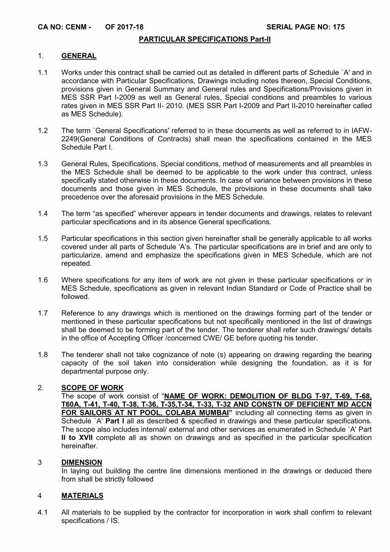
CA NO: CENM - OF 2017-18 SERIAL PAGE NO: 175
PARTICULAR SPECIFICATIONS Part-II 1. GENERAL 1.1 Works under this contract shall be carried out as detailed in different parts of Schedule `A' and in
accordance with Particular Specifications, Drawings including notes thereon, Special Conditions, provisions given in General Summary and General rules and Specifications/Provisions given in MES SSR Part I-2009 as well as General rules, Special conditions and preambles to various rates given in MES SSR Part II- 2010. (MES SSR Part I-2009 and Part II-2010 hereinafter called as MES Schedule).
1.2 The term `General Specifications' referred to in these documents as well as referred to in IAFW-
2249(General Conditions of Contracts) shall mean the specifications contained in the MES Schedule Part I.
1.3 General Rules, Specifications, Special conditions, method of measurements and all preambles in
the MES Schedule shall be deemed to be applicable to the work under this contract, unless specifically stated otherwise in these documents. In case of variance between provisions in these documents and those given in MES Schedule, the provisions in these documents shall take precedence over the aforesaid provisions in the MES Schedule.
1.4 The term “as specified” wherever appears in tender documents and drawings, relates to relevant
particular specifications and in its absence General specifications. 1.5 Particular specifications in this section given hereinafter shall be generally applicable to all works
covered under all parts of Schedule ‘A’s. The particular specifications are in brief and are only to particularize, amend and emphasize the specifications given in MES Schedule, which are not repeated.
1.6 Where specifications for any item of work are not given in these particular specifications or in
MES Schedule, specifications as given in relevant Indian Standard or Code of Practice shall be followed.
1.7 Reference to any drawings which is mentioned on the drawings forming part of the tender or
mentioned in these particular specifications but not specifically mentioned in the list of drawings shall be deemed to be forming part of the tender. The tenderer shall refer such drawings/ details in the office of Accepting Officer /concerned CWE/ GE before quoting his tender.
1.8 The tenderer shall not take cognizance of note (s) appearing on drawing regarding the bearing
capacity of the soil taken into consideration while designing the foundation, as it is for departmental purpose only.
2. SCOPE OF WORK
The scope of work consist of “NAME OF WORK: DEMOLITION OF BLDG T-97, T-69, T-68, T60A, T-41, T-40, T-38, T-36, T-35,T-34, T-33, T-32 AND CONSTN OF DEFICIENT MD ACCN FOR SAILORS AT NT POOL, COLABA MUMBAI” including all connecting items as given in Schedule `A' Part I all as described & specified in drawings and these particular specifications. The scope also includes internal/ external and other services as enumerated in Schedule `A' Part II to XVII complete all as shown on drawings and as specified in the particular specification hereinafter.
3 DIMENSION
In laying out building the centre line dimensions mentioned in the drawings or deduced there from shall be strictly followed
4 MATERIALS 4.1 All materials to be supplied by the contractor for incorporation in work shall confirm to relevant
specifications / IS.

CA No. : CENM - OF 2017-18 SERIAL PAGE No. : 176
PARTICULAR SPECIFICATIONS-II (CONTD…) 4.2 In case specifications of materials needed for incorporation is not contained anywhere in the
contract documents, the specifications of such materials proposed to be incorporated in work shall be got approved in writing from the GE before incorporation in the work. Contractor is advised to check availability, lead, time of procurement from these suppliers before quoting.
4.3 As far as practicable all manufactured articles other than those manufactured in contractor’s
workshop at site shall bear ISI certification mark and which are readily available in the market and are given in Special Conditions. It is mandatory for the contractor that ISI certified marked items/articles as listed therein shall only be incorporated in the work. Names of manufactures/suppliers of certain items/materials are given in Appendix ‘B’ to Particular Specifications. The Contractor is advised to check availability / lead time of procurement from these suppliers before quoting.
4.4 Local materials such as stone aggregate, sand, lime etc shall generally conform to the sample
kept in GE’s office in addition to their conformity with relevant specifications given in the tender documents. The samples of such materials shall be got approved from GE in writing before the materials are brought at site in bulk. The contractor shall submit samples of materials to GE through Engineer-in-Charge for approval.
4.5 Letters conveying approval of samples/materials by GE will interalia mention source of
supply/name of manufacturer, trade name/brand (if applicable) and reference to clause of the tender documents containing specification of particular materials.
4.6 The contractor and executives will ensure that the materials incorporated in the work are identical
with the approved samples. 5 TESTING OF MATERIALS 5.1 All the materials to be incorporated in the work shall be subject to quality control tests as per the
testing procedure and frequency as laid down in relevant IS and or as specified in the tender’ 5.2 Irrespective of whatever is indicated elsewhere in the tender documents the modalities of testing
arrangements shall be as given here in after, 5.3 The contractor shall set-up a site laboratory fully equipped to the satisfaction of GE to carry out
the `A’ type tests as given in Appendix ‘D’ to these specifications. The laboratory shall be set up in all respects before any activity requiring tests as indicated above is physically commenced. Contractor shall employ a competent person technically qualified as approved by the GE to carry out the testing activities. All the tests shall be carried out in the presence of Engineer –in-Charge and records shall be jointly signed with the contractor.
5.4 Entire cost of laboratory and its functioning including cost of samples will be borne by the
contractor in all respects and no separate recovery for testing charges shall be effected for tests/retest carried out at site laboratory. If in the opinion of GE (Whose decision in this regard shall be final and binding)
5.5 Any of the tests as given in Appendix (D) to these specifications cannot be satisfactorily carried
out in the site laboratory at any stage due to any reason, the same shall be got done in Zonal lab / Govt approved lab/ Engineering college/NABL accredited lab as approved by GE in respect of which all expenditure there of shall be borne by the contractor.
5.6 Any tests marked as type `A’,`B’ or `C’ in Appendix `D’, if got done at Zonal lab / SEMT wing
Pune, testing charges as indicated against them will be recovered from the contractor. In addition to this the contractor shall arrange for samples and its handing/transportation to the concerned labs at his own cost.
CA No. : CENM - OF 2017-18 SERIAL PAGE No. : 177
PARTICULAR SPECIFICATIONS-II (CONTD…) 5.7 The tests marked as type `B’ and `C’ will not be carried out in the site laboratory. These tests
shall be carried out only in zonal lab / SEMT wing / Govt. approved lab/National test House / Engineering college/NABL accredited lab as approved by the GE. Incase type `B’ and `C’ testing is done in zonal lab / SEMT wing the testing charges recoveries shall be as indicated in the Appendix ‘D’ to these PS against each test. However if testing is done in other places as given above the actual cost will be directly borne by the contractor.
5.8 The list of tests given in Appendix ‘D’ to these PS contains only a few common tests. However all other tests required in the work but not covered in the appendix shall also be got done in Govt. approved lab/ Engineering college/NABL accredited lab /National Test House as approved by GE and entire cost of sample, handling, transportation and actual testing charges will be borne by the contractor directly. 6 EXCAVATION AND EARTH WORK 6.1 PREPARATORY WORK 6.1.1 Before setting out the buildings/structure and commencing the construction, the contractor shall
carry out the preparatory work, such as removal of grass, vegetation etc. trimming/surface dressing of the area as per Clause 3.6 and 3.10 of SSR PART-I 2009, to the entire satisfaction of Engineer-in-Charge.
6.1.2 The `Area’ referred to implies the entire building/structure plot extending up to 3m all around the
outer edge of plinth protection/ramp of the building/structure. The cost of preparatory work as necessary, shall be deemed to be included in the Contractor's lump sum for Schedule ‘A’ Part-I
6.2 SURFACE EXCAVATION 6.2.1 Before starting excavation work, the contractor shall carry out surface excavation in any type of
soil not exceeding 30 cm deep and averaging 15cm deep over the entire area covered by the Buildings/ Works under Schedule `A' Part-I. The site shall be dressed to slope away from the structure.
6.2.2 All spoils obtained from surface excavation shall be disposed off to a distance n. exc. 50 m as
directed by the Engineer-in-Charge. 6.2.3 Surface excavation shall be carried out before the excavation for foundation is started. 6.2.4 Depth of foundation shown in drawings for the buildings is the depth after surface excavation.
GL marked on drawings shall be average GL as fixed by GE after surface excavation. 6.3 EXCAVATION - GENERAL 6.3.1 Unit rates for buildings in Schedule `A' Part-I shall include for excavation and earthwork in hard /
dense soil & soft / disintegrated rock. Any change in strata during excavation than mentioned hereinbefore shall be regularized through a deviation order.
6.3.2 Excavation shall be done to the depth as shown on drawings/as required at site and as directed
by Engineer-in-Charge. 6.3.3 Decision of the Garrison Engineer shall be final, conclusive and binding as regards classification
of soils and rocks met during excavation.

CA No. : CENM - OF 2017-18 SERIAL PAGE No. : 178
PARTICULAR SPECIFICATIONS-II (CONTD…) 6.4 Quoted cost of all items of Schedule `A' Part-I as well as subsequent parts shall also be deemed
to include for bailing, pumping, dewatering from foundation trenches if water is met with or accumulated from any source or cause or working in water or liquid mud. No additional payment as stipulated in Clause 3.11 of MES Schedule Part II will be admissible. In the event of deviations, no adjustment shall be made for cost of bailing, pumping and dewatering, specified hereinbefore. The Contractor shall be deemed to have acquainted himself with the sub-soil water table at site before submitting his tender.
6.5 Stone obtained from excavation in hard rock (if met with during excavation) (other than by chiseling) shall become property of the contractor. The contractor shall pay Rs. 587.50 per cum of measured quantity of stone obtained without deduction of voids in excavation and shall remove it off the site with prior permission of GE/ Engineer-in-Charge. No lead shall be payable for the removal of stone from site. The contractor may use the stone obtained from excavation in filling under floors or road work if permitted by the GE. In cases the excavation in hard rock is carried out by chiseling then the excavated material shall be used in filling as specified hereinafter in floors or road work. The recovery of Rs. 587.50 per cum of stack measurement (without any deduction for voids) of hard rock shall be effected from the contractor to the extent of material used in filling. Surplus excavated material shall be disposed off as directed without any extra cost to Govt.
6.5.1 Blasting of rock is prohibited. Excavation in hard rock (if met with during excavation) shall be by
chiseling or any other agreed method. 6.6. In case timbering to excavation is required and specifically ordered by the GE in writing, it shall
be paid as deviation. 6.7 TRENCHES FOR FOUNDATION AND PIPES 6.7.1 The excavation shall be restricted to dimensions shown on the drawings and as specified in MES
Schedule. Excavation made, if any, in excess of required depth/width shall be made good by the Contractor with cement concrete 1:7:12 type F2 without extra cost to the Government
6.7.2 The beds of the trenches shall be watered and well rammed and any depressions thus formed
shall be filled with approved earth as required to the level and slopes as directed by Engineer-in-Charge.
6.8 FILLING IN TRENCHES/UNDER FLOORS 6.8.1 The approved soil/soft rock obtained from excavation (except earth/ spoil obtained from surface
dressing ) shall be used for returning, filling in trenches, under floors or any other situation after removing big stones, grass, roots and vegetables and other organic matter. Earth mixed with small stones/pebbles (as approved by GE) is permitted for use in filling around pipes after the pipes are laid and tested. Any additional earth required for the purpose of filling shall be arranged by contractor at no extra cost to the Department from outside the Defence Land.
6.8.2 Filling under floors / sides of trenches shall be in layers not exceeding 250mm and each layer
shall be watered, compacted and rammed as approved by Engineer-in-Charge. 6.8.3 Surplus soil/ spoil shall be removed outside MD land. For the purpose of omit part of deviation
order, it shall be considered as 5 KM. 6.8.4 Contractor shall provide leveling instrument ‘Auto level’ with operator for taking the existing and
final levels by Board of Officers without any extra cost to Government.
CA No. : CENM - OF 2017-18 SERIAL PAGE No. : 179
PARTICULAR SPECIFICATIONS-II (CONTD…) 6.9 METHOD OF MEASUREMENTS FOR EXCAVATION AND EATH WORK
(a) The area of cutting and /or filling in each cross section shall be separately computed by Simpson’s rule as described here in after. The volume {cubic contents} of cutting and/or filling shall be separately computed by Prismoidal formula all as described here in after. For computing area of cross section the interval between two ordinates shall be as described by the Engineer-in-charge to suit the site conditions but in no case it will exceed 3.0 metre.
(b) Computation of areas (Simpson’s Rule) Simpson’s rule given below shall apply for the computation of areas where the total number of ordinates is odd and the ordinates are spaced at equal interval.
A = d/3[ (h1 +hn) + 2 (h3 +h5 + …….) +4 (h2 + h4……) ] where A – Area of the cross section in Square metre. d – Common distance between successive ordinates in metres. h 1 – Height of the first ordinate in metres. hn – Height of the last ordinate in metres. (h3 + h5 + ……) – Sum of the heights of odd ordinates in metres in
between h1 and hn. (h2 + h4 + ……) – sum of the heights of even ordinates in metres in between h1
and hn.
(c) In case of odd number of divisions (i.e. where the number of ordinates is even), the area of end division shall be computed as per the formula given below and added to the area of the other divisions computed by Simpson’s Rule. Similarly where the distance between any two parallel ordinates is different, then the area between these ordinates shall be computed by the formula given below and added to the rest of the area computed by the Simpson’s Rule.
Ax = d/2 [ (hx + (hx + 1) ]
Where Ax – Area to be computed between any two ordinates in square metres. hx, (hx+1) = are heights of two ordinates respectively.
(d) Computation of Volume (Prismoidal Formula) V = d[ (a1 + an) + 2 (a3 + a5 + ……… + an-2) + 4 (a2 + a4 + ……… + an-1 )] where 3
V Volume in cum
D Distance between successive ordinates in m
a1 Area of the first cross section in sqm
an Area of the last cross section in sqm
a3 + a5 + …. + an-2 Sum of the areas of odd cross section in sqm between a1 and an
a2 + a4 + …. + an-1 Sum of the areas of even cross section in sqm between a1 and an
(e) The formula shall be applicable only in case where number of cross section is odd. In case where the number of cross sections is even, volume covered by last two sections shall be calculated by applying the formula (given here-in-after) and added to the volume of the remaining sections calculated by application of Prismoidal Formula.
Vx = d ( ax + ax+1 )
3
CA No. : CENM - OF 2017-18 SERIAL PAGE No. : 180
PARTICULAR SPECIFICATIONS-II (CONTD…)
Vx Volume to be computed between any two cross sections in cum
ax Area of the first cross section in sqm
ax+1 Area of the other cross section in sqm
d Distance between the two cross sections in m
6.10 DRESSING AROUND BUILDINGS
After constructions and before handing over any building the area around as defined in Clause 6.1.2 above shall be dressed without extra cost to the Govt. Spoil obtained from surface dressing shall be removed outside Defence land. Rubbish shall be removed from site from time to time as directed by Engineer-in-Charge. Nothing extra shall be admissible on account of any extra lead, if required, due to inadequate space for keeping excavated soil at sides of trenches.
6.11 FOUNDATION AND PLINTH 6.11.1 The lump sum cost for works under Schedule `A’ Part-I shall be for the construction of buildings
as per the contract drawings & specifications. Any change in foundations and plinth, necessitated, which may have to be carried out as per the decision of the GE, shall be adjusted through a proper deviation order.
6.11.2 For the purpose of reckoning the depth of the foundation the average level of the ground after
surface excavation shall be considered. 6.11.3 Site plan shows location of buildings, should it be found necessary to vary the siting of these
buildings, no claim for additional expenses, if any, will be entertained on this account by the Department.
6.11.4 Quoted cost of all items of Schedule `A' Part-I as well as subsequent parts shall also be deemed
to include for removal of roots of the trees if met during excavation. 6.11.5 Excavation for foundation of building / structure under Schedule ‘A’ Part-I includes for excavation
in sand dunes also. Contractor will not have any extra claims to make the side of trenches stable for and/ or to have wider width of trenches.
6.11.6 FILLING OF APPROVED EARTH:-
(i) Additional earth for filling if required as specified in clause 6.8.1 shall be approved granular soil / earth obtained from outside MD land and shall be free from vegetation and other organic substance and spread in layers not exceeding 25 cm and rolling as specified and as directed. Filling of soil shall be carried out at optimum moisture content (OMC) to 95% modified proctor density all as specified in relevant IS code (IS-2720). Watering shall be done before or during the rolling and completed as directed by Engineer-in- Changes so as to achieve the desired field density. Before the earth is obtained shall not be changed without prior approval of GE Granular soil shall be obtained from the source as approved by GE.
(ii) The filled up earth shall be compacted with power roller of minimum 80-100 KN Static weights
with plain drum all as directed by Engineer-in-Charge.
(iii) Each layer shall be rolled till the 95% density is achieved of the maximum dry density of material determined as per IS-2720 Part-8.
(iv) The tests shall be carried out all as per the requirement of IS-2720, the cost of testing including all arrangements for testing and provision of testing equipments shall be responsibility of contractor without any extra cost to Govt.
CA No. : CENM - OF 2017-18 SERIAL PAGE No. : 181
PARTICULAR SPECIFICATIONS-II (CONTD…)
(v) Before commencement of filling work initial levels of the construction site area shall be taken jointly by contractor and Engineer- in- Charge and after completion of filling and after proper completion work again finished levels shall be taken jointly by Engineer-in- Charge and contractor. Qty of earth filling shall be computed by applying Simpson rule and prismoidal formula as specified hereinbefore. Quantity of compacted earth only shall be considered for the payment purpose. The decision of CWE with regard to the Qty and leveling of earth shall be final and binding. All these levels shall be recorded in level books and signed by contractor & Engineer-in-Charge.
(vi) Earth filling in traverse wall shall be done in layers not exceeding 25cm each and watered and well compacted to required shape and gradient all as specified in SSR Part-I, clause 3.22.
6.12.1 HARD CORE
Hard core shall be hand crushed or broken trap / basalt / granite stones of gauge not exceeding 63mm well graded to provide dense and compact sub grade all as specified in Para 3.27.1 and 3.27.6 of MES Schedule Part I. The finished consolidated thickness of hard core shall be as shown in drawings or 150mm unless otherwise specified. Thickness shown on drawings / Schedule of finishes shall be treated as consolidated thickness. The crushed or broken stones shall be brought from the source(s) approved by GE.
7. PRECONSTRUCTION ANTITERMITE TREATMENT 7.1 Preconstruction antitermite chemical treatment shall be carried out for buildings, covered in items
of Schedule `A' Part I (Item Nos 1 to 3) all as described in Clause 3.26 of MES Schedule Part-I to sides of Structures coming in direct contact with soil upto 500mm below the ground, plinth protection, below floors, junctions of walls and floors, external perimeter of building(s) and surroundings of conduits/pipes and below plinth protection.
7.2 In the event of deviations, the rates given in the MES Schedule Part II for the treatment with
emulsion using chlorophyriphos shall be applicable. 7.3 The above preconstruction antitermite treatment work shall be executed through an approved
agency which should be member of Indian Pest Control or pest control Association of India holding valid license as per Column 13 of Insecticide Act 1968 and persons employed to do the antitermite treatment shall be qualified as per rules framed under Insecticide Rules,1971. Specialist firm shall be approved by the GE and the work shall be done to the entire satisfaction of the GE. The defects liability period of antitermite treatment shall be 10 years and the contractor shall be responsible to keep the entire buildings free from termite infection for a period of 10 years after the certified date of completion. The main contractor shall produce paid vouchers along with necessary certificates from the Pest Control specialist firm giving TEN years guarantee (from certified date of completion of contract) to keep the building fully free from termite infestation during guarantee period. This guarantee does not however absolve the main contractor from his responsibility in respect of this specialist work as per contract conditions. The main contractor shall be responsible to ensure that the buildings are kept free from termite infestations during guarantee period.
7.4 A amount at the rate of 2.5% of the Antitermite treatment work done amount shall be retained out
of the final bill amount as security deposit for antitermite treatment work. The amount shall be released to the Contractor after satisfactory expiry of ten years guarantee period. The GE may accept Bank Guarantee Bond from Scheduled Bank or a fixed deposit receipt (pledged in GE's favor) from an approved Bank for the said sum for a period of ten years, in which event no further amount will be recovered from the final bill on this account. Defects liability period under Condition 46 of General conditions of Contracts (IAFW-2249) shall be deemed to be amended to the extent mentioned above for antitermite treatment works.
CA No. : CENM - OF 2017-18 SERIAL PAGE No. : 182
PARTICULAR SPECIFICATIONS-II (CONTD…) 7.5 If at any time during the guarantee period it is found by the GE that the buildings or any parts
thereof are affected by termites, the Contractor shall at his own cost provide post-construction antitermite treatment to such affected portions to the entire satisfaction of Garrison Engineer. The decision of the GE as to the extent to which such post construction treatment is to be provided shall be final, conclusive and binding.
7.6 The chemical for use in antitermite treatment shall be emulsion of chlorpyrifos 20% EC chemical directly purchased from the original manufacturer or his authorized agent as specified in Appendix `B' attached. Chemical should be brought in sealed container(s).
7.7 If necessary GE shall carry out frequent checks after at least one mandatory test with regard to
composition of chemical in an approved laboratory and a record shall be kept incorporating the laboratory results. The cost of the laboratory tests will be borne by the Contractor if the same is got done by the Department despite production of test certificates by the contractor to satisfy that
spurious materials are not being used. A copy of ISI 6313 (Part-II) should be made available at site by the contractor.
7.8 Chemicals shall be stored carefully at site, seals of the containers shall be broken only in the
presence of the Engineer-in-Charge. Empty containers should be got removed off the site promptly. If on any particular day the contents of full containers could not be used in the work, the containers should be got sealed at the end of the day in the presence of the Engineer-in-Charge and opened when required, also in the presence of the Engineer-in-Charge.
7.9 The Contractor shall provide a plate of adequate dimensions, 20mm thick in cement and sand
mortar (1:4) indicating the CA NO, name of the specialist firm and the date of expiry of the antitermite treatment guarantee rendered to the respective blocks of accommodation at place directed by the Engineer-in-Charge. Height of letters shall not be less than 10 cm and shall be engraved in plaster. The plaster plate shall be painted with three coats of synthetic enamel paint (including the priming coat) of tint as decided by the GE. The unit rates inserted in Schedule `A’ Part-I for the respective buildings are deemed to be inclusive of the cost of antitermite treatment and guarantee period specified above.
8 CONCRETE WORK 8.1 CEMENT 8.1.1 Cement shall be procured from the manufacturers /main producers as mentioned in Appendix `C.
However, where estimated requirement of cement is less than 1200 bags, contractor can procure cement from the authorized distributors / dealers of the approved firms but the contractor will have to submit test certificates of the batch issued by the main producers. Cement shall be of tested quality and shall comply with the requirements mentioned in the drawings, SSR, IS Specifications as amended and as specified in Appendix `C' to Particular Specifications given hereinafter.
8.1.2 Type of cement for the subject work shall be ordinary Portland cement grade 43 (forty three) in
accordance with IS 8112-1989 unless otherwise mentioned in structural drawings forming part of the tender documents. Contractor may be permitted to use ordinary Portland cement grade 53 (Fifty three) also without any price adjustment.
8.2 FINE AGGREGATE 8.2.1 Fine aggregate for concrete works shall be natural sand and grading within the limits of Grading
Zones II to III all as specified in Clause 4.4 of MES Schedule. Sand conforming to grading zone IV of IS-383 shall not be used for RCC work.
8.2.2 The sand shall be Hard, dense, strong, durable, clear and free from veins and adherent coatings
and free from injurious amount of disintegrated pieces, alkali, vegetable matters and other deleterious substances. As far as possible flaky and elongated pieces should be avoided.
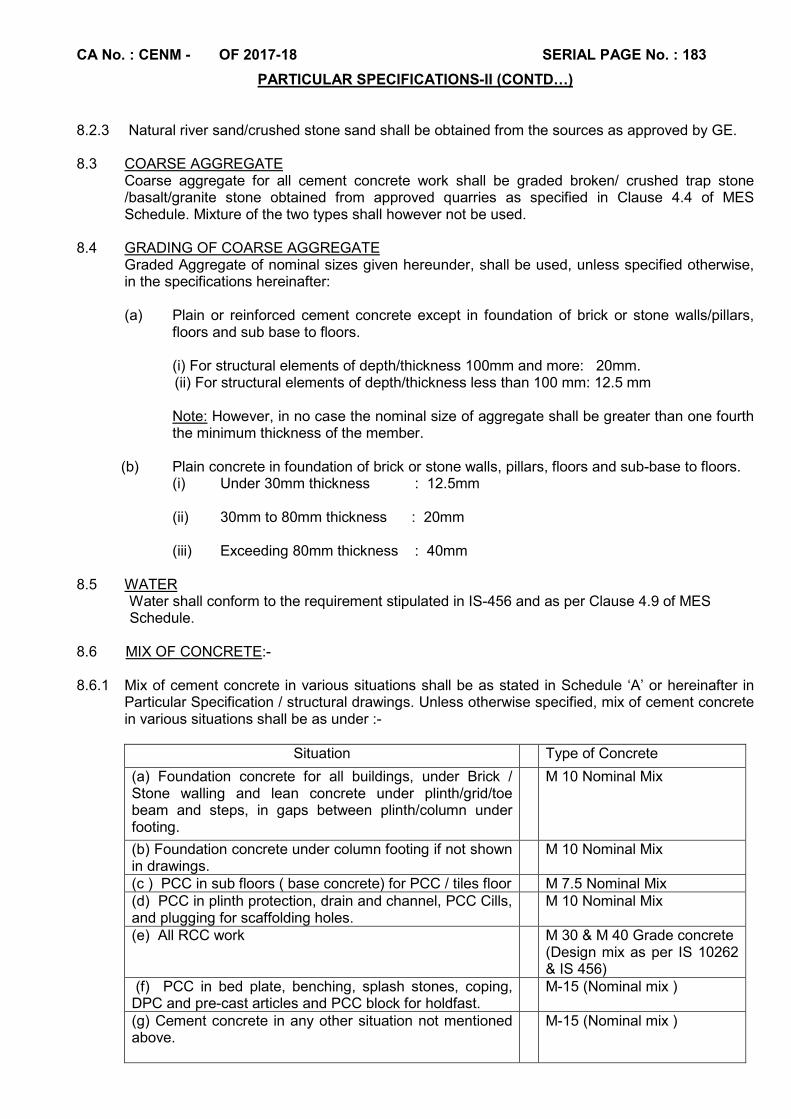
CA No. : CENM - OF 2017-18 SERIAL PAGE No. : 183
PARTICULAR SPECIFICATIONS-II (CONTD…) 8.2.3 Natural river sand/crushed stone sand shall be obtained from the sources as approved by GE. 8.3 COARSE AGGREGATE
Coarse aggregate for all cement concrete work shall be graded broken/ crushed trap stone /basalt/granite stone obtained from approved quarries as specified in Clause 4.4 of MES Schedule. Mixture of the two types shall however not be used.
8.4 GRADING OF COARSE AGGREGATE
Graded Aggregate of nominal sizes given hereunder, shall be used, unless specified otherwise, in the specifications hereinafter: (a) Plain or reinforced cement concrete except in foundation of brick or stone walls/pillars,
floors and sub base to floors. (i) For structural elements of depth/thickness 100mm and more: 20mm.
(ii) For structural elements of depth/thickness less than 100 mm: 12.5 mm Note: However, in no case the nominal size of aggregate shall be greater than one fourth the minimum thickness of the member.
(b) Plain concrete in foundation of brick or stone walls, pillars, floors and sub-base to floors.
(i) Under 30mm thickness : 12.5mm (ii) 30mm to 80mm thickness : 20mm (iii) Exceeding 80mm thickness : 40mm 8.5 WATER Water shall conform to the requirement stipulated in IS-456 and as per Clause 4.9 of MES Schedule. 8.6 MIX OF CONCRETE:- 8.6.1 Mix of cement concrete in various situations shall be as stated in Schedule ‘A’ or hereinafter in
Particular Specification / structural drawings. Unless otherwise specified, mix of cement concrete in various situations shall be as under :-
Situation Type of Concrete
(a) Foundation concrete for all buildings, under Brick / Stone walling and lean concrete under plinth/grid/toe beam and steps, in gaps between plinth/column under footing.
M 10 Nominal Mix
(b) Foundation concrete under column footing if not shown in drawings.
M 10 Nominal Mix
(c ) PCC in sub floors ( base concrete) for PCC / tiles floor M 7.5 Nominal Mix (d) PCC in plinth protection, drain and channel, PCC Cills, and plugging for scaffolding holes.
M 10 Nominal Mix
(e) All RCC work M 30 & M 40 Grade concrete (Design mix as per IS 10262 & IS 456)
(f) PCC in bed plate, benching, splash stones, coping, DPC and pre-cast articles and PCC block for holdfast.
M-15 (Nominal mix )
(g) Cement concrete in any other situation not mentioned above.
M-15 (Nominal mix )
CA No. : CENM - OF 2017-18 SERIAL PAGE No. : 184
PARTICULAR SPECIFICATIONS-II (CONTD…) 8.6.2 Small projects having total volume of concreting not exc. 30 Cum will be dealt as under:-
(a) A normal weigh-batching plant shall be utilized for these types of projects. The specifications of the plant shall be as under:-
(i) The plant shall be a three hopper plant. Three hoppers shall be used for cement, fine aggregate and coarse aggregate.
(ii) The plant shall be motorized.
(iii) Arrangements shall be made for addition of water by weight.
(b) The mix design shall be arrived at as per IS 10262-2009 after three trial mixes and shall be approved by the GE before the start of the work.
(c) Sampling of concrete shall be as per IS : 456-2000.
8.6.3 Medium and large Projects shall be dealt with as under:-
(i) Projects having concreting work of more than 30 Cum shall be considered as medium and large projects.
(ii) Concreting in these projects shall be carried out by any of the following ways at the option of contractor. However, no financial adjustment will be done if the contractor uses any of the two methods:-
(a) By procurement from an approved RMC plant.
(b) From an automatic computerized weigh batching plant installed at site by the contractor (As per details given here-in-after).
8.7 Minimum average slump for reinforced cement concrete and maximum water cement ratio for RCC M-30 & M-40 (design mix) and above grades shall be as specified in IS-456-2000. Design mix of RCC for various grades shall be all as per provisions catered for in IS-456-2000 duly considering the above requirements and minimum cement contents shall be as per relevant clauses in IS 456-2000. The exposure condition shall be considered as `SEVERE' unless otherwise specified in structural drawings. Accordingly the tenderers are advised to verify the quality of various ingredients available for incorporation in the subject work and quote accordingly. The tenderers are advised to note that if the cement contents works out to be less than the above specified minimum cement contents as mentioned hereinbefore, then the above specified minimum cement contents have to be incorporated and in case cement contents works out to be more than the above specified minimum cement contents ,then the cement as per design mix shall be provided without any extra cost to the department. The contractor shall have no claim in this regard due to misunderstanding of above provisions and decision of GE in this regard shall be final and binding.
8.8 READY MIX CONCRETE (RMC)
8.8.1 RMC as specified shall conform to IS : 4926-2003.
8.8.2 The contractor shall procure concrete from RMC manufacture as listed hereinafter .RMC plant if specifically set up from one of the listed manufacturer shall conform to IS 4926:2003.
8.8.3 Mix of the two types i.e. RMC and concrete in situ shall not be permitted for the same element of structure.
8.8.4 The contractor shall obtain a written approval from GE for the specific manufacturer from whom he intends to procure the RMC. GE shall verify the suitability of the plants for the particular project after considering all provisions given in IS:4926-2003. Following are some of the aspects to be verified by GE:-
(i) Output capacity of plant. Min output capacity for RMC plant shall be 30 CUM per hour or
as specified in CA.
CA No. : CENM - OF 2017-18 SERIAL PAGE No. : 185
PARTICULAR SPECIFICATIONS-II (CONTD…)
(ii) Pollution Under Check Certificate. The relevant and valid PUC certificate from
government agency shall be available for the plant.
(iii) Calibration Certificate :- Relevant and valid calibration certificate shall be checked for the
plant as well as for the testing machine
(iv) Transit Mixers:- The number and the condition of the transit mixers shall be satisfactory.
(v) Vicinity of the plant with respect to the site:- The distance between the plant and the site
shall be such as it may satisfy the transportation time as allowed in the IS code.
8.8.5 For projects at locations where movement of transit vehicles are restricted during day time contractor shall carry out the concreting work during night or late hours after obtaining necessary approval from the GE as well as users.
8.8.6 The contractor shall forward an information note as shown in Annex ‘D’ of IS : 4926 – 2003, duly countersigned by GE to the RMC supplier. A copy of the same shall be kept at site for verification.
8.8.7 MIX DESIGN
(i) The mix proportions intended to be used for the demanded mix shall be obtained from the manufacturer in writing and shall be verified by GE to ensure that these are complying with the provisions of IS : 456-2000 and IS : 10262.
(ii) The contractor shall also produce copies of the test certificate for the materials being used by the RMC manufacturer for the verification by the GE. GE shall give a provisional approval for the mix proportion based on this and work can commence accordingly. Final approval will be given only after verifying the 28 day cube strength of the first batch brought at site, as stated herein after at clause 8.8.9 (ii). However the contractor shall render undertaking to redo the work at “No extra cost to Govt” in the event of unsatisfactory results after 28 days test.
(iii) The use of admixture shall be as per the provisions of clause 5.5 of IS : 456 and the amount shall be based on the provisions of IS : 10262. The details of the admixture shall be clearly spelt out at serial no (c) and (d) of Part ‘B’ of the delivery ticket. In no case, amount of extra admixture shall be added at site to regain lost workability.
(iv) Admixtures shall be charged to the mixer at the same time in the mixing sequence for every batch. Liquid admixtures shall be charged with the water. Powdered admixture shall be sprinkled into the mixer with other dry ingredients. When more than one admixture is used, they shall be batched separately and they shall not be premixed before entering the mixer.
(v) The department executive shall have right to visit the RMC plant and collect raw materials being used for testing the same. Such test shall be conducted at least once in three months or after every 200 cum of concrete whichever is earlier.
(vi) The agreement between the RMC manufacturer and the contractor should ensure deployment of a qualified supervisor at plant site and random check by MES supervisor / executives.
8.8.8 BLANK
CA No. : CENM - OF 2017-18 SERIAL PAGE No. : 186
PARTICULAR SPECIFICATIONS-II (CONTD…) 8.8.9 SAMPLING
(i) The sampling criteria for testing of concrete received from the RMC plant shall be as per clause 6 of IS : 4926. One sample containing 9 cubes shall be prepared from each truck mix or 50 cum whichever is less. Out of this one specimen of 3 cubes shall be tested for 7 day strength. The min strength at 7 days shall be at least 2/3 of the specified strength as per clause 16 of IS : 456, acceptance criteria for concrete. The second set of 3 cubes shall be tested for 28 days strength. The third set of three cubes shall be kept for records and any further testing as required. It may be noted that the sampling criteria for concrete based on volume of concrete as specified in clause 15.2.2 of IS : 456 is not applicable for concrete procured from RMC plants. (ii) However the first batch of concrete of a particular grade received from a particular manufacturer shall be sampled by taking at least 12 cubes. These cubes shall be tested in the presence of the GE for confirmation before the final approval of the RMC manufacturer. These cubes shall be tested as follows:-
(a) Specimen of 3 cubes – for 7 days strength. In case these test report does not satisfy the requirement of 2/3rd of the acceptance criteria for 28 day strength, further supply and use of concrete from the particular manufacturer shall be suspended till the 28 day strength are available.
(b) Specimen of 6 cubes shall be tested for 28 day strength. The manufacturer shall be approved for supply if these values are acceptable as per clause 16 of IS : 456, (even if the cubes have failed during 7 day testing). If the reports are not satisfactory the supply from the manufacturer shall be suspended forth with. All the members already cast with these mixes shall be subjected to suitable NDT tests as specified and further corrective measures or demolition of such members and recasting shall be taken. The rates quoted by the contractor shall be deemed to be inclusive of the above and nothing extra shall be payable.
8.8.10 The concrete procured from Ready Mix concrete Plants should meet the requirements specified at the time of placing. Cost of admixture required for retardation of setting time and plasticizers for increasing workability and cost of transportation etc. shall be deemed to be included in the lump sum cost quoted by the Contractor .In case of his own plant established at site contractor has to submit mix design (for approval) from approved Labs such as IIT / NIT / SEMT Pune / Any NABL approved lab, which will be approved by GE. In all other cases when RMC is procured from the manufacturer listed or approved as hereinafter. Mix design shall be approved as specified in relevant clause hereinbefore. However contractor owes responsibility to get the required results after testing and will not have any claim whatsoever if the concrete from these listed makes are procured.
8.8.11 List of Approved RMC manufacturer’s is given below:-
(i) Lafarge India Pvt Ltd (ii) ACC Ready Mix concrete (iii) RMC, Ready Mix (India) Pvt. Ltd, (iv) Ultratech RMC Plant - Vapi (v) Godrej & Boyce Mfg Co. Ltd. (vi) Any other plant as approved by Accepting Officer
8.8.12 In the event of deviation involving price adjustment, though the contractor have used RMC in lieu of design mix, the rate applicable for RMC shall be as per SSR rate for RCC design mix concrete of corresponding grade adjusted with contractor’s quoted percentage.
8.8.13 When required, the RMC plant selected by the contractor shall provide information about the ingredient in the making RMC including admixture, used for RMC to GE. Admixtures for improving workability of concrete and extension of setting time shall be conforming to IS 6925 and IS 9103.
8.8.14 Placing and compaction of concrete shall conform to IS: 4926-2003
8.9 AUTOMATIC BATCHING PLANT INSTALLED AT SITE

CA No. : CENM - OF 2017-18 SERIAL PAGE No. : 187
PARTICULAR SPECIFICATIONS-II (CONTD…)
The contractor shall install a computer controlled automatic batching plant at site with the following specifications / batching procedure:-
(i) The installed capacity of the onsite plant shall be at least 15-20 Cum per hour. (ii) The plant shall conform to the provisions of IS:4926-2003. (iii) The batch mix plant for concrete shall be of minimum four bins, weighing hoppers and scale for fine aggregates and for each of coarse aggregates and for cement. The weighing hopper shall be properly sealed and vented to preclude dust during operation. Approved safety devices shall be provided and maintained for the protection of all personnel engaged in plant operation, inspection ant testing. The batch plant shall be equipped with a suitable non-resettable batch counter, which should correctly indicate the numbers of batches proportioned. The capacity of plant shall at least 25 percent higher than the proposed capacity of laying/paving equipment. (iv) Batch mix plant shall be equipped with automatic weighing devices using load cells for accurate proportions of aggregates and cement. All functions of the plant shall be from computerized controlled panel installed in air-conditioned control cabin. (v) Mixers– Mixer shall be pan type, capable of combining the aggregates, cement, admixtures and water into thoroughly mixed and uniform mass within the specific mixing period and of discharging the mixture without segregation. Stationary mixer shall be equipped with an approved timing device which will automatically lock the discharge, lever, when the drum has been charged and released at the end of the mixing period. The device shall be equipped with a bell or other suitable warning device adjusted to give a clearly audible signal each time the lock is released. In case of failure of the timing device, work will not be executed. However small quantity of emergent requirement can mixed in plant provided each batch is mixed for 90 seconds or as per the manufactures recommendation. The mixer shall be equipped with a suitable non-reset table batch counter, which correctly indicates the number of batches mixed.
(vi) Cleaning and maintenance of Mixer: - The mixer shall be cleaned at suitable intervals. The pickup and throw aver blades in the drums shall be repaired or replaced when they are warn down 20 mm or more. The contractor shall have available at the job site, a copy of the manufacturer’s design, showing dimensions and arrangements of blades in reference to original height and depth. (vii) Calibration of batching plant - Batching plant shall be calibrated in the beginning of work and thereafter at an interval of not exceeding one month. (viii) CWE shall be the competent authority for approval of batching plant.
8.9.1 LABORATORY MIX DESIGN AND TESTS As soon as possible, after receiving the order to commence work, the contractor shall procure sufficient quantities of required type of aggregates, cement and water and find their characteristics to suitability of the specifications in the laboratory approved.
8.9.2 The contractor shall get the design mix, from approved Institution IIT / NIT / SEMT Pune / Any
NABL approved lab, and shall produce the design for approval of CWE/GE(Independent) The contractor shall submit the approved materials along with the required information as per clause 9.1.2 of IS 456-2000 through Engineer-in-Charge to the institution carrying out the mix design. The mix design be carried out on the basis of laboratory trial mixes using approved materials and methods as per IS: 10262 (Recommended guide lines for Mix design) or on the basis of any other method in consultation with Garrison Engineer. The aggregate cement ratio and water cement ratio once decided based on Trial mix design shall not be changed without reference to GE. Any change in sources of coarse and fine aggregate and cement shall be informed to GE and accordingly a fresh mix design is to be submitted for approval. Calculation Details in support of mix design shall also be provided.
8.9.3 For design mix, it is an express condition that only weigh-batching shall be followed and no conversion of weights into volumes shall be permitted.
CA No. : CENM - OF 2017-18 SERIAL PAGE No. : 188
PARTICULAR SPECIFICATIONS-II (CONTD…)
8.9.4 Adequate number of tests at regular intervals shall be carried out to ascertain the properties of materials. In case of variation in grading of aggregate noticed at any point of time the same shall be made good by suitably blending of different sizes of aggregates wherever possible. If this is not feasible the mix design shall be changed immediately before carrying out further work. In case of change in source or quality of cement, fine aggregates or coarse aggregates, the design mix shall be revised as specified hereinabove.
8.9.5 SAMPLING
(i) The sampling and testing of concrete batched and mixed at site shall be carried out as per IS : 456 – 2000. (ii) The onsite tests for workability, cube strength tests etc. as specified shall be carried out.
8.10 RECORD OF ACTUAL CONSUMPTION OF CEMENT
Engineer-in-Charge shall maintain a record of actual consumption of cement in proper register (other than the cement register mentioned in special conditions) and initial the entry for every change in quantity of materials. The register maintained is solely for the purpose to cross check that the quantity consumed in the work and does not mean any proof for additional quantity of cement, if any, incorporated in the work due to site requirement or for any other reason and no claim of whatsoever nature will be entertained on this account
8.11 MIXING FOR SMALL QUANTITY 8.11.1 In case of small quantity of concrete (i.e. the quantity of concrete required being less than one
half the batch of mix), the contractor may, after obtaining written permission of the Engineer-in-Charge, be allowed hand mixing. Where hand mixing is permitted ,it shall be carried out on a water tight platform and care shall be taken to ensure that mixing is continued until the concrete is uniform in colour and consistency. However hand mixed concrete shall not be used for critical structural members such as shear walls, columns, beams, slabs, retaining walls etc.
8.11.2 Mixer performance checks shall be made at regular intervals to ensure uniformity of the concrete.
Visual examination of the concrete shall be one of the aid for maintaining and checking mixer performance.
8.12. TRANSPORTING : Transportation of concrete generally shall be carried out as specified in
Clause 4.11.9 of SSR Part I 2009. 8.12.1 RMC: Concrete from RMC plant shall be transported as specified here-in-below :
(a) The concrete shall be transported only in agitating type truck mixer. The concrete shall be discharged from the truck mixer within two hours after the concrete at the plant. The time of adding water to the cement at the batching plant shall be taken as the time of mixing the concrete. Further the concrete thus discharged shall be placed in position and compacted within 30 minutes, after delivery at site.
(b) Each truck arriving at site shall be accompanied with delivery ticket as specified is IS : 4926 Annexe ‘G’ clause 9.4. The following shall be recorded at site:-
(i) The locations where the particular batch is used. (ii) The workability of the concrete as measured at site.
(iii) The designation / Marking of the cubes prepared for testing from the batch.
8.12.2 AUTOMATIC BATCHING PLANT INSTALLED AT SITE
(a) The concrete shall be placed within 30 minutes after discharge from the automatic plant.
CA No. : CENM - OF 2017-18 SERIAL PAGE No. : 189
PARTICULAR SPECIFICATIONS-II (CONTD…)
(b) In case, the contractor’s automatic plant is located away from the location where concrete is to be placed and require mechanical transportation, the same shall be done in agitating type truck mixer as specified-in-before for transporting concrete from RMC plant.
8.13 PLACINGING AND COMPACTION OF CONCRETE
(a) Placing and compacting generally shall be carried out as specified in Clause 4.11.10 and 4.11.11 respectively of SSR Part I 2009.
(b) All concrete for RCC work shall be consolidated / compacted by mechanical vibrators approved type. Precast / cast-in-situ, plain cement concrete less than 100 mm thickness shall, however, be rammed and consolidated by tamping and rodding as specified in MES Schedule. (c) Concrete shall be transported using transit mixers/tippers without delay and incorporated in works at the position of laying within 30 minutes from the time of discharge from the mixer. Concrete shall be deposited and spread to such depths that when compacted and finished, it shall conform to the grade and cross section required and to ensure the thickness required.
(d) Concrete shall be deposited in such a manner as to require as little handling as possible. In case of dry and hot weather, this time shall not exceed 45 minutes.
8.14 PROTECTION AND CURING OF CONCRETE
This shall be carried out in accordance with specifications, given in clause No. 4.11.13 and 4.11.14 of MES Schedule Part I 2009.
8.15 NON DESTRUCTIVE TESTING OF HARDENED CONCRETE
(a) The Contractor shall provide a calibrated Rebound Hammer for testing of hardened concrete at site. The Rebound Hammer tests shall be conducted on all types of concrete members such as columns, beams, and soffit of slabs. The members to be tested shall be selected by Engr-in-Charge randomly but shall represent a fair sampling. At least 20% of the total number of members in each category may be tested. In order to have a mean value of the strength, the members shall be tested at least at 12 locations. The tests shall be conducted in the presence of GE/AGE(I). The results shall be recorded in a register showing the following data:
(i) Date of casting of the members. (ii) Date of testing. (iii) Type of member and location/identification of the members. (iv) Results. (v) Inference/Remarks. (vi) Signature of JE/AGE and GE.
(b) The test shall be conducted as per IS 13311(Part 2):1992. The test shall be conducted only after proper hardening of concrete. (c) The Hammer shall be calibrated at regular interval as specified hereinafter.
8.15.1 CALIBRATION OF HAMMER 8.15.1.1Specified mix shall be prepared by site engineers before undertaking any concrete work. Following
procedure shall be followed: (a) Minimum of 18 standard cubes shall be prepared and shall be counted as one specimen. (b) Out of the 18 cubes cast, 3 cubes shall be tested at 28 days strength. If the test results at 28 days is found satisfactory, then the remaining 15 cubes shall form the standard sample for calibration otherwise the samples shall be rejected and new samples shall be prepared.
CA No. : CENM - OF 2017-18 SERIAL PAGE No. : 190
PARTICULAR SPECIFICATIONS-II (CONTD…)
(c) All results shall be recorded in a separate register. (d) No concreting shall progress unless standard specimen cubes have been obtained. The criteria for acceptance and calibration of hammer shall remain to be 28 days strength. Concrete work shall be rejected if 28 days strength falls short as per acceptance criteria.
8.15.1.2 Three cubes shall be tested on 28 days to obtain a correlation between compressive strength of concrete and Rebound Number as per procedure described in para 5.2 of IS 13311(Part II):1992. The average values of the rebound number obtained in respect of same three cubes passing on 28 days work test shall form the datum reference for remaining cubes for the strength of cubes. Re-calibration of hammer shall be carried out after every 2000 tests.
8.15.2 Following procedure shall be followed for the Rebound Hammer Test:-
(a) The concrete cubes are held in Compressive Testing Machine under fixed load of 7N/mm2 when impact energy of the hammer is 2.2Nm. Measurements of the rebound hammer are taken and the compressive strength is determined as per IS 516:1959. (b) Wet cured specimen shall be removed from wet storage and kept in lab atmosphere for 24 hrs before testing.
(c) Only vertical faces of the cubes as cast shall be tested.
(d) At least nine readings shall be taken on each of the three vertical accessible faces of the cube in the compressive strength testing machine.
(e) The points of impact shall not be nearer than 20mm from the edge and shall not be less than 20mm from each other. The same point shall not be impacted more than once. (f) The rebound Number of the hammer shall be determined for each of the 18 or 12 (18-3-3) cubes.
(g) While recording the results, it will be necessary to distinguish between readings of the troweled face and those on the moulded face.
8.15.3 INTERPRETATION OF RESULT The results shall be interpreted as follows:- (a) Whenever individual cube rebound number varies + 25% from the datum reading, then that
cube shall be excluded and shall not be considered for standard specimen of cubes for calibration.
(b) It must be ensured that at least 8 out of 12 (66.67%) of the cubes are within permissible range of variation of rebound number. (c) If the above points (a) and (b) are not satisfied then the whole procedure shall be repeated. (d) 8 cubes shall form one standard sample before the commencement of the work and shall be made available for the inspecting Officer during the currency of the project. (e) This calibration shall be done by the executives with their hammer and then a chart of calibration giving the details of the average readings, date and the months of casting, mix of concrete etc shall be prepared and signed by the Engineer-in-charge and will be duly preserved for future reference as and when required.
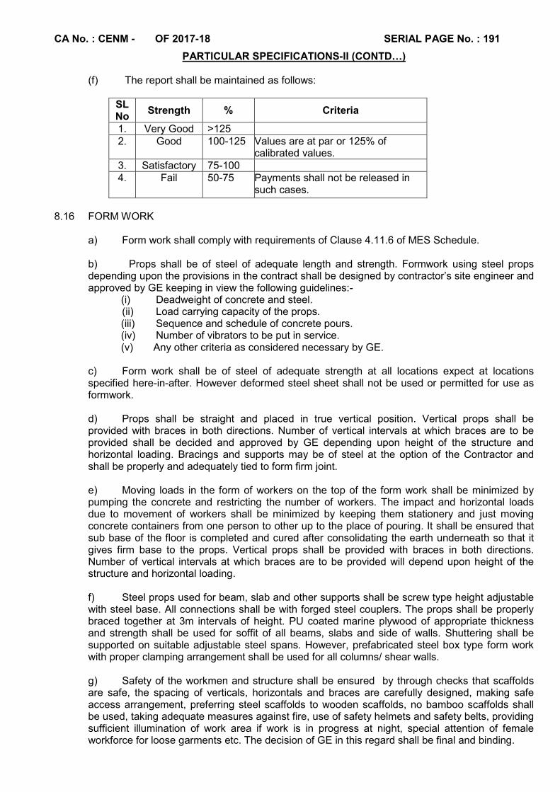
CA No. : CENM - OF 2017-18 SERIAL PAGE No. : 191
PARTICULAR SPECIFICATIONS-II (CONTD…)
(f) The report shall be maintained as follows:
SL No
Strength % Criteria
1. Very Good >125 2. Good 100-125 Values are at par or 125% of
calibrated values. 3. Satisfactory 75-100 4. Fail 50-75 Payments shall not be released in
such cases.
8.16 FORM WORK
a) Form work shall comply with requirements of Clause 4.11.6 of MES Schedule.
b) Props shall be of steel of adequate length and strength. Formwork using steel props depending upon the provisions in the contract shall be designed by contractor’s site engineer and approved by GE keeping in view the following guidelines:-
(i) Deadweight of concrete and steel. (ii) Load carrying capacity of the props.
(iii) Sequence and schedule of concrete pours. (iv) Number of vibrators to be put in service. (v) Any other criteria as considered necessary by GE.
c) Form work shall be of steel of adequate strength at all locations expect at locations specified here-in-after. However deformed steel sheet shall not be used or permitted for use as formwork.
d) Props shall be straight and placed in true vertical position. Vertical props shall be provided with braces in both directions. Number of vertical intervals at which braces are to be provided shall be decided and approved by GE depending upon height of the structure and horizontal loading. Bracings and supports may be of steel at the option of the Contractor and shall be properly and adequately tied to form firm joint.
e) Moving loads in the form of workers on the top of the form work shall be minimized by pumping the concrete and restricting the number of workers. The impact and horizontal loads due to movement of workers shall be minimized by keeping them stationery and just moving concrete containers from one person to other up to the place of pouring. It shall be ensured that sub base of the floor is completed and cured after consolidating the earth underneath so that it gives firm base to the props. Vertical props shall be provided with braces in both directions. Number of vertical intervals at which braces are to be provided will depend upon height of the structure and horizontal loading. f) Steel props used for beam, slab and other supports shall be screw type height adjustable with steel base. All connections shall be with forged steel couplers. The props shall be properly braced together at 3m intervals of height. PU coated marine plywood of appropriate thickness and strength shall be used for soffit of all beams, slabs and side of walls. Shuttering shall be supported on suitable adjustable steel spans. However, prefabricated steel box type form work with proper clamping arrangement shall be used for all columns/ shear walls. g) Safety of the workmen and structure shall be ensured by through checks that scaffolds are safe, the spacing of verticals, horizontals and braces are carefully designed, making safe access arrangement, preferring steel scaffolds to wooden scaffolds, no bamboo scaffolds shall be used, taking adequate measures against fire, use of safety helmets and safety belts, providing sufficient illumination of work area if work is in progress at night, special attention of female workforce for loose garments etc. The decision of GE in this regard shall be final and binding.
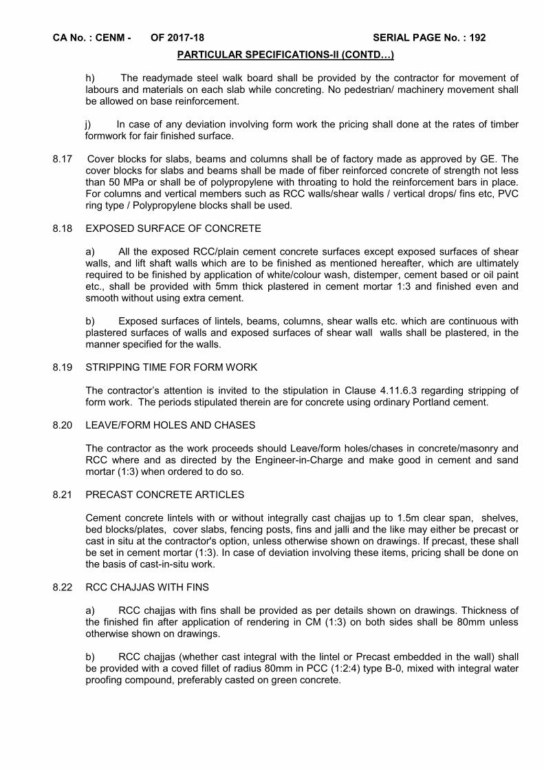
CA No. : CENM - OF 2017-18 SERIAL PAGE No. : 192
PARTICULAR SPECIFICATIONS-II (CONTD…)
h) The readymade steel walk board shall be provided by the contractor for movement of labours and materials on each slab while concreting. No pedestrian/ machinery movement shall be allowed on base reinforcement. j) In case of any deviation involving form work the pricing shall done at the rates of timber formwork for fair finished surface.
8.17 Cover blocks for slabs, beams and columns shall be of factory made as approved by GE. The
cover blocks for slabs and beams shall be made of fiber reinforced concrete of strength not less than 50 MPa or shall be of polypropylene with throating to hold the reinforcement bars in place. For columns and vertical members such as RCC walls/shear walls / vertical drops/ fins etc, PVC ring type / Polypropylene blocks shall be used.
8.18 EXPOSED SURFACE OF CONCRETE
a) All the exposed RCC/plain cement concrete surfaces except exposed surfaces of shear walls, and lift shaft walls which are to be finished as mentioned hereafter, which are ultimately required to be finished by application of white/colour wash, distemper, cement based or oil paint etc., shall be provided with 5mm thick plastered in cement mortar 1:3 and finished even and smooth without using extra cement. b) Exposed surfaces of lintels, beams, columns, shear walls etc. which are continuous with plastered surfaces of walls and exposed surfaces of shear wall walls shall be plastered, in the manner specified for the walls.
8.19 STRIPPING TIME FOR FORM WORK
The contractor’s attention is invited to the stipulation in Clause 4.11.6.3 regarding stripping of form work. The periods stipulated therein are for concrete using ordinary Portland cement.
8.20 LEAVE/FORM HOLES AND CHASES
The contractor as the work proceeds should Leave/form holes/chases in concrete/masonry and RCC where and as directed by the Engineer-in-Charge and make good in cement and sand mortar (1:3) when ordered to do so.
8.21 PRECAST CONCRETE ARTICLES
Cement concrete lintels with or without integrally cast chajjas up to 1.5m clear span, shelves, bed blocks/plates, cover slabs, fencing posts, fins and jalli and the like may either be precast or cast in situ at the contractor's option, unless otherwise shown on drawings. If precast, these shall be set in cement mortar (1:3). In case of deviation involving these items, pricing shall be done on the basis of cast-in-situ work.
8.22 RCC CHAJJAS WITH FINS
a) RCC chajjas with fins shall be provided as per details shown on drawings. Thickness of the finished fin after application of rendering in CM (1:3) on both sides shall be 80mm unless otherwise shown on drawings.
b) RCC chajjas (whether cast integral with the lintel or Precast embedded in the wall) shall be provided with a coved fillet of radius 80mm in PCC (1:2:4) type B-0, mixed with integral water proofing compound, preferably casted on green concrete.

CA No. : CENM - OF 2017-18 SERIAL PAGE No. : 193
PARTICULAR SPECIFICATIONS-II (CONTD…)
c) The top surface of chajjas / fins and the coved fillet shall be finished with 15mm thick cement plaster in CM 1:3 with mixture of approved water proofing compound as per manufacturer's instructions while the concrete is yet green viz. just after the initial setting has taken place.
8.23 THROATING/WEATHERING
Throating to projections or RCC/PCC beyond external faces of the walls where shown on drawings, and where RCC chajjas are not provided with downward facia shall be formed in the concrete while casting, by planting fillets/bar of 12mm diameter in the form work and finished smooth.
8.24 FITTINGS AND FIXTURES
All fittings / fixtures, sockets, pipes, sleeves etc. shown in RCC members shall be placed in position at the time of casting. Structural RCC members shall not be broken after hardening for passing of pipes or for fixing fixtures.
8.25 BEARINGS OF RCC STRUCTURAL MEMBERS
a) Bearings to all roof/floor slabs on masonry walls shall comprise of 20mm thick bearing plaster in CM (1:3) finished even and smooth with one coat of white wash applied and two layers of laminated water proofing building paper type - I conforming to IS-1308 weighing not less than 100 Gms/sq.m. Each layer laid over it. However, in case floor/roof slab rests on RCC beams/bands, this provision does not apply.
b) All RCC beams / lintels/ bressumers resting on masonry work shall be provided with PCC bed blocks cast in PCC (1:2:4) type B-1. Bed blocks shall be twice the width of beams in length covering the entire thickness of wall and of depth 150mm, unless otherwise shown on drawings.
c) The bearing of lintels shall be 15cms or effective depth, whichever is more, unless otherwise shown in drawings.
d) No treatment shall be provided under bearing of RCC bands.
8.26 PLINTH PROTECTION
Plinth protection in all situations as shown on drawings shall be provided with 75mm thick PCC (1:3:6) type C-1 over 100 mm thick consolidated bed of hard core (stone aggregate) grouted with fine sand over well consolidated sub grade. The width of the plinth protection shall be as shown on drawing. In the absence of width on drawing the same shall be considered as 750 mm. PCC shall be laid in alternate bays (not exceeding 2 square meters) and finished fair on top without using extra cement. 10mm wide joints shall be provided throughout the thickness of plinth protection in concrete bays, at every 3 metres interval, corners and turning points and also in between walling and plinth protection. All joints in bay, as well as between walling and the concrete in plinth protection shall be filled-in with mastic filling comprising 1 part of heated bitumen 85/25 or 90/10 grade and 3 parts of sand (all by weight).
8.27 CONCRETE PADDING
Where the required height of walls, openings, is not obtained with adequate size of bricks the same shall be obtained by providing PCC 1:3:6 type C-1.
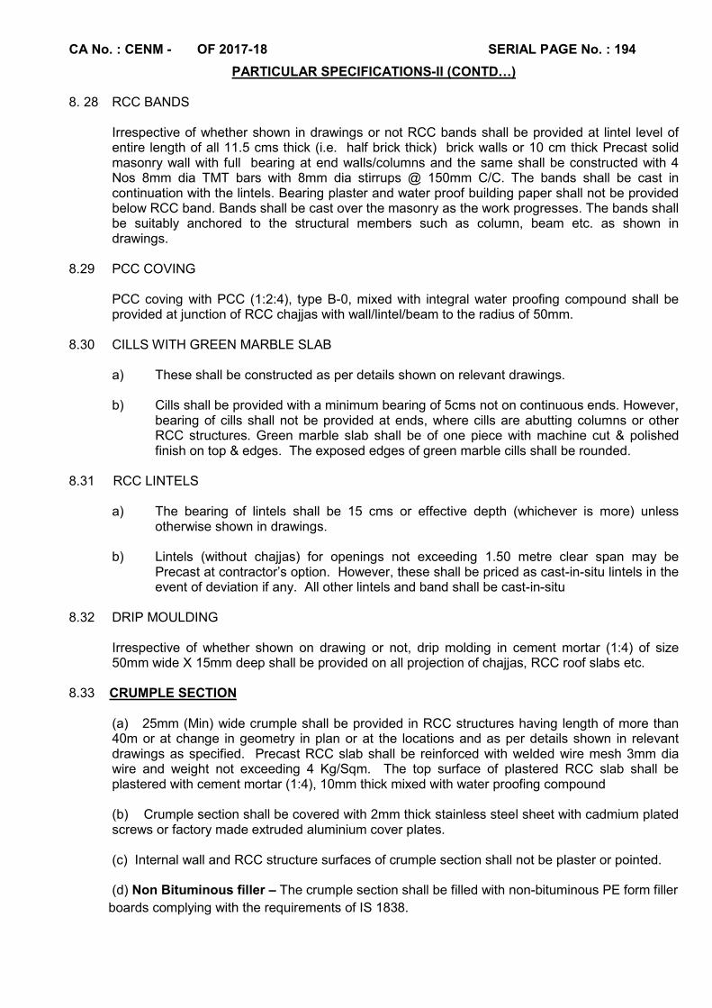
CA No. : CENM - OF 2017-18 SERIAL PAGE No. : 194
PARTICULAR SPECIFICATIONS-II (CONTD…) 8. 28 RCC BANDS
Irrespective of whether shown in drawings or not RCC bands shall be provided at lintel level of entire length of all 11.5 cms thick (i.e. half brick thick) brick walls or 10 cm thick Precast solid masonry wall with full bearing at end walls/columns and the same shall be constructed with 4 Nos 8mm dia TMT bars with 8mm dia stirrups @ 150mm C/C. The bands shall be cast in continuation with the lintels. Bearing plaster and water proof building paper shall not be provided below RCC band. Bands shall be cast over the masonry as the work progresses. The bands shall be suitably anchored to the structural members such as column, beam etc. as shown in drawings.
8.29 PCC COVING
PCC coving with PCC (1:2:4), type B-0, mixed with integral water proofing compound shall be provided at junction of RCC chajjas with wall/lintel/beam to the radius of 50mm.
8.30 CILLS WITH GREEN MARBLE SLAB
a) These shall be constructed as per details shown on relevant drawings.
b) Cills shall be provided with a minimum bearing of 5cms not on continuous ends. However, bearing of cills shall not be provided at ends, where cills are abutting columns or other RCC structures. Green marble slab shall be of one piece with machine cut & polished finish on top & edges. The exposed edges of green marble cills shall be rounded.
8.31 RCC LINTELS
a) The bearing of lintels shall be 15 cms or effective depth (whichever is more) unless otherwise shown in drawings.
b) Lintels (without chajjas) for openings not exceeding 1.50 metre clear span may be
Precast at contractor’s option. However, these shall be priced as cast-in-situ lintels in the event of deviation if any. All other lintels and band shall be cast-in-situ
8.32 DRIP MOULDING
Irrespective of whether shown on drawing or not, drip molding in cement mortar (1:4) of size 50mm wide X 15mm deep shall be provided on all projection of chajjas, RCC roof slabs etc.
8.33 CRUMPLE SECTION
(a) 25mm (Min) wide crumple shall be provided in RCC structures having length of more than 40m or at change in geometry in plan or at the locations and as per details shown in relevant drawings as specified. Precast RCC slab shall be reinforced with welded wire mesh 3mm dia wire and weight not exceeding 4 Kg/Sqm. The top surface of plastered RCC slab shall be plastered with cement mortar (1:4), 10mm thick mixed with water proofing compound (b) Crumple section shall be covered with 2mm thick stainless steel sheet with cadmium plated screws or factory made extruded aluminium cover plates.
(c) Internal wall and RCC structure surfaces of crumple section shall not be plaster or pointed. (d) Non Bituminous filler – The crumple section shall be filled with non-bituminous PE form filler
boards complying with the requirements of IS 1838.

CA No. : CENM - OF 2017-18 SERIAL PAGE No. : 195
PARTICULAR SPECIFICATIONS-II (CONTD…) 9. MASONRY:
Unless otherwise mentioned in drawing masonry work should be of of precast PCC solid block masonry all as specified hereinafter:
9.1 PRECAST PCC SOLID BLOCK MASONRY 9.1.1 The precast PCC solid block masonry where indicated on drawings shall be of grade C (5.0)
having block density of not less than 1800 Kg/cum. The concrete shall be mixed as laid down in IS-2185 (Part I)
9.1.2 AGGREGATES
(a) Coarse aggregate shall be crushed or natural aggregate 20mm and below size, conforming to IS-383.
(b) Fine aggregates (Sand / Crushed rock fines)shall be free from dust and well graded having fineness modulus 3.5 to 4 of combined aggregate conforming to IS-383.
9.1.3 The size of blocks shall be of one of the following:-
Size designation
Nominal Length CM
Breadth CM
Height CM
Actual Length CM
Breadth CM
Height CM
A 40 30 20 39 30 19
B 40 20 20 39 20 19 C 40 10 20 39 10 19 D 20 20 20 E 20 20 10 Sizes other than these specified above may also be used with the approval of Engineer-in-charge.
9.1.4 MANUFACTURE OF BLOCKS
(a) The blocks shall be machine made. The process of concrete mixing, fabrication/casting of blocks, curing and drying shall be in accordance with IS-2185 and all as specified in MES Schedule.
(b) Faces of the blocks shall be flat and rectangular. Wherever minor defects are observed in PCC blocks, surface finish shall be rendered smooth with cement mortar 1:3 (1 cement,3 coarse sand).
9.1.5 PHYSICAL REQUIREMENT.
(a) General All blocks shall be sound and free of cracks or other defects which interfere with proper placing of the block or impair the strength or performance of the construction. Minor chipping resulting from the customary methods of handling during delivery shall not be deemed ground for rejection.
(b) Tolerances The maximum variation in the dimension shall be not more than + 3.0 mm in height & breadth and + 5 mm for length.
(c) Block density The block density shall be as per IS-2185, (Part-I, 2005) for solid PCC block. It will not be less than 1800 Kg/Cum.
(d) Compressive Strength The Average compressive strength of eight blocks when determined in the manner described in IS-2185 shall not be less than 5.0 N/Sq mm of the gross area. The strength of the lowest individual block shall not be less than 80 percent of the average compressive strength of eight (8) blocks. (e) Water absorption
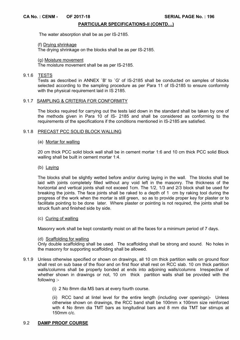
CA No. : CENM - OF 2017-18 SERIAL PAGE No. : 196
PARTICULAR SPECIFICATIONS-II (CONTD…)
The water absorption shall be as per IS-2185. (f) Drying shrinkage The drying shrinkage on the blocks shall be as per IS-2185.
(g) Moisture movement The moisture movement shall be as per IS-2185.
9.1.6 TESTS
Tests as described in ANNEX `B' to `G' of IS-2185 shall be conducted on samples of blocks selected according to the sampling procedure as per Para 11 of IS-2185 to ensure conformity with the physical requirement laid in IS 2185.
9.1.7 SAMPLING & CRITERIA FOR CONFORMITY
The blocks required for carrying out the tests laid down in the standard shall be taken by one of the methods given in Para 10 of IS- 2185 and shall be considered as conforming to the requirements of the specifications if the conditions mentioned in IS-2185 are satisfied.
9.1.8 PRECAST PCC SOLID BLOCK WALLING (a) Mortar for walling 20 cm thick PCC solid block wall shall be in cement mortar 1:6 and 10 cm thick PCC solid Block walling shall be built in cement mortar 1:4. (b) Laying The blocks shall be slightly wetted before and/or during laying in the wall. The blocks shall be laid with joints completely filled without any void left in the masonry. The thickness of the horizontal and vertical joints shall not exceed 1cm. The 1/2, 1/3 and 2/3 block shall be used for breaking the joints. The face joints shall be raked to a depth of 1 cm by raking tool during the progress of the work when the mortar is still green, so as to provide proper key for plaster or to facilitate pointing to be done later. Where plaster or pointing is not required, the joints shall be struck flush and finished side by side. (c) Curing of walling Masonry work shall be kept constantly moist on all the faces for a minimum period of 7 days. (d) Scaffolding for walling Only double scaffolding shall be used. The scaffolding shall be strong and sound. No holes in the masonry for supporting scaffolding shall be allowed.
9.1.9 Unless otherwise specified or shown on drawings, all 10 cm thick partition walls on ground floor
shall rest on sub base of the floor and on first floor shall rest on RCC slab. 10 cm thick partition walls/columns shall be properly bonded at ends into adjoining walls/columns Irrespective of whether shown in drawings or not, 10 cm thick partition walls shall be provided with the following :-
(i) 2 No 8mm dia MS bars at every fourth course.
(ii) RCC band at lintel level for the entire length (including over openings)- Unless otherwise shown on drawings, the RCC band shall be 100mm x 100mm size reinforced with 4 No 8mm dia TMT bars as longitudinal bars and 8 mm dia TMT bar stirrups at 150mm c/c.
9.2 DAMP PROOF COURSE
CA No. : CENM - OF 2017-18 SERIAL PAGE No. : 197
PARTICULAR SPECIFICATIONS-II (CONTD…)
(a) The damp proof course, where shown on drawings/specified, shall consist of 40mm thick layer of PCC M-15 (Nominal Mix) using aggregate of size 12.5mm and below, mixed with water proofing compound and one coat of blown bitumen 85/25 at the rate of 1.5 kg / Sqm applied over top of concrete to form thick layer and laid as specified in Para 5.42 of MES Schedule.
(b) Water proofing compound for damp proof course, shall conform to IS-2645. It shall be mixed with cement concrete in the proportion and manner as given in manufacturer's instructions. Deviations, if any, shall be priced at the rate of 3% by weight of cement.
(c) Damp proof course shall be provided in all the walls including dwarf walls where masonry starting from below the plinth level and is in touch with the soil layer from either outside or in the filling under floors.
(d) Damp proof course shall also be provided under door/openings below floor by providing a vertical DPC along the sides of the drop.
(e) Damp proof course shall be provided in all the cases where top of the plinth beam is below the FFL. Even in the cases where top of the plinth beam is above the normal GL but below the FFL, DPC is required. DPC shall not be provided in cases plinth beam is at par with the FFL and the top of the filling under the floors is at least 150mm below FFL.
9.3 CURING OR WATERING
Masonry work shall be kept constantly moist for a minimum period of 7 days. 10 WOOD WORK AND JOINERY
10.1 TIMBER (a) Timber for all joinery and wood work shall conform to specifications given in Clause 7.3 of the MES Schedule and shall be within the permissible limits of defects defined in Clauses 7.4 and 7.5 of the MES Schedule.
(b) Timber shall be well seasoned, whether air or kiln dried at the discretion of the contractor but without any price adjustments. The moisture content of timber shall not exceed the limits laid down vide Clause 7.7 of the MES Schedule. Adequate number of test shall be carried out by the Engineer-in-Charge to determine the moisture content in the timber to be used in the work and the contractor shall provide necessary facilities for test as required by Engineer-in-Charge without any extra cost to Government. Testing charges shall also be deemed to be included in lumpsum quoted by the contractor for Schedule “A” Part-I.
10.2 PRESERVATION OF TIMBER
(a) Preservative antitermite treatment shall be carried out to all wood work and joinery fabricated by the Contractor at site. Factory made ply/boards are deemed to be provided with antitermite treatment. (b) Chemical used for antitermite treatment to wood work and joinery shall be copper NAPTHANATE, ASCU or any other chemical specified in IS-401, applied in any one of the manners specified in ibid IS.
CA No. : CENM - OF 2017-18 SERIAL PAGE No. : 198
PARTICULAR SPECIFICATIONS-II (CONTD…)
(c) The species of timber for joinery/furniture items fabricated at site and prefabricated wood products i.e. particle board etc. shall be as specified hereunder:-
(i) Fully panelled or partly panelled/glazed/wire gauzed shutters.
Factory made shutters with styles / rails of second class hard wood as per IS-1003 (Part-I) of species LAUREL/ BIJASAL/ BENTEAK/ VENTEAK/ SAL, to be obtained from list of approved manufacturers given in Appendix `B'.
(ii) Frames of built-in cupboards /cabinets and furniture items, if indicated of timber.
IInd class Hard wood (Sal)
(iii) Wooden pelmets
Pelmets of particle boards shall be provided as specified hereinafter.
(iv) Edging/beading for particle/ block/medium density fibre board exposed to view in shutters, shelves and tops of built-in furniture, cupboards and cabinets.
Teak/Shisham wood.
(v) Gutties plugs, cleats/ stoppers, beading and fillets for shutters and frames.
Second class hardwood (Sal/ Kalasiris/Chaplash Hollock)
(vi) All other woodwork and joinery not otherwise specified.
Second class hardwood (Sal/ Kalasiris/ Chaplash/ Hollock).
(vii) Door frames
Second Class Hard Wood.(Sal)
10.3 A WOODEN CHOWKATS/FRAMES FOR DOORS AND WINDOWS
Wooden chowkats/frames for doors and windows shall generally confirm to clause 8.18 & 8.19 of
MES Schedule Part I and shall be provided at locations and as per the details shown on
drawings.
10.3 FACTORY MADE PANELLED DOOR SHUTTERS
10.3.1 Panelled door shutters and glazed / gauged shutters shall be factory made shutters conforming to IS-1003 (Part-I). Styles and rails shall be kiln seasoned and chemically treated by pressure process as per para 5.5 of IS-401 (under vacuum pressure). The dimensions and overall sizes shall however be as shown on drawings.
10.3.2 The thickness of door shutters shall be as shown on drawings and if not shown on drawings, the
same shall be 35mm. 10.3.3 If not shown on drawings panels for panelled door shutters shall be with 12mm thick particle
board BWR quality grade ‘A’ exterior grade solid core, general purpose commercial face veneer on both sides conforming to IS-3097. Panelled shutter shall be provided with suitable size wooden beading all round the panel insert on both the sides of the shutter.
10.4 FACTORY MADE SKELETON SHUTTER FOR MOSQUITO PROOF DOORS 10.4.1 Mosquito proof shutters where indicated on drawings shall be of factory made skeleton shutters
conforming to IS-1003 (Part-I) with second class hard wood styles and rails of species specified here-in-before and wire gauze as shown on drawings. The dimension and overall size shall however be as shown on drawings & If not shown the same shall be considered as 35mm thick.
10.4.2 Timber shall be of kiln seasoned and chemically treated by pressure process as specified in Para
5.5 of IS-401 (under vacuum pressure). 10.4.3 Other treatments to timber surfaces such as tarring, painting etc., shall be carried out in addition.
CA No. : CENM - OF 2017-18 SERIAL PAGE No. : 199
PARTICULAR SPECIFICATIONS-II (CONTD…) 10.5 Factory made panelled / skeleton shutters shall be obtained from any one of the manufacturers
specified here-in-after. Sample of shutters alongwith test certificates shall be produced to the GE for inspection and approval. Sample shutters shall be got approved from the GE before placing bulk order.
10.6 Factory made panelled / skeleton shutters may be obtained from any other manufacturer,
provided the same fulfill the following requirements:- (a) Shall conform to the specification given above. (b) Standard and quality are equal or superior to that of the products mentioned above. (c) Is approved by the Accepting Officer in writing before incorporation in the work.
10.7 Factory made shutters shall be brought to site before applying the primer and the shutters shall
be got passed by the Engineer-in-Charge before application of the primer. 10.8 PARTICLE BOARDS 10.8.1 Plain Particle board wherever shown on drawing or specified hereinafter shall be BWP grade
(Exterior grade) bonded with BWP quality phenol formaldehyde synthetic resin adhesive and confirm to IS 3087. Prelaminated Particle board wherever indicated on drawing or specified hereinafter shall be of decorative type provided with laminated decorative surfaces and shall conform to IS-12823.
10.8.2 Edges of shutters where indicated on drawing of particle boards, shall be provided with 4mm
edging of wood specified hereinbefore. 10.9 PLYWOOD
All plywood where indicated on drawings shall be BWP grade conforming to IS-303. Decorative
lamination where indicated in drawings shall conform to IS-1328.
10.10 WORKMANSHIP 10.10.1 Joinery shall be wrought all over. Timber surface exposed to view shall be wrought and for
surface not exposed to view shall be clean sawn. The workmanship and fixing of joinery shall be as per Clauses 8.15 to 8.19.4 of MES Schedule Part I (2009).
10.10.2 The dimensions of the various components of joinery (other than block board shutters) shown on
drawings, wherever at variance, shall supersede the standard dimensions mentioned in the MES Schedule. However for pricing deviations involving any joinery work, the rates in the MES Schedule for the corresponding joinery shall be applicable.
10.10.3Unless otherwise specified, all work both carpenter's and joineries shall have full dimension
shown on drawings except that an allowance of 1.5 mm shall be allowed for each wrought face. Wooden beads and fillets shall however, hold the full dimensions as shown on drawings. The contractor shall also maintain the overall sizes of the doors and windows etc., as shown on drawings.
10.10.4 Timber member’s upto 3.00 metre length shall be in one piece. 10.10.5 Plugging to walls shall be done with wooden plugs as per Clause 7.29 of the MES Schedule and
specified hereinbefore.
10.10.6 2mm thick PVC sheet to a height 200mm shall be provided to both sides and also at bottom edge of all door shutters of kitchen, unless other material is indicated on drawings.
CA No. : CENM - OF 2017-18 SERIAL PAGE No. : 200
PARTICULAR SPECIFICATIONS-II (CONTD…) 10.10.7 Vertical members of wooden doorframes shall be embedded 40mm deep below FFL. All door
shutters shall have 2 to 3mm clearances above FFL. 10.10.8 ---------------Blank------------------------------------ 10.10.9 ---------------Blank------------------------------------ 10.10.10 ---------------Blank------------------------------------ 10.11 SOLID PVC DOORS AND FRAMES FOR WC & BATH 10.11.1 All door shutters and frames of WCs, Wash and toilets shall be of PVC as shown on drawing
(a) PVC doors and PVC frames for doors shall be solid core factory made confirming to the specifications given in SSR and shall be of Make: i) Rajshri Plasti wood Ltd. ii) Sintex Industries Pvt. Ltd. or equivalent as approved by GE. (b) Solid PVC door frame of size 50mm x 47mm made out of 5 mm thick wood grains printed PVC sheet reinforced with MS square tube and edges and painted to match with printed sheet. (c) 30mm thick (style) factory made solid panel PVC door shutter consisting of frame made out of M.S tubes for top & bottom rails. M.S frame shall be covered with heat moulded plain colour PVC 'C' channel having a PVC sheet strip of 20mm width stuck inside with solvent cement for stiles and plain colour PVC sheets for top rail lock rail & bottom rail on either side & as gap insert for rail & bottom rail; panelling of plain colour PVC sheet to be fitted in the M.S frame welded/ sealed to the stiles & rail with suitable PVC sheet beading, and joined together with solvent cement, in the frame. (d) Shutters shall be in depressed panel design and colors as approved by GE and shall be include extra reinforcement on edges. Shutter shall have recesses to take hinge to fix frame. The whole shutter shall have resistant to mild acid /alkali. Aluminium/iron mongery to PVC shutter shall be fixed as per manufacturer’s instructions. Any tenderer offering PVC shutter with more thickness of PVC will not be paid anything extra Cost to dept. (e) Testing of PVC doors and chowkhats shall be got carried out as per IS: 4020 form Govt. approved laboratory if decided by GE. Cost of testing, transportation of samples etc. to approved laboratory shall be borne by the contractor.
10.12 ALUMINIUM DOORS / WINDOWS / VENTILATORS 10.12.1 Aluminium doors / windows / ventilators shall generally confirm to clause 10.37 of MES
Schedule Part I and shall be provided at locations and as per the details shown on drawings. Aluminium doors/windows/ventilators shall be made out of extruded aluminium sections and shall be powder coated of thickness not less than 50 micron of colour approved by GE. Sections of Aluminium doors / windows / ventilators shall be obtained from any of the firm as listed in Appendix `B'.
10.12.2 Unless otherwise shown on drawing Glazing of aluminium doors / windows / ventilators shall be
with sheet glass ordinary quality conforming to IS-2835 -1977 and thickness of sheet glass shall be 4 mm for panes not exc.0.5 Sqm each and panes exceeding 0.5 Sqm shall be provided with 4.80 mm. Glazing for WC/ toilet shall be figured glass conforming to IS-5437, 1969 & thickness shall be 4.80mm and for aluminium door sheet/float glass confirming to IS-2835 and of thickness 5.5 to 6.0mm.
10.12.3 All fittings to aluminium doors / windows / ventilators shall be as per the manufacturers
instructions.
CA No. : CENM - OF 2017-18 SERIAL PAGE No. : 201
PARTICULAR SPECIFICATIONS-II (CONTD…) 10.12.4 (a) Aluminium sections shall be “Jindal Aluminium Company” as mentioned in drawing for
aluminium doors and aluminium windows and ventilators as per drawings and dimensions shall be as mentioned in Architectural drawings. Contractor may procure the Aluminium sections from the other manufactures as given in Appendix ‘B’ equivalent to sections of Jindal Aluminium Company. In case the weight of sections is more than that of ‘Jindal Aluminium Company ’, No extra cost shall be paid on this account. However in case of less weight of sections minus price adjustment will be done.
(b) Where shown on the drawings, Aluminium windows and ventilators shall be provided with Aluminium grills. Size of grills unless shown on drawing shall be DG (104) of size (10X5.2) mm of make Deco grill or equivalent.
10.12.5 Where shown on the drawings, Aluminium windows and Ventilators shall be provided with fly
proofing shutters of aluminium XPM jalli 24 gauge thicknesses & average 1.40mm width of aperture to be provided all as specified/shown in drawing. Aluminium door shall be provided with fly proofing shutters and grills of specification have been shown in drawings. Aluminium sections shall be obtained from any of firm as listed in Appendix `B'.
10.12.6All other specifications for these aluminium doors/ windows/ ventilators shall be as per the
relevant drawings mentioned in the list of drawings. 11 BUILDERS HARDWARE 11.1 All articles of iron mongery (Builder's Hardware) shall generally conform to the specifications
given in section 9 of MES Schedule Part I. The contractor shall produce the samples of each article of builder’s hardware which he proposes to use and get the same approved in writing by the Garrison Engineer. Articles of builder’s hardware shall bear ISI mark, wherever available.
11.2 The type of builder's hardware shall be as follows:-
(a) Butt hinges shall be of stainless steel (with stainless steel pin) and shall be of bright finish with smooth surface.
(b) Double / single action spring hinges and catches shall be of mild steel. (c) Coat hooks/pegs shall be of Brass chromium plated.
(d) All other articles / fittings of builder's hardware shall be of extruded sections, aluminium anodised white unless superior specification than above has been mentioned in drawings. Thickness of anodising shall be 15 microns.
(e) All hardware shall be fixed with steel cadmium plated screws. 11.3 The type pattern and size of aluminium anodised fittings shall be as follows:-
(a) Aldrop bolts (sliding door bolt) shall be provided to doors where indicated on these shall be with hasp and staples (bolt type) and fixing clips etc. complete and shall conform to IS-2681. Aldrop bolts shall be fixed with nuts and bolts only.
(b) Hasp and staples shall be of safety pattern plate type.
(c) Hooks and eyes shall be plate type and the hooks shall be out of extruded section.
(d) Door handles shall be of plain pattern with back plate. The diameter of the bars shall be 10mm.
(e) Barrel bolt/tower bolts shall be provided with 10mm dia shoot upto 150mm and 12mm dia shoot above 150mm.
(f) Sliding latch shall be 200mm long of 15.5 x 9mm flat slide.

CA No. : CENM - OF 2017-18 SERIAL PAGE No. : 202
PARTICULAR SPECIFICATIONS-II (CONTD…)
(g) Wherever shown on drawing, magic eye shall be provided in the main entrance door of each quarter as approved by GE.
(h) Screws for all fittings shall match the respective fittings, both in materials and finish except that screws for anodised aluminium fittings shall be of steel cadmium plated.
(i) Piano type hinges shall be continuous type and shall be of stainless steel, bright finish.
(k) All Aluminium Doors shall be provided with Self closing system of Hydraulically regulated
exposed type door closure all as specified in Para 9.16.1, Section 9 of SSR Part-I-2009.
12.0 STEEL AND IRON WORK
12.1 All steel required for the work under the Contract shall be procured, supplied and in the work by the Contractor under his own agreement.
12.2 GRADES & QUALITY Steel supplied by the Contractor shall conform to the following grades and quality:
(a) Steel for concrete reinforcement shall be provided at locations as shown on drawing and as specified here-in-after:- (i) Irrespective of whatsoever is specified elsewhere, all steel for reinforcement shall be corrosion resistant steel of grade SAIL 500D HRC/TATA TISCON CRSD (Fe 500D)/ RINL CRS Fe 500D or equivalents of other manufacturer as specified, conforming to IS-1786. If bars of above grades are not available due to manufacturing status, next higher grade may be used without revising the design and without any price adjustment. (ii) Where indicated as HIGH YIELD STRENGTH DEFORMED BARS, it shall be corrosion resistant steel as specified above, conforming to IS-1786-1985 (Reaffirmed 1990) & grades Fe 500D/Fe 550D. (b) Structural steel
(i) Structural steel standard quality shall be of grade E 250 (Fe 410W quality) conforming to IS 2062-2006. This type of steel shall be provided in the locations mentioned in clause 10.4.1 of MES Schedule Part I. (ii) Structural steel ordinary quality shall be of grade E 165 (Fe 290 quality) conforming to IS 2062-2006. This type of steel shall be used for structure not subjected to dynamic loading. This type of steel will not be used where welding is used in fabrication and in the areas falling in the earth quack zone where severe damage is expected and design of structure is based on plastic theory. This type of steel shall be provided in the locations specified in clause 10.4.2 of MES Schedule Part-I.
(c) Hard drawn steel wire fabric for concrete reinforcement: Fabric reinforcement shall conform to IS-1566, 1982.
Note: Any items of steel specified in clause 12.2 (a) to (c) above not conforming in grade and quality shall be rejected and the rejected steel items under the particular consignment shall be removed from the site by the Contractor at his own cost within 7 (seven) days. The Contractor will have no claim whatsoever on this account.
12.3 SOURCE OF PROCUREMENT
(a) Structural Steel
CA No. : CENM - OF 2017-18 SERIAL PAGE No. : 203
PARTICULAR SPECIFICATIONS-II (CONTD…)
The contractor shall procure structural steel from the main producer viz., (i) SAIL (ii) TATA TISCO (iii) Rashtriya Ispat Nigam Ltd/Primary Producers viz (a) M/s Jindal Steels and Power Ltd, Brand : “JINDAL”, Jindal centre, Plot No. 2, Sector – 32, Gurgaon – 122001, Haryana, Tele: 0124-661 2000, Fax: 0124-661 2125, Website: www.jindalsteelpower.com (Angle, Beam, Column, Channel & Plate). In case of non availability with primary producers, structural steel can be procured from approved Secondary producers with a reduction of 5%(Five Percent) of the accepted rate of structural steel. In case the desired section of structural steel is not rolled/ manufactured by primary producers, there shall be no price adjustment in use of structural steel procured from approved secondary producers. A list of such firms is enclosed as Appendix ‘G’ for guidance.
(b) TMT Steel Steel required for the work shall be procured by contractor from Primary Producers viz.,
Sl No.
Firm Name & Brand Address Size / Dia and Type
1 2 3 4 (i) Steel Authority of India
Limited (SAIL) Brand: “SAIL”
Central Marketing Organization, Northern Region, 17
th Floor, Scope
Minar, Laxmi Nagar Distt. Centre Delhi – 110 092
-
(ii) Tata Iron & Steel Company (TISCO or Tata Steel) Brand: “TATA”
Bombay House, 2, 4 Homi Modi Street, Mumbai – 400 001, India, Tel : (91 22) 204 9131, Fax :(91 22) 204 9522, 287 0840, Email: [email protected] (Br office for North : Jeevan Tara Bldg, Patel Chowk , New Delhi)
-
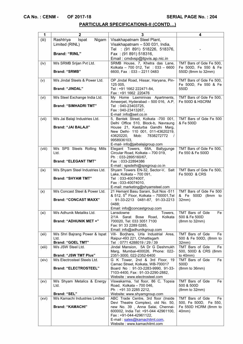
CA No. : CENM - OF 2017-18 SERIAL PAGE No. : 204
PARTICULAR SPECIFICATIONS-II (CONTD…)
1 2 3 4 (iii) Rashtriya Ispat Nigam
Limited (RINL) Brand: “RINL”
Visakhapatnam Steel Plant, Visakhapatnam – 530 031, India, Tel : (91 891) 518226, 518376, Fax : (91 891) 518316, Email : [email protected]
-
(iv) M/s SRMB Srijan Pvt Ltd. Brand: “SRMB”
SRMB House, 7, Khetra das Lane, Kolkata – 700 012, Tel : 033 – 6600 6600, Fax : 033 – 2211 0483
TMT Bars of Gde Fe 500, Fe 500D, Fe 550 & Fe 550D (8mm to 32mm)
(v) M/s Jindal Steels & Power Ltd. Brand: “JINDAL”
OP Jindal Road, Hissar, Haryana, Pin-125 005, Tel : +91 1662 222471-84, Fax : +91 1662 220476
TMT Bars of Gde Fe 500, Fe 500D, Fe 550 & Fe 550D
(vi) M/s Steel Exchange India Ltd. Brand: “SIMHADRI TMT”
My Home Laxminivas Apartments, Ameerpet, Hyderabad – 500 016, A.P, Tel : 040-23403725, Fax : 040-23413267, E-mail :[email protected]
TMT Bars of Gde Fe 500, Fe 500D & HSCRM
(vii) M/s Jai Balaji Industries Ltd. Brand: “JAI BALAJI”
5, Bentek Street, Kolkata -700 001, Delhi Office 510, Block-b, Navraung House 21, Kasturba Gandhi Marg, New Delhi- 110 001, 011-43620219, 43620220, Mob: 7838272772 / 9958936103, E-mail- [email protected]
TMT Bars of Gde Fe 500 & Fe 500D
(viii) M/s SPS Steels Rolling Mills Ltd. Brand: “ELEGANT TMT”
Elegant Towers, 68A, Ballygunge Circular Road, Kolkata – 700 019, Ph : 033-2895160/67, Fax : 033-22894386 E-mail : [email protected]
TMT Bars of Gde Fe 500, Fe 550 & Fe 500D
(ix) M/s Shyam Steel Industries Ltd. Brand: “SHYAM TMT”
Shyam Towers EN-32, Sector-V, Salt Lake, Kolkata – 700 091, Tel : 033-40074007, Fax : 033-40074010, E-mail: [email protected]
TMT Bars of Gde Fe 500, Fe 500D & CRS
(x) M/s Concast Steel & Power Ltd. Brand: “CONCAST MAXX”
21 Hemant Basu Sarani, Suit Nos -511 & 512, 5
th Floor, Kolkata – 700001,Tel
: 91-33-2213 0481-87, 91-33-2213 0488; Email: [email protected]
TMT Bars of Gde Fe 500 & Fe 500D (8mm to 32mm)
(xi) M/s Adhunik Metaliks Ltd. Brand: “ADHUNIK MET +”
Lansdowne Towers, 2/1A Sarat Bose Road, Kolkata 700020, Tel: 033 3051 7100 Fax: 91 33 2289 0285, Email: [email protected]
TMT Bars of Gde Fe 500 & Fe 500D (8mm to 32mm)
(xii) M/s Shri Bajrang Power & Ispat Ltd. Brand: “GOEL TMT”
Vill- Borjhara, Urla Industrial Area, Raipur-493 221, Chhattisgarh Tel : 0771 4288019 / 29 / 39
TMT Bars of Gde Fe 500 & Fe 500D, (8mm to 32mm)
(xiii) M/s JSW Steel Ltd. Brand: “JSW TMT Plus”
Jindal Mansion, 5A Dr G Deshmukh Marg, Mumbai-400026, Phone: 022-2351-3000, 022-2352-6400
TMT Bars of Gde Fe 500, 500D & CRS (8mm to 40mm)
(xiv) M/s Electrosteel Steels Ltd. Brand: “ELECTROSTEEL”
G K Tower, 2nd & 3rd Floor, 19 Camac Street, Kolkata, WB-700017 Board No : 91-33-2283-9990, 91-33-7103-4400, Fax : 91-33-2290-2882, Website : www.electrosteel.com
TMT Bars of Gde Fe 500D (8mm to 36mm)
(xv) M/s Shyam Metalics & Energy Ltd. Brand: “SEL”
Viswakarma, 1st floor, 86 C, Topsia Road, Kolkata – 700 046, Ph : +91 33 2285 2212, Website: www.shyamgroup.com
TMT Bars of Gde Fe 500 & 500D (8mm to 32mm)
(xvi) M/s Kamachi Industries Limited Brand: “KAMACHI”
ABC Trade Centre, 3rd floor (Inside Devi Theatre Complex), old No. 50, new No. 39 , Anna Salai, Chennai-600002, India Tel: +91-044 42961100, Fax : +91-044-42961122, E-mail : [email protected], Website : www.kamachitmt.com
TMT Bars of Gde Fe 500, Fe 500D, Fe 550, Fe 550D HCRM (8mm to 40mm)
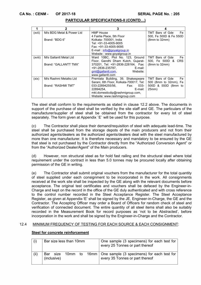
CA No. : CENM - OF 2017-18 SERIAL PAGE No. : 205
PARTICULAR SPECIFICATIONS-II (CONTD…)
1 2 3 4 (xvii) M/s BDG Metal & Power Ltd
Brand: “BDG 6”
HMP House 4 Fairlie Place, 5th Floor Kolkata- 700001, India Tel: +91-33-4005-9005 Fax: +91-33-4005-9095 E-mail : [email protected] Website : www.goyalgroup.in
TMT Bars of Gde Fe 500, Fe 500D & Fe 550D (8mm to 32mm)
(xviii) M/s Gallantt Metal Ltd Brand: “GALLANTT TMX”
Ward 10BC, Plot No. 123, Ground Floor, Gandhi Dham Kutch, Gujarat-370201, Tel: +91-2836-228164, Fax: +91-2836-235787, E-mail: [email protected], Website: www.gallantt.com
TMT Bars of Gde Fe 500, Fe 500D & CRS (8mm to 32mm)
(xix) M/s Rashmi Metalks Ltd Brand: “RASHMI TMT”
Premlata Building, 39, Shakespeare Sarani, 6th Floor, Kolkata-700017, Tel: 033-22894255/56, Fax: 033-22894254, E-mail: [email protected], Website: www.rashmigroup.com
TMT Bars of Gde Fe 500 (8mm to 32mm), Fe 500D & 550D (8mm to 25mm)
The steel shall conform to the requirements as stated in clause 12.2 above. The documents in support of the purchase of steel shall be verified by the site staff and GE. The particulars of the manufacturer/supplier of steel shall be obtained from the contractor for every lot of steel separately. The form given at Appendix `E` will be used for this purpose. (c) The Contractor shall place their demand/requisition of steel with adequate lead-time. The steel shall be purchased from the storage depots of the main producers and not from their authorized agents/dealers as the authorized agents/dealers deal with the steel manufactured by more than one manufacturer. It is therefore necessary and mandatory to be ensured by the GE that steel is not purchased by the Contractor directly from the “Authorized Conversion Agent” or from the “Authorized Dealer/Agent” of the Main producers.
(d) However, non structural steel as for hold fast railing and the structural steel where total
requirement under the contract in less than 5.0 tonnes may be procured locally after obtaining permission of the GE in writing.
(e) The Contractor shall submit original vouchers from the manufacturer for the total quantity of steel supplied under each consignment to be incorporated in the work. All consignments received at the work site shall be inspected by the GE along with the relevant documents before acceptance. The original test certificates and vouchers shall be defaced by the Engineer-in-Charge and kept on the record in the office of the GE duly authenticated and with cross reference to the control number recorded in the Steel Acceptance Register. The Steel Acceptance Register, as given at Appendix-‘E’ shall be signed by the JE, Engineer-in-Charge, the GE and the Contractor. The Accepting Officer may order a Board of Officers for random check of steel and verification of connected document. The entire quantity of all steel items shall also be suitably recorded in the Measurement Book for record purposes as ‘not to be Abstracted’, before incorporation in the work and shall be signed by the Engineer-in-Charge and the Contractor.
12.4 MINIMUM FREQUENCY OF TESTING FOR EACH SOURCE & EACH CONSIGNMENT:
Steel for concrete reinforcement
(i) Bar size less than 10mm One sample (3 specimens) for each test for every 25 Tonnes or part thereof
(ii) Bar size 10mm to 16mm (inclusive)
One sample (3 specimens) for each test for every 35 Tonnes or part thereof
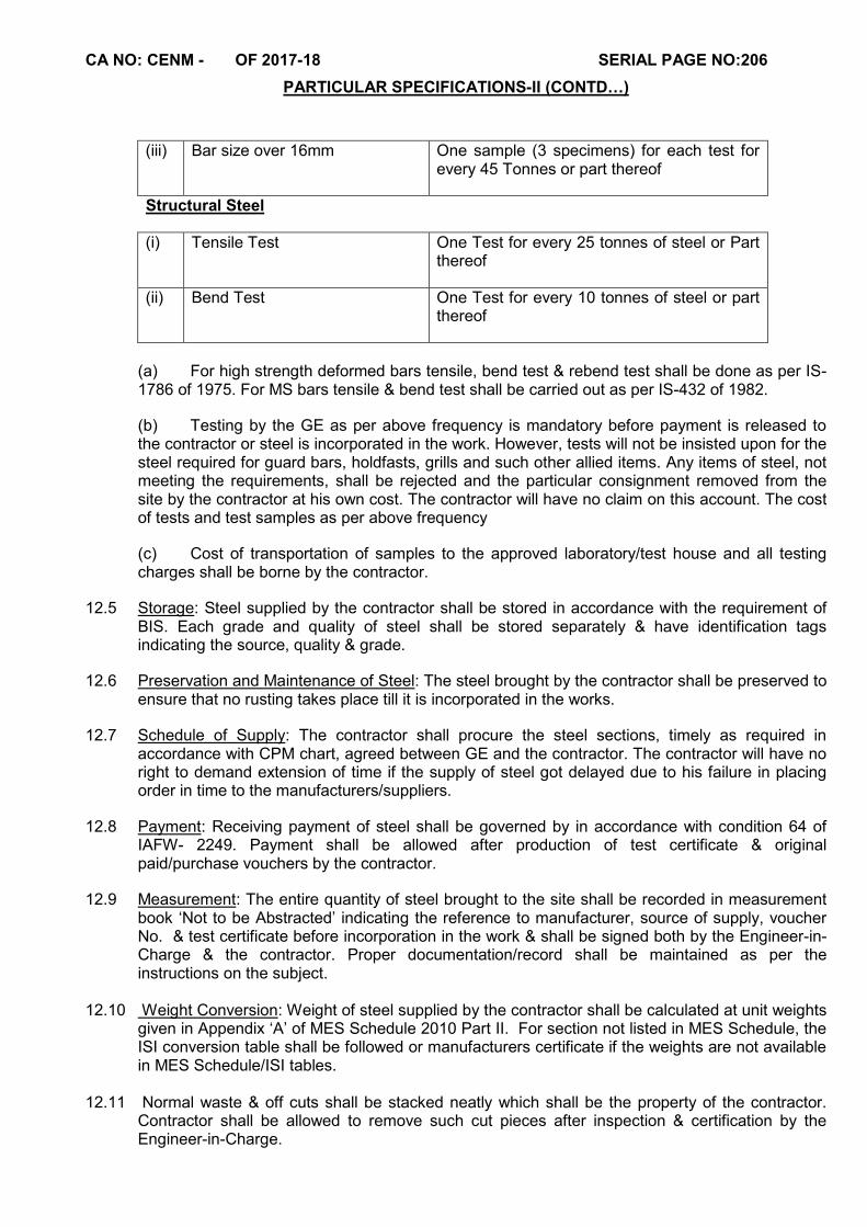
CA NO: CENM - OF 2017-18 SERIAL PAGE NO:206
PARTICULAR SPECIFICATIONS-II (CONTD…)
(iii) Bar size over 16mm One sample (3 specimens) for each test for every 45 Tonnes or part thereof
Structural Steel
(i) Tensile Test One Test for every 25 tonnes of steel or Part thereof
(ii) Bend Test One Test for every 10 tonnes of steel or part thereof
(a) For high strength deformed bars tensile, bend test & rebend test shall be done as per IS-1786 of 1975. For MS bars tensile & bend test shall be carried out as per IS-432 of 1982.
(b) Testing by the GE as per above frequency is mandatory before payment is released to the contractor or steel is incorporated in the work. However, tests will not be insisted upon for the steel required for guard bars, holdfasts, grills and such other allied items. Any items of steel, not meeting the requirements, shall be rejected and the particular consignment removed from the site by the contractor at his own cost. The contractor will have no claim on this account. The cost of tests and test samples as per above frequency
(c) Cost of transportation of samples to the approved laboratory/test house and all testing charges shall be borne by the contractor.
12.5 Storage: Steel supplied by the contractor shall be stored in accordance with the requirement of BIS. Each grade and quality of steel shall be stored separately & have identification tags indicating the source, quality & grade.
12.6 Preservation and Maintenance of Steel: The steel brought by the contractor shall be preserved to ensure that no rusting takes place till it is incorporated in the works.
12.7 Schedule of Supply: The contractor shall procure the steel sections, timely as required in accordance with CPM chart, agreed between GE and the contractor. The contractor will have no right to demand extension of time if the supply of steel got delayed due to his failure in placing order in time to the manufacturers/suppliers.
12.8 Payment: Receiving payment of steel shall be governed by in accordance with condition 64 of IAFW- 2249. Payment shall be allowed after production of test certificate & original paid/purchase vouchers by the contractor.
12.9 Measurement: The entire quantity of steel brought to the site shall be recorded in measurement book ‘Not to be Abstracted’ indicating the reference to manufacturer, source of supply, voucher No. & test certificate before incorporation in the work & shall be signed both by the Engineer-in-Charge & the contractor. Proper documentation/record shall be maintained as per the instructions on the subject.
12.10 Weight Conversion: Weight of steel supplied by the contractor shall be calculated at unit weights
given in Appendix ‘A’ of MES Schedule 2010 Part II. For section not listed in MES Schedule, the ISI conversion table shall be followed or manufacturers certificate if the weights are not available in MES Schedule/ISI tables.
12.11 Normal waste & off cuts shall be stacked neatly which shall be the property of the contractor.
Contractor shall be allowed to remove such cut pieces after inspection & certification by the Engineer-in-Charge.

CA NO: CENM - OF 2017-18 SERIAL PAGE NO:207
PARTICULAR SPECIFICATIONS-II (CONTD…)
12.12 Advance on account payment made towards these cut pieces shall be recovered from advance on
account of payment immediately falling due & before removal of such cut pieces from site. 12.13 Bending & fixing of bars for concrete reinforcement including mild steel wire for binding shall be
carried out all as specified in MES Schedule. 12.14 Hooks shall be provided only for mild steel bars. In case of cold twisted / deformed /TMT steel
bars ends shall be bent instead of hooks as shown on drawings. 12.15 Binding wire for reinforcement shall be mild steel wire (annealed) of size not less than 0.9mm. 12.16. FIELD TEST ON RING FORMATION USING NITRIC ACID AND METHANOL FOR
DIFFERENCIATIONG TMT FROM TOR STEEL 12.16.1 A field test of ring formation using Nitric acid and Methanol shall be carried out to differentiate
TMT from TOR steel. The test shall be conducted in the presence of Engineer-in –Charge/ MES rep and the contractor / his authorized representative and the test results shall be recorded and duly signed by the Engineer-in Charge and the contractor and countersigned by GE.
12.16.2 The test shall be carried out as mentioned below:-
a) Solution of Nitric acid and Methanol is prepared by using 2% of Nitric acid and 98% of Methanol b) Steel rod to be checked is cut into small pieces of 200 mm length and cross section is smoothened by sand paper. c) Rod is kept in contact with above solution for 24 hours. d) Annular ring is visible on cross section in case of TMT. If the ring is not visible, then steel is not TMT steel.
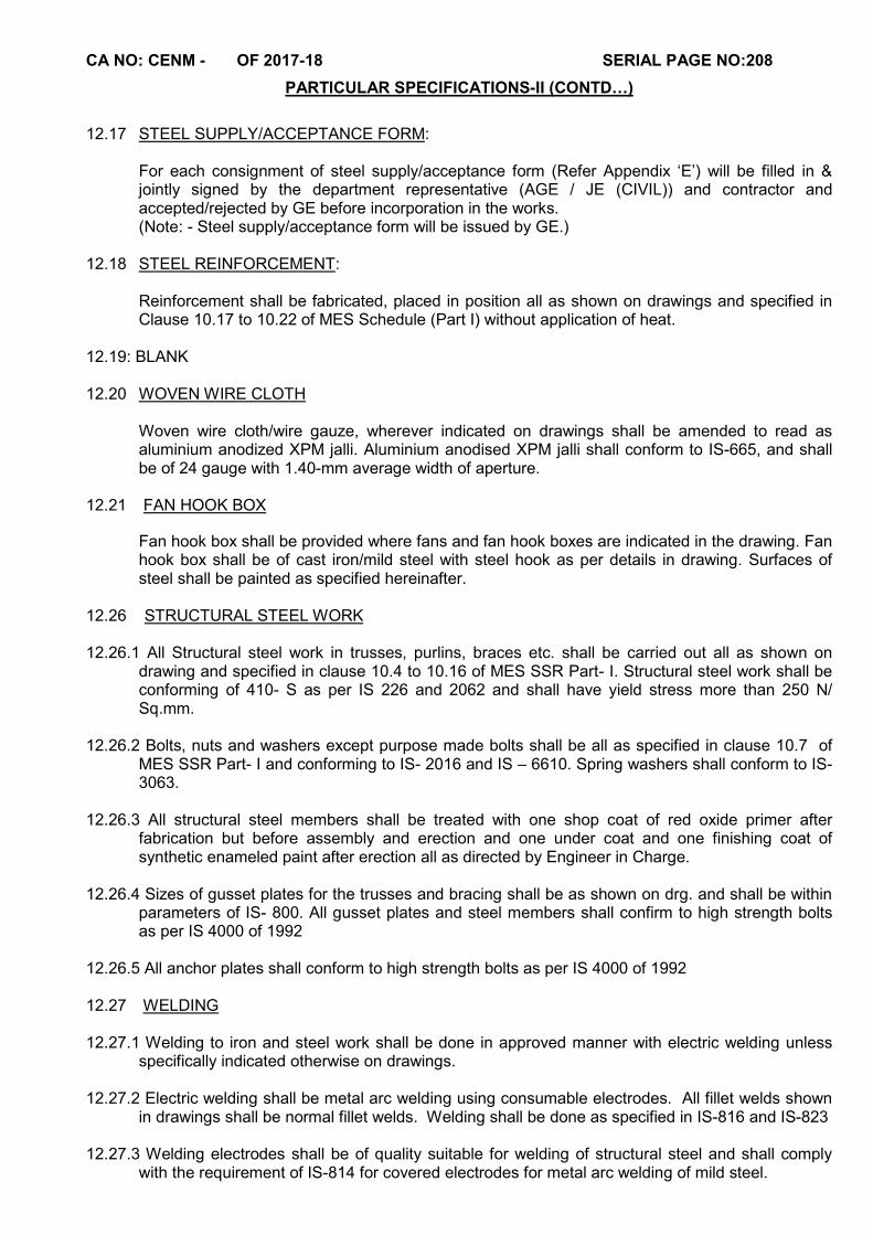
CA NO: CENM - OF 2017-18 SERIAL PAGE NO:208
PARTICULAR SPECIFICATIONS-II (CONTD…)
12.17 STEEL SUPPLY/ACCEPTANCE FORM:
For each consignment of steel supply/acceptance form (Refer Appendix ‘E’) will be filled in & jointly signed by the department representative (AGE / JE (CIVIL)) and contractor and accepted/rejected by GE before incorporation in the works. (Note: - Steel supply/acceptance form will be issued by GE.)
12.18 STEEL REINFORCEMENT:
Reinforcement shall be fabricated, placed in position all as shown on drawings and specified in Clause 10.17 to 10.22 of MES Schedule (Part I) without application of heat.
12.19: BLANK 12.20 WOVEN WIRE CLOTH
Woven wire cloth/wire gauze, wherever indicated on drawings shall be amended to read as aluminium anodized XPM jalli. Aluminium anodised XPM jalli shall conform to IS-665, and shall be of 24 gauge with 1.40-mm average width of aperture.
12.21 FAN HOOK BOX
Fan hook box shall be provided where fans and fan hook boxes are indicated in the drawing. Fan hook box shall be of cast iron/mild steel with steel hook as per details in drawing. Surfaces of steel shall be painted as specified hereinafter.
12.26 STRUCTURAL STEEL WORK 12.26.1 All Structural steel work in trusses, purlins, braces etc. shall be carried out all as shown on
drawing and specified in clause 10.4 to 10.16 of MES SSR Part- I. Structural steel work shall be conforming of 410- S as per IS 226 and 2062 and shall have yield stress more than 250 N/ Sq.mm.
12.26.2 Bolts, nuts and washers except purpose made bolts shall be all as specified in clause 10.7 of
MES SSR Part- I and conforming to IS- 2016 and IS – 6610. Spring washers shall conform to IS- 3063.
12.26.3 All structural steel members shall be treated with one shop coat of red oxide primer after
fabrication but before assembly and erection and one under coat and one finishing coat of synthetic enameled paint after erection all as directed by Engineer in Charge.
12.26.4 Sizes of gusset plates for the trusses and bracing shall be as shown on drg. and shall be within
parameters of IS- 800. All gusset plates and steel members shall confirm to high strength bolts as per IS 4000 of 1992
12.26.5 All anchor plates shall conform to high strength bolts as per IS 4000 of 1992 12.27 WELDING 12.27.1 Welding to iron and steel work shall be done in approved manner with electric welding unless
specifically indicated otherwise on drawings. 12.27.2 Electric welding shall be metal arc welding using consumable electrodes. All fillet welds shown
in drawings shall be normal fillet welds. Welding shall be done as specified in IS-816 and IS-823 12.27.3 Welding electrodes shall be of quality suitable for welding of structural steel and shall comply
with the requirement of IS-814 for covered electrodes for metal arc welding of mild steel.
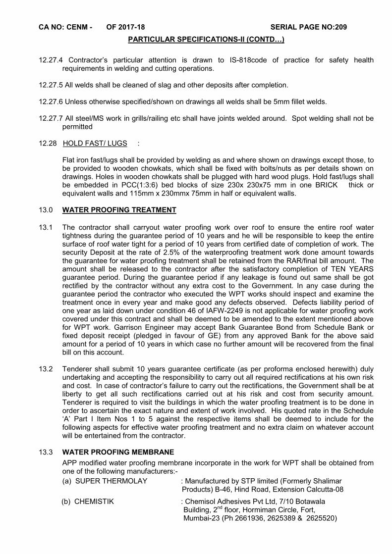
CA NO: CENM - OF 2017-18 SERIAL PAGE NO:209
PARTICULAR SPECIFICATIONS-II (CONTD…)
12.27.4 Contractor’s particular attention is drawn to IS-818code of practice for safety health
requirements in welding and cutting operations. 12.27.5 All welds shall be cleaned of slag and other deposits after completion. 12.27.6 Unless otherwise specified/shown on drawings all welds shall be 5mm fillet welds. 12.27.7 All steel/MS work in grills/railing etc shall have joints welded around. Spot welding shall not be
permitted 12.28 HOLD FAST/ LUGS :
Flat iron fast/lugs shall be provided by welding as and where shown on drawings except those, to be provided to wooden chowkats, which shall be fixed with bolts/nuts as per details shown on drawings. Holes in wooden chowkats shall be plugged with hard wood plugs. Hold fast/lugs shall be embedded in PCC(1:3:6) bed blocks of size 230x 230x75 mm in one BRICK thick or equivalent walls and 115mm x 230mmx 75mm in half or equivalent walls.
13.0 WATER PROOFING TREATMENT
13.1 The contractor shall carryout water proofing work over roof to ensure the entire roof water tightness during the guarantee period of 10 years and he will be responsible to keep the entire surface of roof water tight for a period of 10 years from certified date of completion of work. The security Deposit at the rate of 2.5% of the waterproofing treatment work done amount towards the guarantee for water proofing treatment shall be retained from the RAR/final bill amount. The amount shall be released to the contractor after the satisfactory completion of TEN YEARS guarantee period. During the guarantee period if any leakage is found out same shall be got rectified by the contractor without any extra cost to the Government. In any case during the guarantee period the contractor who executed the WPT works should inspect and examine the treatment once in every year and make good any defects observed. Defects liability period of one year as laid down under condition 46 of IAFW-2249 is not applicable for water proofing work covered under this contract and shall be deemed to be amended to the extent mentioned above for WPT work. Garrison Engineer may accept Bank Guarantee Bond from Schedule Bank or fixed deposit receipt (pledged in favour of GE) from any approved Bank for the above said amount for a period of 10 years in which case no further amount will be recovered from the final bill on this account.
13.2 Tenderer shall submit 10 years guarantee certificate (as per proforma enclosed herewith) duly
undertaking and accepting the responsibility to carry out all required rectifications at his own risk and cost. In case of contractor’s failure to carry out the rectifications, the Government shall be at liberty to get all such rectifications carried out at his risk and cost from security amount. Tenderer is required to visit the buildings in which the water proofing treatment is to be done in order to ascertain the exact nature and extent of work involved. His quoted rate in the Schedule ‘A’ Part I Item Nos 1 to 5 against the respective items shall be deemed to include for the following aspects for effective water proofing treatment and no extra claim on whatever account will be entertained from the contractor.
13.3 WATER PROOFING MEMBRANE
APP modified water proofing membrane incorporate in the work for WPT shall be obtained from one of the following manufacturers:-
(a) SUPER THERMOLAY : Manufactured by STP limited (Formerly Shalimar Products) B-46, Hind Road, Extension Calcutta-08
(b) CHEMISTIK : Chemisol Adhesives Pvt Ltd, 7/10 Botawala Building, 2nd floor, Hormiman Circle, Fort, Mumbai-23 (Ph 2661936, 2625389 & 2625520)
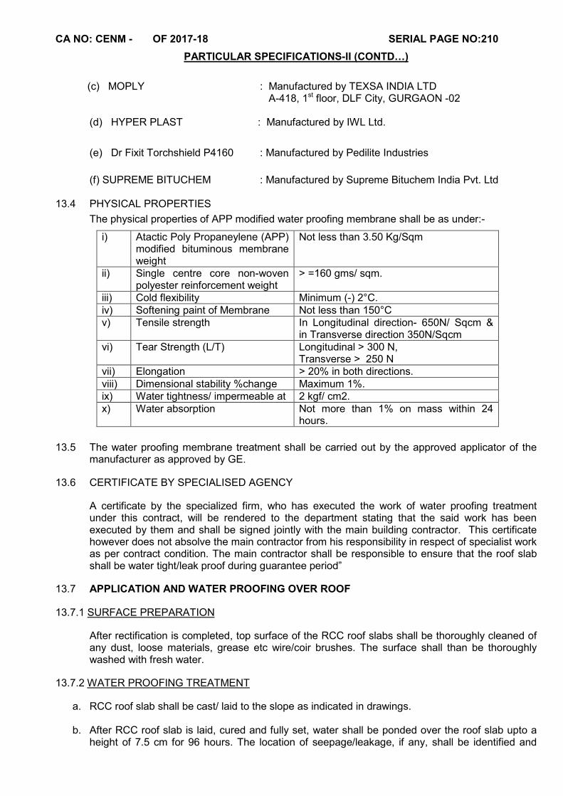
CA NO: CENM - OF 2017-18 SERIAL PAGE NO:210
PARTICULAR SPECIFICATIONS-II (CONTD…)
(c) MOPLY : Manufactured by TEXSA INDIA LTD A-418, 1st floor, DLF City, GURGAON -02
(d) HYPER PLAST : Manufactured by IWL Ltd.
(e) Dr Fixit Torchshield P4160 : Manufactured by Pedilite Industries
(f) SUPREME BITUCHEM : Manufactured by Supreme Bituchem India Pvt. Ltd
13.4 PHYSICAL PROPERTIES
The physical properties of APP modified water proofing membrane shall be as under:-
i) Atactic Poly Propaneylene (APP) modified bituminous membrane weight
Not less than 3.50 Kg/Sqm
ii) Single centre core non-woven polyester reinforcement weight
> =160 gms/ sqm.
iii) Cold flexibility Minimum (-) 2°C. iv) Softening paint of Membrane Not less than 150°C v) Tensile strength In Longitudinal direction- 650N/ Sqcm &
in Transverse direction 350N/Sqcm vi) Tear Strength (L/T) Longitudinal > 300 N,
Transverse > 250 N vii) Elongation > 20% in both directions. viii) Dimensional stability %change Maximum 1%. ix) Water tightness/ impermeable at 2 kgf/ cm2. x) Water absorption Not more than 1% on mass within 24
hours.
13.5 The water proofing membrane treatment shall be carried out by the approved applicator of the
manufacturer as approved by GE.
13.6 CERTIFICATE BY SPECIALISED AGENCY
A certificate by the specialized firm, who has executed the work of water proofing treatment under this contract, will be rendered to the department stating that the said work has been executed by them and shall be signed jointly with the main building contractor. This certificate however does not absolve the main contractor from his responsibility in respect of specialist work as per contract condition. The main contractor shall be responsible to ensure that the roof slab shall be water tight/leak proof during guarantee period”
13.7 APPLICATION AND WATER PROOFING OVER ROOF
13.7.1 SURFACE PREPARATION
After rectification is completed, top surface of the RCC roof slabs shall be thoroughly cleaned of any dust, loose materials, grease etc wire/coir brushes. The surface shall than be thoroughly washed with fresh water.
13.7.2 WATER PROOFING TREATMENT
a. RCC roof slab shall be cast/ laid to the slope as indicated in drawings.
b. After RCC roof slab is laid, cured and fully set, water shall be ponded over the roof slab upto a height of 7.5 cm for 96 hours. The location of seepage/leakage, if any, shall be identified and
CA NO: CENM - OF 2017-18 SERIAL PAGE NO:211
PARTICULAR SPECIFICATIONS-II (CONTD…)
marked. The portion of the slab where leakage/seepage is observed shall be repaired with grouting at contractor’s expense.
c. The area of dripping/ leakage shall be cleaned to expose the surface. Mark the spots for injection grouting. If leakage is through a crack, mark grouting points along the crack in a staggered manner. If the leakage is across the area mark grouting spots in a grid pattern. Drill grouting holes so as to neatly fit the injection packers. Drilling to be done at an angle of 45o to the plane of grouting surface. Fix PVC/MS nozzles in the grouting holes using suitable putty & allow to set. Inject the low viscosity, polyurethane resin/epoxy grout using a grouting pump. Repeat the process after 1 or 2 days if the leakage continues at some points. Allow to cure for 24 hours and seal the grouting holes appropriately using epoxy putty.
d. Over the RCC slab a slope correcting layer of PCC M20 grade nominal mix shall be laid to achieve a final slope of 1:80 with minimum thickness of 40 mm at edges. The PCC layer shall be laid in panels of size not more than 2m X 2m with 10 mm joints filled with non bituminous filler board and sealed with PU sealant. (Note : This PCC layer is required for flat roof slabs laid flat without any slope. For slabs already cast to a slope of 1:80 or more, this layer is not required.)
e. The surface shall be made smooth with 10mm thick cement plaster (1:4) mixed with approved water proofing admixture. The plaster shall be done when the concrete surface is still moist. The plaster surface shall be allowed to set and dry.
f. The dry surface shall be primed with Torch shield primer as per manufacturer’s instructions, manufactured by the same agency as that of APP membrane.
g. Providing and laying APP modified polyester reinforced water proofing membrane with minimum weight of 3.5 kg/sqm, as specified here-in-after.
h. The APP membrane shall be laid using torch-on butane application with minimum 10 cm side overlap and 15 cm end overlap. The laying of membrane shall be got done through an authorised applicator of manufacturer of the membrane.
j. The APP membrane shall be taken up to minimum 200 mm on vertical surfaces. The edge of the membrane shall be fixed with termination bar and fasteners and end shall be properly sealed with sealant.
k. The rain water gutter portion shall be finished with cement mortar (1:4) to provide requisite slope towards rain water pipe outlet.
l. The finishing over the membrane shall be as specified here-in after.
m. FINISHING LAYER FOR INACCESSIBLE ROOF : In case of non accessible roof, the APP membrane shall be finished with two coats of solar reflective bituminous aluminium paint @ 0.1kg/sqm, over the above specifications.
n. FINISHING LAYER FOR ACCESSIBLE ROOF AND TERRACES : In case of accessible roof and terraces, provide a polypropylene/ polyester, non-woven geotextile fabric of 160 gsm over the membrane, specified here-in-above. Over the geotextile fabric provide 20 mm thick cement screed (1:4) and lay 22 mm thick hydraulically pressed PCC tiles of size 250X250 mm set and jointed over APP membrane. While laying tiles a care shall be taken to see that joints between the tiles are kept minimum (not exceeding 5 to 8 mm). Top of finished surface of tiles shall be laid to the true slope so that no stagnation of water take place.
13.8 Wherever junction of vertical and horizontal structures occur a groove of size 75 x 65mm shall be formed at a height of 15 cm above roof level for tucking in edge of water proofing treatment in case of brick wall etc. The groove shall coincide with the horizontal joint of brick course and shall

CA NO: CENM - OF 2017-18 SERIAL PAGE NO:212
PARTICULAR SPECIFICATIONS-II (CONTD…)
be shaped with cement and sand mortar (1:3). In case of junction between RCC beam/parapet etc. PCC 1:2:4 coving with 75mm in radius shall be provided. Cost of above provision shall be deemed to include in the quoted rate against respective Items of Schedule ‘A’ Part I.
13.9 TESTING OF MEMBRANE
The following tests shall be carried out in approved Government Laboratories and necessary test reports shall be submitted to Garrison Engineer for the materials before incorporation in the work.
a) Thickness of membrane b) Weight of membrane
c) Tensile strength (Longitudinal/Crosswise) d) Tear Resistance
e) Softening point f) Weight of Carrier (Polyester).
Apart from above tests contractor shall also produce manufactures test certificate. Test certificate shall be produced with every consignment of material brought at site by the contractor.
13.10 TEMPLATE (LABEL)
Template (Label) made of 15mm thick plaster in CM (1:3) of size 60 x 60 cm showing the following particulars shall be provided on each bldg before the final completion of work without any extra cost to the Department: -
(a) Name of Contractor (c) Date of completion
(b) CA Number (d) Guarantee period
The above information shall be written with white paint with 5 cm size letters and numbers. The entire quantity of materials such as water proofing membrane bitumen primer, bitumen and bituminous aluminium paint etc required for the whole work shall be brought at site in sealed position and shall be entered in the MB as ‘NOT TO BE ABSTRACTED’ showing the date, total quantity brought. Each seal shall be opened in front of Engineer-in-Charge only. Paid vouchers from authorized dealer shall be submitted to the Engineer-in-Charge immediately after every consignment and copy of such paid voucher shall be forwarded to Garrison Engineer b y Engineer-in-Charge duly endorsed.
13.11 BLANK
13.12 GUARANTEE TO BE EXECUTED BY CONTRACTOR FOR REMOVAL OF DEFECTS AFTER COMPLETION IN RESPECT OF WATER PROOFING WORKS.
This agreement made this ___day of ______ two thousand_________between ___________of_______________(son of _________________ of________________________ (hereinafter called guarantor on the one part) and the PRESIDENT OF INDIA (hereinafter called the Government on other part). WHEREAS THIS agreement is supplementary to a contract hereinafter called the contract) dated ________________ and made between the GUARANTOR of the one part and the GOVERNMENT on the other part where by the contractor interalia, undertook render the buildings and structures in the said contract recited completely water and leak proof. AND WHEREAS THE GUARANTOR agreed to give a guarantee to effect that the said structures will remain water leak proof for ten years from the certified date of completion.
NOW THE GUARANTOR hereby guarantees that water proofing treatment given by him will render the structures completely leak proof and the minimum life of such water proofing treatment shall be Ten years to be reckoned from the certified date of completion. Provided that the guarantor will not be responsible for leakages caused by earthquakes or structural defects or misuse of roof and sunken floor slabs or alterations and for such purpose.
CA NO: CENM - OF 2017-18 SERIAL PAGE NO:213
PARTICULAR SPECIFICATIONS-II (CONTD…)
a) Misuse of and sunken floor slabs shall mean by operation which will damage roofing treatment, like chopping of firewood and things of the same nature which might cause damage to the roof. b) Alteration shall mean construction of any additional storey or any part of roof or construction adjoining to existing roof, where by roofing treatment is removed in parts. And removal of finishes of sunken portion of slabs. b) The decision of the Garrison Engineer with regard to cause of leakage shall be final and binding. During this period of guarantee the guarantor shall make good all defects and in case of any defects being found, render the building water proof and finish the disturbed surfaces as existed to the satisfaction of Garrison Engineer at his cost and shall commence the work for such rectification within seven days from the date of issue of the notice from the Garrison Engineer calling upon him to rectify the defects, failing which the work shall be got done by the department by some other contractor at the GUARANTOR’S risk and cost. The decision of the Garrison Engineer as to the cost, payable by the Guarantor shall be final and binding. That if the Guarantor fails to execute the water proofing or commit breach there under then the Guarantor will indemnify the Principal and his successors against all loss, damage, cost expense or otherwise which may be incurred by him by reason of any default on the part of GUARANTOR in performance and observing of this supplementary agreement. As to the amount of loss and/or damage and/or cost incurred by the Government, the decision of the Garrison Engineer will be final and binding on the parties. IN WITNESS WHEREOF these presents have been executed by the obligator____________and by _________for and on behalf of the PRESIDENT OF INDIA on the day month and year first above written. SIGNED sealed and delivered by OBLIGATOR in the presence of :- 1. 2. SIGNED ON BEHALF OF THE PRESIDENT OF INDIA BY ________________ .
14.0 FLOORING
14.1 GENERAL
a) Type of floor shall be provided to details strictly as shown on drawings/Schedule of finishes and as specified here in after, if otherwise not shown in drawings. Provisions contained in Clause 13.25, 13.32, 13.38 and 13.39 of MES Schedule are to be adopted for laying floors and pavements.
b) Floors shall be laid to levels or to falls as shown on drawings and as directed by the Engineer-in-Charge. Floor finish shall be extended over dwarf walls, doors and other openings.
c) Sinking of floors in kitchens, toilets, baths and WCs etc. where shown on drawings shall not be achieved by reducing RCC slab thickness.
d) Connected ramps shall have the same type of floors as adjoining floors of building and shall have in addition chequered finish.
e) The dividing line between the floors of different types wherever they so meet between adjoining rooms, shall be determined on the basis of the finish visible when the doors are closed and the applicable finish shall accordingly be provided.
f) Floor finish over RCC slabs shall be laid all as specified in MES Schedule.
g) Sub floor may not be laid in panels. Topping layers of PCC floor and under and top layers of terrazzo cast in situ floors shall be laid in square or rectangular panels as directed by Engineer-in-Charge. Length of panel not exc. 2.0m, length to width ratio not exc. 1.5 times in rectangular panels.
CA NO: CENM - OF 2017-18 SERIAL PAGE NO:214
PARTICULAR SPECIFICATIONS-II (CONTD…)
14.2 CEMENT CONCRETE SUB FLOOR
Cement concrete sub floor (i.e. PCC Sub base laid below floor finish) in ground floor as indicated in Schedule of finishes shall be plain cement concrete (1:4:8) type D-2, using 40mm graded stone aggregate and same shall be provided as per thickness and locations as indicated in drawings.
14.3 CEMENT CONCRETE FLOORS
a) PCC floors/wearing coat (laid over hard core/cement concrete sub floor/RCC slabs) as indicated in Schedule of finishes shall be plain cement concrete M-20 nominal mix using 20mm graded stone aggregate and the same shall be provided at location mentioned in drawings and as per the thickness indicated in drawings.
b) Cement concrete in floor/wearing coat shall be laid in alternate bays not exceeding four square meters. 3 mm thick PVC dividing strips shall be provided (to form joint) in all cement concrete floors and wearing coat. The Glass dividing strips shall be 3mm less than the thickness of PCC floor/wearing coat. The glass dividing strips shall be inserted in the PCC floor/wearing coat while the concrete is still plastic and the strips shall be left in position. PCC floors/wearing coat to be provided with glass strip shall not be laid in alternate bays and this will not involve any price adjustment.
c) The surface of PCC floor/wearing coat shall be finished (with a steel trowel) to an even
and smooth surface using extra cement.
d) Cement concrete flooring shall be carried out as specified in Clause 13.32 of MES Schedule Part I.
e) If chequered finished is shown on drawing then same shall be achieved by making impression by expanded metal or mesh as directed by Engineer-in-Charge on top surface of concrete while it is still green. The expanded metal shall be impressed to maximum possible depth by tamping and removing the same carefully.
14.4 RAMP
(a) Ramps shall be provided as per details shown in drawing.
(b) Flooring shall be provided with PCC M-15 (Nominal Mix) using 20mm graded stone aggregate over 100mm thick hard core approved earth filling surface shall be finished chequered. This shall be achieved by making impression by expanded metal or mesh as directed by Engineer-in-Charge on top surface of concrete while it is still green. The expanded metal shall be impressed to maximum possible depth by tamping and removing the same carefully”.
14.5 MACHINE CUT MIRROR POLISHED KOTA STONE FLOORING
a) Machine cut mirror polished Kota stone flooring shall be provided in the locations indicated in drawings/Schedule of finishes.
b) Kota stone tiles/slab shall have size 450mm x 600 mm for flooring shall be of selected quality, hard, sound dense & homogeneous in texture, free from defects & conforming to clause 13.12 of SSR Part I. Thickness of tile shall be 20 to 25mm as indicated in drawings. Mirror polished Kota stone shall be cut to correct geometry at site and table rubbed to achieve fine joints.
c) Kota stone tiles/slabs shall be set, jointed & pointed in neat cement slurry with pigment to match the colour of tiles and laid over 20mm thick bedding layer in CM 1:4 over concrete sub-base/ RCC slab. Joints shall be thin & nearly indistinguishable.
d) Polishing of Kota stone flooring shall be done to achieve mirror polish with using polishing machine and required grinding stones and in a manner and to the satisfaction of Garrison Engineer.
CA NO: CENM - OF 2017-18 SERIAL PAGE NO:215
PARTICULAR SPECIFICATIONS-II (CONTD…)
14.6 MACHINE CUT MIRROR POLISHED KOTA STONE SKIRTING
a) Kota stone skirting shall be provided at locations as shown on drawings. The height of skirting shall be as shown on drawing and if not shown shall be 125 mm height. Mirror polished Kota stone shall be cut to correct geometry at site and table rubbed to achieve fine joints.
b) Kota stone tiles shall be laid over 12mm thick cement and sand mortar (1:4) irrespective of whatever specified elsewhere, jointed and pointed in grey cement. The exposed surfaces of Kota stone shall be mirror polished.
c) Kota stone tile for skirting shall be of the selected quality hard, sound, dense and homogenous in texture, free from defects, machine cut and mirror polished all as specified in clause 13.12 of MES Schedule Part I. The size of the Kota stone tile skirting as shown in drawing and shall be 20mm to 25 mm thick. Where size does not fit on the same place, it shall be provided as per directions of Engineer-in-Charge. The Kota stone shall be uniform in thickness & shall be uniform in colour.
14.6(A) KOTA STONE FOR STAIR CASE
(a) 23 to 25 mm thick polished kota stone slab in single piece, bull nosing/rounding to edges of stone slab one edge and two Nos grip line for staircase treads fixed over 20 mm thick cement screed in CM 1:4 all as shown on drawing of schedule of finishes.
(b) 23 to 25 mm thick polished kota stone slab in single piece for staircase treads fixed over 10 mm thick cement screed in CM 1:4 all as shown on drawing of schedule of finishes.
14.7 NON SKID CERAMIC TILES FLOORING/DADO
a) Non skid ceramic tiles in flooring / dado shall be provided in the locations indicated in drawings/ Schedule of finishes.
b) Non skid ceramic tiles in flooring shall be 300 mm x 300 mm size and 7 to 8 mm thick unless otherwise specified in drg, coloured of group B II (a)/B II (b) and of abrasion resistance PEI -III or above. Ceramic tiles fixed with 20 mm thick cement sand screed 1:4 over PCC sub base / RCC slabs. Tiles shall be set and jointed in neat cement paste and shall be grouted with Epoxy grout “Ezy grout from Somany”, “Ferro102 from Ferrous Crete”, Bal Endura, Fevimate TG from Dr Fixit. Joints shall be thin & nearly indistinguishable. The workmanship in all respects shall be as specified in Clause 13.40 of SSR Part I.
c) Non Skid ceramic tiles shall be any one of the make as per make. Colour, pattern & design of tiles shall be as approved by GE.
d) Glazed ceramic tiles in dado shall be 300 mm x 300 mm size and not less than 7 to 8 mm thick, coloured, shall be of group same as that of the floor and shall be provided in locations shown on drawing. Tiles shall be fixed with polymer modified tile adhesive “Ezy fix from Somany” , “Ferro 1111 from Ferrous Crete” , “ Favimate XL from Pidilite”, Bal Endura. Joints grouted with Epoxy grout “Ezy grout from Somany”, “Ferro102 from Ferrous Crete”, Bal Endura,Fevimate TG from Dr Fixit.. Joints shall be thin & nearly indistinguishable. The workmanship in all respects shall be as specified in Clause 13.40 of SSR Part I.
e) Height of dado shall be as shown on drawing.
14.8 VITRIFIED TILES
Vitrified tiles shall be of first quality and all as specified in CL 13.5 of SSR part I, 2009 print.
Vitrified tiles shall be of size 600mm x 600mm (where specified) fixed with cement sand screed
1:4 and minimum uniform joint thickness of 3mm. Joints grouted with Epoxy grout “ Ezy grout
from Somany”, “Ferro 102 from Ferrous Crete”, Bal Endura, Fevimate TG from Dr Fixit.
CA NO: CENM - OF 2017-18 SERIAL PAGE NO:216
PARTICULAR SPECIFICATIONS-II (CONTD…)
14.9 PCC TILES
PCC tiles shall be all as specified in CL 13.16 of SSR part I, 2009 print and all as specified in drawings.
14.10 CEMENT PLASTER SKIRTING / DADO
Cement plaster skirting/dado where PCC cast in situ flooring is indicated in drawings shall comprise rendering coat 12mm thick in cement and sand mortar (1:4) finished smooth with extra cement. The height of skirting shall be 100mm irrespective of what is indicated in drawings.
14.11 WATER PROOF TREATMENT TO ALL SUNKEN PORTIONS OF SLAB
(a) The sunken RCC slab shall be laid with slope as indicated on drawings to drain water through spout(s).
(b) 30mm thick (average) PCC (1:2:4) mixed with water proofing compound as per manufacturer's instructions shall be provided on bottom of sunken portion with proper coving on sides and 15mm thick cement plaster (1:3) with water proofing compound on sides. PCC and plaster shall be carried out at the same time.
(c) Spout / spouts of 80mm dia GI pipes, medium grade projecting at least by 10 cm clear of face of the outer wall or as shown in drawings shall be provided to drain out seepage water if any.
(d) After laying of all CI connections and branch pieces, etc. apply two coats of hot bitumen 85/25 grade at the rate of 1.7kg/sqm over vertical sides and floor of sunken portion.
(e) All the joints of pipes with the wall shall be sealed properly by bitumen after these are filled with PCC (1:2:4) mixed with water proofing compound.
(f) The sunken portion shall be filled with plain cement concrete 1:7:12 with brick aggregate after carrying out required tests for CI pipes / joints / water proofing.
(g) The guarantee specified in clause 13.1 hereinbefore shall also include for water proofing to sunken slabs also.
14.12 WEAR PROOF TOPPING
(a) Wearing coat (laid over hard core/cement concrete sub floor/RCC slabs) as indicated in Schedule of finishes shall be provided as specified in MES Schedule Part I clause 13.36 and the same shall be provided as per the thickness indicated in drawings.
(b) The surface of wearing coat shall be finished (with a steel trowel) to a even and smooth surface using extra cement.
14.13 MACHINE CUT MACHINE POLISHED MARBLE STONE PLATFORM FOR KITCHEN
Provide Kitchen platform Marble stone slab shall be in one piece of selected quality, hard, sound dense & homogeneous in texture, free from defects and conforming to clause 13.12 of SSRPart-I and of thickness 18 to 20mm machine cut machine polished (exposed surfaces only) and shall be provided over RCC Slab as per locations shown in drawings. Colour of stone slab shall be Baroda Green or any other colour as approved by the GE. Stone Slab shall be provided in a chase inside the wall at least 25mm deep and set, jointed and pointed in neat cement slurry to match with the colour of the slab. The edge exposed shall be bull nosed as directed by the GE. 19mm thick prelaminated particle board shutter below cooking platform shall be provided all as shown on drawing. Provide Cuddappa stone shelving 20 to 25 mm thick below cooking platform as shown on drawing.
CA NO: CENM - OF 2017-18 SERIAL PAGE NO:217
PARTICULAR SPECIFICATIONS-II (CONTD…)
14.14 MACHINE CUT MACHINE POLISHED GRANITE STONE FLOORING/DADO:-
(a) Granite stone slab in flooring/dado shall be single piece of selected quality, hard, sound dense & homogeneous in texture, free from defects & conforming to clause 13.12 of SSR Part-I. Thickness of slab shall be 20 to 25 mm. Granite stone slab shall be machine cut machine polished (exposed surfaces only) and shall be provided as per locations shown in drawings. Colour of slab shall be ‘Ruby Red’ with ‘Black’ colour in border. Granite stone Slab in flooring shall be set, jointed & pointed in neat cement slurry & shall be laid over 20mm thick bedding in CM 1:3 over concrete sub-base/ RCC slab. Joints shall be thin & nearly indistinguishable. In case of dado Granite stone slab shall be fixed over 10mm thick cement mortar (1:3), jointed & pointed in grey cement. The exposed surface shall be machine polished. (b) For platform Granite stone slab shall be in one piece of selected quality, hard, sound dense & homogeneous in texture, free from defects & conforming to clause 13.12 of SSR Part I and of thickness 20 to 25 mm machine cut machine polished (exposed surfaces only) and shall be provided as per locations shown in drawings. Colour of slab shall be ‘Ruby Red’ or ‘Black’ as approved by GE. Slab shall be provided in a chase inside the wall at least 25 mm deep and set, jointed & pointed in neat cement slurry to match with the colour of the slab. The edge exposed shall be bull nosed as directed by GE.
15 PLASTERING 15.1A Plastering shall be provided as per details shown in ‘Schedule of Finishes’ and as specified here-
in-after if not shown in drawings
15.1 GENERAL
(a) Where plaster on concrete surfaces is shown to match the adjacent PCC Block masonry surfaces, the mix of plaster shall be as for the PCC Block masonry surfaces.
(b) All plastered surfaces shall be trowelled to a smooth and even surface without using extra cement.
(c) Thickness of cement plaster mentioned hereinafter shall be finished thickness exclusive of dubbing. Dubbing may however be done in one operation with plaster.
(d) All corners, angles, junctions and edges shall be truly vertical or horizontal as the case may be and shall be carefully finished. Corners around jambs of openings and junctions of walls shall be rounded to minimum radius of 5mm.
(e) To avoid cracks at junction of RCC and Brick / Block masonry wall, 150 mm wide GI chicken wire mesh of 0.9 mm dia, 12mm mesh shall be nailed on the joints before plastering on external surfaces. Grooves between junction of RCC and masonry shall be formed on internal faces.
(f) Particular attention of the contractor is invited to take note of local practices and local availability of materials like bricks / stones, form work etc for any extra quantity of mortar required for rendering smooth, extra dubbing required, touching up properly and achieving smooth and even surfaces. This shall be deemed to have been included in the lumpsum quoted for plaster work, as applicable.
15.2 MATERIALS:-
(a) Cement: - Refer `Appendix `C' on Sl. Page Nos.
(b) Sand : - Refer Clause 14.5 of MES Schedule Part I.
(c) Water: - Refer Clause 14.11 of MES Schedule Part I.
15.3 CEMENT PLASTER (INTERNAL) & CEILING PLASTER:-
(a) Cement plaster (internal) wherever indicated in drawings for walls shall comprise rendering of 8 mm thick polymer modified ready mixed cement based plaster finished even and smooth (Make:- Acoplast of ACC, Ready Plast of Ultra Tech, Easy Palst from Wall Plast, Chem Plast).
CA NO: CENM - OF 2017-18 SERIAL PAGE NO:218
PARTICULAR SPECIFICATIONS-II (CONTD…)
(b) Cement plaster for soffits of slabs i.e. ceiling and all exposed concrete surfaces shall comprise rendering of 5mm thick in cement and sand mortar (1:3) finished smooth with thick wall care putty finish irrespective of what is indicated on Schedule of finishes.
(c) The plaster work on the concrete surfaces adjoining to wall shall be carried out as per specification for the wall plaster.
15.4 WALL CARE PUTTY FINISH
Cement plaster mentioned above for soffits of slabs i.e. Ceiling shall be treated with wall care putty finish to thickness not less than 3.00mm trawled to an even and smooth finish. Wall care putty to be used for "Wall care putty Finish" shall be of ‘Birla Putty’, ‘SARA Putty (Ferrous Crete)’ or equivalent make and shall be as approved by the GE.
15.5 CEMENT PLASTER (EXTERNAL)
(a) Cement plaster (external) wherever indicated in drawings for walls shall comprise rendering of 20 mm thick polymer modified ready mixed cement based plaster in two layers (i.e.) 15mm & 5mm finished even and smooth (Make:- Acoplast of ACC, Ready Plast of Ultra Tech, Easy Palst from Wall Plast, Chem Plast).
(b) Irrespective of what is shown in drawings top, front and side surfaces of Chajjas and front and sides of canopies shall be given plaster in two coats as specified hereinbefore.
(c) The percentage of integral water proofing compound to be used in the work shall be as per the manufacturer's instructions, but in case of deviation the same shall be 3% (by weight of cement).
15.6 INTEGRAL WATER PROOFING COMPOUND
Integral Water proofing compound wherever specified in these particular specifications shall conform to IS 2645, ISI marked & shall be in powder form. Mixing shall be done strictly as per manufacturer’s instructions. For purpose of deviations it shall be taken as 3% by weight of cement.
16-A WHITE WASHING 16.A.1 Three coats of white (lime) wash shall be provided as indicated in drawings, all as specified in
MES Schedule. For white washing on ceiling adequate quantity of zinc oxide shall be added to lime wash for achieving egg white shade. Skirting and dado are not to be white washed.
16 PLASTIC EMULSION PAINT/ACRYLIC EMULSION ANTIFUNGAL PAINT/OIL BOUND
DISTEMPER
16.1 Plastic Emulsion Paint : - Plastic Emulsion Paint conforming to IS 5411Part-I) in two coats over a coat of alkali resistant
priming paint conforming to IS-109-1968 shall be provided where shown in Schedule of Finishes, all as specified in MES Schedule Part I as per Clause 17.16. Skirting and dado are not to be painted.
16.2 Oil Bound Distemper Oil bound distemper conforming to IS 428- 1969 in two coats over a coat of alkali resistant priming paint conforming to IS-109-1968 shall be provided where shown in Schedule of Finishes, all as specified in clause No 15.14.1, 15.14.3 to 15.14.5.3 of MES Schedule Part I. The make and brand of distemper shall be as per Appendix-`B' to these specifications.
CA NO: CENM - OF 2017-18 SERIAL PAGE NO:219
PARTICULAR SPECIFICATIONS-II (CONTD…)
16.3 Acrylic Emulsion 100% exterior grade (Anti-fungal paint)
APPLICATIONS
(a) Old fungus / Moss / Algae affected surface on new or old surfaces, remove fungus growth if any antifungal treatment or with the help of available fungicide bleaching powder solution all as per Manufacturer’s instructions. The surfaces shall be cleaned by wire brushing and washed with water before application of primer or paint. (b) Before application of primer for plastered surfaces, the surfaces shall be cleaned, made free of loose particles, dust, grease, chalk, fungus and mould. One coat of acrylic emulsion weather coat paint with water (1:1 by volume) as a self priming coat shall be applied as per manufacture’s instructions and as directed by Engineer-in-Charge. (c) The acrylic emulsion weather coat paint shall be applied by brush or roller. No stainer or colorants shall be used. The paint shall be stirred well before use. The primer coat shall not be left without application of top coats for a long period of time. (d) Application of Acrylic emulsion weather coat paint. Two coats of acrylic emulsion weather coat paint thinned with 400 ml water per lit of paint shall be applied. The drying period between two coats shall be minimum 4 hours or as per Manufacture’s instructions. The shade shall be as approved by GE. Finish of acrylic emulsion weather paint shall be smooth matt finish. (e) The paint shall be as per Manufacture’s original colour as available no mix of tint shall be made into original shades.
(f) The weather coating Acrylic emulsion paint shall be any one of the make given in Appendix ‘B’.
16.4 GUARANTEE:-
(a) The contractor shall ensure that all the buildings painted with acrylic paint free from fungal infections, light patches, discolor, etc. during the guarantee period of 05 years and he shall be responsible to upkeep the entire surface for a period of 05 years from the certified date of completion of work. The security deposit towards the guarantee for efficiency of treatment (acrylic painting) shall be retained from the RAR/Final bill amount. The security deposit amount shall be calculated as per the scales laid down by MES for calculating Individual Security deposit on the total amount of exterior painting carried out at contract rates. This amount shall be released to the contractor after satisfactory expiry of five years guarantee period. The GE may accept BGB from schedule bank or a fixed deposit receipt (pledged in GE’s favour) from any Nationalised Bank for the said guarantee amount for a period of five years, in which event no further amount will be recovered from the final bill/RAR on this account. The defects liability period under condition 46 of General conditions of contract (IAFW-2249) shall be deemed to be amended to the extent mentioned above for acrylic painting works. (b) Necessary guarantee shall be obtained from the manufacturer applicator on non judicial stamp paper giving five years guarantee from the certified date of completion of contract to keep the building free from fading, peeling off paint during guarantee period. The guarantee does not however, absolve the contractor from his responsibility in respect of this specialized work as per contract conditions. The contractor shall be responsible to ensure that the buildings are kept free from fading or peeling off the acrylic paint during guarantee period.
CA NO: CENM - OF 2017-18 SERIAL PAGE NO:220
PARTICULAR SPECIFICATIONS-II (CONTD…)
16.5 SCAFFOLDING 16.5.1 The exterior painting works shall be carried out by using scaffolding. No jhoola is permitted for the
work under any circumstances. Suitable protection shall be provided for workmen. The contractor shall be solely responsible for all the labours deployed for the work for identity/security. In case of any accident/injury fatal or partial disability, the contractor shall be solely responsible for settling all claims, compensation. Department shall have all rights to recover any sum indicated/claimed by labour commissioner/court directives. Engineer-in-charge will have to ensure that contractor has provided all adequate and required means for the workmen and contractor may get his personnel insured as per labour law.
16.5.2 Scaffolding or staging more than 3.5m above the ground or floor, swung or suspended from any
overhead support or erected with stationery support shall have a guard rail properly attached, braced and otherwise secured at least 1m high above the floor or platform of such scaffolding or staging and extending along the entire length of the outside and ends thereof with only such opening as may be necessary for the delivery of materials. Such scaffolding or staging shall be so fastened as to prevent it from swaying from the building or structure.
16.5.3 Working platform, Gangways and stairways should be so constructed that they should not sag
unduly or unequally, and if the height of the platform or the Gangway of the stairway is more than 3.5m above ground level they should be closely boarded, should have adequate width and should be suitably fenced, as described herein before.
16.5.4 Every opening in the floor of a building or in a working platform be provided with suitable means
to prevent the fall of persons or materials by providing suitable fencing or railing whose minimum height shall be 1m.
16.5.5 Safe means of access shall be provided to all working platforms and other working places. 16.5.6 The rates quoted are deemed to included the above provision of scaffolding and no extra will
be payable to contractor on this account. The scaffolding shall be removed only after obtaining clearance of Engineer-in-Charge/Garrison Engineer after considering the quality of the work undertaken.
16.6 STAGEWISE APPLICATION FOR ACRYLIC PAINT
Work for acrylic emulsion paint shall be carried out as per stage given below. Before starting the work for next stage prior approval of Engineer-in-charge shall be obtained.
Stage I : Preparation of surface.
Stage II : Applying priming coat Stage III : Applying first coat of acrylic emulsion paint Stage IV : Applying second coat of acrylic emulsion paint 17 PAINTING 17.1 GENERAL:-
(a) All synthetic enamel paint shall be of Ist quality manufactured by the standard firms of make as per Appendix `B' attached. Synthetic enamel paint shall be fire resistant paint conforming to IS- 162-1950
(b) The contractor shall inform the GE, within three weeks of the acceptance of the tender, the brand / names of the manufacturers of paint proposed to be used in the works and submit ample thereof and obtain prior written approval of GE before their use in works.
CA NO: CENM - OF 2017-18 SERIAL PAGE NO:221
PARTICULAR SPECIFICATIONS-II (CONTD…)
(c) The contractor shall when so required by the GE, produce certificate from the manufacturer or their representative to establish that the brands of paints purchased by the contractor from them satisfy the requirements of the relevant Indian Standards. The total quantity of paint brought by the contractor at site shall be in sealed containers.
(d) Paints for priming coat, under coat and finishing coat shall be of the same manufacturer.
(e) Tint of paint, if not mentioned in drawings/Schedule of Finishes, will be approved by the GE.
17.2 WORKMANSHIP:-
(a) All wood work required to be painted shall be smoothened, sized and knotted and then applied with priming coat. Stopping and filling (filler coat) shall be done after priming coat and surface rubbed down it to a level of smooth surface and thereafter under coat and finishing coat applied, all as specified in Clause 17.6 of MES Schedule. Steel and iron work shall be painted in the manner as specified in Clause 17.8 of MES Schedule Part I.
17.3 CREOSOTING
Creosoting shall be done for hidden wooden surfaces all as specified in clauses No. 17.11 of MES Schedule Part – I.
17.4 CEMENT SLURRY
Portions of MS bolts, lugs, anchor bolts etc embedded in concrete shall be treated with neat cement slurry.
18 MISCELLANEOUS ITEMS
All items as given in this clause if shown on drawings shall be provided as per details shown in drawings and specifications given below and their cost shall be deemed to be included in lump sum cost of buildings in Sch ‘A’ Part I unless omitted specifically.
18.1 RAILING
Stainless Steel railing shall be provided at locations shown on drawings. The diameter of pipe shall be as mentioned in relevant drawings. Stainless steel hand rail shall be grade SS-316 provided to the size / diameter mentioned therein. Make of pipe shall be “SALEM STEEL” or equivalent as approved by the GE.
18.2 NICHE SWITCH BOARD
All surfaces of the niche shall be plastered to match the surrounding surfaces. Size of niche shall be to suit the size of steel boxes to be provided under Schedule ‘A’ Part-IV.
18.3 BRICK /BLOCK MASONRY STEPS
Wherever shown on drawing provide Brick/Block masonry steps shall be constructed in CM (1:4) over PCC 1:4:8, Type D2 foundations all as shown on drawings. Treads of steps shall be provided with Kota stone slab 22 to 25 mm thick mirror polished machine cut and in a single piece laid over a screed of 20 mm thick in cement mortar 1:4. Kota stone for treads shall be with bull nosing with two no grip lines..
18.4 Blank
18.5 Blank
CA NO: CENM - OF 2017-18 SERIAL PAGE NO:222
PARTICULAR SPECIFICATIONS-II (CONTD…)
18.6 PARAPET
Wherever parapets are provided, water proofing treatment as per specifications given hereinbefore shall be done at the junction of the parapet and roof slab as per drawing.
18.7 SPOUTS
PVC Spouts shall be of 40 mm dia and 450 mm long. Where length / diameter of spout are not indicated it shall be taken as passing throughout the width of parapet or facia and projecting 15 cm from outer face of the wall and of 40mm dia.
18.8 PVC RAIN WATER PIPE
PVC rain water pipe shall be provided at all locations as shown on drawings from roof level to plinth level fixed with GI clamps with spacing 1m c/c These shall be of 110mm dia irrespective of whatever shown on drawing & shall withstand continuous internal hydraulic pressure of 4kg/sqcm, conforming to IS-4985. Pipes and fittings shall be secured to wall just below all joint with PVC clamps as per manufacturer’s instructions. Pipes and fittings shall be jointed with epoxy resin or compound as recommended in manufacturer’s instruction. The grating shall be of CI, round type, weighing not less than 0.5 kg each, provided and fixed at the inlet of rain water pipes.
18.9 PEGS /HOOKS:-
Pegs / hooks shall be anodised aluminium with anodised aluminium back strip and in sets as indicated on drawings and shall be as approved by the GE.
18.10 DECORATIVE CURTAIN ROD
Curtain rod shall be of aluminium 25mm dia not less that 1mm wall thickness powder coated decorative type with decorative brackets. The colour of curtain rod and design of the bracket shall be as approved by GE.
18.11 SOAP TRAY
Readymade vitreous China semi recess soap tray shall be provided as per locations shown in drawings. Size 160X160X90mm shall be fixed as shown in drawings and matching to tile.
18.12 SHOWER ROSE:- 18.13 Shower rose shall be chromium plated, Brass with swivel joints 125mm size as shown on
drawing. 18.14 TOWEL RING
Provide towel ring of C.P chromium plated with screws and rawl plugs as approved by GE at location where shown on drg.
18.15 TOWEL RAIL:-
Irrespective of what is shown on drawing or not, 01 No Towel Rail (TR) for each toilet & bath shall be provided of anodised aluminium tubular conduit 19/20mm dia, 600mm long with 1mm wall thickness with cast aluminium brackets at both ends. Fixing shall be done with rawl plugs and cadmium plated steel screws.
CA NO: CENM - OF 2017-18 SERIAL PAGE NO:223
PARTICULAR SPECIFICATIONS-II (CONTD…)
18.16 DRAPERY ROD
Provide 25mm dia standard drapery rod of required length with extra support in the middle as approved by GE at the locations as shown in drawing.
18.17 PLATE RACK:
Provide Stainless Plate Rack of standard type of 600 x 600 x 250mm size as approved by GE at the locations as shown in drawing.
18.19 STAINLESS STEEL SINK & DRAINING BOARD
It shall be manufactured from stainless steel grade A1 SI 305. Thickness of sheet shall be 1mm. Overall size of stainless steel sink with drainage board shall be 915mm x 460mm bowl size 410mm x 330mm x 160mm and type of stainless steel sink and draining board shall be as approved by GE with necessary brackets, connecting union, waste pipe. The surface of the sink shall be plastic coated to make it safe & scratch free installation. Make shall be Nirali or equivalent as approved by GE.
18.20 KITCHEN CABINET ABOVE & BELOW COOKING PLATFORM :- Irrespective of what is specified in tender documents and drawings, the specifications for Kitchen Cabinet shall be as under:- (a) Kitchen Cabinet (i) Top, bottom sheet & shelves: 19mm thick marine plywood conforming to IS-710. (ii) Shutter: 18mm thick marine plywood (as per IS-710) with 1.5mm thick lamination (shade and colour as approved by GE). (iii) Internal surfaces of plywood finished with french polish. (iv) 100mm stainless steel handle 8mm thick for every shutter.
18.21 CUP BOARD (BUILT IN) / WARD ROBE:- Irrespective of what is specified in tender documents and drawings, the specifications for Wardrobe shall be as under:- (i) Partitions: 18mm thick BWR grade type AA plywood conforming to IS-303. (ii) Shutter: 25mm thick block board flush shutter conforming to IS-1659 with 1.5mm thick lamination (shade and colour as approved by GE). (iii) Internal surface finished with french polish. (iv) 200mm stainless steel handle 8mm thick one on every shutter.

CA NO: CENM - OF 2017-18 SERIAL PAGE NO:224
PARTICULAR SPECIFICATIONS-II (CONTD…)
18.22 CI GRATING
CI Gratings to each rain water pipe shall be provided. Grating shall be painted with Black Japan paint all as specified and directed.
18.23 SHELVES
25mm thick machine cut machine polished cudappah stone shall be provided as per locations & details shown in drawings. Polishing shall be done on both faces & exposed edges.
19 SANITARY AND TOILET FITTINGS 19.1 GENERAL
(a) All sanitary appliances shall be of vitreous china first quality, white in colour and shall be as per IS-2556 for General requirements and the specific requirements bearing IS Mark as mentioned in relevant Clause of MES Schedule. These shall be of an approved make from the list given in Appendix `B' (b) All waste pipes and fittings upto Floor / Nahani traps shall be of galvanised steel tubing medium grade conforming to IS-1239 (Part II 1969).
(c) Flush pipe and socket of flushing rim of WC shall be jointed with white and red lead cement (white and red lead in equal portion by weight) and linseed oil added to form pasted.
(d) `P' and or `S' trap shall be jointed to WC pan with cement joint as specified in Clause 18.48.5 of MES Schedule.
(e) PVC low level flushing cistern shall conform to IS’
(f) The sizes given hereinafter are approximate sizes. The size of sanitary fittings to be provided shall be the nearest size as per manufacturers catalogue as approved by GE.
19.2 WATER CLOSET (ORISSA PATTERN) )
(a) Water Closet (Orissa Pattern) shall confirm to IS 2556 (Part III) and shall be long pattern, coloured of size 580 mm x 440 mm provided with integral foot rests and with `P’ or `S’ trap and the following fittings:-
(i) 10 litres discharge capacity low level PVC flushing cistern of Commander/ Champion/ Water bird or equivalent make and of colour to match colour of WC with valve less symphonic fittings brass ball valve horizontal plunger type and polythene float ball all conforming to IS-1703 and flush pipe.
(ii) The pan shall be set in the lime concrete (1:2) at least 15 Cm around and finished just below the ring to receive the specified thickness of floor finish
(iii) PVC ready made connecting pieces suitable for 15 mm GI Pipes, 450 mm long low density confirming to IS-4985 including brass union and nuts at both ends.
(b) Where flushing cistern cannot be fixed in wall due to window/lintel as per sanitary as sample plan shall be fixed in he side of wall with aluminium bracket the cost of which shall be included in the lump sum of buildings give in Schedule `A’ part I.
19.3 WATER CLOSET PEDESTAL PATTERN Water Closet (Pedestal Pattern) shall consist of:-

CA NO: CENM - OF 2017-18 SERIAL PAGE NO:225
PARTICULAR SPECIFICATIONS-II (CONTD…)
(a) Water closet wash down pattern coloured of height 40 cms with vitreous china (with `P' trap in intermediate floors) all as per IS-2566, 1981 Part II.
(b) Plastic seat and cover with flat under side solid moulding closet front pattern with cover conforming to IS-2548 (Part I). Seat & cover shall be of matching colour of WC with chromium plated hinges and nuts of make "Commander" or equivalent as approved by GE.
(c) 10 litres discharge capacity low level PVC flushing cistern of Commander (champion/water bird) or equivalent make and of colour to match colour of WC with valve less syphonic fittings brass ball valve horizontal plunger type and polythene float ball all conforming to IS-1703 and flush pipe. (d) A pair of standard bracket/ clamps as supplied by manufacturers.
(e) 450mm long 15mm dia low density PVC connecting pipe with brass union at both ends.
(f) 32 mm dia flush pipe of chromium plated brass tube bent to required shape including chromium plated coupling.
(g) The closet shall be screwed with brass screws to sheesham wood plugs embedded in floor. (h) 15mm bore brass CP hand faucet with suitable SS flexible pipe
19.4 WASH HAND BASIN 19.4.1 Wash hand basin flat back pattern where shown on drawing shall consist of:-
(a) Wash hand basin of size as shown on drawing of vitreous glazed ware with waste union and perforated grating (both fittings of brass chromium plated).
(b) A pair of cast iron brackets.
(c) 32mm dia galvanised steel medium grade waste pipe fitted with brass chromium plated screws coupling outlet complete. Length of waste pipe shall be as indicated on drawing.
(d) Chromium plated steel chain and rubber plug.
(e) One 15mm bore chromium plated pillar cocks/taps.
(f) 450mm long 15mm dia low density PVC connecting pipe with brass union at both ends.
(g) Beveled edge mirror of size of 600x900mm as shown on drawing having glass thickness not less than 5 mm fixed on 6 mm thick commercial plywood of make – Kohinoor, Atul or Modiguard.
CA NO: CENM - OF 2017-18 SERIAL PAGE NO:226
PARTICULAR SPECIFICATIONS-II (CONTD…)
20 OVER HEAD WATER TANK PVC (HDPE) 20.1 Over head water tank(s) wherever shown in drawing shall be PVC (HDPE) water storage tank(s)
of polythene in one piece of capacity as indicated in the drawings. 20.2 Water tank shall be provided with inlet and outlet connections with ball valve to suit the size of
inlet pipe. Wash out pipe and over flow pipe shall be as recommended by manufacturers. The ball valve shall be high pressure brass (excluding float or ball) confirming to IS–1703 including polythene float or ball.
20.3 Water tank shall be provided at location shown in the drawings. Water tanks shall be placed on
the PCC platform. PCC platform shall be laid only after carrying out water proofing treatment to roof underneath.
20.4 Water tank shall be double wall layer confirming to IS and shall be procured from any one of the
manufacturer as listed in approved makes hereinafter.
20.5 Inlet and out let pipes shall be measured and paid for separately under relevant item of Schedule `A’ Part III. Cost of PVC tanks, float valves, over flow pipe, washout sockets, wash out pipe with valve, inlet pipe from water meter to tank and outlet pipes up to sluice valve and connections shall be deemed to include in lump sum cost given in Schedule `A’ Part-I.
21.0 BLANK
22 PLUMBING WORK 22.1 GENERAL
(a) Plumbing work shall be carried out as specified in Clauses 18.27 A of MES Schedule (Part I).
(b) Soil / Waste / Vent Pipe / Fittings / Accessories These shall be of cast iron (centrifugally cast) conforming to IS-3989 with or without ears and with spigot and socket ends except 50mm dia CI Pipe which shall be of sand cast confirming to IS-1729. All the pipes and fittings shall have ISI certification mark. (c) Jointing All CI pipes and fittings shall be jointed with run lead joints as specified in Clause 18.48 and 18.67 of MES Schedule Part I. However vent pipes shall be jointed in CM all as specified in MES Schedule.
(d) Fixing of pipes to walls CI pipes and fittings shall be fixed to wall all as specified to Clause 18.67.7 of MES Schedule except that MS clamps fixed to walls by nails of adequate size.
22.2 NAHANI / FLOOR TRAPS
Nahani / floor traps shall be provided in situations as shown on drawings. These shall conform to IS-3989. Floor traps shall be provided with CP brass grating. Note: - Where Nahani / Floor Traps of 32.5cms depth cannot be accommodated in sunken floor, a 300mmx300mm portion of the RCC slab shall be sunken to the extent it accommodates the Nahani Trap without any additional cost.
CA NO: CENM - OF 2017-18 SERIAL PAGE NO:227
PARTICULAR SPECIFICATIONS-II (CONTD…)
22.3 SHORTER LENGTHS
Except for WC connections the contractor may be allowed to use the pipe pieces with sockets in shorter lengths (less than one pipe length) if approved by the GE and connect these to pipe fittings with double sockets/collars, including additional joints specified above without extra cost to the Government.
22.4 GULLY TRAPS
(a) Where shown Gully Traps shall be of salt glazed stone ware complying with the
requirements of IS-651.
(b) Gully Traps shall be square mouthed, 100mm size type `P' set in PCC (1:3:6) type C-2, block measuring 45mm square, thickness of bed concrete shall be 10cm. Jointing to drain pipe shall be done in cement mortar (1:1). (c) Cast iron perforated grating shall be 150mmx150mm bituminous coated and fixed as directed by the Engineer-in-Charge.
(d) PCC (1:2:4) type B-1 kerb and RCC cover slabs shall be provided all as directed by the Engineer-in-Charge.
22.5 SALT GLAZED STONE WARE PIPES
These shall be grade `A' conforming to IS-651 and shall be laid and jointed all as specified in MES Schedule Part I.
22.5.1 TRENCHES FOR PIPE LINES UPTO FIRST MANHOLE
The excavation in trenches in any type of soil shall be done as per the width given in SSR 2004 and depth as required at site. The trenches shall be back filled after testing of pipes with excavated earth in layers not exceeding 250mm and surplus spoil disposed outside the MD land.
22.6 TESTING
Soil/waste and vent pipes shall be tested as specified in Clauses 18.79.1 and 18.79.5 of MES Schedule Part I.
23.0 Blank 24 INTERNAL WATER SUPPLY 24.1 SCOPE OF WORK
The extent of work under this contract is as indicated in relevant Part of Schedule `A', Particular Specifications and drawings. All reference to Clauses in succeeding paragraphs pertains to MES Schedule Part I.
24.2 GENERAL REQUIREMENT
(a) The requirement pertaining to materials, conformity with National Building Code, workmanship, testing, record of installation shall be all as specified in MES Schedule (Clause 18.40 and 18.41).
(b) All pipe work shall be laid or fixed to be completely airtight and watertight as specified.
(c) Testing of pipe shall be carried out as specified in Clause 18.50.4 of MES Schedule.

CA NO: CENM - OF 2017-18 SERIAL PAGE NO:228
PARTICULAR SPECIFICATIONS-II (CONTD…)
24.3 WATER TUBING
All water tubing shall be galvanised medium grade conforming to IS 1239 and fittings shall comply with the requirement of relevant IS. Laying of GI pipe shall be in accordance with Clause 18.51 of MES Schedule. The pipes (for supply of water), with all fittings, shall run concealed in the walls except where otherwise specified. Where GI pipes crosses the wall, GI sleeve piece of suitable dia/length shall be provided to accommodate the pipe and cost of same shall be deemed to be included in the lumpsum cost of building. The contractor shall use proper bends, elbows, tees etc at turning corners. Contractor shall provide screwed plugs to all open ends of pipe on completion of days work.
24.4 BIB TAPS AND STOP VALVES
Bib taps and stop valves shall be as mentioned in schedule ‘A’ and specified in Clause 18.14 and 18.15 of MES Schedule.
24.5 PVC CONNECTIONS
Cold water supply connection shall be of PVC connection pipes, 45 cms long suitable for 15mm nominal bore GI pipe complete with brass chromium plated unions and rubber washers. The weight of brass coupling nuts shall not be less than 40 grams. The weight of PVC pipe shall not be less than 47 grams. The cost of same is included in Schedule ‘A’ Part-I.
24.6 TESTING
(a) The entire water piping work, when completed shall be tested for leaks under working conditions of pressure flow. The joints found leaking on pipes shall be removed and replaced at Contractor's expense.
(b) Works shall be executed by a licensed plumber. The contractor shall produce the license of the plumber for verification.
24.7 Shower roses shall be brass chromium plated manufactured out of 20/22 gauge brass sheet with
swivel joint. 24.8 All water supply pipes for bath, WC and toilets shall be exposed on external walls. 24.9 WORKMANSHIP
The pipes passing through the walls, floor, slabs, roof slab etc. shall pass through sleeves of approved materials of adequate sizes. Holes through walls, etc. around the sleeves to full thickness of wall shall be finished to match surrounding surface. Unit rate for the building given in Schedule `A' Part I shall be deemed to be inclusive of the cost of these provisions also.
25 INTERNAL ELECTRIFICATION 25.1 SCOPE OF WORK
The work included in this schedule comprises of internal electrification complete including testing as shown on drawings and as specified in Schedule ‘A’ Part-IV & XVI. The layout of conductors/cable route shall be as directed by the Engineer-in-Charge.
25.2 GENERAL REQUIREMENTS
(a) This installation shall strictly comply with the provisions contained in the latest edition of the Indian Electricity Rules and amended IS-732-1963. Code of practice for Electrical wiring and fittings in buildings as applicable to these works except where such regulation and rule are modified by these specifications.
CA NO: CENM - OF 2017-18 SERIAL PAGE NO:229
PARTICULAR SPECIFICATIONS-II (CONTD…)
(b) All electrical work shall be executed properly by skilled licensed electricians and ITI certificate holder under the supervision of suitably qualified electrical supervisors with minimum qualification shall be degree in electrical engineering. The contractor on demand by Engineer-in-Charge shall produce such evidence of qualification of his workmen, supervisors(s) either at the time of commencement of the work or at any time thereafter during the contract period.
(c) The position of various electrical fittings and fixtures shown on the drawings may be changed by the Engineer-in-Charge at the time of execution if found necessary.
(d) The run of PVC/Steel conduits shall be marked on the walls and soffits of roof / floors slabs for the wiring. Approval of the Engineer-in-Charge shall be obtained in writing before starting the works.
(e) Looping back system of wiring shall invariably be used throughout the installation.
(f) All electrical fittings and wirings shall be clear of door, windows and other openings.
(g) The main switches and controls should have the voltage of supply clearly painted on them.
(h) The phase indication (RYB) should be provided at the main incoming switches and controls.
(j) The name of functions of each distribution board shall be clearly and neatly painted on the distribution boards.
25.3 MATERIALS AND SAMPLE BOARD
a) All materials unless otherwise specified shall possess ISI mark or conform to relevant IS specifications or to BSS if ISS is not available. Approval of GE referred to in clause 19.2.1 and 19.2.2 of MES Schedule shall be in writing. Approved samples shall be labeled as such and signed both by the contractor and the Engineer-in-Charge. They shall remain in the custody of Engineer-in-Charge, till final completion of work.
b) Blank
25.4 TYPE OF WIRING
The type of wiring shall be as given in relevant section of Schedule `A', Particular specification and as directed by Engineer-in-Charge. Point wiring for light/power/fan/bell or buzzer/telephone point(s) includes all works comprising of:-
(a) Supplying and fixing/drawing of Copper conductor cables including surface / concealed stove enameled steel conduit or PVC conduit and fittings and accessories for carrying out wiring as specified in Schedule ‘A’.
(b) Supply and fixing of suitable size sunk CI/pressed steel terminal box covered with white plastic laminated sheet to accommodate requisite switches, fan regulator(s), sockets or switch socket combination.
25.5 CABLES
Cable for internal wiring for light, power and sub mains shall be with copper conductor and shall be of following type :-
25.6 Wiring in concealed PVC conduit PVC insulated single core multi stranded copper conductor
unsheathed cable upto 1100 volts grade conforming to IS 694. 25.7 FLEXIBLE CORDS TWISTED WITH COPPER CONDUCTOR
CA NO: CENM - OF 2017-18 SERIAL PAGE NO:230
PARTICULAR SPECIFICATIONS-II (CONTD…)
Flexible cord twin core with tinned annealed copper conductor stranded, PVC insulated, twisted together, size 23/0076.
25.8 PVC CONDUIT AND PVC FITTING/FIXTURES
These shall be in accordance with IS specification and make as per Appendix `B' attached.
25.9 PLUG, SCREWS AND FASTNERS
All as specified in Clause 19.30 and 19.31 of MES Schedule Part I
25.10 SUNK TYPE BOXES
These shall be of cast iron or pressed steel conforming to IS-5133 (Part I) and as specified in Clause 19.38 of MES Schedule Part I
25.11 CEILING ROSE, SHADES AND BULK HEAD FITTING
These shall be as specified in Clause 19.32 and 19.34 of MES Schedule Part I 25.12 SWITCH, SOCKET OUTLETS
These shall be of Bakelite flush type 5 or 15 amps multipurpose non-shuttered type conforming to relevant IS.
25.13 LAMP HOLDER
These shall be of brass conforming with IS-1250 and as per Clause 19.41 of MES Schedule.
25.14 MINIATURE CIRCUIT BREAKER/MCB DB
These shall conform to IS 8828 and shall be housed in suitable size standard sheet metal enclosure.
25.15 LIGHT FITTING
These shall be as specified in Schedule `A', Particular Specifications and as shown in drawings.
25.16 LOCATION OF VARIOUS FITTINGS
Particular attention is drawn to the neatness in appearance which is to be achieved by judicious location of light fittings, switches socket outlets and main controls etc. Due regards shall be given to doors, windows, opening, etc. in fixing the run of cables, position of fittings, control switches etc. The location of fittings etc shall be marked in advance on walls etc. and approved by GE.
25.17 APPROVAL OF SAMPLES
Sample of all materials to be incorporated should be approved by GE before incorporation and shall conform to IS wherever applicable.
25.18 EARTHING AND TESTING
Earthling shall be carried out as described in IS 3043 and as per Schedule `A' and as shown in drawing. It shall be conforming to the Clause 19.137 of MES Schedule Part I
25.19 SITING ELECTRICAL EQUIPMENT
CA NO: CENM - OF 2017-18 SERIAL PAGE NO:231
PARTICULAR SPECIFICATIONS-II (CONTD…)
The siting of cable conduit, controls, distribution boards, fittings and accessories, etc. shall be as laid down in IS 4648 "Guide for electrical layout in building" or as directed by EIC/GE.
25.20 SYSTEM OF WIRING Wiring shall be carried out with PVC insulated cable and shall run as far as possible near walls, ceilings so as to be easily accessible and capable of being inspected. Power wiring shall be kept apart and shall be distinct from other wiring. Separate conduit shall be used for power wiring.
25.21 CONTROLS AT POINT OF ENTRANCE OF SUPPLY
These shall be a linked main switch gear with MCB on each live conductors of supply main at the point of entrance. No fuse shall be inserted in the neutral.
25.22 TYPE OF SWITCH BOARD
Hinged type metal boards for mounting main switch/MCCB/MCB and electric meter shall be of 16 gauge MS sheets with provision of locking arrangement and all as specified.
25.23 FAN REGULATORS AND CLAMPS
(a) All ceiling fans and regulators shall be earthed effectively by means of suitable copper earth continuity conductors. Cost of earthling of fans and regulators/fittings (with copper earth continuity conductors) shall be deemed to be included in the unit rate for point wiring for fans/lights. (b) The ceiling fans with down rods and regulators shall be issued under Schedule `B' free for fixing and connecting only.
25.25 TESTING
(a) On completion of the work the entire electrical installation shall be tested by the Contractor for the following tests which shall be carried out in accordance with IEE Regulations in the presence of Engineer-in-Charge.
(i) Continuity, (ii) Insulation Resistance, (iii) Earth Resistance, (iv) Any other test prescribed by Engineer-in-Charge.
(b) All testing equipment/apparatus materials, labour etc required for above test shall be provided by the Contractor by his own expense through his sources. Works for which test results do not conform to standards will be redone by contractor at his own expenses.
(c) The result of aforesaid test shall be recorded jointly and signed (in triplicate) by the contractor and the Engineer-in-Charge.
25.26 The lumpsum quoted for item of Schedule `A' Part I are deemed to include for provision of wall
mounting panel board made out of 2mm thick MS sheet on angle iron frame of suitable size for mounting the KWH meters & cut-outs/ MCBs catered for the respective Blocks.

CA NO: CENM - OF 2017-18 SERIAL PAGE NO:232
PARTICULAR SPECIFICATIONS-II (CONTD…)
26 SEWAGE DISPOSAL 26.1 EXCAVATION AND EARTH WORK
Irrespective of the width of trenches for the pipes excavated, the width for the purpose of payment shall be the authorised width as defined in Clause 3.2 of MES Schedule SSR 2004. Other requirements specified hereinbefore and in the MES Schedule as applicable shall be complied with.
26.2 SEWAGE PIPE / SGSW PIPE AND FITTINGS
(a) SGSW (Salt Glazed Stone Ware) pipes including fittings and accessories shall conform to the specifications laid down in Clause 18.28 of the MES Schedule and shall be of Grade `A' conforming to IS 651 (1971).
(b) Laying and jointing of SGSW pipe shall be done all as specified in Clause 18.69 and 18.70 of MES Schedule Part I.
(c) PCC in concrete bedding and haunching shall be of the type and mix given in relevant section of Schedule `A'.
(d) In Schedule `A' bedding and haunching has been catered for. However, reference shall be made to IS 4127 (Clause 4.1, 4.2 and 4.3) and if the site conditions regarding sub soil water level and other related factors so require, adjustment for providing bedding only or completely encasing the pipe shall be made through a deviation order.
(e) Filling of spoil in trenches and ramming shall be carried out in layers not exceeding 25 cm thick and surfaces left slightly proud of the adjacent ground. Surplus spoil shall be disposed off to a distance as specified in Schedule ‘A”.
26.3 CONCRETE PIPES
Reinforced concrete pipe of size indicated for drains and culverts shall be non-pressure type (class NP 2) all as specified in MES Schedule. Laying and jointing of the pipe shall be all as specified in MES Schedule Part I
26.4 TESTING
Drains and sewers shall be tested as per Clause 18.79 and 18.79.2 to 18.79.5 of MES Schedule Part I.
26.5 MANHOLE
Manholes shall be built as per relevant items given in the respective section of Schedule `A' and as shown on drawings.
26.6 RCC MANHOLE COVERS AND FRAMES
Frames shall be of mild steel angle made to shape, embedded in concrete/masonary and flinched as shown in drawings. Cover shall be with CI RCC all as described in item in Schedule ‘A’. Handle and frame shall be painted with a coat of black bituminous paint.
27 AREA DRAINAGE 27.1 Work under this schedule shall be carried out all as shown on drawings and as described in
Schedule `A’ items and specified in this particular specifications
CA NO: CENM - OF 2017-18 SERIAL PAGE NO:233
PARTICULAR SPECIFICATIONS-II (CONTD…)
27.2 The cross sections of drains shown on drawings is tentative and GE reserves the right to order
variations to suit site conditions. 27A COMPOUND WALL 27A.1 Work under this schedule shall be carried out all as shown on drawings and as described in
Schedule `A’ items and specified in this particular specifications 28 ROAD/FOOT PATH/HARD STANDING/CULVERT: Work shall be carried out as mentioned in
Schedule ‘A’. Workmanship shall be as per relevant clauses of MES Schedule Part I and as directed by Engineer.
28.1 EXCAVATION AND EARTHWORK
(a) Excavation and earth work shall be carried out all as described in Clause 20-A.15 of MES Schedule.
(b) Before commencement of excavation of earth filling, the representative of the GE and the contractor will be required to take the levels jointly, of the existing ground surfaces at intervals as decided by the GE (the decision of the GE being final and binding in this respect) and plot the same on longitudinal and cross sections to be prepared by the Engineer-in-Charge. These cross sections shall also show the proposed formation levels after consolidation and shall be signed by the GE and Contractor in token of their acceptance.
(c) For the purpose of filling/cutting, the entire area where filling/cutting activity is to be done shall be divided into grids of suitable sizes and quantities shall be computed by using Simpson's rule for areas and Prismoidal formula for computing volumes.
(d) The earth for fillings shall be of PI value less than 20. 28.2 MATERIALS
(a) Stone metal for soling (or bottoming), water bound macadam and stone chippings for premix carpet shall be of trap stone obtained from approved quarries and shall conform to the sample kept in the office of GE as mentioned here-in-before. Stone metal for soling (or bottoming) shall be clean, sound hard. It shall be reasonably free from lamination and unsound fragment free from decay and weathered stuff. Stone metal for soling (or bottoming) shall be of crushed/broken stone. The soling (or bottoming) shall be of gauge not exceeding 80 mm all as per sample kept in sample room of GE referred here-in-before. (b) Stone metal for WBM shall be crushed or broken stone aggregate of size ranging from 6.3 to 40 mm as specified in grading No 2 in clause No.20.2 of SSR Part I. It shall be hard and durable and shall be free from excess of flat, elongated, soft and disintegrated particles, dirt, and other objectionable matter. (c ) Moorum /approved soil shall be used as screening in WBM. Moorum/approved soil shall be as specified in clause 20.4.7.6 of SSR Part I. Stone chippings for premix carpet shall be as per clause 20.4.7.6 of SSR Part I. (d) Binder for premixed carpet including tack coat and seal coat shall be paving bitumen conforming to IS-73-2006 specification for paving bitumen (Revised). The grade of bitumen shall be VG-30.
28.3 WORKMANSHIP FORMATION SURFACE
Roll and consolidate the formation with 8 to 12 tonne power roller, where in filling. Rolling of formations in cutting shall be done where specifically ordered by Engineer-in-Charge.
28.4 SOLING
CA NO: CENM - OF 2017-18 SERIAL PAGE NO:234
PARTICULAR SPECIFICATIONS-II (CONTD…)
Where soling (hard core) shown on drawings for roads, provide soling (or bottoming) of stone as specified hereinbefore. Soling shall be provided on the prepared sub grade in conformity with lines, grade, thickness and cross section as shown on drawings or specified. The edge of soling shall be marked out by straights and shall be carried out as specified in SSR Part I vide clause 20.4.20.1
28.5 WATER BOUND MACADAM
(a) Stone aggregate, screenings and binding materials for water bound macadam shall be as specified in Clause 20-A.3 of MES Schedule and conform to the samples kept in GE's office and approved by the GE before incorporation in the work. Screenings shall be of Grade `A' as specified in Clause 20-A.3.2 of MES Schedule. (b) Each layer of water bound macadam shall consist of 75mm thick (compacted thickness) of broken stone aggregate consolidated in one layer. Spreading, rolling, applying screening and watering shall be as specified in Clause 20-A.21.1 to 21.13 of MES Schedule. The rolling shall be done with power roller after the application of screenings and wet rolling as described in MES Schedule.
28.6 PRIMING COAT/TACK COAT
The binder used for priming coat/tack coat shall be bituminous emulsion as per IS-3117-2004 over surfaces as specified in respective items of Sch `A’. The binder shall be applied uniformly with the help of pressure sprayer. For methodology of using bituminous emulsion the provision in IS-3117-2004 and IRC shall be applicable in conjunction with SSR provisions.
28.7 BITUMINOUS PREMIX ASPHALTIC DENSE CONCRETE, SEMI DENSE ASPHALTIC
CONCRETE/ BITUMINOUS MACADAM/ DENSE BITUMINOUS MACADAM a) 40mm (consolidated thickness) premix carpet of dense asphaltic concrete shall be provided over a coat of tack coat/prime coat as specified in Schedule ‘A’ and MES Schedule Part I. Semi Dense Asphaltic Concrete/ Bituminous Macadam/ Dense Bituminous Macadam shall be laid to thickness as specified in BOQ/ Schedule ‘A’.
b) Bitumen shall be paving bitumen of Grade VG-30 penetration. The aggregates shall be as specified in relevant clauses of MES Schedule.
c) The design, preparation of mix and spreading shall be done with hot mix process and electronic sensor paver as per site requirement and as directed by GE . d) The mix after spreading shall be thoroughly compacted by wheeled power roller of 8 to 12 tonne capacity. The wheel of the roller shall be kept moist and rolling shall commence longitudinally from the edge and progress towards center to finish the road surface to the required gradient and camber.
e) The finished surface shall be uniform and conform to the lines, grades and typical cross sections indicated in the plans and shall present satisfactory surface when tested with a template and a straight edge, the finished surface shall show no variation greater than 4mm over 300 cm length in longitudinal and cross section. f) No price adjustment shall be applicable if excess quantity of binder content (VG-30) is used/approved in the execution of work as per approved Job Mix Formulae from IIT/SEMT/Any NABL approved lab. However, minus price adjustment for less quantity of bitumen as per approved Job Mix Formulae shall be made at the ‘supply only’ rate of Rs. 36.00 per Kg of bitumen. The Job Mix Formulae shall be approved by GE.
CA NO: CENM - OF 2017-18 SERIAL PAGE NO:235
PARTICULAR SPECIFICATIONS-II (CONTD…)
g) Bitumen: Bitumen shall be straight run paving bitumen of grade VG-30 conforming to IS:73. It shall be procured directly from refinery of IOCL/BPCL/HPCL. Testing of bitumen shall be carried out as specified in IS/SSR/MORTH. h) Grading, physical characteristics of all materials including coarse aggregate, fine aggregate, filler and bitumen; design requirements and job mix formulae, capacity and type of Hot Mix Plant including minimum ‘T’ & ‘P’ required at site, required temperature to be maintained at the time of mixing, laying and rolling; quality control and all requisite tests shall be all as specified in relevant clauses of MES schedule (SSR Part-I 2009) under Section Runway Pavement & Hard Standing Flexible & Rigid Pavement and as per site requirement as directed by GE.
28.8 MOORUM FILLING IN BERMS
Moorum incorporated in the work shall be brought from outside the MD land, conform to the specifications given in clause 20.A.7.6 of MES Schedule and shall be got approved from GE. The work shall be carried out all as specified in clause 20.A.22 of MES Schedule. However hand roller shall be used in lieu of power roller.
28.9 KERB STONES
Kerb stone shall be of PCC and as mentioned in Schedule ‘A’. Workmanship shall be as per relevant clauses of MES Schedule Part I and as directed by Engineer –in- charge.
28.10 INTERLOCKING TYPE PAVER BLOCKS
(a) The paver block shall be of PCC M-35, 60mm thick [as mentioned in Sch-’A’] reflective & inter locking type factory made as per sample kept in the office of the GE. The paver block shall be brought from the manufacturer mentioned hereinafter and as approved by the GE.
(b) The compressive strength of paver block shall be 400kg/sqcm and of colour as approved
by the GE.
(c) The top layer of paver blocks shall not be less than 6 to 8mm thick and should have antiskid groove finish (vermicular finish). Paver block should have 1mm spacer to provide minimum gap between paver unit to allow joint filling send to go in it and establish camplete interlocking between blocks. Paver blocks should be lacquer coated to seal the micro porosity and give glossy finish.
(d) The paver block shall be laid dry over 50mm thick (compacted thickness) sand bedding. Joints shall be filled with sand as directed by the Engineer-in-Charge.
(e) The sand shall be free from clay and alkaline particles and conform to relevant IS.
(f) The edges of the paver block shall be neatly trimmed to fit within kerbs along the peripheri of the paved area.
(g) The unit rates quoted shall be inclusive of laying of paver block of different colour for
making the Anchor pattern of size 4x6m and other pattern as directed by the GE/Engineer-in-Charge.
(h) Before incorporating the paver block in the work the paver block shall be got tested for
compressive strength and record maintained signed by the Contractor and the Engineer-in-Charge.
28.11 SAND CUSHIONING / FILLING
(a) Sand for filling in trenches where specified shall be free from foreign matters and shall be natural river sand from the sources approved by the GE.
(b) Sand shall be stacked at site before incorporation and the entire quantity of sand shall be
recorded in measurement books marked suitably as ‘Not to be abstracted’ before incorporation

CA NO: CENM - OF 2017-18 SERIAL PAGE NO:236
PARTICULAR SPECIFICATIONS-II (CONTD…)
and shall be signed by the Engineer-in-charge and the Contractor. Consolidated thickness of sand as specified shall be recorded for payment purpose.
(c) Sand filing shall be done as specified in Clause 3.21.2 of SSR Part-I 2009. 28.12 CONSTRUCTION JOINTS:
The construction joints shall be straight and vertical through and full thickness of the slab. The vertical edge of the concrete on the side of the joint shall be treated with a coat of lime wash or bituminous paint before the adjacent bay is concreted. A groove 30 mm deep and 10 mm wide shall be cut at the top surface of the joint to receive the sealing compound. This groove will be formed in the same manner as that for a dummy joint by using diamond saw cutting machine after 48 hours of casting of slab and within 72 hours of placing concrete.
28.12.1The construction operation shall be so planned that the location of the construction joint coincides with either an expansion joint or a dummy/contraction joint. Construction joint shall be provided at locations where concreting has to be suspended due to unforeseen reasons. If the joint is at the location of expansion joint, regular expansion joint shall suffice.
29 EXTERNAL WATER SUPPLY 29.1 GENERAL
Works under this contract shall be carried out in accordance with the drawing and these particular specifications read in conjunction with the specifications, general rules, special conditions and all preamble contained in MES Standard Schedule of Rates 2009 Part I and SSR -2010 Part II. In case of variance the provisions of particular specifications shall take precedence over the aforesaid provisions in the MES Schedule Part I
29.2 SCOPE OF WORK
Laying of DI/ GI (medium grade) water tube with necessary fittings and connections from existing pipe line to building/ structure
29.3 MATERIALS
All materials incorporated in this work shall conform to the relevant Indian Standard Specifications and shall be best indigenous make of reputed firm approved by GE.
29.4 CAST/DUCTILE IRON PRESSURE PIPES AND FITTINGS
All pipes and fittings shall be as specified in Schedule ‘A’.
29.5 CAULKING LEAD 29.5.1 Pig lead and wool shall comply with IS-702, 1978 specified for caulking lead. 29.5.2 Pig lead shall be uniform quality, clean and free from foreign materials and shall be of uniform
softness and capable of being easily caulked and driven. 29.5.3 Lead wool shall not contain sulphur and shall not be manufactured from discarded accumulator
battery plates. The lead wool shall consist of fine strands or plate ribbons of lead. The cross section of individual strand shall be flat. The dimensions in sectional plane shall not be less than 0.13mm and not more than 0.9mm and of length same as the length of rope.
29.5.4 Run lead joint shall be provided as per clause 18.48.2 of SSR Part- I 29.6 TESTING OF PIPE LINES
CA NO: CENM - OF 2017-18 SERIAL PAGE NO:237
PARTICULAR SPECIFICATIONS-II (CONTD…)
Testing of pipelines shall be carried out as stated in Clause 18.48.7 and 18.50.4 of MES Schedule 2009, Part I and result of test shall be recorded.
29.7 PIPING WORK The entire work including DI and GI pipe shall be done as per ISS and as specified in MES Schedule. All joints shall be flanged type and shall be provided with suitable rubber ring, bolt, nut, and washers etc. as per ISS. Flanges to the GI pipe shall be welded and the joints shall be treated with anticorrosive agents before painting.
29.8 CONTROL VALVE
Control valve provided in the ground shall be housed in a valve chamber. 29.9 SLUICE VALVE
Sluice valve shall conform to IS 14846-2000 long body type class I and tested to 300 psi pressure. The spindle of the valve shall be made of high tensile bronze and the valve scaling and facing shall be of gunmetal. All other parts shall be closed grained cast iron and shall be of make mentioned in Appendix ‘B’
29.10 VALVE CHAMBER
Valve chamber shall be constructed to the size as indicated in Schedule ‘A’ and as per details shown on drawings. The specifications for various items as described in Schedule ‘A’ and shown on drawings shall be as described here in before.
29.11 TESTING OF PIPE LINE AFTER LAYING
Testing shall be carried out by the contractor all as specified in clause No 18.54 and 18.55 of MES Schedule Part-I (2009) in the presence of Engineer-in-Charge. If any fittings, specials, joints leak during testing, the same shall be replaced / rectified by the contractor without any extra cost to the Government. The lumpsum amount quoted by the tenderers against the Schedule ‘A’ is deemed to include for the above provision and no extra claim will be entertained on this account.
29.12 MAKING GOOD
Roads, footpath including side drains if any cut through for trenches shall be made good by the contractor to match the original specification as directed by the Engineer-in-Charge. When roads shave to be crossed, half the width of the road shall be dug at a time and proper warning notices, signs and lights shall be displayed and watchman posted by the contractor at his own cost.
29.13 Gun metal gate/globe valve shall have IS certificate marks and of make mentioned in Appendix
‘B’ and as approved by GE. 29.14 SEPTIC TANK AND FILTER BED:-Provide Septic tank & Filter bed all as specified in Schedule
‘A’ & as shown on TD drawing. Any specification not catered in drawing shall be all as specified hereinbefore.
30 EXTERNAL ELECTRIFICATION 30.1 The layout for External Electrification shall be as indicated in the site plan and approved by
Garrison Engineer. 30.2.1 The works concerned under BOQ (Schedule `A’ Part) XIV & XVI shall be carried out through a
licensed electrician/wireman. Contractor shall produce such license when required by GE. 30.3 Scope of work: Scope of work shall be as described in BOQ (Schedule “A”) Part XIV & XVI. 30.4 MATERIALS

CA NO: CENM - OF 2017-18 SERIAL PAGE NO:238
PARTICULAR SPECIFICATIONS-II (CONTD…)
LT cables shall be XLPE insulated armoured and PVC sheathed heavy-duty 1100-volt grade with multi-stranded aluminium conductor. LT cable shall be conforming to IS 7098; Part I. LT cables shall be issued under Schedule ‘B’.
30.5 WORKMANSHIP
The entire work shall be carried out as specified in Indian Electricity Rules and regulations, ISS and MES Schedule Part I
30.6 LAYING OF CABLE
Laying of under ground cable shall conform to Clause 19.72 to 19.86 of SSR Part I.
30.7 SAND CUSHIONING
Sand shall be clean river sand from the sources approved by GE. Sand cushion shall be done as specified in Clause 19.75 of SSR Part I.
30.8 PCC CABLE COVER
PCC Cable cover shall be provided as specified in Schedule `A’ and as per SSR clause 19.20. 30.9 EARTHING
Earthing shall be provided as specified in Schedule `A' and shown in Electrical Plate No.5.
30.10 PAINTING
All fittings and equipments shall be factory painted. All other steel and ironwork, unless mentioned otherwise, shall be painted with two coats of synthetic enamel paint over a coat of anticorrosive primer.
30.11 MCB: MCB shall comply with IS and shall be fixed in existing LT panel all as specified in Schedule `A'.
30.12 TESTS
The contractors shall carry out the following tests at site in the presence of Engineer-in-Charge and results will be recorded in triplicate, signed by both parties. (a) Tests on cables for IR, Earth Resistance, Continuity and Cross Phasing. (b) Earth test for the earthing and the entire installation as per IS-732. (c) The contractor shall arrange the testing equipment and the labour required for test without any cost to the Government. If the tests are not satisfactory, the contractor shall rectify the defect and retest the installation.
30.13 STEEL TUBULAR SWAGED POLES: Steel tubular swaged poles shall be as mentioned in Schedule `A' & clause 19.3 of SSR Part-I. Make of the pole shall be as mentioned in Appx. ‘B’ and approved by GE.

CA NO: CENM - OF 2017-18 SERIAL PAGE NO:239
PARTICULAR SPECIFICATIONS-II (CONTD…)
30.14 TRANSFORMER 30.14.1Transformer shall be double wound (copper wound), oil immersed naturally air cooled, step
down, indoor mounting type with HT 11KV 3 phase 50 Hz LT 433 Volts, 750 KVA, 3 phase 4 wire 50 Hz including tapping arrangement on HT side to vary secondary voltage to +2 ½ % and +7 ½ % with externally operated on/off circuit tap changing switch locking arrangement. The capacity of the transformer shall be connected with Delta-star as per vector group reference DYN-11 with transformer neutral brought out. the solid insulation shall be class ‘A’ type as specified in IS 1271 and liquid insulation shall be mineral oil complying with IS 335. The temperature rise of the transformer shall not exceed 50 degree centigrade as measured by thermometer. The transformer shall be equipped with following: - (a) Off load tap changing switch gear with indicator operating handle and locking arrangement. (b) Rating and diagram plates. (c) Lifting lugs. (d) HT cable box suitable for connecting cable. (e) LT terminal box suitable for connecting cable. (f) Four number of rollers. (g) Earthing terminals. (h) Skids.
The transformer shall be designed and manufactured in accordance with the latest edition
of IS 2026/IEC-76 & shall be of make as mentioned in Appendix ‘B’ to particular specifications. Contractor shall submit the detailed specification, constructional drawing showing all arrangement for approval to this HQ. The factory inspection shall be carried out by the rep of the Accepting Officer prior to dispatch of the transformer. The Contractor through GE shall intimate to Accepting Officer, the probable date of inspection at least one month in advance.
30.14.2 TESTS: On completion of the installation, the resistance to earth of the whole installation and of
each earth terminations shall be measured and the electrical continuity of all conductors, bonds and joints and their mechanical condition verified. The method of measuring resistance shall be as indicated in Appendix ‘A’ IS-2309. The ohmic resistance of the lightning conductor system complete with air terminations but without the earth connection shall be a fraction of Ohm and in any case it should not exceed 1 Ohm. For this purpose a continuous current of about 10 Amps shall be passed through the portion of the system under test and the resistance verified against its calculated value. Suitable precision tests for this purpose shall be used by the contractor. For this test the system may be divided into convenient sections at testing points by suitable joints. A test certificate for buildings as per Appendix ‘F’ on IS-2309 of 1969 shall be rendered jointly signed by the contractor and the Engineer-in-Charge.
31.0 FIRE FIGHTING
Work under this schedule shall be carried out all as shown on drawings and as described in Schedule-`A’ Part-X & XVI items and as specified in this Particular Specifications. Earthwork & excavation shall be measured and paid under Sch ‘A’ Part II.
31.1 SCOPE OF WORK
The scope of work of fire protection works for the Building consists of the following, but is not limited to the same:
Hydrant System (for Multi Storey Blocks only) consisting of Internal Hydrant Risers, Hydrant Stations with all accessories such as Hydrants, Hoses, First Aid Hose Reel, Branch Pipe etc.
Supply of Fire Extinguishers.
Manual Fire Alarm System. Obtain statutory approval from concerned Fire Authorities for the Systems installed as well as for the overall Building. This shall be without any cost to the Owners.
CA NO: CENM - OF 2017-18 SERIAL PAGE NO:240
PARTICULAR SPECIFICATIONS-II (CONTD…)
31.2 APPOINTMENT OF SPECIALIST VENDOR FOR FIRE PROTECTION WORKS.
The Contractor shall appoint the Specialist Vendor for Fire Protection Works on the basis of the following criteria:
The Fire Fighting Vendor should have executed Hydrant System works whose value should exceed the amount quoted by the Contractor for this project. Contractor will quote as per specialist Vendor and ensure that the tender is submitted in proper manner.
31.3 CO-ORDINATION WITH OTHER SERVICES
The Contractor and his specialist agency shall be required to co-ordinate his activities with all other services such as Electrical, water and Civil.
31.4 EXCLUSIONS
The Contractor shall however furnish all details and relevant data required for design and detailed engineering of all such civil work.
31.5 DRAWINGS The drawings issued are indicative only and are issued for guidance only. The Contractor shall prepare and submit shop drawings/data sheets of all the relevant materials used in the systems. The Contractor also shall prepare the drawings of all the fabricated items used in the system and before execution of the same, the drawings shall be got approved by the Engineer from Project Manager.
31.5.1 SUPPLY OF DRAWINGS AND TECHNICAL DOCUMENTS The Contractor shall provide to the Project Manager five sets of :
Approved final/As built Drawings including, but not limited to fabrication, structural general arrangement/layout, erection /installation drawing, wiring circuits/diagrams etc. Maintenance and repair manuals of all equipments incorporated in the system. Illustrated spare part list along with sources of supply. Operation manuals / working instructions. Test Schedules, Test reports as per relevant IS code for equipments. Detailed Technical Specifications / Data of various equipments / assembled parts actually supplied.
31. 6 SYSTEM TESTING
The Contractor shall arrange interim / stage inspection during execution of the works as and when so called for and shall carry out any rectification/modification as may be required by the GE. Soon after the work is completed, the Contractor shall inform in writing to the GE for getting the complete system including all sub-systems and instrumentation control panels etc. thoroughly inspected and tested for satisfactory performance. After satisfactory completion of tests of the Systems by the GE, the Contractor shall be required to carry out all start up trials of the Systems provided by him. Any defects noticed during these tests shall be speedily rectified by the Contractor.

CA NO: CENM - OF 2017-18 SERIAL PAGE NO:241
PARTICULAR SPECIFICATIONS-II (CONTD…)
Note: The size and capacity of various equipments selected are tentative and contractor will redesign/check before placing order to vendors to ensure that model /capacity selected by him gives net output of water quantity and pressure level as asked or in the schedule.
31.7 COMMISSIONING OF THE SYSTEMS After completion of the start –up trials and duly tested by the AGE/GE, the GE may instruct the Contractor for commissioning of the Systems. All the equipments/items in the system shall be operated to establish proper sequencing /synchronization and coordinated working of the equipments/ items. Any defect noticed during this period shall be promptly rectified by the Contractor.
31. 8 DEPUTING OF PERSONNEL AT SITE.
The Contractor shall depute one qualified Engineer of this trade to site as his Project Engineer for Fire Protection Works during the currency of the Contract for handling the erection, testing and commissioning of his Systems on full time basis. He shall be present in all site meetings for appraisal of progress and site instructions till work is completed and commissioned.
31. 9 PERFORMANCE CERTIFICATES OF VENDOR EQUIPMENTS
The Contractor shall be required to submit the Performance certificate from the manufacturer of the equipments procured by him. Individual item or batch certificates shall be provided as applicable.
31. 9.1 TRAINING OF EMPLOYER’S STAFF The Contractor/Specialized Sub Contractors, shall undertake to train free of cost at least two personnel named by the AGE before taking over of the Systems.
31.9.2 SAMPLES The Contractor shall be required to produce samples of the following items for approval, which shall be carefully maintained at site after approval. The Contractor shall use only those items whose samples have been approved. Pipes and fittings, Hydrant, Swinging type Hose Reel, RRL Hose, Gun Metal Gate Valve, Pipe supports and clamps. All types of Fire Extinguishers, cast Iron Valves, Pressure Gauge, Pressure Switch, Gaskets, Nuts, Bolts, Response Indicators, Manual Call Box, Hooter cum Speaker, Conduit, Cable etc.
32.0 LIGHTNING PROTECTION (SCHEDULE-‘A’ PART-IX) 32.1 Work under this schedule shall be carried out all as shown on drawings and as described in
Schedule-`A’ Part—IX items and as specified in this Particular Specifications. Earthwork & excavation shall be measured and paid under Sch ‘A’ Part II.
33.0 DIESEL ENGINE GENERATING SET
(a) The work of DG set under this contract shall be carried out in accordance with Sch ‘A’ description, particular specifications and drg. Which shall be read in conjunction with the specification, general rules, special conditions and preambles contained in SSR Part-I & II (Zone ‘B’). Where at variance the provision in the Schedule ‘A’ shall take precedence over the aforesaid provisions of SSR.
(b) The work to be carried under this schedule comprise of supply, installation, testing and commissioning of Diesel Engine driven generating set on PCC foundation with anti-vibration pads. Common base plate, instrument panel board. Fuel tank with fuel line and accessories manually operated, fuel pump and pipe, starting battery with cable lead, terminals, exhaust pipe, pipe connection with suitable insulation all as specified in Sch ‘A’.
(c) Coupling of diesel engine with alternator should be through authorized original equipment manufacturers.
CA NO: CENM - OF 2017-18 SERIAL PAGE NO:242
PARTICULAR SPECIFICATIONS-II (CONTD…)
(d) The DG set will be initially inspected by the Rep of Accepting officer in factory premises before dispatch at work site.
33.1 (a) (i) Fuel level indicator to indicate level of diesel in the tank.
(ii) Drain pipe with 2 metre piping
(iii) Fuel pipe for inlet, out let with connections.
(iv) Fule strainer.
(v) Air vent
(vi) Angle iron floor mounting bracket including minor civil works (b) SEMIROTARY PUMP: Manually operated fuel pump for filling diesel in the tank of adequate capacity with inlet connection to the tank. (Semirotary pump size and duty shall be intimated by tenderer in his offer)
(c) BATTERIES: Starting batteries heavy duty 2 Nos of 12Volts 150 AH of EXIDE / AMRON / AMCO make connected to the system fully charged and ready for use. All batteries shall be supplied with leads and terminals.
(d) BASE PLATE: Shall be MS structural channel fabricated base plate of rigidly welded construction duly ribbed suitable for receiving engine, alternator alongwith flexible coupling. It shall include foundation bolts, washers, nuts anti-vibration pads, drip tray and protective guards for coupling.
33.2 FOUNDATION : Generating set shall be installed in accordance with latest engineering practice and adequately designed ,vibration-proof. The tenderer shall submit details and drawings of PCC foundation immediately after acceptance of tender for approval of Engineer-in-charge alongwith the tender. Necessary anti-vibration rubber device of adequate size and standard shall be provided.
Notes:-
(i) Voltage variation permissible is 415 Volts + 2.5% (ii) The alternator shall be self excited and self regulated. (iii) Frequency variation permissible is 50 Hz + 1% (iv) Generator Set shall be provided with radio interference suppressor and surge arrestor. (v) Diesel, engine oil, grease etc required for commissioning and testing shall be supplied by the contractor at his own cost. (vi) Fuel tank – (service tank) MS tank of 8 hours running capacity shall be mounted with feed line to the engine including all supports, foundation etc. (vii) Exhaust piping with silencer shall be provided with asbestos rope insulation of appropriate size and the insulation extended upto 30 cm away to the external face of the wall.
33.3 Scope of work shall also include for submission of list of spares and tools required for normal maintenance and repair of generating set, fast moving spares for normal maintenance of the set for a period of two years as recommended by the manufacturers. The tenderer is specifically required to note that the unit rate quoted shall not include the cost of these spares and tools.
33.4 The tenderer shall include in his quoted rate for all the connected work which are required in the installation of generating set, viz. providing suitable opening on wall, wiring and other incidental works which are essential for the entire completion of the work.
33.5 Diesel engine for generating set shall conform to BS 5514, IS 100 02 and shall be of make as
mentioned in Sch ‘A’. The engine shall be 4 stroke vertical and stationery design, water cooled and shall develop not less than suitable BHP at 1500 RPM at NTP condition to drive alternator suitable rated 100 KVA of 415 Volts 3 phase 4 wire. The diesel engine shall be rated for continuous operation and shall be able to operate 10% over load for a period of 12 hours operation reliability.
CA NO: CENM - OF 2017-18 SERIAL PAGE NO:243
PARTICULAR SPECIFICATIONS-II (CONTD…)
33.6 ALTERNATOR Under normal condition the voltage regulation will be + 2.5% of rated voltage +
2.5% and that of frequency regulation with in alternator of suitable capacity to give 50 HZ 3 phase, 4 wire output of 400 KW 100 KVA, 0.8 PF lagging 415 Volts SUPPLY AT 1500 RPM. It shall be of make as specified in Sch ‘A’. The alternator shall be self excited and self regulated with automatic voltage regulation within + 1% and the alternator will have Class ‘F/H’ insulation. The alternator shall be screen protected drip proof and single shaft extension type with damper winding in pole faces and self ventilated. The alternator shall be supplied with standard accessories and shall be fixed in common base plate/frame with nut, bolt and shall be coupled with diesel engine through flexible coupling . The cost of set shall include the cost of foundation bolts, nuts etc.
33.7 AMF CONTROL PANEL: The AMF (Automatic on Mains Failure) panel shall be factory
fabricated cubical type free standing floor mounted, provided with removable rear panels & hinged front panels for easy accessibility, fabricated out of not less than 2mm thick CRCA sheet duly painted with two coats of powder coated paint of approved shed over a coat of red oxide primer. The AMF control panel shall comprise of all the accessories mentioned in Sch ‘A’ The contractor will submit test certificate obtained from the manufacture before commissioning.
33.8 ACOUSTIC ENCLOSURE (CANOPY)
(a) The acoustic enclosure (canopy) shall be suitable for 120 kVA DG set to reduce noise level to 75 dB measured at 1.0 meter distance for audible frequencies as approved from ARAI for emission compliance as per Central Pollution Control Board norms and manufacturer’s specification. The acoustic panels shall be tubular in section fabricated out of cold rolled steel sheet / FRP sheets filled with high density rock wool of 100 mm thickness (65 Kg/Cum density) retained in the inner surface by perforated cold rolled sheets specially designed for optimum sound attenuation. (b) FEATURES: The construction and design of the acoustic enclosure shall be very rugged durable and virtually maintenance free. All materials used for acoustic treatment will be fire resistant/fire retardant grade. For effective sealing necessary gasket material will be provided. The sheet steel treatment will consist of derusting followed by two zinc coats of synthetic enamel paint in the shade approved by GE. (c) PERFORMANCE: Noise level from the outer surface of the enclosure, when measured at a distance of 1.0 meter will be maintained at not more than 75 dB (A) under free field condition.
(d) The type of POL (Diesel, Engine oil, Grease) etc. to be used for running the set as per manufacturer’s instructions shall be indicated with consumption per unit time.
(e) The POL (Diesel, Engine oil, Grease) etc. required for the commissioning, testing shall be supplied by the contractor at his own cost. The unit rate quoted in Sch ‘A’ shall be deemed to include this aspect.
(f) The contractor shall ensure that the complete equipment to produce the least noise level. For this purpose the contractor shall provide all necessary insulatory arrangement, vibration proofing and such other arrangement required to reduce the noise level.
33.10 PERFORMANCES
(a) The entire plant shall be guaranteed for one year from the date of taking over the plant. The installation shall be taken over after the system has been commissioned and Accepting Officer or his authorized representative is satisfied of tests specified hereinafter.
(b) The test shall be carried out by the Accepting Officer or his representative in the presence of the contractor in accordance with IE rules and regulations.IS_732 and the test results

CA NO: CENM - OF 2017-18 SERIAL PAGE NO:244
PARTICULAR SPECIFICATIONS-II (CONTD…)
(c) The test shall comprises of the following :-
(i) Trial test (ii) Generating set shall run for no load, full load and overload (10%) test (iii) Regulation test shall be carried out in accordance with BS-649-1958.
(iv) The generating set shall run for total 12 hours for conducting above test and the performances of the plant as a whole shall be recorded in test sheet.
(v) Efficiency test (vi) IR and earth test of cable, generator.
(d) If the performance or the test result of the test of the test as detailed above are not found satisfactory, the contractor shall on his own cost shall rectify/replace the defective installation or part thereof as directed by the Accepting Officer or his representative before the installation is taken over. The decision of the Accepting Officer in this regard shall be final and binding in this regard. The test results shall be recorded in triplicate and signed by both the parties.
(e) The contractor shall submit the following after completion of work:-
(i) Complete literature in English/catalogue giving technical information of components/parts of equipments offered by him. (ii) Complete literature on maintenance and operation and installation of generating set---6 sets.
(iii) Spare part catalogue (iv) Maintenance chart of the installation duly framed with glass-1 set (v)Shock treatment chart (In English & Vernacular) framed with glass-1 set
(f) Artificial load shall be arranged by the contractor at his own cost for full load and overload test. The Contractor shall arrange a decibel meter to measure sound level during test.
(g) Rubber matting of full length of LT panel against Sch ‘A’ item No. 2 shall be provided by the contractor and rate quoted for the LT panel board is deemed to be inclusive of the cost of rubber matting.
33.11 The contractor shall submit a copy type Approval certificate for Gen set from the authorized dealer / manufacturer from one of the following five agencies:- (a) Automotive Research Association of India (Pune)
(b) National Physical Laboratory (New Delhi)
(c) Naval Science and Technology Laboratory (Visakhapatnam)
(d) Fluid Control Research Institute (Palghat)
(e) National Aerospace Laboratory (Banglore)
34.0 Blank
35.0 Blank
36.0 Blank
37.0 Blank
38.0 Blank
39.0 Blank
40.0 Blank
CA NO: CENM - OF 2017-18 SERIAL PAGE NO:245
PARTICULAR SPECIFICATIONS-II (CONTD…)
41.0 LIFTS (SCHEDULE ‘A’ PART-XI & XVI) 41.1 SCOPE OF WORK 41.1.1 This specification covers the technical requirements of design, manufacture, testing at work,
delivery in well packed condition to site, installation, testing and commissioning of lifts.
(a) 04 x 8 Passengers (544Kg) and 02 x 13 Passengers (884Kg) lifts with rated speed of 1.5 meter per second to serve stilt plus eighteen upper floors (i.e., total 19 stories) 19 stops & 19 openings (one opening on each floor) for each lifts.
41.2 GENERAL
41.2.1 The work shall be carried out in accordance with local / state / municipal rules for electric lifts and the codes of practice for installation, operation and maintenance of electric lifts as per Indian Standard. In case of any discrepancy of specifications between the state acts, the superior specifications shall be adopted.
41.3 PERMITS AND INSPECTIONS
41.3.1 The Contractor shall obtain approval of all necessary local / state / Central Government authorities as the case may be and make arrangements for inspection and tests required thereby.
41.4 DRAWINGS.
41.4.1 The lift well & other details are shown in the architectural drawings. The tenderer is advised to go through these and satisfy himself as to the adequacy of the provisions with respect to IS specifications / local / state rules / his requirements. However, if any changes to the structures are considered necessary by him, he shall specify them in his tender so that the owner can undertake necessary corrective work. Any change in structures, if not notified in his tender by the Contractor, but considered necessary for proper installation and working of lift, shall be executed by Contractor at no extra cost. Drawings showing general arrangements of lifts offered by the tender will be approved by the owner.
41.4.2 The tenderer shall submit full dimensioned working drawings of equipment offered together
with detailed technical specifications thereof and illustrative & descriptive literature to enable full technical appreciation of the offer. The tender shall also submit drawings showing foundation details of equipment, layout of plant / equipment / accessories and electrical wiring diagrams.
41.4.3 The tenderer is advised to check the relevant dimensions of the lift wells at site for the
purpose of tallying with those indicated on drawings. Any minor variation required in the overall dimensions to suit the actual dimensions at site shall be done by the lift contractor without any price adjustment.
41.5 GUARANTEE
41.5.1 The tenderer shall submit the tender to suit overall specifications given in the tender and shall guarantee that materials and workmanship of the lift and connected equipment offered and installed by him under the contract are new / first class in every respect and he will make good any defects, damage which are not attributed to normal wear and tear or misuse and will be responsible for repairing / replacing any parts which are rendered defective within one year after the date of completion. He will produce test and inspection certificates for machine, motors, governors, controllers, motor generating sets, ropes buffers in triplicate, which are incorporated in the lifts, of having passed necessary tests required under Indian Standard. He will also produce high voltage test certificates of dielectric of electric apparatus as required as per Indian Standard.

CA NO: CENM - OF 2017-18 SERIAL PAGE NO:246
PARTICULAR SPECIFICATIONS-II (CONTD…)
41.6 PAINTING. 41.6.1 All exposed metal work (except aluminium or aluminium alloy) carried out under particular
specifications shall be properly painted with two coats of approved enameled paint over a coat of primer and wooden portions shall be given necessary preservation in hidden surfaces and two coats of varnish in exposed surfaces to produce a smooth glossy surface.
41.7 MAINTENANCE AND TRAINING. 41.7.1 Maintenance services for the equipment furnished under particular specification shall be
provided by the contractor without any extra cost for a period of 12 months after the certified dates of completion. The maintenance service shall mean regular examination of lifts installed as needed or as directed by the owner and shall include necessary adjustments, greasing oiling, repair and replacement of major or minor parts rendered defective due to any reason with new genuine standard parts so as to keep the equipment in proper operation.
41.8 TEST INSTRUCTIONS. 41.8.1 All equipment / instruments for testing of the lifts shall b arranged by the contractor. This will
remain his property after the tests are over. 41.9 CIVIL WORKS. 41.9.1 The tenderer shall interalia include in his unit rates of items of schedule ‘A’ of tender, the cost
of the following works: - (a) Foundation of plant / machinery and equipments including steel channels, RCC
platform in the pits for buffers. (b) Cutting holes in walls, floors etc. and making good to match the existing surface of
walls, floors etc. (c) Supplying and fixing necessary grouting bolts, nuts washers etc. adequate size
required for fixing guides, brackets, etc. in the walls of lifts wells / pits / Compact rooms etc.
(d) Supply and fixing necessary ladder or steel rungs of adequate size and strength for
access inside the lift pits and making good the surfaces of walls, floors, etc. of lift pits to match the existing surface.
41.9.2 All items of steel shall be procured by the contractor from market under his own
arrangements the steel items procured by him shall be of tested quality and conforming to respective standard specifications, code of practice as per Indian Standard.
41.10 INSTRUCTION BOOK & CATELOGUES. 41.10.1 The tender shall submit the follow literature: -
(i) With tender : Two sets of complete literature giving technical information of components / parts of the equipment offered for each type of lift.
(ii) After Acceptance of tender : The tenderer shall submit after acceptance of tender four sets of the following for each type of lift.

CA NO: CENM - OF 2017-18 SERIAL PAGE NO:247
PARTICULAR SPECIFICATIONS-II (CONTD…)
(a) Manufacturers instructions Book for case, maintenance & operation of the equipment. (b) Complete literature giving technical information of all components / parts of the
equipment offered (as desired by the Accepting Officer). (c) Maintenance check chart, lubrication chart, schematic wiring diagram from MES
control switch and relays / switches in hoist way / landing door etc. 41.11 SCAFFOLDING. 41.11.1 The contractor shall make his own arrangements of scaffolding required for the erection of
the lifts which shall be removed by the contractor after completion of work. 41.12 WORK TO BE DONE BY THE CONTRACTOR. 41.12.1 The following items of work required in connection with the installation of lifts shall be
provided by the CONTRACTOR. (a) Lift wells properly framed and enclosed including pits of proper depth with drains and
water proofing as required. The lift wells and pit walls shall be treated and painted to minimize accumulation and circulation of dust.
(b) Properly lighted, well ventilated with thermostatically controlled exhaust fan and fire
proof machine rooms including floors, access door and ceiling treated and painted to minimize accumulation of dust. The tender shall provide cut outs, cable channels and pockets for grouting bolts required lifts well slabs.
(c) One MCB, as required, of suitable capacity at ground floor will be provided by the
contractor for further wiring to the machinery, controls panels including main switch on controller.
(d) Cill support projections on all floor landings architrave’s at all landing and facias. (e) Illumination of lift shaft & pit shall be done by providing 15 W CFL corresponding to
each floor level including provision of control DB with MCB & submain copper wiring with earth wire.
41.13 DESIGN STANDARDS, INTER CHANGEABILITY OF PARTS AND COMPLETION OF
INSTALLATION. 41.13.1 All materials, plants, equipment, apparatus and lift cars to be incorporated in the lift system
shall conform to the highest standard and latest practice in design and manufacturer and shall be of robust construction liberally rated and capable of operating efficiently and economically under the stipulated service conditions.
41.13.2 Cost of all elements of installation, plant, equipment, apparatus and accessories, fittings and
fixtures, electric works of every nature from the outgoing terminal of distribution boards in
particular specification but are required and notified by the Engineer in charge for efficient
operation and performance of the installation shall be deemed to be covered in the tendered
rates.
41.14 PROTECTION AGAINST FIRE ACCIDENTS. 41.14.1 Whole of the contained equipment and apparatus in the lift wells shall be rendered fire
resisting to the greatest possible extent.
CA NO: CENM - OF 2017-18 SERIAL PAGE NO:248
PARTICULAR SPECIFICATIONS-II (CONTD…)
41.14.2 When the car rests on its fully compressed buffer, no part of the car or any equipment
attached thereto shall strike any part of the pit or any part of the equipment located therein. 41.15 MISCELLANEOUS WORKS. 41.15.1 The tenderer shall include in his quotation the cost of all civil and miscellaneous works
including: - (a) All works related to the erection, testing and commissioning of the installations
including one year’s maintenance period. (b) Scaffolding as required during installation. (c) Any building work in the hoist way including making good to original finish, providing
and fixing brackets, supports, beams etc. and final grouting of various items. (d) Conduit / trough work from compact machine rooms to various floors for control
system and indicator wiring system etc. (e) Any temporary electric wiring and power connection, if required during installations,
shall be the Contractor’s responsibility, who will ensure that it conforms to requirements of the IE Act and rules and fulfils safety requirements.
(f) Necessary wiring for the alarm bell. (g) All tools & tackles, equipment / appliances required for erection. 41.16 MACHINE LOCATION & LIFTS WELLS. 41.16.1 The lift machine shall be installed over lift car as per manufacturer’s details specification, if
any minor changes are considered necessary for the installation of equipment in the compact machine room and lift wells, the same shall be clearly got approved from GE before execution of work and brought out at the time of submission of the tenders. The compact machine room is not to be air conditioned.
41.17 VIBRATIONS. 41.17.1 The system provided shall have vibration free and noiseless elevator movement. The reduce
vibration, pads of proper density shall be provided to efficiently insulate the machine from supporting beams and floor slabs.
41.18 MACHINE.
41.18.1 The Elevator machine shall be squirrel cage type induction motor having high starting torque protected by means of thermister embedded in the stator winding complete with electronically controlled continuous speed monitoring and precision control for acceleration, deceleration and stopping all as integrated matching system to give excellent riding comfort. The motor shall be provided with class ‘F’ insulation with temperature rise limited to that of class ‘B’. The machine shall include electromagnetic brake, steel work, bronze gear, steel sheave shaft and sheave all compactly moulded in base of bed plate.
41.18.2 The driving sheave shall be grooved to ensure sufficient traction and minimize rope wear.
Adequate means of lubrication shall be provided for all bearings and work gear. The machine shall be equipped with an arrangement for manual winding of the machine for testing purposes or for operation when the power supply fails.
CA NO: CENM - OF 2017-18 SERIAL PAGE NO:249
PARTICULAR SPECIFICATIONS-II (CONTD…)
41.18.3 POWER SYSTEM. 41.18.3.1 The elevator induction motor shall be powered by a bank of thyristor working on three phase
AC power supply. The thyristor bank shall be provided such that it shall have separate thyristor units for driving the machine motor and braking of the machine motor. Digital speed back from velocity transducer shall be provided for improved leveling accuracy.
41.18.4 VELOCITY TRANSDUCER. 41.18.4.1 A velocity transducer shall be provided to sense the elevator speed data and convert it into
digital pulse. This velocity transducer (Pulse generator shall have closed lock system with a microprocessor to run machine motor and regulate it closest to the ideal speed curve.
41.18.5 POSITION OF TRANSDUCER. 41.18.5.1 Lift car shall be provided with a magnetic sensor to generate and feed the control unit the
correct floor location data. The data so provided shall be taken as reference position to establish the precise position of lift car for leveling to ensure safety and correct floor location data. The data so provided shall be taken as reference position to establish the precise position of lift car for leveling to ensure safety and correct opening and closing of the lift car doors.
41.18.6 MOTOR CONTROL UNIT. 41.18.6.1 The motor control unit shall have provision to control the 3 phase AC voltage of thyristor bank
to precisely regulate motor speed. The motor control unit shall ensure that the torque generated by the motor conform to the requirement of ideal speed curve. The motor control unit shall have a real time frame reference and shall control the firing angle of the thyristor to provide precision and riding comfort.
41.18.7 MICROCOMPUTER. 41.18.7.1 A microcomputer system shall be provided with EPROM (Erasable Programmable Read Only
Memory) chips and RAM (Random Access Memory) chips. The microcomputer shall have provision to reprogram it through EPROM chips to meet future traffic demands.
41.18.8 The microcomputer shall have input from shaft switches, Car calls, hall calls, machine
motors, velocity transducer and position transducer. It shall have provision to process these simultaneous inputs at a very rapid rate and give command to motor control unit to start, accelerate, full speed run, decelerate and stop the elevator.
41.18.9 The microcomputer shall compute in real time the speed of elevator, its position, distance
travelled and will compare these input with the pre-programme data available with EPROM chips and correct the deviation, if any, immediately and to give a smooth riding in.
41.18.10 the microcomputer shall also receive inputs and shall continuously monitor the elevator car
sub system such as doors, brakes and machine motor accessories at every instant to ensure almost safety and efficient handling of passengers.
41.19 BRAKES. 41.19.1 The electromagnetic brakes mounted on the motor and gear shall work on rectified DC
supply. The brakes shall be fitted, with self aligning shoes and operated on power release principle to ensure safety, if the power supply fails. The tenderer shall specify the make of rectifier and the arrangement of DC supply. The brakes shall design to provide smooth stops under variable loads.
CA NO: CENM - OF 2017-18 SERIAL PAGE NO:250
PARTICULAR SPECIFICATIONS-II (CONTD…)
41.20 SHEAVES AND SUPPORTING BEAMS. 41.20.1 Reflector and overhead sheaves with their steel supporting beam shall be provided as
needed for obtaining the proper load of the ropes to the car and counter weights. All sheaves shall be fixed by means of two sunk keys of sufficient strength and quality Drums and pulleys shall be of cast iron or steel. The shall have machine top machine rope and pulleys shall be of cast iron or steel. They shall have machine top machine rope grooves and shall be provided with suitable flanges. The grooving of drum diverts sheaves or pulley shall have radius of the rope but not less than it extend over at least one third of the circumstance of the ropes.
41.21 SHAFT FILLETS & KEYS. 41.21.1 A fillet shall be provided at every point of change of diameter of the machine shafts and
sheave shaft to prevent excessive stress concentrations in the shaft which transmit torque with tight fitting keys.
41.22 BUFFERS. 41.22.1 Suitable spring buffers shall be provided for car and counter weight as required under Indian
Standard . The mode of mounting of buffers i.e., RCC in the Block / any other steel work shall be included in the unit rate of item in Schedule ‘A’.
41.23 COUNTER WEIGHT. 41.23.1 The counter weight shall consist of cast iron weights and contained in rigid steel frame and
shall be equal to the weight of the elevator car plus approximately 45% of the capacity specified. Specification as given in the relevant IS should be compiled with.
41.24 COUNTER WEIGHT GUARD. 41.24.1 The Contractor shall provide and install expanded metal counter weight guard of required
length at the bottom of the hoist way. 41.25 ROPES. 41.25.1 The hoist ropes shall be traction steel of suitable size, construction and number to ensure the
proper operation of elevator and shall give satisfactory wearing qualities. The governor ropes shall be of steel. All ropes shall consist of the least six strand wound about a hempcore. The factor of safety shall be a given in Indian Standard. No part of counter weight ropes shall be repaired or lengthened by splicing. Fixing arrangement shall conform to relevant IS.
41.26 AUTOMATIC TERMINAL STOP. 41.26.1 The elevator shall be equipped with an automatic stopping device arranged to bring the car to
a stop at the terminal landings, independent of the regular operating device. Final limit switches shall be so provided in the hoist way operated by the car and so arranged as to stop the car and prevent its normal operation should it travel beyond the zone of the normal stopping device.
41.26.2 All the elevators shall be provided with microself leveling feature that shall automatically bring
the car to the floor landings. This microself leveling device shall, within its zone, be entirely correct for over travel or under travel and rope stretch.

CA NO: CENM - OF 2017-18 SERIAL PAGE NO:251
PARTICULAR SPECIFICATIONS-II (CONTD…)
41.27 ALARM BELL. 41.27.1 Battery operated alarm bell located at the main floor landing adjustment to the hoist way shall
be solid state siren type operated by push button in car operating panel including wiring and batteries of suitable capacities and number to give a waxing and warning sound when alarm button in the car is pressed momentarily. The duration shall be between 25 to 30 seconds. The Battery shall be re-chargeable type, with charging circuit incorporated to keep the Battery fully operational at all times.
41.28 CAR AND CAR FRAME. 41.28.1 The internal dimensions of the lift car shall be if suitable size of the specified load and in
accordance with statutory requirements. The inside car measurement shall be based on lift well dimensions shown in drawing forming part of contract.
41.28.2 (a) The lift shall be of scratch resistance bright annealed with stainless steel finish inside.
The metal sheet used for construction shall be adequate thickness and not less than 1.6 mm thick (16 gauge). The floor of the lift car shall be sufficiently strong and rigid and covered with marble light grey flooring of not less than 20 mm thickness, over suitable structural steel frame.
(b) The car enclosure for the lifts shall be of scratch resistance bright annealed stainless
steel and shall be of an elegant design comprising of the following: -
(i) Ceiling - Scratch resistance bright annealed stainless steel
(ii) Lighting - LED light fitting 5 x 11 W. (iii) Ventilation - Concealed exhaust fan or pressure type
fan grill in suspended ceiling. (iv) Flooring - Aluminium chequered plate 5mm thick (v) Panels - Stainless steel. (vi) Car Door (on one
side of car) - The car entrance shall be provided with
automatic centre opening Scratch resistance bright annealed stainless steel sliding door.
(vii) Hoist way door (at each landing)
- Door shall be automatic centre opening Scratch resistance bright annealed stainless steel sliding door.
41.28.3 SIGNAL AND OPERATING FIXTURE & FITTINGS. Following signal and operating fixtures shall be provided with stainless steel finish face in the
lifts: - (a) Combined Luminous hall buttons with seven segment digital hall position indicator on all
floors. (b) Seven segment digital car position indicator in the car. (c) Inter phone shall have master unit in machine room, one master unit in control room and
one slave unit in elevator car. The inter phone system shall have a rechargeable battery backup system in case of Mains Power failure.
(d) Battery operated alarm bells and emergency light. (e) Car direction indicator in car.
CA NO: CENM - OF 2017-18 SERIAL PAGE NO:252
PARTICULAR SPECIFICATIONS-II (CONTD…)
(f) Fireman switch: A toggle switch covered by a glass cover shall be provided on ground
floor for each elevator. It shall facilitate the lift to stop at the ground floor with the door open to permit the fireman to have exclusive use of the elevator without any interference from the landing calls.
(g) A key operated switch in each car to be operated by an attendant. (h) A ‘non-stop’ button for the purpose of by-passing landing calls for emergency use but the
landing calls shall however, remain registered till they are answered.
(j) Over Load Warning: - Over load warning feature with audio visual indication (visual indication shall show “OVER LOADED”) with stainless face plate shall be installed in the elevator car so that when there is overloaded in the car the sign shall lit up a flashing light indicating “OVER LOAD” and Buzzer shall operate during this period and the elevator doors shall remain open until the overload is removed.
(k) Provision of cross flow rectangular (low noise / mild air flow) fan of approved make. (l) A multi beam full length infra red door sensor (minimum – 32) should be provided.
(m) Extra cover in travelling cable for customer smoke detectors should be provided.
(n) Back ground music speaker should be provided.
41.28.4 Each lift car shall be provided with one specification plate showing rated load. 41.29 GOVERNOR. 41.29.1 The governor shall be placed where they cannot be struck by the lift car or counter weight in
the event of over run. Governor for car safety gears shall be adjusted to actuate the safety gear at the following rated speed as mentioned in Indian Standard.
(a) For rated speed up to 1.5 metre per second maximum governor tripping speed shall be
either 140 percent of rated speed or 0.88 metre per second whichever is higher. For rated speed above 1.5 metre per second maximum governor tripping speed shall be 115 percent of the rated speed plus 0.25 metre per second.
(b) Minimum governor tripping speed shall be 115 percent of the speed. 41.30 EMERGENCY SAFETY DEVICES.
41.30.1 Every lift suspended by wire ropes shall be provided with one more safety device, attached to the lift car frame placed beneath the car. The safety device shall be capable of stopping and sustaining the lift car with full rated load in the car at tripping speed. Safety gear shall operate to stop and sustain the lift car in the event of lift exceeding a predetermined maximum speed in the descending direction when a speed governor is fitted. Every safety gear shall operate positively and mechanically independent of any springs used in its construction. Design will conform to Indian Standard.
41.31 GUIDES.
41.31.1 Car and counter weight guides shall be of rigid steel in all the cases. ‘T’ sections shall be used continuous throughout the entire length and shall be provided with steel bracket or equivalent fixing of such design and spacing that the guide shall not deflect more than 5 mm under normal operation. Guides shall be arranged to withstand the action of the safety gear when stopping a counter weight or fully loaded car. Guides shall be of such length that it shall not be possible for any of the car or counter weight choice to run off the guides. Mechanized ‘T’ section shall be provided for guides as per Indian Standard.
CA NO: CENM - OF 2017-18 SERIAL PAGE NO:253
PARTICULAR SPECIFICATIONS-II (CONTD…)
41.32 GUIDE SHOES. 41.32.1 Guides shall be spring-loaded and shall be of phosphorous bronze or cast iron of adequate
length and shaped to fit in the guide. 41.33 CAR ENTRANCE CAR DOORS & LANDING DOORS. 41.33.1 Entrance to the lift car shall be one side only as shown in the drawings. (a) CAR DOOR: The car entrance shall be protected by centrer Opening Scratch resistance
bright annealed Stainless Steel Sliding Door.
(b) HOIST WAY: At each landing centre opening Scratch resistance bright annealed stainless steel sliding door.
41.34 Blank 41.34.1 Blank 41.34.2 Door locking device shall be provided on all floors. 41.35 ELECTRO-MECHANICAL HOISTWAY, CAR DOOR INTER-LOCKS. 41.35.1 Each landing door shall be equipped with a positive electro mechanical inter lock auxiliary
door closing device so that the lift car can only be operated after the inter locks are established. The inter locks shall also prevent the opening of the doors except at the landing where the car has stopped.
41.36 PROTECTIVE DEVICE. 41.36.1 A protective device / safety shoe shall extended to the full height of the door and project
beyond front edge of the car door so that any person or object coming in contact with door while entering the doors, shall return to their original positions. Where the doors of the centre opening type are used, there will be two safety shoes one on each side. Reversal of the doors shall also be accomplished by pressing the (OPEN DOOR) buttons in the car operating panel.
41.36.2 An air cord drive or other suitable arrangement shall be used to transmit motion from one
door panel to the other. 41.36.3 Sheave type hanger tied with suitable sound reducing materials and tracks shall be provided
for car doors and landing doors. Sheaves and rollers shall be of steel and adjustment ball bearing rollers shall take the up thrust of the doors. Tracks shall be of cold drawn steel of heavy section with surface shaped in conformity to thread of hangers / sheaves and rollers.
41.37 INDICATOR AT LANDING. 41.37.1 Indication lamps showing registration of calls made are to be provided at the landings, in
addition to indication lamps, illuminated direction showing the directional movement of the cars and the positions shall be fitted at the landings. All face plates for operating and signal fixtures shall be provided in attractive stainless steel plate.
CA NO: CENM - OF 2017-18 SERIAL PAGE NO:254
PARTICULAR SPECIFICATIONS-II (CONTD…)
41.38 POWER CONTROLLER UNIT. 41.38.1 The Power Controller Unit of latest improved design comprising main circuit breaker shall be
with adjustable overload release, phases and phases failure and reverse phase relays etc. as per design and operational requirement of lifts.
41.38.2 The controller shall be located in the control room and shall be suitable for the control system
and facilities required in car and landings as detailed in particular specifications. All control wiring shall be suitable secured and conform to standard wiring practice. Ferrule of insulation materials shall be stamped on all termination’s with identification letters or numerals corresponding to wiring diagram to be supplied by the contractor.
41.38.3 Inspector’s change over switch and a set of test buttons shall be provided at a suitable place.
Operation of the inspector’s change over switch shall make both the car and landing buttons in- operative and permit lift to be worked from the inspector switch in either direction for the purpose of testing.
41.38.4 All central circuits shall be fused with HRC fuses or otherwise protected against faults or
overloads independently of the main circuits. 41.38.5 The interruption of the electric circuit shall stop and / or shall prevent the movement of car. 41.38.6 The controller unit and operating device shall be provided according to best elevator practice
and employing with the applicable Indian standards as adopted by BIS. 41.39 LIFT CONTROL. 41.39.1 AUTOMATIC SIMPLEX UNIT AND OPERATING / COLLECTIVE PUSH BUTTONS
MICROPROCESSOR BASED OPERATION WITH / WITHOUT ATTENDANT. The operation of the elevators shall be simply selective collective automatic push buttons, as
per IS code. In the car, each landings level will be serviced by up and down buttons at the landings wherein the calls are registered by momentary actuation of the landing buttons made in order in which the landings are reached in each direction of travel after the buttons have been actuated.
41.39.2 With this type of operation “UP” landing calls are answered when the car is travelling in the
“UP” direction and all “DOWN” landing calls are answered when the car is travelling in “DOWN” direction except in the case of the upper most and lower most calls which are answered as soon they are reached irrespective of direction of travel.
41.39.3 After the ar stops at a landing in response to a call or landing call, the car will remain in
operative from the landing buttons for a predetermined interval to allow car passenger to leave or landing passenger to enter and register his calls.
41.40 CAR OPERATING PANEL. 41.40.1 The car operating panel shall be flush mounted in the car enclosure and shall contain the
following: - (a) A bank of buttons to correspond to the various landing levels served. (b) An emergency stop push buttons for stopping the car independently of the regular
operating device. (c) An alarm push buttons connection to an alarm bell located at the main floor landing
outside of and adjustment to the hoist way.

CA NO: CENM - OF 2017-18 SERIAL PAGE NO:255
PARTICULAR SPECIFICATIONS-II (CONTD…)
(d) A switch for the car fan. (e) A door open button for reversing the doors while closing. (f) A switch for operating fluorescent light inside the car. 41.41 ATTENDANT OPERATION. 41.41.1 With attendant, operation shall be furnished in connection with selective / collective automatic
operation specified. 41.41.2 The attendant shall press buttons in the car operating panel corresponding to the floors
desired. The hall buttons shall stop the car as previously described. 41.41.3 For the use of the attendant, the following additional equipment shall be added to the car
operating panel: - (a) Key operated switch for cutting in and out additional equipment for with attendant
operation. (b) A buzzer for notifying the attendant when an up trip should be made in answer to hall
calls. (c) A non-stop “NS” button for the purpose of by-passing landing calls, but these landing
calls shall remain registered however until they are answered. (d) Up and down light jewels for indicating the direction the car is set to travel. 41.42 LIFT CONTROL FEATURES. 41.42.1 Detection of stuck hall button: If the car arrives at a floor and the hall button is jammed or
kept pressed continuously for more than a pre-determined time, then the car shall proceed to attend the pending calls.
41.42.2 Home landing car after answering the last pending call. 41.42.3 Fast speed / declaration protection: If the elevator runs for more than 10 seconds in the fast
speed without encountering slow vane, the elevator shall go into emergency stop. The elevator shall restart automatically.
41.42.4 Auto Light and Fan ‘ON-OFF’: If the car is not used for a predetermined time, the light and
fan inside the cart shall be automatically switched off. They shall be “ON” automatically when someone calls car from main landing.
41.42.5 Load Non-stop: Upon detection of 80% and up to 100% of duty load the car shall ignore the
registered hall calls and attend only to the car calls until the load inside the car reduce to less than 80% of the duty load.
41.42.6 Top of car in controller inspection operation: An inspection ”U” & “D” buttons shall be
provided on top of car and in controller. The elevator is put in inspection mode by operating a toggle switch. Upon continuously pressing the “U” or “D” button the elevator shall run inspection speed lower than normal speed i.e., 1.5 MPS.
41.42.7 Emergency Stop Button: Actuation of “STOP” button (red colour) in car shall stop the car
immediately (by application or brakes in machine) as long as the button is pressed. Upon releasing the button the car shall proceed to answer the pending calls.
CA NO: CENM - OF 2017-18 SERIAL PAGE NO:256
PARTICULAR SPECIFICATIONS-II (CONTD…)
41.43 ELECTRICAL WIRING. 41.43.1 All cables and other wiring in connection with lift installation shall be of copper of suitable
grade for the voltage at which these are intended to be worked and of ISI approved and if metallic covering is used, it shall be efficiently earthed. The machine motor and, control panel will be connected to independent earthing as per rules. Suitable caution notice shall be fixed on machine rooms, entrance. Circuit, which supply current to electric motor shall be separate from trailing cable used for control and safety device.
41.44 TESTING OF THE INSTALLATION ON COMPLETION. 41.44.1 All the lifts shall be tested on completion of work. The lifts shall be put into normal service
and taken over. The tests at site will be in accordance with Indian Standard. Necessary weights and instruments for test shall be arranged by the lift contractor. During tests, electric power required for carrying out testing will be supplied free of cost. The following tests shall also be carried out in addition to the tests described in IS: -
(a) Test to determine that safety gear will stop the lifts car with rated load. Owner speed test
will be made with ropes attached and all electrical apparatus operative except the over speed switch in the Governor. Tests shall be carried permanent distortion, if any, safety gear shall be examined for signs of weights the distance related car or counterweights speed shall stop lift car with rated load or the counter weight from governor tripping speed within the range of stopping distance given in Indian Standard.
(b) The installation will be taken over only, if the above mentioned acceptance tests are
found to be satisfactory and certificate to this effect is issued by the Accepting officer or his representative.
(c) Commissioning of the lift shall be got approved by Govt Lift Inspector. (d) It shall be the responsibility of the contractors of get all works in this scope approved from
local state authority & competent department Engineer authority before completion of work.
(e) Apart from the above mentioned test, if any other test is recommended by the manufacturer or contractor or mentioned in Bombay lift act 1939 Para 29, Bombay lift rules 1958, IS code of practice and required for the smooth functioning keeping in mind the human safety shall also be carried out on recommendation of manufacture.
41.45 ACCIDENT/THEFT/INSURANCE COVER (DURING THE PERIOD OF CONTRACT
INCLUDING PERIOD OF COMPREHENSIVE MAINTENANCE AND MANNING & OPERATION)
41.45.1The contractor is required to get the complete lift installation insured against theft of parts/ fixtures of the lift and contractor is responsible to replace / repair the lift to make it functional within 24 hours.
41.45.2The contractor is also liable to pay the compensation to the passengers on account of any major accident due to mal-functioning of Lift. The necessary insurance policy will be taken by the contractor and the cost of the same is deemed to be included in the unit rates quoted by the contractor for any claims due to accident. A minimum amount of the compensation to be paid to the next of kin deceased, shall be Rs 1,00,000/- (Rupees one Lakh only) per person.
41.46 BLANK
CA NO: CENM - OF 2017-18 SERIAL PAGE NO:257
PARTICULAR SPECIFICATIONS-II (CONTD…)
41.47 COMPREHENSIVE MAINTENANCE OF LIFTS (SCH ‘A’ / BOQ ITEM NOS ……. TO …….) The contractor shall provide free comprehensive maintenance service during defects liability.
The maintenance service tendered shall include all kinds of routine and preventive maintenance and breakdown maintenance, these services shall be provided on 24 Hrs x365 days basis.
41.47.1This service shall include regular examination of installation, cleaning, the provision of necessary
spares, assembly and consumables etc. as per proforma No 1 to 6 ( Appx ‘H’) and as per Bombay Lift Act to keep the lift in proper operation and the contractor shall be responsible to carry out the above maintenance service as stipulated hereinafter.
41.47.2 GENERAL
The rates quoted in Sch ‘A’/ BOQ shall be deemed to include for following:- (a) Supervision by responsible qualified and trained staff for all the lifts in order to keep the
lift’s equipment properly adjusted, lubricated and maintained in proper neat and safe operating conditions.
(b) To examine periodically the equipment, gear relays, control devices, safety devices governor and carry out the customary annual safety tests. The senior mechanic or foreman shall carryout the inspection as per maintenance schedule and make necessary entries in the proforma No 01 to 06 respectively (attached as Appx ‘H’ to these particular specifications) and be kept in switch room. It will be responsibility of the contractor to see that the maintenance schedule book is maintained by their senior mechanic or foreman.
(c) To carry out daily, fortnightly servicing including cleaning, adjustment, lubrication repair and replacement of the worn out parts of lifts for effective functioning.
(d) To attend the break-down during day and night including holidays and putting the lifts in
working condition in shortest possible time and including keeping sufficient stock of spares available always to ensure smooth and regular functioning of lifts.
(e) The contractor shall observe rules of Bombay lift Rules 1958 as amended from time to
time and shall be responsible for preparation of drawings and obtaining necessary permission from lift inspector whenever additions/ alteration or changes to lifts are ordered.
(f) To ensure that alarm system always working in case of emergency. (g) To ensure sufficient illumination in car always by replacing unserviceable parts as and when required. (h) To ensure all car/landing gates movements is friction-less and free.
(j) To ensure that lift pit and lift car top and lift Machine room are clean and free from debris and waste materials at all time so that smooth functioning of lifts is ensured without any breakdown that may cause or caused due to debris/ waste materials. Contractor shall ensure that doors/windows are kept properly closed avoiding any damage to glass panes during rainy/ stormy days. If broken/damaged during rainy / stormy days, he will make good the same without any extra cost. Necessary protective arrangement for equipment of machine room shall be made to avoid any damage, cost of which shall be deemed to be included in the rates quoted for Sch ‘A’ / BOQ. If any break-down is caused due to this reason contractor shall immediately take action to rectify the defect without any extra cost of Govt.
(k) The contractor shall also make arrangement to pump out water from the lift pits immediately to avoid damage/ short circuiting in order to keep the lifts in working conditions during the contract period. Any damage that may cause/ caused due to water logging in lift pits shall be made good by the contractor immediately and no separate claim on this account shall be entertained.
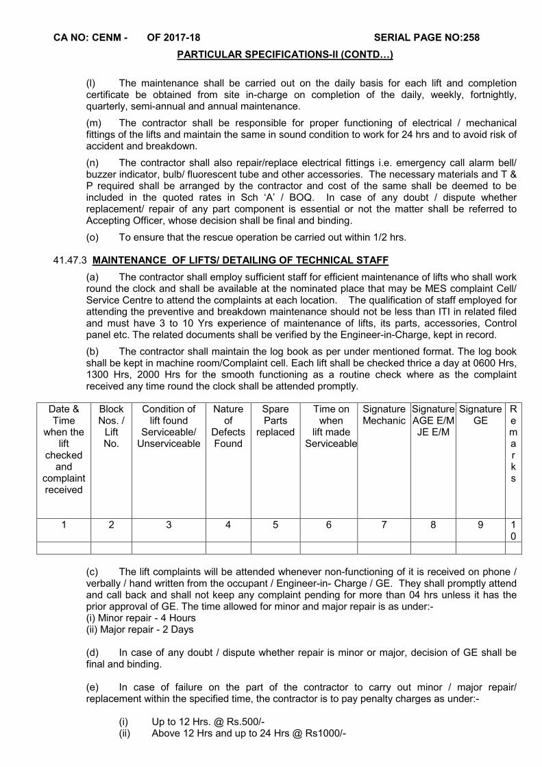
CA NO: CENM - OF 2017-18 SERIAL PAGE NO:258
PARTICULAR SPECIFICATIONS-II (CONTD…)
(l) The maintenance shall be carried out on the daily basis for each lift and completion certificate be obtained from site in-charge on completion of the daily, weekly, fortnightly, quarterly, semi-annual and annual maintenance.
(m) The contractor shall be responsible for proper functioning of electrical / mechanical fittings of the lifts and maintain the same in sound condition to work for 24 hrs and to avoid risk of accident and breakdown.
(n) The contractor shall also repair/replace electrical fittings i.e. emergency call alarm bell/ buzzer indicator, bulb/ fluorescent tube and other accessories. The necessary materials and T & P required shall be arranged by the contractor and cost of the same shall be deemed to be included in the quoted rates in Sch ‘A’ / BOQ. In case of any doubt / dispute whether replacement/ repair of any part component is essential or not the matter shall be referred to Accepting Officer, whose decision shall be final and binding.
(o) To ensure that the rescue operation be carried out within 1/2 hrs. 41.47.3 MAINTENANCE OF LIFTS/ DETAILING OF TECHNICAL STAFF
(a) The contractor shall employ sufficient staff for efficient maintenance of lifts who shall work round the clock and shall be available at the nominated place that may be MES complaint Cell/ Service Centre to attend the complaints at each location. The qualification of staff employed for attending the preventive and breakdown maintenance should not be less than ITI in related filed and must have 3 to 10 Yrs experience of maintenance of lifts, its parts, accessories, Control panel etc. The related documents shall be verified by the Engineer-in-Charge, kept in record.
(b) The contractor shall maintain the log book as per under mentioned format. The log book shall be kept in machine room/Complaint cell. Each lift shall be checked thrice a day at 0600 Hrs, 1300 Hrs, 2000 Hrs for the smooth functioning as a routine check where as the complaint received any time round the clock shall be attended promptly.
(c) The lift complaints will be attended whenever non-functioning of it is received on phone / verbally / hand written from the occupant / Engineer-in- Charge / GE. They shall promptly attend and call back and shall not keep any complaint pending for more than 04 hrs unless it has the prior approval of GE. The time allowed for minor and major repair is as under:-
(i) Minor repair - 4 Hours (ii) Major repair - 2 Days
(d) In case of any doubt / dispute whether repair is minor or major, decision of GE shall be final and binding.
(e) In case of failure on the part of the contractor to carry out minor / major repair/ replacement within the specified time, the contractor is to pay penalty charges as under:-
(i) Up to 12 Hrs. @ Rs.500/- (ii) Above 12 Hrs and up to 24 Hrs @ Rs1000/-
Date & Time
when the lift
checked and
complaint received
Block Nos. /
Lift No.
Condition of lift found
Serviceable/ Unserviceable
Nature of
Defects Found
Spare Parts
replaced
Time on when
lift made Serviceable
Signature Mechanic
Signature AGE E/M JE E/M
Signature GE
R e m a r k s
1 2 3 4 5 6 7 8 9 10
CA NO: CENM - OF 2017-18 SERIAL PAGE NO:259
PARTICULAR SPECIFICATIONS-II (CONTD…)
(iii) Above 24 Hrs @ Rs.2000/- per day
(f) Penalty charges as mentioned in Para (e) above shall be subject to max of 10% of the contract value but these penalties shall be in addition to provision made in condition 50 of IAFW – 2249.
(g) The contractor shall obtain signature of authorised representative of GE at MES office in token of satisfactory completion of defects indicating the time of complaint received and time of complaint defect rectified.
(h) The contractor shall stock sufficient spare parts to ensure putting the lifts in working condition in the above.
(j) The decision of the GE as to whether a particular lift has been maintained or not on a particular day will be final and binding.
41.47.4RESCUE OPERATION IN CASE OF AN EMERGENCY
In case of an emergency viz happening of a person inside the lift and lift getting stuck in between floors, it will be the responsibility of the mechanic to reach the lift within ½ to 1 hour of being informed by the operator / user and carry out rescue operation. The Engineer-in-Charge will satisfy himself with regard to the capability of the mechanic to carry out rescue operations in an emergency. In case the mechanic fails to reach the lift with ½ to 1 hour being informed by operators / users a penalty of Rs.5,000/- shall be imposed.
41.47.5INSPECTION
(a) The contractor shall employ a qualified & experienced supervisor to inspect each lift covered under this contract at least once in a quarter and he shall submit a written report for the serviceability of lifts and his recommendation for repairs/ renewals to ascertain the better and safety and service of the lift and machinery. Cost of these inspections is deemed to be included in the unit rates quoted in schedule` Á’ Part II.
(b) MES representative shall be associated with this inspection. However contractor shall submit a tentative progress of inspections arranged by him.
(c) The lifts shall be inspected by the concerned Engineer-in-Charge/GE at regular intervals in order to check that lifts are in proper working conditions and proper records shall be maintained in the sub division.
41.47.6RECORD
(a) The record of documents in support of repair/ replacement, periodical maintenance and testing should be maintained as per the instructions given by Engineer-in-Charge / GE, which should be signed jointly by Engineer-in-Charge and contractor. The records so maintained for each lift shall be enclosed with each claim of RAR.
(b) The contractor shall assist the Engineer-in-Charge to maintain the records as required as per the lift Rules 1958 and as amended from time to time.
41.47.7INSPECTION BY GOVT LIFT INSPECTOR: The lift shall be got inspected by Govt. Lift Inspector for the worthiness certificate as per the
rules. Charges for inspection if any shall be payable by the contractor and are deemed to be included in the rates quoted in Sch ‘A‘.
41.47.8PENALTY FOR NOT CARRYING OUT MAINTENANCE SCHEDULE
The contractor will carry out daily fortnightly, monthly, quarterly, half yearly and annual maintenance as per Proforma 01 to 06 respectively (Attached to these Particular Specifications), in case contractor fails to carry out these maintenance following penalty will be imposed daily.
(a) Not carrying out maintenance daily : Rs.1500/-
(b) Not carrying out maintenance fortnightly : Rs.2500/-
CA NO: CENM - OF 2017-18 SERIAL PAGE NO:260
PARTICULAR SPECIFICATIONS-II (CONTD…)
(c) Not carrying out maintenance monthly : Rs.3000/- (d) Not carrying out maintenance quarterly : Rs.4000/- (e) Not carrying out maintenance half yearly : Rs.5000/- (f) Not carrying out maintenance annually : Rs.10000/-
41.47.9 PURCHASE VOUCHER
Original purchase vouchers shall be submitted by the contractor in support of genuineness of material along with test certificate before claiming RAR payment.
42.0 HOLLOW METAL FIRE DOORS WITH HONEY COMB CORE
42.1 Fire door shall be 2 hour fire rated and door quality shall be approved by CBRI and tested
conforming to IS: 3614 Code / BS 476 Part 20 and 22. Unless otherwise specified, maximum size of door in this type: Single shutter door : 1000 mm x 2100mm
42.2 Frame -
a) Material - Frame to be manufactured from 1.60 mm max (16 gauge) galvanized steel sheets complying to IS 277 Code of GPL Grade with Z 120 Coating.
b) Profile - Single Rebated Frame to be of dimensions 100mm x 58 mm.
c) Manufacture - Frame to be manufactured from 1.60 mm thick galvanized steel sheet to the specified profiles and dimensions. Frames manufactured at factory shall be knock down form with mitered assembly at site.
d) Door frame preparations – Frames to be provided with back plates on all jambs with provision for anchor bolt fixing to wall openings. All frames to have reinforcement pads for fixing of door closer, at appropriate location as per manufacturer’s details.
e) Frames to have factory finish-pre-punched cut outs to receive specific hardware and iron mongery.
f) Frames to be provided with hinge plates 3 mm thick pre-drilled to receive hinges for screw mounted fixing. All cut outs including hinge plates, strike plates to have mortar guard covers from inside to prevent cement, dust ingress into cut outs at the time of grouting.
g) Frames to have rubber shutter silencer on strike jambs for single shutter frames and on the head jambs for double shutter frames.
h) Frames shall be finished with Pure Polyester Powder Coated to any RAL Shade / Wood Stained to withstand 300 hours of salt spray.
42.3 Fire door shutter
a) Material - Fire door shutter to be manufactured from 1.20 mm galvanized sheets conforming to latest IS: 277 Code of GPL Grade with Z 120 coating.
b) Manufacture - Shutters to be press formed to 47 mm thick double skin hollow door with lock seam joints at stile edges. Shutters to have no visible screws or fasteners on either face.
c) Door Shutter Cores – Shutters to be provided with honeycomb craft paper core to be bonded to the inner faces of the shutter.
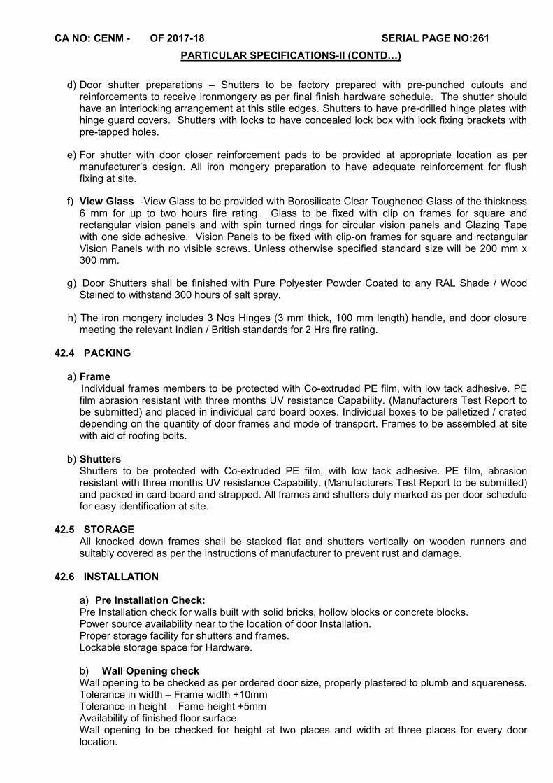
CA NO: CENM - OF 2017-18 SERIAL PAGE NO:261
PARTICULAR SPECIFICATIONS-II (CONTD…)
d) Door shutter preparations – Shutters to be factory prepared with pre-punched cutouts and
reinforcements to receive ironmongery as per final finish hardware schedule. The shutter should have an interlocking arrangement at this stile edges. Shutters to have pre-drilled hinge plates with hinge guard covers. Shutters with locks to have concealed lock box with lock fixing brackets with pre-tapped holes.
e) For shutter with door closer reinforcement pads to be provided at appropriate location as per manufacturer’s design. All iron mongery preparation to have adequate reinforcement for flush fixing at site.
f) View Glass -View Glass to be provided with Borosilicate Clear Toughened Glass of the thickness 6 mm for up to two hours fire rating. Glass to be fixed with clip on frames for square and rectangular vision panels and with spin turned rings for circular vision panels and Glazing Tape with one side adhesive. Vision Panels to be fixed with clip-on frames for square and rectangular Vision Panels with no visible screws. Unless otherwise specified standard size will be 200 mm x 300 mm.
g) Door Shutters shall be finished with Pure Polyester Powder Coated to any RAL Shade / Wood Stained to withstand 300 hours of salt spray.
h) The iron mongery includes 3 Nos Hinges (3 mm thick, 100 mm length) handle, and door closure meeting the relevant Indian / British standards for 2 Hrs fire rating.
42.4 PACKING a) Frame Individual frames members to be protected with Co-extruded PE film, with low tack adhesive. PE
film abrasion resistant with three months UV resistance Capability. (Manufacturers Test Report to be submitted) and placed in individual card board boxes. Individual boxes to be palletized / crated depending on the quantity of door frames and mode of transport. Frames to be assembled at site with aid of roofing bolts.
b) Shutters Shutters to be protected with Co-extruded PE film, with low tack adhesive. PE film, abrasion
resistant with three months UV resistance Capability. (Manufacturers Test Report to be submitted) and packed in card board and strapped. All frames and shutters duly marked as per door schedule for easy identification at site.
42.5 STORAGE
All knocked down frames shall be stacked flat and shutters vertically on wooden runners and suitably covered as per the instructions of manufacturer to prevent rust and damage.
42.6 INSTALLATION
a) Pre Installation Check: Pre Installation check for walls built with solid bricks, hollow blocks or concrete blocks. Power source availability near to the location of door Installation. Proper storage facility for shutters and frames. Lockable storage space for Hardware.
b) Wall Opening check Wall opening to be checked as per ordered door size, properly plastered to plumb and squareness. Tolerance in width – Frame width +10mm Tolerance in height – Fame height +5mm Availability of finished floor surface. Wall opening to be checked for height at two places and width at three places for every door location.
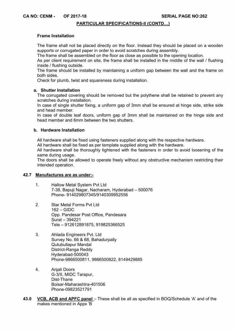
CA NO: CENM - OF 2017-18 SERIAL PAGE NO:262
PARTICULAR SPECIFICATIONS-II (CONTD…)
Frame Installation
The frame shall not be placed directly on the floor. Instead they should be placed on a wooden supports or corrugated paper in order to avoid scratches during assembly. The frame shall be assembled on the floor as close as possible to the opening location. As per client requirement on site, the frame shall be installed in the middle of the wall / flushing inside / flushing outside. The frame should be installed by maintaining a uniform gap between the wall and the frame on both sides. Check for plumb, twist and squareness during installation.
a. Shutter Installation The corrugated covering should be removed but the polythene shall be retained to prevent any scratches during installation. In case of single shutter fixing, a uniform gap of 3mm shall be ensured at hinge side, strike side and head member. In case of double leaf doors, uniform gap of 3mm shall be maintained on the hinge side and head member and 6mm between the two shutters.
b. Hardware Installation
All hardware shall be fixed using fasteners supplied along with the respective hardware. All hardware shall be fixed as per template supplied along with the hardware. All hardware shall be thoroughly tightened with the fasteners in order to avoid loosening of the same during usage. The doors shall be allowed to operate freely without any obstructive mechanism restricting their intended operation.
42.7 Manufactures are as under:- 1. Hallow Metal System Pvt Ltd 7-38, Bapuji Nagar, Nacharam, Hyderabad – 500076 Phone- 914029807345/9140309952556 2. Star Metal Forms Pvt Ltd 162 – GIDC Opp. Pandesar Post Office, Pandesara Surat – 394221 Tele – 912612891875, 919825366525 3. Ahlada Engineers Pvt. Ltd Survey No. 66 & 68, Bahadurpally Qutubullapur Mandal District-Ranga Reddy Hyderabad-500043 Phone-9866500811, 9866500822, 8149429885 4. Anjali Doors G-3/II, MIDC Tarapur, Dist-Thane Boisar-Maharashtra-401506 Phone-09823521791
43.0 VCB, ACB and APFC panel :- These shall be all as specified in BOQ/Schedule ‘A’ and of the makes mentioned in Appx ‘B
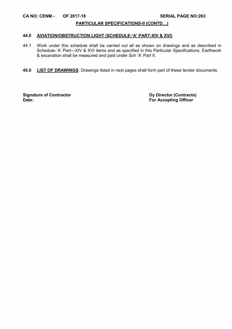
CA NO: CENM - OF 2017-18 SERIAL PAGE NO:263
PARTICULAR SPECIFICATIONS-II (CONTD…)
44.0 AVIATION/OBSTRUCTION LIGHT (SCHEDULE-‘A’ PART-XIV & XVI) 44.1 Work under this schedule shall be carried out all as shown on drawings and as described in
Schedule-`A’ Part—XIV & XVI items and as specified in this Particular Specifications. Earthwork & excavation shall be measured and paid under Sch ‘A’ Part II.
45.0 LIST OF DRAWINGS: Drawings listed in next pages shall form part of these tender documents. Signature of Contractor Dy Director (Contracts) Date: For Accepting Officer
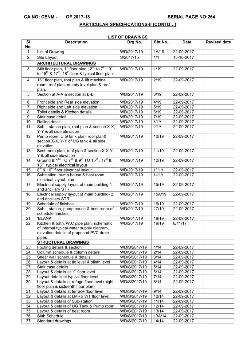
CA NO: CENM - OF 2017-18 SERIAL PAGE NO:264
PARTICULAR SPECIFICATIONS-II (CONTD…)
LIST OF DRAWINGS
Sl No.
Description Drg No. Sht No. Date Revised date
1 List of Drawing WD/2017/19 1A/19 22-09-2017
2 Site Layout S/2017/15 1/1 13-10-2017
ARCHITECTURAL DRAWINGS
3 Stilt floor plan, 1st floor plan , 2
nd to 7
th , 9
th
to 15th & 17
th, 18
th floor & typical floor plan
WD/2017/19 1/19 22-09-2017
4 16th floor plan, roof plan & lift machine
room, roof plan, mumty level plan & roof plan.
WD/2017/19 2/19 22-09-2017
5 Section at A-A & section at B-B WD/2017/19 3/19 22-09-2017
6 Front side and Rear side elevation WD/2017/19 4/19 22-09-2017 7 Right side and Left side elevation WD/2017/19 5/19 22-09-2017 8 Toilet details & Kitchen details WD/2017/19 6/19 22-09-2017 9 Stair case detail WD/2017/19 7/19 22-09-2017
10 Railing detail WD/2017/19 8/19 22-09-2017 11 Sub – station plan, roof plan & section X-X,
Y-Y & all side elevation WD/2017/19 9/19 22-09-2017
12 Pump room, U G tank plan, roof plan& section X-X, Y-Y of UG tank & all side elevation
WD/2017/19 10/19 22-09-2017
13 Best room plan, roof plan & section X-X Y-Y & all side elevation
WD/2017/19 11/19 22-09-2017
14 Ground & 1St
TO 7th
& 9th TO 15
th , 17
th &
18th typical electrical layout
WD/2017/19 12/19 22-09-2017
15 8th & 16
th floor electrical layout WD/2017/19 13/19 22-09-2017
16 Substation, pump house & best room electrical layout plan
WD/2017/19 14/19 22-09-2017
17 Electrical supply layout of main building-1 and ancillary STR
WD/2017/19 15/19 22-09-2017
18 Electrical supply layout of main building- 2 and ancillary STR
WD/2017/19 15A/19 22-09-2017
19 Schedule of finishes WD/2017/19 16/19 22-09-2017 20 Sub – station, pump house & best room of
schedule finishes WD/2017/19 17/19 22-09-2017
21 ‘BLANK’ WD/2017/19 18/19 22-09-2017 22 Kitchen & bath, W.C pipe plan, schematic
of internal typical water supply diagram, elevation details of proposed PVC drain pipes
WD/2017/19 19/19 8/11/17
STRUCTURAL DRAWINGS 23 Footing details & section WD/S/2017/19 1/14 22-09-2017 24 Column schedule & column details WD/S/2017/19 2/14 22-09-2017 25 Shear wall schedule & details WD/S/2017/19 3/14 22-09-2017 26 Layout & details at tie level & plinth level WD/S/2017/19 4/14 22-09-2017 27 Stair case details WD/S/2017/19 5/14 22-09-2017 28 Layout & details at 1
st floor level WD/S/2017/19 6/14 22-09-2017
29 Layout details at typical floor level WD/S/2017/19 7/14 22-09-2017 30 Layout & details at refuge floor level (eight
floor plan & sixteenth floor plan) WD/S/2017/19 8/14 22-09-2017
31 Layout & details at terrace floor level WD/S/2017/19 9/14 22-09-2017 32 Layout & details at LMR& WT floor level WD/S/2017/19 10/14 22-09-2017 33 Layout & details of Sub-station WD/S/2017/19 11/14 22-09-2017 34 Layout & details of UG Tank & Pump room WD/S/2017/19 12/14 22-09-2017 35 Layout & details of best room WD/S/2017/19 13/14 22-09-2017 36 Slab Schedule WD/S/2017/19 13A/14 22-09-2017 37 Standard drawings WD/S/2017/19 14/14 22-09-2017
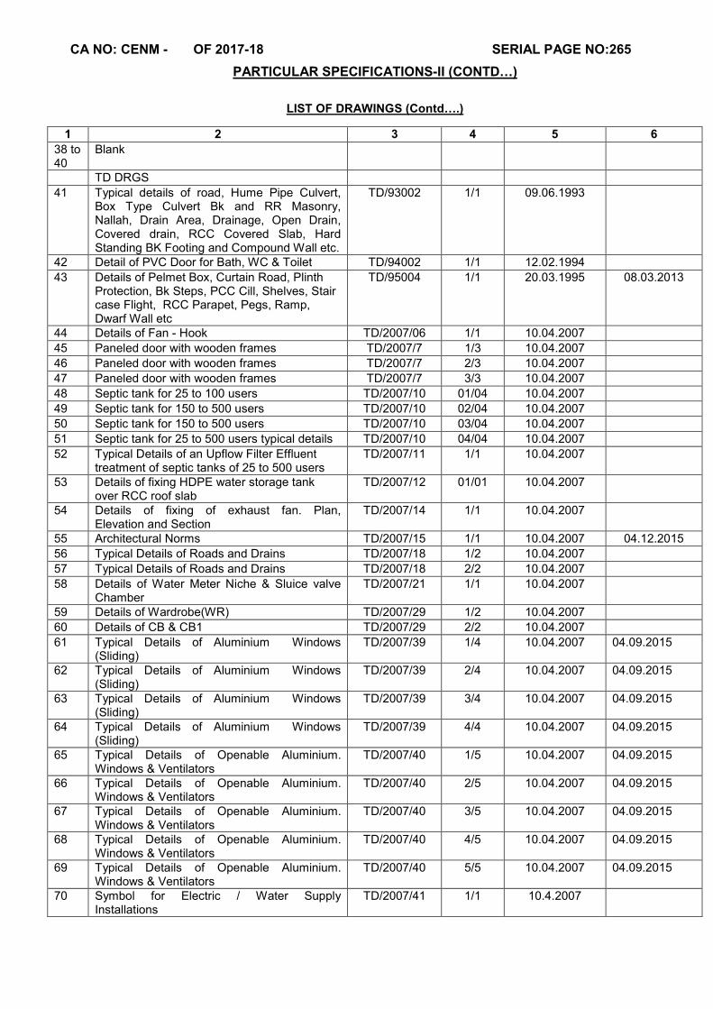
CA NO: CENM - OF 2017-18 SERIAL PAGE NO:265
PARTICULAR SPECIFICATIONS-II (CONTD…)
LIST OF DRAWINGS (Contd….)
1 2 3 4 5 6
38 to 40
Blank
TD DRGS
41 Typical details of road, Hume Pipe Culvert, Box Type Culvert Bk and RR Masonry, Nallah, Drain Area, Drainage, Open Drain, Covered drain, RCC Covered Slab, Hard Standing BK Footing and Compound Wall etc.
TD/93002 1/1 09.06.1993
42 Detail of PVC Door for Bath, WC & Toilet TD/94002 1/1 12.02.1994
43 Details of Pelmet Box, Curtain Road, Plinth Protection, Bk Steps, PCC Cill, Shelves, Stair case Flight, RCC Parapet, Pegs, Ramp, Dwarf Wall etc
TD/95004 1/1 20.03.1995 08.03.2013
44 Details of Fan - Hook TD/2007/06 1/1 10.04.2007
45 Paneled door with wooden frames TD/2007/7 1/3 10.04.2007
46 Paneled door with wooden frames TD/2007/7 2/3 10.04.2007
47 Paneled door with wooden frames TD/2007/7 3/3 10.04.2007
48 Septic tank for 25 to 100 users TD/2007/10 01/04 10.04.2007
49 Septic tank for 150 to 500 users TD/2007/10 02/04 10.04.2007
50 Septic tank for 150 to 500 users TD/2007/10 03/04 10.04.2007
51 Septic tank for 25 to 500 users typical details TD/2007/10 04/04 10.04.2007
52 Typical Details of an Upflow Filter Effluent treatment of septic tanks of 25 to 500 users
TD/2007/11 1/1 10.04.2007
53 Details of fixing HDPE water storage tank over RCC roof slab
TD/2007/12 01/01 10.04.2007
54 Details of fixing of exhaust fan. Plan, Elevation and Section
TD/2007/14 1/1 10.04.2007
55 Architectural Norms TD/2007/15 1/1 10.04.2007 04.12.2015
56 Typical Details of Roads and Drains TD/2007/18 1/2 10.04.2007
57 Typical Details of Roads and Drains TD/2007/18 2/2 10.04.2007
58 Details of Water Meter Niche & Sluice valve Chamber
TD/2007/21 1/1 10.04.2007
59 Details of Wardrobe(WR) TD/2007/29 1/2 10.04.2007
60 Details of CB & CB1 TD/2007/29 2/2 10.04.2007
61 Typical Details of Aluminium Windows (Sliding)
TD/2007/39 1/4 10.04.2007 04.09.2015
62 Typical Details of Aluminium Windows (Sliding)
TD/2007/39 2/4 10.04.2007 04.09.2015
63 Typical Details of Aluminium Windows (Sliding)
TD/2007/39 3/4 10.04.2007 04.09.2015
64 Typical Details of Aluminium Windows (Sliding)
TD/2007/39 4/4 10.04.2007 04.09.2015
65 Typical Details of Openable Aluminium. Windows & Ventilators
TD/2007/40 1/5 10.04.2007
04.09.2015
66 Typical Details of Openable Aluminium. Windows & Ventilators
TD/2007/40 2/5 10.04.2007 04.09.2015
67 Typical Details of Openable Aluminium. Windows & Ventilators
TD/2007/40 3/5 10.04.2007 04.09.2015
68 Typical Details of Openable Aluminium. Windows & Ventilators
TD/2007/40 4/5 10.04.2007 04.09.2015
69 Typical Details of Openable Aluminium. Windows & Ventilators
TD/2007/40 5/5 10.04.2007 04.09.2015
70 Symbol for Electric / Water Supply Installations
TD/2007/41 1/1 10.4.2007

CA NO: CENM - OF 2017-18 SERIAL PAGE NO:266
PARTICULAR SPECIFICATIONS-II (CONTD…)
LIST OF DRAWINGS (Contd….)
1 2 3 4 5 6
71 Details of Switch Boxes for domestic light & power main switches and Distribution board (Including meters).
TD/2007/42 1/3 10.04.2007
72 Details of Switch Boxes for domestic light & power main switches and Distribution board (Including meters).
TD/2007/42 2/3 10.04.2007
73 Details of Switch Boxes for domestic light & power main switches and Distribution board (Including meters).
TD/2007/42 3/3 10.04.2007
74 Miscellaneous Details (Detail of Pelmet Box, Ramp, MS Rungs, Roof Slab Projection, RCC Chajja etc)
TD/2007/43 1/3 10.04.2007
75 Detail of Peg Set, PCC Coping Format, Plinth Protection, Railing etc
TD/2007/43 2/3 10.04.2007
76 Detail of Curtain Rod TD/2007/43 3/3 10.04.2007
77 Details of Nihani Trap & Pipe connections
TD/2007/44 2/2 10.04.2007
78 Notes on RCC works. TD/S/2010/08 1/12 29.10.2010
79 Notes on RCC works. TD/S/2010/08 2/12 29.10.2010
80 Notes on RCC works. TD/S/2010/08 3/12 29.10.2010
81 Notes on RCC works. TD/S/2010/08 4/12 29.10.2010
82 Notes on RCC works. TD/S/2010/08 5/12 29.10.2010
83 Notes on RCC works. TD/S/2010/08 6/12 29.10.2010
84 Notes on RCC works. TD/S/2010/08 7/12 29.10.2010
85 Notes on RCC works. TD/S/2010/08 8/12 29.10.2010
86 Notes on RCC works. TD/S/2010/08 9/12 29.10.2010
87 Notes on RCC works. TD/S/2010/08 10/12 29.10.2010 12.11.2010
88 Notes on RCC works. TD/S/2010/08 11/12 29.10.2010
89 Notes on RCC works. TD/S/2010/08 12/12 29.10.2010
90 Typical details of R.C.C Chajjas, lintels and Schedule of RCC Lintels
TD/S/2010/09 1/10 29.10.2010
91 Typical details of R.C.C Chajjas, lintels and Schedule of RCC Lintels
TD/S/2010/09 2/10 29.10.2010
92 Typical details of R.C.C Chajjas, lintels and Schedule of RCC Lintels
TD/S/2010/09 3/10 29.10.2010
93 Typical details of R.C.C Chajjas, lintels and Schedule of RCC Lintels
TD/S/2010/09 4/10 29.10.2010
94 Typical details of R.C.C Chajjas, lintels and Schedule of RCC Lintels
TD/S/2010/09 5/10 29.10.2010
95 Typical details of R.C.C Chajjas, lintels and Schedule of RCC Lintels
TD/S/2010/09 6/10 29.10.2010
96 Typical details of R.C.C Chajjas, lintels and Schedule of RCC Lintels
TD/S/2010/09 7/10 29.10.2010
97 Typical details of R.C.C Chajjas, lintels and Schedule of RCC Lintels
TD/S/2010/09 8/10 29.10.2010
98 Typical details of R.C.C Chajjas, lintels and Schedule of RCC Lintels
TD/S/2010/09 9/10 29.10.2010
99 Typical details of R.C.C Chajjas, lintels and Schedule of RCC Lintels
TD/S/2010/09 10/10 29.10.2010
100 Ductile Detailing/Typical Details of Stirrups in Beam, Ties in Column And Details of Beam Column Junction.
TD/S/2010/10 1/3 29.10.2010
101 Ductile Detailing/Typical Details of Stirrups in Beam, Ties in Column And Details of Beam Column Junction.
TD/S/2010/10 2/3 29.10.2010
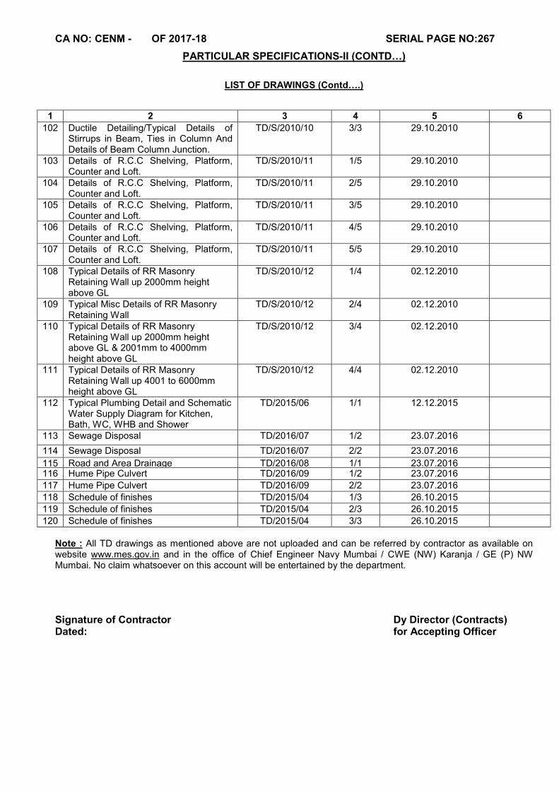
CA NO: CENM - OF 2017-18 SERIAL PAGE NO:267
PARTICULAR SPECIFICATIONS-II (CONTD…)
LIST OF DRAWINGS (Contd….)
Note : All TD drawings as mentioned above are not uploaded and can be referred by contractor as available on website www.mes.gov.in and in the office of Chief Engineer Navy Mumbai / CWE (NW) Karanja / GE (P) NW Mumbai. No claim whatsoever on this account will be entertained by the department.
Signature of Contractor Dy Director (Contracts) Dated: for Accepting Officer
1 2 3 4 5 6
102 Ductile Detailing/Typical Details of Stirrups in Beam, Ties in Column And Details of Beam Column Junction.
TD/S/2010/10 3/3 29.10.2010
103 Details of R.C.C Shelving, Platform, Counter and Loft.
TD/S/2010/11 1/5 29.10.2010
104 Details of R.C.C Shelving, Platform, Counter and Loft.
TD/S/2010/11 2/5 29.10.2010
105 Details of R.C.C Shelving, Platform, Counter and Loft.
TD/S/2010/11 3/5 29.10.2010
106 Details of R.C.C Shelving, Platform, Counter and Loft.
TD/S/2010/11 4/5 29.10.2010
107 Details of R.C.C Shelving, Platform, Counter and Loft.
TD/S/2010/11 5/5 29.10.2010
108 Typical Details of RR Masonry Retaining Wall up 2000mm height above GL
TD/S/2010/12 1/4 02.12.2010
109 Typical Misc Details of RR Masonry Retaining Wall
TD/S/2010/12 2/4 02.12.2010
110 Typical Details of RR Masonry Retaining Wall up 2000mm height above GL & 2001mm to 4000mm height above GL
TD/S/2010/12 3/4 02.12.2010
111 Typical Details of RR Masonry Retaining Wall up 4001 to 6000mm height above GL
TD/S/2010/12 4/4 02.12.2010
112 Typical Plumbing Detail and Schematic Water Supply Diagram for Kitchen, Bath, WC, WHB and Shower
TD/2015/06 1/1 12.12.2015
113 Sewage Disposal TD/2016/07 1/2 23.07.2016
114 Sewage Disposal TD/2016/07 2/2 23.07.2016
115 Road and Area Drainage TD/2016/08 1/1 23.07.2016 116 Hume Pipe Culvert TD/2016/09 1/2 23.07.2016
117 Hume Pipe Culvert TD/2016/09 2/2 23.07.2016
118 Schedule of finishes TD/2015/04 1/3 26.10.2015
119 Schedule of finishes TD/2015/04 2/3 26.10.2015
120 Schedule of finishes TD/2015/04 3/3 26.10.2015
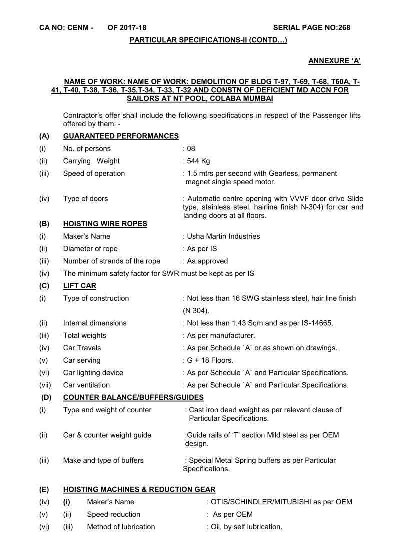
CA NO: CENM - OF 2017-18 SERIAL PAGE NO:268
PARTICULAR SPECIFICATIONS-II (CONTD…)
ANNEXURE ‘A’
NAME OF WORK: NAME OF WORK: DEMOLITION OF BLDG T-97, T-69, T-68, T60A, T-41, T-40, T-38, T-36, T-35,T-34, T-33, T-32 AND CONSTN OF DEFICIENT MD ACCN FOR
SAILORS AT NT POOL, COLABA MUMBAI Contractor’s offer shall include the following specifications in respect of the Passenger lifts offered by them: -
(A) GUARANTEED PERFORMANCES
(i) No. of persons : 08
(ii) Carrying Weight : 544 Kg
(iii) Speed of operation : 1.5 mtrs per second with Gearless, permanent magnet single speed motor. (iv) Type of doors : Automatic centre opening with VVVF door drive Slide
type, stainless steel, hairline finish N-304) for car and landing doors at all floors.
(B) HOISTING WIRE ROPES
(i) Maker’s Name : Usha Martin Industries
(ii) Diameter of rope : As per IS
(iii) Number of strands of the rope : As approved
(iv) The minimum safety factor for SWR must be kept as per IS
(C) LIFT CAR
(i) Type of construction : Not less than 16 SWG stainless steel, hair line finish
(N 304).
(ii) Internal dimensions : Not less than 1.43 Sqm and as per IS-14665.
(iii) Total weights : As per manufacturer.
(iv) Car Travels : As per Schedule `A` or as shown on drawings.
(v) Car serving : G + 18 Floors.
(vi) Car lighting device : As per Schedule `A` and Particular Specifications.
(vii) Car ventilation : As per Schedule `A` and Particular Specifications.
(D) COUNTER BALANCE/BUFFERS/GUIDES
(i) Type and weight of counter : Cast iron dead weight as per relevant clause of Particular Specifications.
(ii) Car & counter weight guide :Guide rails of ‘T’ section Mild steel as per OEM design.
(iii) Make and type of buffers : Special Metal Spring buffers as per Particular Specifications.
(E) HOISTING MACHINES & REDUCTION GEAR
(iv) (i) Maker’s Name : OTIS/SCHINDLER/MITUBISHI as per OEM
(v) (ii) Speed reduction : As per OEM
(vi) (iii) Method of lubrication : Oil, by self lubrication.
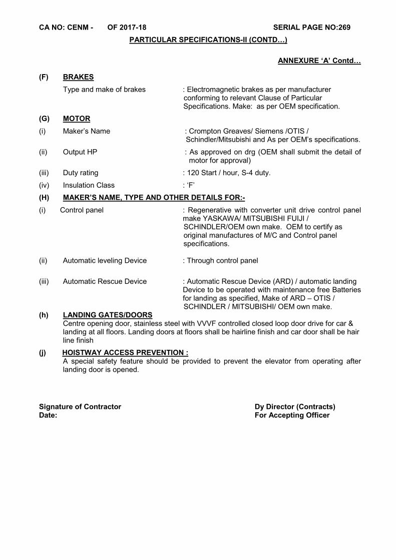
CA NO: CENM - OF 2017-18 SERIAL PAGE NO:269
PARTICULAR SPECIFICATIONS-II (CONTD…)
ANNEXURE ‘A’ Contd…
(F) BRAKES
Type and make of brakes : Electromagnetic brakes as per manufacturer conforming to relevant Clause of Particular Specifications. Make: as per OEM specification.
(G) MOTOR
(i) Maker’s Name : Crompton Greaves/ Siemens /OTIS / Schindler/Mitsubishi and As per OEM’s specifications.
(ii) Output HP : As approved on drg (OEM shall submit the detail of motor for approval)
(iii) Duty rating : 120 Start / hour, S-4 duty.
(iv) Insulation Class : ‘F’
(H) MAKER’S NAME, TYPE AND OTHER DETAILS FOR:-
(i) Control panel : Regenerative with converter unit drive control panel make YASKAWA/ MITSUBISHI FUIJI /
SCHINDLER/OEM own make. OEM to certify as original manufactures of M/C and Control panel specifications. (ii) Automatic leveling Device : Through control panel
(iii) Automatic Rescue Device : Automatic Rescue Device (ARD) / automatic landing Device to be operated with maintenance free Batteries
for landing as specified, Make of ARD – OTIS / SCHINDLER / MITSUBISHI/ OEM own make. (h) LANDING GATES/DOORS Centre opening door, stainless steel with VVVF controlled closed loop door drive for car &
landing at all floors. Landing doors at floors shall be hairline finish and car door shall be hair line finish
(j) HOISTWAY ACCESS PREVENTION : A special safety feature should be provided to prevent the elevator from operating after
landing door is opened.
Signature of Contractor Dy Director (Contracts) Date: For Accepting Officer
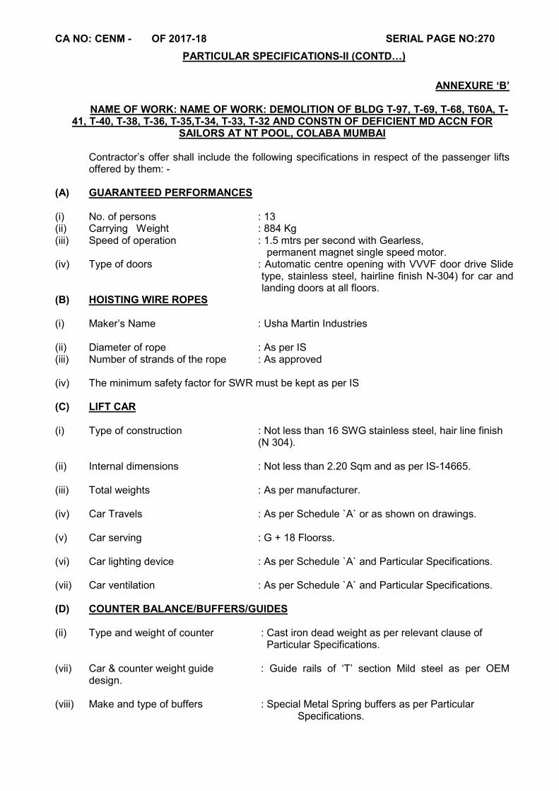
CA NO: CENM - OF 2017-18 SERIAL PAGE NO:270
PARTICULAR SPECIFICATIONS-II (CONTD…)
ANNEXURE ‘B’
NAME OF WORK: NAME OF WORK: DEMOLITION OF BLDG T-97, T-69, T-68, T60A, T-41, T-40, T-38, T-36, T-35,T-34, T-33, T-32 AND CONSTN OF DEFICIENT MD ACCN FOR
SAILORS AT NT POOL, COLABA MUMBAI Contractor’s offer shall include the following specifications in respect of the passenger lifts offered by them: -
(A) GUARANTEED PERFORMANCES (i) No. of persons : 13 (ii) Carrying Weight : 884 Kg (iii) Speed of operation : 1.5 mtrs per second with Gearless, permanent magnet single speed motor. (iv) Type of doors : Automatic centre opening with VVVF door drive Slide
type, stainless steel, hairline finish N-304) for car and landing doors at all floors.
(B) HOISTING WIRE ROPES (i) Maker’s Name : Usha Martin Industries (ii) Diameter of rope : As per IS (iii) Number of strands of the rope : As approved (iv) The minimum safety factor for SWR must be kept as per IS (C) LIFT CAR (i) Type of construction : Not less than 16 SWG stainless steel, hair line finish (N 304). (ii) Internal dimensions : Not less than 2.20 Sqm and as per IS-14665. (iii) Total weights : As per manufacturer. (iv) Car Travels : As per Schedule `A` or as shown on drawings. (v) Car serving : G + 18 Floorss. (vi) Car lighting device : As per Schedule `A` and Particular Specifications. (vii) Car ventilation : As per Schedule `A` and Particular Specifications. (D) COUNTER BALANCE/BUFFERS/GUIDES (ii) Type and weight of counter : Cast iron dead weight as per relevant clause of
Particular Specifications. (vii) Car & counter weight guide : Guide rails of ‘T’ section Mild steel as per OEM
design.
(viii) Make and type of buffers : Special Metal Spring buffers as per Particular Specifications.
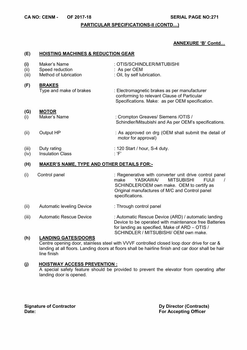
CA NO: CENM - OF 2017-18 SERIAL PAGE NO:271
PARTICULAR SPECIFICATIONS-II (CONTD…)
ANNEXURE ‘B’ Contd… (E) HOISTING MACHINES & REDUCTION GEAR (i) Maker’s Name : OTIS/SCHINDLER/MITUBISHI (ii) Speed reduction : As per OEM (iii) Method of lubrication : Oil, by self lubrication. (F) BRAKES Type and make of brakes : Electromagnetic brakes as per manufacturer
conforming to relevant Clause of Particular Specifications. Make: as per OEM specification.
(G) MOTOR (i) Maker’s Name : Crompton Greaves/ Siemens /OTIS /
Schindler/Mitsubishi and As per OEM’s specifications. (ii) Output HP : As approved on drg (OEM shall submit the detail of
motor for approval) (iii) Duty rating : 120 Start / hour, S-4 duty. (iv) Insulation Class : ‘F’ (H) MAKER’S NAME, TYPE AND OTHER DETAILS FOR:- (i) Control panel : Regenerative with converter unit drive control panel
make YASKAWA/ MITSUBISHI FUIJI / SCHINDLER/OEM own make. OEM to certify as
Original manufactures of M/C and Control panel specifications. (ii) Automatic leveling Device : Through control panel (iii) Automatic Rescue Device : Automatic Rescue Device (ARD) / automatic landing Device to be operated with maintenance free Batteries
for landing as specified, Make of ARD – OTIS / SCHINDLER / MITSUBISHI/ OEM own make. (h) LANDING GATES/DOORS Centre opening door, stainless steel with VVVF controlled closed loop door drive for car &
landing at all floors. Landing doors at floors shall be hairline finish and car door shall be hair line finish
(j) HOISTWAY ACCESS PREVENTION : A special safety feature should be provided to prevent the elevator from operating after
landing door is opened. Signature of Contractor Dy Director (Contracts) Date: For Accepting Officer
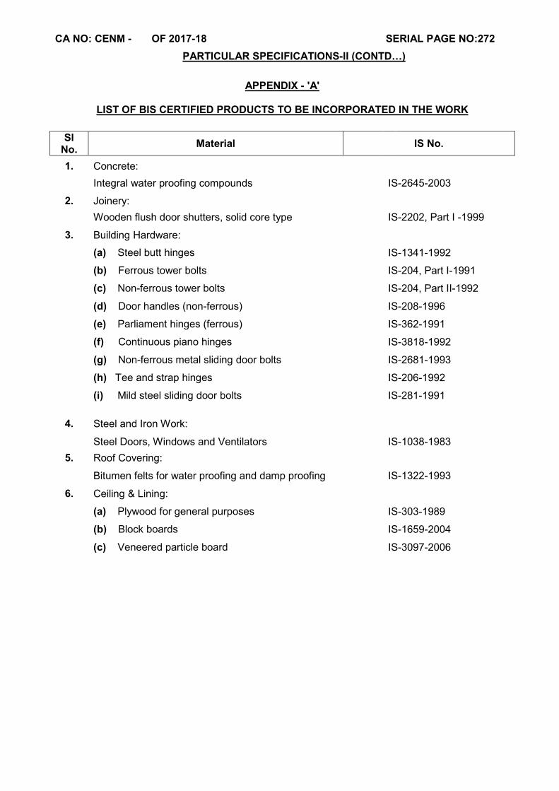
CA NO: CENM - OF 2017-18 SERIAL PAGE NO:272
PARTICULAR SPECIFICATIONS-II (CONTD…)
APPENDIX - 'A'
LIST OF BIS CERTIFIED PRODUCTS TO BE INCORPORATED IN THE WORK
Sl No.
Material IS No.
1. Concrete:
Integral water proofing compounds IS-2645-2003
2. Joinery:
Wooden flush door shutters, solid core type IS-2202, Part I -1999
3. Building Hardware:
(a) Steel butt hinges IS-1341-1992
(b) Ferrous tower bolts IS-204, Part I-1991
(c) Non-ferrous tower bolts IS-204, Part II-1992
(d) Door handles (non-ferrous) IS-208-1996
(e) Parliament hinges (ferrous) IS-362-1991
(f) Continuous piano hinges IS-3818-1992
(g) Non-ferrous metal sliding door bolts IS-2681-1993
(h) Tee and strap hinges IS-206-1992
(i) Mild steel sliding door bolts IS-281-1991
4. Steel and Iron Work:
Steel Doors, Windows and Ventilators IS-1038-1983 5. Roof Covering:
Bitumen felts for water proofing and damp proofing IS-1322-1993
6. Ceiling & Lining:
(a) Plywood for general purposes IS-303-1989
(b) Block boards IS-1659-2004
(c) Veneered particle board IS-3097-2006
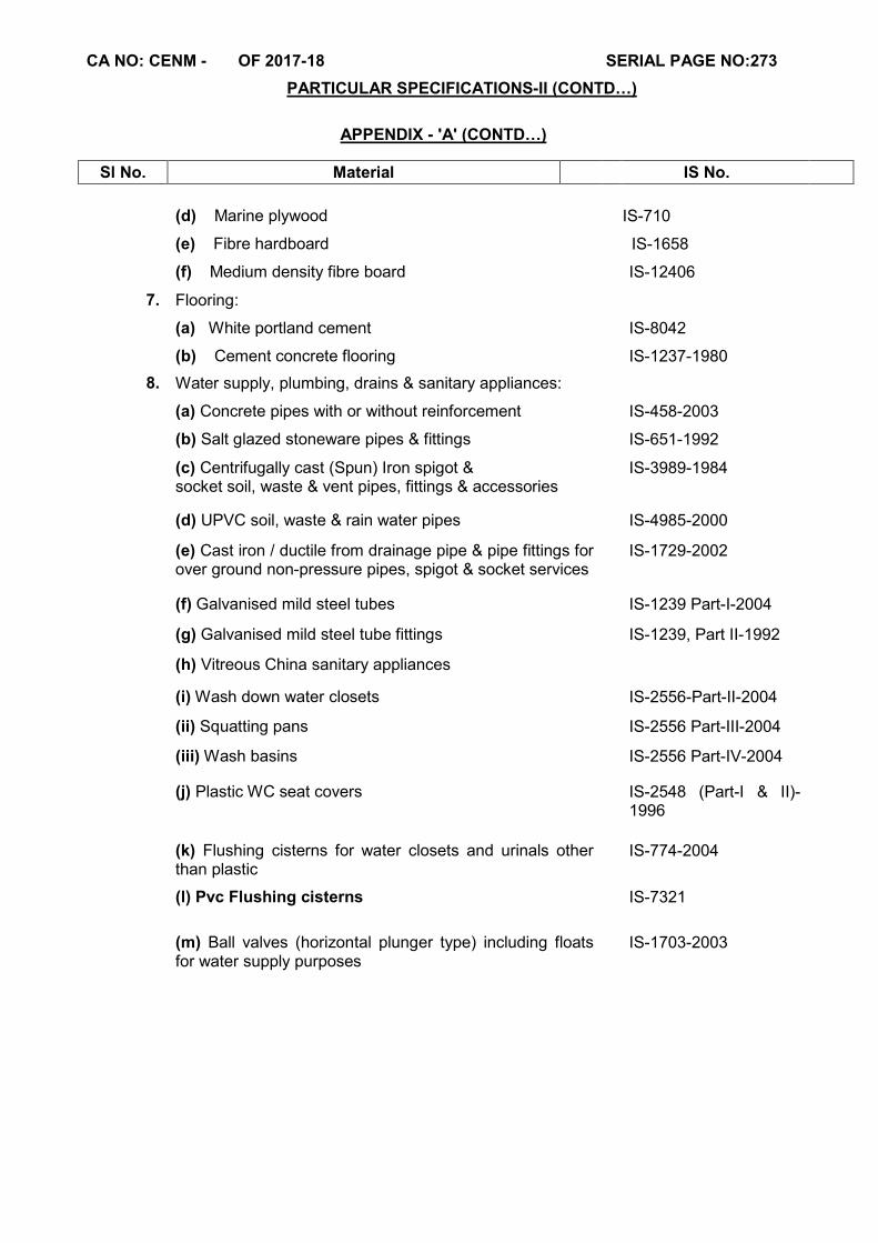
CA NO: CENM - OF 2017-18 SERIAL PAGE NO:273
PARTICULAR SPECIFICATIONS-II (CONTD…)
APPENDIX - 'A' (CONTD…)
Sl No. Material IS No.
(d) Marine plywood IS-710
(e) Fibre hardboard IS-1658
(f) Medium density fibre board IS-12406
7. Flooring:
(a) White portland cement IS-8042
(b) Cement concrete flooring IS-1237-1980
8. Water supply, plumbing, drains & sanitary appliances:
(a) Concrete pipes with or without reinforcement IS-458-2003
(b) Salt glazed stoneware pipes & fittings IS-651-1992
(c) Centrifugally cast (Spun) Iron spigot & socket soil, waste & vent pipes, fittings & accessories
IS-3989-1984
(d) UPVC soil, waste & rain water pipes IS-4985-2000
(e) Cast iron / ductile from drainage pipe & pipe fittings for over ground non-pressure pipes, spigot & socket services
IS-1729-2002
(f) Galvanised mild steel tubes IS-1239 Part-I-2004
(g) Galvanised mild steel tube fittings IS-1239, Part II-1992
(h) Vitreous China sanitary appliances
(i) Wash down water closets IS-2556-Part-II-2004
(ii) Squatting pans IS-2556 Part-III-2004
(iii) Wash basins IS-2556 Part-IV-2004
(j) Plastic WC seat covers IS-2548 (Part-I & II)-1996
(k) Flushing cisterns for water closets and urinals other
than plastic IS-774-2004
(l) Pvc Flushing cisterns IS-7321
(m) Ball valves (horizontal plunger type) including floats for water supply purposes
IS-1703-2003
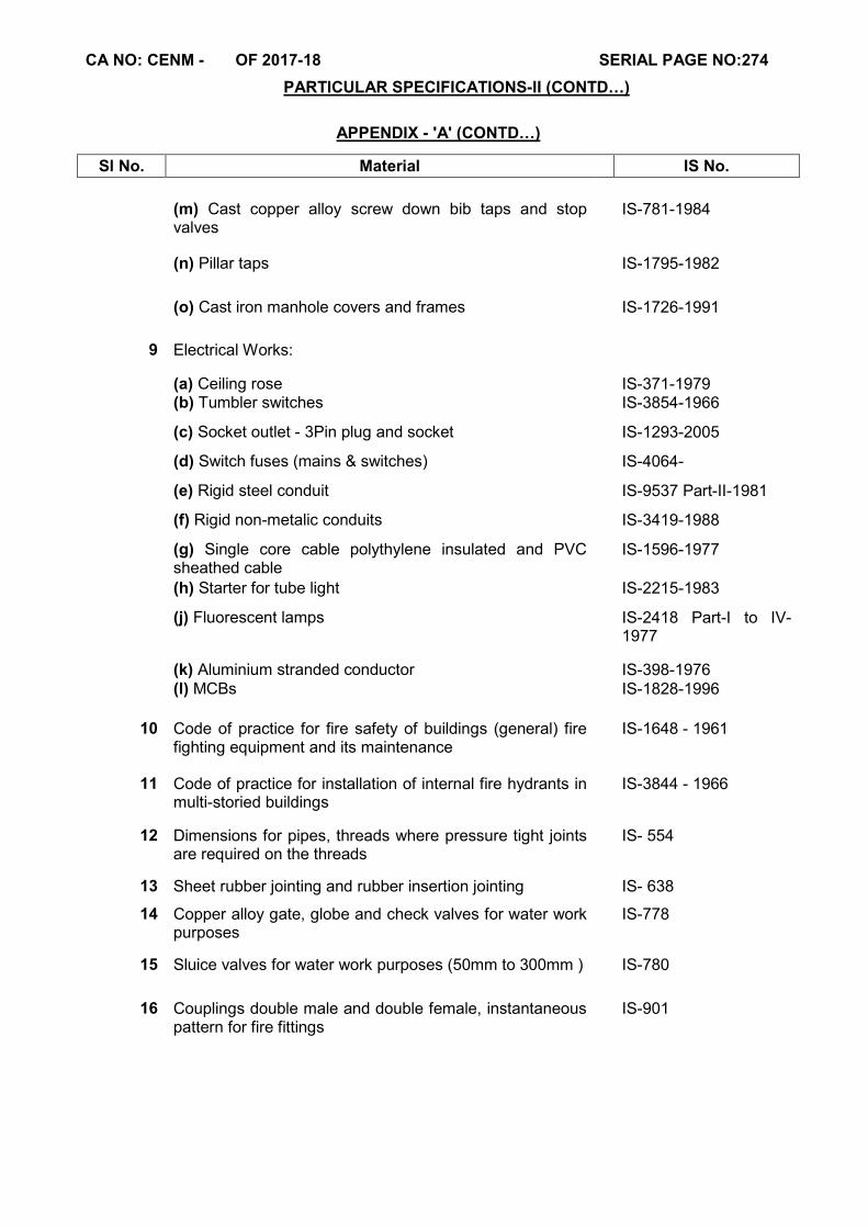
CA NO: CENM - OF 2017-18 SERIAL PAGE NO:274
PARTICULAR SPECIFICATIONS-II (CONTD…)
APPENDIX - 'A' (CONTD…)
Sl No. Material IS No.
(m) Cast copper alloy screw down bib taps and stop valves
IS-781-1984
(n) Pillar taps IS-1795-1982
(o) Cast iron manhole covers and frames IS-1726-1991
9 Electrical Works:
(a) Ceiling rose IS-371-1979 (b) Tumbler switches IS-3854-1966
(c) Socket outlet - 3Pin plug and socket IS-1293-2005
(d) Switch fuses (mains & switches) IS-4064-
(e) Rigid steel conduit IS-9537 Part-II-1981
(f) Rigid non-metalic conduits IS-3419-1988
(g) Single core cable polythylene insulated and PVC sheathed cable
IS-1596-1977
(h) Starter for tube light IS-2215-1983
(j) Fluorescent lamps IS-2418 Part-I to IV-1977
(k) Aluminium stranded conductor IS-398-1976 (l) MCBs IS-1828-1996
10 Code of practice for fire safety of buildings (general) fire fighting equipment and its maintenance
IS-1648 - 1961
11 Code of practice for installation of internal fire hydrants in multi-storied buildings
IS-3844 - 1966
12 Dimensions for pipes, threads where pressure tight joints are required on the threads
IS- 554
13 Sheet rubber jointing and rubber insertion jointing IS- 638
14 Copper alloy gate, globe and check valves for water work purposes
IS-778
15 Sluice valves for water work purposes (50mm to 300mm ) IS-780
16 Couplings double male and double female, instantaneous pattern for fire fittings
IS-901
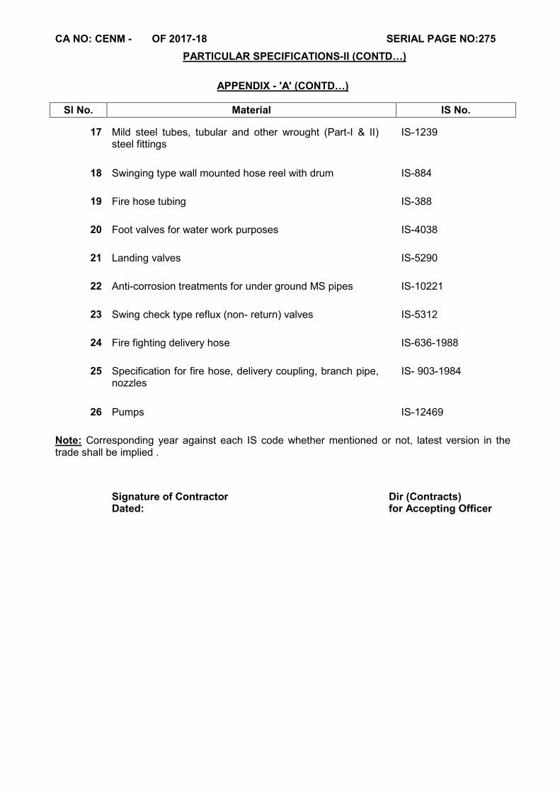
CA NO: CENM - OF 2017-18 SERIAL PAGE NO:275
PARTICULAR SPECIFICATIONS-II (CONTD…)
APPENDIX - 'A' (CONTD…)
Sl No. Material IS No.
17 Mild steel tubes, tubular and other wrought (Part-I & II)
steel fittings IS-1239
18 Swinging type wall mounted hose reel with drum IS-884
19 Fire hose tubing IS-388
20 Foot valves for water work purposes IS-4038
21 Landing valves IS-5290
22 Anti-corrosion treatments for under ground MS pipes IS-10221
23 Swing check type reflux (non- return) valves IS-5312
24 Fire fighting delivery hose IS-636-1988
25 Specification for fire hose, delivery coupling, branch pipe, nozzles
IS- 903-1984
26 Pumps IS-12469
Note: Corresponding year against each IS code whether mentioned or not, latest version in the trade shall be implied .
Signature of Contractor
Dir (Contracts)
Dated: for Accepting Officer
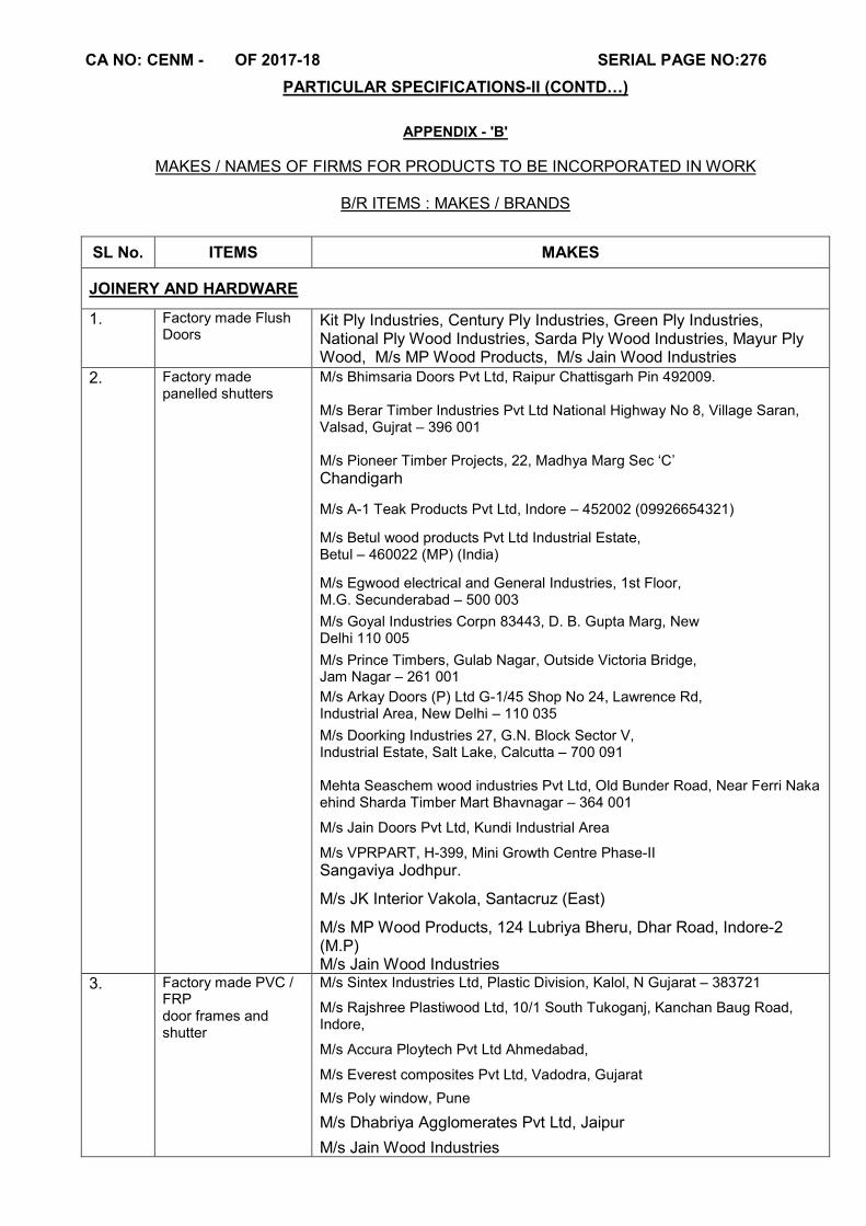
CA NO: CENM - OF 2017-18 SERIAL PAGE NO:276
PARTICULAR SPECIFICATIONS-II (CONTD…)
APPENDIX - 'B'
MAKES / NAMES OF FIRMS FOR PRODUCTS TO BE INCORPORATED IN WORK
B/R ITEMS : MAKES / BRANDS
SL No. ITEMS MAKES
JOINERY AND HARDWARE
1. Factory made Flush Doors
Kit Ply Industries, Century Ply Industries, Green Ply Industries, National Ply Wood Industries, Sarda Ply Wood Industries, Mayur Ply Wood, M/s MP Wood Products, M/s Jain Wood Industries
2. Factory made panelled shutters
M/s Bhimsaria Doors Pvt Ltd, Raipur Chattisgarh Pin 492009. M/s Berar Timber Industries Pvt Ltd National Highway No 8, Village Saran, Valsad, Gujrat – 396 001 M/s Pioneer Timber Projects, 22, Madhya Marg Sec ‘C’
Chandigarh
M/s A-1 Teak Products Pvt Ltd, Indore – 452002 (09926654321)
M/s Betul wood products Pvt Ltd Industrial Estate, Betul – 460022 (MP) (India)
M/s Egwood electrical and General Industries, 1st Floor, M.G. Secunderabad – 500 003
M/s Goyal Industries Corpn 83443, D. B. Gupta Marg, New Delhi 110 005
M/s Prince Timbers, Gulab Nagar, Outside Victoria Bridge, Jam Nagar – 261 001
M/s Arkay Doors (P) Ltd G-1/45 Shop No 24, Lawrence Rd, Industrial Area, New Delhi – 110 035
M/s Doorking Industries 27, G.N. Block Sector V, Industrial Estate, Salt Lake, Calcutta – 700 091 Mehta Seaschem wood industries Pvt Ltd, Old Bunder Road, Near Ferri Naka ehind Sharda Timber Mart Bhavnagar – 364 001
M/s Jain Doors Pvt Ltd, Kundi Industrial Area
M/s VPRPART, H-399, Mini Growth Centre Phase-II Sangaviya Jodhpur.
M/s JK Interior Vakola, Santacruz (East)
M/s MP Wood Products, 124 Lubriya Bheru, Dhar Road, Indore-2 (M.P) M/s Jain Wood Industries
3. Factory made PVC / FRP door frames and shutter
M/s Sintex Industries Ltd, Plastic Division, Kalol, N Gujarat – 383721
M/s Rajshree Plastiwood Ltd, 10/1 South Tukoganj, Kanchan Baug Road, Indore,
M/s Accura Ploytech Pvt Ltd Ahmedabad,
M/s Everest composites Pvt Ltd, Vadodra, Gujarat
M/s Poly window, Pune
M/s Dhabriya Agglomerates Pvt Ltd, Jaipur
M/s Jain Wood Industries
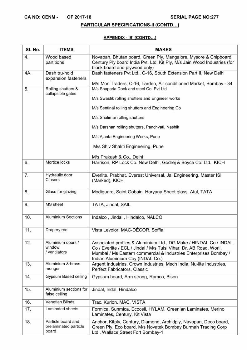
CA NO: CENM - OF 2017-18 SERIAL PAGE NO:277
PARTICULAR SPECIFICATIONS-II (CONTD…)
APPENDIX - 'B' (CONTD…)
SL No. ITEMS MAKES
4. Wood based partitions
Novapan, Bhutan board, Green Ply, Mangalore, Mysore & Chipboard, Century Ply board India Pvt. Ltd, Kit Ply, M/s Jain Wood Industries (for block board and plywood only)
4A. Dash tru-hold expansion fasteners
Dash fasteners Pvt Ltd., C-16, South Extension Part II, New Delhi M/s Mon Traders, C-16, Tardeo, Air conditioned Market, Bombay - 34
5. Rolling shutters & collapsible gates
M/s Shaparia Dock and steel Co. Pvt Ltd M/s Swastik rolling shutters and Engineer works M/s Sentinal rolling shutters and Engineering Co M/s Shalimar rolling shutters M/s Darshan rolling shutters, Panchvati, Nashik M/s Ajanta Engineering Works, Pune
M/s Shiv Shakti Engineering, Pune M/s Prakash & Co., Delhi
6. Mortice locks Harrison, RP Lock Co. New Delhi, Godrej & Boyce Co. Ltd., KICH
7. Hydraulic door Closers
Everlite, Prabhat, Everest Universal, Jai Engineering, Master ISI (Marked), KICH
8. Glass for glazing Modiguard, Saint Gobain, Haryana Sheet glass, Atul, TATA
9. MS sheet TATA, Jindal, SAIL
10. Aluminium Sections
Indalco , Jindal , Hindalco, NALCO
11. Drapery rod Vista Levolor, MAC-DÉCOR, Soffia
12. Aluminium doors / window / ventilators
Associated profiles & Aluminium Ltd., DG Make / HINDAL Co / INDAL Co / Everlite / ECL / Jindal / M/s Tulsi Vihar, Dr. AB Road, Worli, Mumbai / Ms Eastern commercial & Industries Enterprises Bombay / Indian Aluminium Coy (INDAL Co.)
13. Aluminium & brass monger
Argent Industries, Crown Industries, Mech India, Nu-lite Industries, Perfect Fabricators, Classic
14. Gypsum Based ceiling Gypsum board, Arm strong, Ramco, Bison
15. Aluminium sections for false ceiling
Jindal, Indal, Hindalco
16. Venetian Blinds Trac, Kurlon, MAC, VISTA
17. Laminated sheets Formica, Sunmica, Ecocell, HYLAM, Greenlan Laminates, Merino Laminates, Century, Kit Vista
18. Particle board and prelaminated particle board
Anchor, Kitply, Century, Diamond, Archidply, Navopan, Deco board, Green Ply, Eco board, M/s Novatek Bombay Burmah Trading Corp Ltd., Wallace Street Fort Bombay-1
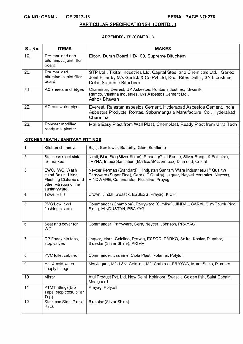
CA NO: CENM - OF 2017-18 SERIAL PAGE NO:278
PARTICULAR SPECIFICATIONS-II (CONTD…)
APPENDIX - 'B' (CONTD…)
SL No. ITEMS MAKES
19. Pre moulded non bituminous joint filler board
Elcon, Duran Board HD-100, Supreme Bituchem
20. Pre moulded bituminous joint filler board
STP Ltd., Tikitar Industries Ltd, Capital Steel and Chemicals Ltd., Garlex Joint Filler by M/s Garlick & Co Pvt Ltd, Roof Rites Delhi , SN Industries, Delhi, Supreme Bituchem
21. AC sheets and ridges Charminar, Everest, UP Asbestos, Rohtas industries, Swastik, Ramco, Visakha Industries, M/s Asbestos Cement Ltd.,
Ashok Bhawan
22. AC rain water pipes Everest, Rajastan asbestos Cement, Hyderabad Asbestos Cement, India Asbestos Products, Rohtas, Sabarmangala Manufacture Co., Hyderabad Charminar
23. Polymer modified ready mix plaster
Make Easy Plast from Wall Plast, Chemplast, Ready Plast from Ultra Tech
KITCHEN / BATH / SANITARY FITTINGS
1 Kitchen chimneys Bajaj, Sunflower, Butterfly, Glen, Sunflame
2 Stainless steel sink ISI marked
Nirali, Blue Star(Silver Shine), Prayag (Gold Range, Silver Range & Solitaire), JAYNA, Impex Sanitation (Marlex/AMC/Simpex) Diamond, Cristal
3 EWC, IWC, Wash Hand Basin, Urinal Flushing Cisterns and other vitreous china sanitaryware
Neycer Kermag (Standard), Hindustan Sanitary Ware Industries,(1st Quality)
Parryware (Super Fine), Cera (1st Quality), Jaquar, Neyveli ceramics (Neycer),
HINDWARE, Commander, Flushline, Prayag
4 Towel Rails Crown, Jindal, Swastik, ESSESS, Prayag, KICH
5 PVC Low level flushing cistern
Commander (Champion), Parryware (Slimline), JINDAL, SARAL Slim Touch (riddi Siddi), HINDUSTAN, PRAYAG
6 Seat and cover for WC
Commander, Parryware, Cera, Neycer, Johnson, PRAYAG
7 CP Fancy bib taps, stop valves
Jaquar, Marc, Goldline, Prayag, ESSCO, PARKO, Seiko, Kohler, Plumber, Bluestar (Silver Shine), PRIMA
8 PVC toilet cabinet Commander, Jasmine, Cipla Plast, Rotamax Polytuff
9 Hot & cold water supply fittings
M/s Jaquar, M/s L&K, Goldline, M/s Crabtree, PRAYAG, Marc, Seiko, Plumber
10 Mirror Atul Product Pvt. Ltd. New Delhi, Kohinoor, Swastik, Golden fish, Saint Gobain, Modiguard
11 PTMT fittings(Bib Taps, stop cock, pillar Tap)
Prayag, Polytuff
12 Stainless Steel Plate Rack
Bluestar (Silver Shine)
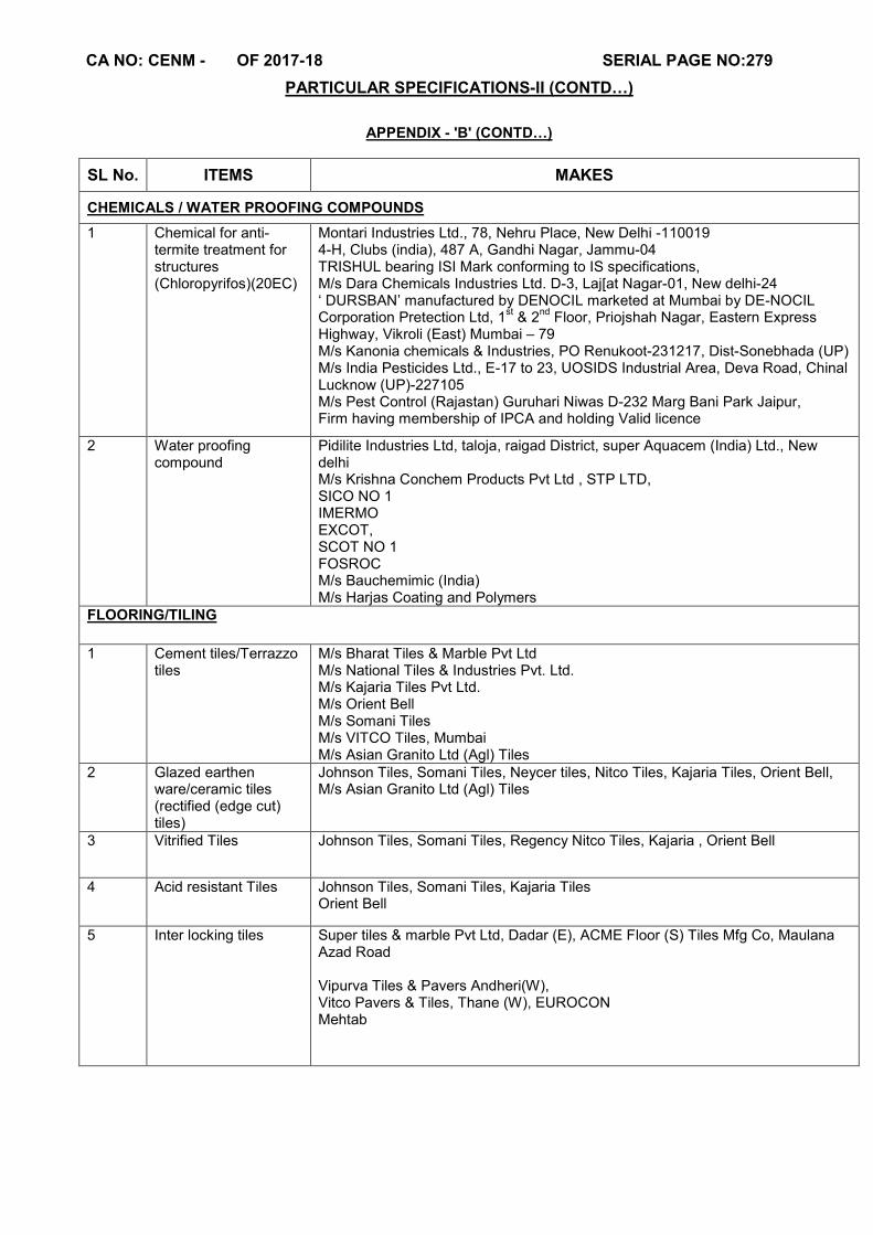
CA NO: CENM - OF 2017-18 SERIAL PAGE NO:279
PARTICULAR SPECIFICATIONS-II (CONTD…)
APPENDIX - 'B' (CONTD…)
SL No. ITEMS MAKES
CHEMICALS / WATER PROOFING COMPOUNDS
1 Chemical for anti-termite treatment for structures (Chloropyrifos)(20EC)
Montari Industries Ltd., 78, Nehru Place, New Delhi -110019 4-H, Clubs (india), 487 A, Gandhi Nagar, Jammu-04 TRISHUL bearing ISI Mark conforming to IS specifications, M/s Dara Chemicals Industries Ltd. D-3, Laj[at Nagar-01, New delhi-24 ‘ DURSBAN’ manufactured by DENOCIL marketed at Mumbai by DE-NOCIL Corporation Pretection Ltd, 1
st & 2
nd Floor, Priojshah Nagar, Eastern Express
Highway, Vikroli (East) Mumbai – 79 M/s Kanonia chemicals & Industries, PO Renukoot-231217, Dist-Sonebhada (UP) M/s India Pesticides Ltd., E-17 to 23, UOSIDS Industrial Area, Deva Road, Chinal Lucknow (UP)-227105 M/s Pest Control (Rajastan) Guruhari Niwas D-232 Marg Bani Park Jaipur, Firm having membership of IPCA and holding Valid licence
2 Water proofing compound
Pidilite Industries Ltd, taloja, raigad District, super Aquacem (India) Ltd., New delhi M/s Krishna Conchem Products Pvt Ltd , STP LTD, SICO NO 1 IMERMO EXCOT, SCOT NO 1 FOSROC M/s Bauchemimic (India) M/s Harjas Coating and Polymers
FLOORING/TILING
1 Cement tiles/Terrazzo tiles
M/s Bharat Tiles & Marble Pvt Ltd M/s National Tiles & Industries Pvt. Ltd. M/s Kajaria Tiles Pvt Ltd. M/s Orient Bell M/s Somani Tiles M/s VITCO Tiles, Mumbai M/s Asian Granito Ltd (Agl) Tiles
2 Glazed earthen ware/ceramic tiles (rectified (edge cut) tiles)
Johnson Tiles, Somani Tiles, Neycer tiles, Nitco Tiles, Kajaria Tiles, Orient Bell, M/s Asian Granito Ltd (Agl) Tiles
3 Vitrified Tiles Johnson Tiles, Somani Tiles, Regency Nitco Tiles, Kajaria , Orient Bell
4 Acid resistant Tiles Johnson Tiles, Somani Tiles, Kajaria Tiles Orient Bell
5 Inter locking tiles Super tiles & marble Pvt Ltd, Dadar (E), ACME Floor (S) Tiles Mfg Co, Maulana Azad Road Vipurva Tiles & Pavers Andheri(W), Vitco Pavers & Tiles, Thane (W), EUROCON Mehtab

CA NO: CENM - OF 2017-18 SERIAL PAGE NO:280
PARTICULAR SPECIFICATIONS-II (CONTD…)
APPENDIX - 'B' (CONTD…)
SL No. ITEMS MAKES
PAINTS/FINISHES 1 Primer Asian paints, Nerolac, Shalimar, J&N, Berger Synthetic Enamel
2 Synthetic enamel paint
Berger Paints (Luxol high gloss), Goodlass Nerolac (Nerolac), Asian Paints (Apcolite Premium), Dulux Gloss 5 in
3 Anti corrosive paint on structural steel
Asina Paints, Nerolac, Berger,Dulux, Shalimar, Johnson Nicholson
4 Cement Base Pint SUPER SNOWCEM, DUROCEM, SILVOCEM, AQUACEM, SIMCO, SNOWEM, SHALIMAR, Asian Paints, Nitco Paint, Pvt Ltd.
5 Acrylic emulsion paints (interior)
Berger Paints (Rangoli Acrylic emulsion), Asian Paints (Premium emulsion), Nerolac Paints (Beauty Gold acrylic emulsion), ICI Dulux (super smooth acrylic emulsion)
6 Acrylic exterior antifungal paints
Asian Paint (Apex) / Ultima, Berger Paint (Weather coat all guard emulsion) ICI Dulux (Whether shield max/Ultra clean emulsion) Nerolac (Excel anti peel emulsion)
7 Dry Oil bound distempers and emulsions
Asian Paints (Tractor acrylic distemper) Nerolac Paints (Beauty acrylic distemper) Berger Paints, Shalimar Paints, Jenson & Nicholson. (Jensolin acrylic distemper), ICI (Mailite acrylic distemper)
8 Colour anodizing for Aluminium sections
Conpaptex, Vadodara, KrishnaMetal industries, Mumbai. Mansi chemical, ahemdabad, Anand tech Process, Bengaluru
9 Putty Shalimar, diamond Paints New delhi, UK Paint Industries, New Delhi, Birala, J K White, Gold Mohar
10 Hot applied thermo plastic road marking paint (As per cl 803.4 of MORTH)
M/s Shivalik Primo India Pvt Ltd. New delhi, Asian Paints Ltd, SHALIMAR, STP Ltd, SAI Thermoplastic Paints Ltd..
PLUMBING
1 CI Pipes (centrifugally cast & vertical cast ) and fittings
Neco, Kesoram, IISCO, JINDAL, TATA, TISCO, Kalinga, Prince. SKF
2 GI and MS pipes Tata, Swastik, Jindal, Prakash, Zenith, Surya, Quality, Gujrat tubes, Lotus, Hindustan.
3 HDPE pipes Dutron, Finolex, Prince, Kissan, Prayag, Reliance4, Noble
4 PVC SWR Pipes Kissan, Prince, Supreme.
5 Stop valves Jaquar, Leader, Jindal, Seico, GEM, Goldline, T&K Industries, Neeta, Zolto
6 Foot valve Kirloskar, Leader, Prayag, SANT, Kartar
7 Sluice valves (ISI marked) Leader, Venus, Kirloskar, Kajariwal Upadhyaya Valves, L&T (AUDCO), BIR, SANTA, Kartar, Indian Valves
8 Gate valve, Ball valve Neeta, Kartar, Leader, Zoloto, Rotex, Prayag, Boss,
9 PVC/HDPE water tanks (ISI marked) Sintex, Rotomex, Polycon, OMTEX, Ashish
10 Float Valve Prayag, Satyam, Goldline, Techno
11 GI Pipe Fitting Zolto, Leader, Unik
12 Loft Tanks Sintex, Polycon, Plasto, Ganga
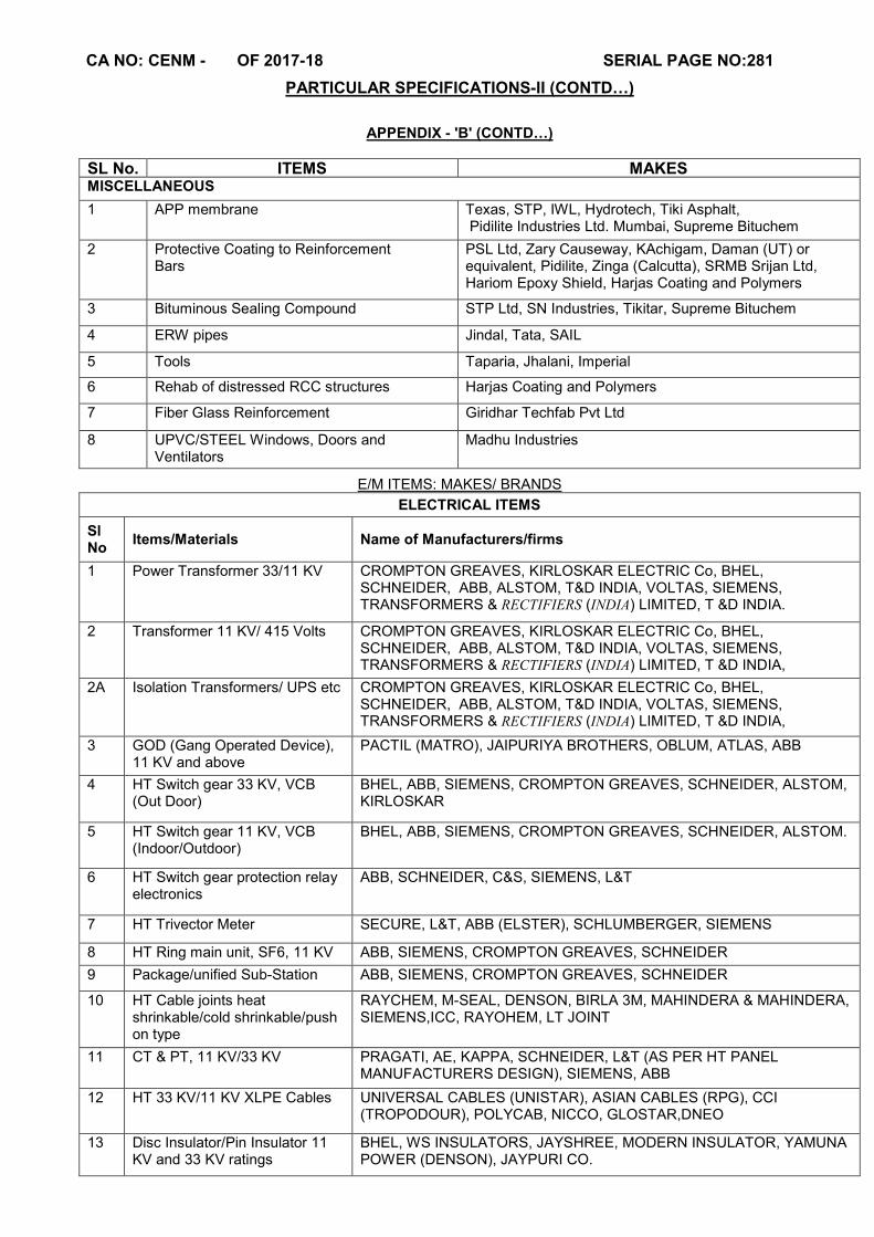
CA NO: CENM - OF 2017-18 SERIAL PAGE NO:281
PARTICULAR SPECIFICATIONS-II (CONTD…)
APPENDIX - 'B' (CONTD…)
SL No. ITEMS MAKES MISCELLANEOUS
1 APP membrane Texas, STP, IWL, Hydrotech, Tiki Asphalt, Pidilite Industries Ltd. Mumbai, Supreme Bituchem
2 Protective Coating to Reinforcement Bars
PSL Ltd, Zary Causeway, KAchigam, Daman (UT) or equivalent, Pidilite, Zinga (Calcutta), SRMB Srijan Ltd, Hariom Epoxy Shield, Harjas Coating and Polymers
3 Bituminous Sealing Compound STP Ltd, SN Industries, Tikitar, Supreme Bituchem
4 ERW pipes Jindal, Tata, SAIL
5 Tools Taparia, Jhalani, Imperial
6 Rehab of distressed RCC structures Harjas Coating and Polymers
7 Fiber Glass Reinforcement Giridhar Techfab Pvt Ltd
8 UPVC/STEEL Windows, Doors and Ventilators
Madhu Industries
E/M ITEMS: MAKES/ BRANDS
ELECTRICAL ITEMS
Sl No
Items/Materials Name of Manufacturers/firms
1 Power Transformer 33/11 KV CROMPTON GREAVES, KIRLOSKAR ELECTRIC Co, BHEL, SCHNEIDER, ABB, ALSTOM, T&D INDIA, VOLTAS, SIEMENS, TRANSFORMERS & RECTIFIERS (INDIA) LIMITED, T &D INDIA.
2 Transformer 11 KV/ 415 Volts CROMPTON GREAVES, KIRLOSKAR ELECTRIC Co, BHEL, SCHNEIDER, ABB, ALSTOM, T&D INDIA, VOLTAS, SIEMENS, TRANSFORMERS & RECTIFIERS (INDIA) LIMITED, T &D INDIA,
2A Isolation Transformers/ UPS etc CROMPTON GREAVES, KIRLOSKAR ELECTRIC Co, BHEL, SCHNEIDER, ABB, ALSTOM, T&D INDIA, VOLTAS, SIEMENS, TRANSFORMERS & RECTIFIERS (INDIA) LIMITED, T &D INDIA,
3 GOD (Gang Operated Device), 11 KV and above
PACTIL (MATRO), JAIPURIYA BROTHERS, OBLUM, ATLAS, ABB
4 HT Switch gear 33 KV, VCB (Out Door)
BHEL, ABB, SIEMENS, CROMPTON GREAVES, SCHNEIDER, ALSTOM, KIRLOSKAR
5 HT Switch gear 11 KV, VCB (Indoor/Outdoor)
BHEL, ABB, SIEMENS, CROMPTON GREAVES, SCHNEIDER, ALSTOM.
6 HT Switch gear protection relay electronics
ABB, SCHNEIDER, C&S, SIEMENS, L&T
7 HT Trivector Meter SECURE, L&T, ABB (ELSTER), SCHLUMBERGER, SIEMENS
8 HT Ring main unit, SF6, 11 KV ABB, SIEMENS, CROMPTON GREAVES, SCHNEIDER
9 Package/unified Sub-Station ABB, SIEMENS, CROMPTON GREAVES, SCHNEIDER
10 HT Cable joints heat shrinkable/cold shrinkable/push on type
RAYCHEM, M-SEAL, DENSON, BIRLA 3M, MAHINDERA & MAHINDERA, SIEMENS,ICC, RAYOHEM, LT JOINT
11 CT & PT, 11 KV/33 KV PRAGATI, AE, KAPPA, SCHNEIDER, L&T (AS PER HT PANEL MANUFACTURERS DESIGN), SIEMENS, ABB
12 HT 33 KV/11 KV XLPE Cables UNIVERSAL CABLES (UNISTAR), ASIAN CABLES (RPG), CCI (TROPODOUR), POLYCAB, NICCO, GLOSTAR,DNEO
13 Disc Insulator/Pin Insulator 11 KV and 33 KV ratings
BHEL, WS INSULATORS, JAYSHREE, MODERN INSULATOR, YAMUNA POWER (DENSON), JAYPURI CO.
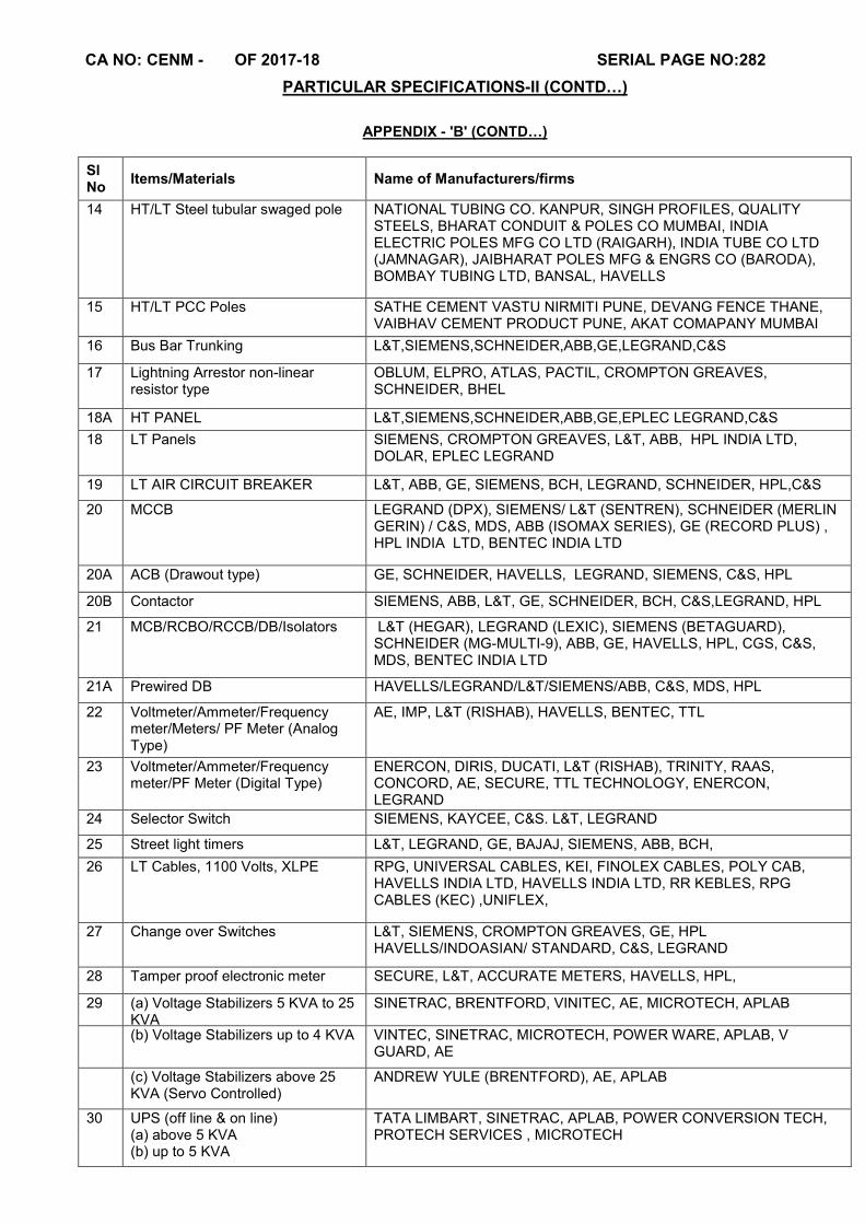
CA NO: CENM - OF 2017-18 SERIAL PAGE NO:282
PARTICULAR SPECIFICATIONS-II (CONTD…)
APPENDIX - 'B' (CONTD…)
Sl No
Items/Materials Name of Manufacturers/firms
14 HT/LT Steel tubular swaged pole NATIONAL TUBING CO. KANPUR, SINGH PROFILES, QUALITY STEELS, BHARAT CONDUIT & POLES CO MUMBAI, INDIA ELECTRIC POLES MFG CO LTD (RAIGARH), INDIA TUBE CO LTD (JAMNAGAR), JAIBHARAT POLES MFG & ENGRS CO (BARODA), BOMBAY TUBING LTD, BANSAL, HAVELLS
15 HT/LT PCC Poles SATHE CEMENT VASTU NIRMITI PUNE, DEVANG FENCE THANE, VAIBHAV CEMENT PRODUCT PUNE, AKAT COMAPANY MUMBAI
16 Bus Bar Trunking L&T,SIEMENS,SCHNEIDER,ABB,GE,LEGRAND,C&S
17 Lightning Arrestor non-linear resistor type
OBLUM, ELPRO, ATLAS, PACTIL, CROMPTON GREAVES, SCHNEIDER, BHEL
18A HT PANEL L&T,SIEMENS,SCHNEIDER,ABB,GE,EPLEC LEGRAND,C&S
18 LT Panels SIEMENS, CROMPTON GREAVES, L&T, ABB, HPL INDIA LTD, DOLAR, EPLEC LEGRAND
19 LT AIR CIRCUIT BREAKER L&T, ABB, GE, SIEMENS, BCH, LEGRAND, SCHNEIDER, HPL,C&S
20
MCCB LEGRAND (DPX), SIEMENS/ L&T (SENTREN), SCHNEIDER (MERLIN GERIN) / C&S, MDS, ABB (ISOMAX SERIES), GE (RECORD PLUS) , HPL INDIA LTD, BENTEC INDIA LTD
20A
ACB (Drawout type) GE, SCHNEIDER, HAVELLS, LEGRAND, SIEMENS, C&S, HPL
20B
Contactor SIEMENS, ABB, L&T, GE, SCHNEIDER, BCH, C&S,LEGRAND, HPL
21 MCB/RCBO/RCCB/DB/Isolators L&T (HEGAR), LEGRAND (LEXIC), SIEMENS (BETAGUARD), SCHNEIDER (MG-MULTI-9), ABB, GE, HAVELLS, HPL, CGS, C&S, MDS, BENTEC INDIA LTD
21A Prewired DB HAVELLS/LEGRAND/L&T/SIEMENS/ABB, C&S, MDS, HPL
22 Voltmeter/Ammeter/Frequency meter/Meters/ PF Meter (Analog Type)
AE, IMP, L&T (RISHAB), HAVELLS, BENTEC, TTL
23 Voltmeter/Ammeter/Frequency meter/PF Meter (Digital Type)
ENERCON, DIRIS, DUCATI, L&T (RISHAB), TRINITY, RAAS, CONCORD, AE, SECURE, TTL TECHNOLOGY, ENERCON, LEGRAND
24 Selector Switch SIEMENS, KAYCEE, C&S. L&T, LEGRAND
25 Street light timers L&T, LEGRAND, GE, BAJAJ, SIEMENS, ABB, BCH,
26 LT Cables, 1100 Volts, XLPE RPG, UNIVERSAL CABLES, KEI, FINOLEX CABLES, POLY CAB, HAVELLS INDIA LTD, HAVELLS INDIA LTD, RR KEBLES, RPG CABLES (KEC) ,UNIFLEX,
27 Change over Switches L&T, SIEMENS, CROMPTON GREAVES, GE, HPL HAVELLS/INDOASIAN/ STANDARD, C&S, LEGRAND
28 Tamper proof electronic meter SECURE, L&T, ACCURATE METERS, HAVELLS, HPL,
29 (a) Voltage Stabilizers 5 KVA to 25 KVA
SINETRAC, BRENTFORD, VINITEC, AE, MICROTECH, APLAB
(b) Voltage Stabilizers up to 4 KVA VINTEC, SINETRAC, MICROTECH, POWER WARE, APLAB, V GUARD, AE
(c) Voltage Stabilizers above 25 KVA (Servo Controlled)
ANDREW YULE (BRENTFORD), AE, APLAB
30 UPS (off line & on line) (a) above 5 KVA (b) up to 5 KVA
TATA LIMBART, SINETRAC, APLAB, POWER CONVERSION TECH, PROTECH SERVICES , MICROTECH
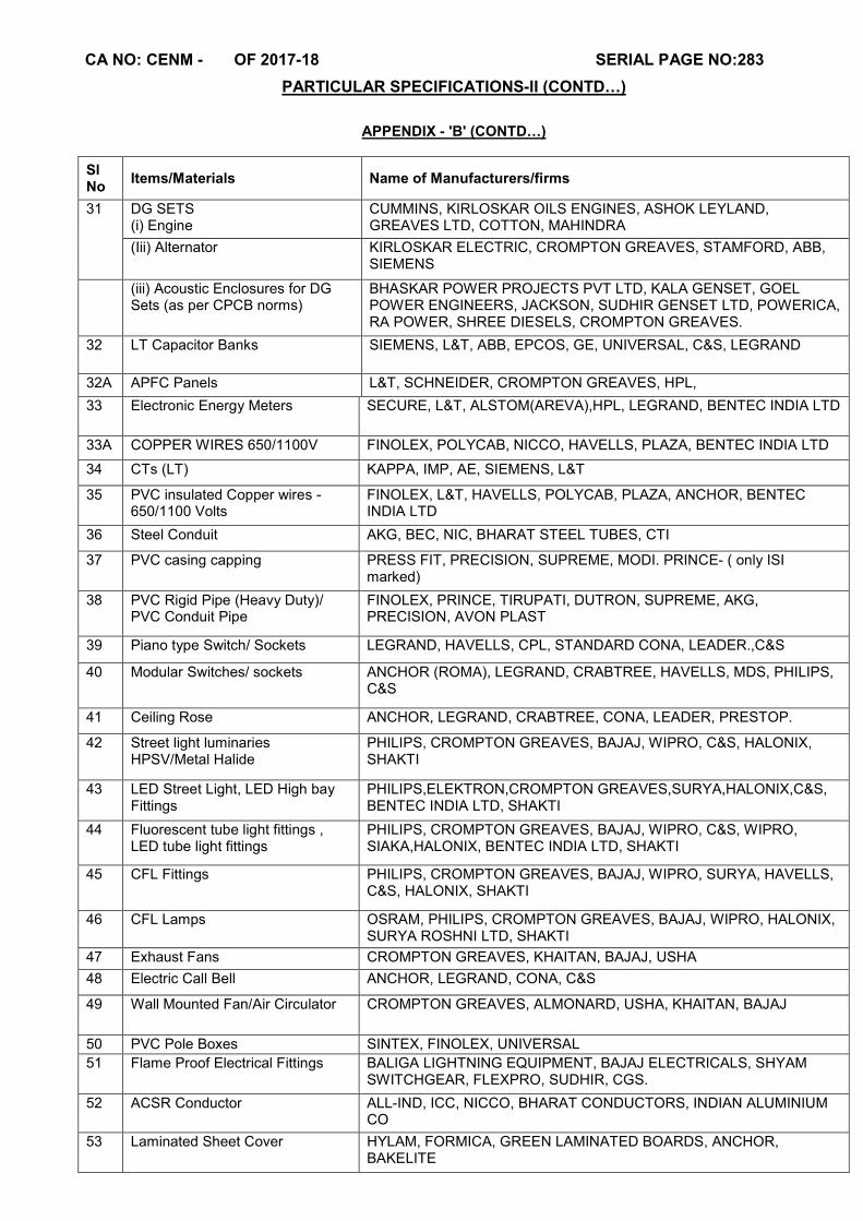
CA NO: CENM - OF 2017-18 SERIAL PAGE NO:283
PARTICULAR SPECIFICATIONS-II (CONTD…)
APPENDIX - 'B' (CONTD…)
Sl No
Items/Materials Name of Manufacturers/firms
31 DG SETS (i) Engine
CUMMINS, KIRLOSKAR OILS ENGINES, ASHOK LEYLAND, GREAVES LTD, COTTON, MAHINDRA
(Iii) Alternator KIRLOSKAR ELECTRIC, CROMPTON GREAVES, STAMFORD, ABB, SIEMENS
(iii) Acoustic Enclosures for DG Sets (as per CPCB norms)
BHASKAR POWER PROJECTS PVT LTD, KALA GENSET, GOEL POWER ENGINEERS, JACKSON, SUDHIR GENSET LTD, POWERICA, RA POWER, SHREE DIESELS, CROMPTON GREAVES.
32
LT Capacitor Banks
SIEMENS, L&T, ABB, EPCOS, GE, UNIVERSAL, C&S, LEGRAND
32A APFC Panels L&T, SCHNEIDER, CROMPTON GREAVES, HPL,
33
Electronic Energy Meters SECURE, L&T, ALSTOM(AREVA),HPL, LEGRAND, BENTEC INDIA LTD
33A COPPER WIRES 650/1100V FINOLEX, POLYCAB, NICCO, HAVELLS, PLAZA, BENTEC INDIA LTD
34 CTs (LT) KAPPA, IMP, AE, SIEMENS, L&T
35 PVC insulated Copper wires - 650/1100 Volts
FINOLEX, L&T, HAVELLS, POLYCAB, PLAZA, ANCHOR, BENTEC INDIA LTD
36 Steel Conduit AKG, BEC, NIC, BHARAT STEEL TUBES, CTI
37 PVC casing capping PRESS FIT, PRECISION, SUPREME, MODI. PRINCE- ( only ISI marked)
38 PVC Rigid Pipe (Heavy Duty)/ PVC Conduit Pipe
FINOLEX, PRINCE, TIRUPATI, DUTRON, SUPREME, AKG, PRECISION, AVON PLAST
39 Piano type Switch/ Sockets LEGRAND, HAVELLS, CPL, STANDARD CONA, LEADER.,C&S
40 Modular Switches/ sockets ANCHOR (ROMA), LEGRAND, CRABTREE, HAVELLS, MDS, PHILIPS, C&S
41 Ceiling Rose ANCHOR, LEGRAND, CRABTREE, CONA, LEADER, PRESTOP.
42 Street light luminaries HPSV/Metal Halide
PHILIPS, CROMPTON GREAVES, BAJAJ, WIPRO, C&S, HALONIX, SHAKTI
43 LED Street Light, LED High bay Fittings
PHILIPS,ELEKTRON,CROMPTON GREAVES,SURYA,HALONIX,C&S, BENTEC INDIA LTD, SHAKTI
44 Fluorescent tube light fittings , LED tube light fittings
PHILIPS, CROMPTON GREAVES, BAJAJ, WIPRO, C&S, WIPRO, SIAKA,HALONIX, BENTEC INDIA LTD, SHAKTI
45 CFL Fittings PHILIPS, CROMPTON GREAVES, BAJAJ, WIPRO, SURYA, HAVELLS, C&S, HALONIX, SHAKTI
46 CFL Lamps OSRAM, PHILIPS, CROMPTON GREAVES, BAJAJ, WIPRO, HALONIX, SURYA ROSHNI LTD, SHAKTI
47 Exhaust Fans CROMPTON GREAVES, KHAITAN, BAJAJ, USHA
48 Electric Call Bell ANCHOR, LEGRAND, CONA, C&S
49 Wall Mounted Fan/Air Circulator CROMPTON GREAVES, ALMONARD, USHA, KHAITAN, BAJAJ
50 PVC Pole Boxes SINTEX, FINOLEX, UNIVERSAL
51 Flame Proof Electrical Fittings BALIGA LIGHTNING EQUIPMENT, BAJAJ ELECTRICALS, SHYAM SWITCHGEAR, FLEXPRO, SUDHIR, CGS.
52 ACSR Conductor ALL-IND, ICC, NICCO, BHARAT CONDUCTORS, INDIAN ALUMINIUM CO
53 Laminated Sheet Cover HYLAM, FORMICA, GREEN LAMINATED BOARDS, ANCHOR, BAKELITE
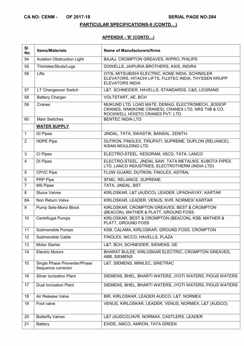
CA NO: CENM - OF 2017-18 SERIAL PAGE NO:284
PARTICULAR SPECIFICATIONS-II (CONTD…)
APPENDIX - 'B' (CONTD…)
Sl No
Items/Materials Name of Manufacturers/firms
54 Aviation Obstruction Light BAJAJ, CROMPTON GREAVES, WIPRO, PHILIPS
55 Thimbles/Studs/Lugs DOWELLS, JAIPURIA BROTHERS, AXIS, INDIRA
56 Lifts OTIS, MITSUBISHI ELECTRIC, KONE INDIA, SCHINDLER ELEVATORS, HITACHI LIFTS, FUJITEC INDIA, THYSSEN KRUPP ELEVATORS INDIA
57
LT Changeover Switch
L&T, SCHNEIDER, HAVELLS, STANDARDS, C&S, LEGRAND
58 Battery Charger VOLTSTART, AE, BCH
59 Cranes MUKUND LTD, LOAD MATE, DEMAG, ELECTROMECH, JESSOP CRANES, WMI(KONE CRANES), CRANEX LTD, NRS TIIB & CO, ROCKWELL HOISTO CRANES PVT. LTD.
60 Main Switches BENTEC INDIA LTD
WATER SUPPLY
1 GI Pipes JINDAL, TATA, SWASTIK, BANSAL, ZENITH.
2 HDPE Pipe DUTRON, FINOLEX, TIRUPATI, SUPREME, DUPLON (RELIANCE), KISAN MOULDING LTD
3 CI Pipes ELECTRO-STEEL, KESORAM, IISCO, TATA, LANCO
4 DI Pipes ELECTRO-STEEL, JINDAL SAW, TATA METALIKS, KUBOTA PIPES LTD, LANCO INDUSTRIES, ELECTROTHERM (INDIA LTD)
5 CPVC Pipe FLOW GUARD, DUTRON, FINOLEX, ASTRAL
5 PRP Pipe SFMC, RELIANCE, SUPREME.
7 MS Pipes TATA, JINDAL, BST
8 Sluice Valves KIRLOSKAR, L&T (AUDCO), LEADER, UPADHAYAY, KARTAR
8A Non Return Valve KIRLOSKAR, LEADER, VENUS, NVR, NORMEX/ KARTAR
9 Pump Sets-Mono Block KIRLOSKAR, CROMPTON GREAVES, BEST & CROMPTON (BEACON), MATHER & PLATT, GROUND FOSS
10 Centrifugal Pumps KIRLOSKAR, BEST & CROMPTON (BEACON), KSB, MATHER & PLATT, GROUND FOSS
11 Submersible Pumps KSB, CALAMA, KIRLOSKAR, GROUND FOSS, CROMPTON
12 Submersible Cable FINOLEX, NICCO, HAVELLS, PLAZA
13 Motor Starter L&T, BCH, SCHNEIDER, SIEMENS, GE
14 Electric Motors BHARAT BIJLEE, KIRLOSKAR ELECTRIC, CROMPTON GREAVES, ABB, SIEMENS
15 Single Phase Preventer/Phase Sequence corrector
L&T, SIEMENS, MINILEC, SINETRAC
16 Silver Ionization Plant
SIEMENS, BHEL, BHARTI WATERS, JYOTI WATERS, PIOUS WATERS
17 Dual Ionization Plant SIEMENS, BHEL, BHARTI WATERS, JYOTI WATERS, PIOUS WATERS
18 Air Release Valve BIR, KIRLOSKAR, LEADER AUDCO, L&T, NORMEX
19 Foot valve VENUS, KIRLOSKAR, LEADER, VENUS, NORMEX, L&T (AUDCO)
20 Butterfly Valves L&T (AUDCO),NVR, NORMAX, CASTLERS, LEADER
21 Battery EXIDE, AMCO, AMRON, TATA GREEN

CA NO: CENM - OF 2017-18 SERIAL PAGE NO:285
PARTICULAR SPECIFICATIONS-II (CONTD…)
APPENDIX - 'B' (CONTD…)
Sl No
Items/Materials Name of Manufacturers/firms
22 CI Fitting UPADHAYAY, KEJERIWAL, BIR, SANT, VENUS
23 Water Meter CAPSTON, DASHMESH, ACCUFLOW, PRIMA
24 Gate Valves/ Globe Valves ZOLOTO/LEADER/PRAYAG/CRI/HM
25 PPR/UPVC Pipes & fittings KPT
26 Gun Metal Ferrules for water supply
PRIMA
AIR CONDITIONING
1 Air Handling Unit BLUE STAR/ VOLTAS/ CARRIER / HITACHI
2 Cooling Tower MIHIR/ PAHARPUR/ VOLTAS/ POLO/ DELTA
3 Chillers/Condenser VOLTAS/ BLUE STAR/ CARRIER
4 Compressors DANFOSS/ KIRLOSKAR, BLUE STAR, VOLTAS, CARRIER.
5 Pumps (Chillers & Condensers) KIRLOSKAR/GROUNDFOSS/MATHER & PLATT/BEST & CROMPTON (BEACON)
6 Motors SIEMENS/ABB/CROMPTON GREAVES/KIRLOSKAR ELECTRIC/BHARAT BIJLEE/NGEF
7 Pot/Y-Strainer EMERALD/RAPID COOL/DANFOSS/SPARLAN
8 MS Piping TATA/BST/JINDAL
9 (a) Butterfly Valve AUDCO/SANT/ NORMAX/LEADER
(b) Check Valve/Non Return Valve Non Return Valve
AUDCO/SANT/ BIR/ KIRLOSKAR/LEADER
(c) Gate Valve LEADER/ AUDCO/ITT BELL & GOSSETT/ HM/ZOLOTO
10 Balancing Valve AUDCO/DANFOSS/FLOWCON
11 Pressure Gauge FIEBIG/ BAKER MERCER/DANFOSS/L&T
12 Dial Type Thermometers FIEBIG/ TEDDINGTON/DANFOSS
13 Insulation
(i) Glass wool OWENS CORNING/UP TWIGA/LLOYD
(ii) Insulation (Expand Polystyrene)
CAPRICORN/BEARDSELL/PENGUIN/LLOYD
(iii) Insulation (Cross Polyethylene Foam)
SUPREME/TROCELLANE/PARAMOUNT/LLOYD
14 (a) Controls (3 Way Valves Actuator & Motor)
SIEMENS/HONEYWELL/JOHNSON/ANERGY
(b) Thermostats ENERGY/ SIEMENS/ HONEYWELL/ JOHNSON/ ANERGY
15 Extruded Aluminum Grills Diffusers
DYNA CRAFT/ RAVISTAR/ MAPRO/ CARRYAIRE/ COSMOS
16 (a) Control Cable NICCO/ASIAN CABLES/UNIVERSAL/FINOLEX/POLYCAB
(b) Power Cable GLOSTER, ASIAN, UNIVERSAL, ELEKTRON
17 Contactors/Starters L&T/SIEMENS/ABB/BCH
18 Overload Relay L&T/SIEMENS/ABB/BCH
19 Time Delay Device L&T/SIEMENS/SCHNEIDER/BCH

CA NO: CENM - OF 2017-18 SERIAL PAGE NO:286
PARTICULAR SPECIFICATIONS-II (CONTD…)
APPENDIX - 'B' (CONTD…)
Sl No
Items/Materials Name of Manufacturers/firms
20 Single Phasing Preventer L&T, SIEMEN, MINILEC, SCHNEIDER
21 GSS Sheets SAIL/TATA/JINDAL
22
AIR CURTAIN
SAN PRODUCTS,EURONICS,CRISIL
23 DEHUMIDIFIER BRYAIR,OSTER BIONAIRE, NOVITA
24 Fire Dampers/ Grill/Diffuser DYNA/RAVISTAR/MAPRO/CARYAIRE/ATE
25 Expansion Valve DANFOSS/SPORLAN/RANCO
26 Switch gears MCCBs/ ACBs/MCBs
LEGRAND/L&T/SCHNEIDER (MERLIN GERIN) / GE / SIEMENS / BCH / C&S
27 LT Control Panel FACTORY FABRICATED CONTROL PANEL WITH CPRI TEST CERTIFICATE
28 LT current transformer IMP, KAPPA, AE, SIEMENS
29 HP/LP/Op Cut Out PENN/INDOFOSS/RANCO/DANFOSS/JOHNSON
30 Digital temp and RH meters HONEYWELL/FORBES MARSHALL/SUBZERO/JOHNSON CONTROL
31 Centrifugal Fans (for AHU's) NICOTRA/KRUGER/COMBIFREE/OEM'S MAKE
32 Strip Heaters RACOLD/DASSPASS/UE
33 Humidistat PENN, DANFOSS, HONEY WELL, JOHNSON, INDOFOSS
34 Filter JOHN FOWLER/THERMODYNE/TENACITY/PUROLOTER
35 Factory Built Duct ROLASTAR/TECHNO AIR/CAM DUCT
36 Selector Switch L & T, LEGRAND, C&S, OMEGA, KAYCEE
37 Indicating light SIEMEN, CONCORD, C&S, LEGRAND
38 Digital Voltmeter/ Amp meter AE, EMERCON, SECURE, L&T,C&S
39 Current Transformer AE, KAPPA, SCHENIDER
40 Flexible Connector CORI ENGINEER, RESISTO FLEX
41 Hot Water Generator RAPID COOL/ROSS THERMAL SYSTEM PVT LTD/REYNOLD/RAPID CONTROL
42 Air Washer BREEZE AIR/THERMODYNE/CHEMPAC/KLENZOID
43 Non Chemical Type Electrostatic Scale Preventer
SCALEOFF (MFD BY M/S WELDON), SCALEX (MFD BY M/S TBI SYSTEM), HYDROCON
44
Split Ac , Window Ac
DAIKIN/BLUESTAR/LG/VOLTAS/SAMSUNG
45 Smoke Detector APPOLO, EDWARD, MARLAY SYSTEMS, SAFEX, SENSOR
46 Manual Call Point MINIMAX, APPOLO, VIJAY, SAFTEX, HARDIK ENGGS
47 Fire Hydrant Valves MINIMAX, VIJOY, SAFEX, CEASE FIRE.
46 Fire Hose Pipe/ Reel MINIMAX, SAFEX, VIJAY, DUNLOP
47 Fire Extinguishers MINIMAX, SAFEX, VIJAY, SAFEZONE, CEASE FIRE, MONARC ENGINEERINGS
48 Branch Pipe Nozzle and Couplings
MINIMAX, SAFEX, VIJAY, SAIFEZONE, CEASE FIRE, MONARC ENGINEERINGS
49 Control Panels CEASE FIRE, VIJAY FIRE PROTECTION SYSTEMS, EX- FLAME.

CA NO: CENM - OF 2017-18 SERIAL PAGE NO:287
PARTICULAR SPECIFICATIONS-II (CONTD…)
APPENDIX - 'B' (CONTD…)
Sl No
Items/Materials Name of Manufacturers/firms
50 AIR WASHER BREEZE AIR, THERMODYNE,CHEMPAC,KLENZOID
51 SOLAR WATER HEATER BHEL, MAHARAJA WHITELINE, RACOLD, TATA BP,USHA
52 SOLAR LED STREET LIGHT WIPRO, CROMPTON GREAVES, PHILIPS, HAVELLS, BAJAJ
MISC
53 SODIUM HYDROCHLORIDE AQAFID, ALTOCH DECLIBAC,BIROJING
54 BLEACHING POWDER KANORIA CHEMICALS, SREERAM BENGAL CHEMICALS, KASHYAP INDUSTRIES
55 ALUM SREERAM BENGAL CHEMICALS, JYOTI, INDIAN ABRASIVE IMPEX INDIA, DANEC INTERNATIONAL
56 GLAND PACKING CHAMPION, COMMANDER, NAVEEN ENGINEERING
57 WATER GASKET CHAMPOIN, CHARMINAR, COMMANDER
58 FLOAT VALVE PRAYAG, SATYAM, TECHNO, GOLDLINE
59 GI PIPE FITTINGS ZOLOTO, LEADER, UNIK
NOTES:
1. Items shall be considered whichever is applicable only and if not specifically mentioned in Sch ‘A’.
2. Sources indicated are only for guidance and approval of the Garrison Engineer shall be taken in proper time before procurement of materials and its incorporation.
3. The above list is not exhaustive but indicative of all items required for work under the contract.
4. Sources of materials shall be as above or in the vicinity thereof. The tenderer shall ascertain the actual position/exact location of source before submitting his tender and no additional payment shall be made on account of misunderstanding of its distance from site of works. Contractor may bring material conforming to contract specifications from other sources without any price adjustment after obtaining written approval of the Garrison Engineer.
5. The tender shall amongst other things also ascertain all information such as royalties, taxes duties and other charges etc. on the materials and no additional payment shall be made on account of the foregoing.
Signature of Contractor Dir (Contracts) Dated: for Accepting Officer

CA NO: CENM - OF 2017-18 SERIAL PAGE NO:288
PARTICULAR SPECIFICATIONS-II (CONTD…)
APPENDIX - 'C’
1. CEMENT 1.1 GENERAL
Cement required for the work under the contract shall be procured, supplied and incorporated in the works by the Contractor under his own arrangement. Cement shall be of tested quality and shall comply with the requirements mentioned in the drawings, SSR, IS specifications as amended and particular specifications given hereinafter.
1.2 TYPES OF CEMENT
(i) Ordinary Portland cement Grade 43 - (IS: 8112-1989) (ii) Ordinary Portland cement Grade 53 - (IS: 12269-1987) (iii) Rapid Hardening Portland cement - (IS: 8041-1990) (iv) Portland Pozzollana Cement - (IS: 1489-1991 Pt-I) (v) High Alumina Cement - (IS: 6452-1989) (vi) Sulphate Resisting Portland cement - (IS: 12230 – 1988)
1.2.1 Type of cement for the subject work shall be Ordinary Portland Cement grade 43 (Forty Three) in
accordance with IS: 8112-1989 unless otherwise mentioned in structural drawings forming part of the tender documents. Contractor may be permitted to use OPC 53 grade without any extra cost to the Government.
1.2.2 In case of non availability of OPC (Ordinary Portland cement) in the market, the Contractor can
use PPC (Pozzollana Portland Cement) with prior permission from the Accepting Officer and his decision shall be final and binding, and in that case PPC shall meet the strength criteria of 43grade OPC (Ordinary Portland Cement) as laid down in IS-8112-1989. Mixing of OPC and PPC is not allowed.
1.2.3 The type of cement to be selected for use shall invariably depend upon the specific usage in the
work (s). 33 grade OPC shall not be used in the works. Use of PPC of required strength with fly ash content as per IS: 1489-1991 Pt-I is also permitted.
1.3 PROCUREMENT / SUPPLY OF CEMENT BY CONTRACTOR
(a) PROCUREMENT The cement supplied by the Contractor shall only be procured from main producers of cement. The particulars of the manufactures of cement along with the date of manufacture shall be obtained from the Contractor for every lot of cement separately. The documents in support of the purchase of cement shall be verified by the Engineer-in-Charge / GE and site staff. The cement shall be procured by the Contractor from the manufacturers as given below.
(b) MANUFACTURES The following are the main producers of Ordinary Portland cement & Portland Pozzollana Cement: Sl No
COMPANY NAME & BRAND
ADDRESS REMARKS
1 2 3 4 1. M/s Cement
Manufacturing Company Ltd. Brand: “STAR”
Mayur Garden, 2nd Floor, Opp-Rajuv Bhawan, GS Road, Guwhati-781005, Ph: 0361-2462215/216/513 Fax: 0361-2462217, Email: [email protected]
OPC 43, 53 Gr & PPC
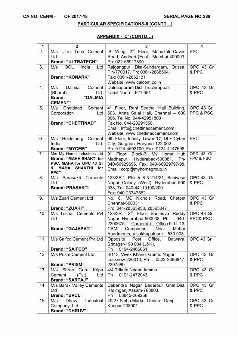
CA NO: CENM - OF 2017-18 SERIAL PAGE NO:289
PARTICULAR SPECIFICATIONS-II (CONTD…)
APPENDIX - 'C’ (CONTD…)
1 2 3 4 2. M/s Ultra Tech Cement
Ltd Brand: “ULTRATECH”
‘B’ Wing, 2nd Floor, Mahakali Caves Road, Andheri (East), Mumbai-400093, Ph: 022-66917800
PSC
3. M/s OCL India Ltd Brand: “KONARK”
Rajgangpur, Dist-Sundargarh, Orissa, Pin-770017, Ph: 0361-2668504, Fax: 0361-2662131 Website: www.calcom.co.in
OPC 43 Gr & PPC
4. M/s Dalmia Cement (Bharat) Ltd. Brand: “DALMIA CEMENT”
Dalmiapuram Dist-Truchirappalli, Tamil Nadu – 621 651
OPC 43 Gr & PPC
5. M/s Chettinad Cement Corporation Ltd Brand: “CHETTINAD”
4th Floor, Rani Seethai Hall Building, 603, Anna Salai Hall, Chennai – 600 006, Tel No. 044-42951800 Fax No. 044-28291558, Email: [email protected] Website: www.chettinadcement.com
OPC 43 Gr, PPC & PSC
6. M/s Heidelberg Cement India Ltd. Brand: “MYCEM”
9th Floor, Infinity Tower ‘C’, DLF Cyber City, Gurgaon, Haryana-122 002 Ph: 0124-4503700, Fax: 0124-4147698
PPC
7. M/s My Home Industries Ltd Brand: “MAHA SHAKTI for PSC, MAHA for OPC 43 Gr & MAHA SHAKTHI for PPC”
9th Floor, Block-3, My Home Hub Madhapur, Hyderabad-500081, Ph-040-66929696, Fax: 040-66929797/98, Email: [email protected]
OPC 43 Gr, PPC & PSC
8. M/s Parasakti Cements Ltd Brand: PRASAKTI
123/3RT, Plot # 8-3-214/21, Srinivasa Nagar Colony (West), Hyderabad-500 038, Tel: 040-44119100/200 Fax: 040-23747562
OPC-43 Gr & PPC
9. M/s Zuari Cement Ltd Brand: “ZUARI”
No. 6, MC Nichols Road, Chetpet Chennai-600031 Ph: 044-28363958, 28365047
OPC 43 Gr & PPC
10 M/s Toshali Cements Pvt Ltd Brand: “GAJAPATI”
123/3RT 2nd Floor Sanjeeva Reddy Nagar Hyderabad-500038, Ph : 040-2300675; Corporate Office:9-14-13, CBM Compound, Near Mehar Apartments, Visakhapatnam – 530 003
OPC 43 Gr, PPC& PSC
11 M/s Saifco Cement Pvt Ltd Brand: “SAIFCO”
Opposite Post Office, Batwara, Srinagar-190 004 (J&K), Ph : 0194-2466061
OPC 43 Gr
12 M/s Prism Cement Ltd Brand: “PRISM”
3/113, Vivek Khand, Gomto Nagar Lucknow-226010, Ph : 0522-2396847, 2397589
OPC 43 Gr & PPC
13 M/s Shree Guru Kripa Cement (Pvt) Ltd Brand: “SARTAJ”
4/4 Trikuta Nagar Jammu Ph : 0191-2472043
OPC 43 Gr & PPC
14 M/s Barak Valley Cements Ltd Brand: “BVCL”
Debendra Nagar Badarpur Ghat,Dist. Karimganj Assam-788803, Ph : 03845-269258
OPC 43 Gr & PPC
15 M/s Dhruv Industrial Company Ltd Brand: “DHRUV”
49/27 Sinha Market General Ganj Kanpur-208001
OPC 43 Gr & PPC
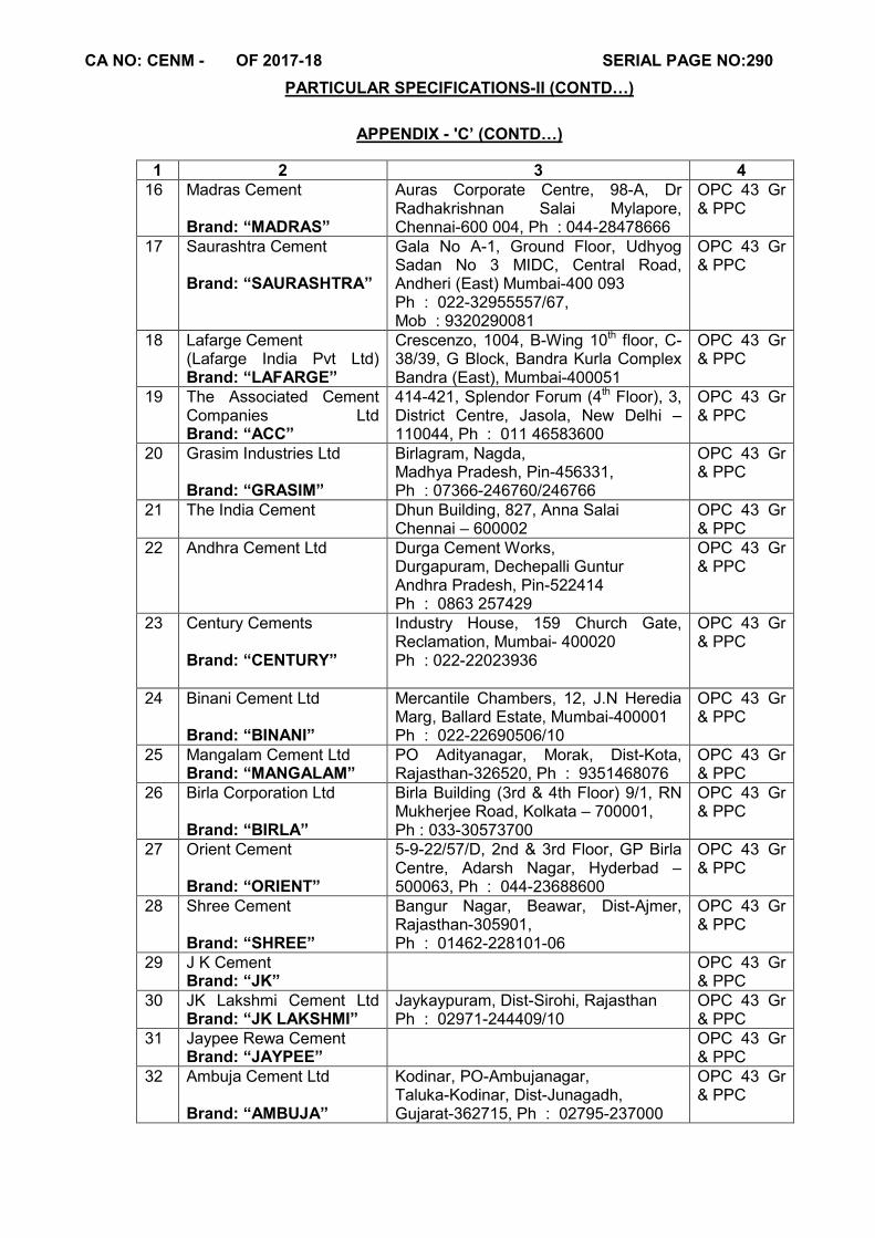
CA NO: CENM - OF 2017-18 SERIAL PAGE NO:290
PARTICULAR SPECIFICATIONS-II (CONTD…)
APPENDIX - 'C’ (CONTD…)
1 2 3 4 16 Madras Cement
Brand: “MADRAS”
Auras Corporate Centre, 98-A, Dr Radhakrishnan Salai Mylapore, Chennai-600 004, Ph : 044-28478666
OPC 43 Gr & PPC
17 Saurashtra Cement Brand: “SAURASHTRA”
Gala No A-1, Ground Floor, Udhyog Sadan No 3 MIDC, Central Road, Andheri (East) Mumbai-400 093 Ph : 022-32955557/67, Mob : 9320290081
OPC 43 Gr & PPC
18 Lafarge Cement (Lafarge India Pvt Ltd) Brand: “LAFARGE”
Crescenzo, 1004, B-Wing 10th floor, C-38/39, G Block, Bandra Kurla Complex Bandra (East), Mumbai-400051
OPC 43 Gr & PPC
19 The Associated Cement Companies Ltd Brand: “ACC”
414-421, Splendor Forum (4th Floor), 3, District Centre, Jasola, New Delhi – 110044, Ph : 011 46583600
OPC 43 Gr & PPC
20 Grasim Industries Ltd Brand: “GRASIM”
Birlagram, Nagda, Madhya Pradesh, Pin-456331, Ph : 07366-246760/246766
OPC 43 Gr & PPC
21 The India Cement Dhun Building, 827, Anna Salai Chennai – 600002
OPC 43 Gr & PPC
22 Andhra Cement Ltd Durga Cement Works, Durgapuram, Dechepalli Guntur Andhra Pradesh, Pin-522414 Ph : 0863 257429
OPC 43 Gr & PPC
23 Century Cements Brand: “CENTURY”
Industry House, 159 Church Gate, Reclamation, Mumbai- 400020 Ph : 022-22023936
OPC 43 Gr & PPC
24 Binani Cement Ltd Brand: “BINANI”
Mercantile Chambers, 12, J.N Heredia Marg, Ballard Estate, Mumbai-400001 Ph : 022-22690506/10
OPC 43 Gr & PPC
25 Mangalam Cement Ltd Brand: “MANGALAM”
PO Adityanagar, Morak, Dist-Kota, Rajasthan-326520, Ph : 9351468076
OPC 43 Gr & PPC
26 Birla Corporation Ltd Brand: “BIRLA”
Birla Building (3rd & 4th Floor) 9/1, RN Mukherjee Road, Kolkata – 700001, Ph : 033-30573700
OPC 43 Gr & PPC
27 Orient Cement Brand: “ORIENT”
5-9-22/57/D, 2nd & 3rd Floor, GP Birla Centre, Adarsh Nagar, Hyderbad – 500063, Ph : 044-23688600
OPC 43 Gr & PPC
28 Shree Cement Brand: “SHREE”
Bangur Nagar, Beawar, Dist-Ajmer, Rajasthan-305901, Ph : 01462-228101-06
OPC 43 Gr & PPC
29 J K Cement Brand: “JK”
OPC 43 Gr & PPC
30 JK Lakshmi Cement Ltd Brand: “JK LAKSHMI”
Jaykaypuram, Dist-Sirohi, Rajasthan Ph : 02971-244409/10
OPC 43 Gr & PPC
31 Jaypee Rewa Cement Brand: “JAYPEE”
OPC 43 Gr & PPC
32 Ambuja Cement Ltd Brand: “AMBUJA”
Kodinar, PO-Ambujanagar, Taluka-Kodinar, Dist-Junagadh, Gujarat-362715, Ph : 02795-237000
OPC 43 Gr & PPC

CA NO: CENM - OF 2017-18 SERIAL PAGE NO:291
PARTICULAR SPECIFICATIONS-II (CONTD…)
APPENDIX - 'C’ (CONTD…)
1 2 3 4
33 M/s Calcom Cement India Ltd (Only for NE region) Brand: “DALMIA CEMENT”
Silpukhuri South Bank, Guwahati, Assam – 781003, Ph ; 0361-2668504 Fax -2662131, Website : www.calcom.co.in
OPC 43 Gr & PPC
34 M/s Trumboo Industries Pvt Ltd (Only for J & K region) Brand : “TCI MAX”
50, Sanat Nagar, Near Industrial Area, Srinagar – 190005 (J&K) Tel No : 0194-2439979, Fax No : 0194-2440001 E-mail : [email protected]
OPC 43 Gr
35 M/s Shree Digvijay Cement Co.Ltd (Only for Gujarat) Brand : “KAMAL”
2nd Floor, Amola Chambers, CG Road, Navrangpuram, Ahmedabad – 380006 Ph : 079-30084670
OPC 43 Gr & PPC
36 M/s Cement Corporation of India Ltd (Only for AP & Adjoining states) Brand : “MAHASHAKTI”
PO-CCI Tandur, Distt-Ranga Reddy, Andhra Pradesh- 5011158 Ph : 08411-247240
OPC 43 Gr
37 M/s Cemtac Cement Pvt Ltd (Only for J&K region) Brand : “CEMTAC”
H/O Lake Wood Plaz (Near Petrol Pump), Nawgam, Srinagar – 190015 (J&K), Ph : 0194-2431500
OPC 43 Gr
38 M/s Meghalaya Cements Ltd (Only for Eastern Region) Brand : “TOP CEM”
Lohia House, M.G Road Factory Bazar, Guwahati – 781001, Ph : 0361-260367/671
OPC 43 Gr
39 M/s Narayan Kar & Associates Pvt Ltd (Only for NE region)
Bodhjungnagar Ind, Growth Centre PO Khayerpur – 799008 West Tripura, Ph : 0381-2514927/4786
OPC 43 Gr & PPC
40 Star Cement Meghalaya (Only for CE Shillong Zone & CE (AF) Shillong area)
Lumshnong, PO-Khaliehriat, Dist – Jantia Hills, Meghalaya Ph : 03655-278215/16/18
OPC 43 Gr & PPC
41 J & K Cement Corp, Kathua (Only for for J&K, region)
OPC 43 Gr
42 Shiva Industries, Kathua (Only for for J&K, region)
OPC 43 Gr
43 M/s Sanghi Industries Ltd Brand : “SANGHI”
10th Floor, Kataria Arcade, Off S G Highway, PO-Makarba, Dist-Ahmedabad, Pin-380051, Mo- 09825803690, Tel-079-26838000, Fax-079-26838111, Website: www.sanghicement.com
OPC 53 Gr & PPC
1.3.1 USE OF PPC (POZOLONA PORTLAND CEMENT)
1.3.1.1 Portland Pozzollana Cement shall not be used for the following: (i) In cold climate reason (ii) Over head reservoir (iii) Under ground sump (iv) Prestigious Building (v) Building with spans 10metre or more (vi) PPC and OPC shall not be mixed
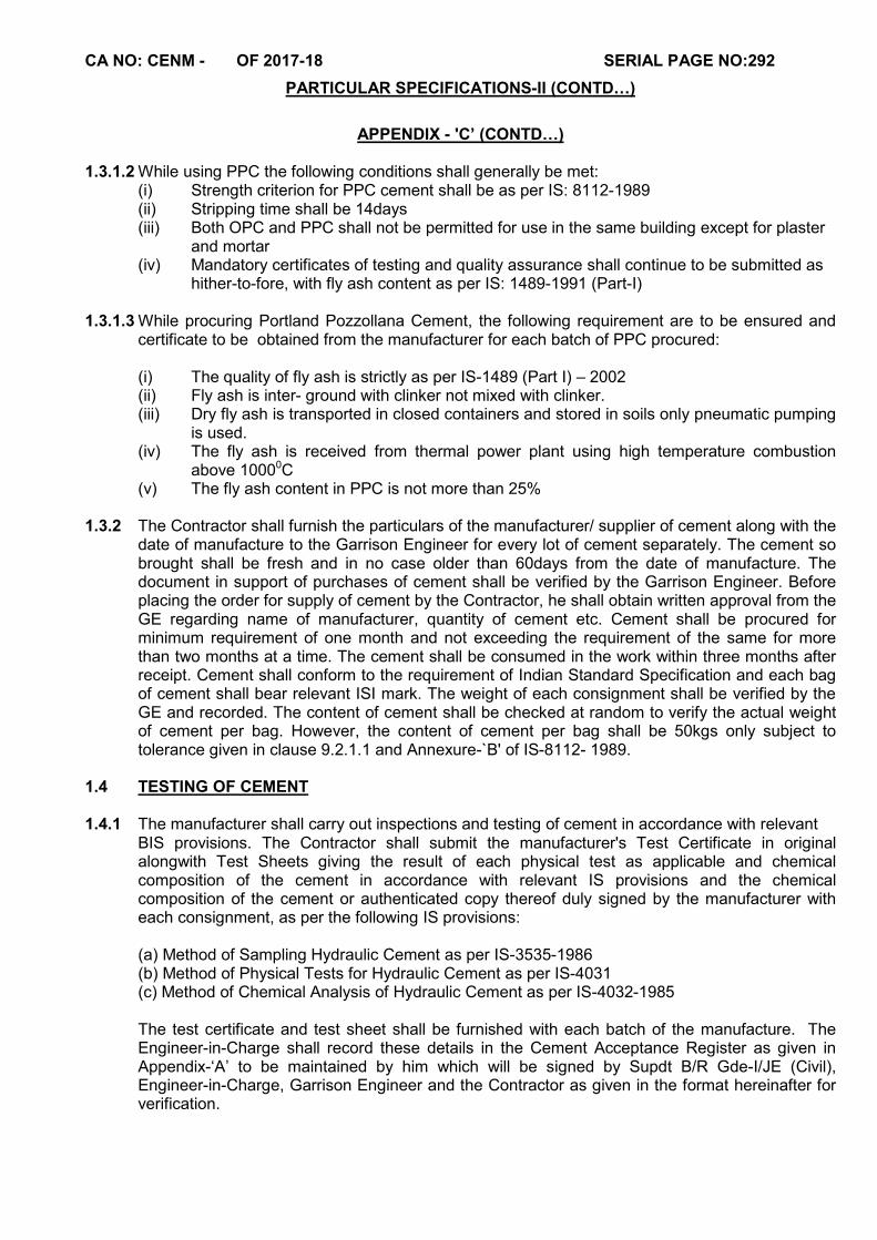
CA NO: CENM - OF 2017-18 SERIAL PAGE NO:292
PARTICULAR SPECIFICATIONS-II (CONTD…)
APPENDIX - 'C’ (CONTD…)
1.3.1.2 While using PPC the following conditions shall generally be met: (i) Strength criterion for PPC cement shall be as per IS: 8112-1989 (ii) Stripping time shall be 14days (iii) Both OPC and PPC shall not be permitted for use in the same building except for plaster
and mortar (iv) Mandatory certificates of testing and quality assurance shall continue to be submitted as
hither-to-fore, with fly ash content as per IS: 1489-1991 (Part-I) 1.3.1.3 While procuring Portland Pozzollana Cement, the following requirement are to be ensured and
certificate to be obtained from the manufacturer for each batch of PPC procured: (i) The quality of fly ash is strictly as per IS-1489 (Part I) – 2002 (ii) Fly ash is inter- ground with clinker not mixed with clinker. (iii) Dry fly ash is transported in closed containers and stored in soils only pneumatic pumping
is used. (iv) The fly ash is received from thermal power plant using high temperature combustion
above 10000C (v) The fly ash content in PPC is not more than 25%
1.3.2 The Contractor shall furnish the particulars of the manufacturer/ supplier of cement along with the
date of manufacture to the Garrison Engineer for every lot of cement separately. The cement so brought shall be fresh and in no case older than 60days from the date of manufacture. The document in support of purchases of cement shall be verified by the Garrison Engineer. Before placing the order for supply of cement by the Contractor, he shall obtain written approval from the GE regarding name of manufacturer, quantity of cement etc. Cement shall be procured for minimum requirement of one month and not exceeding the requirement of the same for more than two months at a time. The cement shall be consumed in the work within three months after receipt. Cement shall conform to the requirement of Indian Standard Specification and each bag of cement shall bear relevant ISI mark. The weight of each consignment shall be verified by the GE and recorded. The content of cement shall be checked at random to verify the actual weight of cement per bag. However, the content of cement per bag shall be 50kgs only subject to tolerance given in clause 9.2.1.1 and Annexure-`B' of IS-8112- 1989.
1.4 TESTING OF CEMENT 1.4.1 The manufacturer shall carry out inspections and testing of cement in accordance with relevant BIS provisions. The Contractor shall submit the manufacturer's Test Certificate in original
alongwith Test Sheets giving the result of each physical test as applicable and chemical composition of the cement in accordance with relevant IS provisions and the chemical composition of the cement or authenticated copy thereof duly signed by the manufacturer with each consignment, as per the following IS provisions:
(a) Method of Sampling Hydraulic Cement as per IS-3535-1986 (b) Method of Physical Tests for Hydraulic Cement as per IS-4031 (c) Method of Chemical Analysis of Hydraulic Cement as per IS-4032-1985 The test certificate and test sheet shall be furnished with each batch of the manufacture. The Engineer-in-Charge shall record these details in the Cement Acceptance Register as given in Appendix-‘A’ to be maintained by him which will be signed by Supdt B/R Gde-I/JE (Civil), Engineer-in-Charge, Garrison Engineer and the Contractor as given in the format hereinafter for verification.
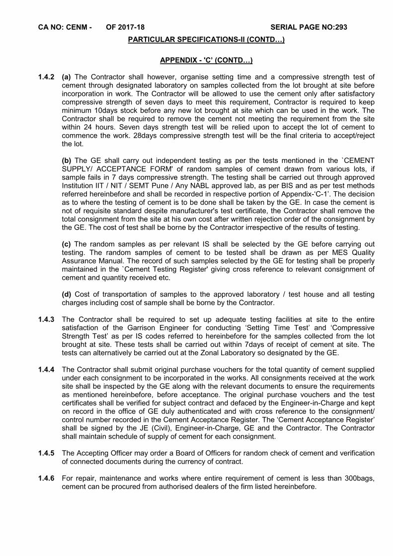
CA NO: CENM - OF 2017-18 SERIAL PAGE NO:293
PARTICULAR SPECIFICATIONS-II (CONTD…)
APPENDIX - 'C’ (CONTD…)
1.4.2 (a) The Contractor shall however, organise setting time and a compressive strength test of
cement through designated laboratory on samples collected from the lot brought at site before incorporation in work. The Contractor will be allowed to use the cement only after satisfactory compressive strength of seven days to meet this requirement, Contractor is required to keep minimum 10days stock before any new lot brought at site which can be used in the work. The Contractor shall be required to remove the cement not meeting the requirement from the site within 24 hours. Seven days strength test will be relied upon to accept the lot of cement to commence the work. 28days compressive strength test will be the final criteria to accept/reject the lot. (b) The GE shall carry out independent testing as per the tests mentioned in the `CEMENT SUPPLY/ ACCEPTANCE FORM' of random samples of cement drawn from various lots, if sample fails in 7 days compressive strength. The testing shall be carried out through approved Institution IIT / NIT / SEMT Pune / Any NABL approved lab, as per BIS and as per test methods referred hereinbefore and shall be recorded in respective portion of Appendix-‘C-1’. The decision as to where the testing of cement is to be done shall be taken by the GE. In case the cement is not of requisite standard despite manufacturer's test certificate, the Contractor shall remove the total consignment from the site at his own cost after written rejection order of the consignment by the GE. The cost of test shall be borne by the Contractor irrespective of the results of testing.
(c) The random samples as per relevant IS shall be selected by the GE before carrying out testing. The random samples of cement to be tested shall be drawn as per MES Quality Assurance Manual. The record of such samples selected by the GE for testing shall be properly maintained in the `Cement Testing Register' giving cross reference to relevant consignment of cement and quantity received etc.
(d) Cost of transportation of samples to the approved laboratory / test house and all testing charges including cost of sample shall be borne by the Contractor.
1.4.3 The Contractor shall be required to set up adequate testing facilities at site to the entire
satisfaction of the Garrison Engineer for conducting ‘Setting Time Test’ and ‘Compressive Strength Test’ as per IS codes referred to hereinbefore for the samples collected from the lot brought at site. These tests shall be carried out within 7days of receipt of cement at site. The tests can alternatively be carried out at the Zonal Laboratory so designated by the GE.
1.4.4 The Contractor shall submit original purchase vouchers for the total quantity of cement supplied
under each consignment to be incorporated in the works. All consignments received at the work site shall be inspected by the GE along with the relevant documents to ensure the requirements as mentioned hereinbefore, before acceptance. The original purchase vouchers and the test certificates shall be verified for subject contract and defaced by the Engineer-in-Charge and kept on record in the office of GE duly authenticated and with cross reference to the consignment/ control number recorded in the Cement Acceptance Register. The ‘Cement Acceptance Register’ shall be signed by the JE (Civil), Engineer-in-Charge, GE and the Contractor. The Contractor shall maintain schedule of supply of cement for each consignment.
1.4.5 The Accepting Officer may order a Board of Officers for random check of cement and verification
of connected documents during the currency of contract.
1.4.6 For repair, maintenance and works where entire requirement of cement is less than 300bags, cement can be procured from authorised dealers of the firm listed hereinbefore.

CA NO: CENM - OF 2017-18 SERIAL PAGE NO:294
PARTICULAR SPECIFICATIONS-II (CONTD…)
APPENDIX - 'C’ (CONTD…)
1.5 STORAGE / ACCOUNTING / PRESERVATION OF CEMENT 1.5.1 Cement shall be stored in covered godown over dry platform at least 20cm high in such a
manner as to prevent deterioration due to moisture or intrusion of foreign matters. In case of store rooms, the stack should be at least 20cm away from floors and walls. The stacking of cement shall be not more than 10bags and or done as specified in relevant IS. The storage, accounting and preservation of cement supplied by the Contractor shall be done as per standard engineer practice till the same is incorporated in the work and the cost of the same is deemed to be included in the unit rate/amount quoted by the tenderer. The EIC shall inspect once a day to verify that cement lying at site is stored, accounted, preserved and maintained as per the norms. The cement shall be stored so as to differentiate each tested and untested consignment separately with distinct identification. If the GE is not satisfied with the storage/ preservation of cement, he may order for any test(s) of cement as applicable for that consignment to ensure its conformity to the quality mentioned in the manufacturer's test certificate. The Contractor shall bear the cost of necessary testing(s) in this regard and no claim whatsoever shall be entertained.
1.5.2 Stacking of cement shall be done as per relevant IS and as under:
(a) Each cement consignment shall be stacked separately and removal shall be made on the basis of `First in First out'.
(b) Adequate top cover will be provided
(c) Stacks in no case shall be higher than 10bags. The maximum width of each stack shall be 3.00m. If the stack is to be more than 7 or 8bags high, the bags shall be arranged in header and stretcher fashion, alternatively lengthwise and crosswise so as to tie the piles together and avoid danger of topping over.
(d) Adequate space shall be kept between two stacks.
1.5.3 Cement godown shall be provided with two locks on each door. The key of one lock at each door
shall remain with the EIC or his representative and that of the other lock with the Contractor's authorised agent at site of works so that cement is removed from the godown only according to daily requirement with the knowledge of both the parties. During the period of storage, if any cement bag(s) found to be in damaged condition due to whatsoever reason, the same shall be removed from the cement godown on written orders of the GE and suitable replacement for the cement bag(s) so removed shall be made and no claim whatsoever shall be admissible on this account.
1.5.4 Cement shall be removed from the store only according to daily requirement with the knowledge
of both the parties and daily consumption of cement shall be recorded in cement consumption register which shall be signed by the Engineer-in-Charge and the Contractor. Cement constants given in Appendix `A' to E-in-C's branch letter No.19280/E8 dated 03 May 1976 shall form the basis of consumption of cement for various items of works unless indicated otherwise.
1.5.5 In case of consumption of cement as per cement consumption register is found to be more than
the estimated quantity of cement due to whatsoever reason, the Contractor shall not have any claim whatsoever for such excess consumption of cement.
1.6 SCHEDULE OF SUPPLY
The Contractor shall procure the cement timely as required in accordance with CPM chart agreed between GE and himself. The Contractor will forfeit his right to demand extension of time if the supplies of cement get delayed due to his failure in placing order in time to the manufacturer.
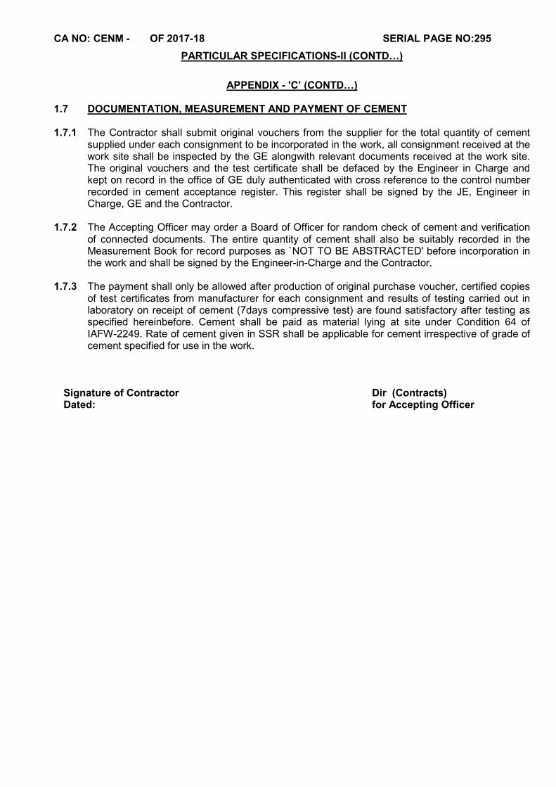
CA NO: CENM - OF 2017-18 SERIAL PAGE NO:295
PARTICULAR SPECIFICATIONS-II (CONTD…)
APPENDIX - 'C’ (CONTD…)
1.7 DOCUMENTATION, MEASUREMENT AND PAYMENT OF CEMENT 1.7.1 The Contractor shall submit original vouchers from the supplier for the total quantity of cement
supplied under each consignment to be incorporated in the work, all consignment received at the work site shall be inspected by the GE alongwith relevant documents received at the work site. The original vouchers and the test certificate shall be defaced by the Engineer in Charge and kept on record in the office of GE duly authenticated with cross reference to the control number recorded in cement acceptance register. This register shall be signed by the JE, Engineer in Charge, GE and the Contractor.
1.7.2 The Accepting Officer may order a Board of Officer for random check of cement and verification
of connected documents. The entire quantity of cement shall also be suitably recorded in the Measurement Book for record purposes as `NOT TO BE ABSTRACTED' before incorporation in the work and shall be signed by the Engineer-in-Charge and the Contractor.
1.7.3 The payment shall only be allowed after production of original purchase voucher, certified copies
of test certificates from manufacturer for each consignment and results of testing carried out in laboratory on receipt of cement (7days compressive test) are found satisfactory after testing as specified hereinbefore. Cement shall be paid as material lying at site under Condition 64 of IAFW-2249. Rate of cement given in SSR shall be applicable for cement irrespective of grade of cement specified for use in the work.
Signature of Contractor Dated:
Dir (Contracts) for Accepting Officer
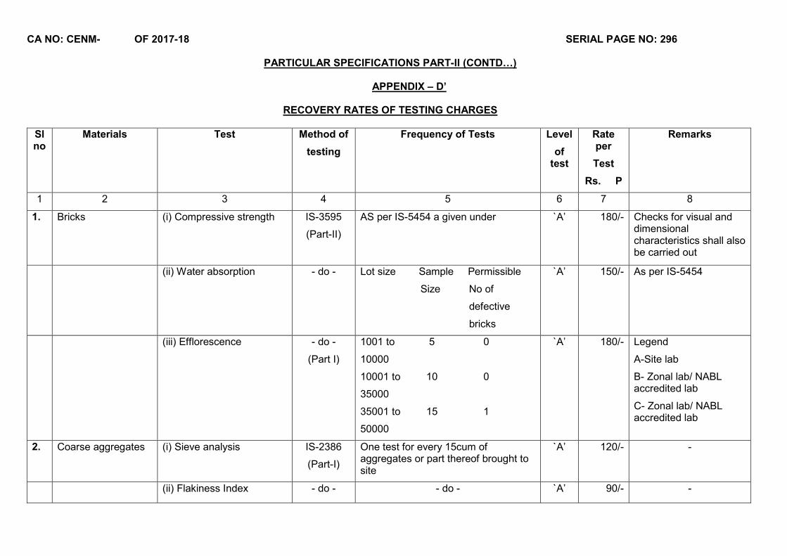
CA NO: CENM- OF 2017-18 SERIAL PAGE NO: 296
PARTICULAR SPECIFICATIONS PART-II (CONTD…)
APPENDIX – D’
RECOVERY RATES OF TESTING CHARGES
Sl no
Materials Test Method of
testing
Frequency of Tests Level
of test
Rate per
Test
Rs. P
Remarks
1 2 3 4 5 6 7 8
1. Bricks (i) Compressive strength IS-3595
(Part-II)
AS per IS-5454 a given under `A’ 180/- Checks for visual and dimensional characteristics shall also be carried out
(ii) Water absorption - do - Lot size Sample Permissible
Size No of
defective
bricks
`A’ 150/- As per IS-5454
(iii) Efflorescence - do -
(Part I)
1001 to 5 0
10000
10001 to 10 0
35000
35001 to 15 1
50000
`A’ 180/- Legend
A-Site lab
B- Zonal lab/ NABL accredited lab
C- Zonal lab/ NABL accredited lab
2. Coarse aggregates (i) Sieve analysis IS-2386
(Part-I)
One test for every 15cum of aggregates or part thereof brought to site
`A’ 120/- -
(ii) Flakiness Index - do - - do - `A’ 90/- -
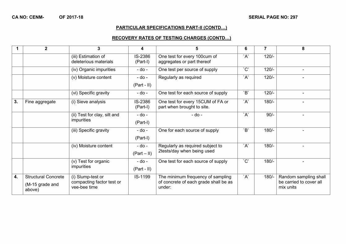
CA NO: CENM- OF 2017-18 SERIAL PAGE NO: 297
PARTICULAR SPECIFICATIONS PART-II (CONTD…)
RECOVERY RATES OF TESTING CHARGES (CONTD…)
1 2 3 4 5 6 7 8
(iii) Estimation of deleterious materials
IS-2386 (Part-I)
One test for every 100cum of aggregates or part thereof
`A’ 120/-
(iv) Organic impurities - do - One test per source of supply `C’ 120/- -
(v) Moisture content - do -
(Part - II)
Regularly as required `A’ 120/- -
(vi) Specific gravity - do - One test for each source of supply `B’ 120/- -
3. Fine aggregate (i) Sieve analysis IS-2386 (Part-I)
One test for every 15CUM of FA or part when brought to site.
`A’ 180/- -
(ii) Test for clay, silt and impurities
- do -
(Part-I)
- do - `A’ 90/- -
(iii) Specific gravity - do -
(Part-I)
One for each source of supply `B’ 180/- -
(iv) Moisture content - do -
(Part – II)
Regularly as required subject to 2tests/day when being used
`A’ 180/- -
(v) Test for organic impurities
- do -
(Part - II)
One test for each source of supply `C’ 180/- -
4. Structural Concrete
(M-15 grade and above)
(i) Slump-test or compacting factor test or vee-bee time
IS-1199 The minimum frequency of sampling of concrete of each grade shall be as under:
`A’ 180/- Random sampling shall be carried to cover all mix units
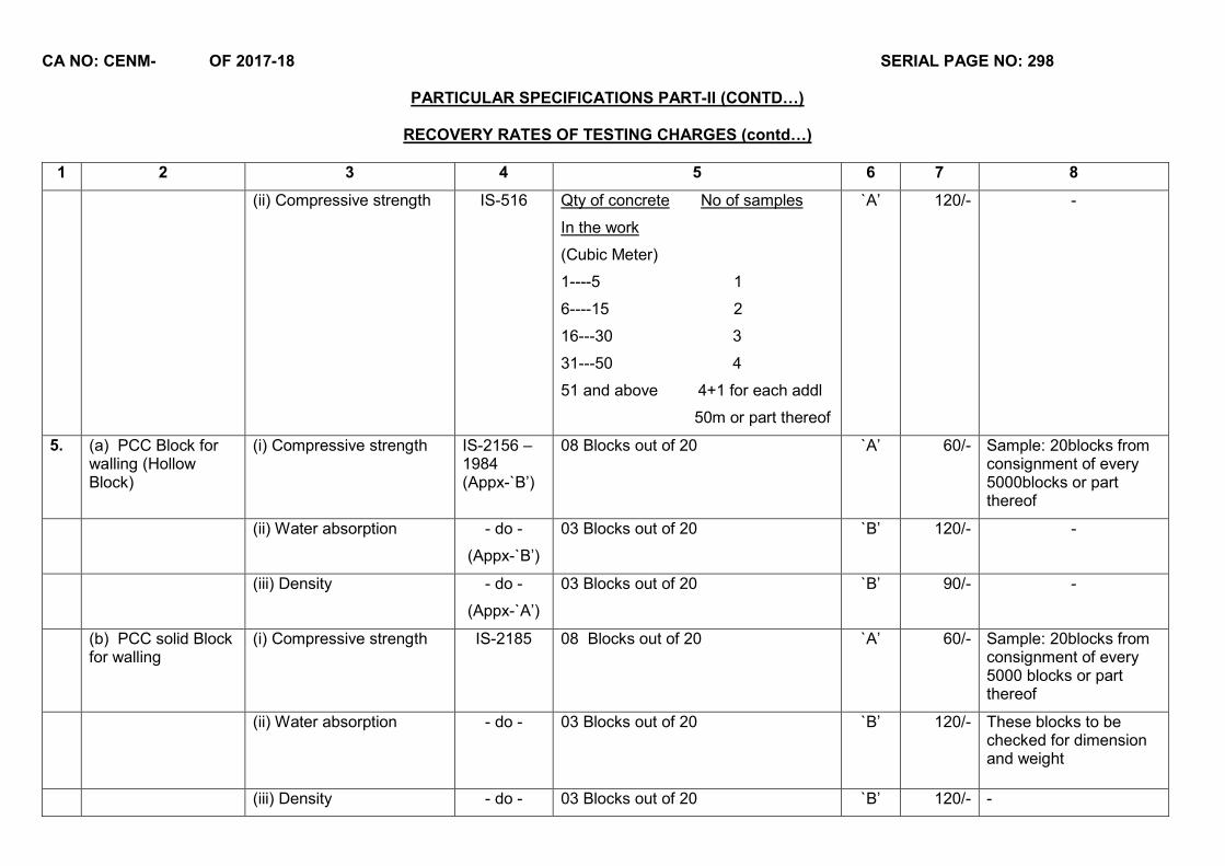
CA NO: CENM- OF 2017-18 SERIAL PAGE NO: 298
PARTICULAR SPECIFICATIONS PART-II (CONTD…)
RECOVERY RATES OF TESTING CHARGES (contd…)
1 2 3 4 5 6 7 8
(ii) Compressive strength IS-516 Qty of concrete No of samples
In the work
(Cubic Meter)
1----5 1
6----15 2
16---30 3
31---50 4
51 and above 4+1 for each addl
50m or part thereof
`A’ 120/- -
5. (a) PCC Block for walling (Hollow Block)
(i) Compressive strength IS-2156 – 1984 (Appx-`B’)
08 Blocks out of 20 `A’ 60/- Sample: 20blocks from consignment of every 5000blocks or part thereof
(ii) Water absorption - do -
(Appx-`B’)
03 Blocks out of 20 `B’ 120/- -
(iii) Density - do -
(Appx-`A’)
03 Blocks out of 20 `B’ 90/- -
(b) PCC solid Block for walling
(i) Compressive strength IS-2185 08 Blocks out of 20 `A’ 60/- Sample: 20blocks from consignment of every 5000 blocks or part thereof
(ii) Water absorption - do - 03 Blocks out of 20 `B’ 120/- These blocks to be checked for dimension and weight
(iii) Density - do - 03 Blocks out of 20 `B’ 120/- -

CA NO: CENM- OF 2017-18 SERIAL PAGE NO: 299
PARTICULAR SPECIFICATIONS PART-II (CONTD…)
RECOVERY RATES OF TESTING CHARGES (contd…)
1 2 3 4 5 6 7 8
6. Cement Flooring Tiles / Terrazzo Tiles
(i) Water absorption IS-1237
(Appx-`D’)
06 tiles out of 18 `B’ 180/- Sample of 18tiles from each source of supply selected at random
(ii) Wet transverse strength - do -
(Appx-`E’)
- do - `B’ 144/- -
7. Burnt clay roofing tiles (hand made) as per IS-2690 (Part-II)
(i) Water Absorption IS-3495
(Part-II)
6 tiles out of 12 `B’ 216/- Samples: 12tiles from each source of supply selected at random.
Length
150mm to 250mm
Width
100mm to 200mm
Thickness
35mm to 50mm
(ii) Compressive strength - do -
(Part-I)
- do - `A’ 180/- -
8. Mangalore pattern roof tiles
(i) Water Absorption IS-654
(Appx-`A’)
6 tiles out of 32 `B’ 180/- Samples: 32 tiles from each consign-ment of 3000tiles or part thereof. These tiles shall be checked for dimension
(ii) Breaking Load - do -
(Appx-`C’)
- do - `B’ 120/- -
9. Timber (i) Specific gravity and weight
IS-1708-1960
Minimum `3’ samples from a lot of 4 Cum or 250pieces of seasoned timber.
`B’ 120/- -
(ii) Moisture content - do - - `A’ 120/- -
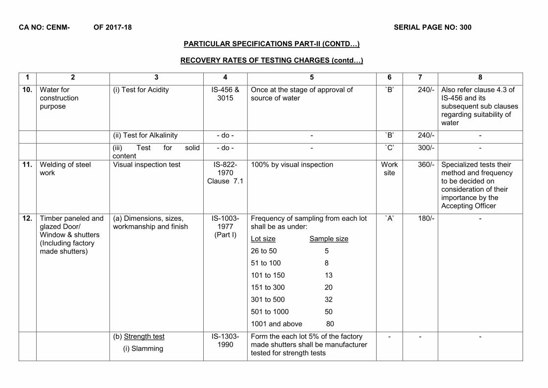
CA NO: CENM- OF 2017-18 SERIAL PAGE NO: 300
PARTICULAR SPECIFICATIONS PART-II (CONTD…)
RECOVERY RATES OF TESTING CHARGES (contd…)
1 2 3 4 5 6 7 8
10. Water for construction purpose
(i) Test for Acidity IS-456 & 3015
Once at the stage of approval of source of water
`B’ 240/- Also refer clause 4.3 of IS-456 and its subsequent sub clauses regarding suitability of water
(ii) Test for Alkalinity - do - - `B’ 240/- -
(iii) Test for solid content
- do - - `C’ 300/- -
11. Welding of steel work
Visual inspection test IS-822-1970
Clause 7.1
100% by visual inspection Work site
360/- Specialized tests their method and frequency to be decided on consideration of their importance by the Accepting Officer
12. Timber paneled and glazed Door/ Window & shutters (Including factory made shutters)
(a) Dimensions, sizes, workmanship and finish
IS-1003-1977
(Part I)
Frequency of sampling from each lot shall be as under:
Lot size Sample size
26 to 50 5
51 to 100 8
101 to 150 13
151 to 300 20
301 to 500 32
501 to 1000 50
1001 and above 80
`A’ 180/- -
(b) Strength test
(i) Slamming
IS-1303-1990
Form the each lot 5% of the factory made shutters shall be manufacturer tested for strength tests
- - -
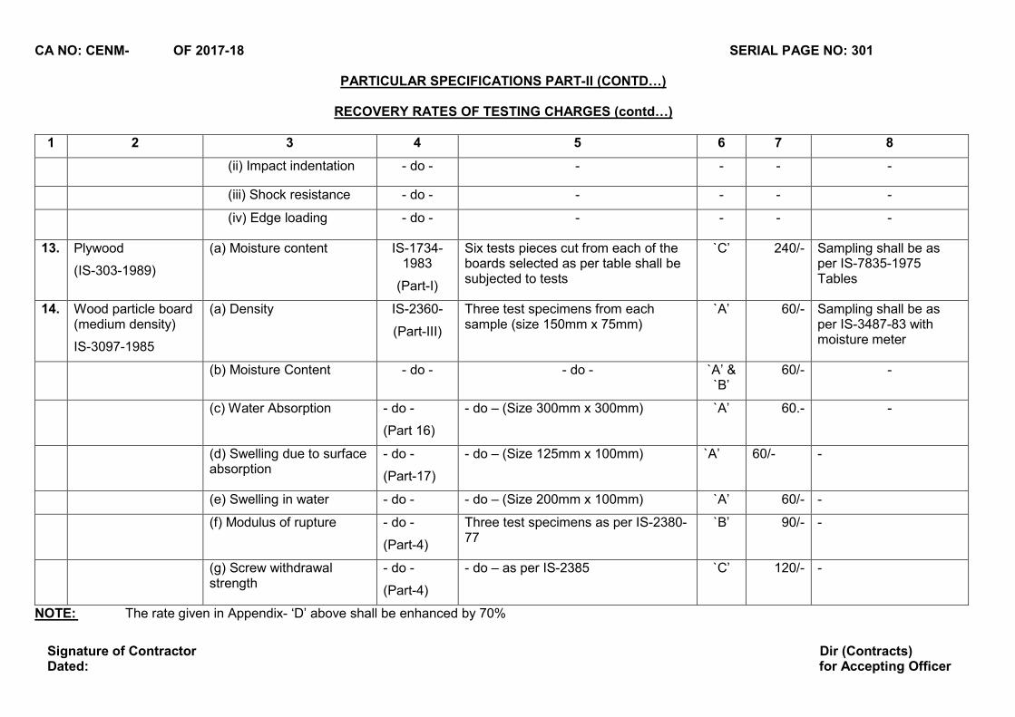
CA NO: CENM- OF 2017-18 SERIAL PAGE NO: 301
PARTICULAR SPECIFICATIONS PART-II (CONTD…)
RECOVERY RATES OF TESTING CHARGES (contd…)
1 2 3 4 5 6 7 8
(ii) Impact indentation - do - - - - -
(iii) Shock resistance - do - - - - -
(iv) Edge loading - do - - - - -
13. Plywood
(IS-303-1989)
(a) Moisture content IS-1734-1983
(Part-I)
Six tests pieces cut from each of the boards selected as per table shall be subjected to tests
`C’ 240/- Sampling shall be as per IS-7835-1975 Tables
14. Wood particle board (medium density)
IS-3097-1985
(a) Density IS-2360-
(Part-III)
Three test specimens from each sample (size 150mm x 75mm)
`A’ 60/- Sampling shall be as per IS-3487-83 with moisture meter
(b) Moisture Content - do - - do - `A’ & `B’
60/- -
(c) Water Absorption - do -
(Part 16)
- do – (Size 300mm x 300mm) `A’ 60.- -
(d) Swelling due to surface absorption
- do -
(Part-17)
- do – (Size 125mm x 100mm) `A’ 60/- -
(e) Swelling in water - do - - do – (Size 200mm x 100mm) `A’ 60/- -
(f) Modulus of rupture - do -
(Part-4)
Three test specimens as per IS-2380-77
`B’ 90/- -
(g) Screw withdrawal strength
- do -
(Part-4)
- do – as per IS-2385 `C’ 120/- -
NOTE: The rate given in Appendix- ‘D’ above shall be enhanced by 70%
Signature of Contractor Dated:
Dir (Contracts) for Accepting Officer
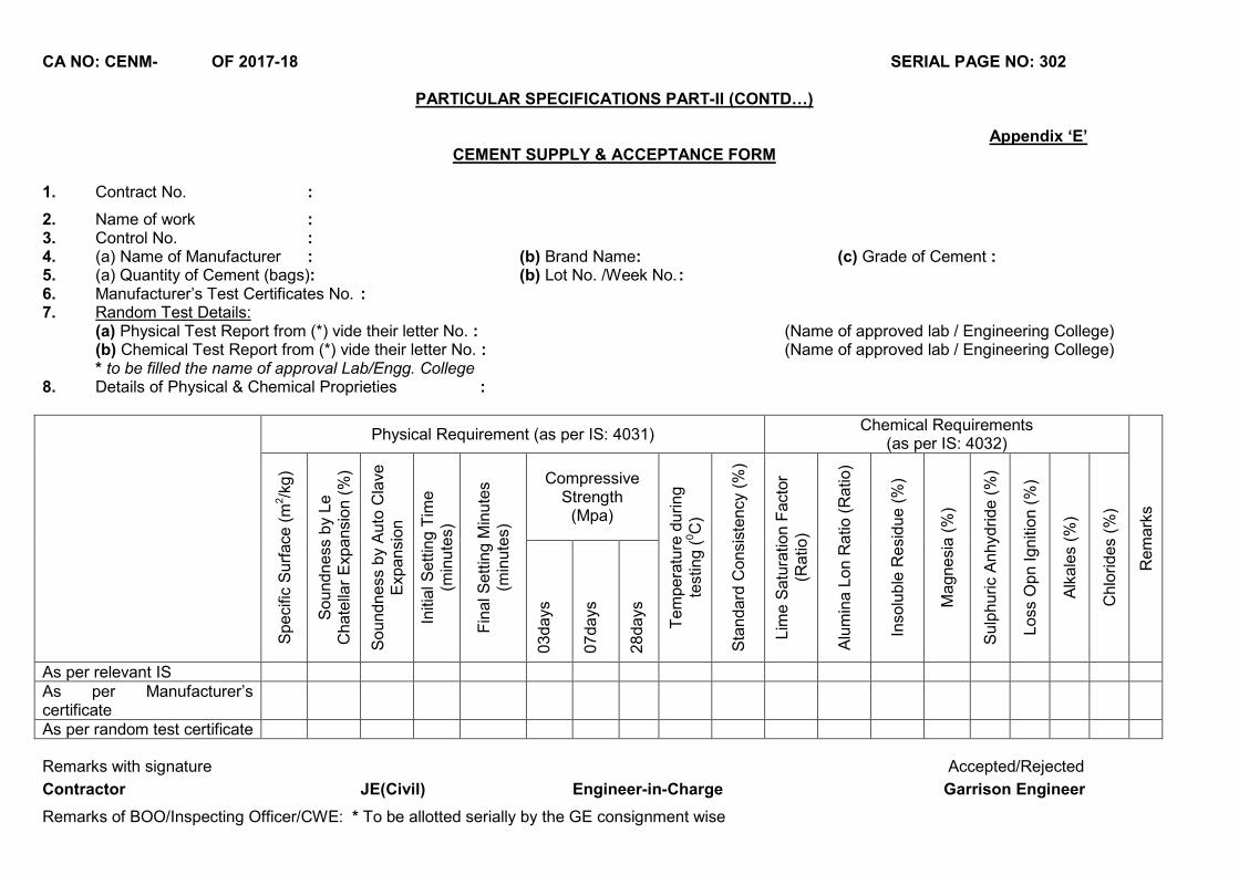
CA NO: CENM- OF 2017-18 SERIAL PAGE NO: 302
PARTICULAR SPECIFICATIONS PART-II (CONTD…)
Appendix ‘E’ CEMENT SUPPLY & ACCEPTANCE FORM
1. Contract No. :
2. Name of work : 3. Control No. : 4. (a) Name of Manufacturer : (b) Brand Name: (c) Grade of Cement : 5. (a) Quantity of Cement (bags): (b) Lot No. /Week No. : 6. Manufacturer’s Test Certificates No. : 7. Random Test Details:
(a) Physical Test Report from (*) vide their letter No. : (Name of approved lab / Engineering College) (b) Chemical Test Report from (*) vide their letter No. : (Name of approved lab / Engineering College)
* to be filled the name of approval Lab/Engg. College 8. Details of Physical & Chemical Proprieties :
Physical Requirement (as per IS: 4031) Chemical Requirements
(as per IS: 4032)
Rem
ark
s
Specifi
c S
urf
ace (
m2/k
g)
Soundness
by
Le
Chate
llar
Expansi
on (
%)
Soundness b
y A
uto
Cla
ve
Expansi
on
Initia
l Sett
ing T
ime
(min
ute
s)
Fin
al S
ett
ing M
inute
s (m
inute
s)
Compressive Strength
(Mpa)
Tem
pera
ture
during
test
ing (
0C
)
Sta
ndard
Consis
tency
(%)
Lim
e S
atu
ration F
act
or
(Ratio)
Alu
min
a L
on R
atio
(R
atio)
Insolu
ble
Resid
ue (
%)
Magnesi
a (
%)
Sulp
huric A
nhydride (
%)
Loss
Opn Igniti
on (
%)
Alk
ale
s (%
)
Chlo
rides (
%)
03days
07days
28days
As per relevant IS As per Manufacturer’s certificate
As per random test certificate
Remarks with signature Accepted/Rejected
Contractor JE(Civil) Engineer-in-Charge Garrison Engineer
Remarks of BOO/Inspecting Officer/CWE: * To be allotted serially by the GE consignment wise
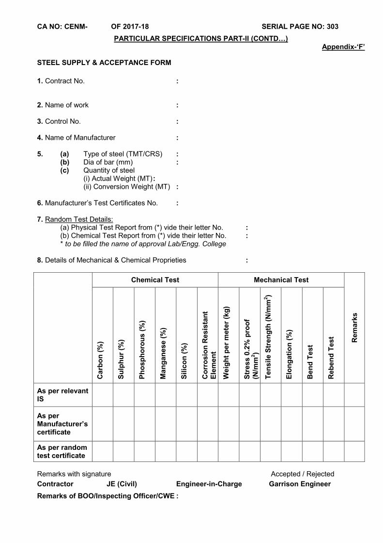
CA NO: CENM- OF 2017-18 SERIAL PAGE NO: 303
PARTICULAR SPECIFICATIONS PART-II (CONTD…)
Appendix-‘F’
STEEL SUPPLY & ACCEPTANCE FORM
1. Contract No. :
2. Name of work : 3. Control No. : 4. Name of Manufacturer : 5. (a) Type of steel (TMT/CRS) : (b) Dia of bar (mm) : (c) Quantity of steel (i) Actual Weight (MT) : (ii) Conversion Weight (MT) : 6. Manufacturer’s Test Certificates No. : 7. Random Test Details: (a) Physical Test Report from (*) vide their letter No. : (b) Chemical Test Report from (*) vide their letter No. : * to be filled the name of approval Lab/Engg. College 8. Details of Mechanical & Chemical Proprieties : Chemical Test Mechanical Test
Rem
ark
s
Carb
on
(%
)
Su
lph
ur
(%)
Ph
osp
ho
rou
s (
%)
Man
gan
ese (
%)
Sil
ico
n (
%)
Co
rro
sio
n R
esis
tan
t E
lem
en
t
Weig
ht
per
mete
r (k
g)
Str
ess 0
.2%
pro
of
(N/m
m2)
Ten
sil
e S
tren
gth
(N
/mm
2)
Elo
ng
ati
on
(%
)
Ben
d T
est
Reb
en
d T
est
As per relevant IS
As per Manufacturer’s certificate
As per random test certificate
Remarks with signature Accepted / Rejected
Contractor JE (Civil) Engineer-in-Charge Garrison Engineer
Remarks of BOO/Inspecting Officer/CWE :
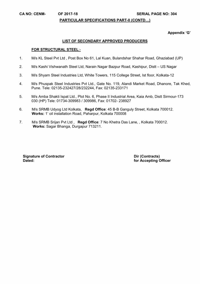
CA NO: CENM- OF 2017-18 SERIAL PAGE NO: 304
PARTICULAR SPECIFICATIONS PART-II (CONTD…)
Appendix ‘G’
LIST OF SECONDARY APPROVED PRODUCERS FOR STRUCTURAL STEEL:- 1. M/s KL Steel Pvt Ltd , Post Box No 61, Lal Kuan, Bulandshar Shahar Road, Ghaziabad (UP) 2. M/s Kashi Vishwanath Steel Ltd, Narain Nagar Bazpur Road, Kashipur, Distt – US Nagar 3. M/s Shyam Steel Industries Ltd, White Towers, 115 College Street, Ist floor, Kolkata-12 4. M/s Phuspak Steel Industries Pvt Ltd., Gate No. 119, Alandi Market Road, Dhanore, Tak Khed,
Pune. Tele: 02135-232427/28/232244, Fax: 02135-233171 5. M/s Amba Shakti Ispat Ltd., Plot No. 6, Phase II Industrial Area, Kaia Amb, Distt Sirmour-173
030 (HP) Tele: 01734-309983 / 309986, Fax: 01702- 238927 6. M/s SRMB Udyog Ltd Kolkata, Regd Office: 45 B-B Ganguly Street, Kolkata 700012. Works: 1’ oil installation Road, Paharpur, Kolkata 700008 7. M/s SRMB Srijan Pvt Ltd , Regd Office: 7 No Khetra Das Lane, , Kolkata 700012. Works: Sagar Bhanga, Durgapur 713211.
Signature of Contractor Dated:
Dir (Contracts) for Accepting Officer

CA NO: CENM- OF 2017-18 SERIAL PAGE NO: 305
PARTICULAR SPECIFICATIONS Part-II (CONTD…) APPENDIX’H’
PROFORMA NO-1 DAILY MAINTENANCE OPERATION
S N
Nature of work to be completed Record of Replacement/maint carried
out
Signature of
Mechanic
Sign of AGE E/M / JE E/M
1 Cleaning the traction machines, relay panels, Control panels, starter panels, selectors, governors, car top, car gates, sills, machine room pits, car panels, car mirror, Landing gates, indicator panels, push buttons, car ceiling, car base, Lights, alarm etc.
2 Checking and repairs of all relays contacts. 3 Checking and toping of oils/grease in all bearings, rings and
chains. 4 Checking and repairing of breaking action. 5 Checking and repairing of movement of door switches, gate
switches, emergency stop switches 6 Checking and repairing of all indicator lamp and indicator. 7 Checking and repairing of annunicator Lights, Buzzer, Car
Lights, Emergency Light, car top light, machine room lights, landing door lights, car ventilation fan etc.
8 Checking and repair to ARD function. 9 Checking and Adjusting leveling difference, brake slippage,
acceleration, deceleration and riding comfort. 10 Checking and repairing of earthing connection of Lift car
panels, machines and all other metal parts 11 Checking and repairing movements of Car Control buttons,
switches etc. Note:1 During the above maintenance if any other component found unserviceable that shall also be repaired/replaced and recorded in proforma No.1.
Note:2 During the maintenance all defective parts shall be replaced and record for them shall be mentioned in appropriate coloum. The rates for replacement of defective parts, toping of oil/greasing etc is deemed to be included in the unit rate quoted by the Contractor under BOQ.
Note:3 This maintenance sheet shall be part of RAR & FB. Signature of Contractor Signature of GE

CA NO: CENM- OF 2017-18 SERIAL PAGE NO: 306
PARTICULAR SPECIFICATIONS Part-II (CONTD…) APPENDIX’H’ (CONTD…)
PROFORMA NO-2 FORTNIGHTLY MAINTENENCE OPERATION (IN ADDITION TO DAILY CHECK)
S N
Nature of work to be completed Record of Replacement
Signature of
Mechanic
Sign of AGE E/M JE E/M
1 Checking and cleaning to traction motor brushes, brush holders, internal frame, hoist way, beams slow down cams, out side cages, rails, counter weight rails.
2 check lift stops in down word direction properly with 25 % overload with operation of the Emergency stop when lift is moving at full speed. It required carry out necessary repair and replacement.
3 Check and lubricate by grease cup for speed governors, compensating pulleys.
4 Check, repairs top up rail lubricators, oil selectors. 5 Check, Lubricate and repair to main ropes, compensating
rope, tensioning pulleys etc. 6 Check and adjust slip rings, commuters. 7 Check and oil electric brake pins and pins of door
operation and door opening mechanism. 8 Check and repair door closers and Leavers. 9 Check and repair door protection edge.
10 Check and repair main sheaves, Secondary sheaves, rope sheaves on car top and counter weight top.
11 Check and repair brake wheels, shoes. Note:1 During the above maintenance if any other
component found Unserviceable that shall also be repaired/replaced and recorded in proforma No.2.
Note:2 During the maintenance all defective parts shall be replaced and record for them shall be mentioned in appropriate column. The rates for replacement of defective parts, toping of oil/greasing etc is deemed to be included in the unit rate quoted by the Contractor under BOQ.
Note:3 This maintenance sheet shall be part of RAR & FB.
Signature of Contractor Signature of GE
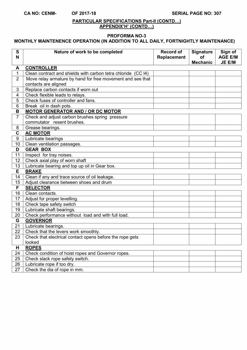
CA NO: CENM- OF 2017-18 SERIAL PAGE NO: 307
PARTICULAR SPECIFICATIONS Part-II (CONTD…) APPENDIX’H’ (CONTD…)
PROFORMA NO-3 MONTHLY MAINTENENCE OPERATION (IN ADDITION TO ALL DAILY, FORTNIGHTLY MAINTENANCE) S N
Nature of work to be completed Record of Replacement
Signature of
Mechanic
Sign of AGE E/M JE E/M
A CONTROLLER 1 Clean contract and shields with carbon tetra chloride (CC l4) 2 Move relay armature by hand for free movement and see that
contacts are aligned
3 Replace carbon contacts if worn out
4 Check flexible leads to relays.
5 Check fuses of controller and fans.
6 Break oil in dash pots.
B MOTOR GENERATOR AND / OR DC MOTOR 7 Check and adjust carbon brushes spring pressure
commutator resent brushes.
8 Grease bearings.
C AC MOTOR
9 Lubricate bearings
10 Clean ventilation passages. D GEAR BOX 11 Inspect for tray noises. 12 Check axial play of worn shaft
13 Lubricate bearing and top up oil in Gear box.
E BRAKE 14 Clean if any and trace source of oil leakage. 15 Adjust clearance between shoes and drum F SELECTOR 16 Clean contacts.
17 Adjust for proper levelling.
18 Check tape safety switch
19 Lubricate shaft bearings.
20 Check performance without load and with full load. G GOVERNOR
21 Lubricate bearings.
22 Check that the levers work smoothly.
23 Check that electrical contact opens before the rope gets looked
H ROPES
24 Check condition of hoist ropes and Governor ropes.
25 Check slack rope safety switch.
26 Lubricate rope if too dry.
27 Check the dia of rope in mm.
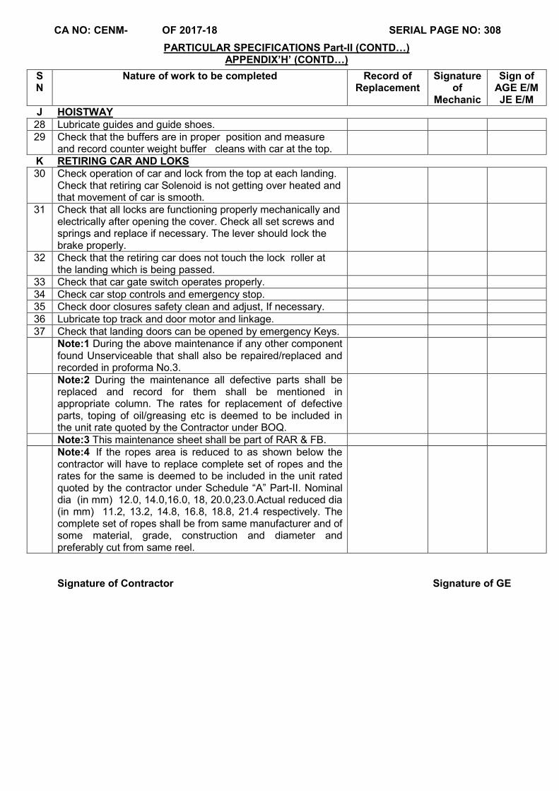
CA NO: CENM- OF 2017-18 SERIAL PAGE NO: 308
PARTICULAR SPECIFICATIONS Part-II (CONTD…) APPENDIX’H’ (CONTD…)
S N
Nature of work to be completed Record of Replacement
Signature of
Mechanic
Sign of AGE E/M JE E/M
J HOISTWAY
28 Lubricate guides and guide shoes.
29 Check that the buffers are in proper position and measure and record counter weight buffer cleans with car at the top.
K RETIRING CAR AND LOKS
30 Check operation of car and lock from the top at each landing. Check that retiring car Solenoid is not getting over heated and that movement of car is smooth.
31 Check that all locks are functioning properly mechanically and electrically after opening the cover. Check all set screws and springs and replace if necessary. The lever should lock the brake properly.
32 Check that the retiring car does not touch the lock roller at the landing which is being passed.
33 Check that car gate switch operates properly. 34 Check car stop controls and emergency stop. 35 Check door closures safety clean and adjust, If necessary. 36 Lubricate top track and door motor and linkage.
37 Check that landing doors can be opened by emergency Keys. Note:1 During the above maintenance if any other component
found Unserviceable that shall also be repaired/replaced and recorded in proforma No.3.
Note:2 During the maintenance all defective parts shall be replaced and record for them shall be mentioned in appropriate column. The rates for replacement of defective parts, toping of oil/greasing etc is deemed to be included in the unit rate quoted by the Contractor under BOQ.
Note:3 This maintenance sheet shall be part of RAR & FB. Note:4 If the ropes area is reduced to as shown below the
contractor will have to replace complete set of ropes and the rates for the same is deemed to be included in the unit rated quoted by the contractor under Schedule “A” Part-II. Nominal dia (in mm) 12.0, 14.0,16.0, 18, 20.0,23.0.Actual reduced dia (in mm) 11.2, 13.2, 14.8, 16.8, 18.8, 21.4 respectively. The complete set of ropes shall be from same manufacturer and of some material, grade, construction and diameter and preferably cut from same reel.
Signature of Contractor Signature of GE
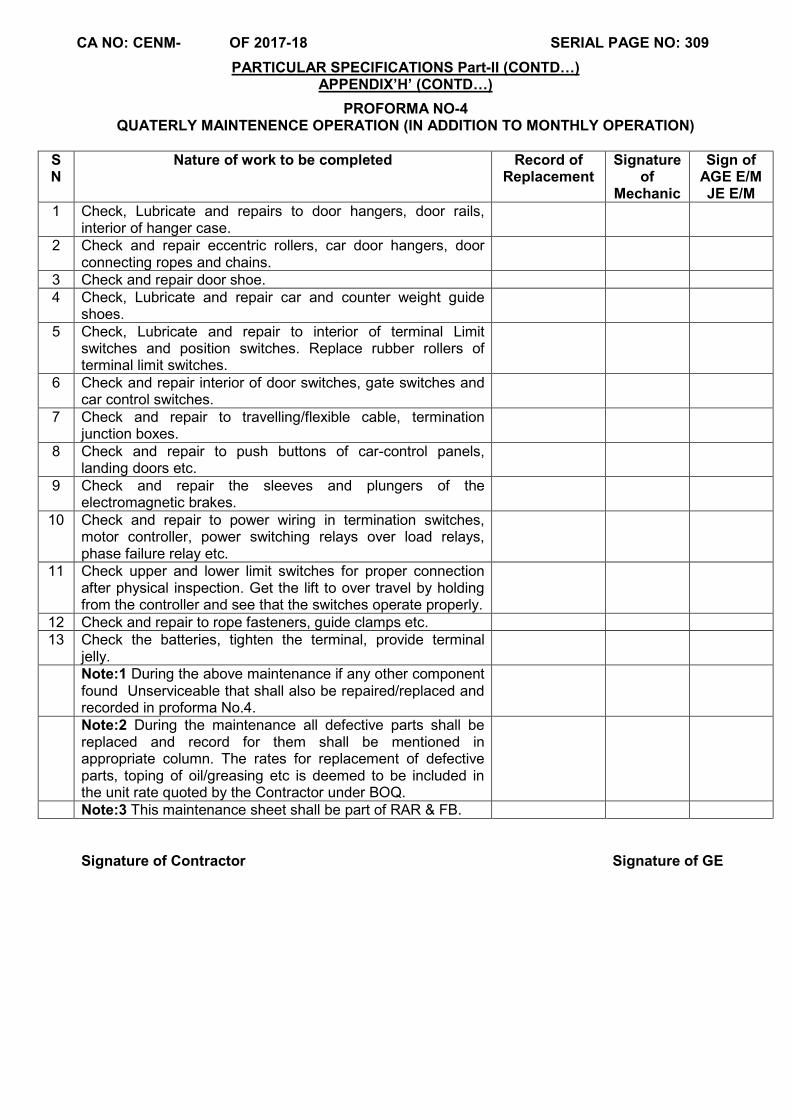
CA NO: CENM- OF 2017-18 SERIAL PAGE NO: 309
PARTICULAR SPECIFICATIONS Part-II (CONTD…) APPENDIX’H’ (CONTD…)
PROFORMA NO-4 QUATERLY MAINTENENCE OPERATION (IN ADDITION TO MONTHLY OPERATION)
S N
Nature of work to be completed Record of Replacement
Signature of
Mechanic
Sign of AGE E/M JE E/M
1 Check, Lubricate and repairs to door hangers, door rails, interior of hanger case.
2 Check and repair eccentric rollers, car door hangers, door connecting ropes and chains.
3 Check and repair door shoe. 4 Check, Lubricate and repair car and counter weight guide
shoes. 5 Check, Lubricate and repair to interior of terminal Limit
switches and position switches. Replace rubber rollers of terminal limit switches.
6 Check and repair interior of door switches, gate switches and car control switches.
7 Check and repair to travelling/flexible cable, termination junction boxes.
8 Check and repair to push buttons of car-control panels, landing doors etc.
9 Check and repair the sleeves and plungers of the electromagnetic brakes.
10 Check and repair to power wiring in termination switches, motor controller, power switching relays over load relays, phase failure relay etc.
11 Check upper and lower limit switches for proper connection after physical inspection. Get the lift to over travel by holding from the controller and see that the switches operate properly.
12 Check and repair to rope fasteners, guide clamps etc. 13 Check the batteries, tighten the terminal, provide terminal
jelly. Note:1 During the above maintenance if any other component
found Unserviceable that shall also be repaired/replaced and recorded in proforma No.4.
Note:2 During the maintenance all defective parts shall be replaced and record for them shall be mentioned in appropriate column. The rates for replacement of defective parts, toping of oil/greasing etc is deemed to be included in the unit rate quoted by the Contractor under BOQ.
Note:3 This maintenance sheet shall be part of RAR & FB. Signature of Contractor Signature of GE
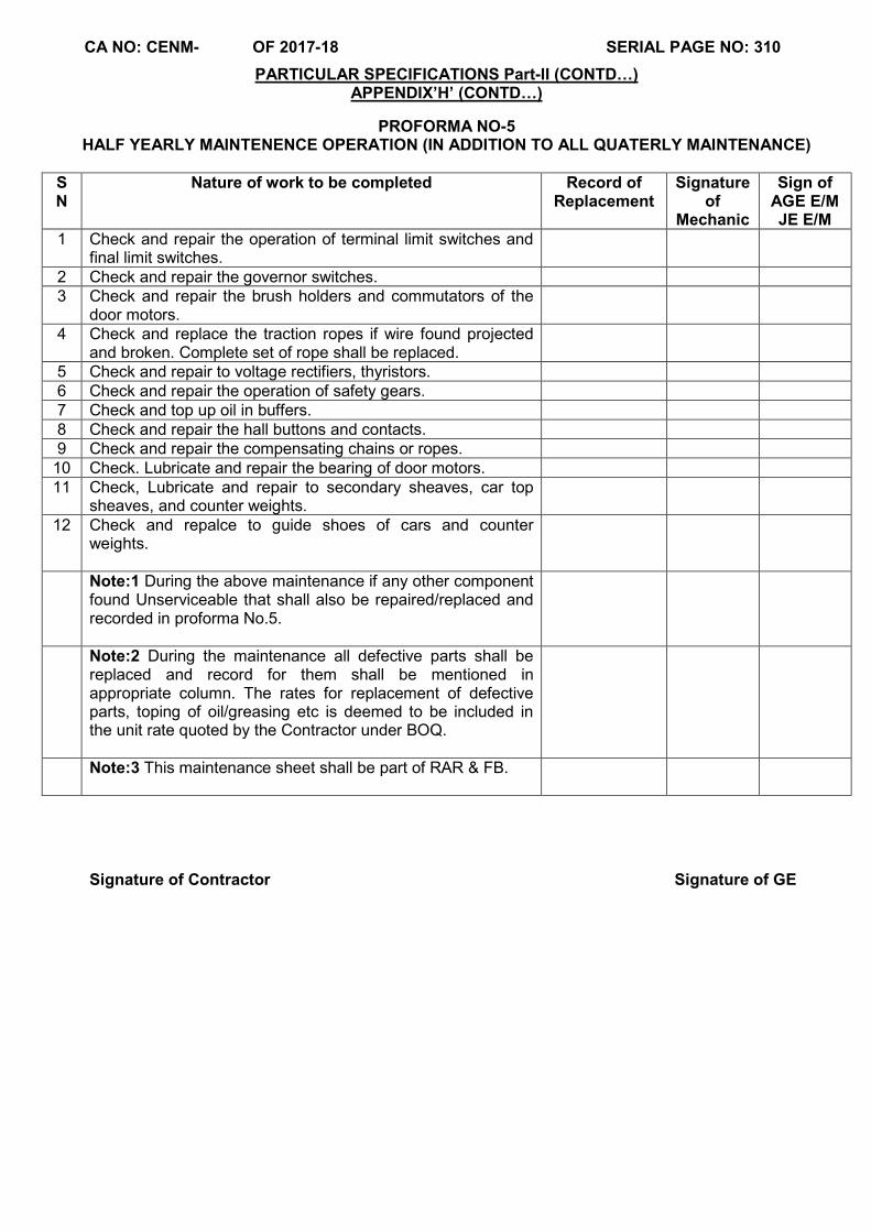
CA NO: CENM- OF 2017-18 SERIAL PAGE NO: 310
PARTICULAR SPECIFICATIONS Part-II (CONTD…) APPENDIX’H’ (CONTD…)
PROFORMA NO-5 HALF YEARLY MAINTENENCE OPERATION (IN ADDITION TO ALL QUATERLY MAINTENANCE)
S N
Nature of work to be completed Record of Replacement
Signature of
Mechanic
Sign of AGE E/M JE E/M
1 Check and repair the operation of terminal limit switches and final limit switches.
2 Check and repair the governor switches. 3 Check and repair the brush holders and commutators of the
door motors. 4 Check and replace the traction ropes if wire found projected
and broken. Complete set of rope shall be replaced. 5 Check and repair to voltage rectifiers, thyristors. 6 Check and repair the operation of safety gears. 7 Check and top up oil in buffers. 8 Check and repair the hall buttons and contacts. 9 Check and repair the compensating chains or ropes.
10 Check. Lubricate and repair the bearing of door motors. 11 Check, Lubricate and repair to secondary sheaves, car top
sheaves, and counter weights. 12 Check and repalce to guide shoes of cars and counter
weights.
Note:1 During the above maintenance if any other component found Unserviceable that shall also be repaired/replaced and recorded in proforma No.5.
Note:2 During the maintenance all defective parts shall be replaced and record for them shall be mentioned in appropriate column. The rates for replacement of defective parts, toping of oil/greasing etc is deemed to be included in the unit rate quoted by the Contractor under BOQ.
Note:3 This maintenance sheet shall be part of RAR & FB.
Signature of Contractor Signature of GE

CA NO: CENM- OF 2017-18 SERIAL PAGE NO: 311
PARTICULAR SPECIFICATIONS Part-II (CONTD…) APPENDIX’H’ (CONTD…)
PROFORMA NO-6 ANNUAL MAINTENENCE OPERATION (IN ADDITION TO ALL HALF YEARLY MAINTENANCE
S N
Nature of work to be completed Record of Replacement
Signature of
Mechanic
Sign of AGE E/M JE E/M
1 Inspect the lift car, car doors, landing doors and ceiling etc carry out buffing on steel hair line finish to get them shine. Replace the inside mirror, hand rail, Light fittings, ventilating fan etc if found broken/Unserviceable.
2 Open all the indicating panels from car, landing etc clear from inside replace all defective items.
3 Check and replace all defective push buttons. 4 Check and repair the worm gear and the thrust bearing from
the gear box. 5 Check and repair the power Ckt in junction boxes, cables,
controllers power relays, motor etc at every landing and car cages. Check the condition of cables and conduit inlets and outlets.
6 Check and repair the operation of car over speed safety gear by moving the leavers manually and ensure that they are working properly.
7 Check, repair and tighten screws and foundation bolts of traction machine, Secondary sheaves exterior of lift frame, guide rails, guide rail clamps and bracket etc.
8 Dismantle, clean and repair the electro magnetic brake of gearless machines, replace the necessary parts for smooth functioning.
9 open all control panels, starter panels, relay panels replace all worn out parts, all contacts to be replace, screws to be tighten, indicators to be replace, relays to be tested etc.
10 Check and repair the ARD, replace the batteries if required. 11 Check and repair the VVVF drive and replace if creating
frequent breakdown. 12 Check and ensure all earthing connections are in sound
conditions, check earthing resistance and maintain the record. 13 Check and replace the alarm system, Emergency lights,
announcing system etc. 14 Carry out joint inspection of lift in the presence of IEM and
garrison engineer. During inspection if any item related to the operation of lift found unserviceable shall be replaced.
Note:1 During the above maintenance if any other component found Unserviceable that shall also be repaired/replaced and recorded in proforma No.6.
Note:2 During the maintenance all defective parts shall be replaced and record for them shall be mentioned in appropriate column. The rates for replacement of defective parts, toping of oil/greasing etc is deemed to be included in the unit rate quoted by the Contractor under BOQ.
Note:3 This maintenance sheet shall be part of RAR & FB
Signature of Contractor Signature of GE

CA NO: CENM- OF 2017-18 SERIAL PAGE NO: 312
Tel: 022-22185694 Chief Engineer (Navy) Mumbai, 26, Assaye Buildings, Colaba, Mumbai - 400 005
87682/ 32 /E8 03 Feb 2018 M/s____________________________
_______________________________
_______________________________
_______________________________
DEMOLITION OF BLDG T-97, T-69, T-68, T60A, T-41, T-40, T-38, T-36, T-35,T-34, T-33, T-32 AND
CONSTN OF DEFICIENT MD ACCN FOR SAILORS AT NT POOL, COLABA MUMBAI Dear Sir (s), 1. Tender documents in respect of above work are uploaded on the site www.eprocuremes.gov.in/ www.defproc.gov.in and published on 03 Feb 2018. The quoted e-Tender will be received on 15 Mar 2018 upto 1800 hrs and opened on or after 21 Mar 2018 at 1200 hrs. The tender is on single stage two cover e-tendering system. The contents of Cover I & Cover II are specified in NOTICE OF TENDER. 2. Bids will be received online by ACCEPTING OFFICER upto the date and time mentioned in the NOTICE INVITNG TENDER (NIT). No tender/bid will be received in physical form and any tender/bid received in such manner will be treated as non bonafide tender/bid. 3. Bid will be opened on due date and time fixed for opening in the presence of tenderers/bidders or their authorized representatives, who have uploaded their quotation bid and who wish to be present at the time of opening the bids. 4. Your attention is also drawn to instruction on filling and submission of tender attached herewith. You may forward your points on tender documents and/or depute your technical representative for discussion on tender/drawing and to clarify doubts, if any, on or before 15 Feb 2018. You are requested not to write piece meal points and forward your points duly consolidated before due date viz. 15 Feb 2018. 5. Unenlisted contractors are required to submit the scanned copies (in pdf file) of documents required as per eligibility criteria mentioned in instructions for filling the tender documents and Appendix ‘A’ to NIT alongwith EARNEST MONEY DEPOSIT (EMD) and tender fee on e-procurement portal and submit the physical documents in the office of HQ Chief Engineer (Navy) Mumbai, 26 Assaye Building Colaba Mumbai- 400 005 within time limit specified in NIT. Inadequacy/deficiency of documents shall make the bid liable for rejection resulting in disqualification for opening of finance bid. 6. (a) Contractor having not executed standing security bond and standing security deposit in
any MES formation shall upload scanned copy of EARNEST MONEY DEPOSIT (EMD) mentioned in Notice of Tender and shall ensure receipt of hard copy of EMD in the office of tender issuing authority before date & time fixed for this purpose. In case of failure to abide by any of these two requirements, the finance bid will not be opened.
(a) Contractor having not executed standing security bond and standing security deposit in any MES formation would be required to deposit individual security deposit on acceptance of tender which will be calculated with reference to the tendered cost as per scales laid down by MES for calculation of “EARNEST MONEY” enhanced by 25% subject to maximum of Rs 18,75,000/- (Rupees Eighteen Lakhs seventy five thousand only).

CA NO: CENM- OF 2017-18 SERIAL PAGE NO: 313
7. Enlisted contractors of MES shall submit the scanned copies (pdf file) of enlistment letter, tender fee and such other documents as mentioned in Appx ‘A’ to NIT on e-procurement portal and submit physical documents in the office of HQ Chief Engineer (Navy) Mumbai, 26 Assaye Building, Colaba, Mumbai-400 005 before date and time fixed for this purpose. 8. The contractor must ensure that the tender/bid on the proper form is uploaded in time as the Accepting Officer will take no cognizance of any quotations/offer received in any other electronic or physical form like email/fax/by hand/through post from tenderer/bidder even if they are received in time. 9. In view of delays due to system failure or other communication related failures, it is suggested that the tender/bid be uploaded, if necessary, sufficiently in advance of the last due date and time fixed. 10. General Conditions of Contracts (IAFW-2249) (1989 Print) and errata and amendments thereto, Schedule of minimum fair wages and MES SSR (Part –I and Part –II) are not enclosed with these documents. These are available for perusal in the Office of GE concerned and this office. 11. ANY TENDERER, WHICH PROPOSES ALTERATIONS TO ANY OF THE CONDITION, SPECIFICATIONS LAID DOWN IN THE TENDER DOCUMENTS OR ANY NEW CONDITION, WHATSOEVER, IS LIABLE TO BE REJECTED.
12. This letter shall form part of the tender documents.
Yours faithfully,
Encls :- (As above)
(M Arunachalam) Signature of Contractor Dir (Contracts) Dated: for Accepting Officer