c172_g1000_poh.pdf - redcliffe aero club
TRANSCRIPT

TEMPORARY REVISION
MODEL 172S
NAV III AVIONIC8 OPTION - KAP 140 AUTOPILOT
8erials
17289810 thru 172810467
and 172810469 thru 172810506
and 172810508 thru 172810639
and 172810641 thru 172810655
PILOT'8 OPERATING HANDBOOK
AND
FAA APPROVED AIRPLANE FLIGHT MANUAL
15 MAY 2008
PART NUMBER:
1728PHAU8-04 TR02
INSERT THE FOLLOWING TEMPORARY REVISION LIST AND TEMPORARY REVISION INTO THE PILOT'S OPERATING HANDBOOK IN ACCORDANCE WITH THE FILING INSTRUCTIONS.

REVISION MODEL 172S NAV III OPTION
Serials 172S981 0 and On
PILOT'S OPERATING HANDBOOK AND FAA APPROVED
AIRPLANE FLIGHT MANUAL
REVISION 4 12 OCTOBER 2006
172SPHAUS-04

~ -CeSSrii
A Textron ComPl'ny
Pilot's Operating Handbook and
FAA Approved Airplane Flight Manual
Model 172S
NAV III AVIONICS OPTION Serials 172S981 0 and On
Serial No. 172510472
Registration No. N2172V
This publication includes the material required to be furnished to the pilot by 14 CFA part 23.
APPROVED BY
f) Member of GAMA
rMN"IINMD1NIIR MCllllMIn'Zt""'" • -_ ... ......... ---1JtII,.,~
"._ COPYRIGHT © 2005 DATE OF APPROVlU PZ-Uj _K CESSNA AIRCRAFT COMPANY
WICHITA, KANSAS USA ORIGINAL ISSUE 25 FEBRUARY 2005
172SPHAUS·04 REVISION 4 12 OCTOBER 2006 U.S.

THIS MANUAL WAS PROVIDED FOR THE
AIRPLANE IDENTIFIED ON THE TITLE PAGE ON 04/05/2007
SUBSEQUENT REVISIONS SUPPLIED BY
CESSNA AIRCRAFT COMPANY MUST BE
PRORERLYINSERTED.

CESSNA INTRODUCTION MODEL 172S NAV III
Pilot's Operating Handbook
and
FAA Approved Airplane Flight Manual
172S NAV III AVIONICS OPTION
Serials 172S981 0 and On
Original Issue - 25 February 2005
Revision 4 - 12 October 2006
PART NUMBER: 172SPHAUS-04
172SPHAUS-04 U.S. i/ii

CESSNA INTRODUCTION MODEL 172S NAV III
CONGRATULATIONS Congratulations on your purchase and welcome to Cessna ownership! Your Cessna has been designed and constructed to give you the most in performance, value and comfort.
This Pilot's Operating Handbook has been prepared as a guide to help you get the most utility from your airplane. It contains information about your airplane's equipment, operating procedures, performance and suggested service and care. Please study it carefully and use it as a reference.
The worldwide Cessna Organization and Cessna Customer Service are prepared to serve you. The following services are offered by each Cessna Service Station:
• THE CESSNA AIRPLANE WARRANTIES, which provide coverage for parts and labor, are upheld through Cessna Service Stations worldwide. Warranty provisions and other important information are contained in the Customer Care Program Handbook supplied with your airplane. The Customer Care Card assigned to you at delivery will establish your eligibility under warranty and should be presented to your local Cessna Service Station at the time of warranty service.
• FACTORY TRAINED PERSONNEL to provide you with courteous, expert service.
• FACTORY APPROVED SERVICE EQUIPMENT to provide you efficient and accurate workmanship.
• A STOCK OF GENUINE CESSNA SERVICE PARTS are available when you need them.
• THE LATEST AUTHORITATIVE INFORMATION FOR SERVICING CESSNA AIRPLANES. Cessna Service Stations have all of the current Maintenance Manuals, Illustrated Parts Catalogs and various other support publications produced by Cessna Aircraft Company.
A current Cessna Service Station Directory accompanies your new airplane. The Directory is revised annually, and a current copy can be obtained from your nearest Cessna Service Station.
We urge all Cessna owners/operators to utilize the benefits available within the Cessna Organization.
172SPHAUS-OO U.S. iii

INTRODUCTION CESSNA MODEL 172S NAV III
PERFORMANCE - SPECIFICATIONS ·SPEED:
Maximum at Sea Level ................... 126 KNOTS I Cruise, 75% Power at 8500 Feet . . . . . . . . . . . 124 KNOTS
I CRUISE: Recommended lean mixture with fuel allowance for
engine start, taxi, takeoff, climb and 45 minutes reserve.
75% Power at 8500 Feet ........... Range 518 NM 53 Gallons Usable Fuel Time 4.26 HOURS
Range at 10,000 Feet, 45% power .... Range 638 NM 53 Gallons Usable Fuel Time 6.72 HOURS
RATE-OF-CLlMB AT SEA LEVEL ................. 730 FPM
!SERVICE CEILING ......................... 14,000 FEET
TAKEOFF PERFORMANCE:
I Ground Roll ............................ . Total Distance Over 50 Foot Obstacle
LANDING PERFORMANCE:
I Ground Roll ............................ . Total Distance Over 50 Foot Obstacle ........ .
STALL SPEED: Flaps Up, Power Off ...................... . Flaps Down, Power Off .................... .
960 FEET 1630 FEET
575 FEET 1335 FEET
53 KCAS 48 KCAS
MAXIMUM WEIGHT:
I Ramp ............................ . Takeoff ........................... . Landing ........................... .
(Continued Next Page)
U.S.
2558 POUNDS 2550 POUNDS 2550 POUNDS
172SPHAUS-01

CESSNA INTRODUCTION MODEL 172S NAV III
PERFORMANCE-SPECIFICATIONS (Continued)
STANDARD EMPTY WEIGHT .............. .
MAXIMUM USEFUL LOAD ................. .
BAGGAGE ALLOWANCE .................. .
WING LOADING: Lbs/Sq Ft
POWER LOADING Lbs/HP
FUEL CAPACITY ........................ .
OIL CAPACITY ............................ .
ENGINE: Textron Lycoming ................... . 180 BHP at 2700 RPM
PROPELLER: Fixed Pitch, Diameter
NOTE
1663 POUNDSI
895 POUNDS
120 POUNDS
14.7
14.2
56 GALLONSI
8 QUARTS
IO-360-L2A
761NCHESI
• Speed performance is shown for an airplane equipped with speed fairings which increase the speeds by approximately 2 knots. There is a corresponding difference in range, while all other performance figures are unchanged when speed fairings are installed.
The above performance figures are based on airplane weights at 2550 pounds, standard atmospheric conditions, level, hard-surface dry runways and no wind. They are calculated values derived from flight tests conducted by Cessna Aircraft Company under carefully documented conditions and will vary with individual airplanes and numerous factors affecting flight performance.
I 172SPHAUS-01 U.S. v

INTRODUCTION
COVERAGE
CESSNA MODEL 172S NAV III
The Pilot's Operating Handbook in the airplane at the time of delivery from Cessna Aircraft Company contains information applicable to the Model 172S Nav III Airplanes by serial number and registration number shown on the Title Page. This handbook is fipplicable to 172S Nav III airplanes Serials 172S9810 and On equipped with the NAV III Avionics Option. All information is based on data available at the time of publication.
This handbook consists of nine sections that cover all operational aspects of a standard-equipped airplane. Following Section 8 are the Supplements, Section 9, which provide expanded operational procedures for the avionics equipment (both standard and optional), and provides information on special operations.
Supplements are individual documents, and may be issued or revised without regard to revision dates which apply to the POH itself. These supplements contain a Log of Effective Pages, which should be used to determine the status of each supplement.
ORIGINAL ISSUE AND REVISIONS This Pilot's Operating Handbook and FAA Approved Airplane Flight Manual is comprised of the original issue and any subsequent
Irevisions. To make sure that information in this manual is current, the revisions must be incorporated as they are issued. As revisions
lare issued, they will be noted in the Log of Effective Pages.
The part number of this manual has also been designed to further aid the owner/operator in determining the revision level of any POH. Refer to the example below for a breakdown:
172S PHAUS -00
L L"".., """ ... "". 0,"". ""Manual (Pilot's Operating Handbook, NAV Ill, U.S.)
'--------Airplane Model (172S Serials 172S981 0 and On)
vi U.S. 172SPHAUS-01
CESSNA INTRODUCTION MODEL 172S NAV III
ORIGINAL ISSUE AND REVISIONS (Continued)
It is the responsibility of the owner to maintain this handbook in a current status when it is being used for operational purposes. Owners should contact their local Cessna Service Station whenever the revision status of their handbook is in question.
Revisions are distributed to owners of U.S. Registered Aircraft according to FAA records at the time of revision issuance, and to Internationally Registered Aircraft according to Cessna Owner Advisory records at the time of issuance. Revisions should be read carefully upon receipt and incorporated in this POH.
REVISION FILING INSTRUCTIONS REGULAR REVISIONS
Pages to be removed or inserted in the Pilots' Operating Handbook and FAA Approved Airplane Flight Manual are determined by the Log of Effective Pages located in this section. This log contains the page number and revision level for each page within the POH. As revisions to the POH occur, the revision level on effected pages is updated. When two pages display the same page number, the page with the latest revision level shall be inserted into the POH. The revision level on the Log Of Effective Pages shall also agree with the revision level of the page in question.
TEMPORARY REVISIONS
Under limited circumstances, temporary revisions to the POH may be issued. These temporary revisions are to be filed in the applicable section in accordance with filing instructions appearing on the first page of the temporary revision.
The recession of a temporary revision is accomplished by incorporation into the POH at revision time or by a superseding temporary revision. In order to accurately track the status of temporary revisions as they pertain to a POH, a Temporary Revision List will be located previous to this section when required. This list will indicate the date the temporary revision was incorporated into the POH, thus authorizing the recession of the temporary revision.
172SPHAUS-01 U.S. vii

INTRODUCTION CESSNA MODEL 172S NAV III
IDENTIFYING REVISED MATERIAL A bar located in the outer margin adjacent to the applicable text will extend the full length of new pages and deleted, new, or revised text , added on new or presently existing pages.
A bar in the footer will indicate a revision to the header/footer, a new page, format or spelling/grammar changes and/or that information has slipped to or from that page.
A bar located adjacent to the figure number in the outer margin will be used to indicate that the figure number only has changed.
A miniature pointing hand __ will be used to indicate that an illustration has been revised or is all new material. The miniature hand will point to the figure number.
All revised pages will carry the revision number opposite the page number on the applicable page. A list of revisions is located at the beginning of the Log Of Effective Pages.
WARNINGS, CAUTIONS AND NOTES Throughout the text, warnings, cautions and notes pertaining to airplane handling and operations are utilized. These adjuncts to the text are used to highlight or emphasize important points.
WARNING OPERATING PROCEDURES, TECHNIQUES, ETC., WHICH WILL RESULT IN PERSONAL INJURY OR LOSS OF LIFE IF NOT CAREFULLY FOLLOWED.
CAUTION
OPERATION PROCEDURES, TECHNIQUES, ETC., WHICH WILL RESULT IN DAMAGE TO EQUIPMENT IF NOT CAREFULLY FOLLOWED.
NOTE
An operating procedure, technique, etc., which is considered essential to emphasize.
viii U.S. 172SPHAUS-03

CESSNA INTRODUCTION MODEL 172S NAV III
LOG OF EFFECTIVE PAGES Use this page to determine the currency and applicability of your POH.
Pages affected by the current revision are indicated by an asterisk (0) preceding the pages listed under the Page column.
Revision Number Date Revision Number Date
Original 25 February 2005 Revision 3 22 December 2005 Revision 1 30 June 2005 Revision 4 12 October 2006 Revision 2 19 July 2005
Page Page RevIsion Number Status Number
o Title Revised 4
Assignment Record Revised 1
o i/ii Revised 4 iii Original 0 iv thru vii Revised 1 viii Revised 3
o ix thru xi/xii Revised 4 xiii/xiv Added 3
1-1/1-2 thru 1-28 Original 0
02-1/2-2 Revised 4 2-3 thru 2-8 Revised 3
02_9 Revised 4 2-10 thru 2-11 Revised 3 2-12 Revised 2 2-13 Original 0 2-14 Revised 3 2-15 Revised 2 2-16 thru 2-17 Revised 3
o 2-18 thru 2-22 Revised 4 02-23/2-24 Added 4
3-1 Revised 1 3-2 thru 3-3/3-4 Revised 3 3-5 Revised 1
(Continued Next Page)
1172SPHAUS-04 U.S. ix

INTRODUCTION CE55NA MODEL 1725 NAV III
LOG OF EFFECTIVE PAGES (Continued)
Page Page Revision Number Status Number
3-6 thru 3-21 Revised 3 3-22 thru 3-25 Revised 1 3-26 thru 3-30 Revised 3 3-31 th ru 3-33 Revised 1 3-34 Revised 3 3-35 Revised 1 3-36 Revised 3
4-1 thru4-7 Revised 3 * 4-8 Revised 4
4-9 Original 0 4-10 thru 4-38 Revised 3
* 4-39 Revised 4 4-40 thru 4-50 Revised 3
5-1/5-2 thru 5-23/5-24 Original 0
6-1/6-2 thru 6-12 Revised 1 * 6-13 Revised 4
6-14 thru 6-23/6-24 Revised 1
7-1 thru 7-2 Original 0 7-3/7-4 Revised 3 7-5 thru 7-10 Original 0 7-11 thru 7-12 Revised 3 7-13 thru 7-35 Original 0 7-36 Revised 3 7-37 thru 7-44 Original 0 7-45 thru 7-48 Revised 3 7-49 thru 7-54 Original 0 7-55 thru 7-56 Revised 3 7-57 thru 7-58 Original 0 7-59 thru 7-60 Revised 3
(Continued Next Page)
Ix U.S. 172SPHAUS-04

CESSNA INTRODUCTION MODEL 172S NAV III
LOG OF EFFECTIVE PAGES (Continued)
Page Page RevIsIon Number Status Number
7-61 thru 7-62 Original 0 7-63 thru 7-65 Revised 3 7-66 Original 0 7-67 thru 7-68 Revised 3 7-69 Original 0 7-70 thru 7-72 Revised 3
8-1 thru 8-2 Revised 3 8-3 thru 8-12 Original 0 8-13 Revised 3 8-14 thru 8-22 Original 0
* 8-23 Revised 4 8-24 Original 0 8-25 thru 8-26 Revised 3
9-1/9-2 Original 0
APPROVED BY FMII'PIICM!!IIHJER" CAt"'"" IUPNIT J
c.n. .... c.., DIiIIgIlIIIICI!*II ...... ~
DATE OF APPROVAL
I 172SPHAUS-04 U.S. xi/xii

172SPHAUS
NOTE: The accompanying (attached) FAA Approved Temporary Revision page(s) mayor may not be applicable to your serial airplane. Please refer to the individual FAA Approved Temporary Revision page(s) to determine applicability status for your airplane.

TEMPORARY REVISIONS MODEL 172S NAV III KAP 140 AUTOPILOT
U.S. Pilot's Operating Handbook and FM Approved Airplane Flight Manual Model 1725 Nay III - KAP 140 Autopilot Airplanes 17259810 thru 172510467 and 172510469 thru 172510506 and 172510508 thru 172510639 and 172510641 thru 172510655
THI5 15 A Ll5T OF ALL CURRENT FAA APPROVED TEMPORARY REV1510N5.
The following list of temporary revisions must be incorporated into this basic U.S. Pilot's Operating Handbook and FAA Approved AirpJane Flight Manual until the removal instructions have been complied with.
Insert this page opposite the Log of Effective Pages in the front of this basic U.S. Pilot's Operating Handbook and FM Approved Airplane Flight Manual.
TEMPORARY PAGE 155UE 5ERVICE BULLETIN, MODIFICATION REVI510N NUMBER NUMBER DATE KIT (IF APPLICABLE) OR 5ERIAL
1725PHAU5-04 TR01 2-18
1725PHAU5-04 TR02 2-19
U.5
EFFECTIVITY
10/09/07 Airplanes 17259810 thru 172510431 incorporating MK206-34-0B.
5/15/08 Airplanes 17259810 thru 172510467 and 172510469 thru 172510506 and 172510508 thru 172510639 and 172510641 thru 172510655 equipped with TAWS-B avionics option.
15 May 2008 1725PHAU5
""- -./

CESSNA INTRODUCTION MODEL 172S NAV III
TABLE OF CONTENTS
SECTION
GENERAL 1
LIMITATIONS .......................... 2
EMERGENCY PROCEDURES .............. 3
NORMAL PROCEDURES ................. 4
PERFORMANCE ........................ 5
WEIGHT AND BALANCE/EQUIPMENT LIST. . .. 6
AIRPLANE AND SYSTEMS DESCRIPTION .... 7
HANDLING, SERVICE AND MAINTENANCE ... 8
SUPPLEMENTS ........................ 9
I 172SPHAUS-03 U.S. xiii/xiv

CESSNA MODEL 172S NAV III
GENERAL TABLE OF CONTENTS
SECTION 1 GENERAL
Page
Three View - Normal Ground Attitude ................... 1-3 Introduction ...................................... 1-5 Descriptive Data .................................. 1-5
Engine ....................................... 1-5 Propeller ...................................... 1-5 Fuel ......................................... 1-5 Oil .......................................... 1-6 Maximum Certificated Weights ..................... 1-7 Standard Airplane Weights ........................ 1-8 Cabin And Entry Dimensions ....................... 1-8 Baggage Space And Entry Dimensions ............... 1-8 Specific Loadings ............................... 1-8
Symbols, Abbreviations and Terminology ................ 1-9 General Airspeed Terminology And Symbols ........... 1-9 Meteorological Terminology ....................... 1-10 Engine Power Terminology ....................... 1-10 Airplane Performance And Flight Planning Terminology 1-11 Weight And Balance Terminology .................. 1-12
Metric /Imperial 1 U.S. Conversion Charts .............. 1-14 Weight Conversions ............................ 1-15 Length Conversions ............................ 1-17 Distance Conversions ........................... 1-21 Volume Conversions ............................ 1-22 Temperature Conversions ........................ 1-25 Hectopascals to Inches Mercury ................... 1-26 Volume to Weight Conversions .................... 1-27 Quick Conversions ............................. 1-28
172SPHAUS-00 U.S. 1-1/1-2

CESSNA MODEL 172S NAV III
SECTION 1 GENERAL
, 1+------36.-1"-----', 76' MAX
Figure 1-1. Three View - Normal Ground Attitude (Sheet 1 of 2)
172SPHAUS-OO U.S. 1-3

SECTION 1 GENERAL
CESSNA MODEL 172S NAV III
-1------------27'-2'------+1
NOTE
• Wing span is shown with strobe lights installed.
• Wheel base length is 65".
• Propeller ground clearance is 11 1/4".
• Wing area is 174 square feet.
• Minimum turning radius (* pivot point to outboard wing tip) is 27'-51/2".
• Norrnal ground attitude is shown with nose strut showing approximately 2" of strut, and wings level.
81-11" MAX.
Figure 1-1. Three View - Norrnal Ground Attitude (Sheet 2)
1-4 U.S. 172SPHAUS-OO

CESSNA MODEL 172S NAV III
INTRODUCTION
SECTION 1 GENERAL
This handbook contains 9 sections, and includes the material required to be furnished to the pilot by FAR Part 23. It also contains supplemental data supplied by Cessna Aircraft Company.
Section 1 provides basic data and information of general interest. It also contains definitions or explanations of symbols, abbreviations, and terminology commonly used.
DESCRIPTIVE DATA ENGINE
Number of Engines: 1. Engine Manufacturer: Textron Lycoming. Engine Model Number: IO-360-L2A. Engine Type: Normally aspirated, direct drive, air-cooled,
horizontally opposed, fuel injected, four cylinder engine with 360 cu. in. displacement.
Horsepower Rating and Engine Speed: 180 rated BHP at 2700 RPM.
PROPELLER
Propeller Manufacturer: McCauley Propeller Systems. Propeller Model Number: 1A170E/JHA7660. Number of Blades: 2. Propeller Diameter: 76 inches. Propeller Type: Fixed pitch.
FUEL WARNING
USE OF UNAPPROVED FUELS MAY RESULT IN DAMAGE TO THE ENGINE AND FUEL SYSTEM COMPONENTS, RESULTING IN POSSIBLE ENGINE FAILURE.
Approved Fuel Grades (and Colors): 100LL Grade Aviation Fuel (Blue). 100 Grade Aviation Fuel (Green).
(Continued Next Page)
172SPHAUS-00 U.S. 1-5

SECTION 1 GENERAL
CESSNA MODEL 172S NAV III
FUEL (Continued) NOTE
Isopropyl alcohol or diethylene glycol monomethyl ether (DiEGME) may be added to the fuel supply. Additive concentrations shall not exceed 1 % for isopropyl alcohol or 0.10% to 0.15% for DiEGME. Refer to Section 8 for additional information.
Fuel Capacity:
Total Capacity: Total Usable:
56.0 U.S. gallons. 53.0 U.S. gallons.
Total Capacity Each Tank: 28.0 U.S. gallons. Total Usable Each Tank: 26.5 U.S. gallons.
NOTE
To ensure maximum fuel capacity and minimize cross-feeding when refueling, always park the airplane in a wings-level, normal ground attitude and place the fuel selector in the left or Right position. Refer to Figure 1-1 for normal ground attitude dimensions.
OIL
Oil Specification:
Mll-l-6082 or SAE J1966 Aviation Grade Straight Mineral Oil: Used when the airplane was delivered from the factory and should be used to replenish the supply during the first 25 hours. This oil should be drained and the filter changed after the first 25 hours of operation. Refill the engine with Mll-l-6082 or SAE J1966 Aviation Grade Straight Mineral Oil and continue to use until a total of 50 hours has accumulated or oil consumption has stabilized.
Mll-l-22851 or SAE J1899 Aviation Grade Ashless Dispersant Oil: Oil conforming to the latest revision and/or supplements to Textron lycoming Service Instruction No. 1014, must be used after first 50 hours or once oil consumption has stabilized.
(Continued Next Page)
1-6 U.S. 172SPHAUS-00

CESSNA MODEL 172S NAV III
OIL (Continued)
SECTION 1 GENERAL
Recommended Viscosity for Temperature Range:
Temperature MIL-L-6082 MIL-L-22851 or SAE or J1899
SAE J1966 Ashless Dispersant Straight SAE Grade
Mineral Oil SAE Grade
Above 27°C (80°F) 60 15W-50, 20W-50 or 60
Above 16°C (60°F) 50 40 or 50
-1°C (30°F) to 32°C (90°F) 40 40
-18°C (O°F) to 21°C (70°F) 30 30, 40 or 20W-40
Below -12°C (10°F) 20 300r20W-30
-180(; (O°F) to 320(; (90°F) 20W-50 20W-SO or 1 SW-SO
All Temperatures --- 1 SW-SO or 20W-SO
NOTE
When operating temperatures overlap, use the lighter grade of oil.
Oil Capacity: Sump: 8 U.S. Quarts Total: 9 U.S. Quarts
MAXIMUM CERTIFICATED WEIGHTS
Ramp Weight
Takeoff Weight
Landing Weight
172SPHAUS-00
Normal Category: 2558 Ibs. Utility Category: 2208 Ibs.
Normal Category: 2550 Ibs. Utility Category: 2200 Ibs.
Normal Category: 2550 Ibs. Utility Category: 2200 Ibs.
(Continued Next Page)
U.S. 1-7

SECTION 1 GENERAL
CESSNA MODEL 172S NAV III
MAXIMUM CERTIFICATED WEIGHTS (Continued)
Weight in Baggage Compartment, Normal Category:
Baggage Area 1 (Station 82 to 108): 120 Ibs. See note below. Baggage Area 2 (Station 108 to 142): 50 Ibs. See note below.
NOTE
The maximum combined weight capacity for Baggage Area 1 and Baggage Area 2 is 120 Ibs.
Weight in Baggage Compartment, Utility Category:
In this category, the rear seat must not be occupied and the baggage compartment must be empty.
STANDARD AIRPLANE WEIGHTS
Standard Empty Weight: Maximum Useful Load, Normal Category Maximum Useful Load, Utility Category:
CABIN AND ENTRY DIMENSIONS
16631bs. 8951bs. 5451bs.
Detailed dimensions of the cabin interior and entry door openings are illustrated in Section 6.
BAGGAGE SPACE AND ENTRY DIMENSIONS
Dimensions of the baggage area and baggage door opening are illustrated in detail in Section 6.
SPECIFIC LOADINGS
Wing Loading: Power Loading:
1-8 U.S.
14.7 Ibs./sq. ft. 14.2 Ibs'/hp.
172SPHAUS-00

CESSNA MODEL 172S NAV III
SECTION 1 GENERAL
SYMBOLS, ABBREVIATIONS AND TERMINOLOGY GENERAL AIRSPEED TERMINOLOGY AND SYMBOLS
KCAS
KIAS
KTAS
Vs
Vso
Vx
Vy
Knots Calibrated Airspeed is indicated airspeed corrected for position and instrument error and expressed in knots. Knots calibrated airspeed is equal to KT AS in standard atmosphere at sea level.
Knots Indicated Airspeed is the speed shown on the airspeed indicator and expressed in knots.
Knots True Airspeed is the airspeed expressed in knots relative to undisturbed air which is KCAS corrected for altitude and temperature.
Maneuvering Speed is the maximum speed at which full or abrupt control movements may be used without overstressing the airirame.
Maximum Flap Extended Speed is the highest speed permissible with wing flaps in a prescribed extended position.
Maximum Structural Cruising Speed is the speed that should not be exceeded except in smooth air, then only with caution.
Never Exceed Speed is the speed limit that may not be exceeded at any time.
Stalling Speed or the minimum steady flight speed is the minimum speed at which the airplane is controllable.
Stalling Speed or the minimum steady tlight speed is the minimum speed at which the airplane is controllable in the landing configuration at the most forward center of gravity. Best Angle-ot-Climb Speed is the speed which results in the greatest gain of altitude in a given horizontal distance.
Best Rate-ot-Climb Speed is the speed which results in the greatest gain in altitude in a given time.
172SPHAUS-OO U.S. 1-9
SECTION 1 GENERAL
CESSNA MODEL 172S NAV III
METEOROLOGICAL TERMINOLOGY
OAT Outside Air Temperature is the free air static temperature. It may be expressed in either degrees Celsius or degrees Fahrenheit.
Standard Temperature
Pressure Altitude
Standard Temperature is 15°C at sea level pressure altitude and decreases by 2°C for each 1000 feet of altitude.
Pressure Altitude is the altitude read from an altimeter when the altimeter's barometric scale has been set to 29.92 inches of mercury (1013 mb).
ENGINE POWER TERMINOLOGY
BHP Brake Horsepower is the power developed by the engine.
RPM Revolutions Per Minute is engine speed.
Static Static RPM is engine speed attained during a full RPM throttle engine runup when the airplane is on the
ground and stationary.
MAP
Lean Mixture
Rich Mixture
HO U.S.
Manifold Absolute Pressure is the absolute pressure measured in the engine induction system. MAP is measured in units of inches of mercury (inHG).
Decreased proportion of fuel in the fuel-air mixture supplied to the engine. As air density decreases, the amount of fuel required by the engine decreases for a given throttle setting. Adjusting the fuel-air mixture to provide a smaller portion of fuel is known as "leaning" the mixture.
Increased proportion of fuel in the fuel-air mixture supplied to the engine. As air density increases, the amount of fuel required by the engine increases for a given throttle setting. Adjusting the fuel-air mixture to provide a greater portion of fuel is known as "richening" the mixture.
(Continued Next Page)
172SPHAUS-00

CESSNA MODEL 172S NAV III
SECTION 1 GENERAL
ENGINE POWER TERMINOLOGY (Continued)
Full Rich
Idle Cutoff
Full Throttle
Closed Throttle
Mixture control full forward (pushed in, full control travel, toward the panel).
Mixture control full aft (pulled out, full control travel, away from the panel).
Throttle full forward (pushed in, full control travel, toward the panel) Also known as "full open" throttle.
Throttle full aft (pulled out, full control travel, away from the panel). Also known as the throttle "idle" position.
AIRPLANE PERFORMANCE AND FLIGHT PLANNING TERMINOLOGY
Demonstrated Crosswind Velocity
Usable Fuel
Unusable Fuel
GPH
NMPG
g
Course Datum
172SPHAUS-OO
Demonstrated Crosswind Velocity is the velocity of the crosswind component for which adequate control of the airplane during takeoff and landing was actually demonstrated during certification tests. The value shown is not considered to be limiting.
Usable Fuel is the fuel available for flight planning.
Unusable Fuel is the quantity of fuel that can not be safely used in flight.
Gallons Per Hour is the amount of fuel consumed per hour.
Nautical Miles Per Gallon is the distance which can be expected per gallon of fuel consumed at a specific engine power setting and/or flight configuration.
9 is acceleration due to gravity.
Course Datum is the compass reference used by the autopilot, along with course deviation, to provide lateral control when tracking a navigation signal.
U.S. 1-11

SECTION 1 GENERAL
CESSNA MODEL 172S NAV III
WEIGHT AND BALANCE TERMINOLOGY
Reference Datum
Station
Arm
Moment
Center of Gravity (C.G.)
C.G. Arm
C.G. Limits
Standard Empty Weight
Reference Datum is an imaginary vertical plane from which all horizontal distances are measured for balance purposes.
Station is a location along the airplane fuselage given in terms of the distance from the reference datum.
Arm is the horizontal distance from the reference datum to the center of gravity (C.G.) of an item.
Moment is the product of the weight of an item multiplied by its arm. (Moment divided by the constant 1000 is used in this handbook to simplify balance calculations by reducing the number of digits.)
Center of Gravity is the point at which an airplane, or equipment, would balance if suspended. Its distance from the reference datum is found by dividing the total moment by the total weight of the airplane.
Center of Gravity Arm is the arm obtained by adding the airplane's individual moments and dividing the sum by the total weight.
Center of Gravity Limits are the extreme center of gravity locations within which the airplane must be operated at a given weight.
Standard Empty Weight is the weight of a standard airplane, including unusable fuel, full operating fluids and full engine oil.
Basic Empty Basic Empty Weight is the standard empty weight Weight plus the weight of optional equipment.
Useful Load Useful Load is the difference between ramp weight and the basic empty weight.
(Continued Next Page)
1-12 U.S. 172SPHAUS-00

CESSNA MODEL 172S NAV III
SECTION 1 GENERAL
WEIGHT AND BALANCE TERMINOLOGY (Continued)
MAC
Maximum Ramp Weight
Maximum Takeoff Weight
Maximum Landing Weight
Tare
MAC (Mean Aerodynamic Chord) is the chord of an imaginary rectangular airfoil having the same pitching moments throughout the flight range as that of the actual wing.
Maximum Ramp Weight is the maximum weight approved for ground maneuver, and includes the weight of fuel used for start, taxi and runup.
Maximum Takeoff Weight is the maximum weight approved for the start of the takeoff roll.
Maximum Landing Weight is the maximum weight approved for the landing touchdown.
Tare is the weight of chocks, blocks, stands, etc. used when weighing an airplane, and is included in the scale readings. Tare is deducted from the scale reading to obtain the actual (net) airplane weight.
172SPHAUS-OO U.S. 1-13

SECTION 1 GENERAL
CESSNA MODEL 172S NAV III
METRIC !IMPERIAL! U.S. CONVERSION CHARTS
The following charts have been provided to help international operators convert U.S. measurement supplied with the Pilot's Operating Handbook into metric and imperial measurements.
The standard followed for measurement units shown, is the National Institute of Standards Technology (NIST), Publication 811, "Guide for the Use of the International System of Units (SI)."
Refer to the following pages for these charts.
1-14 U.S. 172SPHAUS-OO

CESSNA MODEL 172S NAV III
SECTION 1 GENERAL
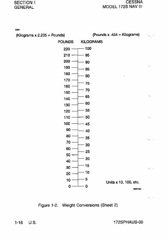
(Kilograms x 2.205 = Pounds) (Pounds x .454 = Kilograms)
kg 0 1
lb. lb.
0 2.205 10 22.046 24.251 20 44.093 46.297 30 66.139 68.343 40 88.185 90.390
50 110.23 112.44 60 132.28 134.48 70 154.32 156.53 80 176.37 178.57 90 198.42 200.62
100 220.46 222.67
lb. a 1
kg kg 0 0.454
10 4.536 4.990 20 9.072 9.525 30 13.608 14.061 40 18.144 18.597
50 22.680 23.133 60 27.216 27.669 70 31.752 32.205 80 36.287 36.741
90 40.823 41.277
100 45.359 45.813
KILOGRAMS INTO POUNDS KILOGRAMMES EN LIVRES
2 3 4 5 6
lb. lb. lb. lb. lb.
4.409 6.614 8.819 11.023 13.228 26.456 28.660 30.865 33.069 35.274 48.502 50.706 52.911 55.116 57.320 70.548 72.753 74.957 77.162 79.366 92.594 94.799 97.003 99.208 101.41
114.64 116.85 119.05 121.25 123.46 136.69 138.89 141.10 143.30 145.51 158.73 160.94 163.14 165.35 167.55 180.78 182.98 185.19 187.39 189.60 202.83 205.03 207.24 209.44 211.64
224.87 227.08 229.28 231.49 233.69
POUNDS INTO KILOGRAMS LIVRES EN KILOGRAMMES
2 3 4 5 6
kg kg kg kg kg 0.907 1.361 1.814 2.268 2.722 5.443 5.897 6.350 6.804 7.257
9.979 10.433 10.886 11.340 11.793 14.515 14.969 15.422 15.876 16.329 19.051 19.504 19.958 20.412 20.865
23.587 24.040 24.494 24.948 25.401 28.123 28.576 29.030 29.484 29.937 32.659 33.112 33.566 34.019 34.473 37.195 37.848 38.102 38.555 39.009 41.731 42.184 42.638 43.091 43.545
46.266 46.720 47.174 47.627 48.081
7 8 9
lb. lb. lb.
15.432 17.637 19.842 37.479 39.683 41.888 59.525 61.729 63.934 81.571 83.776 85.980 103.62 105.82 108.03
125.66 127.87 130.07 147.71 149.91 152.12 169.76 171.96 174.17 191.80 194.01 196.21 213.85 216.05 218.26
235.90 238.10 240.30
7 8 9
kg kg kg 3.175 3.629 4.082 7.711 8.165 8.618
12.247 12.701 13.154 16.783 17.237 17.690 21.319 21.772 22.226
25.855 26.303 26.762 30.391 30.844 31.298 34.927 35.380 35.834 39.463 39.916 40.370 43.999 44.452 44.906
48.534 48.988 49.442
Figure 1-2. Weight Conversions (Sheet 1 of 2)
172SPHAUS-00 U.S. 1-15
SECTION 1 GENERAL
-, (Kilograms x 2.205 = Pounds)
POUNDS
220
210 200
190
180
170
160
150
140
130
120
110
100
90
80
70
60
50
40
30
20
10
0
CESSNA MODEL 172S NAV III
(Pounds x .454 = Kilograms)
KILOGRAMS
100
95
90
85
80
75
70
65
60
55
50
45
40
35
30
25
20
15
10
5 Units x 10, 100, etc.
0 -~,
Figure 1-2. Weight Conversions (Sheet 2)
1-16 U.S. 172SPHAUS-OO

CESSNA MODEL 172S NAV III
SECTION 1 GENERAL
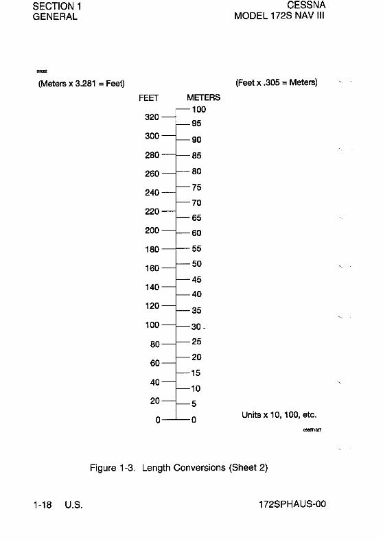
(Meters x 3.281 = Feet) (Feet x .305 = Meters)
m 0 1 2
feet feet feet
0 -.. 3.281 6.562 10 32.808 36.089 39.370 20 65.617 68.897 72.178 30 98.425 101.71 104.99 40 131.23 134.51 137.79
50 164.04 167.32 170.60 60 195.85 200.13 203.41 70 229.66 232.94 236.22 80 262.47 265.75 269.03 90 295.27 298.56 301.84
100 328.08 331.36 334.64
ft 0 1 2
m m m
0 ... 0.305 0.610 10 3.048 3.353 3.658 20 6.096 6.401 6.706
30 9.144 9.449 9.754 40 12.192 12.497 12.802
50 15.240 15.545 15.850 60 18.288 18.593 18.898 70 21.336 21.641 21.946 80 24.384 24.689 24.994 90 27.432 27.737 28.042
100 30.480 30.785 31.090
METERS INTO FEET METRES EN PIEDS
3 4 5
feet feet feet
9.842 13.123 16.404 42.651 45.932 49.212 75.459 78.740 82.021 108.27 111.55 114.83 141.08 144.36 147.64
173.86 177.16 180.45 206.69 209.97 213.25 239.50 242.78 246.06 272.31 275.59 278.87 305.12 308.40 311.68
337.93 341.21 344.49
FEET INTO METERS PIEDS EN METRES
3 4 5
m m m
0.914 1.219 1.524 3.962 4.267 4.572 7.010 7.315 7.620
10.058 10.363 10.668 13.106 13.411 13.716
16.154 16.459 16.754 19.202 19.507 19.812 22.250 22.555 22.860 25.298 25.603 25.908 28.346 28.651 28.956
31.394 31.699 32.004
6 7 8 9
feet feet feet feet
19.685 22.956 26.247 29.528 52.493 55.774 59.055 62.336 85.302 88.582 91.863 95.144 118.11 121.39 124.67 127.95 150.92 154.20 157.48 160.76
183.73 187.01 190.29 193.57 216.53 219.82 223.10 226.38 249.34 252.62 255.90 259.19 282.15 285.43 288.71 291.58 314.96 318.24 321.52 324.80
347.77 351.05 354.33 357.61
6 7 8 9
m m m m
1.829 2.134 2.438 2.743 4.877 5.182 5.486 5.791 7.925 8.230 8.534 8.839
10.973 11.278 11.582 11.887 14.021 14.326 14.630 14.935
17.069 17.374 17.678 17.983 20.117 20.422 20.726 21.031 23.165 23.470 23.774 24.079 26.213 26.518 26.822 27.127 29.261 29.566 29.870 30.175
32.309 32.614 32.918 33.223
Figure 1-3. Length Conversions (Sheet 1 of 2)
172SPHAUS-00 U.S. 1-17
SECTION 1 GENERAL
-(Meters x 3.281 = Feet)
FEET
320
300
280
260
240
220
200
180
160
140
120
100
80
60
40
20
0
METERS 100
95
90
85
80
75
70
65
60
55
50
45
40
35
30 -
25
20
15
10
5
0
CESSNA MODEL 172S NAV III
(Feet x .305 = Meters)
Units x 10, 100, etc.
...,,'"
Figure 1-3. Length Conversions (Sheet 2)
1-18 U.S. 172SPHAUS-OO

CESSNA MODEL 172S NAV 111
SECTION 1 GENERAL
(Centimeters x .394 = Inches) (Inches x 2.54 = Centimeters)
cm 0 1
in. in.
0 . " 0.394 10 3.937 4.331 20 7.874 8.268 30 11.811 12.205 40 15.748 16.142
50 19.685 20.079 60 23.622 24.016 70 27.559 27.953 80 31.496 31.890 90 35.433 35.827
100 39.370 39.784
in. 0 1
cm cm
0 ... 2.54 10 25.40 27.94 20 50.80 53.34 30 76.20 78.74 40 101.60 104.14
50 127.00 129.54 60 152.40 154.94 70 177.80 180.34 80 203.20 205.74 90 228.60 231.14
100 254.00 256.54
CENTIMETERS INTO INCHES CENTIMETRES EN POUCES
2 3 4 5 6
in. in. in. in. in.
0.787 1.181 1.575 1.969 2.362 4.724 5.118 5.512 5.906 6.299 8.661 9.055 9.449 9.843 10.236
12.598 12.992 13.386 13.780 14.173 16.535 16.929 17.323 17.717 18.110
20.472 20.866 21.260 21.654 22.047 24.409 24.803 25.197 25.591 25.984 28.346 28.740 29.134 29.528 29.921
32.283 32.677 33.071 33.465 33.858 36.220 36.614 37.008 37.402 37.795
40.157 40.551 40.945 41.339 41.732
INCHES INTO CENTIMETERS POUCES EN CENTIMETRES
2 3 4 5 6
cm cm cm cm cm
5.08 7.62 10.16 12.70 15.24 30.48 33.02 35.56 38.10 40.64 55.88 58.42 60.96 63.50 66.04 81.28 83.82 86.36 88.90 91.44
106.68 109.22 111.76 114.30 116.84
132.08 134.62 137.16 139.70 142.24 157.48 160.02 162.56 165.10 167.64 182.88 185.42 187.96 190.50 193.04 208.28 210.82 213.36 215.90 218.44 233.68 236.22 238.76 241.30 243.84
259.08 261.62 284.16 266.70 269.24
7 8 9
in. in. in.
2.756 3.150 3.543 6.693 7.087 7.480
10.630 11.024 11.417 14.567 14.961 15.354 18.504 18.898 19.291
22.441 22.835 23.228 26.378 26.772 27.184 30.315 30.709 31.1 02 34.252 34.646 35.039 38.189 38.583 38.976
42.126 42.520 42.913
7 8 9
cm cm cm
17.78 20.32 22.96 43.18 45.72 48.26 68.58 71.12 73.66 93.98 96.52 99.06
119.38 121.92 124.46
144.78 147.32 149.86 170.18 172.72 175.26 195.58 198.12 200.66 220.98 223.52 226.06 246.38 248.92 251.46
271.78 274.32 276.86
Figure 1-4. Length Conversions (Sheet 1 of 2)
172SPHAUS-OO U.S. 1-19

SECTION 1 GENERAL
CESSNA MODEL 172S NAV III
(Centimeters x .394 = Inches)
INCHES 10
(Inches x 2.54 = Centimeters)
CENTIMETERS
25
24
9-J---23
22 21
8-" 20
19
7 18
17
16 15
14
5 13
12
11
10
9
3 8
7
6 2--1--5
4 3
2
1 Units x 10, 100, etc. o-..L..-0
_ ..
Figure 1-4. Length Conversions (Sheet 2)
1-20 U.S. 172SPHAUS-00
CESSNA MODEL 172S NAV III
-
SECTION 1 GENERAL
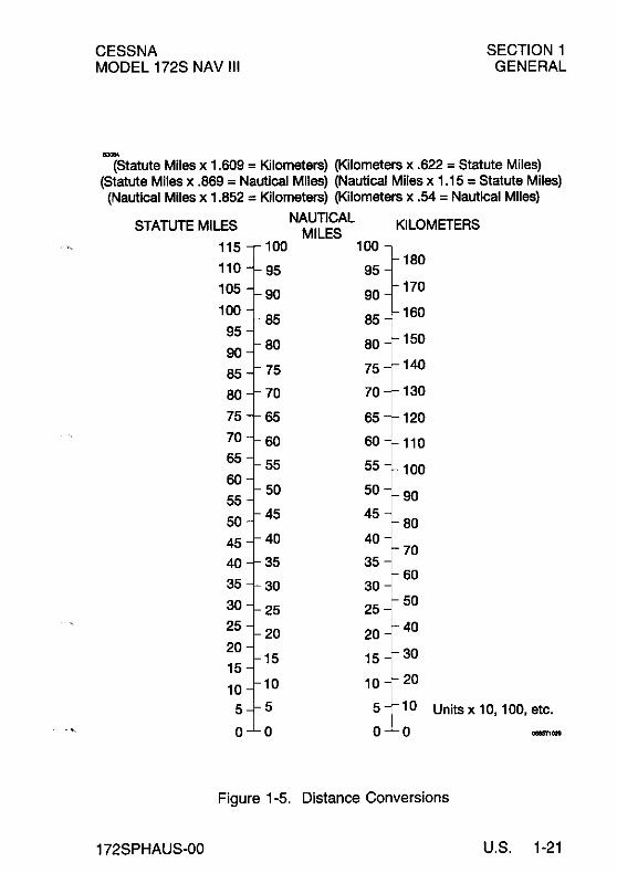
(Statute Miles x 1.609 = Kilometers) (Kilometers x .622 = Statute Miles) (Statute Miles x .869 = Nautical Miles) (Nautical Miles x 1.15 = Statute Miles) (Nautical Miles x 1.852 = Kilometers) (Kilometers x .54 = Nautical Miles)
STATUTE MILES NAUTICAL KILOMETERS
MILES 115 100 100
110 180
95 95 105 90 90
170
100 85 85 160
95 150 90
80 80
85 75 75 140
80 70 70 130
75 65 65 120
70 60 60 110 65 55 55 60
100
50 50 90 55
50 45 45
80
45 40 40 70
40 35 35
35 60
30 30 30 25 25
50
25 20 20 40
20 30 15
15 15
10 10 20 10
5 5 5 10 Units x 10, 100, etc.
0 0 0 0 _ ..
Figure 1-5. Distance Conversions
172SPHAUS-00 U.S. 1-21

SECTION 1 GENERAL
CESSNA MODEL 172S NAV III
(Imperial Gallons x 4.546 = Liters) (Liters x .22 = Imperial Gallons)
Lt 0 1
IG IG
0 ... 0.220 10 2.200 2.420 20 4.400 4.620 30 6.599 6.819 40 8.799 9.019
50 10.999 11.219 60 13.199 13.419 70 15.398 15.618 80 17.598 17.818
90 19.798 20.018
100 21.998 22.218
IG 0 1
Lt Lt
0 ... 4.546 10 45.460 50.006 20 90.919 95.465 30 136.38 140.93 40 181.84 186.38
50 227.30 231.84 60 272.76 277.30 70 318.22 322.76 80 363.68 368.22 90 409.14 413.68
100 454.60 459.14
LITERS INTO IMPERIAL GALLONS LITRES EN GALLONS IMPERIAL
2 3 4 5 6
IG IG IG IG IG
0.440 0.660 0.880 1.100 1.320
2.640 2.860 3.080 3.300 3.520 4.840 5.059 5.279 5.499 5.719
7.039 7.259 7.479 7.699 7.919
9.239 9.459 9.679 9.899 10.119
11.439 11.659 11.879 12.099 12.319 13.639 13.859 14.078 14.298 14.518
15.838 16.058 16.278 16.498 16.718 18.038 18.258 18.478 18.698 18.918
20.238 20.458 20.678 20.898 21.118
22.438 22.658 22.878 23.098 23.318
IMPERIAL GALLONS INTO LITERS GALLONS IMPERIAL EN LITRES
2 3 4 5 6
Lt Lt Lt Lt Lt
9.092 13.638 18.184 22.730 27.276
54.552 59.097 63.543 68.189 72.735 100.01 104.56 109.10 113.65 118.20
145.47 150.02 154.56 159.11 163.66
190.93 195.48 200.02 204.57 209.11
236.39 240.94 245.48 250.03 254.57 281.85 286.40 290.94 295.49 300.03
327.31 331.86 336.40 340.95 345.49
372.77 377.32 381.86 386.41 390.95 418.23 422.77 427.32 431.87 436.41
463.69 468.23 472.78 477.33 481.87
7 8 9
IG IG IG
1.540 1.760 1.980 3.740 3.960 4.180 5.939 6.159 6.379 8.139 8.359 8.579
10.339 10.559 10.779
12.539 12.759 12.979
14.738 14.958 15.178 16.938 17.158 17.378 19.138 19.358 19.578 21.338 21.558 21.778
23.537 23.757 23.977
7 8 9
Lt Lt Lt
31.822 36.368 40.914 77.281 81.827 86.373 122.74 127.29 131.83 168.20 172.75 177.29 213.66 218.21 222.75
259.12 263.67 268.21 304.58 309.13 313.67 350.04 354.59 359.13 395.50 400.04 404.59 440.96 445.50 450.05
486.42 490.96 495.51
Figure 1-6. Volume Conversions (Sheet 1 of 3)
1-22 U.S. 172SPHAUS-oO

CESSNA MODEL 172S NAV III
(Imperial Gallons x 4.4546 = Liters) (Liters x .22 = Imperial Gallons)
100 IMPERIAL
95 440 LlTERS
GALLONS 420 90
400 85 380 80 360 75 340
70 320
65 300
60 280 260
55 240
50 220 45 200 40 180
35 160
30 140
25 120
20 100
80 15
60 10 40
5 20
0 0
Units x 10, 100, etc.
Figure 1-6. Volume Conversions (Sheet 2)
172SPHAUS-00
SECTION 1 GENERAL
0585T1032
U.S. 1-23
SECTION 1 CESSNA GENERAL MODEL 172S NAV III
"'"
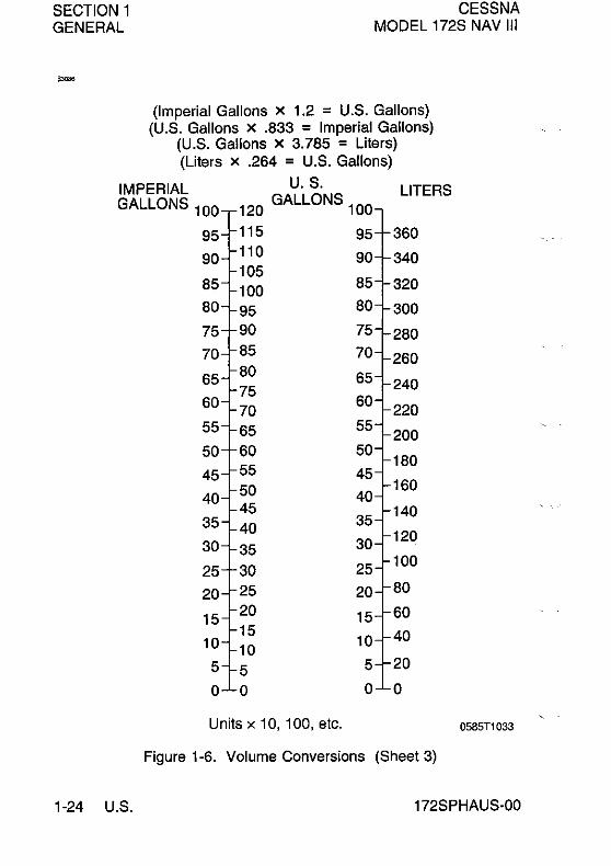
(Imperial Gallons x 1.2 = U.S. Gallons) (U.S. Gallons x .833 = Imperial Gallons)
(U.S. Gallons x 3.785 = Liters) (Liters x .264 = U.S. Gallons)
IMPERIAL U. S. LlTERS GALLONS 100 120 GALLONS 100
95 115 95 360
90 110 90 340 105
85 100 85 320
80 95 80 300
75 90 75 280 70 85 70 260 65 80 65
75 240 60 70
60 220
55 65 55 200
50 60 50 180
45 55 45 50 40
160 40
45 140 35 40 35
30 35 30 120
25 30 25 100
20 25 20 80
15 20 15 60 15
10 40 10 10 5 5 5 20
0 0 0 0
Units x 10, 100, etc. 0585T1033
Figure 1-6. Volume Conversions (Sheet 3)
1-24 U.S. 172SPHAUS-00

CESSNA SECTION 1 MODEL 172S NAV III GENERAL
,~,
TEMPERATURE CONVERSIONS
(OF-32) x 5/9 = °C °Cx9/5 + 32 = OF OF °C of °C -40 -40 320 160 -30 340 -20 -30 360 180
-10 380 0
-20 400 200
10 -10 420 220 20 440 30 0 460 240 40 480 50 10 500 260 60 520 70 20 540 280
80 560 90 30 580 300
100 40 600 320 110 620 120 50 640 340 130 660 140 60 680 360 150 700 160 70 720 380
170 180 80
740 760 400
190 90 780 420 20 800 210 100 820 440 220 840 230 110 860 460 240 BBO 250 120 900 480 260 27 130
920 940 500
2BO 140 960 520 290 9BO 300 150 1000 540 310 1020 320 160 1040 560
0585Tl034
Figure 1-7_ Temperature Conversions
172SPHAUS-OO U_S_ 1-25

SECTION 1 GENERAL
CESSNA MODEL 172S NAV III
PRESSURE CONVERSION HECTOPASCALS (MILLIBARS) TO INCHES MERCURY (inHG)
-:l~ ~~
I~ • ~~ • I~ • F •• ,-' • I- II
" -. !le • I C ;; §....: t-a .C ;
I C . ;
le i ;;
g~ iI I~ ;; .~ iI . ~ •• i~
;;
1-' ; ;;
F ;; E-' " 1- 0
_1- ;I
~ I--~ !I- ; ~ u- ;; ~ 1- .~ ,.
Figure 1-8. Heclopascals 10 Inches Mercury
1-26 U.S. 172SPHAUS-OO

CESSNA MODEL 172S NAV III
.... AVGAS Specific Gravity = .72
SECTION 1 GENERAL
(L~ers x .72 = Kilograms) (Kilograms x 1.389 = Liters) (Liters x 1.58 = Pounds) (Pounds x .633 = L~ers) LlTERS POUNDS LlTERS KILOGRAMS
100 100
95 150 135 130 95
90 140 125 90
85 120 85 130 AVGASFUEL 115
80 110 80
75 120 105 75
70 110 100
70 95 65
100 90 65
60 85 60 90 80
55 75 55
50 80 70 50
45 65
45 70 60 40
60 55 40
35 50 35 50 45
30 40 30
25 40 35 25
20 30 20 30 25 15 20 15
20 15 10 10
10 10 5 5 5
0 0 0 0
Un~s x 10, 100, etc. -~
Figure 1-9. Volume to Weight Conversion
172SPHAUS-OO U.S. 1-27

SECTION 1 GENERAL
AV GAS
SPECIFIC GRAVITY
0.72
1-28 U.S.
CESSNA MODEL 172S NAV III
0585T1031
Figure 1-10. Quick Conversions
172SPHAUS-OO
'-.c'.
CESSNA MODEL 172S NAV III
SECTION 2 OPERATING LIMITATIONS
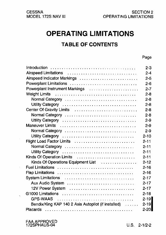
OPERATING LIMITATIONS
TABLE OF CONTENTS
Introduction ..................................... . Airspeed Limitations .............................. . Airspeed Indicator Markings ......................... . Powerplant Limitations ............................. . Powerplant Instrument Markings ..................... . Weight Limits ................................... .
Normal Category ............................... . Utility Category ............................ .... .
Center Of Gravity Limits ........................... . Normal Category ............................... . Utility Category ................................ .
Maneuver Limits ................................. . Normal Category ............................... . Utility Category ............................... .
Flight Load Factor Limits .......................... . Normal Category .............................. . Utility Category ............................... .
Kinds Of Operation Limits ......................... . Kinds Of Operations Equipment List ............... .
Fuel Limitations ................................. . Flap Limitations ................................. . System Limitations .............................. .
Aux Audio System ............................. . 12V Power System ............................ .
G 1 000 Limitations ............................... . GPS-WAAS ................................. . BendixlKing KAP 140 2 Axis Autopilot (if installed) ..... .
Placards ...................................... .
Page
2-3 2-4 2-5 2-6 2-7 2-8 2-8 2-8 2-8 2-8 2-9 2-9 2-9
2-10 2-11 2-11 2-11 2-11 2-12 2-16 2-16 2-17 2-17 2-17 2-18
2-191 2-19
2-20
FAA APPROVED 172SPHAUS-04 U.S. 2-1/2-2

CESSNA MODEL 172S NAV III
SECTION 2 OPERATING LIMITATIONS
INTRODUCTION
Section 2 includes operating limitations, instrument markings, and basic placards necessary for the safe operation of the airplane, its engine, standard systems and standard equipment. The limitations included in this section and in Section 9 have been approved by the Federal Aviation Administration. Observance of these operating limitations is required by Federal Aviation Regulations.
NOTE
• Refer to the Supplements, Section 9, of this Pilot's Operating Handbook for amended operating limitations, operating procedures, performance data and other necessary information for airplanes equipped with specific options .
• The airspeeds listed in Figure 2-1, Airspeed I Limitations, and Figure 2-2, Airspeed Indicator Markings, are based on Airspeed Calibration data shown in Section 5 with the normal static source. If the alternate static source is being used, ample margins should be observed to allow for the airspeed calibration variations between the normal and alternate static sources as shown in Section 5.
The Cessna Model 172S is certificated under FAA Type Certificate No.3A12.
FAA APPROVED 172SPHAUS-03 U.S. 2-3

SECTION 2 CESSNA MODEL 172S NAV III OPERATING LIMITATIONS
I
AIRSPEED LIMITATIONS
Airspeed limitations and their operational significance are shown in Figure 2-1. Maneuvering speeds shown apply to normal category operations. The utility category maneuvering speed is 98 KIAS at 2200 pounds.
AIRSPEED LIMITATIONS
SYMBOL SPEED KCAS KIAS REMARKS
VNE Never Exceed Speed 160 163 Do not exceed this speed in any operation.
VNO Maximum Structural 126 129 Do not exceed this Cruising Speed speed except in
smooth air, and then only with caution.
VA Maneuvering Do not make full or Speed: abrupt control
2550 Pounds 102 105 movements above 2200 Pounds 95 98 this speed. 1900 Pounds 88 90
VFE Maximum Flap Do not exceed this Ex1ended Speed: speed with flaps
Flaps 10° 107 110 down. Flaps 1 0° to FU LL 85 85
Maximum 160 163 Do not exceed this ----- Window Open speed with windows
Speed open.
Figure 2-1
2-4 U.S. FAA APPROVED 172SPHAUS-03

CESSNA MODEL 172S NAV III
SECTION 2 OPERATING LIMITATIONS
AIRSPEED INDICATOR MARKINGS
Airspeed indicator markings and their color code significance are shown in Figure 2-2.
AIRSPEED INDICATOR MARKINGS KIAS
MARKING VALUE SIGNIFICANCE OR RANGE
Red Arc' 20 - 40 Low airspeed warning.
White Arc 40 - 85 Full Flap Operating Range. Lower limit is maximum weight VSo in landing configuration. Upper limit is maximum speed permissible with flaps extended.
Green Arc 48 - 129 Normal Operating Range. Lower limit is maximum weight V S1 at most forward C.G. with flaps retracted. Upper limit is maximum structural cruising speed.
Yellow Arc 129-163 Operations must be conducted with caution and only in smooth air.
Red Line 163 Maximum speed for all operations.
• Gl000 airspeed indicator only.
I
Figure 2-2 I
FAA APPROVED 172SPHAUS-03 U.S. 2-5

SECTION 2 OPERATING LIMITATIONS
POWERPLANT LIMITATIONS
Engine Manufacturer: Textron Lycoming. Engine Model Number: IO-360-L2A. Maximum Power: 180 BHP rating.
CESSNA MODEL 172S NAV III
Engine Operating Limits for Takeoff and Continuous Operations: Maximum Engine Speed: ................... 2700 RPM
NOTE
The static RPM range at full throttle is 2300 - 2400 RPM.
Maximum Oil Temperature: .............. 245'F (118'C) Oil Pressure, Minimum: ....................... 20 PSI Oil Pressure, Maximum: ...................... 115 PSI
Fuel Grade: See Fuel Limitations.
Oil Grade (Specification): MIL-L-6082 or SAE J1966 Aviation Grade Straight Mineral Oil or MIL-L-22851 or SAE J1899 Ashless Dispersant Oil. Oil must comply with the latest revision and/or supplement for Textron Lycoming Service Instruction No. 1014.
Propeller Manufacturer: McCauley Propeller Systems. Propeller Model Number: 1 A 170ElJHA7660.
IPropeller Diameter Maximum: 76 INCHES Minimum: 75 INCHES
2-6 U.S. FAA APPROVED 172SPHAUS-03

CESSNA MODEL 172S NAV III
SECTION 2 OPERATING LIMITATIONS
POWERPLANT INSTRUMENT MARKINGS
Powerplant instrument markings and their color code significance are shown in Figure 2-3. Operation with indications in the red rangel is prohibited. Avoid operating with indicators in the yellow range.
POWERPLANT INSTRUMENT MARKINGS
RED GREEN ARC
RED YELLOW (NORMAL INSTRUMENT LINE ARC
(MIN) (LWR) ARC OPERATING RANGE)
Tachometer ---- ---- ---- RPM Sea Level 2100 to 2500 5000 Feet 2100 to 2600 10,000 Feet 2100 to 2700
Cylinder ---- ---- ---- 200 to 500°F Head Temperature
Oil ---- ---- ---- lOO to 245°F Temperature
Oil Pressure ---. Ot020 ---- 50 to 90 PSI PSI
Fuel 0(1.5 ---- 0 5 to 24 Gallons Quantity Gallons to 5
Unusable Gallons Each Tank)
Fuel Flow ---- ---- ---- Oto12GPH
Vacuum ---- ---- ---- 4.5 to 5.5 Indicator in.hg.
• Maximum operating limit is lower end of red arc.
FAA APPROVED 172SPHAUS-03
Figure 2-3
RED ARC (UPR)
RPM 2700' to 3000
----
245' to 250°F
liS' to 120 PSI
----
----
----
I
U.S. 2-7

SECTION 2 CESSNA MODEL 172S NAV III OPERATING LIMITATIONS
WEIGHT LIMITS
NORMAL CATEGORY
I Maximum Ramp Weight: Maximum Takeoff Weight: Maximum Landing Weight:
2558 POUNDS 2550 POUNDS 2550 POUNDS
Maximum Weight in Baggage Compartment:
I Baggage Area A - Station 82 to 108: ........ . Baggage Area B - Station 108 to 142: ........ .
120 POUNDS 50 POUNDS
I
NOTE
The maximum combined weight capacity lor baggage areas A and B is 120 Ibs.
UTILITY CATEGORY
IMaximum Ramp Weight: .................. . Max!mum Take?ff Wei~ht: ................. . Maximum Landing Weight: ................ .
2208 POUNDS 2200 POUNDS 2200 POUNDS
I
I
Maximum Weight in Baggage Compartment: In the utility category, the baggage compartment must be empty and rear seat must not be occupied.
CENTER-OF-GRAVITY LIMITS
NORMAL CATEGORY
Center-ol-Gravity Range:
Forward: 35.0 inches aft 01 datum at 1950 pounds or less, with straight line variation to 41.0 inches aft 01 datum at 2550 pounds.
Aft: 47.3 inches aft 01 datum at all weights.
Relerence Datum: Lower portion 01 Iront lace 01 lirewall.
2-8 U.S. FAA APPROVED 172SPHAUS-03

CESSNA MODEL 172S NAV III
SECTION 2 OPERATING LIMITATIONS
CENTER OF GRAVITY LIMITS (Continued)
UTILITY CATEGORY
Center of Gravity Range:
Forward: 35.0 inches aft of datum at 1950 pounds or less, with straight line variation to 37.5 inches aft of datum at 2200 pounds.
Aft: 40.5 inches aft of datum at all weights.
Reference Datum: Lower portion of front face of firewall.
MANEUVER LIMITS
NORMAL CATEGORY
This airplane is certificated in both the normal and utility category. The normal category is applicable to aircraft intended for non aerobatic operations. These include any maneuvers incidental to normal flying, stalls (except whip stalls), lazy eights, chandelles, and turns in which the angle-of-bank is not more than 60°.
NORMAL CATEGORY MANEUVERS AND RECOMMENDED ENTRY SPEED"
Chandelles ............................... 105 KNOTS Lazy Eights ............................... 105 KNOTS Steep Turns ............................... 95 KNOTS Stalls (Except Whip Stalls) ................ Slow Deceleration
" Abrupt use of the controls is prohibited above 105 KNOTS. I
FAA APPROVED 172SPHAUS-04
(Continued Next Page)
U.S. 2-9

SECTION 2 OPERATING LIMITATIONS
MANEUVER LIMITS (Continued)
UTILITY CATEGORY
CESSNA MODEL 172S NAV III
This airplane is not designed for purely aerobatic flight. However, in the acquisition of various certificates such as commercial pilot and flight instructor, certain maneuvers are required by the FAA. All of these maneuvers are permitted in this airplane when operated in the utility category.
In the utility category, the rear seat must not be occupied and the baggage compartment must be empty .
UTILITY CATEGORY MANEUVERS AND RECOMMENDED ENTRY SPEED'
IChandelles ............................... 105 KNOTS Lazy Eights ............................... 105 KNOTS Steep Turns ............................... 95 KNOTS Spins ............................... Slow Deceleration Stalls (Except Whip Stalls) ................ Slow Deceleration
1* Abrupt use of the controls is prohibited above 98 KNOTS.
Aerobatics that may impose high loads should not be attempted. The important thing to bear in mind in flight maneuvers is that the ~ airplane is clean in aerodynamic design and will build up speed quickly with the nose down. Proper speed control is an essential requirement for execution of any maneuver, and care should always be exercised to avoid excessive speed which in turn can impose excessive loads. In the execution of all maneuvers, avoid abrupt use of controls.
2-10 U.S. FAA APPROVED 172SPHAUS-03

CESSNA MODEL 172S NAV III
SECTION 2 OPERATING LIMITATIONS
FLIGHT LOAD FACTOR LIMITS
NORMAL CATEGORY
Flight Load Factors (Maximum Takeoff Weight - 2550 POUNDS): I -Flaps Up ....................... +3.8g, -1.52g -Flaps Down ..................... +3.0g
- The design load factors are 150% of the above, and in all cases, the structure meets or exceeds design loads.
UTILITY CATEGORY
Flight Load Factors (Maximum Takeoff Weight - 2200 POUNDS): I -Flaps Up ....................... +4.4g, -1.76g -Flaps Down . . . . . . . . . . . . . . . . . . . . . +3.0g
- The design load factors are 150% of the above, and in all cases, the structure meets or exceeds design loads.
KINDS OF OPERATION LIMITS
The Cessna 172S Nav III airplane is approved for day and night, VFR and IFR operations. Flight into known-icing conditions is prohibited.
The minimum equipment for approved operations required under the Operating Rules are defined by 14 CFR Part 91 and 14 CFR Part 135, as applicable.
The following Kinds of Operations Equipment List (KOEL) identifies the equipment required to be operational for airplane airworthiness in the listed kind of operations.
FAA APPROVED 172SPHAUS-03 U.S. 2-11

SECTION 2 OPERATING LIMITATIONS
KINDS OF OPERATIONS EQUIPMENT LIST
CESSNA MODEL 172S NAV III
KIND OF OPERATION V I F F
V R I R F F R N R N
I I D G D G
System, Instrument, Equipment A H A H and/or Function y T Y T COMMENTS
PLACARDS AND MARKINGS
172S Nav III POH/AFM 1 1 1 1 Accessible to pilot in flight
Garmin G1000TM Cockpit 1 1 1 1 Accessible to pilot Reference Guide in flight
AIR CONDITIONING 1. Forward Avionics Fan 1 1 1 1 2. PFD Fan 0 0 0 0 3. MFD Fan 0 0 0 0 4. Aft Avionics Fan 1 1 1 1
AUTOFLlGHT 1. BendixlKing KAP 140 POH 0 0 AIR AIR Accessible to pilot
Supplement in flight when usin autopilot
COMMUNICATIONS 1. VHFCOM 0 0 1 1
ELECTRICAL POWER 1. 24V Main Battery 1 1 1 1 2. 28V Alternator 1 1 1 1 3. 24V Standby Battery 0 . . . ·Refer to Note 1 4. Main Ammeter 1 1 1 1 5. Standby Ammeter 0 • • . ·Refer to Note 1
NOTE
1. The European Aviation Safety Agency (EASA)
2-12 U.S.
requires the 24V Standby Battery and Standby Ammeter to successfully complete the pre-flight check before operating the airplane in VFR night, IFR day, or IFR night conditions in Europe. Correct operation of the 24V Standby Battery and Stand by Ammeter is recommended for all other operations.
(Continued Next Page)
FAA APPROVED 172SPHAUS-02

CESSNA MODEL 172S NAV III
SECTION 2 OPERATING LIMITATIONS
KINDS OF OPERATIONS EQUIPMENT LIST (Continued)
KIND OF OPERATION V I F F
V R I R F F R N R N
I I D G D G
System. Instrument. Equipment A H A H and/or Function Y T Y T EQUIPMENT AND FURNISHINGS
1. Seat Belt Assembly 1 1 1 1
2. Shoulder Harness 1 1 1 1
FLIGHT CONTROLS 1. Flap Position Indicator 1 1 1 1 2. Flap Motor 1 1 1 1 3. Elevator Trim System 1 1 1 1 4. Elevator Trim Indicator 1 1 1 1
FUEL SYSTEM 1. Electric Fuel Pump 1 1 1 1 2. Fuel Quantity Indicator - LH 1 1 1 1
Tank 3. Fuel Quantity Indicator - RH 1 1 1 1
Tank ICE AND RAIN PROTECTION
1. Alternate Static Air Source 0 0 1 1 2. Alternate Induction Air 0 0 1 1
System INDICATING/RECORDING SYSTEM
1. Stall Warning System 1 1 1 1 2. System Annunciator and 1 1 1 1
Warning Displays LANDING GEAR
1. Wheel Fairings 0 0 0 0
(Continued Next Page)
FAA APPROVED 172SPHAUS-OO
COMMENTS
Each Seat Occupant Front Seat Occupants
Removable
U.S. 2-13

SECTION 2 CESSNA MODEL 172S NAV III OPERATING LIMITATIONS
I
I
I
KINDS OF OPERATIONS EQUIPMENT LIST (Continued) KIND OF OPERATION
V I F F
V R I R F F R N R N
I I D G D G
System, Instrument, Equipment A H A H and/or Function y T Y T COMMENTS
LIGHTING 1. PFD Bezel Lighting 0 0 0 1 2. PFD Backlighting " 1 1 1 "Refer to Note 2 3. MFD Bezel Lighting 0 0 0 1 4. MFD Backlighting " 1 1 1 "Refer to Note 3 5. Switch and Circuit Breaker 0 1 0 1
Panel L~hting 6. Airspee Indicator (Standby) 0 1 0 1
Internal Lighting 7. Altimeter (Standby) Internal 0 1 0 1
Lighting 8. Non-stabilized Magnetic 0 1 0 1
Compass Internal Lighting 9. Attitude Indicator (Vacuum) 0 1 0 1
Internal Lighting 10. Cockpit Flood Light 0 1 0 1 11. Aircraft Position (NAV) 0 1 1 1
Lights 12. STROBE Light System 1 1 1 1 13. BEACON Light 0 0 0 0 14. TAXI Light 0 0 0 0 15. LAND (Landing) Light 0 1 0 1 Operations for
hire only
NOTE
2. PFD backlighting is required for day VFR flight if MFD backlighting has failed. Display backup mode must be active so engine indicators are shown.
3. MFD backlighting is required for day VFR flight if PFD backlighting has failed. Display backup mode must be active so flight instruments are shown.
(Continued Next Page)
2-14 U.S. FAA APPROVED 172SPHAUS-03

CESSNA MODEL 172S NAV III
SECTION 2 OPERATING LIMITATIONS
KINDS OF OPERATIONS EQUIPMENT LIST (Continued)
System, Instrument, Equipment and/or Function
NAVIGATION AND PITOT-STATIC SYSTEM
1. Gl000 Airspeed Indicator 2. Standby Airspeed Indicator 3. G 1 000 Altimeter 4. Standby Altimeter 5. Gl000 Vertical Speed
Indicator 6. Gl000 Attitude Indicator 7. Attitude Indicator - Vacuum
(Standby) 8. Gl000 Directional Indicator
(HSI) 9. Gl 000 Turn Coordinator
10. Non-stabilized Magnetic Compass
11. VHF Nav~ation Radio (VOR/LO /GS)
12. GPS Receiver/Navigator
13. Marker Beacon Receiver
14. Blind Altitude Encoder
15. Clock VACUUM
1. Engine-driven Vacuum Pump 2. Vacuum Indicator
ENGINE FUEL AND CONTROL 1. Fuel Flow Indicator
ENGINE INDICATING 1. Tachometer (RPM) 2. Cylinder Head Temperature
(CHT) Indicator 3. Oil Pressure Indicator 4. Oil Temperature Indicator
ENGINE OIL 1. Engine Crankcase Dipstick
IFAA APPROVED 172SPHAUS-02
KIND OF OPERATION V I F F
V R I R F F R N R N
I I D G D G A H A H Y T Y T COMMENTS
1 1 1 1 0 0 1 1 1 1 1 1 0 0 1 1 0 0 0 0
0 0 1 1 0 0 1 1
0 0 1 1
0 0 1 1 1 1 1 1
0 0 AIR AIR As Required Per Procedure
0 0 AIR AIR As Required Per Procedure
0 0 AIR AIR As Required Per Procedure
AIR AIR 1 1 As Required Per Procedure
0 0 1 1
0 0 1 1 0 0 1 1
1 1 1 1
1 1 1 1 0 0 0 0
1 1 1 1 1 1 1 1
1 1 1 1
U.S. 2-15

SECTION 2 OPERATING LIMITATIONS
FUEL LIMITATIONS
CESSNA MODEL 172S NAV III
Total Fuel: .... 56 U.S. gallons (2 tanks at 28.0 gallons each)
Usable Fuel (all flight conditions): . . . . . . . .. 53.0 U.S. gallons
Unusable Fuel: ...... 3.0 U.S. gallons (1.5 gallons each tank)
NOTE
To ensure maximum fuel capacity and minimize cross-feeding when refueling, always park the airplane in a wings-level, normal ground attitude and place the fuel selector in the Left or Right position. Refer to Figure 1-1 for normal ground attitude definition.
I Takeoff and land with the fuel selector valve handle in the BOTH position.
Maximum slip or skid duration with one tank dry: 30 seconds.
Operation on either LEFT or RIGHT tank limited to level flight only.
With 1/4 tank or less, prolonged uncoordinated flight is prohibited when operating on either left or right tank.
Fuel remaining in the tank after the fuel quantity indicator reads 0 (red line) cannot be safely used in flight.
Approved Fuel Grades (and Colors): 100LL Grade Aviation Fuel (Blue). 100 Grade Aviation Fuel (Green).
IFLAP LIMITATIONS
Approved Takeoff Range: Approved Landing Range:
2-16 U.S.
UP to 10° UP to FULL
FAA APPROVED 172SPHAUS-03

CESSNA MODEL 172S NAV III
SYSTEM LIMITATIONS
AUX AUDIO SYSTEM
SECTION 2 OPERATING LIMITATIONS
Use of the AUX AUDIO IN entertainment input is prohibited during takeoff and landing.
Use of the AUX AUDIO IN entertainment audio input and portable electronic devices (PED) such as cellular telephones, games, cassette, CD or MP3 players is prohibited under IFR unless the operator of the airplane has determined that the use of the Aux Audio System and the connected portable electronic device(s) will not cause interference with the navigation or communication system of the airplane.
12V POWER SYSTEM
The 12 Volt Power System (POWER OUTLET 12V - 10A) is not certified for supplying power to flight-critical communications or navigation devices.
Use of the 12 Volt Power System is prohibited during takeoff and landing.
Use of the 12 Volt Power System is prohibited under IFR unless the operator of the airplane has determined that the use of the 12 VDC power supply and connected portable electronic device(s) will not cause interference with the navigation or communication systems of the airplane.
IFAA APPROVED 172SPHAUS-03 U.S. 2-17

SECTION 2 OPERATING LIMITATIONS
G1000 LIMITATIONS
CESSNA MODEL 172S NAV III
The current Garmin Gl000 Cockpit Reference Guide (CRG) Part Number and System Software Version that must be available to the pilot during flight are displayed on the MFD AUX group, SYSTEM STATUS page.
Use of the NAVIGATION MAP page for pilotage navigation is prohibited. The NAVIGATION MAP is intended only to enhance situational awareness. Navigation is to be conducted using only current charts, data and authorized navigation facilities.
Use of the TRAFFIC MAP to maneuver the airplane to avoid traffic is prohibited. The TRAFFIC INFORMATION SYSTEM (TIS) is intended for adviSOry use only. TIS is intended only to help the pilot to visually locate traffic. It is the responsibility of the pilot to see and maneuver to avoid traffic.
Use of the TERRAIN PROXIMITY information for primary terrain avoidance is prohibited. The TERRAIN PROXIMITY map is intended only to enhance situational awareness. It is the pilot's responsibility to provide terrain clearance at all times.
Navigation using the G 1 000 is not authorized north of 70° North latitude or south of 70° South latitude due to unsuitability of the magnetic fields near the Earth's poles. In addition, operations are not authorized in the following two regions:
1. North of 65° North latitude between longitude 75° Wand 120° W (Northern Canada).
2. South of 55° South latitude between longitude 120° E and 165° E (region south of Australia and New Zealand).
The COM 1/2 (split COM) function of the GMA 1347 Audio Panel is not approved for use. During COM 1/2 operation, transmission by one crew member inhibits reception by the other crew member.
(Continued Next Page)
U.S. FAA APPROVED 172SPHAUS-04

TEMPORARY REVISION FOR CESSNA PILOT'S OPERATING HANDBOOK AND FM APPROVED AIRPLANE FLIGHT MANUAL
Publication Affected:
Airplane Serial Numbers Affected:
Description of Change:
Filing Instructions:
Removal Instructions:
Model 1725 Nav III (KAP 140) Serials 172$9810 thru 172510467 and 172510469 thru 172510506 and 172510508 thru 172510639 and 172510641 thru 172510655, basic Pilot's Operating Handbook and FAA. Approved Airplane Flight Manual, Revision 4, dated 12 October 2006.
Airplanes 17259810 thru 172510467 and 172$10469 thru 172$10506 and 172510508 thru 172510639 and 172510641 thru 172510655 equipped with TAWS-B avionics option.
Section 2, Operating Limitations, G 1 000 Limitations, page 2-19, add TAWS-B limitations.
Insert this temporary revision in the Model 1725 Nav JlI (KAP 140) Serials 17259810 thru 172510467 and 172510469 thru 172$10506 and 172510508 thru 172510639 and 172510641 thru 172510655 basic Pilot's Operating Handbook and FAA Approved Airplane Flight Manual adjacent to page 2-19.
This temporary revision must be removed and discarded when Revision 5 has been collated into the basic Pilot's Operating Handbook and FAA Approved Airplane Flight Manual or when terrain database 08T2 or later is installed.
In Section 2, Operating Limitations, G1000 Limitations, Terrain Awareness and Warning System (TAWS-B) add the following Limitations:
G1000 LIMITATIONS
TERRAIN AWARENESS AND WARNING SYSTEM (TAWS-B)
Flight operations are prohibited over large bodies of sea level water if that flight is conducted under operating regulations that require a functioning TAWS.
CAUTION TAWS-B Forward Looking Terrain Avoidance (FLTA) is not available when fiying over the open ocean/sea (specifically any body of water at sea level, more than 6nm from any terrain features) until terrain database 08T2 or later is installed. Do not use TAWS-B information for primary terrain avoidance. TAWS-B is intended only to enhance situational awareness.
APPROVED BY fMNIPRtMD waR MCfRPMI'21 JLIIIIIIRT J -_ ... .,.....CIIiIDI .......... DQI_1CE
~) _ .. ""-_ .. DATE OF APPROVAL US NIt'! W8
FM APPROVED 172SPHAUS-04 TR02

CESSNA MODEL 172S NAV III
SECTION 2 OPERATING LIMITATIONS
Gl000 LIMITATIONS (Continued)
GPS-WAAS (Airplanes 172S10432 and On) Use of the Garmin G1000 system for GPS or WAAS navigation under Instrument Flight Rules (IFR) requires that:
1. The airplane must be equipped with an approved and operational alternate means of navigation appropriate to the route being flown (NAV receiver, DME or ADF).
2. For flight planning purposes, if an alternate airport is required, it must have an approved instrument approach procedure, other then GPS or RNAV, that is anticipated to be operational and available at the estimated time of arrival. All equipment required for this procedure must be installed and operational.
3. For procedures requiring a prediction of GPS Receiver Autonomous Integrity Monitoring (RAIM) capability for TSOC129a (non-WAAS) equipment (e.g. oceanic operations, U.S. RNAV routes, European BRNAV and PRNAV, etc.), the Garmin WAAS Fault Detection/Exclusion Prediction program (006-A0154-01 or later approved version) should be used to confirm the availability of RAIM for the intended route and time of flight. Generic prediction tools do not provide an accurate indication of RAIM availability for the Garmin Gl000 system.
4. When flight planning an LNAVNNAV or LPV approach, the Garmin WAAS Fault Detection/Exclusion Prediction program (006-AOI54-01 or later approved version) should be used in addition to any NOTAMs issued from the approach.
BENDIXlKING KAP 140 2 AXIS AUTOPILOT (if installed)
Use of the BendixlKing KAP 140 Autopilot is prohibited when the GMA 1347 Audio Panel is inoperative (since the aural warning will not be provided when Autopilot is disengaged).
IFAA APPROVED 172SPHAUS-04 U.S. 2-19

SECTION 2 OPERATING LIMITATIONS
CESSNA MODEL 172S NAV III
PLACARDS
The following information must be displayed in the form of composite or individual placards.
1. In full view of the pilot: (The "DAY-NIGHT-VFR-IFR" entry, shown on the example below, will vary as the airplane is equipped).
The markings and placards installed in this airplane contain operating limitations which must be complied with when operating this airplane in the Normal Category. Other operating limitations which must be complied with when operating this airplane in this category or in the Utility Category are contained in the Pilot's Operating Handbook and FAA Approved Airplane Flight Manual.
Normal Category
Utility Category
Spin Recovery
No acrobatic maneuvers, including spins, approved.
No acrobatic maneuvers approved, except those listed in the Pilot's Operating Handbook.
Baggage compartment and rear seat must not be occupied.
Opposite rudder - forward elevator -neutralize controls.
Flight into known icing conditions prohibited.
This airplane is certified for the following flight operations as of date of original airworthiness certificate:
DAY-NIGHT-VFR-IFR
(Continued Next Page)
U.S. FM APPROVED 172SPHAUS-04

CESSNA MODEL 172S NAV 111
SECTION 2 OPERATING LIMITATIONS
PLACARDS (Continued)
2. On the fuel selector valve:
TAKEOFF LANDING
LEFT 26.5 GAL.
LEVEL FLIGHT ONLY
BOTH 53.0 GAL.
FUEL SELECTOR
ALL FLIGHT ATTITUDES
RIGHT 26.5 GAL.
LEVEL FLIGHT ONLY
3. Near fuel tank filler cap:
FUEL 100LU100 MIN. GRADE AVIATION GASOLINE
CAP. 26.5 U.S. GAL. USABLE CAP 17.5 U.S. GAL USABLE TO BOTTOM
OF FILLER INDICATOR TAB
4. On flap control indicator:
UP to 10° 110 KIAS (Partial flap range with blue color code; also, mechanical detent at 10°.)
10° to FULL 85 KIAS
IFAA APPROVED 172SPHAUS-04
(White color code; also, mechanical detent at 20°.)
(Continued Next Page)
U.S. 2-21

SECTION 2 CESSNA MODEL 172S NAV III OPERATING LIMITATIONS
PLACARDS (Continued)
5. In baggage compartment:
120 POUNDS MAXIMUM BAGGAGE FORWARD OF BAGGAGE DOOR LATCH
50 POUNDS MAXIMUM BAGGAGE AFT OF BAGGAGE DOOR LATCH
MAXIMUM 120 POUNDS COMBINED
FOR ADDITIONAL LOADING INSTRUCTIONS SEE WEIGHT AND BALANCE DATA
6. A calibration card must be provided to indicate the accuracy'" of the magnetic compass in 30c increments.
7. On the oil filler cap:
OIL 8 aTS
8. On control lock:
CAUTION! CONTROL LOCK
REMOVE BEFORE STARTING ENGINE
9. Above the PFD:
MANEUVERING SPEED -105 KIAS
(Continued Next Page)
U.S. FAA APPROVED 172SPHAUS-04

CESSNA MODEL 172S NAV III
SECTION 2 OPERATING LIMITATIONS
PLACARDS (Continued)
10. On the Upper Right Side 01 the Aft Cabin Partition:
EMERGENCY LOCATOR TRANSMITTER INSTALLED AFT OF THIS PARTITION MUST BE SERVICED IN ACCORDANCE WITH FAR PART 91.207.
11. On lorward lace 01 lirewall adjacent to the battery:
CAUTION 24 VOLTS D.C. THIS AIRCRAFT IS EQUIPPED WITH ALTERNATOR AND A NEGATIVE GROUND SYSTEM. OBSERVE PROPER POLARITY. REVERSE POLARITY WILL DAMAGE ELECTRICAL COMPONENTS.
12. On the upper right instrument panel:
SMOKING PROHIBITED
13. Near the center overhead light control:
IFAA APPROVED 172SPHAUS-04
Flood Light
U .S. 2-23/2-24

CESSNA MODEL 172S NAV III
SECTION 3 EMERGENCY PROCEDURES
EMERGENCY PROCEDURES TABLE OF CONTENTS
Introduction ..................................... .
Airspeeds For Emergency Operation .................. .
EMERGENCY PROCEDURES . ................ .
ENGINE FAILURES .............................. . Engine Failure During Takeoff Roll ................. . Engine Failure Immediately After Takeoff ............. . Engine Failure During Flight (Restart Procedures) ...... .
FORCED LANDINGS ............................. . Emergency Landing Without Engine Power ........... . Precautionary Landing With Engine Power ........... . Ditching ..................................... .
FIRES ......................................... . During Start On Ground ......................... . Engine Fire In Flight ........................... . Electrical Fire In Flight ......................... . Cabin Fire ................................... . Wing Fire ................................... .
ICING ........................................ . Inadvertent Icing Encounter During Flight ............ . Static Source Blockage
(Erroneous Instrument Reading Suspected) ........ .
,.F'/i! (Continued Next PaQj;l)
Page
3-5
3-51 3-61 3-6 3-6 3-6 3-61
~:~ 3-8 3-81
3-9 3-9
3-10 3-10 3-11 3-11
3-121
3-12
3-131
I
172SPHAUS-01 U.S. 3-1
SECTION 3 EMERGENCY PROCEDURES
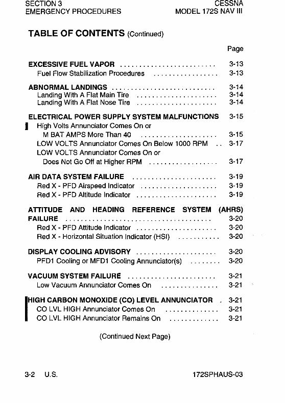
TABLE OF CONTENTS (Continued)
CESSNA MODEL 172S NAV III
Page
EXCESSIVE FUEL VAPOR ......................... 3-13 Fuel Flow Stabilization Procedures 3-13
ABNORMAL LANDINGS ........................... 3-14 Landing With A Flat Main Tire ..................... 3-14 Landing With A Flat Nose Tire ..................... 3-14
ELECTRICAL POWER SUPPLY SYSTEM MALFUNCTIONS 3-15 I High Volts Annunciator Comes On or
M BAT AMPS More Than 40 .. . . . . . . .. . . . . . . . . . . 3-15 LOW VOLTS Annunciator Comes On Below 1000 RPM .. 3-17 LOW VOLTS Annunciator Comes On or
Does Not Go Off at Higher RPM .................. 3-17
AIR DATA SYSTEM FAILURE ...................... 3-19 Red X - PFD Airspeed Indicator .................... 3-19 Red X - PFD Altitude Indicator ..................... 3-19
ATTITUDE AND HEADING REFERENCE SYSTEM (AHRS) FAILURE ...................................... 3-20
Red X - PFD Attitude Indicator ..................... 3-20 Red X - Horizontal Situation Indicator (HSI) ........... 3-20
DISPLAY COOLING ADVISORY ..................... 3-20 PFD1 Cooling or MFD1 Cooling Annunciator(s) ........ 3-20
VACUUM SYSTEM FAILURE ....................... 3-21 Low Vacuum Annunciator Comes On 3-21
IHIGH CARBON MONOXIDE (CO) LEVEL ANNUNCIATOR . 3-21 CO LVL HIGH Annunciator Comes On . . . . . . . . . . . . . . 3-21 CO LVL HIGH Annunciator Remains On ............. 3-21
(Continued Next Page)
3-2 U.S. 172SPHAUS-03

CESSNA MODEL 172S NAV III
SECTION 3 EMERGENCY PROCEDURES
TABLE OF CONTENTS (Continued)
Page
AMPLIFIED EMERGENCY PROCEDURES ,,""""'" 3-22 Engine Failure ",""',"""',"""',""""" 3-22 Maximum Glide """',""',""""',""""" 3-23 Forced Landings """,","""""",""",'" 3-24 Landing Without Elevator Control """"',"",""" 3-25 Fires "',"""""",,""""""",""','" 3-25 Emergency Operation In Clouds "" , , , , , , ' , , , , , , , , , , 3-26.
Executing A 1800 Turn In Clouds (AHRS FAILED) 3-27 Emergency Descent Through Clouds (AHRS FAILED) 3-28 Recovery From Spiral Dive In The Clouds (AHRS FAILED) 3-29
Inadvertent Flight Into Icing Conditions ,,"',""""'" 3-29 Static Source Blocked ",""',""""',"""'," 3-30 Spins "",""""",',""""""',,"""" 3-30 Rough Engine Operation Or Loss 01 Power ,,""""'" 3-31
Spark Plug Fouling ","""""""',""""" 3-31 Magneto Mallunction ,,","""""",""""" 3-31 Idle Power Engine Roughness """"',"""','" 3-31 Engine-Driven Fuel Pump Failure """,""""," 3-32 Excessive Fuel Vapor """""""",""",'" 3-32 Low Oil Pressure "',""'" , , , , , , ' , , , , , , , , , , , , 3-32
Electrical Power Supply System Mallunctions """""" 3-33 Excessive Rate-Ol-Charge ,""""",""""," 3-33 Insufficient Rate-Ol-Charge """',"',""""'" 3-34
High Carbon Monoxide (CO) Level Annunciation , , , , , , , " 3-36. Other Emergencies """"""""",',""""" 3-36
Windshield Damage ,,""""',""',""""" 3-36
172SPHAUS-03 U,S, 3-313-4

CESSNA MODEL 172S NAV III
SECTION 3 EMERGENCY PROCEDURES
INTRODUCTION
Section 3 provides checklist and amplified procedures for coping with emergencies that may occur. Emergencies caused by airplane or engine malfunctions are extremely rare if proper preflight inspections and maintenance are practiced. Enroute weather emergencies can be minimized or eliminated by careful flight planning and good judgment when unexpected weather is encountered. However, should an emergency arise, the basic guidelines described in this section should be considered and applied as necessary to correct the problem. In any emergency situation, the most important task is continued control of the airplane and maneuver to execute a successful landing.
Emergency procedures associated with optional or supplemental equipment are found in Section 9, Supplements.
AIRSPEEDS FOR EMERGENCY OPERATION
ENGINE FAILURE AFTER TAKEOFF Wing Flaps UP ............................ . Wing Flaps 100
- FULL ...................... .
MANEUVERING SPEED 2550 POUNDS ........................... . 2200 POUNDS ............................ . 1900 POUNDS ............................ .
MAXIMUM GLIDE
PRECAUTIONARY LANDING WITH ENGINE POWER
LANDING WITHOUT ENGINE POWER Wing Flaps UP ............................ . Wing Flaps 100
- FULL ..................... ..
172SPHAUS-01
70 KIAS 65 KIASI
105 KIASI 98 KIAS 90 KIAS
68 KIAS
65 KIAS
70 KIAS 65 KIASI
U.S. 3-5

SECTION 3 EMERGENCY PROCEDURES
CESSNA MODEL 172S NAV III
EMERGENCY PROCEDURES Procedures in the Emergency Procedures Checklist portion of this section shown in bold faced type are immediate action items which ~ should be committed to memory.
ENGINE FAILURES
ENGINE FAILURE DURING TAKEOFF ROLL
1. Throttle Control - IDLE (pull full out) 2. Brakes- APPLY 3. Wing Flaps - RETRACT 4. Mixture Control - IDLE CUTOFF (pull full out) 5. MAGNETOS Switch - OFF 6. STBY BATT Switch - OFF 7. MASTER Switch (ALT and BAT) - OFF
ENGINE FAILURE IMMEDIATELY AFTER TAKEOFF
1. Airspeed - 70 KIAS Flaps UP 65 KIAS Flaps 10° - FULL
2. Mixture Control - IDLE CUTOFF (pull full out) 3. FUEL SHUTOFF Valve - OFF (pull full out) 4. MAGNETOS Switch - OFF 5. Wing Flaps - AS REQUIRED (FULL recommended) 6. STBY BATT Switch - OFF 7. MASTER Switch (ALT and BAT) - OFF 8. Cabin Door - UNLATCH 9. Land - STRAIGHT AHEAD
ENGINE FAILURE DURING FLIGHT (Restart Procedures)
1. Airspeed - 68 KIAS (best glide speed) 2. FUEL SHUTOFF Valve - ON (push full in) 3. FUEL SELECTOR Valve - BOTH 4. FUEL PUMP Switch - ON 5. Mixture Control - RICH (if restart has not occurred)
(Continued Next Page)
13-6 U.S. 172SPHAUS-03

CESSNA MODEL 172S NAV III
SECTION 3 EMERGENCY PROCEDURES
ENGINE FAILURES (Continued)
ENGINE FAILURE DURING FLIGHT (Restart Procedures) (Continued)
6. MAGNETOS Switch - BOTH (or START if propeller is stopped)
NOTE
If the propeller is windmilling, engine will restart automatically within a few seconds. If propeller has stopped (possible at low speeds), turn MAGNETOS switch to START, advance throttle slowly from idle and lean the mixture from full rich as required to obtain smooth operation.
7. FUEL PUMP Switch - OFF
NOTE
If the indicated fuel flow (FFLOW GPH) immediately drops to zero, a sign of failure of the engine-driven fuel pump, return the FUEL PUMP switch to the ON position.
FORCED LANDINGS EMERGENCY LANDING WITHOUT ENGINE POWER
1. Pilot and Passenger Seat Backs - MOST UPRIGHT. POSITION
2. Seats and Seat Belts - SECURE 3. Airspeed - 70 KIAS - Flaps UP
65 KIAS - Flaps 10° - FULL 4. Mixture Control - I DLE CUTOFF (pull full out) I 5. FUEL SHUTOFF Valve - OFF (pull full out) 6. MAGNETOS Switch - OFF 7. Wing Flaps - AS REQUIRED (FULL recommended) 8. STBY BATT Switch - OFF 9. MASTER Switch (ALT and BAT) - OFF (when landing is
assured) 10. Doors - UNLATCH PRIOR TO TOUCHDOWN 11. Touchdown - SLIGHTLY TAIL LOW 12. Brakes - APPLY HEAVILY
(Continued Next Page)
172SPHAUS-03 U.S. 3-7

SECTION 3 CESSNA MODEL 172S NAV III EMERGENCY PROCEDURES
FORCED LANDINGS (Continued)
PRECAUTIONARY LANDING WITH ENGINE POWER
I 1. Pilot and Passenger Seat Backs - MOST UPRIGHT POSITION
2. Seats and Seat Belts - SECURE 3. Airspeed - 65 KIAS 4. Wing Flaps - 20° 5. Selected Field - FLY OVER, noting terrain and obstructions. 6. Wing Flaps - FULL (on final approach) 7. Airspeed - 65 KIAS 8. STBY BATT Switch - OFF
I 9. MASTER Switch (ALT and BAT) - OFF (when landing assured)
10. Doors - UNLATCH PRIOR TO TOUCHDOWN 11. Touchdown - SLIGHTLY TAIL LOW
I 12. Mixture Control - IDLE CUTOFF (pull full out) 13. MAGNETOS Switch - OFF
I I
14. Brakes - APPLY HEAVILY
DITCHING
1. Radio - TRANSMIT MAYDAY on 121.5 MHz, (Give location, intentions and SQUAWK 7700)
2. Heavy Objects (in baggage area) - SECURE OR JETTISON (if possible)
3. Pilot and Passenger Seat Backs - MOST UPRIGHT POSITION
4. Seats and Seat Belts - SECURE 5. Wing Flaps - 20° - FULL 6. Power - ESTABLISH 300 FT/MIN DESCENT AT 55 KIAS
NOTE
If no power is available, approach at 70 KIAS with Flaps UP or at 65 KIAS with Flaps 10°.
7. Approach - High Winds, Heavy Seas - INTO THE WIND Light Winds, Heavy Swells - PARALLEL TO SWELLS
8. Cabin Doors - UNLATCH 9. Touchdown - LEVEL ATTITUDE AT ESTABLISHED RATE
OF-DESCENT.
(Continued Next Page)
3-8 U.S. 172SPHAUS-03

CESSNA MODEL 172S NAV III
SECTION 3 EMERGENCY PROCEDURES
FORCED LANDINGS (Continued)
DITCHING (Continued)
10. Face - CUSHION at touchdown with folded coat. 11. ELT - ACTIVATE 12. Airplane - EVACUATE THROUGH CABIN DOORS. Ifl
necessary, open window and flood cabin to equalize pressure so doors can be opened.
13. Life Vests and Raft - INFLATE WHEN CLEAR OF AIRPLANE.
FIRES
DURING START ON GROUND
1. MAGNETOS Switch - START (continue cranking to start the engine).
IF ENGINE STARTS
2. Power - 1800 RPM for a few minutes. 3. Engine - SHUTDOWN and inspect for damage.
IF ENGINE FAILS TO START
2. Throttle Control - FULL (push full in) 3. Mixture Control - IDLE CUTOFF (pull full out) I 4. MAGNETOS Switch - START (continue cranking) 5. FUEL SHUTOFF Valve - OFF (pull full out) 6. FUEL PUMP Switch - OFF 7. MAGNETOS Switch - OFF 8. STBY BATT Switch - OFF 9. MASTER Switch (ALT and BAT) - OFF
10. Engine - SECURE 11. Parking Brake - RELEASE 12. Fire Extinguisher - OBTAIN (have ground attendants obtain
if not installed) 13. Airplane - EVACUATE 14. Fire - EXTINGUISH using fire extinguisher, wool blanket, or
dirt. 15. Fire Damage - INSPECT, (Repair or replace damaged
components and/or wiring before conducting another flight) I (Continued Next Page)
172SPHAUS-03 U.S. 3-9
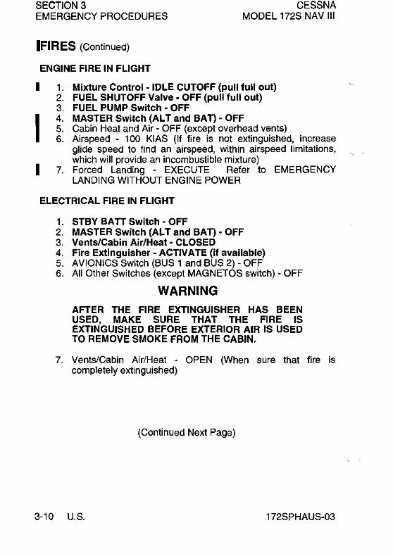
SECTION 3 CESSNA MODEL 172S NAV III EMERGENCY PROCEDURES
IFIRES (Continued)
ENGINE FIRE IN FLIGHT
I
I I
1. Mixture Control - IDLE CUTOFF (pull full out) 2. FUEL SHUTOFF Valve - OFF (pull full out) 3. FUEL PUMP Switch· OFF 4. MASTER Switch (AL T and BAT) • OFF 5. Cabin Heat and Air· OFF (except overhead vents) 6. Airspeed - 100 KIAS (If fire is not extinguished, increase
glide speed to find an airspeed, within airspeed limitations, which will provide an incombustible mixture)
7. Forced Landing - EXECUTE Refer to EMERGENCY LANDING WITHOUT ENGINE POWER
ELECTRICAL FIRE IN FLIGHT
1. STBY BA TT Switch - OFF 2. MASTER Switch (AL T and BAT) - OFF 3. Vents/Cabin Air/Heat - CLOSED 4. Fire Extinguisher - ACTIVATE (if available) 5. AVIONICS Switch (BUS 1 and BUS 2) - OFF 6. All Other Switches (except MAGNETOS switch) - OFF
WARNING
AFTER THE FIRE EXTINGUISHER HAS BEEN USED, MAKE SURE THAT THE FIRE IS EXTINGUISHED BEFORE EXTERIOR AIR IS USED TO REMOVE SMOKE FROM THE CABIN.
7. VentS/Cabin Air/Heat - OPEN (When sure that fire is completely extinguished)
(Continued Next Page)
3-10 U.S. 172SPHAUS-03

CESSNA MODEL 172S NAV III
SECTION 3 EMERGENCY PROCEDURES
FIRES (Continued)
ELECTRICAL FIRE IN FLIGHT (Continued)
IF FIRE HAS BEEN EXTINGUISHED AND ELECTRICAL POWER IS NECESSARY FOR CONTINUED FLIGHT TO NEAREST SUITABLE AIRPORT OR LANDING AREA
8. Circuit Breakers - CHECK for OPEN circuit(s), do not reset. 9. MASTER Switch (ALT and BAT) - ON I
10. STBY SATT Switch - ON 11. AVIONICS Switch (SUS 1) - ON 12. AVIONICS Switch (SUS 2) - ON
CABIN FIRE
1. STBY BA TT Switch - OFF 2. MASTER Switch (AL T and BAn - OFF 3. Vents/Cabin Air/Heat - CLOSED (to avoid drafts) 4. Fire Extinguisher - ACTIVATE (if available)
WARNING
AFTER THE FIRE EXTINGUISHER HAS BEEN USED, MAKE SURE THAT THE FIRE IS EXTINGUISHED BEFORE EXTERIOR AIR IS USED TO REMOVE SMOKE FROM THE CABIN.
5. VentS/Cabin Air/Heat - OPEN (When sure that fire is completely extinguished)
6. Land the airplane as soon as possible to inspect for damage.
WING FIRE
1. LAND and TAXI Light Switches - OFF 2. NAV Light Switch - OFF 3. STROBE Light Switch - OFF 4. PITOT HEAT Switch - OFF
NOTE
Perform a sideslip to keep the flames away from the fuel tank and cabin. Land as soon as possible using flaps only as required for final approach and touchdown.
172SPHAUS-03 U.S. 3-11

SECTION 3 CESSNA MODEL 172S NAV III EMERGENCY PROCEDURES
I
ICING
INADVERTENT ICING ENCOUNTER DURING FLIGHT
1. PITOT HEAT Switch - ON 2. Turn back or change altitude to obtain an outside air
temperature that is less conducive to icing. 3. Pull cabin heat control full out and open defroster
outlets to obtain maximum windshield defroster airflow. Adjust cabin air control to get maximum defroster heat and airflow.
4. Watch for signs of induction air filter icing. A loss of engine RPM could be caused by ice blocking the air intake filter. Adjust the throttle as necessary to hold engine RPM. Adjust mixture, as necessary, for any change in power settings.
5. Plan a landing at the nearest airport. With an extremely rapid ice build-up, select a suitable "off airport" landing site.
6. With an ice accumulation of 0.25 inch or more on the wing leading edges, be prepared for significantly higher power requirements, higher approach and stall speeds, and a longer landing roll.
7. Leave wing flaps retracted. With a severe ice build-up on the horizontal tail, the change in wing wake airflow direction caused by wing flap extension could result in a loss of elevator effectiveness.
8. Open left window and, if practical, scrape ice from a portion of the windshield for visibility in the landing approach.
9. Perform a landing approach using a forward slip, if necessary, for improved visibility.
10. Approach at 65 to 75 KIAS depending upon the amount of the ice accumulation.
11. Perform a landing in level attitude. 12. Missed approaches should be avoided whenever possible
because of severely reduced climb capability.
(Continued Next Page)
3-12 U.S. 172SPHAUS-03

CESSNA MODEL 172S NAV III
SECTION 3 EMERGENCY PROCEDURES
ICI NG (Continued)
STATIC SOURCE BLOCKAGE (ERRONEOUS INSTRUMENT READING SUSPECTED)
1. ALT STATIC AIR Valve - PULL ON 2. CABIN HT and CABIN AIR Knobs - PULL ON 3. Vents - CLOSED 4. Airspeed - Refer to Section 5, Figure 5-1 (Sheet 2) Airspeedl
Calibration, Alternate Static Source correction chart.
EXCESSIVE FUEL VAPOR
FUEL FLOW STABILlZATION PROCEDURES
(If flow fluctuations of 1 GPH or more, or power surges occur.)
1. FUEL PUMP Switch - ON 2. Mixture Control - ADJUST (As necessary for smooth enginel
operation) 3. Fuel Selector Valve· SELECT OPPOSITE TANK (if vapor
symptoms continue) 4. FUEL PUMP Switch - OFF (after fuel flow has stabilized)
172SPHAUS-03 U.S. 3-13

SECTION 3 CESSNA MODEL 172S NAV III EMERGENCY PROCEDURES
I I
ABNORMAL LANDINGS
LANDING WITH A FLAT MAIN TIRE
1. Approach - NORMAL 2. Wing Flaps - FULL 3. Touchdown - GOOD MAIN TIRE FIRST (Hold airplane off
flat tire as long as possible with aileron control) 4. Directional Control - MAINTAIN (Using brake on good wheel
as required)
LANDING WITH A FLAT NOSE TIRE
1. Approach - NORMAL 2. Wing Flaps - AS REQUIRED
85 to 110 KIAS - Flaps Up - 10° Below 85 KIAS - Flaps 10° - FULL
3. Touchdown - ON MAINS (Hold nosewheel off the ground as long as possible)
4. When nosewheel touches down, maintain full up elevator as airplane slows to stop.
3-14 U.S. 172SPHAUS-03

CESSNA MODEL 172S NAV III
ELECTRICAL POWER MALFUNCTIONS
SECTION 3 EMERGENCY PROCEDURES
SUPPLY SYSTEM
HIGH VOLTS ANNUNCIATOR COMES ON OR M BAT AMPS. MORE THAN 40
1. MASTER Switch (Al T Only) - OFF I 2. Electrical load - REDUCE IMMEDIATELY as follows:
a. AVIONICS SWitch (BUS 1) - OFF b. PITOT HEAT - OFF c. BEACON Light - OFF d. LAND Light - OFF (Use as required for landing) e. TAXI Light - OFF f. NAV Lights - OFF g. STROBE Lights - OFF h. CABIN PWR 12V - OFF
NOTE
• The Main Battery supplies electrical power to the Main and Essential Buses until M BUS VOLTS decreases below 20 volts. When M BUS VOLTS falls below 20 volts, the Standby Battery System will automatically supply electrical power to the Essential Bus for at least 30 minutes .
• Select COM1 MIC and NAV1 on the audio panel and tune to the active frequency before setting AVIONICS BUS 2 to OFF. If COM2 MIC and NAV2 are selected when AVIONICS BUS 2 is set to off, the COM and NAV radios cannot be tuned.
(Continued Next Page)
172SPHAUS-03 U.S. 3-15

SECTION 3 CESSNA MODEL 172S NAV III EMERGENCY PROCEDURES
ELECTRICAL POWER MALFUNCTIONS (Continued)
SUPPLY SYSTEM
IHIGH VOLTS ANNUNCIATOR COMES ON OR M BAT AMPS MORE THAN 40 (Continued)
I
I
i. COM1 and NAV1 - TUNE TO ACTIVE FREQUENCY
j. COM1 MIC and NAV1 - SELECT (COM2 MIC and NAV2 will be inoperative once AVIONICS BUS 2 is selected to OFF).
NOTE
When AVIONICS BUS 2 is set to OFF, the following items will not operate:
KAP 140 Autopilot COMM2 GTX 33 Transponder
GMA 1347 Audio Panel NAV2 GDU 1040 MFD
I k. AVIONICS Switch (BUS 2) - OFF (KEEP ON if in clouds)
3. Land as soon as practical.
NOTE
Make sure a successful landing is possible before extending flaps. The flap motor is a large electrical load during operation.
(Continued Next Page)
3-16 U.S. 172SPHAUS-03

CESSNA MODEL 172S NAV 111
SECTION 3 EMERGENCY PROCEDURES
ELECTRICAL POWER MALFUNCTIONS (Continued)
SUPPLY SYSTEM
LOW VOLTS ANNUNCIATOR COMES ON BELOW 1000 RPM
1. Throttle Control - 1000 RPM 2. Low Voltage Annunciator (LOW VOLTS) - CHECK OFF
LOW VOLTS ANNUNCIATOR REMAINS ON AT 1000 RPM
3. Authorized maintenance personnel must do electrical system inspection prior to next flight.
LOW VOLTS ANNUNCIATOR COMES ON OR DOES NOT GO OFF AT HIGHER RPM
1 . MASTER Switch (AL T Only) - OFF 2. Alternator Circuit Breaker (AL T FIELD) - CHECK IN 3. MASTER Switch (AL T and BAT) - ON 4. Low Voltage Annunciator (LOW VOLTS) - CHECK OFF 5. M BUS VOLTS - CHECK 27.5 V minimum 6. M BAT AMPS - CHECK CHARGING (+)
IF LOW VOLTS ANNUNCIATOR REMAINS ON
7. MASTER Switch (AL T Only) - OFF I 8. Electrical Load - REDUCE IMMEDIATELY as follows:
a. AVIONICS Switch (BUS 1) - OFF b. PITOT HEAT - OFF c. BEACON Light - OFF d. LAND Light - OFF (use as required for landing) e. TAXI Light - OFF f. NAV Lights - OFF g. STROBE Lights - OFF h. CABIN PWR 12V - OFF
(Continued Next Page)
I 172SPHAUS-03 U.S. 3-17

SECTION 3 CESSNA MODEL 172S NAV III EMERGENCY PROCEDURES
I
ELECTRICAL POWER MALFUNCTIONS (Continued)
SUPPLY SYSTEM
IF lOW VOLTS ANNUNCIATOR REMAINS ON (Continued)
NOTE
• The Main Battery supplies electrical power to the Main and Essential Buses until M BUS VOLTS decreases below 20 volts. When M BUS VOLTS falls below 20 volts, the Standby Battery System will automatically supply electrical power to the Essential Bus for at least 30 minutes .
• Select COM1 MIC and NAV1 on the audio panel and tune to the active frequency before setting AVIONICS BUS 2 to OFF. If COM2 MIC and NAV2 are selected when AVIONICS BUS 2 is set to OFF, the COM and NAV radios cannot be tuned.
i. COM1 and NAV1 - TUNE TO ACTIVE FREQUENCY
j. COM1 MIC and NAV1 - SELECT (COM2 MIC and NAV2 will be inoperative once AVIONICS BUS 2 is selected to OFF)
NOTE
When AVIONICS BUS 2 is set to OFF, the following items will not operate:
KAP 140 Autopilot COMM2 GTX 33 Transponder
GMA 1347 Audio Panel NAV2 GDU 1040 MFD
k. AVIONICS Switch (BUS 2) - OFF (KEEP ON if in clouds)
(Continued Next Page)
13-18 U.S. 172SPHAUS-03

CESSNA MODEL 172S NAV III
ELECTRICAL POWER MALFUNCTIONS (Continued)
SECTION 3 EMERGENCY PROCEDURES
SUPPLY SYSTEM
IF LOW VOLTS ANNUNCIATOR REMAINS ON (Continued)
9. Land as soon as practical.
NOTE
Make sure a successful landing is possible before extending flaps. The flap motor is a large electrical load during operation.
AIR DATA SYSTEM FAILURE
RED X - PFD AIRSPEED INDICATOR
1. ADC/AHRS Circuit Breakers - CHECK IN (ESS BUS and AVN BUS 1). If open, reset (close) circuit breaker. If circuit breaker opens again, do not reset.
2. Standby Airspeed Indicator - USE FOR AIRSPEED INFORMATION.
RED X - PFD ALTITUDE INDICATOR
1. ADC/AHRS Circuit Breakers - CHECK IN (ESS BUS and AVN BUS 1). If open, reset (close) circuit breaker. If circuit breaker opens again, do not reset.
2. Standby Altimeter - CHECK current barometric pressure SET. USE FOR ALTITUDE INFORMATION.
I 172SPHAUS-03 U.S. 3-19

SECTION 3 EMERGENCY PROCEDURES
CESSNA MODEL 172S NAV III
ATTITUDE AND HEADING REFERENCE SYSTEM (AHRS) FAILURE
RED X - PFD ATTITUDE INDICATOR
1. ADC/AHRS Circuit Breakers - CHECK IN (ESS BUS and AVN BUS 1). If open, reset (close) circuit breaker. If circuit breaker opens again, do not reset.
2. Standby Attitude Indicator - USE FOR ATTITUDE INFORMATION.
RED X - HORIZONTAL SITUATION INDICATOR (HSI)
1. ADC/AHRS Circuit Breakers - CHECK IN (ESS BUS and AVN BUS 1). If open, reset (close) circuit breaker. If circuit breaker opens again, do not reset.
2. Non-Stabilized Magnetic Compass - USE FOR HEADING INFORMATION.
DISPLAY COOLING ADVISORY
PFD1 COOLING OR MFD1 COOLING ANNUNCIATOR(S)
1. Cabin Heat (CABIN HT) - REDUCE (minimum preferred) 2. Forward Avionics Fan - CHECK (feel for airflow from screen
on glareshield)
IF FORWARD AVIONICS FAN HAS FAILED
3. STBY BAIT Switch - OFF (unless needed for emergency power)
IF PFD1 COOLING OR MFD1 COOLING ANNUNCIATOR DOES NOT GO OFF WITHIN 3 MINUTES OR IF BOTH PFD1 ' COOLING AND MFD1 COOLING ANNUNCIATORS COME ON
3. STBY BAIT Switch - OFF (land as soon as practical)
13-20 U.S. 172SPHAUS-03
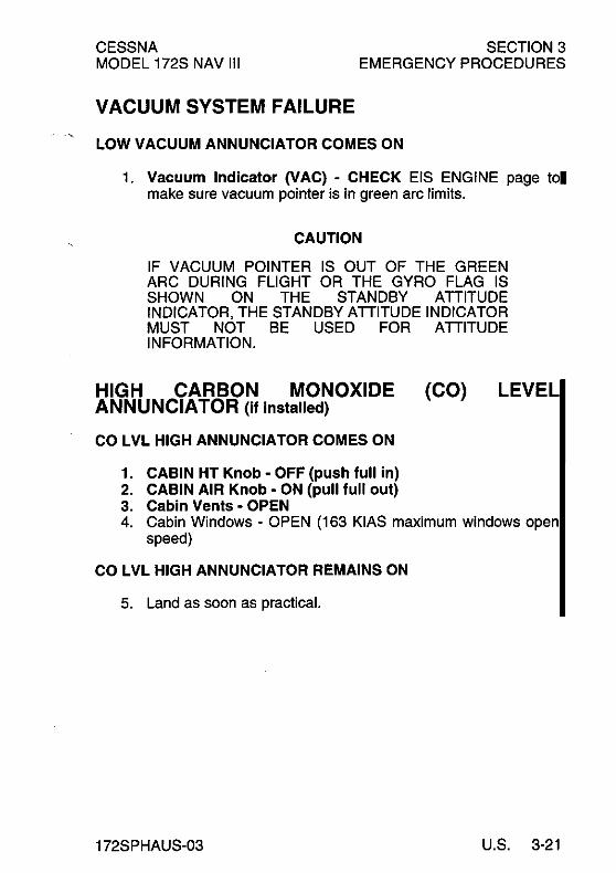
CESSNA MODEL 172S NAV III
SECTION 3 EMERGENCY PROCEDURES
VACUUM SYSTEM FAILURE
LOW VACUUM ANNUNCIATOR COMES ON
1. Vacuum Indicator (VAC) - CHECK EIS ENGINE page tol make sure vacuum pointer is in green arc limits.
CAUTION
IF VACUUM POINTER IS OUT OF THE GREEN ARC DURING FLIGHT OR THE GYRO FLAG IS SHOWN ON THE STANDBY ATTITUDE INDICATOR, THE STANDBY ATTITUDE INDICATOR MUST NOT BE USED FOR ATTITUDE INFORMATION.
HIGH CARBON MONOXIDE (CO) LEVEL ANNUNCIATOR (if installed)
CO LVL HIGH ANNUNCIATOR COMES ON
1. CABIN HT Knob - OFF (push full in) 2. CABIN AIR Knob - ON (pull full out) 3. Cabin Vents - OPEN 4. Cabin Windows - OPEN (163 KIAS maximum windows open
speed)
CO LVL HIGH ANNUNCIATOR REMAINS ON
5. Land as soon as practical.
172SPHAUS-03 U.S. 3-21

SECTION 3 EMERGENCY PROCEDURES
CESSNA MODEL 172S NAV III
AMPLIFIED EMERGENCY PROCEDURES
IThe following Amplified Emergency Procedures provide additional information beyond that in the Emergency Procedures Checklists portion of this section. These procedures also include information not readily adaptable to a checklist format, and material to which a pilot could not be expected to refer in resolution of a specific emergency. This information should be reviewed in detail prior to flying the airplane, as well as reviewed on a regular basis to keep pilot's knowledge of procedures fresh.
ENGINE FAILURE
If an engine failure occurs during the takeoff roll, stop the airplane on the remaining runway. Those ex1ra items on the checklist will provide added safety after a failure of this type.
Ilf an engine failure occurs immediately after takeoff, in most cases, the landing should be planned straight ahead with only small changes in direction to avoid obstructions. Altitude and airspeed are seldom sufficient to execute the 1800 gliding turn necessary to return to the runway. The checklist procedures assume that adequate time exists to secure the fuel and ignition systems prior to touchdown.
IAfter an engine failure in flight, the most important task is to continue flying the airplane. The best glide speed, as shown in Figure 3-1, should be established as quickly as possible. While gliding toward a suitable landing area, an effort should be made to identify the cause of the failure. If time permits, an engine restart should be attempted as shown in the checklist. If the engine cannot be restarted, a forced landing without power must be completed.
13-22 U.S. 172SPHAUS-01

CESSNA MODEL 172S NAV III
SECTION 3 EMERGENCY PROCEDURES
12,000
z <C c:: 8000 c:: W I-W
~ CD <I: IJ: C!l [jj J:
6000
4000
2000
I 172SPHAUS-Ol
MAXIMUM GLIDE
* SPEED 68 -KIAS * PROPELLER WINDMILLlNG * FLAPS UP * ZERO WIND
2 4 6 8 10 12 14 16 18 20
GROUND DISTANCE - NAUTICAL MILES 0585T1011
Figure 3-1 I
U.S. 3-23
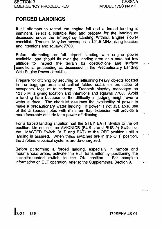
SECTION 3 EMERGENCY PROCEDURES
FORCED LANDINGS
CESSNA MODEL 172S NAV III
If all attempts to restart the engine fail and a forced landing is imminent, select a suitable field and prepare for the landing as discussed under the Emergency Landing Without Engine Power checklist. Transmit Mayday message on 121.5 MHz giving location and intentions and squawk 7700.
Before attempting an "off airport" landing with engine power available, one should flyover the landing area at a safe but low altitude to inspect the terrain for obstructions and surface
Iconditions, proceeding as discussed in the Precautionary Landing With Engine Power checklist.
Prepare for ditching by securing or jettisoning heavy objects located in the baggage area and collect folded coats for protection of occupants' face at touchdown. Transmit Mayday messages on 121.5 MHz giving location and intentions and squawk 7700. Avoid a landing flare because of the difficulty in judging height over a water surface. The checklist assumes the availability of power to make a precautionary water landing. If power is not available, use of the airspeeds noted with minimum flap extension will provide a more favorable attitude for a power off ditching.
For a forced landing situation, set the STBY BATT Switch to the off position. Do not set the AVIONICS (BUS 1 and BUS 2) Switch or the MASTER Switch (ALT and BAT) to the OFF position until a landing is assured. When these switches are in the OFF position, the airplane electrical systems are de-energized.
Before performing a forced landing, especially in remote and mountainous areas, activate the ELT transmitter by positioning the COCkpit-mounted switch to the ON position. For complete information on ELT operation, refer to the Supplements, Section 9.
U.S. 172SPHAUS-Ol
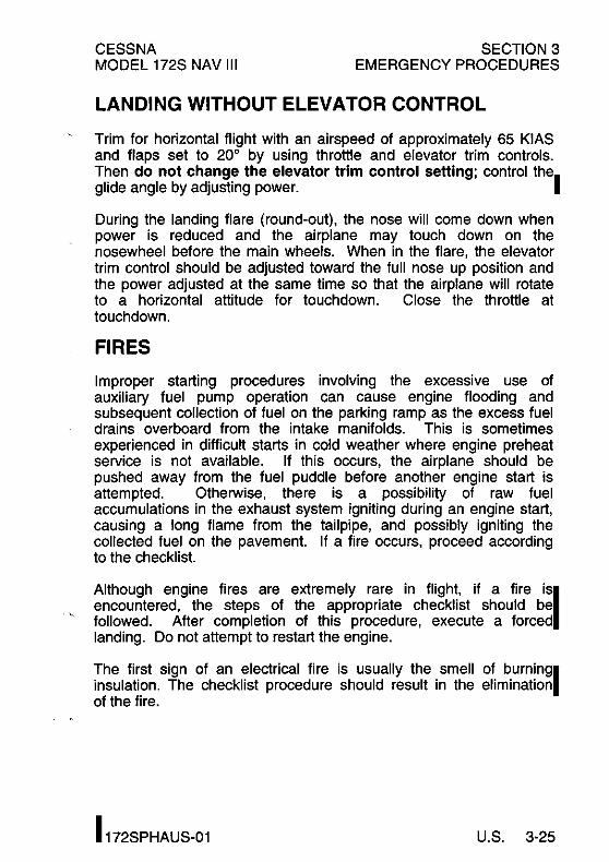
CESSNA MODEL 172S NAV III
SECTION 3 EMERGENCY PROCEDURES
LANDING WITHOUT ELEVATOR CONTROL
Trim for horizontal flight with an airspeed of approximately 65 KIAS and flaps set to 20° by using throttle and elevator trim controls. Then do not change the elevator trim control setting; control the. glide angle by adjusting power.
During the landing flare (round-out), the nose will come down when power is reduced and the airplane may touch down on the nosewheel before the main wheels. When in the flare, the elevator trim control should be adjusted toward the full nose up position and the power adjusted at the same time so that the airplane will rotate to a horizontal attitude for touchdown. Close the throttle at touchdown.
FIRES
Improper starting procedures involving the excessive use of auxiliary fuel pump operation can cause engine flooding and subsequent collection of fuel on the parking ramp as the excess fuel drains overboard from the intake manifolds. This is sometimes experienced in difficult starts in cold weather where engine preheat service is not available. If this occurs, the airplane should be pushed away from the fuel puddle before another engine start is attempted. Otherwise, there is a possibility of raw fuel accumulations in the exhaust system igniting during an engine start, causing a long flame from the tailpipe, and possibly igniting the collected fuel on the pavement. If a fire occurs, proceed according to the checklist.
Although engine fires are extremely rare in flight, if a fire iSI encountered, the steps of the appropriate checklist should be followed. After completion of this procedure, execute a forced landing. Do not attempt to restart the engine.
The first sign of an electrical fire is usually the smell of bUrningl insulation. The checklist procedure should result in the elimination of the fire.
I 172SPHAUS-Ol U.S. 3-25

SECTION 3 EMERGENCY PROCEDURES
CESSNA MODEL 172S NAV III
IEMERGENCY OPERATION IN CLOUDS
If the engine-driven vacuum pump fails in flight, the standby attitude indicator will not be accurate. The pilot must then rely on the attitude and heading information (from the AHRS) shown on the PFD indicators. With valid HDG or GPS/NAV and blind turn coordinator inputs, autopilot operation will not be affected.
If the AHRS unit fails in flight (red X's shown through the PFD attitude and heading indicators), the pilot must rely on the standby attitude indicator and non-stabilized magnetic compass for attitude and heading information.
The KAP 140 Autopilot will not operate in HDG mode without AHRS input. With a valid GPS or NAV input and an operating turn coordinator, the autopilot will operate in NAV, APR or REV modes. Autopilot altitude hold and vertical speed operating modes are independent of AHRS operation. Refer to Section 9, Supplements, for additional details on autopilot operations.
The following instructions assume that the pilot is not very proficient at instrument flying and is flying the airplane without the autopilot engaged.
(Continued Next Page)
3-26 U.S. 172SPHAUS-03

. --..
CESSNA MODEL 172S NAV III
SECTION 3 EMERGENCY PROCEDURES
EMERGENCY OPERATION IN CLOUDS (Continued) I
EXECUTING A 180° TURN IN CLOUDS (AHRS FAILED)
Upon inadvertently entering the clouds, an immediate turn to reverse course and return to VFR conditions should be made as follows:
AHRS Failure
1. Note the non-stabilized magnetic compass heading. 2. Using the standby attitude indicator, initiate a 15° bank left
turn. Keep feet off rudder pedals. Maintain altitude and 15° bank angle. Continue the turn for 60 seconds, then roll back to level flight.
3. When the compass card becomes sufficiently stable, check the accuracy of the turn by verifying that the compass heading approximates the reciprocal of the original heading.
4. If necessary, adjust the heading by keeping the wings level and using the rudder to make skidding turns (the compass will read more accurately) to complete the course reversal.
5. Maintain altitude and airspeed by cautious application of elevator control. Keep the roll pointer and index aligned and steer only with rudder.
(Continued Next Page)
172SPHAUS-03 U.S. 3-27

SECTION 3 EMERGENCY PROCEDURES
CESSNA MODEL 172S NAV III
IEMERGENCY OPERATION IN CLOUDS (Continued)
IEMERGENCY DESCENT THROUGH CLOUDS (AHRS FAILED)
When returning to VFR flight after a 1800 turn is not practical, a descent through the clouds to VFR conditions below may be appropriate. If possible, obtain an ATC clearance for an emergency descent through the clouds.
AHRS Failure
Choose an easterly or westerly heading to minimize non-stabilized magnetic compass card sensitivity. Occasionally check the compass heading and make minor corrections to hold an approximate course. The autopilot may be engaged in ROL mode to keep the wings level and VS mode to control rate-of-descent.
Before descending into the clouds, prepare for a stabilized descent as follows:
1. Apply full rich mixture. 2. Turn pitot heat on. 3. Set power for a 500 to 800 feet per minute rate-of-descent. 4. Set the elevator trim for a stabilized descent at 80 KIAS. 5. Use the standby attitude indicator roll pointer and index to
keep wings level. 6. Check trend of compass card movement and make cautious
corrections with rudder to stop the turn. 7. Upon breaking out of clouds, resume normal cruising flight.
(Continued Next Page)
3-28 U.S. 172SPHAUS-03
,
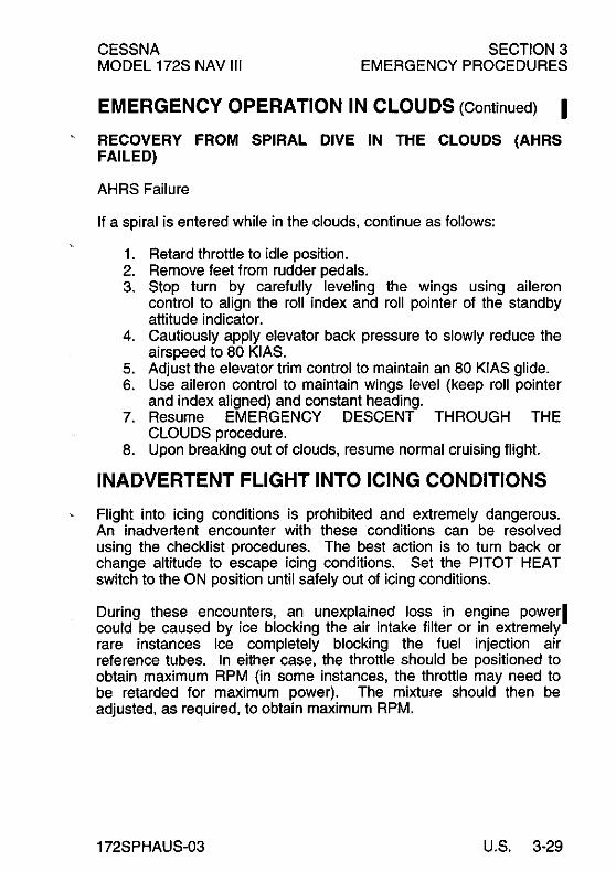
CESSNA MODEL 172S NAV III
SECTION 3 EMERGENCY PROCEDURES
EMERGENCY OPERATION IN CLOUDS (Continued) I RECOVERY FROM SPIRAL DIVE IN THE CLOUDS (AHRS FAILED)
AHRS Failure
If a spiral is entered while in the clouds, continue as follows:
1. Retard throttle to idle position. 2. Remove feet from rudder pedals. 3. Stop turn by carefully leveling the wings using aileron
control to align the roll index and roll pointer of the standby attitude indicator.
4. Cautiously apply elevator back pressure to slowly reduce the airspeed to 80 KIAS.
5. Adjust the elevator trim control to maintain an 80 KIAS glide. 6. Use aileron control to maintain wings level (keep roll pointer
and index aligned) and constant heading. 7. Resume EMERGENCY DESCENT THROUGH THE
CLOUDS procedure. 8. Upon breaking out of clouds, resume normal cruising flight.
INADVERTENT FLIGHT INTO ICING CONDITIONS
Flight into icing conditions is prohibited and extremely dangerous. An inadvertent encounter with these conditions can be resolved using the checklist procedures. The best action is to turn back or change altitude to escape icing conditions. Set the PITOT HEAT switch to the ON position until safely out of icing conditions.
During these encounters, an unexplained loss in engine powerl could be caused by ice blocking the air intake filter or in extremely rare instances ice completely blocking the fuel injection air reference tubes. In either case, the throttle should be positioned to obtain maximum RPM (in some instances, the throttle may need to be retarded for maximum power). The mixture should then be adjusted, as required, to obtain maximum RPM.
172SPHAUS-03 U.S. 3-29
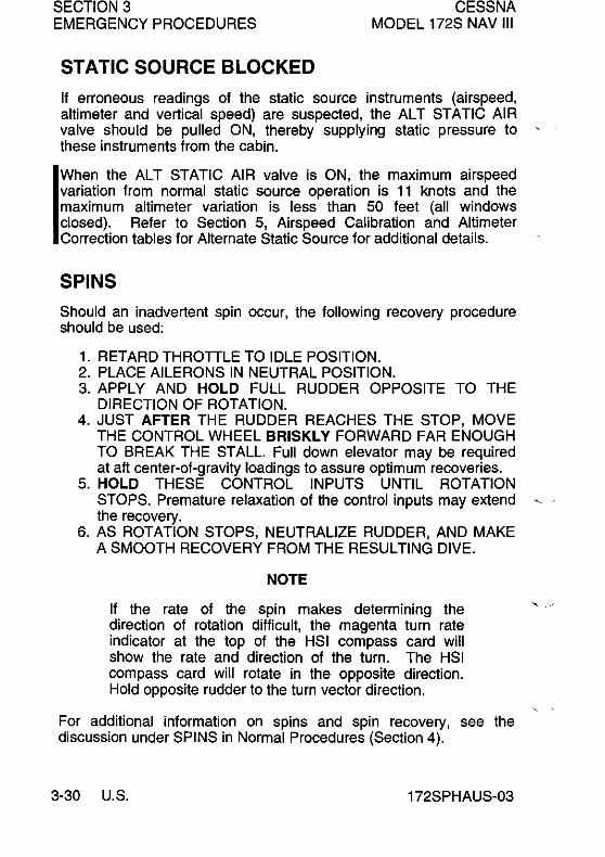
SECTION 3 EMERGENCY PROCEDURES
STATIC SOURCE BLOCKED
CESSNA MODEL 172S NAV III
If erroneous readings of the static source instruments (airspeed, altimeter and vertical speed) are suspected, the AL T STATIC AI R valve should be pulled ON, thereby supplying static pressure to ' these instruments from the cabin.
IWhen the ALT STATIC AIR valve is ON, the maximum airspeed variation from normal static source operation is 11 knots and the maximum altimeter variation is less than 50 feet (all windows closed). Refer to Section 5, Airspeed Calibration and Altimeter Correction tables for Alternate Static Source for additional details.
SPINS
Should an inadvertent spin occur, the following recovery procedure should be used:
1. RETARD THROTTLE TO IDLE POSITION. 2. PLACE AILERONS IN NEUTRAL POSITION. 3. APPLY AND HOLD FULL RUDDER OPPOSITE TO THE
DIRECTION OF ROTATION. 4. JUST AFTER THE RUDDER REACHES THE STOP, MOVE
THE CONTROL WHEEL BRISKLY FORWARD FAR ENOUGH TO BREAK THE STALL. Full down elevator may be required at aft center-of-gravity loadings to assure optimum recoveries.
5. HOLD THESE CONTROL INPUTS UNTIL ROTATION STOPS. Premature relaxation of the control inputs may extend ~ the recovery.
6. AS ROTATION STOPS, NEUTRALIZE RUDDER, AND MAKE A SMOOTH RECOVERY FROM THE RESULTING DIVE.
NOTE
If the rate of the spin makes determining the direction of rotation difficult, the magenta turn rate indicator at the top of the HSI compass card will show the rate and direction of the turn. The HSI compass card will rotate in the opposite direction. Hold opposite rudder to the turn vector direction.
For additional information on spins and spin recovery, see the discussion under SPINS in Normal Procedures (Section 4).
3-30 U.S. 172SPHAUS-03
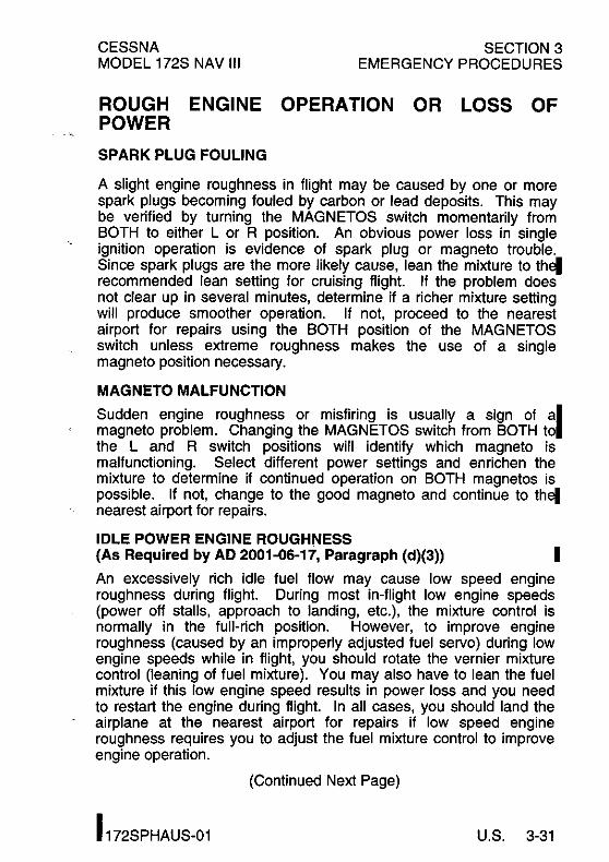
CESSNA MODEL 172S NAV III
SECTION 3 EMERGENCY PROCEDURES
ROUGH ENGINE OPERATION OR LOSS OF POWER
SPARK PLUG FOULING
A slight engine roughness in flight may be caused by one or more spark plugs becoming fouled by carbon or lead deposits. This may be verified by turning the MAGNETOS switch momentarily from BOTH to either L or R position. An obvious power loss in single ignition operation is evidence of spark plug or magneto trouble. Since spark plugs are the more likely cause, lean the mixture to thel recommended lean setting for cruising flight. If the problem does not clear up in several minutes, determine if a richer mixture setting will produce smoother operation. If not, proceed to the nearest airport for repairs using the BOTH position of the MAGNETOS switch unless extreme roughness makes the use of a single magneto position necessary.
MAGNETO MALFUNCTION
Sudden engine roughness or misfiring is usually a sign of al magneto problem. Changing the MAGNETOS switch from BOTH to the Land R switch positions will identify which magneto is malfunctioning. Select different power settings and enrichen the mixture to determine if continued operation on BOTH magnetos is possible. If not, change to the good magneto and continue to thel nearest airport for repairs.
IDLE POWER ENGINE ROUGHNESS (As Required by AD 2001-06-17, Paragraph (d)(3» I An excessively rich idle fuel flow may cause low speed engine roughness during flight. During most in-flight low engine speeds (power off stalls, approach to landing, etc.), the mixture control is normally in the full-rich position. However, to improve engine roughness (caused by an improperly adjusted fuel servo) during low engine speeds while in flight, you should rotate the vernier mixture control (leaning of fuel mixture). You may also have to lean the fuel mixture if this low engine speed results in power loss and you need to restart the engine during flight. In all cases, you should land the airplane at the nearest airport for repairs if low speed engine roughness requires you to adjust the fuel mixture control to improve engine operation.
(Continued Next Page)
I 172SPHAUS-01 U.S. 3-31

SECTION 3 EMERGENCY PROCEDURES
IROUGH ENGINE POWER (Continued)
OPERATION
ENGINE-DRIVEN FUEL PUMP FAILURE
CESSNA MODEL 172S NAV III
OR LOSS OF
Failure of the engine-driven fuel pump will be shown by a sudden reduction in the fuel flow indication (FFLOW GPH) immediately before a loss of power while operating from a fuel tank containing adequate fuel.
I" the engine-driven fuel pump fails, immediately set the FUEL PUMP switch to the ON position to restore engine power. The flight should be terminated as soon as practical and the engine-driven fuel pump repaired.
EXCESSIVE FUEL VAPOR
Fuel vapor in the fuel injection system is most likely to occur on the ground, typically during prolonged taxi operations, when operating at higher altitudes and/or in unusually warm temperatures.
Excessive fuel vapor accumulation is shown by fuel flow indicator (FFLOW GPH) fluctuations greater than 1 gal./hr. This condition, with leaner mixtures or with larger fluctuations, can result in power surges, and if not corrected, may cause power loss.
To slow vapor formation and stabilize fuel flow on the ground or in the air, set the FUEL PUMP switch to the ON pOSition and adjust the mixture as required for smooth engine operation. If vapor symptoms continue, select the oppOSite fuel tank. When fuel flow stabilizes, set the FUEL PUMP switch to the OFF position and adjust the mixture as desired.
LOW OIL PRESSURE
If the low oil pressure annunciator (OIL PRESS) comes on, check ' the oil pressure indicator (OIL PRES on ENGINE page or OIL PSI on SYSTEM page) to confirm low oil pressure condition. If oil pressure and oil temperature (OIL TEMP on ENGINE page or OIL OF on SYSTEM page) remain normal, it is possible that the oil pressure sending unit or relief valve is malfunctioning. Land at the nearest airport to determine the source of the problem.
(Continued Next Page)
13-32 U.S. 172SPHAUS-01

CESSNA MODEL 172S NAV III
SECTION 3 EMERGENCY PROCEDURES
ROUGH ENGINE OPERATION POWER (Continued)
lOW Oil PRESSURE (Continued)
OR LOSS
If a total loss of oil pressure and a rise in oil temperature occur at about the same time, it could mean that the engine is about to fail. Reduce power immediately and select a field suitable for a forced landing. Use only the minimum power necessary to reach the landing site.
ELECTRICAL POWER SUPPLY SYSTEM MALFUNCTIONS
Malfunctions in the electrical power supply system can be detected through regular monitoring of the main battery ammeter (M BAT AMPS) and the main electrical bus voltmeter (M BUS VOLTS); however, the cause of these malfunctions is usually difficult to determine. A broken alternator drive belt, too much wear on th~ alternator brushes, or an error in wiring is most likely the cause 0 alternator failures, although other factors could cause the problem. A defective alternator control unit (ACU) can also cause malfunctions. Problems of this nature constitute an electrical emergency and should be dealt with immediately. Electrical power malfunctions usually fall into two categories: excessive rate-ofcharge and insufficient rate-of-charge. The following paragraphs describe the recommended remedy for each situation.
EXCESSIVE RATE-OF-CHARGE
After engine starting and heavy electrical usage at low engine speeds (such as extended taxiing) the battery condition will be low enough to accept above normal charging during the initial part of a flight. However, after thirty minutes of cruising flight, the main battery ammeter (M BAT AMPS) should be indicating less than 5 amps of charging (+) current. If the charging current remainsl above this value on a long flight, the battery electrolyte could overheat and evaporate.
(Continued Next Page) I
I 172SPHAUS-01 U.S. 3-33

SECTION 3 EMERGENCY PROCEDURES
CESSNA MODEL 172S NAV III
ELECTRICAL POWER MALFUNCTIONS (Continued)
SUPPLY SYSTEM
EXCESSIVE RATE-OF-CHARGE (Continued)
Electronic components in the electrical system can be adversely affected by higher than normal voltage. The alternator control unit includes an overvoltage sensor circuit which will automatically disconnect the alternator if the charge voltage increases to more than approximately 31.75 volts. If the overvoltage sensor circuit does not operate correctly, as shown by voltage more than 31.75 volts on the main battery bus voltmeter, the MASTER switch Al T section should be set to the OFF position. Unnecessary electrical equipment should be de-energized and the flight terminated as soon as practical.
INSUFFICIENT RATE-OF-CHARGE
When the over-voltage sensor circuit, or other fault, opens the alternator (AlT FIELD) circuit breaker and de-energizes the alternator, a discharge (-) current will be shown on the main battery ammeter and the low voltage annunciator (lOW VOLTS) will come on. The ACU can de-energize the alternator due to minor disturbances in the electrical system, resulting in a "nuisance" opening of the AlT FIELD circuit breaker. If this happens, an attempt should be made to energize the alternator system.
To energize the alternator system
1. MASTER Switch (Al T Only) - OFF. 2. Alternator Circuit Breaker (Al T FIELD) - CHECK IN. 3. MASTER Switch (Al T Only) - ON.
If the problem was a minor ACU disturbance in the electrical system, normal main battery charging will start. A charge (+) current will be shown on the main battery ammeter and the lOW VOLTS annunciator will go off.
If the lOW VOLTS annunciator comes on again, there is an lalternator system problem. Do not repeat steps to energize the !alternator system. The electrical load on the battery must be minimized (by de-energizing nonessential electrical equipment and avionics) because the battery can supply the electrical system for only a short time. Reduce electrical load as soon as possible to extend the life of the battery for landing. land as soon as practical.
(Continued Next Page)
3-34 U.S. 172SPHAUS-03

CESSNA MODEL 172S NAV III
ELECTRICAL POWER MALFUNCTIONS (Continued)
SECTION 3 EMERGENCY PROCEDURES
SUPPLY SYSTEMI
INSUFFICIENT RATE-OF-CHARGE (Continued)
Main battery life can be extended by setting the MASTER switch (Al T and BAT) to OFF and operating the equipment on the ESS BUS from the standby battery. The standby battery is only capable of providing power for systems on the Essential Bus and cannot provide power for transponder (XPDR) operation. Main battery life should be extended, when practical, for possible later operation of the wing flaps and use of the landing light (at night).
NOTE
The lOW VOLTS annunciator can come on when the engine is operated at low RPM with a high electrical load. The lOW VOLTS annunciator will usually go off when the engine is operated at higher RPM for greater alternator system output. Make sure that the M BATT AMPS indication shows positive (+) current at the higher RPM.
I 172SPHAUS-01 U.S. 3-35
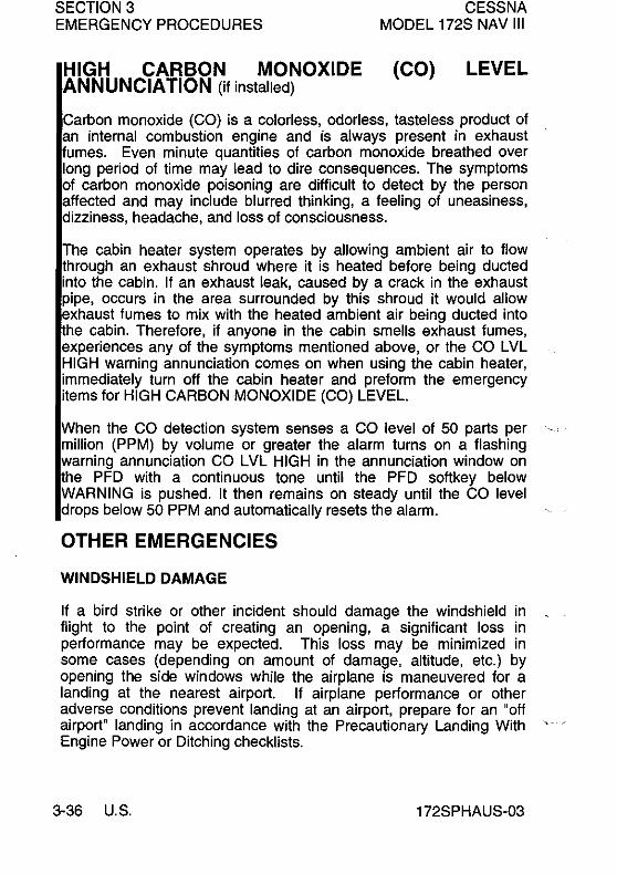
SECTION 3 EMERGENCY PROCEDURES
HIGH CARBON MONOXIDE ANNUNCIATION (if installed)
CESSNA MODEL 172S NAV III
(CO) LEVEL
Carbon monoxide (CO) is a colorless, odorless, tasteless product of an internal combustion engine and is always present in exhaust umes. Even minute quantities of carbon monoxide breathed over
long period of time may lead to dire consequences. The symptoms of carbon monoxide poisoning are difficult to detect by the person affected and may include blurred thinking, a feeling of uneasiness, dizziness, headache, and loss of consciousness.
The cabin heater system operates by allowing ambient air to flow through an exhaust shroud where it is heated before being ducted into the cabin. If an exhaust leak, caused by a crack in the exhaust pipe, occurs in the area surrounded by this shroud it would allow exhaust fumes to mix with the heated ambient air being ducted into he cabin. Therefore, if anyone in the cabin smells exhaust fumes, experiences any of the symptoms mentioned above, or the CO LVL HIGH warning annunciation comes on when using the cabin heater, immediately turn off the cabin heater and preform the emergency items for HIGH CARBON MONOXIDE (CO) LEVEL.
When the CO detection system senses a CO level of 50 parts per million (PPM) by volume or greater the alarm turns on a flashing warning annunciation CO LVL HIGH in the annunciation window on the PFD with a continuous tone until the PFD softkey below WARNING is pushed. It then remains on steady until the CO level drops below 50 PPM and automatically resets the alarm.
OTHER EMERGENCIES
WINDSHIELD DAMAGE
If a bird strike or other incident should damage the windshield in flight to the point of creating an opening, a significant loss in performance may be expected. This loss may be minimized in some cases (depending on amount of damage, altitude, etc.) by opening the side windows while the airplane is maneuvered for a landing at the nearest airport. If airplane performance or other adverse conditions prevent landing at an airport, prepare for an "off airport" landing in accordance with the Precautionary Landing With Engine Power or Ditching checklists.
3-36 U.S. 172SPHAUS-03

CESSNA MODEL 172S NAV III
SECTION 4 NORMAL PROCEDURES
NORMAL PROCEDURES TABLE OF CONTENTS
Introduction """"',""""""""""""""
AIRSPEEDS"",""""""""""""""'" , Airspeeds For Normal Operation ""","',"""'"
NORMAL PROCEDURES """',',"',"""","" Preflight Inspection "',"""""',"',"""",'"
Cabin"",,"""""""""""""""'" , Empennage "',",""""""",,"""""" Right Wing Trailing Edge , , , , , , , , , , , , ' , , , , , , , , , , , ,
RightWing ""',',"""""""',"""""" Nose """""',","""""",',"""'" Left Wing Leading Edge """""",',""""" Left Wing """","',"""""',""',"'" Left Wing Trailing Edge "',""""',""","'"
Before Starting Engine """""',"","""','" Starting Engine (With Battery) """",',"""""', Starting Engine (With External Power) "",""',""" Before Takeoff """,,"""""""',""""'" Takeoff """""","',"""""',",""""
Normal Takeoff "",""""',""',""""',' Short Field Takeoff ,,""""""',',""""'"
Enroute Climb ","","""""""',""""'" Cruise"", .. ,""""", .. ,", .. ,"""""" , Descent """""',"""',"""',""""',' Before Landing ""","""""""',',"""'"
(Continued Next Page)
Page
4-5
4-5 4-5
4-61 4-6 4-7 4-8 4-8 4-9
4-10
::~ ~ I 4-12 4-12 4-12 4-14 4-16 4-19 4-19 4-19 4-19 4-20 4-20 4-22
172SPHAUS-03 U,S, 4-1

SECTION 4 NORMAL PROCEDURES
TABLE OF CONTENTS (Continued)
NORMAL PROCEDURES (Continued)
CESSNA MODEL 172S NAV III
Page
Landing ...................... . . . . . . . . . . . . . . . . . 4-22 Normal Landing ............................... 4-22 Short Field Landing ............................. 4-22 Balked Landing ................................ 4-23
After Landing ................................... 4-23 Securing Airplane ................................ 4-23
AMPLIFIED PROCEDURES ........................ 4-24 Preflight Inspection ............................... 4-24 Starting Engine .................................. 4-25
Recommended Starter Duty Cycle .................. 4-26 Leaning For Ground Operations ...................... 4-27 Taxiing ........................................ 4-27 Before Takeoff ................................... 4-29
Warm Up .................................... 4-29 Magneto Check ................................ 4-29 Alternator Check ............................... 4-29 Elevator Trim ................................. 4-30 Landing Lights ................................ 4-30
Takeoff ........................................ 4-30 Power Check ................................. 4-30 Wing Flap Settings ............................. 4-31 Crosswind Takeoff ............................. 4-31
Enroute Climb ................................... 4-32 Cruise ......................................... 4-32
Leaning Using Exhaust Gas Temperature (EGT) ....... 4-34 Fuel Savings Procedures for Flight Training Operations 4-37 Fuel Vapor Procedures .......................... 4-38
(Continued Next Page)
4-2 U.S. 172SPHAUS-03

CESSNA MODEL 172S NAV 111
SECTION 4 NORMAL PROCEDURES
TABLE OF CONTENTS (Continued)
Page
AMPLIFIED PROCEDURES (Continued) Stalls ........................................ . Spins ........................................ . Holding, Procedure Turns and Missed Approaches ...... . Landing ...................................... .
Normal Landing .............................. . Short Field Landing ............................ . Crosswind Landing ............................ . Balked Landing ............................... .
Cold Weather Operation .......................... . Starting ..................................... . Winterization Kit .............................. .
Hot Weather Operation ........................... . Noise Characteristics And Noise Reduction ............ .
172SPHAUS-03 U.S. 4-3/4-4

CESSNA MODEL 172S NAV III
SECTION 4 NORMAL PROCEDURES
INTRODUCTION
Section 4 provides procedures and amplified instructions for normal operations using standard equipment. Normal proceduresl associated with optional systems can be found in Section 9, Supplements.
AIRSPEEDS
AIRSPEEDS FOR NORMAL OPERATION
Unless otherwise noted, the following speeds are based on a maximum weight of 2550 pounds and may be used for any lesser weight.
TAKEOFF: Normal Climb Out ........................ 75 - 85 KIAS Short Field Takeoff, Flaps 10°, Speed at 50 Feet .... 56 KIAS
ENROUTE CLIMB, FLAPS UP: Normal, Sea Level ....................... 75 - 85 KIAS Normal, 10,000 Feet ...................... 70 - 80 KIAS Best Rate-of-Climb, Sea Level .................. 74 KIAS Best Rate-of-Climb, 10,000 Feet ................ 72 KIAS Best Angle-of-Climb, Sea Level ................. 62 KIAS Best Angle-of-Climb, 10,000 Feet ............... 67 KIAS
LANDING APPROACH: Normal Approach, Flaps UP ................ 65 - 75 KIAS Normal Approach, Flaps FULL . . . . . . . . . . . . .. 60 - 70 KIAS Short Field Approach, Flaps FULL ............... 61 KIAS
BALKED LANDING: Maximum Power, Flaps 20° 60 KIAS
MAXIMUM RECOMMENDED TURBULENT AIR PENETRATION SPEED:
2550 POUNDS ........................... . 2200 POUNDS ............................ . 1900 POUNDS ............................ .
MAXIMUM DEMONSTRATED CROSSWIND VELOCITY:
105 KIASI 98 KIAS 90 KIAS
Takeoff or Landing ........................ 15 KNOTS
172SPHAUS-03 U.S. 4-5
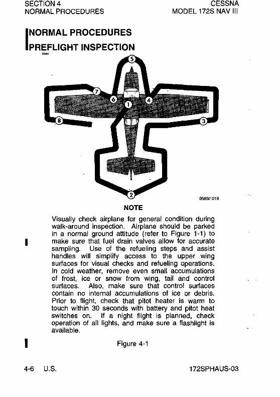
SECTION 4 CESSNA MODEL 172S NAV III NORMAL PROCEDURES
INORMALPROCEDURES
PREFLIGHT INSPECTION
I
I
NOTE
Visually check airplane for general condition during walk-around inspection. Airplane should be parked in a normal ground attitude (refer to Figure 1-1) to make sure that fuel drain valves allow for accurate sampling. Use of the refueling steps and assist handles will simplify access to the upper wing surfaces for visual checks and refueling operations. In cold weather, remove even small accumulations of frost, ice or snow from wing, tail and control surfaces. Also, make sure that control surfaces contain no internal accumulations of ice or debris. Prior to flight, check that pitot heater is warm to touch within 30 seconds with battery and pitot heat switches on. If a night flight is planned, check operation of all lights, and make sure a flashlight is available.
Figure 4-1
4-6 U.S. 172SPHAUS-03

CESSNA MODEL 172S NAV III
SECTION 4 NORMAL PROCEDURES
PREFLIGHT INSPECTION (Continued)
G)CABIN
1. Pitot Tube Cover - REMOVE (Check for pitot blockage) 2. Pilot's Operating Handbook - ACCESSIBLE TO PILOT 3. Garmin Gl000TM Cockpit Reference Guide - ACCESSIBLE
TO PILOT 4. Airplane Weight and Balance - CHECKED 5. Parking Brake - SET 6. Control Wheel Lock - REMOVE
WARNING
WHEN THE MASTER SWITCH IS ON, USING AN EXTERNAL POWER SOURCE, OR MANUALLY ROTATING THE PROPELLER, TREAT THE PROPELLER AS IF THE MAGNETOS SWITCH WERE ON. DO NOT STAND, NOR ALLOW ANYONE ELSE TO STAND, WITHIN THE ARC OF THE PROPELLER SINCE A LOOSE OR BROKEN WIRE, OR A COMPONENT MALFUNCTION, COULD CAUSE THE ENGINE TO START.
7. MAGNETOS Switch - OFF 8. AVIONICS Switch (BUS 1 and BUS 2) - OFF 9. MASTER Switch (ALT and BAT) - ON
10. Primary Flight Display (PFD) - CHECK (Verfiy PFD is ON) I 11. FUEL QTY (L and R) - CHECK 12. LOW FUEL L and LOW FUEL R Annunciators - CHECK
(Verify annunciators are not shown on PFD) I 13. OIL PRESSURE Annunciator - CHECK (Verify annunciator
is shown) 14. LOW VACUUM Annunciator - CHECK (Verify annunciator iSI
shown) 15. AVIONICS Switch (BUS 1) - ON 16. Forward Avionics Fan - CHECK (Verify fan is heard)
(Continued Next Page)
I 172SPHAUS-03 U.S. 4-7
SECTION 4 NORMAL PROCEDURES
CESSNA MODEL 172S NAV III
PREFLIGHT INSPECTION (Continued)
CD CABIN (Continued)
17. AVIONICS Switch (BUS 1) - OFF 18. AVIONICS Switch (BUS 2) - ON 19. Aft Avionics Fan - CHECK (Verify fan is heard) 20. AVIONICS Switch (BUS 2) - OFF 21. PITOT HEAT Switch - ON (Carefully check that pitot tube is
warm to the touch within 30 seconds) 22. PITOT HEAT Switch - OFF 23. lOW VOLTS Annunciator - CHECK (Verify annunciator is
shown) 24. MASTER Switch (AlT and BAT) - OFF 25. Elevator Trim Control - TAKEOFF position 26. FUEL SELECTOR Valve - BOTH
I 27. AlT STATIC AIR Valve - OFF (push full in) 28. Fire Extinguisher - CHECK (Verify gage pointer in green
arc).
@ EMPENNAGE
1. Baggage Door - CHECK (lock with key) 2. Autopilot Static Source (if installed) - CHECK (Verify opening
is clear) 3. Rudder Gust lock (if installed) - REMOVE 4. Tail Tiedown - DISCONNECT 5. Control Surfaces - CHECK freedom of movement and
security 6. Elevator Trim Tab - CHECK security 7. Antennas - CHECK for security of attachment and general
condition
® RIGHT WING Trailing Edge
1. Flap - CHECK for security and condition 2. Aileron - CHECK freedom of movement and security
(Continued Nex1 Page)
U.S. 172SPHAUS-04

CESSNA MODEL 172S NAV III
SECTION 4 NORMAL PROCEDURES
PREFLIGHT INSPECTION (Continued)
@ RIGHT WING
1. Wing Tiedown - DISCONNECT 2. Main Wheel Tire - CHECK for proper inflation and general
condition (weather checks, tread depth and wear, etc.). 3. Fuel Tank Sump Quick Drain Valves - DRAIN
Drain at least a cupful of fuel (using sampler cup) from each sump location to check for water, sediment, and proper fuel grade before each flight and after each refueling. If water is observed, take further samples until clear and then gently rock wings and lower tail to the ground to move any additional contaminants to the sampling points. Take repealed samples from all fuel drain points until all contamination has been removed. If contaminants are still present, refer to WARNING below and do not fly airplane.
NOTE
Collect all sampled fuel in a safe container. Dispose of the sampled fuel so that it does not cause a nuisance, hazard, or damage to the environment.
WARNING
IF, AFTER REPEATED SAMPLING, EVIDENCE OF CONTAMINATION STILL EXISTS, THE AIRPLANE SHOULD NOT BE FLOWN. TANKS SHOULD BE DRAINED AND SYSTEM PURGED BY QUALIFIED MAINTENANCE PERSONNEL. ALL EVIDENCE OF CONTAMINATION MUST BE REMOVED BEFORE FURTHER FLIGHT.
4. Fuel Quantity - CHECK VISUALLY for desired level 5. Fuel Filler Cap· SECURE and VENT CLEAR
(Continued Next Page)
172SPHAUS-OO U.S. 4·9

SECTION 4 CESSNA MODEL 172S NAV III NORMAL PROCEDURES
I
PREFLIGHT INSPECTION (Continued)
@NOSE
1. Fuel Strainer Quick Drain Valve (Located on bottom of fuselage) - DRAIN
Drain at least a cupful of fuel (using sampler cup) from valve to check for water, sediment, and proper fuel grade before each flight and after each refueling. If water is observed, take further samples until clear and then gently rock wings and lower tail to the ground to move any additional contaminants to the sampling points. Take repeated samples from all fuel drain pOints, including the fuel reservoir and fuel selector, until all contamination has been removed. If contaminants are still present, refer to WARNING below and do not fly the airplane.
NOTE
Collect all sampled fuel in a safe container. Dispose of the sampled fuel so that it does not cause a nuisance, hazard, or damage to the environment.
WARNING IF, AFTER REPEATED SAMPLING, EVIDENCE OF CONTAMINATION STILL EXISTS, THE AIRPLANE SHOULD NOT BE FLOWN. TANKS SHOULD BE DRAINED AND SYSTEM PURGED BY QUALIFIED MAINTENANCE PERSONNEL. ALL EVIDENCE OF CONTAMINATION MUST BE REMOVED BEFORE FURTHER FLIGHT.
2. Engine Oil Dipstick/Filler Cap - CHECK oil level, then check dipstick/filler cap SECURE. Do not operate with less than 5 quarts. Fill to 8 quarts for extended flight.
3. Engine Cooling Air Inlets - CLEAR of obstructions. 4. Propeller and Spinner - CHECK for nicks and security. 5. Air Filter - CHECK for restrictions by dust or other foreign
matter. 6. Nosewheel Strut and Tire - CHECK for proper inflation of
strut and general condition of tire. (weather checks, tread depth and wear, etc.)
7. Static Source Opening - CHECK (Verify opening is clear)
(Continued Next Page)
4-10 U.S. 172SPHAUS-03
CESSNA MODEL 172S NAV III
SECTION 4 NORMAL PROCEDURES
PREFLIGHT INSPECTION (Continued)
@ LEFT WING Leading Edge
1. Fuel Tank Vent Opening - CHECK for blockage I
2. Stall Warning Opening - CHECK for blockage. To check the system, place a clean handkerchief over the vent opening and apply suction; a sound from the warning horn will confirm system operation.
3. LandingfTaxi Light(s) - CHECK for condition and cleanliness. of cover.
(j) LEFT WING
1. Wing Tiedown - DISCONNECT 2. Fuel Quantity - CHECK VISUALLY for desired level 3. Fuel Filler Cap - SECURE and VENT CLEAR 4. Fuel Tank Sump Quick Drain Valves - DRAIN
Drain at least a cupful of fuel (using sampler cup) from each sump location to check for water, sediment, and proper fuel grade before each flight and aiter each refueling. If water is observed, take further samples until clear and then gently rock wings and lower tail to the ground to move any additional contaminants to the sampling points. Take repeated samples from all fuel drain points until all contamination has been removed. If contaminants are still present, refer to WARNING below and do not fly airplane.
NOTE
Collect all sampled fuel in a safe container. Dispose of the sampled fuel so that it does not cause a nuisance, hazard, or damage to the environment.
WARNING IF, AFTER REPEATED SAMPLING, EVIDENCE OF CONTAMINATION STILL EXISTS, THE AIRPLANE SHOULD NOT BE FLOWN. TANKS SHOULD BE DRAINED AND SYSTEM PURGED BY QUALIFIED MAINTENANCE PERSONNEL. ALL EVIDENCE OF CONTAMINATION MUST BE REMOVED BEFORE FURTHER FLIGHT.
5. Main Wheel Tire - CHECK for proper inflation and general condition (weather checks, tread depth and wear, etc.).
(Continued Next Page)
I 172SPHAUS-03 U.S. 4-11
I
I

SECTION 4 NORMAL PROCEDURES
CESSNA MODEL 172S NAV III
PREFLIGHT INSPECTION (Continued)
@ LEFT WING Trailing Edge
I 1. Aileron - CHECK freedom of movement and security 2. Flap - CHECK for security and condition
BEFORE STARTING ENGINE 1. Preflight Inspection - COMPLETE 2. Passenger Briefing - COMPLETE
I 3. Seats and Seat Belts - ADJUST and LOCK (Verify inertia reel locking)
4. Brakes - TEST and SET 5. Circuit Breakers - CHECK IN 6. Electrical Equipment - OFF 7. AVIONICS Switch (BUS 1 and BUS 2) - OFF
CAUTION
THE AVIONICS SWITCH (BUS 1 AND BUS 2) MUST BE OFF DURING ENGINE START TO PREVENT POSSIBLE DAMAGE TO AVIONICS.
8. FUEL SELECTOR Valve - BOTH 9. FUEL SHUTOFF Valve - ON (push full in)
STARTING ENGINE (With Battery) 1. Throttle Control - OPEN 1/4 INCH 2. Mixture Control - I DLE CUTOFF (pull full out) 3. STBY BAIT Switch:
a. TEST - (Hold for 20 seconds, verify that green TEST lamp does not go off)
b. ARM - (Verify that PFD comes on) 4. Engine Indicating System - CHECK PARAMETERS (Verify
no red X's through ENGINE page indicators) 5. BUS E Volts - CHECK (Verify 24 VOLTS minimum shown) 6. M BUS Volts - CHECK (Verify 1.5 VOLTS or less shown) 7. BAIT S Amps - CHECK (Verify discharge shown (negative)) 8. STBY BAIT Annunciator - CHECK (Verify annunciator is
shown) 9. Propeller Area - CLEAR (Verify that all people and
eqUipment are at a safe distance from the propeller)
(Continued Next Page)
U.S. 172SPHAUS-03

CESSNA MODEL 172S NAV III
SECTION 4 NORMAL PROCEDURES
STARTING ENGINE (With Battery) (Continued)
10. Master Switch (AL T and BAT) - ON 11. BEACON Light Switch - ON I
NOTE
If engine is warm, omit priming procedure steps 12 I thru 14 below.
12. FUEL PUMP Switch - ON 13. Mixture Control - SET to FULL RICH (full forward) until
stable fuel flow is indicated (approximately 3 to 5 seconds), then set to IDLE CUTOFF (full aft) position.
14. FUEL PUMP Switch - OFF 15. MAGNETOS Switch - START (release when engine starts) I 16. Mixture Control - ADVANCE smoothly to RICH when engine
starts.
NOTE
If the engine is primed too much (flooded), place the mixture control in the IDLE CUTOFF position, open the throttle control 1/2 to full, and engage the starter motor (START). When the engine starts, advance the mixture control to the FULL RICH position and retard the throttle control promptly.
I
17. Oil Pressure - CHECK (Verify that oil pressure increasesl into the GREEN ARC range in 30 to 60 seconds).
18. AMPS (M BATT and BATT S) - CHECK charge (positive) 19. LOW VOLTS Annunciator - CHECK (Verify annunciator i1
not shown) 20. NAV Lights Switch - ON as required 21. AVIONICS Switch (BUS 1 and BUS 2) - ON
I
I 172SPHAUS-03 U.S. 4-13

SECTION 4 CESSNA MODEL 172S NAV III NORMAL PROCEDURES
STARTING ENGINE (With External Power)
1. Throttle Control - OPEN 1/4 INCH 2. Mixture Control - IDLE CUTOFF (pull full out) 3. STBY BATT Switch:
a. TEST - (Hold for 20 seconds, verify green TEST lamp does not go off)
b. ARM - (Verify that PFD comes on) 4. Engine Indication System - CHECK PARAMETERS (Verify
no red X's through ENGINE page indicators) 5. BUS E Volts - CHECK (Verify 24 VOLTS minimum shown) 6. M BUS Volts - CHECK (Verify 1.5 VOLTS or less shown) 7. BATT S Amps - CHECK (Verify discharge shown (negative)) 8. STBY BATT Annunciator - CHECK (Verify annunciator is
shown) 9. AVIONICS Switch (BUS 1 and BUS 2) - OFF
10. MASTER Switch (ALTand BAT) - OFF I 11. Propeller Area - CLEAR (Verify that all people and
eqUipment are at a safe distance from the propeller)
112. External Power - CONNECT to ground power receptacle 13. MASTER Switch (ALT and BAT) - ON 14. BEACON Light Switch - ON 15. M BUS VOLTS - CHECK (Verify that approximately 28
VOLTS is shown)
I I 16.
17.
NOTE
If engine is warm, omit priming procedure steps 16 thru 18 below.
FUEL PUMP Switch - ON Mixture Control - SET to FULL RICH (full forward) until stable fuel flow is indicated (approximately 3 to 5 seconds), then set to I DLE CUTOFF (full aft) position.
I 18. FUEL PUMP Switch - OFF 19. MAGNETOS Switch - START (release when engine starts)
(Continued Next Page)
4-14 U.S. 172SPHAUS-03
CESSNA MODEL 172S NAV III
SECTION 4 NORMAL PROCEDURES
STARTING ENGINE (With External Power) (Continued)
20. Mixture Control - ADVANCE smoothly to RICH when engine. starts.
NOTE
If the engine is primed too much (flooded), place the I mixture control in the IDLE CUTOFF position, open the throttle control 1/2 to full, and engage the starter motor (START). When the engine starts, advance the mixture control to the FULL RICH position and retard the throttle control promptly.
21. Oil Pressure - CHECK (Verify oil pressure increases into the. green arc range in 30 to 60 seconds)
22. Power - REDUCE to idle I 23. External Power - DISCONNECT from ground power. (Latch
external power receptacle door) 24. Power - INCREASE (to approximately 1500 RPM for severall
minutes to charge battery) 25. AMPS (M BATT and BATT S) - CHECK charge (positive) I 26. LOW VOLTS Annunciator - CHECK (Verify annunciator is
not shown) 27. Internal Power - CHECK I
a. MASTER Switch (AL T) - OFF b. TAXI and LANDING Light Switches - ON c. Throttle Control - REDUCE to idle I d. MASTER Switch (ALT and BAT) - ON e. Throttle Control - INCREASE (to approximately 15001
RPM) f. Main Battery (M BATT) Ammeter -
charging, Amps positive) g. LOW VOLTAGE Annunciator
annunciator is not shown)
CHECK (Batteryl
CHECK (Verify
WARNING
IF M BATT (MAIN BATTERY) DOES NOT SHOW + AMPS, REMOVE THE MAIN BATTERY FROM THE AIRPLANE AND SERVICE OR REPLACE THE BATTERY BEFORE FLIGHT.
28. NAV Lights Switch - ON as required 29. AVIONICS Switch (BUS 1 and BUS 2) - ON
I 172SPHAUS-03 U.S. 4-15
I

SECTION 4 CESSNA MODEL 172S NAV III NORMAL PROCEDURES
I
BEFORE TAKEOFF
1. Parking Brake - SET 2. Pilot and Passenger Seat Backs - MOST UPRIGHT
POSITION 3. Seats and Seat Belts - CHECK SECURE 4. Cabin Doors - CLOSED and LOCKED 5. Flight Controls - FREE and CORRECT 6. Flight Instruments (PFD) - CHECK (no red X's) 7. Altimeters:
a. PFD(BARO)-SET b. Standby Altimeter - SET c. KAP 140 Autopilot (BARO) - SET (if installed)
8. G1000 ALT SEL - SET 9. KAP 140 Altitude Preselect - SET (if installed)
NOTE
There is no connection between the G1000 ALT SEL feature and the KAP 140 autopilot altitude preselect or altitude hold functions. G 1 000 and KAP 140 altitudes are set independently.
10. Stand by Flight Instruments - CHECK I 11. Fuel Quantity - CHECK (Verify level is correct)
NOTE
Flight is not recommended when both fuel quantity indicators are in the yellow arc range.
12. Mixture Control - RICH 13. FUEL SELECTOR Valve - SET BOTH
114. Elevator Trim Control - SET FOR TAKEOFF 15. Manual Electric Trim (MET) System (if installed) - CHECK
(Refer to the POH/AFM, Supplement 3, for Manual Electric Trim check procedures)
(Continued Next Page)
U.S. 172SPHAUS-03

CESSNA MODEL 172S NAV III
SECTION 4 NORMAL PROCEDURES
BEFORE TAKEOFF (Continued)
I 16. Throttle Control - 1800 RPM a. MAGNETOS Switch - CHECK (RPM drop should not
exceed 150 RPM on either magneto or 50 RPM differential between magnetos)
b. VAC Indicator - CHECK c. Engine Indicators - CHECK d. Ammeters and Voltmeters - CHECK
17. Annunciators - CHECK (Verify no annunciators are shown) 18. Throttle Control - CHECK IDLE 19. Throttle Control - 1000 RPM or LESS 20. Throttle Control Friction Lock - ADJUST 21. COM Frequency(s) - SET 22. NAV Frequency(s) - SET 23. FMS/GPS Flight Plan - AS DESIRED
NOTE
Check GPS availability on AUX-GPS STATUS page. No annunciation is provided for loss of GPS2.
I 24. XPDR - SET 25. CDI Softkey - SELECT NAV source
CAUTION
THE G1000 HSI SHOWS A COURSE DEVIATION INDICATOR FOR THE SELECTED GPS, NAV 1 OR NAV 2 NAVIGATION SOURCE. THE G1000 HSI DOES NOT PROVIDE A WARNING "FLAG" WHEN A VALID NAVIGATION SIGNAL IS NOT BEING SUPPLIED TO THE INDICATOR. WHEN A VALID NAVIGATION SIGNAL IS NOT BEING SUPPLIED, THE COURSE DEVIATION BAR (D-BAR) PART OF THE INDICATOR IS NOT SHOWN ON THE HSI COMPASS CARD. THE MISSING D-BAR IS CONSIDERED TO BE THE WARNING FLAG.
(Continued Next Page)
I 172SPHAUS-03 U.S. 4-17
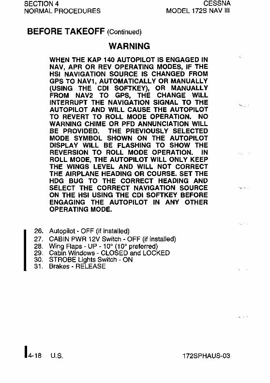
SECTION 4 NORMAL PROCEDURES
BEFORE TAKEOFF (Continued)
WARNING
CESSNA MODEL 172S NAV III
WHEN THE KAP 140 AUTOPILOT IS ENGAGED IN NAV, APR OR REV OPERATING MODES, IF THE HSI NAVIGATION SOURCE IS CHANGED FROM GPS TO NAV1, AUTOMATICALLY OR MANUALLY (USING THE COl SOFT KEY), OR MANUALLY FROM NAV2 TO GPS, THE CHANGE WILL INTERRUPT THE NAVIGATION SIGNAL TO THE AUTOPILOT AND WILL CAUSE THE AUTOPILOT TO REVERT TO ROLL MODE OPERATION. NO WARNING CHIME OR PFD ANNUNCIATION WILL BE PROVIDED. THE PREVIOUSLY SELECTED MODE SYMBOL SHOWN ON THE AUTOPILOT DISPLAY WILL BE FLASHING TO SHOW THE REVERSION TO ROLL MODE OPERATION. IN ROLL MODE, THE AUTOPILOT WILL ONLY KEEP THE WINGS LEVEL AND WILL NOT CORRECT THE AIRPLANE HEADING OR COURSE. SET THE HOG BUG TO THE CORRECT HEADING AND SELECT THE CORRECT NAVIGATION SOURCE ON THE HSI USING THE COl SOFTKEY BEFORE ENGAGING THE AUTOPILOT IN ANY OTHER OPERATING MODE.
26. Autopilot - OFF (if installed) 27. CABIN PWR 12V Switch - OFF (if installed) 28. Wing Flaps - UP - 10° (10° preferred) 29. Cabin Windows - CLOSED and LOCKED 30. STROBE Lights Switch - ON 31. Brakes - RELEASE
U.S. 172SPHAUS-03

CESSNA MODEL 172S NAV III
SECTION 4 NORMAL PROCEDURES
TAKEOFF
NORMAL TAKEOFF
1. Wing Flaps - UP - 10° (10° preferred) 2. Throttle Control - FULL (push full in) I 3. Mixture Control - RICH
(Above 3000 feet pressure altitude, lean for maximum RPM) 4. Elevator Control- LIFT NOSEWHEEL AT 55 KIAS 5. Climb Speed - 70 - 80 KIAS 6. Wing Flaps - RETRACT at safe altitude
SHORT FIELD TAKEOFF
1. Wing Flaps - 10° 2. Brakes - APPLY 3. Throttle Control - FULL (push full in) I 4. Mixture Control - RICH
(Above 3000 feet pressure altitude, lean for maximum RPM) 5. Brakes - RELEASE 6. Elevator Control - SLIGHTLY TAIL LOW 7. Climb Speed - 56 KIAS (Until all obstacles are cleared) 8. Wing Flaps - RETRACT SLOWLY (When airspeed is mor,
than 60 KIAS)
ENROUTE CLIMB 1. Airspeed - 70 - 85 KIAS 2. Throttle Control - FULL (push full in) I 3. Mixture Control - RICH
(Above 3000 feet pressure altitude, lean for maximum RPM)
I 172SPHAUS-03 U.S. 4-19

SECTION 4 CESSNA MODEL 172S NAV III NORMAL PROCEDURES
I
I I
CRUISE
1. Power - 2100 - 2700 RPM (No more than 75% power is recommended)
NOTE
If a maximum performance climb is necessary. use speeds shown in the Rate-of-Climb chart in section 5.
2. Elevator Trim Control - ADJUST 3. Mixture Control - LEAN for desired performance or economy 4. FMS/GPS - REVIEW and BRIEF OBS/SUSP softkey
operation for holding pattern procedure (IFR)
DESCENT
1. Power - AS DESIRED 2. Mixture - ADJUST if necessary to make the engine run
smoothly. 3. Altimeters:
a. PFD(BARO)-SET b. Standby Altimeter - SET c. KAP 140 Autopilot (BARO) - SET (if installed)
4. G1000 ALT SEL - SET 5. KAP 140 Altitude Preselect - SET (if installed)
NOTE
There is no connection between the G1000 ALT SEL feature and the KAP 140 autopilot altitude preselect or altitude hold functions. G 1 000 and KAP 140 altitudes are set independently.
6. CDI Softkey - SELECT NAV source 7. FMS/GPS - REVIEW and BRIEF OBS/SUSP softkey
operation for holding pattern procedure (IFR).
(Continued Next Page)
14-20 U.S. 172SPHAUS-03

CESSNA MODEL 172S NAV III
DESCENT (Continued)
CAUTION
SECTION 4 NORMAL PROCEDURES
THE Gl000 HSI SHOWS A COURSE DEVIATION INDICATOR FOR THE SELECTED GPS, NAV 1 OR NAV 2 NAVIGATION SOURCE. THE Gl000 HSI DOES NOT PROVIDE A WARNING "FLAG" WHEN A VALID NAVIGATION SIGNAL IS NOT BEING SUPPLIED TO THE INDICATOR. WHEN A VALID NAVIGATION SIGNAL IS NOT BEING SUPPLIED, THE COURSE DEVIATION BAR (D-BAR) PART OF THE INDICATOR IS NOT SHOWN ON THE HSI COMPASS CARD. THE MISSING D-BAR IS CONSIDERED TO BE THE WARNING FLAG.
WARNING
WHEN THE KAP 140 AUTOPILOT IS ENGAGED IN NAV, APR OR REV OPERATING MODES, IF THE HSI NAVIGATION SOURCE IS CHANGED FROM GPS TO NAV1, AUTOMATICALLY OR MANUALLY (USING THE COl SOFTKEY), OR MANUALLY FROM NAV2 TO GPS, THE CHANGE WILL INTERRUPT THE NAVIGATION SIGNAL TO THE AUTOPILOT AND WILL CAUSE THE AUTOPILOT TO REVERT TO ROLL MODE OPERATION. NO WARNING CHIME OR PFD ANNUNCIATION WILL BE PROVIDED. THE PREVIOUSLY SELECTED MODE SYMBOL SHOWN ON THE AUTOPILOT DISPLAY WILL BE FLASHING TO SHOW THE REVERSION TO ROLL MODE OPERATION. IN ROLL MODE, THE AUTOPILOT WILL ONLY KEEP THE WINGS LEVEL AND WILL NOT CORRECT THE AIRPLANE HEADING OR COURSE. SET THE HOG BUG TO THE CORRECT HEADING AND SELECT THE CORRECT NAVIGATION SOURCE ON THE HSI USING THE COl SOFTKEY BEFORE ENGAGING THE AUTOPILOT IN ANY OTHER OPERATING MODE.
(Continued Next Page)
I 172SPHAUS-03 U.S. 4-21
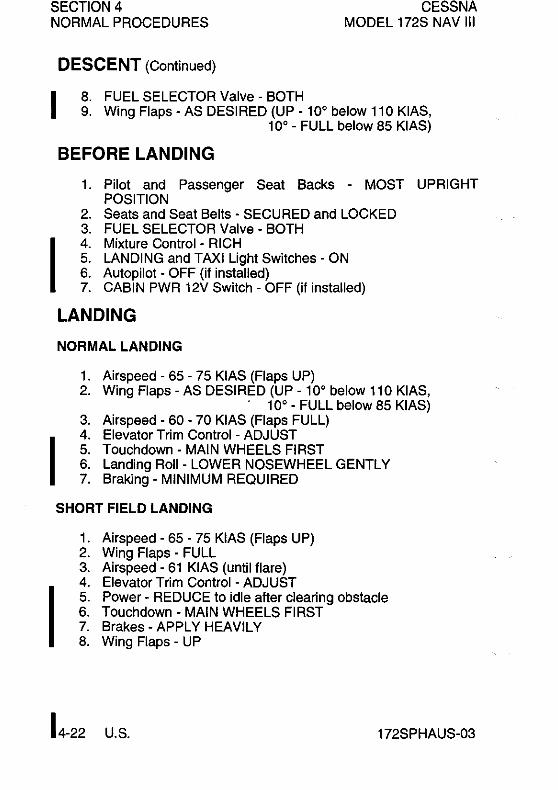
SECTION 4 CESSNA MODEL 172S NAV III NORMAL PROCEDURES
I
I
I
DESCENT (Continued)
8. FUEL SELECTOR Valve - BOTH 9. Wing Flaps - AS DESIRED (UP - 100 below 110 KIAS,
100 - FULL below 85 KIAS)
BEFORE LANDING
1. Pilot and Passenger Seat Backs - MOST UPRIGHT POSITION
2. Seats and Seat Belts - SECURED and LOCKED 3. FUEL SELECTOR Valve - BOTH 4. Mixture Control - RICH 5. LANDING and TAXI Light Switches - ON 6. Autopilot - OFF (if installed) 7. CABIN PWR 12V Switch - OFF (if installed)
LANDING
NORMAL LANDING
1. Airspeed - 65 - 75 KIAS (Flaps UP) 2. Wing Flaps - AS DESIRED (UP - 100 below 110 KIAS,
. 100 - FULL below 85 KIAS) 3. Airspeed - 60 - 70 KIAS (Flaps FULL) 4. Elevator Trim Control - ADJUST 5. Touchdown - MAIN WHEELS FIRST 6. Landing Roll - LOWER NOSEWHEEL GENTLY 7. Braking - MINIMUM REQUIRED
SHORT FIELD LANDING
1. Airspeed - 65 - 75 KIAS (Flaps UP) 2. Wing Flaps - FULL 3. Airspeed - 61 KIAS (until flare)
I 4. Elevator Trim Control - ADJUST 5. Power - REDUCE to idle after clearing obstacle 6. Touchdown - MAIN WHEELS FIRST 7. Brakes - APPLY HEAVILY 8. Wing Flaps - UP
U.S. 172SPHAUS-03

CESSNA MODEL 172S NAV III
BALKED LANDING
SECTION 4 NORMAL PROCEDURES
1. Throttle Control - FULL (push full in) I 2. Wing Flaps - RETRACT to 20° 3. Climb Speed - 60 KIAS 4. Wing Flaps - 10° (until obstacles are cleared), then UP (after
reaching a safe altitude and 65 KIAS)
AFTER LANDING
1. Wing Flaps - UP
SECURING AIRPLANE
1. Parking Brake - SET 2. Throttle Control - IDLE (pull full out) I 3. Electrical Equipment - OFF 4. AVIONICS Switch (BUS 1 and BUS 2) - OFF 5. Mixture Control - I DLE CUTOFF (pull full out) I 6. MAGNETOS Switch - OFF 7. MASTER Switch (AL T and BAT) - OFF 8. STBY BATT Switch - OFF 9. Control Lock - INSTALL
10. FUEL SELECTOR Valve - LEFT or RIGHT (to prevent crossfeeding between tanks)
I 172SPHAUS-03 U.S. 4-23

SECTION 4 NORMAL PROCEDURES
AMPLIFIED PROCEDURES PREFLIGHT INSPECTION
CESSNA MODEL 172S NAV III
The Preflight Inspection, described in Figure 4-1 and adjacent checklist, is required prior to each flight. If the airplane has been in extended storage, has had recent major maintenance, or has been operated from rough runways, a more extensive exterior inspection is recommended.
Before every flight, check the condition of main and nose landing gear tires. Keep tires inflated to the pressure specified in Section 8, Airplane Handling, Service And Maintenance. Examine tire sidewalls for patterns of shallow cracks called weather checks. These cracks are evidence of tire deterioration caused by age, improper storage, or prolonged exposure to weather. Check the tread of the tire for depth, wear, and cuts. Replace the tire if fibers are visible.
After major maintenance has been performed, the flight and trim tab controls should be double checked for free and correct movement and security. The security of all inspection plates on the airplane should be checked following periodiC inspections. If the airplane has been waxed or polished, check the external static pressure source hole for stoppage.
If the airplane has been kept in a crowded hangar, it should be checked for dents and scratches on wings, fuselage, and tail
Isurfaces, damage to navigation, strobe lights, and avionics antennas. Check for damage to the nosewheel steering system, the result of exceeding nosewheel turning limits while towing.
Outside storage for long periods may result in dust and dirt accumulation on the induction air filter, obstructions in airspeed system lines, water contaminants in fuel tanks and insecVbird/rodent nests in any opening. If any water is detected in the fuel system, the fuel tank sump quick drain valves, fuel reservoir quick drain valve, and fuel strainer quick drain valve should all be thoroughly drained again. The wings should then be gently rocked and the tail lowered to the ground to move any further contaminants to the sampling points. Repeated samples should then be taken at all quick drain points until all contamination has been removed. If, after repeated sampling, evidence of contamination still exists, the fuel tanks should be completely drained and the fuel system cleaned.
(Continued Next Page)
L-24 U.S. 172SPHAUS-03
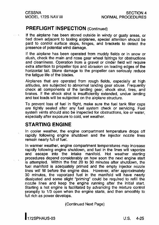
CESSNA MODEL 172S NAV III
SECTION 4 NORMAL PROCEDURES
PREFLIGHT INSPECTION (Continued)
If the airplane has been stored outside in windy or gusty areas, or tied down adjacent to taxiing airplanes, special attention should be paid to control surface stops, hinges, and brackets to detect the presence of potential wind damage.
If the airplane has been operated from muddy fields or in snow or slush, check the main and nose gear wheel fairings for obstructions and cleanliness. Operation from a gravel or cinder field will require extra attention to propeller tips and abrasion on leading edges of the horizontal tail. Stone damage to the propeller can seriously reduce the fatigue life of the blades.
Airplanes that are operated from rough fields, especially at high altitudes, are subjected to abnormal landing gear abuse. Frequently check all components of the landing gear, shock strut, tires, and brakes. If the shock strut is insufficiently extended, undue landing and taxi loads will be subjected on the airplane structure.
To prevent loss of fuel in flight, make sure the fuel tank filler caps are tightly sealed after any fuel system check or servicing. Fuel system vents should also be inspected for obstructions, ice or water, especially after exposure to cold, wet weather.
STARTING ENGINE In cooler weather, the engine compartment temperature drops off rapidly following engine shutdown and the injector nozzle lines remain nearly full of fuel.
In warmer weather, engine compartment temperatures may increase rapidly following engine shutdown, and fuel in the lines will vaporize and escape into the intake manifold. Hot weather starting procedures depend considerably on how soon the next engine start is attempted. Within the first 20 to 30 minutes after shutdown, the fuel manifold is adequately primed and the empty injector nozzle lines will fill before the engine dies. However, after approximately 30 minutes, the vaporized fuel in the manifold will have nearly dissipated and some slight "priming" could be required to refill the nozzle lines and keep the engine running after the initial start. Starting a hot engine is facilitated by advancing the mixture control promptly to 1/3 open when the engine starts, and then smoothly to full rich as power develops.
(Continued Next Page)
I 172SPHAUS-03 U.S. 4-25

SECTION 4 NORMAL PROCEDURES
STARTING ENGINE (Continued)
CESSNA MODEL 172S NAV III
If the engine does not continue to run, set the FUEL PUMP switch to the ON position temporarily and adjust the throttle and/or mixture as necessary to keep the engine running. In the event of over priming or flooding, set the FUEL PUMP switch to OFF, open the throttle from 1/2 to full open, and continue cranking with the mixture in the idle CUTOFF position (pull full out). When the engine fires, smoothly advance the mixture control to full rich and retard the throttle to desired idle speed.
If the engine is under primed (most likely in cold weather with a cold engine) it will not start at all, and additional priming will be necessary.
After starting, if the oil pressure gage does not begin to show pressure within 30 seconds in warmer temperatures and approximately one minute in very cold weather, stop the engine and find cause before continued operation. Lack of oil pressure can cause serious engine damage.
NOTE
Additional details concerning cold weather starting and operation may be found under COLD WEATHER OPERATION paragraphs in this section.
RECOMMENDED STARTER DUTY CYCLE
Operate the starter motor for 10 seconds followed by a 20 second cool down period. This cycle can be repeated two additional times, followed by a ten minute cool down period before resuming cranking. After cool down, operate the starter motor again, three cycles of 10 seconds followed by 20 seconds of cool down. If the engine still does not start, try to find the cause.
(Continud Next Page)
U.S. 172SPHAUS-03
,.-, /
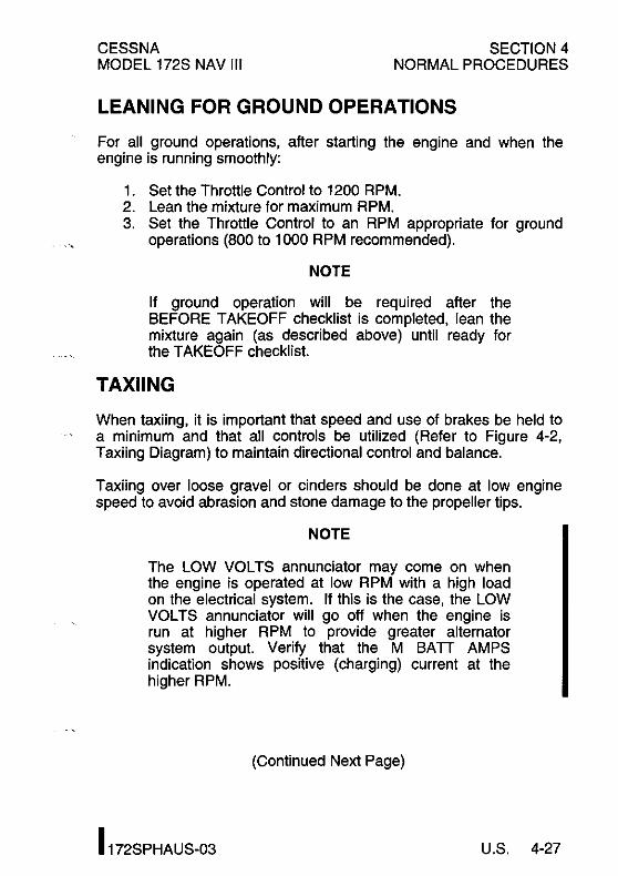
CESSNA MODEL 172S NAV III
SECTION 4 NORMAL PROCEDURES
LEANING FOR GROUND OPERATIONS
For all ground operations, after starting the engine and when the engine is running smoothly:
1. Set the Throttle Control to 1200 RPM. 2. Lean the mixture for maximum RPM. 3. Set the Throttle Control to an RPM appropriate for ground
operations (800 to 1000 RPM recommended).
NOTE
If ground operation will be required after the BEFORE TAKEOFF checklist is completed, lean the mixture again (as described above) until ready for the TAKEOFF checklist.
TAXIING
When taxiing, it is important that speed and use of brakes be held to a minimum and that all controls be utilized (Refer to Figure 4-2, Taxiing Diagram) to maintain directional control and balance.
Taxiing over loose gravel or cinders should be done at low engine speed to avoid abrasion and stone damage to the propeller tips.
NOTE
The LOW VOLTS annunciator may come on when the engine is operated at low RPM with a high load on the electrical system. If this is the case, the LOW VOLTS annunciator will go off when the engine is run at higher RPM to provide greater alternator system output. Verify that the M BATT AMPS indication shows positive (charging) current at the higher RPM.
(Continued Next Page)
I 172SPHAUS-03 U.S. 4-27

SECTION 4 NORMAL PROCEDURES
TAXIING (Continued)
CESSNA MODEL 172S NAV III
TAXIING DIAGRAM
CODE
WIND DIRECTION.
NOTE
Strong quartering tail winds require caution. Avoid sudden bursts of the throttle and sharp braking when the airplane is in this attitude. Use the steerable nosewheel and rudder to maintain direction. '" •
Figure 4-2
U.S. 172SPHAUS-03

CESSNA MODEL 172S NAV III
BEFORE TAKEOFF
WARM UP
SECTION 4 NORMAL PROCEDURES
If the engine idles (approximately 600 RPM) and accelerates smoothly, the airplane is ready for takeoff. Since the engine is closely cowled for efficient in-flight engine cooling, be careful to avoid overheating during prolonged engine operation on the ground. Long periods of idling can cause fouled spark plugs.
MAGNETO CHECK
The magneto check must be done at 1800 RPM. Turn the MAGNETOS switch from the BOTH position to the R position. Note the new RPM, then turn the MAGNETOS switch back to the BOTH position to clear the spark plugs. Turn the MAGNETOS switch to the L position, note the new RPM, then turn the switch back to the BOTH position. RPM decrease should not be more than 150 RPM on either magneto or be greater than 50 RPM difference between magnetos. If there is a doubt concerning operation of the ignition system, RPM checks at higher engine speeds will usually confirm whether a deficiency exists.
No RPM drop may indicate a faulty ground to one magneto or magneto timing set in advance of the angle specified.
ALTERNATOR CHECK
Make sure that both the alternator and alternator control unit are operating properly before night or instrument flight, or flights where electrical power is essential. Check the electrical system during the MAGNETO check (1800 RPM) by setting all electrical equipment required for the flight to the ON position. When the alternator and alternator control unit are both operating properly, the ammeters will show zero or positive current (amps), the voltmeters should show! between 27 to 29 volts, and no electrical system annunciations wilt appear. Reduce the electrical load before reducing engine speed so the battery will not discharge while the engine is at idle.
(Continued Next Page)
I 172SPHAUS-03 U.S. 4-29

SECTION 4 NORMAL PROCEDURES
BEFORE TAKEOFF (Continued)
ELEVATOR TRIM
CESSNA MODEL 172S NAV III
The elevator trim tab is in the takeoff position when the trim pointer ' is aligned with the index mark on the pedestal cover. Adjust the trim wheel during flight as necessary to make control wheel forces more neutral.
LANDING LIGHTS
It is recommended that only the taxi light be used to enhance the visibility of the airplane in the traffic pattern or enroute. This will extend the service life of the landing light.
TAKEOFF
POWER CHECK
It is important to check full throttle engine operation early in the takeoff roll. Any sign of rough engine operation or sluggish engine acceleration is good cause for discontinuing the takeoff. The engine should run smoothly and turn approximately 2300 - 2400 RPM with mixture leaned to provide maximum RPM.
Full throttle run ups over loose gravel are especially harmful to propeller tips. When takeoffs must be made over a gravel surface, advance the throttle slowly. This allows the airplane to start rolling before high RPM is developed, and the gravel will be blown behind the propeller rather than pulled into it.
I Prior to takeoff from fields above 3000 feet pressure elevation, the mixture should be leaned to give maximum RPM at full throttle with the airplane not moving.
After full throttle is applied, adjust the throttle friction lock clockwise to prevent the throttle from moving back from the maximum power position. Similar friction lock adjustments should be made as required in other flight conditions to hold the throttle setting.
(Continued Next Page)
U.S. 172SPHAUS-03

CESSNA MODEL 172S NAV III
TAKEOFF (Continued)
WING FLAP SETTINGS
SECTION 4 NORMAL PROCEDURES
Normal takeoffs use wing flaps UP - 10°. Using 10° wing flaps reduces the ground roll and total distance over an obstacle by approximately 10 percent. Flap deflections greater than 10° are not approved for takeoff. If 10° wing flaps are used for takeoff, the flaps should stay at 10° until all obstacles are cleared and a safe flap retraction speed of 60 KIAS is reached. For a short field, 10° wing flaps and an obstacle clearance speed of 56 KIAS should be used.
Soft or rough field takeoffs are performed with 10° flaps by lifting the airplane off the ground as soon as practical in a slightly tail low attitude. "no obstacles are ahead, the airplane should be leveled off immediately to accelerate to a higher climb speed. When departing a soft field with an aft C.G. loading, the elevator trim control should be adjusted towards the nose down direction to give comfortable control wheel forces during the initial climb.
CROSSWIND TAKEOFF
Takeoffs into strong crosswind conditions normally are performed with the minimum flap setting necessary for the field length to minimize the drift angle immediately after takeoff. With the ailerons partially deflected into the wind, the airplane is accelerated to a speed slightly higher than normal, then the elevator control is used to quickly, but carefully, lift the airplane off the ground and to prevent possible settling back to the runway while drifting. When clear of the ground, make a coordinated turn into the wind to correct for drift.
I 172SPHAUS-03 U.S. 4-31

SECTION 4 NORMAL PROCEDURES
ENROUTE CLIMB
CESSNA MODEL 172S NAV III
Normal enroute climbs are performed with flaps up, at 75 - 85 KIAS and full throttle for the best combination of performance, visibility and engine cooling. The mixture should be full rich during climb at altitudes up to 3000 feet pressure altitude. Above 3000 feet pressure altitude, the mixture can be leaned as needed for increased power or to provide smoother engine operation.
If it is necessary to climb more rapidly to clear mountains or reach avorable winds at higher altitudes, the best rate of climb speed should be used with maximum power. This speed is 74 KIAS at sea level, decreasing to 72 KIAS at 10,000 feet.
If an obstruction dictates the use of a steep climb angle, the best angle-of-climb speed should be used with flaps up and maximum power. This speed is 62 KIAS at sea level, increasing to 67 KIAS at 10,000 feet. This type of climb should be of the minimum duration and engine temperatures should be carefully monitored due to the low climb speed.
CRUISE Normal cruise is performed between 45% and 75% power. The engine RPM and corresponding fuel consumption for various altitudes can be determined by using the data in Section 5.
NOTE
Cruise flight should use 75% power as much as possible until the engine has operated for a total of 50 hours or oil consumption has stabilized. Operation at this higher power will ensure proper seating of the rings and is applicable to new engines, and engines in service following cylinder replacement or top overhaul of one or more cylinders.
The Cruise Performance charts in Section 5 provide the pilot with flight planning information for the Model 172S in still air. Power, altitude, and winds determine the time and fuel needed to complete any flight.
(Continued Next Page)
U.S. 172SPHAUS-03

CESSNA MODEL 172S NAV III
CRUISE (Continued)
SECTION 4 NORMAL PROCEDURES
The Cruise Performance Table, Figure 4-3, shows the true airspeed and nautical miles per gallon during cruise for various altitudes and percent powers, and is based on standard conditions and zero wind. This table should be used as a guide, along with the available winds aloft information, to determine the most favorable altitude and power setting for a given trip. The selection of cruise altitude on the basis of the most favorable wind conditions and the use of low power settings are significant factors that should be considered on every trip to reduce fuel consumption.
In addition to power settings, proper leaning techniques also contribute to greater range and are figured into cruise performance tables. To achieve the recommended lean mixture fuel consumption figures shown in Section 5, the mixture should be leaned using the exhaust gas temperature (EGT) indicator as noted.
CRUISE PERFORMANCE TABLE
CONDITIONS: Standard Conditions Zero Wind
75% POWER 65% POWER 55% POWER ALTITUDE KTAS NMPG KTAS NMPG KTAS NMPG
Sea Level 114 11.2 lOB 12.0 101 12.B
4000 feet 119 11.7 112 12.4 lD4 13.2
BOOO feet 124 12.2 117 12.9 107 13.6
Figure 4-3 I
(Continued Next Page)
I 172SPHAUS-03 U.S. 4-33

8ECTION4 NORMALPROCEDURE8
CRUISE (Continued)
CE88NA MODEL 1728 NAV III
LEANING USING EXHAUST GAS TEMPERATURE (EGT)
The cruise performance data in this handbook is based on the recommended lean mixture setting determined from the maximum
lor Peak Exhaust Gas Temperature (EGT) at power settings of 75% Maximum Continuous Power (MCP) and less. The 1728 Nav III provides EGT indications for all (4) engine cylinders. The ability to monitor all cylinders is an aid in early identification and correction of fuel injection system problems.
NOTE
All engine cylinders do not receive identical fuel/air mixtures (due to unequal intake pipe lengths, uneven intake air temperatures, fuel injection nozzle tolerances etc.). However, all cylinder EGTs should be within approximately 100°F of each other during normal operations. An EGT difference greater than 100°F between cylinders indicates that fuel injection system maintenance is necessary.
EGT is displayed on the EIS ENGINE and LEAN pages. The ENGINE page has a horizontal scale with a temperature indicator (inverted triangle) with a number representing the cylinder with the highest EGT.
The EIS LEAN page provides vertical bar graph displays showing EGT for all cylinders. The cylinder with the highest EGT is shown in cyan (light blue). The numerical value for the highest EGT is located below the bar. The EGT and Cylinder Head Temperature (CHT) value for any cylinder may be shown by using the CYL 8LCT softkey to select the desired cylinder. After a short period without CYL SLCT softkey activity, automatic indication of the highest EGT and CHT will start again.
(Continued Next Page)
U.S. 1728PHAU8-03

CESSNA MODEL 172S NAV III
CRUISE (Continued)
SECTION 4 NORMAL PROCEDURES
LEANING USING EXHAUST GAS TEMPERATURE (EGT) (Continued)
To aid in leaning the mixture, push the ENGINE, LEAN and ASSIST softkeys, ~PEAK of will display below the EGT of numerical value. Lean the mixture by slowly turning the Mixture Control knob in the counterclockwise direction while monitoring EGTs. As EGTs increase, continue to lean the mixture until the hottest (cyan) cylinder reaches Peak EGT. This is identified by the EGT bar graph for that cylinder changing to cyan with a hollow bar at the top. Note the ~PEAK OF and FFLOW GPH values for the first peaked cylinder. Peak EGT is represented by ~PEAK O°F, if ~PEAK OF value is negative (-) the mixture can be on the lean side of peak. Enrichen the mixture by slowly turning the mixture control clockwise and monitor both fuel flow and EGTs until the leanest cylinder returns to peak EGT (~PEAK 0° F) or desired setting based on the EGT Table, Figure 4-4.
~PEAK of values rich of peak will also be a negative (-) value (-50°). The lean assist system calculation is defined such that the peak EGT is the highest value and any lesser value is represented with a negative (-) value, whether on the lean or rich side of the peak.
NOTE
The 172S engine manufacturer, Textron Lycoming, has not approved operation of the engine at fuel flow rates (mixture settings) less than necessary to reach Peak EGT in the leanest cylinder (the first cylinder to reach peak EGT). Use FULL RICH mixture when operating the engine above 75% power.
(Continued Next Page)
I 172SPHAUS-03 U.S. 4-35

SECTION 4 NORMAL PROCEDURES
CRUISE (Continued)
CESSNA MODEL 172S NAV III
LEANING USING EXHAUST GAS TEMPERATURE (EGT) (Continued)
EGTTABLE
MIXTURE DESCRIPTION EXHAUST GAS TEMPERATURE
RECOMMENDED LEAN 50° Rich of Peak EGT (Pilot's Operating Handbook)
BEST ECONOMY Peak EGT
Figure 4-4
IOperation at peak EGT provides the best fuel economy. This results in approximately 4% greater range than shown in this handbook accompanied by approximately a 3 knot decrease in speed.
Under some conditions, engine roughness may occur while operating at peak EGT. In this case, operate at the Recommended Lean mixture.
NOTE
• Any change in altitude or power setting will require a change in the recommended lean mixture setting and a recheck of the EGT setting .
• The EGT indicators take several seconds, after a mixture adjustment, to start to show exhaust gas temperature changes. Finding peak EGT and adjusting the mixture to the applicable setting should take approximately one minute when the adjustments are made carefully and accurately. Adjusting the mixture quickly is not recommended.
(Continued Next Page)
U.S. 172SPHAUS,03

CESSNA MODEL 172S NAV III
SECTION 4 NORMAL PROCEDURES
CRUISE (Continued)
FUEL SAVINGS PROCEDURES FOR FLIGHT TRAINING OPERATIONS
For best fuel economy during flight training operations, the following procedures are recommended.
I
1. After engine start and for all ground operations, set the throttle to 1200 RPM and lean the mixture for maximum RPM. After leaning, set the throttle to the appropriate RPMI for ground operations. Leave the mixture at this setting until beginning the BEFORE TAKEOFF checklist. After the BEFORE TAKEOFF checklist is complete re-lean the mixture as described above until ready for the TAKEOFF checklist.
2. Lean the mixture for maximum RPM during full throttle climbs above 3000 feet. The mixture may remain leaned (maximum RPM at full throttle) for practicing maneuvers such as stalls and slow flight.
3. Lean the mixture for maximum RPM during all operations at any altitude, including those below 3000 feet, when using 75% or less power.
NOTE
• When cruising or maneuvering at 75% or less power, the mixture may be further leaned until the EGT indicator peaks and is then enrichened 50°F. I This is especially applicable to cross-country training flights, but should be practiced during transition flight to and from the practice area as well.
• Using the above recommended procedures can provide fuel savings in excess of 5% when compared to typical training operations at full rich mixture. In addition, the above procedures will minimize spark plug fouling since the reduction in fuel consumption results in a proportional reduction in tetraethyllead passing through the engine.
(Continued Next Page)
I 172SPHAUS-03 U.S. 4-37

SECTION 4 CESSNA MODEL 172S NAV III NORMAL PROCEDURES
ICRUISE (Continued)
FUEL VAPOR PROCEDURES
The engine fuel system can cause fuel vapor formation on the ground during warm weather. This will generally occur when the outside ambient air temperature is above 80°F. Vapor formation may increase when the engine fuel flows are lower at idle and taxi engine speeds. The following procedures are recommended when
lengine idle speed and fuel flow fluctuations show that fuel vapor may be present:
I I
1. With the mixture full rich, set the throttle at 1800 RPM to 2000 RPM. Maintain this power setting for 1 to 2 minutes or until smooth engine operation returns.
2. Retard the throttle to idle to verify normal engine operation.
3. Advance the throttle to 1200 RPM and lean the mixture as described under FUEL SAVINGS PROCEDURES FOR FLIGHT TRAINING OPERATIONS.
4. In addition to the above procedures, the Auxiliary Fuel Pump may be turned ON with the mixture adjusted as required to aid vapor suppression during ground operations. The Auxiliary Fuel Pump should be turned OFF prior to takeoff.
5. Just prior to TAKEOFF, apply full throttle, for approximately 10 seconds to verify smooth engine operation for takeoff.
NOTE
When the engine is operated above 1800 RPM, the resulting increased fuel flow also makes for lower fuel temperatures throughout the engine fuel system. This increased flow purges the fuel vapor and the cooler fuel minimizes vapor formation.
(Continued Next Page)
14-38 U.S. 172SPHAUS-03

CESSNA MODEL 172S NAV III
CRUISE (Continued)
FUEL VAPOR PROCEDURES (Continued)
SECTION 4 NORMAL PROCEDURES
In addition to the above procedures, the sections below should be reviewed, and where applicable, adhered to:
Section 3 - Take note of the excessive fuel vapor procedures inl both the checklist and the amplified procedures sections.
Section 4 - Take note of the hot weather operational notes and procedures in both the checklist and the amplified procedures sections.
Section 7 Take note of the altitude operational procedures and the section on auxiliary fuel pump operation.
STALLS
The stall characteristics are conventional. An aural warning is provided by a stall warning horn which sounds between 5 and 10 knots above the stall in all configurations.
Power off stall speeds at maximum weight for both forward and aft C.G. positions are presented in Section 5.
SPINS
Intentional spins are approved when the airplane is operated in the utility category. Spins with baggage loadings or occupied rear seat(s) are not approved.
However, before attempting to perform spins several items should be carefully considered to assure a safe flight. No spins should be attempted without first having received dual instruction both in spin entries and spin recoveries from a qualified instructor who is familiar with the spin characteristics of the Cessna 172S NAV III airplane.
The cabin should be clean and all loose equipment (including the microphone and rear seat belts) should be stowed or secured. For a solo flight in which spins will be conducted, the copilot's seat belt and shoulder harness should also be secured. Care should be taken to ensure that the pilot can easily reach the flight controls and produce maximum control travels.
(Continued Next Page)
172SPHAUS-04 U.S. 4-39

SECTION 4 NORMAL PROCEDURES
SPINS (Continued)
CESSNA MODEL 172S NAV III
It is recommended that entries be accomplished at high enough altitude that recoveries are completed 4000 feet or more above ground level. At least 1000 feet of altitude loss should be allowed for a l-turn spin and recovery, while a 6-turn spin and recovery may require somewhat more than twice that amount. For example, the recommended entry altitude for a 6-turn spin would be 6000 feet above ground level. In any case, entries should be planned so that recoveries are completed well above the minimum 1500 feet above ground level required by FAR 91.303. Another reason for using high altitudes for practicing spins is that a greater field of view is provided which will assist in maintaining pilot orientation.
The normal entry is made from a power off stall. As the stall is approached, the elevator control should be smoothly pulled to the full aft position. Just prior to reaching the stall "break", rudder control in the desired direction of the spin rotation should be applied so that full rudder deflection is reached almost simultaneously with reaching full aft elevator. A slightly greater rate of deceleration than for normal stall entries, application of ailerons in the direction of the desired spin, and the use of power at the entry will assure more consistent and positive entries to the spin. As the airplane begins to spin, reduce the power to idle and return the ailerons to neutral. Both elevator and rudder controls should be held full with the spin until the spin recovery is initiated. An inadvertent relaxation of either of these controls could result in the development of a nose down spiral.
For the purpose of training in spins and spin recoveries, a 1 or 2 turn spin is adequate and should be used. Up to 2 turns, the spin will progress to a fairly rapid rate of rotation and a steep attitude. Application of recovery controls will produce prompt recoveries (within 1/4 turn). During extended spins of two to three turns or more, the spin will tend to change into a spiral, particularly to the right. This will be accompanied by an increase in airspeed and gravity loads on the airplane. If this occurs, recovery should be accomplished promptly but smoothly by leveling the wings and recovering from the resulting dive.
(Continued Next Page)
U.S. 172SPHAUS-03

CESSNA MODEL 172S NAV III
SPINS (Continued)
SECTION 4 NORMAL PROCEDURES
Regardless of how many turns the spin is held or how it is entered, the following recovery technique should be used:
1. VERIFY THAT THROTTLE IS IN IDLE POSITION AND AILERONS ARE NEUTRAL.
2. APPLY AND HOLD FULL RUDDER OPPOSITE TO THE DIRECTION OF ROTATION.
3. JUST AFTER THE RUDDER REACHES THE STOP, MOVE THE CONTROL WHEEL BRISKLY FORWARD FAR ENOUGH TO BREAK THE STALL.
4. HOLD THESE CONTROL INPUTS UNTIL ROTATION STOPS.
5. AS ROTATION STOPS, NEUTRALIZE RUDDER, AND MAKE A SMOOTH RECOVERY FROM THE RESULTING DIVE.
NOTE
If disorientation makes the direction of rotation difficult to determine, see the turn vector near the index at the top of the Horizontal Situation Indicator (HSI).
Variations in basic airplane rigging or in weight and balance due to installed equipment or right seat occupancy can cause differences in behavior, particularly in extended spins. These differences are normal and will result in variations in the spin characteristics and in the spiraling tendencies for spins of more than 2 turns. However, the recovery technique should always be used and will result in the most expeditious recovery from any spin.
Intentional spins with flaps extended are prohibited, since the high airspeeds which may occur during recovery can be more than the flap airspeed limitation and can damage the flap and wing structures.
(Continued Next Page)
I 172SPHAUS-03 U.S. 4-41

SECTION 4 NORMAL PROCEDURES
CESSNA MODEL 172S NAV III
HOLDING A PROCEDURE TURNS AND MISSED APPROA~HES
NOTE
Due to the sophistication of the G 1 000 Flight Management System (FMS), IFR enroute and instrument approach procedures using the G 1000 FMS/GPS and KAP 140 Autopilot should be mastered in VFR conditions (with a safety pilot) before attempting I FR operations. Refer to the G 1 000 Cockpit Reference Guide for additional information.
Special consideration must be given to SUSP softkey operation and KAP 140 mode selection during holding pattern, course reversal maneuver (procedure turn) or missed approach procedures when using the G1000 FMS/GPS. The G1000 FMS/GPS provides initial entry cues for the procedure turn and the holding pattern but does not provide course guidance for either maneuver.
Holding pattern operations, whether in the en route or the terminal environment, require temporary suspension of flight plan execution on reaching the holding waypoint. If the holding pattern is part of an Instrument Approach Procedure (lAP) without an associated Procedure Turn, suspend (SUSP) mode will be invoked automatically by the G1000 FMS/GPS on reaching the holding waypoint (usually an IAF). Holding at an enroute waypoint will require the pilot to manually suspend flight plan execution using the OBS softkey and set the course pointer to the inbound course.
CAUTION
IF THE KAP 140 AUTOPILOT IS ENGAGED IN EITHER NAV OR APR MODE WHEN THE G1000 FMS/GPS GOES TO SUSP MODE OR IF THE PILOT MANUALLY SELECTS OBS MODE, THE KAP 140 AUTOPILOT WILL BE OPERATING WITHOUT A VALID NAVIGATION SOURCE. SELECT HDG MODE FOR KAP 140 AUTOPILOT OPERATION AND CONTROL AIRCRAFT HEADING USING THE HDG CONTROL ON THE PFD (TO SET THE HSI HEADING BUG).
(Continued Next Page)
U.S. 172SPHAUS-03

CESSNA MODEL 172S NAV III
SECTION 4 NORMAL PROCEDURES
HOLDING PROCEDURE TURNS AND MISSED APPROACHES (Continued)
NOTE
If the holding waypoint is shown with a holding pattern on the MFD NAVIGATION MAP display, selecting the OBS softkey (to suspend flight plan execution) will cause the G1000 to erase the depicted holding pattern from the display.
The G1000 FMS/GPS provides course guidance on the in bound leg (toward the holding waypoint) of the holding pattern only. Turns at either end of the holding pattern and the outbound leg must be executed by the pilot manually or by setting the KAP 140 Autopilot to HDG mode and then setting the HDG bug on the PFD to command the Autopilot to turn to each new heading. The KAP 140 Autopilot may be set to APR mode to track the inbound course but must be returned to HDG mode for command through the remainder of the holding pattern.
NOTE
On interception of the inbound course for RNAV(GPS) Approach holding patterns, SUSP will be automatically deselected by the G 1 000 FMS/GPS. If continued holding is desired, SUSP must be manually selected before reaching the holding waypoint.
When the pilot wants to discontinue holding, either to proceed enroute or for the lAP, flight plan execution is resumed by selecting the OBS or SUSP key as appropriate.
(Continued Next Page)
I 172SPHAUS-03 U.S. 4-43
SECTION 4 NORMAL PROCEDURES
CESSNA MODEL 172S NAV III
HOLDING,;. PROCEDURE TURNS AND MISSED APPROA~HES (Continued)
The Gl000 FMS/GPS treats the procedure turn maneuver as a flight plan leg and does not suspend (SUSP) flight plan execution at the IAF waypoint. The Gl000 FMS/GPS provides an outbound heading for the procedure turn and prompts "BEGIN PROCEDURE TURN" at approximately one minute beyond the IAF. The pilot must turn away from the final approach course to start procedure turn either manually or must select the KAP 140 Autopilot HDG mode and set the HDG bug on the PFD to command the Autopilot to turn to the new heading. Following course reversal (in bound to join the final approach course), the Gl000 FMS/GPS sequences to capture the final approach course. The pilot must intercept and join the final approach course manually or select the KAP 140 Autopilot APR mode to enable automatic capture the final approach course.
GPS or RNAV(GPS) approaches are managed by the Gl000 FMS/GPS to provide course guidance and waypoint sequencing through the approach procedure. For ILS approaches, the Gl000 FMS/GPS provides course guidance for the KAP 140 to capture the final approach course. The G 1 000 will tune the NAV 1 radio to the applicable facility frequency (with identifier) and set the course pointer to the final approach course. Within approximately 0.5 nm of the final approach course, the Gl000 FMS/GPS will automatically change the HSI navigation source from GPS to NAV\. The change from GPS to NAVl will make the KAP 140 change from NAV, APR or APR ARM mode to ROL mode operation and allow the airplane to fly through the final approach course, if not corrected. The pilot must manually set APR mode again to make the KAP 140 lock on the final approach course and the glideslope using the VHF NAVl signal. If using radar vectors to navigate with the KAP 140 engaged in HDG mode to the ILS final approach course, wait until the Gl000 changes the HSI navigation source to NAVl before the KAP 140 is set to APR mode to avoid KAP 140 ROL mode reversion.
(Continued Next Page)
U.S. 172SPHAUS-03

CESSNA MODEL 172S NAV III
SECTION 4 NORMAL PROCEDURES
HOLDING PROCEDURE TURNS AND MISSED APPROACHES (Continued)
WARNING
WHEN THE KAP 140 AUTOPILOT IS ENGAGED IN NAV, APR OR REV OPERATING MODES, IF THE HSI NAVIGATION SOURCE IS CHANGED FROM GPS TO NAV1 AUTOMATICALLY OR MANUALLY (USING THE COl SOFTKEY) OR MANUALLY FROM NAV2 TO GPS, THE CHANGE WILL INTERRUPT THE NAVIGATION SIGNAL TO THE AUTOPILOT AND WILL CAUSE THE AUTOPILOT TO REVERT TO ROL MODE OPERATION. NO WARNING CHIME OR PFD ANNUNCIATION IS PROVIDED. THE PREVIOUSLY SELECTED MODE SYMBOL SHOWN ON THE AUTOPILOT DISPLAY WILL BE FLASHING TO SHOW THE REVERSION TO ROL MODE OPERATION. IN ROL MODE, THE AUTOPILOT WILL ONLY KEEP THE WINGS LEVEL AND WILL NOT CORRECT THE AIR PLANE HEADING OR COURSE. SET THE HOG BUG TO THE CORRECT HEADING AND SELECT THE CORRECT NAVIGATION SOURCE ON THE HSI USING THE COl SOFTKEY BEFORE ENGAGING THE AUTOPILOT IN ANY OTHER OPERATING MODE.
Other VHF NAV-based Instrument Approach Procedures (VOR, LaC, LaC BC) require the pilot to manually tune and identify the NAV facility, select the corresponding NAV source on the HSI and set the HSI course pointer to the final approach course. See the G1000 Cockpit Reference Guide for additional information.
On reaching the Missed Approach Point (MAP), the G 1 000 FMS/GPS will automatically go into suspend (SUSP) mode but will continue to provide course guidance along the extended runway centerline. After the pilot stabilizes the airplane in climb, SUSP mode may be deselected using the SUSP softkey and the G 1000 FMS/G PS will provide course guidance to the Missed Approach Holding Point (MAHP). On reaching the MAHP, the pilot may elect to hold (as noted above) or may select another lAP. See the G1000 Cockpit Reference Guide for additional information.
I 172SPHAUS-03 U.S. 4-45

SECTION 4 NORMAL PROCEDURES
LANDING
NORMAL LANDING
CESSNA MODEL 172S NAV III
Normal landing approaches can be made with power on or power off with any flap setting within the flap airspeed limits. Surface winds and air turbulence are usually the primary factors in determining the most comfortable approach speeds. Steep slips with flap settings greater than 20° can cause a slight tendency for the elevator to oscillate under certain combinations of airspeed, sideslip angle, and center of gravity loadings.
Landing at slower speeds will result in shorter landing distances and minimum wear to tires and brakes. Power must be at idle as the main wheels touch the ground. The main wheels must touch the ground before the nosewheel. The nosewheel must be lowered to the runway carefully after the speed has diminished to avoid unnecessary nose gear loads. This procedure is very important for rough or soft field landings.
SHORT FIELD LANDING
For a short field landing in smooth air conditions, approach at 61 KIAS with FULL flaps using enough power to control the glide path. (Slightly higher approach speeds should be used in turbulent air conditions.) After all approach obstacles are cleared, smoothly reduce power and hold the approach speed by lowering the nose of the airplane. The main wheels must touch the ground before the nose wheel with power at idle. Immediately after the main wheels touch the ground, carefully lower the nose wheel and apply heavy braking as required. For maximum brake performance, retract the flaps, hold the control wheel full back, and apply maximum brake pressure without skidding the tires.
(Continued Next Page)
14-46 U.S. 172SPHAUS-03

CE88NA MODEL 1728 NAV III
LANDING (Continued)
CROSSWIND LANDING
8ECTION4 NORMALPROCEDURE8
When landing in a strong crosswind, use the minimum flap setting required for the field length. If flap settings greater than 20° are used in sideslips with full rudder deflection, some elevator oscillation may be felt at normal approach speeds. However, this does not affect control of the airplane. Although the crab or combination method of drift correction may be used, the wing low method gives the best control. After touchdown, hold a straight course with the steerable nosewheel, with aileron deflection as applicable, and occasional braking if necessary.
The maximum allowable crosswind velocity is dependent upon pilot capability as well as airplane limitations. Operation in direct crosswinds of 15 knots has been demonstrated (not an operating limitation).
BALKED LANDING
In a balked landing (go-around) climb, reduce the flap setting to 20° immediately after full power is applied and climb at 60 KIA8. If obstacles must be cleared during the go-around climb, reduce the wing flap setting to 10° and maintain a safe airspeed until the obstacles are cleared. Above 3000 feet pressure altitude, lean the. mixture to obtain maximum RPM. After clearing any obstacles, carefully retract the flaps and allow the airplane to accelerate to normal climb airspeed.
I 1728PHAU8-03 U.8. 4-47

SECTION 4 CESSNA MODEL 172S NAV III NORMAL PROCEDURES
COLD WEATHER OPERATION
Special consideration should be given to the operation of the airplane fuel system during the winter season or prior to any flight in cold temperatures. Proper preflight draining of the fuel system is especially important and will eliminate any free water accumulation. The use of additives such as isopropyl alcohol or diethylene glycol monomethyl ether may also be desirable. Refer to Section 8 for information on the proper use of additives.
Cold weather oiten causes conditions which require special care during airplane operations. Even small accumulations of frost, ice, or snow must be removed, particularly from wing, tail and all control surfaces to assure satisfactory flight performance and handling. Also, control surfaces must be free of any internal accumulations of ice or snow.
If snow or slush covers the takeoff surface, allowance must be made for takeoff distances which will be increasingly extended as the snow or slush depth increases. The depth and consistency of this cover can, in fact. prevent takeoff in many instances.
STARTING
When air temperatures are below 20°F (-6°C). use an external preheater and an external power source whenever possible to obtain positive starting and to reduce wear and abuse to the engine and electrical system. Preheat will thaw the oil trapped in the oil , cooler. which probably will be congealed prior to starting in extremely cold temperatures.
14-48
WARNING
WHEN TURNING THE PROPELLER BY HAND, TREAT IT AS IF THE MAGNETOS SWITCH IS IN THE ON POSITION. A LOOSE OR BROKEN GROUND WIRE ON EITHER MAGNETO COULD ENERGIZE THE ENGINE.
(Continued Next Page)
U.S. 172SPHAUS-03

CESSNA MODEL 172S NAV III
SECTION 4 NORMAL PROCEDURES
COLD WEATHER OPERATIONS (Continued)
Prior to starting on cold mornings, it is advisable to tum the propeller manually through several engine compression cycles by hand to loosen the oil, so the engine cranks (motors) more easily and uses less battery power. When the propeller is turned manually, turn it in the opposite direction to normal engine rotation for greater safety. Opposite rotation disengages the magneto impulse couplings and prevents possible unwanted ignition.
When using an external power source, the MASTER switch AL T and BAT sections must be in the OFF position before connecting the ex1ernal power source to the airplane receptacle. Refer to Section 7, Ground Service Plug Receptacle, for ex1ernal power source operations.
Cold weather starting procedures are the same as the normal starting procedures. However, to conserve battery power the beaconl light can be left off until the engine is started. Use caution to prevent inadvertent forward movement of the airplane during starting when parked on snow or ice.
NOTE
If the engine does not start during the first few attempts, or if engine firing diminishes in strength, the spark plugs may be frosted over. Preheat must be used before another start is attempted.
During cold weather operations, the oil temperature indicator may not be in the green arc prior to takeoff if outside air temperatures are very cold. After a suitable warm up period (2 to 5 minutes at 1000 RPM), accelerate the engine several times to higher engine RPM. If the engine accelerates smoothly and the oil pressure remains normal and steady, the airplane is ready for takeoff.
WINTERIZATION KIT
An optional winterization kit is available and may be utilized whenl cold weather operations are conducted. Refer to Section 9, Supplement 4 for installation and operational details.
I 172SPHAUS-03 U.S. 4-49

SECTION 4 NORMAL PROCEDURES
HOT WEATHER OPERATION
CESSNA MODEL 172S NAV III
Refer to the general warm temperature starting information under Starting Engine in this section. Avoid prolonged engine operation on the ground.
NOISE CHARACTERISTICS AND NOISE REDUCTION
IThe certified takeoff noise level for the Model 172S at 2550 pounds maximum weight is 75.1 dB(A) per 14CFR36 Appendix G (through Amendment 36-21) and 78.2 dB (A) per ICAO Annex 16 Chapter 10 (through Amendment 4). No determination has been made that the noise levels of this airplane are or should be acceptable or unacceptable for operation at, into, or out of, any airport.
The following procedures are suggested to minimize the effect of airplane noise on the public:
1. Pilots operating airplanes under VFR over outdoor assemblies of persons, recreational and park areas, and other noise sensitive areas should make every effort to fly not less than 2000 feet above the surface, weather permitting, even though flight at a lower level may be consistent with the provisions of government regulations.
2. During departure from or approach to an airport, climb after takeoff and descent for landing should be made so as to avoid prolonged flight at low altitude near noise sensitive areas.
NOTE
The above recommended procedures do not apply where they would conflict with Air Traffic Control clearances or instructions, or where, in the pilot'S judgment, an altitude of less than 2000 feet is necessary to adequately exercise the duty to see and avoid other airplanes.
U.S. 172SPHAUS-03

CESSNA MODEL 172S NAV III
PERFORMANCE TABLE OF CONTENTS
SECTION 5 PERFORMANCE
Page
Introduction ...................................... 5-3 Use of Performance Charts .......................... 5-3 Sample Problem .................................. 5-3
Takeoff ....................................... 5-4 Cruise ....................................... 5-5 Fuel Required .................................. 5-6 Landing ...................................... 5-8
Demonstrated Operating Temperature .................. 5-8 Airspeed Calibration - Normal Static Source .............. 5-9 Airspeed Calibration - Alternate Static Source . . . .. . . . . .. 5-10 Temperature Conversion Chart ...................... 5-11 Stall Speeds at 2550 Pounds ........................ 5-12 Crosswind Components ............................ 5-13 Short Field Takeoff Distance at 2550 Pounds . . . . . . . . . . . 5-14 Short Field Takeoff Distance at 2400 Pounds . . . . . . . . . . . 5-15 Short Field Takeoff Distance at 2200 Pounds . . . . . . . . . . . 5-16 Maximum Rate Of Climb at 2550 Pounds . . . . . . . . . . . . . . 5-17 Time, Fuel, And Distance To Climb at 2550 Pounds ....... 5-18 Cruise Performance ............................... 5-19 Range Profile ................................... 5-21 Endurance Profile ................................ 5-22 Short Field Landing Distance at 2550 Pounds .. . . . . . 5-23/5-24
172SPHAUS-00 U.S. 5-1/5-2

CESSNA MODEL 172S NAV III
INTRODUCTION
SECTION 5 PERFORMANCE
Performance data charts on the following pages are presented so that you may know what to expect from the airplane under various conditions, and also, to facilitate the planning of flights in detail and with reasonable accuracy. The data in the charts has been computed from actual flight tests with the airplane and engine in good condition and approximating average piloting techniques.
It should be noted that performance information presented in the range and endurance profile charts allows for 45 minutes reserve fuel at the specified power setting. Fuel flow data for cruise is based on the recommended lean mixture setting at all altitudes. Some indeterminate variables such as mixture leaning technique, fuel metering characteristics, engine and propeller condition, and air turbulence may account for variations of 10% or more in range and endurance. Therefore, it is important to utilize all available information to estimate the fuel required for the particular flight and to flight plan in a conservative manner.
USE OF PERFORMANCE CHARTS
Performance data is presented in tabular or graphical form to illustrate the effect of different variables. Sufficiently detailed information is provided in the tables so that conservative values can be selected and used to determine the particular performance figure with reasonable accuracy.
SAMPLE PROBLEM
The following sample flight problem utilizes information from the various charts to determine the predicted performance data for a typical flight. Assume the following information has already been determined:
AIRPLANE CONFIGURATION: Takeoff weight Usable fuel
172SPHAUS-00
2550 Pounds 53 Gallons
(Continued Next Page)
U.S. 5-3

SECTION 5 PERFORMANCE
CESSNA MODEL 172S NAV III
SAMPLE PROBLEM (Continued)
TAKEOFF CONDITIONS: Field pressure altitude Temperature Wind component Field length
CRUISE CONDITIONS: Total distance Pressure altitude Temperature Expected wind enroute
LANDING CONDITIONS: Field pressure altitude Temperature Field length
TAKEOFF
1500 Feet 28°C (16°C Above Standard) 12 Knot Headwind 3500 Feet
360 Nautical Miles 7500 Feet 16°C (16°C Above Standard) 10 Knot Headwind
2000 Feet 25°C 3000 Feet
The takeoff distance chart, Figure 5-5, should be consulted, keeping in mind that distances shown are based on the short field technique. ' Conservative distances can be established by reading the chart at the next higher value of weight, altitude and temperature. For example, in this particular sample problem, the takeoff distance information presented for a weight of 2550 pounds, pressure altitude of 2000 feet and a temperature of 30°C should be used and results in the following:
Ground roll 1285 Feet Total distance to clear a 50-foot obstacle 2190 Feet
These distances are well within the available takeoff field length. , However, a correction for the effect of wind may be made based on Note 3 of the takeoff chart. The correction for a 12 knot headwind is:
5-4 U.S.
12 Knots X 1 0% = 13% Decrease 9 Knots
(Continued Next Page)
172SPHAUS-00

CESSNA MODEL 172S NAV III
TAKEOFF (Continued)
SECTION 5 PERFORMANCE
This results in the following distances, corrected for wind:
Ground roll, zero wind Decrease in ground roll
(1285 feet X 13%) Corrected ground roll
Total distance to clear a 50-foot obstacle, zero wind
Decrease in total distance (2190 feet X 13%)
Corrected total distance
1285 -167
1118 Feet
2190
- 285
to clear 50-foot obstacle 1905 Feet
CRUISE
The cruising altitude should be selected based on a consideration of trip length, winds aloft, and the airplane's performance. A typical cruising altitude and the expected wind enroute have been given for this sample problem. However, the power setting selection for cruise must be determined based on several considerations. These include the cruise performance characteristics presented in Figure 5-8, the range profile chart presented in Figure 5-9, and the endurance profile chart presented in Figure 5-10.
The relationship between power and range is illustrated by the range profile chart. Considerable fuel savings and longer range result when lower power settings are used. For this sample problem, a cruise power of approximately 65% will be used.
The cruise performance chart, Figure 5-8, is entered at 8000 feet pressure altitude and 20°C above standard temperature. These values most nearly correspond to the planned altitude and expected temperature conditions. The engine speed chosen is 2600 RPM, which results in the following:
172SPHAUS-00
Power True airspeed Cruise fuel flow
64% 117 Knots 8.9 GPH
U.S. 5-5

SECTION 5 PERFORMANCE
CESSNA MODEL 1728 NAV III
FUEL REQUIRED
The total fuel requirement for the flight may be estimated using the performance information in Figure 5-7 and Figure 5-8. For this sample problem, Figure 5-7 shows that a climb from 2000 feet to 8000 feet requires 2.2 gallons of fuel. The corresponding distance during the climb is 15 nautical miles. These values are for a standard temperature and are sufficiently accurate for most flight planning purposes. However, a further correction for the effect of temperature may be made as noted on the climb chart. The approximate effect of a non-standard temperature is to increase the time, fuel, and distance by 10% for each 1Q°C above standard temperature, due to the lower rate of climb. In this case, assuming a temperature 16°C above standard (16°C - O°C), the correction would be:
16°C X 10% = 16% Increase 1Q°C
With this factor included, the fuel estimate would be calculated as follows:
Fuel to climb, standard temperature Increase due to non-standard temperature
(2.2 X 16%)
Corrected fuel to climb
2.2 0.4
2.6 Gallons
Using a similar procedure for the distance to climb results in 18 nautical miles. (15 nm using chart + 2.4 nm to correct for higher than standard temperature = 17.4 nm. Rounded up to 18 nm.)
The resultant cruise distance is:
Total distance Climb distance Cruise distance
5-6 U.8.
(Continued Next Page)
360 -18
342nm
1728PHAUS-00

CESSNA MODEL 172S NAV III
FUEL REQUIRED (Continued)
SECTION 5 PERFORMANCE
With an expected 10 knot headwind, the ground speed for cruise is predicted to be:
117 -10
107 Knots
Therefore, the time required for the cruise portion of the trip is:
342 Nautical Miles = 3.2 Hours 107 Knots
The fuel required for cruise is:
3.2 hours X 8.9 gallons/hour = 28.5 Gallons
A 45-minute reserve requires:
45 60 X 8.9 gallons / hour = 6.7 Gallons
The total estimated fuel required is as follows:
Engine start, taxi, and takeoff Climb Cruise Reserve
Total fuel required
1.4 2.6
28.5 6.7
39.2 Gallons
Once the flight is underway, ground speed checks will provide a more accurate basis for estimating the time enroute and the corresponding fuel required to complete the trip with ample reserve.
172SPHAUS-00 U.S. 5-7
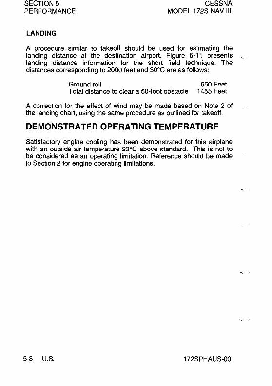
SECTIONS PERFORMANCE
CESSNA MODEL 172S NAV III
LANDING
A procedure similar to takeoff should be used for estimating the landing distance at the destination airport. Figure 5-11 presents landing distance information for the short field technique. The distances corresponding to 2000 feet and 30°C are as follows:
Ground roll 650 Feet Total distance to clear a 50-foot obstacle 1455 Feet
A correction for the effect of wind may be made based on Note 2 of the landing chart, using the same procedure as outlined for takeoff.
DEMONSTRATED OPERATING TEMPERATURE
Satisfactory engine cooling has been demonstrated for this airplane with an outside air temperature 23°C above standard. This is not to be considered as an operating limitation. Reference should be made to Section 2 for engine operating limitations.
5-8 U.S. 172SPHAUS-00

CESSNA MODEL 172S NAV III
SECTIONS PERFORMANCE
AIRSPEED CALIBRATION
NORMAL STATIC SOURCE
CONDITION: Power required for level flight or maximum power descent.
FLAPS UP
KIAS 50 60 70 80 90 100 110 120 130 140 150 160
KCAS 56 62 70 78 87 97 107 117 127 137 147 157
FLAPS 10·
KIAS 40 50 60 70 80 90 100110 --- --- --- ---
KCAS 51 57 63 71 80 89 99 109 --- --- --- ---
FLAPS FULL KIAS 40 50 60 70 80 85 --- .-- --- --- --- -.-
KCAS 50 56 63 72 81 86 --- .-- --- --- --- -.-
Figure 5-1. Airspeed Calibration (Sheet 1 of 2)
172SPHAUS-00 U.S. 5-9

SECTION 5 PERFORMANCE
CESSNA MODEL 172S NAV III
AIRSPEED CALIBRATION
ALTERNATE STATIC SOURCE
CONDITION: Power required for level flight or maximum power descent.
FLAPS UP
KIAS 50 60 70 80 90 100 110 120 130 140 150 160
KCAS 56 62 68 76 85 95 105 115 125 134 144 154
FLAPS 10'
KIAS 40 50 60 70 80 90 100110 --- --- --- ---
KCAS 51 55 60 68 77 86 96 105 --- --- --- ---FLAPS FULL
KIAS 40 50 60 70 80 85 --- --- __ M _________
KCAS 49 54 61 69 78 83 --- --- __ M ____ • ____
NOTE
Windows closed, ventilators closed, cabin heater, cabin air, and defroster on maximum.
Figure 5-1. Airspeed Calibration (Sheet 2)
5-10 U.S. 172SPHAUS-00

CESSNA MODEL 172S NAV III
SECTION 5 PERFORMANCE
100
80
t:: w 60 J: Z w a: J:
L1: 40
en w w a: (!) 20 w Cl
0
TEMPERATURE CONVERSION CHART
:: ~'ir : .:1~ :~f .: t
~:. :"r '. :t:.-.- .:.:} .
.: -!--* ..... + .. .• ; •• 1 •••.. 1.:
-20 0 20 40 DEGREES - CELSIUS
Figure 5-2. Temperature Conversion Chart
172SPHAUS-OO
60
0585T1002
U.S. 5-11
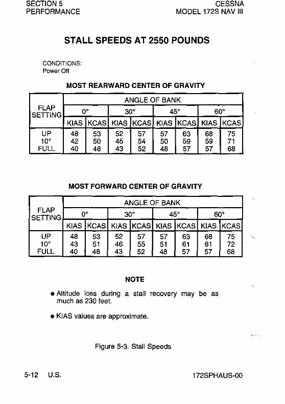
SECTION 5 PERFORMANCE
CESSNA MODEL 172S NAV III
STALL SPEEDS AT 2550 POUNDS
CONDITIONS: Power Off
MOST REARWARD CENTER OF GRAVITY
ANGLE OF BANK FLAP 0° 30° 45° 60° SETTING
KIAS KCAS KIAS KCAS KIAS KCAS KIAS KCAS
UP 48 53 52 57 57 63 68 75 10° 42 50 45 54 50 59 59 71
FULL 40 48 43 52 48 57 57 68
MOST FORWARD CENTER OF GRAVITY
ANGLE OF BANK FLAP
0° 30° 45° 60° SETTING KIAS KCAS KIAS KCAS KIAS KCAS KIAS
UP 48 53 52 57 57 63 68 10° 43 51 46 55 51 61 61
FULL 40 48 43 52 48 57 57
NOTE
• Altitude loss during a stall recovery may be as much as 230 feet.
• KIAS values are approximate.
Figure 5-3. Stall Speeds
KCAS
75 72 68
5-12 U.S. 172SPHAUS-00

CESSNA MODEL 172S NAV III
SECTION 5 PERFORMANCE
0 z
~ ~ 0
J:
z ~ , !z w z 0 0-:::;: 0 U 0 Z ~
0 Z
~ ~
CROSSWIND COMPONENT
20
15
10
1 30 35
CROSSWIND COMPONENT - KNOTS
NOTE Maximum demonstrated crosswind velocity is 15 knots (not a limitation).
Figure 5-4. Crosswind Components
172SPHAUS-OO U.S. 5-13

SECTION 5 PERFORMANCE
CESSNA MODEL 172S NAV III
SHORT FIELD TAKEOFF DISTANCE AT 2550 POUNDS
CONDITIONS:
Flaps 10° Zero Wind Full Throttle Prior 10 Brake Release Paved, level, dry runway
Lift Off: 51 KIAS Speed al 50 Ft: 56 KIAS
Press Alt In
Feet S.L. 1000 2000 3000 4000 5000 6000 7000 8000
ooe 100 e 200 e 300 e 400 e Grnd TOlal Grnd Tolal Grnd Tolal Grnd Tolal Grnd Roll FtTo Roll FITo Roll FITo Roll FITo Roll FI Clear FI Clear FI Clear FI Clear FI
50 FI 50 FI 50 FI 50 FI Obsl Obsl Obsl Obsl
860 1465 925 1575 995 1690 1070 1810 1150
940 1600 1010 1720 1090 1850 1170 1990 1260
1025 1755 1110 1890 1195 2035 1285 2190 1380
1125 1925 1215 2080 1310 2240 1410 2420 1515
1235 2120 1335 2295 1440 2480 1550 2685 1660
1355 2345 1465 2545 1585 2755 1705 2975 1825
1495 2605 1615 2830 1745 3075 1875 3320 2010
1645 2910 1785 3170 1920 3440 2065 3730 2215
1820 3265 1970 3575 2120 3880 2280 4225 2450
NOTE
• Short field technique as specified in Section 4.
• Prior to takeoff from fields above 3000 feet elevation, the mixture should be leaned to give maximum RPM in a full throttle, static runup.
• Decrease distances 1 0% for each 9 knots headwind. For operation with tail winds up to 10 knots, increase distances by 10% for each 2 knots.
• For operation on dry grass runway, increase distances by 15% of the "ground roll" figure.
Tolal FtTo Clear 50 FI Obsl
1945 2135 2355 2605 2880 3205
3585 4045 4615
Figure 5-5. Short Field Takeoff Distance (Sheet 1 of 3)
5-14 U.S. 172SPHAUS-00
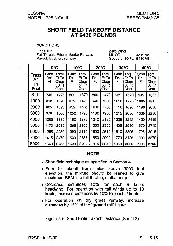
CESSNA MODEL 172S NAV III
SECTION 5 PERFORMANCE
SHORT FIELD TAKEOFF DISTANCE AT 2400 POUNDS
CONDITIONS: Flaps 10° Zero Wind Full Throttle Prior to Brake Release Paved, level, dry runway
Lift Off: 48 KIAS Speed at 50 Ft: 54 KIAS
Press Alt In
Feet
S.L. 1000
2000 3000 4000
5000 6000 7000 8000
ooe 100 e 200 e 300 e 400 e Grnd Total Grnd Total Grnd Total Grnd Total Grnd Roll Ft To Roll FtTo Roll FtTo Roll Ft To Roll Ft Clear Ft Clear Ft Clear Ft Clear Ft
50 Ft 50 Ft 50 Ft 50 Ft Obst Obst Obst Obst
745 1275 800 1370 860 1470 925 1570 995 810 1390 875 1495 940 1605 1010 1720 1085
885 1520 955 1635 1030 1760 1110 1890 1190
970 1665 1050 1795 1130 1930 1215 2080 1305
1065 1830 1150 1975 1240 2130 1335 2295 1430
1170 2015 1265 2180 1360 2355 1465 2530 1570
1285 2230 1390 2410 1500 2610 1610 2805 1725
1415 2470 1530 2685 1650 2900 1770 3125 1900
1560 2755 1690 3000 1815 3240 1950 3500 2095
NOTE
• Short field technique as specified in Section 4.
• Prior to takeoff from fields above 3000 feet elevation, the mixture should be leaned to give maximum RPM in a fuU throttle, static runup.
• Decrease distances 10% for each 9 knots headwind. For operation with tail winds up to 10 knots, increase distances by 10% for each 2 knots.
• For operation on dry grass runway, increase distances by 15% of the "ground roU" figure.
Figure 5-5. Short Field Takeoff Distance (Sheet 2)
Total FtTo Clear 50 Ft Obst
1685
1845
2030
2230
2455
2715
3015
3370
3790
172SPHAUS-00 U.S. 5-15

SECTIONS PERFORMANCE
CESSNA MODEL 172S NAV III
SHORT FIELD TAKEOFF DISTANCE AT 2200 POUNDS
CONDITIONS:
Flaps 10" Zero Wind Full Throttle Prior to Brake Release Paved, level, dry runway
Lift Off: 44 KIAS Speed at 50 Ft: 50 KIAS
Press Alt In
Feet S.L. 1000 2000 3000 4000 5000 6000 7000 8000
O"C 10"C 20"C 30"C 40"C
Grnd Total Grnd Total Grnd Total Grnd Total Grnd Roll Ft To Roll FtTo Roll FtTo Roll FtTo Roll Ft Clear Ft Clear Ft Clear Ft Clear Ft
50 Ft 50 Ft 50 Ft 50 Ft Obst Obst Obst Obst
610 1055 655 1130 705 1205 760 1290 815
665 1145 720 1230 770 1315 830 1410 890
725 1250 785 1340 845 1435 905 1540 975
795 1365 860 1465 925 1570 995 1685 1065
870 1490 940 1605 1010 1725 1090 1855 1165
955 1635 1030 1765 1110 1900 1195 2035 1275
1050 1800 1130 1940 1220 2090 1310 2240 1400
1150 1985 1245 2145 1340 2305 1435 2475 1540
1270 2195 1370 2375 1475 2555 1580 2745 1695
NOTE
• Short field technique as specified in Section 4.
• Prior to takeoff from fields above 3000 feet elevation, the mixture should be leaned to give maximum RPM in a full throttle, static runup.
• Decrease distances 10% for each 9 knots headwind. For operation with tail winds up to 10 knots, increase distances by 10% for each 2 knots.
• For operation on dry grass runway, increase distances by 15% of the "ground roll" figure.
Figure 5-5. Short Field Takeoff Distance (Sheet 3)
Total FtTo Clear 50 Ft Obst
1380 1505 1650 1805 1975 2175 2395 2650 2950
5-16 U.S. 172SPHAUS-00

CESSNA MODEL 172S NAV III
SECTION 5 PERFORMANCE
MAXIMUM RATE OF CLIMB AT 2550 POUNDS
CONDITIONS:
Flaps Up Full Throttle
PRESS ALT FT
S.L.
2000
4000
6000 8000
10,000
12,000
CLIMB SPEED
KIAS
74
73
73 73
72
72
72
RATE OF CLIMB - FPM
-20°C O°C 20°C 40°C
855 785 710 645
760 695 625 560
685 620 555 495
575 515 450 390 465 405 345 285
360 300 240 180
255 195 135 - - -
NOTE
Mixture leaned above 3000 feet elevation for maximum RPM.
Figure 5-6. Maximum Rate of Climb
172SPHAUS-00 U.S. 5-17

SECTION 5 PERFORMANCE
CESSNA MODEL 172S NAV III
TIME, FUEL AND DISTANCE TO CLIMB AT 2550 POUNDS
CONDITIONS:
Flaps Up Full Throttle Standard Temperature
PRESS CLIMB RATE FROM SEA LEVEL OF ALT SPEED TIME FUEL
FT KIAS CLIMB IN USED DIST FPM MIN GAL NM
S.L. 74 730 0 0.0 1000 73 695 1 0.4 2000 73 655 3 0.8
3000 73 620 4 1.2
4000 73 600 6 1.5 5000 73 550 8 1.9 6000 73 505 10 2.2 7000 73 455 12 2.6
8000 72 410 14 3.0 9000 72 360 17 3.4
10,000 72 315 20 3.9 11,000 72 265 24 4.4 12,000 72 220 2B 5.0
NOTE
• Add 1.4 gallons of fuel for engine start, taxi and takeoff allowance.
• Mixture leaned above 3000 feet elevation for maximum RPM.
• Increase time, fuel and distance by 10% for each 10°C above standard temperature.
• Distances shown are based on zero wind.
Figure 5-7. Time, Fuel and Distance to Climb
0 2 4
6
B
10
13
16
19
22
27
32
38
5-18 U.S. 172SPHAUS-00

CESSNA MODEL 172S NAV III
SECTION 5 PERFORMANCE
CRUISE PERFORMANCE CONDITIONS: 2550 Pounds Recommended Lean Mixture At All Altitudes (Refer to Section 4, Cruise)
PRESS ALT FT
2000
4000
6000
20'C BELOW STANDARD 20'CABOVE STANDARD TEMP TEMPERATURE STANDARD TEMP
RPM % KTAS GPH % KTAS GPH % KTAS MCP MCP MCP
2550 83 117 11.1 77 118 10.5 72 117 2500 78 115 10.6 73 115 9.9 68 115 2400 69 111 9.6 64 110 9.0 60 109 2300 61 105 8.6 57 104 8.1 53 102 2200 53 99 7.7 50 97 7.3 47 95 2100 47 92 6.9 44 90 6.6 42 89
2600 83 120 11.1 77 120 10.4 72 119 2550 79 118 10.6 73 117 9.9 68 117 2500 74 115 10.1 69 115 9.5 64 114 2400 65 110 9.1 61 109 8.5 57 107 2300 58 104 8.2 54 102 7.7 51 101 2200 51 98 7.4 48 96 7.0 45 94 2100 45 91 6.6 42 89 6.4 40 87
2650 83 122 11.1 77 122 10.4 72 121 2600 78 120 10.6 73 119 9.9 68 118 2500 70 115 9.6 65 114 9.0 60 112 2400 62 109 8.6 57 108 8.2 54 106 2300 54 103 7.8 51 101 7.4 48 99 2200 48 96 7.1 45 94 6.7 43 92
NOTE
Maximum cruise power using recommended lean mixture is 75% MCP. Values above 75% MCP are shown in table for interpolation purposes only. Operations above 75% MCP must use full rich mixture.
Figure 5-8. Cruise Performance (Sheet 1 of 2)
GPH
9.9 9.4 8.5 7.7 6.9 6.3
9.8 9.4 8.9 8.1 7.3 6.7 6.1
9.8 9.4 8.5 7.7 7.0 6.4
172SPHAUS-00 U.S. 5-19

SECTION 5 PERFORMANCE
CESSNA MODEL 172S NAV III
CRUISE PERFORMANCE CONDITIONS: 2550 Pounds Recommended Lean Mixture At All Altitudes (Refer to Secton 4, Cruise)
PRESS ALT FT
18000
10,000
12,000
20°C BELOW STANDARD 20°C ABOVE STANDARD TEMP TEMPERATURE STANDARD TEMP
RPM % KTAS GPH % KTAS GPH % KTAS
MCP MCP MCP
2700 83 125 11.1 77 124 10.4 71 123
2650 78 122 10.5 72 122 9.9 67 120
2600 74 120 10.0 68 119 9.4 64 117
2500 65 114 9.1 61 112 8.6 57 111
2400 58 108 8.2 54 106 7.8 51 104
2300 52 101 7.5 48 99 7.1 46 97
2200 46 94 6.8 43 92 6.5 41 90
2700 78 124 10.5 72 123 9.8 67 122
2650 73 122 10.0 68 120 9.4 63 119
2600 69 119 9.5 64 117 9.0 60 115
2500 62 113 8.7 57 111 8.2 54 109
2400 55 106 7.9 51 104 7.5 49 102
2300 49 100 7.2 46 97 6.8 44 95
2650 69 121 9.5 64 119 8.9 60 117
2600 65 118 9.1 61 116 8.5 57 114
2500 58 111 8.3 54 109 7.8 51 107
2400 52 105 7.5 49 102 7.1 46 100
2300 47 98 6.9 44 95 6.6 41 92
NOTE
Maximum cruise power using recommended lean mixture is 75% MCP. Values above 75% MCP are shown in table for interpolation purposes only. Operations above 75% MCP must use full rich mixture.
Figure 5-8. Cruise Performance (Sheet 2)
GPH
9.7
9.3 8.9
8.1
7.4 6.8 6.2
9.3
8.9
8.5
7.8 7.1
6.5
8.5
8.1
7.4
6.8
6.3
5-20 U.S. 172SPHAUS-00

CESSNA MODEL 172S NAV III
RANGE PROFILE
SECTIONS PERFORMANCE
45 MINUTES RESERVE 53 GALLONS USABLE FUEL
CONDITIONS: 2550 Pounds Recommended Lean Mixture for Cruise At All Altitudes
Standard Temperature Zero Wind
12'000~_
ti w ~
10,000 1tH= H:;H=i=ffiE
8,000
, 6,000
~
~
2,000
500 550 600 65<l 700
RANGE - NAUTICAL MILES 0585T1004
NOTE
This chart allows for the fuel used for engine start, taxi, takeoff and climb, and the distance during climb,
Figure 5-9, Range Profile
172SPHAUS-OO U,S, 5-21
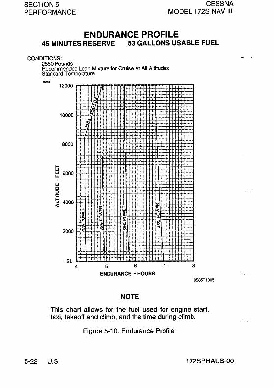
SECTION 5 PERFORMANCE
CESSNA MODEL 172S NAV III
ENDURANCE PROFILE 45 MINUTES RESERVE 53 GALLONS USABLE FUEL
CONDITIONS: 2550 Pounds Recommended Lean Mixture for Cruise At All Altitudes Standard Temperature
7
NOTE
8
0585T1005
This chart allows for the fuel used for engine start, taxi, takeoff and climb, and the time during climb.
Figure 5-10. Endurance Profile
5-22 U.S. 172SPHAUS-OO

CESSNA MODEL 172S NAV III
SECTION 5 PERFORMANCE
SHORT FIELD LANDING DISTANCE AT 2550 POUNDS
CONDITIONS:
Flaps Full Power Off Maximum Braking
Paved, level, dry runway Zero Wind Speed at 50 Ft: 61 KIAS
o·e 10·e 20·e 30·e 40·e
Grnd Total Grnd Total Grnd Total Grnd Total Grnd Press Roll Ft To Roll Ft To Roll Ft To Roll Ft To Roll
Ft Clear Ft Clear Ft Clear Ft Clear Ft Alt In
Feet S,l,
1000
2000
3000
4000
5000
6000
7000
8000
50 Ft 50 Ft 50 Ft 50 Ft Obst Obst Obst Obst
545 1290 565 1320 585 1350 605 1380 625
565 1320 585 1350 605 1385 625 1420 650
585 1355 610 1385 630 1420 650 1455 670
610 1385 630 1425 655 1460 675 1495 695
630 1425 655 1460 675 1495 700 1535 725
655 1460 680 1500 705 1535 725 1575 750
680 1500 705 1540 730 1580 755 1620 780
705 1545 730 1585 760 1625 785 1665 810
735 1585 760 1630 790 1670 815 1715 840
NOTE
• Short field technique as specified in Section 4,
• Decrease distances 10% for each 9 knots headwind. For operation with tail winds up to 10 knots, increase distances by 10% for each 2 knots.
• For operation on dry grass runway, increase distances by 45% of the "ground roll" figure.
• If landing with flaps up, increase the approach speed by 9 KIAS and allow for 35% longer distances.
Figure 5-11. Short Field Landing Distance
Total Ft To Clear 50 Ft Obst
1415
1450
1490
1530
1570
1615
1660
1705
1755
172SPHAUS-00 U.S. 5-23/5-24

CESSNA SECTION 6 MODEL 172S NAV III WEIGHT AND BALANCE/EQUIPMENT LIST
WEIGHT AND BALANCEI EQUIPMENT LIST
TABLE OF CONTENTS
Page
I ntrod uction ...................................... 6-3 Airplane Weighing Procedures ........................ 6-3
Airplane Weighing Form .......................... 6-5 Sample Weight and Balance Record ................. 6-7
Weight And Balance ............................... 6-8 Baggage Tiedown ............................... 6-9 Sample Loading Problem ........................ 6-10 Loading Graph ................................ 6-12 Loading Arrangements .......................... 6-13 Internal Cabin Dimensions ........................ 6-14 Center-of-Gravily Moment Envelope ................ 6-15 Center-of-Gravily Limits .......................... 6-16
Comprehensive Equipment List ...................... 6-17
172SPHAUS-Ol U.S. 6-1/6-2
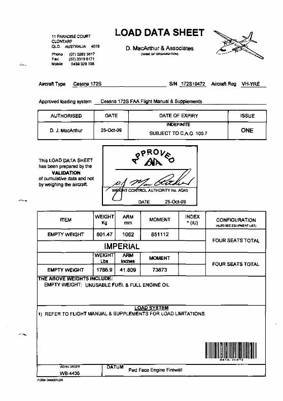
11 PARADISE COURT CLONTARF OLD. AUSTRALIA 4019
Phone· (07) 3283 3817 Fax: (07)33196171 Mobile 0439 328 338
LOAD DATA SHEET
D. MacArthur & Associates (No'IME Of ORG.¥IISAl1ON)
AiroraftType Cessna._'cc7.,,2S"---________ SIN 172510472 AircraftReg VH·YRE
Approved loading system
AUTHORISED
D. J. MacArthur
This LOAD DATA SHEET has been prepared by the
VALIDAT10N of cumulative data and not by weighing the aircraft.
ITEM
EMPTY WEIGHT
EMPTY WEIGHT
Cessna 172S FAA Flight Manual & SUPPlements
DATE DATE OF EXPIRY
INDEFINITE 25-Oct-09
SUBJECT TO C.A.O. 100.7
WEIGHT ARM MOMENT INDEX
Kg mm • (IU)
801.47 1062 851112
IMPERIAL WEIGHT ARM
MOMENT lbs Inches
1766.9 41.809 73873
THE ABOVE WEIGHTS INCLUDE: EMPTY WEIGHT; UNUSABLE FUEL & FUll ENGINE Oil
LOAD SYSTEM 1) REFER TO FLIGHT MANUAL & SUPPLEMENTS FOR LOAD LIMITATIONS.
DATUM Fwd Face Engine Firewall WORt<;OROER
WB-4436 FORMOWOO1L.D5
ISSUE
ONE
CONFIGURATION (ALSO SEE EQUIPMEr<f UST)
FOUR SEATS TOTAL
FOUR SEATS TOTAL

CESSNA SECTION 6 MODEL 172S NAV III WEIGHT AND BALANCE/EQUIPMENT LIST
INTRODUCTION
This section describes the procedure for establishing the basic empty weight and moment of the airplane. Sample forms are provided for reference. Procedures for calculating the weight and moment for various operations are also provided. For additional I information regarding Weight and Balance procedures, refer to the Aircraft Weight and Balance Handbook (FAA-H-SOS3-1). A comprehensive list of Cessna equipment available for this airplane is included at the back of this section.
Specific information regarding the weight, arm, moment and. installed equipment for this airplane as delivered from the factory can be found in the plastic envelope in the back of this handbook. •
WARNING
IT IS THE RESPONSIBILITY OF THE PILOT TO • MAKE SURE THE AIRPLANE IS LOADED PROPERLY. OPERATION OUTSIDE OF PRESCRIBED WEIGHT AND BALANCE LIMITATIONS COULD RESULT IN AN ACCIDENT AND SERIOUS OR FATAL INJURY.
AIRPLANE WEIGHING PROCEDURES
1. Preparation: a. Inflate tires to recommended operating pressures. b. Defuel airplane. Refer to the Maintenance Manual. c. Service engine oil as required to obtain a normal
indication (approximately 7 quarts on dipstick). d. Move sliding seats to the most forward position. e. Raise flaps to the fully retracted position. f. Place all control surfaces in neutral position. g. Remove all non-required items from airplane.
I 172SPHAUS-01 U.S. 6-3

SECTION 6 CESSNA MODEL 172S NAV III WEIGHT AND BALANCE/EQUIPMENT LIST
AIRPLANE WEIGHING PROCEDURES (Continued)
I
I
I
16-4
2. Level: a. Place scales under each wheel (minimum scale
capacity, 1000 pounds). b. Deflate the nose tire and/or lower or raise the nose strut
to properly center the bubble in the level (refer to Figure 6-1).
3. Weigh: a. Weigh airplane in a closed hangar to avoid errors
caused by air currents. b. With the airplane level and brakes released, record the
weight shown on each scale. Deduct the tare, if any, from each reading.
4. Measure: a. Obtain measurement A by measuring horizontally (along
the airplane centerline) from a line stretched between the main wheel centers to a plumb bob dropped from the firewall.
b. Obtain measurement B by measuring horizontally and parallel to the airplane centerline, from center of nose wheel axle, left side, to a plumb bob dropped from the line between the main wheel centers. Repeat on right side and average the measurements.
5. Using weights from step 3 and measurements from step 4, the Basic Empty Weight and C.G. can be determined by completing Figure 6-1.
6. Changes to the Airplane Weight and Balance due to alteration or repair must be documented in a permanent record within the POH Similar to that shown in Figure 6-2.
7. A new Basic Empty Weight and CG Arm based on actual airplane weight (as weighed) is required after a major repair or alteration. It is recommended that the airplane be weighed to verify Basic Empty Weight and CG Arm at intervals not to exceed 5 years.
(Continued Next Page)
U.S. 172SPHAUS-01

CESSNA SECTION 6 MODEL 172S NAV III WEIGHT AND BALANCE/EQUIPMENT LIST
Sl .J::: o
150
100
.E 50 , ::J'
~ 0 CD <: ~ CD
1ii -5 :;;;
AIR PLANE WEIGHING FORM
Reference Datum (Firewall, front face, lower portion)
FSO.O MAC _--+r- 58.80
25.90
Level at upper door sill or leveling screws on left side of tailcone
-101~--,-~,-~~-.---,--,--,--,
-100 -50 o 50 100 150 200 250 300
Fuselage Station (FS) - Inches
NOTE It is the responsibility of the pilot to make sure that the airplane is loaded properly.
.. Figure 6-1 (Sheet 1 of 2)
I 172SPHAUS-01
OS10noos
I U.S. 6-5

SECTION 6 CESSNA MODEL 172S NAV III WEIGHT AND BALANCE/EQUIPMENT LIST
I
I
AIRPLANE WEIGHING FORM 84073
Locating CG with Airplane on Landing Gear
X (Inches Aft of Datum) ~ A _[NoSeWheel Weight x BJ Total Weight'
Locating Percent MAC "(Nose + L + R Wheel Weights)
CG Percent MAC ~ (CG Arm of Airplane) - 25.90 0.5880
Leveling Provisions Longitudinal - Left side of tailcon at FS 108.00 and 142.00
Measuring A and B Measure A and B per pilot's operating handbook instructions to assist in locating CG with airplane weighed on landing gear.
Airplane as Weighed Table
Position Scale reading Scale drift Tare Net weight
Left Wheel Right Wheel
Nose Wheel
Airplane total as weighed
BaSIC Empty WeIght and Canter-ol-Gravlty Table -
Weight CGArm Moment
Item (Inch-Pounds Pounds (Inches)
11000)
Airplane (calculated or as weighed) (includes all undrainable Iluids and full oil)
Drainable unusable fuel at 6.0 pounds per 18.0 46.00 0.83 gallon - (3 gallons)
Basic Empty Weight
__ Figure 6-1 (Sheet 2)
16-6 U.S. 172SPHAUS-01

~
~ en "1J :J: » c en 6 ~
~ :!!
<Cl <: Cil
~
o C g: o j g
0> ~ -
S:O
SAMPLE WEIGHT AND BALANCE RECORD
(Continuous history of changes in structure or equipment affecting weight and balance)
Airplane model I Serial number Page number
Weight change Running Item no. Description basic empty
Date Added (+) Removed (-) weight of article or
~ Om oen
Cl) men l>
rZ ~»
s: -..j
"tI '" en r- Z m ~ :E m
In Out modification WT. Arm Moment WT. Arm Moment WT. Moment (lb.) (in.) /1000 (lb.) (in.) /1000 (lb.) /1000
As delivered
G> ::I: :E -I m
l> G5 z :J:
-I C » ID Z l> 0
r- III
l> »
Z ~
" Z 0
m m :a ill m 0
" c
0 'ii :a s:en
mm C zO
-1-1 rO iii z - -10>
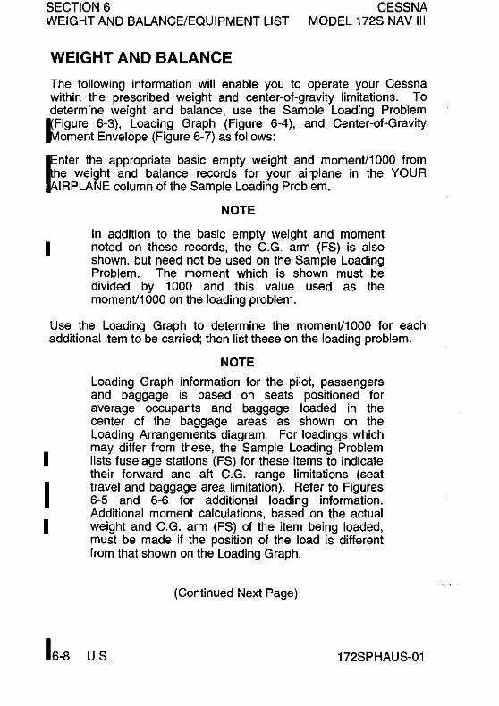
SECTION 6 CESSNA MODEL 172S NAV III WEIGHT AND BALANCE/EQUIPMENT LIST
WEIGHT AND BALANCE
The following information will enable you to operate your Cessna within the prescribed weight and center-of-gravity limitations. To determine weight and balance, use the Sample Loading Problem
I(Figure 6-3), Loading Graph (Figure 6-4), and Center-of-Gravity J;1oment Envelope (Figure 6-7) as follows:
Enter the appropriate basic empty weight and momenV1000 from
he weight and balance records for your airplane in the YOUR IRPLANE column of the Sample Loading Problem.
I
NOTE
In addition to the baSic empty weight and moment noted on these records, the C.G. arm (FS) is also shown, but need not be used on the Sample Loading Problem. The moment which is shown must be divided by 1000 and this value used as the momenV1000 on the loading problem.
Use the Loading Graph to determine the momenV1000 for each additional item to be carried; then list these on the loading problem.
I
I I
16-8
NOTE
Loading Graph information for the pilot, passengers and baggage is based on seats positioned for average occupants and baggage loaded in the center of the baggage areas as shown on the Loading Arrangements diagram. For loadings which may differ from these, the Sample Loading Problem lists fuselage stations (FS) for these items to indicate their forward and aft C.G. range limitations (seat travel and baggage area limitation). Refer to Figures 6-5 and 6-6 for additional loading information. Additional moment calculations, based on the actual weight and C.G. arm (FS) of the item being loaded, must be made if the position of the load is different from that shown on the Loading Graph.
(Continued Next Page)
U.S. 172SPHAUS-01
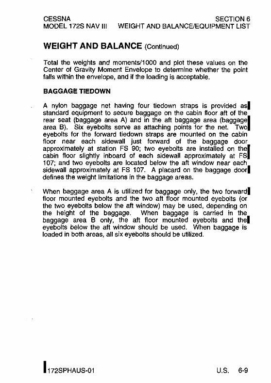
CESSNA SECTION 6 MODEL 172S NAV III WEIGHT AND BALANCE/EQUIPMENT LIST
WEIGHT AND BALANCE (Continued)
Total the weights and moments/lOOO and plot these values on the Center of Gravity Moment Envelope to determine whether the point falls within the envelope, and if the loading is acceptable.
BAGGAGE TIEDOWN
A nylon baggage net having four tiedown straps is provided as. standard equipment to secure baggage on the cabin floor aft of the rear seat (baggage area A) and in the aft baggage area (baggagel area B). Six eyebolts serve as attaching points for the net. Two eyebolts for the forward tiedown straps are mounted on the cabin floor near each sidewall just forward of the baggage door approximately at station FS 90; two eye bolts are installed on thel cabin floor slightly inboard of each sidewall approximately at FS 107; and two eyebolts are located below the aft window near each sidewall approximately at FS 107. A placard on the baggage door. defines the weight limitations in the baggage areas.
When baggage area A is utilized for baggage only, the two forward. floor mounted eyebolts and the two aft floor mounted eyebolts (or the two eye bolts below the aft window) may be used, depending on the height of the baggage. When baggage is carried in the baggage area B only, the aft floor mounted eyebolts and the. eyebolts below the aft window should be used. When baggage is loaded in both areas, all six eyebolts should be utilized.
I 172SPHAUS-01 U.S. 6-9
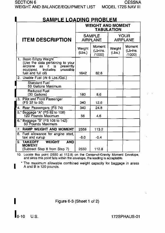
SECTION 6 CESSNA MODEL 172S NAV III WEIGHT AND BALANCE/EQUIPMENT LIST
I
I
I
I
SAMPLE LQADING t"'HudLEM WEIGHT AND MOMENT
TABULATION
SAMPLE YOUR ITEM DESCRIPTION AIRPLANE AIRPLANE
Weight Moment Weight Moment (Lb-ins. (Lb-ins.
(Lbs.) /1000) (Lbs.) /1000) t. Basic Empty Weight
(Use the data pertaining to your airplane as it is presently equipped. Includes unusable fuel and full oil) 1642 62.6
2. Usable Fuel (At 6 Lbs./Gal.)
Standard Fuel 53 Gallons Maximum Reduced Fuel (30 Gallons) 180 8.6
3. Pilot and Front Passenger (FS 32 to 50) 340 12.6
4. Rear Passengers (FS 74) 340 24.8 5: Baggage "A" (FS 82 to 108)
120 Pounds Maximum 56 4.6 6: Bag~age "B" (FS 108 to 142)
50 ounds Maximum
7. RAMP WEIGHT AND MOMENT 2558 113.2 8. Fuel allowance for engine start,
taxi and runup -8.0 -0.4 9. TAKEOFF WEIGHT AND
MOMENT (Subtract Step 8 from Step 7) 2550 112.8
10. Locate this point (2550 at 112.8) on the Center-et-Gravity Moment Envelope, and since this point falls within the envelope, the loading is acceptable .
• The maximum allowable combined weight capacity for baggage in areas A and B is 120 pounds.
Figure 6-3 (Sheet 1 of 2)
16-10 U.S. 172SPHAUS-Ol

CESSNA SECTION 6 MODEL 172S NAV III WEIGHT AND BALANCE/EQUIPMENT LIST
SAMPLE LOADING PROBLEM
YOUR YOUR YOUR AIRPLANE AIRPLANE AIRPLANE
Weight Moment (Lb-ins, (Ibs.) 11000)
Weight Moment (Lb-ins, (Ibs.) 11000)
Weight Moment (Lb-ins, (Ibs.) 11000)
When several loading configurations are representative of your operations, it may be useful to fill out one or more of the above columns so that specific loadings are available at a glance.
Figure 6-3 (Sheet 2)
I 172SPHAUS-01 U.S. 6-11
I
I
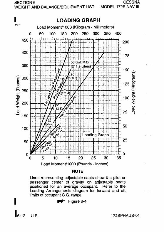
SECTION 6 CESSNA MODEL 172S NAV III WEIGHT AND BALANCE/EQUIPMENT LIST
I LOADING GRAPH Load Moment/1000 (Kilogram - Millimeters)
o 50 1 00 150 200 250 300 350 400 I -ij-- -- --200
-_ +iJ'~ IfL! --175
150 ~ (/J
E !:!!
125 ~ g. :E
100 Cl
~ ~ .3
50~~7 q~~tti±iP±~~~tu~25
o ~~±i~11U.tth:1±ilti11J±=·~--·-t--LCttfttf£.~ 0
o 5 10 15 20 25 30 35
Load Moment/1000 (Pounds - Inches)
NOTE
Lines representing adjustable seats show the pilot or passenger center of gravity on adjustable seats positioned for an average occupant Refer to the Loading Arrangements diagram for forward and aft limits of occupant C_G_ range_
I W" Figure 6-4
16-12 U_S_ 172SPHAUS-01

CESSNA SECTION 6 MODEL 172S NAV III WEIGHT AND BALANCE/EQUIPMENT LIST
""" C.G. Arm
(FS)
*37-
LOADING ARRANGEMENTS
~ ~
(34-46) ~~ CB\ ________ ~ r;:c
73-(Rear pass) I ~- .. -.-.-..... -.. --- ....
**95--(B2-1OBhOB
**123-(10B-142)
142
_Baggage Area A
Baggage -AreaB
~ FS FS FS
1 42.00 1 OB.OO B2.00 FS
0.00
0585T10,&
* Pilot or passenger center-of-gravity on adjustable seats positioned for average occupant. Numbers in parentheses indicate forward and aft limits of occupant center-of-gravity range.
** Arms measured to the center of the areas shown.
NOTE
• The usable fuel C.G. arm is located at FS 4B.00. • The aft baggage wall (approximate FS 108.00) or
aft baggage wall (approximate FS 142.00) can be used as a convenient interior reference point for determining the location of baggage area fuselage stations.
• To achieve an airplane loading within the utility I category, it may be necessary to remove the rear passenger seat assembly from the airplane. Refer to Figure 6-9 for applicable weight and arm.
Figure 6-5
172SPHAUS-04 U.S. 6-13
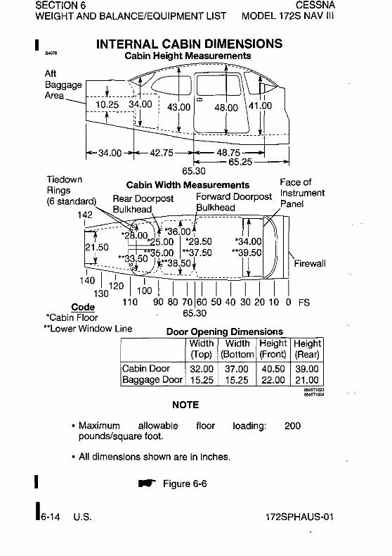
SECTION 6 CESSNA WEIGHT AND BALANCE/EQUIPMENT LIST MODEL 172S NAV III
I ,.,,,
Aft Baggage Area
INTERNAL CABIN DIMENSIONS Cabin Height Measurements
____ L ___ \ m<=--n--------- --- I
1 0.25 3~.00: 43.00 '" 48.00 41.00
---T----U ... L_L 1 ~34.00 42.75 - -----~8:;~---~-----1
f---- 65.25 ~ 65.30
Cabin Width Measurements Face of
Rear Doorpost Forward Doorpost Instrument Panel
Firewall
o FS
"Lower Window Line Door Opening Dimensions Width Width Height Height (Top) (Bottom (Front) (Rear)
Cabin Door 32.00 37.00 40.50 39.00 Baggage Door 15.25 15.25 22.00 21.00
NOTE
• Maximum allowable floor loading: 200 pounds/square foot.
• All dimensions shown are in inches.
I
16-14 U.S.
__ Figure 6-6
172SPHAUS-01

CESSNA SECTION 6 MODEL 172S NAV III WEIGHT AND BALANCE/EQUIPMENT LIST
CENTER-OF-GRAVITY MOMENT ENVELOPE I
""" Loaded AirpJane MomenV1000 (Kilogram - MiJlimeters)
600 700 800 900 1000 11 00 1200 1300 1400 1500 2600
2500 .
2400
:gj' 2300 c ~ o ~22oo E 0>
~ 2100 Cl c ~2000
~ ~ 1900
~ Ifffilllml~ (; ...J 1800
1700
1600
1500
1150
1100
1050
Ci) 1000E
~
~ 950 S2
~
E 0>
900 ~ Cl C
'" 850 e-;.;;:
800 ~ ~ .3
750
700
50 60 70 80 90 100 110 120 130
Loaded Airplane MomenV1000 (Pounds - Inches)
__ Figure 6-7 I
172SPHAUS-01 U.S. 6-15

SECTION 6 CESSNA WEIGHT AND BALANCE/EQUIPMENT LIST MODEL 172S NAV III
I CENTER-OF-GRAVITY LIMITS
"''''
I
1600t~
ls00E[E 34 35 36 37 38 39 40 41 42 43 44 45 46 47 48 49
Airplane C.G. Location - Inches Aft of Datum (FS 0.0)
.. Figure 6-8
750
Q) c as C. ~ « "0 Q) "0
.3
6-16 U.S. 172SPHAUS-01

CESSNA MODEL 172S NAV III
SECTION 6 WEIGHT AND BALANCE/EQUIPMENT LIST
COMPREHENSIVE EQUIPMENT LIST Figure 6-9 is a comprehensive list of all Cessna equipment which is available I for the Model 1725 airplane equipped with Garmin Gl000 Integrated Cockpit System (Serials 17289810 and On). This comprehensive equipment list provides the following information in column form:
In the ITEM NO column, each item is assigned a coded number. The first two digits of the code represent the identification of the item within Air Transport Association Specification 100 (11 for Paint and Placards; 24 for Electrical Power; 77 for Engine Indicating, etc.). These assignments also correspond to the Maintenance Manual chapter for the airplane. After the first two digits, items receive a unique sequence number (01, 02, 03, etc.). After the sequence number, a suffix letter is assigned to identify equipment as a required item, a standard item or an optional item.
Suffix letters are as follows:
R= Required items or equipment for FAA certification (14 CFR Part 23 or Part 91).
S= Standard equipment items. 0= Optional equipment items replacing required or standard items. A= Optional equipment items which are in addition to required or
standard items.
In the EQUIPMENT LIST DESCRIPTION column, each item is assigned a descriptive name to help identify its function.
In the REF DRAWING column, a Cessna drawing number is provided which corresponds to the item.
NOTE
If additional equipment is to be installed, it must be done in accordance with the reference drawing, service bulletin or a separate FM approval.
In the WT LBS and ARM INS columns, information is provided on the weight (in pounds) and arm (in inches) of the equipment item.
NOTE
• Unless otherwise indicated, true values (not net change values) for the weight and arm are shown. Positive arms are distances aft of the airplane datum; negative arms are distances forward of the datum .
• Asterisks (*) in the weight and arm column indicate complete assembly installations. Some major components of the assembly are listed on the lines immediately following. The sum of these major components does not necessarily equal the complete assembly installation.
172SPHAUS-01 U.S. 6-17

SECTION 6 WEIGHT AND BALANCE/EQUIPMENT LIST
CESSNA MODEL 172S NAV III
ITEM EQUIPMENT LIST DESCRIPTION REFDRAWING WT ARM NO LBS INS.
11 - PLACARDS AND MARKINGS
11-02-S PAINT. OVERALL WHITE W/COLOR STRIPE 0500531 19.2· 95.4"
- OVERALL WHITE COVER 18.4 91.5
- COLOR STRIPING 0.8 135.9
21 - AIR CONDITIONING
21-01-S VENTILATORS. ADJUSTABLE. CABIN AIR 0513575-2 1.7 60.0
21-02-S CABIN HEATER SYSTEM. SHROUDED 0550365 2.5 -4.0 MUFFLER TYPE
21-03-R FORWARD AVIONICS COOLING FAN - 3930379 0.5 12.7 MC24B3
21-04-R AFT AVIONICS COOLING FAN 3940397 1.1 109.0
22 - AUTO FLIGHT
1 22-03-S TWO AXIS AUTOPILOT - KAP 140 TWO AXIS AUTOPILOT 3930492 2.6 12.0 COMPUTER WITH ALTITUDE PRESELECT AND GPS ROLL STEERING
- KS-270C PITCH SERVO 0501145-1 4.2 171.3
- KS-272C PITCH TRIM SERVO 0501153-1 4.1 175.5
- KS-271C ROLL SERVO 3940400-1 3.6 54.2
23 - COMMUNICATIONS
23-01-S STATIC DISCHARGE WICKS (SET OF 10) 0501048-1 0.4 143.2
23-18-R AUDIO/INTERCOM/MARKER BEACON - GMA 1347 AUDIO PANEL 3930377 1.7 16.3
- CI-l02 MARKER BEACON ANTENNA 3960193-5 0.5 129.0
23-20-R NAV/COMlGPS#1 COMPUTER 3921155
- GIA 63 INTEGRATED AVIONICS UNIT 3940397 4.9 113.3
- Cl 2480-200 VHF COMMlGPS ANTENNA 3960220-3 0.5 61.2
23-21-S NAV/COM/GPS#2 COMPUTER 3921155
- GIA 63 INTEGRATED AVIONICS UNIT 3940397 4.9 113.3
- Cl 2480-400 VHF COMM/GPSIXM ANTENNA 3960220-4 0.5 61.2
24 - ELECTRICAL POWER
24-01-R ALTERNATOR. 28 VOLT. 60 AMP -9910591-11 0550365 10.0 -29.0
24-02-R BATTERY. 24 VOLT. 12.75 AMP HOUR 0518006 23.2 -5.0
24-03-R POWER DISTRIBUTION MODULE S3100-344 0518006 6.4" -2.5"
- ALTERNATOR CONTROL AC2101 0.2 -2.5
- MASTER CONTACTOR X61-0007 0.7 -2.5
- STARTER CONTACTOR X61-0012 0.7 -2.5
- AMMETER TRANSDUCER CS31 00 0.1 -2.0
24-07-S BATTERY. STANDBY - AVT 200413 0518025 14.0 11.2
Figure 6-9 (Sheet 1 of 8)
16-18 U.S. 172SPHAUS-01

CESSNA MODEL 172S NAV III
SECTION 6 WEIGHT AND BALANCE/EQUIPMENT LIST
ITEM EQUIPMENT LIST DESCRIPTION REFDRAWING WT ARM NO LBS INS.
25 • EQUIPMENTIFURNISHINGS
25·01·R SEAT, PILOT, ADJUSTABLE, CLOTH COVER 0719025·1 33.8 41.5 ~ 25·02-0 SEAT, PILOT, ADJUSTABLE, LEATHERNINYL 0719025-4 34.3 41.5 COVER
25·03·S SEAT, FRONT PASSENGER, ADJUSTABLE, 0719025·1 33.8 41.5 CLOTH COVER
25·04·0 SEAT, FRONT PASSENGER, ADJUSTABLE, 0719025-4 34.3 41.5 LEATHERNINYL COVER
• 25·05·S SEAT, REAR PASSENGER, TWO PIECE 0719028·1 50.0 82.0
BACK, CLOTH COVER
25·06·0 SEAT, REAR PASSENGER, TWO PIECE 0719028·2 51.0 82.0 BACK, LEATHERNINYL COVER
25·07·R SEAT BELT AND SHOULDER HARNESS, 0519031-1 5.2 50.3 INERTIA REEL, AUTO ADJUST, PILOT AND FRONT PASSENGER
25·08-0 SEAT BELT AND SHOULDER HARNESS, 0519031·200 4.0 50.3 INERTIA REEL, MANUAL ADJUSTABLE, PILOT AND FRONT PASSENGER
25·09·S SEAT BELT AND SHOULDER HARNESS, 0519031·1 5.2 87.8 INERTIA REEL, AUTO ADJUST, REAR SEAT
25·10-0 SEAT BELT AND SHOULDER HARNESS, 0519031·200 4.0 87.8
~ INERTIA REEL, MANUAL ADJUSTABLE, REAR SEAT
25·11·S SUN VISOR (SET OF 2) 0514166·2 1.1 32.8
• 25·12·S BAGGAGE RESTRAINT NET 2015009·7 0.5 95.0
25·13·S CARGO TIEDOWN RINGS (SET OF 10) 0515055·6 0.2 95.0
25·15·R PILOT'S OPERATING HANDBOOK AND FM 0500832·1 2.2 50.0 APPROVED AIRPLANE FLIGHT MANUAL (STOWED IN FRONT PASSENGER'S SEAT BACK) ..
25·16·S FUEL SAMPLING CUP S2107·1 0.1 50.0 (STOWED IN PILOT'S SEAT BACK)
25·17·S TOW BAR, NOSE GEAR (STOWED) 0501019·1 1.7 124.0
25·18·R EMERGENCY LOCATOR TRANSMITTER 3940401-1
J • ELT TRANSMITTER 3940440 1.8 113.3
• ANTENNA AND CABLE ASSEMBLY 3940440 0.1 122.0
l 25·39·R GARMIN G1000 COCKPIT REFERENCE 1.5 15.0 GUIDE (STOWED IN COCKPIT SIDE PANEL POCKET)
25-40·S APPROACH PLATE HOLDER 0715083·1 0.1 22.0
Figure 6·9 (Sheet 2)
I 172SPHAUS·01 U.S. 6·19

SECTION 6 WEIGHT AND BALANCE/EQUIPMENT LIST
CESSNA MODEL 172S NAV III
ITEM EQUIPMENT LIST DESCRIPTION REF DRAWING WT ARM NO LBS INS.
26 • FIRE PROTECTION
26·01·S FIRE EXTINGUISHER 0501011·2 • FIRE EXTINGUISHER. HAND TYPE A352GS 4.8 44.0 • MOUNTING CLAMP AND HARDWARE 1290010·1 0.5 42.2
27 • FLIGHT CONTROLS
27·01·S DUAL CONTROLS, RIGHT SEAT 0506008·1 5.5' 12.4'
- CONTROL WHEEL, COPILOT 0513576-4 2.6 26.0
- RUDDER AND BRAKE PEDAL, COPILOT 0510402-16 1.1 6.8
27-02-A RUDDER PEDAL EXTENSION (SET OF 2) 0501082-1 2.9 8.0 (INSTALLED ARM SHOWN)
28 - FUEL
28-01-R AUXILIARY FUEL PUMP - 5100-00-4 0516015 1.9 9.5
28-03-R FUEL SENDER - S3852-2 0522644 0.1 47.4
30 - ICE AND RAIN PROTECTION
30-01-S PITOT HEAT 0523080 0.1 28.0
31 -INDICATING/RECORDING SYSTEM
31-02-S RECORDING HOURMETER - C664503-0103 0506009 0.5 16.1
31-04-R PNEUMATIC STALL WARNING SYSTEM 0523112 0.4 28.5
31-05-R GEA 71 ENGINElAIRFRAME UNIT 3930377 2.2 11.4
31-06-R GTP 59 OUTSIDE AIR TEMPERATURE (OAT) 0518006 0.1 41.5 PROBE
32 - LANDING GEAR
32-01-R WHEEL BRAKE AND TIRE, 6.00 X 6 MAIN (2) 0541200-7,-8 34.4' 57.8'
- WHEEL ASSEMBLY, (EACH) C163001-0104 6.2 58.2 - BRAKE ASSEMBLY, (EACH) C163030-0111 1.8 54.5
- TIRE, 6-PL Y, 6.00 X 6, BLACKWALL C262003-0101 7.9 58.2
- TUBE, (EACH) C262023-0102 1.3 58.2
32-02-R WHEEL AND TIRE, 5.00 X 5 NOSE 0543062-17 9.5' -6.8'
- WHEEL ASSEMBLY 1241156-12 3.5 -6.8
- TIRE, 6-PLY, 5.00 X 5, BLACKWALL C262003-0202 4.6 -6.8
-TUBE C262023-0101 1.4 -6.8
32-03-A WHEEL FAIRINGS AND INSTALLATION 0541225-1 16.5' 48.1' - WHEEL FAIRING, NOSE 0543079-3 3.5 -3.5
- WHEEL FAIRINGS, MAIN (SET OF 2) 0541223-1, -2 10.1 61.1
- BRAKE FAIRINGS (SET OF 2) 0541224-1, -2 1.1 55.6 - MOUNTING PLATE (SET OF 2) 0541220-1,-2 0.8 59.5
32-04-0 HUB CAPS WHEELS 0741048-8 0.1 62.1
Figure 6-9 (Sheet 3)
16-20 U.S. 172SPHAUS-01

CESSNA MODEL 172S NAV III
SECTION 6 WEIGHT AND BALANCE/EQUIPMENT LIST
ITEM EQUIPMENT LIST DESCRIPTION REFDRAWING WT ARM NO LBS INS.
33 - LIGHTS
33·01-S MAP LIGHT IN CONTROL WHEEL 0706015 0.2 21.5
33-02-S COURTESY LIGHTS UNDER WING 0521101-8 0.5 610 I 33-04-S FLASHING BEACON 0506003-6 1.4 204.7 ~ 33-05-R ANTICOLLlSION STROBE LIGHT 0723628 3.4 43.3
33-06-S LANDING AND TAXI LIGHT 0523029-7 2.4 28.7
34 - NAVIGATION
34-01-R INDICATOR. AIRSPEED - 53325-1 0506009 0.6 16.2 ~ 34-02-S ALTERNATE STATIC AIR SOURCE 0501017-1 0.2 15.5
34-03-R ALTIMETER, SENSITIVE WITH 20 FOOT 0506009 0.9 14.0 MARKINGS, INCHES OF MERCURY AND MILLIBARS - S3328-1
34-06-R COMPASS, MAGNETIC 0513262-3 0.5 18.0
34-17-R TRANSPONDER 3940397 - GTX-33 TRANSPONDER 3910317-5 3.0 134.0 - Cl 105-16 TRANSPONDER ANTENNA 3960191 0.4 86.3
34-18-R PFD DISPLAY 3930377
- GDU-l040 DISPLAY 3910317-1 6.3 16.4
34-19-R MFD DISPLAY 3930377
- GDU-l040 DISPLAY 3910317-1 6.3 16.4
34-20-R ATTITUDE HEADING REFERENCE SENSOR 3940397 (AHRS) -GRS 77 AHRS 3910317-3 2.4 134.0
- GMU 44 MAGNETOMETER 3940398 0.4 52.7
34-21-R AIR DATA COMPUTER 3940397
- GDC 74A AIR DATA COMPUTER 3910317-6 1.7 11.4
34-23-S BLIND YAW RATE SENSOR 3930493 1.0 15.5 (TURN COORDINATOR)
34-24-0 WX 500 STORMSCOPE - PROCESSOR - S31OO-276 3940403 2.5 162.0
- ANTENNA - 805-10930-001 3960206 1.0 175.4
34-25-S GDL-69A DATALlNK 3940397 1.9 112.8
34-26-0 AUTOMATIC DIRECTION FINDER (ADF)
- KR 87 ADF RECEIVER 3930494 3.2 12.1
- ADF ANTENNA 3960187 4.2 39.3
34-27-0 DISTANCE MEASURING EQUIPMENT (DME)
- KN 63 REMOTE DME 3940448 2.8 154.0
- Cl 105-16 DME ANTENNA 3960231 0.4 114.5
134-28-0 I KTA 810 10MM., 00 , .. n
Figure 6-9 (Sheet 4)
I 172SPHAUS-01 U.S. 6-21

SECTION 6 WEIGHT AND BALANCE/EQUIPMENT LIST
CESSNA MODEL 172S NAV III
ITEM EQUIPMENT LIST DESCRIPTION REFDRAWING WT ARM NO LBS INS.
37- VACUUM
37-01-R ENGINE DRIVEN VACUUM PUMP - VACUUM PUMP - M3215CC 0501135 2.1 -5.0
- COOLING SHROUD 1201998-1 0.2 -5.6
- FILTER 1201075-2 0.3 2.0
- VACUUM REGULATOR f',A2H3-2 0.5 2.0
37-04-R VACUUM TRANSDUCER - P165-5786 0501135 0.3 10.3
53 - FUSELAGE
I 53-01-S REFUELlNG STEPS AND HANDLE 0513415-2 1.7 16.3
56-WINDOWS
56-01-S WINDOW. HINGED RIGHT SIDE 0517001-40 2.3- 48.0-(NET CHANGE)
56-02-S WINDOW, HINGED LEFT DOOR 0517001-39 2.3- 48.0-(NET CHANGE)
61 - PROPELLER
I 61-01-R FIXED PITCH PROPELLER 0550320-18 38.8- -38.2-
- MCCAULEY 76 INCH PROPELLER lA 170ElJHA7660 35.0 -38.4
- MCCAULEY 3.5 INCH PROPELLER C5464 3.6 -36.0 SPACER
61-Q2-R SPINNER, PROPELLER 0550320-11 1.8* -41.0-
- SPINNER DOME ASSEMBLY 0550236-14 1.0 -42.6 - FWD SPINNER BULKHEAD 0552231-1 0.3 -40.8
- AFT SPINNER BULKHEAD 0550321-10 0.4 -37.3
71 - POWERPLANT
71-01-R FILTER, INDUCTION AIR 0550365 0.3 -27.5
71-02-0 WINTERIZATION KIT (STOWED) 0501128-3 0.8- -20.3-(INSTALLED ARM SHOWN) - BREATHER TUBE INSULATION 0552011 0.4 -13.8 - COWL INLET COVERS (INSTALLED) 0552229-3,-4 0.3 -32.0
- COWL INLET COVERS (STOWED) 0552229-3,-4 0.3 95.0
Figure 6-9 (Sheet 5)
16-22 U.S. 172SPHAUS-01

CESSNA MODEL 172S NAV III
SECTION 6 WEIGHT AND BALANCE/EQUIPMENT LIST
ITEM EQUIPMENT LIST DESCRIPTION REFDRAWING WT ARM NO LBS INS.
72- ENGINES
72·03·R ENGINE. L YCOMING IO·360·L2A 0550365 297.8- ·18.6' •
73 • ENGINE FUEL AND CONTROL
73.04·S FUEL FLOW TRANSDUCER· 680501 K 0501168 0.8 ·22.6 ~ n -ENGINE INDICATING
77·03·R ENGINE TACHOMETER SENSOR· lA3C·l 0501168 0.2 ·8.0 77·04·S CYLINDER HEAD THERMOCOUPLES 0501168 0.2 ·12.0
(ALL CYLINDERS)· 32DKWUE006F0126 n.05·S EXHAUST THERMOCOUPLES 0501168 0.3 ·12.0
(ALL CYLINDERS)· 86317
78· EXHAUST
78·01·R EXHAUST SYSTEM 9954100·1 16.3' .20.0'. • MUFFLER AND TAILPIPE WELD ASSEMBLY 9954000·2 4.6 ·22.7 • SHROUD ASSEMBLY. MUFFLER HEATER 9954100·3 0.8 ·22.7
79-0IL
79·01·R OIL COOLER· 108nA 0550365 2.3 ·11.0 79'()2·R OIL PRESSURE SENSOR· P165·5281 0550365 0.2 ·12.9 79·03·R OIL T "CO SENSOR· S2335·1 0.2 ·8.5
Figure 6-9 (Sheet 6)
I 172SPHAUS-01 U.S. 6-23/6-24
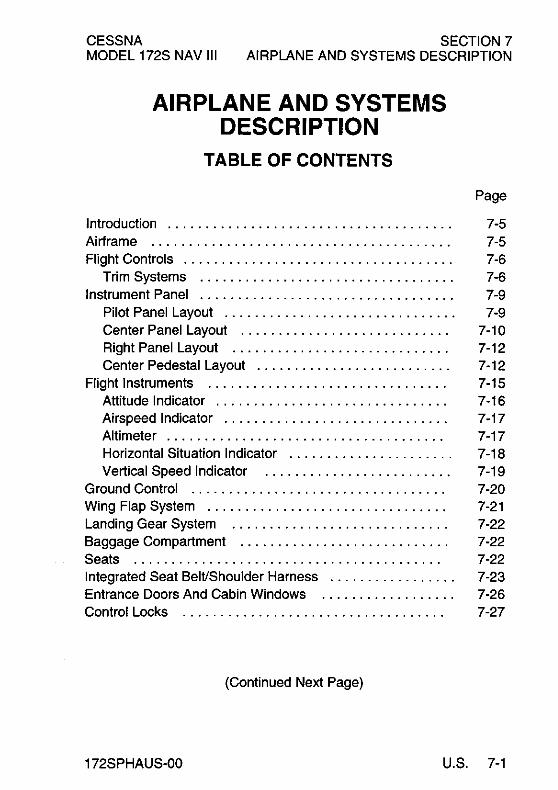
CESSNA MODEL 172S NAV III
SECTION 7 AIRPLANE AND SYSTEMS DESCRIPTION
AIRPLANE AND SYSTEMS DESCRIPTION
TABLE OF CONTENTS
Page
Introduction ...................................... 7-5 Airframe ........................................ 7-5 Flight Controls .................................... 7-6
Trim Systems .................................. 7-6 Instrument Panel .................................. 7-9
Pilot Panel Layout ............................... 7-9 Center Panel Layout ............................ 7-10 Right Panel Layout ............................. 7-12 Center Pedestal Layout .......................... 7-12
Flight Instruments ................................ 7-15 Attitude Indicator ............................... 7-16 Airspeed Indicator .............................. 7-17 Altimeter ..................................... 7-17 Horizontal Situation Indicator ...................... 7-18 Vertical Speed Indicator ......................... 7-19
Ground Control .................................. 7-20 Wing Flap System ................................ 7-21 Landing Gear System ............................. 7-22 Baggage Compartment ............................ 7-22 Seats ......................................... 7-22 Integrated Seat Belt/Shoulder Harness ................. 7-23 Entrance Doors And Cabin Windows .................. 7-26 Control Locks ................................... 7-27
(Continued Next Page)
172SPHAUS-00 U.S. 7-1

SECTION 7 AIRPLANE AND SYSTEMS DESCRIPTION
TABLE OF CONTENTS (Continued)
CESSNA MODEL 172S NAV III
Page
Engine ",""""","',"","""""""'" 7-28 Engine Controls "',"",",',"""""""',' 7-28 Engine Instruments ,"","',""""',","",' 7-29 New Engine Break In And Operation ",',"',"','" 7-33 Engine Lubrication System """",""",',"'" 7-34 Ignition And Starter System ""',""""',""'" 7-34 Air Induction System "",',""""",",""',' 7-35 Exhaust System """,',"""",""",,"'" 7-35 Fuel Injection System """"""',""',","" 7-36 Cooling System """"',""""","","'," 7-36
Propeller """"""',","""",""","",' 7-36 Fuel System "',""""',',"""""""""" 7-36
Fuel Distribution """",',"""""',',""" 7-37 Fuel Indicating System ",',"""""',',""'" 7-38 Auxiliary Fuel Pump Operation " , , , , ' , , , , , , , , , , , ' , 7-39 Fuel Return System "",'" , , , , , , , , , ' , , , , , , , , ' , 7-41 Fuel Venting """",","""",""",",'" 7-41 Reduced Tank Capacity ,,"",""""",',"'" 7-41 Fuel Selector Valve ""',"',"""""",""" 7-42 Fuel Drain Valves ,""","',"""""',,"'" 7-42
Brake System """"',","""",""","'," 7-43 Electrical System """"","""""',"',""" 7-43
G1000 Annunciator Panel ,""""""',',""'" 7-48 Master Switch """"",',""""""',""" 7-48 Standby Battery Switch ",""""""',',""'" 7-49 Avionics Switch """"',""""""',',""" 7-49 Electrical System Monitoring And Annunciations , , , , , " 7-50
Voltmeter ""',"""',""',""""',",'" 7-50 Ammeter, , , , , , , , , , , , , , , , , , , , , , , , , , , , , , , , , , , , , 7-50
Low Voltage Annunciation """,',"""',""'" 7-51 Circuit Breakers And Fuses """""""',""'" 7-52 External Power Receptacle """"',',"',""'" 7-52
(Continued Next Page)
7-2 U,S, 172SPHAUS-00

CESSNA MODEL 172S NAV III
SECTION 7 AIRPLANE AND SYSTEMS DESCRIPTION
TABLE OF CONTENTS (Continued)
Lighting Systems ................................ . Exterior Lighting .............................. . Interior Lighting ............................... .
Cabin Heating, Ventilating And Defrosting System ....... . Pitot-Static System And Instruments .................. . Vacuum System And Instruments ................... .
Attitude Indicator .............................. . Vacuum Indicator ............................. . Low Vacuum Annunciation ...................... .
Clock/O.A.T. Indicator ............................ . Stall Warning System ............................ . Standard Avionics ............................... .
GDU 1040 Color Display ........................ . GMA 1347 Audio Panel ......................... . GIA 63 Integrated Avionics Unit ................... . GRS n Attitude Heading Reference System (AHRS)
and GMU 44 Magnetometer .................... . GDC 74A Air Data Computer ..................... . GEA 71 Engine Monitor ........................ . GTX 33 Transponder ........................... . GDL 69A XM Weather and Radio Data Link .......... . BendixlKing KAP 140 2 Axis Autopilot (if installed) ..... .
Avionics Support Equipment ....................... . Avionics Cooling Fans .......................... . Antennas ................................... . Microphone And Headset Installations .............. . Auxiliary Audio Input Jack ....................... . 12V Power Outlet ........................... .. . Static Dischargers ............................. .
Cabin Features ................................. . Emergency Locator Transmitter (ELT) .............. . Cabin Fire Extinguisher ......................... . Carbon Monoxide Detection System (if installed) ...... .
Page
7-54 7-54 7-55 7-57 7-59 7-60 7-60 7-60 7-60 7-62 7-62 7-62 7-62 7-63 7-63
7-64 7-64 7-64
7-641 7-65 7-65 7-66 7-66 7-67 7-67 7-68 7-70 7-70 7-71 7-71 7-71 7-721
172SPHAUS-03 U.S. 7-317-4
CESSNA MODEL 172S NAV III
INTRODUCTION
SECTION 7 AIRPLANE AND SYSTEMS DESCRIPTION
This section provides description and operation of the airplane and its systems. Some equipment described herein is optional and may not be installed in the airplane. Refer to the Supplements, Section 9, for details of other optional systems and equipment.
AIRFRAME
The airplane is an all metal, four-place, high wing, single engine airplane equipped with tricycle landing gear and is designed for general utility and training purposes.
The construction of the fuselage is a conventional formed sheet metal bulkhead, stringer, and skin design referred to as semimonocoque. Major items of structure are the front and rear carry through spars to which the wings are attached, a bulkhead and forgings for main landing gear attachment at the base of the rear door posts, and a bulkhead with attach fittings at the base of the forward door posts for the lower attachment of the wing struts. Four engine mount stringers are also attached to the forward door posts and extend forward to the firewall.
The ex1ernally braced wings, containing integral fuel tanks, are constructed of a front and rear spar with formed sheet metal ribs, doublers, and stringers. The entire structure is covered with aluminum skin. The front spars are equipped with wing-to-fuselage and wing-to-strut attach fittings. The aft spars are equipped with wing-to-fuselage attach fittings, and are partial span spars. Conventional hinged ailerons and single slot type flaps are attached to the trailing edge of the wings. The ailerons are constructed of a forward spar containing balance weights, formed sheet metal ribs and "V" type corrugated aluminum skin joined together at the trailing edge. The flaps are constructed basically the same as the ailerons, with the exception of the balance weights and the addition of a formed sheet metal leading edge section.
(Continued Nex1 Page)
172SPHAUS-OO U.S. 7-5

SECTION 7 AIRPLANE AND SYSTEMS DESCRIPTION
AIRFRAME (Continued)
CESSNA MODEL 172S NAV III
The empennage (tail assembly) consists of a conventional vertical stabilizer, rudder, horizontal stabilizer, and elevator. The vertical stabilizer consists of a spar, formed sheet metal ribs and reinforcements, a wraparound skin panel, formed leading edge skin and a dorsal. The rudder is constructed of a formed leading edge skin and spar with attached hinge brackets and ribs, a center spar, a wrap around skin, and a ground adjustable trim tab at the base of the trailing edge. The top of the rudder incorporates a leading edge extension which contains a balance weight.
The horizontal stabilizer is constructed of a forward and aft spar, ribs and stifieners, center, left, and right wrap around skin panels, and formed leading edge skins. The horizontal stabilizer also contains the elevator trim tab actuator.
Construction of the elevator consists of formed leading edge skins, a forward spar, aft channel, ribs, torque tube and bellcrank, left upper and lower "V" type corrugated skins, and right upper and lower "V" type corrugated skins incorporating a trailing edge cutout for the trim tab. The elevator tip leading edge extensions incorporate balance weights. The elevator trim tab consists of a spar, rib, and upper and lower "V" type corrugated skins.
FLIGHT CONTROLS
The airplane's flight control system (Refer to Figure 7-1) consists of conventional aileron, rudder, and elevator control surfaces. The control surfaces are manually operated through cables and mechanical linkage using a control wheel for the ailerons and elevator, and rudder/brake pedals for the rudder.
TRIM SYSTEM
A manually operated elevator trim system is provided (Refer to Figure 7-1). Elevator trimming is accomplished through the elevator trim tab by utilizing the vertically mounted trim control wheel in the cockpit. Forward rotation of the trim wheel will trim nose down; conversely, aft rotation will trim nose up.
7-6 U.S. 172SPHAUS-OO

CESSNA MODEL 172S NAV III
SECTION 7 AIRPLANE AND SYSTEMS DESCRIPTION
0585T1017
Figure 7-1. Flight Control and Trim Systems (Sheet 1 of 2)
172SPHAUS-OO U.S. 7-7

SECTION 7 AIRPLANE AND SYSTEMS DESCRIPTION
ELEVATOR TRIM CONTROL SYSTEM
CESSNA MODEL 172S NAV III
0585T1018
Figure 7-1. Flight Control and Trim Systems (Sheet 2)
7-8 U.S. 172SPHAUS-OO
CESSNA MODEL 172S NAV III
SECTION 7 AIRPLANE AND SYSTEMS DESCRIPTION
INSTRUMENT PANEL
The instrument panel (refer to Figure 7-2) is of all metal construction and is installed in sections so equipment can be easily removed for maintenance. The glareshield, above and projecting aft from the instrument panel, limits undesirable reflections on the windshield from lighted equipment and displays mounted in the instrument panel.
The Nav III instrument panel contains the Garmin GDU 1040 Primary Flight (PFD) and Multifunction (MFD) Displays and the Garmin GMA 1347 Audio Panel. For specific details regarding the instruments, switches, circuit breakers and controls on the instrument panel, refer to the related topics in this section.
PILOT SIDE PANEL LAYOUT
The GDU 1040 Primary Flight Display (PFD), centered on the instrument panel in front of the pilot, shows the primary flight instruments during normal operation. During engine start, reversionary operation (MFD failure) or when the DISPLAY BACKUP switch is selected, the Engine Indication System (EIS) is shown on the PFD. Refer to the Garmin G1000™ Cockpit Reference Guide for specific operating information.
The Standby Battery (STBY BAT) switch is found at the upper left corner of the pilot instrument panel on an internally lighted subpanel. The switch positions (ARM/OFFfTEST) select the standby battery operating modes. The rocker-type MASTER and AVIONICS switches are found immediately below the standby battery switch.
The controls for adjusting instrument panel, equipment, and pedestal lighting are found together on the sub-panel below the MASTER and AVIONICS switches. See the INTERNAL LIGHTING paragraphs of this section for more information.
(Continued Next Page)
172SPHAUS-00 U.S. 7-9
SECTION 7 AIRPLANE AND SYSTEMS DESCRIPTION
INSTRUMENT PANEL (Continued)
PILOT SIDE PANEL LAYOUT (Continued)
CESSNA MODEL 172S NAV III
Switches for the airplane electrical systems and equipment are found on an internally lighted sub-panel found below the lower left corner of the PFD. Each switch is labeled for function and is ON when the handle is in the up position. See the ELECTRICAL EQUIPMENT descriptions in this section for further information.
The circuit breaker panel is found along the lower edge of the pilot's instrument panel below the electrical equipment switch panel and pilot control wheel column. Each circuit breaker is identified for the equipment or function it controls and for the bus from which it receives power. Lighting for this sub-panel is controlled using the SW/CB PANELS dimmer control. See the ELECTRICAL EQUIPMENT descriptions in this section for further information.
CENTER PANEL LAYOUT
The Garmin GMA 1347 Audio Panel is found on the upper half of the center instrument panel (immediately to the right of the PFD). A pushbutlon switch labeled "DISPLAY BACKUP" to manually select display reversion mode is found on the lower face of the GMA 1347. Refer to the GMA 1347 Pilot's Guide for operating information.
The GDU 1040 Multifunction Display (MFD) is found on the upper center panel to the right of the GMA 1347. The MFD depicts Engine Indication System information along the left side of the display and shows navigation, terrain, lightning and traffic data on the moving map. Flight management or display configuration information can be shown on the MFD in place of the moving map pages. Refer to the Garmin G1000™ GPS/MFD Pilot's Guide for operating information.
(Continued Next Page)
7-10 U.S. 172SPHAUS-00

CESSNA MODEL 172S NAV III
SECTION 7 AIRPLANE AND SYSTEMS DESCRIPTION
INSTRUMENT PANEL (Continued)
CENTER PANEL LAYOUT (Continued)
The standby instrument cluster is in the center instrument panel below the GMA 1347 Audio Panel. A conventional (mechanical) airspeed indicator and a sensitive aneroid altimeter are on each side of the vacuum-powered attitude indicator. The pitot-static instruments share the airplane pitot head and static ports with the GDC 74A Air Data Computer. The attitude indicator features a low vacuum "flag" to provide immediate warning of vacuum system failure.
The BendixlKing KAP 140 2 Axis Autopilot with Altitude Preselect is found on the center panel below the standby instruments. A DC electric powered turn coordinator, installed forward of the instrument panel and not visible to the pilot, provides a roll rate signal to the KAP 140. The KAP 140 receives NAV, HDG, and analog roll steering inputs from the G1000 system. KAP 140 ROL, VS, and AL T modes operate independently from the G 1 000. Refer to sectionl 9, Supplement 3 for operation of the BendixlKing KAP 140 2 Axis Autopilot.
The engine controls are found on the lower center instrument panel below the KAP 140 Autopilot (if installed). The controls arel conventional push-pull-type controls for throttle and mixture. See ENGINE description in this section for operating information.
The Alternate Static Air valve is found adjacent to the throttle control. Refer to the PITOT-STATIC SYSTEM AND INSTRUMENTS description in this section for operating information.
The wing flap control and indicator is found at the lower right side of the center panel. Refer to the WING FLAP SYSTEM description in this section for operating information.
(Continued Next Page)
172SPHAUS-03 U.S. 7-11

SECTION 7 AIRPLANE AND SYSTEMS DESCRIPTION
INSTRUMENT PANEL (Continued)
RIGHT PANEL LAYOUT
CESSNA MODEL 172S NAV III
The Emergency Locator Transmitter (ELT) mode switch (ON/AUTO/RESET) is positioned at the upper inboard corner of the right panel adjacent to the MFD. Refer to the EMERGENCY LOCATOR TRANSMITTER description in this section for operating information.
The Hour (Hobbs) meter is found to the right of the ELT switch and records engine operating time (when oil pressure is greater than 20 PSI) for maintenance purposes. Refer to the ENGINE INSTRUMENTS description in this section for further information.
CENTER PEDESTAL LAYOUT
The center pedestal, located below the center panel, contains the
lelevator trim control wheel, trim position indicator, 12V power outlet, aux audio input jack and a bracket for the microphone. The fuel selector valve handle is located at the base of the pedestal.
7-12 U.S. 172SPHAUS-03
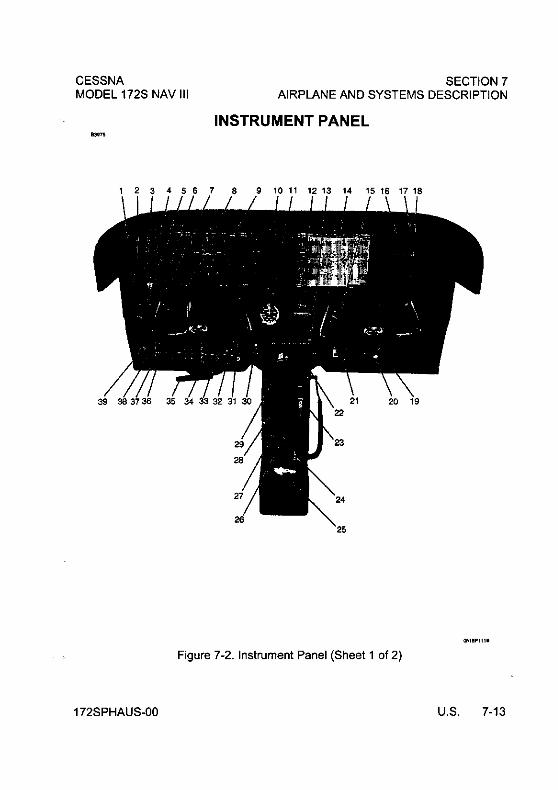
CESSNA MODEL 172S NAV III
SECTION 7 AIRPLANE AND SYSTEMS DESCRIPTION
INSTRUMENT PANEL
OI'il!Plt1.
Figure 7-2. Instrument Panel (Sheet 1 of 2)
172SPHAUS-OO U.S. 7-13
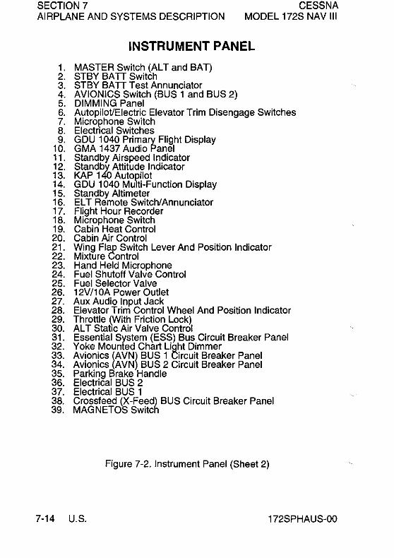
SECTION 7 CESSNA MODEL 172S NAV III AIRPLANE AND SYSTEMS DESCRIPTION
1. 2. 3. 4. 5. 6. 7. 8. 9.
10. 11. 12. 13. 14. 15. 16. 17. 18. 19. 20. 21. 22. 23. 24. 25. 26. 27. 28. 29. 30. 31. 32. 33. 34. 35. 36. 37. 38. 39.
INSTRUMENT PANEL
MASTER Switch (ALT and BAT) STBY BA TT Switch STBY BATT Test Annunciator AVIONICS Switch (BUS 1 and BUS 2) DIMMING Panel AutopiloVElectric Elevator Trim Disengage Switches Microphone Switch Electncal Switches GDU 1040 Primary Flight Display GMA 1437 Audio Panel Standby Airspeed Indicator Standby Attitude Indicator KAP 1 40 Autopilot GDU 1040 Multi-Function Display Standby Altimeter ELT Remote Switch/Annunciator Flight Hour Recorder Microphone Switch Cabin Heat Control Cabin Air Control Wing Flap Switch Lever And Position Indicator Mixture Control Hand Held Microphone Fuel Shutoff Valve Control Fuel Selector Valve 12V /10A Power Outlet Aux Audio Input Jack Elevator Trim Control Wheel And Position Indicator Throttle (With Friction Lock) AL T Static Air Valve Control Essential System (ESS) Bus Circuit Breaker Panel Yoke Mounted Chart Light Dimmer Avionics (AVNl BUS 1 Circuit Breaker Panel Avionics (AVN BUS 2 Circuit Breaker Panel Parking Brake Handle Electrical BUS 2 Electrical BUS 1 Crossfeed (X-Feed) BUS Circuit Breaker Panel MAGNETOS Switch
Figure 7-2. Instrument Panel (Sheet 2)
7-14 U.S. 172SPHAUS-00

CESSNA MODEL 172S NAV III
SECTION 7 AIRPLANE AND SYSTEMS DESCRIPTION
FLIGHT INSTRUMENTS
The G1000 Integrated Cockpit System primary flight instrument indications are shown on the GDU 1040 Primary Flight Display (PFD). The primary flight instruments are arranged on the PFD in the basic "T" configuration. The attitude indicator (AI) and horizontal situation indicator (HSI) are centered vertically on the PFD and are conventional in appearance and operation. Vertical tape-style (scrolling scale) indicators with fixed pointers and digital displays show airspeed, altitude, and vertical speed. The vertical indicators take the place of analog indicators with a fixed circular scale and rotating pointer.
Knobs, knob sets (two knobs on a common shaft) and membrane type push button switches, found on the bezel surrounding each GDU 1040 display, control COM, NAV, XPDR, and GPS avionics, set BARO (barometric pressure), CRS (course), and HDG (heading), and work various flight management functions. Some push button switches are dedicated to certain functions (keys) while other switches have functions defined by software (softkeys). A softkey may perform various operations or functions at various times based on software definition. Softkeys are found along the lower bezel of the GDU 1040 displays.
(Continued Next Page)
172SPHAUS-00 U.S. 7-15

SECTION 7 AIRPLANE AND SYSTEMS DESCRIPTION
FLIGHT INSTRUMENTS (Continued)
ATTITUDE INDICATOR
CESSNA MODEL 172S NAV III
The G 1 000 attitude indicator is shown on the upper center of the PFD. The attitude indication data is provided by the GRS 77 Attitude and Heading Reference (AHRS) unit. The G1000 attitude indicator provides a horizon line that is the full width of the GDU 1040 display.
The roll index scale is conventional with 10° graduations to 30° and then 15° graduations to 60° of roll. The roll pointer is slaved to the airplane symbol. The pitch index scale is graduated in 5° increments with every 10° of pitch labeled. If pitch limits are exceeded in either the nose-up or nose-down direction, red warning chevrons will appear on the indicator to point the way back to level flight. A small white trapezoid located below the roll pointer moves laterally left and right to provide the slip-skid information previously supplied by the skid indicator ball. The trapezoid should be centered below the roll pointer for coordinated turns. The standby (vacuum) attitude indicator is found on the lower center instrument panel.
(Continued Next Page)
7-16 U.S. 172SPHAUS-00

CESSNA MODEL 172S NAV III
SECTION 7 AIRPLANE AND SYSTEMS DESCRIPTION
FLIGHT INSTRUMENTS (Continued)
AIRSPEED INDICATOR
The G 1 000 vertical tape airspeed indicator is shown along the upper left side of the PFD. The airspeed indication data is provided by the GDC 74A Air Data Computer unit. Colored arcs are provided to indicate the maximum speed, high cruise speed caution range, normal operating range, full wing flap operating range and low airspeed awareness band. Calculated true airspeed is displayed in a window at the bottom edge of the airspeed tape.
The standby (pneumatic) airspeed indicator is found on the lower center instrument panel.
ALTIMETER
The primary altitude indicator (altimeter) is found along the right side of the attitude indicator on the GDU 1040 Primary Flight Display. The altitude indication data is provided by the GDC 74A Air Data Computer unit. The local barometric pressure is set using the BARO knob on the GDU 1040 displays. The GDU 1040 BARO setting has no effect on the KAP 140 Autopilot BARO setting.
A cyan selectable altitude reference pointer ("bug") is displayed on the altimeter tape and is set using the AL T SEL knob on the GDU 1040 displays. The altitude bug set-point is shown in a window at the top edge of the altimeter. The AL T SEL knob has no effect on the KAP 140 Autopilot altitude preselect or altitude hold functions.
NOTE
The KAP 140 Autopilot Altitude Preselect, Altitude Hold and BARO settings are completely independent of the G 1 000 AL T SEL and BARO settings.
The standby (aneroid) sensitive altimeter is found on the center instrument panel.
(Continued Next Page)
172SPHAUS-00 U.S. 7-17
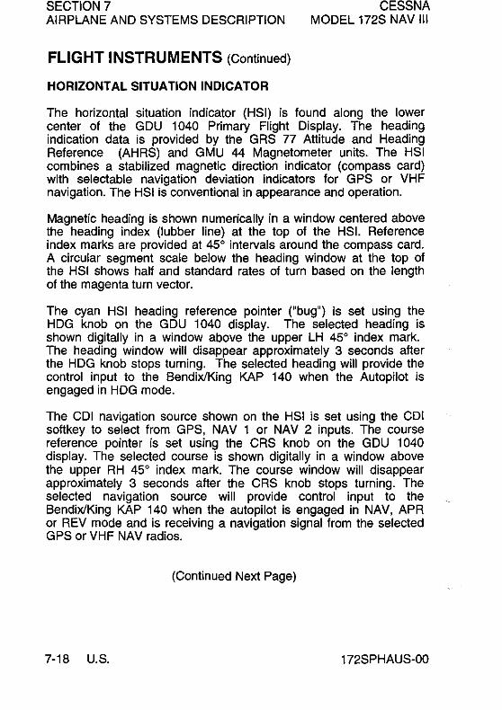
SECTION 7 AIRPLANE AND SYSTEMS DESCRIPTION
FLIGHT INSTRUMENTS (Continued)
HORIZONTAL SITUATION INDICATOR
CESSNA MODEL 172S NAV III
The horizontal situation indicator (HSI) is found along the lower center of the GDU 1040 Primary Flight Display. The heading indication data is provided by the GRS 77 Attitude and Heading Reference (AHRS) and GMU 44 Magnetometer units. The HSI combines a stabilized magnetic direction indicator (compass card) with selectable navigation deviation indicators for GPS or VHF navigation. The HSI is conventional in appearance and operation.
Magnetic heading is shown numerically in a window centered above the heading index (Iubber line) at the top of the HSI. Reference index marks are provided at 450 intervals around the compass card. A circular segment scale below the heading window at the top of the HSI shows half and standard rates of turn based on the length of the magenta turn vector.
The cyan HSI heading reference pointer ("bug") is set using the HDG knob on the GDU 1040 display. The selected heading is shown digitally in a window above the upper LH 450 index mark. The heading window will disappear approximately 3 seconds after the HDG knob stops turning. The selected heading will provide the control input to the BendixlKing KAP 140 when the Autopilot is engaged in HDG mode.
The CDI navigation source shown on the HSI is set using the CDI softkey to select from GPS, NAV 1 or NAV 2 inputs. The course reference pointer is set using the CRS knob on the GDU 1040 display. The selected course is shown digitally in a window above the upper RH 450 index mark. The course window will disappear approximately 3 seconds after the CRS knob stops turning. The selected navigation source will provide control input to the BendixlKing KAP 140 when the autopilot is engaged in NAV, APR or REV mode and is receiving a navigation signal from the selected GPS or VHF NAV radios.
(Continued Next Page)
7-18 U.S. 172SPHAUS-00

CESSNA MODEL 172S NAV III
SECTION 7 AIRPLANE AND SYSTEMS DESCRIPTION
FLIGHT INSTRUMENTS (Continued)
HORIZONTAL SITUATION INDICATOR (Continued)
WARNING WHEN THE KAP 140 AUTOPILOT IS ENGAGED IN NAV, APR OR REV OPERATING MODES, IF THE HSI NAVIGATION SOURCE IS CHANGED FROM GPS TO NAV1, AUTOMATICALLY OR MANUALLY (USING THE COl SOFT KEY), OR MANUALLY FROM NAV2 TO GPS, THE CHANGE WILL INTERRUPT THE NAVIGATION SIGNAL TO THE AUTOPILOT AND WILL CAUSE THE AUTOPILOT TO REVERT TO ROL MODE OPERATION. NO WARNING CHIME OR PFD ANNUNCIATION WILL BE PROVIDED. THE PREVIOUSLY-SELECTED MODE SYMBOL SHOWN ON THE AUTOPILOT DISPLAY WILL BE FLASHING TO SHOW THE REVERSION TO ROL MODE OPERATION. IN ROL MODE, THE AUTOPILOT WILL ONLY KEEP THE WINGS LEVEL AND WILL NOT CORRECT THE AIRPLANE HEADING OR COURSE. SET THE HOG BUG TO THE CORRECT HEADING AND SELECT THE CORRECT NAVIGATION SOURCE ON THE HSI USING THE COl SOFTKEY BEFORE ENGAGING THE AUTOPILOT IN ANY OTHER OPERATING MODE.
VERTICAL SPEED INDICATOR
The vertical speed indicator (VS!) tape is found on the right side of the altimeter display along upper right side of the GDU 1040 Primary Flight Display. The vertical speed pOinter moves up and down the fixed VSI scale and shows the rate of climb or descent in digits inside the pointer. The VSI tape has a notch on the right edge at the 0 feetlmin index for reference. Rate of descent is shown with a negative sign in front of the digits. Vertical speed must exceed 100 feetlmin in climb or descent before digits will appear in the VSI pointer.
172SPHAUS-00 U.S. 7-19

SECTION 7 AIRPLANE AND SYSTEMS DESCRIPTION
GROUND CONTROL
CESSNA MODEL 172S NAV III
Effective ground control while taxiing is accomplished through nose wheel steering by using the rudder pedals; left rudder pedal to steer left and right rudder pedal to steer right. When a rudder pedal is depressed, a spring loaded steering bungee (which is connected to the nose gear and to the rudder bars) will turn the nose wheel through an arc of approximately 10' each side of center. By applying either left or right brake, the degree of turn may be increased up to 30' each side of center.
Moving the airplane by hand is most easily accomplished by attaching a tow bar to the nose gear strut. If a tow bar is not available, or pushing is required, use the wing struts as push points. Do not use the vertical or horizontal surfaces to move the airplane. If the airplane is to be towed by vehicle, never turn the nose wheel more than 30' either side of center or structural damage to the nose gear could result.
The minimum turning radius of the airplane, using differential braking and nose wheel steering during taxi, is approximately 27 feet. To obtain a minimum radius turn during ground handling, the airplane may be rotated around either main landing gear by pressing down at the tailcone bulkhead just forward of the horizontal stabilizer to raise the nose wheel off the ground. Care should be exercised to ensure that pressure is exerted only at the bulkhead area and not on skin between the bulkheads. Pressing down on the horizontal stabilizer is not recommended.
7-20 U.S. 172SPHAUS-00

CESSNA MODEL 172S NAV III
SECTION 7 AIRPLANE AND SYSTEMS DESCRIPTION
WING FLAP SYSTEM
The single-slot type wing flaps (Refer to Figure 7-3), are extended or retracted by positioning the wing flap switch lever on the instrument panel to the desired flap deflection position. The switch lever is moved up or down in a slotted panel that provides mechanical stops at the 10°, 20° and 30° pOSitions. To change flap setting, the flap lever is moved to the right to clear mechanical stops at the 10° and 20° positions. A scale and pointer to the left of the flap switch indicates flap travel in degrees. The wing flap system circuit is protected by a 10-ampere circuit breaker, labeled FLAP, on the left side of the control panel.
B31~
0585T1 021
Figure 7-3. Wing Flap System
172SPHAUS-00 U.S. 7-21

SECTION 7 AIRPLANE AND SYSTEMS DESCRIPTION
LANDING GEAR SYSTEM
CESSNA MODEL 172S NAV III
The landing gear is of the tricycle type, with a steerable nose wheel and two main wheels. Wheel fairings are standard equipment for both the main and nose wheels. Shock absorption is provided by the tubular spring steel main landing gear struts and the air/oil nose gear shock strut. Each main gear wheel is equipped with a hydraulically actuated disc type brake on the inboard side of each wheel.
BAGGAGE COMPARTMENT
The baggage compartment consists of two areas, one extending from behind the rear passengers seat to the aft cabin bulkhead, and an additional area aft of the bulkhead. Access to both baggage areas is gained through a lockable baggage door on the left side of the airplane, or from within the airplane cabin. A baggage net with tiedown straps is provided for securing baggage and is attached by tying the straps to tiedown rings provided in the airplane. For baggage area and door dimensions, refer to Section 6.
SEATS
The seating arrangement consists of two vertically adjusting crew seats for the pilot and front seat passenger, and a single bench seat with adjustable back for rear seat passengers.
Seats used for the pilot and front seat passenger are adjustable fore and aft, and up and down. Additionally, the angle of the seat back is infinitely adjustable.
Fore and aft adjustment is made using the handle located below the center of the seat frame. To position the seat, lift the handle, slide the seat into position, release the handle and check that the seat is locked in place. To adjust the height of the seat, rotate the large crank under the right hand corner of the seat until a comfortable height is obtained. To adjust the seat back angle, pull up on the release button, located in the center front of seat, just under the seat bottom, position the seat back to the desired angle, and release the button. When the seat is not occupied, the seat back will automatically fold forward whenever the release button is pulled up.
(Continued Next Page)
7·22 U.S. 172SPHAUS·OO

CESSNA MODEL 172S NAV III
SEATS (Continued)
SECTION 7 AIRPLANE AND SYSTEMS DESCRIPTION
The rear passengers' seat consists of a fixed, one piece seat bottom and a three-position, reclining back. The reclining back is adjusted by a lever located below the center of the seat frame. To adjust the seat back, raise the lever, position the seat back to the desired angle, release the lever and check that the back is locked in place.
Headrests are installed on both the front and rear seats. To adjust the headrest, apply enough pressure to it to raise or lower it to the desired level.
INTEGRATED SEAT BELT/SHOULDER HARNESS
All seat positions are equipped with integrated seat belts/shoulder harness assemblies (Refer to Figure 7-4). The design incorporates an overhead inertia reel for the shoulder portion, and a retractor assembly for the lap portion of the belt. This design allows for complete freedom of movement of the upper torso area while providing restraint in the lap belt area. In the event of a sudden deceleration, reels lock up to provide positive restraint for the user.
In the front seats, the inertia reels are located on the centerline of the upper cabin. In the rear seats, the inertia reels are located outboard of each passenger in the upper cabin.
To use the integrated seat belt/shoulder harness, grasp the link with one hand, and, in a single motion, extend the assembly and insert into the buckle. Positive locking has occurred when a distinctive "snap" sound is heard.
(Continued Next Page)
172SPHAUS-OO U.S. 7-23

SECTION 7 AIRPLANE AND SYSTEMS DESCRIPTION
CESSNA MODEL 172S NAV III
INTEGRATED SEAT BELT/SHOULDER HARNESS (Continued)
Proper locking of the lap belt can be verified by ensuring that the belts are allowed to retract into the retractors and the lap belt is snug and low on the waist as worn normally during flight. No more than one additional inch of belt should be able to be pulled out of the retractor once the lap belt is in place on the occupant. If more than one additional inch of belt can be pulled out of the retractor, the occupant is too small for the installed restraint system and the aircraft should not be occupied until the occupant is properly restrained.
Removal is accomplished by lifting the release mechanism on the buckle or by pressing the release button on the buckle and pulling out and up on the harness. Spring tension on the inertia reel will automatically stow the harness.
A manually adjustable seat belt/shoulder harness assembly is available for all seats.
To use the manually adjustable seat belt/shoulder harness, fasten and adjust the seat belt/shoulder harness first. Lengthen the seat belt as required by pulling on the release strap on the belt. Snap the connecting link firmly into the buckle, then adjust to length. A properly adjusted harness will permit the occupant to lean forward enough to sit erect, but prevent excessive forward movement and contact with objects during sudden deceleration. Also, the pilot ~ must have the freedom to reach all controls easily.
Disconnecting the manually adjustable seat belt/shoulder harness is accomplished by pushing the button on the buckle to release the connecting link.
7-24 U.S. 172SPHAUS-OO
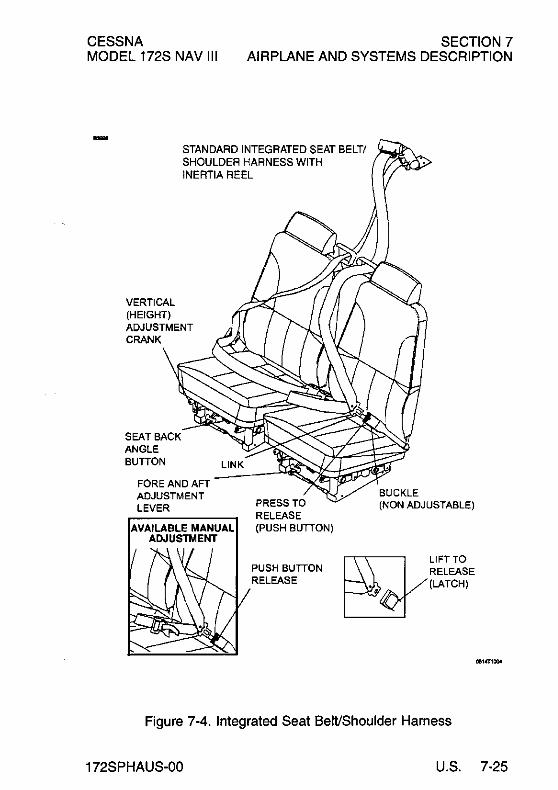
CESSNA MODEL 172S NAV III
SECTION 7 AIRPLANE AND SYSTEMS DESCRIPTION
STANDARD INTEGRATED SEAT BELT! SHOULDER HARNESS WITH INERTIA REEL
VERTICAL (HEIGHT) ADJUSTMENT CRANK
SEAT BACK ANGLE BUTTON
FORE AND AFT ADJUSTMENT LEVER PRESS TO
RELEASE (PUSH BUTTON)
PUSH BUTTON RELEASE
BUCKLE (NON ADJUSTABLE)
RELEASE (LATCH) ~LlFTTO
Figure 7-4. Integrated Seat Belt/Shoulder Harness
172SPHAUS-OO U.S. 7-25

SECTION 7 AIRPLANE AND SYSTEMS DESCRIPTION
CESSNA MODEL 172S NAV III
ENTRANCE DOORS AND CABIN WINDOWS
Entry to, and exit from the airplane is accomplished through either of two entry doors, one on each side of the cabin at the front seat positions (refer to Section 6 for cabin and cabin door dimensions). The doors incorporate a recessed exterior door handle, a conventional interior door handle, a key operated door lock (left door only), a door stop mechanism, and openable windows in both the left and right doors.
NOTE
The door latch design on this model requires that the outside door handle on the pilot and front passenger doors be extended out whenever the doors are open. When closing the door, do not attempt to push the door handle in until the door is fully shut.
To open the doors from outside the airplane, utilize the recessed door handle near the aft edge of either door by grasping the forward edge of the handle and pulling outboard. To close or open the doors from inside the airplane, use the combination door handle and arm rest. The inside door handle has three pOSitions and a placard at its base which reads OPEN, CLOSE, and LOCK. The handle is spring loaded to the CLOSE (up) position. When the door has been pulled shut and latched, lock it by rotating the door handle forward to the LOCK position (flush with the arm rest). When the handle is rotated to the LOCK position, an over center action will hold it in that position. Both cabin doors should be locked prior to flight, and should not be opened intentionally during flight.
NOTE
Accidental opening of a cabin door in flight due to improper closing does not constitute a need to land the airplane. The best procedure is to set up the airplane in a trimmed condition at approximately 75 KIAS, momentarily shove the door outward slightly, and forcefully close and lock the door.
(Continued Next Page)
7-26 U.S. 172SPHAUS-OO

CESSNA MODEL 172S NAV III
SECTION 7 AIRPLANE AND SYSTEMS DESCRIPTION
ENTRANCE DOORS AND CABIN WINDOWS (Continued)
Exit from the airplane is accomplished by rotating the door handle from the LOCK position, past the CLOSE position, aft to the OPEN position and pushing the door open. To lock the airplane, lock the right cabin door with the inside handle, close the left cabin door, and using the ignition key, lock the door.
The left and right cabin doors are equipped with openable windows which are held in the closed position by a detent equipped latch on the lower edge of the window frame. To open the windows, rotate the latch upward. Each window is equipped with a spring- loaded retaining arm which will help rotate the window outward, and hold it there. If required, either window may be opened at any speed up to 163 KIAS. The rear side windows and rear windows are of the fixed type and cannot be opened.
CONTROL LOCKS A control lock is provided to lock the aileron and elevator control surfaces to prevent damage to these systems by wind buffeting while the airplane is parked. The lock consists of a shaped steel rod and flag. The flag identifies the control lock and cautions about its removal before starting the engine. To install the control lock, align the hole in the top of the pilot's control wheel shaft with the hole in the top of the shaft collar on the instrument panel and insert the rod into the aligned holes. Installation of the lock will secure the ailerons in a neutral position and the elevators in a slightly trailing edge down position. Proper installation of the lock will place the flag over the ignition switch. In areas where high or gusty winds occur, a control surface lock should be installed over the vertical stabilizer and rudder. The control lock and any other type of locking device should be removed prior to starting the engine.
172SPHAUS-OO U.S. 7-27

SECTION 7 AIRPLANE AND SYSTEMS DESCRIPTION
ENGINE
CESSNA MODEL 172S NAV III
The airplane is powered by a horizontally opposed, four cylinder, overhead valve, air-cooled, fuel-injected engine with a wet sump lubrication system. The engine is a Lycoming Model IO-360-L2A and is rated at 180 horsepower at 2700 RPM. Major accessories include a starter and belt driven alternator mounted on the front of the engine, and dual magnetos, dual vacuum pumps, and a full flow oil filter mounted on the rear of the engine accessory case.
ENGINE CONTROLS
Engine power is controlled by a throttle located on the switch and control panel above the center pedestal. The throttle is open in the full forward pOSition and closed in the full aft position. A friction lock, which is a round knurled knob, is located at the base of the throttle and is operated by rotating the lock clockwise to increase friction or counterclockwise to decrease it.
The mixture control, mounted adjacent to the throttle control, is a red knob with raised points around the circumference and is equipped with a lock button in the end of the knob. The rich position is full forward, and full aft is the idle cutoff position. For small adjustments, the control may be moved forward by rotating the knob clockwise, and aft by rotating the knob counterclockwise. For rapid or large adjustments, the knob may be moved forward or aft by depressing the lock button in the end of the control, and then positioning the control as desired.
(Continued Next Page)
7-28 U.S. 172SPHAUS-00

CESSNA MODEL 172S NAV III
ENGINE (Continued)
ENGINE INSTRUMENTS
SECTION 7 AIRPLANE AND SYSTEMS DESCRIPTION
The G1000 Engine Indicating System (EIS) provides graphical indicators and numeric values for engine, fuel, and electrical system parameters to the pilot. The EIS is shown in a vertical strip on the left side of the PFD during engine starts and on the MFD during normal operation. If either the MFD or PFD fails during flight, the EIS is shown on the remaining display.
The EIS consists of three pages that are selected using the ENGINE softkey. The ENGINE page provides indicators for Tachometer, Fuel Flow, Oil Pressure, Oil Temperature, Exhaust Gas Temperature (EGT), Vacuum, Fuel Quantity, Engine Hours, Electrical Bus Voltages, and Battery Currents. When the ENGINE softkey is pressed, the LEAN and SYSTEM softkeys appear adjacent to the ENGINE softkey. The LEAN page provides simultaneous indicators for CHT and EGT on all cylinders to be used for adjusting ("leaning") the fuel/air mixture. The SYSTEM page provides numerical values for parameters on the ENGINE page that are shown as indicators only. The SYSTEM page also provides a digital value for fuel flow (FFLOW GPH) and fuel used (GAL USED).
The GEA-71 Engine and Airframe Unit, located forward of the instrument panel, receives signals from the engine/system sensors for the parameters that are being monitored. The GEA-71 provides data to the EIS, which displays the data for the ENGINE page described below.
(Continued Next Page)
172SPHAUS-OO U.S. 7-29

SECTION 7 AIRPLANE AND SYSTEMS DESCRIPTION
ENGINE (Continued)
RPM (TACHOMETER)
CESSNA MODEL 172S NAV III
Engine speed (RPM) is shown by the tachometer indicator found on all EIS pages. The tachometer indicator uses a circular scale with moving pointer and a digital value. The pOinter moves through a range from 0 to 3000 RPM. The numerical RPM value is displayed in increments of 10 RPM in white numerals below the pOinter.
The normal engine speed operating limit (top of green arc) changes with altitude. For standard-day conditions, between sea level and 5000 ft., 2500 RPM is the upper limit of the normal operating range. From 5000 ft. to 10,000 ft., 2600 RPM is the top of the normal range. And above 10,000 ft., 2700 RPM is the upper limit of the normal operating range. When engine speed is 2780 RPM or more, the pointer, digital value, and label (RPM) turn red to show engine speed is more than the limit. The digital value and label (RPM) will flash. The engine speed (tachometer) is displayed in the same configuration and location on the LEAN and SYSTEM pages. If engine speed becomes 2780 RPM or more while on the LEAN or SYSTEM page, the display will return to the ENGINE page.
A speed sensor, mounted on the engine tachometer drive accessory pad, provides a digital signal to the GEA-71 Engine and Airframe Unit which processes and outputs the RPM data to the EIS. A red X through the RPM indicator shows the indicating system is inoperative.
FUEL FLOW
Fuel flow is displayed on the ENGINE page by the FFLOW GPH horizontal indicator. The indicator range is from 0 to 20 GPH with 2 GPH graduations. A green arc from 0 to 12 GPH is the normal operating range. A white pointer indicates the measured fuel flow.
A digital value for FFLOW GPH is included on both the EIS LEAN and SYSTEM pages.
(Continued Next Page)
7-30 U.S. 172SPHAUS-00

CESSNA MODEL 172S NAV III
ENGINE (Continued)
FUEL FLOW (Continued)
SECTION 7 AIRPLANE AND SYSTEMS DESCRIPTION
The fuel flow transducer is located in the engine fuel injection system between the fuel/air control unit (servo) and the fuel distribution manifold (flow divider). The transducer provides a digital signal to the GEA-71 for display on the EIS. A red X through the indicator means the indicating system is inoperative.
OIL PRESSURE
Engine oil pressure is shown on the ENGINE page by the OIL PRES horizontal indicator. The indicator range is 0 to 120 PSI with a red arc from 0 to 20 PSI, a green arc from 50 to 90 PSI (normal operating range) and a red arc from 115 to 120 PSI. A white pointer indicates actual oil pressure. Oil pressure is shown numerically on the SYSTEM page.
When oil pressure is 0 to 20 PSI or 115 to 120 PSI, the pointer, digital value, and label (OIL PRES) will change to red to show that oil pressure is outside normal limits. If oil pressure exceeds either the upper or lower limit while on the LEAN or SYSTEM page, the EIS will return to the ENGINE page.
When the engine speed (RPM) is in the green arc and the oil temperature is in the green arc, the oil pressure should be in the green arc. If oil pressure is below the green arc or above the green arc, adjust the engine speed to maintain adequate oil pressure. When engine speed is at idle or near idle, the oil pressure indication must be above the lower red arc. With the engine at normal operating oil temperature, and engine speed at or close to idle, oil pressure below the green arc (but above the lower red arc) is acceptable.
(Continued Next Page)
172SPHAUS-00 U.S. 7-31

SECTION 7 AIRPLANE AND SYSTEMS DESCRIPTION
ENGINE (Continued)
OIL PRESSURE (Continued)
CESSNA MODEL 172S NAV III
In cold weather, the oil pressure will initially be high (close to the upper red arc when the engine is started). As the engine and oil warm up, the oil pressure will come down into the green arc.
The oil pressure transducer, connected to the engine forward oil pressure port, provides a signal to the GEA-71 that is processed and shown as oil temperature on the EIS. A separate low oil pressure switch causes an "OIL PRESSURE" annunciation on the PFD when oil pressure is 0 to 20 PSI. A red X through the oil pressure indicator means that the indicating system is inoperative.
OIL TEMPERATURE
Engine oil temperature is displayed on the ENGINE page by the OIL TEMP horizontal indicator. The indicator range is from 75°F to 250°F with a green arc (normal operating range) from lOO°F to 245°F and a red arc from 245°F to 250°F. A white pointer indicates actual oil temperature. Oil temperature is displayed numerically on the SYSTEM page.
When oil temperature is in the red band, 245°F to 250°F, the pointer and OIL TEMP turn red and flash to show oil temperature is higher than the limit. If oil temperature becomes hotter than 245°F while on the LEAN or SYSTEM page, the display will default to the ENGINE page.
The oil temperature sensor is installed in the engine oil filter adapter and provides a signal to the GEA-71 that is processed and shown as oil pressure on the EIS. A red X through the indicator shows that the indicating system is inoperative.
(Continued Next Page)
7-32 U.S. 172SPHAUS-00

CESSNA MODEL 172S NAV III
SECTION 7 AIRPLANE AND SYSTEMS DESCRIPTION
ENGINE (Continued)
CYLINDER HEAD TEMPERATURE
The cylinder head temperature (CHT) for all cylinders is displayed on the LEAN page. The cylinder with the hottest CHT is indicated by a cyan bar graph. The indicator range is from 100°F to 500°F, with a red line at 500°F. When a CHT is 500°F or hotter, the "CHT OF" legend and the temperature value will change to red to show that the cylinder head temperature is greater than the limit.
A thermocouple is installed in each cylinder head to provide the signal to the GEA-71 that is processed and shown as cylinder head temperature on the EIS. The LEAN page will show a red X over any cylinder that has a probe or wiring failure.
EXHAUST GAS TEMPERATURE
Exhaust gas temperature (EGT) is displayed on the ENGINE page by the EGT horizontal indicator. The indicator range is from 1250°F to 1650°F. The white pointer indicates relative exhaust gas temperature while the number inside of the pointer identifies the hottest cylinder. The EGT for all cylinders is shown on the LEAN page. The hottest cylinder is indicated by the cyan bar graph. The EGT for a particular cylinder may be shown by using the CYL SLCT softkey to select the desired cylinder. Automatic indication of the hottest cylinder will resume a short lime after the CYL SLCT is last selected.
A thermocouple in the exhaust pipe of each cylinder measures exhaust gas temperature and provides a voltage to the GEA-71 that is processed and shown as exhaust gas temperature on the EIS LEAN page. The LEAN page will show a red X over a cylinder that has a probe or wiring failure.
NEW ENGINE BREAK-IN AND OPERATION
The engine underwent a run in at the factory and is ready for the full range of use. It is, however, suggested that cruising be accomplished at 75% power as much as practicable until a total of 50 hours has accumulated or oil consumption has stabilized. This will ensure proper seating of the piston rings.
(Continued Nex1 Page)
172SPHAUS-00 U.S. 7-33

SECTION? AIRPLANE AND SYSTEMS DESCRIPTION
ENGINE (Continued)
ENGINE LUBRICATION SYSTEM
CESSNA MODEL 172S NAV III
The engine utilizes a full-pressure, wet-sump type lubrication system with aviation-grade oil used as the lubricant. The capacity of the engine sump (located on the bottom of the engine) is eight quarts. Oil is drawn from the sump through an oil suction strainer screen into the engine-driven oil pump. From the pump, oil is routed to a bypass valve. If the oil is cold, the bypass valve allows the oil to bypass the oil cooler and go directly from the pump to the full flow oil filter. If the oil is hot, the bypass valve routes the oil out of the accessory housing and into a flexible hose leading to the oil cooler on the right, rear engine baffle. Pressure oil from the cooler returns to the accessory housing where it passes through the full flow oil filter. The filter oil then enters a pressure relief valve which regulates engine oil pressure by allowing excessive oil to return to the sump while the balance of the oil is circulated to various engine parts for lubrication. Residual oil is returned to the sump by gravity flow.
An oil filler cap/oil dipstick is located at the right rear of the engine. The filler cap/ dipstick is accessible through an access door on the top right side of the engine cowling. The engine should not be operated on less than five quarts of oil. For ex1ended flight, fill to eight quarts (dipstick indication only). For engine oil grade and specifications, refer to Section 8 of this handbook.
IGNITION AND STARTER SYSTEM
Engine ignition is provided by two engine-driven magnetos, and two spark plugs in each cylinder. The right magneto fires the lower right and upper left spark plugs, and the left magneto fires the lower left and upper right spark plugs. Normal operation is conducted with both magnetos due to the more complete burning of the fuel/air mixture with dual ignition.
(Continued Next Page)
7-34 U.S. 172SPHAUS-OO
CESSNA MODEL 172S NAV III
SECTION 7 AIRPLANE AND SYSTEMS DESCRIPTION
ENGINE (Continued)
IGNITION AND STARTER SYSTEM (Continued)
Ignition and starter operation is controlled by a rotary-type switch located on the left switch and control panel. The MAGNETOS switch is labeled clockwise, OFF, R, L, BOTH, and START. The engine should be operated on both magnetos (BOTH position) except for magneto checks. The Rand L positions are for checking purposes and emergency use only. When the MAGNETOS switch is rotated to the spring loaded START position, (with the master switch in the ON position), the starter contactor is closed and the starter, now energized, will crank the engine. When the switch is released, it will automatically return to the BOTH position.
AIR INDUCTION SYSTEM
The engine air induction system receives ram air through an intake on the lower front portion of the engine cowling. The intake is covered by an air filter which removes dust and other foreign matter from the induction air. Airflow passing through the filter enters an air box. The air box has a spring-loaded alternate air door. If the air induction filter should become blocked, suction created by the engine will open the door and draw unfiltered air from inside the lower cowl area. An open alternate air door will result in an approximate 10% power loss at full throttle. After passing through the air box, induction air enters a fuel/air control unit under the engine, and is then ducted to the engine cylinders through intake manifold tubes.
EXHAUST SYSTEM
Exhaust gas from each cylinder passes through riser assemblies to a muffler and tailpipe. Outside air is pulled in around shrouds which are constructed around the outside of the muffler to form heating chambers which supply heat to the cabin.
(Continued Next Page)
172SPHAUS-00 U.S. 7-35

SECTION 7 AIRPLANE AND SYSTEMS DESCRIPTION
ENGINE (Continued)
FUEL INJECTION SYSTEM
CESSNA MODEL 172S NAV III
The engine is equipped with a fuel injection system. The system is comprised of an engine-driven fuel pump, fuel/air control unit, fuel manifold, fuel flow indicator, and air-bleed type injector nozzles.
Fuel is delivered by the engine-driven fuel pump to the fuel/air control unit. The fuel/air control unit correctly proportions the fuel flow to the induction air flow. After passing through the control unit, induction air is delivered to the cylinders through the intake manifold tubes and metered fuel is delivered to a fuel manifold (flow divider). The fuel manifold, through spring tension on a diaphragm and valve, evenly distributes the fuel to an air-bleed type injector nozzle
t·n the intake valve chamber of each cylinder. A turbine-type fuel flow transducer mounted between the fuel/air control unit and the fuel distribution unit produces a digital signal that displays fuel flow n the EIS pages.
COOLING SYSTEM
Ram air for engine cooling enters through two intake openings in the front of the engine cowling. The cooling air is directed around the cylinders and other areas of the engine by baffling, and is then exhausted through an opening at the bottom aft edge of the cowling. No manual cowl flap cooling system control is required.
PROPELLER
The airplane is equipped with a two bladed, fixed pitch, one-piece forged aluminum alloy propeller which is anodized to retard corrosion. The propeller is 76 inches in diameter.
FUEL SYSTEM
The airplane fuel system (see Figure 7-6) consists of two vented integral fuel tanks (one tank in each wing), a three-position selector valve, auxiliary fuel pump, fuel shutoff valve, fuel strainer, engine driven fuel pump, fuel/air control unit, fuel distribution valve and fuel injection nozzles.
(Continued Next Page)
7-36 U.S. 172SPHAUS-03

CESSNA SECTION 7 AIRPLANE AND SYSTEMS DESCRIPTION MODEL 172S NAV III
FUEL SYSTEM (Continued)
WARNING
UNUSABLE FUEL LEVELS FOR THIS AIRPLANE WERE DETERMINED IN ACCORDANCE WITH FEDERAL AVIATION REGULATIONS. FAILURE TO OPERATE THE AIRPLANE IN COMPLIANCE WITH FUEL LIMITATIONS SPECIFIED IN SECTION 2 MAY FURTHER REDUCE THE AMOUNT OF FUEL AVAILABLE IN FLIGHT.
FUEL QUANTITY DATA IN U.S. GALLONS
FUEL FUEL LEVEL TOTAL TOTAL TOTAL USABLE TANKS (QUANTITY FUEL UNUSABLE ALL FLIGHT
EACH TANK) CONDITIONS
Two Full (28.0) 56.0 3.0 53.0
Figure 7-5. Fuel System
FUEL DISTRIBUTION
Fuel flows by gravity from the two wing tanks to a three-position selector valve, labeled BOTH, RIGHT and LEFT and on to the reservoir tank. From the reservoir tank fuel flows through the auxiliary fuel pump, past the fuel shutoff valve, through the fuel strainer to an engine driven fuel pump.
From the engine-driven fuel pump, fuel is delivered to the fuel/air control unit, where it is metered and directed to a fuel distribution valve (manifold) which distributes it to each cylinder. Fuel flow into each cylinder is continuous, and flow rate is determined by the amount of air passing through the fuel/air control unit.
(Continued Next Page)
172SPHAUS-00 U.S. 7-37

SECTION 7 AIRPLANE AND SYSTEMS DESCRIPTION
FUEL SYSTEM (Continued)
FUEL INDICATING SYSTEM
CESSNA MODEL 172S NAV III
Fuel quantity is measured by two float-type fuel quantity sensors (one in each tank) and is displayed on all Engine Indicating System (EIS) pages. The indicators are marked in gallons of fuel. An empty tank is displayed on the fuel quantity indicator (FUEL QTY GAL) as a red line on the far left of the indicator scale, and the number "0". When an indicator shows an empty tank, approximately 1.5 gallons of unusable fuel remain in the tank. The indicators should not be relied upon for accurate readings during skids, slips or unusual attitudes.
The fuel quantity indicator shows the fuel available in the tank up to the limit of the sensor float travel. At this level, additional fuel may be added to completely fill the tank, but no additional movement of the float or the indicator will result. The limit for sensor float travel is approximately 24 gallons and is indicated by the maximum limit of the green arc. When the fuel level decreases below maximum travel of the fuel sensor, the fuel quantity indicator will display fuel quantity measured in each tank. A visual check of each wing tank fuel level must be performed prior to each flight. Compare the visual fuel level and indicated fuel quantity to accurately estimate usable fuel.
The fuel quantity indicators detect low fuel conditions and incorrect sensor outputs. When fuel quantity is less than 5 gallons indicated (and remains less than this level for more than 60 seconds), LOW FUEL L (left) and or LOW FUEL R (right) will be displayed in amber on the PFD and a tone will sound. The fuel quantity indicator pointer(s) and indicator label will change from white to steady amber. When fuel quantity reaches the calibrated usable fuel empty level, the LOW FUEL L and or LOW FUEL R remain amber and the indicator pointer(s) and label change to flashing red.
NOTE
Takeoff is not recommended if both fuel tank pointers are in the yellow arc range and/or any LOW FUEL annunciator is on.
(Continued Next Page)
7-38 U.S. 172SPHAUS-00
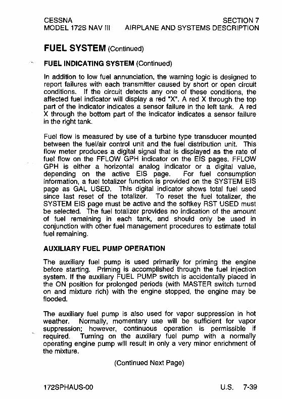
CESSNA MODEL 172S NAV III
SECTION 7 AIRPLANE AND SYSTEMS DESCRIPTION
FUEL SYSTEM (Continued)
FUEL INDICATING SYSTEM (Continued)
In addition to low fuel annunciation, the warning logic is designed to report failures with each transmitter caused by short or open circuit conditions. If the circuit detects anyone of these conditions, the affected fuel indicator will display a red "X". A red X through the top part of the indicator indicates a sensor failure in the left tank. A red X through the bottom part of the indicator indicates a sensor failure in the right tank.
Fuel flow is measured by use of a turbine type transducer mounted between the fuel/air control unit and the fuel distribution unit. This flow meter produces a digital signal that is displayed as the rate of fuel flow on the FFLOW GPH indicator on the EIS pages. FFLOW GPH is either a horizontal analog indicator or a digital value, depending on the active EIS page. For fuel consumption information, a fuel totalizer function is provided on the SYSTEM EIS page as GAL USED. This digital indicator shows total fuel used since last reset of the totalizer. To reset the fuel totalizer, the SYSTEM EIS page must be active and the softkey RST USED must be selected. The fuel totalizer provides no indication of the amount of fuel remaining in each tank, and should only be used in conjunction with other fuel management procedures to estimate total fuel remaining.
AUXILIARY FUEL PUMP OPERATION
The auxiliary fuel pump is used primarily for priming the engine before starting. Priming is accomplished through the fuel injection system. If the auxiliary FUEL PUMP switch is accidentally placed in the ON position for prolonged periods (with MASTER switch turned on and miX1ure rich) with the engine stopped, the engine may be flooded.
The auxiliary fuel pump is also used for vapor suppression in hot weather. Normally, momentary use will be sufficient for vapor suppression; however, continuous operation is permissible if required. Tuming on the auxiliary fuel pump with a normally operating engine pump will result in only a very minor enrichment of the miX1ure.
(Continued NeX1 Page)
172SPHAUS-OO U.S. 7-39

SECTION 7 AIRPLANE AND SYSTEMS DESCRIPTION
FUEL SYSTEM (Continued)
"""
VENT (WITH CHECK VALVE)
FUEL OUANlTY
DRAIN
GEA 71
CESSNA MODEL 172S NAV III
FUEL OUANITY
I VALVE (5 TOTAL)
FUEL
FUEL TANK
FUEL RESERVOIR TAt~K __ ("---'L~~~~
AUXiliARY FUEL ~u.,~ __ FUEL SHUT OFF
VALVE KNOB ~"\ ... FUEL \--. ..-1
DRAIN
" FUEL RETURN
;=[_=_._= .... =._=;.1 FUEL SUPPLY
MECHANICAL
~ liNKAGE
ELECTRICAL CONNECTION
DISTRIBUTION UNIT
GEA71 ENGINE AND AIR FRAME
Figure 7-6. Fuel System
7-40 U.S.
0585T1063
172SPHAUS-00

CESSNA MODEL 172S NAV III
SECTION 7 AIRPLANE AND SYSTEMS DESCRIPTION
FUEL SYSTEM (Continued)
AUXILIARY FUEL PUMP OPERATION (Continued)
It is not necessary to operate the auxiliary fuel pump during normal takeoff and landing, since gravity and the engine-driven pump will supply adequate fuel flow. In the event of failure of the enginedriven fuel pump, use of the auxiliary fuel pump will provide sufficient fuel to maintain flight at maximum continuous power.
FUEL RETURN SYSTEM
A fuel return system helps provide smooth engine operation on the ground during hot weather. The return system carries a metered amount of fuel from the engine fuel-air control unit to the fuel reservoir tank. The increased fuel flow due to the return system results in lower fuel temperatures at the engine inlet, and helps to minimize the amount of fuel vapor generated in the fuel lines during high OAT operations. See Section 4 for Hot Weather operating information.
FUEL VENTING
Fuel system venting is essential to system operation. Blockage of the system will result in decreasing fuel flow and eventual engine stoppage. Venting is accomplished by an interconnecting line from the right fuel tank to the left tank. The left fuel tank is vented overboard through a vent line, equipped with a check valve, which protrudes from the bottom surface of the left wing near the wing strut. Both fuel filler caps are also vented.
REDUCED TANK CAPACITY
The airplane may be serviced to a reduced capacity to permit heavier cabin loadings. This is accomplished by filling each tank to the bottom edge of the fuel filler tab, thus giving a reduced fuel load of 17.5 gallons usable in each tank.
(Continued Next Page)
172SPHAUS-OO U.S. 7-41

SECTION 7 AIRPLANE AND SYSTEMS DESCRIPTION
FUEL SYSTEM (Continued)
FUEL SELECTOR VALVE
CESSNA MODEL 172S NAV III
The FUEL SELECTOR valve should be in the BOTH position for takeoff, climb, landing, and maneuvers that involve prolonged slips or skids of more than 30 seconds. Operation from either LEFT or RIGHT tank is reserved for crUising flight.
NOTE
• When the FUEL SELECTOR valve handle is in the BOTH position in cruising flight, unequal fuel flow from each tank may occur if the wings are not maintained exactly level. Resulting wing heaviness can be alleviated gradually by turning the selector valve handle to the tank in the "heavy" wing. It is not practical to measure the time required to consume all of the fuel in one tank, and, after switching to the opposite tank, expect an equal duration from the remaining fuel. The airspace in both fuel tanks is interconnected by a vent line and, therefore, some sloshing of fuel between tanks can be expected when the tanks are nearly full and the wings are not level.
• When the fuel tanks are 1/4 full or less, prolonged uncoordinated flight such as slips or skids can uncover the fuel tank outlets. Therefore, if operating with one fuel tank dry or if operating on LEFT or RIGHT tank when 1/4 full or less, do not allow the airplane to remain in uncoordinated flight for periods in excess of 30 seconds.
FUEL DRAIN VALVES
The fuel system is equipped with drain valves to provide a means for the examination of fuel in the system for contamination and grade. The system should be examined before each flight and after each refueling, by using the sampler cup provided to drain fuel from each wing tank sump, the fuel reservoir sump, the fuel selector drain and the fuel strainer sump. If any evidence of fuel contamination is found, it must be eliminated in accordance with the Preflight Inspection checklist and the discussion in Section 8 of this publication. If takeoff weight limitations for the next flight permit, the fuel tanks should be filled after each flight to prevent condensation.
7-42 U.S. 172SPHAUS-00
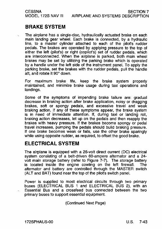
CESSNA MODEL 172S NAV III
BRAKE SYSTEM
SECTION 7 AIRPLANE AND SYSTEMS DESCRIPTION
The airplane has a single-disc, hydraulically actuated brake on each main landing gear wheel. Each brake is connected, by a hydraulic line, to a master cylinder attached to each of the pilot's rudder pedals. The brakes are operated by applying pressure to the top of either the left (pilot's) or right (copilot's) set of rudder pedals, which are interconnected. When the airplane is parked, both main wheel brakes may be set by utilizing the parking brake which is operated by a handle under the left side of the instrument panel. To apply the parking brake, set the brakes with the rudder pedals, pull the handle aft, and rotate it 90° down.
For maximum brake life, keep the brake system properly maintained, and minimize brake usage during taxi operations and landings.
Some of the symptoms of impending brake failure are: gradual decrease in braking action after brake application, noisy or dragging brakes, soft or spongy pedals, and excessive travel and weak braking action. If any of these symptoms appear, the brake system is in need of immediate attention. If, during taxi or landing roll, braking action decreases, let up on the pedals and then reapply the brakes with heavy pressure. If the brakes become spongy or pedal travel increases, pumping the pedals should build braking pressure. If one brake becomes weak or fails, use the other brake sparingly while using opposite rudder, as required, to offset the good brake.
ELECTRICAL SYSTEM
The airplane is equipped with a 28-volt direct current (DC) electrical system consisting of a belt-driven 60-ampere alternator and a 24-volt main storage battery (refer to Figure 7-7). The storage battery is located inside the engine cowling on the left firewall. The alternator and battery are controlled through the MASTER switch (AL T and BAT) found near the top of the pilot's switch panel.
Power is supplied to most electrical circuits through two primary buses (ELECTRICAL BUS 1 and ELECTRICAL BUS 2), with an Essential Bus and a crossfeed bus connected between the two primary buses to support essential equipment.
(Continued Next Page)
172SPHAUS-00 U.S. 7-43

SECTION 7 AIRPLANE AND SYSTEMS DESCRIPTION
ELECTRICAL SYSTEM (Continued)
CESSNA MODEL 172S NAV III
The system is equipped with a secondary or "standby" battery located between the firewall and the instrument panel. The STBY BATT switch controls power to or from the standby battery. The standby battery is available to supply power to the Essential Bus in the event that alternator and main battery power sources have both failed.
The primary buses are supplied with power whenever the MASTER switch (BAT) is turned on, and are not affected by starter or external power usage. Each primary bus is also connected to an avionics bus through a circuit breaker and the AVIONICS BUS 1 and BUS 2 switches. Each avionics bus is powered when the MASTER switch (BAT) and the corresponding AVIONICS switch is in the ON position.
CAUTION
BOTH BUS 1 AND BUS 2 AVIONICS SWITCHES SHOULD BE TURNED OFF TO PREVENT ANY HARMFUL TRANSIENT VOLTAGE FROM DAMAGING THE AVIONICS EQUIPMENT PRIOR TO TURNING THE MASTER SWITCH ON OR OFF,STARTING THE ENGINE OR APPLYING AN EXTERNAL POWER SOURCE
The airplane includes a power distribution module, located on the left forward side of the firewall, to house all the relays used in the airplane electrical system. The alternator control unit, main battery current sensor, and the external power connector are also housed within the module.
(Continued Next Page)
7-44 U.S. 172SPHAUS-OO

CESSNA MODEL 172S NAV III
SECTION 7 AIRPLANE AND SYSTEMS DESCRIPTION
ELECTRICAL SYSTEM (Continued)
'"'' To LOW VOLT annunciator (PFDor MFD)
,--------------------------------------------, Power Distribution Module Low Volt
Alternator Control Unit (ACU)
Ground f----------, , (J-box) V
F ,-------;----1Field Sensef------, Feeder:
Power Inf---,
,---,rmil rt:~r-+-DAlt Input M Outp'ut[}-, C/B: Not
r'0--;'" --used spare
Alternator Current Shunt O----{_B=. To sheet 2
Feeder CIB
'-OO--~,--,A-,- To sheet 2
r--~-4i\l'r1-1'--1I- To WARN
Not used __ ---:---g'. spare
Magnetos
Main Battery
BAT/ALT """,_J1'~_ LJI'-____ --+_--, MASTER
Switch B
Ext Pwr A
c __ --- -~~I~:--- -TIT --~ -n r -= ---- -- -____ 1
~ To ALTFLD
T
+ + - Circuit Breaker External Power 077Oll519
.... Figure 7-7 (Sheet 1 of 3) I 172SPHAUS-03 U.S. 7-45

SECTION 7 CESSNA MODEL 172S NAV III AIRPLANE AND SYSTEMS DESCRIPTION
I
ELECTRICAL SYSTEM (Continued)
'"'' ~U:E~L~----->F~U~EL To aux fuel pump
PUMP PUMP
~BC::C:N>----~Bt:C::\rr--- To flashing beacon
LT LT
To primary flight display To d~kskin and PFD cooling fans
To air data computer and attitude heading reference system
To navigation 111 and engine/airframe unit " !LACN~D~---<>LA~N~b To landing light
~ LT LT ,--------1 m ~ k""",, __ To Qverhead lights "I; CABIN To 12V cabin power
B
To flight information system (If Installed)
~ LTSIPWR o-Tc 12V cabin power
~~ FLAPS To flaps
1'ZVCAB PWR (If installed)
U Avionios S Switch 2
To automatic direction finder (If installed) To distance mea5l.lre equipment (rf installed)
AVN1
ALT ~ FIEL.D
To feeder m
B ~ circuit
breakers ~
,,,..\1 A i U
WARN
1
T Q aft master switch
To stall warning. autopilot warning, ELTwaming. main bus voltmeter, hourmeter, starter relay, stdby battery,
To primary flight display
To ail data computer To attitude heading reference system
To navigation ". engine/airfTame unit, and essential bus voltimeter
and main bIJI!I sense.
VN2
PrTOT ~ HEAT
PITot Te pitot heat
HEAT
~ ~
To NAV and -,,-~~o--- control wh~1
NA NAV map lights L.TS L.TS
~..-~~ iD TAXI L.T TAXlli To taxi light
1l:;~",,",,::lQ-::-::--- To wing strobe BE TROBE lights
L.TS L.TS
PANEL. AN~ To panel lights
L.TS L.TS
To and from standby STDBY battery system BATT
B U Avionics S Switch 2
L __________ ~/AUTO PIL.OT
To multi-function display and MFD fan
To tran$pOnder
To navigation 112 and aft avionics cooling fan
To audio panel
To autopilot system (If installed)
onOT1519
__ Figure 7-7 (Sheet 2)
7-46 U.S. 172SPHAUS-03

CESSNA MODEL 172S NAV III
SECTION 7 AIRPLANE AND SYSTEMS DESCRIPTION
ELECTRICAL SYSTEM (Continued) "'M
(/) ::0
[]J
a; :;:; c:
Switch
~I>"'b-_----.J tfl STD BY
BATT
On/Off Control
L--'O"r<>--v--+--7JTest Voltage Sense
Test Load = =
Test LED Light (green)l1r 121Test iL_ ---~!:----,:SJ Annunciation
, ,
Battery : Fuse :,5A
ToStandby ( Standby Battery :
(/) ::0
[]J
1J
Ammeter , (MFD or PFD) .L-__ --+-: -oFu'-sD-e-
Current Shunt
:5A
~ lS 1>"'0------------'--.;0 Main Bus
c:s WARN : Voltage Sense L _____________________________ _
077OT1S11l
... Figure 7-7 (Sheet 3) I
172SPHAUS-03 U.S. 7-47

SECTION 7 AIRPLANE AND SYSTEMS DESCRIPTION
CESSNA MODEL 172S NAV III
ELECTRICAL SYSTEM (Continued)
G1000 ANNUNCIATOR PANEL
All system alerts, cautions and warnings are shown on the right side of the PFD screen adjacent to the vertical speed indicator. The following annunciations are supported:
I
OIL PRESSURE LOW FUEL L LOW VOLTS HIGH VOLTS STBY BAT
LOW VACUUM LOW FUEL R PITCH TRIM CO LVL HIGH (if installed)
Refer to the Garmin G1000 Cockpit Reference Guide Appendix A for more information on system annunciations.
MASTER SWITCH
The MASTER switch is a two-pole, rocker-type switch. The BAT side of the switch controls the main battery electrical power to the airplane. The AL T side of the switch controls the alternator system.
In normal operation, both sides of the switch (AL T and BAT) are ON simultaneously; however, the BAT side of the switch may be selected separately as necessary. The AL T side of the switch can not be set to ON without the BAT side of the switch also being set to ON.
If the alternator system fails, the MASTER switch may be set to the OFF position to preserve Main Battery capacity for later in the flight. With the MASTER switch OFF and the STBY BATT switch in the ARM position, the standby battery will power the Essential Bus for a limited time. Time remaining may be estimated by monitoring Essential Bus Voltage. At 20 Volts, the standby battery has little or no capacity remaining.
(Continued Next Page)
7-48 U.S. 172SPHAUS-03

CESSNA MODEL 172S NAV III
SECTION 7 AIRPLANE AND SYSTEMS DESCRIPTION
ELECTRICAL SYSTEM (Continued)
STANDBY BATTERY SWITCH
The STBY BATT master switch is a three position (ARM-OFF-TEST) switch that tests and controls the Standby battery system. The energy level of the battery shall be checked before starting the engine (Refer to Section 4) by placing the switch in the momentary TEST position and observing the correct illumination of the TEST lamp found to the right of the switch. Energy level tests after starting engine are not recommended.
Placing the switch in the ARM position during the engine start cycle allows the Standby battery to help regulate and filter Essential Bus voltage during the start cycle. The switch is set to the ARM position during normal flight operation to allow the Standby battery to charge and to be ready to power the Essential Bus in the event of alternator and main battery failure. PlaCing the switch in the OFF position disconnects the Standby battery from the Essential Bus. Operation with the STBY BA TT switch in the OFF position prevents the Standby battery from charging and from automatically providing power should an electrical system failure occur.
AVIONICS SWITCH
The AVIONICS switch is a two-pole rocker-type switch that controls electrical power to AVIONICS BUS 1 and BUS 2. Placing either side of the rocker switch in the ON position supplies power to the corresponding avionics bus. Both sides of the AVION ICS switch should be placed in the OFF position before turning the MASTER switch ON or OFF, starting the engine, or applying an external power source.
(Continued Next Page)
172SPHAUS-OO U.S. 7-49

SECTION 7 AIRPlANE AND SYSTEMS DESCRIPTION
ELECTRICAL SYSTEM (Continued)
CESSNA MODEL 172S NAV III
ELECTRICAL SYSTEM MONITORING AND ANNUNCIATIONS
VOLTMETER
Voltage (VOLTS) indication for the Main and Essential buses is provided at the bottom of the EIS ENGINE or SYSTEM pages, labeled "M BUS E". Main bus voltage is shown numerically below the "M". Essential bus voltage is displayed numerically below the "E". The Main bus voltage is measured at the WARN circuit breaker on the Crossfeed (X-FEED) bus. The Essential bus voltage is measured at the NAV1 ENG circuit breaker on the Essential bus. Normal bus voltages with the alternator operating shall be about 28 volts. When the voltage for either Main or Essential is at or below 24.5 volts, the numeric value and VOLTS text turns red. This warning indication, along with the "lOW VOLTS" annunciation, is an indication that the alternator is not supplying all the power that is required by the aircraft. Indicated voltages between 24.5 and 28 volts may occur during low engine RPM conditions (Refer to note under lOW VOLTAGE ANNUNCIATION).
AMMETER
Electric current (AMPS) indication for both the main and Standby batteries is provided at the bottom of the EIS ENGINE or SYSTEM pages, labeled "M BA TT S". Main battery current is numerically displayed below the "M". Standby battery current is displayed nurnerically below the "S". A positive current value (shown in white) indicates that the battery is charging. A negative current value (shown in amber) indicates that the battery is discharging. In the event the alternator is not functioning or the electrical load exceeds the output of the alternator, the main battery ammeter indicates the main battery discharge rate.
In the event that Standby battery discharge is required, normal discharge should be less than 4 Amps. After engine start, with the STBY BA TT switch in the ARM position, the Standby Battery ammeter should indicate a charge showing correct charging of Standby Battery System.
(Continued Next Page)
7-50 U.S. 172SPHAUS-00

CESSNA MODEL 172S NAV III
SECTION 7 AIRPLANE AND SYSTEMS DESCRIPTION
ELECTRICAL SYSTEM (Continued)
lOW VOLTAGE ANNUNCIATION
A signal from the Alternator Control Unit (ACU), located inside the Power Distribution Module, provides the trigger for a red "lOW VOLTS" annunciation shown on the PFD. "lOW VOLTS" is displayed when the Main bus voltage measured in the junction box is below 24.5 volts. This warning annunciation is an indication that the alternator is not supplying the power that is required by the aircraft. If the conditions causing the warning can not be resolved, nonessential electrical loads should be eliminated and the flight should be terminated as soon as practicable.
NOTE
During low RPM operation, with a high electrical load on the system, such as during a low RPM taxi, the "lOW VOLTS" annunciation may come on, the bus voltage values may turn red, and Main battery ammeter discharge indications may occur. Under these conditions, increase RPM or decrease electrical loads to reduce demand on the battery.
In the event an overvoltage condition (or other alternator fault) occurs, the ACU will automatically open the Al T FIELD circuit breaker, removing alternator field current and stopping alternator output. The Main Battery will then supply current to the electrical system as shown by a discharge (negative number) on the M BAT ammeter. The lOW VOLTS annunciation will come on when the system voltage drops below 24.5 volts. Set the AlT FIELD circuit breaker to the ON position (push in) to energize the ACU. If the warning annunciation extinguishes and the Main Battery (M BATT) ammeter indicates positive current, normal alternator charging has resumed. If the annunciation comes on again, or the Al T FIELD circuit breaker opens again, an alternator malfunction has occurred. If the circuit breaker opens again, do not SET it to the ON position again. Have a qualified technician determine the cause and correct the malfunction. Turn off nonessential electrical loads and land as soon as practicable.
(Continued Next Page)
172SPHAUS-OO U.S. 7-51

SECTION 7 AIRPLANE AND SYSTEMS DESCRIPTION
ELECTRICAL SYSTEM (Continued)
LOW VOLTAGE ANNUNCIATION (Continued)
CESSNA MODEL 172S NAV III
ALT FIELD circuit breaker may open on occasion during normal engine starts due to transient overvoltages. Provided that normal alternator output is resumed after the AL T FIELD circuit breaker is reset, these occurrences are considered nuisance events. If the AL T FIELD circuit breaker opens after reset, do not close again. Repeated occurrences indicate a problem with the electrical system that must be corrected by a qualified maintenance technician before flight.
CIRCUIT BREAKERS AND FUSES
Individual system circuit breakers are found on the circuit breaker panel below the pilot's control wheel. All circuit breakers are "pullable" for electrical load management. Using a "pullable" circuit breaker as a switch is discouraged since the practice will decrease the life of the circuit breaker.
The Power Distribution Module uses three circuit breakers for the electrical bus feeders. A "fast blow" automotive type fuse is used at the Standby Battery. The Standby Battery current shunt circuit uses two field replaceable fuses located on the Standby Battery Controller printed circuit board.
Most Garmin G 1 000 equipment has internal non-field replaceable fuses. Equipment must be returned to Garmin by an approved service station for replacement.
EXTERNAL POWER RECEPTACLE
A external power receptacle is integral to the power distribution module and allows the use of an external power source for cold weather starting or for lengthy maintenance work on electrical and avionics equipment. The receptacle is located on the left side of the cowl near the firewall. Access to the receptacle is gained by opening the receptacle door.
(Continued Next Page)
7-52 U.S. 172SPHAUS-00

CESSNA MODEL 172S NAV III
SECTION 7 AIRPLANE AND SYSTEMS DESCRIPTION
ELECTRICAL SYSTEM (Continued)
EXTERNAL POWER RECEPTACLE (Continued)
NOTE
Set the AVIONICS switches BUS 1 and BUS 2 to OFF if no avionics are required. If maintenance on the avionics equipment is required, a 28 VDC regulated and filtered external power source must be provided to prevent damage to the avionics equipment from transient voltages. Set AVIONICS switches BUS 1 and BUS 2 to OFF before starting the engine.
The following check should be made whenever the engine has been started using external power (after disconnecting the external power source).
1. MASTER Switch (Al T and BAT) - OFF. 2. TAXI and lANDING Light Switches - ON. 3. Engine RPM - REDUCE to idle. 4. MASTER Switch (AlT and BAT) - ON (with taxi and landing
lights turned on). 5. Engine RPM - INCREASE (to approximately 1500 RPM). 6. Main Battery (BAT) Ammeter - CHECK (battery to be
charging, amps positive). 7. low Voltage Annunciator - CHECK (no lOW VOLTS
annunciation).
NOTE
If the Main Battery (M BATT) ammeter does not show a positive rate of charge or the low voltage warning annunciation does not go off, the battery should be removed from the airplane and properly serviced prior to flight.
172SPHAUS-00 U.S. 7-53

SECTION 7 AIRPLANE AND SYSTEMS DESCRIPTION
LIGHTING SYSTEMS
EXTERIOR LIGHTING
CESSNA MODEL 172S NAV III
Exterior lighting consists of navigation lights on the wing tips and the tip of the rudder, landing/taxi lights located on the left wing leading edge, a flashing beacon mounted on top of the vertical fin, and a strobe anticollision light on each wing tip.
Two courtesy lights are recessed into the lower surfaces of each wing and provide illumination for each cabin door area. The switch for the courtesy lights is found on the pilot's overhead console. Pressing the courtesy light switch will make the lights come on and pressing it again will make the lights go out.
All other exterior lights are operated by switches found on the lighted switch panel to the left of the PFD. Exterior lights are grouped together in the LIGHTS section of the switch panel. To activate the BEACON, LAND (Landing Light), TAXI (Taxi Light), NAV, and STROBE light(s), place the switch in the up position. Circuit breakers for the lights are found on the lighted circuit breaker panel on the lower left instrument panel, below the PFD. Circuit breakers are grouped by electrical bus with BEACON and LAND on ELECTRICAL BUS 1 and TAXI, NAV and STROBE on ELECTRICAL BUS 2.
NOTE
The strobes and flashing beacon should not be used when flying through clouds or overcast; the flashing light reflected from water droplets or particles in the atmosphere, particularly at night, can produce vertigo and loss of orientation.
(Continued Next Page)
7-54 U.S. 172SPHAUS-OO

CESSNA MODEL 172S NAV III
SECTION 7 AIRPLANE AND SYSTEMS DESCRIPTION
LIGHTING SYSTEMS (Continued)
INTERIOR LIGHTING
Interior lighting is controlled by a combination of dimmable crew area flood lighting, internally illuminated switch and circuit breaker panels, avionics panel lighting, instrument lighting, pedestal lighting, pilot control wheel map lighting and passenger area flood lighting.
For airplane serials 172S9810 thru 172S1 01 02, flood lighting is. accomplished using one dimmable light in the front crew area and one dome light in the rear passenger area. Both lights are contained in the overhead console, and are controlled by either the dimmer control for the front light, and an on and off type push button switch for the rear light. The front light can be rotated to provide directional lighting for the pilot and front passenger. The rear dome light provides for general illumination in the rear cabin area. Rear domel light and courtesy lights share the same switch.
For airplane serials 172S10103 and On, flood lighting is accomplished using two dimmable lights in the front crew area and one dome light in the rear passenger area. These lights are contained in the overhead console, and are controlled by dimmer controls for the front lights, and an on and off type push button switch for the rear light. The front lights can be rotated to provide directional lighting for the pilot and front passenger. The rear dome light provides for general illumination in the rear cabin area. Rear dome light and courtesy lights share the same switch.
Lighting of the switch panel, circuit breaker panel, engine controlsl and environmental control panel is accomplished by using internally lighted LED lighted panels. Rotating the SW/CB PANELS dimmer, found on the switch panel in the DIMMING group, controls the lighting level for both panels. Rotating the dimmer counterclockwise decreases light intensity from the highest level to off.
Pedestal lighting consists of two hooded lights found at various locations on the pedestal. Rotating the PEDESTAL dimmer, found on the switch panel in the DIMMING group, controls the pedestal lights. Rotating the dimmer counterclockwise decreases light intensity from the highest level to off.
(Continued Next Page)
172SPHAUS-03 U.S. 7-55

SECTION? AIRPLANE AND SYSTEMS DESCRIPTION
LIGHTING SYSTEMS (Continued)
INTERIOR LIGHTING (Continued)
CESSNA MODEL 172S NAV III
Avionics panel lighting consists of the PFD and MFD bezel and display lighting, Audio Panel lighting, and, if installed, KAP 140
I Flight Computer keys and display lighting. Rotating the AVIONICS dimmer, found on the switch panel in the DIMMING group, controls the lighting level. Positioning the dimmer control in the OFF position, rotated fully counterclockwise, causes the avionics displays to use internal photocells to automatically control the lighting levels. This is the recommended use of the avionics lighting for all day and lower lighting levels where lighting of the avionics bezels and keys is not required. In low to night lighting levels rotating the dimmer control clockwise from the OFF position places all avionics lighting level control to the AVIONICS dimmer control. This is the recommended use of avionics lighting for night and low lighting conditions to allow the pilot control of the aVionics illumination levels as dark adaptation occurs.
I Rotating the STDSY IND dimmer, found on the switch panel in the DIMMING group, controls lighting of the standby airspeed indicator, attitude indicator, altimeter and non-stabilized magnetic compass. Rotating the dimmer counterclockwise decreases light intensity from the highest level to off.
Pilot's chart lighting is accomplished by use of a rheostat and a light assembly, both found on the lower surface of the pilot's control wheel. The light provides downward illumination from the bottom of the control wheel to the pilot's lap area. To operate the light, first turn the NAV light switch ON, and then adjust the map light intensity using the knurled rheostat knob. Rotating the dimmer clockwise increases light intensity, and rotating the dimmer counterclockwise decreases light intensity.
(Continued Next Page)
7-56 U.S. 172SPHAUS-03

CESSNA MODEL 172S NAV III
SECTION 7 AIRPLANE AND SYSTEMS DESCRIPTION
LIGHTING SYSTEMS (Continued)
INTERIOR LIGHTING (Continued)
Regardless of the light system in question, the most probable cause of a light failure is a bumed out bulb. However, in the event any lighting system fails to come on, check the appropriate circuit breaker. If the circuit breaker has opened, and there is no obvious indication of a short circuit (smoke or odor), turn the affected lights OFF, close the circuit breaker, and turn the lights ON again. If the circuit breaker opens again, do not reset until maintenance has been performed.
CABIN HEATING, VENTILATING AND DEFROSTING SYSTEM
The temperature and volume of airflow into the cabin can be regulated by manipulation of the push-pull CABIN HT and CABIN AIR controls (Refer to Figure 7-8). Both controls are the locking button type and permit intermediate settings.
For cabin ventilation, pull the CABIN AIR knob out. To raise the air temperature, pull the CABIN HT knob out approximately 1/4 to 1/2 inch for a small amount of cabin heat. Additional heat is available by pulling the knob out farther; maximum heat is available with the CABIN HT knob pulled out and the CABIN AIR knob pushed full in. When no heat is desired in the cabin, the CABIN HT knob is pushed full in.
Front cabin heat and ventilating air is supplied by outlet holes spaced across a cabin manifold just forward of the pilot's and front passenger's feet. Rear cabin heat and air is supplied by two ducts from the manifold, one ex1ending down each side of the cabin to an outlet just aft of the rudder pedals at floor level. Windshield defrost air is also supplied by two ducts leading from the cabin manifold to defroster outlets near the lower edge of the windshield. Two knobs control sliding valves in either defroster outlet to permit regulation of defroster airflow.
(Continued Nex1 Page)
172SPHAUS-OO U.S. 7-57

SECTION 7 AIRPLANE AND SYSTEMS DESCRIPTION
CESSNA MODEL 172S NAV III
El3116
EXHAUST MUFFLER SHROUD
CABIN AIR CONTROL
CABIN HEAT CONTROL
FORWARD CABIN LOWER VENTILATIN
HEATER ____ ..... VALVE
RAM AIR .r--, VENTILATING '\.-'" AIR DOOR
AI R OUTLET ""~~;II,-...:st-~JIi>.,H~-I
FORWARD CABIN LOWER VENTILATING AIR OUTLET
CABIN FLOO AIR OUTLET
REAR CABIN VENTILATING AIR OUTLETS (2) RAM AIR FLOW
1 VENTILATING AIR HEATED AIR
~ BLENDED AIR - MECHANICAL
CONNECTION 0585T1 015
Figure 7-8. Cabin Heating, Ventilating and Defrosting System
7-58 U.S. 172SPHAUS-OO

CESSNA MODEL 172S NAV III
SECTION 7 AIRPLANE AND SYSTEMS DESCRIPTION
CABIN HEATING, VENTILATING AND DEFROSTING SYSTEM (Continued)
Separate adjustable ventilators supply additional air; one near each upper corner of the windshield supplies air for the pilot and front passenger, and two ventilators are available for the rear cabin area to supply air to the rear seat passengers. There are additional ventilators located in various positions in the cockpit.
PITOT-STATIC SYSTEM AND INSTRUMENTS
The pitot-static system uses a heated total pressure (pitot) head mounted on the lower surface of the left wing, external static ports mounted on the left side of the forward fuselage and associated. plumbing to connect the GDC 74A Air Data Computer and the conventional pitot-static instruments to the sources.
The heated pitot system uses an electrical heating element built in the body of the pitot head. The PITOT HEAT control switch is found on the switch panel below the lower LH corner of the PFD. The PITOT HEAT circuit breaker (10 A) is found on the circuit breaker panel at the lower LH side of the pilot panel.
A static pressure alternate source valve (AL T STATIC AI R) is located next to the throttle control. The AL T STATIC AI R valve provides static pressure from inside the cabin if the external static pressure source becomes blocked.
If erroneous instrument readings are suspected due to water or ice in the pressure line going to the standard external static pressure source, the alternate static source valve should be pulled on.
Pressures within the cabin will vary with open heaters/vents and windows. Refer to Section 5, Figure 5-1 (Sheet 2), for the Airspeedl Calibration, Alternate Static Source correction chart.
172SPHAUS-03 U.S. 7-59

SECTION 7 AIRPLANE AND SYSTEMS DESCRIPTION
CESSNA MODEL 172S NAV III
VACUUM SYSTEM AND INSTRUMENTS
The vacuum system (refer to Figure 7-9) provides the vacuum necessary to operate the standby attitude indicator. The system consists of one engine-driven vacuum pump, a vacuum regulator, the standby attitude indicator, a vacuum system air filter, and a vacuum transducer. The GEA-71 Engine and Airframe unit receives the signal from the vacuum transducer and shows vacuum on the
IEIS ENGINE page. If vacuum available through the pump drops below 3.5 in.hg., LOW VACUUM will appear in amber on the PFD.
ATTITUDE INDICATOR
The standby attitude indicator is a vacuum-powered gyroscopic instrument, found on the center instrument panel below the MFD. The Attitude Indicator includes a low-vacuum warning "flag" ("GYRO") that comes into view when the vacuum is below the level necessary for reliable gyroscope operation.
VACUUM INDICATOR
IThe vacuum indicator is incorporated on the EIS ENGINE page, found along the left side of the PFD during engine start or the left edge of the MFD during normal operation. During reversionary operation, the EIS bar appears along the left side of the operational display.
LOW VACUUM ANNUNCIATION
A low vacuum condition is annunciated along the upper right side of the PFD by a amber "LOW VACUUM" text box.
7-60 U.S. 172SPHAUS-03

CESSNA MODEL 172S NAV III
'"''
CODE ,: INLET ··1 ! l AIR
~ VACUUM
DISCHARGE! AIR!
VACUUM SYSTEM AIR FILTER
GDU 1040 CONTROU DISPLAY UNIT
SECTION 7 AIRPLANE AND SYSTEMS DESCRIPTION
VACUUM SYSTEM
OVERBOARD VENT LINE
ENGINEDRIVEN VACUUM PUMP
VACUUM PRESS
EIS/ENGINE PAGE (ENGINE INDICATING SYSTEM)
GEA 71 ENGINE AND AIRFRAME UNIT
05851062
Figure 7-9. Vacuum System
172SPHAUS-00 U.S. 7-61

SECTION 7 AIRPLANE AND SYSTEMS DESCRIPTION
CLOCK I O.A.T. INDICATOR
CESSNA MODEL 172S NAV III
A numerical time or clock window (based on GPS time) and an outside air temperature (OAT.) indicator window are provided along " the lower edge of the PFD. The OAT. indicator uses an air temperature sensor located on top of the cabin.
STALL WARNING SYSTEM
The airplane is equipped with a pneumatic type stall warning system consisting of an inlet in the leading edge of the left wing, an air-operated horn near the upper left corner of the windshield, and associated plumbing. As the airplane approaches a stall, the low pressure on the upper surface of the wings moves forward around the leading edge of the wings. This low pressure creates a differential pressure in the stall warning system which draws air through the warning horn, resulting in an audible warning at 5 to 10 knots above stall in all flight conditions.
STANDARD AVIONICS
The Garmin GIOOO Avionics System is an integrated flight control and navigation system. The system combines primary flight instruments, communications, aircraft system information and navigational information all displayed on two color displays. The GIOOO system consists of the following pieces of equipment:
GDU 1040 COlOR DISPLAY
Two identical units are mounted on the instrument panel. One, located in front of the pilot, is configured as a Primary Flight Display, or PFD. A second panel, located to the right, is configured as a Multi-Function Display, or MFD.
The PFD displays roll and pitch information, heading and course navigation information, plus altitude, airspeed and vertical speed information to the pilot. The PFD also controls and displays all communication and navigation frequencies as well as displaying warning/status annunciations of aircraft systems.
(Continued Next Page)
7-62 U.S. 172SPHAUS-OO

CESSNA MODEL 172S NAV III
SECTION 7 AIRPLANE AND SYSTEMS DESCRIPTION
STANDARD AVIONICS (Continued)
GDU 1040 COlOR DISPLAY (Continued)
The MFD displays a large scalable, moving map that corresponds tol the airplane's current location. Data from other components of the system can be overlaid on this map. Location and direction of movement of nearby aircraft, lightning and weather information can all be displayed on the MFD. The MFD is also the principle display of all of the engine parameters and fuel information.
A Reversionary Mode places the flight information and basic engine information on both the PFD and the MFD. This feature allows the pilot full access to all necessary information should either of the display screens malfunction.
GMA 1347 AUDIO PANEL
The GMA 1347 audio panel for the G1000 system integrates all of the communication and navigation digital audio signals, intercom system and marker beacon controls in one unit. It is installed on the instrument panel between the PFD and the MFD. The GMA 1347 also controls the Reversionary Mode for the PFD and MFD.
NOTE
Use of the COM 1/2 function is not approved.
GIA 63 INTEGRATED AVIONICS UNIT
Two GIA 63 units are installed in the G1000 system. They are mounted in racks in the tailcone, behind the baggage curtain. These units act as the main communications hub linking all of the other peripheral parts to the GDU 1040 displays. Each unit contains a GPS receiver, a VHF navigation receiver, VHF communication transceiver and the main system microprocessors. The first GIA 631 unit to acquire a GPS satellite 3-D navigation signal is the active GPS source.
(Continued Next Page)
I 172SPHAUS-03 U.S. 7-63

SECTION 7 AIRPLANE AND SYSTEMS DESCRIPTION
STANDARD AVIONICS (Continued)
CESSNA MODEL 172S NAV III
GRS 77 ATTITUDE HEADING REFERENCE SYSTEM (AHRS) AND GMU 44 MAGNETOMETER
The GRS 77 AHRS provides airplane attitude and flight characteristics information to the G 1 000 displays and to the G lA 63 units. It is located in the tailcone of the airplane. The unit contains accelerometers, tilt sensors and rate sensors that replace spinning mass gyros used in other airplanes. The GMU 44 Magnetometer is located inside the left wing panel. It interfaces with the AHRS to provide heading information.
GDC 74A AIR DATA COMPUTER
The GDC 74A Air Data Computer (ADC) compiles information from the aircraft's pitoVstatic system. The unit is mounted behind the instrument panel, just forward of the MFD. An outside air temperature probe, mounted on top of the cabin, is connected to the Air Data Computer. The ADC calculates pressure altitude, airspeed, true airspeed, vertical speed and outside air temperature.
GEA 71 ENGINE MONITOR
The GEA 71 Engine Monitor is responsible for receiving and processing the Signals from all of the engine and airframe sensors. It is connected to all of the cylinder head temperature measuring sensors, exhaust gas temperature sensors, RPM, fuel flow and to the fuel gauging system. This unit transmits this information to the GIA 63 computers.
GTX 33 TRANSPONDER
The GTX 33 is a full-featured Mode S transponder which provides Mode A, C and S functions. Control and operation of the '-' transponder is accomplished using the PFD. The GTX 33 unit is mounted in the tailcone avionics racks.
Additional standard avionics supplied for use with the G 1 000 Integrated Cockpit System include:
(Continued Next Page)
U.S. 172SPHAUS-03

CESSNA MODEL 172S NAV III
SECTION 7 AIRPLANE AND SYSTEMS DESCRIPTION
STANDARD AVIONICS (Continued)
GDL 69A XM WEATHER AND RADIO DATA LINK
The GDL 69A XM Weather and Radio Data Link provides weather information and digital audio entertainment in the cockpit. The unit is mounted in the tailcone, behind the baggage curtain. This unit communicates with the MFD on the High-Speed Data Bus. XM Weather and XM Radio operate in the S-band frequency range to provide continuous uplink capabilities at any altitude throughout North America. A subscription to the XM Satellite Radio service is required for the GDL 69A to be used.
BENDIXlKING KAP 140 2 AXIS AUTOPILOT
Refer to Section 9, Supplement 3, for operating information.
WARNING
WHEN THE KAP 140 AUTOPILOT IS ENGAGED IN NAV, APR OR REV OPERATING MODES, IF THE HSI NAVIGATION SOURCE IS CHANGED FROM GPS TO NAV1 AUTOMATICALLY OR MANUALLY (USING THE CDI SOFTKEY) OR MANUALLY FROM NAV2 TO GPS, THE CHANGE WILL INTERRUPT THE NAVIGATION SIGNAL TO THE AUTOPILOT AND WILL CAUSE THE AUTOPILOT TO REVERT TO ROLL MODE OPERATION. NO WARNING CHIME OR PFD ANNUNCIATION IS PROVIDED. THE PREVIOUSLY SELECTED MODE SYMBOL SHOWN ON THE AUTOPILOT DISPLAY WILL BE FLASHING TO SHOW THE REVERSION TO ROLL MODE OPERATION. IN ROLL MODE, THE AUTOPILOT WILL ONLY KEEP THE WINGS LEVEL AND WILL NOT CORRECT THE AIRPLANE HEADING OR COURSE. SET THE HDG BUG TO THE CORRECT HEADING AND SELECT THE CORRECT NAVIGATION SOURCE ON THE HSI USING THE CDI SOFT KEY BEFORE ENGAGING THE AUTOPILOT IN ANY OTHER OPERATING MODE.
I 172SPHAUS-03 U.S. 7-65

SECTION 7 AIRPLANE AND SYSTEMS DESCRIPTION
AVIONICS SUPPORT EQUIPMENT
CESSNA MODEL 172S NAV III
Avionics cooling fans, antennas, microphone and headset provisions, power converter and static discharge wicks support the operation of the avionics equipment installations.
AVIONICS COOLING FAN
Four DC electric fans provide forced air and ambient air circulation cooling for the G 1 000 avionics equipment. A single fan in the tail cone provides forced air cooling to the Integrated Avionics Units and to the Transponder. A fan located forward of the instrument panel removes air from between the firewall bulkhead and instrument panel, directing the warm air up at the inside of the windshield. Two additional fans blow air directly onto the heat sinks located on the forward sides of the PFD and MFD.
Power is provided to these fans when the MASTER (BAT) switch and the AVIONICS (BUS 1 and BUS 2) switch are all ON.
NOTE
None of the cooling fans will operate when the essential bus avionics equipment is being powered by the standby battery.
(Continued Next Page)
7-66 U.S. 172SPHAUS-00
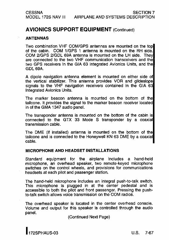
CESSNA MODEL 172S NAV III
SECTION 7 AIRPLANE AND SYSTEMS DESCRIPTION
AVIONICS SUPPORT EQUIPMENT (Continued)
ANTENNAS
Two combination VHF COM/GPS antennas are mounted on the top of the cabin. COM 1/GPS 1 antenna is mounted on the RH side. COM 21GPS 21GDL 69A antenna is mounted on the LH side. They are connected to the two VHF communication transceivers and the two GPS receivers in the GIA 63 Integrated Avionics Units, and the GDL 69A.
A dipole navigation antenna element is mounted on either side of the vertical stabilizer. This antenna provides VOR and glideslope signals to the VHF navigation receivers contained in the G lA 63 Integrated Avionics Units.
The marker beacon antenna is mounted on the bottom of the tailcone. It provides the signal to the marker beacon receiver located in of the GMA 1347 audio panel.
The transponder antenna is mounted on the bottom of the cabin is connected to the GTX 33 Mode S transponder by a coaxial transmission cable.
The DME (if installed) antenna is mounted on the bottom of the tailcone and is connected to the Honeywell KN 63 DME by a coaxial cable.
MICROPHONE AND HEADSET INSTALLATIONS
Standard equipment for the airplane includes a hand-held microphone, an overhead speaker, two remote-keyed microphone switches on the control wheels, and provisions for communications headsets at each pilot and passenger station.
The hand-held microphone includes an integral push-to-talk switch. This microphone is plugged in at the center pedestal and is accessible to both the pilot and front passenger. Pressing the pushto-talk switch allows voice transmission on the COM radios.
The overhead speaker is located in the center overhead console. Volume and output for this speaker is controlled through the audio panel.
(Continued Next Page)
I 172SPHAUS-03 U.S. 7-67
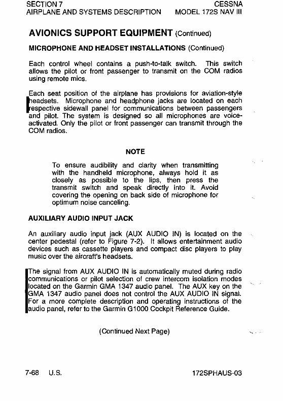
SECTION 7 AIRPLANE AND SYSTEMS DESCRIPTION
CESSNA MODEL 172S NAV III
AVIONICS SUPPORT EQUIPMENT (Continued)
MICROPHONE AND HEADSET INSTALLATIONS (Continued)
Each control wheel contains a push-to-talk switch. This switch allows the pilot or front passenger to transmit on the COM radios using remote mics.
Each seat position of the airplane has provisions for aviation-style t"leadsets. Microphone and head phone jacks are located on each tespective sidewall panel for communications between passengers and pilot. The system is designed so all microphones are voiceactivated. Only the pilot or front passenger can transmit through the COM radios.
NOTE
To ensure audibility and clarity when transmitting with the handheld microphone, always hold it as closely as possible to the lips, then press the transmit switch and speak directly into it. Avoid covering the opening on back side of microphone for optimum noise canceling.
AUXILIARY AUDIO INPUT JACK
An auxiliary audio input jack (AUX AUDIO IN) is located on the center pedestal (refer to Figure 7-2). It allows entertainment audio devices such as cassette players and compact disc players to play music over the aircraft's headsets.
The signal from AUX AUDIO IN is automatically muted during radio communications or pilot selection of crew intercom isolation modes located on the Garmin GMA 1347 audio panel. The AUX key on the GMA 1347 audio panel does not control the AUX AUDIO IN signal. For a more complete description and operating instructions of the audio panel, refer to the Garmin G1000 Cockpit Reference Guide.
(Continued Next Page)
7-68 U.S. 172SPHAUS-03

CESSNA MODEL 172S NAV III
SECTION 7 AIRPLANE AND SYSTEMS DESCRIPTION
AVIONICS SUPPORT EQUIPMENT (Continued)
AUXILIARY AUDIO INPUT JACK (Continued)
Since the entertainment audio input is not controlled by a switch, there is no way to deselect the entertainment source except to disconnect the source at the audio input connector. In the event of a high pilot workload and/or heavy traffic, it is wise to disable the entertainment audio to eliminate a source of distraction for the flight crew.
NOTE
• Passenger briefing should specify that AUX AUDIO IN (entertainment audio input) and Portable Electronic Device (PED) use is permitted only during the enroute phase of flight.
• Disconnect the cable from the AUX AUDIO IN jack when not in use.
• Use caution with audio cables in the cabin to avoid entangling occupants or cabin furnishings and to prevent damage to cables.
172SPHAUS-OO U.S. 7-69
SECTION 7 AIRPLANE AND SYSTEMS DESCRIPTION
CESSNA MODEL 172S NAV III
AVIONICS SUPPORT EQUIPMENT (Continued)
12V POWER OUTLET
A power converter located on the cabin side of the firewall, forward of the right instrument panel, reduces the aircraft's 28 VDC power to 12 VDC. This converter provides up to 10 amps of power to operate portable devices such as notebook computers and audio players. The power output connector (POWER OUTLET 12V -10A) is located on the center pedestal (refer to Figure 7-2).
For airplanes 172S10103 and On, a switch located on the switch panel labeled "CABIN PWR 12V" controls the operation of the power outlets.
NOTE
• Charging of lithium batteries may cause the lithium batteries to explode.
• Take care to observe the manufacturer's power requirements prior to plugging any device into the 12 volt Cabin Power System connector. This system is limited to a maximum of 10 amps.
• Use caution with power/adapter cables in the cabin to avoid entangling occupants or cabin furnishings and to prevent damage to cables supplying live electric current.
• Disconnect power/adapter cables when not in use.
STATIC DISCHARGERS
Static wicks (static dischargers) are installed at various points throughout the airframe to reduce interference from precipitation static. Under some severe static conditions, loss of radio signals is possible even with static dischargers installed. Whenever possible, avoid known severe precipitation areas to prevent loss of dependable radio signals. If avoidance is impractical, minimize airspeed and anticipate temporary loss of radio signals while in these areas.
Static dischargers lose their effectiveness with age, and therefore, should be checked periodically (at least at every annual inspection) by a qualified technician.
7-70 U.S. 172SPHAUS-03

CESSNA MODEL 172S NAV III
SECTION 7 AIRPLANE AND SYSTEMS DESCRIPTION
CABIN FEATURES
EMERGENCY LOCATOR TRANSMITTER (ELT)
A remote switch/annunciator is installed on the top center location of the right front passenger instrument panel for control of the ELT from the flight crew station. The annunciator, which is in the center of the rocker switch, illuminates when the ELT transmitter is transmitting. The ELT emits an omni-directional signal on the international distress frequencies of 121.5 MHz and 243.0 MHz. General aviation and commercial aircraft, the FM and CAP monitor 121.5 MHz, and 243.0 MHz is monitored by the military. For a basic. overview of the ELT, refer to the Section 9, Supplement 1.
CABIN FIRE EXTINGUISHER
A portable Halon 1211 (Bromochlorodifluoromethane) fire extinguisher is installed in a holder on the floorboard between the front seats to be accessible in case of fire. The extinguisher is classified 5B:C by Underwriters Laboratories.
The extinguisher should be checked prior to each flight to ensure that the pressure of the contents, as indicated by the gage at the top of the extinguisher, is within the green arc (approximately 125 psi) and the operating lever lock pin is securely in place.
To operate the fire extinguisher: 1. Loosen retaining clamp(s) and remove extinguisher from
bracket. 2. Hold extinguisher upright, pull operating ring pin, and press
lever while directing the liquid at the base of the fire at the near edge. Progress toward the back of the fire by moving the nozzle rapidly with a side to side sweeping motion.
WARNING
VENTILATE THE CABIN PROMPTLY AFTER SUCCESSFULLY EXTINGUISHING THE FIRE TO REDUCE THE GASES PRODUCED BY THERMAL DECOMPOSITION.
(Continued Next Page)
172SPHAUS-03 U.S. 7-71

SECTION 7 AIRPLANE AND SYSTEMS DESCRIPTION
CABIN FEATURES (Continued)
CABIN FIRE EXTINGUISHER (Continued)
CESSNA MODEL 172S NAV III
3. The contents of the cabin fire extinguisher will empty in approximately eight seconds of continuous use.
Fire extinguishers should be recharged by a qualified fire extinguisher agency after each use. Such agencies are listed under "Fire Extinguisher" in the telephone directory. After recharging, secure the extinguisher to its mounting bracket.
CARBON MONOXIDE DETECTION SYSTEM (if installed)
The carbon Monoxide (CO) detection system consist of a single detector located behind the instrument panel, powered by the airplanes DC electrical system and integrated in the Garmin Gl000 system with a warning annunciation and alert messages displayed on the PFD.
When the CO detection system senses a CO level of 50 parts per million (PPM) by volume or greater the alarm turns on a flashing warning annunciation CO LVL HIGH, in the annunciation window on the PFD with a continuous tone until the PFD softkey below WARNING is pushed. It then remains on steady until the CO level drops below 50 PPM and automatically resets the alarm.
If the CO system detects a problem within the system that requires service a CO DET SRVC message is displayed in the Alerts window of the PFD. If there is an interface problem between the Gl000 system and the CO system a CO DET FAIL message is displayed in the Alerts window of the PFD.
7-72 U.S. 172SPHAUS-03

CESSNA SECTION 8 MODEL 172S NAV III HANDLING, SERVICE AND MAINTENANCE
AIRPLANE HANDLING, SERVICE AND MAINTENANCE
TABLE OF CONTENTS
Page
Introduction ...................................... 8-3 Identification Plate ................................. 8-4 Cessna Owner Advisories ........................... 8-4
United States Airplane Owners ..................... 8-4 International Airplane Owners ...................... 8-5 Publications ................................... 8-5
Airplane File ..................................... 8-6 Airplane Inspection Periods .......................... 8-7
FAA Required Inspections ......................... 8-7 Cessna Inspection Programs ....................... 8-8 Cessna Customer Care Program .................... 8-9
Pilot Conducted Preventive Maintenance ................ 8-9 Alterations Or Repairs ............................. 8-10 Ground Handling ................................. 8-10
Towing ...................................... 8-10 Parking ...................................... 8-11 Tie-Down .................................... 8-11 Jacking ...................................... 8-11 Leveling ..................................... 8-12 Flyable Storage ................................ 8-13
Servicing ....................................... 8-14 Oil ........................................... 8-15
Oil SpeCification ............................... 8-15 Recommended Viscosity for Temperature Range ....... 8-15 Capacity of Engine Sump ........................ 8-16 Oil and Oil Filter Change ......................... 8-16
(Continued Next Page)
I 172SPHAUS-03 U.S. 8-1

SECTION 8 CESSNA HANDLING, SERVICE AND MAINTENANCE MODEL 172S NAV III
TABLE OF CONTENTS (Continued)
Page
Fuel .......................................... 8-17 Approved Fuel Grades (and Colors) ................. 8-17 Fuel Capacity ................................. 8-17 Fuel Additives ................................. 8-18 Fuel Contamination ............................. 8-22
Landing Gear ................................... 8-23 Cleaning And Care ............................... 8-23
Windshield And Windows ........................ 8-23 Painted Surfaces ............................... 8-24 Propeller Care ................................ 8-25 Engine Care .................................. 8-25 Interior Care .................................. 8-26
I Avionics Care ................................. 8-26
8-2 U.S. 172SPHAUS-03

CESSNA SECTION 8 MODEL 172S NAV III HANDLING, SERVICE AND MAINTENANCE
INTRODUCTION
This section contains factory recommended procedures for proper ground handling and routine care and servicing of your airplane. It also identifies certain inspection and maintenance requirements which must be followed if your airplane is to retain that new airplane performance and dependability. It is important to follow a planned schedule of lubrication and preventive maintenance based on climatic and flying conditions encountered in your local area.
Keep in touch with your local Cessna Service Station and take advantage of their knowledge and experience. Your Cessna Service Station knows your airplane and how to maintain it, and will remind you when lubrications and oil changes are necessary, as well as other seasonal and periodic services.
The airplane should be regularly inspected and maintained in accordance with information found in the airplane maintenance manual and in company issued Service Bulletins and Service Newsletters. All Service Bulletins pertaining to the airplane by serial number should be accomplished and the airplane should receive repetitive and required inspections. Cessna does not condone modifications, whether by Supplemental Type Certificate or otherwise, unless these certificates are held and/or approved by Cessna. Other modifications may void warranties on the airplane since Cessna has no way of knowing the full effect on the overall airplane. Operation of an airplane that has been modified may be a risk to the occupants, and operating procedures and performance data set forth in the operating handbook may no longer be considered accurate for the modified airplane.
172SPHAUS-OO U.S. 8-3
SECTION 8 HANDLING, SERVICE AND MAINTENANCE
IDENTIFICATION PLATE
CESSNA MODEL 172S NAV III
All correspondence regarding your airplane should include the Serial Number. The Serial Number, Model Number, Production Certificate Number (PC) and Type Certificate Number (TC) can be found on the Identification Plate, located on the aft left tailcone. The Finish and Trim Plate, located on the lower part of the left forward doorpost, contains a code describing the exterior paint configuration for the airplane. The code may be used in conjunction with an applicable Illustrated Parts Catalog if finish and trim information is needed.
CESSNA OWNER ADVISORIES
Cessna Owner Advisories are sent to Cessna Aircraft FAA Registered owners of record at no charge to inform them about mandatory and/or beneficial airplane service requirements and product changes. Copies of the Service Bulletins are available from Cessna Service Stations and Cessna Customer Service.
UNITED STATES AIR PLANE OWNERS
If your airplane is registered in the U. S., appropriate Cessna Owner Advisories will be mailed to you automatically according to the latest airplane registration name and address which you have provided to the FAA. Therefore, it is important that you provide correct and upto-date mailing information to the FAA.
If you require a duplicate Owner Advisory to be sent to an address different from the FAA airplane registration address, please complete and return an Owner AdviSOry Application (otherwise no action is required on your part).
(Continued Next Page)
8-4 U.S. 172SPHAUS-OO

CESSNA SECTION 8 MODEL 172S NAV III HANDLING, SERVICE AND MAINTENANCE
CESSNA OWNER ADVISORIES (Continued)
INTERNATIONAL AIRPLANE OWNERS
To receive Cessna Owner Advisories, please complete and return an Owner Advisory Application.
Receipt of a valid Owner AdviSOry Application will establish your Cessna Owner Advisory service for one year, after which you will be sent a renewal notice. It is important that you respond promptly to update your address for this critical service.
PUBLICATIONS
Various publications and flight operation aids are furnished in the airplane when delivered from the factory. These items are listed below.
• Customer Care Program Handbook • Pilot's Operating Handbook and FAA Approved Airplane
Flight Manual • Pilot's Checklist • Passenger Briefing Card • Cessna Service Directory
To obtain additional publications or Owner Advisory information, you may contact Cessna's Propeller Aircraft Product Support Department at (316) 517-5800, Fax (316) 942-9006 or write to Cessna Aircraft Company, P.O. Box 7706, Wichita, KS 67277, Dept 751 C.
172SPHAUS-00 U.S. 8-5

SECTION 8 HANDLING, SERVICE AND MAINTENANCE
PUBLICATIONS (Continued)
CESSNA MODEL 172S NAV III
The following additional publications, plus many other supplies that are applicable to your airplane, are available from a Cessna Service Station.
• Information Manual (contains Pilot's Operating Handbook Information)
• Maintenance Manual, Wiring Diagram Manual and Illustrated Parts Catalog
Cessna Service Stations have a Customer Care Supplies and Publications Catalog covering all available items, many of which the Service Station keeps on hand. The Service Station can place an order for any item which is not in stock.
NOTE
A Pilot's Operating Handbook and FAA Approved Airplane Flight Manual which is lost or destroyed may be replaced by contacting a Cessna Service Station. An affidavit containing the owner's name, airplane serial number and reason for replacement must be included in replacement requests since the Pilot's Operating Handbook and FAA Approved Airplane Flight Manual is identified for specific serial numbered airplanes only.
AIRPLANE FILE
There are miscellaneous data, information and licenses that are a part of the airplane file. The following is a checklist for that file. In addition, a periodic check should be made of the latest Federal Aviation Regulations to ensure that all data requirements are met.
To be displayed in the airplane at all times:
1. Aircraft Airworthiness Certificate (FAA Form 8100-2). 2. Aircraft Registration Certificate (FAA Form 8050-3). 3. Aircraft Radio Station License (if applicable).
(Continued Next Page)
8-6 U.S. 172SPHAUS-00

CESSNA SECTION 8 MODEL 172S NAV III HANDLING, SERVICE AND MAINTENANCE
AIRPLANE FILE (Continued)
To be carried in the airplane at all times:
1. Current Pilot's Operating Handbook and FAA Approved Airplane Flight Manual.
2. Garmin G1000 Cockpit Reference Guide (190-00384-00 or subsequent revision).
3. Weight and Balance, and associated papers (latest copy of the Repair and Alteration Form, FAA Form 337, if applicable).
4. Equipment List.
To be made available upon request:
1. Airplane Logbook. 2. Engine Logbook.
Most of the items listed are required by the United States Federal Aviation Regulations. Since the Regulations of other nations may require other documents and data, owners of airplanes not registered in the United States should check with their own aviation officials to determine their individual requirements.
Cessna recommends that these items, plus the Pilot's Checklists, Customer Care Program Handbook and Customer Care Card, be carried in the airplane at all times.
AIRPLANE INSPECTION PERIODS
FAA REQUIRED INSPECTIONS
As required by U.S. Federal Aviation Regulations, all civil aircraft of U.S. registry must undergo a complete inspection (annual) each twelve calendar months. In addition to the required annual inspection, aircraft operated commercially (for hire) must have a complete inspection every 100 hours of operation.
The FAA may require other inspections by the issuance of airworthiness directives applicable to the airplane, engine, propeller and components. It is the responsibility of the owner/operator to ensure compliance with all applicable airworthiness directives, and when the inspections are repetitive, to take appropriate steps to prevent inadvertent noncompliance.
172SPHAUS-00 U.S. 8-7

SECTION 8 HANDLING, SERVICE AND MAINTENANCE
CESSNA INSPECTION PROGRAMS
CESSNA MODEL 172S NAV III
In lieu of the 100 hour and annual inspection requirements, an airplane may be inspected in accordance with a Progressive Care Inspection Program or a PhaseCard Inspection Program. Both programs offer systems which allow the work load to be divided into smaller operations that can be accomplished in shorter time periods.
The Cessna Progressive Care Inspection Program allows an airplane to be inspected and maintained in four operations. The four operations are recycled each 200 hours and are recorded in a specially provided Aircraft Inspection Log as each operation is conducted.
The PhaseCard Inspection Program offers a parallel system for high-utilization flight operations (approximately 600 flight hours per year). This system utilizes 50 hour intervals (Phase 1 and Phase 2) to inspect high-usage systems and components. At 12 months or 600 flight hours, whichever occurs first, the airplane undergoes a complete (Phase 3) inspection.
Regardless of the inspection method selected, the owner should keep in mind that FAR Part 43 and FAR Part 91 establishes the requirement that properly certified agencies or personnel accomplish all required F AA inspections and most of the manufacturer recommended inspections.
8-8 U.S. 172SPHAUS-00

CESSNA SECTION 8 MODEL 172S NAV III HANDLING, SERVICE AND MAINTENANCE
CESSNA CUSTOMER CARE PROGRAM
Specific benefits and provisions of the Cessna Warranty plus other important benefits for you are contained in your Customer Care Program Handbook supplied with your airplane. The Customer Care Program Handbook should be thoroughly reviewed and kept in the airplane at all times.
You will also want to return to your Cessna Service Station either at 50 hours for your first Progressive Care Operation, or at 100 hours for your first 100 hour inspection depending on which program you choose to establish for your airplane. While these important inspections will be performed for you by any Cessna Service Station, in most cases you will prefer to have the Cessna Service Station from whom you purchased the airplane accomplish this work.
PILOT CONDUCTED PREVENTIVE MAINTENANCE
A certified pilot who owns or operates an airplane not used as an air carrier is authorized by FAR Part 43 to perform limited maintenance on his airplane. Refer to FAR Part 43 for a list of the specific maintenance operations which are allowed.
NOTE
Pilots operating airplanes of other than U.S. registry should refer to the regulations of the country of certification for information on preventive maintenance that may be performed by pilots.
A Maintenance Manual must be obtained prior to performing any preventive maintenance to ensure that proper procedures are followed. A Cessna Service Station should be contacted for further information or for required maintenance which must be accomplished by appropriately licensed personnel.
172SPHAUS-00 U.S. 8-9
SECTION 8 CESSNA HANDLING, SERVICE AND MAINTENANCE MODEL 172S NAV III
ALTERATIONS OR REPAIRS
It is essential that the FAA be contacted prior to any alterations on the airplane to ensure that airworthiness of the airplane is not violated. Alterations or repairs to the airplane must be accomplished by licensed personnel, utilizing only FAA Approved components and FAA Approved data, such as Cessna Service Bulletins.
GROUND HANDLING
TOWING
The airplane is most easily and safely maneuvered by hand with the tow bar attached to the nose wheel (the tow bar is stowed on the side of the baggage area). When towing with a vehicle, do not exceed the nose gear turning angle of 30° either side of center, or damage to the nose landing gear will result.
CAUTION
REMOVE ANY INSTALLED RUDDER LOCK BEFORE TOWING.
If the airplane is towed or pushed over a rough surface during hangaring, watch that the normal cushioning action of the nose strut does not cause excessive vertical movement of the tail and the resulting contact with low hangar doors or structure. A flat nose tire or deflated strut will also increase tail height.
(Continued Next Page)
8-10 U.S. 172SPHAUS-00

CESSNA SECTION 8 MODEL 172S NAV III HANDLING, SERVICE AND MAINTENANCE
GROUND HANDLING (Continued)
PARKING
When parking the airplane, head into the wind and set the parking brake. Do not set the parking brake during cold weather when accumulated moisture may freeze the brakes, or when the brakes are overheated. Install the control wheel lock and chock the wheels. In severe weather and high wind conditions, tie the airplane down as outlined in the following paragraph.
TIE-DOWN
Proper tie-down procedure is the best precaution against damage to the parked airplane by gusty or strong winds. To tie-down the airplane securely, proceed as follows:
1. Set the parking brake and install the control wheel lock. 2. Install a surface control lock over the fin and rudder. 3. Tie sufficiently strong ropes or chains (700 pounds tensile
strength) to the wing, tail and nose tie-down fittings and secure each rope or chain to a ramp tie-down.
4. Install a pitot tube cover.
JACKING
When a requirement exists to jack the entire airplane off the ground, or when wing jack points are used in the jacking operation, refer to the Maintenance Manual for specific procedures and equipment required.
Individual main gear may be jacked by using the jack pad which is incorporated in the main landing gear strut step bracket. When using the individual gear strut jack pad, flexibility of the gear strut will cause the main wheel to slide inboard as the wheel is raised, tilting the jack. The jack must then be lowered for a second jacking operation. Do not jack both main wheels simultaneously using the individual main gear jack pads.
(Continued Nex1 Page)
172SPHAUS-00 U.S. 8-11

SECTION 8 CESSNA HANDLING, SERVICE AND MAINTENANCE MODEL 172S NAV III
GROUND HANDLING (Continued)
JACKING (Continued)
CAUTION
DO NOT APPLY PRESSURE ON THE ELEVATOR OR HORIZONTAL STABILIZER SURFACES. WHEN PUSHING ON THE TAILCONE, ALWAYS APPLY PRESSURE AT A BULKHEAD TO AVOID BUCKLING THE SKIN.
If nose gear maintenance is required, the nose wheel may be raised off the ground by pressing down on a tailcone bulkhead, just forward of the horizontal stabilizer, and allowing the tail to rest on the tail tie-down ring.
To assist in raising and holding the nose wheel off the ground, ground anchors should be utilized at the tail tie down point.
NOTE
Ensure that the nose will be held off the ground under all conditions by means of suitable stands or supports under weight supporting bulkheads near the nose of the airplane.
LEVELlNG
Longitudinal leveling of the airplane is accomplished by placing a level on leveling screws located on the left side of the tailcone. Deflate the nose tire and/or lower or raise the nose strut to properly center the bubble in the level. Corresponding points on both upper door sills may be used to level the airplane laterally.
(Continued Next Page)
8-12 U.S. 172SPHAUS-OO

CESSNA SECTION 8 MODEL 172S NAV III HANDLING, SERVICE AND MAINTENANCE
GROUND HANDLING (Continued)
FLYABLE STORAGE
Engines in airplanes that are flown every 30 days or less may notl achieve normal service life because of internal corrosion. Corrosion occurs when moisture from the air and the products of combustion combine to attack cylinder walls and bearing surfaces during periods when the airplane is not flown.
The minimum recommended operating frequency for the engine is one continuous flight hour (not counting taxi, takeoff and landing time) with oil temperatures of 165°F to 200°F every 30 days or less (depending on location and storage conditions). Airplanes operated close to oceans, lakes, rivers and in humid regions are in greater need of engine preservation than airplanes operated in arid regions. Appropriate engine preservation procedures must be practiced by the owner or operator of the airplane based on present environmental conditions and the frequency of airplane activity.
NOTE
The engine manufacturer does not recommend pulling the engine through by hand during storage periods.
If the airplane is to remain inactive for more than 30 days, consult the latest revision of Textron Lycoming Service Letter L180 (www.lycoming.textron.com).
It is recommended when storing the airplane for any period of timel to keep fuel tanks full to minimize condensation in tanks. Keep the battery fully charged to prevent the electrolyte from freezing in cold weather. Refer to the Maintenance Manual for proper airplane storage procedures.
172SPHAUS-03 U.S. 8-13
SECTION 8 HANDLING, SERVICE AND MAINTENANCE
SERVICING
CESSNA MODEL 172S NAV III
In addition to the Preflight Inspection covered in Section 4 of this handbook, complete servicing, inspection and test requirements for your airplane are detailed in the Maintenance Manual. The Maintenance Manual outlines all items which require attention at specific intervals plus those items which require servicing, inspection, and/or testing at special intervals.
Since Cessna Service Stations conduct all service, inspection, and test procedures in accordance with applicable Maintenance Manuals, it is recommended that you contact your local Cessna Service Station concerning these requirements and begin scheduling your airplane for service at the recommended intervals.
Cessna Progressive Care ensures that these requirements are accomplished at the required intervals to comply with the 100 hour or annual inspection as previously covered.
Depending on various flight operations, your local Government Aviation Agency may require additional service, inspections, or tests. For these regulatory requirements, owners should check with local aviation officials where the airplane is being operated.
For quick and ready reference, quantities, materials and speCifications for frequently used service items are as follows.
8-14 U.S. 172SPHAUS-00

CESSNA SECTION 8 MODEL 172S NAV III HANDLING, SERVICE AND MAINTENANCE
OIL
OIL SPECIFICATION
MIL-L-6082 or SAE J1966 Aviation Grade Straight Mineral Oil: Used when the airplane was delivered from the factory and should be used to replenish the supply during the first 25 hours. This oil should be drained and filter replaced after the first 25 hours of operation. Refill the engine and continue to use until a total of 50 hours has accumulated or oil consumption has stabilized.
MIL-L-22851 or SAE J1899 Aviation Grade Ashless Dispersant Oil: Oil conforming to Textron Lycoming Service Instruction No. 1014, and all revision and supplements thereto, must be used after first 50 hours, or when oil consumption has stabilized.
RECOMMENDED VISCOSITY FOR TEMPERATURE RANGE
Multiviscosity or straight grade oil may be used throughout the year for engine lubrication. Refer to the following table for temperature verses viscosity range
MIL-L·6082 or MIL-L·22851 or
Temperature SAE J1966 SAE J1899
Straight Ashless Dispersant Mineral Oil SAE Grade SAE Grade
Above 27°C (80°F) 60 60
Above 16°C (60°F) 50 40 or 50
_1°C (30°F) to 32°C (90°F) 40 40
·18°C (O°F) to 21°C (70°F) 30 30, 40 or 20W-40
Below ·12°C (10°F) 20 300r20W-30
·18°C (O°F) to 32°C (90°F) 20W-50 20W·50 or 15W-50
All Temperatures --- 15W-50 or 20W·50
(Continued Next Page)
172SPHAUS-00 U.S. 8-15

SECTIONS HANDLING, SERVICE AND MAINTENANCE
OIL (Continued)
CAPACITY OF ENGINE SUMP
CESSNA MODEL 172S NAV III
The engine lubrication system has a total capacity of 9 quarts of oil, with the oil filter accounting for 1 quart of that total. The engine oil sump (crankcase) has a capacity of 8 quarts. The engine must not be operated with less than 5 quarts in the sump. For extended flights, the engine oil level should be at 8 quarts.
OIL AND OIL FILTER CHANGE
After the first 25 hours of operation, drain the engine oil sump and replace the filter. Refill sump with straight mineral oil and use until a total of 50 hours has accumulated or oil consumption has stabilized; then change to ashless dispersant oil. Ashless dispersant oil (and oil filter) should then be changed at time intervals set forth by the engine manufacturer.
NOTE
During the first 25 hour oil and filter change, a general inspection of the overall engine compartment is required. Items which are not normally checked during a preflight inspection should be given special attention. Hoses, metal lines and fittings should be inspected for signs of oil and fuel leaks, and checked for abrasions, chafing, security, proper routing and support, and evidence of deterioration. Inspect the intake and exhaust systems for cracks, evidence of leakage, and security of attachment. Engine controls and linkages should be checked for freedom of movement through their full range, security of attachment and evidence of wear. Inspect wiring for security, chafing, burning, defective insulation, loose or broken terminals, heat deterioration, and corroded terminals. Check the alternator belt in accordance with Maintenance Manual instructions, and tighten if necessary. A periodic check of these items during subsequent servicing operations is recommended.
8-16 U.S. 172SPHAUS-00

CESSNA SECTION 8 MODEL 172S NAV III HANDLING, SERVICE AND MAINTENANCE
FUEL
APPROVED FUEL GRADES (AND COLORS)
100LL Grade Aviation Fuel (Blue). 100 Grade Aviation Fuel (Green).
NOTE
Isopropyl alcohol or diethylene glycol monomethyl ether (DiEGME) may be added to the fuel supply in quantities not to exceed 1% (alcohol) or 0.15% (DiEGME) of total volume. Refer to Fuel Additives in later paragraphs for additional information.
FUEL CAPACITY
56.0 U.S. Gallons Total: 28.0 U.S. Gallons per tank.
NOTE
To ensure maximum fuel capacity when refueling and minimize cross feeding, the fuel selector valve should be placed in either the LEFT or RIGHT position and the airplane parked in a wings level, normal ground attitude. Refer to Figure 1-1 for a definition of normal ground attitude.
Service the fuel system after each flight, and keep fuel tanks full to minimize condensation in the tanks.
(Continued Next Page)
172SPHAUS-00 U.S. 8-17

SECTION 8 CESSNA HANDLING, SERVICE AND MAINTENANCE MODEL 172S NAV III
FUEL (Continued)
FUEL ADDITIVES
Strict adherence to recommended preflight draining instructions as called for in Section 4 will eliminate any free water accumulations from the tank sumps. While small amounts of water may still remain in solution in the gaSOline, it will normally be consumed and go unnoticed in the operation of the engine.
One exception to this can be encountered when operating under the combined effect of: (1) use of certain fuels, with (2) high humidity conditions on the ground (3) followed by flight at high altitude and low temperature. Under these unusual conditions, small amounts of water in solution can precipitate from the fuel stream and freeze in sufficient quantities to induce partial icing of the engine fuel system.
While these conditions are quite rare and will not normally pose a problem to owners and operators, they do exist in certain areas of the world and consequently must be dealt with, when encountered.
To help decrease the possibility of fuel icing occurring under these unusual conditions, it is permissible to add isopropyl alcohol or diethylene glycol monomethyl ether (DiEGME) compound to the fuel supply.
Alcohol or DiEGME compound added to the fuel absorbs the dissolved water from the gasoline. Alcohol has a freezing temperature depressant effect.
NOTE
When using fuel additives, it must be remembered that the final goal is to obtain a correct fuel-toadditive ratio in the tank, and not just with fuel coming out of the refueling nozzle. For example, adding 15 gallons of correctly proportioned fuel to a tank which contains 20 gallons of untreated fuel will result in a lower-than-acceptable concentration level to the 35 gallons of fuel which now reside in the tank.
(Continued Next Page)
8-18 U.S. 172SPHAUS-00

CESSNA SECTION 8 MODEL 172S NAV III HANDLING, SERVICE AND MAINTENANCE
FUEL (Continued)
FUEL ADDITIVES (Continued)
Alcohol must be blended with the fuel in a concentration of 1 % by volume. Concentrations greater than 1 % are not recommended since they can be detrimental to fuel tank materials.
Alcohol is most effective when it is completely dissolved in the fuel. To ensure proper mixing, the following is recommended:
1 . For best results, the alcohol should be added during the fueling operation by pouring the alcohol directly on the fuel stream issuing from the fueling nozzle.
2. An alternate method that may be used is to premix the complete alcohol dosage with some fuel in a separate clean container (approximately 2-3 gallon capacity) and then transferring this mixture to the tank prior to the fuel operation.
Diethylene glycol monomethyl ether (DiEGME) compound must be carefully mixed with the fuel in concentrations between 0.10% (minimum) and 0 .15% (maximum) of total fuel volume. Refer to Figure 8-1 for a DiEGME-to-fuel mixing chart.
WARNING
ANTI-ICING ADDITIVE IS DANGEROUS TO HEALTH WHEN BREATHED AND/OR ABSORBED INTO THE SKIN.
(Continued Next Page)
172SPHAUS-00 U.S. 8-19

SECTION 8 CESSNA HANDLING, SERVICE AND MAINTENANCE MODEL 172S NAV III
FUEL (Continued)
FUEL ADDITIVES (Continued)
CAUTION
MIXING OF DIEGME WITH FUEL IS EXTREMELY IMPORTANT. A CONCENTRATION IN EXCESS OF THAT RECOMMENDED (0.15% BY VOLUME MAXIMUM) MAY RESULT IN DETRIMENTAL EFFECTS TO THE FUEL TANK SEALANT, AND DAMAGE TO O-RINGS AND SEALS USED IN THE FUEL SYSTEM AND ENGINE COMPONENTS. A CONCENTRATION OF LESS THAN THAT RECOMMENDED (0.10% BY TOTAL VOLUME MINIMUM) WILL RESULT IN INEFFECTIVE TREATMENT. USE ONLY BLENDING EQUIPMENT THAT IS RECOMMENDED BY THE MANUFACTURER TO OBTAIN PROPER PROPORTIONING.
Prolonged storage of the airplane will result in a water buildup in the fuel which precipitates the additive. An indication of this is when an excessive amount of water accumulates in the fuel tank sumps. The concentration can be checked using a differential refractometer. It is imperative that the technical manual for the differential refractometer be followed explicitly when checking the additive concentration.
(Continued Nex1 Page)
8-20 U.S. 172SPHAUS-00

CESSNA SECTION 8 MODEL 172S NAV III HANDLING, SERVICE AND MAINTENANCE
FUEL MIXING RATIO 83118
0585T1001
Figure 8-1. Fuel Mixing Ratio
172SPHAUS-OO U.S. 8-21

SECTION 8 HANDLING, SERVICE AND MAINTENANCE
FUEL (Continued)
FUEL CONTAMINATION
CESSNA MODEL 172S NAV III
Fuel contamination is usually the result of foreign material present in the fuel system, and may consist of water, rust, sand, dirt, microbes or bacterial growth. In addition, additives that are not compatible with fuel or fuel system components can cause the fuel to become contaminated.
Before each flight and after each refueling, use a clear sampler cup and drain at least a cupful of fuel from each fuel tank drain location and from the fuel strainer quick drain valve to determine if contaminants are present, and to ensure the airplane has been fueled with the proper grade of fuel.
If contamination is detected, drain all fuel drain points including the fuel reservoir and fuel selector quick drain valves and then gently rock the wings and lower the tail to the ground to move any additional contaminants to the sampling points. Take repeated samples from all fuel drain points until all contamination has been removed. If, after repeated sampling, evidence of contamination still exists, the airplane should not be flown. Tanks should be drained and system purged by qualified maintenance personnel. All evidence of contamination must be removed before further flight. If the airplane has been serviced with the improper fuel grade, defuel completely and refuel with the correct grade. Do not fly the airplane with contaminated or unapproved fuel.
In addition, Owners/Operators who are not acquainted with a particular fixed base operator should be assured that the fuel supply has been checked for contamination and is properly filtered before allowing the airplane to be serviced. Fuel tanks should be kept full between flights, provided weight and balance considerations will permit, to reduce the possibility of water condensing on the walls of partially filled tanks.
To further reduce the possibility of contaminated fuel, routine maintenance of the fuel system should be performed in accordance with the airplane Maintenance Manual. Only the proper fuel, as recommended in this handbook, should be used, and fuel additives ' should not be used unless approved by Cessna and the Federal Aviation Administration.
8-22 U.S. 172SPHAUS-OO

CESSNA SECTION 8 MODEL 172S NAV III HANDLING, SERVICE AND MAINTENANCE
LANDING GEAR
Consult the following table for servicing information on the landing gear.
COMPONENT SERVICING CRITERIA
Nose Gear Tire (5.00-5, 6-Ply Rated 45.0 PSI Tire)
Main Gear Tire (6.00-6, 6-Ply Rated 42.0 PSI Tire)
Brakes MIL-H-5606
Nose Gear Shock Strut MIL-H-5606; 45.0 PSI·
• Keep strut filled with MIL-H-5606 hydraulic fluid per filling instructions placard, and with no load on the strut, inflate with air to 45.0 PSI. Do not over inflate.
CLEANING AND CARE
WINDSHIELD AND WINDOWS
The plastic windshield and windows should be cleaned with an aircraft windshield cleaner. Apply the cleaner sparingly with soft cloths, and rub with moderate pressure until all dirt, oil scum and bug stains are removed. Allow the cleaner to dry, then wipe it off with soft flannel cloths.
CAUTION
NEVER USE GASOLINE, BENZENE, ALCOHOL, ACETONE, FIRE EXTINGUISHER, ANTI-ICE FLUID, LACQUER THINNER OR GLASS CLEANER TO CLEAN THE PLASTIC. THESE MATERIALS WILL ATIACK THE PLASTIC AND MAY CAUSE IT TO CRAZE.
If a windshield cleaner is not available, the plastic can be cleaned with soft cloths moistened with Stoddard solvent to remove oil and grease.
172SPHAUS-04 U.S. 8-23

SECTION 8 HANDLING, SERVICE AND MAINTENANCE
CLEANING AND CARE (Continued)
CESSNA MODEL 172S NAV III
Follow by carefully washing with a mild detergent and plenty of water. Rinse thoroughly, then dry with a clean moist chamois. Do not rub the plastic with a dry cloth since this builds up an electrostatic charge which attracts dust. Waxing with a good commercial wax will finish the cleaning job. A thin, even coat of wax, polished out by hand with clean soft flannel cloths, will fill in minor scratches and help prevent further scratching.
Do not use a canvas cover on the windshield unless freezing rain or sleet is anticipated since the cover may scratch the plastic surface.
PAINTED SURFACES
The painted exterior surfaces of your new Cessna have a durable, long lasting finish.
Generally, the painted surfaces can be kept bright by washing with water and mild soap, followed by a rinse with water and drying with cloths or a chamois. Harsh or abrasive soaps or detergents which cause corrosion or scratches should never be used. Remove stubborn oil and grease with a cloth moistened with Stoddard solvent. Take special care to make sure that the exterior graphics are not touched by the solvent. For complete care of exterior graphics refer to the Maintenance Manual.
To seal any minor surface chips or scratches and protect against corrosion, the airplane should be waxed regularly with a good automotive wax applied in accordance with the manufacturer's instructions. If the airplane is operated in a seacoast or other salt water environment, it must be washed and waxed more frequently to assure adequate protection. Special care should be taken to seal around rivet heads and skin laps, which are the areas most susceptible to corrosion. A heavier coating of wax on the leading edges of the wings and tail and on the cowl nose cap and propeller spinner will help reduce the abrasion encountered in these areas. Reapplication of wax will generally be necessary after cleaning with soap solution or after chemical deicing operations.
8-24 U.S. 172SPHAUS-OO
CESSNA SECTION 8 MODEL 172S NAV III HANDLING, SERVICE AND MAINTENANCE
CLEANING AND CARE (Continued)
PAINTED SURFACES (Continued) I When the airplane is parked outside in cold climates and it is necessary to remove ice before flight, care should be taken to protect the painted surfaces during ice removal with chemical liquids. Isopropyl alcohol will satisfactorily remove ice accumulations without damaging the paint. However, keep the isopropyl alcohol away from the windshield and cabin windows since it will attack the plastic and may cause it to craze.
PROPELLER CARE
Preflight inspection of propeller blades for nicks, and wiping them occasionally with an oily cloth to clean off grass and bug stains will assure long blade life. Small nicks on the propeller, particularly near the tips and on the leading edges, should be dressed out as soon as possible since these nicks produce stress concentrations, and if ignored, may result in cracks or failure of the propeller blade. Never use an alkaline cleaner on the blades; remove grease and dirt with Stoddard solvent.
ENGINE CARE
The engine may be cleaned, using a suitable solvent, in accordance with instructions in the airplane Maintenance Manual. Most efficient cleaning is done using a spray type cleaner. Before spray cleaning, ensure that protection is afforded for components which might be adversely affected by the solvent. Refer to the Maintenance Manual for proper lubrication of controls and components after engine cleaning. The induction air filter should be replaced when its condition warrants, not to exceed 500 hours.
(Continued Next Page)
172SPHAUS-03 U.S. 8-25

SECTION 8 HANDLING, SERVICE AND MAINTENANCE
CLEANING AND CARE (Continued)
INTERIOR CARE
CESSNA MODEL 172S NAV III
To remove dust and loose dirt from the upholstery and carpet, clean the interior regularly with a vacuum cleaner.
Blot up any spilled liquid promptly with cleansing tissue or rags. Do not pat the spot; press the blotting material firmly and hold it for several seconds. Continue blotting until no more liquid is taken up. Scrape off sticky materials with a dull knife, then spot clean the area.
Oily spots may be cleaned with household spot removers, used sparingly. Before using any solvent, read the instructions on the container and test it on an obscure place on the fabric to be cleaned. Never saturate the fabric with a volatile solvent; it may damage the padding and backing materials.
Soiled upholstery and carpet may be cleaned with foam type detergent, used according to the manufacturer's instructions. To minimize wetting the fabric, keep the foam as dry as possible and remove it with a vacuum cleaner.
For complete information related to interior cleaning, refer to the Maintenance Manual.
AVIONICS CARE
The Garmin GDU 1040 displays have an anti-reflective coating that is very sensitive to skin oils, waxes, ammonia, and abrasive cleaners. Clean the displays as described in the G 1 000 Cockpit Reference Guide.
8-26 U.S. 172SPHAUS-03

CESSNA MODEL 172S NAV III
SUPPLEMENTS
INTRODUCTION
SECTION 9 SUPPLEMENTS
The supplements in this section contain expanded operational procedures for both standard and optional equipment installed in the airplane. Operators should refer to each supplement to ensure that all limitations and procedures appropriate for their airplane are observed.
A Log Of Approved Supplements is provided, for convenience only, beginning on page Log 1 is a numerical list of all supplements applicable to this airplane by name, number and revision level. This log should be used as a checklist to ensure all applicable supplements have been placed in the Pilot's Operating Handbook (POH). Supplements may be removed from the POH provided the equipment is not installed on the airplane. If equipment is installed on the airplane the supplement(s) must be retained and updated as revisions to each supplement are issued.
Each individual supplement contains its own Log of Effective Pages. This log lists the page number and revision level of every page in the supplement. The log also lists the dates on which revisions to the supplement occurred. Additionally, the part number of the supplement provides information on the revision level. Refer to the following example:
172SPHAUS -Sl -04
L Revision Level of Supplement
'--------Supplement Number
'--------Cessna 172S NAV III Airplane (Serials 172S981 0 and On)
172SPHAUS-OO U.S. 9-1/9-2

•
. ,
CESSNA MODEL 172S NAV III
SECTION 9 SUPPLEMENTS
LOG OF APPROVED SUPPLEMENTS
NOTE
IT IS THE AIRPLANE OWNER'S RESPONSIBILITY TO MAKE SURE THAT HE OR SHE HAS THE LATEST REVISION TO EACH SUPPLEMENT OF A PILOT'S OPERATING HANDBOOK, AND THE LATEST ISSUED "LOG OF APPROVED SUPPLEMENTS". THIS "LOG OF APPROVED SUPPLEMENTS" WAS THE LATEST VERSION AS OF THE DATE IT WAS SHIPPED BY CESSNA; HOWEVER, SOME CHANGES MAY HAVE OCCURRED, AND THE OWNER SHOULD VERIFY THIS IS THE LATEST, MOST UP-TODATE VERSION BY CONTACTING CESSNA CUSTOMER SUPPORT AT (316) 517-5800.
Supplement Name Number
1 Pointer Model 3000-11 or Model 4000-11 Emergency Locator Transmitter (ELT)
I 2 Canadian Certified Airplanes 3 BendixlKing KAP 1402 Axis
Autopilot 4 Winterization Kit 5 Brazilian Certified Airplanes 6 Artex C406-N Emergency Locator
Transmitter (ELT) 7 BendixlKing KR87 Automatic
Direction Finder (ADF) 8 Russian Federation (RF) and
Other Commonwealth of Independent States (CIS) Countries
9 Artex ME406 Emergency Locator Transmitter (ELT)
10 JAR-OPS Operational Eligibility
172SPHAUSLOG-07 7 February 2007
Revision Equipment Level Installed
1
1 0 )< 0 1 1
0
0
0 >< 0
U.S. Log-1/Log-2

~ Cessna
A Textron Company
Pilot's Operating Handbook and
FAA Approved Airplane Flight Manual
CE55NA MODEL 1725 NAV III AVIONICS OPTION
Serials 172S9810 and On
SUPPLEMENT 1
POINTER MODEL 3000-11 OR MODEL 4000-11 EMERGENCY LOCATOR TRANSMITTER
SERIAL NO. ______ _
REGISTRATION NO. _____ _
This supplemenl musl be inserted into Section 9 of the Pilors Operating Handbook and FAA Approved Airplane Flight Manual when the Pointer Model 3000-11 or Model 4000-11 Emergency Locator Transmitter is installed. The Pointer Model 4000-11 Emergency Locator Transmitter is approved for use only in the USA. Canada. Japan and France.
9 MemberofGAMA
COPYRIGHT © 2005 CES$NA AIRCRAFT COMPANY
WICHITA. KANSAS, USA
172SPHAUS-Sl-0l
APPROVED BY
1'M..,.".,..,\IIIlBt14t1'11lM'1'tI-...ATJ -_ .. 0...... .......... -.-.
/jM'J.'*t., t()" DATE OF APPROVAL ez.. K%
25 FEBRUARY 2005
REVISION 1 19 SEPTEMBER 2005
U.S. S1-1
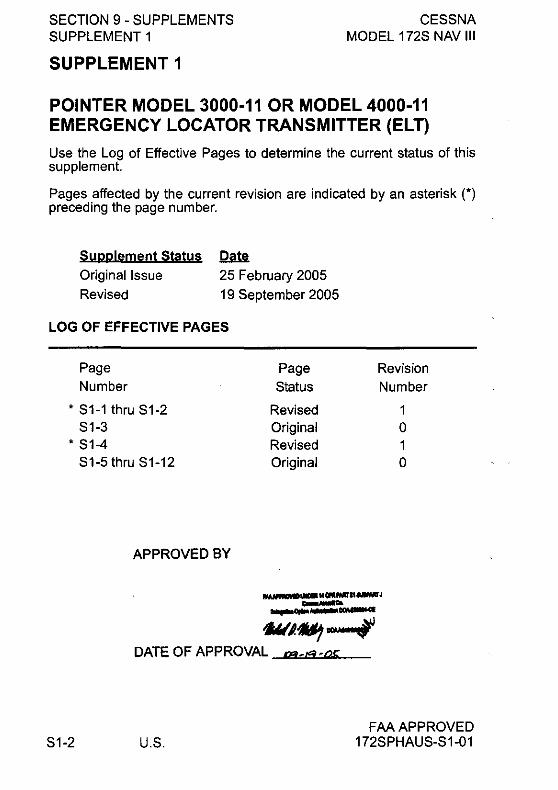
SECTION 9 - SUPPLEMENTS SUPPLEMENT 1
SUPPLEMENT 1
CESSNA MODEL 172S NAV III
POINTER MODEL 3000-11 OR MODEL 4000-11 EMERGENCY LOCATOR TRANSMITTER (ELT)
Use the Log of Effective Pages to determine the current status of this supplement.
Pages affected by the current revision are indicated by an asterisk (*) preceding the page number.
~ Supplement Status
Original Issue
Revised
25 February 2005
19 September 2005
LOG OF EFFECTIVE PAGES
Page
Number
* S1-1 thru S1-2 S1-3
* S1-4 S1-5 thru S1-12
APPROVED BY
Page Revision
Status Number
Revised 1 Original 0 Revised 1 Original 0
~""QflMlf"""'J _ .. .... 0fIIII,......~
1JJtIJ.,*?"" .f DATE OF APPROVAL ",,_,.._oc
S1-2 U.S. FM APPROVED
172SPHAUS-S1-01

CESSNA MODEL 172S NAV III
SECTION 9 - SUPPLEMENTS SUPPLEMENT 1
SERVICE BULLETIN CONFIGURATION LIST
The following is a list of Service Bulletins that are applicable to the operation of the airplane. and have been incorporated into this supplement. This list contains only those Service Bulletins that are currently active.
Number Title
FAAAPPROVED 172SPHAUS-S1-00
Airolane Serial Effectivity
Revision Incorporated Incorporated in Airplane
U.S. S1-3

SECTION 9 - SUPPLEMENTS SUPPLEMENT 1
CESSNA MODEL 172S NAV III
POINTER MODEL 3000-11 OR 4000-11 EMERGENCY LOCATOR TRANSMITTER (ELT)
GENERAL
This supplement provides information which must be observed when operating the Pointer Model 3000-11 or 4000-11 Emergency Locator Transmitter. The Pointer Model 4000-11 Emergency Locator Transmitter is approved for use only in the USA, Canada, Japan and
I France.
Both the Pointer Model 3000-11 ELT (which incorporates the English placard) and Model 4000-11 ELT (which incorporates the bilingual placard) consist of a self-contained, dual-frequency, solid-state transmitter powered by a battery pack consisting of five alkaline "C" cell batteries and is automatically activated by a deceleration sensing inertia "G" switch, which is designed to activate when the unit senses longitudinal inertia forces as required in TSO-C91A. Also, a remote switch/annunciator is installed on the top right hand side of the copilot's instrument panel for control of the ELT from the flight crew station. The annunciator, which is in the center of the rocker switch, comes on when the ELT transmitter is transmitting. The ELT emits an omni-directional signal on the international distress frequencies of 121.5 MHz and 243.0 MHz. General aviation and commercial aircraft, the FAA and CAP monitor 121.5 MHz, and 243.0 MHz is monitored by the military.
The ELT is contained in a high impact, fire retardant, fiberglass filled Lexan case with carrying handle and is mounted behind the aft cabin partition wall on the right side of the tailcone. To gain access to the unit, ' unfasten the turn fasteners on the aft cabin partition. The ELT is operated by a control panel at the forward facing end of the unit or by the remote switch/annunciator located on the top right hand portion of the copilot's instrument panel (refer to Figure S1-1).
Power for the transmitter is provided by an alkaline battery pack inside the transmitter case.
S1-4 U.S.
(Continued Next Page)
FAA APPROVED 172SPHAUS-S 1-01

CESSNA SECTION 9 - SUPPLEMENTS SUPPLEMENT 1 MODEL 172S NAV III
GENERAL (CONTINUED)
In accordance with FAA regulations, the ELT's battery pack must be replaced after 2 years shelf or service life or for any of the following reasons:
.,,"
a. After the transmitter has been used in an emergency situation (including any inadvertent activation of unknown duration).
b. After the transmitter has been operated for more than one cumulative hour (e.g. time accumulated in several tests and inadvertent activation of known duration).
c. On or before battery replacement date. Battery replacement date is marked on the battery pack and the label on the transmitter.
POINTER MODEL 3000-11 EMERGENCY LOCATOR TRANSMITTER
ON 1 ill D II~
4 3 2
Figure S1-1
/ 5
RESET
... ,'"''
1. REMOTE CABLE JACK - Connects to ELT remote switch! annunciator located on the copilot's instrument panel.
2. ANTENNA RECEPTACLE - Connects to antenna mounted on top oftailcone.
3. TRANSMITTER ANNUNCIATOR LIGHT - comes on red to indicate the transmitter is transmitting a distress signal.
FAAAPPROVED 172SPHAUS-S 1-00
(Continued Next Page)
U.S. S1-5

SECTION 9 - SUPPLEMENTS SUPPLEMENT 1
CESSNA MODEL 172S NAV III
GENERAL (CONTINUED)
4. MASTER FUNCTION SELECTOR SWITCH (3-position toggle switch):
AUTO - Arms transmitter for automatic activation if "G" switch senses a predetermined deceleration level.
ON - Activates transmitter instantly. Used for test purposes and if "G" switch is inoperative. The ON position bypasses the automatic activation switch. (The red annunciator in the center of the remote switch/ annunciator should come on).
OFF/ Deactivates transmitter during handling, following RESET - rescue and to reset the automatic activation function.
(The red annunciator in the center of the remote SWitch/annunciator should go off).
5. REMOTE SWITCH/ANNUNCIATOR (3-position rocker switch):
S1-6
ON - Remotely activates the transmitter for test or emergency situations. Red annunciator in center of rocker switch comes on to indicate that the transmitter is transmitting a distress signal.
AUTO - Arms transmitter for automatic activation if "G" switch senses a predetermined deceleration level.
RESET - Deactivates and rearms transmitter after automatic activation by the "G" switch. Red annunciator in center of rocker switch should go off.
(Continued Next Page)
U.S. FAA APPROVED
172SPHAUS-S 1-00

CESSNA SECTION 9 - SUPPLEMENTS SUPPLEMENT 1 MODEL 172S NAV III
GENERAL (CONTINUED)
'"''
POINTER MODEL 4000-11 EMERGENCY LOCATOR TRANSMITIER
ON
1 ~II D II~ RESET
/ 4 3 2 5
Figure S1-2
.,"'"''
1. REMOTE CABLE JACK - Connects to ELT remote switchl annunciator located on the copilot's instrument panel.
2. ANTENNA RECEPTACLE - Connects to antenna mounted on top of tailcone.
3. TRANSMITTER ANNUNCIATOR LIGHT - comes on red to indicate the transmitter is transmitting a distress signal.
4. MASTER FUNCTION SELECTOR SWITCH (3-position toggle switch):
AUTO - Arms transmitter for automatic activation if "G" switch senses a predetermined deceleration level.
ON - Activates transmitter instantly. Used for test purposes and if "G" switch is inoperative. The ON position bypasses the automatic activation switch. (The red annunciator in the center of the remote switchl annunciator should come on).
OFFI Deactivates transmitter during handling, following RESET - rescue and to reset the automatic activation function.
(The red annunciator in the center of the remote switch/annunciator should go off).
FAA APPROVED 172SPHAUS-S1-00
(Continued Next Page)
U.S. 51-7

SECTION 9 - SUPPLEMENTS SUPPLEMENT 1
CESSNA MODEL 172S NAV III
GENERAL (CONTINUED)
5. REMOTE SWITCH/ANNUNCIATOR (3-position rocker switch):
ON - Remotely activates the transmitter for test or emergency situations. Red annunciator in center of rocker switch comes on to indicate that the transmitter is transmitting a distress signal.
AUTO - Arms transmitter for automatic activation if "G" switch senses a predetermined deceleration level.
RESET - Deactivates and rearms transmitter after automatic activation by the "G" switch. Red annunciator in center of rocker switch should go off.
OPERATING LIMITATIONS
Refer to Section 2 of the Pilot's Operating Handbook and FAA Approved Flight Manual (POH/AFM).
EMERGENCY PROCEDURES Before performing a forced landing, especially in remote and , mountainous areas, activate the ELT transmitter by positioning the remote switch/annunciator to the ON position. The annunciator in center of the rocker switch should be illuminated.
Immediately after a forced landing where emergency assistance is required, the ELT should be utilized as follows:
S1-8
NOTE
The ELT remote switch/annunciator system could be inoperative if damaged during a forced landing. If inoperative, the inertia "G" switch will activate automatically. However, to turn the ELT OFF and ON again requires manual switching of the master function selector switch which is located on the ELT unit.
(Continued Next Page)
U.S. FAA APPROVED
172SPHAUS-S 1-00
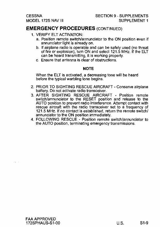
CESSNA MODEL 172S NAV III
SECTION 9 - SUPPLEMENTS SUPPLEMENT 1
EMERGENCY PROCEDURES (CONTINUED)
1. VERIFY ELT ACTIVATION: a. Position remote switch/annunciator to the ON position even if
annunciator light is already on. b. If airplane radio is operable and can be safely used (no threat
of fire or explosion), turn ON and select 121.5 MHz. If the ELT can be heard transmitting, it is working properly.
c. Ensure that antenna is clear of obstructions.
NOTE
When the ELT is activated, a decreasing tone will be heard before the typical warbling tone begins.
2. PRIOR TO SIGHTING RESCUE AIRCRAFT - Conserve airplane battery. Do not activate radio transceiver.
3. AFTER SIGHTING RESCUE AIRCRAFT - Position remote switch/annunciator to the RESET position and release to the AUTO position to prevent radio interference. Attempt contact with rescue aircraft with the radio transceiver set to a frequency of 121.5 MHz. If no contact is established, return the remote sWitch/ annunciator to the ON position immediately.
4. FOLLOWING RESCUE - Position remote switch/annunciator to the AUTO position, terminating emergency transmissions.
FAA APPROVED 172SPHAUS-S1-00 U.S. 51-9

SECTION 9 - SUPPLEMENTS SUPPLEMENT 1
NORMAL PROCEDURES
CESSNA MODEL 172S NAV III
When the remote switch!annunciator is in the AUTO position and the ELT master function selector switch remains in the AUTO position, the ELT automatically activates when the unit senses longitudinal inertia forces as required in TSO-C91A.
After a lightning strike, or an exceptionally hard landing, the ELT may activate although no emergency exists. If the remote switch! annunciator comes on, the ELT has inadvertently activated itself. Another way to check is to select 121.5 MHz on the radio transceiver and listen for an emergency tone transmission. If the remote switch! annunciator is on or an emergency tone is heard, position the remote switch!annunciator in the RESET position and release to the AUTO position.
The ELT must be serviced in accordance with FAR Part 91.207.
INSPECTIONITEST
1. The emergency locator transmitter should be tested every 100 hours.
NOTE
Test should only be conducted within the first 5 minutes of each hour.
2. Disconnect antenna cable from ELT. 3. Set the MASTER switch BAT in the ON position. 4. Turn airplane transceiver ON and set frequency to 121.5 MHz. 5. Place remote switch!annunciator in the ON position. The
annunciator should come on. Permit only three emergency tone transmissions, then immediately reposition the remote switch! annunciator to the RESET position and release to the AUTO position.
S1-10 U.S.
(Continued Next Page)
FAA APPROVED 172SPHAUS-S 1-00

CESSNA MODEL 172S NAV III
SECTION 9 - SUPPLEMENTS SUPPLEMENT 1
NORMAL PROCEDURES (CONTINUED)
6. Place the ELT master function selector switch in the ON position. Verify that the transmitter annunciator light on the ELT and the remote switch/annunciator on the instrument panel are on.
7. Place the ELT master function selector switch in the OFF/RESET position.
8. Reposition ELT master function selector switch to AUTO. 9. Reconnect antenna cable to ELT.
WARNING
A TEST WITH THE ANTENNA CONNECTED SHOULD BE APPROVED AND CONFIRMED BY THE NEAREST CONTROL TOWER.
NOTE
Without its antenna connected, the ELT will produce sufficient signal to reach the airplane transceiver, yet it will not disturb other communications or damage output circuitry.
After accumulated test or operation time equals 1 hour, battery pack replacement is required.
IN-FLIGHT MONITORING AND REPORTING
Pilot's are encouraged to monitor 121.5 MHz and/or 243.0 MHz while in flight to assist in identifying possible emergency ELT transmissions. On receiving a signal, report the following information to the nearest air traffic control facility:
1. Your position at the time the signal was first heard. 2. Your position at the time the signal was last heard. 3. Your position at maximum signal strength. 4. Your flight altitude and frequency on which the emergency signal
was heard - 121.5 MHz or 243.0 MHz. If possible, positions should be given relative to a navigation aid. If the aircraft has homing equipment, provide the bearing to the emergency signal with each reported position.
FAA APPROVED 172SPHAUS-S1-00 U.S. S1-11

SECTION 9 - SUPPLEMENTS SUPPLEMENT 1
PERFORMANCE
CESSNA MODEL 172S NAV III
There is no change in airplane performance when the POinter Model 3000-11 or 4000-11 Emergency Locator Transmitter (ELT) is installed.
S1-12 U.S. FM APPROVED
172SPHAUS-S 1-00
~ Cessna
A Tntmn Company "JYji,mml:-"~ __ -'~~~_~ __ =;;o,
Pilot's Operating Handbook And FAA Approved
Airplane Flight Manual SKYHAVVK
SP CE55NA MODEL 1725
NAV III AVIONICS OPTION Serials 172S9810 and On
SUPPLEMENT 2
CANADIAN CERTIFIED AIRPLANES
SERIAL NO .. _______ I
REGISTRATION NO. _____ 1
This supplement must be inserted into Section 9 of the Pilot's Operating Handbook and FAA Approved Airplane Flight Manual for Canadian Certified Airplanes.
f) Member of GAMA
COPYRIGHT © 2005
CESSNA AIRCRAFT COMPANY
WICHITA, KANSAS, USA
172SPHAUS·S2-01
APPROVED BY
I'MAPI'!II1o'BI1.IClBI """l'MTtllUWMT , -_co. ~a,IIIrI""'lClJo.-.cI
DATE OF APPROVAL I1Z- U"=j'2'f
25 FEBRUARY 2005
REVISION 1 7 FEBRUARY 2007
U.S. S2-1

SECTION 9 - SUPPLEMENTS SUPPLEMENT 2
SUPPLEMENT 2
CESSNA MODEL 172S NAV III
ICANADIAN CERTIFIED AIRPLANES
Use the Log of Effective Pages to determine the current status of this supplement.
Pages affected by the current revision are indicated by an asterisk (*) preceding the page number.
Supplement Statys
Original Issue
Revision 1
LOG OF EFFECTIVE PAGES
Page
Number
• 82-1 thru 82-2
82-3
* 82-4 • 82-5/82-6
APPROVED BY
~ 25 February 2005
7 February 2007
Page Revision
8tatus Number
Revised Original
Revised
Added
'M~"M"HIff"II.IIWII'J -_ ... ..... QIIM ....... ~
tft..4u -.
1
0
DATE OF APPROVAL 07 ryb!ll4'l' -vq~1
S2-2 U.S. FAA APPROVED
172SPHAUS-S2-01
"':"·Y
'=y
,,~~.
CESSNA MODEL 172S NAV III
SECTION 9 - SUPPLEMENTS SUPPLEMENT 2
SERVICE BULLETIN CONFIGURATION LIST
The following is a list of Service Bulletins that are applicable to the operation of the airplane, and have been incorporated into this supplement. This list contains only those Service Bulletins that are currently active.
Number
FAA APPROVED 172SPHAUS-S2-00
Airplane Serial Revision Incorporated Effectivitv Incorporated jn Airolane
U.S. S2-3

SECTION 9 - SUPPLEMENTS SUPPLEMENT 2
CESSNA MODEL 172S NAV III
ICANADIAN CERTIFIED AIRPLANES
GENERAL
This supplement is required for Canadian operation of Cessna Model 1172S airplanes equipped with the Nav III avionics option Serials
172S9810 and On.
I NOTE
In Canada. FM operating rules (i.e .• 14 CFR Part 91 and 14 CFR Part 135) are not applicable. The airplane must be equipped and operated in accordance with Transport Canada.
IThe Artex ME406 Emergency Locator Transmitter installation is not approved for Canadian Certified Airplanes.
OPERATING LIMITATIONS
The following placard must be installed.
1. Near the fuel tank filler cap:
FUEL 100LU100 MIN. GRADE AVIATION GASOLINE
CAP. 26.5 U.S. GAL. (100 LlTERS) USABLE CAP. 17.5 U.S. GAL. (66 LlTERS) USABLE TO BOTTOM
OF FILLER INDICATOR TAB.
EMERGENCY PROCEDURES There is no change to the airplane emergency procedures for
ICanadian Certified Airplanes.
IS2-4 U.S. FM APPROVED
172SPHAUS-S2-01

CESSNA MODEL 172S NAV III
NORMAL PROCEDURES
SECTION 9 - SUPPLEMENTS SUPPLEMENT 2
IThere is no change 10 Ihe airplane normal procedures for Canadian Certified Airplanes.
PERFORMANCE
IThere is no change 10 Ihe airplane performance for Canadian Certified Airplanes.
FAA APPROVED I 172SPHAUS-S2-01 U.S. S2-5/S2-6

, .-.",
/ ; .. ~
, .......
CESSNA MODEL 172S NAV III
SECTION 9 - SUPPLEMENTS SUPPLEMENT 3
SERVICE BULLETIN CONFIGURATION LIST
The following is a list of Service Bulletins that are applicable to the operation of the airplane, and have been incorporated into this supplement. This list contains only those Service Bulletins that are currently active.
Number
FAA APPROVED 172SPHAUS-S3-00
Airplane Serial Effectivity
Revision Incorporated
Incorporated in Airplane
U.S. S3-3

SECTION 9 - SUPPLEMENTS SUPPLEMENT 3
CESSNA MODEL 172S NAV III
BENDIXlKING KAP 140 2 AXIS AUTOPILOT
GENERAL
The BendixlKing KAP 140 2-Axis Autopilot provides the following modes of operation:
1. Roll (ROL) mode - keeps the wings level,
2. Vertical Speed (VS) mode - holds the climb or descent rate at the moment the autopilot is engaged or a manually-set ,<_,'
climb or descent rate. Controlled using the UP and DN buttons.
NOTE
The autopilot can hold a set vertical speed only if engine power and airplane weight will let it. If the vertical speed set on the autopilot is more than the airplane can supply and airspeed decreases sufficiently, the airplane can be made to stall. Make sure that the vertical speed set on the autopilot results in airplane performance that stays in the operating limitations of both the autopilot and the airplane.
3. Altitude Hold (AL T) mode - holds a set altitude using combined engine power, pitch and pitch trim control.
4. Heading (HDG) mode - holds the magnetic heading set using the HDG bug on the Gl000 Primary Flight Display (PFD) HSI.
5. Navigation (NAV) mode - locks on a course set using the CRS knob when a valid VHF navigation source (NAV 1 or NAV 2) is shown on the Gl000 HSI, when GPS is set as the HSI navigation source and the GPS is operating in OSS mode, or when the course is set automatically using GPS direct-to or flight plan (FPL) navigation and GPS is shown on the G 1 000 HSI.
(Continued Next Page)
S3-4 U.S. FM APPROVED
172SPHAUS-S3-00

CESSNA MODEL 172S NAV III
SECTION 9 - SUPPLEMENTS SUPPLEMENT 3
GENERAL (Continued)
6. Approach (APR) mode - locks on-course with greater sensitivity than NAV mode. APR mode is used to lock on the final approach course (to the Final Approach Fix) to start the final approach segment of the procedure. While operating on an intercept heading or course in either HOG or NAV mode, APR mode is set or "armed" (ARM) to lock
,~, on to the final approach course. APR mode will work for VOR, LOC and ILS approaches using either the NAV 1 or NAV 2 VHF navigation radios with the correct signal, the applicable radio set as the navigation source on the HSI and the correct course (CRS) set on the HSI. APR mode will automatically lock on the glideslope (GS) using vertical speed mode during ILS approaches. APR supplies vertical guidance only for I LS approaches, and then only when established on the localizer before glideslope intercept. This mode also works for GPS or RNAV/GPS approaches when GPS is set as the navigation source on the HSI.
The KAP 140 Autopilot gives the pilot Altitude Preselect and Altitude Alert functions. The Altitude Preselect function lets the pilot set a limit or "target" altitude before starting a climb or descent. The KAP 140 will climb or descend, as applicable, at the set vertical speed and will return to level flight at the altitude selection. The autopilot will supply an Altitude Alert (an electronic sound or 'tone") at 1000 feet before the altitude selection or when altitude changes more than 200 feet from the altitude selection.
The KAP 140 Autopilot Elevator Trim System supplies automatic adjustment of elevator trim during autopilot operation and, when the autopilot is not engaged, gives the pilot a manual electric elevator trim (MET) function (using the ON-UP Switches on the Control Wheel). The Elevator Trim system is designed to fail to a safe condition (fail-safe) for any single trim system malfunction during flight. Trim system malfunctions produce warning annunciations on the face of the autopilot and on the G 1000 PFD.
FAA APPROVED 172SPHAUS-S3-00
(Continued Next Page)
U.S. S3-5
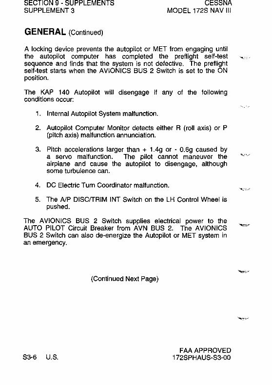
SECTION 9 - SUPPLEMENTS SUPPLEMENT 3
GENERAL (Continued)
CESSNA MODEL 172S NAV III
A locking device prevents the autopilot or MET from engaging until the autopilot computer has completed the preflight self-test ~ .•. sequence and finds that the system is not defective. The preflight self-test starts when the AVIONICS BUS 2 Switch is set to the ON position.
The KAP 140 Autopilot will disengage if any of the following conditions occur:
1. Internal Autopilot System malfunction.
2. Autopilot Computer Monitor detects either R (roll axis) or P (pitch axis) malfunction annunciation.
3. Pitch accelerations larger than + 1.4g or - 0.6g caused by a servo malfunction. The pilot cannot maneuver the airplane and cause the autopilot to disengage, although some turbulence can.
4. DC Electric Turn Coordinator malfunction.
5. The AlP DISCfTRIM INT Switch on the LH Control Wheel is pushed.
The AVIONICS BUS 2 Switch supplies electrical power to the AUTO PILOT Circuit Breaker from AVN BUS 2. The AVIONICS BUS 2 Switch can also de-energize the Autopilot or MET system in an emergency.
(Continued Nex1 Page)
S3-6 U.S. FAA APPROVED
172SPHAUS-S3-00
,,-- ~

--CESSNA MODEL 172S NAV III
GENERAL (Continued)
SECTION 9 - SUPPLEMENTS SUPPLEMENT 3
The following circuit breakers energize and supply protection for the KAP 140 Autopilot:
LABEL FUNCTIONS
AUTO PILOT A pUll-to-open type circuit breaker on AVN ,.", BUS 2 that energizes the KAP 140 Autopilot
computer and the roll, pitch and pitch trim servos.
-
WARN
FAA APPROVED 172SPHAUS-S3-00
A pUll-to-open type circuit breaker on the XFEED BUS that supplies power for the PITCH TRIM annunciation on the G1000 PFD.
(Continued Next Page)
U.S. S3-7

SECTION 9 - SUPPLEMENTS SUPPLEMENT 3
6"79
15
GIA63
NUMBER 2
AILERON
AILERON ACTUATOR
TURN COORDINATOR
S3-8 U.S.
Figure S3-1
CESS~ MODEL 172S NAV
ELEVATOR LJ:::;:-;-::::::7 TRIM WHEEL
CONTROL
ACTUATOR
""-:::!!~
AVN '--"""J.- BUS2
11.--t~
WARN CIB
10 XFEED BUS
0785R1C 071ep10~,,y
FM APPROVED 172SPHAUS-S3-00

. _ .. '"
. >'.
CESSNA SECTION 9 - SUPPLEMENTS SUPPLEMENT 3 MODEL 172S NAV III
GENERAL (Continued)
BENDIXlKING KAP 140 2 AXIS AUTOPILOT WITH ALTITUDE PRESELECT, OPERATING CONTROLS AND INDICATORS
1
IJENOIXf/()NO KIIPl40
2 3 4
18
5
16 23 22
6 7 8 9
Figure S3-2
KAP 140 WITH ALTITUDE PRESELECT
21 20
19
1. PITCH AXIS (P) ANNUNCIATOR - When illuminated, indicates failure of pitch axis and will either disengage the autopilot or not allow engagement of the pitch axis. In turbulent air, will illuminate during abnormal verticaVaccelerations.
2. AUTOPILOT ENGAGE/DISENGAGE (AP) BUTTON - When pressed and held (approx. 0.25 seconds), engages autopilot if all preflight self-test conditions are met. The autopilot will engage in the basic roll (ROL) mode which functions as a wing leveler and the pitch axis vertical speed (VS) mode. The commanded vertical speed will be displayed in the upper right corner of autopilot display area. The captured VS will be the vertical speed present at the moment the AP button is pressed. The button may also be used to disengage the autopilot.
3. ROLL AXIS (RI ANNUNCIATOR - When illuminated, indicates failure of the roll axis and disengages the autopilot.
(Continued Next Page)
FAA APPROVED 172SPHAUS-S3-00 U.S. S3-9

SECTION 9 - SUPPLEMENTS SUPPLEMENT 3
GENERAL (Continued)
CESSNA MODEL 172S NAV III
4. HEADING (HDG) MODE SELECTOR BUTTON - When pushed, will select the Heading mode, which commands the airplane to turn to and maintain the heading selected by the heading bug on the HSI. A new heading may be selected at any time and will result in the airplane turning to the new heading. The button can also be used to change between HDG and ROL modes.
5. NAVIGATION (NAV) MODE SELECTOR BUTTON - When pushed, will select the Navigation mode. This mode provides automatic beam capture and tracking of VOR, LOC, or GPS signals as set on the HSI. NAV mode is recommended for enroute navigation tracking.
6. APPROACH (APR) MODE SELECTOR BUTTON - When pushed, will select the Approach mode. This mode provides automatic beam capture and tracking of VOR, GPS, LOC and Glideslope (GS) on an ILS, as set on the HSI. APR mode tracking sensitivity is recommended for instrument approaches.
7. BACK COURSE APPROACH (REV) MODE BUTTON - This button is active only when the coupled navigation receiver is tuned to a LOC/ILS frequency. When pushed will select the Back Course approach mode. This mode functions identically to the approach mode except that the autopilot response to LOC signals is reversed. Glideslope is locked out with REV mode.
8. ALTITUDE HOLD (AL T) MODE SELECT BUTTON - When pushed, will select the altitude hold mode. This mode provides capture and tracking of the selected altitude. The selected altitude is the airplane altitude at the moment the AL T button is pressed. If the AL T button is pressed with an established VS rate present, there will be about a 10% (of VS rate) overshoot. The airplane will return positively to the selected altitude.
(Continued Next Page)
S3-10 U.S. FAA APPROVED
172SPHAUS-S3-00

CESSNA MODEL 172S NAV 111
SECTION 9 - SUPPLEMENTS SUPPLEMENT 3
GENERAL (Continued)
9. VERTICAL SPEED (UP/DN) MODE BUTTONS - The action 01 these buttons depends on the vertical mode selection when pressed. II VS mode is active (AP plus any lateral mode) and the UP button is pressed, the autopilot will modify the displayed VS command (FPM) in the up direction. Single momentary cycles on either the UP or DN button will increment the VS command by 100 FPM per cycle. When either button is continuously held in, it will modify the vertical speed command by 300 Ipm per second.
II AL T mode is active, pressing the UPIDN buttons will modily the captured altitude by 20 leet per cycle, or il held continuously will command the airplane up or down at the rate 01 500 FPM, synchronizing the AL T relerence to the actual airplane altitude upon button release.
10. AUTO PILOT CIRCUIT BREAKER - A 5-amp pull-off circuit breaker supplies 28 VDC to the KAP 140 system.
11. WARN CIB - Power to the autopilot disconnect horn and the annunciator (PITCH TRIM).
12. AUTOPILOT DISCONNECT (AlP DISCITRIM INT) SWITCHWhen depressed will disengage the autopilot and interrupt manual electric trim (MET) power. An autopilot disconnect will be annunciated by a continuous 2 second tone accompanied by Ilashing "AP" annunciations on the autopilot computer display.
13. MANUAL ELECTRIC TRIM (MET) SWITCHES - When both switches are pressed in the same direction, the trim system will provide pitch trim in the selected direction. Use 01 manual electric trim during autopilot operation will disengage the autopilot.
FAA APPROVED 172SPHAUS-S3-00
(Continued Next Page)
U.S. S3-11
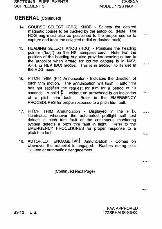
SECTION 9 - SUPPLEMENTS SUPPLEMENT 3
GENERAL (Continued)
CESSNA MODEL 172S NAV III
14. COURSE SELECT (CRS) KNOB - Selects the desired magnetic course to be tracked by the autopilot. (Note: The HDG bug must also be positioned to the proper course to capture and track the selected radial or desired traCk).
15. HEADING SELECT KNOB (HDG) - Positions the heading pointer ("bug") on the HSI compass card. Note that the position of the heading bug also provides heading datum to the autopilot when armed for course capture is in NAV, APR, or REV (BC) modes. This is in addition to its use in the HDG mode.
16. PITCH TRIM (PT) Annunciator - Indicates the direction of pitch trim motion. The annunciation will flash if auto trim has not satisfied the request for trim for a period of 10 seconds. A solid ~ without an arrowhead is an indication of a pitch trim fault. Refer to the EMERGENCY PROCEDURES for proper response to a pitch trim fault.
17. PITCH TRIM Annunciation - Displayed in the PFD, Illuminates whenever the automated preflight self test detects a pitch trim fault or the continuous monitoring system detects a pitch trim fault in flight. Refer to the EMERGENCY PROCEDURES for proper response to a pitch trim fault.
18. AUTOPILOT ENGAGE I AP I Annunciation - Comes on whenever the autopilot is engaged. Flashes during pilot initiated or automatic disengagement.
(Continued Next Page)
S3-12 U.S. FAA APPROVED
172SPHAUS-S3-00

""'-.
CESSNA MODEL 172S NAV 111
SECTION 9 - SUPPLEMENTS SUPPLEMENT 3
GENERAL (Continued)
19. ROTARY KNOBS - Used to set the altitude alerter reference altitude; or may be used immediately after pressing the BARO button, to adjust the autopilot baro setting to match that of the airplane's altimeter when manual adjustment is required.
20. BARO SET (BARO) BUTTON - When pushed and released, will change the display from the altitude alerter selected altitude to the baro setting display (either in. HG or HPA) for 3 seconds. If pushed and held for 2 seconds, will change the baro setting display from in HG to HPA or vice versa. Once the baro setting display is visible the rotary knobs may be used to adjust the baro setting.
21. ALTITUDE ARM (ARM) BUTTON - When pushed, will change the altitude arming function between on or off. When AL T ARM is annunciated, the autopilot will capture the altitude alerter displayed altitude (provided the airplane is climbing or descending in VS to the displayed altitude). AL T hold arming when the autopilot is engaged is automatic upon altitude alerter altitude selection via the rotary knobs. Note that the alerter functions are independent of the arming process thus providing full time alerting, even when the autopilot is disengaged.
22. ALTITUDE ALERTERNERTICAL SPEED/BARO SETTING DISPLAY - Normally displays the altitude alerter selected altitude. If the UP or DN button is pushed while in VS hold, the display changes to the command reference for the VS mode in FPM for 3 seconds. If the BARO button is pushed, the display changes to the autopilot baro setting in either in HG or HPA for 3 seconds.
FAA APPROVED 172SPHAUS-S3-00
(Continued Next Page)
U.S. 83-13
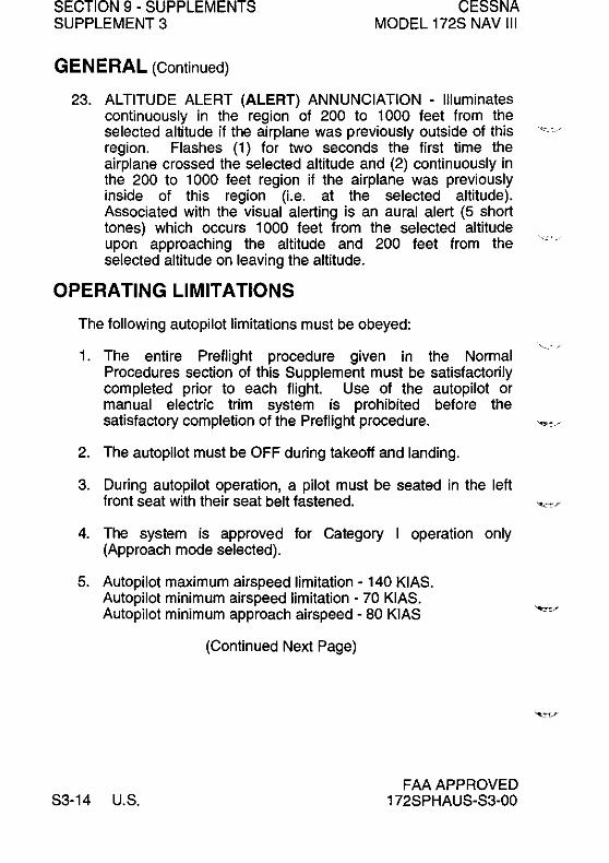
SECTION 9 - SUPPLEMENTS SUPPLEMENT 3
GENERAL (Continued)
CESSNA MODEL 172S NAV III
23. ALTITUDE ALERT (ALERT) ANNUNCIATION - Illuminates continuously in the region of 200 to 1000 feet from the selected altitude if the airplane was previously outside of this region. Flashes (1) for two seconds the first time the airplane crossed the selected altitude and (2) continuously in the 200 to 1000 feet region if the airplane was previously inside of this region (i.e. at the selected altitude). Associated with the visual alerting is an aural alert (5 short tones) which occurs 1000 feet from the selected altitude upon approaching the altitude and 200 feet from the selected altitude on leaving the altitude.
OPERATING LIMITATIONS
The following autopilot limitations must be obeyed:
1. The entire Preflight procedure given in the Normal Procedures section of this Supplement must be satisfactorily completed prior to each flight. Use of the autopilot or manual electric trim system is prohibited before the satisfactory completion of the Preflight procedure. "',/
2. The autopilot must be OFF during takeoff and landing.
3. During autopilot operation, a pilot must be seated in the left front seat with their seat belt fastened.
4. The system is approved for Category I operation only (Approach mode selected).
5. Autopilot maximum airspeed limitation - 140 KIAS. Autopilot minimum airspeed limitation - 70 KIAS. Autopilot minimum approach airspeed - 80 KIAS
(Continued Next Page)
S3-14 U.S. FAA APPROVED
172SPHAUS-S3-00

CESSNA MODEL 172S NAV III
SECTION 9 - SUPPLEMENTS SUPPLEMENT 3
OPERATING LIMITATIONS (Continued)
6. Maximum flap extension - 100•
7. Maximum lateral fuel imbalance with autopilot engaged - 90 Ibs.
8. The autopilot must be disengaged below 200 feet AGL during approach operations and below 800 feet AGL for all other phases of flight.
9. Manually overriding the autopilot to change pitch or roll attitude is prohibited. (Disengage the autopilot before moving the control wheel manually).
10. If the red "PITCH TRIM" warning annunciator (shown on the PFD) comes on during flight, do the Recovery Procedure shown in Emergency Procedures. The electric trim and autopilot systems will be de-energized when the AUTO PILOT circuit breaker is open.
11. Operation of the KAP 140 Autopilot is prohibited when the GMA 1347 Audio Panel is inoperative (no warning tone will be supplied when the Autopilot disengages).
EMERGENCY PROCEDURES The four-step recovery procedure (steps 1 thru 4) listed below should be committed to memory. It is important that the pilot be proficient in accomplishing all four steps without reference to this manual.
RECOVERY PROCEDURE
1. In case of Autopilot, Autopilot Trim, or Manual Electric Trim malfunction (accomplish Items a and b simultaneously): a. Airplane Control Wheel - GRASP FIRMLY and regain
control of airplane. b. AlP DISCITRIM INT Switch - PUSH and HOLD
throughout recovery.
FAA APPROVED 172SPHAUS-S3-00
(Continued Next Page)
U.S. S3-15

SECTION 9 - SUPPLEMENTS SUPPLEMENT 3
CESSNA MODEL 172S NAV III
EMERGENCY PROCEDURES (Continued)
c. AIRPLANE - TRIM manually as needed. d. AUTO PILOT Circuit Breaker - OPEN (pull out).
WARNING
FOLLOWING AN AUTOPILOT, AUTOTRIM OR MANUAL ELECTRIC TRIM SYSTEM MALFUNCTION, DO NOT ENGAGE THE AUTOPILOT UNTIL THE CAUSE OF THE MALFUNCTION HAS BEEN CORRECTED.
NOTE
The AVIONICS BUS 2 switch may be used to deenergize the autopilot and electric trim systems. If necessary, do steps a. thru c. above, set the AVIONICS BUS 2 switch to the OFF position then locate and open (pull) the AUTO PI LOT circuit breaker. Then the AVIONICS BUS 2 switch can be set to the ON position to restore power to the other avionics equipment on AVN BUS 2. Primary attitude, airspeed, directional ",.f compass, and altitude instruments will continue to operate when the AVIONICS BUS 2 switch is OFF.
Maximum Altitude losses due to autopilot malfunction:
CONFIGURATION
Cruise, Climb or Descent Maneuvering Approach
ALTITUDE LOSS (feet)
350 feet 100 feet 90 feet
AMPLIFIED EMERGENCY PROCEDURES
The following paragraphs provide additional information for more complete understanding of the recommended course(s) of action in emergency situations.
(Continued Next Page)
S3-16 U.S. FAA APPROVED
172SPHAUS-S3-00

CESSNA MODEL 172S NAV III
SECTION 9 - SUPPLEMENTS SUPPLEMENT 3
EMERGENCY PROCEDURES (Continued)
1. An autopilot or autotrim malfunction occurs when there is an uncommanded deviation in the airplane flight path or when there is abnormal control wheel or trim wheel motion. In some cases, (especially for autopilot trim), there may be little to no airplane motion, but the PITCH TRIM annunciator (RH side of PDF) may come on.
2. The primary concern in reacting to an autopilot or autopilot trim system malfunction, or to an automatic disconnect of the autopilot, is to keep control of the airplane. Immediately grasp the control wheel and push and hold the AlP DISCrrRIM INT switch throughout the recovery. Manipulate the controls as required to safely keep the airplane within all of its operating limitations. Elevator trim should be used manually as needed to relieve control forces. Locate and open (pull) the AUTO PILOT circuit breaker on the lower right hand corner of the circuit breaker panel to completely disable the autopilot system.
3. A manual electric trim system malfunction (without pilot actuation of the manual electric trim switches) may be recognized by the PITCH TRIM annunciator coming on or by unusual trim wheel motions with the autopilot not engaged. As with an autopilot malfunction, the first concern following a manual electric trim system malfunction is to keep the airplane in control. Grasp the control wheel firmly and push and hold down the AlP DISCrrRIM INT switch. Locate and pull the AUTO PILOT circuit breaker on the lower right hand corner of the circuit breaker panel (AVN BUS 2).
Trim system voice messages will be provided for the following flight conditions:
1. "TRIM I N MOTION" - Elevator trim runs for more than 5 seconds, message repeats every 5 seconds.
FAA APPROVED 172SPHAUS-S3-00
(Continued Next Page)
U.S. S3-17

SECTION 9 - SUPPLEMENTS SUPPLEMENT 3
CESSNA MODEL 172S NAV III
EMERGENCY PROCEDURES (Continued)
2. CHECK PITCH TRIM - An out of trim condition has existed for approximately 20 seconds, take immediate corrective action: a. Airplane Control Wheel - GRASP FIRMLY and keep
airplane in control. b. AlP DISCITRIM INT Switch - PUSH and HOLD
throughout recovery. c. AIRPLANE - RETRIM manually as needed. d. AUTO PILOT Circuit Breaker - OPEN (PULL).
NOTE
Emergency Procedures for any malfunction are essentially the same: immediately grasp the control wheel and regain airplane control while pushing and holding the AlP DISCITRIM INT switch, then trim the airplane as needed. After these steps have been accomplished, secure the autopilot electric trim system by pulling the AUTO PI LOT circuit breaker. As with any airplane emergency procedure, it is important that the 4 steps of the Recovery Procedure be committed to memory.
3. The AVIONICS BUS 2 switch may be used to remove all electric power from the autopilot and electric trim systems while the AUTO PILOT circuit breaker is located and opened. When the AVIONICS BUS 2 switch is OFF, the autopilot and electric trim systems will not operate. After opening the AUTO PILOT circuit breaker, set the AVIONICS BUS 2 switch to the ON position to return power to the other eqUipment on AVN BUS 2.
4. It is important that all portions of the autopilot and electric trim system are tested prior to each flight in accordance with the procedures published herein in order to assure their integrity and continued safe operation during flight.
(Continued Next Page)
S3-18 U.S. FAA APPROVED
172SPHAUS-S3-00
':::: -

CESSNA MODEL 172S NAV III
SECTION 9 - SUPPLEMENTS SUPPLEMENT 3
EMERGENCY PROCEDURES (Continued)
-,. WARNING
_. -'"
FOLLOWING AN AUTOPILOT, AUTOTRIM OR MANUAL ELECTRIC TRIM SYSTEM MALFUNCTION, DO NOT ENGAGE THE AUTOPILOT UNTIL THE CAUSE OF THE MALFUNCTION HAS BEEN CORRECTED.
A flashing auto trim annunciation on the face of the autopilot indicates a failure in the pitch trim system. The pitch trim (autotrim) system has not reduced the load on the pitch servo sufficiently quickly. This condition should be temporary.
1. FLASHING; ANNUNCIATION - OBSERVE airplane pitch behavior. If pitch behavior is satisfactory, wait 5 to 10 seconds for the annunciation to go off.
2. If ; annunciation continues, CONTROL WHEEL - GRASP FIRMLY, DISENGAGE the autopilot and CHECK for out of trim condition in pitch. Manually trim to reduce control forces.
3. AUTOPILOT OPERATION - CONTINUE, if satisfied that the pitch trim malfunction indication was temporary. DISCONTINUE if failure of autotrim.
If a red P or R is shown on the face of the autopilot:
1. A red P indicates that the pitch axis system of the autopilot has been disabled and cannot be engaged.
WARNING
DO NOT ENGAGE THE AUTOPILOT IF ONLY THE ROLL AXIS IS OPERATING.
FAA APPROVED 172SPHAUS-S3-00
(Continued Next Page)
U.S. S3-19

SECTION 9 - SUPPLEMENTS SUPPLEMENT 3
CESSNA MODEL 172S NAV III
EMERGENCY PROCEDURES (Continued)
NOTE
If the red P lamp comes on because of abnormal acceleration of the airplane (due to turbulence), the lamp should go off within approximately one minute and normal operation of the autopilot will begin again.
2. A red R means that the autopilot roll axis system has been disabled and cannot be engaged. The autopilot cannot be engaged again.
If a flashing mode annunciation is shown on the face of the autopilot:
1. HDG flashing - Shows a failed heading input. PUSH the HDG button to change to ROL mode. ROL will be shown on the face of the autopilot.
2. NAV, APR or REV flashing - Shows that the autopilot navigation source is not working correctly (flag). The navigation signal may have been lost or the navigation source may have been switched at the PFD.
NOTE
~./
NAV, APR or REV flashing can also be caused by a ""j failed heading input (during course capture).
3. GS flashing - Shows a failed glideslope signal or input (GS will ARM again if a good glideslope signal comes back).
NOTE
• If the approach is continued using the localizer only, make sure to obey the minimum descent altitude (MDA) for the non-precision approach procedure. Use AL T or VS mode as necessary to control altitude.
(Continued Next Page)
S3-20 U.S. FAA APPROVED
172SPHAUS-S3-00

CESSNA MODEL 172S NAV III
SECTION 9 - SUPPLEMENTS SUPPLEMENT 3
EMERGENCY PROCEDURES (Continued)
• When the mode annunciator starts to flash, the autopilot has changed to a default mode of operation: ROL for lateral control and/or VS for vertical control. The autopilot may be engaged in the previous mode again as soon as the correct navigation, glideslope or heading signal or source is available.
• The HDG annunciation will flash for 5 seconds on the selection of NAV, APR or REV mode to tell the pilot to set the HDG bug (HSI) to the desired course.
Effects of equipment failure on autopilot operation:
1. Failure of Attitude Indicator - No effect on autopilot.
2. Failure of AHRS - The autopilot will function only in ROL mode.
3. Failure of DC Turn Coordinator - Autopilot will disengage or will not engage.
4. Failure of HSI - If HSI fails to function correctly, no heading signal will be available, so the autopilot HDG, NAV, APR and REV modes will not function correctly. Only ROL mode will function correctly.
5. Failure of the Transponder Pressure Altitude Encoder - The Altitude Alert and Altitude Preselect functions will not operate correctly (gray code signal not available).
6. Failure of the No. 2 GIA 63 Integrated Avionics Unit: If the No. 2 G lA 63 unit fails, the autopilot will function only in ROLmode.
7. Failure of the GMA 1347 Audio Panel - No aural annunciator (Electronic sound or tone) will be heard when the autopilot disengages.
FAA APPROVED 172SPHAUS-S3-00
(Continued Next Page)
U.S. S3-21

SECTION 9 • SUPPLEMENTS SUPPLEMENT 3
NORMAL PROCEDURES
CESSNA MODEL 172S NAV III
PREFLIGHT (PERFORM BEFORE EACH FLIGHT):
1. MASTER Switch (BAT)· ON.
2. AVIONICS Switch BUS 2 • ON.
3. POWER APPLICATION and SELF·TEST . The autopilot tests itself when power is first made available. The test is a sequence of internal checks before starting normal system operation. The test sequence is shown on the face of the autopilot as "PFT X". "X" is the test sequence step number. Successful completion of the self·test is shown by all autopilot display elements coming on (Display Test), the PITCH TRIM annunciator on the PFD coming on and the operation of the autopilot disengagement tone.
WARNING
IF THE RED P STAYS ON, THE AUTOPILOT HAS FAILED THE PREFLIGHT TEST. OPEN (PULL) THE AUTO PILOT CIRCUIT BREAKER TO MAKE SURE THAT THE AUTOPILOT AND MANUAL ELECTRIC TRIM SYSTEM WILL NOT OPERATE.
NOTE
When power is first supplied to the autopilot, the red P (pitch trim) lamp on the face of the autopilot may come on to show that the pitch system cannot be engaged. This condition should last approximately 30 seconds. The P will go off and the autopilot pitch trim system will function correctly.
(Continued Next Page)
S3·22 U.S. FM APPROVED
172SPHAUS·S3·00

CESSNA MODEL 172S NAV III
SECTION 9 - SUPPLEMENTS SUPPLEMENT 3
NORMAL PROCEDURES (Continued)
4. MANUAL ELECTRIC TRIM (MET) SYSTEM - TEST (Using the DN - UP Switches on the outboard side of the LH control wheel):
a. LH Switch - PUSH FORWARD to DN position and hold. MONITOR elevator trim wheel for movement. If elevator trim wheel moves, MET system has failed. Release switch to center OFF position.
NOTE
Any movement of the elevator trim wheel during the check of either the LH or RH Switch means that the Manual Electric Trim System has failed. The airplane may be flown if the AUTO PILOT Circuit Breaker is secured in the open position so that the autopilot is disconnected from electrical power and will not operate until it is repaired.
b. LH SWITCH - PULL AFT to UP position and hold. Make sure that the elevator trim wheel does not move. Release switch to center OFF position.
c. RH Switch - PUSH FORWARD to DN position and hold. Make sure that the elevator trim wheel does not move. Make sure the red ~ light on the face of autopilot comes on. Release switch to center OFF position.
NOTE p
If red T light is not shown on the face of the autopilot after the RH SWitch is held in the DN position for 5 seconds, the Trim Monitor System has failed. The airplane may be flown if the AUTO PILOT Circuit Breaker is secured in the open position so the autopilot is disconnected from electrical power and will not operate until until it is repaired.
FAA APPROVED 172SPHAUS-S3-00
(Continued Next Page)
U.S. S3-23
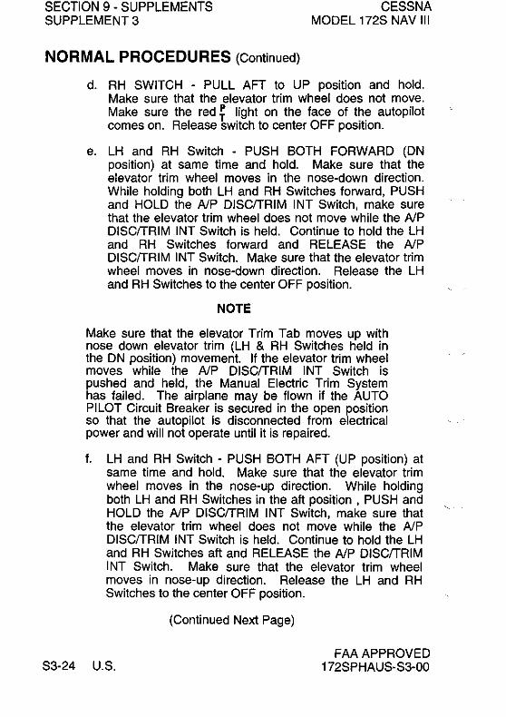
SECTION 9 - SUPPLEMENTS SUPPLEMENT 3
NORMAL PROCEDURES (Continued)
CESSNA MODEL 172S NAV III
d. RH SWITCH - PULL AFT to UP position and hold. Make sure that the elevator trim wheel does not move. Make sure the red ~ light on the face of the autopilot comes on. Release switch to center OFF position.
e. LH and RH Switch - PUSH BOTH FORWARD (DN position) at same time and hold. Make sure that the elevator trim wheel moves in the nose-down direction. While holding both LH and RH Switches forward, PUSH and HOLD the AlP DISCITRIM INT Switch, make sure that the elevator trim wheel does not move while the AlP DISCITRIM INT Switch is held. Continue to hold the LH and RH Switches forward and RELEASE the AlP DISCITRIM INT Switch. Make sure that the elevator trim wheel moves in nose-down direction. Release the LH and RH Switches to the center OFF position.
NOTE
Make sure that the elevator Trim Tab moves up with nose down elevator trim (LH & RH Switches held in the DN position) movement. If the elevator trim wheel moves while the AlP DISCITRIM INT Switch is pushed and held, the Manual Electric Trim System has failed. The airplane may be flown if the AUTO PILOT Circuit Breaker is secured in the open position so that the autopilot is disconnected from electrical power and will not operate until it is repaired.
f. LH and RH Switch - PUSH BOTH AFT (UP position) at same time and hold. Make sure that the elevator trim wheel moves in the nose-up direction. While holding both LH and RH Switches in the aft position, PUSH and HOLD the AlP DISCITRIM INT Switch, make sure that the elevator trim wheel does not move while the AlP DISCITRIM INT Switch is held. Continue to hold the LH and RH Switches aft and RELEASE the AlP DISCITRIM INT Switch. Make sure that the elevator trim wheel moves in nose-up direction. Release the LH and RH Switches to the center OFF position.
(Continued Next Page)
S3-24 U.S. FAA APPROVED
172SPHAUS-S3-00

CESSNA MODEL 172S NAV III
SECTION 9 - SUPPLEMENTS SUPPLEMENT 3
NORMAL PROCEDURES (Continued)
NOTE
Make sure that the elevator Trim Tab moves down with nose up elevator trim (LH & RH Switches held in the UP position) movement. If the elevator trim wheel moves while the AlP DISCfTRIM INT Switch is pushed and held, the Manual Electric Trim System has failed. The airplane may be flown if the AUTO PILOT Circuit Breaker is secured in the open position so that the autopilot is disconnected from electrical power and will not operate until it is repaired.
4. BARO Setting flashing - SET current local barometer (atmospheric pressure) using knobs or push BARO button to accept the present setting.
5. AUTOPILOT - ENGAGE (push and hold AP button for 1 second).
6. FLIGHT CONTROLS - MOVE. Make sure that the autopilot can be overpowered in both pitch axis and roll axis.
7. AlP DISCfTRIM INT Switch - PUSH. Make sure that the autopilot disengages. Make sure that the disengagement warning sound is heard.
FAA APPROVED 172SPHAUS-S3-00
(Continued Next Page)
U.S. S3-25

SECTION 9 - SUPPLEMENTS SUPPLEMENT 3
NORMAL PROCEDURES (Continued)
CESSNA MODEL 172S NAV III
8. ELEVATOR TRIM WHEEL - SET pointer to takeoff position.
WARNING
• WHEN THE AUTOPILOT IS ENGAGED, THE PILOT-IN-COMMAND MUST CONTINUOUSLY MONITOR AND BE READY TO DISENGAGE THE AUTOPILOT AS NOTED ABOVE. DO THE EMERGENCY RECOVERY PROCEDURE IF AUTOPILOT OPERATION IS ERRATIC OR DOES NOT CORRECTLY CONTROL THE AIRPLANE.
• DURING AUTOPILOT OPERATIONS, THE PILOT-IN-COMMAND MUST SET THE AUTOPILOT VS (VERTICAL SPEED) RATE AND ENGINE POWER TO MAKE SURE THAT AIRSPEED STAYS BETWEEN 80 KIAS AND 160 KIAS AND DOES NOT EXCEED ANY OTHER AIRPLANE OPERATING LIMITATION.
NOTE
Autopilot tracking performance will not be as good as usual in turbulence.
9. AVIONICS BUS 2 Switch - OFF
10. MASTER Switch (BAT) - OFF
BEFORE TAKEOFF
1. AlP DISCrrRIM INT Switch - PUSH.
(Continued Next Page)
S3-26 U.S. FAA APPROVED
172SPHAUS-S3-00

CESSNA MODEL 172S NAV III
SECTION 9 - SUPPLEMENTS SUPPLEMENT 3
NORMAL PROCEDURES (Continued)
2. BARO - SET.
CAUTION
CONTINUE TO SET BARO THROUGHOUT THE FLIGHT WHEN THE ALTIMETER SETTING CHANGES. NO FLASHING BARO SETTING WILL BE SHOWN TO REMIND THE PILOT.
3. ALTITUDE SELECT - SET target altitude using knobs.
CAUTION
THERE IS NO CONNECTION BETWEEN THE G1000 ALT SEL FEATURE AND THE KAP 140 ALTITUDE ALERT FUNCTION.
NOTE
1000 feet before the altitude selection, an electronic sound (tone) will be supplied for the pilot. Altitude changes of more than 200 feet from the altitude selection will cause a series of short tones to alert the pilot.
AFTER TAKEOFF
1. Elevator Trim - SET to trim airplane before engaging the autopilot.
NOTE
If the autopilot is engaged when the airplane is outof-trim, the result can be an unwanted altitude change, TRIM FAIL annunciation and autopilot disengagement.
2. Airspeed and Rate-of-Climb - STABLE.
FAA APPROVED 172SPHAUS-S3-00
(Continued Next Page)
U.S. S3-27

SECTION 9 - SUPPLEMENTS SUPPLEMENT 3
NORMAL PROCEDURES (Continued)
NOTE
CESSNA MODEL 172S NAV III
Only engage the autopilot during wings-level stable flight. The autopilot will come on in ROL (wings leveler) and VS (Vertical Speed) modes. The VS mode initial rate-of-climb will be the vertical speed at the time the autopilot is engaged. Do not engage the autopilot when the airplane cannot hold the climb rate because of excessive pitch attitude, low airspeed, low engine power or high airplane weight. Do not engage the autopilot when the performance or operation of the autopilot or airplane will not obey the limitations.
3. AP Button - PUSH and HOLD. Make sure that ROL and VS are shown on the face of the autopilot. If no selection of other operating modes is made, the autopilot will operate in ROL and VS modes.
NOTE
When operating in ROL mode, turbulence may result in changes to airplane heading. ROL mode only works to keep the wings level.
4. Make HOG or NAV mode selection as applicable (optional).
WARNING
• WHEN OPERATING THE AUTOPILOT IN VS MODE WITH POWER SET FOR CLIMB AND AIRSPEED AT OR NEAR BEST RATE-OFCLIMB, CONTINUED OPERATION IN VS MODE CAN RESULT IN A STALL. IF NECESSARY, DISENGAGE THE AUTOPILOT AND RETURN THE AIRPLANE TO STABLE CLIMB BEFORE ENGAGING THE AUTOPILOT AGAIN.
(Continued Next Page)
83-28 U.8. FAA APPROVED
1728PHAUS-83-00

CESSNA MODEL 172S NAV III
SECTION 9 - SUPPLEMENTS SUPPLEMENT 3
NORMAL PROCEDURES (Continued)
WARNING
• WHEN OPERATING AT OR NEAR AUTOPILOT MAXIMUM AIRSPEED, REDUCE POWER TO CONTROL THE DESIRED RATE-OF-DESCENT AND KEEP THE AIRSPEED LESS THAN THE AUTOPILOT MAXIMUM LIMIT.
• DO NOT MOVE THE CONTROL WHEEL WHEN THE AUTOPILOT IS ENGAGED. IF THE PILOT TRIES TO FLY THE AIR PLANE MANUALLY WHEN THE AUTOPILOT IS ENGAGED OR TRIES TO MANUALLY "HELP" THE AUTOPILOT, THE AUTOPILOT WILL ADJUST PITCH TRIM TO OPPOSE CONTROL WHEEL MOVEMENT AND CAUSE THE AIRPLANE TO GO OUT OF TRIM. THE OUT-OF-TRIM CONDITION WILL CAUSE LARGE ELEVATOR CONTROL FORCES WHEN THE AUTOPILOT IS DISENGAGED.
CLIMB OR DESCENT
1. BARO - SET current altimeter.
2. VS (Vertical Speed) Mode: UP or DN Buttons - PUSH button to set airplane vertical speed in 100 feet per minute (ftlmin) increments. PUSH and HOLD the button for the KAP 140 to increase the vertical speed at approximately 300 ftlminlsec to the desired value, then RELEASE. The rate will be set at the time of button release.
CAUTION
THE VERTICAL SPEED MODE HAS SYSTEM LIMITS OF ± 2000 FEET PER MINUTE. OPERATING THE MODEL 172S NEAR THESE LIMITS IS NOT RECOMMENDED
FAA APPROVED 172SPHAUS-S3-00
(Continued Next Page)
U.S. S3-29

SECTION 9 - SUPPLEMENTS SUPPLEMENT 3
NORMAL PROCEDURES (Continued)
CESSNA MODEL 172S NAV III
3. POWER - SET as applicable for vertical speed selection.
NOTE
The autopilot can hold a set vertical speed only if engine power and airplane weight are correct for the conditions. If the vertical speed set for the autopilot is more than the airplane can supply and airspeed decreases sufficiently, the airplane can be made to stall. Make sure that the vertical speed set for the autopilot results in airplane performance that stays in the operating limitations of both the autopilot and the airplane.
ALTITUDE PRESELECT MODE (ALTITUDE LOCK ON).
1. ALTITUDE SELECT - SET target altitude using knob on KAP 140.
2. ALTITUDE ARM - PUSH the ARM button to set the Altitude Lock On feature to the ON position (if needed). AL T ARM will show on the face of the autopilot when Altitude Lock On is set to the ON condition.
NOTE
• Minor differences between the autopilot altitude selection and the airplane altitude indication may be seen after altitude lock on. This small difference is generally due to autopilot system tolerances.
• Use of Altitude Preselect (Lock On) mode is not recommended for lock on at minimum descent altitude (MDA) during non-precision instrument approach procedures due to the possibility of altitude overshoot. Glideslope (GS) lock on during an ILS approach will prevent lock on to a preselect altitude selection.
• Use Vertical Speed mode as described previously in CLIMB or DESCENT for altitude change.
(Continued Next Page)
S3-30 U.S. FAA APPROVED
172SPHAUS-S3-00

CESSNA MODEL 172S NAV III
SECTION 9 - SUPPLEMENTS SUPPLEMENT 3
NORMAL PROCEDURES (Continued)
ALTITUDE HOLD
1. AL T Button - PUSH (Make sure that the AL T annunciator on the front of the autopilot comes on). The autopilot will stay at the set altitude.
NOTE
• If the AL T button is pushed while the airplane is climbing or descending, the airplane may go through the altitude selection by approximately 10% of the vertical rate (example: 500 ftlmin = approximately 50 feet), but will quickly lock on and correct to the target altitude.
• In Advisory Circular ACOO-24B "Thunderstorms", the FAA recommends the use of "Pitch Attitude Hold" for autopilot operation in severe turbulence. The KAP 140 does not use pitch reference, so it is recommended that the autopilot be disengaged and the airplane flown manually in severe turbulence.
CHANGING ALTITUDE
If the autopilot is engaged in AL T mode (Altitude Hold):
1. For small altitude changes (less than 100 feet), push the UP or DN button momentarily to program an increase or decrease to the altitude selection, as applicable, of 20 feet each time the button is pushed. This lets the autopilot make small corrections to the altitude selection.
2. For larger altitude changes, push and HOLD the UP or DN button, as applicable, to start a 500 ftlmin altitude change. Release the button at the altitude the autopilot is to hold.
FAA APPROVED 172SPHAUS-S3-00
(Continued Next Page)
U.S. S3-31

SECTION 9 - SUPPLEMENTS SUPPLEMENT 3
CESSNA MODEL 172S NAV III
NORMAL PROCEDURES (Continued)
II the autopilot is engaged in VS mode (Vertical Speed):
1. UP or DN Button - PUSH momentarily lor 100 fVmin vertical speed increments or PUSH and HOLD lor 300 fVminlsec vertical rate change and RELEASE at the rate desired. The autopilot will climb or descend at rate selection.
NOTE
• The autopilot can hold a Vertical Speed selection only il engine power and airplane weight are correct lor the conditions. II the vertical speed set lor the autopilot is more than the airplane can supply and airspeed decreases sufficiently, the airplane can be made to stall. Make sure that the vertical speed set lor the autopilot results in airplane performance that stays in the operating limitations 01 both the autopilot and the airplane.
• When operating at or near the best rate-ol-climb airspeed, with the engine set to climb power or when in Vertical Speed mode, it can be easy to slow to airspeeds where any additional reduction in airspeed will result reduced rate-ol-climb. Hold sufficient airspeed during Vertical Speed mode operation to avoid a stall.
HEADING (HOG) MODE OPERATION
1. HDG knob - SET the heading pointer ("bug") on the G 1 000 HSI to the correct magnetic heading using the HDG knob on the PFD.
2. HDG Button - PUSH to engage HDG mode. Make sure that the HDG annunciator is shown on the lace 01 the autopilot. The autopilot will turn the airplane at approximately standard rate (3°/sec) to lock on to the heading selection.
(Continued Next Page)
S3-32 U.S. FAA APPROVED
172SPHAUS-S3-00

CESSNA MODEL 172S NAV III
SECTION 9 - SUPPLEMENTS SUPPLEMENT 3
NORMAL PROCEDURES (Continued)
NAVIGATION (NAV) MODE OPERATION
The KAP 140 Autopilot will operate in NAV mode using GPS or VHF (VOR or LOC) navigation signal inputs. The G1000 HSI shows the GPS, NAV 1 or NAV 2 navigation signal being supplied to the autopilot. The navigation source selection shown on the HSI is made using the COl softkey.
If using NAV 1 or NAV 2, make sure that the radio is adjusted to the correct frequency and is the active frequency. Make sure that NAV 1 or NAV 2, as applicable, is shown on the HSI.
WARNING
WHEN THE KAP 140 AUTOPILOT IS ENGAGED IN NAV, APR OR REV OPERATING MODE, IF THE HSI NAVIGATION SOURCE IS CHANGED FROM GPS TO NAV1, AUTOMATICALLY OR MANUALLY (USING THE COl SOFTKEY), OR MANUALLY FROM NAV2 TO GPS, THE CHANGE WILL INTERRUPT THE SIGNAL TO THE AUTOPILOT AND CAUSE THE AUTOPILOT TO GO BACK TO ROL MODE OPERATION. NO WARNING CHIME OR PFD ANNUNCIATION WILL BE SUPPLIED. THE PREVIOUSLY-SELECTED MODE SYMBOL SHOWN ON THE FACE OF THE AUTOPILOT WILL FLASH TO SHOW THE CHANGE TO ROL MODE OPERATION. IN ROL MODE, THE AUTOPILOT WILL ONLY KEEP THE WINGS LEVEL AND WILL NOT CORRECT THE AIRPLANE HEADING OR COURSE. SET THE HOG BUG TO THE CORRECT HEADING AND SELECT THE CORRECT NAVIGATION SOURCE ON THE HSI USING THE COl SOFTKEY BEFORE ENGAGING THE AUTOPILOT IN ANY OTHER OPERATING MODE.
FAA APPROVED 172SPHAUS-S3-00
(Continued Next Page)
U.S. S3-33
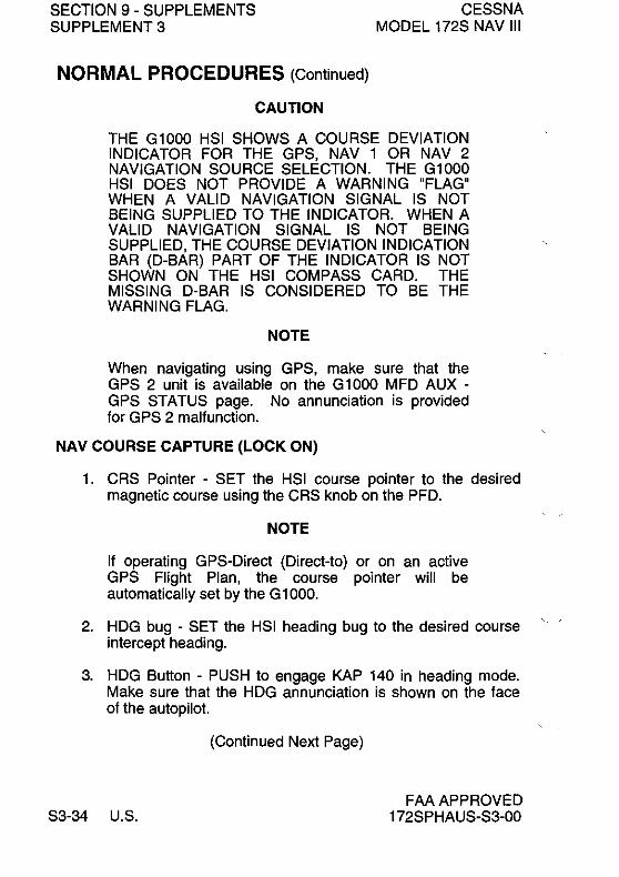
SECTION 9 - SUPPLEMENTS SUPPLEMENT 3
NORMAL PROCEDURES (Continued)
CAUTION
CESSNA MODEL 172S NAV III
THE Gl000 HSI SHOWS A COURSE DEVIATION INDICATOR FOR THE GPS, NAV 1 OR NAV 2 NAVIGATION SOURCE SELECTION. THE Gl000 HSI DOES NOT PROVIDE A WARNING "FLAG" WHEN A VALID NAVIGATION SIGNAL IS NOT BEING SUPPLIED TO THE INDICATOR. WHEN A VALID NAVIGATION SIGNAL IS NOT BEING SUPPLIED, THE COURSE DEVIATION INDICATION BAR (D-BAR) PART OF THE INDICATOR IS NOT SHOWN ON THE HSI COMPASS CARD. THE MISSING D-BAR IS CONSIDERED TO BE THE WARNING FLAG.
NOTE
When navigating using GPS, make sure that the GPS 2 unit is available on the Gl000 MFD AUX -GPS STATUS page. No annunciation is provided for GPS 2 malfunction.
NAV COURSE CAPTURE (LOCK ON)
1. CRS Pointer - SET the HSI course pointer to the desired magnetic course using the CRS knob on the PFD.
NOTE
If operating GPS-Direct (Direct-to) or on an active GPS Flight Plan, the course pointer will be automatically set by the G 1000.
2. HDG bug - SET the HSI heading bug to the desired course intercept heading.
3. HDG Button - PUSH to engage KAP 140 in heading mode. Make sure that the HDG annunciation is shown on the face of the autopilot.
(Continued Next Page)
S3-34 U.S. FAA APPROVED
172SPHAUS-S3-00

CESSNA MODEL 172S NAV 111
SECTION 9 - SUPPLEMENTS SUPPLEMENT 3
NORMAL PROCEDURES (Continued)
4. NAV Button - PUSH to arm the autopilot NAV lock on function. Make sure that the autopilot is correctly engaged from the annunciation on the autopilot:
a. If the HSI D-Bar is less than 2 to 3 dots from center, the autopilot will go to NAV mode. The NAV annunciator will be shown on the face of the autopilot.
b. If the HSI D-Bar is more than 2 to 3 dots from center, the NAVARM annunciator will be shown on the face of the autopilot. When the computed intercept pOint is reached, the ARM annunciator will go off and lock on (capture and track) will begin automatically. The NAV annunciator will stay on the face of the autopilot.
GPS NAV AND ROLL STEERING
The KAP 140 Autopilot has DC (analog) Roll Steering capability. Roll Steering enables the Flight Guidance System (in this case, the G1000 GPS navigation computer) to control the autopilot through automatic course changes at flight plan waypoints and to lock on to the course to the next waypoint.
The GPS navigation computer uses ground speed, track and turnrate data to calculate the bank angle required for waypoint course changes (the KAP 140 limits bank angle in the 172S to approximately 18°). The GPS Roll Steering signal will make the autopilot turn the airplane and lock on course to the next waypoint without flying directly over the current waypoint, except for designated fly-over waypoints. The flight path is approximately tangent to the inbound and outbound flight plan legs.
FAA APPROVED 172SPHAUS-S3-00
(Continued Next Page)
U.S. S3-35

SECTION 9 - SUPPLEMENTS SUPPLEMENT 3
NORMAL PROCEDURES (Continued)
CESSNA MODEL 172S NAV III
The distance from the waypoint to start the turn will vary with groundspeed, degrees of heading change, etc., but will usually be approximately 0.5 nautical mile from the waypoint. Flight plan sequencing to the next waypoint will occur at approximately the midpoint of the turn.
Roll Steering works only if all the following conditions are true:
1. GPS must be the navigation source shown on the G1000 HSI.
2. The GPS navigation computer must be executing an active flight plan.
3. The KAP 140 must be engaged in NAV or APR mode.
4. The GPS must not be operating in OSS mode (PFD).
NOTE
When on an active GPS flightplan with the KAP 140 Autopilot coupled in NAV or APR mode, waypoint course changes greater than approximately 1400
could result in a turn rate that reaches the autopilot bank angle limit. The pilot may need to change the KAP 140 to HDG mode (also arm NAV or APR mode) and manually set the intercept heading to help the autopilot lock on the new course.
HOLDING PATTERNS AND PROCEDURE TURNS:
When operating IFR on an active GPS flight plan, enroute or transitioning to the terminal environment, a holding pattern or course reversal maneuver may be necessary. The G1000 GPS does not provide course guidance through these maneuvers. The pilot must set both the G1000 and the KAP 140 to the correct operating mode and provide course guidance.
The Holding Pattern is usually shown on the MFD Navigation Map (for a published holding fix), but it is not included as a leg of the flight plan. GPS flight plan execution must be paused by entering OSS mode and using autopilot HDG or NAV modes, as applicable, to perform the maneuver.
(Continued Next Page)
S3-36 U.S. FAA APPROVED
172SPHAUS-S3-00

CESSNA MODEL 172S NAV III
SECTION 9 - SUPPLEMENTS SUPPLEMENT 3
NORMAL PROCEDURES (Continued)
The Procedure Turn is included as a leg in the flight plan along with the instrument approach procedure selection. Course guidance is supplied through the turn to outbound course lock on, but is discontinued after approximately 1 minute. G 1 000 OBS mode is not required but the KAP 140 must be set to HDG mode and the HDG bug used to provide guidance through the course reversal. When established inbound, change from HDG to APR mode for lock on to the final approach course.
For a KAP 140 that has been operating in NAV mode on an active GPS flight plan:
On arrival at the Holding Fix, set the KAP 140 in HDG mode and provide course guidance by manually adjusting the Gl000 HDG bug to command turns and heading, as applicable. Pause G 1000 flight plan execution during the holding pattern by using the OBS mode selection on the PFD. Set the correct inbound holding course on the HSI course pointer and NAV mode may be used for the KAP 140 on the inbound leg of the holding pattern for course guidance, but HDG mode must be used for the remainder of the holding pattern maneuver. At the end of the holding procedure, exit OBS mode to start the flight plan executing again and set NAV mode on the KAP 140 to lock on to the course. See the Garmin Gl000 Cockpit Reference Guide for further information.
Arriving at the IAF (usual starting point for the Procedure Turn maneuver), the G 1 000 will command the autopilot to turn to the outbound course and will provide course guidance for a short time (approximately 1 minute). Unlike the Holding Pattern, the G 1000 includes the Procedure Turn as a leg in the flight plan, so no OBS mode change is needed. Set the HDG bug to the Procedure Turn outbound leg heading and push the HDG button on the KAP 140 to start the turn. After the correct time flying outbound, adjust the HDG bug to make the turn to the procedure turn inbound heading. When established on the procedure turn inbound, push the APR button on the KAP 140 to lock on to the final approach course. See the Garmin Gl000 Cockpit Reference Guide for further information.
FAA APPROVED 172SPHAUS-S3-00
(Continued Next Page)
U.S. S3-37
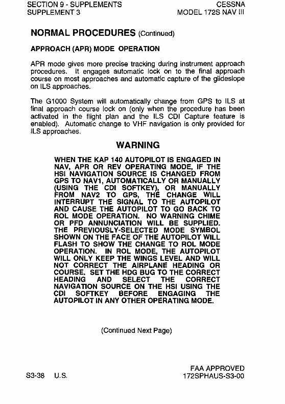
SECTION 9 - SUPPLEMENTS SUPPLEMENT 3
NORMAL PROCEDURES (Continued)
APPROACH (APR) MODE OPERATION
CESSNA MODEL 172S NAV III
APR mode gives more precise tracking during instrument approach procedures. It engages automatic lock on to the final approach course on most approaches and automatic capture of the glideslope on ILS approaches.
The G1000 System will automatically change from GPS to ILS at final approach course lock on (only when the procedure has been activated in the flight plan and the ILS COl Capture feature is enabled). Automatic change to VHF navigation is only provided for ILS approaches.
WARNING
WHEN THE KAP 140 AUTOPILOT IS ENGAGED IN NAV, APR OR REV OPERATING MODE, IF THE HSI NAVIGATION SOURCE IS CHANGED FROM GPS TO NAV1, AUTOMATICALLY OR MANUALLY (USING THE COl SOFTKEY), OR MANUALLY FROM NAV2 TO GPS, THE CHANGE WILL INTERRUPT THE SIGNAL TO THE AUTOPILOT AND CAUSE THE AUTOPILOT TO GO BACK TO ROL MODE OPERATION. NO WARNING CHIME OR PFD ANNUNCIATION WILL BE SUPPLIED. THE PREVIOUSLY-SELECTED MODE SYMBOL SHOWN ON THE FACE OF THE AUTOPILOT WILL FLASH TO SHOW THE CHANGE TO ROL MODE OPERATION. IN ROL MODE, THE AUTOPILOT WILL ONLY KEEP THE WINGS LEVEL AND WILL NOT CORRECT THE AIRPLANE HEADING OR COURSE. SET THE HOG BUG TO THE CORRECT HEADING AND SELECT THE CORRECT NAVIGATION SOURCE ON THE HSI USING THE COl SOFTKEY BEFORE ENGAGING THE AUTOPILOT IN ANY OTHER OPERATING MODE.
(Continued Next Page)
S3-38 U.S. FAA APPROVED
172SPHAUS-S3-00

CESSNA MODEL 172S NAV III
SECTION 9 - SUPPLEMENTS SUPPLEMENT 3
NORMAL PROCEDURES (Continued)
NOTE
Changing from GPS to ILS includes tuning the NAV 1 active frequency to the correct LOC frequency, slewing the course pointer to the applicable final approach course magnetic heading and changing the CDI to NAV 1 while keeping the autopilot in APR mode. The G1000 will do this automatically if ILS CDI Capture is set to AUTO
Roll Steering will only operate on instrument approach procedures selected from a current GPS aeronautical database when:
1. The autopilot is engaged in NAV or APR mode.
2. GPS is shown as the navigation source on the HSI.
NOTE
• Make sure that the applicable GPS mode is set during each portion of the approach procedure selection symbol (NAV, APR or REV) flashing on the face of the autopilot.
• If either the GPS or VHF navigation signal, as applicable, fails when the autopilot is engaged in NAV, APR or REV mode, the autopilot will change back to ROL mode operation. ROL mode operation is shown by the previous mode
APPROACH (APR) CAPTURE (LOCK ON)
1. BARO - SET current local barometric pressure (altimeter).
2. CRS Pointer - SET the HSI course pointer to the desired magnetic course using the CRS knob on the PFD.
NOTE
If operating GPS-Direct (Direct-to) or on an active GPS Flight Plan, the course pointer will be automatically set by the G1000.
FAA APPROVED 172SPHAUS-S3-00
(Continued Next Page)
U.S. S3-39

SECTION 9 - SUPPLEMENTS SUPPLEMENT 3
NORMAL PROCEDURES (Continued)
CESSNA MODEL 172S NAV III
3. HDG bug - SET the HSI heading bug to the desired course intercept heading.
4. HDG Button - PUSH to engage autopilot HDG mode. Make sure that HDG is shown on the face of the autopilot
5. APR Button - PUSH to arm the autopilot APR lock on function. Make sure that the autopilot is correctly engaged from the annunciation on the autopilot:
a. If the HSI D-Bar is less than 2 to 3 dots from center, the autopilot will go to APR mode. The APR annunciator will be shown on the face of the autopilot.
b. If the HSI D-Bar is more than 2 to 3 dots from center, the APR ARM annunciator will be shown on the face of the autopilot. When the computed intercept point is reached, the ARM annunciator will go off and lock on (capture and track) will begin automatically. The APR annunciator will stay on the face of the autopilot.
(Continued Next Page)
S3-40 U.S. FAA APPROVED
172SPHAUS-S3-00

CESSNA MODEL 172S NAV III
SECTION 9 - SUPPLEMENTS SUPPLEMENT 3
NORMAL PROCEDURES (Continued)
WARNING
WHEN THE KAP 140 AUTOPILOT IS ENGAGED IN NAV, APR OR REV OPERATING MODE, IF THE HSI NAVIGATION SOURCE IS CHANGED FROM GPS TO NAV1, AUTOMATICALLY OR MANUALLY (USING THE CDI SOFTKEY), OR MANUALLY FROM NAV2 TO GPS, THE CHANGE WILL INTERRUPT THE SIGNAL TO THE AUTOPILOT AND CAUSE THE AUTOPILOT TO GO BACK TO ROL MODE OPERATION. NO WARNING CHIME OR PFD ANNUNCIATION WILL BE SUPPLIED. THE PREVIOUSLY-SELECTED MODE SYMBOL SHOWN ON THE FACE OF THE AUTOPILOT WILL FLASH TO SHOW THE CHANGE TO ROL MODE OPERATION. IN ROL MODE, THE AUTOPILOT WILL ONLY KEEP THE WINGS LEVEL AND WILL NOT CORRECT THE AIRPLANE HEADING OR COURSE. SET THE HDG BUG TO THE CORRECT HEADING AND SELECT THE CORRECT NAVIGATION SOURCE ON THE HSI USING THE COl SOFTKEY BEFORE ENGAGING THE AUTOPILOT IN ANY OTHER OPERATING MODE.
6. Airspeed - HOLD 100 KIAS minimum (recommended) during approaches when the autopilot is engaged.
GLIDESLOPE ENGAGEMENT AND LOCK-ON
1. APR Mode - ENGAGED. Make sure that GSARM is shown on the face of the autopilot.
NOTE
The glideslope cannot lock-on when the autopilot is engaged in NAV or REV modes. Engaged in APR mode, with NAV 1 or NAV 2 set to the correct ILS frequency, and shown as the related HSI navigation source, the glideslope becomes armed at localizer lock-on.
FAA APPROVED 172SPHAUS-S3-00
(Continued Next Page)
U.S. S3-41

SECTION 9 - SUPPLEMENTS SUPPLEMENT 3
NORMAL PROCEDURES (Continued)
CESSNA MODEL 172S NAV III
2. Glideslope Indicator - CENTERED. Make sure that the ARM annunciator goes out and the GS annunciator stays on.
NOTE
The KAP 140 can lock on the glideslope from above or below. Capturing the glideslope from above is not recommended.
3. Airspeed - HOLD 100 KIAS minimum (recommended) during approaches when the autopilot is engaged.
BACK COURSE (REV) MODE OPERATION
This mode provides reverse sensing for the autopilot navigation course on Back Course-type Localizer approaches.
1. BARO - SET current local barometric pressure (altimeter).
2. CRS Pointer - SET the HSI course pOinter to the ILS front course inbound heading using the CRS knob on the PFD.
3. HDG bug - SET the HSI heading bug to the desired course intercept heading.
4. HDG Button - PUSH to engage HDG mode. Make sure that H DG is shown on the face of the autopilot.
5. REV Button - PUSH to arm the autopilot REV lock-on function. Make sure that the autopilot is correctly engaged from the annunciation on the autopilot:
a. If the HSI D-Bar is less than 2 to 3 dots from center, the autopilot will go to REV mode. The REV annunciator will be shown on the face of the autopilot.
b. If the HSI D-Bar is more than 2 to 3 dots from center, the REV ABM annunciator will be shown on the face of the autopilot. When the computed intercept point is reached, the ARM annunciator will go off and lock on (capture and track) will begin automatically. The REV annunciator will stay on.
(Continued Next Page)
S3-42 U.S. FAA APPROVED
172SPHAUS-S3-00

CESSNA MODEL 172S NAV III
SECTION 9 - SUPPLEMENTS SUPPLEMENT 3
NORMAL PROCEDURES (Continued)
6. Airspeed - HOLD 100 KIAS minimum (recommended) during approaches when the autopilot is engaged.
MISSED APPROACH
1. AlP DISCfTRIM INT Switch - PUSH to disengage the autopilot.
2. Missed Approach Procedure - EXECUTE.
3. If autopilot is to be engaged:
a. Elevator Trim - SET.
b. Airspeed and Rate-of-Climb - STABILIZED.
WARNING
THE Gl000 WILL ENTER SUSP MODE (STOP THE FLIGHT PLAN) AT THE MISSED APPROACH POINT (MAP) AND WILL NOT SUPPLY A NAVIGATION SIGNAL TO THE KAP 140. IF THE Gl000 IS TO BE USED FOR COURSE GUIDANCE TO THE MISSED APPROACH HOLDING POINT (MAHP). PUSH THE SUSP SOFTKEY TO START THE FLIGHT PLAN AND NAVIGATION SIGNAL AGAIN BEFORE ENGAGING THE KAP 140.
NOTE
• Only engage the autopilot during wings-level stable flight. The autopilot will come on in ROL (wings leveler) and VS (Vertical Speed) modes. The VS mode initial rate-of-climb will be the vertical speed at the time the autopilot is engaged. Do not engage the autopilot when the airplane cannot hold the climb rate because of excessive pitch attitude, low airspeed, low engine power or high airplane weight. Do not engage the autopilot when the performance or operation of the autopilot or airplane would not obey the limitations.
FAA APPROVED 172SPHAUS-S3-00
(Continued Next Page)
U.S. S3-43

SECTION 9 - SUPPLEMENTS SUPPLEMENT 3
NORMAL PROCEDURES (Continued)
CESSNA MODEL 172S NAV III
• The autopilot can hold a Vertical Speed selection only il engine power and airplane weight are correct lor the conditions. II the vertical speed set lor the autopilot is more than the airplane can supply and airspeed decreases sufficiently, the airplane can be made to stall. Make sure that the vertical speed set lor the autopilot results in airplane performance that stays in the operating limitations 01 both the autopilot and the airplane .
• When operating at or near the best rate-ol-climb airspeed, with the engine set to climb power or when in Vertical Speed mode, it can be easy to slow to airspeeds where any additional reduction in airspeed will result reduced rate-ol-climb. Hold sufficient airspeed during Vertical Speed mode operation to avoid a stall.
c. AP Button - PUSH and HOLD to engage the autopilot. Make sure that ROL and VS are shown on the lace 01 the autopilot. If no selection 01 other operating modes is made, the autopilot will operate in ROL and VS modes.
NOTE
When operating in ROL mode, turbulence may result in changes to airplane heading. ROL mode only works to keep the wings level. When tracking the I LS course outbound on the missed approach procedure, use NAV mode to prevent unwanted GS coupling.
BEFORE LANDING
1. AlP DISCITRIM INT Switch - PUSH to disengage the autopilot.
PERFORMANCE
There is no change in airplane performance when the KAP 140 Autopilot is installed. See Section 2 lor Limitations that can have an effect on airplane performance.
S3-44 U.S. FAA APPROVED
172SPHAUS-S3-00
Pilot's Operating Handbook and
~ Cessna
A Textron Company
FAA Approved Airplane Flight Manual
CESSNA MODEL 172S NAV III AIRPLANES
Serials 17259810 and On
SUPPLEMENT 4 WINTERIZATION KIT
SERIAL NO .. ________ _
REGISTRATION NO, •• ______ _
This supplement must be inserted into Section 9 of the Pilot's Operating Handbook and FAA Approved Airplane Flight Manual when the Winterization Kit is installed.
f) Member of GAMA
COPYRIGHT Cl 2005 CESSNA AIRCRAFT COMPANY
WICHITA, KANSAS, USA
172SPHAUS-S4-00
APPROVED BY
DATE OF APPROVA' tit-%&; _c?f
25 FEBRUARY 2005 U.S. S4-1

SECTION 9 - SUPPLEMENTS SUPPLEMENT 4
SUPPLEMENT 4 WINTERIZATION KIT
CESSNA MODEL 172S NAV III
Use the Log of Effective Pages to determine the current status of this supplement.
Pages affected by the current revision are indicated by an asterisk (*) preceding the page number.
Supplement Status Date
Original 25 February 2005
LOG OF EFFECTIVITY PAGES
Page Number
S4-1 thru S4-4
S4-2 U.S.
Page Status
Original
Revision Number
o
FAA APPROVED 172SPHAUS-S4-00

CESSNA MODEL 172S NAV III
SECTION 9 - SUPPLEMENTS SUPPLEMENT 4
SERVICE BULLETIN CONFIGURATION LIST
The following is a list of Service Bulletins that are applicable to the operation of the airplane, and have been incorporated into this supplement. This list contains only those Service Bulletins that are currently active.
Number Title
FAA APPROVED 172SPHAUS-S4-00
Airplane Serial Revision Incorporated Effectivitv Incorporated in Airplane
U.S. S4-3

SECTION 9 - SUPPLEMENTS SUPPLEMENT 4
WINTERIZATION KIT
GENERAL
CESSNA MODEL 172S NAV III
The winterization kit consists of two cover plates (with placards) which attach to the air intakes in the cowling nose cap and a placard silk screened on the instrument panel. This equipment should be installed for operations in temperatures consistently below 20°F (-rc).
LIMITATIONS
The following information must be presented in the form of placards when the airplane is equipped with a winterization kit.
1. On each nose cap cover plate:
REMOVE WHEN O.A.T. EXCEEDS +20°F.
2. On the instrument panel below the Primary Flight Display (PFD):
WINTERIZATION KIT MUST BE REMOVED WHEN OUTSIDE AIR TEMPERATURE IS ABOVE 20T
EMERGENCY PROCEDURES There is no change to the airplane emergency procedures when the winterization kit is installed.
NORMAL PROCEDURES
There is no change to the airplane normal procedures when the winterization kit is installed.
PERFORMANCE
There is no change to the airplane performance when the winterization kit is installed.
S4-4 U.S. FAA APPROVED
172SPHAUS-S4-00
~ Cessna
.. "'''*mmo'''''_ ...... _________ .. ;: ....... =:,;;eom,,..y ......
Pilot's Operating Handbook And FAA Approved
Airplane Flight Manual SKYHAVVK
SP CESSNA MODEL 172S NAV III AVIONICS OPTION Serials 172S9810 and On
SUPPLEMENT 5 BRAZILIAN CERTIFIED AIRPLANES
SERIAL NO. ________ I
REGISTRATION NO. ______ 1
This supplement must be inserted into Section 9 of the Pilofs Operating Handbook and FAA Approved Airplane Flight Manual when used for Brazilian Certified Airplanes and is approved by the U.S. Federal Aviation Administration (FAA) on behalf of the "Agencia Nacional de Avia9ao Civil" (ANAC) for Brazilian Registered Airplanes. in accordance with the "Regulamento Brasileiro de Homologa9ao Aeronautica" (RBHA) 21, Section 21.29.
f) Member of GAMA
COPYRIGHT © 2006 CESSNA AIRCRAFT COMPANY
WICHITA, KANSAS, USA
172SPHAUS·S5·01
APPROVED BY 1M/oIIPIICMtI1NlEIt""" IWITtllIIIWIT ~ --... ~~~~
'([.,....E.A/I -,,~
DATE OF APPROVAL \ F'[9~ ypr.
1 FEBRUARY 2006
REVISION 1 2 NOVEMBER 2006
U.S. S5-1

SECTION 9 - SUPPLEMENTS SUPPLEMENT 5
SUPPLEMENT 5
CESSNA MODEL 172S NAV III
BRAZILIAN CERTIFIED AIRPLANES
Use the Log of Effective Pages to determine the current status of this supplement.
Pages affected by the current revision are indicated by an asterisk (*) preceding the page number.
§uRl2lgmgDi §tiilty~ Original Issue
Revision 1
LOG OF EFFECTIVE PAGES
Page
Number
• S5-1 thru S5-2
S5-3 thru S5-4 • S5-5/S5-6
APPROVED BY
~ 1 February 2006
2 November 2006
Page Revision
Status
Revised Original
Revised
FMIIPfII'MDINIBI M CNPNlTII ....... J -_ ... .,....CpIDn~~
P?-~ - .. /ZI-S
Number
0
DATE OF APPROVAL pi tJg",Mb'c un6
S5-2 U.S. FAA APPROVED
172SPHAUS-S5-01

CESSNA MODEL 172S NAV III
SECTION 9 - SUPPLEMENTS SUPPLEMENT 5
SERVICE BULLETIN CONFIGURATION LIST
The following is a list of Service Bulletins that are applicable to the operation of the airplane, and have been incorporated into this supplement. This list contains only those Service Bulletins that are currently active.
Number Title
FAA APPROVED 172SPHAUS-S5-00
Airolane Serial Revision Incorporated
Effectivity I ncoroorated in Airolane
U.S. S5-3

SECTION 9 - SUPPLEMENTS SUPPLEMENT 5
GENERAL
CESSNA MODEL 172S NAV III
This supplement is required for Brazilian operation of Cessna Model 172S With Nav III Avionics option.
OPERATING LIMITATIONS
There is no change to the airplane operating limitations when used for Brazilian operation.
EMERGENCY PROCEDURES There is no change to the airplane emergency procedures when used for Brazilian operation.
NORMAL PROCEDURES There is no change to the airplane normal procedures when used for Brazilian operation.
PERFORMANCE
There is no change to the airplane performance when used for Brazilian operation.
S5-4 U.S. FAA APPROVED
172SPHAUS-S5-00

CESSNA MODEL 172S NAV III
SECTION 9 - SUPPLEMENTS SUPPLEMENT 5
ILOG OF ANAC APPROVED SUPPLEMENTS
The following list contains ANAC accepted supplements. Refer to Log of Approved Supplements in the basic Pilot's Operating Handbook and FAA Approved Airplane Flight Manual for revision status.
I
Supplement Name
Number
1 Pointer Model 3000-11 Or Model 4000-11 Emergency Locator Transmitter (ELT)
2 Reserved
3 BendixlKing KAP 140 2 Axis Autopilot
4 Winterization Kit
5 Brazilian Certified Airplanes
6 Artex C406-N Emergency Locator Transmitter (ELT)
7 BendixlKing KR 87 Automatic Direction Finder (ADF)
FAA APPROVED 172SPHAUS-S5-01 U.8.
Equipment Installed
85-5/85-6

~ Cessna
""",,,,~_g~_~ _______ ..:;A~T":;.::';:"':,:;;Compony_ ...
Pilot's Operating Handbook And FAA Approved
Airplane Flight Manual SKYHAVVK
SP CE55NA MODEL 1725 NAV III AVIONICS OPTION Serials 172S9810 and On
SUPPLEMENT 6
ARTEX C406·N EMERGENCY LOCATOR TRANSMITTER (ELT)
SERIAL NO •. ________ I
REGISTRATION NO •. _____ I
This supplement must be inserted into Section 9 of the Pilo!"s Operating Handbook and FM Approved Airplane Flight Manual when the Artex C406-N Emergency Locator Transmitter (ELT) is installed.
f) Member of GAMA
COPYRIGHT © 2006 CESSNA AIRCRAFT COMPANY
WICHfTA, KANSAS, USA
172SPHAUS-S6-01
APPROVED BY ""'N'I'IIIMDI.NIBIMCAlI'MTII awMT J -_ .. ~QIIIII""""'1:IOiIteIIMQ
'Cf ....... E • .A.& -"""'cl-DATE OF APPROVAL l'-t "~""'I ~
14 FEBRUARY 2006
REVISION 1 16 NOVEMBER 2006
u.S. S6-1

SECTION 9 - SUPPLEMENTS SUPPLEMENT 6
SUPPLEMENT 6
CESSNA MODEL 172S NAV III
ARTEX C406-N EMERGENCY LOCATOR TRANSMITTER (ELT)
Use the Log of Effective Pages to determine the current status of this supplement.
Pages affected by the current revision are indicated by an asterisk (*) preceding the page number.
S!JI2I2I~m~Dl s.tiillld~ Original Issue
Revision 1
LOG OF EFFECTIVE PAGES
Page Number
* S6-1 thru S6-2 S6-3
• S6-4 thru S6-6 • S6-7 thru S6-8
APPROVED BY
I2mi 14 February 2006
16 November 2006
Page Revision Status Number
Revised Original Revised Added
FMN'I'IICIWIDIIIBMIII'WIWIl':naawrr J -_ .. ~ ... ~~
P?--du _to
f!-"~
1
0
DATE OF APPROVAL Ib J.W&(,,,, ZpOb
S6-2 U.S. FAA APPROVED
172SPHAUS-S6-01

CESSNA MODEL 172S NAV III
SECTION 9 - SUPPLEMENTS SUPPLEMENT 6
SERVICE BULLETIN CONFIGURATION LIST
The following is a list of Service Bulletins that are applicable to the operation of the airplane, and have been incorporated into this supplement. This list contains only those Service Bulletins that are currently active.
Number Tille
FAAAPPROVED 172SPHAUS-S6-00
Airolane Serial Revision Incoroorated
Effectivity I ncorporated in Airolane
U.S. S6-3

SECTION 9 - SUPPLEMENTS SUPPLEMENT 6
CESSNA MODEL 172S NAV III
ARTEX C406-N EMERGENCY LOCATOR TRANSMITTER (ELT)
GENERAL
The Artex C406-N Emergency Locator Transmitter (ELT) installation uses a solid-state 3-frequency transmitter powered by an internal
llithium battery. The navigation function of the C406-N ELT receives power from the airplane's main battery thru Avionics Bus 1 and the Essential Bus. The C406-N is also equipped with an instrument panelmounted remote switch assembly, that includes a red warning light, and an external antenna mounted on the top of the tailcone. The remote switch assembly is installed along the top right side of the instrument panel and controls ELT operating modes from the flight crew station.
IWhen the remote switch is set to the ARM position, the transmitter is energized only when the internal "G-switch" senses longitudinal inertia
Iforces per TSO-C91a/TSO-C126. When the remote switch is set to the ON position, the transmitter is immediately energized.
The C406-N transmitter unit is located in the tailcone along the right
I side behind the baggage compartment aft panel. On the ELT transmitter unit is a panel containing an ON/OFF switch and a transmitter warning light.
The ELT installation uses two different warnings to tell the pilot when the ELT is energized. The aural warning is an unusual sound that is easily heard by the pilot. The visual warning is a flashing red light
I directly above the remote switch that shows the pilot that the ELT has been activated.
When the C406-N is energized, the ELT transmits the standard swept tone signal on the international VHF frequency of 121.5 MHz and UHF frequency of 243.0 MHz until battery power is gone. The 121.5 MHz signal is mainly used to pinpoint the beacon during search and rescue operations, and is monitored by general aviation, commercial aircraft, and government agencies.
In addition, for the first 24 hours of the ELT being energized, a 406.028 MHz signal is transmitted at 50 second intervals. This transmission lasts 440 milliseconds and contains identification data programmed into the ELT and is received by COSPAS/SARSAT satellites. The transmitted data may include the Aircraft ID, GPS coordinates, ELT Serial Number, Country Code, and COSPAS/SARSAT ID.
(Continued Next Page)
S6-4 U.S. FAAAPPROVED
172SPHAUS-S6-01

CESSNA MODEL 172S NAV 111
SECTION 9 - SUPPLEMENTS SUPPLEMENT 6
ARTEX C406-N ELT CONTROL PANEL
2 3
1
L __ tiI4
0718T1106
1. ELT PANEL SWITCH (2-Position Toggle Switch): a. OFF - Turns OFF and ARMS transmitter for automatic
activation if "G' switch senses a predetermined deceleration level.
b. ON - Activates transmitter instantly. The ON position bypasses the automatic activation switch. The RED warning light on ELT panel and on the remote switch assembly mounted on the instrument panel should come on.
2. TRANSMITTER WARNING LIGHT - Light comes on RED to indicate the transmitter is transmitting a distress signal.
3. REMOTE CABLE JACK - Connects to the ELT remote switch assembly located on the upper right instrument panel.
4. ANTENNA RECEPTACLE - Connects to the antenna mounted on top of tailcone.
5. REMOTE SWITCH ASSEMBLY - (2-Position Rocker Switch): a. ARM (OFF) - Turns OFF and ARMS transmitter for
automatic activation if "G' switch senses a predetermined deceleration level.
b. ON - Remotely activates the transmitter for test or emergency situations. The RED warning light above the rocker switch comes on to indicate that the transmitter is transmitting a distress signal.
FAA APPROVED I 172SPHAUS-S6-01
Figure S6-1
U.S. S6-5

SECTION 9 - SUPPLEMENTS SUPPLEMENT 6
OPERATING LIMITATIONS
CESSNA MODEL 172S NAV III
There are no additional airplane operating limitations when the Artex C406-N ELT is installed.
The airplane owner or operator must register the C406-N ELT with the applicable civil aviation authority before use to make sure that the identification code transmitted by the ELT is in the COSPAS/SARSAT database. Refer to www.cospas-sarsat.org for registration information.
Refer to 14 CFR 91.207 for ELT inspection requirements. The C406-N must be inspected and tested by an approved technician using the correct test equipment under the appropriate civil aviation authorities approved conditions.
IS6-6 U.S. FAA APPROVED
172SPHAUS-S6-01

CESSNA MODEL 172S NAV III
EMERGENCY PROCEDURES
SECTION 9 - SUPPLEMENTS SUPPLEMENT 6
Ilf a forced landing is necessary, set the remote switch to the ON position before landing. This is very important in remote or
I mountainous terrain. The red warning light above the remote switch will flash and the aural warning will be heard.
I I
I
After a landing when search and rescue aid is needed, use the ELT as follows:
NOTE
The ELT remote switch assembly could be inoperative if damaged during a forced landing. If inoperative, the inertia "G" switch will activate automatically. However, to turn the ELT OFF and ON again requires manual switching of the ELT panel switch which is located on the ELT unit.
1. MAKE SURE THE ELT IS ENERGIZED: a. If the red warning light above the remote switch is not
flashing, set the remote switch to the ON position. b. Listen for the aural warning. If the COM radio(s) operate and
can be energized safely (no threat of fire or explosion), energize a COM radio and set the frequency to 121.5 MHz. The ELT tone should be heard on the COM radio if the ELT is working correctly. When done, de-energize the COM radio(s) to conserve the airplane battery power.
c. Make sure that nothing is touching or blocking the ELT antenna.
2. AFTER RESCUE - Set the remote switch to the ARM position to de-energize the ELT. If the remote switch does not function, set the switch on the C406-N (in the tailcone) to the OFF position.
FAA APPROVED I 172SPHAUS-S6-01 U.S. S6-7

1
SECTION 9 - SUPPLEMENTS SUPPLEMENT 6
NORMAL PROCEDURES
CESSNA MODEL 172S NAV III
When operating in a remote area or over hazardous terrain. it is recommended that the ELT be inspected by an approved technician more frequently than required by 14 CFR 91.207.
NORMAL OPERATION 1. Check that the remote switch (on the right instrument panel) is set
to the ARM position.
Normal operation of the C406-N from the flight crew station is only to de-energize and arm the ELT after it has been accidentally energized (no emergency).
The ELT can be energized by a lightning strike or hard landing. If the 1 red light above the remote switch is flashing and the aural warning is
heard. the ELT is energized. Check for the emergency signal on a COM Iradio set to 121.5 MHz. To stop the transmissions. set the remote switch to the ON position momentarily and then set to the ARM position. Tell the nearest Air Traffic Control facility about the accidental transmissions as soon as possible to hold search and rescue work to a minimum.
PERFORMANCE There is no change to the airplane performance when the Artex C406-N ELT is installed.
IS6-8 U.S. FM APPROVED
172SPHAUS-S6-01

~ Cessna
A Textron Company
Pilot's Operating Handbook and
FAA Approved Airplane Flight Manual
CE55NA MODEL 1725 NAV III AVIONICS OPTION
Serials 172S9810 and On
SUPPLEMENT 7
BENDIXlKING KR87 AUTOMATIC DIRECTION FINDER (ADF)
SERIAL NO. ________ I
REGISTRATION NO. ______ 1
This supplement must be inserted into Section 9 of the Pilot's Operating Handbook and FM Approved Airplane Flight Manual when the BendixlKing KR 87 Automatic Direction Finder (ADF) is installed.
f) Member of GAMA
COPYRIGHT@ 2005 CESSNA AIRCRAFT COMPANY
WICHITA, KANSAS, USA
172SPHAUS-S7·00
APPROVED BY
22 DECEMBER 2005
u.s. S7-1

SECTION 9 - SUPPLEMENTS SUPPLEMENT 7
SUPPLEMENT 7
CESSNA MODEL 172S NAV III
BENDIXlKING KR87 AUTOMATIC DIRECTION FINDER (ADF)
Use the Log of Effective Pages to determine the current status of this supplement.
Pages affected by the current revision are indicated by an asterisk (*) preceding the page number.
Supplement Status
Original Issue ~ 22 December 2005
LOG OF EFFECTIVE PAGES
S7-2
Page Number
S7-1 thru S7-12
U.S.
Page Status
Original
Revision Number
o
FAA APPROVED 172SPHAUS-S7 -00

CESSNA MODEL 172S NAV III
SECTION 9 - SUPPLEMENTS SUPPLEMENT 7
SERVICE BULLETIN CONFIGURATION LIST
The following is a list of Service Bulletins that are applicable to the operation of the airplane, and have been incorporated into this supplement. This list contains only those Service Bulletins that are currently active.
Number
FAA APPROVED 172SPHAUS-S7 -00
Ajrp!ane Serial Revision Incorporated Effectjvity Incorporated in Airolane
U.S. S7-3

SECTION 9 - SUPPLEMENTS SUPPLEMENT 7
CESSNA MODEL 172S NAV III
BENDIXlKING KR87 AUTOMATIC DIRECTION FINDER (ADF)
GENERAL
The BendixlKing Digital ADF is a panel-mounted, digitally tuned automatic direction finder. It is designed to provide continuous 1-kHz digital tuning in the frequency range of 200-kHz to 1799-kHz and eliminates the need for mechanical band switching. The system has a receiver, a built-in electronic timer, a bearing pointer shown on the G1000 Horizontal Situation Indicator (HSI), and a KA-44B combined loop and sense antenna. Controls and displays for the BendixlKing Digital ADF are shown and described in Figure S7-1. The Garmin GMA 1347 Audio Panel is used to control audio output. Audio panel operation is described in the Garmin G1 000 Cockpit Reference Guide.
The Bendix/King Digital ADF can be used for position plotting and homing procedures, and for aural reception of amplitude modulated (AM) signals.
The flip-flop frequency display allows switching between preselected standby and active frequencies by pushing the frequency transfer button. Both preselected frequencies are stored in a nonvolatile memory circuit (no battery power required) and displayed in large, easy-to-read, self-dimming gas discharge numbers. The active frequency is continuously displayed in the left window, while the right window will display either the stand by frequency or the selected readout from the built-in electronic timer.
The built-in electronic timer has two timing functions that operate independently. An automatic flight timer starts when the unit is turned on. This timer counts up to 59 hours and 59 minutes. An elapsed timer will count up or down for up to 59 minutes and 59 seconds. When a preset time interval has been programmed and the countdown reaches:OO, the display will flash for 15 seconds. Since both the flight timer and elapsed timer operate independently, it is possible to monitor either one without disrupting the other. The push button controls are internally lighted. The light intensity is controlled by the AVIONICS dimmer control.
S7-4 U.S.
(Continued Next Page)
FAA APPROVED 172SPHAUS-S7 -00
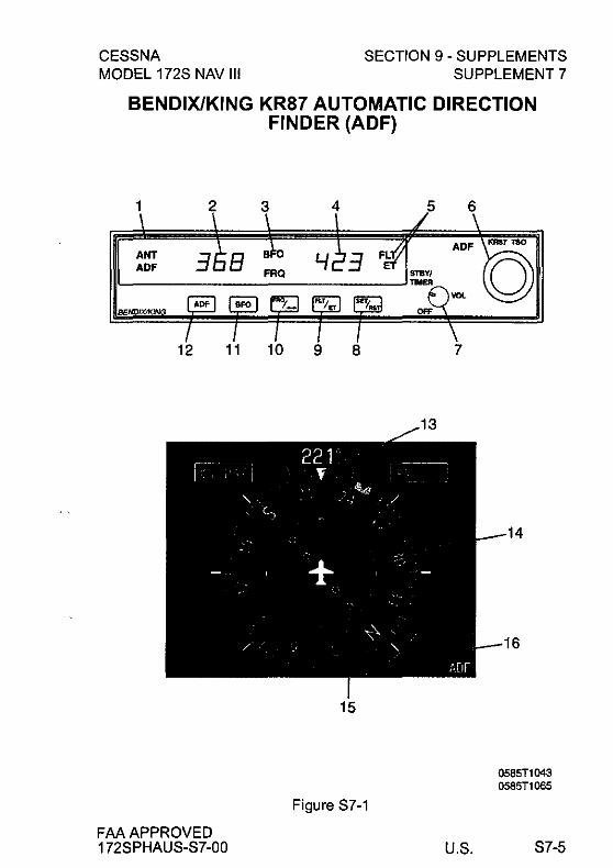
CESSNA MODEL 172S NAV III
SECTION 9 - SUPPLEMENTS SUPPLEMENT 7
BENDIXlKING KR87 AUTOMATIC DIRECTION FINDER (ADF)
1 2
ANT ADF
BENDIXfI(IN
12 11
FAA APPROVED 172SPHAUS-S7-00
3
10
4 5
9 8
15
Figure S7-1
6
ADF
1/Ol
7
U.S.
'.'87 "<SO
0585T1043 0585T1055
S7-5

SECTION 9 - SUPPLEMENTS SUPPLEMENT 7
CESSNA MODEL 172S NAV III
GENERAL (CONTINUED)
1. ANT/ADF MODE ANNUNCIATOR - Antenna (ANT) is selected when the ADF button is in the OUT position. This mode improves the audio reception and is usually used for station identification. The bearing pointer is deactivated and will park in the 90· relative position. Automatic Direction Finder (ADF) mode is selected by pushing the ADF button. This mode activates the bearing pointer and will point in the direction of the station relative to the aircraft heading.
2. ACTIVE FREQUENCY DISPLAY - The frequency to which the ADF is tuned is displayed here. The active ADF frequency can be changed directly when either of the timer functions is selected.
3. BFO (Beat Frequency Oscillator) ANNUNCIATOR - The BFO mode is activated and annunciated by pushing the BFO button. When BFO mode is active, the carrier wave and its morse code identifier can be heard.
NOTE
CW signals (Morse Code) are unmodulated and no audio will be heard without use of BFO. This type of signal is not used in the United States air navigation. It is used in some foreign countries and marine beacons.
4. STANDBY FREQUENCY/FLIGHT TIME OR ELAPSED TIME DISPLAY - When FRQ is shown, the STANDBY frequency is shown in the right display. The STANDBY frequency is selected using the frequency select knobs. The selected STANDBY frequency is put into the active frequency window by pushing the frequency transfer button. Either the standby frequency, the flight timer, or the elapsed time is shown in this position. The flight timer and elapsed timer replace the stand by frequency which goes into blind memory to be called back at any time by pushing the FRQ button. Flight time or elapsed time are shown and annunciated by depressing the FLT/ET button.
5. FLIGHT TIMER AND ELAPSED TIMER MODE ANNUNCIATION - Either the elapsed time (ET) or flight time (FLT) mode is annunciated here.
S7-6 U.S.
(Continued Next Page)
FAA APPROVED 172SPHAUS-S7-00

CESSNA MODEL 172S NAV III
GENERAL (CONTINUED)
SECTION 9 - SUPPLEMENTS SUPPLEMENT 7
6. FREQUENCY SELECT KNOBS - Selects the standby frequency when FRQ is displayed and directly selects the active frequency whenever either of the time functions is selected. The frequency selector knobs may be turned either clockwise or counterclockwise. The small knob is pulled out to tune the 1's. The small knob is pushed in to tune the 10's. The outer knob tunes the 100's with roll over into the 1000's up to 1799. These knobs are also used to set the desired time when the elapsed timer is used in the countdown mode.
7. ON/OFFNOLUME CONTROL SWITCH (ON/OFFNOL) -Controls power and audio output level. Turn the control switch clockwise from the OFF position to energize the receiver and increase audio volume. The KR87 has audio muting which causes the audio output to be muted unless the receiver is locked on a valid station.
8. SET/RESET ELAPSED TIMER BUnON (SET/RST) - The SETI RST button resets the elapsed timer whether it is being displayed or not.
9. FLIGHT TIMER/ELAPSED TIMER MODE SELECTOR BUnON (FLT/ET) -- The FLT/ET button selects either Flight Timer mode or Elapsed Timer mode when pushed.
10.FREQUENCY TRANSFER BUnON (FRQ) - The FRQ transfer button interchanges the active and standby frequencies when pushed.
11.BFO (Beat Frequency Oscillator) BunON - The BFO button selects the BFO mode when pushed in. (See note under item 3).
12.ADF BUTTON - The ADF button selects either the ANT mode or the ADF mode. The ANT mode is selected when the ADF button is in the out position. The ADF mode is selected when the ADF button is pushed in.
13.LUBBER LINE - Indicates magnetic heading of the airplane. 14.ROTATING COMPASS ROSE (HSI COMPASS CARD) - The
rotating compass rose turns as the heading of the airplane changes. The magnetic heading of the airplane is under the lubber line.
15.BEARING POINTER - Shows magnetic bearing to the station. 16.BEARING INFORMATION WINDOW - Shows the type of pointer
that is being used as the ADF bearing pointer. If ADF is not shown, push the BRG1 or BRG2 softkey until ADF is shown.
FM APPROVED 172SPHAUS-S7 -00 U.S. S7-7
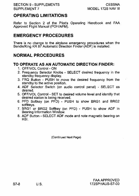
SECTION 9 - SUPPLEMENTS SUPPLEMENT 7
OPERATING LIMITATIONS
CESSNA MODEL 172S NAV III
Refer to Section 2 of the Pilot's Operating Handbook and FM Approved Flight Manual (POH/AFM).
EMERGENCY PROCEDURES There is no change to the airplane emergency procedures when the BendixlKing KR 87 Automatic Direction Finder (AD F) is installed.
NORMAL PROCEDURES
TO OPERATE AS AN AUTOMATIC DIRECTION FINDER: 1. OFFNOL Control - ON 2. Frequency Selector Knobs - SELECT desired frequency in the
standby frequency display. 3. FRQ Button - PUSH to move the desired frequency from the
standby to the active position. 4. ADF Selector Switch (on audio control panel) - SELECT as
desired. 5. OFFNOL Control - SET to desired volume level and identify that
desired station is being received. 6. PFD Softkey (on PFD) - PUSH to show BRG1 and BRG2
softkeys. 7. BRG1 or BRG2 Softkey (on PFD) - PUSH to show ADF in
Bearing Information Window. 8. ADF Button - SELECT ADF mode and note magnetic bearing on
HSI.
S7-8 U.S.
(Continued Next Page)
FM APPROVED 172SPHAUS-S7 -00

CESSNA MODEL 172S NAV III
SECTION 9 - SUPPLEMENTS SUPPLEMENT 7
NORMAL PROCEDURES (CONTINUED)
ADF TEST (PREFLIGHT or IN FLIGHT): 1. ADF Button - SELECT ANT mode and note pointer moves to 90°
position. 2. ADF Button - SELECT ADF mode and note the pointer moves
without hesitation to the station bearing. Excessive pointer sluggishness, wavering or reversals indicate a signal that is too weak or a system malfunction.
TO OPERATE BFO: 1. OFFNOL Control - ON 2. BFO Button - PRESS ON 3. ADF Selector Buttons (on audio control panel) - SET to desired
mode. 4. VOL Control - ADJUST to desired listening level.
NOTE
A 1 OOO-Hz tone and Morse Code identifier is heard in the audio output when a CW signal is received.
TO OPERATE FLIGHT TIMER: 1. OFFNOL Control - ON 2. FLT/ET Mode Button - PRESS (once or twice) until FLT is
annunciated. Timer will already be counting since it is activated by turning the unit on.
3. OFFNOL Control - OFF and then ON if it is desired to reset the flight timer.
TO OPERATE AS A COMMUNICATIONS RECEIVER ONLY: 1. OFFNOL Control - ON 2. ADF Button - SELECT ANT mode 3. Frequency Selector Knobs - SELECT desired frequency in the
standby frequency display. 4. FRQ Button - PRESS to move the desired frequency from the
standby to the active position. 5. ADF Selector Buttons (on audio control panel) - SET to desired
mode. 6. VOL Control - ADJUST to desired listening level.
FAA APPROVED 172SPHAUS-S7-00
(Continued Next Page)
U.S. 57-9

SECTION 9 - SUPPLEMENTS SUPPLEMENT 7
CESSNA MODEL 172S NAV III
NORMAL PROCEDURES (CONTINUED)
TO OPERATE ELAPSED TIME TIMER-COUNT UP MODE: 1. OFFNOL Control - ON 2. FLT/ET Mode Button - PRESS (once or twice) until ET is
annunciated. 3. SET/RST Button - PRESS momentarily to reset elapsed timer to
zero.
NOTE
The Stand by Frequency which is in memory while Flight Time or Elapsed Time modes are being displayed may be called back by pushing the FRQ button, then transferred to active by pushing the FRQ button again.
TO OPERATE ELAPSED TIME TIMER COUNT DOWN MODE:
1. OFFNOL Control - ON 2. FLT/ET Mode Button - PRESS (once or twice) until ET is
annunciated. 3. SET/RST Button - PRESS until the ET annunciation begins to
flash. 4. FREQUENCY SELECTOR KNOBS - SET desired time in the
elapsed time display. The small knob is pulled out to tune the 1's. The small knob is pushed in to tune the 10's. The outer knob tunes minutes up to 59 minutes.
NOTE
Selector knobs remain in the time set mode for 15 seconds after the last entry or until the SET/RST, FLT/ET or FRQ button is pressed.
5. SET/RST Button - PRESS to start countdown. When the timer reaches 0, it will start to count up as display flashes for 15 seconds.
NOTE
While FLT or ET are displayed, the active frequency on the left side of the window may be changed, by using the frequency selector knobs, without any effect on the stored standby frequency or the other modes.
S7-10 U.S.
(Continued Next Page)
FAAAPPROVED 172SPHAUS-S7-00

CESSNA MODEL 172S NAV III
SECTION 9 - SUPPLEMENTS SUPPLEMENT 7
NORMAL PROCEDURES (CONTINUED)
ADF OPERATION NOTES:
ERRONEOUS ADF BEARING DUE TO RADIO FREQUENCY PHENOMENA:
In the U.S., the FCC, which assigns AM radio frequencies, occasionally will assign the same frequency to more than one station in an area. Certain conditions, such as Night Effect, may cause signals from such stations to overlap. This should be taken into consideration when using AM broadcast stations for navigation.
Sunspots and atmospheric phenomena may occasionally distort reception so that signals from two stations on the same frequency will overlap. For this reason, it is always wise to make positive identification of the station being tuned, by switching the function selector to ANT and listening for station call letters.
ELECTRICAL STORMS:
In the vicinity of electrical storms, an ADF indicator pointer tends to swing from the station tuned toward the center of the storm.
NIGHT EFFECT:
This is a disturbance particularly strong just after sunset and just after dawn. An ADF indicator pointer may swing erratically at these times. If possible, tune to the most powerful station at the lowest frequency. If this is not possible, take the average of pointer oscillations to determine station bearing.
MOUNTAIN EFFECT:
Radio waves reflecting from the surface of mountains may cause the pointer to fluctuate or show an erroneous bearing. This should be taken into account when taking bearings over mountainous terrain.
COASTAL REFRACTION:
Radio waves may be refracted when passing from land to sea or when moving parallel to the coastline. This also should be taken into account.
FM APPROVED 172SPHAUS-S7-00 U.8. 87-11

SECTION 9 - SUPPLEMENTS SUPPLEMENT 7
PERFORMANCE
CESSNA MODEL 172S NAV III
There is no change in airplane performance when the BendixlKing KR 87 Automatic Direction Finder (ADF) is installed. However, the installation of an externally mounted antenna or related external antennas, will result in a minor reduction in cruise performance.
S7-12 U.S. FAA APPROVED
172SPHAUS-S7 -00

~ Cessna
A Textron Company
Pilot's Operating Handbook and
FAA Approved Airplane Flight Manual
CESSNA MODEL 172S NAV III AVIONICS OPTION
Serials 172S9810 and On
SUPPLEMENT 8
RUSSIAN FEDERATION (RF) AND OTHER COMMONWEALTH OF INDEPENDENT
STATES (CIS) COUNTRIES
SERIAL NO. ________ I
REGISTRATION NO., ______ I
This supplement must be inserted into Section 9 of the Pllot·s Operating Handbook and FAA Approved Airplane Flight Manual when the airplane is operated within the territory of the Russian Federation (RF) and other Commonwealth of Independent States (CIS) Countries. This supplement is approved by the U.S. Federal Aviation Administration (FAA) on behalf of the Russian Aviation Register.
o Member of GAMA
COPYRIGHT © 2006
CESSNA AIRCRAFT COMPANY
WICHITA, KANSAS, USA
172SPHAUS·S8·00
APPROVED BY
~"'Maw. ... ItIlllMl'~ -_ .. _0lI'l --.ca
""'I."~ DATE OF APPROVAL oI--04-Ok
4 APRIL 2006
u.s. S8-1
SECTION 9 - SUPPLEMENTS SUPPLEMENT 8
SUPPLEMENT 8
CESSNA MODEL 172S NAV III
RUSSIAN FEDERATION (RF) AND OTHER COMMONWEALTH OF INDEPENDENT STATES (CIS) COUNTRIES
Use the Log of Effective Pages to determine the current status of this supplement.
Pages affected by the current revision are indicated by an asterisk (*) preceding the page number.
Sypplement Statys ~
Original Issue 4 April 2006
LOG OF EFFECTIVE PAGES
Page Number
S8-1 thru 88-21/S8-22
Page Status
Original
Revision Number
o
Approved for RF and CI8 Countries Only
FAA APPROVED S8-2 U.S. 172SPHAUS-S8-00

CESSNA MODEL 172S NAV III
SECTION 9 - SUPPLEMENTS SUPPLEMENT 8
SERVICE BULLETIN CONFIGURATION LIST
The following is a list of Service Bulletins that are applicable to the operation of the airplane, and have been incorporated into this supplement. This list contains only those Service Bulletins that are currently active.
Airplane Serial Revision Incorporated
Number Effectjvjtv Incorporated in Ajrptane
Approved for RF and CIS Countries Only
FAA APPROVED 172SPHAUS-S8-00 U.S. S8-3
SECTION 9 - SUPPLEMENTS SUPPLEMENT 8
CESSNA MODEL 172S NAV III
RUSSIAN FEDERATION (RF) AND COMMONWEALTH OF INDEPENDENT (CIS) COUNTRIES
OTHER STATES
GENERAL
This supplement must be placed in Section 9 of the basic Pilot's Operating Handbook and FAA Approved Airplane Flight Manual, when the airplane is operated within the territory of the Russian Federation (RF) and other Commonwealth of Independent States (CIS) Countries. The information contained herein supplements the information of the basic Pilot's Operating Handbook and FAA Approved Airplane Flight Manual. Limitations, procedures, and performance found in this supplement supersedes those found in the basic Pilot's Operating Handbook and FAA Approved Airplane Flight Manual. For limitations, procedures, and performance information not contained in this supplement, consult the basic Pilot's Operating Handbook and FAA Approved Airplane Flight Manual.
S8-4
NOTE
In RF and CIS countries, FAA operating rules (Le., 14 CFR Part 91 and 14 CFR Part 135) are not applicable. The airplane must be equipped and operated in accordance with RF and CIS applicable operational requirements.
Approved for RF and CIS Countries Only
U.S. FAA APPROVED
172SPHAUS-S8-00

CESSNA MODEL 172S NAV III
SECTION 9 - SUPPLEMENTS SUPPLEMENT 8
OPERATING LIMITATIONS
The following Limitations supersede and/or are in addition to the Limitations set forth in the basic Pilot's Operating Handbook and FAA Approved Airplane Flight Manual:
Maximum number of airplane occupants: 1 Pilot plus 3 Passengers
Maximum bank angle: 60·
Operation in heavy precipitation (rain or snow) is prohibited.
Flight into known significant convective activity and thunderstorms is prohibited.
Flight into known icing or freezing rain is prohibited.
Operations in RF and CIS airspace are approved only on routes covered by ATC ground facilities using RBS mode.
The Nav III Avionics Option is approved for Category IlLS approach operations only.
The Global Positioning Satellite (GPS) system is not approved for approach.
Operation over water beyond the Maximum Glide distance from shore is prohibited (Refer to the POH/AFM, Section 3, Figure 3-1).
Spins are prohibited at weight more than 2100 pounds.
Autopilot must be installed and operational for all operations within RF and CIS airspace.
Approved for RF and CIS Countries Only
FAAAPPROVED 172SPHAUS-S8-00 U.S. S8-5

SECTION 9 - SUPPLEMENTS SUPPLEMENT 8
KINDS OF OPERATION LIMITS
CESSNA MODEL 172S NAV III
The following Kinds of Operations Equipment List (KOEl) identifies the equipment required to be operational for airplane airworthiness in the listed kind of operations for airplanes operating within the territory of the Russian Federation and other Commonwealth of Independent States countries.
The following KOEl supersedes the KOEl located in Section 2 of the POH/AFM.
KINDS OF OPERATIONS EQUIPMENT LIST KIND OF OPERATION
V I
V F I F
F R F R
R R
N N
D I D I
A G A G
System, Instrument, Equipment y H Y H
and/or Function T T COMMENTS
PLACARDS AND MARKINGS
172S Nav III POH/AFM 1 1 1 1 Accessible to pilot in flight
Garmin G1000™ Cockpit 1 1 1 1 Accessible to pilot
Reference Guide in flight
AIR CONDITIONING
1 - Forward Avionics Fan 1 1 1 1
2 - PFD Fan 0 0 0 0
3 - MFD Fan 0 0 0 0
4 - Aft Avionics Fan 1 1 1 1
AUTOFLlGHT
1 - BendixlKing KAP 140 POH 1 1 1 1 Accessible to pilot Supplement in flight when using
autopilot
2 - BendixlKing KAP 140 1 1 1 1 Autopilot
(Continued Next Page)
Approved for RF and CIS Countries Only
FAAAPPROVED S8-6 U.S. 172SPHAUS-S8-00
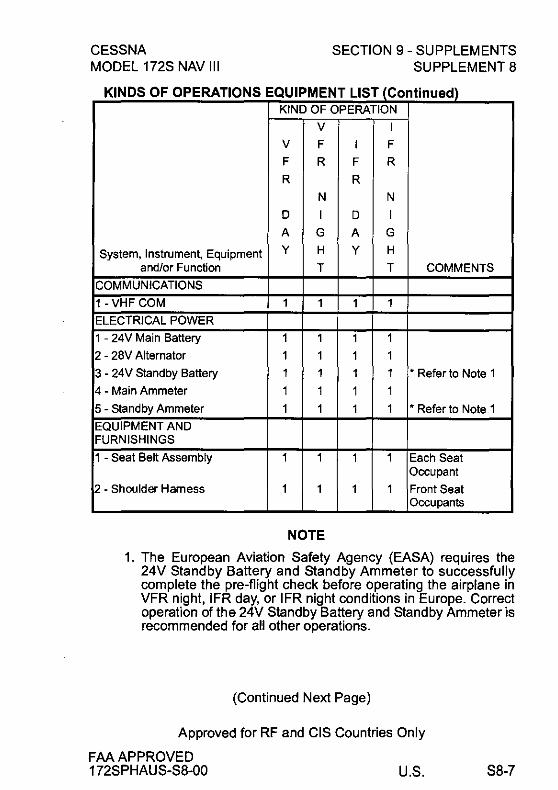
CESSNA MODEL 172S NAV III
SECTION 9 - SUPPLEMENTS SUPPLEMENT 8
KINDS OF OPERATIONS EQUIPMENT LIST (Continued) KIND OF OPERATION
V I
V F I F
F R F R
R R
N N
0 I 0 I
A G A G
System, Instrument, Equipment y H Y H
and/or Function T T COMMENTS
COMMUNICATIONS
1 - VHF COM 1 1 1 1
ELECTRICAL POWER
1 - 24V Main Battery 1 1 1 1
2 - 28V Alternator 1 1 1 1
3 - 24V Slandby Battery 1 1 1 1 • Refer to Note 1
4 - Main Ammeter 1 1 1 1
5 - Standby Ammeter 1 1 1 1 • Refer to Note 1
EQUIPMENT AND FURNISHINGS
1 - Seat Belt Assembly 1 1 1 1 Each Seat Occupant
2 - Shoulder Harness 1 1 1 1 Front Seat Occupants
NOTE
1, The European Aviation Safety Agency (EASA) requires the 24V Standby Battery and Standby Ammeter to successfully complete the pre-flight check before operating the airplane in VFR night, IFR day, or IFR night conditions in Europe. Correct operation of the 24V Standby Battery and Standby Ammeter is recommended for all other operations.
(Continued Next Page)
Approved for RF and CIS Countries Only
FM APPROVED 172SPHAUS-S8-00 U.5. 58-7

SECTION 9 - SUPPLEMENTS SUPPLEMENT 8
CESSNA MODEL 172S NAV III
KINDS OF OPERATIONS EQUIPMENT LIST (Continued) KIND OF OPERATION
V I
V F I F
F R F R
R R
N N
D I D I
A G A G
System, Instrument, Equipment Y H Y H
and/or Function T T COMMENTS
FLIGHT CONTROLS
1 - Flap Position Indicator 1 1 1 1
2 - Flap Motor 1 1 1 1
3 - Elevator Trim System 1 1 1 1
4 - Elevator Trim Indicator 1 1 1 1
FUEL SYSTEM
1 - Electric Fuel Pump 1 1 1 1
2 - Fuel Quantity Indicator - LH 1 1 1 1 Tank
3 - Fuel Quantity Indicator - RH 1 1 1 1 Tank
ICE AND RAIN PROTECTION
1 - Alternate Static Air Source 0 1 1 1
2 - Alternate Induction Air 0 1 1 1 System
INDICATING/RECORDING SYSTEM
1 - Stall Warning System 1 1 1 1
2 - System Annunciator and 1 1 1 1 Warning Displays
LANDING GEAR
1 - Wheel Fairings 0 0 0 0 Removable
(Continued Next Page)
Approved for RF and CIS Countries Only
FM APPROVED S8-8 U.S. 172SPHAUS-S8-00

CESSNA MODEL 172S NAV III
SECTION 9 - SUPPLEMENTS SUPPLEMENT 8
KINDS OF OPERATIONS EQUIPMENT LIST (Continued) KIND OF OPERATION
V I
V F I F
F R F R
R R
N N
D I D I
A G A G
System, Instrument, Equipment y H Y H
and/or Function T T COMMENTS
LIGHTING
1 - PFD Bezel Lighting 0 0 0 1
2 - PFD Backlighting ,
1 1 1 'Refer to Note 2
3 - MFD Bezel Lighting 0 0 0 1
4 - MFD Backlighting ,
1 1 1 'Refer to Note 3
5 - Switch and Circuit Breaker 0 1 0 1 Panel Lighting
6 - Airspeed Indicator (Stand by) 0 1 0 1 Internal Lighting
7 - Altimeter (Stand by) Internal 0 1 0 1 Lighting
8 - Non-stabilized Magnetic 0 1 0 1 Compass Internal Lighting
9 - Attitude Indicator (Vacuum) 0 1 0 1 Internal Lighting
10 - Cockpit Flood Light 0 1 0 1
11 - Aircraft Position (NAV) Lights 0 1 1 1
NOTE
2. PDF backlighting is required for day VFR flight if MFD backlighting has failed. Display backup mode must be active so engine indicators are shown.
3. MFD backlighting is required for day VFR flight if PDF backlighting has failed. Display backup mode must be active so flight instruments are shown.
(Continued Next Page)
Approved for RF and CIS Countries Only
FAA APPROVED 172SPHAUS-S8-00 U.S. S8-9

SECTION g - SUPPLEMENTS SUPPLEMENT 8
CESSNA MODEL 172S NAV III
KINDS OF OPERATIONS EQUIPMENT LIST (Continued) KIND OF OPERATION
V I
V F I F
F R F R
R R
N N
D I D I
A G A G
System, Instrument, Equipment Y H Y H
and/or Function T T COMMENTS
LIGHTING (Continued)
12 - STROBE Light System 1 1 1 1
13 - BEACON Light 0 0 0 0
14 - TAXI Light 0 0 0 0
15 - LAND (Landing) Light 0 1 0 1 Operations for hire only
NAVIGATION AND PITOT-STATIC SYSTEM
1 - G1000 Airspeed Indicator 1 1 1 1
2 - Standby Airspeed Indicator 1 1 1 1
3 - G1000 Altimeter 1 1 1 1
4 - Standby Altimeter 1 1 1 1
5 - G1000 Vertical Speed 1 1 1 1 Indicator
6 - G1000 Attitude Indicator 1 1 1 1
7 - Attitude Indicator - Vacuum 1 1 1 1 (Standby)
8 - G1000 Directional Indicator 1 1 1 1 (HSI)
9 - G1000 Turn Coordinator 1 1 1 1
10 - Non-stabilized Magnetic 1 1 1 1 Compass
11 - VHF Navigation Radio AIR AIR AIR AIR As Required Per (VORlLOC/GS) Procedure
(Continued Next Page)
Approved for RF and CIS Countries Only
S8-10 U.S. FAA APPROVED
172SPHAUS-S8-00

CESSNA MODEL 172S NAV III
SECTION 9 - SUPPLEMENTS SUPPLEMENT 8
KINDS OF OPERATIONS EQUIPMENT LIST (Continued) KIND OF OPERATION
V I
V F I F
F R F R
R R
N N
D I D I
A G A G
System, Instrument, Equipment Y H Y H
andlor Function T T COMMENTS
NAVIGATION AND PITOT-STATIC SYSTEM (Continued)
12 - GPS ReceiverlNavigator AIR AIR AIR AIR As Required Per Procedure
13 - ADF Navigation Radio AIR AIR AIR AIR As Required Per Procedure
14 - Marker Beacon Receiver AIR AIR AIR AIR As Required Per Procedure
15 - Blind Altitude Encoder AIR 1 1 1 As Required Per Procedure
16 - Clock 1 1 1 1
VACUUM
1 - Engine-driven Vacuum Pump 1 1 1 1
2 - Vacuum Indicator 1 1 1 1
ENGINE FUEL AND CONTROL
1 - Fuel Flow Indicator 1 1 1 1
ENGINE INDICATING
1 - Tachometer (RPM) 1 1 1 1
2 - Cylinder Head Temperature 0 0 0 0 (CHT) Indicator
3 - Oil Pressure Indicator 1 1 1 1
4 - Oil Temperature Indicator 1 1 1 1
ENGINE OIL
1 - Engine Crankcase Dipstick 1 1 1 1
Approved for RF and CIS Countries Only
FAAAPPROVED 172SPHAUS-S8-00 U.S. S8-11

SECTION 9 - SUPPLEMENTS SUPPLEMENT 8
FUEL LlMIATIONS
Approved Fuels:100LL (ASTM-D910)
CESSNA MODEL 172S NAV III
100 (Formerly 100/130) (ASTM-D910) 691/115 (GOST 1012-72)
See the latest revision of Lycoming Service Instruction NO.1070 for approved fuel grades.
Fuels must contain an anti-icing fuel additive (Isopropyl Alcohol or DiEGME) in concentrations mixed as noted in Section 8 of the POHI AFM.
MAXIMUM OPERATING ALTITUDE LIMIT
MAXIMUM APPROVED OPERATING ALTITUDE: 3000 meters (9800 Feet).
If oxygen is provided for each occupant. the airplane can be operated up to the maximum altitude for the oxygen system. or 4200 meters (13.779 feet). whichever altitude is lower.
OUTSIDE AIR TEMPERATURE LIMITS
Ground operations limits for a cold day: ................ Minus 40·C
Ground operations limits for a hot day: ..................... 40·C
Approved for RF and CIS Countries Only
FAA APPROVED S8-12 U.S. 172SPHAUS-S8-00

CESSNA MODEL 172S NAV III
TAXI OPERATIONAL LIMITS
Uncontaminated paved taxiway:
SECTION 9 - SUPPLEMENTS SUPPLEMENT 8
• Maximum wind velocity while taxiing: ........... 14 m/s (27 Knots)
Paved taxiway contaminated with precipitation: • Maximum wind velocity while taxiing: ............. 3 m/s (5 Knots)
Refer to Section 4 of the POH/AFM for additional information on taxiing.
TAKEOFF AND LANDING OPERATIONAL LIMITS Maximum Takeoff and Landing Altitude: .... 2438 meters (8000 Feet)
Maximum Headwind Velocity: .................. 14 m/s (27 Knots)
Maximum Tailwind Velocity: ..................... 5 m/s (10 Knots)
Maximum crosswind velocity on uncontaminated paved runway: ............... . 7m/s (15 Knots)
ALLOWABLE RUNWAY SURFACE CONDITIONS 1. Uncontaminated runway with paved surface. 2. Paved runway contaminated with precipitation (average depth
and types): a. Water, less that 10.0 mm. b. Slush, less than 10.0 mm. c. Loose snow less than 30.0 mm.
3. Unpaved runway a. Surface hardness must be greater than 7 kg/cm2
NOTE
Landing on contaminated unpaved runways is prohibited.
Operating with the landing gear fairings removed is recommended on wet or un paved runways when temperatures are near or below freezing.
Approved for RF and CIS Countries Only
FAA APPROVED 172SPHAUS-S8-00 U.8. 88-13

SECTION 9 - SUPPLEMENTS SUPPLEMENT 8
CESSNA MODEL 172S NAV III
MAXIMUM CROSSWIND ON CONTAMINATED RUNWAYS
Contaminated paved runways with: Water, less than 10.0 mm ..................... 3 m/s (5 Knots) Slush, less than 10.0 mm ..................... 3 m/s (5 Knots) Loose snow, less than 30.0 mm ................ 3 m/s (5 Knots)
Paved runway with less than 3 mm of water, snow or slush and braking coefficient of friction(~) of:
~=0.3 (poor braking) ......................... 3 m/s (5 Knots) ~=0.4 (average braking) ...................... 5 m/s (9 Knots) ~=0.5 (good braking, dry or
equivalent to dry runway) ............... 7 m/s (15 Knots)
REQUIRED PLACARDS AND MARKINGS
Above exit doors, in clear view of each occupant:
Exit Bbixo.q
EMERGENCY PROCEDURES The following pages from Section 3 of the POH/AFM have instructions for operations in RF and CIS countries. These pages replace the procedures found in Section 3 of the POH/AFM for those operations:
S8-14
(Continued Next Page)
Approved for RF and CIS Countries Only
U.S. FAA APPROVED
172SPHAUS-S8-00

CESSNA MODEL 172S NAV III
SECTION 9 - SUPPLEMENTS SUPPLEMENT 8
EMERGENCY PROCEDURES (Continued)
FORCED LANDINGS
EMERGENCY LANDING WITHOUT ENGINE POWER 1. Passenger Seats - MOST UPRIGHT POSITION 2. Seats and Seat Belts - SECURE 3. Airspeed - 70 KIAS Flaps UP
65 KIAS Flaps 10· - FULL 4. Mixture Control - IDLE CUT OFF 5. FUEL SHUTOFF Valve - OFF (pull full out) 6. MAGNETOS Switch - OFF 7. Wing Flaps - AS REQUIRED (FULL recommended) 8. STBY BATT Switch - OFF 9. MASTER Switch (ALT and BAT) - OFF (when landing is assured) 10.Doors - UN LATCH PRIOR TO TOUCHDOWN 11.Touchdown - SLIGHTLY TAIL LOW 12.Brakes - APPLY HEAVILY 13. Emergency Radio - Operate (P-855A 1) Russian made
Emergency Radio according to attached instructions.
PRECAUTIONARY LANDING WITH ENGINE POWER 1. Passenger Seats - MOST UPRIGHT POSITION 2. Seats and Seat Belts - SECURE 3. Airspeed - 65 KIAS 4. Wing Flaps - 20· 5. Selected Field - FLY OVER, noting terrain and obstructions. 6. Wing Flaps - FULL (on final approach) 7. Airspeed - 65 KIAS 8. STBY BATT Switch - OFF 9. MASTER Switch (ALT and BAT) - OFF 10.Doors - UNLATCH PRIOR TO TOUCHDOWN 11.Touchdown - SLIGHTLY TAIL LOW 12.Mixture Control - IDLE CUT OFF 13.MAGNETOS Switch - OFF 14.Brakes - APPLY HEAVILY 15.Emergency Radio - Operate (P-855A1) Russian made
Emergency Radio according to attached instructions.
(Continued Next Page)
Approved for RF and CIS Countries Only
FAAAPPROVED 172SPHAUS-S8-00 U.S. S8-15

SECTION 9 - SUPPLEMENTS SUPPLEMENT 8
CESSNA MODEL 172S NAV III
EMERGENCY PROCEDURES (Continued)
DITCHING 1. Radio - TRANSMIT MAYDAY on 121.5 MHz, giving location and
intentions and SQUAWK 7700. 2. Heavy Objects (in baggage area) - SECURE OR JETTISON (if
possible) 3. Passenger Seats - MOST UPRIGHT POSITION 4. Seats and Seat Belts - SECURE 5. Wing Flaps - 20' to FULL 6. Power - ESTABLISH 300 FT/MIN DESCENT AT 55 KIAS
NOTE
If no power is available, approach at 65 KIAS with Flaps UP or 60 KIAS with Flaps 10'.
7. Approach - High Winds, Heavy Seas -INTO THE WIND Light Winds, Heavy Swells - PARALLEL TO SWELLS
8. Cabin Doors - UNLATCH 9. Touchdown - LEVEL ATTITUDE AT ESTABLISHED RATE-OF-
DESCENT. 1 O.Face - CUSHION at touchdown with folded coat. 11.ELT - ACTIVATE 12.Airplane - EVACUATE through cabin doors. If necessary, open
window and flood cabin to equalize pressure so doors can be opened.
13.Life Vests and Raft -INFLATE WHEN CLEAR OF AIRPLANE. 14.Emergency Radio - Operate (P-855A 1) Russian made
Emergency Radio according to attached instructions.
S8-16
(Continued Next Page)
Approved for RF and CIS Countries Only
U.S. FAAAPPROVED
172SPHAUS-S8-00
CESSNA MODEL 172S NAV III
SECTION 9 - SUPPLEMENTS SUPPLEMENT 8
EMERGENCY PROCEDURES (Continued)
FORCED LANDINGS
If all attempts to restart the engine fail and a forced landing is imminent, select a suitable field and prepare for the landing as discussed under the Emergency Landing Without Engine Power checklist. Transmit Mayday message on 121.5 MHz giving location and intentions and squawk 7700.
Before attempting an "off-airport" landing with engine power available, one should flyover the landing area at a safe, but low altitude, to inspect the terrain for obstructions and surface conditions, proceeding as discussed in the Precautionary Landing With Engine Power checklist.
Prepare for ditching by securing or jettisoning heavy objects located in the baggage area and collect folded coats for protection of occupants' face at touchdown. Transmit Mayday messages on 121.5 MHz giving location and intentions and squawk 7700. Avoid a landing flare because of the difficulty in judging height over a water surface. The checklist assumes the availability of power to make a precautionary water landing. If power is not available, use of the airspeeds noted with minimum flap extension will provide a more favorable attitude for a power off ditching.
In a forced landing situation, do not turn off the AVIONICS switch or MASTER switch until a landing is assured. Premature deactivation of the switches will disable all airplane electrical systems.
Following evacuation from the airplane, operate (P-885A 1) Russian made Emergency Radio according to the attached instructions provided with the radio.
Approved for RF and CIS Countries Only
FAAAPPROVED 172SPHAUS-S8-00 U.8. 88-17

SECTION 9 - SUPPLEMENTS SUPPLEMENT 8
CESSNA MODEL 172S NAV III
NORMAL PROCEDURES
NOTE
• In a left slip maneuver, the airspeed indicator may show a maximum of 20 knots below the actual airspeed. In a right slip maneuver, the airspeed indicator may show a maximum of 5 knots above the actual airspeed. This is because of the single static pressure port on the 172S left forward fuselage.
• At airspeeds greater than 120 KIAS, close the throttle if necessary to keep engine speed below 2700 RPM.
In the event of GPS failure when operating along routes that are ± 5 km wide without VORlDME facilities and no NDB coverage, airplane position between the width of such routes can only be assured up to approximately 140 km from the last known position.
The pilot is to disregard Supplement 1 of the POH/AFM describing the pointer Model 3000-11 or 4000-11 Emergency Locator Transmitter (ELT).
COLD WEATHER OPERATIONS
S8-18
NOTE
• The Garmin GDU 1040 PFD/MFD requires a warm-up time of up to 30 minutes when exposed to Minus 40'C for an extended period. A warm-up time of up to 15 minutes may be required when exposed to Minus 30'C for an extended period of time.
• During operation at outside temperatures below ISA Standard, the engine may develop greater than rated power at normal rated RPM, particularly at lower altitudes.
Approved for RF and CIS Countries Only
U.S. FAA APPROVED
172SPHAUS-S8-00

CESSNA MODEL 172S NAV III
COLD SOAK
SECTION 9 - SUPPLEMENTS SUPPLEMENT 8
If extended exposure to cold weather is expected, refer to Maintenance Manual procedures to prepare the airplane for cold soak. If the airplane has cold soaked for more than two hours at temperatures colder than Minus 10°C, refer to Maintenance Manual procedures to prepare the airplane for flight. Cold temperatures will affect control cable tension. See Chapter 27 of the Maintenance Manual for flight control cable tensions. See Chapter 12 of the Maintenance Manual for information on lubrication and greasing of moving parts. See Section 8 of the PO HI AFM for correct engine oil viscosity. See paragraphs on Cold Weather Operation in Section 4 of the POH/AFM for additional information on procedures for operating the airplane in cold temperatures.
When the outside temperature is less than Minus 34°C, the airplane batteries should be removed and stored in the warm conditions.
The engine must be preheated before starting if engine temperature is less than Minus 6°C.
When the outside temperature is less than O°C, moisture from combustion can freeze on the engine spark plugs if the engine does not continue to operate after it is started. This will prevent the engine from starting again. Preheat the engine to more than O°C before starting the engine again.
Preheat the engine by directing warm air into the engine cooling inlets behind the propeller. The temperature of the preheating air should not be more than 120°C to prevent damage to the exterior paint. Open flames are prohibited near the airplane.
Before takeoff, preheat the airplane cabin to more than Minus 30°C for correct operation of the standby altimeter. If there is no warning that an instrument is operating incorrectly, all other instruments will operate down to the minimum temperature of the airplane.
Before operating the airplane, it is recommended to heat the cabin to a comfortable temperature for the cabin occupants.
Approved for RF and CIS Countries Only
FM APPROVED 172SPHAUS-S8-00 U.8. 88-19

SECTION 9 - SUPPLEMENTS SUPPLEMENT 8
PERFORMANCE
CESSNA MODEL 172S NAV III
OPERATION ON CONTAMINATED RUNWAY
The takeoff distance on a paved runway with no more than 3 mm of precipitation is equal to dry runway takeoff distance.
The takeoff distance on a paved runway with precipitation greater than 3 mm is 20% greater than the dry runway takeoff distance.
To determine the required landing distance on a contaminated paved runway. the dry runway landing distance shall be multiplied by the following K factors:
Conditions Basic Airfield Alternate Airfield 11 ? 0.5 K -1.67 K-1.43
(good braking and runway with no standing water)
0.5? ~? 0.4 K -1.72 K = 1.72
(Average Braking)
More than 3 mm precipitation K = 2.00 K = 2.00
or
0.4 ? ~ ? 0.3 (Poor Braking)
For unpaved runway landing distance. refer to figure 5-12 in the POHI AFM for the correction applied to grass runway landing distance.
S8-20
Approved for RF and CIS Countries Only
U.S. FAA APPROVED
172SPHAUS-S8-00

CESSNA MODEL 172S NAV III
SECTION 9 - SUPPLEMENTS SUPPLEMENT 8
LANDING DISTANCE CORRECTION FACTORS FOR CONTAMINATED PAVED RUNWAYS
'a5 l!
2000
15 1800 ex: "0 c: :::J
~ 1600 C> c: =g
•••• j
j 1400 ..
~ ;;: c: :::J ex: 1
~ c: .~ 1 C o ()
800.
.. '. '.
" ""'1"
600 700 800 900 1000 1100 Dry Runway Landing Ground Roll (Feet)
Figure S8-1
Approved for RF and CIS Countries Only
FAA APPROVED 172SPHAUS-S8-00 U.S. S8-21/S8-22

Pilot's Operating Handbook And FAA Approved
Airplane Flight Manual SKYHAVVK
SP CESSNA MODEL 172S NAV III AVIONICS OPTION Serials 17259810 and On
SUPPLEMENT 9
ARTEX ME406 EMERGENCY LOCATOR TRANSMITTER (ELT)
SERIAL NO •. ________ 1
REGISTRATION NO .. _____ I
This supplement must be inserted into Section 9 of the Pilot's Operating Handbook and FAA Approved Airplane Flight Manual when the Artex ME406 Emergency Locator Transmitter (ELT) is installed.
f) Member of GAMA
COPYRIGHT © 2006
CESSNA AIRCRAFT COMPANY
WICHITA, KANSAS, USA
172SPHAUS·S9·QQ
APPROVED BY FMAPI'fIOWDtlClEAMCRPMI'lI1t8Wn' J -_ .. DlillgllrllQIIan~~
tf?..-du _ .. Kt-5
DATE OF APPROVAL 30 Orr/phe( Wp
30 OCTOBER 2006
U.8. 89-1

SECTION 9 - SUPPLEMENTS SUPPLEMENT 9
SUPPLEMENT 9
CESSNA MODEL 172S NAV III
ARTEX ME406 EMERGENCY LOCATOR TRANSMITTER (ELT)
Use the Log of Effective Pages to determine the current status of this supplement.
Pages affected by the current revision are indicated by an asterisk (*) preceding the page number.
Supplement Status
Original Issue
LOG OF EFFECTIVE PAGES
QD1i 30 October 2006
Page Page Number Status
59-1 thru 59-8 Original
S9-2 U.S.
Revision Number
o
FM APPROVED 172SPHAUS-S9-00

CESSNA MODEL 172S NAV III
SECTION 9 - SUPPLEMENTS SUPPLEMENT 9
SERVICE BULLETIN CONFIGURATION LIST
The following is a list of Service Bulletins that are applicable to the operation of the airplane. and have been incorporated into this supplement. This list contains only those Service Bulletins that are currently active.
Number Title
FAA APPROVED 172SPHAUS-S9-00
Airplane Serial Revision Incorporated
Effectivity Incorporated in Airplane
U.S. S9-3
SECTION 9 - SUPPLEMENTS SUPPLEMENT 9
CESSNA MODEL 172S NAV III
ARTEX ME406 EMERGENCY LOCATOR TRANSMITTER (ELT)
GENERAL
The Artex ME406 Emergency Locator Transmitter (ELT) installation uses a solid-state 2-frequency transmitter powered by an internal lithium battery. The ME406 is also equipped with an instrument panelmounted remote switch assembly. that includes a red warning light. and an external antenna mounted on the top of the tailcone. The remote switch assembly is installed along the upper right instrument panel and controls ELT operating modes from the flight crew station. When the remote switch is set to the ARM position. the transmitter is energized only when the internal "G" switch senses longitudinal inertia forces per TSO-C91a/TSO-C126. When the remote switch is set to the ON position. the transmitter is immediately energized.
The ME406 transmitter unit is located in the tailcone along the right side behind the baggage compartment aft panel. On the ELT transmitter unit is a panel containing an ARM/ON switch and a transmitter warning light.
The ELT installation uses two different warnings to tell the pilot when the ELT is energized. The aural warning is an unusual sound that is easily heard by the pilot. The visual warning is a flashing red light directly above the remote switch that shows the pilot that the ELT has been activated.
When the ME406 is energized. the ELT transmits the standard swept tone signal on the international VHF frequency of 121.5 MHz until battery power is gone. The 121.5 MHz signal is mainly used to pinpoint the beacon during search and rescue operations. and is monitored by general aviation. commercial aircraft. and government agencies.
In addition. for the first 24 hours of the ELT being energized. a 406.028 MHz signal is transmitted at 50 second intervals. This transmission lasts 440 milliseconds and contains identification data programmed into the ELT and is received by COSPAS/SARSAT satellites. The transmitted data may include the Aircraft ID. ELT Serial Number. Country Code. and COSPAS/SARSAT ID.
(Continued Next Page)
S9-4 U.S. FAA APPROVED
172SPHAUS-S9-00

CESSNA SECTION 9 - SUPPLEMENTS SUPPLEMENT 9 MODEL 172S NAV III
ARTEX ME406 ELT CONTROL PANEL
'"'' 1 2 3
4
0718T1107
1. ELT PANEL SWITCH (2-Position Toggle Switch): a. ARM (OFF) - Turns OFF and ARMS transmitter for
automatic activation if "G" switch senses a predetermined deceleration level.
b. ON - Activates transmitter instantly. The ON position bypasses the automatic activation switch. The RED warning light on ELT panel and on the remote switch assembly mounted on the instrument panel should come on.
2. TRANSMITTER WARNING LIGHT - Light comes on RED to indicate the transmitter is transmitting a distress signal.
3. ANTENNA RECEPTACLE - Connects to the antenna mounted on top of tailcone.
4. REMOTE CABLE JACK - Connects to the ELT remote switch assembly located on the upper right instrument panel.
5. REMOTE SWITCH ASSEMBLY - (2-Position Rocker SWitch): a. ARM (OFF) - Turns OFF and ARMS transmitter for
automatic activation if "G" switch senses a predetermined deceleration level.
b. ON - Remotely activates the transmitter for test or emergency situations. The RED warning light above the rocker switch comes on to indicate that the transmitter is transmitting a distress signal.
FM APPROVED 172SPHAUS-S9-00
Figure S9-1
U.S. S9-5

SECTION 9 - SUPPLEMENTS SUPPLEMENT 9
OPERATING LIMITATIONS
CESSNA MODEL 172S NAV III
There are no additional airplane operating limitations when the Artex ME406 ELT is installed.
The airplane owner or operator must register the ME406 ELT with the applicable civil aviation authority before use to make sure that the identification code transmitted by the ELT is in the COSPAS/SARSAT database. Refer to www.cospas-sarsat.org for registration information.
Refer to 14 CFR 91.207 for ELT inspection requirements. The ME406 must be inspected and tested by an approved technician using the correct test equipment under the appropriate civil aviation authorities approved conditions.
S9-6 U.S. FAA APPROVED
172SPHAUS-S9-00

CESSNA MODEL 172S NAV III
SECTION 9 - SUPPLEMENTS SUPPLEMENT 9
EMERGENCY PROCEDURES If a forced landing is necessary, set the remote switch to the ON position before landing. This is very important in remote or mountainous terrain. The red warning light above the remote switch will flash and the aural warning will be heard.
After a landing when search and rescue aid is needed, use the ELT as follows:
NOTE
The ELT remote switch assembly could be inoperative if damaged during a forced landing. If inoperative, the inertia "G" switch will activate automatically. However, to turn the ELT OFF and ON again requires manual switching of the ELT panel switch which is located on the ELT unit.
1. MAKE SURE THE ELT IS ENERGIZED: a. If the red warning light above the remote switch is not
flashing, set the remote switch to the ON position. b. Listen for the aural warning. If the CaM radio(s) operate and
can be energized safely (no threat of fire or explosion), energize a CaM radio and set the frequency to 121.5 MHz. The ELT tone should be heard on the CaM radio if the ELT is working correctly. When done, de-energize the CaM radio(s) to conserve the airplane battery power.
c. Make sure that nothing is touching or blocking the ELT antenna.
2. AFTER RESCUE - Set the remote switch to the ARM position to de-energize the ELT. If the remote switch does not function, set the switch on the ME406 (in the tailcone) to the ARM position.
FAA APPROVED 172SPHAUS-S9-00 U.S. S9-7
SECTION 9 - SUPPLEMENTS SUPPLEMENT 9
NORMAL PROCEDURES
CESSNA MODEL 172S NAV III
When operating in a remote area or over hazardous terrain, it is recommended that the ELT be inspected by an approved technician more frequently than required by 14 CFR 91.207.
NORMAL OPERATION 1. Check that the remote switch (on the upper right instrument
panel) is set to the ARM position.
Normal operation of the ME406 from the flight crew station is only to de-energize and arm the ELT after it has been accidentally energized (no emergency).
The ELT can be energized by a lightning strike or hard landing. If the red light above the remote switch is flashing and the aural warning is heard, the ELT is energized. Check for the emergency signal on a COM radio set to 121.5 MHz. To stop the transmissions, set the remote switch to the ON position momentarily and then set to the ARM position. Tell the nearest Air Traffic Control facility about the accidental transmissions as soon as possible to hold search and rescue work to a minimum.
PERFORMANCE
There is no change to the airplane performance when the Artex M E406 ELT is installed.
S9-8 U.S. FAA APPROVED
172SPHAUS-S9-00

~ Cessna
"""4C_,!"' _~ ________ .... "":A:'::T"",,,";::::::,:,:C_~
Pilot's Operating Handbook And FAA Approved
Airplane Flight Manual SKYHAVVK
SP CE55NA MODEL 1725 NAV III AVIONICS OPTION
Serials 172S9810 and On
SUPPLEMENT 10
JAR-OPS OPERATIONAL ELIGIBILITY
SERIAL NO •. _______ 1
REGISTRATION NO .. _____ I
This supplement must be inserted into Section 9 of the Pilot's Operating Handbook and FAA Approved Airplane Flight Manual for JAR-OPS Operational Eligibility.
o Member of GAMA
COPYRIGHT © 2006
CESSNA AIRCRAFT COMPANY
WICHITA, KANSAS, USA
172SPHAUS-Sl0-00
APPROVED BY ~~LNII!JIt .. CII't"'""IUPMI'~ --.. ~0Ib"""1IOIt-.cE
rfl....da. _M ~,,~
DATE OF APPROVAL Ib No""",,,,,,, 'ZpOb
16 NOVEMBER 2006
u.S. S10-1

SECTION 9 • SUPPLEMENTS SUPPLEMENT 10
SUPPLEMENT 10
CESSNA MODEL 172S NAV III
JAR-OPS OPERATIONAL ELIGIBILITY
Use the Log of Effective Pages to determine the current status of this supplement.
Pages affected by the current revision are indicated by an asterisk (*) preceding the page number.
Supplement Status
Original Issue
LOG OF EFFECTIVE PAGES
Page Number
810·1 thru 810·5/810·6
S10·2 U.S.
Qili 16 November 2006
Page 8tatus
Original
Revision Number
o
FAA APPROVED 172SPHAUS·S 10·00

CESSNA MODEL 172S NAV III
SECTION 9 - SUPPLEMENTS SUPPLEMENT 10
SERVICE BULLETIN CONFIGURATION LIST
The following is a list of Service Bulletins that are applicable to the operation of the airplane, and have been incorporated into this supplement. This list contains only those Service Bulletins that are cu rrently active.
Number
FAA APPROVED 172SPHAUS-S 10-00
Ajrplane Serial Revision Incorporated Effectjvjty Incorporated in Ajrp!ane
U.S. S10-3

SECTION 9 - SUPPLEMENTS SUPPLEMENT 10
CESSNA MODEL 172S NAV III
JAR-OPS OPERATIONAL ELIGIBILITY
GENERAL
OPERATIONAL ELIGIBILITY
The JAA TGLs noted below specify that Operational Eligibility information be included in the airplane POH/AFM or POH/AFM Supplement for convenience in the JAR-OPS approval process. This Supplement provides a consistent location for the requested information. This information does not address the operation of the airplane or equipment by the pilot.
NAVIGATION OPERATIONAL ELIGIBILITY
The GPS/GNSS receivers in the G1000 System are certified to TSO C129a Class A1 and ETSO C129a Class A1 or TSO C145a and ETSO 2C145a.
The installed performance of the G1000 System has been tested and approved for IFR enroute, terminal and non-precision (RNAV or GPS) approach operations per AC 20-138A when using GPS/GNSS with the correct navigation database.
The G1000 System meets the requirements for GPS/GNSS as a Primary Means of Navigation for Oceanic/Remote Operations (RNP-10) per AC 20-138A, FAA Notice N8110.60, FAA Order 8400-12A and FAA Order 8700-1. Both GPS/GNSS receivers are required to be operating and receiving usable signals except for routes requiring only one Long Range Navigation sensor.
The G1000 System has been shown to be eligible for BRNAV (RNP-5) and PRNAV (RNP-1) Enroute and Terminal navigation per JAA TGL-2 (ACJ20X4), JAA TGL-10 and AC 90-96A provided that the G1000 is receiving usable navigation information from at least one GPS receiver. Eligibility does not constitute Operational Approval.
(Continued Next Page)
S10-4 U.S. FAA APPROVED
172SPHAUS-S10-00

CESSNA MODEL 172S NAV III
GENERAL (Continued)
SECTION 9 - SUPPLEMENTS SUPPLEMENT 10
SSR MODE S ENHANCED SURVEILLANCE OPERATIONAL ELIGIBILITY
The GTX 33 Transponder is certified to TSO C112a and ETSO 2C112a. The installed performance of the GTX 33 has been tested and approved per AC 20-131A, Draft AC-131B and AC 23-8B.
The GTX 33 is able to respond to interrogations in Modes A, C and is fully compliant with the requirements of Mode S Elementary Surveillance per TGL 13 Rev 1 and Draft TGL 13 Rev 2. Extended Squitter functionality is supported by the GTX 33. This does not constitute airworthiness or operational approval for Extended Squitter functionality.
OPERATING LIMITATIONS
There is no change to the airplane operating limitations for JAR-OPS Operational Eligibility. JAR-OPS may require separate airspace operating limitations.
EMERGENCY PROCEDURES There is no change to the airplane emergency procedures for JAROPS Operational Eligibility.
NORMAL PROCEDURES There is no change to the airplane normal procedures for JAR-OPS Operational Eligibility.
PERFORMANCE
There is no change to the airplane performance for JAR-OPS Operational Eligibility.
FAA APPROVED 172SPHAUS-S10-00 U.S. S 1 0-5/S 1 0-6

AMSAFE. Inc. Inflatable Restraints DivISion 1043 N. 47''' Avenue Phoenix. AZ.. 85043 Document No .. E508810 RevIsion: IR
FAA APPROVED AIRPLANE FLIGHT MANUAL SUPPLEMENT
to
PILOT'S OPERATING HANDBOOK AND FAA APPROVED AIRPLANE FLIGHT MANUAL
'0' Cessna Aircraft Corporation
(Manual PINs) Skyhawk Models:172R (PIN 172RPHUS09 & 172RI80PHUSXX)
1725 (PIN 172SPHUSOS)
Skylane Models: 1825 (PIN 182SPHUSXX) 182T (182TPHUSOl & 182TPHAUS-Ol NAV Ill) T182T (PIN TI82TPHAUS-OO & T182TPHUS02 NAV Ill)
Stationai, Models: 206H (PIN 206HPHUS06) T206H (PIN T206HPHUS06)
Aircraft Reg. No. ___ _ Aircraft SIN: ____ _
ThiS supplement must be attached to the FAA-approved Cessna Aircraft Models 172R, 172S. 182S. 182T, T182T. 206H, and T206H associated Pilot's Operating Handbook and FAA Approved Airplane Flight Manual when the Airpiane IS modified by the mstallation of AMSAFE AViation Inflatable Restraint (AAIR'~) System, V23 Version In accordance with STC No. S_M1700!..A.
The Information contained herem supplements or supersedes the baSIC manual only In those areas listed herein. For limitations, procedures, and performance Information not contained In thiS supplement. consult the associated Pilot's Operating Handbook and FM Approved Airplane Flight Manual.
FAAAPPROVED-'~~~~~~70==~""~~~ Manager, Flight Test Branch, ANM-160L Federal Aviation Administration Los Angeles Aircraft Certification Office Transport Airplane Directorate
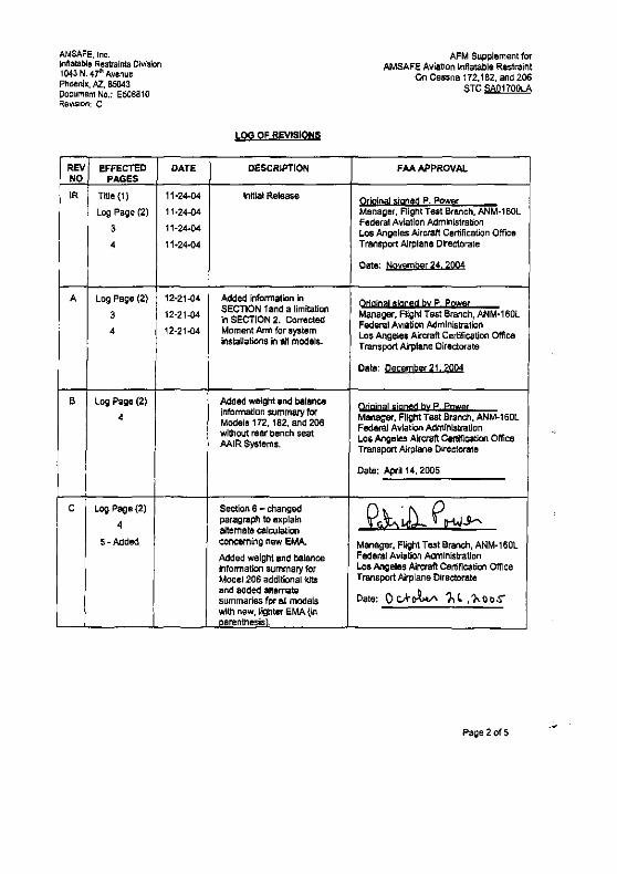
AMSAFE, Inc. Inflatable Remints Division 1043 N. 4f' Avenue PhMlnix, Al, 85043 Document No.: E50BB10 Re~l$lon: C
REV eFFECTED NO PAGES
tR Title (1)
Log Page (2)
3
4
A Log Page (2)
3 , 4
B Le>g Page (2)
4
C Log Pagl!l(2)
4
S-Added
I
DATE
11·24-04
11·24-04
11·24·04
11-24-04
12-21-04
12-21-04
12-21-04
LOG OF REVISIONS
DESCRIPTION
Initial Relea5e
Added infonnation in SECTION land a IImitatiQ(1 In SECTION 2. Corrected Moment Arm for system installations In all models.
Added weight end balance infOrmation summary tor Models 172. 182, and 206 without rear bench seat MlR Sy&tems.
Section 6 - changlKl paragf11ph to explain alternate calculation concerning new EMA.
Added weight and balance lnfoO'nation summary tor Model 206 addiliQnal kits and added altemate summarIes for all models with naw, \~~ter eMA (In oarenthesis .
AFM Supplement for AMSAFE Aviation Inflatable Restraint
On Cessna 172,182, and 206 $TC SAQ1700LA
FAA APPROVAL
Qtjg
AMSAFE, Inc. Inflatable RestraInts Oivision 1043 N. 47111 Avenue Phoenix, /4Z, 85043 Document No.; E50B810 ReVIsion: A
SEcnON 1 GENERAL
AFM Supplement for AMSAFE Aviation Inflatable Restralnl
On CE!$sna 172,182, and 206 STC SAQ1100lA
The MlR V23 is.a self-contained, modular, thrae-poinl restraint syslem that Improves protection from serious head-impact injury during a sUMvable aircraft crash by InclusIOn of an rlflatabl' airbag 10 the lapbell portion of the three-point restraint. An unbLldsle9 !'R!i!trnlot alrMg will nollntlate.
SECTION 2 LlMrTATIONS
A child safety seal shall not be used with the V23 MlR Syslem in tha front &eat (co-pilot). A d1l1d sefety seat may be used in the rear seat positions only by attaching the child seat With an auxiliary child seat buckle. The standard Inftatable rest/illnt buckle cannot be used 10 secure.8 child safety seat.
The Auxiliary Child Seat Buckle adapter (PIN 7035-2090112396 (LH) ilnd 7035-2100212396 (R.H)) secures a Child Safety Seal to either left Of' nght positions of the Rear Seat for all models (see weming label below). It Is typlcany stored under the cushion and Is found in the center of the seat adjacent to the standard MlR. End-R.elease Buckle Assembly, Identlfleble by part number (abOVe) and attadles to the Airbag Belt portion of the $eatbelt Airbag Assembly (see diagram).
Tb. rashinl In an tmoty C9=plloJ Qf passeng,r "111 myst not be bueldtd $0 as to preygnt Inflation qf the I!lobe!! '!bag in the unoeeypltd !!tat
Rear Bench Seat for Models 172, 182, and 206
t Ain::11IfI: Forward
SECTION 3 EMERGENCY PROCEDURES
No Change
SEcnON 4 NORMAL PROCEDURt;S
To eetivate the system, join (buckle) the Ihree-polnt IlI8tralnl in the same manner as any other three-point seatbelt, An empty co-pilOl or pBS:;eooer seal restraint musl nol be bqclded
SECTION 5 PERFORMANCE
No Change
FAAApproved:~ Page a of5

AMSAFE, Ine. Inflatable RestraInt& Divislol'l 1043 N. 41" AvenlJ& Phoel"lIx, Al.. 85043 Document No.: ~810 Revision: C
AFM Supplement for AMSAFE Avi;Jtlon Inflatable Restraint
On Cessna 172,182. and 206 STC SA01700LA
SEcnON 6 WEIGHT AND BALANCE/EQUIPMENT LIST
For complete information of the MlR V23 System effect on weight end balance loading to the aircraft, please refer to AMSAFE Aviation's, Weight and Balance Information Report Document No. E508952.
In the summary that follows. Empty Weights and Moments are given for MlR Systems wlth the current Electronics Module Assembly (EMA), PIN 50835&-409 and the new, lighter-weight EMA, PIN 508358421, useful for loading and Canter of Gravity calculations. Those explWsed in parentheses were calculated using the new, lighter EMA, PIN 508358421.
Modals 172B. 1725 - with optional raar Stat bench MlR S'Iit!m
empty Weight Arm 7.638 57.928 (7.338)
1682.S Ibs
Moment 442.464 (425.075)
MlR System DifTerence Added (EMA, PIN 508358-409) MlR S)'Stem Difference Added (EMA. PIN 508358-421)
1701.1381bs New empty Weight (EMA. PIN 5011358-4(9) (1699,838) Ibs New Empty Weight (EMA, PIN 5083580421)
Models 172R 1725 _ without optional rear Hat blnch MlR Svtttm
Empty Waight Arm 3.8413 45.397 (3.698)
16!J2.S Iba
Momerlt 174.686 (167.871)
MlR System Difference Added (EMA, PIN !08358-409) MlR System Dttrsrsnce Added (EMA, PIN 508356-421)
1898.348 Ibs Nlw Empty Weight (EMA, PIN 508~) (1696.198) Ibs New Empty Weight (EMA, PIN 5083584:2.1)
Models 1829. 182! T182T -with rear "at bench MlR System
Empty WeigOt Arm 7.638 57.882 (7.338)
20291bs
Moment 440.578 (423.270)
MlR System Difterence Added (EMA, PIN 508358-409) MlR system Difference Added (EMA. PIN 508358-421)
2036.631Ibs New Empty Weight (EM~ PIN 508358-409) (2036.338) Ibs New .!mpty Weiuht (EMA, PIN 508368421)
Mod.,s 182S. 112T T1821 _without nw S!,t bench MlR Syst.m
Empty Weight Arm 3.848 41.798 (3.898)
2029 Iba
Moment 160.838 (154.569)
AAlR System Difference Added (EMA, PIN 506358-409) MlR System Difference Added (EMA, PIN 508358--421)
2032.848 11)5 New Empty Weight CEllA, pIN 508358-409) (2032.698) Iba New Elnpty Weight (EMA, PIN 508358 .... 21)
Modlls 206H T2a6H _ with optional !'far seat bench M'R Systam
Empty Weight Arm 11.54 69.782 (11.090)
2210 Iba
FM Approved: 10_26.2005
Moment 805.284 (773.882)
AAIR SY'tem Difference Added (EMA. PIN 508358-409) MlR System Difference Added (EMA, PIN 508358-421)
2221.54 Iba New Empty Weight (EMA, PIN 508358-409) (2221.09) Iba N.w Empty Weight (EMA, PIN 5083580421)
Page4of5

AMSAFE. lne. lrrf\atabie Restraints DNIsIon 1043 N. 47'~ Avenue Phoeni)('}Z.,85043 Document No.: ES08610 RevIsion: C
AFM Supplement for AMSAFE AviatIOn Inflatable Restraint
On Cessna 172,182. and 20B STC SAQ1700LA
Mode!! 206H. T201H - without OpHonll relr • .at b9nth MlR SYStem
Emotv Wftlghl Arm 7.75 53.852 (7.450)
22101bs
Moment 417.350 (401.197)
MlR System Oifference Added (EMA. PIN 508358-4(9) MlR System Difference Added (EMA, PIN 508358-421)
2217.75 lb. Haw Empty Weisht (EMA, PIN 508358-4(9) (2217.45) lb. New empty Weight (EMA. PIN 508358-421)
Mode', 206H T208H - Pilot/Co_Pilot Sut Only MlR system
Empty Weight Arm 2.575 44.563 (2.425)
2210 Jbs
Mqmftn! 114.802 (108.113)
AAIR System Difference Added (EMA, PIN ~08358-409) MlR System Difference Added (EMA, PIN 508358-421)
2212.575Ib. New Empty Weight (EMA. PIN 508355-409) (2212.425) Ib, New Empty Weight (EMA, PIN 508358-421)
Moa" 206H !206H _ M!ddlt §Ut Only MlR SY'tero
Empty Weighl Arm 3.87~ 65.382 (3.725)
2210Ib,
MgmftO! 253.356 (243.547)
MlR System Difference Added (EMA, PIN S083S8-409l MlR System Difference Added (EMA. P""" 508358-421)
2213.875 Iba Naw Empty Weight (EMA. PIN 508358-409) (2213.125) Iba New Empty Weight lEMA, PIN 508358-421)
For all models, the change is less than 1 % Of the CG range at gross weight. wnlch is Insignificant and will cause no CO issues. Refer to the above report for the exact details.
FM Approved: 10_26_2006 Page 50(5