butyl rubber-aliphatic polyester graft ... - citeseerx
TRANSCRIPT
Western UniversityScholarship@Western
Electronic Thesis and Dissertation Repository
June 2013
Butyl Rubber-Aliphatic Polyester GraftCopolymers for Biomedical Applications:Synthesis and Analysis of Chemical, Physical andBiological PropertiesBethany A. TurowecThe University of Western Ontario
SupervisorDr. Elizabeth GilliesThe University of Western Ontario
Graduate Program in Biomedical Engineering
A thesis submitted in partial fulfillment of the requirements for the degree in Master of Engineering Science
© Bethany A. Turowec 2013
Follow this and additional works at: http://ir.lib.uwo.ca/etd
Part of the Biomaterials Commons, Polymer Chemistry Commons, and the Polymer ScienceCommons
This Dissertation/Thesis is brought to you for free and open access by Scholarship@Western. It has been accepted for inclusion in Electronic Thesisand Dissertation Repository by an authorized administrator of Scholarship@Western. For more information, please contact [email protected].
Recommended CitationTurowec, Bethany A., "Butyl Rubber-Aliphatic Polyester Graft Copolymers for Biomedical Applications: Synthesis and Analysis ofChemical, Physical and Biological Properties" (2013). Electronic Thesis and Dissertation Repository. Paper 1313.
BUTYL RUBBER-ALIPHATIC POLYESTER GRAFT COPOLYMERS FOR BIOMEDICAL APPLICATIONS: SYNTHESIS AND ANALYSIS OF CHEMICAL,
PHYSICAL AND BIOLOGICAL PROPERTIES
(Thesis format: Monograph)
by
Bethany Turowec
Graduate Program in Biomedical Engineering
A thesis submitted in partial fulfillment of the requirements for the degree of
Master of Engineering Science
The School of Graduate and Postdoctoral Studies The University of Western Ontario
London, Ontario, Canada
© Bethany Turowec, 2013
ii
Abstract
Biomaterials can be used in a wide variety of medical applications owing to their breadth of
characteristics that can be imparted by varying their chemical structures. Butyl rubber (IIR),
which is a copolymer of isobutylene (IB) and small percentages of isoprene (IP), is
particularly attractive as a biomaterial because of its elastomeric mechanical properties,
biocompatibility, impermeability and high damping characteristics. IIR is typically
vulcanized through chemical-based crosslinking mechanisms. However, these methods are
not acceptable for biological applications. This thesis focuses on the synthesis of IIR-
polyester graft copolymers by grafting biodegradable and biocompatible polyesters including
poly(caprolactone) (PCL) and poly(D,L-lactide) (PDLLA) to the IIR backbone, and on the
study of their properties. These graft copolymers were synthesized by the grafting of amine-
terminated polyesters on a modified IIR backbone having activated carbonate moieties. The
resulting copolymers with varying polyester content were characterized by a wide range of
chemical techniques including nuclear magnetic resonance and infrared spectroscopic
methods as well as size exclusion chromatography. IIR-polyester copolymers displayed an
increase in Young’s modulus (E) and ultimate tensile strength (UTS) relative to IIR, while
maintaining cell-biomaterial interactions and non-toxicity. Despite significant polyester
content, the copolymers did not exhibit any significant degradation, even in 5 M NaOH at
37°C. Overall, this study reveals how the properties of IIR can be readily tuned through the
preparation of graft copolymers and provides a comprehensive evaluation of these properties
for their further study in biomedical applications.
Keywords
butyl rubber, biodegradable polymers, poly(caprolactone), poly(lactide), graft copolymer,
thermoplastic elastomer, ultimate tensile strength
iii
Acknowledgments
I would like to thank Dr. Elizabeth Gillies for her input, guidance and motivation throughout
my graduate studies. It was her patience, as well as continual optimism that drove me
through to completion of this project. Furthermore, the breadth of skills and knowledge that I
attained in the Gillies lab has increased my analytical thinking and problem-solving abilities
that will be applicable in future endeavours. I would also like to thank LANXESS Inc. for
their financial and research contributions. Although many LANXESS Inc. employees were
involved in this project, each individual’s input was greatly appreciated and provided a
positive input toward goal completion. Particular acknowledgment is given to Lorenzo
Ferrari for his continued support throughout the duration of the Gillies lab involvement with
LANXESS Inc.
Next, some of the greatest help and support received stemmed from fellow colleagues, both
past and present, of the Gillies lab. It was because of their knowledge and helpful attitudes
that not only provided the avenues necessary to complete this degree, but also made the
duration fun, positive and exciting. I would like to specifically thank Solmaz Karamdoust for
her constant help concerning any aspect of the butyl rubber project, as well as her and Rasoul
Soleimani for obtaining DSC data, Ryan Amos for cell culture training, Ryan McBride for
help analyzing and generating SEC traces for the degradation study and Aneta Borecki, the
lab technician, for collecting SEC data.
Thank you to the examiners, Dr. Amin Rizkalla, Dr. Joe Gilroy and Dr. JunYang that have
taken time to read and consider this thesis. I would also like to thank support staff at UWO:
Dr. Mat Willans (NMR), Dr. Heng-Yong Nie (AFM training), Dr. Paul Ragogna and group
(training and equipment usage), Nicole Bechard and Karen Nygard (Biotron microscopy),
chemstores staff and the Biomedical Engineering department.
Finally, I would like to thank my family and friends, but especially my parents, Sonia and
Tony Turowec. I am forever grateful for your resounding love, support and advice and
cannot imagine life without your blessings.
iv
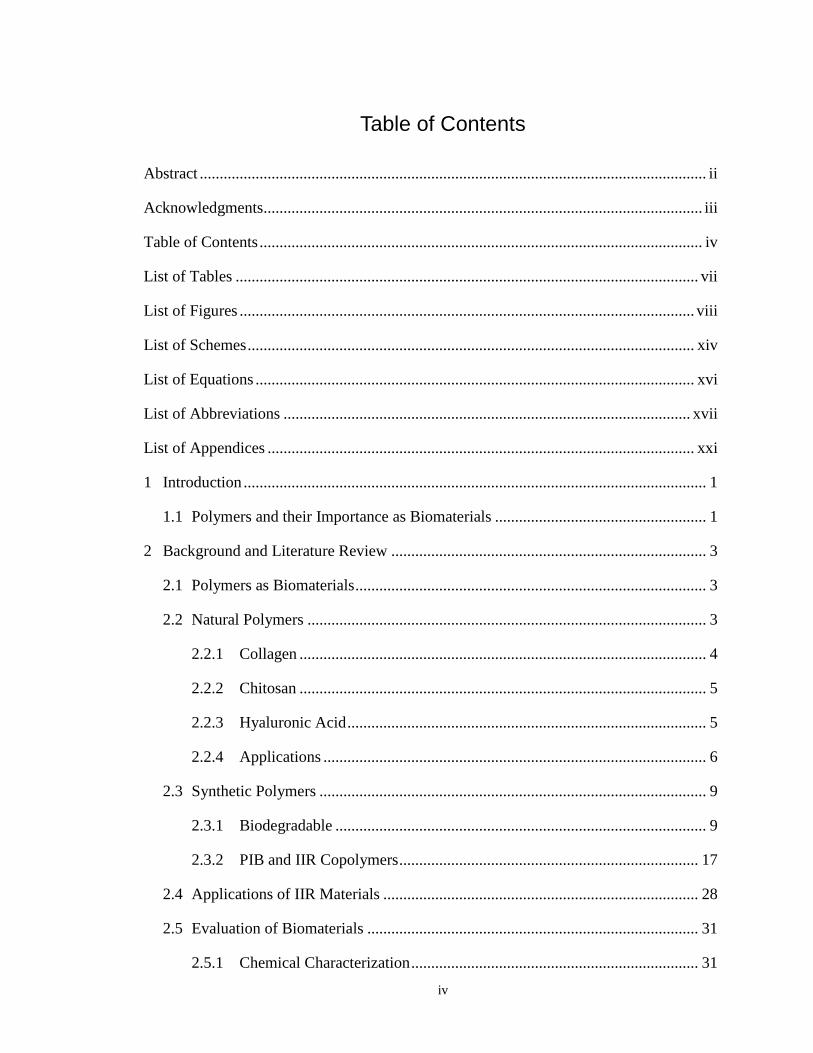
Table of Contents
Abstract ............................................................................................................................... ii
Acknowledgments.............................................................................................................. iii
Table of Contents ............................................................................................................... iv
List of Tables .................................................................................................................... vii
List of Figures .................................................................................................................. viii
List of Schemes ................................................................................................................ xiv
List of Equations .............................................................................................................. xvi
List of Abbreviations ...................................................................................................... xvii
List of Appendices ........................................................................................................... xxi
1 Introduction .................................................................................................................... 1
1.1 Polymers and their Importance as Biomaterials ..................................................... 1
2 Background and Literature Review ............................................................................... 3
2.1 Polymers as Biomaterials ........................................................................................ 3
2.2 Natural Polymers .................................................................................................... 3
2.2.1 Collagen ...................................................................................................... 4
2.2.2 Chitosan ...................................................................................................... 5
2.2.3 Hyaluronic Acid .......................................................................................... 5
2.2.4 Applications ................................................................................................ 6
2.3 Synthetic Polymers ................................................................................................. 9
2.3.1 Biodegradable ............................................................................................. 9
2.3.2 PIB and IIR Copolymers ........................................................................... 17
2.4 Applications of IIR Materials ............................................................................... 28
2.5 Evaluation of Biomaterials ................................................................................... 31
2.5.1 Chemical Characterization ........................................................................ 31
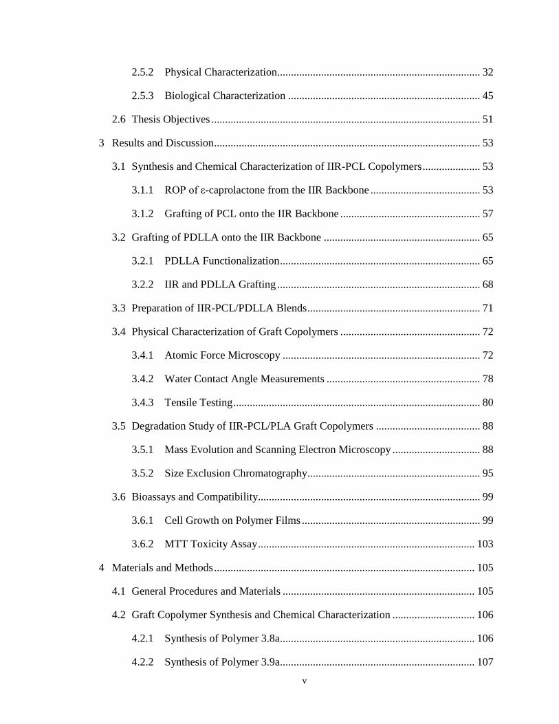
v
2.5.2 Physical Characterization.......................................................................... 32
2.5.3 Biological Characterization ...................................................................... 45
2.6 Thesis Objectives .................................................................................................. 51
3 Results and Discussion ................................................................................................. 53
3.1 Synthesis and Chemical Characterization of IIR-PCL Copolymers ..................... 53
3.1.1 ROP of ε-caprolactone from the IIR Backbone ........................................ 53
3.1.2 Grafting of PCL onto the IIR Backbone ................................................... 57
3.2 Grafting of PDLLA onto the IIR Backbone ......................................................... 65
3.2.1 PDLLA Functionalization ......................................................................... 65
3.2.2 IIR and PDLLA Grafting .......................................................................... 68
3.3 Preparation of IIR-PCL/PDLLA Blends ............................................................... 71
3.4 Physical Characterization of Graft Copolymers ................................................... 72
3.4.1 Atomic Force Microscopy ........................................................................ 72
3.4.2 Water Contact Angle Measurements ........................................................ 78
3.4.3 Tensile Testing .......................................................................................... 80
3.5 Degradation Study of IIR-PCL/PLA Graft Copolymers ...................................... 88
3.5.1 Mass Evolution and Scanning Electron Microscopy ................................ 88
3.5.2 Size Exclusion Chromatography............................................................... 95
3.6 Bioassays and Compatibility................................................................................. 99
3.6.1 Cell Growth on Polymer Films ................................................................. 99
3.6.2 MTT Toxicity Assay ............................................................................... 103
4 Materials and Methods ............................................................................................... 105
4.1 General Procedures and Materials ...................................................................... 105
4.2 Graft Copolymer Synthesis and Chemical Characterization .............................. 106
4.2.1 Synthesis of Polymer 3.8a....................................................................... 106
4.2.2 Synthesis of Polymer 3.9a....................................................................... 107
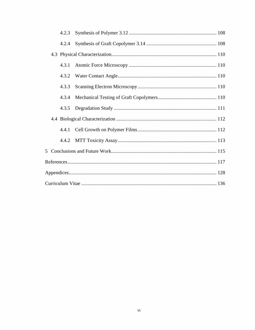
vi
4.2.3 Synthesis of Polymer 3.12 ...................................................................... 108
4.2.4 Synthesis of Graft Copolymer 3.14 ........................................................ 108
4.3 Physical Characterization.................................................................................... 110
4.3.1 Atomic Force Microscopy ...................................................................... 110
4.3.2 Water Contact Angle............................................................................... 110
4.3.3 Scanning Electron Microscopy ............................................................... 110
4.3.4 Mechanical Testing of Graft Copolymers............................................... 110
4.3.5 Degradation Study .................................................................................. 111
4.4 Biological Characterization ................................................................................ 112
4.4.1 Cell Growth on Polymer Films ............................................................... 112
4.4.2 MTT Toxicity Assay ............................................................................... 113
5 Conclusions and Future Work .................................................................................... 115
References ....................................................................................................................... 117
Appendices ...................................................................................................................... 128
Curriculum Vitae ............................................................................................................ 136
vii
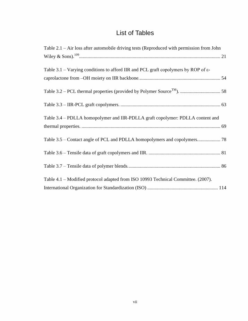
List of Tables
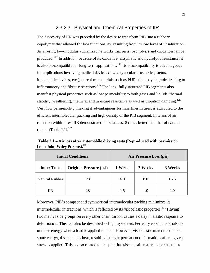
Table 2.1 – Air loss after automobile driving tests (Reproduced with permission from John
Wiley & Sons).109
.................................................................................................................... 21
Table 3.1 – Varying conditions to afford IIR and PCL graft copolymers by ROP of ε-
caprolactone from –OH moiety on IIR backbone. .................................................................. 54
Table 3.2 – PCL thermal properties (provided by Polymer SourceTM
). ................................. 58
Table 3.3 – IIR-PCL graft copolymers. .................................................................................. 63
Table 3.4 – PDLLA homopolymer and IIR-PDLLA graft copolymer: PDLLA content and
thermal properties. .................................................................................................................. 69
Table 3.5 – Contact angle of PCL and PDLLA homopolymers and copolymers................... 78
Table 3.6 – Tensile data of graft copolymers and IIR. ........................................................... 81
Table 3.7 – Tensile data of polymer blends. ........................................................................... 86
Table 4.1 – Modified protocol adapted from ISO 10993 Technical Committee. (2007).
International Organization for Standardization (ISO) .......................................................... 114
viii
List of Figures
Figure 2.1 – Common tripeptide sequence of collagen composed of glycine (Gly), proline
(Pro) and hydroxyproline (Hyp) leading to helical structure. (Reprinted from Progress in
Polymer Science, 35/4, Puppi et. al., Polymeric materials for bone and cartilage repair (403-
440). Copyright (2010), with permission from Elsevier. .......................................................... 4
Figure 2.2 – Structure of chitosan. ............................................................................................ 5
Figure 2.3 – Chemical structure of hyaluronic acid. ................................................................. 6
Figure 2.4 – Structural representations of diisocyanates. ....................................................... 10
Figure 2.5 – Chemical structures of various POEs. ................................................................ 11
Figure 2.6 – Chemical structures of PDLA (S-enantiomer), PLLA (R-enantiomer), PDLLA
(racemic mixture) and PCL. .................................................................................................... 14
Figure 2.7 – Molecular weight changes for a porous PCL structure (triangle) and a linear
PCL structure (square). Reproduced with permission from Taylor & Francis, 2007. ............ 16
Figure 2.8 – Commercialized IIR production: general IIR slurry polymerization (Reproduced
with permission from John Wiley & Sons, 1990).109
.............................................................. 19
Figure 2.9 – Isoprene unit enters chain predominantly in trans-1,4 configuration. ................ 19
Figure 2.10 – Monomer-concentration dependence on number of active sites and styrene
conversion (left); monomer-concentration dependence on MW of grafted PS and MW of PS
homopolymer (Biomaterials, 29, 2008, 448-460 © 2007 Elsevier Ltd. with kind permission
from Springer Science and Business Media). ......................................................................... 27
Figure 2.11 – Fluorescence confocal microscopy images following adsorption of a
rhodamine-fibrinogen conjugate. PEO content: a) 2%, b) 4%, c) 6%, d) 12%, e) 24% and f)
34% (Reprinted with permission from Macromolecules 2011, 44, 6405. Copyright (2011)
American Chemical Society). ................................................................................................. 29
ix
Figure 2.12 – Cartoon representation of PIB-b-PS showing elastomeric entanglements (PIB)
and hard segments (PS) (Reprinted from Biomaterials, 29/4, Pinchuk et. al., Medical
applications of poly(styrene-block-isobutylene-block-styrene) (“SIBS”) (448-460). Copyright
(2008), with permission from Elsevier). ................................................................................. 30
Figure 2.13 – Contact angle measurement (θc) and interphase-energy between 3 phases
(values in Young’s equation found below). ............................................................................ 33
Figure 2.14 – Temperature dependence of stiffness of typical thermoplastic elastomers
(Reprinted from Handbook of Thermoplastic Elastomers, 1st Edition, Drobny, Jiri George,
Introduction (1-7). Copyright (2007), with permission from Elsevier).58
.............................. 37
Figure 2.15 – Instron (3300 series) tensile testing instrument. ............................................... 39
Figure 2.16 – Definitions of uniaxial stress, strain and elastic deformation. (Reprinted from
Nanomaterials, Nanotechnologies and Design: An Introduction for Engineers and Architects,
1st Edition, Ashby, Michael F., Chapter 4 – Material Classes, Structure and properties.
Copyright (2009), with permission from Elsevier).189
............................................................ 41
Figure 2.17 – Stress strain curve for a polymer. Definitions of uniaxial stress, strain and
elastic deformation. (Reprinted from Nanomaterials, Nanotechnologies and Design: An
Introduction for Engineers and Architects, 1st Edition, Ashby, Michael F., Chapter 4 –
Material Classes, Structure and properties. Copyright (2009), with permission from
Elsevier).189
............................................................................................................................. 42
Figure 2.18 – Material property charts showing: a) Young’s modulus and its relation to
material density; b) Young’s modulus and material strength to defined the yield strain (σy/E),
where a material no longer behaves elastically. (Reprinted from Nanomaterials,
Nanotechnologies and Design: An Introduction for Engineers and Architects, 1st Edition,
Ashby, Michael F., Chapter 4 – Material Classes, Structure and properties. Copyright (2009),
with permission from Elsevier).189
.......................................................................................... 44
Figure 2.19 – PCL and PCL-Col (collagen) materials: confocal scanning laser microscopies
showing differences in cell proliferation on different surfaces (Reprinted from Biomaterials,
x
25/11, Cheng and Teoh, Surface modification of ultra thin poly (ε-caprolactone) films using
acrylic acid and collagen (1991-2001). Copyright (2003), with permission from Elsevier). . 46
Figure 2.20 – Morphologies of hMSCs cultured on various substrates: B) glass control; C)
PLCL; D) AAc-PLCL and E) gelatin-AAc-PLCL. Scale bar = 200 μm (Reprinted with
permission from Shin, Y. M.; Kim, K.-S.; Lim, Y. M.; Nho, Y. C.; Shin, H.
Biomacromolecules 2008, 9, 1772. Copyright 2008 American Chemical Society). .............. 47
Figure 2.21 – (a-f) Myoblasts stained for vinculin (light speckles), F-actin (outer periphery)
and nuclei, scale bar = 50 μm. (a) 4 h after seeding on glass coverslip control, (b) 4 h after
seeding on C500 surface, (c) 4 h after seeding on C6000 surface, (d) 12 h after seeding on
glass coverslip control, (e) 12 h after seeding on C500 surface, and (f) 12 h after seeding on
C6000 surface (Reprinted with permission from Dugan, J. M.; Gough, J. E.; Eichhorn, S. J.
Biomacromolecules 2010, 11, 2498, Copyright 2010 American Chemical Society). ............ 48
Figure 2.22 – Confocal microscopy images of C2C12 cells adhered to control and copolymer
surfaces: a) glass (control); b) IIR (control); c) 18wt% PEO ; d) 32wt% PEO; e) 65 wt%
PEO; f) 83 wt% PEO. Nuclei (dark inner portion) and F-actin fibres (lighter periphery) with
image area = 0.22 x 0.22 mm (Reprinted with permission from John Wiley & Sons, 2013). 49
Figure 3.1 – NMR spectra showing: a) hydroxylated IIR; b) 50 wt% IIR-PCL graft
copolymer following methanol precipitation (label k denotes terminal methylene PCL); c)
second precipitation in acetone of the same polymer from b), confirming a decrease in PCL
content to 16 wt% (label k denotes terminal PCL methylene). .............................................. 55
Figure 3.2 – SEC trace for 50 wt% PCL shows free homopolymer. 50 wt% PCL (post-
purification) trace reveals homopolymer removal achieved with secondary precipitation.
Detection was based on differential refractive index. ............................................................. 56
Figure 3.3 – PCL (900 g/mol) functionalization (with k referring to the terminal methylene):
a) 3.7a; b) 3.8a; c) 3.9a. .......................................................................................................... 59
Figure 3.4 – SEC traces of PCL derivatives throughout the functionalization process: a) 3.7a
– 3.9a (900 g/mol); b) 3.7b – 3.9b (3500 g/mol). ................................................................... 59
xi
Figure 3.5 – 1H NMR spectra (CDCl3, 600MHz) of a) activated IIR; b) copolymer 3.15; and
c) copolymer 3.16 showing how PCL content can be determined based on the relative
intensities of PCL to PIB, as well as reaction conversion determination based on peaks from
4.8-5.3 ppm. ............................................................................................................................ 62
Figure 3.6 – SEC traces for: ungrafted IIR (3.1) and each IIR-PCL graft copolymer (3.14-
3.16). ....................................................................................................................................... 63
Figure 3.7 – Schematic depicting PDLLA functionalization: a) 3.10 (2800 g/mol), starting
material; b) 3.11, t-BOC protected β-alanine derivative; c) 3.12, amine-liberated derivative.
In 3.10-3.12, f represents the terminal methylene. ................................................................. 66
Figure 3.8 – SEC traces elucidating functionalization of PDLLA 3.10-3.12. ........................ 67
Figure 3.9 – PDLLA content in copolymer 3.17: determined via integration corresponding to
PDLLA multiplet from 5.13-5.23 ppm and PIB singlet at 1.41 ppm. .................................... 69
Figure 3.10 – SEC traces of ungrafted IIR (polymer 3.1) and IIR-PDLLA graft copolymer
(3.17). ...................................................................................................................................... 70
Figure 3.11 – Topography of copolymers: a) 3.14; b) 3.15; c) 3.16; d) 3.17. ........................ 73
Figure 3.12 – Phase contrast of copolymers: a) 3.14; b) 3.15; c) 3.16; d) 3.17. ..................... 74
Figure 3.13 – AFM analysis of copolymer 3.16. Before annealing: a) topography; b) phase
contrast. After annealing: c) topography; d) phase contrast. .................................................. 75
Figure 3.14 – Topography images of IIR-polyester blends: a) 15 wt% PCL; b) 32 wt% PCL;
c) 44 wt% PCL; d) 30 wt% PDLLA. ...................................................................................... 76
Figure 3.15 – Phase contrast of polymer blends: a) 15 wt% PCL; b) 32 wt% PCL; c) 44 wt%
PCL; d) 30 wt% PDLLA......................................................................................................... 77
Figure 3.16 – Stress-strain curve for: a) IIR; b) copolymer 3.14; c) copolymer 3.15; d)
copolymer 3.16; e) copolymer 3.17. ....................................................................................... 81
xii
Figure 3.17 – Stress vs Strain of a variety of materials (with permission to reprint from MIT
OpenCourseWare, http://flic.kr/p/66XeQc). ........................................................................... 82
Figure 3.18 – Thermoplastic PURs with varying soft segment contents. (Reprinted from
Polymer, 49/19, Xu et. al., Morphology and properties of thermoplastic polyurethanes with
dangling chains in ricinoleate-based soft segments (4248-4258). Copyright (2008), with
permission from Elsevier).244
.................................................................................................. 83
Figure 3.19 – Toughness-Modulus plot for current implant materials and the mechanical
regions for orthopedic hard tissue, orthopedic soft tissue, and cardiovascular tissue.
(Reprinted with permission from Taylor & Francis, 2013).246
............................................... 85
Figure 3.20 – Stress-strain curve for: a) 15 wt% PCL blend; b) 32 wt% PCL blend; c) 44
wt% PCL blend; d) 30 wt% PDLLA blend. ........................................................................... 85
Figure 3.21 – Mass loss of copolymers 3.14-3.16, PCL and IIR controls. ............................. 89
Figure 3.22 – Mass loss of copolymer 3.17 as well as PDLLA and IIR controls................... 90
Figure 3.23 – SEM imaging taken at 100X magnification under variable pressure mode at To
and 4 months of: a) and b) IIR; c) and d) copolymer 3.14; e) and f) copolymer 3.15; g) and h)
copolymer 3.16. ...................................................................................................................... 91
Figure 3.24 – SEM imaging taken at 100X magnification under variable pressure mode at To
and 2 months of: a) and b) copolymer 3.17. Macroscopic images of To-2 months of: c)
copolymer 3.17. ...................................................................................................................... 92
Figure 3.25 – Successive macroscopic images representing To, 1 month, 2 months, 3 months
and 4 months of: a) IIR control; b) copolymer 3.14; c) copolymer 3.15; d) copolymer 3.16. 93
Figure 3.26 – MW data for IIR control as well as copolymer 3.14, 3.15, 3.16 and 3.17: a)
change in Mn; b) change in Mw. .............................................................................................. 95
Figure 3.27 – MW profiles elucidating each time point over the 4 month study period for: a)
IIR control; b) copolymer 3.14; c) copolymer 3.15; d) copolymer 3.16. ............................... 96
xiii
Figure 3.28 – MW profile elucidating each time point over the 2 month study period for
copolymer 3.17. ...................................................................................................................... 97
Figure 3.29 – Growth of murine myoblast cells on: a) glass; b) IIR; c) PCL; d) PDLLA Cell
imaging of copolymers: e) 3.14; f) 3.15; g) 3.16; h) 3.17. .................................................... 100
Figure 3.30 – Cell adhesivity quantified by determining average cell concentrations for each
substrate. ............................................................................................................................... 102
Figure 3.31 – MTT cytotoxicity assay performed on: a) graft copolymers 3.14-3.16; b) graft
copolymer 3.17. .................................................................................................................... 104
xiv
List of Schemes
Scheme 2.1 – Hydrolysis of PCL to 6-hydroxylcaproic acid and acetyl coenzyme A
intermediates followed by elimination from the body through the citric acid cycle. ............. 12
Scheme 2.2 – Mechanism of stannous octoate polymerization of PCL: 1/2 – formation of
stannous alkoxide initiator; 3 – deactivation of catalyst; 4 – coordination/insertion of
monomer; 5 – chain transfer of active polymerizing centre to alcohol. ................................. 13
Scheme 2.3 – Cationic polymerization of IB governed by initiation, propagation and
termination. ............................................................................................................................. 20
Scheme 2.4 – Vulcanization of IIR: a) sulfur-based crosslinking; b) dioxime curing; c)
general structure of resin capable of vulcanization. ................................................................ 23
Scheme 2.5 – IIR bromination followed by isomerization and HX elimination. ................... 24
Scheme 2.6 – Reaction schematic elucidating SIBS production via bifunctional HDCE
initiatior. .................................................................................................................................. 25
Scheme 2.7 – Synthesis of IIR-PEO graft copolymers. .......................................................... 26
Scheme 3.1 – Epoxidation followed by hydroxylation of IIR with 2.2mol% IP and
subsequent ROP of ε-caprolactone from IIR backbone. ......................................................... 53
Scheme 3.2 – Synthesis of t-BOC-protected β-alanine anhydride. ........................................ 57
Scheme 3.3 – Functionalization of PCL (3.7a/b) by first reacting with BOC-protected β-
alanine (3.6) to produce the protected derivative (3.8a/b), followed by deprotection with TFA
(n = 8 for 900 g/mol PCL, 3.7a, initiated with ethylene glycol derivative and n = 31 for 3500
g/mol PCL, 3.7b initiated with ethanol).................................................................................. 58
Scheme 3.4 – p-nitrophenyl chloroformate (PNPC) activated rubber synthesis. ................... 61
Scheme 3.5 – Synthesis of PCL graft copolymers: 3.14 – 15 wt% PCL (n=8); 3.15 – 32 wt%
PCL (n=31); 3.16 – 44 wt% PCL (n=31). ............................................................................... 61
xv
Scheme 3.6 – Functionalization of 3.10 by first reacting with BOC-protected β-alanine (3.6)
to afford 3.11, followed by deprotection with TFA (3.12). .................................................... 65
Scheme 3.7 – Synthesis of PDLLA Graft copolymer: 3.17 – 30 wt% PDLLA. .................... 68
xvi
List of Equations
Equation 1 – Definition of polydispersity index where Mn is the total weight of the sample
divided by the number of molecules (arithmetic mean) and Mw fairly accounts for the
contributions of different sized chains. ................................................................................... 32
Equation 2 – where ϴ = measured contact angle and γ is the surface tension of the solid-gas
(SG), solid-liquid (SG) and liquid-gas (LG) interface. ........................................................... 33
Equation 3 – Young’s modulus determination for a material at a given strain and stress. ..... 39
Equation 4 – Linear relationship relating the shear strain, γ to the shear stress, τ. ................. 40
Equation 5 – Linear relationship showing proportionality between the dilatation, Δ and
pressure, p. .............................................................................................................................. 40
Equation 6 – Definition of Poisson’s ratio where εt is the transverse strain and ε is the axial
strain. ....................................................................................................................................... 40
Equation 7 – Relation between Young’s modulus (E), shear modulus (G) and bulk modulus
(K). .......................................................................................................................................... 41
Equation 8 – Definition of plastic strain. ................................................................................ 42
Equation 9 – Where = average mass of initial 3 discs for a given time point and =
average mass of final 3 discs for a given time point. ............................................................ 111
xvii
List of Abbreviations
(1H) NMR hydrogen nuclear magnetic resonance spectroscopy
AFM atomic force microscopy
BDR butadiene rubber
BIIR bromo-butyl rubber
BOC di-tert-butyl dicarbonate
br. s broad singlet
CA cyanoacrylate
CIIR chloro-butyl rubber
DAPI 4’-6-diamidino-2-phenylindole dyhydrocholoride
DCM dichloromethane
DES drug eluting stent
DMEM Dulbecco’s Modified Eagle Medium
DPNR deproteinized natural rubber
DSC differential scanning calorimetry
E Young’s modulus
ECM extracellular matrix
FTIR fourier transform infrared spectroscopy
G shear modulus
GPC gel permeation chromatography
HA hyaluronic acid
HSD honestly significant difference
IB isobutylene
IIR butyl rubber
IP isoprene
xviii
J coupling constant
K bulk modulus
m-CPBA meta-chloroperoxybenzoic acid
Mn number-average molecular weight
MSA methanesulfonic acid
MTT 3-(4,5-Dimethylthiazol-2-yl)-2,5-Diphenyltetrazolium Bromide
Mw weight-average molecular weight
MW molecular weight
Mz z-average molecular weight
Mν viscosity molecular weight
NBR acrylonitrile butadiene rubber
NR natural rubber
p pressure
PBD poly(butadiene)
PBS phosphate buffered saline
PCL poly(caprolactone)
PDI polydispersity index
PDLA poly(D-lactide)
PDLLA poly(D,L-lactide)
PEG poly(ethylene glycol)
PEO poly(ethylene oxide)
PIB poly(isobutylene)
PLLA poly(L-lactide)
PMMA poly(methyl methacrylate)
PNPC 4 (para)-nitrophenyl chloroformate
xix
POE poly(ortho esters)
PS poly(styrene)
PUR poly(urethane)
PVC poly(vinyl chloride)
RB-402 butyl rubber (LANXESS Inc. derivative)
ROP ring-opening polymerization
RT room temperature
SBR styrene butadiene rubber
SDS sodium lauryl sulfate
SEC size exclusion chromatography
SEM scanning electron microscopy
SIBS styrene-isobutylene-styrene
SMP shape memory polymer
TE tissue engineering
TFA trifluoroacetic acid
Tg glass transition temperature
THF tetrahydrofuran
Tm melt transition temperature
TPE thermoplastic elastomer
UTS ultimate tensile strength
WCA water contact angle
wt% weight percentage
γ shear strain
Δ dilatation
ε strain

xx
εb elongation at break
εt lateral strain
ν Poisson’s ratio
σ stress
σel elastic limit
σy yield strength
τ shear stress
xxi
List of Appendices
Appendix A – 1H NMR depicting functionalization of 3.7b: a) initial homopolymer; b)
reacted with t-BOC-protected β-alanine (3.8b); c) and deprotected with TFA (3.9b). ........ 128
Appendix B – 1H NMR showing PCL content of: a) copolymer 3.16 (44 wt% PCL) and b)
copolymer 3.15 (32wt% PCL). ............................................................................................. 129
Appendix C – FTIR of: a) 3.8a and 3.9a; b) 3.11 and 3.12. ................................................. 130
Appendix D – FTIR of: a) copolymer 3.14; b) copolymer 3.15. .......................................... 131
Appendix E – FTIR of: a) copolymer 3.16; b) copolymer 3.17. .......................................... 132
Appendix F – DSC traces of: IIR-PCL copolymer after 1st precipitation; IIR-PCL copolymer
after a 2nd
precipitation into acetone, ridding of free homopolymer as evidenced by
disappearance of the second Tm at 53°C. ............................................................................. 133
Appendix G – DSC trace depicting the two Tgs of copolymer 3.17. .................................... 133
Appendix H – DSC traces depicting Tg and Tm of IIR-PCL graft copolymers: a) copolymer
3.14; b) copolymer 3.15; c) copolymer 3.16. ........................................................................ 134
Appendix I – DSC traces depicting Tg and Tm of IIR-PCL/PLA blends. ............................. 134
Appendix J – Raw data coinciding with Figure 3.21 for the degradation study of IIR-PCL
copolymers and IIR control. ................................................................................................. 135
Appendix K – Raw data coinciding with Figure 3.22 for the degradation study of IIR-
PDLLA copolymer and IIR control. ..................................................................................... 135
1
Chapter 1
1 Introduction
1.1 Polymers and their Importance as Biomaterials
Biomaterials possess the ability to perform with an appropriate host response in specific
applications.1 They are used extensively in a wide variety of applications, ranging from
cardiovascular, dental and neural implants to orthopaedic prosthetics and drug delivery
systems. Biomaterials have always been important as vehicles for the treatment of
disease, thereby constantly improving health care. Early examples dating back thousands
of years ago are metals and wood for teeth replacement and glass for eyeball prosthetics.
However, the discovery of synthetic polymers such as poly(methacrylates) and
poly(urethanes) led to a much broader range of application possibilities. Moreover,
naturally occurring materials such as collagen are also being developed for better
applicability in biological systems.
Although biomaterials perhaps play a role in the lives of many individuals, there
are several difficulties involved with their use. The main issues stem from deficiencies in
understanding physical, chemical and biological responses that a given biomaterial may
elicit in biological systems, as well as the lack of proper performance in a specific
application.2 Since many biomaterials were not originally designed to be used in a
clinical setting, taking off-the-shelf products has proved to be problematic.3 Examples of
such consist of dialysis tubing derived from cellulose acetate, Dacron for synthesis of
vascular grafts and poly(urethane) for the fabrication of artificial hearts. The
aforementioned applications were unsuccessful as cellulose acetate caused platelet
activation, Dacron grafts were limited to large-diameter vessel applications and
poly(urethane) did not supply sufficient blood-material interactions, respectively.4
In order to reduce issues related to using materials in applications for which they
were not specifically designed, research has been directed toward modifying chemical
structures to improve their mechanical properties, degradability and biocompatibility.5
Modern biomaterial production involves thorough understanding of cell-polymer
2
interactions in order to prevent or minimize undesirable cellular responses.6 Applications
such as polymer-coated stents for drug, protein and hormone delivery, tissue engineering
(TE) and other polymer/cell combinations such as artificial corneas, cartilage and bone,
makes it very important to understand biological response.5 Biomaterials have made great
impacts on medicine and current technology and will therefore impact biomedical
application advancements. As the aging population of developed countries continues to
grow, the demand for biomedical products to enhance life quality and longevity will
proportionally increase.
The focus of this thesis will be on preparing new potential biomaterials based on butyl
rubber (IIR)-polyester copolymers. The incorporation of an elastomeric component in the
biomaterial is especially important when considering its ability to mimic soft tissues.
Because humans predominantly consist of soft tissues, biomaterials that possess similar
mechanical and viscoelastic properties have potential for application in a multitude of
areas ranging from vascular prostheses (blood-interfacing implants) to breast implants
(non-blood-interfacing). Although elastomers are attractive due to their compliance with
soft or cardiovascular tissues, mechanical property enhancements may be required for
various applications. Therefore, in order to provide strength and rigidity, the
incorporation of polyesters (hard phase) with IIR (soft phase) will provide physical
crosslinks. The properties presented by these copolymers may be analogous to
thermoplastic elastomers (TPE). TPEs are typically composed of a phase which is hard at
ambient temperature, while the other is elastomeric. Phases are most commonly bonded
chemically through block/graft copolymerization.7 Without the hard phase, the elastomer
phase would flow freely, rendering it unsuitable for biomedical applications requiring
rigidity. For example, elastin and collagen are important components of various arteries.
Although functions of such soft tissues vary, it is the combination of the elastomeric
elastin with harder collagen that provides appropriate mechanical properties. With this
understanding, it will be interesting to investigate how the properties of IIR can be varied
chemically, physically and biologically to afford potential biomaterials.
3
Chapter 2
2 Background and Literature Review
2.1 Polymers as Biomaterials
Polymers are particularly interesting for use as biomaterials; their chemical, physical and
biological properties vary across a wide variety of structures, rendering them useful in
many different applications. In addition, through modification of the polymer backbone,
these properties can be specifically tuned. However, it is important to understand how
each polymer or polymeric system will impact its performance. Since applications can
range from soft tissue/organ replacement, drug delivery, wound dressings, to even
reconstruction of bone deficiencies, investigating a range of varying polymers to facilitate
new materials for biomedical applications has become increasingly apparent.
2.2 Natural Polymers
Biomedical applications involving the use of natural polymers such as collagen, chitosan
and alginate date back thousands of years. Natural polymers possess the obvious
advantages associated with biocompatibility; they do not elicit inflammatory responses or
other unsuitable side-effects that may result through the use of synthetic systems.
Although synthetic polymers are desirable as their properties can be tuned and controlled
with ease, the inherent issues stemming from biocompatibility still present natural
polymers as viable candidates for use as biomaterials.8 There are a wide variety of natural
polymers, leading to different avenues and applications. Proteins, such as collagen and
silk fibroin; polysaccharides, such as chitosan, hylauronic acid, alginates, dextrans and
starch-based materials; and microbial polyesters, such as polyhydroxyalkanoates are all
viable natural materials that are under current investigation for biomedical usage.
However, focus will be directed toward some notable materials including collagen,
chitosan and hyaluronic acid.
4
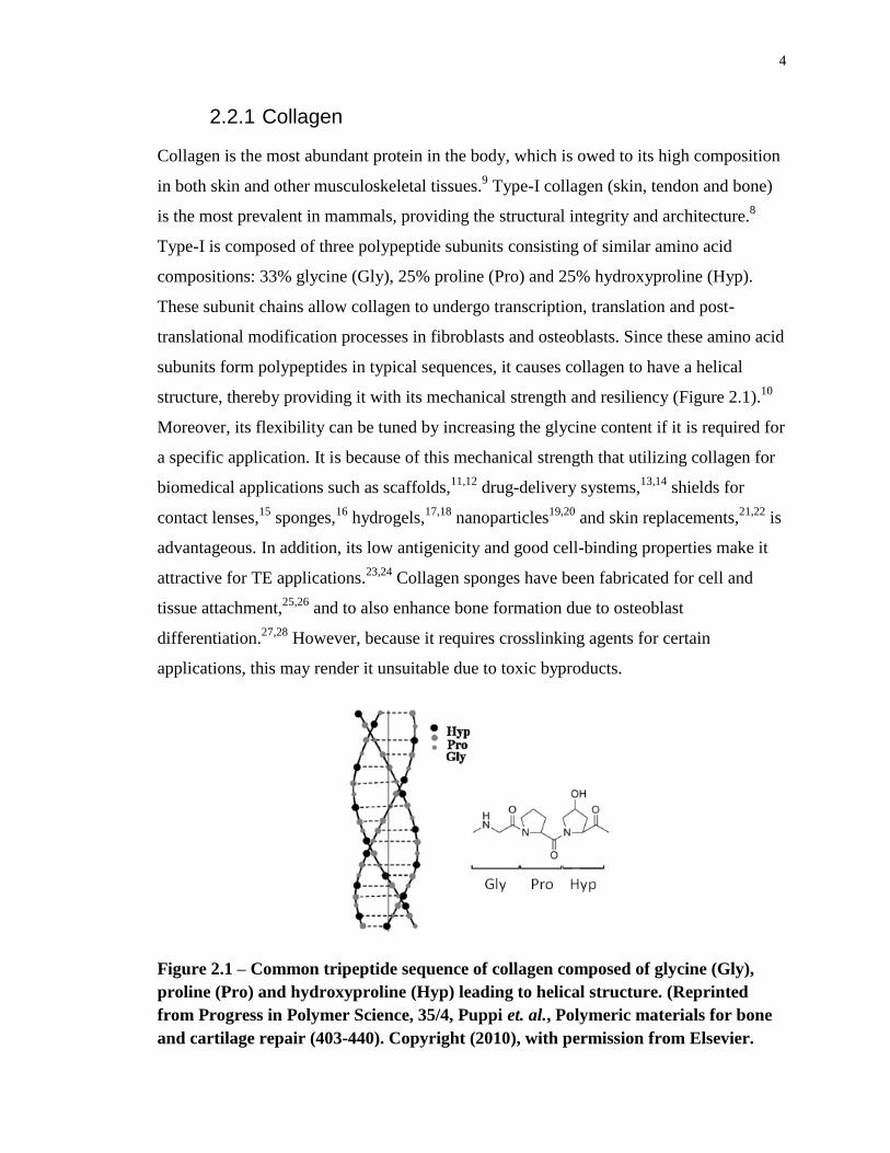
2.2.1 Collagen
Collagen is the most abundant protein in the body, which is owed to its high composition
in both skin and other musculoskeletal tissues.9 Type-I collagen (skin, tendon and bone)
is the most prevalent in mammals, providing the structural integrity and architecture.8
Type-I is composed of three polypeptide subunits consisting of similar amino acid
compositions: 33% glycine (Gly), 25% proline (Pro) and 25% hydroxyproline (Hyp).
These subunit chains allow collagen to undergo transcription, translation and post-
translational modification processes in fibroblasts and osteoblasts. Since these amino acid
subunits form polypeptides in typical sequences, it causes collagen to have a helical
structure, thereby providing it with its mechanical strength and resiliency (Figure 2.1).10
Moreover, its flexibility can be tuned by increasing the glycine content if it is required for
a specific application. It is because of this mechanical strength that utilizing collagen for
biomedical applications such as scaffolds,11,12
drug-delivery systems,13,14
shields for
contact lenses,15
sponges,16
hydrogels,17,18
nanoparticles19,20
and skin replacements,21,22
is
advantageous. In addition, its low antigenicity and good cell-binding properties make it
attractive for TE applications.23,24
Collagen sponges have been fabricated for cell and
tissue attachment,25,26
and to also enhance bone formation due to osteoblast
differentiation.27,28
However, because it requires crosslinking agents for certain
applications, this may render it unsuitable due to toxic byproducts.
Figure 2.1 – Common tripeptide sequence of collagen composed of glycine (Gly),
proline (Pro) and hydroxyproline (Hyp) leading to helical structure. (Reprinted
from Progress in Polymer Science, 35/4, Puppi et. al., Polymeric materials for bone
and cartilage repair (403-440). Copyright (2010), with permission from Elsevier.
5
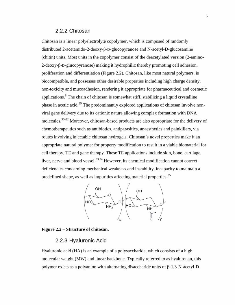
2.2.2 Chitosan
Chitosan is a linear polyelectrolyte copolymer, which is composed of randomly
distributed 2-acetamido-2-deoxy-β-D-glucopyranose and N-acetyl-D-glucosamine
(chitin) units. Most units in the copolymer consist of the deacetylated version (2-amino-
2-deoxy-β-D-glucopyranose) making it hydrophilic thereby promoting cell adhesion,
proliferation and differentiation (Figure 2.2). Chitosan, like most natural polymers, is
biocompatible, and possesses other desirable properties including high charge density,
non-toxicity and mucoadhesion, rendering it appropriate for pharmaceutical and cosmetic
applications.8 The chain of chitosan is somewhat stiff, stabilizing a liquid crystalline
phase in acetic acid.29
The predominantly explored applications of chitosan involve non-
viral gene delivery due to its cationic nature allowing complex formation with DNA
molecules.30-32
Moreover, chitosan-based products are also appropriate for the delivery of
chemotherapeutics such as antibiotics, antiparasitics, anaesthetics and painkillers, via
routes involving injectable chitosan hydrogels. Chitosan’s novel properties make it an
appropriate natural polymer for property modification to result in a viable biomaterial for
cell therapy, TE and gene therapy. These TE applications include skin, bone, cartilage,
liver, nerve and blood vessel.33,34
However, its chemical modification cannot correct
deficiencies concerning mechanical weakness and instability, incapacity to maintain a
predefined shape, as well as impurities affecting material properties.35
Figure 2.2 – Structure of chitosan.
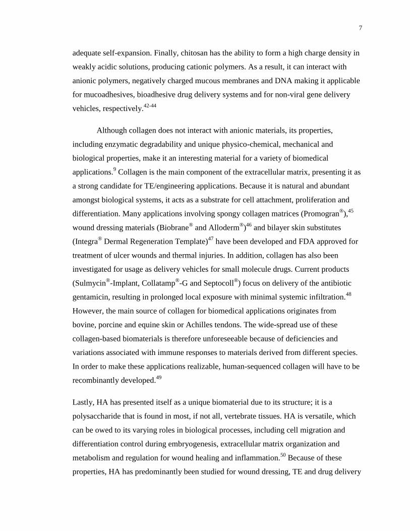
2.2.3 Hyaluronic Acid
Hyaluronic acid (HA) is an example of a polysaccharide, which consists of a high
molecular weight (MW) and linear backbone. Typically referred to as hyaluronan, this
polymer exists as a polyanion with alternating disaccharide units of β-1,3-N-acetyl-D-
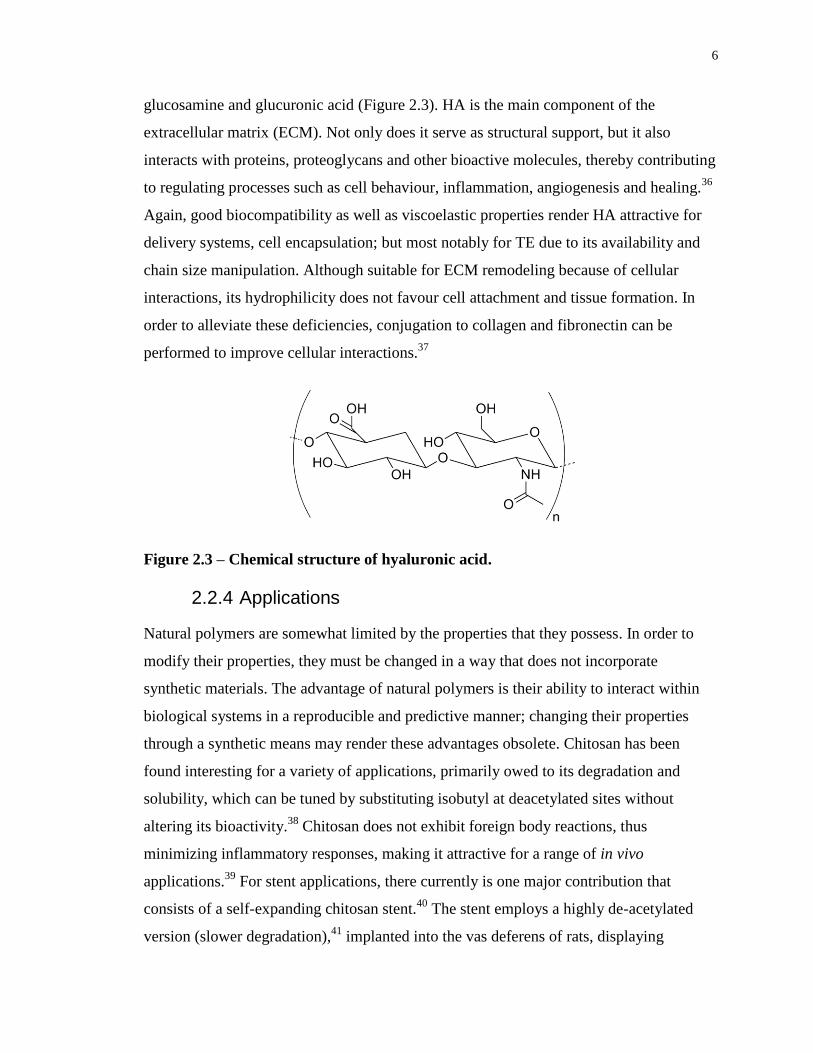
6
glucosamine and glucuronic acid (Figure 2.3). HA is the main component of the
extracellular matrix (ECM). Not only does it serve as structural support, but it also
interacts with proteins, proteoglycans and other bioactive molecules, thereby contributing
to regulating processes such as cell behaviour, inflammation, angiogenesis and healing.36
Again, good biocompatibility as well as viscoelastic properties render HA attractive for
delivery systems, cell encapsulation; but most notably for TE due to its availability and
chain size manipulation. Although suitable for ECM remodeling because of cellular
interactions, its hydrophilicity does not favour cell attachment and tissue formation. In
order to alleviate these deficiencies, conjugation to collagen and fibronectin can be
performed to improve cellular interactions.37
Figure 2.3 – Chemical structure of hyaluronic acid.
2.2.4 Applications
Natural polymers are somewhat limited by the properties that they possess. In order to
modify their properties, they must be changed in a way that does not incorporate
synthetic materials. The advantage of natural polymers is their ability to interact within
biological systems in a reproducible and predictive manner; changing their properties
through a synthetic means may render these advantages obsolete. Chitosan has been
found interesting for a variety of applications, primarily owed to its degradation and
solubility, which can be tuned by substituting isobutyl at deacetylated sites without
altering its bioactivity.38
Chitosan does not exhibit foreign body reactions, thus
minimizing inflammatory responses, making it attractive for a range of in vivo
applications.39
For stent applications, there currently is one major contribution that
consists of a self-expanding chitosan stent.40
The stent employs a highly de-acetylated
version (slower degradation),41
implanted into the vas deferens of rats, displaying
7
adequate self-expansion. Finally, chitosan has the ability to form a high charge density in
weakly acidic solutions, producing cationic polymers. As a result, it can interact with
anionic polymers, negatively charged mucous membranes and DNA making it applicable
for mucoadhesives, bioadhesive drug delivery systems and for non-viral gene delivery
vehicles, respectively.42-44
Although collagen does not interact with anionic materials, its properties,
including enzymatic degradability and unique physico-chemical, mechanical and
biological properties, make it an interesting material for a variety of biomedical
applications.9 Collagen is the main component of the extracellular matrix, presenting it as
a strong candidate for TE/engineering applications. Because it is natural and abundant
amongst biological systems, it acts as a substrate for cell attachment, proliferation and
differentiation. Many applications involving spongy collagen matrices (Promogran®
),45
wound dressing materials (Biobrane® and Alloderm
®)46
and bilayer skin substitutes
(Integra® Dermal Regeneration Template)
47 have been developed and FDA approved for
treatment of ulcer wounds and thermal injuries. In addition, collagen has also been
investigated for usage as delivery vehicles for small molecule drugs. Current products
(Sulmycin®
-Implant, Collatamp®-G and Septocoll
®) focus on delivery of the antibiotic
gentamicin, resulting in prolonged local exposure with minimal systemic infiltration.48
However, the main source of collagen for biomedical applications originates from
bovine, porcine and equine skin or Achilles tendons. The wide-spread use of these
collagen-based biomaterials is therefore unforeseeable because of deficiencies and
variations associated with immune responses to materials derived from different species.
In order to make these applications realizable, human-sequenced collagen will have to be
recombinantly developed.49
Lastly, HA has presented itself as a unique biomaterial due to its structure; it is a
polysaccharide that is found in most, if not all, vertebrate tissues. HA is versatile, which
can be owed to its varying roles in biological processes, including cell migration and
differentiation control during embryogenesis, extracellular matrix organization and
metabolism and regulation for wound healing and inflammation.50
Because of these
properties, HA has predominantly been studied for wound dressing, TE and drug delivery
8
applications. More specifically, HA promotes angiogenesis, thereby reducing
inflammation51
and its high degree of chemical functionality allows it to undergo
crosslinking,52
making it appropriate for regulating wound sites and to tailor its
degradation rate for drug delivery. However, physical and biological limitations have
made HA impractical as a biomaterial due to its low water solubility, rapid resorption,
short residence time and anionic surface thereby prohibiting cellular attachment and
tissue formation.53
9
2.3 Synthetic Polymers
2.3.1 Biodegradable
Biodegradable synthetic polymers have been receiving considerable interest as
biomaterials; long-term biocompatibility issues with permanent implants has turned the
focus towards temporary therapeutic devices for a variety of applications.9 TE scaffolds,
regenerative medicine, drug eluting stents for controlled drug delivery and gene therapy
are some examples of emerging biomedical applications where biodegradable synthetic
polymers are being investigated.54-56
When considering degradable polymers for different
biomedical applications, it is important to ensure that they are bioresorbable. The
polymeric biomaterial is not only biocompatible, but upon degradation, the body can
effectively process and remove monomers, oligomers and byproducts.57
2.3.1.1 Poly(urethanes)
Poly(urethanes) (PURs) are an important class of polymers that have been used in a range
of high-performance materials including films, coatings, adhesives, fibres and elastomers.
Although they are biostable and have been extensively investigated for long-term medical
implants, their good biological properties, biocompatibility and synthetic versatility has
led to the development of biodegradable PURs. There are many different compounds that
can be applied to form PURs (by means of a simple polyaddition reaction) therefore
material properties are highly versatile.58
Typical preparations of polyurethanes involve a
polyester/polyether diol (soft segment), chain extender and a bulky diisocyanate (hard
segment). The multiblock structure is therefore responsible for giving PURs their
elastomeric properties.59
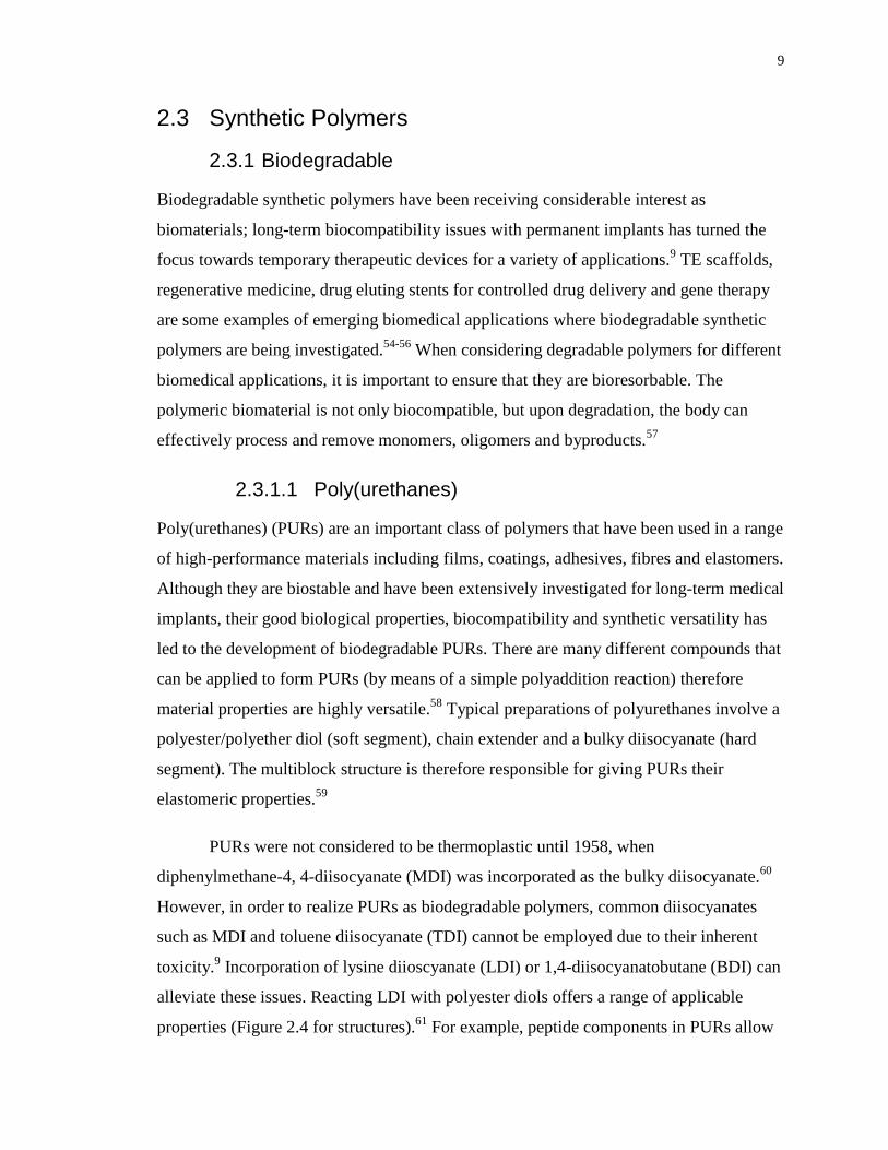
PURs were not considered to be thermoplastic until 1958, when
diphenylmethane-4, 4-diisocyanate (MDI) was incorporated as the bulky diisocyanate.60
However, in order to realize PURs as biodegradable polymers, common diisocyanates
such as MDI and toluene diisocyanate (TDI) cannot be employed due to their inherent
toxicity.9 Incorporation of lysine diioscyanate (LDI) or 1,4-diisocyanatobutane (BDI) can
alleviate these issues. Reacting LDI with polyester diols offers a range of applicable
properties (Figure 2.4 for structures).61
For example, peptide components in PURs allow
10
active moieties (ascorbic acid and glucose) to be introduced into the polymer thereby
promoting cell adhesion, viability and proliferation.62
Figure 2.4 – Structural representations of diisocyanates.
PURs possess excellent mechanical properties, including high tensile strength and
ultimate elongation due to their chemical structure, and because of this structure, can also
be processed via extrusion, injection molding and calendaring.63
The ease of
processability makes PURs attractive for use as injectable biodegradable polymers. This
has led to applications involving injectable hydrogels, which have been developed to
alleviate issues with current surgical techniques. In addition, an injectable LDI-based
polyurethane was developed (PolyNova®
) for orthopaedic applications because of its
good mechanical properties and fast self-setting as well as in vivo crosslinking ability.
Finally, porous scaffolds for TE of bone and cartilage have been proposed by usage of
PURs containing poly(caprolactone) PCL or poly(ethylene glycol) (PEG) segments due
to superior control over crystallinity (by controlling soft segment MW) and mechanical
properties.64,65
PUR-based scaffolds have also been investigated for both in vitro and in
vivo applications, such as analyzing cell density evolution [which was comparable to
biocompatible poly(lactic-co-glycolic acid)]66
and vascularization into dorsal skinfold
chambers of mice.67
Although the scaffolds did not appear to elicit any inflammatory
responses, acidic degradation of PURs autocatalyzes the degradation process and
byproduct production can lead to in vivo inflammatory responses.
11
2.3.1.2 Poly(ortho esters)
The development of poly(ortho esters) (POEs) produced biodegradable polymers higher
hydrophobicity, thereby avoiding issues with bulk degradation in drug delivery
applications.1,68
By imparting hydrolytically sensitive backbones, this would limit
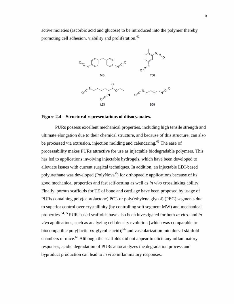
degradation to very slow surface erosion in aqueous environments. There are four
families of POEs, each with varying syntheses to improve on shortcomings of the
preceding POEs (Figure 2.5).69
Figure 2.5 – Chemical structures of various POEs.
Because of versatility in their synthesis through incorporation of different diols, POEs
possess varying degradation rates, levels of pH sensitivity, and glass transition
temperatures.70
For drug release applications, the rate of release depends on the rate of
polymer hydrolysis. For example, the development of POE IV has led to the best control
in terms of release profile for various therapeutic molecules.71
With unprecedented
control over degradation rate as well as good biocompatibility evaluation of POE IV,
research has shifted towards using it as an injectable polymer for ocular applications,
treatment of periodontal diseases and estrus synchronization in sheep.72
2.3.1.3 Aliphatic Polyesters
Polyesters are defined as thermoplastic polymers with hydrolytically labile aliphatic ester
linkages throughout their backbone. This class of polymers is interesting due to its
diversity and synthetic versatility. These polymers can be prepared from a large range of
monomers through ring opening and condensation polymerization, resulting in materials
12
of very different properties. Furthermore, aliphatic polyesters are all biocompatible as
well as bioresorbable and FDA approved for a variety of applications.73,74
Although many
polymers have been studied for their potential applicability as biomaterials, polyesters,
such as poly(lactide) (PLA) and poly(caprolactone) (PCL) have recently been under
extensive investigation due to their exceptional biocompatibility as well as good
mechanical properties. In addition, both of these aliphatic polyesters have been shown to
generate bioresorbable metabolites during hydrolytic degradation, establishing their high
potential for replacing biostable polymers in time-limited applications. For example,
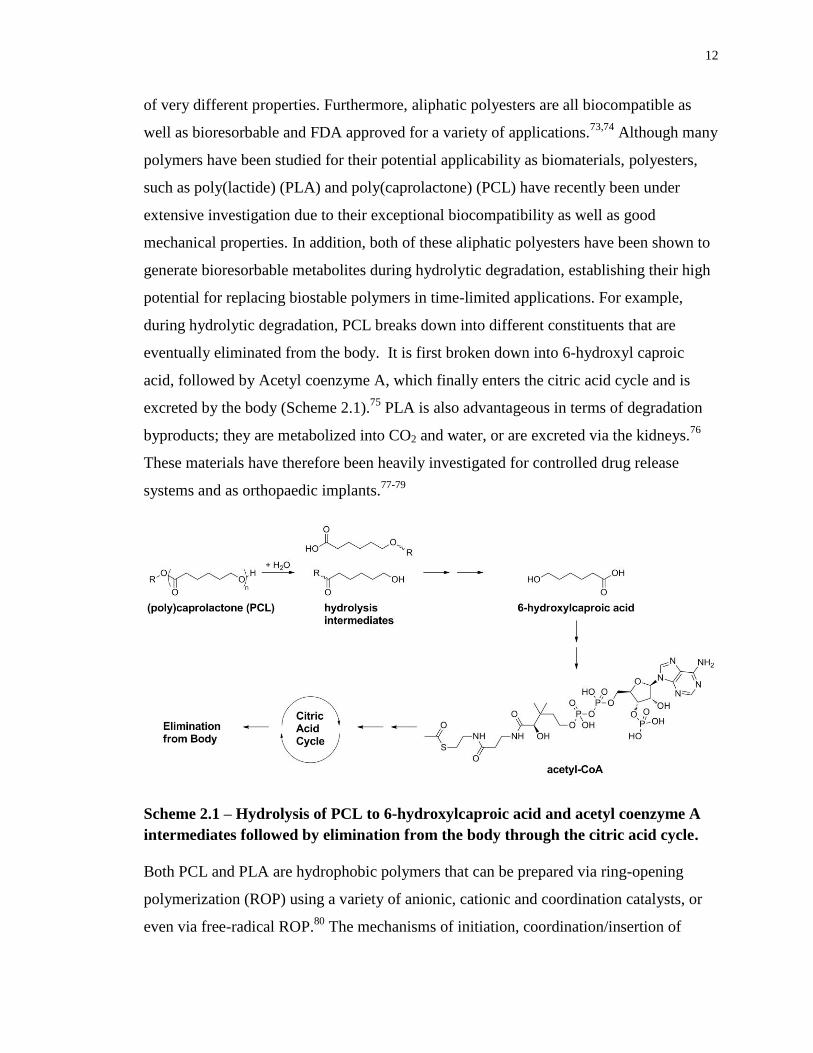
during hydrolytic degradation, PCL breaks down into different constituents that are
eventually eliminated from the body. It is first broken down into 6-hydroxyl caproic
acid, followed by Acetyl coenzyme A, which finally enters the citric acid cycle and is
excreted by the body (Scheme 2.1).75
PLA is also advantageous in terms of degradation
byproducts; they are metabolized into CO2 and water, or are excreted via the kidneys.76
These materials have therefore been heavily investigated for controlled drug release
systems and as orthopaedic implants.77-79
Scheme 2.1 – Hydrolysis of PCL to 6-hydroxylcaproic acid and acetyl coenzyme A
intermediates followed by elimination from the body through the citric acid cycle.
Both PCL and PLA are hydrophobic polymers that can be prepared via ring-opening
polymerization (ROP) using a variety of anionic, cationic and coordination catalysts, or
even via free-radical ROP.80
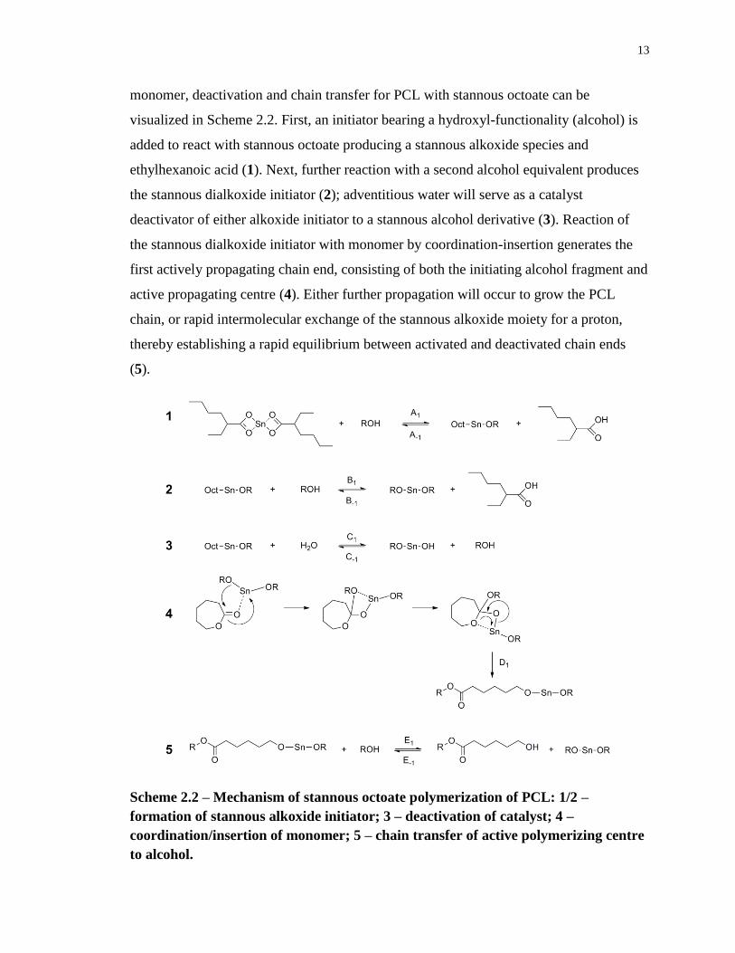
The mechanisms of initiation, coordination/insertion of
13
monomer, deactivation and chain transfer for PCL with stannous octoate can be
visualized in Scheme 2.2. First, an initiator bearing a hydroxyl-functionality (alcohol) is
added to react with stannous octoate producing a stannous alkoxide species and
ethylhexanoic acid (1). Next, further reaction with a second alcohol equivalent produces
the stannous dialkoxide initiator (2); adventitious water will serve as a catalyst
deactivator of either alkoxide initiator to a stannous alcohol derivative (3). Reaction of
the stannous dialkoxide initiator with monomer by coordination-insertion generates the
first actively propagating chain end, consisting of both the initiating alcohol fragment and
active propagating centre (4). Either further propagation will occur to grow the PCL
chain, or rapid intermolecular exchange of the stannous alkoxide moiety for a proton,
thereby establishing a rapid equilibrium between activated and deactivated chain ends
(5).
Scheme 2.2 – Mechanism of stannous octoate polymerization of PCL: 1/2 –
formation of stannous alkoxide initiator; 3 – deactivation of catalyst; 4 –
coordination/insertion of monomer; 5 – chain transfer of active polymerizing centre
to alcohol.
14
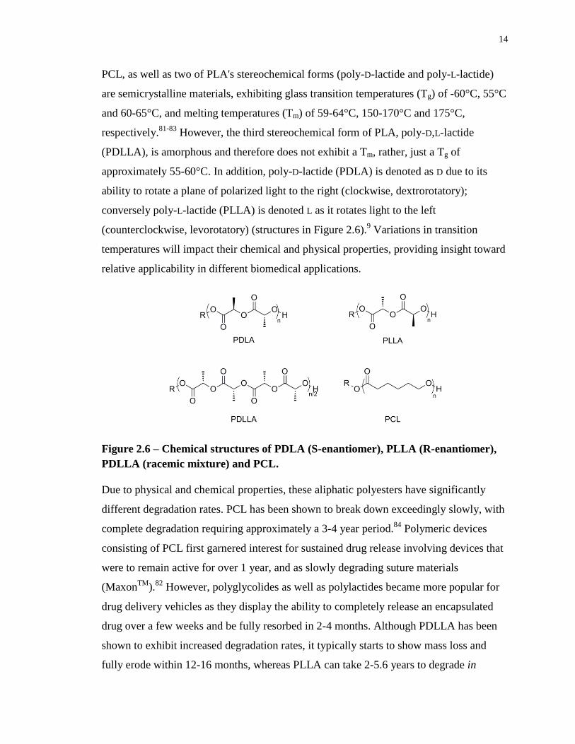
PCL, as well as two of PLA's stereochemical forms (poly-D-lactide and poly-L-lactide)
are semicrystalline materials, exhibiting glass transition temperatures (Tg) of -60°C, 55°C
and 60-65°C, and melting temperatures (Tm) of 59-64°C, 150-170°C and 175°C,
respectively.81-83
However, the third stereochemical form of PLA, poly-D,L-lactide
(PDLLA), is amorphous and therefore does not exhibit a Tm, rather, just a Tg of
approximately 55-60°C. In addition, poly-D-lactide (PDLA) is denoted as D due to its
ability to rotate a plane of polarized light to the right (clockwise, dextrorotatory);
conversely poly-L-lactide (PLLA) is denoted L as it rotates light to the left
(counterclockwise, levorotatory) (structures in Figure 2.6).9 Variations in transition
temperatures will impact their chemical and physical properties, providing insight toward
relative applicability in different biomedical applications.
Figure 2.6 – Chemical structures of PDLA (S-enantiomer), PLLA (R-enantiomer),
PDLLA (racemic mixture) and PCL.
Due to physical and chemical properties, these aliphatic polyesters have significantly
different degradation rates. PCL has been shown to break down exceedingly slowly, with
complete degradation requiring approximately a 3-4 year period.84
Polymeric devices
consisting of PCL first garnered interest for sustained drug release involving devices that
were to remain active for over 1 year, and as slowly degrading suture materials
(MaxonTM
).82
However, polyglycolides as well as polylactides became more popular for
drug delivery vehicles as they display the ability to completely release an encapsulated
drug over a few weeks and be fully resorbed in 2-4 months. Although PDLLA has been
shown to exhibit increased degradation rates, it typically starts to show mass loss and
fully erode within 12-16 months, whereas PLLA can take 2-5.6 years to degrade in
15
vivo.82,85
Degradation of semicrystalline polymers such as PCL occurs in two stages when
subjected to aqueous media. First, water diffuses into the amorphous regions, which are
less organized and allow water to penetrate more easily. Next, hydrolytic degradation
occurs from the edge to the centre of the crystalline domains, followed by intracellular
degradation if the MW is less than 3000 g/mol. This explains why PDLLA degrades
much faster as it lacks crystallinity.86-88
The second stage of degradation confirms that
PCL is resorbable, as polymer fragments are uptaken into phagosomes, whereby an
intracellular mechanism completes the degradation process. In terms of in vivo
degradation, PCL and PDLLA behave similarly.89
PCL’s excellent biocompatibility also makes it attractive for 3D porous scaffolds
in TE applications to direct the growth of cells and new bone at the site of
implantation.76,90
Moreover, its good rheological and viscoelastic properties render it easy
to manufacture and manipulate while providing overall structure and support.91,92
PCL’s
slow degradation and mechanical support are therefore excellent attributes for this
application. The slow degradation coupled with bioresorbability ensures ample time for
neo-bone/tissues to form at the site of implantation without complete fragmentation of the
biomaterial. Along with scaffolds, PCL has also been employed in various TE
applications including bone,93
cartilage,94,95
tendon and ligament,96
cardiovascular,97
blood vessel,98
skin99
and nerve.100
PCL is a highly versatile resorbable polymer and
although there are several FDA approved drug delivery and medical devices, an increase
in TE applications should emerge due to PCL-composite structures and their superior
mechanical and biocompatible properties.
PLA’s advantages also manifest from its biodegradable nature as well as high
strength and biocompatibility.101
PLA’s crystallinity depends on the ratio of D- and L-
enantiomers used. However, combinations with as little as 12% D-lactide result in the
amorphous PDLLA grade.102
PDLLA is commonly used in the food packaging sector due
to its ease of transformation (i.e. injection moulding and thermoforming), which also
makes it attractive for usage in resorbable plating, artificial cartilage or bone,
chemotherapeutic and pharmaceutical applications.103
These applications require faster
degradation, thereby portraying PDLLA’s advantage over its crystalline counterparts,
16
PDLA and PLLA. Because of its faster degradation and moderate strength, PDLLA is
preferably developed as a drug delivery vehicle or a scaffolding material for tissue
regeneration.9
By considering both PCL and PDLLA as possible bioresorbable polymers in this
study, it will provide consistency when comparing results. Although PDLLA has been
shown to degrade more quickly,77,89
degradation kinetics are based heavily upon MW, in
that higher MW polymers will take longer to degrade due to an increase in chain
length.104,105
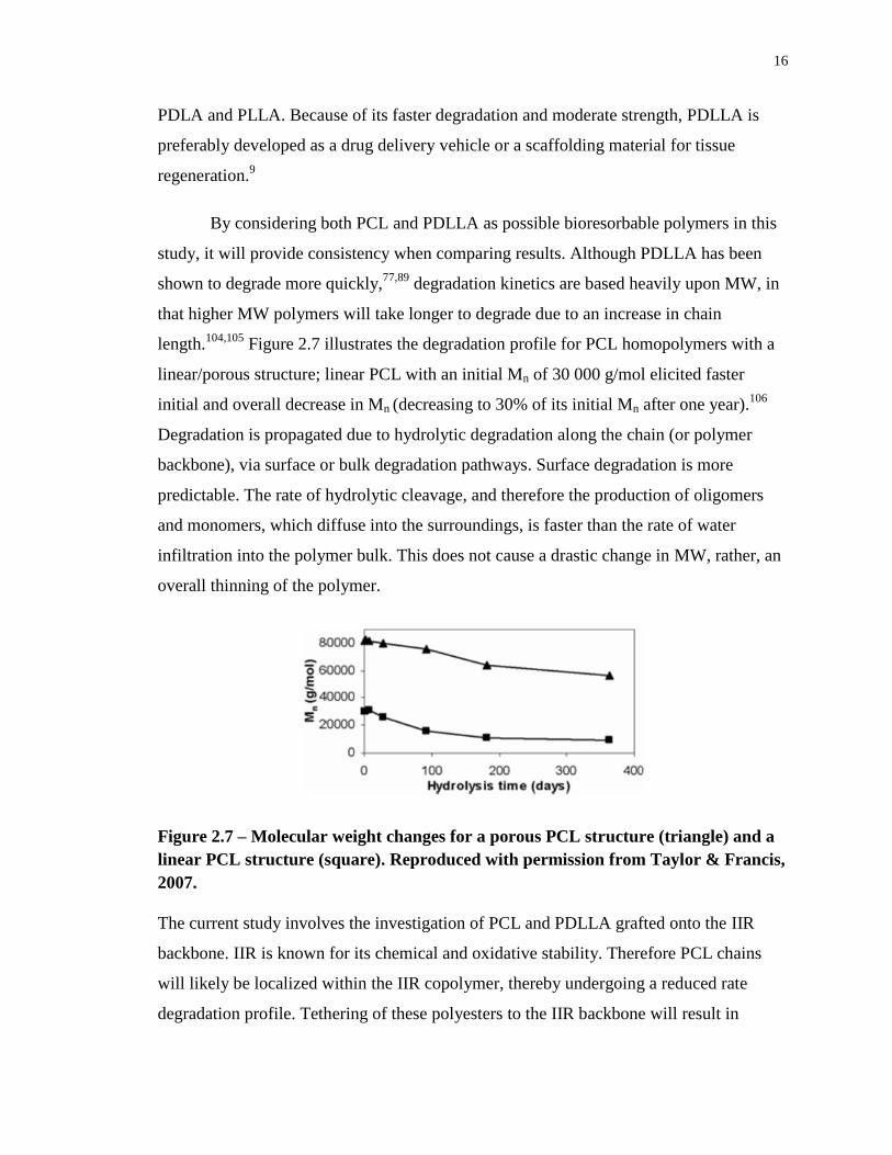
Figure 2.7 illustrates the degradation profile for PCL homopolymers with a
linear/porous structure; linear PCL with an initial Mn of 30 000 g/mol elicited faster
initial and overall decrease in Mn (decreasing to 30% of its initial Mn after one year).106
Degradation is propagated due to hydrolytic degradation along the chain (or polymer
backbone), via surface or bulk degradation pathways. Surface degradation is more
predictable. The rate of hydrolytic cleavage, and therefore the production of oligomers
and monomers, which diffuse into the surroundings, is faster than the rate of water
infiltration into the polymer bulk. This does not cause a drastic change in MW, rather, an
overall thinning of the polymer.
Figure 2.7 – Molecular weight changes for a porous PCL structure (triangle) and a
linear PCL structure (square). Reproduced with permission from Taylor & Francis,
2007.
The current study involves the investigation of PCL and PDLLA grafted onto the IIR
backbone. IIR is known for its chemical and oxidative stability. Therefore PCL chains
will likely be localized within the IIR copolymer, thereby undergoing a reduced rate
degradation profile. Tethering of these polyesters to the IIR backbone will result in
17
compliance, yet stability and rigidity, perhaps making these copolymers suitable for a
variety of applications requiring good mechanical properties such as vascular prosthetics
or intervertebral disc replacement.
2.3.2 PIB and IIR Copolymers
2.3.2.1 Background
Poly(isobutylene) (PIB) is a synthetic elastomer, which yields many desirable properties
such as high elasticity, impermeability to gas and water, chemical stability and
biocompatibility. Because of these properties, PIB and its copolymers with small
percentages of isoprene (IP) (0.5-4mol%), commonly known as IIR, have been used in a
variety of commercial products such as the inner tubes of automobile tires, the bladders
of sporting equipment such as basketballs and soccer balls, lubricating oils, motor fuels,
sealants, and even as a primary component in chewing gum.107
Usage in these
applications is also possible due to its low level of unsaturation, which provides a route
for chemically crosslinking via sulfur-based curing. Crosslinking provides mechanical
improvements as well as abrasion resistance, thereby enhancing its physical properties
and bestowing suitability for different applications.108
PIB and IIR are attractive due to
their aforementioned properties and versatility, and their ability to be (co)polymerized via
cationic polymerization.
IIR was initially investigated by Gorianov and Butlerov (1870), as well as Otto
(1927); they found oily homopolymers of IB were successfully produced by usage of
boron trifluoride. By the 1930s, I.G. Farben Company of Germany fabricated high MW
PIBs, possessing rubber-like properties. The drawback of PIB was its inability to undergo
vulcanization or modification due to its fully saturated structure. Although uncurable,
homopolymers of PIB were commercialized from Badischer of Germany and Exxon
Chemical Company as PANOLand VISTANEX
, respectively. Additional research in
the 1930s conducted by W.J. Sparks and R.M. Thomas of Standard Oil and Development
Company (Exxon) allowed further development of IB into the first curable IB-based
elastomer, by incorporating small amounts of a diolefin, IP, into the molecule. However,
IIR was officially introduced and commercialized in 1942.109
In addition, halogen
18
derivatives such as chloro- and bromo-butyl were introduced in the 1960s as
commercially available products, which have greater variations in terms of vulcanization
and can be cured with other general elastomers. Butyl polymers are considered specialty
elastomers, eliciting the highest worldwide usage of all synthetic elastomers.
Versatility of PIB allows for the development of hybrid materials containing other
polymers, thereby imparting new properties to PIB for specific biomedical applications.
Demand for biomedical products is increasing in the western society due to the increasing
population of the elderly. Diversifying PIB’s usage toward the health sector is crucial to
satisfy the demand for products that enhance life quality and longevity. Although PIB is a
versatile polymer, approximately 80% of total PIB is directed toward the automobile
industry. The current clinical use of PIB-based copolymers in vascular stent coatings, as
well as its preclinical investigation in a number of other areas such as bone cements and
intervertebral disc replacements suggests that PIB is a highly biocompatible and
promising material for a range of biomedical applications.108
2.3.2.2 Synthesis of IIR
Commercial IIR grades such as poly(methylpropene-co-2-methyl-1,3 butadiene) or
poly(isobutylene-co-isoprene) are prepared by copolymerizing high purity IB and IP via
cationic polymerization at -100°C in methyl chloride. A schematic diagram of a typical
butyl plant can be found in Figure 2.8.110
Monomers and methyl chloride are purified via
flashing and stripping. Zinc or calcium stearate and antioxidants are added to prevent
agglomeration throughout the polymerization process. Post-reaction, the PIB product is
separated from the slurry, dried and processed. In addition, the reaction follows a generic
approach to provide living-like conditions, making use of conventional Lewis acid
initiation systems, but with the addition of a Lewis base. By employing Lewis acid
coinitiators (or activators) such as aluminum trichloride (AlCl3), alkylaluminum
dichloride and boron trifluoride (BF3) in methyl chloride or dimethyl sulphoxide (Lewis
base moderators), it modifies the interaction between the carbocation active centre and
counter-ion.111,112
Moreover, without this modified interaction, the counterion would be
too nucelophilic, causing the reactions to be terminated instantaneously.
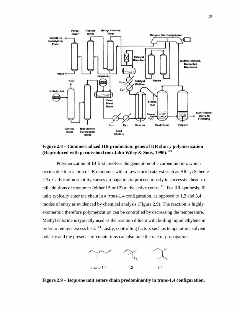
19
Figure 2.8 – Commercialized IIR production: general IIR slurry polymerization
(Reproduced with permission from John Wiley & Sons, 1990).109
Polymerization of IB first involves the generation of a carbenium ion, which
occurs due to reaction of IB monomer with a Lewis acid catalyst such as AlCl3 (Scheme
2.3). Carbocation stability causes propagation to proceed mostly in successive head-to-
tail additions of monomer (either IB or IP) to the active centre.113
For IIR synthesis, IP
units typically enter the chain in a trans-1,4 configuration, as opposed to 1,2 and 3,4
modes of entry as evidenced by chemical analysis (Figure 2.9). The reaction is highly
exothermic therefore polymerization can be controlled by decreasing the temperature.
Methyl chloride is typically used as the reaction diluent with boiling liquid ethylene in
order to remove excess heat.114
Lastly, controlling factors such as temperature, solvent
polarity and the presence of counterions can also tune the rate of propagation.
Figure 2.9 – Isoprene unit enters chain predominantly in trans-1,4 configuration.
20
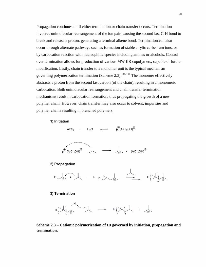
Propagation continues until either termination or chain transfer occurs. Termination
involves unimolecular rearrangement of the ion pair, causing the second last C-H bond to
break and release a proton, generating a terminal alkene bond. Termination can also
occur through alternate pathways such as formation of stable allylic carbenium ions, or
by carbocation reaction with nucleophilic species including amines or alcohols. Control
over termination allows for production of various MW IIR copolymers, capable of further
modification. Lastly, chain transfer to a monomer unit is the typical mechanism
governing polymerization termination (Scheme 2.3).115,116
The monomer effectively
abstracts a proton from the second last carbon (of the chain), resulting in a monomeric
carbocation. Both unimolecular rearrangement and chain transfer termination
mechanisms result in carbocation formation, thus propagating the growth of a new
polymer chain. However, chain transfer may also occur to solvent, impurities and
polymer chains resulting in branched polymers.
Scheme 2.3 – Cationic polymerization of IB governed by initiation, propagation and
termination.
21
2.3.2.3 Physical and Chemical Properties of IIR
The discovery of IIR was preceded by the desire to transform PIB into a rubbery
copolymer that allowed for low functionality, resulting from its low level of unsaturation.
As a result, low-modulus vulcanized networks that resist ozonolysis and oxidation can be
produced.117
In addition, because of its oxidative, enzymatic and hydrolytic resistance, it
is also biocompatible for long-term applications.118
Its biocompatibility is advantageous
for applications involving medical devices in vivo (vascular prosthetics, stents,
implantable devices, etc.), to replace materials such as PURs that may degrade, leading to
inflammatory and fibrotic reactions.119
The long, fully saturated PIB segments also
manifest physical properties such as low permeability to both gases and liquids, thermal
stability, weathering, chemical and moisture resistance as well as vibration damping.120
Very low permeability, making it advantageous for innerliner in tires, is attributed to the
efficient intermolecular packing and high density of the PIB segment. In terms of air
retention within tires, IIR demonstrated to be at least 8 times better than that of natural
rubber (Table 2.1).109
Table 2.1 – Air loss after automobile driving tests (Reproduced with permission
from John Wiley & Sons).109
Initial Conditions Air Pressure Loss (psi)
Inner Tube Original Pressure (psi) 1 Week 2 Weeks 3 Weeks
Natural Rubber 28 4.0 8.0 16.5
IIR 28 0.5 1.0 2.0
Moreover, PIB’s compact and symmetrical intermolecular packing minimizes its
intermolecular interactions, which is reflected by its viscoelastic properties.121
Having
two methyl side groups on every other chain carbon causes a delay in elastic response to
deformation. This can also be described as high hysteresis. Perfectly elastic materials do
not lose energy when a load is applied to them. However, viscoelastic materials do lose
some energy, dissipated as heat, resulting in slight permanent deformations after a given
stress is applied. This is also related to creep in that viscoelastic materials permanently
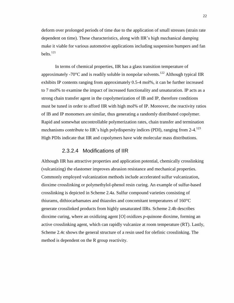
22
deform over prolonged periods of time due to the application of small stresses (strain rate
dependent on time). These characteristics, along with IIR’s high mechanical damping
make it viable for various automotive applications including suspension bumpers and fan
belts.121
In terms of chemical properties, IIR has a glass transition temperature of
approximately -70°C and is readily soluble in nonpolar solvents.122
Although typical IIR
exhibits IP contents ranging from approximately 0.5-4 mol%, it can be further increased
to 7 mol% to examine the impact of increased functionality and unsaturation. IP acts as a
strong chain transfer agent in the copolymerization of IB and IP, therefore conditions
must be tuned in order to afford IIR with high mol% of IP. Moreover, the reactivity ratios
of IB and IP monomers are similar, thus generating a randomly distributed copolymer.
Rapid and somewhat uncontrollable polymerization rates, chain transfer and termination
mechanisms contribute to IIR’s high polydispersity indices (PDI), ranging from 2-4.123
High PDIs indicate that IIR and copolymers have wide molecular mass distributions.
2.3.2.4 Modifications of IIR
Although IIR has attractive properties and application potential, chemically crosslinking
(vulcanizing) the elastomer improves abrasion resistance and mechanical properties.
Commonly employed vulcanization methods include accelerated sulfur vulcanization,
dioxime crosslinking or polymethylol-phenol resin curing. An example of sulfur-based
crosslinking is depicted in Scheme 2.4a. Sulfur compound varieties consisting of
thiurams, dithiocarbamates and thiazoles and concomitant temperatures of 160°C
generate crosslinked products from highly unsaturated IIRs. Scheme 2.4b describes
dioxime curing, where an oxidizing agent [O] oxidizes p-quinone dioxime, forming an
active crosslinking agent, which can rapidly vulcanize at room temperature (RT). Lastly,
Scheme 2.4c shows the general structure of a resin used for olefinic crosslinking. The
method is dependent on the R group reactivity.
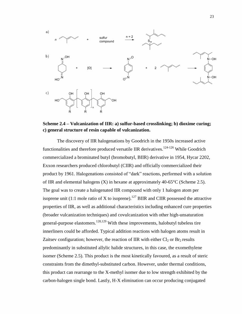
23
Scheme 2.4 – Vulcanization of IIR: a) sulfur-based crosslinking; b) dioxime curing;
c) general structure of resin capable of vulcanization.
The discovery of IIR halogenations by Goodrich in the 1950s increased active
functionalities and therefore produced versatile IIR derivatives.124-126
While Goodrich
commercialized a brominated butyl (bromobutyl, BIIR) derivative in 1954, Hycar 2202,
Exxon researchers produced chlorobutyl (CIIR) and officially commercialized their
product by 1961. Halogenations consisted of “dark” reactions, performed with a solution
of IIR and elemental halogens (X) in hexane at approximately 40-65°C (Scheme 2.5).
The goal was to create a halogenated IIR compound with only 1 halogen atom per
isoprene unit (1:1 mole ratio of X to isoprene).127
BIIR and CIIR possessed the attractive
properties of IIR, as well as additional characteristics including enhanced cure properties
(broader vulcanization techniques) and covulcanization with other high-unsaturation
general-purpose elastomers.128,129
With these improvements, halobutyl tubeless tire
innerliners could be afforded. Typical addition reactions with halogen atoms result in
Zaitsev configuration; however, the reaction of IIR with either Cl2 or Br2 results
predominantly in substituted allylic halide structures, in this case, the exomethylene
isomer (Scheme 2.5). This product is the most kinetically favoured, as a result of steric
constraints from the dimethyl-substituted carbon. However, under thermal conditions,
this product can rearrange to the X-methyl isomer due to low strength exhibited by the
carbon-halogen single bond. Lastly, H-X elimination can occur producing conjugated
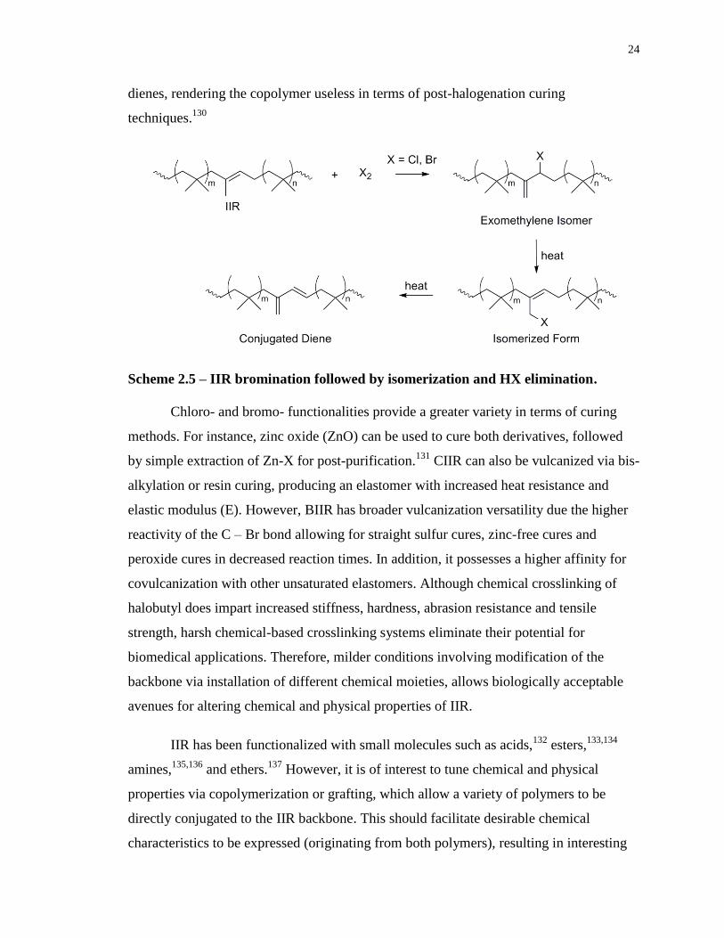
24
dienes, rendering the copolymer useless in terms of post-halogenation curing
techniques.130
Scheme 2.5 – IIR bromination followed by isomerization and HX elimination.
Chloro- and bromo- functionalities provide a greater variety in terms of curing
methods. For instance, zinc oxide (ZnO) can be used to cure both derivatives, followed
by simple extraction of Zn-X for post-purification.131
CIIR can also be vulcanized via bis-
alkylation or resin curing, producing an elastomer with increased heat resistance and
elastic modulus (E). However, BIIR has broader vulcanization versatility due the higher
reactivity of the C – Br bond allowing for straight sulfur cures, zinc-free cures and
peroxide cures in decreased reaction times. In addition, it possesses a higher affinity for
covulcanization with other unsaturated elastomers. Although chemical crosslinking of
halobutyl does impart increased stiffness, hardness, abrasion resistance and tensile
strength, harsh chemical-based crosslinking systems eliminate their potential for
biomedical applications. Therefore, milder conditions involving modification of the
backbone via installation of different chemical moieties, allows biologically acceptable
avenues for altering chemical and physical properties of IIR.
IIR has been functionalized with small molecules such as acids,132
esters,133,134
amines,135,136
and ethers.137
However, it is of interest to tune chemical and physical
properties via copolymerization or grafting, which allow a variety of polymers to be
directly conjugated to the IIR backbone. This should facilitate desirable chemical
characteristics to be expressed (originating from both polymers), resulting in interesting
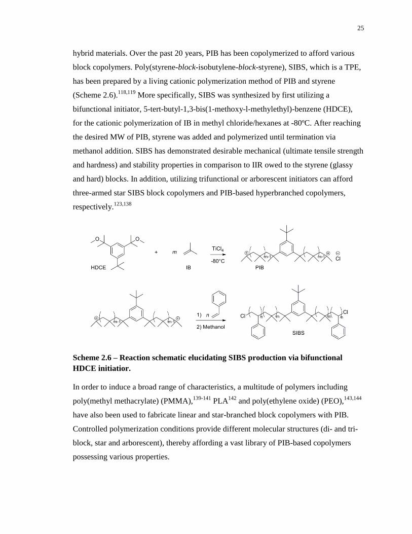
25
hybrid materials. Over the past 20 years, PIB has been copolymerized to afford various
block copolymers. Poly(styrene-block-isobutylene-block-styrene), SIBS, which is a TPE,
has been prepared by a living cationic polymerization method of PIB and styrene
(Scheme 2.6).118,119
More specifically, SIBS was synthesized by first utilizing a
bifunctional initiator, 5-tert-butyl-1,3-bis(1-methoxy-l-methylethyl)-benzene (HDCE),
for the cationic polymerization of IB in methyl chloride/hexanes at -80ºC. After reaching
the desired MW of PIB, styrene was added and polymerized until termination via
methanol addition. SIBS has demonstrated desirable mechanical (ultimate tensile strength
and hardness) and stability properties in comparison to IIR owed to the styrene (glassy
and hard) blocks. In addition, utilizing trifunctional or arborescent initiators can afford
three-armed star SIBS block copolymers and PIB-based hyperbranched copolymers,
respectively.123,138
Scheme 2.6 – Reaction schematic elucidating SIBS production via bifunctional
HDCE initiatior.
In order to induce a broad range of characteristics, a multitude of polymers including
poly(methyl methacrylate) (PMMA),139-141
PLA142
and poly(ethylene oxide) (PEO),143,144
have also been used to fabricate linear and star-branched block copolymers with PIB.
Controlled polymerization conditions provide different molecular structures (di- and tri-
block, star and arborescent), thereby affording a vast library of PIB-based copolymers
possessing various properties.
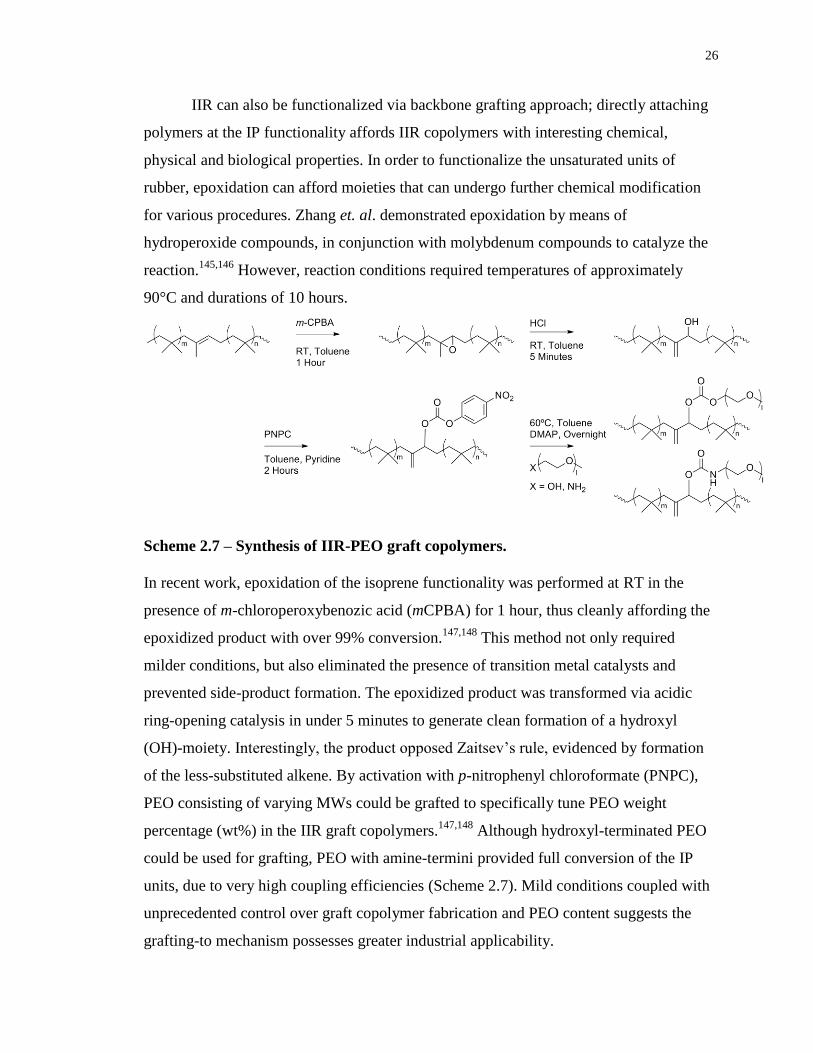
26
IIR can also be functionalized via backbone grafting approach; directly attaching
polymers at the IP functionality affords IIR copolymers with interesting chemical,
physical and biological properties. In order to functionalize the unsaturated units of
rubber, epoxidation can afford moieties that can undergo further chemical modification
for various procedures. Zhang et. al. demonstrated epoxidation by means of
hydroperoxide compounds, in conjunction with molybdenum compounds to catalyze the
reaction.145,146
However, reaction conditions required temperatures of approximately
90°C and durations of 10 hours.
Scheme 2.7 – Synthesis of IIR-PEO graft copolymers.
In recent work, epoxidation of the isoprene functionality was performed at RT in the
presence of m-chloroperoxybenozic acid (mCPBA) for 1 hour, thus cleanly affording the
epoxidized product with over 99% conversion.147,148
This method not only required
milder conditions, but also eliminated the presence of transition metal catalysts and
prevented side-product formation. The epoxidized product was transformed via acidic
ring-opening catalysis in under 5 minutes to generate clean formation of a hydroxyl
(OH)-moiety. Interestingly, the product opposed Zaitsev’s rule, evidenced by formation
of the less-substituted alkene. By activation with p-nitrophenyl chloroformate (PNPC),
PEO consisting of varying MWs could be grafted to specifically tune PEO weight
percentage (wt%) in the IIR graft copolymers.147,148
Although hydroxyl-terminated PEO
could be used for grafting, PEO with amine-termini provided full conversion of the IP
units, due to very high coupling efficiencies (Scheme 2.7). Mild conditions coupled with
unprecedented control over graft copolymer fabrication and PEO content suggests the
grafting-to mechanism possesses greater industrial applicability.
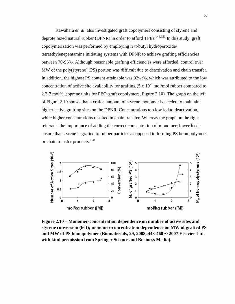
27
Kawahara et. al. also investigated graft copolymers consisting of styrene and
deproteinized natural rubber (DPNR) in order to afford TPEs.149,150
In this study, graft
copolymerization was performed by employing tert-butyl hydroperoxide/
tetraethylenepentamine initiating systems with DPNR to achieve grafting efficiencies
between 70-95%. Although reasonable grafting efficiencies were afforded, control over
MW of the poly(styrene) (PS) portion was difficult due to deactivation and chain transfer.
In addition, the highest PS content attainable was 32wt%, which was attributed to the low
concentration of active site availability for grafting (5 x 10⁻⁴
mol/mol rubber compared to
2.2-7 mol% isoprene units for PEO-graft copolymers, Figure 2.10). The graph on the left
of Figure 2.10 shows that a critical amount of styrene monomer is needed to maintain
higher active grafting sites on the DPNR. Concentrations too low led to deactivation,
while higher concentrations resulted in chain transfer. Whereas the graph on the right
reiterates the importance of adding the correct concentration of monomer; lower feeds
ensure that styrene is grafted to rubber particles as opposed to forming PS homopolymers
or chain transfer products.150
Figure 2.10 – Monomer-concentration dependence on number of active sites and
styrene conversion (left); monomer-concentration dependence on MW of grafted PS
and MW of PS homopolymer (Biomaterials, 29, 2008, 448-460 © 2007 Elsevier Ltd.
with kind permission from Springer Science and Business Media).
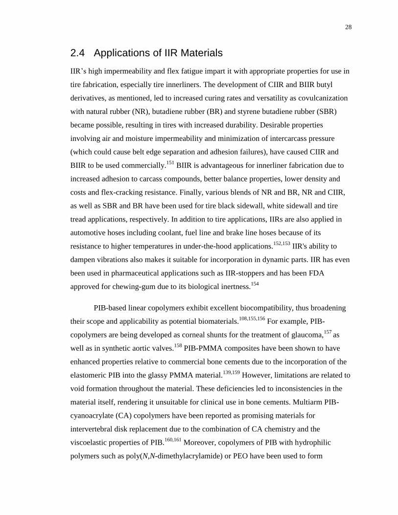
28
2.4 Applications of IIR Materials
IIR’s high impermeability and flex fatigue impart it with appropriate properties for use in
tire fabrication, especially tire innerliners. The development of CIIR and BIIR butyl
derivatives, as mentioned, led to increased curing rates and versatility as covulcanization
with natural rubber (NR), butadiene rubber (BR) and styrene butadiene rubber (SBR)
became possible, resulting in tires with increased durability. Desirable properties
involving air and moisture impermeability and minimization of intercarcass pressure
(which could cause belt edge separation and adhesion failures), have caused CIIR and
BIIR to be used commercially.151
BIIR is advantageous for innerliner fabrication due to
increased adhesion to carcass compounds, better balance properties, lower density and
costs and flex-cracking resistance. Finally, various blends of NR and BR, NR and CIIR,
as well as SBR and BR have been used for tire black sidewall, white sidewall and tire
tread applications, respectively. In addition to tire applications, IIRs are also applied in
automotive hoses including coolant, fuel line and brake line hoses because of its
resistance to higher temperatures in under-the-hood applications.152,153
IIR's ability to
dampen vibrations also makes it suitable for incorporation in dynamic parts. IIR has even
been used in pharmaceutical applications such as IIR-stoppers and has been FDA
approved for chewing-gum due to its biological inertness.154
PIB-based linear copolymers exhibit excellent biocompatibility, thus broadening
their scope and applicability as potential biomaterials.108,155,156
For example, PIB-
copolymers are being developed as corneal shunts for the treatment of glaucoma,157
as
well as in synthetic aortic valves.158
PIB-PMMA composites have been shown to have
enhanced properties relative to commercial bone cements due to the incorporation of the
elastomeric PIB into the glassy PMMA material.139,159
However, limitations are related to
void formation throughout the material. These deficiencies led to inconsistencies in the
material itself, rendering it unsuitable for clinical use in bone cements. Multiarm PIB-
cyanoacrylate (CA) copolymers have been reported as promising materials for
intervertebral disk replacement due to the combination of CA chemistry and the
viscoelastic properties of PIB.160,161
Moreover, copolymers of PIB with hydrophilic
polymers such as poly(N,N-dimethylacrylamide) or PEO have been used to form
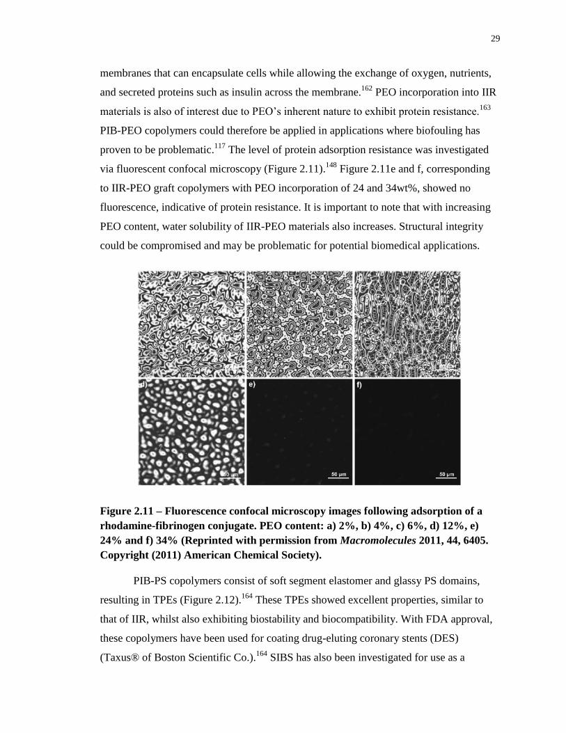
29
membranes that can encapsulate cells while allowing the exchange of oxygen, nutrients,
and secreted proteins such as insulin across the membrane.162
PEO incorporation into IIR
materials is also of interest due to PEO’s inherent nature to exhibit protein resistance.163
PIB-PEO copolymers could therefore be applied in applications where biofouling has
proven to be problematic.117
The level of protein adsorption resistance was investigated
via fluorescent confocal microscopy (Figure 2.11).148
Figure 2.11e and f, corresponding
to IIR-PEO graft copolymers with PEO incorporation of 24 and 34wt%, showed no
fluorescence, indicative of protein resistance. It is important to note that with increasing
PEO content, water solubility of IIR-PEO materials also increases. Structural integrity
could be compromised and may be problematic for potential biomedical applications.
Figure 2.11 – Fluorescence confocal microscopy images following adsorption of a
rhodamine-fibrinogen conjugate. PEO content: a) 2%, b) 4%, c) 6%, d) 12%, e)
24% and f) 34% (Reprinted with permission from Macromolecules 2011, 44, 6405.
Copyright (2011) American Chemical Society).
PIB-PS copolymers consist of soft segment elastomer and glassy PS domains,
resulting in TPEs (Figure 2.12).164
These TPEs showed excellent properties, similar to
that of IIR, whilst also exhibiting biostability and biocompatibility. With FDA approval,
these copolymers have been used for coating drug-eluting coronary stents (DES)
(Taxus® of Boston Scientific Co.).164
SIBS has also been investigated for use as a
30
corneal shunt, with results showing a decrease in inflammatory response when compared
to polydimethylsiloxane.165
These advances have led to the development of the MIDI-
tube, which has demonstrated high patency in rabbit test subjects for the treatment of
glaucoma. SIBS is also viable for the production of intraocular lenses166
as well as
trileaflet heart valve replacements.167,168
Its excellent mechanical properties as a TPE
makes it an attractive candidate for the aforementioned applications, however, creep
deformation may be problematic. Optimization of the polymer chemistry and resulting
properties is still critical for many applications. For example, when SIBS was explored as
a potential implant material in the urinary tract, significant attachment of uropathegenic
species such as E. coli 67 was observed, indicating that the surface properties of the
polymer were not ideal for this application.117
Furthermore, there have been reported
cases of stent coating delamination upon employment in vivo, indicating that the adhesion
of PIB-PS copolymers to the metal materials could be strengthened.169-171
Figure 2.12 – Cartoon representation of PIB-b-PS showing elastomeric
entanglements (PIB) and hard segments (PS) (Reprinted from Biomaterials, 29/4,
Pinchuk et. al., Medical applications of poly(styrene-block-isobutylene-block-
styrene) (“SIBS”) (448-460). Copyright (2008), with permission from Elsevier).
31
2.5 Evaluation of Biomaterials
2.5.1 Chemical Characterization
It is standard to characterize new polymeric materials by a range of techniques including
nuclear magnetic resonance (NMR) spectroscopy, size exclusion chromatography (SEC)
and fourier transform infrared spectroscopy (FTIR) in order to confirm their chemical
structures. NMR spectroscopy is a technique that allows one to obtain detailed
information on the chemical structures of molecules. While NMR spectroscopy can be
performed to probe any nucleus with a non-zero spin, one of the most commonly
investigated nuclei is the proton. In 1H NMR spectroscopy, each signal is characteristic of
a specific proton found in a given molecular structure. The precise resonance frequency is
affected by electron shielding, which is dependent on the chemical environment.
Therefore, this information is important in order to determine the chemical structure and
purity of materials. Moreover, the intensity of each peak can also allow for quantification
of a particular component in a sample. Specifically, by integrating copolymer peaks, the
determination of PCL or PDLLA incorporation for each copolymer can be successfully
calculated.
Gel permeation chromatography (GPC) is a type of size exclusion chromatography (SEC)
that separates analytes based on hydrodynamic volume, thereby providing information
about polymer chain length and in turn, MW. By utilizing packings comprising porous
beads in a column, separation is achieved. Smaller analytes enter the pores, therefore
increasing their retention time in the column, whereas larger analytes bypass the pores
thereby eluting much faster. In conventional SEC, a number of calibration standards of
known MW are run and their retention times are recorded in order to identify the
relationship between retention time and MW. By relating the retention time of an
unknown sample to the calibration curve, the unknown's MW can be determined. The
SEC results will describe different MWs: weight average molecular weight (Mw), number
average molecular weight (Mn), size average molecular weight (Mz) and the viscosity
molecular weight (Mν). Polymers can then be characterized in terms of PDI:
32
1)
Equation 1 – Definition of polydispersity index where Mn is the total weight of the
sample divided by the number of molecules (arithmetic mean) and Mw fairly
accounts for the contributions of different sized chains.
Fourier transform infrared spectroscopy (FTIR) involves the absorption of infrared light,
and is typically performed in order to identify the chemical functional groups present in a
sample. Since every sample is different, different bonds and molecules will lead to a very
specific spectrum, or ‘molecular fingerprint’. The analysis produces an interferogram (all
frequencies being measured at the same time), which undergoes a Fourier transformation,
providing a frequency spectrum. The peaks correspond to the frequencies of vibrations
between the atoms within chemical bonds. The variations in stretching are characteristic
of specific chemical functional groups such as carbonyls, hydroxyls, or alkenes. In
addition, peak intensity is directly related to the amount of a specific compound or
materials, allowing for quantitative analysis.
2.5.2 Physical Characterization
2.5.2.1 Water Contact Angle
The measurement of the water contact angle (WCA) of a surface can provide insight into
the hydrophobicity/hydrophilicty of a given surface, which can be crucial for various
applications. A given surface at a specific temperature and pressure will exhibit a unique
contact angle with a given liquid, which is affected by the surface energy and the
interfacial energy between the liquid and solid (dictated by cohesion and adhesion
forces).172
The critical surface energy (or critical surface tension) characterizes the
wettability of a material. Solids that possess high critical surface energies are more
wettable as opposed to solids with low critical surface energies, which are typically not
wettable by most liquids. WCA is measured by drop shape analysis, where the liquid
interface meets a solid surface as depicted in Figure 2.13.
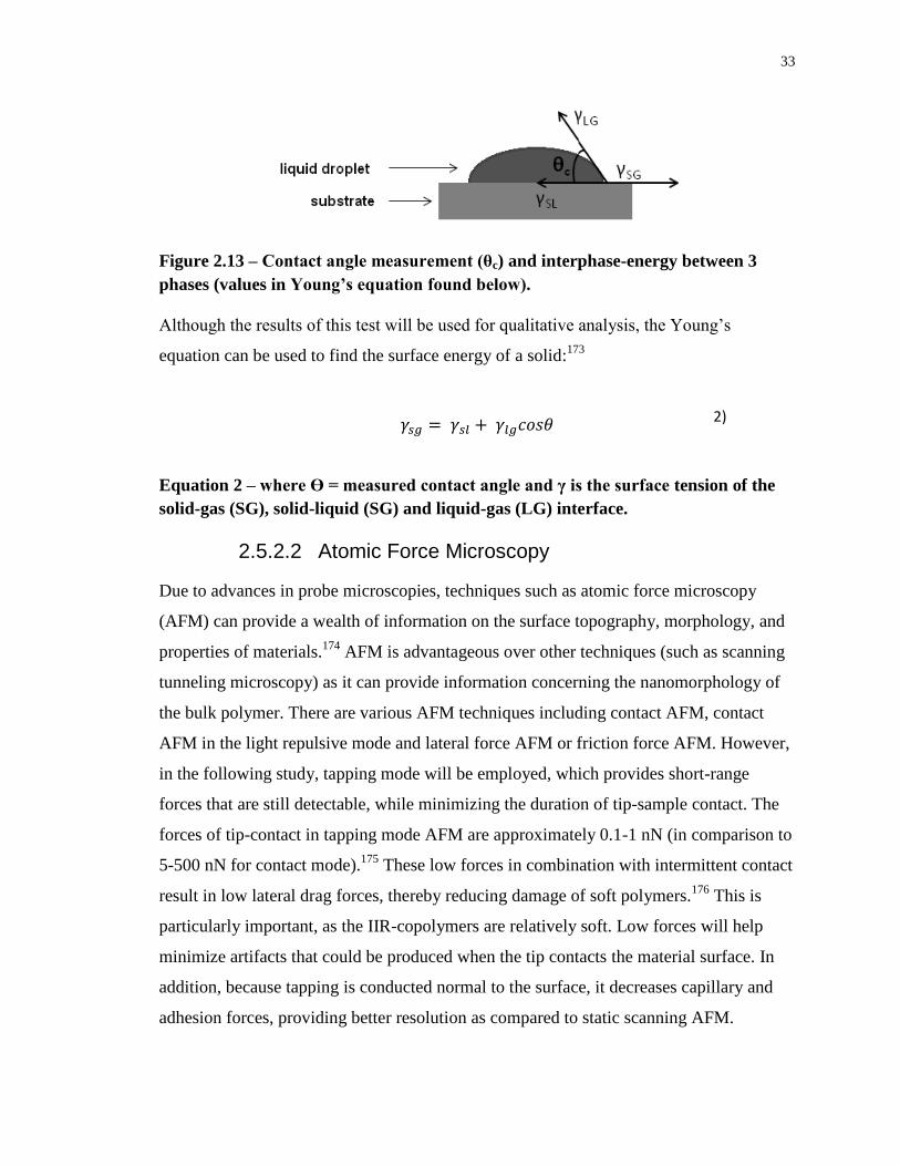
33
Figure 2.13 – Contact angle measurement (θc) and interphase-energy between 3
phases (values in Young’s equation found below).
Although the results of this test will be used for qualitative analysis, the Young’s
equation can be used to find the surface energy of a solid:173
2)
Equation 2 – where ϴ = measured contact angle and γ is the surface tension of the
solid-gas (SG), solid-liquid (SG) and liquid-gas (LG) interface.
2.5.2.2 Atomic Force Microscopy
Due to advances in probe microscopies, techniques such as atomic force microscopy
(AFM) can provide a wealth of information on the surface topography, morphology, and
properties of materials.174
AFM is advantageous over other techniques (such as scanning
tunneling microscopy) as it can provide information concerning the nanomorphology of
the bulk polymer. There are various AFM techniques including contact AFM, contact
AFM in the light repulsive mode and lateral force AFM or friction force AFM. However,
in the following study, tapping mode will be employed, which provides short-range
forces that are still detectable, while minimizing the duration of tip-sample contact. The
forces of tip-contact in tapping mode AFM are approximately 0.1-1 nN (in comparison to
5-500 nN for contact mode).175
These low forces in combination with intermittent contact
result in low lateral drag forces, thereby reducing damage of soft polymers.176
This is
particularly important, as the IIR-copolymers are relatively soft. Low forces will help
minimize artifacts that could be produced when the tip contacts the material surface. In
addition, because tapping is conducted normal to the surface, it decreases capillary and
adhesion forces, providing better resolution as compared to static scanning AFM.
34
Tapping mode is conducted through use of a cantilever and tip (probe). Forces
occur between the cantilever and the surface, which are determined by the resulting
deflection of the cantilever beam. Moreover, a piezoelectric crystal causes the cantilever
to oscillate near its resonance frequency (average of 300 kHz). The amplitude of
oscillation decreases as the cantilever nears the surface, which is a result of energy loss
manifested by Van der Waals and electrostatic forces. It is because of this decrease in
amplitude that the surface features can be measured and identified. However, an
electronic servo must be used in order to maintain the cantilever oscillation amplitude by
means of a feedback mechanism (adjusts the tip-sample separation distance). The
software automatically sets the frequency to maintain the lowest possible level of force
on the sample. In doing so, the oscillation amplitude can be accurately measured by the
detector and input into the controller electronics of the instrument. Both the topographical
and phase images (detections) are produced simultaneously by converting the force of the
tip contacting the surface into an analyzable image. These images can reveal
subnanometer surface chemical resolution due to mechanical differences amongst various
domains.177
To obtain phase information, a phase shift is detected between the driving
and actual tip response oscillation signals. When copolymers or blends are studied via
AFM, one component displays lower surface energy and therefore typically dominates
the top few angstroms of the surface.178
2.5.2.3 Scanning Electron Microscopy
Scanning electron microscopy (SEM) is a commonly used imaging technique for the
determination of surface morphology, three-dimensional (3D) structures, and can also
provide information on chemical composition. The scanning electron microscope utilizes
a focused beam of accelerated electrons, thus generating a variety of signals at the surface
of the test material. Signals that produce the 3D images consist of secondary and
backscattered electrons. Secondary electrons show morphology and topography, while
backscattered electrons show contrasts in composition of multiphase systems. Finally, the
electron beam scans in a raster scan pattern (image capture and reconstruction),
combining the beam’s position with the detected signal to produce the final image.
35
2.5.2.4 Thermal Properties
Differential scanning calorimetry (DSC) is a thermal analysis technique used to measure
heat capacity changes of a given material with respect to temperature for detection of
glass (Tg) and melt transitions (Tm), crystallization, mesomorphic transition temperatures
as well as phase changes and curing/crosslinking. Understanding thermal properties
provides insight relating to the amorphous, semicrystalline or crystalline properties of a
given material. Amorphous materials are those that are completely non-crystalline.
Polymer glasses and rubbers make up the majority of such materials.113
When amorphous
materials are in the solid state, they are considered to be frozen polymer liquids that are
inherently hard and brittle (at low temperatures). However, as the temperature increases
and reaches the Tg, the polymer transforms to a rubbery material, gaining the ability to
flow (non-frozen).179
The glass transition is an important temperature as it dictates
polymer properties. Temperatures lower than Tg result in a dramatic increase in stiffness
relative to higher temperatures, as well as changes to the physical properties (heat
capacity and thermal expansion coefficient) of an amorphous polymer. These physical
properties will vary at temperatures surpassing the Tg. Polymers possess different Tgs,
which are dictated by their chemical structure, molar mass, branching, chain flexibility,
copolymerization and molecular architecture.
Crystalline or semicrystalline polymers possess the ability to crystallize
(thermodynamically favoured to reduce Gibbs free energy, G, or kinetically when cooled
quickly) when cooled below the melting point of the crystalline phase. Many factors
affect the rate and extent of crystallization for a particular polymer such as rate of
cooling, orientation in the melt, specific melt temperature, tacticity, chain branching and
molar mass.180
For crystalline polymers, atoms are covalently bonded into tightly packed,
unidirectional macromolecular arrays. Unit cells are made up of repeating segments of
polymer chains, with several segments of varying complexity in each unit. The polymer
chains lie in one particular direction resulting in relatively weak bonding between the
molecules, resulting in anisotropic physical properties. However, semicrystalline
polymers are of particular importance; melt-crystallized polymers are never completely
crystalline due to a large number of chain entanglements, thereby making it near
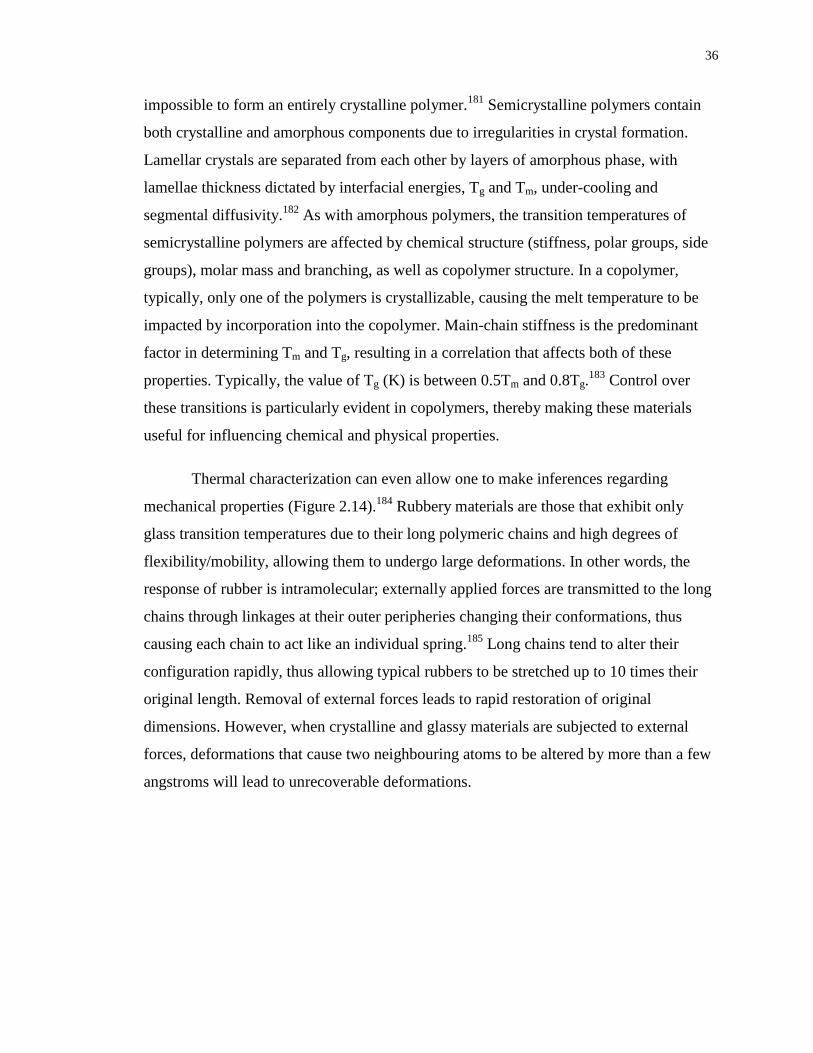
36
impossible to form an entirely crystalline polymer.181
Semicrystalline polymers contain
both crystalline and amorphous components due to irregularities in crystal formation.
Lamellar crystals are separated from each other by layers of amorphous phase, with
lamellae thickness dictated by interfacial energies, Tg and Tm, under-cooling and
segmental diffusivity.182
As with amorphous polymers, the transition temperatures of
semicrystalline polymers are affected by chemical structure (stiffness, polar groups, side
groups), molar mass and branching, as well as copolymer structure. In a copolymer,
typically, only one of the polymers is crystallizable, causing the melt temperature to be
impacted by incorporation into the copolymer. Main-chain stiffness is the predominant
factor in determining Tm and Tg, resulting in a correlation that affects both of these
properties. Typically, the value of Tg (K) is between 0.5Tm and 0.8Tg.183
Control over
these transitions is particularly evident in copolymers, thereby making these materials
useful for influencing chemical and physical properties.
Thermal characterization can even allow one to make inferences regarding
mechanical properties (Figure 2.14).184
Rubbery materials are those that exhibit only
glass transition temperatures due to their long polymeric chains and high degrees of
flexibility/mobility, allowing them to undergo large deformations. In other words, the
response of rubber is intramolecular; externally applied forces are transmitted to the long
chains through linkages at their outer peripheries changing their conformations, thus
causing each chain to act like an individual spring.185
Long chains tend to alter their
configuration rapidly, thus allowing typical rubbers to be stretched up to 10 times their
original length. Removal of external forces leads to rapid restoration of original
dimensions. However, when crystalline and glassy materials are subjected to external
forces, deformations that cause two neighbouring atoms to be altered by more than a few
angstroms will lead to unrecoverable deformations.
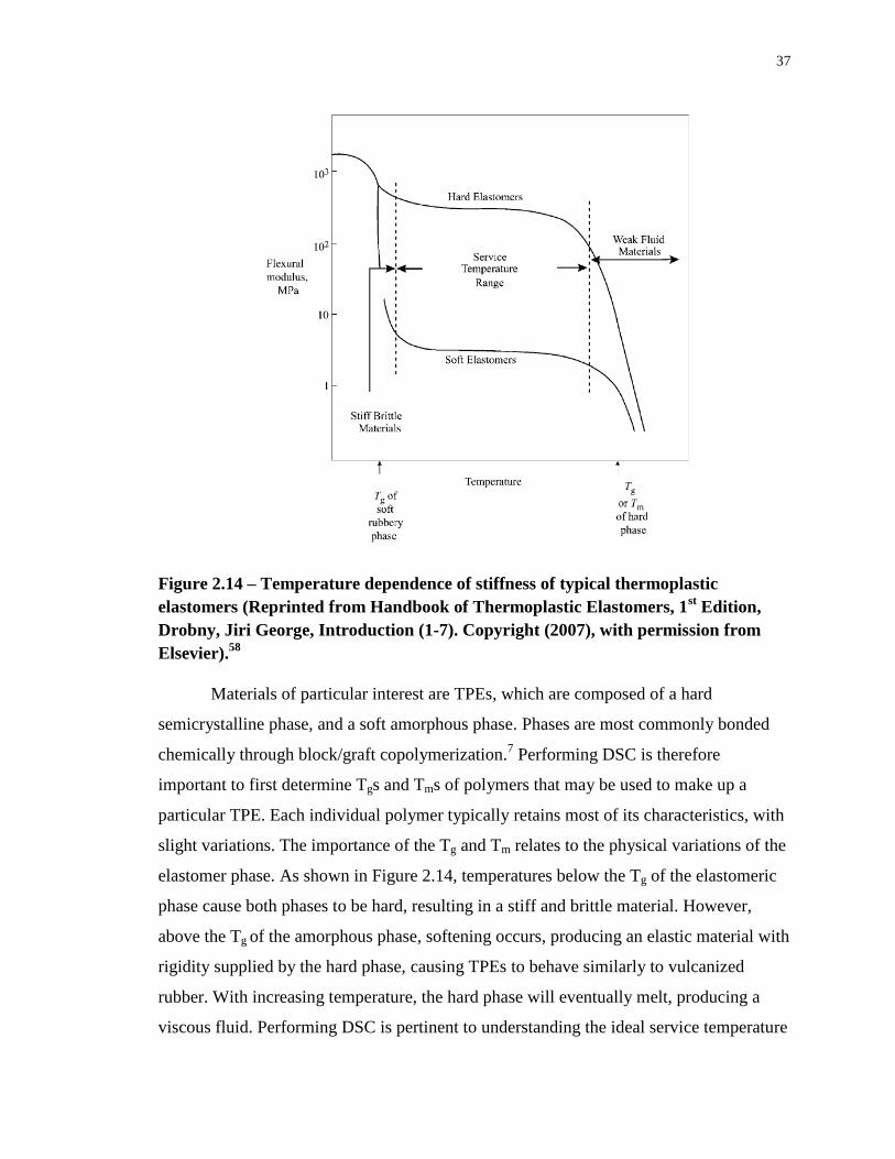
37
Figure 2.14 – Temperature dependence of stiffness of typical thermoplastic
elastomers (Reprinted from Handbook of Thermoplastic Elastomers, 1st Edition,
Drobny, Jiri George, Introduction (1-7). Copyright (2007), with permission from
Elsevier).58
Materials of particular interest are TPEs, which are composed of a hard
semicrystalline phase, and a soft amorphous phase. Phases are most commonly bonded
chemically through block/graft copolymerization.7 Performing DSC is therefore
important to first determine Tgs and Tms of polymers that may be used to make up a
particular TPE. Each individual polymer typically retains most of its characteristics, with
slight variations. The importance of the Tg and Tm relates to the physical variations of the
elastomer phase. As shown in Figure 2.14, temperatures below the Tg of the elastomeric
phase cause both phases to be hard, resulting in a stiff and brittle material. However,
above the Tg of the amorphous phase, softening occurs, producing an elastic material with
rigidity supplied by the hard phase, causing TPEs to behave similarly to vulcanized
rubber. With increasing temperature, the hard phase will eventually melt, producing a
viscous fluid. Performing DSC is pertinent to understanding the ideal service temperature
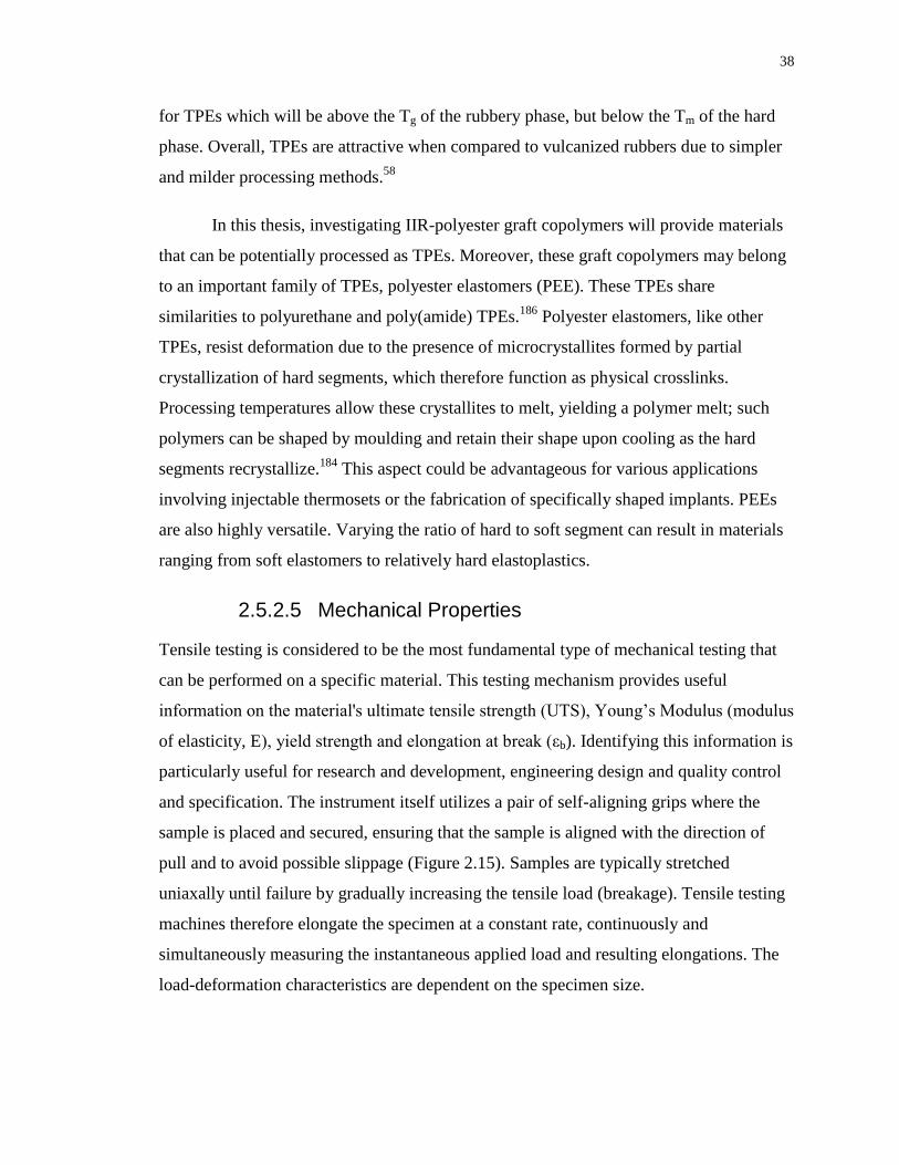
38
for TPEs which will be above the Tg of the rubbery phase, but below the Tm of the hard
phase. Overall, TPEs are attractive when compared to vulcanized rubbers due to simpler
and milder processing methods.58
In this thesis, investigating IIR-polyester graft copolymers will provide materials
that can be potentially processed as TPEs. Moreover, these graft copolymers may belong
to an important family of TPEs, polyester elastomers (PEE). These TPEs share
similarities to polyurethane and poly(amide) TPEs.186
Polyester elastomers, like other
TPEs, resist deformation due to the presence of microcrystallites formed by partial
crystallization of hard segments, which therefore function as physical crosslinks.
Processing temperatures allow these crystallites to melt, yielding a polymer melt; such
polymers can be shaped by moulding and retain their shape upon cooling as the hard
segments recrystallize.184
This aspect could be advantageous for various applications
involving injectable thermosets or the fabrication of specifically shaped implants. PEEs
are also highly versatile. Varying the ratio of hard to soft segment can result in materials
ranging from soft elastomers to relatively hard elastoplastics.
2.5.2.5 Mechanical Properties
Tensile testing is considered to be the most fundamental type of mechanical testing that
can be performed on a specific material. This testing mechanism provides useful
information on the material's ultimate tensile strength (UTS), Young’s Modulus (modulus
of elasticity, E), yield strength and elongation at break (εb). Identifying this information is
particularly useful for research and development, engineering design and quality control
and specification. The instrument itself utilizes a pair of self-aligning grips where the
sample is placed and secured, ensuring that the sample is aligned with the direction of
pull and to avoid possible slippage (Figure 2.15). Samples are typically stretched
uniaxally until failure by gradually increasing the tensile load (breakage). Tensile testing
machines therefore elongate the specimen at a constant rate, continuously and
simultaneously measuring the instantaneous applied load and resulting elongations. The
load-deformation characteristics are dependent on the specimen size.
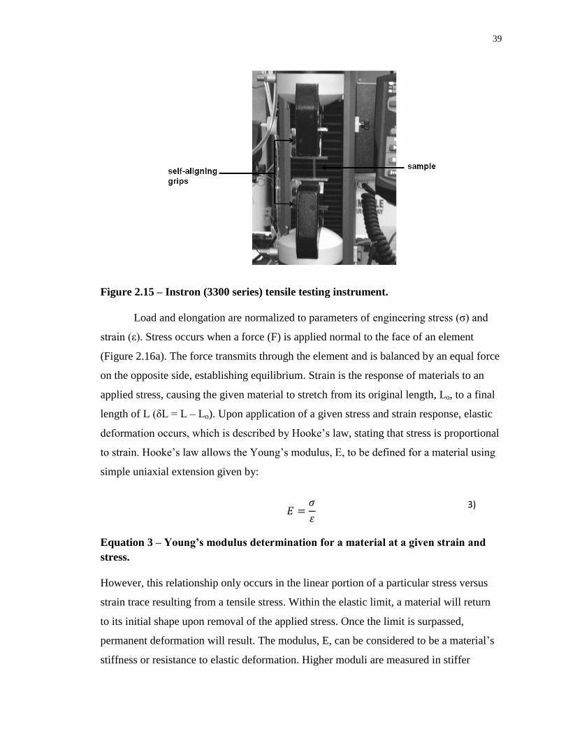
39
Figure 2.15 – Instron (3300 series) tensile testing instrument.
Load and elongation are normalized to parameters of engineering stress (σ) and
strain (ε). Stress occurs when a force (F) is applied normal to the face of an element
(Figure 2.16a). The force transmits through the element and is balanced by an equal force
on the opposite side, establishing equilibrium. Strain is the response of materials to an
applied stress, causing the given material to stretch from its original length, Lo, to a final
length of L (δL = L – Lo). Upon application of a given stress and strain response, elastic
deformation occurs, which is described by Hooke’s law, stating that stress is proportional
to strain. Hooke’s law allows the Young’s modulus, E, to be defined for a material using
simple uniaxial extension given by:
3)
Equation 3 – Young’s modulus determination for a material at a given strain and
stress.
However, this relationship only occurs in the linear portion of a particular stress versus
strain trace resulting from a tensile stress. Within the elastic limit, a material will return
to its initial shape upon removal of the applied stress. Once the limit is surpassed,
permanent deformation will result. The modulus, E, can be considered to be a material’s
stiffness or resistance to elastic deformation. Higher moduli are measured in stiffer
40
materials.187
Certain materials, particularly polymers, do not obey Hooke’s law. When a
uniaxial stress is applied, although there is stretching and elongation in the direction of
the stress, this elongation causes constrictions (strains) to occur in the lateral directions
(εt), perpendicular to the applied stress. In addition to axial stress, there exists stress
parallel to the face of an object resulting in shear strain (Figure 2.16b) as well as equal
tensile/compressive forces to all six faces of a cubic element, resulting in hydrostatic
pressure stress (volume strain, or dilatation, Figure 2.16c). Therefore, as with E, there are
the shear modulus (G) and the bulk modulus (K), showing linearity between shear stress
and shear strain and hydrostatic pressure and dilatation, respectively:
4)
Equation 4 – Linear relationship relating the shear strain, γ to the shear stress, τ.
5)
Equation 5 – Linear relationship showing proportionality between the dilatation, Δ
and pressure, p.
If the material behaves isotropically (strains are equal in lateral directions), a parameter
termed the Poisson’s ratio is defined as the ratio of lateral and axial strains:
6)
Equation 6 – Definition of Poisson’s ratio where εt is the transverse strain and ε is
the axial strain.
When an element is stretched axially in one direction, the element contracts in the lateral
or transverse directions, resulting in a positive value for Poisson’s ratio, typically in the
range between 0.25 and 0.35 (for most materials).188
Therefore the definition of Poisson’s
ratio (Equation 6) successfully relates all three moduli (E, G and K) to one another for an
isotropic material as:

41
;
7)
Equation 7 – Relation between Young’s modulus (E), shear modulus (G) and bulk
modulus (K).
Figure 2.16 – Definitions of uniaxial stress, strain and elastic deformation.
(Reprinted from Nanomaterials, Nanotechnologies and Design: An Introduction for
Engineers and Architects, 1st Edition, Ashby, Michael F., Chapter 4 – Material
Classes, Structure and properties. Copyright (2009), with permission from
Elsevier).189
As shown in Figure 2.17, yield properties/ductility is measured using tensile tests
by taking the material to failure. The yield strength, σy, depicts the stress at which the
stress-strain curve (in the linear elastic regime) for axial loading deviates by a strain of
1% (for polymers). However, the behaviour beyond yield depends on the temperature
relative to the polymer’s characteristic Tg. Below the Tg, most polymers are brittle and
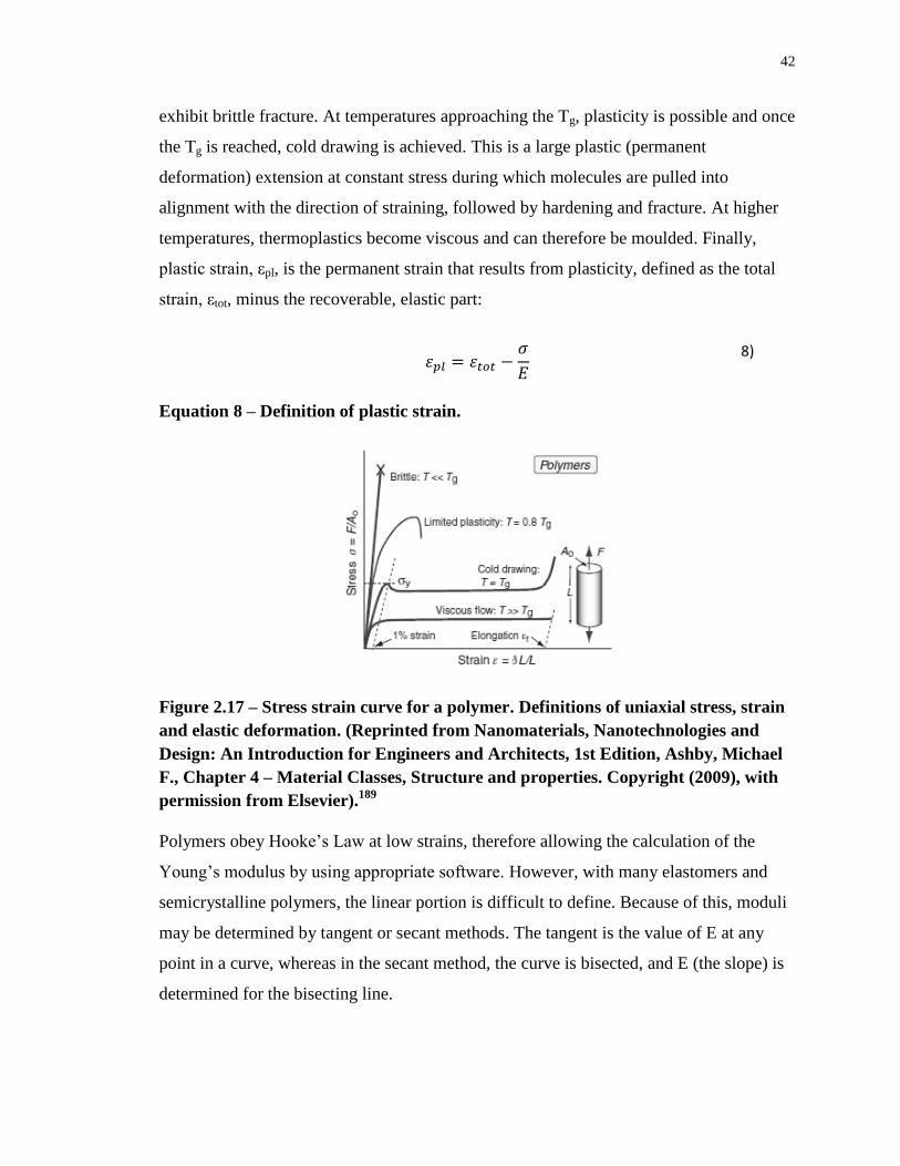
42
exhibit brittle fracture. At temperatures approaching the Tg, plasticity is possible and once
the Tg is reached, cold drawing is achieved. This is a large plastic (permanent
deformation) extension at constant stress during which molecules are pulled into
alignment with the direction of straining, followed by hardening and fracture. At higher
temperatures, thermoplastics become viscous and can therefore be moulded. Finally,
plastic strain, εpl, is the permanent strain that results from plasticity, defined as the total
strain, εtot, minus the recoverable, elastic part:
8)
Equation 8 – Definition of plastic strain.
Figure 2.17 – Stress strain curve for a polymer. Definitions of uniaxial stress, strain
and elastic deformation. (Reprinted from Nanomaterials, Nanotechnologies and
Design: An Introduction for Engineers and Architects, 1st Edition, Ashby, Michael
F., Chapter 4 – Material Classes, Structure and properties. Copyright (2009), with
permission from Elsevier).189
Polymers obey Hooke’s Law at low strains, therefore allowing the calculation of the
Young’s modulus by using appropriate software. However, with many elastomers and
semicrystalline polymers, the linear portion is difficult to define. Because of this, moduli
may be determined by tangent or secant methods. The tangent is the value of E at any
point in a curve, whereas in the secant method, the curve is bisected, and E (the slope) is
determined for the bisecting line.
43
Elastomers typically have very low Young’s moduli, in the approximate range of
0.5-1 MPa, whereas semicrystalline polymers exhibit higher values for E and UTS.
Figure 2.18a shows the broad range of moduli for a variety of material classes with large
differences in density. Polymers and elastomers possess densities lower than metals or
ceramics, as well as moduli below 10 GPa (elastomers specifically in the range of 1-10
MPa). Figure 2.18b depicts the yield strain of various materials. The yield strain (σy/E) is
the strain at which a material deviates from the elastic linear regime. It is important to
note that elastomers, due to their extremely low moduli, display yield strains in the range
of 1 to 10, the highest of all materials. This is important as a larger yield strain
corresponds to greater resistance to brittle fracture, which is important for various
biomedical applications.
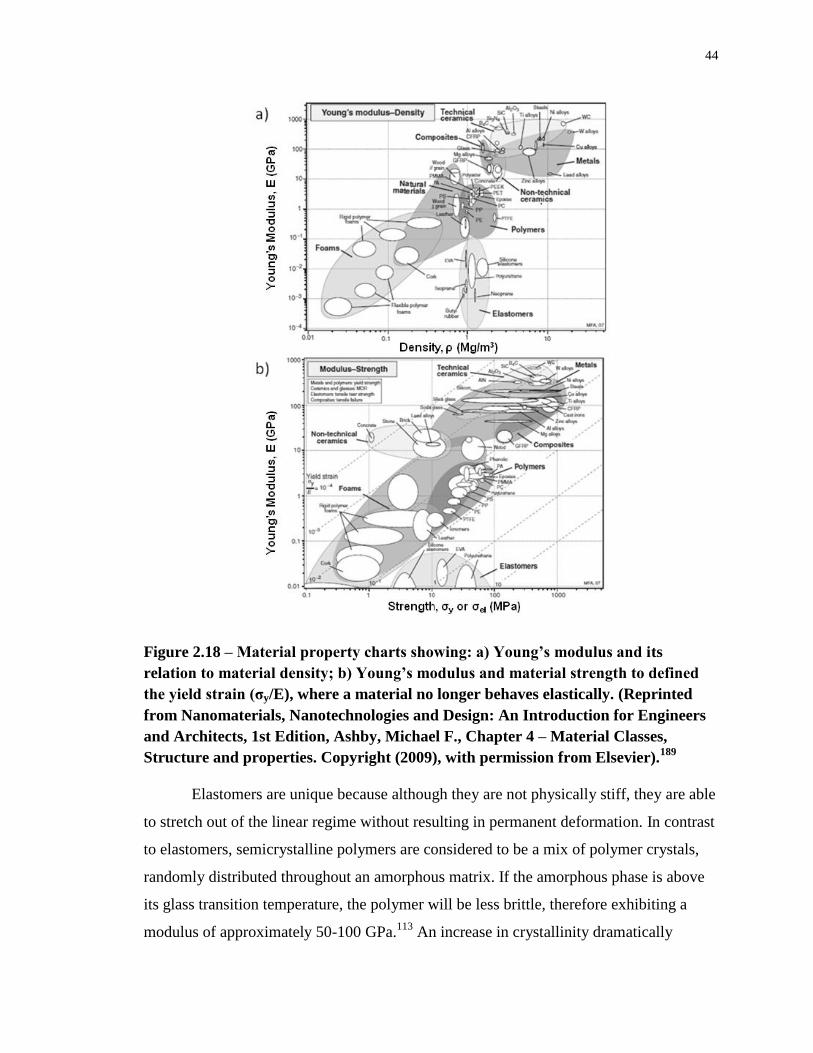
44
Figure 2.18 – Material property charts showing: a) Young’s modulus and its
relation to material density; b) Young’s modulus and material strength to defined
the yield strain (σy/E), where a material no longer behaves elastically. (Reprinted
from Nanomaterials, Nanotechnologies and Design: An Introduction for Engineers
and Architects, 1st Edition, Ashby, Michael F., Chapter 4 – Material Classes,
Structure and properties. Copyright (2009), with permission from Elsevier).189
Elastomers are unique because although they are not physically stiff, they are able
to stretch out of the linear regime without resulting in permanent deformation. In contrast
to elastomers, semicrystalline polymers are considered to be a mix of polymer crystals,
randomly distributed throughout an amorphous matrix. If the amorphous phase is above
its glass transition temperature, the polymer will be less brittle, therefore exhibiting a
modulus of approximately 50-100 GPa.113
An increase in crystallinity dramatically
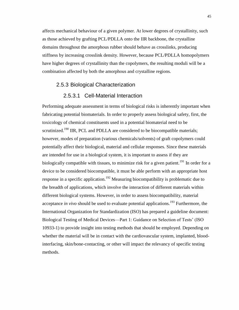
45
affects mechanical behaviour of a given polymer. At lower degrees of crystallinity, such
as those achieved by grafting PCL/PDLLA onto the IIR backbone, the crystalline
domains throughout the amorphous rubber should behave as crosslinks, producing
stiffness by increasing crosslink density. However, because PCL/PDLLA homopolymers
have higher degrees of crystallinity than the copolymers, the resulting moduli will be a
combination affected by both the amorphous and crystalline regions.
2.5.3 Biological Characterization
2.5.3.1 Cell-Material Interaction
Performing adequate assessment in terms of biological risks is inherently important when
fabricating potential biomaterials. In order to properly assess biological safety, first, the
toxicology of chemical constituents used in a potential biomaterial need to be
scrutinized.190
IIR, PCL and PDLLA are considered to be biocompatible materials;
however, modes of preparation (various chemicals/solvents) of graft copolymers could
potentially affect their biological, material and cellular responses. Since these materials
are intended for use in a biological system, it is important to assess if they are
biologically compatible with tissues, to minimize risk for a given patient.191
In order for a
device to be considered biocompatible, it must be able perform with an appropriate host
response in a specific application.192
Measuring biocompatibility is problematic due to
the breadth of applications, which involve the interaction of different materials within
different biological systems. However, in order to assess biocompatibility, material
acceptance in vivo should be used to evaluate potential applications.193
Furthermore, the
International Organization for Standardization (ISO) has prepared a guideline document:
Biological Testing of Medical Devices—Part 1: Guidance on Selection of Tests’ (ISO
10933-1) to provide insight into testing methods that should be employed. Depending on
whether the material will be in contact with the cardiovascular system, implanted, blood-
interfacing, skin/bone-contacting, or other will impact the relevancy of specific testing
methods.
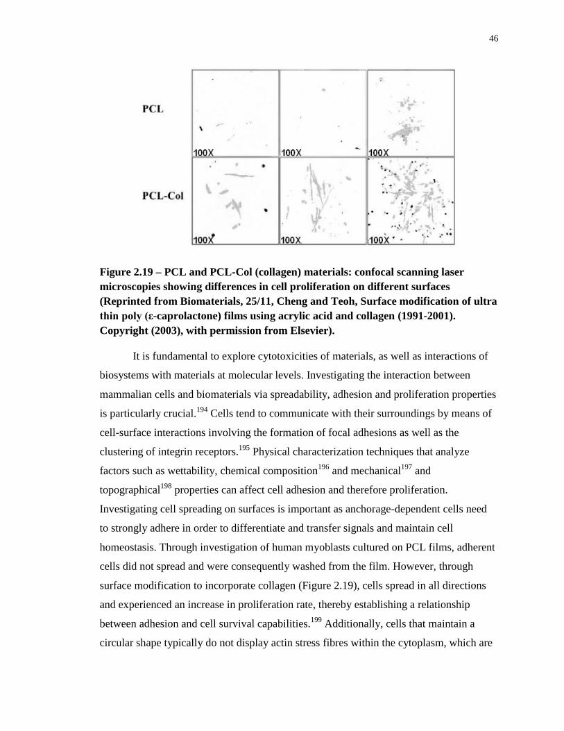
46
Figure 2.19 – PCL and PCL-Col (collagen) materials: confocal scanning laser
microscopies showing differences in cell proliferation on different surfaces
(Reprinted from Biomaterials, 25/11, Cheng and Teoh, Surface modification of ultra
thin poly (ε-caprolactone) films using acrylic acid and collagen (1991-2001).
Copyright (2003), with permission from Elsevier).
It is fundamental to explore cytotoxicities of materials, as well as interactions of
biosystems with materials at molecular levels. Investigating the interaction between
mammalian cells and biomaterials via spreadability, adhesion and proliferation properties
is particularly crucial.194
Cells tend to communicate with their surroundings by means of
cell-surface interactions involving the formation of focal adhesions as well as the
clustering of integrin receptors.195
Physical characterization techniques that analyze
factors such as wettability, chemical composition196
and mechanical197
and
topographical198
properties can affect cell adhesion and therefore proliferation.
Investigating cell spreading on surfaces is important as anchorage-dependent cells need
to strongly adhere in order to differentiate and transfer signals and maintain cell
homeostasis. Through investigation of human myoblasts cultured on PCL films, adherent
cells did not spread and were consequently washed from the film. However, through
surface modification to incorporate collagen (Figure 2.19), cells spread in all directions
and experienced an increase in proliferation rate, thereby establishing a relationship
between adhesion and cell survival capabilities.199
Additionally, cells that maintain a
circular shape typically do not display actin stress fibres within the cytoplasm, which are
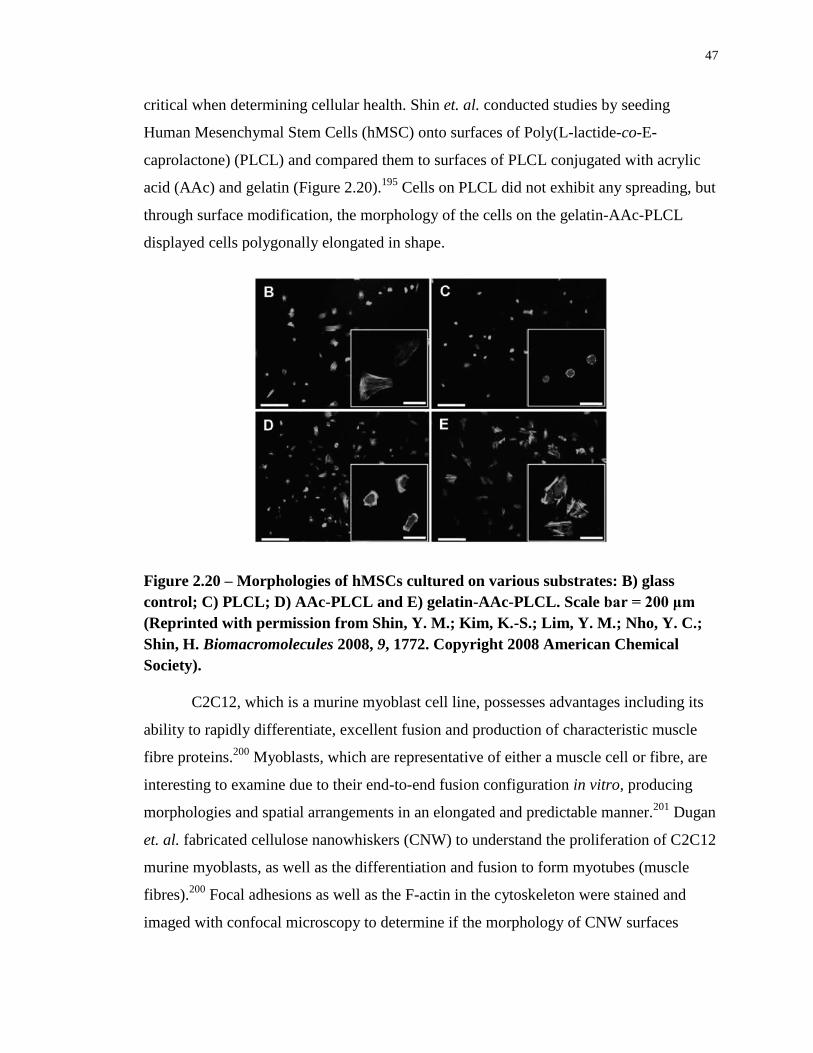
47
critical when determining cellular health. Shin et. al. conducted studies by seeding
Human Mesenchymal Stem Cells (hMSC) onto surfaces of Poly(L-lactide-co-E-
caprolactone) (PLCL) and compared them to surfaces of PLCL conjugated with acrylic
acid (AAc) and gelatin (Figure 2.20).195
Cells on PLCL did not exhibit any spreading, but
through surface modification, the morphology of the cells on the gelatin-AAc-PLCL
displayed cells polygonally elongated in shape.
Figure 2.20 – Morphologies of hMSCs cultured on various substrates: B) glass
control; C) PLCL; D) AAc-PLCL and E) gelatin-AAc-PLCL. Scale bar = 200 μm
(Reprinted with permission from Shin, Y. M.; Kim, K.-S.; Lim, Y. M.; Nho, Y. C.;
Shin, H. Biomacromolecules 2008, 9, 1772. Copyright 2008 American Chemical
Society).
C2C12, which is a murine myoblast cell line, possesses advantages including its
ability to rapidly differentiate, excellent fusion and production of characteristic muscle
fibre proteins.200
Myoblasts, which are representative of either a muscle cell or fibre, are
interesting to examine due to their end-to-end fusion configuration in vitro, producing
morphologies and spatial arrangements in an elongated and predictable manner.201
Dugan
et. al. fabricated cellulose nanowhiskers (CNW) to understand the proliferation of C2C12
murine myoblasts, as well as the differentiation and fusion to form myotubes (muscle
fibres).200
Focal adhesions as well as the F-actin in the cytoskeleton were stained and
imaged with confocal microscopy to determine if the morphology of CNW surfaces
48
affected cellular growth and attachment (Figure 2.21). The top line images show
differences in morphology in that myoblasts on the glass coverslip were less spread when
compared to CNWs (prepared at 500 and 6000 rpm); CNWs also exhibited vinculin (light
specks), indicating adhesivity to surfaces. Morphology differences were attributed to
surface roughness; roughness of various materials can affect cellular growth response.202
Although stress fibres appeared on all surfaces, variations in focal adhesion orientation
became apparent after 12 hours of incubation.
Figure 2.21 – (a-f) Myoblasts stained for vinculin (light speckles), F-actin (outer
periphery) and nuclei, scale bar = 50 μm. (a) 4 h after seeding on glass coverslip
control, (b) 4 h after seeding on C500 surface, (c) 4 h after seeding on C6000 surface,
(d) 12 h after seeding on glass coverslip control, (e) 12 h after seeding on C500
surface, and (f) 12 h after seeding on C6000 surface (Reprinted with permission
from Dugan, J. M.; Gough, J. E.; Eichhorn, S. J. Biomacromolecules 2010, 11, 2498,
Copyright 2010 American Chemical Society).
Finally, protein adsorption is a spontaneous occurrence with a high level of
importance in biomaterials and biomedical science.203
Although biofouling is
nondesirable, the adsorption of cell-adhesive proteins (such as vinculin and F-actin) may
be needed to some extent depending on the intended application. This adsorption can be
controlled in various ways such as modifying surfaces with polymer brushes (polymer
chains attached to a surface),204,205
resulting in stimuli-responsive signals such as
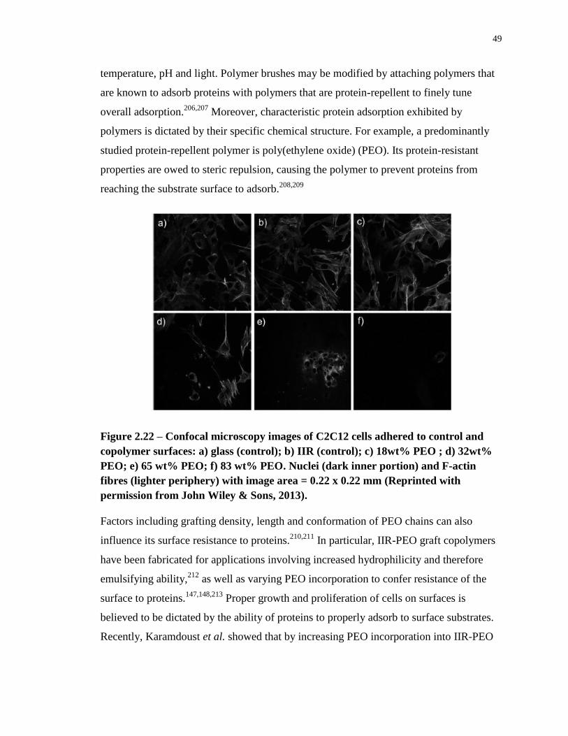
49
temperature, pH and light. Polymer brushes may be modified by attaching polymers that
are known to adsorb proteins with polymers that are protein-repellent to finely tune
overall adsorption.206,207
Moreover, characteristic protein adsorption exhibited by
polymers is dictated by their specific chemical structure. For example, a predominantly
studied protein-repellent polymer is poly(ethylene oxide) (PEO). Its protein-resistant
properties are owed to steric repulsion, causing the polymer to prevent proteins from
reaching the substrate surface to adsorb.208,209
Figure 2.22 – Confocal microscopy images of C2C12 cells adhered to control and
copolymer surfaces: a) glass (control); b) IIR (control); c) 18wt% PEO ; d) 32wt%
PEO; e) 65 wt% PEO; f) 83 wt% PEO. Nuclei (dark inner portion) and F-actin
fibres (lighter periphery) with image area = 0.22 x 0.22 mm (Reprinted with
permission from John Wiley & Sons, 2013).
Factors including grafting density, length and conformation of PEO chains can also
influence its surface resistance to proteins.210,211
In particular, IIR-PEO graft copolymers
have been fabricated for applications involving increased hydrophilicity and therefore
emulsifying ability,212
as well as varying PEO incorporation to confer resistance of the
surface to proteins.147,148,213
Proper growth and proliferation of cells on surfaces is
believed to be dictated by the ability of proteins to properly adsorb to surface substrates.
Recently, Karamdoust et al. showed that by increasing PEO incorporation into IIR-PEO

50
graft copolymers, reaching a critical PEO content (34 wt%, Figure 2.22d) caused a
dramatic decrease in protein adsorption, evidenced by a decrease in cell adhesion.214
51
2.6 Thesis Objectives
The goal of this thesis is to synthesize IIR-polyester graft copolymers and to study their
chemical, physical, mechanical and biological properties in order to gauge their potential
as biomaterials. An advantage of this approach is that rather than using chemical
crosslinking methods that are incompatible with biomedical applications, the thermal and
mechanical properties of the polyester components may impart enhanced strength to IIR
and other properties that are desirable for specific applications. In addition, the slow but
eventual degradability of the polyester component may assist in the gradual
environmental degradation of IIR materials, which are otherwise broken down only
extremely slowly in nature.
The interest in IIR-polyester graft copolymers as potential biomaterials stems
from the widespread interest in IIR for various biomedical applications. For example,
current bone cement applications involve usage of poly(methyl methacrylate), which is
inherently brittle.139,140
To overcome this issue, toughening of bone cements can be
accomplished with IIR-graft copolymer synthesis to impart impact- and fatigue-resistance
properties. Similarly, PIB-CA materials are intended for intervertebral disc replacement,
however, enzymatic attack on CA moieties causes the release of toxic byproducts. PURs
are employed for usage in vascular grafts due to their elastomeric nature, but chemical
and mechanical deficiencies led to inflammatory (and therefore occlusion) and crack
manifestation, respectively.118
Therefore, incorporation of bioresorbable and biodegradable polyesters may
eliminate issues associated with toxicity as well as the resistance of synthetic polymers to
degradation for time-limited applications, including sutures and bone fixation
devices.57,215
Utilization of stable polymers can lead to undesirable inflammatory
responses, as biological systems recognize them as foreign substances. However,
degradable polymers offer advantages for therapeutic applications, specifically in
medicine, surgery or drug delivery.9 For time-limited applications involving degradation,
bioresorbability is important as it describes materials with non-toxic byproducts that can
be eliminated from the body through metabolic pathways.76
52
In order to synthesize the IIR-polyester graft copolymers, the aim will be the
development of a simple synthetic method. This will make the final materials more
attractive on an industrial as well as biomedical level. The exploration of both "grafting
from" and "grafting to" methods will be described. Using the more successful "grafting
to" strategy, a small library of graft copolymers is produced to provide insight concerning
how varying weight percentages of polyester with respect to IIR affect chemical and
physical properties. These are characterized chemically by a variety of techniques
including NMR and IR spectroscopy, and SEC.
From differences in the chemical compositions of the materials, it is demonstrated
that differences in physical properties arise. These are assessed and compared using
techniques such as AFM, SEM, water contact measurements, and DSC. Tensile testing is
used to elucidate changes in the mechanical properties of the materials as a function of
their composition and degradation studies are performed to investigate their
degradabilities. Lastly, although the literature suggests that IIR,216
PCL82
and PDLLA88
are all biocompatible materials, the toxicities and cell adhering/proliferation properties of
the new graft copolymers are studied in this thesis. Combined, this data set provides a
basis of important information concerning the properties of these materials for further use
in specific applications.
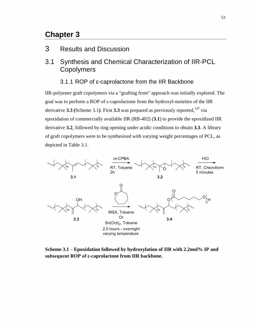
53
Chapter 3
3 Results and Discussion
3.1 Synthesis and Chemical Characterization of IIR-PCL Copolymers
3.1.1 ROP of ε-caprolactone from the IIR Backbone
IIR-polyester graft copolymers via a "grafting from" approach was initially explored. The
goal was to perform a ROP of ε-caprolactone from the hydroxyl-moieties of the IIR
derivative 3.3 (Scheme 3.1). First 3.3 was prepared as previously reported,147
via
epoxidation of commercially available IIR (RB-402) (3.1) to provide the epoxidized IIR
derivative 3.2, followed by ring opening under acidic conditions to obtain 3.3. A library
of graft copolymers were to be synthesized with varying weight percentages of PCL, as
depicted in Table 3.1.
Scheme 3.1 – Epoxidation followed by hydroxylation of IIR with 2.2mol% IP and
subsequent ROP of ε-caprolactone from IIR backbone.
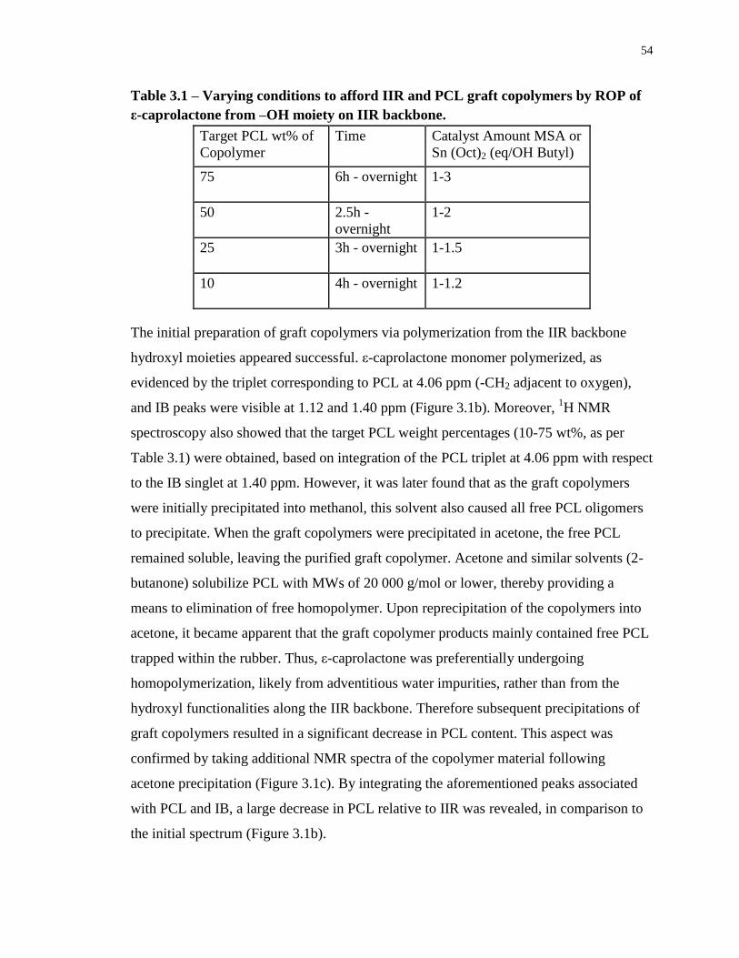
54
Table 3.1 – Varying conditions to afford IIR and PCL graft copolymers by ROP of
ε-caprolactone from –OH moiety on IIR backbone.
Target PCL wt% of
Copolymer
Time Catalyst Amount MSA or
Sn (Oct)2 (eq/OH Butyl)
75 6h - overnight 1-3
50 2.5h -
overnight
1-2
25 3h - overnight 1-1.5
10 4h - overnight 1-1.2
The initial preparation of graft copolymers via polymerization from the IIR backbone
hydroxyl moieties appeared successful. ε-caprolactone monomer polymerized, as
evidenced by the triplet corresponding to PCL at 4.06 ppm (-CH2 adjacent to oxygen),
and IB peaks were visible at 1.12 and 1.40 ppm (Figure 3.1b). Moreover, 1H NMR
spectroscopy also showed that the target PCL weight percentages (10-75 wt%, as per
Table 3.1) were obtained, based on integration of the PCL triplet at 4.06 ppm with respect
to the IB singlet at 1.40 ppm. However, it was later found that as the graft copolymers
were initially precipitated into methanol, this solvent also caused all free PCL oligomers
to precipitate. When the graft copolymers were precipitated in acetone, the free PCL
remained soluble, leaving the purified graft copolymer. Acetone and similar solvents (2-
butanone) solubilize PCL with MWs of 20 000 g/mol or lower, thereby providing a
means to elimination of free homopolymer. Upon reprecipitation of the copolymers into
acetone, it became apparent that the graft copolymer products mainly contained free PCL
trapped within the rubber. Thus, ε-caprolactone was preferentially undergoing
homopolymerization, likely from adventitious water impurities, rather than from the
hydroxyl functionalities along the IIR backbone. Therefore subsequent precipitations of
graft copolymers resulted in a significant decrease in PCL content. This aspect was
confirmed by taking additional NMR spectra of the copolymer material following
acetone precipitation (Figure 3.1c). By integrating the aforementioned peaks associated
with PCL and IB, a large decrease in PCL relative to IIR was revealed, in comparison to
the initial spectrum (Figure 3.1b).
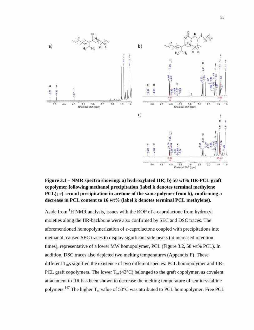
55
Figure 3.1 – NMR spectra showing: a) hydroxylated IIR; b) 50 wt% IIR-PCL graft
copolymer following methanol precipitation (label k denotes terminal methylene
PCL); c) second precipitation in acetone of the same polymer from b), confirming a
decrease in PCL content to 16 wt% (label k denotes terminal PCL methylene).
Aside from 1H NMR analysis, issues with the ROP of ε-caprolactone from hydroxyl
moieties along the IIR-backbone were also confirmed by SEC and DSC traces. The
aforementioned homopolymerization of ε-caprolactone coupled with precipitations into
methanol, caused SEC traces to display significant side peaks (at increased retention
times), representative of a lower MW homopolymer, PCL (Figure 3.2, 50 wt% PCL). In
addition, DSC traces also depicted two melting temperatures (Appendix F). These
different Tms signified the existence of two different species: PCL homopolymer and IIR-
PCL graft copolymers. The lower Tm (43°C) belonged to the graft copolymer, as covalent
attachment to IIR has been shown to decrease the melting temperature of semicrystalline
polymers.147
The higher Tm value of 53°C was attributed to PCL homopolymer. Free PCL
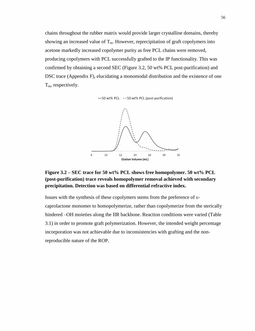
56
chains throughout the rubber matrix would provide larger crystalline domains, thereby
showing an increased value of Tm. However, reprecipitation of graft copolymers into
acetone markedly increased copolymer purity as free PCL chains were removed,
producing copolymers with PCL successfully grafted to the IP functionality. This was
confirmed by obtaining a second SEC (Figure 3.2, 50 wt% PCL post-purification) and
DSC trace (Appendix F), elucidating a monomodal distribution and the existence of one
Tm, respectively.
Figure 3.2 – SEC trace for 50 wt% PCL shows free homopolymer. 50 wt% PCL
(post-purification) trace reveals homopolymer removal achieved with secondary
precipitation. Detection was based on differential refractive index.
Issues with the synthesis of these copolymers stems from the preference of ε-
caprolactone monomer to homopolymerize, rather than copolymerize from the sterically
hindered –OH moieties along the IIR backbone. Reaction conditions were varied (Table
3.1) in order to promote graft polymerization. However, the intended weight percentage
incorporation was not achievable due to inconsistencies with grafting and the non-
reproducible nature of the ROP.
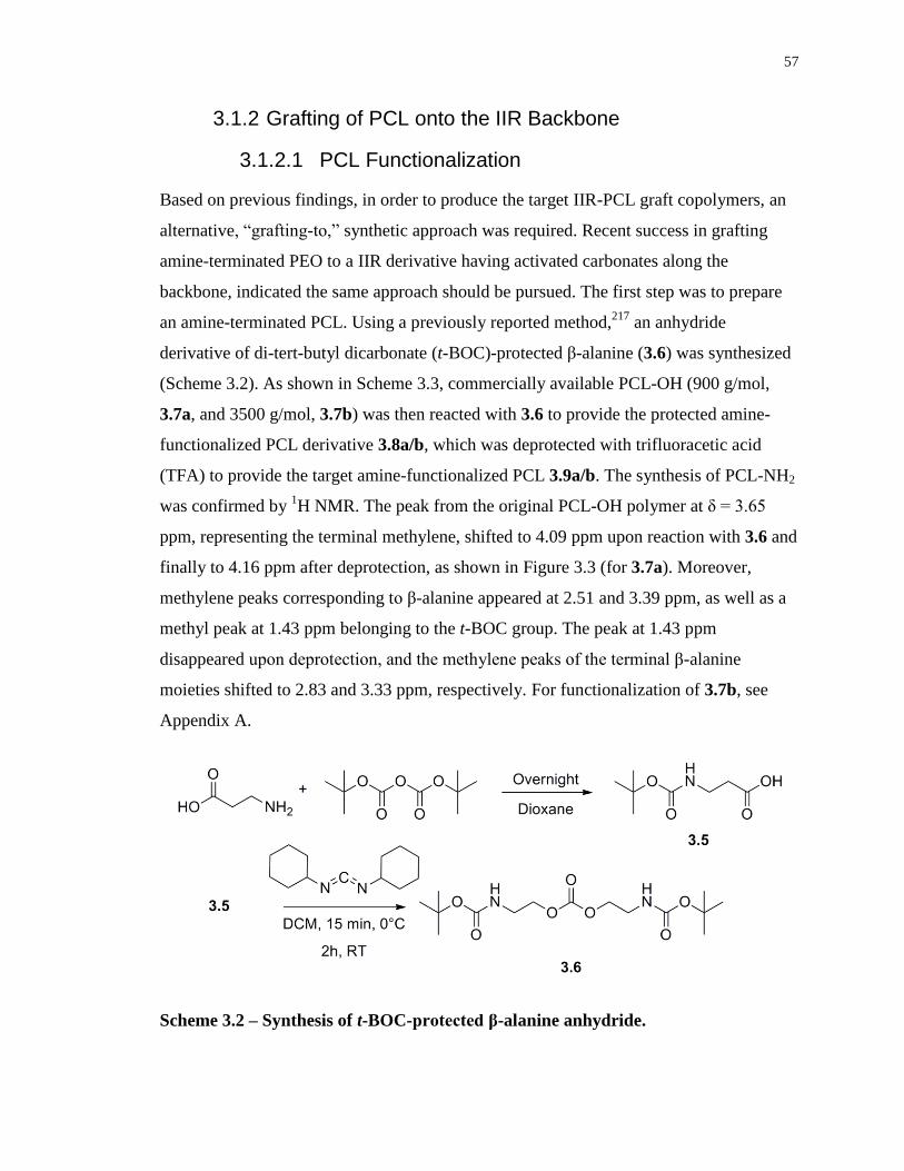
57
3.1.2 Grafting of PCL onto the IIR Backbone
3.1.2.1 PCL Functionalization
Based on previous findings, in order to produce the target IIR-PCL graft copolymers, an
alternative, “grafting-to,” synthetic approach was required. Recent success in grafting
amine-terminated PEO to a IIR derivative having activated carbonates along the
backbone, indicated the same approach should be pursued. The first step was to prepare
an amine-terminated PCL. Using a previously reported method,217
an anhydride
derivative of di-tert-butyl dicarbonate (t-BOC)-protected β-alanine (3.6) was synthesized
(Scheme 3.2). As shown in Scheme 3.3, commercially available PCL-OH (900 g/mol,
3.7a, and 3500 g/mol, 3.7b) was then reacted with 3.6 to provide the protected amine-
functionalized PCL derivative 3.8a/b, which was deprotected with trifluoracetic acid
(TFA) to provide the target amine-functionalized PCL 3.9a/b. The synthesis of PCL-NH2
was confirmed by 1H NMR. The peak from the original PCL-OH polymer at δ = 3.65
ppm, representing the terminal methylene, shifted to 4.09 ppm upon reaction with 3.6 and
finally to 4.16 ppm after deprotection, as shown in Figure 3.3 (for 3.7a). Moreover,
methylene peaks corresponding to β-alanine appeared at 2.51 and 3.39 ppm, as well as a
methyl peak at 1.43 ppm belonging to the t-BOC group. The peak at 1.43 ppm
disappeared upon deprotection, and the methylene peaks of the terminal β-alanine
moieties shifted to 2.83 and 3.33 ppm, respectively. For functionalization of 3.7b, see
Appendix A.
Scheme 3.2 – Synthesis of t-BOC-protected β-alanine anhydride.
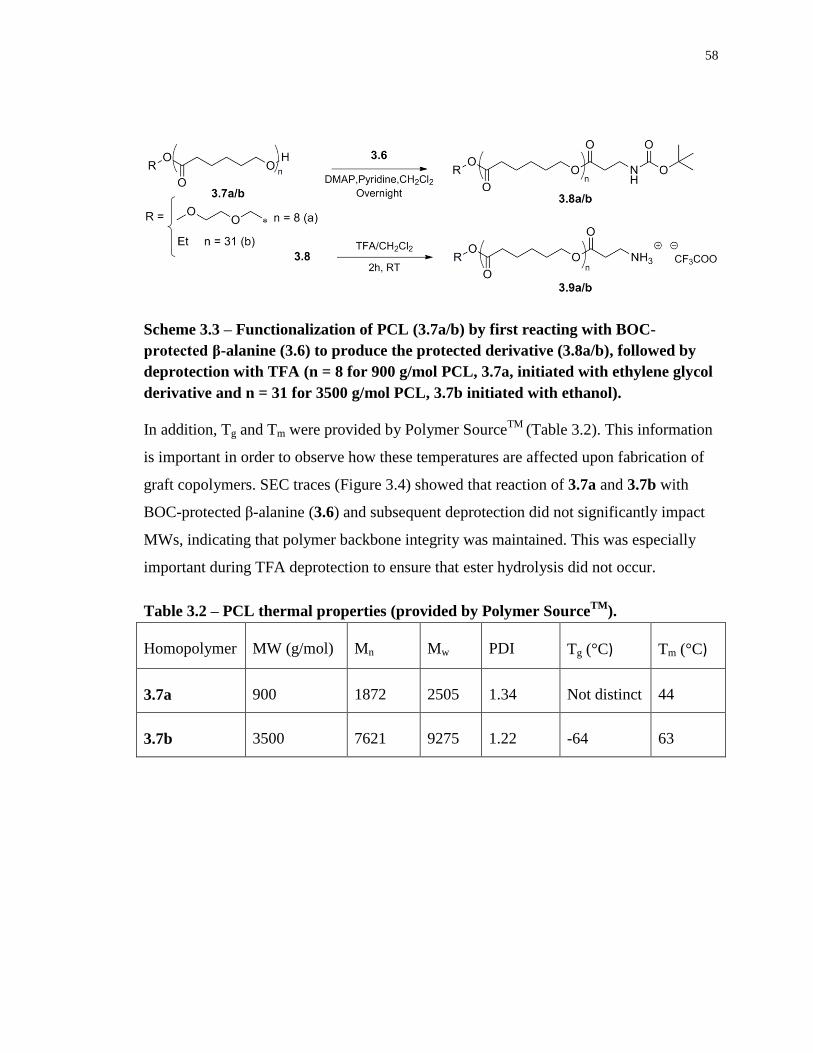
58
Scheme 3.3 – Functionalization of PCL (3.7a/b) by first reacting with BOC-
protected β-alanine (3.6) to produce the protected derivative (3.8a/b), followed by
deprotection with TFA (n = 8 for 900 g/mol PCL, 3.7a, initiated with ethylene glycol
derivative and n = 31 for 3500 g/mol PCL, 3.7b initiated with ethanol).
In addition, Tg and Tm were provided by Polymer SourceTM
(Table 3.2). This information
is important in order to observe how these temperatures are affected upon fabrication of
graft copolymers. SEC traces (Figure 3.4) showed that reaction of 3.7a and 3.7b with
BOC-protected β-alanine (3.6) and subsequent deprotection did not significantly impact
MWs, indicating that polymer backbone integrity was maintained. This was especially
important during TFA deprotection to ensure that ester hydrolysis did not occur.
Table 3.2 – PCL thermal properties (provided by Polymer SourceTM
).
Homopolymer MW (g/mol) Mn Mw PDI Tg (°C) Tm (°C)
3.7a 900 1872 2505 1.34 Not distinct 44
3.7b 3500 7621 9275 1.22 -64 63
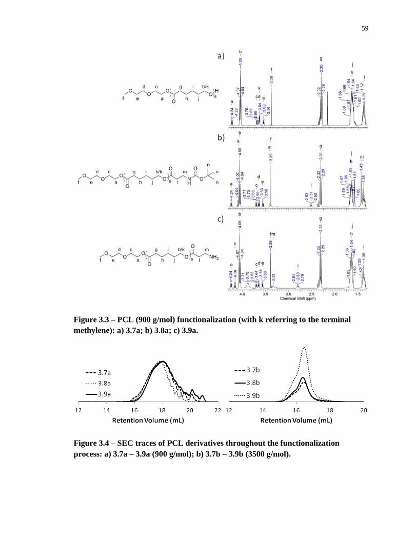
59
Figure 3.3 – PCL (900 g/mol) functionalization (with k referring to the terminal
methylene): a) 3.7a; b) 3.8a; c) 3.9a.
Figure 3.4 – SEC traces of PCL derivatives throughout the functionalization
process: a) 3.7a – 3.9a (900 g/mol); b) 3.7b – 3.9b (3500 g/mol).
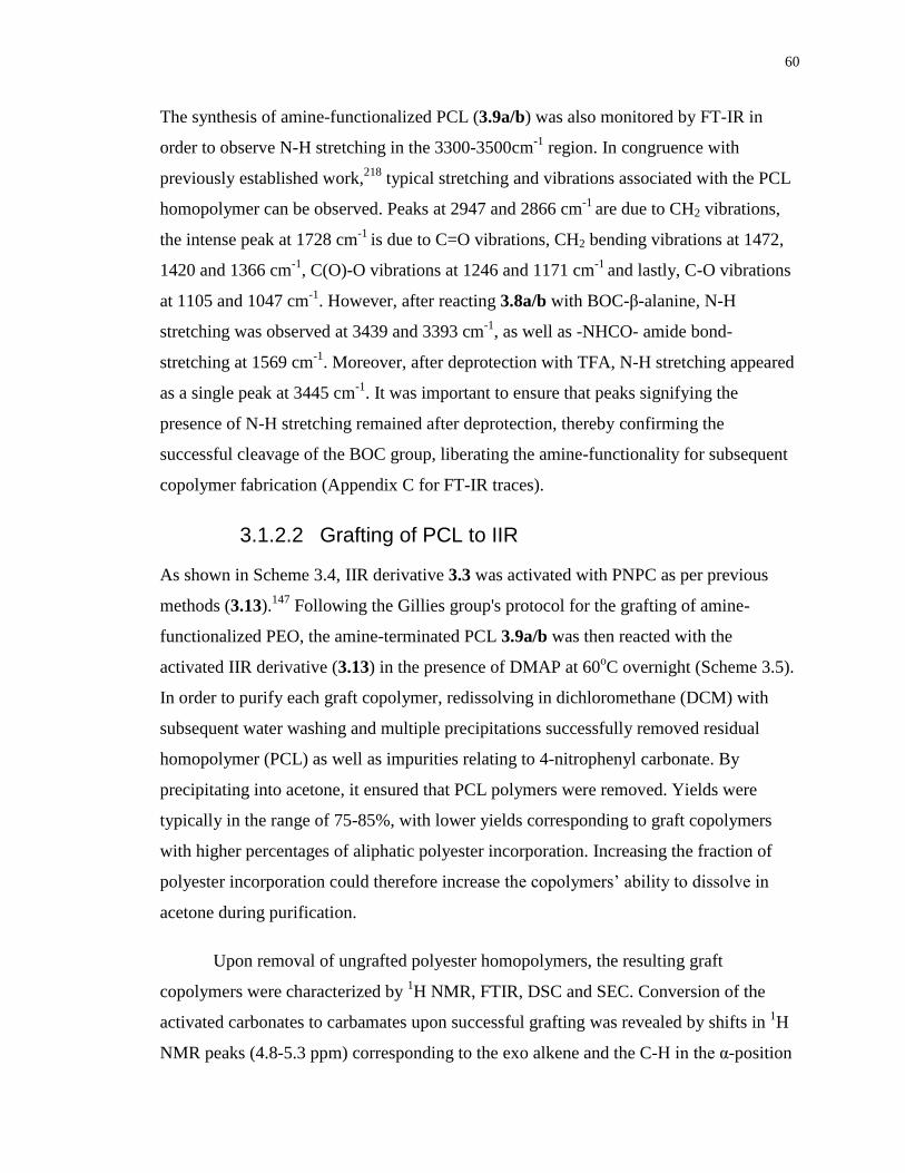
60
The synthesis of amine-functionalized PCL (3.9a/b) was also monitored by FT-IR in
order to observe N-H stretching in the 3300-3500cm-1
region. In congruence with
previously established work,218
typical stretching and vibrations associated with the PCL
homopolymer can be observed. Peaks at 2947 and 2866 cm-1
are due to CH2 vibrations,
the intense peak at 1728 cm-1
is due to C=O vibrations, CH2 bending vibrations at 1472,
1420 and 1366 cm-1
, C(O)-O vibrations at 1246 and 1171 cm-1
and lastly, C-O vibrations
at 1105 and 1047 cm-1
. However, after reacting 3.8a/b with BOC-β-alanine, N-H
stretching was observed at 3439 and 3393 cm-1
, as well as -NHCO- amide bond-
stretching at 1569 cm-1
. Moreover, after deprotection with TFA, N-H stretching appeared
as a single peak at 3445 cm-1
. It was important to ensure that peaks signifying the
presence of N-H stretching remained after deprotection, thereby confirming the
successful cleavage of the BOC group, liberating the amine-functionality for subsequent
copolymer fabrication (Appendix C for FT-IR traces).
3.1.2.2 Grafting of PCL to IIR
As shown in Scheme 3.4, IIR derivative 3.3 was activated with PNPC as per previous
methods (3.13).147
Following the Gillies group's protocol for the grafting of amine-
functionalized PEO, the amine-terminated PCL 3.9a/b was then reacted with the
activated IIR derivative (3.13) in the presence of DMAP at 60oC overnight (Scheme 3.5).
In order to purify each graft copolymer, redissolving in dichloromethane (DCM) with
subsequent water washing and multiple precipitations successfully removed residual
homopolymer (PCL) as well as impurities relating to 4-nitrophenyl carbonate. By
precipitating into acetone, it ensured that PCL polymers were removed. Yields were
typically in the range of 75-85%, with lower yields corresponding to graft copolymers
with higher percentages of aliphatic polyester incorporation. Increasing the fraction of
polyester incorporation could therefore increase the copolymers’ ability to dissolve in
acetone during purification.
Upon removal of ungrafted polyester homopolymers, the resulting graft
copolymers were characterized by 1H NMR, FTIR, DSC and SEC. Conversion of the
activated carbonates to carbamates upon successful grafting was revealed by shifts in 1H
NMR peaks (4.8-5.3 ppm) corresponding to the exo alkene and the C-H in the α-position
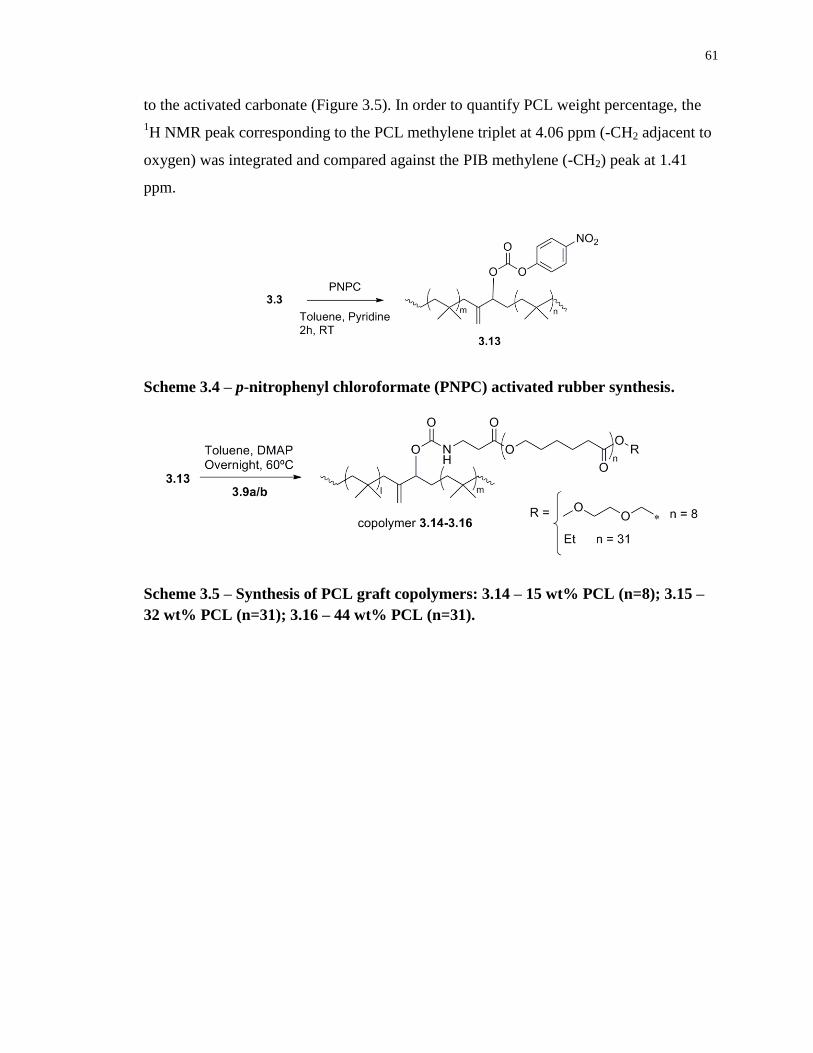
61
to the activated carbonate (Figure 3.5). In order to quantify PCL weight percentage, the
1H NMR peak corresponding to the PCL methylene triplet at 4.06 ppm (-CH2 adjacent to
oxygen) was integrated and compared against the PIB methylene (-CH2) peak at 1.41
ppm.
Scheme 3.4 – p-nitrophenyl chloroformate (PNPC) activated rubber synthesis.
Scheme 3.5 – Synthesis of PCL graft copolymers: 3.14 – 15 wt% PCL (n=8); 3.15 –
32 wt% PCL (n=31); 3.16 – 44 wt% PCL (n=31).
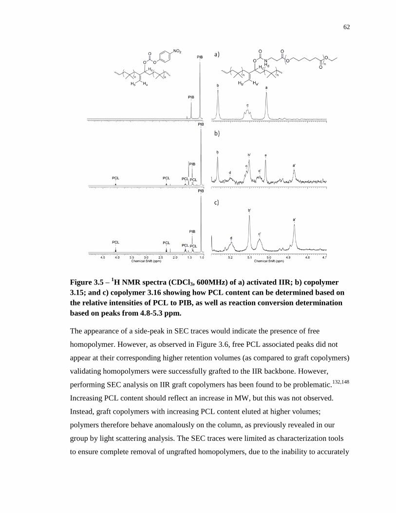
62
Figure 3.5 – 1H NMR spectra (CDCl3, 600MHz) of a) activated IIR; b) copolymer
3.15; and c) copolymer 3.16 showing how PCL content can be determined based on
the relative intensities of PCL to PIB, as well as reaction conversion determination
based on peaks from 4.8-5.3 ppm.
The appearance of a side-peak in SEC traces would indicate the presence of free
homopolymer. However, as observed in Figure 3.6, free PCL associated peaks did not
appear at their corresponding higher retention volumes (as compared to graft copolymers)
validating homopolymers were successfully grafted to the IIR backbone. However,
performing SEC analysis on IIR graft copolymers has been found to be problematic.132,148
Increasing PCL content should reflect an increase in MW, but this was not observed.
Instead, graft copolymers with increasing PCL content eluted at higher volumes;
polymers therefore behave anomalously on the column, as previously revealed in our
group by light scattering analysis. The SEC traces were limited as characterization tools
to ensure complete removal of ungrafted homopolymers, due to the inability to accurately
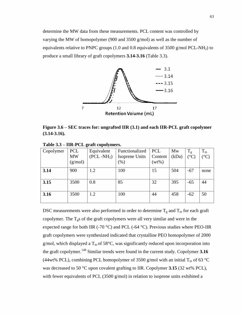
63
determine the MW data from these measurements. PCL content was controlled by
varying the MW of homopolymer (900 and 3500 g/mol) as well as the number of
equivalents relative to PNPC groups (1.0 and 0.8 equivalents of 3500 g/mol PCL-NH2) to
produce a small library of graft copolymers 3.14-3.16 (Table 3.3).
Figure 3.6 – SEC traces for: ungrafted IIR (3.1) and each IIR-PCL graft copolymer
(3.14-3.16).
Table 3.3 – IIR-PCL graft copolymers.
Copolymer PCL
MW
(g/mol)
Equivalent
(PCL -NH2)
Functionalized
Isoprene Units
(%)
PCL
Content
(wt%)
Mw
(kDa)
Tg
(°C) Tm
(°C)
3.14 900
1.2 100 15 504 -67 none
3.15 3500 0.8 85 32 395 -65 44
3.16 3500 1.2 100 44 458 -62 50
DSC measurements were also performed in order to determine Tg and Tm for each graft
copolymer. The Tgs of the graft copolymers were all very similar and were in the
expected range for both IIR (-70 °C) and PCL (-64 °C). Previous studies where PEO-IIR
graft copolymers were synthesized indicated that crystalline PEO homopolymer of 2000
g/mol, which displayed a Tm of 58°C, was significantly reduced upon incorporation into
the graft copolymer.148
Similar trends were found in the current study. Copolymer 3.16
(44wt% PCL), combining PCL homopolymer of 3500 g/mol with an initial Tm of 63 °C
was decreased to 50 °C upon covalent grafting to IIR. Copolymer 3.15 (32 wt% PCL),
with fewer equivalents of PCL (3500 g/mol) in relation to isoprene units exhibited a
64
further decrease in Tm to 44°C. Copolymer 3.14 (15wt% PCL), combining PCL
homopolymer of 900 g/mol with an intial Tm of 44°C, resulted in no apparent Tm for the
graft copolymer. Overall, the increase in melting temperature with increased PCL content
can be attributed to the ability of the larger PCL domains within these copolymers to
more readily crystallize in a manner that is similar to that of the homopolymer. DSC
traces would also show the presence of free, ungrafted PCL chains. In this case, there
would be an additional melting peak at the temperature for the corresponding PCL
homopolymer (Appendix H). This extra melting transition was not observed here,
confirming the purity of copolymers.
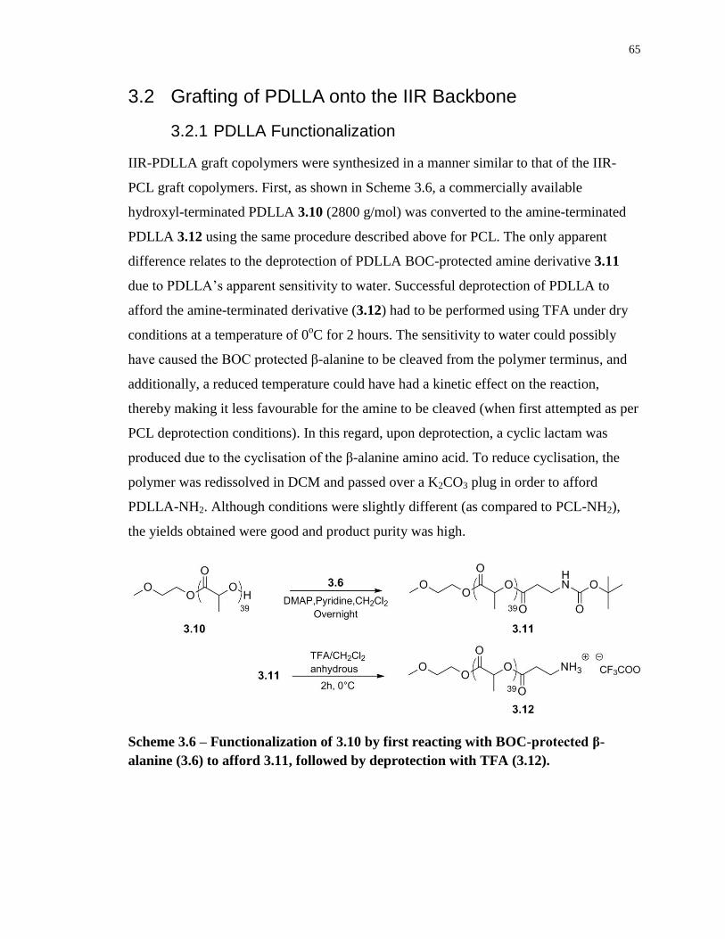
65
3.2 Grafting of PDLLA onto the IIR Backbone
3.2.1 PDLLA Functionalization
IIR-PDLLA graft copolymers were synthesized in a manner similar to that of the IIR-
PCL graft copolymers. First, as shown in Scheme 3.6, a commercially available
hydroxyl-terminated PDLLA 3.10 (2800 g/mol) was converted to the amine-terminated
PDLLA 3.12 using the same procedure described above for PCL. The only apparent
difference relates to the deprotection of PDLLA BOC-protected amine derivative 3.11
due to PDLLA’s apparent sensitivity to water. Successful deprotection of PDLLA to
afford the amine-terminated derivative (3.12) had to be performed using TFA under dry
conditions at a temperature of 0oC for 2 hours. The sensitivity to water could possibly
have caused the BOC protected β-alanine to be cleaved from the polymer terminus, and
additionally, a reduced temperature could have had a kinetic effect on the reaction,
thereby making it less favourable for the amine to be cleaved (when first attempted as per
PCL deprotection conditions). In this regard, upon deprotection, a cyclic lactam was
produced due to the cyclisation of the β-alanine amino acid. To reduce cyclisation, the
polymer was redissolved in DCM and passed over a K2CO3 plug in order to afford
PDLLA-NH2. Although conditions were slightly different (as compared to PCL-NH2),
the yields obtained were good and product purity was high.
Scheme 3.6 – Functionalization of 3.10 by first reacting with BOC-protected β-
alanine (3.6) to afford 3.11, followed by deprotection with TFA (3.12).
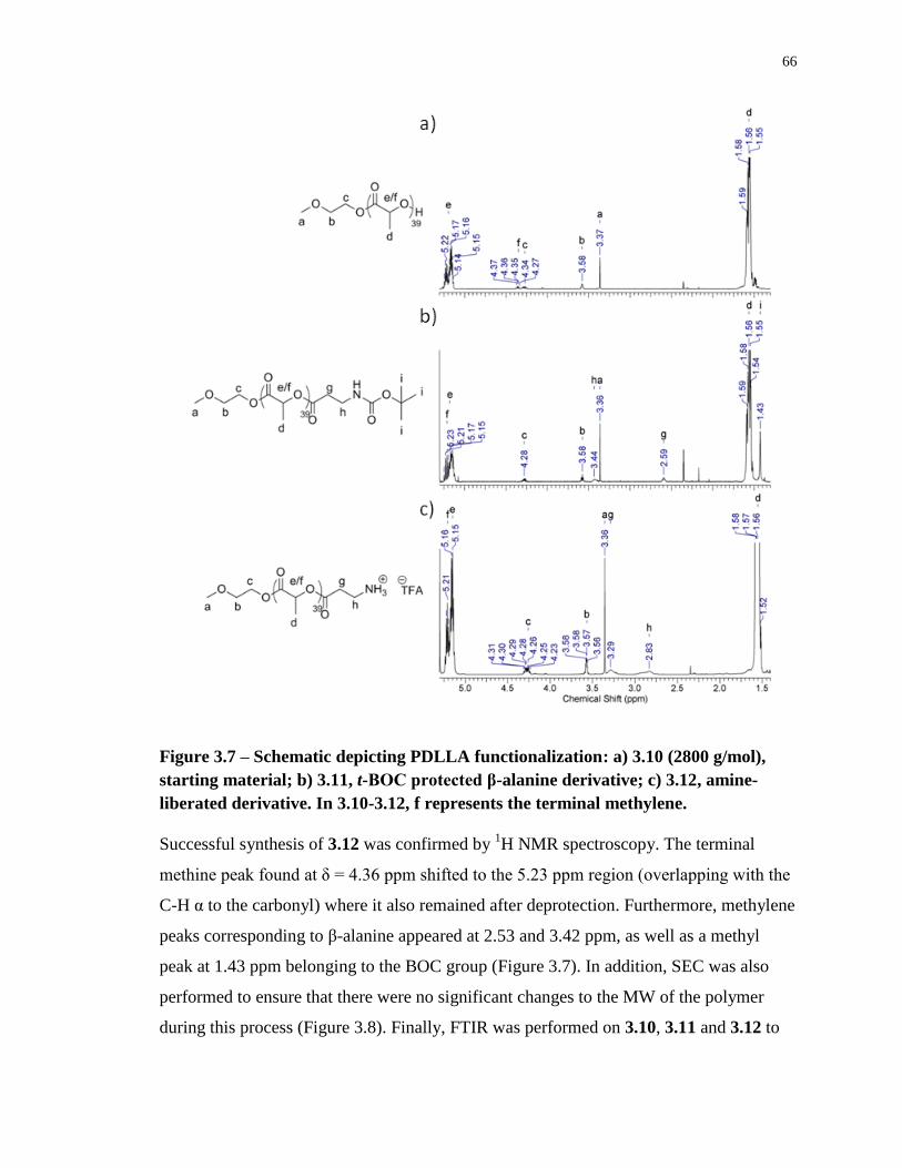
66
Figure 3.7 – Schematic depicting PDLLA functionalization: a) 3.10 (2800 g/mol),
starting material; b) 3.11, t-BOC protected β-alanine derivative; c) 3.12, amine-
liberated derivative. In 3.10-3.12, f represents the terminal methylene.
Successful synthesis of 3.12 was confirmed by 1H NMR spectroscopy. The terminal
methine peak found at δ = 4.36 ppm shifted to the 5.23 ppm region (overlapping with the
C-H α to the carbonyl) where it also remained after deprotection. Furthermore, methylene
peaks corresponding to β-alanine appeared at 2.53 and 3.42 ppm, as well as a methyl
peak at 1.43 ppm belonging to the BOC group (Figure 3.7). In addition, SEC was also
performed to ensure that there were no significant changes to the MW of the polymer
during this process (Figure 3.8). Finally, FTIR was performed on 3.10, 3.11 and 3.12 to
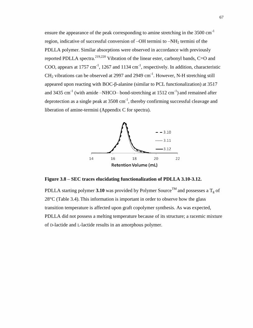
67
ensure the appearance of the peak corresponding to amine stretching in the 3500 cm-1
region, indicative of successful conversion of –OH termini to –NH2 termini of the
PDLLA polymer. Similar absorptions were observed in accordance with previously
reported PDLLA spectra.219,220
Vibration of the linear ester, carbonyl bands, C=O and
COO, appears at 1757 cm-1
, 1267 and 1134 cm-1
, respectively. In addition, characteristic
CH2 vibrations can be observed at 2997 and 2949 cm-1
. However, N-H stretching still
appeared upon reacting with BOC-β-alanine (similar to PCL functionalization) at 3517
and 3435 cm-1
(with amide –NHCO– bond-stretching at 1512 cm-1
) and remained after
deprotection as a single peak at 3508 cm-1
, thereby confirming successful cleavage and
liberation of amine-termini (Appendix C for spectra).
Figure 3.8 – SEC traces elucidating functionalization of PDLLA 3.10-3.12.
PDLLA starting polymer 3.10 was provided by Polymer SourceTM
and possesses a Tg of
28°C (Table 3.4). This information is important in order to observe how the glass
transition temperature is affected upon graft copolymer synthesis. As was expected,
PDLLA did not possess a melting temperature because of its structure; a racemic mixture
of D-lactide and L-lactide results in an amorphous polymer.
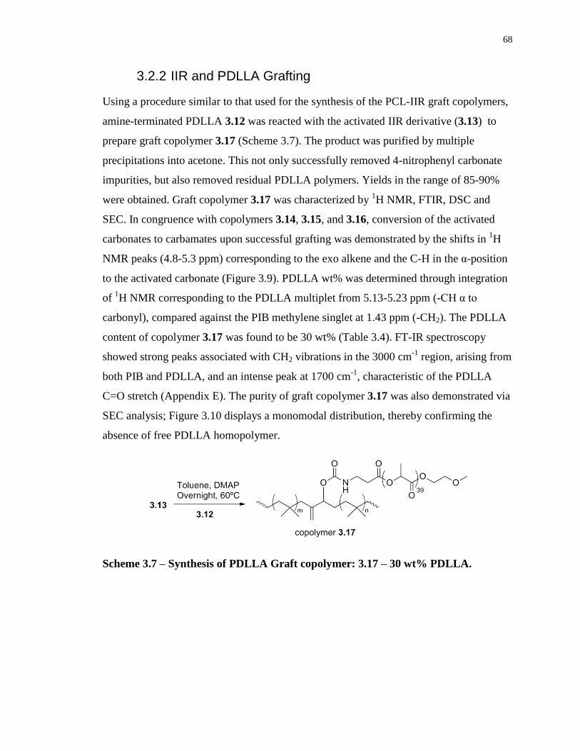
68
3.2.2 IIR and PDLLA Grafting
Using a procedure similar to that used for the synthesis of the PCL-IIR graft copolymers,
amine-terminated PDLLA 3.12 was reacted with the activated IIR derivative (3.13) to
prepare graft copolymer 3.17 (Scheme 3.7). The product was purified by multiple
precipitations into acetone. This not only successfully removed 4-nitrophenyl carbonate
impurities, but also removed residual PDLLA polymers. Yields in the range of 85-90%
were obtained. Graft copolymer 3.17 was characterized by 1H NMR, FTIR, DSC and
SEC. In congruence with copolymers 3.14, 3.15, and 3.16, conversion of the activated
carbonates to carbamates upon successful grafting was demonstrated by the shifts in 1H
NMR peaks (4.8-5.3 ppm) corresponding to the exo alkene and the C-H in the α-position
to the activated carbonate (Figure 3.9). PDLLA wt% was determined through integration
of 1H NMR corresponding to the PDLLA multiplet from 5.13-5.23 ppm (-CH α to
carbonyl), compared against the PIB methylene singlet at 1.43 ppm (-CH2). The PDLLA
content of copolymer 3.17 was found to be 30 wt% (Table 3.4). FT-IR spectroscopy
showed strong peaks associated with CH2 vibrations in the 3000 cm-1
region, arising from
both PIB and PDLLA, and an intense peak at 1700 cm-1
, characteristic of the PDLLA
C=O stretch (Appendix E). The purity of graft copolymer 3.17 was also demonstrated via
SEC analysis; Figure 3.10 displays a monomodal distribution, thereby confirming the
absence of free PDLLA homopolymer.
Scheme 3.7 – Synthesis of PDLLA Graft copolymer: 3.17 – 30 wt% PDLLA.
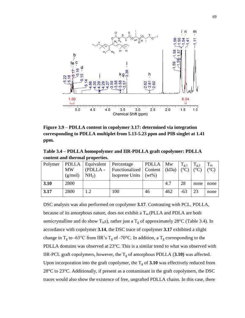
69
Figure 3.9 – PDLLA content in copolymer 3.17: determined via integration
corresponding to PDLLA multiplet from 5.13-5.23 ppm and PIB singlet at 1.41
ppm.
Table 3.4 – PDLLA homopolymer and IIR-PDLLA graft copolymer: PDLLA
content and thermal properties.
Polymer PDLLA
MW
(g/mol)
Equivalent
(PDLLA -
NH2)
Percentage
Functionalized
Isoprene Units
PDLLA
Content
(wt%)
Mw
(kDa)
Tg,1
(°C)
Tg,2
(°C)
Tm
(°C)
3.10 2800 4.7 28 none none
3.17 2800
1.2 100 46 462 -63 23 none
DSC analysis was also performed on copolymer 3.17. Contrasting with PCL, PDLLA,
because of its amorphous nature, does not exhibit a Tm (PLLA and PDLA are both
semicrystalline and do show Tms), rather just a Tg of approximately 28°C (Table 3.4). In
accordance with copolymer 3.14, the DSC trace of copolymer 3.17 exhibited a slight
change in Tg to -63°C from IIR’s Tg of -70°C. In addition, a Tg corresponding to the
PDLLA domains was observed at 23°C. This is a similar trend to what was observed with
IIR-PCL graft copolymers, however, the Tg of amorphous PDLLA (3.10) was affected.
Upon incorporation into the graft copolymer, the Tg of 3.10 was effectively reduced from
28°C to 23°C. Additionally, if present as a contaminant in the graft copolymers, the DSC
traces would also show the existence of free, ungrafted PDLLA chains. In this case, there
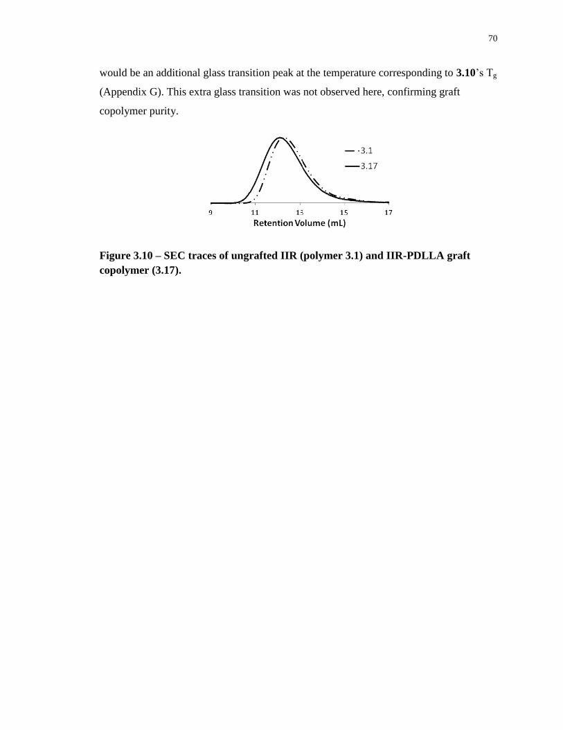
70
would be an additional glass transition peak at the temperature corresponding to 3.10’s Tg
(Appendix G). This extra glass transition was not observed here, confirming graft
copolymer purity.
Figure 3.10 – SEC traces of ungrafted IIR (polymer 3.1) and IIR-PDLLA graft
copolymer (3.17).
71
3.3 Preparation of IIR-PCL/PDLLA Blends
In order to observe the advantages that graft copolymers exhibit, physical blends
consisting of IIR and polyesters were also prepared. In brief, these blends were prepared
by dissolving IIR and either PCL or PDLLA in a common solvent, and then the solvent
was removed. To replicate the polyester content of the graft copolymers, blends with IIR
and 15, 32 and 44 wt% PCL as well as 30 wt% PDLLA were prepared and characterized
by 1H NMR and DSC. DSC traces (Appendix I) for blends consisting of PCL (5000
g/mol) and IIR were found to exhibit the same Tgs (-66°C) and Tms (50°C) regardless of
PCL wt% incorporation. It is also interesting to note DSC traces for PDLLA (18 000
g/mol) blends and IIR. PDLLA homopolymer was provided by Sigma-Aldrichwith a
glass transition temperature in the range of 38-42°C. In this case, two Tgs were observed,
one for IIR at -67°C and the other corresponding to PDLLA at 40°C (Appendix I).
72
3.4 Physical Characterization of Graft Copolymers
3.4.1 Atomic Force Microscopy
The study of IIR-polyester graft copolymer films by AFM was of interest in order to gain
insight into the phase separation and nanoscale morphologies of these polymers. In recent
work, Zhang et. al. have demonstrated that breakout crystallization occurs when studying
the thermal effects on block copolymers consisting of poly(butadiene)-block-PCL (PBD-
b-PCL).221
Breakout crystallization occurs when a crystalline portion that exhibits
nanometer length scale domains is subsequently heated, thus transforming it into
regularly alternating lamellae between the crystalline and amorphous layers. This
successfully alters (or destroys) the melt mesophase, due to the crystallization of one
block. Although the mechanism of breakout crystallization is poorly understood, it may
occur when the crystallization driving force is enough to overcome the energy barrier due
to the amorphous surroundings.222,223
Furthermore, when considering PBD-b-PCL, it has
been shown that PCL minority blocks do in fact break out into lamellar alternating
structures with PBD.224
Therefore, because IIR-PCL copolymers are similar to PBD-b-PCL (amorphous
and semicrystalline domains), AFM analysis could provide interesting images of
copolymer nanoscale structure pre- and post-annealing. Although it would be of interest
to understand the breakout kinetics (such as crystal coalescence and growth), AFM
equipment involving real-time imaging was not available. However, differences in
topographical and phase images could be analyzed, indicating that the development of
crystallization did in fact impact the surrounding amorphous microdomain structures. In
recent work, IIR-PEO graft copolymers exhibited micrometer scale patterns when spin-
cast on to silicon wafer surfaces.147,148
In this case, the patterning was attributed to
kinetic factors such as the freezing of Marangoni instabilities, as well as phase separation
(thermodynamically driven). In this sense, it would be interesting to study the pattern
formation with IIR-PCL graft copolymers. Although PCL, like PEO, is semicrystalline,
its inherent hydrophobicity could possibly affect the resulting surface morphology of
copolymers.
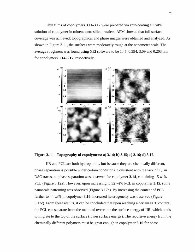
73
Thin films of copolymers 3.14-3.17 were prepared via spin-coating a 3 wt%
solution of copolymer in toluene onto silicon wafers. AFM showed that full surface
coverage was achieved; topographical and phase images were obtained and analyzed. As
shown in Figure 3.11, the surfaces were moderately rough at the nanometer scale. The
average roughness was found using XEI software to be 1.45, 0.394, 3.09 and 0.203 nm
for copolymers 3.14-3.17, respectively.
Figure 3.11 – Topography of copolymers: a) 3.14; b) 3.15; c) 3.16; d) 3.17.
IIR and PCL are both hydrophobic, but because they are chemically different,
phase separation is possible under certain conditions. Consistent with the lack of Tm in
DSC traces, no phase separation was observed for copolymer 3.14, containing 15 wt%
PCL (Figure 3.12a). However, upon increasing to 32 wt% PCL in copolymer 3.15, some
nanoscale patterning was observed (Figure 3.12b). By increasing the content of PCL
further to 44 wt% in copolymer 3.16, increased heterogeneity was observed (Figure
3.12c). From these results, it can be concluded that upon reaching a certain PCL content,
the PCL can separate from the melt and overcome the surface energy of IIR, which tends
to migrate to the top of the surface (lower surface energy). The repulsive energy from the
chemically different polymers must be great enough in copolymer 3.16 for phase
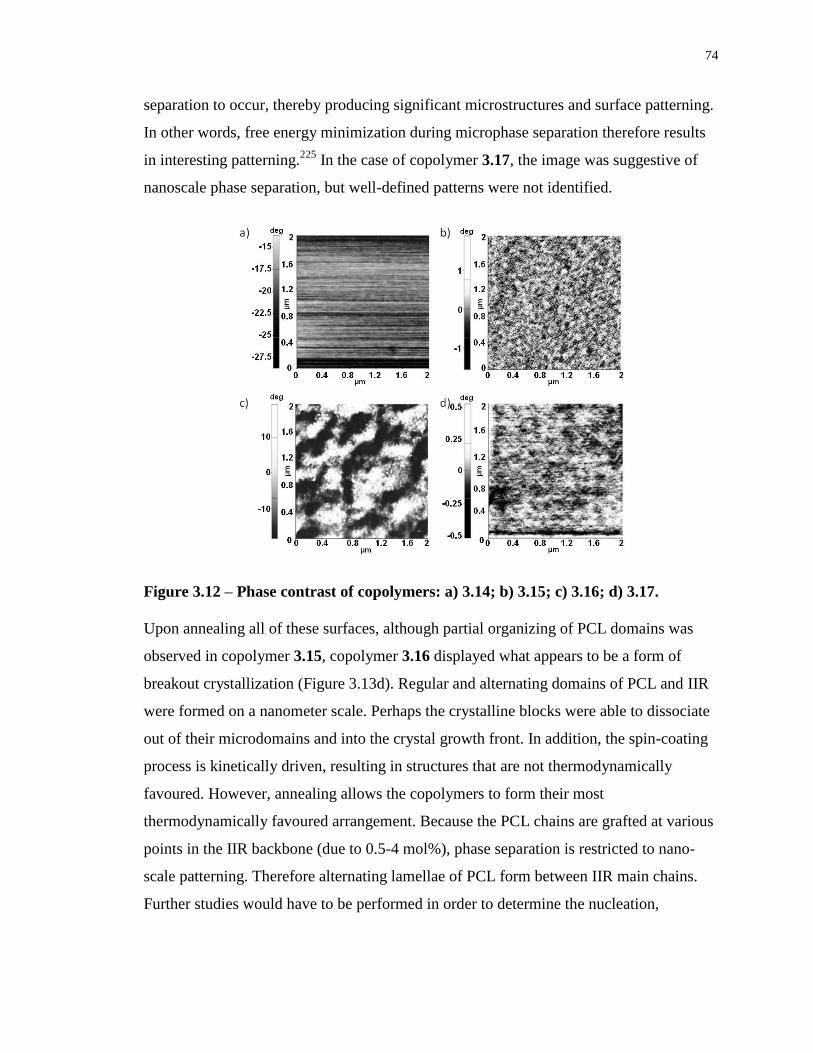
74
separation to occur, thereby producing significant microstructures and surface patterning.
In other words, free energy minimization during microphase separation therefore results
in interesting patterning.225
In the case of copolymer 3.17, the image was suggestive of
nanoscale phase separation, but well-defined patterns were not identified.
Figure 3.12 – Phase contrast of copolymers: a) 3.14; b) 3.15; c) 3.16; d) 3.17.
Upon annealing all of these surfaces, although partial organizing of PCL domains was
observed in copolymer 3.15, copolymer 3.16 displayed what appears to be a form of
breakout crystallization (Figure 3.13d). Regular and alternating domains of PCL and IIR
were formed on a nanometer scale. Perhaps the crystalline blocks were able to dissociate
out of their microdomains and into the crystal growth front. In addition, the spin-coating
process is kinetically driven, resulting in structures that are not thermodynamically
favoured. However, annealing allows the copolymers to form their most
thermodynamically favoured arrangement. Because the PCL chains are grafted at various
points in the IIR backbone (due to 0.5-4 mol%), phase separation is restricted to nano-
scale patterning. Therefore alternating lamellae of PCL form between IIR main chains.
Further studies would have to be performed in order to determine the nucleation,
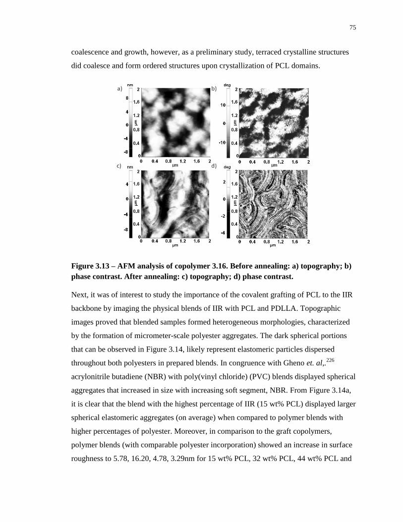
75
coalescence and growth, however, as a preliminary study, terraced crystalline structures
did coalesce and form ordered structures upon crystallization of PCL domains.
Figure 3.13 – AFM analysis of copolymer 3.16. Before annealing: a) topography; b)
phase contrast. After annealing: c) topography; d) phase contrast.
Next, it was of interest to study the importance of the covalent grafting of PCL to the IIR
backbone by imaging the physical blends of IIR with PCL and PDLLA. Topographic
images proved that blended samples formed heterogeneous morphologies, characterized
by the formation of micrometer-scale polyester aggregates. The dark spherical portions
that can be observed in Figure 3.14, likely represent elastomeric particles dispersed
throughout both polyesters in prepared blends. In congruence with Gheno et. al,.226
acrylonitrile butadiene (NBR) with poly(vinyl chloride) (PVC) blends displayed spherical
aggregates that increased in size with increasing soft segment, NBR. From Figure 3.14a,
it is clear that the blend with the highest percentage of IIR (15 wt% PCL) displayed larger
spherical elastomeric aggregates (on average) when compared to polymer blends with
higher percentages of polyester. Moreover, in comparison to the graft copolymers,
polymer blends (with comparable polyester incorporation) showed an increase in surface
roughness to 5.78, 16.20, 4.78, 3.29nm for 15 wt% PCL, 32 wt% PCL, 44 wt% PCL and
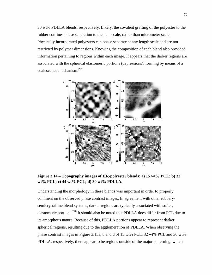
76
30 wt% PDLLA blends, respectively. Likely, the covalent grafting of the polyester to the
rubber confines phase separation to the nanoscale, rather than micrometer scale.
Physically incorporated polyesters can phase separate at any length scale and are not
restricted by polymer dimensions. Knowing the composition of each blend also provided
information pertaining to regions within each image. It appears that the darker regions are
associated with the spherical elastomeric portions (depressions), forming by means of a
coalescence mechanism.227
Figure 3.14 – Topography images of IIR-polyester blends: a) 15 wt% PCL; b) 32
wt% PCL; c) 44 wt% PCL; d) 30 wt% PDLLA.
Understanding the morphology in these blends was important in order to properly
comment on the observed phase contrast images. In agreement with other rubbery-
semicrystalline blend systems, darker regions are typically associated with softer,
elastomeric portions.228
It should also be noted that PDLLA does differ from PCL due to
its amorphous nature. Because of this, PDLLA portions appear to represent darker
spherical regions, resulting due to the agglomeration of PDLLA. When observing the
phase contrast images in Figure 3.15a, b and d of 15 wt% PCL, 32 wt% PCL and 30 wt%
PDLLA, respectively, there appear to be regions outside of the major patterning, which
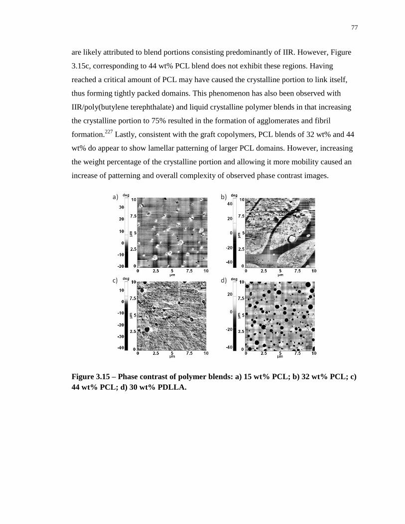
77
are likely attributed to blend portions consisting predominantly of IIR. However, Figure
3.15c, corresponding to 44 wt% PCL blend does not exhibit these regions. Having
reached a critical amount of PCL may have caused the crystalline portion to link itself,
thus forming tightly packed domains. This phenomenon has also been observed with
IIR/poly(butylene terephthalate) and liquid crystalline polymer blends in that increasing
the crystalline portion to 75% resulted in the formation of agglomerates and fibril
formation.227
Lastly, consistent with the graft copolymers, PCL blends of 32 wt% and 44
wt% do appear to show lamellar patterning of larger PCL domains. However, increasing
the weight percentage of the crystalline portion and allowing it more mobility caused an
increase of patterning and overall complexity of observed phase contrast images.
Figure 3.15 – Phase contrast of polymer blends: a) 15 wt% PCL; b) 32 wt% PCL; c)
44 wt% PCL; d) 30 wt% PDLLA.
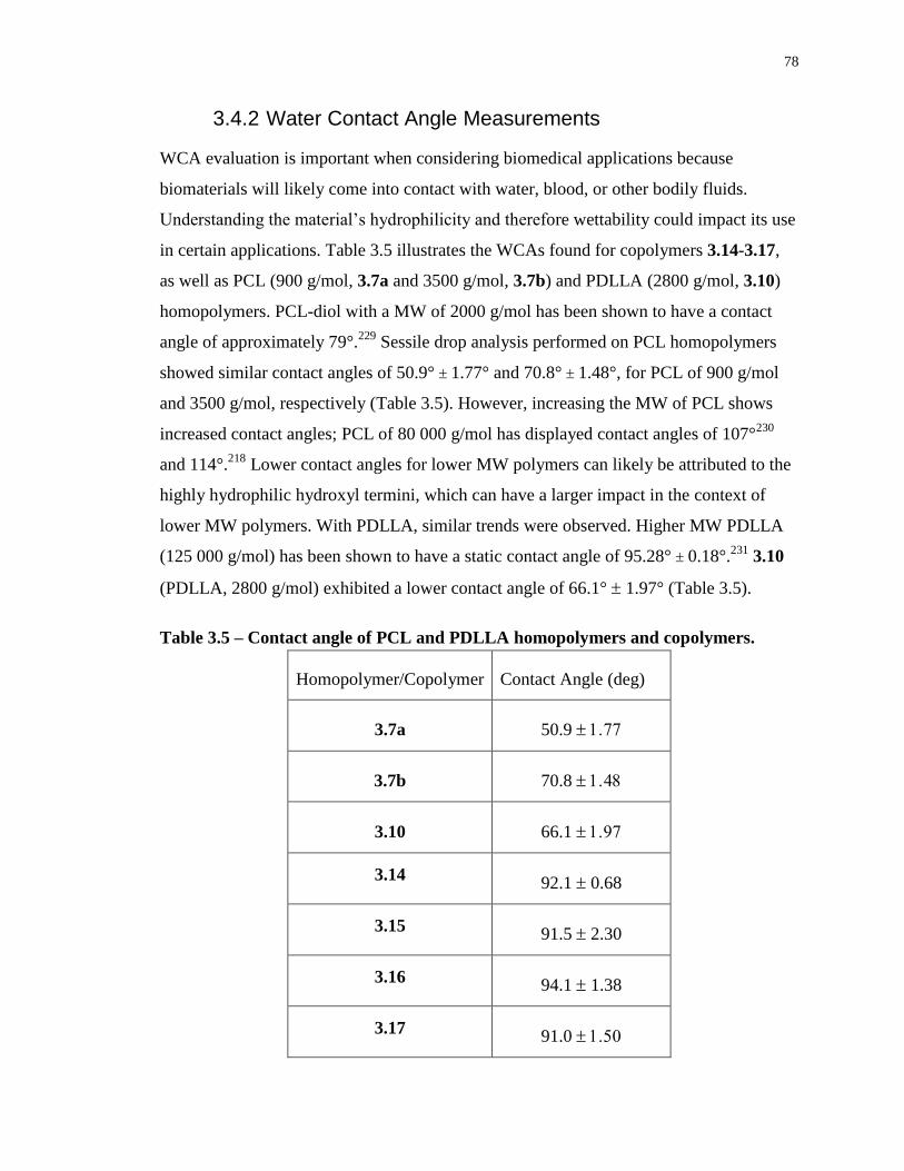
78
3.4.2 Water Contact Angle Measurements
WCA evaluation is important when considering biomedical applications because
biomaterials will likely come into contact with water, blood, or other bodily fluids.
Understanding the material’s hydrophilicity and therefore wettability could impact its use
in certain applications. Table 3.5 illustrates the WCAs found for copolymers 3.14-3.17,
as well as PCL (900 g/mol, 3.7a and 3500 g/mol, 3.7b) and PDLLA (2800 g/mol, 3.10)
homopolymers. PCL-diol with a MW of 2000 g/mol has been shown to have a contact
angle of approximately 79°.229
Sessile drop analysis performed on PCL homopolymers
showed similar contact angles of 50.9° 1.77° and 70.8° 1.48°, for PCL of 900 g/mol
and 3500 g/mol, respectively (Table 3.5). However, increasing the MW of PCL shows
increased contact angles; PCL of 80 000 g/mol has displayed contact angles of 107°230
and 114°.218
Lower contact angles for lower MW polymers can likely be attributed to the
highly hydrophilic hydroxyl termini, which can have a larger impact in the context of
lower MW polymers. With PDLLA, similar trends were observed. Higher MW PDLLA
(125 000 g/mol) has been shown to have a static contact angle of 95.28° 0.18°.231
3.10
(PDLLA, 2800 g/mol) exhibited a lower contact angle of 66.1° 1.97° (Table 3.5).
Table 3.5 – Contact angle of PCL and PDLLA homopolymers and copolymers.
Homopolymer/Copolymer Contact Angle (deg)
3.7a 50.9
3.7b 70.8
3.10 66.1
3.14 92.1 0.68
3.15 91.5 2.30
3.16 94.1 1.38
3.17 91.0
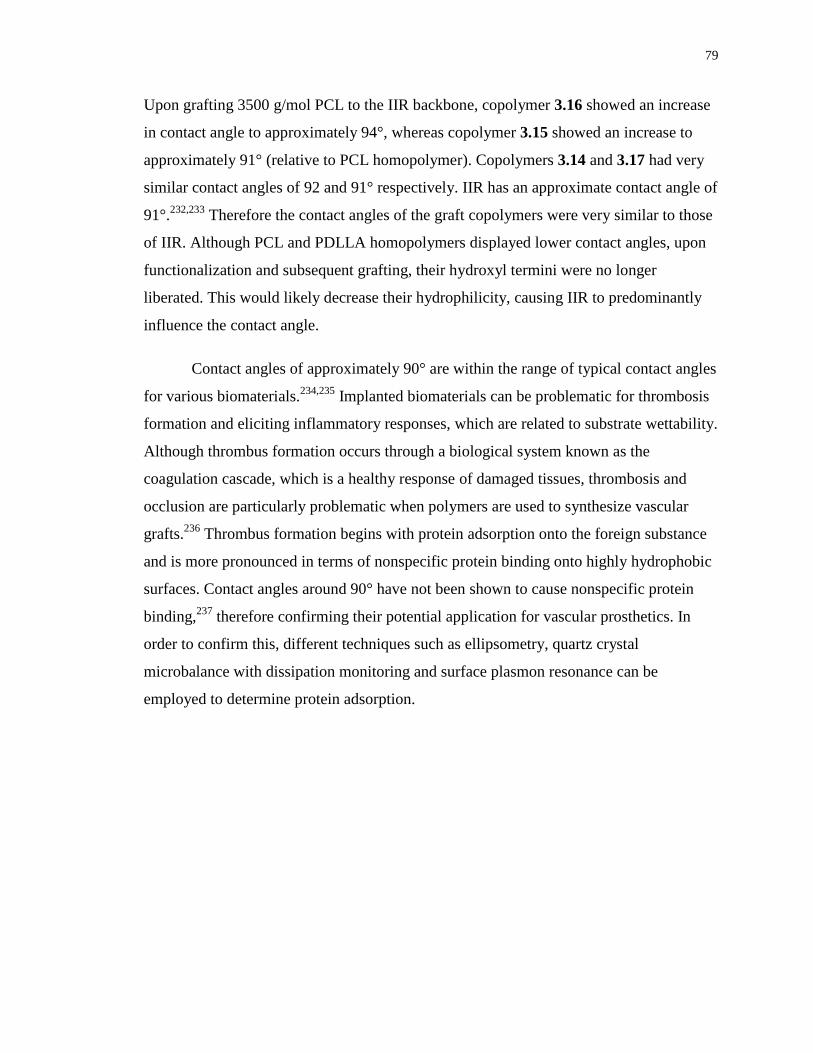
79
Upon grafting 3500 g/mol PCL to the IIR backbone, copolymer 3.16 showed an increase
in contact angle to approximately 94°, whereas copolymer 3.15 showed an increase to
approximately 91° (relative to PCL homopolymer). Copolymers 3.14 and 3.17 had very
similar contact angles of 92 and 91° respectively. IIR has an approximate contact angle of
91°.232,233
Therefore the contact angles of the graft copolymers were very similar to those
of IIR. Although PCL and PDLLA homopolymers displayed lower contact angles, upon
functionalization and subsequent grafting, their hydroxyl termini were no longer
liberated. This would likely decrease their hydrophilicity, causing IIR to predominantly
influence the contact angle.
Contact angles of approximately 90° are within the range of typical contact angles
for various biomaterials.234,235
Implanted biomaterials can be problematic for thrombosis
formation and eliciting inflammatory responses, which are related to substrate wettability.
Although thrombus formation occurs through a biological system known as the
coagulation cascade, which is a healthy response of damaged tissues, thrombosis and
occlusion are particularly problematic when polymers are used to synthesize vascular
grafts.236
Thrombus formation begins with protein adsorption onto the foreign substance
and is more pronounced in terms of nonspecific protein binding onto highly hydrophobic
surfaces. Contact angles around 90° have not been shown to cause nonspecific protein
binding,237
therefore confirming their potential application for vascular prosthetics. In
order to confirm this, different techniques such as ellipsometry, quartz crystal
microbalance with dissipation monitoring and surface plasmon resonance can be
employed to determine protein adsorption.
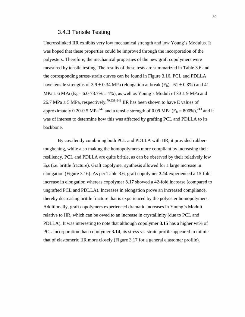
80
3.4.3 Tensile Testing
Uncrosslinked IIR exhibits very low mechanical strength and low Young’s Modulus. It
was hoped that these properties could be improved through the incorporation of the
polyesters. Therefore, the mechanical properties of the new graft copolymers were
measured by tensile testing. The results of these tests are summarized in Table 3.6 and
the corresponding stress-strain curves can be found in Figure 3.16. PCL and PDLLA
have tensile strengths of 3.9 0.34 MPa (elongation at break (Eb) =61 and 41
MPa 6 MPa (Eb = 6.0-73.7% ), as well as Young’s Moduli of 83 9 MPa and
26.7 MPa 5 MPa, respectively.79,238-241
IIR has been shown to have E values of
approximately 0.20-0.5 MPa242
and a tensile strength of 0.09 MPa (Eb = 800%),243
and it
was of interest to determine how this was affected by grafting PCL and PDLLA to its
backbone.
By covalently combining both PCL and PDLLA with IIR, it provided rubber-
toughening, while also making the homopolymers more compliant by increasing their
resiliency. PCL and PDLLA are quite brittle, as can be observed by their relatively low
Ebs (i.e. brittle fracture). Graft copolymer synthesis allowed for a large increase in
elongation (Figure 3.16). As per Table 3.6, graft copolymer 3.14 experienced a 15-fold
increase in elongation whereas copolymer 3.17 showed a 42-fold increase (compared to
ungrafted PCL and PDLLA). Increases in elongation prove an increased compliance,
thereby decreasing brittle fracture that is experienced by the polyester homopolymers.
Additionally, graft copolymers experienced dramatic increases in Young’s Moduli
relative to IIR, which can be owed to an increase in crystallinity (due to PCL and
PDLLA). It was interesting to note that although copolymer 3.15 has a higher wt% of
PCL incorporation than copolymer 3.14, its stress vs. strain profile appeared to mimic
that of elastomeric IIR more closely (Figure 3.17 for a general elastomer profile).
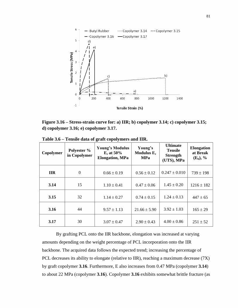
81
Figure 3.16 – Stress-strain curve for: a) IIR; b) copolymer 3.14; c) copolymer 3.15;
d) copolymer 3.16; e) copolymer 3.17.
Table 3.6 – Tensile data of graft copolymers and IIR.
Copolymer Polyester %
in Copolymer
Young’s Modulus
E, at 50%
Elongation, MPa
Young’s
Modulus E,
MPa
Ultimate
Tensile
Strength
(UTS), MPa
Elongation
at Break
(Eb), %
IIR 0 0.66 0.19 0.56 0.12 0.247 ± 0.010 739 198
3.14 15 1.10 0.41 0.47 0.06 1.45 ± 0.20 1216 182
3.15 32 1.14 0.27 0.74 0.15 1.24 ± 0.13 447 65
3.16 44 9.57 1.13 21.66 5.90 3.92 ± 1.03 165 29
3.17 30 3.07 0.47 2.90 0.43 4.00 ± 0.86 251 52
By grafting PCL onto the IIR backbone, elongation was increased at varying
amounts depending on the weight percentage of PCL incorporation onto the IIR
backbone. The acquired data follows the expected trend; increasing the percentage of
PCL decreases its ability to elongate (relative to IIR), reaching a maximum decrease (7X)
by graft copolymer 3.16. Furthermore, E also increases from 0.47 MPa (copolymer 3.14)
to about 22 MPa (copolymer 3.16). Copolymer 3.16 exhibits somewhat brittle fracture (as
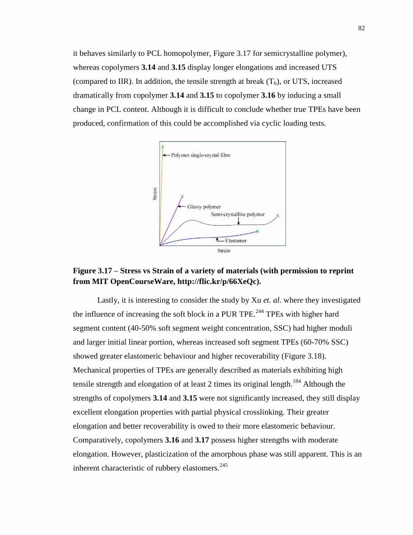
82
it behaves similarly to PCL homopolymer, Figure 3.17 for semicrystalline polymer),
whereas copolymers 3.14 and 3.15 display longer elongations and increased UTS
(compared to IIR). In addition, the tensile strength at break (Tb), or UTS, increased
dramatically from copolymer 3.14 and 3.15 to copolymer 3.16 by inducing a small
change in PCL content. Although it is difficult to conclude whether true TPEs have been
produced, confirmation of this could be accomplished via cyclic loading tests.
Figure 3.17 – Stress vs Strain of a variety of materials (with permission to reprint
from MIT OpenCourseWare, http://flic.kr/p/66XeQc).
Lastly, it is interesting to consider the study by Xu et. al. where they investigated
the influence of increasing the soft block in a PUR TPE.244
TPEs with higher hard
segment content (40-50% soft segment weight concentration, SSC) had higher moduli
and larger initial linear portion, whereas increased soft segment TPEs (60-70% SSC)
showed greater elastomeric behaviour and higher recoverability (Figure 3.18).
Mechanical properties of TPEs are generally described as materials exhibiting high
tensile strength and elongation of at least 2 times its original length.184
Although the
strengths of copolymers 3.14 and 3.15 were not significantly increased, they still display
excellent elongation properties with partial physical crosslinking. Their greater
elongation and better recoverability is owed to their more elastomeric behaviour.
Comparatively, copolymers 3.16 and 3.17 possess higher strengths with moderate
elongation. However, plasticization of the amorphous phase was still apparent. This is an
inherent characteristic of rubbery elastomers.245
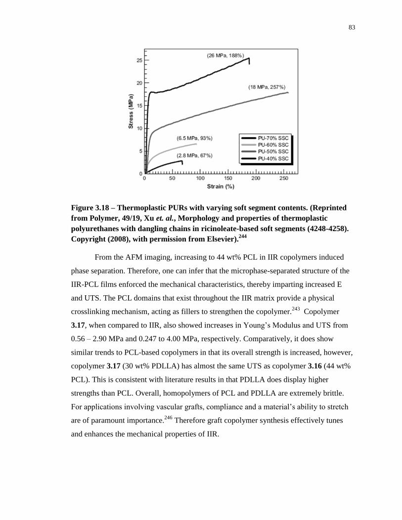
83
Figure 3.18 – Thermoplastic PURs with varying soft segment contents. (Reprinted
from Polymer, 49/19, Xu et. al., Morphology and properties of thermoplastic
polyurethanes with dangling chains in ricinoleate-based soft segments (4248-4258).
Copyright (2008), with permission from Elsevier).244
From the AFM imaging, increasing to 44 wt% PCL in IIR copolymers induced
phase separation. Therefore, one can infer that the microphase-separated structure of the
IIR-PCL films enforced the mechanical characteristics, thereby imparting increased E
and UTS. The PCL domains that exist throughout the IIR matrix provide a physical
crosslinking mechanism, acting as fillers to strengthen the copolymer.243
Copolymer
3.17, when compared to IIR, also showed increases in Young’s Modulus and UTS from
0.56 – 2.90 MPa and 0.247 to 4.00 MPa, respectively. Comparatively, it does show
similar trends to PCL-based copolymers in that its overall strength is increased, however,
copolymer 3.17 (30 wt% PDLLA) has almost the same UTS as copolymer 3.16 (44 wt%
PCL). This is consistent with literature results in that PDLLA does display higher
strengths than PCL. Overall, homopolymers of PCL and PDLLA are extremely brittle.
For applications involving vascular grafts, compliance and a material’s ability to stretch
are of paramount importance.246
Therefore graft copolymer synthesis effectively tunes
and enhances the mechanical properties of IIR.
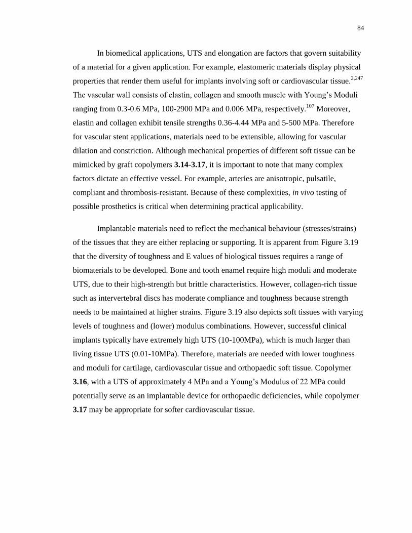
84
In biomedical applications, UTS and elongation are factors that govern suitability
of a material for a given application. For example, elastomeric materials display physical
properties that render them useful for implants involving soft or cardiovascular tissue.2,247
The vascular wall consists of elastin, collagen and smooth muscle with Young’s Moduli
ranging from 0.3-0.6 MPa, 100-2900 MPa and 0.006 MPa, respectively.107
Moreover,
elastin and collagen exhibit tensile strengths 0.36-4.44 MPa and 5-500 MPa. Therefore
for vascular stent applications, materials need to be extensible, allowing for vascular
dilation and constriction. Although mechanical properties of different soft tissue can be
mimicked by graft copolymers 3.14-3.17, it is important to note that many complex
factors dictate an effective vessel. For example, arteries are anisotropic, pulsatile,
compliant and thrombosis-resistant. Because of these complexities, in vivo testing of
possible prosthetics is critical when determining practical applicability.
Implantable materials need to reflect the mechanical behaviour (stresses/strains)
of the tissues that they are either replacing or supporting. It is apparent from Figure 3.19
that the diversity of toughness and E values of biological tissues requires a range of
biomaterials to be developed. Bone and tooth enamel require high moduli and moderate
UTS, due to their high-strength but brittle characteristics. However, collagen-rich tissue
such as intervertebral discs has moderate compliance and toughness because strength
needs to be maintained at higher strains. Figure 3.19 also depicts soft tissues with varying
levels of toughness and (lower) modulus combinations. However, successful clinical
implants typically have extremely high UTS (10-100MPa), which is much larger than
living tissue UTS (0.01-10MPa). Therefore, materials are needed with lower toughness
and moduli for cartilage, cardiovascular tissue and orthopaedic soft tissue. Copolymer
3.16, with a UTS of approximately 4 MPa and a Young’s Modulus of 22 MPa could
potentially serve as an implantable device for orthopaedic deficiencies, while copolymer
3.17 may be appropriate for softer cardiovascular tissue.
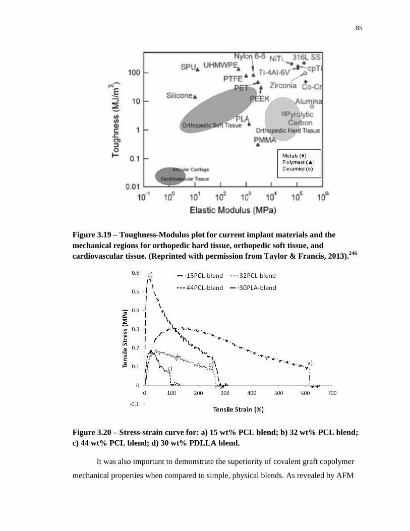
85
Figure 3.19 – Toughness-Modulus plot for current implant materials and the
mechanical regions for orthopedic hard tissue, orthopedic soft tissue, and
cardiovascular tissue. (Reprinted with permission from Taylor & Francis, 2013).246
Figure 3.20 – Stress-strain curve for: a) 15 wt% PCL blend; b) 32 wt% PCL blend;
c) 44 wt% PCL blend; d) 30 wt% PDLLA blend.
It was also important to demonstrate the superiority of covalent graft copolymer
mechanical properties when compared to simple, physical blends. As revealed by AFM
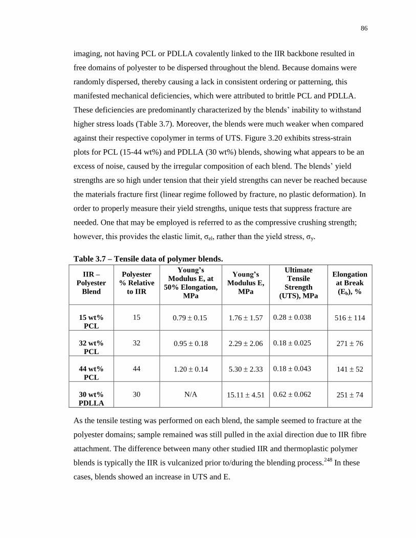
86
imaging, not having PCL or PDLLA covalently linked to the IIR backbone resulted in
free domains of polyester to be dispersed throughout the blend. Because domains were
randomly dispersed, thereby causing a lack in consistent ordering or patterning, this
manifested mechanical deficiencies, which were attributed to brittle PCL and PDLLA.
These deficiencies are predominantly characterized by the blends’ inability to withstand
higher stress loads (Table 3.7). Moreover, the blends were much weaker when compared
against their respective copolymer in terms of UTS. Figure 3.20 exhibits stress-strain
plots for PCL (15-44 wt%) and PDLLA (30 wt%) blends, showing what appears to be an
excess of noise, caused by the irregular composition of each blend. The blends’ yield
strengths are so high under tension that their yield strengths can never be reached because
the materials fracture first (linear regime followed by fracture, no plastic deformation). In
order to properly measure their yield strengths, unique tests that suppress fracture are
needed. One that may be employed is referred to as the compressive crushing strength;
however, this provides the elastic limit, σel, rather than the yield stress, σy.
Table 3.7 – Tensile data of polymer blends.
IIR –
Polyester
Blend
Polyester
% Relative
to IIR
Young’s
Modulus E, at
50% Elongation,
MPa
Young’s
Modulus E,
MPa
Ultimate
Tensile
Strength
(UTS), MPa
Elongation
at Break
(Eb), %
15 wt%
PCL
15 0.79 0.15 1.76 1.57 0.28 ± 0.038 516 114
32 wt%
PCL
32 0.95 0.18 2.29 2.06 0.18 ± 0.025 271 76
44 wt%
PCL
44 1.20 0.14 5.30 2.33 0.18 ± 0.043 141 52
30 wt%
PDLLA
30 N/A 15.11 4.51 0.62 ± 0.062 251 74
As the tensile testing was performed on each blend, the sample seemed to fracture at the
polyester domains; sample remained was still pulled in the axial direction due to IIR fibre
attachment. The difference between many other studied IIR and thermoplastic polymer
blends is typically the IIR is vulcanized prior to/during the blending process.248
In these
cases, blends showed an increase in UTS and E.
87
It can be concluded that the graft copolymers were superior in terms of their
strength (compared to IIR and blend systems), which is an important property when
considering materials for implantable biomedical devices. Although graft copolymers and
blends were non-crosslinked (unvulcanized), the strength and rigidity added by the
aliphatic polyester covalent attachment may serve as an appropriate avenue for avoiding
harsh vulcanization conditions. This has been coined as ‘green strength’: the strength,
cohesiveness, dimensional stability, and extensibility of rubber compounds prior to
curing/vulcanization.228
By avoiding vulcanization, graft copolymers may be considered
viable candidates for in vivo applications.
88
3.5 Degradation Study of IIR-PCL/PLA Graft Copolymers
PCL and PDLLA have both been shown to degrade particularly slowly. Under
physiological conditions, PCL has been found to degrade over a period of 3-4 years,84
and PDLLA degrades over approximately 12-16 months.73,76
IIR possesses high chemical
stability, to the extent where it shows little to no degradation over several years. Because
PCL and PDLLA were grafted onto the IIR backbone, it was expected that their
degradation rates would be slowed. Since degradation rates were expected to proceed
exceedingly slow, the focus of this study was therefore directed toward analyzing
accelerated degradation rates by subjecting samples to 5M NaOH over a four month
period.249-251
3.5.1 Mass Evolution and Scanning Electron Microscopy
Interestingly, the accelerated degradation of copolymers 3.14-3.16 resulted in
minimal weight loss, on the order of 0.5-1% change in weight (Figure 3.21, Appendix J).
However, such minimal change in weight could be due to experimental discrepancies
resulting from weight measurement, associated with the detection limit and low initial
masses. In order to correct for this, future experiments should employ samples of larger
mass to realize greater differences pertaining to crude mass loss. However, these results
were still quite significant when comparing to those of the control materials. Both IIR as
well as PCL were studied under the same accelerated conditions to observe what affect
the copolymerization of these materials had on their apparent degradation characteristics.
The PCL control (MW approximately 5000 g/mol) fully degraded in less than 24 hours.
In previous work, it has been found that the longer (and therefore higher MW) the
aliphatic polyester was, slower degradation rates would therefore result.142,252
Although
mass loss was not apparent, the shorter PCL grafted chains of 900 g/mol (copolymer
3.14) in comparison to 3500 g/mol (copolymers 3.15 and 3.16) did show an increased
rate of hydrolytic degradation, apparent in the subsequent SEC analysis section.
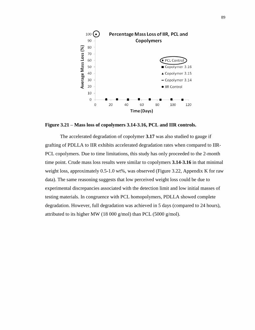
89
Figure 3.21 – Mass loss of copolymers 3.14-3.16, PCL and IIR controls.
The accelerated degradation of copolymer 3.17 was also studied to gauge if
grafting of PDLLA to IIR exhibits accelerated degradation rates when compared to IIR-
PCL copolymers. Due to time limitations, this study has only proceeded to the 2-month
time point. Crude mass loss results were similar to copolymers 3.14-3.16 in that minimal
weight loss, approximately 0.5-1.0 wt%, was observed (Figure 3.22, Appendix K for raw
data). The same reasoning suggests that low perceived weight loss could be due to
experimental discrepancies associated with the detection limit and low initial masses of
testing materials. In congruence with PCL homopolymers, PDLLA showed complete
degradation. However, full degradation was achieved in 5 days (compared to 24 hours),
attributed to its higher MW (18 000 g/mol) than PCL (5000 g/mol).
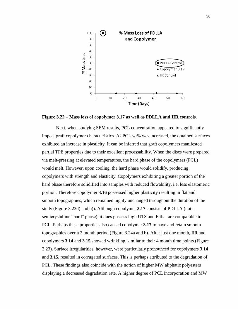
90
Figure 3.22 – Mass loss of copolymer 3.17 as well as PDLLA and IIR controls.
Next, when studying SEM results, PCL concentration appeared to significantly
impact graft copolymer characteristics. As PCL wt% was increased, the obtained surfaces
exhibited an increase in plasticity. It can be inferred that graft copolymers manifested
partial TPE properties due to their excellent processability. When the discs were prepared
via melt-pressing at elevated temperatures, the hard phase of the copolymers (PCL)
would melt. However, upon cooling, the hard phase would solidify, producing
copolymers with strength and elasticity. Copolymers exhibiting a greater portion of the
hard phase therefore solidified into samples with reduced flowability, i.e. less elastomeric
portion. Therefore copolymer 3.16 possessed higher plasticity resulting in flat and
smooth topographies, which remained highly unchanged throughout the duration of the
study (Figure 3.23d) and h)). Although copolymer 3.17 consists of PDLLA (not a
semicrystalline “hard” phase), it does possess high UTS and E that are comparable to
PCL. Perhaps these properties also caused copolymer 3.17 to have and retain smooth
topographies over a 2 month period (Figure 3.24a and b). After just one month, IIR and
copolymers 3.14 and 3.15 showed wrinkling, similar to their 4 month time points (Figure
3.23). Surface irregularities, however, were particularly pronounced for copolymers 3.14
and 3.15, resulted in corrugated surfaces. This is perhaps attributed to the degradation of
PCL. These findings also coincide with the notion of higher MW aliphatic polyesters
displaying a decreased degradation rate. A higher degree of PCL incorporation and MW
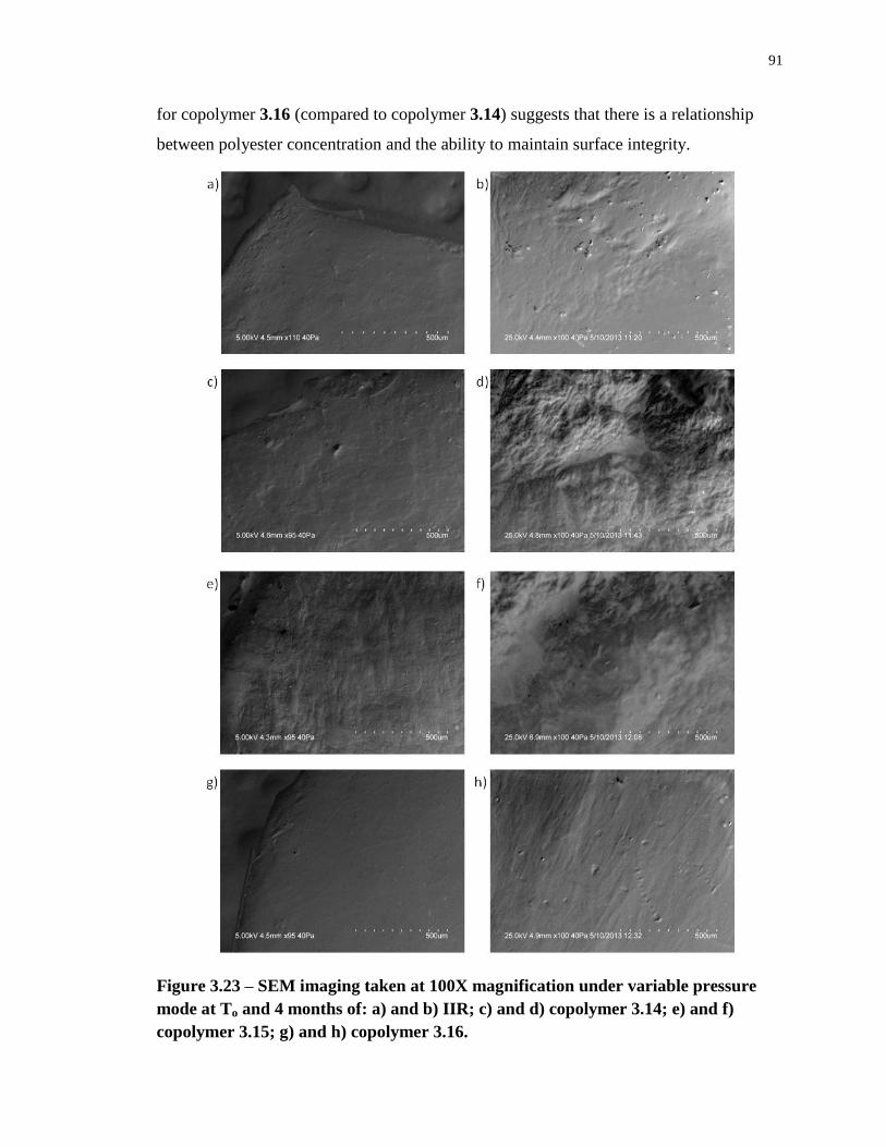
91
for copolymer 3.16 (compared to copolymer 3.14) suggests that there is a relationship
between polyester concentration and the ability to maintain surface integrity.
Figure 3.23 – SEM imaging taken at 100X magnification under variable pressure
mode at To and 4 months of: a) and b) IIR; c) and d) copolymer 3.14; e) and f)
copolymer 3.15; g) and h) copolymer 3.16.
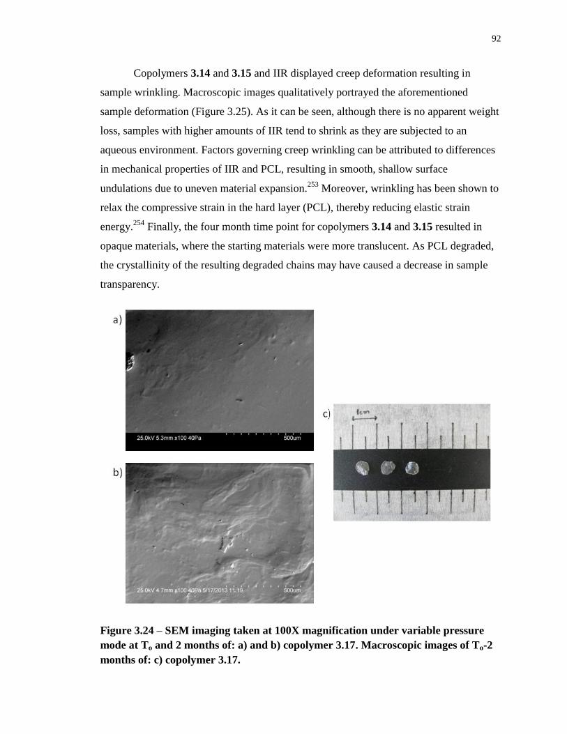
92
Copolymers 3.14 and 3.15 and IIR displayed creep deformation resulting in
sample wrinkling. Macroscopic images qualitatively portrayed the aforementioned
sample deformation (Figure 3.25). As it can be seen, although there is no apparent weight
loss, samples with higher amounts of IIR tend to shrink as they are subjected to an
aqueous environment. Factors governing creep wrinkling can be attributed to differences
in mechanical properties of IIR and PCL, resulting in smooth, shallow surface
undulations due to uneven material expansion.253
Moreover, wrinkling has been shown to
relax the compressive strain in the hard layer (PCL), thereby reducing elastic strain
energy.254
Finally, the four month time point for copolymers 3.14 and 3.15 resulted in
opaque materials, where the starting materials were more translucent. As PCL degraded,
the crystallinity of the resulting degraded chains may have caused a decrease in sample
transparency.
Figure 3.24 – SEM imaging taken at 100X magnification under variable pressure
mode at To and 2 months of: a) and b) copolymer 3.17. Macroscopic images of To-2
months of: c) copolymer 3.17.
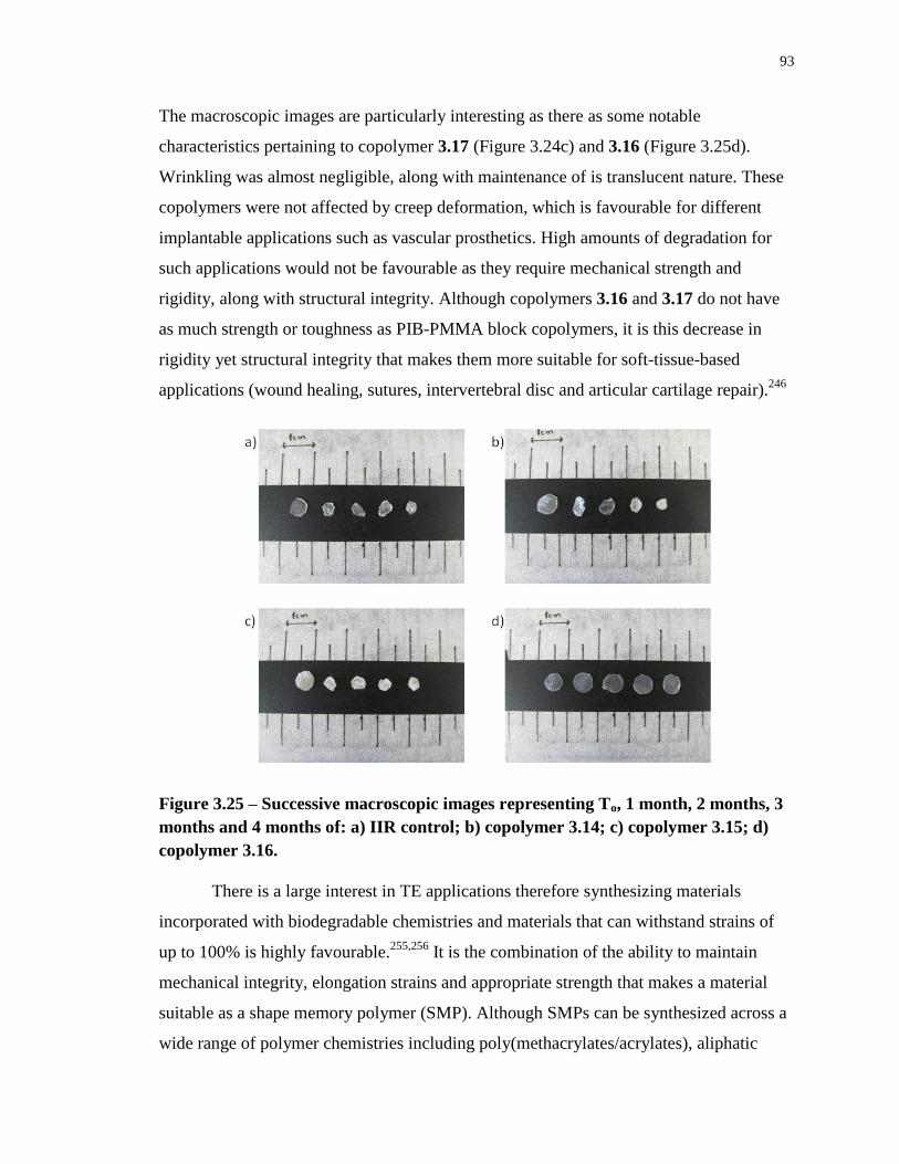
93
The macroscopic images are particularly interesting as there as some notable
characteristics pertaining to copolymer 3.17 (Figure 3.24c) and 3.16 (Figure 3.25d).
Wrinkling was almost negligible, along with maintenance of is translucent nature. These
copolymers were not affected by creep deformation, which is favourable for different
implantable applications such as vascular prosthetics. High amounts of degradation for
such applications would not be favourable as they require mechanical strength and
rigidity, along with structural integrity. Although copolymers 3.16 and 3.17 do not have
as much strength or toughness as PIB-PMMA block copolymers, it is this decrease in
rigidity yet structural integrity that makes them more suitable for soft-tissue-based
applications (wound healing, sutures, intervertebral disc and articular cartilage repair).246
Figure 3.25 – Successive macroscopic images representing To, 1 month, 2 months, 3
months and 4 months of: a) IIR control; b) copolymer 3.14; c) copolymer 3.15; d)
copolymer 3.16.
There is a large interest in TE applications therefore synthesizing materials
incorporated with biodegradable chemistries and materials that can withstand strains of
up to 100% is highly favourable.255,256
It is the combination of the ability to maintain
mechanical integrity, elongation strains and appropriate strength that makes a material
suitable as a shape memory polymer (SMP). Although SMPs can be synthesized across a
wide range of polymer chemistries including poly(methacrylates/acrylates), aliphatic
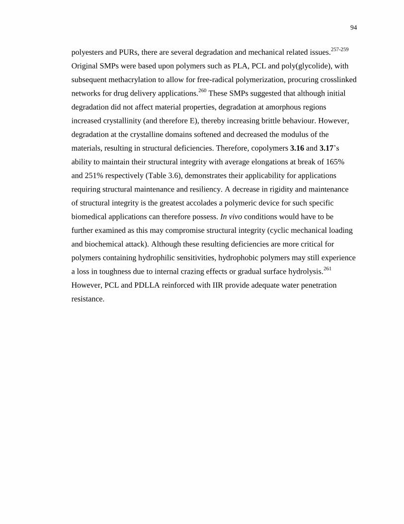
94
polyesters and PURs, there are several degradation and mechanical related issues.257-259
Original SMPs were based upon polymers such as PLA, PCL and poly(glycolide), with
subsequent methacrylation to allow for free-radical polymerization, procuring crosslinked
networks for drug delivery applications.260
These SMPs suggested that although initial
degradation did not affect material properties, degradation at amorphous regions
increased crystallinity (and therefore E), thereby increasing brittle behaviour. However,
degradation at the crystalline domains softened and decreased the modulus of the
materials, resulting in structural deficiencies. Therefore, copolymers 3.16 and 3.17’s
ability to maintain their structural integrity with average elongations at break of 165%
and 251% respectively (Table 3.6), demonstrates their applicability for applications
requiring structural maintenance and resiliency. A decrease in rigidity and maintenance
of structural integrity is the greatest accolades a polymeric device for such specific
biomedical applications can therefore possess. In vivo conditions would have to be
further examined as this may compromise structural integrity (cyclic mechanical loading
and biochemical attack). Although these resulting deficiencies are more critical for
polymers containing hydrophilic sensitivities, hydrophobic polymers may still experience
a loss in toughness due to internal crazing effects or gradual surface hydrolysis.261
However, PCL and PDLLA reinforced with IIR provide adequate water penetration
resistance.
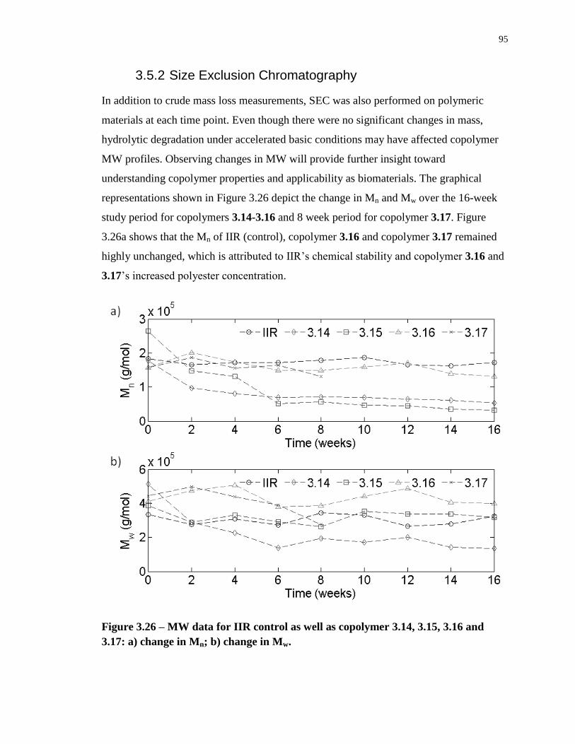
95
3.5.2 Size Exclusion Chromatography
In addition to crude mass loss measurements, SEC was also performed on polymeric
materials at each time point. Even though there were no significant changes in mass,
hydrolytic degradation under accelerated basic conditions may have affected copolymer
MW profiles. Observing changes in MW will provide further insight toward
understanding copolymer properties and applicability as biomaterials. The graphical
representations shown in Figure 3.26 depict the change in Mn and Mw over the 16-week
study period for copolymers 3.14-3.16 and 8 week period for copolymer 3.17. Figure
3.26a shows that the Mn of IIR (control), copolymer 3.16 and copolymer 3.17 remained
highly unchanged, which is attributed to IIR’s chemical stability and copolymer 3.16 and
3.17’s increased polyester concentration.
Figure 3.26 – MW data for IIR control as well as copolymer 3.14, 3.15, 3.16 and
3.17: a) change in Mn; b) change in Mw.
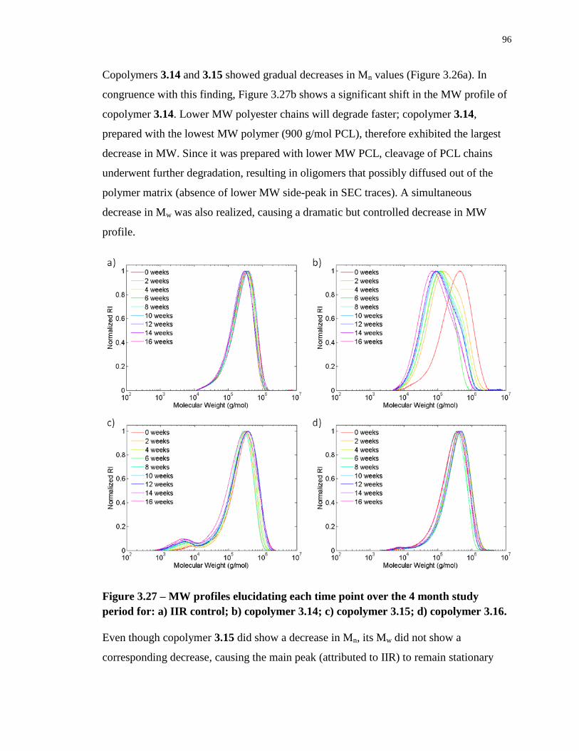
96
Copolymers 3.14 and 3.15 showed gradual decreases in Mn values (Figure 3.26a). In
congruence with this finding, Figure 3.27b shows a significant shift in the MW profile of
copolymer 3.14. Lower MW polyester chains will degrade faster; copolymer 3.14,
prepared with the lowest MW polymer (900 g/mol PCL), therefore exhibited the largest
decrease in MW. Since it was prepared with lower MW PCL, cleavage of PCL chains
underwent further degradation, resulting in oligomers that possibly diffused out of the
polymer matrix (absence of lower MW side-peak in SEC traces). A simultaneous
decrease in Mw was also realized, causing a dramatic but controlled decrease in MW
profile.
Figure 3.27 – MW profiles elucidating each time point over the 4 month study
period for: a) IIR control; b) copolymer 3.14; c) copolymer 3.15; d) copolymer 3.16.
Even though copolymer 3.15 did show a decrease in Mn, its Mw did not show a
corresponding decrease, causing the main peak (attributed to IIR) to remain stationary
97
(Figure 3.27c) causing a significant increase in PDI. This behaviour is attributed to the
shedding of the lower MW PCL side chains and the formation of a bimodal polymer
distribution.
Figure 3.28 – MW profile elucidating each time point over the 2 month study period
for copolymer 3.17.
Copolymer 3.16 did not show a significant decrease in either Mw or Mn, which is
attributed to higher PCL concentrations. Miao et. al. showed that increasing the level of
PCL and therefore crystalline domains in triblock copolymers of PCL and poly(sebacic
anhydride) resulted in slower degradation profiles in both physiological and basic
conditions.262
Therefore in this thesis, increasing PCL content relative to IIR may be the
determining factor for decreased degradation. Conversely, increasing amorphous domains
allows water to penetrate and degrade materials easier. Because of this, degradation of
IIR-PDLLA copolymer 3.17 was hypothesized to display an increased weight loss and
change in MW due to PDLLA’s amorphous state. However, Figure 3.28 showed that its
MW profile remained relatively constant over the first 8 weeks of the study.
Degradation of PCL can occur via surface or bulk processes. However, a
combination of these pathways may have influenced IIR-PCL copolymer degradation.90
Prediction of erosion pathways is particularly complicated when grafting polyesters that
typically abide by bulk erosion (where degradation is unpredictable and starts
spontaneously) onto IIR (one that does not show degradation).263
Although mass
remained almost constant for all samples, Mn did decrease for copolymers 3.14 and 3.15,
98
indicative of PCL chain cleavage and subsequent oligomer formation.264,265
Chain
scission was homogeneous for copolymer 3.14 causing a homogenous decrease in MW
(bulk degradation). It is interesting to note, however, that 3.16 (44 wt% PCL
incorporation) showed little to no change in MW. This is similar to surface degradation in
that water cannot penetrate the polymer, causing the hydrolysed byproducts to diffuse
rapidly into the media, resulting in limited water penetration to the copolymer matrix. As
a result, degradation will occur purely at the surface, causing the polymer to thin while
leaving the MW intact. However, under base-accelerated conditions, autocatalysis at the
surface would not occur. Therefore the high concentration of PCL combined with stable
IIR caused water penetration to be negligible resulting in minimal degradation.
99
3.6 Bioassays and Compatibility
3.6.1 Cell Growth on Polymer Films
The evaluation of cell growth on copolymer surfaces was performed by studying the
adhesion and topology of C2C12 murine myoblast cells on films of copolymers 3.14-
3.17, and comparing them to the same cells grown on selected control surfaces. Although
this method is qualitative, observing cell morphology is an essential screening method for
cytotoxicity and cell compatibility at the initial analysis stage.191
Observation of how the
cells behave in terms of adhesion and viability gauges cellular response, which can be
confirmed via the MTT (3-(4,5-dimethylthiazol-2-yl)-2,5-diphenyltetrazolium bromide)
cytoxicity test.191,266
To prepare the films for these studies, copolymers 3.14-3.17 were
prepared as 3 wt% solutions in toluene with subsequent drop-casting onto glass
coverslips, followed by sterilization.
Seeding myoblasts onto polymer surfaces and comparing cell proliferation to
glass, IIR, PCL and PDLLA homopolymers, allowed for direct comparisons between
substrate and cell morphology. After allowing an incubation period of 48 hours, cells
were stained with DAPI (4’-6-diamidino-2-phenylindole dyhydrocholoride) and Alexa
Fluor 568 phalloidin in order to visualize nuclei and actin protein fibers of the
cytoskeleton, respectively. Observation of the cytoskeleton structure is crucial.
Scrutinizing cellular spread and resulting morphologies provides qualitative comparisons
between copolymers and control substrates to assess cellular health.267
In addition, cells
were also counted on each surface for a quantitative measure. In order to do so, surfaces
were prepared in triplicate for each sample and 3 images were taken at random locations
to determine cell density. Utilizing cellc12 and Matlab 9 numerical values were obtained.
By averaging these values, determining standard deviations, and performing ANOVA
statistical measurements (Prism), confirms whether cell densities are/are not significantly
different between each surface. Figure 3.29 shows representative images from the control
samples (a-d) as well as from each copolymer (e-h). In this regard, one can clearly
evaluate the results on a qualitative and quantitative basis.
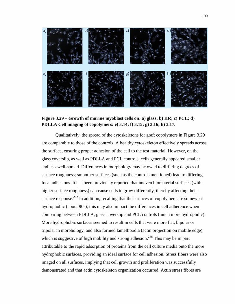
100
Figure 3.29 – Growth of murine myoblast cells on: a) glass; b) IIR; c) PCL; d)
PDLLA Cell imaging of copolymers: e) 3.14; f) 3.15; g) 3.16; h) 3.17.
Qualitatively, the spread of the cytoskeletons for graft copolymers in Figure 3.29
are comparable to those of the controls. A healthy cytoskeleton effectively spreads across
the surface, ensuring proper adhesion of the cell to the test material. However, on the
glass coverslip, as well as PDLLA and PCL controls, cells generally appeared smaller
and less well-spread. Differences in morphology may be owed to differing degrees of
surface roughness; smoother surfaces (such as the controls mentioned) lead to differing
focal adhesions. It has been previously reported that uneven biomaterial surfaces (with
higher surface roughness) can cause cells to grow differently, thereby affecting their
surface response.202
In addition, recalling that the surfaces of copolymers are somewhat
hydrophobic (about 90°), this may also impact the differences in cell adherence when
comparing between PDLLA, glass coverslip and PCL controls (much more hydrophilic).
More hydrophobic surfaces seemed to result in cells that were more flat, bipolar or
tripolar in morphology, and also formed lamellipodia (actin projection on mobile edge),
which is suggestive of high mobility and strong adhesion.266
This may be in part
attributable to the rapid adsorption of proteins from the cell culture media onto the more
hydrophobic surfaces, providing an ideal surface for cell adhesion. Stress fibers were also
imaged on all surfaces, implying that cell growth and proliferation was successfully
demonstrated and that actin cytoskeleton organization occurred. Actin stress fibres are
101
typically associated with strong focal adhesions, which could be tested via vinculin
labeling (major protein associated with focal adhesions). However, although cells were
found to be more rounded on surfaces with slightly higher hydrophilicity, increasing the
incubation time did result in increased cell elongation and therefore adhesion. Since
C2C12 murine myoblast cells proliferate quickly (doubling in approximately 27 hours),
some confocal images (such as Figure 3.29e) featured cells that displayed tips deeply
stained by the dye, indicative of dynamic contact. Overall, actin filaments were observed
on all tested surfaces. This linear polymer microfilament is important for cellular
functions such as mobility and contraction of cells during division, thereby confirming
the existence of healthy, proliferating cells.
Quantitatively, unhealthy cell specimens would result in much fewer cells
adhering to the substrate if conditions were unfavourable for proper attachment. Figure
3.30 reveals the average density of cells on each surface, which ranged from 270-400
cells/mm2. ANOVA tests confirmed that there were no significant differences between
the results for the different surfaces. Control substrates such as glass are considered to be
reasonably good substrates for cell growth, indicating that the graft copolymers provide
favourable conditions as well. These results are crucial in determining cell adhesivity
properties for potential implantable biomaterial applications. This importance is related to
surgical implantation of different medical devices in that local tissue injury resulting from
insertion of vascular grafts, heart valve sewing cuffs and annuloplasty rings, affects both
thrombosis and inflammation at the site. Both of these processes are also known to
contribute to healing of tissue into and around the device.268
Ensuring that a monolayer of
endothelial cells can form on the surface of vascular grafts, for instance, can prevent
thrombosis and allow for faster healing times.108
Moreover, this preliminary test also
suggests that copolymers will provide a non-toxic environment, which will be confirmed
via the MTT cytotoxicity assay.
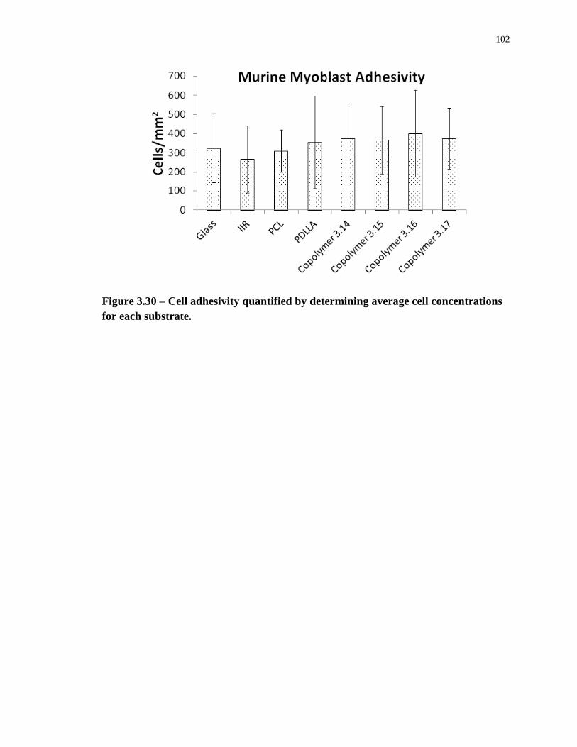
102
Figure 3.30 – Cell adhesivity quantified by determining average cell concentrations
for each substrate.
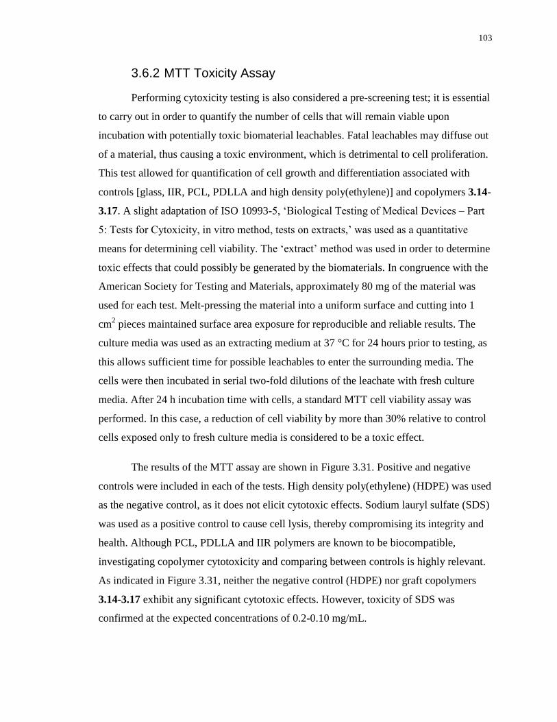
103
3.6.2 MTT Toxicity Assay
Performing cytoxicity testing is also considered a pre-screening test; it is essential
to carry out in order to quantify the number of cells that will remain viable upon
incubation with potentially toxic biomaterial leachables. Fatal leachables may diffuse out
of a material, thus causing a toxic environment, which is detrimental to cell proliferation.
This test allowed for quantification of cell growth and differentiation associated with
controls [glass, IIR, PCL, PDLLA and high density poly(ethylene)] and copolymers 3.14-
3.17. A slight adaptation of ISO 10993-5, ‘Biological Testing of Medical Devices – Part
5: Tests for Cytoxicity, in vitro method, tests on extracts,’ was used as a quantitative
means for determining cell viability. The ‘extract’ method was used in order to determine
toxic effects that could possibly be generated by the biomaterials. In congruence with the
American Society for Testing and Materials, approximately 80 mg of the material was
used for each test. Melt-pressing the material into a uniform surface and cutting into 1
cm2 pieces maintained surface area exposure for reproducible and reliable results. The
culture media was used as an extracting medium at 37 °C for 24 hours prior to testing, as
this allows sufficient time for possible leachables to enter the surrounding media. The
cells were then incubated in serial two-fold dilutions of the leachate with fresh culture
media. After 24 h incubation time with cells, a standard MTT cell viability assay was
performed. In this case, a reduction of cell viability by more than 30% relative to control
cells exposed only to fresh culture media is considered to be a toxic effect.
The results of the MTT assay are shown in Figure 3.31. Positive and negative
controls were included in each of the tests. High density poly(ethylene) (HDPE) was used
as the negative control, as it does not elicit cytotoxic effects. Sodium lauryl sulfate (SDS)
was used as a positive control to cause cell lysis, thereby compromising its integrity and
health. Although PCL, PDLLA and IIR polymers are known to be biocompatible,
investigating copolymer cytotoxicity and comparing between controls is highly relevant.
As indicated in Figure 3.31, neither the negative control (HDPE) nor graft copolymers
3.14-3.17 exhibit any significant cytotoxic effects. However, toxicity of SDS was
confirmed at the expected concentrations of 0.2-0.10 mg/mL.
104
Figure 3.31 – MTT cytotoxicity assay performed on: a) graft copolymers 3.14-3.16;
b) graft copolymer 3.17.
105
Chapter 4
4 Materials and Methods
4.1 General Procedures and Materials
IIR 402 with a Mw of 395kDa and a polydispersity index (PDI) of 2.44, as measured by
size exclusion chromatography (SEC), composed of 2.2mol% isoprene units was kindly
provided by LANXESS and was converted to the activated derivative (3.13) by the
previously reported method.147
Hydroxy-terminated PCL (MW = 900 Da and 3500 Da)
and PDLLA (MW = 2800Da) were purchased from Polymer Source (Montreal, Québec).
Silicon wafers were purchased from University Wafer (Boston, Massachusetts). Cell
culture materials were purchased from Nunclon and Invitrogen. Solvents were
purchased from Caledon, PNPC was purchased from Alfa Aesar (used as received). m-
chloroperbenzoic acid was dissolved in toluene and dried with MgSO4 before use.
Pyridine and ε-caprolactone monomer were distilled over CaH2 before use. All other
chemicals were purchased from Sigma Aldrich and used without further purification
unless stated otherwise. Dry dichloromethane and toluene were obtained from an
Innovative Technology (Newburyport, USA) solvent purification system based on
aluminum oxide columns. 1H NMR spectra were obtained in CDCl3 at 600 MHz using
Varian Inova spectrometers. NMR chemical shifts are reported in ppm and are calibrated
against residual solvent signals of CDCl3 (δ 7.26). Coupling constants (J) are reported in
Hz. The percentage of functionalized isoprene units was determined from 1H NMR,
based on the relative integrations of the signals at 5.03 and 4.87 ppm coinciding to the
alkene adjacent to the activated carbonate and the PCL/PDLLA carbamate product,
respectively. The PCL and PDLLA content in weight percentage was determined by 1H
NMR, based on the relative integrations between the peaks at 4.03ppm (PCL methylene),
5.19ppm (PDLLA methane) and 1.12ppm (isobutylene). Differential
scanning calorimetry (DSC) was performed under a nitrogen atmosphere on a Q20 DSC
TA instrument at a heating/cooling rate of 10 °C/min from -100 to + 100 °C. The Tg and
Tm were obtained from the second heating cycle. SEC was performed in tetrahydrofuran
(THF) using a Viscotek GPCmax VE 2001 GPC Solvent/Sample Module equipped with a
106
Waters 2489 UV/Visible Detector, Viscotek VE 3580 RI Detector and two PolyPore (300
mm x 7.5 mm) columns from Agilent. The calibration was performed using polystyrene
standards. FTIR was performed on a Bruker Optics TENSOR 27 series FT-IR, OPUS 7.0,
via transmittance (%) with a background scan of 16 and a sample scan of 128, recording
wavenumbers from 500-3700cm-1
.
4.2 Graft Copolymer Synthesis and Chemical Characterization
4.2.1 Synthesis of Polymer 3.8a
Following a previously reported literature,148
a round-bottom flask equipped with stir bar
was charged with PCL homopolymer of 900 g/mol (3.7a) (0.40 g, 0.44 mmol, 1.0 equiv.),
4-(dimethylamino)pyridine (DMAP) (0.20 g, 1.64 mmol, 3.7 equiv.) pyridine (0.10 g,
1.29 mmol, 2.9 equiv.) and dichloromethane (DCM) (7 mL) under dry conditions. BOC-
protected β-alanine anhydride (3.6) (0.39 g, 1.1 mmol, 2.5 equiv.) was charged into a
separate flask and dissolved in DCM (2 mL) under dry conditions. The latter solution was
added to the PCL-containing solution and stirred overnight at room temperature. Next,
deionized water was added to the reaction mixture and stirred for an additional 3 hours at
room temperature. Purification involved washing with 1M HCl (3X), 1M Na2CO3 (3X)
and concentrated brine (1X), followed by drying with MgSO4 and reduced pressure
solvent removal.
Yield: 0.35 g, 83% 1H NMR: δ, 4.24 (t, 2H, J = 4.7 Hz), 4.04-4.10 (m, 18H), 3.70
(t, 2H, J = 5.1 Hz), 3.63-3.66 (m, 2H), 3.54-3.56 (m, 2H), 3.40 (br. s, 2H) 3.39 (s, 3H),
2.51 (t, 2H, J = 6.1 Hz), 2.29-2.37 (m, 16H), 1.60-1.69 (m, 32H), 1.43 (s, 9H), 1.34-1.42
(m, 16H). SEC: Mw = 3160 g/mol, PDI = 1.33. IR: 1047, 1105, 1171, 1246, 1366, 1420,
1472, 1569, 1728, 2947, 2866, 3393, 3439 cm-1
.
Polymer 3.8b was prepared using the same procedure as described for polymer 3.8a,
expect that PCL homopolymer of 3500 g/mol (3.7b) (0.40 g, 0.114 mmol, 1.0 equiv.) was
used.
107
Yield: 0.38 g, 88% 1H NMR: δ, 4.13 (td, 2H, J = 7.8, 4.7 Hz), 4.06 (t, 62H, J = 6.8
Hz), 3.39 (q, 2H, J = 6.1 Hz), 2.51 (t, 2H, J = 6.1 Hz), 2.3 (t, 62H, J = 7.4 Hz), 1.62-1.68
(m, 124H), 1.43 (s, 9H), 1.34-1.42 (m, 62H), 1.25 (t, 3H, J = 7 Hz). SEC: Mw = 9202
g/mol, PDI = 1.22. IR: 1047, 1105, 1171, 1246, 1366, 1420, 1472, 1569, 1728, 2947,
2866, 3393, 3439 cm-1
.
Polymer 3.11 was prepared using the same procedure as described for polymer 3.8a,
expect that PDLLA homopolymer of 2800 g/mol (3.10) (0.40 g, 0.143 mmol, 1.0 equiv.)
was used.
Yield: 0.31 g, 81% 1H NMR: δ, 5.12-5.25 (m, 39H), 4.23-4.32 (m, 2H), 3.57 (m,
2H), 3.42 (br. s, 2H), 3.36 (s, 3H), 2.59 (m, 2H), 1.54-1.59 (m, 117H), 1.43 (s, 9H). SEC:
Mw = 5098 g/mol, PDI = 1.19. IR: 1134, 1267, 1512, 1757, 2949, 2997, 3517, 3435 cm-1
.
4.2.2 Synthesis of Polymer 3.9a
Polymer 3.8a (0.34 g, 0.373 mmol, 1.0 equiv.) was dissolved in 1.25 mL DCM: 1.25 mL
trifluoroacetic acid (TFA) (1:1) and the reaction mixture was stirred for 2 hours. DCM
and TFA were removed by pressurized air. The product was redissolved in DCM and
dried in vacuo.
Yield: 0.34 g, > 99% 1H NMR: δ, 4.24 (t, 2H, J = 4.7 Hz), 4.16 (t, 2H, J = 6.4
Hz), 4.06 (t, 16H, J = 6.6 Hz), 3.7 (t, 2H, J = 4.7 Hz), 3.64-3.66 (m, 2H), 3.55-3.58 (m,
2H), 3.39 (s, 3H), 3.33 (br. s, 2H), 2.8 (t, 2H, J = 5.9 Hz), 2.29-2.34 (m, 16H), 1.60-1.69
(m, 32H), 1.34-1.42 (m, 16H). SEC: Mw = 2450 g/mol, PDI = 1.45. IR: 1047, 1105, 1171,
1246, 1366, 1420, 1472, 1569, 1728, 2947, 2866, 3445 cm-1
.
Polymer 3.9b was prepared using the same procedure as described for polymer 3.9a,
expect that polymer 3.8b (0.40 g, 0.114 mmol, 1.0 equiv.) was used.
Yield: 0.40 g, > 99% 1H NMR: δ, 4.17 (t, 2H, J = 6.5 Hz), 4.10-4.15 (m, 2H),
4.06 (t, 62H, J = 6.5 Hz), 3.33 (t, 2H, J = 5.9 Hz), 2.83 (t, 2H, J = 5.3 Hz), 2.31 (t, 62H, J
= 7.6 Hz), 1.62-1.68 (m, 124H), 1.36-1.41 (m, 62H), 1.25 (t, 3H, J = 7.6 Hz). SEC: Mw =
108
9030 g/mol, PDI = 1.22. IR: 1047, 1105, 1171, 1246, 1366, 1420, 1472, 1569, 1728,
2947, 2866, 3445 cm-1
.
4.2.3 Synthesis of Polymer 3.12
Polymer 3.11 and 2 mL of DCM were charged in a round-bottom flask equipped with stir
bar under dry conditions. TFA was added (0.70 g, 6.11 mmol, 100 equiv.) and stirred at
0°C for 2 hours. Next, DCM and TFA were removed under low pressure (~20 mbar), re-
dissolved in DCM and passed over a K2CO3 plug to remove residual TFA.
Yield: 0.65 g, 91% 1H NMR: δ, 5.13-5.23 (m, 39H), 4.23-4.32 (m, 2H), 3.57 (tt,
2H, J = 2.35, 3.52Hz), 3.36 (s, 3H), 3.29 (br. s, 2H), 2.83 (br. s, 2H), 1.54-1.58 (m,
117H). SEC: Mw = 4740 g/mol, PDI = 1.31. IR: 1134, 1267, 1512, 1757, 2949, 2997,
3508 cm-1
.
4.2.4 Synthesis of Graft Copolymer 3.14
In a round-bottom flask equipped with stir bar, 3.9a (0.95 g, 1.06 mmol, 1.2 equiv.) was
dissolved in 20mL of dry toluene at 60°C. A solution of PNPC-activated IIR (3.13)147
(2.19g, 0.882mmol of 4-nitrophenylcarbonate units, 1.0 equiv.) in 25mL of dry toluene
was added dropwise to the reaction mixture. DMAP (0.43g, 3.52mmol, 4.0 equiv.)
dissolved in 4mL dry toluene was also added to the reaction mixture, which was then
stirred overnight at 60°C. The solvent was removed in vacuo and the graft copolymer was
redissolved in DCM, washed with deionized water (3X), dried with MgSO4, concentrated
and precipitated from DCM into acetone to afford copolymer 3.14.
Yield: 2.45 g, 85% 1H NMR: δ, 5.20 (br. s, 1H), 5.10 (s, 1H), 5.05 (s, 1H), 4.87
(s, 1H), 4.24 (t, 2H, J = 5.3 Hz), 4.06 (t, 16H, J = 6.5 Hz, 3.7 (t, 2H, J = 4.7 Hz), 3.6-3.65
(m, 2H), 3.54-3.56 (m, 2H), 3.45 (q, 2H, J = 5.9 Hz), 3.38 (s, 3H), 2.53 (t, 2H, J = 6.2
Hz), 2.3 (t, 16H, J = 7.6 Hz), 1.62-1.68 (m, 32H), 1.41 (s, 88H), 1.37-1.39 (m, 16H), 1.11
(s, 264H). PCL content from 1H NMR = 15 wt%. DSC: Tg = -67°C. IR: 1165, 1230,
1366, 1390, 1470, 1736, 2955, 3445 cm-1
.
109
Graft copolymer 3.15 was prepared using the same procedure as described for polymer
3.14, expect that polymer 3.9b (1.02 g, 0.292 mmol, 0.8 equiv. relative to 4-
nitrophenylcarbonate units) was used.
Yield: 1.17 g, 70% with a conversion of 50% (based on proton integrations
corresponding to a and a’ (Figure 3.5). 1H NMR: δ, 8.27 (d, 1.5H, J = 9.1 Hz), 7.38 (d,
1.5H, J = 9.1 Hz), 5.27 (s, 0.50H), 5.20 (br. s, 0.50H), 5.12 (s, 0.50H), 5.10 (s, 0.50H),
5.05 (s, 0.50H), 4.87 (s, 0.50H), 4.13 (q, 2H, J = 7.2 Hz), 4.07 (t, 62H, J = 6.5 Hz), 3.45
(q, 2H J = 5.9 Hz), 2.53 (t, 2H, J = 5.9 Hz), 2.31 (t, 62H, J = 7.3 Hz), 1.62-1.68 (m,
124H), 1.41 (s, 88H), 1.36-1.40 (m, 62H), 1.25 (t, 3H, J = 7.3 Hz), 1.11 (s, 264H). PCL
content from 1H NMR = 32 wt%. DSC: Tg = -65°C, Tm = 44°C. IR: 1165, 1230, 1366,
1390, 1470, 1736, 2955, 3445 cm-1
.
Graft copolymer 3.16 was prepared using the same procedure as described for polymer
3.14, expect that polymer 3.9b (0.34 g, 0.2098 mmol, 1.2 equiv. relative to 4-
nitrophenylcarbonate units) was used.
Yield: 0.18 g, 75% 1H NMR: δ, 5.19 (br. s, 1H), 5.1 (s, 1H), 5.05 (br. s, 1H), 4.87
(br. s, 1H), 4.13 (q, 2H, J = 7.2 Hz), 4.07 (t, 62H, J = 6.5 Hz), 3.46 (q, 2H, J = 5.9 Hz),
2.53 (t, 2H, J = 5.9 Hz), 2.31 (t, 62H, J = 7.3 Hz), 1.62-1.68 (m, 124H), 1.41 (s, 88H),
1.36-1.40 (m, 62H), 1.25 (t, 3H, J = 7.3 Hz), 1.11 (s, 264H). PCL content from 1H NMR
= 44 wt%. DSC: Tg = -62°C, Tm = 50°C. IR: 1165, 1230, 1366, 1390, 1470, 1736, 2955,
3445 cm-1
.
Graft copolymer 3.17 was prepared using the same procedure as described for polymer
3.14, expect that polymer 3.12 (0.65 g, 0.231 mmol, 1.2 equiv. relative to 4-
nitrophenylcarbonate units) was used.
Yield: 0.51 g, 86% 1H NMR: δ, 5.14-5.25 (m, 39H), 5.11 (br. s, 1H), 5.04 (br. s,
1H), 4.86 (s, 1H), 4.23-4.32 (m, 2H), 3.57-3.59 (m, 2H), 3.45-3.50 (m, 2H), 3.36 (s, 3H),
2.61 (t, 2H, J = 2Hz), 1.54-1.59 (m, 117H), 1.41 (s, 88H), 1.11 (s, 264H). PDLLA
content from 1H NMR = 46 wt%. DSC: Tg,1 = -63°C; Tg,2 = 23°C. SEC: Mw = 485 kDa,
PDI = 3.81. IR: 1094, 1132, 1188, 1365, 1388, 1468, 1757, 2896, 2952 cm-1
.
110
4.3 Physical Characterization
4.3.1 Atomic Force Microscopy
Silicon wafers were cut into small pieces (~1cm2) and treated with “Piranha” solution, a
mixture of 3:1 H2SO2:H2O2 for approximately 1 hour to generate a clean, hydrophilic
oxide surface. The surface was then cleaned with deionized water, acetone and
subsequently dried overnight in a desiccator. Polymer thin films were prepared by spin-
casting 100 μL of a 3 wt% solution of the material in toluene on 1 cm2 of silicon wafer at
6000 rpm for 30 seconds. The surfaces were kept under vacuum for at least 24 hours
prior to image analysis. Surfaces were visualized by an atomic force microscope (XE-100
microscope from psia). Images were obtained by scanning surfaces in tapping mode with
rectangular-shaped silicon cantilevers with a spring constant of 48 N/m. Images were
then refined using XEI Image Processing software for SPM data by applying surface
smoothing and glitch removal.
4.3.2 Water Contact Angle
The water contact angle of the polymer film surface in air was measured by using a
sessile drop method on a KRÜSS DSA100 Drop Shape Analysis System (Hamburg,
Germany). Timing started after dosing a water droplet onto the testing surface, allowing
for an incubation period of 30 seconds for consistency. After 30 seconds, angles were
recorded via tangent analysis.
4.3.3 Scanning Electron Microscopy
SEM micrographs were obtained using a Hitachi 3400-N Variable Pressure Scanning
Electron Microscope. Images were taken at 100X and 1000X magnification utilizing
variable pressure mode to avoid sample preparation via gold sputtering techniques
(possible damage to rubber films).
4.3.4 Mechanical Testing of Graft Copolymers
A 40 mm x 5 mm x 0.3 mm (length x width x thickness) strip of polymer was cut from a
polymer film (prepared via compression-molding with Carver Model 385-OC heated
manual press) and its mechanical properties were measured on an INSTRON universal
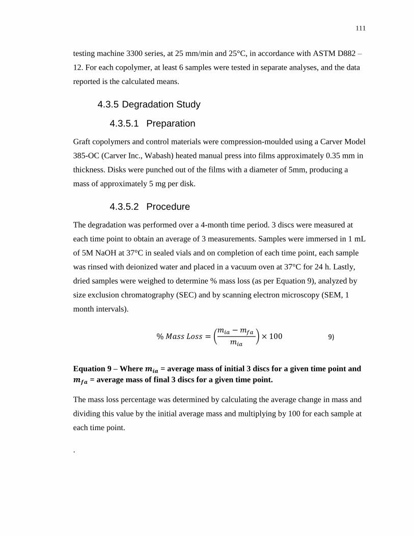
111
testing machine 3300 series, at 25 mm/min and 25°C, in accordance with ASTM D882 –
12. For each copolymer, at least 6 samples were tested in separate analyses, and the data
reported is the calculated means.
4.3.5 Degradation Study
4.3.5.1 Preparation
Graft copolymers and control materials were compression-moulded using a Carver Model
385-OC (Carver Inc., Wabash) heated manual press into films approximately 0.35 mm in
thickness. Disks were punched out of the films with a diameter of 5mm, producing a
mass of approximately 5 mg per disk.
4.3.5.2 Procedure
The degradation was performed over a 4-month time period. 3 discs were measured at
each time point to obtain an average of 3 measurements. Samples were immersed in 1 mL
of 5M NaOH at 37°C in sealed vials and on completion of each time point, each sample
was rinsed with deionized water and placed in a vacuum oven at 37°C for 24 h. Lastly,
dried samples were weighed to determine % mass loss (as per Equation 9), analyzed by
size exclusion chromatography (SEC) and by scanning electron microscopy (SEM, 1
month intervals).
9)
Equation 9 – Where = average mass of initial 3 discs for a given time point and
= average mass of final 3 discs for a given time point.
The mass loss percentage was determined by calculating the average change in mass and
dividing this value by the initial average mass and multiplying by 100 for each sample at
each time point.
.
112
4.4 Biological Characterization
4.4.1 Cell Growth on Polymer Films
C2C12 mouse myoblast cells were maintained at 37oC and 5% CO2 in Dulbecco’s
Modified Eagle Medium (DMEM, Invitrogen) supplemented with 10% fetal bovine
serum (Invitrogen) and supplemented with 1% Glutamax (100) solution and 1%
Penstrep (100). Microscope glass cover slips (circular, 10 mm diameter) were coated
using a 30 mg/mL solution of the copolymers 2, 3, 4 and 5 in toluene by drop-casting (3
coats of 60 μL). The surfaces were placed in the wells of a 24-well (1 mL working
volume, NunclonMultidishes) plate and sterilized by submersion in 70% ethanol for
approximately 30 minutes, aspirated, then left to dry under UV light for approximately 1
hour. Next, the samples were conditioned overnight in Hank’s balanced salt solution
(HBSS). The sterilized samples were seeded with 2000 cells/surface and incubated for 3
hours to promote cell adhesion. Upon adhesion, 0.5 mL of cell culture media was added
to each well. The 24-well plate was incubated for 48 hours; samples were first washed
with pre-warmed 1X phosphate-buffered saline (PBS, pH 7.2) (Invitrogen) and
subsequently fixed with 4% paraformaldehyde in 1X PBS. Samples were washed three
times with 1X PBS and then treated with 0.5mL of acetone at -20oC for 5 minutes to
permeabilize the membrane. Next, they were washed another 3 times with 1X PBS,
stained with Alexa Fluor 568 phalloidin (20X dilution with 1X PBS, Invitrogen) for 15
minutes; 4’-6-diamidino-2-phenylindole dyhydrocholoride (DAPI, 300nM, 500X dilution
with 1X PBS, Invitrogen) was added directly to the surfaces for an additional 5 minutes.
The samples were washed a final 3 times with 1X PBS, placed face up onto glass
microscope slides, sealed with ProLong Gold Antifade Reagent (Invitrogen) and
contained with coverslips (type 1). Confocal images were obtained using a confocal laser
scanning microscope (LSM 510 Duo Vario, Carl Zeiss) using a 20x objective and
excitation wavelengths of 405 (DAPI) and 578 nm (Alexa Fluor 568 phalloidin). Cells
were counted using cellc12, MATLAB-based program. Statistical analyses (ANOVA
followed by Tukey’s honestly significant difference (HSD) post hoc method when
statistically significant) were performed using Prism software.
113
4.4.2 MTT Toxicity Assay
C2C12 mouse myoblast cells were first resuspended by use of Gibco® Trypsin/
ethylenediaminetetraacetic acid (EDTA) (solution of 0.025% trypsin and 0.01% EDTA in
phosphate buffered saline); a cell count was performed with a haemocytometer. Based on
this count, cells were seeded in a Nunclon® 96-well U bottom transparent polystrol plate
to obtain 10 000 cells/well in a volume of 100μL Dulbecco’s Modified Eagle Medium
(Invitrogen) supplemented with 10% fetal bovine serum (Invitrogen), 1% Glutamax
(100) solution and 1% Penstrep (100) to columns labelled C1-C8, SDS, 1-4 and VC
(vehicle control). 100μL of DMEM was introduced to the column labeled JM (just
media). The 96-well plate was then placed in a 5% CO2 incubator at 37°C for 24 hours.
Testing samples were melt-pressed (0.015") to obtain uniformity (and to provide more
surface area for potentially toxic leachates) and cut into squares of 1cm x 1cm. Samples
were then sterilized in 70% ethanol for approximately 30 minutes and subsequently dried
for 2 hours under UV light. Afterwards, they were placed in Petri dishes; 2 mL of DMEM
was added and the resulting Petri dishes were placed in a CO2 incubator at 37°C for 24
hours. After 24 hours, anything that was water soluble would be leached out of the testing
samples; DMEM that samples were subjected to was then acquired via syringe and
passed through a filter (to prevent particles >200 nm). Next, growth media from the
Nunclon® 96-well plate was aspirated. 1200 μL of the filtered DMEM testing sample
was obtained; 100μL was placed in each C8 well (as depicted in Table 4.1) to obtain a
100% leachate testing column. 600 μL of fresh DMEM was then added to the remaining
600 μL of filtered DMEM testing sample to create a 50% leachate; 100 μL was then
added to each of the wells labeled C7. This process was repeated until C1 was reached
with a 0.78% leachate dilution was attained. As a positive control to confirm cell death,
sodium lauryl sulfate (SDS) was added to the columns labeled SDS1, SDS2, SDS3 and
SDS4 with SDS concentrations in DMEM of 0.2 mg/mL, 0.15 mg/mL, 0.10 mg/mL and
0.05mg/mL, respectively. Lastly, the columns labeled VC and media (M) had fresh
DMEM introduced. The Nunclon® 96-well plate was then returned to a 5% CO2
incubator at 37°C for 24 hours. MTT (3-(4,5-Dimethylthiazol-2-yl)-2,5-
Diphenyltetrazolium Bromide) reagent was prepared at 5mg/mL in deionized water; 1
mL of this solution was added to 10 mL of DMEM. Media was aspirated from the 96-
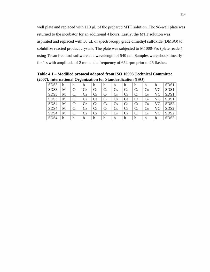
114
well plate and replaced with 110 μL of the prepared MTT solution. The 96-well plate was
returned to the incubator for an additional 4 hours. Lastly, the MTT solution was
aspirated and replaced with 50 μL of spectroscopy grade dimethyl sulfoxide (DMSO) to
solubilize reacted product crystals. The plate was subjected to M1000-Pro (plate reader)
using Tecan i-control software at a wavelength of 540 nm. Samples were shook linearly
for 1 s with amplitude of 2 mm and a frequency of 654 rpm prior to 25 flashes.
Table 4.1 – Modified protocol adapted from ISO 10993 Technical Committee.
(2007). International Organization for Standardization (ISO)
SDS3 b b b b b b b b b b SDS1
SDS3 M C1 C2 C3 C4 C5 C6 C7 C8 VC SDS1
SDS3 M C1 C2 C3 C4 C5 C6 C7 C8 VC SDS1
SDS3 M C1 C2 C3 C4 C5 C6 C7 C8 VC SDS1
SDS4 M C1 C2 C3 C4 C5 C6 C7 C8 VC SDS2
SDS4 M C1 C2 C3 C4 C5 C6 C7 C8 VC SDS2
SDS4 M C1 C2 C3 C4 C5 C6 C7 C8 VC SDS2
SDS4 b b b b b b b b b b SDS2
115
Chapter 5
5 Conclusions and Future Work
IIR is currently used for a variety of applications ranging from foodstuffs (chewing gum),
bladders of sporting goods and most notably, as the innerliner for automotive tires.
However, in recent years there has been significant interest in expanding its application in
biomedical areas. Because of IIRs high elasticity and low strength, it has the inherent
ability to mimic various soft tissues in the body. However, in order to use it in such
applications as vascular prosthetics or orthopaedic implants, its properties have to be
tuned in order to ensure the maintenance of its structural integrity. Therefore this thesis
focused on synthesizing IIR-aliphatic polyester graft copolymers in order to tune IIR’s
chemical, physical and biological properties.
First, copolymer synthesis involving a “grafting-from” approach was investigated.
Performing the ROP of PCL from hydroxyl moieties on the IIR backbone proved to be
problematic and irreproducible. Therefore, the “grafting-to” method involving
functionalization of both the IIR backbone as well as PCL and PDLLA homopolymers
resulted in near 100% functionalization of IP units under mild conditions. Upon
successful synthesis of copolymers, they were chemically (1H NMR, SEC, DSC and
FTIR), physically (AFM, WCA, strain-controlled fatigue testing and accelerated
degradability) and biologically (cell growth on polymer films and cytoxicity testing)
characterized.
By studying the aforementioned characterization data, some important property
changes were imparted by grafting PCL or PDLLA to the IIR backbone. First, changes in
thermal properties upon copolymer preparation suggested that physical properties may be
altered. In fact, by increasing PCL/PDLLA wt%, it was found to induce phase separation,
which was confirmed via AFM analysis. By increasing the percentage of PCL from 32
wt% (copolymer 3.15) to 44 wt% (copolymer 3.16), properties were significantly altered,
as uniaxial tensile testing results showed a dramatic increase in copolymer strength. In
addition, IIR-PDLLA graft copolymer 3.17 (30 wt% PDLLA) also exhibited a
comparative (IIR) increase in UTS. The grafting of these aliphatic polyesters appeared to
116
provide physical crosslinks, thereby increasing their strength while still maintaining
compliance and structural integrity. These properties are especially important for
applications involving implantable biomaterials. In addition, grafting of polyesters may
supply ‘green strength,’ which is a measure of mechanical performance prior to
vulcanization, which is associated with harsh chemical conditions.
Copolymers consisting of lower PCL contents (copolymers 3.14 and 3.15) were
interesting in terms of increased degradability that resulted from decreased levels of
crystallinity. Long-term implantable devices that do not degrade at all elicit inflammation
due to incompatibilities with the biological host. Perhaps such limitations could be
remedied for extended-period applications through prolonged degradation and subsequent
excretion of PCL from the body. In addition, imparting degradability to oxidatively,
hydrolytically and enzymatically stable IIR may provide an avenue toward synthesis of
environmentally friendly applications.
Overall, this thesis provides an important contribution, establishing the
groundwork for understanding the properties of IIR-PCL/PDLLA graft copolymers.
Thorough analysis of chemical structure and its relation to property modification has led
to the discovery of materials with potential for usage outside the breadth of typical IIR-
based applications. Future in vivo and rheological studies will be used to elucidate their
biocompatibility and mechanical properties, respectively. These aspects require critical
analysis before copolymers can be successfully employed in biomedical applications.
117
References
(1) Langer, R. S.; Peppas, N. A. Biomaterials 1981, 2, 201.
(2) Peppas, N. A.; Langer, R. Science 1994, 263, 1715.
(3) Langer, R. Nature 1998, 392, 5.
(4) Langer, R. Chemical Engineering Science 1995, 50, 4109.
(5) Langer, R.; Tirrell, D. A. Nature 2004, 428, 487.
(6) Langer, R.; Cima, L. G.; Tamada, J. A.; Wintermantel, E. Biomaterials
1990, 11, 738.
(7) Legge, N. R.; Holden, G.; Schroeder, H. E.; Editors Thermoplastic
Elastomers. A Comprehensive Review; Hanser Publ., 1987.
(8) Sionkowska, A. Progress in Polymer Science 2011, 36, 1254.
(9) Nair, L. S.; Laurencin, C. T. Progress in Polymer Science 2007, 32, 762.
(10) Altman, G. H.; Diaz, F.; Jakuba, C.; Calabro, T.; Horan, R. L.; Chen, J.;
Lu, H.; Richmond, J.; Kaplan, D. L. Biomaterials 2003, 24, 401.
(11) Huynh, T.; Abraham, G.; Murray, J.; Brockbank, K.; Hagen, P. O.;
Sullivan, S. Nature Biotechnology 1999, 17, 1083.
(12) Narotam, P. K.; José, S.; Nathoo, N.; Taylon, C.; Vora, Y. Spine. 2004,
29, 2861.
(13) Bloomfield, S. E.; Miyata, T.; Dunn, M. W.; Bueser, N.; Stenzel, K. H.;
Rubin, A. L. Archives of Ophthalmology 1978, 96, 885.
(14) Rubin, A. L.; Stenzel, K. H.; Miyata, T.; White, M. J.; Dunn, M. Journal
of Clinical Pharmacology 1973, 13, 309.
(15) Pleyer, U.; Elkins, B.; Ruckert, D.; Lutz, S.; Grammer, J.; Chou, J.;
Schmidt, K. H.; Mondino, B. J. Current Eye Research 1994, 13, 177.
(16) Ponticiello, M. S.; Schinagl, R. M.; Kadiyala, S.; Barry, F. P. Journal of
Biomedical Materials Research 2000, 52, 246.
(17) Shantha, K. L.; Rao, K. P. Journal of Bioactive and Compatible Polymers
1993, 8, 142.
(18) Jeyanthi, R.; Panduranga Rao, K. Biomaterials 1990, 11, 238.
(19) Marty, J. J.; Oppenheim, R. C.; Speiser, P. Pharmaceutica Acta Helvetiae
1978, 53, 17.
(20) Müller, R. H.; Mäder, K.; Gohla, S. European Journal of Pharmaceutics
and Biopharmaceutics 2000, 50, 161.
(21) Bell, E.; Sher, S.; Hull, B.; Merrill, C.; Rosen, S.; Chamson, A.;
Asselineau, D.; Dubertret, L.; Coulomb, B.; Lapiere, C.; Nusgens, B.; Neveux, Y.
Journal of Investigative Dermatology 1983, 81, 2S.
(22) Boyce, S. T.; Goretsky, M. J.; Greenhalgh, D. G.; Kagan, R. J.; Rieman,
M. T.; Warden, G. D. Annals of Surgery 1995, 222, 743.
(23) Lee, C. H.; Singla, A.; Lee, Y. International Journal of Pharmaceutics
2001, 221, 1.
(24) Weinberg, C. B.; Bell, E. Science 1986, 231, 397.
(25) Freyman, T. M.; Yannas, I. V.; Gibson, L. J. Progress in Materials
Science 2001, 46, 273.
(26) O'Brien, F. J.; Harley, B. A.; Yannas, I. V.; Gibson, L. J. Biomaterials
2005, 26, 433.
118
(27) Seol, Y. J.; Lee, J. Y.; Park, Y. J.; Lee, Y. M.; Ku, Y.; Rhyu, I. C.; Lee, S.
J.; Han, S. B.; Chung, C. P. Biotechnology Letters 2004, 26, 1037.
(28) Takahashi, Y.; Yamamoto, M.; Tabata, Y. Biomaterials 2005, 26, 4856.
(29) Terbojevich, M.; Cosani, A.; Conio, G.; Marsano, E.; Bianchi, E.
Carbohydrate Research 1991, 209, 251.
(30) Borchard, G. Advanced Drug Delivery Reviews 2001, 52, 145.
(31) Di Martino, A.; Sittinger, M.; Risbud, M. V. Biomaterials 2005, 26, 5983.
(32) Kim, T. H.; Jiang, H. L.; Jere, D.; Park, I. K.; Cho, M. H.; Nah, J. W.;
Choi, Y. J.; Akaike, T.; Cho, C. S. Progress in Polymer Science (Oxford) 2007, 32, 726.
(33) Kim, I. Y.; Seo, S. J.; Moon, H. S.; Yoo, M. K.; Park, I. Y.; Kim, B. C.;
Cho, C. S. Biotechnology Advances 2008, 26, 1.
(34) Krajewska, B. Enzyme and Microbial Technology 2004, 35, 126.
(35) Puppi, D.; Chiellini, F.; Piras, A. M.; Chiellini, E. Progress in Polymer
Science 2010, 35, 403.
(36) Campoccia, D.; Doherty, P.; Radice, M.; Brun, P.; Abatangelo, G.;
Williams, D. F. Biomaterials 1998, 19, 2101.
(37) Ramamurthi, A.; Vesely, I. Journal of Biomedical Materials Research
2002, 60, 196.
(38) Li, D.-H.; Liu, L.-M.; Tian, K.-L.; Liu, J.-C.; Fan, X.-Q.
Carbohydrohydrate Polymers 2007, 67, 40.
(39) Azab, A. K.; Orkin, B.; Doviner, V.; Nissan, A.; Klein, M.; Srebnik, M.;
Rubinstein, A. Journal of Controlled Release 2006, 111, 281.
(40) Lauto, A.; Ohebshalom, M.; Esposito, M.; Mingin, J.; Li, P. S.; Felsen, D.;
Goldstein, M.; Poppas, D. P. Biomaterials 2001, 22, 1869.
(41) Shi, C.; Zhu, Y.; Ran, X.; Wang, M.; Su, Y.; Cheng, T. Journal of Surgery
Research 2006, 133, 185.
(42) Khor, E.; Lim, L. Y. Biomaterials 2003, 24, 2339.
(43) Mao, H. Q.; Roy, K.; Troung-Le, V. L.; Janes, K. A.; Lin, K. Y.; Wang,
Y.; August, J. T.; Leong, K. W. Journal of Controlled Release 2001, 70, 399.
(44) Martinac, A.; Filipovic-Grcic, J.; Voinovich, D.; Perissutti, B.;
Franceschinis, E. International Journal of Pharmacology 2005, 291, 69.
(45) Vin, F.; Teot, L.; Meaume, S. Journal of Wound Care 2002, 11, 335.
(46) Purna, S. K.; Babu, M. Burns 2000, 26, 54.
(47) Thornton, J. F.; Rohrich, R. J. Plastic and Reconstructive Surgery 2005,
116, 677.
(48) Gruessner, U.; Clemens, M.; Pahlplatz, P. V.; Sperling, P.; Witte, J.;
Rosen, H. R. American Journal of Surgery 2001, 182, 502.
(49) Olsen, D.; Yang, C.; Bodo, M.; Chang, R.; Leigh, S.; Baez, J.;
Carmichael, D.; Perala, M.; Hamalainen, E.-R.; Jarvinen, M.; Polarek, J. Advanced Drug
Delivery Reviews 2003, 55, 1547.
(50) Weigel, P. H.; Hascall, V. C.; Tammi, M. Journal of Biolical Chemistry
1997, 272, 13997.
(51) Brekke, J. H.; Thacker, K.; CRC Press LLC: 2006, p 219.
(52) Prestwich, G. D.; Marecak, D. M.; Marecek, J. F.; Vercruysse, K. P.;
Ziebell, M. R. Journal of Controlled Release 1998, 53, 93.
119
(53) Campoccia, D.; Doherty, P.; Radice, M.; Brun, P.; Abatangelo, G.;
Williams, D. F. Biomaterials 1998, 19, 2101.
(54) Cui, W.; Zhu, X.; Yang, Y.; Li, X.; Jin, Y. Materials Science and
Engineering C 2009, 29, 1869.
(55) Ji, C.; Annabi, N.; Hosseinkhani, M.; Sivaloganathan, S.; Dehghani, F.
Acta Biomaterialia 2012, 8, 570.
(56) Hong, Y.; Ye, S.-H.; Pelinescu, A. L.; Wagner, W. R. Biomacromolecules
2012, 13, 3686.
(57) Vert, M. Biomacromolecules 2005, 6, 538.
(58) Drobny, J. G. Handbook of thermoplastic elastomers; PDL(Plastics
Design Library)/William Andrew Pub: Norwich, NY, 2007.
(59) Holden, G.; John Wiley & Sons, Inc.: 2007; Vol. 24, p 695.
(60) Schollenberger, C. S.; Scott, H.; Moore, G. R. Rubber World 1958, 137,
549.
(61) Storey, R. F.; Wiggins, J. S.; Puckett, A. D. Journal of Polymer Science,
Part A: Polymer Chemistry 1994, 32, 2345.
(62) Zhang, J.-Y.; Doll, B. A.; Beckman, E. J.; Hollinger, J. O. Tissue
Engineering and Regenerative Medecine 2003, 9, 1143.
(63) Guelcher, S. A. Tissue Engineering, Part B 2008, 14, 3.
(64) Gogolewski, S.; Gorna, K. Journal of Biomedical Materials Research,
Part A 2006, 80A, 94.
(65) Laschke, M. W.; Strohe, A.; Menger, M. D.; Alini, M.; Eglin, D. Acta
Biomaterialia 2010, 6, 2020.
(66) Kavlock, K. D.; Pechar, T. W.; Hollinger, J. O.; Guelcher, S. A.;
Goldstein, A. S. Acta Biomaterialia 2007, 3, 475.
(67) Laschke, M. W.; Strohe, A.; Scheuer, C.; Eglin, D.; Verrier, S.; Alini, M.;
Pohlemann, T.; Menger, M. D. Acta Biomaterialia 2009, 5, 1991.
(68) Heller, J. Biomaterials 1980, 1, 51.
(69) Heller, J. Advanced Polymer Science 1993, 107, 41.
(70) Heller, J.; Barr, J.; Ng, S. Y.; Abdellauoi, K. S.; Gurny, R. Advanced Drug
Delivery Reviews 2002, 54, 1015.
(71) Heller, J.; Barr, J. Biomacromolecules 2004, 5, 1625.
(72) Schwach-Abdellaoui, K.; Vivien-Castioni, N.; Gurny, R. European
Journal of Pharmacology Biopharmacology 2000, 50, 83.
(73) Okada, M. Progress in Polymer Science 2002, 27, 87.
(74) Vert, M.; Christel, P.; Chabot, F.; Leray, J.; CRC: 1984, p 119.
(75) Webb, A. R.; Yang, J.; Ameer, G. A. Expert Opinion on Biological Theory
2004, 4, 801.
(76) Hayashi, T. Progress in Polymer Science 1994, 19, 663.
(77) Pistner, H.; Bendix, D. R.; Muhling, J.; Reuther, J. F. Biomaterials 1993,
14, 291.
(78) Ali, S. A. M.; Doherty, P. J.; Williams, D. F. Journal of Biomedical
Materials Research 1993, 27, 1409.
(79) Engelberg, I.; Kohn, J. Biomaterials 1991, 12, 292.
(80) Storey, R. F.; Sherman, J. W. Macromolecules 2002, 35, 1504.
120
(81) Rathi, S. R.; Coughlin, E. B.; Hsu, S. L.; Golub, C. S.; Ling, G. H.;
Tzivanis, M. J. Polymer 2012, 53, 3008.
(82) Woodruff, M. A.; Hutmacher, D. W. Progress in Polymer Science 2010,
35, 1217.
(83) Shao, J.; Sun, J. R.; Bian, X. C.; Cui, Y.; Li, G.; Chen, X. S. Journal of
Physical Chemistry B 2012, 116, 9983.
(84) Woodruff, M. A.; Hutmacher, D. W. Progress in Polymer Science
(Oxford) 2010, 35, 1217.
(85) Maurus, P. B.; Kaeding, C. C. Operative Techniques in Sports Medicine
2004, 12, 158.
(86) Fischer, E. W.; Sterzel, H. J.; Wegner, G. Kolloid-Zeitschrift & Zeitschrift
für Polymere 1973, 251, 980.
(87) Chu, C. C. J. Appl. Polym. Sci. 1981, 26, 1727.
(88) Fukushima, K.; Luis Feijoo, J.; Yang, M.-C. European Polymer Journal
2013, 49, 706.
(89) Pitt, C. G.; Gratzl, M. M.; Kimmel, G. L.; Surles, J.; Schindler, A.
Biomaterials 1981, 2, 215.
(90) Christopher, X. F. L.; Monica, M. S.; Swee-Hin, T.; Dietmar, W. H.
Biomedical Materials 2008, 3, 034108.
(91) Lee, K. H.; Kim, H. Y.; Khil, M. S.; Ra, Y. M.; Lee, D. R. Polymer 2003,
44, 1287.
(92) Luciani, A.; Coccoli, V.; Orsi, S.; Ambrosio, L.; Netti, P. A. Biomaterials
2008, 29, 4800.
(93) Thomas, V.; Jose, M. V.; Chowdhury, S.; Sullivan, J. F.; Dean, D. R.;
Vohra, Y. K. Journal of Biomaterial Science, Polymer Edition 2006, 17, 969.
(94) Huang, Q.; Goh, J. C. H.; Hutmacher, D. W.; Lee, E. H. Tissue Eng. 2002,
8, 469.
(95) Li, W. J.; Danielson, K. G.; Alexander, P. G.; Tuan, R. S. Journal of
Biomedical Materials Research - Part A 2003, 67, 1105.
(96) Kazimoǧlu, C.; Bölükbaşi, S.; Kanatli, U.; Şenköylü, A.; Altun, N. Ş.;
Babaç, C.; Yavuz, H.; Pişkin, C. International Journal of Artificial Organs 2003, 26, 804.
(97) Ajili, S. H.; Ebrahimi, N. G.; Soleimani, M. Acta Biomaterialia 2009, 5,
1519.
(98) Jeong, S. I.; Kim, B. S.; Kang, S. W.; Kwon, J. H.; Lee, Y. M.; Kim, S.
H.; Kim, Y. H. Biomaterials 2004, 25, 5939.
(99) Ananta, M.; Aulin, C. E.; Hilborn, J.; Aibibu, D.; Houis, S.; Brown, R. A.;
Mudera, V. Tissue Engineering - Part A 2009, 15, 1667.
(100) Den Dunnen, W. F. A.; Van Der Lei, B.; Schakenraad, J. M.; Stokroos, I.;
Blaauw, E.; Bartels, H.; Pennings M, A. J.; Robinson, P. H. Microsurgery 1997, 17, 348.
(101) Hakkarainen, M. Advanced Polymer Science 2002, 157, 113.
(102) Ray, S. S.; Okamoto, M. Macromolecular Materials and Engineering
2003, 288, 936.
(103) Newman, D.; Laredo, E.; Bello, A.; Grillo, A.; Feijoo, J. L.; Muller, A. J.
Macromolecules 2009, 42, 5219.
(104) Hakkarainen, M.; Albertsson, A. C.; Karlsson, S. Polymer Degradation
and Stability 1996, 52, 283.
121
(105) Reed, A. M.; Gilding, D. K. Polymer 1981, 22, 494.
(106) Hoglund, A.; Hakkarainen, M.; Albertsson, A. C. Journal of
Macromolecular Science Part a-Pure and Applied Chemistry 2007, 44, 1041.
(107) Puskas, J. E.; Chen, Y. H. Biomacromolecules 2004, 5, 1141.
(108) Puskas, J. E.; Chen, Y. H.; Dahman, Y.; Padavan, D. Journal of Polymer
Science Part A-Polymer Chemistry 2004, 42, 3091.
(109) Morton, M.; Editor Rubber Technology. 3rd Ed; Van Nostrand Reinhold,
1987.
(110) Kroschwitz, J. I. Encyclopedia of Polymer Science and Engineering 1985,
Vol. 8; Wiley, 1987.
(111) Kennedy, J. P. Rubber Chemistry and Technology 1996, 69, G63.
(112) Kennedy, J. P. Cationic Polymerization of Olefins: A Critical Inventory;
Wiley-Interscience, 1975.
(113) Young, R. J. Introduction to Polymers; Methuen, Inc., 1981.
(114) Rehner Jr, J.; Holowchak, J. Industrial and Engineering Chemistry 1944,
16, 98.
(115) Matyjaszewski, K.; Sigwalt, P. Polymer International 1994, 35, 1.
(116) Odian, G. Principles of Polymerization, 4th Edition; Wiley, 2004.
(117) Cadieux, P.; Watterson, J. D.; Denstedt, J.; Harbottle, R. R.; Puskas, J.;
Howard, J.; Gan, B. S.; Reid, G. Colloids and Surfaces B: Biointerfaces 2003, 28, 95.
(118) Pinchuk, L.; Wilson, G. J.; Barry, J. J.; Schoephoerster, R. T.; Parel, J.-M.;
Kennedy, J. P. Biomaterials 2008, 29, 448.
(119) Puskas, J. E.; Dos Santos, L. M.; Orlowski, E. Rubber Chemistry and
Technology 2010, 83, 235.
(120) Van Amerongen, G. J. Journal of Applied Physics 1946, 17, 972.
(121) Roland, C. M.; Ngai, K. L.; Plazek, D. J. Computational and Theoretical
Polymer Science 1997, 7, 133.
(122) Puskas, J. E.; Gergely, A. L.; Kaszas, G. Journal of Polymer Science Part
a-Polymer Chemistry 2013, 51, 29.
(123) Paulo, C.; Puskas, J. E. Macromolecules 2001, 34, 734.
(124) Crawford, R. A.; Morrissey, R. T.; B. F. Goodrich Co.: 1953.
(125) Morrissey, R. T. Journal of Industrial Engineering Chemistry 1955, 47,
1562.
(126) Morrissey, R. T.; Weiss, H. J.; B. F. Goodrich Co.: 1958.
(127) Baldwin, F. P.; Thomas, R. M.; Esso Research and Engineering Co.: 1960.
(128) Baldwin, F. P.; Thomas, R. M.; Esso Research and Engineering Co.: 1960.
(129) Walker, J.; Jones, R. H.; Feniak, G. Rubber Age (NY) 1976, 108, 45.
(130) Edwards, D. C. Elastomerics 1990, 122, 19.
(131) Kuntz, I.; Zapp, R. I.; Pancirov, R. J. Rubber Chemistry and Technology
1984, 57, 813.
(132) McLean, J. K.; Guillen-Castellanos, S. A.; Parent, J. S.; Whitney, R. A.;
Resendes, R. European Polymer Journal 2007, 43, 4619.
(133) Xiao, S.; Parent, J. S.; Whitney, R. A.; Knight, L. K. Journal of Polymer
Science, Part A: Polymer Chemistry 2010, 48, 4691.
(134) Malmberg, S. M.; Parent, J. S.; Pratt, D. A.; Whitney, R. A.
Macromolecules 2010, 43, 8456.
122
(135) Whitney, R. A.; Penciu, A.; Parent, J. S.; Resendes, R.; Hopkins, W.
Macromolecules 2005, 38, 4625.
(136) Parent, J. S.; White, G. D. F.; Thom, D. J.; Whitney, R. A.; Hopkins, W.
Journal of Polymer Science, Part A: Polymer Chemistry 2003, 41, 1915.
(137) Guillén-Castellanos, S. A.; Parent, J. S.; Whitney, R. A. Macromolecules
2006, 39, 2514.
(138) Puskas, J. E.; Antony, P.; El Fray, M.; Altstädt, V. European Polymer
Journal 2003, 39, 2041.
(139) Kennedy, J. P.; Richard, G. C. Macromolecules 1993, 26, 567.
(140) Keszler, B.; Fenyvesi, G. Y.; Kennedy, J. P. Journal of Polymer Science,
Part A: Polymer Chemistry 2000, 38, 706.
(141) Feldthusen, J.; Iván, B.; Müller, A. H. E. Macromolecules 1998, 31, 578.
(142) Ojha, U.; Kulkarni, P.; Cozzens, D.; Faust, R. Journal of Polymer Science
Part A-Polymer Chemistry 2010, 48, 3767.
(143) Gong, C.; Fréchet, J. M. J. Journal of Polymer Science, Part A: Polymer
Chemistry 2000, 38, 2970.
(144) Groenewolt, M.; Brezesinski, T.; Schlaad, H.; Antonietti, M.; Groh, P. W.;
Iván, B. Advanced Materials 2005, 17, 1158.
(145) Zhang, Y.; Zhang, Y.; Chen, X. Z.; Zhang, Y. Reactive and Functional
Polymers 2001, 47, 93.
(146) Zhang, Y.; Chen, X.; Zhang, Y.; Zhang, Y. Macromolecular Materials
and Engineering 2001, 286, 443.
(147) Bonduelle, C. V.; Gillies, E. R. Macromolecules 2010, 43, 9230.
(148) Bonduelle, C. V.; Karamdoust, S.; Gillies, E. R. Macromolecules 2011,
44, 6405.
(149) Suksawad, P.; Yamamoto, Y.; Kawahara, S. European Polymer Journal
2011, 47, 330.
(150) Pukkate, N.; Yamamoto, Y.; Kawahara, S. Colloid and Polymer Science
2008, 286, 411.
(151) Bhakuni, R. S.; Mowdood, S. K.; Waddell, W. H.; Rai, I. S.; Knight, D.
L.; Wiley: 1989; Vol. 16, p 834.
(152) Dunn, J. R. Elastomerics 1991, 123, 15.
(153) Trexler, H. E.; Lee, M. C. H. Journal of Applied Polymer Science 1986,
32, 3899.
(154) Wong, W. K. Rubber World 2009, 240, 20.
(155) Pinchuk, L.; Wilson, G. J.; Barry, J. J.; Schoephoerster, R. T.; Parel, J. M.;
Kennedy, J. P. Biomaterials 2008, 29, 448.
(156) Puskas, J. E.; Chen, Y. Biomacromolecules 2004, 5, 1141.
(157) Acosta, A. C.; Espana, E. M.; Yamamoto, H.; Davis, S.; Pinchuk, L.;
Weber, B. A.; Orozco, M.; Dubovy, S.; Fantes, F.; Parel, J. M. Archives of
Ophthalmology 2006, 124, 1742.
(158) Gallocher, S. L.; Aguirre, A. F.; Kasyanov, V.; Pinchuk, L.;
Schoephoerster, R. T. Journal of Biomedical Materials Research - Part B Applied
Biomaterials 2006, 79, 325.
(159) Kennedy, J. P.; Askew, M. J.; Richard, G. C. Journal of biomaterials
science. Polymer edition 1993, 4, 445.
123
(160) Kennedy, J. P. Macromolecular Symposia 2001, 175, 127.
(161) Kennedy, J. P.; Midha, S.; Gadkari, A. Journal of Macromolecular
Science-Chemistry 1991, A28, 209.
(162) Isayeva, I. S.; Kasibhatla, B. T.; Rosenthal, K. S.; Kennedy, J. P.
Biomaterials 2003, 24, 3483.
(163) Andrade, J. D.; Hlady, V.; Jeon, S. I. Advances in Chemistry Series 1996,
248, 57.
(164) Puskas, J. E.; Kwon, Y.; Antony, P.; Bhowmick, A. K. Journal of Polymer
Science Part a-Polymer Chemistry 2005, 43, 1811.
(165) Aguilar, M.; Yamamoto, H.; Espana, E.; Acosta, A. C.; Orozco, M.; Aly,
M.; Arrieta, E.; Hernandez, E.; Martin, J.; Dubovy, S.; Smiddy, W.; Pinchuk, L.; Parel,
J.-M. Proceedings of SPIE - The International Society for Optical Engineering 2006,
6138, 61381S/1.
(166) Perez-Santonja, J. J.; Alio, J. L.; Jimenez-Alfaro, I.; Zato, M. A. Journal
of Cataract and Refractive Surgery 2000, 26, 1288.
(167) Gallocher, S. L.; Aguirre, A. F.; Kasyanov, V.; Pinchuk, L.;
Schoephoerster, R. T. Journal of Biomedical Materials Research Part B-Applied
Biomaterials 2006, 79B, 325.
(168) Yin, W.; Gallocher, S.; Pinchuk, L.; Schoephoerster, R. T.; Jesty, J.;
Bluestein, D. Artificial Organs 2005, 29, 826.
(169) Levy, Y.; Mandler, D.; Weinberger, J.; Domb, A. J. Journal of Biomedical
Materials Research - Part B Applied Biomaterials 2009, 91, 441.
(170) Ormiston, J. A.; Webster, M. W.; Ruygrok, P. N.; Stewart, J. T.; Currie,
E.; Panther, M. J. American Journal of Cardiology 2002, 90, 76H.
(171) Otsuka, Y.; Chronos, N. A.; Apkarian, R. P.; Robinson, K. A. The Journal
of invasive cardiology 2007, 19, 71.
(172) Duraiswamy, N.; Choksi, T. D.; Pinchuk, L.; Schoephoerster, R. T.
Journal of Biomaterials Applications 2009, 23, 367.
(173) Janssen, D.; De Palma, R.; Verlaak, S.; Heremans, P.; Dehaen, W. Thin
Solid Films 2006, 515, 1433.
(174) Frommer, J. Angewandte Chemie-International Edition 1992, 104, 1325.
(175) Magonov, S. N.; Whangbo, M. H.; Editors Surface Analysis with STM and
AFM: Experimental and Theoretical Aspects of Image Analysis; VCH, 1995.
(176) Magonov, S. N.; Elings, V.; Whangbo, M. H. Surface Science 1997, 375,
L385.
(177) Van, N. S. J. T.; Van, d. W. K. O.; De, G. B. G.; Van, H. N. F.; Greve, J.
Ultramicroscopy 1997, 69, 117.
(178) Magonov, S. N.; Cleveland, J.; Elings, V.; Denley, D.; Whangbo, M. H.
Surface Science 1997, 389, 201.
(179) Haward, R.; Young, R. J.; Editors The Physics of Glassy Polymers,
Second Edition; Chapman & Hall, 1997.
(180) Bassett, D. C. Principles of Polymer Morphology; Cambridge Univ. Press,
1981.
(181) Schultz, J. Polymer Materials Science; Prentice-Hall, 1973.
(182) Bartczak, Z.; Galeski, A. Macromolecular Symposia 2010, 294, 67.
(183) Boyer, R. F. Rubber Chemistry Technology 1963, 36, 1303.
124
(184) Legge, N. R.; Holden, G.; Schroeder, H. E. Thermoplastic elastomers: a
comprehensive review; Hanser Publishers, 1987.
(185) Semon, W. L.; B. F. Goodrich Co. . 1933.
(186) Perego, G.; Cesari, M.; Vitali, R. Journal of Applied Polymer Science
1984, 29, 1157.
(187) Birley, A. W. British Polymer Journal 1989, 21, 181.
(188) Callister, W. D., Jr. Fundamentals of Materials Science and Engineering:
An Interactive E-Text, 2nd Edition; Wiley, 2004.
(189) Ashby, M. F.; Ferreira, P. J.; Schodek, D. L. In Nanomaterials,
Nanotechnologies and Design; Butterworth-Heinemann: Boston, 2009, p 87.
(190) Albert, D.; Hoffmann, A. Medical Device and Diagnostic Industry 2008,
30.
(191) Pizzoferrato, A.; Ciapetti, G.; Stea, S.; Cenni, E.; Arciola, C. R.; Granchi,
D.; Savarino, L. Clinical Materials 1994, 15, 173.
(192) Ratner, B. D.; Hoffman, A. S.; Schoen, F. J.; Lemons, J. E.; Editors
Biomaterials Science, An Introduction to Materials in Medicine, 2nd Edition; Elsevier,
2004.
(193) Chen, H.; Yuan, L.; Song, W.; Wu, Z.; Li, D. Progress in Polymer Science
2008, 33, 1059.
(194) Ryoo, S.-R.; Kim, Y.-K.; Kim, M.-H.; Min, D.-H. ACS Nano 2010, 4,
6587.
(195) Shin, Y. M.; Kim, K.-S.; Lim, Y. M.; Nho, Y. C.; Shin, H.
Biomacromolecules 2008, 9, 1772.
(196) Huang, J.; Grater, S. V.; Corbellini, F.; Rinck, S.; Bock, E.; Kemkemer,
R.; Kessler, H.; Ding, J.; Spatz, J. P. Nanoscience and Nanotechnolgy Letters 2009, 9,
1111.
(197) Discher, D. E.; Janmey, P.; Wang, Y.-l. Science 2005, 310, 1139.
(198) Brunetti, V.; Maiorano, G.; Rizzello, L.; Sorce, B.; Sabella, S.; Cingolani,
R.; Pompa, P. P. Proceedings of the National Academy of Sciences of the U. S. A. 2010,
107, 6264.
(199) Cheng, Z.; Teoh, S.-H. Biomaterials 2004, 25, 1991.
(200) Dugan, J. M.; Gough, J. E.; Eichhorn, S. J. Biomacromolecules 2010, 11,
2498.
(201) Huang, N. F.; Patel, S.; Thakar, R. G.; Wu, J.; Hsiao, B. S.; Chu, B.; Lee,
R. J.; Li, S. Nanoscience and Nanotechnology Letters 2006, 6, 537.
(202) Lampin, M.; Warocquier-Clérout, R.; Legris, C.; Degrange, M.; Sigot-
Luizard, M. F. Journal of Biomedical Materials Research 1997, 36, 99.
(203) Brash, J. L.; Horbett, T. A. ACS Symposium Series 1995, 602, 1.
(204) de Vos, W. M.; de Keizer, A.; Kleijn, J. M.; Cohen Stuart, M. A.
Langmuir 2009, 25, 4490.
(205) Norde, W.; Gage, D. Langmuir 2004, 20, 4162.
(206) Aulich, D.; Hoy, O.; Luzinov, I.; Brücher, M.; Hergenröder, R.; Bittrich,
E.; Eichhorn, K. J.; Uhlmann, P.; Stamm, M.; Esser, N.; Hinrichs, K. Langmuir 2010, 26,
12926.
(207) Uhlmann, P.; Houbenov, N.; Brenner, N.; Grundke, K.; Burkert, S.;
Stamm, M. Langmuir 2007, 23, 57.
125
(208) Jeon, S. I.; Lee, J. H.; Andrade, J. D.; De Gennes, P. G. Journal of Colloid
And Interface Science 1991, 142, 149.
(209) Taunton, H. J.; Toprakcioglu, C.; Fetters, L. J.; Klein, J.; 1 ed. 1989; Vol.
30, p 368.
(210) Unsworth, L. D.; Sheardown, H.; Brash, J. L. Biomaterials 2005, 26,
5927.
(211) Harder, P.; Grunze, M.; Dahint, R.; Whitesides, G. M.; Laibinis, P. E.
Journal of Physical Chemistry B 1998, 102, 426.
(212) Yamashita, S.; Kodama, K.; Ikeda, Y.; Kohjiya, S. Journal of Polymer
Science Part A: Polymer Chemistry 1993, 31, 2437.
(213) Bonduelle, C. V.; Lau, W. M.; Gillies, E. R. ACS Applied Materials &
Interfaces 2011, 3, 1740.
(214) Karamdoust, S.; Bonduelle, C. V.; Amos, R. C.; Turowec, B. A.; Guo, S.;
Ferrari, L.; Gillies, E. R. Journal of Polymer Science Part A: Polymer Chemistry 2013,
n/a.
(215) Vert, M.; Li, S. M.; Spenlehauer, G.; Guerin, P. Journal of Materials
Science: Materials in Medicine 1992, 3, 432.
(216) Wei, X.; Bagdi, K.; Ren, L.; Shah, P.; Seethamraju, K.; Faust, R. Polymer
2013, 54, 1647.
(217) Li, B.; Martin, A. L.; Gillies, E. R. Chemical Communications 2007, 5217.
(218) Chakrapani, V. Y.; Gnanamani, A.; Giridev, V. R.; Madhusoothanan, M.;
Sekaran, G. Journal of Applied Polymer Science 2012, 125, 3221.
(219) Fan, Y. J.; Chen, G. P.; Tanaka, J.; Tateishi, T. Biomacromolecules 2005,
6, 3051.
(220) Harrane, A.; Belaouedj, M. E. A.; Belbachir, M. Reactive and Functional
Polymers 2011, 71, 126.
(221) Zhang, P.; Huang, H.; Yan, D.; He, T. Langmuir 2012, 28, 6419.
(222) Vasilev, C.; Reiter, G.; Pispas, S.; Hadjichristidis, N. Polymer 2006, 47,
330.
(223) Nojima, S.; Nakano, H.; Takahashi, Y.; Ashida, T. Polymer 1994, 35,
3479.
(224) Hsu, J.-Y.; Hsieh, I. F.; Nandan, B.; Chiu, F.-C.; Chen, J.-H.; Jeng, U. S.;
Chen, H.-L. Macromolecules 2007, 40, 5014.
(225) Nandan, B.; Hsu, J.-Y.; Chen, H.-L. Polymer Reviews 2006, 46, 143.
(226) Gheno, S. M.; Passador, F. R.; Pessan, L. A. Journal of Applied Polymer
Science 2010, 117, 3211.
(227) Kumar, S.; Rath, T.; Mahaling, R. N.; Das, C. K.; Srivastava, R. B.;
Yadaw, S. B. Polymer Composites 2009, 30, 655.
(228) Tsou, A. H.; Duvdevani, I.; Datta, S. Journal of Applied Polymer Science
2006, 102, 4447.
(229) Corrales, T.; Larraza, I.; Catalina, F.; Portoles, T.; Ramirez-Santillan, C.;
Matesanz, M.; Abrusci, C. Biomacromolecules 2012, 13, 4247.
(230) Huang, Y.; Zhang, S.; Niu, B.; Wang, D.; Wang, Z.; Feng, S.; Xu, H.;
Kong, D.; Qiao, M. Colloids and Surfaces B: Biointerfaces 2013, 101, 361.
(231) Li, Y.; Zhang, B.; Ruan, C.; Wang, P.; Sun, J.; Pan, J.; Wang, Y. Journal
of Biomedical Materials Research - Part A 2012, 100 A, 3496.
126
(232) Martínez, L.; Nevshupa, R.; Álvarez, L.; Huttel, Y.; Méndez, J.; Román,
E.; Mozas, E.; Valdés, J. R.; Jimenez, M. A.; Gachon, Y.; Heau, C.; Faverjon, F.
Tribology International 2009, 42, 584.
(233) Bonduelle, C. V.; McEachran, M. J.; Karamdoust, S.; Gillies, E. R.
Journal of Coatings Technology Research 2013, 1.
(234) Jiang, T.; He, F.; Zhuo, R.-X. Polymer Degradation and Stability 2013,
98, 325.
(235) Chen, Q.; Liang, S.; Thouas, G. A. Progress in Polymer Science 2013, 38,
584.
(236) Balasubramanian, V.; Grusin, N. K.; Bucher, R. W.; Turitto, V. T.; Slack,
S. M. Journal of Biomedical Materials Research 1999, 44, 253.
(237) Cozzens, D.; Luk, A.; Ojha, U.; Ruths, M.; Faust, R. Langmuir 2011, 27,
14160.
(238) Harte, I.; Birkinshaw, C.; Jones, E.; Kennedy, J.; Debarra, E. Journal of
Applied Polymer Science 2013, 127, 1997.
(239) Castilla-Cortázar, I.; Más-Estellés, J.; Meseguer-Dueñas, J. M.; Escobar
Ivirico, J. L.; Marí, B.; Vidaurre, A. Polymer Degradation and Stability 2012, 97, 1241.
(240) Ji, C.; Annabi, N.; Hosseinkhani, M.; Sivaloganathan, S.; Dehghani, F.
Acta Biomaterialia 2012, 8, 570.
(241) Pok, S.; Myers, J. D.; Madihally, S. V.; Jacot, J. G. Acta Biomaterialia
2013, 9, 5630.
(242) Roy, R. V.; Das, M.; Banerjee, R.; Bhowmick, A. K. Bioresource
Technology 2006, 97, 2485.
(243) Ikeda, Y.; Kodama, K.; Kajiwara, K.; Kohjiya, S. Journal of Polymer
Science Part B-Polymer Physics 1995, 33, 387.
(244) Xu, Y.; Petrovic, Z.; Das, S.; Wilkes, G. L. Polymer 2008, 49, 4248.
(245) Kaszas, G. 1993; Vol. 68, p 325.
(246) Safranski, D. L.; Smith, K. E.; Gall, K. Polymer Reviews 2013, 53, 76.
(247) Kennedy, J. P. Macromolecular Symposia 2001, 175, 127.
(248) Van, D. J. D.; Gnatowski, M.; Burczyk, A. Journal of Applied Polymer
Science 2008, 109, 1535.
(249) Htay, A. S.; Teoh, S. H.; Hutmacher, D. W. Journal of Biomaterial
Science, Polymer Edition 2004, 15, 683.
(250) Cam, D.; Hyon, S.-H.; Ikada, Y. Biomaterials 1995, 16, 833.
(251) Li, S. M.; Chen, X. H.; Gross, R. A.; McCarthy, S. P. Journal of Materials
Science: Materials in Medicine 2000, 11, 227.
(252) Ojha, U.; Kulkarni, P.; Singh, J.; Faust, R. Journal of Polymer Science
Part A-Polymer Chemistry 2009, 47, 3490.
(253) Chen, C. M.; Yang, S. Polymer International 2012, 61, 1041.
(254) Stafford, C. M.; Harrison, C.; Beers, K. L.; Karim, A.; Amis, E. J.;
Vanlandingham, M. R.; Kim, H. C.; Volksen, W.; Miller, R. D.; Simonyi, E. E. Nature
Materials 2004, 3, 545.
(255) Kelch, S.; Choi, N. Y.; Wang, Z.; Lendlein, A. Advanced Engineering
Materials 2008, 10, 494.
(256) Lendlein, A.; Schmidt, A. M.; Langer, R. Proceedings of the National
Academy of Sciences 2001, 98, 842.
127
(257) Yakacki, C. M.; Lyons, M. B.; Rech, B.; Gall, K.; Shandas, R. Biomedical
Materials (Bristol, U. K.) 2008, 3, 015010/1.
(258) Liu, C.; Mather, P. T. Journal of Applied Medical Polymers 2002, 6, 47.
(259) Kelch, S.; Choi, N.-y.; Wang, Z.; Lendlein, A. Advanced Engineering
Materials 2008, 10, 494.
(260) Lendlein, A.; Schmidt, A. M.; Schroeter, M.; Langer, R. Journal of
Polymer Science, Part A: Polymer Chemistry 2005, 43, 1369.
(261) Smith, K. E.; Trusty, P.; Wan, B.; Gall, K. Acta Biomaterialia 2011, 7,
558.
(262) Miao, H.; Hao, J.; Liu, Y.; Liu, Y.; Deng, X. Polymer International 2008,
57, 316.
(263) Burkersroda, F. v.; Schedl, L.; Göpferich, A. Biomaterials 2002, 23, 4221.
(264) Gopferich, A. Biomaterials 1996, 17, 103.
(265) Pitt, C. G.; Chasalow, F. I.; Hibionada, Y. M.; Klimas, D. M.; Schindler,
A. Journal of Applied Polymer Science 1981, 26, 3779.
(266) Tanaka, S.; Ogura, A.; Kaneko, T.; Murata, Y.; Akashi, M.
Biomacromolecules 2004, 5, 2447.
(267) Cole, M. A.; Voelcker, N. H.; Thissen, H.; Griesser, H. J. Biomaterials
2009, 30, 1827.
(268) Chinn, J. A.; Sauter, J. A.; Phillips Jr, R. E.; Kao, W. J.; Anderson, J. M.;
Hanson, S. R.; Ashton, T. R. Journal of Biomedical Materials Research 1997, 39, 130.
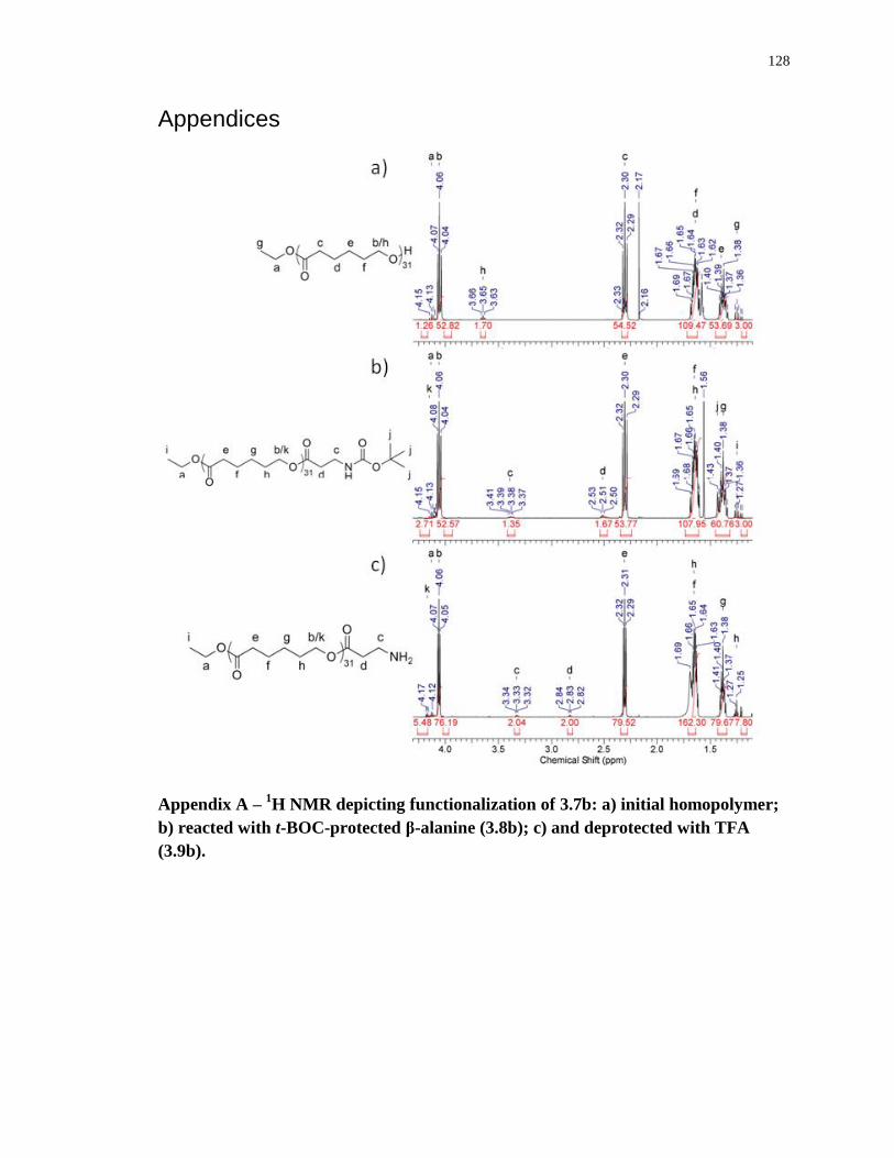
128
Appendices
Appendix A – 1H NMR depicting functionalization of 3.7b: a) initial homopolymer;
b) reacted with t-BOC-protected β-alanine (3.8b); c) and deprotected with TFA
(3.9b).
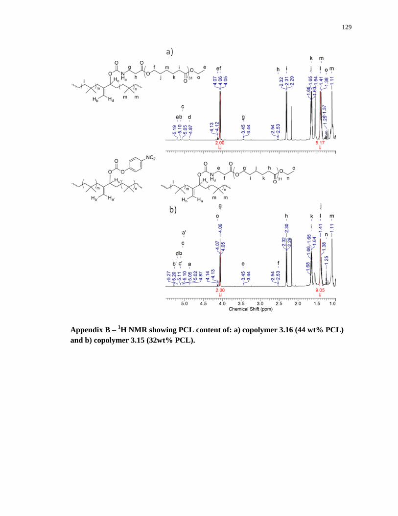
129
Appendix B – 1H NMR showing PCL content of: a) copolymer 3.16 (44 wt% PCL)
and b) copolymer 3.15 (32wt% PCL).
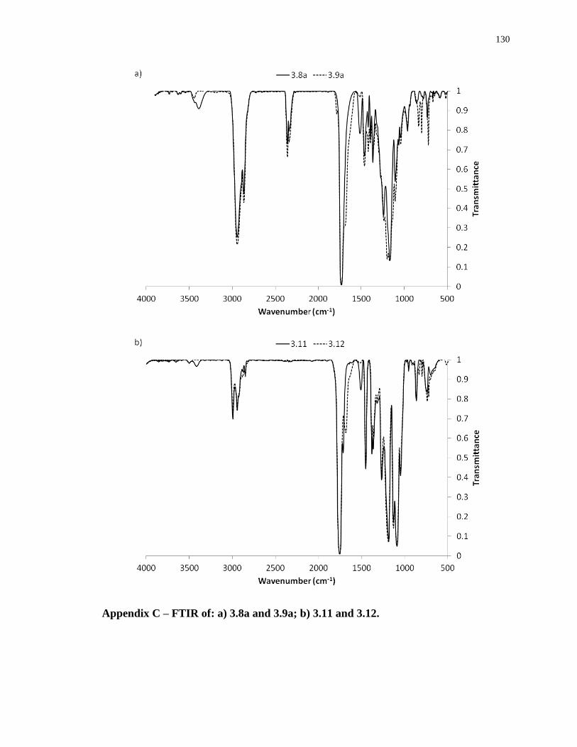
130
Appendix C – FTIR of: a) 3.8a and 3.9a; b) 3.11 and 3.12.
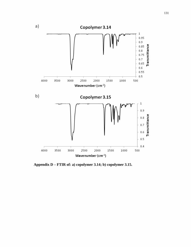
131
Appendix D – FTIR of: a) copolymer 3.14; b) copolymer 3.15.
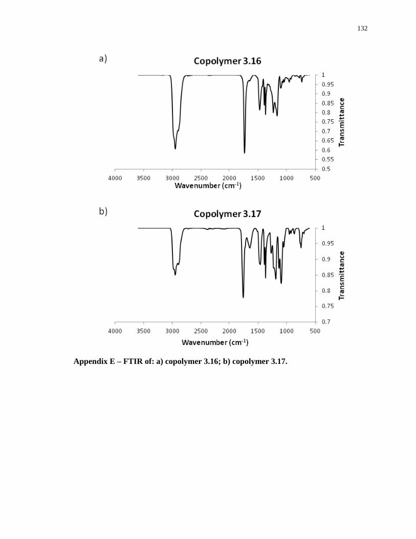
132
Appendix E – FTIR of: a) copolymer 3.16; b) copolymer 3.17.
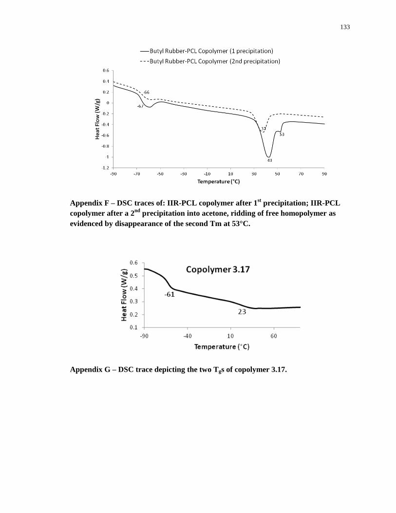
133
Appendix F – DSC traces of: IIR-PCL copolymer after 1st precipitation; IIR-PCL
copolymer after a 2nd
precipitation into acetone, ridding of free homopolymer as
evidenced by disappearance of the second Tm at 53°C.
Appendix G – DSC trace depicting the two Tgs of copolymer 3.17.
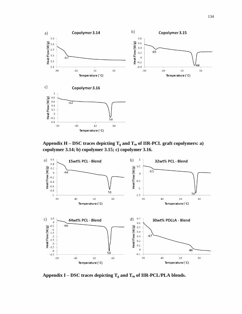
134
Appendix H – DSC traces depicting Tg and Tm of IIR-PCL graft copolymers: a)
copolymer 3.14; b) copolymer 3.15; c) copolymer 3.16.
Appendix I – DSC traces depicting Tg and Tm of IIR-PCL/PLA blends.
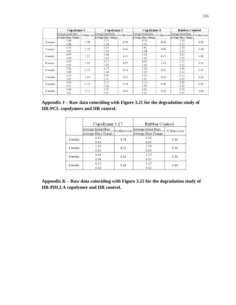
135
Appendix J – Raw data coinciding with Figure 3.21 for the degradation study of
IIR-PCL copolymers and IIR control.
Appendix K – Raw data coinciding with Figure 3.22 for the degradation study of
IIR-PDLLA copolymer and IIR control.
136
Curriculum Vitae
EDUCATION
The University of Western Ontario, London, Ontario
Master of Engineering Science, Biomedical Engineering Graduate Program June 2013
Dissertation: “Butyl Rubber and Polyester Graft Copolymers for Biomedical Applications”
Supervisor: Dr. Elizabeth Gillies
The University of Western Ontario, London, Ontario
Bachelor of Engineering Science, Department of Chemical and Biochemical Engineering April 2011
Specialization: Biochemical and Environmental Engineering
Graduated with Distinction
Honours Thesis: “Utilizing Mesoporous Ordered Silicates as Catalysts for Biodiesel
Production”
EMPLOYMENT EXPERIENCE
The University of Western Ontario | London
Teaching Assistant – to Dr. Shazhad Barghi in “Introduction to Plant Design and Safety” Jan – Apr 2013
Provided student assistance for research assistance and plant development for group-dependent
processes
Evaluated student performance based on a standardized rubric
Met with students upon request to optimize plant design
Teaching Assistant – to Dr. Elizabeth Gillies in “Industrial Organic Chemistry” Sept 2012
Explained methodologies to students pertaining to successful completion of hands-on experiments
Evaluated student in-lab performance as well as comprehension of background theory based on
completion of formal reports
Available to meet with students upon request and marked course midterms
Teaching Assistant – to Dr. Shazhad Barghi in “Introductory Engineering Design and Innovation Studio” Sept 2011
Provided student assistance on the iterative development for several design-based projects
Evaluated student performance based on a standardized rubric
Met with students upon request and graded all written work
Research Assistant – to Dr. Elizabeth Gillies | Department of Chemistry May – Aug 2011
Developed synthetic laboratory skills necessary for working in a polymer research facility Worked on butyl rubber project investigating graft copolymerization to enhance material properties Optimized toxicity cell assays and imaging for biocompatibility testing
NSERC Undergraduate Student Researcher – to Dr. Sohrab Rohani | Chemical Engineering Ap/10 – Ma/11
Developed and optimized biodiesel production with a heterogeneous-based catalyst
Worked as a team member and enhanced laboratory, communication and research skills
Obtained particle characterization skills using various instruments
AWARDS
Ontario Graduate Scholarship, The University of Western Ontario September 2012
Natural Science and Engineering Research Council of Canada, Undergraduate Student Research Award May 2010
Dean’s Honour List, Faculty of Engineering Science April 2008
All Canadian/Ontario University Athletics Academic Achievement Award 2007 – 2012
Queen Elizabeth II Aiming for the Top Scholarship 2007 – 2011
The Governor General’s Academic Medal (highest overall average) June 2006
137
PUBLICATIONS AND PAPERS
Turowec, B..; Gillies, E.; Functionalized Polyisobutylene-Based Materials for Biomedical
Applications.
96th Canadian Chemistry and Exhibition, Québéc City, Québéc.
Presented in oral format. May 2013
Karamdoust, S.; Bonduelle, C.V.; Amos, R.C.; Turowec, B.A..; Guo, S.; Ferrari, L.; Gillies, E.;
Journal of Polymer Science: Part A, 2013. Synthesis and properties of butyl rubber –
poly(ethylene oxide) graft copolymers with high PEO content. May 2013
Turowec, B.; Gillies, E.R.; Polyisobutylene-based Rubber and Polyester Graft Copolymers for
Biomedical Applications.
The University of Western Ontario, Biomedical Engineering Seminar Presentation.
Presented in oral format. April 2013
Kazemian, H.; Turowec, B.; Siddiquee, M. N.; Rohani, S.; Fuel, 2013, 103, 719.
Biodiesel Production using cesium modified mesoporous ordered silica as
heterogeneous base catalyst. January 2013
Turowec, B.; Gillies, E.R.; The Expansion of Polyisobutylene into Biomedical Applications.
The University of Western Ontario, Biomedical Engineering Seminar Presentation.
Presented in oral format. April 2012
Turowec, B.; Gillies, E.R.; Developing Polyisobutylene for Biomedical Applications.
The University of Western Ontario, The London Health Research Day. Presented in
poster format. March 2012
Turowec, B.; Siddiquee, M.N.; Kazemian, H.; and Rohani, S.; Zeolitic Mesoporous Ordered Silica as
Heterogeneous Solid Catalysts for Biodiesel Production.
The University of Western Ontario, Particle Technology Research Centre
Conference, London, ON. Presented in poster format. Received 3rd prize. August 2010
MEMBERSHIPS
The University of Western Ontario | London
Programs Operation Committee 2011 – 2013
Department of Biomedical Engineering
Leader’s Circle 2011 – 2012
Mustang Varsity Athletics
VOLUNTEER ACTIVITIES
The University of Western Ontario Student Orientation Guide 2011
The Western Fair 2010 & 2011
Chemistry/Calculus Tutor 2009 – 2011
CO-CURRICULAR ACTIVITIES
Kawartha Lakes Lacrosse, Senior ‘A’ Team, Ontario 2010 – Present
Women’s Varsity Lacrosse, The University of Western Ontario 2007 – 2011
Won Ontario University Athletic Championship (2009, 2011)
Captain of Lacrosse Team
Women’s Ontario Ball Hockey Team 2004 – 2011
Won National Championship (2009)
Women’s Varsity Hockey Team, The University of Western Ontario 2006 – 2007
Lady Blue Knights Lacrosse, U19 A Team, Ontario
Won Provincial Finals 2005 – 2006