buckling behavior of semi-scale steel tank with carbon fiber
TRANSCRIPT
IJE TRANSACTIONS A: Basics Vol. 32, No. 10, (October 2019) 1407-1415
Please cite this article as: S. Yousefi Khatuni, H. Showkati, Buckling Behavior of Semi-scale Steel Tank with Carbon Fiber Reinforced Polymer Ring Subjected to Lateral Uniform Pressure Loading, International Journal of Engineering (IJE), IJE TRANSACTIONS A: Basics Vol. 32, No. 10, (October 2019) 1407-1415
International Journal of Engineering
J o u r n a l H o m e p a g e : w w w . i j e . i r
Buckling Behavior of Semi-scale Steel Tank with Carbon Fiber Reinforced Polymer
Ring Subjected to Lateral Uniform Pressure Loading
S. Yousefi Khatuni*, H. Showkati
Department of Civil Engineering, Urmia University, Urmia, Iran
P A P E R I N F O
Paper history: Received 14 April 2019 Received in revised form 15 July 2019 Accepted 12 September 2019
Keywords: Buckling Strength Carbon Fiber Reinforced Polymer Rings Semi-scale Tank Storage Tanks
A B S T R A C T
Research on increasing the buckling strength of tanks carrying fluid and also cylindrical shells of thin-walled steel in civil engineering and mechanics is important. This is due to the widespread use of these
structures in the industry. Due to the low thickness of the body and also due to the pressure forces
entering these tanks, these structures are exposed to lateral buckling. In this research, the use of Carbon
Fiber Reinforced Polymer (CFRP) rings to enhance and increase the buckling strength of tanks has been
investigated. For this study, a tank with dimensions close to the actual tanks has been built and reinforced
by a CFRP ring against the buckling. The results of the experiment indicated that the use of CFRP reinforcing ring considerably enhanced the buckling and post-buckling capacity of the tank. Further,
comparing the results obtained from the experimental and numerical analysis and the values extracted
from the theoretical relationships suggested that the results are in good agreement.
doi: 10.5829/ije.2019.32.10a.10
NOMENCLATURE
𝐷 Bending stiffness of plate 𝑤 Deflection in the z-direction
𝐸1. 𝐸2 𝑎𝑛𝑑 𝐸3 Elasticity modules in the direction of the main
axes
𝑍 Curvature Parameter
𝐺12. 𝐺13 𝑎𝑛𝑑 𝐺23 Shear elastic modules in the direction of the main
axes
𝑁𝜃 Axial load in the 𝜃-direction
𝐶𝐹𝑅𝑃 Carbon fiber reinforced polymer 𝑃𝑐𝑟 Buckling load
𝐿 Height of cylindrical shell 𝑡𝑓 Thickness of CFRP strips (without resin epoxy)
𝑚 Number of waves in the z-direction 𝑀𝐷𝐹 Medium-density fiberboard
𝑛 Number of waves in the 𝜃-direction Greek Symbols
𝑁 Number of CFRP layers σcr Critical stress
𝑃𝑚 Elastic instability pressure for collapse of
cylindrical shell
𝜐12. 𝜐13 𝑎𝑛𝑑 𝜐23
Poisson coefficients in the direction of the main
axes
𝑅 Radius of cylindrical shell
𝜀 Elastic circumferential strain at collapse
𝑡 Thickness of cylindrical shell
1. INTRODUCTION1 Recently, thin-walled structures have found important
applications in various branches of engineering [1, 2],
*Corresponding Author Email: [email protected] (S.
Yousefi Khatuni)
which can be attributed to the low thickness of these
structures and their high resistance. In thin-walled
cylindrical shells, the thickness of the shell thickness is
far smaller than its other dimensions. Indeed, in thin-
1408 S. Yousefi Khatuni and H. Showkati / IJE TRANSACTIONS A: Basics Vol. 32, No. 10, (October 2019) 1407-1415
walled cylindrical shells, the R/t ratio can be considered
greater than 500. These structures are used in various
industries such as tanks, silos, and chimneys along with
cooling towers of power plants. Kalantari and Razzaghi
[3] performed a parametric study of the buckling capacity
of cylindrical shells with vertical hardening and showed
that the buckling capacity of the shells varies
exponentially with the adjacent hardening spacing.
Louetri et al. [4] have conducted research on cylindrical
silos in the hopper section reinforced by fiber reinforced
polymeric (FRP) materials. In all cases examined, the use
of FRP has been evaluated positively [5].
In order to enhance the buckling strength of shells,
engineers recommend the use of longitudinal and circular
reinforcement [6]. Lvov et al. [7] investigated the
buckling behavior of steel sheathing of a reinforced wall
with FRP coating. This research has been done
considering the effect of FRP thickness and direction of
FRP and buckling axial load loading. Vakili and
Showkati [8] conducted a study on the effect of using
CFRP reinforcing ring on the elephant foot buckling of
cylindrical shells. They reported that the use of CFRP to
reinforce the shells has a positive effect. Bhetwal and
Yamada [9] studied the use of CFRP to increase the
buckling strength of the thin-walled cylindrical shells in
which the sides of the shell were reinforced. They
observed that the use of CFRP could increase the
buckling capacity of the cylindrical shells, which would
depend on the thickness and direction of the CFRP.
Batikha et al. [10] studied the effect of using FRP on the
buckling strength of cylindrical shells with symmetric
imperfection. They found that the strength of thin-walled
shells with imperfection grew effectively using some
FRP materials in the imperfection area. He and Xian [11]
conducted experimental studies on the behavior of CFRP
rings. The results of the experiments show the failure
modes and the required length for the resistance and
strain distribution and the load-displacement diagrams
and the continuity and slip relations. Showkati and
Shahandeh [12] studied on the stiffeners of pipelines
under hydrostatic pressure and evaluated the main modes
of buckling and extend buckling as well as the
subsequent phases of buckling and extension of the yield
lines and ultimate failure.
Ghanbari Ghazijahani et al. [13] investigated the
partial and full reinforcement effects of the vertical
stiffness and the partial thickness of the cylindrical shell
subjected to the external pressure. Furthermore,
Ghanbari Ghazijahani et al. [14] studied the buckling
capacity of cylindrical shells with several transverse
waves in different positions of the shell.
Rastgar and Showkati [15] conducted an
experimental study to investigate the effect of
imperfections on the buckling behavior of cylindrical
shells under uniform external pressure on specific
specimens.
In this research, in order to enhance the buckling and
post-buckling strength of cylindrical shells, a new
solution is proposed which resolves most of the
abovementioned problems. This solution involves
employing rings with CFRP composite materials to
increase the buckling and post-buckling strength of steel
cylindrical shells against a uniform lateral pressure.
In this paper, using an experimental method and
software analysis method plus mathematical
approximating relations, use of rings with CFRP
composite materials as new materials is recommended to
reinforce the steel tank. The aim of this study was
experimental and analytical investigation of a semi-scale
(Not full scale) steel tank reinforced with CFRP ring.
Also, the buckling capacity of the semi-scale tank was
evaluated.
2. EXPERIMENTAL PROGRAM
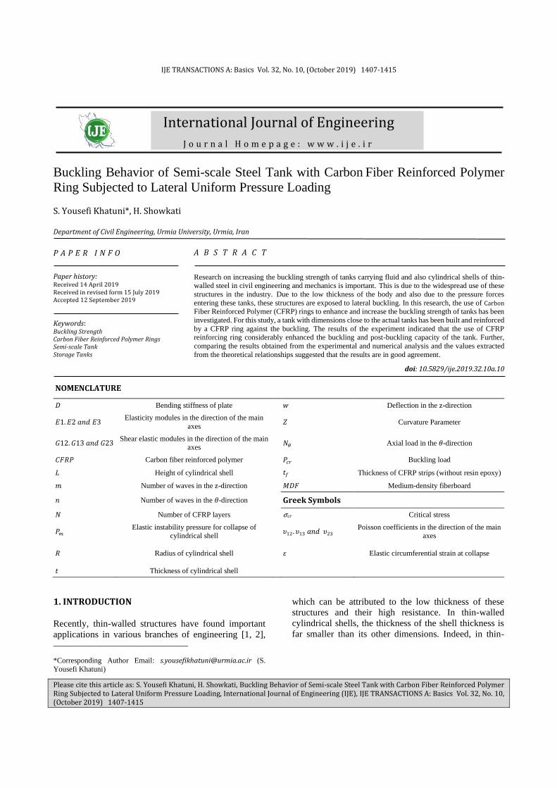
2. 1. Specifications of Experimental Specimen The test specimen had a diameter of 2000 mm and a
height of 1000 mm and the thickness of the tank sheet
was 1.5 mm. The number of CFRP layers was 14. The
number of CFRP layers was based on the results of
nonlinear numerical analysis (ABAQUS) and evaluation
of expected performance of the rings. The expected
performance of the CFRP rings was the production of
sufficient radial stiffness upon radial buckling, and this
function was possible by increasing the number of CFRP
layers. The position of the CFRP reinforcement ring was
in the middle of the tank’s height. The width of the CFRP
reinforcement ring strip was 50 mm. A two-component
epoxy resin was used to attach the CFRP strips to the
body of the cylindrical shell. Regarding supporting
conditions, the specimen is bounded to the lower part in
three directions of tangential, axial and radial but in the
upper part, the specimen is bounded radially and
tangentially, and the axial displacement is free. Figure 1
represents the tank experimental specimen and 2-
component epoxy resin [16] and CFRP strips [17].
Figure 1. Experimental specimen, and 2-component
epoxy resin and CFRP strip
S. Yousefi Khatuni and H. Showkati / IJE TRANSACTIONS A: Basics Vol. 32, No. 10, (October 2019) 1407-1415 1409
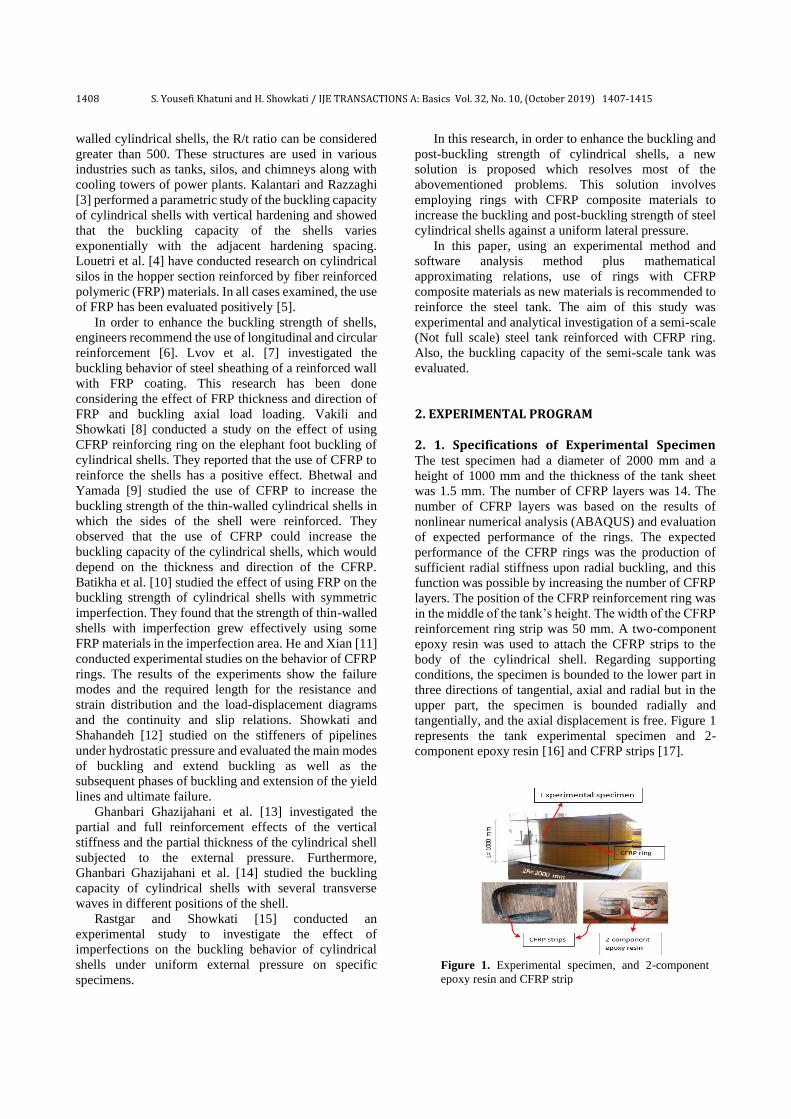
2. 2. Mechanical Properties Table 1 shows
the mechanical properties of the steel plate were obtained
by the tensile test of materials (ASTM E8/E8M-15a).
Figure 2 represents the tested sample and the utilized
device, as well as the stress-strain diagrams. According
to the specification provided by the materials
manufacturer (QUANTOM®), specifications of CFRP
strips [17] and the 2-component epoxy resin [16] to
attach the CFRP rings on the cylinders are presented in
Tables 2 and 3.
3. TESTING AND EVALUATING THE RESULTS 3. 1. Loading the Experimental Specimen A
vacuum pump was used to investigate the buckling and
post-buckling behavior of the experimental tank under
the external uniform pressure. This device discharged the
air inside the tank with a constant flow rate of 40 m3/h.
Therefore, by discharging the inner air, the atmospheric
pressure was uniformly introduced onto the lateral
surfaces of the shell. This type of loading occurs in real-
condition when the contents of the tank's liquid are
drained. Also, since the purpose of this test was
investigating the uniform lateral pressure, the loading
system was selected in a way that via the retaining bars
of the upper and lower sheets of the shell, no vertical
TABLE 1. Mechanical properties of steel tensile specimens
Elastic Modulus 205.9 GPa
Yield Strength 202.5 MPa
Ultimate Strength 327.5 MPa
Rupture Strength 222.5 MPa
Ultimate Strain 48.5%
Figure 2. (a) The two samples, (b) Tensile testing, (c) Stress-
strain diagram of material
TABLE 2. Mechanical properties of CFRP strips [17]
Product name QUANTOM®Wrap300
Description High strength carbon
Thickness 0.167 mm
Tensile strength 4950 MPa
ElastisityModulus 240 GPa
Elangation at breack 1.5%
Areal weight 300 gr/m2
TABLE 3. The properties of the 2-component epoxy resin [16]
Description Value
Color Concrete grey (mixed)
Density 1.5 kg/l (mixed)
Bonding Strength > 3.5 MPa (Concrete failed)
Compressive Strength 95 MPa (7 days) at 35°C
Tensile & Flexural Strength > 30 MPa
Service Temperature -35 to +65°C
Full Cured After 7 days (at 25°C)
Working Time/Pot Life 60 min. (25°C)
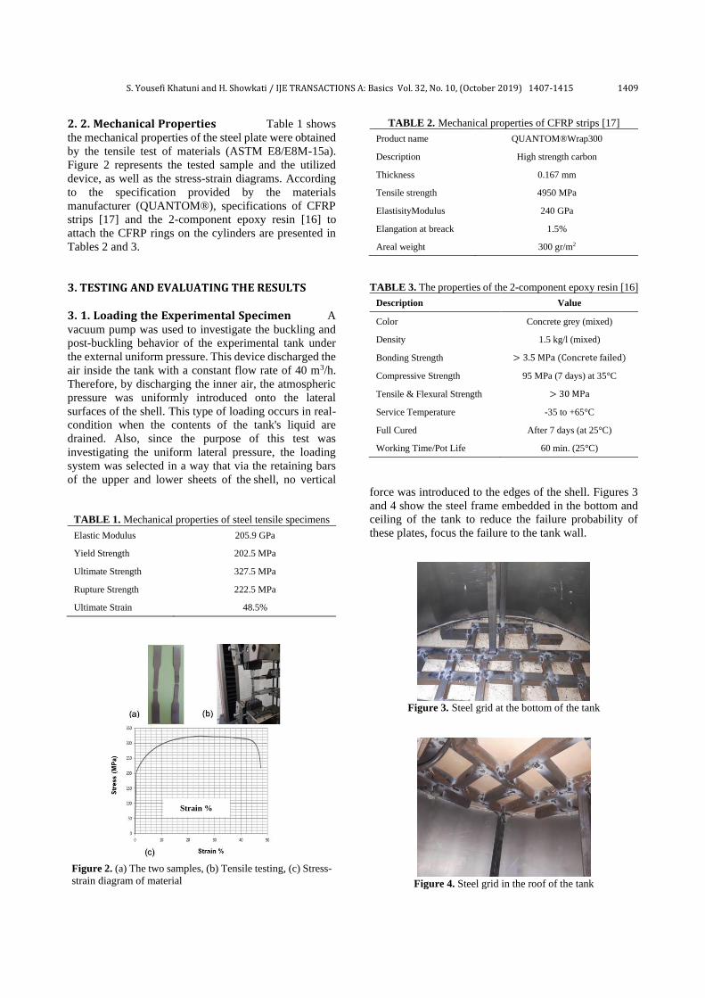
force was introduced to the edges of the shell. Figures 3
and 4 show the steel frame embedded in the bottom and
ceiling of the tank to reduce the failure probability of
these plates, focus the failure to the tank wall.
Figure 3. Steel grid at the bottom of the tank
Figure 4. Steel grid in the roof of the tank
Strain %
1410 S. Yousefi Khatuni and H. Showkati / IJE TRANSACTIONS A: Basics Vol. 32, No. 10, (October 2019) 1407-1415
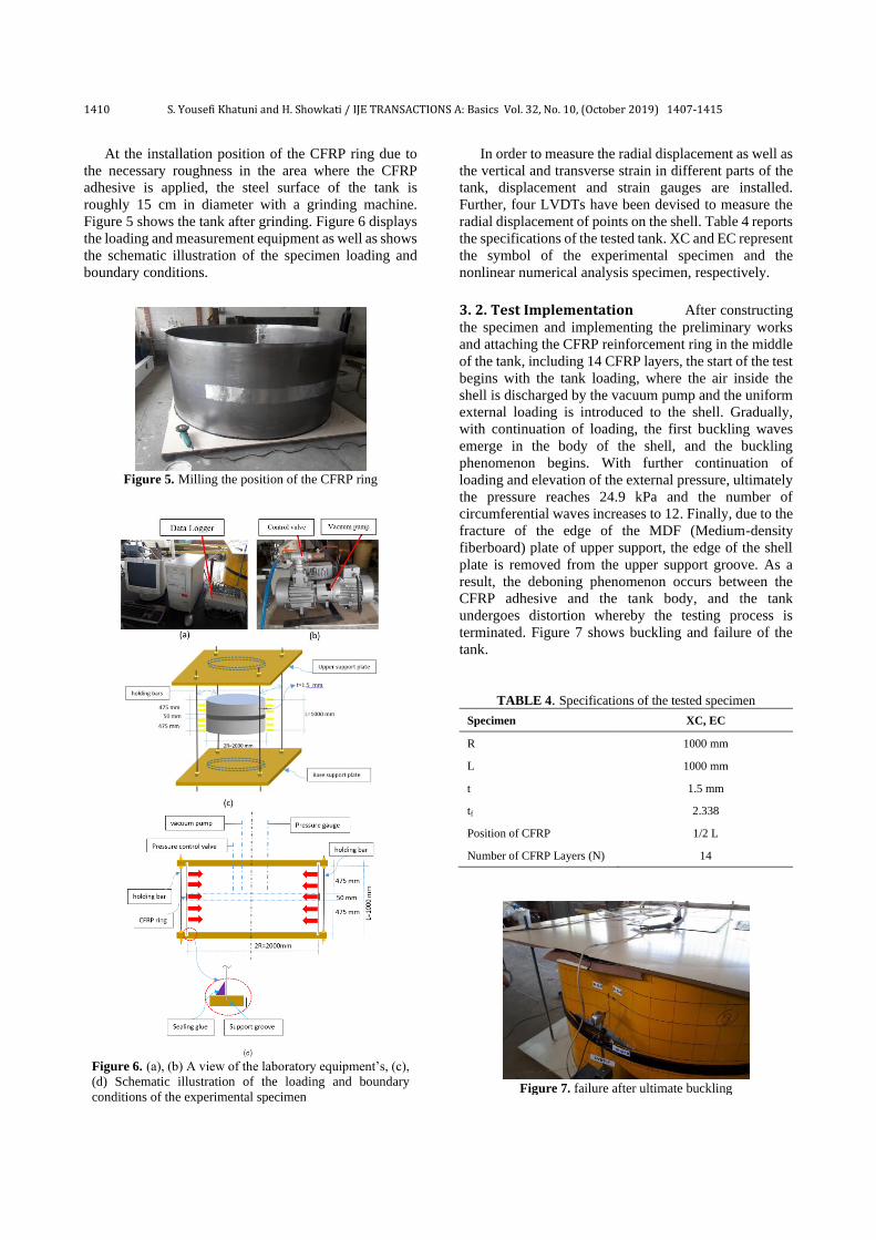
At the installation position of the CFRP ring due to
the necessary roughness in the area where the CFRP
adhesive is applied, the steel surface of the tank is
roughly 15 cm in diameter with a grinding machine.
Figure 5 shows the tank after grinding. Figure 6 displays
the loading and measurement equipment as well as shows
the schematic illustration of the specimen loading and
boundary conditions.
Figure 5. Milling the position of the CFRP ring
Figure 6. (a), (b) A view of the laboratory equipment’s, (c),
(d) Schematic illustration of the loading and boundary
conditions of the experimental specimen
In order to measure the radial displacement as well as
the vertical and transverse strain in different parts of the
tank, displacement and strain gauges are installed.
Further, four LVDTs have been devised to measure the
radial displacement of points on the shell. Table 4 reports
the specifications of the tested tank. XC and EC represent
the symbol of the experimental specimen and the
nonlinear numerical analysis specimen, respectively.
3. 2. Test Implementation After constructing
the specimen and implementing the preliminary works
and attaching the CFRP reinforcement ring in the middle
of the tank, including 14 CFRP layers, the start of the test
begins with the tank loading, where the air inside the
shell is discharged by the vacuum pump and the uniform
external loading is introduced to the shell. Gradually,
with continuation of loading, the first buckling waves
emerge in the body of the shell, and the buckling
phenomenon begins. With further continuation of
loading and elevation of the external pressure, ultimately
the pressure reaches 24.9 kPa and the number of
circumferential waves increases to 12. Finally, due to the
fracture of the edge of the MDF (Medium-density
fiberboard) plate of upper support, the edge of the shell
plate is removed from the upper support groove. As a
result, the deboning phenomenon occurs between the
CFRP adhesive and the tank body, and the tank
undergoes distortion whereby the testing process is
terminated. Figure 7 shows buckling and failure of the
tank.
TABLE 4. Specifications of the tested specimen
Specimen XC, EC
R 1000 mm
L 1000 mm
t 1.5 mm
tf 2.338
Position of CFRP 1/2 L
Number of CFRP Layers (N) 14
Figure 7. failure after ultimate buckling
S. Yousefi Khatuni and H. Showkati / IJE TRANSACTIONS A: Basics Vol. 32, No. 10, (October 2019) 1407-1415 1411
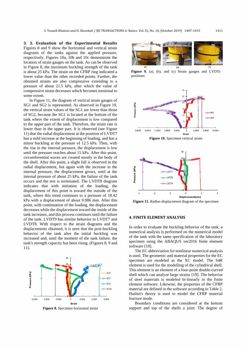
3. 3. Evaluation of the Experimental Results Figures 8 and 9 show the horizontal and vertical strain
diagrams of the tanks against the applied pressure,
respectively. Figures 10a, 10b and 10c demonstrate the
location of strain gauges on the tank. As can be observed
in Figure 8, the maximum buckling strength of the tank
is about 25 kPa. The strain on the CFRP ring indicated a
lower value than the other recorded points. Further, the
obtained strains are also compressive extending to a
pressure of about 21.5 kPa, after which the value of
compressive strain decreases which becomes tensional to
some extent.
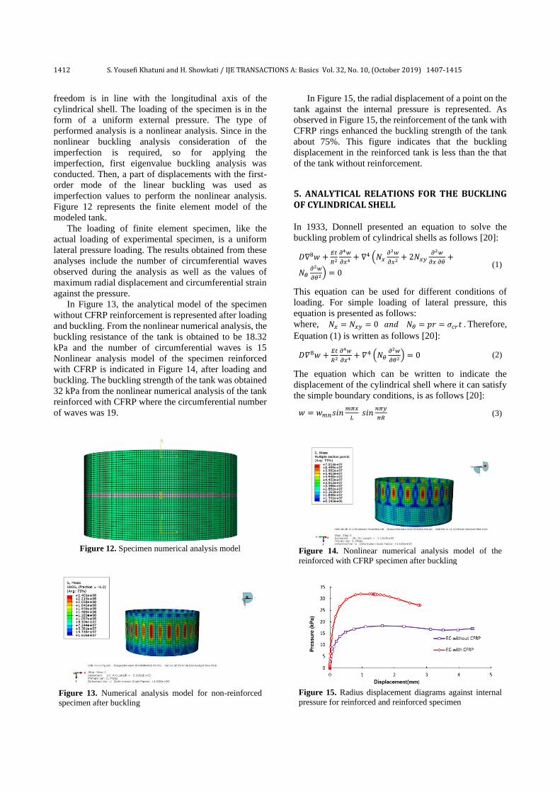
In Figure 11, the diagram of vertical strain gauges of
SG1 and SG2 is represented. As observed in Figure 10,
the vertical strain values of the SG1 are lower than those
of SG2, because the SG1 is located at the bottom of the
tank where the extent of displacement is low compared
to the upper part of the tank. Therefore, the strain rate is
lower than in the upper part. It is observed (see Figure
11) that the radial displacement at the position of LVDT7
has a mild increase at the beginning of loading, and has a
minor buckling at the pressure of 12.5 kPa. Then, with
the rise in the internal pressure, the displacement is low
until the pressure reaches about 15 kPa. After this point,
circumferential waves are created mostly in the body of
the shell. After this point, a slight fall is observed in the
radial displacement, but again with the increase in the
internal pressure, the displacement grows, until at the
internal pressure of about 25 kPa, the failure of the tank
occurs and the test is terminated. The LVDT8 diagram
indicates that with initiation of the loading, the
displacement of this point is toward the outside of the
tank, where this trend continues to a pressure of 18.42
kPa with a displacement of about 0.086 mm. After this
point, with continuation of the loading, the displacement
decreases while the displacement toward the inside of the
tank increases, and this process continues until the failure
of the tank. LVDT9 has similar behavior to LVDT7 and
LVDT8. With respect to the strain diagrams and the
displacements obtained, it is seen that the post-buckling
behavior of the tank after the initial buckling was
increased and, until the moment of the tank failure, the
tank's strength capacity has been rising. (Figures 8, 9 and
11).
Figure 8. Specimen horizontal strain
Figure 9. (a), (b), and (c) Strain gauges and LVDTs
positions
Figure 10. Specimen vertical strain
Figure 11. Radius displacement diagram of the specimen
4. FINITE ELEMENT ANALYSIS In order to evaluate the buckling behavior of the tank, a
numerical analysis is performed on the numerical model
of the tank with the same specification of the laboratory
specimen using the ABAQUS ver2016 finite element
software [18].
The EC abbreviation for nonlinear numerical analysis
is used. The geometric and material properties for the EC
specimen are modeled as the XC model. The S4R
element is used for the modelling of the cylindrical shell.
This element is an element of a four-point double-curved
shell which can analyze large strains [19]. The behavior
of steel materials is modeled bi-linearly in the finite
element software. Likewise, the properties of the CFRP
material are defined in the software according to Table 2.
Hashin's theory is used to model the CFRP material
fracture mode.
Boundary conditions are considered at the bottom
support and top of the shells a joint. The degree of
1412 S. Yousefi Khatuni and H. Showkati / IJE TRANSACTIONS A: Basics Vol. 32, No. 10, (October 2019) 1407-1415
freedom is in line with the longitudinal axis of the
cylindrical shell. The loading of the specimen is in the
form of a uniform external pressure. The type of
performed analysis is a nonlinear analysis. Since in the
nonlinear buckling analysis consideration of the
imperfection is required, so for applying the
imperfection, first eigenvalue buckling analysis was
conducted. Then, a part of displacements with the first-
order mode of the linear buckling was used as
imperfection values to perform the nonlinear analysis.
Figure 12 represents the finite element model of the
modeled tank.
The loading of finite element specimen, like the
actual loading of experimental specimen, is a uniform
lateral pressure loading. The results obtained from these
analyses include the number of circumferential waves
observed during the analysis as well as the values of
maximum radial displacement and circumferential strain
against the pressure.
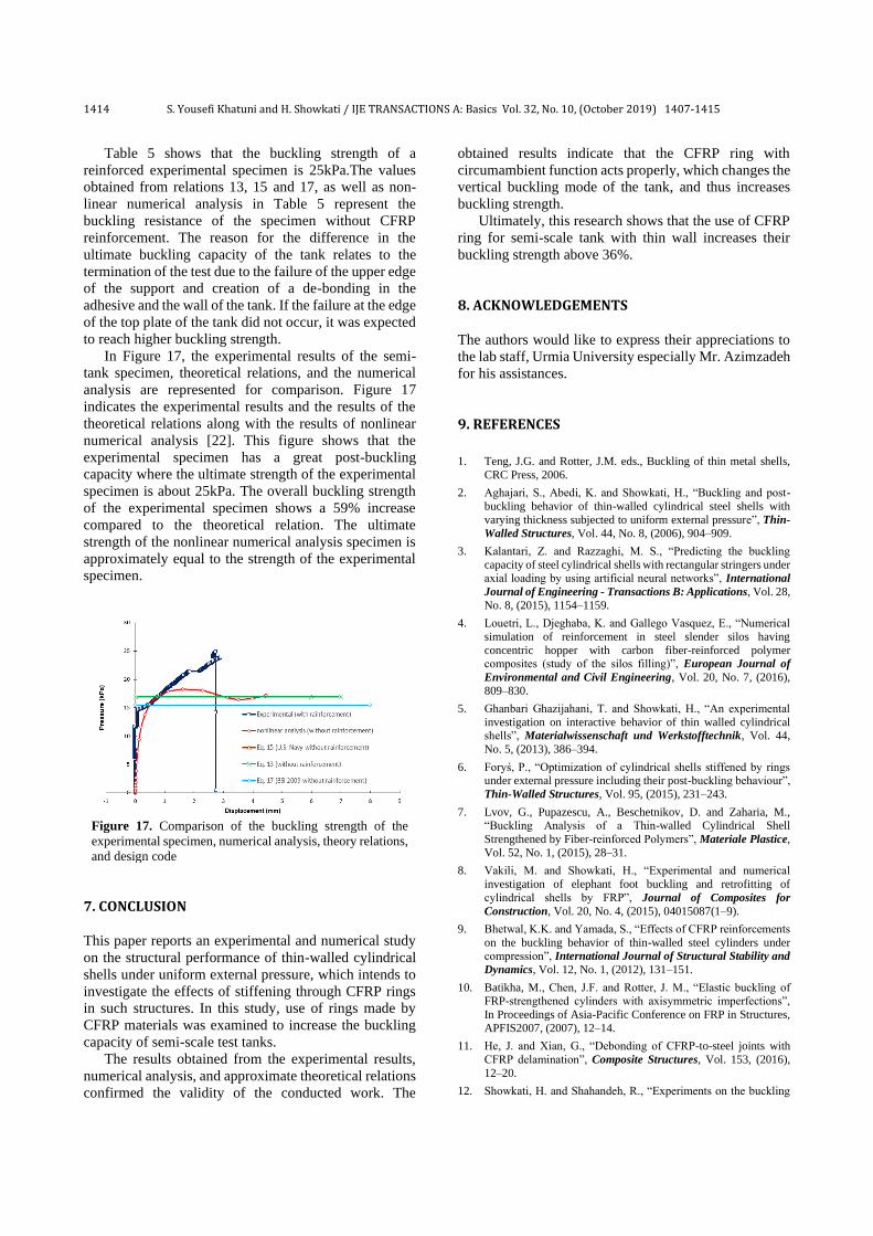
In Figure 13, the analytical model of the specimen
without CFRP reinforcement is represented after loading
and buckling. From the nonlinear numerical analysis, the
buckling resistance of the tank is obtained to be 18.32
kPa and the number of circumferential waves is 15
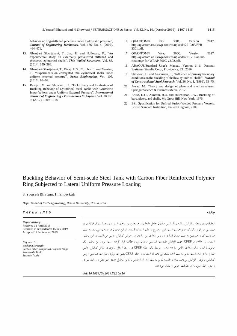
Nonlinear analysis model of the specimen reinforced
with CFRP is indicated in Figure 14, after loading and
buckling. The buckling strength of the tank was obtained
32 kPa from the nonlinear numerical analysis of the tank
reinforced with CFRP where the circumferential number
of waves was 19.
Figure 12. Specimen numerical analysis model
Figure 13. Numerical analysis model for non-reinforced
specimen after buckling
In Figure 15, the radial displacement of a point on the
tank against the internal pressure is represented. As
observed in Figure 15, the reinforcement of the tank with
CFRP rings enhanced the buckling strength of the tank
about 75%. This figure indicates that the buckling
displacement in the reinforced tank is less than the that
of the tank without reinforcement.
5. ANALYTICAL RELATIONS FOR THE BUCKLING OF CYLINDRICAL SHELL In 1933, Donnell presented an equation to solve the
buckling problem of cylindrical shells as follows [20]:
𝐷∇8𝑤 +𝐸𝑡
𝑅2
𝜕4𝑤
𝜕𝑥4+ ∇4 (𝑁𝑥
𝜕2𝑤
𝜕𝑥2+ 2𝑁𝑥𝑦
𝜕2𝑤
𝜕𝑥 𝜕𝜃+
𝑁𝜃𝜕2𝑤
𝜕𝜃2) = 0
(1)
This equation can be used for different conditions of
loading. For simple loading of lateral pressure, this
equation is presented as follows:
where, 𝑁𝑥 = 𝑁𝑥𝑦 = 0 𝑎𝑛𝑑 𝑁𝜃 = 𝑝𝑟 = 𝜎𝑐𝑟𝑡 . Therefore,
Equation (1) is written as follows [20]:
𝐷𝛻8𝑤 +𝐸𝑡
𝑅2
𝜕4𝑤
𝜕𝑥4 + 𝛻4 (𝑁𝜃𝜕2𝑤
𝜕𝜃2) = 0 (2)
The equation which can be written to indicate the
displacement of the cylindrical shell where it can satisfy
the simple boundary conditions, is as follows [20]:
𝑤 = 𝑤𝑚𝑛𝑠𝑖𝑛𝑚𝜋𝑥
𝐿 𝑠𝑖𝑛
𝑛𝜋𝑦
𝜋𝑅 (3)
Figure 14. Nonlinear numerical analysis model of the
reinforced with CFRP specimen after buckling
Figure 15. Radius displacement diagrams against internal
pressure for reinforced and reinforced specimen

S. Yousefi Khatuni and H. Showkati / IJE TRANSACTIONS A: Basics Vol. 32, No. 10, (October 2019) 1407-1415 1413
By substituting this relation in Relation (2), we have:
𝜎𝑐𝑟 =𝜋2𝐾𝐸
12(1−𝜇2)(𝑡 𝐿)⁄ 2
(4)
where:
𝐾 =(𝑚2+𝛽2)2
𝛽2+
12𝑍2
𝜋4𝛽2(1+𝛽2 𝑚2)⁄2 (5)
𝛽 =𝑛𝐿
𝜋𝑅 (6)
𝑍 =𝐿2
𝑅𝑡√(1 − 𝜇2) (7)
The least value of Equation (5) in obtained by m=1. For
short cylinders:
𝐾 =(1+𝛽2)2
𝛽2+
12𝑍2
𝜋4𝛽2(1+𝛽2)2 (8)
For short shells, the curvature parameter of Z is zero with
Equation (8) obtained as follows:
𝐾 = (𝛽 + 1/𝛽)^2 (9)
If the L/r ratio is increased, then the value of β + 1 can
be approximately substituted with β. So, Equation (8) is
written as follows:
𝐾 = 𝛽2 +12𝑍2
𝜋4𝛽6 (10)
Minimizing the above equation toward 𝛽 gives the
following relation:
𝐾 = 1.038√𝑍 (11)
Long cylinders:
For long cylinders, the buckling mode is like circle
rings and is in oval shape. Therefore, n=2 and 𝛽 =2𝐿
𝜋𝑟 as
well as Equation (10) decline as follows:
𝐾 = 𝛽2 (12)
In Figure 16, the K diagram is represented according
to Relations (9), (11), and (12).
Equation (13) is presented by Brush et al. [21] for a
cylindrical shell with simple supporting conditions and
considering the loading of uniform external lateral
pressure.
𝑃𝑐𝑟 =1
𝑅(
(𝑚2
+𝑛2)2
(𝐷
𝑅2)
𝑛2+
𝑚4
𝑛2(𝑚2
+𝑛2)2 (1 − 𝜐2)𝐶) (13)
In which:
𝐷 =𝐸𝑡3
12(1−𝜐2) ‚ 𝐶 =
𝐸𝑡
(1−𝜐2) ‚ 𝑚 =
𝜋𝑅
𝐿
The number of circumferential waveforms obtains from
the following equation [21]:
𝑛 = √6𝜋2√1−𝜐2
(𝐿
𝑅)
2(
𝑡
𝑅)
4≈ 2.74√𝑅
𝐿√
𝑅
𝑡 (14)
According to the experimental relation expanded by
the U.S. Navy, the amount of allowable pressure is
calculated by the following relation [20]:
𝑃𝑐𝑟 =2.42𝐸
(1−𝜐2)3 4⁄
(𝑡 2𝑅⁄ )2.5
[𝐿 2𝑅⁄ −0.45(𝑡 2𝑅⁄ )1 2⁄ ] (15)
For structures with a larger ratio of (R/t), Equation (15)
is written as follows:
𝑃𝑐𝑟 =2.42𝐸
(1−𝜐2)3 4⁄
(𝑡 2𝑅⁄ )2.5
(𝐿 2𝑅⁄ ) (16)
The British Standard Institute (BSI) [22] has proposed
Equation 17 to estimate the Pm (critical load of cylindrical
shells), which requires the calculation of the parameter 𝜀.
The parameter 𝜀 is a function of the values of 2R/t and
L/2R and is obtained from a design chart that is presented
there [22]:
𝑃𝑚 =𝐸𝑡𝜀
𝑅 (17)
6. THE EVALUATION OF RESULTS In Table 5, the summary of the obtained results for the
buckling capacity of experimental specimen and
numerical analysis as well as the obtained results from
the theoretical relations 13, 15 and 17 are represented.
Figure 16. A plot of K [20]
TABLE 5. Comparison of experimental results and theoretical
and design code predictions.
Specimen XC Buckling Strength
(kPa)
Difference
(%)
Experimental Specimen 25 ----
Equation (13) (Without
reinforcement) 16.96 47.4
Equation (15) (Without
reinforcement) 16.9 47.9
Equation (17) (Without
reinforcement) 15.45 61.8
ABAQUS (Without
reinforcement) 18.32 36.46
1414 S. Yousefi Khatuni and H. Showkati / IJE TRANSACTIONS A: Basics Vol. 32, No. 10, (October 2019) 1407-1415
Table 5 shows that the buckling strength of a
reinforced experimental specimen is 25kPa.The values
obtained from relations 13, 15 and 17, as well as non-
linear numerical analysis in Table 5 represent the
buckling resistance of the specimen without CFRP
reinforcement. The reason for the difference in the
ultimate buckling capacity of the tank relates to the
termination of the test due to the failure of the upper edge
of the support and creation of a de-bonding in the
adhesive and the wall of the tank. If the failure at the edge
of the top plate of the tank did not occur, it was expected
to reach higher buckling strength.
In Figure 17, the experimental results of the semi-
tank specimen, theoretical relations, and the numerical
analysis are represented for comparison. Figure 17
indicates the experimental results and the results of the
theoretical relations along with the results of nonlinear
numerical analysis [22]. This figure shows that the
experimental specimen has a great post-buckling
capacity where the ultimate strength of the experimental
specimen is about 25kPa. The overall buckling strength
of the experimental specimen shows a 59% increase
compared to the theoretical relation. The ultimate
strength of the nonlinear numerical analysis specimen is
approximately equal to the strength of the experimental
specimen.
Figure 17. Comparison of the buckling strength of the
experimental specimen, numerical analysis, theory relations,
and design code
7. CONCLUSION This paper reports an experimental and numerical study
on the structural performance of thin-walled cylindrical
shells under uniform external pressure, which intends to
investigate the effects of stiffening through CFRP rings
in such structures. In this study, use of rings made by
CFRP materials was examined to increase the buckling
capacity of semi-scale test tanks.
The results obtained from the experimental results,
numerical analysis, and approximate theoretical relations
confirmed the validity of the conducted work. The
obtained results indicate that the CFRP ring with
circumambient function acts properly, which changes the
vertical buckling mode of the tank, and thus increases
buckling strength.
Ultimately, this research shows that the use of CFRP
ring for semi-scale tank with thin wall increases their
buckling strength above 36%.
8. ACKNOWLEDGEMENTS The authors would like to express their appreciations to
the lab staff, Urmia University especially Mr. Azimzadeh
for his assistances.
9. REFERENCES
1. Teng, J.G. and Rotter, J.M. eds., Buckling of thin metal shells,
CRC Press, 2006.
2. Aghajari, S., Abedi, K. and Showkati, H., “Buckling and post-
buckling behavior of thin-walled cylindrical steel shells with
varying thickness subjected to uniform external pressure”, Thin-
Walled Structures, Vol. 44, No. 8, (2006), 904–909.
3. Kalantari, Z. and Razzaghi, M. S., “Predicting the buckling
capacity of steel cylindrical shells with rectangular stringers under axial loading by using artificial neural networks”, International
Journal of Engineering - Transactions B: Applications, Vol. 28,
No. 8, (2015), 1154–1159.
4. Louetri, L., Djeghaba, K. and Gallego Vasquez, E., “Numerical
simulation of reinforcement in steel slender silos having
concentric hopper with carbon fiber-reinforced polymer composites (study of the silos filling)”, European Journal of
Environmental and Civil Engineering, Vol. 20, No. 7, (2016),
809–830.
5. Ghanbari Ghazijahani, T. and Showkati, H., “An experimental
investigation on interactive behavior of thin walled cylindrical shells”, Materialwissenschaft und Werkstofftechnik, Vol. 44,
No. 5, (2013), 386–394.
6. Foryś, P., “Optimization of cylindrical shells stiffened by rings under external pressure including their post-buckling behaviour”,
Thin-Walled Structures, Vol. 95, (2015), 231–243.
7. Lvov, G., Pupazescu, A., Beschetnikov, D. and Zaharia, M., “Buckling Analysis of a Thin-walled Cylindrical Shell
Strengthened by Fiber-reinforced Polymers”, Materiale Plastice,
Vol. 52, No. 1, (2015), 28–31.
8. Vakili, M. and Showkati, H., “Experimental and numerical
investigation of elephant foot buckling and retrofitting of
cylindrical shells by FRP”, Journal of Composites for
Construction, Vol. 20, No. 4, (2015), 04015087(1–9).
9. Bhetwal, K.K. and Yamada, S., “Effects of CFRP reinforcements
on the buckling behavior of thin-walled steel cylinders under compression”, International Journal of Structural Stability and
Dynamics, Vol. 12, No. 1, (2012), 131–151.
10. Batikha, M., Chen, J.F. and Rotter, J. M., “Elastic buckling of FRP-strengthened cylinders with axisymmetric imperfections”,
In Proceedings of Asia-Pacific Conference on FRP in Structures,
APFIS2007, (2007), 12–14.
11. He, J. and Xian, G., “Debonding of CFRP-to-steel joints with
CFRP delamination”, Composite Structures, Vol. 153, (2016),
12–20.
12. Showkati, H. and Shahandeh, R., “Experiments on the buckling
S. Yousefi Khatuni and H. Showkati / IJE TRANSACTIONS A: Basics Vol. 32, No. 10, (October 2019) 1407-1415 1415
behavior of ring-stiffened pipelines under hydrostatic pressure”, Journal of Engineering Mechanics, Vol. 136, No. 4, (2009),
464–471.
13. Ghanbari Ghazijahani, T., Jiao, H. and Holloway, D., “An experimental study on externally pressurized stiffened and
thickened cylindrical shells”, Thin-Walled Structures, Vol. 85,
(2014), 359–366.
14. Ghanbari Ghazijahani, T., Dizaji, H.S., Nozohor, J. and Zirakian,
T., “Experiments on corrugated thin cylindrical shells under
uniform external pressure”, Ocean Engineering, Vol. 106,
(2015), 68–76.
15. Rastgar, M. and Showkati, H., “Field Study and Evaluation of Buckling Behavior of Cylindrical Steel Tanks with Geometric
Imperfections under Uniform External Pressure”, International
Journal of Engineering - Transactions C: Aspects, Vol. 30, No.
9, (2017), 1309–1318.
16. QUANTOM® EPR 3301, Version 2017, http://quantom.co.uk/wp-content/uploads/2019/03/EPR-
3301.pdf.
17. QUANTOM® Wrap 300C, Version 2017, http://quantom.co.uk/wp-content/uploads/2018/10/online-
catalouge-for-WRAP-300C-v2.02.pdf.
18. ABAQUS/Standard User’s Manual, Version 6.16, Dassault
Systèmes Simulia Corp., Providence, RI., 2016.
19. Showkati, H. and Ansourian, P., “Influence of primary boundary
conditions on the buckling of shallow cylindrical shells”, Journal
of Constructional Steel Research, Vol. 36, No. 1, (1996), 53–75.
20. Jawad, M., Theory and design of plate and shell structures,
Springer Science & Business Media, 2012.
21. Brush, D.O., Almroth, B.O. and Hutchinson, J.W., Buckling of
bars, plates, and shells, Mc Grow Hill, New York, 1975.
22. BSI, Specification for Unfired Fusion-Welded Pressure Vessels,
British Standard Institution, United Kingdom, 2009.
Buckling Behavior of Semi-scale Steel Tank with Carbon Fiber Reinforced Polymer
Ring Subjected to Lateral Uniform Pressure Loading
S. Yousefi Khatuni, H. Showkati
Department of Civil Engineering, Urmia University, Urmia, Iran
P A P E R I N F O
Paper history: Received 14 April 2019 Received in revised form 15 July 2019 Accepted 12 September 2019
Keywords: Buckling Strength Carbon Fiber Reinforced Polymer Rings Semi-scale Tank Storage Tanks
چكيده
ای جدار نازک فوالدی در های استوانهتحقیقات در رابطه با افزایش مقاومت کمانشی مخازن حامل مایعات و همچنین پوسته
علت ه باشد. ب. این موضوع به علت استفاده گسترده از این مخازن در صنعت می استمهندسی عمران و مکانیک حائز اهمیت
باشند. در این تحقیق ها در معرض کمانش جانبی می د بر مخازن این سازه علت میدان فشاری واره ضخامت کم و همچنین ب
جهت افزایش مقاومت کمانشی مخازن مورد مطالعه قرار گرفته است. برای این تحقیق یک CFRP هایاستفاده از حلقه
مقابل کمانش جانبی وسط ارتفاع مخزن در در CFRPحلقه یک مخزن با ابعاد مشابه مخازن واقعی ساخته شده و توسط
بصورت موثری مقاومت کمانشی و پس CFRP مقاوم سازی شده است. نتایج بدست آمده نشان می دهد که استفاده از حلقه
دست آمده از آزمایش با نتایج تحلیل عددی غیرخطی و روابط تئوری دهد. بعالوه مقایسه نتایج بکمانشی مخزن را افزایش می
دهند.ای مطابقت خوبی را نشان می نامهو نیز روابط آئین
doi: 10.5829/ije.2019.32.10a.10