browns ferry nuclear plant (bfn), unit 1 - response to nrc
TRANSCRIPT
August 15, 2005 U.S. Nuclear Regulatory Commission ATTN: Document Control Desk Mail Stop: OWFN, P1-35 Washington, D.C. 20555-0001
Gentlemen:
In the Matter of ) Docket No. 50-259 Tennessee Valley Authority ) BROWNS FERRY NUCLEAR PLANT (BFN) – UNIT 1 – RESPONSE TO NRC REQUEST FOR ADDITIONAL INFORMATION REGARDING THE RESTART TESTING PROGRAM (TAC NO. MC7208) This letter provides additional information concerning the BFN Unit 1 Restart Test Program (RTP) as requested by NRC letter dated June 15, 2005, (Reference 1). As requested, the enclosure to this letter provides a detailed description of the modifications completed or in progress in support of BFN Unit 1 restart and a description of the testing planned as part of the BFN Unit 1 RTP. For comparison purposes, the enclosure also identifies whether the modifications and testing being implemented were performed for BFN Units 2 and 3 during their restart programs. The enclosure also gives a background of the BFN RTP development, a description of the BFN Unit 1 RTP, and a description of the power ascension testing planned for BFN Unit 1 and comparison to the BFN Unit 3 power ascension testing program. With the exception of modifications planned to implement Extended Power Uprate, most of the modifications planned for BFN Unit 1 were previously implemented on BFN Units 2 and 3. In addition to testing being performed as part of the RTP, TVA is also performing system and component post-maintenance, post-modification, calibration, normal surveillance, and power ascension testing to ensure systems will operate in accordance with their design requirements. TVA previously provided a description of the RTP for BFN Units 1 and 3 by letter dated September 27, 1991 (Reference 2), as supplemented by several
U.S. Nuclear Regulatory Commission Page 2 August 15, 2005 additional letters (see the "Background" section in the enclosure to this letter). In Reference 2, TVA indicated it did not plan to perform a complete Loss of Offsite Power/Loss of Coolant Accident (LOP/LOCA) test for BFN Units 1 and 3 as was performed for BFN Unit 2. As stated in Reference 2, the Unit 2 RTP demonstrated the operation of the electrical system for all three units down to the shutdown board level and the operation of all eight diesel generators, and required Technical Specification diesel generator surveillance testing that simulates LOP/LOCA. As all eight BFN diesel generators have been maintained in an operable condition to support operation of BFN Units 2 and 3, TVA maintains that the testing performed to date, and existing surveillance testing requirements are sufficient to ensure that the BFN Unit 1 diesel generators and electrical system could support safe shut down under a LOP/LOCA event. Therefore, as stated previously in Reference 2, TVA does not intend to perform a complete LOP/LOCA test for BFN Unit 1 as part of the BFN Unit 1 RTP. There are no new regulatory commitments associated with this submittal. If you have any questions concerning this letter, please contact me at (256) 729-2636. Sincerely, Original signed by: William D. Crouch
Manager of Licensing and Industry Affairs
Enclosure:
Response to Request for Additional Information Regarding the Restart Testing Program.
Reference:
1. NRC letter to TVA "Browns Ferry Nuclear Plant, Unit 1- Request for Additional Information Regarding Restart Testing Program (TAC No. MC7208)," dated June 15, 2005.
2. TVA letter to NRC, "Browns Ferry Nuclear Plant (BFN) – Restart Test
Program (RTP) for Units 1 and 3," dated September 27, 1991.

U. S. Nuclear Regulatory Commission Page 3 August 15, 2005 Enclosure: (Via NRC Electronic Distribution)
U.S. Nuclear Regulatory Commission Region II Sam Nunn Atlanta Federal Center 61 Forsyth Street, SW, Suite 23T85 Atlanta, Georgia 30303-3415
Mr. Stephen J. Cahill, Branch Chief U.S. Nuclear Regulatory Commission Region II Sam Nunn Atlanta Federal Center 61 Forsyth Street, SW, Suite 23T85 Atlanta, Georgia 30303-8931
NRC Senior Resident Inspector Browns Ferry Nuclear Plant 10833 Shaw Road Athens, Alabama 35611-6970
Margaret Chernoff, Senior Project Manager U.S. Nuclear Regulatory Commission (MS 08G9) One White Flint, North 11555 Rockville Pike Rockville, Maryland 20852-2739
Eva A. Brown, Project Manager U.S. Nuclear Regulatory Commission (MS 08G9) One White Flint, North 11555 Rockville Pike Rockville, Maryland 20852-2739
U.S. Nuclear Regulatory Commission Page 4 August 15, 2005 JEM:MJB:BAB Enclosure cc: B. M. Aukland, POB 2C-BFN
A. S. Bhatnagar, LP 6A-C J. C. Fornicola, LP 6A-C R. G. Jones, NAB 1A-BFN R. F. Marks, PAB 1C-BFN G. W. Morris, BR 4X-C N. M. Moon, LP 6A-C B. J. O'Grady, PAB 1E-BFN J. R. Rupert, NAB 1A-BFN K. W. Singer, LP 6A-C E. J. Vigluicci, ET 11A-K NSRB Support, LP 5M-C EDMS WT CA – K
S:lic/submit/subs/bfn unit 1 RTP reply to rai 05 08 15.doc
E-1
ENCLOSURE
TENNESSEE VALLEY AUTHORITY BROWNS FERRY NUCLEAR PLANT
UNIT 1
RESPONSE TO NRC REQUEST FOR ADDITIONAL INFORMATION REGARDING THE RESTART TESTING PROGRAM
I. INTRODUCTION
The following discussion provides TVA's response to the NRC's June 15, 2005 request for additional information regarding the BFN Unit 1 Restart Test Program (RTP) (Reference 1). The BFN Unit 1 RTP is consistent with the BFN Unit 3 RTP as described in previous correspondence with the NRC and as summarized in Section II below. Section III provides a description of the BFN Unit 1 RTP development, and a description of the procedures and administrative controls for the program. This response provides a line-item description of the BFN Unit 1 RTP testing planned and comparison to the testing previously performed under the BFN Units 2 and 3 RTP. This response also provides a description of the modifications being implemented as part of BFN Unit 1 restart and a comparison to modifications performed for BFN Units 2 and 3.
II. BACKGROUND
Following the shutdown of the BFN units in 1985, and as part of activities to restart the units, TVA developed the Restart Test Program for BFN Unit 2, the lead plant for restart. The primary purpose of the RTP was to verify, following extensive plant modifications and resolution of plant configuration issues, that plant systems were capable of meeting their safe shutdown requirements. The BFN Unit 2 RTP was initially submitted to the NRC by letter dated October 7, 1986 (Reference 2). By letter dated March 3, 1987 (Reference 3), the NRC requested that TVA provide further information concerning the BFN Unit 2 RTP. TVA responded to the NRC's request by letter dated July 13, 1987 (Reference 4), and resubmitted the BFN Unit 2 RTP description in its entirety to reflect refinements made in the program. On April 26, 1988, TVA met with the NRC staff to discuss the BFN Unit 2 RTP in detail (Reference 5). During that meeting, the staff requested that TVA describe the differences between industry typical pre-operational test programs, as described in NRC Regulatory Guide 1.68, "Initial Test Programs For Water-Cooled Nuclear Power Plants," Revision 2, August 1978, and the
E-2
BFN Unit 2 RTP. During a follow-up meeting, on June 21, 1988, TVA described these differences (Reference 6). The primary difference was the BFN Unit 2 RTP scope was limited to those system functions that were required to support safe shutdown of the plant considering design basis accidents and transients, and special events. By letter dated August 12, 1988 (Reference 7), the NRC submitted its Safety Evaluation Report documenting approval of the BFN RTP for Unit 2. The NRC concluded that the BFN Unit 2 RTP was consistent with Regulatory Guide 1.68, Revision 2, and that it would ensure proper verification of the functional integrity of the BFN Unit 2 safety systems. During this same time frame, TVA submitted to the NRC its Nuclear Performance Plan (NPP) for the restart of the Browns Ferry units. The BFN NPP was initially submitted August 28, 1986 (Reference 8), and subsequently revised. The current version of the NPP (Revision 2) was submitted to the NRC by letter dated October 24, 1988 (Reference 9). The BFN Nuclear Performance Plan included a summary description of the BFN RTP. On April 14, 1989 (Reference 10), the NRC issued its Safety Evaluation Report on the BFN Nuclear Performance Plan. The NRC's conclusions in that SER concerning acceptability of the BFN RTP were consistent with its earlier conclusions documented in Reference 7. Following completion of activities required to support its restart, including implementation and completion of the RTP, BFN Unit 2 returned to service in May, 1991. By letter dated September 27, 1991 (Reference 11), TVA submitted a description of the BFN Units 1 and 3 Restart Test Program for NRC review. As discussed in that letter, TVA modified implementation of the RTP for BFN Units 1 and 3 to incorporate lessons learned during implementation of the BFN Unit 2 RTP. These changes included the coordination of RTP testing with post-modification, post-maintenance, and normal surveillance testing, and use of existing surveillance and testing procedures to the maximum extent possible. TVA also indicated it did not plan to perform a complete Loss of Offsite Power/Loss of Coolant Accident (LOP/LOCA) test as was performed for BFN Unit 2. TVA stated that the Unit 2 RTP demonstrated the operation of the electrical system for all three units down to the shutdown board level and the operation of all eight diesel generators. TVA indicated further that it planned to take credit for the Technical Specification diesel generator surveillance testing that simulates LOP/LOCA. In response to an NRC request, TVA provided additional information concerning the BFN Units 1 and 3 RTP in a letter dated February 18, 1992 (Reference 12). That letter documented how the BFN Unit 1 and 3 RTP compared to the criteria contained in Regulatory Guide 1.68, Revision 2, and provided a Unit 3 RTP test matrix comparing the testing planned for BFN
E-3
Unit 3 under the RTP to the testing actually performed under the BFN Unit 2 RTP. The response provided similar information for the BFN Units 1 and 3 Power Ascension Testing (PAT) Program. TVA indicated that there were no differences in the comparison of the BFN Units 1 and 3 RTP testing criteria to Regulatory Guide 1.68, Revision 2 over that provided previously for BFN Unit 2 during its June 21, 1988, meeting with the NRC. Differences in testing planned for BFN Units 1 and 3 under the RTP and that actually performed for BFN Unit 2 under its RTP were categorized as follows:
• TVA did not plan to re-perform BFN Unit 2 RTP tests that fully satisfied the requirements for Units 1 and 3;
• Testing to address shared system modes (functions) between Units 2
and 3, and between Units 1, 2, and 3 might be required; and
• Testing to address the addition of new system modes might be required. Reference 12 also indicated that as of the date of that letter, TVA had not yet completed development of the BFN Unit 3 Baseline Test Requirements Documents, and would update the Unit 3 RTP test matrix upon completion of that effort. By letters dated December 28, 1992 (Reference 13) and July 19, 1993 (Reference 14), TVA provided updates to the BFN Unit 3 RTP test matrix. On December 14, 1993, TVA met with the NRC to discuss the BFN Units 1 and 3 RTP in further detail (Reference 15). In Reference 15, the NRC Staff documented its position that it would evaluate the differences between the BFN Units 1 and 3 restart programs and those previously approved for BFN Unit 2. Those programs that remain the same would not be re-evaluated. Therefore, the purpose of the December 14, 1993 meeting was to ensure that the NRC had a thorough understanding of the BFN Units 1 and 3 RTP, with an emphasis on the differences between the BFN Units 1 and 3 RTP and the BFN Unit 2 RTP. During that meeting, TVA committed to send the NRC a detailed description of the differences between the BFN Units 1 and 3 RTP, and the BFN Unit 2 RTP as described in the associated NRC safety evaluations. By letter dated February 2, 1994 (Reference 16), TVA provided that additional information. By letter dated August 30, 1994 (Reference 17), the NRC issued a safety evaluation accepting the RTP program for BFN Unit 3. In the cover letter, the NRC indicated that much of the information contained in TVA's February 18, 1992, December 28, 1992, and July 19, 1993 letters pertained only to BFN Unit 3. This refers to the BFN Unit 3 RTP testing matrices provided with TVA's February 18, 1992 letter, and updated by the December 28, 1992 and July 19, 1993 letters that described, on a line-item basis, the BFN Unit 3
E-4
specific testing planned under the RTP and its comparison to testing performed under the BFN Unit 2 RTP. The cover letter stated further that the NRC Staff's review included examination of procedures developed to support the BFN Unit 3 RTP, which might not be representative of procedures which may be used to support BFN Unit 1 recovery. On this basis, Reference 17 stated that the staff considered only that set of information sufficient to determine the adequacy of the BFN Unit 3 RTP, and should TVA subsequently decide to pursue restart of BFN Unit 1, TVA should submit similar documentation for BFN Unit 1 planned testing. By letter dated December 13, 2002 (Reference 18), and as supplemented by letter dated February 28, 2003 (Reference 19), TVA submitted to the NRC the proposed regulatory framework for the restart of BFN Unit 1. In that letter, TVA indicated its intent to implement the remaining special programs, including the RTP, in accordance with the implementation precedent and criteria used to restart Unit 3. By letter dated August 14, 2003 (Reference 20), the NRC accepted TVA's proposed approach. By letter dated June 15, 2005 (Reference 1), the NRC requested that TVA provide detailed information concerning modifications being made as part of BFN Unit 1 restart and a detailed description of the testing planned under the BFN Unit 1 RTP. To provide a more complete picture of the BFN Unit 1 RTP and how it relates to the BFN Unit 3 RTP, Section III below provides a description of the BFN Unit 1 RTP, including a description of the procedures under which the program was developed and is controlled. Section IV below discusses and provides the specific information requested by the NRC RAI, including a line-item description of the specific testing planned under the BFN Unit 1 RTP, and a comparison to that performed under the BFN Units 2 and 3 RTP.
III. DESCRIPTION OF BFN UNIT 1 RESTART TEST PROGRAM DEVELOPMENT
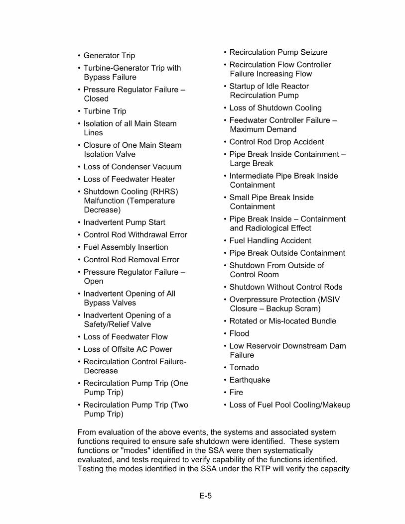
As a component of the BFN Design Basis Verification Program (DBVP), the primary purpose of the BFN Unit 1 RTP is to verify that plant systems are capable of meeting their safe shutdown requirements. To accomplish this objective, TVA performed a Safe Shutdown Analysis (SSA) as part of the BFN DBVP. The SSA, which addresses all three BFN units, is a systematic and comprehensive analysis of the requirements for ensuring the safe shutdown of BFN Units 1, 2, and 3 for transients, accidents, and special events. It documents the safety system actions for which credit has been taken in the UFSAR, reload analyses, and other communications addressing transients, accidents, and special events within the BFN licensing bases. The events considered in the SSA included:
E-5
• Generator Trip • Turbine-Generator Trip with
Bypass Failure • Pressure Regulator Failure –
Closed • Turbine Trip • Isolation of all Main Steam
Lines • Closure of One Main Steam
Isolation Valve • Loss of Condenser Vacuum • Loss of Feedwater Heater • Shutdown Cooling (RHRS)
Malfunction (Temperature Decrease)
• Inadvertent Pump Start • Control Rod Withdrawal Error • Fuel Assembly Insertion • Control Rod Removal Error • Pressure Regulator Failure –
Open • Inadvertent Opening of All
Bypass Valves • Inadvertent Opening of a
Safety/Relief Valve • Loss of Feedwater Flow • Loss of Offsite AC Power • Recirculation Control Failure-
Decrease • Recirculation Pump Trip (One
Pump Trip) • Recirculation Pump Trip (Two
Pump Trip)
• Recirculation Pump Seizure • Recirculation Flow Controller
Failure Increasing Flow • Startup of Idle Reactor
Recirculation Pump • Loss of Shutdown Cooling • Feedwater Controller Failure –
Maximum Demand • Control Rod Drop Accident • Pipe Break Inside Containment –
Large Break • Intermediate Pipe Break Inside
Containment • Small Pipe Break Inside
Containment • Pipe Break Inside – Containment
and Radiological Effect • Fuel Handling Accident • Pipe Break Outside Containment • Shutdown From Outside of
Control Room • Shutdown Without Control Rods • Overpressure Protection (MSIV
Closure – Backup Scram) • Rotated or Mis-located Bundle • Flood • Low Reservoir Downstream Dam
Failure • Tornado • Earthquake • Fire • Loss of Fuel Pool Cooling/Makeup
From evaluation of the above events, the systems and associated system functions required to ensure safe shutdown were identified. These system functions or "modes" identified in the SSA were then systematically evaluated, and tests required to verify capability of the functions identified. Testing the modes identified in the SSA under the RTP will verify the capacity
E-6
of the systems to support their required safety functions. Where applicable, these tests will be performed under Extended Power Uprate (EPU) conditions. Development of the BFN Unit 1 RTP program and identification of the associated BFN Unit 1 RTP test requirements are controlled administratively via BFN Procedure 1-TI-452, "Unit 1 Restart Test Program," which specifies the review and approval of the restart test requirements, associated acceptance criteria, and test results. The RTP test requirements are documented in the BFN Unit 1 Baseline Test Requirements Documents (BTRDs) developed, reviewed, and approved in accordance with BFN Procedure 1-TI-469, "Baseline Test Requirements." Consistent with the BFN Unit 3 RTP, a multi-disciplinary review group (per 1-TI-452, designated the Restart Test Program Review Group or "RTPRG") reviews and approves the RTP test requirements identified for each system, as well as the results of the RTP testing for each system. In addition to the testing planned for BFN Unit 1 under the RTP, TVA is performing system and component post-maintenance, post-modification, calibration, normal surveillance, and power-ascension testing as required to ensure other systems and system functions will operate within their design requirements. This testing, which is not part of the BFN Unit 1 RTP, is identified and controlled as required in accordance with 10 CFR 50 Appendix B. The BFN Unit 1 restart testing is controlled in accordance with BFN Procedure 1-TI-453, "Unit 1 Startup Test Instruction." Procedure 1-TI-453 provides coordination, tracking, and control of testing performed on each system. Under Procedure 1-TI-453, System Test Specifications (STS) are developed to define the minimum testing requirements, their bases, acceptance criteria, and the test procedures that will be used to satisfy the test requirements for selected BFN systems. The STS are intended to encompass all functional testing beyond the scope of static installation and minor post-maintenance testing, and includes component tests, loop calibrations, post-modification functional tests, Technical Instructions (TIs), Special Tests, and Technical Specifications/Technical Requirements surveillance tests. Consistent with the BFN Unit 3 RTP, TVA is utilizing existing surveillance and testing procedures to the extent possible to perform these tests. Where planned testing is not covered by existing procedures, explicit test instructions are developed to perform the testing.
IV. RESPONSE TO NRC REQUEST FOR INFORMATION
The NRC's June 15, 2005 request for additional information requested that TVA provide the following information:
E-7
"In order for the staff to independently verify the adequacy of your restart testing program, please describe in detail the modifications that were made and those still in progress or planned and how they were or will be verified to be within the bounds of the original test data. Also, provide a detailed listing and description of the testing that you referred to in your December 13, 2002 letter."
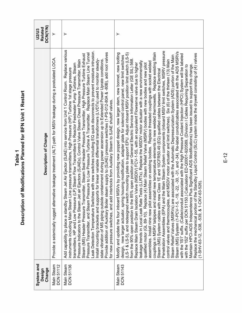
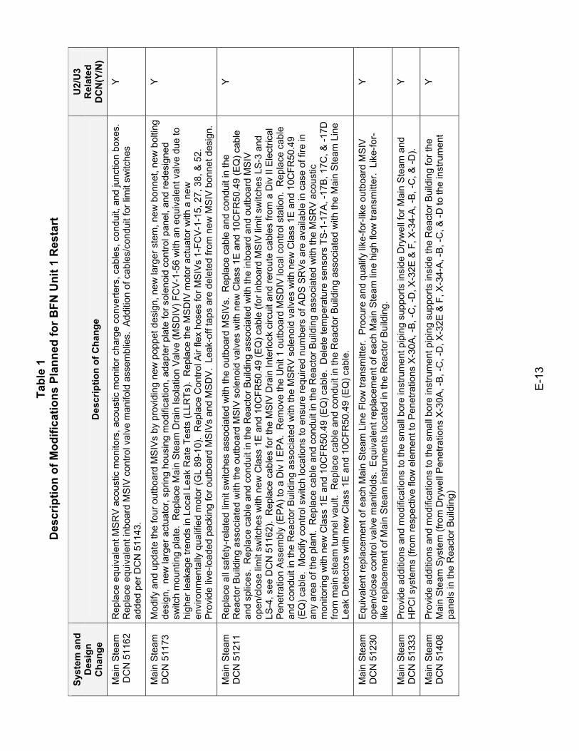
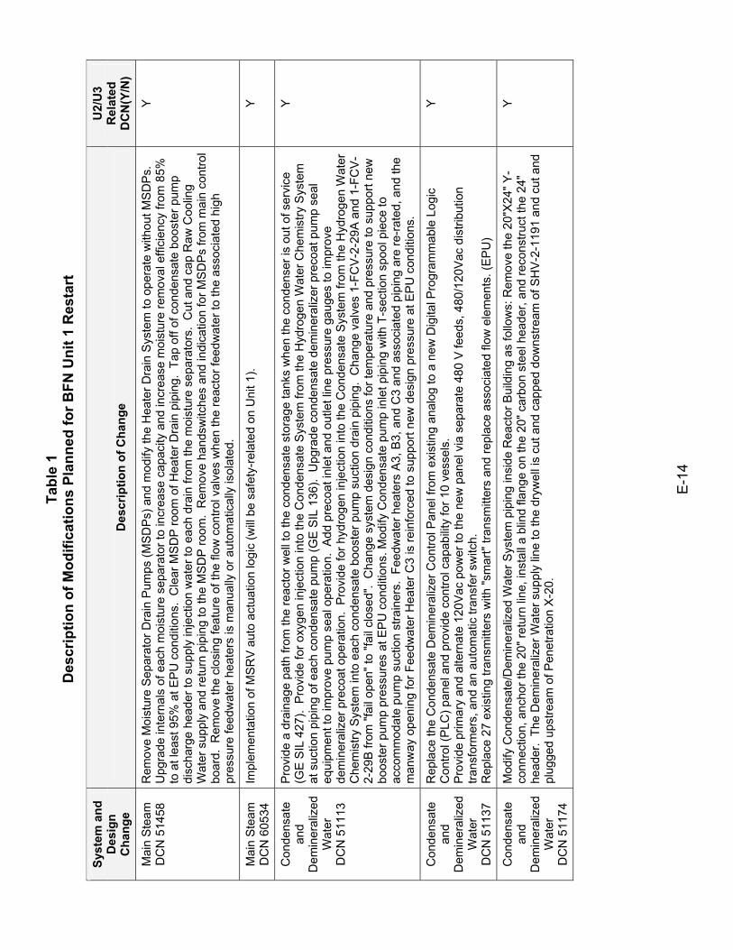
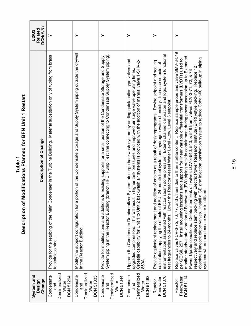
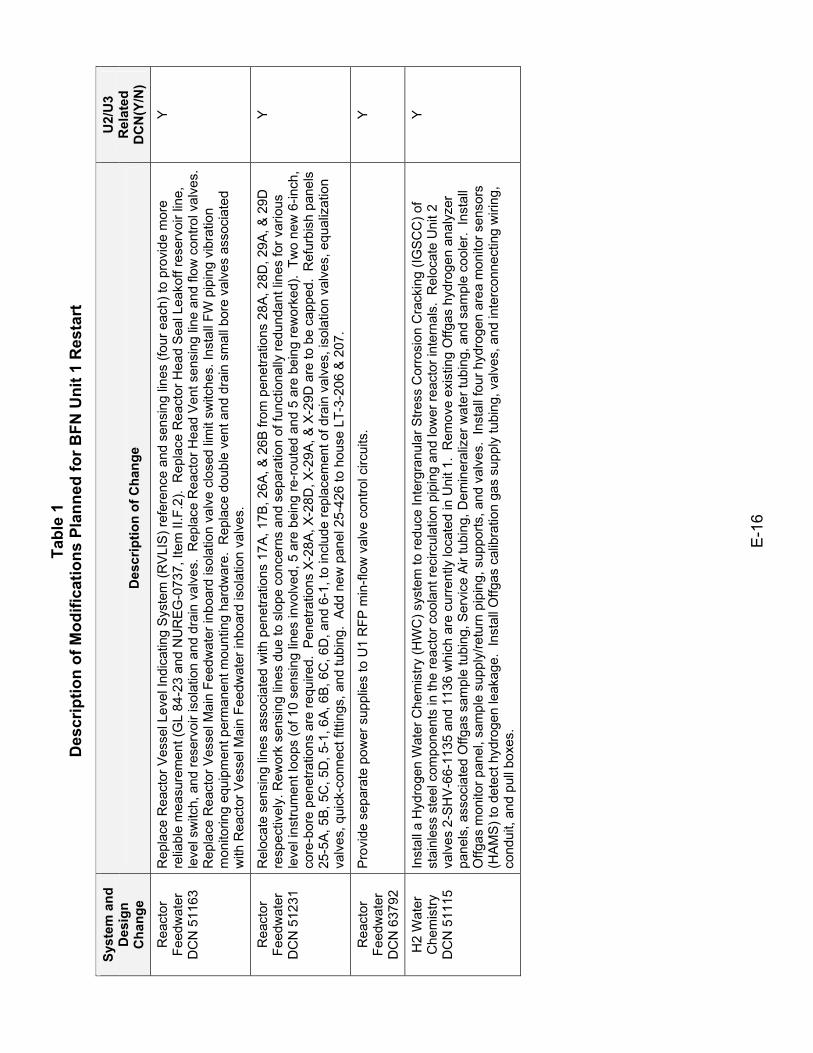
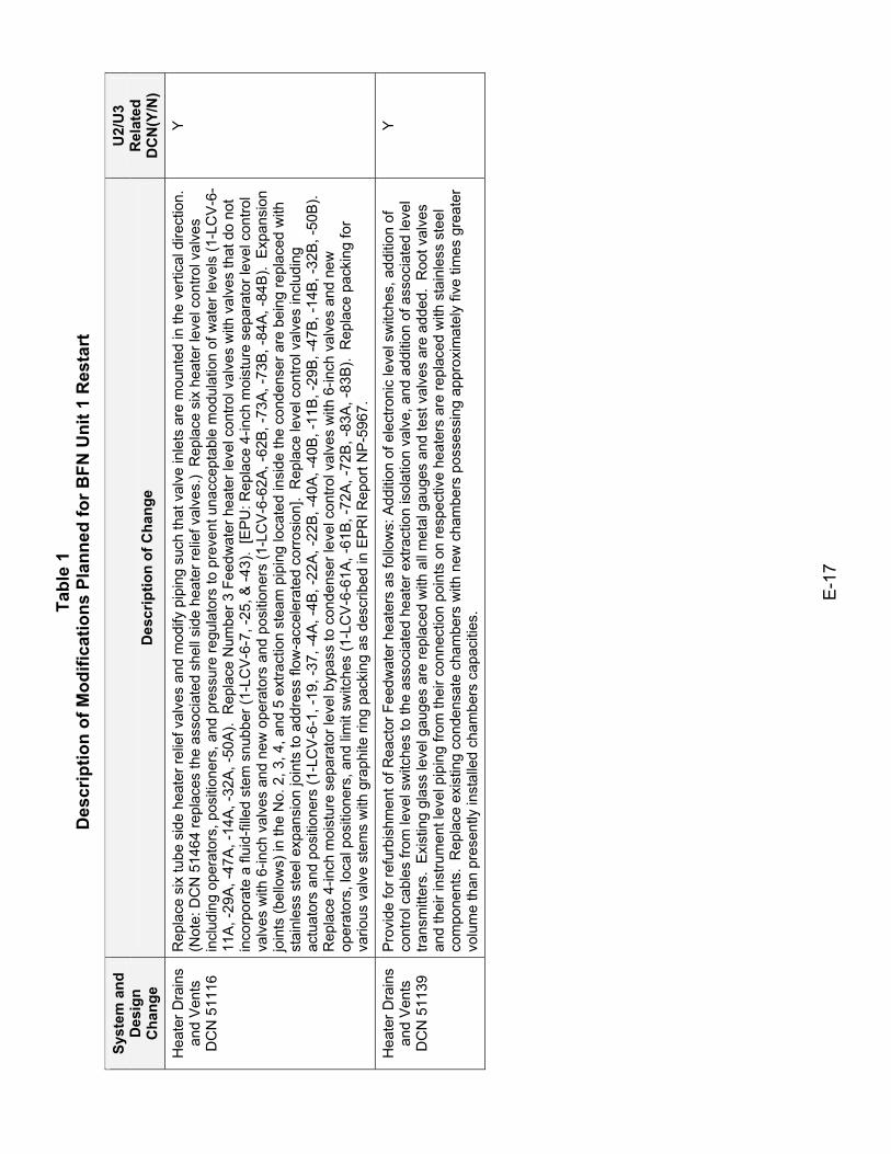
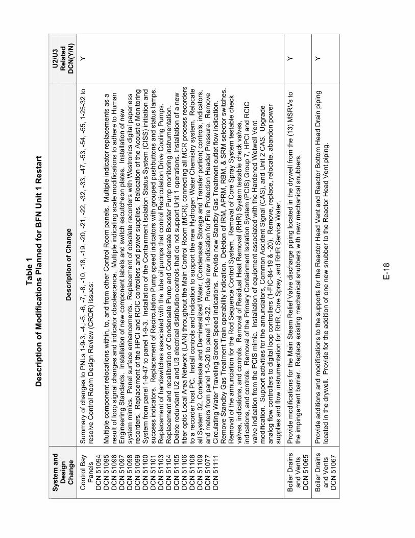
Table 1 identifies the modifications being implemented as part of the BFN Unit 1 restart. The table lists the Design Change Notices (DCNs), sorted by system, provides a detailed description of the modifications and identifies whether a similar DCN was implemented for BFN Units 2 and 3. Modifications developed primarily to implement EPU have been notated as such and grouped at the end of the table. Portions of other modifications supporting implementation of EPU are notated within their descriptions. A more concise description of the EPU modifications and the associated testing planned for those modifications was provided in TVA's April 25, 2005 letter (Reference 21) providing additional information in support of the BFN Unit 1 Extended Power Uprate application. Table 1 shows that with the exception of those modifications planned to implement EPU operation, most of the modifications planned for BFN Unit 1 have been implemented previously for BFN Units 2 and 3. Excluding EPU, the design modifications for Unit 1 are the result of like modifications implemented prior to the restart of Units 2 and 3, any changes made on Units 2 and 3 since their restarts, and changes to replace obsolete equipment. A primary consideration throughout the change process in the design, construction, function, and operation of systems being modified, has been unit fidelity. While minor differences exist among Units 1, 2, and 3, largely due to equipment obsolescence, the systems will remain functionally the same. As discussed in TVA's February 2, 1994 letter concerning the BFN Units 1 and 3 RTP, TVA is not verifying that plant systems and components are within the bounds of the original test data. Rather, the BFN Unit 1 RTP testing requirements and testing acceptance criteria are based on the BFN Safe Shutdown Analysis, and are documented in the BTRDs for each system function credited in the SSA. Therefore, while much of the acceptance criteria remain unchanged since performance of the initial pre-operational testing, the BTRDs establish and document the acceptance criteria based on the revised BFN Unit 1 design bases and design requirements. These acceptance criteria are specified in the applicable test instructions. As part of the BFN plant modification control process, TVA reviews all Design Change Notices (DCNs) to identify, specify, and document appropriate post-modification testing requirements. The purpose of post-modification testing is to demonstrate conformance with the design requirements of the installed or
E-8
modified component(s), confirm expected system response, and verify that no undesirable effects were created. DCNs are prepared and controlled in accordance with TVA procedure SPP-9.3, "Plant Modifications and Engineering Change Control," which requires that Design engineers identify and document any required verification and/or special testing requirements. Per TVA Procedure SPP-8.3, "Post Modification Testing," System engineers review the DCNs to confirm that all necessary post modification testing has been specified and are responsible for reviewing and concurring with acceptability of test results. These programmatic controls ensure for each design change, that the testing required to ensure system performance requirements are met and expected system response is confirmed. Testing is identified and performed with acceptable results prior to turnover of the system for operation. These controls are typical of industry programs developed to ensure compliance with the requirements of 10 CFR 50 Appendix B. As discussed in Section III above, for each system within the scope of the program, a set of System Test Specifications (STS) are developed to identify the testing required to return the system to service. These STS identify planned RTP testing as well as planned post-modification, post-maintenance, surveillance testing, etc. Due to the extent of the modifications and replacements being implemented on BFN Unit 1, it is not practical to list each and every planned post-modification and post-maintenance test in this response. However, these tests are documented in the STS for each system. Examples of typically specified post-modification and/or post-maintenance testing include (as applicable):
• Verification of proper rotation and setting limits on valves • Motor-operated valve (MOV) setting and baseline diagnostics (for
GL 89-10 valves) • Leak-rate testing for Primary Containment isolation valves • Pump operability testing (verification of rated flow within specified
period) • Valve operability testing • System flow balancing • System and component leak testing • Instrument channel calibration and functional testing • Protective relay calibration and functional testing • Logic system functional testing, • System run and confirmation that process parameters are within
expected ranges While these tests overlap with testing planned as part of the BFN Unit 1 RTP, they are identified and specified in accordance with the normal design control
E-9
process to ensure that plant systems are capable of meeting their design and operational requirements. Table 2 provides the matrix of tests planned for BFN Unit 1 under the RTP. As discussed in the description of the BFN Unit 1 RTP development in Section III above, the RTP test requirements are identified by system "modes" or functions that have been identified in the BFN SSA as required to ensure the capability for safe shutdown of the plant. Therefore Table 2 is organized according to these system modes, which are described in the table and which correlate to the modes identified in the BFN SSA and the associated system Baseline Technical Requirements Documents (BTRDs). The table also identifies whether the test was performed for BFN Units 2 and 3, whether the test is planned for BFN Unit 1, and includes clarifying information where appropriate. The BFN Unit 1 Power Ascension Testing (PAT) Program is consistent with the PAT Program described for BFN Unit 3 previously in Reference 12. Table 3 provides a comparison of BFN Unit 1 Power Ascension Testing (PAT) planned to the PAT testing described previously for BFN Unit 3 in Reference 12.
V. REFERENCES
1. NRC letter to TVA "Browns Ferry Nuclear Plant, Unit 1- Request for Additional Information Regarding Restart Testing Program (TAC No. MC7208)," dated June 15, 2005.
2. TVA letter to NRC, regarding the Browns Ferry Nuclear Plant (BFN)
Restart Test Program Plan, dated October 7, 1986. 3. NRC letter to TVA, "NRC Comments to Browns Ferry Unit 2 Restart Test
Program Plan," dated March 3, 1987. 4. TVA letter to NRC, "Browns Ferry Nuclear Plant (BFN) - Refinement of
the Restart Test Program," dated July 13, 1987. 5. NRC memorandum to docket, "Summary of Meeting with TVA
Concerning Restart Test Program at Browns Ferry Nuclear Plant - April 26, 1988 (TAC No. 62264)," dated May 24, 1988.
6. NRC memorandum to docket, "Summary of Meeting with TVA
Concerning Browns Ferry Nuclear (BFN) Plant Restart Test Program - June 21, 1988 (TAC No. 62264)," dated July 27, 1988.
E-10
7. NRC letter to TVA, "Volume 3, Section II.6.0 (Radiological and Chemistry Improvement) and Section III.8.0 (Restart Test Program) of the Nuclear Performance Plan - Browns Ferry Nuclear Plant, Unit 2 (TACS 62253 and 62264)," dated August 12, 1988.
8. TVA letter to NRC, submittal of the Browns Ferry Nuclear Performance
Plan, dated August 28, 1986. 9. TVA letter to NRC, "Browns Terry Nuclear Plant (BFN) - Nuclear
Performance Plan, Revision 2," dated October 24, 1988. 10. NRC letter to TVA, "Safety Evaluation Report on the Browns Ferry
Nuclear Performance Plan - NUREG-1232, Volume 3," dated April 14, 1989.
11. TVA letter to NRC, "Browns Ferry Nuclear Plant (BFN) – Restart Test
Program (RTP) for Units 1 and 3," dated September 27, 1991. 12. TVA letter to NRC, "Browns Ferry Nuclear Plant (BFN) – Request for
Additional Information Regarding the Restart Test Program for Units 1 and 3," dated February 18, 1992.
13. TVA letter to NRC, "Browns Ferry Nuclear Plant (BFN) – Update of
Restart Test Program (RTP) for Units 1 and 3," dated December 28, 1992.
14. TVA letter to NRC, "Browns Ferry Nuclear Plant (BFN) – Restart Test
Program (RTP) Update for Units 1 and 3," dated July 19, 1993. 15. NRC memorandum to docket, "Summary of the December 14, 1993
Meeting Regarding the Restart Test Program for the Browns Ferry Nuclear Plant, Units 1 and 3," dated January 13, 1994.
16. TVA letter to NRC, "Browns Ferry Nuclear Plant (BFN) - Restart Test
Program (RTP) Update for Units 1 and 3," dated February 2, 1994. 17. NRC Letter to TVA, "Browns Ferry Nuclear Plant Units 1 and 3 – Restart
Test Program," dated August 30, 1994. 18. TVA letter to NRC, "Browns Ferry Nuclear Plant (BFN) – Unit 1
Regulatory Framework for the Restart of Unit 1," dated December 13, 2002.
19. TVA letter to NRC, "Browns Ferry Nuclear Plant (BFN) – Unit 1
Regulatory Framework for the Restart of Unit 1," dated February 28, 2003.
E-11
20. NRC Letter to TVA, "Regulatory Framework for the Restart of Browns
Ferry Nuclear Plant Unit 1 (TAC MB7679)," dated August 14, 2003. 21. TVA letter to NRC, "Browns Ferry Nuclear Plant (BFN) - Unit 1 -
Response to NRC's Request for Additional Information Related to Technical Specifications (TS) Change No. TS-431 - Request for Extended Power Uprate Operation (TAC No. MC3812)," dated April 25, 2005.
Tabl
e 1
Des
crip
tion
of M
odifi
catio
ns P
lann
ed fo
r BFN
Uni
t 1 R
esta
rt
E-1
2 Sy
stem
and
D
esig
n C
hang
e D
escr
iptio
n of
Cha
nge
U2/
U3
Rel
ated
D
CN
(Y/N
)
Mai
n S
team
D
CN
511
12
Pro
vide
a s
eism
ical
ly ru
gged
alte
rnat
ive
leak
age
treat
men
t (A
LT) p
ath
for M
SIV
leak
age
durin
g a
post
ulat
ed L
OC
A.
Y
Mai
n S
team
D
CN
511
36
Add
cap
abili
ty to
pla
ce a
sta
ndby
Ste
am J
et A
ir E
ject
or (S
JAE
) int
o se
rvic
e fro
m U
nit 1
Con
trol R
oom
. R
epla
ce v
ario
us
inst
rum
ents
incl
udin
g M
ain
Ste
am L
ine
pres
sure
tran
smitt
ers,
Hig
h P
ress
ure
(HP
) Tur
bine
1st
sta
ge p
ress
ure
trans
mitt
ers,
HP
and
Low
Pre
ssur
e (L
P) S
team
Flo
w T
rans
mitt
ers
to R
eact
or F
eedw
ater
Pum
p Tu
rbin
es, S
team
P
ress
ure
Indi
cato
rs to
the
Ste
am J
et a
ir Ej
ecto
rs (S
JAEs
), C
ontro
l Val
ve S
team
Che
st P
ress
ure
Tran
smitt
er, M
ain
Ste
am (M
S) H
eade
r Pre
ssur
e Tr
ansm
itter
, Ste
am S
eal H
eade
r Pre
ssur
e Tr
ansm
itter
, Hig
h Pr
essu
re T
urbi
ne E
xhau
st
Pre
ssur
e Tr
ansm
itter
, and
Ste
am P
ress
ure
to L
ow P
ress
ure
Turb
ine
A T
rans
mitt
er.
Rep
lace
Mai
n S
team
Lin
e Tu
nnel
Le
ak D
etec
tion
Tem
pera
ture
Sw
itche
s w
ith n
ew s
witc
hes
incl
udin
g E
Q q
uick
dis
conn
ects
to p
reve
nt m
oist
ure
intru
sion
. In
stal
l mou
ntin
g br
acke
ts a
nd s
uppo
rts fo
r lin
ear v
aria
ble
diffe
rent
ial t
rans
form
ers
(LV
DTs
) use
d to
mon
itor s
tead
y-st
ate
vibr
atio
n of
MS
pip
ing
outs
ide
cont
ainm
ent d
urin
g po
wer
asc
ensi
on u
p to
Ext
ende
d P
ower
Upr
ate
cond
ition
s.
Pro
vide
add
ition
of A
uxilia
ry B
oile
r ste
am s
uppl
y to
(SJA
E) p
ress
ure
switc
hes
(1-P
S-0
12-8
0A &
-80B
), ad
d ro
ot v
alve
s fo
r new
pre
ssur
e sw
itche
s, a
nd a
dd in
terlo
cks
from
Aux
iliary
Ste
am to
SJA
E s
huto
ff va
lves
.
Y
Mai
n S
team
D
CN
511
43
Mod
ify a
nd u
pdat
e th
e fo
ur in
boar
d M
SIV
s by
pro
vidi
ng n
ew p
oppe
t des
ign,
new
larg
er s
tem
, new
bon
net,
new
bol
ting
desi
gn,
new
larg
er a
ctua
tor,
sprin
g ho
usin
g m
odifi
catio
n, a
dapt
er p
late
for s
olen
oid
cont
rol p
anel
, new
lim
it sw
itche
s (L
S-1
& L
S-5
), an
d re
desi
gned
sw
itch
mou
ntin
g pl
ate
to s
uppo
rt E
PU
. Adj
ust i
nboa
rd M
SIV
pos
ition
lim
it sw
itch
(LS-
5)
from
the
90%
ope
n po
sitio
n to
the
85%
ope
n po
sitio
n pe
r Gen
eral
Ele
ctric
Ser
vice
Info
rmat
ion
Lette
r (G
E S
IL) 5
68.
Rep
lace
Mai
n S
team
Dra
in Is
olat
ion
Val
ve (M
SD
IV) F
CV
-1-5
5, w
ith a
n eq
uiva
lent
Flo
wse
rve
valv
e du
e to
hig
her
leak
age
trend
s in
Loc
al L
eak
Rat
e Te
sts
(LLR
Ts).
Rep
lace
the
MSD
IV m
otor
act
uato
r with
a n
ew e
nviro
nmen
tally
qu
alifi
ed m
otor
(GL
89-1
0).
Rep
lace
(4) M
ain
Ste
am R
elie
f Val
ve (M
SR
V) b
odie
s w
ith n
ew b
odie
s an
d ne
w p
ilot
asse
mbl
ies.
Inst
all n
ine
new
pilo
t ass
embl
ies
on e
xist
ing
bodi
es.
Rep
lace
thre
aded
cou
plin
gs w
ith s
ocke
t wel
ded
coup
lings
in M
SR
V ta
ilpip
es a
nd in
stal
l new
tem
pera
ture
ele
men
ts in
new
wel
ded
ther
mow
ells
. R
epla
ce e
xist
ing
Mai
n S
team
(MS
) Sys
tem
cab
les
with
new
Cla
ss 1
E a
nd 1
0CFR
50.4
9 (E
Q) q
ualif
ied
cabl
es b
etw
een
the
Ele
ctric
al
Pen
etra
tion
Ass
embl
ies
(EP
A) a
nd th
e M
ain
Ste
am S
yste
m c
ompo
nent
s (in
boar
d M
SIV
lim
it sw
itche
s, M
SR
V p
ress
ure
cont
rol v
alve
s an
d th
erm
ocou
ples
, and
MS
DIV
mot
or a
ctua
tor a
nd li
mit
switc
hes)
. S
ix (6
) of t
he th
irtee
n (1
3) M
ain
Ste
am R
elie
f Val
ves
(MSR
Vs)
are
ass
ocia
ted
with
the
Aut
omat
ic D
epre
ssur
izat
ion
Sys
tem
(AD
S) p
ortio
n of
the
Mai
n S
team
(MS
) Sys
tem
(1-P
CV
-1-5
, -19
, -22
, -30
, -31
, and
-34)
. Re-
labe
l con
duit/
cabl
es a
ssoc
iate
d w
ith th
e A
DS
MS
RV
s w
ith th
e 'IS
1' s
uffix
. (C
able
/con
duit
asso
ciat
ed w
ith th
e H
igh
Pre
ssur
e C
oola
nt In
ject
ion
(HPC
I) S
yste
m w
ill be
labe
led
with
the
'IS2'
suf
fix p
er D
CN
511
50.)
Cal
cula
tion
ED
-Q00
01-9
2058
9, (D
ivis
ion
I Cab
les
Req
uirin
g S
epar
atio
n to
M
aint
ain
HPC
I-AD
S In
depe
nden
ce P
lus
Sig
nific
ant A
DS
Mod
ifica
tions
) has
bee
n is
sued
to s
uppo
rt th
is c
hang
e.
Rep
lace
the
mec
hani
cal p
ortio
n of
the
Sta
ndby
Liq
uid
Con
trol (
SLC
) sys
tem
insi
de th
e dr
ywel
l con
sist
ing
of (4
) val
ves
(1-S
HV
-63-
12, -
538,
-539
, & 1
-CK
V-6
3-52
6).
Y
Tabl
e 1
Des
crip
tion
of M
odifi
catio
ns P
lann
ed fo
r BFN
Uni
t 1 R
esta
rt
E-1
3
Syst
em a
nd
Des
ign
Cha
nge
Des
crip
tion
of C
hang
e
U2/
U3
Rel
ated
D
CN
(Y/N
)
Mai
n S
team
D
CN
511
62
Rep
lace
equ
ival
ent M
SR
V a
cous
tic m
onito
rs, a
cous
tic m
onito
r cha
rge
conv
erte
rs, c
able
s, c
ondu
it, a
nd ju
nctio
n bo
xes.
R
epla
ce e
quiv
alen
t inb
oard
MS
IV c
ontro
l val
ve m
anifo
ld a
ssem
blie
s. A
dditi
on o
f cab
les/
cond
uit f
or li
mit
switc
hes
adde
d pe
r DC
N 5
1143
.
Y
Mai
n S
team
D
CN
511
73
Mod
ify a
nd u
pdat
e th
e fo
ur o
utbo
ard
MSI
Vs
by p
rovi
ding
new
pop
pet d
esig
n, n
ew la
rger
ste
m, n
ew b
onne
t, ne
w b
oltin
g de
sign
, ne
w la
rger
act
uato
r, sp
ring
hous
ing
mod
ifica
tion,
ada
pter
pla
te fo
r sol
enoi
d co
ntro
l pan
el, a
nd re
desi
gned
sw
itch
mou
ntin
g pl
ate.
Rep
lace
Mai
n S
team
Dra
in Is
olat
ion
Val
ve (M
SD
IV) F
CV-
1-56
with
an
equi
vale
nt v
alve
due
to
high
er le
akag
e tre
nds
in L
ocal
Lea
k R
ate
Test
s (L
LRTs
). R
epla
ce th
e M
SD
IV m
otor
act
uato
r with
a n
ew
envi
ronm
enta
lly q
ualif
ied
mot
or (G
L 89
-10)
. R
epla
ce C
ontro
l Air
flex
hose
s fo
r MSI
Vs
1-FC
V-1-
15, 2
7, 3
8, &
52.
P
rovi
de li
ve-lo
aded
pac
king
for o
utbo
ard
MS
IVs
and
MS
DV
. Le
ak-o
ff ta
ps a
re d
elet
ed fr
om n
ew M
SIV
bon
net d
esig
n.
Y
Mai
n S
team
D
CN
512
11
Rep
lace
all
safe
ty-r
elat
ed li
mit
switc
hes
asso
ciat
ed w
ith th
e ou
tboa
rd M
SIV
s. R
epla
ce c
able
and
con
duit
in th
e R
eact
or B
uild
ing
asso
ciat
ed w
ith th
e ou
tboa
rd M
SIV
sol
enoi
d va
lves
with
new
Cla
ss 1
E a
nd 1
0CFR
50.4
9 (E
Q) c
able
an
d sp
lices
. R
epla
ce c
able
and
con
duit
in th
e R
eact
or B
uild
ing
asso
ciat
ed w
ith th
e in
boar
d an
d ou
tboa
rd M
SIV
op
en/c
lose
lim
it sw
itche
s w
ith n
ew C
lass
1E
and
10C
FR50
.49
(EQ
) cab
le (f
or in
boar
d M
SIV
lim
it sw
itche
s LS
-3 a
nd
LS-4
, see
DC
N 5
1162
). R
epla
ce c
able
s fo
r the
MS
IV D
rain
Inte
rlock
circ
uit a
nd re
rout
e ca
bles
from
a D
iv II
Ele
ctric
al
Pen
etra
tion
Ass
embl
y (E
PA) t
o a
Div
I E
PA
. R
emov
e th
e U
nit 1
out
boar
d M
SD
IV lo
cal c
ontro
l sta
tion.
Rep
lace
cab
le
and
cond
uit i
n th
e R
eact
or B
uild
ing
asso
ciat
ed w
ith th
e M
SR
V s
olen
oid
valv
es w
ith n
ew C
lass
1E
and
10C
FR50
.49
(EQ
) cab
le.
Mod
ify c
ontro
l sw
itch
loca
tions
to e
nsur
e re
quire
d nu
mbe
rs o
f AD
S S
RV
s ar
e av
aila
ble
in c
ase
of fi
re in
an
y ar
ea o
f the
pla
nt.
Rep
lace
cab
le a
nd c
ondu
it in
the
Rea
ctor
Bui
ldin
g as
soci
ated
with
the
MS
RV
aco
ustic
m
onito
ring
with
new
Cla
ss 1
E a
nd 1
0CFR
50.4
9 (E
Q) c
able
. D
elet
e te
mpe
ratu
re s
enso
rs T
S-1-
17A
, -17
B, 1
7C, &
-17D
fro
m m
ain
stea
m tu
nnel
vau
lt. R
epla
ce c
able
and
con
duit
in th
e R
eact
or B
uild
ing
asso
ciat
ed w
ith th
e M
ain
Ste
am L
ine
Leak
Det
ecto
rs w
ith n
ew C
lass
1E
and
10C
FR50
.49
(EQ
) cab
le.
Y
Mai
n S
team
D
CN
512
30
Equ
ival
ent r
epla
cem
ent o
f eac
h M
ain
Ste
am L
ine
Flow
tran
smitt
er.
Pro
cure
and
qua
lify
like-
for-
like
outb
oard
MS
IV
open
/clo
se c
ontro
l val
ve m
anifo
lds.
Equ
ival
ent r
epla
cem
ent o
f eac
h M
ain
Ste
am li
ne h
igh
flow
tran
smitt
er.
Like
-for-
like
repl
acem
ent o
f Mai
n S
team
inst
rum
ents
loca
ted
in th
e R
eact
or B
uild
ing.
Y
Mai
n S
team
D
CN
513
33
Pro
vide
add
ition
s an
d m
odifi
catio
ns to
the
smal
l bor
e in
stru
men
t pip
ing
supp
orts
insi
de D
ryw
ell f
or M
ain
Ste
am a
nd
HP
CI s
yste
ms
(from
resp
ectiv
e flo
w e
lem
ent t
o P
enet
ratio
ns X
-30A
, -B
, -C
, -D
, X-3
2E &
F, X
-34-
A, -
B, -
C, &
-D).
Y
Mai
n S
team
D
CN
514
08
Pro
vide
add
ition
s an
d m
odifi
catio
ns to
the
smal
l bor
e in
stru
men
t pip
ing
supp
orts
insi
de th
e R
eact
or B
uild
ing
for t
he
Mai
n S
team
Sys
tem
(fro
m D
ryw
ell P
enet
ratio
ns X
-30A
, -B
, -C
, -D
, X-3
2E &
F, X
-34-
A, -
B, -
C, &
-D to
the
inst
rum
ent
pane
ls in
the
Rea
ctor
Bui
ldin
g)
Y
Tabl
e 1
Des
crip
tion
of M
odifi
catio
ns P
lann
ed fo
r BFN
Uni
t 1 R
esta
rt
E-1
4
Syst
em a
nd
Des
ign
Cha
nge
Des
crip
tion
of C
hang
e
U2/
U3
Rel
ated
D
CN
(Y/N
)
Mai
n S
team
D
CN
514
58
Rem
ove
Moi
stur
e S
epar
ator
Dra
in P
umps
(MSD
Ps)
and
mod
ify th
e H
eate
r Dra
in S
yste
m to
ope
rate
with
out M
SD
Ps.
U
pgra
de in
tern
als
of e
ach
moi
stur
e se
para
tor t
o in
crea
se c
apac
ity a
nd in
crea
se m
oist
ure
rem
oval
effi
cien
cy fr
om 8
5%
to a
t lea
st 9
5% a
t EP
U c
ondi
tions
. C
lear
MS
DP
room
of H
eate
r Dra
in p
ipin
g. T
ap o
ff of
con
dens
ate
boos
ter p
ump
disc
harg
e he
ader
to s
uppl
y in
ject
ion
wat
er to
eac
h dr
ain
from
the
moi
stur
e se
para
tors
. C
ut a
nd c
ap R
aw C
oolin
g W
ater
sup
ply
and
retu
rn p
ipin
g to
the
MS
DP
room
. R
emov
e ha
ndsw
itche
s an
d in
dica
tion
for M
SD
Ps fr
om m
ain
cont
rol
boar
d. R
emov
e th
e cl
osin
g fe
atur
e of
the
flow
con
trol v
alve
s w
hen
the
reac
tor f
eedw
ater
to th
e as
soci
ated
hig
h pr
essu
re fe
edw
ater
hea
ters
is m
anua
lly o
r aut
omat
ical
ly is
olat
ed.
Y
Mai
n S
team
D
CN
605
34
Impl
emen
tatio
n of
MS
RV
aut
o ac
tuat
ion
logi
c (w
ill be
saf
ety-
rela
ted
on U
nit 1
). Y
Con
dens
ate
and
Dem
iner
aliz
ed
Wat
er
DC
N 5
1113
Pro
vide
a d
rain
age
path
from
the
reac
tor w
ell t
o th
e co
nden
sate
sto
rage
tank
s w
hen
the
cond
ense
r is
out o
f ser
vice
(G
E S
IL 4
27).
Pro
vide
for o
xyge
n in
ject
ion
into
the
Con
dens
ate
Sys
tem
from
the
Hyd
roge
n W
ater
Che
mis
try S
yste
m
at s
uctio
n pi
ping
of e
ach
cond
ensa
te p
ump
(GE
SIL
136
). U
pgra
de c
onde
nsat
e de
min
eral
izer
pre
coat
pum
p se
al
equi
pmen
t to
impr
ove
pum
p se
al o
pera
tion.
Add
pre
coat
inle
t and
out
let l
ine
pres
sure
gau
ges
to im
prov
e de
min
eral
izer
pre
coat
ope
ratio
n. P
rovi
de fo
r hyd
roge
n in
ject
ion
into
the
Con
dens
ate
Sys
tem
from
the
Hyd
roge
n W
ater
C
hem
istry
Sys
tem
into
eac
h co
nden
sate
boo
ster
pum
p su
ctio
n dr
ain
pipi
ng.
Cha
nge
valv
es 1
-FC
V-2
-29A
and
1-F
CV
-2-
29B
from
"fai
l ope
n" to
"fai
l clo
sed"
. C
hang
e sy
stem
des
ign
cond
ition
s fo
r tem
pera
ture
and
pre
ssur
e to
sup
port
new
bo
oste
r pum
p pr
essu
res
at E
PU
con
ditio
ns. M
odify
Con
dens
ate
pum
p in
let p
ipin
g w
ith T
-sec
tion
spoo
l pie
ce to
ac
com
mod
ate
pum
p su
ctio
n st
rain
ers.
Fee
dwat
er h
eate
rs A
3, B
3, a
nd C
3 an
d as
soci
ated
pip
ing
are
re-r
ated
, and
the
man
way
ope
ning
for F
eedw
ater
Hea
ter C
3 is
rein
forc
ed to
sup
port
new
des
ign
pres
sure
at E
PU
con
ditio
ns.
Y
Con
dens
ate
and
Dem
iner
aliz
ed
Wat
er
DC
N 5
1137
Rep
lace
the
Con
dens
ate
Dem
iner
aliz
er C
ontro
l Pan
el fr
om e
xist
ing
anal
og to
a n
ew D
igita
l Pro
gram
mab
le L
ogic
C
ontro
l (P
LC) p
anel
and
pro
vide
con
trol c
apab
ility
for 1
0 ve
ssel
s.
Pro
vide
prim
ary
and
alte
rnat
e 12
0Vac
pow
er to
the
new
pan
el v
ia s
epar
ate
480
V fe
eds,
480
/120
Vac
dis
tribu
tion
trans
form
ers,
and
an
auto
mat
ic tr
ansf
er s
witc
h.
Rep
lace
27
exis
ting
trans
mitt
ers
with
"sm
art"
trans
mitt
ers
and
repl
ace
asso
ciat
ed fl
ow e
lem
ents
. (E
PU
)
Y
Con
dens
ate
and
Dem
iner
aliz
ed
Wat
er
DC
N 5
1174
Mod
ify C
onde
nsat
e/D
emin
eral
ized
Wat
er S
yste
m p
ipin
g in
side
Rea
ctor
Bui
ldin
g as
follo
ws:
Rem
ove
the
20"X
24" Y
-co
nnec
tion,
anc
hor t
he 2
0" re
turn
line
, ins
tall
a bl
ind
flang
e on
the
20" c
arbo
n st
eel h
eade
r, an
d re
cons
truct
the
24"
head
er.
The
Dem
iner
aliz
er W
ater
sup
ply
line
to th
e dr
ywel
l is
cut a
nd c
appe
d do
wns
tream
of S
HV
-2-1
191
and
cut a
nd
plug
ged
upst
ream
of P
enet
ratio
n X
-20.
Y
Tabl
e 1
Des
crip
tion
of M
odifi
catio
ns P
lann
ed fo
r BFN
Uni
t 1 R
esta
rt
E-1
5
Syst
em a
nd
Des
ign
Cha
nge
Des
crip
tion
of C
hang
e
U2/
U3
Rel
ated
D
CN
(Y/N
)
Con
dens
ate
and
Dem
iner
aliz
ed
Wat
er
DC
N 5
1294
Pro
vide
for t
he re
tubi
ng o
f the
Mai
n C
onde
nser
in th
e Tu
rbin
e B
uild
ing.
Mat
eria
l sub
stitu
tion
only
of t
ubin
g fro
m b
rass
to
sta
inle
ss s
teel
. Y
Con
dens
ate
and
Dem
iner
aliz
ed
Wat
er
DC
N 5
1335
Mod
ify th
e su
ppor
t con
figur
atio
n fo
r a p
ortio
n of
the
Con
dens
ate
Sto
rage
and
Sup
ply
Sys
tem
pip
ing
outs
ide
the
dryw
ell
in th
e R
eact
or B
uild
ing.
Y
Con
dens
ate
and
Dem
iner
aliz
ed
Wat
er
DC
N 5
1344
Pro
vide
for m
odifi
catio
ns a
nd a
dditi
ons
to e
xist
ing
supp
orts
for a
sm
all p
ortio
n of
the
Con
dens
ate
Sto
rage
and
Sup
ply
Sys
tem
pip
ing
in th
e R
eact
or B
uild
ing
(bra
nch
HP
CI P
ump
Test
line
con
nect
ing
to C
onde
nsat
e S
uppl
y S
yste
m p
ipin
g).
Y
Con
dens
ate
and
Dem
iner
aliz
ed
Wat
er
DC
N 5
1463
Upg
rade
the
Con
dens
ate
Dem
iner
aliz
er S
yste
m a
ir su
rge
back
was
h sy
stem
by
addi
ng q
uick
-act
ion
type
val
ves
and
upgr
aded
com
pres
sors
. Th
is w
ill re
sult
in h
ighe
r tan
k pr
essu
res
and
impr
oved
air
surg
e va
lve
oper
atin
g tim
es.
C
ross
tie c
apab
ility
for U
nit 1
to U
nit 2
bac
kwas
h ai
r sys
tem
s is
pro
vide
d w
ith th
e ad
ditio
n of
man
ual v
alve
1-S
HV
-2-
850A
.
Y
Rea
ctor
Fe
edw
ater
D
CN
510
76
Pro
vide
equ
ival
ent r
epla
cem
ent a
nd a
dditi
on o
f cab
les
as a
resu
lt of
des
ign/
prog
ram
s. R
evis
e se
tpoi
nt a
nd s
calin
g ca
lcul
atio
ns a
pply
ing
the
effe
cts
of E
PU
, 24-
mon
th fu
el c
ycle
, and
hyd
roge
n w
ater
che
mis
try.
Incr
ease
set
poin
t of
inst
rum
enta
tion
asso
ciat
ed w
ith re
acto
r ste
am d
ome
pres
sure
. E
xten
d ch
anne
l cal
ibra
tion
and
logi
c sy
stem
func
tiona
l te
st fr
eque
ncie
s to
24-
mon
ths.
Low
er th
e R
eact
or V
esse
l Wat
er L
evel
-Low
, Lev
el 3
set
poin
t.
Y
Rea
ctor
Fe
edw
ater
D
CN
511
14
Rep
lace
val
ves
FCV
-3-7
5, 7
6, 7
7, a
nd o
ther
s du
e to
thei
r ste
llite
con
tent
. R
epla
ce s
ampl
e pr
obe
and
valv
e S
MV
-3-5
49
per G
E S
IL 2
57.
Inst
all m
ount
ing
brac
kets
and
sup
ports
for l
inea
r var
iabl
e di
ffere
ntia
l tra
nsfo
rmer
s (L
VDTs
) use
d to
m
onito
r ste
ady-
stat
e vi
brat
ion
of F
eedw
ater
(FW
) pip
ing
outs
ide
cont
ainm
ent d
urin
g po
wer
asc
ensi
on u
p to
Ext
ende
d P
ower
Upr
ate
cond
ition
s. D
elet
e st
em le
ak o
ff va
lves
LO
V-3
-540
, 543
, & 5
48 fr
om v
alve
s FC
V-3
-71,
72,
& 7
3 re
spec
tivel
y an
d re
plac
e st
em p
acki
ng w
ith E
lect
ric P
ower
Res
earc
h In
stitu
te (E
PR
I)-st
yle
pack
ing.
Rep
lace
12
obso
lete
Han
cock
glo
be v
alve
s. I
nsta
ll a
GE
zin
c in
ject
ion
pass
ivat
ion
syst
em to
redu
ce C
obal
t-60
build
-up
in p
ipin
g sy
stem
s w
here
con
dens
ate
wat
er is
util
ized
.
Y
Tabl
e 1
Des
crip
tion
of M
odifi
catio
ns P
lann
ed fo
r BFN
Uni
t 1 R
esta
rt
E-1
6
Syst
em a
nd
Des
ign
Cha
nge
Des
crip
tion
of C
hang
e
U2/
U3
Rel
ated
D
CN
(Y/N
)
Rea
ctor
Fe
edw
ater
D
CN
511
63
Rep
lace
Rea
ctor
Ves
sel L
evel
Indi
catin
g S
yste
m (R
VLI
S) r
efer
ence
and
sen
sing
line
s (fo
ur e
ach)
to p
rovi
de m
ore
relia
ble
mea
sure
men
t (G
L 84
-23
and
NU
RE
G-0
737,
Item
II.F
.2).
Rep
lace
Rea
ctor
Hea
d S
eal L
eako
ff re
serv
oir l
ine,
le
vel s
witc
h, a
nd re
serv
oir i
sola
tion
and
drai
n va
lves
. R
epla
ce R
eact
or H
ead
Ven
t sen
sing
line
and
flow
con
trol v
alve
s.
Rep
lace
Rea
ctor
Ves
sel M
ain
Feed
wat
er in
boar
d is
olat
ion
valv
e cl
osed
lim
it sw
itche
s. In
stal
l FW
pip
ing
vibr
atio
n m
onito
ring
equi
pmen
t per
man
ent m
ount
ing
hard
war
e. R
epla
ce d
oubl
e ve
nt a
nd d
rain
sm
all b
ore
valv
es a
ssoc
iate
d w
ith R
eact
or V
esse
l Mai
n Fe
edw
ater
inbo
ard
isol
atio
n va
lves
.
Y
Rea
ctor
Fe
edw
ater
D
CN
512
31
Rel
ocat
e se
nsin
g lin
es a
ssoc
iate
d w
ith p
enet
ratio
ns 1
7A, 1
7B, 2
6A, &
26B
from
pen
etra
tions
28A
, 28D
, 29A
, & 2
9D
resp
ectiv
ely.
Rew
ork
sens
ing
lines
due
to s
lope
con
cern
s an
d se
para
tion
of fu
nctio
nally
redu
ndan
t lin
es fo
r var
ious
le
vel i
nstru
men
t loo
ps (o
f 10
sens
ing
lines
invo
lved
, 5 a
re b
eing
re-r
oute
d an
d 5
are
bein
g re
wor
ked)
. Tw
o ne
w 6
-inch
, co
re-b
ore
pene
tratio
ns a
re re
quire
d. P
enet
ratio
ns X
-28A
, X-2
8D, X
-29A
, & X
-29D
are
to b
e ca
pped
. R
efur
bish
pan
els
25-5
A, 5
B, 5
C, 5
D, 5
-1, 6
A, 6
B, 6
C, 6
D, a
nd 6
-1, t
o in
clud
e re
plac
emen
t of d
rain
val
ves,
isol
atio
n va
lves
, equ
aliz
atio
n va
lves
, qui
ck-c
onne
ct fi
tting
s, a
nd tu
bing
. A
dd n
ew p
anel
25-
426
to h
ouse
LT-
3-20
6 &
207
.
Y
Rea
ctor
Fe
edw
ater
D
CN
637
92
Pro
vide
sep
arat
e po
wer
sup
plie
s to
U1
RFP
min
-flow
val
ve c
ontro
l circ
uits
. Y
H2
Wat
er
Che
mis
try
DC
N 5
1115
Inst
all a
Hyd
roge
n W
ater
Che
mis
try (H
WC
) sys
tem
to re
duce
Inte
rgra
nula
r Stre
ss C
orro
sion
Cra
ckin
g (IG
SCC
) of
stai
nles
s st
eel c
ompo
nent
s in
the
reac
tor c
oola
nt re
circ
ulat
ion
pipi
ng a
nd lo
wer
reac
tor i
nter
nals
. R
eloc
ate
Uni
t 2
valv
es 2
-SH
V-6
6-11
35 a
nd 1
136
whi
ch a
re c
urre
ntly
loca
ted
in U
nit 1
. R
emov
e ex
istin
g O
ffgas
hyd
roge
n an
alyz
er
pane
ls, a
ssoc
iate
d O
ffgas
sam
ple
tubi
ng, S
ervi
ce A
ir tu
bing
, Dem
iner
aliz
er w
ater
tubi
ng, a
nd s
ampl
e co
oler
. In
stal
l O
ffgas
mon
itor p
anel
, sam
ple
supp
ly/re
turn
pip
ing,
sup
ports
, and
val
ves.
Ins
tall
four
hyd
roge
n ar
ea m
onito
r sen
sors
(H
AM
S) t
o de
tect
hyd
roge
n le
akag
e. I
nsta
ll O
ffgas
cal
ibra
tion
gas
supp
ly tu
bing
, val
ves,
and
inte
rcon
nect
ing
wiri
ng,
cond
uit,
and
pull
boxe
s.
Y
Tabl
e 1
Des
crip
tion
of M
odifi
catio
ns P
lann
ed fo
r BFN
Uni
t 1 R
esta
rt
E-1
7
Syst
em a
nd
Des
ign
Cha
nge
Des
crip
tion
of C
hang
e
U2/
U3
Rel
ated
D
CN
(Y/N
)
Hea
ter D
rain
s an
d V
ents
D
CN
511
16
Rep
lace
six
tube
sid
e he
ater
relie
f val
ves
and
mod
ify p
ipin
g su
ch th
at v
alve
inle
ts a
re m
ount
ed in
the
verti
cal d
irect
ion.
(N
ote:
DC
N 5
1464
repl
aces
the
asso
ciat
ed s
hell
side
hea
ter r
elie
f val
ves.
) R
epla
ce s
ix h
eate
r lev
el c
ontro
l val
ves
incl
udin
g op
erat
ors,
pos
ition
ers,
and
pre
ssur
e re
gula
tors
to p
reve
nt u
nacc
epta
ble
mod
ulat
ion
of w
ater
leve
ls (1
-LC
V-6
-11
A, -
29A
, -47
A, -
14A
, -32
A, -5
0A).
Rep
lace
Num
ber 3
Fee
dwat
er h
eate
r lev
el c
ontro
l val
ves
with
val
ves
that
do
not
inco
rpor
ate
a flu
id-fi
lled
stem
snu
bber
(1-L
CV-
6-7,
-25,
& -4
3).
[EP
U: R
epla
ce 4
-inch
moi
stur
e se
para
tor l
evel
con
trol
valv
es w
ith 6
-inch
val
ves
and
new
ope
rato
rs a
nd p
ositi
oner
s (1
-LC
V-6
-62A
, -62
B, -7
3A, -
73B,
-84A
, -84
B).
Exp
ansi
on
join
ts (b
ello
ws)
in th
e N
o. 2
, 3, 4
, and
5 e
xtra
ctio
n st
eam
pip
ing
loca
ted
insi
de th
e co
nden
ser a
re b
eing
repl
aced
with
st
ainl
ess
stee
l exp
ansi
on jo
ints
to a
ddre
ss fl
ow-a
ccel
erat
ed c
orro
sion
]. R
epla
ce le
vel c
ontro
l val
ves
incl
udin
g ac
tuat
ors
and
posi
tione
rs (1
-LC
V-6
-1, -
19, -
37, -
4A, -
4B, -
22A
, -22
B, -4
0A, -
40B
, -11
B, -
29B
, -47
B, -
14B
, -32
B, -
50B
).
Rep
lace
4-in
ch m
oist
ure
sepa
rato
r lev
el b
ypas
s to
con
dens
er le
vel c
ontro
l val
ves
with
6-in
ch v
alve
s an
d ne
w
oper
ator
s, lo
cal p
ositi
oner
s, a
nd li
mit
switc
hes
(1-L
CV
-6-6
1A, -
61B
, -72
A, -
72B
, -83
A, -
83B
). R
epla
ce p
acki
ng fo
r va
rious
val
ve s
tem
s w
ith g
raph
ite ri
ng p
acki
ng a
s de
scrib
ed in
EP
RI R
epor
t NP
-596
7.
Y
Hea
ter D
rain
s an
d V
ents
D
CN
511
39
Pro
vide
for r
efur
bish
men
t of R
eact
or F
eedw
ater
hea
ters
as
follo
ws:
Add
ition
of e
lect
roni
c le
vel s
witc
hes,
add
ition
of
cont
rol c
able
s fro
m le
vel s
witc
hes
to th
e as
soci
ated
hea
ter e
xtra
ctio
n is
olat
ion
valv
e, a
nd a
dditi
on o
f ass
ocia
ted
leve
l tra
nsm
itter
s. E
xist
ing
glas
s le
vel g
auge
s ar
e re
plac
ed w
ith a
ll m
etal
gau
ges
and
test
val
ves
are
adde
d. R
oot v
alve
s an
d th
eir i
nstru
men
t lev
el p
ipin
g fro
m th
eir c
onne
ctio
n po
ints
on
resp
ectiv
e he
ater
s ar
e re
plac
ed w
ith s
tain
less
ste
el
com
pone
nts.
Rep
lace
exi
stin
g co
nden
sate
cha
mbe
rs w
ith n
ew c
ham
bers
pos
sess
ing
appr
oxim
atel
y fiv
e tim
es g
reat
er
volu
me
than
pre
sent
ly in
stal
led
cham
bers
cap
aciti
es.
Y
Tabl
e 1
Des
crip
tion
of M
odifi
catio
ns P
lann
ed fo
r BFN
Uni
t 1 R
esta
rt
E-1
8
Syst
em a
nd
Des
ign
Cha
nge
Des
crip
tion
of C
hang
e
U2/
U3
Rel
ated
D
CN
(Y/N
)
Con
trol B
ay
Pan
els
D
CN
510
94
DC
N 5
1095
D
CN
510
96
DC
N 5
1097
D
CN
510
98
DC
N 5
1099
D
CN
511
00
DC
N 5
1101
D
CN
511
03
DC
N 5
1104
D
CN
511
05
DC
N 5
1106
D
CN
511
08
DC
N 5
1109
D
CN
510
77
DC
N 5
1111
Sum
mar
y of
cha
nges
to P
NLs
1-9
-3, -
4,:-5
, -6,
-7, -
8, -1
0, -1
8, -1
9, -2
0, -2
1, -2
2, -3
2, -3
3, -4
7, -5
3, -5
4, -5
5, 1
-25-
32 to
re
solv
e C
ontro
l Roo
m D
esig
n R
evie
w (C
RD
R) i
ssue
s:
Mul
tiple
com
pone
nt re
loca
tions
with
in, t
o, a
nd fr
om o
ther
Con
trol R
oom
pan
els.
Mul
tiple
indi
cato
r rep
lace
men
ts a
s a
resu
lt of
loop
sig
nal c
hang
es a
nd in
dica
tor o
bsol
esce
nce.
Mul
tiple
indi
catin
g sc
ale
mod
ifica
tions
to a
dher
e to
Hum
an
Eng
inee
ring
Sta
ndar
ds.
Inst
alla
tion
of n
ew c
ompo
nent
labe
ls a
nd s
witc
h es
cutc
heon
pla
tes.
Ins
talla
tion
of n
ew
syst
em m
imic
s. P
anel
sur
face
enh
ance
men
ts.
Rep
lace
men
t of o
bsol
ete
reco
rder
s w
ith W
estro
nics
dig
ital p
aper
less
re
cord
ers.
Rep
lace
men
t of t
he H
PC
I and
RC
IC c
ontro
llers
and
pow
er s
uppl
ies.
Rel
ocat
ion
of th
e A
cous
tic M
onito
ring
Sys
tem
from
pan
el 1
-9-4
7 to
pan
el 1
-9-3
. In
stal
latio
n of
the
Con
tain
men
t Iso
latio
n S
tatu
s S
yste
m (C
ISS
) ini
tiatio
n an
d su
cces
s in
dica
tors
. R
epla
cem
ent o
f Rec
ircul
atio
n P
ump
spee
d in
dica
tors
with
gro
uped
pus
hbut
tons
and
sta
tus
lam
ps.
Rep
lace
men
t of h
ands
witc
hes
asso
ciat
ed w
ith th
e lu
be o
il pu
mps
that
con
trol R
ecirc
ulat
ion
Driv
e C
oolin
g P
umps
. R
epla
cem
ent a
nd re
calib
ratio
n of
Con
dens
ate
Pum
p an
d C
onde
nsat
e B
oost
er P
ump
mon
itorin
g in
stru
men
tatio
n.
Del
ete
redu
ndan
t U2
and
U3
elec
trica
l dis
tribu
tion
cont
rols
that
do
not s
uppo
rt U
nit 1
ope
ratio
ns. I
nsta
llatio
n of
a n
ew
fiber
opt
ic L
ocal
Are
a N
etw
ork
(LA
N) t
hrou
ghou
t the
Mai
n C
ontro
l Roo
m (M
CR
), co
nnec
ting
all M
CR
pro
cess
reco
rder
s to
a re
cord
er h
ost P
C.
Inst
all c
ontro
ls a
nd in
dica
tion
to s
uppo
rt th
e ne
w H
ydro
gen
Wat
er C
hem
istry
sys
tem
. R
eloc
ate
all S
yste
m 0
2, C
onde
nsat
e an
d D
emin
eral
ized
Wat
er, (
Con
dens
ate
Sto
rage
and
Tra
nsfe
r por
tion)
con
trols
, ind
icat
ors,
an
d m
eter
s fro
m p
anel
1-9
-20
to p
anel
1-9
-22.
Pro
vide
new
indi
catio
n fo
r Fire
Pro
tect
ion
Hea
der P
ress
ure.
Rem
ove
Circ
ulat
ing
Wat
er T
rave
ling
Scr
een
Spe
ed In
dica
tions
. P
rovi
de n
ew S
tand
by G
as T
reat
men
t out
let f
low
indi
catio
n.
Rem
ove
Sta
ndby
Gas
Tre
atm
ent T
rain
ope
rabi
lity
indi
catio
n. D
elet
ion
of IR
M, A
PR
M, R
BM
, & S
RM
sel
ecto
r sw
itche
s.
Rem
oval
of t
he a
nnun
ciat
ion
for t
he R
od S
eque
nce
Con
trol S
yste
m.
Rem
oval
of C
ore
Spr
ay S
yste
m te
stab
le c
heck
va
lves
, ind
icat
ions
, and
con
trols
. R
emov
al o
f Res
idua
l Hea
t Rem
oval
(RH
R) S
yste
m te
stab
le c
heck
val
ves,
in
dica
tions
, and
con
trols
. R
emov
al o
f the
Prim
ary
Con
tain
men
t Iso
latio
n S
yste
m (P
CIS
) Gro
up 7
, HP
CI a
nd R
CIC
va
lve
indi
catio
n fro
m th
e PC
IS m
imic
. In
stal
latio
n of
equ
ipm
ent a
ssoc
iate
d w
ith th
e H
arde
ned
Wet
wel
l Ven
t m
odifi
catio
n. S
uppo
rt ac
tiviti
es fo
r the
ann
unci
ator
s, C
omm
on A
ccid
ent S
igna
l (C
AS
), an
d U
nit 2
CA
S.
Upg
rade
an
alog
flow
con
trolle
rs to
dig
ital l
oop
cont
rolle
rs (1
-FIC
-84-
19 &
-20)
. R
emov
e, re
plac
e, re
loca
te, a
band
on p
ower
su
pplie
s an
d flo
w in
stru
men
tatio
n fo
r RH
R, C
ore
Spr
ay, a
nd R
HR
Ser
vice
Wat
er.
Y
Boi
ler D
rain
s an
d V
ents
D
CN
510
65
Pro
vide
mod
ifica
tions
for t
he M
ain
Ste
am R
elie
f Val
ve d
isch
arge
pip
ing
loca
ted
in th
e dr
ywel
l fro
m th
e (1
3) M
SR
Vs
to
the
impi
ngem
ent b
arrie
r. R
epla
ce e
xist
ing
mec
hani
cal s
nubb
ers
with
new
mec
hani
cal s
nubb
ers.
Y
Boi
ler D
rain
s an
d V
ents
D
CN
510
67
Pro
vide
add
ition
s an
d m
odifi
catio
ns to
the
supp
orts
for t
he R
eact
or H
ead
Ven
t and
Rea
ctor
Bot
tom
Hea
d D
rain
pip
ing
loca
ted
in th
e dr
ywel
l. P
rovi
de fo
r the
add
ition
of o
ne n
ew s
nubb
er to
the
Rea
ctor
Hea
d V
ent p
ipin
g.
Y
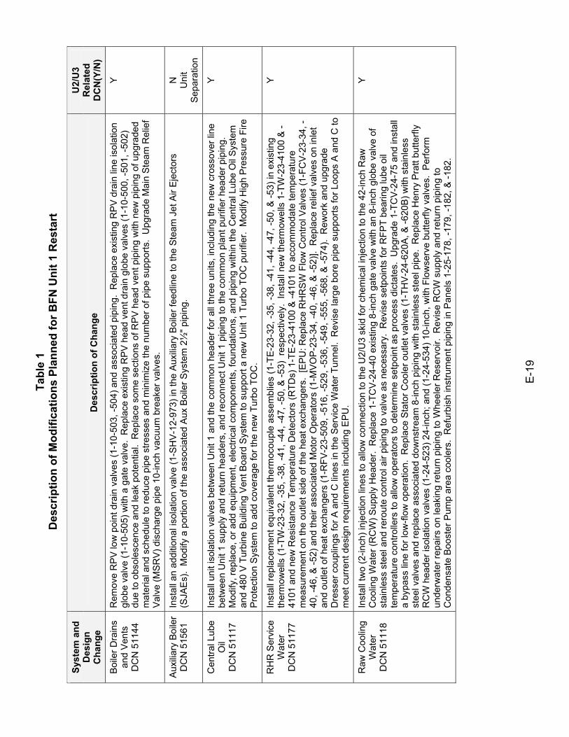
Tabl
e 1
Des
crip
tion
of M
odifi
catio
ns P
lann
ed fo
r BFN
Uni
t 1 R
esta
rt
E-1
9
Syst
em a
nd
Des
ign
Cha
nge
Des
crip
tion
of C
hang
e
U2/
U3
Rel
ated
D
CN
(Y/N
)
Boi
ler D
rain
s an
d V
ents
D
CN
511
44
Rem
ove
RP
V lo
w p
oint
dra
in v
alve
s (1
-10-
503,
-504
) and
ass
ocia
ted
pipi
ng.
Rep
lace
exi
stin
g R
PV
dra
in li
ne is
olat
ion
glob
e va
lve
(1-1
0-50
5) w
ith a
gat
e va
lve.
Rep
lace
exi
stin
g R
PV
hea
d ve
nt d
rain
glo
be v
alve
s (1
-10-
500,
-501
, -50
2)
due
to o
bsol
esce
nce
and
leak
pot
entia
l. R
epla
ce s
ome
sect
ions
of R
PV
hea
d ve
nt p
ipin
g w
ith n
ew p
ipin
g of
upg
rade
d m
ater
ial a
nd s
ched
ule
to re
duce
pip
e st
ress
es a
nd m
inim
ize
the
num
ber o
f pip
e su
ppor
ts.
Upg
rade
Mai
n S
team
Rel
ief
Val
ve (M
SR
V) d
isch
arge
pip
e 10
-inch
vac
uum
bre
aker
val
ves.
Y
Aux
iliary
Boi
ler
DC
N 5
1561
In
stal
l an
addi
tiona
l iso
latio
n va
lve
(1-S
HV
-12-
973)
in th
e A
uxilia
ry B
oile
r fee
dlin
e to
the
Ste
am J
et A
ir E
ject
ors
(SJA
Es)
. M
odify
a p
ortio
n of
the
asso
ciat
ed A
ux B
oile
r Sys
tem
2½
" pip
ing.
N
U
nit
Sep
arat
ion
Cen
tral L
ube
Oil
D
CN
511
17
Inst
all u
nit i
sola
tion
valv
es b
etw
een
Uni
t 1 a
nd th
e co
mm
on h
eade
r for
all
thre
e un
its, i
nclu
ding
the
new
cro
ssov
er li
ne
betw
een
Uni
t 1 s
uppl
y an
d re
turn
hea
ders
, and
reco
nnec
t Uni
t 1 p
ipin
g to
the
com
mon
pla
nt p
urifi
er h
eade
r pip
ing.
M
odify
, rep
lace
, or a
dd e
quip
men
t, el
ectri
cal c
ompo
nent
s, fo
unda
tions
, and
pip
ing
with
in th
e C
entra
l Lub
e O
il S
yste
m
and
480
V T
urbi
ne B
uild
ing
Ven
t Boa
rd S
yste
m to
sup
port
a ne
w U
nit 1
Tur
bo T
OC
pur
ifier
. M
odify
Hig
h P
ress
ure
Fire
P
rote
ctio
n S
yste
m to
add
cov
erag
e fo
r the
new
Tur
bo T
OC
.
Y
RH
R S
ervi
ce
Wat
er
DC
N 5
1177
Inst
all r
epla
cem
ent e
quiv
alen
t the
rmoc
oupl
e as
sem
blie
s (1
-TE-
23-3
2, -3
5, -3
8, -4
1, -4
4, -4
7, -5
0, &
-53)
in e
xist
ing
ther
mow
ells
(1-T
W-2
3-32
, -35
, -38
, -41
, -44
, -47
, -50
, & -5
3) r
espe
ctiv
ely.
Ins
tall
new
ther
mow
ells
1-T
W-2
3-41
00 &
-41
01 a
nd n
ew R
esis
tanc
e Te
mpe
ratu
re D
etec
tors
(RTD
s) 1
-TE
-23-
4100
& -4
101
to a
ccom
mod
ate
tem
pera
ture
m
easu
rem
ent o
n th
e ou
tlet s
ide
of th
e he
at e
xcha
nger
s. [
EP
U: R
epla
ce R
HR
SW
Flo
w C
ontro
l Val
ves
(1-F
CV
-23-
34, -
40, -
46, &
-52)
and
thei
r ass
ocia
ted
Mot
or O
pera
tors
(1-M
VOP
-23-
34, -
40, -
46, &
-52)
]. R
epla
ce re
lief v
alve
s on
inle
t an
d ou
tlet o
f hea
t exc
hang
ers
(1-R
FV-2
3-50
9, -5
16, -
529,
-536
, -54
9, -5
55, -
568,
& -5
74).
Rew
ork
and
upgr
ade
Dre
sser
cou
plin
gs fo
r A a
nd C
line
s in
the
Ser
vice
Wat
er T
unne
l. R
evis
e la
rge
bore
pip
e su
ppor
ts fo
r Loo
ps A
and
C to
m
eet c
urre
nt d
esig
n re
quire
men
ts in
clud
ing
EP
U.
Y
Raw
Coo
ling
Wat
er
DC
N 5
1118
Inst
all t
wo
(2-in
ch) i
njec
tion
lines
to a
llow
con
nect
ion
to th
e U
2/U
3 sk
id fo
r che
mic
al in
ject
ion
to th
e 42
-inch
Raw
C
oolin
g W
ater
(RC
W) S
uppl
y H
eade
r. R
epla
ce 1
-TC
V-2
4-40
exi
stin
g 8-
inch
gat
e va
lve
with
an
8-in
ch g
lobe
val
ve o
f st
ainl
ess
stee
l and
rero
ute
cont
rol a
ir pi
ping
to v
alve
as
nece
ssar
y. R
evis
e se
tpoi
nts
for R
FPT
bear
ing
lube
oil
tem
pera
ture
con
trolle
rs to
allo
w o
pera
tors
to d
eter
min
e se
tpoi
nt a
s pr
oces
s di
ctat
es.
Upg
rade
1-T
CV-
24-7
5 an
d in
stal
l a
bypa
ss li
ne fo
r low
-flow
ope
ratio
n. R
epla
ce S
tato
r Coo
ler o
utle
t val
ves
(1-T
HV
-24-
620A
, & -6
20B
) with
sta
inle
ss
stee
l val
ves
and
repl
ace
asso
ciat
ed d
owns
tream
8-in
ch p
ipin
g w
ith s
tain
less
ste
el p
ipe.
Rep
lace
Hen
ry P
ratt
butte
rfly
RC
W h
eade
r iso
latio
n va
lves
(1-2
4-52
3) 2
4-in
ch; a
nd (1
-24-
534)
10-
inch
, with
Flo
wse
rve
butte
rfly
valv
es.
Per
form
un
derw
ater
repa
irs o
n le
akin
g re
turn
pip
ing
to W
heel
er R
eser
voir.
Rev
ise
RC
W s
uppl
y an
d re
turn
pip
ing
to
Con
dens
ate
Boo
ster
Pum
p ar
ea c
oole
rs.
Ref
urbi
sh in
stru
men
t pip
ing
in P
anel
s 1-
25-1
78, -
179,
-182
, & -1
82.
Y
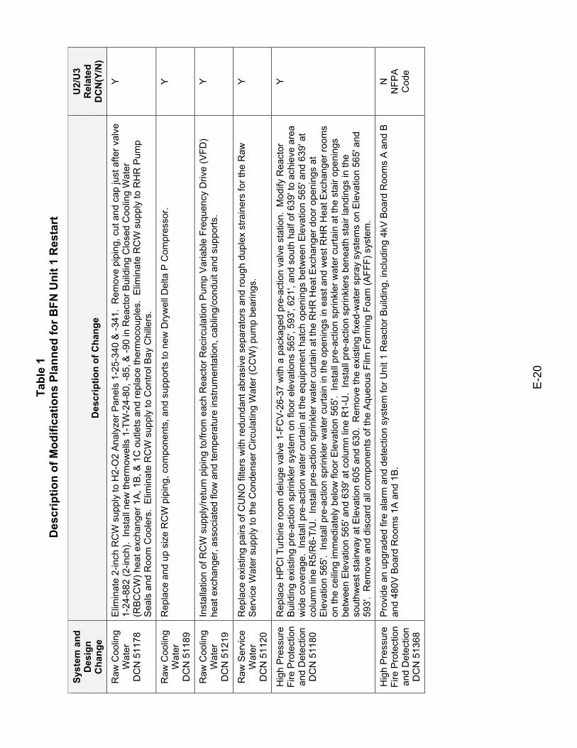
Tabl
e 1
Des
crip
tion
of M
odifi
catio
ns P
lann
ed fo
r BFN
Uni
t 1 R
esta
rt
E-2
0
Syst
em a
nd
Des
ign
Cha
nge
Des
crip
tion
of C
hang
e
U2/
U3
Rel
ated
D
CN
(Y/N
)
Raw
Coo
ling
Wat
er
DC
N 5
1178
Elim
inat
e 2-
inch
RC
W s
uppl
y to
H2-
O2
Ana
lyze
r Pan
els
1-25
-340
& -3
41.
Rem
ove
pipi
ng, c
ut a
nd c
ap ju
st a
fter v
alve
1-
24-8
82 (2
-inch
). In
stal
l new
ther
mow
ells
1-T
W-2
4-80
, -85
, & -9
0 in
Rea
ctor
Bui
ldin
g C
lose
d C
oolin
g W
ater
(R
BCC
W) h
eat e
xcha
nger
1A
, 1B
, & 1
C o
utle
ts a
nd re
plac
e th
erm
ocou
ples
. E
limin
ate
RC
W s
uppl
y to
RH
R P
ump
Sea
ls a
nd R
oom
Coo
lers
. E
limin
ate
RC
W s
uppl
y to
Con
trol B
ay C
hille
rs.
Y
Raw
Coo
ling
Wat
er
DC
N 5
1189
Rep
lace
and
up
size
RC
W p
ipin
g, c
ompo
nent
s, a
nd s
uppo
rts to
new
Dry
wel
l Del
ta P
Com
pres
sor.
Y
Raw
Coo
ling
Wat
er
DC
N 5
1219
Inst
alla
tion
of R
CW
sup
ply/
retu
rn p
ipin
g to
/from
eac
h R
eact
or R
ecirc
ulat
ion
Pum
p V
aria
ble
Freq
uenc
y D
rive
(VFD
) he
at e
xcha
nger
, ass
ocia
ted
flow
and
tem
pera
ture
inst
rum
enta
tion,
cab
ling/
cond
uit a
nd s
uppo
rts.
Y
Raw
Ser
vice
W
ater
D
CN
511
20
Rep
lace
exi
stin
g pa
irs o
f CU
NO
filte
rs w
ith re
dund
ant a
bras
ive
sepa
rato
rs a
nd ro
ugh
dupl
ex s
train
ers
for t
he R
aw
Ser
vice
Wat
er s
uppl
y to
the
Con
dens
er C
ircul
atin
g W
ater
(CC
W) p
ump
bear
ings
. Y
Hig
h P
ress
ure
Fire
Pro
tect
ion
and
Det
ectio
n
DC
N 5
1180
Rep
lace
HP
CI T
urbi
ne ro
om d
elug
e va
lve
1-FC
V-26
-37
with
a p
acka
ged
pre-
actio
n va
lve
stat
ion.
Mod
ify R
eact
or
Bui
ldin
g ex
istin
g pr
e-ac
tion
sprin
kler
sys
tem
on
floor
ele
vatio
ns 5
65',
593'
, 621
', an
d so
uth
half
of 6
39' t
o ac
hiev
e ar
ea
wid
e co
vera
ge.
Inst
all p
re-a
ctio
n w
ater
cur
tain
at t
he e
quip
men
t hat
ch o
peni
ngs
betw
een
Ele
vatio
n 56
5' a
nd 6
39' a
t co
lum
n lin
e R
5/R
6-T/
U.
Inst
all p
re-a
ctio
n sp
rinkl
er w
ater
cur
tain
at t
he R
HR
Hea
t Exc
hang
er d
oor o
peni
ngs
at
Ele
vatio
n 56
5'.
Inst
all p
re-a
ctio
n sp
rinkl
er w
ater
cur
tain
in th
e op
enin
gs in
eas
t and
wes
t RH
R H
eat E
xcha
nger
room
s on
the
ceilin
g im
med
iate
ly b
elow
floo
r Ele
vatio
n 56
5'.
Inst
all p
re-a
ctio
n sp
rinkl
er w
ater
cur
tain
at t
he s
tair
open
ings
be
twee
n E
leva
tion
565'
and
639
' at c
olum
n lin
e R
1-U
. In
stal
l pre
-act
ion
sprin
kler
s be
neat
h st
air l
andi
ngs
in th
e so
uthw
est s
tairw
ay a
t Ele
vatio
n 60
5 an
d 63
0. R
emov
e th
e ex
istin
g fix
ed-w
ater
spr
ay s
yste
ms
on E
leva
tion
565'
and
59
3'.
Rem
ove
and
disc
ard
all c
ompo
nent
s of
the
Aqu
eous
Film
For
min
g Fo
am (A
FFF)
sys
tem
.
Y
Hig
h P
ress
ure
Fire
Pro
tect
ion
and
Det
ectio
n
DC
N 5
1368
Pro
vide
an
upgr
aded
fire
ala
rm a
nd d
etec
tion
syst
em fo
r Uni
t 1 R
eact
or B
uild
ing,
incl
udin
g 4k
V B
oard
Roo
ms
A a
nd B
an
d 48
0V B
oard
Roo
ms
1A a
nd 1
B.
N
NFP
A
Cod
e
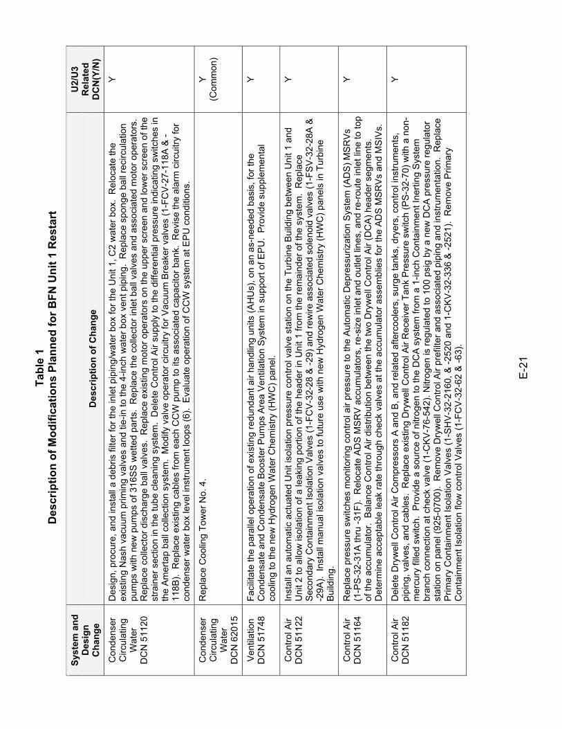
Tabl
e 1
Des
crip
tion
of M
odifi
catio
ns P
lann
ed fo
r BFN
Uni
t 1 R
esta
rt
E-2
1
Syst
em a
nd
Des
ign
Cha
nge
Des
crip
tion
of C
hang
e
U2/
U3
Rel
ated
D
CN
(Y/N
)
Con
dens
er
Circ
ulat
ing
Wat
er
DC
N 5
1120
Des
ign,
pro
cure
, and
inst
all a
deb
ris fi
lter f
or th
e in
let p
ipin
g/w
ater
box
for t
he U
nit 1
, C2
wat
er b
ox.
Rel
ocat
e th
e ex
istin
g N
ash
vacu
um p
rimin
g va
lves
and
tie-
in to
the
4-in
ch w
ater
box
ven
t pip
ing.
Rep
lace
spo
nge
ball
reci
rcul
atio
n pu
mps
with
new
pum
ps o
f 316
SS
wet
ted
parts
. R
epla
ce th
e co
llect
or in
let b
all v
alve
s an
d as
soci
ated
mot
or o
pera
tors
. R
epla
ce c
olle
ctor
dis
char
ge b
all v
alve
s. R
epla
ce e
xist
ing
mot
or o
pera
tors
on
the
uppe
r scr
een
and
low
er s
cree
n of
the
stra
iner
sec
tion
in th
e tu
be c
lean
ing
syst
em.
Del
ete
Con
trol A
ir su
pply
to th
e di
ffere
ntia
l pre
ssur
e in
dica
ting
switc
hes
in
the
Am
erta
p ba
ll co
llect
ion
syst
em.
Mod
ify v
alve
ope
rato
r circ
uitry
for V
acuu
m B
reak
er v
alve
s (1
-FC
V-2
7-11
8A &
-11
8B).
Rep
lace
exi
stin
g ca
bles
from
eac
h C
CW
pum
p to
its
asso
ciat
ed c
apac
itor b
ank.
Rev
ise
the
alar
m c
ircui
try fo
r co
nden
ser w
ater
box
leve
l ins
trum
ent l
oops
(6).
Eva
luat
e op
erat
ion
of C
CW
sys
tem
at E
PU
con
ditio
ns.
Y
Con
dens
er
Circ
ulat
ing
Wat
er
DC
N 6
2015
Rep
lace
Coo
ling
Tow
er N
o. 4
. Y
(Com
mon
)
Ven
tilat
ion
DC
N 5
1748
Fa
cilit
ate
the
para
llel o
pera
tion
of e
xist
ing
redu
ndan
t air
hand
ling
units
(AH
Us)
, on
an a
s-ne
eded
bas
is, f
or th
e C
onde
nsat
e an
d C
onde
nsat
e B
oost
er P
umps
Are
a Ve
ntila
tion
Sys
tem
in s
uppo
rt of
EP
U.
Pro
vide
sup
plem
enta
l co
olin
g to
the
new
Hyd
roge
n W
ater
Che
mis
try (H
WC
) pan
el.
Y
Con
trol A
ir
DC
N 5
1122
In
stal
l an
auto
mat
ic a
ctua
ted
Uni
t iso
latio
n pr
essu
re c
ontro
l val
ve s
tatio
n on
the
Turb
ine
Bui
ldin
g be
twee
n U
nit 1
and
U
nit 2
to a
llow
isol
atio
n of
a le
akin
g po
rtion
of t
he h
eade
r in
Uni
t 1 fr
om th
e re
mai
nder
of t
he s
yste
m.
Rep
lace
S
econ
dary
Con
tain
men
t Iso
latio
n V
alve
s (1
-FC
V-3
2-28
& -2
9) a
nd re
wire
ass
ocia
ted
sole
noid
val
ves
(1-F
SV
-32-
28A
&
-29A
). In
stal
l man
ual i
sola
tion
valv
es to
futu
re u
se w
ith n
ew H
ydro
gen
Wat
er C
hem
istry
(HW
C) p
anel
s in
Tur
bine
B
uild
ing.
Y
Con
trol A
ir
DC
N 5
1164
R
epla
ce p
ress
ure
switc
hes
mon
itorin
g co
ntro
l air
pres
sure
to th
e A
utom
atic
Dep
ress
uriz
atio
n S
yste
m (A
DS)
MS
RV
s (1
-PS
-32-
31A
thru
-31F
). R
eloc
ate
AD
S M
SR
V a
ccum
ulat
ors,
re-s
ize
inle
t and
out
let l
ines
, and
re-r
oute
inle
t lin
e to
top
of th
e ac
cum
ulat
or.
Bal
ance
Con
trol A
ir di
strib
utio
n be
twee
n th
e tw
o D
ryw
ell C
ontro
l Air
(DC
A) h
eade
r seg
men
ts.
Det
erm
ine
acce
ptab
le le
ak ra
te th
roug
h ch
eck
valv
es a
t the
acc
umul
ator
ass
embl
ies
for t
he A
DS
MS
RV
s an
d M
SIV
s.
Y
Con
trol A
ir
DC
N 5
1182
D
elet
e D
ryw
ell C
ontro
l Air
Com
pres
sors
A a
nd B
, and
rela
ted
afte
rcoo
lers
, sur
ge ta
nks,
dry
ers,
con
trol i
nstru
men
ts,
pipi
ng, v
alve
s, a
nd c
able
s. R
epla
ce e
xist
ing
Dry
wel
l Con
trol A
ir R
ecei
ver T
ank
Pre
ssur
e sw
itch
(PS
-32-
70) w
ith a
non
-m
ercu
ry fi
lled
switc
h. P
rovi
de a
sou
rce
of n
itrog
en to
the
DC
A s
yste
m fr
om a
1-in
ch C
onta
inm
ent I
nerti
ng S
yste
m
bran
ch c
onne
ctio
n at
che
ck v
alve
(1-C
KV-7
6-54
2). N
itrog
en is
regu
late
d to
100
psi
g by
a n
ew D
CA
pre
ssur
e re
gula
tor
stat
ion
on p
anel
(925
-070
0).
Rem
ove
Dry
wel
l Con
trol A
ir pr
efilt
er a
nd a
ssoc
iate
d pi
ping
and
inst
rum
enta
tion.
Rep
lace
P
rimar
y C
onta
inm
ent I
sola
tion
Val
ves
(1-S
HV
-32-
2160
, & -2
520
and
1-C
KV-
32-3
36 &
-252
1).
Rem
ove
Prim
ary
Con
tain
men
t Iso
latio
n flo
w c
ontro
l Val
ves
(1-F
CV
-32-
62 &
-63)
.
Y
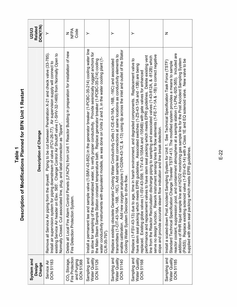
Tabl
e 1
Des
crip
tion
of M
odifi
catio
ns P
lann
ed fo
r BFN
Uni
t 1 R
esta
rt
E-2
2
Syst
em a
nd
Des
ign
Cha
nge
Des
crip
tion
of C
hang
e
U2/
U3
Rel
ated
D
CN
(Y/N
)
Ser
vice
Air
D
CN
511
83
Rem
ove
all S
ervi
ce A
ir pi
ping
from
the
dryw
ell.
Pip
ing
to b
e cu
t bet
wee
n P
enet
ratio
n X
-21
and
chec
k va
lve
(33-
785)
. In
stal
l air
supe
rvis
ion
syst
em fo
r pip
ing
dow
nstre
am o
f val
ve (F
CV
-26-
77).
Air
supe
rvis
ion
supp
ly w
ill co
nnec
t to
exis
ting
Ser
vice
Air
head
er o
n E
lev.
565
'. C
hang
e C
ontro
l Air
Shu
toff
valv
e (1
-SH
V-3
2-14
69) f
rom
Nor
mal
ly O
pen
to
Nor
mal
ly C
lose
d. C
ut a
ssoc
iate
d lin
e, p
lug,
and
labe
l con
nect
ion
as "S
pare
".
Y
CO
2 Sto
rage
, Fi
re P
rote
ctio
n an
d P
urgi
ng
DC
N 5
1368
Del
ete
all L
ocal
Fire
Ala
rm C
ontro
l Pan
els
(LFA
CP
s) fr
om U
nit 1
Rea
ctor
Bui
ldin
g in
pre
para
tion
for i
nsta
llatio
n of
new
Fi
re D
etec
tion
Pro
tect
ion
Sys
tem
. N
N
FPA
C
ode
Sam
plin
g an
d W
ater
Qua
lity
DC
N 5
1126
Inst
all a
per
man
ent t
ee a
nd s
ampl
e va
lve
(1-S
MV
-43-
852)
in th
e ge
nera
tor b
reak
er (1
-PC
BC
-35-
214)
coo
ling
wat
er li
ne
to a
llow
for s
ampl
ing
of th
e de
min
eral
ized
wat
er, t
o ve
rify
prop
er c
ondu
ctiv
ity.
Pro
vide
sei
smic
ally
rugg
ed a
ncho
rs fo
r th
e M
ain
Ste
am S
ampl
e St
atio
n co
nsta
nt te
mpe
ratu
re b
ath.
Rep
lace
gen
erat
or b
reak
er (1
-PC
BC
-35-
214)
coo
ling
wat
er c
ondu
ctiv
ity in
stru
men
ts w
ith e
quiv
alen
t mod
els,
as
was
don
e on
Uni
ts 2
and
3, i
n th
e w
ater
coo
ling
plan
t (1-
CLR
-35-
797)
.
Y
Sam
plin
g an
d W
ater
Qua
lity
DC
N 5
1140
Rep
lace
exi
stin
g ob
sole
te G
ener
ator
Coo
ling
Wat
er C
ondu
ctiv
ity C
ells
(1-C
E-4
3-16
A, -
16B
, -16
C) a
nd a
ssoc
iate
d tra
nsm
itter
s (1
-CIT
-43-
16A
, -16
B, -
16C
). A
dd s
ampl
e te
st c
onne
ctio
ns a
t sam
e lo
catio
ns a
s co
nduc
tivity
ele
men
ts to
en
able
cal
ibra
tion.
Add
new
oxy
gen
anal
yzer
s (1
-O2A
N-4
3-12
, & -1
3) u
sing
dp
acro
ss th
e in
let a
nd o
utle
t of t
he S
tato
r C
oolin
g W
ater
Sys
tem
Dei
oniz
er to
driv
e flo
w.
Y
Sam
plin
g an
d W
ater
Qua
lity
DC
N 5
1168
Rep
lace
(1-F
SV
-43-
13) d
ue to
age
, tim
e in
har
sh e
nviro
nmen
t, an
d de
grad
ed c
ompo
nent
s. R
epla
cem
ent v
alve
to
have
ste
m s
eal p
acki
ng w
hich
mee
ts E
PR
I gui
delin
es.
Ass
ocia
ted
switc
hes
(1-Z
S-4
3-13
A a
nd -1
3B) a
re b
eing
re
plac
ed.
Exi
stin
g gl
obe
valv
es (1
-ISV
-43-
599,
1-T
V-4
3-10
54A
and
-105
4B) w
ith g
ate
valv
es fo
r enh
ance
d pe
rform
ance
and
repl
acem
ent v
alve
s to
hav
e st
em s
eal p
acki
ng w
hich
mee
ts E
PR
I gui
delin
es.
Del
ete
exis
ting
vent
lin
e fro
m th
e R
eact
or R
ecirc
ulat
ion
disc
harg
e pi
ping
to s
ampl
ing
and
asso
ciat
ed v
alve
s (1
-43-
812A
, & -8
12B
) whi
ch
serv
e no
des
ign
func
tion.
Rew
ork
inst
rum
ent s
ensi
ng li
nes
for f
low
ele
men
ts (1
-FE
-71-
1A &
-1B
) to
corr
ect n
egat
ive
slop
e an
d pr
ovid
e ac
cura
te s
team
flow
indi
catio
n an
d lin
e br
eak
dete
ctio
n.
Y
Sam
plin
g an
d W
ater
Qua
lity
DC
N 5
1185
Inst
all a
sca
led-
dow
n P
ost A
ccid
ent S
ampl
ing
Sys
tem
for U
nit 1
. S
ee T
echn
ical
Spe
cific
atio
n Ta
sk F
orce
(TS
TF)
Sta
ndar
d Te
chni
cal S
peci
ficat
ion
Cha
nge
Trav
eler
TST
F-41
3. T
he m
odifi
ed s
yste
m p
rovi
des
a m
eans
to s
ampl
e re
acto
r coo
lant
, sup
pres
sion
poo
l, an
d co
ntai
nmen
t atm
osph
ere
at a
sam
ple
stat
ion
(1-L
PN
L-92
5-36
5).
Incl
uded
are
ad
ditio
ns o
f RH
R li
quid
sam
ple
line
and
H2/
O2
mon
itorin
g ga
s sa
mpl
e lin
e fo
r the
Pos
t Acc
iden
t Sam
plin
g S
yste
m
(PA
SS
). R
epla
ce e
xist
ing
sole
noid
val
ve (1
-FS
V-4
3-14
) with
a C
lass
1E
and
EQ
sol
enoi
d va
lve.
New
val
ve to
be
supp
lied
with
ste
m s
eal p
acki
ng w
hich
mee
ts E
PR
I gui
delin
es.
N
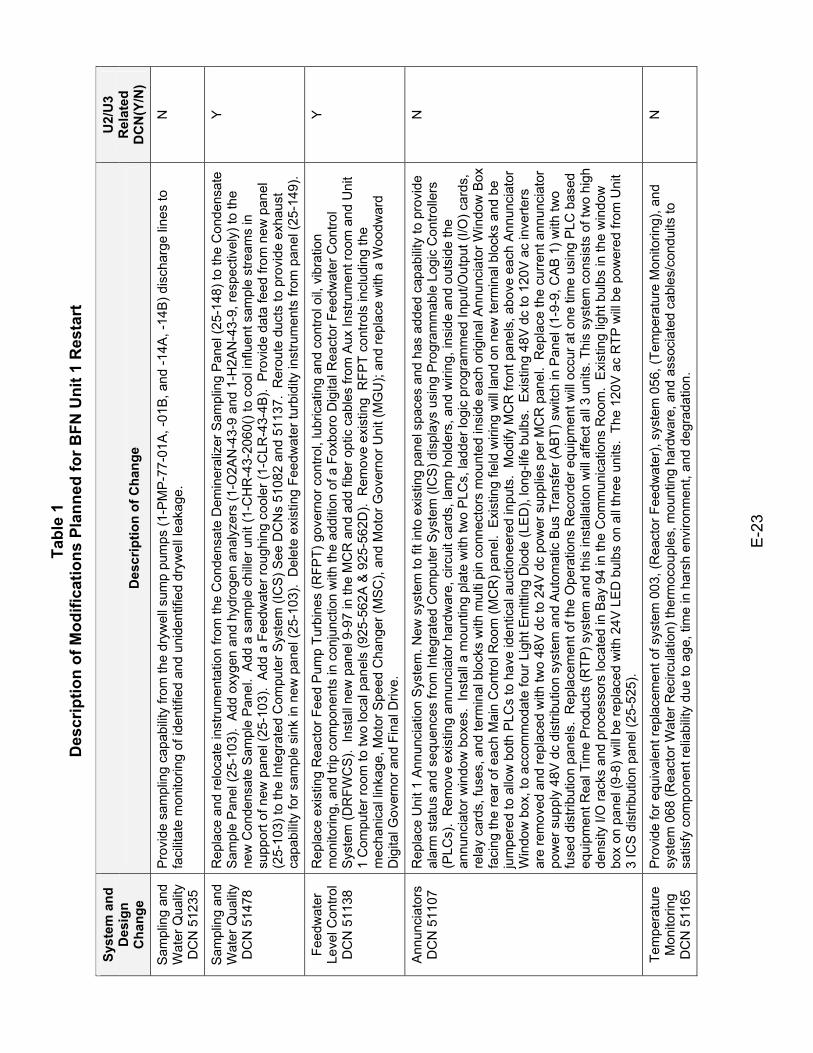
Tabl
e 1
Des
crip
tion
of M
odifi
catio
ns P
lann
ed fo
r BFN
Uni
t 1 R
esta
rt
E-2
3
Syst
em a
nd
Des
ign
Cha
nge
Des
crip
tion
of C
hang
e
U2/
U3
Rel
ated
D
CN
(Y/N
)
Sam
plin
g an
d W
ater
Qua
lity
DC
N 5
1235
Pro
vide
sam
plin
g ca
pabi
lity
from
the
dryw
ell s
ump
pum
ps (1
-PM
P-77
-01A
, -01
B, a
nd -1
4A, -
14B
) dis
char
ge li
nes
to
faci
litat
e m
onito
ring
of id
entif
ied
and
unid
entif
ied
dryw
ell l
eaka
ge.
N
Sam
plin
g an
d W
ater
Qua
lity
DC
N 5
1478
Rep
lace
and
relo
cate
inst
rum
enta
tion
from
the
Con
dens
ate
Dem
iner
aliz
er S
ampl
ing
Pan
el (2
5-14
8) to
the
Con
dens
ate
Sam
ple
Pan
el (2
5-10
3).
Add
oxy
gen
and
hydr
ogen
ana
lyze
rs (1
-O2A
N-4
3-9
and
1-H
2AN
-43-
9, re
spec
tivel
y) to
the
new
Con
dens
ate
Sam
ple
Pan
el.
Add
a s
ampl
e ch
iller u
nit (
1-C
HR
-43-
2060
() to
coo
l inf
luen
t sam
ple
stre
ams
in
supp
ort o
f new
pan
el (2
5-10
3).
Add
a F
eedw
ater
roug
hing
coo
ler (
1-C
LR-4
3-4B
). P
rovi
de d
ata
feed
from
new
pan
el
(25-
103)
to th
e In
tegr
ated
Com
pute
r Sys
tem
(IC
S) S
ee D
CN
s 51
082
and
5113
7. R
erou
te d
ucts
to p
rovi
de e
xhau
st
capa
bilit
y fo
r sam
ple
sink
in n
ew p
anel
(25-
103)
. D
elet
e ex
istin
g Fe
edw
ater
turb
idity
inst
rum
ents
from
pan
el (2
5-14
9).
Y
Feed
wat
er
Leve
l Con
trol
DC
N 5
1138
Rep
lace
exi
stin
g R
eact
or F
eed
Pum
p Tu
rbin
es (R
FPT)
gov
erno
r con
trol,
lubr
icat
ing
and
cont
rol o
il, v
ibra
tion
mon
itorin
g, a
nd tr
ip c
ompo
nent
s in
con
junc
tion
with
the
addi
tion
of a
Fox
boro
Dig
ital R
eact
or F
eedw
ater
Con
trol
Sys
tem
(DR
FWC
S).
Inst
all n
ew p
anel
9-9
7 in
the
MC
R a
nd a
dd fi
ber o
ptic
cab
les
from
Aux
Inst
rum
ent r
oom
and
Uni
t 1
Com
pute
r roo
m to
two
loca
l pan
els
(925
-562
A &
925
-562
D).
Rem
ove
exis
ting
RFP
T co
ntro
ls in
clud
ing
the
mec
hani
cal l
inka
ge, M
otor
Spe
ed C
hang
er (M
SC),
and
Mot
or G
over
nor U
nit (
MG
U);
and
repl
ace
with
a W
oodw
ard
Dig
ital G
over
nor a
nd F
inal
Driv
e.
Y
Ann
unci
ator
s D
CN
511
07
Rep
lace
Uni
t 1 A
nnun
ciat
ion
Sys
tem
. New
sys
tem
to fi
t int
o ex
istin
g pa
nel s
pace
s an
d ha
s ad
ded
capa
bilit
y to
pro
vide
al
arm
sta
tus
and
sequ
ence
s fro
m In
tegr
ated
Com
pute
r Sys
tem
(IC
S) d
ispl
ays
usin
g P
rogr
amm
able
Log
ic C
ontro
llers
(P
LCs)
. R
emov
e ex
istin
g an
nunc
iato
r har
dwar
e, c
ircui
t car
ds, l
amp
hold
ers,
and
wiri
ng, i
nsid
e an
d ou
tsid
e th
e an
nunc
iato
r win
dow
box
es.
Inst
all a
mou
ntin
g pl
ate
with
two
PLC
s, la
dder
logi
c pr
ogra
mm
ed In
put/O
utpu
t (I/O
) car
ds,
rela
y ca
rds,
fuse
s, a
nd te
rmin
al b
lock
s w
ith m
ulti
pin
conn
ecto
rs m
ount
ed in
side
eac
h or
igin
al A
nnun
ciat
or W
indo
w B
ox
faci
ng th
e re
ar o
f eac
h M
ain
Con
trol R
oom
(MC
R) p
anel
. E
xist
ing
field
wiri
ng w
ill la
nd o
n ne
w te
rmin
al b
lock
s an
d be
ju
mpe
red
to a
llow
bot
h P
LCs
to h
ave
iden
tical
auc
tione
ered
inpu
ts.
Mod
ify M
CR
fron
t pan
els,
abo
ve e
ach
Ann
unci
ator
W
indo
w b
ox, t
o ac
com
mod
ate
four
Lig
ht E
mitt
ing
Dio
de (L
ED
), lo
ng-li
fe b
ulbs
. E
xist
ing
48V
dc
to 1
20V
ac
inve
rters
ar
e re
mov
ed a
nd re
plac
ed w
ith tw
o 48
V d
c to
24V
dc
pow
er s
uppl
ies
per M
CR
pan
el.
Rep
lace
the
curr
ent a
nnun
ciat
or
pow
er s
uppl
y 48
V d
c di
strib
utio
n sy
stem
and
Aut
omat
ic B
us T
rans
fer (
AB
T) s
witc
h in
Pan
el (1
-9-9
, CA
B 1
) with
two
fuse
d di
strib
utio
n pa
nels
. R
epla
cem
ent o
f the
Ope
ratio
ns R
ecor
der e
quip
men
t will
occ
ur a
t one
tim
e us
ing
PLC
bas
ed
equi
pmen
t Rea
l Tim
e P
rodu
cts
(RTP
) sys
tem
and
this
inst
alla
tion
will
affe
ct a
ll 3
units
. Thi
s sy
stem
con
sist
s of
two
high
de
nsity
I/O
rack
s an
d pr
oces
sors
loca
ted
in B
ay 9
4 in
the
Com
mun
icat
ions
Roo
m.
Exi
stin
g lig
ht b
ulbs
in th
e w
indo
w
box
on p
anel
(9-8
) will
be
repl
aced
with
24V
LE
D b
ulbs
on
all t
hree
uni
ts.
The
120V
ac
RTP
will
be p
ower
ed fr
om U
nit
3 IC
S d
istri
butio
n pa
nel (
25-5
25).
N
Tem
pera
ture
M
onito
ring
DC
N 5
1165
Pro
vide
for e
quiv
alen
t rep
lace
men
t of s
yste
m 0
03, (
Rea
ctor
Fee
dwat
er),
syst
em 0
56, (
Tem
pera
ture
Mon
itorin
g), a
nd
syst
em 0
68 (R
eact
or W
ater
Rec
ircul
atio
n) th
erm
ocou
ples
, mou
ntin
g ha
rdw
are,
and
ass
ocia
ted
cabl
es/c
ondu
its to
sa
tisfy
com
pone
nt re
liabi
lity
due
to a
ge, t
ime
in h
arsh
env
ironm
ent,
and
degr
adat
ion.
N
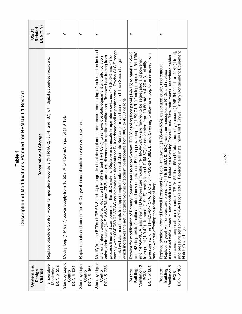
Tabl
e 1
Des
crip
tion
of M
odifi
catio
ns P
lann
ed fo
r BFN
Uni
t 1 R
esta
rt
E-2
4
Syst
em a
nd
Des
ign
Cha
nge
Des
crip
tion
of C
hang
e
U2/
U3
Rel
ated
D
CN
(Y/N
)
Tem
pera
ture
M
onito
ring
DC
N 5
1232
Rep
lace
obs
olet
e C
ontro
l Roo
m te
mpe
ratu
re re
cord
ers
(1-T
R-5
6-2,
-3, -
4, a
nd -3
7) w
ith d
igita
l pap
erle
ss re
cord
ers.
N
Sta
ndby
Liq
uid
Con
trol
DC
N 5
1081
Mod
ify lo
op (1
-P-6
3-7)
pow
er s
uppl
y fro
m 1
0-50
mA
to 4
-20
mA
in p
anel
(1-9
-19)
. Y
Sta
ndby
Liq
uid
Con
trol
DC
N 5
1166
Rep
lace
cab
le a
nd c
ondu
it fo
r SLC
dry
wel
l inb
oard
isol
atio
n va
lve
zone
sw
itch.
Y
Sta
ndby
Liq
uid
Con
trol
DC
N 5
1233
Mod
ify/re
plac
e R
TDs
(1-T
E-6
3-3
and
-4) t
o up
grad
e ob
sole
te e
quip
men
t and
ens
ure
mon
itorin
g of
tank
sol
utio
n in
stea
d of
are
a am
bien
t tem
pera
ture
. R
epla
ce (1
-PI-6
3-7B
and
1-P
T-63
-7) t
o re
mov
e ob
sole
te e
quip
men
t and
add
isol
atio
n va
lve,
dra
in v
alve
(1-IS
IV-6
3-7B
A a
nd -7
BB
) and
qui
ck d
isco
nnec
t to
faci
litat
e ca
libra
tion.
Rem
ove
heat
trac
ing
from
pr
oces
s lin
es a
nd c
ompo
nent
s in
the
SLC
sys
tem
. R
epla
ce a
nd re
scal
e te
mpe
ratu
re s
witc
hes
(1-T
S-6
3-3
and
-4) t
o co
mpl
y w
ith 1
0CFR
50.6
2 A
TWS
equ
ival
ency
requ
irem
ents
for B
10 e
nric
hed
sodi
um p
enta
bora
te.
Rev
ise
SLC
Sto
rage
Ta
nk le
vel a
larm
set
poin
ts to
sup
port
impl
emen
tatio
n of
Alte
rnat
e S
ourc
e Te
rm a
nd a
ssoc
iate
d Te
ch S
pec
chan
ge
whi
ch in
crea
ses
the
net i
njec
tabl
e vo
lum
e of
sod
ium
pen
tabo
rate
from
300
7 to
400
0 ga
llons
.
Y
Rea
ctor
B
uild
ing
Ven
tilat
ion
&
PC
IS
DC
N 5
1081
Pro
vide
for m
odifi
catio
n of
Prim
ary
Con
tain
men
t Iso
latio
n S
yste
m (P
CIS
) cab
ling
from
pan
el (1
-9-1
5) to
pan
els
(1-9
-42
and
-43)
to p
rovi
de fu
nctio
nal r
edun
danc
y se
para
tion.
Exi
stin
g po
wer
sup
ply
(1-P
X-7
4-51
) fee
ding
loop
s (1
-L-6
4-15
9A
and
1-P-
64-1
60A
) and
new
RTD
tem
pera
ture
mod
ifier
(1-T
M-6
4-52
CA
) are
rew
ired
to b
e se
greg
ated
and
pow
ered
fro
m p
anel
(1-9
-42)
. In
pan
el (1
-9-1
9) m
odify
loop
(1-P
-64-
67) f
or c
onve
rsio
n fro
m 1
0-50
mA
to 4
-20
mA
. M
odify
pr
essu
re s
witc
hes
(1-P
DS-
64-1
37A
, B, C
and
1-P
DS-
64-1
38A
, B, a
nd C
) wiri
ng to
allo
w o
ne lo
op to
be
rem
oved
from
se
rvic
e w
ithou
t affe
ctin
g th
e re
dund
ant l
oop.
Y
Rea
ctor
B
uild
ing
Ven
tilat
ion
&
PC
IS
DC
N 5
1166
Rep
lace
obs
olet
e in
boar
d D
ryw
ell P
erso
nnel
Air
Lock
lim
it sw
itch
(1-Z
S-6
4-53
A),
asso
ciat
ed c
able
, and
con
duit.
R
epla
ce D
ryw
ell A
ir Te
mpe
ratu
re e
lem
ents
(1-T
E-64
-52A
& -5
2C) f
rom
ther
moc
oupl
es to
RTD
s an
d re
plac
e as
soci
ated
cab
le, c
ondu
it, a
nd c
ondu
it se
als.
Del
ete
the
follo
win
g D
ryw
ell L
eak
Rat
e in
stru
men
ts, a
ssoc
iate
d ca
bles
an
d co
ndui
t: te
mpe
ratu
re e
lem
ents
(1-T
E-6
4-82
thru
-99)
(18
tota
l); h
umid
ity s
enso
rs (1
-ME
-64-
111
thru
-114
) (4
tota
l);
and
pres
sure
sen
sor (
1-P
T-64
-115
) (1
tota
l). F
abric
ate
and
inst
all n
ew U
nit 1
Dry
wel
l Prim
ary
Con
tain
men
t Equ
ipm
ent
Hat
ch C
over
Lug
s.
Y
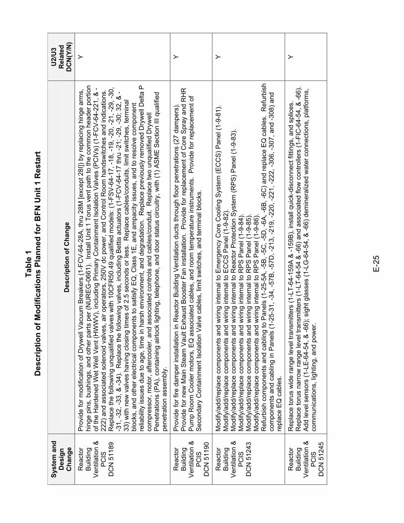
Tabl
e 1
Des
crip
tion
of M
odifi
catio
ns P
lann
ed fo
r BFN
Uni
t 1 R
esta
rt
E-2
5
Syst
em a
nd
Des
ign
Cha
nge
Des
crip
tion
of C
hang
e
U2/
U3
Rel
ated
D
CN
(Y/N
)
Rea
ctor
B
uild
ing
Ven
tilat
ion
&
PC
IS
DC
N 5
1189
Pro
vide
for m
odifi
catio
n of
Dry
wel
l Vac
uum
Bre
aker
s (1
-FC
V-6
4-28
A, t
hru
28M
[exc
ept 2
8I])
by re
plac
ing
hing
e ar
ms,
hi
nge
pins
, bus
hing
s, a
nd o
ther
par
ts p
er (N
UR
EG
-066
1).
Inst
all U
nit 1
Tor
us v
ent p
ath
to th
e co
mm
on h
eade
r por
tion
of th
e H
arde
ned
Wet
Wel
l Ven
t (H
WW
V), i
nclu
ding
Prim
ary
Con
tain
men
t Iso
latio
n V
alve
s (P
CIV
s) (1
-FC
V-64
-221
, & -
222)
and
ass
ocia
ted
sole
noid
val
ves,
air
oper
ator
s, 2
50V
dc
pow
er, a
nd C
ontro
l Roo
m h
ands
witc
hes
and
indi
catio
ns.
Rep
lace
the
follo
win
g un
qual
ified
val
ves
with
10C
FR50
.49
qual
ified
mod
els:
(1-F
SV
-64-
17, -
18, -
19, -
20, -
21, -
29, -
30,
-31,
-32,
-33,
& -3
4).
Rep
lace
the
follo
win
g va
lves
, inc
ludi
ng B
ettis
act
uato
rs (1
-FC
V-6
4-17
thru
-21;
-29,
-30;
32,
& -
33) w
ith n
ew v
alve
s ha
ving
clo
sing
tim
es o
f 2.5
sec
onds
or l
ess.
Rep
lace
cab
les/
cond
uits
, lim
it sw
itche
s, te
rmin
al
bloc
ks, a
nd o
ther
ele
ctric
al c
ompo
nent
s to
sat
isfy
EQ
, Cla
ss 1
E, a
nd a
mpa
city
issu
es, a
nd to
reso
lve
com
pone
nt
relia
bilit
y is
sues
due
to a
ge, t
ime
in h
arsh
env
ironm
ent,
and
degr
adat
ion.
Rep
lace
pre
viou
sly
rem
oved
Dry
wel
l Del
ta P
co
mpr
esso
r, m
otor
, afte
rcoo
ler,
and
asso
ciat
ed c
ontro
ls a
nd c
able
s/co
ndui
t. R
epla
ce tw
o un
qual
ified
Dry
wel
l P
enet
ratio
ns (P
A),
cont
aini
ng a
irloc
k lig
htin
g, te
leph
one,
and
doo
r sta
tus
circ
uitry
, with
(1) A
SM
E S
ectio
n III
qua
lifie
d pe
netra
tion
asse
mbl
y.
Y
Rea
ctor
B
uild
ing
Ven
tilat
ion
&
PC
IS
DC
N 5
1190
Pro
vide
for f
ire d
ampe
r ins
talla
tion
in R
eact
or B
uild
ing
Ven
tilat
ion
duct
s th
roug
h flo
or p
enet
ratio
ns (2
7 da
mpe
rs).
Pro
vide
for n
ew M
ain
Ste
am V
ault
Exh
aust
Boo
ster
Fan
inst
alla
tion.
Pro
vide
for r
epla
cem
ent o
f Cor
e S
pray
and
RH
R
Pum
p R
oom
Coo
ler m
otor
s, E
Q a
ssoc
iate
d ca
bles
, and
room
tem
pera
ture
inst
rum
ents
. P
rovi
de fo
r rep
lace
men
t of
Sec
onda
ry C
onta
inm
ent I
sola
tion
Val
ve c
able
s, li
mit
switc
hes,
and
term
inal
blo
cks.
Y
Rea
ctor
B
uild
ing
Ven
tilat
ion
&
PC
IS
DC
N 5
1243
Mod
ify/a
dd/re
plac
e co
mpo
nent
s an
d w
iring
inte
rnal
to E
mer
genc
y C
ore
Coo
ling
Sys
tem
(EC
CS
) Pan
el (1
-9-8
1).
Mod
ify/a
dd/re
plac
e co
mpo
nent
s an
d w
iring
inte
rnal
to E
CC
S P
anel
(1-9
-82)
. M
odify
/add
/repl
ace
com
pone
nts
and
wiri
ng in
tern
al to
Rea
ctor
Pro
tect
ion
Sys
tem
(RP
S) P
anel
(1-9
-83)
. M
odify
/add
/repl
ace
com
pone
nts
and
wiri
ng in
tern
al to
RP
S P
anel
(1-9
-84)
. M
odify
/add
/repl
ace
com
pone
nts
and
wiri
ng in
tern
al to
RP
S P
anel
(1-9
-85)
. M
odify
/add
/repl
ace
com
pone
nts
and
wiri
ng in
tern
al to
RP
S P
anel
(1-9
-86)
. R
efur
bish
com
pone
nts
and
cabl
ing
to P
anel
s (1
-25-
5A, -
5B, -
5C, -
5D, -
6A, -
6B, -
6C) a
nd re
plac
e E
Q c
able
s. R
efur
bish
co
mpo
nent
s an
d ca
blin
g in
Pan
els
(1-2
5-31
, -34
, -57
B, -5
7D, -
213,
-219
, -22
0, -2
21, -
222,
-306
, -30
7, a
nd -3
08) a
nd
repl
ace
EQ
cab
les.
Y
Rea
ctor
B
uild
ing
Ven
tilat
ion
&
PC
IS
DC
N 5
1245
Rep
lace
toru
s w
ide
rang
e le
vel t
rans
mitt
ers
(1-L
T-64
-159
A &
-159
B),
inst
all q
uick
-dis
conn
ect f
ittin
gs, a
nd s
plic
es.
Rep
lace
toru
s na
rrow
rang
e le
vel t
rans
mitt
ers
(1-L
T-64
-54
& -6
6) a
nd a
ssoc
iate
d flo
w c
ontro
llers
(1-F
IC-6
4-54
, & -6
6).
Add
leve
l sen
sors
(1-L
E-64
-54,
& -6
6); s
ight
gla
sses
(1-L
G-6
4-54
, & -6
6) d
emin
eral
ized
wat
er c
onne
ctio
ns, p
latfo
rms,
co
mm
unic
atio
ns, l
ight
ing,
and
pow
er.
Y
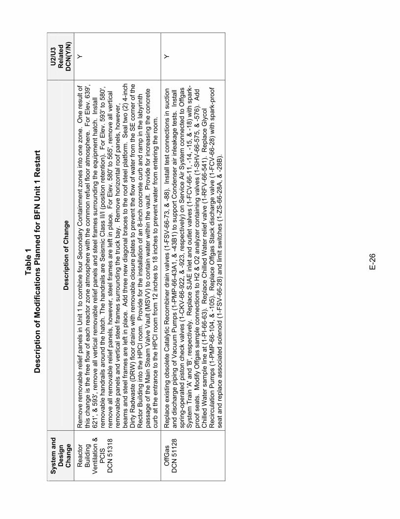
Tabl
e 1
Des
crip
tion
of M
odifi
catio
ns P
lann
ed fo
r BFN
Uni
t 1 R
esta
rt
E-2
6
Syst
em a
nd
Des
ign
Cha
nge
Des
crip
tion
of C
hang
e
U2/
U3
Rel
ated
D
CN
(Y/N
)
Rea
ctor
B
uild
ing
Ven
tilat
ion
&
PC
IS
DC
N 5
1318
Rem
ove
rem
ovab
le re
lief p
anel
s in
Uni
t 1 to
com
bine
four
Sec
onda
ry C
onta
inm
ent z
ones
into
one
zon
e. O
ne re
sult
of
this
cha
nge
is th
e fre
e flo
w o
f eac
h re
acto
r zon
e at
mos
pher
e w
ith th
e co
mm
on re
fuel
floo
r atm
osph
ere.
For
Ele
v. 6
39',
621'
, & 5
93',
rem
ove
all v
ertic
al re
mov
able
relie
f pan
els
and
stee
l fra
mes
sur
roun
ding
the
equi
pmen
t hat
ch.
Inst
all
rem
ovab
le h
andr
ails
aro
und
the
hatc
h. T
he h
andr
ails
are
Sei
smic
Cla
ss II
/I (p
ositi
on re
tent
ion)
. Fo
r Ele
v. 5
93' t
o 58
0',
rem
ove
all r
emov
able
relie
f pan
els,
how
ever
, ste
el fr
ames
are
left
in p
lace
. Fo
r Ele
v. 5
80' t
o 56
5', r
emov
e al
l ver
tical
re
mov
able
pan
els
and
verti
cal s
teel
fram
es s
urro
undi
ng th
e tru
ck b
ay.
Rem
ove
horiz
onta
l roo
f pan
els,
how
ever
, be
ams
and
stee
l fra
mes
are
left
in p
lace
. A
dd th
ree
new
dia
gona
l bra
ces
to th
e ro
of s
teel
pla
tform
. S
eal t
wo
(2) 4
-inch
D
irty
Rad
was
te (D
RW
) flo
or d
rain
s w
ith re
mov
able
clo
sure
pla
tes
to p
reve
nt th
e flo
w o
f wat
er fr
om th
e S
E c
orne
r of t
he
Rec
tor B
uild
ing
into
the
HP
CI r
oom
. P
rovi
de fo
r the
inst
alla
tion
of a
n 8-
inch
con
cret
e cu
rb a
nd ra
mp
in th
e la
byrin
th
pass
age
of th
e M
ain
Ste
am V
alve
Vau
lt (M
SV
V) t
o co
ntai
n w
ater
with
in th
e va
ult.
Pro
vide
for i
ncre
asin
g th
e co
ncre
te
curb
at t
he e
ntra
nce
to th
e H
PC
I roo
m fr
om 1
2 in
ches
to 1
8 in
ches
to p
reve
nt w
ater
from
ent
erin
g th
e ro
om.
Y
OffG
as
DC
N 5
1128
R
epla
ce e
xist
ing
obso
lete
Cat
alyt
ic R
ecom
bine
r dra
in v
alve
s (1
-FS
V-6
6-73
, & -8
8).
Inst
all t
est c
onne
ctio
ns in
suc
tion
and
disc
harg
e pi
ping
of V
acuu
m P
umps
(1-P
MP-
66-4
3A1,
& -4
3B1)
to s
uppo
rt C
onde
nser
air
inle
akag
e te
sts.
Ins
tall
sprin
g-op
erat
ed p
isto
n ch
eck
valv
es (1
-CK
V-6
6-92
2, &
-923
, res
pect
ivel
y) o
n S
ervi
ce A
ir S
yste
m c
onne
cted
to O
ffgas
S
yste
m T
rain
'A' a
nd 'B
', re
spec
tivel
y. R
epla
ce S
JAE
inle
t and
out
let v
alve
s (1
-FC
V-6
6-11
, -14
, -15
, & -1
8) w
ith s
park
-pr
oof s
eats
. M
odify
Offg
as s
ampl
e co
nnec
tions
to H
2 &
O2
anal
yzer
con
tain
ing
valv
es (1
-SH
V-6
6-57
5, &
-576
). A
dd
Chi
lled
Wat
er s
ampl
e lin
e at
(1-P
I-66-
63).
Rep
lace
Chi
lled
Wat
er re
lief v
alve
(1-R
FV-6
6-54
1).
Rep
lace
Gly
col
Rec
ircul
atio
n P
umps
(1-P
MP-
66-1
04, &
-105
). R
epla
ce O
ffgas
Sta
ck d
isch
arge
val
ve (1
-FC
V-6
6-28
) with
spa
rk-p
roof
se
at a
nd re
plac
e as
soci
ated
sol
enoi
d (1
-FS
V-6
6-28
) and
lim
it sw
itche
s (1
-ZS
-66-
28A
, & -2
8B).
Y
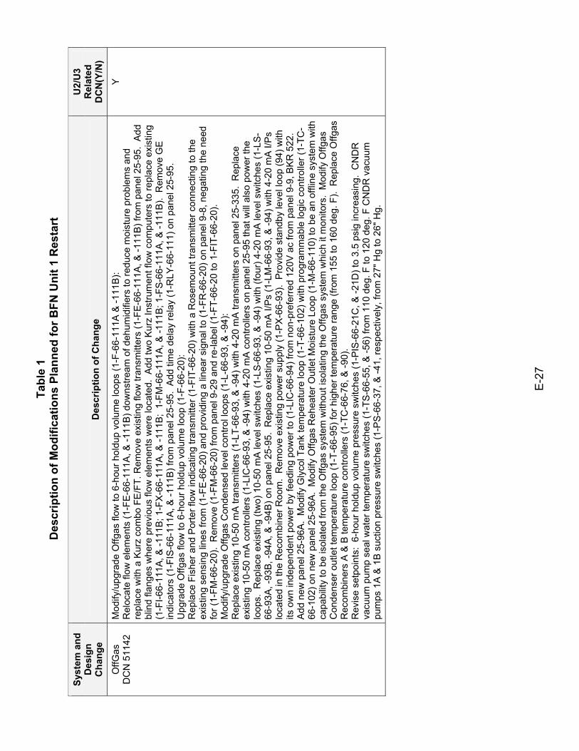
Tabl
e 1
Des
crip
tion
of M
odifi
catio
ns P
lann
ed fo
r BFN
Uni
t 1 R
esta
rt
E-2
7
Syst
em a
nd
Des
ign
Cha
nge
Des
crip
tion
of C
hang
e
U2/
U3
Rel
ated
D
CN
(Y/N
)
OffG
as
DC
N 5
1142
M
odify
/upg
rade
Offg
as fl
ow to
6-h
our h
oldu
p vo
lum
e lo
ops
(1-F
-66-
111A
& -1
11B
): R
eloc
ate
flow
ele
men
ts (1
-FE
-66-
111A
, & -1
11B
) dow
nstre
am o
f deh
umid
ifier
s to
redu
ce m
oist
ure
prob
lem
s an
d re
plac
e w
ith a
Kur
z co
mbo
FE
/FT.
Rem
ove
exis
ting
flow
tran
smitt
ers
(1-F
E-66
-111
A, &
-111
B) f
rom
pan
el 2
5-95
. A
dd
blin
d fla
nges
whe
re p
revi
ous
flow
ele
men
ts w
ere
loca
ted.
Add
two
Kur
z In
stru
men
t flo
w c
ompu
ters
to re
plac
e ex
istin
g (1
-FI-6
6-11
1A, &
-111
B; 1
-FX
-66-
111A
, & -1
11B
; 1-
FM-6
6-11
1A, &
-111
B; 1
-FS-
66-1
11A
, & -1
11B
). R
emov
e G
E
indi
cato
rs (1
-FIS
-66-
111A
, & -1
11B
) fro
m p
anel
25-
95.
Add
tim
e de
lay
rela
y (1
-RLY
-66-
111)
on
pane
l 25-
95.
Upg
rade
Offg
as fl
ow to
6-h
our h
oldu
p vo
lum
e lo
op (1
-F-6
6-20
): R
epla
ce F
ishe
r and
Por
ter f
low
indi
catin
g tra
nsm
itter
(1-F
IT-6
6-20
) with
a R
osem
ount
tran
smitt
er c
onne
ctin
g to
the
exis
ting
sens
ing
lines
from
(1-F
E-6
6-20
) and
pro
vidi
ng a
line
ar s
igna
l to
(1-F
R-6
6-20
) on
pane
l 9-8
, neg
atin
g th
e ne
ed
for (
1-FM
-66-
20).
Rem
ove
(1-F
M-6
6-20
) fro
m p
anel
9-2
9 an
d re
-labe
l (1-
FT-6
6-20
to 1
-FIT
-66-
20).
Mod
ify/u
pgra
de O
ffgas
Con
dens
ed le
vel c
ontro
l loo
ps (1
-L-6
6-93
, & -9
4):
Rep
lace
exi
stin
g 10
-50
mA
trans
mitt
ers
(1-L
T-66
-93,
& -9
4) w
ith 4
-20
mA
tran
smitt
ers
on p
anel
25-
335.
Rep
lace
ex
istin
g 10
-50
mA
con
trolle
rs (1
-LIC
-66-
93, &
-94)
with
4-2
0 m
A c
ontro
llers
on
pane
l 25-
95 th
at w
ill a
lso
pow
er th
e lo
ops.
Rep
lace
exi
stin
g (tw
o) 1
0-50
mA
leve
l sw
itche
s (1
-LS-
66-9
3, &
-94)
with
(fou
r) 4
-20
mA
leve
l sw
itche
s (1
-LS-
66-9
3A, -
93B,
-94A
, & -9
4B) o
n pa
nel 2
5-95
. R
epla
ce e
xist
ing
10-5
0 m
A I/
Ps
(1-L
M-6
6-93
, & -9
4) w
ith 4
-20
mA
I/P
s lo
cate
d in
the
Rec
ombi
ner R
oom
. R
emov
e ex
istin
g po
wer
sup
ply
(1-P
X-6
6-93
). P
rovi
de s
tand
by le
vel l
oop
(94)
with
its
ow
n in
depe
nden
t pow
er b
y fe
edin
g po
wer
to (1
-LIC
-66-
94) f
rom
non
-pre
ferr
ed 1
20V
ac
from
pan
el 9
-9, B
KR
522
. A
dd n
ew p
anel
25-
96A
. M
odify
Gly
col T
ank
tem
pera
ture
loop
(1-T
-66-
102)
with
pro
gram
mab
le lo
gic
cont
rolle
r (1-
TC-
66-1
02) o
n ne
w p
anel
25-
96A
. M
odify
Offg
as R
ehea
ter O
utle
t Moi
stur
e Lo
op (1
-M-6
6-11
0) to
be
an o
fflin
e sy
stem
with
ca
pabi
lity
to b
e is
olat
ed fr
om th
e O
ffgas
sys
tem
with
out i
sola
ting
the
Offg
as s
yste
m w
hich
it m
onito
rs.
Mod
ify O
ffgas
C
onde
nser
out
let t
empe
ratu
re lo
op (1
-T-6
6-95
) for
hig
her t
empe
ratu
re ra
nge
(from
155
to 1
60 d
eg. F
). R
epla
ce O
ffgas
R
ecom
bine
rs A
& B
tem
pera
ture
con
trolle
rs (1
-TC
-66-
76, &
-90)
. R
evis
e se
tpoi
nts:
6-h
our h
oldu
p vo
lum
e pr
essu
re s
witc
hes
(1-P
IS-6
6-21
C, &
-21D
) to
3.5
psig
incr
easi
ng.
CN
DR
va
cuum
pum
p se
al w
ater
tem
pera
ture
sw
itche
s (1
-TS-
66-5
5, &
-56)
from
110
deg
. F to
120
deg
. F C
ND
R v
acuu
m
pum
ps 1
A &
1B
suc
tion
pres
sure
sw
itche
s (1
-PS
-66-
37, &
-41,
resp
ectiv
ely,
from
27"
Hg
to 2
6" H
g.
Y
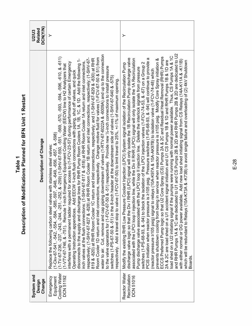
Tabl
e 1
Des
crip
tion
of M
odifi
catio
ns P
lann
ed fo
r BFN
Uni
t 1 R
esta
rt
E-2
8
Syst
em a
nd
Des
ign
Cha
nge
Des
crip
tion
of C
hang
e
U2/
U3
Rel
ated
D
CN
(Y/N
)
Em
erge
ncy
Equ
ipm
ent
Coo
ling
Wat
er
DC
N 5
1192
Rep
lace
the
follo
win
g ca
rbon
ste
el v
alve
s w
ith s
tain
less
ste
el v
alve
s:
(1-C
kv-6
7-54
1, -5
42, -
554,
-584
, -58
5,-5
97, -
648,
-649
, -65
6, -6
57,
& -5
98)
(1-T
V-6
7-23
6, -2
37, -
243,
-244
, -25
1, -2
52, &
-259
) (1-
SH
V-6
7-55
0, -5
51,
-569
, -57
0, -5
93, -
594,
-596
, -61
0, &
-611
) (1
-VTV
-67-
746,
& -7
51).
Rer
oute
1-in
ch E
mer
genc
y Eq
uipm
ent C
oolin
g W
ater
(EE
CW
) lin
e to
H2
Ana
lyze
rs th
at
inte
rfere
s w
ith a
per
man
ent l
adde
r req
uire
d fo
r acc
ess
to (1
-FC
V-2
3-57
) dur
ing
perfo
rman
ce o
f cer
tain
Em
erge
ncy
Ope
ratin
g In
stru
ctio
n ap
pend
ices
. A
dd E
EC
W 1
-inch
flus
h co
nnec
tions
with
pip
ing,
shu
t off
valv
es, a
nd q
uick
di
scon
nect
s to
the
supp
ly a
nd d
isch
arge
line
s fo
r RH
R P
ump
Roo
m C
oole
rs 1
A, 1
B, 1
C, &
1D
. A
dd th
e fo
llow
ing
1-in
ch v
alve
s at
the
flush
con
nect
ions
: (1-
SH
V-6
7-81
7 &
-818
) at R
HR
Roo
m C
oole
r 1A
retu
rn a
nd in
let c
onne
ctio
ns,
resp
ectiv
ely;
(1-S
HV
-67-
827
& -8
28) a
t RH
R R
oom
Coo
ler 1
B re
turn
and
inle
t con
nect
ions
, res
pect
ivel
y; (1
-SH
V-6
7-81
9 &
-820
) at R
HR
Roo
m C
oole
r 1C
retu
rn a
nd in
let c
onne
ctio
ns, r
espe
ctiv
ely;
and
(1-S
HV-
67-8
29 &
-830
) at R
HR
R
oom
Coo
ler 1
D re
turn
and
inle
t con
nect
ions
, res
pect
ivel
y. C
hang
e m
otiv
e flu
id fo
r val
ves
(1-F
CV
-67-
50 &
51)
from
w
ater
to a
ir. C
ut, r
emov
e an
d ca
p pi
ping
dow
nstre
am o
f val
ves
(1-R
TV-6
7-60
22A
& -6
009A
) and
up
to th
e co
nnec
tion
to th
e va
lve
oper
ator
s fo
r (1-
FCV
-67-
50 &
-51)
resp
ectiv
ely.
Pro
vide
new
½-in
ch c
onne
ctio
ns to
inst
all p
ress
ure
switc
hes
(1-P
S-6
7-50
& -5
1) in
the
8-in
ch h
eade
r at t
he d
owns
tream
sid
e of
val
ves
(1-S
HV-
67-6
40 &
-575
) re
spec
tivel
y. A
dd a
trav
el s
top
to v
alve
(1-F
CV
-67-
50) t
o lim
it tra
vel t
o 25
%, +
/-1%
of m
axim
um o
peni
ng.
Y
Rea
ctor
Wat
er
Rec
ircul
atio
n D
CN
510
16
Mod
ify th
e ex
istin
g R
HR
Low
Pre
ssur
e C
oola
nt In
ject
ion
(LPC
I) S
yste
m s
igna
l iso
latio
n of
the
Rec
ircul
atio
n P
ump
disc
harg
e va
lve
logi
c so
that
the
Div
I R
HR
(LP
CI)
sign
al w
ill o
nly
isol
ate
the
1B R
ecirc
ulat
ion
Pum
p di
scha
rge
valv
e as
soci
ated
with
the
LPC
I loo
p I i
njec
tion
line,
whi
le th
e D
iv II
RH
R (L
PC
I) si
gnal
will
only
isol
ate
the
1A R
ecirc
ulat
ion
Pum
p di
scha
rge
valv
e as
soci
ated
with
the
LPC
I loo
p II
inje
ctio
n lin
e. D
elet
e th
e in
terlo
ck s
igna
ls fr
om p
ress
ure
switc
hes
(1-P
S-6
8-93
, & -9
4) to
blo
ck th
e is
olat
ion
of th
e LP
CI i
njec
tion
valv
es (1
-FC
V-7
4-53
, & -6
7) o
n a
Gro
up 2
P
CIS
initi
atio
n w
hen
reac
tor p
ress
ure
is ≥
105
psig
. P
ress
ure
switc
hes
(1-P
S-6
8-93
, & -9
4) w
ill co
ntin
ue to
pro
vide
a
(rea
ctor
pre
ssur
e ≥1
05 p
sig)
sig
nal t
o re
lays
(10A
-K97
A &
10A
-AK
97B
) to
isol
atio
n va
lve
(1-F
CV
-74-
48) w
hich
pr
even
ts s
hutd
own
cool
ing
from
bei
ng in
ser
vice
whe
n re
acto
r pre
ssur
e is
≥10
5 ps
ig.
Mod
ify C
ore
Spr
ay in
itiat
ion
&
EC
CS
Pre
ferr
ed P
ump
logi
c so
that
U2
Cor
e S
pray
(CS
) Pum
ps 2
A &
2C
and
Res
idua
l Hea
t Rem
oval
(RH
R) P
umps
2A
& 2
C a
re lo
ad s
hed
on a
U1
acci
dent
sig
nal i
nitia
tion
and
U1
CS
Pum
ps 1
B &
1D
and
RH
R P
umps
1B
& 1
D a
re
load
she
d on
a U
2 in
itiat
ing
sign
al if
the
pum
ps w
ere
runn
ing
with
nor
mal
pow
er a
vaila
ble.
Thu
s, C
S P
umps
1A
& 1
C
and
RH
R P
umps
1A
& 1
C a
re d
edic
ated
to U
1 an
d C
S P
umps
2B
& 2
D a
nd R
HR
Pum
ps 2
B &
2D
are
ded
icat
ed to
U2
with
eith
er n
orm
al o
r DG
pow
er a
vaila
ble.
Add
new
load
she
d in
itiat
ing
sign
al fr
om C
S R
elay
s (1
4A-K
11A
& -K
11B
) w
hich
will
be
redu
ndan
t to
Rel
ays
(10A
-K73
A &
-K73
B) t
o av
oid
sing
le fa
ilure
and
ove
rload
ing
of (2
) 4kV
Shu
tdow
n B
oard
s.
Y
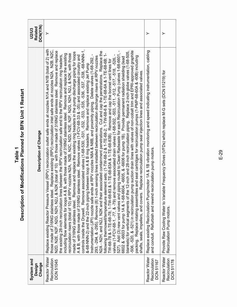
Tabl
e 1
Des
crip
tion
of M
odifi
catio
ns P
lann
ed fo
r BFN
Uni
t 1 R
esta
rt
E-2
9
Syst
em a
nd
Des
ign
Cha
nge
Des
crip
tion
of C
hang
e
U2/
U3
Rel
ated
D
CN
(Y/N
)
Rea
ctor
Wat
er
Rec
ircul
atio
n D
CN
510
45
Rep
lace
exi
stin
g R
eact
or P
ress
ure
Ves
sel (
RP
V) r
ecirc
ulat
ion
outle
t saf
e en
ds a
t noz
zles
N1A
and
N1B
(tot
al o
f 2) w
ith
thos
e m
ade
of 3
16N
G s
tain
less
ste
el.
Rep
lace
exi
stin
g (R
PV
) rec
ircul
atio
n in
let s
afe
ends
at n
ozzl
es N
2A,
N2B
, N2C
, N
2D, N
2E, N
2F, N
2G, N
2H, N
2J, &
N2K
(tot
al o
f 10)
with
thos
e m
ade
of 3
16N
G s
tain
less
ste
el.
Rem
ove
and
repl
ace
the
exis
ting
28-in
ch re
circ
ulat
ion
lines
bet
wee
n th
e R
PV
reci
rcul
atio
n sa
fe e
nd to
the
RP
V re
circ
ulat
ion
ring
head
ers,
in
clud
ing
flow
ele
men
ts fo
r loo
ps A
& B
, with
thos
e m
ade
of 3
16N
G s
tain
less
ste
el.
Rem
ove
and
repl
ace
the
exis
ting
reci
rcul
atio
n ris
ers
(tota
l of 1
0) a
t RP
V n
ozzl
es N
2A,
N2B
, N2C
, N2D
, N2E
, N2F
, N2G
, N2H
, N2J
, & N
2K, w
ith th
ose
mad
e of
316
NG
sta
inle
ss s
teel
. R
emov
e an
d re
plac
e th
e ex
istin
g rin
g he
ader
s in
the
pum
p di
scha
rge
pipi
ng fo
r loo
ps
A &
B, w
ith th
ose
mad
e of
316
NG
sta
inle
ss s
teel
. R
emov
e va
lves
(1-F
CV
-68-
33 &
-35)
and
ass
ocia
ted
circ
uitry
and
co
ntro
ls in
side
the
Dry
wel
l. R
emov
e as
soci
ated
val
ves
(1-6
8-53
0, -5
31, -
532,
-533
, -53
5, -5
36, -
537,
-538
, -68
-NN
N-1
, &
-68-
NN
N-2
) and
the
22-in
ch p
ipin
g be
twee
n lo
op A
& B
ring
hea
ders
. R
emov
e an
d re
plac
e ex
istin
g Je
t Pum
p In
stru
men
tatio
n (J
PI)
nozz
le s
afe
ends
at R
PV
noz
zles
N8A
& N
8B, a
nd p
roxi
mity
pip
ing.
Del
ete
valv
es (1
-68-
292,
-29
3, -2
94, &
-295
). R
emov
e (8
) 1-in
ch s
ensi
ng li
nes
inst
alle
d be
twee
n re
circ
ulat
ion
disc
harg
e ris
ers
at R
PV n
ozzl
es
N2A
- N
2H, a
nd N
2J, N
2K a
nd th
eir a
ssoc
iate
d co
ntai
nmen
t pen
etra
tions
. C
ut a
nd c
ap th
e pe
netra
tions
. R
epla
ce th
e fo
llow
ing
ther
mow
ell/t
empe
ratu
re e
lem
ent s
ets:
(1-T
W-6
8-2
& 1
-TE-
68-2
; 1-T
W-6
8-6
& 1
-TE-
68-6
A &
1-T
E-6
8-6B
; 1-
TW-6
8-78
& 1
-TE
-68-
78; 1
-TW
-68-
83 &
1-T
E-6
8-83
A &
1-T
E-6
8-83
B).
Rem
ove
and
cap
the
bonn
et v
ent l
ines
for
valv
es (1
-FC
V-6
8-1,
-77,
& -7
9) a
nd re
mov
e as
soci
ated
dra
in v
alve
s (1
-68-
502,
-503
, -51
1, -5
12, -
517,
-518
, -5
26, -
527)
. A
dd (3
) new
ven
t val
ves
and
pipi
ng ro
uted
to C
lean
Rad
was
te fo
r eac
h R
ecirc
ulat
ion
Pum
p (v
alve
s 1-
68-6
601,
-66
02 &
-660
3 fo
r pum
p 1A
& 1
-68-
6604
, -66
05, &
-660
6 fo
r pum
p 1B
). P
rovi
de p
erm
anen
t rad
iatio
n sh
ield
ing
(lead
bl
anke
ts) f
or v
ertic
al s
egm
ents
of t
he 1
2-in
ch a
nd 2
8-in
ch re
circ
ulat
ion
pipi
ng.
Rep
lace
2-in
ch g
lobe
val
ves
(1-6
8-50
5,
-506
, -52
0, &
-521
) in
reci
rcul
atio
n pu
mp
suct
ion
drai
n lin
es w
ith v
alve
s of
non
-cob
alt t
rim a
nd E
PR
I-app
rove
d gr
aphi
te
pack
ing.
Rep
lace
rota
ting
asse
mbl
ies
and
seal
car
tridg
es fo
r rec
ircul
atio
n pu
mps
(1-P
MP
-68-
60A
& -6
0B) i
nclu
ding
sh
afts
, sea
ls, i
mpe
llers
, and
cov
ers.
Rep
lace
reci
rcul
atio
n pu
mp
seal
inje
ctio
n lin
es a
nd a
ssoc
iate
d va
lves
.
Y
Rea
ctor
Wat
er
Rec
ircul
atio
n D
CN
511
67
Rep
lace
exi
stin
g R
ecirc
ulat
ion
Pum
p/m
otor
1A
& 1
B v
ibra
tion
mon
itorin
g an
d sp
eed
indi
catin
g in
stru
men
tatio
n, c
ablin
g an
d co
ndui
t. R
efur
bish
and
rew
ind
reci
rcul
atio
n pu
mp
mot
ors.
Y
Rea
ctor
Wat
er
Rec
ircul
atio
n D
CN
511
78
Pro
vide
Raw
Coo
ling
Wat
er to
Var
iabl
e Fr
eque
ncy
Driv
es (V
FDs)
whi
ch re
plac
e M
-G s
ets
(DC
N 5
1219
) for
R
ecirc
ulat
ion
Pum
p m
otor
s.
Y
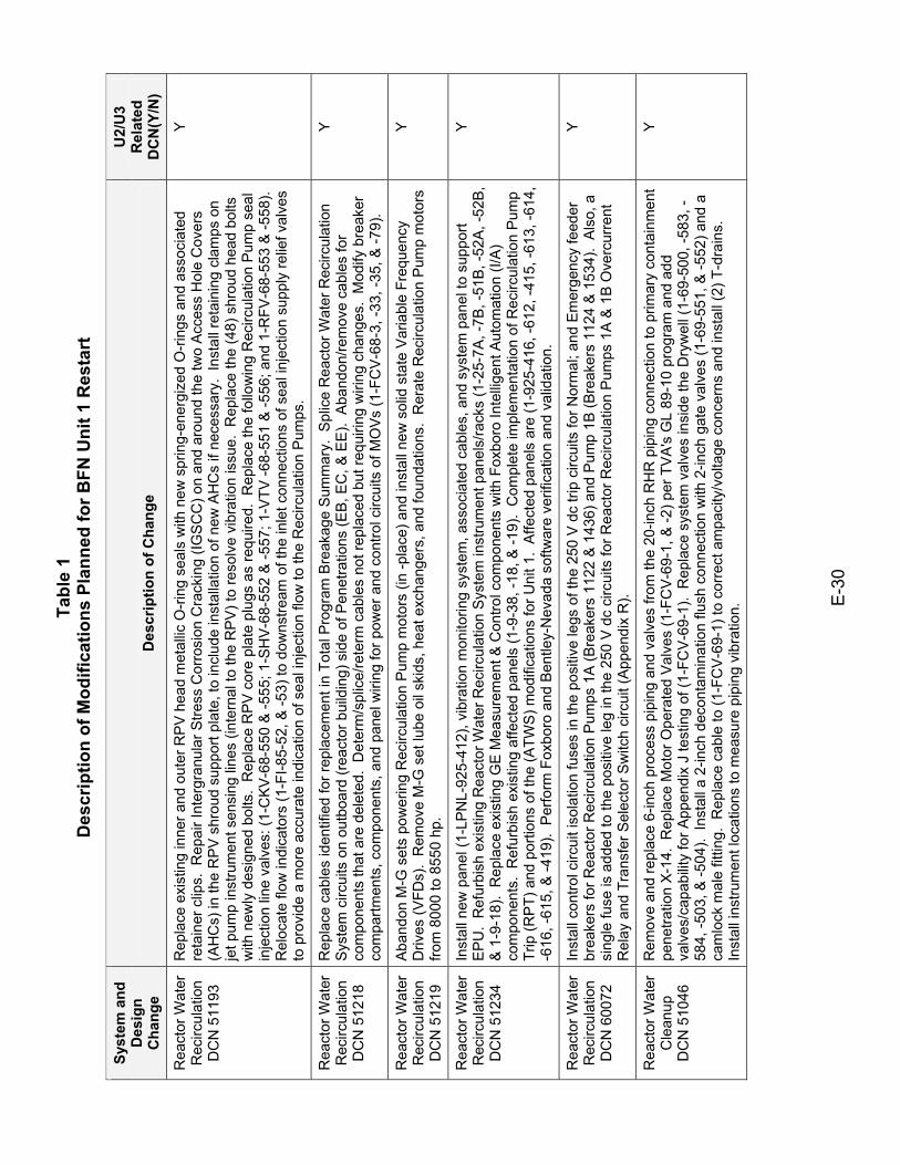
Tabl
e 1
Des
crip
tion
of M
odifi
catio
ns P
lann
ed fo
r BFN
Uni
t 1 R
esta
rt
E-3
0
Syst
em a
nd
Des
ign
Cha
nge
Des
crip
tion
of C
hang
e
U2/
U3
Rel
ated
D
CN
(Y/N
)
Rea
ctor
Wat
er
Rec
ircul
atio
n D
CN
511
93
Rep
lace
exi
stin
g in
ner a
nd o
uter
RP
V h
ead
met
allic
O-r
ing
seal
s w
ith n
ew s
prin
g-en
ergi
zed
O-r
ings
and
ass
ocia
ted
reta
iner
clip
s. R
epai
r Int
ergr
anul
ar S
tress
Cor
rosi
on C
rack
ing
(IGSC
C) o
n an
d ar
ound
the
two
Acc
ess
Hol
e C
over
s (A
HC
s) in
the
RP
V s
hrou
d su
ppor
t pla
te, t
o in
clud
e in
stal
latio
n of
new
AH
Cs
if ne
cess
ary.
Ins
tall
reta
inin
g cl
amps
on
jet p
ump
inst
rum
ent s
ensi
ng li
nes
(inte
rnal
to th
e R
PV
) to
reso
lve
vibr
atio
n is
sue.
Rep
lace
the
(48)
shr
oud
head
bol
ts
with
new
ly d
esig
ned
bolts
. R
epla
ce R
PV
cor
e pl
ate
plug
s as
requ
ired.
Rep
lace
the
follo
win
g R
ecirc
ulat
ion
Pum
p se
al
inje
ctio
n lin
e va
lves
: (1-
CKV
-68-
550
& -5
55; 1
-SH
V-6
8-55
2 &
-557
; 1-V
TV -6
8-55
1 &
-556
; and
1-R
FV-6
8-55
3 &
-558
).
Rel
ocat
e flo
w in
dica
tors
(1-F
I-85-
52, &
-53)
to d
owns
tream
of t
he in
let c
onne
ctio
ns o
f sea
l inj
ectio
n su
pply
relie
f val
ves
to p
rovi
de a
mor
e ac
cura
te in
dica
tion
of s
eal i
njec
tion
flow
to th
e R
ecirc
ulat
ion
Pum
ps.
Y
Rea
ctor
Wat
er
Rec
ircul
atio
n D
CN
512
18
Rep
lace
cab
les
iden
tifie
d fo
r rep
lace
men
t in
Tota
l Pro
gram
Bre
akag
e S
umm
ary.
Spl
ice
Rea
ctor
Wat
er R
ecirc
ulat
ion
Sys
tem
circ
uits
on
outb
oard
(rea
ctor
bui
ldin
g) s
ide
of P
enet
ratio
ns (E
B, E
C, &
EE
). A
band
on/re
mov
e ca
bles
for
com
pone
nts
that
are
del
eted
. D
eter
m/s
plic
e/re
term
cab
les
not r
epla
ced
but r
equi
ring
wiri
ng c
hang
es.
Mod
ify b
reak
er
com
partm
ents
, com
pone
nts,
and
pan
el w
iring
for p
ower
and
con
trol c
ircui
ts o
f MO
Vs
(1-F
CV
-68-
3, -3
3, -3
5, &
-79)
.
Y
Rea
ctor
Wat
er
Rec
ircul
atio
n D
CN
512
19
Aba
ndon
M-G
set
s po
wer
ing
Rec
ircul
atio
n P
ump
mot
ors
(in -p
lace
) and
inst
all n
ew s
olid
sta
te V
aria
ble
Freq
uenc
y D
rives
(VFD
s).
Rem
ove
M-G
set
lube
oil
skid
s, h
eat e
xcha
nger
s, a
nd fo
unda
tions
. R
erat
e R
ecirc
ulat
ion
Pum
p m
otor
s fro
m 8
000
to 8
550
hp.
Y
Rea
ctor
Wat
er
Rec
ircul
atio
n D
CN
512
34
Inst
all n
ew p
anel
(1-L
PN
L-92
5-41
2), v
ibra
tion
mon
itorin
g sy
stem
, ass
ocia
ted
cabl
es, a
nd s
yste
m p
anel
to s
uppo
rt E
PU
. R
efur
bish
exi
stin
g R
eact
or W
ater
Rec
ircul
atio
n S
yste
m in
stru
men
t pan
els/
rack
s (1
-25-
7A, -
7B, -
51B
, -52
A, -
52B
, &
1-9
-18)
. R
epla
ce e
xist
ing
GE
Mea
sure
men
t & C
ontro
l com
pone
nts
with
Fox
boro
Inte
llige
nt A
utom
atio
n (I/
A)
com
pone
nts.
Ref
urbi
sh e
xist
ing
affe
cted
pan
els
(1-9
-38,
-18,
& -1
9).
Com
plet
e im
plem
enta
tion
of R
ecirc
ulat
ion
Pum
p Tr
ip (R
PT)
and
por
tions
of t
he (A
TWS
) mod
ifica
tions
for U
nit 1
. A
ffect
ed p
anel
s ar
e (1
-925
-416
, -61
2, -4
15, -
613,
-614
, -6
16, -
615,
& -4
19).
Per
form
Fox
boro
and
Ben
tley-
Nev
ada
softw
are
verif
icat
ion
and
valid
atio
n.
Y
Rea
ctor
Wat
er
Rec
ircul
atio
n D
CN
600
72
Inst
all c
ontro
l circ
uit i
sola
tion
fuse
s in
the
posi
tive
legs
of t
he 2
50 V
dc
trip
circ
uits
for N
orm
al; a
nd E
mer
genc
y fe
eder
br
eake
rs fo
r Rea
ctor
Rec
ircul
atio
n P
umps
1A
(Bre
aker
s 11
22 &
143
6) a
nd P
ump
1B (B
reak
ers
1124
& 1
534)
. A
lso,
a
sing
le fu
se is
add
ed to
the
posi
tive
leg
in th
e 25
0 V
dc
circ
uits
for R
eact
or R
ecirc
ulat
ion
Pum
ps 1
A &
1B
Ove
rcur
rent
R
elay
and
Tra
nsfe
r Sel
ecto
r Sw
itch
circ
uit (
App
endi
x R
).
Y
Rea
ctor
Wat
er
Cle
anup
D
CN
510
46
Rem
ove
and
repl
ace
6-in
ch p
roce
ss p
ipin
g an
d va
lves
from
the
20-in
ch R
HR
pip
ing
conn
ectio
n to
prim
ary
cont
ainm
ent
pene
tratio
n X-
14.
Rep
lace
Mot
or O
pera
ted
Val
ves
(1-F
CV-
69-1
, & -2
) per
TV
A's
GL
89-1
0 pr
ogra
m a
nd a
dd
valv
es/c
apab
ility
for A
ppen
dix
J te
stin
g of
(1-F
CV
-69-
1).
Rep
lace
sys
tem
val
ves
insi
de th
e D
ryw
ell (
1-69
-500
, -58
3, -
584,
-503
, & -5
04).
Inst
all a
2-in
ch d
econ
tam
inat
ion
flush
con
nect
ion
with
2-in
ch g
ate
valv
es (1
-69-
551,
& -5
52) a
nd a
ca
mlo
ck m
ale
fittin
g. R
epla
ce c
able
to (1
-FC
V-69
-1) t
o co
rrect
am
paci
ty/v
olta
ge c
once
rns
and
inst
all (
2) T
-dra
ins.
In
stal
l ins
trum
ent l
ocat
ions
to m
easu
re p
ipin
g vi
brat
ion.
Y
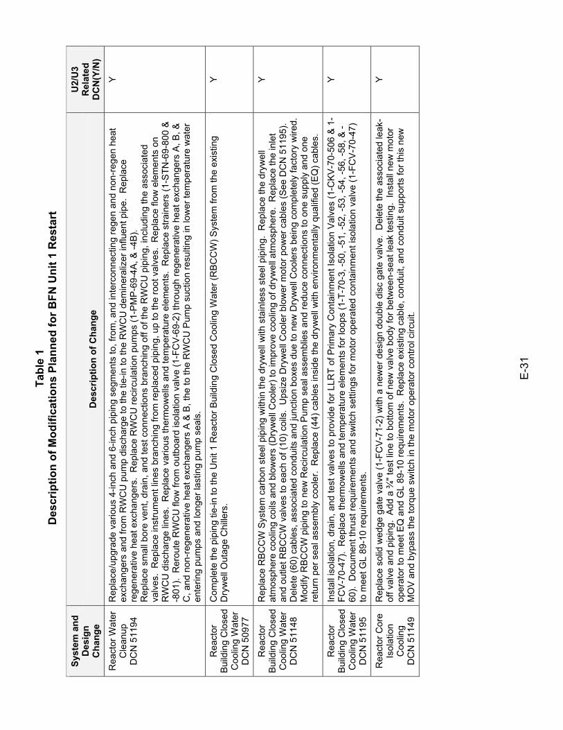
Tabl
e 1
Des
crip
tion
of M
odifi
catio
ns P
lann
ed fo
r BFN
Uni
t 1 R
esta
rt
E-3
1
Syst
em a
nd
Des
ign
Cha
nge
Des
crip
tion
of C
hang
e
U2/
U3
Rel
ated
D
CN
(Y/N
)
Rea
ctor
Wat
er
Cle
anup
D
CN
511
94
Rep
lace
/upg
rade
var
ious
4-in
ch a
nd 6
-inch
pip
ing
segm
ents
to, f
rom
, and
inte
rcon
nect
ing
rege
n an
d no
n-re
gen
heat
ex
chan
gers
and
from
RW
CU
pum
p di
scha
rge
to th
e tie
-in to
the
RW
CU
dem
iner
aliz
er in
fluen
t pip
e. R
epla
ce
rege
nera
tive
heat
exc
hang
ers.
Rep
lace
RW
CU
reci
rcul
atio
n pu
mps
(1-P
MP
-69-
4A, &
-4B
). R
epla
ce s
mal
l bor
e ve
nt, d
rain
, and
test
con
nect
ions
bra
nchi
ng o
ff of
the
RW
CU
pip
ing,
incl
udin
g th
e as
soci
ated
va
lves
. R
epla
ce in
stru
men
t lin
es b
ranc
hing
from
repl
aced
pip
ing,
up
to th
e ro
ot v
alve
s. R
epla
ce fl
ow e
lem
ents
on
RW
CU
dis
char
ge li
nes.
Rep
lace
var
ious
ther
mow
ells
and
tem
pera
ture
ele
men
ts.
Rep
lace
stra
iner
s (1
-STN
-69-
800
&
-801
). R
erou
te R
WC
U fl
ow fr
om o
utbo
ard
isol
atio
n va
lve
(1-F
CV-
69-2
) thr
ough
rege
nera
tive
heat
exc
hang
ers
A, B
, &
C, a
nd n
on-r
egen
erat
ive
heat
exc
hang
ers
A &
B, t
he to
the
RW
CU
Pum
p su
ctio
n re
sulti
ng in
low
er te
mpe
ratu
re w
ater
en
terin
g pu
mps
and
long
er la
stin
g pu
mp
seal
s.
Y
Rea
ctor
B
uild
ing
Clo
sed
Coo
ling
Wat
er
DC
N 5
0977
Com
plet
e th
e pi
ping
tie-
in to
the
Uni
t 1 R
eact
or B
uild
ing
Clo
sed
Coo
ling
Wat
er (R
BC
CW
) Sys
tem
from
the
exis
ting
Dry
wel
l Out
age
Chi
llers
. Y
Rea
ctor
B
uild
ing
Clo
sed
Coo
ling
Wat
er
DC
N 5
1148
Rep
lace
RB
CC
W S
yste
m c
arbo
n st
eel p
ipin
g w
ithin
the
dryw
ell w
ith s
tain
less
ste
el p
ipin
g. R
epla
ce th
e dr
ywel
l at
mos
pher
e co
olin
g co
ils a
nd b
low
ers
(Dry
wel
l Coo
ler)
to im
prov
e co
olin
g of
dry
wel
l atm
osph
ere.
Rep
lace
the
inle
t an
d ou
tlet R
BCC
W v
alve
s to
eac
h of
(10)
coi
ls.
Ups
ize
Dry
wel
l Coo
ler b
low
er m
otor
pow
er c
able
s (S
ee D
CN
511
95).
D
elet
e (6
0) c
able
s, a
ssoc
iate
d co
ndui
ts a
nd ju
nctio
n bo
xes
due
to n
ew D
ryw
ell C
oole
rs b
eing
com
plet
ely
fact
ory
wire
d.
Mod
ify R
BC
CW
pip
ing
to n
ew R
ecirc
ulat
ion
Pum
p se
al a
ssem
blie
s an
d re
duce
con
nect
ions
to o
ne s
uppl
y an
d on
e re
turn
per
sea
l ass
embl
y co
oler
. R
epla
ce (4
4) c
able
s in
side
the
dryw
ell w
ith e
nviro
nmen
tally
qua
lifie
d (E
Q) c
able
s.
Y
Rea
ctor
B
uild
ing
Clo
sed
Coo
ling
Wat
er
DC
N 5
1195
Inst
all i
sola
tion,
dra
in, a
nd te
st v
alve
s to
pro
vide
for L
LRT
of P
rimar
y C
onta
inm
ent I
sola
tion
Val
ves
(1-C
KV
-70-
506
& 1
-FC
V-7
0-47
). R
epla
ce th
erm
owel
ls a
nd te
mpe
ratu
re e
lem
ents
for l
oops
(1-T
-70-
3, -5
0, -5
1, -5
2, -5
3, -5
4, -5
6, -5
8, &
-60
). D
ocum
ent t
hrus
t req
uire
men
ts a
nd s
witc
h se
tting
s fo
r mot
or o
pera
ted
cont
ainm
ent i
sola
tion
valv
e (1
-FC
V-7
0-47
) to
mee
t GL
89-1
0 re
quire
men
ts.
Y
Rea
ctor
Cor
e Is
olat
ion
Coo
ling
DC
N 5
1149
Rep
lace
sol
id w
edge
gat
e va
lve
(1-F
CV-
71-2
) with
a n
ewer
des
ign
doub
le d
isc
gate
val
ve.
Del
ete
the
asso
ciat
ed le
ak-
off v
alve
and
pip
ing.
Add
a ¾
" tes
t lin
e to
bot
tom
of n
ew v
alve
bod
y fo
r bet
wee
n-se
at le
ak te
stin
g. I
nsta
ll ne
w m
otor
op
erat
or to
mee
t EQ
and
GL
89-1
0 re
quire
men
ts.
Rep
lace
exi
stin
g ca
ble,
con
duit,
and
con
duit
supp
orts
for t
his
new
M
OV
and
byp
ass
the
torq
ue s
witc
h in
the
mot
or o
pera
tor c
ontro
l circ
uit.
Y
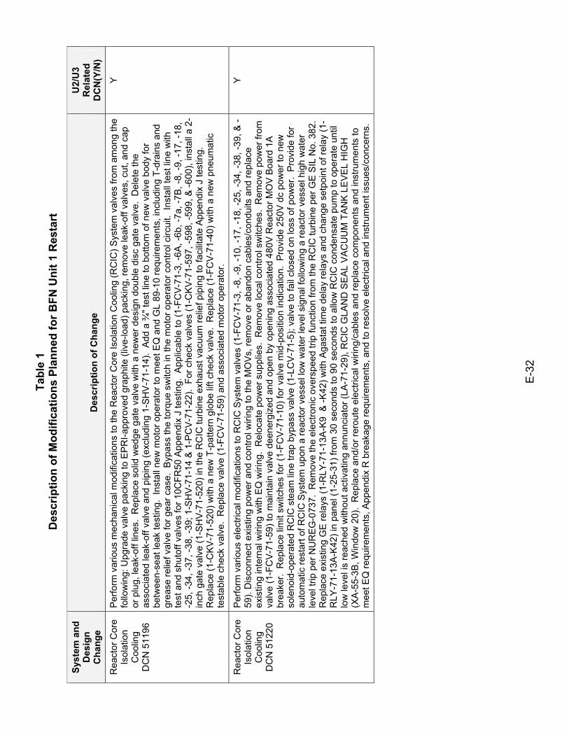
Tabl
e 1
Des
crip
tion
of M
odifi
catio
ns P
lann
ed fo
r BFN
Uni
t 1 R
esta
rt
E-3
2
Syst
em a
nd
Des
ign
Cha
nge
Des
crip
tion
of C
hang
e
U2/
U3
Rel
ated
D
CN
(Y/N
)
Rea
ctor
Cor
e Is
olat
ion
Coo
ling
DC
N 5
1196
Per
form
var
ious
mec
hani
cal m
odifi
catio
ns to
the
Rea
ctor
Cor
e Is
olat
ion
Coo
ling
(RC
IC) S
yste
m v
alve
s fro
m a
mon
g th
e fo
llow
ing:
Upg
rade
val
ve p
acki
ng to
EP
RI-a
ppro
ved
grap
hite
(liv
e-lo
ad) p
acki
ng, r
emov
e le
ak-o
ff va
lves
, cut
, and
cap
or
plu
g, le
ak-o
ff lin
es.
Rep
lace
sol
id w
edge
gat
e va
lve
with
a n
ewer
des
ign
doub
le d
isc
gate
val
ve.
Del
ete
the
asso
ciat
ed le
ak-o
ff va
lve
and
pipi
ng (e
xclu
ding
1-S
HV
-71-
14).
Add
a ¾
" tes
t lin
e to
bot
tom
of n
ew v
alve
bod
y fo
r be
twee
n-se
at le
ak te
stin
g. I
nsta
ll ne
w m
otor
ope
rato
r to
mee
t EQ
and
GL
89-1
0 re
quire
men
ts, i
nclu
ding
T-d
rain
s an
d gr
ease
relie
f val
ve fo
r gea
r cas
e. B
ypas
s th
e to
rque
sw
itch
in th
e m
otor
ope
rato
r con
trol c
ircui
t. In
stal
l tes
t lin
e w
ith
test
and
shu
toff
valv
es fo
r 10C
FR50
App
endi
x J
test
ing.
App
licab
le to
(1-F
CV
-71-
3, -6
A, -
6b, -
7a, -
7B, -
8, -9
, -17
, -18
, -2
5, -3
4, -3
7, -3
8, -3
9; 1
-SH
V-7
1-14
& 1
-PC
V-7
1-22
). F
or c
heck
val
ves
(1-C
KV
-71-
597,
-598
, -59
9, &
-600
), in
stal
l a 2
-in
ch g
ate
valv
e (1
-SH
V-7
1-52
0) in
the
RC
IC tu
rbin
e ex
haus
t vac
uum
relie
f pip
ing
to fa
cilit
ate
App
endi
x J
test
ing.
R
epla
ce (1
-CK
V-7
1-52
0) w
ith a
new
T-p
atte
rn g
lobe
lift
chec
k va
lve.
Rep
lace
(1-F
CV
-71-
40) w
ith a
new
pne
umat
ic
test
able
che
ck v
alve
. R
epla
ce v
alve
(1-F
CV
-71-
59) a
nd a
ssoc
iate
d m
otor
ope
rato
r.
Y
Rea
ctor
Cor
e Is
olat
ion
Coo
ling
DC
N 5
1220
Per
form
var
ious
ele
ctric
al m
odifi
catio
ns to
RC
IC S
yste
m v
alve
s (1
-FC
V-7
1-3,
-8, -
9, -1
0, -1
7, -1
8, -2
5, -3
4, -3
8, -3
9, &
-59
). D
isco
nnec
t exi
stin
g po
wer
and
con
trol w
iring
to th
e M
OV
s, re
mov
e or
aba
ndon
cab
les/
cond
uits
and
repl
ace
exis
ting
inte
rnal
wiri
ng w
ith E
Q w
iring
. R
eloc
ate
pow
er s
uppl
ies.
Rem
ove
loca
l con
trol s
witc
hes.
Rem
ove
pow
er fr
om
valv
e (1
-FC
V-71
-59)
to m
aint
ain
valv
e de
ener
gize
d an
d op
en b
y op
enin
g as
soci
ated
480
V R
eact
or M
OV
Boa
rd 1
A
brea
ker.
Rep
lace
lim
it sw
itche
s fo
r (1-
FCV
-71-
10) f
or v
alve
mid
-pos
ition
indi
catio
n. P
rovi
de 2
50V
dc
pow
er to
new
so
leno
id-o
pera
ted
RC
IC s
team
line
trap
byp
ass
valv
e (1
-LC
V-71
-5);
valv
e to
fail
clos
ed o
n lo
ss o
f pow
er.
Pro
vide
for
auto
mat
ic re
star
t of R
CIC
Sys
tem
upo
n a
reac
tor v
esse
l low
wat
er le
vel s
igna
l fol
low
ing
a re
acto
r ves
sel h
igh
wat
er
leve
l trip
per
NU
RE
G-0
737.
Rem
ove
the
elec
troni
c ov
ersp
eed
trip
func
tion
from
the
RC
IC tu
rbin
e pe
r GE
SIL
No.
382
. R
epla
ce e
xist
ing
GE
rela
ys (1
-RLY
-71-
13A
-K9
& -K
42) w
ith A
gast
at ti
me
dela
y re
lays
and
cha
nge
setp
oint
of r
elay
(1-
RLY
-71-
13A
-K42
) in
pane
l (1-
25-3
1) fr
om 3
0 se
cond
s to
90
seco
nds
to a
llow
RC
IC c
onde
nsat
e pu
mp
to o
pera
te u
ntil
low
leve
l is
reac
hed
with
out a
ctiv
atin
g an
nunc
iato
r (LA
-71-
29),
RC
IC G
LAN
D S
EA
L V
AC
UU
M T
AN
K L
EV
EL
HIG
H
(XA
-55-
3B, W
indo
w 2
0).
Rep
lace
and
/or r
erou
te e
lect
rical
wiri
ng/c
able
s an
d re
plac
e co
mpo
nent
s an
d in
stru
men
ts to
m
eet E
Q re
quire
men
ts, A
ppen
dix
R b
reak
age
requ
irem
ents
, and
to re
solv
e el
ectri
cal a
nd in
stru
men
t iss
ues/
conc
erns
.
Y
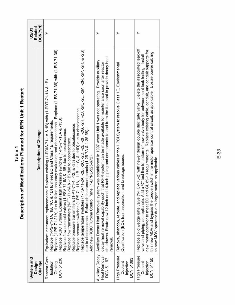
Tabl
e 1
Des
crip
tion
of M
odifi
catio
ns P
lann
ed fo
r BFN
Uni
t 1 R
esta
rt
E-3
3
Syst
em a
nd
Des
ign
Cha
nge
Des
crip
tion
of C
hang
e
U2/
U3
Rel
ated
D
CN
(Y/N
)
Rea
ctor
Cor
e Is
olat
ion
Coo
ling
DC
N 5
1236
Equ
ival
ent i
nstru
men
t rep
lace
men
ts: R
epla
ce e
xist
ing
(1-P
DIS
-71-
1A &
1B
) with
(1-P
DT-
71-1
A &
1B
). R
epla
ce (1
-PS
-71-
1A, 1
B, 1
C, &
1D
) to
mee
t EQ
and
Cla
ss 1
E re
quire
men
ts.
Rep
lace
(1-P
S-7
1-21
A) d
ue to
faile
d ac
cura
cy e
valu
atio
n an
d ob
sole
scen
ce.
Rep
lace
(1-F
S-7
1-36
) with
(1-F
IS-7
1-36
).R
epla
ce R
CIC
Tur
bine
Exh
aust
Hig
h P
ress
ure
switc
hes
(1-P
S-7
1-13
A &
-13B
). R
epla
ce fl
ow s
olen
oid
valv
es (1
-FS
V-7
1-6A
& -6
B) d
ue to
obs
oles
cenc
e.
Rep
lace
flow
tran
smitt
ers
(1-F
T-71
-1A
& -1
B) d
ue to
obs
oles
cenc
e.
Rep
lace
pre
ssur
e tra
nsm
itter
s (1
-PT-
71-4
, -12
, & -3
5) d
ue to
obs
oles
cenc
e.
Rep
lace
pre
ssur
e sw
itche
s (1
-PS
-71-
11A
, -11
B, -
11C
, & -1
1D) d
ue to
obs
oles
cenc
e.
Rep
lace
tem
pera
ture
sw
itche
s (1
-TS-
71-2
A, -
2B, -
2C, -
2D, -
2E, -
2F, -
2G, -
2H, -
2J, -
2K, -
2L, -
2M, -
2N, -
2P, -
2R, &
-2S
) du
e to
obs
oles
cenc
e. R
efur
bish
inst
rum
ent p
anel
s (1
-25-
7A &
1-2
5-58
). A
dd n
ew R
CIC
Tur
bine
Con
trol P
anel
(1-L
PN
L-92
5-67
2).
Y
Aux
iliary
Dec
ay
Hea
t Rem
oval
D
CN
511
97
Aux
iliar
y D
ecay
Hea
t Rem
oval
sys
tem
was
est
ablis
hed
in 1
997
whe
n U
nit 1
was
not
ope
ratin
g. P
rovi
de a
uxilia
ry
deca
y he
at re
mov
al c
apab
ility
such
that
RH
R s
yste
m c
an b
e m
ade
avai
labl
e fo
r mai
nten
ance
soo
n af
ter r
eact
or
shut
dow
ns. R
oute
new
12-
inch
and
14-
inch
pip
ing
and
com
pone
nts
to a
nd fr
om th
e fu
el p
ool t
o pr
ovid
e de
cay
heat
re
mov
al.
Y
Hig
h P
ress
ure
Coo
lant
In
ject
ion
DC
N 5
1083
Rem
ove,
aba
ndon
, rer
oute
, and
repl
ace
vario
us c
able
s in
the
HP
CI S
yste
m to
reso
lve
Cla
ss 1
E, E
nviro
nmen
tal
Qua
lific
atio
n (E
Q),
train
sep
arat
ion,
and
bre
akag
e is
sues
. Y
Hig
h P
ress
ure
Coo
lant
In
ject
ion
DC
N 5
1150
Rep
lace
sol
id w
edge
gat
e va
lve
(1-F
CV-
73-2
) with
new
er d
esig
n do
uble
dis
c ga
te v
alve
. D
elet
e th
e as
soci
ated
leak
-off
valv
e an
d pi
ping
, as
appl
icab
le. A
dd a
¾" t
est l
ine
to b
otto
m o
f new
val
ve b
ody
for b
etw
een-
seat
leak
test
ing.
Ins
tall
new
mot
or o
pera
tor t
o m
eet E
Q a
nd G
L 89
-10
requ
irem
ents
. R
epla
ce e
xist
ing
cabl
e, c
ondu
it, a
nd c
ondu
it su
ppor
ts fo
r th
is n
ew M
OV
and
byp
ass
the
torq
ue s
witc
h in
the
mot
or o
pera
tor c
ontro
l circ
uit,
as a
pplic
able
. U
psiz
e po
wer
cab
ling
to n
ew M
OV
ope
rato
r due
to la
rger
mot
or, a
s ap
plic
able
.
Y
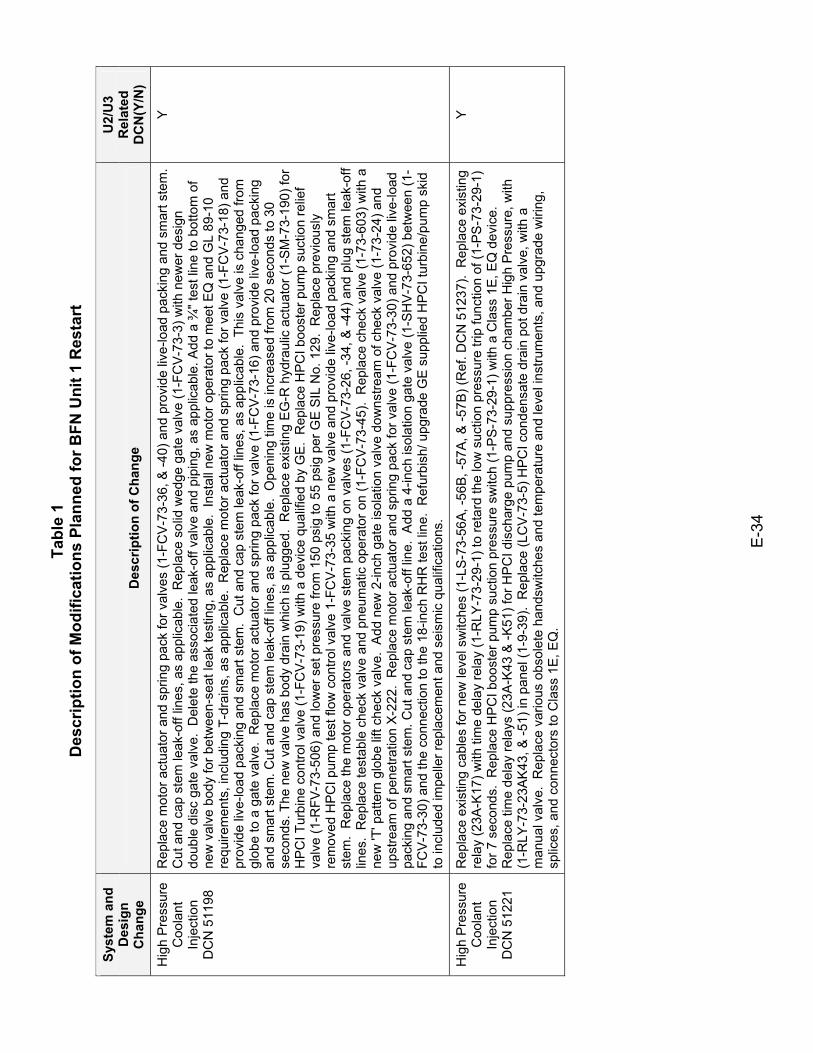
Tabl
e 1
Des
crip
tion
of M
odifi
catio
ns P
lann
ed fo
r BFN
Uni
t 1 R
esta
rt
E-3
4
Syst
em a
nd
Des
ign
Cha
nge
Des
crip
tion
of C
hang
e
U2/
U3
Rel
ated
D
CN
(Y/N
)
Hig
h P
ress
ure
Coo
lant
In
ject
ion
DC
N 5
1198
Rep
lace
mot
or a
ctua
tor a
nd s
prin
g pa
ck fo
r val
ves
(1-F
CV
-73-
36, &
-40)
and
pro
vide
live
-load
pac
king
and
sm
art s
tem
. C
ut a
nd c
ap s
tem
leak
-off
lines
, as
appl
icab
le.
Rep
lace
sol
id w
edge
gat
e va
lve
(1-F
CV
-73-
3) w
ith n
ewer
des
ign
doub
le d
isc
gate
val
ve.
Del
ete
the
asso
ciat
ed le
ak-o
ff va
lve
and
pipi
ng, a
s ap
plic
able
. Add
a ¾
" tes
t lin
e to
bot
tom
of
new
val
ve b
ody
for b
etw
een-
seat
leak
test
ing,
as
appl
icab
le.
Inst
all n
ew m
otor
ope
rato
r to
mee
t EQ
and
GL
89-1
0 re
quire
men
ts, i
nclu
ding
T-d
rain
s, a
s ap
plic
able
. R
epla
ce m
otor
act
uato
r and
spr
ing
pack
for v
alve
(1-F
CV
-73-
18) a
nd
prov
ide
live-
load
pac
king
and
sm
art s
tem
. C
ut a
nd c
ap s
tem
leak
-off
lines
, as
appl
icab
le.
This
val
ve is
cha
nged
from
gl
obe
to a
gat
e va
lve.
Rep
lace
mot
or a
ctua
tor a
nd s
prin
g pa
ck fo
r val
ve (1
-FC
V-7
3-16
) and
pro
vide
live
-load
pac
king
an
d sm
art s
tem
. Cut
and
cap
ste
m le
ak-o
ff lin
es, a
s ap
plic
able
. O
peni
ng ti
me
is in
crea
sed
from
20
seco
nds
to 3
0 se
cond
s. T
he n
ew v
alve
has
bod
y dr
ain
whi
ch is
plu
gged
. R
epla
ce e
xist
ing
EG
-R h
ydra
ulic
act
uato
r (1-
SM-7
3-19
0) fo
r H
PC
I Tur
bine
con
trol v
alve
(1-F
CV
-73-
19) w
ith a
dev
ice
qual
ified
by
GE
. R
epla
ce H
PCI b
oost
er p
ump
suct
ion
relie
f va
lve
(1-R
FV-7
3-50
6) a
nd lo
wer
set
pre
ssur
e fro
m 1
50 p
sig
to 5
5 ps
ig p
er G
E S
IL N
o. 1
29.
Rep
lace
pre
viou
sly
rem
oved
HPC
I pum
p te
st fl
ow c
ontro
l val
ve 1
-FC
V-7
3-35
with
a n
ew v
alve
and
pro
vide
live
-load
pac
king
and
sm
art
stem
. R
epla
ce th
e m
otor
ope
rato
rs a
nd v
alve
ste
m p
acki
ng o
n va
lves
(1-F
CV
-73-
26, -
34, &
-44)
and
plu
g st
em le
ak-o
ff lin
es.
Rep
lace
test
able
che
ck v
alve
and
pne
umat
ic o
pera
tor o
n (1
-FC
V-7
3-45
). R
epla
ce c
heck
val
ve (1
-73-
603)
with
a
new
'T' p
atte
rn g
lobe
lift
chec
k va
lve.
Add
new
2-in
ch g
ate
isol
atio
n va
lve
dow
nstre
am o
f che
ck v
alve
(1-7
3-24
) and
up
stre
am o
f pen
etra
tion
X-2
22.
Rep
lace
mot
or a
ctua
tor a
nd s
prin
g pa
ck fo
r val
ve (1
-FC
V-73
-30)
and
pro
vide
live
-load
pa
ckin
g an
d sm
art s
tem
. Cut
and
cap
ste
m le
ak-o
ff lin
e. A
dd a
4-in
ch is
olat
ion
gate
val
ve (1
-SH
V-7
3-65
2) b
etw
een
(1-
FCV
-73-
30) a
nd th
e co
nnec
tion
to th
e 18
-inch
RH
R te
st li
ne.
Ref
urbi
sh/ u
pgra
de G
E s
uppl
ied
HP
CI t
urbi
ne/p
ump
skid
to
incl
uded
impe
ller r
epla
cem
ent a
nd s
eism
ic q
ualif
icat
ions
.
Y
Hig
h P
ress
ure
Coo
lant
In
ject
ion
DC
N 5
1221
Rep
lace
exi
stin
g ca
bles
for n
ew le
vel s
witc
hes
(1-L
S-7
3-56
A, -
56B,
-57A
, & -5
7B) (
Ref
. DC
N 5
1237
). R
epla
ce e
xist
ing
rela
y (2
3A-K
17) w
ith ti
me
dela
y re
lay
(1-R
LY-7
3-29
-1) t
o re
tard
the
low
suc
tion
pres
sure
trip
func
tion
of (1
-PS
-73-
29-1
) fo
r 7 s
econ
ds.
Rep
lace
HP
CI b
oost
er p
ump
suct
ion
pres
sure
sw
itch
(1-P
S-7
3-29
-1) w
ith a
Cla
ss 1
E, E
Q d
evic
e.
Rep
lace
tim
e de
lay
rela
ys (2
3A-K
43 &
-K51
) for
HP
CI d
isch
arge
pum
p an
d su
ppre
ssio
n ch
ambe
r Hig
h P
ress
ure,
with
(1
-RLY
-73-
23A
K43
, & -5
1) in
pan
el (1
-9-3
9).
Rep
lace
(LC
V-7
3-5)
HP
CI c
onde
nsat
e dr
ain
pot d
rain
val
ve, w
ith a
m
anua
l val
ve.
Rep
lace
var
ious
obs
olet
e ha
ndsw
itche
s an
d te
mpe
ratu
re a
nd le
vel i
nstru
men
ts, a
nd u
pgra
de w
iring
, sp
lices
, and
con
nect
ors
to C
lass
1E
, EQ
.
Y
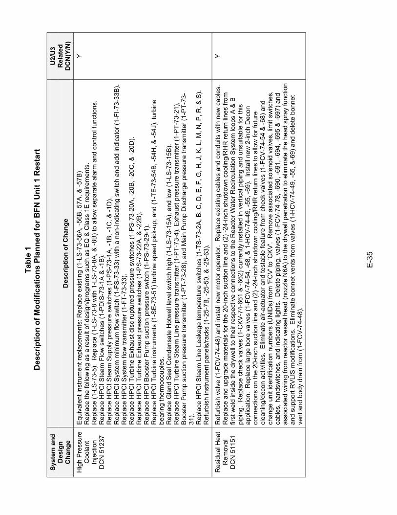
Tabl
e 1
Des
crip
tion
of M
odifi
catio
ns P
lann
ed fo
r BFN
Uni
t 1 R
esta
rt
E-3
5
Syst
em a
nd
Des
ign
Cha
nge
Des
crip
tion
of C
hang
e
U2/
U3
Rel
ated
D
CN
(Y/N
)
Hig
h P
ress
ure
Coo
lant
In
ject
ion
DC
N 5
1237
Equ
ival
ent i
nstru
men
t rep
lace
men
ts: R
epla
ce e
xist
ing
(1-L
S-7
3-56
A, -
56B
, 57A
, & -5
7B)
Rep
lace
the
follo
win
g as
a re
sult
of d
esig
n/pr
ogra
ms
such
as
EQ
& C
lass
1E
requ
irem
ents
. R
epla
ce (1
-LS
-73-
5).
Rep
lace
(1-L
S-7
3-8
with
1-L
S-7
3-8A
, & -8
B) t
o al
low
sep
arat
e al
arm
and
con
trol f
unct
ions
. R
epla
ce H
PC
I Ste
am F
low
sw
itche
s (1
-PD
IS-7
3-1A
& -1
B).
Rep
lace
HP
CI S
team
Sup
ply
pres
sure
sw
itche
s (1
-PS
-73-
1A, -
1B, -
1C, &
-1D
). R
epla
ce H
PC
I Sys
tem
min
imum
flow
sw
itch
(1-F
S-7
3-33
) with
a n
on-in
dica
ting
switc
h an
d ad
d in
dica
tor (
1-FI
-73-
33B
). R
epla
ce H
PC
I Sys
tem
flow
tran
smitt
er (1
-FT-
73-3
3).
Rep
lace
HP
CI T
urbi
ne E
xhau
st d
isc
rupt
ured
pre
ssur
e sw
itche
s (1
-PS
-73-
20A
, -20
B, -
20C
, & -2
0D).
Rep
lace
HP
CI T
urbi
ne E
xhau
st p
ress
ure
switc
hes
(1-P
S-7
3-22
A, &
-22B
). R
epla
ce H
PC
I Boo
ster
Pum
p su
ctio
n pr
essu
re s
witc
h (1
-PS
-73-
29-1
). R
epla
ce H
PC
I Tur
bine
inst
rum
ents
(1-S
E-73
-51)
turb
ine
spee
d pi
ck-u
p; a
nd (1
-TE-
73-5
4B, -
54H
, & -5
4J),
turb
ine
bear
ing
ther
moc
oupl
es.
R
epla
ce G
land
Sea
l Con
dens
ate
Hot
wel
l lev
el s
witc
h hi
gh (1
-LS-
73-1
5A),
and
low
(1-L
S-7
3-15
B).
R
epla
ce H
PC
I Tur
bine
Ste
am L
ine
pres
sure
tran
smitt
er (1
-PT-
73-4
), E
xhau
st p
ress
ure
trans
mitt
er (1
-PT-
73-2
1),
Boo
ster
Pum
p su
ctio
n pr
essu
re tr
ansm
itter
(1-P
T-73
-28)
, and
Mai
n P
ump
Dis
char
ge p
ress
ure
trans
mitt
er (1
-PT-
73-
31).
Rep
lace
HP
CI S
team
Lin
e Le
akag
e te
mpe
ratu
re s
witc
hes
(1-T
S-73
-2A
, B, C
, D, E
, F, G
, H, J
, K, L
, M, N
, P, R
, & S
). R
efur
bish
inst
rum
ent p
anel
s/ra
cks
(1-2
5-7B
, -25
-50,
& -2
5-63
).
Y
Res
idua
l Hea
t R
emov
al
DC
N 5
1151
Ref
urbi
sh v
alve
(1-F
CV
-74-
48) a
nd in
stal
l new
mot
or o
pera
tor.
Rep
lace
exi
stin
g ca
bles
and
con
duits
with
new
cab
les.
R
epla
ce a
nd u
pgra
de m
ater
ials
for t
he 2
0-in
ch s
uctio
n lin
e an
d (2
) -24
-inch
shu
tdow
n co
olin
g/R
HR
retu
rn li
nes
from
fir
st w
eld
insi
de th
e dr
ywel
l to
thei
r res
pect
ive
conn
ectio
ns to
the
Rea
ctor
Wat
er R
ecirc
ulat
ion
Sys
tem
loop
s A
& B
pi
ping
. R
epla
ce c
heck
val
ves
(1-C
KV
-74-
661
& -6
62) c
urre
ntly
inst
alle
d in
ver
tical
pip
ing
and
unsu
itabl
e fo
r thi
s ap
plic
atio
n. R
epla
ce la
rge
bore
val
ves
(1-F
CV
-74-
54, -
68, &
1-H
CV
-74-
49, -
55, -
69).
Inst
all n
ew 2
-inch
Dec
on
conn
ectio
ns o
n th
e 20
-inch
suc
tion
line
and
(2) -
24-in
ch s
hutd
own
cool
ing/
RH
R re
turn
line
s to
allo
w fo
r fut
ure
clea
ning
/dec
on a
ctiv
ities
. E
limin
ate
air-
actu
ator
and
test
able
feat
ure
from
che
ck v
alve
s (1
-FC
V-7
4-54
& -6
8) a
nd
chan
ge u
nit i
dent
ifica
tion
num
bers
(UN
IDs)
from
'FC
V' t
o 'C
KV
'. R
emov
e as
soci
ated
sol
enoi
d va
lves
, lim
it sw
itche
s,
cabl
es, h
ands
witc
hes,
and
indi
catin
g lig
hts.
Del
ete
pipi
ng, v
alve
s (1
-FC
V-7
4-78
, -69
0, -6
91, -
694,
-695
& -6
97) a
nd
asso
ciat
ed w
iring
from
reac
tor v
esse
l hea
d (n
ozzl
e N
6A) t
o th
e dr
ywel
l pen
etra
tion
to e
limin
ate
the
head
spr
ay fu
nctio
n an
d su
ppor
t RV
LIS
mod
ifica
tions
. E
limin
ate
bonn
et v
ents
from
val
ves
(1-H
CV
-74-
49, -
55, &
-69)
and
del
ete
bonn
et
vent
and
bod
y dr
ain
from
(1-F
CV
-74-
48).
Y
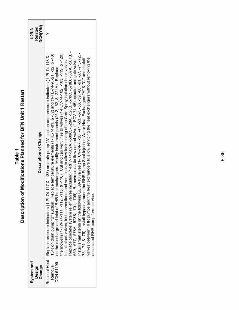
Tabl
e 1
Des
crip
tion
of M
odifi
catio
ns P
lann
ed fo
r BFN
Uni
t 1 R
esta
rt
E-3
6
Syst
em a
nd
Des
ign
Cha
nge
Des
crip
tion
of C
hang
e
U2/
U3
Rel
ated
D
CN
(Y/N
)
Res
idua
l Hea
t R
emov
al
DC
N 5
1199
Rep
lace
pre
ssur
e in
dica
tors
(1-P
I-74-
117
& -1
33) o
n dr
ain
pum
p "A
" suc
tion
and
pres
sure
indi
cato
rs (1
-PI-7
4-11
8 &
-13
4) o
n dr
ain
pum
p "B
" suc
tion.
Rep
lace
tem
pera
ture
ele
men
ts (1
-TE
-74-
81, &
-82)
and
(1-T
E-7
4-9,
-21,
-32,
& -4
3)
on th
e di
scha
rge
and
inle
t of R
HR
hea
t exc
hang
ers.
Mod
ify in
stru
men
t pan
els
(25-
2, -6
2, &
-224
A):
Rep
lace
th
erm
owel
ls (1
-TW
-74-
111,
-112
, -11
5, &
-116
). C
ut a
nd c
ap v
ent l
ines
to v
alve
s (1
-FC
V-7
4-10
2, -1
03, -
119,
& -1
20).
Inst
all b
lock
val
ves,
test
con
nect
ions
, and
ven
t lin
es to
allo
w le
ak te
stin
g of
the
Cor
e S
pray
isol
atio
n ch
eck
valv
es.
Rep
lace
obs
olet
e sy
stem
relie
f val
ves
incl
udin
g (1
-RFV
-74-
509A
, -50
9C, -
528A
, -52
8B, -
578C
, -57
8D, -
587A
, -58
7B, -
659,
-677
, -57
8A, -
578B
, -70
1, -7
09).
Rem
ove
cros
s-tie
flow
con
trol v
alve
(1-F
CV
-74-
46) a
ctua
tor a
nd g
ate
valv
e.
Inst
all s
mar
t ste
ms
on th
e fo
llow
ing
GL
89-1
0 va
lves
(1-F
CV
-74-
7, -3
0, -4
7, -5
3, -5
7, -5
8, -5
9, -6
0, -6
1, -6
7, -7
1, -7
2, -
73, -
74, &
-75)
. In
stal
l byp
ass
arou
nd th
e R
HR
Pum
p S
eal I
njec
tion
Wat
er H
eat E
xcha
nger
s "A
" & "C
'" an
d sh
utof
f va
lves
bet
wee
n R
HR
pum
ps a
nd th
e he
at e
xcha
nger
s to
allo
w s
ervi
cing
the
heat
exc
hang
ers
with
out r
emov
ing
the
asso
ciat
ed R
HR
pum
p fo
rm s
ervi
ce.
Y
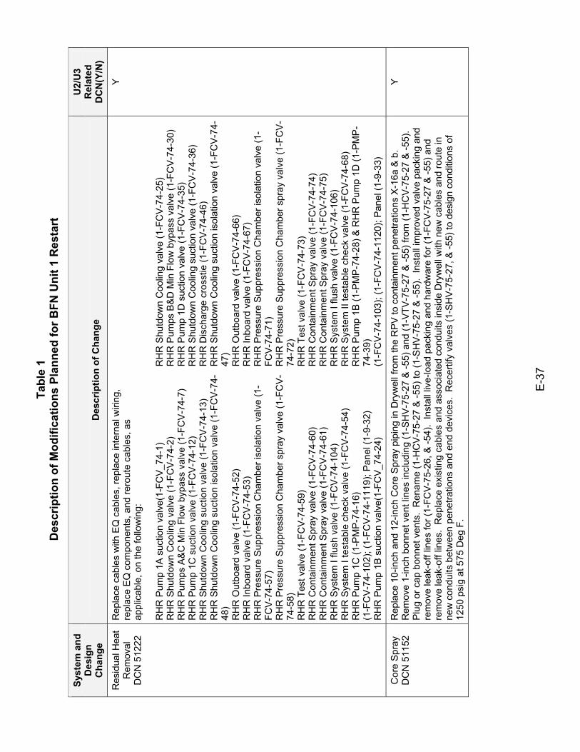
Tabl
e 1
Des
crip
tion
of M
odifi
catio
ns P
lann
ed fo
r BFN
Uni
t 1 R
esta
rt
E-3
7
Syst
em a
nd
Des
ign
Cha
nge
Des
crip
tion
of C
hang
e
U2/
U3
Rel
ated
D
CN
(Y/N
)
Res
idua
l Hea
t R
emov
al
DC
N 5
1222
Rep
lace
cab
les
with
EQ
cab
les,
repl
ace
inte
rnal
wiri
ng,
repl
ace
EQ
com
pone
nts,
and
rero
ute
cabl
es, a
s ap
plic
able
, on
the
follo
win
g:
RH
R P
ump
1A s
uctio
n va
lve(
1-FC
V_7
4-1)
R
HR
Shu
tdow
n C
oolin
g va
lve
(1-F
CV
-74-
2)
RH
R P
umps
A&
C M
in F
low
byp
ass
valv
e (1
-FC
V-7
4-7)
R
HR
Pum
p 1C
suc
tion
valv
e (1
-FC
V-7
4-12
) R
HR
Shu
tdow
n C
oolin
g su
ctio
n va
lve
(1-F
CV
-74-
13)
RH
R S
hutd
own
Coo
ling
suct
ion
isol
atio
n va
lve
(1-F
CV
-74-
48)
RH
R O
utbo
ard
valv
e (1
-FC
V-7
4-52
) R
HR
Inbo
ard
valv
e (1
-FC
V-74
-53)
R
HR
Pre
ssur
e S
uppr
essi
on C
ham
ber i
sola
tion
valv
e (1
-FC
V-7
4-57
) R
HR
Pre
ssur
e S
uppr
essi
on C
ham
ber s
pray
val
ve (1
-FC
V-
74-5
8)
RH
R T
est v
alve
(1-F
CV
-74-
59)
RH
R C
onta
inm
ent S
pray
val
ve (1
-FC
V-7
4-60
) R
HR
Con
tain
men
t Spr
ay v
alve
(1-F
CV
-74-
61)
RH
R S
yste
m I
flush
val
ve (1
-FC
V-7
4-10
4)
RH
R S
yste
m I
test
able
che
ck v
alve
(1-F
CV
-74-
54)
RH
R P
ump
1C (1
-PM
P-7
4-16
) (1
-FC
V-7
4-10
2); (
1-FC
V-74
-111
9); P
anel
(1-9
-32)
R
HR
Pum
p 1B
suc
tion
valv
e(1-
FCV
_74-
24)
RH
R S
hutd
own
Coo
ling
valv
e (1
-FC
V-7
4-25
) R
HR
Pum
ps B
&D
Min
Flo
w b
ypas
s va
lve
(1-F
CV
-74-
30)
RH
R P
ump
1D s
uctio
n va
lve
(1-F
CV
-74-
35)
RH
R S
hutd
own
Coo
ling
suct
ion
valv
e (1
-FC
V-7
4-36
) R
HR
Dis
char
ge c
ross
tie (1
-FC
V-74
-46)
R
HR
Shu
tdow
n C
oolin
g su
ctio
n is
olat
ion
valv
e (1
-FC
V-7
4-47
) R
HR
Out
boar
d va
lve
(1-F
CV
-74-
66)
RH
R In
boar
d va
lve
(1-F
CV-
74-6
7)
RH
R P
ress
ure
Sup
pres
sion
Cha
mbe
r iso
latio
n va
lve
(1-
FCV
-74-
71)
RH
R P
ress
ure
Sup
pres
sion
Cha
mbe
r spr
ay v
alve
(1-F
CV
-74
-72)
R
HR
Tes
t val
ve (1
-FC
V-7
4-73
) R
HR
Con
tain
men
t Spr
ay v
alve
(1-F
CV
-74-
74)
RH
R C
onta
inm
ent S
pray
val
ve (1
-FC
V-7
4-75
) R
HR
Sys
tem
I flu
sh v
alve
(1-F
CV
-74-
106)
R
HR
Sys
tem
II te
stab
le c
heck
val
ve (1
-FC
V-7
4-68
) R
HR
Pum
p 1B
(1-P
MP
-74-
28) &
RH
R P
ump
1D (1
-PM
P-
74-3
9)
(1-F
CV
-74-
103)
; (1-
FCV-
74-1
120)
; Pan
el (1
-9-3
3)
Y
Cor
e S
pray
D
CN
511
52
Rep
lace
10-
inch
and
12-
inch
Cor
e S
pray
pip
ing
in D
ryw
ell f
rom
the
RP
V to
con
tain
men
t pen
etra
tions
X-1
6a &
b.
Rem
ove
1-in
ch b
onne
t ven
t lin
es in
clud
ing
(1-S
HV
-75-
27 &
-55)
and
(1-V
TV-7
5-27
& -5
5) fr
om (1
-HC
V-75
-27
& -5
5).
Plu
g or
cap
bon
net v
ents
. R
enam
e (1
-HC
V-7
5-27
& -5
5) to
(1-S
HV-
75-2
7 &
-55)
. In
stal
l im
prov
ed v
alve
pac
king
and
re
mov
e le
ak-o
ff lin
es fo
r (1-
FCV-
75-2
6, &
-54)
. In
stal
l liv
e-lo
ad p
acki
ng a
nd h
ardw
are
for (
1-FC
V-7
5-27
& -5
5) a
nd
rem
ove
leak
-off
lines
. R
epla
ce e
xist
ing
cabl
es a
nd a
ssoc
iate
d co
ndui
ts in
side
Dry
wel
l with
new
cab
les
and
rout
e in
ne
w c
ondu
its b
etw
een
pene
tratio
ns a
nd e
nd d
evic
es.
Rec
ertif
y va
lves
(1-S
HV
-75-
27, &
-55)
to d
esig
n co
nditi
ons
of
1250
psi
g at
575
Deg
F.
Y
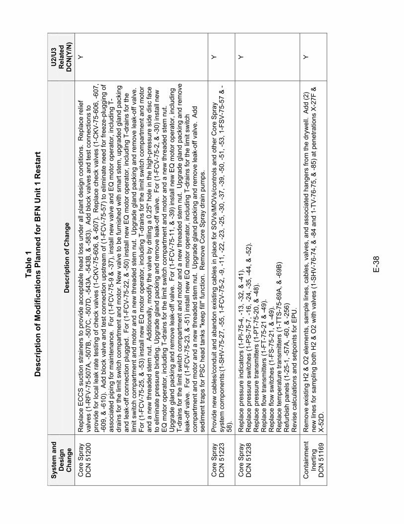
Tabl
e 1
Des
crip
tion
of M
odifi
catio
ns P
lann
ed fo
r BFN
Uni
t 1 R
esta
rt
E-3
8
Syst
em a
nd
Des
ign
Cha
nge
Des
crip
tion
of C
hang
e
U2/
U3
Rel
ated
D
CN
(Y/N
)
Cor
e S
pray
D
CN
512
00
Rep
lace
EC
CS
suc
tion
stra
iner
s to
pro
vide
acc
epta
ble
head
loss
und
er a
ll pl
ant d
esig
n co
nditi
ons.
Rep
lace
relie
f va
lves
(1-R
FV-7
5-50
7A, -
507B
, -50
7C, -
507D
, -54
3A, -
543B
, & -5
83).
Add
blo
ck v
alve
s an
d te
st c
onne
ctio
ns to
pr
ovid
e fo
r loc
al le
ak ra
te te
stin
g of
che
ck v
alve
s (1
-CK
V-7
5-60
6, &
-607
). R
epla
ce c
heck
val
ves
(1-C
KV
-75-
606,
-607
, -6
09, &
-610
). A
dd b
lock
val
ve a
nd te
st c
onne
ctio
n up
stre
am o
f (1-
FCV-
75-5
7) to
elim
inat
e ne
ed fo
r fre
eze-
plug
ging
of
asso
ciat
ed p
ipin
g fo
r mai
nten
ance
. Fo
r (1-
FCV
-75-
9 &
-37)
, ins
tall
new
val
ve a
nd E
Q m
otor
ope
rato
r, in
clud
ing
T-dr
ains
for t
he li
mit
switc
h co
mpa
rtmen
t and
mot
or. N
ew v
alve
to b
e fu
rnis
hed
with
sm
art s
tem
, upg
rade
d gl
and
pack
ing
and
leak
-off
conn
ectio
n pl
ugge
d. F
or (1
-FC
V-7
5-22
, & -5
0) in
stal
l new
EQ
mot
or o
pera
tor,
incl
udin
g T-
drai
ns fo
r the
lim
it sw
itch
com
partm
ent a
nd m
otor
and
a n
ew th
read
ed s
tem
nut
. U
pgra
de g
land
pac
king
and
rem
ove
leak
-off
valv
e.
For (
1-FC
V-7
5-25
, & -5
3) in
stal
l new
EQ
mot
or o
pera
tor,
incl
udin
g T-
drai
ns fo
r the
lim
it sw
itch
com
partm
ent a
nd m
otor
an
d a
new
thre
aded
ste
m n
ut.
Add
ition
ally
, mod
ify th
e va
lve
by d
rillin
g a
0.25
" hol
e in
the
high
-pre
ssur
e si
de d
isc
face
to
elim
inat
e pr
essu
re b
indi
ng. U
pgra
de g
land
pac
king
and
rem
ove
leak
-off
valv
e. F
or (1
-FC
V-7
5-2,
& -3
0) in
stal
l new
E
Q m
otor
ope
rato
r, in
clud
ing
T-dr
ains
for t
he li
mit
switc
h co
mpa
rtmen
t and
mot
or a
nd a
new
thre
aded
ste
m n
ut.
Upg
rade
gla
nd p
acki
ng a
nd re
mov
e le
ak-o
ff va
lve.
For
(1-F
CV
-75-
11, &
-39)
inst
all n
ew E
Q m
otor
ope
rato
r, in
clud
ing
T-dr
ains
for t
he li
mit
switc
h co
mpa
rtmen
t and
mot
or a
nd a
new
thre
aded
ste
m n
ut.
Upg
rade
gla
nd p
acki
ng a
nd re
mov
e le
ak-o
ff va
lve.
For
(1-F
CV-
75-2
3, &
-51)
inst
all n
ew E
Q m
otor
ope
rato
r, in
clud
ing
T-dr
ains
for t
he li
mit
switc
h co
mpa
rtmen
t and
mot
or a
nd a
new
thre
aded
ste
m n
ut.
Upg
rade
gla
nd p
acki
ng a
nd re
mov
e le
ak-o
ff va
lve.
Add
se
dim
ent t
raps
for P
SC
hea
d ta
nks
"kee
p fil
l" fu
nctio
n. R
emov
e C
ore
Spr
ay d
rain
pum
ps.
Y
Cor
e S
pray
D
CN
512
23
Pro
vide
new
cab
les/
cond
uit a
nd a
band
on e
xist
ing
cabl
es in
pla
ce fo
r SO
Vs/
MO
Vs/c
ontro
ls a
nd o
ther
Cor
e S
pray
sy
stem
com
pone
nts:
(1-S
HV
-75-
27, -
55, 1
-FC
V-7
5-2,
-9, -
11, -
22, -
23, -
25, -
30, -
37, -
39, -
50, -
51, -
53, 1
-FS
V-75
-57
& -
58).
Y
Cor
e S
pray
D
CN
512
38
Rep
lace
pre
ssur
e in
dica
tors
(1-P
I-75-
4, -1
3, -3
2, &
-41)
. R
epla
ce p
ress
ure
switc
hes
(1-P
S-7
5-7,
-16,
-24,
-35,
-44,
& -5
2).
Rep
lace
pre
ssur
e tra
nsm
itter
s (1
-PT-
75-2
0, &
-48)
.
Rep
lace
flow
tran
smitt
ers
(1-F
T-75
-21
& -4
9).
Rep
lace
flow
sw
itche
s (1
-FS
-75-
21, &
-49)
. R
epla
ce te
mpe
ratu
re tr
ansm
itter
s (1
-TTS
-75-
69A
, & -6
9B)
Ref
urbi
sh p
anel
s (1
-25-
1, -5
7A, -
60, &
-256
) R
evis
e ca
lcul
atio
ns a
nd s
etpo
ints
for E
PU.
Y
Con
tain
men
t In
ertin
g D
CN
511
69
Rem
ove
exis
ting
H2
& O
2 el
emen
ts, s
ampl
e lin
es, c
able
s, v
alve
s, a
nd a
ssoc
iate
d ha
nger
s fro
m th
e dr
ywel
l. A
dd (2
) ne
w li
nes
for s
ampl
ing
both
H2
& O
2 w
ith v
alve
s (1
-SH
V-7
6-74
, & -8
4 an
d 1-
TV-7
6-75
, & -8
5) a
t pen
etra
tions
X-2
7F &
X
-52D
.
Y
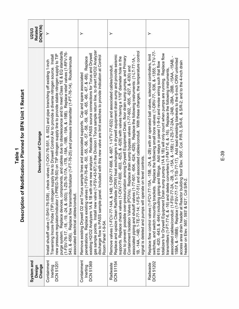
Tabl
e 1
Des
crip
tion
of M
odifi
catio
ns P
lann
ed fo
r BFN
Uni
t 1 R
esta
rt
E-3
9
Syst
em a
nd
Des
ign
Cha
nge
Des
crip
tion
of C
hang
e
U2/
U3
Rel
ated
D
CN
(Y/N
)
Con
tain
men
t In
ertin
g D
CN
512
01
Inst
all s
huto
ff va
lve
(1-S
HV
-76-
538)
, ch
eck
valv
es (1
-CK
V-76
-551
, & -5
52) a
nd p
ipe
bran
chin
g of
f exi
stin
g 1-
inch
Tr
aver
sing
Inco
re P
robe
(TIP
) nitr
ogen
sup
ply
line
to D
ryw
ell C
ontro
l Air
to p
rovi
de a
div
erse
nitr
ogen
sou
rce.
Ins
tall
new
pre
ssur
e re
gula
tor/i
ndic
ator
(1-P
REG
-76-
50) o
n TI
P n
itrog
en s
uppl
y lin
e to
pro
vide
sta
ble
nitro
gen
supp
ly to
TIP
pu
rge
syst
em.
Rep
lace
dev
ices
, com
pone
nts,
and
cab
les
due
to o
bsol
esce
nce
and
to m
eet C
lass
1E
& E
Q s
tand
ards
(1
-FS
V-7
6-17
, -18
, -19
, -24
, & -5
03);
1-ZS
-76-
17A
, -17
B, -
18A
, -18
B, -1
9A, &
-19B
). R
epla
ce re
lief v
alve
s (1
-RFV
-76-
543,
& -6
56).
Rep
lace
flow
tran
smitt
er/to
taliz
er (1
-FT-
76-2
5) a
nd p
ress
ure
trans
mitt
er (1
-PT-
76-1
4).
Rou
te/re
rout
e as
soci
ated
ele
ctric
al c
able
s/co
ndui
t.
Y
Con
tain
men
t In
ertin
g D
CN
513
69
Rem
ove
exis
ting
Dry
wel
l O2
and
Toru
s sa
mpl
e lin
es a
nd a
ssoc
iate
d su
ppor
ts.
Cap
and
spa
re a
ssoc
iate
d pe
netra
tions
. R
epla
ce e
xist
ing
valv
es (1
-FS
V-7
6-49
, -50
, -55
, -56
, -57
, -58
, -59
, -60
, -65
, -66
, -67
, & -6
8).
Rep
lace
ex
istin
g H
2/O
2 A
naly
zers
1A
& 1
B w
ith o
ne n
ew a
naly
zer.
Rel
ocat
e P
AS
S s
ourc
e co
nnec
tions
for T
orus
and
Dry
wel
l ga
s sa
mpl
e po
ints
. In
stal
l new
val
ve (1
-FS
V-4
3-87
) in
the
Div
isio
n I T
orus
sam
ple
retu
rn li
ne, t
o di
vert
H2/
O2
Ana
lyze
r di
scha
rge
flow
to P
AS
S s
ampl
e pa
nel.
Incl
uded
with
this
new
val
ve a
re li
mit
switc
hes
to p
rovi
de in
dica
tion
at C
ontro
l R
oom
Pan
el 1
-9-5
4.
Y
Rad
was
te
DC
N 5
1154
R
emov
e va
lves
(1-F
CV
-77-
14A
, & 1
4B; 1
-DR
V-7
7-66
6, &
-667
; 1-V
TV-7
7-63
2) a
nd a
ssoc
iate
d ca
bles
/con
duit.
R
epla
ce a
nd u
psiz
e C
lean
Rad
Was
te (C
RW
) hea
t exc
hang
ers
in d
ryw
ell e
quip
men
t dra
in s
ump
and
prov
ide
seis
mic
su
ppor
ts. R
epla
ce c
heck
val
ves
(1-C
KV
-77-
600,
-603
, -62
5, &
-628
) with
val
ves
havi
ng a
1/1
6" d
iam
eter
hol
e in
the
disc
to p
reve
nt p
ossi
ble
over
-pre
ssur
izat
ion
amon
g D
ryw
ell E
quip
men
t Dra
in, f
loor
dra
in s
ump
pum
ps, a
nd P
rimar
y C
onta
inm
ent I
sola
tion
Val
ves
(PC
IVs)
. R
epla
ce d
rain
sum
p by
pass
val
ves
(1-7
7-60
2, -6
05, -
627,
& -6
30) a
nd
asso
ciat
ed p
ipin
g an
d sh
utof
f val
ves
(1-7
7-60
1, -6
04, -
624,
-629
). R
epla
ce th
e fo
llow
ing
inst
rum
ents
: (1-
LT-7
7-1A
, -1B
, -14
A, -
14B;
1-T
E-7
7-14
; 1-F
S-7
7-51
) and
ass
ocia
ted
cabl
es/c
ondu
it. W
ith th
ese
chan
ges,
the
tem
pera
ture
con
trol
sign
al is
del
eted
and
pum
ps w
ill o
pera
te o
n le
vel c
ontro
ls.
Y
Rad
was
te
DC
N 5
1202
R
epla
ce fl
ow c
ontro
l val
ves
(1-F
CV
-77-
15A
, -15
B, -
2A, &
-2B
) with
air
oper
ated
bal
l val
ves,
sol
enoi
d co
ntro
llers
, lim
it sw
itche
s, a
nd s
witc
h m
ount
ing
brac
kets
. R
epla
ce th
e fo
llow
ing
smal
l bor
e va
lves
: (1-
DR
V-77
-, 63
6, &
-135
5; 1
-TV
-77-
619,
-620
, -64
3, &
-644
) inc
ludi
ng p
ipin
g an
d fit
tings
. A
dd re
lays
in p
anel
(1-9
-4) a
nd re
vise
wiri
ng s
uch
that
flow
to
taliz
ers
for D
ryw
ell E
quip
men
t Dra
in s
ump
pum
ps (1
A &
1B
) will
onl
y co
unt w
hen
pum
ps a
re ru
nnin
g. R
epla
ce fl
ow
trans
mitt
ers
(1-F
T-77
-6, &
-16)
and
del
ete
conv
erte
rs (1
-FM
-77-
6, &
-16)
. R
epla
ce th
e fo
llow
ing
inst
rum
ents
, as
soci
ated
cab
les/
cond
uit:
(1-F
SV
-77-
2A, -
2B, -
3, -1
5A, &
-15B
); (1
-ZS
-77-
2AA
, -2A
B, -
2BA
, -2B
B, -
15A
A, -
15A
B, -
15B
A, &
-15B
B).
Rep
lace
(1-F
SV
-77-
17 &
1-T
IS-7
7-17
). A
dd le
ad s
hiel
ding
bla
nket
s to
the
6-in
ch C
RW
unl
imite
d ac
cess
are
a dr
ain
head
er a
t Rea
ctor
bui
ldin
g flo
or E
lev.
565
', C
ol. P
/R-3
, S/R
-6,
& S
/R-2
; and
to th
e 4-
inch
dra
in
head
er o
n E
lev.
565
', 59
3' &
621
', C
ol S
/R-2
.
Y
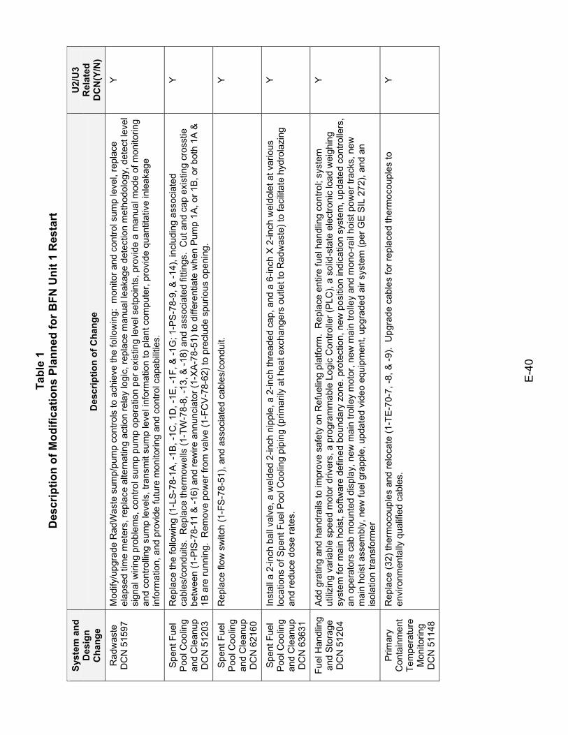
Tabl
e 1
Des
crip
tion
of M
odifi
catio
ns P
lann
ed fo
r BFN
Uni
t 1 R
esta
rt
E-4
0
Syst
em a
nd
Des
ign
Cha
nge
Des
crip
tion
of C
hang
e
U2/
U3
Rel
ated
D
CN
(Y/N
)
Rad
was
te
DC
N 5
1597
M
odify
/upg
rade
Rad
Was
te s
ump/
pum
p co
ntro
ls to
ach
ieve
the
follo
win
g: m
onito
r and
con
trol s
ump
leve
l, re
plac
e el
apse
d tim
e m
eter
s, re
plac
e al
tern
atin
g ac
tion
rela
y lo
gic,
repl
ace
man
ual l
eaka
ge d
etec
tion
met
hodo
logy
, det
ect l
evel
si
gnal
wiri
ng p
robl
ems,
con
trol s
ump
pum
p op
erat
ion
per e
xist
ing
leve
l set
poin
ts, p
rovi
de a
man
ual m
ode
of m
onito
ring
and
cont
rollin
g su
mp
leve
ls, t
rans
mit
sum
p le
vel i
nfor
mat
ion
to p
lant
com
pute
r, pr
ovid
e qu
antit
ativ
e in
leak
age
info
rmat
ion,
and
pro
vide
futu
re m
onito
ring
and
cont
rol c
apab
ilitie
s.
Y
Spe
nt F
uel
Poo
l Coo
ling
and
Cle
anup
D
CN
512
03
Rep
lace
the
follo
win
g (1
-LS
-78-
1A, -
1B, -
1C, 1
D, -
1E, -
1F, &
-1G
; 1-P
S-7
8-9,
& -1
4), i
nclu
ding
ass
ocia
ted
cabl
es/c
ondu
its.
Rep
lace
ther
mow
ells
(1-T
W-7
8-8,
-13,
& -1
8) a
nd a
ssoc
iate
d fit
tings
. C
ut a
nd c
ap e
xist
ing
cros
stie
be
twee
n (1
-PIS
-78-
11 &
-16)
and
rew
ire a
nnun
ciat
or (1
-XA
-78-
51) t
o di
ffere
ntia
te w
hen
Pum
p 1A
, or 1
B, o
r bot
h 1A
&
1B a
re ru
nnin
g. R
emov
e po
wer
from
val
ve (1
-FC
V-7
8-62
) to
prec
lude
spu
rious
ope
ning
.
Y
Spe
nt F
uel
Poo
l Coo
ling
and
Cle
anup
D
CN
621
60
Rep
lace
flow
sw
itch
(1-F
S-78
-51)
, and
ass
ocia
ted
cabl
es/c
ondu
it.
Y
Spe
nt F
uel
Poo
l Coo
ling
and
Cle
anup
D
CN
636
31
Inst
all a
2-in
ch b
all v
alve
, a w
elde
d 2-
inch
nip
ple,
a 2
-inch
thre
aded
cap
, and
a 6
-inch
X 2
-inch
wel
dole
t at v
ario
us
loca
tions
of S
pent
Fue
l Poo
l Coo
ling
pipi
ng (p
rimar
ily a
t hea
t exc
hang
ers
outle
t to
Rad
was
te) t
o fa
cilit
ate
hydr
olaz
ing
and
redu
ce d
ose
rate
s.
Y
Fuel
Han
dlin
g an
d S
tora
ge
DC
N 5
1204
Add
gra
ting
and
hand
rails
to im
prov
e sa
fety
on
Ref
uelin
g pl
atfo
rm.
Rep
lace
ent
ire fu
el h
andl
ing
cont
rol;
syst
em
utili
zing
var
iabl
e sp
eed
mot
or d
river
s, a
pro
gram
mab
le L
ogic
Con
trolle
r (P
LC),
a so
lid-s
tate
ele
ctro
nic
load
wei
ghin
g sy
stem
for m
ain
hois
t, so
ftwar
e de
fined
bou
ndar
y zo
ne. p
rote
ctio
n, n
ew p
ositi
on in
dica
tion
syst
em, u
pdat
ed c
ontro
llers
, an
ope
rato
rs c
ab m
ount
ed d
ispl
ay, n
ew m
ain
trolle
y m
otor
, new
mai
n tro
lley
and
mon
o-ra
il ho
ist p
ower
trac
ks, n
ew
mai
n ho
ist a
ssem
bly,
new
fuel
gra
pple
, upd
ated
vid
eo e
quip
men
t, up
grad
ed a
ir sy
stem
(per
GE
SIL
272
), an
d an
is
olat
ion
trans
form
er
Y
Prim
ary
Con
tain
men
t Te
mpe
ratu
re
Mon
itorin
g D
CN
511
48
Rep
lace
(32)
ther
moc
oupl
es a
nd re
loca
te (1
-TE
-70-
7, -8
, & -9
). U
pgra
de c
able
s fo
r rep
lace
d th
erm
ocou
ples
to
envi
ronm
enta
lly q
ualif
ied
cabl
es.
Y
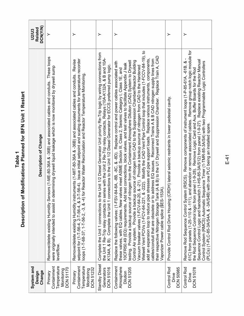
Tabl
e 1
Des
crip
tion
of M
odifi
catio
ns P
lann
ed fo
r BFN
Uni
t 1 R
esta
rt
E-4
1
Syst
em a
nd
Des
ign
Cha
nge
Des
crip
tion
of C
hang
e
U2/
U3
Rel
ated
D
CN
(Y/N
)
Prim
ary
Con
tain
men
t Te
mpe
ratu
re
Mon
itorin
g D
CN
511
70
Rem
ove/
dele
te e
xist
ing
Hum
idity
Sen
sors
(1-M
E-8
0-36
A &
-36B
) and
ass
ocia
ted
cabl
es a
nd c
ondu
its.
Thes
e lo
ops
wer
e or
igin
ally
inte
nded
to a
ssis
t in
dete
rmin
ing
dryw
ell l
iqui
d le
akag
e w
hich
is n
ow m
onito
red
by d
ryw
ell s
ump
leve
l/flo
w.
Y
Prim
ary
Con
tain
men
t Te
mpe
ratu
re
Mon
itorin
g D
CN
512
32
Rem
ove/
dele
te e
xist
ing
Hum
idity
inst
rum
ents
(1-M
IT-8
0-36
A &
-36B
) and
ass
ocia
ted
cabl
es a
nd c
ondu
its.
Rev
ise
setp
oint
for (
1-T-
56-4
, 2-T
-56-
4, &
3-T
-56-
4).
Issu
e in
itial
set
poin
t and
sca
ling
docu
men
ts fo
r tem
pera
ture
reco
rder
lo
ops
(1-T
-68-
37; 1
-T-5
6-2,
-3, &
-4) f
or R
eact
or W
ater
Rec
ircul
atio
n an
d R
eact
or T
empe
ratu
re M
onito
ring.
Y
Sta
ndby
Die
sel
Gen
erat
ors
DC
N 5
1016
Com
plet
e th
e U
nit 1
con
nect
ions
to th
e U
nit 1
/2 D
iese
l Gen
erat
or U
nit p
riorit
y R
e-Tr
ip lo
gic
by w
iring
con
nect
ions
from
th
e U
nit 1
Re-
Trip
rela
y co
ntac
ts in
ser
ies
with
the
Uni
t 2 R
e-Tr
ip re
lay
cont
acts
, Rel
ays
(10A
-K13
2A, &
B a
nd 1
0A-
K13
4A, &
B).
Com
plet
e th
e U
nit 1
con
nect
ions
to th
e U
nit 1
/2 D
iese
l Gen
erat
or fo
r EC
CS
pre
ferr
ed p
ump
logi
c.
Y
Con
tain
men
t A
tmos
pher
e D
ilutio
n D
CN
512
05
Rep
lace
the
follo
win
g va
lves
: (1-
FSV
-84-
8A, -
8B, -
8C, &
-8D
). R
epla
ce c
ontro
l and
pow
er c
able
s as
soci
ated
with
th
ese
valv
es, w
ith E
Q c
able
s. N
ew v
alve
s m
eet A
SM
E S
ectio
n III
, Cla
ss 2
, Sei
smic
Cat
egor
y I,
Cla
ss 1
E, a
nd
10C
FR50
.49
(EQ
) req
uire
men
ts. A
dd te
st c
onne
ctio
ns, b
lock
val
ves,
and
test
val
ves
to fa
cilit
ate
App
endi
x J
leak
te
stin
g. P
rovi
de a
bac
kup
sour
ce o
f nitr
ogen
from
the
Con
tain
men
t Atm
osph
ere
Dilu
tion
(CA
D) S
yste
m to
Dry
wel
l C
ontro
l Air
syst
em.
Pro
vide
a b
acku
p so
urce
of n
itrog
en fr
om C
AD
to th
e S
uppr
essi
on C
ham
ber/R
eact
or B
uild
ing
Vac
uum
bre
aker
val
ves
(1-F
CV
-64-
20, &
-21)
. P
rovi
de a
bac
kup
sour
ce o
f nitr
ogen
from
CA
D to
the
Har
dene
d W
etw
ell V
ent P
CIV
s (1
-FC
V-6
4-22
1, &
-222
). M
odify
the
CA
D V
ent P
ipe
Con
trol l
oop
that
incl
udes
(1-F
CC
V-8
4-19
), to
ad
d an
exp
ansi
on lo
op to
redu
ce p
ipe
stre
sses
and
pip
e su
ppor
t loa
ds.
Rep
lace
var
ious
inst
rum
ents
, com
pone
nts,
ca
bles
/con
duit
that
are
obs
olet
e or
to a
ddre
ss E
Q is
sues
. R
econ
nect
Tra
ins
A &
B C
AD
nitr
ogen
sup
ply
lines
from
th
eir r
espe
ctiv
e N
itrog
en S
tora
ge T
ank
(A &
B) t
o th
e U
1 D
ryw
ell a
nd S
uppr
essi
on C
ham
ber.
Rep
lace
Tra
in A
, CA
D
Vap
oriz
er P
ower
cab
le s
plic
e ($
ES-
153A
).
Y
Con
trol R
od
Driv
e D
CN
509
85
Pro
vide
Con
trol R
od D
rive
Hou
sing
(CR
DH
) lat
eral
sei
smic
rest
rain
ts in
low
er p
edes
tal c
avity
. Y
Con
trol R
od
Driv
e D
CN
510
78
Rem
ove
Rod
Seq
uenc
e C
ontro
l Sys
tem
(RSC
S).
Rem
ove
com
pone
nts
of in
stru
men
t loo
ps (1
-P-8
5-61
A, -
61B
, & -
61C
) fro
m p
anel
s (1
-25-
110
& -1
11),
and
aban
don
or re
mov
e as
soci
ated
cab
les.
Rem
ove
grou
p no
tch
logi
c m
odul
e fo
r th
e R
od S
eque
nce
Con
trol l
ogic
from
pan
el (1
-9-2
8).
Rem
ove
Logi
c C
ard
and
Aux
. Buf
fer B
oard
s fo
r the
Rod
S
eque
nce
Con
trol L
ogic
and
han
dsw
itch
(1-H
S-8
5-3A
/S12
) fro
m p
anel
(1-9
-27)
. R
epla
ce e
xist
ing
Rea
ctor
Man
ual
Con
trol S
yste
m (R
MC
S) A
utom
atic
Seq
uenc
e Ti
mer
(1-T
MR
-85-
3A/S
4) w
ith tw
o P
rogr
amm
able
Log
ic C
ontro
llers
(P
LCs)
(1-P
LC-8
5-3A
/S4A
, & -3
A/S
4B) w
ith o
ne P
LC b
eing
an
inst
alle
d sp
are.
Y
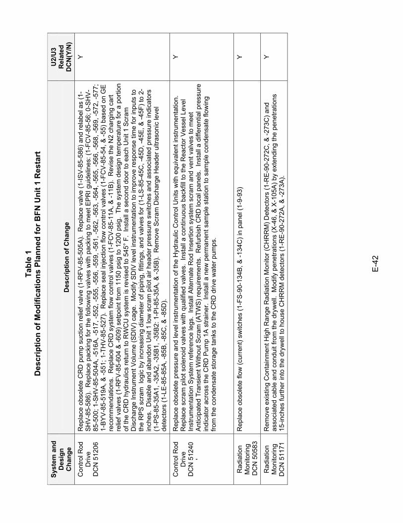
Tabl
e 1
Des
crip
tion
of M
odifi
catio
ns P
lann
ed fo
r BFN
Uni
t 1 R
esta
rt
E-4
2
Syst
em a
nd
Des
ign
Cha
nge
Des
crip
tion
of C
hang
e
U2/
U3
Rel
ated
D
CN
(Y/N
)
Con
trol R
od
Driv
e D
CN
512
06
Rep
lace
obs
olet
e C
RD
pum
p su
ctio
n re
lief v
alve
(1-R
FV-8
5-50
5A).
Rep
lace
val
ve (1
-ISV
-85-
586)
and
rela
bel a
s (1
-S
HV
-85-
586)
. R
epla
ce p
acki
ng fo
r the
follo
win
g va
lves
with
pac
king
to m
eet E
PR
I gui
delin
es: (
1-FC
V-8
5-56
; 0-S
HV
-85
-500
; 1-S
HV
-85-
504A
, -51
6A, -
517,
-552
, -55
5, -5
56, -
559,
-561
, -56
2, -5
63, -
564,
-565
, -56
6, -5
68, -
569,
-572
, -57
7;
1-B
YV
-85-
519A
, & -5
51; 1
-TH
V-85
-527
). R
epla
ce s
eal i
njec
tion
flow
con
trol v
alve
s (1
-FC
V-85
-54,
& -5
5) b
ased
on
GE
re
com
men
datio
ns.
Rep
lace
CR
D s
yste
m fl
ow c
ontro
l val
ves
(1-F
CV
-85-
11A
, & -1
1B).
Rev
ise
the
N2
char
ging
car
t re
lief v
alve
s (1
-RFV
-85-
604
& -6
09) s
etpo
int f
rom
115
0 ps
ig to
120
0 ps
ig.
The
syst
em d
esig
n te
mpe
ratu
re fo
r a p
ortio
n of
the
CR
D h
ydra
ulic
s re
turn
to R
WC
U s
yste
m is
revi
sed
to 5
45°
F. I
nsta
ll a
seco
nd d
oor t
o ea
ch U
nit 1
Scr
am
Dis
char
ge In
stru
men
t Vol
ume
(SD
IV) c
age.
Mod
ify S
DIV
leve
l ins
trum
enta
tion
to im
prov
e re
spon
se ti
me
for i
nput
s to
th
e R
PS
scr
am l
ogic
by
incr
easi
ng d
iam
eter
of p
ipin
g, fi
tting
s, a
nd v
alve
s fo
r (1-
LS-8
5-45
C, -
45D
, -45
E, &
-45F
) to
2-in
ches
. D
isab
le a
nd a
band
on U
nit 1
low
scr
am p
ilot a
ir he
ader
pre
ssur
e sw
itche
s an
d as
soci
ated
pre
ssur
e in
dica
tors
(1
-PS
-85-
35A1
, -35
A2,
-35B
1, -3
5B2:
1-P
I-85-
35A
, & -3
5B).
Rem
ove
Scr
am D
isch
arge
Hea
der u
ltras
onic
leve
l de
tect
ors
(1-L
E-8
5-85
A, -
85B
, -85
C, &
-85D
).
Y
Con
trol R
od
Driv
e D
CN
512
40
'
Rep
lace
obs
olet
e pr
essu
re a
nd le
vel i
nstru
men
tatio
n of
the
Hyd
raul
ic C
ontro
l Uni
ts w
ith e
quiv
alen
t ins
trum
enta
tion.
R
epla
ce s
cram
pilo
t sol
enoi
d va
lves
with
qua
lifie
d va
lves
. In
stal
l a c
ontin
uous
bac
kfill
to th
e R
eact
or V
esse
l Lev
el
Inst
rum
enta
tion
Sys
tem
refe
renc
e le
gs.
Inst
all A
ltern
ate
Rod
Inse
rtion
sys
tem
scr
am a
nd v
ent v
alve
s to
mee
t A
ntic
ipat
ed T
rans
ient
With
out S
cram
(ATW
S) r
equi
rem
ents
. R
efur
bish
CR
D lo
cal p
anel
s. I
nsta
ll a
diffe
rent
ial p
ress
ure
indi
cato
r acr
oss
the
CR
D P
ump
1A s
train
er.
Inst
all a
new
per
man
ent s
ampl
e st
atio
n to
sam
ple
cond
ensa
te fl
owin
g fro
m th
e co
nden
sate
sto
rage
tank
s to
the
CR
D d
rive
wat
er p
umps
.
Y
Rad
iatio
n M
onito
ring
DC
N 5
0583
Rep
lace
obs
olet
e flo
w (c
urre
nt) s
witc
hes
(1-F
S-9
0-13
4B, &
-134
C) i
n pa
nel (
1-9-
93)
Y
Rad
iatio
n M
onito
ring
DC
N 5
1171
Rem
ove
exis
ting
Con
tain
men
t Hig
h R
ange
Rad
iatio
n M
onito
r (C
HR
RM
) Det
ecto
rs (1
-RE-
90-2
72C
, & -2
73C
) and
as
soci
ated
cab
le a
nd c
ondu
it fro
m th
e dr
ywel
l. M
odify
pen
etra
tions
(X-4
6, &
X-1
05A
) by
exte
ndin
g th
e pe
netra
tions
15
-inch
es fu
rther
into
the
dryw
ell t
o ho
use
CH
RR
M d
etec
tors
(1-R
E-9
0-27
2A, &
-273
A).
Y
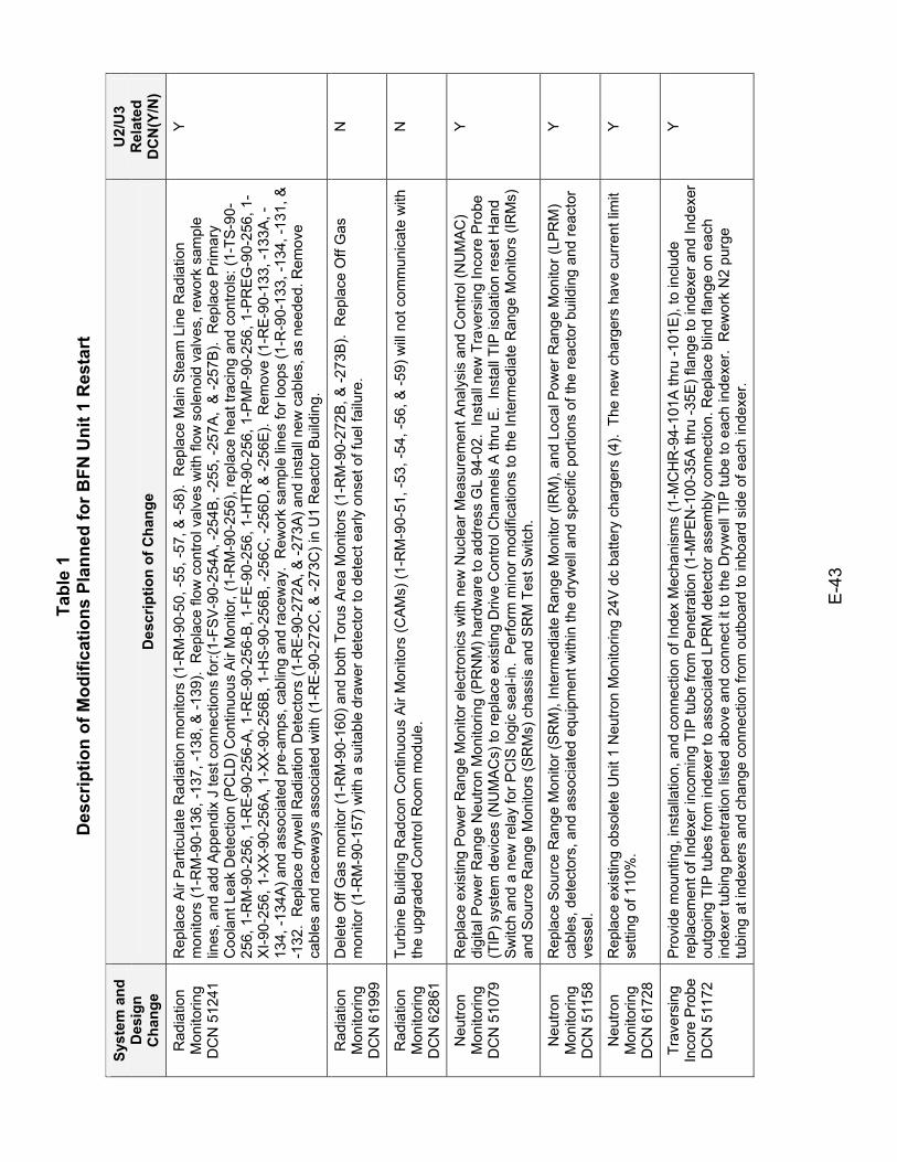
Tabl
e 1
Des
crip
tion
of M
odifi
catio
ns P
lann
ed fo
r BFN
Uni
t 1 R
esta
rt
E-4
3
Syst
em a
nd
Des
ign
Cha
nge
Des
crip
tion
of C
hang
e
U2/
U3
Rel
ated
D
CN
(Y/N
)
Rad
iatio
n M
onito
ring
DC
N 5
1241
Rep
lace
Air
Par
ticul
ate
Rad
iatio
n m
onito
rs (1
-RM
-90-
50, -
55, -
57, &
-58)
. R
epla
ce M
ain
Ste
am L
ine
Rad
iatio
n m
onito
rs (1
-RM
-90-
136,
-137
, -13
8, &
-139
). R
epla
ce fl
ow c
ontro
l val
ves
with
flow
sol
enoi
d va
lves
, rew
ork
sam
ple
lines
, and
add
App
endi
x J
test
con
nect
ions
for:(
1-FS
V-90
-254
A, -
254B
, -25
5, -2
57A
, &
-257
B).
Rep
lace
Prim
ary
Coo
lant
Lea
k D
etec
tion
(PC
LD) C
ontin
uous
Air
Mon
itor,
(1-R
M-9
0-25
6), r
epla
ce h
eat t
raci
ng a
nd c
ontro
ls: (
1-TS
-90-
256,
1-R
M-9
0-25
6, 1
-RE-
90-2
56-A
, 1-R
E-9
0-25
6-B
, 1-F
E-9
0-25
6, 1
-HTR
-90-
256,
1-P
MP
-90-
256,
1-P
RE
G-9
0-25
6, 1
-X
I-90-
256,
1-X
X-9
0-25
6A, 1
-XX
-90-
256B
, 1-H
S-9
0-25
6B, -
256C
, -25
6D, &
-256
E).
Rem
ove
(1-R
E-9
0-13
3, -1
33A
, -13
4, -1
34A
) and
ass
ocia
ted
pre-
amps
, cab
ling
and
race
way
. R
ewor
k sa
mpl
e lin
es fo
r loo
ps (1
-R-9
0-13
3, -1
34, -
131,
&
-132
. R
epla
ce d
ryw
ell R
adia
tion
Det
ecto
rs (1
-RE
-90-
272A
, & -2
73A)
and
inst
all n
ew c
able
s, a
s ne
eded
. Rem
ove
cabl
es a
nd ra
cew
ays
asso
ciat
ed w
ith (1
-RE
-90-
272C
, & -2
73C
) in
U1
Rea
ctor
Bui
ldin
g.
Y
Rad
iatio
n M
onito
ring
DC
N 6
1999
Del
ete
Off
Gas
mon
itor (
1-R
M-9
0-16
0) a
nd b
oth
Toru
s A
rea
Mon
itors
(1-R
M-9
0-27
2B, &
-273
B).
Rep
lace
Off
Gas
m
onito
r (1-
RM
-90-
157)
with
a s
uita
ble
draw
er d
etec
tor t
o de
tect
ear
ly o
nset
of f
uel f
ailu
re.
N
Rad
iatio
n M
onito
ring
DC
N 6
2861
Turb
ine
Bui
ldin
g R
adco
n C
ontin
uous
Air
Mon
itors
(CAM
s) (1
-RM
-90-
51, -
53, -
54, -
56, &
-59)
will
not c
omm
unic
ate
with
th
e up
grad
ed C
ontro
l Roo
m m
odul
e.
N
Neu
tron
Mon
itorin
g D
CN
510
79
Rep
lace
exi
stin
g P
ower
Ran
ge M
onito
r ele
ctro
nics
with
new
Nuc
lear
Mea
sure
men
t Ana
lysi
s an
d C
ontro
l (N
UM
AC
) di
gita
l Pow
er R
ange
Neu
tron
Mon
itorin
g (P
RN
M) h
ardw
are
to a
ddre
ss G
L 94
-02.
Ins
tall
new
Tra
vers
ing
Inco
re P
robe
(T
IP) s
yste
m d
evic
es (N
UM
AC
s) to
repl
ace
exis
ting
Driv
e C
ontro
l Cha
nnel
s A
thru
E.
Inst
all T
IP is
olat
ion
rese
t Han
d S
witc
h an
d a
new
rela
y fo
r PC
IS lo
gic
seal
-in.
Per
form
min
or m
odifi
catio
ns to
the
Inte
rmed
iate
Ran
ge M
onito
rs (I
RM
s)
and
Sou
rce
Ran
ge M
onito
rs (S
RM
s) c
hass
is a
nd S
RM
Tes
t Sw
itch.
Y
Neu
tron
Mon
itorin
g D
CN
511
58
Rep
lace
Sou
rce
Ran
ge M
onito
r (S
RM
), In
term
edia
te R
ange
Mon
itor (
IRM
), an
d Lo
cal P
ower
Ran
ge M
onito
r (LP
RM
) ca
bles
, det
ecto
rs, a
nd a
ssoc
iate
d eq
uipm
ent w
ithin
the
dryw
ell a
nd s
peci
fic p
ortio
ns o
f the
reac
tor b
uild
ing
and
reac
tor
vess
el.
Y
Neu
tron
Mon
itorin
g D
CN
617
28
Rep
lace
exi
stin
g ob
sole
te U
nit 1
Neu
tron
Mon
itorin
g 24
V d
c ba
ttery
cha
rger
s (4
). T
he n
ew c
harg
ers
have
cur
rent
lim
it se
tting
of 1
10%
. Y
Trav
ersi
ng
Inco
re P
robe
D
CN
511
72
Pro
vide
mou
ntin
g, in
stal
latio
n, a
nd c
onne
ctio
n of
Inde
x M
echa
nism
s (1
-MC
HR
-94-
101A
thru
-101
E),
to in
clud
e re
plac
emen
t of I
ndex
er in
com
ing
TIP
tube
from
Pen
etra
tion
(1-M
PEN
-100
-35A
thru
-35E
) fla
nge
to in
dexe
r and
Inde
xer
outg
oing
TIP
tube
s fro
m in
dexe
r to
asso
ciat
ed L
PRM
det
ecto
r ass
embl
y co
nnec
tion.
Rep
lace
blin
d fla
nge
on e
ach
inde
xer t
ubin
g pe
netra
tion
liste
d ab
ove
and
conn
ect i
t to
the
Dry
wel
l TIP
tube
to e
ach
inde
xer.
Rew
ork
N2
purg
e tu
bing
at i
ndex
ers
and
chan
ge c
onne
ctio
n fro
m o
utbo
ard
to in
boar
d si
de o
f eac
h in
dexe
r.
Y
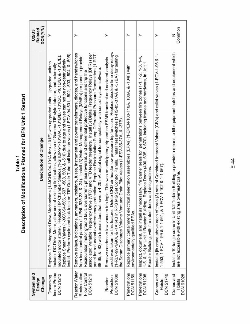
Tabl
e 1
Des
crip
tion
of M
odifi
catio
ns P
lann
ed fo
r BFN
Uni
t 1 R
esta
rt
E-4
4
Syst
em a
nd
Des
ign
Cha
nge
Des
crip
tion
of C
hang
e
U2/
U3
Rel
ated
D
CN
(Y/N
)
Trav
ersi
ng
Inco
re P
robe
D
CN
512
42
Rep
lace
TIP
Inte
grat
ed D
rive
Mec
hani
sms
(1-M
CH
D-9
4-10
1A th
ru -1
01E
) with
upg
rade
d un
its.
Upg
rade
d un
its to
in
clud
e: D
C D
rive
Mot
or, a
llow
use
of e
xist
ing
field
cab
les,
allo
w u
se o
f Gam
ma
TIP
sty
le d
etec
tor,
and
exte
rnal
ly
mou
nted
mot
or s
tarte
r. R
epla
ce T
IP C
ham
ber S
hiel
ds (1
-SH
DP
-94-
101A
/A, -
101B
/B, -
101C
/C, -
101D
/D, &
-101
E/E
). R
epla
ce S
hear
Val
ves
(1-X
CV
-94-
506,
-507
, -50
8, 5
09, &
-510
) due
to a
ge a
nd v
alve
s ca
n no
t be
non-
dest
ruct
ivel
y te
sted
. P
erfo
rm c
ycle
and
leak
test
s on
TIP
Gui
de T
ube
ball
isol
atio
n va
lves
(1-F
CV
-94-
501,
-502
, -50
3, -5
04, &
-505
).
Y
Rea
ctor
Wat
er
Rec
ircul
atio
n Fl
ow C
ontro
l D
CN
512
19
Rem
ove
rela
ys, i
ndic
atio
ns, a
mm
eter
s, re
sist
ors,
fuse
s, in
stru
men
t and
pow
er tr
ansf
orm
ers,
dio
des,
and
han
dsw
itche
s fro
m lo
cal c
ontro
l pan
els
(1-L
PNL-
925-
23, &
-24)
. In
stal
l (3)
Mot
or M
anag
emen
t Rel
ays
(MM
Rs)
per
pan
el to
pro
vide
R
ecirc
ulat
ion
mot
or g
roun
d fa
ult,
over
curr
ent,
phas
e re
vers
al, a
nd d
iffer
entia
l pro
tect
ive
func
tions
and
trip
the
asso
ciat
ed V
aria
ble
Freq
uenc
y D
rive
(VFD
) and
VFD
feed
er b
reak
ers.
Ins
tall
(3) D
igita
l Fre
quen
cy R
elay
s (D
FRs)
per
pa
nel f
or re
dund
ant o
verfr
eque
ncy
prot
ectio
n. R
epla
ce R
ecirc
ulat
ion
Pum
p D
iffer
entia
l Pre
ssur
e Tr
ansm
itter
s (1
-PD
T-68
-65,
& -8
2) w
ith tr
ansm
itter
s th
at h
ave
a 4-
20 m
A o
utpu
t sig
nal f
or c
ompa
tibilit
y w
ith c
ontro
l sys
tem
sof
twar
e.
Y
Rea
ctor
P
rote
ctio
n D
CN
510
80
Rem
ove
cond
ense
r low
vac
uum
trip
logi
c. T
his
was
an
antic
ipat
ory
trip
and
no F
SA
R tr
ansi
ent a
nd a
ccid
ent a
naly
sis
cred
it w
as ta
ken
for t
his
feat
ure.
Del
ete
CR
D a
ir he
ader
low
pre
ssur
e tri
p fu
nctio
n. R
epla
ce o
bsol
ete
time
dela
y re
lays
(1
-RLY
-99-
1AK
4, &
-1A
K4B
in R
PS
MG
Set
Con
trol P
anel
s. I
nsta
ll te
st s
witc
hes
(1-H
S-8
5-37
AA
& -3
7BA
) for
test
ing
the
Scr
am D
isch
arge
Vol
ume
Ven
t and
Dra
in P
ilot V
alve
s (1
-FS
V-8
5-37
A, &
-37B
).
Y
Pen
etra
tions
D
CN
511
59
Rep
lace
prim
ary
cont
ainm
ent e
lect
rical
pen
etra
tion
asse
mbl
ies
(EP
As)
(1-E
PE
N-1
00-1
10A
, 100
A, &
-104
F) w
ith
envi
ronm
enta
lly q
ualif
ied
EP
As.
Y
Pen
etra
tions
D
CN
512
08
Insp
ect,
docu
men
t, an
d in
stal
l as
nece
ssar
y, fi
re b
arrie
r sea
ls fo
r pe
netra
tions
bet
wee
n fir
e zo
nes
(1-1
, 1-2
, 1-3
, 1-4
, 1-
5, &
1-6
) in
Uni
t 1 R
eact
or B
uild
ing.
Rep
lace
Doo
rs (4
90, 6
35, &
670
), in
clud
ing
fram
es a
nd h
ardw
are,
in U
nit 1
R
eact
or B
uild
ing,
with
fire
rate
d do
ors
and
desi
gnat
ions
.
Y
Cra
nes
and
Hoi
sts
DC
N 5
1740
Inst
all a
jib
cran
e ab
ove
each
of t
hree
(3) s
ets
of C
ombi
ned
Inte
rcep
t Val
ves
(CIV
s) a
nd re
lief v
alve
s (1
-FC
V-1
-96
& 1
-1-
553;
1-F
CV-
1-99
& 1
-1-5
61; &
1-F
CV-
1-10
2 &
1-1
-567
). Y
Cra
nes
and
Hoi
sts
DC
N 6
1028
Inst
all a
10-
ton
jib c
rane
in U
nit 1
/2 T
urbi
ne B
uild
ing
to p
rovi
de a
mea
ns to
lift
equi
pmen
t hat
ches
and
equ
ipm
ent w
hich
ar
e no
t acc
essi
ble
with
exi
stin
g ar
ea o
verh
ead
cran
e.
N
Com
mon
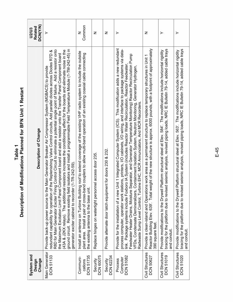
Tabl
e 1
Des
crip
tion
of M
odifi
catio
ns P
lann
ed fo
r BFN
Uni
t 1 R
esta
rt
E-4
5
Syst
em a
nd
Des
ign
Cha
nge
Des
crip
tion
of C
hang
e
U2/
U3
Rel
ated
D
CN
(Y/N
)
Mai
n G
ener
ator
D
CN
511
33
Pro
vide
bac
k-up
pow
er s
ourc
e to
the
Mai
n G
ener
ator
Bre
aker
Air
Com
pres
sor S
yste
m (M
GBA
CS
) to
prov
ide
redu
ndan
t cap
abilit
y fo
r ope
ratio
n of
the
Rep
leni
shin
g V
alve
Con
trol c
ircui
ts. A
dd p
aral
lel d
iode
s ac
ross
Dio
des
R7D
&
R8D
for M
ain
Gen
erat
or E
xcite
r Firi
ng C
ontro
l Circ
uit t
o el
imin
ate
a po
tent
ial s
ingl
e po
int o
f fai
lure
. A
dd a
resi
stor
ont
o th
e M
axim
um E
xcita
tion
Lim
it P
anel
Com
pone
nt b
oard
and
add
a re
sist
or o
nto
the
Tran
sfer
Pan
el C
ompo
nent
boa
rd
(43A
& J
2KX
rela
ys).
The
add
ition
al re
sist
ors
incr
ease
the
cond
ition
ing
effe
ct fo
r the
boa
rds
and
elim
inat
e no
ise
in th
e gr
ound
circ
uit.
Rem
ove
exis
ting
field
isol
ator
s an
d in
stal
l a p
rogr
amm
able
Fie
ld T
empe
ratu
re M
odul
e (1
-TM
-242
-45)
in
gene
rato
r exc
iter c
abin
et to
reco
rder
(1-T
R-2
42-5
9).
Y
Com
mun
i- ca
tions
D
CN
517
35
Inst
all a
n an
tenn
a on
Tur
bine
Bui
ldin
g ro
of to
ext
end
cove
rage
of t
he e
xist
ing
VHF
radi
o sy
stem
to in
clud
e th
e ou
tsid
e pl
ant a
rea.
Ins
tall
a pa
ir of
cro
ss-b
and
coup
lers
to a
llow
mul
ti-ba
nd o
pera
tion
of a
n ex
istin
g co
axia
l cab
le c
onne
ctin
g th
e ex
istin
g an
tenn
a to
the
base
uni
t.
N
Com
mon
Sec
urity
D
CN
600
75
Rep
lace
hin
ges
on w
ater
tight
per
sonn
el a
cces
s do
or 2
35.
N
Sec
urity
D
CN
622
34
Pro
vide
alte
rnat
e do
or la
tch
equi
pmen
t for
doo
rs 2
30 &
232
. N
Pro
cess
C
ompu
ter
DC
N 5
1082
Pro
vide
for t
he in
stal
latio
n of
a n
ew U
nit 1
Inte
grat
ed C
ompu
ter S
yste
m (I
CS)
. Th
is m
odifi
catio
n ad
ds a
new
redu
ndan
t pr
oces
s co
mpu
ter,
oper
ator
wor
k st
atio
ns, p
rinte
rs, I
/O c
abin
ets,
I/O
wiri
ng, a
nd in
terfa
ce to
pac
kage
sys
tem
s vi
a da
ta-
link.
Pac
kage
sys
tem
s in
clud
e Fo
xbor
o IA
Sys
tem
(inc
lude
s R
eact
or W
ater
Rec
ircul
atio
n, R
eact
or F
eedw
ater
, Fe
edw
ater
Hea
ter D
rain
s, M
oist
ure
Sep
arat
or, a
nd G
ener
ator
Tem
pera
ture
Mon
itorin
g) R
eact
or R
ecirc
ulat
ion
Pum
p V
FDs,
Con
dens
ate
Dem
iner
aliz
ers,
Con
tain
men
t Iso
latio
n S
yste
m, N
eutro
n M
onito
ring,
Gen
erat
or H
ydro
gen,
R
adw
aste
Sum
p Le
vel C
ontro
l, Tu
rbin
e E
HC
, MC
R A
nnun
ciat
ors,
And
MC
R R
ecor
ders
.
Y
Civ
il S
truct
ures
D
CN
506
27
Pro
vide
a c
lean
-isla
nd a
nd O
pera
tions
wor
k ar
ea a
s a
perm
anen
t stru
ctur
e to
repl
ace
tem
pora
ry s
truct
ures
in U
nit 1
R
eact
or B
uild
ing
Ele
v. 6
39'.
Tot
al w
eigh
t of t
he n
ew s
truct
ure
is a
ppro
x. 6
000
poun
ds, w
ith a
foot
prin
t of a
ppro
xim
atel
y 39
0 sq
uare
feet
.
N
Civ
il S
truct
ures
D
CN
510
19
Pro
vide
mod
ifica
tions
to th
e D
ryw
ell P
latfo
rm s
truct
ural
ste
el a
t Ele
v. 5
84'.
The
mod
ifica
tions
incl
ude
horiz
onta
l rig
idity
br
acin
g fo
r the
pla
tform
due
to re
vise
d se
ism
ic a
naly
sis,
revi
sed
pipi
ng lo
ads,
NR
C IE
Bul
letin
79-
14, a
dded
cab
le tr
ays
and
cond
uit.
Y
Civ
il S
truct
ures
D
CN
510
20
Pro
vide
mod
ifica
tions
to th
e D
ryw
ell P
latfo
rm s
truct
ural
ste
el a
t Ele
v. 5
63'.
The
mod
ifica
tions
incl
ude
horiz
onta
l rig
idity
br
acin
g fo
r the
pla
tform
due
to re
vise
d se
ism
ic a
naly
sis,
revi
sed
pipi
ng lo
ads,
NR
C IE
Bul
letin
79-
14, a
dded
cab
le tr
ays
and
cond
uit.
Y
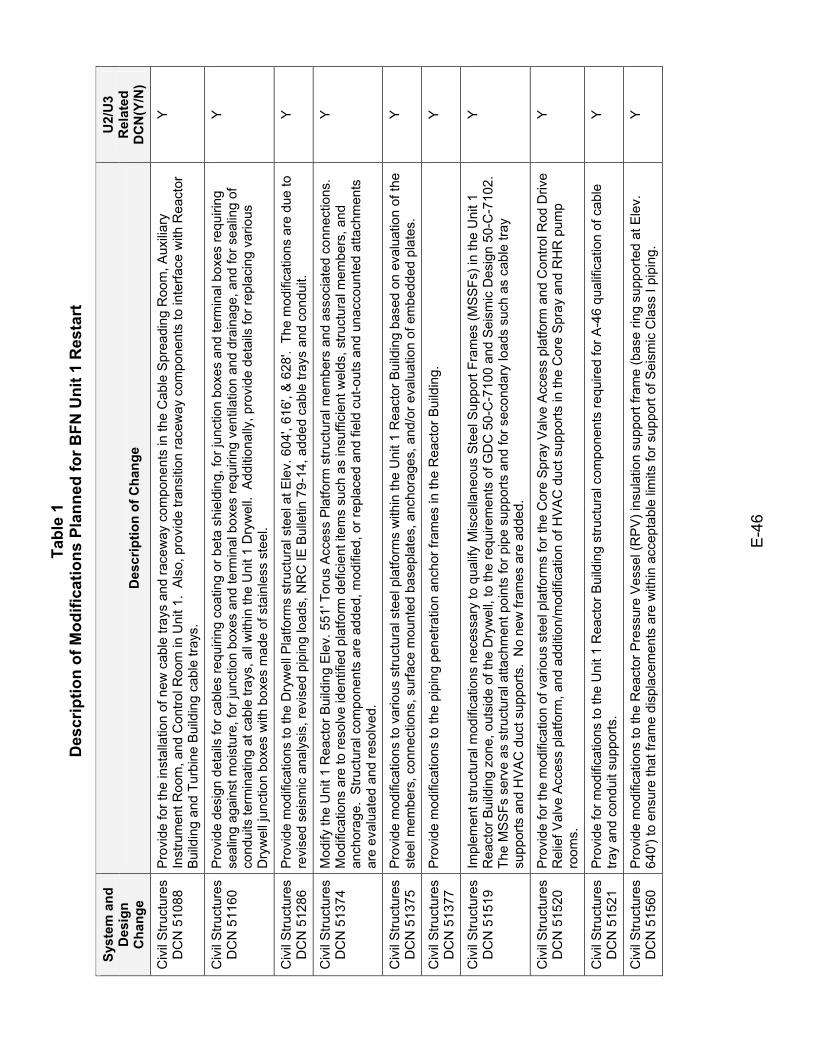
Tabl
e 1
Des
crip
tion
of M
odifi
catio
ns P
lann
ed fo
r BFN
Uni
t 1 R
esta
rt
E-4
6
Syst
em a
nd
Des
ign
Cha
nge
Des
crip
tion
of C
hang
e
U2/
U3
Rel
ated
D
CN
(Y/N
)
Civ
il S
truct
ures
D
CN
510
88
Pro
vide
for t
he in
stal
latio
n of
new
cab
le tr
ays
and
race
way
com
pone
nts
in th
e C
able
Spr
eadi
ng R
oom
, Aux
iliar
y In
stru
men
t Roo
m, a
nd C
ontro
l Roo
m in
Uni
t 1.
Als
o, p
rovi
de tr
ansi
tion
race
way
com
pone
nts
to in
terfa
ce w
ith R
eact
or
Bui
ldin
g an
d Tu
rbin
e B
uild
ing
cabl
e tra
ys.
Y
Civ
il S
truct
ures
D
CN
511
60
Pro
vide
des
ign
deta
ils fo
r cab
les
requ
iring
coa
ting
or b
eta
shie
ldin
g, fo
r jun
ctio
n bo
xes
and
term
inal
box
es re
quiri
ng
seal
ing
agai
nst m
oist
ure,
for j
unct
ion
boxe
s an
d te
rmin
al b
oxes
requ
iring
ven
tilat
ion
and
drai
nage
, and
for s
ealin
g of
co
ndui
ts te
rmin
atin
g at
cab
le tr
ays,
all
with
in th
e U
nit 1
Dry
wel
l. A
dditi
onal
ly, p
rovi
de d
etai
ls fo
r rep
laci
ng v
ario
us
Dry
wel
l jun
ctio
n bo
xes
with
box
es m
ade
of s
tain
less
ste
el.
Y
Civ
il S
truct
ures
D
CN
512
86
Pro
vide
mod
ifica
tions
to th
e D
ryw
ell P
latfo
rms
stru
ctur
al s
teel
at E
lev.
604
', 61
6', &
628
'. T
he m
odifi
catio
ns a
re d
ue to
re
vise
d se
ism
ic a
naly
sis,
revi
sed
pipi
ng lo
ads,
NR
C IE
Bul
letin
79-
14, a
dded
cab
le tr
ays
and
cond
uit.
Y
Civ
il S
truct
ures
D
CN
513
74
Mod
ify th
e U
nit 1
Rea
ctor
Bui
ldin
g E
lev.
551
' Tor
us A
cces
s P
latfo
rm s
truct
ural
mem
bers
and
ass
ocia
ted
conn
ectio
ns.
Mod
ifica
tions
are
to re
solv
e id
entif
ied
plat
form
def
icie
nt it
ems
such
as
insu
ffici
ent w
elds
, stru
ctur
al m
embe
rs, a
nd
anch
orag
e. S
truct
ural
com
pone
nts
are
adde
d, m
odifi
ed, o
r rep
lace
d an
d fie
ld c
ut-o
uts
and
unac
coun
ted
atta
chm
ents
ar
e ev
alua
ted
and
reso
lved
.
Y
Civ
il S
truct
ures
D
CN
513
75
Pro
vide
mod
ifica
tions
to v
ario
us s
truct
ural
ste
el p
latfo
rms
with
in th
e U
nit 1
Rea
ctor
Bui
ldin
g ba
sed
on e
valu
atio
n of
the
stee
l mem
bers
, con
nect
ions
, sur
face
mou
nted
bas
epla
tes,
anc
hora
ges,
and
/or e
valu
atio
n of
em
bedd
ed p
late
s.
Y
Civ
il S
truct
ures
D
CN
513
77
Pro
vide
mod
ifica
tions
to th
e pi
ping
pen
etra
tion
anch
or fr
ames
in th
e R
eact
or B
uild
ing.
Y
Civ
il S
truct
ures
D
CN
515
19
Impl
emen
t stru
ctur
al m
odifi
catio
ns n
eces
sary
to q
ualif
y M
isce
llane
ous
Ste
el S
uppo
rt Fr
ames
(MS
SFs
) in
the
Uni
t 1
Rea
ctor
Bui
ldin
g zo
ne, o
utsi
de o
f the
Dry
wel
l, to
the
requ
irem
ents
of G
DC
50-
C-7
100
and
Sei
smic
Des
ign
50-C
-710
2.
The
MS
SFs
ser
ve a
s st
ruct
ural
atta
chm
ent p
oint
s fo
r pip
e su
ppor
ts a
nd fo
r sec
onda
ry lo
ads
such
as
cabl
e tra
y su
ppor
ts a
nd H
VA
C d
uct s
uppo
rts.
No
new
fram
es a
re a
dded
.
Y
Civ
il S
truct
ures
D
CN
515
20
Pro
vide
for t
he m
odifi
catio
n of
var
ious
ste
el p
latfo
rms
for t
he C
ore
Spr
ay V
alve
Acc
ess
plat
form
and
Con
trol R
od D
rive
Rel
ief V
alve
Acc
ess
plat
form
, and
add
ition
/mod
ifica
tion
of H
VA
C d
uct s
uppo
rts in
the
Cor
e S
pray
and
RH
R p
ump
room
s.
Y
Civ
il S
truct
ures
D
CN
515
21
Pro
vide
for m
odifi
catio
ns to
the
Uni
t 1 R
eact
or B
uild
ing
stru
ctur
al c
ompo
nent
s re
quire
d fo
r A-4
6 qu
alifi
catio
n of
cab
le
tray
and
cond
uit s
uppo
rts.
Y
Civ
il S
truct
ures
D
CN
515
60
Pro
vide
mod
ifica
tions
to th
e R
eact
or P
ress
ure
Ves
sel (
RP
V) i
nsul
atio
n su
ppor
t fra
me
(bas
e rin
g su
ppor
ted
at E
lev.
64
0') t
o en
sure
that
fram
e di
spla
cem
ents
are
with
in a
ccep
tabl
e lim
its fo
r sup
port
of S
eism
ic C
lass
I pi
ping
. Y
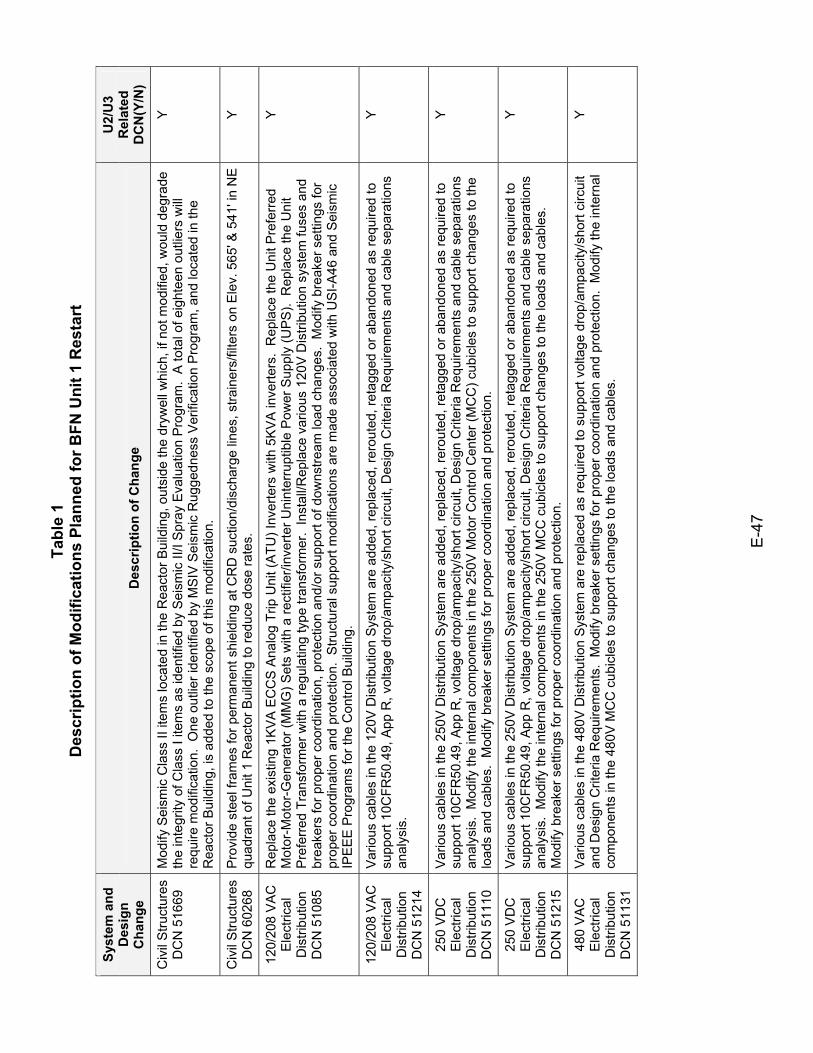
Tabl
e 1
Des
crip
tion
of M
odifi
catio
ns P
lann
ed fo
r BFN
Uni
t 1 R
esta
rt
E-4
7
Syst
em a
nd
Des
ign
Cha
nge
Des
crip
tion
of C
hang
e
U2/
U3
Rel
ated
D
CN
(Y/N
)
Civ
il S
truct
ures
D
CN
516
69
Mod
ify S
eism
ic C
lass
II it
ems
loca
ted
in th
e R
eact
or B
uild
ing,
out
side
the
dryw
ell w
hich
, if n
ot m
odifi
ed, w
ould
deg
rade
th
e in
tegr
ity o
f Cla
ss I
item
s as
iden
tifie
d by
Sei
smic
II/I
Spr
ay E
valu
atio
n P
rogr
am.
A to
tal o
f eig
htee
n ou
tlier
s w
ill re
quire
mod
ifica
tion.
One
out
lier i
dent
ified
by
MS
IV S
eism
ic R
ugge
dnes
s V
erifi
catio
n P
rogr
am, a
nd lo
cate
d in
the
Rea
ctor
Bui
ldin
g, is
add
ed to
the
scop
e of
this
mod
ifica
tion.
Y
Civ
il S
truct
ures
D
CN
602
68
Pro
vide
ste
el fr
ames
for p
erm
anen
t shi
eldi
ng a
t CR
D s
uctio
n/di
scha
rge
lines
, stra
iner
s/fil
ters
on
Ele
v. 5
65' &
541
' in
NE
qu
adra
nt o
f Uni
t 1 R
eact
or B
uild
ing
to re
duce
dos
e ra
tes.
Y
120/
208
VA
C
Ele
ctric
al
Dis
tribu
tion
D
CN
510
85
Rep
lace
the
exis
ting
1KVA
EC
CS
Ana
log
Trip
Uni
t (A
TU) I
nver
ters
with
5K
VA
inve
rters
. R
epla
ce th
e U
nit P
refe
rred
Mot
or-M
otor
-Gen
erat
or (M
MG
) Set
s w
ith a
rect
ifier
/inve
rter U
nint
erru
ptib
le P
ower
Sup
ply
(UPS
). R
epla
ce th
e U
nit
Pre
ferr
ed T
rans
form
er w
ith a
regu
latin
g ty
pe tr
ansf
orm
er.
Inst
all/R
epla
ce v
ario
us 1
20V
Dis
tribu
tion
syst
em fu
ses
and
brea
kers
for p
rope
r coo
rdin
atio
n, p
rote
ctio
n an
d/or
sup
port
of d
owns
tream
load
cha
nges
. M
odify
bre
aker
set
tings
for
prop
er c
oord
inat
ion
and
prot
ectio
n. S
truct
ural
sup
port
mod
ifica
tions
are
mad
e as
soci
ated
with
US
I-A46
and
Sei
smic
IP
EE
E P
rogr
ams
for t
he C
ontro
l Bui
ldin
g.
Y
120/
208
VA
C
Ele
ctric
al
Dis
tribu
tion
DC
N 5
1214
Var
ious
cab
les
in th
e 12
0V D
istri
butio
n Sy
stem
are
add
ed, r
epla
ced,
rero
uted
, ret
agge
d or
aba
ndon
ed a
s re
quire
d to
su
ppor
t 10C
FR50
.49,
App
R, v
olta
ge d
rop/
ampa
city
/sho
rt ci
rcui
t, D
esig
n C
riter
ia R
equi
rem
ents
and
cab
le s
epar
atio
ns
anal
ysis
.
Y
250
VD
C
Ele
ctric
al
Dis
tribu
tion
DC
N 5
1110
Var
ious
cab
les
in th
e 25
0V D
istri
butio
n Sy
stem
are
add
ed, r
epla
ced,
rero
uted
, ret
agge
d or
aba
ndon
ed a
s re
quire
d to
su
ppor
t 10C
FR50
.49,
App
R, v
olta
ge d
rop/
ampa
city
/sho
rt ci
rcui
t, D
esig
n C
riter
ia R
equi
rem
ents
and
cab
le s
epar
atio
ns
anal
ysis
. M
odify
the
inte
rnal
com
pone
nts
in th
e 25
0V M
otor
Con
trol C
ente
r (M
CC
) cub
icle
s to
sup
port
chan
ges
to th
e lo
ads
and
cabl
es.
Mod
ify b
reak
er s
ettin
gs fo
r pro
per c
oord
inat
ion
and
prot
ectio
n.
Y
250
VD
C
Ele
ctric
al
Dis
tribu
tion
DC
N 5
1215
Var
ious
cab
les
in th
e 25
0V D
istri
butio
n Sy
stem
are
add
ed, r
epla
ced,
rero
uted
, ret
agge
d or
aba
ndon
ed a
s re
quire
d to
su
ppor
t 10C
FR50
.49,
App
R, v
olta
ge d
rop/
ampa
city
/sho
rt ci
rcui
t, D
esig
n C
riter
ia R
equi
rem
ents
and
cab
le s
epar
atio
ns
anal
ysis
. M
odify
the
inte
rnal
com
pone
nts
in th
e 25
0V M
CC
cub
icle
s to
sup
port
chan
ges
to th
e lo
ads
and
cabl
es.
Mod
ify b
reak
er s
ettin
gs fo
r pro
per c
oord
inat
ion
and
prot
ectio
n.
Y
480
VA
C
Ele
ctric
al
Dis
tribu
tion
DC
N 5
1131
Var
ious
cab
les
in th
e 48
0V D
istri
butio
n Sy
stem
are
repl
aced
as
requ
ired
to s
uppo
rt vo
ltage
dro
p/am
paci
ty/s
hort
circ
uit
and
Des
ign
Crit
eria
Req
uire
men
ts.
Mod
ify b
reak
er s
ettin
gs fo
r pro
per c
oord
inat
ion
and
prot
ectio
n. M
odify
the
inte
rnal
co
mpo
nent
s in
the
480V
MC
C c
ubic
les
to s
uppo
rt ch
ange
s to
the
load
s an
d ca
bles
.
Y
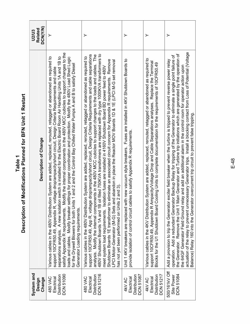
Tabl
e 1
Des
crip
tion
of M
odifi
catio
ns P
lann
ed fo
r BFN
Uni
t 1 R
esta
rt
E-4
8
Syst
em a
nd
Des
ign
Cha
nge
Des
crip
tion
of C
hang
e
U2/
U3
Rel
ated
D
CN
(Y/N
)
480
VA
C
Ele
ctric
al
Dis
tribu
tion
DC
N 5
1090
Var
ious
cab
les
in th
e 48
0V D
istri
butio
n Sy
stem
are
add
ed, r
epla
ced,
rero
uted
, ret
agge
d or
aba
ndon
ed a
s re
quire
d to
su
ppor
t 10C
FR50
.49,
App
endi
x R
, vol
tage
dro
p/am
paci
ty/s
hort
circ
uit,
Des
ign
Crit
eria
Req
uire
men
ts a
nd c
able
se
para
tions
ana
lysi
s. A
new
isol
atio
n sw
itch
is in
stal
led
for t
he E
lect
ric B
oard
Roo
m A
ir H
andl
ing
Uni
ts 1
A a
nd 1
B to
sa
tisfy
App
endi
x R
requ
irem
ents
. M
odify
the
inte
rnal
com
pone
nts
in th
e 48
0V M
CC
cub
icle
s to
sup
port
chan
ges
to th
e lo
ads
and
cabl
es.
Mod
ify b
reak
er s
ettin
gs fo
r pro
per c
oord
inat
ion
and
prot
ectio
n. M
odify
the
480V
Loa
d Sh
ed L
ogic
fo
r the
Dry
wel
l Blo
wer
s fo
r bot
h U
nits
1 a
nd 2
and
the
Con
trol B
ay C
hille
d W
ater
Pum
ps A
and
B to
sat
isfy
Die
sel
Gen
erat
or L
oadi
ng re
quire
men
ts.
Y
480
VA
C
Ele
ctric
al
Dis
tribu
tion
DC
N 5
1216
Var
ious
cab
les
in th
e 48
0V D
istri
butio
n Sy
stem
are
add
ed, r
epla
ced,
rero
uted
, ret
agge
d or
aba
ndon
ed a
s re
quire
d to
su
ppor
t 10C
FR50
.49,
App
R, v
olta
ge d
rop/
ampa
city
/sho
rt ci
rcui
t, D
esig
n C
riter
ia R
equi
rem
ents
and
cab
le s
epar
atio
ns
anal
ysis
. M
odify
the
inte
rnal
com
pone
nts
in th
e 48
0V M
CC
cub
icle
s to
sup
port
chan
ges
to th
e lo
ads
and
cabl
es.
The
480V
Shu
tdow
n B
oard
s 1A
and
1B
oil
fille
d 75
0KV
A tr
ansf
orm
ers
are
repl
aced
with
dry
type
100
0KV
A tr
ansf
orm
ers
to
mee
t sys
tem
load
requ
irem
ents
. Is
olat
ion
fuse
s ar
e in
stal
led
in 4
160V
Shu
tdow
n B
oard
BD
pow
er fe
ed to
480
V
Shu
tdow
n B
oard
s 1E
tran
sfor
mer
to e
limin
ate
an a
ssoc
iate
d ci
rcui
t con
cern
for A
ppen
dix
R re
quire
men
ts.
Rem
ove
LPC
I Mot
or-G
ener
ator
(M-G
) Set
s an
d ab
ando
n in
pla
ce th
e R
eact
or M
OV
Boa
rds
1D &
1E
(LP
CI M
-G s
et re
mov
al
has
not y
et b
een
perfo
rmed
on
Uni
ts 2
and
3).
Y
4kV
AC
E
lect
rical
D
istri
butio
n D
CN
510
87
Uni
t 1 4
KV
bre
aker
s ar
e re
plac
ed w
ith n
ew v
acuu
m s
tyle
bre
aker
s. F
uses
are
inst
alle
d in
4K
V S
hutd
own
Boar
ds to
pr
ovid
e is
olat
ion
of c
ontro
l circ
uit c
able
s to
sat
isfy
App
endi
x R
requ
irem
ents
. Y
4kV
AC
E
lect
rical
D
istri
butio
n D
CN
512
17
Var
ious
cab
les
in th
e 4K
V D
istri
butio
n Sy
stem
are
add
ed, r
epla
ced,
rero
uted
, ret
agge
d or
aba
ndon
ed a
s re
quire
d to
su
ppor
t 10C
FR50
.49,
App
endi
x R
Am
paci
ty/V
olta
ge D
rop
and
Cab
le S
epar
atio
ns a
naly
ses.
Rep
lace
the
Term
inal
B
lock
s fo
r the
U1
Shu
tdow
n B
oard
Coo
ling
Uni
ts to
com
plet
e do
cum
enta
tion
for t
he re
quire
men
ts o
f 10C
FR50
.49
Y
500/
161k
V O
ff S
ite P
ower
D
CN
510
84
Add
a p
rovi
sion
to tr
ip th
e G
ener
ator
exc
iter f
ield
bre
aker
whe
n th
e tu
rbin
e is
trip
ped
to p
reve
nt re
vers
e po
wer
rela
y op
erat
ion.
Add
a re
dund
ant G
ener
ator
Bac
kup
Rel
ay fo
r trip
ping
of t
he G
ener
ator
to e
limin
ate
a si
ngle
poi
nt fa
ilure
of
the
Gen
erat
or.
Rem
ove
the
Uni
t 1 M
ain
Gen
erat
or a
nd T
urbi
ne tr
ip in
itiat
ions
whi
ch a
re g
ener
ated
by
the
oper
atio
n of
th
e 64
GF
Gen
erat
or F
ield
Gro
und
rela
y an
d ad
d an
add
ition
al a
larm
in th
e co
ntro
l roo
m fo
r ope
rato
r act
ion
upon
ac
tuat
ion
of th
e re
lay
to p
reve
nt u
nnec
essa
ry G
ener
ator
trip
s. I
nsta
ll a
bloc
king
con
tact
from
Los
s of
Pot
entia
l (V
olta
ge
Bal
ance
) Rel
ay 1
60 in
to th
e G
ener
ator
ove
rcur
rent
trip
circ
uit t
o pr
even
t fal
se tr
ippi
ng.
Y
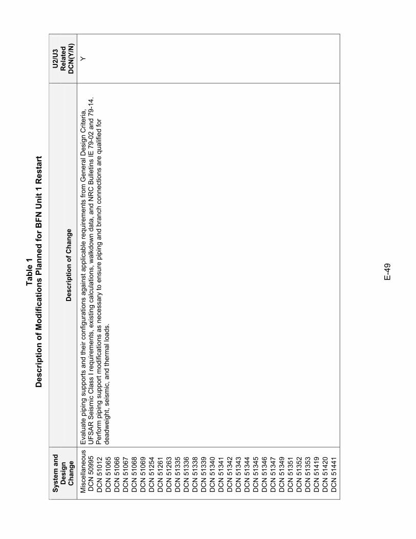
Tabl
e 1
Des
crip
tion
of M
odifi
catio
ns P
lann
ed fo
r BFN
Uni
t 1 R
esta
rt
E-4
9
Syst
em a
nd
Des
ign
Cha
nge
Des
crip
tion
of C
hang
e
U2/
U3
Rel
ated
D
CN
(Y/N
)
Mis
cella
neou
s
DC
N 5
0995
D
CN
510
12
DC
N 5
1065
D
CN
510
66
DC
N 5
1067
D
CN
510
68
DC
N 5
1069
D
CN
512
54
DC
N 5
1261
D
CN
512
63
DC
N 5
1335
D
CN
513
36
DC
N 5
1338
D
CN
513
39
DC
N 5
1340
D
CN
513
41
DC
N 5
1342
D
CN
513
43
DC
N 5
1344
D
CN
513
45
DC
N 5
1346
D
CN
513
47
DC
N 5
1349
D
CN
513
51
DC
N 5
1352
D
CN
513
53
DC
N 5
1419
D
CN
514
20
DC
N 5
1441
Eva
luat
e pi
ping
sup
ports
and
thei
r con
figur
atio
ns a
gain
st a
pplic
able
requ
irem
ents
from
Gen
eral
Des
ign
Crit
eria
, U
FSA
R S
eism
ic C
lass
I re
quire
men
ts, e
xist
ing
calc
ulat
ions
, wal
kdow
n da
ta, a
nd N
RC
Bul
letin
s IE
79-
02 a
nd 7
9-14
. P
erfo
rm p
ipin
g su
ppor
t mod
ifica
tions
as
nece
ssar
y to
ens
ure
pipi
ng a
nd b
ranc
h co
nnec
tions
are
qua
lifie
d fo
r de
adw
eigh
t, se
ism
ic, a
nd th
erm
al lo
ads.
Y
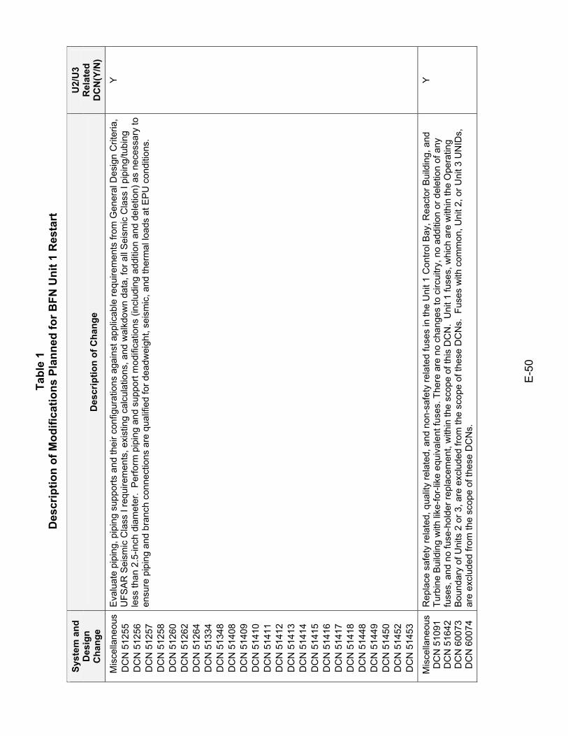
Tabl
e 1
Des
crip
tion
of M
odifi
catio
ns P
lann
ed fo
r BFN
Uni
t 1 R
esta
rt
E-5
0
Syst
em a
nd
Des
ign
Cha
nge
Des
crip
tion
of C
hang
e
U2/
U3
Rel
ated
D
CN
(Y/N
)
Mis
cella
neou
s D
CN
512
55
DC
N 5
1256
D
CN
512
57
DC
N 5
1258
D
CN
512
60
DC
N 5
1262
D
CN
512
64
DC
N 5
1334
D
CN
513
48
DC
N 5
1408
D
CN
514
09
DC
N 5
1410
D
CN
514
11
DC
N 5
1412
D
CN
514
13
DC
N 5
1414
D
CN
514
15
DC
N 5
1416
D
CN
514
17
DC
N 5
1418
D
CN
514
48
DC
N 5
1449
D
CN
514
50
DC
N 5
1452
D
CN
514
53
Eva
luat
e pi
ping
, pip
ing
supp
orts
and
thei
r con
figur
atio
ns a
gain
st a
pplic
able
requ
irem
ents
from
Gen
eral
Des
ign
Crit
eria
, U
FSA
R S
eism
ic C
lass
I re
quire
men
ts, e
xist
ing
calc
ulat
ions
, and
wal
kdow
n da
ta, f
or a
ll S
eism
ic C
lass
I pi
ping
/tubi
ng
less
than
2.5
-inch
dia
met
er.
Per
form
pip
ing
and
supp
ort m
odifi
catio
ns (i
nclu
ding
add
ition
and
del
etio
n) a
s ne
cess
ary
to
ensu
re p
ipin
g an
d br
anch
con
nect
ions
are
qua
lifie
d fo
r dea
dwei
ght,
seis
mic
, and
ther
mal
load
s at
EP
U c
ondi
tions
.
Y
Mis
cella
neou
s D
CN
510
91
DC
N 5
1642
D
CN
600
73
DC
N 6
0074
Rep
lace
saf
ety
rela
ted,
qua
lity
rela
ted,
and
non
-saf
ety
rela
ted
fuse
s in
the
Uni
t 1 C
ontro
l Bay
, Rea
ctor
Bui
ldin
g, a
nd
Turb
ine
Bui
ldin
g w
ith li
ke-fo
r-lik
e eq
uiva
lent
fuse
s. T
here
are
no
chan
ges
to c
ircui
try, n
o ad
ditio
n or
del
etio
n of
any
fu
ses,
and
no
fuse
-hol
der r
epla
cem
ent,
with
in th
e sc
ope
of th
is D
CN
. U
nit 1
fuse
s, w
hich
are
with
in th
e O
pera
ting
Bou
ndar
y of
Uni
ts 2
or 3
, are
exc
lude
d fro
m th
e sc
ope
of th
ese
DC
Ns.
Fus
es w
ith c
omm
on, U
nit 2
, or U
nit 3
UN
IDs,
ar
e ex
clud
ed fr
om th
e sc
ope
of th
ese
DC
Ns.
Y
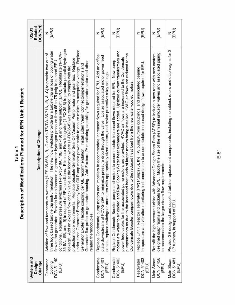
Tabl
e 1
Des
crip
tion
of M
odifi
catio
ns P
lann
ed fo
r BFN
Uni
t 1 R
esta
rt
E-5
1
Syst
em a
nd
Des
ign
Cha
nge
Des
crip
tion
of C
hang
e
U2/
U3
Rel
ated
D
CN
(Y/N
)
Gen
erat
or
Coo
ling
D
CN
511
40
(EP
U)
Add
ition
of f
low
and
tem
pera
ture
sw
itche
s (1
-FS
-35-
65A
, -B
, -C
and
1-T
S/T
W-3
5-71
A, -
B, &
-C) t
o pr
ovid
e tw
o ou
t of
thre
e lo
gic
base
d tu
rbin
e tri
p in
stru
men
tatio
n. T
he n
ew fl
ow s
witc
hes
prov
ide
for a
turb
ine
trip
on lo
ss o
f coo
ling
wat
er
flow
to th
e ge
nera
tor.
Pro
vide
for a
n in
crea
se in
gen
erat
or h
ydro
gen
pres
sure
from
65
to 7
5 ps
ig to
sup
port
EP
U
cond
ition
s. R
epla
ce p
ress
ure
switc
hes
(1-P
S-3
5-18
A, 1
8B, a
nd -1
9) a
nd re
vise
set
poin
t (E
PU
). R
ecal
ibra
te (1
-PC
V-
35-5
A, -
5B, a
nd -9
) in
supp
ort o
f EP
U c
ondi
tions
. E
limin
ate
Flow
Inte
grat
or (1
-FQ
-35-
8) to
pre
clud
e po
tent
ial h
ydro
gen
leak
age.
Add
an
exce
ss fl
ow c
heck
val
ve a
t the
loca
tion
whe
re (1
-FQ
-35-
8) w
as re
mov
ed, t
o co
mpl
y w
ith fi
re
prot
ectio
n co
de re
quire
men
ts.
Rep
lace
obs
olet
e G
ener
ator
Sea
l Oil
Vac
uum
Pum
p m
otor
and
gea
r box
. R
epla
ce
unde
r-si
zed
Gen
erat
or E
mer
genc
y S
eal O
il P
ump
mot
or p
ower
cab
le to
ens
ure
min
imum
acc
epta
ble
volta
ge.
Rep
lace
G
ener
ator
Exc
iter F
lexi
ble
coup
ling
per G
E re
com
men
datio
n. I
nsta
ll Li
tten
Vea
m C
onne
ctor
s/pe
netra
tions
and
G
ener
ator
flux
pro
be o
n ge
nera
tor h
ousi
ng.
Add
Fox
boro
I/A
mon
itorin
g ca
pabi
lity
for g
ener
ator
sta
tor a
nd o
ther
re
late
d th
erm
ocou
ples
.
N
(EP
U)
Con
dens
ate
D
CN
514
01
(EP
U)
Rep
lace
Con
dens
ate
pum
p m
otor
s an
d im
pelle
rs to
acc
omm
odat
e in
crea
sed
flow
s re
quire
d fo
r EP
U.
Add
an
orifi
ce
plat
e do
wns
tream
of F
CV
-2-2
9A to
min
imiz
e pr
essu
re d
rop
thro
ugh
the
valv
e. U
psiz
e as
soci
ated
mot
or p
ower
feed
ca
bles
, rep
lace
sw
itchg
ear a
mm
eter
s w
ith a
ppro
pria
tely
siz
ed m
eter
s, a
nd re
vise
pro
tect
ive
rela
y se
tting
s.
N
(EP
U)
Con
dens
ate
DC
N 5
1402
(E
PU
)
Rep
lace
Con
dens
ate
Boo
ster
pum
ps a
nd m
otor
s to
acc
omm
odat
e in
crea
sed
flow
s re
quire
d fo
r EP
U.
New
pum
p m
otor
s ar
e w
ater
to a
ir co
oled
and
Raw
Coo
ling
Wat
er h
eat e
xcha
nger
s ar
e ad
ded.
Ups
ized
cur
rent
tran
sfor
mer
s an
d po
wer
feed
cab
les
for t
he a
ssoc
iate
d pu
mp
mot
ors
are
prov
ided
. H
VA
C a
ir flo
ws
are
incr
ease
d to
the
Con
dens
ate
pum
ps/m
otor
s as
due
to th
e in
crea
sed
heat
load
s of
larg
er m
otor
s be
ing
inst
alle
d. H
VA
C a
ir flo
ws
are
redu
ced
to th
e C
onde
nsat
e B
oost
er p
umps
/mot
ors
due
to th
e re
duce
d he
at lo
ad fr
om th
e ne
w w
ater
-coo
led
mot
ors.
N
(EP
U)
Feed
wat
er
DC
N 5
1403
(E
PU
)
Rep
lace
Uni
t 1 R
eact
or F
eedw
ater
(FW
) Pum
ps (3
), th
e FW
pum
p/tu
rbin
e co
uplin
gs, a
nd a
ssoc
iate
d be
arin
g te
mpe
ratu
re a
nd v
ibra
tion
mon
itorin
g in
stru
men
tatio
n to
acc
omm
odat
e in
crea
sed
desi
gn fl
ows
requ
ired
for E
PU
. N
(E
PU
)
Mai
n S
team
D
CN
514
56
(EP
U)
Ret
rofit
the
high
pre
ssur
e tu
rbin
e w
ith A
dvan
ced
Des
ign
Ste
am P
ath
(AD
SP
) to
incl
ude
a ne
w ro
tor w
ith n
ew c
usto
m-
desi
gned
dia
phra
gms
and
buck
ets
for E
PU
. M
odify
the
size
of t
he s
team
sea
l unl
oade
r val
ves
and
asso
ciat
ed p
ipin
g to
acc
omm
odat
e th
e la
rger
ste
am fl
ow re
quire
men
ts.
N
(EP
U)
Mai
n S
team
D
CN
514
81
(EP
U)
Pro
vide
GE
des
igne
d an
d su
pplie
d tu
rbin
e re
plac
emen
t com
pone
nts,
incl
udin
g m
onob
lock
roto
rs a
nd d
iaph
ragm
s fo
r 3
LP tu
rbin
es, i
n su
ppor
t of E
PU
. N
(E
PU
)
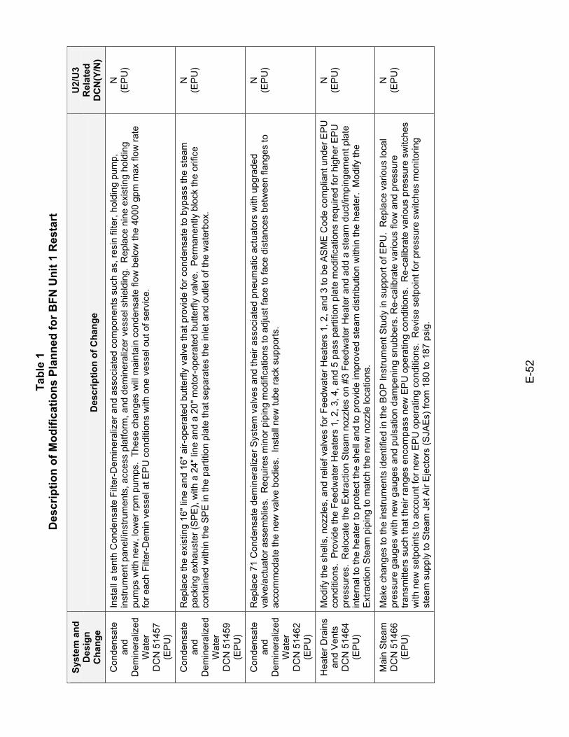
Tabl
e 1
Des
crip
tion
of M
odifi
catio
ns P
lann
ed fo
r BFN
Uni
t 1 R
esta
rt
E-5
2
Syst
em a
nd
Des
ign
Cha
nge
Des
crip
tion
of C
hang
e
U2/
U3
Rel
ated
D
CN
(Y/N
)
Con
dens
ate
and
Dem
iner
aliz
ed
Wat
er
DC
N 5
1457
(E
PU
)
Inst
all a
tent
h C
onde
nsat
e Fi
lter-
Dem
iner
aliz
er a
nd a
ssoc
iate
d co
mpo
nent
s su
ch a
s, re
sin
filte
r, ho
ldin
g pu
mp,
in
stru
men
t pan
el/in
stru
men
ts, a
cces
s pl
atfo
rm, a
nd d
emin
eral
izer
ves
sel s
hiel
ding
. R
epla
ce n
ine
exis
ting
hold
ing
pum
ps w
ith n
ew, l
ower
rpm
pum
ps.
Thes
e ch
ange
s w
ill m
aint
ain
cond
ensa
te fl
ow b
elow
the
4000
gpm
max
flow
rate
fo
r eac
h Fi
lter-D
emin
ves
sel a
t EP
U c
ondi
tions
with
one
ves
sel o
ut o
f ser
vice
.
N
(EP
U)
Con
dens
ate
and
Dem
iner
aliz
ed
Wat
er
DC
N 5
1459
(E
PU
)
Rep
lace
the
exis
ting
16" l
ine
and
16" a
ir-op
erat
ed b
utte
rfly
valv
e th
at p
rovi
de fo
r con
dens
ate
to b
ypas
s th
e st
eam
pa
ckin
g ex
haus
ter (
SP
E),
with
a 2
4" li
ne a
nd a
20"
mot
or-o
pera
ted
butte
rfly
valv
e. P
erm
anen
tly b
lock
the
orifi
ce
cont
aine
d w
ithin
the
SP
E in
the
parti
tion
plat
e th
at s
epar
ates
the
inle
t and
out
let o
f the
wat
erbo
x.
N
(EP
U)
Con
dens
ate
and
Dem
iner
aliz
ed
Wat
er
DC
N 5
1462
(E
PU
)
Rep
lace
71
Con
dens
ate
dem
iner
aliz
er S
yste
m v
alve
s an
d th
eir a
ssoc
iate
d pn
eum
atic
act
uato
rs w
ith u
pgra
ded
valv
e/ac
tuat
or a
ssem
blie
s. R
equi
res
min
or p
ipin
g m
odifi
catio
ns to
adj
ust f
ace
to fa
ce d
ista
nces
bet
wee
n fla
nges
to
acco
mm
odat
e th
e ne
w v
alve
bod
ies.
Ins
tall
new
tube
rack
sup
ports
.
N
(EP
U)
Hea
ter D
rain
s an
d V
ents
D
CN
514
64
(EP
U)
Mod
ify th
e sh
ells
, noz
zles
, and
relie
f val
ves
for F
eedw
ater
Hea
ters
1, 2
, and
3 to
be
AS
ME
Cod
e co
mpl
iant
und
er E
PU
co
nditi
ons.
Pro
vide
the
Feed
wat
er H
eate
rs 1
, 2, 3
, 4, a
nd 5
pas
s pa
rtitio
n pl
ate
mod
ifica
tions
requ
ired
for h
ighe
r EP
U
pres
sure
s. R
eloc
ate
the
Ext
ract
ion
Ste
am n
ozzl
es o
n #3
Fee
dwat
er H
eate
r and
add
a s
team
duc
t/im
ping
emen
t pla
te
inte
rnal
to th
e he
ater
to p
rote
ct th
e sh
ell a
nd to
pro
vide
impr
oved
ste
am d
istri
butio
n w
ithin
the
heat
er.
Mod
ify th
e E
xtra
ctio
n S
team
pip
ing
to m
atch
the
new
noz
zle
loca
tions
.
N
(EP
U)
Mai
n S
team
D
CN
514
66
(EP
U)
Mak
e ch
ange
s to
the
inst
rum
ents
iden
tifie
d in
the
BO
P In
stru
men
t Stu
dy in
sup
port
of E
PU
. R
epla
ce v
ario
us lo
cal
pres
sure
gau
ges
with
new
gau
ges
and
puls
atio
n da
mpe
ning
snu
bber
s. R
e-ca
libra
te v
ario
us fl
ow a
nd p
ress
ure
trans
mitt
ers
such
that
thei
r ran
ges
enco
mpa
ss n
ew E
PU o
pera
ting
cond
ition
s. R
e-ca
libra
te v
ario
us p
ress
ure
switc
hes
with
new
set
poin
ts to
acc
ount
for n
ew E
PU o
pera
ting
cond
ition
s. R
evis
e se
tpoi
nt fo
r pre
ssur
e sw
itche
s m
onito
ring
stea
m s
uppl
y to
Ste
am J
et A
ir E
ject
ors
(SJA
Es)
from
180
to 1
87 p
sig.
N
(EP
U)
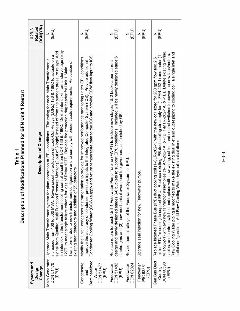
Tabl
e 1
Des
crip
tion
of M
odifi
catio
ns P
lann
ed fo
r BFN
Uni
t 1 R
esta
rt
E-5
3
Syst
em a
nd
Des
ign
Cha
nge
Des
crip
tion
of C
hang
e
U2/
U3
Rel
ated
D
CN
(Y/N
)
Mai
n G
ener
ator
D
CN
514
70
(EP
U)
Upg
rade
Mai
n Tr
ansf
orm
er s
yste
m fo
r pla
nt o
pera
tion
at E
PU
con
ditio
ns.
The
ratin
g fo
r eac
h M
ain
Tran
sfor
mer
is
incr
ease
d fro
m 4
00 to
500
MV
A.
Rev
ise
circ
uit f
or a
ctua
tion
of L
ock-
Out
Rel
ays
(LO
Rs)
186
& 1
86C
to a
ctua
te o
n a
sign
al fr
om Q
ualit
rol M
ulti
Func
tion
Pre
ssur
e M
onito
r (2
out o
f 3 lo
gic)
inst
ead
of fr
om th
e su
dden
pre
ssur
e re
lays
. Add
an
inte
rlock
in th
e tra
nsfo
rmer
s co
olin
g co
ntro
l circ
uit f
rom
LO
R 1
86 &
186
C.
Del
ete
inte
rlock
s fro
m u
nder
volta
ge re
lay
127T
, to
mee
t sin
gle
failu
re c
riter
ia fo
r los
s of
Rel
ay 1
27T.
Rep
lace
fire
pro
tect
ion
ring
head
er fo
r Uni
t 1 M
ain
Tran
sfor
mer
due
to n
ew tr
ansf
orm
ers
conf
igur
atio
n an
d to
com
ply
with
pre
sent
cod
e re
quire
men
ts.
Rel
ocat
ion
of
exis
ting
heat
det
ecto
rs a
nd a
dditi
on o
f (3)
det
ecto
rs.
N
(EP
U)
Con
dens
ate
and
Dem
iner
aliz
ed
Wat
er
DC
N 5
1477
(E
PU
)
Mod
ify th
e U
nit 1
con
dens
er in
stru
men
tatio
n to
pro
vide
for i
mpr
oved
per
form
ance
mon
itorin
g un
der E
PU
con
ditio
ns.
Impr
ove
the
accu
racy
of c
onde
nser
pre
ssur
e in
puts
to th
e In
tegr
ated
Com
pute
r Sys
tem
(IC
S).
Pro
vide
add
ition
al
Con
dens
er C
oolin
g W
ater
(CC
W) s
uppl
y an
d re
turn
tem
pera
ture
dat
a to
the
ICS
and
pro
vide
CC
W fl
ow in
put t
o IC
S.
N
(EP
U)
Feed
wat
er
DC
N 5
1482
(E
PU
)
Rep
lace
roto
rs fo
r eac
h U
nit 1
Fee
dwat
er P
ump
Turb
ine
(FW
PT)
to in
clud
e ne
w s
tage
s 1
& 2
buc
kets
per
cur
rent
de
sign
and
new
ly d
esig
ned
stag
es 3
-6 b
ucke
ts to
sup
port
EP
U c
ondi
tions
. In
clud
ed w
ill b
e ne
wly
des
igne
d st
age
6 di
aphr
agm
s an
d (3
) new
mec
hani
cal o
vers
peed
trip
gov
erno
rs, a
ll fu
rnis
hed
by G
E.
N
(EP
U)
Feed
wat
er
DC
N 6
2024
R
evis
e th
erm
al ra
tings
of t
he F
eedw
ater
Sys
tem
for E
PU
. N
(E
PU
)
Feed
wat
er
PIC
638
81
(EP
U)
Upg
rade
sea
l inj
ectio
n fo
r new
Fee
dwat
er p
umps
. N
(E
PU
)
Gen
Bus
Duc
t C
oolin
g
DC
N 6
0598
(E
PU
)
Rep
lace
Isol
ated
Pha
se B
us (I
PB
) duc
t coo
ling
coil
(1-C
LR-2
62-1
) with
the
new
coi
l siz
ed fo
r 200
gpm
flow
and
2.5
m
illion
BTU
/hr c
oolin
g to
sup
port
EP
U.
Rep
lace
exi
stin
g IP
B d
uct c
oolin
g ai
r sup
ply
fan
(1-F
AN
-262
-1) a
nd m
otor
(1-
MTR
-262
-1) w
ith tw
o ne
w fa
n/m
otor
ass
embl
ies
(1-F
AN
-262
-1A
, & -1
B; 1
-MTR
-262
-1A
, & -1
B).
Del
ete
exis
ting
wiri
ng,
cabl
es, a
nd c
ontro
l sw
itche
s an
d re
plac
e w
ith n
ew w
iring
, cab
les,
and
con
trol s
witc
hes
to p
ower
the
new
fans
/mot
ors.
R
aw C
oolin
g W
ater
pip
ing
is m
odifi
ed to
mak
e th
e ex
istin
g du
al in
let a
nd o
utle
t pip
ing
to c
oolin
g co
il, a
sin
gle
inle
t and
ou
tlet c
onfig
urat
ion.
Add
Raw
Coo
ling
Wat
er h
ydra
ulic
cal
cula
tions
.
N
(EP
U)
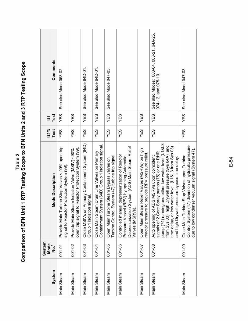
Tabl
e 2
Com
paris
on o
f BFN
Uni
t 1 R
TP T
estin
g Sc
ope
to B
FN U
nits
2 a
nd 3
RTP
Tes
ting
Scop
e
E-5
4
Syst
em
Syst
em
Mod
e N
o.1
Mod
e D
escr
iptio
n U
2/3
Test
U
1 Te
st
Com
men
ts
Mai
n S
team
00
1-01
P
rovi
de M
ain
Turb
ine
Sto
p V
alve
s <
90%
ope
n tri
p si
gnal
to R
eact
or P
rote
ctio
n S
yste
m (9
9).
YE
S
YE
S
See
als
o M
ode
068-
02.
Mai
n S
team
00
1-02
P
rovi
de M
ain
Ste
am Is
olat
ion
Val
ve (M
SIV
) <90
%
open
trip
sig
nal t
o R
eact
or P
rote
ctio
n S
yste
m (9
9).
YES
YES
Mai
n S
team
00
1-03
C
lose
MS
IVs
on P
rimar
y C
onta
inm
ent S
yste
m (6
4D)
Gro
up 1
isol
atio
n si
gnal
. Y
ES
Y
ES
S
ee a
lso
Mod
e 64
D-0
1.
Mai
n S
team
00
1-04
C
lose
Mai
n St
eam
Dra
in L
ine
Val
ves
on P
rimar
y C
onta
inm
ent S
yste
m (6
4D) G
roup
1 is
olat
ion
sign
al.
YE
S
YE
S
See
als
o M
ode
64D
-01.
Mai
n S
team
00
1-05
O
pen
Mai
n Tu
rbin
e S
team
Byp
ass
valv
es o
n Tu
rbin
e C
ontro
l Sys
tem
(47)
turb
ine
trip
sign
al.
YE
S
YE
S
See
als
o M
ode
047-
05.
Mai
n S
team
00
1-06
C
ontro
lled
man
ual d
epre
ssur
izat
ion
of R
eact
or
Pre
ssur
e V
esse
l (R
PV
) by
open
ing
Aut
omat
ic
Dep
ress
uriz
atio
n S
yste
m (A
DS
) Mai
n S
team
Rel
ief
Val
ves
(MSR
Vs)
.
YES
YES
Mai
n S
team
00
1-07
O
pen
Mai
n S
team
Rel
ief V
alve
s (M
SRVs
) on
high
re
acto
r pre
ssur
e to
pro
vide
RP
V p
ress
ure
relie
f. YE
S YE
S
Mai
n S
team
00
1-08
A
uto
open
ing
of A
DS
MS
RV
s up
on c
oinc
iden
t si
gnal
s of
2 C
ore
Spr
ay p
umps
(75)
or o
ne R
HR
pu
mp
(74)
runn
ing
and
eith
er lo
w w
ater
leve
l (L1
&L3
fro
m S
ys 0
3), h
igh
Dry
wel
l pre
ssur
e (S
ys 6
4A),
and
time
dela
y, o
r low
wat
er le
vel
(L1&
L3 fr
om S
ys 0
3)
and
high
Dry
wel
l pre
ssur
e by
pass
tim
e de
lay.
YE
S
YE
S
See
als
o M
odes
: 00
3-04
, 003
-21,
64A
-25,
07
4-12
, and
075
-10
Mai
n S
team
00
1-09
C
lose
Mai
n Tu
rbin
e S
top
Val
ves
upon
Tur
bine
C
ontro
l Sys
tem
(47)
div
ersi
on o
f hyd
raul
ic p
ress
ure
due
to lo
w c
onde
nser
vac
uum
sig
nal (
Sys
tem
47)
.
YE
S
YE
S
See
als
o M
ode
047-
03.
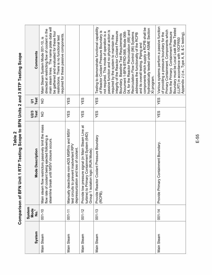
Tabl
e 2
Com
paris
on o
f BFN
Uni
t 1 R
TP T
estin
g Sc
ope
to B
FN U
nits
2 a
nd 3
RTP
Tes
ting
Scop
e
E-5
5
Syst
em
Syst
em
Mod
e N
o.1
Mod
e D
escr
iptio
n U
2/3
Test
U
1 Te
st
Com
men
ts
Mai
n S
team
00
1-10
M
ain
stea
m fl
ow re
stric
tors
pas
sive
ly li
mit
the
mas
s flo
w ra
te o
f coo
lant
bei
ng e
ject
ed fo
llow
ing
a st
eam
line
brea
k un
til M
SIV
clo
sure
occ
urs.
NO
N
O
Mai
n S
team
Sys
tem
Mod
e 00
1-10
, is
dire
cted
at r
estri
ctin
g flo
w o
f coo
lant
in th
e m
ain
stea
m li
nes.
The
nam
e pl
ate
data
will
be g
athe
red
and
eval
uate
d fo
r the
se fo
ur
rest
rictio
ns. T
here
is n
o fu
nctio
nal t
est
requ
ired
for t
hese
pas
sive
com
pone
nts.
Mai
n S
team
00
1-11
M
anua
lly d
eact
ivat
e no
n-AD
S M
SR
Vs
and
MS
IV
test
circ
uits
to p
reve
nt in
adve
rtent
RP
V
depr
essu
rizat
ion
and
loss
of c
oola
nt.
YES
YES
Mai
n S
team
00
1-12
P
rovi
de lo
w p
ress
ure
sign
al (i
n M
ain
Ste
am L
ine
at
turb
ine)
to P
rimar
y C
onta
inm
ent S
yste
m (6
4D)
Gro
up 1
isol
atio
n lo
gic
(RU
N M
ode)
.
YES
YES
Mai
n S
team
00
1-13
P
rovi
de R
eact
or C
oola
nt P
ress
ure
Bou
ndar
y (R
CP
B).
YE
S
YE
S
Test
ing
to d
emon
stra
te fu
nctio
nal c
apab
ility
of R
eact
or C
oola
nt P
ress
ure
Bou
ndar
y is
no
t req
uire
d. T
his
mod
e of
ope
ratio
n is
a
pass
ive
func
tion
and
no p
hysi
cal a
ctio
n is
re
quire
d by
the
syst
em to
mai
ntai
n th
e in
tegr
ity o
f the
Rea
ctor
Coo
lant
Pre
ssur
e B
ound
ary.
Bas
elin
e Te
st R
equi
rem
ents
D
ocum
ent 1
-BFN
-BTR
D-0
68, M
ode
068-
04, f
or th
e R
eact
or R
ecirc
ulat
ion
(68)
and
R
ecirc
ulat
ion
Flow
Con
trol (
96) S
yste
ms
addr
esse
s th
e fu
nctio
nalit
y of
the
RC
PB
an
d its
ove
rall
test
ing.
Pip
ing
and
com
pone
nts
whi
ch s
uppl
y a
RC
PB
sha
ll be
hy
dros
tatic
ally
test
ed u
nder
AS
ME
Sec
tion
XI p
rogr
am.
Mai
n S
team
00
1-14
P
rovi
de P
rimar
y C
onta
inm
ent B
ound
ary.
Y
ES
Y
ES
V
ario
us s
yste
ms
perfo
rm a
pas
sive
func
tion
of p
rovi
ding
a p
ress
ure
boun
dary
for t
he
Prim
ary
Con
tain
men
t. C
ompo
nent
s w
hich
fo
rm th
e P
rimar
y C
onta
inm
ent P
ress
ure
Bou
ndar
y m
ust b
e Lo
cal L
eak
Rat
e Te
sted
(L
LRT)
in a
ccor
danc
e w
ith 1
0CFR
50
App
endi
x J
(i.e.
, Typ
e A
, B, &
C te
stin
g).
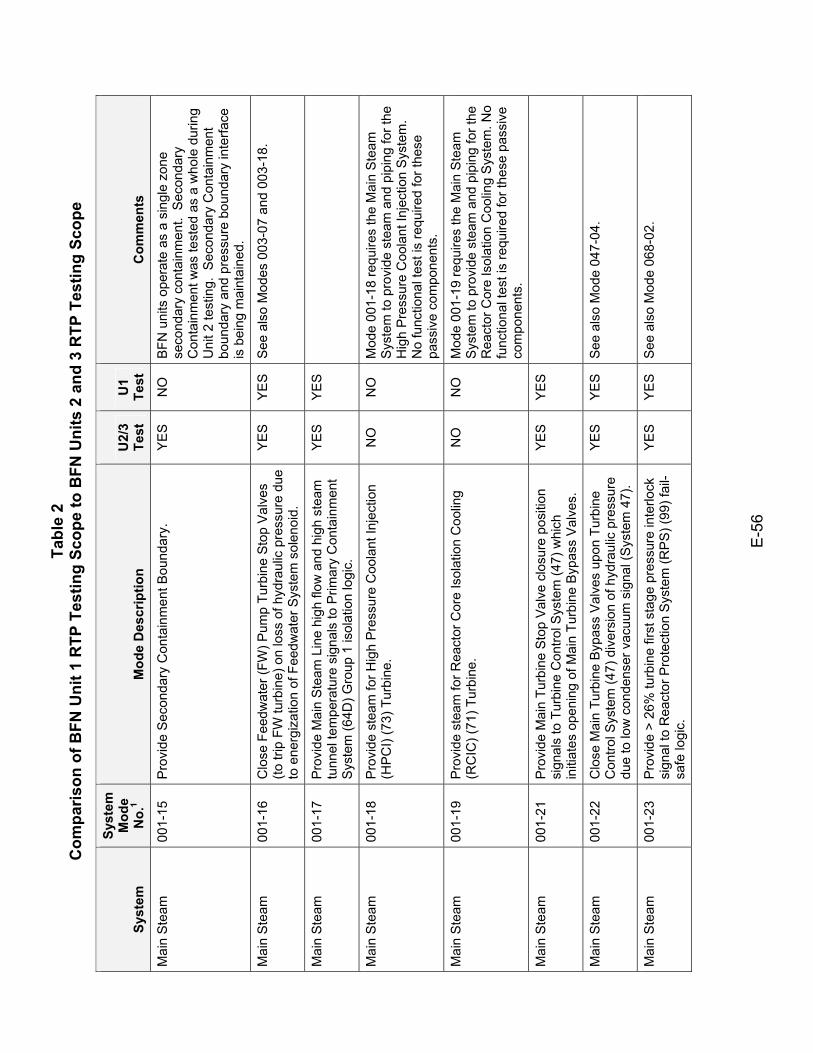
Tabl
e 2
Com
paris
on o
f BFN
Uni
t 1 R
TP T
estin
g Sc
ope
to B
FN U
nits
2 a
nd 3
RTP
Tes
ting
Scop
e
E-5
6
Syst
em
Syst
em
Mod
e N
o.1
Mod
e D
escr
iptio
n U
2/3
Test
U
1 Te
st
Com
men
ts
Mai
n S
team
00
1-15
P
rovi
de S
econ
dary
Con
tain
men
t Bou
ndar
y.
YE
S
NO
B
FN u
nits
ope
rate
as
a si
ngle
zon
e se
cond
ary
cont
ainm
ent.
Sec
onda
ry
Con
tain
men
t was
test
ed a
s a
who
le d
urin
g U
nit 2
test
ing.
Sec
onda
ry C
onta
inm
ent
boun
dary
and
pre
ssur
e bo
unda
ry in
terfa
ce
is b
eing
mai
ntai
ned.
Mai
n S
team
00
1-16
C
lose
Fee
dwat
er (F
W) P
ump
Turb
ine
Stop
Val
ves
(to tr
ip F
W tu
rbin
e) o
n lo
ss o
f hyd
raul
ic p
ress
ure
due
to e
nerg
izat
ion
of F
eedw
ater
Sys
tem
sol
enoi
d.
YE
S
YE
S
See
als
o M
odes
003
-07
and
003-
18.
Mai
n S
team
00
1-17
P
rovi
de M
ain
Ste
am L
ine
high
flow
and
hig
h st
eam
tu
nnel
tem
pera
ture
sig
nals
to P
rimar
y C
onta
inm
ent
Sys
tem
(64D
) Gro
up 1
isol
atio
n lo
gic.
YES
YES
Mai
n S
team
00
1-18
P
rovi
de s
team
for H
igh
Pre
ssur
e C
oola
nt In
ject
ion
(HPC
I) (7
3) T
urbi
ne.
NO
N
O
Mod
e 00
1-18
requ
ires
the
Mai
n S
team
S
yste
m to
pro
vide
ste
am a
nd p
ipin
g fo
r the
H
igh
Pre
ssur
e C
oola
nt In
ject
ion
Sys
tem
. N
o fu
nctio
nal t
est i
s re
quire
d fo
r the
se
pass
ive
com
pone
nts.
Mai
n S
team
00
1-19
P
rovi
de s
team
for R
eact
or C
ore
Isol
atio
n C
oolin
g (R
CIC
) (71
) Tur
bine
. N
O
NO
M
ode
001-
19 re
quire
s th
e M
ain
Ste
am
Sys
tem
to p
rovi
de s
team
and
pip
ing
for t
he
Rea
ctor
Cor
e Is
olat
ion
Coo
ling
Sys
tem
. No
func
tiona
l tes
t is
requ
ired
for t
hese
pas
sive
co
mpo
nent
s.
Mai
n S
team
00
1-21
P
rovi
de M
ain
Turb
ine
Sto
p V
alve
clo
sure
pos
ition
si
gnal
s to
Tur
bine
Con
trol S
yste
m (4
7) w
hich
in
itiat
es o
peni
ng o
f Mai
n Tu
rbin
e B
ypas
s V
alve
s.
YES
YES
Mai
n S
team
00
1-22
C
lose
Mai
n Tu
rbin
e B
ypas
s V
alve
s up
on T
urbi
ne
Con
trol S
yste
m (4
7) d
iver
sion
of h
ydra
ulic
pre
ssur
e du
e to
low
con
dens
er v
acuu
m s
igna
l (S
yste
m 4
7).
YE
S
YE
S
See
als
o M
ode
047-
04.
Mai
n S
team
00
1-23
P
rovi
de >
26%
turb
ine
first
sta
ge p
ress
ure
inte
rlock
si
gnal
to R
eact
or P
rote
ctio
n S
yste
m (R
PS
) (99
) fai
l-sa
fe lo
gic.
YE
S
YE
S
See
als
o M
ode
068-
02.
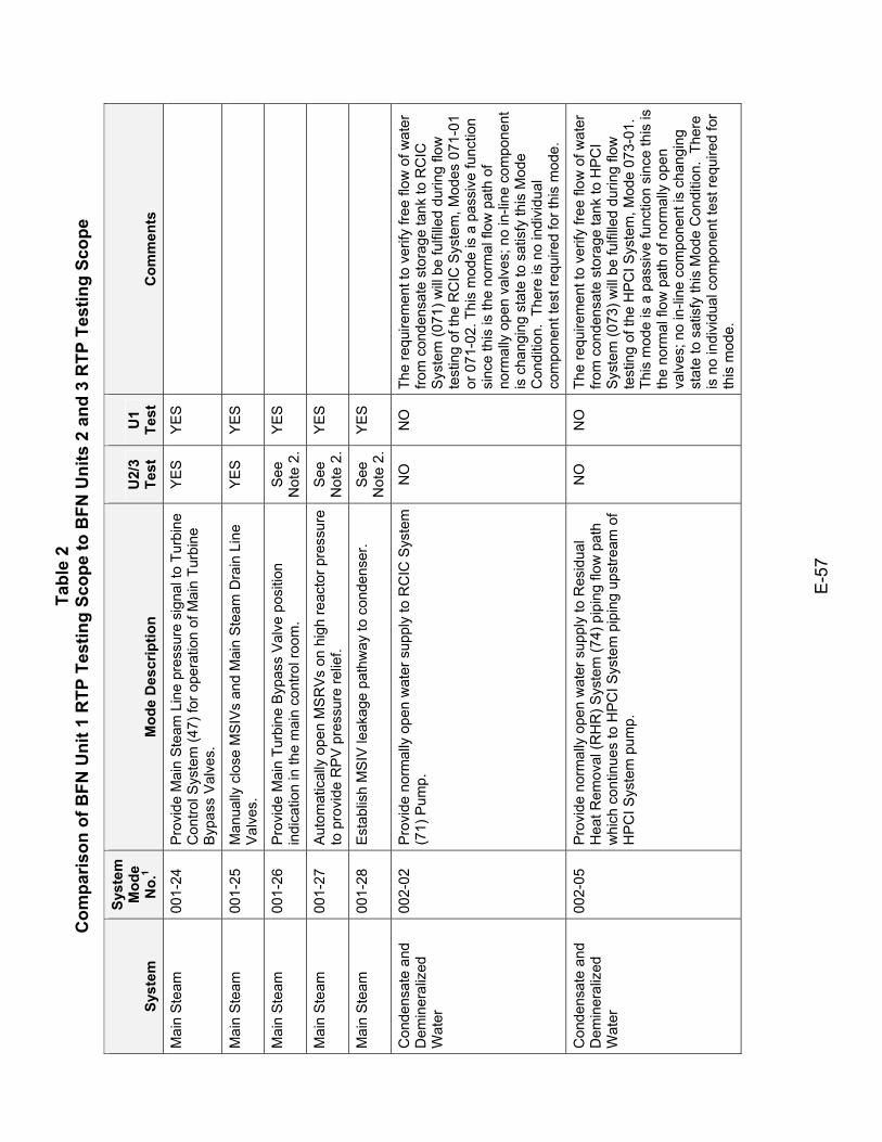
Tabl
e 2
Com
paris
on o
f BFN
Uni
t 1 R
TP T
estin
g Sc
ope
to B
FN U
nits
2 a
nd 3
RTP
Tes
ting
Scop
e
E-5
7
Syst
em
Syst
em
Mod
e N
o.1
Mod
e D
escr
iptio
n U
2/3
Test
U
1 Te
st
Com
men
ts
Mai
n S
team
00
1-24
P
rovi
de M
ain
Ste
am L
ine
pres
sure
sig
nal t
o Tu
rbin
e C
ontro
l Sys
tem
(47)
for o
pera
tion
of M
ain
Turb
ine
Bypa
ss V
alve
s.
YES
YES
Mai
n S
team
00
1-25
M
anua
lly c
lose
MS
IVs
and
Mai
n S
team
Dra
in L
ine
Val
ves.
YE
S YE
S
Mai
n S
team
00
1-26
P
rovi
de M
ain
Turb
ine
Byp
ass
Val
ve p
ositi
on
indi
catio
n in
the
mai
n co
ntro
l roo
m.
See
N
ote
2.
YES
Mai
n S
team
00
1-27
A
utom
atic
ally
ope
n M
SR
Vs o
n hi
gh re
acto
r pre
ssur
e to
pro
vide
RPV
pre
ssur
e re
lief.
See
N
ote
2.
YES
Mai
n S
team
00
1-28
E
stab
lish
MS
IV le
akag
e pa
thw
ay to
con
dens
er.
See
N
ote
2.
YES
Con
dens
ate
and
Dem
iner
aliz
ed
Wat
er
002-
02
Pro
vide
nor
mal
ly o
pen
wat
er s
uppl
y to
RC
IC S
yste
m
(71)
Pum
p.
NO
N
O
The
requ
irem
ent t
o ve
rify
free
flow
of w
ater
fro
m c
onde
nsat
e st
orag
e ta
nk to
RC
IC
Sys
tem
(071
) will
be fu
lfille
d du
ring
flow
te
stin
g of
the
RC
IC S
yste
m, M
odes
071
-01
or 0
71-0
2. T
his
mod
e is
a p
assi
ve fu
nctio
n si
nce
this
is th
e no
rmal
flow
pat
h of
no
rmal
ly o
pen
valv
es; n
o in
-line
com
pone
nt
is c
hang
ing
stat
e to
sat
isfy
this
Mod
e C
ondi
tion.
The
re is
no
indi
vidu
al
com
pone
nt te
st re
quire
d fo
r thi
s m
ode.
Con
dens
ate
and
Dem
iner
aliz
ed
Wat
er
002-
05
Pro
vide
nor
mal
ly o
pen
wat
er s
uppl
y to
Res
idua
l H
eat R
emov
al (R
HR
) Sys
tem
(74)
pip
ing
flow
pat
h w
hich
con
tinue
s to
HPC
I Sys
tem
pip
ing
upst
ream
of
HP
CI S
yste
m p
ump.
NO
N
O
The
requ
irem
ent t
o ve
rify
free
flow
of w
ater
fro
m c
onde
nsat
e st
orag
e ta
nk to
HPC
I S
yste
m (0
73) w
ill be
fulfi
lled
durin
g flo
w
test
ing
of th
e H
PC
I Sys
tem
, Mod
e 07
3-01
. Th
is m
ode
is a
pas
sive
func
tion
sinc
e th
is is
th
e no
rmal
flow
pat
h of
nor
mal
ly o
pen
valv
es; n
o in
-line
com
pone
nt is
cha
ngin
g st
ate
to s
atis
fy th
is M
ode
Con
ditio
n. T
here
is
no
indi
vidu
al c
ompo
nent
test
requ
ired
for
this
mod
e.
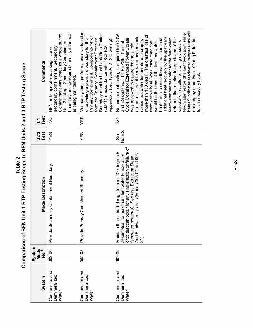
Tabl
e 2
Com
paris
on o
f BFN
Uni
t 1 R
TP T
estin
g Sc
ope
to B
FN U
nits
2 a
nd 3
RTP
Tes
ting
Scop
e
E-5
8
Syst
em
Syst
em
Mod
e N
o.1
Mod
e D
escr
iptio
n U
2/3
Test
U
1 Te
st
Com
men
ts
Con
dens
ate
and
Dem
iner
aliz
ed
Wat
er
002-
06
Pro
vide
Sec
onda
ry C
onta
inm
ent B
ound
ary.
Y
ES
N
O
BFN
uni
ts o
pera
te a
s a
sing
le z
one
seco
ndar
y co
ntai
nmen
t. S
econ
dary
C
onta
inm
ent w
as te
sted
as
a w
hole
dur
ing
Uni
t 2 te
stin
g. S
econ
dary
Con
tain
men
t bo
unda
ry a
nd p
ress
ure
boun
dary
inte
rface
is
bei
ng m
aint
aine
d.
Con
dens
ate
and
Dem
iner
aliz
ed
Wat
er
002-
08
Pro
vide
Prim
ary
Con
tain
men
t Bou
ndar
y.
YE
S
YE
S
Var
ious
sys
tem
s pe
rform
a p
assi
ve fu
nctio
n of
pro
vidi
ng a
pre
ssur
e bo
unda
ry fo
r the
P
rimar
y C
onta
inm
ent.
Com
pone
nts
whi
ch
form
the
Prim
ary
Con
tain
men
t Pre
ssur
e B
ound
ary
mus
t be
Loca
l Lea
k R
ate
Test
ed
(LLR
T) in
acc
orda
nce
with
10C
FR50
A
ppen
dix
J (i.
e., T
ype
A, B
, & C
test
ing)
.
Con
dens
ate
and
Dem
iner
aliz
ed
Wat
er
002-
09
Mai
ntai
n th
e as
-bui
lt de
sign
to m
eet 1
00 d
egre
e F
assu
mpt
ion
for m
axim
um fe
edw
ater
tem
pera
ture
dr
op th
at c
an o
ccur
for a
ny s
ingl
e ac
tion
or fa
ilure
of
feed
wat
er h
eate
r(s).
See
als
o E
xtra
ctio
n S
team
A
nd F
eedw
ater
sys
tem
s (M
odes
005
-01
and
003-
24).
See
N
ote
2.
NO
N
o co
mpo
nent
test
ing
is re
quire
d fo
r CD
W
and
ES
sys
tem
s. T
he P
EP
SE
The
rmal
C
ycle
Mod
el fo
r Ext
ende
d P
ower
Upr
ate
was
revi
ewed
to a
ssur
e th
at n
o si
ngle
ac
tion
or fa
ilure
of f
eedw
ater
hea
ter c
ould
ca
use
feed
wat
er te
mpe
ratu
re to
dro
p by
m
ore
than
100
deg
F. T
he g
reat
est l
oss
of
reco
vera
ble
heat
(wor
st c
ase
cond
ition
) w
ould
be
the
loss
of t
he la
st fe
edw
ater
he
ater
in li
ne s
ince
ther
e is
no
chan
ce o
f ad
ditio
nal h
eat r
ecov
ery
by th
e up
stre
am
feed
wat
er h
eate
rs p
rior t
o th
e fe
edw
ater
re
turn
to th
e re
acto
r. In
terp
reta
tion
of th
e ca
lcul
atio
n re
sults
for t
he h
igh
pres
sure
fe
edw
ater
hea
ter (
the
last
feed
wat
er in
-line
he
ater
) ind
icat
es fe
edw
ater
tem
pera
ture
will
no
t dro
p by
mor
e th
an 1
00 d
eg F
due
to
loss
in re
cove
ry h
eat.
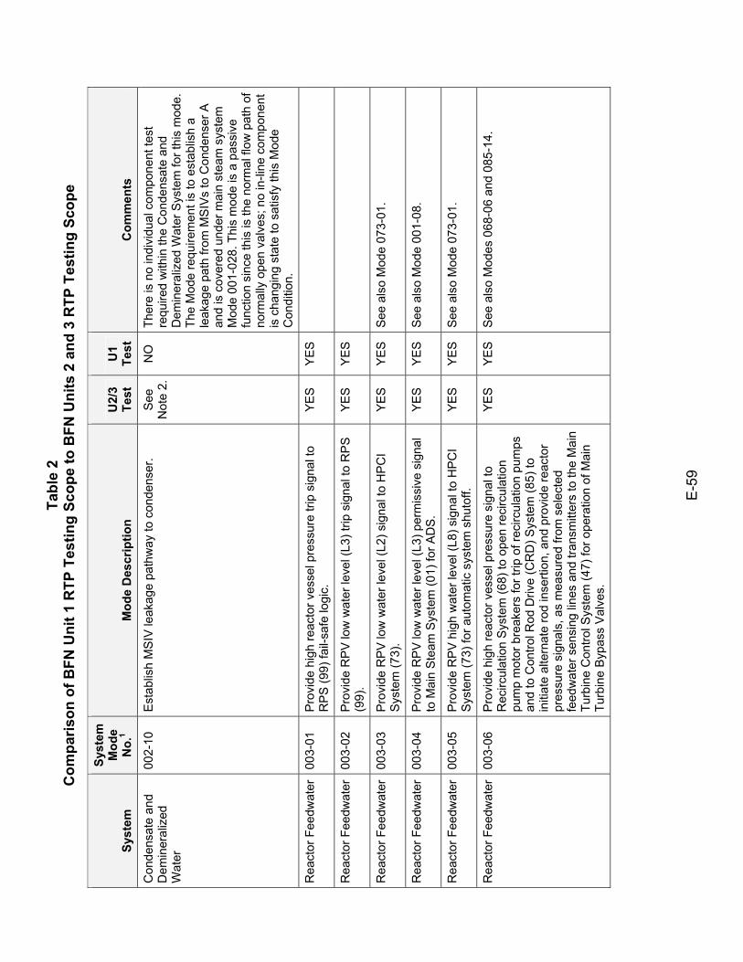
Tabl
e 2
Com
paris
on o
f BFN
Uni
t 1 R
TP T
estin
g Sc
ope
to B
FN U
nits
2 a
nd 3
RTP
Tes
ting
Scop
e
E-5
9
Syst
em
Syst
em
Mod
e N
o.1
Mod
e D
escr
iptio
n U
2/3
Test
U
1 Te
st
Com
men
ts
Con
dens
ate
and
Dem
iner
aliz
ed
Wat
er
002-
10
Est
ablis
h M
SIV
leak
age
path
way
to c
onde
nser
. S
ee
Not
e 2.
N
O
Ther
e is
no
indi
vidu
al c
ompo
nent
test
re
quire
d w
ithin
the
Con
dens
ate
and
Dem
iner
aliz
ed W
ater
Sys
tem
for t
his
mod
e.
The
Mod
e re
quire
men
t is
to e
stab
lish
a le
akag
e pa
th fr
om M
SIV
s to
Con
dens
er A
an
d is
cov
ered
und
er m
ain
stea
m s
yste
m
Mod
e 00
1-02
8. T
his
mod
e is
a p
assi
ve
func
tion
sinc
e th
is is
the
norm
al fl
ow p
ath
of
norm
ally
ope
n va
lves
; no
in-li
ne c
ompo
nent
is
cha
ngin
g st
ate
to s
atis
fy th
is M
ode
Con
ditio
n.
Rea
ctor
Fee
dwat
er
003-
01
Pro
vide
hig
h re
acto
r ves
sel p
ress
ure
trip
sign
al to
R
PS
(99)
fail-
safe
logi
c.
YES
YES
Rea
ctor
Fee
dwat
er
003-
02
Pro
vide
RP
V lo
w w
ater
leve
l (L3
) trip
sig
nal t
o R
PS
(9
9).
YES
YES
Rea
ctor
Fee
dwat
er
003-
03
Pro
vide
RP
V lo
w w
ater
leve
l (L2
) sig
nal t
o H
PC
I S
yste
m (7
3).
YE
S
YE
S
See
als
o M
ode
073-
01.
Rea
ctor
Fee
dwat
er
003-
04
Pro
vide
RP
V lo
w w
ater
leve
l (L3
) per
mis
sive
sig
nal
to M
ain
Ste
am S
yste
m (0
1) fo
r AD
S.
YE
S
YE
S
See
als
o M
ode
001-
08.
Rea
ctor
Fee
dwat
er
003-
05
Pro
vide
RP
V h
igh
wat
er le
vel (
L8) s
igna
l to
HP
CI
Sys
tem
(73)
for a
utom
atic
sys
tem
shu
toff.
Y
ES
Y
ES
S
ee a
lso
Mod
e 07
3-01
.
Rea
ctor
Fee
dwat
er
003-
06
Pro
vide
hig
h re
acto
r ves
sel p
ress
ure
sign
al to
R
ecirc
ulat
ion
Sys
tem
(68)
to o
pen
reci
rcul
atio
n pu
mp
mot
or b
reak
ers
for t
rip o
f rec
ircul
atio
n pu
mps
an
d to
Con
trol R
od D
rive
(CR
D) S
yste
m (8
5) to
in
itiat
e al
tern
ate
rod
inse
rtion
, and
pro
vide
reac
tor
pres
sure
sig
nals
, as
mea
sure
d fro
m s
elec
ted
feed
wat
er s
ensi
ng li
nes
and
trans
mitt
ers
to th
e M
ain
Turb
ine
Con
trol S
yste
m (4
7) fo
r ope
ratio
n of
Mai
n Tu
rbin
e B
ypas
s V
alve
s.
YE
S
YE
S
See
als
o M
odes
068
-06
and
085-
14.
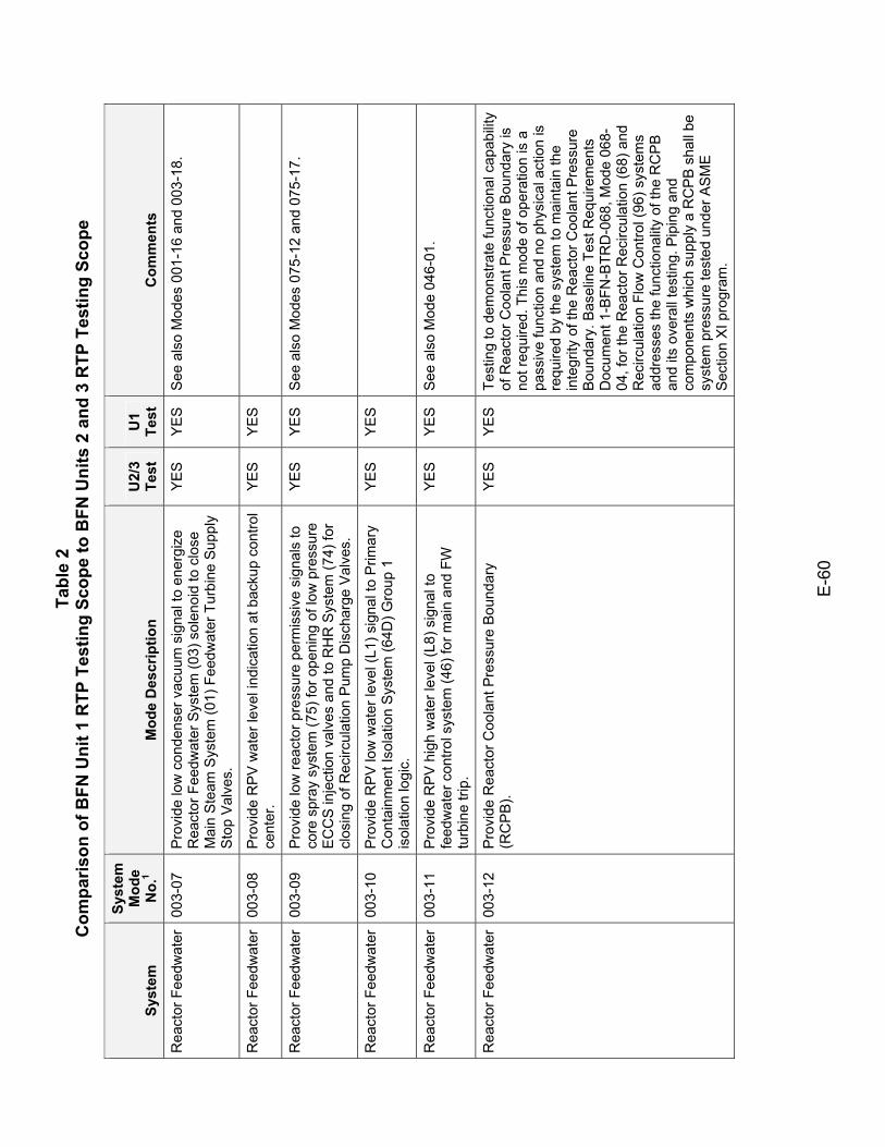
Tabl
e 2
Com
paris
on o
f BFN
Uni
t 1 R
TP T
estin
g Sc
ope
to B
FN U
nits
2 a
nd 3
RTP
Tes
ting
Scop
e
E-6
0
Syst
em
Syst
em
Mod
e N
o.1
Mod
e D
escr
iptio
n U
2/3
Test
U
1 Te
st
Com
men
ts
Rea
ctor
Fee
dwat
er
003-
07
Pro
vide
low
con
dens
er v
acuu
m s
igna
l to
ener
gize
R
eact
or F
eedw
ater
Sys
tem
(03)
sol
enoi
d to
clo
se
Mai
n S
team
Sys
tem
(01)
Fee
dwat
er T
urbi
ne S
uppl
y S
top
Val
ves.
YE
S
YE
S
See
als
o M
odes
001
-16
and
003-
18.
Rea
ctor
Fee
dwat
er
003-
08
Pro
vide
RP
V w
ater
leve
l ind
icat
ion
at b
acku
p co
ntro
l ce
nter
. YE
S YE
S
Rea
ctor
Fee
dwat
er
003-
09
Pro
vide
low
reac
tor p
ress
ure
perm
issi
ve s
igna
ls to
co
re s
pray
sys
tem
(75)
for o
peni
ng o
f low
pre
ssur
e E
CC
S in
ject
ion
valv
es a
nd to
RH
R S
yste
m (7
4) fo
r cl
osin
g of
Rec
ircul
atio
n P
ump
Dis
char
ge V
alve
s.
YE
S
YE
S
See
als
o M
odes
075
-12
and
075-
17.
Rea
ctor
Fee
dwat
er
003-
10
Pro
vide
RP
V lo
w w
ater
leve
l (L1
) sig
nal t
o P
rimar
y C
onta
inm
ent I
sola
tion
Sys
tem
(64D
) Gro
up 1
is
olat
ion
logi
c.
YES
YES
Rea
ctor
Fee
dwat
er
003-
11
Pro
vide
RP
V h
igh
wat
er le
vel (
L8) s
igna
l to
feed
wat
er c
ontro
l sys
tem
(46)
for m
ain
and
FW
turb
ine
trip.
YE
S
YE
S
See
als
o M
ode
046-
01.
Rea
ctor
Fee
dwat
er
003-
12
Pro
vide
Rea
ctor
Coo
lant
Pre
ssur
e B
ound
ary
(RC
PB
). Y
ES
Y
ES
Te
stin
g to
dem
onst
rate
func
tiona
l cap
abilit
y of
Rea
ctor
Coo
lant
Pre
ssur
e B
ound
ary
is
not r
equi
red.
Thi
s m
ode
of o
pera
tion
is a
pa
ssiv
e fu
nctio
n an
d no
phy
sica
l act
ion
is
requ
ired
by th
e sy
stem
to m
aint
ain
the
inte
grity
of t
he R
eact
or C
oola
nt P
ress
ure
Bou
ndar
y. B
asel
ine
Test
Req
uire
men
ts
Doc
umen
t 1-B
FN-B
TRD
-068
, Mod
e 06
8-04
, for
the
Rea
ctor
Rec
ircul
atio
n (6
8) a
nd
Rec
ircul
atio
n Fl
ow C
ontro
l (96
) sys
tem
s ad
dres
ses
the
func
tiona
lity
of th
e R
CP
B
and
its o
vera
ll te
stin
g. P
ipin
g an
d co
mpo
nent
s w
hich
sup
ply
a R
CP
B s
hall
be
syst
em p
ress
ure
test
ed u
nder
AS
ME
S
ectio
n X
I pro
gram
.
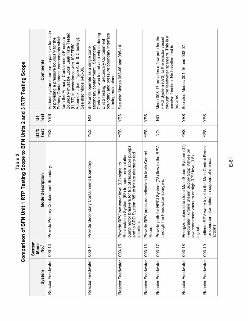
Tabl
e 2
Com
paris
on o
f BFN
Uni
t 1 R
TP T
estin
g Sc
ope
to B
FN U
nits
2 a
nd 3
RTP
Tes
ting
Scop
e
E-6
1
Syst
em
Syst
em
Mod
e N
o.1
Mod
e D
escr
iptio
n U
2/3
Test
U
1 Te
st
Com
men
ts
Rea
ctor
Fee
dwat
er
003-
13
Pro
vide
Prim
ary
Con
tain
men
t Bou
ndar
y.
YE
S
YE
S
Var
ious
sys
tem
s pe
rform
a p
assi
ve fu
nctio
n of
pro
vidi
ng a
pre
ssur
e bo
unda
ry fo
r the
P
rimar
y C
onta
inm
ent.
com
pone
nts
whi
ch
form
the
Prim
ary
Con
tain
men
t Pre
ssur
e B
ound
ary
mus
t be
Loca
l Lea
k R
ate
Test
ed
(LLR
T) in
acc
orda
nce
with
10C
FR50
A
ppen
dix
J (i.
e., T
ype
A, B
, & C
test
ing)
. S
ee a
lso
Mod
e 64
C-0
6.
Rea
ctor
Fee
dwat
er
003-
14
Pro
vide
Sec
onda
ry C
onta
inm
ent B
ound
ary.
Y
ES
N
O
BFN
uni
ts o
pera
te a
s a
sing
le z
one
seco
ndar
y co
ntai
nmen
t. S
econ
dary
C
onta
inm
ent w
as te
sted
as
a w
hole
dur
ing
Uni
t 2 te
stin
g. S
econ
dary
Con
tain
men
t bo
unda
ry a
nd p
ress
ure
boun
dary
inte
rface
is
bei
ng m
aint
aine
d.
Rea
ctor
Fee
dwat
er
003-
15
Pro
vide
RP
V lo
w w
ater
leve
l (L2
) sig
nal t
o R
ecirc
ulat
ion
Sys
tem
(68)
to o
pen
reci
rcul
atio
n pu
mp
mot
or b
reak
ers
for t
rip o
f rec
ircul
atio
n pu
mps
an
d to
CR
D S
yste
m (8
5) to
initi
ate
alte
rnat
e ro
d in
serti
on.
YE
S
YE
S
See
als
o M
odes
068
-06
and
085-
14.
Rea
ctor
Fee
dwat
er
003-
16
Pro
vide
RP
V p
ress
ure
indi
catio
n in
Mai
n C
ontro
l R
oom
. YE
S YE
S
Rea
ctor
Fee
dwat
er
003-
17
Pro
vide
pat
h fo
r HP
CI S
yste
m (7
3) fl
ow to
the
RP
V
thro
ugh
the
Feed
wat
er s
parg
ers.
N
O
NO
M
ode
003-
17 p
rovi
des
a flo
w p
ath
for t
he
HP
CI S
yste
m (0
73) t
o th
e re
acto
r ves
sel
thro
ugh
the
feed
wat
er s
parg
ers.
Thi
s is
a
pass
ive
func
tion.
No
base
line
test
is
requ
ired.
Rea
ctor
Fee
dwat
er
003-
18
Ene
rgiz
e so
leno
id to
clo
se M
ain
Ste
am S
yste
m (0
1)
Feed
wat
er T
urbi
ne S
team
Sup
ply
Sto
p V
alve
s on
lo
w c
onde
nser
vac
uum
or h
igh
RP
V le
vel (
L8)
sign
al.
YE
S
YE
S
See
als
o M
odes
001
-16
and
003-
07.
Rea
ctor
Fee
dwat
er
003-
19
Indi
cate
RP
V w
ater
leve
l in
the
Mai
n C
ontro
l Roo
m
for o
pera
tor i
nfor
mat
ion
in s
uppo
rt of
man
ual
actio
ns.
YES
YES
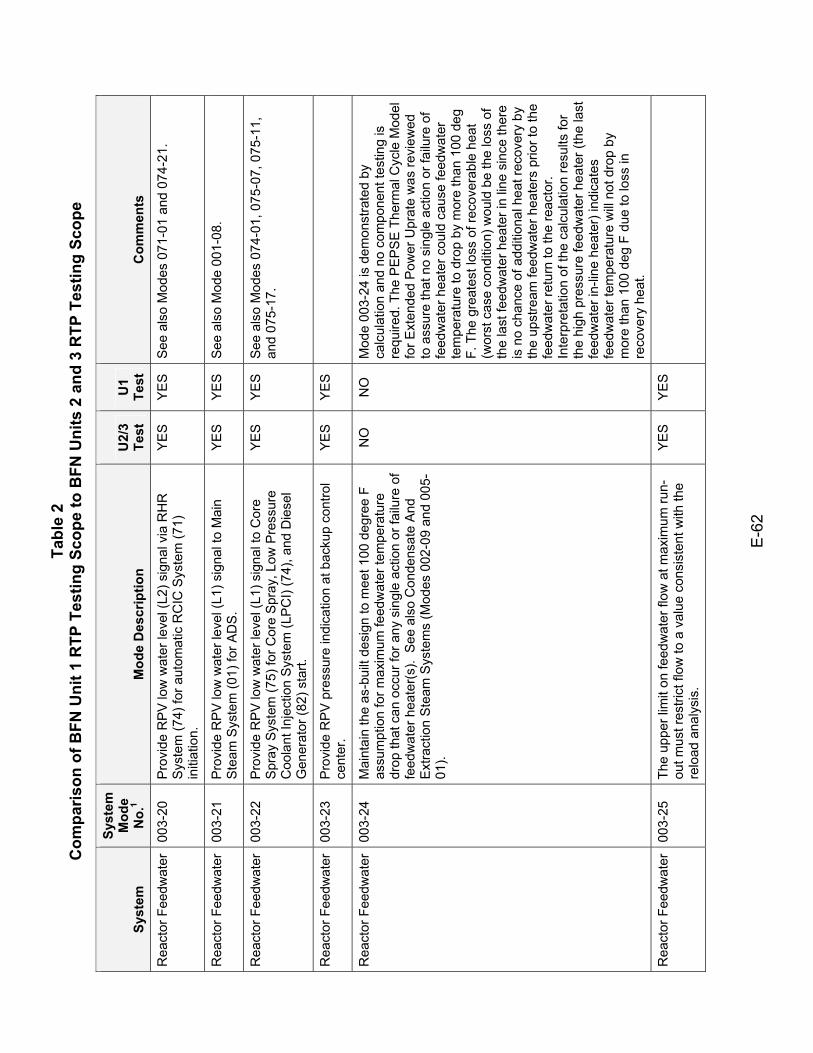
Tabl
e 2
Com
paris
on o
f BFN
Uni
t 1 R
TP T
estin
g Sc
ope
to B
FN U
nits
2 a
nd 3
RTP
Tes
ting
Scop
e
E-6
2
Syst
em
Syst
em
Mod
e N
o.1
Mod
e D
escr
iptio
n U
2/3
Test
U
1 Te
st
Com
men
ts
Rea
ctor
Fee
dwat
er
003-
20
Pro
vide
RP
V lo
w w
ater
leve
l (L2
) sig
nal v
ia R
HR
S
yste
m (7
4) fo
r aut
omat
ic R
CIC
Sys
tem
(71)
in
itiat
ion.
YE
S
YE
S
See
als
o M
odes
071
-01
and
074-
21.
Rea
ctor
Fee
dwat
er
003-
21
Pro
vide
RP
V lo
w w
ater
leve
l (L1
) sig
nal t
o M
ain
Ste
am S
yste
m (0
1) fo
r AD
S.
YE
S
YE
S
See
als
o M
ode
001-
08.
Rea
ctor
Fee
dwat
er
003-
22
Pro
vide
RP
V lo
w w
ater
leve
l (L1
) sig
nal t
o C
ore
Spr
ay S
yste
m (7
5) fo
r Cor
e S
pray
, Low
Pre
ssur
e C
oola
nt In
ject
ion
Sys
tem
(LP
CI)
(74)
, and
Die
sel
Gen
erat
or (8
2) s
tart.
YE
S
YE
S
See
als
o M
odes
074
-01,
075
-07,
075
-11,
an
d 07
5-17
.
Rea
ctor
Fee
dwat
er
003-
23
Pro
vide
RP
V p
ress
ure
indi
catio
n at
bac
kup
cont
rol
cent
er.
YES
YES
Rea
ctor
Fee
dwat
er
003-
24
Mai
ntai
n th
e as
-bui
lt de
sign
to m
eet 1
00 d
egre
e F
assu
mpt
ion
for m
axim
um fe
edw
ater
tem
pera
ture
dr
op th
at c
an o
ccur
for a
ny s
ingl
e ac
tion
or fa
ilure
of
feed
wat
er h
eate
r(s)
. S
ee a
lso
Con
dens
ate
And
E
xtra
ctio
n S
team
Sys
tem
s (M
odes
002
-09
and
005-
01).
NO
N
O
Mod
e 00
3-24
is d
emon
stra
ted
by
calc
ulat
ion
and
no c
ompo
nent
test
ing
is
requ
ired.
The
PE
PS
E T
herm
al C
ycle
Mod
el
for E
xten
ded
Pow
er U
prat
e w
as re
view
ed
to a
ssur
e th
at n
o si
ngle
act
ion
or fa
ilure
of
feed
wat
er h
eate
r cou
ld c
ause
feed
wat
er
tem
pera
ture
to d
rop
by m
ore
than
100
deg
F.
The
gre
ates
t los
s of
reco
vera
ble
heat
(w
orst
cas
e co
nditi
on) w
ould
be
the
loss
of
the
last
feed
wat
er h
eate
r in
line
sinc
e th
ere
is n
o ch
ance
of a
dditi
onal
hea
t rec
over
y by
th
e up
stre
am fe
edw
ater
hea
ters
prio
r to
the
feed
wat
er re
turn
to th
e re
acto
r.
Inte
rpre
tatio
n of
the
calc
ulat
ion
resu
lts fo
r th
e hi
gh p
ress
ure
feed
wat
er h
eate
r (th
e la
st
feed
wat
er in
-line
hea
ter)
indi
cate
s fe
edw
ater
tem
pera
ture
will
not d
rop
by
mor
e th
an 1
00 d
eg F
due
to lo
ss in
re
cove
ry h
eat.
Rea
ctor
Fee
dwat
er
003-
25
The
uppe
r lim
it on
feed
wat
er fl
ow a
t max
imum
run-
out m
ust r
estri
ct fl
ow to
a v
alue
con
sist
ent w
ith th
e re
load
ana
lysi
s.
YES
YES
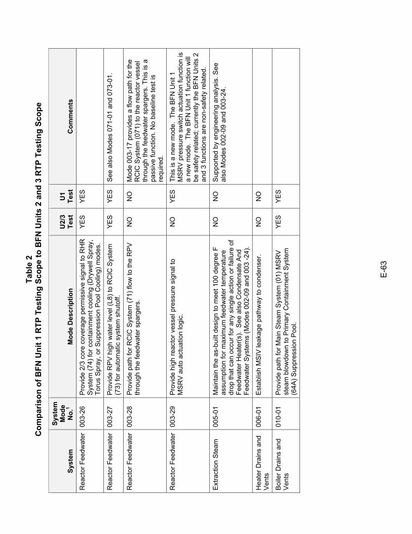
Tabl
e 2
Com
paris
on o
f BFN
Uni
t 1 R
TP T
estin
g Sc
ope
to B
FN U
nits
2 a
nd 3
RTP
Tes
ting
Scop
e
E-6
3
Syst
em
Syst
em
Mod
e N
o.1
Mod
e D
escr
iptio
n U
2/3
Test
U
1 Te
st
Com
men
ts
Rea
ctor
Fee
dwat
er
003-
26
Pro
vide
2/3
cor
e co
vera
ge p
erm
issi
ve s
igna
l to
RH
R
Sys
tem
(74)
for c
onta
inm
ent c
oolin
g (D
ryw
ell S
pray
, To
rus
Spr
ay, o
r Sup
pres
sion
Poo
l Coo
ling)
mod
es.
YES
YES
Rea
ctor
Fee
dwat
er
003-
27
Pro
vide
RP
V h
igh
wat
er le
vel (
L8) t
o R
CIC
Sys
tem
(7
3) fo
r aut
omat
ic s
yste
m s
huto
ff.
YE
S
YE
S
See
als
o M
odes
071
-01
and
073-
01.
Rea
ctor
Fee
dwat
er
003-
28
Pro
vide
pat
h fo
r RC
IC S
yste
m (7
1) fl
ow to
the
RP
V
thro
ugh
the
feed
wat
er s
parg
ers.
N
O
NO
M
ode
003-
17 p
rovi
des
a flo
w p
ath
for t
he
RC
IC S
yste
m (0
71) t
o th
e re
acto
r ves
sel
thro
ugh
the
feed
wat
er s
parg
ers.
Thi
s is
a
pass
ive
func
tion.
No
base
line
test
is
requ
ired.
Rea
ctor
Fee
dwat
er
003-
29
Pro
vide
hig
h re
acto
r ves
sel p
ress
ure
sign
al to
M
SR
V a
uto
actu
atio
n lo
gic.
N
O
YE
S
This
is a
new
mod
e. T
he B
FN U
nit 1
M
SR
V p
ress
ure
switc
h ac
tuat
ion
func
tion
is
a ne
w m
ode.
The
BFN
Uni
t 1 fu
nctio
n w
ill be
saf
ety
rela
ted;
cur
rent
ly th
e B
FN U
nits
2
and
3 fu
nctio
ns a
re n
on-s
afet
y re
late
d.
Ext
ract
ion
Ste
am
005-
01
Mai
ntai
n th
e as
-bui
lt de
sign
to m
eet 1
00 d
egre
e F
assu
mpt
ion
for m
axim
um fe
edw
ater
tem
pera
ture
dr
op th
at c
an o
ccur
for a
ny s
ingl
e ac
tion
or fa
ilure
of
Feed
wat
er H
eate
r(s).
See
als
o C
onde
nsat
e A
nd
Feed
wat
er S
yste
ms
(Mod
es 0
02-0
9 an
d 00
3 -2
4).
NO
N
O
Sup
porte
d by
eng
inee
ring
anal
ysis
. See
al
so M
odes
002
-09
and
003-
24.
Hea
ter D
rain
s an
d V
ents
00
6-01
E
stab
lish
MS
IV le
akag
e pa
thw
ay to
con
dens
er.
NO
N
O
Boi
ler D
rain
s an
d V
ents
01
0-01
P
rovi
de p
ath
for M
ain
Ste
am S
yste
m (0
1) M
SR
V
stea
m b
low
dow
n to
Prim
ary
Con
tain
men
t Sys
tem
(6
4A) S
uppr
essi
on P
ool.
YES
YES
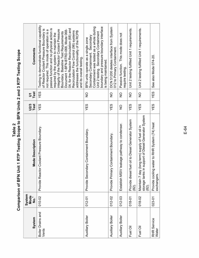
Tabl
e 2
Com
paris
on o
f BFN
Uni
t 1 R
TP T
estin
g Sc
ope
to B
FN U
nits
2 a
nd 3
RTP
Tes
ting
Scop
e
E-6
4
Syst
em
Syst
em
Mod
e N
o.1
Mod
e D
escr
iptio
n U
2/3
Test
U
1 Te
st
Com
men
ts
Boi
ler D
rain
s an
d V
ents
01
0-02
P
rovi
de R
eact
or C
oola
nt P
ress
ure
Bou
ndar
y.
YE
S
YE
S
Test
ing
to d
emon
stra
te fu
nctio
nal c
apab
ility
of R
eact
or C
oola
nt P
ress
ure
Bou
ndar
y is
no
t req
uire
d. T
his
mod
e of
ope
ratio
n is
a
pass
ive
func
tion
and
no p
hysi
cal a
ctio
n is
re
quire
d by
the
syst
em to
mai
ntai
n th
e in
tegr
ity o
f the
Rea
ctor
Coo
lant
Pre
ssur
e B
ound
ary.
Bas
elin
e Te
st R
equi
rem
ents
D
ocum
ent 1
-BFN
-BTR
D-0
68, M
ode
068-
04, f
or th
e R
eact
or R
ecirc
ulat
ion
(68)
and
R
ecirc
ulat
ion
Flow
Con
trol (
96) s
yste
ms
addr
esse
s th
e fu
nctio
nalit
y of
the
RC
PB
an
d its
ove
rall
test
ing.
Aux
iliary
Boi
ler
012-
01
Pro
vide
Sec
onda
ry C
onta
inm
ent B
ound
ary.
Y
ES
N
O
BFN
uni
ts o
pera
te a
s a
sing
le z
one
Seco
ndar
y C
onta
inm
ent.
Sec
onda
ry
Con
tain
men
t was
test
ed a
s a
who
le d
urin
g U
nit 2
test
ing.
Sec
onda
ry C
onta
inm
ent
boun
dary
and
pre
ssur
e bo
unda
ry in
terfa
ce
is b
eing
mai
ntai
ned.
Aux
iliary
Boi
ler
012-
02
Pro
vide
Prim
ary
Con
tain
men
t Bou
ndar
y.
YE
S
NO
D
CN
512
00 d
elet
es in
terfa
ce fr
om S
yste
m
012
to P
rimar
y C
onta
inm
ent.
Aux
iliary
Boi
ler
012-
03
Est
ablis
h M
SIV
leak
age
path
way
to c
onde
nser
. N
O
NO
P
assi
ve fu
nctio
n. T
his
mod
e do
es n
ot
requ
ire te
stin
g.
Fuel
Oil
01
8-01
P
rovi
de d
iese
l fue
l oil
to D
iese
l Gen
erat
or S
yste
m
(82)
. Y
ES
N
O
Uni
t 2 te
stin
g fu
lfille
d U
nit 1
requ
irem
ents
.
Fuel
Oil
018-
02
Mai
ntai
n 7
day
(long
term
) sup
ply
of fu
el o
il in
st
orag
e ta
nks
in s
uppo
rt of
Die
sel G
ener
ator
Sys
tem
(8
2).
YE
S
NO
U
nit 2
test
ing
fulfi
lled
Uni
t 1 re
quire
men
ts.
RH
R S
ervi
ce
Wat
er
023-
01
Pro
vide
coo
ling
wat
er to
RH
R S
yste
m (7
4) h
eat
exch
ange
rs.
YE
S
YE
S
See
als
o M
ode
074-
20.
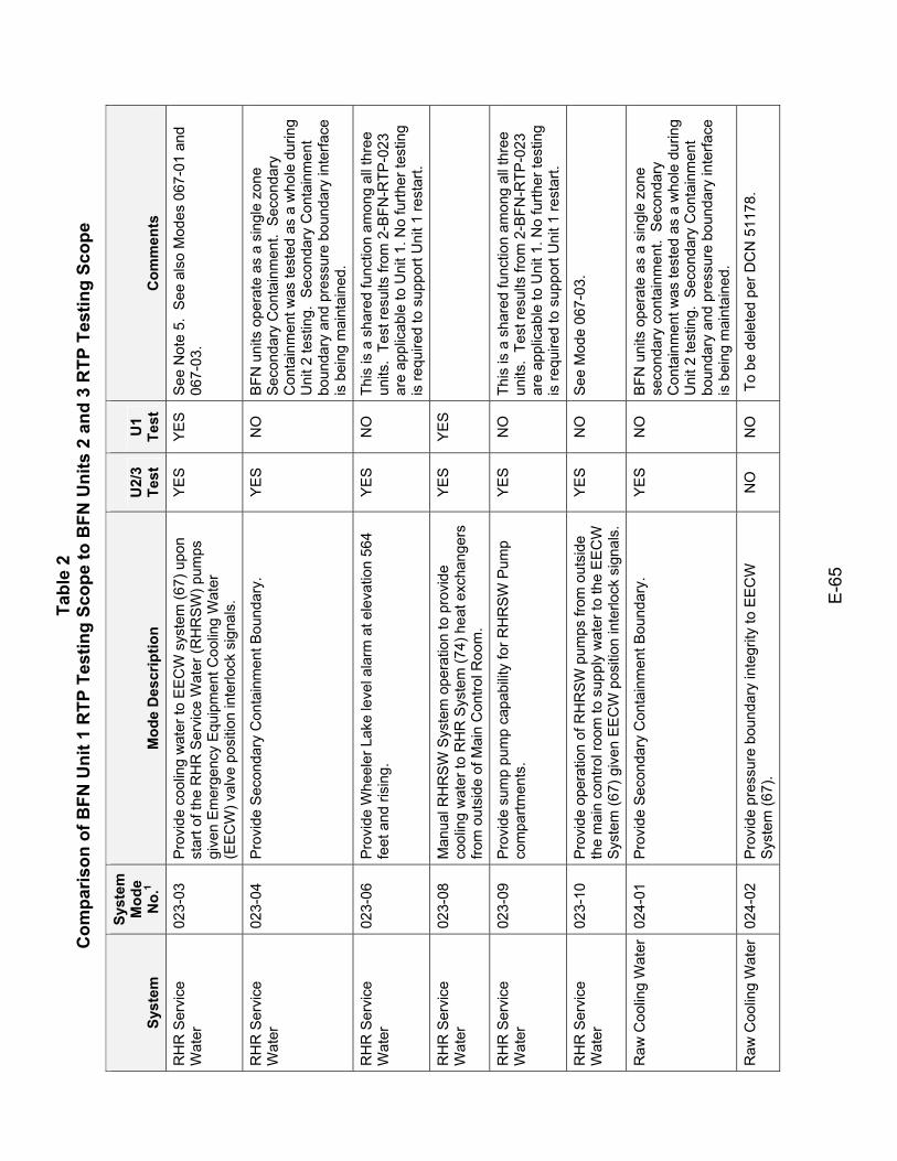
Tabl
e 2
Com
paris
on o
f BFN
Uni
t 1 R
TP T
estin
g Sc
ope
to B
FN U
nits
2 a
nd 3
RTP
Tes
ting
Scop
e
E-6
5
Syst
em
Syst
em
Mod
e N
o.1
Mod
e D
escr
iptio
n U
2/3
Test
U
1 Te
st
Com
men
ts
RH
R S
ervi
ce
Wat
er
023-
03
Pro
vide
coo
ling
wat
er to
EE
CW
sys
tem
(67)
upo
n st
art o
f the
RH
R S
ervi
ce W
ater
(RH
RS
W) p
umps
gi
ven
Em
erge
ncy
Equ
ipm
ent C
oolin
g W
ater
(E
EC
W) v
alve
pos
ition
inte
rlock
sig
nals
.
YE
S
YE
S
See
Not
e 5.
See
als
o M
odes
067
-01
and
067-
03.
RH
R S
ervi
ce
Wat
er
023-
04
Pro
vide
Sec
onda
ry C
onta
inm
ent B
ound
ary.
Y
ES
N
O
BFN
uni
ts o
pera
te a
s a
sing
le z
one
Seco
ndar
y C
onta
inm
ent.
Sec
onda
ry
Con
tain
men
t was
test
ed a
s a
who
le d
urin
g U
nit 2
test
ing.
Sec
onda
ry C
onta
inm
ent
boun
dary
and
pre
ssur
e bo
unda
ry in
terfa
ce
is b
eing
mai
ntai
ned.
RH
R S
ervi
ce
Wat
er
023-
06
Pro
vide
Whe
eler
Lak
e le
vel a
larm
at e
leva
tion
564
feet
and
risi
ng.
YE
S
NO
Th
is is
a s
hare
d fu
nctio
n am
ong
all t
hree
un
its.
Test
resu
lts fr
om 2
-BFN
-RTP
-023
ar
e ap
plic
able
to U
nit 1
. No
furth
er te
stin
g is
requ
ired
to s
uppo
rt U
nit 1
rest
art.
RH
R S
ervi
ce
Wat
er
023-
08
Man
ual R
HR
SW
Sys
tem
ope
ratio
n to
pro
vide
co
olin
g w
ater
to R
HR
Sys
tem
(74)
hea
t exc
hang
ers
from
out
side
of M
ain
Con
trol R
oom
.
YES
YES
RH
R S
ervi
ce
Wat
er
023-
09
Pro
vide
sum
p pu
mp
capa
bilit
y fo
r RH
RSW
Pum
p co
mpa
rtmen
ts.
YE
S
NO
Th
is is
a s
hare
d fu
nctio
n am
ong
all t
hree
un
its.
Test
resu
lts fr
om 2
-BFN
-RTP
-023
ar
e ap
plic
able
to U
nit 1
. No
furth
er te
stin
g is
requ
ired
to s
uppo
rt U
nit 1
rest
art.
RH
R S
ervi
ce
Wat
er
023-
10
Pro
vide
ope
ratio
n of
RH
RS
W p
umps
from
out
side
th
e m
ain
cont
rol r
oom
to s
uppl
y w
ater
to th
e E
EC
W
Sys
tem
(67)
giv
en E
EC
W p
ositi
on in
terlo
ck s
igna
ls.
YE
S
NO
S
ee M
ode
067-
03.
Raw
Coo
ling
Wat
er
024-
01
Pro
vide
Sec
onda
ry C
onta
inm
ent B
ound
ary.
Y
ES
N
O
BFN
uni
ts o
pera
te a
s a
sing
le z
one
seco
ndar
y co
ntai
nmen
t. S
econ
dary
C
onta
inm
ent w
as te
sted
as
a w
hole
dur
ing
Uni
t 2 te
stin
g. S
econ
dary
Con
tain
men
t bo
unda
ry a
nd p
ress
ure
boun
dary
inte
rface
is
bei
ng m
aint
aine
d.
Raw
Coo
ling
Wat
er
024-
02
Pro
vide
pre
ssur
e bo
unda
ry in
tegr
ity to
EE
CW
S
yste
m (6
7).
NO
N
O
To
be d
elet
ed p
er D
CN
511
78.
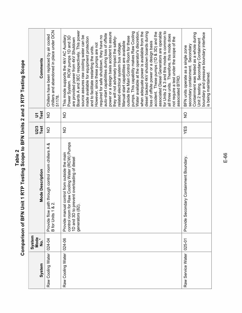
Tabl
e 2
Com
paris
on o
f BFN
Uni
t 1 R
TP T
estin
g Sc
ope
to B
FN U
nits
2 a
nd 3
RTP
Tes
ting
Scop
e
E-6
6
Syst
em
Syst
em
Mod
e N
o.1
Mod
e D
escr
iptio
n U
2/3
Test
U
1 Te
st
Com
men
ts
Raw
Coo
ling
Wat
er
024-
04
Pro
vide
flow
pat
h th
roug
h co
ntro
l roo
m c
hille
rs A
&
B fo
r Uni
ts 1
& 2
. N
O
NO
C
hille
rs h
ave
been
repl
aced
by
air c
oole
d ch
iller
s an
d ab
ando
ned
in p
lace
und
er D
CN
51
178.
Raw
Coo
ling
Wat
er
024-
06
Pro
vide
man
ual c
ontro
l fro
m o
utsi
de th
e m
ain
cont
rol r
oom
for R
aw C
oolin
g W
ater
(RC
W) P
umps
1D
and
3D
to p
reve
nt o
verlo
adin
g of
die
sel
gene
rato
rs (8
2).
NO
N
O
This
mod
e su
ppor
ts th
e 4k
V A
C A
uxilia
ry
Pow
er S
yste
m.
RC
W p
umps
1D
and
3D
ar
e pr
ovid
ed p
ower
from
4kV
Shu
tdow
n B
oard
s A
and
3E
C re
spec
tivel
y. T
his
pow
er
sour
ce a
ssur
es ra
w c
oolin
g w
ater
can
be
mad
e av
aila
ble
for e
quip
men
t pro
tect
ion
and
to fa
cilit
ate
rest
artin
g th
e un
its.
How
ever
, sin
ce th
ese
pum
ps a
re n
ot
requ
ired
for s
afe
shut
dow
n, th
ey h
ave
no
auto
-sta
rt ca
pabi
litie
s du
ring
loss
of o
ffsite
po
wer
or a
des
ign
basi
s ac
cide
nt to
ass
ure
they
will
not a
dver
sely
impa
ct th
e sa
fety
-re
late
d el
ectri
cal s
yste
m b
us v
olta
ge.
Man
ual s
tart
capa
bilit
ies
are
avai
labl
e ou
tsid
e th
e M
ain
Con
trol R
oom
for t
hese
pu
mps
. Thi
s ca
pabi
lity
mak
es R
aw C
oolin
g W
ater
ava
ilabl
e at
the
oper
ator
's d
iscr
etio
n,
whe
n ad
equa
te p
ower
is a
vaila
ble
from
the
dies
el b
acke
d 4k
V s
hutd
own
boar
ds d
urin
g lo
ss o
f offs
ite p
ower
or a
des
ign
basi
s ac
cide
nt.
Thes
e pu
mps
(1D
& 3
D) a
nd th
e as
soci
ated
Die
sel G
ener
ator
s ar
e op
erab
le
for U
nits
2 &
3 a
nd th
is m
ode
is c
omm
on to
al
l thr
ee u
nits
. Th
eref
ore,
this
mod
e do
es
not r
equi
re a
test
und
er th
e sc
ope
of th
e as
soci
ated
BTR
D.
Raw
Ser
vice
Wat
er
025-
01
Pro
vide
Sec
onda
ry C
onta
inm
ent B
ound
ary.
Y
ES
N
O
BFN
uni
ts o
pera
te a
s a
sing
le z
one
seco
ndar
y co
ntai
nmen
t. S
econ
dary
C
onta
inm
ent w
as te
sted
as
a w
hole
dur
ing
Uni
t 2 te
stin
g. S
econ
dary
Con
tain
men
t bo
unda
ry a
nd p
ress
ure
boun
dary
inte
rface
is
bei
ng m
aint
aine
d.
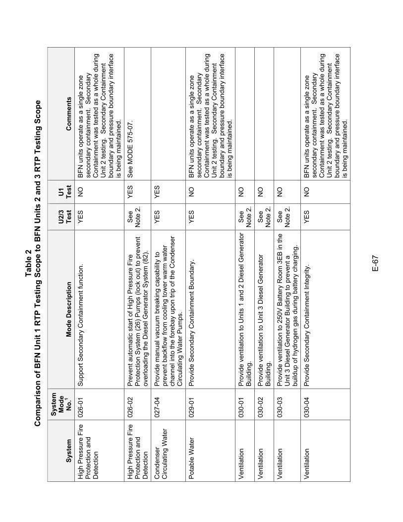
Tabl
e 2
Com
paris
on o
f BFN
Uni
t 1 R
TP T
estin
g Sc
ope
to B
FN U
nits
2 a
nd 3
RTP
Tes
ting
Scop
e
E-6
7
Syst
em
Syst
em
Mod
e N
o.1
Mod
e D
escr
iptio
n U
2/3
Test
U
1 Te
st
Com
men
ts
Hig
h P
ress
ure
Fire
P
rote
ctio
n an
d D
etec
tion
026-
01
Sup
port
Sec
onda
ry C
onta
inm
ent f
unct
ion.
Y
ES
N
O
BFN
uni
ts o
pera
te a
s a
sing
le z
one
seco
ndar
y co
ntai
nmen
t. S
econ
dary
C
onta
inm
ent w
as te
sted
as
a w
hole
dur
ing
Uni
t 2 te
stin
g. S
econ
dary
Con
tain
men
t bo
unda
ry a
nd p
ress
ure
boun
dary
inte
rface
is
bei
ng m
aint
aine
d.
Hig
h P
ress
ure
Fire
P
rote
ctio
n an
d D
etec
tion
026-
02
Pre
vent
aut
omat
ic s
tart
of H
igh
Pre
ssur
e Fi
re
Pro
tect
ion
Sys
tem
(26)
Pum
ps (l
ock
out)
to p
reve
nt
over
load
ing
the
Die
sel G
ener
ator
Sys
tem
(82)
.
See
N
ote
2.
YE
S
See
MO
DE
575
-07.
Con
dens
er
Circ
ulat
ing
Wat
er
027-
04
Pro
vide
man
ual v
acuu
m b
reak
ing
capa
bilit
y to
pr
even
t bac
kflo
w fr
om c
oolin
g to
wer
war
m w
ater
ch
anne
l int
o th
e fo
reba
y up
on tr
ip o
f the
Con
dens
er
Circ
ulat
ing
Wat
er P
umps
.
YES
YES
Pot
able
Wat
er
029-
01
Pro
vide
Sec
onda
ry C
onta
inm
ent B
ound
ary.
Y
ES
N
O
BFN
uni
ts o
pera
te a
s a
sing
le z
one
seco
ndar
y co
ntai
nmen
t. S
econ
dary
C
onta
inm
ent w
as te
sted
as
a w
hole
dur
ing
Uni
t 2 te
stin
g. S
econ
dary
Con
tain
men
t bo
unda
ry a
nd p
ress
ure
boun
dary
inte
rface
is
bei
ng m
aint
aine
d.
Ven
tilat
ion
030-
01
Pro
vide
ven
tilat
ion
to U
nits
1 a
nd 2
Die
sel G
ener
ator
B
uild
ing.
S
ee
Not
e 2.
N
O
Ven
tilat
ion
030-
02
Pro
vide
ven
tilat
ion
to U
nit 3
Die
sel G
ener
ator
B
uild
ing.
S
ee
Not
e 2.
N
O
Ven
tilat
ion
030-
03
Pro
vide
ven
tilat
ion
to 2
50V
Bat
tery
Roo
m 3
EB
in th
e U
nit 3
Die
sel G
ener
ator
Bui
ldin
g to
pre
vent
a
build
up o
f hyd
roge
n ga
s du
ring
batte
ry c
harg
ing.
See
N
ote
2.
NO
Ven
tilat
ion
030-
04
Pro
vide
Sec
onda
ry C
onta
inm
ent I
nteg
rity.
Y
ES
N
O
BFN
uni
ts o
pera
te a
s a
sing
le z
one
seco
ndar
y co
ntai
nmen
t. S
econ
dary
C
onta
inm
ent w
as te
sted
as
a w
hole
dur
ing
Uni
t 2 te
stin
g. S
econ
dary
Con
tain
men
t bo
unda
ry a
nd p
ress
ure
boun
dary
inte
rface
is
bei
ng m
aint
aine
d.
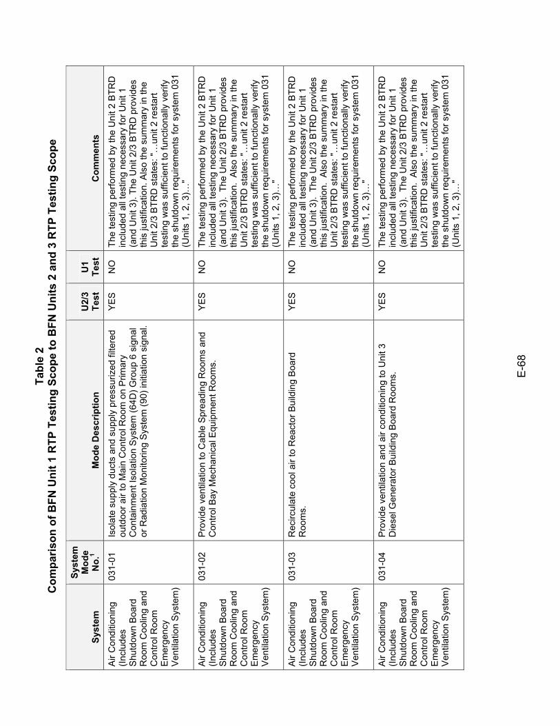
Tabl
e 2
Com
paris
on o
f BFN
Uni
t 1 R
TP T
estin
g Sc
ope
to B
FN U
nits
2 a
nd 3
RTP
Tes
ting
Scop
e
E-6
8
Syst
em
Syst
em
Mod
e N
o.1
Mod
e D
escr
iptio
n U
2/3
Test
U
1 Te
st
Com
men
ts
Air
Con
ditio
ning
(In
clud
es
Shu
tdow
n B
oard
R
oom
Coo
ling
and
Con
trol R
oom
E
mer
genc
y V
entil
atio
n S
yste
m)
031-
01
Isol
ate
supp
ly d
ucts
and
sup
ply
pres
suriz
ed fi
ltere
d ou
tdoo
r air
to M
ain
Con
trol R
oom
on
Prim
ary
Con
tain
men
t Iso
latio
n S
yste
m (6
4D) G
roup
6 s
igna
l or
Rad
iatio
n M
onito
ring
Sys
tem
(90)
initi
atio
n si
gnal
.
YE
S
NO
Th
e te
stin
g pe
rform
ed b
y th
e U
nit 2
BTR
D
incl
uded
all
test
ing
nece
ssar
y fo
r Uni
t 1
(and
Uni
t 3).
The
Uni
t 2/3
BTR
D p
rovi
des
this
just
ifica
tion.
Als
o th
e su
mm
ary
in th
e U
nit 2
/3 B
TRD
sta
tes:
"…un
it 2
rest
art
test
ing
was
suf
ficie
nt to
func
tiona
lly v
erify
th
e sh
utdo
wn
requ
irem
ents
for s
yste
m 0
31
(Uni
ts 1
, 2, 3
)…"
Air
Con
ditio
ning
(In
clud
es
Shu
tdow
n B
oard
R
oom
Coo
ling
and
Con
trol R
oom
E
mer
genc
y V
entil
atio
n S
yste
m)
031-
02
Pro
vide
ven
tilat
ion
to C
able
Spr
eadi
ng R
oom
s an
d C
ontro
l Bay
Mec
hani
cal E
quip
men
t Roo
ms.
Y
ES
N
O
The
test
ing
perfo
rmed
by
the
Uni
t 2 B
TRD
in
clud
ed a
ll te
stin
g ne
cess
ary
for U
nit 1
(a
nd U
nit 3
). T
he U
nit 2
/3 B
TRD
pro
vide
s th
is ju
stifi
catio
n. A
lso
the
sum
mar
y in
the
Uni
t 2/3
BTR
D s
tate
s: "…
unit
2 re
star
t te
stin
g w
as s
uffic
ient
to fu
nctio
nally
ver
ify
the
shut
dow
n re
quire
men
ts fo
r sys
tem
031
(U
nits
1, 2
, 3)…
"
Air
Con
ditio
ning
(In
clud
es
Shu
tdow
n B
oard
R
oom
Coo
ling
and
Con
trol R
oom
E
mer
genc
y V
entil
atio
n S
yste
m)
031-
03
Rec
ircul
ate
cool
air
to R
eact
or B
uild
ing
Boa
rd
Roo
ms.
Y
ES
N
O
The
test
ing
perfo
rmed
by
the
Uni
t 2 B
TRD
in
clud
ed a
ll te
stin
g ne
cess
ary
for U
nit 1
(a
nd U
nit 3
). T
he U
nit 2
/3 B
TRD
pro
vide
s th
is ju
stifi
catio
n. A
lso
the
sum
mar
y in
the
Uni
t 2/3
BTR
D s
tate
s: "…
unit
2 re
star
t te
stin
g w
as s
uffic
ient
to fu
nctio
nally
ver
ify
the
shut
dow
n re
quire
men
ts fo
r sys
tem
031
(U
nits
1, 2
, 3)…
"
Air
Con
ditio
ning
(In
clud
es
Shu
tdow
n B
oard
R
oom
Coo
ling
and
Con
trol R
oom
E
mer
genc
y V
entil
atio
n S
yste
m)
031-
04
Pro
vide
ven
tilat
ion
and
air c
ondi
tioni
ng to
Uni
t 3
Die
sel G
ener
ator
Bui
ldin
g B
oard
Roo
ms.
Y
ES
N
O
The
test
ing
perfo
rmed
by
the
Uni
t 2 B
TRD
in
clud
ed a
ll te
stin
g ne
cess
ary
for U
nit 1
(a
nd U
nit 3
). T
he U
nit 2
/3 B
TRD
pro
vide
s th
is ju
stifi
catio
n. A
lso
the
sum
mar
y in
the
Uni
t 2/3
BTR
D s
tate
s: "…
unit
2 re
star
t te
stin
g w
as s
uffic
ient
to fu
nctio
nally
ver
ify
the
shut
dow
n re
quire
men
ts fo
r sys
tem
031
(U
nits
1, 2
, 3)…
"
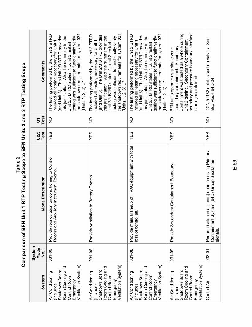
Tabl
e 2
Com
paris
on o
f BFN
Uni
t 1 R
TP T
estin
g Sc
ope
to B
FN U
nits
2 a
nd 3
RTP
Tes
ting
Scop
e
E-6
9
Syst
em
Syst
em
Mod
e N
o.1
Mod
e D
escr
iptio
n U
2/3
Test
U
1 Te
st
Com
men
ts
Air
Con
ditio
ning
(In
clud
es
Shu
tdow
n B
oard
R
oom
Coo
ling
and
Con
trol R
oom
E
mer
genc
y V
entil
atio
n S
yste
m)
031-
05
Pro
vide
reci
rcul
atio
n ai
r con
ditio
ning
to C
ontro
l R
oom
s an
d A
uxili
ary
Inst
rum
ent R
oom
s.
YE
S
NO
Th
e te
stin
g pe
rform
ed b
y th
e U
nit 2
BTR
D
incl
uded
all
test
ing
nece
ssar
y fo
r Uni
t 1
(and
Uni
t 3).
The
Uni
t 2/3
BTR
D p
rovi
des
this
just
ifica
tion.
Als
o th
e su
mm
ary
in th
e U
nit 2
/3 B
TRD
sta
tes:
"…un
it 2
rest
art
test
ing
was
suf
ficie
nt to
func
tiona
lly v
erify
th
e sh
utdo
wn
requ
irem
ents
for s
yste
m 0
31
(Uni
ts 1
, 2, 3
)…"
Air
Con
ditio
ning
(In
clud
es
Shu
tdow
n B
oard
R
oom
Coo
ling
and
Con
trol R
oom
E
mer
genc
y V
entil
atio
n S
yste
m)
031-
06
Pro
vide
ven
tilat
ion
to B
atte
ry R
oom
s.
YE
S
NO
Th
e te
stin
g pe
rform
ed b
y th
e U
nit 2
BTR
D
incl
uded
all
test
ing
nece
ssar
y fo
r Uni
t 1
(and
Uni
t 3).
The
Uni
t 2/3
BTR
D p
rovi
des
this
just
ifica
tion.
Als
o th
e su
mm
ary
in th
e U
nit 2
/3 B
TRD
sta
tes:
"…un
it 2
rest
art
test
ing
was
suf
ficie
nt to
func
tiona
lly v
erify
th
e sh
utdo
wn
requ
irem
ents
for s
yste
m 0
31
(Uni
ts 1
, 2, 3
)…"
Air
Con
ditio
ning
(In
clud
es
Shu
tdow
n B
oard
R
oom
Coo
ling
and
Con
trol R
oom
E
mer
genc
y V
entil
atio
n S
yste
m)
031-
08
Pro
vide
man
ual l
ineu
p of
HV
AC
equ
ipm
ent w
ith to
tal
loss
of c
ontro
l air.
Y
ES
N
O
The
test
ing
perfo
rmed
by
the
Uni
t 2 B
TRD
in
clud
ed a
ll te
stin
g ne
cess
ary
for U
nit 1
(a
nd U
nit 3
). T
he U
nit 2
/3 B
TRD
pro
vide
s th
is ju
stifi
catio
n. A
lso
the
sum
mar
y in
the
Uni
t 2/3
BTR
D s
tate
s: "…
unit
2 re
star
t te
stin
g w
as s
uffic
ient
to fu
nctio
nally
ver
ify
the
shut
dow
n re
quire
men
ts fo
r sys
tem
031
(U
nits
1, 2
, 3)…
"
Air
Con
ditio
ning
(In
clud
es
Shu
tdow
n B
oard
R
oom
Coo
ling
and
Con
trol R
oom
E
mer
genc
y V
entil
atio
n S
yste
m)
031-
09
Pro
vide
Sec
onda
ry C
onta
inm
ent B
ound
ary.
Y
ES
N
O
BFN
uni
ts o
pera
te a
s a
sing
le z
one
seco
ndar
y co
ntai
nmen
t. S
econ
dary
C
onta
inm
ent w
as te
sted
as
a w
hole
dur
ing
Uni
t 2 te
stin
g. S
econ
dary
Con
tain
men
t bo
unda
ry a
nd p
ress
ure
boun
dary
inte
rface
is
bei
ng m
aint
aine
d.
Con
trol A
ir 03
2-01
P
erfo
rm is
olat
ion
actio
n(s)
upo
n re
ceiv
ing
Prim
ary
Con
tain
men
t Sys
tem
(64D
) Gro
up 6
isol
atio
n si
gnal
s.
YE
S
NO
D
CN
511
82 d
elet
es s
uctio
n va
lves
. S
ee
also
Mod
e 64
D-0
4.
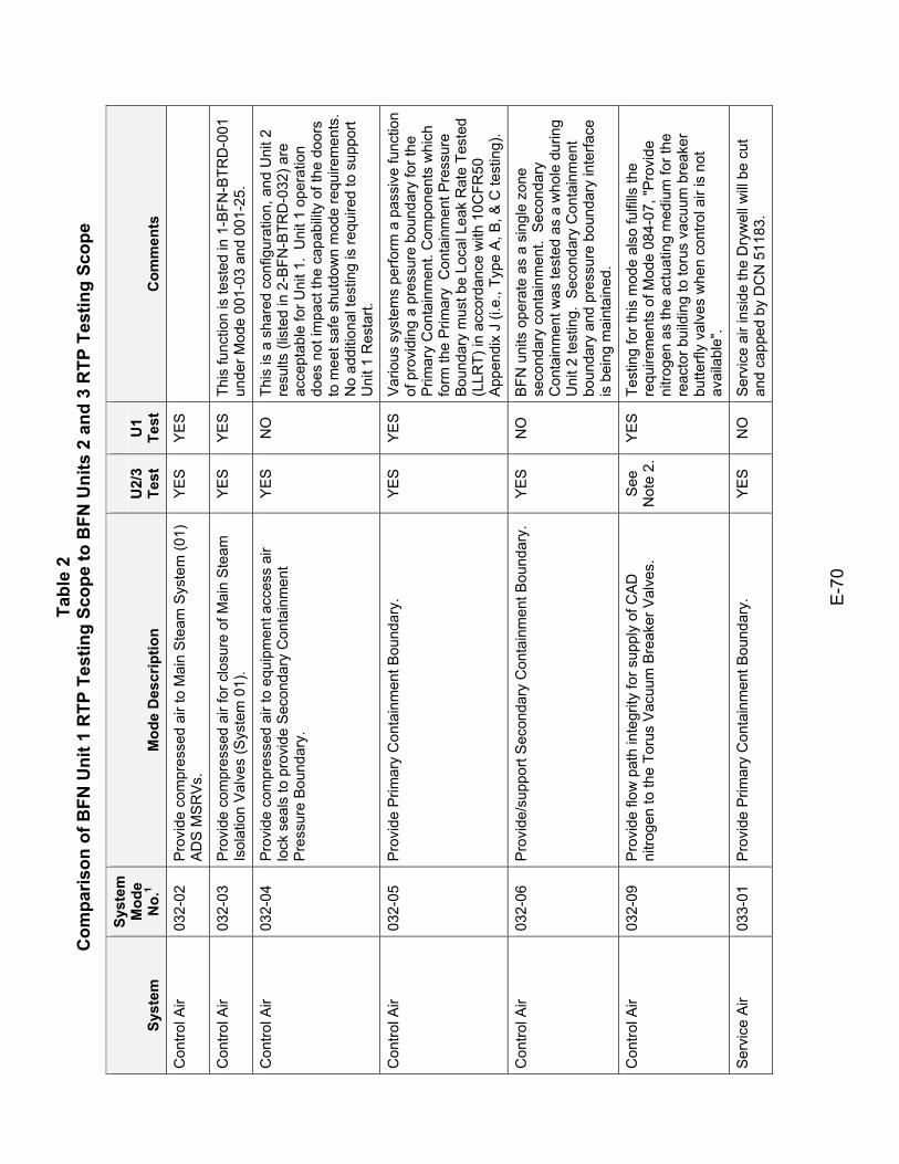
Tabl
e 2
Com
paris
on o
f BFN
Uni
t 1 R
TP T
estin
g Sc
ope
to B
FN U
nits
2 a
nd 3
RTP
Tes
ting
Scop
e
E-7
0
Syst
em
Syst
em
Mod
e N
o.1
Mod
e D
escr
iptio
n U
2/3
Test
U
1 Te
st
Com
men
ts
Con
trol A
ir 03
2-02
P
rovi
de c
ompr
esse
d ai
r to
Mai
n S
team
Sys
tem
(01)
A
DS
MS
RV
s.
YES
YES
Con
trol A
ir 03
2-03
P
rovi
de c
ompr
esse
d ai
r for
clo
sure
of M
ain
Ste
am
Isol
atio
n V
alve
s (S
yste
m 0
1).
YE
S
YE
S
This
func
tion
is te
sted
in 1
-BFN
-BTR
D-0
01
unde
r Mod
e 00
1-03
and
001
-25.
Con
trol A
ir 03
2-04
P
rovi
de c
ompr
esse
d ai
r to
equi
pmen
t acc
ess
air
lock
sea
ls to
pro
vide
Sec
onda
ry C
onta
inm
ent
Pre
ssur
e B
ound
ary.
YE
S
NO
Th
is is
a s
hare
d co
nfig
urat
ion,
and
Uni
t 2
resu
lts (l
iste
d in
2-B
FN-B
TRD
-032
) are
ac
cept
able
for U
nit 1
. U
nit 1
ope
ratio
n do
es n
ot im
pact
the
capa
bilit
y of
the
door
s to
mee
t saf
e sh
utdo
wn
mod
e re
quire
men
ts.
No
addi
tiona
l tes
ting
is re
quire
d to
sup
port
Uni
t 1 R
esta
rt.
Con
trol A
ir 03
2-05
P
rovi
de P
rimar
y C
onta
inm
ent B
ound
ary.
Y
ES
Y
ES
V
ario
us s
yste
ms
perfo
rm a
pas
sive
func
tion
of p
rovi
ding
a p
ress
ure
boun
dary
for t
he
Prim
ary
Con
tain
men
t. C
ompo
nent
s w
hich
fo
rm th
e P
rimar
y C
onta
inm
ent P
ress
ure
Bou
ndar
y m
ust b
e Lo
cal L
eak
Rat
e Te
sted
(L
LRT)
in a
ccor
danc
e w
ith 1
0CFR
50
App
endi
x J
(i.e.
, Typ
e A
, B, &
C te
stin
g).
Con
trol A
ir 03
2-06
P
rovi
de/s
uppo
rt S
econ
dary
Con
tain
men
t Bou
ndar
y.
YE
S
NO
B
FN u
nits
ope
rate
as
a si
ngle
zon
e se
cond
ary
cont
ainm
ent.
Sec
onda
ry
Con
tain
men
t was
test
ed a
s a
who
le d
urin
g U
nit 2
test
ing.
Sec
onda
ry C
onta
inm
ent
boun
dary
and
pre
ssur
e bo
unda
ry in
terfa
ce
is b
eing
mai
ntai
ned.
Con
trol A
ir 03
2-09
P
rovi
de fl
ow p
ath
inte
grity
for s
uppl
y of
CA
D
nitro
gen
to th
e To
rus
Vac
uum
Bre
aker
Val
ves.
S
ee
Not
e 2.
Y
ES
Te
stin
g fo
r thi
s m
ode
also
fulfi
lls th
e re
quire
men
ts o
f Mod
e 08
4-07
, "P
rovi
de
nitro
gen
as th
e ac
tuat
ing
med
ium
for t
he
reac
tor b
uild
ing
to to
rus
vacu
um b
reak
er
butte
rfly
valv
es w
hen
cont
rol a
ir is
not
av
aila
ble"
.
Ser
vice
Air
033-
01
Pro
vide
Prim
ary
Con
tain
men
t Bou
ndar
y.
YE
S
NO
S
ervi
ce a
ir in
side
the
Dry
wel
l will
be
cut
and
capp
ed b
y D
CN
511
83.
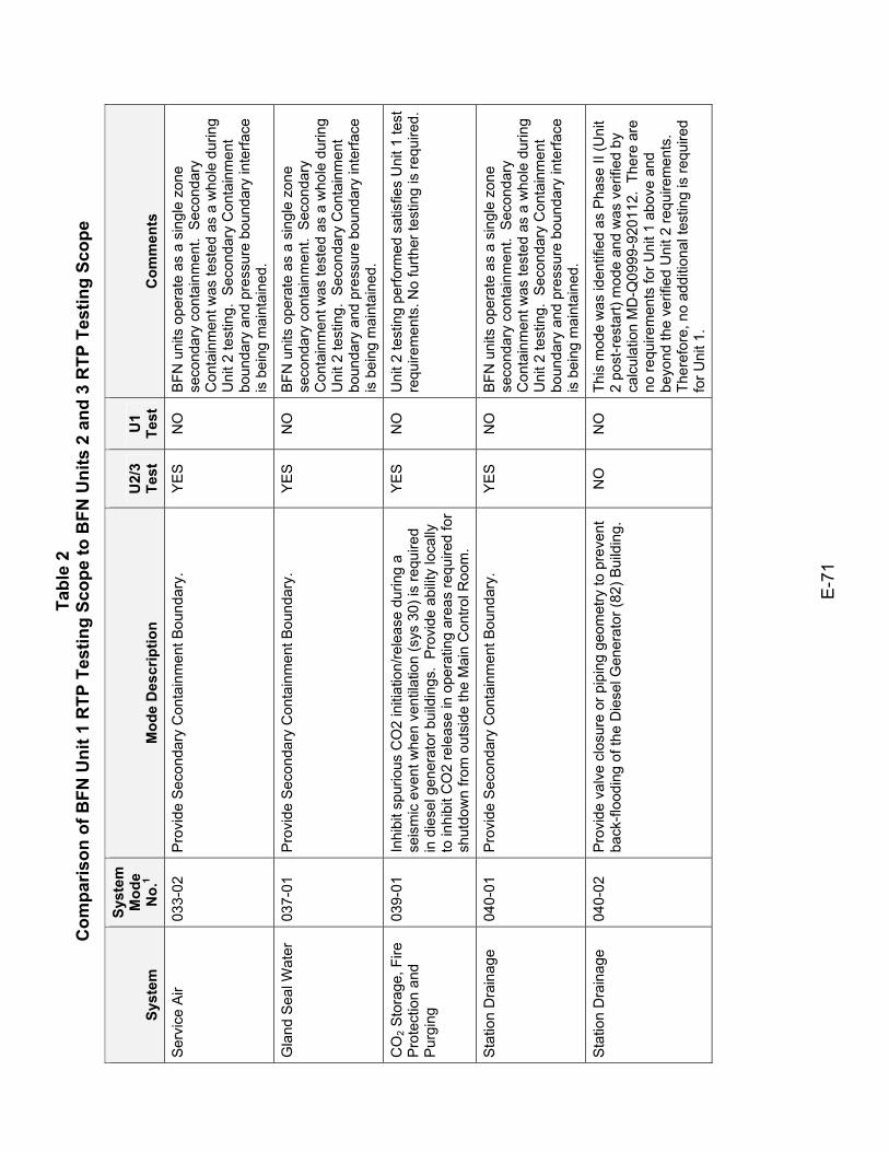
Tabl
e 2
Com
paris
on o
f BFN
Uni
t 1 R
TP T
estin
g Sc
ope
to B
FN U
nits
2 a
nd 3
RTP
Tes
ting
Scop
e
E-7
1
Syst
em
Syst
em
Mod
e N
o.1
Mod
e D
escr
iptio
n U
2/3
Test
U
1 Te
st
Com
men
ts
Ser
vice
Air
033-
02
Pro
vide
Sec
onda
ry C
onta
inm
ent B
ound
ary.
Y
ES
N
O
BFN
uni
ts o
pera
te a
s a
sing
le z
one
seco
ndar
y co
ntai
nmen
t. S
econ
dary
C
onta
inm
ent w
as te
sted
as
a w
hole
dur
ing
Uni
t 2 te
stin
g. S
econ
dary
Con
tain
men
t bo
unda
ry a
nd p
ress
ure
boun
dary
inte
rface
is
bei
ng m
aint
aine
d.
Gla
nd S
eal W
ater
03
7-01
P
rovi
de S
econ
dary
Con
tain
men
t Bou
ndar
y.
YE
S
NO
B
FN u
nits
ope
rate
as
a si
ngle
zon
e se
cond
ary
cont
ainm
ent.
Sec
onda
ry
Con
tain
men
t was
test
ed a
s a
who
le d
urin
g U
nit 2
test
ing.
Sec
onda
ry C
onta
inm
ent
boun
dary
and
pre
ssur
e bo
unda
ry in
terfa
ce
is b
eing
mai
ntai
ned.
CO
2 Sto
rage
, Fire
P
rote
ctio
n an
d P
urgi
ng
039-
01
Inhi
bit s
purio
us C
O2
initi
atio
n/re
leas
e du
ring
a se
ism
ic e
vent
whe
n ve
ntila
tion
(sys
30)
is re
quire
d in
die
sel g
ener
ator
bui
ldin
gs.
Pro
vide
abi
lity
loca
lly
to in
hibi
t CO
2 re
leas
e in
ope
ratin
g ar
eas
requ
ired
for
shut
dow
n fro
m o
utsi
de th
e M
ain
Con
trol R
oom
.
YE
S
NO
U
nit 2
test
ing
perfo
rmed
sat
isfie
s U
nit 1
test
re
quire
men
ts. N
o fu
rther
test
ing
is re
quire
d.
Sta
tion
Dra
inag
e 04
0-01
P
rovi
de S
econ
dary
Con
tain
men
t Bou
ndar
y.
YE
S
NO
B
FN u
nits
ope
rate
as
a si
ngle
zon
e se
cond
ary
cont
ainm
ent.
Sec
onda
ry
Con
tain
men
t was
test
ed a
s a
who
le d
urin
g U
nit 2
test
ing.
Sec
onda
ry C
onta
inm
ent
boun
dary
and
pre
ssur
e bo
unda
ry in
terfa
ce
is b
eing
mai
ntai
ned.
Sta
tion
Dra
inag
e 04
0-02
P
rovi
de v
alve
clo
sure
or p
ipin
g ge
omet
ry to
pre
vent
ba
ck-fl
oodi
ng o
f the
Die
sel G
ener
ator
(82)
Bui
ldin
g.
NO
N
O
This
mod
e w
as id
entif
ied
as P
hase
II (U
nit
2 po
st-r
esta
rt) m
ode
and
was
ver
ified
by
calc
ulat
ion
MD
-Q09
99-9
2011
2. T
here
are
no
requ
irem
ents
for U
nit 1
abo
ve a
nd
beyo
nd th
e ve
rifie
d U
nit 2
requ
irem
ents
. Th
eref
ore,
no
addi
tiona
l tes
ting
is re
quire
d fo
r Uni
t 1.
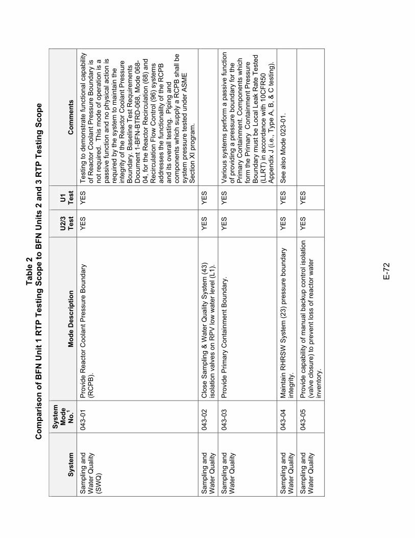
Tabl
e 2
Com
paris
on o
f BFN
Uni
t 1 R
TP T
estin
g Sc
ope
to B
FN U
nits
2 a
nd 3
RTP
Tes
ting
Scop
e
E-7
2
Syst
em
Syst
em
Mod
e N
o.1
Mod
e D
escr
iptio
n U
2/3
Test
U
1 Te
st
Com
men
ts
Sam
plin
g an
d W
ater
Qua
lity
(SW
Q)
043-
01
Pro
vide
Rea
ctor
Coo
lant
Pre
ssur
e B
ound
ary
(RC
PB
). Y
ES
Y
ES
Te
stin
g to
dem
onst
rate
func
tiona
l cap
abilit
y of
Rea
ctor
Coo
lant
Pre
ssur
e B
ound
ary
is
not r
equi
red.
Thi
s m
ode
of o
pera
tion
is a
pa
ssiv
e fu
nctio
n an
d no
phy
sica
l act
ion
is
requ
ired
by th
e sy
stem
to m
aint
ain
the
inte
grity
of t
he R
eact
or C
oola
nt P
ress
ure
Bou
ndar
y. B
asel
ine
Test
Req
uire
men
ts
Doc
umen
t 1-B
FN-B
TRD
-068
, Mod
e 06
8-04
, for
the
Rea
ctor
Rec
ircul
atio
n (6
8) a
nd
Rec
ircul
atio
n Fl
ow C
ontro
l (96
) sys
tem
s ad
dres
ses
the
func
tiona
lity
of th
e R
CP
B
and
its o
vera
ll te
stin
g. P
ipin
g an
d co
mpo
nent
s w
hich
sup
ply
a R
CP
B s
hall
be
syst
em p
ress
ure
test
ed u
nder
AS
ME
S
ectio
n X
I pro
gram
.
Sam
plin
g an
d W
ater
Qua
lity
043-
02
Clo
se S
ampl
ing
& W
ater
Qua
lity
Sys
tem
(43)
is
olat
ion
valv
es o
n R
PV
low
wat
er le
vel (
L1).
YES
YES
Sam
plin
g an
d W
ater
Qua
lity
043-
03
Pro
vide
Prim
ary
Con
tain
men
t Bou
ndar
y.
YE
S
YE
S
Var
ious
sys
tem
s pe
rform
a p
assi
ve fu
nctio
n of
pro
vidi
ng a
pre
ssur
e bo
unda
ry fo
r the
P
rimar
y C
onta
inm
ent.
Com
pone
nts
whi
ch
form
the
Prim
ary
Con
tain
men
t Pre
ssur
e B
ound
ary
mus
t be
Loca
l Lea
k R
ate
Test
ed
(LLR
T) in
acc
orda
nce
with
10C
FR50
A
ppen
dix
J (i.
e., T
ype
A, B
, & C
test
ing)
.
Sam
plin
g an
d W
ater
Qua
lity
043-
04
Mai
ntai
n R
HR
SW
Sys
tem
(23)
pre
ssur
e bo
unda
ry
inte
grity
. Y
ES
Y
ES
S
ee a
lso
Mod
e 02
3-01
.
Sam
plin
g an
d W
ater
Qua
lity
043-
05
Pro
vide
cap
abilit
y of
man
ual b
acku
p co
ntro
l iso
latio
n (v
alve
clo
sure
) to
prev
ent l
oss
of re
acto
r wat
er
inve
ntor
y.
YES
YES
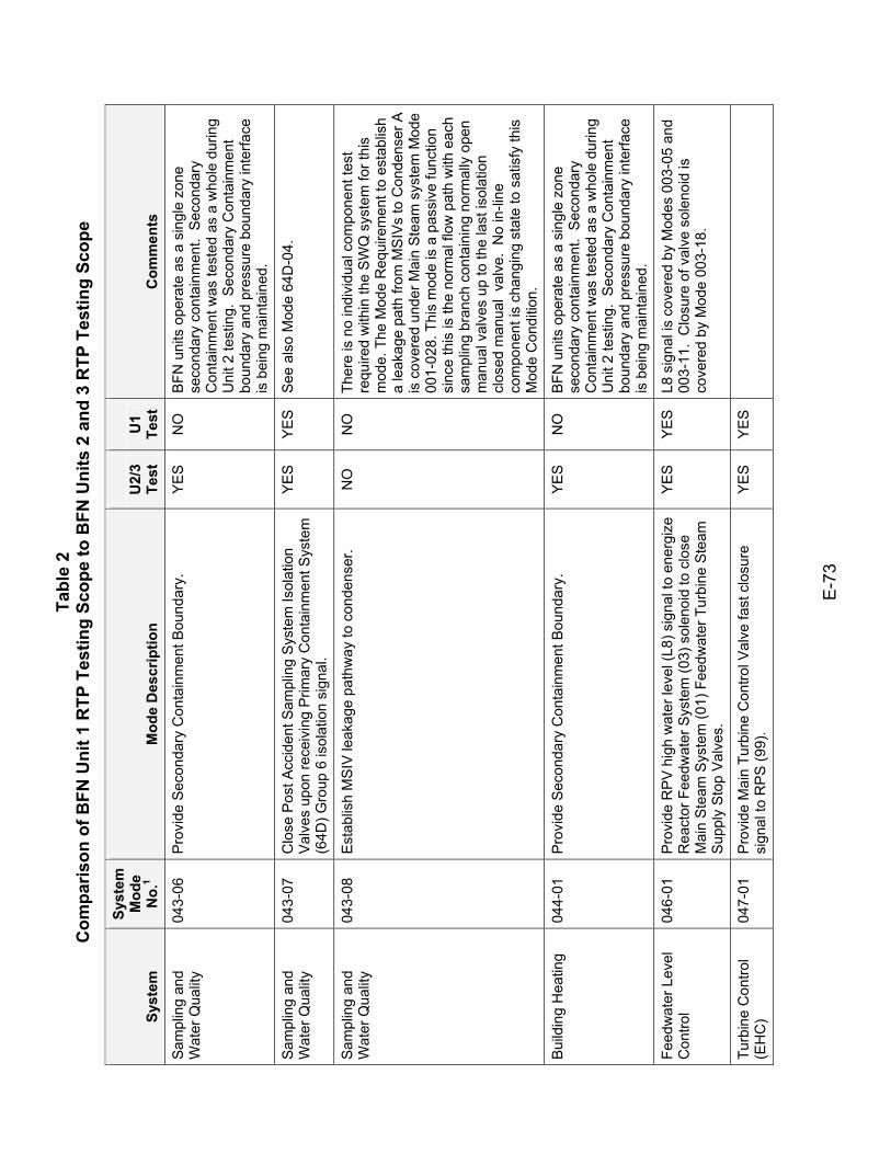
Tabl
e 2
Com
paris
on o
f BFN
Uni
t 1 R
TP T
estin
g Sc
ope
to B
FN U
nits
2 a
nd 3
RTP
Tes
ting
Scop
e
E-7
3
Syst
em
Syst
em
Mod
e N
o.1
Mod
e D
escr
iptio
n U
2/3
Test
U
1 Te
st
Com
men
ts
Sam
plin
g an
d W
ater
Qua
lity
043-
06
Pro
vide
Sec
onda
ry C
onta
inm
ent B
ound
ary.
Y
ES
N
O
BFN
uni
ts o
pera
te a
s a
sing
le z
one
seco
ndar
y co
ntai
nmen
t. S
econ
dary
C
onta
inm
ent w
as te
sted
as
a w
hole
dur
ing
Uni
t 2 te
stin
g. S
econ
dary
Con
tain
men
t bo
unda
ry a
nd p
ress
ure
boun
dary
inte
rface
is
bei
ng m
aint
aine
d.
Sam
plin
g an
d W
ater
Qua
lity
043-
07
Clo
se P
ost A
ccid
ent S
ampl
ing
Sys
tem
Isol
atio
n V
alve
s up
on re
ceiv
ing
Prim
ary
Con
tain
men
t Sys
tem
(6
4D) G
roup
6 is
olat
ion
sign
al.
YE
S
YE
S
See
als
o M
ode
64D
-04.
Sam
plin
g an
d W
ater
Qua
lity
043-
08
Est
ablis
h M
SIV
leak
age
path
way
to c
onde
nser
. N
O
NO
Th
ere
is n
o in
divi
dual
com
pone
nt te
st
requ
ired
with
in th
e S
WQ
sys
tem
for t
his
mod
e. T
he M
ode
Req
uire
men
t to
esta
blis
h a
leak
age
path
from
MS
IVs
to C
onde
nser
A
is c
over
ed u
nder
Mai
n S
team
sys
tem
Mod
e 00
1-02
8. T
his
mod
e is
a p
assi
ve fu
nctio
n si
nce
this
is th
e no
rmal
flow
pat
h w
ith e
ach
sam
plin
g br
anch
con
tain
ing
norm
ally
ope
n m
anua
l val
ves
up to
the
last
isol
atio
n cl
osed
man
ual
valv
e. N
o in
-line
co
mpo
nent
is c
hang
ing
stat
e to
sat
isfy
this
M
ode
Con
ditio
n.
Bui
ldin
g H
eatin
g 04
4-01
P
rovi
de S
econ
dary
Con
tain
men
t Bou
ndar
y.
YE
S
NO
B
FN u
nits
ope
rate
as
a si
ngle
zon
e se
cond
ary
cont
ainm
ent.
Sec
onda
ry
Con
tain
men
t was
test
ed a
s a
who
le d
urin
g U
nit 2
test
ing.
Sec
onda
ry C
onta
inm
ent
boun
dary
and
pre
ssur
e bo
unda
ry in
terfa
ce
is b
eing
mai
ntai
ned.
Feed
wat
er L
evel
C
ontro
l 04
6-01
P
rovi
de R
PV
hig
h w
ater
leve
l (L8
) sig
nal t
o en
ergi
ze
Rea
ctor
Fee
dwat
er S
yste
m (0
3) s
olen
oid
to c
lose
M
ain
Ste
am S
yste
m (0
1) F
eedw
ater
Tur
bine
Ste
am
Sup
ply
Sto
p V
alve
s.
YE
S
YE
S
L8 s
igna
l is
cove
red
by M
odes
003
-05
and
003-
11.
Clo
sure
of v
alve
sol
enoi
d is
co
vere
d by
Mod
e 00
3-18
.
Turb
ine
Con
trol
(EH
C)
047-
01
Pro
vide
Mai
n Tu
rbin
e C
ontro
l Val
ve fa
st c
losu
re
sign
al to
RP
S (9
9).
YES
YES
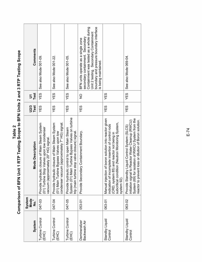
Tabl
e 2
Com
paris
on o
f BFN
Uni
t 1 R
TP T
estin
g Sc
ope
to B
FN U
nits
2 a
nd 3
RTP
Tes
ting
Scop
e
E-7
4
Syst
em
Syst
em
Mod
e N
o.1
Mod
e D
escr
iptio
n U
2/3
Test
U
1 Te
st
Com
men
ts
Turb
ine
Con
trol
(EH
C)
047-
03
Pro
vide
hyd
raul
ic c
losu
re o
f Mai
n S
team
Sys
tem
(0
1) T
urbi
ne S
top
Val
ves
upon
low
con
dens
er
vacu
um (a
ppro
xim
atel
y 20
" HG
) sig
nal.
YE
S
YE
S
See
als
o M
ode
001-
09.
Turb
ine
Con
trol
(EH
C)
047-
04
Pro
vide
hyd
raul
ic c
losu
re o
f Mai
n S
team
Sys
tem
(0
1) M
ain
Turb
ine
Byp
ass
Val
ves
upon
low
co
nden
ser v
acuu
m (a
ppro
xim
atel
y 7"
HG
) sig
nal.
YE
S
YE
S
See
als
o M
ode
001-
22.
Turb
ine
Con
trol
(EH
C)
047-
05
Pro
vide
hyd
raul
ic c
ontro
l to
open
Mai
n S
team
S
yste
m (0
1) M
ain
Turb
ine
Byp
ass
Val
ves
on tu
rbin
e tri
p (m
ain
turb
ine
stop
val
ve c
losu
re) s
igna
l.
YE
S
YE
S
See
als
o M
ode
001-
05.
Dem
iner
aliz
er
Back
was
h Ai
r 05
3-01
P
rovi
de S
econ
dary
Con
tain
men
t Bou
ndar
y.
YE
S
NO
B
FN u
nits
ope
rate
as
a si
ngle
zon
e se
cond
ary
cont
ainm
ent.
Sec
onda
ry
Con
tain
men
t was
test
ed a
s a
who
le d
urin
g U
nit 2
test
ing.
Sec
onda
ry C
onta
inm
ent
boun
dary
and
pre
ssur
e bo
unda
ry in
terfa
ce
is b
eing
mai
ntai
ned.
Sta
ndby
Liq
uid
Con
trol
063-
01
Man
ual i
njec
tion
of b
oron
sol
utio
n in
to re
acto
r giv
en
indi
catio
n of
inco
mpl
ete
inse
rtion
of c
ontro
l rod
s (C
RD
, sys
tem
85)
and
reac
tor n
ot b
eing
in
subc
ritic
al c
ondi
tion
(Neu
tron
Mon
itorin
g S
yste
m,
syst
em 9
2).
YES
YES
Sta
ndby
Liq
uid
Con
trol
063-
02
Pro
vide
Sta
ndby
Liq
uid
Con
trol S
yste
m (S
LCS)
in
itiat
ion
sign
al to
Rea
ctor
Wat
er C
lean
up (R
WC
U)
Sys
tem
(69)
for i
sola
tion
of R
WC
U S
yste
m fr
om th
e re
acto
r to
prev
ent l
oss
or d
ilutio
n of
Bor
on s
olut
ion.
YE
S
YE
S
See
als
o M
ode
069-
04.
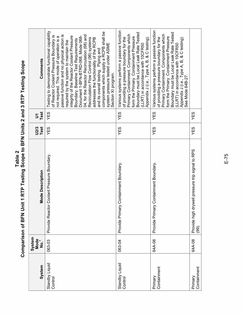
Tabl
e 2
Com
paris
on o
f BFN
Uni
t 1 R
TP T
estin
g Sc
ope
to B
FN U
nits
2 a
nd 3
RTP
Tes
ting
Scop
e
E-7
5
Syst
em
Syst
em
Mod
e N
o.1
Mod
e D
escr
iptio
n U
2/3
Test
U
1 Te
st
Com
men
ts
Sta
ndby
Liq
uid
Con
trol
063-
03
Pro
vide
Rea
ctor
Coo
lant
Pre
ssur
e B
ound
ary.
Y
ES
Y
ES
Te
stin
g to
dem
onst
rate
func
tiona
l cap
abilit
y of
Rea
ctor
Coo
lant
Pre
ssur
e B
ound
ary
is
not r
equi
red.
Thi
s m
ode
of o
pera
tion
is a
pa
ssiv
e fu
nctio
n an
d no
phy
sica
l act
ion
is
requ
ired
by th
e sy
stem
to m
aint
ain
the
inte
grity
of t
he R
eact
or C
oola
nt P
ress
ure
Bou
ndar
y. B
asel
ine
Test
Req
uire
men
ts
Doc
umen
t 1-B
FN-B
TRD
-068
, Mod
e 06
8-04
, for
the
Rea
ctor
Rec
ircul
atio
n (6
8) a
nd
Rec
ircul
atio
n Fl
ow C
ontro
l (96
) sys
tem
s ad
dres
ses
the
func
tiona
lity
of th
e R
CP
B
and
its o
vera
ll te
stin
g. P
ipin
g an
d co
mpo
nent
s w
hich
sup
ply
a R
CP
B s
hall
be
syst
em p
ress
ure
test
ed u
nder
AS
ME
S
ectio
n X
I pro
gram
.
Sta
ndby
Liq
uid
Con
trol
063-
04
Pro
vide
Prim
ary
Con
tain
men
t Bou
ndar
y.
YE
S
YE
S
Var
ious
sys
tem
s pe
rform
a p
assi
ve fu
nctio
n of
pro
vidi
ng a
pre
ssur
e bo
unda
ry fo
r the
P
rimar
y C
onta
inm
ent.
Com
pone
nts
whi
ch
form
the
Prim
ary
Con
tain
men
t Pre
ssur
e B
ound
ary
mus
t be
Loca
l Lea
k R
ate
Test
ed
(LLR
T) in
acc
orda
nce
with
10C
FR50
A
ppen
dix
J (i.
e., T
ype
A, B
, & C
test
ing)
.
Prim
ary
Con
tain
men
t 64
A-0
6 P
rovi
de P
rimar
y C
onta
inm
ent B
ound
ary.
Y
ES
Y
ES
V
ario
us s
yste
ms
perfo
rm a
pas
sive
func
tion
of p
rovi
ding
a p
ress
ure
boun
dary
for t
he
Prim
ary
Con
tain
men
t. C
ompo
nent
s w
hich
fo
rm th
e P
rimar
y C
onta
inm
ent P
ress
ure
Bou
ndar
y m
ust b
e Lo
cal L
eak
Rat
e Te
sted
(L
LRT)
in a
ccor
danc
e w
ith 1
0CFR
50
App
endi
x J
(i.e.
, Typ
e A
, B, &
C te
stin
g).
See
Mod
e 64
B-2
7.
Prim
ary
Con
tain
men
t 64
A-0
8 P
rovi
de h
igh
dryw
ell p
ress
ure
trip
sign
al to
RP
S
(99)
. YE
S YE
S
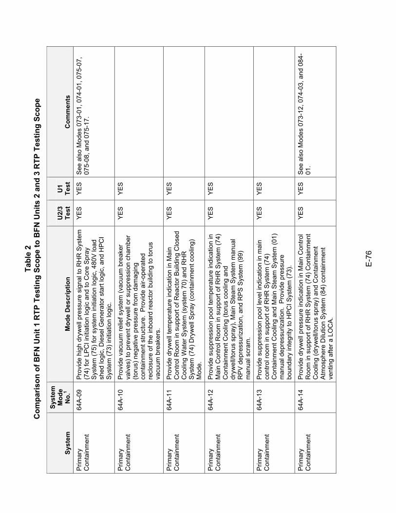
Tabl
e 2
Com
paris
on o
f BFN
Uni
t 1 R
TP T
estin
g Sc
ope
to B
FN U
nits
2 a
nd 3
RTP
Tes
ting
Scop
e
E-7
6
Syst
em
Syst
em
Mod
e N
o.1
Mod
e D
escr
iptio
n U
2/3
Test
U
1 Te
st
Com
men
ts
Prim
ary
Con
tain
men
t 64
A-0
9 P
rovi
de h
igh
dryw
ell p
ress
ure
sign
al to
RH
R S
yste
m
(74)
for L
PC
I ini
tiatio
n lo
gic
and
to C
ore
Spr
ay
Sys
tem
(75)
for s
yste
m in
itiat
ion
logi
c, 4
80V
load
sh
ed lo
gic,
Die
sel G
ener
ator
sta
rt lo
gic,
and
HPC
I S
yste
m (7
3) in
itiat
ion
logi
c.
YE
S
YE
S
See
als
o M
odes
073
-01,
074
-01,
075
-07,
07
5-08
, and
075
-17.
Prim
ary
Con
tain
men
t 64
A-1
0 P
rovi
de v
acuu
m re
lief s
yste
m (v
acuu
m b
reak
er
valv
es) t
o pr
even
t dry
wel
l or s
uppr
essi
on c
ham
ber
(toru
s) n
egat
ive
pres
sure
from
dam
agin
g co
ntai
nmen
t stru
ctur
e. P
rovi
de a
ir-op
erat
ed
recl
osur
e of
the
inbo
ard
reac
tor b
uild
ing
to to
rus
vacu
um b
reak
ers.
YES
YES
Prim
ary
Con
tain
men
t 64
A-1
1 P
rovi
de d
ryw
ell t
empe
ratu
re in
dica
tion
in M
ain
Con
trol R
oom
in s
uppo
rt of
Rea
ctor
Bui
ldin
g C
lose
d C
oolin
g W
ater
Sys
tem
(sys
tem
70)
and
RH
R
Sys
tem
(74)
Dry
wel
l Spr
ay (c
onta
inm
ent c
oolin
g)
Mod
e.
YES
YES
Prim
ary
Con
tain
men
t 64
A-1
2 P
rovi
de s
uppr
essi
on p
ool t
empe
ratu
re in
dica
tion
in
Mai
n C
ontro
l Roo
m in
sup
port
of R
HR
Sys
tem
(74)
C
onta
inm
ent C
oolin
g (to
rus
cool
ing
and
dryw
ell/t
orus
spr
ay),
Mai
n S
team
Sys
tem
man
ual
RP
V d
epre
ssur
izat
ion,
and
RP
S S
yste
m (9
9)
man
ual s
cram
.
YES
YES
Prim
ary
Con
tain
men
t 64
A-1
3 P
rovi
de s
uppr
essi
on p
ool l
evel
indi
catio
n in
mai
n co
ntro
l roo
m in
sup
port
of R
HR
Sys
tem
(74)
C
onta
inm
ent C
oolin
g an
d M
ain
Ste
am S
yste
m (0
1)
man
ual d
epre
ssur
izat
ion.
Pro
vide
pre
ssur
e bo
unda
ry in
tegr
ity to
HP
CI S
yste
m (7
3).
YES
YES
Prim
ary
Con
tain
men
t 64
A-1
4 P
rovi
de d
ryw
ell p
ress
ure
indi
catio
n in
Mai
n C
ontro
l R
oom
in s
uppo
rt of
RH
R S
yste
m (7
4) C
onta
inm
ent
Coo
ling
(dry
wel
l/tor
us s
pray
) and
Con
tain
men
t A
tmos
pher
e D
ilutio
n S
yste
m (8
4) c
onta
inm
ent
vent
ing
afte
r a L
OC
A.
YE
S
YE
S
See
als
o M
odes
073
-12,
074
-03,
and
084
-01
.
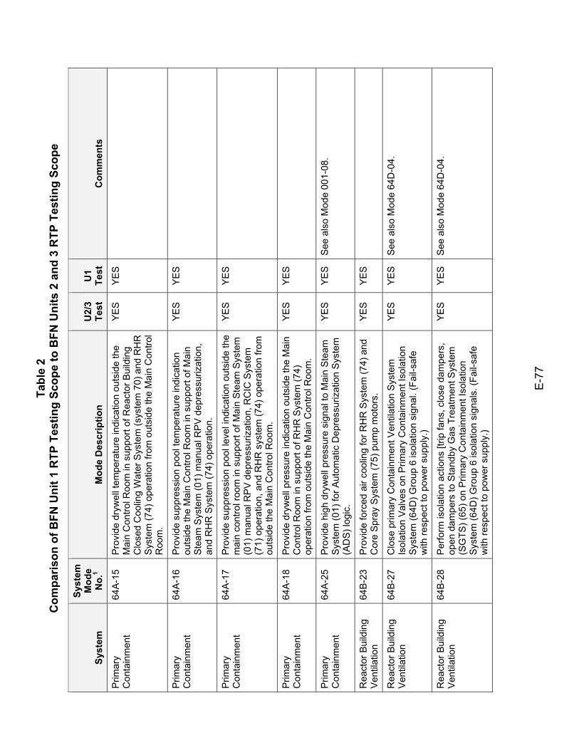
Tabl
e 2
Com
paris
on o
f BFN
Uni
t 1 R
TP T
estin
g Sc
ope
to B
FN U
nits
2 a
nd 3
RTP
Tes
ting
Scop
e
E-7
7
Syst
em
Syst
em
Mod
e N
o.1
Mod
e D
escr
iptio
n U
2/3
Test
U
1 Te
st
Com
men
ts
Prim
ary
Con
tain
men
t 64
A-1
5 P
rovi
de d
ryw
ell t
empe
ratu
re in
dica
tion
outs
ide
the
Mai
n C
ontro
l Roo
m in
sup
port
of R
eact
or B
uild
ing
Clo
sed
Coo
ling
Wat
er S
yste
m (s
yste
m 7
0) a
nd R
HR
S
yste
m (7
4) o
pera
tion
from
out
side
the
Mai
n C
ontro
l R
oom
.
YES
YES
Prim
ary
Con
tain
men
t 64
A-1
6 P
rovi
de s
uppr
essi
on p
ool t
empe
ratu
re in
dica
tion
outs
ide
the
Mai
n C
ontro
l Roo
m in
sup
port
of M
ain
Ste
am S
yste
m (0
1) m
anua
l RP
V d
epre
ssur
izat
ion,
an
d R
HR
Sys
tem
(74)
ope
ratio
n.
YES
YES
Prim
ary
Con
tain
men
t 64
A-1
7 P
rovi
de s
uppr
essi
on p
ool l
evel
indi
catio
n ou
tsid
e th
e m
ain
cont
rol r
oom
in s
uppo
rt of
Mai
n S
team
Sys
tem
(0
1) m
anua
l RP
V d
epre
ssur
izat
ion,
RC
IC S
yste
m
(71)
ope
ratio
n, a
nd R
HR
sys
tem
(74)
ope
ratio
n fro
m
outs
ide
the
Mai
n C
ontro
l Roo
m.
YES
YES
Prim
ary
Con
tain
men
t 64
A-1
8 P
rovi
de d
ryw
ell p
ress
ure
indi
catio
n ou
tsid
e th
e M
ain
Con
trol R
oom
in s
uppo
rt of
RH
R S
yste
m (7
4)
oper
atio
n fro
m o
utsi
de th
e M
ain
Con
trol R
oom
.
YES
YES
Prim
ary
Con
tain
men
t 64
A-2
5 P
rovi
de h
igh
dryw
ell p
ress
ure
sign
al to
Mai
n S
team
S
yste
m (0
1) fo
r Aut
omat
ic D
epre
ssur
izat
ion
Sys
tem
(A
DS
) log
ic.
YE
S
YE
S
See
als
o M
ode
001-
08.
Rea
ctor
Bui
ldin
g V
entil
atio
n 64
B-2
3 P
rovi
de fo
rced
air
cool
ing
for R
HR
Sys
tem
(74)
and
C
ore
Spr
ay S
yste
m (7
5) p
ump
mot
ors.
YE
S YE
S
Rea
ctor
Bui
ldin
g V
entil
atio
n 64
B-2
7 C
lose
prim
ary
Con
tain
men
t Ven
tilat
ion
Sys
tem
Is
olat
ion
Val
ves
on P
rimar
y C
onta
inm
ent I
sola
tion
Sys
tem
(64D
) Gro
up 6
isol
atio
n si
gnal
. (Fa
il-sa
fe
with
resp
ect t
o po
wer
sup
ply.
)
YE
S
YE
S
See
als
o M
ode
64D
-04.
Rea
ctor
Bui
ldin
g V
entil
atio
n 64
B-2
8 P
erfo
rm is
olat
ion
actio
ns [t
rip fa
ns, c
lose
dam
pers
, op
en d
ampe
rs to
Sta
ndby
Gas
Tre
atm
ent S
yste
m
(SG
TS) (
65) o
n P
rimar
y C
onta
inm
ent I
sola
tion
Sys
tem
(64D
) Gro
up 6
isol
atio
n si
gnal
s. (F
ail-s
afe
with
resp
ect t
o po
wer
sup
ply.
)
YE
S
YE
S
See
als
o M
ode
64D
-04.
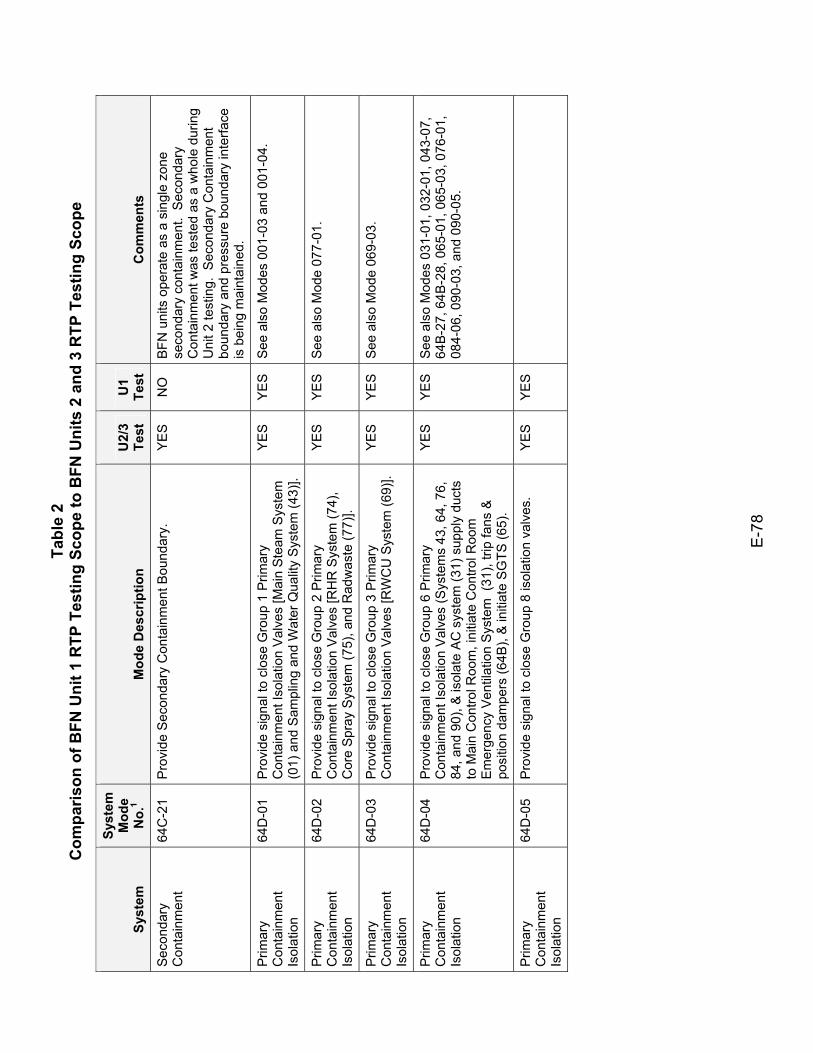
Tabl
e 2
Com
paris
on o
f BFN
Uni
t 1 R
TP T
estin
g Sc
ope
to B
FN U
nits
2 a
nd 3
RTP
Tes
ting
Scop
e
E-7
8
Syst
em
Syst
em
Mod
e N
o.1
Mod
e D
escr
iptio
n U
2/3
Test
U
1 Te
st
Com
men
ts
Seco
ndar
y C
onta
inm
ent
64C
-21
Pro
vide
Sec
onda
ry C
onta
inm
ent B
ound
ary.
Y
ES
N
O
BFN
uni
ts o
pera
te a
s a
sing
le z
one
seco
ndar
y co
ntai
nmen
t. S
econ
dary
C
onta
inm
ent w
as te
sted
as
a w
hole
dur
ing
Uni
t 2 te
stin
g. S
econ
dary
Con
tain
men
t bo
unda
ry a
nd p
ress
ure
boun
dary
inte
rface
is
bei
ng m
aint
aine
d.
Prim
ary
Con
tain
men
t Is
olat
ion
64D
-01
Pro
vide
sig
nal t
o cl
ose
Gro
up 1
Prim
ary
Con
tain
men
t Iso
latio
n V
alve
s [M
ain
Ste
am S
yste
m
(01)
and
Sam
plin
g an
d W
ater
Qua
lity
Sys
tem
(43)
].
YE
S
YE
S
See
als
o M
odes
001
-03
and
001-
04.
Prim
ary
Con
tain
men
t Is
olat
ion
64D
-02
Pro
vide
sig
nal t
o cl
ose
Gro
up 2
Prim
ary
Con
tain
men
t Iso
latio
n V
alve
s [R
HR
Sys
tem
(74)
, C
ore
Spr
ay S
yste
m (7
5), a
nd R
adw
aste
(77)
].
YE
S
YE
S
See
als
o M
ode
077-
01.
Prim
ary
Con
tain
men
t Is
olat
ion
64D
-03
Pro
vide
sig
nal t
o cl
ose
Gro
up 3
Prim
ary
Con
tain
men
t Iso
latio
n V
alve
s [R
WC
U S
yste
m (6
9)].
YE
S
YE
S
See
als
o M
ode
069-
03.
Prim
ary
Con
tain
men
t Is
olat
ion
64D
-04
Pro
vide
sig
nal t
o cl
ose
Gro
up 6
Prim
ary
Con
tain
men
t Iso
latio
n V
alve
s (S
yste
ms
43, 6
4, 7
6,
84, a
nd 9
0), &
isol
ate
AC
sys
tem
(31)
sup
ply
duct
s to
Mai
n C
ontro
l Roo
m, i
nitia
te C
ontro
l Roo
m
Em
erge
ncy
Vent
ilatio
n S
yste
m (
31),
trip
fans
&
posi
tion
dam
pers
(64B
), &
initi
ate
SG
TS (6
5).
YE
S
YE
S
See
als
o M
odes
031
-01,
032
-01,
043
-07,
64
B-2
7, 6
4B-2
8, 0
65-0
1, 0
65-0
3, 0
76-0
1,
084-
06, 0
90-0
3, a
nd 0
90-0
5.
Prim
ary
Con
tain
men
t Is
olat
ion
64D
-05
Pro
vide
sig
nal t
o cl
ose
Gro
up 8
isol
atio
n va
lves
.
YES
YES
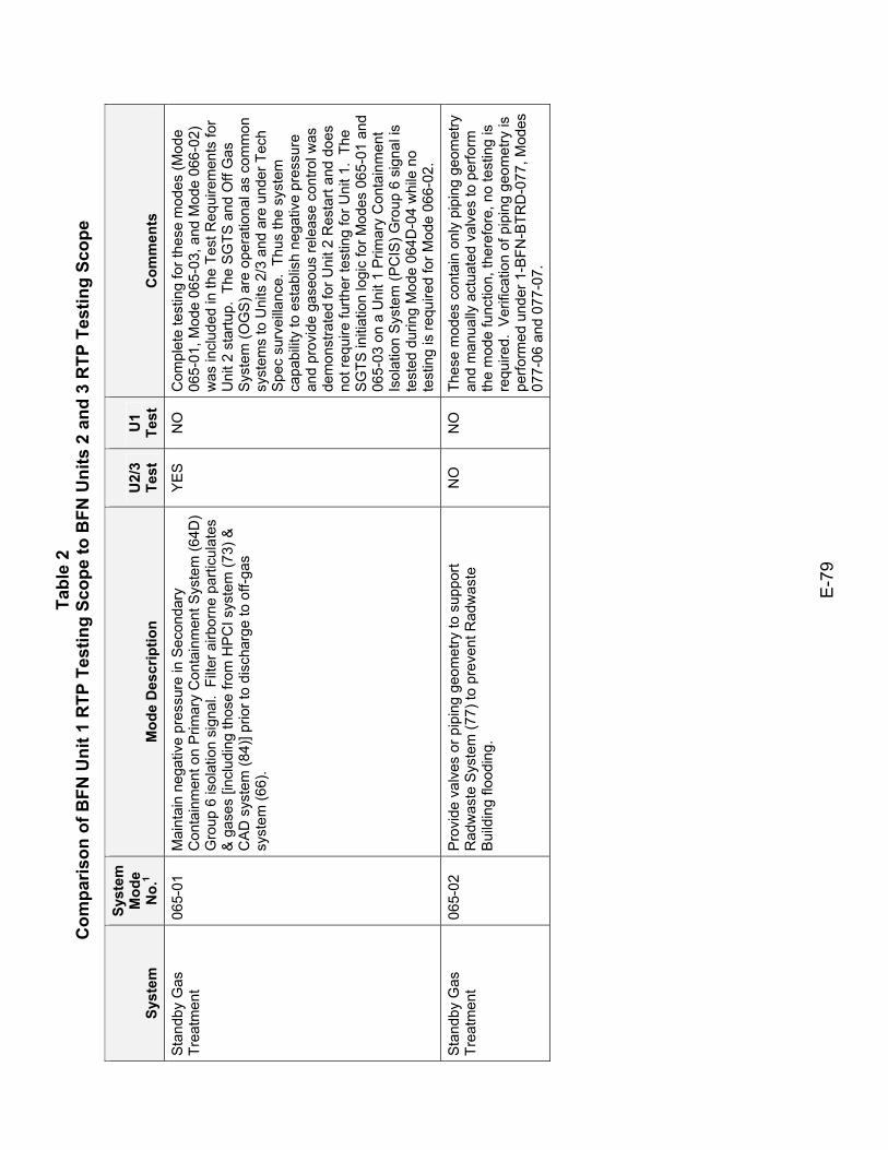
Tabl
e 2
Com
paris
on o
f BFN
Uni
t 1 R
TP T
estin
g Sc
ope
to B
FN U
nits
2 a
nd 3
RTP
Tes
ting
Scop
e
E-7
9
Syst
em
Syst
em
Mod
e N
o.1
Mod
e D
escr
iptio
n U
2/3
Test
U
1 Te
st
Com
men
ts
Sta
ndby
Gas
Tr
eatm
ent
065-
01
Mai
ntai
n ne
gativ
e pr
essu
re in
Sec
onda
ry
Con
tain
men
t on
Prim
ary
Con
tain
men
t Sys
tem
(64D
) G
roup
6 is
olat
ion
sign
al.
Filte
r airb
orne
par
ticul
ates
&
gas
es [i
nclu
ding
thos
e fro
m H
PC
I sys
tem
(73)
&
CA
D s
yste
m (8
4)] p
rior t
o di
scha
rge
to o
ff-ga
s sy
stem
(66)
.
YE
S
NO
C
ompl
ete
test
ing
for t
hese
mod
es (M
ode
065-
01, M
ode
065-
03, a
nd M
ode
066-
02)
was
incl
uded
in th
e Te
st R
equi
rem
ents
for
Uni
t 2 s
tartu
p. T
he S
GTS
and
Off
Gas
S
yste
m (O
GS)
are
ope
ratio
nal a
s co
mm
on
syst
ems
to U
nits
2/3
and
are
und
er T
ech
Spe
c su
rvei
llanc
e. T
hus
the
syst
em
capa
bilit
y to
est
ablis
h ne
gativ
e pr
essu
re
and
prov
ide
gase
ous
rele
ase
cont
rol w
as
dem
onst
rate
d fo
r Uni
t 2 R
esta
rt an
d do
es
not r
equi
re fu
rther
test
ing
for U
nit 1
. Th
e S
GTS
initi
atio
n lo
gic
for M
odes
065
-01
and
065-
03 o
n a
Uni
t 1 P
rimar
y C
onta
inm
ent
Isol
atio
n S
yste
m (P
CIS
) Gro
up 6
sig
nal i
s te
sted
dur
ing
Mod
e 06
4D-0
4 w
hile
no
test
ing
is re
quire
d fo
r Mod
e 06
6-02
.
Sta
ndby
Gas
Tr
eatm
ent
065-
02
Pro
vide
val
ves
or p
ipin
g ge
omet
ry to
sup
port
Rad
was
te S
yste
m (7
7) to
pre
vent
Rad
was
te
Bui
ldin
g flo
odin
g.
NO
N
O
Thes
e m
odes
con
tain
onl
y pi
ping
geo
met
ry
and
man
ually
act
uate
d va
lves
to p
erfo
rm
the
mod
e fu
nctio
n, th
eref
ore,
no
test
ing
is
requ
ired.
Ver
ifica
tion
of p
ipin
g ge
omet
ry is
pe
rform
ed u
nder
1-B
FN-B
TRD
-077
, Mod
es
077-
06 a
nd 0
77-0
7.
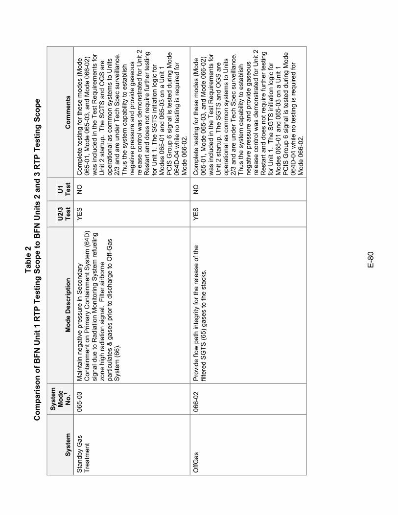
Tabl
e 2
Com
paris
on o
f BFN
Uni
t 1 R
TP T
estin
g Sc
ope
to B
FN U
nits
2 a
nd 3
RTP
Tes
ting
Scop
e
E-8
0
Syst
em
Syst
em
Mod
e N
o.1
Mod
e D
escr
iptio
n U
2/3
Test
U
1 Te
st
Com
men
ts
Sta
ndby
Gas
Tr
eatm
ent
065-
03
Mai
ntai
n ne
gativ
e pr
essu
re in
Sec
onda
ry
Con
tain
men
t on
Prim
ary
Con
tain
men
t Sys
tem
(64D
) si
gnal
due
to R
adia
tion
Mon
itorin
g S
yste
m re
fuel
ing
zone
hig
h ra
diat
ion
sign
al.
Filte
r airb
orne
pa
rticu
late
s &
gas
es p
rior t
o di
scha
rge
to O
ff-G
as
Sys
tem
(66)
.
YE
S
NO
C
ompl
ete
test
ing
for t
hese
mod
es (M
ode
065-
01, M
ode
065-
03, a
nd M
ode
066-
02)
was
incl
uded
in th
e Te
st R
equi
rem
ents
for
Uni
t 2 s
tartu
p. T
he S
GTS
and
OG
S a
re
oper
atio
nal a
s co
mm
on s
yste
ms
to U
nits
2/
3 an
d ar
e un
der T
ech
Spe
c su
rvei
llanc
e.
Thus
the
syst
em c
apab
ility
to e
stab
lish
nega
tive
pres
sure
and
pro
vide
gas
eous
re
leas
e co
ntro
l was
dem
onst
rate
d fo
r Uni
t 2
Res
tart
and
does
not
requ
ire fu
rther
test
ing
for U
nit 1
. The
SG
TS in
itiat
ion
logi
c fo
r M
odes
065
-01
and
065-
03 o
n a
Uni
t 1
PC
IS G
roup
6 s
igna
l is
test
ed d
urin
g M
ode
064D
-04
whi
le n
o te
stin
g is
requ
ired
for
Mod
e 06
6-02
.
OffG
as
066-
02
Pro
vide
flow
pat
h in
tegr
ity fo
r the
rele
ase
of th
e fil
tere
d S
GTS
(65)
gas
es to
the
stac
ks.
YE
S
NO
C
ompl
ete
test
ing
for t
hese
mod
es (M
ode
065-
01, M
ode
065-
03, a
nd M
ode
066-
02)
was
incl
uded
in th
e Te
st R
equi
rem
ents
for
Uni
t 2 s
tartu
p. T
he S
GTS
and
OG
S a
re
oper
atio
nal a
s co
mm
on s
yste
ms
to U
nits
2/
3 an
d ar
e un
der T
ech
Spe
c su
rvei
llanc
e.
Thus
the
syst
em c
apab
ility
to e
stab
lish
nega
tive
pres
sure
and
pro
vide
gas
eous
re
leas
e co
ntro
l was
dem
onst
rate
d fo
r Uni
t 2
Res
tart
and
does
not
requ
ire fu
rther
test
ing
for U
nit 1
. Th
e S
GTS
initi
atio
n lo
gic
for
Mod
es 0
65-0
1 an
d 06
5-03
on
a U
nit 1
P
CIS
Gro
up 6
sig
nal i
s te
sted
dur
ing
Mod
e 06
4D-0
4 w
hile
no
test
ing
is re
quire
d fo
r M
ode
066-
02.

Tabl
e 2
Com
paris
on o
f BFN
Uni
t 1 R
TP T
estin
g Sc
ope
to B
FN U
nits
2 a
nd 3
RTP
Tes
ting
Scop
e
E-8
1
Syst
em
Syst
em
Mod
e N
o.1
Mod
e D
escr
iptio
n U
2/3
Test
U
1 Te
st
Com
men
ts
OffG
as
066-
03
Pro
vide
val
ves
or p
ipin
g ge
omet
ry to
sup
port
Rad
was
te S
yste
m (7
7) to
pre
vent
Rad
was
te
Bui
ldin
g flo
odin
g.
YE
S
YE
S
Thes
e m
odes
con
tain
onl
y pi
ping
geo
met
ry
and
man
ually
act
uate
d va
lves
to p
erfo
rm
the
mod
e fu
nctio
n, th
eref
ore,
no
test
ing
is
requ
ired.
Ver
ifica
tion
of p
ipin
g ge
omet
ry is
pe
rform
ed u
nder
1-B
FN-B
TRD
-077
, Mod
es
077-
06 a
nd 0
77-0
7.
OffG
as
066-
04
Pro
vide
aut
omat
ic c
losu
re o
f bac
k-dr
aft p
reve
ntio
n da
mpe
rs to
pre
vent
bac
k flo
w a
nd p
oten
tial g
roun
d le
vel r
elea
se o
f rad
iatio
n.
See
N
ote
2.
NO
Te
stin
g fo
r Mod
e 06
6-04
was
incl
uded
in
post
mod
ifica
tion
test
ing
for D
CN
W
1799
9A.
Add
ition
al te
stin
g fo
r Uni
t 1 is
no
t req
uire
d. S
ee a
lso
DC
N 5
1128
.
Em
erge
ncy
Equ
ipm
ent C
oolin
g W
ater
067-
01
Pro
vide
coo
ling
wat
er to
AC
Sys
tem
(31)
chi
llers
, R
HR
Sys
tem
(74)
Pum
p S
eal C
oole
rs, C
onta
inm
ent
Iner
ting
Sys
tem
(76)
H2
& O
2 G
as A
naly
zers
, Die
sel
Gen
erat
or (8
2), R
HR
& C
ore
Spr
ay E
quip
men
t R
oom
Coo
lers
(64B
), an
d Fu
el P
ool (
78).
B. P
rovi
de
EE
CW
val
ve p
ositi
on in
terlo
ck s
igna
l for
aut
o-st
art
RH
RS
W (2
3) p
umps
.
YE
S
YE
S
This
is a
sha
red
syst
em.
In a
dditi
on to
the
verif
icat
ion
of a
dequ
ate
cool
ing
wat
er fl
ow
to e
ssen
tial U
nit E
EC
W c
ompo
nent
s, th
e te
stin
g m
ust i
nclu
de s
imul
tane
ous
verif
icat
ion
of a
dequ
ate
flow
to U
nits
2/3
es
sent
ial c
ompo
nent
s. H
owev
er,
verif
icat
ion
of a
dequ
ate
flow
to U
nit 1
H2O
2 an
alyz
er is
not
requ
ired.
Em
erge
ncy
Equ
ipm
ent C
oolin
g W
ater
067-
02
Pro
vide
Sec
onda
ry C
onta
inm
ent B
ound
ary.
Y
ES
N
O
BFN
uni
ts o
pera
te a
s a
sing
le z
one
seco
ndar
y co
ntai
nmen
t. S
econ
dary
C
onta
inm
ent w
as te
sted
as
a w
hole
dur
ing
Uni
t 2 te
stin
g. S
econ
dary
Con
tain
men
t bo
unda
ry a
nd p
ress
ure
boun
dary
inte
rface
is
bei
ng m
aint
aine
d.
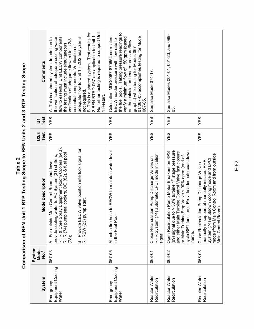
Tabl
e 2
Com
paris
on o
f BFN
Uni
t 1 R
TP T
estin
g Sc
ope
to B
FN U
nits
2 a
nd 3
RTP
Tes
ting
Scop
e
E-8
2
Syst
em
Syst
em
Mod
e N
o.1
Mod
e D
escr
iptio
n U
2/3
Test
U
1 Te
st
Com
men
ts
Em
erge
ncy
Equ
ipm
ent C
oolin
g W
ater
067-
03
A.
For o
utsi
de M
ain
Con
trol R
oom
shu
tdow
n,
prov
ide
cool
ing
wat
er to
AC
Sys
tem
(31)
chi
llers
, R
HR
& C
ore
Spr
ay E
quip
men
t Roo
m C
oole
rs (6
4B),
RH
R (7
4) p
ump
seal
coo
lers
, DG
(82)
, & fu
el p
ool
(78)
; B
. P
rovi
de E
EC
W v
alve
pos
ition
inte
rlock
sig
nal f
or
RH
RS
W (2
3) p
ump
star
t.
YE
S
YE
S
A. T
his
is a
sha
red
syst
em. I
n ad
ditio
n to
th
e ve
rific
atio
n of
ade
quat
e co
olin
g w
ater
flo
w to
ess
entia
l Uni
t EE
CW
com
pone
nts,
th
e te
stin
g m
ust i
nclu
de s
imul
tane
ous
verif
icat
ion
of a
dequ
ate
flow
to U
nits
2/3
es
sent
ial c
ompo
nent
s. V
erifi
catio
n of
ad
equa
te fl
ow to
Uni
t 1 H
2O2
anal
yzer
is
not r
equi
red.
B
. Thi
s is
a s
hare
d sy
stem
. Te
st re
sults
for
2-B
FN-B
TRD
-067
are
app
licab
le to
Uni
t 1.
No
furth
er te
stin
g is
requ
ired
to s
uppo
rt U
nit
1 R
esta
rt.
Em
erge
ncy
Equ
ipm
ent C
oolin
g W
ater
067-
05
Atta
ch a
fire
hos
e to
EE
CW
to m
aint
ain
wat
er le
vel
in th
e Fu
el P
ool.
YE
S
YE
S
Cal
cula
tion
MD
Q00
67-8
7065
4 co
rrela
tes
EE
CW
hea
der p
ress
ure
with
flow
rate
to
the
fuel
poo
ls.
Taki
ng p
ress
ure
read
ings
to
verif
y a
min
imum
flow
of 1
50 g
pm (b
ased
on
the
calc
ulat
ion
head
er p
ress
ure/
flow
gr
aphs
) whi
le te
stin
g fo
r Mod
es 0
67-
01/0
67-0
3 ac
com
plis
hes
test
ing
for M
ode
067-
05.
Rea
ctor
Wat
er
Rec
ircul
atio
n 06
8-01
C
lose
Rec
ircul
atio
n P
ump
Dis
char
ge V
alve
s on
R
HR
Sys
tem
(74)
aut
omat
ic L
PC
I mod
e in
itiat
ion
sign
al.
YE
S
YE
S
See
als
o M
ode
074-
17.
Rea
ctor
Wat
er
Rec
ircul
atio
n 06
8-02
O
pen
Rec
ircul
atio
n P
ump
Mot
or B
reak
ers
on R
PS
(9
9) s
igna
l due
to >
30%
turb
ine
1st s
tage
pre
ssur
e an
d ei
ther
Mai
n Tu
rbin
e C
ontro
l Val
ve fa
st c
losu
re
or M
ain
Turb
ine
Sto
p V
alve
< 9
0% o
pen
(end
-of-
cycl
e R
PT
func
tion)
. P
rovi
de a
dequ
ate
coas
tdow
n in
ertia
.
YE
S
YE
S
See
als
o M
odes
001
-01,
001
-23,
and
099
-05
.
Rea
ctor
Wat
er
Rec
ircul
atio
n 06
8-03
C
lose
Rec
ircul
atio
n P
ump
Dis
char
ge V
alve
s m
anua
lly in
sup
port
of m
anua
lly in
itiat
ed R
HR
S
yste
m (7
4) s
hutd
own
cool
ing
mod
e an
d LP
CI
mod
e (fr
om M
ain
Con
trol R
oom
and
from
out
side
M
ain
Con
trol R
oom
).
YES
YES
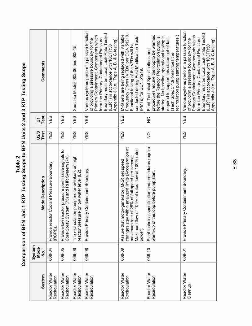
Tabl
e 2
Com
paris
on o
f BFN
Uni
t 1 R
TP T
estin
g Sc
ope
to B
FN U
nits
2 a
nd 3
RTP
Tes
ting
Scop
e
E-8
3
Syst
em
Syst
em
Mod
e N
o.1
Mod
e D
escr
iptio
n U
2/3
Test
U
1 Te
st
Com
men
ts
Rea
ctor
Wat
er
Rec
ircul
atio
n 06
8-04
P
rovi
de re
acto
r Coo
lant
Pre
ssur
e B
ound
ary
(RC
PB
). YE
S YE
S
Rea
ctor
Wat
er
Rec
ircul
atio
n 06
8-05
P
rovi
de lo
w re
acto
r pre
ssur
e pe
rmis
sive
sig
nals
to
Cor
e S
pray
Sys
tem
(75)
and
RH
R S
yste
m (7
4).
YES
YES
Rea
ctor
Wat
er
Rec
ircul
atio
n 06
8-06
Tr
ip re
circ
ulat
ion
pum
p m
otor
-bre
aker
s on
hig
h re
acto
r pre
ssur
e or
low
wat
er le
vel (
L2).
YE
S
YE
S
See
als
o M
odes
003
-06
and
003-
15.
Rea
ctor
Wat
er
Rec
ircul
atio
n 06
8-08
P
rovi
de P
rimar
y C
onta
inm
ent B
ound
ary.
Y
ES
Y
ES
V
ario
us s
yste
ms
perfo
rm a
pas
sive
func
tion
of p
rovi
ding
a p
ress
ure
boun
dary
for t
he
Prim
ary
Con
tain
men
t. C
ompo
nent
s w
hich
fo
rm th
e P
rimar
y C
onta
inm
ent P
ress
ure
Bou
ndar
y m
ust b
e Lo
cal L
eak
Rat
e Te
sted
(L
LRT)
in a
ccor
danc
e w
ith 1
0CFR
50
App
endi
x J
(i.e.
, Typ
e A
, B, &
C te
stin
g).
Rea
ctor
Wat
er
Rec
ircul
atio
n 06
8-09
A
ssur
e th
at m
otor
-gen
erat
or (M
-G) s
et s
peed
ch
ange
s st
ay w
ithin
ana
lyze
d lim
its (A
ccel
erat
ion
at
max
imum
rate
of 2
5% o
f ful
l spe
ed p
er s
econ
d;
Max
imum
flow
of 1
05%
of r
ated
flow
at 1
00%
rate
d po
wer
).
YE
S
YE
S
M-G
set
s ar
e be
ing
repl
aced
with
Var
iabl
e Fr
eque
ncy
Driv
es (V
FDs)
per
DC
N 5
1219
. Fu
nctio
nal t
estin
g of
the
VFD
s w
ill be
co
nduc
ted
durin
g P
ost M
odifi
catio
n Te
sts
(PM
Ts) f
or D
CN
512
19.
Rea
ctor
Wat
er
Rec
ircul
atio
n 06
8-10
P
lant
tech
nica
l spe
cific
atio
n an
d pr
oced
ures
requ
ire
war
m-u
p of
the
loop
bef
ore
pum
p st
art.
NO
N
O
Pla
nt T
echn
ical
Spe
cific
atio
ns a
nd
proc
edur
es re
quire
the
loop
to b
e w
arm
ed
befo
re th
e R
eact
or R
ecirc
ulat
ion
pum
p is
st
arte
d. N
o ba
selin
e op
erat
iona
l tes
ting
is
requ
ired
to s
uppo
rt th
is s
tate
men
t of f
act.
(Tec
h S
pec
3.4.
9 pr
escr
ibes
the
reci
rcul
atio
n pu
mp
star
ting
tem
pera
ture
s.)
Rea
ctor
Wat
er
Cle
anup
06
9-01
P
rovi
de P
rimar
y C
onta
inm
ent B
ound
ary.
Y
ES
Y
ES
V
ario
us s
yste
ms
perfo
rm a
pas
sive
func
tion
of p
rovi
ding
a p
ress
ure
boun
dary
for t
he
Prim
ary
Con
tain
men
t. C
ompo
nent
s w
hich
fo
rm th
e P
rimar
y C
onta
inm
ent P
ress
ure
Bou
ndar
y m
ust b
e Lo
cal L
eak
Rat
e Te
sted
(L
LRT)
in a
ccor
danc
e w
ith 1
0CFR
50
App
endi
x J
(i.e.
, Typ
e A
, B, &
C te
stin
g).
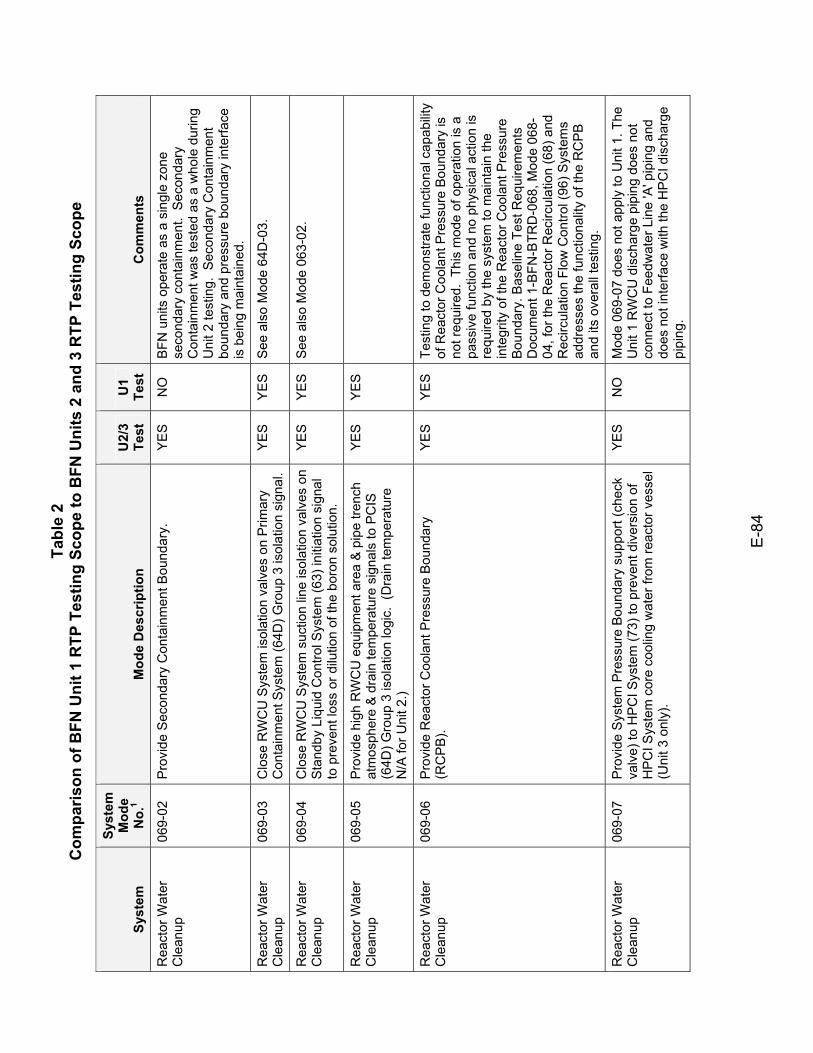
Tabl
e 2
Com
paris
on o
f BFN
Uni
t 1 R
TP T
estin
g Sc
ope
to B
FN U
nits
2 a
nd 3
RTP
Tes
ting
Scop
e
E-8
4
Syst
em
Syst
em
Mod
e N
o.1
Mod
e D
escr
iptio
n U
2/3
Test
U
1 Te
st
Com
men
ts
Rea
ctor
Wat
er
Cle
anup
06
9-02
P
rovi
de S
econ
dary
Con
tain
men
t Bou
ndar
y.
YE
S
NO
B
FN u
nits
ope
rate
as
a si
ngle
zon
e se
cond
ary
cont
ainm
ent.
Sec
onda
ry
Con
tain
men
t was
test
ed a
s a
who
le d
urin
g U
nit 2
test
ing.
Sec
onda
ry C
onta
inm
ent
boun
dary
and
pre
ssur
e bo
unda
ry in
terfa
ce
is b
eing
mai
ntai
ned.
Rea
ctor
Wat
er
Cle
anup
06
9-03
C
lose
RW
CU
Sys
tem
isol
atio
n va
lves
on
Prim
ary
Con
tain
men
t Sys
tem
(64D
) Gro
up 3
isol
atio
n si
gnal
. Y
ES
Y
ES
S
ee a
lso
Mod
e 64
D-0
3.
Rea
ctor
Wat
er
Cle
anup
06
9-04
C
lose
RW
CU
Sys
tem
suc
tion
line
isol
atio
n va
lves
on
Sta
ndby
Liq
uid
Con
trol S
yste
m (6
3) in
itiat
ion
sign
al
to p
reve
nt lo
ss o
r dilu
tion
of th
e bo
ron
solu
tion.
YE
S
YE
S
See
als
o M
ode
063-
02.
Rea
ctor
Wat
er
Cle
anup
06
9-05
P
rovi
de h
igh
RW
CU
equ
ipm
ent a
rea
& p
ipe
trenc
h at
mos
pher
e &
dra
in te
mpe
ratu
re s
igna
ls to
PC
IS
(64D
) Gro
up 3
isol
atio
n lo
gic.
(D
rain
tem
pera
ture
N
/A fo
r Uni
t 2.)
YES
YES
Rea
ctor
Wat
er
Cle
anup
06
9-06
P
rovi
de R
eact
or C
oola
nt P
ress
ure
Bou
ndar
y (R
CP
B).
YE
S
YE
S
Test
ing
to d
emon
stra
te fu
nctio
nal c
apab
ility
of R
eact
or C
oola
nt P
ress
ure
Bou
ndar
y is
no
t req
uire
d. T
his
mod
e of
ope
ratio
n is
a
pass
ive
func
tion
and
no p
hysi
cal a
ctio
n is
re
quire
d by
the
syst
em to
mai
ntai
n th
e in
tegr
ity o
f the
Rea
ctor
Coo
lant
Pre
ssur
e B
ound
ary.
Bas
elin
e Te
st R
equi
rem
ents
D
ocum
ent 1
-BFN
-BTR
D-0
68, M
ode
068-
04, f
or th
e R
eact
or R
ecirc
ulat
ion
(68)
and
R
ecirc
ulat
ion
Flow
Con
trol (
96) S
yste
ms
addr
esse
s th
e fu
nctio
nalit
y of
the
RC
PB
an
d its
ove
rall
test
ing.
Rea
ctor
Wat
er
Cle
anup
06
9-07
P
rovi
de S
yste
m P
ress
ure
Bou
ndar
y su
ppor
t (ch
eck
valv
e) to
HP
CI S
yste
m (7
3) to
pre
vent
div
ersi
on o
f H
PC
I Sys
tem
cor
e co
olin
g w
ater
from
reac
tor v
esse
l (U
nit 3
onl
y).
YE
S
NO
M
ode
069-
07 d
oes
not a
pply
to U
nit 1
. The
U
nit 1
RW
CU
dis
char
ge p
ipin
g do
es n
ot
conn
ect t
o Fe
edw
ater
Lin
e 'A
' pip
ing
and
does
not
inte
rface
with
the
HP
CI d
isch
arge
pi
ping
.
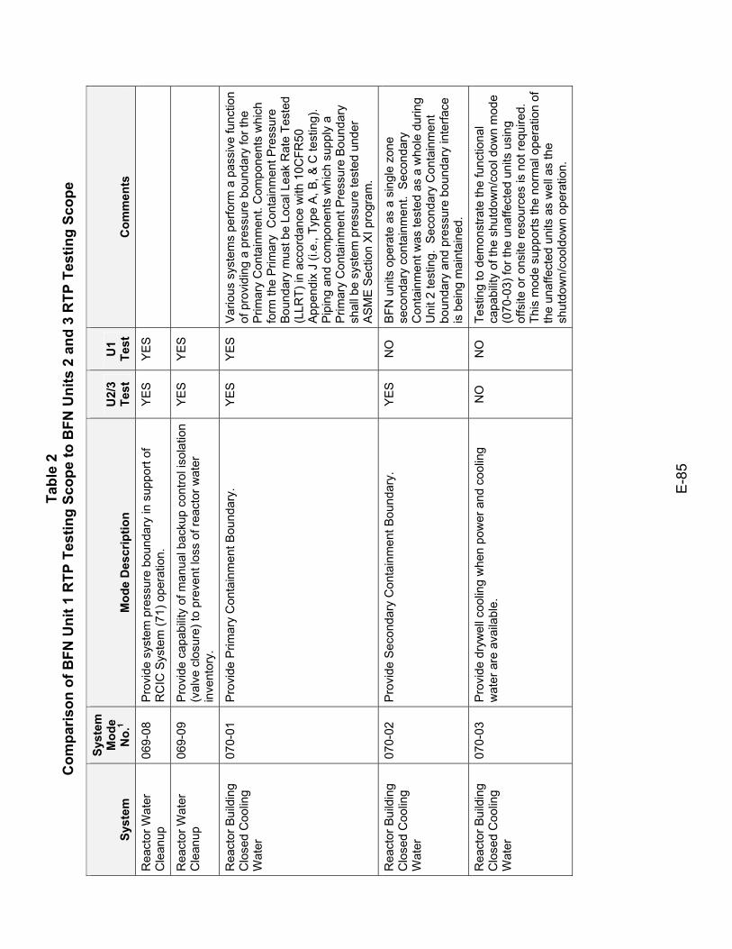
Tabl
e 2
Com
paris
on o
f BFN
Uni
t 1 R
TP T
estin
g Sc
ope
to B
FN U
nits
2 a
nd 3
RTP
Tes
ting
Scop
e
E-8
5
Syst
em
Syst
em
Mod
e N
o.1
Mod
e D
escr
iptio
n U
2/3
Test
U
1 Te
st
Com
men
ts
Rea
ctor
Wat
er
Cle
anup
06
9-08
P
rovi
de s
yste
m p
ress
ure
boun
dary
in s
uppo
rt of
R
CIC
Sys
tem
(71)
ope
ratio
n.
YES
YES
Rea
ctor
Wat
er
Cle
anup
06
9-09
P
rovi
de c
apab
ility
of m
anua
l bac
kup
cont
rol i
sola
tion
(val
ve c
losu
re) t
o pr
even
t los
s of
reac
tor w
ater
in
vent
ory.
YES
YES
Rea
ctor
Bui
ldin
g C
lose
d C
oolin
g W
ater
070-
01
Pro
vide
Prim
ary
Con
tain
men
t Bou
ndar
y.
YE
S
YE
S
Var
ious
sys
tem
s pe
rform
a p
assi
ve fu
nctio
n of
pro
vidi
ng a
pre
ssur
e bo
unda
ry fo
r the
P
rimar
y C
onta
inm
ent.
Com
pone
nts
whi
ch
form
the
Prim
ary
Con
tain
men
t Pre
ssur
e B
ound
ary
mus
t be
Loca
l Lea
k R
ate
Test
ed
(LLR
T) in
acc
orda
nce
with
10C
FR50
A
ppen
dix
J (i.
e., T
ype
A, B
, & C
test
ing)
. P
ipin
g an
d co
mpo
nent
s w
hich
sup
ply
a P
rimar
y C
onta
inm
ent P
ress
ure
Bou
ndar
y sh
all b
e sy
stem
pre
ssur
e te
sted
und
er
AS
ME
Sec
tion
XI p
rogr
am.
Rea
ctor
Bui
ldin
g C
lose
d C
oolin
g W
ater
070-
02
Pro
vide
Sec
onda
ry C
onta
inm
ent B
ound
ary.
Y
ES
N
O
BFN
uni
ts o
pera
te a
s a
sing
le z
one
seco
ndar
y co
ntai
nmen
t. S
econ
dary
C
onta
inm
ent w
as te
sted
as
a w
hole
dur
ing
Uni
t 2 te
stin
g. S
econ
dary
Con
tain
men
t bo
unda
ry a
nd p
ress
ure
boun
dary
inte
rface
is
bei
ng m
aint
aine
d.
Rea
ctor
Bui
ldin
g C
lose
d C
oolin
g W
ater
070-
03
Pro
vide
dry
wel
l coo
ling
whe
n po
wer
and
coo
ling
wat
er a
re a
vaila
ble.
N
O
NO
Te
stin
g to
dem
onst
rate
the
func
tiona
l ca
pabi
lity
of th
e sh
utdo
wn/
cool
dow
n m
ode
(070
-03)
for t
he u
naffe
cted
uni
ts u
sing
of
fsite
or o
nsite
reso
urce
s is
not
requ
ired.
Th
is m
ode
supp
orts
the
norm
al o
pera
tion
of
the
unaf
fect
ed u
nits
as
wel
l as
the
shut
dow
n/co
oldo
wn
oper
atio
n.
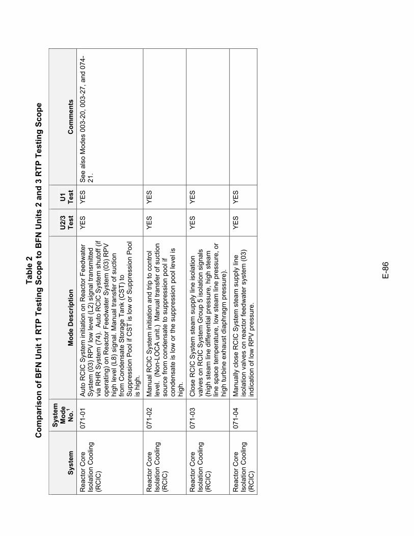
Tabl
e 2
Com
paris
on o
f BFN
Uni
t 1 R
TP T
estin
g Sc
ope
to B
FN U
nits
2 a
nd 3
RTP
Tes
ting
Scop
e
E-8
6
Syst
em
Syst
em
Mod
e N
o.1
Mod
e D
escr
iptio
n U
2/3
Test
U
1 Te
st
Com
men
ts
Rea
ctor
Cor
e Is
olat
ion
Coo
ling
(RC
IC)
071-
01
Aut
o R
CIC
Sys
tem
initi
atio
n on
Rea
ctor
Fee
dwat
er
Sys
tem
(03)
RP
V lo
w le
vel (
L2) s
igna
l tra
nsm
itted
vi
a R
HR
Sys
tem
(74)
. A
uto
RC
IC S
yste
m s
huto
ff (if
op
erat
ing)
on
Rea
ctor
Fee
dwat
er S
yste
m (0
3) R
PV
hi
gh le
vel (
L8) s
igna
l. M
anua
l tra
nsfe
r of s
uctio
n fro
m C
onde
nsat
e S
tora
ge T
ank
(CS
T) to
S
uppr
essi
on P
ool i
f CS
T is
low
or S
uppr
essi
on P
ool
is h
igh.
YE
S
YE
S
See
als
o M
odes
003
-20,
003
-27,
and
074
-21
.
Rea
ctor
Cor
e Is
olat
ion
Coo
ling
(RC
IC)
071-
02
Man
ual R
CIC
Sys
tem
initi
atio
n an
d tri
p to
con
trol
leve
l. (N
on-L
OC
A u
nit.)
Man
ual t
rans
fer o
f suc
tion
sour
ce fr
om c
onde
nsat
e to
sup
pres
sion
poo
l if
cond
ensa
te is
low
or t
he s
uppr
essi
on p
ool l
evel
is
high
.
YES
YES
Rea
ctor
Cor
e Is
olat
ion
Coo
ling
(RC
IC)
071-
03
Clo
se R
CIC
Sys
tem
ste
am s
uppl
y lin
e is
olat
ion
valv
es o
n R
CIC
Sys
tem
Gro
up 5
isol
atio
n si
gnal
s (h
igh
stea
m li
ne d
iffer
entia
l pre
ssur
e, h
igh
stea
m
line
spac
e te
mpe
ratu
re, l
ow s
team
line
pre
ssur
e, o
r hi
gh tu
rbin
e ex
haus
t dia
phra
gm p
ress
ure)
.
YES
YES
Rea
ctor
Cor
e Is
olat
ion
Coo
ling
(RC
IC)
071-
04
Man
ually
clo
se R
CIC
Sys
tem
ste
am s
uppl
y lin
e is
olat
ion
valv
es o
n re
acto
r fee
dwat
er s
yste
m (0
3)
indi
catio
n of
low
RP
V p
ress
ure.
YES
YES
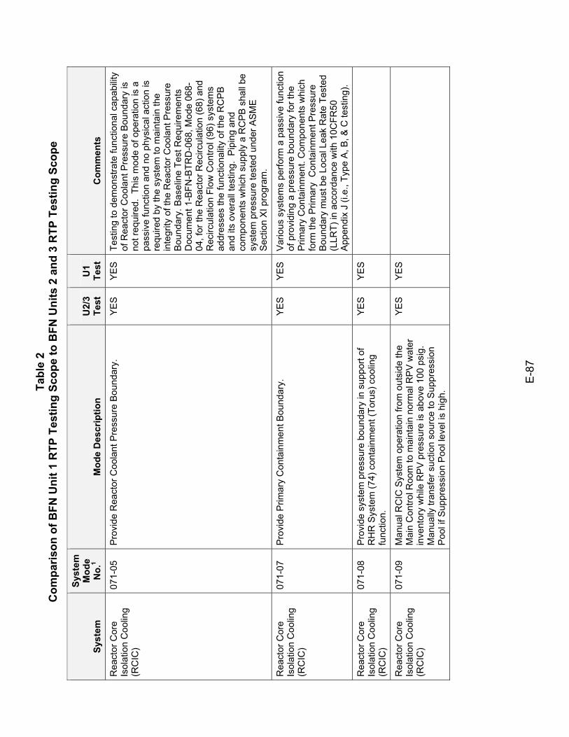
Tabl
e 2
Com
paris
on o
f BFN
Uni
t 1 R
TP T
estin
g Sc
ope
to B
FN U
nits
2 a
nd 3
RTP
Tes
ting
Scop
e
E-8
7
Syst
em
Syst
em
Mod
e N
o.1
Mod
e D
escr
iptio
n U
2/3
Test
U
1 Te
st
Com
men
ts
Rea
ctor
Cor
e Is
olat
ion
Coo
ling
(RC
IC)
071-
05
Pro
vide
Rea
ctor
Coo
lant
Pre
ssur
e B
ound
ary.
Y
ES
Y
ES
Te
stin
g to
dem
onst
rate
func
tiona
l cap
abilit
y of
Rea
ctor
Coo
lant
Pre
ssur
e B
ound
ary
is
not r
equi
red.
Thi
s m
ode
of o
pera
tion
is a
pa
ssiv
e fu
nctio
n an
d no
phy
sica
l act
ion
is
requ
ired
by th
e sy
stem
to m
aint
ain
the
inte
grity
of t
he R
eact
or C
oola
nt P
ress
ure
Bou
ndar
y. B
asel
ine
Test
Req
uire
men
ts
Doc
umen
t 1-B
FN-B
TRD
-068
, Mod
e 06
8-04
, for
the
Rea
ctor
Rec
ircul
atio
n (6
8) a
nd
Rec
ircul
atio
n Fl
ow C
ontro
l (96
) sys
tem
s ad
dres
ses
the
func
tiona
lity
of th
e R
CP
B
and
its o
vera
ll te
stin
g. P
ipin
g an
d co
mpo
nent
s w
hich
sup
ply
a R
CP
B s
hall
be
syst
em p
ress
ure
test
ed u
nder
AS
ME
S
ectio
n X
I pro
gram
.
Rea
ctor
Cor
e Is
olat
ion
Coo
ling
(RC
IC)
071-
07
Pro
vide
Prim
ary
Con
tain
men
t Bou
ndar
y.
YE
S
YE
S
Var
ious
sys
tem
s pe
rform
a p
assi
ve fu
nctio
n of
pro
vidi
ng a
pre
ssur
e bo
unda
ry fo
r the
P
rimar
y C
onta
inm
ent.
Com
pone
nts
whi
ch
form
the
Prim
ary
Con
tain
men
t Pre
ssur
e B
ound
ary
mus
t be
Loca
l Lea
k R
ate
Test
ed
(LLR
T) in
acc
orda
nce
with
10C
FR50
A
ppen
dix
J (i.
e., T
ype
A, B
, & C
test
ing)
.
Rea
ctor
Cor
e Is
olat
ion
Coo
ling
(RC
IC)
071-
08
Pro
vide
sys
tem
pre
ssur
e bo
unda
ry in
sup
port
of
RH
R S
yste
m (7
4) c
onta
inm
ent (
Toru
s) c
oolin
g fu
nctio
n.
YES
YES
Rea
ctor
Cor
e Is
olat
ion
Coo
ling
(RC
IC)
071-
09
Man
ual R
CIC
Sys
tem
ope
ratio
n fro
m o
utsi
de th
e M
ain
Con
trol R
oom
to m
aint
ain
norm
al R
PV
wat
er
inve
ntor
y w
hile
RP
V p
ress
ure
is a
bove
100
psi
g.
Man
ually
tran
sfer
suc
tion
sour
ce to
Sup
pres
sion
P
ool i
f Sup
pres
sion
Poo
l lev
el is
hig
h.
YES
YES
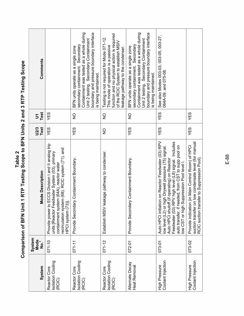
Tabl
e 2
Com
paris
on o
f BFN
Uni
t 1 R
TP T
estin
g Sc
ope
to B
FN U
nits
2 a
nd 3
RTP
Tes
ting
Scop
e
E-8
8
Syst
em
Syst
em
Mod
e N
o.1
Mod
e D
escr
iptio
n U
2/3
Test
U
1 Te
st
Com
men
ts
Rea
ctor
Cor
e Is
olat
ion
Coo
ling
(RC
IC)
071-
10
Pro
vide
pow
er to
EC
CS
Div
isio
n I a
nd II
ana
log
trip
units
[Rea
ctor
Fee
dwat
er S
yste
m (0
3), p
rimar
y co
ntai
nmen
t sys
tem
(64A
), re
acto
r wat
er
reci
rcul
atio
n sy
stem
(68)
, RC
IC s
yste
m (7
1), a
nd
HP
CI s
yste
m (7
3)].
YES
YES
Rea
ctor
Cor
e Is
olat
ion
Coo
ling
(RC
IC)
071-
11
Pro
vide
Sec
onda
ry C
onta
inm
ent B
ound
ary.
Y
ES
N
O
BFN
uni
ts o
pera
te a
s a
sing
le z
one
seco
ndar
y co
ntai
nmen
t. S
econ
dary
C
onta
inm
ent w
as te
sted
as
a w
hole
dur
ing
Uni
t 2 te
stin
g. S
econ
dary
Con
tain
men
t bo
unda
ry a
nd p
ress
ure
boun
dary
inte
rface
is
bei
ng m
aint
aine
d.
Rea
ctor
Cor
e Is
olat
ion
Coo
ling
(RC
IC)
071-
12
Est
ablis
h M
SIV
leak
age
path
way
to c
onde
nser
. N
O
NO
Te
stin
g is
not
requ
ired
for M
ode
071-
12.
This
mod
e of
ope
ratio
n is
a p
assi
ve
func
tion
and
no p
hysi
cal a
ctio
n is
requ
ired
of th
e R
CIC
Sys
tem
to e
stab
lish
MS
IV
leak
age
path
way
to th
e co
nden
ser.
Alte
rnat
e D
ecay
H
eat R
emov
al
072-
01
Pro
vide
Sec
onda
ry C
onta
inm
ent B
ound
ary.
Y
ES
N
O
BFN
uni
ts o
pera
te a
s a
sing
le z
one
seco
ndar
y co
ntai
nmen
t. S
econ
dary
C
onta
inm
ent w
as te
sted
as
a w
hole
dur
ing
Uni
t 2 te
stin
g. S
econ
dary
Con
tain
men
t bo
unda
ry a
nd p
ress
ure
boun
dary
inte
rface
is
bei
ng m
aint
aine
d.
Hig
h P
ress
ure
Coo
lant
Inje
ctio
n 07
3-01
A
uto
HP
CI i
nitia
tion
on R
eact
or F
eedw
ater
(03)
RP
V
low
leve
l (L2
) or h
igh
Dry
wel
l pre
ssur
e (7
5) s
igna
l.
Aut
o H
PC
I shu
toff
(if o
pera
ting)
on
Rea
ctor
Fe
edw
ater
(03)
RP
V h
igh
leve
l (L8
) sig
nal.
Incl
udes
au
to tr
ansf
er, i
f nee
ded,
from
CS
T to
sup
p po
ol o
n lo
w C
ST
or h
igh
Sup
pres
sion
Poo
l lev
el l.
YE
S
YE
S
See
als
o M
odes
003
-03,
003
-05,
003
-27,
06
4A-0
9, a
nd 0
75-0
8.
Hig
h P
ress
ure
Coo
lant
Inje
ctio
n 07
3-02
P
rovi
de in
dica
tion
(in M
ain
Con
trol R
oom
) of H
PC
I su
ctio
n tra
nsfe
r on
low
con
dens
ate
leve
l (fo
r man
ual
RC
IC s
uctio
n tra
nsfe
r to
Sup
pres
sion
Poo
l).
YES
YES
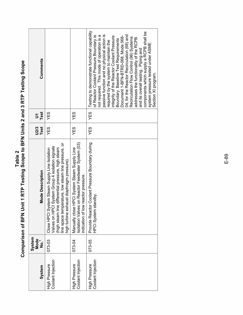
Tabl
e 2
Com
paris
on o
f BFN
Uni
t 1 R
TP T
estin
g Sc
ope
to B
FN U
nits
2 a
nd 3
RTP
Tes
ting
Scop
e
E-8
9
Syst
em
Syst
em
Mod
e N
o.1
Mod
e D
escr
iptio
n U
2/3
Test
U
1 Te
st
Com
men
ts
Hig
h P
ress
ure
Coo
lant
Inje
ctio
n 07
3-03
C
lose
HPC
I Sys
tem
Ste
am S
uppl
y Li
ne Is
olat
ion
Val
ves
on H
PCI S
yste
m G
roup
4 is
olat
ion
sign
als
(hig
h st
eam
line
diff
eren
tial p
ress
ure,
hig
h st
eam
lin
e sp
ace
tem
pera
ture
, low
ste
am li
ne p
ress
ure,
or
high
turb
ine
exha
ust d
iaph
ragm
pre
ssur
e).
YES
YES
Hig
h P
ress
ure
Coo
lant
Inje
ctio
n 07
3-04
M
anua
lly c
lose
HP
CI S
yste
m S
team
Sup
ply
Line
Is
olat
ion
Val
ves
on R
eact
or F
eedw
ater
Sys
tem
(03)
in
dica
tion
of lo
w re
acto
r pre
ssur
e.
YES
YES
Hig
h P
ress
ure
Coo
lant
Inje
ctio
n 07
3-05
P
rovi
de R
eact
or C
oola
nt P
ress
ure
Bou
ndar
y du
ring
HP
CI S
yste
m s
tand
by.
YE
S
YE
S
Test
ing
to d
emon
stra
te fu
nctio
nal c
apab
ility
of R
eact
or C
oola
nt P
ress
ure
Bou
ndar
y is
no
t req
uire
d. T
his
mod
e of
ope
ratio
n is
a
pass
ive
func
tion
and
no p
hysi
cal a
ctio
n is
re
quire
d by
the
syst
em to
mai
ntai
n th
e in
tegr
ity o
f the
Rea
ctor
Coo
lant
Pre
ssur
e B
ound
ary.
Bas
elin
e Te
st R
equi
rem
ents
D
ocum
ent 1
-BFN
-BTR
D-0
68, M
ode
068-
04, f
or th
e R
eact
or R
ecirc
ulat
ion
(68)
and
R
ecirc
ulat
ion
Flow
Con
trol (
96) S
yste
ms
addr
esse
s th
e fu
nctio
nalit
y of
the
RC
PB
an
d its
ove
rall
test
ing.
Pip
ing
and
com
pone
nts
whi
ch s
uppl
y a
RC
PB
sha
ll be
sy
stem
pre
ssur
e te
sted
und
er A
SM
E
Sec
tion
XI p
rogr
am.
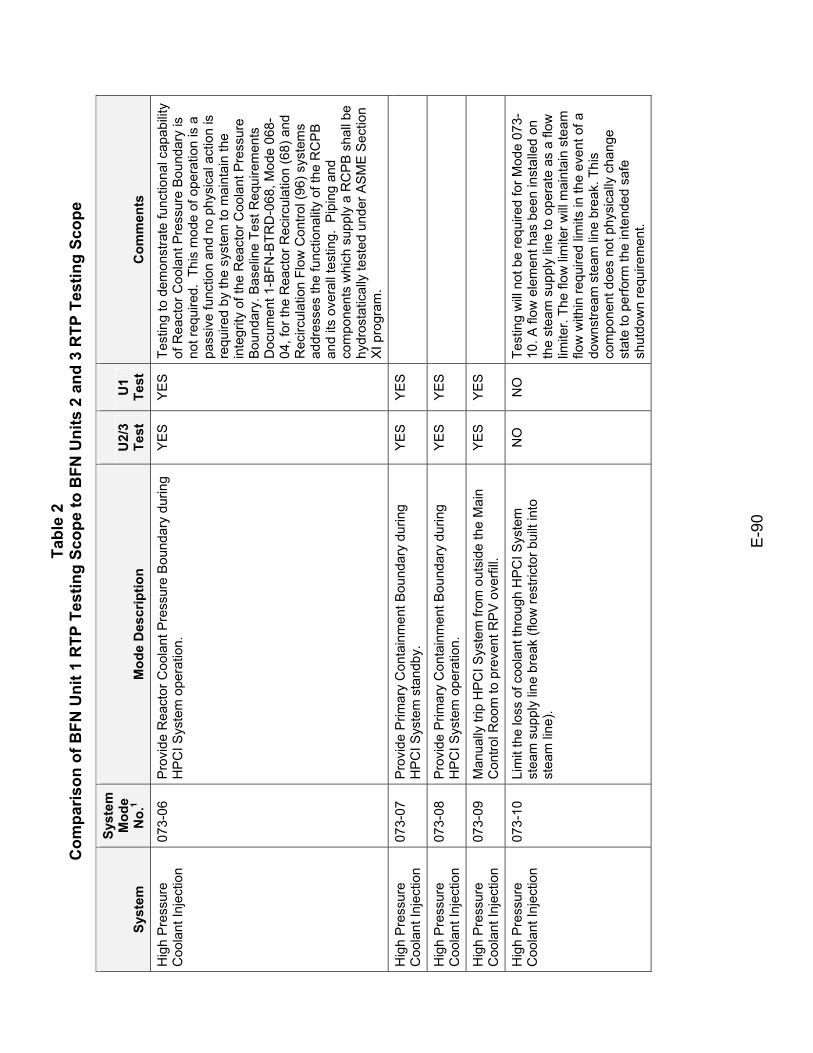
Tabl
e 2
Com
paris
on o
f BFN
Uni
t 1 R
TP T
estin
g Sc
ope
to B
FN U
nits
2 a
nd 3
RTP
Tes
ting
Scop
e
E-9
0
Syst
em
Syst
em
Mod
e N
o.1
Mod
e D
escr
iptio
n U
2/3
Test
U
1 Te
st
Com
men
ts
Hig
h P
ress
ure
Coo
lant
Inje
ctio
n 07
3-06
P
rovi
de R
eact
or C
oola
nt P
ress
ure
Bou
ndar
y du
ring
HP
CI S
yste
m o
pera
tion.
Y
ES
Y
ES
Te
stin
g to
dem
onst
rate
func
tiona
l cap
abilit
y of
Rea
ctor
Coo
lant
Pre
ssur
e B
ound
ary
is
not r
equi
red.
Thi
s m
ode
of o
pera
tion
is a
pa
ssiv
e fu
nctio
n an
d no
phy
sica
l act
ion
is
requ
ired
by th
e sy
stem
to m
aint
ain
the
inte
grity
of t
he R
eact
or C
oola
nt P
ress
ure
Bou
ndar
y. B
asel
ine
Test
Req
uire
men
ts
Doc
umen
t 1-B
FN-B
TRD
-068
, Mod
e 06
8-04
, for
the
Rea
ctor
Rec
ircul
atio
n (6
8) a
nd
Rec
ircul
atio
n Fl
ow C
ontro
l (96
) sys
tem
s ad
dres
ses
the
func
tiona
lity
of th
e R
CP
B
and
its o
vera
ll te
stin
g. P
ipin
g an
d co
mpo
nent
s w
hich
sup
ply
a R
CP
B s
hall
be
hydr
osta
tical
ly te
sted
und
er A
SM
E S
ectio
n X
I pro
gram
.
Hig
h P
ress
ure
Coo
lant
Inje
ctio
n 07
3-07
P
rovi
de P
rimar
y C
onta
inm
ent B
ound
ary
durin
g H
PC
I Sys
tem
sta
ndby
. YE
S YE
S
Hig
h P
ress
ure
Coo
lant
Inje
ctio
n 07
3-08
P
rovi
de P
rimar
y C
onta
inm
ent B
ound
ary
durin
g H
PC
I Sys
tem
ope
ratio
n.
YES
YES
Hig
h P
ress
ure
Coo
lant
Inje
ctio
n 07
3-09
M
anua
lly tr
ip H
PC
I Sys
tem
from
out
side
the
Mai
n C
ontro
l Roo
m to
pre
vent
RP
V o
verfi
ll.
YES
YES
Hig
h P
ress
ure
Coo
lant
Inje
ctio
n 07
3-10
Li
mit
the
loss
of c
oola
nt th
roug
h H
PC
I Sys
tem
st
eam
sup
ply
line
brea
k (fl
ow re
stric
tor b
uilt
into
st
eam
line
).
NO
N
O
Test
ing
will
not
be
requ
ired
for M
ode
073-
10. A
flow
ele
men
t has
bee
n in
stal
led
on
the
stea
m s
uppl
y lin
e to
ope
rate
as
a flo
w
limite
r. Th
e flo
w li
mite
r will
mai
ntai
n st
eam
flo
w w
ithin
requ
ired
limits
in th
e ev
ent o
f a
dow
nstre
am s
team
line
bre
ak. T
his
com
pone
nt d
oes
not p
hysi
cally
cha
nge
stat
e to
per
form
the
inte
nded
saf
e sh
utdo
wn
requ
irem
ent.

Tabl
e 2
Com
paris
on o
f BFN
Uni
t 1 R
TP T
estin
g Sc
ope
to B
FN U
nits
2 a
nd 3
RTP
Tes
ting
Scop
e
E-9
1
Syst
em
Syst
em
Mod
e N
o.1
Mod
e D
escr
iptio
n U
2/3
Test
U
1 Te
st
Com
men
ts
Hig
h P
ress
ure
Coo
lant
Inje
ctio
n 07
3-11
P
rovi
de S
econ
dary
Con
tain
men
t Bou
ndar
y.
YE
S
NO
B
FN u
nits
ope
rate
as
a si
ngle
zon
e se
cond
ary
cont
ainm
ent.
Sec
onda
ry
Con
tain
men
t was
test
ed a
s a
who
le d
urin
g U
nit 2
test
ing.
Sec
onda
ry C
onta
inm
ent
boun
dary
and
pre
ssur
e bo
unda
ry in
terfa
ce
is b
eing
mai
ntai
ned.
Hig
h P
ress
ure
Coo
lant
Inje
ctio
n 07
3-12
P
rovi
de p
ower
to P
rimar
y C
onta
inm
ent S
yste
m
(64A
) dry
wel
l pre
ssur
e in
dica
tors
in s
uppo
rt of
RH
R
Sys
tem
Dry
wel
l/Tor
us s
pray
mod
e an
d C
onta
inm
ent
Atm
osph
ere
Dilu
tion
Sys
tem
pos
t-LO
CA
cont
ainm
ent v
entin
g m
ode.
YES
YES
Hig
h P
ress
ure
Coo
lant
Inje
ctio
n 07
3-13
E
stab
lish
MS
IV le
akag
e pa
thw
ay to
con
dens
er.
NO
N
O
Test
ing
is n
ot re
quire
d fo
r Mod
e 07
3-13
. Th
is m
ode
of o
pera
tion
is a
pas
sive
fu
nctio
n an
d no
phy
sica
l act
ion
is re
quire
d of
the
HP
CI S
yste
m to
est
ablis
h M
SIV
le
akag
e pa
thw
ay to
the
cond
ense
r.
Res
idua
l Hea
t R
emov
al
074-
01
Aut
omat
ic L
PCI m
ode
initi
atio
n on
RP
V lo
w w
ater
le
vel (
L1) s
igna
l or h
igh
Dry
wel
l pre
ssur
e si
gnal
, with
co
ncur
rent
low
RP
V p
ress
ure
perm
issi
ve.
Man
ual
LPC
I mod
e in
itiat
ion
from
the
Mai
n C
ontro
l Roo
m.
YE
S
YE
S
See
als
o M
odes
003
-22
and
64A
-09.
Res
idua
l Hea
t R
emov
al
074-
02
Pro
vide
Sup
pres
sion
Poo
l wat
er c
oolin
g to
mai
ntai
n S
uppr
essi
on P
ool w
ater
tem
pera
ture
bel
ow li
mits
to
assu
re th
at p
ump
NP
SH
requ
irem
ents
are
met
and
th
at c
ompl
ete
cond
ensa
tion
of b
low
dow
n st
eam
fro
m a
des
ign
basi
s LO
CA
can
be
expe
cted
.
YES
YES
Res
idua
l Hea
t R
emov
al
074-
03
Pro
vide
spr
ay to
Dry
wel
l and
Tor
us fo
r con
tain
men
t co
olin
g an
d lo
wer
ing
of c
onta
inm
ent p
ress
ure
unde
r po
st-a
ccid
ent c
ondi
tions
.
YES
YES
See
als
o M
ode
64A
-14.
Res
idua
l Hea
t R
emov
al
074-
04
Pro
vide
Shu
tdow
n C
oolin
g M
ode
(man
ual)
to re
stor
e re
acto
r tem
pera
ture
to n
orm
al.
YES
YES
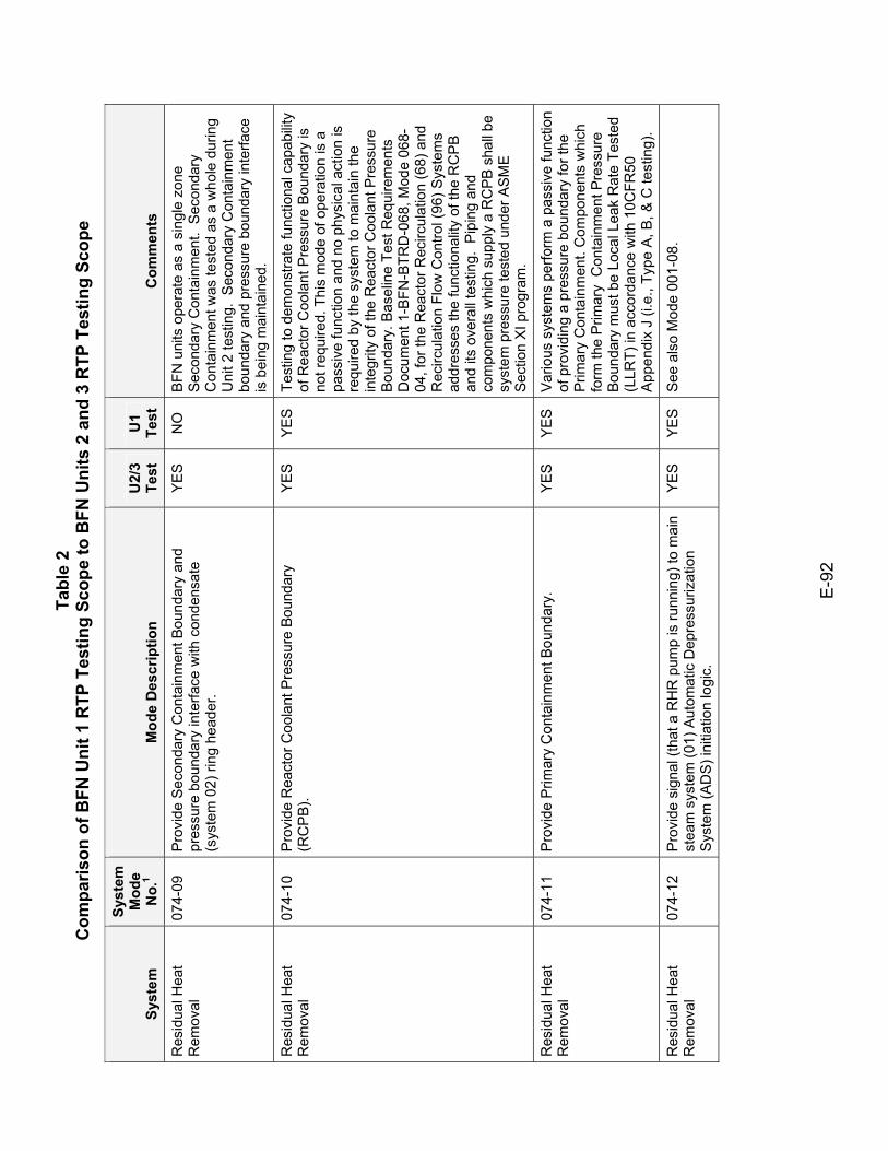
Tabl
e 2
Com
paris
on o
f BFN
Uni
t 1 R
TP T
estin
g Sc
ope
to B
FN U
nits
2 a
nd 3
RTP
Tes
ting
Scop
e
E-9
2
Syst
em
Syst
em
Mod
e N
o.1
Mod
e D
escr
iptio
n U
2/3
Test
U
1 Te
st
Com
men
ts
Res
idua
l Hea
t R
emov
al
074-
09
Pro
vide
Sec
onda
ry C
onta
inm
ent B
ound
ary
and
pres
sure
bou
ndar
y in
terfa
ce w
ith c
onde
nsat
e (s
yste
m 0
2) ri
ng h
eade
r.
YE
S
NO
B
FN u
nits
ope
rate
as
a si
ngle
zon
e Se
cond
ary
Con
tain
men
t. S
econ
dary
C
onta
inm
ent w
as te
sted
as
a w
hole
dur
ing
Uni
t 2 te
stin
g. S
econ
dary
Con
tain
men
t bo
unda
ry a
nd p
ress
ure
boun
dary
inte
rface
is
bei
ng m
aint
aine
d.
Res
idua
l Hea
t R
emov
al
074-
10
Pro
vide
Rea
ctor
Coo
lant
Pre
ssur
e B
ound
ary
(RC
PB
). Y
ES
Y
ES
Te
stin
g to
dem
onst
rate
func
tiona
l cap
abilit
y of
Rea
ctor
Coo
lant
Pre
ssur
e B
ound
ary
is
not r
equi
red.
Thi
s m
ode
of o
pera
tion
is a
pa
ssiv
e fu
nctio
n an
d no
phy
sica
l act
ion
is
requ
ired
by th
e sy
stem
to m
aint
ain
the
inte
grity
of t
he R
eact
or C
oola
nt P
ress
ure
Bou
ndar
y. B
asel
ine
Test
Req
uire
men
ts
Doc
umen
t 1-B
FN-B
TRD
-068
, Mod
e 06
8-04
, for
the
Rea
ctor
Rec
ircul
atio
n (6
8) a
nd
Rec
ircul
atio
n Fl
ow C
ontro
l (96
) Sys
tem
s ad
dres
ses
the
func
tiona
lity
of th
e R
CP
B
and
its o
vera
ll te
stin
g. P
ipin
g an
d co
mpo
nent
s w
hich
sup
ply
a R
CP
B s
hall
be
syst
em p
ress
ure
test
ed u
nder
AS
ME
S
ectio
n X
I pro
gram
.
Res
idua
l Hea
t R
emov
al
074-
11
Pro
vide
Prim
ary
Con
tain
men
t Bou
ndar
y.
YE
S
YE
S
Var
ious
sys
tem
s pe
rform
a p
assi
ve fu
nctio
n of
pro
vidi
ng a
pre
ssur
e bo
unda
ry fo
r the
P
rimar
y C
onta
inm
ent.
Com
pone
nts
whi
ch
form
the
Prim
ary
Con
tain
men
t Pre
ssur
e B
ound
ary
mus
t be
Loca
l Lea
k R
ate
Test
ed
(LLR
T) in
acc
orda
nce
with
10C
FR50
A
ppen
dix
J (i.
e., T
ype
A, B
, & C
test
ing)
.
Res
idua
l Hea
t R
emov
al
074-
12
Pro
vide
sig
nal (
that
a R
HR
pum
p is
runn
ing)
to m
ain
stea
m s
yste
m (0
1) A
utom
atic
Dep
ress
uriz
atio
n S
yste
m (A
DS)
initi
atio
n lo
gic.
YE
S
YE
S
See
als
o M
ode
001-
08.
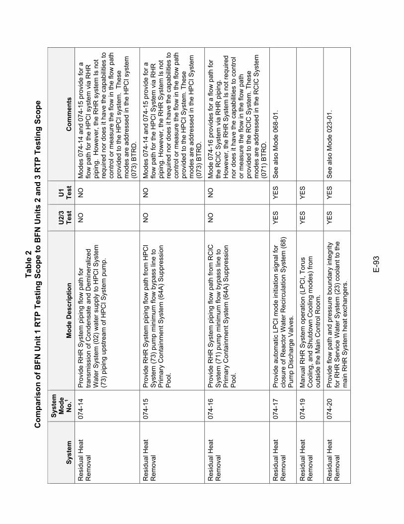
Tabl
e 2
Com
paris
on o
f BFN
Uni
t 1 R
TP T
estin
g Sc
ope
to B
FN U
nits
2 a
nd 3
RTP
Tes
ting
Scop
e
E-9
3
Syst
em
Syst
em
Mod
e N
o.1
Mod
e D
escr
iptio
n U
2/3
Test
U
1 Te
st
Com
men
ts
Res
idua
l Hea
t R
emov
al
074-
14
Pro
vide
RH
R S
yste
m p
ipin
g flo
w p
ath
for
trans
mis
sion
of C
onde
nsat
e an
d D
emin
eral
ized
W
ater
Sys
tem
(02)
wat
er s
uppl
y to
HP
CI S
yste
m
(73)
pip
ing
upst
ream
of H
PCI S
yste
m p
ump.
NO
N
O
Mod
es 0
74-1
4 an
d 07
4-15
pro
vide
for a
flo
w p
ath
for t
he H
PC
I sys
tem
via
RH
R
pipi
ng.
How
ever
, the
RH
R s
yste
m Is
not
re
quire
d no
r doe
s it
have
the
capa
bilit
ies
to
cont
rol o
r mea
sure
the
flow
in th
e flo
w p
ath
prov
ided
to th
e H
PC
I sys
tem
. Th
ese
mod
es a
re a
ddre
ssed
in th
e H
PC
I sys
tem
(0
73) B
TRD
.
Res
idua
l Hea
t R
emov
al
074-
15
Pro
vide
RH
R S
yste
m p
ipin
g flo
w p
ath
from
HP
CI
Sys
tem
(73)
pum
p m
inim
um fl
ow b
ypas
s lin
e to
P
rimar
y C
onta
inm
ent S
yste
m (6
4A) S
uppr
essi
on
Poo
l.
NO
N
O
Mod
es 0
74-1
4 an
d 07
4-15
pro
vide
for a
flo
w p
ath
for t
he H
PC
I Sys
tem
via
RH
R
pipi
ng. H
owev
er, t
he R
HR
Sys
tem
Is n
ot
requ
ired
nor d
oes
it ha
ve th
e ca
pabi
litie
s to
co
ntro
l or m
easu
re th
e flo
w in
the
flow
pat
h pr
ovid
ed to
the
HP
CI S
yste
m. T
hese
m
odes
are
add
ress
ed in
the
HP
CI S
yste
m
(073
) BTR
D.
Res
idua
l Hea
t R
emov
al
074-
16
Pro
vide
RH
R S
yste
m p
ipin
g flo
w p
ath
from
RC
IC
Sys
tem
(71)
pum
p m
inim
um fl
ow b
ypas
s lin
e to
P
rimar
y C
onta
inm
ent S
yste
m (6
4A) S
uppr
essi
on
Poo
l.
NO
N
O
Mod
e 07
4-16
pro
vide
s fo
r a fl
ow p
ath
for
the
RC
IC S
yste
m v
ia R
HR
pip
ing.
H
owev
er, t
he R
HR
Sys
tem
Is n
ot re
quire
d no
r doe
s it
have
the
capa
bilit
ies
to c
ontro
l or
mea
sure
the
flow
in th
e flo
w p
ath
prov
ided
to th
e R
CIC
Sys
tem
. The
se
mod
es a
re a
ddre
ssed
in th
e R
CIC
Sys
tem
(0
71) B
TRD
.
Res
idua
l Hea
t R
emov
al
074-
17
Pro
vide
aut
omat
ic L
PC
I mod
e in
itiat
ion
sign
al fo
r cl
osur
e of
Rea
ctor
Wat
er R
ecirc
ulat
ion
Sys
tem
(68)
P
ump
Dis
char
ge V
alve
s.
YE
S
YE
S
See
als
o M
ode
068-
01.
Res
idua
l Hea
t R
emov
al
074-
19
Man
ual R
HR
Sys
tem
ope
ratio
n (L
PCI,
Toru
s C
oolin
g, a
nd S
hutd
own
Coo
ling
mod
es) f
rom
ou
tsid
e th
e M
ain
Con
trol R
oom
.
YES
YES
Res
idua
l Hea
t R
emov
al
074-
20
Pro
vide
flow
pat
h an
d pr
essu
re b
ound
ary
inte
grity
fo
r RH
R S
ervi
ce W
ater
Sys
tem
(23)
coo
lant
to th
e m
ain
RH
R S
yste
m h
eat e
xcha
nger
s.
YE
S
YE
S
See
als
o M
ode
023-
01.
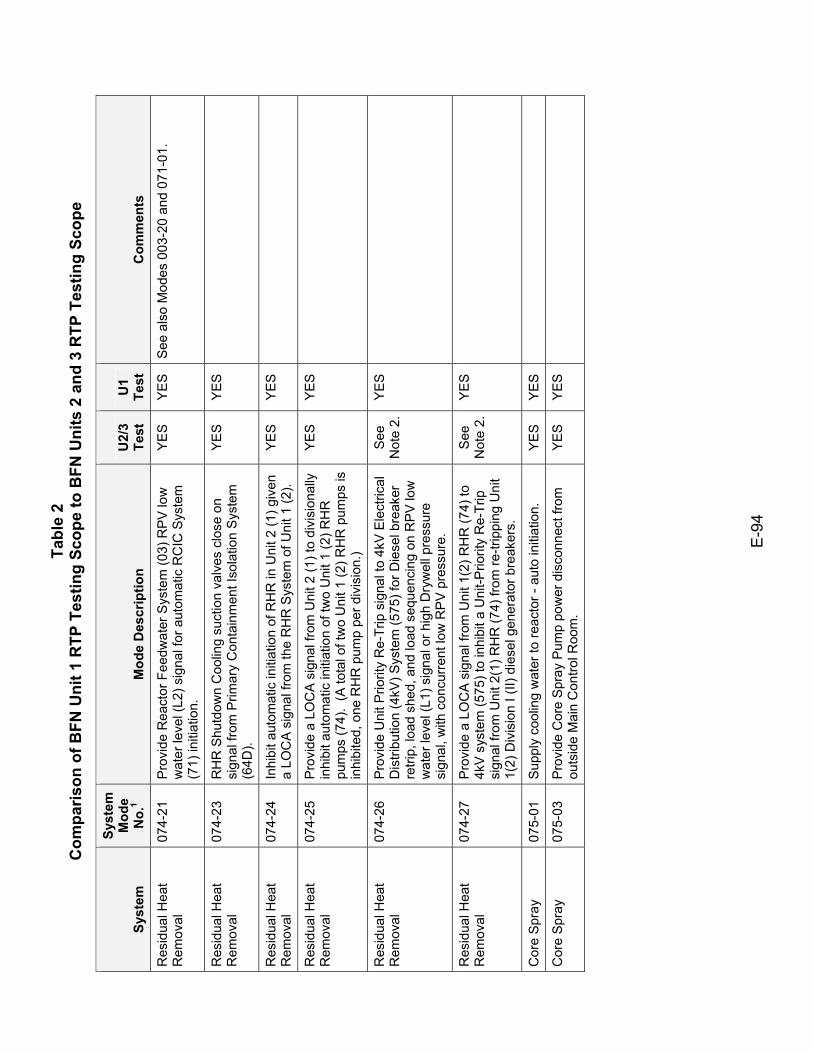
Tabl
e 2
Com
paris
on o
f BFN
Uni
t 1 R
TP T
estin
g Sc
ope
to B
FN U
nits
2 a
nd 3
RTP
Tes
ting
Scop
e
E-9
4
Syst
em
Syst
em
Mod
e N
o.1
Mod
e D
escr
iptio
n U
2/3
Test
U
1 Te
st
Com
men
ts
Res
idua
l Hea
t R
emov
al
074-
21
Pro
vide
Rea
ctor
Fee
dwat
er S
yste
m (0
3) R
PV
low
w
ater
leve
l (L2
) sig
nal f
or a
utom
atic
RC
IC S
yste
m
(71)
initi
atio
n.
YE
S
YE
S
See
als
o M
odes
003
-20
and
071-
01.
Res
idua
l Hea
t R
emov
al
074-
23
RH
R S
hutd
own
Coo
ling
suct
ion
valv
es c
lose
on
sign
al fr
om P
rimar
y C
onta
inm
ent I
sola
tion
Sys
tem
(6
4D).
YES
YES
Res
idua
l Hea
t R
emov
al
074-
24
Inhi
bit a
utom
atic
initi
atio
n of
RH
R in
Uni
t 2 (1
) giv
en
a LO
CA
sig
nal f
rom
the
RH
R S
yste
m o
f Uni
t 1 (2
). YE
S YE
S
Res
idua
l Hea
t R
emov
al
074-
25
Pro
vide
a L
OC
A s
igna
l fro
m U
nit 2
(1) t
o di
visi
onal
ly
inhi
bit a
utom
atic
initi
atio
n of
two
Uni
t 1 (2
) RH
R
pum
ps (7
4).
(A to
tal o
f tw
o U
nit 1
(2) R
HR
pum
ps is
in
hibi
ted,
one
RH
R p
ump
per d
ivis
ion.
)
YES
YES
Res
idua
l Hea
t R
emov
al
074-
26
Pro
vide
Uni
t Prio
rity
Re-
Trip
sig
nal t
o 4k
V E
lect
rical
D
istri
butio
n (4
kV) S
yste
m (5
75) f
or D
iese
l bre
aker
re
trip,
load
she
d, a
nd lo
ad s
eque
ncin
g on
RP
V lo
w
wat
er le
vel (
L1) s
igna
l or h
igh
Dry
wel
l pre
ssur
e si
gnal
, with
con
curre
nt lo
w R
PV
pre
ssur
e.
See
N
ote
2.
YES
Res
idua
l Hea
t R
emov
al
074-
27
Pro
vide
a L
OC
A s
igna
l fro
m U
nit 1
(2) R
HR
(74)
to
4kV
sys
tem
(575
) to
inhi
bit a
Uni
t-Prio
rity
Re-
Trip
si
gnal
from
Uni
t 2(1
) RH
R (7
4) fr
om re
-trip
ping
Uni
t 1(
2) D
ivis
ion
I (II)
die
sel g
ener
ator
bre
aker
s.
See
N
ote
2.
YES
Cor
e S
pray
07
5-01
S
uppl
y co
olin
g w
ater
to re
acto
r - a
uto
initi
atio
n.
YE
S
YE
S
Cor
e S
pray
07
5-03
P
rovi
de C
ore
Spr
ay P
ump
pow
er d
isco
nnec
t fro
m
outs
ide
Mai
n C
ontro
l Roo
m.
YES
YES
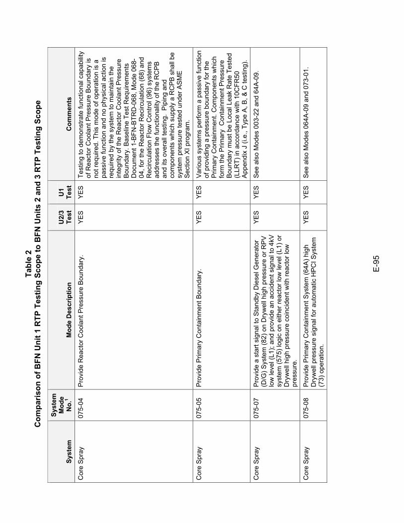
Tabl
e 2
Com
paris
on o
f BFN
Uni
t 1 R
TP T
estin
g Sc
ope
to B
FN U
nits
2 a
nd 3
RTP
Tes
ting
Scop
e
E-9
5
Syst
em
Syst
em
Mod
e N
o.1
Mod
e D
escr
iptio
n U
2/3
Test
U
1 Te
st
Com
men
ts
Cor
e S
pray
07
5-04
P
rovi
de R
eact
or C
oola
nt P
ress
ure
Bou
ndar
y.
YE
S
YE
S
Test
ing
to d
emon
stra
te fu
nctio
nal c
apab
ility
of R
eact
or C
oola
nt P
ress
ure
Bou
ndar
y is
no
t req
uire
d. T
his
mod
e of
ope
ratio
n is
a
pass
ive
func
tion
and
no p
hysi
cal a
ctio
n is
re
quire
d by
the
syst
em to
mai
ntai
n th
e in
tegr
ity o
f the
Rea
ctor
Coo
lant
Pre
ssur
e B
ound
ary.
Bas
elin
e Te
st R
equi
rem
ents
D
ocum
ent 1
-BFN
-BTR
D-0
68, M
ode
068-
04, f
or th
e R
eact
or R
ecirc
ulat
ion
(68)
and
R
ecirc
ulat
ion
Flow
Con
trol (
96) s
yste
ms
addr
esse
s th
e fu
nctio
nalit
y of
the
RC
PB
an
d its
ove
rall
test
ing.
Pip
ing
and
com
pone
nts
whi
ch s
uppl
y a
RC
PB
sha
ll be
sy
stem
pre
ssur
e te
sted
und
er A
SM
E
Sec
tion
XI p
rogr
am.
Cor
e S
pray
07
5-05
P
rovi
de P
rimar
y C
onta
inm
ent B
ound
ary.
Y
ES
Y
ES
V
ario
us s
yste
ms
perfo
rm a
pas
sive
func
tion
of p
rovi
ding
a p
ress
ure
boun
dary
for t
he
Prim
ary
Con
tain
men
t. C
ompo
nent
s w
hich
fo
rm th
e P
rimar
y C
onta
inm
ent P
ress
ure
Bou
ndar
y m
ust b
e Lo
cal L
eak
Rat
e Te
sted
(L
LRT)
in a
ccor
danc
e w
ith 1
0CFR
50
App
endi
x J
(i.e.
, Typ
e A
, B, &
C te
stin
g).
Cor
e S
pray
07
5-07
P
rovi
de a
sta
rt si
gnal
to S
tand
by D
iese
l Gen
erat
or
(D/G
) Sys
tem
(82)
on
Dry
wel
l hig
h pr
essu
re o
r RP
V
low
leve
l (L1
); an
d pr
ovid
e an
acc
iden
t sig
nal t
o 4k
V
syst
em (5
75) l
ogic
on
eith
er re
acto
r low
leve
l (L1
) or
Dry
wel
l hig
h pr
essu
re c
oinc
iden
t with
reac
tor l
ow
pres
sure
.
YE
S
YE
S
See
als
o M
odes
003
-22
and
64A
-09.
Cor
e S
pray
07
5-08
P
rovi
de P
rimar
y C
onta
inm
ent S
yste
m (6
4A) h
igh
Dry
wel
l pre
ssur
e si
gnal
for a
utom
atic
HPC
I Sys
tem
(7
3) o
pera
tion.
YE
S
YE
S
See
als
o M
odes
064
A-0
9 an
d 07
3-01
.
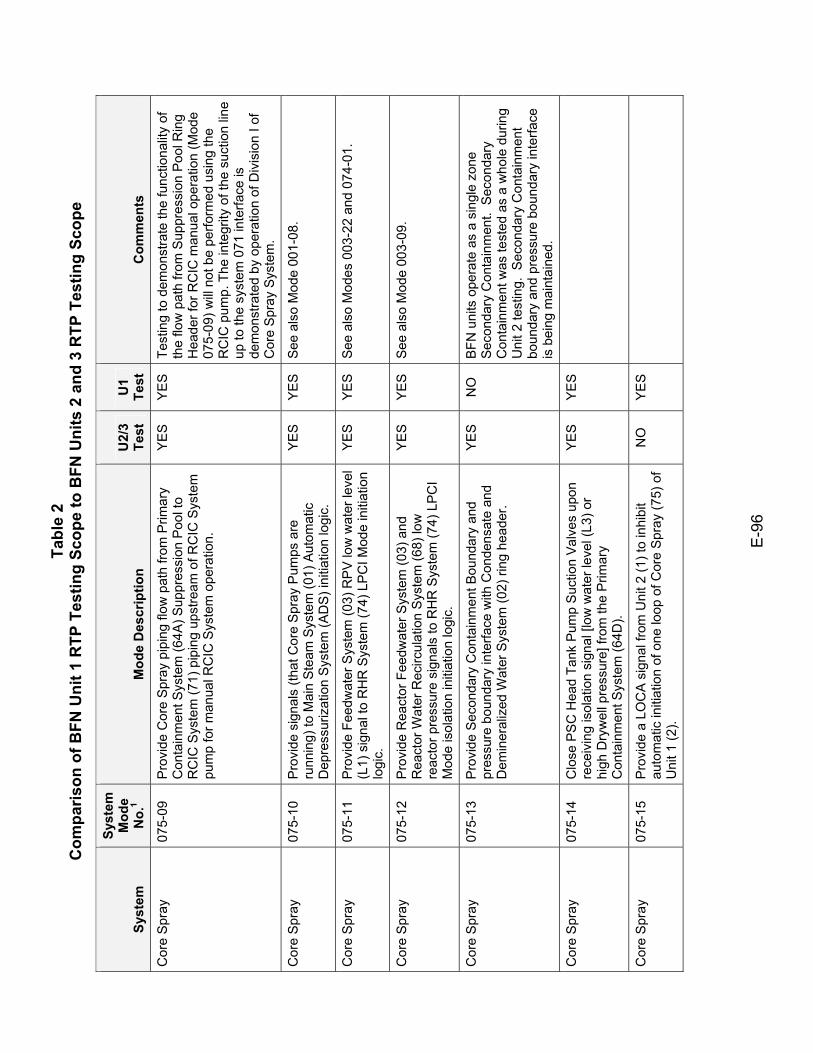
Tabl
e 2
Com
paris
on o
f BFN
Uni
t 1 R
TP T
estin
g Sc
ope
to B
FN U
nits
2 a
nd 3
RTP
Tes
ting
Scop
e
E-9
6
Syst
em
Syst
em
Mod
e N
o.1
Mod
e D
escr
iptio
n U
2/3
Test
U
1 Te
st
Com
men
ts
Cor
e S
pray
07
5-09
P
rovi
de C
ore
Spr
ay p
ipin
g flo
w p
ath
from
Prim
ary
Con
tain
men
t Sys
tem
(64A
) Sup
pres
sion
Poo
l to
RC
IC S
yste
m (7
1) p
ipin
g up
stre
am o
f RC
IC S
yste
m
pum
p fo
r man
ual R
CIC
Sys
tem
ope
ratio
n.
YE
S
YE
S
Test
ing
to d
emon
stra
te th
e fu
nctio
nalit
y of
th
e flo
w p
ath
from
Sup
pres
sion
Poo
l Rin
g H
eade
r for
RC
IC m
anua
l ope
ratio
n (M
ode
075-
09) w
ill n
ot b
e pe
rform
ed u
sing
the
RC
IC p
ump.
The
inte
grity
of t
he s
uctio
n lin
e up
to th
e sy
stem
071
inte
rface
is
dem
onst
rate
d by
ope
ratio
n of
Div
isio
n I o
f C
ore
Spr
ay S
yste
m.
Cor
e S
pray
07
5-10
P
rovi
de s
igna
ls (t
hat C
ore
Spr
ay P
umps
are
ru
nnin
g) to
Mai
n S
team
Sys
tem
(01)
Aut
omat
ic
Dep
ress
uriz
atio
n S
yste
m (A
DS
) ini
tiatio
n lo
gic.
YE
S
YE
S
See
als
o M
ode
001-
08.
Cor
e S
pray
07
5-11
P
rovi
de F
eedw
ater
Sys
tem
(03)
RP
V lo
w w
ater
leve
l (L
1) s
igna
l to
RH
R S
yste
m (7
4) L
PC
I Mod
e in
itiat
ion
logi
c.
YE
S
YE
S
See
als
o M
odes
003
-22
and
074-
01.
Cor
e S
pray
07
5-12
P
rovi
de R
eact
or F
eedw
ater
Sys
tem
(03)
and
R
eact
or W
ater
Rec
ircul
atio
n S
yste
m (6
8) lo
w
reac
tor p
ress
ure
sign
als
to R
HR
Sys
tem
(74)
LPC
I M
ode
isol
atio
n in
itiat
ion
logi
c.
YE
S
YE
S
See
als
o M
ode
003-
09.
Cor
e S
pray
07
5-13
P
rovi
de S
econ
dary
Con
tain
men
t Bou
ndar
y an
d pr
essu
re b
ound
ary
inte
rface
with
Con
dens
ate
and
Dem
iner
aliz
ed W
ater
Sys
tem
(02)
ring
hea
der.
YE
S
NO
B
FN u
nits
ope
rate
as
a si
ngle
zon
e Se
cond
ary
Con
tain
men
t. S
econ
dary
C
onta
inm
ent w
as te
sted
as
a w
hole
dur
ing
Uni
t 2 te
stin
g. S
econ
dary
Con
tain
men
t bo
unda
ry a
nd p
ress
ure
boun
dary
inte
rface
is
bei
ng m
aint
aine
d.
Cor
e S
pray
07
5-14
C
lose
PS
C H
ead
Tank
Pum
p S
uctio
n Va
lves
upo
n re
ceiv
ing
isol
atio
n si
gnal
[low
wat
er le
vel (
L3) o
r hi
gh D
ryw
ell p
ress
ure]
from
the
Prim
ary
Con
tain
men
t Sys
tem
(64D
).
YES
YES
Cor
e S
pray
07
5-15
P
rovi
de a
LO
CA
sig
nal f
rom
Uni
t 2 (1
) to
inhi
bit
auto
mat
ic in
itiat
ion
of o
ne lo
op o
f Cor
e S
pray
(75)
of
Uni
t 1 (2
).
NO
Y
ES
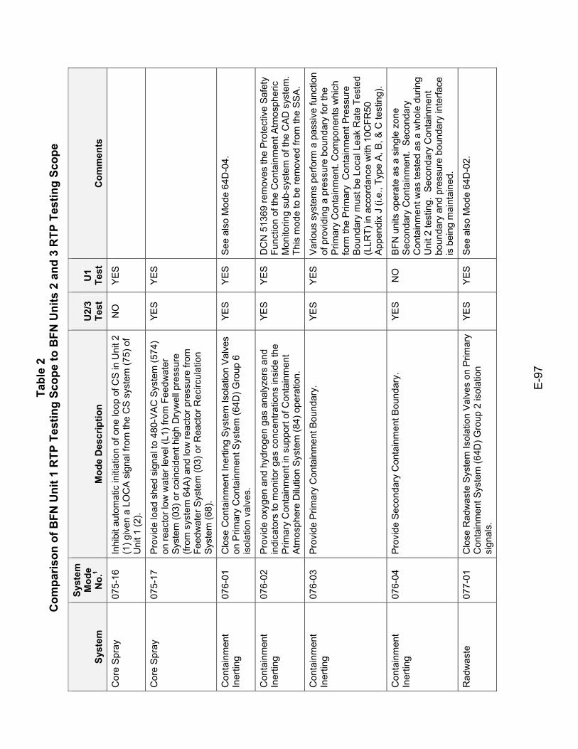
Tabl
e 2
Com
paris
on o
f BFN
Uni
t 1 R
TP T
estin
g Sc
ope
to B
FN U
nits
2 a
nd 3
RTP
Tes
ting
Scop
e
E-9
7
Syst
em
Syst
em
Mod
e N
o.1
Mod
e D
escr
iptio
n U
2/3
Test
U
1 Te
st
Com
men
ts
Cor
e S
pray
07
5-16
In
hibi
t aut
omat
ic in
itiat
ion
of o
ne lo
op o
f CS
in U
nit 2
(1
) giv
en a
LO
CA
sig
nal f
rom
the
CS
sys
tem
(75)
of
Uni
t 1 (2
).
NO
Y
ES
Cor
e S
pray
07
5-17
P
rovi
de lo
ad s
hed
sign
al to
480
-VAC
Sys
tem
(574
) on
reac
tor l
ow w
ater
leve
l (L1
) fro
m F
eedw
ater
S
yste
m (0
3) o
r coi
ncid
ent h
igh
Dry
wel
l pre
ssur
e (fr
om s
yste
m 6
4A) a
nd lo
w re
acto
r pre
ssur
e fro
m
Feed
wat
er S
yste
m (0
3) o
r Rea
ctor
Rec
ircul
atio
n S
yste
m (6
8).
YES
YES
Con
tain
men
t In
ertin
g 07
6-01
C
lose
Con
tain
men
t Ine
rting
Sys
tem
Isol
atio
n V
alve
s on
Prim
ary
Con
tain
men
t Sys
tem
(64D
) Gro
up 6
is
olat
ion
valv
es.
YE
S
YE
S
See
als
o M
ode
64D
-04.
Con
tain
men
t In
ertin
g 07
6-02
P
rovi
de o
xyge
n an
d hy
drog
en g
as a
naly
zers
and
in
dica
tors
to m
onito
r gas
con
cent
ratio
ns in
side
the
Prim
ary
Con
tain
men
t in
supp
ort o
f Con
tain
men
t A
tmos
pher
e D
ilutio
n S
yste
m (8
4) o
pera
tion.
YE
S
YE
S
DC
N 5
1369
rem
oves
the
Prot
ectiv
e S
afet
y Fu
nctio
n of
the
Con
tain
men
t Atm
osph
eric
M
onito
ring
sub-
syst
em o
f the
CA
D s
yste
m.
This
mod
e to
be
rem
oved
from
the
SS
A.
Con
tain
men
t In
ertin
g 07
6-03
P
rovi
de P
rimar
y C
onta
inm
ent B
ound
ary.
Y
ES
Y
ES
V
ario
us s
yste
ms
perfo
rm a
pas
sive
func
tion
of p
rovi
ding
a p
ress
ure
boun
dary
for t
he
Prim
ary
Con
tain
men
t. C
ompo
nent
s w
hich
fo
rm th
e P
rimar
y C
onta
inm
ent P
ress
ure
Bou
ndar
y m
ust b
e Lo
cal L
eak
Rat
e Te
sted
(L
LRT)
in a
ccor
danc
e w
ith 1
0CFR
50
App
endi
x J
(i.e.
, Typ
e A
, B, &
C te
stin
g).
Con
tain
men
t In
ertin
g 07
6-04
P
rovi
de S
econ
dary
Con
tain
men
t Bou
ndar
y.
YE
S
NO
B
FN u
nits
ope
rate
as
a si
ngle
zon
e Se
cond
ary
Con
tain
men
t. S
econ
dary
C
onta
inm
ent w
as te
sted
as
a w
hole
dur
ing
Uni
t 2 te
stin
g. S
econ
dary
Con
tain
men
t bo
unda
ry a
nd p
ress
ure
boun
dary
inte
rface
is
bei
ng m
aint
aine
d.
Rad
was
te
077-
01
Clo
se R
adw
aste
Sys
tem
Isol
atio
n V
alve
s on
Prim
ary
Con
tain
men
t Sys
tem
(64D
) Gro
up 2
isol
atio
n si
gnal
s.
YE
S
YE
S
See
als
o M
ode
64D
-02.
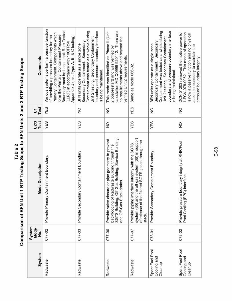
Tabl
e 2
Com
paris
on o
f BFN
Uni
t 1 R
TP T
estin
g Sc
ope
to B
FN U
nits
2 a
nd 3
RTP
Tes
ting
Scop
e
E-9
8
Syst
em
Syst
em
Mod
e N
o.1
Mod
e D
escr
iptio
n U
2/3
Test
U
1 Te
st
Com
men
ts
Rad
was
te
077-
02
Pro
vide
Prim
ary
Con
tain
men
t Bou
ndar
y.
YE
S
YE
S
Var
ious
sys
tem
s pe
rform
a p
assi
ve fu
nctio
n of
pro
vidi
ng a
pre
ssur
e bo
unda
ry fo
r the
P
rimar
y C
onta
inm
ent.
Com
pone
nts
whi
ch
form
the
Prim
ary
Con
tain
men
t Pre
ssur
e B
ound
ary
mus
t be
Loca
l Lea
k R
ate
Test
ed
(LLR
T) in
acc
orda
nce
with
10C
FR50
A
ppen
dix
J (i.
e., T
ype
A, B
, & C
test
ing)
.
Rad
was
te
077-
03
Pro
vide
Sec
onda
ry C
onta
inm
ent B
ound
ary.
Y
ES
N
O
BFN
uni
ts o
pera
te a
s a
sing
le z
one
Seco
ndar
y C
onta
inm
ent.
Sec
onda
ry
Con
tain
men
t was
test
ed a
s a
who
le d
urin
g U
nit 2
test
ing.
Sec
onda
ry C
onta
inm
ent
boun
dary
and
pre
ssur
e bo
unda
ry in
terfa
ce
is b
eing
mai
ntai
ned.
Rad
was
te
077-
06
Pro
vide
val
ve c
losu
re o
r pip
e ge
omet
ry to
pre
vent
ba
ckflo
odin
g of
Rad
was
te B
uild
ing
thro
ugh
the
SG
TS B
uild
ing,
Off-
Gas
Bui
ldin
g, S
ervi
ce B
uild
ing,
an
d O
ff-G
as S
tack
dra
ins.
NO
N
O
This
mod
e w
as id
entif
ied
as P
hase
II (U
nit
2 po
st-r
esta
rt) a
nd w
as v
erifi
ed b
y ca
lcul
atio
n M
D-Q
0999
-920
112.
The
re a
re
no re
quire
men
ts a
bove
and
bey
ond
the
verif
ied
Uni
t 2 re
quire
men
ts.
Rad
was
te
077-
07
Pro
vide
pip
ing
inte
rface
inte
grity
with
the
SG
TS
syst
em (6
5) a
nd th
e of
f gas
sys
tem
(66)
in s
uppo
rt of
rele
ase
of th
e fil
tere
d S
GTS
gas
es th
roug
h th
e st
ack.
YE
S
YE
S
Sam
e as
Mod
e 06
6-02
.
Spe
nt F
uel P
ool
Coo
ling
and
Cle
anup
078-
01
Pro
vide
Sec
onda
ry C
onta
inm
ent B
ound
ary.
Y
ES
N
O
BFN
uni
ts o
pera
te a
s a
sing
le z
one
Seco
ndar
y C
onta
inm
ent.
Sec
onda
ry
Con
tain
men
t was
test
ed a
s a
who
le d
urin
g U
nit 2
test
ing.
Sec
onda
ry C
onta
inm
ent
boun
dary
and
pre
ssur
e bo
unda
ry in
terfa
ce
is b
eing
mai
ntai
ned.
Spe
nt F
uel P
ool
Coo
ling
and
Cle
anup
078-
02
Pro
vide
pre
ssur
e bo
unda
ry in
tegr
ity a
t RH
R/F
uel
Poo
l Coo
ling
(FP
C) i
nter
face
. N
O
NO
D
CN
512
03 re
mov
ed th
e m
otiv
e po
wer
to
1-FC
V-0
78-0
062.
Thi
s m
ode
of o
pera
tion
is n
ow a
pas
sive
func
tion
and
no p
hysi
cal
actio
n is
nec
essa
ry to
mai
ntai
n th
e pr
essu
re b
ound
ary
inte
grity
.
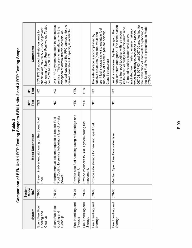
Tabl
e 2
Com
paris
on o
f BFN
Uni
t 1 R
TP T
estin
g Sc
ope
to B
FN U
nits
2 a
nd 3
RTP
Tes
ting
Scop
e
E-9
9
Syst
em
Syst
em
Mod
e N
o.1
Mod
e D
escr
iptio
n U
2/3
Test
U
1 Te
st
Com
men
ts
Spe
nt F
uel P
ool
Coo
ling
and
Cle
anup
078-
03
Pre
vent
inad
verte
nt s
ipho
ning
of t
he S
pent
Fue
l P
ool.
YE
S
NO
E
CN
P72
00 a
dded
ant
i-sip
hon
vent
s to
ch
eck
valv
es 7
8-25
6 &
78-
527
to p
reve
nt
siph
onin
g of
Spe
nt F
uel P
ool w
ater
. Tes
ted
per 1
-PM
T-BF
-78.
003.
Spe
nt F
uel P
ool
Coo
ling
and
Cle
anup
078-
04
Per
form
man
ual a
ctio
ns re
quire
d to
rest
ore
Fuel
P
ool C
oolin
g to
ser
vice
follo
win
g a
loss
of o
ff-si
te
pow
er.
NO
N
O
Uni
t 1 F
PC
sys
tem
has
bee
n in
con
tinuo
us
serv
ice.
The
re a
re n
o lim
itatio
ns, w
ith th
e ex
cept
ion
of a
dmin
istra
tive
cont
rols
, on
man
ual l
oadi
ng o
f the
FP
C p
umps
ont
o th
e di
esel
gen
erat
ors
if ca
paci
ty is
ava
ilabl
e.
Fuel
Han
dlin
g an
d S
tora
ge
079-
01
Pro
vide
saf
e fu
el h
andl
ing
usin
g re
fuel
brid
ge a
nd
equi
pmen
t. YE
S YE
S
Fuel
Han
dlin
g an
d S
tora
ge
079-
02
Pro
vide
inte
rlock
s to
CR
D S
yste
m d
urin
g fu
el
mov
emen
t. YE
S YE
S
Fuel
Han
dlin
g an
d S
tora
ge
079-
03
Pro
vide
saf
e st
orag
e fo
r new
and
spe
nt fu
el.
NO
N
O
The
safe
sto
rage
is a
ccom
plis
hed
by
pass
ive
stru
ctur
es (n
ew fu
el v
ault
and
spen
t fue
l sto
rage
rack
s) to
mai
ntai
n fu
el
sub-
criti
cal a
t all
times
. (A
ll ar
e se
ism
ic
Cla
ss I
stru
ctur
es)
Fuel
Han
dlin
g an
d S
tora
ge
079-
06
Mai
ntai
n S
pent
Fue
l Poo
l wat
er le
vel.
NO
N
O
Leve
l is
mai
ntai
ned
by th
e de
sign
of t
he
pool
stru
ctur
e an
d ga
tes.
The
con
stru
ctio
n of
the
fuel
poo
l tog
ethe
r with
retra
ctio
n lim
its o
n re
fuel
brid
ge h
oist
min
imum
nin
e (9
) fee
t of r
equi
red
wat
er le
vel a
bove
irr
adia
ted
fuel
. Te
sts
to e
nsur
e m
akeu
p w
ater
ava
ilabi
lity
is c
onta
ined
in M
odes
06
7-01
, 067
-03,
and
067
-05
and
test
ing
for
the
prev
entio
n of
inad
verte
nt s
ipho
ning
of
the
Spe
nt F
uel P
ool i
s pr
escr
ibed
in M
ode
078-
03.
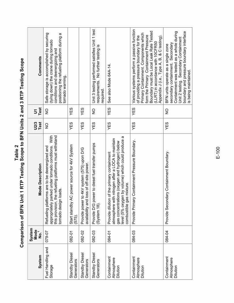
Tabl
e 2
Com
paris
on o
f BFN
Uni
t 1 R
TP T
estin
g Sc
ope
to B
FN U
nits
2 a
nd 3
RTP
Tes
ting
Scop
e
E-1
00
Syst
em
Syst
em
Mod
e N
o.1
Mod
e D
escr
iptio
n U
2/3
Test
U
1 Te
st
Com
men
ts
Fuel
Han
dlin
g an
d S
tora
ge
079-
07
Ref
uelin
g pl
atfo
rms
are
to b
e de
ener
gize
d an
d ap
prop
riate
ly p
arke
d un
der t
orna
do c
ondi
tions
. W
ith
this
pro
visi
on, t
he re
fuel
ing
plat
form
s m
ust w
ithst
and
torn
ado
desi
gn lo
ads.
NO
N
O
Saf
e st
orag
e is
acc
ompl
ishe
d by
sec
urin
g (ty
ing
dow
n) th
e cr
ane
durin
g to
rnad
o co
nditi
ons
and
deen
ergi
zing
and
po
sitio
ning
the
refu
elin
g pl
atfo
rm d
urin
g a
torn
ado
war
ning
.
Sta
ndby
Die
sel
Gen
erat
ors
082-
01
Sta
rt st
andb
y A
C p
ower
sou
rce
for 4
kV S
yste
m
(575
). YE
S YE
S
Sta
ndby
Die
sel
Gen
erat
ors
082-
02
Pro
vide
pow
er to
4kV
sys
tem
(575
) upo
n D
/G
avai
labi
lity
and
loss
of o
ff-si
te p
ower
. YE
S YE
S
Sta
ndby
Die
sel
Gen
erat
ors
082-
03
Pro
vide
D/G
pow
er to
die
sel f
uel t
rans
fer p
umps
(S
yste
m 1
8).
YE
S
NO
U
nit 3
test
ing
perfo
rmed
sat
isfie
s U
nit 1
test
re
quire
men
ts.
No
furth
er te
stin
g is
re
quire
d.
Con
tain
men
t A
tmos
pher
e D
ilutio
n
084-
01
Pro
vide
dilu
tion
of th
e pr
imar
y co
ntai
nmen
t at
mos
pher
e w
ith n
itrog
en a
fter a
LO
CA
to m
aint
ain
gas
conc
entra
tions
(oxy
gen
and
hydr
ogen
) bel
ow
leve
l (5%
oxy
gen
by v
olum
e) w
hich
cou
ld p
rodu
ce a
co
mbu
stib
le g
as m
ixtu
re.
YES
YES
See
als
o M
ode
64A
-14.
Con
tain
men
t A
tmos
pher
e D
ilutio
n
084-
03
Pro
vide
Prim
ary
Con
tain
men
t Pre
ssur
e B
ound
ary.
Y
ES
Y
ES
V
ario
us s
yste
ms
perfo
rm a
pas
sive
func
tion
of p
rovi
ding
a p
ress
ure
boun
dary
for t
he
Prim
ary
Con
tain
men
t. C
ompo
nent
s w
hich
fo
rm th
e P
rimar
y C
onta
inm
ent P
ress
ure
Bou
ndar
y m
ust b
e Lo
cal L
eak
Rat
e Te
sted
(L
LRT)
in a
ccor
danc
e w
ith 1
0CFR
50
App
endi
x J
(i.e.
, Typ
e A
, B, &
C te
stin
g).
Con
tain
men
t A
tmos
pher
e D
ilutio
n
084-
04
Pro
vide
Sec
onda
ry C
onta
inm
ent B
ound
ary.
Y
ES
N
O
BFN
uni
ts o
pera
te a
s a
sing
le z
one
seco
ndar
y co
ntai
nmen
t. S
econ
dary
C
onta
inm
ent w
as te
sted
as
a w
hole
dur
ing
Uni
t 2 te
stin
g. S
econ
dary
Con
tain
men
t bo
unda
ry a
nd p
ress
ure
boun
dary
inte
rface
is
bei
ng m
aint
aine
d.
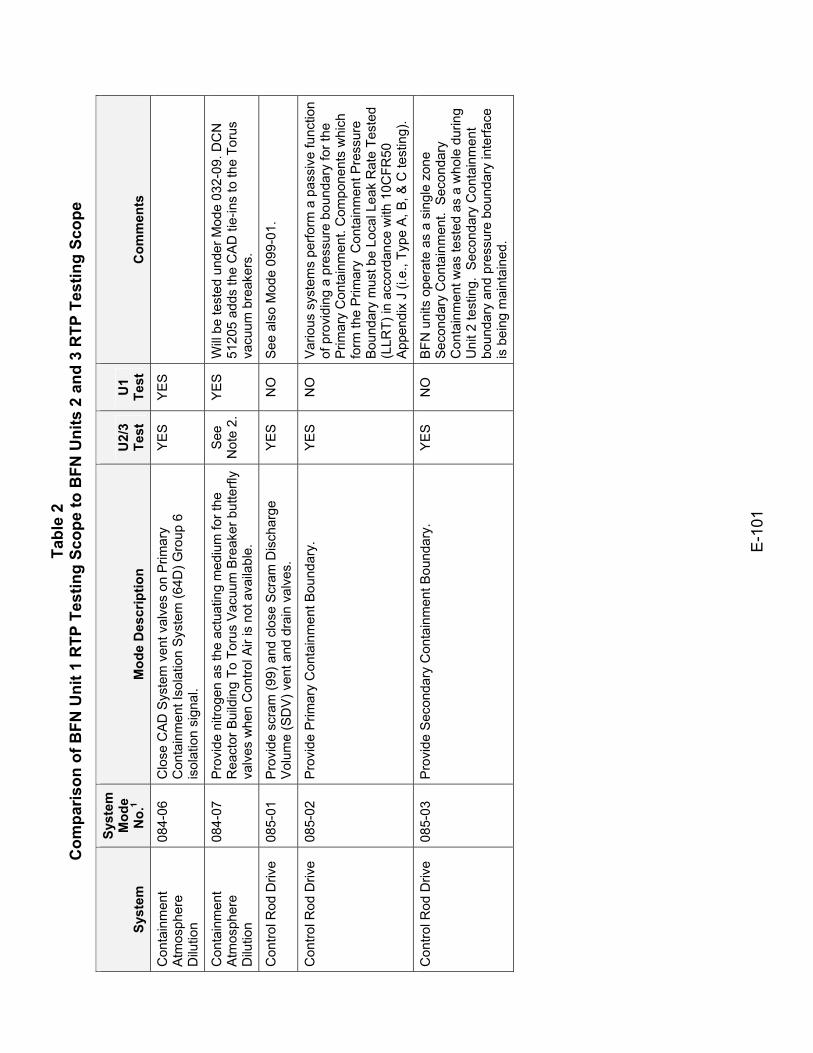
Tabl
e 2
Com
paris
on o
f BFN
Uni
t 1 R
TP T
estin
g Sc
ope
to B
FN U
nits
2 a
nd 3
RTP
Tes
ting
Scop
e
E-1
01
Syst
em
Syst
em
Mod
e N
o.1
Mod
e D
escr
iptio
n U
2/3
Test
U
1 Te
st
Com
men
ts
Con
tain
men
t A
tmos
pher
e D
ilutio
n
084-
06
Clo
se C
AD S
yste
m v
ent v
alve
s on
Prim
ary
Con
tain
men
t Iso
latio
n S
yste
m (6
4D) G
roup
6
isol
atio
n si
gnal
.
YES
YES
Con
tain
men
t A
tmos
pher
e D
ilutio
n
084-
07
Pro
vide
nitr
ogen
as
the
actu
atin
g m
ediu
m fo
r the
R
eact
or B
uild
ing
To T
orus
Vac
uum
Bre
aker
but
terfl
y va
lves
whe
n C
ontro
l Air
is n
ot a
vaila
ble.
See
N
ote
2.
YE
S
Will
be te
sted
und
er M
ode
032-
09. D
CN
51
205
adds
the
CA
D ti
e-in
s to
the
Toru
s va
cuum
bre
aker
s.
Con
trol R
od D
rive
085-
01
Pro
vide
scr
am (9
9) a
nd c
lose
Scr
am D
isch
arge
V
olum
e (S
DV
) ven
t and
dra
in v
alve
s.
YE
S
NO
S
ee a
lso
Mod
e 09
9-01
.
Con
trol R
od D
rive
085-
02
Pro
vide
Prim
ary
Con
tain
men
t Bou
ndar
y.
YE
S
NO
V
ario
us s
yste
ms
perfo
rm a
pas
sive
func
tion
of p
rovi
ding
a p
ress
ure
boun
dary
for t
he
Prim
ary
Con
tain
men
t. C
ompo
nent
s w
hich
fo
rm th
e P
rimar
y C
onta
inm
ent P
ress
ure
Bou
ndar
y m
ust b
e Lo
cal L
eak
Rat
e Te
sted
(L
LRT)
in a
ccor
danc
e w
ith 1
0CFR
50
App
endi
x J
(i.e.
, Typ
e A
, B, &
C te
stin
g).
Con
trol R
od D
rive
085-
03
Pro
vide
Sec
onda
ry C
onta
inm
ent B
ound
ary.
Y
ES
N
O
BFN
uni
ts o
pera
te a
s a
sing
le z
one
Seco
ndar
y C
onta
inm
ent.
Sec
onda
ry
Con
tain
men
t was
test
ed a
s a
who
le d
urin
g U
nit 2
test
ing.
Sec
onda
ry C
onta
inm
ent
boun
dary
and
pre
ssur
e bo
unda
ry in
terfa
ce
is b
eing
mai
ntai
ned.
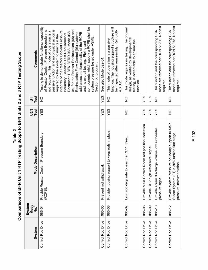
Tabl
e 2
Com
paris
on o
f BFN
Uni
t 1 R
TP T
estin
g Sc
ope
to B
FN U
nits
2 a
nd 3
RTP
Tes
ting
Scop
e
E-1
02
Syst
em
Syst
em
Mod
e N
o.1
Mod
e D
escr
iptio
n U
2/3
Test
U
1 Te
st
Com
men
ts
Con
trol R
od D
rive
085-
04
Pro
vide
Rea
ctor
Coo
lant
Pre
ssur
e B
ound
ary
(RC
PB
). Y
ES
N
O
Test
ing
to d
emon
stra
te fu
nctio
nal c
apab
ility
of R
eact
or C
oola
nt P
ress
ure
Bou
ndar
y is
no
t req
uire
d. T
his
mod
e of
ope
ratio
n is
a
pass
ive
func
tion
and
no p
hysi
cal a
ctio
n is
re
quire
d by
the
syst
em to
mai
ntai
n th
e in
tegr
ity o
f the
Rea
ctor
Coo
lant
Pre
ssur
e B
ound
ary.
Bas
elin
e Te
st R
equi
rem
ents
D
ocum
ent 1
-BFN
-BTR
D-0
68, M
ode
068-
04, f
or th
e R
eact
or R
ecirc
ulat
ion
(68)
and
R
ecirc
ulat
ion
Flow
Con
trol (
96) s
yste
ms
addr
esse
s th
e fu
nctio
nalit
y of
the
RC
PB
an
d its
ove
rall
test
ing.
Pip
ing
and
com
pone
nts
whi
ch s
uppl
y a
RC
PB
sha
ll be
sy
stem
pre
ssur
e te
sted
und
er A
SM
E
Sec
tion
XI p
rogr
am.
Con
trol R
od D
rive
085-
05
Pre
vent
rod
with
draw
al.
YE
S
YE
S
See
als
o M
ode
092-
04.
Con
trol R
od D
rive
085-
06
Pro
vide
hou
sing
sup
port
to k
eep
rods
in p
lace
. Y
ES
N
O
This
mod
e of
ope
ratio
n is
a p
assi
ve
func
tion.
The
hou
sing
sup
port
stru
ctur
e w
ill be
insp
ecte
d af
ter r
eass
embl
y. R
ef. 0
-SI-
4.3.
B.2
.
Con
trol R
od D
rive
085-
07
Lim
it ro
d dr
op ra
te to
less
than
3.1
1 ft/
sec.
N
O
NO
Th
is m
ode
requ
ires
no te
stin
g. T
he o
rigin
al
desi
gn, a
s ve
rifie
d by
dev
elop
men
tal
test
ing,
is a
ccep
tabl
e to
ens
ure
the
func
tion.
Con
trol R
od D
rive
085-
08
Pro
vide
Mai
n C
ontro
l Roo
m ro
d po
sitio
n in
dica
tion.
Y
ES
Y
ES
Con
trol R
od D
rive
085-
09
Pro
vide
SD
V h
igh
wat
er le
vel s
igna
l. Y
ES
Y
ES
Con
trol R
od D
rive
085-
10
Pro
vide
scr
am d
isch
arge
vol
ume
low
air
head
er
pres
sure
sig
nal.
YE
S
NO
Th
is fu
nctio
n an
d th
e co
rresp
ondi
ng S
SA
m
ode
are
rem
oved
per
DC
N 5
1206
. No
test
re
quire
d.
Con
trol R
od D
rive
085-
12
Pro
vide
sys
tem
pre
ssur
e bo
unda
ry s
uppo
rt to
Mai
n S
team
Sys
tem
(01)
> 3
0% tu
rbin
e fir
st s
tage
pr
essu
re in
stru
men
tatio
n.
NO
N
O
This
func
tion
and
the
corre
spon
ding
SS
A
mod
e ar
e re
mov
ed p
er D
CN
510
78. N
o te
st
requ
ired.
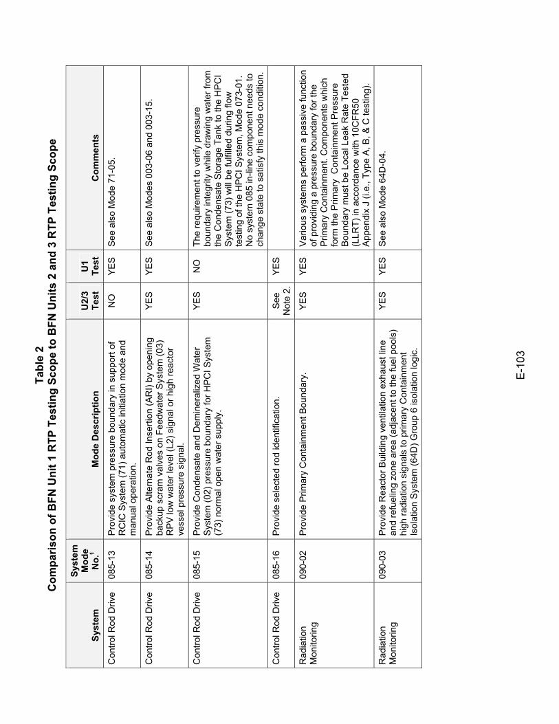
Tabl
e 2
Com
paris
on o
f BFN
Uni
t 1 R
TP T
estin
g Sc
ope
to B
FN U
nits
2 a
nd 3
RTP
Tes
ting
Scop
e
E-1
03
Syst
em
Syst
em
Mod
e N
o.1
Mod
e D
escr
iptio
n U
2/3
Test
U
1 Te
st
Com
men
ts
Con
trol R
od D
rive
085-
13
Pro
vide
sys
tem
pre
ssur
e bo
unda
ry in
sup
port
of
RC
IC S
yste
m (7
1) a
utom
atic
initi
atio
n m
ode
and
man
ual o
pera
tion.
NO
Y
ES
S
ee a
lso
Mod
e 71
-05.
Con
trol R
od D
rive
085-
14
Pro
vide
Alte
rnat
e R
od In
serti
on (A
RI)
by o
peni
ng
back
up s
cram
val
ves
on F
eedw
ater
Sys
tem
(03)
R
PV
low
wat
er le
vel (
L2) s
igna
l or h
igh
reac
tor
vess
el p
ress
ure
sign
al.
YE
S
YE
S
See
als
o M
odes
003
-06
and
003-
15.
Con
trol R
od D
rive
085-
15
Pro
vide
Con
dens
ate
and
Dem
iner
aliz
ed W
ater
S
yste
m (0
2) p
ress
ure
boun
dary
for H
PC
I Sys
tem
(7
3) n
orm
al o
pen
wat
er s
uppl
y.
YE
S
NO
Th
e re
quire
men
t to
verif
y pr
essu
re
boun
dary
inte
grity
whi
le d
raw
ing
wat
er fr
om
the
Con
dens
ate
Sto
rage
Tan
k to
the
HPC
I S
yste
m (7
3) w
ill be
fulfi
lled
durin
g flo
w
test
ing
of th
e H
PC
I Sys
tem
, Mod
e 07
3-01
. N
o sy
stem
085
in-li
ne c
ompo
nent
nee
ds to
ch
ange
sta
te to
sat
isfy
this
mod
e co
nditi
on.
Con
trol R
od D
rive
085-
16
Pro
vide
sel
ecte
d ro
d id
entif
icat
ion.
S
ee
Not
e 2.
YE
S
Rad
iatio
n M
onito
ring
090-
02
Pro
vide
Prim
ary
Con
tain
men
t Bou
ndar
y.
YE
S
YE
S
Var
ious
sys
tem
s pe
rform
a p
assi
ve fu
nctio
n of
pro
vidi
ng a
pre
ssur
e bo
unda
ry fo
r the
P
rimar
y C
onta
inm
ent.
Com
pone
nts
whi
ch
form
the
Prim
ary
Con
tain
men
t Pre
ssur
e B
ound
ary
mus
t be
Loca
l Lea
k R
ate
Test
ed
(LLR
T) in
acc
orda
nce
with
10C
FR50
A
ppen
dix
J (i.
e., T
ype
A, B
, & C
test
ing)
.
Rad
iatio
n M
onito
ring
090-
03
Pro
vide
Rea
ctor
Bui
ldin
g ve
ntila
tion
exha
ust l
ine
and
refu
elin
g zo
ne a
rea
(adj
acen
t to
the
fuel
poo
ls)
high
radi
atio
n si
gnal
s to
prim
ary
Con
tain
men
t Is
olat
ion
Sys
tem
(64D
) Gro
up 6
isol
atio
n lo
gic.
YE
S
YE
S
See
als
o M
ode
64D
-04.
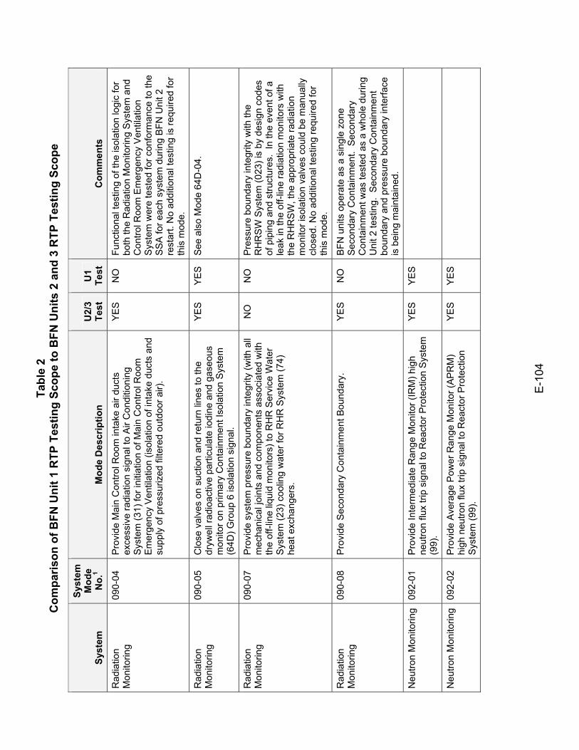
Tabl
e 2
Com
paris
on o
f BFN
Uni
t 1 R
TP T
estin
g Sc
ope
to B
FN U
nits
2 a
nd 3
RTP
Tes
ting
Scop
e
E-1
04
Syst
em
Syst
em
Mod
e N
o.1
Mod
e D
escr
iptio
n U
2/3
Test
U
1 Te
st
Com
men
ts
Rad
iatio
n M
onito
ring
090-
04
Pro
vide
Mai
n C
ontro
l Roo
m in
take
air
duct
s ex
cess
ive
radi
atio
n si
gnal
to A
ir C
ondi
tioni
ng
Sys
tem
(31)
for i
nitia
tion
of M
ain
Con
trol R
oom
E
mer
genc
y Ve
ntila
tion
(isol
atio
n of
inta
ke d
ucts
and
su
pply
of p
ress
uriz
ed fi
ltere
d ou
tdoo
r air)
.
YE
S
NO
Fu
nctio
nal t
estin
g of
the
isol
atio
n lo
gic
for
both
the
Rad
iatio
n M
onito
ring
Sys
tem
and
C
ontro
l Roo
m E
mer
genc
y V
entil
atio
n S
yste
m w
ere
test
ed fo
r con
form
ance
to th
e S
SA
for e
ach
syst
em d
urin
g B
FN U
nit 2
re
star
t. N
o ad
ditio
nal t
estin
g is
requ
ired
for
this
mod
e.
Rad
iatio
n M
onito
ring
090-
05
Clo
se v
alve
s on
suc
tion
and
retu
rn li
nes
to th
e dr
ywel
l rad
ioac
tive
parti
cula
te io
dine
and
gas
eous
m
onito
r on
prim
ary
Con
tain
men
t Iso
latio
n S
yste
m
(64D
) Gro
up 6
isol
atio
n si
gnal
.
YE
S
YE
S
See
als
o M
ode
64D
-04.
Rad
iatio
n M
onito
ring
090-
07
Pro
vide
sys
tem
pre
ssur
e bo
unda
ry in
tegr
ity (w
ith a
ll m
echa
nica
l joi
nts
and
com
pone
nts
asso
ciat
ed w
ith
the
off-l
ine
liqui
d m
onito
rs) t
o R
HR
Ser
vice
Wat
er
Sys
tem
(23)
coo
ling
wat
er fo
r RH
R S
yste
m (7
4)
heat
exc
hang
ers.
NO
N
O
Pre
ssur
e bo
unda
ry in
tegr
ity w
ith th
e R
HR
SW
Sys
tem
(023
) is
by d
esig
n co
des
of p
ipin
g an
d st
ruct
ures
. In
the
even
t of a
le
ak in
the
off-l
ine
radi
atio
n m
onito
rs w
ith
the
RH
RS
W, t
he a
ppro
pria
te ra
diat
ion
mon
itor i
sola
tion
valv
es c
ould
be
man
ually
cl
osed
. No
addi
tiona
l tes
ting
requ
ired
for
this
mod
e.
Rad
iatio
n M
onito
ring
090-
08
Pro
vide
Sec
onda
ry C
onta
inm
ent B
ound
ary.
Y
ES
N
O
BFN
uni
ts o
pera
te a
s a
sing
le z
one
Seco
ndar
y C
onta
inm
ent.
Sec
onda
ry
Con
tain
men
t was
test
ed a
s a
who
le d
urin
g U
nit 2
test
ing.
Sec
onda
ry C
onta
inm
ent
boun
dary
and
pre
ssur
e bo
unda
ry in
terfa
ce
is b
eing
mai
ntai
ned.
Neu
tron
Mon
itorin
g 09
2-01
P
rovi
de In
term
edia
te R
ange
Mon
itor (
IRM
) hig
h ne
utro
n flu
x tri
p si
gnal
to R
eact
or P
rote
ctio
n S
yste
m
(99)
.
YES
YES
Neu
tron
Mon
itorin
g 09
2-02
P
rovi
de A
vera
ge P
ower
Ran
ge M
onito
r (A
PR
M)
high
neu
tron
flux
trip
sign
al to
Rea
ctor
Pro
tect
ion
Sys
tem
(99)
.
YES
YES
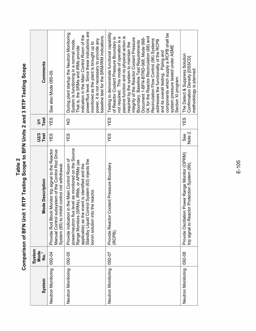
Tabl
e 2
Com
paris
on o
f BFN
Uni
t 1 R
TP T
estin
g Sc
ope
to B
FN U
nits
2 a
nd 3
RTP
Tes
ting
Scop
e
E-1
05
Syst
em
Syst
em
Mod
e N
o.1
Mod
e D
escr
iptio
n U
2/3
Test
U
1 Te
st
Com
men
ts
Neu
tron
Mon
itorin
g 09
2-04
P
rovi
de R
od B
lock
Mon
itor t
rip s
igna
l to
the
Rea
ctor
M
anua
l Con
trol s
ubsy
stem
of t
he C
ontro
l Rod
Driv
e S
yste
m (8
5) to
inhi
bit c
ontro
l rod
with
draw
al.
YE
S
YE
S
See
als
o M
ode
085-
05.
Neu
tron
Mon
itorin
g 09
2-05
P
rovi
de in
dica
tion
in th
e M
ain
Con
trol R
oom
of
pow
er/n
eutro
n flu
x le
vel a
s m
onito
red
on th
e S
ourc
e R
ange
Mon
itors
(SR
Ms)
, IR
Ms,
or A
PR
Ms
(as
appl
icab
le) a
s th
e ev
ent i
s id
entif
ied
and
the
Sta
ndby
Liq
uid
Con
trol S
yste
m (6
3) in
ject
s th
e bo
ron
solu
tion
into
the
reac
tor.
YE
S
NO
D
urin
g pl
ant s
tartu
p th
e N
eutro
n M
onito
ring
Sys
tem
is fu
nctio
ning
in a
nor
mal
mod
e.
That
is, t
he S
RM
s an
d IR
Ms
prov
ide
indi
catio
n in
the
Mai
n C
ontro
l Roo
m o
f the
po
wer
/flux
leve
l. S
ince
thes
e in
dica
tions
are
m
onito
red
as th
e pl
ant i
s br
ough
t up
to
pow
er, i
t is
not n
eces
sary
to p
rovi
de a
ny
base
line
test
for t
he S
RM
/IRM
indi
catio
ns.
Neu
tron
Mon
itorin
g 09
2-07
P
rovi
de R
eact
or C
oola
nt P
ress
ure
Bou
ndar
y (R
CP
B).
YE
S
YE
S
Test
ing
to d
emon
stra
te fu
nctio
nal c
apab
ility
of R
eact
or C
oola
nt P
ress
ure
Bou
ndar
y is
no
t req
uire
d. T
his
mod
e of
ope
ratio
n is
a
pass
ive
func
tion
and
no p
hysi
cal a
ctio
n is
re
quire
d by
the
syst
em to
mai
ntai
n th
e in
tegr
ity o
f the
Rea
ctor
Coo
lant
Pre
ssur
e B
ound
ary.
Bas
elin
e Te
st R
equi
rem
ents
D
ocum
ent 1
-BFN
-BTR
D-0
68, M
ode
068-
04, f
or th
e R
eact
or R
ecirc
ulat
ion
(68)
and
R
ecirc
ulat
ion
Flow
Con
trol (
96) S
yste
ms
addr
esse
s th
e fu
nctio
nalit
y of
the
RC
PB
an
d its
ove
rall
test
ing.
Pip
ing
and
com
pone
nts
whi
ch s
uppl
y a
RC
PB
sha
ll be
sy
stem
pre
ssur
e te
sted
und
er A
SM
E
Sec
tion
XI p
rogr
am.
Neu
tron
Mon
itorin
g 09
2-08
P
rovi
de O
scilla
tion
Pow
er R
ange
Mon
itor (
OPR
M)
trip
sign
al to
Rea
ctor
Pro
tect
ion
Sys
tem
(99)
. S
ee
Not
e 2.
Y
ES
Th
e D
etec
t & S
uppr
ess
Sol
utio
n C
onfir
mat
ion
Den
sity
[DS
SC
D]
met
hodo
logy
is p
lann
ed.
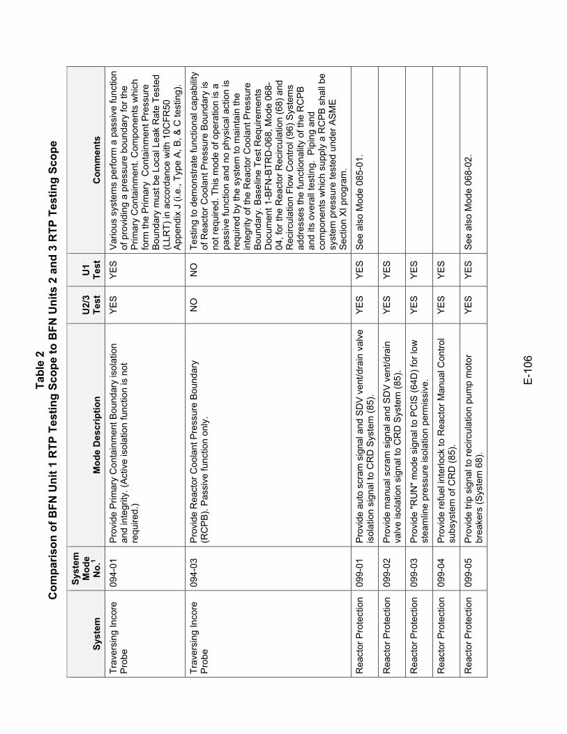
Tabl
e 2
Com
paris
on o
f BFN
Uni
t 1 R
TP T
estin
g Sc
ope
to B
FN U
nits
2 a
nd 3
RTP
Tes
ting
Scop
e
E-1
06
Syst
em
Syst
em
Mod
e N
o.1
Mod
e D
escr
iptio
n U
2/3
Test
U
1 Te
st
Com
men
ts
Trav
ersi
ng In
core
P
robe
09
4-01
P
rovi
de P
rimar
y C
onta
inm
ent B
ound
ary
isol
atio
n an
d in
tegr
ity. (
Act
ive
isol
atio
n fu
nctio
n is
not
re
quire
d.)
YE
S
YE
S
Var
ious
sys
tem
s pe
rform
a p
assi
ve fu
nctio
n of
pro
vidi
ng a
pre
ssur
e bo
unda
ry fo
r the
P
rimar
y C
onta
inm
ent.
Com
pone
nts
whi
ch
form
the
Prim
ary
Con
tain
men
t Pre
ssur
e B
ound
ary
mus
t be
Loca
l Lea
k R
ate
Test
ed
(LLR
T) in
acc
orda
nce
with
10C
FR50
A
ppen
dix
J (i.
e., T
ype
A, B
, & C
test
ing)
.
Trav
ersi
ng In
core
P
robe
09
4-03
P
rovi
de R
eact
or C
oola
nt P
ress
ure
Bou
ndar
y (R
CP
B).
Pas
sive
func
tion
only
. N
O
NO
Te
stin
g to
dem
onst
rate
func
tiona
l cap
abilit
y of
Rea
ctor
Coo
lant
Pre
ssur
e B
ound
ary
is
not r
equi
red.
Thi
s m
ode
of o
pera
tion
is a
pa
ssiv
e fu
nctio
n an
d no
phy
sica
l act
ion
is
requ
ired
by th
e sy
stem
to m
aint
ain
the
inte
grity
of t
he R
eact
or C
oola
nt P
ress
ure
Bou
ndar
y. B
asel
ine
Test
Req
uire
men
ts
Doc
umen
t 1-B
FN-B
TRD
-068
, Mod
e 06
8-04
, for
the
Rea
ctor
Rec
ircul
atio
n (6
8) a
nd
Rec
ircul
atio
n Fl
ow C
ontro
l (96
) Sys
tem
s ad
dres
ses
the
func
tiona
lity
of th
e R
CP
B
and
its o
vera
ll te
stin
g. P
ipin
g an
d co
mpo
nent
s w
hich
sup
ply
a R
CP
B s
hall
be
syst
em p
ress
ure
test
ed u
nder
AS
ME
S
ectio
n X
I pro
gram
.
Rea
ctor
Pro
tect
ion
099-
01
Pro
vide
aut
o sc
ram
sig
nal a
nd S
DV
ven
t/dra
in v
alve
is
olat
ion
sign
al to
CR
D S
yste
m (8
5).
YE
S
YE
S
See
als
o M
ode
085-
01.
Rea
ctor
Pro
tect
ion
099-
02
Pro
vide
man
ual s
cram
sig
nal a
nd S
DV
ven
t/dra
in
valv
e is
olat
ion
sign
al to
CR
D S
yste
m (8
5).
YES
YES
Rea
ctor
Pro
tect
ion
099-
03
Pro
vide
"RU
N" m
ode
sign
al to
PC
IS (6
4D) f
or lo
w
stea
mlin
e pr
essu
re is
olat
ion
perm
issi
ve.
YES
YES
Rea
ctor
Pro
tect
ion
099-
04
Pro
vide
refu
el in
terlo
ck to
Rea
ctor
Man
ual C
ontro
l su
bsys
tem
of C
RD
(85)
. YE
S YE
S
Rea
ctor
Pro
tect
ion
099-
05
Pro
vide
trip
sig
nal t
o re
circ
ulat
ion
pum
p m
otor
br
eake
rs (S
yste
m 6
8).
YE
S
YE
S
See
als
o M
ode
068-
02.
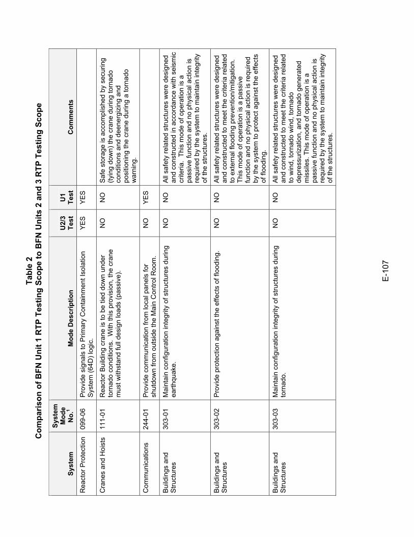
Tabl
e 2
Com
paris
on o
f BFN
Uni
t 1 R
TP T
estin
g Sc
ope
to B
FN U
nits
2 a
nd 3
RTP
Tes
ting
Scop
e
E-1
07
Syst
em
Syst
em
Mod
e N
o.1
Mod
e D
escr
iptio
n U
2/3
Test
U
1 Te
st
Com
men
ts
Rea
ctor
Pro
tect
ion
099-
06
Pro
vide
sig
nals
to P
rimar
y C
onta
inm
ent I
sola
tion
Sys
tem
(64D
) log
ic.
YES
YES
Cra
nes
and
Hoi
sts
111-
01
Rea
ctor
Bui
ldin
g cr
ane
is to
be
tied
dow
n un
der
torn
ado
cond
ition
s. W
ith th
is p
rovi
sion
, the
cra
ne
mus
t with
stan
d fu
ll de
sign
load
s (p
assi
ve).
NO
N
O
Saf
e st
orag
e is
acc
ompl
ishe
d by
sec
urin
g (ty
ing
dow
n) th
e cr
ane
durin
g to
rnad
o co
nditi
ons
and
deen
ergi
zing
and
po
sitio
ning
the
cran
e du
ring
a to
rnad
o w
arni
ng.
Com
mun
icat
ions
24
4-01
P
rovi
de c
omm
unic
atio
n fro
m lo
cal p
anel
s fo
r sh
utdo
wn
from
out
side
the
Mai
n C
ontro
l Roo
m.
NO
Y
ES
Bui
ldin
gs a
nd
Stru
ctur
es
303-
01
Mai
ntai
n co
nfig
urat
ion
inte
grity
of s
truct
ures
dur
ing
earth
quak
e.
NO
N
O
All
safe
ty re
late
d st
ruct
ures
wer
e de
sign
ed
and
cons
truct
ed in
acc
orda
nce
with
sei
smic
cr
iteria
. Th
is m
ode
of o
pera
tion
is a
pa
ssiv
e fu
nctio
n an
d no
phy
sica
l act
ion
is
requ
ired
by th
e sy
stem
to m
aint
ain
inte
grity
of
the
stru
ctur
es.
Bui
ldin
gs a
nd
Stru
ctur
es
303-
02
Pro
vide
pro
tect
ion
agai
nst t
he e
ffect
s of
floo
ding
. N
O
NO
A
ll sa
fety
rela
ted
stru
ctur
es w
ere
desi
gned
an
d co
nstru
cted
to m
eet t
he c
riter
ia re
late
d to
ext
erna
l flo
odin
g pr
even
tion/
miti
gatio
n.
This
mod
e of
ope
ratio
n is
a p
assi
ve
func
tion
and
no p
hysi
cal a
ctio
n is
requ
ired
by th
e sy
stem
to p
rote
ct a
gain
st th
e ef
fect
s of
floo
ding
.
Bui
ldin
gs a
nd
Stru
ctur
es
303-
03
Mai
ntai
n co
nfig
urat
ion
inte
grity
of s
truct
ures
dur
ing
torn
ado.
N
O
NO
A
ll sa
fety
rela
ted
stru
ctur
es w
ere
desi
gned
an
d co
nstru
cted
to m
eet t
he c
riter
ia re
late
d to
win
d, to
rnad
o w
ind,
torn
ado
depr
essu
rizat
ion,
and
torn
ado
gene
rate
d m
issi
les.
Thi
s m
ode
of o
pera
tion
is a
pa
ssiv
e fu
nctio
n an
d no
phy
sica
l act
ion
is
requ
ired
by th
e sy
stem
to m
aint
ain
inte
grity
of
the
stru
ctur
es.
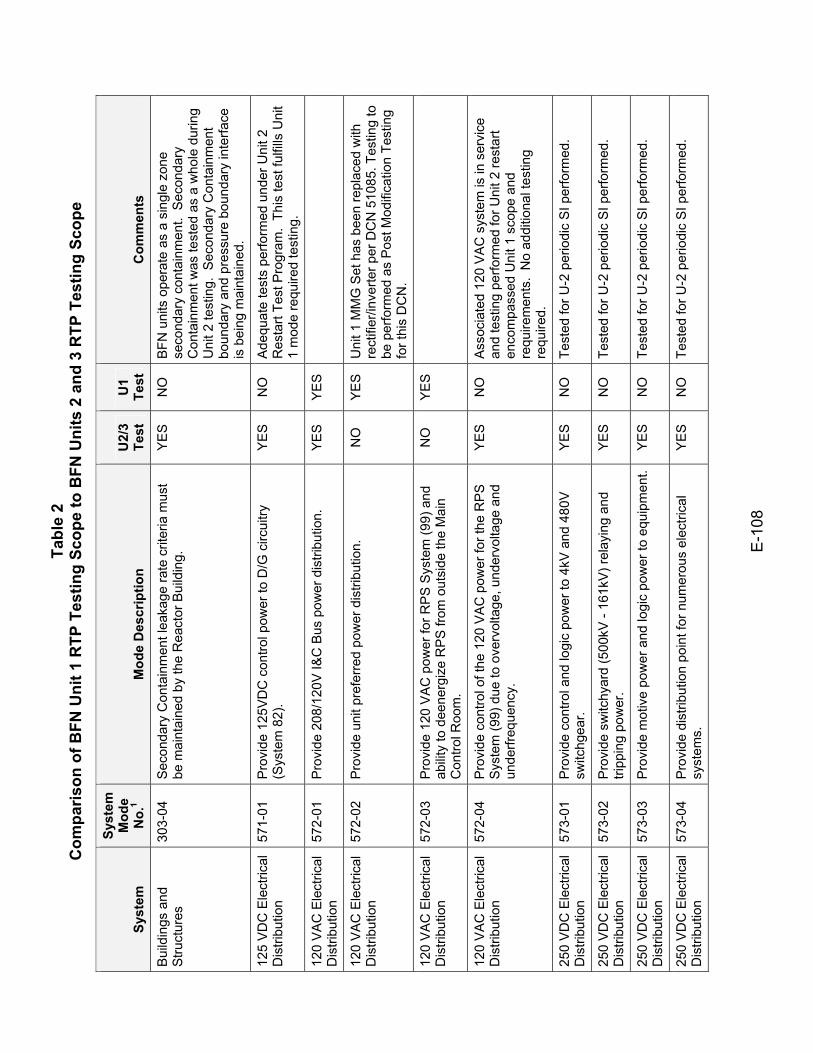
Tabl
e 2
Com
paris
on o
f BFN
Uni
t 1 R
TP T
estin
g Sc
ope
to B
FN U
nits
2 a
nd 3
RTP
Tes
ting
Scop
e
E-1
08
Syst
em
Syst
em
Mod
e N
o.1
Mod
e D
escr
iptio
n U
2/3
Test
U
1 Te
st
Com
men
ts
Bui
ldin
gs a
nd
Stru
ctur
es
303-
04
Sec
onda
ry C
onta
inm
ent l
eaka
ge ra
te c
riter
ia m
ust
be m
aint
aine
d by
the
Rea
ctor
Bui
ldin
g.
YE
S
NO
B
FN u
nits
ope
rate
as
a si
ngle
zon
e se
cond
ary
cont
ainm
ent.
Sec
onda
ry
Con
tain
men
t was
test
ed a
s a
who
le d
urin
g U
nit 2
test
ing.
Sec
onda
ry C
onta
inm
ent
boun
dary
and
pre
ssur
e bo
unda
ry in
terfa
ce
is b
eing
mai
ntai
ned.
125
VD
C E
lect
rical
D
istri
butio
n 57
1-01
P
rovi
de 1
25V
DC
con
trol p
ower
to D
/G c
ircui
try
(Sys
tem
82)
. Y
ES
N
O
Ade
quat
e te
sts
perfo
rmed
und
er U
nit 2
R
esta
rt Te
st P
rogr
am.
This
test
fulfi
lls U
nit
1 m
ode
requ
ired
test
ing.
120
VA
C E
lect
rical
D
istri
butio
n 57
2-01
P
rovi
de 2
08/1
20V
I&C
Bus
pow
er d
istri
butio
n.
YE
S
YE
S
120
VA
C E
lect
rical
D
istri
butio
n 57
2-02
P
rovi
de u
nit p
refe
rred
pow
er d
istri
butio
n.
NO
Y
ES
U
nit 1
MM
G S
et h
as b
een
repl
aced
with
re
ctifi
er/in
verte
r per
DC
N 5
1085
. Tes
ting
to
be p
erfo
rmed
as
Pos
t Mod
ifica
tion
Test
ing
for t
his
DC
N.
120
VA
C E
lect
rical
D
istri
butio
n 57
2-03
P
rovi
de 1
20 V
AC
pow
er fo
r RP
S S
yste
m (9
9) a
nd
abili
ty to
dee
nerg
ize
RP
S fr
om o
utsi
de th
e M
ain
Con
trol R
oom
.
NO
Y
ES
120
VA
C E
lect
rical
D
istri
butio
n 57
2-04
P
rovi
de c
ontro
l of t
he 1
20 V
AC
pow
er fo
r the
RP
S
Sys
tem
(99)
due
to o
verv
olta
ge, u
nder
volta
ge a
nd
unde
rfreq
uenc
y.
YE
S
NO
A
ssoc
iate
d 12
0 V
AC
sys
tem
is in
ser
vice
an
d te
stin
g pe
rform
ed fo
r Uni
t 2 re
star
t en
com
pass
ed U
nit 1
sco
pe a
nd
requ
irem
ents
. N
o ad
ditio
nal t
estin
g re
quire
d.
250
VD
C E
lect
rical
D
istri
butio
n 57
3-01
P
rovi
de c
ontro
l and
logi
c po
wer
to 4
kV a
nd 4
80V
sw
itchg
ear.
YE
S
NO
Te
sted
for U
-2 p
erio
dic
SI p
erfo
rmed
.
250
VD
C E
lect
rical
D
istri
butio
n 57
3-02
P
rovi
de s
witc
hyar
d (5
00kV
- 16
1kV)
rela
ying
and
tri
ppin
g po
wer
. Y
ES
N
O
Test
ed fo
r U-2
per
iodi
c S
I per
form
ed.
250
VD
C E
lect
rical
D
istri
butio
n 57
3-03
P
rovi
de m
otiv
e po
wer
and
logi
c po
wer
to e
quip
men
t.Y
ES
N
O
Test
ed fo
r U-2
per
iodi
c S
I per
form
ed.
250
VD
C E
lect
rical
D
istri
butio
n 57
3-04
P
rovi
de d
istri
butio
n po
int f
or n
umer
ous
elec
trica
l sy
stem
s.
YE
S
NO
Te
sted
for U
-2 p
erio
dic
SI p
erfo
rmed
.
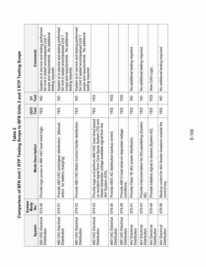
Tabl
e 2
Com
paris
on o
f BFN
Uni
t 1 R
TP T
estin
g Sc
ope
to B
FN U
nits
2 a
nd 3
RTP
Tes
ting
Scop
e
E-1
09
Syst
em
Syst
em
Mod
e N
o.1
Mod
e D
escr
iptio
n U
2/3
Test
U
1 Te
st
Com
men
ts
250
VD
C E
lect
rical
D
istri
butio
n 57
3-05
P
rovi
de lo
gic
pow
er to
480
VA
C lo
ad s
hed
logi
c.
YE
S
NO
S
yste
m is
in s
ervi
ce a
nd te
stin
g pe
rform
ed
for U
nit 2
rest
art e
ncom
pass
ed U
nit 1
sc
ope
and
requ
irem
ents
. N
o ad
ditio
nal
test
ing
requ
ired.
480
VA
C E
lect
rical
D
istri
butio
n 57
4-01
P
rovi
de 4
80 V
AC
sw
itchg
ear d
istri
butio
n. [
Man
ual
actio
n fo
r bat
tery
cha
rgin
g]
YE
S
NO
S
yste
m is
in s
ervi
ce a
nd te
stin
g pe
rform
ed
for U
nit 2
rest
art e
ncom
pass
ed U
nit 1
sc
ope
and
requ
irem
ents
. N
o ad
ditio
nal
test
ing
requ
ired.
480
VA
C E
lect
rical
D
istri
butio
n 57
4-02
P
rovi
de 4
80 V
AC
Mot
or C
ontro
l Cen
ter d
istri
butio
n.
YE
S
NO
S
yste
m is
in s
ervi
ce a
nd te
stin
g pe
rform
ed
for U
nit 2
rest
art e
ncom
pass
ed U
nit 1
sc
ope
and
requ
irem
ents
. N
o ad
ditio
nal
test
ing
requ
ired.
480
VA
C E
lect
rical
D
istri
butio
n 57
4-03
P
rovi
de lo
gic
and
perfo
rm 4
80 V
AC
load
she
d ba
sed
on a
ccid
ent s
igna
l fro
m C
ore
Spr
ay S
yste
m (7
5) a
nd
Die
sel G
ener
ator
vol
tage
ava
ilabl
e si
gnal
from
the
4kV
Sys
tem
(575
).
YES
YES
480
VA
C E
lect
rical
D
istri
butio
n 57
4-04
P
rovi
de 4
80V
AC
dis
tribu
tion
back
up c
ontro
l. Y
ES
Y
ES
480
VA
C E
lect
rical
D
istri
butio
n 57
4-05
P
rovi
de 4
80-V
load
she
d on
deg
rade
d vo
ltage
co
nditi
ons.
YE
S YE
S
4kV
Ele
ctric
al
Dis
tribu
tion
575-
01
Pro
vide
Cla
ss 1
E 4
kV p
ower
dis
tribu
tion.
Y
ES
N
O
No
addi
tiona
l tes
ting
requ
ired.
4kV
Ele
ctric
al
Dis
tribu
tion
575-
03
Pro
vide
inst
rum
enta
tion
for D
G p
aral
lelin
g (S
yste
m
82).
YE
S
NO
N
o ad
ditio
nal t
estin
g re
quire
d.
4kV
Ele
ctric
al
Dis
tribu
tion
575-
04
Pro
vide
initi
atio
n si
gnal
to d
iese
ls (S
yste
m 8
2).
YE
S
YE
S
New
CA
S L
ogic
.
4kV
Ele
ctric
al
Dis
tribu
tion
575-
06
Bac
kup
cont
rol f
or 4
kV fe
eder
bre
aker
s ou
tsid
e th
e co
ntro
l bay
. Y
ES
N
O
No
addi
tiona
l tes
ting
requ
ired.
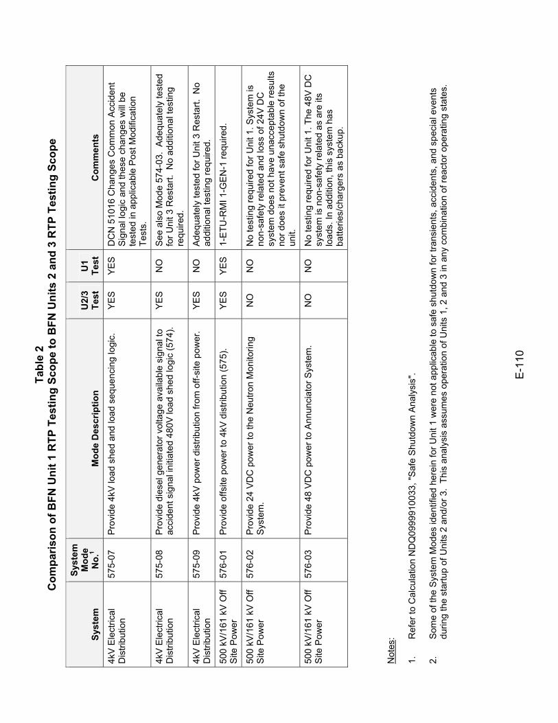
Tabl
e 2
Com
paris
on o
f BFN
Uni
t 1 R
TP T
estin
g Sc
ope
to B
FN U
nits
2 a
nd 3
RTP
Tes
ting
Scop
e
E-1
10
Syst
em
Syst
em
Mod
e N
o.1
Mod
e D
escr
iptio
n U
2/3
Test
U
1 Te
st
Com
men
ts
4kV
Ele
ctric
al
Dis
tribu
tion
575-
07
Pro
vide
4kV
load
she
d an
d lo
ad s
eque
ncin
g lo
gic.
Y
ES
Y
ES
D
CN
510
16 C
hang
es C
omm
on A
ccid
ent
Sig
nal l
ogic
and
thes
e ch
ange
s w
ill b
e te
sted
in a
pplic
able
Pos
t Mod
ifica
tion
Test
s.
4kV
Ele
ctric
al
Dis
tribu
tion
575-
08
Pro
vide
die
sel g
ener
ator
vol
tage
ava
ilabl
e si
gnal
to
acci
dent
sig
nal i
nitia
ted
480V
load
she
d lo
gic
(574
). Y
ES
N
O
See
als
o M
ode
574-
03.
Ade
quat
ely
test
ed
for U
nit 3
Res
tart.
No
addi
tiona
l tes
ting
requ
ired.
4kV
Ele
ctric
al
Dis
tribu
tion
575-
09
Pro
vide
4kV
pow
er d
istri
butio
n fro
m o
ff-si
te p
ower
. Y
ES
N
O
Ade
quat
ely
test
ed fo
r Uni
t 3 R
esta
rt. N
o ad
ditio
nal t
estin
g re
quire
d.
500
kV/1
61 k
V O
ff S
ite P
ower
57
6-01
P
rovi
de o
ffsite
pow
er to
4kV
dis
tribu
tion
(575
). Y
ES
Y
ES
1-
ETU
-RM
I 1-G
EN
-1 re
quire
d.
500
kV/1
61 k
V O
ff S
ite P
ower
57
6-02
P
rovi
de 2
4 VD
C p
ower
to th
e N
eutro
n M
onito
ring
Syst
em.
NO
N
O
No
test
ing
requ
ired
for U
nit 1
. Sys
tem
is
non-
safe
ty re
late
d an
d lo
ss o
f 24V
DC
sy
stem
doe
s no
t hav
e un
acce
ptab
le re
sults
no
r doe
s it
prev
ent s
afe
shut
dow
n of
the
unit.
500
kV/1
61 k
V O
ff S
ite P
ower
57
6-03
P
rovi
de 4
8 VD
C p
ower
to A
nnun
ciat
or S
yste
m.
NO
N
O
No
test
ing
requ
ired
for U
nit 1
. The
48V
DC
sy
stem
is n
on-s
afet
y re
late
d as
are
its
load
s. In
add
ition
, thi
s sy
stem
has
ba
tterie
s/ch
arge
rs a
s ba
ckup
.
Not
es:
1.
R
efer
to C
alcu
latio
n N
DQ
0999
9100
33, "
Saf
e S
hutd
own
Ana
lysi
s".
2.
Som
e of
the
Sys
tem
Mod
es id
entif
ied
here
in fo
r Uni
t 1 w
ere
not a
pplic
able
to s
afe
shut
dow
n fo
r tra
nsie
nts,
acc
iden
ts, a
nd s
peci
al e
vent
s du
ring
the
star
tup
of U
nits
2 a
nd/o
r 3.
This
ana
lysi
s as
sum
es o
pera
tion
of U
nits
1, 2
and
3 in
any
com
bina
tion
of re
acto
r ope
ratin
g st
ates
.
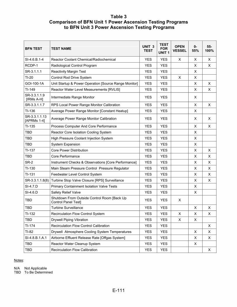
Table 3 Comparison of BFN Unit 1 Power Ascension Testing Programs
to BFN Unit 3 Power Ascension Testing Programs
E-111
BFN TEST TEST NAME UNIT 3 TEST
TEST FOR
UNIT 1 OPEN
VESSEL 0-
55% 55-
100%
SI-4.6.B.1-4 Reactor Coolant Chemical/Radiochemical YES YES X X X RCDP-1 Radiological Control Program YES YES X X SR-3.1.1.1 Reactivity Margin Test YES YES X
TI-20 Control Rod Drive System YES YES X X
GOI-100-1A Unit Startup & Power Operation [Source Range Monitor] YES YES X X
TI-149 Reactor Water Level Measurements [RVLIS] YES YES X X SR-3.3.1.1.9 [IRMs A-H] Intermediate Range Monitor YES YES X
SR-3.3.1.1.7 RPS Local Power Range Monitor Calibration YES YES X X TI-136 Average Power Range Monitor [Constant Heatup] YES YES X SR-3.3.1.1.13 [APRMs 1-4] Average Power Range Monitor Calibration YES YES X X TI-135 Process Computer And Core Performance YES YES X X TBD Reactor Core Isolation Cooling System YES YES X
TBD High Pressure Coolant Injection System YES YES X
TBD System Expansion YES YES X
TI-137 Core Power Distribution YES YES X X TBD Core Performance YES YES X X
SR-2 Instrument Checks & Observations [Core Performance] YES YES X X TI-130 Main Steam Pressure Control Pressure Regulator YES YES X X TI-131 Feedwater Level Control System YES YES X X SR-3.3.1.1.8(8) Turbine Stop Valve Closure [RPS] Surveillance YES YES X X SI-4.7.D Primary Containment Isolation Valve Tests YES YES X
SI-4.6.D Safety Relief Valve YES YES X
TBD Shutdown From Outside Control Room [Back Up Control Panel Test] YES YES X
TBD Turbine Surveillance YES YES X X
TI-132 Recirculation Flow Control System YES YES X X X TBD Drywell Piping Vibration YES YES X X
TI-174 Recirculation Flow Control Calibration YES YES X TI-82 Drywell Atmosphere Cooling System Temperatures YES YES X X SI-4.8.B.1.A.1 Airborne Effluent Release Rate [Offgas System] YES YES X X TBD Reactor Water Cleanup System YES YES X
TBD Recirculation Flow Calibration YES YES X
Notes: N/A Not Applicable TBD To Be Determined