briot couture - visionix academy
TRANSCRIPT

User Manual-EdgerFC001198-rev02
bri
ot
co
utu
re

Dear Customer,
You have purchased a BRIOT COUTURE edger, and the entire team of Briot, a brand belonging to the Luneau Technology
group, would like to thank you for the confidence you have shown us.
The BRIOT COUTURE edger is an equipment for ophthalmic professionals and practitioners and is used for edging spectacle
lenses. Connected to an external server, the edger receives data relating to the assembly (shape).
We advise you to read this manual carefully and keep it near the machine in order to be able to refer to it easily.
The information contained in this manual is not contractually binding and can be modified without prior notice. This
document has been prepared with great care, but some unintentional errors or omissions may occur, although every effort has been made to avoid them. The manufacturer cannot, under any circumstances, be held responsible for any operating
faults that may result from such errors or omissions.
THE MANUFACTURER DOES NOT GUARANTEE THE PERFORMANCE OF YOUR BRIOT COUTURE EDGER IF THE
INSTRUCTIONS CONTAINED IN THIS MANUAL ARE NOT OBSERVED.
DEPENDING ON THE MACHINE VERSION AND OPTIONS AND ON
THE DATE AND COUNTRY OF SALE, SOME EQUIPMENT
ITEM(S)/FUNCTION(S) DESCRIBED IN THIS MANUAL MAY NOT
BE INCLUDED IN YOUR MACHINE.
Luneau Technology Operations 2, rue Roger Bonnet
27340 Pont de l’Arche France
Tel: +33 (0) 232 989 132 Fax: +33 (0) 235 020 294
www.luneautech.com

BRIOT COUTURE … User Manual
COUTURE
GRAPHIC CODES
Different graphic codes have been used in this manual to allow the user to distinguish between different types of
information and easily spot the items which demand special attention (e.g. safety-related items). The table below lists all the codes and describes them:
TABLE 1: DESCRIPTION OF THE PICTOGRAMS
Graphic code Description
Vital warning: Risk of human injury or material damage and machine malfunction. Follow the instructions carefully.
Vital recommendation: Risk of machine damage or malfunction. Follow the instructions carefully.
Vital preliminary action
Before undertaking any action, check that the machine is disconnected.
Electrical hazard
Heavy component
In particular, a second person is necessary to carry and move the edger.
Rotating component In particular, do not put your hands near the wheel unit.
Attaching component In particular, beware of the clamping shafts closing.
Protective gloves must be worn
Especially for cleaning and changing the tanks.
Protective goggles must be worn
Especially for cleaning and changing the tanks.
Overalls must be worn
Especially for cleaning and changing the tanks.

BRIOT COUTURE … User Manual
1 COUTURE
WASTE ELECTRICAL AND ELECTRONIC EQUIPMENT (APPLICABLE IN THE EUROPEAN
UNION AND IN EUROPEAN COUNTRIES USING A SELECTIVE WASTE COLLECTION
SYSTEM)
This symbol affixed to the product or to its packaging indicates that the product will not be treated like household waste. Instead, it must be delivered to the designated collection point where electric and electronic equipment may be recycled. By ensuring that this product is correctly disposed of, you will help prevent potentially harmful environmental and human consequences due to improper handling when improperly disposed of. The use of recovered materials preserves natural resources. For more information about where you can drop off this product for recycling, please contact your local waste disposal service or the agent from whom you purchased this product.

BRIOT COUTURE … User Manual
COUTURE
Table of contents
1. INSTALLATION ............................................................................................................................. 9 1.1. Unpacking the machine .......................................................................................................... 11
1.1.1. Warning .......................................................................................................................... 11 1.1.2. Procedure ........................................................................................................................ 11
1.2. Removing the shipping rails ................................................................................................... 12 1.2.1. Conditions ...................................................................................................................... 12
1.3. Handling the covers ................................................................................................................ 13 1.3.1. Removing the covers ...................................................................................................... 13 1.3.2. Replacing the covers ...................................................................................................... 13
1.4. Removing the internal clamping screws ................................................................................ 15 1.4.1. Removing the locking screws ......................................................................................... 15
1.5. Preparing the bench ................................................................................................................ 16 1.5.1. Machine dimensions ....................................................................................................... 16 1.5.2. Space and drilling required ............................................................................................. 17
1.6. Water connections .................................................................................................................. 18 1.6.1. Specifications ................................................................................................................. 18 1.6.2. Pipe connections ............................................................................................................. 18
1.7. Electrical connections ............................................................................................................. 21 1.7.1. Specifications ................................................................................................................. 21 1.7.2. Edger wiring ................................................................................................................... 21
1.8. Starting the edger .................................................................................................................... 22 1.8.1. Procedure ........................................................................................................................ 22 1.8.2. Switching the machine on/off ......................................................................................... 23
2. PRECAUTIONS FOR USE ........................................................................................................... 24 2.1. Safety ...................................................................................................................................... 25
2.1.1. Operator .......................................................................................................................... 25 2.1.2. Machine .......................................................................................................................... 25
2.2. Recommendations .................................................................................................................. 26
3. USING YOUR EDGER ................................................................................................................. 27 3.1. Presentation ............................................................................................................................ 28
3.1.1. Presentation of the machine ........................................................................................... 28 3.1.2. Presentation of the application screen ............................................................................ 29
3.2. General principles of use ........................................................................................................ 34 3.2.2. Loading a job .................................................................................................................. 35 3.2.3. Inserting / Removing the lens. ........................................................................................ 35 3.2.4. Starting / interrupting an edging cycle ........................................................................... 36 3.2.5. Normal edging cycle sequence ....................................................................................... 37 3.2.6. Important notes ............................................................................................................... 38
3.3. Application screen icons ........................................................................................................ 39 3.3.1. General ........................................................................................................................... 39 3.3.2. Feeling before roughing ................................................................................................. 40 3.3.3. Feeling an executive lens ............................................................................................... 40 3.3.4. Lens materials ................................................................................................................. 41 3.3.5. Types of lenses ............................................................................................................... 42 3.3.6. Finishings ....................................................................................................................... 43 3.3.7. Sub-finishings and associated parameters ...................................................................... 47 3.3.8. Safety bevels ................................................................................................................... 54 3.3.9. Polishing ......................................................................................................................... 56 3.3.10. Lens size ......................................................................................................................... 57

BRIOT COUTURE … User Manual
1 COUTURE
3.4. Usual procedure ...................................................................................................................... 59 3.4.1. Producing a job with bevel finishing .............................................................................. 59 3.4.2. Producing a job with rimless finishing ........................................................................... 61 3.4.3. Producing a job with groove finishing ........................................................................... 63 3.4.4. Producing a job with drilling finishing ........................................................................... 65 3.4.5. Producing a job with grooving and drilling finishing .................................................... 67 3.4.6. Producing a job with “Chemistrie TM” finishing ............................................................ 69 3.4.7. Drilling: Facts worth knowing ....................................................................................... 71
3.5. Special cases ........................................................................................................................... 73 3.5.1. Retouching a lens ........................................................................................................... 73 3.5.2. Retouching a drilled hole ............................................................................................... 74 3.5.3. Retouching a groove ....................................................................................................... 77 3.5.4. Retouching a chamfer ..................................................................................................... 78 3.5.5. Applying an oversize to the lens .................................................................................... 79 3.5.6. Edging the left lens with different parameters from those of the right lens ................... 80 3.5.7. Edging several lenses identically ................................................................................... 82 3.5.8. Checking a finishing before the lens is edged ................................................................ 83 3.5.9. Smart Design "SD" Finishing (complex shape) ............................................................. 95
3.6. Operating principle ................................................................................................................. 98 3.6.1. Points to remember ......................................................................................................... 98 3.6.2. Illustration of finishing limits ....................................................................................... 100 3.6.3. Drilling ......................................................................................................................... 102
4. CONFIGURATION ..................................................................................................................... 104 4.1. Presentation of configuration menus .................................................................................... 105
4.1.1. Presentation of the configuration menu access screen ................................................. 105 4.1.2. Presentation of the personalisation menu access screen............................................... 106
4.2. Configuration of finishing parameter default values ............................................................ 107 4.2.1. Presentation .................................................................................................................. 107 4.2.2. General procedure ........................................................................................................ 108 4.2.3. Saving the new configuration ....................................................................................... 108 4.2.4. Limits ............................................................................................................................ 108
4.3. Personalisation of pull-down menus .................................................................................... 111 4.3.1. Presentation .................................................................................................................. 111 4.3.2. General procedure ........................................................................................................ 112 4.3.3. Saving the new personalization .................................................................................... 113 4.3.4. Note .............................................................................................................................. 113
4.4. Adjustment of setting values ................................................................................................ 116 4.4.1. Preliminary remarks ..................................................................................................... 116 4.4.2. Procedure ...................................................................................................................... 116
4.5. Configuration of general operating parameters .................................................................... 117 4.5.1. Presentation .................................................................................................................. 117 4.5.2. Configuration of the functions ..................................................................................... 123 4.5.3. Saving the new configuration ....................................................................................... 125
5. MAINTENANCE ......................................................................................................................... 126 5.1. Presentation of maintenance menus ..................................................................................... 127
5.1.1. Presentation of the maintenance menu access screen .................................................. 127 5.1.2. Presentation of the maintenance screen ........................................................................ 128
5.2. Displaying the components .................................................................................................. 129 5.3. Task list ................................................................................................................................ 130 5.4. Regular maintenance of the edger ........................................................................................ 131
5.4.1. Replacing the flexible lens clamp adaptor pad ............................................................. 131

BRIOT COUTURE … User Manual
COUTURE
5.4.2. Replacing the mill bit ................................................................................................... 133 5.4.3. Replacing the lens feeler tips ........................................................................................ 136 5.4.4. Dressing a wheel .......................................................................................................... 139 5.4.5. Cleaning / replacing the removable visor ..................................................................... 141 5.4.6. Cleaning the filters and water tank ............................................................................... 143 5.4.7. Emptying the water tank ............................................................................................... 147 5.4.8. Operation in degraded mode ........................................................................................ 149
5.5. Preventive maintenance ........................................................................................................ 150 5.5.1. Hints ............................................................................................................................. 150 5.5.2. Replacement table for standard parts ........................................................................... 150
5.6. Adjustments .......................................................................................................................... 152 5.6.1. Presentation of the settings menus access screen ......................................................... 152 5.6.2. Adjusting the feeling .................................................................................................... 154 5.6.3. Adjusting the sizes ........................................................................................................ 156 5.6.4. Adjust the axis setting with the BRIOT COUTURE blocker ...................................... 162 5.6.5. Adjustment of the axis setting with the tool ................................................................. 165 5.6.6. Adjusting the touch screen ........................................................................................... 167 5.6.7. Consulting the setting values ........................................................................................ 169
5.7. Consulting the statistics ........................................................................................................ 170 5.7.1. Presentation of the statistics menu ............................................................................... 170 5.7.2. Consultation principles ................................................................................................. 171
5.8. Messages .............................................................................................................................. 180 5.8.1. Types of messages ........................................................................................................ 180 5.8.2. List of messages. .......................................................................................................... 180
6. Tests .............................................................................................................................................. 191 6.1. Presentation of test menus .................................................................................................... 192
6.1.1. Presentation of the test access screen ........................................................................... 192 6.1.2. Typical test screen ........................................................................................................ 193
6.2. Operating principle ............................................................................................................... 194 6.2.1. Operating principle of a typical screen ......................................................................... 194 6.2.2. Operation of the other screens ...................................................................................... 195
7. Technical specifications ............................................................................................................... 197 7.1. Characteristics ...................................................................................................................... 198 7.2. Technical specifications ....................................................................................................... 200
7.2.1. BRIOT COUTURE ...................................................................................................... 200

BRIOT COUTURE … User Manual
1 COUTURE
REVISION FOLLOW-UP
Revision 00
Page New/Modified Item

1. INSTALLATION

BRIOT COUTURE … User Manual
COUTURE 10
UNPACKING THE MACHINE
Keep the case, the small carton and the hose near the machine.

BRIOT COUTURE … User Manual
COUTURE 11
1.1. UNPACKING THE MACHINE
1.1.1. WARNING
Ensure that the machine is placed in accordance with the TOP and BOTTOM signs on the box. Place the machine on a flat and stable surface.
1.1.2. PROCEDURE
Follow the steps below to unpack the machine:
#1 Place the machine on the floor in its packing with the help of another person.
#2 Cut the two straps on the main packaging carton.
#3 Cut the adhesive tapes on the main packaging carton.
#4 Check that the accessories (small box, case and tube) have been supplied and keep them close to the machine.
#5 Pull the main packaging carton upwards and remove it.
#6 Cut the two straps on the second packaging carton.
#7 Cut the adhesive tape on the second carton.
#8 Pull the second packaging carton upwards and remove it.
#9 Remove the plastic protection from the machine.
#10 Remove the 4 fixing screws from the rails on the pallet.
#11 With the help of a second person, lift the machine by the rails and place it on the work bench.
#12 Keep the packaging cartons. We advise you to store them flat.
Flow chart 1-1: Unpacking the edger

BRIOT COUTURE … User Manual
COUTURE 12
1.2. REMOVING THE SHIPPING RAILS
1.2.1. CONDITIONS
The machine is placed on the workbench. There is enough space around the machine.
1.2.1.1. PROCEDURE
To remove the shipping rails, follow the procedure below:
#1 With the help of a second person, tip the machine gently to the rear in order to gain access to the 4 rail fixing screws.
#2 With a 13 mm Allen wrench, take out the 4 fixing screws and remove the rails.
#3 Keep the shipping rails with the rest of the packaging cartons.
Flow chart 1-2: Removing the shipping rails
→ As shown...
Illustration 1-1: Removing the fixing screws from the shipping rails

BRIOT COUTURE … User Manual
COUTURE 13
1.3. HANDLING THE COVERS
1.3.1. REMOVING THE COVERS
1.3.1.1. WHEN?
The machine is clamped during transport to ensure maximum stability. To reach the clamping screws, the machine covers must be taken off by a technician.
1.3.1.2. HOW?
To remove the machine covers, follow the procedure below:
#1 Open the drawer on the front of the machine, and remove the 2 M5 BHC screws located at the bottom of the front cover.
#2 Lift the bottom of the front cover to pivot it upwards and pull it up.
#3 Remove the 4 M5 BHC screws located at the rear.
#4 Remove the rear cover.
#5 For each side cover, remove the M5 BHC screw located on the top.
#6 For each side cover, partially unscrew an M5 BHC screw located at the rear bottom of each side cover.
#7 Remove the side cover by pulling on the cover around the clip located on each side at the bottom towards the front of the machine.
Flow chart 1-3: Removing the covers
→ As shown...
Illustration 1-2: Removing the covers
1.3.2. REPLACING THE COVERS
To replace the machine covers, follow the above procedure in reverse order.
x4 screws

BRIOT COUTURE … User Manual
COUTURE 14
Illustration 1-3: Removing the internal clamps from the edger
REMOVING THE CLAMPING SCREWS FROM THE FEELING SYSTEM
x2 headless Hc screws
=> UNCLAMPING THE CARRIAGE
OK!
Unscrew until the carriage moves
freely and add one more turn of
the spanner!
=> UNCLAMPING THE WHEEL UNIT

BRIOT COUTURE … User Manual
COUTURE 15
1.4. REMOVING THE INTERNAL CLAMPING SCREWS
Before undertaking any operation, ensure that the machine is switched off: On/Off switch OFF and
mains plug disconnected.
1.4.1. REMOVING THE LOCKING SCREWS
The wheel unit, the carriage and the lens feeling system are immobilized by locking screws which must be removed before the machine is started.
To remove the locking screws, follow the procedure below:
#1 Remove the machine covers: see Remove the covers.
#2 Unclip and remove the covers of the feeling system.
#3 Loosen the 2 headless screws with a No. 2 Allen key.
DO NOT REMOVE THE SCREWS! Leave them in place.
#4 Re-install the cover of the feeling system.
#5 Go to the wheel unit clamping screw.
#6 Loosen and remove the clamping screw and the spacer.
#7 Reassemble the clamping screw and the spacer in the hole below the initial socket so as to keep them in a safe place.
#8 Go to the carriage clamping screw.
#9 Loosen the carriage clamping screw and free it from the body until the carriage moves freely. DO NOT REMOVE THE SCREW! Leave it in place so as to keep it safe.
#10 Reassemble the machine covers: see Reassemble the covers.
Flow chart 1-4: Removing the locking screws

BRIOT COUTURE … User Manual
COUTURE 16
1.5. PREPARING THE BENCH
1.5.1. MACHINE DIMENSIONS
The following illustrations show the machine dimensions.
Illustration 1-4 : Edger dimensions
→ Height = 570 mm → Width = 510 mm → Depth = 615 mm → Weight = 69 kg
W = 510 mm
D = 615 mm
H =
570 m
m

BRIOT COUTURE … User Manual
COUTURE 17
1.5.2. SPACE AND DRILLING REQUIRED
Θ ILLUSTRATION
The following sketch shows the positioning of the machine on the bench and the openings which must be provided.
Position your machine correctly before drilling the bench!
Illustration 1-5 : Positioning the machine on the bench and drilling to be made
Θ RECOMMENDATIONS
Follow the dimensions given.
Leave enough space around the edger.
Ensure that the bench is stable and level.
Install the edger away from any source of heat.
Discharge

BRIOT COUTURE … User Manual
COUTURE 18
1.6. WATER CONNECTIONS
1.6.1. SPECIFICATIONS
1.6.1.1. GENERAL
Water intake with a stop-valve fitted with a 20 x 27 mm female connector and a filter seal.
This stop-valve must be reserved for the machine and placed at a maximum of 80 cm from the place provided for
the machine.
The stop-valve must be easy to reach and closed when not in use.
Water pressure = 4 - 7 bars Water discharge through a 100 mm diameter pipe.
The slope must be at least 5% to ensure proper evacuation of the refuse.
1.6.1.2. FILTRATION TANK WITH PUMP
W 600 x H 400 x D 315 mm 60-liter capacity Two levels of filtration
1.6.1.3. PUMP
W 400 x H 230 x D 300 mm Power = 450 W max. Q = 20/220 l/min V = 220 - 240 V H = 8 - 1 m F = 50 Hz IP = 68
1.6.2. PIPE CONNECTIONS
1.6.2.1. FIND THE OPENINGS ON THE CHASSIS
Illustration 1-6 : Chassis openings
Water supply
Discharge

BRIOT COUTURE … User Manual
COUTURE 19
1.6.2.2. PROCEDURE
→ As shown...
Button not lit
+ mains plug disconnected
=> DIRECT WATER SUPPLY => CLOSED CIRCUIT
Level!
Filtration tank
Settling tank

BRIOT COUTURE … User Manual
COUTURE 20
→ Flow chart To connect the water supply to the edger and fit the pipes, follow the procedure below:
#1 Check that the machine is switched off: On/Off switch OFF and mains plug disconnected.
#2 Check that the water supply is closed.
#3 Remove the machine covers.
#4 Ensure that the machine is level => screw or unscrew the four feet.
#5 Connect the water drain pipe to the chassis.
#6 Fit the filter seal between the water supply connection and the valve if you operate in direct water supply.
#7 Connect the water supply pipe to the valve (if direct water) or to the pump (in closed circuit).
#8 Connect the used water discharge pipe if you operate in direct water supply.
#9 When the water circuit is being filled, check the watertightness of the unit, especially around the solenoid valves.
Flow chart 1-5: Pipe connections

BRIOT COUTURE … User Manual
COUTURE 21
1.7. ELECTRICAL CONNECTIONS
1.7.1. SPECIFICATIONS
2P+T - 15A - 120V or 200/240V - plug protected by a 30 mA differential circuit-breaker. The socket must be earthed. Position the equipment so that it is easy to be disconnected by the operator.
1.7.2. EDGER WIRING
1.7.2.1. PROCEDURE
→ Flow chart
To connect the peripheral equipment to the edger, proceed as follows:
#1 Check that the machine is switched off: On/Off switch OFF and mains plug disconnected.
#2 Connect the machine to the LAN network or the blocking unit via the RJ45 port.
#3 Connect the bar code reader
#4 If you operate in closed circuit, plug in the pump.
Flow chart 1-6: Electrical connections
→ As shown...
Illustration 1-7 : Electrical connections
Note: The pump and reader illustrations are not the property of the manufacturer and are used purely as examples.

BRIOT COUTURE … User Manual
COUTURE 22
1.8. STARTING THE EDGER
1.8.1. PROCEDURE
→ Flow chart
To start the edger, proceed as follows:
#1 Check that the machine is switched off: On/Off switch OFF and mains plug disconnected.
#2 Reassemble the machine covers.
#3 Fit the lens clamping and lens holder adaptors on the shafts. (Corresponding to the finishing to be completed, see “Inserting / Removing the lens”)
#4 Plug in the machine and switch on (On/Off switch lit).
#5 Start a dummy cycle and adjust the flow of the visor and edging chamber sprays using the adjustment knobs (to reach the knobs, remove the upper cover: see “Handling the covers”).
Flow chart 1-7: Starting the edger
CAUTION IT IS IMPORTANT TO RUN THE MACHINE WITH THE ADAPTORS ON IN ORDER TO PREVENT THE RISK OF CLAMPING
BLOCKAGE. → As shown...
Illustration 1-8 : Starting the edger
Adjust the flow!

BRIOT COUTURE … User Manual
COUTURE 23
1.8.2. SWITCHING THE MACHINE ON/OFF
Flow chart 1-8: Switching the machine ON/OFF
To switch the machine off, first press for 5 seconds, then press the On/Off switch.
ON position
Button on
OFF position
Button off

2. PRECAUTIONS FOR USE

BRIOT COUTURE … User Manual
COUTURE 25
2.1. SAFETY
2.1.1. OPERATOR
Read the instructions carefully and always keep the manual near your machine so you can refer to it easily. This is a rotary machine: the wheels are potentially dangerous. Be very careful and keep your hands away from
the set of wheels. Two people are necessary to move the machine. When you activate the clamp shafts, keep your fingers outside the contact areas. Make sure that the installation is perfectly water-tight. Before servicing the edger, check that the mains cable is unplugged.
2.1.2. MACHINE
Make sure your voltage source corresponds to the voltage specified on the identification plate located at the rear of the machine. If you are unsure of the type of current available in your premises, contact your electricity company.
If the machine is not going to be used for a long period of time, disconnect the power cords from the wall outlet.
Unplug the machine if there is an electrical storm or when the machine is left unattended for a long
period. Keep the machine away from any source of heat. A radiator is a heat source which can be detrimental to the
correct operation of the machine. The openings in the cover are designed to ventilate the machine and contribute to its normal operation. Do
not obstruct them or cover them. Make sure that the machine is installed in a correctly ventilated room. Do not overload the wall sockets or plugs because you would increase the risk of fire or electric shock. Avoid using electric extension leads. Keep the machine away from any source of dust. Any servicing or work on the machine (with the cover open or closed) must be undertaken by a Briot technician.
The symbol defines a general hazard, and you will find it: on the edging chamber: risk of bodily hazard.
THE MANUFACTURER CANNOT BE HELD RESPONSIBLE FOR DAMAGE CAUSED BY ANY USE OF THE MACHINE WHICH
DOES NOT COMPLY WITH THE INSTRUCTIONS IN THIS MANUAL OR DISPLAYED ON THE MACHINE ITSELF.

BRIOT COUTURE … User Manual
COUTURE 26
2.2. RECOMMENDATIONS
Ensure that the edger is cleaned regularly.
Comply with the machine maintenance messages. Protect the machine's power cords. Remove dust daily (glass, CR39, polycarbonate, Tribrid, TrivexTM and HI) using clean water and a soft sponge or a
brush so as not to scratch the plastic surfaces. Before blocking the lens, always check which type of block is required and ensure that the lens blocking and lens
holder adaptors are appropriate for the job to be done. Use blocks designed and supplied by Briot. Change the blocks regularly. Their lifespan is 100 blocking operations. Use new adhesives. Clean the visor regularly. Make regular checks of the condition of the feeler tips and change them if they are worn, chipped or damaged. Before starting the machine, check that the water supply is working (valve open). Make sure that the installation is perfectly water-tight. Change the water in the tank regularly if your machine operates in closed water circuit mode. Contact a Briot technician for all repairs and always order Briot spare parts. To remove the cover from the machine, the technician must use the locking spanner supplied with the edger. Use only products delivered and specified by Briot.
The machine is guaranteed to function correctly if the procedures stipulated in this manual are complied with.

3. USING YOUR EDGER 3

BRIOT COUTURE … User Manual
COUTURE 28
3.1. PRESENTATION
3.1.1. PRESENTATION OF THE MACHINE
Θ GENERAL ILLUSTRATION
The illustration below (Illustration 3-1) is an overall view of the machine and shows its main parts.
Illustration 3-1 : Overall view of the edger
Θ MAIN PARTS
The exploded view below (Illustration 3-2) shows the main parts of the edger.
Illustration 3-2 : Exploded view of the edger
Edging chamber
ON/OFF switch
Touch screen
Carriage
Lens feelers
Screen
Safety-bevel
grooving drilling
system
Edging
chamber
Electronic
system

BRIOT COUTURE … User Manual
COUTURE 29
3.1.2. PRESENTATION OF THE APPLICATION SCREEN
3.1.2.1. WORK INTERFACE
The screen below (Screen 3-1) is displayed after initializing the edger at start-up.
Screen 3-1: Application screen
3.1.2.2. ZONE IDENTIFICATION
The application screen below (Screen 3-2) can be divided into zones.
Commands -Vertical
Configuration screen access
Nose position
symbol
Magnifying glass
Job opening
Shape display
Access to drilling
plan
Side choice tabs
Horizontal
Commands
Possibility of interrupting
the process after feeling
Call up the last 10 jobs done on the BRIOT
COUTURE blocking unit
BRIOT COUTURE … User Manual
COUTURE 30
Screen 3-2: Identification of the application screen zones
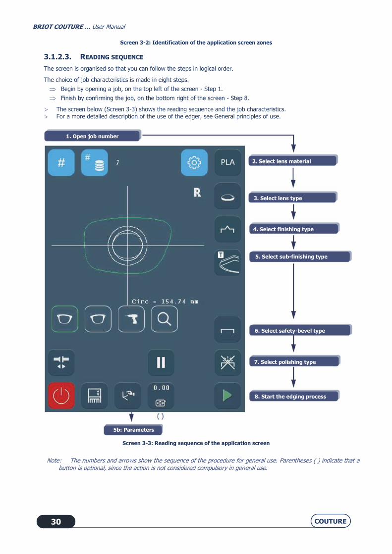
3.1.2.3. READING SEQUENCE
The screen is organised so that you can follow the steps in logical order.
The choice of job characteristics is made in eight steps.
Begin by opening a job, on the top left of the screen - Step 1.
Finish by confirming the job, on the bottom right of the screen - Step 8.
The screen below (Screen 3-3) shows the reading sequence and the job characteristics. For a more detailed description of the use of the edger, see General principles of use.
Screen 3-3: Reading sequence of the application screen
Note: The numbers and arrows show the sequence of the procedure for general use. Parentheses ( ) indicate that a button is optional, since the action is not considered compulsory in general use.
1. Open job number
2. Select lens material
3. Select lens type
4. Select finishing type
5. Select sub-finishing type
6. Select safety-bevel type
7. Select polishing type
8. Start the edging process
5b: Parameters

BRIOT COUTURE … User Manual
COUTURE 31
3.1.2.4. VISUAL REFERENCES
3.1.2.4.1. TYPES OF BUTTONS
There are different types of buttons corresponding to the different types of action or information to be entered: Θ IN ALL OF THE MENUS
Root button: displayed on the screen, it opens a pull-down menu
Example:
Action button: button causing an immediate action when activated.
Example:
Entry button: used to enter a value using the number keypad and to display it.
Example:
Button to be defined: neutral button available for each finishing characteristic (see Personalization of pull-down menus, chapter 4).
Example:
Θ IN THE TECHNICAL MENUS
The selection button: used to select a function.
SEVERAL POSSIBLE SELECTIONS You can enable one or more functions.
ONE POSSIBLE SELECTION ONLY You can enable one function only.
The function is not selected.
The function is not selected.
The function is selected and enabled.
Example: The type of Percentage bevel
will be displayed in the Bevel sub-finishing menu of the main application
screen.
You can select all or part of the bevel types.
The function is selected and enabled exclusively.
Example: When the Bevel finishing type is selected in the personalization menu, it will
be displayed by default on the Finishing
button of the main application screen. One finishing type only can be displayed by
default.

BRIOT COUTURE … User Manual
COUTURE 32
3.1.2.4.2. ACCESSIBILITY OF FUNCTIONS
The accessible menus or functions also follow distinct graphic codes. The available buttons or menus are highlighted.
Example:
The activated buttons or menus or in process of activation appear darker than the others. They remain activated as long as the button is not released or the menu is not closed.
Example:
from the menu
The unavailable buttons are shown in gray (there is no longer a contour around the icon). The function cannot be activated because the current configuration does not allow it.
Example:

BRIOT COUTURE … User Manual
COUTURE 33
MAIN APPLICATION SCREEN
Screen 3-4: Main application screen
Note: The screen shown above is a montage to show all the basic functions available to the user from the main screen.
Parameters
Parameters

BRIOT COUTURE … User Manual
COUTURE 34
3.2. GENERAL PRINCIPLES OF USE
3.2.1.1. USUAL PROCEDURE
3.2.1.2. FLOW CHART
The following flow chart shows the usual procedure for using the machine.
See screen 3-4,
mark no.
Load a job number. 1
Select the lens material. 2
Select the type of lens. 3
Select the finishing type. 4
Select the sub-finishing type. 5
From the Parameters menu, enter the finishing and safety-bevel values.
6
Select polishing, if desired. 7
Place the lens in the edging chamber.
Start the edging process. 8
At the end of the cycle, open the lens camp shaft.
Remove the edged lens carefully.
Flow chart 3-1: Usual procedure

BRIOT COUTURE … User Manual
COUTURE 35
3.2.2. LOADING A JOB
Two functions are available to call up a job:
Press briefly on this button
When the numeric key pad is displayed, enter the job number and confirm it.
Result: The shape requested is displayed on the screen. The job number is displayed in the upper tab of the
shape display zone. The display is modified according to the job characteristics and the default
configuration values.
Example: If the lens material and finishing data are specified in the data given to the edger (e.g.: CR39), they are
displayed automatically.
Press briefly on the Joblist button
Display the blocking unit's last ten un-edged jobs.
Bar-code reading with hand-held scanner
Read your job's bar code with the hand-held bar-code scanner.
Result: The shape requested is displayed on the screen. The job number is displayed in the upper tab of the
shape display zone. The display is modified according to the job characteristics and the default
configuration values.
Example: If the lens material is specified in the data given to the edger (e.g.: Mineral), it is automatically displayed
and the screen is modified (with a mineral lens, only Bevel and Rimless finishing are accessible).
3.2.3. INSERTING / REMOVING THE LENS.
3.2.3.1. TO PLACE THE LENS IN THE EDGING CHAMBER
When all the edging characteristics have been entered, insert the lens in the edging chamber.
Always check that the correct clamping adaptors for the job have been fitted.
Machine equipped with universal adapters:
Note: If the job being run requires special adaptors, a warning message will be displayed automatically.
CAUTION OPERATE THE CLAMPING SYSTEM ONLY IF METAL ADAPTORS HAVE BEEN FITTED ON THE LENS CLAMPING AND DRIVE
SHAFTS.

BRIOT COUTURE … User Manual
COUTURE 36
3.2.3.2. TO REMOVE THE LENS FROM THE EDGING CHAMBER
When the edging cycle is stopped or interrupted, the visor opens.
Press this button .
Result: the lens clamp shaft opens automatically.
Remove the edged lens without removing the block so as to be able to do a retouch if necessary.
3.2.4. STARTING / INTERRUPTING AN EDGING CYCLE
3.2.4.1. STARTING AN EDGING CYCLE
When all the edging characteristics have been entered and the lens is fitted on the lens holder adaptor,
press this button .
Result: The visor closes automatically; the lens clamp shaft closes automatically; the edging cycle is run.
3.2.4.2. STOPPING/PAUSING AN EDGING CYCLE
If you wish to stop/pause the current edging cycle,
press this button .
Caution! Do not confuse it with the machine shut-down procedure which is activated with this button

BRIOT COUTURE … User Manual
COUTURE 37
3.2.5. NORMAL EDGING CYCLE SEQUENCE
Once you have started the edging cycle, the following steps follow automatically: (except if the cycles are personalised)
BRIOT COUTURE
Automatic closing of the visor
Automatic closing of the lens clamp shaft
Lens roughing
Feelers for holes (if holes are present)
Shape feeler
Lens finishing (Rimless or Bevel)
Lens chamfering (if selected)
Lens polishing (if selected)
Lens safety-beveling (if selected)
Lens grooving (if selected)
Lens drilling (if selected)
Partial finishing (if selected)
Smart design (if selected)
Automatic opening of the visor
Flow chart 3-2: Edging cycle sequence
Note: Selecting Manual finishing (beveling, grooving and chamfering) leads to a modification in the standard edging cycle sequence.

BRIOT COUTURE … User Manual
COUTURE 38
3.2.6. IMPORTANT NOTES
3.2.6.1. WHEN JOB DATA ARE RECEIVED
If the job provides the edging data, they are displayed automatically.
Example: If the job finishing is a bevel, the finishing displayed will automatically be Bevel.
If the job does not provide edging data, the default characteristics (see Configuration of finishing default
parameters, chapter 4) will be displayed automatically.
Example: If the default finishing is Bevel and the type is Auto, the displayed finishing will be Bevel and the sub-
finishing Bevel Auto.
If the job specifies data which have been excluded from the edger configuration, an « Incompatible edger
configuration » message is displayed (see Messages, chapter 5).
Example: If the job called up specifies the Mineral lens material and you have excluded the Mineral lens material from
the personalization screens (Personalization of pull-down menus, chapter 4), an "Incompatible edger
configuration" message is displayed.
If you modify the job data before starting to edge one of the lenses, the new characteristics will be memorized
automatically and applied to both lenses.
Caution! Check the parameter values of the two lenses.
The lens characteristics (material and type) determine the types of finishing available.
Example: A mineral lens cannot be drilled. Drilling finishing is therefore not available in the Finishing pull-down menu
when Mineral lens material is selected.
3.2.6.2. DURING EDGING OF THE SECOND LENS
Always check that the preselected type of finishing is the finishing that you wish to apply.
In fact, the finishing selected for the first lens is automatically memorized and preselected for the following lens (see
“Edging several lenses identically” and see “Edging the left lens with different parameters from those of the right lens”).
Check the parameter values.

BRIOT COUTURE … User Manual
COUTURE 39
3.3. APPLICATION SCREEN ICONS
The screens and tables below present and describe all the icons of the user interface classified in type or menu order.
3.3.1. GENERAL
Note: The presence and the order of the icons displayed on the screen depend on the job data (see “When job data are received”) and on the preference configuration (see Personalization of pull-down menus, chapter 4).
Screen 3-5: Screen icons
Opening a job stored on the BRIOT COUTURE blocker or the server
Right side Left side Access to
drilling plan Magnifying
glass
Opening/Closing of the lens clamp shaft
Parameters
Opening/Closing of the visor
START
STOP
Current cycle
Machine
Activate the Pause button to examine the position of the bevel
after feeling

BRIOT COUTURE … User Manual
COUTURE 40
3.3.2. FEELING BEFORE ROUGHING
Lens feeling is started before roughing when the "X" key is activated, if not . This function is deactivated automatically when the next job is called. Feeling after roughing is always run, even if feeling before roughing has been selected.
3.3.3. FEELING AN EXECUTIVE LENS
This function is applicable only for "executive" lenses to prevent damage to the feeler tips.
The lens feeling cycle is started when the key is activated, if not select . The feeling process is run as follows:
- Feeling from top through bottom of lens, to nasal side then temporal side.
This operation prevents the front face feeler from getting out of "step".
Replace the feeler tip when damaged, see “Replacing the lens feeler tips”.
Screen 3-6: Parameter screen for lens feeling before roughing and executive lens feeling functions

BRIOT COUTURE … User Manual
COUTURE 41
3.3.4. LENS MATERIALS
Note: The presence and the order of the icons displayed on the screen depend on the job data (“When job data are received“) and on the preference configuration (see Personalization of pull-down menus, chapter 4).
Screen 3-7: Lens material icons
High Index Plastic Polycarbonate CR 39
Mineral TrivexTM Tribrid

BRIOT COUTURE … User Manual
COUTURE 42
3.3.5. TYPES OF LENSES
Note: The presence and the order of the icons displayed on the screen depend on the job data (see “When job data are received”) and on the preference configuration (see Personalization of pull-down menus, chapter 4).
Screen 3-8: Lens type icons
Hydrophobic/Fragile
Specific cycle suitable for lenses with hydrophobic treatment and fragile mineral lenses.
Normal
Cycle suitable for the majority of lenses.
Hydrophobic Normal

BRIOT COUTURE … User Manual
COUTURE 43
3.3.6. FINISHINGS
Note: The presence and the order of the icons displayed on the screen depend on the job data (see “When job data are received”) and on the preference configuration (see Personalization of pull-down menus, chapter 4).
Screen 3-9: Finishing Type Icons
Groove Mini-bevel Bevel Rimless
Step level Partial
finishing
Small chamfered
bevel
Chamfered bevel

BRIOT COUTURE … User Manual
COUTURE 44
3.3.6.1. PARTIAL FINISHING
By selecting the “Partial Finishing” function, you can define a two-zone (top and bottom) lens finishing type.
3.3.6.1.1. PRESENTATION
Screen 3-10: Partial Finishing Screen
1- Define the finishing type for the red zone. 2- Adjust the finishing parameters for the red zone. 3- Define the finishing type for the blue zone.
4- Adjust the finishing parameters for the blue zone. 5- Select and adjust the general parameters for the blue and red zones. 6- Select the index side to be modified (temporal or nasal). 7- Press + or- to position the index on the desired point. 8- Do not confirm the partial finishing selection and return to previous screen. 9- Confirm the partial finishing selection and return to previous screen.
Note: The index position (temporal or nasal) can be changed by directly pressing the red cursor and sliding it to the desired position.

BRIOT COUTURE … User Manual
COUTURE 45
3.3.6.1.2. EXAMPLE
This is an example of a wide and deep groove on the top and narrow and shallow groove on the bottom.
Screen 3-11: Example of partial finishing
Screen 3-12: Edging Screen
Note: The « Partial Finishing » key remains accessible after edging to display the edging parameters. Note: The "Partial Finishing" key can also be used to rework a groove (increasing width or depth). To
do this, you must switch to "Retouch" mode in the main menu.

BRIOT COUTURE … User Manual
COUTURE 46
Note: If "Retouch" mode has been activated in the main menu, you can then increase the widths and
depths of the grooves.

BRIOT COUTURE … User Manual
COUTURE 47
3.3.7. SUB-FINISHINGS AND ASSOCIATED PARAMETERS
The following screen is a montage to show all possible sub-finishing.
To see details by type of finishing, refer to the following pages.
Screen 3-13: Sub-finishing type icons
Note: The presence and the order of the icons displayed on the screen depend on the type of machine used, job data (see “When job data are received”) and on the preference configuration (see Personalization of pull-down menus, chapter 4).
More information about limits: See “Operating principle”.
GROOVE
Partial finishing
Small chamfered bevel
and chamfered bevel
Parameters
No holes Normal to
base Normal to
rear face Normal to
front face Drilling parallel to clamping shafts
Manual
Percentage
Front face
Automatic
Base + Distance
TrueFit

BRIOT COUTURE … User Manual
COUTURE 48
3.3.7.1. BEVEL, MINI-BEVEL OR FACETTING/CHAMFERING
3.3.7.1.1. TYPES OF BEVELS, MINI-BEVEL OR FACETTING/CHAMFERING
Screen 3-14: Bevel Sub-Finishing Icons
CAUTION FOR BEVEL, SMALL BEVEL, CHAMFERED BEVEL, SMALL CHAMFERED BEVEL FINISHING.
If "TrueFit" sub-finishing
The bevel is positioned automatically, so that its position is esthetically pleasing and parallel to the front face, while
adapting as much as possible to the curvature of the frame.
If "Percentage Bevel" sub-finishing:
The apex of the bevel is positioned at a percentage of the lens thickness from the front face.
Enter the desired percentage using the Parameters button .
Example: for a bevel situated at 1/3 of the lens thickness from the front face, enter 33%.
If "Front Face Bevel" sub-finishing”:
The bevel follows the front face of the lens and is positioned at a given distance in mm between the apex of the bevel
and the front face of the lens.
Enter the desired distance using the Parameters button . Example: Apex of bevel situated 2.2 mm from the front face of the lens.
If "Automatic Bevel" sub-finishing:
The apex of the bevel is automatically positioned at 1/3 of the lens thickness from the front face.
Parameters
Front face
Percentage Manual
Automatic Base + Min. distance -
Front distance
TrueFit

BRIOT COUTURE … User Manual
COUTURE 49
If "Base bevel + minimum distance from front face":
The bevel is positioned at a minimal distance in mm between the apex of the bevel and the front face of the lens, and
its curvature depends on the desired base.
Enter the base values and the distance using the Parameter button .
Example: bevel of base 2 whose apex is located at 1 mm from the front face at its closest point to the front face.
3.3.7.1.2. BEVEL, MINI-BEVEL PARAMETERS
Using the button, go to the following parameters
Bevel Parameters
Finishing Sub-finishing
Parameters Limits Description
0,25 to 12,00 D Base of bevel to be made,
expressed in dioptres. The default base is 4.00 D.
-5.00 to 5.00
mm
Distance in mm between front face
of the lens and the point on the
apex of the bevel which is closest to the front face.
ø ø No parameters to enter. The bevel is automatically
positioned at 1/3 of the lens
thickness from the front face
-5.00 to 5.00 mm
Distance in mm between the front face of the lens and the apex of the
bevel.
0 to 100 % Distance between the apex of the
bevel and the front face of the lens expressed as a percentage of the
lens thickness.
ø ø Parameters to be set using the
manual finishing screen (see
“Produce a manual bevel”).
No parameters No parameters The TrueFit system places the bevel in parallel at the front with a
flexibility that allows it to adapt to
the curve of the frame base (as far as possible given the
configuration).
Table 3-1: Bevel and Mini-Bevel Finishing Parameter Icons
IMPORTANT NOTE If the maximum thickness of the lens is less than 2 mm, the applied bevel will automatically be of 1/2 - 1/2 type,
whichever type of bevel is selected initially.
More information about limits: See “Operating principle"

BRIOT COUTURE … User Manual
COUTURE 50
3.3.7.2. GROOVE
3.3.7.2.1. TYPES OF GROOVES
Screen 3-15: Groove Sub-Finishing Icons
If "Percentage Groove" sub-finishing:
The middle of the groove is positioned at a percentage of the lens thickness from the front face.
Enter the desired percentage using the Parameters button .
Example: If the middle of the groove is situated at 1/3 of the lens thickness from the front face, enter 33 %
If "Front Face Groove" sub-finishing:
The groove follows the front face of the lens and is positioned at a given distance in mm between the middle of the
groove and the front face of the lens.
Enter the desired distance using the Parameters button .
Example: The middle of the groove is located at 3 mm from the front face
Automatic Manual Percentage Front face Base + Min. distance - Front
distance
Parameters

BRIOT COUTURE … User Manual
COUTURE 51
If "Automatic Groove" sub-finishing:
The middle of the groove is automatically positioned at 1/3 of the lens thickness from the front face.
If "Base Groove + Front face" sub-finishing:
The groove is positioned according to the desired base at a minimum distance (in mm) between the middle of the
groove and the front face of the lens.
Enter the base values and the distance using the Parameter button .
Example: groove of base 2 whose centre is situated at 3 mm from the front face at its closest point to the front face.
3.3.7.2.2. GROOVE PARAMETERS
Using this button , go to the following parameters
Groove Parameters
Finishing Sub-
finishing Parameters Limits Description
0,25 to 12,00 D
Base of groove to be made, expressed in dioptres.
The default base is 4.00 D.
-5.00 to 5.00
mm
Distance in mm between front
face of the lens and the point
on the centre of the groove which is closest to the front
face.
0 to 0.80 mm Depth of groove in mm
0.60 to 1.20 mm
Width of groove in mm
0 to 0.80 mm Depth of groove in mm
0.60 to 1.20
mm
Width of groove in mm

BRIOT COUTURE … User Manual
COUTURE 52
Groove Parameters
Finishing Sub-
finishing Parameters Limits Description
-5.00 to 5.00
mm
Distance in mm between the
front face of the lens and the middle of the groove.
0 to 0.80 mm Depth of groove in mm
0.60 to 1.20
mm
Width of groove in mm
0 to 100 % Distance between the middle of the groove and the front
face of the lens expressed as
a percentage of the lens thickness.
0 to 0.80 mm Depth of groove in mm
0.60 to 1.20
mm
Width of groove in mm
ø ø Parameters to be set using
the manual finishing screen
(see “Produce a manual groove”).
Table 3-2: Groove Finishing Parameter Icons
IMPORTANT NOTE If the maximum thickness of the lens is less than 2 mm, the applied groove will automatically be of 1/2 - 1/2 type,
whichever type of groove is selected initially.
More information about limits: See “Operating principle”.

BRIOT COUTURE … User Manual
COUTURE 53
3.3.7.3. DRILLING
3.3.7.3.1. TYPES OF DRILLING
Screen 3-16: Drilling Sub-Finishing Icons
Drilling normal to the rear face of the lens
Illustration: see “ Producing a job with drilling finishing.
Drilling normal to the front face of the lens
Illustration: see “ Producing a job with drilling finishing".
Drilling parallel to clamping shafts
Illustration: see “ Producing a job with drilling finishing".
Drilling normal to the base of your choice
More information about limits: See “Operating principle”.
NOTA : HD drilling enables optimal drilling quality (notching axis or hole diameters) with standard adhesives
available on the market. Since drilling precision is a high priority, drilling time is, as a result, extended.
No holes Normal to base Normal to rear
face Normal to front
face
Drilling parallel to clamping
shafts

BRIOT COUTURE … User Manual
COUTURE 54
NOTA : HD drilling must be used whenever the precision and quality of drilling are a priority and the adhesive used for assembly is a standard one.
Standard drilling, which is faster than HD drilling, offers the same precision as HD drilling, if and only if the adhesive used is of the 3M Leap 3 type (thickness: 0.6 mm) or its equivalent.
3.3.8. SAFETY BEVELS
Note: The presence and the order of the icons displayed on the screen depend on the job data (see « When job data are received ») and on the preference configuration (see Personalisation of pull-down menus, chapter 4).
Screen 3-17: Safety-Bevel type icons
Safety bevels on the front and rear faces of the lens (available only if the facet (chamfer) is not selected) Safety bevel on the rear face (available only if the facet (chamfer) is not selected) Safety bevel on front face No safety bevel
Front + rear faces
Front faces Rear faces None

BRIOT COUTURE … User Manual
COUTURE 55
3.3.8.1. SAFETY BEVEL PARAMETERS
Using the button, go to the following parameters:
Parameters of the safety-bevel option
Option Parameters Limits Description
0 to 0.6 mm Depth in mm of safety-bevel
from the front face of the lens
0 to 0.6 mm Depth in mm of safety-bevel from the rear face of the lens
Available only if the facet
(chamfer) is not selected
0 to 0.6 mm Depth in mm of safety-bevel from the front face of the lens
Available only if the facet
(chamfer) is not selected
0 to 0.6 mm Depth in mm of safety-bevel from the rear face of the lens
Table 3-3: Safety-bevel parameter icons
IMPORTANT NOTES A safety-bevel can only be made when:
- The distance between the apex of the bevel and the front/rear face of the lens is greater than 1.6 mm.
the distance between the front edge of the bevel and the front face of the lens is greater than 0.2 mm, and the distance
between the rear edge of the bevel and the rear face of the lens is greater than 0.2 mm.
If you make a retouch whose value is greater than 0.20 mm, the lens will be retouched but the safety-bevel(s) will be machined or even removed.
More information about limits: See “Operating principle”.

BRIOT COUTURE … User Manual
COUTURE 56
3.3.9. POLISHING
Note: The presence and the order of the icons displayed on the screen depend on the job data (see “When job data are received”) and on the preference configuration (see Personalization of pull-down menus, chapter 4).
Polishing Icons
Screen 3-18: Polishing Icons
With polishing (available only if the facet (chamfer) is not selected)
Without polishing
WITH WITHOUT

BRIOT COUTURE … User Manual
COUTURE 57
3.3.10. LENS SIZE
Note: The presence and the order of the icons displayed on the screen depend on the job data (see “When job data are received”) and on the preference configuration (see Personalisation of pull-down menus, chapter 4).
Screen 3-19: Lens Size Icons
Oversize to boxing width
Oversize to circumference
Retouch to boxing width
Retouch to circumference
More information about limits: See “Operating principle”.
Oversize to boxing width

BRIOT COUTURE … User Manual
COUTURE 58
PRODUCING A JOB WITH BEVEL FINISHING
Screen 3-20: Example of the production of a job with a bevel
Here the job opened is no. 7
Mineral lens
Normal Type
Bevel Finishing
TrueFit: Automatic optimum positioning of the bevel
Rear face safety-bevel
Access to Parameters
menu Without oversize
Without polishing

BRIOT COUTURE … User Manual
COUTURE 59
3.4. USUAL PROCEDURE
To familiarize you with the edger interface and its general operation, we suggest that you carry out the following jobs.
3.4.1. PRODUCING A JOB WITH BEVEL FINISHING
3.4.1.1. OBJECT
Produce a job with the following characteristics:
Mineral > Fragile lens > 1/2-1/2 bevel > Rear safety-bevel = 0.40 mm > Without polishing
3.4.1.2. PROCEDURE
To carry out the job described above, proceed as follows:
Load a job number.
Select MINERAL lens material.
Select NORMAL lens type.
Select BEVEL finishing.
Select TrueFit sub-finishing.
Select REAR safety-bevel type.
Using the Parameters menu, enter the following values:
- bevel positioning percentage = 50%;
- depth of rear safety-bevel = 0.40 mm.
Place the lens in the edging chamber.
Start the edging process.
Flow chart 3-3: Production of a job with Bevel finishing
Tip! To familiarize yourself with the icons associated with each step or obtain more details of the action required, refer to the screen on the left page.
3.4.1.3. HINTS
When the edging cycle is finished, remove the edged lens without removing the block so as to be able to retouch
it if necessary.
If you are unsure about the type of bevel positioning, we advise you to choose Manual type from the main screen. During the cycle, when the manual finishing screen is displayed, press the Manual Bevel button, select the
type of bevel you wish and visualise the position of the bevel apex directly on the screen.

BRIOT COUTURE … User Manual
COUTURE 60
3.4.1.4. LIMITS
If the maximum thickness of the lens is less than 2 mm, the applied bevel will automatically be of 1/2 - 1/2 type,
whichever type of bevel is selected initially.
See also “Produce a manual bevel” and “Operating principle”.
PRODUCING A JOB WITH RIMLESS FINISHING
Screen 3-21: Example of the production of a job with rimless finishing
Here the job opened is no. 7.
Normal Type
Rimless finishing
Access to Parameters menu Without oversize
Without polishing
Trivex TM lens
Safety-bevels on both
faces
With polishing
Without oversize Access to Parameters
menu

BRIOT COUTURE … User Manual
COUTURE 61
3.4.2. PRODUCING A JOB WITH RIMLESS FINISHING
3.4.2.1. OBJECT
Produce a job with the following characteristics:
Trivex™ > Normal lens > Rimless > Front and rear safety-bevel > Polishing
Safety-bevel parameters: front depth = 0.20 mm / rear depth = 0.30 mm
3.4.2.2. PROCEDURE
To carry out the job described above, proceed as follows:
Load a job number.
Select TRIVEX™ lens material.
Select NORMAL lens type.
Select RIMLESS finishing type.
Select FRONT and REAR safety-bevel type.
Using the Parameters menu, enter the following values:
- depth of front safety-bevel = 0.20 mm;
- depth of rear safety-bevel = 0.30 mm.
Select POLISHING option.
Place the lens in the edging chamber.
Start the edging process.
Flow chart 3-4: Production of a job with Rimless finishing
Tip! To familiarize yourself with the icons associated with each step or obtain more details of the action required, refer to the screen on the left page.
3.4.2.3. HINTS
When the edging cycle is finished, remove the edged lens without removing the block so as to be able to retouch it if necessary.
3.4.2.4. LIMITS
See also “Operating principle”.

BRIOT COUTURE … User Manual
COUTURE 62
PRODUCING A JOB WITH GROOVE FINISHING
Screen 3-22: Example of the production of a job with a Groove
Here the job opened is no. 7.
Organic lens
Hydrophobic Type
Groove Finishing
Groove automatically
positioned
Safety-bevels on both
faces
With polishing Oversize to boxing
width of 0.30 mm Access to Parameters
menu

BRIOT COUTURE … User Manual
COUTURE 63
3.4.3. PRODUCING A JOB WITH GROOVE FINISHING
3.4.3.1. OBJECT
Produce a job with the following characteristics:
CR39 > Hydrophobic lens > Automatic groove > Front and rear safety-bevel > Polishing
Groove parameters: width = 1 mm / depth = 0.30 mm
Safety-bevel parameters: front depth = 0.30 mm / rear depth = 0.20 mm
3.4.3.2. PROCEDURE
To carry out the job described above, proceed as follows:
Load a job number.
Select CR39 lens material.
Select HYDROPHOBIC lens type.
Select AUTOMATIC GROOVE finishing type.
Using the Parameters menu, enter the following values:
- width of the groove = 1 mm;
- depth of the groove = 0.30 mm.
Select FRONT and REAR safety-bevel type.
Using the Parameters menu, enter the following values:
- depth of front safety-bevel = 0.30 mm;
- depth of rear safety-bevel = 0.20 mm.
Select POLISHING option.
Using the Oversize button, enter the value of 0.30 mm.
Place the lens in the edging chamber.
Start the edging process.
Flow chart 3-5: Production of a job with Groove finishing
Tip! To familiarize yourself with the icons associated with each step or obtain more details of the action required, refer to the screen on the left page.
3.4.3.3. HINTS
When the edging cycle is finished, remove the edged lens without removing the block so as to be able to retouch it if necessary.
If you are unsure about the type of groove positioning, we advise you to choose Manual type from the main screen. During the cycle, when the manual finishing screen is displayed, press the Manual Groove button, select

BRIOT COUTURE … User Manual
COUTURE 64
the type of groove you wish and visualise the position of the middle of the groove directly on the screen.
3.4.3.4. LIMITS
If the maximum thickness of the lens is less than 2 mm, the applied groove will automatically be of 1/2 - 1/2 type, whichever type of groove is selected initially.
See also “Produce a manual groove” and “Operating principle”.
PRODUCING A JOB WITH GROOVING AND DRILLING FINISHING
Screen 3-23: Example of the production of a job with drilling finishing
Here the job opened is no. 7.
CR39 lens
Normal Type
Rimless finishing
Drilling normal to the
front face
Without safety-bevel
With polishing
Access to Parameters
menu

BRIOT COUTURE … User Manual
COUTURE 65
3.4.4. PRODUCING A JOB WITH DRILLING FINISHING
3.4.4.1. OBJECT
Produce a job with the following characteristics:
CR39 > Normal lens > Drilling normal front face > No safety-bevel > Polishing
3.4.4.2. PROCEDURE
To carry out the job described above, proceed as follows:
Load a job number.
Select CR39 lens material.
Select NORMAL lens type.
Select DRILLING finishing type.
Select NORMAL FRONT FACE sub-finishing type.
Select NO SAFETY-BEVEL.
Select POLISHING option.
Place the lens in the edging chamber.
Start the edging process.
Flow chart 3-6: Production of a job with Drilling finishing
Tip! To familiarize yourself with the icons associated with each step or obtain more details of the action required, refer to the screen on the left page.

BRIOT COUTURE … User Manual
COUTURE 66
PRODUCING A JOB WITH GROOVING AND DRILLING FINISHING
Screen 3-24: Example of the production of a job with Grooving and Drilling finishing
With polishing
Here the job opened is no. 105
Normal Type
Drilling normal to the
front face
HI plastic lens
Groove Finishing
AUTOMATIC positioning of the groove
Safety-bevels on front and rear faces
Access to Parameters menu

BRIOT COUTURE … User Manual
COUTURE 67
3.4.5. PRODUCING A JOB WITH GROOVING AND DRILLING FINISHING
3.4.5.1. OBJECT
Produce a job with the following characteristics:
HI plastic > Normal lens > Grooving + Drilling > Groove % > Front and rear safety-bevel > Polishing
Position of middle of groove = 33% from the front face
Groove parameters: width = 1 mm / depth = 0.30 mm
Safety-bevel parameters: front depth = 0.30 mm / rear depth = 0.20 mm
3.4.5.2. PROCEDURE
To carry out the job described above, proceed as follows:
Load a job number.
Select HI plastic lens material.
Select NORMAL lens type.
Select GROOVING + DRILLING finishing type.
Select % sub-finishing type.
Select FRONT and REAR SAFETY-BEVELS.
Using the Parameters menu, enter the following values:
- position of middle of groove from the front face = 33 %
- depth of front safety-bevel = 0.30 mm;
- depth of rear safety-bevel = 0.20 mm.
Select POLISHING option.
Place the lens in the edging chamber.
Start the edging process.
Flow chart 3-7: Production of a job with Drilling finishing
Tip! To familiarize yourself with the icons associated with each step or obtain more details of the action required, refer to the screen on the left page.

BRIOT COUTURE … User Manual
COUTURE 68
PRODUCING A JOB WITH « CHEMISTRIE TM » FINISHING
Screen 3-25: Producing a job with “Chemistrie TM” finishing on prescription lens
Screen 3-26: Producing a job with “Chemistrie TM” finishing on sun lens
Job parameters
Value of frame
bridge
Height of magnet
hole
Magnet shape
Confirm the entered values and go back to main screen
Do not save entered values
and go back to main screen
To access the next
page
Value of frame bridge
Height of
magnet hole
Height of bridge
holes
Job
parameters
Value of frame
bridge
Bridge
width
Oversize
Confirm the entered values and go back to main screen
Do not save entered values
and go back to main screen
Height of bridge holes
Bridge width

BRIOT COUTURE … User Manual
COUTURE 69
3.4.6. PRODUCING A JOB WITH “CHEMISTRIE TM” FINISHING
3.4.6.1. TO PRODUCE THE JOBS DESCRIBED BELOW, MAKE SURE THAT THE “CHEMISTRIE TM”
FUNCTION IS SELECTED.
The function is disabled by default, see "Enable ChemistrieTM function”.
Step 1: Edging the prescription lens with a non-through hole in which a magnet will be bonded.
Load a job number.
Select a hole programming menu. see “Producing a job with drilling finishing”
Select the next page.
Select the magnet shapes.
If necessary, press the icon shown opposite on the screen then enter the value of the frame bridge using the numeric
key pad.
Enter the height of the magnet hole:
- after pressing the icon shown opposite on the screen using the numeric key pad.
- or using the arrows on each side.
Confirm the entered values.
You are back in the main screen
Select the type of job to be carried out.
Start the edging process.
Flow chart 3-8: Producing a job with « Chemistrie TM » finishing on prescription lens
Note: The value of the frame bridge is transmitted by the tracer.
Note: The position of the hole from the edge of the shape is calculated automatically according to the « Chemistrie TM » specifications.
Note: The hole diameter and depth are calculated automatically according to Specifications “ChemistrieTM”.
BRIOT COUTURE … User Manual
COUTURE 70
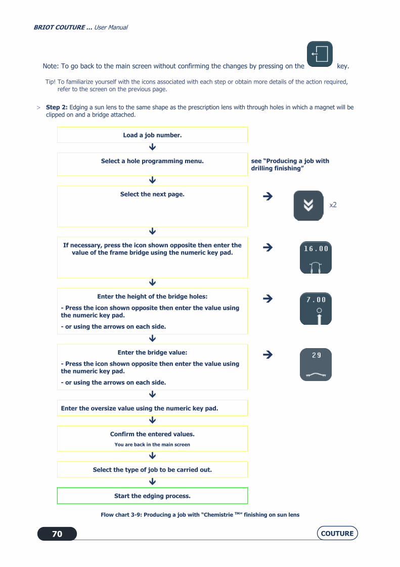
Note: To go back to the main screen without confirming the changes by pressing on the key.
Tip! To familiarize yourself with the icons associated with each step or obtain more details of the action required, refer to the screen on the previous page.
Step 2: Edging a sun lens to the same shape as the prescription lens with through holes in which a magnet will be
clipped on and a bridge attached.
Load a job number.
Select a hole programming menu. see “Producing a job with drilling finishing”
Select the next page.
If necessary, press the icon shown opposite then enter the value of the frame bridge using the numeric key pad.
Enter the height of the bridge holes:
- Press the icon shown opposite then enter the value using
the numeric key pad.
- or using the arrows on each side.
Enter the bridge value:
- Press the icon shown opposite then enter the value using the numeric key pad.
- or using the arrows on each side.
Enter the oversize value using the numeric key pad.
Confirm the entered values.
You are back in the main screen
Select the type of job to be carried out.
Start the edging process.
Flow chart 3-9: Producing a job with “Chemistrie TM” finishing on sun lens

BRIOT COUTURE … User Manual
COUTURE 71
Note: When the bridge height varies, its width is automatically adjusted.
Note: By default, the sun lens is edged to a 1.5 mm oversize value with respect to the prescription lens. The
oversize value can be modified.
Note: The value of the frame bridge is transmitted by the tracer.
Note: To go back to the main screen without confirming the changes by pressing on the key.
Tip! To familiarize yourself with the icons associated with each step or obtain more details of the action required, refer to the screen on the previous page.
3.4.7. DRILLING: FACTS WORTH KNOWING
Drilling, if it is selected, is the last step in the edging process. Elongated holes and notches are always machined from the edge of the lens towards the centre. Characteristics of the diameter of a hole:
→ The diameter of a drilled hole is always greater or equal to that of the mill bit which is fitted.
→ Special case: If the diameter of the fitted bit is greater than the diameter of the hole and you have confirmed the warning message "Bit diameter > hole diameter. Do you wish to drill?", the hole diameter will be equal to the diameter of the bit.
→ A lens may be drilled in four ways:
The drilling function allows drilling the following special holes:
Countersinking is the superimposition of a blind hole over a through hole of smaller diameter. The smallest diameter of the reusable hole corresponds to the mill bit diameter
(two possible choices: 1 mm or 0.8 mm).
Normal à la face avant
Normal à la face avant
Normal à la face arrière
Parallèle aux axes presse et
porte-verre
Normal à la base souhaitée
Chambrage Trous non-débouchants
par rapport à la face avant
Normal to front face Normal to rear face
Normal to the desired base Parallel to the lens clamp and lens holder shafts
Countersunk hole Blind holes relative to the front
face

BRIOT COUTURE … User Manual
COUTURE 72
Note: When the job is received on the edger, if it includes at least one hole whose diameter is smaller than that of the bit, the machine will display the following warning message: Bit diameter > hole diameter. Do you want to drill?" If you reply Yes: the minimum diameter of the holes will be equal to the bit diameter. If you reply No: the entire drilling plan will be ignored and no hole will be drilled. The lens will be finished in rimless.
3.4.7.1. HINTS
When the edging cycle is finished, remove the edged lens without removing the block so as to be able to retouch
it if necessary.
3.4.7.2. LIMITS
The total number of holes and notches is limited.
→ The limit is twenty holes per lens, for all types of holes.
→ An elongated hole or a notch count for one hole.
See also “Drilling”
Diam. minimal du trou = diamètre fraiseDia. Min. hole diameter = bit diameter

BRIOT COUTURE … User Manual
COUTURE 73
3.5. SPECIAL CASES
3.5.1. RETOUCHING A LENS
3.5.1.1. WHY?
When the lens has been edged and you find that its diameter is too large for the frame, you may decide to rework it by carrying out a retouch.
3.5.1.2. HOW?
3.5.1.2.1. PRELIMINARY CONDITIONS
The block must not have been removed from the lens when the lens was taken out of the edging chamber. A lens with drilling data cannot be retouched.
3.5.1.2.2. PROCEDURE
From the main application screen, after edging the lens, proceed as follows.
Note: Using the touch screen, press the zones or buttons shown.
or
Enter the correction value.
Flow chart 3-10: Entering an oversize value
3.5.1.2.3. RESULT
= The lens is edged to the new dimension.
3.5.1.3. HINTS
Always check that the type of oversize displayed - circumference or boxing width - is indeed that which you wish
to apply.
Note the difference between re-edging a lens and retouching a lens:
Re-edging corresponds to a second edging of the lens previously edged, or the edging of a new lens: in both
cases, the characteristics of the first lens to be edged are saved and applied to the second lens.
Example: Edging the same lens twice.
Retouching corresponds to a negative size correction value applied during a second edging to the diameter of the
lens initially edged.

BRIOT COUTURE … User Manual
COUTURE 74
3.5.1.4. IMPORTANT NOTES
The retouch value is negative by default (the sign "-" is already displayed on the numeric key pad screen).
The retouch is applied to the width of the lens. The height of the lens is recalculated to retain the proportions of the initial shape.
The selection of the type of retouch - to circumference or to boxing width - is done from the pull-down menus personalization menu (see Personalisation of pull-down menus, chapter 4).
The type of retouch is the same as that of oversizing.
Example: if you have selected an oversize at the circumference, the retouch will also be made at the circumference.
You can retouch the first lens after edging the second. The retouch function is always accessible.
Example: You have edges both lenses of the job and wish to apply a final retouch to the right lens. Return to the right
lens screen and enter the retouch value.
3.5.1.5. LIMITS
The retouch is also applied to the safety-bevel, if present. The safety-bevel(s) of a lens will be maintained if the retouch value is less than 0.20 mm to the diameter. The groove shall be maintained if the retouch value is less than 0.60 mm for the diameter.
3.5.2. RETOUCHING A DRILLED HOLE
3.5.2.1. HOW?
3.5.2.1.1. PRELIMINARY CONDITION
The lens must have been subject to HD drilling and polished. Otherwise, retouch is not possible. The retouch value can be identical for all the holes. It can also be different for one or more holes. Retouching the holes involves retouching the lens by 0.1 mm on the polishing wheel.
This dimensional retouch is automatic.

BRIOT COUTURE … User Manual
COUTURE 75
3.5.2.1.2. PROCEDURE
Note: Using the touch screen, press the zones or buttons shown.
Enter the retouch value
Check the entered value.
Flow chart 3-11: rework of drilling identical for all the holes

BRIOT COUTURE … User Manual
COUTURE 76
Enter the retouch value for one hole
Example: <+0.20> for hole C
This icon shows if a different retouch is
made on one or more holes (from the Parameters menu).
Flow chart 3-12: Different retouch for one or more holes.
Screen 3-27: Example of a retouch on one hole

BRIOT COUTURE … User Manual
COUTURE 77
3.5.3. RETOUCHING A GROOVE
3.5.3.1. HOW?
3.5.3.1.1. PROCEDURE
Once the lens has been ground, the button appears on the screen.
Note: Using the touch screen, press the zones or buttons shown.
To switch to Retouch mode, you have to enter a value less than or equal to zero.
Enter the retouch value using the numeric keypad. Example: "0.00"
The value "0.00" enables you to modify the groove without
modifying the external size of the lens.
"0.40" and "0.60" are the default values.
Enter the retouch values using the numeric keypad. Example: depth "0.60" and width "0.70".

BRIOT COUTURE … User Manual
COUTURE 78
Check the entered values.
Flow chart 3-13: Example of a retouch on a groove
3.5.4. RETOUCHING A CHAMFER
3.5.4.1. HOW?
3.5.4.1.1. PROCEDURE
Note: Using the touch screen, press the zones or buttons shown.
Once the lens has been edged
You then access one of the two following screens

BRIOT COUTURE … User Manual
COUTURE 79
You can increase the depth of the chamfer by pressing one of the buttons and using the numeric keypad.
Flow chart 3-14: Example of a retouch on a chamfer
3.5.5. APPLYING AN OVERSIZE TO THE LENS
3.5.5.1. WHY?
If you find that the differential applied to the job by default is not suitable, you can decide to apply an oversize which will be applied to the lens to be edged.
3.5.5.2. HOW?
3.5.5.2.1. PRELIMINARY CONDITION
You must enter the oversize value BEFORE edging the lens.
3.5.5.2.2. PROCEDURE
From the main application screen, after selecting all the job characteristics, proceed as follows.
Note: Using the touch screen, press the zones or buttons shown.
Chamfer in line with frame base Other chamfer types

BRIOT COUTURE … User Manual
COUTURE 80
or
Enter the correction value.
Check the entered value.
Flow chart 3-15: Entering an oversize value
3.5.5.2.3. RESULT
= The lens is edged and the initial dimension has been increased or decreased by the entered value.
You may check the lens diameter with a digital caliper and retouch it if necessary.
3.5.5.3. HINTS
Always check that the type of oversize displayed - circumference or boxing width - is indeed that which you wish
to apply.
3.5.5.4. IMPORTANT NOTES
The retouch is applied to the width of the lens. The height of the lens is recalculated to retain the proportions of the initial shape.
The selection of the type of oversize, to circumference or to boxing width - is done from the pull-down menus personalization menu (see Personalisation of pull-down menus, chapter 4).
The type of oversizing determines the type of retouching.
Example: if you select an oversize at the circumference, the retouch will also be made at the circumference.
For the same job, the oversizing applied to the right lens is not automatically applied to the left lens. In the case of a new edging cycle for the same lens (also called “re-edging"), the oversizing applied to the first
lens will be automatically applied to the second.
3.5.5.5. LIMITS
+/- 99.99 mm to boxing width
+/- 99.99 mm to circumference
3.5.6. EDGING THE LEFT LENS WITH DIFFERENT PARAMETERS FROM THOSE OF THE RIGHT
LENS
3.5.6.1. PRINCIPLE
If the left and right lenses of your job do not have the same characteristics, you may modify the edging data from one lens to another.

BRIOT COUTURE … User Manual
COUTURE 81
CAUTION For the same job, the following characteristics cannot be modified from one lens to another:
• Lens material • Finishing type • Polishing type.
You may only modify the following characteristics:
• Lens type • Sub-finishing type • Safety-bevel type.
3.5.6.2. PROCEDURE
To modify the parameters from one lens to another, proceed as follows.
Note: Using the touch screen, press the zones or buttons shown.
Edge the first lens.
Select the left side.
Change the characteristics as you wish.
Check the parameter values.
Flow chart 3-16: Modification of parameters from one lens to another

BRIOT COUTURE … User Manual
COUTURE 82
3.5.7. EDGING SEVERAL LENSES IDENTICALLY
3.5.7.1. PRINCIPLE
You wish to edge several lenses with similar characteristics.
3.5.7.2. PROCEDURE
Fit a new lens on the lens holder shaft.
"Do you want to re-edge?"
Yes
Flow chart 3-17: Edging lenses with identical characteristics
= The lens is edged again, with the same characteristics as the previous edging.
Tip! In this way you can group together similar lenses without entering the same characteristics for each new edging cycle.

BRIOT COUTURE … User Manual
COUTURE 83
3.5.8. CHECKING A FINISHING BEFORE THE LENS IS EDGED
3.5.8.1. PRINCIPLE
You may wish to check the position of the desired finishing - bevel and groove - before beginning the lens edging cycle.
You may also wish to position the finishing yourself when running a job. To do this, press the Pause button. You may be automatically redirected to this screen.
Example: The desired finishing position cannot be applied to the lens being edged.
A special screen allows you to visualize the finishing and modify its position, if desired.
3.5.8.2. PRESENTATION
3.5.8.2.1. MANUAL BEVEL SCREEN
Screen 3-28: Manual bevel screen
IMPORTANT NOTE The indices of zones A and B indicate the same finishing angular position. When you move one, the other moves as
well.
Developed lens profile
Front face developed curve
Bevel apex developed curve
Rear face developed curve
Angular position Index
Lens shape seen from the front
Temporal
Top
Nasal
Bottom
Re-feeling TrueFit
Movement of the index
Lens section at the position of the index
Lens thickness
Distance from apex of bevel ->
rear face, in mm
Distance between front face -> Bevel apex, in mm
Index
Access 3D visualization on the COUTURE blocker.

BRIOT COUTURE … User Manual
COUTURE 84
3.5.8.2.2. MANUAL GROOVE SCREEN
Screen 3-29: Manual groove screen
IMPORTANT NOTE The indices of zones A and B indicate the same finishing angular position. When you move one, the other moves as
well. When you press the “Virtual 3D” button, the data is sent to the blocker.
Developed lens profile
Front face developed curve
Bevel apex developed curve
Rear face developed curve
Angular position Index
Lens shape seen
from the front
Temporal
Top
Nasal
Bottom
Re-feeling Auto
Movement of the index
Lens section at the position
of the index
Lens thickness
Distance mid-groove ->
rear face, in mm
Distance between front face ->
Mid-groove, in mm
Index
Depth Width
Access 3D visualization on the COUTURE blocker.

BRIOT COUTURE … User Manual
COUTURE 85
3.5.8.2.3. CHAMFER CHECK SCREEN
Screen 3-30: Constant chamfer screen (page 1)
Developed lens profile
Front face developed curve
Chamfer apex developed curve
Rear face developed curve
Angular position Index
Temporal
Top
Nasal
Bottom
Movement of the index
Lens section at the position
of the index Lens thickness
Distance between chamfer bottom and rear face, in mm
Distance between front face ->
Chamfer top, in mm
Index
Lens shape Front view
Chamfer lowest point developed curve
Re-feeling Sub-finishing
Height Following pages

BRIOT COUTURE … User Manual
COUTURE 86
Screen 3-31: Constant chamfer screen (page 2)
Developed lens profile
Chamfer apex developed curve
Rear face developed curve
Chamfer lowest point developed curve
Angular position Index
Temporal Top
Nasal
Bottom
Movement of the index
Lens section at the position of the index
Lens thickness
Distance between chamfer bottom and
rear face, in mm
Distance between front face -> Chamfer top, in mm
Index
Height
Previous or following pages
Front face developed curve

BRIOT COUTURE … User Manual
COUTURE 87
Screen 3-32: Control screen of chamfer at frame base (page 3)
IMPORTANT NOTE The indices of zones A and B indicate the same finishing angular position. When you move one, the other moves as
well.
Developed lens profile
Front face developed curve
Chamfer apex developed curve
Rear face developed curve
Angular position Index
Temporal
Top
Nasal
Bottom
Movement of the index
Lens section at the position of the index
Lens thickness
Distance between chamfer bottom and rear face, in mm
Distance between front face ->
Chamfer top, in mm
Index
Lens shape Front view
Chamfer lowest point developed curve
Previous pages
Distance to frame base

BRIOT COUTURE … User Manual
COUTURE 88
3.5.8.3. VISUALISE A FINISHING
3.5.8.3.1. SITUATION
You are not sure about the finishing position and wish to displaying it before it is run.
3.5.8.3.2. PROCEDURE
After opening the job and entering the characteristics, proceed as follows:
Activate the Pause key
At the end of the lens feeling cycle, the manual finishing screen is displayed.
[If necessary]
Scan the lens profile, as you wish.
[Clockwise]
[Counter-clockwise]
Flow chart 3-18: Finishing display screen
3.5.8.3.3. SPECIAL CASES
After the lens feeling, you may have been redirected automatically to the manual finishing screen for the following reasons:
• The bevel or the groove are outside the lens. • The bevel is too far back. • Irregular points were detected during feeling.
In this case, scan the lens profile to visualise the position of the bevel compared to the lens thickness.
You may also reposition the finishing: see”Place a finishing manually”.

BRIOT COUTURE … User Manual
COUTURE 89
3.5.8.4. PLACE A FINISHING MANUALLY
3.5.8.4.1. PRINCIPLE
You wish to display the lens thickness and adjust the finishing position.
3.5.8.4.2. GENERAL PROCEDURE
After opening the job and entering the characteristics, proceed as follows:
Press on
At the end of the lens feeling cycle, the manual finishing screen is displayed.
[If necessary]
Select the finishing point whose position you wish to modify.
Zone A: Position of the index.
Move the finishing and position it as you wish.
OR
[To the rear]
OR
[To the front]
Flow chart 3-19: Placing a finishing manually
IMPORTANT NOTES The finishing position is modified at the place where the index is positioned. Only the middle of the bevel or the
middle of the groove is displaced along this point. The opposite side remains fixed and the curve of the finishing is
unchanged. If you would like to reposition the finishing assembly, press the button located in the middle of the lens drawing.
The button remains pressed in

BRIOT COUTURE … User Manual
COUTURE 90
3.5.8.4.3. SPECIAL CASES
After the lens feeling, you may have been redirected automatically to the manual finishing screen for the following reasons:
• The bevel or the groove are outside the lens. • The bevel is too far back. • Irregular points were detected during feeling.
You may then reposition the finishing as shown in the flow chart above.
3.5.8.5. PRODUCE A MANUAL BEVEL
3.5.8.5.1. PRINCIPLE
You wish to display the lens thickness and adjust the finishing position.
3.5.8.5.2. PROCEDURE
To produce a manual bevel: 1. Open the job.
2. Enter its characteristics.
3. Proceed as shown on the flow chart on the following page - Flow chart 3-15.
3.5.8.5.3. HINTS
When the edging cycle is finished, remove the lens from the edging chamber without removing the block so as to
be able to retouch it if necessary.
Check the lens dimensions and finishing.
3.5.8.5.4. IMPORTANT NOTES
The maximum distance between the apex of the bevel and the front face is 5 mm. The finishing position is modified at the place where the index is positioned. Only the bevel apex is displaced along
this point. The opposite side remains fixed and the curve of the bevel is unchanged. If you would like to reposition the bevel assembly, press the button located in the middle of the lens drawing.
3.5.8.5.5. LIMITS
If the maximum thickness of the lens is less than 2 mm, the applied bevel will automatically be of 1/2 - 1/2 type, whichever type of bevel is selected initially.
To make a safety-bevel of any type, the minimum distance between the bevel apex and the front/rear face must be greater than 1.6 mm. If it is less than 1.6 mm at any point of the lens, the safety-bevel will not be produced at this point.

BRIOT COUTURE … User Manual
COUTURE 91
l Flow chart 3-20: Produce a manual bevel
Press on
The manual finishing screen is displayed. By default the bevel apex is positioned at 1/3 of the lens thickness from the front face.
[If desired]
Move the bevel apex and position it as you wish.
[To the rear]
[To the front]
[Clockwise]
YES
Position the bevel apex
at another point ?
[Counter-clockwise]
[If necessary]
Select the bevel point whose position you wish to modify:
: Position of the index. Zone A
Check the position of the bevel with reference to the lens profile:
Zone B : Press the angular position index.
=> Scan the lens profile, as you wish.
Access 3D visualization on the
Couture blocker.

BRIOT COUTURE … User Manual
COUTURE 92
3.5.8.6. PRODUCE A MANUAL GROOVE
3.5.8.6.1. PRINCIPLE
You wish to visualise the lens thickness and define the curve and the position of the groove.
3.5.8.6.2. PROCEDURE
To produce a manual groove:
1. Open the job.
2. Enter its characteristics. 3. Proceed as shown on the flow chart on the following page - Flow chart 3-16.
3.5.8.6.3. HINTS
When the edging cycle is finished, remove the lens from the edging chamber without removing the block so as to
be able to retouch it if necessary.
Check the lens dimensions and finishing.
3.5.8.6.4. IMPORTANT NOTES
Only plastics can be grooved. The minimum thickness of the lens must be equal to or greater than 1 mm to produce a groove. The groove position is modified at the place where the index is positioned. Only the middle of the groove is moved
along this point. The opposite side remains fixed and the curve of the groove is unchanged. If you would like to reposition the finishing assembly, press the button located in the middle of the lens drawing. The relationship between the minimum Lens face - Groove edge distance and the depth of the groove will always
be adjusted automatically to guarantee the lens resistance.
3.5.8.6.5. LIMITS
If the maximum thickness of the lens is less than 2 mm, the applied groove will automatically be of 1/2 - 1/2 type, whichever type of groove is selected initially.
To make a safety-bevel of any type, the minimum distance between the front face of the lens and the front edge of the groove (or the rear face and rear edge) must be greater than 0.40 mm. If it is less than 0.40 mm at any point of the lens, the safety-bevel will not be produced at this point (by steps of 0.20 mm).
The safety-bevel(s) of a grooved lens will be maintained if the retouch value is less than 0.20 mm to the diameter.
The groove shall be maintained if the retouch value is less than 0.60 mm for the diameter.
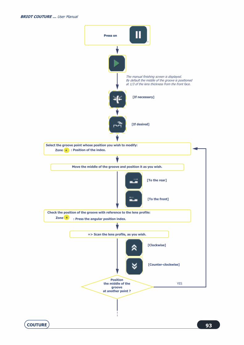
BRIOT COUTURE … User Manual
COUTURE 93
Press on
The manual finishing screen is displayed. By default the middle of the groove is positioned at 1/3 of the lens thickness from the front face.
[If desired]
Move the middle of the groove and position it as you wish.
[To the rear]
[To the front]
[Clockwise]
YES Position
the middle of the groove
at another point ?
[Counter-clockwise]
[If necessary]
Select the groove point whose position you wish to modify:
: Position of the index. Zone
Check the position of the groove with reference to the lens profile:
Zone : Press the angular position index.
=> Scan the lens profile, as you wish.
A
B

BRIOT COUTURE … User Manual
COUTURE 94
Flow chart 3-21: Produce a manual groove
3.5.8.7. FEEL THE LENS AGAIN
If the diameter of the lens being felt is too small, the warning message "Lens too small" is displayed and you transfer to the manual finishing screen.
You may then feel the lens three times successively. The lens is felt 0.5 mm closer to the interior each time.
If the three successive feeling operations are not enough, the lens is too small and cannot be edged.
Confirm the message.
Complete the cycle and retrieve the lens.
Irregular points have been detected during the first phase of the cycle, the message "Irregular points" is displayed and you transfer to the manual finishing screen. We advise you to repeat the lens feeling cycle.
Modify the groove parameters, if desired.
[Depth]
[Width]
Access 3D visualization on the
Couture blocker.

BRIOT COUTURE … User Manual
COUTURE 95
3.5.9. SMART DESIGN "SD" FINISHING (COMPLEX SHAPE)
3.5.9.1. PRINCIPLE
The icon indicates that you have a shape which requires a "Smart Design" cut. The shapes are generated on the blocking device/tracer. When the contour of the shape has concavities whose bend radius is less than the edging radius (45mm), a signal is sent to the edger indicating that the "SD" function will be required to produce the shape.
3.5.9.2. PROCEDURE: CASE 1
Screen 3-33: "Smart Design" without possibility of polishing and safety beveling
With the magnifying glass tab you can access the following screens:
OR
or

BRIOT COUTURE … User Manual
COUTURE 96
With the 90 mm diameter wheel, the areas in red cannot be machined.
With the 90 mm diameter wheel and the 12 mm diameter abrasive point, the red area cannot be machined.
The 1 mm diameter mill bit is used to machine the last area.
1 and 2 are machined with the 12 mm abrasive point.
Area 3 is machined with the 1 mm mill bit.
Note: For shapes such as this where some areas are only machined with the 12 mm abrasive point (areas 1 and 2), all of the edge of the shape will be lightly finished using the abrasive point. In this case, polishing and safety beveling are not possible.

BRIOT COUTURE … User Manual
COUTURE 97
3.5.9.3. PROCEDURE: CASE 2
Screen 3-34: "Smart Design" with possibility of polishing and safety beveling
This result is obtained using a 1 mm diameter mill bit.
Note: For shapes such as this where the milled parts (shown in green) are produced using a 1 mm mill bit, polishing and safety beveling are possible. Finishing is carried out before cutting with the 1 mm mill bit (shown in green here).
or

BRIOT COUTURE … User Manual
COUTURE 98
3.6. OPERATING PRINCIPLE
3.6.1. POINTS TO REMEMBER
→ Lens
Diameter of the uncut lens before edging <= 80 mm Thicknesses
BRIOT COUTURE (all materials)
Maximum thickness at the edge of the uncut (plastic) lens = 17 mm
Maximum thickness at the edge of the uncut (mineral) lens = 11 mm
Rimless finish maximum (detected during lens feeling) = 11 mm
Bevel finish maximum = 17 mm (plastic lens, mineral lens roughing being limited to 11 mm)
BRIOT COUTURE (all plastics)
Maximum thickness at the edge of the uncut (plastic) lens = 20 mm
Rimless finish maximum (detected during lens feeling) = 11 mm
Bevel finish maximum = 17 mm
→ Shape
Machine equipped with BRIOT adaptor
Minimum height of the shape in rimless = 17.00 mm
Minimum height of the shape in bevel = 18.60 mm.
Minimum height of grooving shape = 17.00 + (2 x depth of groove) (17.80 mm for D=0.4 mm)
BRIOT COUTURE (all materials)
Minimum height of chamfer shape = 19.20 + (2 x depth of chamfer) (20.80 mm for H=0.8 mm)
BRIOT COUTURE (all plastics)
Minimum height of chamfer shape = 20.20 + (2 x depth of chamfer) (21.80 mm for H=0.8 mm)
Machine equipped with WECO adaptor
Minimum height of the shape in rimless = 17.75 mm
Minimum height of the shape in bevel = 19.60 mm.
Minimum height of grooving shape = 17.30 + (2 x depth of groove) (18.10 mm for D=0.4 mm)
BRIOT COUTURE (all materials)
Minimum height of chamfer shape = 19.95 + (2 x depth of chamfer) (21.55 mm for H=0.8 mm)
BRIOT COUTURE (all plastics)
Minimum height of chamfer shape = 20.95 + (2 x depth of chamfer) (22.55 mm for H=0.8 mm)

BRIOT COUTURE … User Manual
COUTURE 99
→ Minimum lifespan of the edging wheels:
Mineral roughing = 10000 lenses
Plastic roughing = 50000 lenses
Finishing = 10000 lenses
Polishing = 6,000 lenses
Safety-bevel = 5000 lenses per wheel side Grooving = 5000 lens
Chamfering = 10000 lenses
→ Beveling
Minimum lens thickness to produce the type of bevel desired = 2 mm
If maximum thickness of felt lens less than 2 mm, the bevel is automatically type 1/2 - ½
→ Grooving
Minimum/maximum width = 0.6 to 1.2 mm
Minimum/maximum depth = 0 to 0.8 mm.
Minimum distance between the front face of the lens and the front edge of the groove (or rear face and rear edge) to produce a groove = 0.2 mm.
→ Drilling
Min. hole diameter = milling diameter (2 milling diameters available: 1 mm and 0.8 mm)
Lifespan of the mill bit = 1 hr of total drilling, all lens materials together
Maximum hole depth (= length of the mill bit) = 8 mm
Minimum/maximum angles = 0 to 30°
Accuracy of the drilling angle = +/- 1°
Positioning of holes = +/- 0.1 mm
Non-through holes and countersinking can be drilled on the front face of lens.
Maximum twenty holes per lens, for all types of holes.
→ Safety-bevel
Maximum depth = 0.6 mm in steps of 0.1 mm
Retouching with safety-bevel is possible if the value of the retouch is less than 0.2 mm (at Boxing width)
Minimum distance between the apex of the bevel and the front/rear face to make a safety-bevel = 1.6 mm
Minimum distance between the front face of the lens and the front edge of the groove (or rear face and rear edge) to produce a safety-bevel = 0.4 mm
→ Accuracy of the edger
Dimensional accuracy = +/- 0.06 mm at diameter
Axis setting accuracy = +/- 0.5° per lens (entry+blocking+edging).

BRIOT COUTURE … User Manual
COUTURE 100
3.6.2. ILLUSTRATION OF FINISHING LIMITS
(machine equipped with Briot adaptors and edger types for all plastics for chamfering)
3.6.2.1. RIMLESS FINISHING
Illustration 3-3 : Limits of production of a rimless lens
3.6.2.2. BEVEL FINISHING
Illustration 3-4 : Limits of production of a bevel
Face avant
Glace
Hauteur mini- verre fini = 17,00 mm
Face avant
Hauteur mini- verre fini = 1 8 ,6 0 mm
Hauteur biseau = 0 ,8 mm
Largeur biseau = 2 ,8 mm
Front face
Front face
Min. height of finished lens = 17.00 mm
Min. height of finished lens = 18.60 mm
Bevel width = 2.8 mm
Rimless
Bevel height = 0.8 mm

BRIOT COUTURE … User Manual
COUTURE 101
3.6.2.3. FACET FINISHING
Illustration 3-5 : Limits of production of a facet
3.6.2.4. INCLINED GROOVE FINISHING
Illustration 3-6 : Limits of production of an inclined groove
Face avantHauteur mini- verre fini = 2 1 ,8 0 mm
Hauteur facette (chanfrein) = 0 ,8 à 3 mm
Hauteur verre fini = 2 0 ,2 + 2 x Hauteur facette
Angle maxi- = 2 0 °
Profondeur maxi- rainure = 0,8 mm
Diamètre mini- verre fini= 18,60 mm (si profondeur = 0,8 mm)= 18,20 mm (si profondeur = 0,6 mm)
Face avant
Largeur rainure= 0 ,6 mm à 1 ,2 mm
Diamètre verre fini = 1 7 + Profondeur rainure x 2
Height of facet (chamfer) = 0.8 to 3 mm
Min. height of finished lens = 21.80 mm
Height of finished lens = 20.2 + 2x Facet height
Front face
Front face
Min. diameter of finished lens = 18.60 mm (if depth = 0.8 mm)
= 18.20 mm (if depth = 0.6 mm)
Diameter of finished lens = 17 + Depth of groove x 2
Max. depth of groove = 0.8 mm
Max. angle = 20°
Groove width = 0.6 mm to 1.2 mm

BRIOT COUTURE … User Manual
COUTURE 102
3.6.3. DRILLING
3.6.3.1. CONDITIONS
Only CR39, polycarbonate, Tribrid, polycarbonate, high index (HI) and Trivex™ materials can be drilled. A mineral lens cannot be drilled.
3.6.3.2. LIMITS OF HOLE POSITIONING
Whatever the type of hole, it must be drilled in a specific zone which is defined following the diagrams below. The following constraints must be observed:
→ The circle radius beyond which drilling is possible:
Note: When it is impossible to drill a hole (hole positioned in the end-pieces, notch passing through the centre of the shape, this hole is shown in black in the screen. Some holes displayed in blue in the screen may be impossible to drill after they have been felt (holes too deep, unadapted angle, unadapted end-piece, etc.). In this case, these holes will be displayed in gray in the screen and only marked with the mill bit end (inclined to the maximum) during the drilling phase, once the operator has accepted the marking.
→ The ring formed by the edge of the lens and the internal perimeter of the lens beyond which
drilling is not permitted:
ALL HOLES, WHATEVER THE TYPE, MUST BE WITHIN A 12 MM RING.
Note: If a job includes a hole placed at a distance of more than 12 mm from the edge of the shape, the following message is displayed: "Hole deleted. At least one of the holes cannot be drilled. Do you want to continue?". If you reply Yes: The entire drilling plan is ignored, the lens is not drilled and finished in rimless. If you reply No, you can remove the lens from the drilling chamber.
Min. distance from centre of block - centre of
hole = 19 mm (0°) or 15.25 (30°)
Zone inside which drilling is not permitted.
Zone inside which drilling is permitted.
Max. distance from drill bit centre - edge of lens
= 12 mm
Zone inside which drilling is not permitted.
Zone inside which drilling is permitted.

BRIOT COUTURE … User Manual
COUTURE 103
3.6.3.3. LIMITS RELATED TO THE THICKNESS OF THE LENS
The position of the hole and the strength of the lens to be drilled effect the drilling depth. These two parameters can cause non-through holes which must then be finished manually.
→ Thick lenses ( = thickness in the direction of drilling > 8 mm )
For lenses of high thickness and for high drilling radii (distance from centre of block to centre of hole), it is possible
that the maximum drilling length in the drilling direction may be exceeded. This results in a non-through hole.
Example: Drilling 30 mm from the blocking centre at 0° in a lens of strength -7 D will produce a through hole.
→ Lenses with high front base
For lenses of high front base and for high drilling radii (distance from centre of block to centre of hole), it is possible
that the mill bit retaining nut may interfere with the lens. If so, the edger automatically limits the drilling depth to avoid
this type of damage to the lens. However, this may produce a non-through hole.
Example: Drilling 19 mm from the blocking centre at 0° in a lens of strength +7 D will produce a through hole.
The quality of the final job (accuracy of gaps, axis, diameter and angle of drilling) depends on the performance
and the quality of all the elements in the chain:
The quality of the frame used and its presentation lens;
The use of new Briot blocks and adhesive patches;
data entry and adjustment of centering, blocking, edging and drilling of the lenses.
THE MANUFACTURER DOES NOT GUARANTEE THE PERFORMANCE OF YOUR EDGER IF THESE BASIC RULES ARE
NOT OBSERVED.
Commands -
Attention!
Trou non débouchant pour
épaisseur de verre > 8 mm
Caution! Non-through hole for lens thickness > 8 mm

4. CONFIGURATION 4

BRIOT COUTURE … User Manual
COUTURE 105
4.1. PRESENTATION OF CONFIGURATION MENUS
4.1.1. PRESENTATION OF THE CONFIGURATION MENU ACCESS SCREEN
4.1.1.1. SCREEN DESCRIPTION
The first user technical screen provides access to the user technical menus, including Personalisation, as shown in yellow below:
Screen 4-1: Configuration menu access screen
Tip! The type of menu is shown by the icon which is displayed on the top right of the current screen. If you are working with the Personalisation screen, the edger will be displayed on the top right of the screen.
4.1.1.2. ACCESS / EXIT
4.1.1.2.1. TO ACCESS THE SCREEN
To reach the configuration menus access screen, press on the main application screen for a long time.
Result: The user technical menu screen is displayed.
SETTINGS menu PERSONALIZATION menu
STATISTICS menu TESTS menu
MAINTENANCE menu INFORMATION menu
To exit =>
You are in the User Technical menu

BRIOT COUTURE … User Manual
COUTURE 106
4.1.1.2.2. TO EXIT THE SCREEN
To leave the configuration menu access screen, press the button.
Result: The machine restarts. The main application screen is displayed again.
4.1.2. PRESENTATION OF THE PERSONALISATION MENU ACCESS SCREEN
4.1.2.1. SCREEN DESCRIPTION
The personalisation menu access screen is shown below:
Screen 4-2: Personalisation menu access screen
4.1.2.2. ACCESS / EXIT
4.1.2.2.1. TO ACCESS THE SCREEN
4.1.2.2.2. TO EXIT THE SCREEN
x 2
Personalisation of
pull-down menus
To exit =>
General operation
Parameter default
values Adjustment of setting
values
You are in the Configuration menu

BRIOT COUTURE … User Manual
COUTURE 107
4.2. CONFIGURATION OF FINISHING PARAMETER DEFAULT VALUES
4.2.1. PRESENTATION
4.2.1.1. PRINCIPLE
You have your own way of working and wish to gain time by configuring your own default values.
4.2.1.2. SCREEN DESCRIPTION
The configuration screen for the finishing parameter default values is shown below:
Screen 4-3: Default value configuration screen
For a detailed description of the buttons, see Sub-finishing and associated parameters, chapter 3.
To exit =>
Default values of BEVEL parameters You are in the Finishing
default parameter configuration screen
Default values of GROOVE parameters
Default values
of DRILLING parameters
Default values of safety-bevel parameters

BRIOT COUTURE … User Manual
COUTURE 108
4.2.1.3. ACCESS / EXIT
4.2.1.3.1. TO ACCESS THE SCREEN
4.2.1.3.2. TO EXIT THE SCREEN
4.2.2. GENERAL PROCEDURE
Follow the steps below to set the default value of a parameter:
#1 Press the key-in button of the chosen parameter.
#2 Using the numeric key pad, enter your chosen default value within the limits displayed above the key pad screen.
#3
#4 Continue in the same way for each default value that you wish to change.
Flow chart 4-1: Configuration of finishing parameter default values
4.2.3. SAVING THE NEW CONFIGURATION
When you leave the screen, the default values that you have selected are memorised automatically. When you return to the application screen, you will see that the default values displayed are those you have just
entered.
4.2.4. LIMITS
The information given in the tables below completes the values referred to in Using > Application screen > icons Sub-finishing and associated parameters. The default values that you wish to be memorised must be within the limits given by Briot. Any value outside the interval shown cannot be validated. The number key pad will remain displayed until you have entered a correct value. If you wish to exit the number key pad, use the ESC key. The previous default value will then be applied again.
x 3

BRIOT COUTURE … User Manual
COUTURE 109
4.2.4.1. BEVEL, MINI-BEVEL, FACETED BEVEL, FACETED MINI-BEVEL
TABLE 1:
Sub-finishing
type
Briot
default values
Lower limit Upper limit Incrementation
1 mm 0 mm 2 mm 0.1 mm
1 mm 0 mm 5 mm 0.01 mm
4 D 0.25 D 12 D 0.25 D
33% 0 100% 1 %
1 mm 0.8 mm 3 mm 0.1 mm
2 mm 1 mm 2.8 mm 0.01 mm
4.2.4.2. GROOVE
TABLE 2:
Sub-finishing
type
Briot
default values
Lower limit Upper limit Incrementation
0 mm -5 mm 5 mm 0.01 mm
4 D 0.25 D 12 D 0.25 D
33% 0 100% 1 %

BRIOT COUTURE … User Manual
COUTURE 110
0.4 mm 0 0.8 mm 0.1 mm
0.6 mm 0.6 mm 1.2 mm 0.1 mm
4.2.4.3. SAFETY-BEVEL
TABLE 3:
Type of safety-bevel
Briot
default
values
Lower limit Upper limit Incrementation
0.2 mm 0 0.6 mm 0.1 mm
0.2 mm 0 0.6 mm 0.1 mm
4.2.4.4. DRILLING
TABLE 4:
Sub-finishing type
Briot default
values
Lower limit Upper limit Incrementation
4 D 0.25 D 12 D 0.25 D

BRIOT COUTURE … User Manual
COUTURE 111
4.3. PERSONALISATION OF PULL-DOWN MENUS
4.3.1. PRESENTATION
4.3.1.1. PRINCIPLE
You wish to produce a series of a particular type of job and/or you nearly always work on the same type of job. You want the application screen to display your work.
From this menu, it is possible to designate: • the elements to be displayed at the base of the menu to obtain immediate acces to them; • the elements which must not be displayed because you do not need to use them.
Accordingly, when the machine is started or when the job called up does not contain all the edging data, the application screen is displayed as you have personalized it.
4.3.1.2. SCREEN DESCRIPTION
The pull-down menus personalization screen is shown below:
Screen 4-4: Personalization of pull-down menus (1)
To exit =>
FINISHING
type
BEVEL type
GROOVE
type
DRILLING type
LENS
MATERIAL
OVERSIZE RETOUCH
type
Type of LENS
SAFETY- BEVEL type
DRILLING
type
Personalization of
pull-down menus

BRIOT COUTURE … User Manual
COUTURE 112
4.3.1.3. ACCESS / EXIT
4.3.1.3.1. TO ACCESS THE SCREEN
4.3.1.3.2. TO EXIT THE SCREEN
4.3.2. GENERAL PROCEDURE
To personalize a menu, press the corresponding button on the screen shown above.
Result: A screen of the type shown below is displayed.
Screen 4-5: Personalization of pull-down menus (2)
x 3
To exit =>
Functions that you wish to be
displayed in the pull-down menu.
Button to be defined
Function which will be displayed by default
in the pull-down menu base.
You are in the selection screen for Drilling sub-
finishing displayed by default

BRIOT COUTURE … User Manual
COUTURE 113
Proceed as follows:
#1 Select the function that you wish to see in the base of the pulldown menu.
#2 Select the function(s) that you wish to see in the pulldown menu.
#3
#4 “Do you want to save the new personalisation?”
#5 YES
Flow chart 4-2: Personalization of pull-down menu
4.3.3. SAVING THE NEW PERSONALIZATION
When the message, "Do you wish to save the new personalization? " is displayed, you have three possibilities:
confirm the message: the personalization is registered and you return to the menu buttons configuration screen.
do not confirm the message: the personalization is not registered and you return to the menu buttons
configuration screen. The previous setting is retained.
cancel the personalization: You return to the personalization screen for the menu-button concerned. Select again the elements that you wish to be displayed.
4.3.4. NOTE
4.3.4.1. BUTTON TO BE DEFINED
Each pull-down menu can include a button whose icon has a question mark on it.
Example:
Select this type of button if you wish the user to consult all the possibilities of a menu for each new job.
To start an edging operation, all the job criteria must have been selected. No "To be defined" button can be maintained.
Because of its function, this type of button can only be defined as a base-button.
NOTA : If you call up for a job including drillings with different drilling angles, the multi-angles icon
appears on the screen. Any selection of an other orientation will erase all the individual datas of
the drillings.

BRIOT COUTURE … User Manual
COUTURE 114
4.3.4.2. RETOUCH / OVERSIZE MENU
To boxing width: Decrease/Increase of the boxing width of the entered value. The proportions of the shape are retained.
To the circumference: Decrease/Increase of the finished lens circumference according to the entered value.
The proportions of the shape are retained.
Example: Take a lens for which A (width) = 40 and B (height) = 20.
With a retouch of 0.2 in boxing width, its dimensions will be:
. A = 39.80 (reduction of 0.2 in width)
. B = 19.90 (reduction of 0.1 in height for a constant A/B ratio).

BRIOT COUTURE … User Manual
COUTURE 115
ADJUSTMENT OF SETTING VALUES
Screen 4-6: Adjustment of setting values (1)
Screen 4-7: Adjustment of setting values (2)
To adjust the position of
the apex of the bevel
Adjustment of setting
values
Adjust the depth of the rear
safety bevel
Adjust the depth of the front
safety bevel
Adjust the position of the
middle of the groove
To modify the diameter of the
mill bit = > 0.80 mm to 3 mm
To adjust the position of the
apex of the facet
To adjust the height of the
facette
Following display
Exit
RESET ONCE YOU
HAVE SAVED THE LATEST ADJUSTMENTS
To enter a correction for plastic and metal
frames
Adjustment of setting values
Exit
NOT TAKEN INTO
ACCOUNT IN THE ADJUSTMENTS
To access the previous screen
To enter a correction
for plastic frames

BRIOT COUTURE … User Manual
COUTURE 116
4.4. ADJUSTMENT OF SETTING VALUES
4.4.1. PRELIMINARY REMARKS
The machine is adjusted on factory so that the adjustments meet the needs and requirements of the majority of
users. Any modifications of the standard setting values can affect the performance of the machine. If you wish nonetheless to use the value adjustment function, first target your needs with precision and then
modify the values with full knowledge of our recommendations.
4.4.2. PROCEDURE
To adjust the setting values, proceed as follows:
#1
#2
#3
#4 Press the value to be corrected.
#5 Enter a value using the number key pad.
#6
#7
Flow chart 4-3: Adjustment of setting values

BRIOT COUTURE … User Manual
COUTURE 117
4.5. CONFIGURATION OF GENERAL OPERATING PARAMETERS
4.5.1. PRESENTATION
4.5.1.1. PRINCIPLE
You define the machine's general operating mode.
4.5.1.2. SCREEN DESCRIPTION
The setting screen for the machine's general operating parameters is shown below:
Screen 4-8: Setting the parameters of the machine's general operating functions (Page 1)
Dialog language
You are in the machine's general operating screen
Exit
To access the next page
Modes: Novice/Expert
Retouch Verification
Size compensation according to water
temperature
Size compensation according to wheel
condition
Size compensation according to frame
curvature
Time delay before
switching to stand-by

BRIOT COUTURE … User Manual
COUTURE 118
Screen 4-9: Setting the parameters of the machine's general operating functions (Page 2)
Screen 4-10: Setting the parameters of the machine's general operating functions (Page 3)
Exit
Exit
Chemistrie TM function
To access the previous / next page
To access the previous / next page

BRIOT COUTURE … User Manual
COUTURE 119
Screen 4-11: Setting the parameters of the machine's general operating functions (Page 4)
Screen 4-12: Setting the parameters of the machine's general operating functions (Page 5)
Exit
Exit
To access the previous / next page
To access the previous / next page

BRIOT COUTURE … User Manual
COUTURE 120
Screen 4-13: Setting the parameters of the machine's general operating functions (Page 6)
Screen 4-14: Setting the parameters of the machine's general operating functions (Page 7)
Exit
Exit
To access the
previous / next page
To access the previous / next page

BRIOT COUTURE … User Manual
COUTURE 121
Screen 4-15: Setting the parameters of the machine's general operating functions (Page 8)
Screen 4-16: Setting the parameters of the machine's general operating functions (Page 9)
Exit
Exit
To access the
previous / next page
To access the previous / next page

BRIOT COUTURE … User Manual
COUTURE 122
Screen 4-17: Setting the parameters of the machine's general operating functions (Page 10)
Screen 4-18: Setting the parameters of the machine's general operating functions (Page 11)
Exit
To access the previous / next page
Exit
To access the previous page

BRIOT COUTURE … User Manual
COUTURE 123
4.5.1.3. ACCESS / EXIT
4.5.1.3.1. TO ACCESS THE SCREEN
4.5.1.3.2. TO EXIT THE SCREEN
4.5.2. CONFIGURATION OF THE FUNCTIONS
4.5.2.1. SELECTING THE DIALOG LANGUAGE
4.5.2.1.1. PROCEDURE
To select the dialog language
4.5.2.2. SELECTING NOVICE OR EXPERT OPERATING MODE
4.5.2.2.1. PRINCIPLE
Two operating modes are available so that you can choose the mode that is best suited to what you require as well as to your method of working. NOVICE mode
In this mode, messages are displayed to inform, advise and guide the user during the operations under way or to be
undertaken. This mode is intended for inexperienced operators, or those wishing to be accompanied when using the
machine.
EXPERT mode
In this mode, very few messages are displayed, to ensure faster system response. This mode is intended for expert
operators, or those who know the machine well enough to dispense with advice or guidance when using the machine.
When the edger is installed, decide which operating mode is most suitable and configure the machine with the
technician.
You may change the operating mode later, if you wish.
4.5.2.2.2. PROCEDURE
To select Novice operating mode:
To select Expert operating mode:
4.5.2.3. ACTIVATING RETOUCH VERIFICATION
4.5.2.3.1. PRINCIPLE
At the beginning of a lens cycle, two points of the lens are checked to ensure that the lens fitted is the one you wish to retouch - right or left lens.
x 3

BRIOT COUTURE … User Manual
COUTURE 124
4.5.2.3.2. PROCEDURE
To select retouch verification:
4.5.2.4. ENABLING SIZE COMPENSATION ACCORDING TO TEMPERATURE
4.5.2.4.1. PRINCIPLE
The water temperature affects the degree of expansion of the wheels. Activating the temperature compensation automatically corrects for the expansion of the edging wheels and the
lens due to water temperature variations.
Activating the temperature compensation is strongly recommended if you work in closed circuit mode.
4.5.2.4.2. PROCEDURE
To activate the temperature compensation:
4.5.2.5. ACTIVATING SIZE COMPENSATION ACCORDING TO WHEEL CONDITION
4.5.2.5.1. PRINCIPLE
A wheel becomes very abrasive after dressing. This can lead to some instability in the dimensions of edged lenses following wheel dressing.
The wheel condition compensation function takes this effect into account and allows for compensation of the lens size after the wheel has been dressed.
4.5.2.5.2. PROCEDURE
To enable wheel condition compensation:
4.5.2.6. ENABLING SIZE COMPENSATION ACCORDING TO THE BOWING/FLATTENING OF THE FRAME
4.5.2.6.1. PRINCIPLE
The lens dimension is adapted to the bowing/flattening of the frame in order to obtain a more aesthetic job. The circumference of the lens is then equal to the circumference of the frame.
This function guarantees an optimal finishing quality and is particularly suitable for highly curved frames.
4.5.2.6.2. PROCEDURE
To activate the bowing/flattening compensation:
4.5.2.7. ENTERING A TIME DELAY BEFORE SWITCHING TO SCREEN STAND-BY MODE
4.5.2.7.1. PRINCIPLE
Using the screen stand-by mode extends its working life. According to your method of working, you can decide how much time must elapse before stand-by mode is
activated.

BRIOT COUTURE … User Manual
COUTURE 125
4.5.2.7.2. PROCEDURE
To enter your chosen time delay:
Enter a time delay using the numeric key pad.
4.5.2.8. AACTIVATE THE CHEMISTRIE TM FUNCTION
4.5.2.8.1. PRINCIPLE
The “Chemistrie TM” function is used to prepare sun lenses adaptable to prescription lenses. You can disable the “Chemistrie TM” function later on, if desired.
4.5.2.8.2. PROCEDURE
To enable the “Chemistrie TM” function:
4.5.2.9. CONFIGURING THE OMA
4.5.2.9.1. PRINCIPLE
The OMA 3.07 configuration is used to receive and drill rectangular holes sent from an OMA server also operating in the OMA 3.07 configuration
4.5.2.9.2. PROCEDURE
To select the OMA version
4.5.3. SAVING THE NEW CONFIGURATION
When you quit the screen, the message "Do you wish to save the new configuration?" is displayed. You have three possibilities:
Confirm the message: The configuration is taken into account and you return to the personalization menu access
screen.
Don't confirm the message: The configuration is not taken into account and you return to the personalization
menu access screen. The previous setting is retained.
Cancel the configuration: You return to the configuration screen. Reselect the operating parameters you have chosen.
When you return to the application screen and begin an edging cycle, you will see that the general operating parameters have been saved.
x2
x3 ou or

5. MAINTENANCE 5

BRIOT COUTURE … User Manual
COUTURE 127
5.1. PRESENTATION OF MAINTENANCE MENUS
5.1.1. PRESENTATION OF THE MAINTENANCE MENU ACCESS SCREEN
5.1.1.1. SCREEN DESCRIPTION
The first user technical screen provides access to the user technical menus, including Personalization, as shown in yellow below:
Screen 5-1: Configuration menu access screen
Tip! The type of menu is shown by the icon which is displayed on the top right of the current screen. If you are working with the Maintenance screen, the hand holding the spanner will be displayed on the top right of the screen.
5.1.1.2. ACCESS / EXIT
5.1.1.2.1. TO ACCESS THE SCREEN
To reach the configuration menus access screen, press on the main application screen.
Result: The user technical menu screen is displayed.
5.1.1.2.2. TO EXIT THE SCREEN
To leave the configuration menu access screen, press the button.
Result: The machine restarts. The main application screen is displayed again.
PERSONALIZATION menu SETTINGS menu
STATISTICS menu TESTS menu
MAINTENANCE menu INFORMATION menu
You are in the User
Technical menu
To exit =>

BRIOT COUTURE … User Manual
COUTURE 128
5.1.2. PRESENTATION OF THE MAINTENANCE SCREEN
5.1.2.1. SCREEN DESCRIPTION
The maintenance menus access screen is shown below:
Screen 5-2: Maintenance menu access screen
5.1.2.2. ACCESS / EXIT
5.1.2.2.1. TO ACCESS THE SCREEN
5.1.2.2.2. TO EXIT THE SCREEN
x 2
Dressing wheels
You are in the User
Technical menu
To exit =>
Replacing the lens
feeler tips
Replacing the mill bit
Degraded mode
Remote
maintenance
Emptying the
settling tank
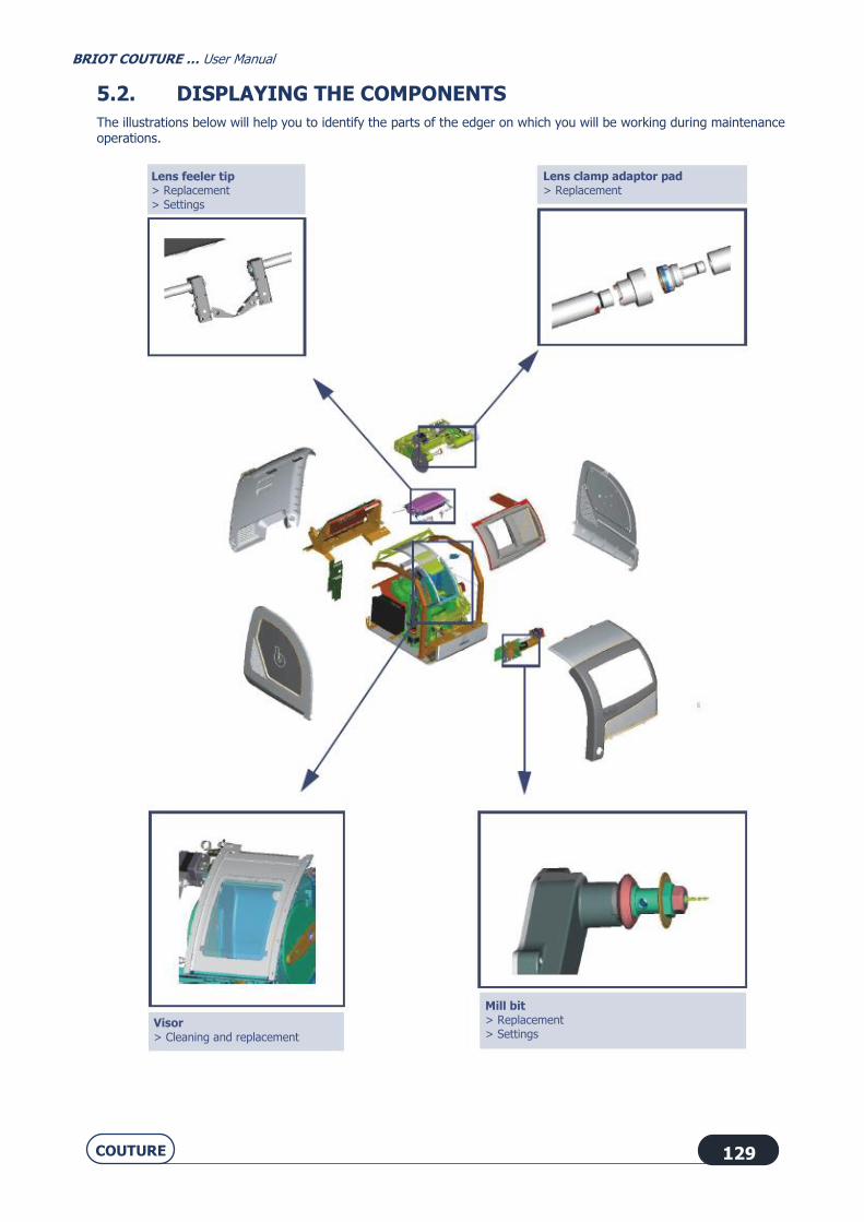
BRIOT COUTURE … User Manual
COUTURE 129
5.2. DISPLAYING THE COMPONENTS
The illustrations below will help you to identify the parts of the edger on which you will be working during maintenance operations.
Lens feeler tip > Replacement
> Settings
Lens clamp adaptor pad > Replacement
Visor
> Cleaning and replacement
Mill bit > Replacement > Settings

BRIOT COUTURE … User Manual
COUTURE 130
5.3. TASK LIST
To keep your edger in perfect condition, we advise you to follow the instructions below:
→ Clean the edger daily with a spray bottle of water.
→ Replace the flexible lens clamp adaptor pad regularly (every 1000 lenses).
→ Replace the mill bit when a message asks you to do so (1 hour of total drilling time).
→ Check the condition of the lens feeler tips regularly and replace them as soon as they appear to be worn or
damaged (or every 3000 lenses).
→ Dress the wheels when a message asks you to do so.
→ Clean the removable visor regularly, and replace it if necessary.
→ Change the water in the tank regularly if your machine operates in closed water circuit mode.
→ Clean the filters and the tanks regularly.
→ Check the condition of the safety-beveling and grooving wheels and have them replaced by a technician if
necessary.
→ Check the condition of the wheels and have them replaced by a technician if necessary.

BRIOT COUTURE … User Manual
COUTURE 131
5.4. REGULAR MAINTENANCE OF THE EDGER
5.4.1. REPLACING THE FLEXIBLE LENS CLAMP ADAPTOR PAD
5.4.1.1. PRELIMINARY REMARKS
Caution! The lens holder adaptor is serrated and the lens feeler tips are pointed.
Make sure that your hands are protected when handling the lens holder adaptor and feeler tip.
5.4.1.2. PROCEDURE
To replace the flexible lens clamp adaptor pad, follow the procedure below:
#1
#2
#3 Remove the lens clamp adaptor pad gently from the clamping shaft (on the right).
#4 Remove the worn blue lens clamp adaptor pad and replace it with a new one.
#5 Refit the lens clamp adaptor pad on the clamping shaft.
Flow chart 5-1: Replacing the flexible lens clamp adaptor pad
→ As shown...
Illustration 5-1 : Replacing the flexible lens clamp adaptor pad

BRIOT COUTURE … User Manual
COUTURE 132
Illustration 5-2 : Replacing the mill bit
Mill bit
Chuck nut
Spacer
Tighten/Loosen the
nut
Block the rotation with an Allen key or with
one turn of the
screwdriver!
Flat organic lens
Diameter > 57 mm 10 00 205
Flush point

BRIOT COUTURE … User Manual
COUTURE 133
5.4.2. REPLACING THE MILL BIT
5.4.2.1. PRELIMINARY REMARKS
It may be necessary to change the mill bit. A change of mill bit may be necessary for the following reasons: Broken bit Worn bit (chips around the holes on the internal side of the lens?) ; Excessive use of the bit.
The machine is guaranteed to operate correctly if Briot mill bits are mounted.
5.4.2.2. PROCEDURE
To change the mill bit, follow the procedure below:
#1
#2
#3
#4
#5 Insert an Allen wrench or a screwdriver in the spacer hole to block the rotation of the spindle.
#6 Fit an 8 mm spanner on the chuck nut.
#7 Loosen the nut with one turn of the spanner, to free the bit.
#8 Use pliers to remove the bit from the chuck.
#9 Fit a new bit in the chuck. We advise you to apply a touch of grease to the end of the bit to ease its insertion into the chuck. Caution! Ensure that the bit is pushed home inside the chuck.
#10 Tighten the chuck nut lightly with the 8 mm spanner to immobilise the mill bit.
#11 When the bit is tightened, remove the Allen wrench or the screwdriver.
#12
#13

BRIOT COUTURE … User Manual
COUTURE 134
#14 Block the adjustment lens 10 00 205 in the centre and fit it on the lens holder shaft.
#15
#16
x3
#17 Remove the drilled lens from the edging station.
Flow chart 5-2: Replacing the mill bit
Note:
→ The drilling counters are automatically updated. → The new setting position is automatically saved.
5.4.2.3. HINTS
During step 8, the bit may be difficult to remove from the chuck because of possible scale deposits. In this case apply a small quantity of a common scale remover, leave it for a few moments and then remove the bit.
Use bits supplied by your Briot representative.
Use the centering help available on screen #4 by pressing the "X" icon .
Screen 5-3: Centering help screen

BRIOT COUTURE … User Manual
COUTURE 135
Illustration 5-1: Replacing the lens feeler tips
FRAGILE MOUNTING!
Removable lens feeler tips
Place the feelers in the replacement position.
Place the feelers in the position to receive the tool.
=> Confirm and switch automatically to the
feeling adjustment screen.

BRIOT COUTURE … User Manual
COUTURE 136
5.4.3. REPLACING THE LENS FEELER TIPS
5.4.3.1. PRELIMINARY REMARKS
Always contact your Briot representative before replacing the lens feeler tips.
5.4.3.2. PROCEDURE
To replace the feeler tips, follow the procedure below:
#1
#2
#3
#4
#5 Hold the holder and immobilise the feeler arm.
#6 Insert a screwdriver or an Allen wrench in the hole of the removable feeler tip.
#7 Tilt the right feeler tip carefully to unclip it.
#8 Remove the worn feeler tip and replace it with a new one.
#9 Do the same for the second feeler tip.
#10
#11 Remove the lens clamping and lens holder adaptors from the shafts.
#12 Fit the setting tool on the shafts.
#13
#14 When the adjustment is finished, remove the tool.
#15
x3
Flow chart 5-3: Replacing the lens feeler tips

BRIOT COUTURE … User Manual
COUTURE 137
5.4.3.3. HINTS
Always replace the two removable feeler tips at the same time.
When you are handling the feeler tips, do not apply pressure on the feeler arms because that could alter the
quality of the work produced by the machine. If you observe any malfunctioning after changing the feeler tips, contact
your Briot representative.

BRIOT COUTURE … User Manual
COUTURE 138
Screen 5-4: Dressing a wheel
Specific procedure for
dressing the polishing wheel
Ensure that the dressing disc is correctly centered
using the indentations
intended to receive the
adaptors.

BRIOT COUTURE … User Manual
COUTURE 139
5.4.4. DRESSING A WHEEL
5.4.4.1. PRELIMINARY REMARKS
Dressing the polishing wheel is not recommended. Too frequent dressing of the wheels reduces their working life.
5.4.4.2. PROCEDURE
Follow the steps below to dress a wheel:
#1
#2
#3
#4
or or or
According to your selection
#5 Make sure large adaptors are fitted.
#6 Fit the dressing disc which corresponds to the wheel to be dressed. Make sure it
is centered on the lens clamping and lens holder adaptors.
#7
#8 When the adjustment is finished, open the lens clamping shaft while holding the disc and remove the disc.
#9
x3
Flow chart 5-4: Dressing a wheel
5.4.4.3. HINTS
Dress the wheels when a message asks you to do so.

BRIOT COUTURE … User Manual
COUTURE 140
Illustration 5-3 : Cleaning and replacing the removable visor

BRIOT COUTURE … User Manual
COUTURE 141
5.4.5. CLEANING / REPLACING THE REMOVABLE VISOR
5.4.5.1. PRELIMINARY REMARKS
Before undertaking any operation, ensure that the machine is switched off: On/Off switch OFF and mains
plug disconnected.
5.4.5.2. CLEANING THE VISOR
5.4.5.2.1. PROCEDURE
Follow the steps below to clean the visor:
#1 Remove the machine top cover (see Handling the covers, chapter 1).
#2
if the visor is closed
#3 Push the visor latching tab from the inside.
#4 Hold the visor holder and gently open the removable visor.
#5 Remove the removable visor from its holder.
#6 Take a clean soft cloth and clean the removable visor.
#7 Refit the removable visor by following the above steps in reverse order.
#8 Refit the machine upper cover.
Flow chart 5-5: Cleaning the visor
5.4.5.3. REPLACING THE VISOR
5.4.5.3.1. PROCEDURE
To replace the visor, proceed as described above. Only Step 6 changes.
#6 Insert a new removable visor in the holder.
5.4.5.4. HINTS
Regular cleaning of the visor increases the visibility of the interior of the edging chamber and the operations under way.
Operating in closed circuit mode affects the cleanliness of the visor. We recommend more frequent cleaning of the visor.

BRIOT COUTURE … User Manual
COUTURE 142
Illustration 5-4 : Presentation of the tanks
Illustration 5-5 : Cleaning the drawer-filter
Illustration 5-6 : Complete cleaning of the tanks and filters
Bac de la pompe
Bac de décantation
(aussi appelé bac principal)Filtre-tiroir
DécanteurSettler
Drawer-filter
Pump tank
Settling tank (also called main tank)
Dump pipe valve closed

BRIOT COUTURE … User Manual
COUTURE 143
5.4.6. CLEANING THE FILTERS AND WATER TANK
5.4.6.1. PRELIMINARY REMARKS
Before undertaking any operation, ensure that the machine is switched off: On/Off switch OFF and mains plug disconnected.
Cleaning frequency is left to the discretion of the user, depending on the number of lenses which have been edged. However, Briot recommends cleaning every 500 lenses (mineral and plastic).
Gloves and eye shields must be worn. It is advisable to wear an overall. Ensure that the dump pipe valve is closed before starting the machine - the red handle must be perpendicular to
the T.
5.4.6.2. PROCEDURES
Three situations are possible:
5.4.6.2.1. FOR DAILY CLEANING
#1 Lift the water drain pipe and remove the drawer-filter.
#2 Clean the drawer-filter with a brush.
#3 Clean the drawer-filter.
#4 Refit the drawer-filter.
Flow chart 5-6: Daily cleaning of the drawer-filter
5.4.6.2.2. COMPLETE CLEANING OF THE TANKS AND FILTERS
#1 Empty the settling tank (see “Emptying the water tank”)
#2 Ensure that the dump pipe valve is correctly closed.
#3 Unscrew the water supply pipe from the valve.
#4 Free the drain pipe from the drawer-filter and remove the drawer-filter.
#5 Remove the 2 fixing screws from the pump support plate.
#6 Remove the pump support plate.
#7 Remove the pump from the pump tank.
#8 Brush the lateral filters of the pump tank.
→ The procedure continues on the next page.

BRIOT COUTURE … User Manual
COUTURE 144
→ Complete cleaning of the tanks and filters (cont.)
Dump pipe valve closed
Water supply pipe connected to the valve
Pump connected to PUMP socket
Drain pipe placed above clean drawer-filter

BRIOT COUTURE … User Manual
COUTURE 145
#9 Remove the settler carefully.
#10 Clean the settler with a plastic spatula and a brush above the drainage system (bucket, waste bin, drain, etc.).
#11 Clean the settler.
#12 Remove the used plastic bag from the settling tank and dispose of it.
#13 Clean the settling tank if necessary.
#14 Place a new plastic bag in the settling tank.
#15 Reassemble the tanks, pump and pipes.
#16 Fill the water tank to within 6 or 7 cm of the upper edge of the plastic bag.
#17 Run a dummy edging cycle to prime the unit.
Flow chart 5-7: Complete cleaning of the settling tank
5.4.6.3. HINTS
If the pump is not activated when you restart the machine after cleaning, open the discharge valve to the minimum to allow the escape of any air which has remained in the pipes. Close the valve before restarting the process.
Always check the water-tightness of the unit before restarting the machine. • Check the connections of the drain, water supply and pump pipes. • Ensure that the discharge valve is closed. • If you have worked on the solenoid valves, check the fixings.

BRIOT COUTURE … User Manual
COUTURE 146
Illustration 5-7 : Emptying the settling tank
Illustration 5-8 : Water connections
Open/Close the discharge valve
Example of a drainage system
Discharge pipe
Edger connector
Discharge connection
Discharge valve Closed position

BRIOT COUTURE … User Manual
COUTURE 147
5.4.7. EMPTYING THE WATER TANK
5.4.7.1. PRELIMINARY REMARKS
Use a standard discharge pipe with a 20x27 connection.
5.4.7.2. PROCEDURE
To empty the settling tank, follow the procedure below:
#1 Fit a discharge pipe on the same side as the valve and connect it to the drainage system (bucket, sink, drain etc.).
#2
#3
#4
#5
#6 Open the discharge valve.
#7 Close the discharge valve when the settling tank is empty.
#8
#9
X 3
#10 Disconnect the discharge pipe and put it away.
Flow chart 5-8: Emptying the settling tank
5.4.7.3. HINTS
If the pump is not activated when you restart the machine after cleaning, open the discharge valve to the minimum to allow the escape of any air which has remained in the pipes. Close the valve before restarting the process.
Always check the water-tightness of the unit before restarting the machine. • Check the connections of the drain, water supply and pump pipes. • Ensure that the discharge valve is closed. • Check that all parts are correctly attached, especially the solenoid valves.

BRIOT COUTURE … User Manual
COUTURE 148
Screen 5-5: Operation in degraded mode
Exit

BRIOT COUTURE … User Manual
COUTURE 149
5.4.8. OPERATION IN DEGRADED MODE
5.4.8.1. PRINCIPLE
An element or function of the visor or of the safety-bevel-grooving-drilling system (SBGD) or the wheel unit photoelectric cell for rotation is out of order but the general operation of the edger must not be altered.
Depending on which element or function is out of order, a hotline technician may ask you to configure the machine in "degraded" mode. This operating mode allows you to de-activate an out of order element or function and continue to use the machine until the visit of a Briot technician.
When a function is de-activated, the icon appears on the user screen and shows that machine is operating in degraded mode.
5.4.8.2. PROCEDURE
#1
#2
#3
#4 Select the appropriate mode:
•
When a component of the CBRP is defective.
•
When the closing micro-switch is defective.
•
When the edging wheel speed sensor is defective.
#5
X 3
Flow chart 5-9: Selecting a degraded operating mode

BRIOT COUTURE … User Manual
COUTURE 150
5.5. PREVENTIVE MAINTENANCE
5.5.1. HINTS
You will optimise the working life of your edger by using only Briot spare parts. Change the blocks regularly - every 100 lenses.
5.5.2. REPLACEMENT TABLE FOR STANDARD PARTS
The following table summarises the replacement frequency for standard parts, calculated according to the number of lenses edged.
TABLE 1: REPLACEMENT OF STANDARD PARTS
Part L.T.O part number Number of lenses edged
Removable lens feeler tip 11 38 190 Every 3000 lenses
Safety-bevel wheel 16 06 207 Every 5,000 lenses, per wheel side
Grooving wheel 16 06 303 Every 5000 lenses
Mill bit (0.8mm) SVS 180158 1 hr of total drilling
Mill bit (1mm) SVS 180138 1 hr of total drilling
Emptying the settling tank (if closed circuit operation) Cleaning of tanks and filters
- Every 500 lenses
Visor 11 97 047 If necessary
Filter seal 20x27 21 62 153 If necessary
If the machine is equipped with universal "BRIOT" adapters:
Part L.T.O part number Number of lenses edged
Briot magnetic block - Large Size (25 mm diameter)
11 63 178 Every 100 lenses
Briot magnetic block - Small Size (19 mm diameter)
11 53 027 Every 100 lenses
Briot magnetic block - 16 across flats 11 53 038 Every 100 lenses
Flexible lens clamp adaptor pad - Large size (25 mm diameter)
11 38 162 Every 1000 lenses
Lens clamp adaptor pad - Small size (19 mm diameter)
11 38 161 Every 1000 lenses
Flexible lens clamp adaptor pad- 16 across flats
11 38 195 Every 1000 lenses
Lens clamp adaptor pad sub-assembly - Small size (19 mm diameter)
S1 14 004 If necessary
Lens clamp adapter pad sub-assembly 16 across flats
S1 14 009 If necessary

BRIOT COUTURE … User Manual
COUTURE 151
Briot unit support - Small size (19 diameter)
11 90 793 If necessary
Briot unit support 16 across flats 11 90 798 If necessary
If the machine is equipped with universal "WECO" adapters:
Part L.T.O part number Number of lenses edged
Weco magnetic block - Large Size (25 mm diameter)
11 53 031 Every 100 lenses
Weco magnetic block - 20 across flats 11 53 037 Every 100 lenses
Weco magnetic block - 17 across flats
chamfered
11 53 036 Every 100 lenses
Flexible lens clamp adaptor pad - Large
size (25 mm diameter)
11 38 162 Every 1000 lenses
Lens clamp adaptor pad - Small size (19 mm diameter)
11 38 161 Every 1000 lenses
Lens clamp adaptor pad sub-assembly -
Small size (19 mm diameter)
S1 14 004 If necessary
Weco magnetic block support - Small size
(19 mm diameter)
S1 14 011 If necessary
Universal Weco magnetic block support 17 across flats
S1 14 012 If necessary
Wheel unit “all materials”
Part L.T.O part number Number of lenses edged
Finishing / chamfering wheel 11 77 427 Every 10000 lenses
Polishing wheel (rimless) 12 mm 11 77 428 Every 6000 lenses
Organic roughing wheel 11 47 127 Every 50000 lenses
Mineral roughing wheel 11 47 129 Every 10000 lenses
Wheel unit “all materials”
Part L.T.O part number Number of lenses edged
Finishing / chamfering wheel 11 77 438 Every 10000 lenses
Polishing wheel (rimless) 18mm 11 77 420 Every 6000 lenses
Organic roughing wheel 11 47 125 Every 50000 lenses

BRIOT COUTURE … User Manual
COUTURE 152
5.6. ADJUSTMENTS
5.6.1. PRESENTATION OF THE SETTINGS MENUS ACCESS SCREEN
5.6.1.1. SCREEN DESCRIPTION
The settings menu access screen is shown below:
Screen 5-6: Setting menu access screen
5.6.1.2. ACCESS / EXIT
5.6.1.2.1. TO ACCESS THE SCREEN
La machine se réinitialise.
You are in the User
Technical menu
To exit =>
Size
adjustment
Adjustment of the axis
setting with the tool
Adjustment of
the flush of the mill bit
Feeling
adjustment
Consultation of setting values
Adjustment of the touch
screen
Adjustment of the axis setting with the BRIOT
COUTURE blocker
The machine restarts.

BRIOT COUTURE … User Manual
COUTURE 153
5.6.1.2.2. TO EXIT THE SCREEN
`
Screen 5-7: Feeling adjustment
x 2

BRIOT COUTURE … User Manual
COUTURE 154
5.6.2. ADJUSTING THE FEELING
5.6.2.1. WHEN?
If a message asks you to do so. If you observe that the feeler tips are beginning to be worn. After replacing the feeler tips - the machine then switches automatically to this screen.
5.6.2.2. PROCEDURE
Follow the steps below to adjust the feeling:
#1
#2
#3
#4 Remove the lens clamping and lens holder adaptors from the shafts.
#5 Fit the setting tool on the shafts.
#6
#7 When the adjustment is finished, remove the tool.
#8 Refit the lens holder and lens clamping adaptors.
#9
X3
Flow chart 5-10: Feeling adjustment
5.6.2.3. HINTS
Always check that the setting tool 14 04 301 is correctly fitted on the shaft. You must neither force the fitting nor feel any play.
The feeling setting can be incorrect if the tool is badly positioned. This factor also affects the quality of the work produced by the machine.

BRIOT COUTURE … User Manual
COUTURE 155
Screen 5-8: Adjusting the sizes - Screen 1

BRIOT COUTURE … User Manual
COUTURE 156
5.6.3. ADJUSTING THE SIZES
5.6.3.1. WHEN?
Perform this adjustment regularly. The wear of the wheels has a direct influence on the lens sizes, which increases over time. This will help you to avoid retouch.
Center the adjustment lens 10 00 205exactly in the center so as to be able to use it from start to finish of size adjustment.
When you measure the lens size with a digital caliper, keep the lens in the same plane as the caliper. Take two consecutive measurements 90° apart and record the average value with the number keypad.
Perform the size adjustment procedure from beginning to end so as to record all the parameters.
5.6.3.2. PROCEDURE
Follow the steps below to adjust sizes:
#1
#2
#3
#4 Make sure the 25 mm adaptors are fitted.
#5 Block a lens 10 00 205 in the center and fit it on the lens holder
shaft .
#6
> Lens edged to 57.5 mm diameter - Rimless finishing

BRIOT COUTURE … User Manual
COUTURE 157
#7 At the end of the edging process, open the lens holder shaft and remove the lens.
#8 Measure the size of the lens with a caliper.
#9
#10 Enter the value using the number key pad.
#11
#12
OR
Continue with the normal procedure
Repeat the edging process
> Lens edged to 55mm diameter - Rimless finishing
#13 Fit the lens on the lens holder shaft again.
#14
> Lens edged to 50 mm diameter - Bevel finishing

BRIOT COUTURE … User Manual
COUTURE 158
#15 At the end of the edging process, open the lens holder shaft and remove the lens.
#16 Measure the size of the lens with a caliper.
#17
#18 Enter the value using the number key pad.
#19
#20 Check the position of the apex of the bevel with a linen-counter. The apex must be in the centre of the edge of the lens.
#21
#22 If the apex of the bevel is off-centered, enter the value of the shift using the number key pad.
• Apex too close to the rear face → enter a negative value • Apex too close to the front face → enter a positive value
#23
#24
OR
Continue with the normal procedure
Repeat the edging process
> Lens edged to 47.5mm diameter - Rimless finishing
#25 Fit the lens on the lens holder shaft again.
#26
> Lens edged to 42.5 mm diameter - Rimless finishing and polishing

BRIOT COUTURE … User Manual
COUTURE 159
#27 At the end of the edging process, open the lens holder shaft and remove the lens.
#28 Measure the size of the lens with a caliper.
#29
#30 Enter the value using the number key pad.
#31
#32 At the end of the edging process, open the lens holder shaft and remove the lens.
#33 Measure the size of the lens with a caliper.
#34
#35
OR
Continue with the normal procedure
Repeat the edging process
> Lens edged to 40 mm diameter - Rimless finishing
#36
#37 Fit the lens on the lens holder shaft again.
#38
> Lens edged to 35 mm diameter - Bevel finishing and polishing
#39 At the end of the edging process, open the lens holder shaft and remove the lens.
#40 Measure the size of the lens with a caliper.

BRIOT COUTURE … User Manual
COUTURE 160
#41
#42 Enter the value using the number key pad.
#43
#44 Check the position of the apex of the bevel with a linen-counter. The apex must be in the centre of the edge of the lens.
#45 If the apex of the bevel is off-centered, enter the value of the shift
using the number key pad.
• Apex too close to the rear face → enter a negative value • Apex too close to the front face → enter a positive value
#46
#47
#48 Check the setting values ; the new values are displayed in red.
#49
Flow chart 5-11: Size adjustment

BRIOT COUTURE … User Manual
COUTURE 161
Screen 5-9: Adjustment of the axis setting with the BRIOT COUTURE blocker

BRIOT COUTURE … User Manual
COUTURE 162
5.6.4. ADJUST THE AXIS SETTING WITH THE BRIOT COUTURE BLOCKER
5.6.4.1. PRELIMINARY REMARKS
To avoid producing an incorrect axis setting, the large adaptors are required for this adjustment. When blocking the lens 14 04 274, put the lens down on its unmarked face (black markings towards the top of the
BRIOT COUTURE blocker).
5.6.4.2. PROCEDURE
To adjust the axis setting with the BRIOT COUTURE blocker, proceed as follows:
#1
#2
After initializing the machine
#3
#4 On the BRIOT COUTURE blocker, load any job and enter null decentering values.
#5 Insert the pre-marked lens 14 04 274 in the BRIOT COUTURE blocker. The rounded corner with the marking should be on the top right.
#6
Centre the adjustment lens in or mode.
#7 Fit a large block on the blocking head and block the lens.
If the message "Lens too small, do you want to continue ?" is displayed, reply "Yes".
#8 Make sure it is centered on the lens clamping and lens holder adaptors.
#9 Fit the blocked lens on the lens holder shaft.
#10
#11 At the end of the adjustment process, open the shafts and remove the lens.
#12 Ensure that there is no water in the hole drilled in the lens.

BRIOT COUTURE … User Manual
COUTURE 163
#13 Remove the block from the lens.
#14 Place the lens on the bearing surface of the BRIOT COUTURE blocker.
The rounded corner should be on the top right.
#15 Start the PROS optical recognition system.
#16 Switch to the left shape of the lens and check that the drilling hole has been detected (the drilling point is visible from the left shape).
#17 From the edger
#18 The axis adjustment is finished!
X3
Flow chart 5-12: Adjustment of the axis setting with the BRIOT COUTURE blocker
5.6.4.3. HINTS
Always ensure that the pattern holder is clean and unscratched before placing the lens on it.

BRIOT COUTURE … User Manual
COUTURE 164
Screen 5-10: Adjustment of the axis setting with the tool

BRIOT COUTURE … User Manual
COUTURE 165
5.6.5. ADJUSTMENT OF THE AXIS SETTING WITH THE TOOL
5.6.5.1. WHEN?
The BRIOT COUTURE is not connected to a BRIOT COUTURE blocker
AND
you have the adjustment tool 14 04 300 (supplied on request by Briot)
AND
a hotline technician asks you to undertake this type of adjustment.
5.6.5.2. PROCEDURE
To adjust the axis setting with the tool, proceed as follows:
#1
#2
#3
#4 Remove the lens clamping and lens holder adaptors from the shafts.
#5 Fit the setting tool on the shafts. Use the pin and push from each side of the tool. No adaptor is necessary.
#6
#7 At the end of the adjustment process, open the shafts and remove the tool.
#8 Remove the lens clamping and lens holder adaptors from the shafts.
#9
Flow chart 5-13: Adjustment of the axis setting with the tool

BRIOT COUTURE … User Manual
COUTURE 166
Screen 5-11: Adjustment of the touch screen

BRIOT COUTURE … User Manual
COUTURE 167
5.6.6. ADJUSTING THE TOUCH SCREEN
5.6.6.1. WHEN?
The machine switches automatically to this screen when the touch screen has not been detected. When you observe a difference between the displayed icon and the touch area of the screen.
5.6.6.2. PROCEDURE
Follow the steps below to adjust the touch screen:
#1
#2
#3
#4 Press carefully on the red crosses which are displayed successively.
#5
X3
Flow chart 5-14: Adjustment of the touch screen
5.6.6.3. HINTS
Make sure that you press carefully on the crosses being adjusted. Otherwise you may affect the touch screen settings.
If you think you have not pressed on a cross correctly, wait a few moments. The adjustment becomes accessible again after 5 seconds.

BRIOT COUTURE … User Manual
COUTURE 168
Screen 5-12: Example of a setting values display screen
Exit
Parameter value
To access the next screen
Parameter

BRIOT COUTURE … User Manual
COUTURE 169
5.6.7. CONSULTING THE SETTING VALUES
5.6.7.1. PRESENTATION
A hotline technician may ask you for some setting values, in order to diagnose a possible problem for example. The setting values cannot be modified from these screens.
5.6.7.2. ACCESS/EXIT/NAVIGATION
5.6.7.2.1. TO ACCESS THE SCREENS
5.6.7.2.2. TO EXIT THE SCREENS
5.6.7.2.3. TO NAVIGATE FROM ONE SCREEN TO ANOTHER
To access the next screen,
To access the previous screen,
5.6.7.3. PRESENTATION OF THE SETTING VALUE CONSULTATION SCREENS
Refer to the next screen, which is typical of the 12 user screens.
x 2

BRIOT COUTURE … User Manual
COUTURE 170
5.7. CONSULTING THE STATISTICS
5.7.1. PRESENTATION OF THE STATISTICS MENU
5.7.1.1. SCREEN DESCRIPTION
The statistics menus access screen is shown below:
Screen 5-13: Statistics access screen
* Since the last wheel dressing
Note: The Statistics menu type is shown by the icon which is displayed on the top right of the current screen.
To exit =>
General list
You are in the Statistics menu
Faults list Warning list Warning list
Incident log
Machine statistics
General operation Number of
mineral lenses* Lens material Bevel and Rimless Finishing
Drilling
Finishing
Groove
Finishing
Smart Design
Facets Maintenance data
Retouch
Safety bevels
Polishing

BRIOT COUTURE … User Manual
COUTURE 171
5.7.1.2. ACCESS/EXIT
5.7.1.2.1. TO ACCESS THE SCREEN
5.7.1.2.2. TO EXIT THE SCREEN
5.7.2. CONSULTATION PRINCIPLES
The statistics relate to two types of information: • Displayed messages, or incident log; • The machine's general operation.
The screens associated with each type of information have different operating principles, as described below:
5.7.2.1. INCIDENT LOG
5.7.2.1.1. CONTENT
The incident log may be consulted according to four themes: → Consultation of the general list of incidents which have occurred (incidents, warnings and information) → Consultation of the list of fault messages displayed → Consultation of the list of warning messages displayed → Consultation of the list of information messages displayed.
5.7.2.1.2. ACCESS/EXIT
You may access the desired statistics using the buttons shown above in the paragraph "Presentation of statistics
menu".
Exit each menu by pressing the button.
5.7.2.1.3. OPERATION
Each button of the Statistics menu related to the incident log allows two possibilities:

BRIOT COUTURE … User Manual
COUTURE 172
→ Consultation of the last incidents listed according to their order of appearance:
Screen 5-14: Consultation of the incidents listed according to their order of appearance:
→ Consultation of the 10 most recent incidents listed according to their occurrences.
Screen 5-15: Consultation of the incidents listed according to their occurrences:
You are in the General List menu
Incident 10 is the most recent; It occurred on
lens 8160 and is of type M9-I20
The list shows the messages displayed since
the last update, in
descending order from
the most recent.
The messages may be
memorized and displayed
by groups of 10 per page.
<= To exit
Incidents
For more information about an event, press the corresponding line. = >The message is then displayed.
10 incidents
You are in the General List menu
The most frequent incident occurred
43 times on the M5-I10 incident.
The list shows the 10 messages displayed
since the last update, in descending order from
the most frequent.
10 messages can be memorized and displayed
For more information about an event, press the corresponding line. = >The message is then displayed.
Scroll down and consult the incidents from the oldest to the most recent.
"See" button
Go to the screen showing the incidents listed according to their occurrences.
Exit
Exit
Scroll down and consult the incidents from the
oldest to the most recent.
"See" button
Go to the screen showing the incidents listed in chronological order.

BRIOT COUTURE … User Manual
COUTURE 173
5.7.2.2. GENERAL OPERATING MODE SCREEN
5.7.2.2.1. CONTENT
The statistics related to the general operation of the machine allow you to consult: → Statistics relating to the operation of the machine itself → Statistics based on the last wheel dressing → Statistics based on the lens material → Statistics based on the bevel and rimless finishings → Statistics based on polishing → Statistics based on safety-bevel → Statistics based on groove finishing → Statistics based on the drilling finishing → Statistics based on retouches → Statistics based on user maintenance → Statistics based on facets
5.7.2.2.2. ACCESS/EXIT
You may access the desired statistics using the buttons shown above in the paragraph "Presentation of statistics menu".
Exit each menu by pressing the button.
5.7.2.2.3. DESCRIPTION
5.7.2.2.3.1 Edger general statistics display screen
The display screen for the edger general statistics is shown below:
Screen 5-16: Consulting the edger general statistics screen
Number of machine starts
You are in the Edger Statistics
menu
Number of machine
stops without observing the
shutdown procedure
Number of lenses edged
Number of manual stops
during dressing
Number of manual stops
during dressing
Number of machine
settings accesses
Number of saved
adjustments
Exit

BRIOT COUTURE … User Manual
COUTURE 174
5.7.2.2.3.2 Display screen for statistics based on the last wheel dressing
The display screen for statistics based on the last wheel dressing is shown below:
Screen 5-17: Consulting statistics based on the last wheel dressing
Number of lenses edged since the
last wheel change
Exit
Statistics based on the last wheel
dressing
Number of mineral lenses roughed
Number of mineral lenses edged with
bevel finishing
Number of mineral lenses edged with rimless finishing

BRIOT COUTURE … User Manual
COUTURE 175
5.7.2.2.3.3 Display screen for statistics based on the type of lens material
The display screen for statistics based on the type of lens material is shown below:
Screen 5-18: Display screen for statistics based on the type of lens material
5.7.2.2.3.4 Consulting statistics based on the bevel and rimless finishings
The display screen for statistics based on finishing is shown below:
Screen 5-19: Consulting statistics based on finishing
Average edging time
Purpose of the statistics
Exit
Statistics based on the
type of lens material
Number of lenses edged since the last wheel change
Total number of lenses edged since the machine installation
Average edging time
Purpose of the statistics
Statistics based on the Bevel and
Rimless finishings
Number of lenses edged since the last wheel change
Total number of lenses edged since
the machine installation
Exit

BRIOT COUTURE … User Manual
COUTURE 176
5.7.2.2.3.5 Display screen for statistics based on polishing
The display screen for statistics based on polishing is shown below:
Screen 5-20: Consulting statistics based on polishing
5.7.2.2.3.6 Display screen for statistics based on the safety-bevels
The display screen for statistics based on safety-bevel is shown below:
Screen 5-21: Consulting statistics based on safety-bevels
Average edging time
Purpose of the statistics
Statistics based on polishing
Number of lenses edged since the last wheel change
Total number of lenses edged since the machine installation
Exit
Average edging time
Purpose of the statistics
Statistics based on
the safety-bevels
Number of lenses edged since the
last wheel change
Total number of lenses edged since
the machine installation
Exit
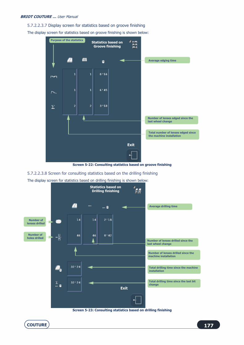
BRIOT COUTURE … User Manual
COUTURE 177
5.7.2.2.3.7 Display screen for statistics based on groove finishing
The display screen for statistics based on groove finishing is shown below:
Screen 5-22: Consulting statistics based on groove finishing
5.7.2.2.3.8 Screen for consulting statistics based on the drilling finishing
The display screen for statistics based on drilling finishing is shown below:
Screen 5-23: Consulting statistics based on drilling finishing
Purpose of the statistics
Statistics based on
Groove finishing
Average edging time
Number of lenses edged since the
last wheel change
Total number of lenses edged since
the machine installation
Exit
Exit
Exit
Number of lenses drilled since the last wheel change
Average drilling time
Number of
lenses drilled
Number of
holes drilled
Number of lenses drilled since the machine installation
Total drilling time since the machine installation
Total drilling time since the last bit change
Statistics based on Drilling finishing

BRIOT COUTURE … User Manual
COUTURE 178
5.7.2.2.3.9 Display screen for statistics based on the number of retouches
The display screen for statistics based on the number of retouches is shown below:
Screen 5-24: Consulting statistics based on retouch
5.7.2.2.3.10 Display screen for statistics based on user maintenance
The display screen for statistics based on user maintenance is shown below:
Screen 5-25: Consulting statistics based on user maintenance
Total number of lenses retouched
since the machine installation
Statistics based on retouches
Percentage of total of each type
Lens type (or machine total)
Exit
Statistics based on the maintenance
Exit
Number of replaced mill bits
Number of replaced feeler tips
Number of dressing operations for the finishing wheel
Number of dressing operations for the chamfering (facet)
Number of 12 mm abrasive point changeover

BRIOT COUTURE … User Manual
COUTURE 179
5.7.2.2.3.11 Display screen for statistics based on facets
Display screen for statistics based on facets:
Screen 5-26: Consulting statistics based on facet finishing
Screen 5-27: Consultation of statistics based on Smart Design
Statistics based on the maintenance
Exit
Total number of lenses
chamfered (facetted) since the machine installation
Number of lenses chamfered (facetted) since the last wheel
change
Average chamfering
(facetting) times
Total number of lenses edged since the machine installation.
Number of lenses edged since the last wheel change
Average time
Statistics based on the maintenance
Exit

BRIOT COUTURE … User Manual
COUTURE 180
5.8. MESSAGES
5.8.1. TYPES OF MESSAGES
There are three types of messages: Information messages Warning messages Fault messages
5.8.2. LIST OF MESSAGES.
The table below shows all the messages, the conditions for their display and the action to undertake.
# Message title Condition(s) for
display Action(s)
0x0 Grooving & drilling not
allowed on mineral lens.
Mineral lens material can neither
be grooved or drilled.
Adapt your job to Mineral lens
material: bevel or rimless
finishing or
Use another lens material for
the current job.
0x1 Edging parameters
incomplete.
You have started edging before
selecting all the parameters.
Check that all parameters have
been selected.
No "To be defined" button must be visible!
0x2 No job selected. You have started edging without
first loading a shape.
Load a shape, select the
parameters and then start the edging process.
0x4 Edging in progress. Job A is in progress and you
have called up job B.
Wait until the end of the job in
progress before loading another job.
0x5 Unknown job number The job number you are trying
to load does not exist on the server.
Check the job number and load
another number.
0x7 Do you want to re-edge the
same lens ?
You have just edged a lens and
then re-started a cycle on the same job number and the same
side.
YES: If you wish to edge the
same lens again or if you wish to edge several lenses with the
same parameters.
NO: Fit a new lens and proceed as you wish.
0x8 Please wait...
during machine shut down.
You have pressed for more than
6 seconds on the machine
standby button.
Wait until the machine has
stopped before switching off.
0x9 You can safely turn off your
machine.
You have asked for the machine
to stop. The close-down
procedure has been followed. The machine can now be
switched off.
Switch off the machine (On/Off
button pressed-in and unlit).

BRIOT COUTURE … User Manual
COUTURE 181
# Message title Condition(s) for
display Action(s)
0xA Incompatible edger configuration.
Trivex lens not allowed.
The job you have loaded calls for Trivex® lens material.
In the personalization menus,
you have excluded this parameter.
Therefore the edger cannot
accept this job.
Confirm the message. If you wish to load this job
nonetheless, change the
personalization of the pull-down menus.
Select Trivex® lens material.
Load the job again.
0xB Incompatible edger
configuration. HI lens not allowed.
The job you have loaded calls
for High Index (HI) lens material.
In the personalization menus,
you have excluded this
parameter.
Therefore the edger cannot
accept this job.
Confirm the message.
If you wish to load this job nonetheless, change the
personalization of the pull-down
menus.
Select High Index (HI) lens
material.
Load the job again.
0xC Incompatible edger
configuration.
Mineral lens not allowed.
The job you have loaded calls
for Mineral lens material.
In the personalization menus, you have excluded this
parameter.
Therefore the edger cannot accept this job.
Confirm the message.
If you wish to load this job
nonetheless, change the personalization of the pull-down
menus.
Select Mineral lens material. Load the job again.
0xD Incompatible edger configuration.
Organic lens not allowed.
The job you have loaded calls for CR39 lens material.
In the personalization menus,
you have excluded this parameter.
Therefore the edger cannot
accept this job.
Confirm the message. If you wish to load this job
nonetheless, change the
personalization of the pull-down menus.
Select CR39 lens material.
Load the job again.
0xE Incompatible edger
configuration. Polycarbonate lens not
allowed.
The job you have loaded calls
for Polycarbonate lens material. In the personalization menus,
you have excluded this
parameter. Therefore the edger cannot
accept this job.
Confirm the message.
If you wish to load this job nonetheless, change the
personalization of the pull-down
menus. Select Polycarbonate lens
material.
Load the job again.
0xF Incompatible edger
configuration.
Bevel finishing not allowed.
The job you have loaded calls
for Bevel finishing.
In the personalization menus, you have excluded this
parameter.
Therefore the edger cannot accept this job.
Confirm the message.
If you wish to load this job
nonetheless, change the personalization of the pull-down
menus.
Select Bevel finishing. Load the job again.

BRIOT COUTURE … User Manual
COUTURE 182
# Message title Condition(s) for
display Action(s)
0x10 Incompatible edger
configuration. Rimless finishing not
allowed.
The job you have loaded calls
for Rimless finishing. In the personalization menus,
you have excluded this
parameter. Therefore the edger cannot
accept this job.
Confirm the message.
If you wish to load this job nonetheless, change the
personalization of the pull-down
menus. Select Rimless finishing.
Load the job again.
0x11 Incompatible edger configuration.
Groove finishing not
allowed.
The job you have loaded calls for Groove finishing.
In the personalization menus,
you have excluded this parameter.
Therefore the edger cannot
accept this job.
Confirm the message. If you wish to load this job
nonetheless, change the
personalization of the pull-down menus.
Select Groove finishing.
Load the job again.
0x12 Incompatible edger
configuration.
Drilling finishing not allowed.
The job you have loaded calls
for Drilling finishing.
In the personalization menus, you have excluded this
parameter.
Therefore the edger cannot accept this job.
Confirm the message.
If you wish to load this job
nonetheless, change the personalization of the pull-down
menus.
Select Drilling finishing. Load the job again.
0x13 Incompatible edger
configuration. Groove/drilling finishing not
allowed.
The job you have loaded calls
for Grooving/Drilling finishing. In the personalization menus,
you have excluded this
parameter. Therefore the edger cannot
accept this job.
Confirm the message.
If you wish to load this job nonetheless, change the
personalization of the pull-down
menus. Select Grooving/Drilling
finishing.
Load the job again.
0x14 Incompatible edger
configuration.
Auto bevel sub-finishing not allowed.
The job you have loaded calls
for automatic Bevel sub-
finishing. In the personalization menus,
you have excluded this
parameter. Therefore the edger cannot
accept this job.
Confirm the message.
If you wish to load this job
nonetheless, change the personalization of the pull-down
menus.
Select automatic bevel sub-finishing.
Load the job again.
0x15 Incompatible edger configuration.
Basic bevel sub-finishing not
allowed.
The job you have loaded calls for basic Bevel sub-finishing.
In the personalization menus,
you have excluded this
parameter.
Therefore the edger cannot
accept this job.
Confirm the message. If you wish to load this job
nonetheless, change the
personalization of the pull-down
menus.
Select basic Bevel sub-finishing.
Load the job again.

BRIOT COUTURE … User Manual
COUTURE 183
# Message title Condition(s) for
display Action(s)
0x16 Incompatible edger configuration.
Bevel distance (in mm) sub-
finishing not allowed.
The job you have loaded calls for Bevel distance (in mm) sub-
finishing.
In the personalization menus, you have excluded this
parameter.
Therefore the edger cannot accept this job.
Confirm the message. If you wish to load this job
nonetheless, change the
personalization of the pull-down menus.
Select Bevel distance (in mm)
sub-finishing. Load the job again.
0x17 Incompatible edger
configuration. Bevel distance (in %) sub-
finishing not allowed.
The job you have loaded calls
for Percent bevel sub-finishing. In the personalization menus,
you have excluded this
parameter.
Therefore the edger cannot
accept this job.
Confirm the message.
If you wish to load this job nonetheless, change the
personalization of the pull-down
menus.
Select Percent bevel sub-
finishing.
Load the job again.
0x18 Incompatible edger
configuration.
Manual bevel sub-finishing not allowed.
The job you have loaded calls
for Manual bevel sub-finishing.
In the personalization menus, you have excluded this
parameter.
Therefore the edger cannot accept this job.
Confirm the message.
If you wish to load this job
nonetheless, change the personalization of the pull-down
menus.
Select Manual bevel sub-finishing.
Load the job again.
0x19 Incompatible edger configuration.
Automatic groove sub-
finishing not allowed.
The job you have loaded calls for automatic Groove sub-
finishing.
In the personalization menus, you have excluded this
parameter.
Therefore the edger cannot accept this job.
Confirm the message. If you wish to load this job
nonetheless, change the
personalization of the pull-down menus.
Select Automatic Groove sub-
finishing. Load the job again.
0x1A Incompatible edger
configuration. Basic groove sub-finishing
not allowed.
The job you have loaded calls
for Groove Curve sub-finishing. In the personalization menus,
you have excluded this
parameter. Therefore the edger cannot
accept this job.
Confirm the message.
If you wish to load this job nonetheless, change the
personalization of the pull-down
menus. Select Groove curve sub-
finishing.
Load the job again.
0x1B Incompatible edger
configuration.
Groove distance (in mm) sub-finishing not allowed.
The job you have loaded calls
for Groove distance (in mm)
sub-finishing. In the personalization menus,
you have excluded this
parameter. Therefore the edger cannot
accept this job.
Confirm the message.
If you wish to load this job
nonetheless, change the personalization of the pull-down
menus.
Select Groove distance (in mm) sub-finishing.
Load the job again.

BRIOT COUTURE … User Manual
COUTURE 184
# Message title Condition(s) for
display Action(s)
0x1C Incompatible edger
configuration. Groove distance (in %) sub-
finishing not allowed.
The job you have loaded calls
for Percent groove sub-finishing.
In the personalization menus,
you have excluded this parameter.
Therefore the edger cannot
accept this job.
Confirm the message.
If you wish to load this job nonetheless, change the
personalization of the pull-down
menus. Select Percent Groove sub-
finishing.
Load the job again.
0x1D Incompatible edger
configuration.
Manual groove sub-finishing not allowed.
The job you have loaded calls
for Manual groove sub-finishing.
In the personalization menus, you have excluded this
parameter.
Therefore the edger cannot accept this job.
Confirm the message.
If you wish to load this job
nonetheless, change the personalization of the pull-down
menus.
Select manual Groove sub-finishing.
Load the job again.
0x1E Incompatible edger configuration.
Drilling perpendicular to rear
face not allowed.
The job you have loaded calls for Drilling normal to rear face.
In the personalization menus,
you have excluded this parameter.
Therefore the edger cannot
accept this job.
Confirm the message. If you wish to load this job
nonetheless, change the
personalization of the pull-down menus.
Select Drilling normal to rear
face sub-finishing. Load the job again.
0x1F Incompatible edger
configuration. Drilling perpendicular to
front face not allowed.
The job you have loaded calls
for Drilling normal to front face. In the personalization menus,
you have excluded this
parameter. Therefore the edger cannot
accept this job.
Confirm the message.
If you wish to load this job nonetheless, change the
personalization of the pull-down
menus. Select Drilling normal to rear
face sub-finishing.
Load the job again.
0x20 Incompatible edger
configuration.
Drilling parallel to clamp shaft not allowed.
The job you have loaded calls
for Drilling parallel to clamp
shaft. In the personalization menus,
you have excluded this
parameter. Therefore the edger cannot
accept this job.
Confirm the message.
If you wish to load this job
nonetheless, change the personalization of the pull-down
menus.
Select Drilling parallel to clamp shaft.
Load the job again.
0x21 Incompatible edger
configuration.
Front safety-bevel not
allowed.
The job you have loaded calls
for front safety-bevel.
In the personalization menus,
you have excluded this parameter.
Therefore the edger cannot
accept this job.
Confirm the message.
If you wish to load this job
nonetheless, change the
personalization of the pull-down menus.
Select safety-bevel parameter
on the front face of the lens. Load the job again.

BRIOT COUTURE … User Manual
COUTURE 185
# Message title Condition(s) for
display Action(s)
0x22 Incompatible edger configuration.
Rear safety-bevel not
allowed.
The job you have loaded calls for rear safety-bevel.
In the personalization menus,
you have excluded this parameter.
Therefore the edger cannot
accept this job.
Confirm the message. If you wish to load this job
nonetheless, change the
personalization of the pull-down menus.
Select safety-bevel parameter
on the rear face of the lens. Load the job again.
0x23 Incompatible edger configuration.
Rear safety-bevel not
allowed.
The job you have loaded calls for front and rear safety-bevels.
In the personalization menus,
you have excluded this
parameter.
Therefore the edger cannot
accept this job.
Confirm the message. If you wish to load this job
nonetheless, change the
personalization of the pull-down
menus.
Select front and rear safety-
bevel parameter. Load the job again.
0x24 Incompatible edger configuration.
Lens without safety-bevel
not allowed.
The job you have loaded has the No safety-bevel parameter.
In the personalization menus,
you have excluded this parameter.
Therefore the edger cannot
accept this job.
Confirm the message. If you wish to load this job
nonetheless, change the
personalization of the pull-down menus.
Select the No safety-bevel
parameter. Load the job again.
0x25 Incompatible edger
configuration. Safety-bevel to be defined
not allowed.
The job you have loaded has the
parameter Safety-bevel to be defined.
In the personalization menus,
you have excluded this parameter.
Therefore the edger cannot
accept this job.
Confirm the message.
If you wish to load this job nonetheless, change the
personalization of the pull-down
menus. Select the Safety-bevel to be
defined parameter.
Load the job again.
0x26 Retouch impossible on
drilled or grooved lens.
You wish to undertake a retouch
on a lens which has been drilled
or grooved. This operation is impossible on a lens with these
finishes.
Carry out the lens size
adjustment procedure. Fit a new
lens and enter a negative oversize value.
0x2B Wrong job received. Problems of communication
with the server have been detected.
Load another job number.

BRIOT COUTURE … User Manual
COUTURE 186
# Message title Condition(s) for
display Action(s)
0x30 Do you want to save the
new personalization?
At least one of the menu
personalization parameters has changed. The machine requests
confirmation of this
modification.
Confirm: the new
personalization is registered. No confirmation: the new
personalization is not
registered. The previous personalization is retained.
Cancel: you return to the
personalization screen for the menu-button concerned. Select
again the elements that you
wish to be displayed.
0x34 Groove too near front. The distance between the front face of the lens and the external
edge of the groove is less than
0.2 mm.
Confirm the message. Select Manual groove sub-
finishing.
Display the position of the groove on the control screen.
Reposition the groove.
0x35 Groove too far back. The distance between the rear
face of the lens and the internal
edge of the groove is less than 0.2 mm.
Confirm the message.
Select Manual groove sub-
finishing. Display the position of the
groove on the control screen.
Reposition the groove.
0x100 Requested job does not
exist.
You have called up a job
number but the corresponding job is not on the server.
Load another number.
0x101 No response from server within time limit.
You have tried to load a job but the edger has not received a
signal from the server.
Check that: - The server is switched on.
- The OMA cord is correctly
connected to both terminals. Then load the job again.
0x102 No server connected. The OMA cord is disconnected. OR
The server is switched off.
Check that: - The server is switched on.
- The OMA cord is correctly
connected to both terminals.
Then load the job again.
0x103 Corrupt OMA frame. The OMA frame sent by the server displays a fault which
prevents reception.
Contact a Briot technician.

BRIOT COUTURE … User Manual
COUTURE 187
# Message title Condition(s) for
display Action(s)
0x104 Invalid OMA frame. The OMA frame sent by the server displays parameters
which the edger does not
recognise.
Contact a Briot technician.
0x300 Touch screen not detected. When the edger is initialized,
the touch screen is not
detected.
Contact a Briot technician.
0x404 Safety-bevelling or grooving
not possible
Safety-bevel and/or groove
cannot be made.
Confirm the message.
Select new parameters.
0x405 Holes removed (at least one
was unfeasible).
Do you want to continue?
The drilling plan includes at
least one hole positioned too
close to the block or too far from the edge of the lens.
YES: the lens is edged but not
drilled. Then you can produce
the holes with a drill. NO: the lens is not edged.
Remove the lens from the
edging station.
0x406 External safety-bevel will
not be made.
Do you want to continue?
External safety-bevel cannot be
made.
The lens is too thin and/or the shape is too small.
YES: the lens is edged without
an external safety-bevel.
NO: the lens is not edged. Remove the lens from the
edging station.
0x407 Internal safety-bevel will not
be made. Do you want to continue?
Internal safety-bevel cannot be
made. The lens is too thin and/or the
shape is too small.
YES: the lens is edged without
an external safety-bevel. NO: the lens is not edged.
Remove the lens from the
edging station.
0x408 The groove cannot be made. Do you want to continue?
The groove cannot be made. The lens is too thin and/or the
shape is too small.
YES: the lens is edged without a groove.
NO: the lens is not edged.
Remove the lens from the edging station.
0x409 The safety-bevels will not be
made.
Do you want to continue?
The safety-bevels cannot be
made.
The lens is too thin and/or the shape is too small.
YES: the lens is edged without
the safety-bevels.
NO: the lens is not edged. Remove the lens from the
edging station.
0x40A External safety-bevel and
groove cannot be made. Do you want to continue?
External safety-bevel and
groove cannot be made. The lens is too thin and/or the
shape is too small.
YES: the lens is edged without
an external safety-bevel or a groove.
NO: the lens is not edged.
Remove the lens from the edging station.
0x40B Internal safety-bevel and
groove cannot be made.
Do you want to continue?
Internal safety-bevel and
groove cannot be made.
The lens is too thin and/or the shape is too small.
YES: the lens is edged without
an internal safety-bevel or a
groove. NO: the lens is not edged.
Remove the lens from the
edging station.

BRIOT COUTURE … User Manual
COUTURE 188
# Message title Condition(s) for
display Action(s)
0x40C Safety-bevels and groove
cannot be made. Do you want to continue?
Safety-bevels and groove
cannot be made. The lens is too thin and/or the
shape is too small.
YES: the lens is edged without
the safety-bevels or the groove. NO: the lens is not edged.
Remove the lens from the
edging station.
0x40D Lens too thick: edging impossible.
The lens thickness at the measured point is greater than
11 mm. The lens cannot be
edged.
Confirm the message. Remove the lens from the
edging station.
0x40E Edging stopped: visor open. You have opened the visor during the edging cycle.
Check the lens and remove it from the edging station.
Confirm the message.
0x40F Problem detected. Machine re-initialisation.
A problem has been detected during the cycle. The machine
must restart before continuing.
Confirm the message.
0x410 Lens too small. Do you want
to continue?
Lens too small or too off-
centered in comparison with the
shape.
YES: the lens is felt again 0.5
mm closer to the interior.
It can be re-felt 3 successive times, 0.5 mm closer to the
interior each time.
NO: Remove the lens from the edging station.
0x411 Small adaptors fitted? The 19 mm diameter adaptors
are required for the procedure
you have selected.
Confirm the message.
Fit the small adaptors.
0x412 Small adaptors fitted? The 17 mm diameter adaptors over flats are required for the
procedure you have selected.
Confirm the message. Fit the small flat adaptors.
0x413 Edging impossible,radius
too small
The shape is smaller than the
smallest adaptor.
Confirm the message.
Remove the lens from the
edging station.
0x414 A feeler fault has been
detected during feeling.
An irregularity has been
detected during lens feeling.
Confirm the message.
Restart the cycle and observe
the lens feeling process:
- If one of the tips is unclipped,
refit it.
- If not, proceed with the lens feeling adjustment.
0x415 Bevel out of lens. The bevel is outside the lens in
at least one point.
Confirm the message.
Display the fault on the control screen and proceed as required.

BRIOT COUTURE … User Manual
COUTURE 189
# Message title Condition(s) for
display Action(s)
0x416 Retouch impossible. You have activated the retouch control and the lens detected
does not match the parameters
of the lens you wish to retouch.
Confirm the message. Remove the lens fitted on the
shafts.
Fit the lens that you actually want to retouch.
0x41A Lens too thin to be grooved, do you want to continue?
A thickness of less than 1 mm has been detected in at least
one point of the lens.
YES: The lens is edged with rimless finishing.
NO: The cycle is stopped.
Remove the lens from the edging station.
0x41B Lens too small. Feeling carried out 3 successive
times, 0.5 mm closer to the interior each time.
Lens too small or too off-
centered in comparison with the shape.
Confirm the message.
Remove the lens from the edging station.
0x41C Bit diameter > hole
diameter.
Do you want to drill?
The diameter of at least one
hole is smaller than the
diameter of the mill bit. But the minimum drilling
diameter is equal to the bit
diameter.
YES: The hole(s) will be drilled
with a minimum diameter equal
to that of the bit. NO: the lens is not edged.
Remove the lens from the
edging station.
0x506 Please remove lens to free
mill bit before
acknowledging this
message.
A fault has occurred when the
mill bit was not in its housing.
The lens could be damaged.
Make sure that the machine is
switched off.
Free the lens from the mill bit
carefully.
Restart the machine.
0x508 Replacing the mill bit is recommended.
Do you want to do it now?
At start-up, the machine records total drilling time greater than 1
hr. Replacing the mill bit is
recommended.
YES: Replace the mill bit (see “Replacing the mill bit”).
NO: You accept the risk of using
a worn mill bit. The risk of chipping the lens is increased.
The message is displayed at
each machine startup.

BRIOT COUTURE … User Manual
COUTURE 190
# Message title Condition(s) for
display Action(s)
0x509 Mineral wheel dressing
recommended. Do you want to do it now?
1000 mineral lenses have been
edged. Dressing the mineral roughing wheel is
recommended.
YES: Dress the mineral roughing
wheel (see “Dressing a wheel”) NO: You accept the risk of using
a dirty wheel. The risk of lens
size error is increased, and so is the edging time. The message
is displayed at each machine
startup.
0x50A Finishing wheel dressing
recommended. Do you want to do it now?
800 mineral lenses have been
edged with bevel finishing. Dressing the mineral roughing
wheel is recommended.
YES: Dress the mineral roughing
wheel (see “Dressing a wheel”) NO: You accept the risk of using
a dirty wheel. The risk of lens
size error is increased, and so is the edging time. The message
is displayed at each machine
startup.
0x902 Dressing impossible
Wrong disc thickness.
The thickness of the fitted disc
does not match the theoretically required thickness.
Confirm the message.
Use an appropriate dressing disc.
0x903 Dressing impossible
Disc diameter too small.
The volume of material to be
machined is less than the minimum volume required.
Confirm the message.
Use an appropriate dressing disc.
0x50C Low voltage source The voltage detected is less
than 20% of the normal voltage.
Please contact your electricity
supplier.
0x909 Adjustment impossible:
Lens too small.
The diameter of the felt lens is
less than 11 mm.
Confirm the message.
Fit another lens 10 00 205 blocked at the centre.

6. TESTS 6

BRIOT COUTURE … User Manual
COUTURE 192
6.1. PRESENTATION OF TEST MENUS
6.1.1. PRESENTATION OF THE TEST ACCESS SCREEN
6.1.1.1. SCREEN DESCRIPTION
The test access screen is shown below:
Screen 6-1: Test access screen
Note: *SBGD = Safety-Bevel Grooving Drilling system
6.1.1.2. ACCESS / EXIT
6.1.1.2.1. TO ACCESS THE SCREEN
6.1.1.2.2. TO EXIT THE SCREEN
x 2
Feeling
You are in the Tests menu
To exit =>
Lifting jack
movement
Carriage
movement Lens rotation
Shaft Opening/closing
Wheel
rotation Visor
Opening/closing
SBGD exit/return*
Pump Key contact
test Touch screen Temperature
Voltmeter Communication Encoders Micro-switches
and photocells

BRIOT COUTURE … User Manual
COUTURE 193
6.1.2. TYPICAL TEST SCREEN
The following screen (lens feeling test) is typical of most tests (“Operating principle”):
You are in the lens feeler test screen
Stopping
current cycle
POSITION of the lens feeler tip END
TEST VALUES
Rear Face Feeler ENCODER COUNTS
Lens THICKNESS
To exit =>
Emergency stop
Micro-switch status
Front Face Feeler

BRIOT COUTURE … User Manual
COUTURE 194
6.2. OPERATING PRINCIPLE
6.2.1. OPERATING PRINCIPLE OF A TYPICAL SCREEN
6.2.1.1. TESTS INVOLVED
The following test screens operate on the same principle: • Lens feeling • Lifting jack movement • Wheel unit translation movement • Lens rotation • SBGD exit/return • Visor Opening/closing • Wheel rotation • Opening/closing of lens clamp shaft
6.2.1.2. PROCEDURE
The operating principle is as follows:
#1
Initialise the movement [mandatory].
#2
Enter a percentage of "one-way" movement.
OR
#2
Enter a percentage of "round-trip" movement.
#3
Enter the number of cycles to be completed.
#4
Enter a power percentage.
#5
Start the test.
Flow chart 6-1: Operating principle of a typical test screen
6.2.1.3. TEST SEQUENCE
Tests must be undertaken in a logical sequence. The tests which appear grayed cannot be carried out so long as the previous accessible test has not been started.
Example: The lens rotation test cannot be undertaken if the lens feelers, lifting jack movement and wheel unit
translation movement tests have not already been carried out.

BRIOT COUTURE … User Manual
COUTURE 195
6.2.2. OPERATION OF THE OTHER SCREENS
6.2.2.1. SCREEN WITH SWITCH
6.2.2.1.1. PRESENTATION
The following screen corresponds to the solenoid valve, pump and extractor tests:
Screen 6-2: Test screen with switch
6.2.2.1.2. PROCEDURE
To start the test, press the switch of the element you wish to test.
Observe the test.
To stop the test, press the switch again.
Rear of edging
chamber spraying
To exit =>
Wheels spraying
Visor
spraying Pump
Extractor

BRIOT COUTURE … User Manual
COUTURE 196
6.2.2.2. SCREEN WITH MICRO-SWITCHES AND PHOTOCELLS
6.2.2.2.1. PRESENTATION
The following screen corresponds to the test screen for all micro-switches and photocells:
Screen 6-3: Test of micro-switches and photocells
6.2.2.2.2. PROCEDURE
Manually operate the micro-switch or photocell of the element you wish to test.
Observe the status of the micro-switch or photocell on the screen.
Exit

7. TECHNICAL SPECIFICATIONS 7

BRIOT COUTURE … User Manual
COUTURE 198
7.1. CHARACTERISTICS
Automatic initialization
Feeling front & rear lens faces in 3 dimensions Equipment:
BRIOT COUTURE (all materials)
Mineral roughing wheel
Roughing wheel for all plastics (CR39, high index, polycarbonate, Tribrid, TrivexTM)
Chamfering - bevel - rimless finishing wheel
Rimless polishing wheel.
BRIOT COUTURE (all plastics)
Roughing wheel for all plastics (CR39, high index, polycarbonate, Tribrid, TrivexTM)
Chamfering - bevel - rimless finishing wheel
Bevel/rimless polishing wheel.
Automatic clamping pressure Automatic edging pressure adjusted according to material to be edged Lens grooving Drilling wide choice of holes:
Through holes
Non-through holes
Couterbored hole
Notches
Elongated holes.
Rectangular
Round
Drilling at variable angles:
Parallel to the lens clamping shaft and lens holder shaft
Normal to front face
Normal to rear face
Normal to base
Smart Design function Safety-beveling of front and/or rear faces of the lens Connection for pump if operating in closed water circuit Edging diameter
Lens diameter <= 80 mm
If machine equipped with BRIOT adapters:
Rimless (without safety-bevel) = 17 mm
Bevel (without safety-bevel) = 18.6 mm
Grooving (without safety-bevel) = 17 mm + twice the groove depth (If depth = 0.6 mm then D =18.20 mm)
Safety-bevel = 21 mm
Machine equipped with WECO adapters:
Rimless (without safety-bevel) = 17.75 mm
Bevel (without safety-bevel) = 19.5 mm
Grooving (without safety-bevel) = 17.3 mm + twice the groove depth (If depth = 0.6 mm then D =18.50 mm)
If finish with bevel, safety-bevel >= 22.9 mm
If finish with bevel, safety-bevel >= 21.3 mm

BRIOT COUTURE … User Manual
COUTURE 199
BRIOT COUTURE (all materials):
Chamfering >= 19.95mm + (2 x height of chamfer)
BRIOT COUTURE (all plastics):
Chamfering >= 20.95mm + (2 x height of chamfer)
Automatic cleaning of shafts and edging station Edging statistics Personalized machine configuration Network connection Option to extract air and emitted dust.

BRIOT COUTURE … User Manual
COUTURE 200
7.2. TECHNICAL SPECIFICATIONS
7.2.1. BRIOT COUTURE
Θ GENERAL
Designed for internal use Dimensions
Width = 510 mm
Depth = 615 mm
Height = 570 mm
Weight = 69 kg Pump section outlet; Power available (for the pump) = 450 W Maximum water pressure = 2 to 7 bars (pH 7 - 7.5) Controls/mains insulation stepped up Noise level = 66 dB Degree of pollution = 2 Installation category = II Ambient temperature = 13° C to 35° C Relative humidity = 10% to 80% Maximum elevation = 2000 m IP 20 Meets CE directives
230 V - 50 HZ OR 60 HZ EDGER
Input voltage = 230 V +/-10% Power consumption = 8 A Electric power = 1800 W Fuses F3 = 3.15 AT Littelfuse 2183-15 F4 and F5 = 3.15 AT Littelfuse 2183-15 F6 = 8 AT Littelfuse 218008
120 V - 60 HZ EDGER
Input voltage = 120 V +/-10% Power consumption = 15 A
Electric power = 1800 W Fuses F3 = 5 AT Ferraz 250 V 5ST 5x20 F4 and F5 = 5 AT Ferraz 250 V 5ST 5x20 F6 = 8 AT Littelfuse 218008 ETL marking for 120 V - 60 Hz version:
UL 61010 - 1
CAN/CSA C22.2 No. 61010 - 1
THE MANUFACTURER CANNOT BE HELD RESPONSIBLE FOR DAMAGE CAUSED BY ANY USE OF THE MACHINE WHICH
DOES NOT COMPLY WITH THE INSTRUCTIONS IN THIS MANUAL OR DISPLAYED ON THE MACHINE ITSELF.

LUNEAU TECHNOLOGY SAS2 Rue Roger Bonnet, 27340 Pont-de-l’Arche - FranceTél. + 33 232 989 132 - Fax + 33 235 020 [email protected]
www.visionix.com
This
doc
umen
t is
not c
ontra
ctua
l. Fe
atur
es a
nd s
peci
ficat
ions
ar
e su
bjec
t to
chan
ge w
ithou
t prio
r not
ice.