biomedical engineering online
TRANSCRIPT
BioMed CentralBioMedical Engineering OnLine
ss
Open AcceReviewSurface pretreatments for medical application of adhesionHans J Erli†2, Rudolf Marx*†1, Othmar Paar2, Fritz U Niethard3, Michael Weber†1 and Dieter C Wirtz†3Address: 1Department of Prosthetic Dentistry, Section of Dental Materials, University Hospital of the University of Technology, Aachen, Germany, 2Department for Trauma Surgery, University Hospital of the University of Technology, Aachen, Germany and 3Department of Orthopedic Surgery, University Hospital of the University of Technology, Aachen, Germany
Email: Hans J Erli - [email protected]; Rudolf Marx* - [email protected]; Othmar Paar - [email protected]; Fritz U Niethard - [email protected]; Michael Weber - [email protected]; Dieter C Wirtz - [email protected]
* Corresponding author †Equal contributors
AbstractMedical implants and prostheses (artificial hips, tendono- and ligament plasties) usually are multi-component systems that may be machined from one of three material classes: metals, plastics andceramics. Typically, the body-sided bonding element is bone.
The purpose of this contribution is to describe developments carried out to optimize thetechniques , connecting prosthesis to bone, to be joined by an adhesive bone cement at theirinterface. Although bonding of organic polymers to inorganic or organic surfaces and to bone hasa long history, there remains a serious obstacle in realizing long-term high-bonding strengths in thein vivo body environment of ever present high humidity.
Therefore, different pretreatments, individually adapted to the actual combination of materials, areneeded to assure long term adhesive strength and stability against hydrolysis. This pretreatment formetal alloys may be silica layering; for PE-plastics, a specific plasma activation; and for bone,amphiphilic layering systems such that the hydrophilic properties of bone become better adaptedto the hydrophobic properties of the bone cement. Amphiphilic layering systems are related tothose developed in dentistry for dentine bonding.
Specific pretreatment can significantly increase bond strengths, particularly after long termimmersion in water under conditions similar to those in the human body. The bond strengthbetween bone and plastic for example can be increased by a factor approaching 50 (pealing workincreasing from 30 N/m to 1500 N/m).
This review article summarizes the multi-disciplined subject of adhesion and adhesives, consideringthe technology involved in the formation and mechanical performance of adhesives joints inside thehuman body.
IntroductionImplants and prostheses can help provide numerous use-ful functions for the human body. However, a device fab-ricated from a single material usually cannot meet all
physical requirements for successful implantation andfunction. Therefore, implants and prostheses usually con-sist of composites and mixtures or alloys.
Published: 18 September 2003
BioMedical Engineering OnLine 2003, 2:15
Received: 18 March 2003Accepted: 18 September 2003
This article is available from: http://www.biomedical-engineering-online.com/content/2/1/15
© 2003 Erli et al; licensee BioMed Central Ltd. This is an Open Access article: verbatim copying and redistribution of this article are permitted in all media for any purpose, provided this notice is preserved along with the article's original URL.
Page 1 of 18(page number not for citation purposes)
BioMedical Engineering OnLine 2003, 2 http://www.biomedical-engineering-online.com/content/2/1/15
Over the last decade, the growth in the use of adhesives formedical applications has been rapid, with many impor-tant developments in the technology of adhesive tech-niques being reported. This growth has also drawnattention to basic studies in the science of adhesion andadhesives, particularly concerning stability under wet con-ditions. There are many analogies between adhesivebonds for industrial applications and the requirements forpre-treatments and adhesives inside the human body. Formany industrial applications, stable bond strengths aremandatory, particularly in the presence of elevated tem-perature and humidity. These conditions are also presentin the human body. In common for the human body andmany industrial applications is the relative humidity of100%, a challenge for any adhesive joining. The elevatedtemperature (37°C inside the body compared with roomtemperature) means higher diffusion rates of water mole-cules through permeable materials like plastics [1].
Long-term stability is crucial for attaining a useful service-life. A bonded component may deteriorate upon exposureof the adhesive interface to its normal operating environ-ment. In the case of structural adhesive interfaces consist-ing of metallic substrates, empirical investigationsestablished many years ago revealed that water, either inliquid or vapor form, is the most hostile environment thatis commonly encountered. The presence of moisture,rather than other components of body fluids, is responsi-ble for the environmental attack, while an appliedmechanical load further increases the rate of adhesionloss. The loss in strength is attributed to the de-bonding ofresin from the metal by the intrusion of water, since obvi-ously the interface between such dissimilar materials as anorganic polymer and a metal does not allow the forma-tion of a water-resistant bond. Similar reasoning holdsthat a similar effect occurs when the substrate is a ceramicor a plastic. Here, also, the presence of water is the mosthostile environment when its molecules come into com-petition with the bonds between the adhesive and theprosthesis. Thus, suitable technologies need to be devel-oped to join different compound materials adhesively toeach other or to human body structures when long servicelife with sufficient adhesion strengths is the goal. Forimplants and prostheses, long-term stability means a lowfailure rate over the total implant time.
In the following review, some issues from the medicalfields for which adhesive techniques are already estab-lished or for which the functionality may be improved byadhesive techniques are discussed, particularly within thebackground of our research results.
ReviewOrthopedic total endoprosthesesHip replacement surgery in the developed countries isbecoming more common as the population has increas-ing life expectancy. There are two types of artificial hipreplacements, the cemented prosthesis focused in thepresent investigation, and the uncemented prosthesis,which is not being considered here.
Each prosthesis is made up of two parts, the femoral stemcomponent which replaces the femoral head and neck,and the acetabular cup component which replaces theacetabulum. Both are held in place by polymethylmeth-acrylate (PMMA) using cementing fixation technique. Thefemoral stem is made of metal (CoCr- or Ti-alloy) and hasa modular ceramic ball on its neck that fits into the acetab-ular cup component and acts as a low friction bearing. Theacetabular cup is most frequently made out of ultra-highmolecular weight polyethylene (UHMWPE).
There are many reasons why an artificial hip replacementfinally fails [2]. Aseptic loosening of cemented implantscauses more than 80% of clinical revisions [3–5].Although this loosening may be due to a wide range of dif-ferent factors, several researchers having performed clini-cal and histological studies have been able to show thatthe beginning of the aseptic loosening process in femoralstems is found in the cement-metal interface (debonding)[6,7]. Supported by diffusion and capillary forces, watermolecules find their way into the bone cement and finallyinto the bone cement-metal interface, separating cementfrom metal by hydrolytic degradation of the primarybond.
As a consequence of the de-bonding, micro-movementbetween the implant and bone cement starts and thenincreases, and eventually leads to the development ofwear debris of cement particles, cement fissures, andcement fractures, with the formation of osteolytic reac-tions within the periprosthetic bone. Loosening of theprosthesis is the final result [8].
Although the rate of loosening has been reduced over thepast two decades by improved cementing technology andmore suitable implant materials, permanent resistance tohydrolytic degradation of the bond of the acrylic PMMAonto the metal surface remains an important unsolvedproblem in total hip arthroplasty of the femoral stem. Incontrast, the weak link of the chain of bonding on theacetabular side is the long-term bond stability betweenthe acrylic PMMA and the acetabular bone stock. There isno true microinterlocking between the cement and thesubchondral sclerotic acetabular bone after reaming theacetabulum. Several studies of primary total hip arthro-plasties with cemented cups showed an increasing failure
Page 2 of 18(page number not for citation purposes)
BioMedical Engineering OnLine 2003, 2 http://www.biomedical-engineering-online.com/content/2/1/15
rate after 8 to 10 years of implantation. On the acetabularside, the bond between the polymer polyethylene and thepolymer bone cement is not of primary concern in reduc-ing the rate of loosening, nevertheless it should not beforgotten.
In this review, the metal stem and the plastic acetabularcup will be the main focus for applicability and usefulnessof adhesion techniques with the aim of reducing thedescribed deficiencies
Metal femoral stemBasicsThe metal femoral stem is implanted into the femur afterthe bone has been prepared by rasping within it a conicalcavity. No adhesive is needed when the implant is fixatedwithout cement ("uncemented prosthesis"), since theimplant surface is covered with a fine mesh of holes (e.g.)that allows bone to grow into the mesh and to tightlyattach to the prosthesis. However, an adhesive techniquebecomes necessary when the prosthesis is to be held inplace by bone cement ("cemented prosthesis"). Bonecement has a methacrylate base, and is used to glue themetal shaft to the mostly cancellous bone of the femurcavity walls (exception: in a hip re-operation, the walls areno longer cancellous). The interfaces metal stem/bone ofthe femur are mechanically (walking, jumping, etc.) andchemically (body reaction, temperature, humidity)stressed. Whereas the cancellous bone offers many reten-tive centers that facilitate a long-life effective anchorage ofthe bone cement to the inner walls of the cavity, the metalsurface, however, is much more subject to the risk of de-bonding. Since the surface of the metallic femur (usuallymachined out of CoCrMo or TiAl6V4 alloy) is substan-tially smooth, mechanical retention has secondary mean-ing and chemical bonding is essential [9,10]. Even if therewere mechanical interlocking, experience has shown thatwith the moist conditions of the human body, interlock-ing between a plastic and a metal alone is not sufficient fora stable bond [11–13].
Water, omnipresent in the body, has an aggressive impacton the metal/acrylic joint interface, in particular becauseof the strong dipole moments of the water molecules. Theinterface is not protected against the attack of water evenif a gap-free and tight contact between substrate and adhe-sive could be established. The water molecules can pene-trate into the interface by diffusion, since the bone cementas a plastic is permeable; the water molecules are respon-sible for the hydrolytic load of chemical bonding of anykind. Water molecules diffuse through any acrylic poly-mer, and eventually reach that interface which is expectedto guarantee the bond between the two materials. Individ-ual water molecules become clustered into a liquid phase.The chemical bond strength is then challenged. The dan-
ger of water at the interface is primarily not determined bythe rate of permeation of water through the polymermatrix, but by the amount of moisture finally retained atthe interface.
Metal surfaces form metal-oxides, oxide-hydrates, andhydroxides when they are exposed to a moist, oxygen con-taining environment. Therefore, after application thePMMA bone cement does not come in touch directly withthe atoms of the bare metal surface, but rather with themetal-oxide layer on it. Such oxide layers may allow highinitial bond strengths to an acrylic polymer because ofbridge linkage, dipole-dipole interactions, and polariza-tion effects. These high initial bond strengths, however,decrease under the influence of clustered water molecules,which shift the chemical balance that is inside the layersystem responsible for bonding, towards the hydrolyzedstate of the interface. The chemical balance, althoughhighly simplified, can be illustrated as follows:
C stands for a carbon atom of the PMMA. After decompo-sition involving splitting of bonds and addition of the ele-ments of water, the bonding strength decreases becausethe hydrolyzed links (right handed side) can only bearfewer mechanical stresses [14].
The water molecules penetrating the PMMA, however, donot only have deteriorating influences, but also healingeffects. The interface becomes pre-loaded during polymer-ization [15], and the corresponding shrinkage stresses theinterface mechanically. This shrinkage is partly compen-sated by the materials' expansion due to penetratingwater. This expansion (1–2%) in part releases the stressdue to post polymerization shrinkage (6–7%).
The use of a silane [28] as a bonding agent does not solvethe problem of unstable bond strength, since the covalentbonds between a silane and the hydroxyl groups -OH of ametal surface have too poor a hydrolytic stability as well.The silane can realize chemical bondings to the CH2groups of the methylmethacrylate [16–19], but not to themetal, since silane coupling agents are designed to stick tomineral surfaces by siloxane bonds, while a metal surface,even if oxidized, does not have the active groups that areneeded. In the presence of a wet atmosphere, the silanecoupling agent is not efficient in contact with a bare metaloxide without mineral enrichment, and hence it is notable to stabilize the bonding when high long-term bondstrength is required.
MeO
CH2O
Kn Me-O-C
MeOH HOC
Page 3 of 18(page number not for citation purposes)
BioMedical Engineering OnLine 2003, 2 http://www.biomedical-engineering-online.com/content/2/1/15
Hence, it becomes obvious that the long-term adhesivestrength between silane interlayer/methylmethacrylateand the metal surface can be improved only if the metalsurface is modified by an adequate mineral coating[16,20,21]. To this end, an additional interlayer of silica isadded such that silicon oxide (SiOx) is adhered to theoxides already present on the metal surface [22–24].
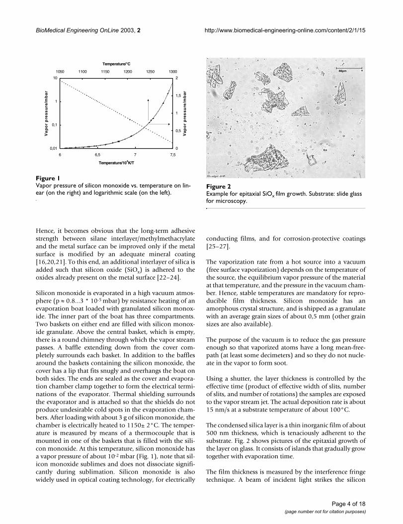
Silicon monoxide is evaporated in a high vacuum atmos-phere (p ≈ 0.8...3 * 10-5 mbar) by resistance heating of anevaporation boat loaded with granulated silicon monox-ide. The inner part of the boat has three compartments.Two baskets on either end are filled with silicon monox-ide granulate. Above the central basket, which is empty,there is a round chimney through which the vapor streampasses. A baffle extending down from the cover com-pletely surrounds each basket. In addition to the bafflesaround the baskets containing the silicon monoxide, thecover has a lip that fits snugly and overhangs the boat onboth sides. The ends are sealed as the cover and evapora-tion chamber clamp together to form the electrical termi-nations of the evaporator. Thermal shielding surroundsthe evaporator and is attached so that the shields do notproduce undesirable cold spots in the evaporation cham-bers. After loading with about 3 g of silicon monoxide, thechamber is electrically heated to 1150± 2°C. The temper-ature is measured by means of a thermocouple that ismounted in one of the baskets that is filled with the sili-con monoxide. At this temperature, silicon monoxide hasa vapor pressure of about 10-2 mbar (Fig. 1), note that sil-icon monoxide sublimes and does not dissociate signifi-cantly during sublimation. Silicon monoxide is alsowidely used in optical coating technology, for electrically
conducting films, and for corrosion-protective coatings[25–27].
The vaporization rate from a hot source into a vacuum(free surface vaporization) depends on the temperature ofthe source, the equilibrium vapor pressure of the materialat that temperature, and the pressure in the vacuum cham-ber. Hence, stable temperatures are mandatory for repro-ducible film thickness. Silicon monoxide has anamorphous crystal structure, and is shipped as a granulatewith an average grain sizes of about 0,5 mm (other grainsizes are also available).
The purpose of the vacuum is to reduce the gas pressureenough so that vaporized atoms have a long mean-free-path (at least some decimeters) and so they do not nucle-ate in the vapor to form soot.
Using a shutter, the layer thickness is controlled by theeffective time (product of effective width of slits, numberof slits, and number of rotations) the samples are exposedto the vapor stream jet. The actual deposition rate is about15 nm/s at a substrate temperature of about 100°C.
The condensed silica layer is a thin inorganic film of about500 nm thickness, which is tenaciously adherent to thesubstrate. Fig. 2 shows pictures of the epitaxial growth ofthe layer on glass. It consists of islands that gradually growtogether with evaporation time.
The film thickness is measured by the interference fringetechnique. A beam of incident light strikes the silicon
Vapor pressure of silicon monoxide vs. temperature on lin-ear (on the right) and logarithmic scale (on the left)Figure 1Vapor pressure of silicon monoxide vs. temperature on lin-ear (on the right) and logarithmic scale (on the left).
0,01
0,1
1
10
6 6,5 7 7,5
Temperature/104K/T
Va
po
r p
res
su
re/m
ba
r
0
0,5
1
1,5
2
1050 1100 1150 1200 1250 1300
Temperature/°C
Va
po
r p
res
su
re/m
ba
rExample for epitaxial SiOx film growthFigure 2Example for epitaxial SiOx film growth. Substrate: slide glass for microscopy.
Page 4 of 18(page number not for citation purposes)
BioMedical Engineering OnLine 2003, 2 http://www.biomedical-engineering-online.com/content/2/1/15
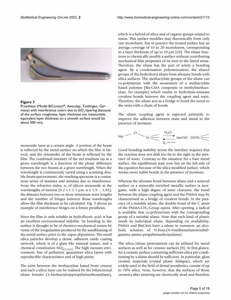
monoxide layer at a certain angle. A portion of the beamis reflected by the metal surface on which the film is lay-ered, and the remainder of the beam is reflected by thefilm. The combined intensity of the net resultant ray at agiven wavelength is a function of the phase differencebetween the two beams at a given wavelength. When thewavelength is continuously varied using a scanning dou-ble-beam spectrometer, the resulting spectrum is a contin-uous series of maxima and minima due to interference.From the refractive index, n, of silicon monoxide at thewavelengths of interest (0.2 ≤ λ ≤ 1 µm, n ≅ 1,9 ... 1,85),the distance between two or more minimum wave lengthsand the number of fringes between those wavelengthsallow the film thickness to be calculated. Fig. 3 shows anexample of interference fringes on a femur prosthesis.
Since the film is only soluble in hydrofluoric acid, it hasan excellent environmental stability. Its bonding to thesurface is thought to be of chemico-mechanical nature byvirtue of the irregularities produced by the sandblasting ofthe metal surface prior to the vapor deposition. The smallsilica particles develop a dense, adherent oxide coatingnetwork, which is of a glass like mineral nature, and achemical constitution SiOx(1≤x≤2). The high vacuum envi-ronment, free of pollution, guarantees silica layers withreproducible characteristics and of high purity.
The joint between the methacrylate based bone cementand such a silica layer can be realized by the bifunctionalsilane bonder (3-Methacryloxypropyltrimethoxysilane),
which is a hybrid of silica and of organic groups related toresins. This surface modifier may theoretically form onlyone monolayer, but in practice the treated surface has anaverage coverage of 10 to 20 monolayers, correspondingto a layer thickness of up to 10 µm [28]. The silane func-tions to chemically modify a surface without contributingmechanical film properties of its own in the literal sense.Therefore, the silane has the part of solely a bondingagent. By a condensation polymerization, the silanolgroups of the hydrolyzed silane form siloxane bonds withsilica surfaces. The methacrylate groups of the silane canco-polymerize with the monomers of a methacrylatebased polymer (Bis-GMA composite or methylmethacr-ylate, for example) which results in hydrolysis-resistantcovalent bonds between the coupling agent and resin.Therefore, the silane acts as a bridge to bond the metal tothe resin with a chain of bonds.
The silane coupling agent is expected primarily toimprove the adhesion between resin and metal in thepresence of moisture.
Good bonding stability across the interface requires thatthe reaction does not shift too far to the right in the pres-ence of water. Contrary to the situation for a bare metalsurface, the equilibrium state now lies on the left side ofthe equation because of the silica modified surface, whichmeans more stable bonds in the presence of moisture.
Whereas the siloxane bond between silane and a mineralsurface or a minerally enriched metallic surface is inor-ganic, with a high degree of ionic character, the bondbetween the silane coupling agent and the PMMA may becharacterized as a bridge of covalent bonds. In the pres-ence of a suitable silane, the double bond of the C atomof the PMMA-CH2-Group opens. After opening, a radicalis available that co-polymerizes with the correspondinggroup of a suitable silane. Note that each kind of plasticneeds its individual silane, depending on availability;PMMA and BisGMA have a silane in common: an alco-holic solution of N-beta-(N-vinylbenzylaminoethyl-gamma-amino-propyltrimethoxysilane).
The silica-/silane pretreatment can be utilized for metalsurfaces as well as for ceramic surfaces [9]. At first glance,for a ceramic surface containing sufficient silica pre-condi-tioning by a silane should be sufficient. In particular, glassceramic materials (crystal phase: feldspar), which arewidely used in the field of dental prosthetics, consist of upto 70% silica. Note, however, that the surfaces of thoseceramics after sintering are chemically dead and therefore
Prosthesis (Model BiContact®, Aesculap, Tuttlingen, Ger-many) with interference colors due to SiOx layering (because of the surface roughness, layer thickness not measurable; equivalent layer thickness on a smooth surface would be about 500 nm)Figure 3Prosthesis (Model BiContact®, Aesculap, Tuttlingen, Ger-many) with interference colors due to SiOx layering (because of the surface roughness, layer thickness not measurable; equivalent layer thickness on a smooth surface would be about 500 nm).
MeO
SiH2O
Kn Me-O-Si
MeOH HOSi
Page 5 of 18(page number not for citation purposes)
BioMedical Engineering OnLine 2003, 2 http://www.biomedical-engineering-online.com/content/2/1/15
need activation prior to their treatment with silane. More-over, although the coupling agent may have three reactivesilanols per molecule, reactive sites on a mineral surfacecan be so spaced that no more than one silanol group permolecule can bond to the surface. The remaining silanolgroups may condense with adjacent silanols to form asiloxane layer or remain partly uncondensed at the surface[28]. For both reasons, silicon monoxide enrichment canremove the described deficiencies, accomplish additional"dangling" bonds on the surface, and – enhanced by theobligatory sandblasting treatment prior to PVD layering –activate the surface. The surfaces of non-siliceous techni-cal ceramics such as alumina- or zirconia-oxide can bemodified in a similar manner.
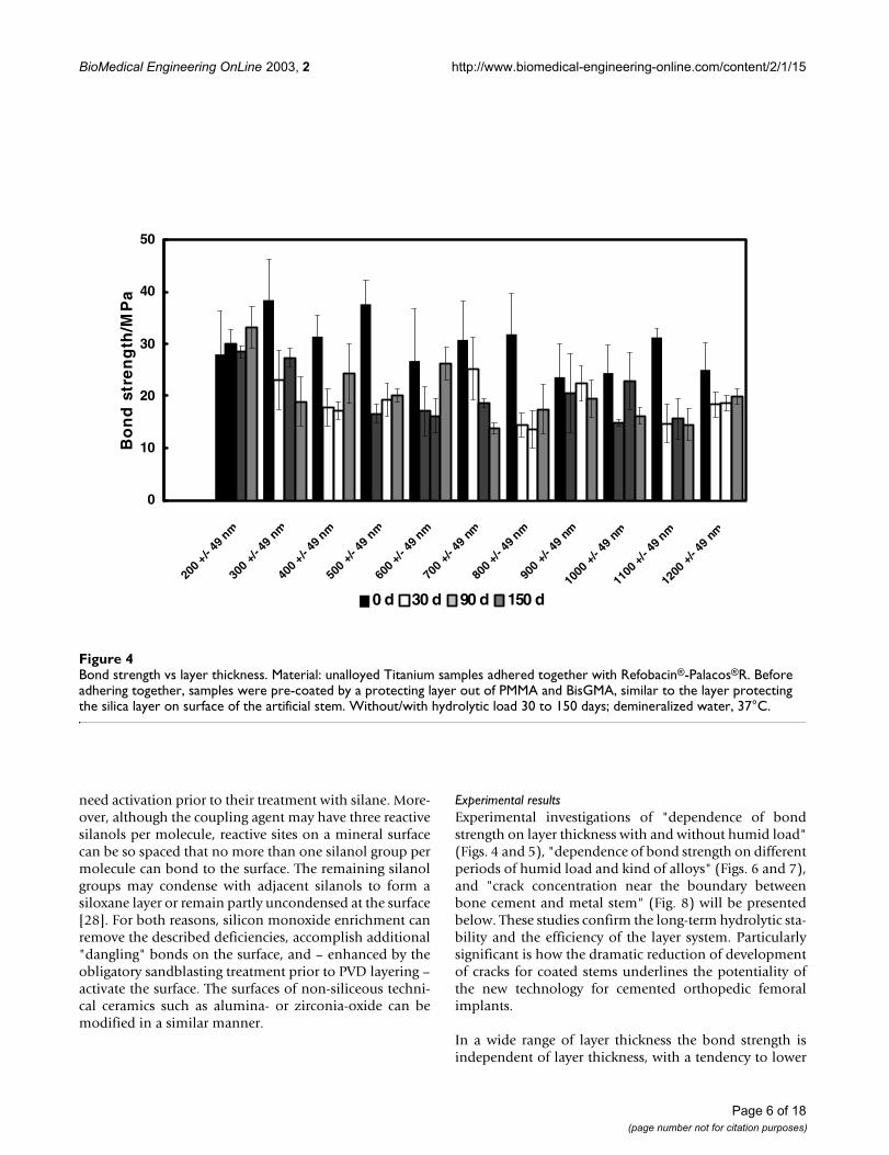
Experimental resultsExperimental investigations of "dependence of bondstrength on layer thickness with and without humid load"(Figs. 4 and 5), "dependence of bond strength on differentperiods of humid load and kind of alloys" (Figs. 6 and 7),and "crack concentration near the boundary betweenbone cement and metal stem" (Fig. 8) will be presentedbelow. These studies confirm the long-term hydrolytic sta-bility and the efficiency of the layer system. Particularlysignificant is how the dramatic reduction of developmentof cracks for coated stems underlines the potentiality ofthe new technology for cemented orthopedic femoralimplants.
In a wide range of layer thickness the bond strength isindependent of layer thickness, with a tendency to lower
Bond strength vs layer thicknessFigure 4Bond strength vs layer thickness. Material: unalloyed Titanium samples adhered together with Refobacin®-Palacos®R. Before adhering together, samples were pre-coated by a protecting layer out of PMMA and BisGMA, similar to the layer protecting the silica layer on surface of the artificial stem. Without/with hydrolytic load 30 to 150 days; demineralized water, 37°C.
0
10
20
30
40
50
200 +/-
49nm
300
+/- 4
9nm
400 +/-
49nm
500
+/-49
nm
600 +/
- 49nm
700
+/-49
nm
800 +/
- 49nm
900
+/-49
nm
1000
+/-49
nm
1100
+/- 49
nm
1200
+/-
49 n
m
SiO layer thickness/nm
Bo
nd
str
en
gth
/MP
a
0 d 30 d 90 d 150 d
Page 6 of 18(page number not for citation purposes)
BioMedical Engineering OnLine 2003, 2 http://www.biomedical-engineering-online.com/content/2/1/15
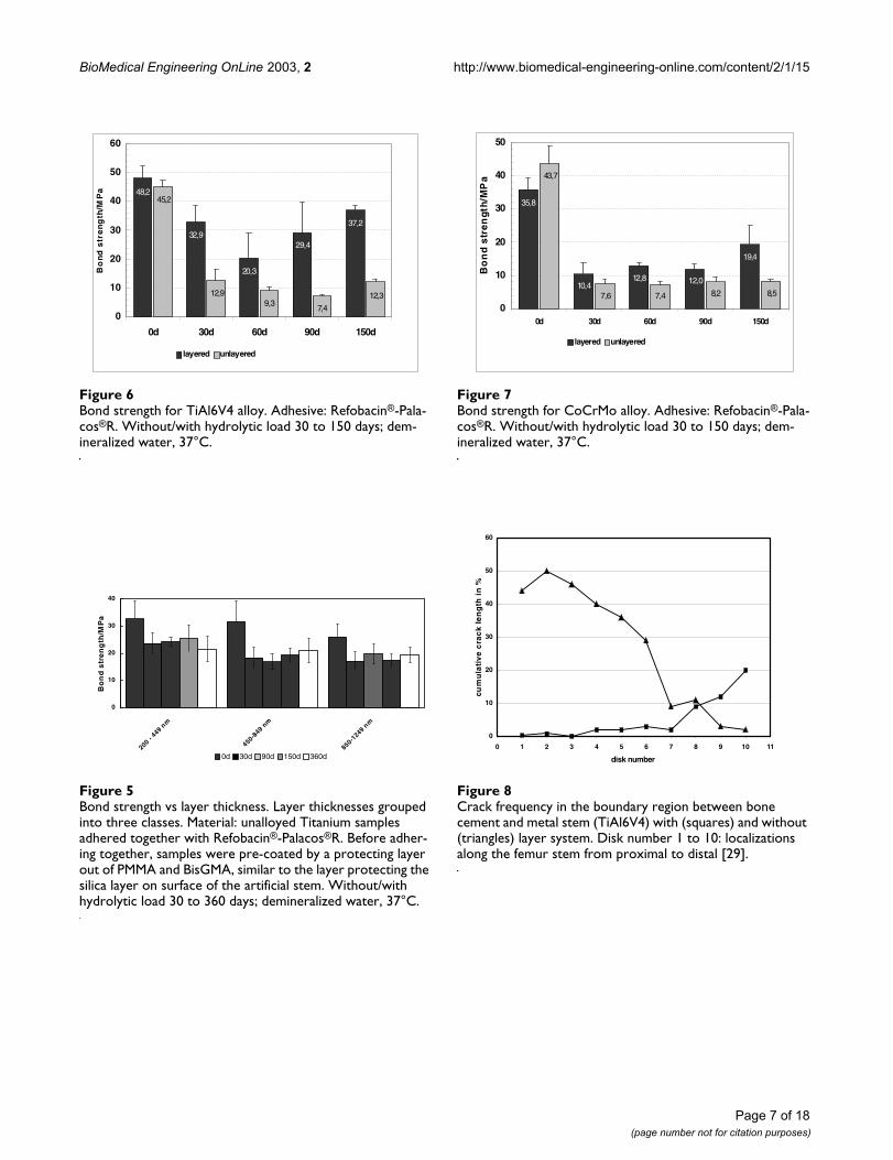
Bond strength for TiAl6V4 alloyFigure 6Bond strength for TiAl6V4 alloy. Adhesive: Refobacin®-Pala-cos®R. Without/with hydrolytic load 30 to 150 days; dem-ineralized water, 37°C.
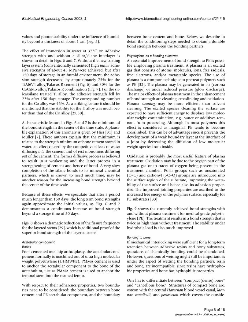
Bond strength vs layer thicknessFigure 5Bond strength vs layer thickness. Layer thicknesses grouped into three classes. Material: unalloyed Titanium samples adhered together with Refobacin®-Palacos®R. Before adher-ing together, samples were pre-coated by a protecting layer out of PMMA and BisGMA, similar to the layer protecting the silica layer on surface of the artificial stem. Without/with hydrolytic load 30 to 360 days; demineralized water, 37°C.
48,2
32,9
20,3
29,4
37,2
45,2
12,99,3
7,4
12,3
0
10
20
30
40
50
60
0d 30d 60d 90d 150d
Bo
nd
str
en
gth
/MP
a
layered unlayered
0
10
20
30
40
200- 449
nm
450-8
49nm
850-1249
nm
layer thickness/nm
Bo
nd
str
en
gth
/MP
a
0d 30d 90d 150d 360d
Bond strength for CoCrMo alloyFigure 7Bond strength for CoCrMo alloy. Adhesive: Refobacin®-Pala-cos®R. Without/with hydrolytic load 30 to 150 days; dem-ineralized water, 37°C.
Crack frequency in the boundary region between bone cement and metal stem (TiAl6V4) with (squares) and without (triangles) layer systemFigure 8Crack frequency in the boundary region between bone cement and metal stem (TiAl6V4) with (squares) and without (triangles) layer system. Disk number 1 to 10: localizations along the femur stem from proximal to distal [29].
35,8
10,412,8 12,0
19,4
43,7
7,6 7,4 8,2 8,5
0
10
20
30
40
50
0d 30d 60d 90d 150d
Bo
nd
str
en
gth
/MP
a
layered unlayered
0
10
20
30
40
50
60
0 1 2 3 4 5 6 7 8 9 10 11
disk number
cum
ula
tiv
e c
rac
k l
en
gth
in
%
Page 7 of 18(page number not for citation purposes)
BioMedical Engineering OnLine 2003, 2 http://www.biomedical-engineering-online.com/content/2/1/15
values and poorer stability under the influence of humid-ity beyond a thickness of about 1 µm (Fig. 5).
The effect of immersion in water at 37°C on adhesivestrength with and without a silica/silane interlayer isshown in detail in Figs. 6 and 7. Without the new coatinglayer system (conventionally cemented) high initial adhe-sive strengths of about 45 MPa were achieved, but after150 days of storage in an humid environment, the adhe-sion strength decreased by approximately 75% for theTiAl6V4 alloy/Palacos R cement (Fig. 6) and 80% for theCoCrMo alloy/Palacos R combination (Fig. 7). For the sil-ica/silane treated Ti alloy, the adhesive strength fell by23% after 150 days storage. The corresponding numberfor the Co alloy was 46%. As a striking feature it should bementioned that the stability for the Ti alloy was much bet-ter than that of the Co alloy [29,30].
A characteristic feature in Figs. 6 and 7 is the minimum ofthe bond strength in the center of the time scale. A plausi-ble explanation of this anomaly is given by Hiss [31] andMüller [7]. These authors explain that the minimum isrelated to the strength minimum of bone cement stored inwater, an effect caused by the competitive effects of waterdiffusing into the cement and of rest monomers diffusingout of the cement. The former diffusive process is believedto result in a weakening and the latter process in astrengthening of cement and hence of bond. A very slowcompletion of the silane bonds to its mineral chemicalpartners, which is known to need much time, may beanother reason for the increasing bond strength beyondthe center of the time scale.
Because of these effects, we speculate that after a periodmuch longer than 150 days, the long term bond strengthsagain approximate the initial values, as Figs. 6 and 7demonstrates a continuous increase of bond strengthbeyond a storage time of 30 days.
Figs. 8 shows a dramatic reduction of the fissure frequencyfor the layered stems [29], which is additional proof of thesuperior bond strength of the layered stems.
Acetabular componentBasicsFor a cemented total hip arthroplasty, the acetabular com-ponent normally is machined out of ultra high molecularweight polyethylene (UHMWPE). PMMA cement is usedto anchor the acetabular component to the bone of theacetabulum, just as PMMA cement is used to anchor thefemoral stem into the reamed femur.
With respect to their adherence properties, two bounda-ries need to be considered: the boundary between bonecement and PE acetabular component, and the boundary
between bone cement and bone. Below, we describe indetail the conditioning steps needed to obtain a durablebond strength between the bonding partners.
Polyethylene as a bonding substrateAn essential improvement of bond strength to PE is possi-ble employing plasma treatment. A plasma is an excitedgas that consists of atoms, molecules, ions, free radicals,free electrons, and/or metastable species. The use ofplasma is a common technique to pretreat polymers suchas PE [32]. The plasma may be generated in air (coronadischarge) or under reduced pressure (glow discharge).The major effects of plasma treatment in the enhancementof bond strength are cleaning, crosslinking and oxidation.Plasma cleaning may be more efficient than solventcleaning. The excited species cleaning the surface areexpected to have sufficient energy to displace low molec-ular weight contamination, e.g., water or additives rem-nant from processing. Although in most polymers thiseffect is considered as marginal, PE tends to becomecrosslinked. This can be of advantage since it prevents thedevelopment of a weak boundary layer at the interface ofa joint by decreasing the diffusion of low molecularweight species from inside.
Oxidation is probably the most useful feature of plasmatreatment. Oxidation may be due to the oxygen part of theplasma gas or to traces of oxygen being present in thetreatment chamber. Polar groups such as unsaturated(C=C) and carbonyl (>C=O) groups are introduced intothe surface region of the substrate, improving the wetta-bility of the surface and hence also its adhesion proper-ties. The improved joining properties are ascribed to theincreased free energy of the polymer surface, especially forPE substrates [33].
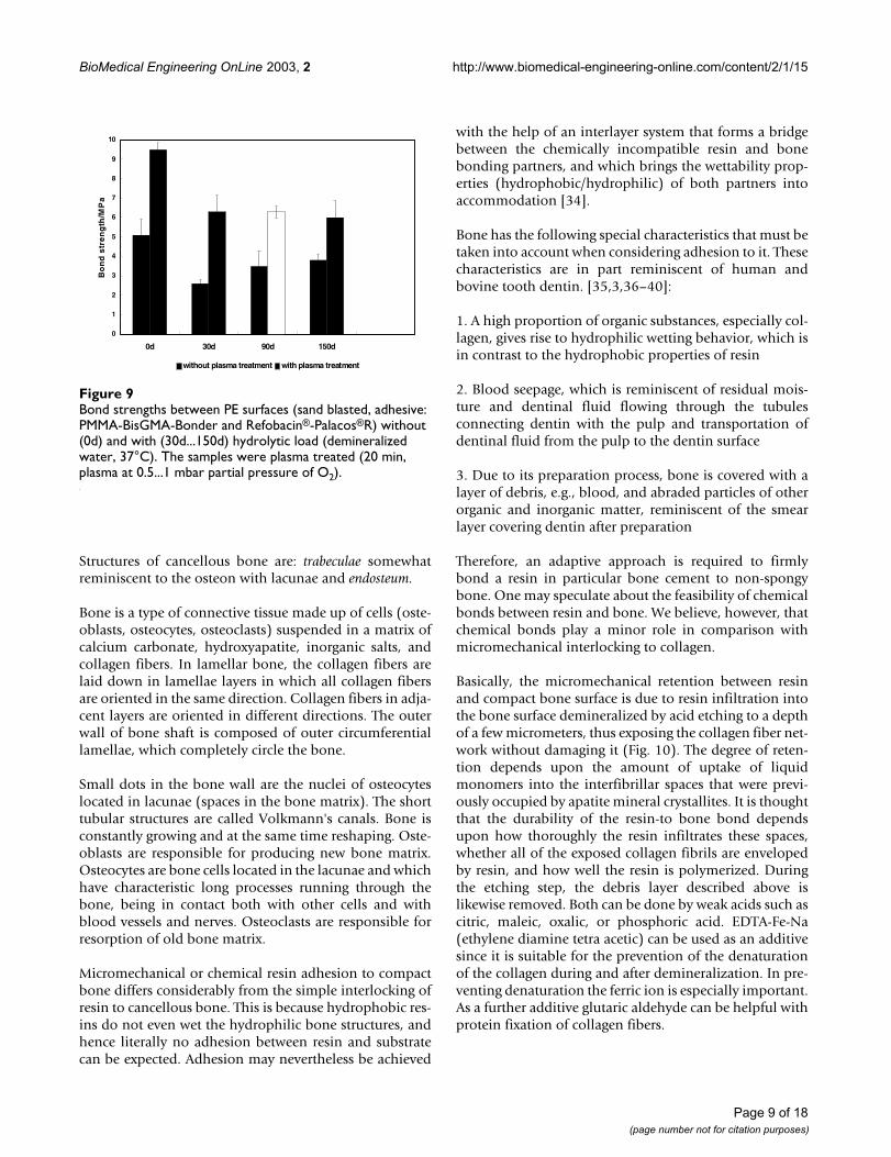
Fig. 9 shows the currently achieved bond strengths withand without plasma treatment for medical grade polyeth-ylene (PE). The treatment results in a bond strength that istwice as high than without treatment. The stability underhydrolytic load is also much improved.
Bonding to boneIf mechanical interlocking were sufficient for a long-termretention between adhesive resins and bony substrates,questions of chemically bonding could be abandoned.However, questions of wetting might still be important asunder the aspect of wetting the bonding partners, resinand bone, are incompatible, since resins have hydropho-bic properties and bone has hydrophilic properties.
One has to differentiate between "compact (dense) bone"and "cancellous bone". Structures of compact bone are:osteon with the central Haversian blood vessel canal, lacu-nae, canaliculi, and periosteum which covers the outside.
Page 8 of 18(page number not for citation purposes)
BioMedical Engineering OnLine 2003, 2 http://www.biomedical-engineering-online.com/content/2/1/15
Structures of cancellous bone are: trabeculae somewhatreminiscent to the osteon with lacunae and endosteum.
Bone is a type of connective tissue made up of cells (oste-oblasts, osteocytes, osteoclasts) suspended in a matrix ofcalcium carbonate, hydroxyapatite, inorganic salts, andcollagen fibers. In lamellar bone, the collagen fibers arelaid down in lamellae layers in which all collagen fibersare oriented in the same direction. Collagen fibers in adja-cent layers are oriented in different directions. The outerwall of bone shaft is composed of outer circumferentiallamellae, which completely circle the bone.
Small dots in the bone wall are the nuclei of osteocyteslocated in lacunae (spaces in the bone matrix). The shorttubular structures are called Volkmann's canals. Bone isconstantly growing and at the same time reshaping. Oste-oblasts are responsible for producing new bone matrix.Osteocytes are bone cells located in the lacunae and whichhave characteristic long processes running through thebone, being in contact both with other cells and withblood vessels and nerves. Osteoclasts are responsible forresorption of old bone matrix.
Micromechanical or chemical resin adhesion to compactbone differs considerably from the simple interlocking ofresin to cancellous bone. This is because hydrophobic res-ins do not even wet the hydrophilic bone structures, andhence literally no adhesion between resin and substratecan be expected. Adhesion may nevertheless be achieved
with the help of an interlayer system that forms a bridgebetween the chemically incompatible resin and bonebonding partners, and which brings the wettability prop-erties (hydrophobic/hydrophilic) of both partners intoaccommodation [34].
Bone has the following special characteristics that must betaken into account when considering adhesion to it. Thesecharacteristics are in part reminiscent of human andbovine tooth dentin. [35,3,36–40]:
1. A high proportion of organic substances, especially col-lagen, gives rise to hydrophilic wetting behavior, which isin contrast to the hydrophobic properties of resin
2. Blood seepage, which is reminiscent of residual mois-ture and dentinal fluid flowing through the tubulesconnecting dentin with the pulp and transportation ofdentinal fluid from the pulp to the dentin surface
3. Due to its preparation process, bone is covered with alayer of debris, e.g., blood, and abraded particles of otherorganic and inorganic matter, reminiscent of the smearlayer covering dentin after preparation
Therefore, an adaptive approach is required to firmlybond a resin in particular bone cement to non-spongybone. One may speculate about the feasibility of chemicalbonds between resin and bone. We believe, however, thatchemical bonds play a minor role in comparison withmicromechanical interlocking to collagen.
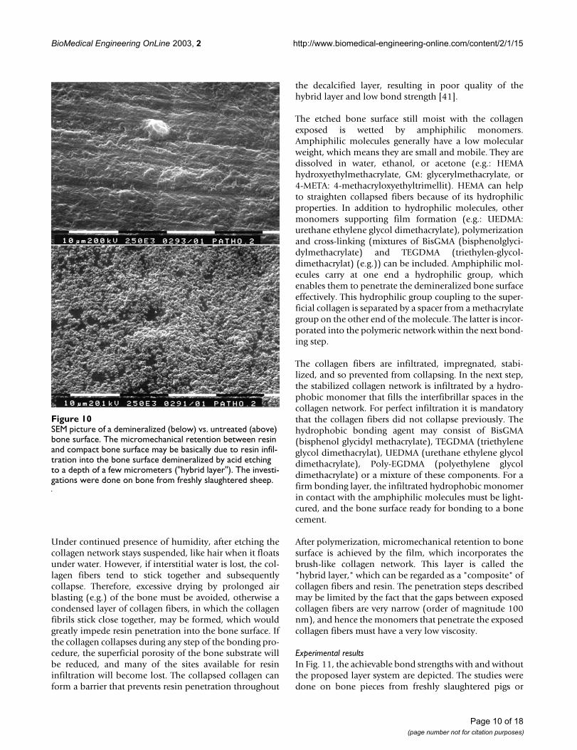
Basically, the micromechanical retention between resinand compact bone surface is due to resin infiltration intothe bone surface demineralized by acid etching to a depthof a few micrometers, thus exposing the collagen fiber net-work without damaging it (Fig. 10). The degree of reten-tion depends upon the amount of uptake of liquidmonomers into the interfibrillar spaces that were previ-ously occupied by apatite mineral crystallites. It is thoughtthat the durability of the resin-to bone bond dependsupon how thoroughly the resin infiltrates these spaces,whether all of the exposed collagen fibrils are envelopedby resin, and how well the resin is polymerized. Duringthe etching step, the debris layer described above islikewise removed. Both can be done by weak acids such ascitric, maleic, oxalic, or phosphoric acid. EDTA-Fe-Na(ethylene diamine tetra acetic) can be used as an additivesince it is suitable for the prevention of the denaturationof the collagen during and after demineralization. In pre-venting denaturation the ferric ion is especially important.As a further additive glutaric aldehyde can be helpful withprotein fixation of collagen fibers.
Bond strengths between PE surfaces (sand blasted, adhesive: PMMA-BisGMA-Bonder and Refobacin®-Palacos®R) without (0d) and with (30d...150d) hydrolytic load (demineralized water, 37°C)Figure 9Bond strengths between PE surfaces (sand blasted, adhesive: PMMA-BisGMA-Bonder and Refobacin®-Palacos®R) without (0d) and with (30d...150d) hydrolytic load (demineralized water, 37°C). The samples were plasma treated (20 min, plasma at 0.5...1 mbar partial pressure of O2).
0
1
2
3
4
5
6
7
8
9
10
0d 30d 90d 150d
Bo
nd
str
en
gth
/MP
a
without plasma treatment with plasma treatment
Page 9 of 18(page number not for citation purposes)
BioMedical Engineering OnLine 2003, 2 http://www.biomedical-engineering-online.com/content/2/1/15
Under continued presence of humidity, after etching thecollagen network stays suspended, like hair when it floatsunder water. However, if interstitial water is lost, the col-lagen fibers tend to stick together and subsequentlycollapse. Therefore, excessive drying by prolonged airblasting (e.g.) of the bone must be avoided, otherwise acondensed layer of collagen fibers, in which the collagenfibrils stick close together, may be formed, which wouldgreatly impede resin penetration into the bone surface. Ifthe collagen collapses during any step of the bonding pro-cedure, the superficial porosity of the bone substrate willbe reduced, and many of the sites available for resininfiltration will become lost. The collapsed collagen canform a barrier that prevents resin penetration throughout
the decalcified layer, resulting in poor quality of thehybrid layer and low bond strength [41].
The etched bone surface still moist with the collagenexposed is wetted by amphiphilic monomers.Amphiphilic molecules generally have a low molecularweight, which means they are small and mobile. They aredissolved in water, ethanol, or acetone (e.g.: HEMAhydroxyethylmethacrylate, GM: glycerylmethacrylate, or4-META: 4-methacryloxyethyltrimellit). HEMA can helpto straighten collapsed fibers because of its hydrophilicproperties. In addition to hydrophilic molecules, othermonomers supporting film formation (e.g.: UEDMA:urethane ethylene glycol dimethacrylate), polymerizationand cross-linking (mixtures of BisGMA (bisphenolglyci-dylmethacrylate) and TEGDMA (triethylen-glycol-dimethacrylat) (e.g.)) can be included. Amphiphilic mol-ecules carry at one end a hydrophilic group, whichenables them to penetrate the demineralized bone surfaceeffectively. This hydrophilic group coupling to the super-ficial collagen is separated by a spacer from a methacrylategroup on the other end of the molecule. The latter is incor-porated into the polymeric network within the next bond-ing step.
The collagen fibers are infiltrated, impregnated, stabi-lized, and so prevented from collapsing. In the next step,the stabilized collagen network is infiltrated by a hydro-phobic monomer that fills the interfibrillar spaces in thecollagen network. For perfect infiltration it is mandatorythat the collagen fibers did not collapse previously. Thehydrophobic bonding agent may consist of BisGMA(bisphenol glycidyl methacrylate), TEGDMA (triethyleneglycol dimethacrylat), UEDMA (urethane ethylene glycoldimethacrylate), Poly-EGDMA (polyethylene glycoldimethacrylate) or a mixture of these components. For afirm bonding layer, the infiltrated hydrophobic monomerin contact with the amphiphilic molecules must be light-cured, and the bone surface ready for bonding to a bonecement.
After polymerization, micromechanical retention to bonesurface is achieved by the film, which incorporates thebrush-like collagen network. This layer is called the"hybrid layer," which can be regarded as a "composite" ofcollagen fibers and resin. The penetration steps describedmay be limited by the fact that the gaps between exposedcollagen fibers are very narrow (order of magnitude 100nm), and hence the monomers that penetrate the exposedcollagen fibers must have a very low viscosity.
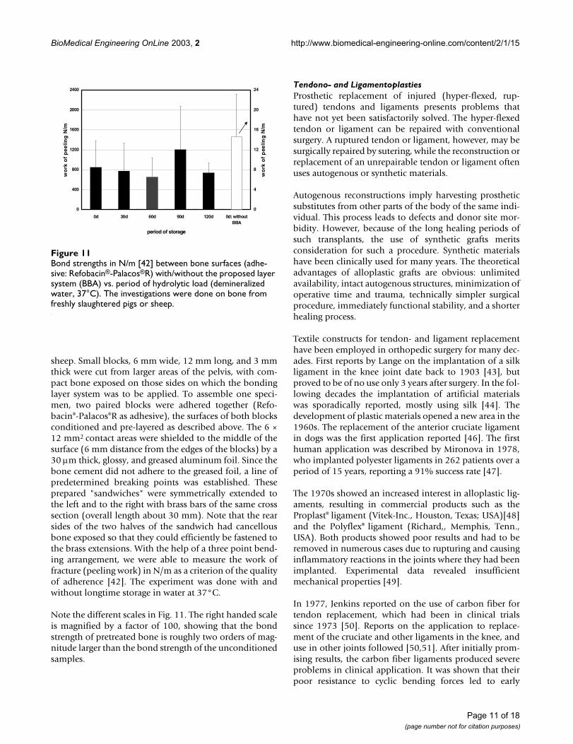
Experimental resultsIn Fig. 11, the achievable bond strengths with and withoutthe proposed layer system are depicted. The studies weredone on bone pieces from freshly slaughtered pigs or
SEM picture of a demineralized (below) vs. untreated (above) bone surfaceFigure 10SEM picture of a demineralized (below) vs. untreated (above) bone surface. The micromechanical retention between resin and compact bone surface may be basically due to resin infil-tration into the bone surface demineralized by acid etching to a depth of a few micrometers ("hybrid layer"). The investi-gations were done on bone from freshly slaughtered sheep.
Page 10 of 18(page number not for citation purposes)
BioMedical Engineering OnLine 2003, 2 http://www.biomedical-engineering-online.com/content/2/1/15
sheep. Small blocks, 6 mm wide, 12 mm long, and 3 mmthick were cut from larger areas of the pelvis, with com-pact bone exposed on those sides on which the bondinglayer system was to be applied. To assemble one speci-men, two paired blocks were adhered together (Refo-bacin®-Palacos®R as adhesive), the surfaces of both blocksconditioned and pre-layered as described above. The 6 ×12 mm2 contact areas were shielded to the middle of thesurface (6 mm distance from the edges of the blocks) by a30 µm thick, glossy, and greased aluminum foil. Since thebone cement did not adhere to the greased foil, a line ofpredetermined breaking points was established. Theseprepared "sandwiches" were symmetrically extended tothe left and to the right with brass bars of the same crosssection (overall length about 30 mm). Note that the rearsides of the two halves of the sandwich had cancellousbone exposed so that they could efficiently be fastened tothe brass extensions. With the help of a three point bend-ing arrangement, we were able to measure the work offracture (peeling work) in N/m as a criterion of the qualityof adherence [42]. The experiment was done with andwithout longtime storage in water at 37°C.
Note the different scales in Fig. 11. The right handed scaleis magnified by a factor of 100, showing that the bondstrength of pretreated bone is roughly two orders of mag-nitude larger than the bond strength of the unconditionedsamples.
Tendono- and LigamentoplastiesProsthetic replacement of injured (hyper-flexed, rup-tured) tendons and ligaments presents problems thathave not yet been satisfactorily solved. The hyper-flexedtendon or ligament can be repaired with conventionalsurgery. A ruptured tendon or ligament, however, may besurgically repaired by sutering, while the reconstruction orreplacement of an unrepairable tendon or ligament oftenuses autogenous or synthetic materials.
Autogenous reconstructions imply harvesting prostheticsubstitutes from other parts of the body of the same indi-vidual. This process leads to defects and donor site mor-bidity. However, because of the long healing periods ofsuch transplants, the use of synthetic grafts meritsconsideration for such a procedure. Synthetic materialshave been clinically used for many years. The theoreticaladvantages of alloplastic grafts are obvious: unlimitedavailability, intact autogenous structures, minimization ofoperative time and trauma, technically simpler surgicalprocedure, immediately functional stability, and a shorterhealing process.
Textile constructs for tendon- and ligament replacementhave been employed in orthopedic surgery for many dec-ades. First reports by Lange on the implantation of a silkligament in the knee joint date back to 1903 [43], butproved to be of no use only 3 years after surgery. In the fol-lowing decades the implantation of artificial materialswas sporadically reported, mostly using silk [44]. Thedevelopment of plastic materials opened a new area in the1960s. The replacement of the anterior cruciate ligamentin dogs was the first application reported [46]. The firsthuman application was described by Mironova in 1978,who implanted polyester ligaments in 262 patients over aperiod of 15 years, reporting a 91% success rate [47].
The 1970s showed an increased interest in alloplastic lig-aments, resulting in commercial products such as theProplast® ligament (Vitek-Inc., Houston, Texas; USA)[48]and the Polyflex® ligament (Richard,, Memphis, Tenn.,USA). Both products showed poor results and had to beremoved in numerous cases due to rupturing and causinginflammatory reactions in the joints where they had beenimplanted. Experimental data revealed insufficientmechanical properties [49].
In 1977, Jenkins reported on the use of carbon fiber fortendon replacement, which had been in clinical trialssince 1973 [50]. Reports on the application to replace-ment of the cruciate and other ligaments in the knee, anduse in other joints followed [50,51]. After initially prom-ising results, the carbon fiber ligaments produced severeproblems in clinical application. It was shown that theirpoor resistance to cyclic bending forces led to early
Bond strengths in N/m [42] between bone surfaces (adhe-sive: Refobacin®-Palacos®R) with/without the proposed layer system (BBA) vs. period of hydrolytic load (demineralized water, 37°C)Figure 11Bond strengths in N/m [42] between bone surfaces (adhe-sive: Refobacin®-Palacos®R) with/without the proposed layer system (BBA) vs. period of hydrolytic load (demineralized water, 37°C). The investigations were done on bone from freshly slaughtered pigs or sheep.
0
400
800
1200
1600
2000
2400
0d 30d 60d 90d 120d 0d: withoutBBA
period of storage
wo
rk o
f p
ee
lin
g N
/m
0
4
8
12
16
20
24
wo
rk o
f p
eeli
ng
N/m
Page 11 of 18(page number not for citation purposes)
BioMedical Engineering OnLine 2003, 2 http://www.biomedical-engineering-online.com/content/2/1/15
ruptures of the fibers, releasing wear particles that couldspread throughout the joint, leading to "black joints" andinitiating an inflammatory response. Particles were eventransported to regional lymph nodes [52,53]. The func-tion of the carbon fibers as a scaffold for the ingrowth ofconnective tissue and for bony ingrowth in the osseouscanal, which had been anticipated, could not be proven[53]. Also, composite grafting with autologous material orthe coupling of resorbable polymers to the surface of theligament could not outweigh the side effects and compli-cations [45].
In 1975, Kennedy described the implantation of a poly-propylen ligament (Kennedy-LAD®, 3M, St. Paul, Minn.,USA) for the first time [54,55], other reports followed[56–59] This prosthetic was implanted mostly asaugmentation for autologous materials, allowing tempo-rary load sharing, while accepting its weakening and rup-ture with time. All reports stress the goodbiocompatibility of polypropylen, butpermanent applica-tion as ligament prosthesis was not recommended.
Polytetrafluoraethylen, (Gore-Tex®, W.F. Gore&Assoc.,Flagstaff, Ariz., USA)a well established biomaterial usedin vascular surgery, in a braided form was also used in lig-ament replacement surgery. This ligament showed thebest initial load bearing properties of all commerciallyavailable alloplastic ligaments. First reports were pub-lished in 1983. Bony ingrowth of the ligament in theosseous canals was demonstrated. Despite these aspectsand promising first clinical reports, the long term clinicalresults were disappointing. Frequent ruptures and syno-vial reactions within the implanted joints were described[46,60].
A different constructive approach was taken for theDacron®-ligament, which was first implanted in the treat-ment of disruptions of the acromioclavicular joint and intendon replacement. This ligament used a braided 4-foldinner part enveloped in a knit cover, which was supposedto improve tissue ingrowth and lead to an improvedadaptation of its elastic properties to the human cruciateligament. Also, this ligament showed good initial,however poor long term, results, with a progressive dete-rioration and high rupture rate [61].
Besides the polypropylen ligaments, today only the differ-ent polyester ligaments play a role in clinical application[62]. Examples are the Leeds-Keio® ligament, the Trevira-hochfest® and the Proflex® ligament.
The Leeds-Kejo® ligament was firstly implanted in Japan1982, also later in the UK. Until 1988 some 20.000 liga-ments had been implanted. The reported results are fewand contradictory [63–65].
The Trevira® ligament consisting of polyethylenterephtha-lat has been clinically in use since 1980 [66]. It was firstused in the cervical spine for stabilizing procedures.Adapted for joint applications, it was implanted in theknee as a cruciate ligament replacement and as anaugmentation of autologous transplants. It shows onlyminor wear and inflammatory response in animal trials aswell as in clinical experience. Clinical results are good dur-ing the first years, while long term studies have not yetbeen reported. A modified over the top implantation tech-nique can improve the ligament longevity.
The common problem of all alloplastic nonresorbable lig-aments is weakening of the structure due to wear, leadingto rupture rates between 5% and 25%per year [67–69].Analyzing 117 surgically excised alloplastic ligamentsafter failure as anterior cruciate ligament prostheses, Gui-doin [70] summarized the major mechanisms that led tofailure as inadequate fiber abrasion resistance againstosseous surfaces, flexural and rotational fatigue of the fib-ers, and loss of integrity of the textile structure due tounpredictable tissue infiltration during healing.
According to Letsch [71], the anchoring mechanism of analloplastic ligament is one of the crucial points of the sys-tem. The maximum load capability of most fixationsystems is 10% to 25% of the load capability of the allo-plastic ligament itself, and therefore is the limiting factorof the system. Moreover, the textile structure is weakenedor damaged by fixation elements like screws or toothedstaples, leading to loosening of the ligament and addi-tional wear [72].
The unsolved problems of alloplastic nonresorbable liga-ment structures has brought the resorbable ligaments intofocus. Even if the latter provoke an inflammatoryresponse, they have the advantage that inflammation endsonce the resorption is complete. Polydioxanon (PDS®)has been widely used since 1979 [73], as augmentation incruciate ligament surgery, and is available in different con-structions. Clinical and experimental comparative testingdid not show a significant advantage compared with nonaugmented transplantation. The decrease in load bearingcapability of the resorbable ligament during resorptionleads to mechanical properties that cannot compete withthose of nonresorbable structures.
It becomes clear that, despite the development of a varietyof synthetic implants and better knowledge of ligamentbiomechanics, there is currently no prosthesis that showssatisfying long term results. In fact, the life span of liga-ment prostheses are rather short. However, this shouldnot lead to the conclusion that synthetic grafts are gener-ally unsuitable. Instead, it is evident that there is a need toreconsider the approach and to develop a new generation
Page 12 of 18(page number not for citation purposes)
BioMedical Engineering OnLine 2003, 2 http://www.biomedical-engineering-online.com/content/2/1/15
of implants and fixations techniques. In particular, themethod of fixation of ligament prostheses requires atten-tion. Currently used fixation techniques allow micromovements of the ligament, which lead to friction againstbone, causing wear and implant failure of the entireprosthesis.
The aim of our investigation was to reduce the deficienciesof the fixation techniques that have been so far applied.New ideas are proposed for the anchoring of textile struc-tures by using modern adhesive methods that aim for amore physiological bone-ligament junction [74].Utilizing adhesive methods also means a suitable selec-tion of the material out of which the artificial tendons andligaments are plaited, since not all plastics are appropriatefor adhesive techniques. Highly desirable are plastics thatfulfill both the clinical necessities and the requirementthat their surface can be effectively conditioned by plasmatreatment.
The fixation technique must result in an anchorage of thealloplastic prosthesis that is strong enough to prevent slip-page. Moreover, the fixation technique must resembleclosely as possible the natural load flux into the bone. Thetechniques currently utilized lack the tensile characteris-tics of physiological load flow, and thus they are unable toprovide optimum distribution of forces to the bone, sincefixation of artificial structures is achieved with staples,screws, and clips, which of course are accompanied by avery unfavorable distribution of forces among tendon, fix-ation tool, and bone.
As an example, we describe the presently used fixationtechnique for the reconstruction of the anterior cruciateligament (ACL) of the knee using a Trevira ligament [75].Note that such a ligament is unsuitable for the applicationof adhesive techniques since it consists of many very thinthreads, difficult to prepare for adherence because highlyviscous adhesives like PMMAs and their modifications arenot able to penetrate threads. For analogous reasonsplasma treatment is also difficult. The ligament is firstfixed at the femur. After turning back the windings outsidethe over-the-top passage, the ligament is laid flat on thefemur. The femur is marked and a staple is driven in to fixthe ligament. The end of the ligament is cut until nearly 2cm and placed under the muscles. The final fixation of theligament takes place with a second staple after markingthe tibial cortex. The end of the ligament is also cut toalmost 2 cm and placed carefully and flatly under the pesanserius.
In the long term, the majority of ligament prosthesesresult in insufficient fixation strength, demonstrating theirdeficient anchorage to the bone. The low fixationstrength, corresponding to fixation failure at forces of
140–180 N, has been found to be the limiting factor ofmost of the ACL replacements. Such forces comparesunfavorably with the fixation strength of goat native ACLs(e.g.), which tolerate loads in excess of 1 kN.
In this paper, we discuss two examples describing the use-fulness of adhesive instead of conventional fixationtechniques. The adhesive technique is described for a ten-don replacement, and may be applied with minor changesfor artificial ligaments as well.
Supraspinatus tendonBasicsFirst, we focus on the replacement of the supraspinatustendon from the rotator cuff group, using alloplastictextile structures. The term "rotator cuff" is used todescribe the group of muscles and their tendons in theshoulder that helps control shoulder joint motion. Thesupraspinatus muscle is at the top, the subscapularis inthe front, and the infraspinatus and teres minor arebehind the shoulder. These muscles attach to the head ofthe upper arm by way of their tendons. The tendons fusetogether, giving rise to the term "cuff." Although eachmuscle acting alone may produce an isolated rotationalmovement of the shoulder, the role they play together isto help keep the head of the upper-arm ball centeredwithin the socket.
In case of a fresh traumatic rupture, the implant is used asan augmentation corresponding to the suture techniquesthat are in use today, connecting the ruptured tendondirectly to the bone, where it can heal under stress protec-tion by the implant. After healing, the implant functionsas a permanent augmentation, which is favorable consid-ering that the tendon heals with scar formation from tis-sue less mechanically stable than the original tendon.
Another application concerns patients with defects in therotator cuff due to degeneration and old rupture. Today,this defect can only be corrected by extensive plastic meth-ods, transposing autogenous tendon material from othersites [76–78]. Even if – due to biological reasons – areplacement cannot restore function in all cases, it is to beexpected that using the novel implant in these situationswill reduce pain by restoring the joint anatomy [79,80].Technically, in these cases it will be necessary to bridge thedefect by up to three implants, depending on the size ofthe defect, in order to get a good distribution of forces.Additionally, it will be necessary to enhance the forma-tion of connective tissue between the implant cords torestore the cuff as a barrier between joint and bursa inorder to avoid irritation. This can be accomplished eitherby local tissue or by additional resorbable implants.
Page 13 of 18(page number not for citation purposes)
BioMedical Engineering OnLine 2003, 2 http://www.biomedical-engineering-online.com/content/2/1/15
The alloplastic tendons presently being investigated werebraided out of polyvinylidenefluoride (PVDF: commonbrand names: Floraflon, Kynar, Solef). PVDF is a semi-crystalline, semi-opaque and white, engineered thermo-plastic that is melt processable. PVDF has good tempera-ture characteristics, and good resistance to generalchemicals, (though not as good as PTFE's), abrasion, andradiation. It is somewhat stiffer and stronger than most(being melt-processable) fluoropolymers, which facili-tates adhesive techniques for threads. The elongation atbreak is 50%, the tensile modulus 1 to3 GPa, the density1.76 g/cm3 and it has a highly dipolar molecule. PVDFradiation resistance (beta, gamma) is good, and thereforeit may be sterilized by beta-radiation, as is standard formany orthopedic devices. The desired form is known asthe β phase or Form I, in which the predominantly "headto tail" polymer chains have an all-trans extended planarzig-zag form, with the dipoles of adjacent chains parallelto one another. This pattern is formed from the morecommon α phase (Form II) by mechanical deformationfollowed by electrical polarization in a very high electricalfield. In practice, both uniaxial and biaxial mechanicalorientations are used. Applications of PVDF include pipesand fittings, bearings, linings, and vessels (all especiallyfor the chemical processing industry), wire insulation andpiezo-electric devices. In medical applications, PVDF hasbeen in use as a suture material for years.
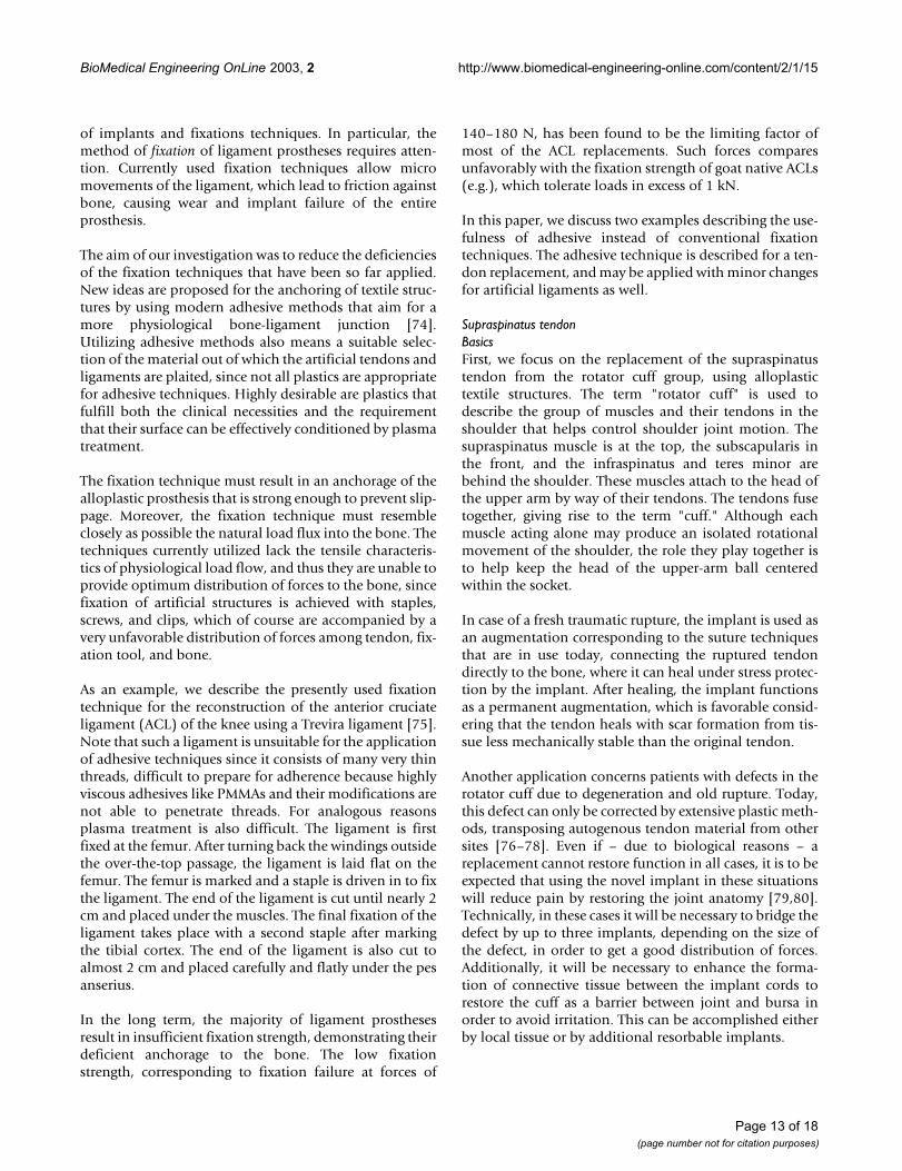
Fig. 12 depicts an overall view of the presently proposedprosthesis as an example. The fixation element [34] con-sists of a banjo bolt (thread M4...M6 or hollow tappingscrew), the alloplastic PVDF tendon axially inserted. Thescrew has been machined out of titanium or a suitabletitanium alloy (TiAl6V4, e.g.). The inner walls of the screwhave been PVD layered with a silicon monoxide coating,silanized, and finally layered with a very thin film ofPMMA/BisGMA coating, which due to its low viscosity inthe unpolymerized state and its hydrophobicity has per-fect wetting properties on a surface enriched by silicate.The PVDF tendon consisting of 8 slackly plaited strands(36 threads bundled into a strand) has been plasmatreated and fixed inside the coated banjo bolt by aBisGMA adhesive, the viscosity of which is adjusted suchthat it can wet each strand or even each thread when theadhesive is applied under pressure. The adhesively assem-bled fixation element (screw and tendon) is allowed tocure overnight.
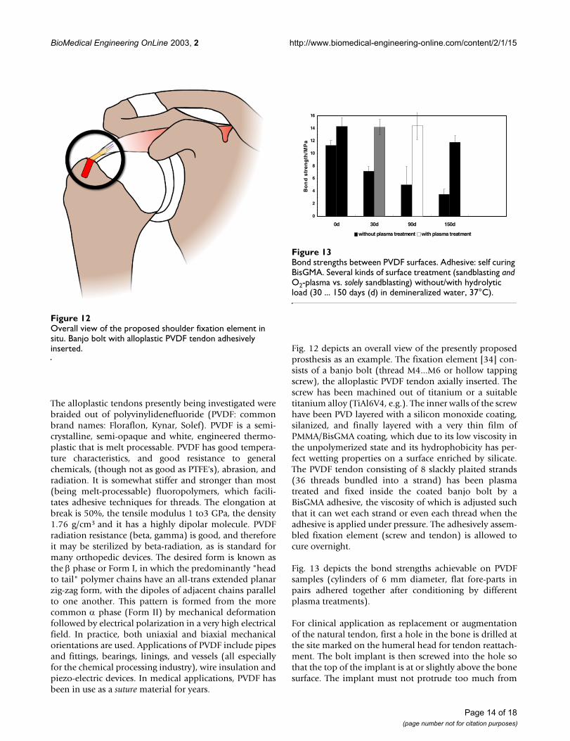
Fig. 13 depicts the bond strengths achievable on PVDFsamples (cylinders of 6 mm diameter, flat fore-parts inpairs adhered together after conditioning by differentplasma treatments).
For clinical application as replacement or augmentationof the natural tendon, first a hole in the bone is drilled atthe site marked on the humeral head for tendon reattach-ment. The bolt implant is then screwed into the hole sothat the top of the implant is at or slightly above the bonesurface. The implant must not protrude too much from
Overall view of the proposed shoulder fixation element in situFigure 12Overall view of the proposed shoulder fixation element in situ. Banjo bolt with alloplastic PVDF tendon adhesively inserted.
Bond strengths between PVDF surfacesFigure 13Bond strengths between PVDF surfaces. Adhesive: self curing BisGMA. Several kinds of surface treatment (sandblasting and O2-plasma vs. solely sandblasting) without/with hydrolytic load (30 ... 150 days (d) in demineralized water, 37°C).
0
2
4
6
8
10
12
14
16
0d 30d 90d 150d
Bo
nd
str
en
gth
/MP
a
without plasma treatment with plasma treatment
Page 14 of 18(page number not for citation purposes)
BioMedical Engineering OnLine 2003, 2 http://www.biomedical-engineering-online.com/content/2/1/15
the surface, otherwise it could give cause to irritation ofthe neighboring tissue with inflammation of the bursa(small sac filled with lubricious fluid). The bursa islocated between the tendon and the bone of the humeralhead and cushions the tendon from the bone, therebyreducing the friction between the moving structures.
The free end of the PVDF tendon is sutured to the suprasp-inatus tendon in a way that allows good interconnectionbetween tissue and graft so as to accelerate healing andallow early load bearing. After implant surgery, patientsshould be able to start active exercise with restrained forcewithin the first week.
Three to nine months are required after implantation toaccomplish bony healing. This process, where bone growsinto the implant, is called osseointegration. In the mean-time, the quality of the mechanical screw fixation isresponsible for the distribution of forces.
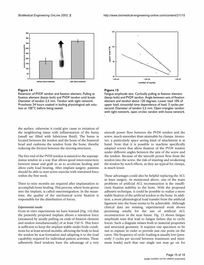
Experimental resultsFrom in vitro experiments we have learned (Fig. 14) thatthe presently proposed implant allows a retention force(measured by axially pulling on ends of fixation elementand tendon simultaneously) of at least 350 N. This forceis sufficient to keep the implant stable under body condi-tions for at least several months, allowing the body to healthe tendon by scar-formation and adapting it to the loadcapability required for individual patient activities. Theseadhesively fixed tendons have the advantage of a very
smooth power flow between the PVDF tendon and thescrew, much smoother than attainable by clamps. Moreo-ver, a particularly space saving kind of attachment is athand. Note that it is possible to machine specificallyadapted screws that allow fixation of the PVDF tendonunder different angles between the axis of the screw andthe tendon. Because of the smooth power flow from thetendon into the screw, the risk of injuring and weakeningthe tendon by notch effects, as they are typical for clamps,is much lower.
These advantages could also be helpful replacing the ACLin knee surgery. As mentioned above, one of the mainproblems of artificial ACL reconstruction is the insuffi-cient fixation stability to the bone. With the proposedadhesive technique, it could be possible to realize a morestable fixation of the artificial tendon to the bone. In addi-tion, a more physiological load transfer from the artificialligament into the bone seems to be achievable. Althoughclinical data are missing, experimental work showspromising results for the use of artificial ACLreconstruction in the near future. Fig. 15 shows fatigueamplitude tests that lead to fatigue failure due to cyclicforces. Such a diagram relates both to material propertiesand structural geometry. It requires one specimen to berun to rupture in order to provide just one point on thecurve. The frequency of cyclic loading is usually low (pres-ently 3 cycles per second between maximum and mini-mum loads) such that one single test may go on for
Retention of PVDF tendon and fixation elementFigure 14Retention of PVDF tendon and fixation element. Pulling at fixation element (banjo bolt) and PVDF tendon until break. Diameter of tendon 2,5 mm. Tendon with tight network. Prosthesis 24 hours soaked in boiling physiological salt solu-tion at 100°C before being tested.
0
50
100
150
200
250
300
350
400
450
without silica treatment with silica treatment
ten
do
n t
en
sil
e s
tre
ng
th/N
Fatigue amplitude testFigure 15Fatigue amplitude test. Cyclically pulling at fixation element (banjo bolt) and PVDF tendon. Angle between axis of fixation element and tendon about 120 degrees. Lower load 10% of upper load, sinusoidal time dependence of load, 3 cycles per second. Diameter of tendon 2,5 mm. Open triangles: tendon with tight network, open circles: tendon with loose network.
40
80
120
160
1,0E+05 1,0E+06 1,0E+07
number of cycles
up
per
load
F/N
Page 15 of 18(page number not for citation purposes)
BioMedical Engineering OnLine 2003, 2 http://www.biomedical-engineering-online.com/content/2/1/15
several days or weeks. A graph of the maximum stressforce, F, in newtons (N) vs. cycles to failure (S-N curves) isplotted. By successively lowering the maximum stress,specimens fatigue-tested without rupture are determined.The maximum stress, that does not result in failure canthus be determined. This procedure provides importantguidelines for the maximum serving stress that the artifi-cial tendon in combination with the fixation element canwithstand (Fig. 15).
ConclusionsWhen inserting a prosthesis into the human body, notonly one but several material classes are involved. Up tonow, clamping and screwing of the structural parts of aprosthesis has been the normal procedure. In the presentcontribution, it is proposed and demonstrated thatjoining by adhesive techniques can also play an importantand useful part, provided the stability under the condi-tions of use within the human body is adequatelyconsidered. Within the scope of adhesive techniques, -resistance to the attack of humidity (besides mechanicalload) is mandatory for clinical success. The present workmaintains the thesis that achieving stable bond strengthsmeans selecting individually and suitably adapted pre-treatments of the material surfaces.
Authors' contributionsRM conceived in the study, participated in the design ofthe study and drafted the manuscript. HJE and DCW car-ried out the clinical and experimental studies, MW carriedout experimental work. OP and FUN coordinated the clin-ical part of the work. All authors read and approved thefinal manuscript.
AcknowledgementsThe project using the Vacuum Vapor Deposition Method to improve the long-term bonding strength between an orthopaedic metal endoprosthesis and PMMA bone cement has been supported by the German Research Community (DFG, project MA 1093/4-1,2). It was realized by close coop-eration between the Department of Dental Prosthetics, Section of Dental Materials, University of Technology Aachen and the Department of Ortho-paedics, University of Technology Aachen.
References1. Pfeiffer P and Marx R: Temperaturbelastung von Adhäsiv-
brücken und ihre Auswirkung auf die Verbundfestigkeit derKlebeverbindung. Schweiz Monatsschr Zahnmed 1989, 99:782-786.
2. Wirtz DC and Niethard FU: Ursachen, Diagnostik und Therapieder aseptischen Hüftendoprothesenlockerung – eineStandortbestimmung. Z Orthop 1997, 135:270-280.
3. Haller B: Aktueller Stand der Komposit-Dentinhaftung. Zah-närztl Mitteilungen 1992, 82:86-97.
4. Malchau H and Herberts P: Prognosis of total hip replacement.Surgical and cementing technique in THR: A revision-riskstudy of 134.056 primary operations. Atlanta, 63rd Annual Meet-ing of the AAOS, Atlanta 1996.
5. Malchau H, Sodermann P and Herberts P: Swedish hip registry:results with 20-year follow up validation clinically andradiographically. Orlando, 67th Annual Meeting of the AAOS 2000 .
6. Jasty M, Maloney WJ, Bragdon CR, O'Connor DO, Haire T and HarrisWH: The initiation of failure in cemented femoral compo-nents of hip arthroplasties. J Bone Joint Surg (Br) 1991, 73:551-558.
7. Müller K: Mechanische Eigenschaften nicht modifizierterKnochenzemente auf PMMA-Basis. In: Knochenzement – Werkst-off, klinische Erfahrungen, Weiterentwicklungen Edited by: Willert HG,Buchhorn G. Bern, Hans Huber Verlag; 1987:31-44.
8. Anthony PP, Gie GA, Ling RSM and Howie CR: Localised endostealbone lysis in relation to the femoral components ofcemented total hip arthroplasties. J Bone Joint Surg 1990,72:971-979.
9. Marx R and Fischer H: Werkstück und Verfahren zum Herstel-len und zum Verwerten des Werkstückes. 1999, DE Patent19937864 C2:.
10. Verdonschot N and Huiskes HWJ: Cement Debonding Processof Total Hip Arthroplasty Stems. Clin Orthop Rel Res 1997,336:297-307.
11. Crowninshield RD and Tolbert JR: Cement strain measurementsurrounding loose and well-fixed femoral component stems.J Biomed Mater Res 1983, 17:819-828.
12. Willert HG, Brobäck LG, Buchhorn GH, Jensen PH, Köster G, Lang I,Ochsner P and Schenk R: Crevice Corrosion of cemented tita-nium alloy stems in total hip replacements. Clin Orthop 1996,333:51-75.
13. Willert HG and Buchhorn GH: The biology of the loosening ofhip implants. In: European Instructional Lectures Courses (Edited byJakob RP,. Fulford, P, Horan F) London, EFORT The British Editorial Societyof Bone and Joint Surgery 1999, vol 4:58-82.
14. Brewis DM, Comyn J and Tegg JL: The durability of some epoxideadhesive-bonded joints on exposure to moist warm air. JAdhesion and Adhesives 1980, 1:35-39.
15. Müller RT and Schürmann N: Shear strength of the cementmetal interface – an experimental study. Arch Orthop TraumaSurg 1999, 119:133-138.
16. Herø H, Ruyter IE, Waarli M and Hultquist G: Adhesion of Resinsto Ag-Pd Alloys by Means of the Silicoating Technique. J DentRes 1987, 66:1380-1385.
17. Ohashi KL, Yerby SA and Dauskardt RH: Effects of a silane adhe-sion promoter on the fracture and fatigue debond character-istics of metal/PMMA interfaces. Orlando, Orthopaedic ResearchSociety 2000.
18. Young PM, Yerby SA, Beaupre GS, Ohashi KL and Goodman SB: Theeffect of silane coupling agent on the alloy/PMMA interface.Orlando, Orthopaedic Research Society 2000.
19. Yerby SA, Paal AF, Young PM, Beaupré GS, Ohashi KL and GoodmanSB: The effect of a silane coupling agent on the bond strengthof bone cement and cobalt-chrome alloy. J Biomed Mater Res2000, 49:127-133.
20. Kern M and Thompson VP: Sandblasting and silica-coating ofdental alloys: volume loss, morphology and changes in thesurface composition. Dent Mat 1993, 9:155-161.
21. Musil R and Tiller HJ: Der Kunststoff-Metall-Verbund in derzahnärztlichen Prothetik. Leipzig, VEB J. A. Barth 1988.
22. Beldner W, Niedermeier W, Marx R and Spiekermann H: Silikatis-ieren als Oberflächenkonditionierung von Metallen für denhydrolysebeständigen Verbund mit Kunststoffen. Quintessenz1992, 43:103-115.
23. Marx R: Auswahl der Werkstoffe. Adhäsivprothetik Edited by: Ker-schbaum T. München, Urbahn & Schwarzenberg; 1995:107-120.
24. Ostkamp V, Vendramini U, Färber H and Marx R: Neue Verfahrender Oberflächenkonditionierung und Verbundfestigkeit vonResinzementen zu Legierungen für die Verblendtechnik undAdhäsivrestaurationen. Stomatologie 1997, 94:111-116.
25. Bahm EL, Peabody IC and Vedder W: Method of making highlyreflective aluminum films. 1968, US Patent 3 498 818:.
26. Haas G: Verfahren zur Verbesserung der Haftfestigkeit vonmetallischen Überzügen. 1957, DE Patent 1 002 584:.
27. Stetter F and Fritz M: Siliciummonoxid – Herstellung, Eigen-schaften und sein Einsatz in der Aufdampftechnik. Chemiker-Zeitung 1973, 97:138-145.
28. Plueddemann EP: Silane Coupling Agents. New York, Plenum Press1982.
29. Wirtz DC: Eine neue Beschichtungsmethode für zementierteFemurschaftimplantate zur hydrolysestabilen Optimierungdes Metall-Knochenzement-Verbundes. Aachen, Wissenschafts-verlag Mainz 2002.
Page 16 of 18(page number not for citation purposes)
BioMedical Engineering OnLine 2003, 2 http://www.biomedical-engineering-online.com/content/2/1/15
30. Fischer H, Wirtz DC, Weber M, Neuss M, Niethard FU and Marx R:Improvement of the long-term adhesive strength betweenmetal stem and polymethylmethacrylate bone cement by asilica/silane interlayer system. J Biomed Mater Res 2001,57:413-418.
31. Hiss E: Untersuchungen zum Alterungsverhalten von Kno-chenzementen – Eine Langzeitstudie. Knochenzement-Werkstoff,klinische Erfahrungen, Weiterentwicklungen Edited by: Willert HG, Buch-horn G. Bern, Hans Huber Verlag; 1987:63-66.
32. Kinloch AJ: Adhesion and Adhesives. Chapman and Hall, London,New York 1987.
33. Habenicht G: Kleben. Springer, Berlin 1990.34. Marx R, Fischer H, Niethard FU and Wirtz DC: Knochenhaftver-
mittler, adhäsives Schichtsystem sowie Verfahren zur Her-stellung des Haftvermittlers. 2001, Patent application DE 10146 053.8/101 46 303.0:.
35. Tinschert J, Wilke M, Esser M and Marx R: Haftfestigkeit undhydrolytische Beständigkeit neuerer Dentinhaftvermittler.Dtsch Zahnärztl Z 1997, 52:1-4.
36. Haller B: Mechanismus und Wirksamkeit vonDentinhaftvermittlern. Dtsch Zahnärztl Z 1994, 49:750-759.
37. Haller B, Hofmann N, Klaiber B and Pfannkuch A: Beständigkeitdes Komposit-Dentinverbundes bei künstlicher Alterung.Dtsch Zahnärztl Z 1993, 48:100-104.
38. Miyasaka K and Nakabayashi N: Combination of EDTA condi-tioner and Phenyl-P/HEMA self-etching primer for bondingto dentin. Dent Mat 1999, 15:153-157.
39. Nakanuma K, Hayakawa T, Tomita T and Yamazaki M: Effect of theapplication of dentin primers and a dentin bonding agent onthe adhesion between the resin-modified glass-ionomercement and dentin. Dent Mat 1998, 14:281-286.
40. Spencer P, Wang Y, Walker MP, Wieliczka DM and Swafford JR:Interfacial Chemistry of the Dentin/Adhesive Bond. J Dent Res2000, 79:1458-1463.
41. Pashley DH, Zhang Y, Agee KA, Rouse CJ, Carvalho RM and RussellCM: Permeability of demineralized dentin to HEMA. Dent Mat2000, 16:7-14.
42. Marx R, Stoβ Th and Herrmann M: Keramikreparatur – HaftenReparaturkunststoffe ausreichend? Dtsch Zahnärztl Z 1991,46:194-196.
43. Lange F: Über die Verwendung von Seidenfäden. Verh Dtsch GesOrthop Chir 1903, 2:10-12.
44. Cotton FJ and Morrison GM: Artificial ligaments at the knee.New Engl J Med 1934, 210:1331-1334.
45. Claes L and Neugebauer R: In vivo and in vitro investigation ofthe long-term behavior and fatigue strength of carbon fiberligament replacement. Clin Orthop 1985:99-111.
46. Ahlfeld SK, Larson RL and Collins HR: Anterior cruciate recon-struction in the chronically unstable knee using an expandedpolytetrafluoroethylene (PTFE) prosthetic ligament. Am JSports Med 1987, 15:326-330.
47. Mironova SS: Follow-up results of reconstructing the kneejoint with ligaments of Lavasan. Zentralbl Chir 1978, 103:432-434.
48. James SL, Woods GW, Homsy CA, Prewitt JM III and Slocum DB:Cruciate ligament stents in reconstruction of the unstableknee. A preliminary report. Clin Orthop 1979:90-96.
49. Grood ES and Noyes FR: Cruciate ligament prosthesis:strength, creep, and fatigue properties. J Bone Joint Surg Am1976, 58:1083-1088.
50. Jenkins DH: The repair of cruciate ligaments with flexible car-bon fibre. A longer term study of the induction of new liga-ments and of the fate of the implanted carbon. J Bone Joint SurgBr 1978, 60B:520-522.
51. Jenkins DH, Forster IW, McKibbin B and Ralis ZA: Induction of ten-don and ligament formation by carbon implants. J Bone JointSurg Br 1977, 59:53-57.
52. Parsons JR, Bhayani S, Alexander H and Weiss AB: Carbon fiberdebris within the synovial joint. A time-dependent mechani-cal and histologic study. Clin Orthop 1985:69-76.
53. Rushton N, Dandy DJ and Naylor CO: The clinical, arthroscopicand histological findings after replacement of the anteriorcruciate ligament with carbon-fibre. J Bone Joint Surg Br 1983,65:308-309.
54. Fowler PJ: Kennedy ligament augmentation device for sup-port of tissue graft in the cruciate deficient knee. Orthop Rev1985, 14:17-25.
55. Kennedy JC: Experience with polypropylene ligament. Abstractbook, Can Orthop Assoc Meeting, Ottawa. 1975.
56. Kennedy JC: Application of prosthetics to anterior cruciateligament reconstruction and repair. Clin Orthop 1983:125-128.
57. Kennedy JC, Roth JH, Mendenhall HV and Sanford JB: Intraarticularreplacement in the anterior cruciate ligament-deficientknee. Am J Sports Med 1980, 8:1-8.
58. McPherson GK, Mendenhall HV, Gibbons DF, Plenk H, Rottmann W,Sanford JB, Kennedy JC and Roth JH: Experimental mechanicaland histologic evaluation of the Kennedy ligament augmen-tation device. Clin Orthop 1985:186-195.
59. Roth JH, Kennedy JC, Lockstadt H, McCallum CL and Cunning LA:Polypropylene braid augmented and nonaugmented intraar-ticular anterior cruciate ligament reconstruction. Am J SportsMed 1985, 13:321-336.
60. Paulos LE, Rosenberg TD, Grewe SR, Tearse DS and Beck CL: TheGORE-TEX anterior cruciate ligament prosthesis. A long-term follow up. Am J Sports Med 1992, 20:246-252.
61. Barrett GR, Line LL Jr, Shelton WR, Manning JO and Phelps R: TheDacron ligament prosthesis in anterior cruciate ligamentreconstruction. A four-year review. Am J Sports Med 1993,21:367-373.
62. Huguet D, Delecrin J, Passuti N and Daculsi G: Ovine anterior cru-ciate ligament reconstruction using a synthetic prosthesisand a collagen inductor. J Mat Science 1997, 8:67-73.
63. Denti M, Arosio A, Monteleone M and Peretti G: Preliminaryassessment of the anterior cruciate reconstruction with theLeeds-Kejo artificial ligament. Am J Knee Surg 1990, 3:181-186.
64. Macnicol MF, Penny ID and Sheppard L: Early results of the Leeds-Keio anterior cruciate ligament replacement. J Bone Joint SurgBr 1991, 73:377-380.
65. Emery MA and Rostrup O: repair of the anterior cruciate liga-ment with 8 mm tube Teflon in dogs. Can J Surg 1960,4:111-115.
66. Mockwitz J and Contzen H: Alloplastic correction of chronicknee ligament instability with polyaethyleneterephthalate.Aktuelle Probl Chir Orthop 1983, 26:110-115.
67. Lobenhoffer P and Tscherne H: Rupture of the anterior cruciateligament. Current status of treatment. Unfallchirurg 1993,96:150-168.
68. Marois Y, Roy R, Vidovszky T, King MW, Belanger AY, Chaput C andGuidoin R: Histopathological and immunological investiga-tions of synthetic fibres and structures used in three pros-thetic anterior cruciate ligaments: in vivo study in the rat.Biomaterials 1993, 14:255-262.
69. Olson EJ, Kang JD, Fu FH, Georgescu HI, Mason GC and Evans CH:The biochemical and histological effects of artificial ligamentwear particles: in vitro and in vivo studies. Am J Sports Med1988, 16:558-570.
70. Guidoin MF, Marois Y, Bejui J, Poddevin N, King MW and Guidoin R:Analysis of retrieved polymer fiber based replacements forthe ACL. Biomaterials 2000, 21:2461-2474.
71. Letsch R: Comparative evaluation of different anchoring tech-niques for synthetic cruciate ligaments. A biomechanical andanimal investigation. Knee Surg Sports Traumatol Arthrosc 1994,2:107-117.
72. Kurosaka M, Yoshiya S and Andrish JT: A biomechanical compar-ison of different surgical techniques of graft fixation in ante-rior cruciate ligament reconstruction. Am J Sports Med 1987,15:225-229.
73. Hudson HC and Glenn JF: New synthetic absorbable suture. JUrol 1979, 122:429-434.
74. Marx R, Fischer H and Erli HJ: Freundes- und Förderkreis desInstituts für Textiltechnik der RWTH Aachen e.V., Aachen:Verbund eines alloplastischen Textilbandes mit zwei Fixa-tionselementen. 2000, Patent application DE 100 23 680.4–23:.
75. Yahia L: Ligaments and Ligamentoplasties. Berlin, Springer Verlag1997.
76. Pfahler M, Branner S and Refior HJ: Complete rotator cuff rup-ture – differential surgical techniques and intermediate-term results. Z Orthop Ihre Grenzgeb 1999, 137:295-300.
77. Warner JJ and Parsons IM: Latissimus dorsi tendon transfer: acomparative analysis of primary and salvage reconstructionof massive, irreparable rotator cuff tears. J Shoulder Elbow Surg2001, 10:514-521.
Page 17 of 18(page number not for citation purposes)
BioMedical Engineering OnLine 2003, 2 http://www.biomedical-engineering-online.com/content/2/1/15
Publish with BioMed Central and every scientist can read your work free of charge
"BioMed Central will be the most significant development for disseminating the results of biomedical research in our lifetime."
Sir Paul Nurse, Cancer Research UK
Your research papers will be:
available free of charge to the entire biomedical community
peer reviewed and published immediately upon acceptance
cited in PubMed and archived on PubMed Central
yours — you keep the copyright
Submit your manuscript here:http://www.biomedcentral.com/info/publishing_adv.asp
BioMedcentral
78. Zeman CA, Arcand MA, Cantrell JS, Skedros JG and Burkhead WZ Jr:The rotator cuff-deficient arthritic shoulder: diagnosis andsurgical management. J Am Acad Orthop Surg 1998, 6:337-348.
79. Halder AM, O'Driscoll SW, Heers G, Mura N, Zobitz ME, An KN andKreusch-Brinker R: Biomechanical comparison of effects ofsupraspinatus tendon detachments, tendon defects, andmuscle retractions. J Bone Joint Surg Am 2002, 84A:780-785.
80. Rickert M, Witzel U, Kolbel R and Georgousis H: Primary strengthof conventional and alternative suture techniques of therotator cuff. A biomechanical study. Unfallchirurg 2002,105:23-30.
Page 18 of 18(page number not for citation purposes)