bid documents - fernandina beach
TRANSCRIPT

BID DOCUMENTS
FOR
CITY OF FERNANDINA BEACH
FERNANDINA BEACH MUNICIPAL AIRPORT
Runway 4-22 Rehabilitation
City Bid No. 2020-04
FAA AIP NO. 3-12-0022-028-2019
FDOT FIN NO. 443809-1
PREPARED BY:
PASSERO ASSOCIATES, LLC
4730 Casa Cola Way, Suite 200 St.
Augustine, FL 32095
PA PROJECT No. 99000047.0089 April 2020


TOC-1
TABLE OF CONTENTS
PART 1
INSTRUCTIONS TO BIDDERS…………………………………..……..… ..ITB-1 to ITB-13
BID FORMS ………..……………………..…….…………..………..………….BF-1 to BF-37
CONTRACT AGREEMENT………………………..………………………….CA-1 to CA-24
PAYMENT BOND…………………………………….……………………...PYB-1 to PYB-3
NOTICE OF AWARD…………..………………………………………………NA-1 to NA-2
NOTICE TO PROCEED………………………………………………………….……. ..NTP-1
FINAL RELEASE OF LIEN………………………………….……………..……………FRL-1
SUPPLEMENTAL FORMS ……………..………………………………………SF-1 TO SF-5
PART 2
FAA ADVISORY CIRCULAR 150/5370-2G, OPERATIONAL SAFETY ON AIRPORT
DURING CONSTRUCTION, located here and incorporated by reference:
https://www.faa.gov/documentLibrary/media/Advisory_Circular/150-5370-2G.pdf
PART 3
DAVIS-BACON WAGES RATES WR-1 to WR-8
PART 4
GENERAL PROVISIONS GP-1 to GP-64
Section 10 - Definition of Terms
Section 20 - Proposal Requirements and Conditions
Section 30 - Award and Execution of Contract
Section 40 - Scope of Work
Section 50 - Control of Work
Section 60 - Control of Materials
Section 70 - Legal Relations and Responsibility to Public
Section 80 - Execution and Progress
Section 90 - Measurement and PaymentItem C-100 - Contractor Quality Control Program
Item C-102 - Temporary Air and Water Pollution, Soil Erosion, and Siltation Control
Item C-105 - MobilizationItem C-110 - Method of Estimating Percentage of Material Within Specification Limits

TOC-2
PART 5 –
TECHNICAL SPECIFICATIONS
Item Number Description
Item C-106 Maintenance and Protection of Traffic
Item C-107 Construction Progress Aerial Photos
Item C-108 Project Survey, Stakeout, and Record Drawings
Item P-101 Preparation and Removal of Existing Pavements
Item P-152 Excavation and Embankment
Item P-160 Subgrade Stabilization
Item P-211 Lime Rock Base Course
Item P-401 Asphalt Mix Pavement
Item P-602 Asphalt Prime Coat
Item P-603 Asphalt Tack Coat
Item P-610 Concrete for Miscellaneous Structures
Item P-620 Airfield Surface Marking
Item P-621 Saw Cut Grooves
Item D-701 Pipe for Storm Drains and Culverts
Item D-702 Pipe Lining for Storm Drains and Culverts
Item D-751 Manholes, Catch Basins, Inlets and Inspection Holes
Item T-901 Seeding
Item T-904 Sodding
Item T-905 Topsoil
Item L-108 Underground Power Cable for Airports
Item L-109 Airport Vault Equipment
Item L-110 Airport Underground Electrical Duct Banks and Conduits
Item L-125 Installation of Airport Lighting Systems
Item L-126 Flight Inspection
Item X-100 Adjust Construction Start Date

TOC-3
PART 6 –
PLANS
Drawing Number Title
C-000 Cover Sheet
C-010 Index of Sheets and Bid Quantities
C-011 Safety, Security, and General Notes
C-100 Project Layout Plan
C-201-204 Construction Safety And Phasing Plan
C-303-304 Demolition Plan
C-401-403 Typical Sections and Pavement Layout Details
C-501-504 Grading Plan and Profile
C-601-603 Pavement Elevation Plan
D-650 Drainage Details
L-700-704 Lighting Plan,
L-705 Homerun cable plan and notes
L-750-751 Lighting details
L-800 Electrical vault layout
C-900-904 Marking plan
C-951 Sawcut Grooving Detail
C-952-956 Stormwater Pollution Prevention Plan
PART 7
GEOTECHNICAL REPORT
END OF TABLE OF CONTENTS


Advertisement for Bids
City of Fernandina Beach Fernandina Beach Municipal Airport
Runway 4-22 Rehabilitation
FAA AIP NO.: 3-12-0022-028-2019 FDOT Project FIN: 443809-1
City ITB#: 2020-04
NOTICE IS HEREBY GIVEN that the City of Fernandina Beach will receive sealed bids at the City Clerk’s Office, City Hall, 204 Ash Street, Fernandina Beach, FL, until 2:00 p.m. EST on May 8, 2020, and the submitted bids will be opened in the Commission Chambers, immediately following the submittal closing time.
Runway 4-22 Rehabilitation: The project includes bituminous pavement rehabilitation and reconstruction of the southwestern most portion of Runway 4-22 (3,800-feet long by 100-feet wide), replacement of edge and threshold lights with new LED fixtures, isolation transformers, and cable, replacement of existing constant current regulator, installation of new pavement marking for entire runway length, pipe lining approximately 600 feet of 30-inch RCP under Runway 4-22, and top soiling and sodding.
A complete Bid Document set, including project drawings and technical specifications, will be available on April 8, 2020, and may be obtained from Passero Associates, LLC at www.passero.com under the ‘BID’ tab. The Complete Bid Document will also be available from the following sources: City of Fernandina Beach Website at the following link: www.fbfl.us & www.demandstar.com. Additionally available at Plan Room of Construction Bulletin/Construction Journal, Jacksonville, FL; Mid-State Builders Exchange, Ocala, FL; Dodge Data & Analytics, Jacksonville, FL; iSqFT Plan room, Orlando FL; DataFax.net, Pelham, AL; Builders Exchange Plan Rooms, Daytona & Tampa, FL; Construction Market Data, Norcross, GA.
Contact Wanda Weaks at [email protected] or Angela Witt at [email protected] to obtain complete bid document set.
A Pre-bid Conference Webinar for this project will be held at 2:00 PM, EST, on April 17, 2020 via video conference. The meeting platform is StarLeaf. The meeting can be accessed via computer or phone by https://meet.starleaf.com/7606604 or Dial +1 (669) 800 5335 or +1 (669) 202 3202 and enter meeting ID 760 6604.
Bid Summary Schedule:
Advertisement Bid Document Available
Pre-Bid Mtg Webinar
Last Day for Questions
Addendum Issued
Bid Opening
4/8/2020 4/8/2020 4/17/2020 4/24/2020 5/1/2020 5/8/2020
End of Section
AFB-1

ITB-1
PART 1 INSTRUCTIONS TO BIDDERS
City of Fernandina Beach Fernandina Beach Municipal Airport
Runway 4-22 Rehabilitation
FAA AIP NO: 3-12-0022-028-2019 FDOT Project FIN: 443809-1
City ITB#: 2020-04
Owner and Owner’s Representative The Owner, as stated herein, refers to the City of Fernandina Beach.
The Owner’s authorized representative as stated herein refers to the Owner’s Consultant, Passero Associates, LLC, 4730 Casa Cola Way, Suite 200, St. Augustine, FL 32095, herein referred to as the Engineer or Representative.
Pre-bid Webinar Teleconference A Pre-bid Webinar Teleconference for this project will be held at 2:00 PM, EST, on April 17, 2020, at
The meeting platform is StarLeaf. From a computer with internet access, either click the following hyperlink or enter it (copy/paste or type) into your web browser. The meeting can be access via video conference (by computer) at this address:
https://meet.starleaf.com/7606604/app Join the meeting and follow the provided instructions, or to join by phone, dial one of the following numbers and enter the meeting ID:
Phone Number: +1 (669) 800 5335 or +1 (669) 202 3202 Meeting ID: 760 6604.
Site Visit Contactors may schedule a site-visit of the project location by contacting Nathan Coyle, Airport Director, at 904-310-3436 any time after advertisement of the bid on 4/8/2020.
Provisions This project is subject to the following Federal provisions, statutes and regulations:
Foreign Trade Restriction – 49 CFR Part 30 The Bidder and Bidder’s subcontractors, by submission of an offer and / or execution of a contract, is required to certify that it:
a. Is not owned or controlled by one or more citizens of a foreign country included in the list ofcountries that discriminate against U.S. firms published by the Office of the United States TradeRepresentative (USTR);
b. Has not knowingly entered into any contract or subcontract for this project with a person that isa citizen or national of a foreign country on said list, or is owned or controlled directly orindirectly by one or more citizens or nationals of a foreign country on said list;
c. Has not procured any product nor subcontracted for the supply of any product for use on theproject that is produced in a foreign country on said list.
Contract Time The Owner has established a contract performance time of 140 calendar days from the date of the Notice-to- Proceed. All project work shall be substantially completed within the stated timeframe. This project is subject to liquidated damages as prescribed within the Contract Agreement and project Bid Tab Forms.

ITB-2
Bidder Representations By submittal of a bid (bid), the BIDDER (Bidder) represents the following: • The Bidder has read and thoroughly examined the project documents.• The Bidder has a complete understanding of the terms and conditions required for the satisfactory
performance of project work.• The Bidder has fully informed themselves of the project site, the project site conditions and the
surrounding area.• The Bidder has familiarized themselves of the requirements of working on an operating airport and
understands the site conditions that may in any manner affect cost, progress or performance of thework.
• The Bidder has correlated their observations with that of the project documents.• The Bidder has found no errors, conflicts, ambiguities or omissions in the project documents, except
as previously submitted in writing to the Owner that would affect cost, progress or performance ofthe work.
• The Bidder is familiar with all applicable Federal, State and local laws, rules and regulationspertaining to execution of the contract and the project work.
• The Bidder has complied with all requirements of these instructions and the associated biddocuments.
Bid Document The Bid Document is comprised of the following: Advertisement for Bids, Instructions to Bidders, General Provisions, Supplemental Provisions, Technical Specifications, Project Drawings, Bid Forms, Bid Bond Form, and related forms, any Addenda issued by the Owner’s authorized Representative, and any document(s) incorporated in whole or in part by reference therein.
No part of the Bid Document may be removed or substituted by anyone other than the Owner’s Engineer / Representative.
All bid documents and bid submittals shall be included as exhibits to the City Contract Agreement which will establish terms, conditions, and obligations of the successful bidder.
Prospective Bidders may obtain a copy of the City Contract Agreement from the sources published in the Advertisement for Bids.
Modifications to Bidding Document Project Specifications Modifications to the project specifications outlined in bidding documents may only be made by written addendum issued by the Owner or the Engineer. Verbal explanations, interpretations or comments made by the Owner or Owner’s Representative shall not be binding. Addenda will be transmitted via the City of Fernandina Beach Website, www.fbfl.us and DemandStar website, www.demandstar.com and Plan Rooms specified in the Owner’s Advertisement for Bids and will be posted on the Representative's website, www.passero.com, under its ‘Bid’ Tab.
If there is an Addendum it becomes part of the original Bid or RFP and shall be acknowledged by attaching a copy of the Addendum, signed by an authorized representative of the person or company submitting the bid. Failure to do so may disqualify the bid.
Errors and Discrepancies in Project Documents Should Bidder find an error, discrepancy, ambiguity or omission in the Bidding Documents prior to submittal of a bid, the Bidder is obligated to contact the Owner’s Engineer with written notice of the error, discrepancy, ambiguity or omission. The written notice shall identify the nature and location of the error, discrepancy, ambiguity or omission.

ITB-3
Corrections or modifications to the Bidding Documents will only be made by written addendum as prescribed herein.
By submittal of a bid, Bidder represents that they have thoroughly reviewed the Bid Documents and that they have not identified any error, discrepancy, ambiguity or omission that would affect cost, progress or performance of the project work.

ITB-4
Clarifications and Interpretations A Bidder requiring a clarification or interpretation of the Bid Documents shall make a written request to the Owner’s Engineer by contacting [email protected]. The Owner’s Engineer, Passero Associates and Wanda Weaks, City Purchasing Agent at [email protected], must receive the written request by Thursday, April 24, 2020, thirteen (14) calendar days prior to the date of the bid opening.
Interpretations of Estimated Bid Quantities An estimate of quantities of work to be accomplished and materials to be furnished under these specifications are stated within the Bid Documents. Those estimates are the Engineer’s opinion of probable quantities and are given only as a basis for comparison of bids and the award of contract. The Owner and Engineer do not expressly or impliedly agree that the actual quantities involved will correspond exactly with the estimated quantities.
The Bidder shall not plead misunderstandings or deception because of such estimates of quantities, or of the character, location, or other conditions pertaining to the work. Payment to the Contractor will be made only for the actual quantities of work performed or materials furnished in accordance with the plans and specifications.
It is understood that the quantities may be increased or decreased as hereinafter provided in the subsection titled “Alteration of Work and Quantities” of the General Provisions without in any way invalidating the unit bid prices.
Examination of Plans, Specifications and Site Conditions As stated within the “Bidder Representations” and reaffirmed herein, the Bidder is expected to carefully examine the site of the proposed work, the bid, drawings, specifications, terms and conditions of the proposed agreement and the form of agreement. The Bidder shall satisfy themselves as to the character, quality, and quantities of work to be performed, materials to be furnished and as to the requirements of the proposed contract. The submission of a bid shall be prima facie evidence that the Bidder has made such examination and is satisfied as to the conditions to be encountered in performing the work and as to the requirements of the proposed contract, plans and specifications.
Boring logs and other records of subsurface investigations and tests, as appropriate may be available for inspection by the Bidder. It is understood and agreed that such subsurface information, whether included in the project drawings, specifications or otherwise made available to the Bidder, was obtained and is intended for the Owner’s design and estimating purposes only. Such information has been made available for the convenience of all Bidders. It is further understood and agreed that Bidder is solely responsible for all assumptions, deductions, or conclusions which he or she may make from his or her examination of the boring logs and other records of subsurface investigations and tests that are furnished by the Owner.
Issuance of Bid Submittal Forms The Owner reserves the right to refuse to accept a bid from a prospective Bidder should the Bidder be in default for any of the following reasons:
a. Failure to comply with any pre-qualification regulations of the Owner, if such regulations are citedor otherwise included, in the bid as a requirement for bidding.
b. Failure to pay, or satisfactorily settle, all bills due for labor and materials on former contracts inforce (with the Owner) at the time the Owner issues the bid to a prospective Bidder.
c. Contractor default under previous contracts with the Owner.d. Unsatisfactory work on previous contracts with the Owner.

ITB-5
Form of Bid Submittal All bids shall be made on the forms provided by the Owner within the Bid Documents. Bidders must supply all required information prior to the time of bid opening. No Bidder may submit more than one bid. All bids are to be written in ink or type-written and shall be clearly legible. All blank spaces in the bid forms shall be legibly completed for each and every bid item. The Bidder shall not qualify any bid item. The Bidder shall initial any erasures and alterations made on the bid form by the Bidder.
The Bidder shall state the price of their bid in U.S. dollars and cents in both written and numeral format. In the event of a discrepancy, the written value will take precedence.
Signature of Bid Submittal The submittal shall be signed and dated by an authorized representative of the Bidder. All signatures shall be made with a blue ink pen. The Bidder’s representative shall have the legal authority to obligate and bind the Bidder to the terms and conditions of the contract. The Bidder shall legibly state the name of the Bidder’s representative, the legal name of the Bidder, the address of the Bidder including City, State and Zip Code, and the telephone number of the Bidder.
• For bid submittals by corporations, an officer of the corporation shall sign the bid, the State ofincorporation shall be identified, and the corporate seal affixed.
• For bid submittals submitted by an agent, evidence of the power of attorney shall be attached to the bid.
• For bid submittals submitted by a partnership or joint venture, the bid shall identify the name of allfirms and the authorized parties of all firms. A copy of the partnership/joint-venture agreement shallbe provided to the Owner as an attachment to the bid submittal.
Modification or Withdrawal of Bid Submittal Bidder may modify or withdraw their bid submittal at any point up to the specified time and date identified for receipt of bids. Any request for bid submittal withdrawal or modification must be submitted in writing by the Bidder. Bids submitted after the stated time and date for receipt of bids will be automatically rejected without consideration and will be returned unopened.
Any modification to a Bid Submittal, subject to the time constraint noted herein, must be made on the bid submittal forms contained in the Bidding Documents. The submitter’s authorized representative must sign the modification. The modification shall be placed in a sealed envelope and the statement “Modification to Bid” shall be legibly marked in the upper left-hand corner.
Withdrawal of a bid submittal may be made, subject to the time constraint noted herein, only with written confirmation under signature of the Submitter.
Bid Guaranty Each bid must be accompanied by a Bid Guaranty in the amount of five percent (5%) of the total amount of the bid. The Bid Guaranty may be by bid bond or certified check made payable to the Owner. The bid bond shall be from a responsible surety qualified to conduct business within the State of FLORIDA. A certified check shall be issued from a responsible and solvent bank or trust company.
Submitter Qualifications Each Submitter shall furnish the owner satisfactory evidence of their competency and financial capability to perform the proposed work. The Submitter shall demonstrate that they are a responsible firm that possesses the skills, abilities, and integrity to faithfully perform the project work. To be determined responsible, a prospective contractor must:

ITB-6
• Have adequate resources (financial, technical, etc.) to perform the contract, or the ability to obtainthem;
• Be able to comply with the required or proposed delivery or performance schedule, considering allexisting business commitments;
• Have a satisfactory performance record;• Have a satisfactory record of integrity and business ethics;• Be otherwise qualified and eligible to receive an award under applicable laws and regulations;• Have satisfactorily completed at least three similar projects on an airport currently under state and
federal jurisdiction.
Evidence of competency shall consist of statements covering the Submitter’s past experience of similar work, a listing of plant and equipment immediately available for use on the project, and a listing of key personnel that are available for the project. The listing for plant and equipment shall identify the type, the capacity and the present condition of the item.
Evidence of financial responsibility shall consist of a confidential statement or report of the Submitter’s financial resources and liabilities as of the last calendar year. A public accountant must certify such statements and reports.
Additive/Alternate Bid Submittals Submitter shall complete all blanks provided on the bid forms. When so permitted by the Owner, the Submitter shall legibly write the statement “No Bid” for those additive/alternate bids options that the Bidder elects not to submit a bid.
Submission of Bid An original and two (2) copies of the bid, and one electronic copy (cd or thumb drive), shall be sent to arrive at the specified time and date for receipt of bids. Bids received after the specified time will not receive consideration. Award of the Bid is subject to funds in the budget for fiscal years 2019-2020 and 2020-2021. Due to the restrictions of COVID 19, hand delivered submittals will not be accepted at this time. Bid submittals shall be enclosed in a sealed opaque envelope and addressed to:
City of Fernandina Beach ITB # 2020-04 City Clerk’s Office, City Hall 204 Ash Street Fernandina Beach, FL 32034
The upper left-hand corner of the envelope shall be marked as follows:
Sealed Bid Bid of: [Insert Name of Contractor/Bidder] For: Runway 4-22 Rehabilitation
At: Fernandina Beach Municipal Airport FAA AIP NO.: 3-12-0022-028-2019 FDOT FIN: 443809-1 City ITB#: 2020-04 To be opened at: 2:00 p.m. EST, May 8, 2020
For a modification to a previously submitted bid, insert “Modification to Bid” in place of “Sealed Bid.”

ITB-7
Bid Opening All bids submitted prior to the stated time and date for receipt of bids will be opened by the Owner or the Owner’s Representative. Due to the restrictions of COVID 19, Bidders, their authorized agents, and other interested parties are not invited to attend. Bids submitted after the stated time and date for receipt of bids will be automatically rejected without consideration and will be returned unopened.
ITB-8
Evaluation of Bids Bids may be held by the Owner for purposes of review and evaluation by the Owner for a period not to exceed 90 calendar days from the stated date for receipt of bids. The Owner will tabulate all bids and verify proper extension of unit costs. The Bidder shall honor their bid for the duration of this period of review and evaluation. The Bid Guaranty will be held by the Owner until this period of review has expired or a contract has been formally executed.
Bid Informalities and Irregularities The Owner reserves the right to waive any informality or irregularity discovered in any bid, which in the Owner’s judgment best serves the Owner’s interest. In the situation where an extension of a unit price is found to be incorrect, the stated unit price and correct extension will govern. In the event of a discrepancy between the written and numeral values, the written value shall take precedence.
Irregular Bids Bids meeting the following criteria are subject to consideration as being irregular:
1. If the bid is on a form other than that furnished by the Owner or Owner’s Representative.2. If the form furnished by the Owner or Owner’s Representative is altered or detached from the
original document.3. If there are unauthorized additions, conditional or alternate pay items or irregularities of any kind
that make the bid incomplete, indefinite, or otherwise ambiguous.4. If the bid does not contain a unit price for each pay item listed in the bid, except in the case of
authorized pay items, for which the Bidder is not required to furnish a unit price.5. If the bid contains unit prices that are obviously unbalanced.6. If the bid is not accompanied by the Bid Guaranty specified herein.
Disqualification of Bids The Owner reserves the right to reject any or all bids, as determined to be in the best interest of the Owner. The Owner will be the sole judge of the submittals. The Owner’s decision will be final.
Causes for rejection of bids include but are not limited to: • Submittal of an irregular bid;• Submittal of more than one bid from the same partnership, firm or corporation;• Failure by Bidder to submit the bid prior to the stated time and date for receipt of bids;• Failure by Bidder to furnish satisfactory Bid Guaranty;• Failure by Bidder to provide all information required of the bid forms;• Failure by Bidder to comply with the requirements of bid instructions;• Failure by the Bidder to demonstrate good faith efforts in obtaining participation by certified DBE
firms;• Determination by the Owner that Bidder is not qualified to accomplish the project work;• Determination by the Owner that the Bidder has placed conditions on or qualified their bid;• Discovery of any alteration, interlineations or erasure of any project requirement by the Bidder;• Inclusion of the Bidder on the “Excluded Parties Listing System” as maintained and published by
the General Services Administration; and• Evidence of collusion among Bidders.

ITB-9
Cancellation of Award At any time prior to execution of a contract agreement, the Owner reserves the right to cancel the award for any reason without liability to the Bidder, with the exception of the return of the Bid Guaranty, at any time prior to execution of the contract.
Notice of Award of Contract It is the intent of the Owner, after a period of review of required bid submittal documents, to award a contract to the responsible Bidder that submits the lowest responsive bid. The successful Bidder will be informed their bid has been accepted through the Owner’s issuance of a Notice-of-Award. The Notice-of-Award shall not be construed as a binding agreement. The proper execution of a contract agreement shall serve as the binding agreement.
Prospective Bidders are hereby advised that award of contract is contingent upon the Owner receiving applicable State and Federal funding assistance.
Award of Additives/Alternates Unless specifically stated, the Owner reserves the right to accept additives/alternates in any order or combination which, in the judgment of the Owner, best serves the Owner’s interest.
Return of Bid Guaranty The Bid Guaranty of the successful Bidder will be returned upon successful execution of the contract agreements as specified herein. Failure by the successful Bidder to execute the contract agreements within the specified time shall result in forfeiture of the Bid Guaranty. The Bid Guaranty of the second and third lowest responsible Bidders will be retained for a period of ten (10) days pending the execution of the contract agreements by the successful Bidder.
Except as noted above, the Bid Guaranty of unsuccessful Bidders will be returned at the point their bid is rejected.
Contract Agreement The successful Bidder shall execute the contract agreement in accordance with the accepted bid within thirty calendar (30) days of the date of the Notice-of-Award. Failure to execute the contract agreement within the specified time frame may result in the bid being awarded to the next low Bidder and shall result in the forfeiture of the Bidder’s Bid Guaranty as a liquidated damage.
Performance and Payment Bonds The successful Bidder shall furnish separate Performance and Payment Bonds each in the amount of 100% of the contract price. The Bonds shall be made payable to the Owner as security for faithful performance of the contract and for the payment of all persons, firms or corporations to whom the Bidder may become legally indebted for labor, materials, tools, equipment or services in the performance of the project work. The form of the Bonds shall be that provided within the Bid Submittal Documents. The current Power of Attorney for the person signing the Bonds as a representative of the surety shall be attached to the Bonds.
The executed Bonds shall be delivered to the Owner within fifteen (15) calendar days from the date of contract execution. Bonds should not be executed prior to execution of the contract agreement. The Bonds shall be issued by a solvent Surety, which is certified to operate within the State the project work is located, and which is listed in the current issue of the U.S. Treasury Circular 570. If specifically requested by the Owner, the successful Bidder shall obtain and submit information on the surety’s financial strength rating.

ITB-10
Certificates of Insurance The successful Bidder shall furnish to the Owner all required Certificates of Insurance as specified with the Project Manual. Certificate of Insurance shall be accompanied by the separate Endorsement page showing the City of Fernandina Beach as Additional Insured, no exceptions. Also, on the commercial auto liability, the Bidder/Contractor/Vendor must include “any auto” on the Certificate of Insurance. “Description of Operations” box on the Certificate of Insurance shall read “The Certificate Holder is named as additional insured on the General Liability, Auto Liability and Umbrella Liability Policies with respect to the work being performed by the Insured on the Runway 4-22 Rehabilitation project under City ITB #2020-04. Certificate of Insurance shall name the City of Fernandina Beach as Certificate Holder. The Certificate of Insurance shall provide thirty (30) days written notice to the Certificate Holder prior to cancellation or modification of coverage.
Approval of the Contract Upon receipt of the Contract Agreement, Performance and Payment Bonds, and Certificate of Insurance as executed by the successful Bidder, the Owner will complete execution of the contract conditioned upon the Owner’s judgment that it remains in their best interest to enter into the Agreement.
Delivery of the fully executed Contract Agreement to the successful Bidder shall constitute the Owner’s approval to be bound by the successful Bidder and all terms and conditions of the Contract Agreement and Bidding Documents which shall be exhibits to the Contract Agreement.
Upon satisfactory execution of the contract by the successful Bidder and the Owner, all references to “Bidder” in the Bidding Documents become equivalent to the term “Contractor”.

ITB-11
INDEMNIFICATION AND INSURANCE
INDEMNIFICATION The CONTRACTOR agrees to assume liability for and indemnify, hold harmless, and defend the City, its commissioners, mayor, officers, employees, agents, and attorneys of, from, and against all liability and expense, including reasonable attorney’s fees, in connection with any and all claims, demands, damages, actions, causes of action, and suits in equity of whatever kind or nature, including claims for personal injury, property damage, equitable relief, or loss of use, to the extent caused by the negligence, recklessness, or intentionally wrongful conduct of the CONTRACTOR, its agents, officers, contractors, subcontractors, employees, or anyone else employed or utilized by the CONTRACTOR in the performance of this Agreement. The CONTRACTOR’s liability hereunder must include all attorney’s fees and costs incurred by the City in the enforcement of this indemnification provision. This includes claims made by the employees of the CONTRACTOR against the City and the CONTRACTOR hereby waives its entitlement, if any, to immunity under Section 440.11, Florida Statutes. The obligations contained in this provision will survive termination of this Agreement and will not be limited by the amount of any insurance required to be obtained or maintained under this Agreement. Subject to the limitations set forth in this Section, the CONTRACTOR must assume control of the defense of any claim asserted by a third party against the City and, in connection with such defense, must appoint lead counsel, in each case at the CONTRACTOR’s expense. The City will have the right, at its option, to participate in the defense of any third-party claim, without relieving CONTRACTOR of any of its obligations hereunder. If the CONTRACTOR assumes control of the defense of any third-party claim in accordance with this paragraph, the CONTRACTOR must obtain the prior written consent of the City before entering into any settlement of such claim. Notwithstanding anything to the contrary in this Section, the CONTRACTOR must not assume or maintain control of the defense of any third party claim, but must pay the fees of counsel retained by the City and all expenses, including experts’ fees, if (i) an adverse determination with respect to the third party claim would, in the good faith judgmentof the City, be detrimental in any material respect to the City’s reputation; (ii) the third party claim seeksan injunction or equitable relief against the City; or (iii) the CONTRACTOR has failed or is failing toprosecute or defend vigorously the third party claim. Each party must cooperate, and cause its agents tocooperate, in the defense or prosecution of any third party claim and must furnish or cause to be furnishedsuch records and information, and attend such conferences, discovery proceedings, hearings, trials, orappeals, as may be reasonably requested in connection therewith. It is the specific intent of the partieshereto that the foregoing indemnification complies with Section 725.06, Florida Statutes, as amended.CONTRACTOR expressly agrees that it will not claim, and waives any claim, that this indemnificationviolates Section 725.06, Florida Statutes, as amended. Nothing contained in the foregoingindemnification will be construed as a waiver of any immunity or limitation of liability the City may haveunder the doctrine of sovereign immunity or Section 768.28, Florida Statutes.
INSURANCE Prior to commencement of any work under this Contract and until completion and final acceptance of the work, the CONTRACTOR/VENDOR must, at its sole expense, maintain the following insurance on its own behalf, and furnish to the CITY certificates of insurance evidencing same and reflecting the effective date of such coverage as follows:
The term "Contractor" as used in the insurance rider, will mean and include Subcontractors of every tier.
A. Worker's Compensation and Occupational Disease Insurance in accordance with the applicable law orlaws; Employer's Liability Insurance with limit of at least One Million ($1,000,000) dollars. This includessole proprietorships and officers of corporations who will be performing work on the job.B. Commercial General Liability with a combined Bodily Injury and Property Damage limit of not lessthan ONE Million ($1,000,000) dollars per occurrence and TWO Million ($2,000,000) Dollars in theaggregate. The aggregate must be applicable on a per project basis. Coverage must include the followingperils:

ITB-12
1. Broad Form Blanket Contractual Liability for liability assumed under this Contract and all otherContracts relative to the project.2. Completed Operations/Products Liability.3. Broad Form Property Damage4. Personal and Advertising Injury Liability5. Independent Contractors6. Endorsements must be furnished reflecting the inclusion of the interests of Owner, ConstructionManager, General Contractor, Contractor, (your company) , their officers, directors, partners,representatives, agents and employees, and naming each as an Additional Insured on a primary and non-contributing basis.7. Coverage is to be endorsed to reflect that insurance is to be primary and non-contributory with respectto any other collectable insurance, for the Owner, General Contractor, Contractor, (your company) andall other parties required to be named as additional insureds.8. Coverage is to be provided on an "occurrence" basis with carriers licensed and admitted to do businessin the State of [your state] or otherwise acceptable to the Contractor (your company).9. A copy of policy and/or endorsement(s) and any other documents required to verify such insurance areto be submitted with the appropriate certificate(s), or upon the request of Contractor (your company).Failure to provide these documents is not to be construed as a waiver of the requirements to provide suchinsurance.C. Commercial Automobile Liability Insurance covering the use of all Owned, Non-Owned, and HiredVehicles with combined Bodily Injury and Property Damage Limit of at least One Million ($1,000,000)Dollars.D. Umbrella I Excess Liability Insurance with a limit of no less than One Million ($1,000,000) minimumper occurrence.E. During the term of this agreement, (if applicable) the Contractor/Vendor will carry ProfessionalLiability Insurance which will cover liability for any damage or non-performance on account of any error,omission, or other provable negligence caused by the Contractor/Vendor. The amount of insurance mustnot be less than One Million ($1, 000,000) per occurrence and aggregate.F. Loss Deductible – If the insurance of any CONTRACTOR/VENDOR contains deductible(s),penalty(s) or self-insured retention(s), the CONTRACTOR/VENDOR whose insurance contains suchprovision(s) must be
solely responsible for payment of such deductible(s), penalty(s) or self-insured retention(s). G. Where an Off Project Site Property exposure exists, the Contractor at its sole expense must furnishto the Owner and Contractor (your company) Certificates of Insurance and other required documentationevidencing the following coverage which will provide for the interests of [Name of Owner] , [Name ofGeneral Contractor] and (your company) to be named as Loss Payees and will contain a provisionrequiring the insurance carriers to waive their rights of subrogation against all indemnities’ named in thecontract. "All Risk" Property Insurance on all materials, equipment and supplies intended to become apermanent part of the construction stored on premises away from the project site and while in transit,until actually delivered to the project site. Coverage is to be provided on a replacement cost basis.H. The above insurances must each contain the following wording verbatim: "[Name of Owner], [Nameof General Contractor] , and (your company) are interested in the maintenance of this insurance and it isagreed that this insurance will not be canceled , materially changed or not renewed without at least athirty (30) day advance written notice to [Name and address of Owner] , [Name and address of GeneralContractor] and [Name and address of your company] by certified mail-return receipt requested ."I. The amount of insurance contained in the aforementioned insurance coverages will not be construedto be a limitation of the liability on the part of the Subcontractor or any of its Subcontractors.J. The Contractor must file certificates of insurance prior to the commencement of work with the Ownerand the General Contractor which will be subject to the Owner, General Contractor and (your company)approval of adequacy of protection and the satisfactory character of the Insurer.K. Any type of insurance or any increase of limits of liability not described above which the Subcontractor requires for its own protection or on account of statute must be its own responsibility and at its ownexpense.

ITB-13
L. The carrying of the insurance described will in no way be interpreted as relieving the Contractor orSubcontractor of any responsibility of liability under this Contract.M. Any policies effected by the Contractor on its Owned and/or Rented Equipment and Materials mustcontain a provision requiring the insurance carriers to waive their rights of subrogation against the [Nameof Owner], [Name of General Contractor], [Name of Contractor (your company)] and all otherindemnities’ named in the Contract.N. Should the Contractor engage a Subcontractor, the same conditions must apply under this contract toeach Subcontractor, however, the retained Subcontractor must be required to maintain limits of liabilityof not less than One Million ($1,000,000.00) Dollars per occurrence and Two Million ($2,000,000)Dollars in the aggregate, with said limits applicable on a per project basis, or such greater limits as maybe required by the retaining Subcontractor.
PAYMENT Payment due hereunder must be made by the City to CONTRACTOR/VENDOR in accordance with the Florida Prompt Payment Act. The City’s preferred method of payment is electronically by credit card/line. Upon award, CONTRACTOR/VENDOR will be contacted by the City’s provider, Commerce Bank, to participate in the City’s electronic payments program. CONTRACTOR/ VENDOR must state on Exhibit “A” Bid Form whether they accept credit card payments and provide their Accounting Department contact name, phone number and email address.
BID PROTESTS Bid protest conditions and procedures are in accordance with City Ordinances – Part 2, Chapter 2, Article VII, Division 2, Section, 2-444.
FEDERAL GRANT MONEY In the event this project is funded with federal grant monies, CONTRACTOR/VENDOR may not participate in the bid if CONTRACTOR/VENDOR is listed in the Excluded Parties List System (EPLS) a federal suspension and debarment listing. The Federal Government's Excluded Parties List System (EPL) is located at, including but not limited to, https://www.sam.gov/portal/SAM/. CONTRACTOR/VENDOR must include copy of search results with bid or proposal.
LOBBYING Lobbying is defined as any action taken by an individual, firm, association, joint venture, partnership, syndicate, corporation, and/or all other groups who seek to influence the governmental decision of a Board Member, the City Manager, and/or any City Personnel during the solicitation process. The lobbying black-out period commences upon the issuance of this solicitation and concluded upon the signing of the agreement. CONTRACTORS must not contact any Commission Member and/or any requesting or evaluating Department/Office personnel during said black-out period. All questions and procedural matters must be directed to the City Manager. The City Commissioners and/or the City Manager may disqualify any solicitation response where any Commissioner, the City Manager, and/or City Personnel have been lobbied in violation of the black-out period.
END OF INSTRUCTION TO BIDDERS SECTION

BF- 1
BID FORMS FAA AIP NO.: 3-12-0022-028-2019
FDOT Project FIN: 443809-1 City ITB#: 2020-04
TO: City of Fernandina Beach, FL
The undersigned, in compliance with the request for bids for construction of the following Projects:
RUNWAY 4-22 REHABILITATION Contractor hereby proposes to furnish all labor, permits, material, machinery, tools, supplies and equipment to faithfully perform all work required for construction of the Project in accordance with the Bid Documents, including Project drawings and issued Addenda, within the specified time of performance for the prices shown on the bid forms included in this Proposal Section.
Bid will be as per the attached Bid Forms.

BF- 2
ACKNOWLEDGEMENTS BY BIDDER a. By submittal of a bid, the BIDDER acknowledges and accepts that the quantities established by the OWNER are
the Engineer’s opinion of probable quantities required to fully complete the Project and are principally intended to serve as a basis for evaluation of bids. The BIDDER further acknowledges and accepts that payment under this contract will be made only for actual quantities and that quantities will vary in accordance with the General Provisions subsection entitled “Alteration of Work and Quantity.”
b. The BIDDER acknowledges and accepts that the Bid Documents are comprised of the documents identified within the Instructions to Bidders as the project requirements and, in addition to the City contract agreement, establish the complete terms, conditions and obligations of the successful BIDDER.
c. As evidence of good faith in submitting this bid, the undersigned encloses a Bid Guaranty in the form of a certified check or bid bond in the amount of 5% of the bid price. The BIDDER acknowledges and accepts that refusal or failure to accept award and execute a contract within the terms and conditions established herein will result in forfeiture of the Bid Guaranty to the Owner as a liquidated damage.
d. The BIDDER acknowledges and accepts the OWNER’S right to reject any or all bids and to waive any minor informality in any Bid or solicitation procedure.
e. The BIDDER acknowledges and accepts the OWNER’S right to hold all Bids for purposes of review and evaluation and not issue a notice-of-award for a period not to exceed 90 calendar days from the stated date for receipt of bids.
f. The undersigned agrees that upon written notice of award of contract, he or she will execute the contract within thirty (30) calendar days of the notice-of-award, and furthermore, provide executed Payment and Performance bonds within fifteen (15) calendar days from the date of contract execution. The undersigned accepts that failure to execute the contract and provide the required bonds within the stated timeframe shall result in forfeiture of the Bid Guaranty to the Owner as a liquidated damage.
g. Time of Performance: By submittal of this bid, the undersigned acknowledges and agrees to commence work within thirty (30) calendar days of the date specified in the written “Notice-to-Proceed” as issued by the OWNER. The undersigned further agrees to complete the Project within one hundred forty (140) Calendar days from the commencement date specified in the Notice-to-Proceed as prescribed within the Contract Agreement and Project Bid Synopsis/Bid Forms.
h. The undersigned acknowledges and accepts that for each and every Calendar day the project remains incomplete beyond the contract time of performance, the Contractor shall pay the non-penal amount of $1000.00 per Calendar day as a liquidated damage to the OWNER.
i. By submitting this Bid and executing the same, the Bidder hereby affirms that he is aware of the provisions of the Florida Statutes under Section 287.133(3)(a) dealing with the Public Entity Crimes (a copy of which is included and executed by the Bidder). The Bidder further affirms that he will adhere to such laws and instruct and require all agents, employees and sub-contractors to do the same. The Bidder further affirms that he is aware that any violation of these rules subjects this agreement to revocation, his removal from bid lists, prohibiting future contract or subcontract work, revocation of permits and prosecution.
j. By submitting this Bid the Bidder acknowledges that the successful Bidder shall utilize the U.S. Department of Homeland Security’s E-Verify system, in accordance with the terms governing use of the system, to confirm the employment eligibility of all persons employed by the Contractor during the term of the Contract to perform employment duties within Florida and all persons, including subcontractors, assigned by the Contractor to perform work pursuant to the Contract.
k. By submitting this Bid the Bidder acknowledges that the Owner reserves the right to implement a sales tax savings program with respect to the Project, as described in Special Provisions, 60-09, and as commonly referred to as Owner Direct Purchase of materials.

BF- 3
REPRESENTATIONS BY BIDDER
By submittal of a bid, the BIDDER represents the following: a. The BIDDER has read and thoroughly examined the bid documents including all authorized addenda.b. The BIDDER has a complete understanding of the terms and conditions required for the satisfactory
performance of project work.c. The BIDDER has fully informed themselves of the project site, the project site conditions and the
surrounding area.d. The BIDDER has familiarized themselves of the requirements of working on an operating airport and
understands the conditions that may in any manner affect cost, progress or performance of the work.e. The BIDDER has correlated their observations with that of the project documents.f. The BIDDER has found no errors, conflicts, ambiguities or omissions in the project documents, except as
previously submitted in writing to the owner that would affect cost, progress or performance of the work.g. The BIDDER is familiar with all applicable Federal, State and local laws, rules and regulations pertaining to
execution of the contract and the project work.h. The BIDDER has complied with all requirements of these instructions and the associated project documents.
CERTIFICATIONS BY BIDDER
a. The undersigned hereby declares and certifies that the only parties interested in this bid are named herein andthat this bid is made without collusion with any other person, firm or corporation. The undersigned furthercertifies that no member, officer or agent of OWNER’S has direct or indirect financial interest in this bid.
b. Trade Restriction Certification: (49 CFR Part 30)The Bidder, by submission of an offer certifies that it:
1. is not owned or controlled by one or more citizens of a foreign country included in the list ofcountries that discriminate against U.S. firms published by the Office of the United StatesTrade Representative (USTR);
2. has not knowingly entered into any contract or subcontract for this project with a person thatis a citizen or national of a foreign country on said list, or is owned or controlled directly orindirectly by one or more citizens or nationals of a foreign country on said list;
3. has not procured any product nor subcontracted for the supply of any product for use on theproject that is produced in a foreign country on said list.
c. Certification Regarding Debarment, Suspension, Ineligibility and Voluntary Exclusion: (49 CFR Part 29)The Bidder certifies, by submission of this bid, that neither it nor its principals is presently debarred, suspended,proposed for debarment, declared ineligible, or voluntarily excluded from participation in this transaction by anyFederal department or agency. It further agrees by submitting this bid that it will include this clause withoutmodification in all lower tier transactions, solicitations, bids, contracts, and subcontracts. Where the Bidder orany lower tier participant is unable to certify to this statement, it shall attach an explanation to this solicitation/bid.
d. Drug Free Workplace Certification: (FL Statutes Section 287.07)Pursuant to Section 287.087, Florida Statutes, preference shall be given to business with Drug-Free Work PlacePrograms. The Bidder must complete the attached Drug Free Workplace Certification.
e. Sworn Statement on Public Entity Crimes: (FL Statute 287.133(3)(a)) Any person or affiliate who has beenplaced on the convicted vendor list following a conviction for a public entity crime may not submit a bid on acontract to provide any goods or services to a public entity, may not submit a bid on a contract with a publicentity for the construction or repair of a public building or public work, may not submit bids on leases of realproperty to a public entity, may not be awarded or perform work as a contractor, supplier, subcontractor, orconsultant under a contract with any public entity, and may not transact business any public entity in excess of

BF- 4
the threshold amount provided in Section 287.017, for CATEGORY TWO of the Florida Statutes for a period of 36 months from the date of being placed on the convicted vendor list. The Bidder must complete the attached Sworn Statement under Section 287.133(3)(a) Florida Statutes, on Public Entity Crimes.
ATTACHMENTS TO THIS BID The following documents are attached to and made a part of this Bid:
1. Completed Signature of Bidder Form.
2. Bid Forms with Bid Calculated Correctly.
3. Bid Guaranty in the form of (check one): Certified Check Bid Bond
a. Bid Bond form and Bid Bond Affidavit form if Bid Guaranty is in the form of a bid bond.
4. Completed EEO Participation & Compliance Report Statements.
5. Completed Certification of Buy American Compliance.
6. Completed Trade Restriction Certification.
7. Completed Bidder Certification of Non-Segregated Facilities.
8. Completed Notice of Requirement for Affirmative Action to Ensure Equal Employment Opportunity.
9. Completed DBE 1- Bidders DBE Utilization Commitment.
10. Completed DBE 2- Bidders DBE Assurances.
11. Completed DBE 3- Bidders DBE Intent to Utilize a Certified DBE.
12. Completed Certification of Bidders Tax Delinquency & Felony Convictions.
13. Completed Certification of Bidder Regarding Debarment.
14. Completed Certification of Bidder of Lower Tier Contractors Regarding Debarment.
15. Completed Insurance Forms.
16. Completed Subcontractors and Suppliers form.
17. Completed Addenda Receipt form.
18. Completed Contractor’s Certification of Eligibility form.
19. Evidence of BIDDER’S qualifications per the requirements of the Instructions-to-Bidders. CompletedStatement of Bidder's Qualifications form.
20. Completed and signed W-9.
21. Completed Bid Opening Checklist form.
22. Exhibit A – Completed Contact Sheet.
23. Exhibit B – Completed Public Entity Crimes Form.
24. Exhibit C – Drug Free Work-Place Certification Form.
25. Exhibit D – Completed E-Verify Statement Form.
26. Exhibit E – Completed Proposer Acknowledgements and Agreements Form
27. Exhibit F – Completed Conflict of Interest Form.
28. Exhibit G – Completed Non-Collusion Affidavit Form.
29. Exhibit H – Completed Disputes Disclosure Form.
[SIGNATURE PAGES FOLLOW THIS PAGE]

BF- 5
SIGNATURE OF BIDDER IF AN INDIVIDUAL:
Name:
By: (Signature of Individual)
Doing Business as:
Business Address:
Telephone Number:
IF A PARTNERSHIP:
Partnership Name:
By: (Authorized Signature)
(Attach Evidence of Authority to sign as a Partnership)
Name and Title:
Business Address:
Telephone Number:
IF A CORPORATION:
Corporation Name:
By: (Authorized Signature)
(Attach Evidence of Authority to sign)
Name and Title:
Business Address: (CORPORATE SEAL)
Telephone Number:
ATTEST:
By: (Authorized Signature)
Name and Title:

BF- 6
IF A JOINT VENTURE: (Attach copy of Joint Venture Agreement)
Joint Venture Name:
By: (Authorized Signature)
(Attach Evidence of Authority to sign)
Name and Title:
Business Address:
Telephone Number:
Joint Venture Name:
By: (Authorized Signature)
(Attach Evidence of Authority to sign)
Name and Title:
Business Address:
Telephone Number:

BID FORM
ITEMNUMBER
DESCRIPTION AND UNIT PRICEIN WORDS
UNIT PRICEIN NUMBERS
TOTALAMOUNT
DOLLARS PER LS
DOLLARS PER LS
DOLLARS PER LF
DOLLARS PER EA
DOLLARS PER LS
DOLLARS PER LS
TEMPORARY AIR AND WATER POLLUTION, SOIL EROSION, AND SILTATION CONTROL
EA
INLET PROTECTION
$
$
$
$C-102-5.2 1,400 LF
MAINTENANCE AND PROTECTION OF TRAFFIC
$
$C-102-5.1 1 LS $
C-102-5.3 1
SILT FENCE
$
$
C-105-6.1 1 LS
MOBILIZATION
$
C-106-4.1 1 LS
$ $
CONTRACTOR QUALITY CONTROL, INCLUDING TESTING
BASE BID
C-100-14.1
NUMBER OF UNITS
1 LS
BF-7(1)

BID FORM
ITEMNUMBER
DESCRIPTION AND UNIT PRICEIN WORDS
UNIT PRICEIN NUMBERS
TOTALAMOUNT
DOLLARS PER LS
DOLLARS PER LS
DOLLARS PER SY
DOLLARS PER SY
DOLLARS PER SY
DOLLARS PER CY
PROJECT SURVEY, STAKEOUT AND RECORD DRAWINGS
$ $
$
C-108-8.1
BITUMINOUS PAVEMENT REMOVAL, VARIABLE DEPTH (3-INCH OR LESS)
$
$
P-101-5.1 5,800 SY
BITUMINOUS PAVEMENT REMOVAL, FULL DEPTH
1 LS
BITUMINOUS PAVEMENT REMOVAL, VARIABLE DEPTH (3-INCH OR LESS)
BASE BIDNUMBER OF UNITS
C-107-3.1 1 LS
CONSTRUCTION PROGRESS AERIAL PHOTOS
$ $
$
$ $
P-101-5.2 43,000
P-101-5.2 43,000 SY
SY
$ $P-152-4.1 1,700 CY
UNCLASSIFIED EXCAVATION
BF-7(2)

BID FORM
ITEMNUMBER
DESCRIPTION AND UNIT PRICEIN WORDS
UNIT PRICEIN NUMBERS
TOTALAMOUNT
DOLLARS PER SY
DOLLARS PER SY
DOLLARS PER SY
DOLLARS PER TON
DOLLARS PER TON
DOLLARS PER TON
BASE BIDNUMBER OF UNITS
SY
12-INCH SUBGRADE STABILIZATION
$ $
$ $
$ $P-160-8.1 5,000
P-401-8.1 6,300 TON
BITUMINOUS SURFACE COURSE, 2-INCH
P-211-5.2 6,100 SY
LIMEROCK BASE COURSE, 10-INCH
P-211-5.2 6,100 SY
LIMEROCK BASE COURSE, 10-INCH
$ $
6,300
P-401-8.2 50 TON
BITUMINOUS LEVELING COURSE
TON
BITUMINOUS SURFACE COURSE, 2-INCH
$ $
$ $
P-401-8.1
BF-7(3)

BID FORM
ITEMNUMBER
DESCRIPTION AND UNIT PRICEIN WORDS
UNIT PRICEIN NUMBERS
TOTALAMOUNT
DOLLARS PER GAL
DOLLARS PER SF
DOLLARS PER SF
DOLLARS PER SF
DOLLARS PER SF
DOLLARS PER SF
BASE BIDNUMBER OF UNITS
P-603-5.1 9,900 GAL
TACK COAT
$
P-620-5.1 75,600 SF
TEMPORARY RUNWAY/TAXIWAY MARKING
$
$
$ $
P-620-5.3 47,000
$
768
$ $
SF
CONCRETE THRESHOLD BAR, 4-INCH
SF
$ $
P-610-5.1
P-620-5.2 71,600
RUNWAY/TAXIWAY MARKING, WHITE, WITH GLASS BEADS
RUNWAY/TAXIWAY MARKING, YELLOW, WITH GLASS BEADS
$
SF
P-620-5.2 71,600 SF
RUNWAY/TAXIWAY MARKING, WHITE, WITH GLASS BEADS
$
BF-7(4)

BID FORM
ITEMNUMBER
DESCRIPTION AND UNIT PRICEIN WORDS
UNIT PRICEIN NUMBERS
TOTALAMOUNT
DOLLARS PER SY
DOLLARS PER LF
DOLLARS PER EA
DOLLARS PER EA
DOLLARS PER EA
DOLLARS PER SY
D-751-5.2
D-751-5.1 EA
47,000 SY
FDOT TYPE E DITCH BOTTOM INLET
$ $
PAVEMENT GROOVING
BASE BIDNUMBER OF UNITS
REMOVE INLET
$ $
D-702-6.1 615 LF
30-INCH REINFORCED CONCRETE PIPE LINING
$
P-621-5.1
$
FDOT TYPE E DITCH BOTTOM INLET
$1 EA
T-904-5.1 2,500 SY
SODDING
$
$
D-751-5.2 1 EA
1
$
$ $
BF-7(5)

BID FORM
ITEMNUMBER
DESCRIPTION AND UNIT PRICEIN WORDS
UNIT PRICEIN NUMBERS
TOTALAMOUNT
DOLLARS PER LS
DOLLARS PER LF
DOLLARS PER LF
DOLLARS PER LS
DOLLARS PER LS
DOLLARS PER EA
L-108-5.2 19,000 LF
1/C NO. 8 AWG 5KV L-824 TYPE C CABLE, INSTALLED IN EXISTNG OR NEW CONDUIT
$ $
L-108-5.1 1
LF
NO. 6 AWG, SOLID, BARE COUNTERPOISE WIRE INSTALLED IN TRENCH INCLUDING BACKFILL, GROUND RODS AND GROUND CONNECTORS
$
BASE BIDNUMBER OF UNITS
LS
ELECTRICAL DEMOLITION, CABLE
$ $
$ $
$ $
LS
REMOVE EXISTING CONSTANT CURRENT REGULATOR
LS
REMOVE EXISTING CONSTANT CURRENT REGULATOR
$
$ $L-109-7.1 1
L-108-5.3 500
L-109-7.1 1
L-109-7.2 1 EA
7.5 KW CONSTANT CURRENT REGULATOR AND NECESSARY CONNECTIONS
BF-7(6)

BID FORM
ITEMNUMBER
DESCRIPTION AND UNIT PRICEIN WORDS
UNIT PRICEIN NUMBERS
TOTALAMOUNT
DOLLARS PER LS
DOLLARS PER EA
DOLLARS PER EA
DOLLARS PER EA
DOLLARS PER EA
DOLLARS PER EA
BASE BID
$ $
$ $
$ $
L-125-5.3 56 EA
L-861 ELEVATED MEDIUM INTENSITY LEDRUNWAY EDGE LIGHT ON EXISTING L-867BLIGHT CAN INCLUDING TRANSFORMER ANDCONNECTIONS
L-125-5.2 2 EA
L-861 ELEVATED MEDIUM INTENSITY LEDRUNWAY EDGE LIGHT ON NEW L-867B LIGHTCAN, INCLUDING TRANSFORMER ANDCONNECTIONS
EA
L-861 ELEVATED MEDIUM INTENSITY LEDTHRESHOLD LIGHT ON NEW L-867B LIGHT CANINCLUDING TRANSFORMER ANDCONNECTIONS
NUMBER OF UNITS
L-125-5.1 1 LS
ELECTRICAL DEMOLITION, LIGHTS
$ $
$ $
L-125-5.4 16
L-125-5.4 16 EA
L-861 ELEVATED MEDIUM INTENSITY LEDTHRESHOLD LIGHT ON NEW L-867B LIGHT CANINCLUDING TRANSFORMER ANDCONNECTIONS
$ $L-125-5.5 8 EA
L-861 ELEVATED MEDIUM INTENSITY LEDTHRESHOLD LIGHT ON EXISTING L-867B LIGHTCAN INCLUDING TRANSFORMER ANDCONNECTIONS
BF-7(7)

BID FORM
ITEMNUMBER
DESCRIPTION AND UNIT PRICEIN WORDS
UNIT PRICEIN NUMBERS
TOTALAMOUNT
DOLLARS PER EA
FIXED DOLLAR AMOUNT
BASE BIDNUMBER OF UNITS
EA
L-867D JUNCTION CAN WITH BLANK LID
$ $L-125-5.7 4
L-126-7.1 1 FIXED
FLIGHT CHECK
$12,000.00 $12,000.00TWELVE THOUSAND DOLLARS AND NO CENTS
BF-7(8)
TOTAL BASE BID: $________________________________

BID FORM
DOLLARS PER LS
BID ALTERNATE NO. 1
X-100-3.1 1 LS
CHANGE IN CONTRACT AMOUNT TO DELAY START OF CONSTRUCTION TO MARCH 15, 2021
$ $
BF-7(9)
THIS FORM MUST BE INCLUDED WITH BID/PROPOSAL
TOTAL BID: $________________________________
TOTAL BID ADDITIVE NO. 1: $________________________________

BF-8
BID BOND
(NOT TO BE FILLED OUT IF A CERTIFIED CHECK IS SUBMITTED)
Know all men by these presents: That we, the undersigned
, as principal, and
, a corporate surety authorized under the laws of the State of Florida to do business in the State of Florida and authorized to write this type of bond through a resident agent of the corporation located in the State of Florida, as surety, are held and firmly bound unto the City of Fernandina Beach in the sum of dollars ($ ), which equals five percent of the amount bid, for the payment of which, well and truly to be made, we hereby jointly and severally bind ourselves, our heirs, executors, administrators, successors and assigns.
The condition of the above obligation is such that if the attached bid of Runway 4-22 Rehabilitation for the improvement of the Fernandina Beach Municipal Airport facilities stipulated in said bid in accordance with the Instruction to Bidders, the plans and specifications provided therefore, is accepted and the contract awarded to the above named bidder. The said principal shall within thirty (30) days after notice of said award enter into a contract in writing and furnish the required payment and performance bonds with surety, or sureties, to be approved by the City of Fernandina Beach, this obligation shall be void: otherwise, the same shall be in full force and virtue of law, and the full amount of this bid bond will be paid to the City of Fernandina Beach, as stipulated for liquidated damages.
Signed this day of , 20 _.
(Principal must indicate whether corporation, partnership, company or individual)
Principal
This person signing shall, in his own handwriting, sign the principal’s name, and his title. Where the person signing for a corporation is other than By: the president or vice-president, he must by affidavit, show his authority to bind the corporation. Title:
Corporate Surety:
By:

BF-9
BID BOND AFFIDAVIT
STATE OF
COUNTY OF
Before me, the undersigned authority, personally appeared
who, being duly sworn, deposes and says that he is a duly authorized (resident) (non-resident) insurance agent, properly licensed
under the laws of the State of , and the State of Florida, to represent
of a company authorized to make corporate surety bonds under the
laws of the State of Florida. Said further certifies that the premium on the said bond is
, which will be paid in full direct to him as attorney-in-fact, and included in his
regular accounts to the said , and that he will receive his regular commission of
percent as attorney-in-fact for the execution of said bond and that his commission will not be
divided with anyone except as follows, percent to , who is duly
authorized resident insurance agent and properly licenses under the laws of the State of Florida.
Countersigned
Florida Resident Agent Agent and Attorney-in-Fact
Acknowledgement for Attorney-in-Fact
Sworn to and subscribed before me this day of , 20 .
My commission expires:
Notary Public
State of

BF-10
THIS FORM SHALL BE COMPLETED BY ALL BIDDERS AND SHALL ACCOMPANY ALL SUBMITTALS
The Bidder shall complete the following statement by checking the appropriate boxes:
The Bidder [ ] has [ ] has not participated in a previous Contract subject to the Equal Opportunity clause prescribed by Executive Order 10925, or Executive Order 11114 or Executive Order 11246.
The Bidder [ ] has [ ] has not submitted all compliance reports in connection with any such Contract due under the applicable filing requirements; and that representations indicating submission of required compliance reports signed by proposed Subcontractors will be obtained prior to award of Subcontracts.
If the Bidder has participated in a previous Contract subject to the Equal Opportunity clause and has not submitted compliance reports under applicable filing requirements, the Bidder shall submit a compliance report on standard Form 100, "Employee Information Report EEO-1" prior to the award of Contract.
Standard Form 100 is normally furnished employees annually, based on a mailing list currently maintained by the Joint Reporting Committee. In the event a Contractor has not received the form, he may obtain it by writing to the following address:
Joint Reporting Committee Post Office box 2236 Norfolk, VA 20501

BF-11
BUY AMERICAN PREFERENCE STATEMENT The Contractor (successful bidder) agrees to comply with 49 USC § 50101, which provides that Federal funds may not be obligated unless all steel and manufactured goods used in AIP funded projects are produced in the United States, unless the Federal Aviation Administration has issued a waiver for the product; the product is listed as an Excepted Article, Material Or Supply in Federal Acquisition Regulation subpart 25.108; or is included in the FAA Nationwide Buy American Waivers Issued list.
A bidder or offeror must complete and submit the Buy America certification included herein with their bid or offer. The Owner will reject as nonresponsive any bid or offer that does not include a completed Certificate of Buy American Compliance.
Certificate of Buy American Compliance for Manufactured Products
As a matter of bid responsiveness, the bidder or offeror must complete, sign, date, and submit this certification statement with their proposal. The bidder or offeror must indicate how they intend to comply with 49 USC § 50101 by selecting one on the following certification statements. These statements are mutually exclusive. Bidder must select one or the other (not both) by inserting a checkmark () or the letter “X”.
Bidder or offeror hereby certifies that it will comply with 49 USC § 50101 by:a) Only installing steel and manufactured products produced in the United States;b) Installing manufactured products for which the Federal Aviation Administration (FAA) has issued a waiver as
indicated by inclusion on the current FAA Nationwide Buy American Waivers Issued listing; orc) Installing products listed as an Excepted Article, Material or Supply in Federal Acquisition Regulation Subpart
25.108.By selecting this certification statement, the bidder or offeror agrees:
1. To provide to the Owner evidence that documents the source and origin of the steel and manufactured product.2. To faithfully comply with providing U.S. domestic product.3. To furnish U.S. domestic product for any waiver request that the FAA rejects4. To refrain from seeking a waiver request after establishment of the contract, unless extenuating circumstances
emerge that the FAA determines justified. The bidder or offeror hereby certifies it cannot comply with the 100 percent Buy American Preferences of 49 USC §
50101(a) but may qualify for either a Type 3 or Type 4 waiver under 49 USC § 50101(b). By selecting this certificationstatement, the apparent bidder or offeror with the apparent low bid agrees:
1. To the submit to the Owner within 15 calendar days of the bid opening, a formal waiver request and requireddocumentation that supports the type of waiver being requested.
2. That failure to submit the required documentation within the specified timeframe is cause for a non-responsivedetermination may result in rejection of the proposal.
3. To faithfully comply with providing U.S. domestic products at or above the approved U.S. domestic contentpercentage as approved by the FAA.
4. To refrain from seeking a waiver request after establishment of the contract, unless extenuating circumstancesemerge that the FAA determines justified.
Required Documentation
Type 3 Waiver – The cost of the item components and subcomponents produced in the United States is more that 60 percent of the cost of all components and subcomponents of the “item”. The required documentation for a Type 3 waiver is:
a) Listing of all product components and subcomponents that are not comprised of 100 percent U.S. domestic content(Excludes products listed on the FAA Nationwide Buy American Waivers Issued listing and products excluded byFederal Acquisition Regulation Subpart 25.108; products of unknown origin must be considered as non-domesticproducts in their entirety).
b) Cost of non-domestic components and subcomponents, excluding labor costs associated with final assembly atplace of manufacture.

BF-12
c) Percentage of non-domestic component and subcomponent cost as compared to total “item” component andsubcomponent costs, excluding labor costs associated with final assembly at place of manufacture.
Type 4 Waiver – Total cost of project using U.S. domestic source product exceeds the total project cost using non-domestic product by 25 percent. The required documentation for a Type 4 of waiver is:
a) Detailed cost information for total project using U.S. domestic productb) Detailed cost information for total project using non-domestic product
False Statements: Per 49 USC § 47126, this certification concerns a matter within the jurisdiction of the Federal Aviation Administration and the making of a false, fictitious or fraudulent certification may render the maker subject to prosecution under Title 18, United States Code.
Date Signature
Company Name Title

BF-13
TRADE RESTRICTION CERTIFICATION
By submission of an offer, the Offeror certifies that with respect to this solicitation and any resultant contract, the Offeror – 1) is not owned or controlled by one or more citizens of a foreign country included in the list of countries that discriminate
against U.S. firms as published by the Office of the United States Trade Representative (USTR);2) has not knowingly entered into any contract or subcontract for this project with a person that is a citizen or national of a
foreign country included on the list of countries that discriminate against U.S. firms as published by the USTR; and3) has not entered into any subcontract for any product to be used on the Federal project that is produced in a foreign country
included on the list of countries that discriminate against U.S. firms published by the USTR.
This certification concerns a matter within the jurisdiction of an agency of the United States of America and the making of a false, fictitious, or fraudulent certification may render the maker subject to prosecution under Title 18 USC Section 1001.
The Offeror/Contractor must provide immediate written notice to the Owner if the Offeror/Contractor learns that its certification or that of a subcontractor was erroneous when submitted or has become erroneous by reason of changed circumstances. The Contractor must require subcontractors provide immediate written notice to the Contractor if at any time it learns that its certification was erroneous by reason of changed circumstances.
Unless the restrictions of this clause are waived by the Secretary of Transportation in accordance with 49 CFR 30.17, no contract shall be awarded to an Offeror or subcontractor:
1) who is owned or controlled by one or more citizens or nationals of a foreign country included on the list of countries thatdiscriminate against U.S. firms published by the USTR or
2) whose subcontractors are owned or controlled by one or more citizens or nationals of a foreign country on such USTR list or3) who incorporates in the public works project any product of a foreign country on such USTR list.
Nothing contained in the foregoing shall be construed to require establishment of a system of records in order to render, in good faith, the certification required by this provision. The knowledge and information of a contractor is not required to exceed that which is normally possessed by a prudent person in the ordinary course of business dealings.
The Offeror agrees that, if awarded a contract resulting from this solicitation, it will incorporate this provision for certification without modification in all lower tier subcontracts. The Contractor may rely on the certification of a prospective subcontractor that it is not a firm from a foreign country included on the list of countries that discriminate against U.S. firms as published by USTR, unless the Offeror has knowledge that the certification is erroneous.
This certification is a material representation of fact upon which reliance was placed when making an award. If it is later determined that the Contractor or subcontractor knowingly rendered an erroneous certification, the Federal Aviation Administration (FAA) may direct through the Owner cancellation of the contract or subcontract for default at no cost to the Owner or the FAA.
BIDDER’S SIGNATURE

BF-14
BIDDER CERTIFICATION OF NON-SEGREGATED FACILITIES:
The Contractor (successful bidder) agrees that it does not and will not maintain or provide for its employees any segregated facilities at any of its establishments and that it does not and will not permit its employees to perform their services at any location under its control where segregated facilities are maintained. The Contractor (successful bidder) agrees that a breach of this clause is a violation of the Equal Employment Opportunity clause in this contact.
As used in this certification, the term "segregated facilities" means any waiting rooms, work areas, restrooms and washrooms, restaurants and other eating areas, timeclocks, locker rooms and other storage or dressing areas, parking lots, drinking fountains, recreation or entertainment areas, transportation and housing facilities provided for employees that are segregated by explicit directive or are in fact segregated on the basis of race, color, religion, sex or national origin, because of written or oral or employee custom. The term does not include separate of single-user rest rooms or necessary dressing or sleeping areas provided to assure privacy between the sexes.
The Contractor (successful bidder) shall include this clause in every subcontract and purchase order that is subject to the Equal Employment Opportunity clause of this contract, regardless of the amount contracted.
Certification: The information above is true and complete to the best of my knowledge and belief.
Name and Title of Signer
Signature
Date
NOTE: The penalty for making false statements in offers is prescribed in 18 U.S.C. 1001.

BF-15
NOTICE OF REQUIREMENT FOR AFFIRMATIVE ACTION to ENSURE EQUAL EMPLOYMENT OPPORTUNITY
1. The Offeror’s or Bidder’s attention is called to the “Equal Opportunity Clause” and the “Standard Federal EqualEmployment Opportunity Construction Contract Specifications” set forth herein.
2. The goals and timetables for minority and female participation, expressed in percentage terms for the Contractor’saggregate workforce in each trade on all construction work in the covered area, are as follows:
Timetables
Goals for minority participation for each trade: 21.8% Goals for female participation in each trade: 6.9%
These goals are applicable to all of the Contractor’s construction work (whether or not it is Federal or federally assisted) performed in the covered area. If the Contractor performs construction work in a geographical area located outside of the covered area, it shall apply the goals established for such geographical area where the work is actually performed. With regard to this second area, the Contractor also is subject to the goals for both its federally involved and non-federally involved construction.
The Contractor’s compliance with the Executive Order and the regulations in 41 CFR Part 60-4 shall be based on its implementation of the Equal Opportunity Clause, specific affirmative action obligations required by the specifications set forth in 41 CFR 60-4.3(a) and its efforts to meet the goals. The hours of minority and female employment and training must be substantially uniform throughout the length of the contract, and in each trade, and the Contractor shall make a good faith effort to employ minorities and women evenly on each of its projects. The transfer of minority or female employees or trainees from Contractor to Contractor or from project to project for the sole purpose of meeting the Contractor’s goals shall be a violation of the contract, the Executive Order and the regulations in 41 CFR Part 60-4. Compliance with the goals will be measured against the total work hours performed.
3. The Contractor shall provide written notification to the Director of the Office of Federal Contract Compliance Programs(OFCCP) within 10 working days of award of any construction subcontract in excess of $10,000 at any tier for constructionwork under the contract resulting from this solicitation. The notification shall list the name, address, and telephone number ofthe subcontractor; employer identification number of the subcontractor; estimated dollar amount of the subcontract; estimatedstarting and completion dates of the subcontract; and the geographical area in which the subcontract is to be performed.
4. As used in this notice and in the contract resulting from this solicitation, the “covered area” is State of Florida, NassauCounty, City of Fernandina Beach, FL.
BIDDER’S SIGNATURE

BF-16
OWNER’S DBE POLICY STATEMENT and
BIDDER’S CONDITION OF BID RESPONSIVENESS / RESPONSIBILITY REQUIREMENTS
The Sponsor has established a Disadvantaged Business Enterprise (DBE) program in accordance with regulations of the U.S. Department of Transportation (DOT), 49 CFR Part 26. The Sponsor has received Federal financial assistance from the Department of Transportation, and as a condition of receiving this assistance, the Sponsor, has signed an assurance that it will comply with 49 CFR Part 26.
It is the policy of the Sponsor to ensure that DBEs as defined in Part 26, have an equal opportunity to receive and participate in DOT–assisted contracts.
The Owner’s award of this contract is conditioned upon Bidder or Offeror satisfying the good faith effort requirements of 49 CFR §26.53.
As a condition of bid responsiveness, the Bidder or Offeror must submit the following information with its proposal on the forms provided herein:
1) The names and addresses of Disadvantaged Business Enterprise (DBE) firms that will participate in the contract;2) A description of the work that each DBE firm will perform;3) The dollar amount of the participation of each DBE firm listed under (1)4) Written statement from Bidder or Offeror that attests their commitment to use the DBE firm(s) listed under (1) to meet
the Owner’s project goal; and5) If Bidder or Offeror cannot meet the advertised project DBE goal, evidence of good faith efforts undertaken by the
Bidder or Offeror as described in appendix A to 49 CFR part 26.As a condition of bid responsibility, the successful Bidder or Offeror must provide written confirmation of participation from each of the DBE firms the Bidder or Offeror lists in its commitment within five days after bid opening on the forms provided herein:
1. The names and addresses of Disadvantaged Business Enterprise (DBE) firms that will participate in the contract;2. A description of the work that each DBE firm will perform;3. The dollar amount of the participation of each DBE firm listed under (1)4. Written statement from Bidder or Offeror that attests their commitment to use the DBE firm(s) listed under (1) to meet
the Owner’s project goal; and5. If Bidder or Offeror cannot meet the advertised project DBE goal, evidence of good faith efforts undertaken by the
Bidder or Offeror as described in appendix A to 49 CFR part 26.

BF-17
DISADVANTAGED BUSINESS ENTERPRISE (DBE) UTILIZATION FORMS
Form 1 – BIDDER’S DBE UTILIZATION COMMITMENT
The undersigned bidder/offeror has satisfied the requirements of the bid specification in the following manner (please check the appropriate space):
The bidder/offeror is committed to a minimum of 10.45 % DBE utilization on this contract.
The bidder/offeror (if unable to meet the DBE goal of 10.45%) is committed to a minimum
of % DBE utilization on this contract and submits documentation demonstrating good faith
efforts.
Name of bidder/offeror’s firm:
State Registration No.
By: (Signature) (Title)
Date:

BF-18
DISADVANTAGED BUSINESS ENTERPRISE (DBE) UTILIZATION FORMS
FORM 2 – BIDDER’S DBE ASSURANCES
The requirements of 49 CFR Part 26, Regulations of the U.S. Department of Transportation, apply to this contract. A Disadvantaged Business Enterprise (DBE) contract goal of 10.45 % percent has been established for this contract.
All bidders must submit an assurance stating the percentage of Disadvantaged Business Enterprises they intend to employ on this project.
The successful bidder must submit the following information within 15 business days of being notified that they are the successful bidder, but before the contract is executed:
1. The names and addresses of DBE AND non-DBE firms that will participate inthe contract, including:a. Firm’s status as a DBE or non-DBE.b. Age of the firm.c. Annual gross receipts of the firm (use categories below):
[ ] < $500,000; [ ] $500,000-$1 million; [ ] $1-2 million; [ ] $2-5 million; [ ] > 5 million.d. Description of the work the firm will perform.e. Dollar amount of the work the firm will perform.
2. Written documentation of the commitment to use a DBE firm whose participation is submitted to meet the contract goal.3. Written confirmation from the DBE firm that it is participating in the contract.4. If the contract goal is not met, evidence of good faith efforts as defined in 49 CFR Part 26.
CERTIFICATION: This firm, as Bidder, assures that it will utilize not less than % of DBE participation, and provide the required information on the firms that will participate in the contract.
Bidder’s Name:
Address:
Bidder’s Status: DBE Non-DBE
Age of Firm:
Annual gross receipts of the firm (check category):
[ ] < $500,000; [ ] $500,000-$1 million; [ ] $1-2 million; [ ] $2-5 million; [ ] > 5 million.
Signature and Title Date

BF-19
DISADVANTAGED BUSINESS ENTERPRISE (DBE) UTILIZATION FORMS
FORM 3: BIDDER’S INTENT TO UTILIZE A CERTIFIED DBE [Submit this form for each DBE subcontractor.]
Name of bidder/offeror’s firm:
Address:
City: State: Zip:
Name of DBE firm:
Address:
City: State: Zip:
Telephone:
Description of work to be performed by DBE firm:
- - - - - - - - - - - - - - - - - - - - - - - - - - - - - - - - - - - - - - - - - - - - - - - - - - - - - - - - - - -
- - - - - - - - - - - - - - - - - - - - - - - - - - - - - - - - - - - - - - - - - - - - - - - - - - - - - - - - - - -
- - - - - - - - - - - - - - - - - - - - - - - - - - - - - - - - - - - - - - - - - - - - - - - - - - - - - - - - - - -
If awarded the prime contract, the bidder/offeror is committed to utilizing the above-named DBE firm for the work described above.
The estimated dollar value of this work is $ .
Affirmation of Intent The above-named DBE firm affirms that if the above-named bidder is awarded the prime contract, it will perform the portion of the contract for the estimated dollar value as stated above, and that the firm is DBE certified to perform the specific trades.
By (Signature)
Type / Print Name, Title
Date:

BF-20
CERTIFICATION OF OFFERER/BIDDER REGARDING TAX DELINQUENCY AND FELONY CONVICTIONS
The Bidder must complete the following two certification statements. The Bidder must indicate its current status as it relates to tax delinquency and felony conviction by inserting a checkmark () in the space following the applicable response. The Bidder agrees that, if awarded a contract resulting from this solicitation, it will incorporate this provision for certification in all lower tier subcontracts.
Certifications
The Bidder represents that it is ( ) is not ( ) a corporation that has any unpaid Federal tax liability that has been assessed, for which all judicial and administrative remedies have been exhausted or have lapsed, and that is not being paid in a timely manner pursuant to an agreement with the authority responsible for collecting the tax liability.
The Bidder represents that it is ( ) is not ( ) a corporation that was convicted of a criminal violation under any Federal law within the preceding 24 months.
Note
If a Bidder responds in the affirmative to either of the above representations, the Bidder is ineligible to receive an award unless the Owner has received notification from the agency suspension and debarment official (SDO) that the SDO has considered suspension or debarment and determined that further action is not required to protect the Government’s interests. The Bidder therefore must provide information to the Owner about its tax liability or conviction to the Owner, who will then notify the FAA Airports District Office, which will then notify the agency’s SDO to facilitate completion of the required considerations before award decisions are made.
Term Definitions
Felony conviction: Felony conviction means a conviction within the preceding twenty-four (24) months of a felony criminal violation under any Federal law and includesconviction of an offense defined in a section of the U.S. code that specifically classifiesthe offense as a felony and conviction of an offense that is classified as a felony under 18U.S.C. § 3559.
Tax Delinquency: A tax delinquency is any unpaid Federal tax liability that has been assessed, for which all judicial and administrative remedies have been exhausted, or have lapsed, and that is not being paid in a timely manner pursuant to an agreement with the authority responsible for collecting the tax liability.
BIDDER’S SIGNATURE

BF-21
CERTIFICATION OF BIDDER REGARDING DEBARMENT
By submitting a bid under this solicitation, the bidder certifies that neither it nor its principals are presently debarred or suspended by any Federal department or agency from participation in this transaction.
CERTIFICATION OF LOWER TIER CONTRACTORS REGARDING DEBARMENT
By submitting a bid under this solicitation, the bidder understands and agrees to do the following:
The successful bidder, by administering each lower tier subcontract that is expected to equal or exceed $25,000 as a “covered transaction”, must verify each lower tier participant of a “covered transaction” under the project is not presently debarred or otherwise disqualified from participation in this federally assisted project. The successful bidder will accomplish this by:
1. Checking the System for Award Management at website: http://www.sam.gov.
2. Collecting a certification statement similar to the Certification of Bidder Regarding Debarment, above.
3. Inserting a clause or condition in the covered transaction with the lower tier contract.
If the Federal Aviation Administration later determines that a lower tier participant failed to disclose to a higher tier participant that it was excluded or disqualified at the time it entered the covered transaction, the FAA may pursue any available remedies, including suspension and debarment of the non-compliant participant.
[Note: AIP funded contracts are non-procurement transactions, as defined by 2 CFR § 180.970. Covered transactions include any AIP-funded contract, regardless of tier, that is awarded by a contractor, subcontractor, supplier, consultant, or its agent or representative in any transaction, if the amount of the contract is expected to equal or exceed $25,000. This includes contracts associated with land acquisition projects.]
BIDDER’S SIGNATURE

BF-22
FLORIDA’S PUBLIC RECORDS LAW
The City is a public agency subject to Chapter 119, Florida Statutes. The Contractor shall comply with Florida’s public records law. Specifically, the Contractor shall:
1. Keep and maintain public records required by the public agency to perform the service.
2. Upon request from the public agency’s custodian of public records, provide the public agency with a copy of the requested recordsor allow the records to be inspected or copied within a reasonable time at a cost that does not exceed the cost provided in this chapter or as otherwise provided by law.
3. Ensure that public records that are exempt or confidential and exempt from public records disclosure requirements are notdisclosed except as authorized by law for the duration of the contract term and following completion of the contract if the contractordoes not transfer the records to the public agency.
4. Upon completion of the contract, transfer, at no cost, to the public agency all public records in possession of the contractor or keep and maintain public records required by the public agency to perform the service. If the contractor transfers all public records tothe public agency upon completion of the contract, the contractor shall destroy any duplicate public records that are exempt orconfidential and exempt from public records disclosure requirements. If the contractor keeps and maintains public records uponcompletion of the contract, the contractor shall meet all applicable requirements for retaining public records. All records storedelectronically must be provided to the public agency, upon request from the public agency’s custodian of public records, in aformat that is compatible with the information technology systems of the public agency.
5. Redacted Copies of Confidential Information - If the contractor considers any portion of any documents, data, or records submittedto the city to be confidential, proprietary, trade secret or otherwise not subject to disclosure pursuant to Chapter 119, FloridaStatutes, the Florida Constitution or other authority, the contractor must simultaneously provide the city with a separate redactedcopy of the information it claims as Confidential and briefly describe in writing the grounds for claiming exemption from thepublic records law, including the specific statutory citation for such exemption. This redacted copy shall contain the Agreementname and number and shall be clearly titled “Confidential.” The redacted copy should only redact those portions of material thatthe contractor claims is confidential, proprietary, trade secret or otherwise not subject to disclosure.
6. Request for Redacted Information - In the event of a public records or other disclosure request pursuant to Chapter 119, FloridaStatutes, the Florida Constitution or other authority, to which documents that are marked as “Confidential” are responsive, the city will provide contractor-redacted copies to the requestor. If a requestor asserts a right to the Confidential Information, the city willnotify the contactor such an assertion has been made. It is contractor’s responsibility to assert that the information in question isexempt from disclosure under Chapter 119 or other applicable law. If the city becomes subject to a demand for discovery ordisclosure of the Confidential Information of contractor under legal process, the Client shall give the contractor prompt notice ofthe demand prior to releasing the information labeled “Confidential” (unless otherwise prohibited by applicable law). Thecontractor shall be responsible for defending its determination that the redacted portions of its response are confidential,proprietary, trade secret, or otherwise not subject to disclosure.
7. Indemnification - The contractor shall protect, defend, and indemnify the city for any and all claims arising from or relating tocontractors’ determination that the redacted portions of its response are confidential, proprietary, trade secret, or otherwise notsubject to disclosure. If the contractor fails to submit a redacted copy of information it claims is Confidential, the City is authorizedto produce the entire documents, data, or records submitted to the City in answer to a public records request or other lawful request for these records.
IF THE CONTRACTOR HAS QUESTIONS REGARDING THE APPLICATION OF CHAPTER 119, FLORIDA STATUTES, TO THE CONTRACTOR'S DUTY TO PROVIDE PUBLIC RECORDS RELATING TO THIS CONTRACT, AT (904) 310-3115, OR [email protected], OFFICE OF THE CITY CLERK, 204 ASH STREET, FERNANDINA BEACH, FL 3203

BF-23
SUBCONTRACTORS AND SUPPLIERS
SUBCONTRACTOR AND SUPPLIER NAME AND TITLE OF SIGNER SIGNATURE AND DATE
1.
2.
3.
4.
5.
6.
7.
8.
9.
10.
NOTE: The penalty for making false statements in offers is prescribed in 18 U.S.C. 1001.

BF-24
ADDENDA RECEIPT
Receipt of the following Addenda is acknowledged:
ADDENDUM NO.: DATED:
ADDENDUM NO.: DATED:
ADDENDUM NO.: DATED:
(Firm or Corporation Making Bid)
(Signature of Authorized Person)
P. O. Address
Dated
The full names and residences of all persons interested in this bid as principals are as follows:
Bidders must fill out the above complete.

BF-25
CONTRACTOR'S CERTIFICATION OF ELIGIBILITY
The bidder/offeror certifies, by submission, of this bid or acceptance of this contract, that neither it nor its principals is presently debarred, suspended, proposed for debarment, declared ineligible, or voluntarily excluded from participation in this transaction by any Federal department or agency. It further agrees by submitting this proposal that it will include this clause without modification in all lower tier transactions, solicitations, bids, contracts, and subcontracts. Where the bidder/contractor or any lower tier participant is unable to certify to this statement, it shall attach an explanation to this solicitation/bid.
That, the information above is true and complete to the best of my knowledge.
Name and Title (Please Print)
Signature Date
NOTE: The penalty for making false statements in offers is prescribed in 18 U.S.C. 1001.
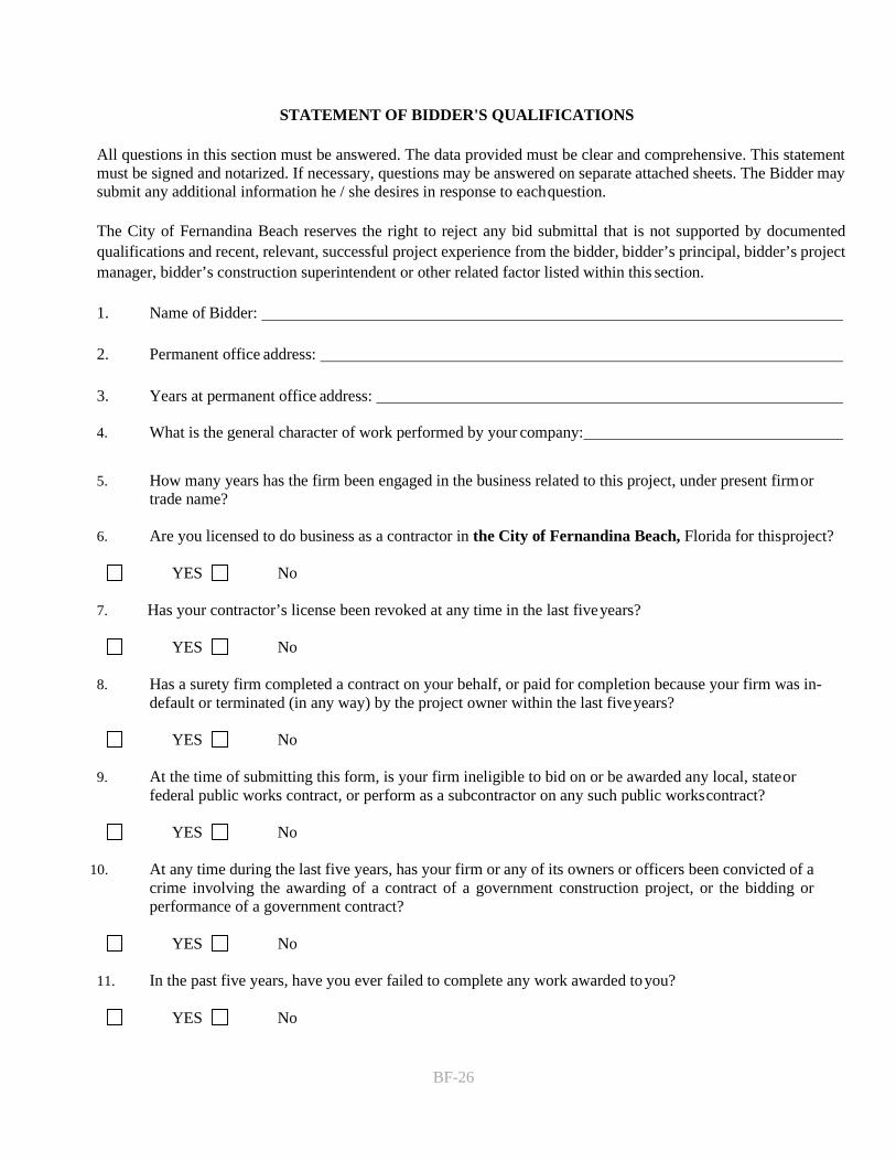
BF-26
STATEMENT OF BIDDER'S QUALIFICATIONS
All questions in this section must be answered. The data provided must be clear and comprehensive. This statement must be signed and notarized. If necessary, questions may be answered on separate attached sheets. The Bidder may submit any additional information he / she desires in response to each question.
The City of Fernandina Beach reserves the right to reject any bid submittal that is not supported by documented qualifications and recent, relevant, successful project experience from the bidder, bidder’s principal, bidder’s project manager, bidder’s construction superintendent or other related factor listed within this section.
1. Name of Bidder:
2. Permanent office address:
3. Years at permanent office address:
4. What is the general character of work performed by your company:
5. How many years has the firm been engaged in the business related to this project, under present firm ortrade name?
6. Are you licensed to do business as a contractor in the City of Fernandina Beach, Florida for this project?
YES No
7. Has your contractor’s license been revoked at any time in the last five years?
YES No
8. Has a surety firm completed a contract on your behalf, or paid for completion because your firm was in-default or terminated (in any way) by the project owner within the last five years?
YES No
9. At the time of submitting this form, is your firm ineligible to bid on or be awarded any local, state orfederal public works contract, or perform as a subcontractor on any such public works contract?
YES No
10. At any time during the last five years, has your firm or any of its owners or officers been convicted of acrime involving the awarding of a contract of a government construction project, or the bidding orperformance of a government contract?
YES No
11. In the past five years, have you ever failed to complete any work awarded to you?
YES No

BF-27
12. In the past five years, have you ever been terminated by the Owner of a project?
YES No 13. In the last five years has your firm been assessed and paid liquidated damages prior to or after completion
of the project under a construction contract with either a public or private owner?
YES No
14. In the last five years has your firm been debarred, disqualified, removed or otherwise prevented frombidding on, or completing any government agency or public works project for any reason?
YES No
15. In the past five years has any claim against your firm concerning your firm’s work on a construction projectbeen filed in court or arbitration?
YES No
16. In the past five years has your firm filed any claim against a project owner or consultant concerningwork on a project or payment for a contract and filed that claim in court or arbitration?
YES No
17. In the last five years, have you sued an Owner of a project?
YES No
18. In the past five years, have you sued a Consultant (engineer, architect or other) representing theOwner of a project?
YES No
19. Identify and list all administrative, arbitration, or litigation actions, terminations, construction claims or thelike (cumulatively referred to as "claims") related to issues arising from any construction contract performedwithin the past five (5) years for which the Bidder or its team members was a party. For each claim, identifythe project, the parties to the claim, the court or jurisdiction (if applicable), the initiator of the claim and thefinal resolution, or if not resolved the status (attach additional sheets as needed).
20. Will your firm's workforce be performing work on this project equal to a monetary value of 25% of more ofthe Contract amount as awarded?
YES NO
21. Primary Bank Reference:

BF-28
22. Bonding Capacity: Provide documentation from your surety identifying thefollowing: Name of bonding company / surety: Name of surety agent: Address:
Phone:
23. Will you, upon request, fill out a detailed financial statement and furnish any other pertinent informationthat may be required by the Owner?
YES No
The undersigned hereby authorizes and requests any persons, firm, or corporation to furnish any information requested by the Owner, in verification of the recitals comprising this Statement of Bidder's Qualifications.
Dated at , this day of , 2020.
By:
(Contractor)
Title:
, being duly sworn deposes and says that he/she is
of and that the answers to the
foregoing questions and all statements therein contained are true and correct.
SUBSCRIBED AND SWORN to before me this day of , 20 .
Notary's Signature
Notary's Printed Name
NOTARY PUBLIC, STATE OF My commission
expires: , 20

BF-29
EXHIBIT “A” CONTACT SHEET
Name:
Federal Taxpayer ID:
Mailing Address:
City, State, & Zip Code:
Telephone: _ Fax:
Email:
Submitted By:
Title:
FIRM Accepts Credit Cards*: Yes No
Accounting Contact:
Name: Title:
Email Address: Phone:
*See preferred method of payment under “Prompt Payment Act” section of the General Conditions
THIS FORM MUST BE INCLUDED WITH BID/PROPOSAL

BF-30
EXHIBIT “B” SWORN STATEMENT UNDER F.S. SECTION 287.133(3) (A), ON PUBLIC ENTITY CRIMES
THIS FORM MUST BE SIGNED IN THE PRESENCE OF A NOTARY PUBLIC OR OTHER OFFICER AUTHORIZED TO ADMINISTER OATHS.
1. This sworn statement is submitted with Bid, Proposal or Contract for .
2. This sworn statement is submitted by (entity) whose business address is and (if applicable) Federal Employer Identification Number
(FEIN) is ( If a Sole Proprietor and you have no FEIN, include the last four (4) digits of your Social Security Number: .)
3. My name is and my relationship to the entity named above is .
4. I understand that a "public entity crime" as defined in Paragraph 287.133(a) (g). Florida Statutes, means aviolation of any state or federal law by a person with respect to and directly related to the transaction ofbusiness with any public entity or with an agency or political subdivision of any other state or with the United States, including, but not limited to, any proposal or contract for goods or services to be provided to anypublic entity or any agency or political subdivision of any other state or of the United States and involvingantitrust, fraud, theft, bribery, collusion, racketeering, conspiracy, or material misrepresentation.
5. I understand that "convicted" or "conviction" as defined in paragraph 287.133(a) (b), Florida Statutes, means finding of guilt or a conviction of a public entity crime with or without an adjudication of guilt, in any federalor state trial court of records relating to charges brought by indictment or information after July 1, 1989, asa result of a jury verdict, non-jury trial, or entry of a plea of guilty or nolo contendere.
6. I understand that an "affiliate" as defined in Paragraph 287.133(1) (a), Florida Statutes, means:
1. A predecessor or successor of a person convicted of a public entity crime; or
2. An entity under the control of any natural person who is active in the management of the entity and whohas been convicted of a public entity crime. The term "affiliate" includes those officers, directors,executives, partners, shareholders, employees, members, and agents who are active in the management of an affiliate. The City of Fernandina Beach, Florida ownership by one of shares constituting a controllingincome among persons when not for fair interest in another person, or a pooling of equipment or incomeamong persons when not for fair market value under a length agreement, shall be a prima facie casethat one person controls another person. A person who was knowingly convicted of a public entity crime, in Florida during the preceding 36 months shall be considered an affiliate.
7. I understand that a "person" as defined in Paragraph 287.133(1) (e), Florida Statutes, means any naturalperson or entity organized under the laws of the state or of the United States with the legal power to enterinto a binding contract for provision of goods or services let by a public entity, or which otherwise transactsor applies to transact business with a public entity. The term "person" includes those officers, directors,executives, partners, shareholders, employees, members, and agents who are active in management of anentity.
8. Based on information and belief, the statement which I have marked below is true in relation to the entitysubmitting this sworn statement. (Please indicate which statement applies)
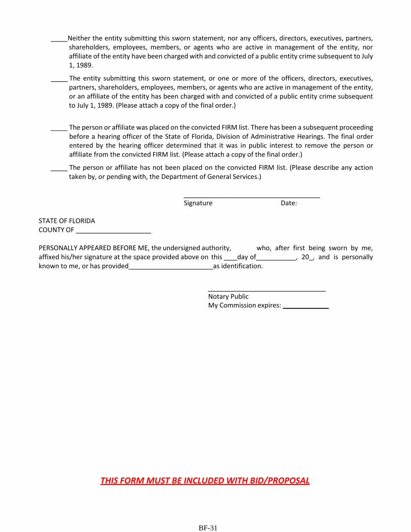
BF-31
Neither the entity submitting this sworn statement, nor any officers, directors, executives, partners, shareholders, employees, members, or agents who are active in management of the entity, nor affiliate of the entity have been charged with and convicted of a public entity crime subsequent to July 1, 1989.
The entity submitting this sworn statement, or one or more of the officers, directors, executives, partners, shareholders, employees, members, or agents who are active in management of the entity, or an affiliate of the entity has been charged with and convicted of a public entity crime subsequent to July 1, 1989. (Please attach a copy of the final order.)
The person or affiliate was placed on the convicted FIRM list. There has been a subsequent proceeding before a hearing officer of the State of Florida, Division of Administrative Hearings. The final order entered by the hearing officer determined that it was in public interest to remove the person or affiliate from the convicted FIRM list. (Please attach a copy of the final order.)
The person or affiliate has not been placed on the convicted FIRM list. (Please describe any action taken by, or pending with, the Department of General Services.)
Signature Date:
STATE OF FLORIDA COUNTY OF
PERSONALLY APPEARED BEFORE ME, the undersigned authority, who, after first being sworn by me, affixed his/her signature at the space provided above on this day of , 20 , and is personally known to me, or has provided as identification.
Notary Public My Commission expires:
THIS FORM MUST BE INCLUDED WITH BID/PROPOSAL

BF-32
EXHIBIT “C” DRUG-FREE WORKPLACE CERTIFICATION
The below-signed INDIVIDUAL/FIRM certifies that it has implemented a drug-free workplace program. In order to have a drug-free workplace prepare, a business shall:
1. Publish a statement notifying employees that the unlawful manufacture, distribution, dispensing,possession, or use of a controlled substance is prohibited in the workplace and specifying the actions thatwill be taken against employees for violation of such prohibition.
2. Inform employees about the dangers of drug abuse in the workplace, the business's policy of maintaining adrug-free workplace, any available drug counseling, rehabilitation, and employee assistance programs, andthe penalties that may be imposed upon employees for drug abuse violations.
3. Give each employee engaged in providing the commodities or services a copy of the statement specified inparagraph 1.
4. In the statement in paragraph 1., notify the employees that, as a condition of working on the commoditiesor contractual services that are under proposal, the employee will abide by the terms of the statement andwill notify the employer of any conviction of, or plea of nolo contendere to, any violation occurring in theworkplace no later than five (5) working days after such conviction.
5. Impose a sanction on, or require fine satisfactory participation in drug abuse assistance or rehabilitationprogram if such is available in the employee's community, by any employee who is convicted.
6. Make a good faith effort to continue to maintain a drug-free workplace through implementation of thissection.
As the person authorized to sign this statement, I Certify that this firm complies fully with the above drug-free workplace requirements.
COMPANY:
CITY: STATE: ZIP CODE:
SIGNATURE: PHONE:
NAME (TYPED OR PRINTED): TITLE:
THIS FORM MUST BE INCLUDED WITH BID/PROPOSAL

BF-33
EXHIBIT “D” E-VERIFY STATEMENT
Bid/Proposal Number:
Project Description:
I/FIRM acknowledges and agrees to the following:
I/FIRM shall utilize the U.S. Department of Homeland Security’s E-Verify system, in accordance with the terms governing use of the system, to confirm the employment eligibility of:
1. All persons employed by the FIRM during the term of the Contract to perform employment dutieswithin Florida; and
2. All persons assigned by the FIRM to perform work pursuant to the contract with the Department.
Individual/Company/Firm:
Authorized Signature:
Title:
Date:
THIS FORM MUST BE INCLUDED WITH BID/PROPOSAL

BF-34
EXHIBIT “E” PROPOSER ACKNOWLEDGEMENTS AND AGREEMENTS
The undersigned, as an employee or agent of the Proposer, having the authority to sign a binding agreement on behalf of the corporation, company, or firm presenting this submittal, confirms understanding and/or agreement and/or takes exception with any statement in the following sections of this ITB/RFP document.
1. INTRODUCTION AND GENERAL INFORMATION
Understands and agrees to all terms.
2. PROPOSAL INSTRUCTIONS, TERMS AND CONDITIONS Understands and agrees to all terms.
3. EVALUATION AND CONTRACT OVERVIEW
Understands and agrees to all terms.
4. PROPOSER’S RESPONSE: SUBMITTAL INFORMATION Understands and agrees to all terms.
5. PROPOSER’S RESPONSE: PROPOSED TEAM
Understands and agrees to all terms.
6. PROPOSER’S RESPONSE: PROPOSED COMPENSATION Understands and agrees to all terms.
Name: Title:
Signature: Date:
THIS FORM MUST BE INCLUDED WITH BID/PROPOSAL

BF-35
EXHIBIT “F” CONFLICT OF INTEREST STATEMENT This sworn statement is submitted with Bid, Proposal or Contract for .
This sworn statement is submitted by (entity) whose business address is and (if applicable) Federal Employer Identification Number (FEIN)
is ( If a Sole Proprietor and you have no FEIN, include the last four (4) digits of your Social Security Number: .)
My name is and my relationship to the entity named above is . 1. The above named entity is submitting a Proposal for the City of Fernandina Beach.2. The Affiant has made diligent inquiry and provides the information contained in the Affidavit based
upon his/her own knowledge.3. The Affiant states that only one submittal for the above proposal is being submitted and that the
above named entity has no financial interest in other entities submitting proposals for the sameproject.
4. Neither the Affiant nor the above named entity has directly or indirectly entered into anyagreement, participated in any collusion, or otherwise taken any action in restraints of freecompetitive pricing in connection with the entity’s submittal for the above proposal. This statementrestricts the discussion of pricing data until the completion of negotiations if necessary andexecution of the Contract for this project.
5. Neither the entity not its affiliates, nor anyone associated with them, is presently suspended orotherwise ineligible from participation in contract letting by any local, State, or Federal Agency.
6. Neither the entity nor its affiliates, nor anyone associated with them have any potential conflict ofinterest due to any other clients, contracts, or property interests for this project.
7. I certify that no member of the entity’s ownership or management is presently applying for anemployee position or actively seeking an elected position with the City of Fernandina Beach.
8. I certify that no member of the entity’s ownership or management, or staff has a vested interestin any aspect of the City of Fernandina Beach.
9. In the event that a conflict of interest is identified in the provision of services, I, on behalf of theabove named entity, will immediately notify the City of Fernandina Beach.
_________________________________ Signature Date:
STATE OF FLORIDA COUNTY OF ____________________ PERSONALLY APPEARED BEFORE ME, the undersigned authority, who, after first being sworn by me, affixed his/her signature at the space provided above on this ___ day of _________________ , 20 _, and is personally known to me, or has provided ______________________ as identification.
_______________________________My Commission expires: ___________________ Notary Signature

BF-36
EXHIBIT “G” NON-COLLUSION AFFIDAVIT This sworn statement is submitted with Bid, Proposal or Contract for .
This sworn statement is submitted by (entity) whose business address is and (if applicable) Federal Employer Identification Number (FEIN)
is ( If a Sole Proprietor and you have no FEIN, include the last four (4) digits of your Social Security Number: .)
My name is and my relationship to the entity named above is .
1. The above named is fully informed respecting the preparation and contents of the attached proposaland of all pertinent circumstances respecting such proposal;
2. Such Proposal is genuine and is not a collusive or sham proposal;3. Neither the said Proposer nor any of its officers, partners, owners, agents, representatives, employees,
or parties in interest, including this affiant, has in any way colluded, connived, or agreed, directly orindirectly, with any other Bidder, firm or person to submit a collusive or sham Proposal in connectionwith such Contract, or has in any manner, directly or indirectly, sought by agreement or collusion orcommunication or conference with any other Bidder, firm, or person to fix the price or prices in theattached proposal or any other Bidder, or to fix any overhead, profit or cost element of the proposalprice or the proposal price of any other Bidder, or to secure through any collusion, connivance, orunlawful agreement any advantage against the City of Fernandina Beach, Florida or any personinterested in the proposed Contract; and
4. The price or prices quoted in the attached proposal are fair and proper and are not tainted by anycollusion, conspiracy, connivance, or unlawful agreement on the part of the Bidder or any of its agents,representatives, owners, employees, or parties in interest, including this affiant.
STATE OF FLORIDA COUNTY OF ____________________
_______________ ___ ______________ Signature Date:
PERSONALLY APPEARED BEFORE ME, the undersigned authority, who, after first being sworn by me, affixed his/her signature at the space provided above on this ___ day of ___ ___________, 20__, and is
personally known to me, or has provided _______________________ as identification.
___________________________________ My Commission expires: ________________ Notary Signature

BF-37
EXHIBIT “H” DISPUTES DISCLOSURE FORM
Answer the following questions by placing as “X” after “YES” or “NO”. If you answer “YES”, please explain in the space provided, or via attachment.
Has your firm or any of its officers, received a reprimand of any nature or been suspended by the Department of Professional Regulations or any other regulatory agency or professional association within the last five (5) years?YES NO
Has your firm, or any member of your firm, been declared in default, terminated or removed from a contract or job related to the services your firm provides in the regular course of business within the last five (5) years?YES NO
Has your firm had against it or filed any request for equitable adjustment, contract claims, bid protest, or litigation in the past five (5) years that is related to the services your firm provides in the regular course of business? YES NO
If yes, state the nature of the request for equitable adjustment, contract claim, litigation, or protest, and state a brief description of the case, the outcome or status of the suit and the monetary amounts or extended contract time involved.
I hereby certify that all statements made are true and agree and understand that any misstatement or misrepresentation or falsification of facts shall be cause for forfeiture of rights for further consideration of this proposal for the City of Fernandina Beach.
Firm Date
Authorized Signature Printed or Typed Name and Title
END OF BID FORMS

CA-1
CITY OF FERNANDINA BEACH CONTRACT AND GENERAL CONDITIONS
FOR CONSTRUCTION SERVICES
This AGREEMENT made on the day of in the year of 20 , BETWEEN the owner, CITY OF FERNANDINA BEACH, 204 Ash Street, Fernandina Beach, FL 32034 (hereinafter referred to as “Owner” or “City”) and the Contractor, (insert Name, Address, City, State, Zip)
PROJECT:
CONTRACTOR:
ARCHITECT/ENGINEER:
The Owner and Contractor Agree as Follows:
ARTICLE 1 - CONTRACT DOCUMENTS
1. Enumeration of Contract Documents
Contract Documents comprise this Agreement, the plans, drawings, specifications, project manual, addenda, and other materials contained in City of Fernandina Beach Bid Number . Documents comprising Bid Number are incorporated into this Agreement by reference and are a part of this Agreement as if attached or repeated herein. This Agreement represents the entire Agreement between the parties hereto and supersedes any prior negotiations, representations, agreements, or understandings, either written or oral.
2. Intent of Contract Documents
Execution of the Contract by the Contractor is a representation that the Contractor has become familiar with the Contract Documents and field conditions under which the Work is to be performed within the requirements of Work specified by the Contract Documents.
The headings of the sections of this Agreement and capitalizations are for the purpose of convenience only and shall not be deemed to expand or limit the provisions contained in such sections.
3. Definitions:
Definitions are provided in Appendix 1 of this Agreement.
ARTICLE 2 - SCOPE OF WORK
The Contractor shall execute the entire Work described in the Contract Documents, Summary of Work.
ARTICLE 3 - COMMENCEMENT DATE
The Commencement Date shall be established by the Owner and communicated to the Contractor in a Notice to Proceed (NTP) sent by registered mail to the Contractor's place of business not later than 30 days following execution of the Contract, or receipt of all insurance certificates, bonds, and Schedules of Values required by the Contract, whichever is later. Failure to provide the required insurance or bonds within ten (10) days of the Award of Bid shall constitute a delay by the Contractor in honoring his Bid.
The Contractor will not commence Work on the project until receiving a Notice to Proceed from the Owner.
ARTICLE 4 - SUBSTANTIAL COMPLETION DATE
The Contractor shall commence work within thirty (30) calendar days from the date of Notice to Proceed. The Contractor shall achieve Substantial Completion of the Work not later than one hundred forty (140) consecutive calendar days after the date specified by the Notice to Proceed, subject to adjustments of the Contract Time as provided in the Contract Documents. The Contractor shall achieve Final Completion of the work not later than thirty (30) days after reaching Substantial Completion.
Time limits herein stated in the Contract Documents are of the essence of the Contract. By executing the Agreement the Contractor confirms that the Contract Time is a reasonable period for performing the Work.

CA-2
ARTICLE 5 - CONTRACT AMOUNT
The Owner shall pay the Contractor the sum of $xxx,xxx subject to additions and deductions as provided in the Contract Documents for all Work described in Article 2.
ARTICLE 6 - LIQUIDATED DAMAGES
The Contractor and Owner mutually agree that said work shall be prosecuted regularly, diligently, and uninterruptedly at such rate of progress as will ensure full completion thereof within the time specified. It is expressly understood and agreed, by and between the Contractor and the Owner, that the time for the completion of the Work described herein is a reasonable time for the completion of the same, taking into consideration the average climatic range and usual industrial conditions prevailing.
If the said Contractor shall neglect, fail or refuse to complete the work within the time specified, or any proper extension thereof granted in accordance with this Agreement, then the Contractor does hereby agree, as a part consideration for the award of this contract, to pay to the Owner for the first twenty calendar days the amount of XXXXXX per calendar day from the twenty first day and beyond for each calendar day beyond the Substantial Completion Date not as a penalty but as liquidated damages for such breach of Contract. Furthermore, the Contractor agrees to pay to the Owner the amount of XXXXXXXX for each calendar day that the Work remains incomplete after the date established for Final Completion.
The said amount is fixed and agreed upon by and between the Contractor and the Owner because of the impracticably and extreme difficulty of fixing and ascertaining the actual damages the Owner would in such event sustain, and said amount is agreed to be the amount of damages which the Owner would sustain. Also, failure to meet requirements for substantial or final completion shall subject the Contractor to reinspection fees as set forth in the specifications.
In addition to liquidated damages, should the Owner become liable for additional architectural fees due to delays by the Contractor which extend construction beyond the contracted construction time, the Contractor shall be liable for payment of such expenses to the Owner.
Both Liquidated Damages and Reinspection Fees shall be implemented using a Deductive Change Order or Construction Change Directive. The exact form used and its titling of such change order shall be as determined by the Owner.
ARTICLE 7 - PAYMENTS
1. Progress Payments
Based upon Applications for Payment submitted to the Architect/Engineer by the Contractor and Certificates for Payment issued by the Architect/Engineer, the Owner shall make progress payments on account of the Contract Amount to the Contractor as provided below and elsewhere in the Contract Documents.
The period covered by each Application for Payment shall be one calendar month ending on the last day of the month.
Provided an Application for Payment is received by the Architect/Engineer not later than the 15th day of the month, the Owner shall make payment to the Contractor not later than the last day of the month. If a valid Application for Payment is received by the Architect/Engineer after the Application date fixed above, payment shall be made 15 days after the Architect/Engineer received the Application for Payment.
Each Application for Payment shall be based upon the Schedule of Values submitted by the Contractor in accordance with the Contract Documents.
Applications for Payment shall indicate the percentage of completion of each portion of the Work as of the end of the period covered by the Application for Payment.
Subject to the provisions of the Contract Documents, the amount of each progress payment shall be computed as follows:
Take that portion of the Contract Amount properly allocable to completed Work as determined by multiplying the percentage completion of each portion of the Work by the share of the total Contract Amount allocated to that portion of the Work in the Schedule of Values, less retainage of 10%.
Add that portion of the Contract Amount properly allocable to materials and equipment delivered and stored at the Project Site for subsequent incorporation into the Work, less retainage of 10%.
Subtract the aggregate of previous payments made by the Owner.
The progress payment amount shall be further modified under the following circumstances:
Add, upon Substantial Completion of the Work, a sum sufficient to increase the total payments to 90% of the Contract Amount, less such amounts as the Architect/Engineer and Owner shall determine for incomplete Work and unsettled claims.
2. Final Payment
Final payment, comprising the entire unpaid balance of the Contract Amount, shall be made by the Owner to the Contractor when the Contract has been fully performed and accepted by the Owner. Final payment shall be contingent upon the Contractor providing all warranties, guaranties and waivers of liens required under the Project Closeout Section of the Specifications. Furthermore, payment shall be made in accordance with the Florida Prompt Payment Act applicable to local governments.
3. Certifying a Schedule of Values

CA-3
Within 10 days after award of the Contract, the Contractor shall submit to the Architect/Engineer a Schedule of Values allocating the values of various portions of the Work, prepared in such form and supported by such data to substantiate its accuracy as the Architect/Engineer or Owner may require. This Schedule of Values shall be reviewed by the Architect/Engineer and approved by the Owner, and shall be used as the basis for reviewing the Contractor's Applications for Payment.
The Schedule of Values shall include a cost breakdown indexed per the Sections of the Specifications, which shall clearly set forth labor as distinct from materials and from equipment. Rough-in work shall be shown separately from finish work.
4. Contractor Applications for Payment
By the 15th of each month the Contractor shall submit to the Architect/Engineer an itemized Application for Payment in accordance with the Schedule of Values. Such application shall be supported by data substantiating the Contractor's right to payment as the Owner or Architect/Engineer may require. Payment shall be made on account of materials and equipment delivered and suitably stored at the site for subsequent incorporation into Work. If approved in writing by the Owner, payment may similarly be made for materials and equipment suitably stored off the site.
Applications for Payment shall not include:
• Request payments on account of changes in the Work which have not been approved by the Owner in a Change Order; and• Payment of amounts the Contractor does not intend to pay to a Subcontractor or Supplier because of a dispute or other reason.
The Contractor warrants that title to all Work covered by an Application for Payment will pass to the Owner no later than the time of payment. The Contractor further warrants that all work, equipment and materials included in the Application for Payment are to the best of the Contractor's knowledge, information and belief, free from liens, claims, security interests or encumbrances.
5. Certification of Payment Requests
Within seven (7) days after receipt of a Contractor's Application for Payment, the Architect/Engineer, in consultation with the Owner, will issue a Certificate for Payment for an amount the Architect/Engineer and Owner determines is due, or notify the Contractor in writing of the reasons for withholding certification. A Certificate for Payment shall not constitute acceptance of Work not in accordance with the Contract Documents.
6. Criteria for Withholding A Certificate for Payment
The Architect/Engineer or Owner may withhold approval of a Certificate for Payment or, because of subsequent events, may nullify a prior approval of payment in whole or in part if in the Architect/Engineer's or Owner's opinion Contractor representations to the Owner are not supported or are deemed inaccurate. If the Contractor and Architect/Engineer or Owner cannot agree on a revised amount, the Architect/Engineer will promptly issue a Certificate of Payment for the amount to which the Architect/Engineer and Owner are able to certify payment. Certification may be withheld for these reasons: Defective Work not corrected;
• Reasonable evidence that the Work cannot be completed for the unpaid balance of the Contract Amount• Damages owed to the Owner or others;• Evidence that the Work will not be completed within the Contract Time, and that the unpaid balance would not be adequate to cover actual or
estimated Liquidated Damages; or• Failure by Contractor to make payments properly and promptly to subcontractors or suppliers; or• Persistent failure to carry out the Work in accordance with the Contract Documents or other material breach by Contractor.
When reasons for withholding certification are corrected, the Architect/Engineer and Owner will certify amounts previously withheld.
ARTICLE 8 - TERMINATION OR SUSPENSION OF THE CONTRACT
1. Termination by The Contractor
The Contractor may terminate the Contract if work is stopped for a period of 60 days or longer for the following reasons:
• Issuance of a Stop Work Order by a court regulatory agency having jurisdiction over the project; or• An act of Government making materials or labor unavailable.
If any one of the reasons stated above exists, the Contractor shall be compensated as provided in this Agreement only for Work executed in accordance with the Contract Documents.
2. Termination by The Owner For Cause
The Owner may terminate the Contract due to the Contractor's inability to perform for these reasons:
• Refusal or failure to supply properly skilled workers or materials;• Disregarding the laws, ordinances or regulations of public authorities having jurisdiction over the Work; or• Substantially breaching provisions of the Contract Documents.
If such conditions exist the Owner may, without prejudice of any other rights or remedies of the Owner, after having given the Contractor and the Contractor's surety seven days written notice, terminate the Agreement and, subject to any prior rights of the surety:

CA-4
• Take possession of the site and materials, equipment, tools, and machinery therein owned by the Contractor;• Accept assignment of Subcontracts; and• Finish the work by whatever means are available to the Owner.
Should the Work be terminated according to this section the Contractor shall not be entitled to receive further payment until the Work is finished.
If the unpaid balance of the Contract Amount exceeds the costs of finishing the work, such excess shall be used to pay the Contractor amounts due for materials and equipment stored on site and Work completed in accordance with the Contract Documents which has been Certified by the Architect/Engineer and accepted by the Owner. If such costs exceed the unpaid balance, the Contractor shall pay the difference to the Owner, which obligation for payment shall survive the termination of the Agreement.
The costs of finishing the Work include, without limitation, all reasonable attorney's fees, additional title costs, insurance, additional interest because of delay in completing the Work, and all other direct, indirect, and consequential costs incurred by the Owner by reason of the termination of the Contractor as stated herein. The Owner shall be entitled to hold all amounts due the Contractor at the date of termination until all of the Owner's costs have been established, and to apply such amounts to such costs.
Should the Owner's termination of the Contractor for Cause be challenged, and should such challenge prevail, then the Owner's termination of the Contractor shall be deemed to have been a Termination for Convenience, and Contractor's entitlement to compensation shall be determined in accordance with paragraph 3 below.
3. Termination by the Owner for Convenience
The Owner may, without cause, order the Contractor in writing to suspend, delay or terminate the Work in whole or in part for such period of time the Owner may determine. The Owner shall adjust the Contract Amount for increases in the cost of performance under the Contract caused by suspension, delay, or interruption.
No change in Contract Amount shall be made where the suspension, delay, or interruption for which the Contractor is responsible or attributable.
In the event of termination for convenience by the Owner, the Contractor shall only be entitled to and paid compensation earned through the date of termination and Termination Expenses. Termination Expenses are those jobsite costs directly attributable to termination (such as jobsite demobilization costs). Contractor shall not be entitled to direct, indirect, or consequential damages, or other damages for loss from and including, but not limited to economic loss, lost profit on under-performed portions of the work, loss of anticipated profits, idle equipment expenses, interest or carrying costs, overhead expenses, loss of efficiency, or loss of productivity, lost or reduced bonding capacity.
ARTICLE 9 - EXECUTION OF THE PROJECT
A. OBLIGATIONS OF THE ARCHITECT/ENGINEER
1. Architect/Engineer as Owner's Representative
The Architect/Engineer will provide project management services as described in the Contract Documents, and will serve as the Owners representative during construction, and until final payment is certified. The Architect/Engineer will consult with and advise the Owner. The Architect/Engineer will have the authority to act on behalf of the Owner only to the extent as provided in the Contract documents.
The Architect/Engineer specifically assumes no duty or responsibility which may be construed as being for the benefit of and thereby enforceable by other parties providing labor, materials or services in connection with the Work such as, though not limited to, Contractor, Subcontractors, Sub- subcontractors, their agents, employees, or any of their bonding companies, it being understood that the Architect/Engineer's obligations are to the Owner, and in performing such obligations the Architect/Engineer may consequently alter the burdens and expense of such other parties. If the Contractor claims additional cost or time on account of the Architect/Engineers performing such obligations, the Contractor shall give notice as provided in Article 13.
The Owner and Contractor shall communicate through the Architect/Engineer. Communications by and with the Architect/Engineer and Architect/Engineer's consultants shall be through the Architect. Communications by and with subcontractors and suppliers shall be through the Contractor. Communication by and with other Contractors working on the site which are not parties to this Agreement shall be through the Owner.
2. Monitoring Progress, Quality and Compliance with Contract Requirements
The Architect will perform site inspections at critical stages of construction to become generally familiar with progress and quality of completed Work to determine if in general the Work is performed in accordance with the Contract Documents. The Architect will have authority to reject work which does not comply with the Contract Documents. Wherever considered necessary, the Architect may require additional inspection or testing of the Work whether the Work is fabricated, installed or completed.
The Architect will not have control over or charge of and will not be responsible for construction means, methods, techniques, sequences or procedures, or for safety precautions and programs in connection with the Work, since these are solely the Contractor's responsibility. The Architect will not be responsible for the Contractor's failure to carry out the Work in accordance with the Contract Documents. The Architect will not have control over or charge of and will not be responsible for acts or omissions of the Contractor, Subcontractors, or their agents or employees, or of any other persons performing portions of the Work.
Actions of the Architect undertaken while providing administration of the Contract shall not be construed as either supervision or coordination, since these are solely the Contractor's responsibility.

CA-5
3. Review and Approval of Contractor's Submittals
The Architect will review and approve the Contractor's Submittals, such as shop drawings and product samples, for the limited purpose of checking for compliance with the Contract Documents. The Architect's review does not relieve the Contractor of his obligations under the Contract to comply with the plans and specifications.
The Architect's approval of a submittal which contains a deviation which has not been specifically called to the Architect's attention excludes approval of that deviation and shall not serve as a waiver of the rights of the Architect or Owner unless the Architect makes specific written acceptance of said deviation on the Architect's letterhead or Owner makes specific written acceptance of said deviation on the Owner's letterhead.
4. Interpret Plans
The Architect will provide interpretations of the Plans and Specifications for compliance with the Contract Documents. The Architect's response to interpretation requests shall be made with reasonable promptness, or a maximum of 15 days from the date of written request.
Interpretations of the Architect will be consistent with the intent of the Contract Documents and will be documented in writing or in the form of plans and drawings.
The Architect may, as the Architect judges desirable, issue additional drawings or information indicating in greater detail the construction or design of the various parts of the Work; such drawings or information may be affected by field order or other notice to the Contractor, and provided such drawings or information are reasonably consistent with the previously existing Contract Documents, the Work shall be executed in accordance with such additional drawings or information without additional cost or extension of the Contract Time. If the Contractor claims additional cost or time on account of such additional drawings or information, the Contractor shall give the notice provided in Article 13.
5. Approving Non-Substantial Deviations
The Architect will have the authority to order minor changes in the Work not involving adjustments of Contract Amount or Contract Time, and which is not inconsistent with the intent of the Contract Documents. Such changes shall be implemented by issuing a Construction Change Directive which shall be immediately binding on the Contractor upon receipt.
6. Certifying Applications for Payment
Based on the Architect's observations and evaluations of the Contractor's Applications for Payment, the Architect will review amounts due the Contractor and will, upon approval by Owner, issue Certificates for Payments.
7. Preparing Change Orders
The Architect will prepare Change Orders for approval by the Owner.
8. Substantial Completion and Acceptant Reviews
The Architect will conduct inspections, and if Work is found Substantially Complete by the Owner and Architect, establish the date or dates of Substantial Completion and the date of Final Completion. The Architect will receive and forward to the Owner for the Owners' review, project records, written warranties and related documents required by the Contract and assembled by the Contractor. The Architect will issue a final Certificate for Payment upon compliance with requirements of the Contract Documents and acceptance by the Owner.
B. OBLIGATIONS OF THE OWNER
1. Project Manager
The Owner will designate a Project Manager, through which the City will communicate with the Architect and Contractor.
2. Information Provided by Owner
The Owner shall furnish surveys describing physical characteristics of the site, and utility locations.
Information or services requested by the Contractor and under the Owner's control shall be promptly supplied to the Contractor in order to promote orderly progress of the Work. Such information and services will be provided to the Contractor free, unless otherwise provided in the Contract Documents.
The Owner will furnish the Contractor, free of charge, a maximum of ten sets of Construction Documents.
The Owner disclaims any responsibility for information not expressly set forth in the plans or specifications. Therefore, the Owner shall not be responsible for archived information or other information that may be in the Owner's possession or control, but which has not been utilized by the Project Architect and expressly contained, depicted, or otherwise expressly set forth in the Contract Documents.
3. Permits
Unless otherwise provided in the Contract Documents, the Contractor shall secure and pay for any and all Permits necessary to construct the facilities described by the Contract Documents.
4. Owner's Right to Stop Work

CA-6
If the Contractor fails to correct Work which is not in accordance with requirements of the Contract Documents or persistently fails to carry out Work in accordance with the Contract Documents, the Owner may order the Contractor to stop work or any portion thereof until the cause of such order has been eliminated. Such an order must be in writing.
5. Owner's Right to Carry Out Work
If the Contractor defaults or neglects to carry out the Work in accordance with the Contract Documents, after giving seven (7) days written notice, the Owner may without prejudice to other remedies, correct such deficiencies. In such a case, a Change Order shall be issued deducting from the Contract Amount the cost of correcting such deficiencies, including additional design and administrative costs as may be necessary by the default, neglect, or failure.
6. Interpretation of Contract Documents and Performance
In all matters concerning performance under this Agreement and requirements of the Contract Documents, the Owner's interpretation will prevail.
7. Approving Substantial Deviations
The Owner will approve in writing all changes in the Work involving:
• Adjustments to the Contract Amount;• Contract Time; or• Work that is inconsistent with the Intent of the Contract Documents.
8. Owner's Right to Expedite Schedule
If Owner determines, in its reasonable opinion, that the performance of the Work as of any date during construction has not progressed or reached the level of completion required by the Contract Documents and/or the construction schedule acceptable to Owner, the Owner shall have the right to order the Contractor to take corrective measures necessary to expedite the progress of construction including, without limitation, (I) working additional shifts or overtime, (ii) supplying additional manpower, equipment and facilities, and (iii) other similar measures (hereinafter referred to collectively as “Corrective Measures”),. Such Corrective Measures shall continue until the progress of the Work complies with the stage of completion required by the Contract Documents and the construction schedule. The Contractor shall not be entitled to an adjustment in the Contract Sum in connection with Corrective Measures required by Owner pursuant to this paragraph. The Owner may exercise the rights furnished hereunder or specifically pursuant to this paragraph as frequently as Owner deems reasonably necessary to ensure that the Contractor's performance of the Work will comply with the construction schedule and the Contract Documents.
Such changes shall be affected by a Change Order signed by the Contractor, Architect, and the Owner.
C. OBLIGATIONS OF THE CONTRACTOR
1. Superintendent
The Contractor shall employ a competent Superintendent and necessary assistants who shall be in attendance at the Project Site during performance of the Work. The Superintendent shall represent the Contractor, and communications given to the Superintendent shall be as binding as if given to the Contractor.
2. Review of Contact Documents
The Contractor shall carefully review Contract Documents and information provided by the Owner, and shall at once report to the Architect any errors, omissions, or inconsistencies discovered.
If the Contractor performs any construction activities with knowledge of an error, omission or inconsistencies in the Contract Documents without such notice to the Architect, the Contractor shall assume responsibility for such performance.
3. Review of Field Conditions
The Contractor shall take field measurements and verify field conditions and carefully compare such with the Contract Documents before commencing the Work. Errors, omissions or inconsistencies discovered shall be reported to the Architect at once. The Contractor and each Subcontractor shall evaluate and satisfy themselves as to the conditions and limitations under which the Work is to be performed, including, without limitation (1) the location, condition, layout and nature of the Project site and surrounding areas, (2) generally prevailing climatic conditions, (3) anticipated labor supply and costs, (4) availability and cost of materials (except for unforeseeable serious material shortages), tools and equipment, (5) availability of temporary utility service and (6) other similar issues. The Owner assumes no responsibility or liability for the physical condition or safety of the Project site or any improvements located on the Project site. Except as set forth in subparagraph 10.1.2, the Contractor shall be solely responsible for providing a safe workplace. The Owner shall not be required to make any adjustment in either the Contract Sum or Contract Time in connection with any failure by the Contractor of any Subcontractor to comply with the requirements of this Subparagraph.
4. Supervision and Construction Procedures
The Contractor shall perform the Work in accordance with the Contract Documents and Submittals approved by the Architect.
The Contractor shall supervise and direct the Work, using the Contractor's best skill and attention. The Contractor shall be solely responsible for and have control over construction means, methods, techniques, sequences and procedures; and for coordinating all portions of the Work, under Contract, unless otherwise specified in the Contract Documents.

CA-7
The Contractor shall be responsible to the Owner for acts and omissions of the Contractor's employees, Subcontractors, Suppliers, and their agents and employees, and other persons performing portions for the Work under a contract with the Contractor or his Subcontractors.
The Contractor shall not be relieved of obligations to perform the Work in accordance with the Contract Documents either by activities or duties of the Architect or, the Owner's Project Manager, in administration of the Contract, or by tests, inspections or approvals required or performed by persons other than the Contractor.
5. Inspection of Work
The Contractor shall be responsible for inspection of portions of the Work already performed under this Contract to determine if such portions are in proper condition to receive subsequent Work.
6. Labor and Materials
Unless otherwise provided in the Contract Documents, the Contractor shall provide and pay for labor, materials, equipment, tools, water, electric, other utilities, transportation, taxes and other facilities and services necessary for proper execution and completion of the Work. It is the Contractor's responsibility to provide these resources whether temporary or permanent, and whether or not incorporated or to be incorporated in the Work.
The Contractor shall enforce strict discipline and good order among the Contractor's employees and other persons carrying out the Contract. The Contractor shall not permit employment of unfit persons or persons not skilled in tasks assigned to them.
7. Warranty
The Contractor warrants to the Owner that materials, equipment, and skilled labor will be provided in accordance with the Contract Documents, and that the Work will be free from defects. Work not conforming with these requirements, including substitutions not properly approved and authorized, may be considered defective.
8. Construction Schedule
Prior to issuance of a Notice to Proceed, but not later than fourteen (14) days after Notice of Award, the Contractor shall prepare and submit to the Architect a Construction Schedule for the Work. The Schedule shall not exceed the time limits established in the Contract Documents, nor shall the Schedule reflect an early completion of the Work. The construction schedule shall document major construction activities and tasks, identifying the estimated beginning and ending dates for each identifiable component of the Work with activity durations limited to 14 days. The Construction Schedule shall also identify the critical path and any other near critical events which would most greatly affect the Construction Schedule. The Construction Schedule will be prepared in sufficient detail as may be acceptable to the Architect. The Construction Schedule shall be revised at appropriate intervals as required by conditions of the Work.
9. Project Records
The Contractor shall maintain the following project records at the project site:
• Construction Schedule• Plans and Drawings• Specifications• Addenda• Change Orders• Construction Change Directives• Shop Drawings• Product Data• Samples• Required Submittals• Superintendent's Log
Records shall be maintained in good order and, marked to reflect current changes and selections made during the construction process.
Records shall be available to the Architect and Owner and, with the exception of the Superintendent's Log, shall be delivered to the Architect for submittal to the Owner upon completion of the Work.
Additionally, the Superintendent's Log shall at a minimum document the dates and times of critical inspections; instructions received from the Architect; and weather conditions including dates, times, and amount of rainfall received.
10. Approval of Shop Drawings and Other Submittals
The Contractor shall review, approve, and submit to the Architect Shop Drawings, Product Data, Samples, and other Submittals required by the Contract Documents for approval by the Architect prior to their implementation. The Contractor shall perform no portion of the Work requiring submittal and review of these or similar data until approved by the Architect. Such Work shall be accomplished in accordance with approved Submittals.
The Contractor shall not submit any shop drawing or other submittal that is merely a tracing or other copy of any of the Contract Documents. Each submittal item must be prepared by the Contractor, or for the Contractor by a Subcontractor or Supplier of the Contractor. The Architect shall have the authority to reject any submittal items that violate this provision, and no extension of Contract Time shall be given on account of such rejection.
CA-8
Architect's review and action on any such Submittals shall not serve as a basis for or give rise to any claim in favor of Contractor or any third party against the Owner or Architect. By submitting the materials described above to the Architect for approval, the Contractor represents that he has determined and verified materials, field measurements, and field construction criteria related to the Submittals and has checked and verified their compliance with requirements of the Contract Documents. The Contractor shall not be relieved of responsibility for errors or omissions in Shop Drawings, Product Data, Samples or other Submittals. The Contractor shall not be relieved of responsibility for deviations from the requirements of the Contract Documents unless the Architect makes specific written acceptance of said deviations on the Architect's letterhead.
11. Use of the Project Site
The Contractor shall confine operations to the Site as designated by the Owner, and shall confine operations and activities to those permitted by law, ordinances, permits, and the Contract Documents; and should not unreasonably encumber the site with materials or equipment. The Contractor is specifically prohibited from the storage of materials, equipment, or supplies not related to the Work on the Project Site.
The Owner will be responsible for resolving disputes between the Contractor and other Contractors with which the Owner has a separate Agreement concerning use of the Project Site.
12. Cleanup of Project Site
The Contractor shall keep the premises and surrounding area reasonably free of rubbish, waste materials, or debris caused by operations under the Contract. At completion of the Work, the Contractor shall remove from and about the Project Site, waste materials, rubbish, tools, construction equipment, machinery, and surplus materials to the Owner's satisfaction. Should the Contractor fail to clean up as provided in the Contract Documents, the Owner may do so and the cost charged to the Contractor through a deductive Change Order or Construction Change Directive.
13. Observations and Inspections
The Contractor shall provide Owner and Architect access to the Work, wherever located and in whatever stage of construction for the purpose of providing inspections and observations necessary to assess compliance with applicable codes and to identify the quality and quantity of Work performed.
If a portion of the Work is covered contrary to the Architect's request or to the requirements expressed in the Contract Documents, it must be uncovered to allow the requested inspection or observation and replaced at the Contractor's expense without change in Contract Time.
If a portion of the Work has been covered for which the Owner or Architect has not specifically requested prior observation, the Architect may request to see such Work and it shall be uncovered by the Contractor. If such Work has been completed in accordance with the Contract Documents, the cost for uncovering and replacement shall be borne by the Owner and implemented through a Change Order recommended by the Architect and approved by the Owner. If such Work was inspected and found not to be in conformance with the Contact Documents, the Contractor shall pay the cost of uncovering and replacement without a change in Contract Time.
14. Correcting Rejected Work
The Contractor shall promptly correct Work rejected by the Architect for failing to conform to the requirements of the Contact Documents, whether observed before or after Substantial Completion and whether or not fabricated, installed, or completed. The Contractor shall bear the costs of correcting such Work, including those for additional testing and inspections and compensation for any additional design or necessary administrative costs.
If, within one year after the date of Final Acceptance, or before the expiration of warranties provided by the Contractor, Subcontractor, or Suppliers, whichever is greater, or by the terms of a special warranty required by the Contract Documents; any of the Work is found not to be in accordance with the requirements of the Contract Documents, the Contractor shall correct it within ten (10) days after receipt of a written notice from the Owner. This obligation shall survive acceptance of the Work under the Contract and Termination of the Contract, if such Termination has been exercised by the Owner.
If the Contractor fails to correct nonconforming Work within ten (10) days or such reasonable time as may apply, the Owner may complete the work in accordance with the provisions in Article 9-B-5 and 9-B-8 of this Agreement.
15. Acceptance of Non-Conforming Work
The Owner may at his option accept Work which is not in accordance with the requirements of the Contact Documents instead of requiring its removal and correction. In such cases the Contract Amount will be reduced as appropriate and equitable. Such adjustment shall be affected whether or not final payment has been made.
16. Tests & Inspections
Tests, inspections and approvals of portions of the Work required by law, ordinance, rules, regulations, or other orders of public authorities having jurisdiction shall be made at the appropriate time. Unless otherwise provided, the Contractor will make arrangements for such tests, inspections and approvals, and shall be responsible for paying testing, inspection, and reinspection fees.
Other tests, inspections, and approvals required by the Contact Documents shall also be made at the appropriate times. The Contractor shall make arrangements for such tests, inspections and approvals with the independent testing laboratories or entities designated by the Owner. The Owner shall bear the costs related to these tests, inspections and approvals.
For all tests and inspections conducted under this section, the Contractor shall give the Architect timely notice of when and where tests and inspections are to be made so that observations may be made.

CA-9
If tests or inspections reveal failure of portions of the Work to comply with the Contract Documents, or approval is not secured from a public authority having jurisdiction over the project for a portion of the Work covered by the Contract Documents, the Contractor shall bear all costs made necessary by such failure.
Certificates of testing, inspection or approval shall be secured by the Contractor and promptly delivered to the Architect
ARTICLE 10 - SUBCONTRACTORS
1. Reporting of Proposed Subcontractors
As soon as practical after the issuance of a Notice to Proceed, or as otherwise provided in the Contract Documents, the Contractor will furnish in writing to the Architect the names of persons or entities, including Subcontractors, material suppliers, equipment suppliers, and fabricators proposed for Principal Portions of the Work. After conferring with the Owner, the Architect will promptly inform the Contractor in writing whether or not there are reasonable objections to the any of the proposed persons or entities unto which the Contractor proposes to enter into an Agreement.
2. Rejection of Subcontractors
Neither the Contractor nor the Owner shall be required to Contract with anyone to whom either party has made a reasonable objection; excepting instances where the Contract Documents require use of a material, equipment, or other product for which there is no acceptable alternate supplier or installer.
3. Removal of Subcontractors
The Contractor shall not change a Subcontractor, person or entity previously selected if the Owner makes reasonable objection to such change.
4. Subcontractors Bound by Contract Documents
By appropriate Agreement, the Contractor shall require each Subcontractor, to the extent of the Work to be performed by the Subcontractor, to be bound to the Contractor by the terms of the Contract Documents, and to assume toward the Contractor all the obligations and responsibilities which the Contractor, under this Agreement, assumes toward the Owner.
Each Subcontract shall preserve and protect the right of the Owner under the Contract Documents with respect to the Work to be performed by the Subcontractor so that Subcontracting thereof will not prejudice such rights and shall allow the Subcontractor, to the extent provided in the Contract Documents, the benefit of all rights, remedies and redress against the Contractor that the Contractor has against the Owner.
In all Contracts between the Contractor and Subcontractor, suppliers, or fabricators, the Owner will be named as third party beneficiary.
Each Subcontract for a portion of the Work is assigned by the Contractor to the Owner under these conditions:
• Assignment is effective only after termination of the Contract by the Owner for cause pursuant to Article 8-2 of this Agreement.• Assignment is subject to the prior rights of the surety, if any, obligated under bond relating to the Contract.
ARTICLE 11 - CONSTRUCTION BY OWNER OR SEPARATE CONTRACTORS
1. Owner's Right to Perform Construction
The Owner reserves the right to perform construction or operations related to the Project outside the scope of this Agreement with Owner's own forces and to award separate Contracts in connection with other portions of the Project not covered under the scope of this Agreement.
2. Owner to Provide Coordination
The Owner shall provide for coordination of activities of the Owner's own forces and for Contractors under a separate Agreement to provide construction services on the Project Site. If part of the Contractor's Work depends upon prior Work performed by the Owner or other separate Contractors, the Contractor shall, prior to proceeding with that portion of the Work, at least forty-eight (48) hours prior to the start of such activity, report to the Architect apparent discrepancies or defects in other such construction that would render it unsuitable for the proper execution and results of the Contractor's Work. Failure of the Contractor to so report shall constitute an acknowledgment that the Owner's previously completed construction is fit and proper to receive the Contractor's Work. Further, Contractor shall cooperate in scheduling the work by providing the Owner with all requested schedule information and shall adjust the sequencing of its work, at no additional cost to the Owner.
ARTICLE 12 - CHANGES IN THE WORK
1. Contract Held Valid
Changes in the Work may be accomplished after execution of the Contract without invalidating the Contract where they are documented by a Construction Change Order or Construction Change Directive executed in accordance with this Agreement.
2. Construction Change Directive
Changes in the Work may be directed by a Construction Change Directive prepared and signed by the Architect. A Construction Change Directive signed by the Contractor indicates agreement of the Contractor with the actions specified in the Directive, including the inclusion or absence of an adjustment in Contract Amount or Contract Time or the method for determining them. Construction Change Directives shall be issued using AIA Form G714.

CA-10
3. Construction Change Order
In addition to a Construction Change Directive, a Construction Change Order will be required wherever the issuance of a Construction Change Directive would involve a change in:
• Contract Amount• Contract Time• The intent of the Contract Documents
In such instances, a Construction Change Order must be signed by the Architect, Contractor and Owner. Construction Change Orders shall be issued using AIA Form G701.
Change Orders may not have typed text altered or additions placed thereon after the signing process has begun. Change Orders with alterations to typed text or additions placed thereon shall not be considered altered by such, and the original Change Order shall govern. Should alterations or additions to a Change Order be desired, said Change Order shall be re-typed and re-signed, and said Change Order shall be identified as ‟Revised”.
4. Changes in Contract Amount
No change in the Work, whether by way of alteration or addition to the Work, shall be the basis of an addition to the Contract Sum or a change in the Contract Time unless and until such alteration or addition has been authorized by a Change Order executed and issued by Owner. This requirement is of the essence of the Contract Documents. Accordingly, no course of conduct or dealings between the parties, nor express or implied acceptance of alterations or additions to the Work, and no claim that the Owner has been unjustly enriched by an alteration or addition to the Work, whether or not there is in fact any such unjust enrichment, shall be the basis for any claim to an increase to the Contract Sum or change in the Contract Time. Claims for disputes concerning Contract Amount shall be determined in accordance with Article 13 of this Agreement.
5. Cost of Work
The term "Cost of Work,” or "Direct Cost.” for the purpose of Change Orders, means the costs necessarily incurred and paid by the Contractor in the proper performance of the Change Order Work. Except as may be agreed to in writing by the Owner, such costs shall be in amounts no higher than those prevailing in the area of the project and may include the following categories:
• Labor (payroll, taxes, fringe benefits, workers' compensation, health and retirement benefits, sick leave)• Owned equipment (at lowest applicable equipment manual rate)• Rented equipment (at actual rental rate)• Materials• Supplies• Subcontractor's costs• Bonds and insurance
The Contractor shall require all Subcontractors and suppliers to comply with all requirements of, and provide itemizations of all claims in accordance with this Article.
The term "Cost of the Work” or "Direct Cost” shall not include any of the following:
• Payroll costs and other compensation of the Contractor's officers, executives, principals (of partnership and sole proprietorships), generalmanagers, engineers, architects, estimators, lawyers, auditors, accountants, purchasing and contracting agents, expediters, timekeepers, clerks,and other personnel employed by the Contractor whether at the site or in its principal or a branch office for general administration of the ChangeOrder Work and not specifically included in the agreed upon schedule of job classifications, all of which are to be considered administrative costscovered by the Contractor's allowance for overhead and profit.
• Extraordinary fringe benefits not specifically identified above.• Expenses of Contractor's principal and branch offices other than the Contractor's office at the job site.• Any part of the Contractor's capital expenses, including interest on the Contractor's capital used for the Change Order Work and charges against
the Contractor for delinquent payments.• Costs due to the negligence of the Contractor, any Subcontractor, or anyone directly or indirectly employed by any of them or for whose acts any
of them may be liable, including, but not limited to, the correction of defective Work, disposal of materials or equipment wrongly supplied, andmaking good any damage to property.
For all changes, the Contractor shall submit an itemized cost breakdown, together with supporting data in such detail and form as prescribed by the Architect. When a credit is due, the amount of credit to be allowed by the Contractor to the Owner for any such change which results in a net decrease in direct cost will be the amount of the actual net decrease in direct cost as determined by the Architect plus the actual reduction in overhead and profit. When both additions and credits are involved in any change, the combined overhead and profit shall be calculated on the basis of the net change, whether an increase or decrease. In any event, the minimum detail shall be an itemization of all man-hours required by discipline/trade with the unit cost per man-hour and total labor price, labor burden equipment hours and rate for each piece of equipment, material by units of measure and price per unit, other costs specifically itemized, plus the overhead and profit allowance.
The allowance for combined overhead and profit included in the total cost to the Owner shall be based upon the following schedule:
• For the Contractor, for Work performed by the Contractor's own forces, fifteen percent (15%) of the cost.• For the Contractor, for Work performed by the Contractor's Subcontractor, seven and one-half percent (7-1/2%) of the amount due to the

CA-11
Subcontractor. • For each Subcontractor or Sub-subcontractor involved, for Work performed by that Subcontractor's or Sub-subcontractor's own forces, fifteen
percent (15%) of the cost.• For each Subcontractor, for Work performed by the Subcontractor's Sub-contractor, seven and one-half percent (7-1/2%) of the amount due the
Sub-contractor.
6. Changes in Contract Time
Changes in Contract Time shall be granted only by Construction Change Order. Claims for disputes concerning Contract Time shall be determined in accordance with Article 13 of this Agreement.
7. Changes in Contract Time Due to Weather Conditions
The Contractor shall consider climatic conditions in preparing the construction schedule and shall anticipate therein periods where work may not be practical due to adverse weather conditions.
Weather conditions shall not comprise grounds for extension of Contract Time unless the Contractor is able to demonstrate that the number of rain days during the entire Contract Time exceeded 120% of that for the same period in the prior year. In making such an assertion the Contractor shall use rain data recorded in the Superintendent's Log, which must include the date, duration and volume of rain recorded at the Project Site for each day, as compared to that recorded for the area closest to the Project Site, as reported by the National Weather Service. The Owner shall determine the criteria for establishing ‟rain days”.
8. Contractor's Obligation to Comply with Construction Change Directives
Upon receipt of a Construction Change Directive, the Contractor shall promptly proceed with the change in the Work. The Contractor shall promptly comply with the Construction Change Directive whether or not a Construction Change Order has been executed.
9. Effective Date of Change Orders
Construction Change Orders shall become effective immediately upon execution by the Contractor, Architect, and Owner.
ARTICLE 13 - CLAIMS AND DISPUTES
1. Time Limits on Claims
Contractor Claims must be made by written notice within 14 days after the occurrence of the event giving rise to such Claim or within 14 days after the Contractor would have reasonably first recognized the condition giving rise to the Claim, whichever is later. Claims for additional time and additional compensation must be made in accordance with the conditions of this Article.
Such written notice of Contractor Claims shall be complete. Written notice which is incomplete and only partially identifies a claim, with wording such as ‟(time or cost) impact to be determined at a later date” or ‟we reserve the right to claim additional (time or cost) at a later date” will not be considered.
2. Continuing Performance on the Contract
Pending resolution of a Claim, unless otherwise agreed to in writing, the Contractor shall proceed diligently with performance of the Contract and the Owner shall continue to make payments in accordance with the Contract Documents.
3. Claims for Concealed or Unknown Conditions
If conditions are encountered at the Site which are subsurface or otherwise concealed physical conditions which differ materially from those indicated in the Contract Documents, or comprise unknown physical conditions of an unusual nature which differ materially from those ordinarily found to exist and are generally recognized as inherent in construction activities of the character provided for in the Contract Documents; then the Contractor shall inform the Project Architect of the materially different field conditions in writing within 14 days after first observance of the conditions, or within 14 days after the Contractor would have reasonably first recognized the materially different field conditions.
The Architect will promptly investigate and report to the Owner if field conditions were found to be materially different than those which could have been reasonably found given the criteria indicated above. If field conditions are found to be materially different, the Owner shall prepare a Construction Change Order providing an equitable adjustment in Contract Amount and/or Contract Time.
If the Owner determines that the conditions at the site are not materially different from those indicated in the Contract Documents and that no change in the terms of the contract are justified, the Owner shall so notify the Contractor in writing stating the reasons.
4. Claims for Additional Time
Claims for an increase in Contract Time will be made by the Contractor by presenting a "Request for Delay" (RFD) form to the Architect within 14 days of the occurrence giving rise to the claim. All claims for an increase in the Contract Time are waived if not so presented. RFD forms will be supplied to the Contractor by Owner or the Architect.
The sole and exclusive manner of increasing the Contract Time due to some occurrence giving rise to the representation of an RFD form is by Construction Change Order. Timely presentation of a RFD form is the prerequisite for obtaining a Construction Change Order. The Construction Change Order shall address any and all Claims based on said occurrence. With respect thereto, Contractor agrees that its exclusive remedy for delays in the performance of the Contract caused by events beyond its control, including delays claimed to be caused by the Owner or the Architect or

CA-12
attributable to the Owner or the Architect, and including Claims based on breach of Contract or negligence, shall be an extension of the Contract Time. Contractor hereby waives any and all other Claims based on said occurrence which are not addressed by the Construction Change Order.
Nothing contained herein will prevent the parties from increasing the Contract Time by mutual agreement.
5. Claims for Additional Compensation
Owner's liability to Contractor for any Claims other than Claims for extension of Contract Time, as described above, arising out of or related to the subject matter of this Contract including, but not limited to, claims for payment by Owner of the costs, damages, or losses because of changed condition under which the Work is to be performed or for additional Work, shall be governed by Article 12-4 and must be submitted in strict accordance with the following provisions:
All Claims must be submitted as a Request for Construction Change Order in the manner provided herein;
• Contractor must submit a Notice of Claim to the Owner and to the Architect within fourteen days (14) of when the Contractor was, or should havebeen, aware of the occurrence of the event giving rise to the Claim; and
• Within fourteen days (14) of submitting its Notice of Claim, Contractor shall submit to the Architect and Owner its Request for Construction ChangeOrder using AIA Form G701, which shall include a written statement of details of the Claim, including a description of the Work affected.
Contractor agrees that the Owner shall not be liable for any Claim the Contractor fails to submit as a Request for Construction Change Order or as a timely presented RFD form as provided in this Agreement.
After receipt of a Request for Construction Change Order, Owner, in consultation with the Architect, shall deliver to Contractor within thirty (30) days after receipt of request its written determination of the Claim.
Contractor's exclusive remedy for delays in performance of construction caused by events beyond its control, including delays claimed to be caused by or attributable to the Owner or the Architect including claims based on breach of contract or negligence, shall be a Claim or a RFD form submitted in compliance with this Article.
Contractor expressly agrees that the conditions established by this Article constitutes its sole and exclusive remedies for delays and changes in such Work and eliminates any other remedies for Claim for increase in the Contract Amount, delays, changes in the Work, damages, losses, or additional compensation.
6. Resolution of Disputes by the Owner
If a Claim has not been resolved after consideration under other terms of this Article, the Architect shall notify the Contractor in writing that the Owner shall make a determination within seven (7) days, which determination shall be final and binding on the Parties, but subject to litigation in a court having competent jurisdiction. Upon expiration of such time period, the Owner shall render to the parties a written decision relative to the Claim, including any change in Contract Amount and/or Time.
If there is surety and there appears to be a possibility of the Contractor's default, the Owner may, but is not obligated to, notify the surety and request the surety's assistance in resolving the dispute.
7. Injury of Damage to Person or Property
If any party to the Contract suffers injury or damage to person or property because of an act or omission of the other party, of any of the other party's employees or agents, or for others whose acts such party is legally liable; written notice of such injury or damage, whether or not insured, shall be given to the other party within a reasonable amount of time not exceeding 21 days after first observance. The notice shall provide sufficient detail to enable the other party to investigate the matter. If a Claim for additional cost or time related to the Claim is to be asserted, it shall be filed as a Claim pursuant to the conditions of this Article.
ARTICLE 14 - PROJECT CLOSEOUT
1. Substantial Completion of a Designated Portion
The Owner may release a Designated Portion of the Work under this Contract upon the issuance of a Certificate of Substantial Completion for the Designated Portion. Subsequent to said release, the Owner may make payment to the Contractor up to the pro-rated amount of the Contract Amount which is allocable to the value of the Designated Portion of the Work under the Contract. Payment under this provision may be made in full with no retainage or, a lesser retainage, at the sole discretion of the Owner.
Further, the parties agree that in the event the Owner releases a Designated Portion of the Work, whether or not retainage is released for the Designated Portion of the Work, the Contractor agrees that all insurance required by the Contract Documents will remain in full force and effect until final acceptance of the entire Work by the Owner.
2. Substantial Completion
When the Contractor considers that the Work, or a portion thereof, which the Owner agrees to accept separately, is Substantially Complete, the Contractor shall prepare and submit to the Architect a comprehensive list of items to be completed and corrected. The Contractor shall proceed promptly to complete and correct items on the list. Failure to include an item on the list does not relieve the Contractor of the responsibility to complete all Work in accordance with the Contract Documents.
Upon receipt of the Contractor's list, the Architect will make an inspection, and with the approval of the Owner, determine whether the Work, or

CA-13
designated portion thereof, is Substantially Complete. If the Architect's inspection discloses any item, whether or not included on the Contractor's list, which is not in accordance with the requirements of the Contact Documents, the Contractor shall, before issuance of the Certificate of Substantial Completion, complete or correct such item upon notification by the Architect.
The Contractor may request additional inspections by the Architect as may be reasonable to determine when Substantial Completion has been achieved. When the Work or designated portion thereof, is Substantially Complete, the Architect will prepare a Certificate of Substantial Completion which shall establish the date of Substantial Completion and shall establish responsibilities of the Owner and Contractor for:
• Security• Maintenance• Water, sewer, electric and other utilities• Damages to the Work; and• Insurance Responsibilities
The Certificate shall also establish the time within which the Contractor shall finish all items on the list of incomplete Work or corrections otherwise necessary to meet the requirements of the Contract Documents.
Warranties required by the Contract Documents shall commence on the date of Substantial Completion, or designated portion thereof, unless otherwise provided in the Certificate of Substantial Completion. The Certificate of Substantial Completion shall be submitted to the Owner and Contractor for their written acceptance of responsibilities assigned to each.
Upon Substantial Completion of the Work, or designated portion thereof, and upon application by the Contractor, certification by the Architect, and approval by the Owner, the Owner shall make payment, reflecting adjustment in retainage, if any, for such Work or portion thereof as provided in the Contract Documents.
3. Final Acceptance and Payment
Upon receipt of written notice that the Work is ready for Final Inspection and upon receipt of a Final Application for Payment, the Architect shall promptly inspect the Work. When the Architect and Owner find the Work acceptable under the Contract Documents and the Contract fully performed, the Architect shall issue a Certificate for Final Payment.
Neither final payment nor any remaining retainage shall become due until the Contractor submits to the Architect all information required in the Contract Documents, including, but not limited to, warranties, as-built plans, and operation and maintenance manuals.
Furthermore, final payment, nor any remaining retainage, shall be due until the Contractor executes and presents to the Owner a ‟Certificate of Claims Paid” and ‟Release of all Claims” form in such a form as may be acceptable to the Owner. Acceptance of final payment by the Contractor shall comprise a release of all claims under the Contract, and receipt of which acknowledges full and complete payment for all Work done, materials and equipment furnished, and damages or claims arising under this Agreement.
ARTICLE 15 - PROTECTION OF PERSONS AND PROPERTY
1. Compliance with Federal, State, and Local Laws, Ordinances, and Regulations
Contractor agrees to comply with all applicable Federal, State, and local laws, regulations, and ordinances, including, but not necessarily limited to, the following:
• Title VI of the 1964 Civil Rights Act.• Title VII of the 1964 Civil Rights Act, as amended by the Equal Employment Opportunity Act which prohibits discrimination I employment.• Age Discrimination Act of 1973.• Contract Work Hours and Safety Standards Act.• Section 504 of the Rehabilitation Act prohibiting discrimination in the employment of the handicapped.• Fair Labor Standards Act.• Chapter 112, Florida Statutes, prohibiting conflicts of interest in the procurement of contracts with a governmental agency.• Trench Excavation System & Shoring standards as adopted by the Department of Labor and Employment Security and related trenching
regulations.• Construction Work Hours and Safety Act (Construction Safety Act)
2. Safety of Employees and Property
The Contractor shall be solely responsible for initiating, maintaining, and supervising all safety precautions and programs in connection with the Work. The Contractor shall take reasonable precautions for safety of, and shall provide reasonable protection to prevent damage, injury or loss to:
• Employees on the Project Site and other persons who may be affected thereby;• The Work and materials and equipment to be incorporated therein, whether in storage on or off the site, under care, custody or control of the
Contractor or the Contractor's Subcontractors or sub-subcontractors; and• Other property at the site or adjacent thereto, such as trees, shrubs, lawns, walks, pavements, roadways, structures and utilities not designated
for removal, relocation or replacement in the course of construction.
The Contractor shall give notices and comply with applicable laws, ordinances, rules, regulations and lawful orders of public authorities bearing on safety of persons or property or their protection from damage, injury or loss.

CA-14
When use or storage of explosives or other hazardous materials or equipment or unusual methods are necessary for execution of the Work, the Contractor shall exercise utmost care and carry on such activities under supervision of properly qualified personnel.
The Contractor shall promptly remedy damage and loss (other than damage or loss insured under requirements of the Contract Documents) to property referred in this Section caused in whole or in part by the Contractor, Subcontractor, Sub-subcontractor, or anyone directly or indirectly employed by any of them, or by anyone for whose acts they may be liable and for which the Contractor is responsible, except damage or loss attributable to acts or omissions of the Owner or Architect or anyone directly or indirectly employed by either of them, or by anyone for whose acts either of them may be liable, and not attributable to the fault or negligence of the Contractor.
The Contractor shall designate a responsible member of the Contractor's organization at the Site whose duty shall be the prevention of accidents. This person shall be the Contractor's Superintendent unless otherwise designated by the Contractor in writing to the Owner and Architect.
The Contractor shall not load or permit any part of the construction or Site to be loaded so as to endanger its safety.
3. Emergencies
In an emergency affecting safety of persons or property, the Contractor shall act, at the Contractor's discretion, to prevent threatened damage, injury or loss. Additional compensation or extension of time claimed by the Contractor on account of an emergency shall be determined as provided in this Agreement.
ARTICLE 16 - INDEMNIFICATION, INSURANCE AND BONDS
1. Indemnification
The parties recognize that the Contractor is an independent contractor. The Contractor agrees to assume liability for and indemnify, hold harmless, and defend the Owner, its commissioners, mayor, officers, employees, agents, and attorneys of, from, and against all liability and expense, including reasonable attorney’s fees, in connection with any and all claims, demands, damages, actions, causes of action, and suits in equity of whatever kind or nature, including claims for personal injury, property damage, equitable relief, or loss of use, to the extent caused by the negligence, recklessness, or intentionally wrongful conduct of the Contractor, its agents, officers, contractors, subcontractors, employees, or anyone else utilized by the Contractor in the performance of this Agreement. The Contractor’s liability hereunder shall include all attorney’s fees and costs incurred by the City in the enforcement of this indemnification provision. This includes claims made by the employees of the Contractor against the Owner and the Contractor hereby waives its entitlement, if any, to immunity under Section 440.11, Florida Statutes. Such obligations contained in this provision shall survive termination of this Agreement and shall not be limited by the amount of any insurance required to be obtained or maintained under this Agreement.
Subject to the limitations set forth in this Section, Contractor shall assume control of the defense of any claim asserted by a third party against the Owner and, in connection with such defense, shall appoint lead counsel, in each case at the Contractor’s expense. The Owner shall have the right, at its option, to participate in the defense of any third-party claim, without relieving Contractor of any of its obligations hereunder. If the Contractor assumes control of the defense of any third-party claim in accordance with this paragraph, the Contractor shall obtain the prior written consent of the Owner before entering into any settlement of such claim. Notwithstanding anything to the contrary in this Section, the Contractor shall not assume or maintain control of the defense of any third party claim, but shall pay the fees of counsel retained by the Owner and all expenses, including experts’ fees, if (i) an adverse determination with respect to the third party claim would, in the good faith judgment of the Owner, be detrimental in any material respect to the Owner’s reputation; (ii) the third party claim seeks an injunction or equitable relief against the Owner; or (iii) the Contractor has failed or is failing to prosecute or defend vigorously the third party claim. Each party shall cooperate, and cause its agents to cooperate, in the defense or prosecution of any third party claim and shall furnish or cause to be furnished such records and information, and attend such conferences, discovery proceedings, hearings, trials, or appeals, as may be reasonably requested in connection therewith. It is further the specific intent and agreement of said parties that all the Contract Documents on this Project are hereby amended to include the foregoing indemnification. CONTRACTOR expressly agrees that it will not claim, and waives any claim, that this indemnification violates Section 725.06, Florida Statutes or is unenforceable pursuant to Section 725.06, Florida Statutes.
Nothing contained in the foregoing indemnification shall be construed as a waiver of any immunity or limitation of liability the Owner may have under the doctrine of sovereign immunity or Section 768.28, Florida Statutes.
2. Waiver of Subrogation
The Owner and the Contractor waive all rights against each other for damages caused by perils coverage by insurance provided under this Agreement to the extent covered by such insurance, except such rights as they may have to the proceeds of such insurance held by the Owner and the Contractor as trustees. The Contractor shall require similar waivers from all subcontractors and their subcontractors and suppliers.
The Owner and the Contractor waive all rights against each other for loss or damage to any equipment used in connection with the Project and covered by any property insurance. The Contractor shall require similar waivers from all subcontractors and their subcontractors and suppliers. The Owner waives subrogation against the Contractor on all property and consequential loss policies carried by the Owner on adjacent properties and under property and consequential loss policies purchased for the Project after its completion.
If the insurance policies referred to in this Section require an endorsement to provide for continued coverage where there is a waiver of subrogation, the owner of such policies will cause them to be so endorsed; failure to obtain endorsement nullifies the waiver of subrogation.
3. Contractor's Insurance
The Contractor shall not commence any Work in connection with this Agreement until he has obtained all of the following types of insurance and such insurance has been approved by the Owner, has named the Owner as an additional insured, except for Worker's Compensation Coverage, nor shall the Contractor allow any Subcontractor to commence Work on his subcontract until all similar insurance required of the Subcontractor has been so obtained.

CA-15
Such insurer shall have a currently valid Certificate of Authority issued by the State of Florida, Department of Insurance authorizing it to write insurance policies in the State of Florida and be doing business in the State of Florida. Insurers shall have at least a Policy Holders Rating of A-, and Financial Rating of Class VI as identified in the latest issue of ‟Best's Key Rating Guide” unless otherwise accepted by the Owner in writing.
The Contractor's insurance, and the insurance of any other party bound to the Contractor, shall be considered primary. The Owner's insurance, if any, shall be considered excess, as may be applicable to claims which arise out of indemnifications, insurance, certificates of insurance and any additional insurance provisions of this Agreement.
4. Loss Deductible
The Owner shall be exempt from, and in no way liable for, any sums of money which may represent a deductible in any insurance policy. The payment of deductibles shall be the sole responsibility of the Contractor.
5. Subcontractor's Insurance
The Contractor shall require each of his Subcontractors to procure and maintain, during the life of the subcontract, insurance of the types specified in this Article or insure the activities of his Subcontractors in his policy as required in this Article.
6. Certificate of Insurance
The Owner shall be furnished proof of insurance coverage as follows:
• The name of the insured Contractor, the specific job by name and job number, the name of the insurer, the number of the policy, its effective date,and its termination date
• Statement that the insurer will mail notice to the Owner and a copy to the Architect at least thirty (30) days prior to any material changes inprovisions, cancellation, renewal, or non-renewal of the policy
• Certificate of Insurance shall be in the form as approved by the Owner and such Certificate shall clearly state all the coverages required in thisArticle
• If requested by the Owner, the Contractor shall furnish complete copies of his and his Subcontractor's insurance policies, forms and endorsements;and
• Receipt of certificates or other documentation of insurance or policies or copies of policies by the Contractor or by any of its representatives whichindicate less coverage than required by the Contract Documents does not constitute a waiver of the Contractor's obligations to fulfill therequirements of this Article.
7. Workers' Compensation Insurance
The Contractor shall take out and maintain, during the life of this Agreement, Workers' Compensation and Employer's Liability Insurance for all his employees connected with the Work of this Project, and in case any Work is sublet, the Contractor shall require the Subcontractor similarly to provide Workers' Compensation Insurance for all of the latter's employees, unless such employees are covered by the protection afforded by the Contractor. Such insurance shall comply with the Florida Workers' Compensation Law. In case any class of contract at the Project Site is not protected under the Workers' Compensation statute, the Contractor shall provide adequate insurance, satisfactory to Owner for the protection of employees not otherwise protected.
8. Liability Insurance
The Contractor shall take out and maintain, during the life of this Agreement, Commercial General Liability and Commercial Automobile Liability Insurance as shall protect Owner from claims for damage for bodily injury and personal injury, including accidental death, as well as claims for property damages which may arise from operating under this Agreement, whether such operations are by himself or by anyone directly or indirectly employed by him, and the amount of such insurance shall be minimum limits as follows:
Commercial General Liability:
• Minimum Coverage is $2,000,000 including a separate project aggregate limit of $2,000,000 for the Contract.• Coverage shall include premises, operations, products, completed operations, independent contractors, contractual liability covering this
Agreement, contracts and leases, broad form property damage coverages, personal injury and bodily injury.• The Contractor is required to continue to purchase products and completed operations coverage for Work performed under this Agreement for a
minimum of three (3) years following Substantial Completion.• If Umbrella or Excess liability coverage is used to satisfy the requirements of this Section, it shall not be more restrictive than the underlying
insurance policy coverages.
Commercial Automobile Liability:
• Minimum Coverage is $1,000,000.
Coverage shall include bodily injury and property damage arising out of ownership, maintenance or use of any auto, including owned, non-owner and hired automobiles and employee non-ownership use.
9. Builder's Risk Coverage
The Contractor shall take out and maintain during the life of this Agreement a "Builder's Risk Policy" completed value form issued to provide coverages

CA-16
on an ‟all-risk” basis, including: • Theft Coverage, and flood insurance where specified in the Contract Documents.• A waiver of any co-insurance or deductible requirements.• Off-site storage, transit and installation risks.• Coverage of the interests of all parties, including the Contractor, Owner, Subcontractors, Sub-subcontractors and suppliers.• A provision that the coverage shall not be lapsed or canceled due to occupancy by the Owner prior to final acceptance and payment by the
Owner.• The Owner being named as an additional insured.
10. Payment and Performance Bond
Contractor shall provide Owner with a Payment and a Performance Bond in the amount of the Contract Price within ten (10) days of the Notice of Award of Contract. Failure to provide the bond(s) shall result in this Agreement becoming null and void. No action on the part of the Owner shall be deemed to waive this requirement except a written amendment to this Agreement. Said bonds shall be in substantially the same form as in Section 255.05, Florida Statutes.
Additionally, bonds must meet the following specifications:
• The surety company shall have a currently valid Certificate of Authority issued by the State of Florida, Department of Insurance, authorizing it towrite surety bonds in the State of Florida and be doing business in the State of Florida
• The surety company shall have a currently valid Certificate of Authority issued by the United States Department of the Treasury under Sections9304 and 9308, Title 31, of the United States Code.
• The surety company shall be in full compliance with the provisions of the Florida Insurance Code• The surety company shall have at least twice the minimum surplus and capital required by the Florida Insurance Code at the time the invitation to
bid is issued; and• The surety company shall have at least a Policy Holding's Rating of "A-” and Financial Rating of VI in the latest issue of ‟Best's Key Rating Guide”.
Alternative forms of security as described in Section 255.05, Florida Statues, are acceptable where approved by the Owner in writing.
ARTICLE 17 - COMMENCEMENT OF STATUTORY LIMITATION PERIOD
1. The Commencement of Statutory Limitation Periods Between the Owner, Contractor and assignees are as follows:
• Before Substantial Completion. As to acts or failures to act occurring prior to the relevant date of Substantial Completion, any applicable statute oflimitations shall commence to run and any alleged cause of action shall be deemed to have accrued in any and all events not later than such dateof Substantial Completion.
• Between Substantial Completion and Final Certificate for Payment. As to acts or failure to act occurring subsequent to the relevant date ofSubstantial Completion and prior to issuance of the final Certificate for Payment, any applicable statute of limitations shall commence to run andany alleged cause of action shall be deemed to have accrued in any and all events not later than the date of issuance of the final Certificate forPayment; and
• After Final Certificate for Payment. As to acts or failures to act occurring after the relevant date of issuance of the final Certificate for Payment, anyapplicable statute of limitations shall commence to run and any alleged cause of action shall be deemed to have accrued in any and all events notlater than the date of any act or failure to act by the Contractor pursuant to any warranty provided under the Contract Documents, the date of any correction of the Work or failure to correct the Work by the Contractor or the date of actual commission of any other act or failure to perform anyduty or obligation by the Contractor or Owner, whichever occurs last.
2. Concerning Latent Defects and Fraud
As to latent defects and fraud, the applicable statute of limitations shall commence upon the date of discovery or the date discovery of the defect should reasonably have occurred.
ARTICLE 18 - MISCELLANEOUS PROVISIONS
1. Governing Law
This Agreement shall be governed by the laws of the State of Florida.
2. Successors and Assigns
The Owner and Contractor respectively bind themselves, their partners, successors, assigns and legal representatives to the other party hereto and to partners, successors, assigns and legal representatives of such other party in respect to covenants, agreements and obligations contained in the Contract Documents. Neither party to the Contract shall assign the Contract as a whole without the written consent of the other. If either party attempts to make such an assignment without such written consent, that party shall nevertheless remain legally responsible for all obligations under the Contract.
3. Written Notice
Written notice shall be deemed to have been duly served if delivered in person to the individual or a member of the firm or entity or to an officer of the corporation for which it was intended, or if delivered at or sent by registered or certified mail to the last business address known to the party giving

CA-17
notice. Email delivery shall also constitute delivery of written notice, and may, at Owner's sole discretion, include US Mail with proof of delivery in addition to the email.
4. Limitation of Liability
The Owner shall be liable only to the extent of its interest in the Project; and no elected official, officer, agent, or employee of the Owner shall ever be personally or individually liable with respect to this Contract or the Work. Each Subcontract shall include the foregoing limitation, which shall be effective if the Owner ever succeeds to the Contractor's rights or obligations under a Subcontract. The Architect shall be liable only to the extent of its interest in the Project; and no officer, director, partner, agent, or employee of the Architect (or any partner of a partner or any agent or employee of a partner) shall ever be personally or individually liable with respect to this Contract or the Work. Each Subcontract shall include the foregoing limitation.
5. Attorney Fees and Costs
In the event of any action brought by either party against the other to enforce any of the obligations hereunder or arising out of any dispute concerning the terms and conditions hereby created, the losing party shall pay the prevailing party such reasonable amounts for fees, costs, and expenses, including attorney fees, as may be set by the Court.
6. Validity, Severability and Reformation
The validity, interpretation, construction, and effect of this agreement shall be in accordance with and be governed by the laws of the State of Florida. Any provision or part of this Agreement held to be void or unenforceable under any law shall be deemed stricken, and all remaining provisions shall continue to be valid and binding upon the parties. The parties agree that this Agreement shall be reformed to replace such stricken provision or part thereof with a valid and enforceable provision which comes as close as possible to expressing the intention of the stricken provision.
7. Force Majeure
Neither party hereto shall be liable for its failure to perform hereunder due to any circumstances beyond its reasonable control, such as acts of God, wars, riots, acts of terrorism, national emergencies, sabotage, strikes, labor disputes, accidents, and governmental laws, rules, ordinances, rules of regulations. The Contractor or Owner may suspend its performance on any assignment as a result of a force majeure without being in default of this Agreement, but upon the removal of such force majeure, the Contractor or Owner shall resume its performance as soon as is reasonably possible.
8. Contractor Not A Third-Party Beneficiary
Contractor understands and agrees that it shall look only to the City/Owner for payment and that it is not a third party beneficiary or in any manner otherwise a beneficiary of that certain Interlocal Agreement between the City of Fernandina Beach and Nassau County, Florida regarding payment of invoices on this project. Contractor, for good and valuable consideration contained in this Agreement does hereby irrevocably waive any right it might claim to seek payment from Nassau County, Florida for work performed on this project.
9. Public Records Law and Obligations
Pursuant to Section 119.0701, Florida Statutes, Contractor shall: (a) keep and maintain all public records as that term is defined in Chapter 119, Florida Statutes (“Public Records”), that ordinarily and necessarily would be required by the City in order to perform the work contemplated by this Agreement; (b) provide the public with access to Public Records, on the same terms and conditions that the City would provide the records and at a cost that does not exceed the costs provided in Chapter 119, Florida Statutes, or as otherwise provided by law; (c) ensure that Public Records that are exempt or confidential and exempt from public records disclosure requirements are not disclosed except as authorized by law; (d) meet all requirements for retaining Public Records and transfer, at no cost to the City, all public records in possession of Contractor within thirty (30) days after termination of this Agreement, however terminated, and destroy any duplicate Public Records that are exempt or confidential and exempt from public records disclosure requirements and provide the City with a letter confirming that this has been done within thirty (30) days of the termination of this Agreement. All Public Records stored electronically must be provided to the City in a format that is compatible with the information technology of the City. If Contractor does not comply with a public records request, the City may pursue any and all remedies available in law or equity, including but not limited to specific performance.
IN WITNESS WHEREOF the parties have executed the Agreement on the day and date first above written.
OWNER: The City of Fernandina Beach
Dale L. Martin, City Manager
ATTEST –Caroline Best, City Clerk
APPROVED AS TO FORM AND LEGALITY:
Tammi E. Bach, City Attorney

CA-18
CONTRACTOR:
Contractor's Name:
Title/Officer
ATTEST -

CA-19
APPENDIX I - DEFINITIONS
Allowance - An amount included in the contract amount to be used exclusively for equipment, materials, or some other purpose specified in the Contract Documents and whose use is under the control of the Owner.
Application for Payment - A formal written request for payment submitted by the Contractor to the Architect for payment for work performed pursuant to this Agreement.
Architect - The design professional retained by the Owner responsible for designing the facilities to be constructed and/or the design professional responsible for providing contract administration during construction services and to assess whether construction services are provided in accordance with the Contract Documents.
Bid - A properly signed proposal to do the work, or designated portion thereof for the stipulated sum indicated on the bid form and supported by data required by the Bid Documents.
Bid Documents - The documents either provided or incorporated by reference defining and documenting the scope of services, conditions under which services are to be provided, conditions under which a contractor will be selected and the work will be performed, and the technical specifications for the equipment, goods, or services being procured.
Certificate for Payment - An application for payment which has been signed by the Architect, who certifies that the pay request is proper and all representations made by the Contractor are correct.
Certificate of Substantial Completion - A form signed by the Architect certifying that the work, or a designated portion of the work, has been completed to such an extent that it may be occupied by the Owner for its intended purpose.
Change Order - A form documenting the Contractor's and Owner's agreement to modify the work where the modification involves a change in Contract Amount, Contract Time, or the intent of the Contract Documents.
Claim - A demand or assertion by one of the parties to the Agreement for an adjustment or interpretation of contract terms, payment of money, extension of time, or other relief with respect to the terms of the Contract. Claims may also include other disputes between the Owner and Contractor concerning the manner in which work is being performed.
Construction Change Directive - An order signed by the Architect instructing the Contractor to change the Work.
Construction Schedule - An action plan summarizing how the Contractor proposes to complete the entire work in the Contract Documents within the established Contract Time. The Construction Schedule should identify key tasks and activities necessary to complete the project within the Contract Time.
Contract/Agreement - The Agreement between the Owner and the Contractor as defined by the Contact Documents.
Contractor - The person or entity identified in the Contract Documents as being responsible for performing the work under the Contract.
Contract Amount - The stipulated sum to which the Owner agrees to pay the Contractor for performing the work described in the Contract Documents, as modified by Change Order.
Contract Documents - Individual documents which collectively comprise the Contract between the Owner and Contractor, including: 1) the Agreement between the Owner and Contractor, 2) Bid Documents including the invitation to bid, Instructions to bidders and Contractor bid package, 3) Drawings, Specifications, Plans prepared by the Architect which describe the work to be performed, 4) addenda issued prior to execution of the Contract, 5) other documents listed in the Agreement, and 6) modifications issued after execution of the Contract, including: 1) written amendments to the Contract signed by both parties, 2) Construction Change Orders, and Construction Change Directives.
Contract Time - The period of time, including authorized adjustments, allotted in the Contract Documents for Substantial Completion of the work. Contract Time is the time between the Date of Commencement identified in the Notice to Proceed issued by the Owner and the date established in the Agreement for Substantial Completion.
Date of Commencement - The date specified in the Notice to Proceed issued by the Owner specifying when the Contractor may begin work on the Project.
Day - As referenced in this Agreement ‟Day” includes all calendar days including weekends, holidays, and days of inclement weather.
Drawings & Plans - Graphic and pictorial portions of the Contract Documents, showing the design, location and dimensions of the work generally including plans, elevations, sections, details, schedules and diagrams.
Final Acceptance - The Owner's final acceptance of the work performed by the Contractor as recognized by making final and complete payment for all work intended by the Contract Documents.
Invitation to Bid - A formal solicitation issued by the City of Fernandina Beach identifying the scope, terms, conditions, and specifications of goods and services procured from private contractors.
Non-Substantial Deviation - A change in the work or - deviation from the plans, specifications, or other Contract Documents which does not change the Contract Amount, Contract Time, or the intent of the Contact Documents.

CA-20
Notice of Award of Contract - Written notice to the Contractor that his Bid has been accepted by the City Commission with the intent to enter into a Contract for the Construction of the Project.
Notice of Claim - A memorandum or letter presented to the Architect detailing a Claim for additional compensation. The memorandum or letter must be labeled ‟Notice of Claim” and specifically identify the conditions giving rise to the Claim and the amount of additional compensation being requested.
Notice to Proceed - A letter issued by the Owner officially communicating the date when the Contractor may begin work on the Project or a designated portion of the Project.
Owner - The City of Fernandina Beach, or the City of Fernandina Beach's authorized representatives.
Partial Occupancy or Substantial Completion of a Designated Portion - Declaration by the Owner that a designated portion of the work has been completed so that it is ready for occupancy by the Owner for its intended purpose.
Principal Portion of the Work - Work or equipment provided by a Subcontractor with which the Contractor has a direct Contract; and Sub- Subcontractors or other material or equipment providers as designated by the Architect or Project Manager.
Project - All physical improvements planned for a defined site. Work performed under the Contract Documents may comprise the whole work, or a part of the work planned for the Project Site.
Product Data - Illustrations, standard schedules, performance charts, instructions, brochures, diagrams, and other information furnished by the Contractor to illustrate materials or equipment for some portion of the work.
Project Manual - A volume or volumes usually assembled to describe the work which may include bidding requirements, sample forms, the Contract, and specifications.
Project Manager - The City's authorized agent for communication with the Architect and Contractor and making decisions on the City's behalf as provided in the Contract Documents.
Project Site - The physical location identified in the Contact Documents where work is to be accomplished.
Samples - Physical examples which illustrate the materials, equipment, workmanship, or application methods by which the work will be judged.
Schedule of Values - The amount of money and percentage of the Contract Amount attributable to various components or portions of the work, where prepared in such a form and supported by such data to substantiate its accuracy.
Shop Drawings - Drawings, diagrams, schedules and other data specially prepared for the work by the Contractor or a Subcontractor, manufacturer, supplier, or distributor to illustrate some portion of the work in greater detail than is provided in the plans or specifications.
Specifications - That portion of the Contract Documents comprising written standards and requirements for materials, equipment, construction systems, and workmanship for the work, and performance of related systems.
Subcontractor - A person or entity who has a direct Contract with the Contractor to perform a portion of the work.
Substantial Completion - The stage of construction where the work or designated portion thereof is sufficiently complete so that the Owner can occupy or use the work for its intended purpose.
Substantial Deviation - A change in the work which deviates from the intent of the Contract Documents, Contract Amount, or Contract Time.
Superintendent - The Contractor's authorized representative on the Project Site.
Supplier - A person or entity who provides equipment, material, or other resources required by the Contractor or Subcontractors to perform the Work.
Work - The construction and services required by the Contract Documents, whether completed or partially completed, including all labor, materials, equipment and services provided or to be provided by the Contractor in fulfillment of obligations under the Contract. The work may constitute the whole Project or part of the Project.

CA-21
Bond Number PERFORMANCE BOND
PRINCIPAL (Legal Name and Business Address) STATE OF INCORPORATION
SURETY (Legal Name and Business Address) CONTRACT NO. CONTRACT DATE
PENAL SUM OF BOND (Expressed in words and numerals)
OBLIGATION KNOW ALL PERSONS BY THESE PRESENTS, that the above named PRINCIPAL, hereinafter referred to and called CONTRACTOR, and the above named SURETY hereby bind themselves unto City of Fernandina Beach, 204 Ash St., Fernandina Beach, FL 32034, as OBLIGEE, hereinafter referred to and called OWNER, in the penal sum stated above, in lawful money of the United States of America to be paid to OWNER. For payment of the penal sum, we bind ourselves, our heirs, executors, administrators, successors and assigns, jointly and severally, firmly by these presents.
WHEREAS, CONTRACTOR has entered into the written contract agreement identified hereinabove with the OWNER for the following project:
Project Name: Runway 4-22 Rehabilitation
Project Location: Fernandina Beach Municipal Airport, Fernandina Beach, FL
which said contract and associated contract documents, including any present or future amendment thereto, is incorporated herein by reference and is hereinafter referred to as the Contract.
CONDITION NOW, THEREFORE, THE CONDITION OF THIS OBLIGATION is such that, if CONTRACTOR shall promptly and faithfully perform all undertakings, covenants, terms, conditions and agreements of the Contract during the original term of the Contract and any extensions thereof that are granted by the OWNER, with or without notice to the SURETY, and during the period of any guarantee or warranties required under the Contract, and if CONTRACTOR shall perform and fulfill all undertakings, covenants, terms, conditions and agreements of any and all duly authorized modifications of the Contract that hereafter are made, then this obligation shall be void; otherwise it shall remain in full force and effect subject to the following additional conditions:
1. SURETY, for value received, hereby stipulates and agrees that no change, extension of time,modification, omission, addition or change in or to the Contract, or the work performed thereunderor the specifications accompanying the same, shall in any way affect the SURETY’S obligation onthis bond; and SURETY hereby agrees to waive notice of any and all such extensions,modifications, omissions, alterations, and additions to the terms of the Contract, work orspecifications.

CA-22
2. Whenever CONTRACTOR shall be and declared by the OWNER to be in default under theContract, the Surety shall promptly and at the SURETY’S expense remedy the default byimplementing one or more of the following actions:
a. Arrange for the CONTRACTOR, with consent of the OWNER, to perform and complete theContract; or
b. Undertake to perform and complete the Contract itself, through its agents or throughindependent contractors; or
c. Obtain bids or negotiated bids from qualified contractors acceptable to the OWNER for acontract for performance and completion of the Contract; arrange for a contract to be preparedfor execution by the OWNER and the contractor selected with the OWNER’S concurrence, tobe secured with performance and payment bonds executed by a qualified surety equivalent tothe Bonds issued on the Contract; and make available as work progresses (even though thereshould be a default or a succession of defaults under the contract or contracts of completionarranged under this paragraph) sufficient funds to pay the cost of completion less the balanceof the contract price; but not exceeding, including other costs and damages for which the Suretymay be liable hereunder, the penal sum of the bond. The term "balance of the contract price",as used in this paragraph, shall mean the total amount payable by OWNER to CONTRACTORunder the Contract and any amendments thereto, disbursed at the rate provided in the originalcontract, less the amount properly paid by OWNER to CONTRACTOR.
d. With written consent of the OWNER, SURETY may waive its right to perform and complete,arrange for completion or obtain a new contractor and with reasonable promptness, investigateand determine the amount the SURETY is liable to the OWNER and tender payment thereforto the OWNER.
3. CONTRACTOR and SURETY agree that if in connection with the enforcement of this Bond, theOWNER is required to engage the services of an attorney, that reasonable attorney fees incurredby the OWNER, with or without suit, are in addition to the balance of the contract price.
4. No right of action shall accrue on this bond to or for the use of any person or corporation other thanthe OWNER named herein or the successors or assigns of the OWNER.

CA-23
WITNESS
In witness whereof, this instrument is executed this the day of , 20 .
INDIVIDUAL PRINCIPAL: Company Name:
Signature:
Name and Title:
CORPORATE PRINCIPAL:
ATTEST: Corporate Name:
Signature: Signature:
Name and Title:
(Affix Corporate Seal)
SURETY:
ATTEST:
Name and Title:
Surety Name:

CA-24
Signature: Signature:
Name and Title: Name and Title:
(Affix Seal) (Attach Power of Attorney)
OWNER ACCEPTANCE
The OWNER approves the form of this Performance Bond.
Date: Signature:
Name and Title:
ATTEST:
Signature:
Name and Title: (Affix Seal)
END OF CONTRACT AGREEMENT

PYB-1
PAYMENT BOND Bond Number
PRINCIPAL (Legal Name and Business Address) STATE OF INCORPORATION
SURETY (Legal Name and Business Address) CONTRACT NO. CONTRACT DATE
PENAL SUM OF BOND (Expressed in words and numerals)
OBLIGATION KNOW ALL PERSONS BY THESE PRESENTS, that the above named PRINCIPAL, hereinafter referred to and called CONTRACTOR, and the above named SURETY hereby bind themselves unto City of Fernandina Beach, 204 Ash St., Fernandina Beach, FL 32034, as OBLIGEE, hereinafter referred to and called OWNER, in the penal sum stated above, in lawful money of the United States of America to be paid to OWNER. For payment of the penal sum, we bind ourselves, our heirs, executors, administrators, successors and assigns, jointly and severally, firmly by these presents.
WHEREAS, CONTRACTOR has entered into the written contract agreement identified hereinabove with the OWNER for the following project:
Project Name: Runway 4-22 Rehabilitation
Project Location: Fernandina Beach Municipal Airport, Fernandina Beach, FL
which said contract and associated contract documents, including any present or future amendment thereto, is incorporated herein by reference and is hereinafter referred to as the Contract.
CONDITION NOW, THEREFORE, THE CONDITION OF THIS OBLIGATION is such that, if CONTRACTOR shall promptly make payment to all employees, persons, firms or corporations for all incurred indebtedness and just claims for labor, supplies, materials and services furnished for or used in connection with the performance of the Contract, then this obligation shall be void; otherwise it shall remain in full force and effect subject to the following additional conditions:
1. CONTRACTOR and SURETY indemnify and hold harmless the OWNER for all claims, demands,liens or suits that arise from performance of the Contract
2. SURETY, for value received, hereby stipulates and agrees that no change, extension of time,modification, omission, addition or change in or to the Contract, or the work performed thereunderor the specifications accompanying the same, shall in any way affect the SURETY’S obligation onthis bond; and SURETY hereby agrees to waive notice of any and all such

PYB-2
extensions, modifications, omissions, alterations, and additions to the terms of the Contract, work or specifications.
3. No final settlement between the OWNER and the CONTRACTOR shall abridge the right of anybeneficiary hereunder, whose claim may be unsatisfied.
4. The amount of this bond shall be reduced by and to the extent of any payments made in good faithhereunder.
5. Amounts owed by the OWNER to the CONTRACTOR under the Contract shall be used for theperformance of the Contract and to satisfy claims, if any, under any Performance Bond. By theCONTRACTOR furnishing and the OWNER accepting this Bond, they agree that all funds earnedby the CONTRACTOR in the performance of the Contract are dedicated to satisfy obligations ofthe CONTRACTOR and the SURETY under this Bond, subject to the OWNER’S priority to usethe funds for the completion of the project.
SIGNATURES ON NEXT PAGE

PYB-3
WITNESS
In witness whereof, this instrument is executed this the day of , 20 .
INDIVIDUAL PRINCIPAL:
Company Name:
Signature:
Name and Title:
CORPORATE PRINCIPAL:
ATTEST:
Corporate Name:
Signature: Signature:
Name and Title:
(Affix Corporate Seal)
SURETY:
ATTEST:
Name and Title:
Surety Name:
Signature: Signature:
Name and Title: Name and Title:
(Affix Seal) (Attach Power of Attorney)
OWNER ACCEPTANCE
The OWNER approves the form of this Payment Bond.
Date: Signature:
Name and Title:
ATTEST:
Signature:
Name and Title:
(Affix Seal)
END OF PAYMENT BOND SECTION

NA-1
City of Fernandina Beach 204 Ash Street
Fernandina Beach, Florida 32034
NOTICE OF AWARD
STATE OF FLORIDA COUNTY OF NASSAU
THIS CONTRACT AWARD made this day of , 20 ,
by the City of Fernandina Beach, Florida, hereinafter called the OWNER,
to , hereinafter called the CONTRACTOR,
is for the completion of a certain project described as:
Runway 4-22 Rehabilitation
FDOT Project FIN: 443809-1
for the use and benefit of the Owner as shown on the plans and described in the specifications as prepared by:
Passero Associates, LLC 4730 Casa Cola Way, Suite 200
St. Augustine, FL 32095
The project consists of the Bid, dated , 20 plus the following Additives, if applicable:
NA
The consideration to be paid by the Owner to the Contractor for completion of the project
in accordance with the contract documents is the sum of:
$
(Amount in Written Words)
($ ) (Amount in Numerals)

NA-2
Commencement of work under this contract shall begin not less than five (5) nor more than ten
(10) days after Contractor’s receipt of a Notice to Proceed issued by the Owner and the project is to be
fully completed on or before one hundred forty (140) calendar days after that specified date unless
otherwise subsequently agreed.
OWNER:
City of Fernandina Beach Name
Signature
Printed Name
Title
Acknowledgement of Receipt of Contract Award by Contractor:
Name
Signature
Printed Name
Title
Date

NTP-1
NOTICE TO PROCEED
DATE:
TO:
PROJECT: Runway 4-22 Rehabilitation
You are hereby notified to commence work in accordance with the Agreement dated , 20 , with the exception of the following work items: N/A.
Work must commence not less than five (5) days nor more than ten (10) days after your receipt of this Notice to Proceed as evidenced by the date of receipt shown on the certified mail return receipt, and you are to complete the WORK, with the exception of the above listed items, within one hundred forty (140) calendar days from the project start date established as set forth herein above.
City of Fernandina Beach, Florida
BY: Dale L. Martin, City Manager
ACCEPTANCE OF NOTICE:
Receipt of the above NOTICE TO PROCEED is hereby acknowledged by:
this day of , 20
By: (Signature)
(Printed Name)
(Title)

FRL-1
FINAL RELEASE OF LIEN
KNOWN ALL MEN BY THESE PRESENTS, that the undersigned, for and in consideration of the payment of the sum of
Dollars ($ ), paid by the City of Fernandina Beach, Florida hereinafter referred to as “Owner”, receipt of which is hereby acknowledged as total compensation for performance of the below-described Contract for Bid Schedule(s)
, does hereby fully and completely discharge and release the Owner from and waives any and all debts, accounts, promises, damages, liens, encumbrances, causes of action, suits, bonds, judgments, claims and demands whatsoever, in law or in equity, which the undersigned ever had, now has or might hereafter have on account of labor performed, material furnished or services rendered, directly or indirectly, for the Contract between the parties dated , 20 , for the Runway 4-22 Rehabilitation except for those claims, disputes and other matters arising out of or relating to said Contract which have been raised by written demand in accordance with the Contract Documents prior to this data and identified by the Contractor as unsettled in the final Application for Payment and are either in arbitration or court litigation, as the case may be, in accordance with the Contract Documents.
The undersigned further covenants that subcontractors, suppliers, and materials suppliers, and any or all other persons supplying materials, supplies, service or labor used directly or indirectly in the prosecution of the work provided for in the Contract, have been paid in full for all work under this contract.
The undersigned represents and warrants that the statements contained in the foregoing Release are true and correct.
IN WITNESS WHEREOF, I have hereunto set my hand and seal this day of
, 20 .
WITNESS: CONTRACTOR
By:
(Print Name and Title)
STATE OF
COUNTY OF
Sworn to and subscribed before me this day of , 20
(NOTARY SEAL) NOTARY PUBLIC My Commission Expires:
END OF FINAL RELEASE OF LIEN SECTION

SF-1
Contractor's Project Closeout Checklist (Items required prior to Final Payment)
1. As-Built Drawings, including redline drawings; per section S-126.
2. Warranty Letter (1 Year warranty period from date of Final Acceptance).
3. Final Release of Lien from Prime Contractor and all Subcontractors.
4. Final Pay Estimate.
5. Equipment Manuals; as applicable and as required by the technical specifications.
6. Demonstration & Training of installed equipment, as applicable and as required by the technicalspecifications.
7. Quality Control Testing Records & Results.
8. NPDES Documentation:a. NOI.b. NOT.c. Stormwater Pollution Prevention Plan Construction Inspection Reports. Reports are
generated on a weekly basis and after each storm event greater than 0.5" of rainfall.
9. Final Aerial Progress Photos, capturing the completed project per the applicable technicalspecification.
10. Testing Reports and/or Certification Forms of all installed utilities and equipment asapplicableand as required by the technical specifications May include:a. TV tests for utilities.b. Bacteriological test for new water mains.c. Pressure tests for new water and sanitary force mains.
11. Demonstration & Training of installed equipment, as applicable and required by the technicalspecifications.
12. The following items are additional requirements for projects, including building/architecturalportions of work. Closeout Procedures and other requirements per AIA General Provisions andper the applicable technical specification, if provided, shall be followed.a. Project Record Documents: Record Drawings, Record Specifications, Record Product Data,
Miscellaneous Record Submittals; per technical specification for Project Record Documentsand other applicable specifications and general provisions.
b. Operation and Maintenance Manualsc. Warrantiesd. Demonstration and Traininge. Final Cleaning

Fees/Permitting Requirements Checklist for Contractors
Forms/Permits Estimated Costs of Fees N/A Completed Checked
By Date By Date 1 NEPA Environmental/Determination 2 FAA Requirements
Certification for commissioning of equipment as builts
3 FDOT Requirements as-builts asphalt core testings
4 Water Management District Requirements Commencement Form as builts
5 FDEP Requirements (Water & Sewer) TV tests for Utilities Bacteriological test for new water mains Pressure tests for new water Pressure tests for new sanitary force mains as-builts
6 City Requirements (impact fees, construction fees, etc) 7 County Requirements (impact fees, construction fees, etc) 8 Regional Requirements (impact fees, construction fees, etc) 9 Utility Requirements (water, sewer, electric impact fees, etc)
10 NPDES Requirements NOI NOT Storm Pollution Prevention Plan Construction Inspection Reports; Reports are generated on a weekly basis and after each storm event greater than 0.5” of rainfall
11 Railroad Right of Way 12 ACOE/WMD - Wetlands permit (clearing house)
Commencement Termination
SF-2
SF-3
Agreement for Delivery and Use of Electronic Documents
In connection with the Fernandina Beach Municipal Airport Runway 4-22 Rehabilitation (hereinafter "Project"), for which Passero Associates, LLC (also referred to as Passero Associates) has been retained to provide services, (hereinafter referred to as "Recipient”) has requested that Passero Associates, LLC, provide Recipient with certain “Instruments of Services” prepared by Passero Associates, LLC and its sub-consultants in electronic machine readable format. These documents in such format shall hereinafter be referred to as the "Electronic Documents."
In consideration of Passero Associates’ agreement to deliver Electronic Documents, the Recipient agrees as follows:
1. Passero Associates retains ownership of the Electronic Documents. Use of the files is permitted onlywith the express authorization of Passero Associates, LLC. It is understood and agreed that alldrawings, specifications, or documents of any kind prepared by Passero Associates, LLC or its sub-consultants, whether in hard copy or any electronic or machine-readable format, shall remaininstruments of their services. Passero Associates, LLC and its sub-consultants retain all common law,statutory and other reserved rights, including the copyright. This Agreement shall not in any other wayalter the respective interests of the parties in the Instruments of Services as set forth in any agreementfor services between Recipient and Passero Associates, LLC, notwithstanding Passero Associates’agreement to release the Electronic Documents to Recipient.
2. The Electronic Documents are provided to the Recipient for information purposes only. The Electronic Documents do not replace or supplement the paper copies of the Drawings and Specifications whichare, and remain a part of the Contract Agreement for the Project or the paper copies of any otherdocument prepared by Passero Associates, LLC, or its sub-consultants. If there is any discrepancybetween the Electronic Documents and the sealed paper copies, the sealed paper copies will prevail.
3. The parties agree that the Electronic Documents are not, nor shall they be construed to be, a product.It is expressly agreed by the Recipient that there are no warranties of any kind in such ElectronicDocuments or in the media in which they are contained, either express or implied.
4. Recipient agrees not to add to, modify or alter, in any way, or to allow others to add to, modify oralter, in any way, the Electronic Documents.
5. Where the Recipient has received specific permission from Passero Associates, LLC, or anauthorized agent of the Project’s Owner, to use the Electronic Documents in connection withRecipient’s obligation to prepare certain document for the Project, Recipient shall, in addition to otherobligations set forth herein, remove from the copy of Electronic Documents, Passero Associates, LLCand/or Passero Associates’ sub-consultants’ title block and/or any other reference information on thedocuments that could extend liability of the Recipient’s work to Passero Associates, LLC and/or itssub-consultants.
6. Recipient further agrees that the Electronic Documents were prepared for use in connection with thisproject only and that the Electronic Documents are supplied to Recipient for the limited purpose statedabove only. Recipient agrees not to use, or allow others to use, the Electronic Documents, in whole orin part, for any purpose or project other than as stated above, without the express written permissionof Passero Associates, LLC.
SF-4
7. Recipient agrees to waive any and all claims and liability against Passero Associates, LLC, and itssub-consultants resulting in any way from any failure by Recipient to comply with the requirementsof this Agreement for the Delivery of Documents in Electronic Format.
8. Recipient further agrees to indemnify and hold harmless Passero Associates, LLC, and its sub-consultants and each of their partners, officers, shareholders, directors and employees from any and allclaims, judgments, suits, liabilities, damages, costs or expenses (including reasonable defense andattorneys fees) arising as the result of either: 1.) Recipient's failure to comply with any of therequirements of this Agreement for Delivery and Use of Electronic Documents; or 2.) a defect, erroror omission in the Electronic Documents or the information contained therein, which defect, error oromission was not contained in the Bidding Documents or Contract Agreement as defined in Paragraph2 or where the use of such Bidding Documents or Contract Agreement would have prevented the claim,judgments, suit, liability, damage, cost or expense.
By receipt of this document you are hereby bound to the conditions herein.
Recipient:
Date: Signature
Title
Company

SF-5
AFFIDAVIT AND PARTIAL RELEASE OF LIEN
STATE OF FLORIDA CONTRACTOR: COUNTY OF NASSAU
Project Description: Runway 4-22 Rehabilitation Project Location: Fernandina Beach Municipal Airport
BEFORE ME, the undersigned authority, personally appeared (the “Affiant”), who after being duly sworn, says that he is the “CONTRACTOR”, pursuant to a Contract (the “Contract) dated
, 20 with the City of Fernandina Beach (the “OWNER”), for the supply of certain labor and/or materials (the “WORK”), to certain property, as shown and described in the Contract, subsequent Addendums or Change Orders, and on behalf of the Contractor makes the following warranties:
I. The CONTRACTOR represents and warrants that it has fully completed in accordance with theplans and specifications therefore, that portion of the Work, pursuant to the Contract (the“Completed Work”) covered by the attached Periodic Progress Payment Request.
II. The CONTRACTOR further warrants and represents that:1. All subcontractors, vendors, materialmen, suppliers, persons, firm, and other parties of
whatever kind of nature who are entitled to payment from the CONTRACTOR forproviding labor, services and/or materials to the CONTRACTOR, pursuant to the Contract,have been paid in full.
2. Title to all materials and equipment covered by the attached Periodic Pay Request forPayment dated _ , 20 , passes to the Owner at the time of payment by the Ownerto the Contractor, free and clear of all claims of any type.
3. This Affidavit and is made by affiant with full knowledge of the applicable laws ofFlorida.
4. The affiant herein does hereby represent that he has the authority to execute this for and onbehalf of the Contractor as set forth above.
(Contractor)
(Signature)
(Print Name and Title)
SWORN TO AND SUBSCRIBED before me this day of , 20 .
(SEAL) Notary Public, State of
My Commission Expires
END OF SUPPLEMENTAL FORMS


PART 2
FAA ADVISORY CIRCULAR

FAA AC- 1
FAA ADVISORY CIRCULAR 150/5370-2G, OPERATIONAL SAFETY ON AIRPORT DURING CONSTRUCTION, located here and incorporated by reference:
https://www.faa.gov/documentLibrary/media/Advisory_Circular/150-5370-2G.pdf

PART 3
DAVIS-BACON WAGE RATES

WR-1
General Decision Number: FL20200193 01/03/2020
Superseded General Decision Number: FL20190193
State: Florida
Construction Type: Highway
Counties: Baker and Nassau Counties in Florida.
HIGHWAY CONSTRUCTION PROJECTS
Note: Under Executive Order (EO) 13658, an hourly minimum wage of $10.80 for calendar year 2020 applies to all contracts subject to the Davis-Bacon Act for which the contract is awarded (and any solicitation was issued) on or after January 1, 2015. If this contract is covered by the EO, the contractor must pay all workers in any classification listed on this wage determination at least $10.80 per hour (or the applicable wage rate listed on this wage determination, if it is higher)for all hours spent performing on the contract in calendar year 2020. If this contract is covered by the EO and a classification considered necessary for performance of work on the contract does not appear on this wage determination, the contractor must pay workers in that classification at least the wage rate determined through the conformance process set forth in 29 CFR 5.5(a)(1)(ii) (or the EO minimum wage rate, if it is higher than the conformed wage rate). The EO minimum wage rate will be adjusted annually. Please note that this EO applies to the above-mentioned types of contracts entered into by the federal government that are subject to the Davis-Bacon Act itself, but it does not apply to contracts subject only to the Davis-Bacon Related Acts, including those set forth at 29 CFR 5.1(a)(2)-(60). Additional information on contractor requirements and worker protections under the EO is available at www.dol.gov/whd/govcontracts.

WR-2
Modification Number Publication Date 0 01/03/2020
* SUFL2013-054 08/19/2013
Rates
Fringes
CARPENTER, Includes Form Work. .. $ 14.14 0.00
CEMENT MASON/CONCRETE FINISHER...$ 14.35 0.00
ELECTRICIAN. .................... $ 21.87 0.00
FENCE ERECTOR. .................. $ 11.41 0.00
HIGHWAY/PARKING LOT STRIPING: Operator (Striping Machine). ... $
12.37
0.32
HIGHWAY/PARKING LOT STRIPING:
Painter. ....................... $ 12.13 0.00
INSTALLER - GUARDRAIL. .......... $ 11.94 0.00
IRONWORKER, ORNAMENTAL. ......... $ 13.48 0.00
IRONWORKER, REINFORCING. ........ $ 15.77 0.00
IRONWORKER, STRUCTURAL. ......... $ 17.50 0.00
LABORER (Traffic Control Specialist). .................... $
10.94
0.00
LABORER: Asphalt, Includes Raker, Shoveler, Spreader and Distributor. .................... $
13.61
0.00
LABORER: Common or General. .... $ 10.70 0.00
LABORER: Concrete Saw (Hand Held/Walk Behind). .............. $
12.04
0.00
LABORER: Flagger. .............. $ 12.02 0.00
LABORER: Grade Checker. ........ $ 13.64 0.00

WR-3
LABORER: Landscape & Irrigation. ..................... $
11.48
0.00
LABORER: Mason Tender - Cement/Concrete. ................ $
12.81
0.00
LABORER: Pipelayer. ............ $ 14.42 0.00
OPERATOR: Auger. ............... $ 12.43 0.00
OPERATOR: Backhoe/Excavator/Trackhoe. ..... $
15.06
0.00
OPERATOR: Bobcat/Skid Steer/Skid Loader. .............. $
12.86
0.00
OPERATOR: Boom. ................ $ 16.50 0.00
OPERATOR: Boring Machine. ...... $ 17.18 0.00
OPERATOR: Broom/Sweeper. ....... $ 11.60 0.00
OPERATOR: Bulldozer. ........... $ 15.76 0.00
OPERATOR: Concrete Finishing Machine. ........................ $
15.44
0.00
OPERATOR: Concrete Pump. ....... $ 19.57 0.00
OPERATOR: Concrete Saw. ........ $ 15.09 0.00
OPERATOR: Crane. ............... $ 20.62 0.00
OPERATOR: Curb Machine. ........ $ 19.21 0.00
OPERATOR: Distributor. ......... $ 15.01 0.00
OPERATOR: Drill. ............... $ 14.71 0.00
OPERATOR: Forklift. ............ $ 12.02 0.00
OPERATOR: Gradall. ............. $ 14.71 0.00

WR-4
OPERATOR: Grader/Blade..........$ 18.21 0.00 OPERATOR: Grinding/Grooving Machine. ........................ $ 16.07 0.00
OPERATOR: Loader. .............. $ 14.07 0.00
OPERATOR: Mechanic. ............ $ 18.20 0.00
OPERATOR: Milling Machine. ..... $ 15.27 0.00
OPERATOR: Oiler. ............... $ 14.92 0.00
OPERATOR: Paver (Asphalt, Aggregate, and Concrete). ....... $
15.32
0.00
OPERATOR: Piledriver. .......... $ 17.23 0.00
OPERATOR: Post Driver (Guardrail/Fences). ............. $
20.22
0.00
OPERATOR: Roller. .............. $ 12.61 0.00
OPERATOR: Scraper. ............. $ 12.01 0.00
OPERATOR: Screed. .............. $ 14.97 0.00
OPERATOR: Tractor. ............. $ 12.91 0.00
OPERATOR: Trencher. ............ $ 20.17 0.00
PAINTER: Spray. ................ $ 19.57 0.00
TRAFFIC SIGNALIZATION: Traffic Signal Installation. .... $
16.36
0.00
TRUCK DRIVER: Dump Truck. ...... $ 13.47 0.00
TRUCK DRIVER: Flatbed Truck. ... $ 14.28 0.00
TRUCK DRIVER: Lowboy Truck. .... $ 15.85 0.00
TRUCK DRIVER: Slurry Truck. .... $ 11.96 0.00

WR-5
TRUCK DRIVER: Vactor Truck......$ 13.70 0.00 TRUCK DRIVER: Water Truck.......$ 14.23 0.00 -----------------------------------------------------------
WELDERS - Receive rate prescribed for craft performing operation to which welding is incidental.
===========================================================
Note: Executive Order (EO) 13706, Establishing Paid Sick Leave for Federal Contractors applies to all contracts subject to the Davis-Bacon Act for which the contract is awarded (and any solicitation was issued) on or after January 1, 2017. If this contract is covered by the EO, the contractor must provide employees with 1 hour of paid sick leave for every 30 hours they work, up to 56 hours of paid sick leave each year. Employees must be permitted to use paid sick leave for their own illness, injury or other health-related needs, including preventive care; to assist a family member (or person who is like family to the employee) who is ill, injured, or has other health-related needs, including preventive care; or for reasons resulting from, or to assist a family member (or person who is like family to the employee) who is a victim of, domestic violence, sexual assault, or stalking. Additional information on contractor requirements and worker protections under the EO is available at www.dol.gov/whd/govcontracts. Unlisted classifications needed for work not included within the scope of the classifications listed may be added after award only as provided in the labor standards contract clauses (29CFR 5.5 (a) (1) (ii)).
----------------------------------------------------------
The body of each wage determination lists the classification and wage rates that have been found to be prevailing for the cited type(s) of construction in the area covered by the wage determination. The classifications are listed in alphabetical order of ""identifiers"" that indicate whether the particular rate is a union rate (current union negotiated rate for local),

WR-6
a survey rate (weighted average rate) or a union average rate (weighted union average rate).
Union Rate Identifiers A four-letter classification abbreviation identifier enclosed in dotted lines beginning with characters other than ""SU"" or ""UAVG"" denotes that the union classification and rate were prevailing for that classification in the survey.
Example: PLUM0198-005 07/01/2014. PLUM is an abbreviation identifier of the union which prevailed in the survey for this classification, which in this example would be Plumbers. 0198 indicates the local union number or district council number where applicable, i.e., Plumbers Local 0198. The next number, 005 in the example, is an internal number used in processing the wage determination. 07/01/2014 is the effective date of the most current negotiated rate, which in this example is July 1, 2014.
Union prevailing wage rates are updated to reflect all rate changes in the collective bargaining agreement (CBA) governing this classification and rate.
Survey Rate Identifiers Classifications listed under the ""SU"" identifier indicate that no one rate prevailed for this classification in the survey and the published rate is derived by computing a weighted average rate based on all the rates reported in the survey for that classification. As this weighted average rate includes all rates reported in the survey, it may include both union and non-union rates.
Example: SULA2012-007 5/13/2014. SU indicates the rates are survey rates based on a weighted average calculation of rates and are not majority rates. LA indicates the State of Louisiana. 2012 is the year of survey on which these classifications and rates are based. The next number, 007 in the example, is an internal number used in producing the wage determination. 5/13/2014 indicates the survey completion date for the classifications and rates under that identifier.

WR-7
Survey wage rates are not updated and remain in effect until a new survey is conducted.
Union Average Rate Identifiers
Classification(s) listed under the UAVG identifier indicate that no single majority rate prevailed for those classifications; however, 100% of the data reported for the classifications was union data. EXAMPLE: UAVG-OH-0010 08/29/2014. UAVG indicates that the rate is a weighted union average rate. OH indicates the state. The next number, 0010 in the example, is an internal number used in producing the wage determination. 08/29/2014 indicates the survey completion date for the classifications and rates under that identifier.
A UAVG rate will be updated once a year, usually in January of each year, to reflect a weighted average of the current negotiated/CBA rate of the union locals from which the rate is based.
----------------------------------------------------------
WAGE DETERMINATION APPEALS PROCESS
1.) Has there been an initial decision in the matter? This can be:
* an existing published wage determination * a survey underlying a wage determination * a Wage and Hour Division letter setting forth a position on a wage determination matter * a conformance (additional classification and rate) ruling On survey related matters, initial contact, including requests for summaries of surveys, should be with the Wage and Hour Regional Office for the area in which the survey was conducted because those Regional Offices have responsibility for the Davis-Bacon survey program. If the response from this initial contact is not satisfactory, then the process described in 2.) and 3.) should be followed.
With regard to any other matter not yet ripe for the formal process described here, initial contact should be with the

WR-8
Branch of Construction Wage Determinations. Write to:
Branch of Construction Wage Determinations Wage and Hour Division U.S. Department of Labor 200 Constitution Avenue, N.W. Washington, DC 20210
2.) If the answer to the question in 1.) is yes, then an interested party (those affected by the action) can request review and reconsideration from the Wage and Hour Administrator (See 29 CFR Part 1.8 and 29 CFR Part 7). Write to:
Wage and Hour Administrator U.S. Department of Labor 200 Constitution Avenue, N.W. Washington, DC 20210
The request should be accompanied by a full statement of the interested party's position and by any information (wage payment data, project description, area practice material, etc.) that the requestor considers relevant to the issue.
3.) If the decision of the Administrator is not favorable, an interested party may appeal directly to the Administrative Review Board (formerly the Wage Appeals Board). Write to:
Administrative Review Board U.S. Department of Labor 200 Constitution Avenue, N.W. Washington, DC 20210
4.) All decisions by the Administrative Review Board are final.

WR-9
END OF GENERAL DECISION

GENERAL PROVISIONS


Part 1 – General Contract Provisions
SECTION 10 DEFINITION OF TERMS
When the following terms are used in these specifications, in the contract, or in any documents
or other instruments pertaining to construction where these specifications govern, the intent and
meaning shall be defined as follows:
Paragraph
Number
Term Definition
10-01 AASHTO The American Association of State Highway and
Transportation Officials.
10-02 Access Road The right-of-way, the roadway and all improvements
constructed thereon connecting the airport to a public
roadway.
10-03 Advertisement A public announcement, as required by local law,
inviting bids for work to be performed and materials
to be furnished.
10-04 Airport Airport means an area of land or water which is used
or intended to be used for the landing and takeoff of
aircraft; an appurtenant area used or intended to be
used for airport buildings or other airport facilities or
rights of way; airport buildings and facilities located
in any of these areas, and a heliport.
10-05 Airport
Improvement
Program (AIP)
A grant-in-aid program, administered by the Federal
Aviation Administration (FAA).
10-06 Air Operations
Area (AOA)
The term air operations area (AOA) shall mean any
area of the airport used or intended to be used for the
landing, takeoff, or surface maneuvering of aircraft.
An air operation area shall include such paved or
unpaved areas that are used or intended to be used for
the unobstructed movement of aircraft in addition to
its associated runway, taxiway, or apron.
10-07 Apron Area where aircraft are parked, unloaded or loaded,
fueled and/or serviced.

Paragraph
Number
Term Definition
10-08 ASTM
International
(ASTM)
Formerly known as the American Society for Testing
and Materials (ASTM).
10-09 Award The Owner’s notice to the successful bidder of the
acceptance of the submitted bid.
10-10 Bidder Any individual, partnership, firm, or corporation,
acting directly or through a duly authorized
representative, who submits a proposal for the work
contemplated.
10-11 Building Area An area on the airport to be used, considered, or
intended to be used for airport buildings or other
airport facilities or rights-of-way together with all
airport buildings and facilities located thereon.
10-12 Calendar Day Every day shown on the calendar.
10-13 Certificate of
Analysis (COA)
The COA is the manufacturer’s Certificate of
Compliance (COC) including all applicable test results
required by the specifications.
10-14 Certificate of
Compliance (COC)
The manufacturer’s certification stating that materials
or assemblies furnished fully comply with the
requirements of the contract. The certificate shall be
signed by the manufacturer’s authorized
representative.
10-15 Change Order A written order to the Contractor covering changes in
the plans, specifications, or proposal quantities and
establishing the basis of payment and contract time
adjustment, if any, for work within the scope of the
contract and necessary to complete the project.
10-16 Contract A written agreement between the Owner and the
Contractor that establishes the obligations of the
parties including but not limited to performance of
work, furnishing of labor, equipment and materials
and the basis of payment.
The awarded contract includes but may not be limited
to: Advertisement, Contract form, Proposal,
Performance bond, payment bond, General provisions,
certifications and representations, Technical

Paragraph
Number
Term Definition
Specifications, Plans, Supplemental Provisions,
standards incorporated by reference and issued
addenda.
10-17 Contract Item (Pay
Item)
A specific unit of work for which a price is provided
in the contract.
10-18 Contract Time The number of calendar days or working days, stated
in the proposal, allowed for completion of the
contract, including authorized time extensions. If a
calendar date of completion is stated in the proposal,
in lieu of a number of calendar or working days, the
contract shall be completed by that date.
10-19 Contractor The individual, partnership, firm, or corporation
primarily liable for the acceptable performance of the
work contracted and for the payment of all legal debts
pertaining to the work who acts directly or through
lawful agents or employees to complete the contract
work.
10-20 Contractors Quality
Control (QC)
Facilities
The Contractor’s QC facilities in accordance with the
Contractor Quality Control Program (CQCP).
10-21 Contractor Quality
Control Program
(CQCP)
Details the methods and procedures that will be taken
to assure that all materials and completed construction
required by the contract conform to contract plans,
technical specifications and other requirements,
whether manufactured by the Contractor, or procured
from subcontractors or vendors.
10-22 Control Strip A demonstration by the Contractor that the materials,
equipment, and construction processes results in a
product meeting the requirements of the specification.
10-23 Construction Safety
and Phasing Plan
(CSPP)
The overall plan for safety and phasing of a
construction project developed by the airport operator,
or developed by the airport operator’s consultant and
approved by the airport operator. It is included in the
invitation for bids and becomes part of the project
specifications.
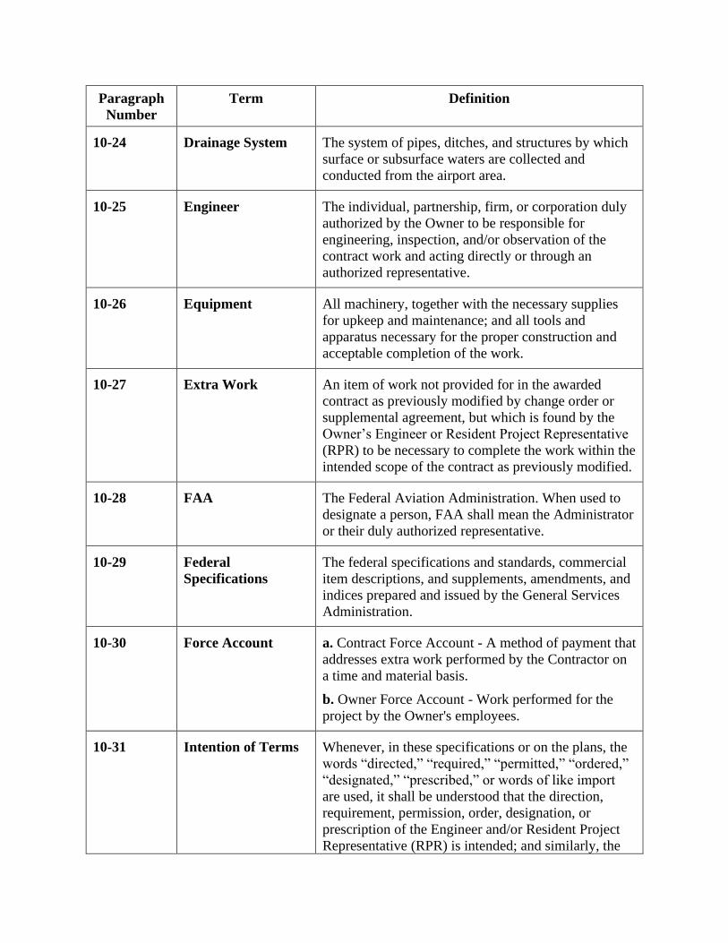
Paragraph
Number
Term Definition
10-24 Drainage System The system of pipes, ditches, and structures by which
surface or subsurface waters are collected and
conducted from the airport area.
10-25 Engineer The individual, partnership, firm, or corporation duly
authorized by the Owner to be responsible for
engineering, inspection, and/or observation of the
contract work and acting directly or through an
authorized representative.
10-26 Equipment All machinery, together with the necessary supplies
for upkeep and maintenance; and all tools and
apparatus necessary for the proper construction and
acceptable completion of the work.
10-27 Extra Work An item of work not provided for in the awarded
contract as previously modified by change order or
supplemental agreement, but which is found by the
Owner’s Engineer or Resident Project Representative
(RPR) to be necessary to complete the work within the
intended scope of the contract as previously modified.
10-28 FAA The Federal Aviation Administration. When used to
designate a person, FAA shall mean the Administrator
or their duly authorized representative.
10-29 Federal
Specifications
The federal specifications and standards, commercial
item descriptions, and supplements, amendments, and
indices prepared and issued by the General Services
Administration.
10-30 Force Account a. Contract Force Account - A method of payment that
addresses extra work performed by the Contractor on
a time and material basis.
b. Owner Force Account - Work performed for the
project by the Owner's employees.
10-31 Intention of Terms Whenever, in these specifications or on the plans, the
words “directed,” “required,” “permitted,” “ordered,”
“designated,” “prescribed,” or words of like import
are used, it shall be understood that the direction,
requirement, permission, order, designation, or
prescription of the Engineer and/or Resident Project
Representative (RPR) is intended; and similarly, the

Paragraph
Number
Term Definition
words “approved,” “acceptable,” “satisfactory,” or
words of like import, shall mean approved by, or
acceptable to, or satisfactory to the Engineer and/or
RPR, subject in each case to the final determination of
the Owner.
Any reference to a specific requirement of a numbered
paragraph of the contract specifications or a cited
standard shall be interpreted to include all general
requirements of the entire section, specification item,
or cited standard that may be pertinent to such specific
reference.
10-32 Lighting A system of fixtures providing or controlling the light
sources used on or near the airport or within the
airport buildings. The field lighting includes all
luminous signals, markers, floodlights, and
illuminating devices used on or near the airport or to
aid in the operation of aircraft landing at, taking off
from, or taxiing on the airport surface.
10-33 Major and Minor
Contract Items
A major contract item shall be any item that is listed
in the proposal, the total cost of which is equal to or
greater than 20% of the total amount of the award
contract. All other items shall be considered minor
contract items.
10-34 Materials Any substance specified for use in the construction of
the contract work.
10-35 Modification of
Standards (MOS)
Any deviation from standard specifications applicable
to material and construction methods in accordance
with FAA Order 5300.1.
10-36 Notice to Proceed
(NTP)
A written notice to the Contractor to begin the actual
contract work on a previously agreed to date. If
applicable, the Notice to Proceed shall state the date
on which the contract time begins.
10-37 Owner The term “Owner” shall mean the party of the first
part or the contracting agency signatory to the
contract. Where the term “Owner” is capitalized in
this document, it shall mean airport Sponsor only.

Paragraph
Number
Term Definition
10-38 Passenger Facility
Charge (PFC)
Per 14 Code of Federal Regulations (CFR) Part 158
and 49 United States Code (USC) § 40117, a PFC is a
charge imposed by a public agency on passengers
enplaned at a commercial service airport it controls.
10-39 Pavement Structure The combined surface course, base course(s), and
subbase course(s), if any, considered as a single unit.
10-40 Payment bond The approved form of security furnished by the
Contractor and their own surety as a guaranty that the
Contractor will pay in full all bills and accounts for
materials and labor used in the construction of the
work.
10-41 Performance bond The approved form of security furnished by the
Contractor and their own surety as a guaranty that the
Contractor will complete the work in accordance with
the terms of the contract.
10-42 Plans The official drawings or exact reproductions which
show the location, character, dimensions and details
of the airport and the work to be done and which are
to be considered as a part of the contract,
supplementary to the specifications. Plans may also be
referred to as 'contract drawings.’
10-43 Project The agreed scope of work for accomplishing specific
airport development with respect to a particular
airport.
10-44 Proposal The written offer of the bidder (when submitted on the
approved proposal form) to perform the contemplated
work and furnish the necessary materials in
accordance with the provisions of the plans and
specifications.
10-45 Proposal guaranty The security furnished with a proposal to guarantee
that the bidder will enter into a contract if their own
proposal is accepted by the Owner.
10-46 Quality Assurance
(QA)
Owner’s responsibility to assure that construction
work completed complies with specifications for
payment.
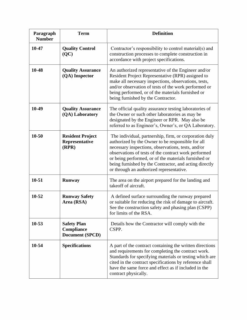
Paragraph
Number
Term Definition
10-47 Quality Control
(QC)
Contractor’s responsibility to control material(s) and
construction processes to complete construction in
accordance with project specifications.
10-48 Quality Assurance
(QA) Inspector
An authorized representative of the Engineer and/or
Resident Project Representative (RPR) assigned to
make all necessary inspections, observations, tests,
and/or observation of tests of the work performed or
being performed, or of the materials furnished or
being furnished by the Contractor.
10-49 Quality Assurance
(QA) Laboratory
The official quality assurance testing laboratories of
the Owner or such other laboratories as may be
designated by the Engineer or RPR. May also be
referred to as Engineer’s, Owner’s, or QA Laboratory.
10-50 Resident Project
Representative
(RPR)
The individual, partnership, firm, or corporation duly
authorized by the Owner to be responsible for all
necessary inspections, observations, tests, and/or
observations of tests of the contract work performed
or being performed, or of the materials furnished or
being furnished by the Contractor, and acting directly
or through an authorized representative.
10-51 Runway The area on the airport prepared for the landing and
takeoff of aircraft.
10-52 Runway Safety
Area (RSA)
A defined surface surrounding the runway prepared
or suitable for reducing the risk of damage to aircraft.
See the construction safety and phasing plan (CSPP)
for limits of the RSA.
10-53 Safety Plan
Compliance
Document (SPCD)
Details how the Contractor will comply with the
CSPP.
10-54 Specifications A part of the contract containing the written directions
and requirements for completing the contract work.
Standards for specifying materials or testing which are
cited in the contract specifications by reference shall
have the same force and effect as if included in the
contract physically.

Paragraph
Number
Term Definition
10-55 Sponsor A Sponsor is defined in 49 USC § 47102(24) as a
public agency that submits to the FAA for an AIP
grant; or a private Owner of a public-use airport that
submits to the FAA an application for an AIP grant
for the airport.
10-56 Structures Airport facilities such as bridges; culverts; catch
basins, inlets, retaining walls, cribbing; storm and
sanitary sewer lines; water lines; underdrains;
electrical ducts, manholes, handholes, lighting fixtures
and bases; transformers; navigational aids; buildings;
vaults; and, other manmade features of the airport that
may be encountered in the work and not otherwise
classified herein.
10-57 Subgrade The soil that forms the pavement foundation.
10-58 Superintendent The Contractor’s executive representative who is
present on the work during progress, authorized to
receive and fulfill instructions from the RPR, and who
shall supervise and direct the construction.
10-59 Supplemental
Agreement
A written agreement between the Contractor and the
Owner that establishes the basis of payment and
contract time adjustment, if any, for the work affected
by the supplemental agreement. A supplemental
agreement is required if: (1) in scope work would
increase or decrease the total amount of the awarded
contract by more than 25%: (2) in scope work would
increase or decrease the total of any major contract
item by more than 25%; (3) work that is not within the
scope of the originally awarded contract; or (4) adding
or deleting of a major contract item.
10-60 Surety The corporation, partnership, or individual, other than
the Contractor, executing payment or performance
bonds that are furnished to the Owner by the
Contractor.
10-61 Taxilane A taxiway designed for low speed movement of
aircraft between aircraft parking areas and terminal
areas.

Paragraph
Number
Term Definition
10-62 Taxiway The portion of the air operations area of an airport that
has been designated by competent airport authority for
movement of aircraft to and from the airport’s
runways, aircraft parking areas, and terminal areas.
10-63 Taxiway/Taxilane
Safety Area (TSA)
A defined surface alongside the taxiway prepared or
suitable for reducing the risk of damage to an aircraft.
See the construction safety and phasing plan (CSPP)
for limits of the TSA.
10-64 Work The furnishing of all labor, materials, tools,
equipment, and incidentals necessary or convenient to
the Contractor’s performance of all duties and
obligations imposed by the contract, plans, and
specifications.
10-65 Working day A working day shall be any day other than a legal
holiday, Saturday, or Sunday on which the normal
working forces of the Contractor may proceed with
regular work for at least six (6) hours toward
completion of the contract. When work is suspended
for causes beyond the Contractor’s control, it will not
be counted as a working day. Saturdays, Sundays and
holidays on which the Contractor’s forces engage in
regular work will be considered as working days.
END OF SECTION 10


SECTION 20 PROPOSAL REQUIREMENTS AND CONDITIONS
20-01 Advertisement (Notice to Bidders).
See Notice To Bidders section for Advertisement date.
20-02 Qualification of bidders. Each bidder shall submit evidence of competency and evidence
of financial responsibility to perform the work to the Owner at the time of bid opening.
Evidence of competency, unless otherwise specified, shall consist of statements covering the
bidder’s past experience on similar work, and a list of equipment and a list of key personnel that
would be available for the work.
Each bidder shall furnish the Owner satisfactory evidence of their financial responsibility.
Evidence of financial responsibility, unless otherwise specified, shall consist of a confidential
statement or report of the bidder’s financial resources and liabilities as of the last calendar year
or the bidder’s last fiscal year. Such statements or reports shall be certified by a public
accountant. At the time of submitting such financial statements or reports, the bidder shall further
certify whether their financial responsibility is approximately the same as stated or reported by
the public accountant. If the bidder’s financial responsibility has changed, the bidder shall
qualify the public accountant’s statement or report to reflect the bidder’s true financial condition
at the time such qualified statement or report is submitted to the Owner.
Unless otherwise specified, a bidder may submit evidence that they are prequalified with the
State Highway Division and are on the current “bidder’s list” of the state in which the proposed
work is located. Evidence of State Highway Division prequalification may be submitted as
evidence of financial responsibility in lieu of the certified statements or reports specified above.
20-03 Contents of proposal forms. The Owner's proposal forms state the location and
description of the proposed construction; the place, date, and time of opening of the proposals;
and the estimated quantities of the various items of work to be performed and materials to be
furnished for which unit bid prices are asked. The proposal form states the time in which the
work must be completed, and the amount of the proposal guaranty that must accompany the
proposal. The Owner will accept only those Proposals properly executed on physical forms or
electronic forms provided by the Owner. Bidder actions that may cause the Owner to deem a
proposal irregular are given in paragraph 20-09 Irregular proposals.
A prebid conference is required on this project to discuss as a minimum, the following items:
material requirements; submittals; Quality Control/Quality Assurance requirements; the
construction safety and phasing plan including airport access and staging areas; and unique
airfield paving construction requirements.
See Instructions To Bidders section for details regarding Pre-Bid Meeting Webinar.
20-04 Issuance of proposal forms. The Owner reserves the right to refuse to issue a proposal
form to a prospective bidder if the bidder is in default for any of the following reasons:
a. Failure to comply with any prequalification regulations of the Owner, if such regulations
are cited, or otherwise included, in the proposal as a requirement for bidding.

b. Failure to pay, or satisfactorily settle, all bills due for labor and materials on former
contracts in force with the Owner at the time the Owner issues the proposal to a prospective
bidder.
c. Documented record of Contractor default under previous contracts with the Owner.
d. Documented record of unsatisfactory work on previous contracts with the Owner.
20-05 Interpretation of estimated proposal quantities. An estimate of quantities of work to be
done and materials to be furnished under these specifications is given in the proposal. It is the
result of careful calculations and is believed to be correct. It is given only as a basis for
comparison of proposals and the award of the contract. The Owner does not expressly, or by
implication, agree that the actual quantities involved will correspond exactly therewith; nor shall
the bidder plead misunderstanding or deception because of such estimates of quantities, or of the
character, location, or other conditions pertaining to the work. Payment to the Contractor will be
made only for the actual quantities of work performed or materials furnished in accordance with
the plans and specifications. It is understood that the quantities may be increased or decreased as
provided in the Section 40, paragraph 40-02, Alteration of Work and Quantities, without in any
way invalidating the unit bid prices.
20-06 Examination of plans, specifications, and site. The bidder is expected to carefully
examine the site of the proposed work, the proposal, plans, specifications, and contract forms.
Bidders shall satisfy themselves to the character, quality, and quantities of work to be performed,
materials to be furnished, and to the requirements of the proposed contract. The submission of a
proposal shall be prima facie evidence that the bidder has made such examination and is satisfied
to the conditions to be encountered in performing the work and the requirements of the proposed
contract, plans, and specifications.
Boring logs and other records of subsurface investigations and tests are available for inspection
of bidders. It is understood and agreed that such subsurface information, whether included in the
plans, specifications, or otherwise made available to the bidder, was obtained and is intended for
the Owner’s design and estimating purposes only. Such information has been made available for
the convenience of all bidders. It is further understood and agreed that each bidder is solely
responsible for all assumptions, deductions, or conclusions which the bidder may make or obtain
from their own examination of the boring logs and other records of subsurface investigations and
tests that are furnished by the Owner.
20-07 Preparation of proposal. The bidder shall submit their proposal on the forms furnished
by the Owner. All blank spaces in the proposal forms, unless explicitly stated otherwise, must be
correctly filled in where indicated for each and every item for which a quantity is given. The
bidder shall state the price (written in ink or typed) both in words and numerals which they
propose for each pay item furnished in the proposal. In case of conflict between words and
numerals, the words, unless obviously incorrect, shall govern.
The bidder shall correctly sign the proposal in ink. If the proposal is made by an individual, their
name and post office address must be shown. If made by a partnership, the name and post office
address of each member of the partnership must be shown. If made by a corporation, the person
signing the proposal shall give the name of the state where the corporation was chartered and the
name, titles, and business address of the president, secretary, and the treasurer. Anyone signing a

proposal as an agent shall file evidence of their authority to do so and that the signature is
binding upon the firm or corporation.
20-08 Responsive and responsible bidder. A responsive bid conforms to all significant terms
and conditions contained in the Owner’s invitation for bid. It is the Owner’s responsibility to
decide if the exceptions taken by a bidder to the solicitation are material or not and the extent of
deviation it is willing to accept.
A responsible bidder has the ability to perform successfully under the terms and conditions of a
proposed procurement, as defined in 2 CFR § 200.318(h). This includes such matters as
Contractor integrity, compliance with public policy, record of past performance, and financial
and technical resources.
20-09 Irregular proposals. Proposals shall be considered irregular for the following reasons:
a. If the proposal is on a form other than that furnished by the Owner, or if the Owner’s form
is altered, or if any part of the proposal form is detached.
b. If there are unauthorized additions, conditional or alternate pay items, or irregularities of
any kind that make the proposal incomplete, indefinite, or otherwise ambiguous.
c. If the proposal does not contain a unit price for each pay item listed in the proposal, except
in the case of authorized alternate pay items, for which the bidder is not required to furnish a unit
price.
d. If the proposal contains unit prices that are obviously unbalanced.
e. If the proposal is not accompanied by the proposal guaranty specified by the Owner.
f. If the applicable Disadvantaged Business Enterprise information is incomplete.
The Owner reserves the right to reject any irregular proposal and the right to waive technicalities
if such waiver is in the best interest of the Owner and conforms to local laws and ordinances
pertaining to the letting of construction contracts.
20-10 Bid guarantee. Each separate proposal shall be accompanied by a bid bond, certified
check, or other specified acceptable collateral, in the amount specified in the proposal form.
Such bond, check, or collateral, shall be made payable to the Owner.
20-11 Delivery of proposal. Each proposal submitted shall be placed in a sealed envelope
plainly marked with the project number, location of airport, and name and business address of
the bidder on the outside. When sent by mail, preferably registered, the sealed proposal, marked
as indicated above, should be enclosed in an additional envelope. No proposal will be considered
unless received at the place specified in the advertisement or as modified by Addendum before
the time specified for opening all bids. Proposals received after the bid opening time shall be
returned to the bidder unopened.
20-12 Withdrawal or revision of proposals. A bidder may withdraw or revise (by withdrawal
of one proposal and submission of another) a proposal provided that the bidder’s request for
withdrawal is received by the Owner by email before the time specified for opening bids.
Revised proposals must be received at the place specified in the advertisement before the time
specified for opening all bids.

20-13 Public opening of proposals. Proposals shall be opened, and read, publicly at the time
and place specified in the advertisement. Bidders, their authorized agents, and other interested
persons are invited to attend. Proposals that have been withdrawn (by written or telegraphic
request) or received after the time specified for opening bids shall be returned to the bidder
unopened.
20-14 Disqualification of bidders. A bidder shall be considered disqualified for any of the
following reasons:
a. Submitting more than one proposal from the same partnership, firm, or corporation under
the same or different name.
b. Evidence of collusion among bidders. Bidders participating in such collusion shall be
disqualified as bidders for any future work of the Owner until any such participating bidder has
been reinstated by the Owner as a qualified bidder.
c. If the bidder is considered to be in “default” for any reason specified in paragraph 20-04,
Issuance of Proposal Forms, of this section.
20-15 Discrepancies and Omissions. A Bidder who discovers discrepancies or omissions with
the project bid documents shall immediately notify the Owner’s Engineer of the matter. A
bidder that has doubt as to the true meaning of a project requirement may submit to the Owner’s
Engineer a written request for interpretation no later than 7 days prior to bid opening.
Any interpretation of the project bid documents by the Owner’s Engineer will be by written
addendum issued by the Owner. The Owner will not consider any instructions, clarifications or
interpretations of the bidding documents in any manner other than written addendum.
END OF SECTION 20

Section 30 Award and Execution of Contract
30-01 Consideration of proposals. After the proposals are publicly opened and read, they will
be compared on the basis of the summation of the products obtained by multiplying the
estimated quantities shown in the proposal by the unit bid prices. If a bidder’s proposal contains
a discrepancy between unit bid prices written in words and unit bid prices written in numbers,
the unit bid price written in words shall govern.
Until the award of a contract is made, the Owner reserves the right to reject a bidder’s proposal
for any of the following reasons:
a. If the proposal is irregular as specified in Section 20, paragraph 20-09, Irregular
Proposals.
b. If the bidder is disqualified for any of the reasons specified Section 20, paragraph 20-14,
Disqualification of Bidders.
In addition, until the award of a contract is made, the Owner reserves the right to reject any or all
proposals, waive technicalities, if such waiver is in the best interest of the Owner and is in
conformance with applicable state and local laws or regulations pertaining to the letting of
construction contracts; advertise for new proposals; or proceed with the work otherwise. All such
actions shall promote the Owner’s best interests.
30-02 Award of contract. The award of a contract, if it is to be awarded, shall be made within
90 calendar days of the date specified for publicly opening proposals, unless otherwise specified
herein.
If the Owner elects to proceed with an award of contract, the Owner will make award to the
responsible bidder whose bid, conforming with all the material terms and conditions of the bid
documents, is the lowest in price.
30-03 Cancellation of award. The Owner reserves the right to cancel the award without liability
to the bidder, except return of proposal guaranty, at any time before a contract has been fully
executed by all parties and is approved by the Owner in accordance with paragraph 30-07
Approval of Contract.
30-04 Return of proposal guaranty. All proposal guaranties, except those of the two lowest
bidders, will be returned immediately after the Owner has made a comparison of bids as
specified in the paragraph 30-01, Consideration of Proposals. Proposal guaranties of the two
lowest bidders will be retained by the Owner until such time as an award is made, at which time,
the unsuccessful bidder’s proposal guaranty will be returned. The successful bidder’s proposal
guaranty will be returned as soon as the Owner receives the contract bonds as specified in
paragraph 30-05, Requirements of Contract Bonds.
30-05 Requirements of contract bonds. At the time of the execution of the contract, the
successful bidder shall furnish the Owner a surety bond or bonds that have been fully executed
by the bidder and the surety guaranteeing the performance of the work and the payment of all
legal debts that may be incurred by reason of the Contractor’s performance of the work. The
surety and the form of the bond or bonds shall be acceptable to the Owner. Unless otherwise

specified in this subsection, the surety bond or bonds shall be in a sum equal to the full amount
of the contract.
30-06 Execution of contract. The successful bidder shall sign (execute) the necessary
agreements for entering into the contract and return the signed contract to the Owner, along with
the fully executed surety bond or bonds specified in paragraph 30-05, Requirements of Contract
Bonds, of this section, within 15 calendar days from the date mailed or otherwise delivered to the
successful bidder.
30-07 Approval of contract. Upon receipt of the contract and contract bond or bonds that have
been executed by the successful bidder, the Owner shall complete the execution of the contract in
accordance with local laws or ordinances, and return the fully executed contract to the
Contractor. Delivery of the fully executed contract to the Contractor shall constitute the Owner’s
approval to be bound by the successful bidder’s proposal and the terms of the contract.
30-08 Failure to execute contract. Failure of the successful bidder to execute the contract and
furnish an acceptable surety bond or bonds within the period specified in paragraph 30-06,
Execution of Contract, of this section shall be just cause for cancellation of the award and
forfeiture of the proposal guaranty, not as a penalty, but as liquidated damages to the Owner.
END OF SECTION 30

Section 40 Scope of Work
40-01 Intent of contract. The intent of the contract is to provide for construction and
completion, in every detail, of the work described. It is further intended that the Contractor shall
furnish all labor, materials, equipment, tools, transportation, and supplies required to complete
the work in accordance with the plans, specifications, and terms of the contract.
40-02 Alteration of work and quantities. The Owner reserves the right to make such changes
in quantities and work as may be necessary or desirable to complete, in a satisfactory manner, the
original intended work. Unless otherwise specified in the Contract, the Owner’s Engineer or
RPR shall be and is hereby authorized to make, in writing, such in-scope alterations in the work
and variation of quantities as may be necessary to complete the work, provided such action does
not represent a significant change in the character of the work.
For purpose of this section, a significant change in character of work means: any change that is
outside the current contract scope of work; any change (increase or decrease) in the total contract
cost by more than 25%; or any change in the total cost of a major contract item by more than
25%.
Work alterations and quantity variances that do not meet the definition of significant change in
character of work shall not invalidate the contract nor release the surety. Contractor agrees to
accept payment for such work alterations and quantity variances in accordance with Section 90,
paragraph 90-03, Compensation for Altered Quantities.
Should the value of altered work or quantity variance meet the criteria for significant change in
character of work, such altered work and quantity variance shall be covered by a supplemental
agreement. Supplemental agreements shall also require consent of the Contractor’s surety and
separate performance and payment bonds. If the Owner and the Contractor are unable to agree on
a unit adjustment for any contract item that requires a supplemental agreement, the Owner
reserves the right to terminate the contract with respect to the item and make other arrangements
for its completion.
40-03 Omitted items. The Owner, the Owner’s Engineer or the RPR may provide written notice
to the Contractor to omit from the work any contract item that does not meet the definition of
major contract item. Major contract items may be omitted by a supplemental agreement. Such
omission of contract items shall not invalidate any other contract provision or requirement.
Should a contract item be omitted or otherwise ordered to be non-performed, the Contractor shall
be paid for all work performed toward completion of such item prior to the date of the order to
omit such item. Payment for work performed shall be in accordance with Section 90, paragraph
90-04, Payment for Omitted Items.
40-04 Extra work. Should acceptable completion of the contract require the Contractor to
perform an item of work not provided for in the awarded contract as previously modified by
change order or supplemental agreement, Owner may issue a Change Order to cover the
necessary extra work. Change orders for extra work shall contain agreed unit prices for
performing the change order work in accordance with the requirements specified in the order,
and shall contain any adjustment to the contract time that, in the RPR’s opinion, is necessary for
completion of the extra work.

When determined by the RPR to be in the Owner’s best interest, the RPR may order the
Contractor to proceed with extra work as provided in Section 90, paragraph 90-05, Payment for
Extra Work. Extra work that is necessary for acceptable completion of the project, but is not
within the general scope of the work covered by the original contract shall be covered by a
supplemental agreement as defined in Section 10, paragraph 10-59, Supplemental Agreement.
If extra work is essential to maintaining the project critical path, RPR may order the Contractor
to commence the extra work under a Time and Material contract method. Once sufficient detail
is available to establish the level of effort necessary for the extra work, the Owner shall initiate a
change order or supplemental agreement to cover the extra work.
Any claim for payment of extra work that is not covered by written agreement (change order or
supplemental agreement) shall be rejected by the Owner.
40-05 Maintenance of traffic. It is the explicit intention of the contract that the safety of
aircraft, as well as the Contractor’s equipment and personnel, is the most important
consideration. The Contractor shall maintain traffic in the manner detailed in the Construction
Safety and Phasing Plan (CSPP).
a. It is understood and agreed that the Contractor shall provide for the free and unobstructed
movement of aircraft in the air operations areas (AOAs) of the airport with respect to their own
operations and the operations of all subcontractors as specified in Section 80, paragraph 80-04,
Limitation of Operations. It is further understood and agreed that the Contractor shall provide for
the uninterrupted operation of visual and electronic signals (including power supplies thereto)
used in the guidance of aircraft while operating to, from, and upon the airport as specified in
Section 70, paragraph 70-15, Contractor’s Responsibility for Utility Service and Facilities of
Others.
b. With respect to their own operations and the operations of all subcontractors, the
Contractor shall provide marking, lighting, and other acceptable means of identifying personnel,
equipment, vehicles, storage areas, and any work area or condition that may be hazardous to the
operation of aircraft, fire-rescue equipment, or maintenance vehicles at the airport in accordance
with the construction safety and phasing plan (CSPP) and the safety plan compliance document
(SPCD).
c. When the contract requires the maintenance of an existing road, street, or highway during
the Contractor’s performance of work that is otherwise provided for in the contract, plans, and
specifications, the Contractor shall keep the road, street, or highway open to all traffic and shall
provide maintenance as may be required to accommodate traffic. The Contractor, at their
expense, shall be responsible for the repair to equal or better than preconstruction conditions of
any damage caused by the Contractor’s equipment and personnel. The Contractor shall furnish,
erect, and maintain barricades, warning signs, flag person, and other traffic control devices in
reasonable conformity with the Manual on Uniform Traffic Control Devices (MUTCD)
(http://mutcd.fhwa.dot.gov/), unless otherwise specified. The Contractor shall also construct and
maintain in a safe condition any temporary connections necessary for ingress to and egress from
abutting property or intersecting roads, streets or highways. Unless otherwise specified herein,
the Contractor will not be required to furnish snow removal for such existing road, street, or
highway

40-06 Removal of existing structures. All existing structures encountered within the established
lines, grades, or grading sections shall be removed by the Contractor, unless such existing
structures are otherwise specified to be relocated, adjusted up or down, salvaged, abandoned in
place, reused in the work or to remain in place. The cost of removing such existing structures
shall not be measured or paid for directly, but shall be included in the various contract items.
Should the Contractor encounter an existing structure (above or below ground) in the work for
which the disposition is not indicated on the plans, the Resident Project Representative (RPR)
shall be notified prior to disturbing such structure. The disposition of existing structures so
encountered shall be immediately determined by the RPR in accordance with the provisions of
the contract.
Except as provided in Section 40, paragraph 40-07, Rights in and Use of Materials Found in the
Work, it is intended that all existing materials or structures that may be encountered (within the
lines, grades, or grading sections established for completion of the work) shall be used in the
work as otherwise provided for in the contract and shall remain the property of the Owner when
so used in the work.
40-07 Rights in and use of materials found in the work. Should the Contractor encounter any
material such as (but not restricted to) sand, stone, gravel, slag, or concrete slabs within the
established lines, grades, or grading sections, the use of which is intended by the terms of the
contract to be embankment, the Contractor may at their own option either:
a. Use such material in another contract item, providing such use is approved by the RPR and
is in conformance with the contract specifications applicable to such use; or,
b. Remove such material from the site, upon written approval of the RPR; or
c. Use such material for the Contractor’s own temporary construction on site; or,
d. Use such material as intended by the terms of the contract.
Should the Contractor wish to exercise option a., b., or c., the Contractor shall request the RPR’s
approval in advance of such use.
Should the RPR approve the Contractor’s request to exercise option a., b., or c., the Contractor
shall be paid for the excavation or removal of such material at the applicable contract price. The
Contractor shall replace, at their expense, such removed or excavated material with an agreed
equal volume of material that is acceptable for use in constructing embankment, backfills, or
otherwise to the extent that such replacement material is needed to complete the contract work.
The Contractor shall not be charged for use of such material used in the work or removed from
the site.
Should the RPR approve the Contractor’s exercise of option a., the Contractor shall be paid, at
the applicable contract price, for furnishing and installing such material in accordance with
requirements of the contract item in which the material is used.
It is understood and agreed that the Contractor shall make no claim for delays by reason of their
own exercise of option a., b., or c.
The Contractor shall not excavate, remove, or otherwise disturb any material, structure, or part of
a structure which is located outside the lines, grades, or grading sections established for the

work, except where such excavation or removal is provided for in the contract, plans, or
specifications.
40-08 Final cleanup. Upon completion of the work and before acceptance and final payment
will be made, the Contractor shall remove from the site all machinery, equipment, surplus and
discarded materials, rubbish, temporary structures, and stumps or portions of trees. The
Contractor shall cut all brush and woods within the limits indicated and shall leave the site in a
neat and presentable condition. Material cleared from the site and deposited on adjacent property
will not be considered as having been disposed of satisfactorily, unless the Contractor has
obtained the written permission of the property Owner.
END OF SECTION 40

Section 50 Control of Work
50-01 Authority of the Resident Project Representative (RPR). The RPR has final authority
regarding the interpretation of project specification requirements. The RPR shall determine
acceptability of the quality of materials furnished, method of performance of work performed,
and the manner and rate of performance of the work. The RPR does not have the authority to
accept work that does not conform to specification requirements.
50-02 Conformity with plans and specifications. All work and all materials furnished shall be
in reasonably close conformity with the lines, grades, grading sections, cross-sections,
dimensions, material requirements, and testing requirements that are specified (including
specified tolerances) in the contract, plans, or specifications.
If the RPR finds the materials furnished, work performed, or the finished product not within
reasonably close conformity with the plans and specifications, but that the portion of the work
affected will, in their opinion, result in a finished product having a level of safety, economy,
durability, and workmanship acceptable to the Owner, the RPR will advise the Owner of their
determination that the affected work be accepted and remain in place. The RPR will document
the determination and recommend to the Owner a basis of acceptance that will provide for an
adjustment in the contract price for the affected portion of the work. Changes in the contract
price must be covered by contract change order or supplemental agreement as applicable.
If the RPR finds the materials furnished, work performed, or the finished product are not in
reasonably close conformity with the plans and specifications and have resulted in an
unacceptable finished product, the affected work or materials shall be removed and replaced or
otherwise corrected by and at the expense of the Contractor in accordance with the RPR’s
written orders.
The term “reasonably close conformity” shall not be construed as waiving the Contractor’s
responsibility to complete the work in accordance with the contract, plans, and specifications.
The term shall not be construed as waiving the RPR’s responsibility to insist on strict compliance
with the requirements of the contract, plans, and specifications during the Contractor’s execution
of the work, when, in the RPR’s opinion, such compliance is essential to provide an acceptable
finished portion of the work.
The term “reasonably close conformity” is also intended to provide the RPR with the authority,
after consultation with the Sponsor and FAA, to use sound engineering judgment in their
determinations to accept work that is not in strict conformity, but will provide a finished product
equal to or better than that required by the requirements of the contract, plans and specifications.
The RPR will not be responsible for the Contractor’s means, methods, techniques, sequences, or
procedures of construction or the safety precautions incident thereto.
50-03 Coordination of contract, plans, and specifications. The contract, plans, specifications,
and all referenced standards cited are essential parts of the contract requirements. If electronic
files are provided and used on the project and there is a conflict between the electronic files and
hard copy plans, the hard copy plans shall govern. A requirement occurring in one is as binding
as though occurring in all. They are intended to be complementary and to describe and provide
for a complete work. In case of discrepancy, calculated dimensions will govern over scaled

dimensions; contract technical specifications shall govern over contract general provisions,
plans, cited standards for materials or testing, and cited advisory circulars (ACs); contract
general provisions shall govern over plans, cited standards for materials or testing, and cited
ACs; plans shall govern over cited standards for materials or testing and cited ACs. If any
paragraphs contained in the Special Provisions conflict with General Provisions or Technical
Specifications, the Special Provisions shall govern.
From time to time, discrepancies within cited testing standards occur due to the timing of the
change, edits, and/or replacement of the standards. If the Contractor discovers any apparent
discrepancy within standard test methods, the Contractor shall immediately ask the RPR for an
interpretation and decision, and such decision shall be final.
The Contractor shall not take advantage of any apparent error or omission on the plans or
specifications. In the event the Contractor discovers any apparent error or discrepancy,
Contractor shall immediately notify the Owner or the designated representative in writing
requesting their written interpretation and decision.
50-04 List of Special Provisions. Not applicable to this contract.
50-05 Cooperation of Contractor. The Contractor shall be supplied with two hard copies or an
electronic PDF of the plans and specifications. The Contractor shall have available on the
construction site at all times one hardcopy each of the plans and specifications. Additional hard
copies of plans and specifications may be obtained by the Contractor for the cost of reproduction.
The Contractor shall give constant attention to the work to facilitate the progress thereof, and
shall cooperate with the RPR and their inspectors and with other Contractors in every way
possible. The Contractor shall have a competent superintendent on the work at all times who is
fully authorized as their agent on the work. The superintendent shall be capable of reading and
thoroughly understanding the plans and specifications and shall receive and fulfill instructions
from the RPR or their authorized representative.
50-06 Cooperation between Contractors. The Owner reserves the right to contract for and
perform other or additional work on or near the work covered by this contract.
When separate contracts are let within the limits of any one project, each Contractor shall
conduct the work not to interfere with or hinder the progress of completion of the work being
performed by other Contractors. Contractors working on the same project shall cooperate with
each other as directed.
Each Contractor involved shall assume all liability, financial or otherwise, in connection with
their own contract and shall protect and hold harmless the Owner from any and all damages or
claims that may arise because of inconvenience, delays, or loss experienced because of the
presence and operations of other Contractors working within the limits of the same project.
The Contractor shall arrange their work and shall place and dispose of the materials being used
to not interfere with the operations of the other Contractors within the limits of the same project.
The Contractor shall join their work with that of the others in an acceptable manner and shall
perform it in proper sequence to that of the others.
50-07 Construction layout and stakes. The Engineer/RPR shall establish necessary horizontal
and vertical control. The establishment of Survey Control and/or reestablishment of survey
control shall be by a State Licensed Land Surveyor. Contractor is responsible for requirements

of Item C-108 and preserving integrity of horizontal and vertical controls established by
Engineer/RPR. In case of negligence on the part of the Contractor or their employees, resulting
in the destruction of any horizontal and vertical control, the resulting costs will be deducted as a
liquidated damage against the Contractor.
Prior to the start of construction, the Contractor will check all control points for horizontal and
vertical accuracy and certify in writing to the RPR that the Contractor concurs with survey
control established for the project. All lines, grades and measurements from control points
necessary for the proper execution and control of the work on this project will be provided to the
RPR. The Contractor is responsible to establish all layout required for the construction of the
project.
Copies of survey notes will be provided to the RPR for each area of construction and for each
placement of material as specified to allow the RPR to make periodic checks for conformance
with plan grades, alignments and grade tolerances required by the applicable material
specifications. Surveys will be provided to the RPR prior to commencing work items that cover
or disturb the survey staking. Survey(s) and notes shall be provided in the following format(s):
written & electronic.
Laser, GPS, String line, or other automatic control shall be checked with temporary control as
necessary. In the case of error, on the part of the Contractor, their surveyor, employees or
subcontractors, resulting in established grades, alignment or grade tolerances that do not concur
with those specified or shown on the plans, the Contractor is solely responsible for correction,
removal, replacement and all associated costs at no additional cost to the Owner.
No direct payment will be made, unless otherwise specified in contract documents, for this labor,
materials, or other expenses. The cost shall be included in the price of the bid for the various
items of the Contract.
50-08 Authority and duties of Quality Assurance (QA) inspectors. QA inspectors shall be
authorized to inspect all work done and all material furnished. Such QA inspection may extend
to all or any part of the work and to the preparation, fabrication, or manufacture of the materials
to be used. QA inspectors are not authorized to revoke, alter, or waive any provision of the
contract. QA inspectors are not authorized to issue instructions contrary to the plans and
specifications or to act as foreman for the Contractor.
QA Inspectors are authorized to notify the Contractor or their representatives of any failure of
the work or materials to conform to the requirements of the contract, plans, or specifications and
to reject such nonconforming materials in question until such issues can be referred to the RPR
for a decision.
50-09 Inspection of the work. All materials and each part or detail of the work shall be subject
to inspection. The RPR shall be allowed access to all parts of the work and shall be furnished
with such information and assistance by the Contractor as is required to make a complete and
detailed inspection.
If the RPR requests it, the Contractor, at any time before acceptance of the work, shall remove or
uncover such portions of the finished work as may be directed. After examination, the Contractor
shall restore said portions of the work to the standard required by the specifications. Should the
work thus exposed or examined prove acceptable, the uncovering, or removing, and the replacing
of the covering or making good of the parts removed will be paid for as extra work; but should

the work so exposed or examined prove unacceptable, the uncovering, or removing, and the
replacing of the covering or making good of the parts removed will be at the Contractor’s
expense.
Provide advance written notice to the RPR of work the Contractor plans to perform each week
and each day. Any work done or materials used without written notice and allowing opportunity
for inspection by the RPR may be ordered removed and replaced at the Contractor’s expense.
Should the contract work include relocation, adjustment, or any other modification to existing
facilities, not the property of the (contract) Owner, authorized representatives of the Owners of
such facilities shall have the right to inspect such work. Such inspection shall in no sense make
any facility owner a party to the contract, and shall in no way interfere with the rights of the
parties to this contract.
50-10 Removal of unacceptable and unauthorized work. All work that does not conform to
the requirements of the contract, plans, and specifications will be considered unacceptable,
unless otherwise determined acceptable by the RPR as provided in paragraph 50-02, Conformity
with Plans and Specifications.
Unacceptable work, whether the result of poor workmanship, use of defective materials, damage
through carelessness, or any other cause found to exist prior to the final acceptance of the work,
shall be removed immediately and replaced in an acceptable manner in accordance with the
provisions of Section 70, paragraph 70-14, Contractor’s Responsibility for Work.
No removal work made under provision of this paragraph shall be done without lines and grades
having been established by the RPR. Work done contrary to the instructions of the RPR, work
done beyond the lines shown on the plans or as established by the RPR, except as herein
specified, or any extra work done without authority, will be considered as unauthorized and will
not be paid for under the provisions of the contract. Work so done may be ordered removed or
replaced at the Contractor’s expense.
Upon failure on the part of the Contractor to comply with any order of the RPR made under the
provisions of this subsection, the RPR will have authority to cause unacceptable work to be
remedied or removed and replaced; and unauthorized work to be removed and recover the
resulting costs as a liquidated damage against the Contractor.
50-11 Load restrictions. The Contractor shall comply with all legal load restrictions in the
hauling of materials on public roads beyond the limits of the work. A special permit will not
relieve the Contractor of liability for damage that may result from the moving of material or
equipment.
The operation of equipment of such weight or so loaded as to cause damage to structures or to
any other type of construction will not be permitted. Hauling of materials over the base course or
surface course under construction shall be limited as directed. No loads will be permitted on a
concrete pavement, base, or structure before the expiration of the curing period. The Contractor,
at their own expense, shall be responsible for the repair to equal or better than preconstruction
conditions of any damage caused by the Contractor’s equipment and personnel.
50-12 Maintenance during construction. The Contractor shall maintain the work during
construction and until the work is accepted. Maintenance shall constitute continuous and
effective work prosecuted day by day, with adequate equipment and forces so that the work is
maintained in satisfactory condition at all times.

In the case of a contract for the placing of a course upon a course or subgrade previously
constructed, the Contractor shall maintain the previous course or subgrade during all
construction operations.
All costs of maintenance work during construction and before the project is accepted shall be
included in the unit prices bid on the various contract items, and the Contractor will not be paid
an additional amount for such work.
50-13 Failure to maintain the work. Should the Contractor at any time fail to maintain the
work as provided in paragraph 50-12, Maintenance during Construction, the RPR shall
immediately notify the Contractor of such noncompliance. Such notification shall specify a
reasonable time within which the Contractor shall be required to remedy such unsatisfactory
maintenance condition. The time specified will give due consideration to the exigency that
exists.
Should the Contractor fail to respond to the RPR’s notification, the Owner may suspend any
work necessary for the Owner to correct such unsatisfactory maintenance condition, depending
on the exigency that exists. Any maintenance cost incurred by the Owner, shall be recovered as a
liquidated damage against the Contractor.
50-14 Partial acceptance. If at any time during the execution of the project the Contractor
substantially completes a usable unit or portion of the work, the occupancy of which will benefit
the Owner, the Contractor may request the RPR to make final inspection of that unit. If the RPR
finds upon inspection that the unit has been satisfactorily completed in compliance with the
contract, the RPR may accept it as being complete, and the Contractor may be relieved of further
responsibility for that unit. Such partial acceptance and beneficial occupancy by the Owner shall
not void or alter any provision of the contract.
50-15 Final acceptance. Upon due notice from the Contractor of presumptive completion of the
entire project, the RPR and Owner will make an inspection. If all construction provided for and
contemplated by the contract is found to be complete in accordance with the contract, plans, and
specifications, such inspection shall constitute the final inspection. The RPR shall notify the
Contractor in writing of final acceptance as of the date of the final inspection.
If, however, the inspection discloses any work, in whole or in part, as being unsatisfactory, the
RPR will notify the Contractor and the Contractor shall correct the unsatisfactory work. Upon
correction of the work, another inspection will be made which shall constitute the final
inspection, provided the work has been satisfactorily completed. In such event, the RPR will
make the final acceptance and notify the Contractor in writing of this acceptance as of the date of
final inspection.
50-16 Claims for adjustment and disputes. If for any reason the Contractor deems that
additional compensation is due for work or materials not clearly provided for in the contract,
plans, or specifications or previously authorized as extra work, the Contractor shall notify the
RPR in writing of their intention to claim such additional compensation before the Contractor
begins the work on which the Contractor bases the claim. If such notification is not given or the
RPR is not afforded proper opportunity by the Contractor for keeping strict account of actual
cost as required, then the Contractor hereby agrees to waive any claim for such additional
compensation. Such notice by the Contractor and the fact that the RPR has kept account of the
cost of the work shall not in any way be construed as proving or substantiating the validity of the

claim. When the work on which the claim for additional compensation is based has been
completed, the Contractor shall, within 10 calendar days, submit a written claim to the RPR who
will present it to the Owner for consideration in accordance with local laws or ordinances.
Nothing in this subsection shall be construed as a waiver of the Contractor’s right to dispute final
payment based on differences in measurements or computations.
50-17 Value Engineering Cost Proposal.
The provisions of this paragraph will apply only to contracts awarded to the lowest bidder
pursuant to competitive bidding.
On projects with original contract amounts in excess of $100,000, the Contractor may submit to
the RPR, in writing, proposals for modifying the plans, specifications or other requirements of
the contract for the sole purpose of reducing the cost of construction. The value engineering cost
proposal shall not impair, in any manner, the essential functions or characteristics of the project,
including but not limited to service life, economy of operation, ease of maintenance, desired
appearance, design and safety standards. This provision shall not apply unless the proposal
submitted is specifically identified by the Contractor as being presented for consideration as a
value engineering proposal.
Not eligible for value engineering cost proposals are changes in the basic design of a pavement
type, runway and taxiway lighting, visual aids, hydraulic capacity of drainage facilities, or
changes in grade or alignment that reduce the geometric standards of the project.
As a minimum, the following information shall be submitted by the Contractor with each
proposal:
a. A description of both existing contract requirements for performing the work and the
proposed changes, with a discussion of the comparative advantages and disadvantages of each.
b. An itemization of the contract requirements that must be changed if the proposal is
adopted.
c. A detailed estimate of the cost of performing the work under the existing contract and
under the proposed changes.
d. A statement of the time by which a change order adopting the proposal must be issued.
e. A statement of the effect adoption of the proposal will have on the time for completion of
the contract.
f. The contract items of work affected by the proposed changes, including any quantity
variation attributable to them.
The Contractor may withdraw, in whole or in part, any value engineering cost proposal not
accepted by the RPR, within the period specified in the proposal. The provisions of this
subsection shall not be construed to require the RPR to consider any value engineering cost
proposal that may be submitted.
The Contractor shall continue to perform the work in accordance with the requirements of the
contract until a change order incorporating the value engineering cost proposal has been issued.
If a change order has not been issued by the date upon which the Contractor’s value engineering
cost proposal specifies that a decision should be made, or such other date as the Contractor may

subsequently have requested in writing, such value engineering cost proposal shall be deemed
rejected.
The RPR shall be the sole judge of the acceptability of a value engineering cost proposal and of
the estimated net savings from the adoption of all or any part of such proposal. In determining
the estimated net savings, the RPR may disregard the contract bid prices if, in the RPR’s
judgment such prices do not represent a fair measure of the value of the work to be performed or
deleted.
The Owner may require the Contractor to share in the Owner’s costs of investigating a value
engineering cost proposal submitted by the Contractor as a condition of considering such
proposal. Where such a condition is imposed, the Contractor shall acknowledge acceptance of it
in writing. Such acceptance shall constitute full authority for the Owner to deduct the cost of
investigating a value engineering cost proposal from amounts payable to the Contractor under
the contract.
If the Contractor’s value engineering cost proposal is accepted in whole or in part, such
acceptance will be by a contract change order that shall specifically state that it is executed
pursuant to this paragraph. Such change order shall incorporate the changes in the plans and
specifications which are necessary to permit the value engineering cost proposal or such part of it
as has been accepted and shall include any conditions upon which the RPR’s approval is based.
The change order shall also set forth the estimated net savings attributable to the value
engineering cost proposal. The net savings shall be determined as the difference in costs between
the original contract costs for the involved work items and the costs occurring as a result of the
proposed change. The change order shall also establish the net savings agreed upon and shall
provide for adjustment in the contract price that will divide the net savings equally between the
Contractor and the Owner.
The Contractor’s 50% share of the net savings shall constitute full compensation to the
Contractor for the value engineering cost proposal and the performance of the work.
Acceptance of the value engineering cost proposal and performance of the work shall not extend
the time of completion of the contract unless specifically provided for in the contract change
order.
END OF SECTION 50


Section 60 Control of Materials
60-01 Source of supply and quality requirements. The materials used in the work shall
conform to the requirements of the contract, plans, and specifications. Unless otherwise
specified, such materials that are manufactured or processed shall be new (as compared to used
or reprocessed).
In order to expedite the inspection and testing of materials, the Contractor shall furnish
documentation to the RPR as to the origin, composition, and manufacture of all materials to be
used in the work. Documentation shall be furnished promptly after execution of the contract but,
in all cases, prior to delivery of such materials.
At the RPR’s option, materials may be approved at the source of supply before delivery. If it is
found after trial that sources of supply for previously approved materials do not produce
specified products, the Contractor shall furnish materials from other sources.
The Contractor shall furnish airport lighting equipment that meets the requirements of the
specifications; and is listed in AC 150/5345-53, Airport Lighting Equipment Certification
Program and Addendum, that is in effect on the date of advertisement.
60-02 Samples, tests, and cited specifications. All materials used in the work shall be
inspected, tested, and approved by the RPR before incorporation in the work unless otherwise
designated. Any work in which untested materials are used without approval or written
permission of the RPR shall be performed at the Contractor’s risk. Materials found to be
unacceptable and unauthorized will not be paid for and, if directed by the RPR, shall be removed
at the Contractor’s expense.
Unless otherwise designated, quality assurance tests will be made by and at the expense of the
Owner in accordance with the cited standard methods of ASTM, American Association of State
Highway and Transportation Officials (AASHTO), federal specifications, Commercial Item
Descriptions, and all other cited methods, which are current on the date of advertisement for
bids.
The testing organizations performing on-site quality assurance field tests shall have copies of all
referenced standards on the construction site for use by all technicians and other personnel.
Unless otherwise designated, samples for quality assurance will be taken by a qualified
representative of the RPR. All materials being used are subject to inspection, test, or rejection at
any time prior to or during incorporation into the work. Copies of all tests will be furnished to
the Contractor’s representative at their request after review and approval of the RPR.
A copy of all Contractor QC test data shall be provided to the RPR daily, along with printed
reports, in an approved format, on a weekly basis. After completion of the project, and prior to
final payment, the Contractor shall submit a final report to the RPR showing all test data reports,
plus an analysis of all results showing ranges, averages, and corrective action taken on all failing
tests.
The Contractor shall employ a Quality Control (QC) testing organization to perform all
Contractor required QC tests in accordance with Item C-100 Contractor Quality Control Program
(CQCP). The contractor shall provide all test data in an electronic format.

60-03 Certification of compliance/analysis (COC/COA). The RPR may permit the use, prior
to sampling and testing, of certain materials or assemblies when accompanied by manufacturer’s
COC stating that such materials or assemblies fully comply with the requirements of the
contract. The certificate shall be signed by the manufacturer. Each lot of such materials or
assemblies delivered to the work must be accompanied by a certificate of compliance in which
the lot is clearly identified. The COA is the manufacturer’s COC and includes all applicable test
results.
Materials or assemblies used on the basis of certificates of compliance may be sampled and
tested at any time and if found not to be in conformity with contract requirements will be subject
to rejection whether in place or not.
The form and distribution of certificates of compliance shall be as approved by the RPR.
When a material or assembly is specified by “brand name or equal” and the Contractor elects to
furnish the specified “or equal,” the Contractor shall be required to furnish the manufacturer’s
certificate of compliance for each lot of such material or assembly delivered to the work. Such
certificate of compliance shall clearly identify each lot delivered and shall certify as to:
a. Conformance to the specified performance, testing, quality or dimensional requirements;
and,
b. Suitability of the material or assembly for the use intended in the contract work.
The RPR shall be the sole judge as to whether the proposed “or equal” is suitable for use in the
work.
The RPR reserves the right to refuse permission for use of materials or assemblies on the basis of
certificates of compliance.
60-04 Plant inspection. The RPR or their authorized representative may inspect, at its source,
any specified material or assembly to be used in the work. Manufacturing plants may be
inspected from time to time for the purpose of determining compliance with specified
manufacturing methods or materials to be used in the work and to obtain samples required for
acceptance of the material or assembly.
Should the RPR conduct plant inspections, the following conditions shall exist:
a. The RPR shall have the cooperation and assistance of the Contractor and the producer with
whom the Contractor has contracted for materials.
b. The RPR shall have full entry at all reasonable times to such parts of the plant that concern
the manufacture or production of the materials being furnished.
c. If required by the RPR, the Contractor shall arrange for adequate office or working space
that may be reasonably needed for conducting plant inspections. Place office or working space in
a convenient location with respect to the plant.
It is understood and agreed that the Owner shall have the right to retest any material that has
been tested and approved at the source of supply after it has been delivered to the site. The RPR
shall have the right to reject only material which, when retested, does not meet the requirements
of the contract, plans, or specifications.

60-05 Engineer/ Resident Project Representative (RPR) field office. An Engineer/RPR field
office is not required.
60-06 Storage of materials. Materials shall be stored to assure the preservation of their quality
and fitness for the work. Stored materials, even though approved before storage, may again be
inspected prior to their use in the work. Stored materials shall be located to facilitate their prompt
inspection. The Contractor shall coordinate the storage of all materials with the RPR. Materials
to be stored on airport property shall not create an obstruction to air navigation nor shall they
interfere with the free and unobstructed movement of aircraft. Unless otherwise shown on the
plans and/or CSPP, the storage of materials and the location of the Contractor’s plant and parked
equipment or vehicles shall be as directed by the RPR. Private property shall not be used for
storage purposes without written permission of the Owner or lessee of such property. The
Contractor shall make all arrangements and bear all expenses for the storage of materials on
private property. Upon request, the Contractor shall furnish the RPR a copy of the property
Owner’s permission.
All storage sites on private or airport property shall be restored to their original condition by the
Contractor at their expense, except as otherwise agreed to (in writing) by the Owner or lessee of
the property.
60-07 Unacceptable materials. Any material or assembly that does not conform to the
requirements of the contract, plans, or specifications shall be considered unacceptable and shall
be rejected. The Contractor shall remove any rejected material or assembly from the site of the
work, unless otherwise instructed by the RPR.
Rejected material or assembly, the defects of which have been corrected by the Contractor, shall
not be returned to the site of the work until such time as the RPR has approved its use in the
work.
60-08 Owner furnished materials. The Contractor shall furnish all materials required to
complete the work, except those specified, if any, to be furnished by the Owner. Owner-
furnished materials shall be made available to the Contractor at the location specified.
All costs of handling, transportation from the specified location to the site of work, storage, and
installing Owner-furnished materials shall be included in the unit price bid for the contract item
in which such Owner-furnished material is used.
After any Owner-furnished material has been delivered to the location specified, the Contractor
shall be responsible for any demurrage, damage, loss, or other deficiencies that may occur during
the Contractor’s handling, storage, or use of such Owner-furnished material. The Owner will
deduct from any monies due or to become due the Contractor any cost incurred by the Owner in
making good such loss due to the Contractor’s handling, storage, or use of Owner-furnished
materials.
END OF SECTION 60


Section 70 Legal Regulations and Responsibility to Public
70-01 Laws to be observed. The Contractor shall keep fully informed of all federal and state
laws, all local laws, ordinances, and regulations and all orders and decrees of bodies or tribunals
having any jurisdiction or authority, which in any manner affect those engaged or employed on
the work, or which in any way affect the conduct of the work. The Contractor shall at all times
observe and comply with all such laws, ordinances, regulations, orders, and decrees; and shall
protect and indemnify the Owner and all their officers, agents, or servants against any claim or
liability arising from or based on the violation of any such law, ordinance, regulation, order, or
decree, whether by the Contractor or the Contractor’s employees.
70-02 Permits, licenses, and taxes. The Contractor shall procure all permits and licenses, pay all
charges, fees, and taxes, and give all notices necessary and incidental to the due and lawful
execution of the work.
70-03 Patented devices, materials, and processes. If the Contractor is required or desires to use
any design, device, material, or process covered by letters of patent or copyright, the Contractor
shall provide for such use by suitable legal agreement with the Patentee or Owner. The
Contractor and the surety shall indemnify and hold harmless the Owner, any third party, or
political subdivision from any and all claims for infringement by reason of the use of any such
patented design, device, material or process, or any trademark or copyright, and shall indemnify
the Owner for any costs, expenses, and damages which it may be obliged to pay by reason of an
infringement, at any time during the execution or after the completion of the work.
70-04 Restoration of surfaces disturbed by others. The Owner reserves the right to authorize
the construction, reconstruction, or maintenance of any public or private utility service, FAA or
National Oceanic and Atmospheric Administration (NOAA) facility, or a utility service of
another government agency at any time during the progress of the work.
Except as listed above, the Contractor shall not permit any individual, firm, or corporation to
excavate or otherwise disturb such utility services or facilities located within the limits of the
work without the written permission of the RPR.
Should the Owner of public or private utility service, FAA, or NOAA facility, or a utility service
of another government agency be authorized to construct, reconstruct, or maintain such utility
service or facility during the progress of the work, the Contractor shall cooperate with such
Owners by arranging and performing the work in this contract to facilitate such construction,
reconstruction or maintenance by others whether or not such work by others is listed above.
When ordered as extra work by the RPR, the Contractor shall make all necessary repairs to the
work which are due to such authorized work by others, unless otherwise provided for in the
contract, plans, or specifications. It is understood and agreed that the Contractor shall not be
entitled to make any claim for damages due to such authorized work by others or for any delay to
the work resulting from such authorized work.
70-05 Federal Participation. The United States Government has agreed to reimburse the Owner
for some portion of the contract costs. The contract work is subject to the inspection and
approval of duly authorized representatives of the FAA Administrator. No requirement of this

contract shall be construed as making the United States a party to the contract nor will any such
requirement interfere, in any way, with the rights of either party to the contract.
70-06 Sanitary, health, and safety provisions. The Contractor’s worksite and facilities shall
comply with applicable federal, state, and local requirements for health, safety and sanitary
provisions.
70-07 Public convenience and safety. The Contractor shall control their operations and those of
their subcontractors and all suppliers, to assure the least inconvenience to the traveling public.
Under all circumstances, safety shall be the most important consideration.
The Contractor shall maintain the free and unobstructed movement of aircraft and vehicular
traffic with respect to their own operations and those of their own subcontractors and all
suppliers in accordance with Section 40, paragraph 40-05, Maintenance of Traffic, and shall limit
such operations for the convenience and safety of the traveling public as specified in Section 80,
paragraph 80-04, Limitation of Operations.
The Contractor shall remove or control debris and rubbish resulting from its work operations at
frequent intervals, and upon the order of the RPR. If the RPR determines the existence of
Contractor debris in the work site represents a hazard to airport operations and the Contractor is
unable to respond in a prompt and reasonable manner, the RPR reserves the right to assign the
task of debris removal to a third party and recover the resulting costs as a liquidated damage
against the Contractor.
70-08 Construction Safety and Phasing Plan (CSPP). The Contractor shall complete the work
in accordance with the approved Construction Safety and Phasing Plan (CSPP) developed in
accordance with AC 150/5370-2, Operational Safety on Airports During Construction. The
CSPP is on sheet(s) C-200 through C-204 of the project plans.
70-09 Use of explosives. The use of explosives is not permitted on this project.
All explosives shall be stored in a secure manner in compliance with all laws and ordinances,
and all such storage places shall be clearly marked. Where no local laws or ordinances apply,
storage shall be provided satisfactory to the RPR and, in general, not closer than 1,000 feet (300
m) from the work or from any building, road, or other place of human occupancy.
The Contractor shall notify each property Owner and public utility company having structures or
facilities in proximity to the site of the work of their intention to use explosives. Such notice
shall be given sufficiently in advance to enable them to take such steps as they may deem
necessary to protect their property from injury.
The use of electrical blasting caps shall not be permitted on or within 1,000 feet (300 m) of the
airport property.
70-10 Protection and restoration of property and landscape. The Contractor shall be
responsible for the preservation of all public and private property, and shall protect carefully
from disturbance or damage all land monuments and property markers until the Engineer/RPR
has witnessed or otherwise referenced their location and shall not move them until directed.
The Contractor shall be responsible for all damage or injury to property of any character, during
the execution of the work, resulting from any act, omission, neglect, or misconduct in manner or
method of executing the work, or at any time due to defective work or materials, and said
responsibility shall not be released until the project has been completed and accepted.

When or where any direct or indirect damage or injury is done to public or private property by or
on account of any act, omission, neglect, or misconduct in the execution of the work, or in
consequence of the non-execution thereof by the Contractor, the Contractor shall restore, at their
expense, such property to a condition similar or equal to that existing before such damage or
injury was done, by repairing, or otherwise restoring as may be directed, or the Contractor shall
make good such damage or injury in an acceptable manner.
70-11 Responsibility for damage claims. The Contractor shall indemnify and hold harmless the
Engineer/RPR and the Owner and their officers, agents, and employees from all suits, actions, or
claims, of any character, brought because of any injuries or damage received or sustained by any
person, persons, or property on account of the operations of the Contractor; or on account of or
in consequence of any neglect in safeguarding the work; or through use of unacceptable
materials in constructing the work; or because of any act or omission, neglect, or misconduct of
said Contractor; or because of any claims or amounts recovered from any infringements of
patent, trademark, or copyright; or from any claims or amounts arising or recovered under the
“Workmen’s Compensation Act,” or any other law, ordinance, order, or decree. Money due the
Contractor under and by virtue of their own contract considered necessary by the Owner for such
purpose may be retained for the use of the Owner or, in case no money is due, their own surety
may be held until such suits, actions, or claims for injuries or damages shall have been settled
and suitable evidence to that effect furnished to the Owner, except that money due the Contractor
will not be withheld when the Contractor produces satisfactory evidence that he or she is
adequately protected by public liability and property damage insurance.
70-12 Third party beneficiary clause. It is specifically agreed between the parties executing the
contract that it is not intended by any of the provisions of any part of the contract to create for the
public or any member thereof, a third-party beneficiary or to authorize anyone not a party to the
contract to maintain a suit for personal injuries or property damage pursuant to the terms or
provisions of the contract.
70-13 Opening sections of the work to traffic. If it is necessary for the Contractor to complete
portions of the contract work for the beneficial occupancy of the Owner prior to completion of
the entire contract, such “phasing” of the work must be specified below and indicated on the
approved Construction Safety and Phasing Plan (CSPP) and the project plans. When so
specified, the Contractor shall complete such portions of the work on or before the date specified
or as otherwise specified.
Upon completion of any portion of work listed above, such portion shall be accepted by the
Owner in accordance with Section 50, paragraph 50-14, Partial Acceptance.
No portion of the work may be opened by the Contractor until directed by the Owner in writing.
Should it become necessary to open a portion of the work to traffic on a temporary or
intermittent basis, such openings shall be made when, in the opinion of the RPR, such portion of
the work is in an acceptable condition to support the intended traffic. Temporary or intermittent
openings are considered to be inherent in the work and shall not constitute either acceptance of
the portion of the work so opened or a waiver of any provision of the contract. Any damage to
the portion of the work so opened that is not attributable to traffic which is permitted by the
Owner shall be repaired by the Contractor at their expense.

The Contractor shall make their own estimate of the inherent difficulties involved in completing
the work under the conditions herein described and shall not claim any added compensation by
reason of delay or increased cost due to opening a portion of the contract work.
The Contractor must conform to safety standards contained AC 150/5370-2 and the approved
CSPP.
Contractor shall refer to the plans, specifications, and the approved CSPP to identify barricade
requirements, temporary and/or permanent markings, airfield lighting, guidance signs and other
safety requirements prior to opening up sections of work to traffic.
70-14 Contractor’s responsibility for work. Until the RPR’s final written acceptance of the
entire completed work, excepting only those portions of the work accepted in accordance with
Section 50, paragraph 50-14, Partial Acceptance, the Contractor shall have the charge and care
thereof and shall take every precaution against injury or damage to any part due to the action of
the elements or from any other cause, whether arising from the execution or from the non-
execution of the work. The Contractor shall rebuild, repair, restore, and make good all injuries or
damages to any portion of the work occasioned by any of the above causes before final
acceptance and shall bear the expense thereof except damage to the work due to unforeseeable
causes beyond the control of and without the fault or negligence of the Contractor, including but
not restricted to acts of God such as earthquake, tidal wave, tornado, hurricane or other
cataclysmic phenomenon of nature, or acts of the public enemy or of government authorities.
If the work is suspended for any cause whatever, the Contractor shall be responsible for the work
and shall take such precautions necessary to prevent damage to the work. The Contractor shall
provide for normal drainage and shall erect necessary temporary structures, signs, or other
facilities at their own expense. During such period of suspension of work, the Contractor shall
properly and continuously maintain in an acceptable growing condition all living material in
newly established planting, seeding, and sodding furnished under the contract, and shall take
adequate precautions to protect new tree growth and other important vegetative growth against
injury.
70-15 Contractor’s responsibility for utility service and facilities of others. As provided in
paragraph 70-04, Restoration of Surfaces Disturbed by Others, the Contractor shall cooperate
with the owner of any public or private utility service, FAA or NOAA, or a utility service of
another government agency that may be authorized by the Owner to construct, reconstruct or
maintain such utility services or facilities during the progress of the work. In addition, the
Contractor shall control their operations to prevent the unscheduled interruption of such utility
services and facilities.
To the extent that such public or private utility services, FAA, or NOAA facilities, or utility
services of another governmental agency are known to exist within the limits of the contract
work, the approximate locations have been indicated on the plans and/or in the contract
documents. The airport contact is:
Nathan Coyle, Airport Director
Phone: (904) 310-3436
Email: [email protected]
It is understood and agreed that the Owner does not guarantee the accuracy or the completeness

of the location information relating to existing utility services, facilities, or structures that may be
shown on the plans or encountered in the work. Any inaccuracy or omission in such information
shall not relieve the Contractor of the responsibility to protect such existing features from
damage or unscheduled interruption of service.
It is further understood and agreed that the Contractor shall, upon execution of the contract,
notify the Owners of all utility services or other facilities of their plan of operations. Such
notification shall be in writing addressed to “The Person to Contact” as provided in this
paragraph and paragraph 70-04, Restoration of Surfaces Disturbed By Others. A copy of each
notification shall be given to the RPR.
In addition to the general written notification provided, it shall be the responsibility of the
Contractor to keep such individual Owners advised of changes in their plan of operations that
would affect such Owners.
Prior to beginning the work in the general vicinity of an existing utility service or facility, the
Contractor shall again notify each such Owner of their plan of operation. If, in the Contractor’s
opinion, the Owner’s assistance is needed to locate the utility service or facility or the presence
of a representative of the Owner is desirable to observe the work, such advice should be included
in the notification. Such notification shall be given by the most expeditious means to reach the
utility owner’s “Person to Contact” no later than two normal business days prior to the
Contractor’s commencement of operations in such general vicinity. The Contractor shall furnish
a written summary of the notification to the RPR.
The Contractor’s failure to give the two days’ notice shall be cause for the Owner to suspend the
Contractor’s operations in the general vicinity of a utility service or facility.
Where the outside limits of an underground utility service have been located and staked on the
ground, the Contractor shall be required to use hand excavation methods within 3 feet (1 m) of
such outside limits at such points as may be required to ensure protection from damage due to
the Contractor’s operations.
Should the Contractor damage or interrupt the operation of a utility service or facility by accident
or otherwise, the Contractor shall immediately notify the proper authority and the RPR and shall
take all reasonable measures to prevent further damage or interruption of service. The
Contractor, in such events, shall cooperate with the utility service or facility owner and the RPR
continuously until such damage has been repaired and service restored to the satisfaction of the
utility or facility owner.
The Contractor shall bear all costs of damage and restoration of service to any utility service or
facility due to their operations whether due to negligence or accident. The Owner reserves the
right to deduct such costs from any monies due or which may become due the Contractor, or
their own surety.
70-15.1 FAA facilities and cable runs. The Contractor is hereby advised that the construction
limits of the project include existing facilities and buried cable runs that are owned, operated and
maintained by the FAA. The Contractor, during the execution of the project work, shall comply
with the following:
a. The Contractor shall permit FAA maintenance personnel the right of access to the project
work site for purposes of inspecting and maintaining all existing FAA owned facilities.

b. The Contractor shall provide notice to the FAA Air Traffic Organization (ATO)/Technical
Operations/System Support Center (SSC) Point-of-Contact through the airport manager a
minimum of seven (7) calendar days prior to commencement of construction activities in order to
permit sufficient time to locate and mark existing buried cables and to schedule any required
facility outages.
c. If execution of the project work requires a facility outage, the Contractor shall contact the
FAA Point-of-Contact a minimum of 72 hours prior to the time of the required outage.
d. Any damage to FAA cables, access roads, or FAA facilities during construction caused by
the Contractor’s equipment or personnel whether by negligence or accident will require the
Contractor to repair or replace the damaged cables, access road, or FAA facilities to FAA
requirements. The Contractor shall not bear the cost to repair damage to underground facilities
or utilities improperly located by the FAA.
e. If the project work requires the cutting or splicing of FAA owned cables, the FAA Point-
of-Contact shall be contacted a minimum of 72 hours prior to the time the cable work
commences. The FAA reserves the right to have a FAA representative on site to observe the
splicing of the cables as a condition of acceptance. All cable splices are to be accomplished in
accordance with FAA specifications and require approval by the FAA Point-of-Contact as a
condition of acceptance by the Owner. The Contractor is hereby advised that FAA restricts the
location of where splices may be installed. If a cable splice is required in a location that is not
permitted by FAA, the Contractor shall furnish and install a sufficient length of new cable that
eliminates the need for any splice.
70-16 Furnishing rights-of-way. The Owner will be responsible for furnishing all rights-of-way
upon which the work is to be constructed in advance of the Contractor’s operations.
70-17 Personal liability of public officials. In carrying out any of the contract provisions or in
exercising any power or authority granted by this contract, there shall be no liability upon the
Engineer, RPR, their authorized representatives, or any officials of the Owner either personally
or as an official of the Owner. It is understood that in such matters they act solely as agents and
representatives of the Owner.
70-18 No waiver of legal rights. Upon completion of the work, the Owner will expeditiously
make final inspection and notify the Contractor of final acceptance. Such final acceptance,
however, shall not preclude or stop the Owner from correcting any measurement, estimate, or
certificate made before or after completion of the work, nor shall the Owner be precluded or
stopped from recovering from the Contractor or their surety, or both, such overpayment as may
be sustained, or by failure on the part of the Contractor to fulfill their obligations under the
contract. A waiver on the part of the Owner of any breach of any part of the contract shall not be
held to be a waiver of any other or subsequent breach.
The Contractor, without prejudice to the terms of the contract, shall be liable to the Owner for
latent defects, fraud, or such gross mistakes as may amount to fraud, or as regards the Owner’s
rights under any warranty or guaranty.
70-19 Environmental protection. The Contractor shall comply with all federal, state, and local
laws and regulations controlling pollution of the environment. The Contractor shall take
necessary precautions to prevent pollution of streams, lakes, ponds, and reservoirs with fuels,

oils, asphalts, chemicals, or other harmful materials and to prevent pollution of the atmosphere
from particulate and gaseous matter.
70-20 Archaeological and historical findings. Unless otherwise specified in this subsection, the
Contractor is advised that the site of the work is not within any property, district, or site, and
does not contain any building, structure, or object listed in the current National Register of
Historic Places published by the United States Department of Interior.
Should the Contractor encounter, during their operations, any building, part of a building,
structure, or object that is incongruous with its surroundings, the Contractor shall immediately
cease operations in that location and notify the RPR. The RPR will immediately investigate the
Contractor’s finding and the Owner will direct the Contractor to either resume operations or to
suspend operations as directed.
Should the Owner order suspension of the Contractor’s operations in order to protect an
archaeological or historical finding, or order the Contractor to perform extra work, such shall be
covered by an appropriate contract change order or supplemental agreement as provided in
Section 40, paragraph 40-04, Extra Work, and Section 90, paragraph 90-05, Payment for Extra
Work. If appropriate, the contract change order or supplemental agreement shall include an
extension of contract time in accordance with Section 80, paragraph 80-07, Determination and
Extension of Contract Time.
70-21 Insurance Requirements. See attached.
END OF SECTION 70


Section 80 Execution and Progress
80-01 Subletting of contract. The Owner will not recognize any subcontractor on the work. The
Contractor shall at all times when work is in progress be represented either in person, by a
qualified superintendent, or by other designated, qualified representative who is duly authorized
to receive and execute orders of the Resident Project Representative (RPR).
The Contractor shall perform, with his organization, an amount of work equal to at least 25%
percent of the total contract cost.
Should the Contractor elect to assign their contract, said assignment shall be concurred in by the
surety, shall be presented for the consideration and approval of the Owner, and shall be
consummated only on the written approval of the Owner.
The Contractor shall provide copies of all subcontracts to the RPR 14 days prior to being
utilized on the project. As a minimum, the information shall include the following:
• Subcontractor's legal company name.
• Subcontractor's legal company address, including County name.
• Principal contact person's name, telephone and fax number.
• Complete narrative description, and dollar value of the work to be performed by the
subcontractor.
• Copies of required insurance certificates in accordance with the specifications.
• Minority/ non-minority status.
80-02 Notice to proceed (NTP). The Owners notice to proceed will state the date on which
contract time commences. The Contractor is expected to commence project operations within 7
days of the NTP date. The Contractor shall notify the RPR at least 24 hours in advance of the
time contract operations begins. The Contractor shall not commence any actual operations prior
to the date on which the notice to proceed is issued by the Owner.
80-03 Execution and progress. Unless otherwise specified, the Contractor shall submit their
coordinated construction schedule showing all work activities for the RPR’s review and
acceptance at least 10 days prior to the start of work. The Contractor’s progress schedule, once
accepted by the RPR, will represent the Contractor's baseline plan to accomplish the project in
accordance with the terms and conditions of the Contract. The RPR will compare actual
Contractor progress against the baseline schedule to determine that status of the Contractor's
performance. The Contractor shall provide sufficient materials, equipment, and labor to
guarantee the completion of the project in accordance with the plans and specifications within
the time set forth in the proposal.
If the Contractor falls significantly behind the submitted schedule, the Contractor shall, upon the
RPR’s request, submit a revised schedule for completion of the work within the contract time
and modify their operations to provide such additional materials, equipment, and labor necessary
to meet the revised schedule. Should the execution of the work be discontinued for any reason,
the Contractor shall notify the RPR at least 24 hours in advance of resuming operations.

The Contractor shall not commence any actual construction prior to the date on which the NTP is
issued by the Owner.
The project schedule shall be prepared as a network diagram in Critical Path Method (CPM),
Program Evaluation and Review Technique (PERT), or other format, or as otherwise specified. It
shall include information on the sequence of work activities, milestone dates, and activity
duration. The schedule shall show all work items identified in the project proposal for each work
area and shall include the project start date and end date.
The Contractor shall maintain the work schedule and provide an update and analysis of the
progress schedule on a twice monthly basis, or as otherwise specified in the contract. Submission
of the work schedule shall not relieve the Contractor of overall responsibility for scheduling,
sequencing, and coordinating all work to comply with the requirements of the contract.
80-04 Limitation of operations. The Contractor shall control their operations and the operations
of their subcontractors and all suppliers to provide for the free and unobstructed movement of
aircraft in the air operations areas (AOA) of the airport.
When the work requires the Contractor to conduct their operations within an AOA of the airport,
the work shall be coordinated with airport operations (through the RPR) at least 48 hours prior to
commencement of such work. The Contractor shall not close an AOA until so authorized by the
RPR and until the necessary temporary marking, signage and associated lighting is in place as
provided in Section 70, paragraph 70-08, Construction Safety and Phasing Plan (CSPP).
When the contract work requires the Contractor to work within an AOA of the airport on an
intermittent basis (intermittent opening and closing of the AOA), the Contractor shall maintain
constant communications as specified; immediately obey all instructions to vacate the AOA; and
immediately obey all instructions to resume work in such AOA. Failure to maintain the specified
communications or to obey instructions shall be cause for suspension of the Contractor’s
operations in the AOA until satisfactory conditions are provided. The areas of the AOA
identified in the Construction Safety Phasing Plan (CSPP) and as listed below, cannot be closed
to operating aircraft to permit the Contractor’s operations on a continuous basis and will
therefore be closed to aircraft operations intermittently as follows:
The Contractor shall be required to conform to safety standards contained in AC 150/5370-2,
Operational Safety on Airports During Construction and the approved CSPP.
80-04.1 Operational safety on airport during construction. All Contractors’ operations shall
be conducted in accordance with the approved project Construction Safety and Phasing Plan
(CSPP) and the Safety Plan Compliance Document (SPCD) and the provisions set forth within
the current version of AC 150/5370-2, Operational Safety on Airports During Construction. The
CSPP included within the contract documents conveys minimum requirements for operational
safety on the airport during construction activities. The Contractor shall prepare and submit a
SPCD that details how it proposes to comply with the requirements presented within the CSPP.
The Contractor shall implement all necessary safety plan measures prior to commencement of
any work activity. The Contractor shall conduct routine checks to assure compliance with the
safety plan measures.
The Contractor is responsible to the Owner for the conduct of all subcontractors it employs on
the project. The Contractor shall assure that all subcontractors are made aware of the

requirements of the CSPP and SPCD and that they implement and maintain all necessary
measures.
No deviation or modifications may be made to the approved CSPP and SPCD unless approved in
writing by the Owner. The necessary coordination actions to review Contractor proposed
modifications to an approved CSPP or approved SPCD can require a significant amount of time.
80-05 Character of workers, methods, and equipment. The Contractor shall, at all times,
employ sufficient labor and equipment for prosecuting the work to full completion in the manner
and time required by the contract, plans, and specifications.
All workers shall have sufficient skill and experience to perform properly the work assigned to
them. Workers engaged in special work or skilled work shall have sufficient experience in such
work and in the operation of the equipment required to perform the work satisfactorily.
Any person employed by the Contractor or by any subcontractor who violates any operational
regulations or operational safety requirements and, in the opinion of the RPR, does not perform
his work in a proper and skillful manner or is intemperate or disorderly shall, at the written
request of the RPR, be removed immediately by the Contractor or subcontractor employing such
person, and shall not be employed again in any portion of the work without approval of the RPR.
Should the Contractor fail to remove such person or persons, or fail to furnish suitable and
sufficient personnel for the proper execution of the work, the RPR may suspend the work by
written notice until compliance with such orders.
All equipment that is proposed to be used on the work shall be of sufficient size and in such
mechanical condition as to meet requirements of the work and to produce a satisfactory quality
of work. Equipment used on any portion of the work shall not cause injury to previously
completed work, adjacent property, or existing airport facilities due to its use.
When the methods and equipment to be used by the Contractor in accomplishing the work are
not prescribed in the contract, the Contractor is free to use any methods or equipment that will
accomplish the work in conformity with the requirements of the contract, plans, and
specifications.
When the contract specifies the use of certain methods and equipment, such methods and
equipment shall be used unless otherwise authorized by the RPR. If the Contractor desires to use
a method or type of equipment other than specified in the contract, the Contractor may request
authority from the RPR to do so. The request shall be in writing and shall include a full
description of the methods and equipment proposed and of the reasons for desiring to make the
change. If approval is given, it will be on the condition that the Contractor will be fully
responsible for producing work in conformity with contract requirements. If, after trial use of the
substituted methods or equipment, the RPR determines that the work produced does not meet
contract requirements, the Contractor shall discontinue the use of the substitute method or
equipment and shall complete the remaining work with the specified methods and equipment.
The Contractor shall remove any deficient work and replace it with work of specified quality, or
take such other corrective action as the RPR may direct. No change will be made in basis of
payment for the contract items involved nor in contract time as a result of authorizing a change
in methods or equipment under this paragraph.
80-06 Temporary suspension of the work. The Owner shall have the authority to suspend the
work wholly, or in part, for such period or periods the Owner may deem necessary, due to

unsuitable weather, or other conditions considered unfavorable for the execution of the work, or
for such time necessary due to the failure on the part of the Contractor to carry out orders given
or perform any or all provisions of the contract.
In the event that the Contractor is ordered by the Owner, in writing, to suspend work for some
unforeseen cause not otherwise provided for in the contract and over which the Contractor has no
control, the Contractor may be reimbursed for actual money expended on the work during the
period of shutdown. No allowance will be made for anticipated profits. The period of shutdown
shall be computed from the effective date of the written order to suspend work to the effective
date of the written order to resume the work. Claims for such compensation shall be filed with
the RPR within the time period stated in the RPR’s order to resume work. The Contractor shall
submit with their own claim information substantiating the amount shown on the claim. The
RPR will forward the Contractor’s claim to the Owner for consideration in accordance with local
laws or ordinances. No provision of this article shall be construed as entitling the Contractor to
compensation for delays due to inclement weather or for any other delay provided for in the
contract, plans, or specifications.
If it becomes necessary to suspend work for an indefinite period, the Contractor shall store all
materials in such manner that they will not become an obstruction nor become damaged in any
way. The Contractor shall take every precaution to prevent damage or deterioration of the work
performed and provide for normal drainage of the work. The Contractor shall erect temporary
structures where necessary to provide for traffic on, to, or from the airport.
80-07 Determination and extension of contract time. The number of calendar days shall be
stated in the proposal and contract and shall be known as the Contract Time.
If the contract time requires extension for reasons beyond the Contractor’s control, it shall be
adjusted as follows:
80-07.1 Contract time based on calendar days. Contract Time based on calendar days shall
consist of the number of calendar days stated in the contract counting from the effective date of
the Notice to Proceed and including all Saturdays, Sundays, holidays, and non-work days. All
calendar days elapsing between the effective dates of the Owner’s orders to suspend and resume
all work, due to causes not the fault of the Contractor, shall be excluded.
At the time of final payment, the contract time shall be increased in the same proportion as
the cost of the actually completed quantities bears to the cost of the originally estimated
quantities in the proposal. Such increase in the contract time shall not consider either cost of
work or the extension of contract time that has been covered by a change order or supplemental
agreement. Charges against the contract time will cease as of the date of final acceptance.
80-08 Failure to complete on time. For each calendar day or working day, as specified in the
contract, that any work remains uncompleted after the contract time (including all extensions and
adjustments as provided in paragraph 80-07, Determination and Extension of Contract Time) the
sum specified in the contract and proposal as liquidated damages (LD) will be deducted from any
money due or to become due the Contractor or their own surety. Such deducted sums shall not be
deducted as a penalty but shall be considered as liquidation of a reasonable portion of damages
including but not limited to additional engineering services that will be incurred by the Owner
should the Contractor fail to complete the work in the time provided in their contract.

Phase Liquidated Damages Cost Allowed Construction Time
1 Not Applicable 100 Calendar Days
2A Not Applicable 20 Calendar Days
2B Not Applicable 5 Calendar Days
3 Not Applicable 30 Calendar Days
4 Not Applicable 10 Calendar Days
TOTAL $1,000.00 140 Calendar Days
The maximum construction time allowed for Phases 1, 2A, 2B, 3 & 4 will be the sum of the
time allowed for individual schedules but not more than 140 calendar days. Permitting the
Contractor to continue and finish the work or any part of it after the time fixed for its completion,
or after the date to which the time for completion may have been extended, will in no way
operate as a wavier on the part of the Owner of any of its rights under the contract.
80-09 Default and termination of contract. The Contractor shall be considered in default of
their contract and such default will be considered as cause for the Owner to terminate the
contract for any of the following reasons, if the Contractor:
a. Fails to begin the work under the contract within the time specified in the Notice to
Proceed, or
b. Fails to perform the work or fails to provide sufficient workers, equipment and/or
materials to assure completion of work in accordance with the terms of the contract, or
c. Performs the work unsuitably or neglects or refuses to remove materials or to perform
anew such work as may be rejected as unacceptable and unsuitable, or
d. Discontinues the execution of the work, or
e. Fails to resume work which has been discontinued within a reasonable time after notice to
do so, or
f. Becomes insolvent or is declared bankrupt, or commits any act of bankruptcy or
insolvency, or
g. Allows any final judgment to stand against the Contractor unsatisfied for a period of 10
days, or
h. Makes an assignment for the benefit of creditors, or
i. For any other cause whatsoever, fails to carry on the work in an acceptable manner.
Should the Owner consider the Contractor in default of the contract for any reason above, the
Owner shall immediately give written notice to the Contractor and the Contractor’s surety as to
the reasons for considering the Contractor in default and the Owner’s intentions to terminate the
contract.
If the Contractor or surety, within a period of 10 days after such notice, does not proceed in
accordance therewith, then the Owner will, upon written notification from the RPR of the facts
of such delay, neglect, or default and the Contractor’s failure to comply with such notice, have

full power and authority without violating the contract, to take the execution of the work out of
the hands of the Contractor. The Owner may appropriate or use any or all materials and
equipment that have been mobilized for use in the work and are acceptable and may enter into an
agreement for the completion of said contract according to the terms and provisions thereof, or
use such other methods as in the opinion of the RPR will be required for the completion of said
contract in an acceptable manner.
All costs and charges incurred by the Owner, together with the cost of completing the work
under contract, will be deducted from any monies due or which may become due the Contractor.
If such expense exceeds the sum which would have been payable under the contract, then the
Contractor and the surety shall be liable and shall pay to the Owner the amount of such excess.
80-10 Termination for national emergencies. The Owner shall terminate the contract or
portion thereof by written notice when the Contractor is prevented from proceeding with the
construction contract as a direct result of an Executive Order of the President with respect to the
execution of war or in the interest of national defense.
When the contract, or any portion thereof, is terminated before completion of all items of work in
the contract, payment will be made for the actual number of units or items of work completed at
the contract price or as mutually agreed for items of work partially completed or not started. No
claims or loss of anticipated profits shall be considered.
Reimbursement for organization of the work, and other overhead expenses, (when not otherwise
included in the contract) and moving equipment and materials to and from the job will be
considered, the intent being that an equitable settlement will be made with the Contractor.
Acceptable materials, obtained or ordered by the Contractor for the work and that are not
incorporated in the work shall, at the option of the Contractor, be purchased from the Contractor
at actual cost as shown by receipted bills and actual cost records at such points of delivery as
may be designated by the RPR.
Termination of the contract or a portion thereof shall neither relieve the Contractor of their
responsibilities for the completed work nor shall it relieve their surety of its obligation for and
concerning any just claim arising out of the work performed.
80-11 Work area, storage area and sequence of operations. The Contractor shall obtain
approval from the RPR prior to beginning any work in all areas of the airport. No operating
runway, taxiway, or air operations area (AOA) shall be crossed, entered, or obstructed while it is
operational. The Contractor shall plan and coordinate work in accordance with the approved
CSPP and SPCD.
END OF SECTION 80

SECTION 90 MEASUREMENT AND PAYMENT
90-01 Measurement of quantities. All work completed under the contract will be measured by
the RPR, or their authorized representatives, using United States Customary Units of
Measurement.
The method of measurement and computations to be used in determination of quantities of
material furnished and of work performed under the contract will be those methods generally
recognized as conforming to good engineering practice.
Unless otherwise specified, longitudinal measurements for area computations will be made
horizontally, and no deductions will be made for individual fixtures (or leave-outs) having an
area of 9 square feet (0.8 square meters) or less. Unless otherwise specified, transverse
measurements for area computations will be the neat dimensions shown on the plans or ordered
in writing by the RPR.
Unless otherwise specified, all contract items which are measured by the linear foot such as
electrical ducts, conduits, pipe culverts, underdrains, and similar items shall be measured parallel
to the base or foundation upon which such items are placed.
The term “lump sum” when used as an item of payment will mean complete payment for the
work described in the contract. When a complete structure or structural unit (in effect, “lump
sum” work) is specified as the unit of measurement, the unit will be construed to include all
necessary fittings and accessories.
When requested by the Contractor and approved by the RPR in writing, material specified to be
measured by the cubic yard (cubic meter) may be weighed, and such weights will be converted
to cubic yards (cubic meters) for payment purposes. Factors for conversion from weight
measurement to volume measurement will be determined by the RPR and shall be agreed to by
the Contractor before such method of measurement of pay quantities is used.
Measurement and Payment Terms
Term Description
Excavation and
Embankment
Volume
In computing volumes of excavation, the average end area method will be
used unless otherwise specified.
Measurement
and Proportion
by Weight
The term “ton” will mean the short ton consisting of 2,000 pounds (907
km) avoirdupois. All materials that are measured or proportioned by
weights shall be weighed on accurate, independently certified scales by
competent, qualified personnel at locations designated by the RPR. If
material is shipped by rail, the car weight may be accepted provided that
only the actual weight of material is paid for. However, car weights will
not be acceptable for material to be passed through mixing plants. Trucks
used to haul material being paid for by weight shall be weighed empty
daily at such times as the RPR directs, and each truck shall bear a plainly
legible identification mark.

Term Description
Measurement by
Volume
Materials to be measured by volume in the hauling vehicle shall be
hauled in approved vehicles and measured therein at the point of delivery.
Vehicles for this purpose may be of any size or type acceptable for the
materials hauled, provided that the body is of such shape that the actual
contents may be readily and accurately determined. All vehicles shall be
loaded to at least their water level capacity, and all loads shall be leveled
when the vehicles arrive at the point of delivery.
Asphalt Material Asphalt materials will be measured by the gallon (liter) or ton (kg). When
measured by volume, such volumes will be measured at 60°F (16°C) or
will be corrected to the volume at 60°F (16°C) using ASTM D1250 for
asphalts. Net certified scale weights or weights based on certified volumes
in the case of rail shipments will be used as a basis of measurement,
subject to correction when asphalt material has been lost from the car or
the distributor, wasted, or otherwise not incorporated in the work. When
asphalt materials are shipped by truck or transport, net certified weights
by volume, subject to correction for loss or foaming, will be used for
computing quantities.
Cement Cement will be measured by the ton (kg) or hundredweight (km).
Structure Structures will be measured according to neat lines shown on the plans or
as altered to fit field conditions.
Timber Timber will be measured by the thousand feet board measure (MFBM)
actually incorporated in the structure. Measurement will be based on
nominal widths and thicknesses and the extreme length of each piece.
Plates and
Sheets
The thickness of plates and galvanized sheet used in the manufacture of
corrugated metal pipe, metal plate pipe culverts and arches, and metal
cribbing will be specified and measured in decimal fraction of inch.
Miscellaneous
Items
When standard manufactured items are specified such as fence, wire,
plates, rolled shapes, pipe conduit, etc., and these items are identified by
gauge, unit weight, section dimensions, etc., such identification will be
considered to be nominal weights or dimensions. Unless more stringently
controlled by tolerances in cited specifications, manufacturing tolerances
established by the industries involved will be accepted.
Scales Scales must be tested for accuracy and serviced before use. Scales for
weighing materials which are required to be proportioned or measured
and paid for by weight shall be furnished, erected, and maintained by the
Contractor, or be certified permanently installed commercial scales.
Platform scales shall be installed and maintained with the platform level
and rigid bulkheads at each end.

Term Description
Scales shall be accurate within 0.5% of the correct weight throughout the
range of use. The Contractor shall have the scales checked under the
observation of the RPR before beginning work and at such other times as
requested. The intervals shall be uniform in spacing throughout the
graduated or marked length of the beam or dial and shall not exceed 0.1%
of the nominal rated capacity of the scale, but not less than one pound
(454 grams). The use of spring balances will not be permitted.
In the event inspection reveals the scales have been “overweighing”
(indicating more than correct weight) they will be immediately adjusted.
All materials received subsequent to the last previous correct weighting-
accuracy test will be reduced by the percentage of error in excess of 0.5%.
In the event inspection reveals the scales have been under-weighing
(indicating less than correct weight), they shall be immediately adjusted.
No additional payment to the Contractor will be allowed for materials
previously weighed and recorded.
Beams, dials, platforms, and other scale equipment shall be so arranged
that the operator and the RPR can safely and conveniently view them.
Scale installations shall have available ten standard 50-pound (2.3 km)
weights for testing the weighing equipment or suitable weights and
devices for other approved equipment.
All costs in connection with furnishing, installing, certifying, testing, and
maintaining scales; for furnishing check weights and scale house; and for
all other items specified in this subsection, for the weighing of materials
for proportioning or payment, shall be included in the unit contract prices
for the various items of the project.
Rental
Equipment
Rental of equipment will be measured by time in hours of actual working
time and necessary traveling time of the equipment within the limits of the
work. Special equipment ordered in connection with extra work will be
measured as agreed in the change order or supplemental agreement
authorizing such work as provided in paragraph 90-05 Payment for Extra
Work.
Pay Quantities When the estimated quantities for a specific portion of the work are
designated as the pay quantities in the contract, they shall be the final
quantities for which payment for such specific portion of the work will be
made, unless the dimensions of said portions of the work shown on the
plans are revised by the RPR. If revised dimensions result in an increase
or decrease in the quantities of such work, the final quantities for payment
will be revised in the amount represented by the authorized changes in the
dimensions.

90-02 Scope of payment. The Contractor shall receive and accept compensation provided for in
the contract as full payment for furnishing all materials, for performing all work under the
contract in a complete and acceptable manner, and for all risk, loss, damage, or expense of
whatever character arising out of the nature of the work or the execution thereof, subject to the
provisions of Section 70, paragraph 70-18, No Waiver of Legal Rights.
When the “basis of payment” subsection of a technical specification requires that the contract
price (price bid) include compensation for certain work or material essential to the item, this
same work or material will not also be measured for payment under any other contract item
which may appear elsewhere in the contract, plans, or specifications.
90-03 Compensation for altered quantities. When the accepted quantities of work vary from
the quantities in the proposal, the Contractor shall accept as payment in full, so far as contract
items are concerned, payment at the original contract price for the accepted quantities of work
actually completed and accepted. No allowance, except as provided for in Section 40, paragraph
40-02, Alteration of Work and Quantities, will be made for any increased expense, loss of
expected reimbursement, or loss of anticipated profits suffered or claimed by the Contractor
which results directly from such alterations or indirectly from their own unbalanced allocation of
overhead and profit among the contract items, or from any other cause.
90-04 Payment for omitted items. As specified in Section 40, paragraph 40-03, Omitted Items,
the RPR shall have the right to omit from the work (order nonperformance) any contract item,
except major contract items, in the best interest of the Owner.
Should the RPR omit or order nonperformance of a contract item or portion of such item from
the work, the Contractor shall accept payment in full at the contract prices for any work actually
completed and acceptable prior to the RPR’s order to omit or non-perform such contract item.
Acceptable materials ordered by the Contractor or delivered on the work prior to the date of the
RPR’s order will be paid for at the actual cost to the Contractor and shall thereupon become the
property of the Owner.
In addition to the reimbursement hereinbefore provided, the Contractor shall be reimbursed for
all actual costs incurred for the purpose of performing the omitted contract item prior to the date
of the RPR’s order. Such additional costs incurred by the Contractor must be directly related to
the deleted contract item and shall be supported by certified statements by the Contractor as to
the nature the amount of such costs.
90-05 Payment for extra work. Extra work, performed in accordance with Section 40,
paragraph 40-04, Extra Work, will be paid for at the contract prices or agreed prices specified in
the change order or supplemental agreement authorizing the extra work.
90-06 Partial payments. Partial payments will be made to the Contractor at least once each
month as the work progresses. Said payments will be based upon estimates, prepared by the
RPR, of the value of the work performed and materials complete and in place, in accordance
with the contract, plans, and specifications. Such partial payments may also include the delivered
actual cost of those materials stockpiled and stored in accordance with paragraph 90-07, Payment
for Materials on Hand. No partial payment will be made when the amount due to the Contractor
since the last estimate amounts to less than five hundred dollars.
10% of each payment application will be retained until the project is completed.

It is understood and agreed that the Contractor shall not be entitled to demand or receive partial
payment based on quantities of work in excess of those provided in the proposal or covered by
approved change orders or supplemental agreements, except when such excess quantities have
been determined by the RPR to be a part of the final quantity for the item of work in question.
No partial payment shall bind the Owner to the acceptance of any materials or work in place as
to quality or quantity. All partial payments are subject to correction at the time of final payment
as provided in paragraph 90-09, Acceptance and Final Payment.
The Contractor shall deliver to the Owner a complete release of all claims for labor and material
arising out of this contract before the final payment is made. If any subcontractor or supplier fails
to furnish such a release in full, the Contractor may furnish a bond or other collateral satisfactory
to the Owner to indemnify the Owner against any potential lien or other such claim. The bond or
collateral shall include all costs, expenses, and attorney fees the Owner may be compelled to pay
in discharging any such lien or claim.
90-07 Payment for materials on hand. Partial payments may be made to the extent of the
delivered cost of materials to be incorporated in the work, provided that such materials meet the
requirements of the contract, plans, and specifications and are delivered to acceptable sites on the
airport property or at other sites in the vicinity that are acceptable to the Owner. Such delivered
costs of stored or stockpiled materials may be included in the next partial payment after the
following conditions are met:
a. The material has been stored or stockpiled in a manner acceptable to the RPR at or on an
approved site.
b. The Contractor has furnished the RPR with acceptable evidence of the quantity and quality
of such stored or stockpiled materials.
c. The Contractor has furnished the RPR with satisfactory evidence that the material and
transportation costs have been paid.
d. The Contractor has furnished the Owner legal title (free of liens or encumbrances of any
kind) to the material stored or stockpiled.
e. The Contractor has furnished the Owner evidence that the material stored or stockpiled is
insured against loss by damage to or disappearance of such materials at any time prior to use in
the work.
It is understood and agreed that the transfer of title and the Owner’s payment for such stored or
stockpiled materials shall in no way relieve the Contractor of their responsibility for furnishing
and placing such materials in accordance with the requirements of the contract, plans, and
specifications.
In no case will the amount of partial payments for materials on hand exceed the contract price for
such materials or the contract price for the contract item in which the material is intended to be
used.
No partial payment will be made for stored or stockpiled living or perishable plant materials.
The Contractor shall bear all costs associated with the partial payment of stored or stockpiled
materials in accordance with the provisions of this paragraph.

90-08 Payment of withheld funds. At the Contractor’s option, if an Owner withholds retainage
in accordance with the methods described in paragraph 90-06 Partial Payments, the Contractor
may request that the Owner deposit the retainage into an escrow account. The Owner’s deposit of
retainage into an escrow account is subject to the following conditions:
a. The Contractor shall bear all expenses of establishing and maintaining an escrow account
and escrow agreement acceptable to the Owner.
b. The Contractor shall deposit to and maintain in such escrow only those securities or bank
certificates of deposit as are acceptable to the Owner and having a value not less than the
retainage that would otherwise be withheld from partial payment.
c. The Contractor shall enter into an escrow agreement satisfactory to the Owner.
d. The Contractor shall obtain the written consent of the surety to such agreement.
90-09 Acceptance and final payment. When the contract work has been accepted in accordance
with the requirements of Section 50, paragraph 50-15, Final Acceptance, the RPR will prepare
the final estimate of the items of work actually performed. The Contractor shall approve the
RPR’s final estimate or advise the RPR of the Contractor’s objections to the final estimate which
are based on disputes in measurements or computations of the final quantities to be paid under
the contract as amended by change order or supplemental agreement. The Contractor and the
RPR shall resolve all disputes (if any) in the measurement and computation of final quantities to
be paid within 30 calendar days of the Contractor’s receipt of the RPR’s final estimate. If, after
such 30-day period, a dispute still exists, the Contractor may approve the RPR’s estimate under
protest of the quantities in dispute, and such disputed quantities shall be considered by the Owner
as a claim in accordance with Section 50, paragraph 50-16, Claims for Adjustment and Disputes.
After the Contractor has approved, or approved under protest, the RPR’s final estimate, and after
the RPR’s receipt of the project closeout documentation required in paragraph 90-11, Contractor
Final Project Documentation, final payment will be processed based on the entire sum, or the
undisputed sum in case of approval under protest, determined to be due the Contractor less all
previous payments and all amounts to be deducted under the provisions of the contract. All prior
partial estimates and payments shall be subject to correction in the final estimate and payment.
If the Contractor has filed a claim for additional compensation under the provisions of Section
50, paragraph 50-16, Claims for Adjustments and Disputes, or under the provisions of this
paragraph, such claims will be considered by the Owner in accordance with local laws or
ordinances. Upon final adjudication of such claims, any additional payment determined to be due
the Contractor will be paid pursuant to a supplemental final estimate.
90-10 Construction warranty.
a. In addition to any other warranties in this contract, the Contractor warrants that work
performed under this contract conforms to the contract requirements and is free of any defect in
equipment, material, workmanship, or design furnished, or performed by the Contractor or any
subcontractor or supplier at any tier.
b. This warranty shall continue for a period of one year from the date of final acceptance of
the work, except as noted. If the Owner takes possession of any part of the work before final
acceptance, this warranty shall continue for a period of one year from the date the Owner takes
possession. However, this will not relieve the Contractor from corrective items required by the

final acceptance of the project work. Light Emitting Diode emitting diode (LED) light fixtures
with the exception of obstruction lighting, must be warranted by the manufacturer for a
minimum of four (4) years after date of installation inclusive of all electronics.
c. The Contractor shall remedy at the Contractor’s expense any failure to conform, or any
defect. In addition, the Contractor shall remedy at the Contractor’s expense any damage to
Owner real or personal property, when that damage is the result of the Contractor’s failure to
conform to contract requirements; or any defect of equipment, material, workmanship, or design
furnished by the Contractor.
d. The Contractor shall restore any work damaged in fulfilling the terms and conditions of
this clause. The Contractor’s warranty with respect to work repaired or replaced will run for one
year from the date of repair or replacement.
e. The Owner will notify the Contractor, in writing, within seven (7) days after the discovery
of any failure, defect, or damage.
f. If the Contractor fails to remedy any failure, defect, or damage within fourteen (14) days
after receipt of notice, the Owner shall have the right to replace, repair, or otherwise remedy the
failure, defect, or damage at the Contractor’s expense.
g. With respect to all warranties, express or implied, from subcontractors, manufacturers, or
suppliers for work performed and materials furnished under this contract, the Contractor shall:
(1) Obtain all warranties that would be given in normal commercial practice; (2) Require all
warranties to be executed, in writing, for the benefit of the Owner, as directed by the Owner, and
(3) Enforce all warranties for the benefit of the Owner.
h. This warranty shall not limit the Owner’s rights with respect to latent defects, gross
mistakes, or fraud.
90-11 Contractor Final Project Documentation. Approval of final payment to the Contractor
is contingent upon completion and submittal of the items listed below. The final payment will
not be approved until the RPR approves the Contractor’s final submittal. The Contractor shall:
a. Provide two (2) copies of all manufacturers warranties specified for materials, equipment,
and installations.
b. Provide weekly payroll records (not previously received) from the general Contractor and
all subcontractors.
c. Complete final cleanup in accordance with Section 40, paragraph 40-08, Final Cleanup.
d. Complete all punch list items identified during the Final Inspection.
e. Provide complete release of all claims for labor and material arising out of the Contract.
f. Provide a certified statement signed by the subcontractors, indicating actual amounts paid
to the Disadvantaged Business Enterprise (DBE) subcontractors and/or suppliers associated with
the project.
g. When applicable per state requirements, return copies of sales tax completion forms.
h. Manufacturer's certifications for all items incorporated in the work.
i. All required record drawings, as-built drawings or as-constructed drawings.

j. Project Operation and Maintenance (O&M) Manual(s).
k. Security for Construction Warranty.
l. Equipment commissioning documentation submitted, if required.
END OF SECTION 90

Part 2 – General Construction Items
ITEM C-100: CONTRACTOR QUALITY CONTROL PROGRAM (CQCP)
100-1 General. Quality is more than test results. Quality is the combination of proper materials,
testing, workmanship, equipment, inspection, and documentation of the project. Establishing and
maintaining a culture of quality is key to achieving a quality project. The Contractor shall
establish, provide, and maintain an effective Contractor Quality Control Program (CQCP) that
details the methods and procedures that will be taken to assure that all materials and completed
construction required by this contract conform to contract plans, technical specifications and
other requirements, whether manufactured by the Contractor, or procured from subcontractors or
vendors. Although guidelines are established and certain minimum requirements are specified
here and elsewhere in the contract technical specifications, the Contractor shall assume full
responsibility for accomplishing the stated purpose.
The Contractor shall establish a CQCP that will:
a. Provide qualified personnel to develop and implement the CQCP.
b. Provide for the production of acceptable quality materials.
c. Provide sufficient information to assure that the specification requirements can be met.
d. Document the CQCP process.
The Contractor shall not begin any construction or production of materials to be incorporated
into the completed work until the CQCP has been reviewed and approved by the Resident
Project Representative (RPR). No partial payment will be made for materials subject to specific
quality control (QC) requirements until the CQCP has been reviewed and approved.
The QC requirements contained in this section and elsewhere in the contract technical
specifications are in addition to and separate from the quality assurance (QA) testing
requirements. QA testing requirements are the responsibility of the RPR or Contractor as
specified in the specifications.
A Quality Control (QC)/Quality Assurance (QA) workshop with the Engineer, Resident Project
Representative (RPR), Contractor, subcontractors, testing laboratories, and Owner’s
representative must be held prior to start of construction. The QC/QA workshop will be
facilitated by the Contractor. The Contractor shall coordinate with the Airport and the RPR on
time and location of the QC/QA workshop. Items to be addressed, at a minimum, will include:
a. Review of the CQCP including submittals, QC Testing, Action & Suspension Limits for
Production, Corrective Action Plans, Distribution of QC reports, and Control Charts.
b. Discussion of the QA program.
c. Discussion of the QC and QA Organization and authority including coordination and
information exchange between QC and QA.
d. Establish regular meetings to discuss control of materials, methods and testing.

e. Establishment of the overall QC culture.
100-2 Description of program.
a. General description. The Contractor shall establish a CQCP to perform QC inspection
and testing of all items of work required by the technical specifications, including those
performed by subcontractors. The CQCP shall ensure conformance to applicable specifications
and plans with respect to materials, off-site fabrication, workmanship, construction, finish, and
functional performance. The CQCP shall be effective for control of all construction work
performed under this Contract and shall specifically include surveillance and tests required by
the technical specifications, in addition to other requirements of this section and any other
activities deemed necessary by the Contractor to establish an effective level of QC.
b. Contractor Quality Control Program (CQCP). The Contractor shall describe the CQCP
in a written document that shall be reviewed and approved by the RPR prior to the start of any
production, construction, or off-site fabrication. The written CQCP shall be submitted to the RPR
for review and approval at least 10 calendar days before the CQCP Workshop. The Contractor’s
CQCP and QC testing laboratory must be approved in writing by the RPR prior to the Notice to
Proceed (NTP).
The CQCP shall be organized to address, as a minimum, the following:
1. QC organization and resumes of key staff
2. Project progress schedule
3. Submittals schedule
4. Inspection requirements
5. QC testing plan
6. Documentation of QC activities and distribution of QC reports
7. Requirements for corrective action when QC and/or QA acceptance criteria are not
met
8. Material quality and construction means and methods. Address all elements
applicable to the project that affect the quality of the pavement structure including
subgrade, subbase, base, and surface course. Some elements that must be addressed
include, but is not limited to mix design, aggregate grading, stockpile management,
mixing and transporting, placing and finishing, quality control testing and inspection,
smoothness, laydown plan, equipment, and temperature management plan.
The Contractor must add any additional elements to the CQCP that is necessary to adequately
control all production and/or construction processes required by this contract.
100-3 CQCP organization. The CQCP shall be implemented by the establishment of a QC
organization. An organizational chart shall be developed to show all QC personnel, their
authority, and how these personnel integrate with other management/production and construction
functions and personnel.
The organizational chart shall identify all QC staff by name and function, and shall indicate the
total staff required to implement all elements of the CQCP, including inspection and testing for
each item of work. If necessary, different technicians can be used for specific inspection and

testing functions for different items of work. If an outside organization or independent testing
laboratory is used for implementation of all or part of the CQCP, the personnel assigned shall be
subject to the qualification requirements of paragraphs 100-03a and 100-03b. The organizational
chart shall indicate which personnel are Contractor employees and which are provided by an
outside organization.
The QC organization shall, as a minimum, consist of the following personnel:
a. Program Administrator. The Contractor Quality Control Program Administrator
(CQCPA) must be a full-time employee of the Contractor, or a consultant engaged by the
Contractor. The CQCPA must have a minimum of five (5) years of experience in QC pavement
construction with prior QC experience on a project of comparable size and scope as the contract.
Included in the five (5) years of paving/QC experience, the CQCPA must meet at least one
of the following requirements:
(1) Professional Engineer with one (1) year of airport paving experience.
(2) Engineer-in-training with two (2) years of airport paving experience.
(3) National Institute for Certification in Engineering Technologies (NICET) Civil
Engineering Technology Level IV with three (3) years of airport paving experience.
(4) An individual with four (4) years of airport paving experience, with a Bachelor of
Science Degree in Civil Engineering, Civil Engineering Technology or Construction.
The CQCPA must have full authority to institute any and all actions necessary for the successful
implementation of the CQCP to ensure compliance with the contract plans and technical
specifications. The CQCPA authority must include the ability to immediately stop production
until materials and/or processes are in compliance with contract specifications. The CQCPA
must report directly to a principal officer of the construction firm. The CQCPA may supervise
the Quality Control Program on more than one project provided that person can be at the job site
within two (2) hours after being notified of a problem.
b. QC technicians. A sufficient number of QC technicians necessary to adequately
implement the CQCP must be provided. These personnel must be either Engineers, engineering
technicians, or experienced craftsman with qualifications in the appropriate field equivalent to
NICET Level II in Civil Engineering Technology or higher, and shall have a minimum of two
(2) years of experience in their area of expertise.
The QC technicians must report directly to the CQCPA and shall perform the following
functions:
(1) Inspection of all materials, construction, plant, and equipment for conformance to the
technical specifications, and as required by paragraph 100-6.
(2) Performance of all QC tests as required by the technical specifications and
paragraph100-8.
(3) Performance of tests for the RPR when required by the technical specifications.
Certification at an equivalent level of qualification and experience by a state or nationally
recognized organization will be acceptable in lieu of NICET certification.

c. Staffing levels. The Contractor shall provide sufficient qualified QC personnel to monitor
each work activity at all times. Where material is being produced in a plant for incorporation into
the work, separate plant and field technicians shall be provided at each plant and field placement
location. The scheduling and coordinating of all inspection and testing must match the type and
pace of work activity. The CQCP shall state where different technicians will be required for
different work elements.
100-4 Project progress schedule. Critical QC activities must be shown on the project schedule
as required by Section 80, paragraph 80-03, Execution and Progress.
100-5 Submittals schedule. The Contractor shall submit a detailed listing of all submittals (for
example, mix designs, material certifications) and shop drawings required by the technical
specifications. The listing can be developed in a spreadsheet format and shall include as a
minimum:
a. Specification item number
b. Item description
c. Description of submittal
d. Specification paragraph requiring submittal
e. Scheduled date of submittal
100-6 Inspection requirements. QC inspection functions shall be organized to provide
inspections for all definable features of work, as detailed below. All inspections shall be
documented by the Contractor as specified by paragraph 100-9.
Inspections shall be performed as needed to ensure continuing compliance with contract
requirements until completion of the particular feature of work. Inspections shall include the
following minimum requirements:
a. During plant operation for material production, QC test results and periodic inspections
shall be used to ensure the quality of aggregates and other mix components, and to adjust and
control mix proportioning to meet the approved mix design and other requirements of the
technical specifications. All equipment used in proportioning and mixing shall be inspected to
ensure its proper operating condition. The CQCP shall detail how these and other QC functions
will be accomplished and used.
b. During field operations, QC test results and periodic inspections shall be used to ensure
the quality of all materials and workmanship. All equipment used in placing, finishing, and
compacting shall be inspected to ensure its proper operating condition and to ensure that all such
operations are in conformance to the technical specifications and are within the plan dimensions,
lines, grades, and tolerances specified. The CQCP shall document how these and other QC
functions will be accomplished and used.
100-7 Contractor QC testing facility.
a. For projects that include Item P-401, Item P-403, and Item P-404, the Contractor shall
ensure facilities, including all necessary equipment, materials, and current reference standards,
are provided that meet requirements in the following paragraphs of ASTM D3666, Standard
Specification for Minimum Requirements for Agencies Testing and Inspecting Road and Paving
Materials:

• 8.1.3 Equipment Calibration and Checks;
• 8.1.9 Equipment Calibration, Standardization, and Check Records;
• 8.1.12 Test Methods and Procedures
b. For projects that include P-501, the Contractor shall ensure facilities, including all
necessary equipment, materials, and current reference standards, are provided that meet
requirements in the following paragraphs of ASTM C1077, Standard Practice for Agencies
Testing Concrete and Concrete Aggregates for Use in Construction and Criteria for Testing
Agency Evaluation:
• 7 Test Methods and Procedures
• 8 Facilities, Equipment, and Supplemental Procedures
100-8 QC testing plan. As a part of the overall CQCP, the Contractor shall implement a QC
testing plan, as required by the technical specifications. The testing plan shall include the
minimum tests and test frequencies required by each technical specification Item, as well as any
additional QC tests that the Contractor deems necessary to adequately control production and/or
construction processes.
The QC testing plan can be developed in a spreadsheet fashion and shall, as a minimum, include
the following:
a. Specification item number (e.g., P-401)
b. Item description (e.g., Hot Mix Asphalt Pavements)
c. Test type (e.g., gradation, grade, asphalt content)
d. Test standard (e.g., ASTM or American Association of State Highway and Transportation
Officials (AASHTO) test number, as applicable)
e. Test frequency (e.g., as required by technical specifications or minimum frequency when
requirements are not stated)
f. Responsibility (e.g., plant technician)
g. Control requirements (e.g., target, permissible deviations)
The QC testing plan shall contain a statistically-based procedure of random sampling for
acquiring test samples in accordance with ASTM D3665. The RPR shall be provided the
opportunity to witness QC sampling and testing.
All QC test results shall be documented by the Contractor as required by paragraph 100-9.
100-9 Documentation. The Contractor shall maintain current QC records of all inspections and
tests performed. These records shall include factual evidence that the required QC inspections or
tests have been performed, including type and number of inspections or tests involved; results of
inspections or tests; nature of defects, deviations, causes for rejection, etc.; proposed remedial
action; and corrective actions taken.
These records must cover both conforming and defective or deficient features, and must include
a statement that all supplies and materials incorporated in the work are in full compliance with
the terms of the contract. Legible copies of these records shall be furnished to the RPR daily. The

records shall cover all work placed subsequent to the previously furnished records and shall be
verified and signed by the CQCPA.
Contractor QC records required for the contract shall include, but are not necessarily limited to,
the following records:
a. Daily inspection reports. Each Contractor QC technician shall maintain a daily log of all
inspections performed for both Contractor and subcontractor operations. These technician’s daily
reports shall provide factual evidence that continuous QC inspections have been performed and
shall, as a minimum, include the following:
(1) Technical specification item number and description
(2) Compliance with approved submittals
(3) Proper storage of materials and equipment
(4) Proper operation of all equipment
(5) Adherence to plans and technical specifications
(6) Summary of any necessary corrective actions
(7) Safety inspection.
(8) Photographs and/or video
The daily inspection reports shall identify all QC inspections and QC tests conducted, results of
inspections, location and nature of defects found, causes for rejection, and remedial or corrective
actions taken or proposed.
The daily inspection reports shall be signed by the responsible QC technician and the CQCPA.
The RPR shall be provided at least one copy of each daily inspection report on the work day
following the day of record. When QC inspection and test results are recorded and transmitted
electronically, the results must be archived.
b. Daily test reports. The Contractor shall be responsible for establishing a system that will
record all QC test results. Daily test reports shall document the following information:
(1) Technical specification item number and description
(2) Test designation
(3) Location
(4) Date of test
(5) Control requirements
(6) Test results
(7) Causes for rejection
(8) Recommended remedial actions
(9) Retests
Test results from each day’s work period shall be submitted to the RPR prior to the start of the
next day’s work period. When required by the technical specifications, the Contractor shall
maintain statistical QC charts. When QC daily test results are recorded and transmitted
electronically, the results must be archived.

100-10 Corrective action requirements. The CQCP shall indicate the appropriate action to be
taken when a process is deemed, or believed, to be out of control (out of tolerance) and detail
what action will be taken to bring the process into control. The requirements for corrective action
shall include both general requirements for operation of the CQCP as a whole, and for individual
items of work contained in the technical specifications.
The CQCP shall detail how the results of QC inspections and tests will be used for determining
the need for corrective action and shall contain clear rules to gauge when a process is out of
control and the type of correction to be taken to regain process control.
When applicable or required by the technical specifications, the Contractor shall establish and
use statistical QC charts for individual QC tests. The requirements for corrective action shall be
linked to the control charts.
100-11 Inspection and/or observations by the RPR. All items of material and equipment are
subject to inspection and/or observation by the RPR at the point of production, manufacture or
shipment to determine if the Contractor, producer, manufacturer or shipper maintains an
adequate QC system in conformance with the requirements detailed here and the applicable
technical specifications and plans. In addition, all items of materials, equipment and work in
place shall be subject to inspection and/or observation by the RPR at the site for the same
purpose.
Inspection and/or observations by the RPR does not relieve the Contractor of performing QC
inspections of either on-site or off-site Contractor’s or subcontractor’s work.
100-12 Noncompliance.
a. The Resident Project Representative (RPR) will provide written notice to the Contractor of
any noncompliance with their CQCP. After receipt of such notice, the Contractor must take
corrective action.
b. When QC activities do not comply with either the CQCP or the contract provisions or
when the Contractor fails to properly operate and maintain an effective CQCP, and no effective
corrective actions have been taken after notification of non-compliance, the RPR will
recommend the Owner take the following actions:
(1) Order the Contractor to replace ineffective or unqualified QC personnel or
subcontractors and/or
(2) Order the Contractor to stop operations until appropriate corrective actions are taken.
METHOD OF MEASUREMENT
100-13 Basis of measurement and payment. Contractor Quality Control Program (CQCP) is
for the personnel, tests, facilities and documentation required to implement the CQCP. The
CQCP will be paid as a lump sum with the following schedule of partial payments:
a. With first pay request, 25% with approval of CQCP and completion of the Quality Control
(QC)/Quality Assurance (QA) workshop.
b. When 25% or more of the original contract is earned, an additional 25%.
c. When 50% or more of the original contract is earned, an additional 20%.

d. When 75% or more of the original contract is earned, an additional 20%
e. After final inspection and acceptance of project, the final 10%.
BASIS OF PAYMENT
100-14 Payment will be made under:
Item C-100-14.1 – CONTRACTOR QUALITY CONTROL PROGRAM, INCLUDING
TESTING – per lump sum
REFERENCES
The publications listed below form a part of this specification to the extent referenced. The
publications are referred to within the text by the basic designation only.
National Institute for Certification in Engineering Technologies (NICET)
ASTM International (ASTM)
ASTM C1077 Standard Practice for Agencies Testing Concrete and Concrete
Aggregates for Use in Construction and Criteria for Testing
Agency Evaluation
ASTM D3665 Standard Practice for Random Sampling of Construction Materials
ASTM D3666 Standard Specification for Minimum Requirements for Agencies
Testing and Inspecting Road and Paving Materials
END OF ITEM C-100

ITEM C-102: TEMPORARY AIR AND WATER POLLUTION, SOIL EROSION, AND
SILTATION CONTROL
DESCRIPTION
102-1. This item shall consist of temporary control measures as shown on the plans or as ordered
by the Resident Project Representative (RPR) during the life of a contract to control pollution of
air and water, soil erosion, and siltation through the use of silt fences, berms, dikes, dams,
sediment basins, fiber mats, gravel, mulches, grasses, slope drains, and other erosion control
devices or methods.
Temporary erosion control shall be in accordance with the approved erosion control plan; the
approved Construction Safety and Phasing Plan (CSPP) and AC 150/5370-2, Operational Safety
on Airports During Construction. The temporary erosion control measures contained herein shall
be coordinated with the permanent erosion control measures specified as part of this contract to
the extent practical to assure economical, effective, and continuous erosion control throughout
the construction period.
Temporary control may include work outside the construction limits such as borrow pit
operations, equipment and material storage sites, waste areas, and temporary plant sites.
Temporary control measures shall be designed, installed and maintained to minimize the creation
of wildlife attractants that have the potential to attract hazardous wildlife on or near public-use
airports.
MATERIALS
102-2.1 Grass. Grass that will not compete with the grasses sown later for permanent cover per
Item T-901shall be a quick-growing species (such as ryegrass, Italian ryegrass, or cereal grasses)
suitable to the area providing a temporary cover. Selected grass species shall not create a wildlife
attractant.
102-2.2 Mulches. Mulches may be hay, straw, fiber mats, netting, bark, wood chips, or other
suitable material reasonably clean and free of noxious weeds and deleterious materials per Item
T-908. Mulches shall not create a wildlife attractant.
102-2.3 Fertilizer. Fertilizer shall be a standard commercial grade and shall conform to all
federal and state regulations and to the standards of the Association of Official Agricultural
Chemists.
102-2.4 Slope drains. Slope drains may be constructed of pipe, fiber mats, rubble, concrete,
asphalt, or other materials that will adequately control erosion.
102-2.5 Silt fence. Silt fence shall consist of polymeric filaments which are formed into a stable
network such that filaments retain their relative positions. Synthetic filter fabric shall contain
ultraviolet ray inhibitors and stabilizers to provide a minimum of six months of expected usable
construction life. Silt fence shall meet the requirements of ASTM D6461.
102-2.6 Other. All other materials shall meet commercial grade standards and shall be approved
by the RPR before being incorporated into the project.

CONSTRUCTION REQUIREMENTS
102-3.1 General. In the event of conflict between these requirements and pollution control laws,
rules, or regulations of other federal, state, or local agencies, the more restrictive laws, rules, or
regulations shall apply.
The RPR shall be responsible for assuring compliance to the extent that construction practices,
construction operations, and construction work are involved.
102-3.2 Schedule. Prior to the start of construction, the Contractor shall submit schedules in
accordance with the approved Construction Safety and Phasing Plan (CSPP) and the plans for
accomplishment of temporary and permanent erosion control work for clearing and grubbing;
grading; construction; paving; and structures at watercourses. The Contractor shall also submit a
proposed method of erosion and dust control on haul roads and borrow pits and a plan for
disposal of waste materials. Work shall not be started until the erosion control schedules and
methods of operation for the applicable construction have been accepted by the RPR.
102-3.3 Construction details. The Contractor will be required to incorporate all permanent
erosion control features into the project at the earliest practicable time as outlined in the plans
and approved CSPP. Except where future construction operations will damage slopes, the
Contractor shall perform the permanent seeding and mulching and other specified slope
protection work in stages, as soon as substantial areas of exposed slopes can be made available.
Temporary erosion and pollution control measures will be used to correct conditions that develop
during construction that were not foreseen during the design stage; that are needed prior to
installation of permanent control features; or that are needed temporarily to control erosion that
develops during normal construction practices, but are not associated with permanent control
features on the project.
Where erosion may be a problem, schedule and perform clearing and grubbing operations so that
grading operations and permanent erosion control features can follow immediately if project
conditions permit. Temporary erosion control measures are required if permanent measures
cannot immediately follow grading operations. The RPR shall limit the area of clearing and
grubbing, excavation, borrow, and embankment operations in progress, commensurate with the
Contractor’s capability and progress in keeping the finish grading, mulching, seeding, and other
such permanent control measures current with the accepted schedule. If seasonal limitations
make such coordination unrealistic, temporary erosion control measures shall be taken
immediately to the extent feasible and justified as directed by the RPR.
The Contractor shall provide immediate permanent or temporary pollution control measures to
minimize contamination of adjacent streams or other watercourses, lakes, ponds, or other areas
of water impoundment as directed by the RPR. If temporary erosion and pollution control
measures are required due to the Contractor’s negligence, carelessness, or failure to install
permanent controls as a part of the work as scheduled or directed by the RPR, the work shall be
performed by the Contractor and the cost shall be incidental to this item.
The RPR may increase or decrease the area of erodible earth material that can be exposed at any
time based on an analysis of project conditions.
The erosion control features installed by the Contractor shall be maintained by the Contractor
during the construction period.

Provide temporary structures whenever construction equipment must cross watercourses at
frequent intervals. Pollutants such as fuels, lubricants, bitumen, raw sewage, wash water from
concrete mixing operations, and other harmful materials shall not be discharged into any
waterways, impoundments or into natural or manmade channels.
102-3.4 Installation, maintenance and removal of silt fence. Silt fences shall extend a
minimum of 16 inches (41 cm) and a maximum of 34 inches (86 cm) above the ground surface.
Posts shall be set no more than 10 feet (3 m) on center. Filter fabric shall be cut from a
continuous roll to the length required minimizing joints where possible. When joints are
necessary, the fabric shall be spliced at a support post with a minimum 12-inch (300-mm)
overlap and securely sealed. A trench shall be excavated approximately 4 inches (100 mm) deep
by 4 inches (100 mm) wide on the upslope side of the silt fence. The trench shall be backfilled
and the soil compacted over the silt fence fabric. The Contractor shall remove and dispose of silt
that accumulates during construction and prior to establishment of permanent erosion control.
The fence shall be maintained in good working condition until permanent erosion control is
established. Silt fence shall be removed upon approval of the RPR.
METHOD OF MEASUREMENT
102-4.1 Temporary erosion and pollution control work required will be performed as scheduled
or directed by the RPR. Completed and accepted work will be measured as follows:
a. Temporary seeding and mulching will be measured by the square yard (square meter).
b. Temporary slope drains will be measured by the linear foot (meter).
c. Temporary benches, dikes, dams, and sediment basins will be measured by the cubic yard
(cubic meter) of excavation performed, including necessary cleaning of sediment basins, and the
cubic yard (cubic meter) of embankment placed as directed by the RPR.
d. All fertilizing will be measured by the ton (kg).
e. Installation and removal of silt fence will be measured by the Lump sum.
102-4.2 Control work performed for protection of construction areas outside the construction
limits, such as borrow and waste areas, haul roads, equipment and material storage sites, and
temporary plant sites, will not be measured and paid for directly but shall be considered as a
subsidiary obligation of the Contractor.

BASIS OF PAYMENT
102-5.1 Accepted quantities of temporary water pollution, soil erosion, and siltation control work
ordered by the RPR and measured as provided in paragraph 102-4.1 will be paid for under:
Item C-102-5.1 – TEMPORARY AIR AND WATER POLLUTION, SOIL EROSION, AND
SILTATION CONTROL – per lump sum
Item C-102-5.2 – SILT FENCE – per linear foot
Item C-102-5.3 – INLET PROTECTION – per each unit
Where other directed work falls within the specifications for a work item that has a contract
price, the units of work shall be measured and paid for at the contract unit price bid for the
various items.
Temporary control features not covered by contract items that are ordered by the RPR will be
paid for in accordance with Section 90, paragraph 90-05 Payment for Extra Work.
REFERENCES
The publications listed below form a part of this specification to the extent referenced. The
publications are referred to within the text by the basic designation only.
Advisory Circulars (AC)
AC 150/5200-33 Hazardous Wildlife Attractants on or Near Airports
AC 150/5370-2 Operational Safety on Airports During Construction
ASTM International (ASTM)
ASTM D6461 Standard Specification for Silt Fence Materials
United States Department of Agriculture (USDA)
FAA/USDA Wildlife Hazard Management at Airports, A Manual for Airport Personnel
END OF ITEM C-102

ITEM C-105: MOBILIZATION
105-1 Description. This item of work shall consist of, but is not limited to, work and operations
necessary for the movement of personnel, equipment, material and supplies to and from the
project site for work on the project except as provided in the contract as separate pay items.
105-2 Mobilization limit. Mobilization shall be limited to 15 percent of the total project cost.
105-3 Posted notices. Prior to commencement of construction activities, the Contractor must
post the following documents in a prominent and accessible place where they may be easily
viewed by all employees of the prime Contractor and by all employees of subcontractors
engaged by the prime Contractor: Equal Employment Opportunity (EEO) Poster “Equal
Employment Opportunity is the Law” in accordance with the Office of Federal Contract
Compliance Programs Executive Order 11246, as amended; Davis Bacon Wage Poster (WH
1321) - DOL “Notice to All Employees” Poster; and Applicable Davis-Bacon Wage Rate
Determination. These notices must remain posted until final acceptance of the work by the
Owner.
105-4 Engineer/RPR field office. An Engineer/RPR field office is not required.
METHOD OF MEASUREMENT
105-5 Basis of measurement and payment. Based upon the contract lump sum price for
“Mobilization” partial payments will be allowed as follows:
a. With first pay request, 25%.
b. When 25% or more of the original contract is earned, an additional 25%.
c. When 50% or more of the original contract is earned, an additional 40%.
d. After Final Inspection, Staging area clean-up and delivery of all Project Closeout materials
as required by Section 90, paragraph 90-11, Contractor Final Project Documentation, the final
10%.
BASIS OF PAYMENT
105-6 Payment will be made under:
Item C-105-6.1 – MOBILIZATION – per lump sum
REFERENCES
The publications listed below form a part of this specification to the extent referenced. The
publications are referred to within the text by the basic designation only.
Office of Federal Contract Compliance Programs (OFCCP)
Executive Order 11246, as amended
EEOC-P/E-1 – Equal Employment Opportunity is the Law Poster

United States Department of Labor, Wage and Hour Division (WHD)
WH 1321 – Employee Rights under the Davis-Bacon Act Poster
END OF ITEM C-105

ITEM C-110: METHOD OF ESTIMATING PERCENTAGE OF MATERIAL WITHIN
SPECIFICATION LIMITS (PWL)
110-1 General. When the specifications provide for acceptance of material based on the method
of estimating percentage of material within specification limits (PWL), the PWL will be
determined in accordance with this section. All test results for a lot will be analyzed statistically
to determine the total estimated percent of the lot that is within specification limits. The PWL is
computed using the sample average (X) and sample standard deviation (Sn) of the specified
number (n) of sublots for the lot and the specification tolerance limits, L for lower and U for
upper, for the particular acceptance parameter. From these values, the respective Quality index,
QL for Lower Quality Index and/or QU for Upper Quality Index, is computed and the PWL for
the lot for the specified n is determined from Table 1. All specification limits specified in the
technical sections shall be absolute values. Test results used in the calculations shall be to the
significant figure given in the test procedure.
There is some degree of uncertainty (risk) in the measurement for acceptance because only a
small fraction of production material (the population) is sampled and tested. This uncertainty
exists because all portions of the production material have the same probability to be randomly
sampled. The Contractor’s risk is the probability that material produced at the acceptable quality
level is rejected or subjected to a pay adjustment. The Owner’s risk is the probability that
material produced at the rejectable quality level is accepted.
It is the intent of this section to inform the Contractor that, in order to consistently offset the
Contractor’s risk for material evaluated, production quality (using population average and
population standard deviation) must be maintained at the acceptable quality specified or higher.
In all cases, it is the responsibility of the Contractor to produce at quality levels that will meet the
specified acceptance criteria when sampled and tested at the frequencies specified.
110-2 Method for computing PWL. The computational sequence for computing PWL is as
follows:
a. Divide the lot into n sublots in accordance with the acceptance requirements of the
specification.
b. Locate the random sampling position within the sublot in accordance with the
requirements of the specification.
c. Make a measurement at each location, or take a test portion and make the measurement on
the test portion in accordance with the testing requirements of the specification.

d. Find the sample average (X) for all sublot test values within the lot by using the following
formula:
X = (x1 + x2 + x3 + . . .xn) / n
Where: X = Sample average of all sublot test values within a lot
x1, x2, . . .xn = Individual sublot test values
n = Number of sublot test values
e. Find the sample standard deviation (Sn) by use of the following formula:
Sn = [(d12 + d2
2 + d32 + . . .dn
2)/(n-1)]1/2
Where: Sn = Sample standard deviation of the number of sublot test values in the set
d1, d2, . . .dn = Deviations of the individual sublot test values x1, x2, … from the
average value X
that is: d1 = (x1 - X), d2 = (x2 - X) … dn = (xn - X)
n = Number of sublot test values
f. For single sided specification limits (i.e., L only), compute the Lower Quality Index QL by
use of the following formula:
QL = (X - L) / Sn
Where: L = specification lower tolerance limit
Estimate the percentage of material within limits (PWL) by entering Table 1 with QL, using
the column appropriate to the total number (n) of measurements. If the value of QL falls between
values shown on the table, use the next higher value of PWL.
g. For double-sided specification limits (i.e., L and U), compute the Quality Indexes QL and
QU by use of the following formulas:
QL = (X - L) / Sn
and
QU = (U - X) / Sn
Where: L and U = specification lower and upper tolerance limits
Estimate the percentage of material between the lower (L) and upper (U) tolerance limits
(PWL) by entering Table 1 separately with QL and QU, using the column appropriate to the total
number (n) of measurements, and determining the percent of material above PL and percent of
material below PU for each tolerance limit. If the values of QL fall between values shown on the
table, use the next higher value of PL or PU. Determine the PWL by use of the following formula:

PWL = (PU + PL) - 100
Where: PL = percent within lower specification limit
PU = percent within upper specification limit
EXAMPLE OF PWL CALCULATION
Project: Example Project
Test Item: Item P-401, Lot A.
A. PWL Determination for Mat Density.
1. Density of four random cores taken from Lot A.
A-1 = 96.60
A-2 = 97.55
A-3 = 99.30
A-4 = 98.35
n = 4
2. Calculate average density for the lot.
X = (x1 + x2 + x3 + . . .xn) / n
X = (96.60 + 97.55 + 99.30 + 98.35) / 4
X = 97.95% density
3. Calculate the standard deviation for the lot.
Sn = [((96.60 - 97.95)2 + (97.55 - 97.95)2 +(99.30 -97.95)2 + (98.35 -97.95)2)) / (4 - 1)]1/2
Sn = [(1.82 + 0.16 + 1.82 + 0.16) / 3]1/2
Sn = 1.15
4. Calculate the Lower Quality Index QL for the lot. (L=96.3)
QL = (X -L) / Sn
QL = (97.95 - 96.30) / 1.15
QL = 1.4348
5. Determine PWL by entering Table 1 with QL= 1.44 and n= 4.
PWL = 98
B. PWL Determination for Air Voids.
1. Air Voids of four random samples taken from Lot A.
A-1 = 5.00
A-2 = 3.74
A-3 = 2.30
A-4 = 3.25
2. Calculate the average air voids for the lot.

X = (x1 + x2 + x3 . . .n) / n
X = (5.00 + 3.74 + 2.30 + 3.25) / 4
X = 3.57%
3. Calculate the standard deviation Sn for the lot.
Sn = [((3.57 - 5.00)2 + (3.57 - 3.74)2 + (3.57 - 2.30)2 + (3.57 -3.25)2) / (4 - 1)]1/2
Sn = [(2.04 + 0.03 + 1.62 + 0.10) / 3]1/2
Sn = 1.12
4. Calculate the Lower Quality Index QL for the lot. (L= 2.0)
QL = (X - L) / Sn
QL = (3.57 - 2.00) / 1.12
QL = 1.3992
5. Determine PL by entering Table 1 with QL = 1.41 and n = 4.
PL = 97
6. Calculate the Upper Quality Index QU for the lot. (U= 5.0)
QU = (U - X) / Sn
QU = (5.00 - 3.57) / 1.12
QU = 1.2702
7. Determine PU by entering Table 1 with QU = 1.29 and n = 4.
PU = 93
8. Calculate Air Voids PWL
PWL = (PL + PU) - 100
PWL = (97 + 93) - 100 = 90
EXAMPLE OF OUTLIER CALCULATION (REFERENCE ASTM E178)
Project: Example Project
Test Item: Item P-401, Lot A.
A. Outlier Determination for Mat Density.
1. Density of four random cores taken from Lot A arranged in descending order.
A-3 = 99.30
A-4 = 98.35
A-2 = 97.55
A-1 = 96.60
2. From ASTM E178, Table 1, for n=4 an upper 5% significance level, the critical value for
test criterion = 1.463.

3. Use average density, standard deviation, and test criterion value to evaluate density
measurements.
a. For measurements greater than the average:
If (measurement - average)/(standard deviation) is less than test criterion,
then the measurement is not considered an outlier.
For A-3, check if (99.30 - 97.95) / 1.15 is greater than 1.463.
Since 1.174 is less than 1.463, the value is not an outlier.
b. For measurements less than the average:
If (average - measurement)/(standard deviation) is less than test criterion,
then the measurement is not considered an outlier.
For A-1, check if (97.95 - 96.60) / 1.15 is greater than 1.463.
Since 1.435 is less than 1.463, the value is not an outlier.
Note: In this example, a measurement would be considered an outlier if the density were:
Greater than (97.95 + 1.463 × 1.15) = 99.63%
OR
less than (97.95 - 1.463 × 1.15) = 96.27%.
Table 1. Table for Estimating Percent of Lot Within Limits (PWL)
Percent
Within
Limits
(PL and PU)
Positive Values of Q (QL and QU)
n=3 n=4 n=5 n=6 n=7 n=8 n=9 n=10
99 1.1541 1.4700 1.6714 1.8008 1.8888 1.9520 1.9994 2.0362
98 1.1524 1.4400 1.6016 1.6982 1.7612 1.8053 1.8379 1.8630
97 1.1496 1.4100 1.5427 1.6181 1.6661 1.6993 1.7235 1.7420
96 1.1456 1.3800 1.4897 1.5497 1.5871 1.6127 1.6313 1.6454
95 1.1405 1.3500 1.4407 1.4887 1.5181 1.5381 1.5525 1.5635
94 1.1342 1.3200 1.3946 1.4329 1.4561 1.4717 1.4829 1.4914
93 1.1269 1.2900 1.3508 1.3810 1.3991 1.4112 1.4199 1.4265
92 1.1184 1.2600 1.3088 1.3323 1.3461 1.3554 1.3620 1.3670
91 1.1089 1.2300 1.2683 1.2860 1.2964 1.3032 1.3081 1.3118
90 1.0982 1.2000 1.2290 1.2419 1.2492 1.2541 1.2576 1.2602
89 1.0864 1.1700 1.1909 1.1995 1.2043 1.2075 1.2098 1.2115
88 1.0736 1.1400 1.1537 1.1587 1.1613 1.1630 1.1643 1.1653
87 1.0597 1.1100 1.1173 1.1192 1.1199 1.1204 1.1208 1.1212
86 1.0448 1.0800 1.0817 1.0808 1.0800 1.0794 1.0791 1.0789
85 1.0288 1.0500 1.0467 1.0435 1.0413 1.0399 1.0389 1.0382
84 1.0119 1.0200 1.0124 1.0071 1.0037 1.0015 1.0000 0.9990
83 0.9939 0.9900 0.9785 0.9715 0.9671 0.9643 0.9624 0.9610
82 0.9749 0.9600 0.9452 0.9367 0.9315 0.9281 0.9258 0.9241
81 0.9550 0.9300 0.9123 0.9025 0.8966 0.8928 0.8901 0.8882

Percent
Within
Limits
(PL and PU)
Positive Values of Q (QL and QU)
n=3 n=4 n=5 n=6 n=7 n=8 n=9 n=10
80 0.9342 0.9000 0.8799 0.8690 0.8625 0.8583 0.8554 0.8533
79 0.9124 0.8700 0.8478 0.8360 0.8291 0.8245 0.8214 0.8192
78 0.8897 0.8400 0.8160 0.8036 0.7962 0.7915 0.7882 0.7858
77 0.8662 0.8100 0.7846 0.7716 0.7640 0.7590 0.7556 0.7531
76 0.8417 0.7800 0.7535 0.7401 0.7322 0.7271 0.7236 0.7211
75 0.8165 0.7500 0.7226 0.7089 0.7009 0.6958 0.6922 0.6896
74 0.7904 0.7200 0.6921 0.6781 0.6701 0.6649 0.6613 0.6587
73 0.7636 0.6900 0.6617 0.6477 0.6396 0.6344 0.6308 0.6282
72 0.7360 0.6600 0.6316 0.6176 0.6095 0.6044 0.6008 0.5982
71 0.7077 0.6300 0.6016 0.5878 0.5798 0.5747 0.5712 0.5686
70 0.6787 0.6000 0.5719 0.5582 0.5504 0.5454 0.5419 0.5394
69 0.6490 0.5700 0.5423 0.5290 0.5213 0.5164 0.5130 0.5105
68 0.6187 0.5400 0.5129 0.4999 0.4924 0.4877 0.4844 0.4820
67 0.5878 0.5100 0.4836 0.4710 0.4638 0.4592 0.4560 0.4537
66 0.5563 0.4800 0.4545 0.4424 0.4355 0.4310 0.4280 0.4257
65 0.5242 0.4500 0.4255 0.4139 0.4073 0.4030 0.4001 0.3980
64 0.4916 0.4200 0.3967 0.3856 0.3793 0.3753 0.3725 0.3705
63 0.4586 0.3900 0.3679 0.3575 0.3515 0.3477 0.3451 0.3432
62 0.4251 0.3600 0.3392 0.3295 0.3239 0.3203 0.3179 0.3161
61 0.3911 0.3300 0.3107 0.3016 0.2964 0.2931 0.2908 0.2892
60 0.3568 0.3000 0.2822 0.2738 0.2691 0.2660 0.2639 0.2624
59 0.3222 0.2700 0.2537 0.2461 0.2418 0.2391 0.2372 0.2358
58 0.2872 0.2400 0.2254 0.2186 0.2147 0.2122 0.2105 0.2093
57 0.2519 0.2100 0.1971 0.1911 0.1877 0.1855 0.1840 0.1829
56 0.2164 0.1800 0.1688 0.1636 0.1607 0.1588 0.1575 0.1566
55 0.1806 0.1500 0.1406 0.1363 0.1338 0.1322 0.1312 0.1304
54 0.1447 0.1200 0.1125 0.1090 0.1070 0.1057 0.1049 0.1042
53 0.1087 0.0900 0.0843 0.0817 0.0802 0.0793 0.0786 0.0781
52 0.0725 0.0600 0.0562 0.0544 0.0534 0.0528 0.0524 0.0521
51 0.0363 0.0300 0.0281 0.0272 0.0267 0.0264 0.0262 0.0260
50 0.0000 0.0000 0.0000 0.0000 0.0000 0.0000 0.0000 0.0000
Percent
Within
Limits
(PL and PU)
Negative Values of Q (QL and QU)
n=3 n=4 n=5 n=6 n=7 n=8 n=9 n=10
49 -0.0363 -
0.0300
-
0.0281
-
0.0272
-
0.0267
-
0.0264
-
0.0262
-
0.0260

Percent
Within
Limits
(PL and PU)
Negative Values of Q (QL and QU)
n=3 n=4 n=5 n=6 n=7 n=8 n=9 n=10
48 -0.0725 -
0.0600
-
0.0562
-
0.0544
-
0.0534
-
0.0528
-
0.0524
-
0.0521
47 -0.1087 -
0.0900
-
0.0843
-
0.0817
-
0.0802
-
0.0793
-
0.0786
-
0.0781
46 -0.1447 -
0.1200
-
0.1125
-
0.1090
-
0.1070
-
0.1057
-
0.1049
-
0.1042
45 -0.1806 -
0.1500
-
0.1406
-
0.1363
-
0.1338
-
0.1322
-
0.1312
-
0.1304
44 -0.2164 -
0.1800
-
0.1688
-
0.1636
-
0.1607
-
0.1588
-
0.1575
-
0.1566
43 -0.2519 -
0.2100
-
0.1971
-
0.1911
-
0.1877
-
0.1855
-
0.1840
-
0.1829
42 -0.2872 -
0.2400
-
0.2254
-
0.2186
-
0.2147
-
0.2122
-
0.2105
-
0.2093
41 -0.3222 -
0.2700
-
0.2537
-
0.2461
-
0.2418
-
0.2391
-
0.2372
-
0.2358
40 -0.3568 -
0.3000
-
0.2822
-
0.2738
-
0.2691
-
0.2660
-
0.2639
-
0.2624
39 -0.3911 -
0.3300
-
0.3107
-
0.3016
-
0.2964
-
0.2931
-
0.2908
-
0.2892
38 -0.4251 -
0.3600
-
0.3392
-
0.3295
-
0.3239
-
0.3203
-
0.3179
-
0.3161
37 -0.4586 -
0.3900
-
0.3679
-
0.3575
-
0.3515
-
0.3477
-
0.3451
-
0.3432
36 -0.4916 -
0.4200
-
0.3967
-
0.3856
-
0.3793
-
0.3753
-
0.3725
-
0.3705
35 -0.5242 -
0.4500
-
0.4255
-
0.4139
-
0.4073
-
0.4030
-
0.4001
-
0.3980
34 -0.5563 -
0.4800
-
0.4545
-
0.4424
-
0.4355
-
0.4310
-
0.4280
-
0.4257
33 -0.5878 -
0.5100
-
0.4836
-
0.4710
-
0.4638
-
0.4592
-
0.4560
-
0.4537
32 -0.6187 -
0.5400
-
0.5129
-
0.4999
-
0.4924
-
0.4877
-
0.4844
-
0.4820
31 -0.6490 -
0.5700
-
0.5423
-
0.5290
-
0.5213
-
0.5164
-
0.5130
-
0.5105
30 -0.6787 -
0.6000
-
0.5719
-
0.5582
-
0.5504
-
0.5454
-
0.5419
-
0.5394
29 -0.7077 -
0.6300
-
0.6016
-
0.5878
-
0.5798
-
0.5747
-
0.5712
-
0.5686

Percent
Within
Limits
(PL and PU)
Negative Values of Q (QL and QU)
n=3 n=4 n=5 n=6 n=7 n=8 n=9 n=10
28 -0.7360 -
0.6600
-
0.6316
-
0.6176
-
0.6095
-
0.6044
-
0.6008
-
0.5982
27 -0.7636 -
0.6900
-
0.6617
-
0.6477
-
0.6396
-
0.6344
-
0.6308
-
0.6282
26 -0.7904 -
0.7200
-
0.6921
-
0.6781
-
0.6701
-
0.6649
-
0.6613
-
0.6587
25 -0.8165 -
0.7500
-
0.7226
-
0.7089
-
0.7009
-
0.6958
-
0.6922
-
0.6896
24 -0.8417 -
0.7800
-
0.7535
-
0.7401
-
0.7322
-
0.7271
-
0.7236
-
0.7211
23 -0.8662 -
0.8100
-
0.7846
-
0.7716
-
0.7640
-
0.7590
-
0.7556
-
0.7531
22 -0.8897 -
0.8400
-
0.8160
-
0.8036
-
0.7962
-
0.7915
-
0.7882
-
0.7858
21 -0.9124 -
0.8700
-
0.8478
-
0.8360
-
0.8291
-
0.8245
-
0.8214
-
0.8192
20 -0.9342 -
0.9000
-
0.8799
-
0.8690
-
0.8625
-
0.8583
-
0.8554
-
0.8533
19 -0.9550 -
0.9300
-
0.9123
-
0.9025
-
0.8966
-
0.8928
-
0.8901
-
0.8882
18 -0.9749 -
0.9600
-
0.9452
-
0.9367
-
0.9315
-
0.9281
-
0.9258
-
0.9241
17 -0.9939 -
0.9900
-
0.9785
-
0.9715
-
0.9671
-
0.9643
-
0.9624
-
0.9610
16 -1.0119 -
1.0200
-
1.0124
-
1.0071
-
1.0037
-
1.0015
-
1.0000
-
0.9990
15 -1.0288 -
1.0500
-
1.0467
-
1.0435
-
1.0413
-
1.0399
-
1.0389
-
1.0382
14 -1.0448 -
1.0800
-
1.0817
-
1.0808
-
1.0800
-
1.0794
-
1.0791
-
1.0789
13 -1.0597 -
1.1100
-
1.1173
-
1.1192
-
1.1199
-
1.1204
-
1.1208
-
1.1212
12 -1.0736 -
1.1400
-
1.1537
-
1.1587
-
1.1613
-
1.1630
-
1.1643
-
1.1653
11 -1.0864 -
1.1700
-
1.1909
-
1.1995
-
1.2043
-
1.2075
-
1.2098
-
1.2115
10 -1.0982 -
1.2000
-
1.2290
-
1.2419
-
1.2492
-
1.2541
-
1.2576
-
1.2602
9 -1.1089 -
1.2300
-
1.2683
-
1.2860
-
1.2964
-
1.3032
-
1.3081
-
1.3118

Percent
Within
Limits
(PL and PU)
Negative Values of Q (QL and QU)
n=3 n=4 n=5 n=6 n=7 n=8 n=9 n=10
8 -1.1184 -
1.2600
-
1.3088
-
1.3323
-
1.3461
-
1.3554
-
1.3620
-
1.3670
7 -1.1269 -
1.2900
-
1.3508
-
1.3810
-
1.3991
-
1.4112
-
1.4199
-
1.4265
6 -1.1342 -
1.3200
-
1.3946
-
1.4329
-
1.4561
-
1.4717
-
1.4829
-
1.4914
5 -1.1405 -
1.3500
-
1.4407
-
1.4887
-
1.5181
-
1.5381
-
1.5525
-
1.5635
4 -1.1456 -
1.3800
-
1.4897
-
1.5497
-
1.5871
-
1.6127
-
1.6313
-
1.6454
3 -1.1496 -
1.4100
-
1.5427
-
1.6181
-
1.6661
-
1.6993
-
1.7235
-
1.7420
2 -1.1524 -
1.4400
-
1.6016
-
1.6982
-
1.7612
-
1.8053
-
1.8379
-
1.8630
1 -1.1541 -
1.4700
-
1.6714
-
1.8008
-
1.8888
-
1.9520
-
1.9994
-
2.0362
REFERENCES
The publications listed below form a part of this specification to the extent referenced. The
publications are referred to within the text by the basic designation only.
ASTM International (ASTM)
ASTM E178 Standard Practice for Dealing with Outlying Observations
END OF ITEM C-110

TECHNICAL SPECIFICATIONS


ITEM C-106: MAINTENANCE AND PROTECTION OF TRAFFIC
DESCRIPTION 106-1.1 GENERAL. This work shall consist of maintaining aircraft and vehicular traffic and protecting the public from damage to person and property within the limits of and for the duration of the Contract. The following additional items are specifically included without limiting the generality implied by these Specifications and the Plans: Restoration of all surfaces disturbed as a result of the Contractor's operations. Installation, maintenance and removal of temporary access roads and haul roads. Construction of permanent access roads and maintenance and repair of existing access roads. Installation and maintenance of permanent or temporary fences and access gates, if required. Installation, maintenance and removal of temporary barricades, warning signs, hazard markings, displaced runway markings, runway closure markings. Installation, maintenance and removal and temporary lights and lighting circuits. Installation, maintenacne (fueling) and postioning of Lighted Runway Closure Markers. Installation, maintenance and removal of barricade lights. Cleaning and maintenance of all paved areas, including affected portion of main highways, and
any dust control measures that may be necessary. Supplying of gate monitor, runway crossing guards and observers, and radios if necessary. Restoration of staging areas, borrow pits, and haul roads outside of the grading limits. Removal of temporary or interim runway and taxiway markings to the satisfaction of the Engineer and Owner.
MATERIALS 106-2.1 AIRPORT LOW PROFILE BARRICADES. Barricades used for the temporary closures of runways, taxiways or aprons shall be low profile aviation barricades. They shall be provided with alternating high reflective white and orange tape stripes, three way State DOT approved red lights, and always extended orange flags at least 12 inches square. Barricades shall be securely held in place by means of sand bags or other approved means. Barricades shall be routinely inspected to replace damaged units and to replace batteries. Barricades shall be provided and maintained as needed.

106-2.2 TYPE III LIGHTED BARRICADES. Where required, barricades used for the temporary closure of vehicle roadways shall be Type III lighted barricades in accordance with FDOT design standards index 600. Barricades shall be securely held in place by means of sand bags or other approved means. Barricades shall be routinely inspected to replace damaged units and to replace batteries. Barricades shall be provided and maintained as needed. 106-2.3 TEMPORARY RUNWAY CLOSURE MARKERS. 106-2.3-1.1 L-893, Raised-Lighted “X” Runway Closure Markers. The contractor shall supply two sets (four each – total) of raised lighted temporaryrunway closure markers. The Contractor shall operate and maintain these "X"s for the entire duration of the Contract. The “X”s shall conform to the requirements of AC 150/5345-55A and be certified under AC 150/5345-53C. The ideal placement location is over the runway designation numeral or, if required by construction acitivty, within 250’ of the runway end. 106-2.3-1.2 Laydown (Unlighted) “X” Runway Closure Markers. Unlit runway closure markers laid on the ground are required for this project. The ideal placement location is over the runway designation numeral or, when required by construction activity, just off the runway end. The temporary “X” marker shall be per Figure 25 of AC 150/5340-1K, and shall be constructed of an easily removable material such as plywood, plastic, or fabric. If the materials are not secured by their own weight, then sandbags or other suitable anchors shall be used to keep the temporary “X” securely in place. The Engineer shall approve the materials being used prior to placement. The Airport will provide laydown runway closure markers at the Contractor’s request.
METHOD OF MEASUREMENT 106-3.1 Payment for maintenance and protection of traffic will be made on a lump sum basis. The lump sum shall include all items required to satisfy this Specification and the requirements of the Plans as they relate to Maintenancea & Protection of Traffic.
BASIS OF PAYMENT 106-4.1 The lump sum price bid for maintenance and protection of traffic shall include all equipment, materials and labor necessary to adequately and safely maintain and protect aircraft and vehicular traffic. In the event the contract completion date is extended, no additional payment will be made for maintenance and protection of traffic. Progress payments will be made for this item in proportion to the total amount of contract work completed, less any deductions for unsatisfactory maintenance and protection of traffic. No payment will be made under maintenance and protection of traffic for each calendar day during which there are substantial deficiencies in compliance with the Specification requirements of any subsection of this Item as determined by the Engineer.

The amount of such calendar day non-payment will be determined by dividing the lump sum amount bid for maintenance and protection of traffic by the number of calendar days between the date the Contractor commences work and the date of completion as designated in this proposal, without regard to any extension of contract time. If the Contractor fails to maintain and protect traffic adequately and safely for a period of 24 hours, the Owner shall correct the adverse conditions by any means it deems appropriate and shall deduct the cost of the corrective work from any monies due the Contractor. The cost of this work shall be in addition to the liquidated damages and non-payment for maintenance and protection of traffic listed above. However, where major nonconformance with the requirements of this Specification is noted by the Engineer and prompt Contractor compliance is deemed not to be obtainable, all contract work may be stopped by direct order of the Engineer regardless of whether corrections are made by the Owner as stated in the paragraph above. Payment will be made under:
Item C-106-4.1 - MAINTENANCE AND PROTECTION OF TRAFFIC – per lump sum
END ITEM C-106


ITEM C-107: CONSTRUCTION PROGRESS AERIAL PHOTOS
DESCRIPTION 107-1.1 This item shall consist of providing low oblique aerial photography of the construction site, at altitudes between 1,000 and 5,000 feet Above Ground Level (AGL), to record progress. This item also includes one high resolution perpendicular-view photograph of the entire airport property at completion of the project. The Contractor shall have suitable photographs taken before, during and after construction of the project. All photography shall be handled by an established commercial photographer who is trained in construction photography. The photographer shall be approved by the Engineer; upon request, the photographer shall provide examples of prior work and/or references, prior to taking the initial photographs. During construction, photographs shall be taken monthly, with the first set of photographs taken no later than the second week of Contract Time, and the last set of photographs taken after completion of final pavement marking and landscaping (in addition to a set before and after construction). Each set of photographs shall include one photograph with a view from each direction (north, south, east & west). For runway and taxiway projects, in addition there shall be one photograph taken from each end of the runway and/or taxiway encompassing a view of its entire length. The Engineer shall be given the opportunity to designate any alternate views that may be of interest. Aerial photographs shall be taken on a clear and non-hazy day, when the sun is well above the horizon. To the maximum extent practicable, photographs should be taken at the same time of the day through progress of the contracted work. Timing shall be approved by the Engineer. Digital Images shall be scanned/reproduced to at least 2556 x3300 pixels and calibrated for proper color / brightness / contrast; no manipulation of the image is permitted. The project name, date of photography, image direction and description of view, name of contractor / engineer / owner, plus unique digital file numbers, shall be embedded in the footer of the digital image file in a manner that is ‘permanent’ and clearly legible when the image file is opened. Color prints shall be made from the digital image files in order to include and display the embedded descriptive information. Do not permit prints to be issued for any other purpose without specific written approval from the ENGINEER.
METHOD OF MEASUREMENT 107-2.1 Payment for the Construction Progress Aerial Photos will be made on a lump sum basis. The lump shall include all items required to satisfy this Specification.
BASIS OF PAYMENT 107-3.1 Payment for this item will be made at the contract lump sum price for providing the aerial photos. Payment will be made under:
Item C-107-3.1 – CONSTRUCTION PROGRESS AERIAL PHOTOS – per lump sum END OF ITEM C-107


ITEM C-103: PROJECT SURVEY, STAKEOUT, AND RECORD DRAWINGS
DESCRIPTION
100-1.1 Under this item, the Contractor shall do all necessary surveying required to construct all elements of the Project as shown on the Plans and specified in the Proposal and Specifications. This shall include but not be limited to stakeout, layout and elevations for pavements, structures, forms and appurtenances as shown and required, consistent with the current practices and shall be performed by competently qualified personnel acceptable to the Engineer. The stakeout survey shall proceed immediately following the award of the Contract and shall be expeditiously progressed to completion in a manner and at a rate satisfactory to the Engineer. The Contractor shall keep the Engineer fully informed as to the progress of the stakeout survey. All survey work shall be provided under the direction of a licensed land surveyor.
MATERIALS
100-2.1 All instruments, equipment, stakes, and any other material necessary to perform the work satisfactorily shall be provided by the Contractor. All stakes used shall be of a type approved by the Engineer. It shall always be the Contractor’s responsibility to maintain these stakes in their proper location and position. Record drawing deliverables shall meet the requirements of the Sections 100-4.1 and 100-4.2 as applicable to the project.
CONSTRUCTION DETAILS
100-3.1 The Contractor shall trim trees, brush, and other interfering objects, not consistent with the Plans, from survey lines in advance of all survey work to permit accurate and unimpeded work by his stakeout survey crews and cross-section and topographic survey crews. The exact position of all work shall be established from control points, baseline transit points or other points of similar nature which are shown on the Plans and/or modified by the Engineer. Any error, apparent discrepancy, or absence in or of data shown or required for accurately accomplishing the stakeout survey shall be referred to the Engineer for interpretation. Permanent survey marker locations shall be established and referenced by the Contractor. The Contractor shall be responsible for the accuracy of his work and shall maintain all reference points, stakes, etc., throughout the life of the Contract. Damaged or destroyed points, benchmarks or stakes, or any reference points made inaccessible by the progress of the construction, shall be replaced or transferred by the Contractor. Any of the above points which may be destroyed or damaged shall be transferred by the Contractor before construction begins. All control points shall be referenced by ties to acceptable objects and recorded. Any alterations or revisions in the ties shall be so noted and the information furnished to the Engineer immediately. All computations necessary to establish the

exact position of the work from control points shall be made and preserved by the Contractor. All computations, survey notes and other records necessary to accomplish the work shall be neatly made. Such computations, survey notes and other records shall be made available to the Engineer upon request and delivered to the Engineer not later than the date of acceptance of the Contract, to become the property of the Owner. The Engineer may check all or any portion of the stakeout survey work or notes made by the Contractor. Any necessary correction to the work shall be made immediately by the Contractor. Such checking by the Engineer shall not relieve the Contractor of any responsibilities for the accuracy or completeness of his work. Prior to the final cross-section and topo survey of the Project by the Contractor, the Contractor shall re-establish centerline or baseline points and stationing as required by the Engineer. During the progress of the construction work, the Contractor will be required to furnish all of the surveying and stakeout incidental to the proper location by line and grade for each phase of the work. For paving and any other operation requiring extreme accuracy, the Contractor will restake with pins or other acceptable hubs located directly adjacent to the work at a spacing directed by the Engineer. Any existing stakes, iron pins, survey monuments or other markers defining property lines which may be disturbed during construction shall be properly tied into fixed reference points before construction begins and accurately reset in their proper position upon completion of the work. The Contractor shall set nails or pins flush with finished grade on the centerline of the runway pavement at each runway threshold. The set points shall be located, elevated and referenced to the project coordinate system. The as-built runway threshold elevation and coordinates shall be given to the Engineer. Just prior to completion of the Contract, the Contractor shall reestablish if necessary, and retie all control points as permanently as possible, to the satisfaction of the Engineer.
AS-BUILT DRAWINGS 100-4.1. REDLINE DRAWINGS. The Contractor shall be provided one (1) set of full-size construction drawings by the Engineer for the sole purpose of recording as-built conditions. The Contractor shall mark each sheet of the non-reproducible drawings in red pencil and record thereon in a legible manner, (heretofore known as redline drawings) any and all field changes and conditions as they occur. A complete file of approved field sketches, diagrams, and other approved changes/modifications shall be maintained and attached to the redline drawings. A Redline set of As-Built drawings shall be kept current during the progress of the work. All deviations from the proposed drawings shall be noted. Special attention shall be given to note any shift in the location of underground items (utilities, pipes, etc) to facilitate accurately locating underground items on the final As-Built drawings. Redline drawings shall be reviewed by the Engineer for accuracy as often as deemed necessary by

the Engineer. Errors or omissions that are identified shall be promptly corrected. The Engineer may withhold the monthly progress payment request until such time as the redline drawings have been updated by the Contractor. At the completion of the work, each sheet of the redline drawings, plus all approved field sketches and diagrams shall be certified by the Contractor as reflecting the as-built conditions of the work. The Contractor shall thereafter submit to the Engineer the original redline drawings, referenced above, for approval prior to release of any retainage and establishing the value of the work. 100-4.2. FINAL AS-BUILT AND ELECTRONIC DRAWINGS. Horizontal datum shall be State Plane Coordinates derived from North American Datum of 1983 (NAD 83). Vertical Datum shall be North American Vertical Datum of 1988 (NAVD 1988). The location and elevation all benchmarks used shall be shown on the As-Built drawings. The As-Built drawings shall accurately reflect and shall encompass all alterations that occurred during the progress of the work. The term As-Built Condition, referenced in this specification, shall be defined as the result of construction alterations. All proposed lines and proposed features on the design drawings that do not accurately reflect the As-Built condition shall not be shown on the As-Built drawings. Such proposed lines and features shall be erased and redrawn or otherwise modified on the As-Built drawings to accurately reflect the As-Built Condition. All proposed notes on the design drawings that do not reflect the As-Built Condition shall not be shown on the As-Built drawings. Such notes shall be erased and replaced, struck-through and corrected, or otherwise modified to accurately reflect the As-Built Condition. Design elevations that deviate from As-Built elevations shall be struck-through, and the As-Built elevation shall be noted adjacent to the struck-through design elevation. The Contractor shall provide original and finished grade, As-Built topographic survey of all areas altered during construction. Unless otherwise noted, As-Built elevations shall be measured at 50 feet intervals (50 feet grid), at changes in surface slope, and at limits of construction alteration (grading, clearing or otherwise). This spacing requirement applies to paved and unpaved surfaces that do not have specific topographic measurement spacing requirements defined elsewhere. A topographic digital terrain model (DTM) that can be utilized in .dwg, CAD format, version 2004 or later shall be provided for all areas altered during construction. DTM shall mean the AutoCAD surface generated from surface data points (location and elevation) connected by TIN (triangulated irregular network) lines. Ditches: As-Built elevations shall be measured along the centerline, at toes of slopes, and at tops of bank. These measurements shall be taken at 50 feet intervals and at the beginning and end points of the ditch alteration. Storm Drains, Structures, and Retention/Detention Ponds: All piping, wyes, tees, manholes, inlets, cleanouts and points of connection to the existing system shall be located and shown on the As-Built Drawings. Runs of storm sewers shall be identified (i.e. 300’ of 15” RCP at S=.004). Elevations shall be given for top of rim/grate of all manhole covers and inlets. Elevations shall be given for all manhole, inlet, and catch basin inverts. Elevations shall be given for underdrain inverts at the location of cleanouts. Elevations shall be given for control structure weirs, orifices, and outfall elevations. Elevations shall be given for inverts of all outfall pipes. Elevations shall be given for the bottom of

pond and top of bank for Retention/Detention ponds. Elevations may be required for any other pertinent design data not listed here. A review-set of Final As-Built drawings shall be submitted to the Engineer (electronic PDF or CAD files is acceptable) and if requested modifications shall be made. When modifications are required, the Contractor shall make the requested modifications and submit a revised review-set. Written approval from the Engineer shall be given prior to submitting the Final As-Built drawings described in the below paragraph. The Final As-Built drawings shall be prepared, signed, and sealed by a licensed Professional Surveyor. These drawings shall describe all alterations that occurred during the construction project. The Contractor shall provide one (1) set of Redline As-Built drawings, five (5) sets of signed and sealed Final As-Built drawings, and one (1) electronic copy of the As-Built drawings in CAD (version 20018 or later) including a DTM of all topographic information. Final payment for this project will not be made until the As-Built drawings have been reviewed and accepted by the engineer. Cost of producing the As-built drawings shall be considered incidental to the contract unless a specific pay item is provided.
METHOD OF MEASURMENT
100-7.1 This is a Lump Sum Item and thus there is no measurement for payment. The Item shall be completed per the requirements of this specification.
BASIS OF PAYMENT 100-8.1 The lump sum price bid shall include the cost of furnishing all labor, equipment, instruments, and all other material necessary to satisfactorily complete all requirements of this specification. Partial payments may be made at the discretion of the Engineer as the work progresses. Payment will be made under: Item C-103 - PROJECT SURVEY, STAKEOUT, AND RECORD DRAWINGS – per lump sum
END ITEM C-103

ITEM P-101: PREPARATION AND REMOVAL OF EXISTING PAVEMENTS
DESCRIPTION 101-1 This item shall consist of preparation of existing pavement surfaces for overlay, surface treatments, removal of existing pavement, and other miscellaneous items. The work shall be accomplished in accordance with these specifications and the applicable plans.
EQUIPMENT AND MATERIALS 101-2 All equipment and materials shall be specified here and in the following paragraphs or approved by the Resident Project Representative (RPR). The equipment shall not cause damage to the pavement to remain in place.
CONSTRUCTION 101-3.1 Removal of existing pavement. The Contractor’s removal operation shall be controlled to not damage adjacent pavement structure, and base material, cables, utility ducts, pipelines, or drainage structures which are to remain under the pavement.
a. Concrete pavement removal. Full depth saw cuts shall be made perpendicular to the slab surface. The Contractor shall saw through the full depth of the slab including any dowels at the joint, removing the pavement and installing new dowels as shown on the plans and per the specifications. Where the perimeter of the removal limits is not located on the joint and there are no dowels present, the perimeter shall be saw cut the full depth of the pavement. The pavement inside the saw cut shall be removed by methods which will not cause distress in the pavement which is to remain in place. All remaining materials after pavement removal shall be disposed of off-site. Concrete slabs that are damaged by under breaking shall be repaired or removed and replaced as directed by the RPR.
The edge of existing concrete pavement against which new pavement abuts shall be protected from damage at all times. Spall and underbreak repair shall be in accordance with the plans. Any underlaying material that is to remain in place, shall be recompacted and/or replaced as shown on the plans. Adjacent areas damaged during repair shall be repaired or replaced at the Contractor’s expense.
b. Asphalt pavement removal. Asphalt pavement to be removed shall be cut to the full depth of the asphalt pavement around the perimeter of the area to be removed. All waste material, other than as shown/noted in the contract drawings, shall be disposed of off airport property.
c. Repair or removal of Base, Subbase, and/or Subgrade. All failed material including surface, base course, subbase course, and subgrade shall be removed and repaired as shown on

the plans or as directed by the RPR. Materials and methods of construction shall comply with the applicable sections of these specifications. Any damage caused by Contractor’s removal process shall be repaired at the Contractor’s expense. 101-3.2 Preparation of joints and cracks prior to overlay/surface treatment. Remove all vegetation and debris from cracks to a minimum depth of 1 inch (25 mm). If extensive vegetation exists, treat the specific area with a concentrated solution of a water-based herbicide approved by the RPR. Fill all cracks greater than 1/4 inch (6 mm) wide) with a crack sealant per ASTM D6690. The crack sealant, preparation, and application shall be compatible with the surface treatment/overlay to be used. To minimize contamination of the asphalt with the crack sealant, underfill the crack sealant a minimum of 1/8 inch (3 mm), not to exceed ¼ inch (6 mm). Any excess joint or crack sealer shall be removed from the pavement surface. 101-3.3 Removal of Foreign Substances/contaminates prior to overlay and remarking. Removal of foreign substances/contaminates from existing pavement that will affect the bond of the new treatment shall consist of removal of rubber, fuel spills, oil, crack sealer, at least 90% of paint, and other foreign substances from the surface of the pavement. Areas that require removal are designated on the plans and as directed by the RPR in the field during construction. High-pressure water, cold milling, and sandblasting may be used. If chemicals are used, they shall comply with the state’s environmental protection regulations. Removal methods used shall not cause major damage to the pavement, or to any structure or utility within or adjacent to the work area. Major damage is defined as changing the properties of the pavement, removal of asphalt causing the aggregate to ravel, or removing pavement over 1/8 inch (3 mm) deep. If it is deemed by the RPR that damage to the existing pavement is caused by operational error, such as permitting the application method to dwell in one location for too long, the Contractor shall repair the damaged area without compensation and as directed by the RPR. Removal of foreign substances shall not proceed until approved by the RPR. Water used for high-pressure water equipment shall be provided by the Contractor at the Contractor's expense. No material shall be deposited on the pavement shoulders. All wastes shall be disposed of in areas indicated in this specification or shown on the plans. 101-3.4 Concrete spall or failed asphaltic concrete pavement repair.
a. Repair of concrete spalls in areas to be overlaid with asphalt. The Contractor shall repair all spalled concrete as shown on the plans or as directed by the RPR. The perimeter of the repair shall be saw cut a minimum of 2 inches (50 mm) outside the affected area and 2 inches (50 mm) deep. The deteriorated material shall be removed to a depth where the existing material is firm or cannot be easily removed with a geologist pick. The removed area shall be filled with asphalt mixture with aggregate sized appropriately for the depth of the patch. The material shall be compacted with equipment approved by the RPR until the material is dense and no movement or marks are visible. The material shall not be placed in lifts over 4 inches (100 mm) in depth. This method of repair applies only to pavement to be overlaid.
b. Asphalt pavement repair. The Contractor shall repair all spalled concrete as shown on the plans or as directed by the RPR. The failed areas shall be removed as specified in paragraph 101-3.1b. All failed material including surface, base course, subbase course, and subgrade shall be removed. Materials and methods of construction shall comply with the applicable sections of these specifications.

101-3.5 Cold milling. Milling shall be performed with a power-operated milling machine or grinder, capable of producing a uniform finished surface. The milling machine or grinder shall operate without tearing or gouging the underlaying surface. The milling machine or grinder shall be equipped with grade and slope controls, and a positive means of dust control. All millings shall be removed and disposed off Airport property. If the Contractor mills or grinds deeper or wider than the plans specify, the Contractor shall replace the material removed with new material at the Contractor’s Expense.
a. Patching. The milling machine shall be capable of cutting a vertical edge without chipping or spalling the edges of the remaining pavement and it shall have a positive method of controlling the depth of cut. The RPR shall layout the area to be milled with a straightedge in increments of 1-foot (30 cm) widths. The area to be milled shall cover only the failed area. Any excessive area that is milled because the Contractor doesn’t have the appropriate milling machine, or areas that are damaged because of his negligence, shall be repaired by the Contractor at the Contractor’s Expense.
b. Profiling, grade correction, or surface correction. The milling machine shall have a minimum width of 7 feet and it shall be equipped with electronic grade control devices that will cut the surface to the grade specified. The tolerances shall be maintained within +0 inch and -1/4 inch (+0 mm and -6mm) of the specified grade. The machine must cut vertical edges and have a positive method of dust control. The machine must have the ability to remove the millings or cuttings from the pavement and load them into a truck. All millings shall be removed and disposed of off the airport property.
c. Clean-up. The Contractor shall sweep the milled surface daily and immediately after the milling until all residual materials are removed from the pavement surface. Prior to paving, the Contractor shall wet down the milled pavement and thoroughly sweep and/or blow the surface to remove loose residual material. Waste materials shall be collected and removed from the pavement surface and adjacent areas by sweeping or vacuuming. Waste materials shall be removed and disposed off Airport property. 101-3.6. Preparation of asphalt pavement surfaces prior to surface treatment. Existing asphalt pavements to be treated with a surface treatment shall be prepared as follows:
a. Patch asphalt pavement surfaces that have been softened by petroleum derivatives or have failed due to any other cause. Remove damaged pavement to the full depth of the damage and replace with new asphalt pavement similar to that of the existing pavement in accordance with paragraph 101-3.4b.
b. Repair joints and cracks in accordance with paragraph 101-3.2. c. Remove oil or grease that has not penetrated the asphalt pavement by scrubbing with a
detergent and washing thoroughly with clean water. After cleaning, treat these areas with an oil spot primer.
d. Clean pavement surface immediately prior to placing the surface treatment so that it is free of dust, dirt, grease, vegetation, oil or any type of objectionable surface film. 101-3.7 Maintenance. The Contractor shall perform all maintenance work necessary to keep the pavement in a satisfactory condition until the full section is complete and accepted by the RPR. The surface shall be kept clean and free from foreign material. The pavement shall be

properly drained at all times. If cleaning is necessary or if the pavement becomes disturbed, any work repairs necessary shall be performed at the Contractor’s expense. 101-3.9.4 Removal of Pipe and other Buried Structures.
a. Removal of Existing Pipe Material. Remove the types of pipe as indicated on the plans. The pipe material shall be legally disposed of off-site in a timely manner following removal. Trenches shall be backfilled with material equal to or better in quality than adjacent embankment. Trenches under paved areas must be compacted to 95% of ASTM.
b. Removal of Inlets/Manholes. Where indicated on the plans or as directed by the RPR, inlets and/or manholes shall be removed and legally disposed of off-site in a timely fashion after removal. Excavations after removal shall be backfilled with material equal or better in quality than adjacent embankment. When under paved areas must be compacted to 95% of ASTM D1557, when outside of paved areas must be compacted to 95% of ASTM D698.
METHOD OF MEASUREMENT 101-4.1 Pavement removal. The unit of measurement for pavement removal shall be the number of square yards removed by the Contractor. Any pavement removed outside the limits of removal because the pavement was damaged by negligence on the part of the Contractor shall not be included in the measurement for payment. No direct measurement or payment shall be made for saw cutting. Saw cutting shall be incidental to pavement removal. Dowel bar installation shall be incidental to pavement removal. 101-4.2 Cold milling. The unit of measure for cold milling shall be three inches or less of milling per square yard . The location and average depth of the cold milling shall be as shown on the plans. If the initial cut does not correct the condition, the Contractor shall re-mill the area and will be paid for the total depth of milling. 101-4.3 Removal of Pipe and other Buried Structures. The unit of measurement for removal of pipe and other buried structures will be made at the contract unit price for each completed and accepted item. This price shall be full compensation for all labor, equipment, tools, and incidentals necessary to complete this item in accordance with paragraph 101-3.9.4.
BASIS OF PAYMENT 101-5.1 Payment. Payment shall be made at contract unit price for the unit of measurement as specified above. This price shall be full compensation for furnishing all materials and for all preparation, hauling, and placing of the material and for all labor, equipment, tools, and incidentals necessary to complete this item. Payment will be made under: Item P-101-5.1 - BITUMINOUS PAVEMENT REMOVAL, FULL DEPTH – per square yard Item P-101-5.2 - BITUMINOUS PAVEMENT REMOVAL, VARIABLE DEPTH (3-INCH OR
LESS) – per square yard

REFERENCES The publications listed below form a part of this specification to the extent referenced. The publications are referred to within the text by the basic designation only. Advisory Circulars (AC)
AC 150/5380-6 Guidelines and Procedures for Maintenance of Airport Pavements.
ASTM International (ASTM) ASTM D6690 Standard Specification for Joint and Crack Sealants, Hot Applied,
for Concrete and Asphalt Pavements
END OF ITEM P-101


ITEM P-152: EXCAVATION, SUBGRADE, AND EMBANKMENT
DESCRIPTION 152-1.1 This item covers excavation, disposal, placement, and compaction of all materials within the limits of the work required to construct safety areas, runways, taxiways, aprons, and intermediate areas as well as other areas for drainage, building construction, parking, or other purposes in accordance with these specifications and in conformity to the dimensions and typical sections shown on the plans. 152-1.2 Classification. All material excavated shall be classified as defined below:
a. Unclassified excavation. Unclassified excavation shall consist of the excavation and disposal of all material, regardless of its nature. Borrow excavation. Borrow excavation shall consist of approved material required for the construction of embankments or for other portions of the work in excess of the quantity of usable material available from required excavations. Borrow material shall be obtained from areas designated by the Resident Project Representative (RPR) within the limits of the airport property but outside the normal limits of necessary grading, or from areas outside the airport boundaries. 152-1.3 Unsuitable excavation. Unsuitable material shall be disposed in designated waste areas as shown on the plans. Materials containing vegetable or organic matter, such as muck, peat, organic silt, or sod shall be considered unsuitable for use in embankment construction. Material suitable for topsoil may be used on the embankment slope when approved by the RPR.
CONSTRUCTION METHODS 152-2.1 General. Before beginning excavation, grading, and embankment operations in any area, the area shall be cleared or cleared and grubbed in accordance with Item P-151. The suitability of material to be placed in embankments shall be subject to approval by the RPR. All unsuitable material shall be disposed of in waste areas as shown on the plans. All waste areas shall be graded to allow positive drainage of the area and adjacent areas. The surface elevation of waste areas shall be specified on the plans or approved by the RPR. When the Contractor’s excavating operations encounter artifacts of historical or archaeological significance, the operations shall be temporarily discontinued and the RPR notified per Section 70, paragraph 70-20. At the direction of the RPR, the Contractor shall excavate the site in such a manner as to preserve the artifacts encountered and allow for their removal. Such excavation will be paid for as extra work. Areas outside the limits of the pavement areas where the top layer of soil has become compacted by hauling or other Contractor activities shall be scarified and disked to a depth of 4 inches (100 mm), to loosen and pulverize the soil. Stones or rock fragments larger than 4 inches (100 mm) in their greatest dimension will not be permitted in the top 6 inches (150 mm) of the subgrade.

If it is necessary to interrupt existing surface drainage, sewers or under-drainage, conduits, utilities, or similar underground structures, the Contractor shall be responsible for and shall take all necessary precautions to preserve them or provide temporary services. When such facilities are encountered, the Contractor shall notify the RPR, who shall arrange for their removal if necessary. The Contractor, at their own expense, shall satisfactorily repair or pay the cost of all damage to such facilities or structures that may result from any of the Contractor’s operations during the period of the contract.
a. Blasting. Blasting shall not be allowed. 152-2.2 Excavation. No excavation shall be started until the work has been staked out by the Contractor and the RPR has obtained from the Contractor, the survey notes of the elevations and measurements of the ground surface. The Contractor and RPR shall agree that the original ground lines shown on the original topographic mapping are accurate, or agree to any adjustments made to the original ground lines. Existing grades on the design cross sections or DTM’s, where they do not match the locations of actual spot elevations shown on the topographic map, were developed by computer interpolation from those spot elevations. Prior to disturbing original grade, Contractor shall verify the accuracy of the existing ground surface by verifying spot elevations at the same locations where original field survey data was obtained as indicated on the topographic map. Contractor shall recognize that, due to the interpolation process, the actual ground surface at any particular location may differ somewhat from the interpolated surface shown on the design cross sections or obtained from the DTM’s. Contractor's verification of original ground surface, however, shall be limited to verification of spot elevations as indicated herein, and no adjustments will be made to the original ground surface unless the Contractor demonstrates that spot elevations shown are incorrect. For this purpose, spot elevations which are within 0.1 foot (30 mm) of the stated elevations for ground surfaces, or within 0.04 foot for hard surfaces (pavements, buildings, foundations, structures, etc.) shall be considered “no change”. Only deviations in excess of these will be considered for adjustment of the original ground surface. If Contractor's verification identifies discrepancies in the topographic map, Contractor shall notify the RPR in writing at least two weeks before disturbance of existing grade to allow sufficient time to verify the submitted information and make adjustments to the design cross sections or DTM’s. Disturbance of existing grade in any area shall constitute acceptance by the Contractor of the accuracy of the original elevations shown on the topographic map for that area. All areas to be excavated shall be stripped of vegetation and topsoil. Topsoil shall be stockpiled for future use in areas designated on the plans or by the RPR. All suitable excavated material shall be used in the formation of embankment, subgrade, or other purposes as shown on the plans. All unsuitable material shall be disposed of as shown on the plans. The grade shall be maintained so that the surface is well drained at all times. When the volume of the excavation exceeds that required to construct the embankments to the grades as indicated on the plans, the excess shall be used to grade the areas of ultimate development or disposed as directed by the RPR. When the volume of excavation is not sufficient for constructing the embankments to the grades indicated, the deficiency shall be obtained from (offsite) borrow areas.

a. Selective grading. When selective grading is indicated on the plans, the more suitable material designated by the RPR shall be used in constructing the embankment or in capping the pavement subgrade. If, at the time of excavation, it is not possible to place this material in its final location, it shall be stockpiled in approved areas until it can be placed. The more suitable material shall then be placed and compacted as specified. Selective grading shall be considered incidental to the work involved. The cost of stockpiling and placing the material shall be included in the various pay items of work involved.
b. Undercutting. Rock, shale, hardpan, loose rock, boulders, or other material unsatisfactory for safety areas, subgrades, roads, shoulders, or any areas intended for turf shall be excavated to a minimum depth of 12 inches below the subgrade or to the depth specified by the RPR. Muck, peat, matted roots, or other yielding material, unsatisfactory for subgrade foundation, shall be removed to the depth specified. Unsuitable materials shall be disposed off the airport. The cost is incidental to this item. This excavated material shall be paid for at the contract unit price per cubic yard. The excavated area shall be backfilled with suitable material obtained from the grading operations or borrow areas and compacted to specified densities. The necessary backfill will constitute a part of the embankment. Where rock cuts are made, backfill with select material. Any pockets created in the rock surface shall be drained in accordance with the details shown on the plans. Undercutting will be paid as unclassified excavation.
c. Over-break. Over-break, including slides, is that portion of any material displaced or loosened beyond the finished work as planned or authorized by the RPR. All over-break shall be graded or removed by the Contractor and disposed of as directed by the RPR. The RPR shall determine if the displacement of such material was unavoidable and their own decision shall be final. Payment will not be made for the removal and disposal of over-break that the RPR determines as avoidable. Unavoidable over-break will be classified as “Unclassified Excavation.”
d. Removal of utilities. The removal of existing structures and utilities required to permit the orderly progress of work will be accomplished by the Contractor as indicated on the plans. All existing foundations shall be excavated at least 2 feet below the top of subgrade or as indicated on the plans, and the material disposed of as directed by the RPR. All foundations thus excavated shall be backfilled with suitable material and compacted as specified for embankment or as shown on the plans. 152-2.3 Borrow excavation. There are no borrow sources within the boundaries of the airport property. The Contractor shall locate and obtain borrow sources, subject to the approval of the RPR. The Contractor shall notify the RPR at least 15days prior to beginning the excavation so necessary measurements and tests can be made by the RPR. All borrow pits shall be opened to expose the various strata of acceptable material to allow obtaining a uniform product. Borrow areas shall be drained and left in a neat, presentable condition with all slopes dressed uniformly. Borrow areas shall not create a hazardous wildlife attractant 152-2.4 Drainage excavation. Drainage excavation shall consist of excavating drainage ditches including intercepting, inlet, or outlet ditches; or other types as shown on the plans. The work shall be performed in sequence with the other construction. Ditches shall be constructed prior to starting adjacent excavation operations. All satisfactory material shall be placed in embankment fills; unsuitable material shall be placed in designated waste areas or as directed by the RPR. All necessary work shall be performed true to final line, elevation, and cross-section. The Contractor
shall maintain ditches constructed on the project to the required cross-section and shall keep them free of debris or obstructions until the project is accepted. 152-2.5 Preparation of cut areas or areas where existing pavement has been removed. In those areas on which a subbase or base course is to be placed, the top 2 inches of subgrade shall be compacted to not less than 100 % of maximum density for non-cohesive soils, and 95% of maximum density for cohesive soils. As used in this specification, "non-cohesive" shall mean those soils having a plasticity index (PI) of less than 3 as determined by ASTM D4318. 152-2.6 Preparation of embankment area. All sod and vegetative matter shall be removed from the surface upon which the embankment is to be placed. The cleared surface shall be broken up by plowing or scarifying to a minimum depth of 6 inches (150 mm) and shall then be compacted per paragraph 152-2.10. Sloped surfaces steeper than one (1) vertical to four (4) horizontal shall be plowed, stepped, benched, or broken up so that the fill material will bond with the existing material. When the subgrade is part fill and part excavation or natural ground, the excavated or natural ground portion shall be scarified to a depth of 12 inches (300 mm) and compacted as specified for the adjacent fill. No direct payment shall be made for the work performed under this section. The necessary clearing and grubbing and the quantity of excavation removed will be paid for under the respective items of work. 152-2.7 Control Strip. The first half-day of construction of subgrade and/or embankment shall be considered as a control strip for the Contractor to demonstrate, in the presence of the RPR, that the materials, equipment, and construction processes meet the requirements of this specification. The sequence and manner of rolling necessary to obtain specified density requirements shall be determined. The maximum compacted thickness may be increased to a maximum of 12 inches (300 mm) upon the Contractor’s demonstration that approved equipment and operations will uniformly compact the lift to the specified density. The RPR must witness this demonstration and approve the lift thickness prior to full production. Control strips that do not meet specification requirements shall be reworked, re-compacted, or removed and replaced at the Contractor’s expense. Full operations shall not begin until the control strip has been accepted by the RPR. The Contractor shall use the same equipment, materials, and construction methods for the remainder of construction, unless adjustments made by the Contractor are approved in advance by the RPR. 152-2.8 Formation of embankments. The material shall be constructed in lifts as established in the control strip, but not less than 6 inches (150 mm) nor more than 12 inches (300 mm) of compacted thickness. When more than one lift is required to establish the layer thickness shown on the plans, the construction procedure described here shall apply to each lift. No lift shall be covered by subsequent lifts until tests verify that compaction requirements have been met. The Contractor shall rework, re-compact and retest any material placed which does not meet the specifications. The lifts shall be placed, to produce a soil structure as shown on the typical cross-section or as directed by the RPR. Materials such as brush, hedge, roots, stumps, grass and other organic matter, shall not be incorporated or buried in the embankment.

Earthwork operations shall be suspended at any time when satisfactory results cannot be obtained due to rain, freezing, or other unsatisfactory weather conditions in the field. Frozen material shall not be placed in the embankment nor shall embankment be placed upon frozen material. Material shall not be placed on surfaces that are muddy, frozen, or contain frost. The Contractor shall drag, blade, or slope the embankment to provide surface drainage at all times. The material in each lift shall be within ±2% of optimum moisture content before rolling to obtain the prescribed compaction. The material shall be moistened or aerated as necessary to achieve a uniform moisture content throughout the lift. Natural drying may be accelerated by blending in dry material or manipulation alone to increase the rate of evaporation. The Contractor shall make the necessary corrections and adjustments in methods, materials or moisture content to achieve the specified embankment density. The contractor will take samples of excavated materials which will be used in embankment for testing and develop a Moisture-Density Relations of Soils Report (Proctor) in accordance with ASTM D698. A new Proctor shall be developed for each soil type based on visual classification. Density tests will be taken by the contractor for every 3,000 square yards of compacted embankment for each lift which is required to be compacted, or other appropriate frequencies as determined by the RPR. If the material has greater than 30% retained on the 3/4-inch (19.0 mm) sieve, follow AASHTO T-180 Annex Correction of maximum dry density and optimum moisture for oversized particles. Rolling operations shall be continued until the embankment is compacted to not less than 100% of maximum density for non-cohesive soils, and 95% of maximum density for cohesive soils. On all areas outside of the pavement areas, no compaction will be required on the top 4 inches which shall be prepared for a seedbed in accordance with Item T-901. The in-place field density shall be determined in accordance with ASTM D1556. The Contractor’s laboratory shall perform all density tests in the RPR’s presence and provide the test results upon completion to the RPR for acceptance. If the specified density is not attained, the area represented by the test or as designated by the RPR shall be reworked and/or re-compacted and additional random tests made. This procedure shall be followed until the specified density is reached. Compaction areas shall be kept separate, and no lift shall be covered by another lift until the proper density is obtained. During construction of the embankment, the Contractor shall route all construction equipment evenly over the entire width of the embankment as each lift is placed. Lift placement shall begin in the deepest portion of the embankment fill. As placement progresses, the lifts shall be constructed approximately parallel to the finished pavement grade line. When rock, concrete pavement, asphalt pavement, and other embankment material are excavated at approximately the same time as the subgrade, the material shall be incorporated into the outer portion of the embankment and the subgrade material shall be incorporated under the future paved areas. Stones, fragmentary rock, and recycled pavement larger than 4 inches (100 mm) in their greatest dimensions will not be allowed in the top 12 inches (300 mm) of the subgrade. Rockfill shall be brought up in lifts as specified or as directed by the RPR and the finer material shall be used to fill the voids forming a dense, compact mass. Rock, cement concrete pavement,

asphalt pavement, and other embankment material shall not be disposed of except at places and in the manner designated on the plans or by the RPR. When the excavated material consists predominantly of rock fragments of such size that the material cannot be placed in lifts of the prescribed thickness without crushing, pulverizing or further breaking down the pieces, such material may be placed in the embankment as directed in lifts not exceeding 2 feet (60 cm) in thickness. Each lift shall be leveled and smoothed with suitable equipment by distribution of spalls and finer fragments of rock. The lift shall not be constructed above an elevation 4 feet (1.2 m) below the finished subgrade. There will be no separate measurement of payment for compacted embankment. All costs incidental to placing in lifts, compacting, discing, watering, mixing, sloping, and other operations necessary for construction of embankments will be included in the contract price for excavation, borrow, or other items. 152-2.9 Proof rolling. The purpose of proof rolling the subgrade is to identify any weak areas in the subgrade and not for compaction of the subgrade. Before start of embankment, and After compaction is completed, the subgrade area shall be proof rolled with a 20 ton Tandem axle Dual Wheel Dump Truck loaded to the legal limit with tires inflated to 80/100/150 psi in the presence of the RPR. Apply a coverage as specified by the RPR, under pavement areas. A coverage is defined as the application of one tire print over the designated area. Soft areas of subgrade that deflect more than 1 inch (25 mm) or show permanent deformation greater than 1 inch (25 mm) shall be removed and replaced with suitable material or reworked to conform to the moisture content and compaction requirements in accordance with these specifications. Removal and replacement of soft areas is incidental to this item. 152-2.10 Compaction requirements. The subgrade under areas to be paved shall be compacted to a depth of 12 inches and to a density of not less than 100 percent of the maximum dry density as determined by ASTM D698. The subgrade in areas outside the limits of the pavement areas shall be compacted to a depth of 12 inches and to a density of not less than 95 percent of the maximum density as determined by ASTM D698. The material to be compacted shall be within ±2% of optimum moisture content before being rolled to obtain the prescribed compaction (except for expansive soils). When the material has greater than 30 percent retained on the ¾ inch (19.0 mm) sieve, follow the methods in ASTM D698 The in-place field density shall be determined in accordance with ASTM D6938 using Procedure A, the direct transmission method, and ASTM D6938 shall be used to determine the moisture content of the material. The machine shall be calibrated in accordance with ASTM D6938 within 12 months prior to its use on this contract. The gage shall be field standardized daily. Maximum density refers to maximum dry density at optimum moisture content unless otherwise specified. If the specified density is not attained, the entire lot shall be reworked and/or re-compacted and additional random tests made. This procedure shall be followed until the specified density is reached. All cut-and-fill slopes shall be uniformly dressed to the slope, cross-section, and alignment shown on the plans or as directed by the RPR and the finished subgrade shall be maintained.

152-2.11 Finishing and protection of subgrade. Finishing and protection of the subgrade is incidental to this item. Grading and compacting of the subgrade shall be performed so that it will drain readily. All low areas, holes or depressions in the subgrade shall be brought to grade. Scarifying, blading, rolling and other methods shall be performed to provide a thoroughly compacted subgrade shaped to the lines and grades shown on the plans. All ruts or rough places that develop in the completed subgrade shall be graded, re-compacted, and retested. The Contractor shall protect the subgrade from damage and limit hauling over the finished subgrade to only traffic essential for construction purposes. The Contractor shall maintain the completed course in satisfactory condition throughout placement of subsequent layers. No subbase, base, or surface course shall be placed on the subgrade until the subgrade has been accepted by the RPR. 152-2.12 Haul. All hauling will be considered a necessary and incidental part of the work. The Contractor shall include the cost in the contract unit price for the pay of items of work involved. No payment will be made separately or directly for hauling on any part of the work. The Contractor's equipment shall not cause damage to any excavated surface, compacted lift or to the subgrade as a result of hauling operations. Any damage caused as a result of the Contractor's hauling operations shall be repaired at the Contractor's expense. The Contractor shall be responsible for providing, maintaining and removing any haul roads or routes within or outside of the work area, and shall return the affected areas to their former condition, unless otherwise authorized in writing by the Owner. No separate payment will be made for any work or materials associated with providing, maintaining and removing haul roads or routes. 152-2.13 Surface Tolerances. In those areas on which a subbase or base course is to be placed, the surface shall be tested for smoothness and accuracy of grade and crown. Any portion lacking the required smoothness or failing in accuracy of grade or crown shall be scarified to a depth of at least 3 inches (75 mm), reshaped and re-compacted to grade until the required smoothness and accuracy are obtained and approved by the RPR. The Contractor shall perform all final smoothness and grade checks in the presence of the RPR. Any deviation in surface tolerances shall be corrected by the Contractor at the Contractor’s expense.
a. Smoothness. The finished surface shall not vary more than +/- ½ inch (12 mm) when tested with a 12-foot (3.7-m) straightedge applied parallel with and at right angles to the centerline. The straightedge shall be moved continuously forward at half the length of the 12-foot (3.7-m) straightedge for the full length of each line on a 50-foot (15-m) grid.
b. Grade. The grade and crown shall be measured on a 50-foot (15-m) grid and shall be within +/-0.05 feet (15 mm) of the specified grade.
On safety areas, turfed areas and other designated areas within the grading limits where no subbase or base is to placed, grade shall not vary more than 0.10 feet (30 mm) from specified grade. Any deviation in excess of this amount shall be corrected by loosening, adding or removing materials, and reshaping. 152-2.14 Topsoil. When topsoil is specified or required as shown on the plans or under Item T-905, it shall be salvaged from stripping or other grading operations. The topsoil shall meet the requirements of Item T-905. If, at the time of excavation or stripping, the topsoil cannot be placed in its final section of finished construction, the material shall be stockpiled at approved

locations. Stockpiles shall be located as shown on the plans and the approved CSPP, and shall not be placed on areas that subsequently will require any excavation or embankment fill. If, in the judgment of the RPR, it is practical to place the salvaged topsoil at the time of excavation or stripping, the material shall be placed in its final position without stockpiling or further re-handling. Upon completion of grading operations, stockpiled topsoil shall be handled and placed as shown on the plans and as required in Item T-905. Topsoil shall be paid for as provided in Item T-905. No direct payment will be made for topsoil under Item P-152.
METHOD OF MEASUREMENT 152-3.1 Measurement for payment specified by the cubic yard shall be computed by contractor and field verified by the RPR. The end area is that bound by the original ground line established by field cross-sections and the final theoretical pay line established by cross-sections shown on the plans, subject to verification by the RPR. 152-3.1 The quantity of unclassified excavation to be paid for shall be the number of cubic yards measured in its original position. Measurement shall not include the quantity of materials excavated without authorization beyond normal slope lines, or the quantity of material used for purposes other than those directed. 152-3.2 The quantity of embankment in place shall be the number of cubic yards measured in its final position.
152-3.3 Stockpiled material shall be paid for on the basis of the number of cubic yards measured in the stockpiled position.
BASIS OF PAYMENT 152-4.1 Unclassified excavation payment shall be made at the contract unit price per cubic yard (cubic meter). This price shall be full compensation for furnishing all materials, labor, equipment, tools, and incidentals necessary to complete the item. 152-4.2 For embankment in place, payment shall be made at the contract unit price per cubic yard. This price shall be full compensation for furnishing all materials, labor, equipment, tools, and incidentals necessary to complete the item. Payment will be made under:
Item P-152-4.1 – UNCLASSIFIED EXCAVATION – per cubic yard Item P-152-4.2 – EMBANKMENT IN PLACE – per cubic yard
REFERENCES The publications listed below form a part of this specification to the extent referenced. The publications are referred to within the text by the basic designation only.
American Association of State Highway and Transportation Officials (AASHTO) AASHTO T-180 Standard Method of Test for Moisture-Density Relations of Soils
Using a 4.54-kg (10-lb) Rammer and a 457-mm (18-in.) Drop ASTM International (ASTM)
ASTM D698 Standard Test Methods for Laboratory Compaction Characteristics of Soil Using Standard Effort (12,400 ft-lbf/ft3 (600 kN-m/m3))
ASTM D1556 Standard Test Method for Density and Unit Weight of Soil in Place by the Sand-Cone Method
ASTM D1557 Standard Test Methods for Laboratory Compaction Characteristics of Soil Using Modified Effort (56,000 ft-lbf/ft3 (2700 kN-m/m3))
ASTM D6938 Standard Test Methods for In-Place Density and Water Content of Soil and Soil-Aggregate by Nuclear Methods (Shallow Depth)
Advisory Circulars (AC) AC 150/5370-2 Operational Safety on Airports During Construction Software
Software FAARFIELD – FAA Rigid and Flexible Iterative Elastic Layered Design
U.S. Department of Transportation FAA RD-76-66 Design and Construction of Airport Pavements on Expansive Soils
END OF ITEM P-152


ITEM P-160: SUBGRADE STABILIZATION
DESCRIPTION
160-1.1 The work specified in this section consists of the stabilizing of designated portions of the pavement subgrade to provide a firm and unyielding subgrade having the required bearing value specified in the. The work shall be constructed in accordance with these specifications, FDOT Specification Sections 160 and 914, according to an approved Quality Control Plan meeting the requirements of GP 100, and the lines, grades, thicknesses and notes shown in the plans. 160-2.1 STABILIZED SUBGRADE. For stabilized subgrade, the type of materials, commercial or local, is at the Contractor's option and no separate payment for stabilizing materials will be made. Compliance with the bearing value requirements will be determined by the Limerock Bearing Ratio Method. It is the Contractor's responsibility that the finished pavement subgrade section meets the bearing value requirements, regardless of the quantity of stabilizing materials necessary to be added. Also, full payment will be made for any areas where the existing subgrade materials meet the design bearing value requirements without the addition of stabilizing additives, as well as areas where the Contractor may elect to place select high-bearing value materials from other sources, within the limits of the stabilizing. After the grading operations have been substantially completed, the Contractor shall make his own determination as to the quantity (if any) of stabilizing material necessary for compliance with the bearing value requirements. If the Contractor determines that stabilizing material is necessary for compliance, then he shall submit material data and testing documentation and certification that the material meets all Contract requirements. Written approval from the Engineer is required prior to incorporating the material into the work. The Contractor shall notify the Engineer of the approximate quantity to be added. The spreading and mixing in of such quantity of materials shall meet the approval of the Engineer as to uniformity and effectiveness.
MATERIALS
160-3.1 COMMERCIAL AND LOCAL MATERIALS. The particular type of stabilizing material to be used shall meet the requirements of Item P-211, FDOT Section 914, or an approved equal. 160-3.2 USE OF MATERIALS FROM EXISTING BASE. When the utilization of materials from an existing base is called for (as all or a portion of the stabilizing additives), the Engineer will approve the locations, placing and distribution of such materials and this work shall be done prior to the spreading of any additional commercial or local materials. No materials from an existing base will be eligible for payment as Commercial Materials.

CONSTRUCTION METHODS
160-4.1 GENERAL. Prior to the beginning of stabilizing operations, the area to be stabilized shall have been constructed to an elevation such that upon completion of stabilizing operations the completed stabilized subgrade will conform to the lines, grades and cross-section shown in the plans. Prior to the spreading of any additive stabilizing material, the surface of the pavement subgrade shall be brought to a plane approximately parallel to the plane of the proposed finished surface. The subgrade to be stabilized may be processed in one course unless the equipment and methods being used do not provide the required uniformity, particle size limitation, compaction and other desired results, in which case, the processing be done in more than one course. 160-4.2 APPLICATION OF STABILIZING MATERIAL. When additive stabilizing materials are required, the designated quantity shall be spread uniformly over the area to be stabilized.
When materials from an existing base are to be utilized in the stabilizing at a particular location, all of such materials shall be placed and spread prior to the addition of other stabilizing additives.
Commercial stabilizing material shall be spread by the use of mechanical material spreaders except that where use of such equipment is not practicable. Other means of spreading may be used, but only upon written approval of the proposed alternate method.
a. Sampling and Testing of Local Materials: When local materials are being utilized as stabilizing material, the material shall be sampled once for every two LOTs and tested for liquid limit, plastic index and organic content.
160-4.3 MIXING. The mixing shall be done with rotary tillers or other equipment meeting the approval of the Engineer. At the Contractor's election, the mixing of the materials may be accomplished in a plant of an approved type suitable for this work. The area to be stabilized shall be thoroughly mixed throughout the entire depth and width of the stabilizing limits.
The mixing operations, as specified, (either in place or in a plant) will be required regardless of whether the existing soil, or any select soils placed within the limits of the stabilized sections, have the required bearing value without the addition of stabilizing materials.
As an exception to the above mixing requirements, where the subgrade is of rock, the Engineer may direct that the mixing operations (and the work of stabilizing) be waived and no payment for stabilization will be made for such sections of the area to be paved.
160-4.4 MAXIMUM PARTICLE SIZE OF MIXED MATERIALS. At the completion of mixing, all particles of material within the limits of the area to be stabilized shall pass a 3-1/2 inch ring. Any particles not meeting this requirement shall be removed from the stabilized area or shall be broken down so as to meet this requirement.
160-4.5 COMPACTION. After the mixing operations have been completed and requirements

for bearing value, uniformity and particle size have been satisfied, the stabilized area shall be compacted in accordance with 160-6.1. The materials shall be compacted at a moisture content permitting the specified compaction. If the moisture content of the material is improper for attaining the specified density, either water shall be added or the material shall be permitted to dry until the proper moisture content for the specified compaction is reached.
160-4.6 FINISH GRADING. The completed stabilized subgrade shall be shaped to conform with the finished lines, grades and cross-section indicated in the plans. The subgrade shall be checked by the use of elevation stakes or other means approved by the Engineer.
160-4.7 REQUIREMENTS FOR CONDITION OF COMPLETED SUBGRADE. After the stabilizing and compacting operations have been completed, the subgrade shall be firm and substantially unyielding to the extent that it will support construction equipment and will have the bearing value required by the plans.
All soft and yielding material and any other portions of the subgrade which will not compact readily shall be removed and replaced with suitable material and the whole subgrade brought to line and grade with proper allowance for subsequent compaction. 160-4.8 MAINTENANCE OF COMPLETED SUBGRADE. After the subgrade has been completed as specified above, the Contractor shall maintain it free from ruts, depressions and any damage resulting from the hauling or handling of materials, equipment, tools, etc. It shall be the Contractor's responsibility to maintain the required density until the subsequent base or pavement is in place. Such responsibility shall include any repairs, replacement, etc., of curb and gutter, sidewalk, etc. which might become necessary in order to recompact the subgrade in the event of underwash or other damage occurring to the previously compacted subgrade.
Any such work required for recompaction shall be at the Contractor's expense. Ditches and drains shall be constructed and maintained along the completed subgrade section.
160-5.1 BEARING VALUE REQUIREMENTS. The minimum limerock bearing value shall be 40, unless otherwise required by the Contract. Bearing value samples will be obtained and tested by the Engineer at completion of satisfactory mixing of the stabilized area. For any area where the bearing value obtained is deficient from the value indicated in the plans in excess of the tolerances established herein, additional stabilizing material shall be spread and mixed in accordance with 160-4.3. This reprocessing shall be done for the full width of the pavement area being stabilized and longitudinally for a distance of fifty feet (50') beyond the limits of the area in which the bearing value is deficient.
The Contractor shall make his own determination of the quantity of additional stabilizing material to be used in reprocessing.
160-5.2 TOLERANCES IN BEARING VALUE REQUIREMENTS. The following under tolerances from the specified bearing value will be allowed on individual tests performed on samples obtained after mixing operations have been completed:

Specified Bearing Value Undertolerance
LBR 40 3.0 LBR 35 2.5
LBR 30 (and under) 2.0
160-6.1 DENSITY REQUIREMENTS. Within the entire limits of the width and depth of the areas to be stabilized (other than as provided in 160-6.2) the minimum density acceptable at any location will be 100 percent of the Modified Proctor maximum density as determined by FM 1-T 180. For maximum laboratory density, Test Method D of ASTM D698 will be used. 160-6.2 EXCEPTION TO DENSITY REQUIREMENTS. Attainment of the minimum density specified in 160-6.1 is not required under this section when the surface of the area is to be grassed under the same contract. This area shall be compacted to a reasonably firm condition and approved by the Engineer. 160-6.3 FREQUENCY OF QUALITY CONTROL TESTING. A LOT is defined as a single lift of finished subgrade not to exceed 1500 square yards. Isolated mixing and compaction operations will be considered as separate LOTS. For multiple phase construction, a LOT shall not extend beyond the limits of the phase. Conduct Quality Control sampling and testing at a minimum frequency listed in the table below. The Engineer may determine alternate LOT sizes and testing frequencies as deemed appropriate.
Test Name Frequency Modified Proctor Maximum Density
One per two consecutive LOTs
Field Density One per LOT Stabilizing Mixing Depth Three per 1500 square yards
LBR One per two consecutive LOTs
METHOD OF MEASUREMENT
160-7.1 MEASUREMENT. For all work of Subgrade Stabilization specified herein, the areas to be paid for shall be plan quantity within limerock base course neat lines.

BASIS OF PAYMENT
160-8.1 QUANTITY. The quantity of Subgrade Stabilization, determined as provided in 160-7.1, shall be paid for at the contract price per square yard of Subgrade Stabilization. Such price and payment shall constitute full compensation for all work specified in this section applicable to these types of stabilization, including furnishing and spreading of all stabilizing material required and any reprocessing of stabilization areas necessary to attain the specified bearing value.
160-8.2 COMMERCIAL STABILIZING MATERIAL. No separate payment shall be made for any commercial stabilizing material which the Contractor may elect to utilize in Subgrade Stabilization.
No separate payment will be made for the work of utilizing of materials from an existing base in the stabilizing section.
160-8.3 GENERAL. The above prices and payments shall constitute full compensation for all work and materials specified in this section and shall specifically include all costs of the processing and incorporation of existing base materials into the proposed stabilization area when such work is required by the plans.
Payment shall be made under:
Item P-160-8.1 – 12-INCH SUBGRADE STABILIZATION – per square yard
TESTING REQUIREMENTS ASTM C 136 Sieve or Screen Analysis of Fine and Coarse Aggregate FM 5-515 Limerock Bearing Ratio ASTM D 698 Moisture-Density Relations of Soils and Aggregate Mixtures Using 5.5 lb
(2.49 Kg) Rammer and 12 in. (305 mm) Drop. ASTM D 1556 Density of Soil in Place by the Sand-Cone Method ASTM D 2167 Density of Soil in Place by the Rubber-Balloon Method ASTM D 4318 Liquid limit, Plastic Limit, and Plasticity Index of Soils ASTM D 2922 Standard Test Methods for Density of Soil and Soil-Aggregate in Place
by Nuclear Methods ASTM D 3017 Standard Test Method for Water Content of Soil and Rock in Place by
Nuclear Methods (Shallow Depth) ASTM D 6938 Standard Test Method for In-Place Density and Water Content of Soil
and Soil-Aggregate by Nuclear Methods (Shallow Depth)
END OF ITEM P-160


ITEM P-211: LIME ROCK BASE COURSE
DESCRIPTION 211-1.1 This item shall consist of a base course composed of lime rock constructed on the prepared underlying course per these specifications and shall conform to the dimensions and typical cross-section shown on the plans.
MATERIALS 211-2.1 Materials. The lime rock base course material shall consist of fossiliferous limestone of uniform quality. The material shall not contain hard or flinty pieces that will cause a rough surface containing pits and pockets. The rock shall show no tendency to “air slake” or undergo chemical change when exposed to the weather. The material when watered and rolled shall be capable of compacting to a dense and well-bonded base.
Lime Rock Base Course Material Properties2
Lime Rock Oolitic Non-Oolitic Carbonates of calcium and magnesium1
95% minimum 70% minimum 75% minimum
Oxides of iron and aluminum1
Less than or equal to 2%
Less than or equal to 2%
Less than or equal to 2%
Liquid limit Not greater than 35 NA Not greater than 35 Plasticity Index Not greater than 6 NA Not greater than 6 Organic or foreign matter
Not more than 0.5% Not more than 0.5% Not more than 0.5%
Lime Bearing Ratio (LBR)3 at 0 to +1.5% optimum
125 125 125
1 The combined amount of carbonates, oxides, and silica shall be at least 97%. The material shall be non-plastic.
2 The chemical analysis of lime rock shall consist of determining the insoluble silica, iron oxide, and alumina by solution of the sample in hydrochloric (HCl) acid, evaporating, dehydrating, re-dissolving the residue, and neutralizing with ammonium hydroxide, filtering, washing, and igniting the residue lime rock. The difference between the percentage of insoluble matter and 100% is reported as carbonates of calcium and magnesium.
3 FM 5-515, Florida Method of Test for Lime Rock Bearing Ratio

Lime Rock Base Course Gradation
Sieve Designation (square openings)
Percentage by Weight Passing Sieves
3-1/2 inch (87.5 mm) 100 3/4 inch (19.0 mm) 50-100
All fine material shall consist entirely of dust of fracture (fine portion passing the No. 10 sieve). 211-2.2 Sampling and Testing.
a. Aggregate base materials. The Contractor shall take samples of the aggregate base in accordance with ASTM D75 to verify initial aggregate base requirements and gradation. Material shall meet the requirements in paragraph 211-2.1. This sampling and testing will be the basis for approval of the aggregate base quality requirements.
b. Gradation requirements. The Contractor shall take at least two aggregate base samples per day in the presence of the Resident Project Representative (RPR) to check the final gradation. Sampling shall be per ASTM D75. Material shall meet the requirements in paragraph 209-2.1. The lot will be consistent with the lot size used for density. The samples shall be taken from the in-place, un-compacted material at sampling points and intervals designated by the RPR. 211-2.3 Separation Geotextile. Not used.
CONSTRUCTION METHODS 211-3.1 Control strip. The first half-day of construction shall be considered the control strip. The Contractor shall demonstrate, in the presence of the RPR, that the materials, equipment, and construction processes meet the requirements of the specification. The sequence and manner of rolling necessary to obtain specified density requirements shall be determined. Control strips that do not meet specification requirements shall be removed and replaced at the Contractor’s expense. Full operations shall not continue until the control strip has been accepted by the RPR. Upon acceptance of the control strip by the RPR, the Contractor shall use the same equipment, materials, and construction methods for the remainder of construction, unless adjustments made by the Contractor are approved in advance by the RPR. 211-3.2 Preparing underlying course. The RPR shall check and accept the underlying course before placing and spreading operations are started. Any ruts or soft yielding places caused by improper drainage conditions, hauling, or any other cause shall be corrected at the Contractor’s expense before the base course is placed. Material shall not be placed on frozen subgrade. 211-3.3 Placement. The material shall be placed and spread on the prepared underlying layer by spreader boxes or other devices as approved by the RPR, to a uniform thickness and width. The equipment shall have positive thickness controls to minimize the need for additional manipulation of the material. Dumping from vehicles that require re-handling shall not be permitted. Hauling over the uncompacted base course shall not be permitted.

The material shall meet gradation and moisture requirements prior to compaction. The layer shall be constructed in lifts as established in the control strip, but not less than 4 inches nor more than 12 inches of compacted thickness. When more than one lift is required to establish the layer thickness shown on the plans, the construction procedure described here shall apply to each lift. No lift shall be covered by subsequent lifts until tests verify that compaction requirements have been met. The Contractor shall rework, re-compact and retest any material placed which does not meet the specifications. 211-3.4 Compaction. Immediately upon completion of the spreading operations, compact each layer of the base course, as specified, with approved compaction equipment. The number, type, and weight of rollers shall be sufficient to compact the material to the required density within the same day that the aggregate is placed on the subgrade. The field density of each compacted lift of material shall be at least 100% of the maximum density of laboratory specimens prepared from samples of the subbase material delivered to the jobsite. The moisture content of the material during placing operations shall be within ±2 percentage points of the optimum moisture content as determined by ASTM D698. Maximum density refers to maximum dry density at optimum moisture content unless otherwise specified. 211-3.5 Finishing. After the watering and rolling of the base course, the entire surface shall be scarified to a depth of at least 3 inches and shaped to the exact crown and cross-section with a blade grader. The scarified material shall be rewetted and thoroughly rolled. Rolling shall continue until the base is bonded and compacted to a dense, unyielding mass, true to grade and cross-section. Scarifying and rolling of the surface of the base shall follow the initial rolling of the lime rock by not more than four (4) days. When the lime rock base is constructed in two layers, the scarifying of the surface shall be to a depth of 2 inches. If cracks or checks appear in the base before the surface course is laid, the Contractor shall rescarifying, reshaping, watering, add lime rock where necessary, and recompact. If the underlying material becomes mixed with the base course material, the Contractor shall, without additional compensation, remove, reshape, and recompact the mixture. 211-3.6 Weather limitations. Material shall not be placed unless the ambient air temperature is at least 40°F (4°C) and rising. Work on base course shall not be conducted when the subgrade or subbase is wet or frozen or the base material contains frozen material. 211-3.7 Maintenance. The base course shall be maintained in a condition that will meet all specification requirements until the work is accepted by the RPR. When material has been exposed to excessive rain, snow, or freeze-thaw conditions, prior to placement of additional material, the Contractor shall verify that materials still meet all specification requirements. Equipment may be routed over completed sections of base course, provided that no damage results and the equipment is routed over the full width of the completed base course. Any damage resulting to the base course from routing equipment over the base course shall be repaired by the Contractor at the Contractor’s expense. 211-3.8 Surface tolerance. After the course has been compacted, the surface shall be tested for smoothness and accuracy of grade and crown. Any portion lacking the required smoothness or failing in accuracy of grade or crown shall be scarified to a depth of at least 3 inches, reshaped and recompacted to grade. until the required smoothness and accuracy are obtained and approved by the RPR. Any deviation in surface tolerances shall be corrected by the Contractor at the

Contractor’s expense. The smoothness and accuracy requirements specified here apply only to the top layer when base course is constructed in more than one layer.
a. Smoothness. The finished surface shall not vary more than 3/8-inch when tested with a 12-foot straightedge applied parallel with and at right angles to the centerline. The straightedge shall be moved continuously at half the length of the 12-foot straightedge for the full length of each line on a 50-foot grid.
b. Grade. The grade and crown shall be measured on a 50-foot grid and shall be within +0 and -1/2 inch of the specified grade. 211-3.9 Acceptance sampling and testing. Lime rock base course shall be accepted for density on an area basis. Two tests shall be made for density and thickness for each 1000 square yds. Sampling locations will be determined on a random basis per ASTM D3665.
a. Density. The Contractor’s laboratory shall perform all density tests in the RPR’s presence and provide the test results upon completion to the RPR for acceptance.
Each area shall be accepted for density when the field density is at least 100% of the maximum density of laboratory specimens compacted and tested per ASTM D698. The in-place field density shall be determined per ASTM D6938 using Procedure A, the direct transmission method, and ASTM D6938 shall be used to determine the moisture content of the material. The machine shall be calibrated in accordance with ASTM D6938. If the specified density is not attained, the entire area shall be reworked and/or recompacted and two additional random tests made. This procedure shall be followed until the specified density is reached. Maximum density refers to maximum dry density at optimum moisture content unless otherwise specified.
b. Thickness. Depth tests shall be made by test holes or cores at least 3 inches in diameter that extend through the base. The thickness of the base course shall be within +0 and -1/2 inch of the specified thickness as determined by depth tests taken by the Contractor in the presence of the RPR for each area. Where the thickness is deficient by more than 1/2-inch , the Contractor shall correct such areas at no additional cost by scarifying to a depth of at least 3 inches, adding new material of proper gradation, and the material shall be blended and recompacted to grade. The Contractor shall replace, at his expense, base material where depth tests have been taken.
METHOD OF MEASUREMENT 211-4.1 The quantity of lime rock base course shall be the number of cubic yards of base material placed, bonded, and accepted in the completed base course. The quantity of base course material shall be measured in final position based upon depth tests taken as directed by the RPR by means of average end areas on the complete work computed from elevations to the nearest 0.01 foot. On individual depth measurements, thicknesses more than 1/2 inch in excess of that shown on the plans shall be considered as the specified thickness plus 1/2 inch in computing the yardage for payment.

BASIS OF PAYMENT 211-5.1 Payment shall be made at the contract unit price per cubic yard for lime rock base course. This price shall be full compensation for furnishing all materials and for all preparation, hauling, and placing of these materials, and for all labor, equipment, tools, and incidentals necessary to complete the item. The cost of removing cracks and checks including the labor, and the additional lime rock necessary for crack elimination, will not be paid for separately but shall be included in the contract price per cubic yard for lime rock base course. 211-5.2 Payment shall be made at the contract unit price per cubic yard for lime rock base course. This price shall be full compensation for furnishing all materials and for all preparation, hauling, and placing of these materials, and for all labor, equipment, tools, and incidentals necessary to complete the item. The cost of removing cracks and checks including the labor, and the additional lime rock necessary for crack elimination, will not be paid for separately but shall be included in the contract price per cubic yard for lime rock base course. Payment will be made under:
Item P-211-5.1 – LIME ROCK BASE COURSE, 4-INCH – per square yard Item P-211-5.2 – LIME ROCK BASE COURSE, 10-INCH – per square yard
REFERENCES The publications listed below form a part of this specification to the extent referenced. The publications are referred to within the text by the basic designation only. ASTM International (ASTM)
ASTM C136 Standard Test Method for Sieve or Screen Analysis of Fine and Coarse Aggregates
ASTM D75 Standard Practice for Sampling Aggregates ASTM D698 Standard Test Methods for Laboratory Compaction Characteristics
of Soil Using Standard Effort (12,400 ft-lbf/ft3 (600 kN-m/m3)) ASTM D1556 Standard Test Method for Density and Unit Weight of Soil in Place
by the Sand-Cone Method ASTM D1557 Standard Test Methods for Laboratory Compaction Characteristics
of Soil Using Modified Effort (56,000 ft-lbf/ft3 (2700 kN-m/m3)) ASTM D3665 Standard Practice for Random Sampling of Construction Materials ASTM D4318 Standard Test Methods for Liquid Limit, Plastic Limit, and
Plasticity Index of Soils ASTM D4491 Standard Test Methods for Water Permeability of Geotextiles by
Permittivity

ASTM D4751 Standard Test Methods for Determining Apparent Opening Size of a Geotextile
American Association of State Highway and Transportation Officials (AASHTO) M288 Standard Specification for Geosynthetic Specification for Highway
Applications
END OF ITEM P-211

ITEM P-401: ASPHALT MIX PAVEMENT
DESCRIPTION 401-1.1 This item shall consist of pavement courses composed of mineral aggregate and asphalt binder mixed in a central mixing plant and placed on a prepared base or stabilized course in accordance with these specifications and shall conform to the lines, grades, thicknesses, and typical cross-sections shown on the plans. Each course shall be constructed to the depth, typical section, and elevation required by the plans and shall be rolled, finished, and approved before the placement of the next course. This specification shall address surface and leveling courses. At the Contractor’s discretion, the proposed surface course JMF may be used for leveling course.
MATERIALS 401-2.1 Aggregate. Aggregates shall consist of crushed stone, crushed gravel, crushed slag, screenings, natural sand, and mineral filler, as required. The aggregates should have no known history of detrimental pavement staining due to ferrous sulfides, such as pyrite. Coarse aggregate is the material retained on the No. 4 (4.75 mm) sieve. Fine aggregate is the material passing the No. 4 (4.75 mm) sieve.
a. Coarse aggregate. Coarse aggregate shall consist of sound, tough, durable particles, free from films of matter that would prevent thorough coating and bonding with the asphalt material and free from organic matter and other deleterious substances. Coarse aggregate material requirements are given in the table below.

Coarse Aggregate Material Requirements
Material Test Requirement Standard Resistance to Degradation Loss: 40% maximum ASTM C131 Soundness of Aggregates by Use of Sodium Sulfate
or Magnesium Sulfate
Loss after 5 cycles: 12% maximum using Sodium sulfate - or - 18% maximum using magnesium sulfate
ASTM C88
Clay lumps and friable particles
0.3% maximum ASTM C142
Percentage of Fractured Particles
For pavements designed for aircraft gross weights of 60,000 pounds (27200 kg) or more:
Minimum 75% by weight of particles with at least two fractured faces and 85% with at least one
fractured face1
ASTM D5821
For pavements designed for aircraft gross weights less than 60,000 pounds (27200 kg):
Minimum 50% by weight of particles with at least two fractured faces and 65% with at least one
fractured face1
Flat, Elongated, or Flat and Elongated Particles
8% maximum, by weight, of flat, elongated, or flat and elongated particles at 5:1 2
ASTM D4791
Bulk density of slag 3 Weigh not less than 70 pounds per cubic foot (1.12 Mg/cubic meter)
ASTM C29.
1 The area of each face shall be equal to at least 75% of the smallest mid-sectional area of the piece. When two fractured faces are contiguous, the angle between the planes of fractures shall be at least 30 degrees to count as two fractured faces.
2 A flat particle is one having a ratio of width to thickness greater than five (5); an elongated particle is one having a ratio of length to width greater than five (5).
3 Only required if slag is specified. b. Fine aggregate. Fine aggregate shall consist of clean, sound, tough, durable, angular
shaped particles produced by crushing stone, slag, or gravel and shall be free from coatings of clay, silt, or other objectionable matter. Natural (non-manufactured) sand may be used to obtain the gradation of the fine aggregate blend or to improve the workability of the mix. Fine aggregate material requirements are listed in the table below.

Fine Aggregate Material Requirements
Material Test Requirement Standard Liquid limit 25 maximum ASTM D4318 Plasticity Index 4 maximum ASTM D4318 Soundness of Aggregates by Use of Sodium Sulfate or Magnesium Sulfate
Loss after 5 cycles: 10% maximum using Sodium sulfate - or - 15% maximum using magnesium sulfate
ASTM C88
Clay lumps and friable particles
0.3% maximum ASTM C142
Sand equivalent 45 minimum ASTM D2419
c. Sampling. ASTM D75 shall be used in sampling coarse and fine aggregate. 401-2.2 Mineral filler. Mineral filler (baghouse fines) may be added in addition to material naturally present in the aggregate. Mineral filler shall meet the requirements of ASTM D242.
Mineral Filler Requirements
Material Test Requirement Standard Plasticity Index 4 maximum ASTM D4318
401-2.3 Asphalt binder. Asphalt binder shall conform to ASTM D6373 Performance Grade (PG) 76-22. 401-2.4 Anti-stripping agent. Any anti-stripping agent or additive (anti-strip) shall be heat stable and shall not change the asphalt binder grade beyond specifications. Anti-strip shall be an approved material of the Department of Transportation of the State in which the project is located.
COMPOSITION 401-3.1 Composition of mixture(s). The asphalt mix shall be composed of a mixture of aggregates, filler and anti-strip agent if required, and asphalt binder. The aggregate fractions shall be sized, handled in separate size groups, and combined in such proportions that the resulting mixture meets the grading requirements of the job mix formula (JMF). 401-3.2 Job mix formula (JMF) laboratory. The laboratory used to develop the JMF shall possess a current certificate of accreditation, listing D3666 from a national accrediting authority and all test methods required for developing the JMF; and be listed on the accrediting authority’s website. A copy of the laboratory’s current accreditation and accredited test methods shall be submitted to the Resident Project Representative (RPR) prior to start of construction. 401-3.3 Job mix formula (JMF). No asphalt mixture shall be placed until an acceptable mix design has been submitted to the RPR for review and accepted in writing. The RPR’s review

shall not relieve the Contractor of the responsibility to select and proportion the materials to comply with this section. When the project requires asphalt mixtures of differing aggregate gradations and/or binders, a separate JMF shall be submitted for each mix. Add anti-stripping agent to meet tensile strength requirements. The JMF shall be prepared by an accredited laboratory that meets the requirements of paragraph 401-3.2. The asphalt mixture shall be designed using procedures contained in Asphalt Institute MS-2 Mix Design Manual, 7th Edition. Samples shall be prepared and compacted using the gyratory compactor in accordance with ASTM D6925. Should a change in sources of materials be made, a new JMF must be submitted to the RPR for review and accepted in writing before the new material is used. After the initial production JMF has been approved by the RPR and a new or modified JMF is required for whatever reason, the subsequent cost of the new or modified JMF, including a new control strip when required by the RPR, will be borne by the Contractor. The RPR may request samples at any time for testing, prior to and during production, to verify the quality of the materials and to ensure conformance with the applicable specifications. The JMF shall be submitted in writing by the Contractor at least 30 days prior to the start of paving operations. The JMF shall be developed within the same construction season using aggregates proposed for project use. The JMF shall be dated, and stamped or sealed by the responsible professional Engineer of the laboratory and shall include the following items as a minimum:
• Manufacturer’s Certificate of Analysis (COA) for the asphalt binder used in the JMF in accordance with paragraph 401-2.3. Certificate of asphalt performance grade is with modifier already added, if used and must indicate compliance with ASTM D6373. For plant modified asphalt binder, certified test report indicating grade certification of modified asphalt binder.
• Manufacturer’s Certificate of Analysis (COA) for the anti-stripping agent if used in the JMF in accordance with paragraph 401-2.4.
• Certified material test reports for the course and fine aggregate and mineral filler in accordance with paragraphs 401-2.1.
• Percent passing each sieve size for individual gradation of each aggregate cold feed and/or hot bin; percent by weight of each cold feed and/or hot bin used; and the total combined gradation in the JMF.
• Specific Gravity and absorption of each coarse and fine aggregate.
• Percent natural sand.
• Percent fractured faces.
• Percent by weight of flat particles, elongated particles, and flat and elongated particles (and criteria).
• Percent of asphalt.

• Number of blows or gyrations
• Laboratory mixing and compaction temperatures.
• Supplier-recommended field mixing and compaction temperatures.
• Plot of the combined gradation on a 0.45 power gradation curve.
• Graphical plots of air voids, voids in the mineral aggregate (VMA), and unit weight versus asphalt content. To achieve minimum VMA during production, the mix design needs to account for material breakdown during production.
• Tensile Strength Ratio (TSR).
• Type and amount of Anti-strip agent when used.
• Asphalt Pavement Analyzer (APA) results.
• Date the JMF was developed. Mix designs that are not dated or which are from a prior construction season shall not be accepted.
• Percentage and properties (asphalt content, asphalt binder properties, and aggregate properties) of reclaimed asphalt mix pavement (RAP) in accordance with paragraph 401-3.4.
Table 1. Asphalt Design Criteria
Test Property Value Test Method
Number of gyrations 75 ASTM D6925
Air voids (%) 3.5 ASTM D3203
Percent voids in mineral aggregate (VMA), minimum See Table 2 ASTM D6995
Tensile Strength Ratio (TSR)1 not less than 80 at a saturation of 70-80%
ASTM D4867
Asphalt Pavement Analyzer (APA)2
Less than 10 mm @ 4000 passes
AASHTO T340 at 250 psi hose pressure at 64°C test
temperature 1 Test specimens for TSR shall be compacted at 7 ± 1.0 % air voids. In areas subject to
freeze-thaw, use freeze-thaw conditioning in lieu of moisture conditioning per ASTM D4867.
2 AASHTO T340 at 100 psi hose pressure at 64°C test temperature may be used in the interim. If this method is used the required Value shall be less than 5 mm @ 8000 passes
The mineral aggregate shall be of such size that the percentage composition by weight, as determined by laboratory sieves, will conform to the gradation or gradations specified in Table 2 when tested in accordance with ASTM C136 and ASTM C117.

The gradations in Table 2 represent the limits that shall determine the suitability of aggregate for use from the sources of supply; be well graded from coarse to fine and shall not vary from the low limit on one sieve to the high limit on the adjacent sieve, or vice versa.
Table 2. Aggregate - Asphalt Pavements
Sieve Size Percentage by Weight Passing Sieves
Gradation 2 Gradation 31
1 inch (25.0 mm) -- -- 3/4 inch (19.0 mm) 100 -- 1/2 inch (12.5 mm) 90-100 100 3/8 inch (9.5 mm) 72-88 90-100 No. 4 (4.75 mm) 53-73 58-78 No. 8 (2.36 mm) 38-60 40-60 No. 16 (1.18 mm) 26-48 28-48 No. 30 (600 µm) 18-38 18-38 No. 50 (300 µm) 11-27 11-27 No. 100 (150 µm) 6-18 6-18 No. 200 (75 µm) 3-6 3-6
Minimum Voids in Mineral Aggregate
(VMA) 15.0 16.0
Asphalt percent by total weight of mixture: Stone or gravel 5.0-7.5 5.5-8.0 Slag 6.5-9.5 7.0-10.5 Recommended Minimum Construction Lift Thickness
2 inch 1 1/2 inch
1 Gradation 3 is intended for leveling courses. FAA approval is required for use in other locations.
401-3.4 Reclaimed asphalt pavement (RAP). RAP shall not be used.
401-3.5 Control Strip. Full production shall not begin until an acceptable control strip has been constructed and accepted in writing by the RPR. The Contractor shall prepare and place a quantity of asphalt according to the JMF. The underlying grade or pavement structure upon which the control strip is to be constructed shall be the same as the remainder of the course represented by the control strip.

The Contractor will not be allowed to place the control strip until the Contractor quality control program (CQCP), showing conformance with the requirements of paragraph 401-5.1, has been accepted, in writing, by the RPR. The control strip will consist of at least 250 tons (227 metric tons) or 1/2 sublot, whichever is greater. The control strip shall be placed in two lanes of the same width and depth to be used in production with a longitudinal cold joint. The cold joint must be cut back in accordance with paragraph 401-4.14 using the same procedure that will be used during production. The cold joint for the control strip will be an exposed construction joint at least four (4) hours old or when the mat has cooled to less than 160°F (71°C). The equipment used in construction of the control strip shall be the same type, configuration and weight to be used on the project. The control strip will be considered acceptable by the RPR if the gradation, asphalt content, and VMA are within the action limits specified in paragraph 401-5.5a; and Mat density greater than or equal to 94.5%, air voids 3.5% +/- 1%, and joint density greater than or equal to 92.5%. If the control strip is unacceptable, necessary adjustments to the JMF, plant operation, placing procedures, and/or rolling procedures shall be made and another control strip shall be placed. Unacceptable control strips shall be removed at the Contractor’s expense. The control strip will be considered one lot for payment based upon the average of a minimum of 3 samples (no sublots required for control strip). Payment will only be made for an acceptable control strip in accordance with paragraph 401-8.1 using a lot pay factor equal to 100.
CONSTRUCTION METHODS 401-4.1 Weather limitations. The asphalt shall not be placed upon a wet surface or when the surface temperature of the underlying course is less than specified in Table 4. The temperature requirements may be waived by the RPR, if requested; however, all other requirements including compaction shall be met.
Table 4. Surface Temperature Limitations of Underlying Course
Mat Thickness Base Temperature (Minimum)
°F °C
3 inches (7.5 cm) or greater 40 1 4
Greater than 2 inches (50 mm) but less than 3 inches (7.5 cm) 45 7
401-4.2 Asphalt plant. Plants used for the preparation of asphalt shall conform to the requirements of American Association of State Highway and Transportation Officials (AASHTO) M156 including the following items.
a. Inspection of plant. The RPR, or RPR’s authorized representative, shall have access, at all times, to all areas of the plant for checking adequacy of equipment; inspecting operation of the plant: verifying weights, proportions, and material properties; and checking the temperatures maintained in the preparation of the mixtures.

b. Storage bins and surge bins. The asphalt mixture stored in storage and/or surge bins shall meet the same requirements as asphalt mixture loaded directly into trucks. Asphalt mixture shall not be stored in storage and/or surge bins for a period greater than twelve (12) hours. If the RPR determines there is an excessive heat loss, segregation, or oxidation of the asphalt mixture due to temporary storage, temporary storage shall not be allowed. 401-4.3 Aggregate stockpile management. Aggregate stockpiles shall be constructed in a manner that prevents segregation and intermixing of deleterious materials. Aggregates from different sources shall be stockpiled, weighed and batched separately at the asphalt batch plant. Aggregates that have become segregated or mixed with earth or foreign material shall not be used. A continuous supply of materials shall be provided to the work to ensure continuous placement. 401-4.4 Hauling equipment. Trucks used for hauling asphalt shall have tight, clean, and smooth metal beds. To prevent the asphalt from sticking to the truck beds, the truck beds shall be lightly coated with a minimum amount of paraffin oil, lime solution, or other material approved by the RPR. Petroleum products shall not be used for coating truck beds. Each truck shall have a suitable cover to protect the mixture from adverse weather. When necessary, to ensure that the mixture will be delivered to the site at the specified temperature, truck beds shall be insulated or heated and covers shall be securely fastened. 401-4.4.1 Material transfer vehicle (MTV). A material transfer vehicle is not required but encouraged to be used. If used, the MTV shall be a self-propelled, vehicle with a swing conveyor that can deliver material to the paver without making contact with the paver. The MTV shall be able to move back and forth between the hauling equipment and the paver providing material transfer to the paver, while allowing the paver to operate at a constant speed. The Material Transfer Vehicle will have remixing and storage capability to prevent physical and thermal segregation. 401-4.5 Asphalt pavers. Asphalt pavers shall be self-propelled with an activated heated screed, capable of spreading and finishing courses of asphalt that will meet the specified thickness, smoothness, and grade. The paver shall have sufficient power to propel itself and the hauling equipment without adversely affecting the finished surface. The asphalt paver shall be equipped with a control system capable of automatically maintaining the specified screed grade and elevation. If the spreading and finishing equipment in use leaves tracks or indented areas, or produces other blemishes in the pavement that are not satisfactorily corrected by the scheduled operations, the use of such equipment shall be discontinued. The paver shall be capable of paving to a minimum width specified in paragraph 401-4.12. 401-4.6 Rollers. The number, type, and weight of rollers shall be sufficient to compact the asphalt to the required density while it is still in a workable condition without crushing of the aggregate, depressions or other damage to the pavement surface. Rollers shall be in good condition, clean, and capable of operating at slow speeds to avoid displacement of the asphalt. All rollers shall be specifically designed and suitable for compacting asphalt concrete and shall be properly used. Rollers that impair the stability of any layer of a pavement structure or underlying soils shall not be used.

401-4.7 Density device. The Contractor shall have on site a density gauge during all paving operations in order to assist in the determination of the optimum rolling pattern, type of roller and frequencies, as well as to monitor the effect of the rolling operations during production paving. The Contractor shall supply a qualified technician during all paving operations to calibrate the gauge and obtain accurate density readings for all new asphalt. These densities shall be supplied to the RPR upon request at any time during construction. No separate payment will be made for supplying the density gauge and technician. 401-4.8 Preparation of asphalt binder. The asphalt binder shall be heated in a manner that will avoid local overheating and provide a continuous supply of the asphalt binder to the mixer at a uniform temperature. The temperature of unmodified asphalt binder delivered to the mixer shall be sufficient to provide a suitable viscosity for adequate coating of the aggregate particles, but shall not exceed 325°F (160°C) when added to the aggregate. The temperature of modified asphalt binder shall be no more than 350°F (175°C) when added to the aggregate. 401-4.9 Preparation of mineral aggregate. The aggregate for the asphalt shall be heated and dried. The maximum temperature and rate of heating shall be such that no damage occurs to the aggregates. The temperature of the aggregate and mineral filler shall not exceed 350°F (175°C) when the asphalt binder is added. Particular care shall be taken that aggregates high in calcium or magnesium content are not damaged by overheating. The temperature shall not be lower than is required to obtain complete coating and uniform distribution on the aggregate particles and to provide a mixture of satisfactory workability. 401-4.10 Preparation of Asphalt mixture. The aggregates and the asphalt binder shall be weighed or metered and mixed in the amount specified by the JMF. The combined materials shall be mixed until the aggregate obtains a uniform coating of asphalt binder and is thoroughly distributed throughout the mixture. Wet mixing time shall be the shortest time that will produce a satisfactory mixture, but not less than 25 seconds for batch plants. The wet mixing time for all plants shall be established by the Contractor, based on the procedure for determining the percentage of coated particles described in ASTM D2489, for each individual plant and for each type of aggregate used. The wet mixing time will be set to achieve 95% of coated particles. For continuous mix plants, the minimum mixing time shall be determined by dividing the weight of its contents at operating level by the weight of the mixture delivered per second by the mixer. The moisture content of all asphalt upon discharge shall not exceed 0.5%. 401-4.11 Application of Prime and Tack Coat. Immediately before placing the asphalt mixture, the underlying course shall be cleaned of all dust and debris. A prime coat in accordance with Item P-602 shall be applied to aggregate base prior to placing the asphalt mixture. A tack coat shall be applied in accordance with Item P-603 to all vertical and horizontal asphalt and concrete surfaces prior to placement of the first and each subsequent lift of asphalt mixture. 401-4.12 Laydown plan, transporting, placing, and finishing. Prior to the placement of the asphalt, the Contractor shall prepare a laydown plan with the sequence of paving lanes and width to minimize the number of cold joints; the location of any temporary ramps; laydown temperature; and estimated time of completion for each portion of the work (milling, paving, rolling, cooling, etc.). The laydown plan and any modifications shall be approved by the RPR.

Deliveries shall be scheduled so that placing and compacting of asphalt is uniform with minimum stopping and starting of the paver. Hauling over freshly placed material shall not be permitted until the material has been compacted, as specified, and allowed to cool to approximately ambient temperature. The Contractor, at their expense, shall be responsible for repair of any damage to the pavement caused by hauling operations. Contractor shall survey each lift of asphalt surface course and certify to RPR that every lot of each lift meets the grade tolerances of paragraph 401-6.2d before the next lift can be placed. Edges of existing asphalt pavement abutting the new work shall be saw cut and the cut off material and laitance removed. Apply a tack coat in accordance with P-603 before new asphalt material is placed against it. The speed of the paver shall be regulated to eliminate pulling and tearing of the asphalt mat. Placement of the asphalt mix shall begin along the centerline of a crowned section or on the high side of areas with a one way slope unless shown otherwise on the laydown plan as accepted by the RPR. The asphalt mix shall be placed in consecutive adjacent lanes having a minimum width of 12 feet except where edge lanes require less width to complete the area. Additional screed sections attached to widen the paver to meet the minimum lane width requirements must include additional auger sections to move the asphalt mixture uniformly along the screed extension. The longitudinal joint in one course shall offset the longitudinal joint in the course immediately below by at least one foot (30 cm); however, the joint in the surface top course shall be at the centerline of crowned pavements. Transverse joints in one course shall be offset by at least 10 feet (3 m) from transverse joints in the previous course. Transverse joints in adjacent lanes shall be offset a minimum of 10 feet (3 m).On areas where irregularities or unavoidable obstacles make the use of mechanical spreading and finishing equipment impractical, the asphalt may be spread and luted by hand tools. The RPR may at any time, reject any batch of asphalt, on the truck or placed in the mat, which is rendered unfit for use due to contamination, segregation, incomplete coating of aggregate, or overheated asphalt mixture. Such rejection may be based on only visual inspection or temperature measurements. In the event of such rejection, the Contractor may take a representative sample of the rejected material in the presence of the RPR, and if it can be demonstrated in the laboratory, in the presence of the RPR, that such material was erroneously rejected, payment will be made for the material at the contract unit price. Areas of segregation in the surface course, as determined by the RPR, shall be removed and replaced at the Contractor’s expense. The area shall be removed by saw cutting and milling a minimum of the construction lift thickness as specified in paragraph 401-3.3, Table 2 for the approved mix design. The area to be removed and replaced shall be a minimum width of the paver and a minimum of 10 feet (3 m) long. 401-4.13 Compaction of asphalt mixture. After placing, the asphalt mixture shall be thoroughly and uniformly compacted by self-propelled rollers. The surface shall be compacted as soon as possible when the asphalt has attained sufficient stability so that the rolling does not cause undue displacement, cracking or shoving. The sequence of rolling operations and the type of rollers used shall be at the discretion of the Contractor. The speed of the roller shall, at all times, be sufficiently slow to avoid displacement of the hot mixture and be effective in

compaction. Any surface defects and/or displacement occurring as a result of the roller, or from any other cause, shall be corrected at the Contractor’s expense. Sufficient rollers shall be furnished to handle the output of the plant. Rolling shall continue until the surface is of uniform texture, true to grade and cross-section, and the required field density is obtained. To prevent adhesion of the asphalt to the roller, the wheels shall be equipped with a scraper and kept moistened with water as necessary. In areas not accessible to the roller, the mixture shall be thoroughly compacted with approved power tampers. Any asphalt that becomes loose and broken, mixed with dirt, contains check-cracking, or in any way defective shall be removed and replaced with fresh hot mixture and immediately compacted to conform to the surrounding area. This work shall be done at the Contractor’s expense. Skin patching shall not be allowed. 401-4.14 Joints. The formation of all joints shall be made to ensure a continuous bond between the courses and obtain the required density. All joints shall have the same texture as other sections of the course and meet the requirements for smoothness and grade. The roller shall not pass over the unprotected end of the freshly laid asphalt except when necessary to form a transverse joint. When necessary to form a transverse joint, it shall be made by means of placing a bulkhead or by tapering the course. The tapered edge shall be cut back to its full depth and width on a straight line to expose a vertical face prior to placing the adjacent lane. In both methods, all contact surfaces shall be coated with an asphalt tack coat before placing any fresh asphalt against the joint. Longitudinal joints which have been left exposed for more than four (4) hours; the surface temperature has cooled to less than 175°F (80°C); or are irregular, damaged, uncompacted or otherwise defective shall be cut back with a cutting wheel or pavement saw a maximum of 3 inches (75 mm) to expose a clean, sound, uniform vertical surface for the full depth of the course. All cutback material and any laitance produced from cutting joints shall be removed from the project. Asphalt tack coat in accordance with P-603 shall be applied to the clean, dry joint prior to placing any additional fresh asphalt against the joint. The cost of this work shall be considered incidental to the cost of the asphalt. 401-4.15 Saw-cut grooving. Saw-cut grooves shall be provided as specified in Item P-621. 401-4.16 Diamond grinding. Diamond grinding shall be completed prior to pavement grooving. Diamond grinding shall be accomplished by sawing with saw blades impregnated with industrial diamond abrasive. Diamond grinding shall be performed with a machine designed specifically for diamond grinding capable of cutting a path at least 3 feet (0.9 m) wide. The saw blades shall be 1/8-inch (3-mm) wide with a sufficient number of blades to create grooves between 0.090 and 0.130 inches (2 and 3.5 mm) wide; and peaks and ridges approximately 1/32 inch (1 mm) higher than the bottom of the grinding cut. The actual number of blades will be determined by the Contractor and depend on the hardness of the aggregate. Equipment or grinding procedures that cause ravels, aggregate fractures, spalls or disturbance to the pavement will not be permitted. Contractor shall demonstrate to the RPR that the grinding equipment will produce satisfactory results prior to making corrections to surfaces.Grinding will be tapered in all directions to provide smooth transitions to areas not requiring grinding. The slurry resulting from the grinding operation shall
be continuously removed and the pavement left in a clean condition. The Contractor shall apply a surface treatment per P-608 to all areas that have been subject to grinding. 401-4.17 Nighttime paving requirements. The Contractor shall provide adequate lighting during any nighttime construction. A lighting plan shall be submitted by the Contractor and approved by the RPR prior to the start of any nighttime work. All work shall be in accordance with the approved CSPP and lighting plan.
CONTRACTOR QUALITY CONTROL (CQC) 401-5.1 General. The Contractor shall develop a Contractor Quality Control Program (CQCP) in accordance with Item C-100. No partial payment will be made for materials without an approved CQCP. 401-5.2 Contractor quality control (QC) facilities. The Contractor shall provide or contract for testing facilities in accordance with Item C-100. The RPR shall be permitted unrestricted access to inspect the Contractor’s QC facilities and witness QC activities. The RPR will advise the Contractor in writing of any noted deficiencies concerning the QC facility, equipment, supplies, or testing personnel and procedures. When the deficiencies are serious enough to be adversely affecting the test results, the incorporation of the materials into the work shall be suspended immediately and will not be permitted to resume until the deficiencies are satisfactorily corrected. 401-5.3 Contractor QC testing. The Contractor shall perform all QC tests necessary to control the production and construction processes applicable to these specifications and as set forth in the approved CQCP. The testing program shall include, but not necessarily be limited to, tests for the control of asphalt content, aggregate gradation, temperatures, aggregate moisture, field compaction, and surface smoothness. A QC Testing Plan shall be developed as part of the CQCP.
a. Asphalt content. A minimum of two tests shall be performed per day in accordance with ASTM D6307 or ASTM D2172 for determination of asphalt content. When using ASTM D6307, the correction factor shall be determined as part of the first test performed at the beginning of plant production; and as part of every tenth test performed thereafter. The asphalt content for the day will be determined by averaging the test results.
b. Gradation. Aggregate gradations shall be determined a minimum of twice per day from mechanical analysis of extracted aggregate in accordance with ASTM D5444, ASTM C136, and ASTM C117.
c. Moisture content of aggregate. The moisture content of aggregate used for production shall be determined a minimum of once per day in accordance with ASTM C566.
d. Moisture content of asphalt. The moisture content shall be determined once per day in accordance with AASHTO T329 or ASTM D1461.
e. Temperatures. Temperatures shall be checked, at least four times per day, at necessary locations to determine the temperatures of the dryer, the asphalt binder in the storage tank, the asphalt at the plant, and the asphalt at the job site.

f. In-place density monitoring. The Contractor shall conduct any necessary testing to ensure that the specified density is being achieved. A nuclear gauge may be used to monitor the pavement density in accordance with ASTM D2950.
g. Smoothness for Contractor Quality Control. The Contractor shall perform smoothness testing in transverse and longitudinal directions
daily to verify that the construction processes are producing pavement with variances less than ¼ inch in 12 feet, identifying areas that may pond water which could lead to hydroplaning of aircraft. If the smoothness criteria is not met, appropriate changes and corrections to the construction process shall be made by the Contractor before construction continues
The Contractor may use a 12-foot (3.7 m) “straightedge, a rolling inclinometer meeting the requirements of ASTM E2133 or rolling external reference device that can simulate a 12-foot (3.7m) straightedge approved by the RPR. Straight-edge testing shall start with one-half the length of the straightedge at the edge of pavement section being tested and then moved ahead one-half the length of the straightedge for each successive measurement. Testing shall be continuous across all joints. The surface irregularity shall be determined by placing the freestanding (unleveled) straightedge on the pavement surface and allowing it to rest upon the two highest spots covered by its length, and measuring the maximum gap between the straightedge and the pavement surface in the area between the two high points. If the rolling inclinometer or external reference device is used, the data may be evaluated using either the FAA profile program, ProFAA, or FHWA ProVal, using the 12-foot straightedge simulation function.
Smoothness readings shall not be made across grade changes or cross slope transitions. The transition between new and existing pavement shall be evaluated separately for conformance with the plans.
(1) Transverse measurements. Transverse measurements shall be taken for each day’s production placed. Transverse measurements shall be taken perpendicular to the pavement centerline each 50 feet (15 m) or more often as determined by the RPR. The joint between lanes shall be tested separately to facilitate smoothness between lanes.
(2) Longitudinal measurements. Longitudinal measurements shall be taken for each day’s production placed. Longitudinal tests shall be parallel to the centerline of paving; at the center of paving lanes when widths of paving lanes are less than 20 feet (6 m); and at the third points of paving lanes when widths of paving lanes are 20 ft (6 m) or greater. Deviations on the final surface course in either the transverse or longitudinal direction that will trap water greater than 1/4 inch (6 mm) shall be corrected with diamond grinding per paragraph 401-4.16 or by removing and replacing the surface course to full depth. Grinding shall be tapered in all directions to provide smooth transitions to areas not requiring grinding. All areas in which diamond grinding has been performed shall be subject to the final pavement thickness tolerances specified in paragraph 401-6.1d(3). Areas that have been ground shall be sealed with a surface treatment in accordance with Item P-608. To avoid the surface treatment creating any conflict with runway or taxiway markings, it may be necessary to seal a larger area.
Control charts shall be kept to show area of each day’s placement and the percentage of corrective grinding required. Corrections to production and placement shall be initiated when corrective grinding is required. If the Contractor’s machines and/or methods produce significant areas that need corrective actions in excess of 10 percent of a day’s production, production shall be stopped until corrective measures are implemented by the Contractor.

h. Grade. Grade shall be evaluated daily to allow adjustments to paving operations when grade measurements do not meet specifications. As a minimum, grade shall be evaluated prior to and after the placement of the first lift and after placement of the surface lift.
Measurements will be taken at appropriate gradelines (as a minimum at center and edges of paving lane) and longitudinal spacing as shown on cross-sections and plans. The final surface of the pavement will not vary from the gradeline elevations and cross-sections shown on the plans by more than 1/2 inch (12 mm) vertically and 0.1 feet (30 mm) laterally. The documentation will be provided by the Contractor to the RPR within 24 hours.
Areas with humps or depressions that exceed grade or smoothness criteria and that retain water on the surface must be ground off provided the course thickness after grinding is not more than 1/2 inch (12 mm) less than the thickness specified on the plans. Grinding shall be in accordance with paragraph 401-4.16.
The Contractor shall repair low areas or areas that cannot be corrected by grinding by removal of deficient areas to the depth of the final course plus ½ inch and replacing with new material. Skin patching is not allowed. 401-5.4 Sampling. When directed by the RPR, the Contractor shall sample and test any material that appears inconsistent with similar material being sampled, unless such material is voluntarily removed and replaced or deficiencies corrected by the Contractor. All sampling shall be in accordance with standard procedures specified. 401-5.5 Control charts. The Contractor shall maintain linear control charts for both individual measurements and range (i.e. difference between highest and lowest measurements) for aggregate gradation, asphalt content, and VMA. The VMA for each day will be calculated and monitored by the QC laboratory. Control charts shall be posted in a location satisfactory to the RPR and kept current. As a minimum, the control charts shall identify the project number, the contract item number, the test number, each test parameter, the Action and Suspension Limits applicable to each test parameter, and the Contractor’s test results. The Contractor shall use the control charts as part of a process control system for identifying potential problems and assignable causes before they occur. If the Contractor’s projected data during production indicates a problem and the Contractor is not taking satisfactory corrective action, the RPR may suspend production or acceptance of the material.
a. Individual measurements. Control charts for individual measurements shall be established to maintain process control within tolerance for aggregate gradation, asphalt content, and VMA. The control charts shall use the job mix formula target values as indicators of central tendency for the following test parameters with associated Action and Suspension Limits:

Control Chart Limits for Individual Measurements
Sieve Action Limit Suspension Limit
3/4 inch (19.0 mm) ±6% ±9%
1/2 inch (12.5 mm) ±6% ±9% 3/8 inch (9.5 mm) ±6% ±9% No. 4 (4.75 mm) ±6% ±9% No. 16 (1.18 mm) ±5% ±7.5% No. 50 (300 µm) ±3% ±4.5% No. 200 (75 µm) ±2% ±3% Asphalt Content ±0.45% ±0.70% Minimum VMA -0.5% -1.0%
b. Range. Control charts shall be established to control gradation process variability. The range shall be plotted as the difference between the two test results for each control parameter. The Suspension Limits specified below are based on a sample size of n = 2. Should the Contractor elect to perform more than two tests per lot, the Suspension Limits shall be adjusted by multiplying the Suspension Limit by 1.18 for n = 3 and by 1.27 for n = 4.
Control Chart Limits Based on Range
Sieve Suspension Limit 1/2 inch (12.5 mm) 11% 3/8 inch (9.5 mm) 11% No. 4 (4.75 mm) 11% No. 16 (1.18 mm) 9% No. 50 (300 µm) 6% No. 200 (75 µm) 3.5% Asphalt Content 0.8%
c. Corrective Action. The CQCP shall indicate that appropriate action shall be taken when the process is believed to be out of tolerance. The Plan shall contain rules to gauge when a process is out of control and detail what action will be taken to bring the process into control. As a minimum, a process shall be deemed out of control and production stopped and corrective action taken, if:
(1) One point falls outside the Suspension Limit line for individual measurements or range; or
(2) Two points in a row fall outside the Action Limit line for individual measurements. 401-5.6 QC reports. The Contractor shall maintain records and shall submit reports of QC activities daily in accordance with Item C-100

MATERIAL ACCEPTANCE 401-6.1 Acceptance sampling and testing. Unless otherwise specified, all acceptance sampling and testing necessary to determine conformance with the requirements specified in this section will be performed by the RPR at no cost to the Contractor except that coring as required in this section shall be completed and paid for by the Contractor.
a. Quality assurance (QA) testing laboratory. The QA testing laboratory performing these acceptance tests will be accredited in accordance with ASTM D3666. The QA laboratory accreditation will be current and listed on the accrediting authority’s website. All test methods required for acceptance sampling and testing will be listed on the lab accreditation.
b. Lot size. A standard lot will be equal to one day’s production divided into approximately equal sublots of between 400 to 600 tons. When only one or two sublots are produced in a day’s production, the sublots will be combined with the production lot from the previous or next day. Where more than one plant is simultaneously producing asphalt for the job, the lot sizes will apply separately for each plant.
c. Asphalt air voids. Plant-produced asphalt will be tested for air voids on a sublot basis. (1) Sampling. Material from each sublot shall be sampled in accordance with ASTM
D3665. Samples shall be taken from material deposited into trucks at the plant or at the job site in accordance with ASTM D979. The sample of asphalt may be put in a covered metal tin and placed in an oven for not less than 30 minutes nor more than 60 minutes to maintain the material at or above the compaction temperature as specified in the JMF.
(2) Testing. Air voids will be determined for each sublot in accordance with ASTM D3203 for a set of compacted specimens prepared in accordance with ASTM D6926.
d. In-place asphalt mat and joint density. Each sublot will be tested for in-place mat and joint density as a percentage of the theoretical maximum density (TMD).
(1) Sampling. The Contractor will cut minimum 5 inch (125 mm) diameter samples in accordance with ASTM D5361. The Contractor shall furnish all tools, labor, and materials for cleaning, and filling the cored pavement. Laitance produced by the coring operation shall be removed immediately after coring, and core holes shall be filled within one day after sampling in a manner acceptable to the RPR.
(2) Bond. Each lift of asphalt shall be bonded to the underlying layer. If cores reveal that the surface is not bonded, additional cores shall be taken as directed by the RPR to determine the extent of unbonded areas. Unbonded areas shall be removed by milling and replaced at no additional cost as directed by the RPR.
(3) Thickness. Thickness of each lift of surface course will be evaluated by the RPR for compliance to the requirements shown on the plans after any necessary corrections for grade. Measurements of thickness will be made using the cores extracted for each sublot for density measurement. The maximum allowable deficiency at any point will not be more than 1/4 inch (6 mm) less than the thickness indicated for the lift. Average thickness of lift, or combined lifts, will not be less than the indicated thickness. Where the thickness tolerances are not met, the lot or sublot shall be corrected by the Contractor at his expense by removing the deficient area and replacing with new pavement. The Contractor, at his expense, may take additional cores as approved by the RPR to circumscribe the deficient area.

(4) Mat density. One core shall be taken from each sublot. Core locations will be determined by the RPR in accordance with ASTM D3665. Cores for mat density shall not be taken closer than one foot (30 cm) from a transverse or longitudinal joint. The bulk specific gravity of each cored sample will be determined in accordance with ASTM D2726. The percent compaction (density) of each sample will be determined by dividing the bulk specific gravity of each sublot sample by the TMD for that sublot.
(5) Joint density. One core centered over the longitudinal joint shall be taken for each sublot that has a longitudinal joint. Core locations will be determined by the RPR in accordance with ASTM D3665. The bulk specific gravity of each core sample will be determined in accordance with ASTM D2726. The percent compaction (density) of each sample will be determined by dividing the bulk specific gravity of each joint density sample by the average TMD for the lot. The TMD used to determine the joint density at joints formed between lots will be the lower of the average TMD values from the adjacent lots. 401-6.2 Acceptance criteria.
a. General. Acceptance will be based on the implementation of the Contractor Quality Control Program (CQCP) and the following characteristics of the asphalt and completed pavements: air voids, mat density, joint density, grade.
b. Air Voids and Mat density. Acceptance of each lot of plant produced material for mat density and air voids will be based on the percentage of material within specification limits (PWL). If the PWL of the lot equals or exceeds 90%, the lot will be acceptable. Acceptance and payment will be determined in accordance with paragraph 401-8.1.
c. Joint density. Acceptance of each lot of plant produced asphalt for joint density will be based on the PWL. If the PWL of the lot is equal to or exceeds 90%, the lot will be considered acceptable. If the PWL is less than 90%, the Contractor shall evaluate the reason and act accordingly. If the PWL is less than 80%, the Contractor shall cease operations and until the reason for poor compaction has been determined. If the PWL is less than 71%, the pay factor for the lot used to complete the joint will be reduced by five (5) percentage points. This lot pay factor reduction will be incorporated and evaluated in accordance with paragraph 401-8.1.
d. Grade. The final finished surface of the pavement shall be surveyed to verify that the grade elevations and cross-sections shown on the plans do not deviate more than 1/2 inch (12 mm) vertically or 0.1 feet (30 mm) laterally.
Cross-sections of the pavement shall be taken at a minimum 50-foot (15-m) longitudinal spacing and at all longitudinal grade breaks. Minimum cross-section grade points shall include grade at centerline, and edge of runway pavement.
The survey and documentation shall be stamped and signed by a licensed surveyor. Payment for sublots that do not meet grade for over 25% of the sublot shall not be more than 95%.
e. Profilograph roughness for QA Acceptance. Not used. 401-6.3 Percentage of material within specification limits (PWL). The PWL will be determined in accordance with procedures specified in Item C-110. The specification tolerance limits (L) for lower and (U) for upper are contained in Table 5.

Table 5. Acceptance Limits for Air Voids and Density
Test Property Pavements Specification Tolerance Limits
L U
Air Voids Total Mix (%) 2.0 5.0
Surface Course Mat Density (%)
92.8 -
Base Course Mat Density (%) 92.0 -
Joint density (%) 90.5 --
a. Outliers. All individual tests for mat density and air voids will be checked for outliers (test criterion) in accordance with ASTM E178, at a significance level of 5%. Outliers will be discarded, and the PWL will be determined using the remaining test values. The criteria in Table 5 is based on production processes which have a variability with the following standard deviations: Surface Course Mat Density (%), 1.30; Base Course Mat Density (%), 1.55; Joint Density (%), 1.55. The Contractor should note that (1) 90 PWL is achieved when consistently producing a surface course with an average mat density of at least 94.5% with 1.30% or less variability, (2) 90 PWL is achieved when consistently producing a base course with an average mat density of at least 94.0% with 1.55% or less variability, and (3) 90 PWL is achieved when consistently producing joints with an average joint density of at least 92.5% with 1.55% or less variability. 401-6.4 Resampling pavement for mat density.
a. General. Resampling of a lot of pavement will only be allowed for mat density, and then, only if the Contractor requests same, in writing, within 48 hours after receiving the written test results from the RPR. A retest will consist of all the sampling and testing procedures contained in paragraphs 401-6.1d and 401-6.2b. Only one resampling per lot will be permitted.
(1) A redefined PWL will be calculated for the resampled lot. The number of tests used to calculate the redefined PWL will include the initial tests made for that lot plus the retests.
(2) The cost for resampling and retesting shall be borne by the Contractor. b. Payment for resampled lots. The redefined PWL for a resampled lot will be used to
calculate the payment for that lot in accordance with Table 6. c. Outliers. Check for outliers in accordance with ASTM E178, at a significance level of 5%.
401-6.5 Leveling course. The leveling course is the first variable thickness lift placed to correct surface irregularities prior to placement of subsequent courses. The leveling course shall meet the aggregate gradation in Table 2, paragraph 401-3.3. The leveling course shall meet the requirements of paragraph 401-3.3, 401-6.2b for air voids, but shall not be subject to the density requirements of paragraph 401-6.2b for mat density and 401-6.2c for joint density. The leveling course shall be compacted with the same effort used to achieve density of the

control strip. The leveling course shall not exceed the lift thickness associated with each gradation in Table 2, paragraph 401-3.3.
METHOD OF MEASUREMENT 401-7.1 Measurement. Asphalt shall be measured by the number of tons of asphalt used in the accepted work. Batch weights or truck scale weights will be used to determine the basis for the tonnage.
BASIS OF PAYMENT 401-8.1 Payment. Payment for a lot of asphalt meeting all acceptance criteria as specified in paragraph 401-6.2 shall be made based on results of tests for mat density and air voids. Payment for acceptable lots shall be adjusted according to paragraph 401-8.1c for mat density and air voids; and paragraph 401-6.2c for joint density, subject to the limitation that:
a. The total project payment for plant mix asphalt pavement shall not exceed 100 percent of the product of the contract unit price and the total number of tons of asphalt used in the accepted work.
b. The price shall be compensation for furnishing all materials, for all preparation, mixing, and placing of these materials, and for all labor, equipment, tools, and incidentals necessary to complete the item.
c. Basis of adjusted payment. The pay factor for each individual lot shall be calculated in accordance with Table 6. A pay factor shall be calculated for both mat density and air voids. The lot pay factor shall be the higher of the two values when calculations for both mat density and air voids are 100% or higher. The lot pay factor shall be the product of the two values when only one of the calculations for either mat density or air voids is 100% or higher. The lot pay factor shall be the lower of the two values when calculations for both mat density and air voids are less than 100%. If PWL for joint density is less than 71% then the lot pay factor shall be reduced by 5% but be no higher than 95%.
For each lot accepted, the adjusted contract unit price shall be the product of the lot pay factor for the lot and the contract unit price. Payment shall be subject to the total project payment limitation specified in paragraph 401-8.1a. Payment in excess of 100% for accepted lots of asphalt shall be used to offset payment for accepted lots of asphalt pavement that achieve a lot pay factor less than 100%.
Payment for sublots which do not meet grade in accordance with paragraph 401-6.2d after correction for over 25% of the sublot shall be reduced by 5%.

Table 6. Price adjustment schedule1
Percentage of material within specification limits (PWL)
Lot pay factor (percent of contract unit price)
96 – 100 106 90 – 95 PWL + 10 75 – 89 0.5 PWL + 55 55 – 74 1.4 PWL – 12
Below 55 Reject 2 1 Although it is theoretically possible to achieve a pay factor of 106% for each lot, actual
payment above 100% shall be subject to the total project payment limitation specified in paragraph 401-8.1a.
2 The lot shall be removed and replaced. However, the RPR may decide to allow the rejected lot to remain. In that case, if the RPR and Contractor agree in writing that the lot shall not be removed, it shall be paid for at 50% of the contract unit price and the total project payment shall be reduced by the amount withheld for the rejected lot.
d. Profilograph Roughness. Not used.
401-8.1 Payment. Payment will be made under:
Item P-401-8.1 – BITUMINOUS SURFACE COURSE, 2-INCH – per ton Item P-401-8.2 – BITUMINOUS LEVELING COURSE – per ton
REFERENCES The publications listed below form a part of this specification to the extent referenced. The publications are referred to within the text by the basic designation only. ASTM International (ASTM)
ASTM C29 Standard Test Method for Bulk Density (“Unit Weight”) and Voids in Aggregate
ASTM C88 Standard Test Method for Soundness of Aggregates by Use of Sodium Sulfate or Magnesium Sulfate
ASTM C117 Standard Test Method for Materials Finer than 75-μm (No. 200) Sieve in Mineral Aggregates by Washing
ASTM C127 Standard Test Method for Density, Relative Density (Specific Gravity) and Absorption of Coarse Aggregate

ASTM C131 Standard Test Method for Resistance to Degradation of Small-Size Coarse Aggregate by Abrasion and Impact in the Los Angeles Machine
ASTM C136 Standard Test Method for Sieve or Screen Analysis of Fine and Coarse Aggregates
ASTM C142 Standard Test Method for Clay Lumps and Friable Particles in Aggregates
ASTM C566 Standard Test Method for Total Evaporable Moisture Content of Aggregate by Drying
ASTM D75 Standard Practice for Sampling Aggregates ASTM D242 Standard Specification for Mineral Filler for Bituminous Paving
Mixtures ASTM D946 Standard Specification for Penetration-Graded Asphalt Cement for
Use in Pavement Construction ASTM D979 Standard Practice for Sampling Asphalt Paving Mixtures ASTM D1073 Standard Specification for Fine Aggregate for Asphalt Paving
Mixtures ASTM D1188 Standard Test Method for Bulk Specific Gravity and Density of
Compacted Bituminous Mixtures Using Coated Samples ASTM D2172 Standard Test Method for Quantitative Extraction of Bitumen from
Asphalt Paving Mixtures ASTM D1461 Standard Test Method for Moisture or Volatile Distillates in
Asphalt Paving Mixtures ASTM D2041 Standard Test Method for Theoretical Maximum Specific Gravity
and Density of Bituminous Paving Mixtures ASTM D2419 Standard Test Method for Sand Equivalent Value of Soils and Fine
Aggregate ASTM D2489 Standard Practice for Estimating Degree of Particle Coating of
Bituminous-Aggregate Mixtures ASTM D2726 Standard Test Method for Bulk Specific Gravity and Density of
Non-Absorptive Compacted Bituminous Mixtures ASTM D2950 Standard Test Method for Density of Bituminous Concrete in Place
by Nuclear Methods ASTM D3203 Standard Test Method for Percent Air Voids in Compacted Dense
and Open Bituminous Paving Mixtures ASTM D3381 Standard Specification for Viscosity-Graded Asphalt Cement for
Use in Pavement Construction ASTM D3665 Standard Practice for Random Sampling of Construction Materials

ASTM D3666 Standard Specification for Minimum Requirements for Agencies Testing and Inspecting Road and Paving Materials
ASTM D4318 Standard Test Methods for Liquid Limit, Plastic Limit, and Plasticity Index of Soils
ASTM D4552 Standard Practice for Classifying Hot-Mix Recycling Agents ASTM D4791 Standard Test Method for Flat Particles, Elongated Particles, or
Flat and Elongated Particles in Coarse Aggregate ASTM D4867 Standard Test Method for Effect of Moisture on Asphalt Concrete
Paving Mixtures ASTM D5361 Standard Practice for Sampling Compacted Asphalt Mixtures for
Laboratory Testing ASTM D5444 Standard Test Method for Mechanical Size Analysis of Extracted
Aggregate ASTM D5821 Standard Test Method for Determining the Percentage of Fractured
Particles in Coarse Aggregate ASTM D6084 Standard Test Method for Elastic Recovery of Bituminous
Materials by Ductilometer ASTM D6307 Standard Test Method for Asphalt Content of Hot Mix Asphalt by
Ignition Method ASTM D6373 Standard Specification for Performance Graded Asphalt Binder ASTM D6752 Standard Test Method for Bulk Specific Gravity and Density of
Compacted Bituminous Mixtures Using Automatic Vacuum Sealing Method
ASTM D6925 Standard Test Method for Preparation and Determination of the Relative Density of Hot Mix Asphalt (HMA) Specimens by Means of the SuperPave Gyratory Compactor.
ASTM D6926 Standard Practice for Preparation of Bituminous Specimens Using Marshall Apparatus
ASTM D6927 Standard Test Method for Marshall Stability and Flow of Bituminous Mixtures
ASTM D6995 Standard Test Method for Determining Field VMA based on the Maximum Specific Gravity of the Mix (Gmm)
ASTM E11 Standard Specification for Woven Wire Test Sieve Cloth and Test Sieves
ASTM E178 Standard Practice for Dealing with Outlying Observations ASTM E1274 Standard Test Method for Measuring Pavement Roughness Using a
Profilograph

ASTM E950 Standard Test Method for Measuring the Longitudinal Profile of Traveled Surfaces with an Accelerometer Established Inertial Profiling Reference
ASTM E2133 Standard Test Method for Using a Rolling Inclinometer to Measure Longitudinal and Transverse Profiles of a Traveled Surface
American Association of State Highway and Transportation Officials (AASHTO) AASHTO M156 Standard Specification for Requirements for Mixing Plants for
Hot-Mixed, Hot-Laid Bituminous Paving Mixtures. AASHTO T329 Standard Method of Test for Moisture Content of Hot Mix Asphalt
(HMA) by Oven Method AASHTO T324 Standard Method of Test for Hamburg Wheel-Track Testing of
Compacted Asphalt Mixtures AASHTO T 340 Standard Method of Test for Determining the Rutting
Susceptibility of Hot Mix Asphalt (APA) Using the Asphalt Pavement Analyzer (APA)
Asphalt Institute (AI) Asphalt Institute Handbook MS-26, Asphalt Binder Asphalt Institute MS-2 Mix Design Manual, 7th Edition AI State Binder Specification Database
Federal Highway Administration (FHWA) Long Term Pavement Performance Binder Program
Advisory Circulars (AC) AC 150/5320-6 Airport Pavement Design and Evaluation
FAA Orders 5300.1 Modifications to Agency Airport Design, Construction, and
Equipment Standards Software
FAARFIELD
END OF ITEM P-401


ITEM P-602: BITUMINOUS PRIME COAT
DESCRIPTION 602-1.1 This item shall consist of an application of bituminous material on the prepared base course in accordance with these specifications and in reasonably close conformity to the lines shown on the plans.
MATERIALS 602-2.1 BITUMINOUS MATERIAL. The types, grades, controlling specifications, and application temperatures for the bituminous materials are given in Table 1. The Contractor shall select the specific material to be used and shall submit material data documentation and certification that the material meets the specified requirements of Table 1. Bituminous prime coat materials meeting the requirements of the FDOT Specification Sections 300 and 916 are also acceptable. This submittal shall be made to the Engineer and approved in writing prior to incorporating the material into the work.
TABLE 1. BITUMINOUS MATERIAL
Application Temperatures \1\
Type and Grade
Specification Deg. F Deg. C
Emulsified Asphalt
SS-1, SS-1h
ASTM D 977 70-160 20-70
MS-2, HFMS-1
ASTM D 977 70-160 20-70
CSS-1, CSS-1h
ASTM D 2397 70-160 20-70
CMS-2 ASTM D 2397 70-160 20-70 Cutback Asphalt
RC-30 ASTM D 2028 80+ 30+ RC-70 ASTM D 2028 120+ 50+ RC-250 ASTM D 2028 165+ 75+
\1\ The maximum temperature for cutback asphalt shall be that at which fogging occurs.
CONSTRUCTION METHODS

602-3.1 WEATHER LIMITATIONS. The prime coat shall be applied only when the existing surface is dry or contains sufficient moisture to get uniform distribution of the bituminous material, when the atmospheric temperature is above 60°F (15°C), and when the weather is not foggy or rainy. The temperature requirements may be waived, but only when so directed by the Engineer. 602-3.2 EQUIPMENT. The equipment used by the Contractor shall include a self-powered pressure bituminous material distributor and equipment for heating bituminous material. The distributor shall be designed, equipped, maintained, and operated so that bituminous material at even heat may be applied uniformly on variable widths of surface at the specified rate. The allowable variation from the specified rate shall not exceed 10 percent. Distributor equipment shall include a tachometer, pressure gages, volume-measuring devices or a calibrated tank, and a thermometer for measuring temperatures of tank contents. The distributor shall be self-powered and shall be equipped with a power unit for the pump and full circulation spray bars adjustable laterally and vertically. If the distributor is not equipped with an operable quick shut off valve, the prime operations shall be started and stopped on building power. The Contractor shall remove blotting sand prior to asphalt concrete lay down operations at no additional expense to the owner. A power broom and/or blower shall be provided for any required cleaning of the surface to be treated. 602-3.3 APPLICATION OF BITUMINOUS MATERIAL. Immediately before applying the prime coat, the full width of the surface to be primed shall be swept with a power broom to remove all loose dirt and other objectionable material. The bituminous material including solvent shall be uniformly applied with a bituminous distributor at the rate of 0.25 to 0.50 gallons per square yard (1.20 to 2.40 liters per square meter) depending on the base course surface texture. The type of bituminous material and application rate shall be approved by the Engineer prior to application. Following the application, the primed surface shall be allowed to dry not less than 48 hours without being disturbed or for such additional time as may be necessary to permit the drying out of the prime coat until it will not be picked up by traffic or equipment. This period shall be determined by the Engineer. The surface shall then be maintained by the Contractor until the surfacing has been placed. Suitable precautions shall be taken by the Contractor to protect the primed surface against damage during this interval, including supplying and spreading any sand necessary to blot up excess bituminous material. 602-3.4 BITUMINOUS MATERIAL CONTRACTOR'S RESPONSIBILITY. Samples of the bituminous materials that the Contractor proposes to use, together with a statement as to their source and character, must be submitted and approved before use of such material begins. The Contractor shall require the manufacturer or producer of the bituminous materials to furnish material subject to this and all other pertinent requirements of the contract. Only satisfactory materials, so demonstrated by service tests, shall be acceptable.

The Contractor shall furnish vendor's certified test reports for each carload, or equivalent, of bituminous material shipped to the project. The test reports shall contain all the data required by the applicable specification. If the Contractor applies the prime material prior to receipt of the tests reports, payment for the material shall be withheld until they are received. If the material does not pass the specifications it shall be replaced at the contractor's expense. The report shall be delivered to the Engineer before permission is granted for use of the material. The furnishing of the vendor's certified test report for the bituminous material shall not be interpreted as basis for final acceptance. All such test reports shall be subject to verification by testing samples of materials received for use on the project. 602-3.5 FREIGHT AND WEIGH BILLS. Before the final estimate is allowed, the Contractor shall file with the Engineer receipted bills when railroad shipments are made, and certified weigh bills when materials are received in any other manner, of the bituminous materials actually used in the construction covered by the contract. The Contractor shall not remove bituminous material from the tank car or storage tank until the initial outage and temperature measurements have been taken by the Engineer, nor shall the car or tank be released until the final outage has been taken by the Engineer. Copies of freight bills and weigh bills shall be furnished to the Engineer during the progress of the work.
METHOD OF MEASUREMENT
602-4.1 The bituminous material for prime coat shall be measured by the gallon . Volume shall be corrected to the volume at 60°F (15°C) in accordance with ASTM D 1250 for cutback asphalt, and Table IV-3 of The Asphalt Institute's Manual MS-6 for emulsified asphalt.
BASIS OF PAYMENT
602-5.1 Payment shall be made at the contract unit price per gallon for bituminous prime coat. This price shall be full compensation for furnishing all materials and for all preparation, delivering, and applying the materials, and for all labor, equipment, tools, and incidentals necessary to complete this item. Payment will be made under:
Item P-602-5.1 – PRIME COAT – per gallon
MATERIAL REQUIREMENTS
ASTM D 977 Emulsified Asphalt ASTM D 2028 Cutback Asphalt (Rapid Curing Type) ASTM D 2397 Cationic Emulsified Asphalt

TESTING REQUIREMENTS
ASTM D 1250 Petroleum Measurement Tables Asphalt Institute Asphalt Pocketbook of Useful Information (Temperature-Volume
Corrections Manual MS-6 for Emulsified Asphalts) Table IV-3
END OF ITEM P-602

ITEM P-603: EMULSIFIED ASPHALT TACK COAT
DESCRIPTION 603-1.1 This item shall consist of preparing and treating an asphalt or concrete surface with asphalt material in accordance with these specifications and in reasonably close conformity to the lines shown on the plans.
MATERIALS 603-2.1 Asphalt materials. The asphalt material shall be an emulsified asphalt as specified in ASTM D3628 as an asphalt application for tack coat appropriate to local conditions. The emulsified asphalt shall not be diluted. The Contractor shall provide a copy of the manufacturer’s Certificate of Analysis (COA) for the asphalt material to the Resident Project Representative (RPR) before the asphalt material is applied for review and acceptance. The furnishing of COA for the asphalt material shall not be interpreted as a basis for final acceptance. The manufacturer’s COA may be subject to verification by testing the material delivered for use on the project.
CONSTRUCTION METHODS 603-3.1 Weather limitations. The tack coat shall be applied only when the existing surface is dry and the atmospheric temperature is 50°F (10°C) or above; the temperature has not been below 35°F (2°C) for the 12 hours prior to application; and when the weather is not foggy or rainy. The temperature requirements may be waived when directed by the RPR. 603-3.2 Equipment. The Contractor shall provide equipment for heating and applying the emulsified asphalt material. The emulsion shall be applied with a manufacturer-approved computer rate-controlled asphalt distributor. The equipment shall be in good working order and contain no contaminants or diluents in the tank. Spray bar tips must be clean, free of burrs, and of a size to maintain an even distribution of the emulsion. Any type of tip or pressure source is suitable that will maintain predetermined flow rates and constant pressure during the application process with application speeds under eight (8) miles per hour (13 km per hour) or seven (700) feet per minute (213 m per minute). The equipment will be tested under pressure for leaks and to ensure proper set-up before use to verify truck set-up (via a test-shot area), including but not limited to, nozzle tip size appropriate for application, spray-bar height and pressure and pump speed, evidence of triple-overlap spray pattern, lack of leaks, and any other factors relevant to ensure the truck is in good working order before use. The distributor truck shall be equipped with a minimum 12-foot (3.7-m) spreader spray bar with individual nozzle control with computer-controlled application rates. The distributor truck shall have an easily accessible thermometer that constantly monitors the temperature of the emulsion,

and have an operable mechanical tank gauge that can be used to cross-check the computer accuracy. If the distributor is not equipped with an operable quick shutoff valve, the prime operations shall be started and stopped on building paper. The distributor truck shall be equipped to effectively heat and mix the material to the required temperature prior to application as required. Heating and mixing shall be done in accordance with the manufacturer’s recommendations. Do not overheat or over mix the material. The distributor shall be equipped with a hand sprayer. Asphalt distributors must be calibrated annually in accordance with ASTM D2995. The Contractor must furnish a current calibration certification for the asphalt distributor truck from any State or other agency as approved by the RPR. A power broom and/or power blower suitable for cleaning the surfaces to which the asphalt tack coat is to be applied shall be provided. 603-3.3 Application of emulsified asphalt material. The emulsified asphalt shall not be diluted. Immediately before applying the emulsified asphalt tack coat, the full width of surface to be treated shall be swept with a power broom and/or power blower to remove all loose dirt and other objectionable material. The emulsified asphalt material shall be uniformly applied with an asphalt distributor at the rates appropriate for the conditions and surface specified in the table below. The type of asphalt material and application rate shall be approved by the RPR prior to application.
Emulsified Asphalt
Surface Type Residual Rate, gal/SY (L/square meter)
Emulsion Application Bar Rate, gal/SY (L/square meter)
New asphalt 0.02-0.05 (0.09-0.23) 0.03-0.07 (0.13-0.32) Existing asphalt 0.04-0.07 (0.18-0.32) 0.06-0.11 (0.27-0.50) Milled Surface 0.04-0.08 (0.18-0.36) .0.06-0.12 (0.27-0.54) Concrete 0.03-0.05 (0.13-0.23) 0.05-0.08 (0.23-0.36)
After application of the tack coat, the surface shall be allowed to cure without being disturbed for the period of time necessary to permit drying and setting of the tack coat. This period shall be determined by the RPR. The Contractor shall protect the tack coat and maintain the surface until the next course has been placed. When the tack coat has been disturbed by the Contractor, tack coat shall be reapplied at the Contractor’s expense. 603-3.4 Freight and waybills The Contractor shall submit waybills and delivery tickets, during progress of the work. Before the final statement is allowed, file with the RPR certified waybills and certified delivery tickets for all emulsified asphalt materials used in the construction of the pavement covered by the contract. Do not remove emulsified asphalt material from storage until the initial outage and temperature measurements have been taken. The delivery or storage units will not be released until the final outage has been taken.

METHOD OF MEASUREMENT 603-4.1 The emulsified asphalt material for tack coat shall be measured by the gallon (liter). Volume shall be corrected to the volume at 60°F (16°C) in accordance with ASTM D1250. The emulsified asphalt material paid for will be the measured quantities used in the accepted work, provided that the measured quantities are not 10% over the specified application rate. Any amount of emulsified asphalt material more than 10% over the specified application rate for each application will be deducted from the measured quantities, except for irregular areas where hand spraying of the emulsified asphalt material is necessary. Water added to emulsified asphalt will not be measured for payment.
BASIS OF PAYMENT 603.5-1 Payment shall be made at the contract unit price per gallon (liter) of emulsified asphalt material. This price shall be full compensation for furnishing all materials, for all preparation, delivery, and application of these materials, and for all labor, equipment, tools, and incidentals necessary to complete the item. Payment will be made under:
Item P-603-5.1 – TACK COAT – per gallon
REFERENCES The publications listed below form a part of this specification to the extent referenced. The publications are referred to within the text by the basic designation only. ASTM International (ASTM)
ASTM D1250 Standard Guide for Use of the Petroleum Measurement Tables ASTM D2995 Standard Practice for Estimating Application Rate and Residual
Application Rate of Bituminous Distributors ASTM D3628 Standard Practice for Selection and Use of Emulsified Asphalts
END ITEM P-603


ITEM P-610: STRUCTURAL PORTLAND CEMENT CONCRETE
DESCRIPTION 610-1.1 This item shall consist of plain and/or reinforced structural Portland cement concrete, prepared and constructed in accordance with these specifications, at the locations and of the form and dimensions shown on the plans.
MATERIALS 610-2.1 GENERAL. The Contractor shall submit cement concrete mixture and materials data documentation and certifications to the Engineer and receive written approval for use prior to implementing any concrete mix design or incorporating the material into the work. The same requirement shall apply for materials other than cement concrete covered under this Item. Only approved materials, conforming to the requirements of these specifications, shall be used in the work. They may be subjected to inspection and tests at any time during the progress of their preparation or use. The source of supply of each of the materials shall be approved by the Engineer before delivery or use is started. Representative preliminary samples of the materials shall be submitted by the Contractor, when required, for examination and test. Materials shall be scored and handled to insure the preservation of their quality and fitness for use and shall be located to facilitate prompt inspection. All equipment for handling and transporting materials and concrete must be clean before any material or concrete is placed therein. In no case shall the use of pit-run or naturally mixed aggregates be permitted. Naturally mixed aggregate shall be screened and washed, and all fine and coarse aggregates shall be stored separately and kept clean. The mixing of different kinds of aggregates from different sources in one storage pile or alternating batches of different aggregates will not be permitted. a. Reactivity. Aggregates shall be tested for deleterious reactivity with alkalis in the cement, which may cause excessive expansion of the concrete. Separate tests of coarse and fine aggregate shall be made in accordance with ASTM C 1260. If the expansion of coarse or fine aggregate test specimens, tested in accordance with ASTM C 1260, does not exceed 0.10 % at 28 days (30 days from casting), the coarse or fine aggregates shall be accepted. If the expansion of any aggregate, coarse or fine, at 28 days is greater than 0.10%, tests of combined materials shall be made in accordance with ASTM C 1567 using the aggregates, cementitious materials, and/or specific reactivity reducing chemicals in the proportions proposed for the mixture design. If the expansion of the proposed combined materials test specimens, tested in accordance with ASTM C 1567, does not exceed 0.10 % at 28 days, the proposed combined materials will be accepted. If the expansion of the proposed combined materials test specimens is greater than 0.10% at 28 days, the aggregates will not be accepted unless adjustments to the combined materials mixture can reduce the expansion to less than 0.10 % at 28 days, or new aggregates shall be evaluated and tested.

610-2.2 COARSE AGGREGATE. The coarse aggregate for concrete shall meet the requirements of ASTM C 33. Crushed stone aggregate shall have a durability factor, as determined by ASTM C 666, greater than or equal to 95. The Engineer may consider and reserve final approval of other State classification procedures addressing aggregate durability. Coarse aggregate shall be well graded from coarse to fine and shall meet one of the gradations shown in Table 1, using ASTM C 136. 610-2.3 FINE AGGREGATE. The fine aggregate for concrete shall meet the requirements of ASTM C 33. The fine aggregate shall be well graded from fine to coarse and shall meet the requirements of Table 2 when tested in accordance with ASTM C 136:
TABLE 1. GRADATION FOR COARSE AGGREGATE
Sieve Designation (square openings)
Percentage by Weight Passing Sieves 2” 1-
1/2” 1” 3/4'' 1/2'' 3/8'' No.4
No. 4 to 3/4 in. (4.75-19.0 mm)
100
90-100
20-55
0-10
No. 4 to 1 in. (4.75-25.0 mm) 100 90-100
25-60
0-10
No. 4 to 1-1/2 in. (4.75-38.1 mm)
100 95-100
35-70 10-30
0-5
TABLE 2. GRADATION FOR FINE AGGREGATE
Sieve Designation (square openings)
Percentage by Weight Passing Sieves
3/8 inch (9.5 mm) No. 4 (4.75 mm) No. 16 (1.18 mm) No. 30 (0.60 mm) No. 50 (0.30 mm) No. 100 (0.15 mm)
100
95-100 45-80 25-55 10-30 2-10
Blending will be permitted, if necessary, in order to meet the gradation requirements for fine aggregate. Fine aggregate deficient in the percentage of material passing the No. 50 mesh sieve may be accepted, provided that such deficiency does not exceed 5% and is remedied by the addition of pozzolanic or cementitious materials other than portland cement, as specified in

610-2.6 on admixtures, in sufficient quantity to produce the required workability as approved by the Engineer. 610-2.4 CEMENT. Cement shall conform to the requirements of ASTM C 150 Type I or II, unless otherwise specified in the Contract/Plans or requested by the Engineer. The Contractor shall furnish vendors' certified test reports for each carload, or equivalent, of cement shipped to the project. The report shall be delivered to the Engineer before permission to use the cement is granted. All such test reports shall be subject to verification by testing sample materials received for use on the project. 610-2.5 WATER. The water used in concrete shall be free from sewage, oil, acid, strong alkalies, vegetable matter, and clay and loam. If the water is of questionable quality, it shall be tested in accordance with AASHTO T 26. 610-2.6 ADMIXTURES. The use of any material added to the concrete mix shall be approved by the Engineer. Before approval of any material, the Contractor shall be required to submit the results of complete physical and chemical analyses made by an acceptable testing laboratory. Subsequent tests shall be made of samples taken by the Engineer from the supply of the material being furnished or proposed for use on the work to determine whether the admixture is uniform in quality with that approved. Pozzolanic admixtures shall be fly ash or raw or calcined natural pozzolons meeting the requirements of ASTM C 618. Air-entraining admixtures shall meet the requirements of ASTM C 260. Air-entraining admixtures shall be added at the mixer in the amount necessary to produce the specified air content. Water-reducing, set-controlling admixtures shall meet the requirements of ASTM C 494, Type A, water-reducing or Type D, water-reducing and retarding. Water-reducing admixtures shall be added at the mixer separately from air-entraining admixtures in accordance with the manufacturer's printed instructions. 610-2.7 PREMOLDED JOINT MATERIAL. Premolded joint material for expansion joints shall meet the requirements of either ASTM D 1751 or ASTM D 1752 as applicable to Contract requirements, as shown in the Plans, or as requested by the Engineer. 610-2.8 JOINT FILLER. The filler for joints shall meet the requirements of Item P-605, unless otherwise specified in the proposal. 610-2.9 STEEL REINFORCEMENT. Reinforcing shall consist of that which is shown in the Plans or otherwise required by the Contract and conforming to the requirements of the below table.
Welded Steel
ASTM A 185

Wire Fabric Welded Deformed Steel Fabric
ASTM A 497
Bar Mats ASTM A 184 or A 704
610-2.10 COVER MATERIALS FOR CURING. Curing materials shall conform to one of the following specifications:
Waterproof paper for curing concrete ASTM C 171 Polyethylene Sheeting for Curing Concrete ASTM C 171 Liquid Membrane-Forming Compounds for Curing Concrete
ASTM C 309, Type 2
CONSTRUCTION METHODS 610-3.1 GENERAL. The Contractor shall furnish all labor, materials, and services necessary for, and incidental to, the completion of all work as shown on the drawings and specified herein. All machinery and equipment owned or controlled by the Contractor, which he proposes to use on the work, shall be of sufficient size to meet the requirements of the work, and shall be such as to produce satisfactory work; all work shall be subject to the inspection and approval of the Engineer. 610-3.2 CONCRETE COMPOSITION. The concrete shall develop a compressive strength of 4000 psi in 28 days as determined by test cylinders made in accordance with ASTM C 31 and tested in accordance with ASTM C 39. The concrete shall contain not less than 470 pounds of cement per cubic yard (280 kg per cubic meter). The concrete shall contain 5 percent of entrained air, plus or minus 1 percent, as determined by ASTM C 231 and shall have a slump of not more than 4 inches (10 cm) as determined by ASTM C 143. 610-3.3 ACCEPTANCE SAMPLING AND TESTING. Concrete for each structure will be accepted on the basis of the compressive strength specified in paragraph 3.2. The concrete shall be sampled in accordance with ASTM C 172. Compressive strength specimens shall be made in accordance with ASTM C 31 and tested in accordance with ASTM C 39. Concrete cylindrical test specimens shall be made in accordance with ASTM C 31 and tested in accordance with ASTM C 39. The Contractor shall cure and store the test specimens under such conditions as directed. The Engineer will make the actual tests on the specimens at no expense to the Contractor. Frequency of testing shall be agreed upon at least seven days prior to incorporating the concrete into the work. The Contractor shall notify the Engineer of the upcoming work if an acceptance sampling and testing plan is not already in place. Acceptance sampling and testing shall be coordinated with Quality Control sampling and testing.

610-3.3.1 QUALITY CONTROL SAMPLING AND TESTING. The Contractor shall sample and test the concrete in accordance with an approved Quality Control Plan meeting the requirements of General Provision 100. All costs associated with Quality Control sampling and testing shall be borne by the Contractor. 610-3.4 PROPORTIONING AND MEASURING DEVICES. When package cement is used, the quantity for each batch shall be equal to one or more whole sacks of cement. The aggregates shall be measured separately by weight. If aggregates are delivered to the mixer in batch trucks, the exact amount for each mixer charge shall be contained in each batch compartment. Weighing boxes or hoppers shall be approved by the Engineer and shall provide means of regulating the flow of aggregates into the batch box so that the required and exact weight of aggregates can be readily obtained. 610-3.5 CONSISTENCY. The consistency of the concrete shall be checked by the slump test specified in ASTM C 143. 610-3.6 MIXING. Concrete may be mixed at the construction site, at a central point, or wholly or in part in truck mixers. The concrete shall be mixed and delivered in accordance with the requirements of ASTM C 94. 610-3.7 MIXING CONDITIONS. The concrete shall be mixed only in quantities required for immediate use. Concrete shall not be mixed while the air temperature is below 40°F (4°C) without permission of the Engineer. If permission is granted for mixing under such conditions, aggregates or water, or both, shall be heated and the concrete shall be placed at a temperature not less than 50°F (10°C) nor more than 100°F (38°C). The Contractor shall be held responsible for any defective work, resulting from freezing or injury in any manner during placing and curing, and shall replace such work at his/her expense. Retempering of concrete by adding water or any other material shall not be permitted. The delivery of concrete to the job shall be in such a manner that batches of concrete will be deposited at uninterrupted intervals. 610-3.8 FORMS. Concrete shall not be placed until all the forms and reinforcements have been inspected and approved by the Engineer. Forms shall be of suitable material and shall be of the type, size, shape, quality, and strength to build the structure as designed on the plans. The forms shall be true to line and grade and shall be mortar-tight and sufficiently rigid to prevent displacement and sagging between supports. The Contractor shall bear responsibility for their adequacy. The surfaces of forms shall be smooth and free from irregularities, dents, sags, and holes. The internal ties shall be arranged so that, when the forms are removed, no metal will show in the concrete surface or discolor the surface when exposed to weathering. All forms shall be wetted with water or with a non-staining mineral oil, which shall be applied shortly before the concrete is placed. Forms shall be constructed so that they can be removed without injuring the concrete or concrete surface. The forms shall not be removed before the expiration of at least 30 hours from

vertical faces, walls, slender columns, and similar structures; forms supported by falsework under slabs, beams, girders, arches, and similar construction shall not be removed until tests indicate that at least 60% of the design strength of the concrete has developed. 610-3.9 PLACING REINFORCEMENT. All reinforcement shall be accurately placed, as shown on the plans, and shall be firmly held in position during concreting. Bars shall be fastened together at intersections. The reinforcement shall be supported by approved metal chairs. Shop drawings, lists, and bending details shall be supplied by the Contractor when required. 610-3.10 EMBEDDED ITEMS. Before placing concrete, any items that are to be embedded shall be firmly and securely fastened in place as indicated. All such items shall be clean and free from coating, rust, scale, oil, or any foreign matter. The embedding of wood shall be avoided. The concrete shall be spaded and consolidated around and against embedded items. 610-3.11 PLACING CONCRETE. All concrete shall be placed during daylight, unless otherwise approved. The concrete shall not be placed until the depth and character of foundation, the adequacy of forms and falsework, and the placing of the steel reinforcing have been approved. Concrete shall be placed as soon as practical after mixing and in no case later than 1 hour after water has been added to the mix. The method and manner of placing shall be such to avoid segregation and displacement of the reinforcement. Troughs, pipes, and chutes shall be used as an aid in placing concrete when necessary. Dropping the concrete a distance of more than 5 feet (1.5 m), or depositing a large quantity at one point, will not be permitted. Concrete shall be placed upon clean, damp surfaces, free from running water, or upon properly consolidated soil. The concrete shall be compacted with suitable mechanical vibrators operating within the concrete. When necessary, vibrating shall be supplemented by hand spading with suitable tools to assure proper and adequate compaction. Vibrators shall be manipulated so as to work the concrete thoroughly around the reinforcement and embedded fixtures and into corners and angles of the forms. The vibration at any joint shall be of sufficient duration to accomplish compaction but shall not be prolonged to the point where segregation occurs. Concrete deposited under water shall be carefully placed in a compact mass in its final position by means of a tremie, a closed bottom dump bucket, or other approved method and shall not be disturbed after being deposited. 610-3.12 CONSTRUCTION JOINTS. When the placing of concrete is suspended, necessary provisions shall be made for joining future work before the placed concrete takes its initial set. For the proper bonding of old and new concrete, such provisions shall be made for grooves, steps, keys, dovetails, reinforcing bars or other devices as may be prescribed. The work shall be arranged so that a section begun on any day shall be finished during daylight of the same day. Before depositing new concrete on or against concrete that has hardened, the surface of the hardened concrete shall be cleaned by a heavy steel broom, roughened slightly, wetted, and covered with a neat coating of cement paste or grout. 610-3.13 EXPANSION JOINTS. Expansion joints shall be constructed at such points and of such dimensions as may be indicated on the drawings. The premolded filler shall be cut to the same shape as that of the surfaces being joined. The filler shall be fixed firmly against the surface

of the concrete already in place in such manner that it will not be displaced when concrete is deposited against it. 610-3.14 DEFECTIVE WORK. Any defective work discovered after the forms have been removed shall be immediately removed and replaced. If any dimensions are deficient, or if the surface of the concrete is bulged, uneven, or shows honeycomb, which in the opinion of the Engineer cannot be repaired satisfactorily, the entire section shall be removed and replaced at the expense of the Contractor. 610-3.15 SURFACE FINISH. All exposed concrete surfaces shall be true, smooth, and free from open or rough spaces, depressions, or projections. The concrete in horizontal plane surfaces shall be brought flush with the finished top surface at the proper elevation and shall be struck-off with a straightedge and floated. Mortar finishing shall not be permitted, nor shall dry cement or sand-cement mortar be spread over the concrete during the finishing of horizontal plane surfaces. When directed, the surface finish of exposed concrete shall be a rubbed finish. If forms can be removed while the concrete is still green, the surface shall be pointed and wetted and then rubbed with a wooden float until all irregularities are removed. If the concrete has hardened before being rubbed, a carborundum stone shall be used to finish the surface. When approved, the finishing can be done with a rubbing machine. 610-3.16 CURING AND PROTECTION. All concrete shall be properly cured and protected by the Contractor. The work shall be protected from the elements, flowing water, and from defacement of any nature during the building operations. The concrete shall be cured as soon as it has sufficiently hardened by covering with an approved material. Water-absorptive coverings shall be thoroughly saturated when placed and kept saturated for a period of at least 3 days. All curing mats or blankets shall be sufficiently weighted or tied down to keep the concrete surface covered and to prevent the surface from being exposed to currents of air. Where wooden forms are used, they shall be kept wet at all times until removed to prevent the opening of joints and drying out of the concrete. Traffic shall not be allowed on concrete surfaces for 7 days after the concrete has been placed. 610-3.17 DRAINS OR DUCTS. Drainage pipes, conduits, and ducts that are to be encased in concrete shall be installed by the Contractor before the concrete is placed. The pipe shall be held rigidly so that it will not be displaced or moved during the placing of the concrete. 610-3.18 COLD WEATHER PROTECTION. When concrete is placed at temperatures below 40°F (4°C), the Contractor shall provide satisfactory methods and means to protect the mix from injury by freezing. The aggregates, or water, or both, shall be heated in order to place the concrete at temperatures between 50°F and 100°F (10°C and 38°C). Calcium chloride may be incorporated in the mixing water when directed by the Engineer. Not more than 2 pounds (908 grams) of Type 1 nor more than 1.6 pounds (726 grams) of Type 2 shall be added per bag of cement. After the concrete has been placed, the Contractor shall provide sufficient protection such as cover, canvas, framework, heating apparatus, etc., to enclose and

protect the structure and maintain the temperature of the mix at not less than 50°F (10°C) until at least 60% of the designed strength has been attained. 610-3.19 FILLING JOINTS. All joints that require filling shall be thoroughly cleaned, and any excess mortar or concrete shall be cut out with proper tools. Joint filling shall not be started until after final curing and shall be done only when the concrete is completely dry. The cleaning and filling shall be carefully done with proper equipment and in a manner to obtain a neat looking joint free from excess filler.
METHOD OF MEASUREMENT 610-4.1 No measurement will be made for direct payment of structural concrete, as the cost of furnishing and installing shall be considered incidental to the work covered under other Pay Items. Portland cement concrete shall be measured by the number of cubic yards (cubic meters) of concrete complete in place and accepted. In computing the yardage of concrete for payment, the dimensions used shall be those shown on the plans or ordered by the Engineer. No measurements or other allowances shall be made for forms, falsework, cofferdams, pumping, bracing, expansion joints, or finishing of the concrete. No deductions in yardage shall be made for the volumes of reinforcing steel or embedded items. 610-4.2 Reinforcing steel shall be measured by the calculated theoretical number of pounds (kg) placed, as shown on the plans, complete in place and accepted. The unit weight used for deformed bars shall be the weight of plain square or round bars of equal nominal size. If so indicated on the plans, the poundage to be paid for shall include the weight of metal pipes and drains, metal conduits and ducts, or similar materials indicated and included.
BASIS OF PAYMENT 610-5.1 Payment shall be made at the contract unit price per cubic yard (cubic meter) for structural portland cement concrete and per pound (kg) for reinforcing steel. These prices shall be full compensation for furnishing all materials and for all preparation, delivery and installation of these materials, and for all labor, equipment, tools, and incidentals necessary to complete the item. No Payment will be made separately or directly for this item on any part of the work, unless otherwise listed in the various pay items. All structural concrete will be considered a necessary and incidental part of the work and its cost shall be considered by the Contractor and included in the contract price for the pay items of work involved. Payment will be made under:
Item P-610-5.1 –CONCRETE THRESHOLD BAR, 4-INCH – per square yard
TESTING REQUIREMENTS
ASTM C 31 Making and Curing Test Specimens in the Field

ASTM C 39 Compressive Strength of Cylindrical Concrete Specimens ASTM C 136 Sieve Analysis of Fine and Coarse Aggregates ASTM C 138 Density (Unit Weight), Yield, and Air Content (Gravimetric) of Concrete ASTM C 143 Slump of Hydraulic Cement Concrete ASTM C 231 Air Content of Freshly Mixed Concrete by the Pressure Method ASTM C 666 Resistance of Concrete to Rapid Freezing and Thawing ASTM C 1077 Laboratories Testing Concrete and Concrete Aggregates for Use in
Construction and Criteria for Laboratory Evaluation ASTM C 1260 Potential Alkali Reactivity of Aggregates (Mortar-Bar Method)
MATERIAL REQUIREMENTS ASTM A 184 Specification for Fabricated Deformed Steel Bar or Rod Mats for Concrete
Reinforcement ASTM A 185 Steel Welded Wire Fabric, Plain, for Concrete Reinforcement ASTM A 497 Steel Welded Wire Fabric, Deformed, for Concrete Reinforcement ASTM A 615 Deformed and Plain Billet-Steel Bars for Concrete Reinforcement ASTM A 704 Welded Steel Plain Bars or Rod Mats for Concrete Reinforcement ASTM C 33 Concrete Aggregates ASTM C 94 Ready-Mixed Concrete ASTM C 150 Portland Cement ASTM C 171 Sheet Materials for Curing Concrete ASTM C 172 Sampling Freshly Mixed Concrete ASTM C 260 Air-Entraining Admixtures for Concrete ASTM C 309 Liquid Membrane-Forming Compounds for Curing Concrete ASTM C 494 Chemical Admixtures for Concrete

ASTM C 595 Blended Hydraulic Cements ASTM C 618 Coal Fly Ash and Raw or Calcined Natural Pozzolan for Use as a Mineral
Admixture in Concrete ASTM D 1751 Specification for Preformed Expansion Joint Fillers for
Concrete Paving and Structural Construction (Non-extruding and Resilient Bituminous Types)
ASTM D 1752 Specification for Preformed Sponge Rubber and Cork
Expansion Joint Fillers for Concrete Paving and Structural Construction
AASHTO T 26 Quality of Water to be Used in Concrete
END OF ITEM P-610

ITEM P-620: AIRFIELD SURFACE MARKING
DESCRIPTION 620-1.1 This item shall consist of the preparation and painting of numbers, markings, and stripes on the surface of runways, taxiways, and aprons, in accordance with these specifications and at the locations shown on the plans, or as directed by the Resident Project Representative (RPR). The terms “paint” and “marking material” as well as “painting” and “application of markings” are interchangeable throughout this specification.
MATERIALS 620-2.1 Materials acceptance. The Contractor shall furnish manufacturer’s certified test reports, for materials shipped to the project. The certified test reports shall include a statement that the materials meet the specification requirements. This certification along with a copy of the paint manufacturer’s surface preparation; marking materials, including adhesion, flow promoting and/or floatation additive; and application requirements must be submitted and approved by the Resident Project Representative (RPR) prior to the initial application of markings. The reports can be used for material acceptance or the RPR may perform verification testing. The reports shall not be interpreted as a basis for payment. The Contractor shall notify the RPR upon arrival of a shipment of materials to the site. All material shall arrive in sealed containers that are easily quantifiable for inspection by the RPR. 620-2.2 Marking materials.
a. Paint. Paint shall be epoxy and preformed thermoplastic in accordance with the requirements of this paragraph. Paint colors shall comply with Federal Standard No. 595.
Paint Color Fed Std. No 595 Color Number
White 37925 Red 31136
Yellow 33538 or 33655 Black 37038 Pink 1 part 31136 to 2 parts 37925
Green 34108
Waterborne or solvent base black paint should be used to outline a border at least 6 inches (150 mm) wide around markings on all light-colored pavements.

Application Rates for Paint and Glass Beads for Table 1
Paint Glass Beads
Type Application
Rate Maximum
Type I, Gradation A1
Minimum
Type III
Minimum Type IV1
Minimum
Waterborne Type I or II
115 ft2/gal (2.8 m2/l) N/A 10 lb/gal
(1.2 kg/l) N/A
Temporary Marking
Waterborne Type I or II
230 ft2/gal (5.6 m2/l) N/A No beads N/A
Waterborne. Paint shall meet the requirements of Federal Specification TT-P-1952F, Type I. The non-volatile portion of the vehicle for all paint types shall be composed of a 100% acrylic polymer as determined by infrared spectral analysis. b. Reflective media. Glass beads for white and yellow paint shall meet the requirements for Federal Specification TT-B-1325D Type III. Glass beads shall be treated with all compatible coupling agents recommended by the manufacturers of the paint and reflective media to ensure adhesion and embedment. Glass beads shall not be used in black paint.
CONSTRUCTION METHODS 620-3.1 Weather limitations. Painting shall only be performed when the surface is dry, and the ambient temperature and the pavement surface temperature meet the manufacturer’s recommendations in accordance with paragraph 620-2.1. Painting operations shall be discontinued when the ambient or surface temperatures does not meet the manufacturer’s recommendations. Markings shall not be applied when the wind speed exceeds 10 mph unless windscreens are used to shroud the material guns. Markings shall not be applied when weather conditions are forecasts to not be within the manufacturers’ recommendations for application and dry time. 620-3.2 Equipment. Equipment shall include the apparatus necessary to properly clean the existing surface, a mechanical marking machine, a bead dispensing machine, and such auxiliary hand-painting equipment as may be necessary to satisfactorily complete the job. The mechanical marker shall be an atomizing spray-type or airless type marking machine with automatic glass bead dispensers suitable for application of traffic paint. It shall produce an even and uniform film thickness and appearance of both paint and glass beads at the required coverage and shall apply markings of uniform cross-sections and clear-cut edges without running or

spattering and without over spray. The marking equipment for both paint and beads shall be calibrated daily. 620-3.3 Preparation of surfaces. Immediately before application of the paint, the surface shall be dry and free from dirt, grease, oil, laitance, or other contaminates that would reduce the bond between the paint and the pavement. Use of any chemicals or impact abrasives during surface preparation shall be approved in advance by the RPR. After the cleaning operations, sweeping, blowing, or rinsing with pressurized water shall be performed to ensure the surface is clean and free of grit or other debris left from the cleaning process.
a. Preparation of new pavement surfaces. The area to be painted shall be cleaned by broom, blower, water blasting, or by other methods approved by the RPR to remove all contaminants, including PCC curing compounds, minimizing damage to the pavement surface.
b. Preparation of pavement to remove existing markings. Existing pavement markings shall be removed by rotary grinding, water blasting, or by other methods approved by the RPR minimizing damage to the pavement surface. The removal area may need to be larger than the area of the markings to eliminate ghost markings. After removal of markings on asphalt pavements, apply a fog seal or seal coat to ‘block out’ the removal area to eliminate ‘ghost’ markings.
c. Preparation of pavement markings prior to remarking. Prior to remarking existing markings, loose existing markings must be removed minimizing damage to the pavement surface, with a method approved by the RPR. After removal, the surface shall be cleaned of all residue or debris.
Prior to the application of markings, the Contractor shall certify in writing that the surface is dry and free from dirt, grease, oil, laitance, or other foreign material that would prevent the bond of the paint to the pavement or existing markings. This certification along with a copy of the paint manufactures application and surface preparation requirements must be submitted to the RPR prior to the initial application of markings. 620-3.4 Layout of markings. The proposed markings shall be laid out in advance of the paint application. The locations of markings to receive glass beads shall be shown on the plans. 620-3.5 Application. A period of 30 days shall elapse between placement of surface course or seal coat and application of the permanent paint markings. Paint shall be applied at the locations and to the dimensions and spacing shown on the plans. Paint shall not be applied until the layout and condition of the surface has been approved by the RPR. The edges of the markings shall not vary from a straight line more than 1/2 inch (12 mm) in 50 feet (15 m), and marking dimensions and spacing shall be within the following tolerances:

Marking Dimensions and Spacing Tolerance
Dimension and Spacing Tolerance 36 inch (910 mm) or less ±1/2 inch (12 mm)
greater than 36 inch to 6 feet (910 mm to 1.85 m)
±1 inch (25 mm)
greater than 6 feet to 60 feet (1.85 m to 18.3 m)
±2 inch (50 mm)
greater than 60 feet (18.3 m) ±3 inch (76 mm) The paint shall be mixed in accordance with the manufacturer’s instructions and applied to the pavement with a marking machine at the rate shown in Table 1. The addition of thinner will not be permitted. Glass beads shall be distributed upon the marked areas at the locations shown on the plans to receive glass beads immediately after application of the paint. A dispenser shall be furnished that is properly designed for attachment to the marking machine and suitable for dispensing glass beads. Glass beads shall be applied at the rate shown in Table 1. Glass beads shall not be applied to black paint or green paint. Glass beads shall adhere to the cured paint or all marking operations shall cease until corrections are made. Different bead types shall not be mixed. Regular monitoring of glass bead embedment and distribution should be performed. 620-3.6 Application--preformed thermoplastic airport pavement markings. Preformed thermoplastic pavement markings not used. 620-3.7 Control strip. Prior to the full application of airfield markings, the Contractor shall prepare a control strip in the presence of the RPR. The Contractor shall demonstrate the surface preparation method and all striping equipment to be used on the project. The marking equipment must achieve the prescribed application rate of paint and population of glass beads (per Table 1) that are properly embedded and evenly distributed across the full width of the marking. Prior to acceptance of the control strip, markings must be evaluated during darkness to ensure a uniform appearance. 620-3.8 Retro-reflectance. Reflectance shall be measured with a portable retro-reflectometer meeting ASTM E1710 (or equivalent). A total of 6 reading shall be taken over a 6 square foot area with 3 readings taken from each direction. The average shall be equal to or above the minimum levels of all readings which are within 30% of each other.

Minimum Retro-Reflectance Values
Material Retro-reflectance mcd/m2/lux
White Yellow Red
Initial Type I 300 175 35
Initial Type III 600 300 35
Initial Thermoplastic 225 100 35
All materials, remark when less than1 100 75 10
1 ‘Prior to remarking determine if removal of contaminants on markings will restore retro-reflectance 620-3.9 Protection and cleanup. After application of the markings, all markings shall be protected from damage until dry. All surfaces shall be protected from excess moisture and/or rain and from disfiguration by spatter, splashes, spillage, or drippings. The Contractor shall remove from the work area all debris, waste, loose reflective media, and by-products generated by the surface preparation and application operations to the satisfaction of the RPR. The Contractor shall dispose of these wastes in strict compliance with all applicable state, local, and federal environmental statutes and regulations.
METHOD OF MEASUREMENT 620-4.1a The quantity of surface preparation will not be measured. 620-4.2 The quantity of markings shall be paid for shall be measured by the number of square feet (square meters) of painting. 620-4.3 The quantity of reflective media shall be paid for as an incidental to be included in (Item P-620-5.2 – Pavement Marking, White, With Glass Beads) and (Item P-620-5.3 – Pavement Marking, Yellow, With Glass Beads). 620-4.4 The quantity of temporary markings to be paid for shall be the number of square feet (square meters) of painting performed in accordance with the specifications and accepted by the RPR. Temporary marking includes surface preparation, application and complete removal of the temporary marking
BASIS OF PAYMENT 620-5.1 This price shall be full compensation for furnishing all materials and for all labor, equipment, tools, and incidentals necessary to complete the item complete in place and accepted by the RPR in accordance with these specifications. 620-5.2 Payment for surface preparation shall not be paid for separately.

620-5.3 Payment for temporary markings shall be made at the contract price for the number of square feet (square meters) of painting. This price shall be full compensation for furnishing all materials and for all labor, equipment, tools, and incidentals necessary to complete the item. 620-5.4 Payment for markings shall be made at the contract price for by the number of square feet (square meters) of painting. 620-5.5 Payment for reflective media shall be included in the price for permanent markings. Payment will be made under:
Item P-620-5.1 – TEMPORARY RUNWAY/TAXIWAY MARKING – per square foot Item P-620-5.2 – RUNWAY/TAXIWAY MARKING, WHITE, WITH GLASS BEADS – per
square foot Item P-620-5.3 – RUNWAY/TAXIWAY MARKING, YELLOW, WITH GLASS BEADS – per
square foot Item P-620-5.4 – RUNWAY/TAXIWAY MARKING, BLACK – per square foot
REFERENCES The publications listed below form a part of this specification to the extent referenced. The publications are referred to within the text by the basic designation only. ASTM International (ASTM)
ASTM D476 Standard Classification for Dry Pigmentary Titanium Dioxide Products
ASTM D968 Standard Test Methods for Abrasion Resistance of Organic Coatings by Falling Abrasive
ASTM D1652 Standard Test Method for Epoxy Content of Epoxy Resins ASTM D2074 Standard Test Method for Total, Primary, Secondary, and Tertiary
Amine Values of Fatty Amines by Alternative Indicator Method ASTM D2240 Standard Test Method for Rubber Property - Durometer Hardness ASTM D7585 Standard Practice for Evaluating Retroreflective Pavement
Markings Using Portable Hand-Operated Instruments ASTM E303 Standard Test Method for Measuring Surface Frictional Properties
Using the British Pendulum Tester ASTM E1710 Standard Test Method for Measurement of Retroreflective
Pavement Marking Materials with CEN-Prescribed Geometry Using a Portable Retroreflectometer
ASTM E2302 Standard Test Method for Measurement of the Luminance Coefficient Under Diffuse Illumination of Pavement Marking Materials Using a Portable Reflectometer

ASTM G154 Standard Practice for Operating Fluorescent Ultraviolet (UV) Lamp Apparatus for Exposure of Nonmetallic Materials
Code of Federal Regulations (CFR) 40 CFR Part 60, Appendix A-7, Method 24
Determination of volatile matter content, water content, density, volume solids, and weight solids of surface coatings
29 CFR Part 1910.1200 Hazard Communication Federal Specifications (FED SPEC)
FED SPEC TT-B-1325D Beads (Glass Spheres) Retro-Reflective FED SPEC TT-P-1952F Paint, Traffic and Airfield Marking, Waterborne FED STD 595 Colors used in Government Procurement
Commercial Item Description A-A-2886B Paint, Traffic, Solvent Based
Advisory Circulars (AC) AC 150/5340-1 Standards for Airport Markings AC 150/5320-12 Measurement, Construction, and Maintenance of Skid Resistant
Airport Pavement Surfaces
END OF ITEM P-620


ITEM P-621: SAW-CUT GROOVES
DESCRIPTION 621-1.1 This item consists of providing a skid resistant surface that prevents hydroplaning during wet weather in accordance with these specifications and at the locations shown on the plans, or as directed by the Engineer.
CONSTRUCTION METHODS 621-2.1 Procedures. The Contractor shall submit to the Engineer the grooving sequence and method of placing guide lines to control grooving operation. Transverse grooves saw-cut in the pavement must form a 1/4 inch (+1/16 inch, -0 inch) wide by 1/4 inch (±1/16 inch) deep by 1-1/2 inch (-1/8 inch, +0 inch) center-to-center configuration. The grooves must be continuous for the entire runway length. They must be saw-cut transversely (perpendicular to centerline) in the runway and high-speed taxiway pavement to not less than 10 feet from the runway pavement edge to allow adequate space for equipment operation. The saw-cut grooves must meet the following tolerances. The tolerances apply to each day’s production and to each piece of grooving equipment used for production. The Contractor is responsible for all controls and process adjustments necessary to meet these tolerances. The Contractor shall routinely spot check for compliance each time the equipment aligns for a grooving pass.
a. Alignment Tolerance. The grooves shall not vary more than ±1-1/2 inch (38 mm) in alignment for 75 feet (23 m) along the runway length, allowing for realignment every 500 feet (150 m) along the runway length.
b. Groove Tolerance. Depth. The standard depth is 1/4 inch (6 mm). At least 90% of the
grooves must be at least 3/16 inch (5 mm), at least 60% of the grooves must be at least 1/4 inch (6 mm), and not more than 10% of the grooves may exceed 5/16 inch (8 mm).
c. Width. The standard width is 1/4 inch (6 mm). At least 90% of the grooves must be at
least 3/16 inch (5 mm), at least 60% of the grooves must be at least 1/4 inch (6 mm), and not more than 10% of the grooves may exceed 5/16 inch (8 mm).
d. Center-to-Center Spacing. The standard spacing is 1-1/2 inch (38 mm). Minimum
spacing 1-3/8 inch (34 mm). Maximum spacing 1-1/2 inch (38 mm). Saw-cut grooves must not be closer than 3 inches (8 cm) or more than 9 inches (23 cm) from transverse joints in concrete pavements. Grooves must not be closer than 6 inches (150 mm) and no more than 18 inches (0.5 m) from in-pavement light fixtures. Grooves may be continued through longitudinal construction joints. Where neoprene compression seals have been installed and the compression seals are recessed sufficiently to prevent damage from the grooving operation, grooves may be continued through the longitudinal joints. Where neoprene compression seals have been installed and the compression seals are not recessed sufficiently to

prevent damage from the grooving operation, grooves must not be closer than 3 inches (8 cm) or more than 5 inches (125 mm) from the longitudinal joints. Where lighting cables are installed, grooving through longitudinal or diagonal saw kerfs shall not be allowed. 621-2.2 Environmental Requirements. Grooving operations will not be permitted when freezing conditions prevent the immediate removal of debris and/or drainage of water from the grooved area. Discharge and disposal of waste slurry shall be the Contractor’s responsibility. 621-2.3 Test Section. Groove a test section in an area of the pavement, as approved by the Engineer. The area shall be 80 feet long by two lanes wide. Demonstrate the setup and alignment process, the grooving operation, and the waste slurry disposal. 621-2.4 Existing Pavements. Bumps, depressed areas, bad or faulted joints, and badly cracked and/or spalled areas in the pavement shall not be grooved until such areas are adequately repaired or replaced. 621-2.5 New Pavements. New asphalt concrete pavements shall be allowed to cure for a minimum of 21 days before grooving, to allow the material to become stable enough to prevent closing of the grooves under normal use. Spalling along or tearing or raveling of the groove edges shall not be allowed. 621-2.6 Grooving Machine. Provide a grooving machine that is power driven, self-propelled, specifically designed and manufactured for pavement grooving, and has a self-contained and integrated continuous slurry vacuum system as the primary method for removing waste slurry. The grooving machine shall be equipped with diamond-saw cutting blades, and capable of making at least 18 inches (0.5 m) in width of multiple parallel grooves in one pass of the machine. Thickness of the cutting blades shall be capable of making the required width and depth of grooves in one pass of the machine. The cutting head shall not contain a mixture of new and worn blades or blades of unequal wear or diameter. Match the blade type and configuration with the hardness of the existing airfield pavement. The wheels on the grooving machine shall be of a design that will not scar or spall the pavement. Provide the machine with devices to control depth of groove and alignment. 621-2.7 Water Supply. Water for the grooving operation shall be provided by the Contractor. Hydrant water meter are available for rent from the City of Fernandina Beach Utility Department, (904) 310-3420. Fire hydrants are located at the airport (along Airport Road) are in reasonable proximity to the project area. 621-2.8 Clean-up. During and after installation of saw-cut grooves, the Contractor must remove from the pavement all debris, waste, and by-products generated by the operations to the satisfaction of the Engineer. Cleanup of waste material must be continuous during the grooving operation. Flush debris produced by the machine to the edge of the grooved area or pick it up as it forms. The dust coating remaining shall be picked up or flushed to the edge of the area if the resultant accumulation is not detrimental to the vegetation or storm drainage system. Accomplish all flushing operations in a manner to prevent erosion on the shoulders or damage to vegetation. Waste material must be disposed of in an approved manner. Waste material must not be allowed

to enter the airport storm sewer system. The Contractor must dispose of these wastes in strict compliance with all applicable state, local, and Federal environmental statutes and regulations 621-2.9 Repair of Damaged Pavement. Grooving must be stopped and damaged pavement repaired at the Contractor’s expense when, in the opinion of the Engineer, the result of the grooving operation will be detrimental to aircraft tires.
ACCEPTANCE 621-3.1 Acceptance Testing. Grooves will be accepted based on results of zone testing. All acceptance testing necessary to determine conformance with the groove tolerances specified will be performed by the Engineer. Instruments for measuring groove width and depth must have a range of at least 0.5 inch (12 mm)and a resolution of at least 0.005 inch (0.13 mm). Gauge blocks or gauges machined to standard grooves width, depth, and spacing may be used. Instruments for measuring center-to-center spacing must have a range of at least 3 inches (8 cm) and a resolution of at least 0.02 inch (0.5 mm). The Engineer will measure grooves in five zones across the pavement width. Measurements will be made at least three times during each day’s production. Measurements in all zones will be made for each cutting head on each piece of grooving equipment used for each day’s production. The five zones are as follows:
Zone 1 Centerline to 5 feet (1.5 m) left or right of the centerline. Zone 2 5 feet (1.5 m) to 25 feet (7.5 m) left of the centerline. Zone 3 5 feet (1.5 m) 25 feet (7.5 m) right of the centerline. Zone 4 25 feet (7.5 m) to edge of grooving left of the centerline. Zone 5 25 feet (7.5 m) to edge of grooving right of the centerline.
At a random location within each zone, five consecutive grooves sawed by each cutting head on each piece of grooving equipment will be measured for width, depth, and spacing. The five consecutive measurements must be located about the middle blade of each cutting head ±4 inches (100 mm). Measurements will be made along a line perpendicular to the grooves. Width or depth measurements less than 0.170 inch (4 mm) shall be considered less than 3/16 inch (5 mm). Width or depth measurements more than 0.330 inch (8 mm) shall be considered more than 5/16 inch (8 mm). Width or depth measurements more than 0.235 inch (6 mm) shall be considered more than 1/4 inch (6 mm).

Production must be adjusted when more than one groove on a cutting head fails to meet the standard depth, width, or spacing in more than one zone.
METHOD OF MEASUREMENT 621-4.1 The quantity of grooving to be paid for shall be the number of square yards (square meters) of grooving performed in accordance with the specifications and accepted by the Engineer per paragraph 621-3.1.
BASIS OF PAYMENT 621-5.1 Payment for Saw-Cut Grooving. Payment for saw-cut grooving will be made at the contract unit price per square yard (square meter) for saw-cut grooving. This price shall be full compensation for furnishing all materials, and for all preparation, delivering, and application of these materials, and for all labor, equipment, tools, and incidentals necessary to complete the item. Payment will be made under:
Item P-621-5.1 – PAVEMENT GROOVING – per square yard
END OF ITEM P-621

ITEM D-701: PIPE FOR STORM DRAINS AND CULVERTS
DESCRIPTION 701-1.1 This item shall consist of the construction of pipe culverts and storm drains in accordance with these specifications and in reasonably close conformity with the lines and grades shown on the plans.
MATERIALS 701-2.1 Materials shall meet the requirements shown on the plans and specified below. Underground piping and components used in drainage systems for terminal and aircraft fueling ramp drainage shall be noncombustible and inert to fuel in accordance with National Fire Protection Association (NFPA) 415. 701-2.2 Pipe. The pipe shall be of the type called for on the plans or in the proposal and shall be in accordance with the following appropriate requirements:
American Association of State Highway and Transportation Officials (AASHTO) M167 Standard Specification for Corrugated Steel Structural Plate, Zinc-Coated, for Field-Bolted Pipe, Pipe-Arches, and Arches
AASHTO M190 Standard Specification for Bituminous-Coated Corrugated Metal Culvert Pipe and Pipe Arches
AASHTO M196 Standard Specification for Corrugated Aluminum Pipe for Sewers and Drains
AASHTO M219 Standard Specification for Corrugated Aluminum Alloy Structural Plate for Field-Bolted Pipe, Pipe-Arches, and Arches
AASHTO M243 Standard Specification for Field-Applied Coating of Corrugated Metal Structural Plate for Pipe, Pipe-Arches, and Arches
AASHTO M252 Standard Specification for Corrugated Polyethylene Drainage Pipe AASHTO M294 Standard Specification for Corrugated Polyethylene Pipe, 300- to
1500-mm (12- to 60-in.) Diameter AASHTO M304 Standard Specification for Poly (Vinyl Chloride) (PVC) Profile
Wall Drain Pipe and Fittings Based on Controlled Inside Diameter AASHTO MP20 Standard Specification for Steel Reinforced Polyethylene (PE)
Ribbed Pipe, 300- to 900-mm (12- to 36-in.) Diameter AASHTO R73 Standard Practice for Evaluation of Precast Concrete Drainage
Productions

ASTM A760 Standard Specification for Corrugated Steel Pipe, Metallic-Coated for Sewers and Drains
ASTM A761 Standard Specification for Corrugated Structural Steel Plate, Zinc-Coated, for Field-Bolted Pipe, Pipe-Arches, and Arches
ASTM A762 Standard Specification for Corrugated Steel Pipe, Polymer Precoated for Sewers and Drains
ASTM A849 Standard Specification for Post Applied Coatings, Pavings, and Linings for Corrugated Steel Sewer and Drainage Pipe
ASTM B745 Standard Specification for Corrugated Aluminum Pipe for Sewers and Drains
ASTM C14 Standard Specification for Nonreinforced Concrete Sewer, Storm Drain, and Culvert Pipe
ASTM C76 Standard Specification for Reinforced Concrete Culvert, Storm Drain, and Sewer Pipe
ASTM C506 Standard Specification for Reinforced Concrete Arch Culvert, Storm Drain, and Sewer Pipe
ASTM C507 Standard Specification for Reinforced Concrete Elliptical Culvert, Storm Drain, and Sewer Pipe
ASTM C655 Standard Specification for Reinforced Concrete D-Load Culvert, Storm Drain, and Sewer Pipe
ASTM C1433 Standard Specification for Precast Reinforced Concrete Monolithic Box Sections for Culverts, Storm Drains, and Sewers
ASTM C1479 Standard Practice for Installation of Precast Concrete Sewer, Storm Drain, and Culvert Pipe Using Standard Installations
ASTM C1577 Standard Specification for Precast Reinforced Concrete Monolithic Box Sections for Culverts, Storm Drains, and Sewers Designed According to AASHTO LRFD
ASTM C1786 Standard Specification for Segmental Precast Reinforced Concrete Box Sections for Culverts, Storm Drains, and Sewers Designed According to AASHTO LRFD
ASTM C1840 Standard Practice for Inspection and Acceptance of Installed Reinforced Concrete Culvert, Storm Drain, and Storm Sewer Pipe
ASTM D3262 Standard Specification for “Fiberglass” (Glass-Fiber-Reinforced Thermosetting-Resin) Sewer Pipe
ASTM D4161 Standard Specification for “Fiberglass” (Glass-Fiber-Reinforced Thermosetting-Resin) Pipe Joints Using Flexible Elastomeric Seals
ASTM F667 Standard Specification for 3 through 24 in Corrugated Polyethylene Pipe and Fittings

ASTM F714 Standard Specification for Polyethylene (PE) Plastic Pipe (DR-PR) Based on Outside Diameter
ASTM F794 Standard Specification for Poly (Vinyl Chloride) (PVC) Profile Gravity Sewer Pipe and Fittings Based on Controlled Inside Diameter
ASTM F894 Standard Specification for Polyethylene (PE) Large Diameter Profile Wall Sewer and Drain Pipe
ASTM F949 Standard Specification for Poly (Vinyl Chloride) (PVC) Corrugated Sewer Pipe with a Smooth Interior and Fittings
ASTM F2435 Standard Specification for Steel Reinforced Polyethylene (PE) Corrugated Pipe
ASTM F2562 Specification for Steel Reinforced Thermoplastic Ribbed Pipe and Fittings for Non-Pressure Drainage and Sewerage
ASTM F2736 Standard Specification for 6 to 30 in. (152 to 762 mm) Polypropylene (PP) Corrugated Single Wall Pipe and Double Wall Pipe
ASTM F2764 Standard Specification for 30 to 60 in. (750 to 1500 mm) Polypropylene (PP) Triple Wall Pipe and Fittings for Non-Pressure Sanitary Sewer Applications
ASTM F2881 Standard Specification for 12 to 60 in. (300 to 1500 mm) Polypropylene (PP) Dual Wall Pipe and Fittings for Non-Pressure Storm Sewer Applications
ASTM D3034 Standard Specification for Type PSM Poly (Vinyl Chloride) (PVC) Sewer Pipe and Fittings ]
701-2.3 Concrete. Not used. 701-2.4 Rubber gaskets. Not used. 701-2.5 Joint mortar. Not used. 701-2.6 Joint fillers. Not used. 701-2.7 Plastic gaskets. Not used. 701-2.8. Controlled low-strength material (CLSM). Not used. 701-2.9 Precast box culverts. Manufactured in accordance with and conforming to ASTM C1433. 701-2.10 Precast concrete pipe. Precast concrete structures shall be furnished by a plant meeting National Precast Concrete Association Plant Certification Program or American Concrete Pipe Association QCast Plant Certification program.

CONSTRUCTION METHODS 701-3.1 Excavation. The width of the pipe trench shall be sufficient to permit satisfactory jointing of the pipe and thorough tamping of the bedding material under and around the pipe, but it shall not be less than the external diameter of the pipe plus 12 inches (300 mm) on each side. The trench walls shall be approximately vertical. The Contractor shall comply with all current federal, state and local rules and regulations governing the safety of men and materials during the excavation, installation and backfilling operations. Specifically, the Contractor shall observe that all requirements of the Occupational Safety and Health Administration (OSHA) relating to excavations, trenching and shoring are strictly adhered to. The width of the trench shall be sufficient to permit satisfactorily jointing of the pipe and thorough compaction of the bedding material under the pipe and backfill material around the pipe, but it shall not be greater than the widths shown on the plans trench detail. Where rock, hardpan, or other unyielding material is encountered, the Contractor shall remove it from below the foundation grade for a depth of at least 8 inch (200 mm) or 1/2 inch (12 mm) for each foot of fill over the top of the pipe (whichever is greater) but for no more than three-quarters of the nominal diameter of the pipe. The excavation below grade should be filled with granular material to form a uniform foundation. Where a firm foundation is not encountered at the grade established, due to soft, spongy, or other unstable soil, the unstable soil shall be removed and replaced with approved granular material for the full trench width. The RPR shall determine the depth of removal necessary. The granular material shall be compacted to provide adequate support for the pipe. The excavation for pipes placed in embankment fill shall not be made until the embankment has been completed to a height above the top of the pipe as shown on the plans. 701-3.2 Bedding. The bedding surface for the pipe shall provide a foundation of uniform density to support the pipe throughout its entire length.
a. Rigid pipe. The pipe bedding shall be constructed uniformly for the full length of the pipe barrel, as required on the plans. The maximum aggregate size shall be 1 in when the bedding thickness is less than 6 inches, and 1-1/2 in when the bedding thickness is greater than 6 inches. Bedding shall be loosely placed uncompacted material under the middle third of the pipe prior to placement of the pipe.
b. Flexible pipe. For flexible pipe, the bed shall be roughly shaped to fit the pipe, and a bedding blanket of sand or fine granular material shall be provided as follows:

Flexible Pipe Bedding
Pipe Corrugation Depth
Minimum Bedding Depth
inch mm inch mm 1/2 12 1 25 1 25 2 50 2 50 3 75
2-1/2 60 3-1/2 90
c. Other pipe materials. For PVC, polyethylene, polypropylene, or fiberglass pipe, the bedding material shall consist of coarse sands and gravels with a maximum particle size of 3/4 inches (19 mm). For pipes installed under paved areas, no more than 12% of the material shall pass the No. 200 (0.075 mm) sieve. For all other areas, no more than 50% of the material shall pass the No. 200 (0.075 mm) sieve. The bedding shall have a thickness of at least 6 inches (150 mm) below the bottom of the pipe and extend up around the pipe for a depth of not less than 50% of the pipe’s vertical outside diameter. 701-3.3 Laying pipe. The pipe laying shall begin at the lowest point of the trench and proceed upgrade. The lower segment of the pipe shall be in contact with the bedding throughout its full length. Bell or groove ends of rigid pipes and outside circumferential laps of flexible pipes shall be placed facing upgrade. Paved or partially lined pipe shall be placed so that the longitudinal center line of the paved segment coincides with the flow line. Elliptical and elliptically reinforced concrete pipes shall be placed with the manufacturer’s reference lines designating the top of the pipe within five degrees of a vertical plane through the longitudinal axis of the pipe. 701-3.4 Joining pipe. Joints shall be made with (1) cement mortar, (2) cement grout, (3) rubber gaskets, (4) plastic gaskets, (5) coupling bands. Mortar joints shall be made with an excess of mortar to form a continuous bead around the outside of the pipe and shall be finished smooth on the inside. Molds or runners shall be used for grouted joints to retain the poured grout. Rubber ring gaskets shall be installed to form a flexible watertight seal.
a. Concrete pipe. Concrete pipe may be either bell and spigot or tongue and groove. Pipe sections at joints shall be fully seated and the inner surfaces flush and even. Concrete pipe joints shall be sealed with rubber gaskets meeting ASTM C443 when leak resistant joints are required.
b. Metal pipe. Metal pipe shall be firmly joined by form-fitting bands conforming to the requirements of ASTM A760 for steel pipe and AASHTO M196 for aluminum pipe.
c. PVC, Polyethylene, or Polypropylene pipe. Joints for PVC, Polyethylene, or Polypropylene pipe shall conform to the requirements of ASTM D3212 when leak resistant joints are required. Joints for PVC and Polyethylene pipe shall conform to the requirements of AASHTO M304 when soil tight joints are required. Fittings for polyethylene pipe shall conform

to the requirements of AASHTO M252 or ASTM M294. Fittings for polypropylene pipe shall conform to ASTM F2881, ASTM F2736, or ASTM F2764.
d. Fiberglass pipe. Joints and fittings shall be as detailed on the plans and in accordance with the manufacturers recommendations. Joints shall meet the requirements of ASTM D4161 for flexible elastomeric seals. 701-3.5 Embedment and Overfill. Pipes shall be inspected before any fill material is placed; any pipes found to be out of alignment, unduly settled, or damaged shall be removed and re-laid or replaced at the Contractor’s expense. 701-3.5-1 Embedment Material Requirements
a. Concrete Pipe. Embedment material and compaction requirements shall be in accordance with the applicable Type of Standard Installation (Types 1, 2, 3, or 4) per ASTM C1479. If a concrete cradle or CLSM embedment material is used, it shall conform to the plan details.
b. Plastic and fiberglass Pipe. Embedment material shall meet the requirements of ASTM D3282, A-1, A-2-4, A-2-5, or A-3. Embedment material shall be free of organic material, stones larger than 1.5 inches in the greatest dimension, or frozen lumps. Embedment material shall extend to 12 inches above the top of the pipe.
c. Metal Pipe. Embedment material shall be granular as specified in the contract document and specifications, and shall be free of organic material, rock fragments larger than 1.5 inches in the greatest dimension and frozen lumps. As a minimum, backfill materials shall meet the requirements of ASTM D3282, A-1, A-2, or A-3. Embedment material shall extend to 12 inches above the top of the pipe. 701-3.5-2 Placement of Embedment Material The embedment material shall be compacted in layers not exceeding 6 inches (150 mm) on each side of the pipe and shall be brought up one foot (30 cm) above the top of the pipe or to natural ground level, whichever is greater. Thoroughly compact the embedment material under the haunches of the pipe without displacing the pipe. Material shall be brought up evenly on each side of the pipe for the full length of the pipe. When the top of the pipe is above the top of the trench, the embedment material shall be compacted in layers not exceeding 6 inches (150 mm) and shall be brought up evenly on each side of the pipe to one foot (30 cm) above the top of the pipe. All embedment material shall be compacted to a density required under Item P-152. Concrete cradles and flowable fills, such as controlled low strength material (CLSM) or controlled density fill (CDF), may be used for embedment provided adequate flotation resistance can be achieved by restraints, weighing, or placement technique. It shall be the Contractor’s responsibility to protect installed pipes and culverts from damage due to construction equipment operations. The Contractor shall be responsible for installation of any extra strutting or backfill required to protect pipes from the construction equipment. 701-3.6 Overfill Pipes shall be inspected before any overfill is in place. Any pipes found to be out of alignment, unduly settled, or damaged shall be removed and relaid or replaced at the Contractor’s expense. Evaluation of any damage to RCP shall be evaluated based on AASHTO R73.

Overfill material shall be place and compacted in layers as required to achieve compaction to at least 95 percent standard proctor per ASTM D698. The soil shall contain no debris, organic matter, frozen material, or stones with a diameter greater than one half the thickness of the compacted layers being placed. 701-3.7 Inspection Requirements: Existing pipe inspection will not be required.
METHOD OF MEASUREMENT 701-4.1 No separate measurement for payment will be made under Item D-701. The Specification is provided for reference only.
BASIS OF PAYMENT 701-5.1 No separate payment will be made under Item D-701. The Specification is provided for reference only.
REFERENCES The publications listed below form a part of this specification to the extent referenced. The publications are referred to within the text by the basic designation only. American Association of State Highway and Transportation Officials (AASHTO)
AASHTO M167 Standard Specification for Corrugated Steel Structural Plate, Zinc-Coated, for Field-Bolted Pipe, Pipe-Arches, and Arches
AASHTO M190 Standard Specification for Bituminous-Coated Corrugated Metal Culvert Pipe and Pipe Arches
AASHTO M196 Standard Specification for Corrugated Aluminum Pipe for Sewers and Drains
AASHTO M219 Standard Specification for Corrugated Aluminum Alloy Structural Plate for Field-Bolted Pipe, Pipe-Arches, and Arches
AASHTO M243 Standard Specification for Field Applied Coating of Corrugated Metal Structural Plate for Pipe, Pipe-Arches, and Arches
AASHTO M252 Standard Specification for Corrugated Polyethylene Drainage Pipe AASHTO M294 Standard Specification for Corrugated Polyethylene Pipe, 300- to
1500-mm (12- to 60-in.) Diameter AASHTO M304 Standard Specification for Poly (Vinyl Chloride) (PVC) Profile
Wall Drain Pipe and Fittings Based on Controlled Inside Diameter AASHTO MP20 Standard Specification for Steel Reinforced Polyethylene (PE)
Ribbed Pipe, 300- to 900-mm (12- to 36-in.) Diameter

ASTM International (ASTM) ASTM A760 Standard Specification for Corrugated Steel Pipe, Metallic Coated
for Sewers and Drains ASTM A761 Standard Specification for Corrugated Steel Structural Plate, Zinc
Coated, for Field-Bolted Pipe, Pipe-Arches, and Arches ASTM A762 Standard Specification for Corrugated Steel Pipe, Polymer
Precoated for Sewers and Drains ASTM A849 Standard Specification for Post-Applied Coatings, Pavings, and
Linings for Corrugated Steel Sewer and Drainage Pipe ASTM B745 Standard Specification for Corrugated Aluminum Pipe for Sewers
and Drains ASTM C14 Standard Specification for Nonreinforced Concrete Sewer, Storm
Drain, and Culvert Pipe ASTM C76 Standard Specification for Reinforced Concrete Culvert, Storm
Drain, and Sewer Pipe ASTM C94 Standard Specification for Ready Mixed Concrete ASTM C144 Standard Specification for Aggregate for Masonry Mortar ASTM C150 Standard Specification for Portland Cement ASTM C443 Standard Specification for Joints for Concrete Pipe and Manholes,
Using Rubber Gaskets ASTM C506 Standard Specification for Reinforced Concrete Arch Culvert,
Storm Drain, and Sewer Pipe ASTM C507 Standard Specification for Reinforced Concrete Elliptical Culvert,
Storm Drain and Sewer Pipe ASTM C655 Standard Specification for Reinforced Concrete D-Load Culvert,
Storm Drain and Sewer Pipe ASTM C990 Standard Specification for Joints for Concrete Pipe, Manholes, and
Precast Box Sections Using Preformed Flexible Joint Sealants ASTM C1433 Standard Specification for Precast Reinforced Concrete Monolithic
Box Sections for Culverts, Storm Drains, and Sewers ASTM D1056 Standard Specification for Flexible Cellular Materials Sponge or
Expanded Rubber ASTM D3034 Standard Specification for Type PSM Poly (Vinyl Chloride) (PVC)
Sewer Pipe and Fittings ASTM D3212 Standard Specification for Joints for Drain and Sewer Plastic Pipes
Using Flexible Elastomeric Seals ASTM D3262 Standard Specification for "Fiberglass" (Glass-Fiber Reinforced
Thermosetting Resin) Sewer Pipe

ASTM D3282 Standard Practice for Classification of Soils and Soil-Aggregate Mixtures for Highway Construction Purposes
ASTM D4161 Standard Specification for "Fiberglass" (Glass-Fiber Reinforced Thermosetting Resin) Pipe Joints Using Flexible Elastomeric Seals
ASTM D6690 Standard Specification for Joint and Crack Sealants, Hot Applied, for Concrete and Asphalt Pavements
ASTM F477 Standard Specification for Elastomeric Seals (Gaskets) for Joining Plastic Pipe
ASTM F667 Standard Specification for 3 through 24 in. Corrugated Polyethylene Pipe and Fittings
ASTM F714 Standard Specification for Polyethylene (PE) Plastic Pipe (DR PR) Based on Outside Diameter
ASTM F794 Standard Specification for Poly (Vinyl Chloride) (PVC) Profile Gravity Sewer Pipe & Fittings Based on Controlled Inside Diameter
ASTM F894 Standard Specification for Polyethylene (PE) Large Diameter Profile Wall Sewer and Drain Pipe
ASTM F949 Standard Specification for Poly (Vinyl Chloride) (PVC) Corrugated Sewer Pipe with a Smooth Interior and Fittings
ASTM F2435 Standard Specification for Steel Reinforced Polyethylene (PE) Corrugated Pipe
ASTM F2562 Specification for Steel Reinforced Thermoplastic Ribbed Pipe and Fittings for Non-Pressure Drainage and Sewerage
ASTM F2736 Standard Specification for 6 to 30 in. (152 to 762 mm) Polypropylene (PP) Corrugated Single Wall Pipe and Double Wall Pipe
ASTM F2764 Standard Specification for 30 to 60 in. (750 to 1500 mm) Polypropylene (PP) Triple Wall Pipe and Fittings for Non-Pressure Sanitary Sewer Applications
ASTM F2881 Standard Specification for 12 to 60 in. (300 to 1500 mm) Polypropylene (PP) Dual Wall Pipe and Fittings for Non-Pressure Storm Sewer Applications
National Fire Protection Association (NFPA) NFPA 415 Standard on Airport Terminal Buildings, Fueling Ramp Drainage,
and Loading Walkways
END ITEM D-701


ITEM D-702 - LINING FOR STORM DRAINS AND CULVERTS
DESCRIPTION 702-1 Rehabilitate existing concrete drainage pipe by installing a pipe liner in accordance with the requirements of this Section. The Plans indicate the location of the pipe to be rehabilitated and material composition. The allowable pipe liner types that may be used to rehabilitate the pipe and the method of liner installation are per this Item D-702.
MATERIALS
Liner Repair Systems for Rehabilitation of Pipe and Other Drainage Structures. 702-2.1 General: Liner systems shall have at least the minimum stiffness required for the intended application in accordance with the AASHTO LRFD Bridge Design Specifications. 702-2.2 Folded Liner: Folded liner shall be manufactured in an out of form state, usually collapsed circumferentially, and folded on the long axis. After installation in a host structure, the liner is formed by means of heat and pressure to fit the host structure. When installed, folded liner shall extend from one structure to the next in one continuous length with no intermediate joints.
a. Polyethylene: Folded polyethylene liner shall meet the requirements of ASTM 2718 or ASTM F714 with a minimum cell classification of 335420 and between 2% to 4% carbon black.
b. PVC: Folded PVC liner shall meet the requirements of ASTM F1504 (meet all the requirements for cell classification 12334 or 13223) or ASTM F1871 (meet all the requirements for cell classification 12111).
c. C. Cured-In-Place: Folded resin impregnated flexible tubing shall meet the requirements of ASTM F1216 and ASTM D5813.
702-2.3 Prefabricated (Slip) Pipe Liner: When used in slip lining applications, prefabricated liner shall be round, flexible or semi-rigid liner, manufactured in lengths that may be joined in a manhole or access pit before insertion in a host pipe. 702-2.3.1 Polyethylene:
1. Solid wall polyethylene pipe liner shall meet the requirements of ASTM F714 or AASHTO M326 and shall have a minimum cell classification of 345464 and between 2% to 4% carbon black.
2. Profile wall polyethylene pipe liner shall meet the requirements of AASHTO M294 and shall have a minimum cell classification of 435400 and between 2% to 4% carbon black
3. Steel reinforced polyethylene pipe liner shall meet the requirements of AASHTO MP20-13, ASTM F2562 or ASTM F2435 and shall have a minimum cell classification of 334452 and between 2% to 4% carbon black.
702-2.3.2 PVC: 1. Solid wall PVC pipe liner shall meet the requirements of ASTM D2729 and shall have a
minimum cell classification of 12454. 2. Profile wall PVC pipe liner shall meet the requirements of ASTM F794, ASTM F949, or
AASHTO M304 and shall have a minimum cell classification of 12454. 702-2.3.3 Fiberglass: Prefabricated fiberglass pipe liner shall meet the requirements of ASTM D3262. 702-2.4 Spiral-Wound Liner: Spiral-wound liner shall consist of coils of profile strips or one piece profile strips that are wound directly into a host pipe helically

702-2.4.1 Polyethylene: Polyethylene spiral-wound liner shall meet the requirements of ASTM F1697 or ASTM F1735, except the resin shall conform to ASTM D3350 with a minimum cell classification of 335420 and between 2% to 4% carbon black. 702-2.4.2 PVC: PVC spiral-wound liner shall meet the requirements of ASTM F1697 or ASTM F1735 and shall have a minimum cell classification of 12454. 702-2.4.3 Steel Reinforced: Steel reinforced spiral-wound liner shall meet the requirements of ASTM F1697 or ASTM F1735, except the resin shall conform to ASTM D3350 with a minimum cell classification of 335420 and between 2% to 4% carbon black. The steel reinforcement shall be fully encapsulated to prevent exposure to corrosive elements. 702-2.5 Segmental Panel Liner: Segmental panel liner consists of custom fit flat or curved panels that are formed to the inside wall of a host structure. 702-2.5.1 Polyethylene: Polyethylene segmental panel liner shall meet the requirements of ASTM F1735, except the resin shall conform to ASTM D3350 with a minimum cell classification of 345464 and between 2% to 4% carbon black. 702-2.5.2 PVC: PVC segmental panel liner shall meet the requirements of ASTM F1735 and shall have a minimum cell classification of 12454.
CONSTRUCTION METHODS 702-3.1 Pre-installation Requirements. Prior to installing the pipe liner, inspect the host pipe and ensure that it is clean, dry and stable. Inspect the host pipe by means of closed-circuit television. The closed-circuit television inspection may be augmented by a visual inspection in which persons enter a host pipe to inspect it, at no additional cost to the Owner. Obtain written approval from the Engineer prior to allowing persons to enter a host pipe. Furnish all equipment necessary to inspect, remove silt and other debris, and dewater the host pipe to the satisfaction of the Engineer. Seal cracks and joints using an approved chemical grout of either acrylamide base gel, acrylic base gel, urethane base gel, or urethane base foam. Place flowable fill as directed by the Engineer to maintain the stability of the host pipe. 702-3.2 Installation Methods. 702-3.2.1 General: Install the liner using one of, or a combination of, the following methods: sliplining, inverting, pulling/pushing. Seal or grout the annular space between the interior of the host pipe and the exterior of the liner according to the liner manufacturer’s written instructions. 702-3.2.2 Sliplining: Use either polyethylene, high density polyethylene, polyvinyl chloride, fiberglass, steel or aluminum pipe liner. Install the liner by joining discrete lengths, panels or segments of the pipe liner in a manhole or other access point and inserting the liner into the host pipe.
702-3.2.3 Polyethylene: Install polyethylene pipe liner in accordance with ASTM F-585. The manufacturer’s written instructions may be substituted for ASTM F-585 with written permission from the Engineer.

702-3.2.4 High density polyethylene: Install high density polyethylene pipe liner in accordance with ASTM F-585. The manufacturer’s written instructions may be substituted for ASTM F-585 with written permission from the Engineer. 702-3.2.5 Polyvinyl chloride: Install polyvinyl chloride pipe liner in accordance with ASTM F-1698. 702-3.2.6 Fiberglass, steel or aluminum: Install fiberglass, steel or aluminum pipe liner in accordance with the manufacturer’s written instructions. 702-3.2.7 Steel Reinforced Polyethylene Ribbed Pipe: Install reinforced pipe liner in accordance with ASTM F-585. The manufacturer’s written instructions may be substituted for ASTM F-585 with written permission from the Engineer.
702-3.3 Inverting: Install a resin impregnated felt tube pipe liner into the host pipe, and cure in place, in accordance with ASTM F-1216. 702-4.4 Pulling/Pushing: Install the liner in accordance with the manufacturer’s written instructions. Protect the pipe liner end using a device that uniformly distributes the applied load around the perimeter of the liner. Continuously monitor the applied load, and do not stretch the liner by more than 1% of its original length. For liner lengths of 100 feet or less, the end protection device may be omitted, with written permission from the Engineer. Do not seal the liner ends or begin grouting prior to 24 hours after liner installation. 702-4.5 Acceptance. Inspect the complete rehabilitation by means of closed-circuit television. Obtain written approval from the Engineer prior to allowing persons to enter a host pipe. Provide the Engineer videos of all preliminary and final inspections.
METHOD OF MEASUREMENT 702-5.1 The length of pipe to be lined shall be measured in linear feet of proposed pipe lining in place, completed, and approved. It shall be measured along the centerline of the pipe from end or inside face of structure to the end or inside face of structure, whichever is applicable. The several types and sizes shall be measured separately.
BASIS OF PAYMENT 702-6.1 Payment will be made at the contract unit price per linear foot for each size of existing pipe designated to be lined. These prices shall fully compensate the Contractor for furnishing all materials and for all preparation, excavation, dewater and clean host pipe, seal cracks and joints in the host pipe, and seal and grout the annular space between the liner and interior of the host pipe, backfill, site restoration and installation of these materials; and for all labor, equipment, tools, and incidentals necessary to complete the item. Price and payment for pipe liner inspections, and for furnishing videos of the inspections to the Engineer. Payment will be made under:
Item D-702-6.1 30-INCH REINFORCED CONCRETE PIPE LINING – Per Linear Foot
END ITEM D-702


ITEM D-751: MANHOLES, CATCH BASINS, INLETS AND INSPECTION HOLES
DESCRIPTION 751-1.1 This item shall consist of construction of manholes, catch basins, inlets, and inspection holes, in accordance with these specifications, at the specified locations and conforming to the lines, grades, and dimensions shown on the plans or required by the RPR.
MATERIALS 751-2.1 Brick. The brick shall conform to the requirements of ASTM C32, Grade MS. 751-2.2 Mortar. Mortar shall consist of one part Portland cement and two parts sand. The cement shall conform to the requirements of ASTM C150, Type I. The sand shall conform to the requirements of ASTM C144. 751-2.3 Concrete. Plain and reinforced concrete used in structures, connections of pipes with structures, and the support of structures or frames shall conform to the requirements of Item P-610. 751-2.4 Precast concrete pipe manhole rings. Precast concrete pipe manhole rings shall conform to the requirements of ASTM C478. Unless otherwise specified, the risers and offset cone sections shall have an inside diameter of not less than 36 inches (90 cm) nor more than 48 inches (120 cm). There shall be a gasket between individual sections and sections cemented together with mortar on the inside of the manhole. Gaskets shall conform to the requirements of ASTM C443. 751-2.5 Corrugated metal. Corrugated metal shall conform to the requirements of American Association of State Highway and Transportation Officials (AASHTO) M36. 751-2.6 Frames, covers, and grates. The castings shall conform to one of the following requirements:
a. ASTM A48, Class 35B: Gray iron castings b. ASTM A47: Malleable iron castings c. ASTM A27: Steel castings d. ASTM A283, Grade D: Structural steel for grates and frames e. ASTM A536, Grade 65-45-12: Ductile iron castings f. ASTM A897: Austempered ductile iron castings
All castings or structural steel units shall conform to the dimensions shown on the plans and shall be designed to support the loadings, aircraft gear configuration and/or direct loading, specified. Each frame and cover or grate unit shall be provided with fastening members to prevent it from being dislodged by traffic but which will allow easy removal for access to the structure.

All castings shall be thoroughly cleaned. After fabrication, structural steel units shall be galvanized to meet the requirements of ASTM A123. 751-2.7 Steps. The steps or ladder bars shall be gray or malleable cast iron or galvanized steel. The steps shall be the size, length, and shape shown on the plans and those steps that are not galvanized shall be given a coat of asphalt paint, when directed. 751-2.8 Precast inlet structures. Manufactured in accordance with and conforming to ASTM C913.
CONSTRUCTION METHODS 751-3.1 Unclassified excavation.
a. The Contractor shall excavate for structures and footings to the lines and grades or elevations, shown on the plans, or as staked by the RPR. The excavation shall be of sufficient size to permit the placing of the full width and length of the structure or structure footings shown. The elevations of the bottoms of footings, as shown on the plans, shall be considered as approximately only; and the RPR may direct, in writing, changes in dimensions or elevations of footings necessary for a satisfactory foundation.
b. Boulders, logs, or any other objectionable material encountered in excavation shall be removed. All rock or other hard foundation material shall be cleaned of all loose material and cut to a firm surface either level, stepped, or serrated, as directed by the RPR. All seams or crevices shall be cleaned out and grouted. All loose and disintegrated rock and thin strata shall be removed. Where concrete will rest on a surface other than rock, the bottom of the excavation shall not be disturbed and excavation to final grade shall not be made until immediately before the concrete or reinforcing is placed.
c. The Contractor shall do all bracing, sheathing, or shoring necessary to implement and protect the excavation and the structure as required for safety or conformance to governing laws. The cost of bracing, sheathing, or shoring shall be included in the unit price bid for the structure.
d. All bracing, sheathing, or shoring involved in the construction of this item shall be removed by the Contractor after the completion of the structure. Removal shall not disturb or damage finished masonry. The cost of removal shall be included in the unit price bid for the structure.
e. After excavation is completed for each structure, the Contractor shall notify the RPR. No concrete or reinforcing steel shall be placed until the RPR has approved the depth of the excavation and the character of the foundation material. 751-3.2 Brick structures.
a. Foundations. A prepared foundation shall be placed for all brick structures after the foundation excavation is completed and accepted. Unless otherwise specified, the base shall consist of reinforced concrete mixed, prepared, and placed in accordance with the requirements of Item P-610.
b. Laying brick. All brick shall be clean and thoroughly wet before laying so that they will not absorb any appreciable amount of additional water at the time they are laid. All brick shall be laid in freshly made mortar. Mortar not used within 45 minutes after water has been added shall

be discarded. Retempering of mortar shall not be permitted. An ample layer of mortar shall be spread on the beds and a shallow furrow shall be made in it that can be readily closed by the laying of the brick. All bed and head joints shall be filled solid with mortar. End joints of stretchers and side or cross joints of headers shall be fully buttered with mortar and a shoved joint made to squeeze out mortar at the top of the joint. Any bricks that may be loosened after the mortar has taken its set, shall be removed, cleaned, and re-laid with fresh mortar. No broken or chipped brick shall be used in the face, and no spalls or bats shall be used except where necessary to shape around irregular openings or edges; in which case, full bricks shall be placed at ends or corners where possible, and the bats shall be used in the interior of the course. In making closures, no piece of brick shorter than the width of a whole brick shall be used; and wherever practicable, whole brick shall be used and laid as headers.
c. Joints. All joints shall be filled with mortar at every course Exterior faces shall be laid up in advance of backing. Exterior faces shall be plastered or parged with a coat of mortar not less than 3/8 inch (9 mm) thick before the backing is laid up. Prior to parging, all joints on the back of face courses shall be cut flush. Unless otherwise noted, joints shall be not less than 1/4 inch (6 mm) nor more than 1/2 inch (12 mm) wide and the selected joint width shall be maintained uniform throughout the work.
d. Pointing. Face joints shall be neatly struck, using the weather-struck joint. All joints shall be finished properly as the laying of the brick progresses. When nails or line pins are used, the holes shall be immediately plugged with mortar and pointed when the nail or pin is removed.
e. Cleaning. Upon completion of the work all exterior surfaces shall be thoroughly cleaned by scrubbing and washing with water. If necessary to produce satisfactory results, cleaning shall be done with a 5% solution of muriatic acid which shall then be rinsed off with liberal quantities of water.
f. Curing and cold weather protection. The brick masonry shall be protected and kept moist for at least 48 hours after laying the brick. Brick masonry work or pointing shall not be done when there is frost on the brick or when the air temperature is below 50°F (10°C) unless the Contractor has, on the project ready to use, suitable covering and artificial heating devices necessary to keep the atmosphere surrounding the masonry at a temperature of not less than 60°F (16°C) for the duration of the curing period. 751-3.3 Concrete structures. Concrete structures which are to be cast-in-place within the project boundaries shall be built on prepared foundations, conforming to the dimensions and shape indicated on the plans. The construction shall conform to the requirements specified in Item P-610. Any reinforcement required shall be placed as indicated on the plans and shall be approved by the RPR before the concrete is placed. All invert channels shall be constructed and shaped accurately to be smooth, uniform, and cause minimum resistance to flowing water. The interior bottom shall be sloped to the outlet. 751-3.4 Precast concrete structures. Precast concrete structures shall be furnished by a plant meeting National Precast Concrete Association Plant Certification Program or another RPR approved third party certification program. Precast concrete structures shall conform to ASTM C478. Precast concrete structures shall be constructed on prepared or previously placed slab foundations conforming to the dimensions and locations shown on the plans. All precast concrete sections necessary to build a completed

structure shall be furnished. The different sections shall fit together readily. Joints between precast concrete risers and tops shall be full-bedded in cement mortar and shall: (1) be smoothed to a uniform surface on both interior and exterior of the structure or (2) utilize a rubber gasket per ASTM C443. The top of the upper precast concrete section shall be suitably formed and dimensioned to receive the metal frame and cover or grate, or other cap, as required. Provision shall be made for any connections for lateral pipe, including drops and leads that may be installed in the structure. The flow lines shall be smooth, uniform, and cause minimum resistance to flow. The metal or metal encapsulated steps that are embedded or built into the side walls shall be aligned and placed in accordance to ASTM C478. When a metal ladder replaces the steps, it shall be securely fastened into position. 751-3.5 Corrugated metal structures. Corrugated metal structures shall be prefabricated. All standard or special fittings shall be furnished to provide pipe connections or branches with the correct dimensions and of sufficient length to accommodate connecting bands. The fittings shall be welded in place to the metal structures. The top of the metal structure shall be designed so that either a concrete slab or metal collar may be attached to allow the fastening of a standard metal frame and grate or cover. Steps or ladders shall be furnished as shown on the plans. Corrugated metal structures shall be constructed on prepared foundations, conforming to the dimensions and locations as shown on the plans. When indicated, the structures shall be placed on a reinforced concrete base. 751-3.6 Inlet and outlet pipes. Inlet and outlet pipes shall extend through the walls of the structures a sufficient distance beyond the outside surface to allow for connections. They shall be cut off flush with the wall on the inside surface of the structure, unless otherwise directed. For concrete or brick structures, mortar shall be placed around these pipes to form a tight, neat connection. 751-3.7 Placement and treatment of castings, frames, and fittings. All castings, frames, and fittings shall be placed in the positions indicated on the plans or as directed by the RPR, and shall be set true to line and elevation. If frames or fittings are to be set in concrete or cement mortar, all anchors or bolts shall be in place before the concrete or mortar is placed. The unit shall not be disturbed until the mortar or concrete has set. When frames or fittings are placed on previously constructed masonry, the bearing surface of the masonry shall be brought true to line and grade and shall present an even bearing surface so the entire face or back of the unit will come in contact with the masonry. The unit shall be set in mortar beds and anchored to the masonry as indicated on the plans or as directed by the RPR. All units shall set firm and secure. After the frames or fittings have been set in final position, the concrete or mortar shall be allowed to harden for seven (7) days before the grates or covers are placed and fastened down. 751-3.8 Installation of steps. The steps shall be installed as indicated on the plans or as directed by the RPR. When the steps are to be set in concrete, they shall be placed and secured in position before the concrete is placed. When the steps are installed in brick masonry, they shall be placed as the masonry is being built. The steps shall not be disturbed or used until the concrete or mortar has hardened for at least seven (7) days. After seven (7) days, the steps shall be cleaned and painted, unless they have been galvanized.

When steps are required with precast concrete structures they shall meet the requirements of ASTM C478. The steps shall be cast into the side of the sections at the time the sections are manufactured or set in place after the structure is erected by drilling holes in the concrete and cementing the steps in place. When steps are required with corrugated metal structures, they shall be welded into aligned position at a vertical spacing of 12 inches (300 mm). Instead of steps, prefabricated ladders may be installed. For brick or concrete structures, the ladder shall be held in place by grouting the supports in drilled holes. For metal structures, the ladder shall be secured by welding the top support to the structure and grouting the bottom support into drilled holes in the foundation or as directed by the RPR. 751-3.9 Backfilling.
a. After a structure has been completed, the area around it shall be backfilled with approved material, in horizontal layers not to exceed 8 inches (200 mm) in loose depth, and compacted to the density required in Item P-152. Each layer shall be deposited evenly around the structure to approximately the same elevation. The top of the fill shall meet the elevation shown on the plans or as directed by the RPR.
b. Backfill shall not be placed against any structure until approved by the RPR. For concrete structures, approval shall not be given until the concrete has been in place seven (7) days, or until tests establish that the concrete has attained sufficient strength to withstand any pressure created by the backfill and placing methods.
c. Backfill shall not be measured for direct payment. Performance of this work shall be considered an obligation of the Contractor covered under the contract unit price for the structure involved. 751-3.10 Cleaning and restoration of site. After the backfill is completed, the Contractor shall dispose of all surplus material, dirt, and rubbish from the site. Surplus dirt may be deposited in embankments, shoulders, or as approved by the RPR. The Contractor shall restore all disturbed areas to their original condition. The Contractor shall remove all tools and equipment, leaving the entire site free, clear, and in good condition.
METHOD OF MEASUREMENT 751-4.1 Manholes, catch basins, inlets, and inspection holes shall be measured by the unit.
BASIS OF PAYMENT 751-5.1 The accepted quantities of manholes, catch basins, inlets, and inspection holes will be paid for at the contract unit price per each in place when completed. This price shall be full compensation for furnishing all materials and for all preparation, excavation, backfilling and placing of the materials; furnishing and installation of such specials and connections to pipes and other structures as may be required to complete the item as shown on the plans; and for all labor equipment, tools and incidentals necessary to complete the structure.

Payment will be made under: D-751-5.1 – REMOVE INLET – per each unit D-751-5.2 – FDOT TYPE E DITCH BOTTOM INLET – per each unit
REFERENCES The publications listed below form a part of this specification to the extent referenced. The publications are referred to within the text by the basic designation only. ASTM International (ASTM)
ASTM A27 Standard Specification for Steel Castings, Carbon, for General Application
ASTM A47 Standard Specification for Ferritic Malleable Iron Castings ASTM A48 Standard Specification for Gray Iron Castings ASTM A123 Standard Specification for Zinc (Hot-Dip Galvanized) Coatings on
Iron and Steel Products ASTM A283 Standard Specification for Low and Intermediate Tensile Strength
Carbon Steel Plates ASTM A536 Standard Specification for Ductile Iron Castings ASTM A897 Standard Specification for Austempered Ductile Iron Castings ASTM C32 Standard Specification for Sewer and Manhole Brick (Made from
Clay or Shale) ASTM C144 Standard Specification for Aggregate for Masonry Mortar ASTM C150 Standard Specification for Portland Cement ASTM C443 Standard Specification for Joints for Concrete Pipe and Manholes,
Using Rubber Gaskets. ASTM C478 Standard Specification for Precast Reinforced Concrete Manhole
Sections ASTM C913 Standard Specification for Precast Concrete Water and Wastewater
Structures. American Association of State Highway and Transportation Officials (AASHTO)
AASHTO M36 Standard Specification for Corrugated Steel Pipe, Metallic-Coated, for Sewers and Drains
END OF ITEM D-751

ITEM T-901: SEEDING
DESCRIPTION 901-1.1 This item shall consist of soil preparation, seeding the areas shown on the plans or as directed by the RPR in accordance with these specifications.
MATERIALS 901-2.1 Seed. The species and application rates of grass, legume, and cover-crop seed furnished shall be those stipulated herein. Seed shall conform to the requirements of Federal Specification JJJ-S-181, Federal Specification, Seeds, Agricultural. Seed shall be furnished separately or in mixtures in standard containers labeled in conformance with the Agricultural Marketing Service (AMS) Seed Act and applicable state seed laws with the seed name, lot number, net weight, percentages of purity and of germination and hard seed, and percentage of maximum weed seed content clearly marked for each kind of seed. The Contractor shall furnish the RPR duplicate signed copies of a statement by the vendor certifying that each lot of seed has been tested by a recognized laboratory for seed testing within six (6) months of date of delivery. This statement shall include: name and address of laboratory, date of test, lot number for each kind of seed, and the results of tests as to name, percentages of purity and of germination, and percentage of weed content for each kind of seed furnished, and, in case of a mixture, the proportions of each kind of seed. Wet, moldy, or otherwise damaged seed will be rejected. 901-2.2 Lime. Not required. 901-2.3 Fertilizer. Not required. 901-2.4 Soil for repairs. The soil for fill and topsoiling of areas to be repaired shall be at least of equal quality to that which exists in areas adjacent to the area to be repaired. The soil shall be relatively free from large stones, roots, stumps, or other materials that will interfere with subsequent sowing of seed, compacting, and establishing turf, and shall be approved by the RPR before being placed.
CONSTRUCTION METHODS 901-3.1 Advance preparation and cleanup. After grading of areas has been completed and before applying fertilizer and ground limestone, areas to be seeded shall be raked or otherwise cleared of stones larger than 2 inches (50 mm) in any diameter, sticks, stumps, and other debris that might interfere with sowing of seed, growth of grasses, or subsequent maintenance of grass-covered areas. If any damage by erosion or other causes has occurred after the completion of grading and before beginning the application of fertilizer and ground limestone, the Contractor shall repair such damage include filling gullies, smoothing irregularities, and repairing other incidental damage.

An area to be seeded shall be considered a satisfactory seedbed without additional treatment if it has recently been thoroughly loosened and worked to a depth of not less than 5 inches (125 mm) as a result of grading operations and, if immediately prior to seeding, the top 3 inches (75 mm) of soil is loose, friable, reasonably free from large clods, rocks, large roots, or other undesirable matter, and if shaped to the required grade. When the area to be seeded is sparsely sodded, weedy, barren and unworked, or packed and hard, any grass and weeds shall first be cut or otherwise satisfactorily disposed of, and the soil then scarified or otherwise loosened to a depth not less than 5 inches (125 mm). Clods shall be broken and the top 3 inches (75 mm) of soil shall be worked into a satisfactory seedbed by discing, or by use of cultipackers, rollers, drags, harrows, or other appropriate means. 901-3.2 Dry application method.
a. Liming. Not required. b. Fertilizing. Not required. c. Seeding. Grass seed shall be sown at the rate specified in paragraph 901-2.1 immediately
after fertilizing. The fertilizer and seed shall be raked within the depth range stated in the special provisions. Seeds of legumes, either alone or in mixtures, shall be inoculated before mixing or sowing, in accordance with the instructions of the manufacturer of the inoculant. When seeding is required at other than the seasons shown on the plans or in the special provisions, a cover crop shall be sown by the same methods required for grass and legume seeding.
d. Rolling. After the seed has been properly covered, the seedbed shall be immediately compacted by means of an approved lawn roller, weighing 40 to 65 pounds per foot (60 to 97 kg per meter) of width for clay soil (or any soil having a tendency to pack), and weighing 150 to 200 pounds per foot (223 to 298 kg per meter) of width for sandy or light soils. 901-3.3 Wet application method.
a. General. The Contractor may elect to apply seed and fertilizer (and lime, if required) by spraying them on the previously prepared seedbed in the form of an aqueous mixture and by using the methods and equipment described herein. The rates of application shall be as specified in the special provisions.
b. Spraying equipment. The spraying equipment shall have a container or water tank equipped with a liquid level gauge calibrated to read in increments not larger than 50 gallons (190 liters) over the entire range of the tank capacity, mounted so as to be visible to the nozzle operator. The container or tank shall also be equipped with a mechanical power-driven agitator capable of keeping all the solids in the mixture in complete suspension at all times until used.
The unit shall also be equipped with a pressure pump capable of delivering 100 gallons (380 liters) per minute at a pressure of 100 lb / sq inches (690 kPa). The pump shall be mounted in a line that will recirculate the mixture through the tank whenever it is not being sprayed from the nozzle. All pump passages and pipe lines shall be capable of providing clearance for 5/8 inch (16 mm) solids. The power unit for the pump and agitator shall have controls mounted so as to be accessible to the nozzle operator. There shall be an indicating pressure gauge connected and mounted immediately at the back of the nozzle.
The nozzle pipe shall be mounted on an elevated supporting stand in such a manner that it can be rotated through 360 degrees horizontally and inclined vertically from at least 20 degrees

below to at least 60 degrees above the horizontal. There shall be a quick-acting, three-way control valve connecting the recirculating line to the nozzle pipe and mounted so that the nozzle operator can control and regulate the amount of flow of mixture delivered to the nozzle. At least three different types of nozzles shall be supplied so that mixtures may be properly sprayed over distance varying from 20 to 100 feet (6 to 30 m). One shall be a close-range ribbon nozzle, one a medium-range ribbon nozzle, and one a long-range jet nozzle. For case of removal and cleaning, all nozzles shall be connected to the nozzle pipe by means of quick-release couplings.
In order to reach areas inaccessible to the regular equipment, an extension hose at least 50 feet (15 m) in length shall be provided to which the nozzles may be connected.
c. Mixtures. Lime, if required, shall be applied separately, in the quantity specified, prior to the fertilizing and seeding operations. Not more than 220 pounds (100 kg) of lime shall be added to and mixed with each 100 gallons (380 liters) of water. Seed and fertilizer shall be mixed together in the relative proportions specified, but not more than a total of 220 pounds (100 kg) of these combined solids shall be added to and mixed with each 100 gallons (380 liters) of water.
All water used shall be obtained from fresh water sources and shall be free from injurious chemicals and other toxic substances harmful to plant life. The Contractor shall identify to the RPR all sources of water at least two (2) weeks prior to use. The RPR may take samples of the water at the source or from the tank at any time and have a laboratory test the samples for chemical and saline content. The Contractor shall not use any water from any source that is disapproved by the RPR following such tests.
All mixtures shall be constantly agitated from the time they are mixed until they are finally applied to the seedbed. All such mixtures shall be used within two (2) hours from the time they were mixed or they shall be wasted and disposed of at approved locations.
d. Spraying. Lime, if required, shall be sprayed only upon previously prepared seedbeds. After the applied lime mixture has dried, the lime shall be worked into the top 3 inches (75 mm), after which the seedbed shall again be properly graded and dressed to a smooth finish.
Mixtures of seed and fertilizer shall only be sprayed upon previously prepared seedbeds on which the lime, if required, shall already have been worked in. The mixtures shall be applied by means of a high-pressure spray that shall always be directed upward into the air so that the mixtures will fall to the ground like rain in a uniform spray. Nozzles or sprays shall never be directed toward the ground in such a manner as might produce erosion or runoff.
Particular care shall be exercised to ensure that the application is made uniformly and at the prescribed rate and to guard against misses and overlapped areas. Proper predetermined quantities of the mixture in accordance with specifications shall be used to cover specified sections of known area.
Checks on the rate and uniformity of application may be made by observing the degree of wetting of the ground or by distributing test sheets of paper or pans over the area at intervals and observing the quantity of material deposited thereon.
On surfaces that are to be mulched as indicated by the plans or designated by the RPR, seed and fertilizer applied by the spray method need not be raked into the soil or rolled. However, on surfaces on which mulch is not to be used, the raking and rolling operations will be required after the soil has dried.

901-3.4 Maintenance of seeded areas. The Contractor shall protect seeded areas against traffic or other use by warning signs or barricades, as approved by the RPR. Surfaces gullied or otherwise damaged following seeding shall be repaired by regrading and reseeding as directed. The Contractor shall mow, water as directed, and otherwise maintain seeded areas in a satisfactory condition until final inspection and acceptance of the work. When either the dry or wet application method outlined above is used for work done out of season, it will be required that the Contractor establish a good stand of grass of uniform color and density to the satisfaction of the RPR. A grass stand shall be considered adequate when bare spots are one square foot (0.01 sq m) or less, randomly dispersed, and do not exceed 3% of the area seeded.
METHOD OF MEASUREMENT 901-4.1 No separate measurement for payment will be made under Item T-901. The specification is provided for reference.
BASIS OF PAYMENT 901-5.1 No separate payment will be made under Item T-901. The specification is provided for reference.
REFERENCES The publications listed below form a part of this specification to the extent referenced. The publications are referred to within the text by the basic designation only. ASTM International (ASTM)
ASTM C602 Standard Specification for Agricultural Liming Materials Federal Specifications (FED SPEC)
FED SPEC JJJ-S-181, Federal Specification, Seeds, Agricultural Advisory Circulars (AC)
AC 150/5200-33 Hazardous Wildlife Attractants on or Near Airports FAA/United States Department of Agriculture
Wildlife Hazard Management at Airports, A Manual for Airport Personnel
END OF ITEM T-901

ITEM T-904: SODDING
DESCRIPTION 904-1.1 This item shall consist of furnishing, hauling, and placing approved live sod on prepared areas in accordance with this specification at the locations shown on the plans or as directed by the Engineer.
MATERIALS
904-2.1 SOD. Sod furnished by the Contractor shall have a good cover of living or growing grass. This shall be interpreted to include grass that is seasonally dormant during the cold or dry seasons and capable of renewing growth after the dormant period. All sod shall be obtained from areas where the soil is reasonably fertile and contains a high percentage of loamy topsoil. Sod shall be cut or stripped from living, thickly matted turf relatively free of weeds or other undesirable foreign plants, large stones, roots, or other materials that might be detrimental to the development of the sod or to future maintenance. At least 70% of the plants in the cut sod shall be composed of the species stated in below and any vegetation more than 6 inches (150 mm) in height shall be mowed to a height of 3 inches (75 mm) or less before sod is lifted. Sod, including the soil containing the roots and the plant growth showing above, shall be cut uniformly to a thickness not less than 1-1/4 inches thick including a 3/4 inch thick layer of roots and topsoil. Unless a particular type of sod is called for in the Plans or elsewhere in the Contract, sod may be either Centipede, Bahia, or Bermuda at the Contractor's option. 904-2.2 LIME. Lime shall conform to the requirements of 901-2.2. 904-2.3 FERTILIZER. Fertilizer shall conform to the requirements of 901-2.3. 904-2.4 WATER. The water shall be sufficiently free from oil, acid, alkali, salt, or other harmful materials that would inhibit the growth of grass. It shall be subject to the approval of the Engineer prior to use. 904-2.5 SOIL FOR REPAIRS. The soil for fill and topsoiling of areas to be repaired shall conform to the requirements of 901-2.4.
CONSTRUCTION METHODS
904-3.1 GENERAL. Areas to be solid, strip, or spot sodded shall be shown on the plans. Areas requiring special ground surface preparation such as tilling and those areas in a satisfactory condition that are to remain undisturbed shall also be shown on the plans. Suitable equipment necessary for proper preparation of the ground surface and for the handling and placing of all required materials shall be on hand, in good condition, and shall be approved by the Engineer before the various operations are started. The Contractor shall demonstrate to the Engineer before starting the various operations that the application of required materials will be made at the specified rates.

904-3.2 PREPARING THE GROUND SURFACE. After grading of areas has been completed and before applying fertilizer and limestone, areas to be sodded shall be raked or otherwise cleared of stones larger than 2 inches (50 mm) in any diameter, sticks, stumps, and other debris which might interfere with sodding, growth of grasses, or subsequent maintenance of grass-covered areas. If any damage by erosion or other causes occurs after grading of areas and before beginning the application of fertilizer and ground limestone, the Contractor shall repair such damage. This may include filling gullies, smoothing irregularities, and repairing other incidental damage. 904-3.3 APPLYING FERTILIZER AND GROUND LIMESTONE. Following ground surface preparation, fertilizer shall be uniformly spread at a rate which will provide not less than the minimum quantity of each fertilizer ingredient, as stated in the Contract special provisions. If use of ground limestone is required, it shall then be spread at a rate that will provide not less than the minimum quantity stated in the special provisions. These materials shall be incorporated into the soil to a depth of not less than 2 inches (50 mm) by discing, raking, or other methods acceptable to the Engineer. Any stones larger than 2 inches (50 mm) in any diameter, large clods, roots, and other litter brought to the surface by this operation shall be removed. 904-3.4 OBTAINING AND DELIVERING SOD. After inspection and approval of the source of sod by the Engineer, the sod shall be cut with approved sod cutters to such a thickness that after it has been transported and placed on the prepared bed, but before it has been compacted, it shall have a uniform thickness of not less than 2 inches (50 mm). Sod sections or strips shall be cut in uniform widths, not less than 10 inches (250 mm), and in lengths of not less than 18 inches (45 cm), but of such length as may be readily lifted without breaking, tearing, or loss of soil. Where strips are required, the sod must be rolled without damage with the grass folded inside. The Contractor may be required to mow high grass before cutting sod. The sod shall be transplanted within 24 hours from the time it is stripped, unless circumstances beyond the Contractor's control make storing necessary. In such cases, sod shall be stacked, kept moist, and protected from exposure to the air and sun and shall be kept from freezing. Sod shall be cut and moved only when the soil moisture conditions are such that favorable results can be expected. Where the soil is too dry, permission to cut sod may be granted only after it has been watered sufficiently to moisten the soil to the depth the sod is to be cut. 904-3.5 LAYING SOD. Sodding shall be performed only during the seasons when satisfactory results can be expected. Frozen sod shall not be used and sod shall not be placed upon frozen soil. Sod may be transplanted during periods of drought with the approval of the Engineer, provided the sod bed is watered to moisten the soil to a depth of at least 4 inches (100 mm) immediately prior to laying the sod. The sod shall be moist and shall be placed on a moist earth bed. Pitch forks shall not be used to handle sod, and dumping from vehicles shall not be permitted. The sod shall be carefully placed by hand, edge to edge and with staggered joints, in rows at right angles to the slopes, commencing at the base of the area to be sodded and working upward. The sod shall immediately be pressed firmly into contact with the sod bed by tamping or rolling with approved equipment to provide a true and even surface, and insure knitting without displacement of the sod or deformation of the

surfaces of sodded areas. Where the sod may be displaced during sodding operations, the workmen when replacing it shall work from ladders or treaded planks to prevent further displacement. Screened soil of good quality shall be used to fill all cracks between sods. The quantity of the fill soil shall not cause smothering of the grass. Where the grades are such that the flow of water will be from paved surfaces across sodded areas, the surface of the soil in the sod after compaction shall be set approximately 1 inch (25 mm) below the pavement edge. Where the flow will be over the sodded areas and onto the paved surfaces around manholes and inlets, the surface of the soil in the sod after compaction shall be placed flush with pavement edges. On slopes steeper than 1 vertical to 2-1/2 horizontal and in v-shaped or flat-bottom ditches or gutters, the sod shall be pegged with wooden pegs not less than 12 inches (300 mm) in length and have a cross-sectional area of not less than 3/4 square inch (18 square millimeter). The pegs shall be driven flush with the surface of the sod. 904-3.6 WATERING. Adequate water and watering equipment must be on hand before sodding begins, and sod shall be kept moist until it has become established and its continued growth assured. In all cases, watering shall be done in a manner that will avoid erosion from the application of excessive quantities and will avoid damage to the finished surface. 904-3.7 ESTABLISHING TURF. a. General. The Contractor shall provide general care for the sodded areas as soon as the sod has been laid and shall continue until final inspection and acceptance of the work. b. Protection. All sodded areas shall be protected against traffic or other use by warning signs or barricades approved by the Engineer. c. Mowing. The Contractor shall mow the sodded areas with approved mowing equipment, depending upon climatic and growth conditions and the needs for mowing specific areas. In the event that weeds or other undesirable vegetation are permitted to grow to such an extent that, either cut or uncut, they threaten to smother the sodded species, they shall be mowed and the clippings raked and removed from the area. 904-3.8 REPAIRING. When the surface has become bullied or otherwise damaged during the period covered by this contract, the affected areas shall be repaired to re-establish the grade and the condition of the soil, as directed by the Engineer, and shall then be sodded as specified in 904-3.5.
METHOD OF MEASUREMENT
904-4.1 This item shall be measured on the basis of the area in square yards (square meters) of the surface covered with sod and accepted.
BASIS OF PAYMENT

904-5.1 This item will be paid for on the basis of the contract unit price per square yard (square meter) for sodding, which price shall be full compensation for all labor, equipment, material, staking, and incidentals necessary to satisfactorily complete the items as specified. Payment will be made under:
Item T-904-5.1 – SODDING – per square yard
END OF ITEM T-904

ITEM T-905: TOPSOILING
DESCRIPTION 905-1.1 This item shall consist of preparing the ground surface for topsoil application, removing topsoil from designated stockpiles or areas to be stripped on the site or from approved sources off the site, and placing and spreading the topsoil on prepared areas in accordance with this specification at the locations shown on the plans or as directed by the Engineer.
MATERIALS
905-2.1 TOPSOIL. Topsoil shall be the surface layer of soil with no admixture of refuse or any material toxic to plant growth, and it shall be reasonably free from subsoil and stumps, roots, brush, stones (2 inches or more in diameter), and clay lumps or similar objects. Brush and other vegetation that will not be incorporated with the soil during handling operations shall be cut and removed. Ordinary sods and herbaceous growth such as grass and weeds are not to be removed but shall be thoroughly broken up and intermixed with the soil during handling operations. The topsoil or soil mixture, unless otherwise specified or approved, shall have a pH range of approximately 5.5 pH to 7.6 pH, when tested in accordance with the methods of testing of the association of official agricultural chemists in effect on the date of invitation of bids. The organic content shall be not less than 3% nor more than 20% as determined by the wet-combustion method (chromic acid reduction). There shall be not less than 20% nor more than 80% of the material passing the 200 mesh (0.075 mm) sieve as determined by the wash test in accordance with ASTM C117. Natural topsoil may be amended by the Contractor with approved materials and methods to meet the above specifications. 905-2.2 INSPECTION AND TESTS. Within 10 days following acceptance of the bid, the Engineer shall be notified of the source of topsoil to be furnished by the Contractor. The topsoil shall be inspected to determine if the selected soil meets the requirements specified and to determine the depth to which stripping will be permitted. At this time, the Contractor may be required to take representative soil samples from several locations within the area under consideration and to the proposed stripping depths, for testing purposes as specified in 905-2.1.
CONSTRUCTION METHODS
905-3.1 GENERAL. Areas to be topsoiled shall be shown on the plans. If topsoil is available on the site, the location of the stockpiles or areas to be stripped of topsoil and the stripping depths shall be shown on the plans. Suitable equipment necessary for proper preparation and treatment of the ground surface, stripping of topsoil, and for the handling and placing of all required materials shall be on hand, in good condition, and approved by the Engineer before the various operations are started.

905-3.2 PREPARING THE GROUND SURFACE. Immediately prior to dumping and spreading the topsoil on any area, the surface shall be loosened by discs or spike-tooth harrows, or by other means approved by the Engineer, to a minimum depth of 2 inches (50 mm) to facilitate bonding of the topsoil to the covered subgrade soil. The surface of the area to be topsoiled shall be cleared of all stones larger than 2 inches (50 mm) in any diameter and all litter or other material which may be detrimental to proper bonding, the rise of capillary moisture, or the proper growth of the desired planting. Limited areas, as shown on the plans, which are too compact to respond to these operations shall receive special scarification. Grades on the area to be topsoiled, which have been established by others as shown on the plans, shall be maintained in a true and even condition. Where grades have not been established, the areas shall be smooth-graded and the surface left at the prescribed grades in an even and properly compacted condition to prevent, insofar as practical, the formation of low places or pockets where water will stand. 905-3.3 OBTAINING TOPSOIL. Prior to the stripping of topsoil from designated areas, any vegetation, briars, stumps and large roots, rubbish or stones found on such areas, which may interfere with subsequent operations, shall be removed using methods approved by the Engineer. Heavy sod or other cover, which cannot be incorporated into the topsoil by discing or other means shall be removed. When suitable topsoil is available on the site, the Contractor shall remove this material from the designated areas and to the depth as directed by the Engineer. The topsoil shall be spread on areas already tilled and smooth-graded, or stockpiled in areas approved by the Engineer. Any topsoil stockpiled by the Contractor shall be rehandled and placed without additional compensation. Any topsoil that has been stockpiled on the site by others, and is required for topsoiling purposes, shall be removed and placed by the Contractor. The sites of all stockpiles and areas adjacent thereto which have been disturbed by the Contractor shall be graded if required and put into a condition acceptable for seeding. When suitable topsoil is secured off the airport site, the Contractor shall locate and obtain the supply, subject to the approval of the Engineer. The Contractor shall notify the Engineer sufficiently in advance of operations in order that necessary measurements and tests can be made. The Contractor shall remove the topsoil from approved areas and to the depth as directed. The topsoil shall be hauled to the site of the work and placed for spreading, or spread as required. Any topsoil hauled to the site of the work and stockpiled shall be rehandled and placed without additional compensation. 905-3.4 PLACING TOPSOIL. The topsoil shall be evenly spread on the prepared areas to a uniform depth of 2 inches (50 mm) after compaction, unless otherwise shown on the plans or stated in the special provisions. Spreading shall not be done when the ground or topsoil is frozen, excessively wet, or otherwise in a condition detrimental to the work. Spreading shall be carried on so that turfing operations can proceed with a minimum of soil preparation or tilling. After spreading, any large, stiff clods and hard lumps shall be broken with a pulverizer or by other effective means, and all stones or rocks (2 inches (50 mm) or more in diameter), roots, litter, or
any foreign matter shall be raked up and disposed of by the Contractor. after spreading is completed, the topsoil shall be satisfactorily compacted by rolling with a cultipacker or by other means approved by the Engineer. The compacted topsoil surface shall conform to the required lines, grades, and cross sections. Any topsoil or other dirt falling upon pavements as a result of hauling or handling of topsoil shall be promptly removed.
METHOD OF MEASUREMENT
905-4.2 Topsoil obtained off the site shall be measured by the number of cubic yards (cubic meters) of topsoil measured in its original position and stripped or excavated. Topsoil shall be measured by volume in cubic yards (meters) computed by the method of end areas.
BASIS OF PAYMENT
905-5.1 Payment will be made at the contract unit price per cubic yard (cubic meter) for topsoiling. This price shall be full compensation for furnishing all materials and for all preparation, placing, and spreading of the materials, and for all labor, equipment, tools, and incidentals necessary to complete the item. Payment will be made under:
Item T-905-5.1 – TOPSOIL PLACEMENT, 4-INCH – per cubic yard
TESTING MATERIALS ASTM C117 Materials Finer than 75-m (No. 200) Sieve in Mineral Aggregates by Washing
END OF ITEM T-905


ITEM L-108: UNDERGROUND POWER CABLE FOR AIRPORTS
DESCRIPTION 108-1.1 This item shall consist of furnishing and installing power cables that are direct buried and furnishing and/or installing power cables within conduit or duct banks per these specifications at the locations shown on the plans. It includes excavation and backfill of trench for direct-buried cables only. Also included are the installation of counterpoise wires, ground wires, ground rods and connections, cable splicing, cable marking, cable testing, and all incidentals necessary to place the cable in operating condition as a completed unit to the satisfaction of the RPR. This item shall not include the installation of duct banks or conduit, trenching and backfilling for duct banks or conduit, or furnishing or installation of cable for FAA owned/operated facilities.
EQUIPMENT AND MATERIALS 108-2.1 General.
a. Airport lighting equipment and materials covered by advisory circulars (AC) shall be approved under the Airport Lighting Equipment Certification Program per AC 150/5345-53, current version.
b. All other equipment and materials covered by other referenced specifications shall be subject to acceptance through manufacturer’s certification of compliance with the applicable specification, when requested by the RPR.
c. Manufacturer’s certifications shall not relieve the Contractor of the responsibility to provide materials per these specifications. Materials supplied and/or installed that do not comply with these specifications shall be removed (when directed by the RPR) and replaced with materials that comply with these specifications at the Contractor’s cost.
d. All materials and equipment used to construct this item shall be submitted to the RPR for approval prior to ordering the equipment. Submittals consisting of marked catalog sheets or shop drawings shall be provided. Submittal data shall be presented in a clear, precise and thorough manner. Original catalog sheets are preferred. Photocopies are acceptable provided they are as good a quality as the original. Clearly and boldly mark each copy to identify products or models applicable to this project. Indicate all optional equipment and delete any non-pertinent data. Submittals for components of electrical equipment and systems shall identify the equipment to which they apply on each submittal sheet. Markings shall be made bold and clear with arrows or circles (highlighting is not acceptable). The Contractor is solely responsible for delays in the project that may accrue directly or indirectly from late submissions or resubmissions of submittals.
e. The data submitted shall be sufficient, in the opinion of the RPR, to determine compliance with the plans and specifications and electronically submitted in pdf format. The RPR reserves

the right to reject any and all equipment, materials, or procedures that do not meet the system design and the standards and codes, specified in this document.
f. All equipment and materials furnished and installed under this section shall be guaranteed against defects in materials and workmanship for at least twelve (12) months from the date of final acceptance by the Owner. The defective materials and/or equipment shall be repaired or replaced, at the Owner’s discretion, with no additional cost to the Owner. The Contractor shall maintain a minimum insulation resistance in accordance with paragraph 108-3.10e with isolation transformers connected in new circuits and new segments of existing circuits through the end of the contract warranty period when tested in accordance with AC 150/5340-26, Maintenance Airport Visual Aid Facilities, paragraph 5.1.3.1, Insulation Resistance Test. 108-2.2 Cable. Underground cable for airfield lighting facilities (runway and taxiway lights and signs) shall conform to the requirements of AC 150/5345-7, Specification for L-824 Underground Electrical Cable for Airport Lighting Circuits latest edition. Conductors for use on 6.6 ampere primary airfield lighting series circuits shall be single conductor, seven strand, #8 American wire gauge (AWG), L-824 Type C , 5,000 volts, non-shielded, with ethylene propylene insulation. Conductors for use on 20 ampere primary airfield lighting series circuits shall be single conductor, seven strand, #6 AWG, L-824 Type C , 5,000 volts, non-shielded, with ethylene propylene insulation, L-824 conductors for use on the L-830 secondary of airfield lighting series circuits shall be sized in accordance with the manufacturer’s recommendations. All other conductors shall comply with FAA and National Electric Code (NEC) requirements. Conductor sizes noted above shall not apply to leads furnished by manufacturers on airfield lighting transformers and fixtures. Wire for electrical circuits up to 600 volts shall comply with Specification L-824 and/or Commercial Item Description A-A-59544A and shall be type THWN-2, 75°C for installation in conduit and RHW-2, 75°C for direct burial installations. Conductors for parallel (voltage) circuits shall be type and size and installed in accordance with NFPA-70, National Electrical Code. Unless noted otherwise, all 600-volt and less non-airfield lighting conductor sizes are based on a 75°C, THWN-2, 600-volt insulation, copper conductors, not more than three single insulated conductors, in raceway, in free air. The conduit/duct sizes are based on the use of THWN-2, 600-volt insulated conductors. The Contractor shall make the necessary increase in conduit/duct sizes for other types of wire insulation. In no case shall the conduit/duct size be reduced. The minimum power circuit wire size shall be #12 AWG. Conductor sizes may have been adjusted due to voltage drop or other engineering considerations. Equipment provided by the Contractor shall be capable of accepting the quantity and sizes of conductors shown in the Contract Documents. All conductors, pigtails, cable step-down adapters, cable step-up adapters, terminal blocks and splicing materials necessary to complete the cable termination/splice shall be considered incidental to the respective pay items provided. Cable type, size, number of conductors, strand and service voltage shall be as specified in the Contract Document. 108-2.3 Bare copper wire (counterpoise, bare copper wire ground and ground rods). Wire for counterpoise or ground installations for airfield lighting systems shall be No. 6 AWG bare solid copper wire for counterpoise and/or No. 6 AWG insulated stranded for grounding bond

wire per ASTM B3 and ASTM B8, and shall be bare copper wire. For voltage powered circuits, the equipment grounding conductor shall comply with NEC Article 250. Ground rods shall be cooper. The ground rods shall be of the length and diameter specified on the plans, but in no case be less than 10 feet (2.54 m) long and 3/4 inch (19 mm) in diameter. 108-2.4 Cable connections. In-line connections or splices of underground primary cables shall be of the type called for on the plans, and shall be one of the types listed below. No separate payment will be made for cable connections.
a. The cast splice. A cast splice, employing a plastic mold and using epoxy resin equivalent to that manufactured by 3MTM Company, “Scotchcast” Kit No. 82-B, or an approved equivalent, used for potting the splice is acceptable.
b. The field-attached plug-in splice. Field attached plug-in splices shall be installed as shown on the plans. The Contractor shall determine the outside diameter of the cable to be spliced and furnish appropriately sized connector kits and/or adapters. Tape or heat shrink tubing with integral sealant shall be in accordance with the manufacturer’s requirements. Primary Connector Kits manufactured by Amerace, "Super Kit", Integro "Complete Kit", or approved equal is acceptable.
c. The factory-molded plug-in splice. Specification for L-823 Connectors, Factory-Molded to Individual Conductors, is acceptable.
d. The taped or heat-shrink splice. Taped splices employing field-applied rubber, or synthetic rubber tape covered with plastic tape is acceptable. The rubber tape should meet the requirements of ASTM D4388 and the plastic tape should comply with Military Specification MIL-I-24391 or Commercial Item Description A-A-55809. Heat shrinkable tubing shall be heavy-wall, self-sealing tubing rated for the voltage of the wire being spliced and suitable for direct-buried installations. The tubing shall be factory coated with a thermoplastic adhesive-sealant that will adhere to the insulation of the wire being spliced forming a moisture- and dirt-proof seal. Additionally, heat shrinkable tubing for multi-conductor cables, shielded cables, and armored cables shall be factory kits that are designed for the application. Heat shrinkable tubing and tubing kits shall be manufactured by Tyco Electronics/ Raychem Corporation, Energy Division, or approved equivalent. In all the above cases, connections of cable conductors shall be made using crimp connectors using a crimping tool designed to make a complete crimp before the tool can be removed. All L-823/L-824 splices and terminations shall be made per the manufacturer’s recommendations and listings. All connections of counterpoise, grounding conductors and ground rods shall be made by the exothermic process or approved equivalent, except that a light base ground clamp connector shall be used for attachment to the light base. All exothermic connections shall be made per the manufacturer’s recommendations and listings. 108-2.5 Splicer qualifications. Every airfield lighting cable splicer shall be qualified in making airport cable splices and terminations on cables rated at or above 5,000 volts AC. The Contractor shall submit to the RPR proof of the qualifications of each proposed cable splicer for the airport cable type and voltage level to be worked on. Cable splicing/terminating personnel shall have a minimum of three (3) years continuous experience in terminating/splicing medium voltage cable.

108-2.6 Concrete. Concrete shall be proportioned, placed, and cured per state department of transportation structural concrete with minimum 25% Type F fly ash, and a minimum allowable compressive strength of 4,000 psi (28 MPa). 108-2.7 Flowable backfill. Flowable material used to backfill trenches for power cable trenches shall conform to the requirements of Item P-153, Controlled Low Strength Material. 108-2.8 Cable identification tags. Cable identification tags shall be made from a non-corrosive material with the circuit identification stamped or etched onto the tag. The tags shall be of the type as detailed on the plans. 108-2.9 Tape. Electrical tapes shall be ScotchTM Electrical Tapes –ScotchTM 88 (1-1/2 inch (38 mm) wide) and ScotchTM 130C® linerless rubber splicing tape (2-inch (50 mm) wide), as manufactured by the Minnesota Mining and Manufacturing Company (3MTM), or an approved equivalent. 108-2.10 Electrical coating. Electrical coating shall be Scotchkote™ as manufactured by 3MTM, or an approved equivalent. 108-2.11 Existing circuits. Whenever the scope of work requires connection to an existing circuit, the existing circuit’s insulation resistance shall be tested, in the presence of the RPR. The test shall be performed per this item and prior to any activity that will affect the respective circuit. The Contractor shall record the results on forms acceptable to the RPR. When the work affecting the circuit is complete, the circuit’s insulation resistance shall be checked again, in the presence of the RPR. The Contractor shall record the results on forms acceptable to the RPR. The second reading shall be equal to or greater than the first reading or the Contractor shall make the necessary repairs to the existing circuit to bring the second reading above the first reading. All repair costs including a complete replacement of the L-823 connectors, L-830 transformers and L-824 cable, if necessary, shall be borne by the Contractor. All test results shall be submitted in the Operation and Maintenance (O&M) Manual. 108-2.12 Detectable warning tape. Plastic, detectable, American Public Works Association (APWA) Red (electrical power lines, cables, conduit and lighting cable) with continuous legend tape shall be polyethylene film with a metalized foil core and shall be 3-6 inches (75-150 mm) wide. Detectable tape is incidental to the respective bid item. Detectable warning tape for communication cables shall be orange. Detectable warning tape color code shall comply with the APWA Uniform Color Code.
CONSTRUCTION METHODS 108-3.1 General. The Contractor shall install the specified cable at the approximate locations indicated on the plans. Unless otherwise shown on the plans, all cable required to cross under pavements expected to carry aircraft loads shall be installed in concrete encased duct banks. Cable shall be run without splices, from fixture to fixture. Cable connections between lights will be permitted only at the light locations for connecting the underground cable to the primary leads of the individual isolation transformers. The Contractor shall be responsible for providing cable in continuous lengths for home runs or other long cable runs without connections unless otherwise authorized in writing by the RPR or shown on the plans.

In addition to connectors being installed at individual isolation transformers, L-823 cable connectors for maintenance and test points shall be installed at locations shown on the plans. Cable circuit identification markers shall be installed on both sides of the L-823 connectors installed and on both sides of slack loops where a future connector would be installed. Provide not less than 3 feet (1 m) of cable slack on each side of all connections, isolation transformers, light units, and at points where cable is connected to field equipment. Where provisions must be made for testing or for future above grade connections, provide enough slack to allow the cable to be extended at least one foot (30 cm) vertically above the top of the access structure. This requirement also applies where primary cable passes through empty light bases, junction boxes, and access structures to allow for future connections, or as designated by the RPR. Primary airfield lighting cables installed shall have cable circuit identification markers attached on both sides of each L-823 connector and on each airport lighting cable entering or leaving cable access points, such as manholes, hand holes, pull boxes, junction boxes, etc. Markers shall be of sufficient length for imprinting the cable circuit identification legend on one line, using letters not less than 1/4 inch (6 mm) in size. The cable circuit identification shall match the circuits noted on the construction plans. 108-3.2 Installation in duct banks or conduits. This item includes the installation of the cable in duct banks or conduit per the following paragraphs. The maximum number and voltage ratings of cables installed in each single duct or conduit, and the current-carrying capacity of each cable shall be per the latest version of the National Electric Code, or the code of the local agency or authority having jurisdiction. The Contractor shall make no connections or splices of any kind in cables installed in conduits or duct banks. Unless otherwise designated in the plans, where ducts are in tiers, use the lowest ducts to receive the cable first, with spare ducts left in the upper levels. Check duct routes prior to construction to obtain assurance that the shortest routes are selected and that any potential interference is avoided. Duct banks or conduits shall be installed as a separate item per Item L-110, Airport Underground Electrical Duct Banks and Conduit. The Contractor shall run a mandrel through duct banks or conduit prior to installation of cable to ensure that the duct bank or conduit is open, continuous and clear of debris. The mandrel size shall be compatible with the conduit size. The Contractor shall swab out all conduits/ducts and clean light bases, manholes, etc., interiors immediately prior to pulling cable. Once cleaned and swabbed, the light bases and all accessible points of entry to the duct/conduit system shall be kept closed except when installing cables. Cleaning of ducts, light bases, manholes, etc., is incidental to the pay item of the item being cleaned. All raceway systems left open, after initial cleaning, for any reason shall be re-cleaned at the Contractor’s expense. The Contractor shall verify existing ducts proposed for use in this project as clear and open. The Contractor shall notify the RPR of any blockage in the existing ducts. The cable shall be installed in a manner that prevents harmful stretching of the conductor, damage to the insulation, or damage to the outer protective covering. The ends of all cables shall be sealed with moisture-seal tape providing moisture-tight mechanical protection with minimum bulk, or alternately, heat shrinkable tubing before pulling into the conduit and it shall be left

sealed until connections are made. Where more than one cable is to be installed in a conduit, all cable shall be pulled in the conduit at the same time. The pulling of a cable through duct banks or conduits may be accomplished by hand winch or power winch with the use of cable grips or pulling eyes. Maximum pulling tensions shall not exceed the cable manufacturer’s recommendations. A non-hardening cable-pulling lubricant recommended for the type of cable being installed shall be used where required. The Contractor shall submit the recommended pulling tension values to the RPR prior to any cable installation. If required by the RPR, pulling tension values for cable pulls shall be monitored by a dynamometer in the presence of the RPR. Cable pull tensions shall be recorded by the Contractor and reviewed by the RPR. Cables exceeding the maximum allowable pulling tension values shall be removed and replaced by the Contractor at the Contractor’s expense. The manufacturer’s minimum bend radius or NEC requirements (whichever is more restrictive) shall apply. Cable installation, handling and storage shall be per manufacturer’s recommendations. During cold weather, particular attention shall be paid to the manufacturer’s minimum installation temperature. Cable shall not be installed when the temperature is at or below the manufacturer’s minimum installation temperature. At the Contractor’s option, the Contractor may submit a plan, for review by the RPR, for heated storage of the cable and maintenance of an acceptable cable temperature during installation when temperatures are below the manufacturer’s minimum cable installation temperature. Cable shall not be dragged across base can or manhole edges, pavement or earth. When cable must be coiled, lay cable out on a canvas tarp or use other appropriate means to prevent abrasion to the cable jacket. 108-3.3 Installation of direct-buried cable in trenches. Unless otherwise specified, the Contractor shall not use a cable plow for installing the cable. Cable shall be unreeled uniformly in place alongside or in the trench and shall be carefully placed along the bottom of the trench. The cable shall not be unreeled and pulled into the trench from one end. Slack cable sufficient to provide strain relief shall be placed in the trench in a series of S curves. Sharp bends or kinks in the cable shall not be permitted. Where cables must cross over each other, a minimum of 3 inches (75 mm) vertical displacement shall be provided with the topmost cable depth at or below the minimum required depth below finished grade.
a. Trenching. Where turf is well established and the sod can be removed, it shall be carefully stripped and properly stored. Trenches for cables may be excavated manually or with mechanical trenching equipment. Walls of trenches shall be essentially vertical so that a minimum of surface is disturbed. Graders shall not be used to excavate the trench with their blades. The bottom surface of trenches shall be essentially smooth and free from coarse aggregate. Unless otherwise specified, cable trenches shall be excavated to a minimum depth of 18 inches (0.5 m) below finished grade per NEC Table 300.5, except as follows:
• When off the airport or crossing under a roadway or driveway, the minimum depth shall be 36 inches (91 cm) unless otherwise specified.
• Minimum cable depth when crossing under a railroad track, shall be 42 inches (1 m) unless otherwise specified.

The Contractor shall excavate all cable trenches to a width not less than 6 inches (150 mm). Unless otherwise specified on the plans, all cables in the same location and running in the same general direction shall be installed in the same trench.
When rock is encountered, the rock shall be removed to a depth of at least 3 inches (75 mm) below the required cable depth and it shall be replaced with bedding material of earth or sand containing no mineral aggregate particles that would be retained on a 1/4-inch (6.3 mm) sieve. Flowable backfill material may alternatively be used.
Duct bank or conduit markers temporarily removed for trench excavations shall be replaced as required.
It is the Contractor’s responsibility to locate existing utilities within the work area prior to excavation. Where existing active cables cross proposed installations, the Contractor shall ensure that these cables are adequately protected. Where crossings are unavoidable, no splices will be allowed in the existing cables, except as specified on the plans. Installation of new cable where such crossings must occur shall proceed as follows:
(1) Existing cables shall be located manually. Unearthed cables shall be inspected to assure absolutely no damage has occurred.
(2) Trenching, etc., in cable areas shall then proceed, with approval of the RPR, with care taken to minimize possible damage or disruption of existing cable, including careful backfilling in area of cable.
In the event that any previously identified cable is damaged during the course of construction, the Contractor shall be responsible for the complete repair or replacement.
b. Backfilling. After the cable has been installed, the trench shall be backfilled. The first layer of backfill in the trench shall encompass all cables ; be 3 inches (75 mm) deep, loose measurement; and shall be either earth or sand containing no mineral aggregate particles that would be retained on a 1/4-inch (6.3 mm) sieve. This layer shall not be compacted. The second layer shall be 5 inches (125 mm) deep, loose measurement, and shall contain no particles that would be retained on a one inch (25.0 mm) sieve. The remaining third and subsequent layers of backfill shall not exceed 8 inches (20 cm) of loose measurement and be excavated or imported material and shall not contain stone or aggregate larger than 4 inches (100 mm) maximum diameter.
The second and subsequent layers shall be thoroughly tamped and compacted to at least the density of the adjacent material. If the cable is to be installed in locations or areas where other compaction requirements are specified (under pavements, embankments, etc.) the backfill compaction shall be to a minimum of 100 percent of ASTM D1557.
Trenches shall not contain pools of water during backfilling operations. The trench shall be completely backfilled and tamped level with the adjacent surface, except that when turf is to be established over the trench, the backfilling shall be stopped at an appropriate depth consistent with the type of turfing operation to be accommodated. A proper allowance for settlement shall also be provided. Any excess excavated material shall be removed and disposed of per the plans and specifications.
Underground electrical warning (caution) tape shall be installed in the trench above all direct-buried cable. Contractor shall submit a sample of the proposed warning tape for

acceptance by the RPR. If not shown on the plans, the warning tape shall be located 6 inches (150 mm) above the direct-buried cable or the counterpoise wire if present. A 3-6 inch (75 - 150 mm) wide polyethylene film detectable tape, with a metalized foil core, shall be installed above all direct buried cable or counterpoise. The tape shall be of the color and have a continuous legend as indicated on the plans. The tape shall be installed 8 inches (200 mm) minimum below finished grade.
c. Restoration. Following restoration of all trenching near airport movement surfaces, the Contractor shall visually inspect the area for foreign object debris (FOD) and remove any that is found. Where soil and sod has been removed, it shall be replaced as soon as possible after the backfilling is completed. All areas disturbed by work shall be restored to its original condition. The restoration shall include the topsoiling, fertilizing, seeding and mulching as shown on the plans. The Contractor shall be held responsible for maintaining all disturbed surfaces and replacements until final acceptance. When trenching is through paved areas, restoration shall be equal to existing conditions. If the cable is to be installed in locations or areas where other compaction requirements are specified (under pavements, embankments, etc.) the backfill compaction shall be to a minimum of 100 percent of ASTM D1557. Restoration shall be considered incidental to the pay item of which it is a component part. 108-3.4 Cable markers for direct-buried cable. The location of direct buried circuits shall be marked by a concrete slab marker, 2 feet (60 cm) square and 4-6 inch (10 - 15 cm) thick, extending approximately one inch (25 mm) above the surface. Each cable run from a line of lights and signs to the equipment vault shall be marked at approximately every 200 feet (61 m) along the cable run, with an additional marker at each change of direction of cable run. All other direct-buried cable shall be marked in the same manner. Cable markers shall be installed directly above the cable. The Contractor shall impress the word “CABLE” and directional arrows on each cable marking slab. The letters shall be approximately 4 inches (100 mm) high and 3 inches (75 mm) wide, with width of stroke 1/2 inch (12 mm) and 1/4 inch (6 mm) deep. Stencils shall be used for cable marker lettering; no hand lettering shall be permitted. At the location of each underground cable connection/splice, except at lighting units, or isolation transformers, a concrete marker slab shall be installed to mark the location of the connection/splice. The Contractor shall impress the word “SPLICE” on each slab. The Contractor also shall impress additional circuit identification symbols on each slab as directed by the RPR. All cable markers and splice markers shall be painted international orange. Paint shall be specifically manufactured for uncured exterior concrete. After placement, all cable or splice markers shall be given one coat of high-visibility aviation orange paint as approved by the RPR. Furnishing and installation of cable markers is incidental to the respective cable pay item. 108-3.5 Splicing. Connections of the type shown on the plans shall be made by experienced personnel regularly engaged in this type of work and shall be made as follows:
a. Cast splices. These shall be made by using crimp connectors for jointing conductors. Molds shall be assembled, and the compound shall be mixed and poured per the manufacturer’s instructions and to the satisfaction of the RPR.
b. Field-attached plug-in splices. These shall be assembled per the manufacturer’s instructions. These splices shall be made by plugging directly into mating connectors. The joint where the connectors come together shall be finished by one of the following methods: (1) wrapped with at least one layer of rubber or synthetic rubber tape and one layer of plastic tape,

one-half lapped, extending at least 1-1/2 inches (38 mm) on each side of the joint (2) Covered with heat shrinkable tubing with integral sealant extending at least 1-1/2 inches (38 mm) on each side of the joint or (3) On connector kits equipped with water seal flap; roll-over water seal flap to sealing position on mating connector.
c. Factory-molded plug-in splices. These shall be made by plugging directly into mating connectors. The joint where the connectors come together shall be finished by one of the following methods: (1) Wrapped with at least one layer of rubber or synthetic rubber tape and one layer of plastic tape, one-half lapped, extending at least 1-1/2 inches (38 mm) on each side of the joint. (2) Covered with heat shrinkable tubing with integral sealant extending at least 1-1/2 inches (38 mm) on each side of the joint. or (3) On connector kits so equipped with water seal flap; roll-over water seal flap to sealing position on mating connector.
d. Taped or heat-shrink splices. A taped splice shall be made in the following manner: Bring the cables to their final position and cut so that the conductors will butt. Remove insulation and jacket allowing for bare conductor of proper length to fit compression sleeve connector with 1/4 inch (6 mm) of bare conductor on each side of the connector. Prior to splicing, the two ends of the cable insulation shall be penciled using a tool designed specifically for this purpose and for cable size and type. Do not use emery paper on splicing operation since it contains metallic particles. The copper conductors shall be thoroughly cleaned. Join the conductors by inserting them equidistant into the compression connection sleeve. Crimp conductors firmly in place with crimping tool that requires a complete crimp before tool can be removed. Test the crimped connection by pulling on the cable. Scrape the insulation to assure that the entire surface over which the tape will be applied (plus 3 inches (75 mm) on each end) is clean. After scraping, wipe the entire area with a clean lint-free cloth. Do not use solvents. Apply high-voltage rubber tape one-half lapped over bare conductor. This tape should be tensioned as recommended by the manufacturer. Voids in the connector area may be eliminated by highly elongating the tape, stretching it just short of its breaking point. The manufacturer's recommendation for stretching tape during splicing shall be followed. Always attempt to exactly half-lap to produce a uniform buildup. Continue buildup to 1-1/2 times cable diameter over the body of the splice with ends tapered a distance of approximately one inch (25 mm) over the original jacket. Cover rubber tape with two layers of vinyl pressure-sensitive tape one-half lapped. Do not use glyptol or lacquer over vinyl tape as they react as solvents to the tape. No further cable covering or splice boxes are required. Heat shrinkable tubing shall be installed following manufacturer’s instructions. Direct flame heating shall not be permitted unless recommended by the manufacturer. Cable surfaces within the limits of the heat-shrink application shall be clean and free of contaminates prior to application.
e. Assembly. Surfaces of equipment or conductors being terminated or connected shall be prepared in accordance with industry standard practice and manufacturer’s recommendations. All surfaces to be connected shall be thoroughly cleaned to remove all dirt, grease, oxides, nonconductive films, or other foreign material. Paints and other nonconductive coatings shall be removed to expose base metal. Clean all surfaces at least 1/4 inch (6.4 mm) beyond all sides of the larger bonded area on all mating surfaces. Use a joint compound suitable for the materials used in the connection. Repair painted/coated surface to original condition after completing the connection.

108-3.6 Bare counterpoise wire installation for lightning protection and grounding. If shown on the plans or included in the job specifications, bare solid #6 AWG copper counterpoise wire shall be installed for lightning protection of the underground cables. The RPR shall select one of two methods of lightning protection for the airfield lighting circuit based upon sound engineering practice and lightning strike density.
a. Equipotential. The counterpoise size is as shown on the plans. The equipotential method is applicable to all airfield lighting systems; i.e. runway, taxiway, apron – touchdown zone, centerline, edge, threshold and approach lighting systems. The equipotential method is also successfully applied to provide lightning protection for power, signal and communication systems. The light bases, counterpoise, etc – all components - are bonded together and bonded to the vault power system ground loop/electrode.
Counterpoise wire shall be installed in the same trench for the entire length of buried cable, conduits and duct banks that are installed to contain airfield cables. The counterpoise is centered over the cable/conduit/duct to be protected.
The counterpoise conductor shall be installed no less than 8 inches (200 mm) minimum or 12 inches (300 mm) maximum above the raceway or cable to be protected, except as permitted below:
(1) The minimum counterpoise conductor height above the raceway or cable to be protected shall be permitted to be adjusted subject to coordination with the airfield lighting and pavement designs.
(2) The counterpoise conductor height above the protected raceway(s) or cable(s) shall be calculated to ensure that the raceway or cable is within a 45-degree area of protection, (45 degrees on each side of vertical creating a 90 degree angle).
The counterpoise conductor shall be bonded to each metallic light base, mounting stake, and metallic airfield lighting component.
All metallic airfield lighting components in the field circuit on the output side of the constant current regulator (CCR) or other power source shall be bonded to the airfield lighting counterpoise system.
All components rise and fall at the same potential; with no potential difference, no damaging arcing and no damaging current flow.
See AC 150/5340-30, Design and Installation Details for Airport Visual Aids and NFPA 780, Standard for the Installation of Lightning Protection Systems, Chapter 11, for a detailed description of the Equipotential Method of lightning protection.
Reference FAA STD-019E, Lightning and Surge Protection, Grounding Bonding and Shielding Requirements for Facilities and Electronic Equipment, Part 4.1.1.7
b. Isolation. Counterpoise size is as shown on the plans. The isolation method is an alternate method for use only with edge lights installed in turf and stabilized soils and raceways installed parallel to and adjacent to the edge of the pavement. NFPA 780 uses 15 feet to define “adjacent to”.
The counterpoise conductor shall be installed 8 inches (203 mm) minimum below grade. The counterpoise is not connected to the light base or mounting stake. An additional grounding

electrode is required at each light base or mounting stake. The grounding electrode is bonded to the light base or mounting stake with a 6 AWG solid copper conductor.
See AC 150/5340-30, Design and Installation Details for Airport Visual Aids and NFPA 780, Standard for the Installation of Lightning Protection Systems, Chapter 11, for a detailed description of the Isolation Method of lightning protection.
c. Common Installation requirements. When a metallic light base is used, the grounding electrode shall be bonded to the metallic light base or mounting stake with a No. 6 AWG bare, annealed or soft drawn, solid copper conductor.
Grounding electrodes may be rods, ground dissipation plates, radials, or other electrodes listed in the NFPA 70 (NEC) or NFPA 780.
Where raceway is installed by the directional bore, jack and bore, or other drilling method, the counterpoise conductor shall be permitted to be installed concurrently with the directional bore, jack and bore, or other drilling method raceway, external to the raceway or sleeve.
The counterpoise wire shall also be exothermically welded to ground rods installed as shown on the plans but not more than 500 feet (150 m) apart around the entire circuit. The counterpoise system shall be continuous and terminate at the transformer vault or at the power source. It shall be securely attached to the vault or equipment external ground ring or other made electrode-grounding system. The connections shall be made as shown on the plans and in the specifications.
Where an existing airfield lighting system is being extended or modified, the new counterpoise conductors shall be interconnected to existing counterpoise conductors at each intersection of the new and existing airfield lighting counterpoise systems.
d. Parallel Voltage Systems. Provide grounding and bonding in accordance with NFPA 70, National Electrical Code. 108-3.7 Counterpoise installation above multiple conduits and duct banks. Counterpoise wires shall be installed above multiple conduits/duct banks for airfield lighting cables, with the intent being to provide a complete area of protection over the airfield lighting cables. When multiple conduits and/or duct banks for airfield cable are installed in the same trench, the number and location of counterpoise wires above the conduits shall be adequate to provide a complete area of protection measured 45 degrees each side of vertical. Where duct banks pass under pavement to be constructed in the project, the counterpoise shall be placed above the duct bank. Reference details on the construction plans. 108-3.8 Counterpoise installation at existing duct banks. When airfield lighting cables are indicated on the plans to be routed through existing duct banks, the new counterpoise wiring shall be terminated at ground rods at each end of the existing duct bank where the cables being protected enter and exit the duct bank. The new counterpoise conductor shall be bonded to the existing counterpoise system. 108-3.9 Exothermic bonding. Bonding of counterpoise wire shall be by the exothermic welding process or equivalent method accepted by the RPR. Only personnel experienced in and regularly engaged in this type of work shall make these connections.

Contractor shall demonstrate to the satisfaction of the RPR, the welding kits, materials and procedures to be used for welded connections prior to any installations in the field. The installations shall comply with the manufacturer’s recommendations and the following:
a. All slag shall be removed from welds. b. Using an exothermic weld to bond the counterpoise to a lug on a galvanized light base is
not recommended unless the base has been specially modified. Consult the manufacturer’s installation directions for proper methods of bonding copper wire to the light base. See AC 150/5340-30 for galvanized light base exception.
c. If called for in the plans, all buried copper and weld material at weld connections shall be thoroughly coated with 6 mm of 3MTM ScotchkoteTM, or approved equivalent, or coated with coal tar Bitumastic® material to prevent surface exposure to corrosive soil or moisture. 108-3.10 Testing. The Contractor shall furnish all necessary equipment and appliances for testing the airport electrical systems and underground cable circuits before and after installation. The Contractor shall perform all tests in the presence of the RPR. The Contractor shall demonstrate the electrical characteristics to the satisfaction of the RPR. All costs for testing are incidental to the respective item being tested. For phased projects, the tests must be completed by phase. The Contractor must maintain the test results throughout the entire project as well as during the warranty period that meet the following:
a. Earth resistance testing methods shall be submitted to the RPR for approval. Earth resistance testing results shall be recorded on an approved form and testing shall be performed in the presence of the RPR. All such testing shall be at the sole expense of the Contractor.
b. Should the counterpoise or ground grid conductors be damaged or suspected of being damaged by construction activities the Contractor shall test the conductors for continuity with a low resistance ohmmeter. The conductors shall be isolated such that no parallel path exists and tested for continuity. The RPR shall approve of the test method selected. All such testing shall be at the sole expense of the Contractor.
After installation, the Contractor shall test and demonstrate to the satisfaction of the RPR the following:
c. That all affected lighting power and control circuits (existing and new) are continuous and free from short circuits.
d. That all affected circuits (existing and new) are free from unspecified grounds. e. That the insulation resistance to ground of all new non-grounded high voltage series
circuits or cable segments is not less than 50 megohms. Verify continuity of all series airfield lighting circuits prior to energization.
f. That the insulation resistance to ground of all new non-grounded conductors of new multiple circuits or circuit segments is not less than 100 megohms.
g. That all affected circuits (existing and new) are properly connected per applicable wiring diagrams.
h. That all affected circuits (existing and new) are operable. Tests shall be conducted that include operating each control not less than 10 times and the continuous operation of each lighting and power circuit for not less than 1/2 hour.

i. That the impedance to ground of each ground rod does not exceed 25 ohms prior to establishing connections to other ground electrodes. The fall-of-potential ground impedance test shall be used, as described by American National Standards Institute/Institute of Electrical and Electronic Engineers (ANSI/IEEE) Standard 81, to verify this requirement. As an alternate, clamp-on style ground impedance test meters may be used to satisfy the impedance testing requirement. Test equipment and its calibration sheets shall be submitted for review and approval by the RPR prior to performing the testing. Two copies of tabulated results of all cable tests performed shall be supplied by the Contractor to the RPR. Where connecting new cable to existing cable, insulation resistance tests shall be performed on the new cable prior to connection to the existing circuit. There are no approved “repair” procedures for items that have failed testing other than complete replacement.
METHOD OF MEASUREMENT 108-4.1 The cost of all excavation, backfill, dewatering and restoration regardless of the type of material encountered shall be included in the unit price bid for the work. 108-4.2 Cable or counterpoise wire installed in trench, duct bank or conduit shall be measured by the number of linear feet installed and grounding connectors, and trench marking tape ready for operation, and accepted as satisfactory. Separate measurement shall be made for each cable or counterpoise wire installed in trench, duct bank or conduit. The measurement for this item shall include additional quantities required for slack. “Cable and counterpoise slack is considered incidental to this item and is included in the Contractor’s unit price. No separate measurement or payment will be made for cable or counterpoise slack.” 108-4.3 No separate payment will be made for ground rods.
BASIS OF PAYMENT
108-5.1 Payment will be made at the contract unit price for trenching, cable and bare counterpoise wire installed in trench (direct-buried), or cable and equipment ground installed in duct bank or conduit, in place by the Contractor and accepted by the RPR. This price shall be full compensation for furnishing all materials and for all preparation and installation of these materials, and for all labor, equipment, tools, and incidentals, including ground rods and ground connectors and trench marking tape, necessary to complete this item. Payment will be made under: Item L-108-5.1 – ELECTRICAL DEMOLITION, CABLE – per lump sum Item L-108-5.2 – 1/C NO. 8 AWG 5KV L-824 TYPE C CABLE, INSTALLED IN EXISTING
OR NEW CONDUIT – per linear foot Item L-108-5.3 – NO. 6 AWG, SOLID, BARE COUNTERPOISE WIRE, INSTALLED IN
TRENCH INCLUDING BACKFILL, GROUND RODS AND GROUND CONNECTORS – per linear foot

REFERENCES The publications listed below form a part of this specification to the extent referenced. The publications are referred to within the text by the basic designation only. Advisory Circulars (AC)
AC 150/5340-26 Maintenance of Airport Visual Aid Facilities AC 150/5340-30 Design and Installation Details for Airport Visual Aids AC 150/5345-7 Specification for L-824 Underground Electrical Cable for Airport
Lighting Circuits AC 150/5345-26 Specification for L-823 Plug and Receptacle, Cable Connectors AC 150/5345-53 Airport Lighting Equipment Certification Program
Commercial Item Description A-A-59544A Cable and Wire, Electrical (Power, Fixed Installation) A-A-55809 Insulation Tape, Electrical, Pressure-Sensitive Adhesive, Plastic
ASTM International (ASTM) ASTM B3 Standard Specification for Soft or Annealed Copper Wire ASTM B8 Standard Specification for Concentric-Lay-Stranded Copper
Conductors, Hard, Medium-Hard, or Soft ASTM B33 Standard Specification for Tin-Coated Soft or Annealed Copper
Wire for Electrical Purposes ASTM D4388 Standard Specification for Nonmetallic Semi-Conducting and
Electrically Insulating Rubber Tapes Mil Spec
MIL-PRF-23586F Performance Specification: Sealing Compound (with Accelerator), Silicone Rubber, Electrical
MIL-I-24391 Insulation Tape, Electrical, Plastic, Pressure Sensitive National Fire Protection Association (NFPA)
NFPA-70 National Electrical Code (NEC) NFPA-780 Standard for the Installation of Lightning Protection Systems
American National Standards Institute (ANSI)/Institute of Electrical and Electronics Engineers (IEEE)
ANSI/IEEE STD 81 IEEE Guide for Measuring Earth Resistivity, Ground Impedance, and Earth Surface Potentials of a Ground System
Federal Aviation Administration Standard FAA STD-019E Lightning and Surge Protection, Grounding Bonding and Shielding
Requirements for Facilities and Electronic Equipment END OF ITEM L-108

ITEM L-109: AIRPORT VAULT EQUIPMENT
DESCRIPTION 109-1.1 This item shall consist of removing existing airport vault equipment and providing and installing new vault equipment per these specifications and as shown in the plans.
EQUIPMENT AND MATERIALS 109-2.1 General.
a. Airport lighting equipment and materials covered by advisory circulars (AC) shall be certified in AC 150/5345-53, Airport Lighting Equipment Certification Program (ALECP) and listed in the ALECP Addendum.
b. All other equipment and materials covered by other referenced specifications shall be subject to acceptance through manufacturer’s certification of compliance with the applicable specification when requested by the RPR.
c. Manufacturer’s certifications shall not relieve the Contractor of the responsibility to provide materials per these specifications. Materials supplied and/or installed that do not comply with these specifications shall be removed (when directed by the RPR) and replaced with materials that comply with these specifications at the Contractor’s cost.
d. All materials and equipment used to construct this item shall be submitted to the RPR for approval prior to ordering the equipment. Submittals consisting of marked catalog sheets or shop drawings shall be provided. Submittal data shall be presented in a clear, precise and thorough manner. Original catalog sheets are preferred. Photocopies are acceptable provided they are as good a quality as the original. Clearly and boldly mark each copy to identify products or models applicable to this project. Indicate all optional equipment and delete any non-pertinent data. Submittals for components of electrical equipment and systems shall identify the equipment to which they apply on each submittal sheet. Markings shall be made bold and clear with arrows or circles (highlighting is not acceptable). The Contractor is solely responsible for delays in the project that may accrue directly or indirectly from late submissions or resubmissions of submittals.
e. The data submitted shall be sufficient, in the opinion of the RPR, to determine compliance with the plans and specifications. The Contractor’s submittals shall be provided in electronic pdf format, tabbed by specification section. The RPR reserves the right to reject any and all equipment, materials or procedures that do not meet the system design and the standards and codes, specified in this document.
f. All equipment and materials furnished and installed under this section shall be guaranteed against defects in materials and workmanship for a period of at least twelve (12) months from final acceptance by the Owner. The defective materials and/or equipment shall be repaired or replaced, at the Owner’s discretion, with no additional cost to the Owner.

CONSTRUCTION OF VAULT EQUIPMENT 109-3.1 FAA-approved equipment. Certain items of airport lighting equipment installed in vaults are covered by individual ACs listed below:
AC 150/5345-3 Specification for L-821, Panels for Remote Control of Airport Lighting
AC 150/5345-5 Circuit Selector Switch AC 150/5345-7 Specification for L-824 Underground Electrical Cable for Airport
Lighting Circuits AC 150/5345-10 Specification for Constant Current Regulators and Regulator
Monitors The regulators must include an integrated control and monitoring
unit such as an ACE unit with 7-inch LCD touchscreen display. The regulators must be calibrated for the specific installation.
AC 150/5345-13 Specification for L-841 Auxiliary Relay Cabinet Assembly for Pilot Control of Airport Lighting Circuits.
AC 150/5345-49 Specification for L-854, Radio Control Equipment AC 150/5345-56 Specification for L-890 Airport Lighting Control and Monitoring
System (ALCMS) 109-3.2 Other electrical equipment. Distribution transformers, oil switches, cutouts, relays, terminal blocks, transfer relays, circuit breakers, and all other regularly used commercial items of electrical equipment not covered by FAA equipment specifications and ACs shall conform to the applicable rulings and standards of the Institute of Electrical and Electronic Engineers (IEEE) or the National Electrical Manufacturers Association (NEMA). When specified, test reports from a testing laboratory indicating that the equipment meets the specifications shall be supplied. In all cases, equipment shall be new and a first-grade product. This equipment shall be supplied in the quantities required for the specific project and shall incorporate the electrical and mechanical characteristics specified in the proposal and plans. Equipment selected and installed by the Contractor shall maintain the interrupting current rating of the existing systems or specified rating whichever is greater. 109-3.3 Wire. Wire (in conduit) rated up to 5,000 volts shall be per AC 150/5345-7, Specification for L-824 Underground Electrical Cables for Airport Lighting Circuits. For ratings up to 600 volts, moisture and heat resistant thermoplastic wire conforming to Commercial Item Description A-A-59544A Type THWN-2 shall be used. The wires shall be of the type, size, number of conductors, and voltage shown in the plans or in the proposal.
a. Control circuits. Unless otherwise indicated on the plans, wire shall be not less than No. 12 American wire gauge (AWG) and shall be insulated for 600 volts. If telephone control cable is specified, No. 19 AWG telephone cable per ANSI/Insulated Cable Engineers Association (ICEA) S-85-625 specifications shall be used.
b. Power circuits.

(1) 600 volts maximum – Wire shall be No. 6 AWG or larger and insulated for at least 600 volts.
(2) 3,000 volts maximum – Wire shall be No. 6 AWG or larger and insulated for at least 3,000 volts.
(3) Over 3,000 volts-Wire shall be No. 6 AWG or larger and insulated for at least the circuit voltage.
METHOD OF MEASUREMENT 109-6.1 The quantity of equipment to be paid for under this item shall be per each for equipment installed, connected and accepted as a complete unit ready for operation within the vault. 109-6.2 The equipment removed in the existing terminal building shall be measured per lump sum.
BASIS OF PAYMENT 109-7.1 Payment will be made at the contract unit price per each lump sum to remove equipment, control boxes, conduit, cable and racks as shown on the plans. This price shall also be full compensation for furnishing all labor, materials, preparation, assembly, and installation of connections and equipment to connect control from the existing beacon to the airfield electrical vault. 109-7.2 Payment will be made at the contract unit price for each completed constant current regulator installed. This price shall be full compensation for furnishing all materials and for all preparation, assembly, and installation of these materials, and for all labor, equipment, tools, and incidentals necessary to complete the item. Payment will be made under: Item L-109-7.1 – REMOVE EXISTING CONSTANT CURRENT REGULATOR – per lump
sum Item L-109-7.2 – 7.5 KW CONSTANT CURRENT REGUALTOR AND NECESSARY
CONNECTIONS – per each unit
REFERENCES The publications listed below form a part of this specification to the extent referenced. The publications are referred to within the text by the basic designation only. Advisory Circulars (AC)
AC 150/5340-30 Design and Installation Details for Airport Visual Aids AC 150/5345-3 Specification for L-821, Panels for Remote Control of Airport
Lighting AC 150/5345-5 Circuit Selector Switch

AC 150/5345-7 Specification for L-824 Underground Electrical Cable for Airport Lighting Circuits
AC 150/5345-10 Specification for Constant Current Regulators and Regulator Monitors
AC 150/5345-13 Specification for L-841 Auxiliary Relay Cabinet Assembly for Pilot Control of Airport Lighting Circuits
AC 150/5345-49 Specification L-854, Radio Control Equipment; AC 150/5345-53 Airport Lighting Equipment Certification Program
American National Standards Institute / Insulated Cable Engineers Association (ANSI/ICEA) ANSI/ICEA S-85-625 Standard for Telecommunications Cable Aircore, Polyolefin
Insulated, Copper Conductor Technical Requirements ASTM International (ASTM)
ASTM A615 Standard Specification for Deformed and Plain Carbon-Steel Bars for Concrete Reinforcement
ASTM C62 Standard Specification for Building Brick (Solid Masonry Units Made from Clay or Shale)
ASTM C90 Standard Specification for Loadbearing Concrete Masonry Units ASTM D2823 Standard Specification for Asphalt Roof Coatings, Asbestos
Containing ASTM D4479 Standard Specification for Asphalt Roof Coatings – Asbestos-Free
Commercial Item Description (CID) A-A 59544 Cable and Wire, Electrical (Power, Fixed Installation)
Institute of Electrical and Electronic Engineers (IEEE) IEEE 1584 Guide for Performing Arc-Flash Hazard Calculations
Master Painter’s Institute (MPI) MPI Reference #9 Alkyd, Exterior, Gloss (MPI Gloss Level 6)
Underwriters Laboratories (UL) UL Standard 6 Electrical Rigid Metal Conduit – Steel UL Standard 514B Conduit, Tubing, and Cable Fittings UL Standard 514C Nonmetallic Outlet Boxes, Flush-Device Boxes, and Covers UL Standard 651 Schedule 40, 80, Type EB and A Rigid PVC Conduit and Fittings UL Standard 651A Type EB and A Rigid PVC Conduit and HDPE Conduit
National Fire Protection Association (NFPA) NFPA-70 National Electrical Code (NEC) NFPA-70E Standard for Electrical Safety in the Workplace

NFPA-780 Standard for the Installation of Lightning Protection Systems
END OF ITEM L-109


ITEM L-110: AIRPORT UNDERGROUND ELECTRICAL DUCT BANKS AND CONDUITS
DESCRIPTION 110-1.1 This item shall consist of underground electrical conduits and duct banks (single or multiple conduits encased in concrete or buried in sand) installed per this specification at the locations and per the dimensions, designs, and details shown on the plans. This item shall include furnishing and installing of all underground electrical duct banks and individual and multiple underground conduits. It shall also include all turfing trenching, backfilling, removal, and restoration of any paved or turfed areas; concrete encasement, mandrelling, pulling lines, duct markers, plugging of conduits, and the testing of the installation as a completed system ready for installation of cables per the plans and specifications. This item shall also include furnishing and installing conduits and all incidentals for providing positive drainage of the system. Verification of existing ducts is incidental to the pay items provided in this specification.
EQUIPMENT AND MATERIALS
110-2.1 General. a. All equipment and materials covered by referenced specifications shall be subject to
acceptance through manufacturer’s certification of compliance with the applicable specification when requested by the RPR.
b. Manufacturer’s certifications shall not relieve the Contractor of the responsibility to provide materials per these specifications and acceptable to the RPR. Materials supplied and/or installed that do not comply with these specifications shall be removed, when directed by the RPR and replaced with materials, that comply with these specifications, at the Contractor’s cost.
c. All materials and equipment used to construct this item shall be submitted to the RPR for approval prior to ordering the equipment. Submittals consisting of marked catalog sheets or shop drawings shall be provided. Submittal data shall be presented in a clear, precise and thorough manner. Original catalog sheets are preferred. Photocopies are acceptable provided they are as good a quality as the original. Clearly and boldly mark each copy to identify products or models applicable to this project. Indicate all optional equipment and delete non-pertinent data. Submittals for components of electrical equipment and systems shall identify the equipment for which they apply on each submittal sheet. Markings shall be made bold and clear with arrows or circles (highlighting is not acceptable). The Contractor is solely responsible for delays in project that accrue directly or indirectly from late submissions or resubmissions of submittals.
d. The data submitted shall be sufficient, in the opinion of the RPR, to determine compliance with the plans and specifications. The Contractor’s submitals shall be electronically submitted in pdf format, tabbed by specification section. The RPR reserves the right to reject any and all equipment, materials or procedures that do not meet the system design and the standards and codes specified in this document.

e. All equipment and materials furnished and installed under this section shall be guaranteed against defects in materials and workmanship for a period of at least twelve (12) months from final acceptance by the Owner. The defective materials and/or equipment shall be repaired or replaced, at the Owner’s discretion, with no additional cost to the Owner.
110-2.2 Steel conduit. Rigid galvanized steel (RGS) conduit and fittings shall be hot dipped galvanized inside and out and conform to the requirements of Underwriters Laboratories Standards 6, 514B, and 1242. All RGS conduits or RGS elbows installed below grade, in concrete, permanently wet locations or other similar environments shall be painted with a 10-mil thick coat of asphaltum sealer or shall have a factory-bonded polyvinyl chloride (PVC) cover. Any exposed galvanizing or steel shall be coated with 10 mils of asphaltum sealer. When using PVC coated RGS conduit, care shall be exercised not to damage the factory PVC coating. Damaged PVC coating shall be repaired per the manufacturer's written instructions. In lieu of PVC coated RGS, corrosion wrap tape shall be permitted to be used where RGS is in contact with direct earth.” 110-2.3 Plastic conduit. Plastic conduit and fittings-shall conform to the following requirements:
• UL 514B covers W-C-1094-Conduit fittings all types, classes 1 thru 3 and 6 thru 10.
• UL 514C covers W-C-1094- all types, Class 5 junction box and cover in plastic (PVC).
• UL 651 covers W-C-1094-Rigid PVC Conduit, types I and II, Class 4.
• UL 651A covers W-C-1094-Rigid PVC Conduit and high-density polyethylene (HDPE) Conduit type III and Class 4.
Underwriters Laboratories Standards UL-651 and Article 352 of the current National Electrical Code shall be one of the following, as shown on the plans:
a. Type I–Schedule 40 and Schedule 80 PVC suitable for underground use either direct-buried or encased in concrete.
b. Type II–Schedule 40 PVC suitable for either above ground or underground use. c. Type III – Schedule 80 PVC suitable for either above ground or underground use either
direct-buried or encased in concrete. d. Type III –HDPE pipe, minimum standard dimensional ratio (SDR) 11, suitable for
placement with directional boring under pavement. The type of solvent cement shall be as recommended by the conduit/fitting manufacturer. 110-2.4 Split conduit. Split conduit shall be pre-manufactured for the intended purpose and shall be made of steel or plastic. 110-2.5 Conduit spacers. Conduit spacers shall be prefabricated interlocking units manufactured for the intended purpose. They shall be of double wall construction made of high grade, high density polyethylene complete with interlocking cap and base pads. They shall be designed to accept No. 4 reinforcing bars installed vertically.

110-2.6 Concrete. Concrete shall be proportioned, placed, and cured per state department of transportation structural concrete with minimum 25% Type F fly ash, and a minimum allowable compressive strength of 4,000 psi (28 MPa). 110-2.7 Precast concrete structures. Precast concrete structures shall be furnished by a plant meeting National Precast Concrete Association Plant Certification Program or another RPR approved third party certification program. Precast concrete structures shall conform to ASTM C478. 110-2.8 Flowable backfill. Flowable material used to back fill conduit and duct bank trenches shall conform to the requirements of Item P-153, Controlled Low Strength Material. 110-2.9 Detectable warning tape. Plastic, detectable, American Public Works Association (APWA) red (electrical power lines, cables, conduit and lighting cable), orange (telephone/fiber optic cabling) with continuous legend magnetic tape shall be polyethylene film with a metallized foil core and shall be 3-6 inches (75-150 mm) wide. Detectable tape is incidental to the respective bid item.
CONSTRUCTION METHODS 110-3.1 General. The Contractor shall install underground duct banks and conduits at the approximate locations indicated on the plans. The RPR shall indicate specific locations as the work progresses, if required to differ from the plans. Duct banks and conduits shall be of the size, material, and type indicated on the plans or specifications. Where no size is indicated on the plans or in the specifications, conduits shall be not less than 2 inches (50 mm) inside diameter or comply with the National Electrical Code based on cable to be installed, whichever is larger. All duct bank and conduit lines shall be laid so as to grade toward access points and duct or conduit ends for drainage. Unless shown otherwise on the plans, grades shall be at least 3 inches (75 mm) per 100 feet (30 m). On runs where it is not practicable to maintain the grade all one way, the duct bank and conduit lines shall be graded from the center in both directions toward access points or conduit ends, with a drain into the storm drainage system. Pockets or traps where moisture may accumulate shall be avoided. Under pavement, the top of the duct bank shall not be less than 18 inches (0.5 m) below the subgrade; in other locations, the top of the duct bank or underground conduit shall be be not less than 18 inches (0.5 m) below finished grade. The Contractor shall mandrel each individual conduit whether the conduit is direct-buried or part of a duct bank. An iron-shod mandrel, not more than 1/4 inch (6 mm) smaller than the bore of the conduit shall be pulled or pushed through each conduit. The mandrel shall have a leather or rubber gasket slightly larger than the conduit hole. The Contractor shall swab out all conduits/ducts and clean base can, manhole, pull boxes, etc., interiors immediately prior to pulling cable. Once cleaned and swabbed the light bases, manholes, pull boxes, etc., and all accessible points of entry to the duct/conduit system shall be kept closed except when installing cables. Cleaning of ducts, base cans, manholes, etc., is incidental to the pay item of the item being cleaned. All raceway systems left open, after initial cleaning, for any reason shall be recleaned at the Contractor’s expense. All accessible points shall be kept closed when not installing cable. The Contractor shall verify existing ducts proposed for use in this project as clear and open. The Contractor shall notify the RPR of any blockage in the existing ducts.

For pulling the permanent wiring, each individual conduit, whether the conduit is direct-buried or part of a duct bank, shall be provided with a 200-pound (90 kg) test polypropylene pull rope. The ends shall be secured and sufficient length shall be left in access points to prevent it from slipping back into the conduit. Where spare conduits are installed, as indicated on the plans, the open ends shall be plugged with removable tapered plugs, designed for this purpose. All conduits shall be securely fastened in place during construction and shall be plugged to prevent contaminants from entering the conduits. Any conduit section having a defective joint shall not be installed. Ducts shall be supported and spaced apart using approved spacers at intervals not to exceed 5 feet (1.5 m). Unless otherwise shown on the plans, concrete encased duct banks shall be used when crossing under pavements expected to carry aircraft loads, such as runways, taxiways, taxilanes, ramps and aprons. When under paved shoulders and other paved areas, conduit and duct banks shall be encased using flowable fill for protection. All conduits within concrete encasement of the duct banks shall terminate with female ends for ease in current and future use. Install factory plugs in all unused ends. Do not cover the ends or plugs with concrete. Where turf is well established and the sod can be removed, it shall be carefully stripped and properly stored. Trenches for conduits and duct banks may be excavated manually or with mechanical trenching equipment unless in pavement, in which case they shall be excavated with mechanical trenching equipment. Walls of trenches shall be essentially vertical so that a minimum of shoulder surface is disturbed. Blades of graders shall not be used to excavate the trench. When rock is encountered, the rock shall be removed to a depth of at least 3 inches (75 mm) below the required conduit or duct bank depth and it shall be replaced with bedding material of earth or sand containing no mineral aggregate particles that would be retained on a 1/4-inch (6.3 mm) sieve. Flowable backfill may alternatively be used Underground electrical warning (Caution) tape shall be installed in the trench above all underground duct banks and conduits in unpaved areas. Contractor shall submit a sample of the proposed warning tape for approval by the RPR. If not shown on the plans, the warning tape shall be located 6 inches above the duct/conduit or the counterpoise wire if present. Joints in plastic conduit shall be prepared per the manufacturer’s recommendations for the particular type of conduit. Plastic conduit shall be prepared by application of a plastic cleaner and brushing a plastic solvent on the outside of the conduit ends and on the inside of the couplings. The conduit fitting shall then be slipped together with a quick one-quarter turn twist to set the joint tightly. Where more than one conduit is placed in a single trench, or in duct banks, joints in the conduit shall be staggered a minimum of 2 feet (60 cm). Changes in direction of runs exceeding 10 degrees, either vertical or horizontal, shall be accomplished using manufactured sweep bends. Whether or not specifically indicated on the drawings, where the soil encountered at established duct bank grade is an unsuitable material, as determined by the RPR, the unsuitable material shall be removed per Item P-152 and replaced with suitable material. Additional duct bank supports shall be installed, as approved by the RPR.

All excavation shall be unclassified and shall be considered incidental to Item L-110. Dewatering necessary for duct installation, and erosion per federal, state, and local requirements is incidental to Item L-110. Unless otherwise specified, excavated materials that are deemed by the RPR to be unsuitable for use in backfill or embankments shall be removed and disposed of offsite. Any excess excavation shall be filled with suitable material approved by the RPR and compacted per Item P-152. It is the Contractor’s responsibility to locate existing utilities within the work area prior to excavation. Where existing active cables) cross proposed installations, the Contractor shall ensure that these cables are adequately protected. Where crossings are unavoidable, no splices will be allowed in the existing cables, except as specified on the plans. Installation of new cable where such crossings must occur shall proceed as follows:
a. Existing cables shall be located manually. Unearthed cables shall be inspected to assure absolutely no damage has occurred
b. Trenching, etc., in cable areas shall then proceed with approval of the RPR, with care taken to minimize possible damage or disruption of existing cable, including careful backfilling in area of cable. In the event that any previously identified cable is damaged during the course of construction, the Contractor shall be responsible for the complete repair. 110-3.2 Duct banks. Unless otherwise shown in the plans, duct banks shall be installed so that the top of the concrete envelope is not less than 18 inches (0.5 m) below the bottom of the base or stabilized base course layers where installed under runways, taxiways, aprons, or other paved areas, and not less than 18 inches (0.5 m) below finished grade where installed in unpaved areas. Unless otherwise shown on the plans, duct banks under paved areas shall extend at least 3 feet (1 m) beyond the edges of the pavement or 3 feet (1 m) beyond any under drains that may be installed alongside the paved area. Trenches for duct banks shall be opened the complete length before concrete is placed so that if any obstructions are encountered, provisions can be made to avoid them. Unless otherwise shown on the plans, all duct banks shall be placed on a layer of concrete not less than 3 inches (75 mm) thick prior to its initial set. The Contractor shall space the conduits not less than 3 inches (75 mm) apart (measured from outside wall to outside wall). All such multiple conduits shall be placed using conduit spacers applicable to the type of conduit. As the conduit laying progresses, concrete shall be placed around and on top of the conduits not less than 3 inches (75 mm) thick unless otherwise shown on the plans. All conduits shall terminate with female ends for ease of access in current and future use. Install factory plugs in all unused ends. Do not cover the ends or plugs with concrete. Conduits forming the duct bank shall be installed using conduit spacers. No. 4 reinforcing bars shall be driven vertically into the soil a minimum of 6 inches (150 mm) to anchor the assembly into the earth prior to placing the concrete encasement. For this purpose, the spacers shall be fastened down with locking collars attached to the vertical bars. Spacers shall be installed at 5-foot (1.5-m) intervals. Spacers shall be in the proper sizes and configurations to fit the conduits. Locking collars and spacers shall be submitted to the RPR for review prior to use.

When specified, the Contractor shall reinforce the bottom side and top of encasements with steel reinforcing mesh or fabric or other approved metal reinforcement. When directed, the Contractor shall supply additional supports where the ground is soft and boggy, where ducts cross under roadways, or where shown on the plans. Under such conditions, the complete duct structure shall be supported on reinforced concrete footings, piers, or piles located at approximately 5-foot (1.5-m) intervals. All pavement surfaces that are to have ducts installed therein shall be neatly saw cut to form a vertical face. All excavation shall be included in the contract with price for the duct. Install a plastic, detectable, color as noted, 3 to 6 inches (75 to 150 mm) wide tape, 8 inches (200 mm) minimum below grade above all underground conduit or duct lines not installed under pavement. Utilize the 3-inch (75-mm) wide tape only for single conduit runs. Utilize the 6-inch (150-mm) wide tape for multiple conduits and duct banks. For duct banks equal to or greater than 24 inches (600 mm) in width, utilize more than one tape for sufficient coverage and identification of the duct bank as required. When existing cables are to be placed in split duct, encased in concrete, the cable shall be carefully located and exposed by hand tools. Prior to being placed in duct, the RPR shall be notified so that he may inspect the cable and determine that it is in good condition. Where required, split duct shall be installed as shown on the drawings or as required by the RPR. 110-3.3 Conduits without concrete encasement. Trenches for single-conduit lines shall be not less than 6 inches (150 mm) nor more than 12 inches (300 mm) wide. The trench for 2 or more conduits installed at the same level shall be proportionately wider. Trench bottoms for conduits without concrete encasement shall be made to conform accurately to grade so as to provide uniform support for the conduit along its entire length. Unless otherwise shown on the plans, a layer of fine earth material, at least 4 inches (100 mm) thick (loose measurement) shall be placed in the bottom of the trench as bedding for the conduit. The bedding material shall consist of soft dirt, sand or other fine fill, and it shall contain no particles that would be retained on a 1/4-inch (6.3 mm) sieve. The bedding material shall be tamped until firm. Flowable backfill may alternatively be used. Unless otherwise shown on plans, conduits shall be installed so that the tops of all conduits within the Airport’s secured area where trespassing is prohibited are at least 18 inches (0.5 m) below the finished grade. Conduits outside the Airport’s secured area shall be installed so that the tops of the conduits are at least 24 inches (60 cm) below the finished grade per National Electric Code (NEC), Table 300.5. When two or more individual conduits intended to carry conductors of equivalent voltage insulation rating are installed in the same trench without concrete encasement, they shall be spaced not less than 3 inches (75 mm) apart (measured from outside wall to outside wall) in a horizontal direction and not less than 6 inches (150 mm) apart in a vertical direction. Where two or more individual conduits intended to carry conductors of differing voltage insulation rating are installed in the same trench without concrete encasement, they shall be placed not less than 3 inches (75 mm) apart (measured from outside wall to outside wall) in a horizontal direction and lot less than 6 inches (150 mm) apart in a vertical direction.

Trenches shall be opened the complete length between normal termination points before conduit is installed so that if any unforeseen obstructions are encountered, proper provisions can be made to avoid them. Conduits shall be installed using conduit spacers. No. 4 reinforcing bars shall be driven vertically into the soil a minimum of 6 inches (150 mm) to anchor the assembly into the earth while backfilling. For this purpose, the spacers shall be fastened down with locking collars attached to the vertical bars. Spacers shall be installed at 5-foot (1.5-m) intervals. Spacers shall be in the proper sizes and configurations to fit the conduits. Locking collars and spacers shall be submitted to the RPR for review prior to use. 110-3.4 Markers. The location of each end and of each change of direction of conduits and duct banks shall be marked by a concrete slab marker 2 feet (60 cm) square and 4 - 6 inches (100 - 150 mm) thick extending approximately one inch (25 mm) above the surface. The markers shall also be located directly above the ends of all conduits or duct banks, except where they terminate in a junction/access structure or building. Each cable or duct run from a line of lights and signs to the equipment vault must be marked at approximately every 200 feet (61 m) along the cable or duct run, with an additional marker at each change of direction of cable or duct run. The Contractor shall impress the word “DUCT” or “CONDUIT” on each marker slab. Impression of letters shall be done in a manner, approved by the RPR, for a neat, professional appearance. All letters and words must be neatly stenciled. After placement, all markers shall be given one coat of high-visibility orange paint, as approved by the RPR. The Contractor shall also impress on the slab the number and size of conduits beneath the marker along with all other necessary information as determined by the RPR. The letters shall be 4 inches (100 mm) high and 3 inches (75 mm) wide with width of stroke 1/2 inch (12 mm) and 1/4 inch (6 mm) deep or as large as the available space permits. Furnishing and installation of duct markers is incidental to the respective duct pay item. 110-3.5 Backfilling for conduits. For conduits, 8 inches (200 mm) of sand, soft earth, or other fine fill (loose measurement) shall be placed around the conduits ducts and carefully tamped around and over them with hand tampers. The remaining trench shall then be backfilled and compacted per Item P-152 except that material used for back fill shall be select material not larger than 4 inches (100 mm) in diameter. Flowable backfill may alternatively be used. Trenches shall not contain pools of water during back filling operations. The trench shall be completely backfilled and tamped level with the adjacent surface; except that, where sod is to be placed over the trench, the backfilling shall be stopped at a depth equal to the thickness of the sod to be used, with proper allowance for settlement. Any excess excavated material shall be removed and disposed of per instructions issued by the RPR. 110-3.6 Backfilling for duct banks. After the concrete has cured, the remaining trench shall be backfilled and compacted per Item P-152 “Excavation and Embankment” except that the material used for backfill shall be select material not larger than 4 inches (100 mm) in diameter. In addition to the requirements of Item P-152, where duct banks are installed under pavement, one moisture/density test per lift shall be made for each 250 linear feet (76 m) of duct bank or one work period’s construction, whichever is less.
Flowable backfill may alternatively be used. Trenches shall not contain pools of water during backfilling operations. The trench shall be completely backfilled and tamped level with the adjacent surface; except that, where sod is to be placed over the trench, the backfilling shall be stopped at a depth equal to the thickness of the sod to be used, with proper allowance for settlement. Any excess excavated material shall be removed and disposed of per instructions issued by the RPR. 110-3.7 Restoration. Where sod has been removed, it shall be replaced as soon as possible after the backfilling is completed. All areas disturbed by the work shall be restored to its original condition. The restoration shall include topsoiling, fertilizing, seeding and mulching shown on the plans. The Contractor shall be held responsible for maintaining all disturbed surfaces and replacements until final acceptance. All restoration shall be considered incidental to the respective L-110 pay item. Following restoration of all trenching near airport movement surfaces, the Contractor shall thoroughly visually inspect the area for foreign object debris (FOD), and remove any such FOD that is found. This FOD inspection and removal shall be considered incidental to the pay item of which it is a component part. 110-3.8 Ownership of removed cable. N/A
METHOD OF MEASUREMENT 110-4.1 Underground conduits and duct banks shall be measured by the linear feet of conduits and duct banks installed, including encasement, locator tape, trenching and backfill with designated material, and restoration, and for drain lines, the termination at the drainage structure, all measured in place, completed, and accepted. Separate measurement shall be made for the various types and sizes.
BASIS OF PAYMENT 110-5.1 Payment will be made at the contract unit price per linear foot for each type and size of conduit and duct bank completed and accepted, including trench and backfill with the designated material, and, for drain lines, the termination at the drainage structure. This price shall be full compensation for removal and disposal of existing duct banks and conduits as shown on the plans, furnishing all materials and for all preparation, assembly, and installation of these materials, and for all labor, equipment, tools, and incidentals necessary to complete this item per the provisions and intent of the plans and specifications. Payment will be made under:
Item L-110-5.1 – 2-INCH PVC CONDUIT, INSTALLED IN TRENCH - per linear foot
REFERENCES The publications listed below form a part of this specification to the extent referenced. The publications are referred to within the text by the basic designation only.

Advisory Circular (AC) AC 150/5340-30 Design and Installation Details for Airport Visual Aids AC 150/5345-53 Airport Lighting Equipment Certification Program
ASTM International (ASTM) ASTM A615 Standard Specification for Deformed and Plain Carbon-Steel Bars
for Concrete Reinforcement National Fire Protection Association (NFPA)
NFPA-70 National Electrical Code (NEC) Underwriters Laboratories (UL)
UL Standard 6 Electrical Rigid Metal Conduit - Steel UL Standard 514B Conduit, Tubing, and Cable Fittings UL Standard 514C Nonmetallic Outlet Boxes, Flush-Device Boxes, and Covers UL Standard 1242 Electrical Intermediate Metal Conduit Steel UL Standard 651 Schedule 40, 80, Type EB and A Rigid PVC Conduit and Fittings UL Standard 651A Type EB and A Rigid PVC Conduit and HDPE Conduit
END OF ITEM L-110


ITEM L-125: INSTALLATION OF AIRPORT LIGHTING SYSTEMS
DESCRIPTION 125-1.1 This item shall consist of airport lighting systems furnished and installed in accordance with this specification, the referenced specifications, and the applicable advisory circulars (ACs). The systems shall be installed at the locations and in accordance with the dimensions, design, and details shown in the plans. This item shall include the furnishing of all equipment, materials, services, and incidentals necessary to place the systems in operation as completed units to the satisfaction of the RPR.
EQUIPMENT AND MATERIALS 125-2.1 General.
a. Airport lighting equipment and materials covered by Federal Aviation Administration (FAA) specifications shall be certified under the Airport Lighting Equipment Certification Program in accordance with AC 150/5345-53, current version. FAA certified airfield lighting shall be compatible with each other to perform in compliance with FAA criteria and the intended operation. If the Contractor provides equipment that does not performs as intended because of incompatibility with the system, the Contractor assumes all costs to correct the system for to operate properly.
b. Manufacturer's certifications shall not relieve the Contractor of their responsibility to provide materials in accordance with these specifications and acceptable to the RPR. Materials supplied and/or installed that do not comply with these specifications shall be removed, when directed by the RPR and replaced with materials, which do comply with these specifications, at the sole cost of the Contractor.
c. All materials and equipment used shall be submitted to the RPR for approval prior to ordering the equipment. Submittals consisting of marked catalog sheets or shop drawings shall be provided. Clearly mark each copy to identify pertinent products or models applicable to this project. Indicate all optional equipment and delete non-pertinent data. Submittals for components of electrical equipment and systems shall identify the equipment for which they apply on each submittal sheet. Markings shall be clearly made with arrows or circles (highlighting is not acceptable). The Contractor shall be responsible for delays in the project accruing directly or indirectly from late submissions or resubmissions of submittals.
d. The data submitted shall be sufficient, in the opinion of the RPR, to determine compliance with the plans and specifications. The Contractor's submittals shall be submitted in electronic PDF format, tabbed by specification section. The RPR reserves the right to reject any or all equipment, materials or procedures, which, in the RPR’s opinion, does not meet the system design and the standards and codes, specified herein.

e. All equipment and materials furnished and installed under this section shall be guaranteed against defects in materials and workmanship for a period of at least twelve (12) months from final acceptance by the Owner. The defective materials and/or equipment shall be repaired or replaced, at the Owner's discretion, with no additional cost to the Owner.
EQUIPMENT AND MATERIALS 125-2.2 Conduit/Duct. Conduit shall conform to Specification Item L-110 Airport Underground Electrical Duct Banks and Conduits. 125-2.3 Cable and Counterpoise. Cable and Counterpoise shall conform to Item L-108 Underground Power Cable for Airports. 125-2.4 Tape. Rubber and plastic electrical tapes shall be Scotch Electrical Tape Numbers 23 and 88 respectively, as manufactured by 3M Company or an approved equal. 125-2.5 Cable Connections. Cable Connections shall conform to Item L-108 Installation of Underground Cable for Airports. 125-2.6 Retroreflective Markers. Not required. 125-2.7 Runway and Taxiway Lights. Runway and taxiway lights shall conform to the requirements of AC 150/5345-46. Lamps shall be of size and type indicated, or as required by fixture manufacturer for each lighting fixture required under this contract. Filters shall be of colors conforming to the specification for the light concerned or to the standard referenced. 125-2.11 Circuit Selector Cabinet. The circuit selector cabinet shall meet the requirements of AC 150/5345-5, Type L-847. 125-2.12 Light Base and Transformer Housings. Light Base and Transformer Housings should conform to the requirements of AC 150/5345-42. Light bases shall be Type L-867 and [L-868 shall be provided as indicated or as required to accommodate the fixture or device installed thereon. Base plates, cover plates, and adapter plates shall be provided to accommodate various sizes of fixtures. 125-2.13 Isolation Transformers. Isolation Transformers shall be Type L-830 and L-831, size as required for each installation. Transformer shall conform to AC 150/5345-47.
INSTALLATION 125-3.1 Installation. The Contractor shall furnish, install, connect and test all equipment, accessories, conduit, cables, wires, buses, grounds and support items necessary to ensure a complete and operable airport lighting system as specified here and shown in the plans. The equipment installation and mounting shall comply with the requirements of the National Electrical Code and state and local code agencies having jurisdiction. The Contractor shall install the specified equipment in accordance with the applicable advisory circulars and the details shown on the plans. 125-3.2 Testing. All lights shall be fully tested by continuous operation for not less than 24 hours as a completed system prior to acceptance. The test shall include operating the constant

current regulator in each step not less than 10 times at the beginning and end of the 24-hour test. The fixtures shall illuminate properly during each portion of the test. 125-3.3 Shipping and Storage. Equipment shall be shipped in suitable packing material to prevent damage during shipping. Store and maintain equipment and materials in areas protected from weather and physical damage. Any equipment and materials, in the opinion of the RPR, damaged during construction or storage shall be replaced by the Contractor at no additional cost to the owner. Painted or galvanized surfaces that are damaged shall be repaired in accordance with the manufacturer’s recommendations. 125-3.4 Elevated and In-pavement Lights. Water, debris, and other foreign substances shall be removed prior to installing fixture base and light. A jig or holding device shall be used when installing each light fixture to ensure positioning to the proper elevation, alignment, level control, and azimuth control. Light fixtures shall be oriented with the light beams parallel to the runway or taxiway centerline and facing in the required direction. The outermost edge of fixture shall be level with the surrounding pavement. Surplus sealant or flexible embedding material shall be removed. The holding device shall remain in place until sealant has reached its initial set.
METHOD OF MEASUREMENT 125-4.1 Reflective markers will be measured by the number installed as completed units in place, ready for operation, and accepted by the RPR. Runway and taxiway lights will be measured by the number of each type installed as completed units in place, ready for operation, and accepted by the RPR. Guidance signs will be measured by the number of each type and size installed as completed units, in place, ready for operation, and accepted by the RPR. Runway End Identifier Lights shall be measured by each system installed as a completed unit in place, ready for operation, and accepted by the RPR. Precision Approach Path Indicator shall be measured by each system installed as a completed unit, in place, ready for operation, and accepted by the RPR. Abbreviated Precision Approach Path Indicator shall be measured by each system installed as a completed unit, in place, ready for operation, and accepted by the RPR.
BASIS OF PAYMENT 125-5.1 Payment will be made at the Contract unit price for each complete runway or taxiway light, guidance sign, reflective marker, runway end identification light, precision approach path indicator, or abbreviated precision approach path indicator installed by the Contractor and accepted by the RPR. This payment will be full compensation for furnishing all materials and for all preparation, assembly, and installation of these materials, and for all labor, equipment, tools and incidentals necessary to complete this item. Payment will be made under: Item L-125-5.1 – ELECTRICAL DEMOLITION, LIGHTS – per lump sum

Item L-125-5.2 – L-861 ELEVATED MEDIUM INTENSITY LED RUNWAY LIGHT ON NEW L-867B LIGHT CAN, INCLUDING TRANSFORMER AND CONNECTIONS – per each unit
Item L-125-5.3 – L-861 ELEVATED MEDIUM INTENSITY LED RUNWAY LIGHT ON EXISTING L-867B LIGHT CAN, INCLUDING TRANSFORMER AND CONNECTIONS – per each unit
Item L-125-5.4 – L-861 ELEVATED MEDIUM INTENSITY LED THRESHOLD LIGHT ON NEW L-867B LIGHT CAN, INCLUDING TRANSFORMER AND CONNECTIONS – per each unit
Item L-125-5.5 – L-861 ELEVATED MEDIUM INTENSITY LED THRESHOLD LIGHT ON EXISTING L-867B LIGHT CAN, INCLUDING TRANSFORMER AND CONNECTIONS – per each unit
Item L-125-5.6 – L-850 FLUSH MOUNTED MEDIUM INTENSITY LED RUNWAY EDGE LIGHT ON EXISTING L-868B LIGHT CAN, INCLUDING TRANSFORMER AND CONNECTIONS – per each unit
Item L-125-5.7 – L-867D JUNCTION CAN WITH BLANK LID – per each unit
REFERENCES The publications listed below form a part of this specification to the extent referenced. The publications are referred to within the text by the basic designation only. Advisory Circulars (AC)
AC 150/5340-18 Standards for Airport Sign Systems AC 150/5340-26 Maintenance of Airport Visual Aid Facilities AC 150/5340-30 Design and Installation Details for Airport Visual Aids AC 150/5345-5 Circuit Selector Switch AC 150/5345-7 Specification for L-824 Underground Electrical Cable for Airport
Lighting Circuits AC 150/5345-26 Specification for L-823 Plug and Receptacle, Cable Connectors AC 150/5345-28 Precision Approach Path Indicator (PAPI) Systems AC 150/5345-39 Specification for L-853, Runway and Taxiway Retroreflective
Markers AC 150/5345-42 Specification for Airport Light Bases, Transformer Housings,
Junction Boxes, and Accessories AC 150/5345-44 Specification for Runway and Taxiway Signs AC 150/5345-46 Specification for Runway and Taxiway Light Fixtures AC 150/5345-47 Specification for Series to Series Isolation Transformers for
Airport Lighting Systems

AC 150/5345-51 Specification for Discharge-Type Flashing Light Equipment AC 150/5345-53 Airport Lighting Equipment Certification Program
Engineering Brief (EB) EB No. 67 Light Sources Other than Incandescent and Xenon for Airport and
Obstruction Lighting Fixtures
END OF ITEM L-125


ITEM L-126: FAA FLIGHT CHECK COMMISSIONING ADMINISTRATION
DESCRIPTION 126-1.1 This item shall consist of a CONTRACT ALLOWANCE to pay the Federal Aviation Administration (FAA) to perform a flight check inspection and approval to commission the new airfield lights at Runway 4-22 at Fernandina Beach Municipal Airport.
PROCEDURES
126-2.1 FAA COMMISIONING OF LIGHTING SYSTEM. FAA acceptance and commisioning is required for this project. The Contractor shall coordinate with the Owner and Engineer to facilite the process. Although it is unlikely that any modifcation is required the Contractor shall provide a technician on site during the flight check to adjust equipment (threshold lights) as directed by the FAA flight check pilot. Communication with the pilot shall be via the local Airport radio frequency. Coordinate with the Airport manager for all necessary Airport information. 126-3.1 not used. 126-4.1 not used. 126-5.1 not used.
METHOD OF MEASUREMENT
126-6.1. FAA Flight Check Commissioning cost will be paid by the Contractor from the established fixed fee ALLOWANCE amount.
BASIS OF PAYMENT 126-7.1 Payment to FAA will be made from the ALLOWANCE amount based on the actual invoice from FAA. Payment will be made under:
Item L-126-7.1 – FLIGHT CHECK – per fixed fee
END OF ITEM L-126


ITEM X-100: ADJUST CONSTRUCTION START DATE
DESCRIPTION
100-1.1 The anticipated construction start date of the Runway 4-22 Rehabilitation project is approximately October 15, 2020.
100-1.2 Runway 4-22 is the primary runway at Fernandina Beach Municipal Airport and allows larger, jet aircraft to land at the airport.
100-1.3 The annual Concours d'Elegance Festival is scheduled March 6-7, 2021. This event is critical to the success of Fernandina Beach Municipal Airport.
100-1.4 Due to the impact to the Airport of a possible Runway 4-22 closure during this critical period, the City requests a price from the Contractor to shift the proposed construction start date to March 15, 2021, after the Concours d'Elegance Festival. The City would execute a contract with the successful bidder based on the bid prices received. The Contractor shall hold the contract bid prices for the construction duration in 2021.
METHOD OF MEASUREMENT
100-2.1. The method of measurement to adjust the construction start date to March 15, 2021 is per lump sum amount.
BASIS OF PAYMENT
100-3.1 The Payment (or deduct) to the contract shall be made at the estsablished lump sum price for Item X-100-3.1. A positive dollar value is an increase to the contract amount; a negative dollar value is a deduction to the contract amount.
Payment (or contract deduction) will be made under:
Item X-100-3.1 – CHANGE IN CONTRACT AMOUNT TO DELAY START OF CONSTRUCTION TO MARCH 15, 2021 – per lump sum
END OF ITEM X-100

GEOTECH REPORT


7064 Davis Creek Road, Jacksonville, FL 32256 • T: 904-880-0960 • F: 904-880-0970 • ecslimited.com
ECS Capitol Services, PLLC • ECS Florida, LLC • ECS Mid-Atlantic, LLC • ECS Midwest, LLC • ECS Southeast, LLP • ECS Southwest, LLP
October 14, 2019 Mr. Bradley Wente, P.E. Passero Associates, LLC 4730 Casa Cola Way, Suite 200 St. Augustine, Florida 32095 Reference: Report of Geotechnical Exploration
Fernandina Beach Municipal Airport Runway 4-22 Rehab Fernandina Beach, Florida
ECS Project No. 35-29307 Client ID: MK04 Dear Mr. Wente: As requested recently, ECS Florida, LLC (ECS) has completed a geotechnical exploration of the subject site. This letter briefly describes the field exploration performed and presents the data obtained.
The site for the subject project is located along runway 4-22 at the Fernandina Beach Municipal Airport in Fernandina Beach, Florida. The general site location is shown superimposed on the Site Location Plan, Figure 1. Based on visual observation at the time of our field exploration the topography of the site is currently generally level.
FIELD EXPLORATION
We performed a field exploration on August 28, 2019. The approximate boring locations are indicated on the attached Field Exploration Plan (Figure 2). Our personnel determined the boring locations using a handheld GPS unit. The boring locations on the referenced Field Exploration Plan should be considered accurate only to the degree implied by the method of measurement used.
We located and performed five Standard Penetration Test (SPT) borings, drilled to depths of approximately 10 feet below the existing ground surface, in general accordance with the methodology outlined in ASTM D 1586 to explore the subsurface conditions along runway 4-22. Split-spoon soil samples recovered during performance of the borings were visually classified in the field and representative portions of the samples were transported to our laboratory for further evaluation.
LABORATORY TESTYING
A geotechnical engineer classified representative soil samples obtained during our field exploration using the AASHTO Soil Classification System in general accordance with ASTM D 2488. A Key to the Soil Classification System is included in Appendix A.
Selected samples of the soils encountered during the field exploration were subjected to quantitative laboratory testing to better define the composition of the soils encountered and to provide data for

Fernandina Beach Municiopal Airport Runway 4-22 Rehab
35-29307 October 14, 2019
correlation to their anticipated strength and compressibility characteristics. The laboratory testing determined the California Bearing Ratio (CBR) value, gradation, and moisture contents of selected soil samples. The results of the laboratory testing are shown in the Summary of Sieve Analysis Test Results included in Appendix C. Also, these results are shown on the Generalized Subsurface Profiles on Figure 3 and on the Log of Boring records at the respective depths from which the tested samples were recovered.
GENERAL SUBSURFACE CONDITIONS
The attached Generalized Subsurface Profiles present the descriptions of the soils encountered at the boring locations. The stratifications indicated on the boring profiles represent the approximate boundary between soil types as determined in the field by our drillers, and classified in the laboratory by a geotechnical engineer. The transition between soil types at each boring location may be gradual. It should be understood that the soil conditions will vary between boring locations. The following table summarizes the soil conditions encountered.
GENERAL SOIL PROFILE
TYPICAL DEPTH (ft) SOIL DESCRIPTION AASHTO(1)
FROM TO
0 0.5-0.8 Asphalt and Asphalt Treated Base --
0.5-0.8 10 Loose to Medium Dense Fine Sand and Fine Sand with Silt A-3
(1) AASHTO Soil Classification System
In general, the borings encountered between approximately 1 ¾ inches and 9 inches of asphalt pavement. The pavement at Borings B1 and B5 encountered a layer of asphalt treated base material below the asphalt measuring approximately 4 inches and 6 inches thick. Photographs of the asphalt cores are included in Appendix B.
The groundwater level was encountered at each of the boring locations and recorded, at the time of drilling, at depths of approximately 7 feet below the existing ground surface. The depth to the groundwater level at each boring location is noted in the Generalized Subsurface Profiles. However, it should be anticipated the groundwater level will fluctuate due to seasonal climatic variations, surface water runoff patterns, construction operations, and other interrelated factors.
NORMAL SEASONAL HIGH GROUNDWATER LEVEL
The normal seasonal high groundwater level is affected by a number of factors. The drainage characteristics of the soils, land surface elevation, relief points such as drainage ditches, lakes, rivers, swamp areas, etc., and distance to relief points are some of the more important factors influencing the seasonal high groundwater level.
Based on our interpretation of the site conditions, including the boring logs and Nassau Soil Survey, we estimate the normal seasonal high groundwater level at the boring locations to be approximately at the depths shown on the Generalized Subsurface Profiles. It is possible that groundwater levels may exceed the estimated normal seasonal high groundwater level as a result of significant or prolonged rains.

Fernandina Beach Municiopal Airport Runway 4-22 Rehab
35-29307 October 14, 2019
CLOSURE
We appreciate this opportunity to be of service as your geotechnical consultant on this phase of the project, and look forward to providing the materials testing and inspection that will be required during the construction phase. If you have any questions concerning this report, or if we may be of any further service, please contact us.
Very truly yours,
ECS FLORIDA, LLC
_____________________________ _________________________________ Chris M. Egan, P.E. David W. Spangler, P.E. Project Engineer Principal Engineer Registered, Florida No. 79645 Registered, Florida No. 58770 FIGURES
Figure 1 Site Location Plan Figure 2 Field Exploration Plan Figure 3 Generalized Subsurface Profiles
APPENDICES
Appendix A Soil Boring Logs Field Exploration Procedures Key to Soil Classification Appendix B Asphalt Pavement Photographs Appendix C Summary of Sieve Analysis Test Results Particle Size Distribution Reports Bearing Ratio Test Report Compaction Test Report
Laboratory Test Procedures Distribution: Mr. Bradley Wente, P.E. – Passero Associates, LLC 1 pdf

FIGURES


N0
5
10
0
5
10
DE
PT
H, F
EE
T
PROJ. NO.: 35-29307 Figure 3
Fernandina Beach MunicipalAirport; Runway 4-22 Rehab
Fernandina Beach, Florida
DE
PT
H,
FE
ET
DATE: 10/3/19
Boring No.
Generalized Subsurface ProfilesAsphalt Treated Base
Fine SAND, Fine SAND WithSilt (A-3)
LEGEND
-200 % Passing No. 200 U.S. Standard SieveN Standard Penetration Resistance,Blows/Foot
A-3 AASHTO Soil Classification System
Groundwater Level at Time of Drilling
Estimated Normal Seasonal HighGroundwater Level
w Natural Moisture Content (%)
BT Boring Terminated at Depth BelowGrade
Asphalt Pavement
B1
BT @ 10.0'
N
8/28/2019
B2
BT @ 10.0'
NB3
BT @ 10.0'
NB4
BT @ 10.0'
NB5
BT @ 10.0'
8/28/2019 8/28/2019 8/28/2019 8/28/2019
-200 = 4w = 18
2" Asphalt Pavement4" Asphalt Treated Base
MEDIUM DENSE Gray toBrown Fine SAND (A-3)
9
11
11
15
25
-200 = 4w = 7
9" Asphalt Pavement
LOOSE to MEDIUM DENSEBrown and Light Brown FineSAND (A-3)
6
15
9
11
26
-200 = 4w = 9
8" Asphalt Pavement
MEDIUM DENSE to DENSELight Brown to Brown FineSAND (A-3)
9
23
11
28
33
-200 = 3w = 20
9" Asphalt Pavement
LOOSE to MEDIUM DENSEDark Brown to Brown FineSAND (A-3)
3
6
6
15
16
-200 = 6w = 10
9
7
9
17
22
LOOSE to MEDIUM DENSEBrown Fine SAND With Silt(A-3)
2" Asphalt Pavement
6" Asphalt Treated Base

APPENDIX A
FIELD EXPLORATION PROCEDURES LABORATORY TEST PROCEDURES
KEY TO SOIL CLASSIFICATION

9
11
11
15
25
1
2
3
4
5
2" Asphalt Pavement4" Asphalt Treated BaseMEDIUM DENSE Gray Fine SAND (A-3)
MEDIUM DENSE Brown Fine SAND (A-3)
Boring Terminated @ 10 ft.
354447437744678137121317
4
See Field Exploration Plan
Boring Completed: 8/28/19
Boring No.: B1
Boring Location:
BL
OW
S P
ER
6 IN
.
of 1
Drill Rod: AWJ Drill Mud: Super Gel-X
Time: Drilling
Unconfined Compression
Length of Casing:
SA
MP
LE
TY
PE
Driller: S. BurnsDrill Rig: 109G
DESCRIPTION
L
IQU
ID L
IMIT
N V
alu
e
MO
IST
UR
EC
ON
TE
NT
Remarks
Fernandina Beach Municipal Airport; Runway 4-22 Rehab
PE
RC
EN
T O
RG
AN
ICM
AT
ER
IAL
(%)
Groundwater Depth: 7 ft
0 1 20 10 20 30 40
PE
RC
EN
T P
AS
SIN
GN
O. 2
00 S
IEV
E
DE
PT
H, F
EE
T
Casing Size:Boring Begun: 8/28/19Date: 8/28/19
Triaxial Compression
Project: Client: Passero Associates, Inc.
SA
MP
LE
NO
.
LOG OF BORING
Project No.: 35-29307
Pocket PenetrometerDisturbed Sample
Torvane
Sheet 1
P
LA
ST
IC L
IMIT
Pocket PenetrometerUndisturbed Sample
SHEAR STRENGTH(ksf)
LOG
OF
BO
RIN
G 3
5-29
307.
GP
J E
LLIS
AS
SO
CIA
TE
S.G
DT
10/
14/
19
0
5
10
15
20
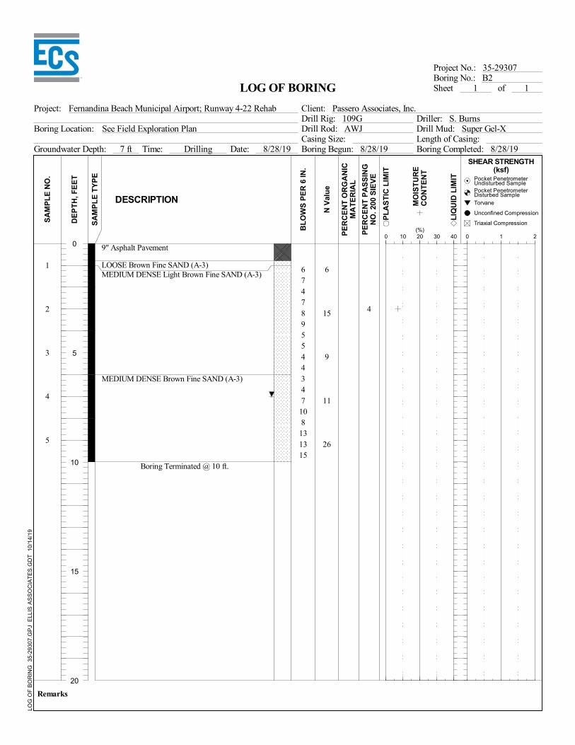
6
15
9
11
26
1
2
3
4
5
9" Asphalt Pavement
LOOSE Brown Fine SAND (A-3)MEDIUM DENSE Light Brown Fine SAND (A-3)
MEDIUM DENSE Brown Fine SAND (A-3)
Boring Terminated @ 10 ft.
6747895544347108131315
4
See Field Exploration Plan
Boring Completed: 8/28/19
Boring No.: B2
Boring Location:
BL
OW
S P
ER
6 IN
.
of 1
Drill Rod: AWJ Drill Mud: Super Gel-X
Time: Drilling
Unconfined Compression
Length of Casing:
SA
MP
LE
TY
PE
Driller: S. BurnsDrill Rig: 109G
DESCRIPTION
L
IQU
ID L
IMIT
N V
alu
e
MO
IST
UR
EC
ON
TE
NT
Remarks
Fernandina Beach Municipal Airport; Runway 4-22 Rehab
PE
RC
EN
T O
RG
AN
ICM
AT
ER
IAL
(%)
Groundwater Depth: 7 ft
0 1 20 10 20 30 40
PE
RC
EN
T P
AS
SIN
GN
O. 2
00 S
IEV
E
DE
PT
H, F
EE
T
Casing Size:Boring Begun: 8/28/19Date: 8/28/19
Triaxial Compression
Project: Client: Passero Associates, Inc.
SA
MP
LE
NO
.
LOG OF BORING
Project No.: 35-29307
Pocket PenetrometerDisturbed Sample
Torvane
Sheet 1
P
LA
ST
IC L
IMIT
Pocket PenetrometerUndisturbed Sample
SHEAR STRENGTH(ksf)
LOG
OF
BO
RIN
G 3
5-29
307.
GP
J E
LLIS
AS
SO
CIA
TE
S.G
DT
10/
14/
19
0
5
10
15
20

9
23
11
28
33
1
2
3
4
5
8" Asphalt Pavement
MEDIUM DENSE Light Brown Fine SAND (A-3)
MEDIUM DENSE to DENSE Brown Fine SAND(A-3)
Boring Terminated @ 10 ft.
9910131011556671315177151820
4
See Field Exploration Plan
Boring Completed: 8/28/19
Boring No.: B3
Boring Location:
BL
OW
S P
ER
6 IN
.
of 1
Drill Rod: AWJ Drill Mud: Super Gel-X
Time: Drilling
Unconfined Compression
Length of Casing:
SA
MP
LE
TY
PE
Driller: S. BurnsDrill Rig: 109G
DESCRIPTION
L
IQU
ID L
IMIT
N V
alu
e
MO
IST
UR
EC
ON
TE
NT
Remarks
Fernandina Beach Municipal Airport; Runway 4-22 Rehab
PE
RC
EN
T O
RG
AN
ICM
AT
ER
IAL
(%)
Groundwater Depth: 7 ft
0 1 20 10 20 30 40
PE
RC
EN
T P
AS
SIN
GN
O. 2
00 S
IEV
E
DE
PT
H, F
EE
T
Casing Size:Boring Begun: 8/28/19Date: 8/28/19
Triaxial Compression
Project: Client: Passero Associates, Inc.
SA
MP
LE
NO
.
LOG OF BORING
Project No.: 35-29307
Pocket PenetrometerDisturbed Sample
Torvane
Sheet 1
P
LA
ST
IC L
IMIT
Pocket PenetrometerUndisturbed Sample
SHEAR STRENGTH(ksf)
LOG
OF
BO
RIN
G 3
5-29
307.
GP
J E
LLIS
AS
SO
CIA
TE
S.G
DT
10/
14/
19
0
5
10
15
20

3
6
6
15
16
1
2
3
4
5
9" Asphalt Pavement
LOOSE Dark Brown Fine SAND (A-3)
LOOSE to MEDIUM DENSE Brown Fine SAND(A-3)
Boring Terminated @ 10 ft.
33233222475781067911
3
See Field Exploration Plan
Boring Completed: 8/28/19
Boring No.: B4
Boring Location:
BL
OW
S P
ER
6 IN
.
of 1
Drill Rod: AWJ Drill Mud: Super Gel-X
Time: Drilling
Unconfined Compression
Length of Casing:
SA
MP
LE
TY
PE
Driller: S. BurnsDrill Rig: 109G
DESCRIPTION
L
IQU
ID L
IMIT
N V
alu
e
MO
IST
UR
EC
ON
TE
NT
Remarks
Fernandina Beach Municipal Airport; Runway 4-22 Rehab
PE
RC
EN
T O
RG
AN
ICM
AT
ER
IAL
(%)
Groundwater Depth: 7 ft
0 1 20 10 20 30 40
PE
RC
EN
T P
AS
SIN
GN
O. 2
00 S
IEV
E
DE
PT
H, F
EE
T
Casing Size:Boring Begun: 8/28/19Date: 8/28/19
Triaxial Compression
Project: Client: Passero Associates, Inc.
SA
MP
LE
NO
.
LOG OF BORING
Project No.: 35-29307
Pocket PenetrometerDisturbed Sample
Torvane
Sheet 1
P
LA
ST
IC L
IMIT
Pocket PenetrometerUndisturbed Sample
SHEAR STRENGTH(ksf)
LOG
OF
BO
RIN
G 3
5-29
307.
GP
J E
LLIS
AS
SO
CIA
TE
S.G
DT
10/
14/
19
0
5
10
15
20

9
7
9
17
22
1
2
3
4
5
2" Asphalt Pavement6" Asphalt Treated BaseLOOSE to MEDIUM DENSE Brown Fine SANDWith Silt (A-3)
Boring Terminated @ 10 ft.
5443343345671076691315
6
See Field Exploration Plan
Boring Completed: 8/28/19
Boring No.: B5
Boring Location:
BL
OW
S P
ER
6 IN
.
of 1
Drill Rod: AWJ Drill Mud: Super Gel-X
Time: Drilling
Unconfined Compression
Length of Casing:
SA
MP
LE
TY
PE
Driller: S. BurnsDrill Rig: 109G
DESCRIPTION
L
IQU
ID L
IMIT
N V
alu
e
MO
IST
UR
EC
ON
TE
NT
Remarks
Fernandina Beach Municipal Airport; Runway 4-22 Rehab
PE
RC
EN
T O
RG
AN
ICM
AT
ER
IAL
(%)
Groundwater Depth: 7 ft
0 1 20 10 20 30 40
PE
RC
EN
T P
AS
SIN
GN
O. 2
00 S
IEV
E
DE
PT
H, F
EE
T
Casing Size:Boring Begun: 8/28/19Date: 8/28/19
Triaxial Compression
Project: Client: Passero Associates, Inc.
SA
MP
LE
NO
.
LOG OF BORING
Project No.: 35-29307
Pocket PenetrometerDisturbed Sample
Torvane
Sheet 1
P
LA
ST
IC L
IMIT
Pocket PenetrometerUndisturbed Sample
SHEAR STRENGTH(ksf)
LOG
OF
BO
RIN
G 3
5-29
307.
GP
J E
LLIS
AS
SO
CIA
TE
S.G
DT
10/
14/
19
0
5
10
15
20

FIELD EXPLORATION PROCEDURES
Standard Penetration Test (SPT) Borings The Standard Penetration Test (SPT) borings were made in general accordance with the latest
revision of ASTM D 1586, “Penetration Test and Split-Barrel Sampling of Soils”. The borings were
advanced by rotary (or “wash-n-chop”) drilling techniques. At 2 ½ to 5 foot intervals, a split-barrel
sampler inserted to the borehole bottom and driven 18 inches into the soil using a 140 pound hammer
falling on the average 30 inches per hammer blow. The number of hammer blows for the final 12
inches of penetration is termed the “penetration resistance, blow count, or N-value”. This value is an
index to several in-place geotechnical properties of the material tested, such as relative density and
Young’s Modulus.
After driving the sampler 18 inches (or less if in hard rock-like material), the sampler was retrieved
from the borehole and representative samples of the material within the split-barrel were
containerized and sealed. After completing the drilling operations, the samples for each boring were
transported to our laboratory where they were examined by our engineer in order to verify the
driller’s field classification. The retrieved samples will be kept in our facility for a period of six (6)
months unless directed otherwise.
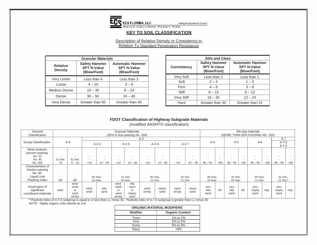
Silts and Clays
Consistency
Safety Hammer SPT N-Value (Blow/Foot)
Automatic Hammer SPT N-Value (Blow/Foot)
Very Soft Less than 2 Less than 1
Soft 2 – 4 1 – 3
Firm 4 – 8 3 – 6
Stiff 8 – 15 6 – 12
Very Stiff 15 – 30 12 – 24
Hard Greater than 30 Greater than 24
Granular Materials
Relative Density
Safety Hammer SPT N-Value (Blow/Foot)
Automatic Hammer SPT N-Value (Blow/Foot)
Very Loose Less than 4 Less than 3
Loose 4 – 10 3 – 8
Medium Dense 10 – 30 8 – 24
Dense 30 – 50 24 – 40
Very Dense Greater than 50 Greater than 40
KEY TO SOIL CLASSIFICATION
Description of Relative Density or Consistency in Relation To Standard Penetration Resistance
FDOT Classification of Highway Subgrade Materials
(modified AASHTO classification)
General Classification
Granular Materials (35% or less passing No. 200)
Silt-clay materials (MORE THAN 35% PASSING NO. 200)
Group Classification
A-3
A-2 A-4
A-5
A-6
A-7
A-2-4 A-2-5 A-2-6 A-2-7 A-7-5 A-7-6
Sieve analysis, percent passing:
No. 10 No. 40 No. 200
-
51 min. <5
-
51 min. 5 – 10
- -
<12
- -
12 – 35
- -
<12
- -
12 – 35
- -
<12
- -
12 – 35
- -
<12
- -
12 – 35
- -
36 – 50
- -
>50
- -
36 – 50
- -
>50
- -
36 – 50
- -
>50
- -
36 – 50
- -
>50
Characteristics of fraction passing
No. 40: Liquid Limit
Plasticity Index
- NP
- NP
40 max. 10 max.
41 min. 10 max.
40 max. 11 min.
41 min. 11 min.
40 max. 10 max.
41 min. 10 max.
40 max. 11 min.
41 min. 11 min.*
Usual types of
significant constituent materials
sand
sand w/silt
or sand
w/clay
sand w/silt
silty sand
sand w/silt
or sand
w/clay
silty sand
or clayey sand
sand
w/clay
clayey sand
sand
w/clay
clayey sand
very silty sand
silt
very silty sand
silt
very
clayey sand
clay
very
clayey sand
clay
* Plasticity Index of A-7-5 subgroup is equal to or less than LL minus 30. Plasticity index of A-7-6 subgroup is greater than LL minus 30. NOTE: Highly organic soils classify as A-8.
ORGANIC MATERIAL MODIFIERS
Modifier Organic Content
Trace 1% to 2% Few 2% to 5%
Some 5% to 8%
Many >8%

APPENDIX B
ASPHALT PAVEMENT PHOTOGRAPHS


APPENDIX C
SUMMARY OF SIEVE ANALYSIS TEST RESULTS
PARTICLE SIZE DISTRIBUTION REPORTS
BEARING RATIO TEST REPORT
COMPACTION TESTREPORT
LABORATORY TEST PROCEDURES

Sample # Depth
Moisture
Content
(%) 1" 3/4" 1/2" 3/8" #4 #10 #20 #40 #60 #100 #200
B1 - 1 0-2 17.5 100.0 100.0 100.0 100.0 100.0 100.0 99.8 98.7 95.6 36.6 4.4
B2 - 2 2-4 6.6 100.0 100.0 100.0 100.0 100.0 100.0 100.0 99.9 98.0 37.7 3.7
B3 - 1 0-2 9.4 100.0 100.0 100.0 100.0 100.0 99.9 99.7 98.9 94.5 36.9 3.8
B4 - 7 2-4 19.6 100.0 100.0 100.0 100.0 100.0 100.0 99.9 99.8 96.3 29.8 2.4
B5 - 1 0-2 9.9 100.0 100.0 100.0 100.0 100.0 99.7 99.6 99.3 96.2 35.2 6.2
SUMMARY OF SIEVE ANALYSIS TEST RESULTS
Project: Fernandina Beach Municipal Airport; Runway 4-22 Rehab
Client: Passero Associates
Project No.: 29307

Particle Size Distribution ReportP
ER
CE
NT
FIN
ER
0
10
20
30
40
50
60
70
80
90
100
GRAIN SIZE - mm.
0.0010.010.1110100
% +3"Coarse
% Gravel
Fine Coarse Medium
% Sand
Fine Silt
% Fines
Clay
0.0 0.0 0.0 0.0 1.3 94.3 4.4
6 in
.
3 in
.
2 in
.
1½
in
.
1 in
.
¾ in
.
½ in
.
3/8
in
.
#4
#1
0
#2
0
#3
0
#4
0
#6
0
#1
00
#1
40
#2
00
Test Results (ASTM C 136 & ASTM C 117)
Opening Percent Spec.* Pass?
Size Finer (Percent) (X=Fail)
Material Description
Atterberg Limits (ASTM D 4318)
Classification
Coefficients
Date Received: Date Tested:
Tested By:
Checked By:
Title:
Date Sampled:Source of Sample: B1 - 1 Depth: 0.00-2.00Sample Number: D4S-2
Client:
Project:
Project No: Figure
Fine Sand trace Silt
3/8"#4
#10#20#40#60#80
#100#140#200
100.0100.0100.0
99.898.795.672.836.6
6.74.4
SP
0.2107 0.1977 0.16830.1605 0.1441 0.12620.1164 1.45 1.06
SB
SB
Passero Associates
Fernandina Beach Municipal Airport; Runway 4-22 Rehab
29307
PL= LL= PI=
USCS (D 2487)= AASHTO (M 145)=
D90= D85= D60=D50= D30= D15=D10= Cu= Cc=
Remarks
* (no specification provided)

Particle Size Distribution ReportP
ER
CE
NT
FIN
ER
0
10
20
30
40
50
60
70
80
90
100
GRAIN SIZE - mm.
0.0010.010.1110100
% +3"Coarse
% Gravel
Fine Coarse Medium
% Sand
Fine Silt
% Fines
Clay
0.0 0.0 0.0 0.0 0.1 96.2 3.7
6 in
.
3 in
.
2 in
.
1½
in
.
1 in
.
¾ in
.
½ in
.
3/8
in
.
#4
#1
0
#2
0
#3
0
#4
0
#6
0
#1
00
#1
40
#2
00
Test Results (ASTM C 136 & ASTM C 117)
Opening Percent Spec.* Pass?
Size Finer (Percent) (X=Fail)
Material Description
Atterberg Limits (ASTM D 4318)
Classification
Coefficients
Date Received: Date Tested:
Tested By:
Checked By:
Title:
Date Sampled:Source of Sample: B2 - 2 Depth: 2.00-4.00Sample Number: D4S-3
Client:
Project:
Project No: Figure
Fine Sand trace Silt
#4#10#20#40#60#80
#100#140#200
100.0100.0100.0
99.998.075.237.7
6.23.7
SP
0.2028 0.1928 0.16680.1593 0.1434 0.12610.1170 1.43 1.05
SB
SB
Passero Associates
Fernandina Beach Municipal Airport; Runway 4-22 Rehab
29307
PL= LL= PI=
USCS (D 2487)= AASHTO (M 145)=
D90= D85= D60=D50= D30= D15=D10= Cu= Cc=
Remarks
* (no specification provided)

Particle Size Distribution ReportP
ER
CE
NT
FIN
ER
0
10
20
30
40
50
60
70
80
90
100
GRAIN SIZE - mm.
0.0010.010.1110100
% +3"Coarse
% Gravel
Fine Coarse Medium
% Sand
Fine Silt
% Fines
Clay
0.0 0.0 0.0 0.1 1.0 95.1 3.8
6 in
.
3 in
.
2 in
.
1½
in
.
1 in
.
¾ in
.
½ in
.
3/8
in
.
#4
#1
0
#2
0
#3
0
#4
0
#6
0
#1
00
#1
40
#2
00
Test Results (ASTM C 136 & ASTM C 117)
Opening Percent Spec.* Pass?
Size Finer (Percent) (X=Fail)
Material Description
Atterberg Limits (ASTM D 4318)
Classification
Coefficients
Date Received: Date Tested:
Tested By:
Checked By:
Title:
Date Sampled:Source of Sample: B3 - 1 Depth: 0.00-2.00Sample Number: D4S-4
Client:
Project:
Project No: Figure
Fine Sand trace Silt
#4#10#20#40#60#80
#100#140#200
100.099.999.798.994.570.536.9
6.33.8
SP
0.2195 0.2035 0.16960.1610 0.1436 0.12530.1161 1.46 1.05
SB
SB
Passero Associates
Fernandina Beach Municipal Airport; Runway 4-22 Rehab
29307
PL= LL= PI=
USCS (D 2487)= AASHTO (M 145)=
D90= D85= D60=D50= D30= D15=D10= Cu= Cc=
Remarks
* (no specification provided)

Particle Size Distribution ReportP
ER
CE
NT
FIN
ER
0
10
20
30
40
50
60
70
80
90
100
GRAIN SIZE - mm.
0.0010.010.1110100
% +3"Coarse
% Gravel
Fine Coarse Medium
% Sand
Fine Silt
% Fines
Clay
0.0 0.0 0.0 0.0 0.2 97.4 2.4
6 in
.
3 in
.
2 in
.
1½
in
.
1 in
.
¾ in
.
½ in
.
3/8
in
.
#4
#1
0
#2
0
#3
0
#4
0
#6
0
#1
00
#1
40
#2
00
Test Results (ASTM C 136 & ASTM C 117)
Opening Percent Spec.* Pass?
Size Finer (Percent) (X=Fail)
Material Description
Atterberg Limits (ASTM D 4318)
Classification
Coefficients
Date Received: Date Tested:
Tested By:
Checked By:
Title:
Date Sampled:Source of Sample: B4 - 7 Depth: 2.00-4.00Sample Number: D4S-5
Client:
Project:
Project No: Figure
Fine Sand trace Silt
#4#10#20#40#60#80
#100#140#200
100.0100.0100.0
99.896.364.229.8
5.52.4
SP
0.2233 0.2104 0.17590.1671 0.1502 0.13260.1229 1.43 1.04
SB
SB
Passero Associates
Fernandina Beach Municipal Airport; Runway 4-22 Rehab
29307
PL= LL= PI=
USCS (D 2487)= AASHTO (M 145)=
D90= D85= D60=D50= D30= D15=D10= Cu= Cc=
Remarks
* (no specification provided)

Particle Size Distribution ReportP
ER
CE
NT
FIN
ER
0
10
20
30
40
50
60
70
80
90
100
GRAIN SIZE - mm.
0.0010.010.1110100
% +3"Coarse
% Gravel
Fine Coarse Medium
% Sand
Fine Silt
% Fines
Clay
0.0 0.0 0.0 0.3 0.4 93.1 6.2
6 in
.
3 in
.
2 in
.
1½
in
.
1 in
.
¾ in
.
½ in
.
3/8
in
.
#4
#1
0
#2
0
#3
0
#4
0
#6
0
#1
00
#1
40
#2
00
Test Results (ASTM C 136 & ASTM C 117)
Opening Percent Spec.* Pass?
Size Finer (Percent) (X=Fail)
Material Description
Atterberg Limits (ASTM D 4318)
Classification
Coefficients
Date Received: Date Tested:
Tested By:
Checked By:
Title:
Date Sampled:Source of Sample: B5 - 1 Depth: 0.00-2.00Sample Number: D4S-6
Client:
Project:
Project No: Figure
Fine Sand with Silt
3/8"#4
#10#20#40#60#80
#100#140#200
100.0100.0
99.799.699.396.268.535.2
9.46.2
0.2189 0.2053 0.17160.1628 0.1448 0.12340.1087 1.58 1.12
SB
SB
Passero Associates
Fernandina Beach Municipal Airport; Runway 4-22 Rehab
29307
PL= LL= PI=
USCS (D 2487)= AASHTO (M 145)=
D90= D85= D60=D50= D30= D15=D10= Cu= Cc=
Remarks
* (no specification provided)

BEARING RATIO TEST REPORTASTM D1883-14
Project No: 29307
Project: Fernandina Beach Municipal Airport; Runway 4-22 Rehab
Source of Sample: Borng B3 Depth: 0.00-0.10
Sample Number: D4S-1
Date:
Brown Fine Sand
Test Description/Remarks:
Figure
104.4 14.2 NPSP
Material DescriptionUSCS
Max.Dens.(pcf)
OptimumMoisture
(%)LL PI
Molded
Density(pcf)
Percent ofMax. Dens.
Moisture(%)
Soaked
Density(pcf)
Percent ofMax. Dens.
Moisture(%)
CBR (%)
0.10 in. 0.20 in.
LinearityCorrection
(in.)
Surcharge(lbs.)
Max.Swell(%)
1 104.4 100 14.6 8.9 11.7 0.000 10 0
2 103.0 98.7 14.6 8.2 10.4 -0.004 10 0
3 101.8 97.5 14.3 6.3 8.4 0.006 10 0
Pe
ne
tra
tio
n R
es
ista
nc
e (
ps
i)
0
70
140
210
280
350
Penetration Depth (in.)0 0.1 0.2 0.3 0.4 0.5
CB
R (
%)
6
7
8
9
10
Molded Density (pcf)101 102 103 104 105 106
56 blows
25 blows
10 blows
CBR at 98% Max. Density = 7.2%for 0.10 in. Penetration

Tested By: BS Checked By: SB
COMPACTION TEST REPORTD
ry d
en
sity, p
cf
102.5
103
103.5
104
104.5
105
Water content, %
12 13 14 15 16 17 18
14.2%, 104.4 pcf
Test specification: ASTM D 1557-12 Method C Modified
0.00-0.10 SP 2.7 NP
Brown Fine Sand
29307 Passero Associates
Elev/ Classification Nat.Sp.G. LL PI
% > % <
Depth USCS AASHTO Moist. 3/4 in. No.200
TEST RESULTS MATERIAL DESCRIPTION
Project No. Client: Remarks:
Project:
Source of Sample: Borng B3 Sample Number: D4S-1
Figure
Maximum dry density = 104.4 pcf
Optimum moisture = 14.2 %
Fernandina Beach Municipal Airport; Runway 4-22 Rehab

LABORATORY TEST PROCEDURES
Natural Moisture Content
The water content of the sample tests was determined in general accordance with the latest revision of
ASTM D 2216. The water content is defined as the ratio of “pore” or “free” water in a given mass of
material to the mass of solid material particles.