best available - citeseerx
TRANSCRIPT

' I
i
Best Available
Copy
.,
\
■■ ■
AD-761 203
WAVE PROPAGATION IN ANISOTROPIC ROCKS
Werner Goldsmith, et al
California University
Prepared for:
Advanced Research Projects Agency Bureau of Mines
1 June 1973
DISTRIBUTED BY:
KHJ National Technical Information Service U. S. DEPARTMENT OF COMMERCE 5285 Port Royal Road, Springfield Va. 22151
■
• — mäm m
00 o;
WAVE PROPAGATION IN ANISOTROPIC ROCKS
Final Technical Report
Contract No. H0220021
Sponsored by Advanced Research Projects Agency, ARPA Order No. 1579, Anend. 3
Program Code 62701D
Principal Investigator: Dr. W. Goldsmith Faculty Investigator; Dr. J. L. Sackman
University of California Berkeley, California 9^720
June 1, 1973
Reproduced by — . ■
NATIONAL TECHNICAL INFORMATION SERVICE
one nlP OTpl U> JUN « 1915
MUM
*mm
1
Unclassified nsarirßmiim?
POCUMINT CONTROL DATA -R&D
University of California, Berkeley Unclassified v.anoup
ION
I. NIPORT TITkB
WAVE PROPAGATION IN ANISOTROPIC ROCKS
4, OttemPJfVt MOru (Tjrß* •! npett mm* Inchitlrt d»lf) Final Technical Report, February 23, 1972 to June 1, 1973
•. AUTHOHdimntiMm, «Mrffaliilllal, fa((Min«> '
Werner Goldsmith and Jerome L. tlackman
C RMORt DATt
June 1, 1973 la. CONTRACT ON «RANT NO,
H0220021 K PROJECT NO.
ARPA Order No. 1579, Amend. 3
Procram Code No. 62701D
jr. rontc m w üABH w> H6. gy Km 81
U. ORIOINATOR'* REPORT NUMIIRItl
M. OTHER REPORT NO(t) {Any otlwr ntmbn» (Ac« mmy b» •••««naif Ihll rmpotl)
10. OISTRIOUTION STATEMENT
Distribution of this document is unlimited
11. 1UP It fPONIORINO MILITARY ACTIVITY
Advanced Research Projects Agency
I*. AMTRACT
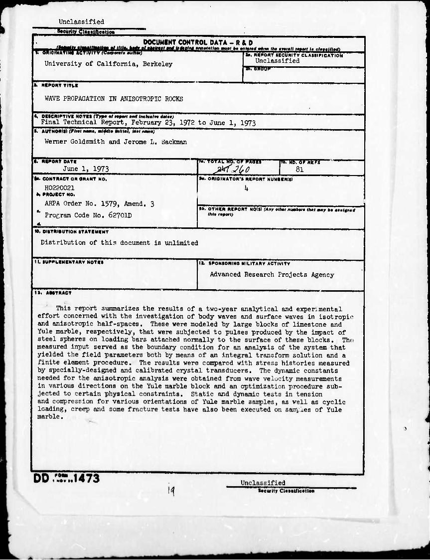
This report summarizes the results of a two-year analytical and experimental effort concerned with the investigation of body waves and surface waves in isotropio and anisotropic half-spaces. These were modeled by large blocks of limestone and Yule marble, respectively, that were subjected to pulses produced by the impact of steel spheres on loading bars attached normally to the surface of these blocks. The measured input served as the boundary condition for an analysis of the system that yielded the field parameters both by means of an integral transform solution and a finite element procedure. The results were compared with stress histories measured by specially-designed and calibrated crystal transducers. The dynamic constants needed for the anisotropic analysis were obtained from wave velocity measurements in various directions on the Yule marble block and an optimization procedure sub- jected to certain physical constraints. Static and dynamic tests in tension and compression for various orientations of Yule marble samples, as veil as cyclic loading, creep and some fracture tests have also been executed on samyxes of Yule marble.
00 I MOV «• 1473 II
Unclassified (•ewtty CUsslftcatlea

Unclassified "Security Cl>»»tfic«tloii
It 4. KCY WORDS
LINK A ROLE
Rock mechanics Properties of rock Fracture of rock Wave propagation Anisotropie half-spaces Impact Transient signals in rocks Transducers Finite element analysis Integral transform techniques
WT
LINK ■ HOLE WT
LINK C
ROLE JSL
Security CUatificatloa
■tfai MMMflBriaai
WAVE PROPAGATION IN ANISOTROPIC ROCKS
Final Technical Report
Contract No. H0220021
Sponsored by Advanced Research Projects Agency, ARPA Order No. 1579, Amend. 3
Program Code 62701D
Principal Investigator: Dr. W. Goldsmith Faculty Investigator: Dr. J. L. Sackman
University of California Berkeley, California 9U72O
June 1, 1973
1
i
n
FINAL TECHNICAL REPORT
ARPA Order Number: 1579, Amendment 3
Program Code Number: 6270x0
Contractor: The Regents of the University of California
Effective Date of Contract: February 23, 1972
Contract Expiration Date: June 30, 1973
Amount of Contract: $62,^36.00
Contract Number: H0220021
Principal Investigator: Professor W. Goldsmith, (U15)61+2-3739
Project Engineer: Professor J. L. Sackman (Ul5)6U2-2950
Title: "Wave Propagation in Anisotropie Rocks"
Report Period: February 23, 197:; to June 1, 1973
Sponsored by
Advanced Research Projects Agency
ARPA Order No. 1579 Amend. 3
Program Code 62701D
This research was supported by the Advanced Research Projects Agency of the
Department of Defense and was monitored by the Bureau of Mines under Contract
No. H02a0021.
The views and conclusions contained in this document are those of the authors
and should not be interpreted as necessarily representing the official policies,
either expressed or implied, of the Advanced Research Projects Agency or the
U, S. Government.
id
^^m^^mm MMM
■i-t'
ABSTRACT
This is the final report of a two-year activity involving a theoretical and
experimental investigation of non-destructive wave propagation resulting from the
impact of steel spheres on a Yule marble block, including a determination of its
static and dynamic mechanical properties. The basic system was modeled as a
transversely Isotropie half-space with the axis of elastic symmetry lying in the
free surface loaded by means of a specified normal force of variable shape and
duration. This simulates the experimental conditions where a large block of
Yule marble is loaded by metallic bars in intimate contact that are subjected
to longitudinal Impact of steel spheres with the input monitored by a sandwiched
crystal arrangement. Calibrated crystal transducer packages that were developed
as part of the program have been embedded at various points of two Yule marble
blocks and have provided records of the transient stresses and wave velocities
at both interior and surface positions.
A solution of the mathematical model has been accomplished using integral
transform methods that make use of an inversion procedure in the complex plane
involving a Cagniard-de Hoop path. An important part of the manipulation involves
the evaluation of the roots of this path from a sextic algebraic equation that
breaks down into a quartic and a quadratic factor. Formulations for the dis-
placements, strains and stresses within the entire domain resulting from the
application of a point load on the surface of the half-space represent ii.g a Heaviside
function of time have been obtained, characterizing a basic solution of the
problem. The detemination of these parameters for an actual impact situation
is accomplished by convolving the measured input for each case with the basic
solution. A computer program has been developed that has yielded numerical
results for the predicted stress histories at selected stations corresponding to
certain experimentauLly-detemined inputs.
I
-ii-
A finite element program corresponding to the integral transform analysis
has also been developed. The init-'-J. application of this program was the prediction
of the field variables in a block of limestone, representing an essentially
Isotropie material, and a comparison of these with corresponding experimental
data obtained by means of internal transducer packages under loading conditions
similar to those described above; excellent correlation was obtained. The program
was extended to the transversely isotropic case; satisfactory correspondence
was found to prevail between the predictions both of the integral transform and the
finite element solution with recorded test information. However, better correlation
with the data existed with the finite element technique close in, and with the
integral transform solution at more distant stations. The elastic constants
employed in these evaluations were deduced from wave speed data in different
direotions involving the actual specimen and an optimization procedure subject
to constraints based on presumed positive values of these parameters.
The macroscopic properties of the marble were obtained both by petrographic
and mechanical methods. The axis of transverse isotropy was ascertained by
means of crystallography; the material exhibited an average crystal size of 0.5 mm.
The five constants describing the presumed purely elastic behavior were obtained
for quasi-static uniaxial compression; creep tests on specimens oriented both
parallel and perpendicular to the symmetry axis indicated little viscoelastic
behavior at low stress levels, but dominance of this effect near fracture. Com-
pressive quasi-static stress-strain curves to fracture were obtained at rates
-6 -? from 10 to 10 per second for the two directions of interest, and numerous
tensile quasi-static curves were also secured. Hopkinson-bar experiments on rods
cut from three different directions yieldcl the values of the dynamic constants
for both tensile and compressive low stress levels, amounting to about twice
the corresponding quasi-static values. Compress}ve and tensile fracture stresses
parallel and perpendicular to the axis of symmetry were obtained from split

-ili-
Hopkinson-bar specimens possessing a special contour at rates of 10 per second.
The totality of the tests conducted indicated that the material behaves in a
very complicated Tanner even at low stress levels and that the use of appropriate
material constants is crucially dependent on both stress level and loading
history.
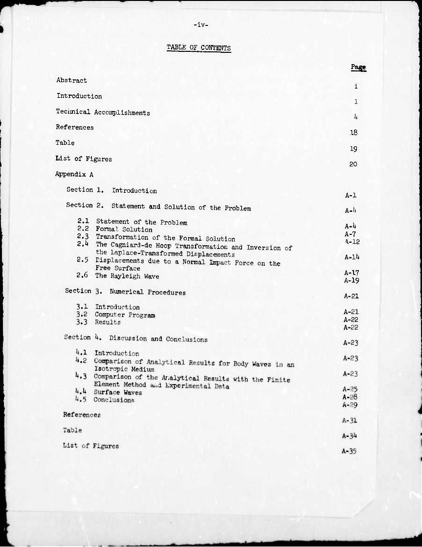
•iv-
TABLE OF CONTENTS
Abstract
Introduction
Technical Accomplishments
References
Table
List of Figures
Appendix A
Section 1. Introduction
Section 2. Statement and Solution of the Problem
2.1 Statement of the Problem 2.2 Formal Solution
2.3 Transformation of the Formal Solution 2.k The Cagniard-de Hoop Transformation and Inversion of
the Laplace-Transformed Displacements 2.5 Msplacements due to a Normal Impuct Force on the
Free Surface 2.6 The Rayleigh Wave
Section 3. Numerical Procedures
3.1 Introduction 3*2 Computer Program 3.3 Results
Section k. Discussion and Conclusions
^.1 Introduction
U.2 ComparlEon of Analytical Results for Body Waves In an Isotropie Medium
M Comparison of the Ar-alytical Results with the Finite Element Method eu.d Lxpcrimental Data
U.U Surface Waves ^.5 Conclusions
Reference?
Table
List of Figures
P2S£
i
1
h
18
19
20
A-l
A-ll
A-l» A-7 ^-12
A-lli
A-17 A-19
A-21
A-21 A-22 A-22
A-23
A-23
A-23
A-25 A-28 Ä-29
A-31
A-3U
A-35
-v.
Appendix B
Users Manual and Fortran Listing for the Finite Element Method Applied to Wave Propagation Analysis in Isotropie and Anisotropie Media
Appendix C Experimental Examination of Wave Processes in Natural Rock
Section I. Scope and Objectives
1.1 Scope of the Experimental Investigation 1.2 Objectives of the Experimental Work
Section II. Design, Development and Calibration of the Piezoelectric Transducers
II. 1 Design and Development of the Transducer 11.2 Choice of the Piezoelectric Crystal Element 11.3 Construction and Assembly of the Transducers II,If Development of a Split Hopkinson Bar Arrangement
fjr Calibration 11.5 External Calibration of the Transducers 11.6 In Situ Calibration
11.7 Correlation of the External Calibration with In Situ Calibration in Rock Bars
Section III. Body Wave Propagation in an Isotropie Rock Model
111.1 Introduction 111.2 Installation of the Traiiüducers 111.3 Generation and Measurement of Input Pulse HI.If Measurement of Body Wave Propagation
Section IV. Body Wave Propagation in an Anisotropie Rock Model
IV. 1 Direction of the Axis of Elastic Symmetry IV.2 Determination of Transducer Locations IV.3 Transducers Employed Vttk Preparation of the Yule Marble Block IV.5 Body Wave Propagation Measurements
Section V. Surface Wave Propagation in the Anisotropie Rock
V.l Anisotropie Model for Surface Waves V.2 Objectives V.3 Transducer Modification V.1+ Location and Installation of Transducers V.5 Surface Wave Propagation Measurements
C-l
C-l C-2
C-k
c-k C-9 C-ll
C-ll C-13 C-15
c-16
C-19
C-19 C-20 C-21 C-22
C-2U
C-2U C-2k C-27 C-27 C-28
C-30
C-30 C-31 C-31 C-32 C-33
-vi-
Page
0-3^ Section VI. Summary of the Experimental Investigation
VI 1 Stress Factors from External Calibration Constants C-3H VI.2 Body Wave Measurements in the Isotropie Model ^ VI 3 Body Wave Measurements in the Yule Marble Block C ij Vl'.k Surface Wave Measurements in the Yule Marble Block C-3U
Section VII. Determination of Dynamic Elastic Properties From ^^ Arrival Times
VII.l Dynamic Elastic Constants of Yule Marble C-35 VII.2 Elastic Stiffness Matrix and Velocity Equation ^J VTI ^ Velocities from Experimental Measurements ^ VIl'.U Determination of C^ and c^ from p-Wave Tests C 3«
VII.5 Requirements Inrposed by the Positive Definite Form ^ of the Strain Energy _ r.Uo
VII.6 FomSation for Determining the Elastic Constants C_J0 VII.7 Minimization Technique c_lJ2 VII.8 Remarks
C-U3 Section VIII. Discussion
C-U3 VTTT 1 General Outline .. ■■ i C-'-R VIII 2 Body Wave Measurements in the Isotropie Model ^ VIII 3 Body Wave Measurements in the Anisotropie Model VIII.U Surface Wave Propagation Measurements m the c_^2
Anisotropie Model , _ n ^,, VIII.5 Determination of Dynamic Elastic Constants from Body ^^
Wave and Surface Wave Measurements , „., C-5U VIII.6 Stress Wave Measurements with Embedded Transducers
C-56
C-58
C-67
References
Tables
List of Figures
Appendix D Determination of Static and Dynamic Mechanical Properties •^ of Yale Marble !>,]_
I. Introduction
II. Physical and Geometrical Characteristics
III. Quasi-Static Tests
IV. Creep Tests
V. Dynamic Tests
VI. Discussion and Conclusions
D-3
D-5
D-ll
D-12
D-l6
^mt^äm MM^BflMflB^M^I

-vii-
Page
References
List of Figures
D-21
D-23
i
t^^m
INTRODUCTION
This report represents the final annual technical report under contract
H0220021 between the U.S. Bureau of Mines and the University of California on
the subject entitled "Wave Propagation in Anisotropie Rocks", representing the
culmination of a two-year effort. The current contract period, originally
destined to expire February 22, 1973, has been extended to June 30, 1973 in
order to pemit the proper correlation of the various aspects of the program and
suitable documentation of these phases. The body of the report will delineate
the objectives, methodology and principal results of each of these subdivisions
of the investigation and their overall connection; the details of the individual
efforts are recorded in appendices which are self-contained.
The scope of the program was detailed in proposals identified as UCB-Eiig 315U,
dated August 19, 1970, and UCB-Eng 3286, dated April 26, 1971, and submitted on
behalf of the University of California, Berkeley, by Werner Goldsmith as
Principal Investigator; it is also spelled out in Article I of the subject
contract. Briefly, the investigation can be divided into the following categories:
(a) Theoretical Examination of the Propagation of Body Waves in a Transversely
Isotropie Elastic Solid resulting from an Impact on the Free Surface
by means of
(1) Integral Transform Techniques
(2) Finite Element Methods;
(b) Experimental Examination of the Wave Processes corresponding to (a) and
the Measurement of Stress Histories at various Selected Positions in the
Interior or near and at the Siirface resulting from Projectile Impact on
a Loading Bar in intimate Contact with a large Block of Yule Marble
simulating a Half-space;
(c) Determination of Mechanical Properties of Yule Marble under Static and
Dynamic Loading of variously-oriented Specimens,
M^^^MMMMMMI
- 2 -
Many of the results obtainad have teen reported previously in Reference! (l) and
(2).
The following personnel have had a major «hare of the reaponalbility of the
execution of the various tasks: (i) Mr. S. L. 3uh who pursued the integral
transform solution and produced a "ooputer Tjrogra» that yield« the field variables
at any position for any predeterminel input, (11) Messrs. M. Katona and 0. Dasgupta
who succsssi/ely aided In the development of a finite element program for the
subject problem that has been successfully applied for the evaluation of the
desired parameters both for an Isotropie and a transversely Isotropie half-space
loaded by a point force of arbitrary time variation, (111) Mr. K. KrishnamoorU.y
who was responsible for the design, development, testing, calibration, Installation
and use of tne transducers and their packaging that have yielded stress histories
within and on the surface of llmeutone and Yule aarble blocks under Ij^act loading
from steel spheres, and who also obtained the data and devised the technique for
the specification of the dynamic elastic constants pertaining to the actual test
sample, and (iv) Mr. S. Howe who conducted the crystallographlc, petrographlc and
mechanical tests that delineated the geometric and static and dynamic material
properties of the Yfcle marble. These students are utilising the results of the
investigation as the content of their masters theses and doctoral dissertations.
Werner Goldsmith, Professor of Applied Mechanics, Department of Mechanical
Engineering and Jerome L. Sackaan, Professor of Engineering Science, Departmtn»
of Civil Engineering, have Jointly supervised the program from its inception to
its conclusion and are responsible for Its conduct. In addition, the project has
received notlcable technical assistance from Mr. R. Kenner In the Fortran programing,
from Mr. E. Lin in specimen preparation, from Mr. Tom Jonas In Instnaentatlon
development, frcm Mr. G. Wll^ox In general laboratory assistance, and frt»
Mr. R. M. Hamilton of the Glassbl wing Shop of the Department of Electrical
Engineering in ine fabrication of the transducer«. The export assistance of
Prof«Mor R. L. T«ylor of the Dep*rtÄent of Civil Bigineering in the dcvelopaant
of the finite element progm is grmtefullr acknowledged.
The objective! of the program have been «ubstantlally fulfilled with the
possible exception of certain aspects of fracture Initiation and propagation.
It was originally anticipated that this portion of tte work would require a period
in excess of the two years that represented the life nf the contract. When advice
was received that a continuation of the support was not to be expected, it was
decided, with the consent of the Technical Monitor, not to initiate such an
Investigation since It would have to be abandoned before successful techniques
could be adequately developed. On the other hand, a host of Information not
specifically contained In the contract has been obtained as a byproduct of the
research. This includes Information on surface waves obtained experimentally,
and the definition (and, In a manner of speaking, the resolution) of difficulties
associated with an analytical Investigation of surface waves produced by Impact
on transversely Isotropie half-spaces.
The results obtained represent not only a significant advancement of the field
of wave propagation In elastic, anisotroplc media, but should have considerable
VPlleablllty to the interpretation of signals that might be employed by trans-
mitters in rapid tunneling or excavation situations to send the character of the
rock formations ahead of the boring device, and also should be of utility for parallel
circumstances In the field of geophysical prospecting. The transducer pat .age
developed and its successful application for the measurement of internal transient
stresses could find widespread employment in a nultitude of fields involving basic
research, design and development, testing and production of large-scale components
with potential problems due to local stress concentrations or overloads. Finally,
the techniques employed for the property determination of the rock employed here
are individually not new, but the totality of the various tests has not been
prev* ously brought to bear on a slnrle natural rock to ascertain its behavior pattern.
mm
It had been the Intention of the re.enrch tew to «u^est the continuation
of the effort for the purpose of extending the re.ult. to ■ variety of natural
rocka. With very UttU effort, the finite eleiant progra. developeu could be
ad«pted to an orthotroplc oaterlal auch aa Barre granite, uhlch occura widely
in the field. With further .odlf5catloi»a. It should be po.slbie to Include the
•ffacta of fault «ones or other discontinuities In the program, ead to Incorporate
the effects of reflections fro« bounding surfaces. This aspect of a continuing
Investigation might lead to the Identification of sveclflc discontinuities In
rock strata, a «ubject believed to be or vast Interest. It «as further hoped to
attack a new phase of leportance In rock reeoval, naMly a fundamental study of
the coMlnutlon process. Soae very prellBlnai7 experlmenta in Mdl direction
appeared to Indicate potential for a successful pursuit of this objectlva. Such
Investlgatlona via no« have to be relegated to the future, and If Initiated
at ell, «m be sponsored and Monitored by different agencies, although the
group having prleary Interest In these doMlns la the U.S. Bureau of Mines.
TBCHJCICAL ACCOMPMSHMHiTS
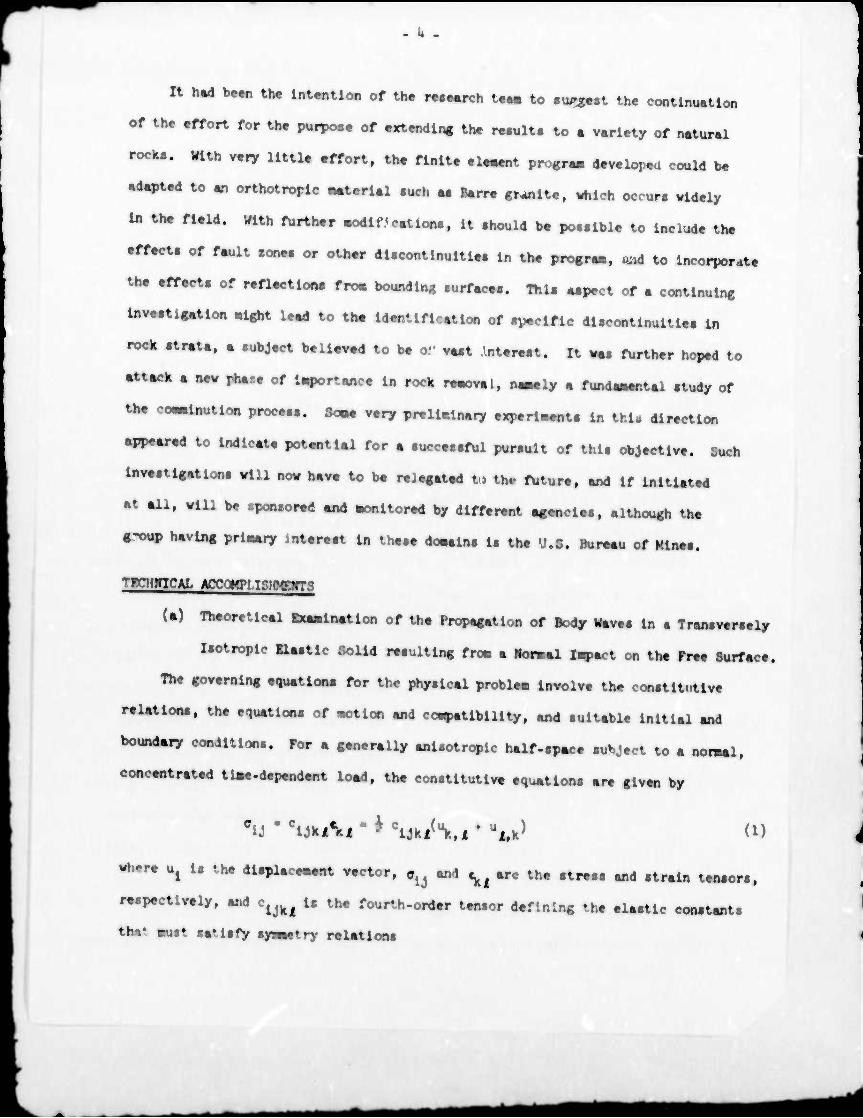
(a) Theoretical Bxaalnatlon of the Propagation of Body Waves In a Transveraely
Isotropie nestle Solid reaultlng froe a Horael lapact on the Free Surface.
The governing equatlooa for the physical problea Involve the conatltutlve
reUtlona, the equatlona of motion and co^atlblllty, and suitable Initial and
boundery condition.. For a generally anlsotroplc half-spece subject to a noraal,
concentrated tie«.dependent load, the constitutive equatlona are given by
^■ClJkA,-KWUk,l'Ul.k) (1)
wture ^ Is the displacement vector, «^ and ^ are the stress and strain tensors,
respectively, and e^ Is the fourth-order tensor defining the elastic constants
thi* eust satisfy sywetry relations
tmm
- 5 -
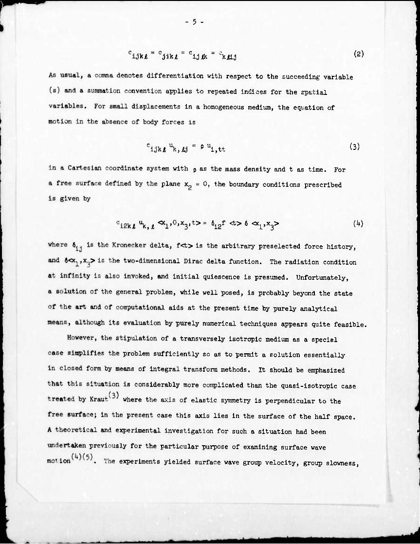
cijki = cjikjt = cidik = \tLi (2)
AB usual, a comma denotes differentiation with respect to the succeeding variable
(a) and a smnnation convention applies to repeated indices for the spetial
variables. For small displacements in a homogeneous medium, the equation of
motion in the absence of body forces is
^juVij = Ptti,tt (3)
in a Cartesian coordinate system with p as the mass density and t as time. For
a free surface defined by the plane x2 = 0, the boundary conditions prescribed
is given by
Ci2kJt \ t <*V0>*3>t> = 6i2f <t> 6 <Xl,x3> (k)
where b is the Kronecker delta, f<t> is the arbitrary preselected force history,
and Kt,9Sg>ii the two-dimensional Dirac delta function. The radiation condition
at Infinity is also invoked, and initial quiescence is presumed. Unfortunately,
a ■olutlon of the general problem, while well posed, is probably beyond the state
of the art and of computational aids at the present time by purely analytical
means, although its evaluation by purely numerical techniques appears quite feasible.
However, the stipulation of a transversely Isotropie medium as a special
caae simplifies the problem sufficiently so as to permit a polution essentially
In closed form by means of integral transform methods. It should be emphasized
that this situation is considerably more complicated than the quasi-isotropic case
(3) treated by Kraut ' where the axis of elastic symmetry is perpendicular to the
free aurface; in the present case this axis lies in the surface of the half space.
A theoretical and experimental investigation for such a situation had been
undertaken previously for the particular purpose of examining surface wave
motion . The experiments yielded surface wave group velocity, group slowness.
mat
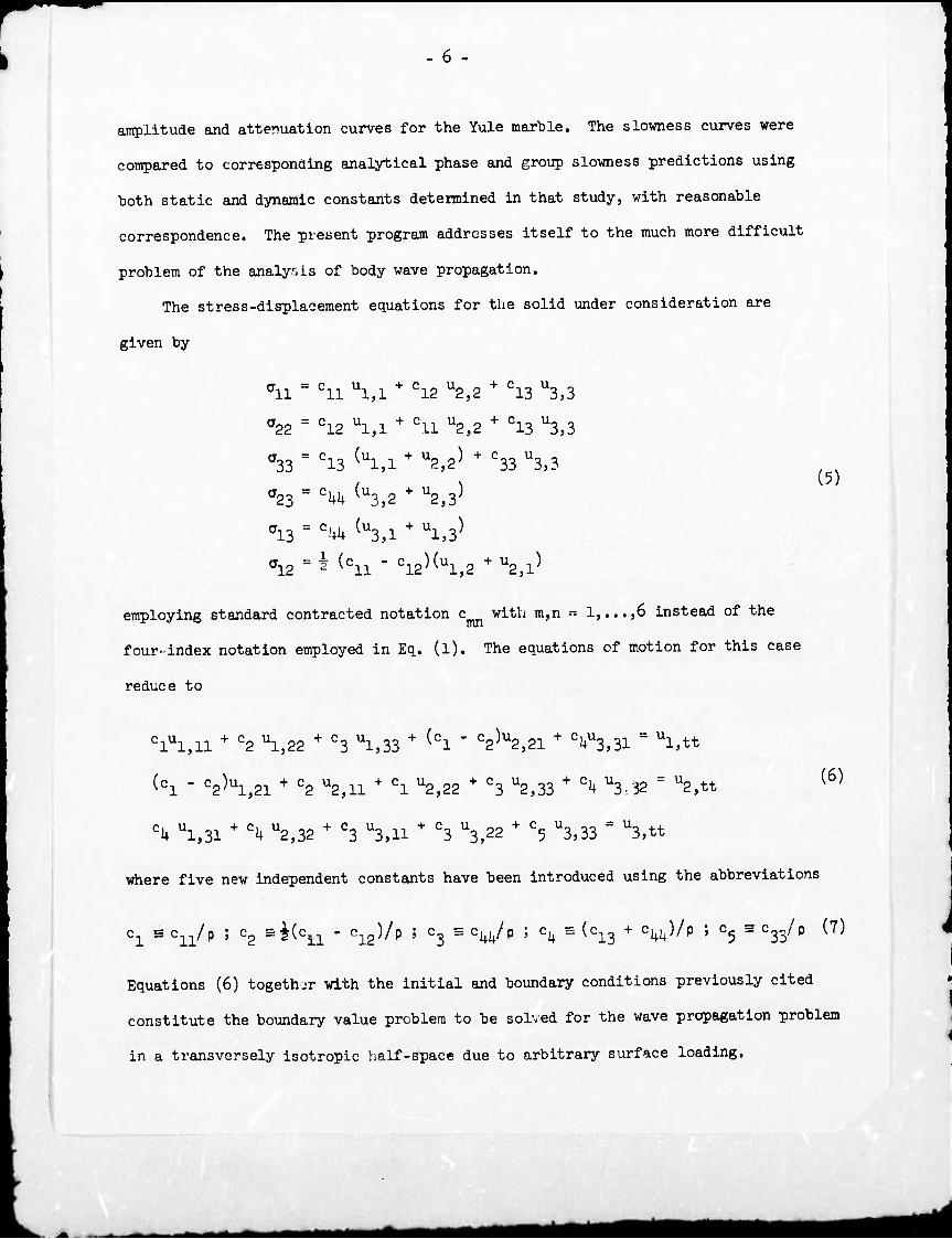
- 6
amplitude and attenuation curves for the Yule marble. The slowness curves were
compared to corresponding analytical phase and group slowness predictions using
both static and dynamic constants determined in that study, with reasonable
correspondence. The present program addresses itself to the much more difficult
problem of the analysis of body wave propagation.
The stress-displacement equations for the solid under consideration are
given by
ffll = Cll U1}1 + C12 U2,2 + C13 U3,3
CT22 = C12 Ul.l + Cll U2,2 + C13 U3,3
(5) ^33 = C13 (ul,l + U2,2) + c33 U3,3
a23 = CUU (u3,2 + u2,3)
a13 = chh (u3,l + ul,3)
a12=* (C11- C12)(U1,2+U2,1)
employing standard contracted notation c with m,n - 1,...,6 instead of the
four-index notation employed in Eq. (l). The equations of motion for this case
reduce to
clul,ll + c2 ul,22 + c3 ul,33 + (cl " c2)u2,21 + CUU3,31 = Ul,tt
(Cl ■ C2)U1,21 + C2 U2,ll + Cl U2,22 + C3 U2,33 + % Vtf = U2,tt
CU ul,31 + % u2,32 + c3 U3,ll + C3 U3,22 + c5 U3,33 = U3,tt
where five new independent constants have been introduced using the abbreviations
c1 a c^/p ; c2 =i(c11 - c12)/p } c3 = c^/p ; c^ = (c13 + cuu)/P ; c^ = 033/p (7)
Equations (6) together with the initial and boundary conditions previously cited
constitute the boundary value problem to be solved for the wave propagation problem
in a transversely isotropic half-space due to arbitrary surface loading.
(6)
Mi *■*
(i) Integral Transform Technique
The governing relations for the problem were subjected to a one-sided Laplace
transform and a double Fourier transform as described in Refs. (l) and (5). This
leads to a system of three second-order coupled ordinary differential equations.
A solution assumed in the form of an exponential iecaying with direction x leads
to a homogeneous system of algebraic equations in terms of the coefficients of the
twice transformed displacement. The conditions for a non-trivial evaluation of
this system yields a sextic algebraic equation that decomposer into the product
of a biquadratic and a Quadratic factor which define the slcwness surfaces of the
medium. These surfaces constitute the reciprocal vectors of the phase velocity
for the material, consisting, in general, of three surfaces for a transversely
Isotropie materifir ^'K The method described is the solution of an eigenvalue
problem which provides both the eigenvalues and the associated eigenvectors that
are ipso facto the coefficients of the transformed displacement components.
Use of the transformed boundary conditions eliminates the unknown arbitrary
constants and provides the displacement in the transform space; the Fourier
inversion theorem permits the restatement of the displacement components solely
in the Laplace transform space. Inversion of this expression into the real time
domain is expedited by use of a spherical polar coordinate system R, 0, ^, with
6 as the meridional and / as the azimuthal angle for the x..-x_ plane aid the use
of complex variables for employment of a method of solution due to Cagnlard and
(8)(9N de Hoop 'v ' . This transformation yields a path in the complex plane whose
intersection with the real axis defines the slowness surfaces of the medium and
represents an absolutely necessary condition for the solution of the problem.
A major portion of the numerical effort was concerned with this subsection of the
analysis and its evaluation provided some important physical insight into the
possible behavior patterns of the substance characterized by different polar
angles. Upon employment of this procedure, the time-transfomed solution could
8
be inverted Into the real plane by Inepeetlon, and the dlsplacownt field for
the entire half-apace was readily progr^Med. A eorreapondin« procedure «aa adapted
for the delineation of the atraln and ttreaa variables, utilizing an Initial ana-
lytlcal definition for theae quantitlea froo derlvatlvea of the dlaplaceaent
conponenta rather than utilizing a nu«erlcal differentiation fro» the evaluated
displacement solution». The maaerlcal procedure vaa effected by calculating
a «olutlon for a "baalc" Input conalatlng of a Heavlalde step function and thea
convolving a reallatlc Input vlth thla solution. Both a sine-squared Input,
considered to be a reasonable representation of sphere Impact loading on a
half-space, as well as actually measured pressure-tlme Inputs were convolved with
the basic solution to provide the history of the field varlsbles for the actual
physical situation that was to be analyzed.
An attempt was also made to evaluate the fl*ld varf%bles on the free surface
of the medium by taking the limiting conditions off the solution for the case when
the angle of the ray along which these parameters were to be obtained approached
90 degrees relative to the nomai to the ftM surface. Here, the Cagnlard-de Hoop
path collapses to the real axis which contains a Rayielgh pole. Slnci the path
of Integration oust be deformed to exclude this singularity, the resulting detour
around this pole no longer corresponds to real time and the contributions from the
Raylelgh pole must be evaluated a^parately; this requirement Introduced serious
numerical difficulties as It yielded rapid and extreme oscillations into the
solution of the basic problem so that the numerical results were significantly
suspect, since the solutions within the free surface were thus not amenable to
t-eatreent by the method Indicated, results for r ch stations were deduced by
considering rays at very small angles, of the order of 0.1 degrees from the free
surface direction where the nuiterlcal solution exhibited regular behavior, although
portraying Its tendency towards singular behavior with a diminishing value of this
angle.
9 -
Detail« of thlB portion of the investigation are presented In Appendix A.
A coBprehenalvo description of this work and Its background vlll also be found
lo the doctoral dissertation by S. L. Suh presented to the Graduate Division
of the University of California, Berkeley, In 1973.
(II) Finite Element Technique
A finite element computer code, FEAP-71, developed at the University of
California has been sdapted aftd extended for application to the present problem.
It Is a research-orlentdd finite eleksat assembly progrem with a selection
library of twenty elements, extensive Input-output utility routines and autcaatlc
error checking. The present formulation Include« the construction of a
three-dimensional element, associated time Integration schemes suitable for use
In a wave propagation problem, which are represented by an laportent subroutine
entitled EXPUTT, a printer plot subroutine, DYMPLT, for the vlsualltatloo of strei«
evolution, and options to utilize either analytically specified Input functions
or tabular Information denoting the value of the Impulsive load at each time
Stifp.
The dynaHlc formulation of the finite element method as derived from Lagrange's
Central Principle was Indicated In Ref. 1. The resultant set of coupled linear
differential equations, given by
[Ml (fi) ♦ (K) {(!} - {f) (8)
where [M] Is the diagonal mass matrix, [K] Is the global stiffness matrix, (tf)
la the nodal displacement vector for the entire domain, fif) Is the nodal
acceleration vector, and {f} Is the loading vector. The solution Is executed by
a «tep-by-step forvard integration method known as Newmark's Beta method. The
technique was Initially applied to some test cases, but has since been employed
for the evaluation of the stress field In an Isotropie half-space, as modeled by
a limestone block, *here ccmparls'.n with experimental Information Is available.
- 10
and ha« finally been applied to the evaluation of the corresponding tranavemely
laotroplc caa« as represented by sphere Impact on the Yule taarble block.
A report constituting a User's Manual for the use of the FEAP-72 progrs«
as applied to wave propagation problew, with several saaple situations evaluated,
«as previously furnished^. An updated version of the progra« Is Included with
this final report as Appendix B. This doc»«nt differ« fro« Ref. (10) primarily
In SOM of the modifications providing for greater efficiency of execution, the
Inclusion of a provision for determination snd use of a critical tl»e step to
avoid instabllltle« In the solution, and greater flexibility In the Input-output
arrangements of the program. The results from the orogram are presented along
with cc rrespondlng Information from the Integral transform solution and from the
experimental phase of the Investigation.
(b) Experimental Examination of Wave Processes In Blocks of Natural Rock
The experimental determination of stress histories In the Interior of rock
blocks of sufficiently large dimensions to simulate half •spaces during the time
of Interest ««re conducted on a 15" x 15" « Hi" block of Bedford limestone and a
2U" x 2Un x 10M block of Yule marble. In addition, measurements very close to the
free surface were performed on another Yule marble block of the same dimension; the
axis of elastic syvetry was located In the free surface so that a normal load on the
system paralleled an axis of a truly transversely Isotropie half-space. The blocks
«ere loaded by «hooting 3/l6" and f* diameter steel balls from an «Ir gun at
veloeitle« of about 20 ft/«ec agalnet the plane end of a l/^M diameter, or,
occaalonally, a i" diameter alwlnum loading bar, «b .t 15" long. In Intimate normal
contact to the free «urfaee of the «peeimena. The input pulae to the block «a«
matured with a 1/8" or a f diameter X-cut quart» cryatal «andwlched between the
Loading bar and the block.
The development of appropriate tranaducrr« designed to measure the stress
histories in the block Interiors, their construction, calibration, insertion «nd
11
fMUnlng reprc.«fd . «Jor .xperl««tal .ffort M detail^ ü, R,f.r«cM (i)
"d (2). After «n, different devlcee had been te.ted, « optlml arr«»ge^nt
vw produced coneietlng of • 1/8" diäter «gneelu. b«. with . l««th of
^out 10 in, et the front of which t 1/16" dl«eter x 0.020" thick PZT-I. e^etel
wei ...idwlched betv. .n another 1/16" long dl.k of Mgnesl» of 1/8" dU^ter.
The cnr.tal wre eurwunded, but .epereted phyelcelly fro. en ennuler glee, wwher
ueed a. e ep^er; the treneducer leede were brought out through a elot In the
«egneal« bar. Voltege e^llficatlon wee e^ioy«l for .tree, aeaeure^nt; the
-mtput va« photographed on dual-be«. oeclllopee whoee reeponee wa. fUt to 3
«ega Hi. The treneducer package exhibited . good acouetlc lapedance Mtch reUtlve
to that of both the ll^etone end the Yule .arble block., thu. ^nll.lng r^Uctlo«
problem •. the re.ult of Internal •l.wtch. The rock blocke were cored to the
deilred depth In direction« perpendicular to their eurface« uelng a 1/8" dleMter
drill; the Inetallatlon. of the treneducere we. Mc<«pll.hed by uelng e ^xture
of eluainum oxide end epoxy edheslve ee the bonding egent.
All «yetal treneducer« were individually calibrated prior to Inetallatlon
by the uee of a epllt Hopkln.on bar arrange^nt co-poeed of .egne.lu. with .train
gege« .ounted on the bar. furnl.hlng e dli^ct co^arl.on with the cryetal output.
Each treneducer wee externally calibrated uelng a epllt Hopklneon bar. In eddltlon.
■ co^arl.on of U eltu re^on.c In rock bare of the traduce with reconl. fro.
etraln on the .urface of these bar. provided a relatlonehlp between the two
pleroelectrlc conetant. obtained by the.e two type, of ^aeure^nte. Thl. retlo
I. e^loyed to co^mte a .tre.e factor that convert, .eeeured voltege to the
ectual »tress extant at the tren.ducer «tetlon.
Appendix C which provide, .ore detail on thl. pheee of the Inve.tlgatlon
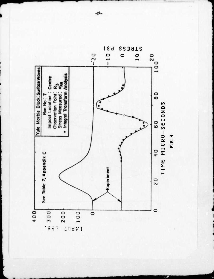
present, .cheeatlce of the locetlon. of the treneducer peckage. In the ll^.tone
end in the two «arble block.. The re.ult. of repre.entatlve te.t. are .hown In
Flg.. l-U together with the .easured input; the.e date are al.o compared to the
urn
12
•nalytlcal or nuaerical prediction» shown, with the degree of agreement varying
fro« excellent, in most instances, to unsatisfactory in a few cases. Excellent
correspondence between the measured values and both the integral transform and
finite elenent calcuUtlon» was unlforaily obtained for the Isotropie limestone
block which, analytically had to be regarded as a slightly „r.isotropic material.
For Yule marble, reaults near the source were found to be very well predicted by
the finite element method, whereas farther into the medium, the integral transform
procedure yielded a much better shape for the first portion of the stress history,
although deviating aignlflcantly from measured values after one cycle. The finite
element technique yielded an oscillatory pattern for the nomal stress in the
direction perpendicular to the free surface at positions Just below and close
> the load, but not on the other rays in the half-space. This behavior may be
due to an Inherent characteristic of the procedure stemming from displacement
boundary cor.JUlon. along this ray and/or noise introduced into the input by the
discretisation. It la not a priori obvious whether other failures to produce an
acceptable degree of correlation are the result of numerical or analytical difficulties,
as convergence problems, experimental vagaries, or a combination of these causes.
On the whole, considering the difficulties Involved in all these processes,
the predictions are very reasonable, agreeing qualitatively almost everywhere
and quantitatively In the majority of instances with an acceptable degree of
error, (toe of the problems involved in this comparison is the lack of precise
knowledge of the elastic constants (which were obtained by the best available
procedure described above) at the various Nations, i.e. a possible degree of local
inhomogenelty and/or anisotropy. It is also possible that the presumed elastic
model must be modified to account for discipative effects, particularly In view
the aberrant behavior of the material exhibited by a variety of static and
dynamic tes%s as described in the sequel that does not conform to any published
version of a "simple" subfctance.
^rtaaaMI mm *m*
- 13
The impact tests on the Yule marble blocks also furnished 1+6 measurements
of wave arrival tdmes at vaxious stations that were employed to devise a procedure
of determining the five dynamic elastic constants required to be specified by the
theory. The procedure involved the use of the phase velocity equation and devising
an objective function by a weighted least-square method and a minimizing procedure
with certain embedded constraints determined by the positive defjniteness of the
elastic stiffness matrix that yielded values of p^ to pc ranging from 11.2 x 10⁶psi
to 2.5^ x 10 psi. These values were intermediate between those used in previous
dynamic analyses for Yule marble(1|)(5) and those obtained independently during the
present investigation from a separate slab of the material.
(c) Determination of Static and Dynamic Mechanical Properties of Yule Marble
The macroscopic mechanical properties of Yule marble were obtained both under
static and dynamic conditions in an attempt to completely characterize its con-
stitutive behavior that is required both for an interpretation of test results
and the application of analytical techniques. Yule marble was chosen as the
basic substance for the present investigation because (a) numerous tests indicated
that it was macroscopically homogeneous (with respect to typical wave length
produced by impact) and transversely isotropic, (b) it was available in sufficiently
large blocks without discontinuities to satisfy the requirements for a physical
model in the present tests, (c) it had been previously examined on a number of
occasions so that some correlative information, particularly in the geologic and
petrographic domain, was available for comparison, and (d) it had been previously
utilized for a study of surface wave phenomena under the direction of the Principal (k) Investigatorv '.
All specimens were obtained from a separate marble slab obtained commercially.
The specific gravity was ascertained to be 2.8l, with average crystal sizes ranging
from 0.2 mm to 0.7 mm. It was originally assumed that the axis of transverse
^mü
Ik -
isotropy was coincident with the average normal of the bedding planes which are
visually evident from grey bands of opaque mineral running through the slab.
Although these planes are sometimes warped and are not completely parallel through
the rock mass, their average normal was found to be relatively constant and was
located In the largest plane of the slab. From thin sections taken from planes
perpendicular to the bedding normal (and thus orthogonal to the assumed axis of
transverse isotropy, or Z-direction) the orientation of each of 100 calcite
crystals was obtained spectroscopically and the results supported both the
hypothesis of transverse isotropy and its direction as properly being perpendicular
to the bedding planes.
Static uniaxial compression specimens with a diameter of 1.05 in. and lengths of
1-2 in. and 2 in. for the X and the Y, Z directions, respectively, were tested in
-6 2 an Instron machine at rates ranging from 10 to 10 per second; strain was
determined from 1/8" foil gages mounted in pairs on each specimen at the opposite
end of a diameter and connected so as to eliminate flexural components. The
results appeared to be independent of strain rate within this domain; however, the
curves were uniformly concave upward near the origin, nearly straight in the middle
third of the stress range, and concave downward in the upper third, the data in
the Z-direction indicating a higher failure level than for specimens in the other
two directions. These tests were also employed to obtain Young's modulus and
Poisson's ratio in the directions along and perpendicular to the axis of elastic
symmetry and the shear modulus in any plane perpendicular to the plane of isotropy;
these were obtained on the 7th cycle of a 0-1200 psi-0 loading. The results from
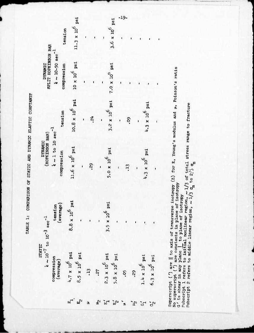
these as well as from the dynajnic tests are presented in Table 1. It was necessary
to avoid a so-called first-cycle effect which yielded appreciable hysteresis;
subsequent loading along the same path yielded essentially reversible deformations.
- — iM*^^^MMMMflMMi
15
Quasi-static tensile tests at rates ranging from 10"8 to 10"3 per second
were run in the Instron tester for various sample directions and with various
specimen configurations, including a modification of a special contour previoualy
utilized in tests on bone specimens(l:L^12). Difficulties were experienced when
uniform specimens were cemented to aluminum holding pieces placed in the grips
of the tester by failure occurring through such bonds; stress-strain curves ob-
tained here may be in error due to the higher section where the gages are located
and any apparent strain-rate sensitivity may be largely a property of the glue
rather than that of the specimen proper. Z-direction special contour specimens
were tested; a* in other cases, the fracture stress was a function of the
distance of the strain gage from the break, but the fracture strain in all cases
was about 0.025 percent,
Y- and Z-direction specimens were subjected to both compressive and tensile
creep tests in order to determine the approximate stress levels at which visco-
elastic effects begin to dominate the material behavior. Compressive specimens
were loaded to failure in approximately 700 psi increments at a rate of 700 psi/sec
using an MTS testing machine in the constant load mode, whereas tensile specimens
were loaded by weights as well as by an Instron machine, with loading rates for
the latter operation limited to 30 psi/sec; these were not tested to failure.
No significant creep was observed in any of the cases except in the vicinity of
the failure point (6,900 and 10,000 psi for the compressive Y- and Z- specimens,
respectively).
Hopkinson bars composed of three sections of rods initially 6" x B/U", of
the same orientation and glued together were supplied with aluminum endcaps to
prevent local shattering under the impact of ^" diameter steel balls dropped from
a height of 22.5 in. Longitudinal and transverse gages monitored the pulses so
produced and measured wave speeds were employed to yield the dynamic elastic
MAte ^MHMÜ
- 16 -
conjtant« equivalent to those detemlned fro. tt.tlc tension end cos^resslon
teets, shorn also In Table 1, by means of a one-dl^nslonal analysis. The
latter type of hypothesis Is validated by the ratio of bar radius to pulse
length of 0.06 In the present case.
Split Hopklnson bar tests «ere performed on contoured Y- and Z-dlruction
specimen 2^" Ion« by 3AM In dlareter both In tension and compression. The
sables were sandwiched between aluminum loading and recording bars all of which
featured strain gage pairs connected to eliminate flexural components. A bending
suppressor devUed by Lewls(l^ was employ^ to minimise unwanted fle«ural
transients. Pulses were produced by the impact of |" diameter cylindrical
steel projectiles with a 30° conical tip; bullets producing compreaslve failures
had a shaft length of 2^ In., while those Inducing tensile fracture had a
cylindrical section only 1 In. long. Pulses of 200 mlcrosec duration with a
nearly linear rise were produced, Involving a relatively constant strain rate.
The test analysis was performed bised on the hypotheses of one-dimensional
stress distribution, neglect of lateral Inertia and shear, small elaatlc strains,
an equivalent cylinder for the test specimen with diameter equal to that at
the gage section, and the lack of effect of Initial compresslve wave passage on the
tensile characteristics of the sample. The dynamic constants obtained from this
series of tests are also presented in Table 1. Details of this phase of the work
are given in Appendix D. There, Table U provides a comparison of the value« of
the elastic parameters ^ c.. defined by Eqs. (D-7) obtained here and In
the previous investigation^ ^'.
The preserce of an initial non-linear range of the stress-strain curves
followed by a secondary, nearly linear region may explain the anomaly reported In
previous tests of lower values of "dynamic" constants than those of corresponding
static parameters. This vill be the case If UM strain level for the former Is
considerably lower than for the latter. The rock examined does not conform to
17 -
• prwwtly acc«pt«l thrt-dl.«.!«*! ( or mi Ml ItwiiHl) coo.tltutly
rtUtloo. InltUl .Urtic coMfnt. ar, valla only for «all .train.; t««lU «d
cc^rttsiy «dun dlffar both .tatlcally ^d dyn^cally. «d th. «t.rlal .Alblt.
a flrtt-cycU affact. Th« rock 1. not co«plat«ly brittle, but exhibit, uomt «aU
tÜM.d«p«»d,nt pla.tic or ri.cou. ragion., .nd hy.t.r«.i. acco^nio. unloading
fro. «ny MMH Uvel beyond tha initial d<»ain. Thu. th. «tt.rial Ml currantly
b. charwtaritod by i .at of .«perietal data rath.r th.. by « «nalytical
fomulation.

18 -
Refcrtncet
n fifiiii.^th H and Swtaw», J. L., "äV« Prop^atlon In Anl«otroplf ROCJJ". l) ££*£&*£*%. ij C^t^t «o. «02100^ ARPA Or^r Jj. Iff».
/teend. 2, P»«r«m Cod« 1F10, University of CallfornU, Berkeley, lyrz.
2)
3)
k)
5)
6)
7)
n«ii4—ith U and Sackann. J. L., "Mfcv« Proj««atloo In AnUotroplc Roc1""»^
AiMmd. 3, Progr« Codt 62701D, Unlv.rtlty of CUlfornU, Bertwlay, ITK.
Kraut. E. A.. "Advance in the Theory of Anl.otroplc Elaatlc Wave Pnwatloo". Rev. Oecph., v. 1, 1963, P. ^l,
Rlcketta, T. E., "Jphere l«paet on an Anl.otroplc Half-Space", PtuD^ Pfgrtn'-lon. Unlverrlty of California. Berkeley, 1970.
Rlcketta, T. E. and Oold^Uh, W., ""-v Propagation In an Anl.otroplc Half- Space", Int. J. Rock Mech. Mln. Ccl., v.9, 1972, p. U^.
Puchwald, V. T., "Elaatlc Wavea In Anl.otroplc Media", Proc. Roy. Soc. London, A, v. 253, 1959, P. 563.
yu.ar.ve M J P. "Ela.tlc Have. In Anl.otroplc Media", EEgfig^-iSJiSiia SS, 5. J. ^.edd^aid R. Hill, ed.. v. 2. A-terd... ÖSrth.Hoi land Pubi. tut 1961, p. 63.
8) DeHoop, A. f., "A Modification of C^l*rd'» Method for Solving Sel.-lc Pul.c ProbleM'*, Appi. Scl. Re.., V., v. 8, I960, p. 3,»9.
9) Durrldge, R., "I^b'. Problem for an Anl.otroplc Half-Hpace". Oiar. J. Mech.
Appl. Math., v. ?U, pt. 1, 1971, p. 81.
10) Katona. M.. "Wave Propagation irlth FEAP.72% Berkeley, Univer.lty of California,
1972.
11) Heyvood, R. B. ^^^ bv n roelaatlclty. !x,ndon, Cbaymn and Hall, Ltd.,
1952.
iM Lewi« J. L.. "Dynamic Mechanical Propertle. of Compact Bone", Ph^ 12) ^ekaao;: t^er.lty of CUlfomla, Berkeley, «72.
c o
(4 P.
^3
•H -19- ft
^o_
(0 c
m
o to
o irv
Q H I
rH I
Ü 0) 10
c o
•H n 10
f o
§ V) c
•p
n Pi
\£)
■ P«
X
00
o
•o.
X o
^o_
X
CM
00
ON O
co ft
H
m
2
'0 CO
■H
•a s
3 ■g s
(D U
+3 ü
2 <k-t
o ■p
<u QD
IS o X
u i> (0
m i o
o
i s
o CO ■H ■tJ | ft a
•H CO CO 0)
ft
r-l
X rH
VD O o
ml tf\
C 0) O '
m C 0) 4) > •P C0
O
00
CO CO c ft ft o «^ •H (U VO VD CO U) co cd
O rH
O H 01 t-
(-1 0) X x & > B cd r- m o —- • •
u
m oj
CVJ w
ft ^o
x
I on
co ft
CO ft
CO
ft ^P-
-f
CM
w
00
«™
CO
l/N o
•H •rl CO CO ft ft
^Q-v VO O o rH rH
ON CM X X
^ o
ro vo'
^CM
bo
5 w
o <)H
N
■P O O CO
CO CO OJ (H p co
B
CO -H
P o »o p^. HH O O
0§ I ^H P O O U) «
W (L> ß
S) v > a <»H WHO
»H Ö Ö .rl ^ P 'S 3 H Cd
^H co ft o ß
CO § P H P , ed «
5 w H H ro C-^IP -O „ O .H T3 O O (U ß .H
^ o. S ^ 0
^ H O O cd ft+> .p
hC- >» M CO «'S ß (H »H
—- ro o) OJ C" ^ "»H <tH
P ß fl> 0) ^-' ftH JH >H
P ^ »H ft u cd •HMO)
O m
CM
P P >-i £ ft ft 0) M H
^ U O Cl CO CO
^o- "§•§ W S C5 o. (y;
0) co -H
MM
-20-
List of Figures
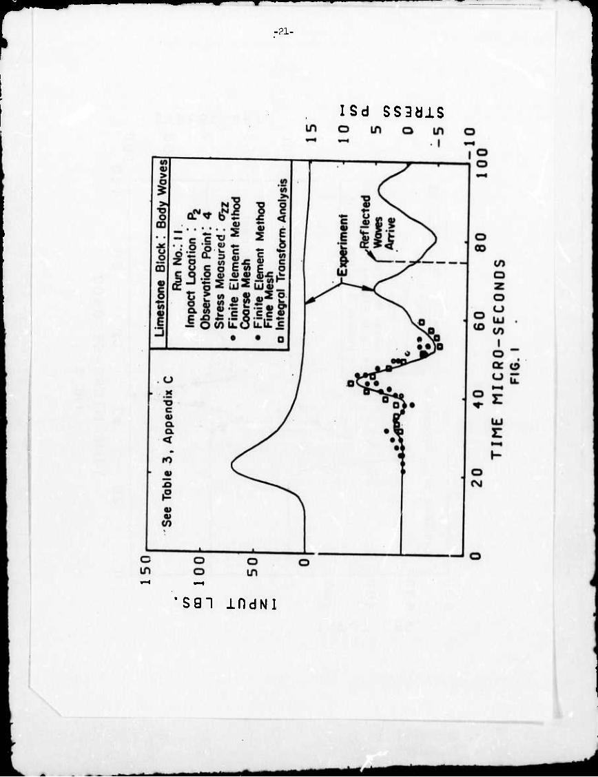
Fig. 1 Comparison of Experimental Data for Body Waves, the Finite Element Results and the Integral Transform Analysis for the Stress oZ7 parallel to the Direction of Loading at a Point 1-5/8" Deep with a Raaial Distance of 2" from the Impact Position in a Limestone Block.
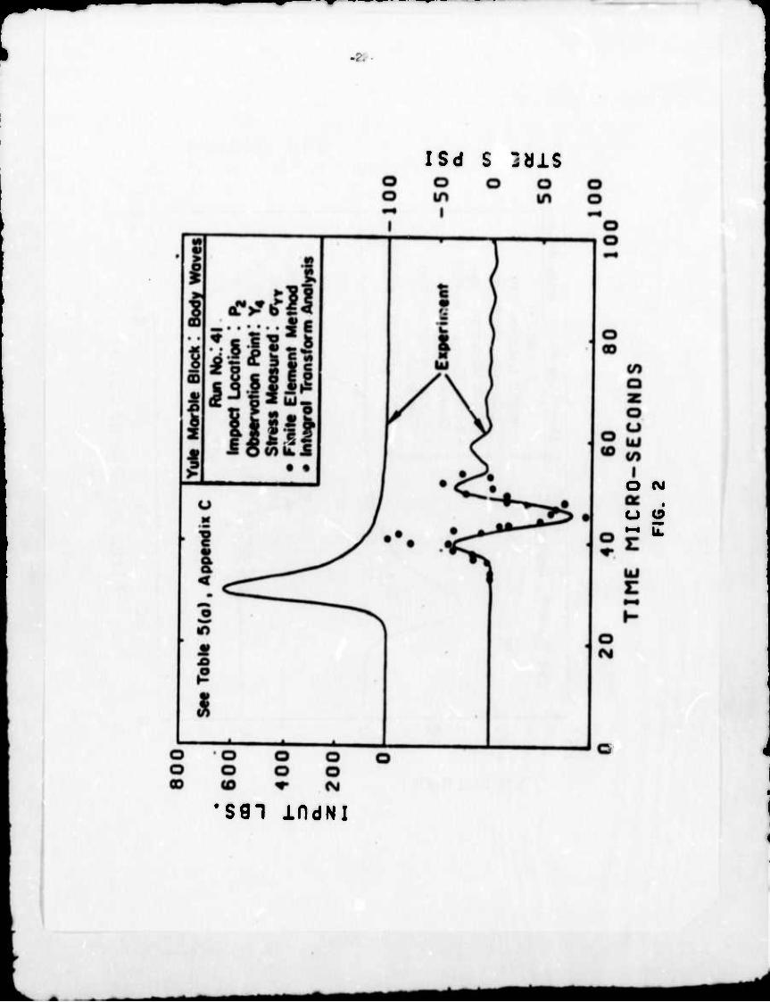
Fig. 2 Comparison of Near-Field Experimental Data for Body Waves, the Finite Element Results and the Integral Transform Analysis for Stress c^ in a Direction Normal to the Load on the Free Surface and 55 Clockwise from the Axis of Elastic Symmetry. The Position of the Observation Station in Cylindrical Coordinates with the Impact Point as Origin is r = 1", 6 = TT/12, and z = 1--|".
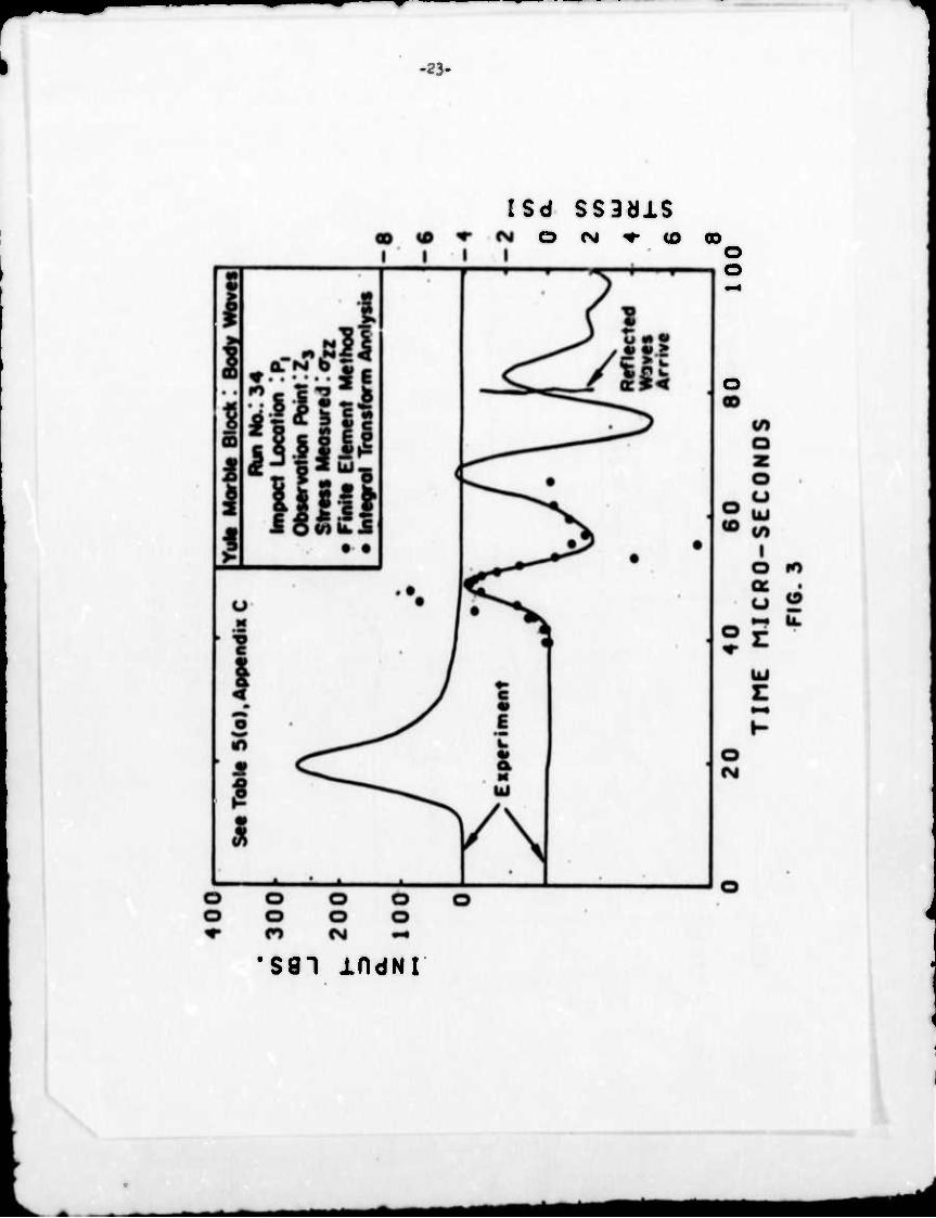
Fig. 3 Comparison of Far-Field Experimental Data for Body Waves, the Finite Element Results and the Integral Transform Analysis for the Stress azz parallel to the Direction of Loading and Orthogonal to the Axis of Elastic Symmetry. The Position of the Observation Station in Cylindrical Coordinates with the Impact Point as Origin is r = 2-^", 9 = 2", Z = 5",
Fig. k Comparison of the Experimental Data for Surface Waves with the Integral Transform Analysis for the Radial Surface Stress aRB a* a Distance of 5" from the Impact Point in a Direction 30 Clockwise from the Axis of Elastic Syir-..ietry in the Yule Marble Block.
•MMiM^^^HMMMMH
•21-
ISd SS3dlS
•891 indNI
ttm
-
ISd S jöiS
O (M
O O
•S91 IfldNI
-23-
rsd ss3äis O <M ^ <0 o
o
i
•sai indNi
am
-2U.
O <M 'I
ISd SS3älS o o o
CO a z o CJ UJ CO
I o ♦ a d
UJ
^
s 91 i n d N i
im«
A-l
APPENDIX A
Section I. Introduction
The subject treated in this investigation is concerned with wave propagation
in a homogeneous, transversely Isotropie, linearly elastic half-space produced
by a normal concentrated time-dependent load applied to the free surface of the
medium which contains the axis of elastic symmetry. This problem is known as
Lamb's problem in em anisotropic half-space and it can be physically modelled
by normal impact on a sufficiently large block of a transversely Isotropie
material such as Yule marble.
Lamb's problem for an Isotropie elastic half-space has been investigated
extensively^ ' ,2, *'**'** and the wave processes in such a body axe by now
well understood. However, relatively few results have been obtained relating
to wave propagation in anisotropic solids. An excellent summary of this topic
has been presented by Musgravew/ who provided not only a classification of
anisotropic media in terms of crystal symmetry but also discussed general features
of the wave propagation in anisotropic substances in terms of three characteristic
surfaces, that is, the velocity, slowness and wave surface. Lord Kelvin^ '
first introduced these surfaces in the course of formulating the laws of dynamics
in elastic anisotropic media. The velocity surface is formed by all the radius
vectors passing through a source, which is the origin of the space, each having a
length proportional to the phase velocity permissible in its direction; the
slowness surface is the inverse of the velocity surface with respect to a unit
sphere, and the wave surface represents a surface of equal phase of waves at the
time t = 1 that started at the origin at time t = 0, i.e., it is the shape of a
wave front as it propagates outward from a point source, determined at the
particular time t = 1. Musgrave also described wave processes in considerable
detail for solids with specific symmetry such as hexagonal, cubic and trigonal
as well as the lattice dynamics of crystals. Comprehensive references up to 1970
may be found in this volume.
A-2
Recently Burridge " executed a surface wave analysis for a generally
anisotropic elastic half-space. He demonstrated that if a surface wave can exist
in any particular direction, there will then exist a fan containing this
direction along any one of whose rays such waves may propagate. This result was
demonstrated by a reducio ad absurdum argument which shows that in the contrary
oase, a solution may be constructed to the equation of motion which is inconsistent
with the principle of conservation of energy. This conclusion generalized a
result by Buchwald^ and corrected a suggestion of Synge^13' that, in general,
undamped surface waves may only be propagated in discrete directions. In another
(1U) article , Burridge presented a solution for wave propagation in a generally
anisotropic half-space due to a line source, employing a Fourier-Laplace transform
and a Cagniard-de Hoop transformation^' '17»18^ that facilitates the Inversion
of the transfortied function into the real time domain. It was shown that In
s^ite of the possibility of certain branch points lying In a complex plane, the
Cagniard-de Hoop transformation may be carried out irrespective of the orientation
of the free surface or type of anisotropy. Numerical results of the surface
waves for cubic copper were obtained in the form of theoretical seismograms. He
also derived a solution to Lamb's problem in an anisotropic medium by integrating
responses of line sources on the free surface over the unit circle.
(19) Buchwald found the displacements due to surface waves radiating from
a given harmonic; source in terms of double Fourier integrals in transversely
Isotropie materials. He considered both the quasi-Isotropie and anisotropic
cases, which correspond to the axis of elastic symmetry of the medium being
normal and parallel to the free surface, respectively; the slowness curve in the
quasi-isotropic case was a circle and the wave curve a concentric circle. The
anisotropic case exhibited more complicated behavior. He used a method developed
(20) by Lighthill to, estimate asymptotically the multidimensional Fourier integrals
■- ^
mmm
A-3
tuid obtained all the geometrical properties of the waves, as well as asymptotic
expressions for the wave amplitudes in terras of the distance from the source.
(21 22) Krautv ' ' investigated a plane strain problem of pulse propagation
resulting from a surface line load in a quasi-Isotropie medium, a much simpler
situation than for the truly transversely Isotropie cars. This appeared to be the
first attempt of utilizing the Cagniard-de Hoop transformation in the solution of
wave propagation problem in an anlsotropic half-space. He discussed in full detail
the physical significance of the Cagniard-de Hoop transformation in conjunction
with the slowness and wave curves of the solid.
(23) Cameron ind Eason ' discussed a problem involving a source which is suddenly
applied at a point on the axis of elastic symmetry of an infinite transversely
Isotropie elastic solid. They obtained numerical values of the displacements
(2k) for the quasi-isotropio case. Ryan^ ' presented a solution to Lamb's problem
for a transversely Isotropie half-space. A Heaviside point load was directed
along an axis of material symmetry which was taken as normal to the free surface
so that the problem reduced to the quasi-isotropic ease. Following Kraut' ', a
Cagniard-de Hoop transformation was employed which yielded a single finite integral
for the displacement field, that was, however, evaluated numerically only for
points on the surface. Ricketts^ 5^ and Ricketts and Goldsmith^ ' have attanpted
to solve the problem posed in this thesis, i.e., Lamb's problem for a transversely
Isotropie half-space with the axis of elastic symmetry located in the free surface.
Although they did not obtain a solution for the displacement field in a form
amenable for a numerical evaluation, the problem was formulated in a manner permitting
its present utilization with only minor changes. Experimental data such as
group velocity, group slowness and attenuation characteristics of the amplitude
were also obtained for the surface waves produced by the normal impact of a
spherical steel ball on the free plane of the half-space modelled by a large
Yule marble block.
MMtfaHM mm MMi mm*
k-k
Section 2. Statement and Solution of the Problem
2.1 Statement of the F. -■blem.
The problem will first be discussed for a general anisotropic medium and then
be specialized for a transversely Isotropie substance.
The anisotropic half-space is represented by a 0 artesian coordinate system
(x^x^jX-) as shown in Fig. 1 with the free surface defined by x? = 0 and the
direction of Xp positive toward the interior. Although the problem is formulated
in a Cartesian system, cylindrical and spherical coordinate systen^, indicated
by (r^Xp) and (R, 6,cp)» respectively, are also introduced in the development
of the final solution. The anisotropic elastic half-space is assumed to be homo-
geneous and is governed by the generalized Hooke's law
cri;j(x,t) = ciJki ekjt (x,t) (i,j,k,X = 1,2,3) (A2.1-1)
and the linearly elastic strain-displacement relation
6i^-'t- = ^ ^Ui j^'*) + uj i(^'t)) (A2.1-2)
Here, x is the position vector, t is time, and u.(x,t), a. .(x»*) and ejj(x,t)
are the Cartesian components of the displacement vector, and the stress and strain
tensor, respectively. Also, c. is the fourth-order tensor of the elastic
constants that satisfy the symmetry relations
Cil1kjl Coikjl " cijj2k Ckjlij (A2.1-3)
if a strain energy exists. Then among the 8l quantities in c. ., , only 21 are
independent for the most general anisotropic elastic medium. Throughout the
following discussion, the usual tensor notation and summation convention on
rpatial variables are employed. A comma indicates partial differentiation with respect
A-5
to the subsequent variable(s). In an elastic medium obeying relations (A2.1-1),
(A2.1-2) and (A2.1-3), the displacement equation of motion in the absence of body-
forces is given by
Ci^\,Jed (S»*) - PVt^.t) (A2.1.U)
where p is the mass density. A concentrated load with an arbitrary time history
is considered to be applied on the free surface at x = 0. The boundary condition
then becomes
^uXi^i'0'^ --V^^vV (A2.1-5)
on >u = lg = 0, where 6(x1,x ) is the two-dimensional Dirac delta function and
Fi(t) are the components of the arbitrary force with F (t) = 0 for t < 0. The
radiation condition at infinity is also invoked so that
lim [u (x,t),u (x,t),etc.] = 0 . (A2.1-6) x -w>
Finally, the medium is assumed to be at rest initially; thus the initial condition
is represented by
[u^x.O),^ t(x,0)] = 0 for t $0 (A2.1-7)
As can be seen from the boundary condition (A2.1-5), the force applied on
the boundary need not be confined to the case of a normal impact on the free
surface x2 = 0 since it can exhibit other components in the formulation and
in the formal solution; however, numerical results have been, obtained here only
for the case of normal impact, i.e., whenF (t) =F (t) =0 , andF-(t) / 0.
The problem posed above may be solved formally in exact form in a single
finite integral by using a Cagniard-de Hoop transformation^ '. However, in view
of the complexity involved in the computer programming for the case of general
am
A-6
«nlsotropy, attention is here restricted to a transversely Isotropie half-space
with the axis of elastic symetry, chosen as the x.-axla, located In the free
surface. The synanetry of the medlvia permits a factorization of the characteristic
equation of the system; this feature saves ctwputlng time In the numerical «valuation
of field quantities from the formal solution obtained. Moreover, due to the
choice of the direction of the applied force fAt), wnlch is normal to the free
surface that contains the axis of elastic nymmtry, the solution is obtained for
a truly transversely Isotropie medium rather than for the quasi-Isotropie
case. Out of 21 elastic constants necessary to describe the properties of a
general anlsotropic medium, only five independent non-zero values are required for
the present case. Therefore, the stress-dlcplacement relations, from Eqs, (A2,l-1)
«aid (A?.1-2),are reduced to
*n ' cllul,l * C12U2,2 + e13U3,3
a22 " c12ul,l + "lA,! * c13u3,3
033 " C13U1,1 + C13U2,2 + C33U3.3 (A2.1^)
a23 " CUU^,3 + u3,2)
013 ■ CUUK,3 + ■S.l)
^■♦<«U -C12)(ul,2*u2,l)
where the standard contracted notation c^ with M,N - 1,2,...6 has been employed
instead of a fourth-order tnesor representation c z27'. The displacement
equations of motion 'A2,l-U) reduce to
C] U1,U + c2 u1.22 + c3 Ul,33 * ^l-'J *2,2. * % \» ' \tt
(VC2) ul,21 + c2 u2,ll * cl "2,22 * c3 "2,33* CU u3.32 ' H$*
UK.
A-7
Ck »l.Jl • CU "2.32 * c3 ^,11 * c3 «3.22 • c5 «3,33 " ^.tt ****
«her« flv« now Indcpcndmt velocity eoottent« h«ve been defined by
«X ■ cu/p , c2 - i(c11-c12)/p , c3 - c^p
ck • (c13 ♦ c^/p t c5 - e^9
(A2.1-10)
for the trenevereely Isotropie aedlua, the boundary coodltloo« (A2.1-$) reduce
fl(t>
^(t) (el ■ 2c2)ul.l * cl V2 # (cl. " C3,U3.3 " " 0 h(xl^
(A2.1.U)
«2 • 0.
2.2 yowMa Solution.
In view of the Inltlel conditions (A2.1-7), the boundery conditions (A2.1-11),
end the redletlon condition (A2.1-6), en epproprlete nethod of solution for the
systea of second order, linear partial differential equation« (A2.1-9) governln« the
response of transversely Isotropie asdla Is represented by successive eaploynent of
the Ls^Uee and double Fourier tranafomt
F#(«) - f F(t)e-St <»t , r(t) - ^ J F#(.)e,tds c Br
ae -l«(a,»t ♦Qua ) n^aj - JJ F(x1,K3)e ! l T 3 dx^
(A2.2-1)
(A2.2.2)
iW ii
A^
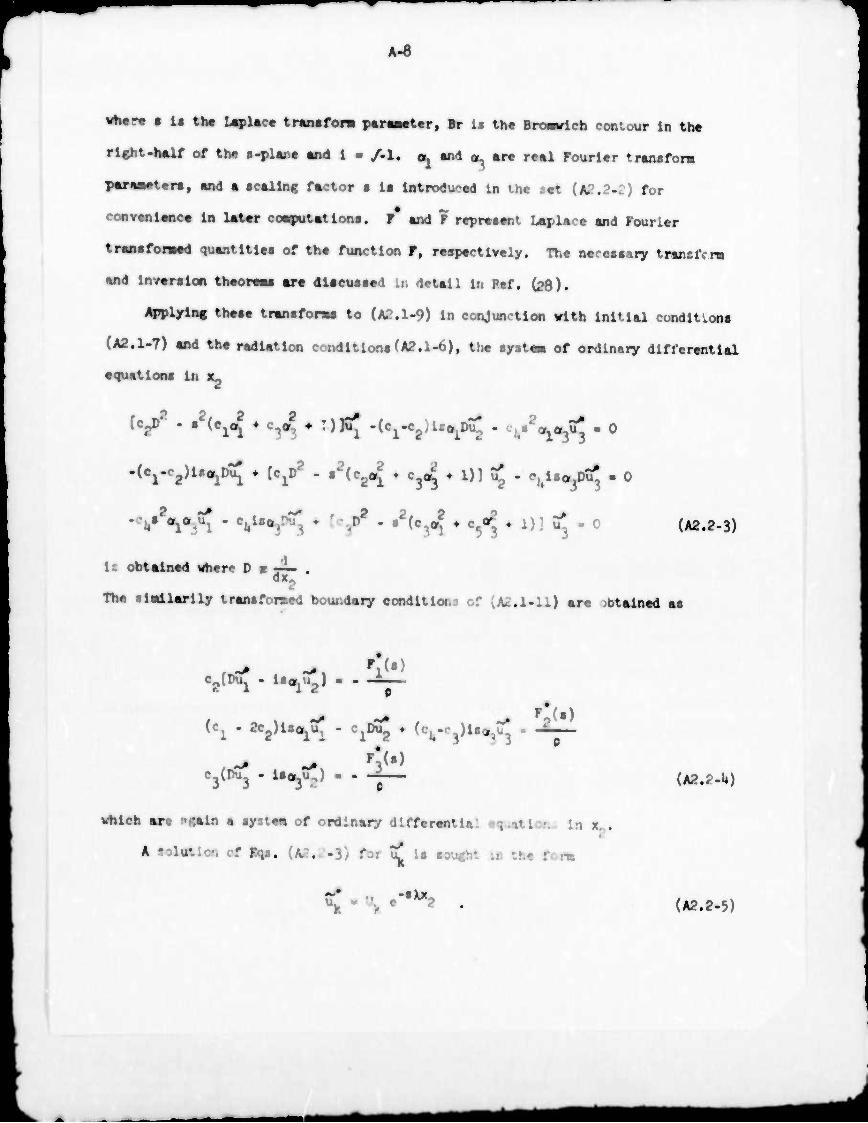
**r9 • Is tlw UpUct trsnafora p«r«wt«r, Br is the BroMrich contour In th«
rlght-half of the «-ylsn« and 1 - /-I. a^ tnd ^ are reel Fourier trwwfom
pereMters, end a scaling factor s Is Introduced In the aet (A2.2-2) for
convenience in later coeqputat Ions. P and F represent Laplace and Fourier
transfomad quantities of the function F, respectively. The neressary transfrrm
and Inversion theoreas are discussed Ln detail In Bef. (28).
Applying these transform to (A2.1>9) In conjunction vlth Initial conditions
(A2.1-7) and the radiation conditions^.1-6), the systea of ordinary differential
equations In s,
[CgD2 - .2(c1oJ ♦ c^o? ♦ T)K^ -(c^CgUs^ - cj/^o^ - 0
-(0^2)18^ ♦ [c^ - s2(c2oJ » tj^ ♦ 1)3 «{ - V«^ - 0
•V^X " CUUftr^ * ^ " §2icA * Vl ' 1)] "3 " 0 (A2.2-3)
1c obtained «here 0 m «p- .
The il«ilarlly transfomed boundary conditions of (A2.1-11) are jbtained as
C2[DU1 • li<*lU2J • * ^V
(c1 - 2*2)^^ - c^ • (cu.c3)ls^ - ^jL
c3(nu3 * ,-W 0
which are ngaln a systen of ordinary differentia: «q • . :■. x .
k solution cf Eqs. (A2..-3) for uj Is sought in the :
-SXX
(A2.2-U)
(A2.2.5)
A-9
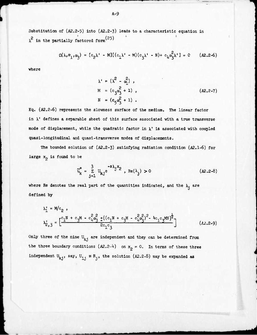
Substitution of (A2.2-5) into (A2.2-3) leads to a characteristic equation in
2 ' (25) X In the partially factored fomr '
nU,*^) ■ [CgX« - M][(c1\' - M)(c3X' - N)+ cka*V] = 0 (A2.2-6)
where
X' = (X2 - a*) ,
M = ic^ + 1) ,
N = (c5c| + 1) .
(A2.2-7)
Eq. (A2.2-6) represents the slowness surface of the medium. The linear factor
in X' defines a separable sheet of this surface associated with a true transverse
mode of displacement, while the quadratic factor in X1 is associated with coupled
quasi-longitudinal and quasi-transverse modes of displacements.
The bounded solution of (A2.2-3) satisfying radiation condition (A2.1-6) for
large x_ is found to be
•sX4xr
\ = E Ukje i 2 , RetXj) >0 (A2.2-8)
where Re denotes the real part of the quantities indicated, and the \. are
defined by
X{ = M/c2 ,
pCjN + c3M - cla2 ^(c-jN + c^ - c2^)2- Uc^MN]^
^»3 = L 2c1c J (A2.2-9)
Only three of the nine U . are independent and they can be determined from
the three boundary conditions (A2.2-U) on x = 0. In terms of these three
Independent U.., say, U = R , the solution (A2.2-8) may be expanded as kj id J
MM
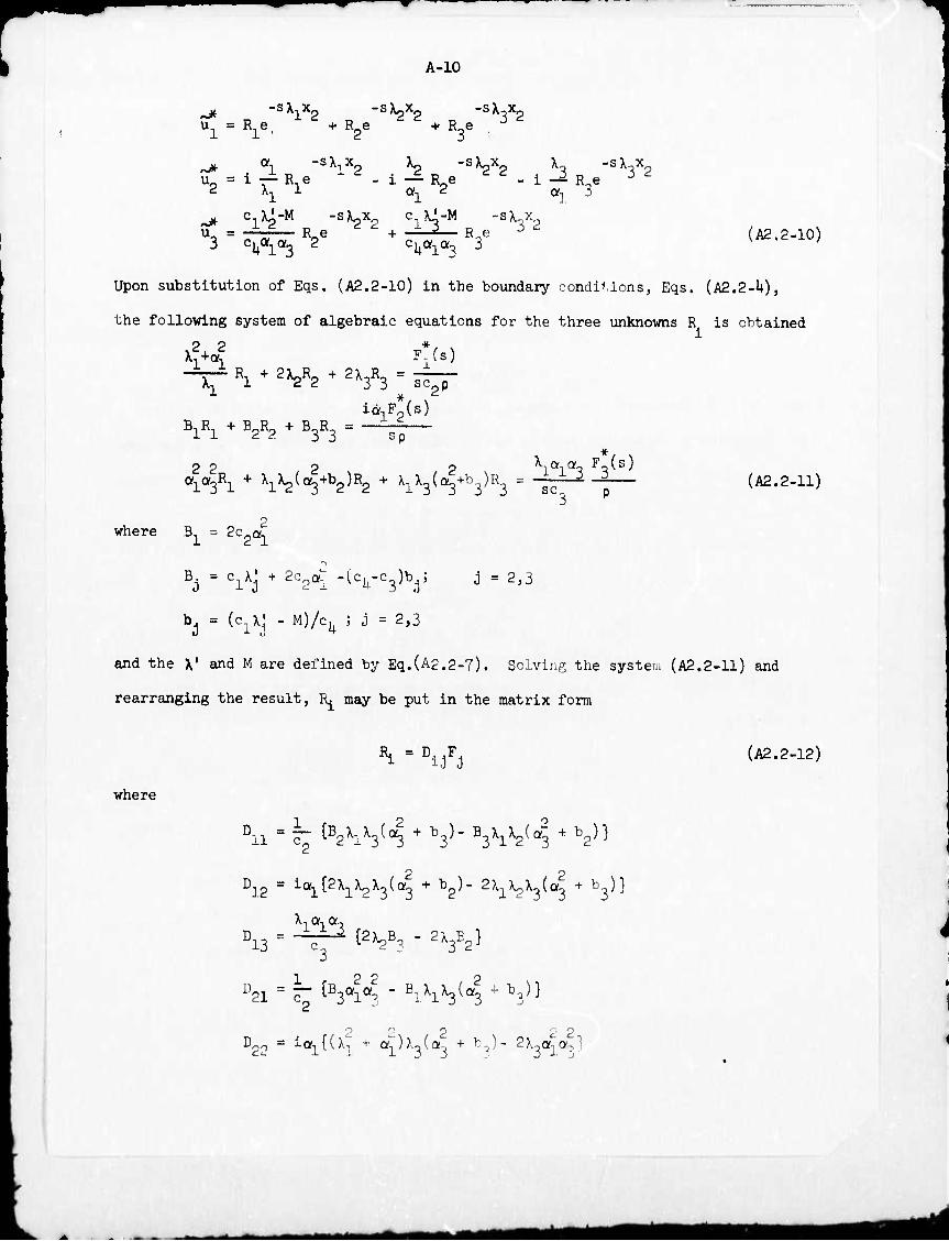
A-10
M. -sX.. x_ -sX^x^. -sX_x_ Gj = R^. 1 2 + R2e " 2 + R3e , 3 2
^ «1 -s^x. 1 ,. -V;. , ^2 „ .-SX2X2 , X3 n "^^ L — Re «I 2
i — R-e al 3
^ c X^-M -SX2X c JJ-M -sxx
3 c^i^ 2 cU<ylQ'3 3 (A2.2-10)
Upon substitution of Eqs. (A2.2-10) in the boundary conditions, Eqs. (A2.2-U),
the following system of algebraic equations for the three unknowns R is obtained i
op ■*•
--— R + 2}^R + 2XQRo = — X-j^ 1 ^2 3 3 sc0p
ia,F0(s) B1R1 + B2R2 + B3R3 = ~~~
^3R1 + Xl^^+b2)R2 + ^S( Vh3)R3 = "fcp p (A2.2-11)
where B = Sc-o,
B. = c iM + 2cpai "(cU"c3^bj5 j = 2'3
bj = (c^Vj - M)^^ ; j = 2,3
and the X1 and M are defined by Eq.(A2,2-7). Solving the system (A2.2-11) and
rearranging the result, Rj may be put in the matrix form
R. = D.T, 1 i.l J (A2.2-12)
where
Dll = ^ tB2X1X3(^ + b3)^3X^(4 +b2)}
h.2 = H^l^V^ + b2^" 2>iX2X3(a3 + b3^ Xlala3
13 = -^ t2X2B? " 2X3E2^
21 r^ViV^W^V3
Doo 2 2.
= ia1{(X^ + ^)>^(a., + b-)- SX^a^a-l
A-ll
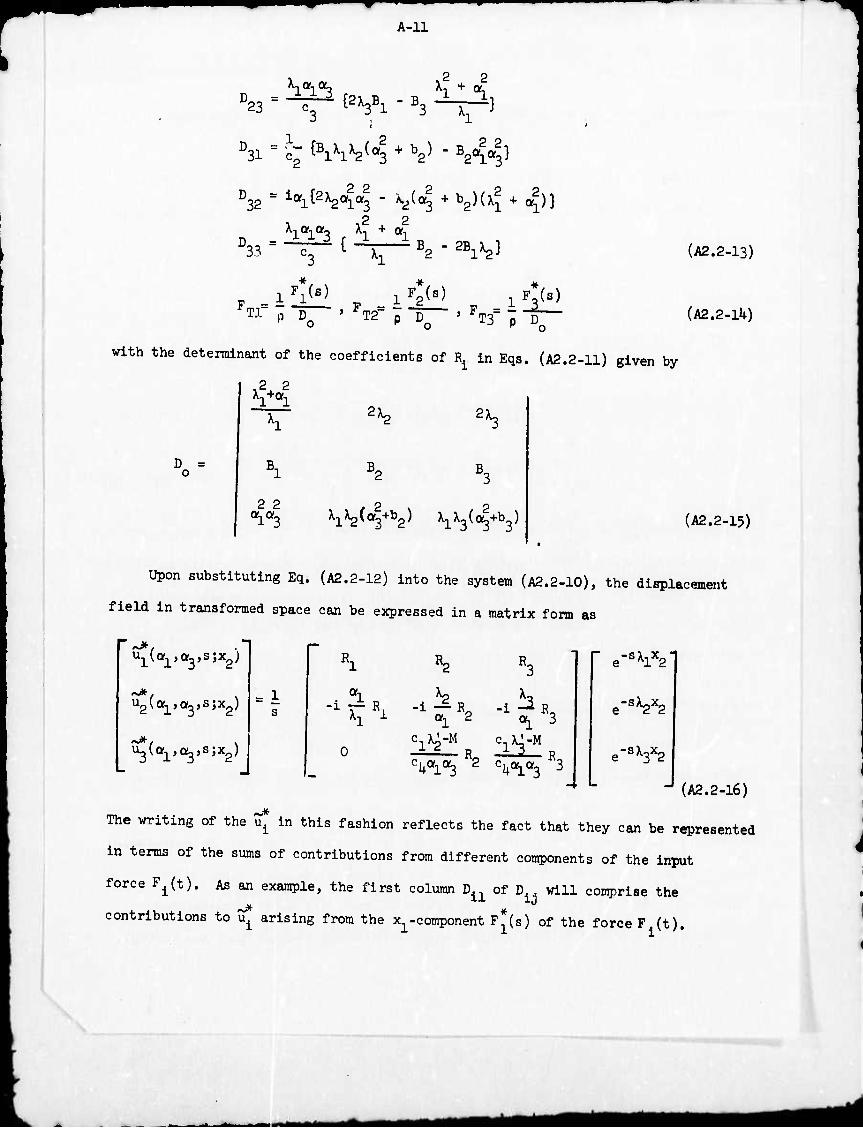
2 ?
(
D31 = c- ^ihh^l + V - B2V3}
D32 = K^VH " ^(4 + b2)(X? + «>i)3
33
2 2
iV8) FTr p "D » FT2= p "D— ' F-= L
o K o
iF2(s) _ i ys)
(A2.2-13)
(A2.2-1U)
with the determinant of the coefficients of ^ in Eqs. (A2.2-11) given by
2X2 Xl+al
2 V,
D = o B
2 2
B,
^i^vV ^^(a^) (A2.2-15)
Upon substituting Eq. (A2.2-12) into the system (A2.2-10), the displacement
field in transformed space can be expressed in a matrix form as
urai,a3,s;V
U3(a1,c^,s;x2)
r _ 1
s
R,
. ai h ^ ^i ■'- ^i 2 ^i 3
c^-M R- 2^
cU«l«3 2 ^^«3 3
r e-sx^i
e-sX2X2
e-sX3X2
(A2.2-16) ^
The writing of the u. in this fashion reflects the fact that they can be represented
in terms of the sums of contributions from different components of the input
force Fi(t). As an example, the first column D11 of D will comprise the
contributions to ^ arising from the x^coraponent P (s) of the force F (t).
■ ■■ ■ —M mt-M^mä^täm
A-12
Similarly D12 and D^ will coaprise the contribution« to UL from <(•) and
7 (s), respectively.
After obtaining the Uplace-Fourler transformed .( . M r. vr v. apfilcatloo
of the Fourier Inversion formula given by expression (A2.2.?) yields the Laplace-
transformed displacement as
Ul^»8) " ^7 jjv*j(af1,a3) Q^flr^Oj.s^d^doj (A2.2-17)
« where V^ Is the square matrix of the right-hand term In Eq. (A2.2-16) and
^ m 8.[l(Vl * «3X3)- tfy] ^
S-c 33 ^3*2 # {Klt2mlß)
The integrals in (A2.2-17) oor.verge because ReCx^) > 0. It Is still necessary to
invert the Lapla --transformed soluti< n into the r.-aJ time domain. It is sufficient
for the following calnuiiitlons to assume that the [«plMt transi rm parameter Is
(29) guarantees the existence and real and positive. Then, Lerch's theor
unijueness of u. (x,t),
2.3 Transformation of the Formal Solu*ion.
Eq. (A2.2-17) together with Eqs. (A2.2a3) and (A2.P-15) comprise the
Laplace-transformed displa ement under arbiträr; .a5>act load; however, its foim
is not cojw.iüent for inversion. By a sequence of transfo ran Mona vid
contour integrations, the integrals appearing In Eqs. (A?.2-17) will be converted
Inl a fcrm that lilows the inversion of the Lapla*e-transformed solution by
inspection. In this way, the exai-t inversion of each u. »rill be accomplished
as the OUT. of a llaglt flniv» Integral and rale exjesslon« that are suitable
*mm
A-13
for nuaerlcal «valuation. For these purposes, two transformations are executed
on the variables (x-.x ) and (or.tou)«
Flrtit, a plane polar coordinate systen on the free surface of the half-space
is Introduced, given by
Also, let
x. - r cos 6 , x ■ r sin 6
(0«r<» , 0g'g<2n) . (A2.3-1)
o^ •■ « cos 6 , eu ■ • sin e
(.•<«<• , -2<e#f) (A2.3-2)
and let « • -ip so that d« da, - -pdpdG . considering now p as a complex
variable. Then, from the above transformations.
i8(a1x1 ♦ OJXJ) - apr cos(e - 9) (A2.3-3)
so that Q. in Eq. (2.2-18) becomes
■ [pr co8(e - 6)- X.x.] QJ(r,e'x2;P'e'8) " * (A2.3-U)
Using the above result, the Laplace-transformed displacement (A2.2-17) may now
be written aa
n
"?(».•) " - -3 1F dö J V* (r,e)Qi(r,,5,x?;p,e,i)dp (A2.3-5)
? r
where V (p,e) is defined by substitution of Eq. (2.3-2) in V-^o^oJ.
A-lU
2,U The Cagniard-de Hoop Transformation and Inversion of the Laplace-
Transformed Displacements.
As Indicated earlier, Inversion of the Laplace-trai:sfonn will be accoraplished
by Inspection of the solution after first performing another transformation that
will be discussed here. This procedure essentially involves the rewriting of
Eq. (A2.3-5) in a form that yields the Laplace transform of V,. by _ lj
J e"S Vi.(x,t;p,e,-)dt = u*(x,ß) . (A2.1+-1)
As can be seen from Eq. (A2.2-1), which defines the Laplace transform pair,
this is formally accomplished by three pairs of conformal transformations
Re[pr eos(e-e)+ X.Xg] = t ,
Imfpr cos(e-e)+ \^2] = 0 , (j = 1,2,3) (A2.U-2)
wi'.ere t is ponltlve i&d rea]. The above equations define the Cagniard-de Hoop
transformation which is utilized in i contour integration to obtain the inversion
of the Laplace transformed solution.
Substitution of the expression for X, from Eq. (A2.2-9) into Eq. (A2.U-2)
yields the Cagnlard-de Heap path for \. in explicit form as
c 2 p'(cos <p cos (9-e)*(cos 9 ♦ -^ sin Q)siri cp}-pJ2T costp cos(0-9)y{T - —2-^} = 0
1 C2 C2 (A2.U.3)
Similarly, the Cagniard-de Hoop paths for Xp « are obtained from the expression
P2 3 + AiT.e,«,e)Pj - ♦ B(T,^,tp,e)p2 3 * c(T,e,c,e)p2).J ♦ ECT.^O,e) = o (A2.U-U)
Here, a trinsf itnation for the cpace variables was introduced, given by
8 2\l -1 *0
R » (r + t)s , © = tan — ,
*M* mi
A-15
and
where
T = R '
A = - - [2T COS cp cos (9-6)+ T P cos 9 cos(e-e)sin2cp] ,
B = ^ [6T COS cp cos2(&.e)+ T2P sin2^ - sin2cp cos2^ cos2(e-e)e1- sin^q, J] ,
C = - ^ [2T cos cp cos(e-e)- T cos cp sin2{p cos(e-e)e1] ,
r 1 r ^ 2.2 . k ^ = 2 LT - T sin cp e, + sin cp h J ,
Z = cos 6 + (2-m )sin2e cos26 + -^ sin^fl . J. c, '
2 2 J = ^2, cos 0 + f sin 9 ,
P = 2 - n^ sin 9 ,
V V2cic3 - cic5 " c3 + c') '
el= hi(ci + c3) »
fl= hl(c3 + c^ >
61= hl^cl " V '
Eq. (A2.4-3) Is quadratic in p with real coefficients which can be easily solved
and will yield either two real or a pair of complex conjugate roots. Eq. (A2.U0
is quartic in p with real coefficients and will yield k real, or 2 real and one
pair of complex conjugate or 2 pairs of complex conjugate roots. These will be
found numerically as discussed in the sequel.
(22) Following Kraut for the construction of the Rieraann surfaces of p to
establish the analyticity of \. = ^(p) and introducing the Cagniard-de Hoop
transformation discussed above, the Laplace transformed displacement, Eq. (A2.3-5),
can be written as
A-16
u*(x,s) T f de J s E ViJ(pd,e)pJ "dt e dt ^-1»2>3) (A2.U.6) 2TT TT *. j-l
where t are the arrival times of the body wave fronts given by the double points
of the paths. This relation is written in the desired form for an inversion
of the Laplace trai iform and inspection yields immediately the solution in the
time domain as
M (* 3 dp u4(x,t) = - ^~ r de I Re[ E v. .(t,f,p,e)p. -^idt-nCt-t ) (A2.U.7)
"2 «3 >°l
Here v. is that function of T and x defined in Eqs. (A2.U-3) and (A2.U-4), and
V12=D2A(t-t,)+D22Vt-t,)+V3(t-t,) '
V13^ Vl(t-t,)+ ^A^-*^ +V3(t-t,) ' ia-i ^2
V21=-irVll ' V22=- i^V12'
23 itT13 ' V3l = 0'
V, 32 cU0(la3 12 '
v c1U-M
33 ~ c.»,«- " 13 •V, (A2.U-8)
:kala3
where the superposed dot represents differentiation with respect to time.
A fundamental solution is defined as the displacement field of the solid
due to a Heaviside point load H(t). Eq. (A2.U-7) can be then u;;ed to obtain
the fundamental solution as follows
n (A2.U-9)
"2
J 3 „ dp uJCx.t) - - -V f äe (ReC S V«. p3 ^1]) H(t-t.;
2TT R TT J-J-
where
■MMtfH
A-17
v^ = D^iViQ) + D12(p,e) + D^Cp.e) ,
v?2 = D21(p,e) + D,p(p,e) + D0-(p,e) ,
vj3 = D31(p,e) + D32(p,e) + D33(p,e) ,
and similar expressions for V". and V? are obtained from Eqs. (A2.'+-8) upon
replacing V^ by V^^^ for i = 2,3 and j =1,2,3. When Fi(t) is replaced by the
Dirac delta function 6(t), then Green's function for the system is obtained as
TT
15 ul6(-'t) = ■ s ^de {i ^il ^J vi "S33 H(t-td) {A2'k-10)
"2
It is to be noticed that since Green's function, Eq. (A2.U-10), involves a time
differentiation which generally yields poor results in numerical procedures,
Eq. (A2.U-9) constitutes a better representation for the numerical evaluation
of field quantities.
2.c Displacement due to a Normal Impact Force on the Free Surface.
Since considerable effort and expense are involved in a numerical evaluation
of the field quantities such as displacements and stresses, only responses due to
a normal force will be considered. Thus taking F (t) = F (t) = 0 in the above
formulations, a solution is obtained for the case of normal impact. This problem,
which is Lamb's problem for a transversely Isotropie medium, is considerably
simpler than that for an arbitrarily directed input force. Furthermore, such a
numerical evaluation was compared with corresponding results for an isotropic
medium and also with data that was obtained from laboratory experiments on a
suitable model. If F2(t) is chosen as F(t) and F^t) = F (t) = 0 in Eq. (A2.1-11),
the boundary conditions become
mm
A-18
Ul,2 + U2,l = 0
(cl-2c2)ul,l + clu2,2 + (Vc3)u3,3 ^ ^v^) U3,2 + u2,3 = 0 (A2.5-1)
on x = 0.
Thus, l, all terms in Eq. (A2.J+-7) which are multiplied by either F (t) or F (t)
must vanish. The displacement for the normal impact force is obtained as
Ui (x,t) = - ~|_ j^deCj F(t-f)Re[ Z W (x,t3f ;p,e)p. i^t' }H(t-t. N 2TT pR _TT t. j=l 1J J QT J
where
where
and
W1J = D7 Ad '' i= 1'2'3
i W21 a O7 ^ ; W2J ' D^ Ad 5 d - 2,3
N ib
w31 = o , w y "3% :i J = 2,3 ,
Al = ■ 2Xi^X3(b3 - bg) ,
Ag = X3[\{(a3 + b3)+ 2^] ,
^ = - ^[XjCo2 + b2)+ 2^b2]
Bl = 2c2al '
B. =
U
)
(A2.5-2)
j = clXj + 2c2al " (cU-03)hj ' J = 2'3 (A2.5-3)
Do = AIB1 + A2B2 + AB .
i^ria
A-19
Vy Xj and M are defined in Eqs. (A2.2-7) and (A2.2.9). The subscript |
is used to represent the fact that quantities discussed here are derive for a
normal impact force, p^ are again given by Eqs. (tf.M) and {a.k-k) since
these are related only to the characteristic equation of the medium considered.
The fundamental solution similar to Eq. (A2.U.9) for this case can be written
as
^ - ■ Ät eRe[ii ^-^ ^«(t^) (A2.5-J+)
for P(t) = H(t) and the Green's function corresponding to Eq. (A2.U-10) is
11 -3 dp4
'2 (A2.5-5)
for P(t) = 6(t).
The integrand of Eq. fe^) is 8imilar to that of ^ ^ 8ource ^^^
obtained by Kraut^21). it can be considered as the sum of responses generated
by a continuous spectrum of line sources spread angularly on the free aurface
through the impact point ^.
2«6 The Rayleiffh WRVP.
As the normal distance from the plane boundary into the medium goes to zero.
Eq. (A2.U-2) becomes
Pr C08(e - e) = * (A2.6.1)
so that the Cagniard-de Hoop path runs along the real axis of the right-hand half
of the complex p-plane. The presence of a simple pole PR on the real axis.
known as the Rayleigh pole^»12^), squires an indentation of the path of
integration to avoid this singularity. Thus, when x,, .0, the points on a small
mm Mi
A-20
semi-circular indentation about the pole no longer "orrespond to real tlaa.
Therefore, the contribution to the tlae-trfinaformed dlsplaceaent field arising
from the semi-circular indentation mu«t be evaluated separately, then inverted
into the time domain and added to the displacement field arising from integration
along the Cagniard-de Hoop path. As an txaapla, when F(t) • H(t) the contribution
from the Rayleigh pole is given by
u*H (x-.O^.s) - -4- f de{(ni)- He.[ I W (r,©;p,e)--Pr ^^L- ) ^le1 ^ 2tTZp n >1 1J ^R
"2 (A2.6-2)
in the transformed space when; Res denotes residue of the Indicated quantities
at the given location of p. Inversion to real I Ime yields
uj (x^o.x-.t) . - -i- p de{R«[ z w.^r/Sfpen-efT-p <-os(e.e)lL_ ^ie1 3 2TTpr % J-l 1J ^R "I
. 3 ^ H(T-Ti») • " AS tResf tW (r,©;p ,0)1 z rl (A2.6-3)
2nor j^ ij R |pRiin(6-^)1
where TR - PpCocle-^) and ^ . e - cos" (-&) , "he factor P^M©.^) i« n
introduced in Eq. (A2.6-3) since the Llrac delta function Involved is an
implicit function of 9 . The displacement fielu at a station on the free
surface due to a unit normal Impact force H(t) is thus
u" (x^O.x »t) - uj (x ,0,x ,t) 4 si- Im{Resf Z «..(r/fcp ,* ) ^ -)} lrtßurface 3 hi 1 2wpr .!-l lJ |PR«ln(^%n
(A2.6.4)
where the first tern on the right-hand side NprtMOtl '-ontributions due to body
wave disturbances while the second term arises ir m the Vayleigli jol».
imm
A.?l
Section 3* IwMrical Proredur*«
3.1 Introduction.
DispUecMBt fields such M glvtn by Iq. (A2.U-7) obtftlMd In the prevlout chep.
ter are generally expressed In terns of complicated algebraic functions of i,p end t
and are Intractable analytically. Therefore, the fundeaental solution, Iq. (A2.5-**)
the displacement field of the aedlua under a KeavUlde noraal lapact, has been
programed for evaluation by a digital computer. The Green's function (A?.5-5)
••y also be used for such en evaluation that trill exhibit the basic character
of the response of the aedlua; however. It Involves the tlae differentiation
Indicated In Eq. (A2.5-5) vhlch must be carried out numerically; at a
consequence, this procedure often leads to unsatisfactory results.
In most practical problems, physical Input forces are not realised in a
Dlrac delta function form end the desired solution Is a combination of several
fui.'tlons of which the Green's function Is only one. For an example. If p(t)
Is the a-tual input force of the problem and &r (u. (x,t)] i« the Green's
function from Iqs. (A2.5-1*) and (A2.5-5), the displacement field due to F(t)
Is then
u^x.t) - FU)«!^" (x.t)l - uj (x,t) •F(t) (A3.1-1)
where the symbol • denotes a convolution product in time. Eq. (A3.1-1) is
Identical to Eq. (A2.5-2). Thus, the fundamental solution, Eq. (A2.5-1*), can
be used for evaluation to avoid the numerical differentiation Involved in the
Green's function, Fq. (A2.5-5). Numerical differentiation of the Input function
Is needed In this case; however, this operation Is simpler and generally yields
more accurate results than that Indicated above.
A.22
3.2 Co^utT Prc«i
Tb« co^uter proffTM dcwlajMd ealcui«t«« l) tb« rund«wnt%l dlipUe«Mat
fleW given by Iq. (A?.t)-U), 11) the eo^Mnentt of UM l-nJMti.te. .trr.Ln «nd
•tr«M, ill) the Actual dl«pUe«Mnt«, strains and siresies obtained by the
cflBYolutlon lnt«cralt Bq, (A3.1.1) for a given Input f(t).
In order to coopute the fundeaental dleplaceaent, Ik subroutines are
used of which two are very l^ortant. One of these Is e routine which finds
roots of the quertlc algebrelc equation (A2.UJi). This routine uses Balrstov's (3b)
sehSM ■ which Is general enough to solve any even degree algebraic equation
so that this routine «ay be used to find roots of the sextlc equation arising
in the fore of the characteristic equation of a generally anlsotroplc aedlw.
The aethod provides a corresponding nuaber of quadratic factors of the given
even degree poiymmlal by an Iteration scheac. Fast and accurfe convergence
requires a quit*, good IrlMa: approx'-natl. n and this Is obtalncl easily fro« s
:••« trlml and error tehnlques. Ano'her routln« of laportance '•oaputes the
coarle« quantities W^ In Eq. (A2.5-»«). These two routines take aost of the
computer tlae necessary to solve the problea.
3.1 Results.
Several sets of nuaerlcal results which are considered to be representative
of »he solution obtained are shown In the following.
(I) Three coapooents of the fundamental dlsplaceaen* s at various locations
are shown In Pigs. 2, 3 and U.
(II) These dlsplaceaet.. t convolved with
(a) an Input force given by PU) - sln2^), where t* Is the duration t
of the Input pjW are . v wn In Figs. '., 6, 7 and 8, and
(bi the stresses j: luced by the L-.pat force wb«vr/ed fron experlaents are
shown In Plgs.l» 2, 3, k of the =»: repot-, and Appendix C.
slowness and wave curves tr« ghcv, :a Fl€g# 9t 10t ^ ^ ^ ^
AMÜ
A-23
Section U. Discussion and Conclusions
U.l Introduction.
It appears that the solution presented here is the first available for
U**t proble» in three dimensions involving a truly transversely Isotropie medium.
A three-dimensional formulation is introduced in the course of the solution and
the problem is solved using a modified Cagniard method. This procedure may be
used to solve the same type of problem fonnally for any anisotropic, elastic
medium even though it may take a substantial amount of computer time for evaluation.
Burridge suggested essentially the same fom of the solution to Lamb's problem
as presented here in three dimensions for a generally anisotropic medium; however,
he used a two-dimensional result to construct the solution for the three-dimen- '
-lonal «pace and he presented only numerical results for two-dimensional solutions
on the free surface for a cubic crystal. Ricketts^) presented a formal solution
for the same problem investigated here but he was not able to obtain any
numerical results since the solution he suggested includes an integral operation
whose limit is, in general, not finite.
Since the solution obtained here is in the form of quadratures, it must be
evaluated numerically. However, the evaluation of Eq. (^-7) for cases other
than a normal impact is beyond the scope of the present study. Numerical results
for the responses of the solid due to a pure shear load might be of interest to
geophysicist. in reUtion to earthquake phenomena; these could be obtained with
a certain modification of the program developed here.
k'2 Co-P^ison of Analytical Results for Bodv WavPS in an Isotropi. g^giffl
(*• type of investigation to check the validity of the numerical results was
carried out by charing the present lament* solution to corresponding values
obtained by Pek.ria and Up.on^ and Shib^ya a^ Nakahara^) for the i8otropic
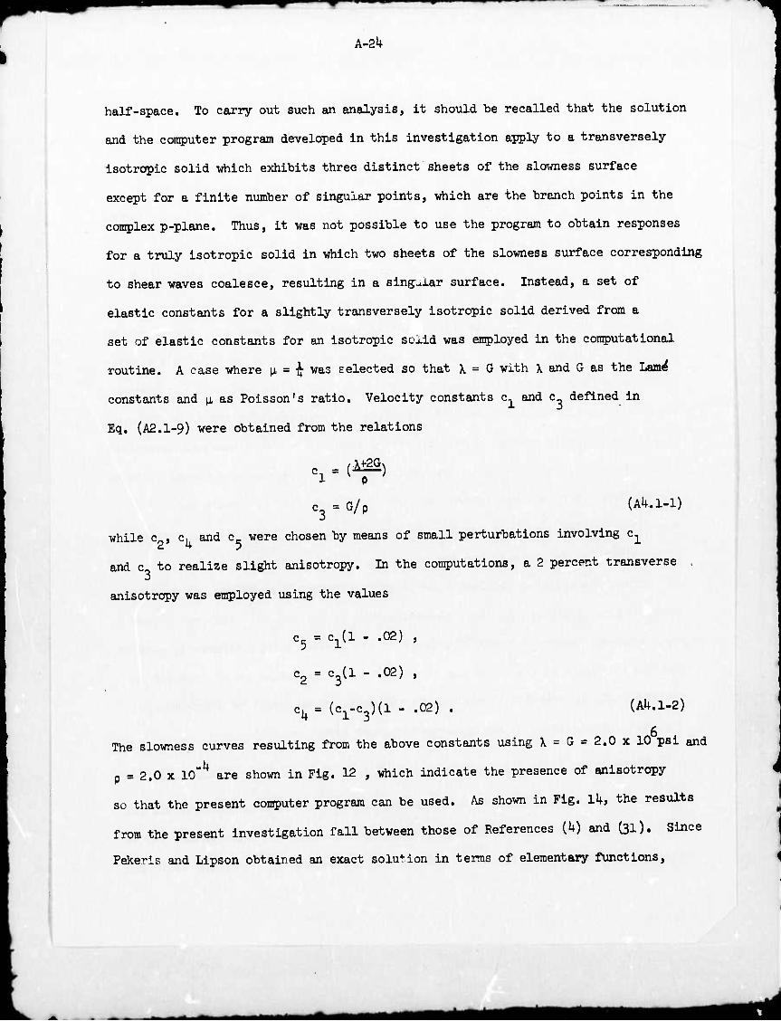
A~2k
half-space. To carry out such an analysis, it should be recalled that the solution
and the computer program developed in this investigation apply to a transversely
Isotropie solid which exhibits three distinct sheets of the slowness surface
except for a finite number of singular points, which are the branch points in the
complex p-plane. Thus, it was not possible to use the program to obtain responses
for a truly Isotropie solid in which two sheets of the slowness surface corresponding
to shear waves coalesce, resulting in a singvJ.ar surface. Instead, a set of
elastic constants for a slightly transversely Isotropie solid derived from a
set of elastic constants for an Isotropie solid was employed in the computational
routine. A case where \i = ■% was selected so that \ = G with \ and G as the Lwn^
constants and \i, as Poisson's ratio. Velocity constants c, and c_ defined In
Eq. (A2.1-9) were obtained from the relations
h - m) C3 = G/p (AU.1-1)
while c , c, and c were chosen by means of small perturbations involving c1
and c to realize slight anisotropy. In the computations, a 2 percent transverse
anisotropy was employed using the values
c5 = c^l - .02) ,
c2 = c3(l - .02) ,
c^ = (c1-c3)(l - .02) . (AU.1-2)
The slowness curves resulting from the above constants using X = G = 2.0 x 10 psl and
p = 2.0 x 10"^ are shown in Fig. 12 , which indicate the presence of anisotropy
so that the present computer program can be used. As shown in Fig. Ik, the results
from the present investigation fall between those of References {k) and (31). Since
Pekeris and Lipson obtained an exact solution in terms of elementary functions.
Mi *■*■
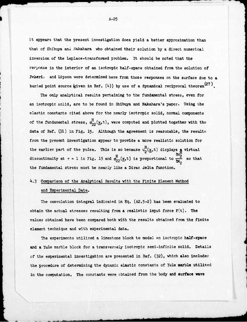
A-25
it appears that the present investigation does yield a better approximation than
that of Shibuya and rlakahara who obtained their solution by a direct numerical
inversion of the Laplace-transformed problem. It should be noted that the
response in the interior of an isotropic half-space obtained from the solution of
Ppjseri*. and Lipson were determined here from those responses on the surface due to a
(27) buried point source (given in Ref. (U)) by use of a dynamical reciprocal theorenr .
The only analytical results pertaining to the fundamental stress, even for
an isotropic solid, are to be found in Shibuya and Nakahara's paper. Using the
elastic constants cited above for the nearly isotropic solid, normal components
of the fundamental stress, OppCi»*)» were computed and plotted together with the
data of Ref, (31) in Fig. I5, Although the agreement is reasonable, the results.
from the present investigation appear to provide a more realistic solution for
H the earlier part of the pulse. This is so because u^Xjt) displays a virtual
hu" H 2
discontinuity at T = 1 in Fig. 15 and aoofc»*) ^B proportional to -r—- so that " "" CKo
the fundamental stress must be nearly like a Dirac delta function.
k,3 Conrparison of the Analytical Results with the Finite Element Method
and Experimental Data.
The convolution integral indicated in Eq. (A2.5-2) has been evaluated to
obtain the actual stresses resulting from a realistic input force F(t). The
values obtained have been compared both with the results obtained from the finite
element technique and with experimental data.
The experiments utilized a limestone block to model an isotropic half-space
and a Yule marble block for a transversely isotropic semi-infinite solid. Details
of the experimental investigation are presented in Ref. (32), which also include:;
the procedure of determining the dynamic elastic constants of Yule marble utilized
in the computation. The constants were obtained from the body and surface wave
Mi mmm
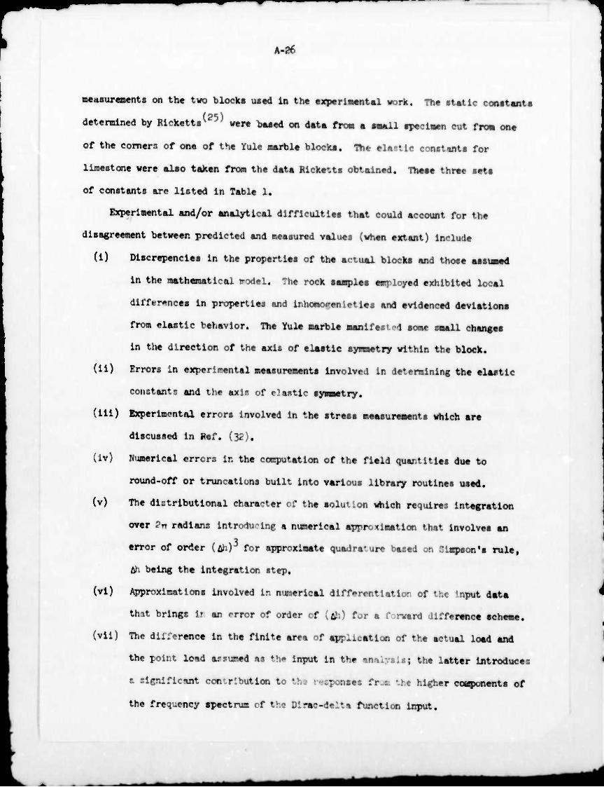
A-2f
mettsureaents on the two block« tu«d In the experlaent&l wort. The ■tetlc cooctanta
determined by Rlckettiv were baaed on data fro« a aaall apeclaen cut fro« one
of the corners of one of the Yule aarble blocka. The elastic const«nta for
llmestcme were alao taken from the data Ricke^ta obtained. Theae three seta
of constants are listed in Table 1.
Experimental and/or analytical difficulties that could account for the
disagreement between predicted and measured values (when extant) include
(i) Discrepancies in the properties of the actual blocka and those assiaed
in the mathematical model. The rock samples employed exhibited local
differences in properties and inhomogenletles and evidenced deviationa
from elastic behavior. The Yule marble man!fee; -4 some small changes
in the direction of the axis of elastic synsetry within the block,
(ii) Errors In experimental measurements involved in determining the elastic
constants and the axis of elastic symmetry.
(ill) Experimental errors involved in the stress measurements which are
discussed In Ref. (32).
(iv) Numerical errors In the computation of the field quantities due to
round-off or truncations built into various library routines used,
(v) The distributional character of the «olution which requires integration
over Pn radians introducing a numerical approximation that involvea an
error of or<ler (Ah)3 for approximate quadrature based on Simpson's rule,
&h being the integration step,
(vi) Approximations involved In numerical differentiation of the Input data
that brings ir an *«rror of order of [&) for a forward difference acheme.
(vii) The dii:erence in the finite area of applicatioo of the actual load and
the point lead arsumed as the Input In the mmlyalti the latter Introduces
t significant con'.rl but ion to thj r-icponses f r L UM higher cospunents of
the frequency spectrum rf the Dirac-delta function input.
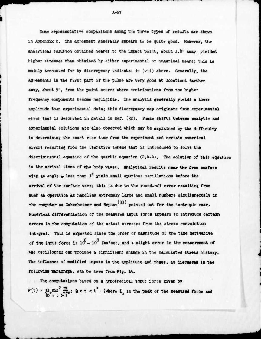
A-27
SOB« r«pr«s«Dtatlv« coaparlaons tmoag the thr«« types of results are shown
in Appendix C. The sgreeaent generally appears to be quit« good. However, the
analytical solution obtained nearer to the isqpact point, about 1.8" away, yielded
higher stresses than obtained by either experlaental or numerical aeans; this is
■alnly accounted for by discrepency indicated in (vii) above. Generally, the
•greeaents in the first part of the pulse are very good at locations farther
away, about 5M, fro« the point source where contributions frosi the higher
frequency cosqpnents becoae negligible. The analysis generally yields a lover
aaplltude than experlsental data; this discrepancy may originate fro« experiaental
error that is described in detail in Ref. (32). Phase shifts between analytic and
experiaental solutions are also observed which «ay be explained by the difficulty
in deteraining the exact rise tiae froa the experiment and certain nuaerlcal
errors resulting fro« the iterative scheae that is introduced to solve the
discrialr.antal equation of the quartic equation (2.U.I4). The solution of this equation
is the arrival tiaes of the body waves. Analytical results near the free surface
with an angle 9 less than 1° yield saall spurious oscillations before the
arrival of the surface wave; this is due to the round-off error resulting froa
such an operation as handling extreaely large and saall nuabers siaultaneously in
(33) the coaputer as Gakenheiaer and Repnau ' pointed out for the Isotropie case.
Nuaerical differentiation of the aeasured input force appears to introduce certain
errors in the coaputatlon of the actual stresses froa the stress convolution
integral. This is expected since the order of aagnltude of the tiae derivative
of the Input force is ICT- 10 lbs/sec, and a slight error in the aeasureaent of
the oscillograa can produce a significant change in the calculated stress history.
The influence of aodified inputs in the aaplitude and phase, as discussed in the
following paragraph, can be seen froa Fig. 16.
The computations based on a hypothetical input force given by
r't) ■ (losin ti«* G < t < t , (where I is the peak of the aeasured force and 10 : t > t
A-28
t la tvice the actual rlie tlae) li shown In Fig. 17, and is in good correBpondence
vith those results where the actual input is used in the calculations of the
■tress. However, the analytical expression for the input yields a slightly
broader stress pulse than that computed from the measured values. The best
agreeaent wi*.n the experiment was obtained when a symmetric puiee was used in
the coaputation where the entire rise portion of the pulse was identical to that
measured but where the rest of the pulse was artificially changed to consist of
a mirror image of the rise. However, if the input pulse is already close to a
•ywsetrlc shape, the Improvement is, in general, not greit relative to those
calculations where the actual force history is used.
At shown in Pig, 2 of the main report, numerical results using the finite
element technique were found to be in better correspondence with the data for
receiver polntr nearer to the source. This would be expected since the load is
Inevitably spread over a finite area In the finite element method and thus the
point source effect is substantially eliminated. Such a loading Is required by
the actual physical situation arising In the experiments. However, at distant
stations a complete tlae history could not be obtained by the finite element method
for a sufficient length of time to provide a meaningful co^arlson, this is
mainly due to the limitations of the computer capacity and the time required
for computation.
'♦.'• Surface Waves.
A computer program was written which evaluates surface rerults given by
Sq. (2,6-U): however, an unstable oscillatory result was .-»btalr.r 1 due to round-off
errors. Thus, «he evaluation of the field quantities on the surface at x« • 0
wa< not purtued any further In this Investigation.
A-29
Since the displacement must be continuous in the half-space, the field
quantities computed on a ray at a shallow angle from the surface should yield a
reasonable approximation for thjse right on the surface. The displacement
fields and the comparison of the calculated components of stresses near the
surface with the experimental results are shown in Fig. k of the main report
and Appendix C, where good agreement is indicated.
^.5 Conclusiras.
A solution to the wave propagation problem in a transversely Isotropie half-
space under arbitrary concentrated normal loading on the free surface has been
presented within the scope of the linear theory of elasticity. A mixed Laplace and
two-dimensional Fourier transform and a modified Cagniard-de Hoop technique
were employed to solve the problem; it should be pointed out that this particular
method can be used to solve similar three-dimensional problems in a solid possessing
any type of anisotropy. The solution obtained in this manner may be considered
as the sum of responses due to line sources spread uniformly over 0 to 2TT radians
on the free surface all of which are passing through the loading point. Therefore,
the solutions to a line source input of any orientations located in the surface
can be obtained easily from the present fomxlation of the three-dimensional solution.
A conputer program which evaluates responses of displacement, stress and
strain due both to a Heaviside and to an actual force input was developed for
normal loading. The numerical results for a fundamental displacement and stress
obtained from a set of elastic constants for a nearly isotropic solid exhibited
good correspondence with the known analytical results for a corresponding isotropic
solid. For both an isotropic and a transversely isotropic medium, the solution
from the program provided good agreement with experimental data for the first
part of the pulse for stations distant from the impact point, although the
A-30
remaining part of the pulse predicted lower amplitudes than the data. Predictions
at stations nearer to the source were generally not as satisfactory due to the
contributions from higher frequency components arising from the singularity of
the point load used in the analytical model that does not actually correspond
to the experiment. The responses on the surface of the half-space my be obtained
approximately by computing them along a ray near the surface with a shallow
angle, even though an exact evaluation was not realized in this investigation.
The responses along a ray in the direction of the load may not be computed from
the present program due to a singularity arising from the transverse isotropy
of the medium; however, this is not a serious limitation since the responses along
this ray may again be computer approximately as descrloed in the above. Also,
the program can be used to approximately evaluate the responses of an isotropic
medium with reasonable accuracy by introducing nearly isotropic elastic constants.
The mathematical model employed generally predicted the responses of the Yule
marble block tested under a normal point load reasonably well in spite of
discrepencies in modeling of the type discussed in section U.3.
A computer program for the solution due to a tangential load on the surface
may be developed utilizing the formulations presented here without much difficulty.
ÜB ■tfMMI *m*
A-31
Bibliography
1. Lamb, H., "On the Propagation of Tremors over the Surface of Elastic Solids", Phil. Trans. Roy. Soc. London, A, v. 203, 190U, p. 1,
2. Pekerls, 0. L., "The Seismic Burled Pulse", Proc. Nat. Acad. Sei., USA, v. 1*1, 1955, P. 629.
3. Pekeris, C. L., "The Seismic Surface Pulse", Proc. Nat. Acad. Sei., USA, v. Itl, 1955, P. 1*69.
U. Pekeris, C. L, and Lipson, H., "Motion of the Surface of a Uniform Elastic Half-Space Produced by a Buried Pulse", J. Acous. Soc. Amer,, v. 29, n. 11, 1957, p. 1233.
5. Chao, C. C, "Dynamical Response of an Elastic Half-Space to Tangential Surface Loadings", J. Appl. Mech., Trans. ASME, September i960, p. 559.
6. Gabenheimer, D. C. and Miklowitz, J., "Transient Excitation of an Elastic Half-Space by a Point Load Travelling on the Surface", J. Appl. Mech., Trans. ASME, September 1969, p. 505.
7. Johnson, L. R., "A Collection of Solutions to Lamb's Problem", unpublished paper, U. C. Berkeley, Calif., 1973.
8. Ewing, W. M., Jardetzky, W. S. and Press, F., Elastic Waves in Layered Media, McGraw-Hill, New York, 1957.
9. Musgrave, M. J. P., Crystal Acoustics. Holden Day, San Francisco, Calif., 1970.
10. Kelvin, Lord, Baltimore Lectures, Cambridge Univ. Press, 190U.
11. Burridge, R., "The Directions in which Rayleigh Waves May Be Propagated on Crystals", Quart., J, Mech. Appl. Math., v. 23, pt. 2, 1970, p. 217.
12. Buchwald, V. T., "Rayleigh Waves in Anisotropie Media", Quart. J. Mech. Appl. Math., v. ll*, pt. k, 1961, p. 1+61.
13. Synge, J. L., "Elastic Waves in Anisotropie Media", J. Math. Physics, 35, 1957, p. 323.
lU. Burridge, R., "Lamb's Problem for an Anisotropie Half-Space", Quart. J. Mech. Appl. Math., v. 2k, pt. 1, 1972, p. 8l.
15. Cagniard, L., Reflection and Refraction of Progressive Seismic Waves, translated and revised by E. A. Flinn and C. H. Dix, McGraw-Hill, New York, 1962.
16. Cagniard, L., Reflexion et refraction des ondes s^ismiques progressives, Gauthier-Villars, Paris, 1939.
MMtfH
A-3£
17. DeHoop, A. T., "A Modification of Cagniard's Method for Solving Seismic Pulse Problems", Appl. Sei. Res., Sec. B, v. 8, i960, p. 3U9.
18. DeHoop, A. T., "Theoretical Determination of the Surface Motion of a Uniform Elastic Half-Space produced by a Dilatational, Impulsive, Point Source", La Propagation des Ebranlements dans les Milieux Heterogenes, Colloques Intemationaux du Centre National de la Recherche Scientifique, Marseille, 1961, p. 21.
19. Buchwald, V. T., "Rayleigh Waves in Transversely Isotropie Media", Quart. J. Mech. Appl. Math., v. lU, 1961, p. 293.
20. Lighthill, M. J., "Studies on Magneto-Hydrodynamic Waves and other Anisotropie Wave Motions", Phil. Trans. Roy. Soc. London, A, v. 252, I960, p. 397.
21. Kraut, E. A., "Advances in the Theory of Anisotropie Elastic Wave Propagation" Rev. Geophysics, v. 1, 1963, P. ^01.
22. Kraut, E. A., Propagation of a Pulse from a Surface Line Source on a Transversely Isotropie Elastic Half-Space, Ph.D. Thesis, Univ. of Calif., Los Angeles, 1962.
23. Cameron, N. and Eason, G., "Wave Propagation in an Infinite Transversely Isotropie Elastic Solid", Quart. J. Mech. Appl. Math., v. 20, n. 1, I967, P. 23.
2k, Ryan, R. L., "Pulse Propagation in a Transversely Isotropie Half-Space", J. Sound Vib., ih, 1971, p. 511.
25. Ricketts, T. E., Sphere Impact on an Anisotropie Half-Space, Ph.D. Thesis, Univ. of Calif., Berkeley, 1970. " ~~
26. Ricketts, T. E. and Goldsmith, W., "Wave Propagation in an Anisotropie Half-Space", Int. J. Rock Mech. Min. Sei., v. 9, 1972, p. U93.
27. Sokolnikoff, I. S., Mathematical Theory of Elasticity, 2nd ed., McGraw-Hill, New York, 1956. ~ ' " ^
28. Sneddon, I. N., Fourier Transforms, McGraw-Hill, New York. 1951.
29. Carslaw, H. S. and Jaeger, J. C, Operational Methods in Applied Mathematics, Oxford Univ. Press, I9Ü1.
30. Stakgold, I., Boundary Value Problems of Mathematical Physier., Vol. II, Macmillan Co., New York, 196Ü.
31. Shibuya, T. and Nakahara, I., "The Semi-Infinite Boiy Subjected to a Concentrated Impact Load on the Surface", Bull. JSME,
32. Krishnamoorthy, ?:., Internal Dynamic Stress MeBsure:::Hnt in Model Half-Spaces of Rock, Ph.D. Thesis, Univ. of Calif., Berkeley, 1973.
-^-l--B

A-33
33. Gakenheimer, D. and Repnau, T., "A Numerical Procedure for Evaluating Ground Motions Generated by Surface Blasts", WN-7208-PR, Rand Corp. Rept., 1971.
3U. Buckingham, R. A., Numerical Methods, Pitman, New York, 1957.
itfa am MÜ
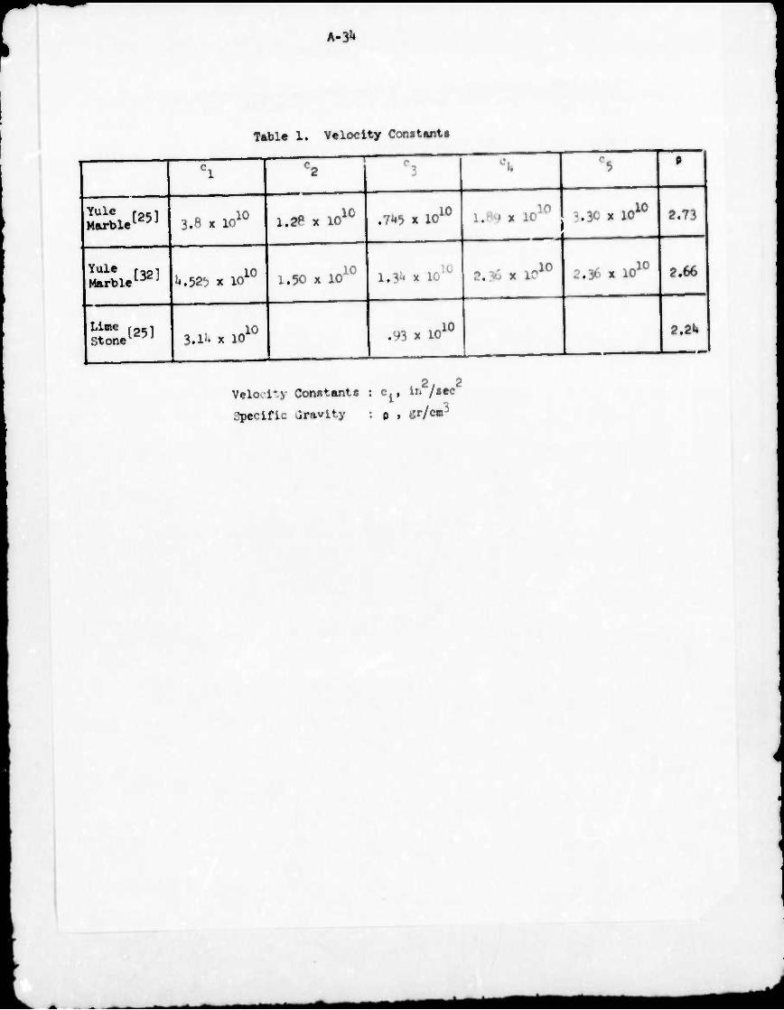
rr h-&
Table 1. Velocity Constents
Yule [25] Marble10 J
Yule Marble [32]
3.8 x 10 10
U.tfb x 10 10
Lime Stone 1251
-u
1.2P x 10 10
1.50 x 10 10
3.1^ x 10 10
.7U5 x 10 10
l,ll* x 10 IU
3.30 « 1010
.93 x 10 10
?. -'• x 1' .10
2.73
2.36 x 10 10 MM
2 2 Velo-l*.y Constants : c^, LB /sec
specific Gravity : p , ör/cm3
2.2U
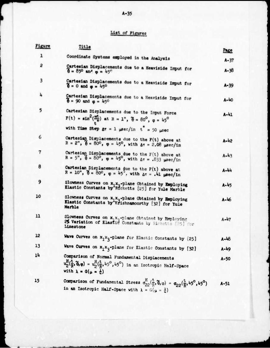
12
A-35
LUt of flgur»«
5 CftrtMlM DitpUeownts du« to th« Input Pore« F(t) - •lii2(4) «t B - 1-, ^ . 86°, v . U50
*ith Tim 8t«p AT - 1 ^«c/ln t* . 50 ^«c
i-37 1 CoordlMt« 83r«t«M m^loymA in th« Analysla
2 irrrjo1^?1^^du*to ■ ***•"* ^,or ** 3 JTfSS ;l^>l?s,~nt•du# to •ltoÄrl,id' ^^fo' A.39
A-Ul
6 S*'*!!1^ "^■■■■fM"i to th« F(t) «bov« «t A-l»2
R • 5". 3 - 80°. , - I.50, »nth AT . .633 a.«c/ln
8 C*rt««l«n Dl«pUc«»»ti due to th« P(t) above «t A-U R - 10". ^ - 800, T . U5*, ^h AT /.ix^/Ji A-U
9 SlouMifc Curv«. on x^-plen« Obtained by alloying A-US llMtlc Constant! by^Hfcketts [i5j for YulTSuSlT
10 SJ0!?!" CurvM "■ VS-P1M>« Obtained by brployln« A-w ElMtle Conetant« by^KflehnaKwrthy (32] for Yul« Marble
U IB0?1*" Cunrei on «iXi-r1«»« Obtilned by Bnpl.vl' A-1»7 2% Variation of Ela«tltf Coneteütt, bj i Liaectone
Wavt Curves on Xjj^-plane for Elaatic Constants by (25] A-W
13 Wave Curves on x^-plane for Elaatic Constants by (32] A-U9
Ml Conparlson of Komal JXtndaaiental Displacements A-50
^(^»Uv) » ^(R.^0,^0) ü, an Isotropie Half-Space with X - 0(n - i)
15 Conparlson of Fundamental Stress a"2(|,1,<p) - 022(^U5o.U50) A-51 In an Isotropie Half-Space with X « ('.(^ =• 1)

A-36
Figure TIXU
16 Efr«eti of ModlfUd Input; the Real Input end the Streas are the aaae aa fig. 17 for »he Ujaeatone Block
17 Co^»arUoo of a^-Streaa at (r&t) • (if .J.J") in
the Yule Marble Block 1
A-52
A-53
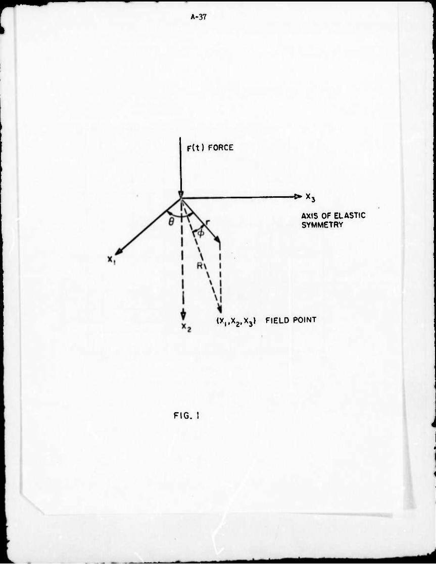
A-37
F(t) FORCE
-O- X.
AXIS OF ELASTIC SYMMETRY
(X^Xg.Xj) FIELD POINT
FIG. I
A-38
-9 10
lö10
M '
II
I " 1 ■ ■ -i— —1 1 1 1
"2
-7 •
' l
4'
' 1 • *'
^
\
i
\ f "I
. 1 i 1
U3
1 1 1 1
6 12 16 20 t/R , /xsec/in
10
10
II
10 13
24 28
IO-3
10 ~
10
10
II
10
FIG.2
A-39
10'
n K Id' M Is (SI
^
Iö"
•a0
109
Um-^O
8 12 16 ^/R , /.isec/in
«i
.ö15
k M
iö II »
Itf K>
20 24
FIG. 3
■ ^ ^^M
A-ltO
10" ■
ü?
1 1
/
<
I
4 ► t
o
4 » Uj-O <
10"
.o10 V \
\ v^ —
"3
K56
( ) < ( i } 1 2 6 2 0 24 ^R , fi»«C/in
1(5 13
Q:
-KJ12 10- <M
-,«" '
10 to <i
FIG. 4
^
A--.
U13XD •dU03 -IdSIO GflMn
L1 ♦ l I I f i i i
J
i 1
I
5 *-\ if)
9UJ "x
5»- cn •—•
2 \ Ul c
ii &
■»-
5
-j i i i i
•
(0 i <
• • * • o. a. Q.
aaa z UJ c
\i »
j oou
• • •
RERL
PLRC
^ 7
DISP
DISP
DISP
en »—• Q
1
^
? < 1 538 UJ n ►—•
»- )
"'S \
> s * . ^-K -jf
7s
i u *^ F^ s N
. ■ i
J i l l I ? : ; (^i3X) •dUD3 ndsia 2n
i
^m*
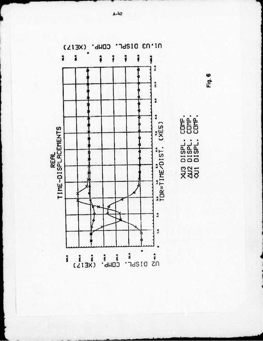
A-l»2
(Zi3x) 'dUDD ndsio en*
5 2 ? ? ? | a
in
•
■ 1 5
in • Ul ^x
u
in .o i \
Ul c
'\- II tk
.a
• • • U. CL CL nee aaa uuu ...
_I_J_I CL CL Q- C/) (/) (/) •—• «-^ ^H
OOO
ncvi -^
•
:
Ü-
• j
tn h- Z UJ c UJ
I« ^^
♦—»
a i
< ■
|
I
UJ c I—
A J (
^ ^
f- ^ X ■>.
i
i
i I i i i ' « ui3X) •duoo ndsia zn ^
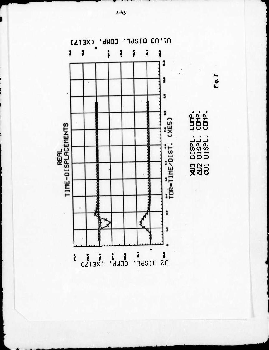
A-U3
(Z13XD 'dUDD ndsia cnMn
? 2 * ? ? ? ? |
'•• - - I r ■■•'•*■■*'•'*' *
I I i I i * * C/13XD -dUOD -16310 ZH
9 11
• • • CLQ. Q. c n n aaa
-i-i-J 0.0. o.
ooo rocsi —
*m mm
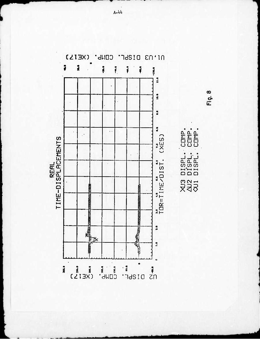
k-kk
CZT3XD 'dUDa "idsia cn'in 3 5 • • • o _ 11 f ? f f 1
</) h- Z UJ C UJ
CECE
rv OL
•—« Q
I UJ
f^ "^
f
ID UJ X
oQ - \
UJ H
□
00
o» • *** U.
o. 0. a. HUE: ana (J (JO
• - ■ ■
CL Q. CL CO CO CO •—iV-1 »—i
Q QQ
CO (N -•
33$
■■■■■''■
• • • • . ° S 8 8 8 8 8*83 ?
CZI3XD 'duoa -idsia zn
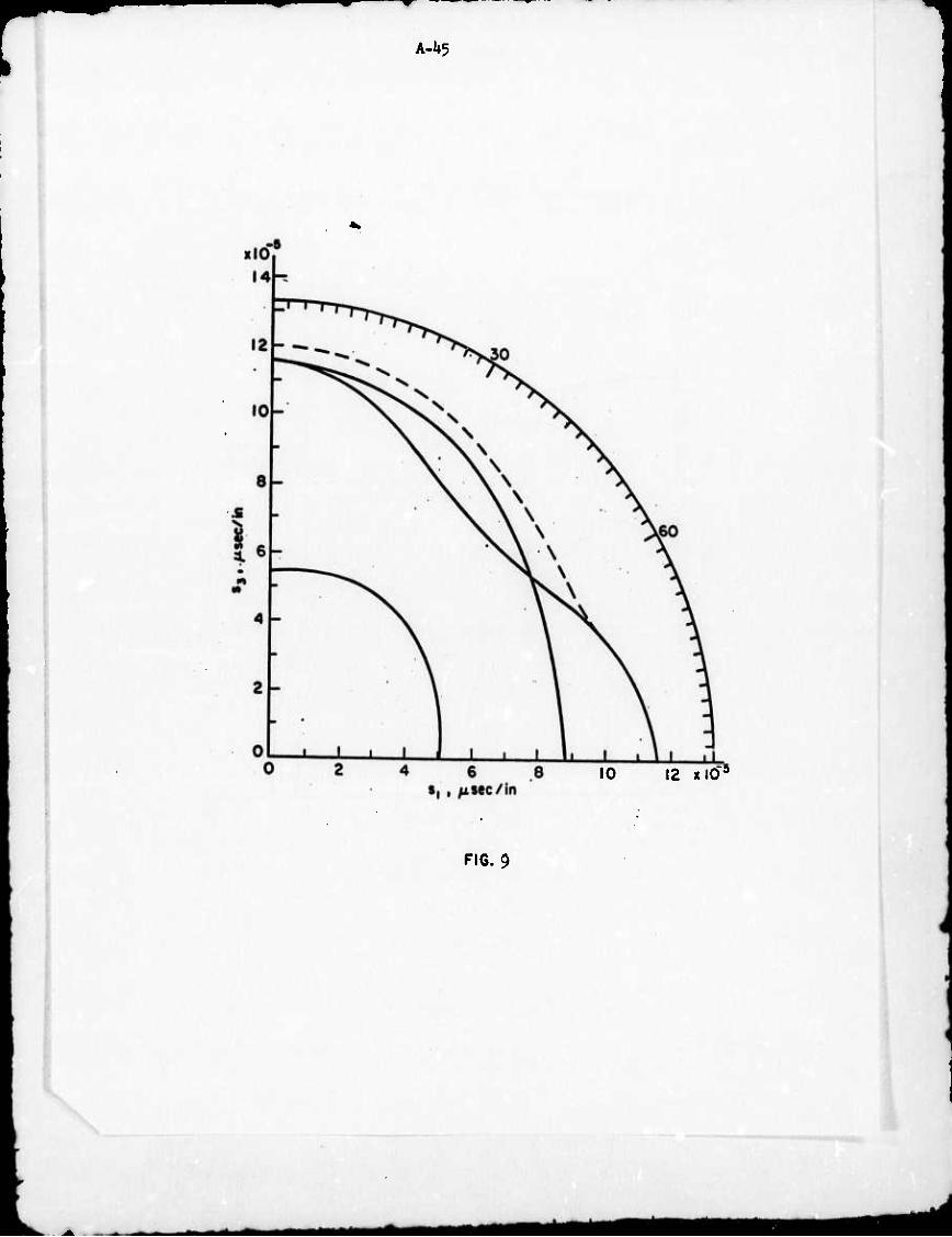
A-U5
10 12 xlO'
FIG. 9
A-U6
4 ,- 6 8 10
F!G. 10
*mm^ä jgf^mm
A-U7
FIG. U.
-^Ba^mm^mmm*
A-l*8
2.0 x I05
FIG.12
MB^kMMi
A-U9
0.4 0.8 1.2 1.6 ^i • in/sec
2.0 xlO5
FIG. 33
b A-50
«n-
dn *-NMO0
— rO
<
< I o < z GO
O ^
(ß z
Q: Z UJ UJ
CD Q; UJ I 111 CC <^ Ü. CL
I I i
J L if)
O LL
tA4aa Mtf^n ■H *mM
A-51
(VJ
o. (M
o
o_
lO-
N0ISN31
2- I
k
V)
<
< b ? z D LÜ CD <^ - ÜJ X (T (/) Q.
0 x
NOISS3ddWO0
J_J I L _ <M ro 5J- iO u> rTVb
i
«k AMriMi
A-52
d» li.
J! *-' +- JC 3 o Q. o ♦- c m 3 »H
0) C^ c t-H .0* o 4- 4- 0 "2 Q> <u O
E CC 5
in i
ISd o
SS3dlS •n o »n
+
O iD o
03Srf/SQ-]) 3^11/indN
A-53
ISd 1 ssgyis v- CM O (\J • «-
1 1 o to «1>
1 TT n *- o > ^_. | ^-« 1 K lf>
V ID
^ • J
>. v^-^ f ■o \ • l O \ ■*5J j-, \
CD ^vx I\ b v© H sin • V.
• •
o o
SJ
>
K S
n A_ J
Ö 00
lu ^ 'V \ &* \ f
JO ^ X \ N n V v. o
2 N ̂ 5 ß o
0) * ^tf* CO 3 &
>:_ \
(A ^fc
1 O ü "H Q C v A < O -H
i ■ o
£ •• •• u
. 1 ^ ii 1: j^2 o o» *- V a> 2 a c c c —• H
•/-E
xper
imen
t
.
o
1 o
• o —-J L_ ■
•
o o o o o o in o in ■
(\J »—« •-<
CO Q
O O UJ CO
i ^r o .
UJ
S81. IfldNI
M^^flM iiMiM

Appendix B
Users Manual and Fortran Listing for the Finite
Element Method Applied to Wave Propagation
Analysis in Isotropie and Anisotropie Media
This document replaces and supplements the Users
Manual submitted previously (Reference 10 of Main Report).
■MMMM
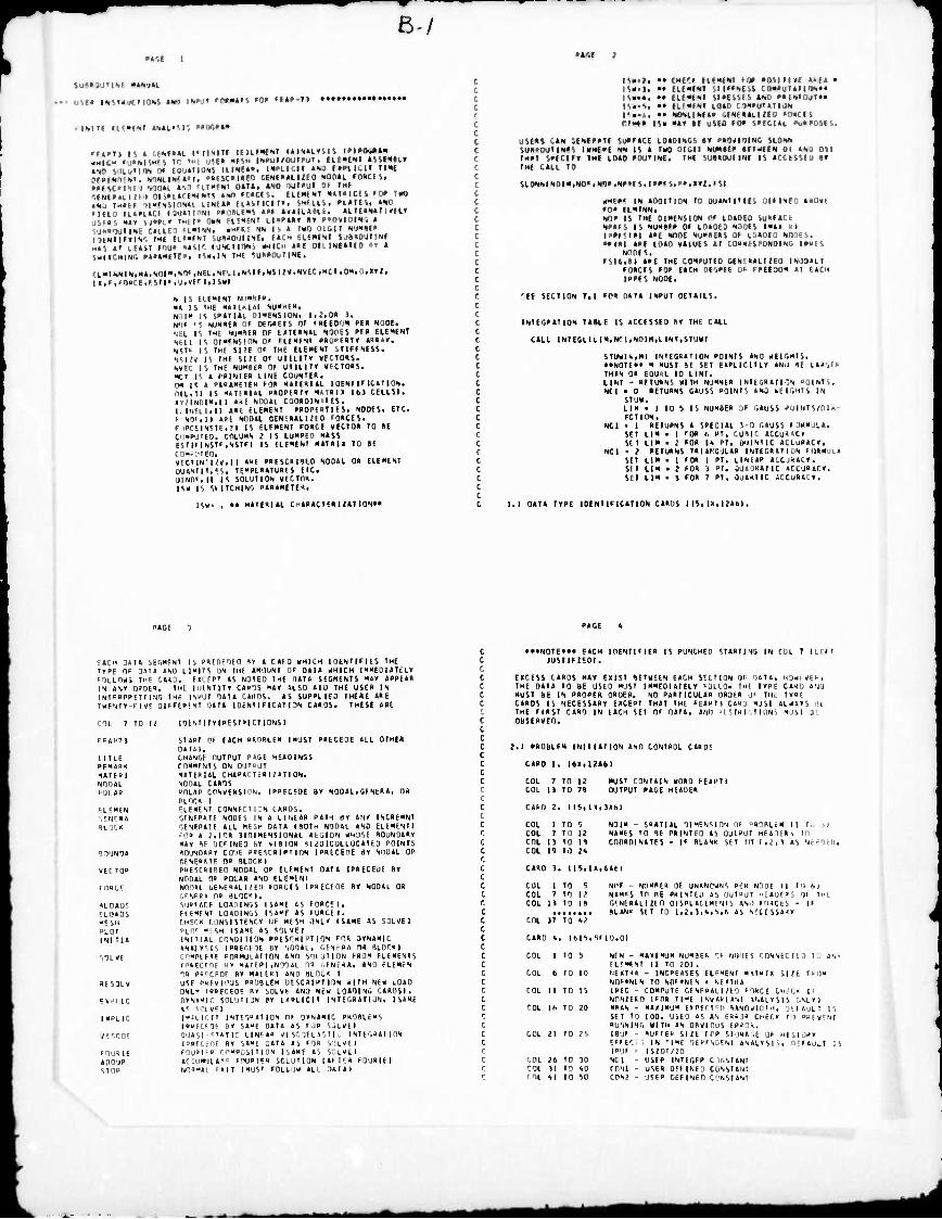
ß-/ •««
SuM3tI'l<l> »Witt
HMi iMTCactMH ••' mmt '«"««n »o« »tw-n •••••
.mit« fi««fit iMimi »»«vt»«
«Hie« »utNn«ts n "• »tO illu»I<»l 0» fOU»I
»•f Wii» i soim •••ii '.{«•»Ll/» i on»i.»f«« • Iü fH«f( ii"fNMn>«»i ■ lilK IUP14CI (sum utm •<»» SJ»'I« '">
tts «' tUit nu" "•'> ',*( ICMIM '«"»"tTI"
iiN|T( uiifiKki (ii-i«!«.!'. (»laogo« , •'• -'■•■ INPul/OUIrUT, (LfXiNI IbVOIIcT I PS-, ItiNt»-. (»LlCII «s ' MPLICM IIN(
••(tcaiif) ,iti>«ii.. ) NOMI. fO*Cfli irnfNi "-■ *so IJT«UI or rH( NT« «Mt Fr*CM. ElfMCNt «»t'lCll 'I,« lao llkFtl EKVMC.II«. SMHl.it »liHSt MO
nNI MoaitMS t«F ...... ii n-Mi /■!■ • (MN CKNESt iiaaMV a» aanvlsiN. » lISli, «..■!.■ NS IS 1 INO .JIM! N/«■!(» Hl suaaOullliE. E1(.H CLfNENT SolaOUTIHE IC fuNCtinos -T aae f •.•»' ar a ISK.HI tMF «uaaouTiHE.
■ l.P«INNiN,H«,".ni"«,KT iNfl .Nf. l.,",.IE.NJi;»,NKfC.«C>.0«tU1«»li u,f .(nacE.fStif.'j.vfM.tSKl
S li flE"ENI «(«Hfa. «l IS THE -.■ ' , ■..--. ■■ - IS "Ullli l-r'.' i ;■.. i. , i- If N'IF 11 NUMasa Of ofoaEES nr fattO'J« i>ta Hoai. •in. r TMF: MJ««E« OF («TtaNaL tOTts aE« ELEHENT NU 1 IS DIHFNSION QF FlfKfNT fRÜl'taT» »aR»Y, SSI' IS THE SI'E OF TMF UfHENT .TIFFNESS. NSIN IS IMF SKF OF UTUITV Vlt-TOaS. NVtC IS THE NUKSe» OF UTILIT» »fCTOas. m < : t raiNTEB LINE COUNTEa. OH is < ataaHETEu Foa naiFaiai luENfiFicaTlON. na,II IS •UTFHIM. paoPEarv HAiau 16) CELLS). lyilNDINitl "E NoutL cuaaoiN'ies. I INClUll aaE FLENENT PROPEHTIES. NODES. ETC. ► NO«,ii «HE Nooat CENtaaLino lacs'.. F l«CtlN5IF,?l IS ELEMENT FORCE VECTOa TO it C'IHPUTEO. COLUMN J IS LUMPED Mass ESI|FINSTr,NSTF| IS ELEMENT MaT«l« TO BE COH^'IEO. VFCTIN i;v,ll «»F PBESCamo NODAL OB CLEMENT gu4MiTi«s. TEHPtaaTuaES eic. UINOFill is SOLUTION VECTna. ISM is SIITCHINO paaaMETE',
ISH. • • M»TEai»L r.iaaacTERUailON»»
is«.;, •» CMiri HfMtNi »o» aosiiKE a>ia • • • >. •• ELEMENT STIMNCSt COM*ulal IHN««
■Mail •• - ■. ■ staissES ano »aiNToji«» lliuii •• fLEMFNt LQao ciMau'arijii r.. . •• NosilNiaa ,i-mmif, ■ ■.. > r.TMta is« «ai •( uito FM saECiat »uaaasES.
.'■•. »s .IHMIII suPFaci LoaoiNOS •« aaa<ioiNC UDNN
SUaaiMTINFS l»Mf»F NN IS a THQ niGIT NUMiEa «ElatEN 01 «N , uu TMaT sarciFT IM« Loao »OU'INE. TM« suiaouMNt is acctssEu «r TMI cacL 10
SLDNNIND|M,>M>',NOa,NMES,|PaFS,",ir/,(SI
MW IN aooiTinN io uuaNMMEs UEFINEO a*o«E FOa ELMTNN, NOP IS «ME DIMENSION OF IdaOEO SuaFtCt NPa>S IS NUMBFa OF LOaOEO NODES I Mai 9 1 |P»F<l«l taE NODE NUMSEas Of LÜAOED Nilit ,. •aiai aar loao «aiuEs ai JNOINO ia««s
NOOFS. Fsi6,ei aaE THE COMPUTED -.t . -MI/' I iNiioan
FOBCFS Foa EACH DEr,aEF OF FatEDOM ai (aCM IPBFS NODE.
'(E SECTION T.l FOB DtTa INPUT DETallS.
INTESaaTION mi F IS ACCESSED a« THE CALL
CALL INTEGLUIM.NM.NOIM.LIN^STUHI
STUMU.MI INTEGAATION POINTS AND HEIGHTS. ....HI., M MUST BE SET ' .I'll' Mir i-, , 4E i J- THAN OP EQUAL TO LINI, LINT - BFTUaNS HITH NUMHEB INTLGBATIGN POINTS. NCI • 0 RETUANS GAUSS POINIS AND kEIOHTS IN
STUK. LIM ■ 1 TO S IS NUMBER ; r,AuSS ■ -i-.i/ I FCTI ON.
NCI ■ I RETURNS A SPECIAL 5-0 GAUSS (ÜKMdLA. SET LIM • 1 FOR 6 PT, CUIIC ACCOBACr SET LIM . .■ FOR I« PT, UIINTIC ACLUPACf.
NCI • 2 RETURNS TR| AFIGULAR INTEGRATIUN FURHULA
SET LIM • 1 FOR 1 PT. LINEAR ACCJHACV. SET LIM • i FOR 3 PI. OUA.IRATIC »CCURaC». SET LIM . 5 FOR 7 PT. JU4<IIC ACCURACY.
t.l DATA TYPE IDENTIFICATION CARDS I IS, in.WA6I.
EACH DAT« SEGNEN1 IS PRFOFOEO BV A C AF 0 KMICM IDtNTlFltS IHE TYPf rjt (1AIA AND LIUITS ON THE AMOUNT OF DATA «H1CH IMMEOIATtLY ■iKLOMi IMF CARD. KCFP' AS NOIEO THE .14T4 SEGMENTS »AY APPEAR IN ANY OPOER. THE UIINTITY CAPOS "AY ALSO AID THE USER IN ISIFOPOFTTING IHf INPUT DATA CARDS. AS SUPPLIED THERE ARE tUF'tlY-FIVE OIFFERFNT DATA IDENTIFICATION CARDS. THESE ARE
COL 7 TO 12 lOENTITYIRESTRICTIONSI
FFAPTl START OF FACH PROBLEM (MUST PRECEDE ALL OTHER 0AI1I,
TITLE CHANGE OUTPUT PAGE HEADINGS PFMAlK COMMFNTS ON OUTPUT MAIE»I MATERIAL CHAOATTERI;AT | ON. NOOAl NODAL CARDS FOI.AR oniAR CONVERSION. IPBECfDE BY NOOAL. GENERA, On
BLnr.R I FLEHEN ELEMENT CONNFUIIN CARDS. GENERA GFNFPATF NODE-. IN A LINEAR PATH »Y ItU INCRtMNI HLO'.K OENEPATF AIL ME5H DATA IBOTH NODAL AND ELEMENT!
'OR A i,IOR 1I0IMENSIUNAL REGION MH'JSE ROUNDARY MAY HF DEFINED hY «IS10R 1Iiü1CQLL0CATED POINTS
BOUND« ROUNOABY CO'JE PRESCRIPTION IPRECEDE iY NODAL OR CFNEPME OR BLOCK I
VECICIB P»F5C»IFlEn NOOAL OR ELEMENT DATA IPRECEJE BY NOOAL OP POLAR AND ELEMENI
FORCE NODAL ÜFNE"AL|;ED FORCES IPRECEDE BY NOOAL OR C.FNFPA OB BLOCIF I.
RLOADr. ','IBIAr.F LOADINGS I SAME AS FORCEI. ILI1A05 ElEMFN' LOADINGS ISA»F AS FURCE I . MCSH CHECK F.uNSISTENCY UF MESH ONLY (SAME AS SOLVFI PLOT PLO' »1SH ISAMF AS SOIVEI INITIA INITIAL CONDIriUN PRESC«1PTION FOR DYNAMIC
ANAIVSIS IPRECEDE BY NÜOAL, OFNcRA OR BLOCK I VILYE COMPIFT« FOBHULAIinN AND SOljTION FROM ELEMENTS
IPBELFHF ill MATERI,NODAL OR GENERA, AND fLEMfN OR PR'r.Fnr BY MATEHI AND BLOCK I
itESDLV USE PHFYI'-'US P»08LEM DESCRIPTION <ITM NEK LOAD
ONLY IPRfCEOE B« SOLVE AND NcM LOADING CARDSI. JH^IIC OYNAMIl. SOLUIIJN BY tUPLICIT INTEGRATIUN, I SAME
»' Si'lV«! IHPLIC IMPllCn INIE'.BAI ION OF OYNAHIC PROBLEMS
IPPFCFOE BY SARE DATA AS FOR SjLVEl Vi'.f.OE QUASI-'TATir LIN'AR VISCQELtStIC INTEGRATION
IPRECEDE BY SAME DATA AS FOR VlLYEI FOURIE F0UR1F" COMPOSITION ISAME AS SCLVEI APD'JP ACCUMUIAF^ FOURIER SOLUTION IAFUR FOURIEI STOP NO'RAl F<|T IMUS' FOLLIM ALL DA' A )
• ••NOTE»«» EACH IDENTIFIER IS PUNCHED STUTING IN COL 7 ILEFT JUSTIFIEDI.
EXCESS CARDS MAY EXIST BETWEEN EACH SECTION OF DATA, HOMl-VEB, THE DATA TO BE USED MUST IMMEDIATELY FOLLO« THE TYPE CARD AND MUST BE IN PROPER ORDER. NO PARTICULAR ORDER UF THL TYPE CARDS IS NECESSARY EXCEPT THAI THE FEAPTT CAKJ RJSI ALMAYS BE THE FIRST CARD IN EACH SET OF DATA, AND IESTRICTIONS MJSI OL OBSERVED.
2.1 PROBLFM INITIATION ANO CONTROL CARDS
CARD 1. I6I.12A6I
COL T TO 12 COL H TO 7B
MUS1, CONTAIN MORD FEAP7) OUTPUT PACE HEADER
CARD 2. I IS, 1 »,1AM
COL I TO 5 NOIM - SPATIAL 0IMFN5I0N Of UROBLEM II t„ il COL 7 TO 12 NAMES '0 BE PRINTED AS UJTPUI HEADERS TO COL 13 TO IB COORDINATES - IF BLANK SET Ml 1,2,1 AS NEEOEO. COL 19 TO 2*
CARD 3. IIB,lX,6Atl
CUL 1 TO 5 NPF - NUMBER OF UNKNOWNS PER NODE II 10 61 COL 7 TO 12 NAM^S TO BE PRINIEU AS OJIPUl "LADERS OF THE COL U TO IB GENERALI^fO 01SPL ACEMf Nl s AN.l (ORCtS - IF BLANK SET TO l,2,3,t,S,F AS '.■U ,',.wv
COL 37 TO «2
CARD ",. I61S,SF10,0I
COl 1 TO 5
COL 6 TO 10
COL II TO 15
COL ll< TO 20
COL 21 TO 2S
I.OL 26 TO 30 COL II TO 40 ' OL SI TO SO
N(N MAHIMUM NUMBER OF NODES CONNECFED AV FLFMENT II TO 201 . NEXTR« - INCREASES ELEMENT MAIBU SUE F i UM
NDF'NIN TO NIH'NEN > NE«TR« IREC - COMPUTE GENFRALUtD FORCE CHECK II NON/EBO IFOR TIME INVABIANI ANALYSIS TAL»! MPAN - MAXIMU" EXPECTED BANDwICIH, JEFAULI IS SET TO 100. USED AS AN ERR]» CHECK II PRfVENt RUNNING WITH AN OBVIOUS ERROR. IB'JF - BUFFFB SIU FOB STORAGE UF HISTuRY ^FFEC . IN 'IME IBi.lF . ISJ0W20 NCI - USER INTEGER ClI.SIANt CONl - USER DEFINED CONSIAN;
C0N2 - USER GEFINEO CONSTANT
IOENI ANALYSIS, lEfAU^I IS
MM
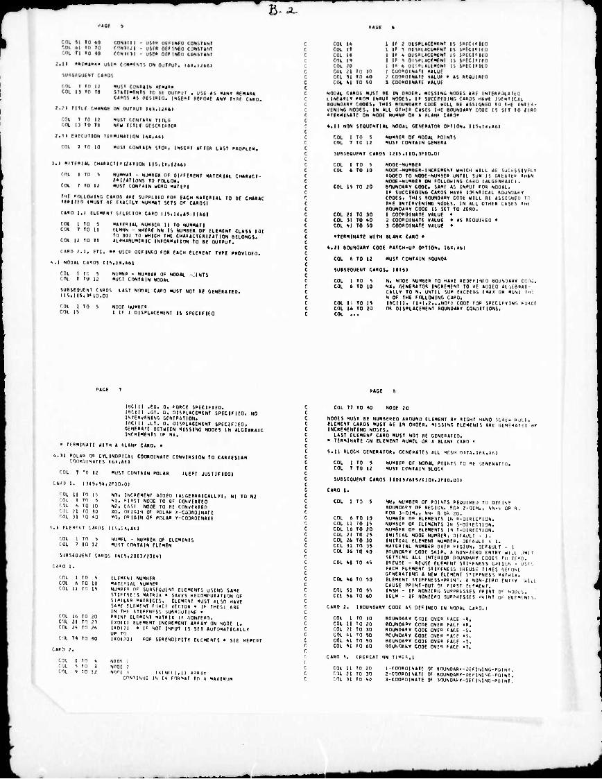
B-J-
cm »i »o »o COHIIII • oj»« oi'mir tox-.iiHi '.<K 41 10 »0 fWUI^I - ullt OMIOfO c INSHM COt Tt 10 M "-111 n - ull* Oil IMC ClASItm
lall Miau«* UM« Crm<HS1<, OH oulfut. Itl.U«!
SiliHiUlNI CMOS
fOl I to It «ust c «.t«!«. mMH cot ii »n Ti tTiitamit to «c our»ui , ust »s «N» m-. .
Ctini tt nitlHIO. INtC<t BIIOHI «NT TV't CUO.
Ml il'ir CH»ir,( IM output iti.ijtti
cot » to Ii cut I) to n
•utt ■•.«■■. tlfll ••■ - I'll ■• . . ll-T. .
2.11 CIKUtlON I(««lmT|rl>, Ua,>«l
COt 7 10 10 «utt tONtllN $10». INHM «HE« L«4I »»0»Lfx.
).l « l'-l«i r.H«««cl(« l/«tlON i 1'.. i ., i.'ii j
'Ol l to i
C01 I to 12
«MM1 - MMH of DiriEXNT Nttiaui CM*««CI- MIMtlONS 10 I'll«, ""•i roMtiit «oao N«tE«l
til rOLlOHlNO C««05 ««E iUCPLIIO t0» E«CM 4«tEa|«L to BE CM«««i TE»HEn (XUtt If «««CUT NUKMt SEtS Of CMOSI
c««o i.i llfWDf sritcio« ctao l||tu»<f U«»)
roi l to 5 COt T to ||
"»ir»I«L XUXBE« II ID HU>lH«fl 'LNNH - HHFBE -in 15 NUHIEI) OF ELIMENt CI.«SS 101 to in to WHICH IHE CM««»CtE«i;«tlON BELONGS. «IPM«>IU"E«IC |l«fO«««tlON to BE QUtPUt. COL u to tt
C««0 I.I, EIC. •• USE« DlflNED fO« E«(.H HINMI t»PI PROVIDEO
-..I NOD«l. C«»OS II'. .K.A.l.l
COL 1 tO » C01 7 10 12
NUKNP - NUKBEK Of HO0«L MUS' MMN NOU«L
■ NFS
SJBSEOJENI r«»OS l«SI NlntL r.«(n «uSt NOt BE CENEIUtED. II''.MS,If 10.01
COl i 10 COL l^
NHOF .u-i" u I I' I DISPL«rfNENI IS SPECIFIED
COl 14 1 IP 2 OISPHCIIFNI It SPFCIfllO CX It I IP 1 OlSPltCIMFNI IS SPEtlllla COL IB 1 II * OlSPLtCCWNI IS SPCCIfiCO rot 11 I If * OISPL«C(«INt IS SPECIFIFO FOL 20 I I« 4 Of P.<LI>(NI IS SPtClflCD Cut 21 to io i CUO«OIN«'( viiui cot si to «0 . COOPDIMK «tUF • «s «fauiiEa COt 41 to SO 1 COOPDINttl »«LUE
NOOll CMM ■"• ' *t IN 0«DM. KISSING NOOF S ««F . - iHltO ■...-i< >«■>« INPUT NODES. I« SUCCFFDING [««OS H«vl luENTICtL
BOUND«Bt COOES. IxIS PIXINOtaT I Ml .ILL BE «SSIGNEO IU I^F INIM- VENINC NOSES. IN ttt OIMF« C«SfS I"E BOUND««* CODE IS SEI 10 IIBn • T(«ll|Nttt ON NODE NUNNP 0« « PltNf C»0«
4.11 NON SFSUENtltl NOO«l GENEPttO« OPtlON. IIS.|1,«6I
NUNBE« OF NO0«L POINtS MUSt roNKIN OENFP«
NODE-NUMBE» NOD«-NUMBEB-INCBENENt HMICM HILL He Slim» ' .in ■) 10 NOOE-NUMBFB UNtIL SJM IS OaEllLi' IH«N NODF-NUMtE« ON FOLLDilINO CIKO I «LGCB'tlC I . BOUNDOV CODE. •-«-' «S INPUT fU« ■..■•!. If SUCCEEDING CMOS HIVE IO'.NIIC«L BQUNOtU« COOES. tHIS BDUNOtPT COOc HILL BE «SSI'.NE) tn IHI INtEDVENINC NOUIS. IN «LL OIHE« C«SES IHC
BOUND««« COOf IS SEt to ZERO. 1 COPPOINttE V«LUE • 2 COOPOINttF VtLUE • «S BEOUUEO • 3 COO«OINttE VtLUE •
cot '01
1 T
ro in
» 12
SUBSEOUFNI C
i.:Jl
CM 1 1
to in
i 10
COL is TO 20
COL 21 to 10 COl 11 tO 40 COL 41 to SO
• tE'NINttE MIM BUN« OHO •
4.21 BOUNO««» CODE P«tCH-UP OPtlON. It«l>6l
COt 4 tO 12 MUST rONttIN «OUNO«
SUBSEQiJENt CARDS. KISI
COL 1 to S Ni NODE NUMBER 10 HIVE REOEMNFO «OJNIIAHV CODE. COL 6 tO 10 N>, OENERtlOR INCREMENT 10 IF «UDED ■■;■■.■ ,:i
CRLLY tO N. UNTIL SU" EUCEEOS IM4X Oil MINI IM
N OF THE FOLLOMING CARD. COL II tO IS IBCIII. ll<li2...NDM CODE F 1« SPECIFYING FIMCF COt 16 tO 20 OR OISPL«CFNENt BOUNORRT COMHI IONS.
IBCIII .EO. 0, FORCE SPECIFIED. IRCIII .Ot. Ot OISPL«CEMENt SPECIFIED, NO ISTEavFNING GENERATION. I'iClII .LT. 0, DISPL«CEMENt SPECIf.EO, OtNERHrC OETWEEN MISSING NODES IN «LGEBRAIC INFOEMENtS Of N«.
• IFRMRAfE WITH « PLAN« CARD. •
<1.3I POLAR 0» CtLlNORKAl COOROINAtF CONVERSION TO CARIESIAN rOO»l)lN«I£5 (HI,Afl
COL 7 To it MUST CONTAIN POLAR ILEFT JUSTIFIED)
l I I. I M s.sx, ,i 111,1)1
'OL II TO IS NI, INCREMENT AOOEO IALGEBR«ICALLYl, Nl TO N2 COL 1 TO S Nl, HBSt NODE TO Bf CONVERTED COL «. TO 10 N2, L«SI NODE TO HE CONVERTED '. 1L 21 TO 10 XO, OFIGIN 01 POLAR X-CJOROINAIF 'OL 31 '0 1.0 YO, OUIGIN OF POLAR Y-COO«OIN«It
S.I ELEMENT CARDS IIS,lX,«tl
COL 1 TO S COL 7 to 12
NIJMFL - NUMBER OF ELEMENtS MUST CONTAIN ELEMEN
SUBSEQUENT CARDS 141J|2013/20141
CAi>D 1.
COL I TO S COL (i TO 10 COL II TO 15
r.OL 16 TO 20 COL 21 TO 21 COL 24 TO 26
COl 78 TO BO
COl 1 TO » COL s to a COL <t 10 12
ELFMFNI NUMBER MATFHIAL NUMBER NUMHfo nr SUBSEautNT ElEMENTS USING S«ME SIIFFNF'.S MATRU • SAVES »ECOMPUTAt I ON IJF SJMILAB «AIB1CES. ELEMENT MUST ALSO HAVE SAMF FllMti,! tend VECTU« « IF THESl ARE IN TMF STIFFNESS SUB»f.UtINf • PBINT ELFMENI MATRIX If KONIERI. IXD11I ELEMtNI INCREMENT «RRAY ON NODE I. UOm • IF NOT INPUT IS SET AUTUMATI CALL Y UP TO IXDI.'OI FOB SERENOIPItY ELEMENTS • SEE REPO»!
NODE 1 NODE ,i NODE 1 l«INlll,ll A«BA<
CONTIMJF IN |< fORIAt TO « MAXIMUM
COL 77 TO NODE 20
NODES HUSt BE NUMBERED AROUND ELEMENT 8» RIGHT HAND SCREN Hull, ELEMENt C«»OS MUSt BE IN ORDER. MISSING ELEMFNIS ARE GENrJAIEO 11» INCREMENTING NOOES. L«St ELEMENT C««D MUSt NOT BE GENERATCO.
• TERMINATE CN ELEMENT NUNEL OR A BLAN» CARD •
5.II BLOCK GENE««tOR, CENEBATES ALL MESH D»rA.I6X,A6l
COL 1 tO 5 COL 7 TO 12
NUMBER Of NODAL POINTS TO Bt SCNERATED. MUST CONTAIN BLOC«
SUBSEOUENT CARDS I 1015/615/110x,3F10.ül I
CARD 1.
CDL 1 TO 5
COL 6 TO 10 COL U TO IS COl 16 TO 20 CUL 21 TO 25 COL 26 TO 30 COL 31 TO 3! COL 36 TO 40
COL 41 TO «5
COL 46 TO 5D
COL 51 TO 55 COL 56 TO 60
•W, NUMBER OF POINTS BEUUIKEJ 10 DEEIN« BOIJNDABY OF REGION. FOR 2-OIM., NN*4 UR B. FOR 3-DIM., NN" 8 OR 20. NUMBER OF ELEMENTS IN B-DIRUMON. NUMBfO OF FIEMENTS IN S-DMECTION. NUMBER OF ELEMENTS IN T-OIRECTION. INITIAL NODE NUMBER, DFfAULI ■ 1. INITIAL ELEMENT NUMBtB, DEIAULI ■ I. MATERIAL NUMBER OVER BFGIUN, DEFAUH - I BOUNDAOY CODE SKIP. A NON-/EKU ENTRY HUl LIMIT SftTINC, ALL INTERIOR IIOUNOAHY COOES Tu ;r»0. IBFU'E - REUSE ELEMENT SIIfFNESS GPIl^N - US". FACH ELEMENT STIFFNESS IREUSF TIMES ilEKIKE GfNERATING A NEW ELEMENT STIffNESS MATJI«. ELEMENT StIFFNESS-PRINT. A NON-URO FNIJ» win CAUSE PBINI-OUI OF FIRST ELEMENT. IMSH - IF NON/FRO SUPPRESSES PBINT OF NDOtS. IELM - IF NONZERO SUPPRESSES iMINT Of ELEMENTS.
.
CARD 2. I BOUNDARY CODF AS DEFINED IN NOOAl CA«D.I
COl I TO ID COL II TO 20 COL ?l TO 30 COL II TO 50 COL 41 TO SO COL 51 10 60
BOUNDARY CODE OVER fACE BOUNDARY CODE OVER FALE BOUNDARY CODE OVER FACE "CUNOABY CODE OVER "-ACE BOUNDAOY CODE OVER FACE BOUNDARY CODE OVER FACE
CARD 1. IBEPEAT NN T|MC«,|
COL II TO 20 1 rOOBDINAtf OF BOUNOAR»-JEFINl HG-PU1NT. 'll 21 TO 30 2-C0n»DINATE OF BOUNDARY-i)E F 1 Nl NG • POI NT . COL 31 TO 43 1-COOROINAtE Of SOUNDAB »-OEF | M Mr,-»Li I Nl .
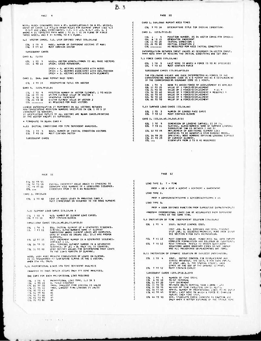
ß. 5
IMXT 11. cxM J.l PflUm ■'",■- - ui- inn .i---'.' iN^ur ISil !•■ • -S-T »-t 1 K»L CafMriNtTfS. I.E. 1-1 alfa *,%,! .{.(. 1. I
«HE«f • IS DlUftTCO f«f» tOnl 1 IÜ J, S IS IN »1.4« Of HKSI 'HtlE N10IS! «■• I IS ■ —•-' 10 »-I PLÄNt.
e.i vrcra« ci«os, i.f. U<F« OFflxtD INPUT IKtUtUI
IIU, DUMM OF OIFFEIIENr VECTODS IT NAH MUST r.ONUlN .i' in«
COl c«.
I f
TO TO
s U
SUdSEOUENl CMOS
C»0 1 • Itltl '.ni UM
1 6
TO in
S 10
V l/v. VFCIOR IFNCTH.COMNO«! TO »Ll NVEC VECTOHS ICH». fiFci PintnFiEK.
|P|C« • Oi VECnnS tSSOCUTED »II" NiJOES IPICK • 1. «ECTOPS ASS0CUTE3 . i 1 ■• DECFaEFDOH IPIO • || VFCTI1PS tSSOCIATEa NITH ELEMENTS
CtHO 2. 16», ?«6I PFPFtT NVEC TIMES
cni i rn is OFSCPIPTIKE TIUE FOS VECTOR
CiDD 1. I2IS.TF1D.OI
COL i to s »rsiTios NUMur» (ii VECIO« FLEMENT, i TO NSIIV
COL II II .'0 WCTW FlfMENt V«iur OF VECTOR 1 COL Ii IC 10 r,FNF"»tU« INCRFHENT COL 21 TO 10 vtCin» FLtMFNI V«LUE OF VECTOR 2 COL « RFUUIREO FOR NVFC VFCTORS
ll'JEda INIFRPOUTIt» I« PtPfflRMFO ON UL VECTORS DETMEEN NllN-r.ONSFCUTIVF POSIIION NUMBERS SPECIFIED IN COL 1 TO 5 IF INCRriENT IS NONZER". ( UESCRIPTI VE riTLCi OF ALL VEdORS ARE BLANK CARDS, PRINT INC OF THE VECTOR VALIIFS IS SUPRESSED.
• TERMINATE ON BLAN« CARD •
f..II INITIAL CONDIIinNS FOB TIME DEPENDENT ANALYSIS.
COL 1 TO S COL T TO 12
NICO, NUMBER OF INITIAL CONDITION VECTORS MUST CONTAIN INITIA
SJBSEOUENI CARDS
CARD 1. II>I,2A6I REPEAT NICD TIMES
COl T TO U DESCRIPTIVE TITLE FOR INITIAL CONOII lÜNi
CARD 2. I2IS,TF10.0I
COL i S POSITION NUMBER, AS IN VECIOR CARDS FOR IPICIM COL 6 0 10 GENERATOR INCREMENT COl 11 TO 20 INITIAL CONDITION 1 COL 21 TO JO INITIAL CONDITION 2 COl AS REOUIRED FOR NICD INITIAL CONDITIONS
INTERPOLATION BETMEEN INPUT VALUES AS DESCRIBED IN VECTOR INPUT, »••» NOTE •••• IF MISSING THE INITIAL CONDITIONS ARE SET 2ER0
T.I FORCE CARDS IIS,1X,A6I
COl 1 TO 5 COl T TO 12
LAST NODE TO MHICM A FORCE IS 10 BE SPECIFIED l«JST CONTAIN EDRCE
SUBSEQUENT CARDS I I!>.SX,tF 10.01
THE FOLLOHING VALUES ARE EACH INTERPRETTEO AS FORCES IF HIE CORRESPONDING BOUNDARY CODE IS A 0 •2ER0P AND AS A Dl SPLACtMi. NI IF THE CORRESPONDING BOUNDARY CODE IS 1 «ONE«.
COl 1 TO '. NODE TO WHICH FORCE OR DISPLACEMENT IS APPLIEn COl 11 TO 20 VALUE 0' 1 FORCE/DISPLACEMENT COL 21 TO JO VALUF OF 2 FORCE/DISPLACEMENT • AS • COL 31 TO AO VALUE OF 3 FORCE/DISPLACEMENT • RtQUlRt:) • COL Al TO »0 VALUE OF A FORCE/DISPLACEMENT COL 51 TO 60 VALUF OF 5 FORCE/DISPLACEMENT COL 61 TO TO VALUE OF 6 FORCE/DISPLACEMENT
T.ll SURFACE LOAD CARDS IIS,1«,A6I
COl 1 TO 5 COL T TO 12
NUMRER OF LOADED FACE CARDS MUST CONTAIN SLOADS
CARD 1. m,U.AS,l*,BI^,lim
COL 1 TO S DINENSION OF LOADING SURFACE, II OR 21. COL T TO 11 SLDINNI, ALPHA-NUMERIC NAME OF SURFACE LOADING
SUBROUTINP INN IS BETWEEN 1 AND SI COl 12 TO IS NRT,NUMBER OF ADDITIONAL ELEMENT LJAU
SURFACES TO BE GENEPATjO FROM CURRENT HUOEL. COl 16 TO 20 IPRFSINI, NODE NUMBERS DEFINING LOADING SJUFACF COl 21 TO 2! OP CURRENT ELEMENT. COL ... MOENTiFY FROM 2 TO B AS REdUIREOI
CQL '.I TO 55 ' OL »6 TO 5B tsi ■■') n 6i COL ...
CARD 2. (Bl10.01
COL 1 tO HO
INCINI, INCREMENT VALUE AOOEO TO IPRES1N1 TO lOENTIT» •lODE NUMBERS OF A GENE^UTEO SEQUENCE. IIOtNIIFY FROM Z TO 8 AS H60UIRE0I
LOAD «T NODES GIVEN ON PREVIOUS CARD • MUST cnRRESPUND IN SEQUENCE TO THE NODE NUMBERS
7.21 ELEMFNT LOAD CARDS II5,IX,A6 I
COL 1 10 5 ; COL T TO U ,
SUBSCOUENT Cl
rni 1 TO 5 - coi 1 10 11
, ' ■ COL 12 TO 15 '. ■. COL 16 TO ?0
-OL .-1 TO BO
NLD, NUMBER OF ELEMFNT LOAD CARDS. MUST EONTAIN ELOAOS
IFL, INITIAL ELFMENT OF A GENERATED SEQUENCE. EIMINNI, ALPHA-NUMERIC NAME OF ELEMENT SUBROUTINE WHERE ELEMENT LOADS ARE COMPUTED. USED »? CHECK TO INSURE IEL, ET.2 ARE PROPER ELEMENTS. INC, INCREMENT NUMBER IN A GENERATED SEQUENCE, lOETAflT . II. JEL, IFRMINAL ELFMENT NUMBER IN A GENERATED SEOUENCEi IF JEL • 0, ONLY IEL IS COUNTED. USEB OEFINEn VALUES FOR DETERMINING BODY LOAPS IN THE ISW'S »ORIION OF ELM1NNI.
NOTE, USF» MOST POOVIOE COMPUTATION OF LOADS IN ELMTNN. PR IS IRANSFEREO If SUBROUTINE ELMTNN IN THE U VECTOR, WHEN ISW «5, ONLY.
7.31 P-lOnORTIONAL LOADS FOR TIME OEPENOENT ANALYSIS
IRANSFE* TO THIS OPTION OCCURS ONLY Fro TIME ANALYSES.
ONE CARD FOR EACH PR0»O«IIDN4L LOAD REOUIRED
'.OL I TO 5 PRO"r»IIONAL L043 TYPE. 1,2 OR 3 COL 6 TO 10 «. 'ABLE CPNSIANT COL 11 TO 20 TWIN, SMALLEST 11 ME LOADING IS W4LIU COl 21 TO 10 !»»>. LARGFSI TIME LOADING IS VALID COL 11 TO 43 40 EOL *1 TO 50 »1 COL 51 TO 60 4? COL 61 TO TO 4^ COL Tl 10 60 »<.
LQ40 TYPE I, T • TIME
PROP • 40 » »1»T * 42«T»T > 43«TM«I . »A«T»T»T»T
LOAD TYPE 2.
PROP • 40>ISINIA1*TI l>PK » 42«IC0SI4>MI l»K t 45
LOAD TYPE 3.
PROP • USER DEFINED FUNCTION FROM SUflkUJMNE EXI'RLOIPKOP, I I
'•NOTE»« PROPORTIONAL L040S t4N BE 4CCUMUL4IE3 F10H DIEEtaENT TYPES 4T THE SAME TIME.
B.I INITIATION OF TIME INDEPENDENT SOLUTION IIS,lX,4bl
COl I TO A inuT, OUTPUT CONTROL CODE,
lOUT .BO. 0, 4LL STRESSES 4NI) OIS». PRINTtO IfUT .NF. 0, SELECUD PRINIU./I, MORE n4t4 INPUT 5CE SECTION 9 FDR 04U PRf»4<4IIUN.
MUST C0NT4IN SOLVE »INDIEtlES ALL )4I4 INPUT» COMPLETE F0RMU14TI0N »NO SIILJIION Uf E JUi 11 Ü>|',. MUST ':rNT4IN RESOLV 10 0BI4IN SU'!1! JUEN1 SOLUTIONS WHERE BOUNnRBY CODES DU NOT CHANCE 4N0 4LL PRESCRIBED 01 SPL4CE»ENI S ARE .'ERO.
COL 7 TO 12
COL 7 TO 12
.11 INITIATION OF DYNAMIC SOLUIION BY EXHICII INTBBRAT ION.
COL 1 TO 4 IOUT, OUTPUT CONTROL I OR DISPLACEMENT 4in STRESS PRINTOUT, SEE SECT. 9 EPB 0414 INPJI.
IF IOUT .NE. 0, THE SP4II4L CONTROL UAIH
COMES 4T THE END OF T«£ ÜYN4HIC SEGMENT. COL 7 TO 12 MUST rPNT4IN EXPLK
SUBSEQUENT CARDS I2I5,2F10.D,2I51
COL 1 TO 5 NUMBER OF TIME SIEBS COl 6 TO 10 PR INT INTERVAL COl 11 TO 20 Tl"' IWRFMENT COL 21 TO 30 NFiMABK 0ELT4-D4MP1NG TERM I ,»MMA ■ .'.1 COL 31 TO 35 NU'BFB OF 11 ME EVOLU'lON SIO=Si PLOIi. COL 36 TO »0 N»»OP, NUMBE0 OF PR0PPRIIUN41 LJ4Di TO BE INPlll COL 41 TO 45 NEOPC, L4ST NODE ON WHICH 4 KIBEE IS CH4N1,L0
OURINO F4CH TIME STEP. COl 46 TO 50 KK«, STABILITY CHECK CVERBIOE •• C4UIII1N USE
ONLY WHEN « HITIE» ESTIMAIE OF THE SIABLE TIME
MMMI riM^M
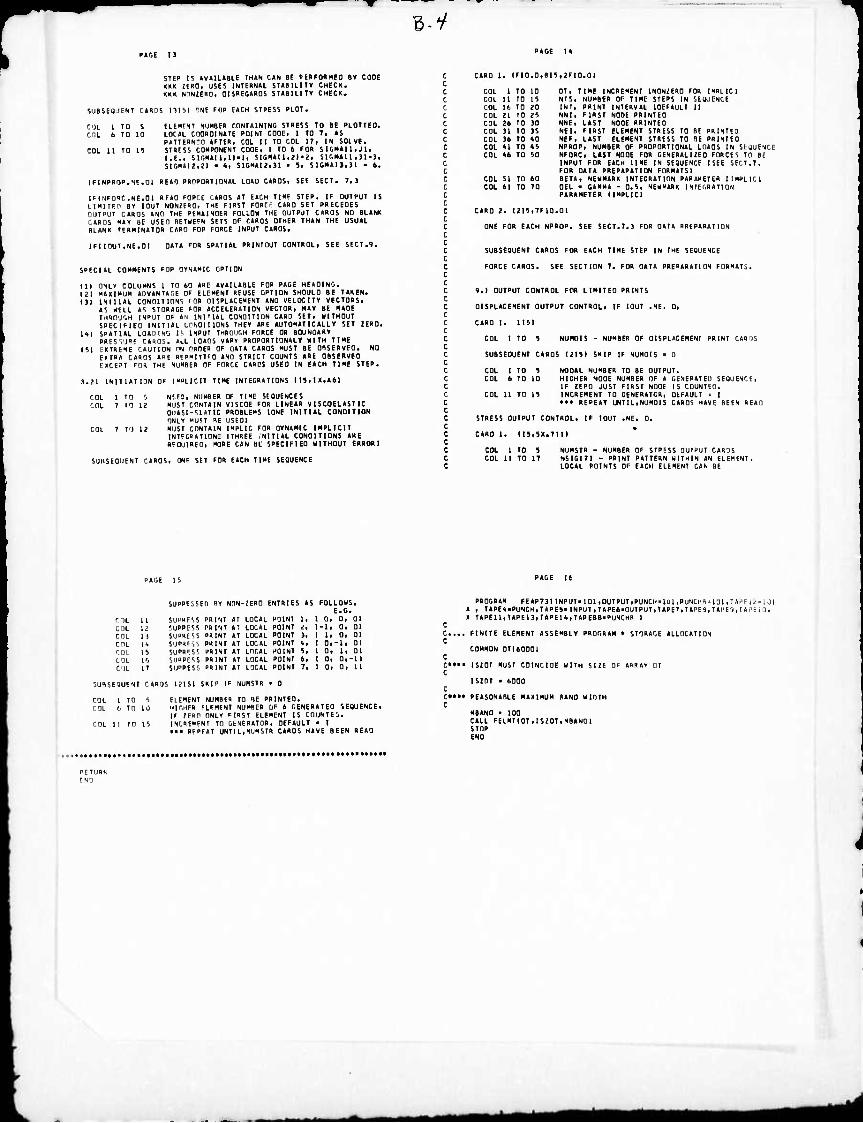
B-y
STEP 15 »V«IL«BLE THAN CAN BE PEHFIMHEO BY CODE KK« tmn, USES INTERNAL STABILITY CHECK. «R« NHNZEKn, OlSREOARDS STABILITY CHECK.
SUBSEOJENT CARDS 11151 ONE FOR EACH STRESS PLOT.
f'lL 1 TO 5 ELEMENT NUKBER CONTAINING STRESS TO BE PLOTTED. r.riL 6 TO 10 LOCAL COORDINATE POINT CODE, 1 TO 7, AS
PATTERNm AFTER, COL U TO COL IT, IN SOLVE. COL U TO 15 STRESS COMPONENT CODE, 1 TO 6 FOR SIGHAiI,JI,
I.E., Mi.«Al 1,11.1, SIGItAll,2l'2. SIGMAI1.3I-3, SIGHAI2,;i • t, SIGHAI2.)I • It SIGMAI3,3I ■ 6.
IFINPROP.NE.OI RfAO PRnPORTIONAL LOAU CARDS, SEE SECT. 7.3
IHNFORC.NE.Ol REAO CORCE CAPOS AT EACH TIME STEP. IF OUTPUT IS LIMITE" BY 10UT NON(E«0, THE FIRST FORCf CARD SET PRECEDES OUTPUT CARDS AND THE REMAINDER FOLLOW THE OUTPUT CARDS NO BLANK CARDS MAY BE USED BETMEFN SETS OF CARDS OTHER THAN THE USUAL BLANK TERMINATOR CARD FOP FORCE INPUT CARDS.
IFIIOUT.NE.OI DATA FOR SPATIAL PRINTOUT CONTROL, SEE SECT.9.
SPECIAL COMMENTS FOP DYNAMIC OPTION
111 ONLY COLUMNS I TO 60 ARE AVAILABLE FOR PAGE HEADING. 121 MAXIMUM ADVANTAGE OF ELEMENT REUSE OPTION SHOULD BE TAKEN. Ill INITIAL CONDITIONS (OR DISPLACEMENT AND VELOCITY VECTORS,
AS WELL AS STORAGE EOR ACCELERATION VECTOR, MAY BE MADE rHKOUSH INPUT OF AN INITIAL CONDITION CARD SET, MITHOUT SPECIFIED INITIAL crNDIUONS THEY ARE AUTOMATICALLY SET ZERO.
m SPATIAL LOADING IS INPUT THROUGH FORCE 0« BOUNDARY PRFSVI" CApJOS. ALL LOADS VARY PROPORTIONAL» KITH TIME
151 EXTREME CAUTION PN PRDE" OF DATA CARDS MUST BE OBSERVED. NO EXTRA CARDS ABE PEP"ITTFO AND STRICT COUNTS ARE OBSERVED IXCE'I FOR THE NUMBER OF FORCE CARDS USED IN EACH TIME STEP.
3.21 INITIATION OF IMPLICIT TIME INTEGRATIONS II5,1X,A61
COL 1 TO S NCEO, NUMBER OF TIME SE0UENCE5 COL 7 rO 12 MUST CONTAIN VISCOE FOR LINEAR VISCOELASTIC
OUASI-STATIC PROBLEMS IONE INITIAL CONDITION ONLY "U?T HE USEOI
COt 7 TO 12 MUSI CONTAIN IHPLIC FOR DYNAMIC IMPLICIT INTEG»ATION: ITHREE .NITIAL CONDITIONS «HE
RFOUIRED, MORE CAN BL SPECIFIED MITHOUT ERRORI
SUBSEOUENT CARDS, ONF SET FOR EACH TIME SEQUENCE
CARD 1. (fl0.0,BI5,?F10.01
COL I TO 10 COL 11 TO 15 COL 16 TO 20 COL 21 TO 25 COL 26 TO 30 COL 31 TO 35 COL 36 TO tO COL Al TO A5 COL 46 TO 50
COL 51 TO 60 COL 61 TO 70
OT, TIME INCREMENT IN0N2ER0 FOR IMPLICI NTS, NUMBER OF TIME STEPS IN SEQUENCE INT, PRINT INTERVAL IDEFAULT 11 NN1, FIRST NODE PRINTED NNE, LAST NODE PRINTED NEI, FIRST ELEMENT STRESS TO BE PRINTED NEF, LAST ELEMENT STRESS TO 9E PRINTED NPROP, NUMBER OF PROPORTIONAL LOADS IN SEQUENCE NFURC, LAST NODE FOR GENERALIZED FORCE!» TO Be INPUT FOR EACH TIME IN SEQUENCE I SEE SECT .7. FOR DATA PREPARATION FORMATSI BETA, NEHMARK INTEGRATION PARAMETER (IMPLICI DEL • GAMMA - 0.5, NEHMARK INTEGRATION PARAMETER (IMPLICI
CARD 2. I2I5,7F10.0I
ONE FOR EACH NPROP. SEE SECT.7.3 FOR DATA PREPARATION
SUBSEOUENT CARDS FOR EACH TIME STEP IN THE SEQUENCE
FORCE CARDS. SEE SECTION 7. FOR DATA PREPARATION FORMATS.
9.1 OUTPUT CONTROL FOR LIMITED PRINTS
DISPLACEMENT OUTPUT CONTROL, IF IOUT .NE. 0,
CARD 1. (151
COL 1 TO 5 NUHOIS - NUMBER OF DISPLACEMENT PRINT (..>» r,
SUBSEQUENT CARDS 12151 SKIP IF NUM0I5 • Q
COL 1 TO 5 NODAL NUMBER TO BE OUTPUT. COL 6 TO 10 HIGHER NODE NUMBER OF A GENERATED SEQUENCE,
IF ZERO JUST FIRST NODE IS COUNTED. COL 11 TO 15 INCREMENT TO GENERATOR, DEFAULT ■ 1
••• REPEAT UNTIL,NUMDIS CARDS HAVE BEEN READ
STRESS OUTPUT CONTROL. IF IOUT .NE. 0.
CARD 1. II5I5X,7I1I
COL I TO 5 NUMSTR - NUMBER OF STRESS OUTPUT CARDS COL 11 TO 17 NSIOm - PRINT PATTERN WITHIN AN ELEMENT.
LOCAL POINTS OF EACH ELEMENT CAN BE
SUPRES5E0 HY NON-ZERO ENTRIES AS FOLLOMS,
riL 11 COL 12 COL 1 1 COL 1- COL 15 COL 16 OIL 17
'jlJBSEWEN C
COL 1 TO 5 COL 6 TO 10
SUPRFSS PRINT AT LOCAL POINT 1, '.UP«t'.S PRINT AT LOCAL POINT 2, SUPRESS PRINT AT LOCAL POINT 3, SUPR^SS PRINT AT LOCAL POINT A, SUPRF^ PRINI AT LOCAL POINT 5, SUPBCSS PRINT AT LOCAL POINT 6,
E.G. I 0, 0. 01 (-1, 0, 01 ( 1, 0, 01 ( 0,-1, 01
0, 1, 01 ■II II
( ( 0, 0,
CDL 11 TO 15
SUPRESS PRINT AT LOCAL POINT 7, ( U, 0,
ELEMENT NUMBER TO BE PRINTED. Hlr.HFP ELEMENT NUMBER OF A GENERATED SEQUENCE, IF ZERO ONLY FIRST ELEMENT IS COUNTED. INCREMENT TO GENERATOR, DEFAULT ■ 1 ••• REPEAT UNTIL,NUMSTR CARDS HAVE BEEN READ
C C... c
c
c
C»«1
c
PROGRAM FEAP73( INPUT. 101 ,OUTPUT ,PUNCM> lül,PUNCH1> 101,1 A.'E u.101 X , TAPE«-PUNCH, TAPES« INPUT, TAPE6'0UTPUT, TAPE7, UPEI, TAPET, TAPt ID, X TAPE11,TAPE13,TAPE1*,TAPEB8.PUNCHR I
. FINITE ELEMENT ASSEMBLY PROGRAM • STORAGE ALLOCATION
COMMON omoooi
• ISZDT MUST COINCIDE MITH SIZE OF ARRAY DT
ISZDT • 6000
• REASONABLE MAXIMUM BAND HIOTH
MBAND • 100 CALL FELNTIOT,ISZDT,MBANDI STOP END
PETURN END
J
MM
B^-
SUBROUTINE fFl><T(OI.n/n',MH»ND)
HAIN I1S5EK6LV PHOr.lUH tNO STn«»r,t »LL0CAT10N FD« VARIABLES
REAL LAOL ICIOICAL CHFC« .FLA'i.NPL DIBtNSION CONKDU'.l.rLAr, CiXMON /TAPES/ ITPStlTP6 c iinnN/njRIEB/NK'iOliXN.r CC'HGN/GAllS/ LIH.Sr.AUSSlS roHHnN/LAHELS/ LARLIH.KH
< ,AKf;Rnl, AaOHO?,AHni<,,13iHf C.3MHIIN/SHAP/ KJACSHAPEI« rnimON/TIILE',/ XITLIil.UT CONHON/VALUES/ NCi.r.nNl.r ; IHinN/OVNAXD/IIHE .NSLOC OATA CnNND/6Hl<ATCt<Uf,HN0n
/ (,rtHt]uNnA,6Mfosr,c .«HRina ' iHvnuft I£t^MRKHAR<,ftHINn X MIAOOlJP ,6HVI SCOEtbHIHPL
DATA RE/AHNOT ,AH /i R PAT» NILAG,NLI5T/7,2A/i"l
l7l,IITLEI12litrHEI7l,DTIIS2DTI,REI2l
ttltWOAUSSISiSI ED()l,«HiFHEOItl il:H,JHEOI<.ltUH,RHEDI61,RH AD (U I. START, CEASE. IPG.NSIR, JORDI 301 ,2ai.Sr,l3,ll,SK(3,3l,X(3,2ai,L0(i20l TLI6I UN2,C0N3I31 l,NT,NSTEP,nS,NU"PLr.N£OAIAI^0,3 1.NI'R,SPL AL .6HPaLAR ,bHELEHENt6HSaLVt .6HRESOLV1 ÜS,(>HEL0A0S.6HWECTaR,6HH6SH ,6HPLQT , IA,tHGENERA,bHTITLE .I.HHLUCX 16HEXP1.IC1 IC,6HNEUT0N/ LANK/6H / ,M2,N3lHA,N5(M6i><B/7«l/,ITA/9/
■. INITIAT? SEARCH FOR START OF PROBLEH DO REAOIITPS,10001 CCHEAO
CC-HFAOIll If ICC.EO.START) 00 TO 2A0 lHCr,.Ea.6HFEAP731 GO TO 240 Itir.C.EO.CEASEI RETURN GO n 100 CONTINUE DO 122 l>1.12 HEADItl'TtTlEIII
•.0 BEAHITPS,10001 CC.IITLE NDIi . CC 00 HO I " l.NOIM CC - TITLFIII «MtOIII " CC If ICC.EO.'ILANKI XHEOIM ■ XITL(I)
1 CONTINUE REAOIIIP5.10001 CC.TITLE NDF . CC 00 152 1 ' l.NOF CC ■ TITLEI I I irl'.C.tO.HLANKI CC ■ UTTLIII FMtOIII ■ CC UHEDIII • CC RHE0I1I • CC NUNEL " 0 H Ml 11 T i",.1O01 1 NEN.NEXTBA.IREC.NBAN. IHUt.NCI.CONl.C0N2.C0N3
IFINBAN.LE.OI MBAN - »BAND ISI7 ■ IS20T IOT ■ IS2DI/2 NICO • 0 N7EC • 0 NPL ■ .TRUE. NUMPLT ■ 0 NT - 1
...INITIALISE TYXE AND CLOCK CALL TICTOCITrHE.OI 00 lit I'll 7
121 T»»FIII " 0.0 NEL1 . NfN » 2 REHIND 12 NTERM ' 0 DO 10 W.NFLAG FLAGIII".FALSE.
... STORAGE IS SET FOR A NSTF X NSTF ELBHENT MATRIX AND FORCE VECIDK
... «AXINU* SIZE FOR NSTF IS ISO, THIS IS CUNTROLEO BY DIHENSIJN ON LC
NSTF - NOF«NEN » NEXTRA M? • 2»NSTF f I MO • NSTF«INSTF«2I » 1 IFIHO .GT. IDTI GO TO 710 IP0"1 IFIIBUF.LE.OI IBUF • ISZDT/20 IFI IREC.NE.OI IREC > I WRITEI IIP6,2000I HEAD(I>>G.NDIM,NDF,NEN,NSTF,REIIRECUI.HbAN, IBUF ,
X NCliC0Nl,CaN2.C0N3 IPC • IPG . 1 IF(N0I>1.GT.3.OR.N0F.GT.6.0R.NEN.GT.20l CO TO 720
.... SEARCH THE LIST OF NAHES FOR A TRANSFER ADDRESS
12"> REAOIITPS,10001 CC.TITLE I • CC CC-TITLEIll DO 126 J ■ l.NLIST IFICC.EO.CONMDIJII GO TO 127
26 CONTINUE IFICC.EO.STARTI GO TO 120 IFICC.EQ.6HFEAP73I GO TO 120 IFICC.ea.CEASEI RETURN GO TO 125
C C... 127
, NAHESIHAT.NOOiROL.FLE.SOL.RES.BCS.FOR.BLD.ELO.VECtES.PUJ.FO'J.REM, GO T0(210,220.226,230.200,270,228. 260.2 60.255,2'.'), 200.200,200,131,
X 345,220,133,220.200,200,200,200,2001 ,4 , ICO,GEN,TIT,eLO, EXPiAOO,VIS.IMP,NEWI
■ UUIFEIIrP6,200)1 ITITLEIIl,I'2,12l GO TO 125 no 134 I > 2,12 HEAOIII • TITLEI1I GO TO 125
., INPUT THE HAIERIAL CHARACTERIZATIONS.
J 1 IM'LAGIlll GO TO 215 FLA,-.l II..TRUE. IF(I.LE.ÜI GO TO 700 Sil«MAT - I Ml » MO M? . HO ♦ N'JHHAI HO = HO ■ 64«NUMHAT IFIHO.GT.I$20TI GO TO 710 FALl HESHI J,NUMNP,NU"EL,NUHH4T,NDIH,N0F,NEN,NELl,
X 0T,0IIHn,OTIH2l,0T(U1|,Dri»4l,0TIH5) ,DTIH6II IFIIOG.LE.OI GO TO 100 GO '0 125
. INPUT THF NO'IAL LOCATIONS AND BOUNDARY CONDITION CODES.
IFIFLAGm I GO TO 225 FLAGUI-.TRUF. IFI l.LE.OI GO TO 700 NtJMNP « I Ml . HO M4 , MO ♦ NUMNP M5 > H4 • NÜIM*NUHNP MQ ■ H5 ♦ NOF«NUHNP IFIHO.GI.ISZDII GO TO 110 II ( .NOI.FLAGI 311 H6 • Mf) CnNTINUE IFICC.Eg.tONWOI l"!! I GO TO ?27 J ■ 2 IfICC.EU.CONMOI1711 J ■ 4 GO TO 215 |fl."1T.FLAGI2lI GO TO 7)0 CALL CnNVF»TINJHNP,NPIM,0T|H4ll GO TO 125 C1NIINUE CALL «RFl.fNINUHNP.HUMEL^DIH^OF^FN.NELI , OT 1 HI I ,D : I »•. I , 0TIH5 1 ,
« 0IIM6II IF(IPG.IF,01 GO TO 705 IK .NOT.'LAr.mi MO . MO 4 NtLl'NUHfL )LAGI3I ■ .IRUF. 1FIM0.GI, IS/1M GT T 710
C C... c 22a
c c... c 230
c c... c 245
C c... c
GO TO 125
BOUNDARY CODE OVERWRITE
IFI.N0T.FLACI2II GO TO 710 CALL eC00ESINUHNP,0T(H3ll GO TO 125
INPUT THE ELEHENT CPNNECTinN ARRAY.
J ■ 3 IFIFLAGI3M GO TO 215 FLAGI3I-.TRUE. IFIl.LE.OI GO TO 700 NUHEl ■ I H6 ■ HO HO • NO * NEL1RNUHEL GO TO 215
INPUT THE VECTORS OF PRESCRIBED VALUE.
IFI.NOT.FLAGUIl 00 TO 730 IFIl.LE.OI GO TO 700 IFIFLAGI4II GO 10 2*7 FLAGI4I ■ .TRUE. READIITP5,10011 NSIZV,I°ICK NVEC • I HB ■ MO HA " HR t NSIZVM HO • HA IFIH0»2M.GT.ISZDTI GO TT 710 CALL VECIN INUHNP.NUHFL,NDF,NSIZV,IPICXiNVEC,OTIHAI.OTINUI I IFUPC.LE.OI GO TO 100 GO TO 125 CONTINUE IFIl.LE.OI CO TO 125
, INPUT BOUNDARY LOADS
CALL BLOAOSI l,NUHNP>NOIH,NOF,OTIH3liOI|H4l,u)TIH5ll IF||RG .LE. 01 GO 10 705 GO TO 125
. INPUT ELEHENT LOADS
IFII.LE. 01 GO TO 125 CALL EL DADS I I,NOI M,NOF,NFN,NFL1,N5I' ■NSIZV1NVEC1OTIH1It0TIH2II
1 DTIH3I ,nMH4l,0TIH» l,0'l H5|,0I,DT1»':|,DTIHBI I IFI|0G .LE. 01 GO TP 705 CO TO 125
,
ß-£ HM *l
»»Of n
INPJI '.'■ IXIMtl 'V MI.-.
II IfUMUll U 10 1*7 rit.iti • .rauf. HI10 • I ■. I . . NO» •NU«»!!' m • «o «c • M • Nlco«NSi(.n ■C • "tf . ' M.i. ■•!. .i.l ..■ ill CO TO TIO («11 .(UN INUtNF,NU'fl.»Of .NMCa,I.NICO.OtlltCl.aMIIOII IMP- .i'.'l r.n 11 100 M ro in 5?Jtt tMf SnutlCN «C »l"$I lOtOING CtSE
II IHMtlll W ^0 «01
CCU Uli II.".,11 no ill i. i.i |. I .-i I.M «cl II I i"l . .■•Li(, CI1NIIMIE ll I.MT.CHICKI 00 10 ?0T MM • 0 If .. i .V .. n.. HAM.«».!).!.. .M .(.l-^iH. -1 I 01 TO tlt SM JP .1 . -..»un /N:^I 1NH» SniullCN CtLL MM • 1 NMO • I ■ •0 ISII • IS/lt - HUF lot • lii;/^ II (MCD.NE.Ol '.ü 10 M". IMITtll i.'i... i ' i MCli • I 1 ' I . .. IS«' i ."IJ M' . 1 •«SICO • Nir.SUMNP Mr, i MQ MO • MO . MCO'NSICO inMo.Gi.isiM oo ro iio DO ilO J > M&.MO nrui • o. MT • MO M74 « HO K 1 lOI.OF.HTI M7 . lot • I MU . MJ 101 ■ IUT . I MQ • MT » .4 . ..ji.^S'1
IFIHO.OT.ISin 00 tO TIO Mt . MO-l
c c... c 405
c.
. CMfC« FMI MUM fO« CONMiTfUCr CF INPUI O«>«
till ". .1. ■ IN.IM'l.. .NUMll ,f r-M»T,',.Jl«,s,ll . M ,,■ i i i . n.l . I . .»■.."». .«1. ■• .'. .i i-i i. iic«. i. ni«ii,rii iM,i,(n-ti,lui.i7), i ,,'.,.,, j ,, i „., ,,, ., Ml • 101 - NEQS
, 910t IM'; HESM fO» IMO OIMFNSIONtl IPPOlOOies.
l.lil • I IFII .NF. 01 MMIIEIim.70311 IFICC.E9.C0NUDI11II
I t»IL nnrMSMINUNNPiNUMFl.NOIM.NEN.NEll.DTIMtl.ailMf,!,! | («ll MCfOCirVME.21 IMM-.t J.C'INMDW»! I NtEO'l IFICC.EJ.C INMOIJ»! I GO TO <I20 IFICC .'u. CONMD JÜM 00 tO *li ir IMinHVL.i'.MluNI GO TO T»0 IFire .EO. CONMOIWI .Dt. CC ,E0. I 1IN1.111 l ll l 00 10 li1. IFIIVG .Ha 01 GO TO 70t IFICC.NE.CONMDIUII CO TO »0'.
. tniinn roMKOSITlON
«EAIHITPS,100^1 J.F|.E2.F),F« M*ITEI IIP«,10021 <E»0,|P0,J,Fl,K'.l l.f. IPG • IPS • 1 NTE«M • NTEIIN »l NCINTERNI • J >N • J
. FORM THE STIFFNESS FOR THE ELEHENIS
IFIFltGIMI GO TO 410 I« • 1 J • |M»XB4NMl«Nner, * NDF«NUHNP>II . NTMI IFIISI2-J.IT.NT*I GO TO «10
. ONCDHE SOLUTION IS POSSIBLE HRITEIITP6.20311 NEOB • NDEG IBIK • 0
. CHECK TO SEE IF IOEST IS TO HE MOVED UP J • NUMNPPNOF-1
.StVE FORCE VECTOR FOR NONLINEtR SQLUTiaN MK-HS.J REMIND 9 MRITEIIHOTIII.I.MS.Mtl IFIN7.E9.HTtl GO TO «Ol 00 «08 K • UJ DTIMTttKI • 0TIN7»KI
MT I A
r^MTAI ■ MT» MT . J I
MU • LA * NOEO'MAXHAN M« . Mu * NUM7(l>»N0F MO • M4 * NDEO 101 ■ W)1'0»M4<9AN • I H^'.m ' .T1UE. IFINTH. E'J.I I GO TO bJO CALL H)»"Sr(NIIMNP,NUMEL.NUHM»!,N01H,NDF , NEN.NtU 1 .MS. DT , DT IM. I,
< TIIH;),0IIM1I,0TI"4I,0I(M5I10TIM6I,DT,DTIMfll.OTIMTI.OTIMBI. 1 OTIMUI |0:IL4I ,NSTF,|BL><.NVFCiNSIZViMtXI<4N.IREC>N0EGI CiLL Tir.TOCITTME.SI If IIPO .LE, 01 GO TO "70^
.. FORM IHE r.LOIAL STIFFNESS ANO SOLVE USING GAUSS ELIMINATION
I ALL SnL^FOINUMNP.NUMFLiNnF.IOl.MI.MAXBAN.ITA.NSTF.ISZAiNEOOiIBLK, «OTIltliDTIMSItOTINUIiDTIMTI,DT,0TIM9I,DTIMK| .NOEOI r»LL TICrOCnvME.«i GO TO «20
.. OVNAMK SOLITION B» EXPLICIT INTEGRATION
IFINICO .'(. 31 00 TO «I« MRixeiirrtiZOsai turn • 3 NSICO ■ NOI»SUMNP MÜ ■ MQ MO ' MO * NICD'NSICO I'IMO .Of. ISZUTI 00 TO 710 00 '.17 J-MG.MO m IJI ■ o.o MC • Mr, . «jlicri MI) • HC • NSICO MI • MO «I . MF » NSTF MO ■ 2»NSIF • Mf IFIMO .oi. is/on on TO TIO CALL FHPLCTINUMNP.NOMEL.Nl/MMAT.NOIM.NnF.NEN.NELl.NSTF.NVECNSIZV,
< OIlMll.OT|MJl,üHM)|,nT(M«|,OTIH5I.OTIMt|,OTIMTI,DTIll,D1IM<7lf X OIIMBI.OTIMGI.OTIMCI.OTIMOI.OTIMEI.DTIMFl.TYMt.IOUT.NSICDl no n 12S 10UT ■ I CALL TICTOCITYME.ll
.. FORM THE NEW LOAD AND 00 A BfSOLUTION ONLY
CALL RESVELMNUMNP.NOf ,M> 1 , HAXBAN, I S 2A .NEOBi I BLK.DT I LAI .UTIHM . X DTINUIIOTIMS|.071 NT I« OT|MX 11NDf»NUMNPI
420 C C... c
271 C C, c... c 21C
c I...
CALL TICTDCITYME.SI MRITEI12l(0TINI.N>M7.Hei
. COMPUTE AND OUTPUT THE NODAL DISPLACEMENTS AND ELEMENT STRESSES
IFIIREC.GT.O.AND.IBLK.EO.OI RFMlND 7 CALL DI5TRSINUMNP,NUMEl.NUMMATfNDlM,N0r,NEN,NELl,NSTP,NVf<.,HSUVi
X 0IIMll,DTIM2l,DTIM3l,nT(M4l,DTIMS| ,0riM(,| .OTIMul .01,01 IMll.uriHI'l X,IOUT,IREC,IBLKI
CALL TICT0CITYHE.6I IFIIBLK.GT.OI REWIND 7 IFdBLK.GT.OI REAOI7IIOTIII,|.1,MB| I • 0 WRITEIITPt,20301 TYMf DO 271 N ■!, 7 TYMEINI • 0.0
. INPUT THE FORCE VECTORS ON NODES (RESET TO JERO »UIOMAI[CALLY . ATTBR EACH PROBLEM SOLUTION OR RESOLUTION!.
CONTINUE IFl.NOT.FLACmi GO TO T30 CALL RESETII,NUHNP,NDF,DT|MMI GO TO 125
. TIME INTEGRATION SUBROUTINE FOR DYNAMIC AND VISCOELAST K. SOLUTIONS
IFIFLAGITII GO TO 540 FLAGI7I • .TRUE. I - MO ► NSICO - 1 IFII.GT.ISin GO TO 710 DO 530 J ■ MO,l DTIJI • 0. IFIIBLK.EO.OI 00 TO 5«0 MU ■ MO » NSICO iFiMu>Nsico.cr.isin GO TO TIO
0 IFICC.ES.CnNMDI22l.nR.Cr..E0.CONMDI21ll X C4LL TSOLVEINUMNP,NUMEL,NUMMAT,NOIM,Nnl .Nt-dNEL UNSIF ,NVK.. 1 NSUV,NICO.NSICO, IBL>, IS2A,NE')H,MAxHAN,'.ut<.. I n . i ., Mjf ,0 I, 2 DT(Mll,DTIM2llaTIM3l,CTIM«l,0TIM5l,OTIM6l,OTIM7l,OIIMlll, 3 OT,DTIN)l,OTIMLI.OTILA|,OTIHOI,OTIMM ,011 ISW.l l,DTIMOI.I.<IIMUI , « NSEU.TYMfl
IFICC.Eg.CONMOI2«ll XCALl NEWTON (NUMNP,NUMEL,NUMMAT,NOIM,M»,NcN,NfI liNSTFiNVECNSIIVi IlaLlt,IS;A,NEaB,Mt«B«N,NOFn, I0I,M8, IBUF.DI ,<ITIMI I .Ul IM/I.OtlMH, 2OTIM«l,OTIM'il,nrm6l,0T|M71,DTIMDI,OI,0l|M?l,OIIHi; .DHL'. I .OIIMUI , JOTIMXI,OI(ISI2»ll,OTIMU),N5EO,TYMei
I • 0 GO TO 260
. PROGRAM EXECTON TYMF APR AY ,REFr»ENr. E SUBROUTINE I.L0CK
Jb. 7
rc> .-i !• i ;•>■(...'Oiin TVI
00 10 100 i .■'IM ( llf'.,.MnM> nr.l 11. IM. M
CO '1 i00 7o0 tmilEI |T>6>?0HI er
GO T3 100 'Iü J-H'i |Ii" . . JIM 10<ISUiCC
00 T3 100 MO ■• ' i-ll I'WOIM NDlNiNOr.NEN
00 ro loo I <0 -'UTf (lIPb.^OIM CC
r.u i'i loo «Ul" IllPft.^Ol«! r.n TO 100
J M«nE(III>6i20)!l t»«««N GO TO 100
#•• ••• FORHtlS
VlO TOCitT IFf.O.U.lIt»! . FOKXtTIAIS.SFIO.OI
01 FQÜXtTIt^iilitFlO.OI 00 . UJXAKIMI.I/Jö. )0<.«"i'»OE. 1»"/'
11/141,>;H FINITE ELEMENT «NtlVSIS PRO&s»"//m«, 22I2H »I // < 1U.?H «.IH.UH rimFN5l(W»L PROSLEN «««...// > 1II(,2H •.IB.?*H 0EG4EES CF FBEEOOM PER NODE • •// n n«.2H ».le.HH NODES CONNECTED TO EtCH ELEMENT •// x l)x,2H •.l'J.HM ELEKENT STIFFNESS SWE • • • • 'IUHtlHlH »ill t 111,1H •,ax,34H « OENFBtLIIED FORCE CHECK HAS • // X nx,2H •.•)i,4»,HH(>rin DEOUESTEO! 1«X, 1H>// « UX,<!H «.U.UH IS XAX1MUM PEUKI SS I «L E M«LfD»NO • // X M<,.M '.l'. WH w()«r KOFFER Oht» RESERVED FOR H »ini%,lU!n •!// » HXtlH •>UX,I8H CDNSUNT NC1 •,I8,7X,1H« // X 13X,:M •■BX.ISH CONSTXNI l ■■tl?.*,«H •// X IIK.JH •«IXittN CnNSTXKT 2 •fE12.4|«H •// X n«,?H »laXtltH CONSTANT 1 •lE12.«l«H •// < nx.2M •.BX.ISM CONSTdNT * • , t 1 .■•. <i, «H •// « 13X.2H «.BX.HH C^N^TftNI S •,C12.t.<lM •//llXf22l2H •!/>
)l fnK'<»T(lHl,12»f.,30X,<.HO«r;e,|«// x 5X,37HF0U«IS» COEFFICIENTS FOR HtRHONIC NO. , 1»// 1 10X, ?M1BAI1UL COEFFICIENT • IW.MI X 10X, JSHTtNCENTUL COEFFICIENT • E12.4// X 10X, 2SH»XI«L CnrFFICIENT • E12.«// X l.lx. ."„itHtu-SL COEFFICIENT • E12.<i// I
03 FORH4T(/20X,ll»6l uiy tOmOT llrtl,21X,12HEL«PSED 11HE///10X, 2SHINRUT PROPERTIES »NO HESH
■ HO. 1/10X,2SHCHECK »ND PLOT INPUT 0»T»,F 10.3/10X.UHFOR1» STIFFNESS >F2l.3/10Xi21MS0LUTI0N OF FOUi'IONS^F1*.3/10>i21HRESOLUTION OF tOU« ,TIONS|F12.3/iax,14HauTP(lT tNSUERSlF2l.3/10XlIOHTaTAL TIHE|F2S.3 I
>1 FHRHXTI// 5X,14HIN-I"00F SOLUTION I
2032 2011
2J>«
201T 201)
f 1'1«I lITHOSiNJHlOTH FICfCOlD, «FXhO-IM FOFMTIttHOtLL INFORNiTION FOR THIS PROIIEK HRS NOT «FEN P-rvlimi/
X |M<0«iT(RUL CRROS . \. 11 X IViDNOOU CRROS i 12/ X l'.-ilni«'Sl CiROS • 12/ I -OKIH i ■.!.«>., im rvPF CRRO ERROR/I FORDtTUeHORElMIREO STORRGI • IT/20H0RV«URilLE STORRGE • MI
X 2tH0Sm*GE EXCEEOID DURING tRt/l FORORTUOHOINPUT SI2I ERROR, .IH NDIN • ,15,«H, NDF • .It,
C IH, NEL • .IM FORHRTIItHORTTENPI TO INPUT ,Xf..;OH IIEFORE NOORL PJINTS I FORNRTItXt «IHRRNON-FiriL ERROR» INITUL DyNRNIC VECTORS HAVE NUT
X REIN INPUT ••INITIRl CONDITION ASSUMED URn I F0PNtTU3HORE0UEST MOE PO« LINITED RNOUNT OF OUTPUT,
X .2SH »00IT10NAI ORT* RfOUIRED/IXt END
l'»GE 77
I1L0CX DAT« PEAL LAÖL i nrir&i WP4 M»'l COHMON/oyN»NO/TIHBiNS10ITIiNTfNSTePfDTiNUHPLTiNBD»T»l2««ll«NPR«NW. r.O»HON/i.«Üb/ LIM,SGAUSSIt,St.NGAUSSIi,5l CTM1N/LABFLS/ URL 1*1, »HFO( 3 I, XM,FHE0I61 ,FH,UHED( 11 .ÜH, RHEDItl, RH
X ,AKOPDl,AKO»OJ,A«nRD3,HE«Dn2l,ST»«T,CEASE.IPG.NSTR.I(OROOOI tlHUON/SHAP/ XJACSM« EI<,,20l,SCt3,Jl,S«n.3I.XI3.20l,LOU20l
rOMMON/IIILES/ XtllHliUTTLItl CONSON /TAPES/ 1TPS,1TP6 COXMON/VIAPE/ ITP13IITPI*IIT»»0IITPWR UAIA sn»PE/80»0.0/,START,CEASE/bMfE»P73,6HSTOP / nATA l(0RD/>,MEt"01,5HfLM02,5MELN03,5HEL«0*,5HELN05. 5HEIH06,5HELNOT,
x ■,HtLHOR,tHELNO').'jHfL110,->HELHll,SH6LM12,SHELNU,6MELHl*tiHELNl5, X lHFLH16,5HEL«l7,SH£L"lfl,5HELk'l,J.5HECN20,SHeLH21,iHELN22.5HELN23, X SH(LH24,',HELHJ5,SHFI'I26,5MEIN2;1SHELH28,5HELNJ9>5HELN30/
DATA sOAUSS/5»0.i-.»''73802T..JT7WOlTtS»0.(-.T7*S966Tt0.t.TTW»667 C ,2»0.,-.8(.U31.31,-.3 3')')HIO«,.3 39S810R,.8 61136 31,0.,-.90617985, r -.■.38461 ll,.0..S3«',(.")31,.'fOt'.VV8S/
DATA KSAUSS/5»2.t5«l.i.S555'iSS6..S8«SeBe9«.9W555S6)2»0.«.l*7es««J C ,2»,»HlR»lSi.3*7M»»».0.i.236»2*S»».V7<62867(.568M8M).»7«»2l»7 f , .21t'>26l<'»/
DATA LARLlll/BH 1112, / DATA XTTL^H 1, 6H :,6H 3/, XH/6H ORO. / OATA UTTL/6H 1,(,H 2,*H 3,OH *,6H S,6H 6/ DAT» FM,BH,I)H/6H F0RrE,6H FORCE,6H OISPL/ D4IA »KORTU-XORUi/SH Fll.*, , 8M 6E13.4I/, ANORD S/8H Fl!.2,/ DATA ITPS.lTPft /S,6/ , NSIG/7»0/, TINE/O.O/.NUHPLI,NPR.NPL/0,0,1/ DATA |rP13,lTPl«/13,l»/ END
SUBROUTINE TICTOCITVME, II
5UBR0UIINF TO TIME PROGRAH SEGMENTS AS MEAJURE OF EFFICIENCT
DIMENSION TVMEITI IF I I .LE. 01 GO TO 100 CALL SEC0NDIT1I TYME III • 71 - 70 TVMFITI ■ TVMEITI ♦ TVMEIII TO ■ Tl RETURN
100 CALL SECONDITOI RETURN END
e>./ ••C( to
iUMTO'INt INtfr.lll|l«i»<tl,NOI»tllHT,$TUIil
ÜIHENMON lt«IIT.ll,Tt«ll7.ll,UI»IIT,11.l(»«HMIiirUIII«fll OlNFMSIm , l«in,t IM7I, Hl'l."^!.') .■•( .M.».!.'!. ' in
cnntlHKiiMSt ItliUMilSUilliMMIMIttSI Cn»«0«</L»«Ui/ L»SII> l.«Hini llilM.fMt'JUItM.UHfDIH.UM^MlDUUM
> ,.-:]J \l,»«,l"n.'.«*'li.1ll.Mf«P( Wl,SI»«I,Cf «SI . IPü.tSK.KOKOl 10P j»n sim/o.n>iini.»»o..o.*t0.o1o.».»«o.Ot0.mn>»>i0.o»«TmT,
( .■.c.k701».'nf.O.7<!T»?«,<^,?»O.lOli«<iM/ otT4 i ru .u.)iiiini,».»o.o,.'-n.-.,o.i).»»o.o,o.>>inij».o.«;oi«.'cn>,
1. o.OM7l»llT,0,*TOl*?0»iO.JOlJt»iltO.'HT»J6««,0.lOm6»l/ 0»T» OKI/O.JllJUl^t'O.OiO.O.l'O.i.^'O.OiO.niJiUI.J'O^TOUJOk
(, ,O.OMimT.?»0.lOlJI»»liO.,»«T*Jt«»/ o»l« llT«l/T»l.0lT»0.Mlll11l»0.IW»l»0«»»Mt*llt»»0«JHW«W 0»t« il», tH,Ul»/l.Oii,0.C.»»l.0.O.ii.iO.iJ,l.t-l.i-l.i0..O..l.il.
, -lai-U>l>/ D»tl il1,^ll,IIC.SC.'l.Jm31Ji0.«e6*J6»41.l.0.0.T»»«JJ»J»i0..
r 0.1MllOO»iO.O>O.MtTa69ll/ • > INTFSMTIQN TAHE CONST'UCTIQN
IFINCl.LT.OI NCI • 0 IKNr,l.,-,T..'l NCI • 1 NC • NCI > 1 f.i) 10 I2M.2*«I2»'I>NC
>• NM • Oi '.«U'.i 1N1K."«MIN II • 0 IHLIH.LT.JI LI« • 2 imiN.&I.tl Lit • • tl«1 • LI« IMNOIl.tO.?! L1N1 ■ 1 0) iM I ■ 111 1X3 OH • SGtUSSII.LIMI »J ■ UGtUSSII.LI"! IFINOIM.NE.?! SO '0 IS7 UU ■ -1.0 MU • 1.0
.' coMiNue 00 ■!•>> J ' ItLII" TT ■ ^.«USSIJiLl«! Ut • WLSO«/.! J,LI'<I««J 03 2*» « ■ I.LIM M • II < I STUHIlilll
I INI • * li ll l«.'.l ..1 LINT • I« IS • ttlklKI DM • MllllNI DO '<' I • l.' I? • M II • 12 • I I'll.NE.*) GO 10 {«« is • SCIIIN) I« • HCIIIKI
t*> fUNIINUf STUUIIilll • siaill'lt MUlllliI.I • SIUHM.Ill MUMW.Ill • TKIIIXt STUMIiiUI • -tTUKIIdll sTumiiin • umilMts ITUMIliWI • -SIJUUilll STU> ■«•111 • ""
2«k SIUJU.IM • KM co TO ;«•
r...« NCI • !• riUNCULM COOaDINtTE iNTECatTION 2«« LINT • 1
IFIllK.GT.il UN • 1 IML|N.(S.2I LINT • J IFILIN.GE.M LINT • 1 00 2*7 I • liLINT STUMIlill • STalll.LINI
TTallliLIMI uniiiiiim «TaniiLlNI 2«T
2«t
SCtUSSOiLIHI TT
US*U$S<KillMI*IIT
STUNlIiltl STUMISiUI STUUItilll
'.' CONIINUE I IN' • II GO TO 248
tat« Ml • li IKONS INTEGRATinN 44 IFINDIM.NE.3.0I).L|M.EU.II GO TO 241
STUHU.II sruMitiii STUWI4tll CONTINUE ■ETUaN END
SUMOUTINE MESHIHCiNUNNPiNIJMELiNUNMaT.NOINiNOFiNBliNELli
« DTiTYPEtOilCOOiXYifFilxi Ctttt INPUT Q'' MESH AIIO «*TF«I«L PKOPERTieS
rONNON /T/infS/ ITBiilTPfc
nlM^NilllN TYPEIlliO|li2lilliICODIlliX»2(NOIHilliFINDF.lli X I<INELl.n.I«i)l?0liT»l3liIxl,l2OI.XMO«Ollll
CciHHON/o«tiS/ LI>l,S6»U55IStSI.«0«U5SISi5l caMHON/HBELS/ L«Bll6ltllH60l3tiXH,FMED(6l,FH1UMEOI6liUHt«MJOI6l(»H
X .»MORBl.HWaaOJtWOaoaiMEHOI 121.STARTt«»SeflPO«NST»iMOROI30l rnnMON/SlUP/ XJ«C,SH«PEI4I20IISGI3I3I.SKI3i31iXI3,201.LOI1201 CfiMIIN/VULUES/ NCIiCONliCON2iCaN3l3l 0»T» ia»NK/(>HllL«NI( / r.n mi liil3l2liMC
1 CONTINUE MCT " 0 00 300 I ■ liNUNM»! MCT ■ MfT - 1 IPIHCT.GT.OI GO '0 in UBITEIITP(.,2001I HEUOiIPGiNUNMiT IPr, ■ IPO t I "CT • 4
10 CONTINUE REAOIITPS.1002I N.OHiXMDKO IF (H.GI.N'J'XAT.OR.N.lF.Ol GO TO 301 IVPEI«! ■ 0- wmTFIIIP(.i200?l OMiNiXUORO 00 280 J '1.3 OH 290 - ■ Ii21
,".0 OIJ.X.MI.O.O
K = 0 DO 210 J ■ 1.30 |FIO«.CO.W01>OI Jll GO TO 400
.'TO CONTINUE r.... ERROa If EXIT ON LOOP 210
301 WRIItlITP6iMJ2IHtOH |PG • 0 RETURN
4U0 C4LL EL-LlalN.H .NDIN.NDF.NEl.NELl.NSTFiNSHV.NVEC.MCT^NiOiXYJi X l>,F,(ORCCiFSTIFiUiVECT.il
30- r.OMINUF RETURN
/ fONTINUF C ' SEI XY2I1.NI TO BLANKS
00 20 N • I.NUMNP XYMl.NI • 11 «N« O'' 20 I ■ I.Nnt
21
2S C c. c
22 23
c c.. • . c ■>o
£•••• 3
130 1S1
Fll.NI • 0.0
ST«RT FILLING 0«T»
N • 0 NXP ■ 0 NP ■ N IFIMCFO^.ANO.N.GE.NUNNPI GO TO 30 NX ■ NXP Uf »01 ITC'i, 100M NiNXPil.OX IFIN.LE.O.OR.N.GT.NUMNPI GO TO 30 IFIMC.Eq.2l NXP • 1 ICQDINI ■ I DO 26 l>liNOIM XYZIIiNI • 0X1II IFINX.EO.OI GO TO 21 IFIIN-NPI»NX.GE.O) GO TO 25 NX ■ - NX NRITSIIIP6,20331 NP.N CONTINUE
GENERATE THE NOOES BrTMFFN NP AND N IN INIERV1LS ÜF NX
LX • IIABSIN-NPI » IABSINXI - ll/UBSINXI DO 22 I • l.NDIH OXlll • IXY2II,NI - XVtllihPII/LX NP ■ NP > NX IFINX.GT.O.AND.NP.GE.NI GO '0 21 IFINX.LT.O.AND.NP.LF.NI GO TO 21 00 24 I - I.NOIN XYIII.NPI ■ XYMI.NP-NII « OXlll 1 COD INPI ■ 0 IFIICOOINP-NXI.EO.ICOOINII ICOOINPI ■ KOOINI 00 TO 23
C IECK IF »LL DATA HAS BEEN INPUT OR GENtRMEO «NO "«INI OJIPJT
CALL PRTMSHIliNUNNPiNDI'iIC00iXY2l RETURN INPUT ELEMENT CONNFCTION ARRAY «CT • 0 NSIOE .|NEL»ll/NDI«»2 N>0 MAP > 0 SET JP INCREMENT ARRAY IF NOT INPUT OFF C«RDS
r.n TO 13; DO 151 L ■ l.NEL IK0IL1 " KPILI irllxOlll.NE.OI GO TO 1ST 00 1G0 L • l.NEL
*m
B 7 »toi 1>
I inui • N^IDI M • «••.•,! I • I M • f«,i\i .1 - « !■ IN ■..I.NM 1 ÜO '9 14* 01 IV l • HI,N?
./ MOIkl • I 14 Hi • ."V.lli
M . HI ■ ; ■ HilOl N* • Nl • N? on '.5k l • si.ti I1DILI • 1 UOH • Nil • I IFIN2.CI.Nlll OH in |U ■ «Oil. • •«.M • 1 lieu • N*I • i
M CONTINUE tINMNUl
I] irt'illl'" 10011 •»,««, I».ir. I»» IFIN.If.Oi HETUIN > i Uli!'S.. 0*1 IIIII.NI.I-ltNEll iriN.eo.oi . . • - i UlNELIiNI ■ ••• • lO'li • 100M" «I • 1 00 131 II • liNEl IFIIIIIl.NI.EQ.OI 00 Tn 11* «1 • Kt • I
I ') tON'INU? I ■■. IFin.OT.NEU 00 TO 1«0
DO 118 II • KI.NFl I in MKI 111 • 0 1*0 N>N»l
"Ct • NCE - I iFiMci.or.oi oo to i*? UHI TMl "•«■JOllI HEtn. IHC • l»0 • 1 «CT • 50
s.' fONMNUE IKN.IE.NI GO TO 170 DO 158 L • ItNEl
SI) IHIL.NI ■ Ull<N-ll UINEILNI • «P
170 CONTINUE K • 0 no 1*J U'ltNIl IFIUIIUNI.EQ.OI 00 TO Ul 00 li? Jl'UiNEL M i m ji.M .tu.oi on TO 3«o .. U«SII«I ll.NI-UIJl.NIl IFIK.LE.IKI ICKK
1J« CONTINUE
1«0 CONTINUE IM ■<i». mini iiiNUi.Ni.ioi
1« • IIINFll^NI/lOO |P • Nnnl IHNElltNI.IOOl >I0 ualTIIITPf.. {0051 1.»«i'.lN. I., lllll,NI,l-l,,.ll I.- IFIN-NI I55tll0il*a
115 KMTIIITPt.IOMI N IPO • 0 MtlMM
kl.) "»P • Nt IFINUNEl.CT.NI CO TO 1)0 Riium
:•••• F0<NtT5 100! f'l»~«T|!S,l«.«5.1l»H
pomtTuiiitoui rOMtTltOI*! FO«N>tl2l5ill0.6F10.OI F?H»«IIIM1,1J« . )0«,<.MP»r.t,l»//i5,lOH NtTEtKLS//
;0M «»If«!»!. PPOPEaTIES //HI FOMtTm.tltUi IIH«»Tf»UL,ls,»«,U«l./l>l
KlUUTItllll F0«l«»TllHl,l2»»,10«.»MP»C,e,U//l5,9M ElENENTS//
I 20H PINT K«Tl HE »»NT ,]l(,2*MN0OES CONNECTED TO ELEMENT/ < 20H NO. NO. UiCS .I«.20I2H •■li.lH.ll
C«»»» C»**» ER»0» MESSAGES • C»»»» 20)1 FO»M«T I2*H0 ELEMENT CMO EPHO«. NM5I
FO«N>TI26H0NATE»i*l C»»D E»«0», M • , 1 l^X.tM.TYPE • .»5/1 FOMtTI
«»«.»•M"NON-F»TU EMO«" INCREMENT FO« C.ENE«»TI3N »ETWEFN NODiS, X 15.»H »NO.l-i.nH M OF INCO«»ECI S10N •• SIGN tt«NGEO/l«l
END
100) too« loot 2001
2002 7005 2011
20)2 201)
IPO.NUMEL.II.IM.NELI
ixoai
PACE 35
SUBHOunNE B«K0BN(MUMNP)NUIIBtiN0INfN0l!tNELiNELlflCO0iXVl>(,it«l
«f»i mi n i MENU ON irnnni.xv/iNTi". II.I»INEL1.II.FINOF,II
CTOtn'i /UPES/ ITP5.1TP6 ((IMMOM/LAnnS/ LAai.lMiXME013l,XM,FHEDI6l,FH,JHE0(41.UM,RHeDI6l,»H
> .AJOPDl. swO»0?,«»n»n3.HF«nll2l.STAUT,CEASE.IPO.NST»iKO«DI)OI nilMON/SHAP/ XJAC,!M»PH'.,?0I.5GI),)).SK( 3.11 iXI 3,201.1.011201
. GENtlAIION OF NOOAL COnRnlNATES AND BrUNDARY COOES FOR BAICK SHAPE
. "FGION^ USING ELEMENT SHAPE FUNCTIONS • • »
. INPUT THF «EGinN PBOPFRTIFS
PEAOIlIKb. 10001 NN,NI>,N5tNT,N!,NC,MA,NI>C.lBEUSE,lPRINT,IMSH,IELM
READIITPStlOOll 11,12,13,I*,15,It >-. Sill 1 I" . lOI.'l IIXII,JI.I'1,1I,J-1,NNI IFINS.IE.OI NS'l II IND.LE.OI NII<1 IflNI.LE.OI NI>1 IFINI.LE.OI Nl ■ 1 IFINE.LE.OI IF . 1 IFIMA.LE.O) MA • I U»1TFI ITP<,,20001 HEAn,IPG,NP,NSiNT,K ,NE.MA «RlIEIItr'b.nOOl ll,I2,l),lt,l5,lt,IXHEDIIl,«H,|.l,ND|MI
00 10 N ' l.NN MmTEIITPtiZOOll IXII.NI, l-i.' )IMI
. MI IHE (.ONTPOL CONSTANTS
NSIOE • 1WMI/NOIMPPJ 0» ■ 2./FL0«II'l«l OS ' 2./FLnAIINSI OT " 2./FLnATlNTI NH ■ NR * I NS • N5 • 1 NT ■ NT • I IFINDIM.E0.2I NT ■ 1 NX • NR«NS NF . NRS'NT • Nl - 1 IMNF.GT.NuNNPI GO TO »00 1FIM1C.NE.0I BO 10 30
.. SET THE »OUNOAKY CONOlTinN CODES TO ZE«0
DO JO I ■ NI.NF 00 15 J ■ 1.NOF FIJt11 " 0.0 irnnin • o ' ONIlNUf N ■ Nl
C C. C
to 50 c c. c
ME • NE - 1 T ■ -1,0 DO 300 K ' t.NT S ■ -1,0 DO 200 J ■ UNS » • - 1.0 DO 100 I • l.N» CALL BRICK2l»iS,T,NDIM,NN.NSI0EI
COMPUTE THE NODAL COORDINATES OF THE N -III NUJt
DO 50 L • CC • 0. DO »0 M ■ CC ■ CC « XV2IL,NI
100 200 )00
320 ItO
I.NOIM
liNN SHAPEIt,MI*XI
i CC
SET IHE SURFACE BOUNDARY CONDITIONS TO PRrsCRIHED CONDITIONS
II 12 I) I» 15 16
K.NE.ll CO TO 100 EO. NSI CO TO 100
IFII.EO.l I ICOOINI • ICDOINI IFII.EO.NRI ICOOINI • ICOOINI IFU.EO.l I ICOOINI ■ ICOOINI 1FU.E0.NSI ICOOINI • ICOOINI IFIK.FO.l I ICOOINI > ICOOINI IFIX.ES.NTI ICOOINI • ICOOINI N ■ N ♦ 1 |F|K .EO.NT .AND. IFII.FO.NR .OR. J ME ■ ME ♦ 1 IXINEll ,MEI > MA IXII.MEI • N - 1 1X12,MEI • N IXI),MFI • N • NR IXI»,MEI . N • N» - 1 IFIN0IN.Ea.2l CO TO 100 IXI5,MEI • N » NRS -I IXIA.MEI • N • NRS 1X17.Mr, ■ N » NKS • NR 1X18.ME I • N ♦ NRS * NR -1 R • R ♦ OR S ■ S ♦ OS T • T » DT IFIIREUSE .EO. 01 00 Tn 360 J • IIREUSE - 11*100 ♦ Mt 00 120 I • NE,ME,IREOSF IXINELl,!! • J 1FI1PRINT .NF. OIIXINFll.NEI • IXINFISNFI • 10 IFIIMSH.EO.DI CALL PRI"?HINI,NF,NDIN,ICOn,<Y(l IFIIELM.EJ.OI CALL PRULMINE,ME,NEL<NEL 1, I XI IFIMF.OT.NUMELI NUMFL • "E
L
b" ►•or ir
•f TU»t< MtltlimtiKUl \t', • n MTUW I --»■!.■..■!
■- ii...n.
Iia«tiiloii ■.J.OI
tS'^i^flU't^F* 0' •-IhCMXINIS lOIi^^HNUtUC* )l S-INmEWINTS IT,.". iNu»'i!a GF T-lhCafNrMTS
' 0«, ■■.•iM«'.I NOni« NU«*!«
< lOI.'tHflMENT «H(»1«L NU»» tt UNkri
> ■>•,.••>■•. net «ouNnov rooe iü>, .".H.'-I t;t anuNOtiiv cent
« IO«,.",MI-. «M anutotny cool - iaxi2>H«-FtcE snuHOivv coot > |(1>..".■<■. I «CF «OUNH«»» CODE
< ia«l?tHK-rilE IIIUM)«»» CODE roMUTiiitimiidi FODMiTIMl.tTH ••l«I«l EO'Olt** INSUFFICIENT STOXCE fOU NOOESI [NO
• It/ .1%' • I«/ ilt/ .15/ •l>/ III
• 110/ • 110/ • 110/ • 110/ • 110/ ,I10//I<^1l2t6ll
1» 1«0 ito 100
zoo-. 2011
M1M0UMNE i'«t(i"INF,«r,>,'l.Nlll.t>l • ' »i LUl DIKENMnN MlNtll.ll CnxKON /Ik'iSI It»-!,!!^ .- XNON/ltltELl/ (.»■<! !►,. <"ni >l.<M,lH(tl|. i .l.l.u'.l'Kti.UM.«.., ,,i, |,
« .««•l«')l,««iM0;,4.0«0(,Mf»fm.'l,iH"I.Cf«M. ^..-.S!«." -M 10 1
"CI ■ 0 00 100 N • Hl.*l «CT • "'i - 1 IFIICT.ST.OI CO TO 100 DM TCI I "»,20111 MF»n,IPr..»F,U.IM,1fl I IKO . Kr. . i »CI • tO CONIINUI • • 0 X« • XtlDIl «INILl.Nl.lOl I« • IIINEll^NI/lOO if • »onnxNiLUNi,looi/io 00 1*0 II • l.NEl IFIIIIIl.Nl.fO.OI GO Id 150 00 Dt Jl • ll.NEL IFIKIJUNI.EO.OI GO TO 1*0 «11 ■ UBSIUl U.NI-m Jl.NII > 1 IFHt.kT.KKI K ■ «« CONTINUE CONTINUE l<l|TEIITP6^200tl >»,X«,I«,|P,(I«(I.NI .l.l.N.Ll.« CONTINUE RITUIIN rMMITIUIfl F0BH»Ill"l,12«t. )0«.»HP«U, l«//M,9H ELENENTS//
X 20H ELMT NtTl «f PUNT •»•2tHN00E: CONNECTED 10 ELEHENW « 20H NO. NO. USES ,1«,20(JH ».UitH«!!
(NO
SUHKOUTINE Pl|THSHINl.NU«"N».NOIM,ICO0iXV2l 0E4L 1**1 OIMCNMON ir.0'i( 1I,XY/(NM". 1 I COHmN /TXPfS/ IT»5^ITPt LaHHON/LtAELS/ L«9L 16 I, XHED I i I .XH,FHEDI6I .FH.UHEDI 61 •UH,I)HE0I6I |>H
X , AJ l»,)!.«-'^').. ,»-r)qoi.lH»t)H?l,<.r<'tt,CF»5E.|PG.NSTa,l<OROnOI Otrt qLUNK/fiHBLXNX / HOT -0 GO 33 N • NliNÜMNP "CT • NCT - 1 IMXCt.GT.OI GO TT 31 ■ ■i 1 r ■ f 1 Ii-',,70101 HE<OilPGfNU«NP.IXHSDtlliX»M>nNDINI IPG • IPG » 1 NCI « 'iO IFIXVIIl.NI.EO.BLANKI GO TO 32 •11)1 tei!TP6.2006l Nt KOIINNIXYII^NI •I-UNOINI GO TO 33
.- HIIITEIITP6i2007l N CONTINUE VITU«N rUBXiTl?!li|TFt1.4l FQRNATIIUitXiJlHHtS NOT »EEN INPUT OB GENERATED I >noMnT(lHl,12«u,S0«.*HP»GF.I<.//l5,13M NODAL POINTS//
X 12H MODAL POINT . bX •tHtt.C. • . 711«.< .HI END
SUBIIOUTINE PRTIATIMFAO^ IPG.NELH.NSTF ,ESI IF .FÜBCc .Lll.NT I CONHON /TAPES/ ITP5.ITP6 01 HENS I ON f tt IFINT.NTl.fi'OCf (Nn.lOINII .Hi «Oil.') HBLK - INSTF»23l/2» NBl« ■ INSTF ♦ BI/9 Nl • 1 DO 200 NN • l.NBLK N2 • Nl > B IFIN2.&T.NSTFI N2 ■ N5TF Ml - I DO 100 «N • l.NBLK N2 • HI « 23 IFIH2.GT.NSTFI H2 - NSTF HmTEIITP6,20001 HEAO.IPG.NELH, IJ, .'-Nl.NZl IPC ■ IPG » 1 DO tO I ■ H1.H2
iO HRITEIITP6.20D2I 1 ,LOI 11,1 EST IFII. J 1. J-l.. .N2I
100 HI ■ M2 > 1 WRITFIITP6,2001I I FORCE«J1.J'Nl.N2I
200 Nl • N2 • I RETURN
2000 FDRHATI1H1.12A6,30X,«HPAGE.I4//5X,THELE"EN..ItiTH HAIBI<// X 2X,7HR0H/C0L<3X.9I12I
2001 FQRHATI/3X,tHFOPCE.AX,lP<lE12.11 2002 F0RHtTI/l*.3H LD. 11. IP1)? 1 2.31
ENO
«mmmmmmmMt
*mä
b,/ MM «I
.?ü!!^n\!«wo/'«o.oi.-i.on<i.»tMt.ti»ii.l»o.wi«.«o«oi.o.
iriN.r.T.m so to roo DH 101 I • l.NOKK» no 100 i • UNO»
I MJitl-0.0 IMN.IU.OI «ITUM » • - N
j tONIINuf ■ t«o(n»*.loooi j.im.jui'i.wn
5i^mUiiMoiTSiSji»«,iii«i».«««oiii,w.i. I.«». ii, • i»i. • i •* i • u
■SO »Hilf IM»»il001l J.I'lI.JI.I'ltNOH lMJ.r.6.NU»N»l KHUtH i u.i.r.il «i i)»N GU 10 700
.:, ;nn:::',i!H;?!^!»s:.H«ot..w/1».nK NOOU *<*<.*» ■ 1?» »ODH »nlNT,7ll«i2»»ll
(NO
100
100 c. • . •
III
201
101
too
TOO
1000 2000 2001
20)0
I /«Ml.IS ••U'LOl'.'.l 01«INll(M ••«im.s tTl.llll CIMOli /TiH 4/ I »»«til»» Dtn tn./io"'^»' i«t«i •lOM.itmnic .lOHUti* IWJI/
iiis.ro.ii CO m /00 INfUl '«" '
• (»nut", loooi IITMUItWtit*l<VliJ*ttHI NITIIITMtlNtl DO 100 J • UN « • imnuJi in. .i'. i.n«.».oi.il CO 10 100 I . i»«i.FW.ji .... »«Ill 111»%. 20001 1l.i«l>I.L,(1*«lHI.Jl.l'l.''« unu raono • o. INIIIMlltlE TNI 14111 00 100 J • liNTERNt 1NIN « HBUM.JI T«»l • t«HLtl».Jl IHT.lT.TmN.O«.T.CT,TI«««l SO TO »00 « • imnuji .. i 10 I ?01..'0.'.201l,» IT • 1.0 00 211 I ■ '.» P«n»LD • P«J»lO • T4M.CIIiJI*1T IT • 1MT GO 10 100 « • HdLfW.JI
J«oJiDCi0Uo»LOl. Tmtl».JI .1»«UI'*.JI»IS1NI1»8I.H6.JIMI).« 1 . T»«LH1.JI»tCO$(T»«lf(I.Jl»Tll»««
CO TO «00 cm t«moi"aPfTiTm(i2>k>i MOrLO • »«OP CONIINUt IE TURN l(«l"U1P6,?0101 K l»r. • 0 UTUM niiMTitn.eiWto<oi FailNiTI2ll.tlO.ll.TEl«.>) »0«»«T(//*«.21HPIlOPO«TION»l 10»D T««IE//
1 »«.»MITPt LO40.5M BXF,5«,»M«IN. TINE.5«.9MH»K. IINE.««. II 2M«0.12X.2M»1,1«.2M«2.12«.IN»J,12«.2M«WI«I »MKTMOM WO»OI«TION«l 10»0 INWT 1»«l( £««0«. INPU1 1YPE ..IS/1 END
0»CE «I
iUBBnUTINE HMLIBIN,N»,ND|M,NDF,NEL.NElliNSTF,NSlZV.NI/EC,NCT,ON,D, K xVi.lx.F.FnilCS.ESTIf.U.VEr.T.ISyl
?0ÄM0N?SBEIS/ U9UM.XHFD.M.XH.FHED161.FM.UHED.61.UM.RHE0I6..PH x ,«»0lir)l,«wn«n2,»UOPDJ,HE«nll2I.S1»'IT,CE«SE,lP0,NStR.NGIlD(J0l
. ELfHENI I IB«»«» FOR FEXPT2
ISK ■ 1 ran HXTERUL CM««ACTERIZ»TION ISW • J FOR CHFCX m "FSM 1SW ■ 3 FOR ELEXENI STIFFNESS F0RNUL4TI0N ISH ■ 4 FOR ELENtNT 0UT»UTS ISM . i FOR ELFNENT L0»D/VEC10R COMPUTRTIONS ISN • 6 FOR NON-llNE»R LORD VECTOR CONPUTRTIONS
00 56 J ■ l.JO IFlOM.CO.HOROtJll 00 TO 57
r.iri'Ml^.J.^s.e.T.e.u.io.ll.lz.n.l^.ls.lt.W.l«.»».20.21.22. ^»u'EL-m(N"i!Jö",.Nni.NEi.NEU,NSrF.NSUV,NVEC.NCT.OH.D.«YZ. X IX.F.FOKE.ESTIF.U.VECI.ISWl
t!AlLOELM102IN,M«.NDlM,N0F,NEl..NEH.NSTF.NSUV.NVEC.HCT,DN.D.XY2, X |X,f,FORCE.ESIIF.U.VECT.ISNI
CAttOeiNTOJIM.N».NOm,N0F,Nlli«H.NSTF,N$UV.NV8C,MT.0H,0,xyi. X IX,F,FORCE.ESTIF.U.VELISW)
CALlOEt*ITO»INiN«.N0IH,N0f.NlttMttl,N$TF,NSlM.NVBCiKCT.0l*.O.XYt1
X IX,F,FORCE,ESTIF.U./ECT.ISMI
r'»LLaFL«TO5IN,N.,NOIR.N0F,NEL.NELl,NSTF.NSUV.NYEC.NCI,0N,D.XVl, X IX,F,FORCE,ESIlF,IJ,VEtI,IStll
C'«\L',E'«TOMN,H»,NDIH.NOF,NEI.,NELI.NSTF,NSUV,NVEC.NCT,OH,O,X»2,
X IX,F,F0RCE,ESIlF,U,V!C1,IStll
C»L,LnElHT0TIN,«.NOI«.NOF.NFL,NEU,NSTF.NSIlV,NVEC.MCT,0N,O,X«,
X IX,F,FORCE,E5TIF,U.VFCT,I5M1
CALrEl^IOalN.HA.NOIK.NOF^EL.NELl.MSTF.NSIEV.NKECNCT.OM.D^YZ,
x l«,F,F0RCE.ES1|F.U.V£fT.ISMI
CALrflMTOTIN.MA.NDIR.NnF.NEl.NELl.NSTF.NSWY.NWEC.NCT.ON.O.XYZ,
X IX,F,FORCE,ESnF,U,VECI,lSMI
r'ALrEL«n0IN.i»A,N01«.NnF,NEL.NELl,NS1F,NSWV.NVfC.NCT.0N,0,XY2.
< U,F,FORCE.ES1|F,U.VECT.ISWI GO TO ■»•)
11
12
13
1*
H
16
IT
IB
H
20
21
22
?7
•AGE 6«
CALL ELNT11IN,NA.ND1N.N0F.NEL.NELI.NS1F,N' . .NVECHCT.OM.O.XYI, X IX,F,FORCE.ESTIF.U.VECI.ISMI
?SLL0ELNT12IN.NA.NDIN.N0F.NEL.NELl.N5TF.NSI«.NVE:.NCI.OH,D.X*i.
X IX,F.FORCE,ESTIF.U.VECT.ISHt WLL0E"T13IN.NA.N0IN.N0F.NEL.NeLl.NSTF.NSWV,NVEC,HCT,L)N,0,XY£.
X IX.F,FORCE,ESTIF.U.VECT.ISNl
cSu0eiHTl*IN.NA,MOI«,NW,N6t,NeUiNSTF,NSUV,NVEC,MCT.0«.O,XVl, X IX.F.FORCE.ESTIF.U.VECT.ISWI c!LTL0E"T15IN.NA,NDlN.NnF.NFL.NELl.NSTF.NSUV,NVEC,MCI,0M,D,XY/,
X IX.F.FORCE.ESTIF.U.VKT.ISNI adOHSTl6(H,l«»,NO|M,MDR,Nei.NeU,NSTF,NSUV,N»EC,NCT,OM.0.XY2.
X IX,F,FORCE.ESTIF.U.VECT.ISNI
»LL0EL!TlTIN.NA,NOI>.,NnF.NEL.NELl.NSTF,NSUV,NV£C,HCT,Di..n,XYi,
X IX,F.FORCE,ESTIF.U.VECT.ISNI
CUL0ELHT19IN.NA.N01N.N0F,NEL.NEL1.NSTF.NSI2V,NVEC.HCT,0N,0,XY;,
X IX,F,F0RCE.EST1F.U.VECT.ISIII
?ALL0E"T19IN.NA.NOIN,Nnf.NEL.NELl.NSTF.N5IZV,Ny£C,NCT.OM,D,«Y/,
X IX,F,FORCE,E5T1F,U.VECT,1SNI
C'AL^E^OIN.NA.NOIN.NDF.NEL^ELI.NSIF.SSUV.SYEC.HCT.D-.O.XY/,
X IX,F,FORCE.ESTIF.U.VECI.ISMI
?AlLaELSl21IN.NA,N0|N,NOF,NEL.N(Ll.NSTF,NSUV,NVEC.NCT,0R.0,XYZ,
X IX,F,FORCE,ESTIF,U,VECT,ISHI
cJLLaE"T22IN.HA.MDIN.NnF,NEl.NELliNSTF.NMZV.NVEC.NCT.OM,0,XY7.
X IX,F,FORCE.ESTIF.U.VECI.I5III
CALLnE"l21IN.»A.MOIN,NOF,NEL,NELl,NSTF,NSI2V,NVEC,NCT,OM,o,«Y(,
X IX,F,FORCE,ESTIF,U,VECT,ISNI
Ul"ELNT2*IN.MA.NO|N.NPF,NBL.NEll.NSTF,NSWV,NV£r..NCT,OM,0,XYi,
K IX,F,FORCE.ESTIF.U.VECI.IS«!
cÄLL',ELMT25IN.NA.N0I'<.N0f.NEL.NELl.N5TF,NSUV,NVEC,NCT,')",D.XY;,
X IX,F,FORCE,ES11F,U.VECT.ISN)
"LL,E"T26(N.NA,N0IH,N0F,NEl,NELl,NSIF,NSIiV,NVEt,NC1.aM,0,XY!.
X H,F.FORCE.ES1IF,U,VECT,ISIII
CtLLnE'NI2'IN.HA,NOI«,NOF,NEL.NELl,NStF,NSUV,NVEC.NC1.0H,D,XY2,
I |X,F,FORCE,EST|F,u,VECI,ISNI
■Mi^Haii
b/a. »«61 »*
CUi (i»t.'4iN,«t,NOI«.NP> imiMUtklTPiMltViNVKiUCfiMtSilTti • |l(*|faMliltTlfiU«VKT»ltil
in TO »•» f«ll H«MIII«M»llOlllillWillHiimiiMWiimi»«IWIStHCT«DWtOiWli
< iiiPifMUtitTiftittvietfiwi GO rn 44 ceil »i«iioi».'«»i,<ni'<,Nn»,ii»i.Ntil.»»»»iNMI»iNV(t,iiCI.OK.')i«»li
■ i .,> .11- t .MM'. i.vn I.IS.P
•ETU4N IM
«umoofiMi «(J>«c«i><uiiN>,Nuiili.iu««>t,<iOl«.NDf.Nti.Kiii.ior.iai. « -'.■«4.-',I"f.n.|r')o,ivr,u,|DMl,ll/«,M..,i ,i«,Ml .1
-1" V . !•. '»-Mil. I>. l.ll.HMSOI-.ll.HlMll.li,! r.lll. •.[ I • >icooiii
f l-^,.-,/! ••■ l ,/ I»"! l(,l.«..(U(»MM.fMllilM.fH.J.H,l|t.J.JH.«.., U.I,-.. ■ .»■i»)..«'.)«i?.»«ii"i,><(«iiiii,sn«i,cnM .i» ,,s,r-.. i.,!i M, COI«0<I/SM4»/ «J»r,SM«r l»..-OI.SGIJ.Il.i.( I. n.il !. on.,, I.MI Coman /I«»fi/ ii»»,if» l'«T» ■lAM/kHaiAN« / 101 • 101 • I
Ca... S(T \1* iMf DfSrtN4T|0N VICIP> wtn • a no 140 N • liNUDN» IC • ICOSIHI It • I00000 no wa I • i.Not I Usru.NI • 0 IMlc.lT.Ui CO TO ISO
100 tc • IC - II PIIC.GT.Ill SO TO 100 GO TO 110
1J0 M.tr. • NOEC • I I0(STI|,NI • NDIS
120 II • IL/IO 1*0 CONTINUE
»CT • 0 DO 160 N • ItNUNN» NCT • NCT - I IFINCT.GT.OI GO TO 1*0 "CT • >0 ««I Tt 11 IP*, 20331 HEAO.IPd IUHEOI 11,1-1 ,UD>-1 IPG • IPG . i
1*0 MUTEIITP*,20001 N.IIOESTI|,NI,l*l,NOFI C... COMPUTE THE »«NDWIOTM f'P THE NESH
Nl • 0 00 140 N • I.NUNEl NX • 0 NN • 0 00 ITO I • I.NEl II • IKII.NI IFIK.EO.OI GO TO UO 00 ITO J • l.NOF IC • lOESTIJ.KI IFUC.GI.tMl UN . |C IfIIC -EO. 01 CO TO ITO IMIC.IT.NN.OB.NN.EO.OI NN • IC
170 CONTINUE 180 IFIMN-NN.CT.NBI MS • MM-NN 190 CONTINUE
P>GE *(
MS • MB • 1 H'll ■ NO ♦ 2 NfQH ■ lOT/IBl IFI NEOB.CT.NOEGI NFOB • NDEG nil- • INOEG'NESB - ll/NEOB UllircnTP6,2031l HEtD.IPn.NOECHB.NEOe^BLK IPG • IPG t 1 I'./J • NEOBtlNBtll
. •••• CHECK "E5H FOB CONSKIENCV OF 04TA DO SO N • l.NUHFl Mt - «ODIIKINELltNl.lOl IFIMt.GT.NUMHtr.OK.Ht.LE.OI GO TO 40 DM . TVPEIMAI FLIO . 1,0 00 20^ 1-1,NEL « • IXII,NI 1F|K.(.T.NU"NO.D».«.LT.OI GO TO 40 IFIK.EO.OI GO TO 205 NEN ■ I IFI xyjll.KI .NE. nL«N«l 00 TO 145 FLUG " -I. U4ITEI iri'(,I?01«m.N IPG ■ 0 GO TO 205
105 CONTINUE UO 200 J • 1,ND|H
.'OC «IJtll ■ l«ZIJ,KI 205 CONTINUE
M((l«. .GT. 0.01 X CALL ELMLIBIN,<l«,NOIMlNDF.NENiNELliN5TF,NSI2V)NVEClMCT,DM<DiXVZ, x u.f,<na'.(.[>im,u.vfr.r.ri
».0 IflDM.GI.O.OI GO TO 50 .(. UPIT;iirP6,20301 N.NA.IM.dM J,NI, J-UNFLI
IPG • 0 50 CONTINUE
IFI1PG .01. 01 wmTEIITPb,20121 BETUKN
2000 f OI)M*TII10>5X,*1*I 2030 rnRHtTMH0EieMENT,I5,10H, MtTESltl • 15,10H, J»C08UN, E12.*/
X 4H IX •>>tf,20I5l 2031 FIPHtTUHl, 12«t,30X,<,HPlGE,l4//lTH EOUtTION SUMMMr//
< 5Xl21HNUM4Ea OF EOUtTIONS •.I*//5X,21HM><|MUM H*IFB*ND •■16// x 5X,21MEaUiTIPNS PE« »IOC« -,16// X 5X,21HNÜMBEP OF BlOfKS >, I6//4X,2)11H4I/////I«I
2032 f0P"»TI5«.46HN0 E««0»5 OFTECTEO DURING » CHECK OF THE MESH I 20S3 FIRMtTIlHl,12>6,30«.4HPtGE,l4//14H DESTINATIUN VECTOR//
I 6X,4HNaOF,2X,3H0OF,*>6!, 2034 >0PMtTI2IH ••►«til FRPOPONOOE, lb, 34H NOT INPUT BUI IS USEU IN E
«LEMENT, 16 I END
SUBROUTINE CKBRIKINOIM.NEN,FIAGI COMMON/SHAP/ XJ»C,5H*PEI*,2OI.SGI3,3l,5KI3,31,XI3,2OI,LDI120l FLAG ■ 1. NSIDE ■ INENfll/N0IM4*2 I • 1 IFINDIM.EO.JI I • 2 SS • 1.0 DO 30 I • 1,2 SS ■ -SS TT . UO 00 30 J • 1,2 IT . - TT UU • 1,0 DO 30 K • 1,2 UU ■ -UU CAll BfllCK2IÜU,TT,SS,N0IM,NEN,NSI0EI IFIXJAC.LE.O.OI GO TO 40 CONTINUE RETURN FLAG • XJAC RETURN END
MflMMH *mM
V £.'* »of »»
■ i.tiiy.i»»f.o.ico5.<*«.«.i«.u.»^c».fsM».»tc».i.xi'. «IC.I»I«I
■lli l»«l ^^^r^V.r",......-non...»|lNun.i..i..«u..l..o.u.
« .•UI,itHIHi»<'»'ll.l.»l»«l^l
II INf .GT.ll 50 tj l<10 •••« 41 T l»»fl ST»tl«fN' 'W »«IHT OUTS
N*N • NDI« • NOf • hOf I • 2 nri iao J • iiNDt« I*IH (ii • »«o^ni RIA^III ■ s«!"
IDO 1 • 1 • 1 1«|1L1II • »MtXW Pl»«lll • HWO!
C OIPL»Ct«fNt »«INTOUt COOING
c on 40 J •l.NUXNI»
«0 I cootJI • I OUT |«llOUt .'1. 01 GO TO *i »f.OIITP*,?0'.OI NUOOII IHNUNOIS .EO. 01 00 TO *4 UO *J J • l.SUiOIS • F»OIir("i.iOI.OI lST»"I.ltNO,l"C IFIINC.IF.OI INC . I |MIIN0>OT«NUNNfl IP" " WHW
DO «,1 I • IST»»1,IfN0.INC ,! 1L00III ■ 0 i7 If (IfNO.r.T.OI IC00IIEN01 • 0
C SIHFS5 PRlNTOUt COnlN1", r .,•. NL2 • NFNM
00 *» JMiNUNtL ^6 UINL2.JI • nut
innuT .Fu. oi GO n> no PE»ninost'osoi NIJ»'TP,N>;IG
irlNUHST« .FU. 01 GO TO HO 00 «.9 J ■ I.NUHST» OC»OI|TPS.?0(.OI ISIdHT.IFNO.INC
l i iv ... .)i l<K • I i i I>M. I.>I«.I i IFNO • Nuari DO «T I • l4'««T.IIH0,INf
*T !lINlt.ll • 0 M IFII'NO.GI.OI I ■ INI ', l»v i • u HO C.1NTINUF
iriimc.o.oi 'iD to jit NOFG • NDF'NUNNP on no i • ttNOio
210 III' ■ 0.0
'•••• COOOT« FLINfNt »MlUtll • • »T«(1S 1N0 SF«»IN CO"»«)!»! IONS HC. r.».. COKPUTI «EtCTIONS >0« CHEC<
tit* • 0. NOP>NT • NP« DO 400 N • i.NiJNFL NPl • .T«;lf. NP« • NOPPNT IFIKINLJ^NI .NC. 01 N>ll • .T*UC. IFIWINPLT .f). 01 GO TO 40 00 14 l-I.NUNPIT
)4 IflNEOtTtll.ll .ft. Nl NPl • .FUSE. 40 CONTINUE
II lltEC.r.l.OI KEtOITI ESTIP Mt • P<)OII>INFll.NI,10l DM • l*Pt(«»l IFION.NE.TltRI NCI • 0 tLtB • ON L • 0 DO 110 I • l.NFN K • UlltN) NJ • NOFXK-ll 00 212 J » I.NDF L • I ♦ I 10ILI ■ Nl ♦ J IFIK.EO.OI LOU) • 0
212 CONTINUE UM.EQ.01 GO TO 110 NFL • I DO 100 J • liNOIN
100 «IJ.Il • KYtlJ.KI 110 CONTINUE
IFIUEC.EO.DI SO TD 2*0 N4T • NDFPNEL DO 210 I • liNST TEMP • 0.0 DO 220 J ■ I.N4T L • LOIJI IFIL.IE.OI GO TO 220 TEMP • TEMP . ESTIfI1,JI«ÜIL1
CONTINUE K • L'l 1 I K, N.LE.OI GO TC ^30 KIKI ■ »IKI • TEMP CONTINUE IFINPP .ÄNO. NPLI GO TO 400
CALL HMLl11N,Mt,N0IM,NDF,NEl.NELl.NSTF.N5UV.NVeCtMCT,0M.Di«*Z.
X U,FfFQRCEiEST|FiUiVECT)4l CONTINUE
>• nulPUI SOLUTION »T NOOtL POINTS MC " 0 00 ".OI N ■ l.NUMN» irllCOOINI .NE. 01 ".0 TO tO I N3 • NOF»IN - II MCT ■ MCT ■ I ir IMCT.i.T.OI CO TO «OO MCT • 50 tl (NFPO.'-.r.ll MCI « 24 |i ll»FC.ET.O.0n.NFPO.GT.9l
KlillITeiITP6i 20001 HCtO.TIMF.IOG.IKHEDII I .XH.I •! .NOI Ml, X (IJHEOIIl.UH.I.l.NDFI
IFIIHEC .&T.0.«ND.'IFP0.GT.9I UP ITE I 1 TPk, 200 11 I 9LNK6. BLNR6. I» 11 NDIM
I |,ll«HEDItliRHiI>ltNDFI If IMEC.r.t.O.AND.NFPn.LE.II
«UKITFlITOfc.JOOOl Mttn.T|Mt,IPr„IXHEDIIl.XM,I"I.NDlMt, » (UMtO(II.UH,|.|,NOFI,IRHEDIlli«H. IM.NDFI
IPO • IPO ♦ I IMX^I l.NI.NE.BLtNK.t'^D. IIPFC.GT.O.tND.NFPD.LE.II 1
X <mTE(IIP6.L»l)l.l N,IXY/(I,NI,l«l,NDIMIt(UlNB » II.IM.NOFI X ,l»(N3»ll.I'l.NDFl IFIXYMUNl.NE.BUNX.tNO. IIPFC.FO.O.OB.NFPO.UT.IJII
X MOITEI ITPi .LtSLI N.IX»Zn,NI,l-lfN0IMI,IU(N3 • ll,l«l.NOFl irixtMl.Nl .NE.BltNK.lNll.llPeC.GT.O.tND.NFPO.OT.III
X MPITEIIIPti.PLtHI l»IN3»I l.l'UNOFl CONTINUE IFIIRCC.EO.OI GO TO 300 RNOPM > 0.0 00 240 K ■ l.NDF STXTIKI - 0.0
) tSTATIXI ■ 0.0 OM ^60 N ■ I.NUMNP Nl ■ NOFPIN-ll tin ii,0 « ■ liNOF pNnPM ■ BNQPM . mNi>XI«ll(N3t«l SI AII«I . iHT 1« I • UNI.« I
3 ASTMIM ■ »STAIIXI . »BSIUINl»«!! »•• OillPUI STA1 ICS CHEC«
URITEIITP«,.200^1 HFAO.IPO IPC • IPG • 1
00 310 « " l.NDF 310 URITEIITP6.20031 X,STtTIK|.«STtTIKI
UPITEIITP6.200tl RtlDPM IFIIBIK.EO.OI RETURN REWIND T REtDITI RETURN F0RMtTIIHl,l2ttlEI3.4t2DXi4HPtGElH'/4X. 12HN0UAL VALUES//
X 12H NOOtL POINT,>mx.?ttll F0RMtTll2X,<)llX,2t6ll FORHtTllHll12t6t30X.tHPtCEtIt//4X.lBHRE«CTI0N SUM ''.HECK//
X T>,3HN0F,SX.4HSUM R.3X,I0H5UM ABSIRI/I F0RMtTlll0.2Ell.«l
2004 FORMAt|//SX.I«HENEBGy NORM • ,E20.10I 2040 FORMATIIS.SX.TIl1 2060 FORMtTIIISI
END
300
2000
2001 2002
2003
L mm *—*
£j*
■-• ijt; . >II>i.CtlNllliN>,NU»fl..Numil,NDI<.>inf .NIl.Nll'.DStf.NVCI . • ■. l/v, tri'l . Mi I0,<»;.>. Ii.'OS.n <<f ,1MI' .vt. I.u.'j.i, ,0 i.ju.v.. fMf tlOUT.NDIil
»«HUM Ilil ,Mfr.««1 .; ■DCiriCt'lUN l.
1* TMt UN0«"IC(O EgUiJ.OKS 0t «UTION
19 to C c. c
«fit -i\%
01 MENTION tvrdll-Oll.?!. lit tCOO II li<;{IN''|M,l:,>l lltlllNEl lill, . -»sMi !.■ .jui MNS'I ,. i.i-, IIMN'.II .-.'.u i.iv«M?i. i ii.mu 1. ,1.1)11 1, > iiuiii.vvii i CnMION'OVNtOQ/l l«f ,"<'. !■ I M.N'.NSfr '•.nT,Nl,«l'Ll. .1J4HI20. II.NH.NPI C0HX0N /T«»H/ (•• ..ll^f COKKlN/^Ht»/ > |,-,'."«1>M'.WÜI,,..I1, ll.b«! I.1l,«l l,.'0l,Lill I.' ',
('«"•J'.n «■U I ./ I «Hl IM ,>>•("! 1 l.«M,lMtni61 ,1 H,JH£ :)li.l,U'l,P'H,'6 I.IIM < »«ri"Ill,A<,MI)/,««ll«T,»F»U(UI.SI«m,Cf«Sl ,|I>G.NST1<,1(U»0U0I D*T> Tiinaoi.Tm>n;/ 6H>*>CIL, 6H TI«(> /
. INPUT fHI »UxaEH IF TIKE STEOS. POINT INTfuvU, TIME INCKENENT.
. NEKH»« OtHPINI Tl««, «NO PmNr tUPHESSE« COD« fo« EIPL.TTr , INIf ,UI|')N IBETt • 01 .
• E«OI|tP1,loOOI NStEP.NPPt.OT.OIl.NUNPltiNPROP.NPO-.C-.KKK IFINPPT. «,01 NPPT • I
. nuIPJT Tt. INPUT 0«T»
IIRITEI |TP6i.naOI HEin.TPCNSTFPiNPIIT.DIiOEl JHPLT ,NPHOP. NFORC IFINFdPC'.r.a.tND.NPPCP.CT.OI ualTEIITP*,«Orill IFIKKK.Fg.OI tl>ITFIITP6.20021 IFUKK.NE.OI M«IIF1|TP<.,200J1 IPG • IPG • I UMINP 7 IFINUNPLT .LI« 01 GO TO «0 KENINO 9 »»ITEIIIPfc.JOOSI 0(1 l-. N'liNUKPLT PEiinilt"*, IQO&I (N>'lAT4IN,n,l.l. 1 .RITEIITP6,200&I N,INfn«Til v, ll.lM.JI CONTINUE
. SET TH' CGNSTANTS INI) INITULWE
DT2 • DTPOT/2. CPD • 1.9 • DELIPOT GHO ■ 1.9 - OELIPOT HEtOlllI ■ lin/.i)l Hf»0ll?l • Thim? NSIEP • NSTEP H
»0
P»r.E 9*
tiw • o. T| • 0.0 >s • 0.0 I» • 0.0 l«Eu\F • .F«|.SI. OU ^0 N • liNOEC, NtSSINI ■ 0.0 0^ 99 I . I.N'TF 19111 ■ 0 ItlNUKPU .ST. C»U PltEHOINiN.NiNiNtSS.NtSS.iltSJ.MAS^I 1FI UINFI 1, 11/100.r,f.NlJ»FL-ll KEUSF. .T»IJf.
roKfllNF »OUNMRV CONOITIONS INTO » SINGLE VECTO«. F. 'INI .i.I. BIG INPIIFS OlSPltCENCNT PC. FINI .IE. BIG INPLIES FOPCE SC.
BIG • Pill Sl( ■ fill 00 is NW.NOEG CC • 'INI IFICC .LT. Sill SIE • CC IMCC .GT. BIGI BIG ■ CC CONTINUE Sl< • BIG-SII »I. J • 0 DO 90 N -l.NUNNP IC • ICOOINI IL • 100000 JO 9T |.|,N0r IFIIC .LT. Ill GO TO 9T IC . IC-ll IFIIC .GT. FII*JI • Fl II • IC/IO J • J ♦ NOF
LI GJ TO i6 •Jl . Sit
97 9« C C... COMPUTE GLOBAL KISS fUTRIX C
62 9«
NSKIP • 0 00 10 N -l.NUMEl N • 0 DO 9» J «l.NfL K • IKIJ.Nl IFIK .LE. 01 GO TO »3 KR ■ IK-1IPNDF DO «1 l>l,NDIH XU.JI • xvm.Ki DO «2 t • I,NOF LDIUMI • K«.i H • N » NOF
PAGE 96
60 C
70 tO
r c.
IF I «1« IP .GT. 0) GO TT 60 MS«|P . I<(NEL1,NI/100 » I MA.'ICMIXINELI.NI.IOI ON ■ TTPEIHAI 00 6". I ■ l.NSTf FOnrtllill • 0.0
'HCEII ,21 ■ 0.0 ■ 10 66 J ■ l.NSTF ESTIFItiJI ■ 0.0 CALL ELNLISIN.HA.NOIM.NriF.NELiNELl.NSTF.NVEC.NSIiViHCT.DN.OtXTt.
» [XtFiFOKCEiESTlFiUtVECTtSI K»ITFI71 6STIF J.MOOIIHINELI.NI.IOOI/IO IFIJ ,0T. 01 CALL PPTMATlHEADilPGtN.NSTF.ESTIF.FOBCEIlitl.LD.NSTFI
rn^PUTE AN ESTIMATF TO THE LARGEST FREOUENC» IN THE HESH
OTXA« • 0. on 6,• I ■ i ■» IFIFIlRCf I l,2l.[Q.0.OI HRITEI ITP6.<i000l Nil iF(FaRr.aii,2i.EQ.o.oi GO TO 65 SUM ■ 0. 00 66 J - 1,1 SUM • SUM • ABMESIIFII.Jll SU" • SU«/AnSIFO«CEIItJII IFISUM.GT.OTMA»! OTMA« > SUM r.DNTINUE NSKIP ■ NSKIP - I
00 70 I • 1,« J ■ LOII I NASSIJI ■ MASSIJI ♦ FORCEI1,21 CONTINUE
MAXIMUM TIMF STEP ESTIMATE
OTMAX • 2./S5RTIDTMAX1 HRtTEItTPdiiOOll OTMAX IFIKKK.FO.O.ANO.OTMAX.LT.PTI RETURN MRITEIIIP6,2010I IHFAOII 1,1-1,101, IPG IPG • IPG • 1 •:CT . so rALL TICT0CII»MF,2I
LOOP THROUGH FIR EACH T|ME POINT, STARTING WITH TIME ■ 0.0
FACT ■ 1.0 IFINPROP.GT.OI FACT . PRPPLOITIME,NPROPI no TOO NT . I,NSTEP IFINPROP.GT. 01 FACT . PRPPLOITIME'DT,01
90 C C. c
99 C c. c
IFINFORC.GT.OI CALL RESFrl-NFORC,NUMNP,NDF,FI
, COMPUTE AND PRINT NON-ZERO LOADING FOR EACH TIME POINT
WRITEIITP6,20191 IT MCT > MCT-6 DO 90 NM.NDEG IFI FINI .GT. BIG) GO TO 90 UDDINI • FINIPFACT IFIUDDINI .CO. 0.01 GO TO 90 NODE • IN-11/NOF f 1 NF • N - NOFPINODE-ll MCT • MCT - 1 IFIMCT .GT. 01 GO TO SB MRITEnTP6, 20101 IHEAOII I, I •! ,101, IPG IPG • IPG ♦ 1 MCT • 50
NRITEIITP6i2020INO0E.FHEOINFI,UODINI CONTINUE
. OUTPUT THE DISPLACEMENTS AND STRESSES AT PIINI INTERVALS
NPR • .TRUE. IFIINT/NPRT)»NPRT .EO. NT I NPR . .FALSE. NPL • .TRUE. IFINUMPLT .GT. 01 NPL . .FALSE. IFINPR .AND. NPLI GO TO »l CALL TICTOCITYME,«! T« ■ T« » TVMEUI
CALL OISTRSINUMNP,NUMEL,NUMMAT,NOIM,NDF,NEL,NEL1,NSIF,NVEC,NOEG, « TYPE,0,ICaO,XYZ,F,tx,u,FORCe,ESTIF,UO,IOUT,0,OI WRITEIITP6,2010I (HEAOII I,I«1,101.IPG IPG • IPG > 1 MCT • 50 CALL TICT0CIT»ME,9I T5 • T5 » TVMEI5I CONTINUE
. GET THE CURRENT ACCELERATION 9T EQUILIBRIUM EQUATION.
NSKIP . 0 REMIND 7 DO «00 N • l,f,JMEL IM1REUSEI GO TCI 96 IFINSKIP .GT. 01 GO TO 95 CALL TICTQCITYMF,«! T4 ■ T* » TVMEIM NSKIP • UINELI.NI/IOO ♦ 1 »EAOITI ESTIF
■■ *M*
5-/5- ■•»01 S7
i>tC( II
11 t2
t»Li riCTKITt'litl ti . ii » rmiisi ■.'.li' • NSKIf - I II • 0 «ClfLO • .T«Ut. DO 9? J • I.NFL « • IHIJ.NI IK«.IE.01 GO to 9» ■K . I»-1I«N0' no 9i i • l.NO» CC • UIKK»!I IFICC.NE.O.OI »CIFLC ■ .F»LSe. uo("«»i' ■ ce LOIN»:i ■ K>»I M . a • NOF |F(tCTFir,| GC TO «00
. »CtUNUUIE THE H«Tm« PHOOUCT OF IST1F»UU
. CPtPUTE IX»SS»U0D . F - EM1F»UU )
DO J50 I • It* CC • 0. 00 200 J • li" CC ■ CC ♦ ES-lFIItJl'WjiJl K • LOII) UOOIKI • JOOIKI - CC CONTINUE
C... c '60 r c... c
too
TOO C C
.. GET THE »CCELF"AII0NS »NO VELOCimS »T THE NT TIKE STEP
DO ■ 0.0 1FINI.0T.ll DO • GNO DO tOO N • 1>N0EG CC • FIN» IFICC.LE.nlOl GO TO 5i0
.. MOOIF» FOP P«ESC«inEO DISPKCEHENTS
U(NI ■ CC - "li UDN - 0. UPfjw ■ 0. CO Tn 560 UDN > UOINI jnnN • UDDINI JM»S5 • KASSINI ir|xH»S5.NE.O.OI UDDW • UD0N/KN»SS UDN ■ UDN » Dn«UOON
.. CJRPENT VELOCITV AND »CCEIEB4TI0N M»WE BEEN OETERHINED, PRINT 0«
C
C 1000 1006 1010 2000
PLOT tt REaUIRtD.
CONTINUE
UPD4TE IMF SOLUTION FOR 1MB NE«T TIN! STEP
UINI • UINI • OTPUON I 0T2«UD0N UOINI • UON » GP0*U00N TINE • TINE ♦ OT CONTINUE
CUL ncror.iTVNt,»! T* . T* ♦ TYNEU1 II • NSTEP IFINUNPLT ,NE. 01 OLl PLOTGQ INUHELiNOIM.NEL.11lU.UO.UDD.FORCEl C»U TICTOCITYNEiöl WRITEIITP»i20iai TVNEIlllTVNEI2lfr)lT«,Tt,TVNEI6l,rVNEITI RETURN
FORHtTS
FORNtT^IS^FIO.Oi^lll FORNtTISISI FORNtTIFlO.OI FORHtTllHlil2*6tS0ll.«HPtGElI«//26H EXPLICIT HIE INTEGRATION //
« 5l<,25HNUNBeR OF TI«F STEPS -il5/ « t<i2W°RINT |NTERV»L -.15/ « 5«,25MTI«E INCREMENT -iE12.<>/ X 5Xi2SHNEMN»RR CELT» 0*NP|NG -|E12.*/ X SX.25HNUMBER OF STRESS PLOTS -.15 / X SX.25HNUNBER PROPORTION'L LOtDS.M/ X 5«,25HL*RGEST FORCE NODE -,I5/1KI
2001 FORNRTISX.JOHNtXINUN TIME STEP ESTIMJIE IS . 1PE12.S/I 2002 FORNtTI9Xi23l<STR«ILirv CHECK 0ESIRE0/1XI 2009 F0RNtTI5Xt2tHSTtSILITV CHECK 0VERRI00EN/1XI 2009 FOMtTUXt 50H DESCRIPrlON OF STRESS EVOLUTION PLOTS TO HE MADE.
X9XilOH PLOT NO. 9XilH ELEMENT.TXi9H XYi-C00E,6«, 9h SIG-COOE /) 2006 FORNtTIMTX. 19.3X11 2010 FORNATdHl, lJ»6.«2X,«HP»r.f, |« | 2019 FDRMATI/mH NON-ZERO LOtOINC FORCES FOR TINE INTERVAL ■ 1} //
X 9X>9H N00E>9Xil2HDEa. FREE00MI9X,6HF0RCE /I 2020 F0RNATI9X,I9.SXiA6tUXiE19.9l 2030 FaRMATIlH0f61Xil2HELAPSE0 TINE ///
X 50X. 25HINPUT PROPERTIES AND MESH F10.3/ X 90X. 23HFaRM LUMPED MASS VECTOR F12.)/ X 50X, 25HELENENT STIFFNESS TIME f10.3 / X 50«. UHEXPLICIT ALGORITHM FIT.3 / X 50«, 25H0UTPUT STRES AND OISPL. F10.3 / X 50«, 13HPL0TTING TI» . F22.3 /
PAGE 59
X 50«, lOHroTM. TIMF F25.J 1 ........ «000 FORM«tl<.«HO»««ARNING«» THE STA8ILIT» CHECK FOR ELEMENT. 15.56H MAV
XNUt 9E MEAN NGFUL. THE "ASS FOR DEGREE OF FREEDOM,19, «M IS 2ER0) «001 Fn«MATIB5H0>«w»»NING»» BOTH THE PROPORTIONAL LOADING AND FORCE ARE
« BEING RESET UN EACH TIME STEPI FND
PAGE 60
SUBROUTINE PACKDID.I.C11.C12,C3],MI
DIMENSION 013,21.11 GO TO 1291 .293.29«lil CONTINUE Dl 1, 1,MI • Cll Dl 1, 2,HI • C12 Dl 2, 2,Ml ■ Cll 01 2, l.MI ■ C12 01 3, 3,11 ■ «.0»C33 RETURN CONTINUE 0(1. 9,Ml • C12 012,15,»1 ■ C12 013,18,Ml • Cll CONTINUE Oil. l.MI • cu Oil, 5,«1 ■ C12 Oil.10,Ml - C33 Oll.lt..Ml ■ C33 012, 2,Ml > C33 012, «.Ml • C31 012.11.Ml ■ Cll 012,17,HI • C13 013, 3.Ml ■ C31 DI3. T.MI ■ C33 D(3.12,MI ■ C31 nl3,l«,NI ■ C33 RETURN END
tfMM
b't •>CE »I
• >M »1
IUMOIITIM IlfTOCItY«», II
SUB«nutlNt 10 tl« »«OOtl« J!0 r-jT» ki «»SU«! Of IMICUNC»
mniNSlON ryofm ir 11 .ill ai '.ü in IOO
iJU SECONOITll i»xe III ■ Tl - TO -»Hfiii • T»i<tm ♦ tvtin TO • Tl PfTU»S
100 CAll StCONOITOI HETU»! (HO
OiafKION .|I1/I.I.-II;I.S|. WI.S.1-IUJ..- >. MI. i. 1-. n.i. .i li mifittKM cni«Mi .].»"•.■.«.•/ IJ» . —»Pl I... Jl.-.,., 1. l,,-,.il. ||, n ,. Ji., , ,; ■, •»•« •. ' ...t..«, .1 .1. .1. . 1,.|. .1«.../ OtTl si/;.. ,;..■,>... i. ■....•,., •/ .»;;.•.»,.•. i. i...i.,.., .... • 04T> DKt.l.t.l.l.i.l.l.t.l.l.l/ 0«!« \.K.l/-.S.-.>, .«.-.»,•.1, .S, )•••««. ,«. .•. .t. ,«/ otrt situi/-.», .t.•.«,-,».-.»,■.«, ,£ ,(, ,1, ,«, .«,.,«/ tsm • • SSI.I • I 5MII • T ■ 1 • * tl • I I IHSIOf.fO.ll GO TO 110 •1 • II II • 2
CM» ro«« NIOSIOC SHIM rUNCTICKS 00 100 l-l.W N • NOOEIll 1 • Nllll j • imt « • Nil LI U • S20II0ILI SI • SlOtOILI DP • 1. -SSIII»} V • O.t • SJMSIJI I» ■ 0.1 » IHIMIIfNI IHWIIJiH) IMfllKiNI
100 SHtPtlt.NI
SL*$SIKI • -t.O*SSIII>SP*TP • SJMPPTP • $1*>P>SP
RPPSPPTP C»u» FOM COPN» SNtPE PUNCTIONS 110 SJ • -0.5
K • 0 DO 290 J • lit L • 1 00 200 I • >.( r» . .5 • S20IIOIIIM
iiowiit*t $J»T
Kl
SP • .i TP • .5 SHAPE Ilil SHMIItfl SHtPEDil IHWIUil
200 L • I « 11 K • Kl
250 SJ • 0.5 IFINSIDE.EO.ll SO TO 360
C»"» COPRECT BASIC COPNEP 'UNCTIONS B» PROPUPIIONS Of MIDSIDE fuNCTHNi
S20P0III*SP*TP Kl • RP«S3aP0ll|PTP
RP«SP«SJ RPPSPPTP
Kl Kl
300
370
<.0D
Oi 350 I DO 300 J SHAPEUi SH»1>E( J,
« • SHSP « ■ I
350 I " L • (.•••• rani THE
360 DO I'O I 00 370 J SKIIiJI 00 '.an I no 400 j 01 '.10 K
SMI, Jl IHNOIM. 5011,11
Sr,l3,3l SGIliZI sr.n ,II SSI,Ml SSI2i3l S<il 1,11 Sr,l3,JI XJAC ■ 0 oa ».oo i XJAC ■ > 00 1100 J Dl) 710 I IFKP • 0 oa 7oo K
TEKP ■ niKin 00 800 I SHAPFII , »ETU»N END
ItitZ l.«
II > SHAPEIJ,ll-0.5PISHAPEIJiUll*SHAPElJiKI*SHAPEIJiLII l»12l"SHAPEIJ,I»12l-0.5»(SHAPE(J,I«13l»SHAPE(JiK»UI FlJiLII 1
>.oo
7 00 710
»00
J» COfll 1,3 1,3 .0 UNO l.Nl liNE MI 21 S SKI? SKI1 5KI1 SKI 1 SKI1 SKI 2 SKll SK12 SKll
AN nETEPPANANT
IM IM L Jl • SMAOEIJiK Ml. 11 ■ 1.0 i)*SM3t3l - 1I«SK|3,3I - ll«SKI2,21 - 2l*SKI3i3l * 2I*SK|2,}| - 1I*SKI3,3I •
,1I*SKI2,3I » ll*Sll<3i2l - 1IPSKI3.2I •
IMII.KI
SKI2i)l*SKI3 SKI1«3I*SKI3 SKI1|2|»5KI2 SKIli3l«SKI3 SKIIi3|PSKI2 SKI2i3l«SKI3 SKI2ill>SKIl SKI2|2I*SKI1 SKIli2l«SKI3
SUBROUTINE SL003IN0IN|N0F|N0P,NP«ES.IPRES,?«,Ki,FS1 OINENSIQN IPRESIBI,PRIBIiFSI6|BI CONNQN/GAUS/ LI>I,SGAUSSI5,5I,WCAUSSI 5.51 COKMON/SHAP/ XJACISHAPEIAI20I,SGI3I31,SK(3,JI,XI3.20IILJ1U01 NSIOE ■ NPRES - I LIN • NS1DE « 1
C»»»» COMPUTE NORMAL PRESSURE CENFRAL11E0 FPRCtS 00 606 JJ • liLIM TT ■ SGAUSSIJJiLIMI WT • HGAUSSIJJ.LIMI CALL BRICK2ITTi-l.i-l.iN0IM,NPRES,NSIDei PN • 0. RR • 0.0 DO 602 I > liNPRES «R ■ RR » SHAPSI6,II«XI1,II
602 PN • PN » PRI1|PSHAPEI6,II PN ■ PNPMTPR« DO 606 I • 1,NPRES RR • SHAPEUiIIPPN 00 606 !•!,?
606 FSUiIl . FSIJiH t S0I2,JI«RR 606 CONTINUE
RETURN END
l.NOI" » sr,ii,ll«SKiiiii
NEl 11NO IM
• 11NO IM EMP » SCIK,II*$HAPEIK|J| ■ TEMP ■ 1.NO IM Jl • COLMIII
I
* .. m m - m I
■A^k^^^n^M
.«'7 »%
« •tl.H.<<>«tl.tV<l>>«>l«(Mtol • IN '»•» LMKM ••«.«•».«•»«•• II«-««! i« •l|.>»l.t|.ii,t(l< ..ll»l.•••»«.•»>l«l.ilM»l.»t«».tl
. .< .iifi«\i<.«ti • i»i•«.<i.••n««i».ii.i»n«»•.•<.*••».Mt ( vi*».«.«■.\««*<l».v«i« iLyili
I l—>!.) illl 1 "I- Tll't ' " —"-' "■'•""' '- '-^ '*• • tMM>«lMi w it« ■ n.i^ot 11.••.•■«•(•■••a.4NM»>4«.•>••«»•.••
• IMai<>i.*«<»:ii.*«iM<i.>«*»iif>.tiMi.(t>«t.i*«.«ii«.a(*«iMi («■•M/V»««' «»»C.«"»»!!».#••.**!»•»•.«•• It »l.tl ».MUt« l»«l I0MOWI**««« II»«.I'** • •It ..,■•.<•■•".."•••••••■•••••■ Hi» %1'O.fltiltttx*«' 0*U k>f«..*.<J.a-l..l>« Mil •'». >..4..t..>.' ri'i %-»(•».• •••.*<• H-,4» •!•.«•" »l-i *• l-it« f-i
I «««44441 »414 W.I«.«»4I«»#»"I«4I»I.•-•'•• '■•- * Mllla lita >l W It 4M -•1 • •!«• •|l** M 14 II« •l«*l.l%« 4l4tl|l»t.|tMI •«•«».40 • 4 111 III»«, .■•Ml l.tWtf.4' eil««4l • •• I .».««I • l»l./ll.-»«4l«MI •H.»41 • •/:.»■ !..••.I C4(l !•.••• ll.««f«tl*'«l'W«l (P4| • .■ , • ■ «N, ,. . ., . ■tWM (411 '«««I«! •.«••••-•'I MMN 44 • 911.«41 •4 • eif««4l ■J, • 0II««4I
•»•Ml« I.M« ««.».« «l|.li»V«»NI«.||
(••••
C*«««
•►•
••■• !••• « ■< • •1*4» « t« • 11«.'. « Cll • 3.0 • Cll • Cl» • (II • 0«4 • 'A
00 14« •« • |.ll*l Muni l.««i
> |tu«ll.««l • « • •.....■.
• I. ••! •.<•.<. . 4.«ni» •H .«IIMI 44 • 0.4
II • M IN I • i.«4. t«1«l| i«Mt* «Mt • .«• . «<iX«ta^«|«,||«M • ••ii.i, .«I . •«Httii .«, , •)«• • <Mtll|M««l • »«KUlML^I • •«•> CMNr** nl**«* HI*»«!» *« • 4i«»Hl|«ll«««M«««nk
•• • ««•»•). I. <♦».«»»«» #• • V««*«l«.ll«*44«^ •II « ■II»«« • ..;«.• . ... . •I* « «IHI« « «.»••% Ml « (If««* 4 («*Mi • I« • I*»««* ••I « ■•••• « .•••• • .... • M « «»»«I« 4 IH««« Ml • .•«. • ., . »«# « (*«•;« ■ <«««•« «I 4 H ■••■.• I.tu« •« • •«•!■.,...•«4! I« • VM**lf.4Mt«M II « IM*«.4. II**« • '•i.in .4| i . HUfiii .„ | • »Htm .t|4;i * Hl|*l|| «41411 l'll»M«.l
4t|IMII|lt,Jt | 4 •|I|4I||4|(4. I • «Mill ,..,.,. « I.'IOI,.!.,..,. «. « J* • M* II • U • M* CMf|«M
i («Ml*«! ••«■.. .Il|t ■...'■• .■..:•.
4 « II M M» * « 1.4 lt«l*l|«ll « M'MII... . 111.. ,.1. tttiHj.ii num.<i « • • M ' »I«.«4. •• ' •«/.«Ml «♦ • «•«•• Ml M I«« (MMI*4<lt M *M «I.«*« * « II. « 41 • ...... M 4M i«I.M*
_| « IM44I • Mr** || 4 *MMI
•4»*1# • t-Ut ' <••*«« «•«. • . .. ..
•••i-
>IWNM«M«M
« ' *>
«0« VII,Jl • UU«4|I P4 440 II 4 |.*|M4 NO*0lffMM l>|i|M-.l lll.r.l.oi s^ ..l..i« . •141..I4UI. I«I<4J»', ■ .if. si r.n 'r s - oo «n ■.'■ , ■, I'-I.' IMSFUtUlt».!) .N*. *l r.o I« t|l i ■■• «■»i-.».. i. .'.u i %»i..i nr. .
»H ns'ltior <■.'> .'Ii-i .4«). -.ir.s'i r,9 11 *«•
* • sinn ■ • ...in rt'.l ■ ;■/ i ■. . ; ..s i..s. i.» i. .
I«..« Mrt.l niS4l4L<«IKI C4iai*N«l 11 «It J • I,Illl* riM . o. (.IS. . o. i>u ■>;•> I»I.*(I tii%» • . .■■ • i .. i.« •■•'■ i«. i.
«25 T|«>- . ■ «. • .1 i, l ,.-.».(i%. 1 i UUI.'I • D <» HI I • Tt*l> m «is i « i.Nr» nw • o. is.,.. . I,-.. I
«10 'I"' • 11«* « .M.P.(J..|«.ll."l «it . . i • •ffim (t*** in» STtltS - .1J»I1\
i- IKIII .• j. o.oi on in «40 ('till • ./i i.. i r*si?i. -jui II »mi i CM ii • OVI;.*I E*SI«I • OVI 2,11 • u*l |,)l «KIM . «.•. . PM 1 l""' I ' 1,1.".C 1! I 'I.I. | « KIH • . ...i" I 1 I M . 1 • ■•"•. « .•.!"1.P SIGI II • <"M • ..•■•■III ■ i .m « ..•• .«i/ .i
'.... ■ .«.'m ;sv«"MSf. iiin TkO i no*lf«l riNV . II .111 • M-l HI/.. SOI' • II.Ill SICIIII/2.0 (■•0 • ■ v^ M ■, II. «■. '!■ . l|r,i«i«t|r,i«i| MOI'il • II INV • (4411 .1'.' -.1 • l< I'.. - C44UI lltlTI . 0.0 irisit'.nf.0.1 siliri IHSII-«"«!! IM ' I ««■• •f • »tl - I I'KCI.dt.OI '.O 10 «»0
IN* »Mt
»M/
««litl|l**,4M|l4«M.I*««l4«*»ill. «.Kl«« I.IV*MII«W>«I«I«I I • .I«M».<«•«•.|.|* l.lH«M-..<-.l«t.l I IM • IM 4 | • • • It •*IMI|l4*.|Mll •.■•4l|l,|«|.i l«»l*«M.4K.||»tl||.l«l.«»i l«l.«M.4MI (Ml »lMIMMMl««M*.««ll.f**.44.tl«.t*.<.i tMtMÜ IM 4 ( 4|'i**% *M«III|4||.«I
• •••I«..IKI**44 IMMK ■••I4I44. 4.«!.«««t4II Vtl*«.<*«l'* I *«,•-* •.••«.«.«4.«Mt« •.•|t.*.t4.««1 • «I«.* I •r*«*,IIO«M*»lf.»«l**«l*.»,M»l*.»»«««4»«l»,«»»,|*«»U,|* |4 I • ««4lll«|.|*4*.tM.«<**U.II***«.l4«4ll«l** • 1*1 IM»/*
I ■••t. •■«•.•...«.....». .. IM
' ' «l«.!»«^-.!-.!.,. M ,
k ß-'/
SUfDOUTINE tl ■«ri ii'l.MA.NPIM.NW .NfL.NELl.NSfr.NSi; < XYtifXiFiFORCEfESTtPiUtVECTitSNI DlHrNSmH 0(65.11 ,<VMN01H,ll.IXINFl.l,ll,F(NDF,l
- ESTIFINSTFiNSTFIiVECTINSUViNVECttUdl niHENStnN V(3i20l.xx(1I,S
' ^ " x. 1 ,', l',tM , fA'l. (I , i ,TAI1, I lll,SHED(3,]l,THEü(6l ..■ id .■.,.'71 , 1D(3,20l.rTI3i2ai,EEI6l,COI6.6) »f«l l«BL LCJ1.1C*L NPRiNPLiNfloPUT rn»Ha.V/D»N4HO/riMEiNSlCil7 >,NT,NSTEP1OT.NUHPl.T,NeDt ' :«« II.'1 411 I -./ L«llL(eliXHEDniiXH,FHED(tl.FH,UHEO(
« , I» IBDI , «d i«n?,4ijci»ni,i(f »(K ui.snui.r.EA'ir, [P'i.NS CnnHON/SHtP/ SJACfSH>PEI«.2aitSCI3i3I.SK(3.^liXt3i nHXON/TAPES/ ITP5.ITP6 roMMON/VALUES/ HCliCONl,CnN2,CnN3(3) DATA si/ a.,-i,, i., o.. o., a., o./ DATA S2/ O.i O.t 0.,-!.. I.. 0.. 0./ DATA 51/ 0.. 0.. 0.. 0.. 0..-1., 1,/ DATA TAeillllTAB2lll/8HllH0.IT ,KM I 8« DATA SHE0/6H XX-,tH »V-,6H X2-,6H
X 6H XZ-.6H YZ-,6H 22-/ HAIA FuaRDiENO,,0.XHCei)/SHl0PF12.3>8H.lPE12.i>SH OAT» 5H.EH,aLI.»IK/6HSTRE5S,6H5TR«IN.6H /,»«0R0 IF( ISW.GT.4I CO TO 400 NSIDE >(N6L»1)/NDIII«»2 r.O TO I 1,7,3,«.1 .ISM
INPUT HATESIAL PROPESTIES
V.NVEC.HCr.DM.D,
I.FQRCEINSTF^I,
im,S2l7{ ,S3( n ,DV(3,3I
A(20,3I,NPB,NPL 6llUH,KHbO(6|.»H TH.MOKtM 101 20^1011201
/.SMQRO/ XY-,6H
IM1/ yV-,6H
12X / /BH,A5,I7 /
C 0113,KAI IS MASS DENSITY FOB OYNANIC OPTION
1 BEAOIITPsaOOOl IDII.KAl.1.1,131 MBITEUTP6,2000I I 0(1,HA I, I .1,131 BETUBN
! CALL CKeBIK(NOIH,NEL,ONI BETUBN
3 LIH ■ NS1DE NCI • I IF(NI)H.F0.3I LI» . LIN » I IFIND|M.Ea.2l NCI • 0 CALL INTECLILri,NCl,NOIH,LINT,STUyl
C«»«» SET UP NATEBIAL PBOPEBTIFS BO • n(13,HAI CALL NnOULI(N,N<,NVEC,VECT,0,DO,CT,NOIMI LI • 0 L • 0 DO 24 K« . l.N'IF 00 22 LL • KK,NDF 00 20 I • 1,N0.I» L " L • 1
PACE TO
LI ■ LI » 1 00 20 J ■ l.NOIM
20 CTU.LI ■ OOIJ.LII 22 LI • LI » 3 - NDF 2* LI • LI • 3»I3 - NOFI (,.,, FOBH STIFFNESS AT EACH INTEGBATION POINT
DO 180 II • l.LINT SS > STUUI1,III TT • STUHIlttt) UU • STUHI3,1I| MU • STUKC, I I 1 CALL BBICK2ISS.TT,UU.NDIM,NEL.NSI0EI OVOL • UU/XJAC
C«»»» CONPUTE A LUHPED HASS HATRIX II - 0 00 110 I-1,NEL TEMP . BO*SHAPEU,ll*XJAC*WU 00 100 KK .l.NOIH
100 F0BCE(I1«KK,2) • FOBCE( 11 »KK.2 I » TEMP 110 II ■ 11 . NDF
LI ■ 0 DO 170 KK • l.NOF DO 170 LL • <K.NOF II • KK 00 160 I • l.NFl Jl • LI DO 110 J r l.NOIH Jl ■ Jl » 1 TEHP • 0. DO 120 K • l.NOIH
120 TEHP . TEHP » SHAPEIK.IIPCTIK.Jll 130 S1GIJI ■ TEHP»OyOL
L • I IFIKK.EQ.LLI L • 1 Jl • LL ♦ NOF»(L - I) 00 HO 1 ■ l.NEL TEUP • a. DO UO K • l.NOIH
1A0 TEHt' . TEHP » 5I0(K|«SHAPBIK.JI fSTIFUI.Jll . ESTIF(li.Jl) » TEMP
110 Jl • Jl » NDF 160 11 • II » NDF
LI ■ LI ♦ NDIH 170 CONTINUE 180 CONTINUE CM« CONSTRUCT SYHHETRIC PART OF HATBIX
LL ■ NSTF - 1 00 190 I • l.LL K • I * 1 DO 190 J • KiNSTF
PACE 72
ESIIFII.JI . ESTIFII.JI ♦ ESTIFIJ.n 190 FST1HJ.1 I ■ ESTIFII.JI
BFTIJBN 4 NL • IN0IM«(N0I»>lll/2
CONl • «^./AlANr..1/2. ',.«.. SET 'IP LOCAL COC<OINAIES AND 015PLACEHENTS
TALL MODULI(N.MA.NVFC.VECT.O.V.CD.NOIMI on 210 J • l.NEL K • I«IJ.NI KI . NnF»I«-ll D') 210 I ■ l.NOF
210 VIL. Jl ■ UILKI! DO 350 II • I.NS'R NOPRNT • NSK.III I t NPB NPL ■ 1 IFCIJHPLT .LF. ^1 r,0 TO 230 DT 220 NP » l.NUMPLT IFINEDATAINP.II .HI. HI GO TO 220 IMNE0ATAINP|2I .EO. Ill NPL • 0
220 CONTINUE 21P IFCIBl .AND. N3PRNTI GO ID 350
B ■ ,11111 S • 521111 T ■ S3(III IFC40IX.13.2I T ■« -1.0 CAtl HRICK2(R.5.T.NO|M,NFL.N5IDEI
(•••• (OB" DISl'LACEMFNT GRAOIFNTS DO <50 I • l.NOF 00 .50 J ■ l.NIIH TEMP . 0. DO 2*0 « • l.NEL
2A0 TEMP . TEMP • SHAPEU.KIP'MI.Kl 250 0V(I.Jl • TFMP/KJAC
DO 260 I ' l.NDIM ■■111 ■ 0. DO 260 J ■ l.NFl
2(0 XXIII • Kill > JM , J1<V'APH4,,1I C«»»» FOBH STRESS - STRAINS
K • 0 TEMP p 0. DO 2 70 I ' l.NOF TEMP . TEMP ♦ DVll.tI OD 270 J • l.NOF « ■ K • 1 SIGUI • 0.0
270 EPSCI • J. ■••rivl 1 , )i . DVIJ.III CEI11-FPSI1I EEllt'EPSIll FE(6l'2.»tPS( .'I IFINOIN.EO»! I GO TO 275
280 285
288 C...
EE(2I-EPSI*1 EEI3I-EPSI6I EEI4I-2.«EPSI3I EEI5l"2.»fPSI5l DO 285 IM.« KIM 11(1.EU.Kl Kl-6 CON-O.O On 280 J-l.K L1*J IFIJ.EO.KI L1'6 Cns-CONtCDIKI .Lll'EEdll SIOIIt'CON CON-SIGIKI SIGIKI-SIG(2I SIG(7I'C0N IFIN0IM.Ea.2l GO TO 288 C0N<SIG(3I SIGDI-SIGUI SIGU)'SI0I6I SIGI6I-C0N CONTINUE COMPUTE INVARIANTS FOR TWO 0 PROBLEMS IFIN0IH.NF.2I GO Tn 290 CON • 1.0 FINV « ISIGIll » SIGI3I1/2.0
(SIGUI - 5IC( Jl 1/2.0 S0RT(S0IF»sniF » 510(21.SICI2(I
IFINV * CRAOITON (FINV - CBAOI^CON
SDIF CRAO SIGIAI SIG(5I SIG(6I 0.0
290 IFISOIF.NE.O.I SIG(6I ■ CONl»AT AN2 ( S lr,( 2 I , S01F I CONTINUE HCT ■ HCT - 1 11(MCI.CT.01 GO TO 330
C»««« SFT UP HEADS FOR PRINTOUTS 1 • 2 00 300 J-l.NOIM UP,mi • FWORO
'AH/I I I • XMORO 300 1 ■ I . 1
00 310 J • 1.6 TABKII • EUORD
310 1AB2III • EMÜRO 1 > 1 ♦ 1 TABU II • SMORD TAfl2IIi • SNORT TAI)2(2I • YMOBO « ■ 0 DO 320 ■ l.NO
L *—m

na «^ ■wj»'
£-'1
nn 3?o J • ,U'if
120 TucPm =• SMFOl I . .1 lf(Nn(>»NTi r.n in 3<i0 MKI 'C| I ','.,, V.i •! ■■ A", ( I"!, I.' ., I'luf'l I ] , «II, I» i . HOIHI,
x ITHEOItlfSHil'liNll WÜITFIITPO. 20011 l"LAN» . .'I. «•<». I- l.NOJXI , ( IHLiK 1 ) ,t M, !■! ,NL J ifiNom .fg, j; «m TEIITO6.30001 1PG ■ IPO » 1 "CT ■ 15
330 IfINQI NT) r,0 TO 3*0 HRi rei.-pfuT&nii N. ix(( 11, I-I.NOIHI, SIG KUlTEil ■'t.TAnjl 0«,M«,tEPSIII,l-l,NLI
340 If(NPLI 1-0 TG 350 CALL PIDATMNUHEUNOIM.N, I I iTHEO, ««, Sl G.FORCE I
350 CONTINUE RETURN
400 I IT. - 0 RETURN
C... FORM«! UJTBHENIS 1000 MlHMAtlM 10.0/n 10.01 2000 rn0M»TI/5K,l'.HEL»SnC MOnuLl //13X*Hr-ll,9X4HC-l^,8«4HC-l:■.
1 BX4HC-22,eX«HC-23.BX*Hr-33,8X«HG-32.8X4HG-U,8X<iMG-12. ? //5K, lP')El2.«'/nX<iHR-ll,«X4Hfl-22.eX4HR-3 3,5X7HOENSIT»//5« .IP4E12 3 .4/M
2001 FORM4ria«,')i2«(.i i 2002 FC1K"«T(1H1,1245,E13.5,20X,4HP«GE,13//5X,15HELEHENT SIRt55ES//
1 IX.THELEHENT^UtAII ■jOO FORM»TIT2X,8Ml-5TRES^,««,8H2-SiRESS.7x,5M»NiLE I
END
".JBROUHN: HOOUII (N,M«,NVEC,VECT,O,0O,C.NDIHI OIMFNSION 0163,1 I 01HENSI0N ri6,ll,00(3,ll
INITIXLIZE 00 15 11-1,6 DU 15 JJ>II,6
15 f iI l.jyl-d. 00 20 11-1,3 00 20 JJ-1,18
20 0011 UJJI-O. CC>0(1|NAI Cll,li-cr noii,ii-cc CC-0(2,HM Cll,2l-CC ooii,si-:c CC-0I3,HAI CI1,3I-CC noii,9i-cc CC>OI4iMI CI2i21>Ct 00(2,UI-CC CC-DII>HAI CI2,3I-CC 0DI2,15I-CC CC>Olk)MI C(3,]|-CC D0(],1BI-CC CC>D(T,'4>I CI6,6I>CC DDt3,3l-CC 0DI3,7I-CC 00(l,ltl-CC CC-D(a,lltl
C(5,5I>CC DDI3,12I>CC 0013,l»)-r.c 00(2,m.cc CC'0(9flMI
CC'DIttMl CC'OO,»«)
C 16,61-^ DOUtll'CC 0D(2,4I-CC OD(1,10I-CC
00 25 11-1,6 00 25 JJ-1,II
25 C(II,JJI-CIJJ,II I RETURN IND

C h
Appendix C
Experimental Exnjnlnatlon of Wave
Processes in Natural Rock
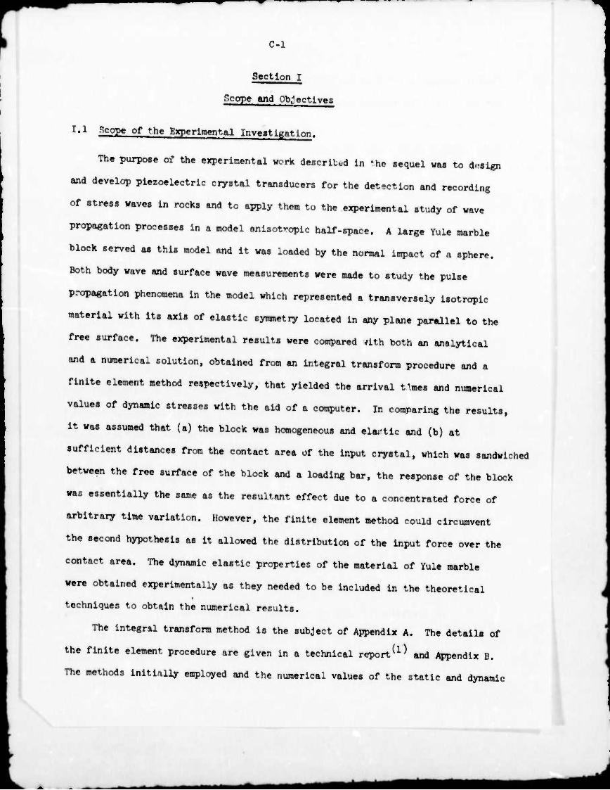
C-l
Section I
Scope and Objectives
I'1 Scope of the Experimental Inveitigation.
The purpose of the experimental work described In *he sequel was to design
and develop piezoelectric ciystal transducers for the det-ctlon and recording
of stress waves In rocks and to apply them to the experimental study of wave
propagation processes In a model snlsotroplc half-space. A large Yule marble
block served as this model and It was loaded by the normal Impact of a sphere.
Both body wave and surface wave measurements were made to study the pulse
propagation phenomena In the model which represented a transversely Isotropie
material with Its axis of elastic symmetry located In any plane parallel to the
free surface. The experimental results were compared rtth both an analytical
and a numerical solution, obtained from an integral transform procedure and a
finite element method respectively, that yielded the arrival times and numerical
values of dynamic stresses with the aid of a computer. In comparing the results,
it was assumed that (a) the block was homogeneous and elartic and (b) at
sufficient distances from the contact area of the input crystal, which was sandwiched
between the free surface of the block and a loading bar. the response of the block
was essentially the same as the resultant effect due to a concentrated force of
arbitrary time variation. However, the finite element method could circumvent
the second hypothesis as it allowed the distribution of the input force over the
contact area. The dynamic elastic properties of the material of Yule marble
were obtained experimentally as they needed to be included in the theoretical
techniques to obtain the numerical results.
The Integral transform method is the subject of Appendix A. The details of
the finite element procedure are given in a technical report^ and Appendix B.
The methods initially employed and the numerical values of the static and dynamic
*mm
C-2
elastic properties of Yule marble specimens so obtained are given In Appendix D
and Ref. (2). Two sets of val' es of the properties were obtained, one from saaples
taken from on» of the two blocks utilized in the present investigation and the other
from a slab of Yule marble secur-id separately for this purpose. The slab and
the two blocks were not secured from the same source and apparently were quite
dissimilar as suggested by some significant differences in their dynamic elastic
constants (Table k of Appendix D). Hence another set of dynamic elastic constants
was obtained from the wave arrival time measurements for the actual blocks based
on the procedure adopted in Ref. (2^. The details ar« given in Section VII.
1,2 Objectives of the Experimental Work.
The overaj.] objectives of the present investigation were the experimental
determination of the wave arrival times and stress histories in the interior and
very near the surface of a block of Yule marble due to normal impact of a sphere,
and the comparison cf such data wiLh corresponding theoretical predictions. This
test configuration models a transversely Isotropie elastic half-space subjected to
a concentrated time-dependent normal force on the free surface. The task Involved
the achievement of the following subsidiary objectives:
(I) The design and development of transducers using piezoelectric crystal
elements,
(li) The development of an embedding technique which was compatible with
the transducer design,
(ill) The calibration of the transducer and the correlation with the in situ
calibration in rock bars.
(Iv) The construction of a large number of trensducc-s.
(v) The generation and measurement of the input pulse using a crystal
transducer sandwiched between the free surface of the model half-space
and a loading bar.
C-3
(vO The drilling of long narrow holes in a rock block and the installation
of the transducers using a suitable bonding agent,
(vii) The detection and recording of body waves and the determination of arrival
times and sTess histories in an Isotropie half-space modeled by a
15" x 15" x ll|" Bedford limestone block,
(vili) The correlation of the data obtained in the model i.otroplc half-space
with corresponding theoretical results, thus testing the satisfactory
nature of the embedding technique,
(ix) The verification of the in situ calibration procedure by the above
correlation,
(x) The detection and recording of body waves In an anisotropic half-space
modeled by a Yule marble block and the measurement of their arrival
times and stress histories at specific locations In the Interior of
the block.
(xl) The detection and recording of surface waves In the anisotropic half-
space modeled by a second Yule marble block and the measurement of their
arrival times and stress histories at specific locations near the surface
of the block.
The present experimental Investigation was undertaken essentially as a
continuation of the previous surface-wave study of Ref. (2). However, the use
of the piezoelectric crystal transducers Instead of the semi-conductor strain
gages employed In Ref. (2) considerably facilitated the measurement techniques.
In particular, the highly sensitive PZT crystals not only allowed the delineation
of a normal transient stress component In a specific direction at a predetemlned
location of the Interior of the rock, but also permitted the use of a low stress
level Input pulse on the free surface of the rock. This In turn enabled the
meas- -ement of the Input pulse by means of an x-cut quartz crystal sandwiched between
the rock surface and a loading bar. The utilization of a low stress level Input
pulae prevented the occurrance of local damage at the impact location. The
experimentally determined input pulse was used in the two theoretical techniques
to obtain numerical results of wave arrival times and stress histories.
The two blocks of Yule marble measuring 20" x 20" x 10" were mined at
Yule, Colorado and the Bedford limestone block was from Bedford, Indiana.
The blocks were supplied by the U. S. Bureau of Mines, Twin Cities Mining Research
Center, Minneapolls, Minnesota. One of the Yule marble blocks, which was previously
(2) used for the surface wave studies^ ', was employed for the present body wave
measurements and the other was utilized for the present surface wave experiments.
Section II
Design. Development and Calibration of the
Piezoelectric Transducers
The different stages of the development of the transducer and of a compatible
embedding te^nnlque are described in this section. The calibration procedure of
the transducers is also presented.
II.1 Design and Development of the Transducer.
The purpose of the development work was to design a transducer which could
be embedded in a rock model and used to detect and record a stress component of a
pulse in a given direction at a certain location in the medium and to develop
simultaneously an embedding technique compatible with the transdice- design.
Initially, a number of experiments were conducted to establish satisfactory
techniques of measurement of one-dimensional pulse propagation with piezoelectric
x-cut quartz crystals useu in a compression mode. Later on, the more sensitive
PZT crystals were employed for similar measurements before establishing a final
transducer design using the PZT crystals as the transducer elements. The crystal
axes for the corapress.'.on mode x-cut quartz and PZT crystals are shown in Fig. 1
and the corresponding piezoelectric constants are listed in Table 1. The equivalent
^^■^
C-5
electric circuit of a piezoelectric crystal used in the compression node is
described in Ref. (3). Such a crystal may be represented as a charge generator
and the potential difference between its faces is given by
k (Cl)
where q is the charge generated and Ct is the capacitance of the crystal. If
the external capacitance of the circuit is C8 which include« the capacitances
of the connecting wires, connectors and the input capacitance of the connecting
device, then
In the case of the x-cut quartz crystal or a ceramic crystal used in the
longitudinal compression mode, the piezoelectric relations reduce to
(:-?)
(0-3)
where a is the uniformly distributed longitudinal stress, A is the area of the
crystal, and d is the appropriate piezoelectric constant. Kqs. (2) and (3) may
be combined to give
. v(ct*V VC
A • d Ad (C-M
where d « d^^ for an x-cut quartz crystal and
d = d33 for a piezoelectric ceramic crystal, used in the compression mode.
The crystals were utlized to record longitudinal pulse propagation in
bars using the established technique of a split Hopkinson bar arrangement^.
Two procedures of recording the output from an x-cut qvartz crystal, which was
sandwiched between two aluminum bare of the same diameter as the crystal and
subjected to longitudinal impact, were employed, namely a voltage amplification
method and a charge amplification method. Comparison of the data obtained from
the two methods with the corresponding strain gage pulse shape indicated that the
^*m ^■MtfBl
C-6
low frequency response with charge «mpllflcation was superior. In the case of
PZT cerandc crystals, the voltage amplification method reproduced the longitudinal
pulse propagation with good fidelity, indicating a much better low frequency
reponse of the PZT crystals than that of x-cut quartz crystals without an/
additional shunt capacitance.
Preliminary experiments with circular x-cut quartz crystals, 1/8" dia.
x 1/32" thick, embedded in rock bars indicated that such crystals may be used
effectively for the detection of longitudinal pulse propagation^ '. Initial
experiments were performed in rock bars of about 3/U" in diameter subjected to
central longitudinal impact with a crystal completely embedded at one section
of the bar. This involved the attachment of lead wires to the crystals using
Electrobond l20l6 adhesive manufactured by Adhesive Engineering Company. A bar
about 18" long was cut into two and a hole 3/l6" in diameter and 3/l6" deep was
drilled on one end of one of the segments in the center. A diamet al groove
was sliced across the hole to accomnodate the lead wires; the hole was then
filled with a mixture of epoxy and rock powder and the crystal was embedded in
this conpoaite. The other segment was then bonded to the firjt to produce a
single test specimen with an internal transducer.
Strain gages were mounted on the opposite ends of a bar diameter at a poiition
about 3" from the crystal position. These gages were incorporated In a potentio-
metric circuit and were coupled in series to eliminate any antisymmetric components
of the transients from th? records. A V diameter steel ball was dropped from a
height of 14 feet onto ^he end face of the vertically held bar and the resulting
pulse was detected by both the strain gage and the crystal and recorded on an
oscilloscope. A comparison of the crystal response with the corresponding signal
from the surface strain gages showed a distortion in the former. A second experiment
with an x-cut quartz crystal totally embedded la another bar indicated that even
though such crystals effectively detect the stress pulse propagation, the crystal
C-7
signal conaiatently showed similar distortion. This wr.8 succetefully eliminated
by the removal of the lateral constraint on the crystal by surrounding the crystal
Kith a rubber ring. In consequence, it was concluded that the coupling between
the polerUation in the x-direction. which coincided with the longitudinal direction
of the bar, and the stress on the lateral side of the crystal influenced the
response of a totally embedded crystal.
This effect was confirmed when two identical x-cut quartz crystals were
embedded in the same rock bar. One crystal was totally embedded and the other
was laterally unconstrained by surrounding the crystal with an annular rubber
ring. The response of the former again exhibited a distortion in the recorded
pulse shape as compared to the corresponding response of the latter and the
signal from the strain gages. The totally embedded crystal also recorded a
lower amplitude. Therefore, to measure a truly one-dimensional stress, a
transducer which could be embedded in a rock bar and yet would retain the freedom
of the crystal element from lateral constraint had to be devised.
In or.er to achieve such a design. It was deemed necessary to mount the
cryatal In a housing which would prevent any bonding material used in the embedment
process fr^m surrounding the crystal itself. In principle, the housing consisted
of two metal end pieces separated by a glass washer, of the aaiar, thickness as the
crystal, with the crystal encased in the arrangement. The freedom of the crystal
from lateral conatraint was achieved by maintaining a small air gap, about 0.002"
wide, between the outside diameter of the circular cxystal and the Inside diameter
of the glass washer. Lead wires attached to the metal end pieces completed the
transducer assembly. The calibration of such a transducer using a circular x-cut
quartz crystal, 1/8" dia. x 1/32" thick, as the transducer element was successfully
accomplished by the split Hopkinson bar technique(U). However, an alternative
embedding procedure to the one originally envisaged prevailed, requiring a simple
redesign of the transducer as explained below.
C-8
In the development of a suitable embedding technique, the preliminary
experiments were conducted with rock bars cored from a slab of Yule marble.
The following alternatives were considered: (a) The lead wire arrangement of
the transducer assembly described above was modified^ ' to pemit ready insertion
in a relatively deep cored hole of the snme diameter as the transducer in a rock
bar. A 3" deep hole was core-drilled coaxially in a 9" long bar and the trans-
ducer >fa8 Inserted and anchored at the base of the hole using a mixture of rock
jowder and epoxy as the bonding agent. The hole was then filled with the same
mixture of rock powder and epoxy after extracting the wire leads out of the
hole, (b) The same pr ^dure as described in (a) was followed except that the
filler material used was a mixture of aluminum oxide and epoxy. Based on the fact
that Yule marble has an acoustic impedance higher than that of epoxy and lower
than that of aluminum oxide (Table 2), it was thought that such a mixture
in appropriate proportions would provide a better impedance match with the
Yule marble than the mixture of rock powder and epoxy. (c) A metal bar, whose
acoustic impedance matched that of Yule marble with the crystal assembly mounted
on one end was considered since such a bar could be Inserted easily into a deep
hole. Since magnesium has an acoustic Impedance closely matching the average
acoustic impedance of the Yule marble material (Table 2), a transducer assembly
was constructed using a 3/l6" diameter bar of magnesium as shown in Fig. 2.
Experiments with rock bars and a sandstone block indicated that the embedding of
the transducers would be considerably facilitated with such a design. Hence a
final transducer design in the form of a magnesium bar with the crystal element
attached at one end was adopted. The ".ystal was again encased in a glass washer
and a metal end piece arrangement. A lead wire was attached to the metal end
piece and extracted out through a groove machined along the length of the bar
and a second lead wire was attached direc j.y to the bar (Fig. 2).
c-9
11,2 Choice of the Plezoelectrjc Cryatal Element.
An examination of the piezoelectric constants of quartz and ceramic crystals,
shown in Table 1 indicates that when these crystal, are used in a compression «ode
a truly one-dimensional stress measurement is obtained. Now if such a crystal
were to be embedded within a rock »ediun, it would be subjected to a complex stress
field in any general three-dimensional stress wave propagation situatio.:. It is
then not possible to delineate the stresses at a location of the medium completely
with one compression mode crystal. However, if the crystal properly measured the
stress in one direction it would give useful information concerning such a
component at this position. In some cases, such as for an axlsymmetric state of
»tress, several crystals may be suitably located to take advantage of this symmetry
so that more Information may be obtained regarding the state of stress for a given
pulse at a point In the medium without repeating the test.
To obtain the stress along the axl8 of an embedded compression mode
crystal, the foUowlng conditions must be met: (I) The crystal must be free from
any lateral stressj (11) The charge generated across the crystal must be dependent
only on the normal stress on the crystal, I.e., there cannot be any coupling
between the face shear stress which Is the shear component of the stress vector
acting on the crystal face and the polarization In the compression mode; and
(III) The crystal must be embedded In a manner so that It responds to both com-
presslon and tension.
The first condition was met by the design of the transducer. In the case of
x-cut quartz crystals, the cross coupling between the fare shear and the polarization
in the x-dlrectlon Is revealed by the non-zero piezoelectric stress constant d , 1U»
which Is one of the two Independent constants relating the electric charge to the
stress tensor In this type of crystal material^, m general, the electric charge
density or polarization and the stress are related by(5^
C-10
^1= ^^.l
where the subscript i takes the values 1,2,3 and the subfcript j takes the
values of 1,2,...,C. With reference to Fig. 1, the x,y,z axes correspond to
the subscripts 1,2,3 and the yz, xz and xy planes correspond to the subscripts
U,5,6 respectively. Thus the polarization in the x-direction or 1-direction for
an x-cut quartz crystal is given by
^1 B dllal + d12ff2 + dlUaU
where d12 ^ _d and th« other constants vanish (Table l). The effect of the
second term was eliminated by the design of the transducer based on the assumption
that there were no end effects due to the encasement of the crystal between the
metal end piece and the bar. However, the non-zero constant d.. , precludes the
use of x-cut quartz crystals for a truly uniaxial stress measurement in a
complex stress field. Novii for ceramic crystals, the compression mode direction
is the z-direction. Again referring to Fig. 1, the polarization in the z-direction
or 3-direction for a ceramic crystal in the compression mode is given by
^3 = Vl + d3202 + d33a3
where d^ » d-2, and the other constants vanish (Table 2). The effect of the
first two terms is eliminated by the design of the transducer and hence the
second condition cited above was met by the choice of PZT ceramic crystals as
the transducer elements. The construction of the transducer and embedment with
a strong bonding agent ensured that the crystal would respond to both compression
and tension.
Three types of ceramic crystals were used as the transducer elements, namely
PZT-U, PZT-5a and PZT-5H. Table 1 lists the various crystals used in the course
of the present investigation including the^r properties, dimensions, the name and
address of the supplier and where they were utilized.
C-ll
II«3 Construction and Assembly of the Transducers.
The initial development work was performed with PZT-5a crystals, 1/8" dia.
x 1/32" thick. A number of 3/16" dia. transducers were constructed to the design
shown in Fig. 1. Similar transducers utilizing circular PZT-5H crystals, 1/8" dia.
x 1/32" thick, were also fabricated. In the eventual measurements on the Yule
marble blocks, PZT-U crystals, l/l6" dia. x 0.020" thick, were used and the transducer
diameter was l/8" (Fig. 3) but the design was essentially the same as for the
3/l6" dia. transducer.
A special procedure was devised to mount a large number of transducers
conveniently, which enabi precision assembly. However, uniformity in assembly
could not be achieved due to a number of factors such as the thickness of the
epoxy adhesives, small variations in the thickness of the crystals and vu-iations
in the thickness of the glass washers. Hence the transducers had to be calibrated
individually.
II'^ Development of a Split Hopkinson Bar Arrangement for Calibration.
In order to utilize the crystal transducers for internal dynamic stress
measurements, a suitable calibration procedure had to be devised. Initial
calibration attempts with an earlier design of the transducer, using an x-cut
quartz crystal as the transducer element were quite successful^. The split
Hopkinson bar technique used in these experiments indicated that a piezoelectric
constant could be established for the transducer assembly as opposed to the
corresponding constant of the crystal itself (Fig.U). A comparison of the signals from
the surface strain ga^es, located both before and after the transducer, with the
crystal response showed that (i) it was possible to detect and record longitudinal
pulse propagation using the crystal transducer with good fidelity based on signals
from the strain gages; (ii) Neither the transducer nor the epoxy Joints between
the transducer and the aluminum split Hopkinson bars caused any significant
mm
C-12
reflections of the pulse at the transducer station, as is indicated by the
identical signals obtained from both the strain gage stations, and (iii) The
small air gap of about 0,002" between the crystal and the surrounding glass
washer did not cause reflections of the pulse. In view of the small thickness
of the crystal, namely l/32", compared to the length of the pulse employed in
these experiments (about 8 in.), these results confirmed the hypothesis that the
introduction of such a discontinuity would not interrupt the wave propagation
process^ . This conclusion was also significant in relation to the subsequent
use of the transducers for internal measurements.
The technique of calibrating the transducer by comparing its response with
a corresponding strain gage signal was also used for the final transducer design.
The transducer in the form of a magnesium bar with the crystal assembly at one
end made up one-half of the split Hopkinson bar arrangement (Fig. 5). The second
half consisted of another magnesium bar of the same diameter. The two bars
were attached together with an epoxy adhesive. Initial experiments were again
successful in the sense that the correspondence between the crystal response and
signal from the strain gages was very good and a piezoelectric constant could be
established for the transducer assembly. However, since the crystal housing
was in the middle of the split Hopkinson bar arrangement, the transducer could
not be disengaged from the second half of the composite bar without breaking the
rather fragile glass washer and end-piece assembly. Hence the bars were repositioned
as shown in Pig. 6 to allow a simple removal of the transducer after calibration.
By breaking the epoxy joinfc between the free end of the transducer bar and the
second half of the split Hopkinson bar, the transducer could be disengaged easily.
Two more magnesium bars were utilized, one in front of the transducer and the
other at the far end of the arrangement and were held firmly against their
respective contact faces with a thin layer of wax. The purpose of the former was
dmmtmm
C-13
to avoid striking the crystal assembly directly and the latter served as a momentum
trap to prevent the tension pulse reflected from the far end from damaging the
czystal assembly unit. The same physical arrangement was used for calibrating
both the 3/16" dia. and l/8" dia. transducers.
II.5 External Calibration of the Transducers.
The external calibration procedure for the transducers described in this
section holds for both the 3/16" dia. and the l/8" dia. transducers. For
illustrating the procedure, a 3/l6" dia. transducer using a PZT-5H crystal
is chosen.
The experimental arrangement for the calibration of the transducers is shown
in Fig. 6. The four bars are designated as the loading bar, the transducer bar,
the strain gage bar and the momentum trap. The construction of the transducer
ensured that the ends were smooth and square. The end faces of the other bars
were previously machined for good contact at the joints The transducer bar was
placed in position and its free end was attached to the strain gage bar with
Scotch-Weld 1838 B/A structural epoxy adhesive manufactured by 3M Company, St. Paul,
Minn.. The epoxy adhesive was allowed to cure. To accelerate the curing process,
heat was applied with a blow lamp; a temperature of about 1500F was attained and
the epoxy hardened in about 1 hour. The other bars were assembled as shown in
Fig. 6.
Since previous experiments indicated that there would be no reflection of a
relatively long pulse at the epoxy joint, only one strain gage station was
employed for comparison with the crystal response. This strain gage station,
about k" from the epoxy Joint, consisted of a pair of SE-h strain gages type
FAE-12-12S9L manufactured by BLH Electronics, Inc., Mass. bonded with EPY-150
cement. The strain gages, each exhibiting a gage factor of 2.03 + 1% and a
resistance of 120 ohms + 0.2^, were incorporated in a potentiometer circuit
- - - -- A *—M
C-lU
and were coupled in series to eliminate the antisyianetric components of a pulse. The
total capacitance of the crystal circuit was measured by means of an Impedance
Bridge type I65O-A manufactured by General Radio Company.
The crystal response was measured by the voltage amplification method. The
PZT crystals employed in the transducers were highly sensitive, capable of
producing voltages in excess of the maximum that could be -ecorded on the oscillo-
scope, thus requiring the use of a 100X attenuator before the output from the
crystal could be so recorded. For example, the d„ constant of PZT-5H crystals
from Table 1 is 2638 pc/Lb while the d^ constant for x-cut quartz crystals is
10.2 pc/Lb. Hence, in comparison with the voltages of abou*- 2.0 V obtained
with x-cut quartz crystals in the experiments wl^h the earlier design of the
transducer, voltages of the order of hOO V may be expected with the PZT crystal
transducers. However, even lower impact velocities of about 20-30 ft./sec. were
actually sufficient to obtain the necessary comparison with the corresponding
pulse from the strain gage station. A Tektronix type 565 dual beam oscilloscope
was employed to record both the strain gage signal and the crystal output on the
same oscillogram. The channel measuri.ig the crystal response with a band width
of dc to 300 kc. was carefully calibrated using the amplitude calibrator.
The pulse was initiated by shooting a 3/l6" diameter steel ball from an air
gun longitudinally and centrally against the impact end of the loading bar. The
oscilloscope was triggered using the amplified output from another crystal attached
firmly to the side of the loading bar with some adhesive tape and the various
pulse shapes were then recorded photographically. The strain gages were calibrated
by the dynamic shunting of external resistances into the potentiometer circuit
and recording the corresponding deflections of the trace' . With the aid of a
simple experiment involving longitudinal pulse propagation in a 3/l6" diameter
magnesium bar, the dynamic modulus of magnesium was determined. A value of
C-15
6.32 x 10 pai was obtained which conpared well with the atatic modulu« of
6.5 x 10⁶pai(7).
With the aid of Eq. (C-U), the measured total capacitance of the tranaducer
circuit including the input capacitance of the attenuator, the area of the trana-
ducer face (not the area of the crystal face), the peak voltage output from the
crystal and the peak atress, the piezoelectric conatant for the tranaducer was
evaluated. Thia gave an equivalent constant for the tranaducer as explained in
Flg. U. This conatant obtained by such an external calibration was designated
by the symbol K.
II.6 In gjtu Oallbration.
Body wave measurements In a limestone blook^, indicated that the external
calibration procedure alone was Insufficient to obtain stresses from internal
measurements. Such a conclusion was reached after embedded measurements in the
limestone block uaing wax as the bonding agent did not correlate with the
corresponding results obtained by the finite element method. The meaaurementa
apparently failed to give satisfactory results because:
(i) The transducers were not calibrated individually. It was originally
assumed on the basis of calibrating two transducers externally that
the external calibration constant would be nearly the same for all
transducers using the same type of crystal element. However, It was
later found that the external calibration constants depended on the
tolerance of the individual elements making up the crystal units and
varied considerably from one transdicer to another;
(II) The wax used as the bonding agent pnved Ineffective for transmitting
tensile stresses, and;
(III) A calibration procedure was not established to correlate the external
calibration constant with an in situ calibration.
*am
C-16
Hence additional experiments were performed to devise a suitable method
for in situ calibration in rock bars. Tests on limestone rock bars with embedded
transducers using wax as the bonding agent again indicated an inconsistency between
the transducer response and the rurface strain gage signal. The transducer output
varied depending upon the contact inside the hole between the transducer face and
the material of the rock. Since an epoxy type of Joint had proven to be effective
in a number of earlier applications, such as the external calibration of the
transducer, a mixture of aluminum oxide and epoxy was considered a more suitable
bonding agent between the transducer and the rock material. Similar experiments
with limestone rock bars with emtedded transducers and surface strain gages
showed that the correspondence between the embedded crystal response and the
signal from the strain gages was more consistent when a mixture of aluminum oxide
and epoxy was used as the bonding agent.
II.7 Correlation of the External Calibration with In Situ Calibration In Rock Bars.
A limestone bar with a diameter of about 3/U" and a length of 15" was chosen
for the in situ cillbration because the dynamic mismatch between limestone and
magnesium was found to be less than % as shown in Table 1, An experiment was
executed to measure the longitudinal stress pulse propagation in the bar using a
transducer In the embedded state. A comparison of the transducer response with
surface strain gages was expected to give an In situ calll ration constant for the
transducer, say K,. The objective was to correlate this constant with that obtained
by external calibration.
A 3/l6" diameter transducer 10" long (Fig. 2 ) was constructed using r, 1/8" dla.
x 1/32" thick PZT-5a crystal. A 3/16" diameter hole about 8" deep from one end was
core-drilled coaxially in the limestone bar. The drilling was performed with a
diamond drill supplied by Keen Kut Products, Burlinga^e, California. The trans-
ducer was calibrated externally and the constant K was established. The transducer
C-17
was then liwerted in the hole, uaing a mixture of epoxy adhesive and aluminum
oxide aa the bonding agent, thus securely anchoring the crystal assembly end of
the transducer at the bottom of the hole. A pair of SR-U semiconductor strain
gages were mounted at the same section of the rock bar aa the crystal station.
The strain gages were of the type SPB 3-12-12 manufactured by ELH Electronics
Inc., Moss, and EPY-150 epoxy cement was used for bonding the usages to the rock
bar. The gagea were mounted on the oppoaite ends of a diameter of the bar and
coupled in aerlea to eliminate antiaymmetri'; effects and incorporated in %
potentiometer circuit. The experimental arrangement is shown in Tig. 7. A
thin layer of Electrobond #2016 conducting epoxy adhesive manufactured by
Adhesive Bigineering Company was applied to the Impact end and a lead wire
was taken off the epoxy. The epoxy layer was polished to a amooth surface.
The surface waa then smeared with seme conducting epoxy without the hardener.
The rock bar was subjected to central longitudinal ijnpact through an 1/8"
diameter aluminum loading bar with 1/8" dia. x 1/32" thick x-cut quartz crystal
sandwiched between the loading bar and the rock bar. Again, a thin layer o*
conducting epoxy without the hardener was applied to the contact faces of the
crystal and the loading bar. A second lead wire waa attached to the loading
b^r cloae to the crystal. Thia cryatal atatlon waa utilized to measure the input
pulse with the aid of a charge amplifier. The pulse was generated by shooting the
Impact end of the loading bar with a 3/l6" dia. steel ball fron m air gun at a
velocity of about 20 ft/sec. The input pulse and the signal from the calibrated
strain gages were recorded on a dual-beam oscilloscope and the embedded crystal
response was recorded on another oscilloscope.
The input pulse measurement obtained by charge amplification was effectively
a fcrce-tlme record. A comparison of the Input pulse and the strain-time record,
Mine the area of the cross section of the limestone bar and a value of 5.0 x 10⁶ psi
for the dynamic elastic modulua of limestone, showed good correspondence. This
mm
C-18
Indicated that the input measurement by means of an x-cut quartz crystal loaded
through a loading bar was correct.
The experiment was repeated using voltage amplification for the measurement
of the input pulse and similar agreement as above between the strain pulse and the
force-time record proved that either method of input measurement was reliable.
The capacitance of the transducer circuit was measured and the input capacitance
of the oscilloscope was added to give the total capacitance of the circuit. With
the aid of Eq, (C-U) the stress-time record was established from the transducer
response for both experiments. A comparison of the peak stress from the stress-
time record and the peak strain from the surface strain gage data using the same
value of the dynamic elastic modulus of limestone enabled the establishment of
an in situ calibration constant for the transducer. It was found that this
constant K.. was related to the external calibration constant K by
J. _ a K " Ä (CX5)
where a is the area of the crystal face and A is the area of the transducer face.
Similar experiments involving a second limestone bar with an embedded transducer
which was previously calibrated externally and surface strain gages yielded the
same correlation.
Since it was obviously not practical to establish a correlation between the
external calibration constant and the in situ calibration constant for each
transducer, the above correlation was accepted to hold for all transducers. Thus,
each transducer was calibrated externally and individual constants, K, were
established and subsequent internal measurements were expected to yield values
for stresses using this constant K and the above correlation.
MMMMM
C-19
Section III
Body Wave Propagation In An
Isotropie Rock Model
III.l' Introduction.
The method of the measurement of body wave propagation in a model Isotropie
half-space, repre8ent«d by a Bedford limestone block, 15" x 15" x 111", generated
by sphere impact perpendicular to the free surface is described in this stction.
These experiments were preceded by body wave measurements with the same block
as described in Ref. (8). The earlier experiments failed to give satisfactory
results for the reasons given in II.6 and the lack of agreement between the
experimental results and the theoretical predictions prompted a reappraisal of
the calibration procedure and the bonding technique (cf. II.6 and II.7). The
main purpose of the experiments described in this section was to test the validity
of the correlation between the external calibration and the in situ calibration
in rock bars established in Section II and to confirm the satisfactory nature of
the bonding technique. In order to meet these objectives it was necessary:
(1) To establish the necessary technique for drilling long holes of small
diameter, with diamond core drills, in a block of rock material,
(il) To install externally calibrated transducers in the holes using a
suitable bonding agent.
(ill) To devise a method of generation and measurement of the input pulse
using a spherical steel ball as the striker,
(iv) To detect and record body wave propagetirn and obtain arrival times,
(v) To obtain stress histories in particular directions at certain locations
in the rock medium by using the correlation between the in situ calibration
and the external calibration established in Section II,
M^te ■M^MflHtaflHM
C-20
(vi) To compare the experimentally obtained stress-time records with the
corresponding theoretical results obtained by the integral transform
analysis and the finite element method and hence to verify the cali-
bration procedure.
(vii) To confirm the satisfactory nature of the embedding technique, and
finally;
(viii) To establish the experimental techniques that would be used later for
• the study of the wave propagation processes in the model anisotropic
half-space.
III.2 Installation of the Transducers.
The limestone block was drilled using a 3/l6" dia. x 10" long core drill
on a press especially adapted to provide a continuous supply of vater. Ilhe
transducers previously embedded with waxv were removed. In the process of
removal, the crystal assembly ends of two of the transducers broke off inside
their respective holes. These ends were removed by drilling them out with an
extended 3/l6" dia. flat bottomed fluted drill driven by a hand-operated power
drill. The deep holes were cleaned by pouring acetone down the holes and
inserting the long fluted drill inside the holer and rotating by hand until there
was no trace of metal filings or wet rock powder in the flutes when the drill was
removed.
A total of four transducers with 3/l6" dia. magnesium bars utilizing circular
PZT-5 crystals were constructed (Fig. 2); two of the transducers utilized PZT-5a
crystals and two featured PZT-5H crystals as the transducer elements. Each
transducer was about 10" long and was externally calibrated with constants given
in Table 3. The transducers were cleaned with acetone to remove any traces of
grease from previous machining operations. The hole depths in the rock were
carefully measured and the corresponding lengths were marked on the transducers.
C-21
A mixture of aluninun. oxide and epoxy was prepared heated with a blow leap to
make it flow more easily, and smeared on the transducer«. A liberal coating
was applied so that the crystal assembly end of the transducer had a l/l6N
thick layer of the bonding agent around it. The transducers were then installed
in their respective positions. The secure anchoring of the crystal assembly
ends at the bottom of the holes was insured by observing that the previously
provided markers on the transducer bar« maintained a certain predetemined distance
from the rock surface. The transducers were lightly pushed into position. Heat
was applied to the rock by means of a blow lamp. A temperature of about 1500F
was attained on the rock surface. The bonding agent was allowed to cure for
about one day. Low noise cables, each about 3'-0" long with BNC connectors at
their ends were attached to the transducer leads. The transducer locations are
indicated in Fig. 8. During the calibration of the transducers, the polarity
of each transducer was also determined.
III'3 Generation and Measurement of Input Pulse.
A stress pulse of low magnitude such as one generated bg tapping the
free surface of the block was sufficient to detect pulse propagation with the
embedded transducers. Such a pulse was recorded by connecting one of the transducer«
to a type 5U9, Tektronix storage oscilloscope and triggering the scope internally.
All the embedded transducers were tested this way to make sure they were functioning
properly. It was clear that a sufficiently strong inpact could be achieved by
shooting a 3/16" dia. steel ball with an air gun at a low velocity but it was
restricted to such a stress level that the impact through a 1/8" diameter loading
bar, a« described in II.7, on a 1/8" dia. x-cut sandwiched quartt crystal. Fig. 9,
did not break the sensor. The input was measured by mean« of charge amplification
using a Kistler s/N U77 unit. A charge sensitivity of 10.2 x lO"12 coulombs/lb
was used; this was the value obtained in the course of the present investigation
mt^am^^mM
C-22
" MMHM in M. (M. Th, 0.CIU0.C0P.. „„ trtgg.r., ^ Man. of the mpllfl)((1
output of mm* ory.t.1 .ttaohed to M. io^lng k» rtout U" «Ml „f th. Input
crystal.
III.U Meaaurewent of Body Wave Propagation.
The experlnental arrangement employed is shown in Fig. 9. The limestone
block was set up on a table which could be adjusted in three mutually perpendicular
directions by means of cross slides, each provided with a screwed spindle and a
handle. The block was aligned with the aid of a precision level and a triangle
so that the loading bar was perpendicular to the free surface. The capacitances
of the transducers and the respective cables and connectors were measured by mean,
of the impedance bridge cited in II.5. The total capacitance of each transducer
Mrcuit was obtained by adilng the input capacitance of the oscilloscope plug-in
unit to the measured capacitance. The voltage amplification method was employed
to record the response of each of the embedded crystals.
The limestone block was adjusted by means of the three perpendicular motions
of f . table for aligning the chosen impact position on the rock face with the
loading bar. The motion of the table parallel to the gun was used to keep the
input crystal sandwiched flmly between the free surface of the rock and this bar.
At each impact location the rock surface was prepared in the manner described
in II.7 so as to attach a lead wire for measuring the input pulse but still allowing
the crystal to have a good flat contact with the free surface of the rock. The
second lead wire was again attached to the aluminum loading bar close to the
crystal station.
The input pulse, generated by shooting a 3/l6" dia. steel ball with an air
gun, and the internal measuremenvs, called the outputs, were recorded on Tektronix
type 565 dual beam oscilloscopes. A number of measurements „-„ taken for
C-23
dirr.r«* lmtt 10KtlM.. Tor Mch .uch po<ition m ^riMnt ^ ^^
to M IMUI,. ». ^u^. or «. lnput ^ rlrt „^
. mm* or th. i.p.ct umum. «„^ .trN.„ „ approprlite scsie ^^ ror th. v^oo. „OOM. „e elven. ^ BtaUon sra>ed tiie ^^ ^^^ ^
«.. onr.ta «u. i... tn the ilncUm ot the ^^^ ^ por ^^^
rororr^ to ng. 6, .tatlon. , ^ U M..ur.a ^ ^ .tsUoo. , „„ , ^^
JCX
No att^t .„ „^ to »***„ *, „^ yelocltlM. Slnce the lnput
PUU. «. ob„^ airoctiy «i .uch . «tho. or immmm «a ro^ to b. r.U.hl. .. lmMm „ „.,, lt „„ not ^^ McMsiiy ^ ^^^ ^ ^^
or i^ct „„ r.bou„d „„ to „^ the lnput ^^^ ^ ^^^^^ ^ ^^ ^
-.„to,. At hlgher lnpsct ^^^ thls ^^^^ couid ^ ^ ^^ ^
MM. or th, onr-t.! would occur, 1„ thl, .v.«, th. mm. coui. h. r^UC by . ..t or MM, gw. mount^ on th, loadlng bar thit TOU1(1 ^^^^ ^ ^^
« th. UM,«, „.t««, th. „COM. or th. i„iu.i .i th. rim „ri.ct.a pulse paasage.
A «MM dl.cu..lo„ or th. r..ult. 1. glv.„ l„ sootion VIH. R U only
mentioned here that the data Mreed well *Htv, ♦>,- *u ^^ , ■w agreea well with the theoretical values for arrival
ti«. «I .tr... hl.torl.. .. „opiotoa „ Flg. , of th. ^ ^^ ^ ne^ ^
to 12 (... T.bl. 3), indicts that th, calibration procdur. va. valid and th.
,»b,ddlng t,chnl,u, v., .aturactory. „,. bondlng Wnt .lao proved ,rr,ctlv,
and th, ,,p,riM,nt.l t,chnl,u,. d,v,lop,d provldod a rall.bl, n,an. or dot,*!,*
and recording body waves.
C-2I+
Section IV
Body Wave Propagation In An
Anisotropie Rock Model
IV. 1 Direction of the Axis of Elastic Symmetry.
The main objective of the present experimental investigation was the study
of body wave propagation in an anisotropic half-space modeled by a 20" x 20" x 10"
block of Yule marble that represented a transversely Isotropie half-space with the
axis of elastic symmetry in a plane parallel to the 20" x 20" free surface. In
a previous surface wave investigation^ '^' involving the same block the axis
of elastic symmetry was located by crystallographic analysis of a thin sample
prepared from a trapezoidal piece of material cut from one comer of the block.
However, in Ref. (9) the authors expressed some uncertainty about the actual
direction of the axis of elastic symmetry (AES). In the course of the present
work, another attempt was made to determine the direction of the AES. Another
crystallographic analysis did not locate this direction with any more accuracy,
but the discolorations in the block due to impurities indicated that the AES
might be located about 15 from the one previously determined, as sketched in
Figs. 13 and Ik. However, the body wave measurements were expected to give
additional evidence through wave arrival times to substantiate the direction of
the AES.
IV.2 Determination of Transducer Locations.
With the AES located as shown in Fig. 13, the transducer locations had to be
determined so that (i) The transducers may be utilized to detect and record body
wave propagation due to the impact of a sphere on the free surface of the block
without interference by reflections from the boundaries; (ii) The distances of the
transducers from the impact position were such that the signal to noise ratio would
.a^aa-aaMte ^fl^^Mi
C-25
allow the detection of the transients initiated on the free surface by shooting
3/l6" diameter or l/U" diameter stesl balls from an air gun at velocities which
would not break the input crystal; (iii) The various observation points in the
interior of the block would yield wave arrival ulmes along a number of rays
oriented at different directions to the AES; (iv) The transducers would yield
representative stress histories, each transducer measuring the stress in a
specific direction at the observation point relative to the impact location,
and (v) Advantage was taken of the symmetry of the block in locating the
transducers so as to obtain stresses in different directions but effectively
at the same location relative to the impact position.
The signal to noise ratios from the previous experiments on the limes-.one
block and a comparison of the sensitivities of the 3/l6" diameter transducers
employing l/8" diameter PZT-5 crystals used in these experiments with the
sensitivities of the l/8" diameter transducers employing l/l6" diameter
PZT-U crystals for measurements f.n the Yule marble block indicated that the
transducers could be located up to about 5" from the impact position. The transducers
were required to detect the body waves produced by the impact of a sphere on the
free surface achieved by shooting a 3/l6" diameter ball at velocities comparable
to those employed in the limestone block experiments without either significant
noise or without breaking the 1/8" diameter crystal that monitored the input. A
drop test of a l/k" diameter steel sphere from a height of about k feet on the top
of a sandstone block with a transducer held against the side of the target indicated
the capability of transducers to detect pulses of the level described above.
Eventually l/k" diameter x 0.1" thick x-cut quartz crystals were also used for the
measurement of the input pulse that were capable of withstanding higher input
stress levels and hence offered better conditions of measurement. In fact, the
transition from the 3/16" diameter to l/8" diameter transducers was made after
taking into f.ccount the above considerations. There was no further need to determine
•AMk^^^i
C-26
an acceptable signal level for the present experiments.
The center of the surface, designated Po in Fig. 15, was chosen as the
principal impact location. The pulse length obtained in the limestone block
experiments ranged from 30 to kO ^ec and was expected to be about the same for
the marble. This block was 10" deep and previous experiments on the specimen
Indicated that the fastest wave speed corresponded to about 5 usec/in in the
direction of the depth. It was thus estimated that the first passage of the
pulse could be recorded up to a distance of 5" from the impact location without
interference due to reflections from the boundaries. Thus the size of the block,
the transducer sensitivity, the length of the pulse, the velocity of impact, the
requirements of the input measurements and the fact that the response was
required at a sufficiently large distance away from the Impact position (so that
it could be considered essentially as the response due to a concentrated load of
arbitrary time variation as was assumed in the integral transform method (Appendix A))
all had to be considered in determining the positions of the transducers.
The locations of the transducers should be such as to display all the
distinctive features of the wave propagation phenomena as suggested by theoretical
predictions. Originally, significant differences in the slowness surface from
the corresponding isotropic case were expected on the basis of the dynamic elastic
constants cited in Ref. (9) that, resulted in a tripartition of wave surface; the
initial selection for the transducer positions reflected these characteristics.
However, the present body wave measurements resulted both in a relocation of the
axis of elastic symmetry, as shown in Fig. lk, as well as in new dynamic elastic
constants, as described in Section VIII, that did not predict a wave surface
partition. Henre, the exact locations of the transducers no longer needed to
correspond to any particular behavior of the wave propagation phenomena except
that they were conveniently located to yield the wave arrival times and stress
histories which could be compared with corresponding theoretical predictions.
C-27
^e transducer locations are shovm in Figs. 16 to 21. impact positions
other than the center of the free surface were alno e^oyed. privily to obtain
Information on body waves detected by transducers located nearer to the impact
position, such data were called the near field response of the block while the
data obtained by central intact were termed the far field response. The near
field data were obtained prWily for comparison with corresponding results
obtained by the finite element method which was not particularly suitable for
fa. field comparison due to excessive computing time required to secure numerical
results.
IV.3 Transducers Employed.
Transducers in the form of l/8" dia. magnesium bars with the crystal assembly
on one end, as shown in Fig. 3, employing PZT-l. cxystals as the transducer
element were used for the body wave measurements. Care was taken in the
assembly of the transducers to preserve the outside dimension of 0.126 + 0.001",
which was the dialer of the bar, especially near the crysta! end. ^ transducers
were identified and externally calibrated using the procedure described in Section
II. Linearity of response, repeatability and reproducibility were established.
The polarity of individual transducers was also determined. A total of 18
transducers were selected for the body wave measurements. The correlation with
the in situ calibration in rock bars and subsequent verification of this by the
measurements in the limestone block provided a means of obtaining individual
stress factors for the transducers (see Table 3).
W.k Preparation of the Yule Marble Block.
The general technique of drilling the Yule marble block was the saae as that
employed for drilling the limestone block, described in Section III. previous
experience with slabs and rock bars showed that long holes of small diameter could
be drilled straight and smooth in Yule marble fabric with diamond core drills.
■an
C-28
The drills enrployed were 1/8" in dimeter (0.128" * 0.001") purchased from
Keen-Kut" Products, Burlingame, California.
The block was marked for drilling with depths of the holes carefully noted.
Pilot holes were made with an electric hand drill to facilitate the starting of
the core drill. During these operations, care was taken to keep the center of
the drill free from any clogged-up or powdered material so that a profuse supply
of water was constantly kept flowing down its center. The operations of drilling,
finishing of the holes by means of a 0.128" dia. flat bottomed extended fluted
drill and subsequent clearing of the holes to remove excess powdered rock material
were performed as described in Section III. Straight holes with smooth sides of
the required diameter were obtained. It was noticed that there was no significant
drift of the core drill even in the drilling of the deeper holes; the maximum
depth was about 8|", as checked by inserting a l/8" dia. bar in the holes and
verifying that the extended bar was normal to the rock surface. JV total of 18
holes of various depths were drilled, 6 from each of three sides of the block.
The three directions corresponded with the X,Y,Z axes defined in Fig. lk.
The previously calibrated transducers were installed in the holes following
the same procedure as described in III.3. A mixture of aluminum oxide and epoxy
was again used as the bonding agent. Similar precautions as described in III.3
were taken to make sure that the crystal assembly ends of the transducers were
securely anchored at the bottom of the holes. Heat was applied to the rock by
means of two infrared heat lamps and the bonding agent was allowed to cure for
a day. As before, Endevco low-noise cables about 5'-0" long were soldered to the
transducer leads and the ends of the cables were provided with BNC connectors.
IV.5 Body Wave Propagation Measurements.
The experimental arrangement for the Yule marble teste «as similar to that
shovn in Fis. 9. The hloc. was arrayed on the tahle employed prevlouely for the
HA^.^^MMMflMMH
0-^9
U^tcne bloolt. It „ ,_, convTOUnt ^ ^ ^ ^ ^^^ ^
Pe^lcuU. to tta fre. s^e on« it TOS so a,Justed. ^ ,_ ^ ^
input gen.ration „d MUl^e„t ., charge ^Xinc.tton as „sa. « prevlou.
occaaicn. va. ae.1„ e*^.. m. tlme 8ln0e clrcular ^ ^^ ^^^
V8" *War or VV aia.ate. ... uUU.e., a Xoa^, bar of *. srae dUMt,r
as the crystal was used to transmit the pulse.
iw t.«^ type ^ aual bera osclUo8copes ^ ^^ for ^^^^
tha output» tro. thre, ™bedaea transauce.s for each i^ot. ft. ^ WM
record.* ei^ltaneousl, on the three oscUloecopea alo^ vith the reapectlv.
-tput. so that the wave arrtval tLea coula he direct^ ohtalned for each
transducer location.
«ost of the data „ere ohtalned hy cettr^ Impact on the free eurfac.
desisted Po in Pig. 15 aUhon* other i^act location.. ^ Plg. „,
«re also used. Por detecting and recording the hody waves by .o.. of the
«re distant trsnsducers at aa^etrical stations, sn input pulse with a higher
stress level was retired. However, this womd have hroken the 1/6" dia.et.r
crystal and damaged the rock surface A+ +v,o ^ «. i CK sun ace at the impact location; thus, it was found
expedient to use a l/k" diameter x 0 1" +h^v / aiame^er x 0.1 thick x-cut quartz crystal for the
nons^rical i^act locations. The smaller costal was adequate for .ensuring
the lower stress level input pm« fro. central tapact. Both 3/16" dimeter ^
l/k- dimeter steel halls were used, the latter produced an increase of ahout
10 ^e=s in thepulse length. With the uns^etrical i^act positions. so.e of the
transduoers were ahout l-S/V- frOT the i^act locations, ft. „sponses fro.
these transducers were recorded to ohtain the near field response of the hiock
in addition to the ahove hody wave „easureMents, transducers at special
locations relative to the Ms „ere chosen to determine arrival ti... along
directions parallel to the ABS inside the hlooh and along directions parallel
C-30
to the AF£ BLB determined previously1 . These measuretnentB were made primarily
to compare the wave speeds along a number of directions parallel to the initially
determined and the relocated AE? so as to yield additional evidence regarding the
exact location of the AEF.
The capacitance of each transduce.* circuit was measured before and after
taking the data and the average value ol the two measurept'nts plus the Input
capacitance of the oscilloscope plug-In unit was taken U the approximate true
capacitance of the circuit. Usually a difference of ♦ 2lt was observed In the two
measurements. The external calibration constantc of the transducers, the total
transducer circuit capacitances for the body wave measurements and the correspondine
stress factors are listed In Table k. The various runs are described in Table 5a and 5b.
Section V
urface Wave Propagation In
The Anisotropie Rock
V.l Anisotropie Model for furface Waves.
A second Yule marble block of the same dimensions as the one employed for
body wave measurements and with the axis of elastic symmetry also located in a
plane parallel to the 20" x 20" free surface, was used to study surface wave
phenomena. The direction of the AES was determined from the discoloration
pattern on the various sides of the block. The crystallographlc analysis of a
apeciraen prepared from sample material cut off from one corner of the previous
block indicated that the discoloration lines, which were approximately parallel
on any one face of the block, correspond to the foliation plane, I.e. to a
plane verpendlrular to the AEG. The average directional properties of these
lines on all sides of the block indicated that the foliation plane was perpendicular
tc the free surface. From these observatUas, It appeared that the determination
^^^—^-
C-31
of th. direction of the AES as a line pe^ndicular to the averse direction of
the di.coloration. on the free surface was valid. In the sa.e „anner, the AES
of th. .econd blocK was located as a line pedicular to the discolorations on
the nee surface; the overall pattern of these line, again suggested that the
foliation plane was perpendicular to the free surface. In Fig. 22, the AES of
the second block and the coordinate systea chosen are shown.
V.2 Objectives.
The objective, of the surface wave propagation investigation were:
(I) To embed suitably modified transducers Just below the free surface to
measure the dyna«lc radial and circumferential stresses at given
locations due to normal sphere impact;
(II) To obtain arrival times, and;
(III) To compare the experimental data with corresponding theoretical
results.
Th, g<,„,r.i .^rlmental toa.rt^ ^ the melho(is of measurement deveioped
in th, cour., „f bodjr «,. „MureMnts vere stlll appllcaMe. „^^ ^ ^
ducr. M to b. „odlfl,. .n,r Indivldu.! .xt.™.! o.Ubr.tlo„ for Mb.a,.„t Just
below the free surface.
V.3 Transducer Modification.
In order to measure .tre.ses Just below the surface, it was intended to drill
small slots on the surface of the block and embed tran.ducers m the slots.
The ^design of these transducers was essentially the same as the earlier
«• vhich was superseded except that magnesium end pieces replaced the alumina
end pieces employed previously. However, instead of constructing transducers
in this manner, the following procedure was adopted. The transducer in the fo™
of a 1/8" diameter magnesium bar, with a l/l6" dia. x 0.020" thick PZT-U crystal
*m
C-32
element, was assembled leaving out the lead wires. Two 1/6U" dia. and l/l6"
deep holes were drilled, one in the bar and one in the end piece and wire leads
were attached in the holes with Electrobond #2016 conducting epoxy adhesive.
The transducer was then externally calibrated. The magnesium bar was now cut off
in a lathe. Thus, a transducer was obtained as required that had already been
calibrated. Such a procedure was adopted because the transducer in the form of
a bar could be calibrated and disengaged easily from the split Hopkinson bar
arrangement as explained in II.U, while a similar separation after calibration
of the final form of the transducer would have presented some difficulties in
that respect.
V.U Location and Installation of Transducers.
The AES of the Yule marble block was marked on the free surface. The
transducer locations were chosen to measure the radial and circumferential
stresses as shown in Fig. 22. To measure the radial stress, the crystal
compression mode direction must coincide with a radial line and to measure the
circumferential stress, it must be perpendicular to a radial line as shown in
Fig. 23.
From the center of the free surface a circle of 5" radius was drawn.
Diametral lines were marked off every 15° from the AES. Locations were chosen
nn either end of the 10" diameters, one end of the diameter for the radial stress
and the other end for the circumferential stress measurement.
To embed the transducers just below the free surface, small holes with dimen-
sions of l/V x l/U" x 1/8" were milled with a 3/32" dia. end mill. A total of
lU slots were made including two on the AE3 and two on a perpendicular axis
that represented the direction of the foliation plane. The slots were l/8JI '
deep identical to the diameter of the transducer so that the average stress
measured corresponded approximately to the stress at a point l/l6" below the surface.
MM
C-33
The slots were cleaned with acetone and allowed to dry. The transducers were
embedded in the slots using a mixture of aluminum oxide and epoxy as the bonding
agent and low noise cables were attached to the exposed lead wires.
V.5 Surface Wave Propagation Measurements.
The experimental arrangement was similar to that-shown in Fig. 9. The
input measurement and the loading bar arrangement was similar to the system used
previously. A l/k" dia. aluminum loading bar and a circular x-cut quartz crystal
l/V dia. x 0.1" thick were used. The input pulse was initiated by shooting a
l/V dia. steel ball with an air gun. A central impact location was chosen with
all the transducers located at a 5" radius from the impact position. Two
Tektronix type 565 dual beam oscilloscopes were utilized to record simultaneously
the outputs from two transducers located on either end of a diametral line.
Since the diametral line represented a ray at a certain angle bo the AES, both
lying in the plane of the free surface, the two transducers effectively measured
the propagation of the pulse at the same point relative to the impact location.
The input was also simultaneously recorded on the same dual beam oscilloscopes.
The other techniques of measurement utilized for the body wave measurements were
again employed. The external calibration constants of the transducers employed
are listed in Table 6, which includes the total transducer circuit capacitances
and the corresponding stress factors for internal measurements. The various runs
are described in Table 7.
• MM
C-3h
Section VI
Summary of the Experimental tovegtlgatloc
V1,1 Stress Factors from Exberna] Calibration Cangtanta
The various stress factors are listed in Tables 3,U and 6 corresponding to
a 1 volt output from the transducers, i.e.,if the gain level for a measurement
was 5 imr/div, the stress/div was (5 x lo"3 x stress factor) psl.
V1,2 Body Wave Measurements in the IsotroDic Mn^n
The details of the input and output measurements for the body wave tests
in limestone are given in Table 3. The corresponding figures depicting the input
and output data are also listed. The dynamic elastic properties of limestone
employed in the two theoretical analyses were(i0)
Young's modulus, E = 5.0 x 10⁶ psl
Poisson's ratio, ^ = 0.29
Density , p = 0.0805 lb/in3
V1,3 Body Wave Measurements in the Yule Marble Block.
The body wave measurements in the Yule marble block are described in Tables 5(a)
and 5(b). The dynamic elastic properties of Yule marble are listed in Table If,
Appendix D. The procedure of determining the properties from the body wave aid
surface wave measurements on the Yule marble blocks is included in Section VII.
VI'h Surface Wave Measurements in the Yule Marble Block.
The surface wave measurements are described in Table 7 which includes the
details of input and output measurements and a list of the corresponding figures.
^m^t
C-35
Section VII
Determination of Dynamic Elastic
Properties From Arrival Times
VI1*1 Dynamic Elastic Constants of Yule Marble.
in the course of previous theoretical and experimental Investigations of
surface waves produced by the normal ünpact of a sphere on a half-space
modeled by one of the Yule marble blocKs^2) which was again used In the present
investigation, the theory was developed for linearly elastic constitutive behavior
of the material. The dynamic values of the elastic constants were detennlned
from the measurements of wave speeds along specific directions In the block,
in addition, the static and dynamic properties of the material were also detemined
from samples of the material cut from the block by means of standard procedures.
However, in the more extensive experimental investigation described in Appendix D.
the dynamic elastic of Yule marble were again obtained from samples of a slab
secured from another source. Since the two sets of values appeared to differ
in some respects (Table kt Appendix D) a procedure was devised to d.tennlne
the constants by utilizir.g the actual body wave and surface wave measurements
from the two blocks of Yule marble. The procedure of detemlning the constants
was based on fomulating a programming problem for the minimization of a function
of an arbitrary number of variables. A least square approximation method was
applied to devise an objective function using the velocity equation for the
propagation of elastic waves in a transversely Isotropie medium(ll> Rosenbrock's
method of functional optimization was used for the minimization.
VI1-2 Elastic Stiffness Matrix »nd Velocity RTi*tHnn
The coefficients of the generalized Hooke's law are also refe'rred to as elastic
stiffnesses. Their matrix, which reduces to a 6 x 6 symmetric matrix due to the
^mmdm
I
C-36
symnetry of the stress and strain tensors, the constitutive law, and a positive
definite energy function may be shown to have the following non-zero elastic
stiffnesses for a transversely Isotropie material (11)
Cll ' C22'C33
C12,C13 = C23
cUk ' c55 5 K«!!-0^
(C-6)
-66
A set of five Independent constants completely specifies the elastic behavior
of the solid.
If the source of the disturbance Is chosen as the origin of an orthogonal
coordinate system (x1,Xp,x ), where the x.-axls coincides with the axis of elastic
symmetry, the equation for the phase velocity of elastic waves has the form
[H - J(l-n2)c](n2-[(l-n2)a + n2h]H + n2(l-n2)(ah.d2)] x o
(ID
(0-7)
Mere
C " Cll " C12 " 2ckh
d = c13 + %k h •= c33 - cul4
(C.8)
H - 0 v - cuu
p is the density of the material, v is the phase velocity and n is the direction
cosine of a radius vector from the origin with respect to the r.-axis. The
equation gives the phase velocity as a function of orientation of a certain
direction with respect to the axis of elastic symmetry and constitutes a sextic
in v that has three real roots.
C-37
With the aid of Eq. (C-7), the geometrical features of the velocity and
slowness surfaces for a particular set of elastic constnnts can be studied.
However, the present discussion is concerned only with the following concepts(l1!
(I) With the source of the disturbance of the medium chosen as the origin,
the velocity surface is formed by all the radius vectors passing
through the origin, each having a length proportional to the phase
velocity permissible in its direction. Thus, Eq. (c-7) represents
three sheets of the velocity surface; the first factor is associated
with a true transverse displacement expressed by
H - i(l-n2)c = 0 (c.9)
and the second factor is a quadratic in H and represents the other
two sheets of the velocity surface which cannot be separately
factored. The latter may also be written as
(H-m2a)(H-n2h) - m2n2d2 = 0
where 1-n2 = m2 (C-10)
(11) In view of the elastic symmetry of the block and the chosen coordinate
system, the orientation of a given direction is completely detemined
by one direction cosine with respect to the axis of elastic symmetry
(x3).
(ill) The first factor of Eq. (C-7) is associated with a pure shear velocity
but the second factor is neither associated with a pure shear velocity
nor a pure longitudinal velocity except in specific directions, namely,
along the coordinate axes.
C-38
VH'B Velocities from Experimental Measurements.
With the embedded transducers, the detection and recording of wave propagation
processes in the two Yule marble blocks furnished the wave arrival times at various
locations situated in different directions relative to the impact points. From
these arrival tunes and the distances of the transducers from the various impact
positions, wave speeds in different directions were calculated. These do not
truly represent p-wave phase velocities even though they were calculated from the
first arrival of the wave because the wave propagation undergoes considerable
refraction ] However, since the maximum difference in the p-wave velocities
along the x^axis and x1 or x2 axis was about 20$, it was assumed that the
experimental wave speeds may be considered as the approximate p-wave velocities.
The coordinate axes are directions along which exact p-wave velocities
would be obtained. Both the body wave and the surface wave measurements
furnished information regarding the approximate p-wave velocities in a number
of directions relative to the axis of elastic symmetry (x^axis). In addition,
an examination of the surface wave records indicated that the Rayleigh wave
velocity was approximately 63% of the corresponding p-wave speed in any given
direction. Since the Rayleigh wave speed differs but little from the shear
wave speed, it was assumed that the latter also bears approximately the same
relationship to the p-wave velocity along any particular direction (see VII.8(V)).
VII.1| Determination of c^ and c from p-Wave Tests^ ',
The constants c11 and c^ are each associated with the p-wave speeds along
the AES and in the Isotropie plane normal to this axis. The fact that these
two extremal p-wave speeds are each associated with a distinct elastic constant
may be seen by putting n = 0 and n = 1 in Eq. (C-10).
mmm^ms
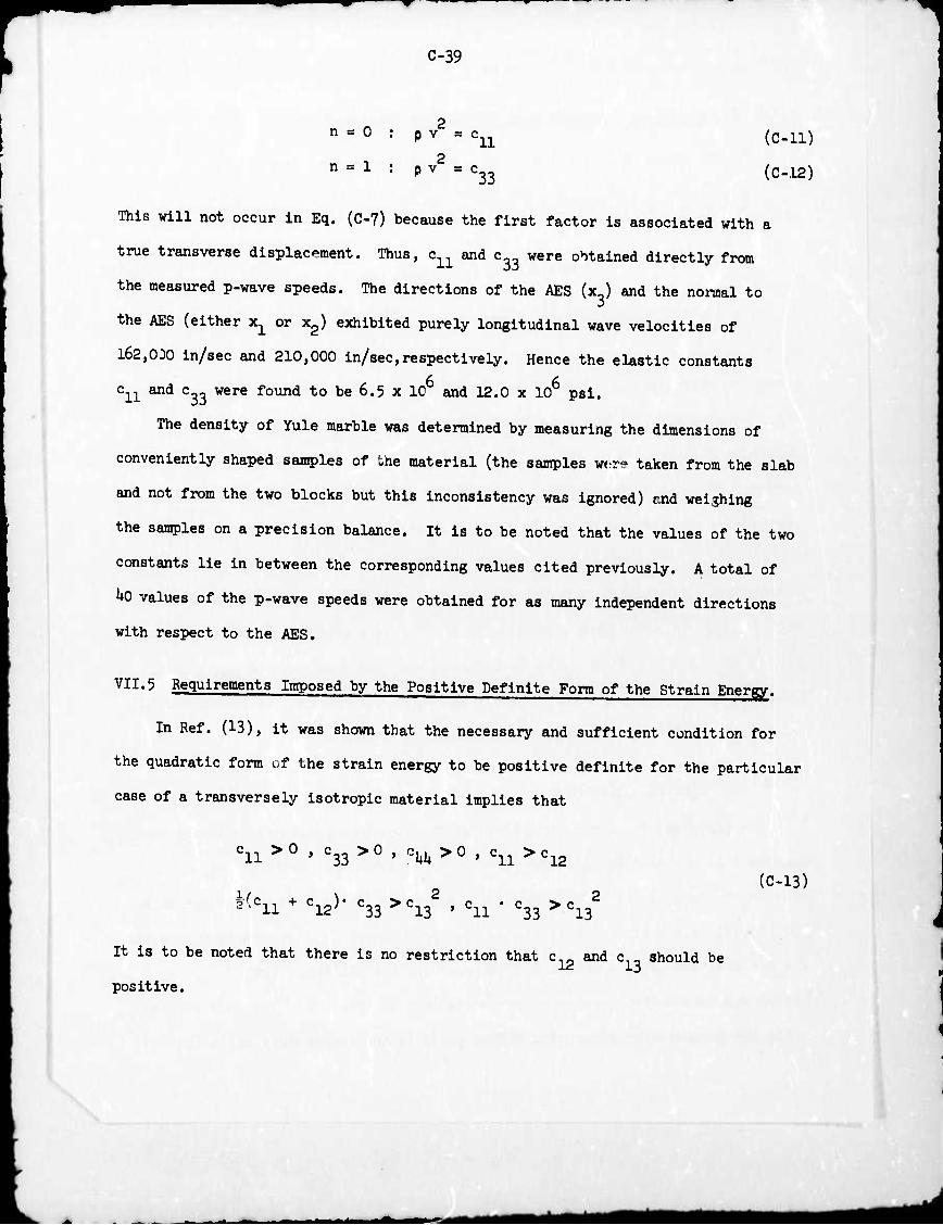
C-39
n = 0 : p v = c11 (en)
n = 1 : p v2 = c33 (c^)
This will not occur in Eq. (C~7) because the first factor is associated with a
true transverse displacement. Thus, c.^ and c were obtained directly from
the measured p-wave speeds. The directions of the AES (x.) and the normal to
the AES (either x^^ or x2) exhibited purely longitudinal wave velocities of
162,030 in/sec and 210,000 in/sec,respectively. Hence the elastic constants
6 6 c^ and c_3 were found to be 6.5 x 10 and 12.0 x 10 psi.
The density of Yule marble was determined by measuring the dimensions of
conveniently shaped samples of the material (the samples w<,r? taken from the slab
and not from the two blocks but this inconsistency was ignored) and weighing
the samples on a precision balance. It is to be noted that the values of the two
constants lie in between the corresponding values cited previously. A total of
kO values of the p-wave speeds were obtained for as many independent directions
with respect to the AES.
VII«5 Requirements Imposed by the Positive Definite Form of the Strain Energy.
In Ref. (13), it was shown that the necessary and sufficient condition for
the quadratic form of the strain energy to be positive definite for the particular
case of a transversely Isotropie material implies that
c11>0 , c33>0 , e^>0 , o11>c12
(C-L3) :^c11 + c12). c33>c13 , c11 • c33>c13
2
It is to be noted that there is no restriction that c and c should be
positive.
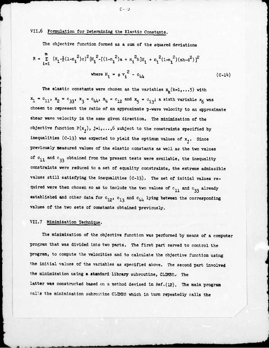
C- J
VII.6 Formulation for Determining the Elaatic Constants.
The objective function formed as a sum of the squared deviations
R = Z (Hi4(l-ni2)c)2{H1
2-[(l-ni2)a + n^h]^ + n^l-n^Mah-d2))
where ^ * p v^2 - c^ (C-l^)
The elastic constants were chosen as the variables x. (kal,...5) with
xl - cii* x2 ss c33» x3 = c^> xii ■ ci2 an<i x5 = ci'9» a sixth variable x^ was
chosen to represent the ratio of an approximate p-wave velocity to an approximate
shear wave velocity in the same given direction. The minimization of the
objective function P(x.), J«l,...,6 subject to the constraints specified by
inequalities (C-13) was expected to yield the optimum values of x.. Since
previously measured values of the elastic constants as well as the two values
of c11 and c obtained from the present tests were available, the inequality
constraints were reduced to a set of equality constraints, the extreme admissible
values still satisfying the inequalities (C-13). The set of initial values re-
quired were then chosen so as to include the two values of c and c. already
established and other data for c12, c1_ and Cj^ lying between the corresponding
values of the two sets of constants obtained previously.
VII.7 Minimization Technique.
The minimization of the objective function was performed by means of a computer
program that was divided into two parts. The first part served to control the
program, to compute the velocities and to calculate the objective function using
the initial values of the variables as specified above. The second part involved
the minimization using a standard library subroutine, CLIMBS.. The
latter was constructed based on a method devised in Ref.(12). The main program
car.s the minimization subroutine CLIMBS which in turn repeatedly calls the
*m*
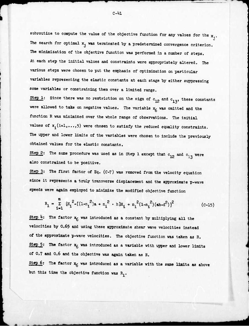
c-ui
subroutine to compute the value of the objective function for any values for the x
The search for optimal x^ was terminated by a predetermined convergence criterion.
The minimization of the objective function was performed in a number of steps.
At each step the initial values and constraints were appropriately altered. The
various steps were chosen to put the emphasis of optimization on particular
variables representing the elastic constants at each stage by either suppressing
some variables or constraining them over a limited range.
Ste2_l: Since there was no restriction on the sign of c12 and civ these constants
were allowed to take on negative values. The variable x. was omitted and the
function R was minimized over the whole range of observations. The initial
values of xi(i=l,...,5) were chosen to satisfy the reduced equality constraints.
The upper and lower limits of the variables were chosen to include the previously
obtained values for the elastic constants.
Ste£j2: The same procedure was used as in Step 1 except that c.- and c were
also constrained to be positive,
StegJJ: The first factor of Eq. (C-7) was removed from the velocity equation
since it represents a truly transverse displacement and the approximate p-wave
speeds were again employed to minimize the modified objective function
m Rl = ^ tH1
2-[(l-ni2)a + n^ . h]^ + n^l-n^Hah-d2))2 (C-15)
Ste£_U: The factor x^ was introduced as a constant by multiplying all the
velocities by O.65 and using these approximate shear wave velocities instead
of the approximate p-wave velocities. The objective function was taken as R.
steP 5; The factor xg was introduced as a variable with upper and lower limits
of 0.7 and 0.6 and the objective was again taken as R.
Ste£_6: The factor xg was introduced as a variable with the same limits as above
but this time the objective function was R,.
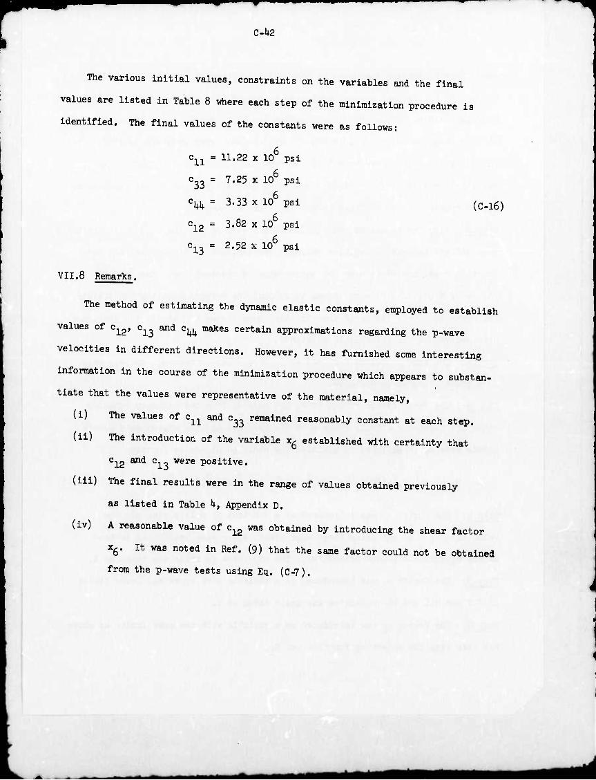
C-U2
The various initial values, constraints on the variables and the final
values are listed in Table 8 where each step of the minimization procedure is
identified. The final values of the constants were as follows:
c^ m 11.22 x 10 psi
c33 = 7.25 x 10 psi
c^ = 3.33 x 10 psi
3.82 x 10 psi
(C-16)
'12
c13 = 2.52 x 10 psi
VII.8 Remarks.
The method of estimating the dynamic elastic constants, employed to establish
values of c^, c^ and c^ makes certain approximations regarding the p-wave
velocities in different directions. However, it has furnished some Interesting
information In the course of the minimization procedure which appears to substan-
tiate that the values were representative of the material, namely,
(i) The values of c^ and c^ remained reasonably constant at each step,
(ii) The introduction of the variable x6 established with certainty that
c12 and c13 were positive,
(ill) The final results were in the range of values obtained previously
as listed in Table k, Appendix D.
(iv) A reasonable value of c^ was obtained by introducing the shear factor
Xg. It was noted in Ref. (9) that the same factor could not be obtained
from the p-wave tests using Eq. (C-7).
mm
C-U3
Sactlon VIII
Discussion
VIII.1 General Outline
In this section the following matters are considered:
(i) A discussion of the infomation obtained from the experimental results;
(ii) The comparison of the experimental results with the corresponding
theoretical predictions; and
(Hi) A critical discussion of the method of detecting and recording wave
propagation phenomena with embedded transducers in the light of the
above comparison.
Withe the input crystals and an embedded transducer, the detection and re-
cording of wave propagation processes in a rock model furnished the following
information:
(a) The history of the stress component in the direction of the transducer
bar which coincided with the crystal axis in compression mode.
The wave arrival time, determined directly from the time difference of
the two records obtained on a dual-beam oscilloscope by simultaneous
triggering of the two traces as shown, for example, in Fig. 10.
The input pulse or the force history of the Impulse on the free surface
of the model half-space which could be used directly to obtain the
corresponding theoretical results with the aid of the computer programs
of Appendices A and B.
VI11-2 Body Wave Measurements in the Isotropie Mo^i,
(i) Experimental Results.
Records were obtained from three of the four transducers embedded in the
limestone block. With reference to Fig. 8, body wave measurements were recorded
(b)
(c)
C-Ui*
with transducers 2, 3 and U. Transducer U detected o and transducers 2 and 3 zz
detected o^. Fig. 1 of the main report and Figs. 10 to 12 show the input
and output measurements; the corresponding impact locations and the stresses measured
are also indicated. The data were not extensive since the main objective of the
experiments was primarily to verify the calibration proc-dure of the transducers.
It is recalled, the latter was established by comparing the external calibration
constant with the in situ calibration in rock bars, and the stress factors of
the transducers listed in Table 3 were based on this correlation. Hence a
comparison of the experimental stress-time records with the corresponding
theoretical results was mainly expected to substantiate generally the reliability
of the experimental techniques as well as the validity of the theoretical solutions.
(11) Conparison with Theoretical Results.
Both the finite element technique and the integral transform analysis
were chosen for comparison with the experimental data from the limestone block;
however, the integral transform approach could not be applied directly to the
case of an Isotropie solid as the solution became degenerate. Consequently, a
small degree of transverse isotropy was introduced by the Judicious choice of
the dynamic elastic constants so that the analytical solution could virtually be
considered as the response of an Isotropie half-space subjected to normal point
force history of arbitrary shape. Accordingly, the dynamic elastic properties
were chosen to correspond to those of the Bedford limestone block used in the
experiments and are listed in Section VI.U. The experimental Input pulse was
digitited and a table of values of the impulsive force on the free surface at
each time step was obtained. A step of l/U ygec was chosen for this process that
was considered optimal for accurrcy of the numerical computations and the computer
time required. With this input pulse, the stress histories and arrival times were
obtained oorrespending to those measured by the embedded transducers. In Fig. 1
^mtt

C-U5 n of th« main report and Pig. 11 results from the integral transfom solution are
superposed on the experimental stress histories.
The finite element computer pngram was devised to solve a similar boundary
value problem. However, here the Isotropie and anisotropic media could be
considered Independently. Thus, using the dynamic elastic properties of
limestone cited above and the experimental input pulse in the form of tabulated
values at convenient time intervals, the stress histories and wave arrival times
corresponding to the experimental measurements were obtained. These finite
element predictions are superposed on the previous results in Fig. 1 of the
main report and Figs. 10 to 12. The previously-stated conclusion that the
experimental techniques employed provide a reliable means of detecting and
recording body waves inside a rock is thus substantiated by the satisfactory
agreement of both the stress levels and the arrival time«.
Comments on the Wave Propagation Phenomena.
Even though the data obtained on the limestone block were not extensive,
the results reveal a number of ideas associated with the theory of body wave
propagation in an Isotropie half-space.
(•) P-Wave Velocity.
The wave velocity calculated on the basis of the first signal arrival
corresponds to the p-wave speed in an Isotropie medium since it is the fastest of
the two possible wave speeds; yielding an average value of 170,000 in/see. This
compares well to that obtained from the material constants used in the theoretical
solutions, namely, 17U,000 in/sec and the corresponding rod wave velocity of
1U1,I*00 in/.ec(lU).
(to) Precursor to the Main Pulse.
In the stress history depicted in Fig. 1 of the main text, the precursor to
the major effect of the pulse also corresponds to the first arrival of the p-wave.
0-1*6
It clearly shows a shape similar to that predicted by theory. The second peak is
mainly the effect of the shear wave. A comparison of the arrival times of the
two pulses gives a reasonable estimate of the ratio of the shear wave speed to
the p-wave speed namely about O.65.
(c) Attenuation of the Pulse.
The a^ stress histories shown in Figs. 11 and 12 indicate the degree of
attenuation along a k? ray at distances of 2.83" and U.S" from the impact location.
Both the theoretical and the experimental results showed that the attenuation in the
tensile stress was significantly less than the corresponding attenuation in the
conpressive stresses which appears to be due to the dispersion of the pulse.
The peak compressive stress in the x-direction (a^ in Fig. 9) decreased as r"1'5
where r was the distance of the observation point from the impact location. The
peak tensile itresa in the same direction did not attenuate according to the
same law.
W First Passage of the Pulse and Reflection from the Boundaries.
The first passage of the pulse was recorded for a sufficient length of time
before the reflections from the boundaries distorted the data. In Fig. 1 of the
main text it is estimated that the reflections arrived at about 65 ^ec after
the initiation of the pulse on the free surface which means that the theoretical
solution was not compared with the experimental stress history for the complete
passage of the first pulse. This was necessarily so in the case of the finite
element method because of the finite size of the block chosen to represent the
Isotropie half-space as well as the computation time required for obtaining the
transient. However, the integral transform solution predicted a more rapid decay
of the transient. This indicates that there might have been some reflections
at the rock/transducer bar interfaces.
^n*
C-l+7
-e ^ rapla aeCay of ^ meaBurea translent inaloates ^ ^^ ^
Of error, in the ^ure.ente, ^ the soatterlng of ^ ^ ^ ^
addlttcnal dlspereta of the pulse due to the presence of th. t . presence of the transducers. Since
econtinuities introduced hy the e^ent of treneducers, it TOs ejected that
-e™ ^uid he sMlli of the s.e order as encountered in the one-dWeionai
oaciUations Mediate., after the first cycle TOre not caused hy .flections
fro. the houndaries of the hlock. the first arrival of „hich is indicated in the
respective fibres. The theoretical solution hy the finite element .ethod does
predict such osoillationa of the stress even thou*, the inteeral transfo» .ethod
predicts a .ore rapid deca. ^e reason for this diso^ancy is not imediately
odious. K m be due to the fact that the integral transfer, ana^is assumed
a concentrated load while the actual load was distrihuted on the area of the input
^.tali the latter type of loadin, would create a .ore ccplicated dispersion
Of the ^ise. It is noted that the finite elcent .ethod invariahly asSMeS so.
-arin, of the i^t i^lse. m any case, the reflections frc the hedaries
cf the hloc* arrived hefore the .easured transient decayed cc^letely.
VI11"3 My V'Ve MSgJgSBgti ig th. an^otropio tedg]
f1) Experimental Result».
The infection ohtained fro. the e^eriMntal results was si.ilar to that
deacrihed in VHX... ^ sUe of the hlock and the len^h of the input p^se
inaured the ohservation of the first passage of the pulse for sufficient lengths
of time at variou. locations. ^ e^eri^ntal data with Po as the i^act location. Pi, l5. oorresponaing t0 observation ^ ^^ 5 ^ ^ ^ ^
the i^act position were te^ed far field response. The data obtained with
^M*
«
J
C-J48
P P P . P, as the impact locations, Fig. 15, from the transducers which were
about 1.8 inches and 3.U inches from these locations were chosen to represent
the near field response. These data were compared with corresponding theoretical
predictions of arrival times and stress histories.
In order to discern the infonnation obtained experimentally, the stress
histories depicted in Figs. 29, 30 and 31 are described in some detail. These
three transient normal stress components were obtained for the same impact.
The input pulse was also recorded simultaneously as shown in the respective
figures. With reference to Fig. 19, transducer Y^ detected a^ and with reference
to Fig. 21, transducer Zu detected azz. These two stress histories are shown in
Fig. 30 and Fig. 31 respectively. In view of the symmetry of the block these
two records give the stress histories at the same location, namely (5",T? »1z )
corresponding to the cylindrical coordinate system shown in Fig. lU. Along with
these two stress histories a axx record was obtained at a second location,
(K" 3TT VI.IN as shown in Fig. 29. The corresponding stress transient was of the
shape and of the same order of magnitude as the o^ stress of Fig. 30. This is
another indication of the previously mentioned finding that the new set of dynamic
elastic constants obtained in Section VII did not predict significant differences in
the slowness surface from the corresponding isotropic case. The other stress
transients described in Table 6 show the same pattern in the similarity between the
a stress at (RjO^Z) and o^ stress at (R,^,Z).
Other experimental results yielded arrival times and stress histories which
were not all compared with corresponding theoretical results. However, all arrival
times obtained were utilized to determine approximate p-wave speeds in various
directions and, in conjunction with similar results obtained from surface wave
investigation, were used in devising a procedure for estimating the dynamic elastic
stiffnes. matrix of the material as described in Section VII. In particular, the
C-h9
P-wave speed along the AES was obtained as 162,000 in/sec and the p-vave speed
along the AES determined in Ref. (2) wafl obtalned aa m§m ^^ ^
additional evidence, namely the lower p-wave speed along the relocated AB8,
Fig. Ik, reasonably confirmed its actual direction.
The mathematical theory of propagation of elastic waves In a transversely
isotropic medium, with the particular dynamic elastic constant, of Yule marble,
predicts that the p-wave speed along the AES is the lowest while that nonnal to
the AES is the highest. An average value obtained for the latter was 210,000
in/sec which was computed from both the body wave and the surface wave measure-
ments. In the fomer, a ray nonnal to the free surface with a transducer located
in line with the impact position was utilized whereas in the latter case, a
radial stress measurement along the axis of foliation plane waa utilized. The
fact that such data as well as those along the AES yield the exact p-wave speeds
has also been used in Ref. (9). However, since the pre.ent experimental investigation
utilized a more reliable method of determining wave arrival times, it is believed
that the previously obtained values of 203,000 in/sec and 237.000 in/aec(9) are
too high; compared with the speeds of 162.000 in/sec and 210,000 in/sec obtained
in the present work. This is attributed to the possible .pecific experimental
error in Ref. (9) caused by the late triggering of the oscilloscope by the output
from an accelorometer placed near the impa.t point and the estimation of the wave
arrival time as that corresponding to the length of trace before the first arrival
of the wave at the observation point as recorded on the oscillogram.
(ii) Comparison with Theoretical Results.
(a) Near Field Response.
A typical cc*parison of the near field response with the corresponding
theoretical results is depicted in Fig. 2 of the main report, which show, that
the stresses obtained by the integral transfonn analysis were much higher than the
corresponding measured stresses and those obtained by the finite element method.
mm
C-50
In general, the finite element method predicted stress histories that were in
closer agreement with the experimental transients than the integral transform analysis
for observation points which were in such close proximity to the impact location.
In the finite element method, since the near field experimental data were obtained
by using a l/U" dia. input crystal, the input force was approximated as a uniformly
distributed impulse over a circular area of l/U in. diameter. Hence it appears
that poorer agreement obtained with the integral transform method was due to the
approximation involved in assuming that the response of the block was effectively
due to a concentrated time-dependent load; indicating that such an assumption
is valid only for observation points which are located at relatively larger
distances from the impact pcsition.
Therefore, it was considered Inappropriate to compare the experimental data
more in detail with the corresponding integral transform results for the near field
response of the block and such a comparison was made only for the far field. On the
other hand, a memingful comparison with the finite element method results could
be achieved only with the near field data in view of the constraints imposed
regarding the size of the block, the nlze of the mesh, the time interval chosen and
the computation time required. Thus, the rest of the comparison of the near field
results with the finite element method is depicted in Figs. 2k to 28. In Figs. 2k
to 26, the transducers were located about 1.8" from the tiupact position as well
as In Fig. 2 of the main text discussed above. In figs. 27 and 28 the transducers
were situated in a ray normal to the free surface in line with, and at a distance
of 3-3/8" from the impact location. For such locations, i.e. for observation
points vertically below the normal load on the horizontal free surface, the finite
element method ..olution was closer in agreement with the experiment in the case of
a stress component normal to the z-direction, Fig. 28, than in the case of a
stress componen*- in the t-direction, Fig. ?7. This discrepancy is consistent
C-51
with similar disagreement between the Integral transform analysis and experiment
discussed below In relation to the far field response of the block,
(b) Far Field Response.
The comparison of the expirimental data was effected only with the
corresponding integral transform results as depicted in Figs. 29 to 35» reasonable
agreement prevails for the stress levels. However, the exact shape of the predicted
transient appears to be susceptible to numerical errors especially in the digiti-
zation of the experimentally-determined input pulse and subsequent numerical
differentiation. In most cases, the input pulse was somewhat asymmetric and the
disagreement between experiment and theory appeared to be more marked where such
asymmetry was more pronounced. The actual input frequently closely resembled the
shape of a single sine-squared pulse with a duration twice that of the rise time;
consequently, ouch a boundary condition with an amplitude equal to the measured
peak force was also used in the stress computation. Another alternative used for
the numerical input consisted of a symmetrical loading with the rising portion
mirrored about the peak force. A comparison of a number of stress histories
with the corresponding theoretical results using the three possible input shapes
showed that except for some improvement in isolated cases with the last input
pulse shape, there was little difference in the agreement with the experimental
results. Hence, the actual pulse has been used for comparison in the sequel.
As in the case of the limestone block, the analysis predicted a more
rapid decay of the pulse than was observed. Since the first passage of the pulse
could be recorded for sufficient lengths of time without distortion due to
reflections from the boundaries of the block, the oscillations observed in the
transient were again in disagreement with the integral transform predictions as
shown in Fig. 30. In Fig. 3 of the main text, a comparison of the far field response
with corresponding predictions of both the theoretical techniques was shown to
*mt
C-52
illustrate the comparison with the integral transform analysis as described above
as well as the inability to obtain satisfactory results with the finite element
method at such a distant observation point for the reasons stated in VIII.3 (ii)(a).
The comparison of the experimental results with the integral transform
analysis was not entirely conclusive regarding the accuracy of the measurements,
especially those involving the ozz stress history as shown in Fig. 3^. Here, the
second peak in the measured transient appears to be due to the reflection of the
pulse as it propagated through the embedded transducer by virtue of an impedance
mismatch. Similar anamoly was observed in the comparison of the a^ transient
with the analysis at other locations such as shown in Fig. 35.
VIII.U Surface Wave Propagation Measurements in the Anisotropie Model.
(i) Experimental Results.
Since the transducers were approximately 5" away from the impact location,
the measured transients could again be compared only with the corresponding
integral transform results. A total of 6 complete sets of data were obtained,
each set consisting of the radial and circumferential stress histories, effectively
at the same location relative to the impact location. Out of the 7 pairs of
transducers, stress histories were recorded with 6 pairs; only the circumferential
stress history was recorded at location ^.
At any location such as (Rafftj)» Fig- 22> tlie radial stress transient
distinctly exhibits the p-wave and Rayleigh wave effects as shown in Fig. k of
the main report. The shear wave effect was not clearly distinguishable. The
tangential stress histories as depicted for example in Fig. 37 did not record the
effect of the p-wave. The tangential stress was of the same order of magnitude
at (R.,©,) and (R^GO but was negligibly small at i^,^) (foliation plane).
This latter effect appears to be due to the absence of quasi-Rayleigh effects at
a location such as (R^), the quasi-Rayleigh wave being one which exhibits a
■■
C-53
transverse conrponent of motion in the plane of the free surface. Such a component
seems to exist up to 150 from the direction of the foliation plane. I^se stress
histories were obtained at about l/l6" below the free surface and even if the
attenuation of the Rayleigh wave were large, these stress components may be
considered as representative of the surface wave effects,
(ii) Ccmrparison with Theoretical Results.
The experimental results were compared with corresponding theoretical
predictions of the integral transfom method as shown in Fig. 1» of the main
report and Figs. 36 and 37. The first two diagrams show the comparison of two
typical radial stress histories while the third shows the comparison of a
tangential stress history. The good agreement indicates that the theoretical
model agrees remarkably well with experiment. However, the integral transform
method did not predict the diminution of the transverse effect due to the
Rayleigh wave as the direction approaches the direction of the foliation plane.
It is not clear whether the failure of the analysis to predict such a phenomenon
was due to numerical errors and also whether the observed absence of the quasi-
Rayleigh waves may have been due to experimental vagaries. This discrepancy
was left unresolved and is not shown in the figures.
VI11,5 termination of Dynamic Elogtlc Constants from Body Wave and Surface
Wave Measurements.
T^e values determined in Section VII lie between those obtained previously
(Table U, Appendix D). Thus, it appears that such a method may be applied
in general to other rock materials. The actual values may be improved by adding
other refinements to the technique such as weighing the various data obtained
experimentally and a more general program may be written. Some other features could
be built into the program such as automatically reverting from one function to
C-5U
another, and approximation procedures other than least square methods may be used
m part or all of the functions which may be also changed as required as the
minimization progresses.
It is noted that it is possible to obtain the dynamic elastic stiffness
constants c^ c^, c^ and c13 from the phase velocity equation cited in
Section VII directly using the approximate p-wave speeds obtained for a nimiber of
directions. Such a procedure was adopted in Ref. (9). However, the fifth constant
c12 cannot be obtained by using p-wave tests^'. The same procedure failed to
give satisfactory results in the course of the present investigation and hence
the method of Section VII was devised.
VI11'^ Stress Wave Measurements with Embedded Transducers.
The results show that the PZT ceraMc crystal transducers are suitable for
detecting and recording body wave pulse propagation in rocks. The choice of
magnesium as the material for the transducer bar was originally made on the basis
of average value of the acoustic impedance of Yule marble. However, it appears
that the anisotropy of the Yule marble block employed was such that the use of
another material such as aluminum would have been more appropriate in some directions
such as the z-axis in Fig. Ik, The embedding technique was quite effective even
if there is some uncertainty about entrapped air bubbles between the transducer bar
and the rock. To achieve intimate contact between the crystal unit and the rock
and in order that the calibration should apply and that the same calibration may
be used for all transducers to obtain internal stress uniformity of embedment is
required, with crystal assembly unit completely embedded in the rook with an epoxy
and aluminum oxide mixture surrounding the unit.
The voltage iraplification was employed for recording the embedded transducer
response since the initial testing of the PCT crystals by this method in a split
rk'-nson bar gave good correspondence of the pulse shapes between the crystal
^M*

: C-55
and the strain gage records. The general techniques of the experimental measurements
provided a reliable means of detecting and recording waves in the interior and near
the surface of the rock.
C-56
References
(1) Katona, M., "Wave Propagation with FEAP-72", Berkeley, University of California, 1972.
(2) Rlcketts, T. E., "Sphere Impact on an Anisotropie Half-Space", Ph.D. Dissertation, University of California, Berkeley, 1970.
(3) Dove, R. C. and Adams, Paul H., Experimental Stress Analysis and Motion Measurement , Columbus Ohio, Charles E. Merrill Books, Inc., 196U.
(U) Ooldamlth, W. and Sackman, J. L., "Wave Propagation in Anisotropie Rocks", Annual Technical Report No. 1, Contract No. H0210021, ARPA Order No. 1579, Amend. 2, Program Code U10, University of California, Berkeley, 1972.
(5) Mason, Warren P., Physical Acoustics. Principles and Methods, Volume 1- Part As New York, Academic Trees, 196U.
(6) Kenner, V. H. and Goldsmith, W., "One-Dimensional Wave Propagation Through a Short Discontinuity", J. Acoust. Soc. Amer., Vol. U5, No. 1, 1969, p. 115.
(7) Tlmoshenko, S. end Young, D. H., "Elements of Strength of Materials1,1 Fourth Edition, Prlnrcton, Ne« Jersey, D. Van Nostrand Company, Inc., 1962.
(8) Goldsmith, W. and Sactanan, J. L., "Wave Propagation in Anisotropie Rocks", Semiannual Technical Report No. 1, Contract No. H0210021, ARPA Order No. 1579» Amend. 3, Program Code 62701D, University of California, Berkeley, 1972.
(9) Rlcketts, T. E. «nd Goldsmith, W., "Wave Propagation in an Anisotropie Half-Space", Int. Jc Rock Mech. Min. Sol., v. 9, 1972, p. U93.
(10) Krech, W., Henderson, F. A. and HJelmstead, K., "A Standard Rock Suite for Rapid accavatlon Research", U.S. Bureau of Klnes, Twin Cities Mining Research Center, Minneapolis, Minnesota, 1972.
(11J Musgrave, M. J, P., Crystal Acoustics. San Francisco, Holden Day, 1970.
(12) Roaenbrock, H. H., "An Automatic Method of Finding the Greatest or Least Value of a Function". Computer Journal, Vol. 3, i960, pp. 175-18U.
(13) Das Gupta, Suahll Chandra, "Propagation of Rayleigh Waves in Transversely Isotropie Medium in Three Dimensions", Transactions, American Geophysical Union, Vol. 36, No. U, 1955.
(1U) Rlcketts, T. E. and Goldsmith, W., "Dynamic Properties of Rocks and Composite Structural Materials", Int. J. Rock Mech. Min. Scl., Vol. 7, pp. 315-335, 1970.
(15) E»pe, W., Materials of High Vacuum Technology. Pergamon Press, 1966.

f C-57
<16) sStem r-rr0:1"!^!"!0'"°"r"i ■
4
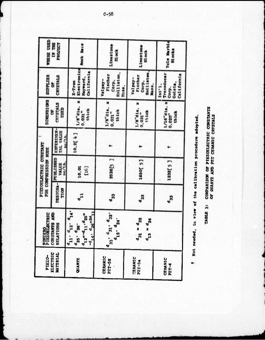
C-58
I
t 9
U O.
t
a
> 3
V.CX U K
<?ȣ U J
H as SOP
"H 10 N „ ^ N ^ -a •a r r f
^ $
n o
p
U N CJ 0.
o
IE
1 I g o
SB
11 BE
s
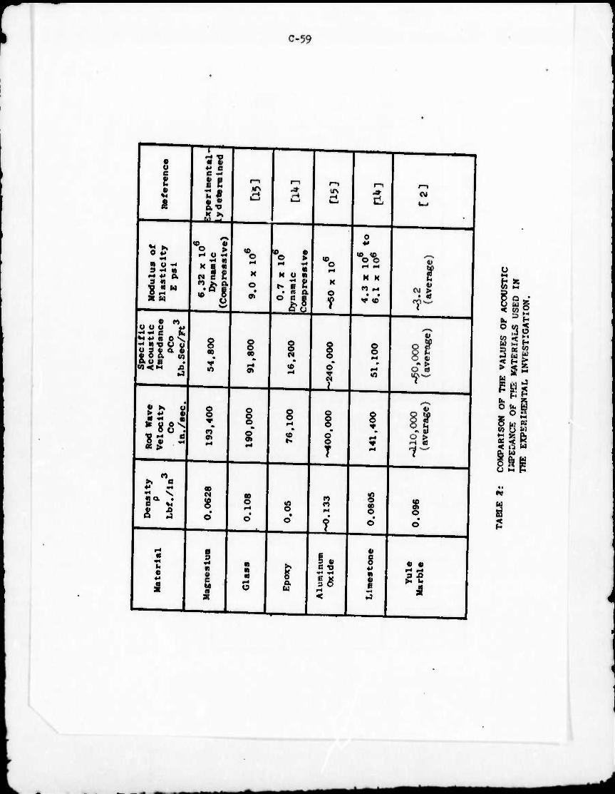
r C-59
u a e
^ ft o «* mo-. M ♦* a 3 «
13"
— T> • ti ^ C a - f e m n
•f\ -» ^ ^4
K >v
'*
• n u u u *< *<♦'•» o s. •< « TJ o u
3 4. o a
«
>» a ♦* «4
«a. • a M XI J <s
o ?!
n JK a • O B
«o 6 a
o
o>
X)
g 00
f lO
o o
Ol
I 00
—
■ MO«
• « QL o a ■
l/N
IT
s
CO CM
o
B 3
«4 •) « c tc a
a?
ao o
g
§
I*
o § § T
in « «
lO O
r a u
n n
18
J
d
Vo M K
V (0
OJ
§
lO
§
00 o
c o «-> fi 4) e
CM
r 4) I
O ft) " > O cd
ft>
f 1W Q5
ft* •
3 A
y IB
w t r* W t-i H S? K S HE
•J B P<
ill
o
I w
5

c-60
1
'
Aia/ssauxs CO
• M
• n
• 14 3
.90
AT P/Aw NIVO «4
O in
O S
'ON 'Did O PH a - I)
M < E fe >. QC
aaunsvau ssauxs
■ •« o«
N
U/9fi3.)J/0 »ioA/i«a
HOIJV.-! ssaiix?
•
i • o n
r-« •
n
J1ITI-J
aONVXIDV -dva xino -Mio ms
-AMO IVXGX
o o
n m n
o o
M'i/sa M MGXDV^
NOIX -VMonvo avNyaixa
00 o n E a»
eo (0
"via ..8/T aasn
1VXSAHO
■ 1
. E g ■ i
H N K
■
E 8 '«li
ON NOIXVXS
▼ M n V
•MP/qi U0X3VJ
aiVDS xndKi o in o ■
8 *M NOIXVOO'I
XOVdl.'l
p4 0. M
0.
'ON Km n •
P4
B
n
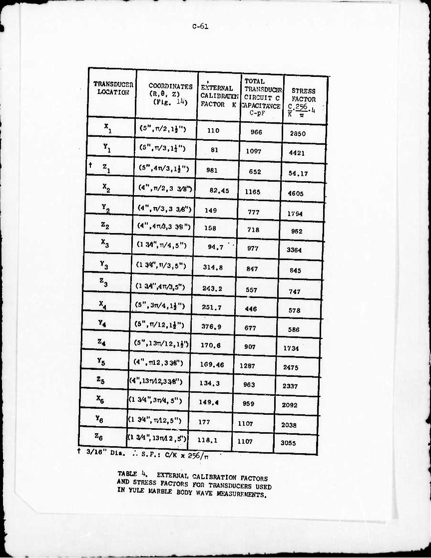
C-6l
TRANSDUCER LOCATION
t Z.
U-i
c6
COORDINATES (R.e, Z)
(Fig. Vi)
EXTERNAL CALIDRAHI; FACTOR K
(S",^,!}")
^".n/S,^")
(5,,,4n/3,lJ")
110
81
(4",17/2,3 3/8")
(4",11/3,3 3/6")
981
82.45
149
(4",4TI/},3 n")
a«r,VMH)
158
94.7
(l^n/a^s")
(1 3A",4v/3,5")
(5",3n/4,lJ")
314.8
243.2
(5",TT/I2,li")
251.7
376.9
(5", 1311/12,1^
(4",TTl2,3 3tf,)
170.6
169.46
(4",13TV1 2,336")
(1^4", 3^4,5")
(1 y4,,,TVl2,5")
134.3
149.4
tlW\l3M2,S')
177
118.1
3/16" Dla. ;, s.P.: c/K x 256/TT
TOTAL TRANSDUCER STRESS CIRCUIT C FACTOR
^PACITAVCE C 256 ,
966
1097
2850
4421
652
1165
777
54.17
4605
1794
718 962
977
847
3364
845
557
446
677
747
578
586
907 1734
1287
963
959
2475
2337
1107
1107
2092
2038
J 3055
TABLE U. EXTERNAL CALIBRATION FACTORS
S^S^SfSK ^ T™SDUCERS USED IN YULE MARBLE BODY WAVE MEASUREMENTS.
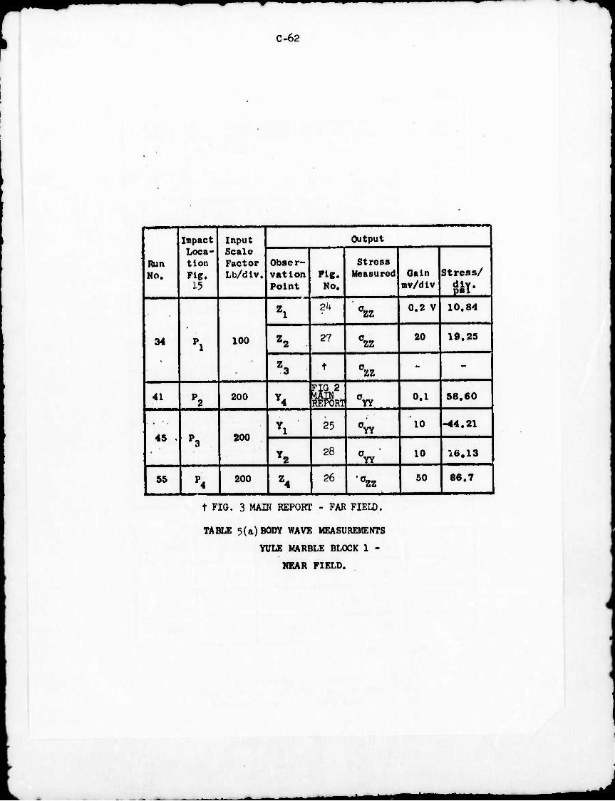
C-62
Run No.
Impact Loca- tion Fig.
15
Input Scale Factor Lb/dlv.
Output
Obser- vation Point
Pig. No.
Stress Measurod Gain
mv/dlv Stress/
diy. pBI
34 Pl 100
Zl 2k 0zz 0.2 V 10.84
Z2 27 0zz 20 19.25
Z3 t azz - -
41 P2 200 Y4 nq 2 RETORl CYV
0.1 58.60
45 . P3 200
Vl 25 0Yy 10 -44.21
Y2 28
0YY' 10 16.13
55 P4 200 Z4
26 •0zz 50 86.7
t FIG. 3 MAIN REPORT - FAR FIELD.
TABLE 3(a) BODY WAVE MEASUREMENTS
YULE MARBLE BLOCK 1 -
NEAR FIELD.
^m*t
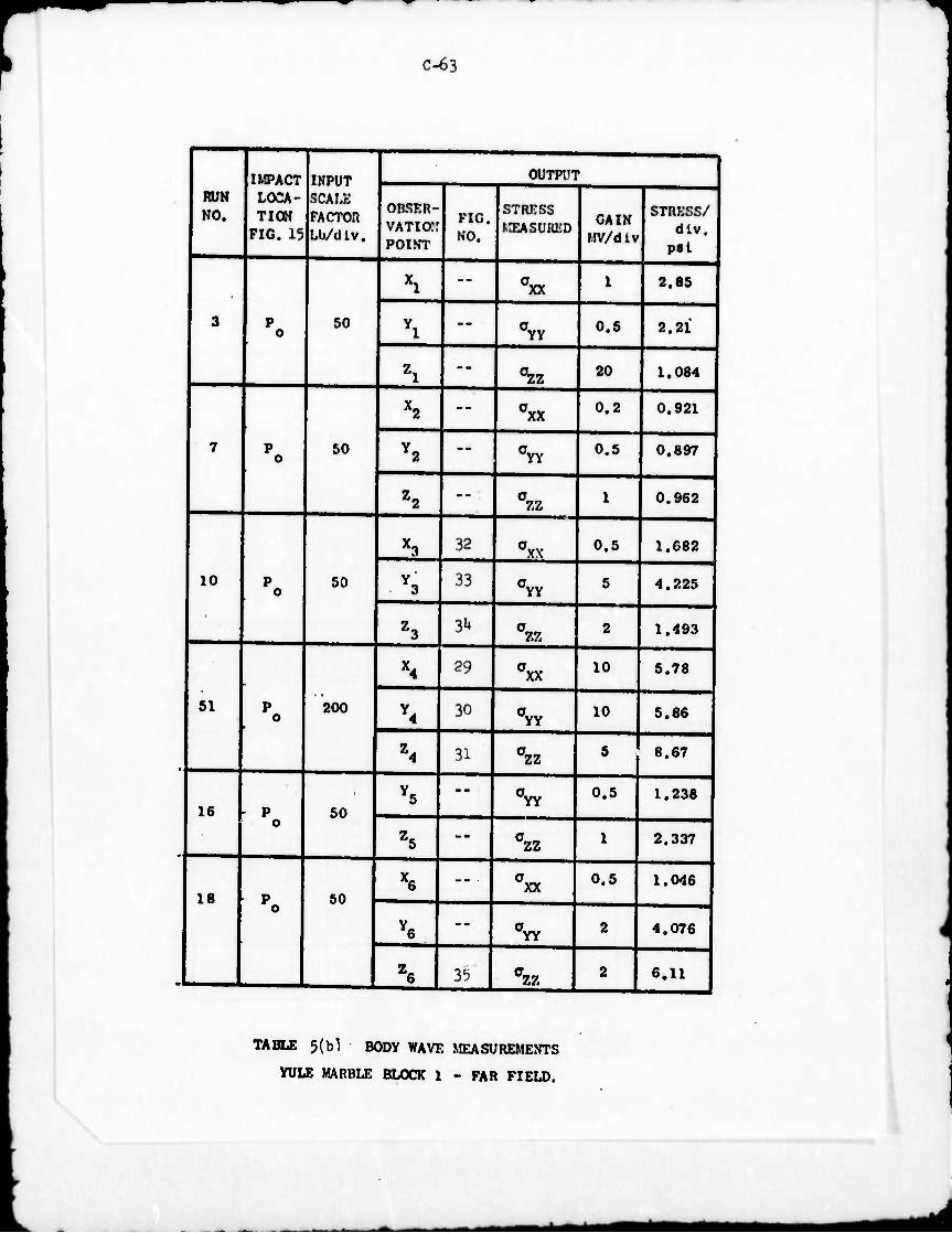
C-63
RUN NO.
IMPACT LOCA- TION
FIG. 15
INPUT SCALE FACTOR Lb/dlv.
1 OUTPUT
OBSKR- VATiorr POINT
FIG. NO.
STRESS LIEASURED
GAIN MV/div
STRKSS/ dlv.
psl
•
3 P o 50
Xl -- axx 1 2.85
Yl --
aYy 0.5 2.21
Zl --
^zz 20 1.084
7 Po 50
X2 -- axx 0.2 0.921
Y2
-- CTYY 0.5 0.897
Z2 -- 07.2
1 0.962
10 p o
50
X3 32 0yx 0.5 1.682
Y3 33 a YY
5 4.225
Z3 3»4 0zz 2 1.493
51 p o 200
X4 29 0xx 10 5.78
Y4 30 0YY 10 5.86
Z4 31 02Z 5 8.67
16 - p o 50 Y5
-- aYY
0.5 1.238
Z5 — 0zz 1 2.337
18 Po 50 X6 -- axx 0.5 1.046
Y6 -- a
YY 2 4.076
Z6 35 azz 2 6,11
TABLE 5(b1 BODY WAVE MEASUREMENTS
YULE MARBLE BLOCK 1 - FAR FIELD.
^M* Mi
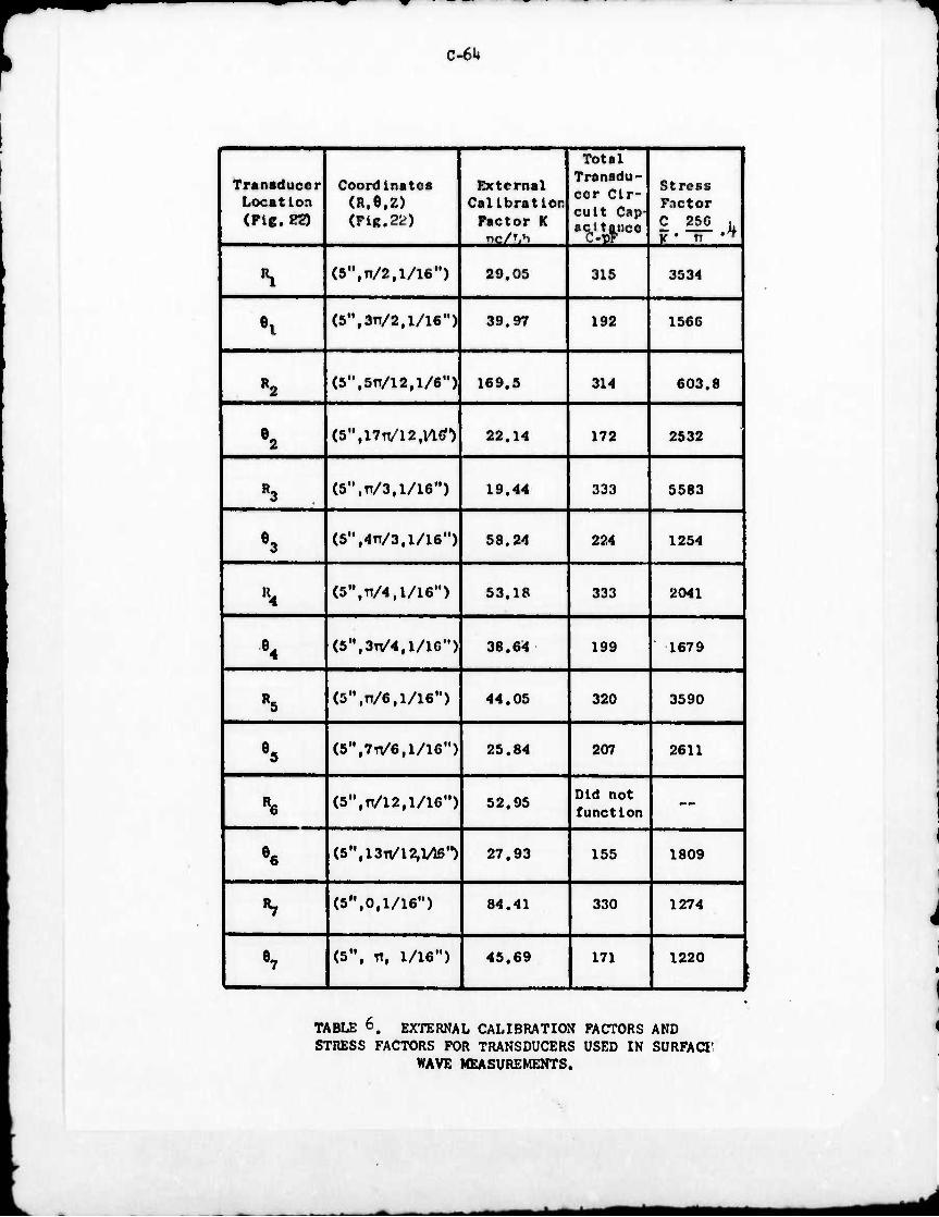
C-6U
Transducer Location (Flg. K)
Coordinates (R.e.z) (Fig.22)
External Calibration
Factor K nc/'.h
Total Transdu- cer Cir- cuit Cap- acitance
Stress Factor C 250 . K • n ^
•H (s-.n^.i/ie") 29.05 315 3534
«l (5",3X1/2,1/16") 39.97 192 1566
R2 (5",5n/12,l/6") 169.5 314 603.8
e2 (5M,l7n/12,nO 22.14 172 2532
R3 (5",v/3,l/l6") 19.44 333 5583
e3 (5,,,4TT/3,1/16") 58.24 224 1254
\ (5,,,^/4,l/l6,,) 53.18 333 2041
e4 (5",3TT/4,1/16") 38.64 199 1679
R5 (5,,,^/6,l/16,,) 44.05 320 3590
e5 (5",7V6,l/l6,,) 25.84 207 2611
R6 (5",Tt/l2,l/l6") 52.95 Did not function —
e6 (5", 13^12,1/16") 27.93 155 1809
^ (S",0,1/16") 84.41 330 1274
S (S", 11, 1/16") 45,69 171 1220
TABLE 6. EXTERNAL CALIBRATION FACTORS AND STRESS FACTORS FOR TRANSDUCERS USED IN SURFACT
WAVE MEASUREMENTS.
I^^^I
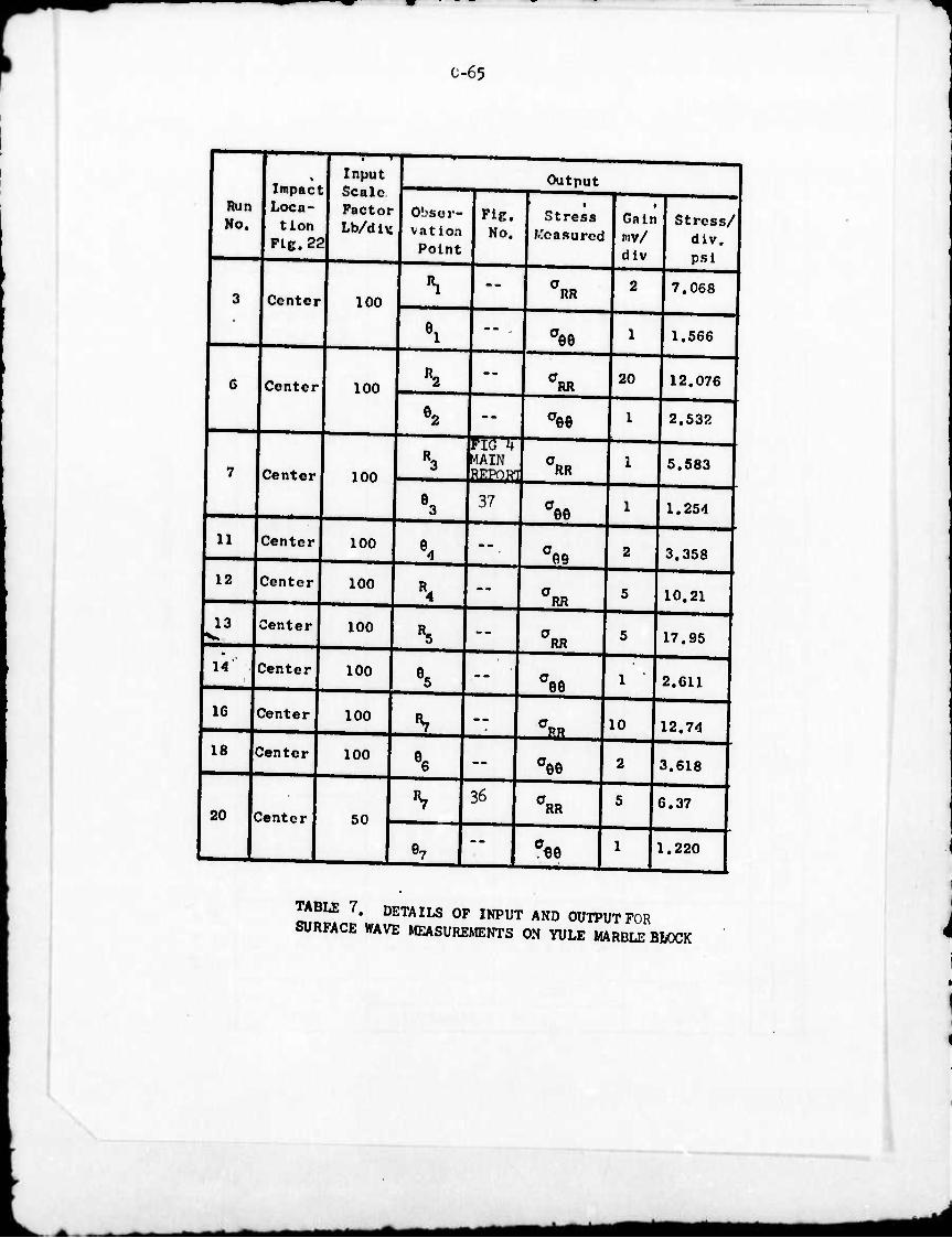
c-65
Run Ko.
Impact Loca- tion
Fie. 22
Input Scale Factor Lb/d iv
Output j
Obser- vation Point
FiE. No.
• Stress
Measured
• Gain mv/ div
Stress/ div. psi
3 Center 100 \ -- anR 2 7.068
9. -- i aee 1 1.566
6 Center 100 «2 --
ci« 20 12.076
»2 -- aee 1 2.532
7 Center 100 »3 MIN 0RR 1 5.583
S 37 aee 1 1.254
11 Center 100 *< a
fl9 2 3.358
12 Center 100 \
-- aRR 5 10.21
13 Center 100 h -- aRR 5 17.95 •
14 Center 100 •a — ae9 1 2.611
IG Center 100 «i
-- 0pR
10 12.74
18 Sentor 100 % -- 0ee 2 3.618
20 Center 50 ■v 36 0RR 5 6.37
•> -- c«e 1 1.220
TABLE 7. DETAILS OF INPUT AND OUTPUT FOR SURFACE WAVE MEASUREMENTS ON YULE MARBLE BWCK
_B^Ma MMM *mm
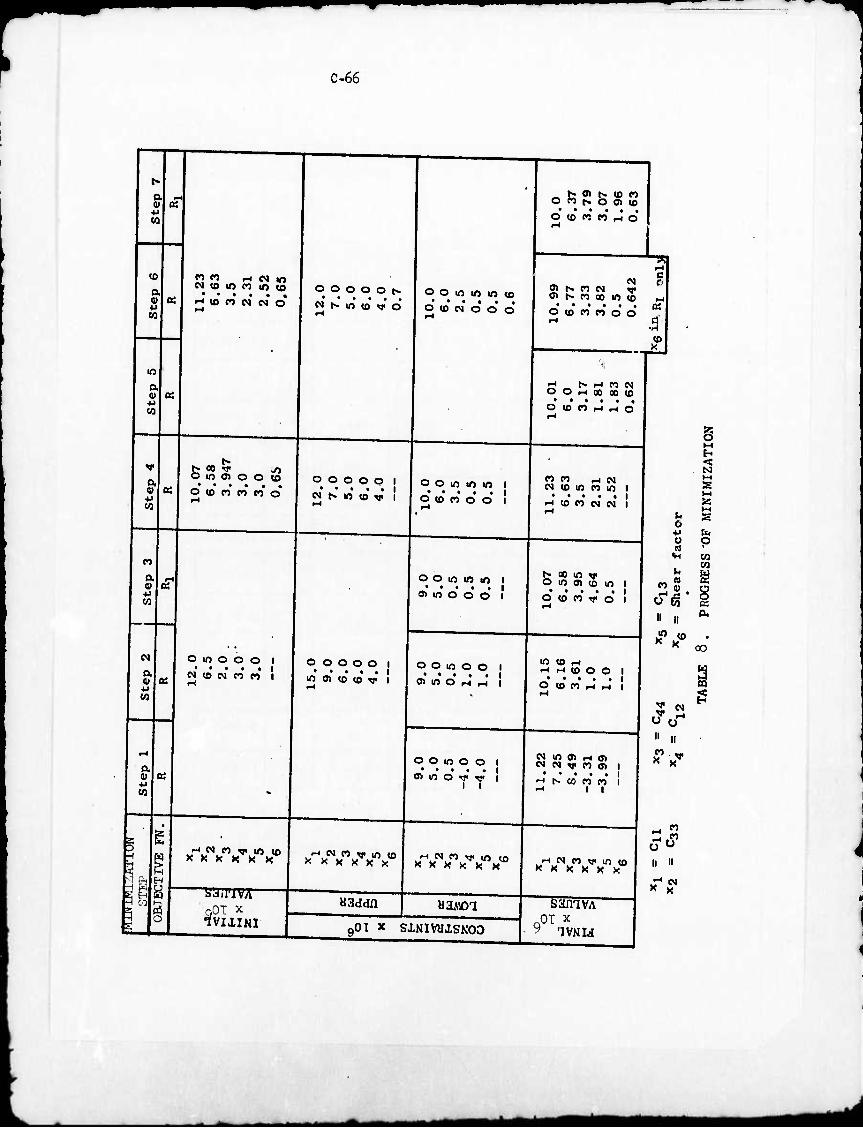
c.66
w
<0
w
OQ
o to m co m to • • • • • • •-< <e CJ c» eg o
. Pi 0> N (0 n o t«. o O) «0 • • • • • o to n C3 t-4 o
O O O O O N
M N 10 «0 V O
co
w
t» 00 V «o O IO O) O O <D
O <0 fO O CO o O O O O Q I
• • • • • I N N 10 <0 V I
N
m
w
'1 ■1 ft
w f-' w
o w o O O I -v.* • • • »I N «O N CO CO I
o o o o o • • • • • V) 0> to iO rf
rJ N CO w< in U) X K K H K K
QOT x
^-i M n v m (s x x x x x x
aaddn
o o m m io to • ••••. O (0 N O O O
o o m m m • • • • • O <0 CO o o
o o m in ir> • * • • • o^ in o o o
o o in o o i • • • • • i a> \n o rA ^4 i
o o in o o i • • t • «i
0> io O V w< I
i-i N co «r m to x x x x x x
HaAlDT
901 X SJLNIVMiSNOO
0> t. CO M v oi t* co oo m «o • ••••« O «0 CO CO o o
'if
Ej _ S r-< 00 o o r-i oo n • • • • • O U> CO r-l r-( r-t
N
• O
"CO ,-1 PJ CM <o in co m I I
rH (0 CO N N 1
N oo in T}< o m 0) to m «• .J • • •
1 1
(0 X
o to CO v o
>n «0 r4 >-<>-< to o o I
• .... i O tO CO M r-l I
N in o> ^ <n « N v co o> i
. • . . . i >-< h- CO CO CO I H I |
i-t N co v m <o X K X X X X
samvA
h 0 ♦» u n>
h CO ni
m <o
a M
M is
o CO CO
8 0.
3 2
CO
00
CQ
r-l
co
II II
<-l M X X
i
C-67
LIST OF FIGURES
Figure
1. Crystal Axes for X-cut Quartz and PZT-Compression Mode
2. Transducer Employing 3/l6" Diameter Magnesium Bar and I/o" Diameter Crystal
3' WA?61" P^y^S 1/8" Diemeter Magnesium Bar and l/lo Diameter Crystal
h. Definition of External Calibration Constant of Transducer
3' llZTZstTv:^ ^—^-in Gage Station
6. Transducer Calibration Arrangement-St rain Gage Station After Crystal Unit and with Loading Bar and Momentum irap
7. Experimental Arrangement for In Situ Calibration in ROCK Bars
8. Sketch Showing the Embedded Transducers in Limestone
9' J^1*611^! Arrangement of Impact Test of Limestone Block for Body Wave Measurements
10-12 Comparison of the Body Wave Measurements on the Limestone Block with Theory (See also Fig. 1 of Main Report)
13. Yule Marble Block for Body Wave Measurements with the Axis of Elastic Symmetry of Ref. (2)
Ik. Block of Fig. 13 with Relocated AES
15. Impact Positions on the Free Surface for Body Wave Measurements
l6'21 Bl^k^061" LOCations in the Interior of Yule Marble
22. Transducer Locations for Surface Wave Study
23. Transducer Configurations for Radial and Circumferential Stress Measurement cxcuuiaj.
Page No.
C-69
C-70
C-71
C-72
C-73
C-73
C-7k
C-75
C-76
C-77 C-78 C-79
C-80
C-80
C-8l
C-82-C-86
C-87
C-88

C-68
LIST OF FIGURES (Continued)
Figure
2U-28 Comparison of Near Field Results with Theory (See also Fig. 2 of Main Report)
29-35 Comparison of Far Field Results with Theory (See also Fig. 3 of Main Report)
36,37 Comparison of Surface Stress Histories with Integral Transform Results (See also Fig. h of Main Report)
Page No.
C-89-C-93
C.9U-C-IOO
C-101 C-102
Mi jam*
c 6g
U
x-cut quartz
PzT-Compression mode
FIG. I
C-70
I
I (Vi
C
mt
[ C-71
I <
C
L MM
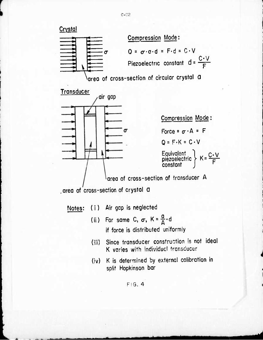
C-72
Crystal
» * ■ » * •> «
Compression Mode:
0 = o--a-d = F-d = C-V
Piezoelectric constant d = C-V
^area of cross-section of circular crystal a
Transducer
Compression Mode:
Force = cr • A = F
Q= F-K= C-V
C-V Equivalent piezoelectric constant
> K =
^rea of cross-section of transducer A
, area of cross-section of crystal a
Notes: (i) Air gap is neglected
(li) For same C, cr, K = ^-d
If force is distributed uniformly
(Hi) Since transducer construction is not ideal K varies with Individual transducer
(iv) K is determined by external calibration in split Hopkinson bar
FIG. 4
_^^—^-i-«»^—^Mdi
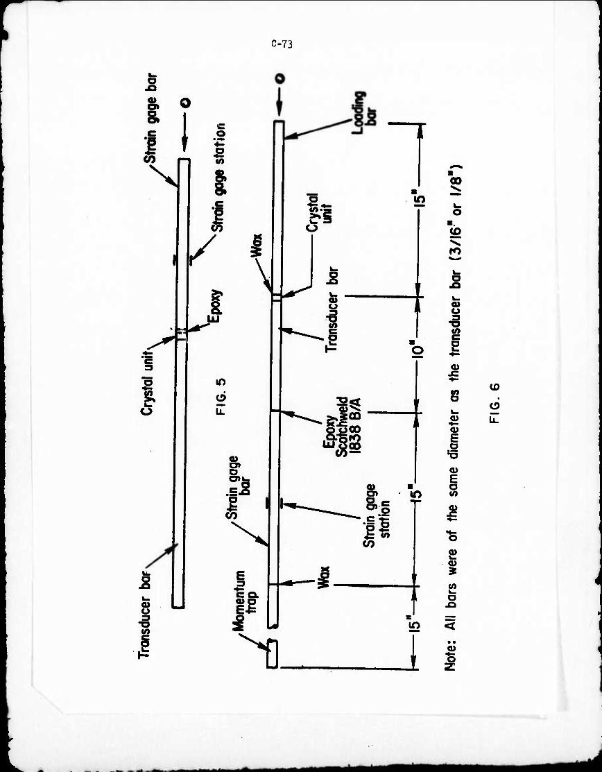
C-73
i I 0
I f]
'S
/
l -.'"
2 O 3 •o
IT)
O
\
o is I
CCL
11
2 o -3
SuCO
8.
1^ «o a>
I
IO
00
o
ro
f ■ o
i
IO
t
o>
8>
en \— o
^1_ JO <
1 • « a>
Mktf^MM
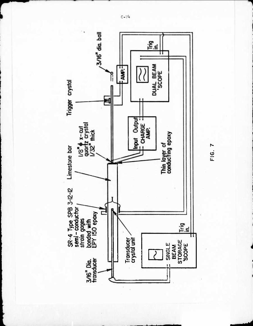
C-YU
u.
coo g
^i: oCL (/> v) .OLlJ 8s JH r:
^ ■o o
<— to o >% Po
UJ
z tu O UJ
;7* 2r < 0- O < rr o
cn^h-]?) I
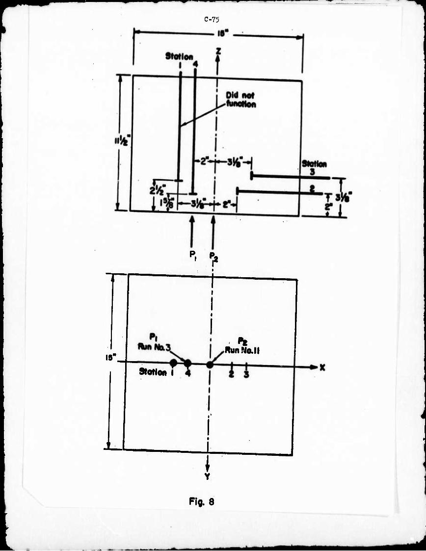
C-75
P. P,
19"
Stotion I
,RunNa.l|
L \ Y
Pi* 8
- ■ .^^—-aaM ^M^l ^HMMBBMiÜ

C-7o
Rock Block
Conducting Epoxy on Block
Input Crystol
Triggering Crystol
i ^Aluminum Bor
Typical- Output Crystol
;/|6 Ola Ball
Fig. 9
^■«^ ^MIMriHMMi
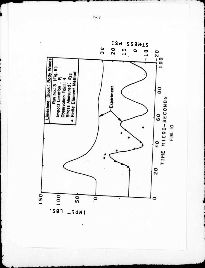
C-77
O n
ISd SS3ddS o o o o
'SST IfldNl
*m MM
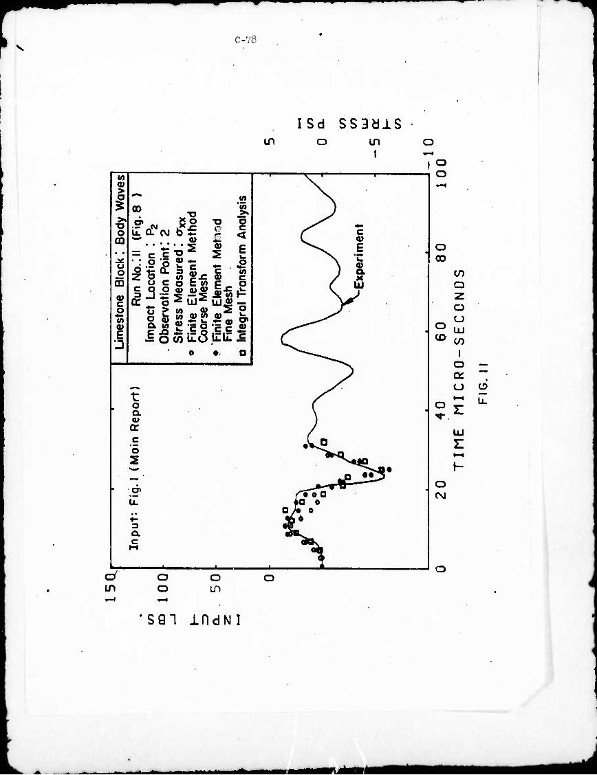
C-78
ISd ssaais in o in
i
v> 0) ^v > ^v o Ä in ^v
5 a> ^ 5, }
o — a* ♦. ^, r c
CD L 0) • • •••••• 5 «> c ^\ i u o
Run
No.
! Lo
catio
ot
ion
Poi
Mea
sure
E
lem
ent
Mes
h E
lem
ent
lesh
1 T
rons
foi ) 1
m ( UJ 0) c
V MM
o T: > M a> 2 P J^ U)
Obs
er
Str
es
Rni
te
Coo
rs
Rni
te
Rn
e In
tegr
^t0l^^
c^ o • o ^^^
^x t jr
o ( a \ ' a> 1 o: J c •VO "5 2 ^'"^^fO *—*• ^^•«ji« MM n 0*3
ig.
/^Too u. iQ 0
0> e ■»- A6 3 •t a •B^- c dOv M
^ , 1
o o
o 00
O (O
O
to Q
O O UJ CO
I o Q: o
UJ
LL
O (SJ
in a o
o us
o
•SQ"! IDdNI
J
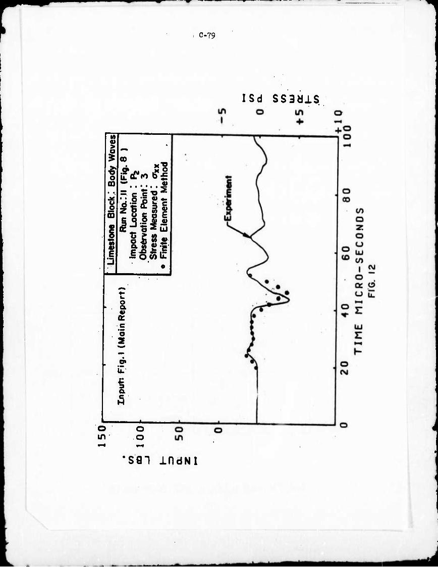
C-79
ISd ssaais
M 0) >
o 00
u o s
3
• ••••• «s = C C "O ^
sis« ^ » 2 c
o a « a: o 2
^. o in
o o
'sgi indNi
^m*t *d
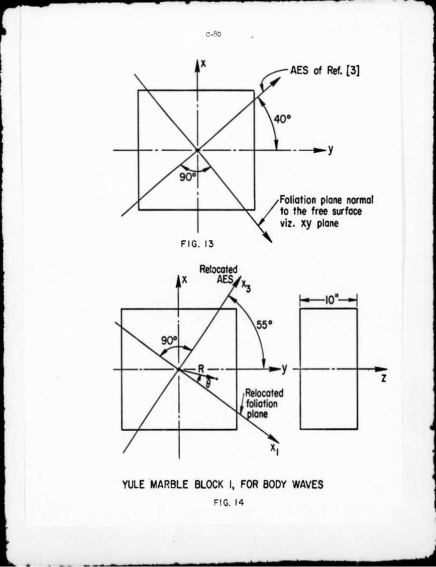
C-Ro
AES of Ref. [3]
y
FIG. 13
/Foliation plane normal ^ / to the free surface V^ viz. xy plane
Relocated AX AES.
YULE MARBLE BLOCK I. FOR BODY WAVES
FIG. 14
^■^M^M
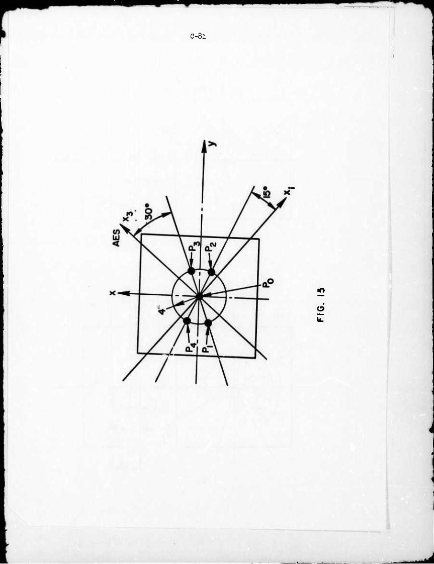
C-8l
■•v
d
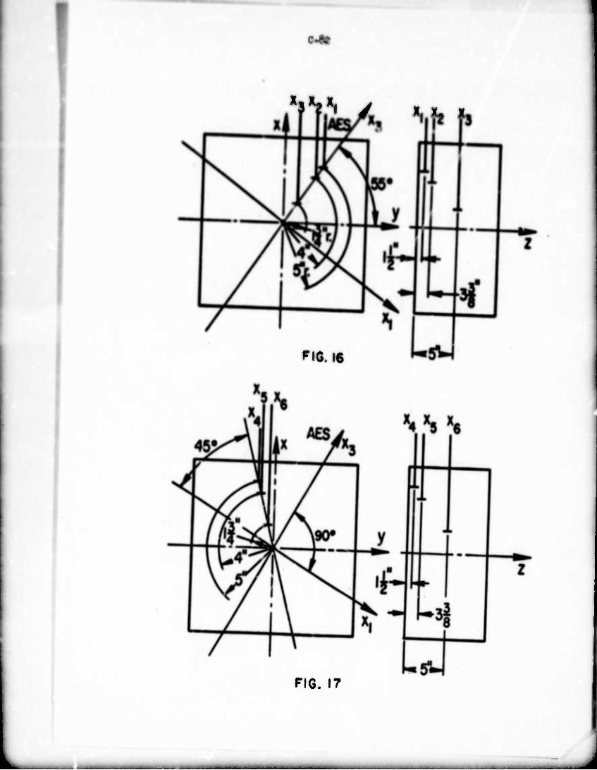
Ki*th
HG. 16
FIG. 17
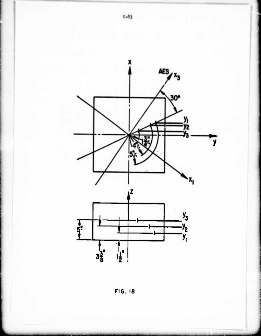
c-as
f
i 5* L ^
n -H
FIG. 18
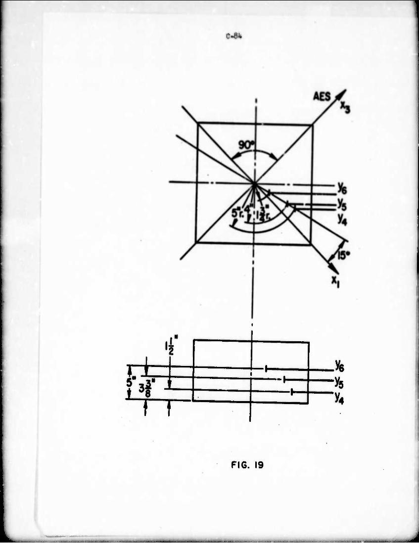
cat
i 4"
iz
T7 -l-
"^4
FIG. 19
__. ,.- ■ —*^^^^"
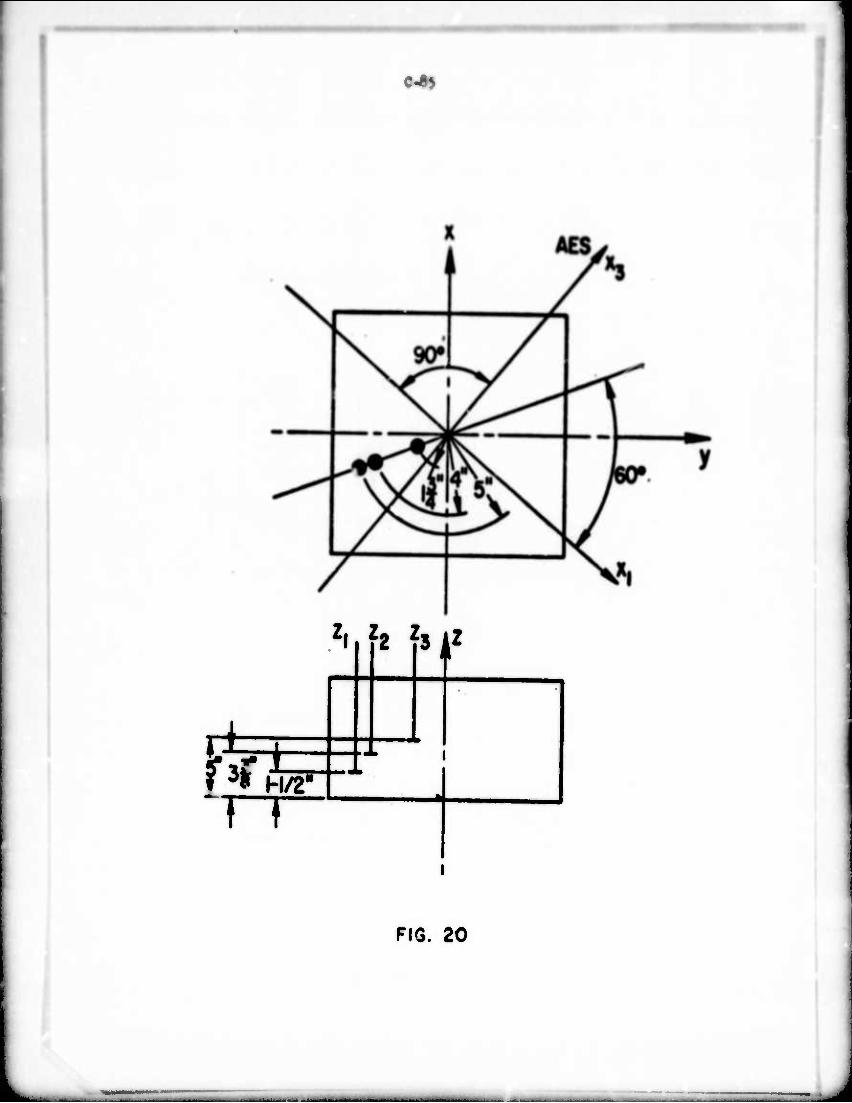
e<4)
zi h hk*
FIG. 20
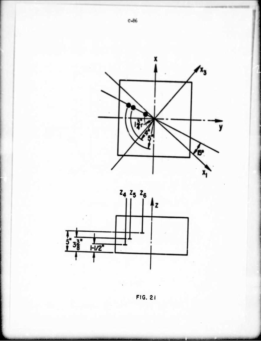
C-M
Z4 ^5 h
FIG. 21
_J1J. - - ■—-
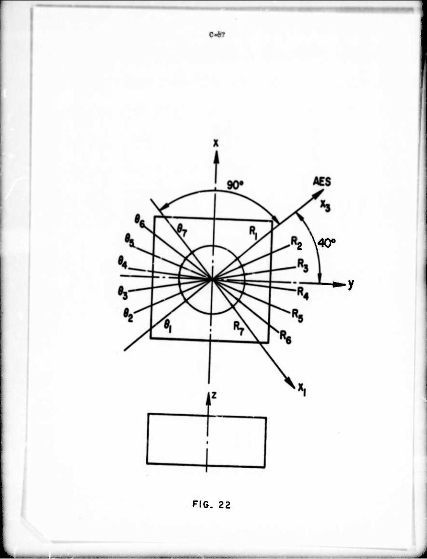
c*
—
2 X^O0
•-y
FIG. 22
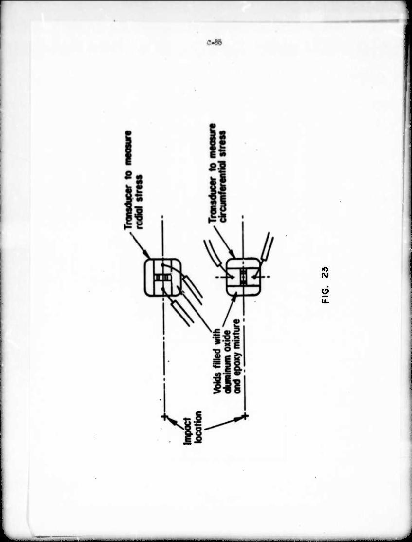
c-ae
lO Csl
u.
A
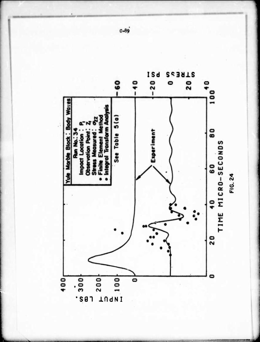
C^9
ISd Sc3älS o o
(VJ
d Ü.
•S91 IfldNI
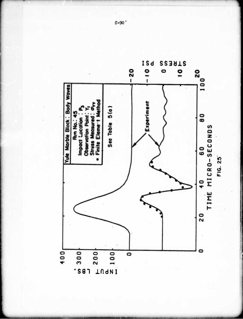
:-x-
O CM I 1
ISO SS3dlS O o o
o Ü.
'S81 indNI
- ■ —
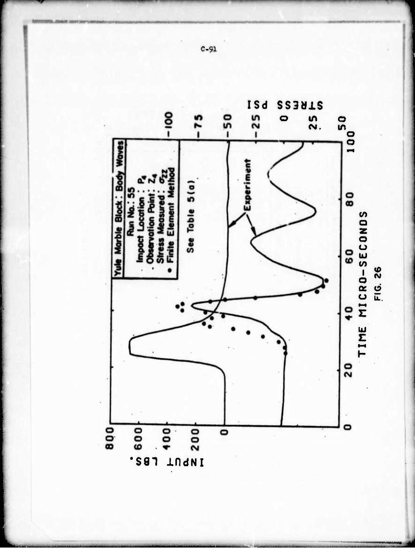
C-91
ISd SS9U1S O LO
OJ. o in o o
Q
O o UJ (/)
I o oc u
UJ E
(0 (Ni
O U..
•S81 indNI
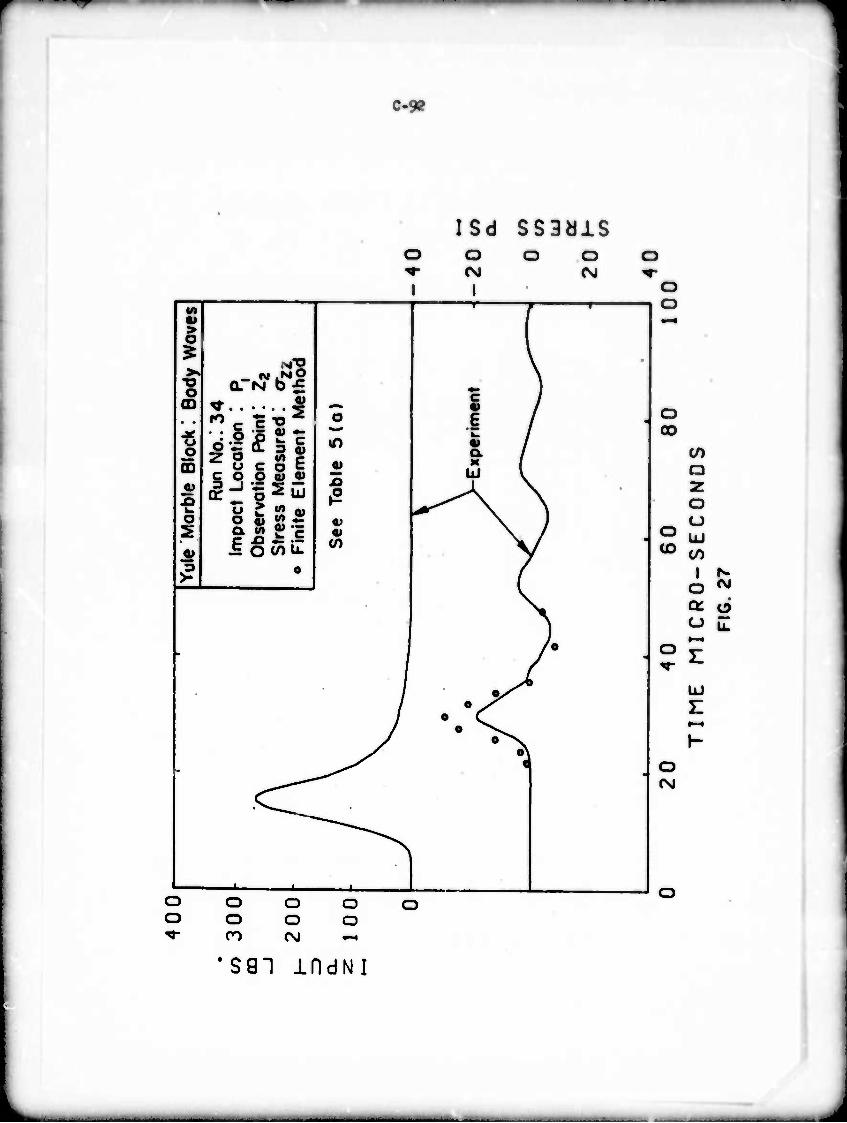
r
"'»
1 C-9?
O
I
SSBdlS o o
(M I
o (NJ
M r—p «1 i s $ v
>«"2 \ >s (M .NO \ o QTM b£ «
) 00
o ,- (t a a>
M » /
o
O • i / Z o w c o c o c 9- 1
CD «i I/I i C O O O) <u ^ v 0) IffSu .2 ^^A \ w ^ * s «) ^r^ ^V 1 O o fc w -^ a* ^k
2 a w «E ■ \^ /
O) c ^ •= :- i O t/) L"- 0) \J
3 o / >* . (
•
A •
/
/ y* 1 * s / • c / 0 ^^ J o\
>^ o\ ^s *
<
o 00
o CD
to
o u UJ CO
I o
u
UJ
CM
O
O fSJ
o o
o o
o o CM
o o
'591 mdNI
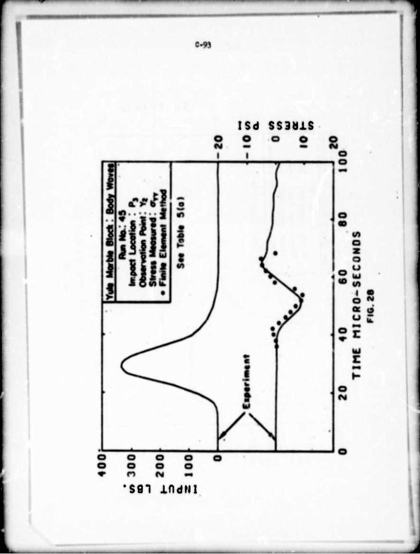
C.9J
isd ssaais
'S91 iOdMl
J
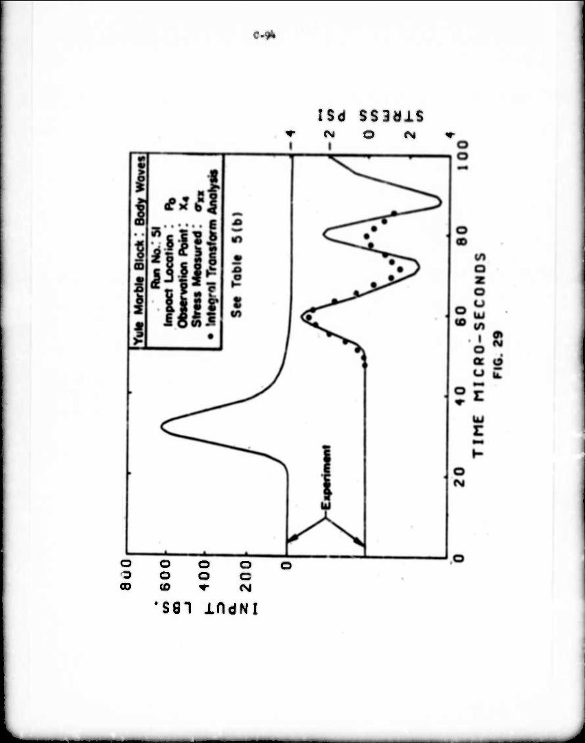
C-fk
ISd SS3äiS M O f^
o o o o ■o o o c 00 (D ^• <M
sei indNi
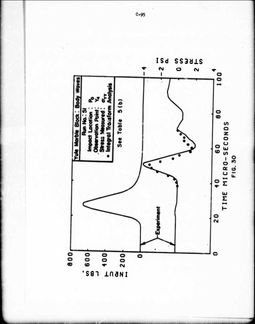
C-9J
d?
fill"
I
6
ISd SS3dlS O (\i
•sgi maNi
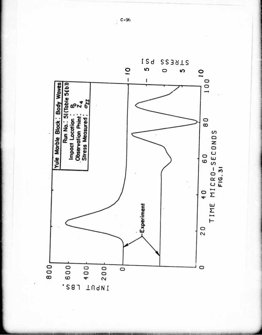
C-96
ISd SS3dlS •n o m
sen mdNi
■ ■
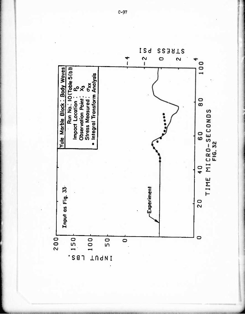
C-97
CM O CsJ
Vi Ä ' a> A > « 1 ^ 0) -=•
o 1^*11 GO • •
silll u o z8 eg i CD <u R
un
Ct
LJO
'vat
ic
s M
e ra
lTi
O o 5 « o» 5 a S) J> a)
i o to ^ 3 m
3H
d» il
o
3 Q. C H
c
i a K
Lü
^
UJ
o o o o o in o in (\J »—i »—1
o (SJ
sgi mdNi
J
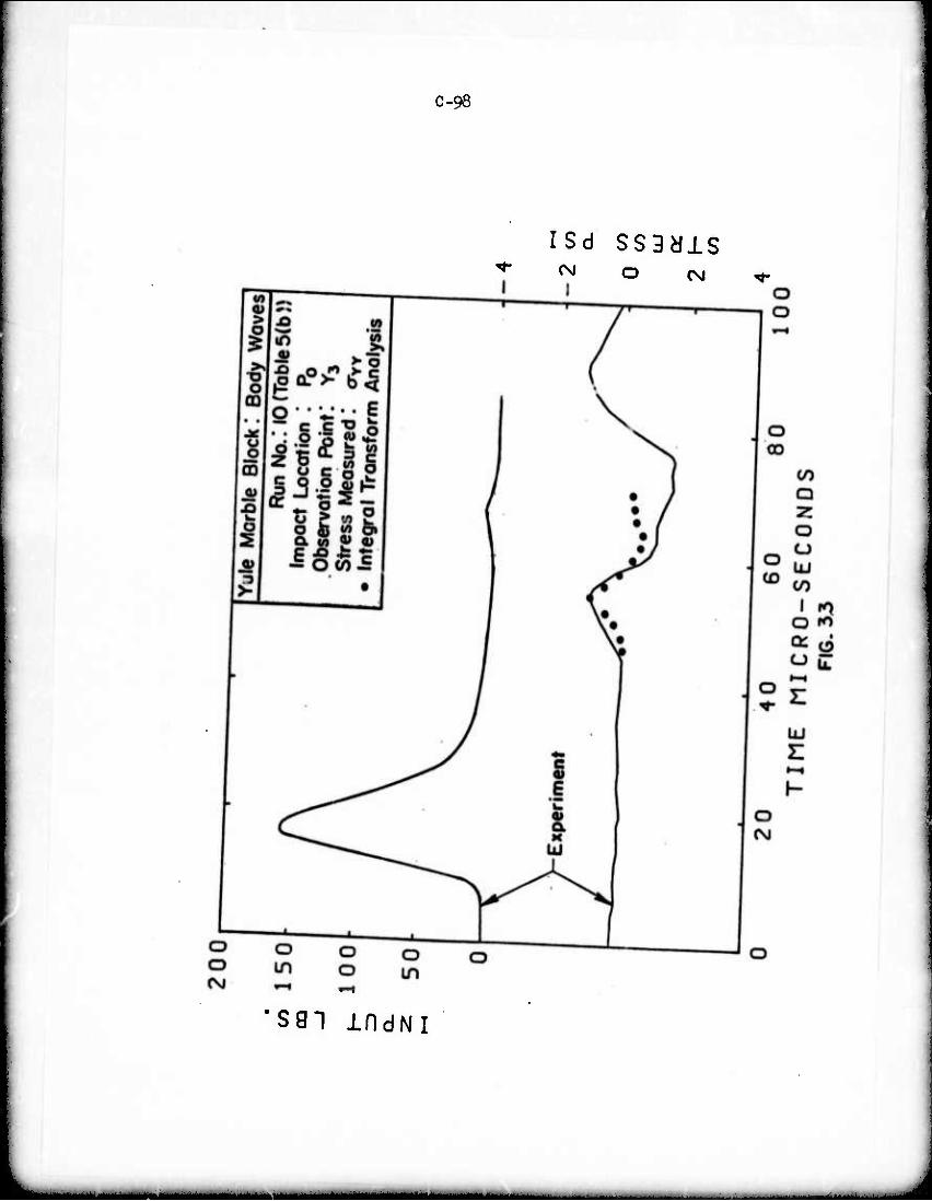
C-98
isd ssgyis ^ O CM
S81 IfldNI
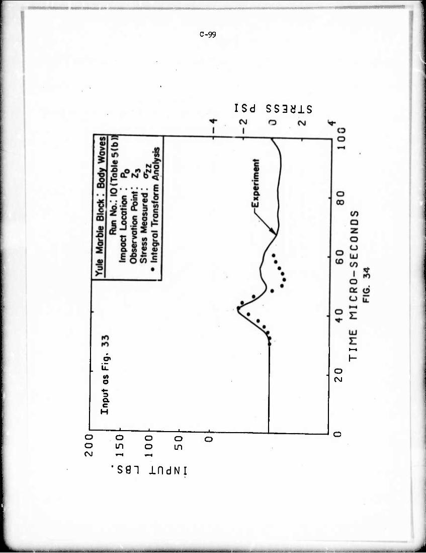
C-99
ISd SS3älS
O«
«n o 4-
CL c H
O Cvl
o O o o o LO o Lfl CsJ »-H »—«
SSI indNI
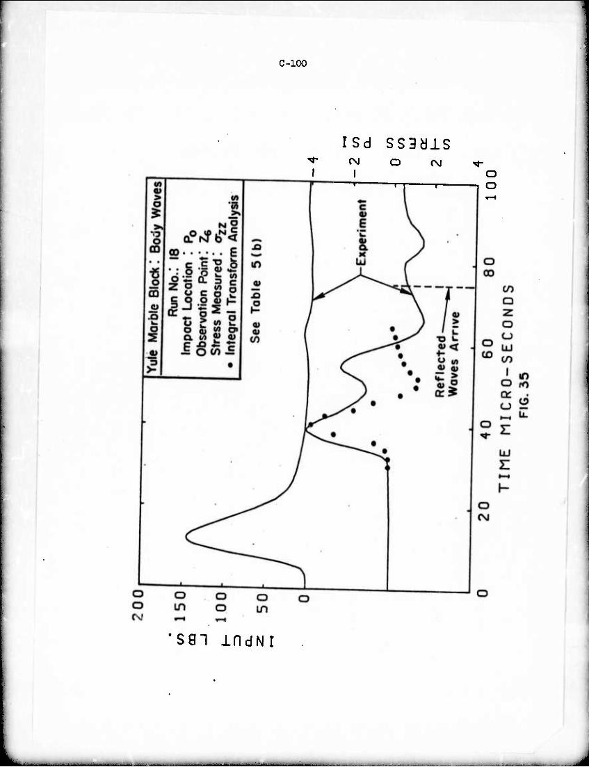
C-100
ISd ss3ais
1 O CM ^fr-
O —n r 1 o
SGI IfldNI
-
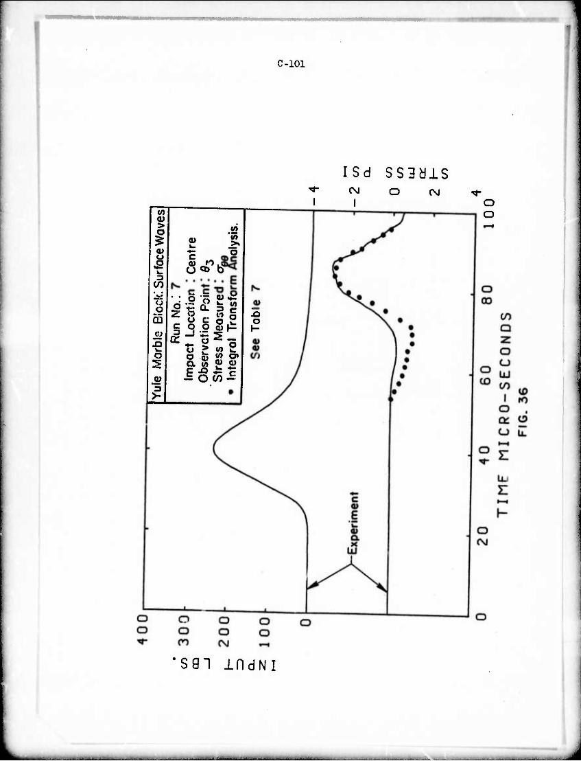
C-101
isd sssais CNJ o CSJ
tn <D > o
a> u
O
JO v. o 2
3 >-
o «t> b
'Jo o
O O
B C ft S Q. <}> a> c> E -0 -^ r
o I-
S91 IDdNI
J
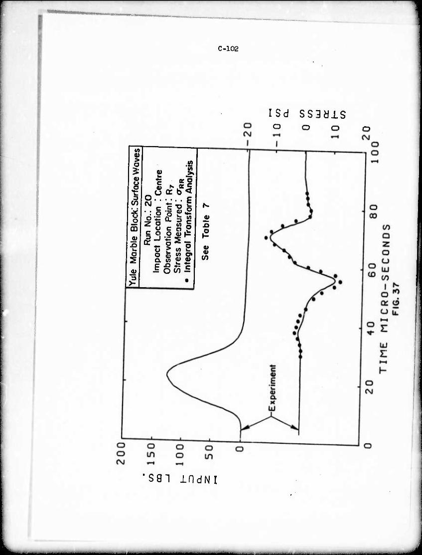
C-102
ISd SS3älS o o o
(/> <u > a V>
3: e I <u
1 1 -5I 0 er b < 3
Run
No.
! 20
oc
t L
oca
tion
: sr
vatio
n P
oin
t!
ss M
easu
red:
gral T
rans
form
<0 Id o o
CQ <u
Si
o
X}
?
2 4) Im
p O
bs«
Str
e In
te
3 >- •
sai mdNi
_j

MVHMVHBMi «MV
b M
APPENDIX D: DETERMINATION OF STATIC AND DYNAMIC MECHANICAL PROPERTIES OF YULE MARBLE
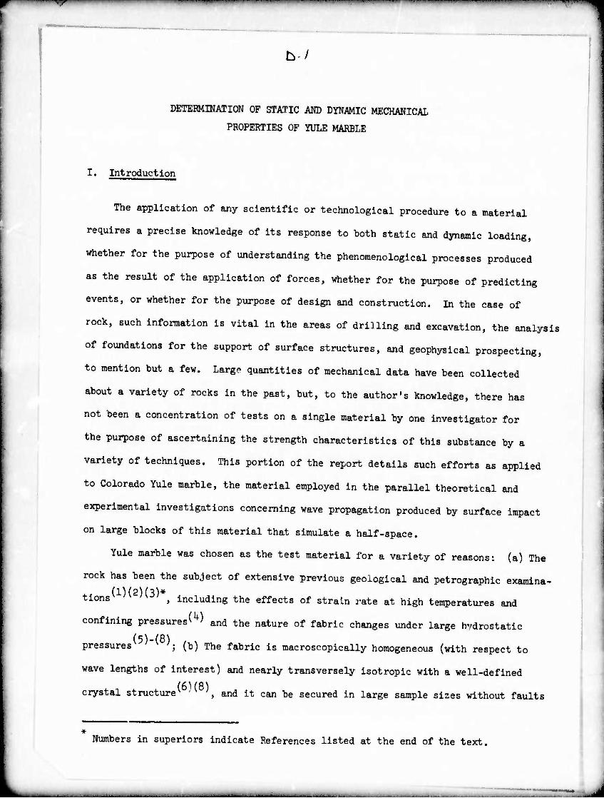
ty/
DETERMINATION OF STATIC AND DYNAMIC MECHANICAL
PROPERTIES OF YULE MARBLE
I. Introduction
The application of any scientific or technological procedure to a material
requires a precise knowledge of its response to both static and dynamic loading,
whether for the purpose of understanding the phenomenological processes produced
as the result of the application of forces, whether for the purpose of predicting
events, or whether for the purpose of design and construction. In the case of
rock, such information is vital in the areas of driUing and excavation, the analysis
of foundations for the support of surface structures, and geophysical prospecting,
to mention but a few. Largo quantities of mechanical data have been collected
about a variety of rocks in the past, but, to the author's knowledge, there has
not been a concentration of tests on a single material by one investigator for
the purpose of ascertaining the strength characteristics of this substance by a
variety of techniques. This portion of the report details such efforts as applied
to Colorado Yule marble, the material employed in the parallel theoretical and
experimental investigations concerning wave propagation produced by surface impact
on large blocks of this material that simulate a half-space.
Yule marble was chosen as the test material for a variety of reasons: (a) The
rock has been the subject of extensive previous geological and petrographic examina-
(l)(2)(3)* tions > including the effects of strain rate at high temperatures and
confining pressures^) and the nature of fabric changes under large hydrostatic
pressures ; (b) The fabric is macroscopically homogeneous (with respect to
wave lengths of interest) and nearly transversely Isotropie with a well-defined
crystal structure^ ■ ^, and it can be secured in large sample sizes without faults
Numbers in superiors indicate References listed at the end of the text.
t— ■ -
—I i I—i
D-2
or cracks. Thus, it is an ideal substance to be experimentally employed for the
verification of wave propagation analyses utilizing transverse isotropy; and
(c) Previous 9 (10) and concurrent surface and body wave studies were executed
with the aid of two 2k" x 2V x 10" blocks of this material furnished by the
U. S. Bureau of Mines, Minneapolis. The investigations of Refs. (9) ^ (i0)
required the detemination of some of the properties of the marble; however,
some anomalies were observed that the present more detailed examination resolved.
It should be mentioned that all the previous dynamic tests with the
exception of the measurement of transit times of one of the two blocks (which
were eventually utilized for the calculation of the elastic constants of the
maxerial) were performed on randomly obtained specimens. The samples utilized
in the present investigation were all derived from a 5' x 2' x 4" slab obtained
from the Clervi Marble Company of San Francisco, California. Differences in the
data cited here and that obtained from other previous and concurrent tests may
thus, at least in part, be attributable to natural differences in composition
and/or structure of the raw material (since no quality control could be exercised).
The general objectives of the present investigation consisted of the deter-
^nation of the a.is of sy^ and the mechanical properties of the marble, includin,
fracture properties, as a function of strain rate; the effects of te^erature,
confining pressure, porosity, water content and similar parameters were not
considered. Specifically, the location of the axis of transverse isotropy of the
slab was obtain-d by cxystallographic techniques; the five constants characterizing
a transversely Isotropie elastic material were obtained in t ^nsion and compression
and under static and dynamic loading; the influence of strain rate and specimen
orientation on the modulus and unconfined strength of tensile and compressive
specimens was examined; and the nonlinear and/or anelastic behavior of the rock was
characterized. Standard testing equipment was employed to secure the quasi-static
■ --■--■-
'*T mt*m^'**i*r^*m " > > wmmi
D-3
mechanical properties, while Hopkinson and split Hopkinson-bar procedures (cf. 11, 12)
were utilized to derive the corresponding dynamic information. A considerable
amount of developmental work was required to select specimen shapes that permitted
fabrication without brittle failure occurring during the manufacturing process. In
many cases, the test technique was verified by the use of aluminuu specimens whose
known properties could be checked against experimental results.
II' Physical and Geometrical Characteristics.
Yule marble has been described by Thill(3) as a pure calcite marble with
specific gravity of about 2.70 and grain sizes ranging from 0.3 mm to 0.5 mm
with an average of 0.U mm for the spherical specimen examined ultrasonically.
Knopf observed a porosity of about 0.15 percent and called the crystalline
calcite grains to be medium-sized ellipsoidal grains whose short axes are oriented
predominantly nomal to the marble "grain". It has been shown(6)(8) that Yule
marble displays a distinct pattern of preferred orientation of calcite optic
axes. A 1000-point-count modal analysis indicated that the marble comprised about
99 percent calcite and 1 percent accessory minerals, notably biotite, epidote,
magnetite and muscovite by volume.
The present 5' x 2' x 4" test slab exhibited bedding planes as evidenced by
the presence of grey bands of opaque mineral throughout the specimen. Although
not totally uniform, the average normal to these planes is relatively constant and
is located in the largest plane of the slab; this will be termed the Z-direction.
The specific gravity of the material was found to be 2.8l with crystal sizes
ranging from 0.2 mm to 0.7 mm and a mean of 0.5 mm. All test samples were cut
from thi. .lab and are identified by two letters followed by a single or two-digit
number. The first letter shows the general coring location as indicated in Fig. 1,
the second denotes the direction of coring for the sample, while the numbers identify
a more initial position of the specimen in the slab.
—
D-4
»• inltui Mt^tioo of eoiMlteM« of UM «cu of tfMavwM iMinnv
vlth th. t^d,. tb. mrf aorml to U« M«lag 9!«^ «M «ortft«« b, proporUf
t thlo ••ctloo «Ä fr« too «Ub (fi«. I) pwp.iiciUr to tto Z^lroetteo utf
•uolnlnc th« orl«oUtl» of ooeh of 100 e^eito crynol« of tto tpoelMO. IM«
^t .ceo^u^d by r^rdlo« tb« UeUooUo« of tb« ml^r-X fU^ l«eorpor«t«d I
I« tb« cry.uUotr^blc •lcro«cop« tbot «M ro^olroi to protee« tb« lM«rf«r«oc« I
P«tt«rn of 1 cnr«tol Ao«« optlcol «*« 1. prp^dicmUr to ■ fUM 4lroctl«o(l3).
Oily thM« eiyntol« «Itb opt. « «n« ««i«. IOM U^ ^ oitb tb« boiilat «oraol
co«l- b« d«t«ct«d do« to iPMtnmmi UMv^immi bo^vor, 91 yo^t of tb«
crytaU «.r« loc«t«d wltbU tb« «^.«nrÄU. r«,!«. Co-M^u« «f tb« ^ibi. ,
dooalo, r«pr«t«ot*d by tbot portion of tb« rarfbe« of % bMlipbin Meloooi by
50° coo« with t.b« op«« «t tb« orlcU. lodleoto« tbot tb« ratio of tbU «roo to i
thot of tb« brai«pb«„ 1« ^oot O.JO. CraiHiiUXy, | p^iy „,** efnUl
orl«utlon ouch «• fb«d Ui tb« «^ «f « i^wpiff ootorUl «o«U lodlcot« tb«t
70 p.w.t of tb« obo.nr^i cty.tol« (ratbor tbra 9 ptrmt •« forai b«ra) «boold b«
ouuid« th« MO« of poMlbl« cfp.toilosnpiae «MüMtlra. «M bl*ly «oi Ttraple
notur« of thU raUrUl 1« tbua ««t«bll«b«d.
■Jb« loc«tlo« of th« eipotol •»« «M ft«i to bo «at« «yUiOrioolly «yra«trle
with r««p«ct to tb« 1^1«, tb« loltlol ««««^iiao co^ralof tb« «oloel*«* «f tb«
boddln« pl«n« ooraol with tbo «KI, of truMrara« l«otrapy ^««rod to b« ««b«u«tUU4.
Thl. cooclu.10« U b«^ 00 tb« bypoth««U tb.t th« ^^trlb^lra of optleol pn^rtlo«
1. dlrtctly corr«UtlT« olth tb« oHooutlo. of o«cfo««opl« raebooleol pfop«ni««
•nd tbot othor rock choroctorl«tlc«, ««eb M, for «wl«. tb« orUMotloo of
crwk. .ith«r «Uo conflra. tbl« r««ult or U«« U ra offtct of ««coM ora«r. TbU
tr«od If ttroacly fupportrd by •vld«oc« tool v«i jty «Uotropl«« obUla«d by
ultrwoulc «^urra««! t«clAlqu«t 00 Tbl« «ubl« eoiocMo «rlth ciystollacr^ble
•oitotroplM eorrotpondloc to a trmmoly taotrapte ootorlol (1)

D-5
III. »laal-Statlc Te»ti.
a) Coopreialon.
Ten unlaxial co«pr«ialvt ttst ipeclMng with a dltMUr of 1.05 In. w»r« cored
In each of th% three prlnclpel directions ueinc en oil-cooled diaaood bit nounted
on a specially converted ■illlnf «achine. Nocinal lenftha of the te^lei «ere 2 in,
for the Y- and Z-direction«, while the «lab thicknees limited that la the X-directlon
to li in. The specimens were ground flat with an abrasive diamond wheel with a
maximum difference of 0.0015 in. In the dimensions of the axis and two generators
90 apart. In spite of extreme care in the fabrication process, then Is a possi-
bility of the disturbance of the fabric reUtive to its virgin state, although
it is expected that any such damage will have only secondary effects on the
mechanical response of the samples.
BW PAE-12-12S9L epcxy-backed strain gages with a length of 1/8", a resistance
of 120 ohms and a gage factor of 2.01 were mounted longitudinally with KPY.150
epoxy at the two ends of the midsection diameter of each specimen; for the Q.series
of saxples (cored normal to the X-direction), a pair of transverse gages were
additionally mounted In a similar manner near the specimen center. All gages
were wired In series to eliminate any flexural components end were Incorporated la
an AC-exclted bridge circuit; they were calibrited with the aid of shunting a
known resistance across each gage pair. 1^ compressive force applied through
bearing plates by means of a 0-20,000 lb. capacity Inntron testing machine was
determined by a calibrated load cell. Both a variable time base strip chart
recorder and a dual-trace oscilloscope were employed to record the strain and lw|
histories. The arrangement was checked out by the determination cf the known elastic
constants for a 7075 aluminisn test specimen.
Two specimens from each direction Wire tested to fracture at each of five
strain rates ranging from c - 10 to lü"2 per second, yielding the results shown
1 D-6
.. «... 2, 3, «a u for th. „^„t i ]we.t r.te „ M0h instance! ^^^
-t. «M. .„ ...u or n.gllglbl. tn thli ^^ ^ ^^^ charaoteri8ticai^
MM thr.. ^„^ „ ^ cmctn upwd ^^ ^ ^ ^^^ ^^
«M. ^ «p t„ ^ ^^ of the faUurc ^^^ foiiowd ^ ^ ^
•«Mi M .1^ ^ „ th. lt(M1, thlrt of the 5trMa rMige> ^^^ ^ ^
' — ^"^ • t0 -*- "«- S, *i=H U ^ U*. than Mta. .t«.. ef. „. „.^ vllUM for ^ of ^ ^^ ^^ ^ ^
- i «r. ,.6. 6.6 „,. M x 106 p-a for Ei Md 8.9t e., ^ 5_8 x ^ ^ ^
H ~. th. „tlr. ^.l..utic ^| th.r, vM f.r !.„ VIrlaUon b,tween
•Ptcl»en. for the llnew »odulu» E. thui fo^ «• ^ iu. Ej ttan for E,, *,„ error. In Its detemlnatlon «m ..tt-tM .t !0 p.««*. th. .xt««! vau.. for th. l.tt.r o«^^ M th. Mtart.« .t , r.te of M , lp-2 p<r ^^^ ^ ^^^ ^ ^ ^
W x XO p.1. «.p^tlv.!,. for th. t.o mmtm,. ». etraln ^ ^^
»r. uiuMd to b« unlfom up to th. v.lu. o. (o/ai v ^ -f o M YUU. of (2/3)^, but their V4JU.S at fractur. •««tu., wr. coo.«.«!)!, ,r.at.r th«, thl. avar,«..
in th. Nata „„ fr«^., .,„,„ rM0Hed ^ ^^ gigM ^ ^^ i8 ^
«curat. -I of -.rag. croa...«»!^x ^clTCn .,„,„., ^^ ^^^
.«^tl«, fr^tur. path. muut. at th. con,.r. of th. .pec^n „d travel
«MU-IO, throu*. al«. c ^.ure pXan.. „ the „ „d Y „^^ ^
PU«.. «« uvarlah!, orl«™ .«h that thair no™.! *, „ th. plMle deflned
H th. ^. of th. «M. a^ a point iym, h the z-dlr.ction. c^e. counted
auch that thU ,1«. of fallur, traral«, thr^ th« produced larger .train
r-dln^ th«, tboa. Wad auv frc. the fracture path. Thl. oonclualon ™. r«chad after «ountrn, four t^.. m „o ^^ ^ ^ ^^ ^ ^ ^
«d MtoMta m^m. ^ .^^ the .lre„..traln ^^ ^^ ^^ ^^
t« orthconal ^e p.ir. „ .h01m „ ^ ^ ^ m ^^ ^ ^ ^^^^^
«re - Hill toMM ao that thv .ere a. far a. po..lhl. fro. the fracture
' ' 'T ... wmmmm i ■ ■ N ■" . I..P...1.1 1 i. i i in i WIIII»II n i iii ■-■^ v
D-7
pat» mu th08e on speclfflens in the
-^ ^ "" "ere VMitloned such that the
fracture path aiways passed thro^ the gages ft«. »
while V-dlrectiou as.o! " " " SPeCi"enS ^"^ britt1'. ectlon s«sples exhlhltlug a region * Urge strains and Xow „cdulu.
aX 7 indlClteS ^ ^ — " «- — * - - the assu^tton of one-d^ensicnaUt, hrsaKs do» in the pre.aiiure region
«MiMU m the Z-direction show no preference 1„ <•
^ r aiso spiit diagon... JZ IZ^ZX^
«ag , there was very little aiff^^^ ^ ^^^
of gages even though the fracture passed directlv t. .. ,„.„ (
d alreCt:iy ^«'^ one set tf transducera. The maximum stress in the t iHy.*~t,
the 8t . ^-direction varied fro. about 83U0 to <*00 psi over the straxn-rate range of about lo"6 to 8 x 10⁻³ wl+h t - ftQo * o o x 10 with maximum strains rangin« from 982 to 1300 x 10'6. +v,Q anging
**> x w , the corresponding values for thp v ^^ *. to g^OO r>«-. *• ■ Y-direction were 7600 to 9300 psi for strains of about 3300 to 2100 x lO"6 - , of a - 10 .so + ^ ^ o 2100 x 10 and values for the Z-direction
% - 10,350 to 16,500 psi at strains of 3070 to 4750 x lO"6
^o^-i . -> < ou HOU x 10 , respectively. The failure stress increased weakl r vitv, ^ i
0 ^^ rate f0r Erections in the plane of isotropy, and more sharpiy with th^ „
m -st .sea the fract ^ ^ ^ ^ *~— iS—• fracture stress „as 3omewhat iower than the faiiure stress hut
it «as difficuit to det^ine this parameter precisely Barti , , rates. Precisely, particularly at high strain
^ - constitutiye nations for a tr™ely isotropic eiasUc material, giyen
6XX = I ^XX-^yy)" ^ Ozz
-i t ■ ^./2G,
yz "yz
exZ ' »»/ao'
V 2G E^
(D-l)
xy
" T ■ ■■'
D-8
contain five elastic conatants: E, p and E', ^ denote Young's modulus and
Poisson's ratio in the plane of isotropy X-Y and parallel to the axis of transverse
isotropy, Z, respectively. The fifth constant G' is the shear modulus in any plane
perpendicular to the plane of isotropy. Four elastic constant« can be obtained with
the aid of Eqs. (D-l) by measuring axial load and longitudinal and transverse
strain in uniaxial specimens oriented parallel to the Y and Z-axes, vhile G« can
be detemined from values of these quantities in a specimen cut parallel to a
line hf counterclockwise from the Z-axis in the X-Y plane. Transformation of
both stress and strain tensors yield the relation
at . *+?
^V^-W (I>-2)
where subscripts L and T refer to longitudinal and transverse strain, respectively,
and U5 refers to the specimen orientation.
These constants were evaluated from specimens 1.05" x 2" long cut along the
Y, Z and kf directions as indicated by the G-series in Fig. 1. The samples were
first loaded from 0 to 1200 psi and then unloaded at about 100 psi/sec for seven
cycles in the Instron machine and then loaded and unloaded to 6000 psi at a rate
of about 300 psi/sec for three additional cycles. Typical results are shown in
Fig. 6 , 7 , and 8 . The material exhibits a "first cycle" effect as shown in
Fig. 8 : a permanent deformation accompanies each virgin stress level, but upon
subsequent loading to this level, there is hysteresis, but no appreciable permanent
set. The ratio of transverse to longitudinal strain was found to be non-linear
(or perhaps bilinear) for both Y- and Z-dirsction specimen. In order to avoid the
problems of non-linearity and first cycle variations, the elastic constants were
determined from the seventh 0-1200 psi loading cycle as
E1 = U.7 x 10 psi; ^ . 0.13; I* - 2.3 x 10⁶ psi; ^ = 0.05; G' « l.U x 106 psi

—— ■ ■ t'wm
tmmammamm
D-9
b) Tensile Tests
After two initially-selected specimen geometries proved to be unsatisfactory,
0.768-in. diameter rods were cored from the Y, Z and ^5° directions with the aid
of a converted water-cooled gravity drill press and cut to lengchs of approximately
5-3A in. by a diamond saw. Two 3/^in. diameter x 4 in. threaded aluminum
endcaps were glued flat to the specimens with Scotchweld Structural Adhesive
and wrapped wich transparent tape so that their diameter approached that of the
rock cores.
In order to estimate the magnitude of the bending stresses that are invariably
extant to some extent in any tensile specimen during testing, three gages were
mounted at 120° intervals around the midsection of a sample yielding readings of
V e2 and £y A simple analysis(lU) shovs that the pure tensile strain v the
angle between the neutral axis and the gage reading ^ namely eo, and the peak
bending stress ^ are given by
et^t/E = 3Cei+V«3];tan% = 2^r^
(D-3)
'b sin 9
With a value of E = 7 x 10 psi, the ratio of the outer fiber bending stress to
average tensile stress was about 15 percent for a specimen loaded about two-thlrds
to fracture.
Four specimens each from the Y- and Z-directions, supplied with two diametrically
opposed strain gages at the rock midsection were loaded to fracture at various
strain rates with results as shown in Figs. 9 and 10; all of the Y-direction samples
broke at the glue joint, whereas two of the four Z-direction specimens broke near
the gages. The data presented mre most likely in error since (a) the measured
strain is probably smaller than that at the interface where failure generally
occurred, (b) the fracture stress is underestimated since a stress concentration
~ ' ■ ■
D-10
apparently exists at the interface, and (c) the apparent increase in fracture
stress with strain rate may be partly due to the property of the glue rather
than that of the rock.
In order to overcome these deficiencies, an initial attempt was made to
produce a special contour previously employed for fracture investigations of hone^1^
that had been photoelastically and analytically shown to yield a nearly uniform
stress distribution across the section^ ', but the production of Lhe geometry
proved to be very time-consuming and, further, most often resuxL-d in specimen
failure during fabrication. A contoured specimen geometry was then machined from
a 3A-in. diameter cylinder with a length of 2-7/16", consisting of a central
15/16" long reduced section exhibiting a uniform 3/8" long region with a diameter
of I in. where a pair of gages was attached, and end fillets of ^-in. radius
that did not break in the manufacturing process. Contouring by means of sandpaper
applied to a rotating workpiece yielded an ellipsoidal section exhibiting a
distinct "grain" and requiring the use of a powertool to fabricate a cylindrical
test specimen. It was subsequently determined analytically that a 3/U-in. radius
fillet would have been more satisfactory by significantly reducing stress concen-
trations in the region of the section change.
Table 1 presents the results of the quasi-static tensile tests both for the
3A-in. diameter by 6" long and special contour specimens, including two special
samples represented by the last two ent?'ies that were exajnined at comparable strain
rates to provide a direct comparison of the effect of a change in the test section
geometry on mechanical properties. Here a much lower total fracture strain was
noted for the contoured specimens, although the maximum stress a for the two cases m
agreed closely. The gages were found to tt located at the maximum possible
distance from the fracture path and thus yield different results as explained in
conjunction with Fig. 5. Fig. 11 shows the stress-strain curves for three contoured
Z-direction samples. While there appears to be an increase with strain rate of
n—, ^WWPlfliP"""1-1 ' " m^ P» 'W
D-ll
initial modulus E1 for the Y-direction, this does not appear to be the case along
the axis of transverse isotropy.
IV. Creep Tests.
Creep tests were performed on both tensile and compressive specimens in
order to determine the approximate stress levels where viscoelastic effects begin
to dominate the material behavior. Instrumented compression specimens fabricated
as described previously were loaded in approximately 700 psi increments at a rate
of 700 psi/sec by an MTS testing machine in the constant load mode. Each level
was maintained for 100 sec, after which the next load increment was applied; the
strain gage output was continuously monitored. The results are shown in Figs. 12
and 13 for the Y- and Z-directions, respectively. An additional creep test on a
Z-direction sample involving a load of 36OO psi applied for 15 minutes yielded
less than 20 || in/in of creep strain. It is evident from these data that there
is no significant creep except in the vicinity of failure which appears to b«
brought about by this flow.
Rock specimens equipped with aluminum endcaps as employed in the quasi-static
tensile tests were rapidly loaded to a constant stress level of up to 230 psi by
the attachment of weights to the lower loading chain of the Instron machine. The
constant strain response for loads applied up to 10 minutes indicated the absence
of noticeable viscoelastic effects in this range. Qnployment of higher stress levels
required the use of the Instron machine in a constant load capacity; however, this
mode of operation limited loading rates to about 30 psi/sec so that only the last
part of the creep curves were obtained. Here, too, with stre*? levels up to 65O psi,
no significant viscoelastic behavior was observed either in the Y- or Z-direction.
'7- 1,1 ■ « ""' m i " PP i ■■PW^wwur- 7«w(i >«iwH»p'i"w<^^ai
D-12
V. Dynamic Tests.
a) Hopklnson-Bar Experiments.
One Y- and one Z-dlrectlon Hopklnson bar, samples JZ and IY, respectively,
were fabricated by gluing together three appropriately oriented 3/U-ln. diameter
rods 6" long, similar to those employed In the tension tests, and were supplied
with two sets of diametrically opposed longitudinal gages mounted on the central
section about U-13/l6" apart as well as with one transverse pair Immediately
adjacent to the farthest longitudinal transducer set. Another specimen, Uk3,
but 5-3/U" long was cored at U50 In the Y-Z plane with Identical bedding to IY
and instrumented with a single pair of longitudinal and transverse gages, the
former being located 2-5/16" from the rock Impact end. All specimens were pre-
faced by 3/U-ln. diameter x J* aluminum end caps attached with wax to prevent
local fracturing. They were held vertically In an arrangement pemlttlng loading
by the Impact of a ^-In. diameter steel ball dropped from a height of 22$ In.
through an aligning tube onto the aluminum cap. The strain r-lses detected by
the gages were recorded simultaneously by a 565 dual-beam Tektronix oscilloscope
whose amplifier had a bandpass flat to 3 megahertz using a potentlometric circuit
that permitted gage calibration by observation of the effect of Inclusion of
known shunt resistors in the loop. Triggering of the device was achieved from
the signal generated by a piezoelectric crystal taped to the side of the specimen.
Peak arrival times were used to calculate both rod wave velocities c and the 0
ratio of transverse to longitudinal strains for both compressive and tensile
pulses, the latter being generated by reflection at the distal bar end. Wave
speed determination for specimen MU5 required the use of both incident and
reflected pulses.
A uniaxlal elastic analysis without correction factors was employed to evaluate
the dynamic elastic constants. Since minimum pulse lengths of 6 Inches prevailed
throughout the tests, yielding a bar radius to wavelength of about 0.06, geometric
^^r"^ "■ i ■■ ■ m^^-^mmm^ff^mim •
D-13
(17) dispersion will be minimalv*,/ and this theory should accurately describe the
phenomenon. This was substantiated by the virtual congruence of the strain pulses
at the two gage stations. Again assuming transverse isotropy, the constants
were determined from the relations
E^ = P c.
El = PC d
G1 = •■<(c%/c)i
ClicOJ
^
4' •i
2l%o ^
for the rod in the Y-direction
for the rod in the Z-direction {D-k)
for the rod at 1+5° to Y-Z (M^5)
where p is the mass density and the subscript U50 refers to data from bar MU5.
It should be noted that the results are not affected at all or negligibly by the
presence of glue Joints due to the manner of construction of the specimens. The
results of these tests are summarized in Table 2.
b) Split Hopkinson-Bar Experiments.
(12) The split Hopkinson-bar tests' ' were performed not only for the purpose of
obtaining the dynamic elastic constants of the material by an alternative technique,
but also to examine the strength characteristics of the substance at loading rates
higher than those produced in the quasi-static experiments. The sample examined
consisted of the contoured specimen employed for the quasi-static tensile tests;
its size is large compared to that usually employed in this type of test, but it
was believed that this geometry represented the minimum distance necessary to prevent
the alteration of macroscopic mechanical properties due to the fabrication process.
The shape exhibited the advantages of known boundary conditions on the end faces of
the contoured region that is integral with the larger diameter rock cylinder and
consequent elimination of any frictional effects, the use of identical geometries
for both tensile and compressive tests and comparison with quasi-static results fcr
the same geometry, and the localization of the maximum stress in the vicinity of
the strain gage location at the contour center apprc .imatirÄ the achievement of
•~*^^mmmm
D-lU
the goal of simultaneous stress and strain measurement at the same position.
Concomitant disadvantages include the difficulties of specimen fabrication and
the problem of accurate determination of the stress history for short pulses
and/or anelastic material properties. However, since the ratio of specimen length
to wavelength is less than l/8 and the material is nearly elastic/brittle, the
fecond objection is mitigated.
Fig. 11+ presents the configuration of the split Hopkinson bar testsj^15^ a
contpressive and essentially one-dimensional pulse of about 200 ^sec duration
produced by the impact of ^-in. diameter 30° cylindro-conical hardened steel
projectile fired from a pneumatic propulsion device travels through an elastic
aluminum loading bar to the specimen which passes the major portion of the wave
onto the succeeding output or record bar where the transmitted stress history
is recorded by a pair of coupled longitudinal strain gages. The strain history
is monitored by a pair of gages at the center of the contoured section. An
important feature of these wavefoms is the nearly linear wavefront that yields
a relatively constant strain rate. Tensile pulses were produced with the aid of
a somewhat shorter projectile by permitting the initial transient to reflect at the
distal end of the unit and reversing the role of the loading and recording bars,
with the stress histories deduced from strain outputs on the loading bar. The
transient recording and triggering arrangement has been previously described.
Each specimen was cemented between the loading and recording bars by means
of Scotchweld Structural Adhesive; the entire unit was carefully aligned both in
a horizontal position and coaxially with the centerline of the gun to minimize
the introduction of bending. Two other steps were taken to reduce flexural effects:
a bending suppressor consisting of a 1" O.D. x 6" long section of acrylic tubing
1/8" thick, which was successfully employed in previous Hopkinson bar experiments^15^,
was slip-fit over the loading bar l*| in. from the specimen, and the length of the
loading bar was chosen as 5 feet to reduce any interference by the much more slowly
-_
B[« i >IIIIM V Mf **-*-' - — ' "• ■— —■- ■ — —'— -■ll "- ^nvmmm^mm**- ' •-— —— ■■■ ■ ■^- M| IIN|IVVI^
D-15
travelling flexural components with the primary longitudinal pulse in the test
section.
Ite stress history at the center of the gage section was deduced from the
strain gage outputs on the aluminum bar with the aid of uniaxial elastic wave
propagation theory. The assumptions present in such an analysis include the
uniform distribution of stress across the section and the neglect of lateral inertia
and shear as well as the hypothesis of plane sections, the elastic behavior of the
specimen and small values of the measured strain, the equivalence of a system
composed of a uniform cylindrical rod of the sar.e length and constant minimum
dimeter for the contoured specimen actually utilized, and the absence of an
effect of an initial compressive wave on the tensile properties of the sample.
Ih. equivalent system hypothesized here actually represents an extremal case
since the discontinuity actually present is not as severe. The other assumptions
are either reasonable or have been deliberately satisfied by the choice of the
experimental conditions.
Based on the above considerations, the stresset the center of the test
specimen a<t> can be evaluated from measured data by means of the relation
0<t>=ÄiEaer<t>tt-(2rL + ^)] 0r 0a
(D-5)
where A is the cross-section area, t is time, Xr is the specimen length, ^ is
the distance of the record gage from the rock-aluminum interface, and subscripts
r and a refer to rock and aluminum, respectively. The most serious error in the
proper application of Eq. (D.5) reSults „om even small inacaracies in the time lag
td between stress and strain readings and not in the analytical model of the process.
Utilizing the relations developed for one-dimensional wave propagation in bars / I OS
with discontinuities^ ', the abrupt change in geometry involved providing the
equivalent system for the use of Eq. (D-5) yields a stross-strain curve with only
--
—7- ^■■i ■•! I ,. ^Wl.-V.. -w- P.wnp«^«« ■-«■««« WV««9^^*W—^HH
D-l6
a 5 percent higher modulus and maximuin stress, albeit with noticeable hysteresis
relative to the correct results produced for an infinite ratio of wavelength to
specimen length^ .
A total of nine contoured specimen from the Y- and Z-direction were tested in
tension or compression by means of the split Hopkinson bar technique. Typical
results are shown in Figs. 15, 16, 17 and 18, where d represents the eccentricity
of one striking projectile. A summary of the tests is presented in Table 3.
VI. Discussion and Conclusions.
The accuracy of the assignment of the Z-direction as the axis of transverse
isotropy as shown in n* 1 is supported by optical observation of tne preferred
orientation of calcite crystals, by visual examination of the slab bedding planes,
by the "grain" of the rock experienced when specially-contoured tensile and split
Hopkinson bar specimens were fabricated, by the maximum strength anisotrapy observed
experimentally, and by the anisotropy of initial and secondary moduli associated
with the static stress-strain curves obtained. If maximum compressive stress
transverse isotropy is to coincide with the Z-axis, the maximum compressive stress
in the X- and Y-directions should be identical. Using the formula suggested
by Obert et al 19 to correct for the short column length used in the X-direction
specimens,
CT ■ ^0-8 + !7§) (D-6)
where a = oo at L/D = 1, L is the specimen length and D is the specimen diameter,
X-direction specimens exhibit compressive strengths approximately 3% higher than
Y-direction specimens. However, Z-dlrection specimens have cc-prer.sive strengths
from 38^ to 7^ higher, depending on strain rate. From the dai a of Section Ilia,
the initial modulus E1 and secondary modulus E2 show the same anisotropy; thus,
the orientation of the axis of transverse isotropy for the slab is well established.
The determination of bht five elastic constants from quasi-static compression
cf. Thesis by S. P. Howe
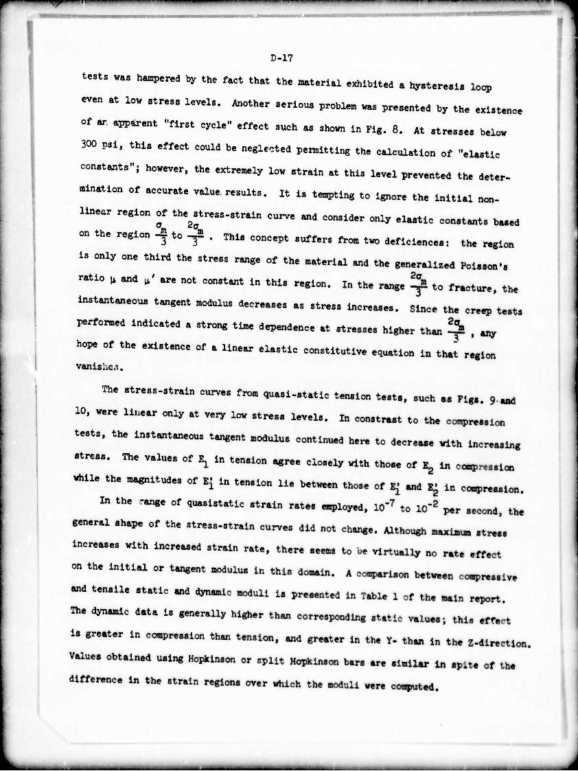
— 1
D-17
tests was hampered by the fact that the material exhibited a hysteresis loop
even at low stress levels. Another serious problem was presented by the existence
of ar apparent "first cycle" effect such as shown in Fig. 8. At stresses below
300 psi, this effect could be neglected pemitting the calculation of "elastic
constants"; however, the extremely low strain at this level prevented the deter-
mination of accurate value re.ults. it is tempting to ignore the initial non-
linear region of the^tress-strain curve and consider only elastic constants boed
on the region -* to -Jü . This concept suffers from two deficiences: the region
is only one third the stress range of the material and the generalized Poisson'.
ratio ^ and / are not constant in this region, m the range ^ to fracture, the
instantaneous tangent modulus decreases as stress increases. Since th. creep test.
performed indicated a strong time dependence at stresses higher than fi , any
hope of the existence of a linear elastic constitutive equation in that region
vanishes.
The stress-strain curves from quasi-static tension test., such as Fig.. 9 ^
10, were linear only at very low stress levels. In con.traat to the comprea.ion
tests, the instantaneous tangent modulus continued here to decreaae with increaaing
stress. The values of E, in tension agree closely with those of E, in co-pres.ion
while the magnitudes of E[ in tension lie between those of E^ and E^ in ,^ i
in the <ange of quaslstatic strain rates employ^. ICT7 to lO"2 per .econd. the
general shape of the stress-strain curves did not change. Although maxim« .tr...
Increases with Increased strain rate, there aeems to be virtually no rat. effect
on the initial or tangent modulus in thia domain. A compari.on betv^n co^.alv.
and tensile static and dynamic moduli 1. pra.ented In Table 1 of the main report.
The dynamic data is generally higher than corresponding .tatic value.; thl. .ff.ct
is greater in compression than tension, and greater in the Y- th« in the Z^ir.ctloo.
Value, obtained u.ing Hopkln.on or .pllt Hopkinson bar. ar. .Imllar In .pit. of th.
difference in the strain regions over which the moduli war. computed.
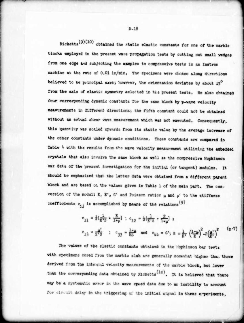
^-r
1 D.I8
Rlck«tU(9,(l0) obtalMd th* »t«tlc «iMtlc COMUD!« for on« of th« aarblt
block« «ployad In th« pre tont ««.•« propafBtioa U«t« by cut tin« out «Mil ««dc*«
fro« on« «d«« «rd tubjtctln« th« ■■^il«« to co^roMlv« t««t« la «n iMtron
Mchin« «t th« r«t« of 0.01 ln/alo. Th« «pocüwn« wr« clntan %Xm% dlroctlooa
b«ll«v«d tc b« principal «SM; how«v«r( th« orlMUtlon 'U»vut«« by «bout 19°
fro« th« axis of «iMtlc ■!—itry •«l«(t«d U U« prM«Bt t««U. H« also obtalnad
four corr««pondlnc dynamic cooatanta for th« aaa* block by p-wav« valoclty
■aaauraatants In dlffarant dlrocriona; th« fifth cjaataot could not b« obtAlnod
trlthout an actual «hoar vav« aaacoraMnt uhlch «aa not aaacutad. Cooaaqutntly,
thla quantify «aa actlad upraida fm ita atatlc «alua by th« avaract Incraaaa of
tha othar constant« undar dyuaadc coodltlooa. Thaaa conatanta ar« co^arad In
Tabla i« vlth th« raaulta fro« Ihi «aa« «aloclty MM—i utllltl. ^ tha fiH^dtil
cryat«la that al«j Involva tha aaaa block «a «all aa tha co^raaalaa Hoidilnscn
bar data of tha prvaant IttvaatUatlon for tha initial (or tancant) aodulu«. It
should b« «s^haaUad that th« lattar data war« obtalnad fro» a different parant
block and ara baaad JO tha valuas flvao la Tabla 1 of tha aala part. Iba coo.
varaloo of tha aodull I, I*( 0' and h>Uam ratio« » «d ^ to tha atlffaaaa
soafflelanta c la acco^Uahod by aaaaa of tha ralatloaa^9'
^'rt » ^-B* ^ ew. • ^ 8 • r (T11)2^)2 <D7)
Th« valuas of tha alaatle coaataata obtalnad la tu Copklaaoa bar t««t«
with spaclaans eorad fro« th« «arbl« slab ar« ganarally ao«a«tiat hl«har th^. thoaa
d«rlY«d fro« UM Inun il «aloclty «^suraatnts af th« «ai^la block, but low«r
than tha corraapoodlnc <»»t« obtalnad by Mckatta^10^. it la baUaaad that thar«
«ay ba a ayataaatlc arror la th« wava apaad data dua u> an Inability to accotnt
for clr. .It dalay in tb« 'rlcccrlnc o. MN Initial aifaal U tbaaa arparlaaata,

D-19 rMtm . mm* tr„.it urn M. MMMMT, . h^«. «^ 8f „„ ^^^ con,t„t. n U 11« »!.„ th.t It ^.„t kl (MM. .. MM »Uu.. or tb.
«MM« con.tmt. lo«r th„ !■■■ Ill, corr.^ondin, MM. MM If tb. tormr
«. taM on MM of th. InltlU tap« ««„, ,*.„„ th. uu.r ^
MMM fro. th. .iop. of th. MO. third of th. oo^„..lT. «^..itr^0
cur».. OMMM h.tv..„ «y lint, .hould ^„y. ^ .„„.^ 4t
•pprox^toly th. .«.. .tr.l„ l.v.1 «, .trUa „t. „, „ tb. ^ ^ ^
losing, A mmmum of th. m»ai «* MM MM obuin*. i. th. pr..„t ..qu.n=, of t..t. I. pro^nt., ln ^u , of ^ „^ „^ of ^ ^^ ^^
MMM unlfomly MMM hlgh.r MM Mi th. cor^^ond!,,, rt.tl.
■nagnltudes.
Th. MMM of IMilMll M MM« .tr^gth o . function of rtr.ln
«t. u MMM m rig.. 19 „d 20, w^.m.a,. Incr.aiwl „^ coapwiiiyt
MM vlth MMM MM M. U nor. p^^no^ ^cng th. ^. of MM -,.
Lotropy Ml« Ml trend 1. MM- In IMM. Th... MM. r.lnforc. „
intuitiv. MM, for UU mm MM MMM Mi In MM^ p^lcuu,!,
when MM« fore, net p.rp«,dlcuUr to th. bedding pUn...
Th. M« Mta p.rfom.d. .Itbough of . prolUinwy «.tu«, provld.
MMM1 ln.lght into th. «.„«.loü «^on.. of th. MM*. Tb. t.« MM.
inpiy tb.t M. »rble ennot b. MM« .. . MM. .olid Mi .t „hl„t
MMMM. „d MMM, It .„«„. Ml IM .ff.ct. MM MMM to
MMil MMM .t MMM n.„ -^ for MMMta. MM» It Ml b.
^ha^lz^ th.t th... IM. point to th. pr...nc. of .«. tl« d^nd.nc. M th.
l^ort^o. of M. MM .t .tr..... .hov. ^ to . MU M» < MMMM
MM MM MM tt. . MM« to MMM . «MM MMMM .*..'.!«,
for th. MMU. MM. t..t. M. indict. UM. IM d^ond«,« .t M
»tr... level, but , deflnlt. tlne-dependenc. ne.r mior..
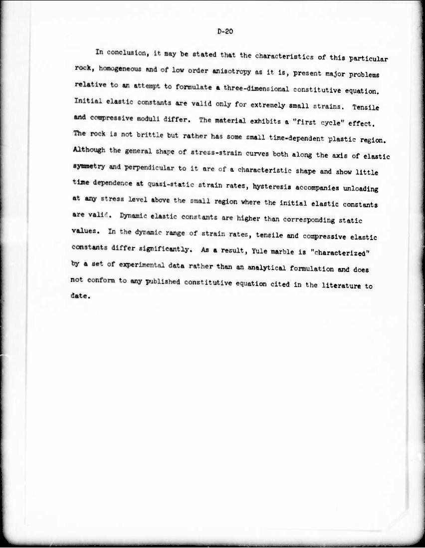
0-20
In concluilon, it »ay be .tated that the characteri.tlcs of this particular
rock, hcmogßn.ooB and of low order ani.otropy as it is. present major problems
r^Utlre to an attenpt to fonnulate a threeHliaenalonal constitutive equation.
Initial .Uatlc constants are valid only for extremely small strains. Tensile
•nd covpressive moduli differ. The material exhibits a "first cycle" effect.
Th. rock is not brittle but rather has some small time-dependent plastic region.
Although the general shape of atress-strain curves both along the axis of elastic
•ymmetnr and perpendicular to it are of a characteristic shape and show little
ti«e dependence at quasl-static strain rates, hysteresis accompanies unloading
•t any stress level above the small region where the Initial elastic constants
are vail-'. Dynamic elastic constants are higher than corresponding static
value.. In the dynamic range of strain rates, tensile and compresslve elastic
constants differ significantly. A« a result. Yule marble Is "characterized"
by a set of experimental data rather than an analytical fomulation and does
not conform to any published constitutive equation cited In the literature to
date.

D-21
REFERENCES
(1)
(2)
(3)
ik)
(5)
(6)
(7)
(8)
(9)
(10)
(U)
(12)
(13)
(HO
(15)
(16)
Ynfri^/*^ 5S TUrner' F* J" "Mi^oacoplc Structure and Fabric of
^l.r^^'Sr*1^ Def0med ^ Different Strain Rat««"» Jou^. Lepper, H. A., "Compression Tests on Oriented Specimens of Nile Marble" Amer. Jour. Sei., ^ No. 8, 570, I9U9. e '
Grlggs, D. and Handin, J., eds., Rock Deformation. Memoir 79 fieol ^n Amer., New York, N.Y., i960. J^i' Mem01r 'y» ^o1- Soc-
Knopf, E. B., "Fabric Changes in Yule Marble After Deforaation in Compression, I: Preliminary Potrofabric Analysis of YuS Martle" Amer. Jour. Scl., 2k7, I+33, 19U9. Maroie ,
Turner, F. J., "Nature and Dynamic Interpretation of Deformation L—alw. in Calclte of Ihree Marbles", Amer. Jour! Scl.,^, 276,^.933°
tt&f&iS^T*^1"of Calcite *Yule Marble"' **• Ricketts, T. E., "Sphere Impact 01. an Anistropic Half-Space". Ph D Dissertation, University of California, Berkeley, 1970.
Ricketts, T. E. and Goldsmith, W., "Dynamic Properties of Rnok« «nH Composlt^Structural Ma-.rials", int^four. STSÄ ^n^Scl.^7,
£I5Ä W%?-ÄÄ^^\Ut4Ä "streßS waves
BWn'R^es-; S^Ä ^^^8! ^^^^ ****» * «*
n!?LS,|U.' f::^ .In!r0dUCtl0" tL the MethMs of Q^11^1 "ystallographv. Holt, Rinehart and Winston, New York, 1967" *■ & f V»
Howe, S. P., "Macroscopic Mechanical Properties of Yule Marble" M i Thesis, University of California, BerkeleJ, 1973! ' "' S•
Lewis, J.L., "Dynamic Mechanical Properties of Compact Bone". Ph D Dlasertation, University of California, Berkeley, 1972. '
Haywood, Designing by Photoelasticity. Chapman rnd Hall, London, 336, 1952.

D-22
(17) Davies R. M., "A Critical Study of the Hopkinson Pressure Bar". Phil Trans. Roy. Soc, London A, 2k0, 375, 19148.
<19, s^:'^ snyj[-^.r.m^^r ',w,|n ^ ^
J
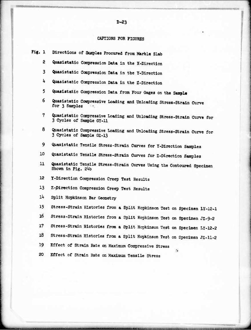
18
D-23
CAPTIONS FOR FIGURES
Fig. 1 Directions of Staples Procured from Marble Slab
2 Quasistatic Compression Data in the X-Directlon
3 ^lasistatic Compression Data in the Y-Directlon
• Quasistatic Compression Data in the Z-Direction
5 (^lasistatic Compression Data from Four Gages on the Sample
6 Quasistatic Compresslve Loading and Unlcading Stress-Strain Curve for 3 Samples
7 Quasistatic Compresslve Loading and Unloading Stress-Strain Curve for 3 Cycles of Sample GY-11
8 ^lasistatic Compresslve Loading and Unloading Stress-Strain Curve for 3 Cycles of Sample GZ-13
9 Quasistatic Tensile Stress-Strain Curves for Y-Directlon Samples
10 Quasistatic Tensile Stress-Strain Curves for Z-Direction Samples
11 Quasistatic Tensile Stress-Strain Curves Using the Contoured Specimen Shown in Fig. 2kb
12 Y-Directlon Compression Creep Test Results
13 Z-Direction Compression Creep Test Results
lh Split Hopkinson Bar Geometry
15 Stress-Strain Histories from a Split Hopkinson Test on Specimen LY-12-1
16 Stress-Strain Histories from a Split Hopkinson Test on Specimen JZ-9-2
17 Stress-Strain Histories from a Split Hopkinson Test on Specimen LY-12-2
Stress-Strain Histories from a Split Hopkinson Test on Specimen JZ-11-2
19 Effect of Strain Rate on Maximum Compresslve Stress
20 Effect of Strain Rate on Maximum Tensile Stress
*-
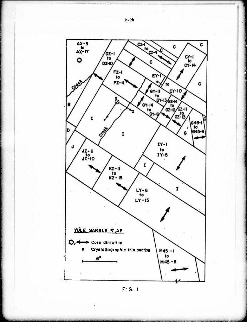
D-2U
AX-3 to
AX-17
YULE MARBLE SLAB
O/ ^ ^ Core direction
» Crystollogrophlc thin section
6"
FIG. I
«M^a^^MMM^i tMftuaflftMMMU^fe*
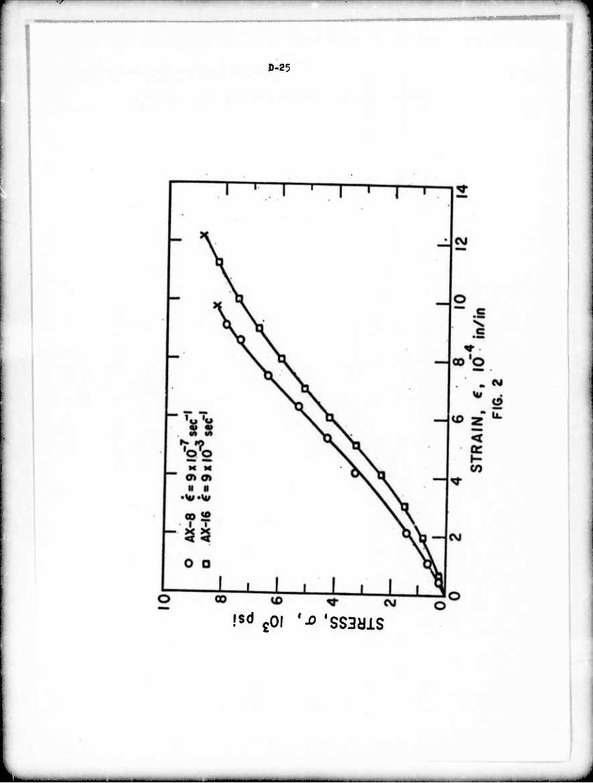
D-25
Is«1 gOi '-o 'ssaais
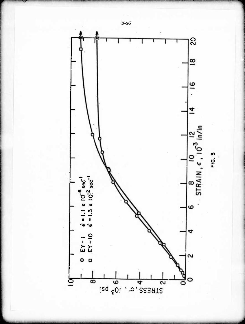
D-26
O CM
a> tn
%D N
'o b X X
• rO •
II ii
•W •w
^,, o i 1
>- UJ
>- UJ
ro I o
!sd £01 '-o'SSBUlS
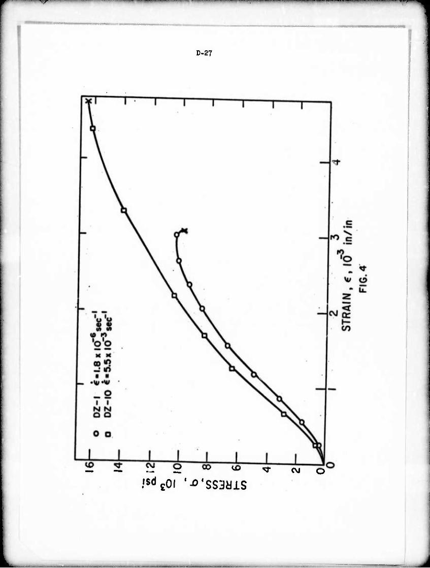
'■r ii^i ■«MI111 ip " ■ ■■ KI" i wn ^^^mim^^mn^mm ■■ •"' "' ■"I " ■■ < M» . . r ^ . ..*...—. ..^« «^i* ■■m
D-27
O 00 VD ^-
,'s«icoi '-o'ssayis <M
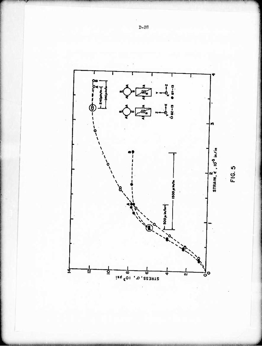
•*r^^*t^r^r'^ VTfW ■»■ii IIHH-IWII» iw» ppi^ii i ■ pi up in« i m^^mmmm^m ww^rwmm^rr^ i -.ii«» i -■ ti^fwtm
D-28
1 ' i -i T r p« T-
- *
. pi] -o-^-ar ^ -O-^JU
•
i < V o
| M
0 \ \ \
N -f -T Jl
N » .s No \
N 1 b m r N i
\ i u*m d
\ * i z < ■
u.
^^ § \ 2
- »
v^ X
X~ i i | 1 i ^i r ^ 2 « .i i 1 1< !«0c0l 'JO'SSBMIS
3
■- - —_ ■ — ■■ - ..... ^- ... .— ..-■. . - ■ ^
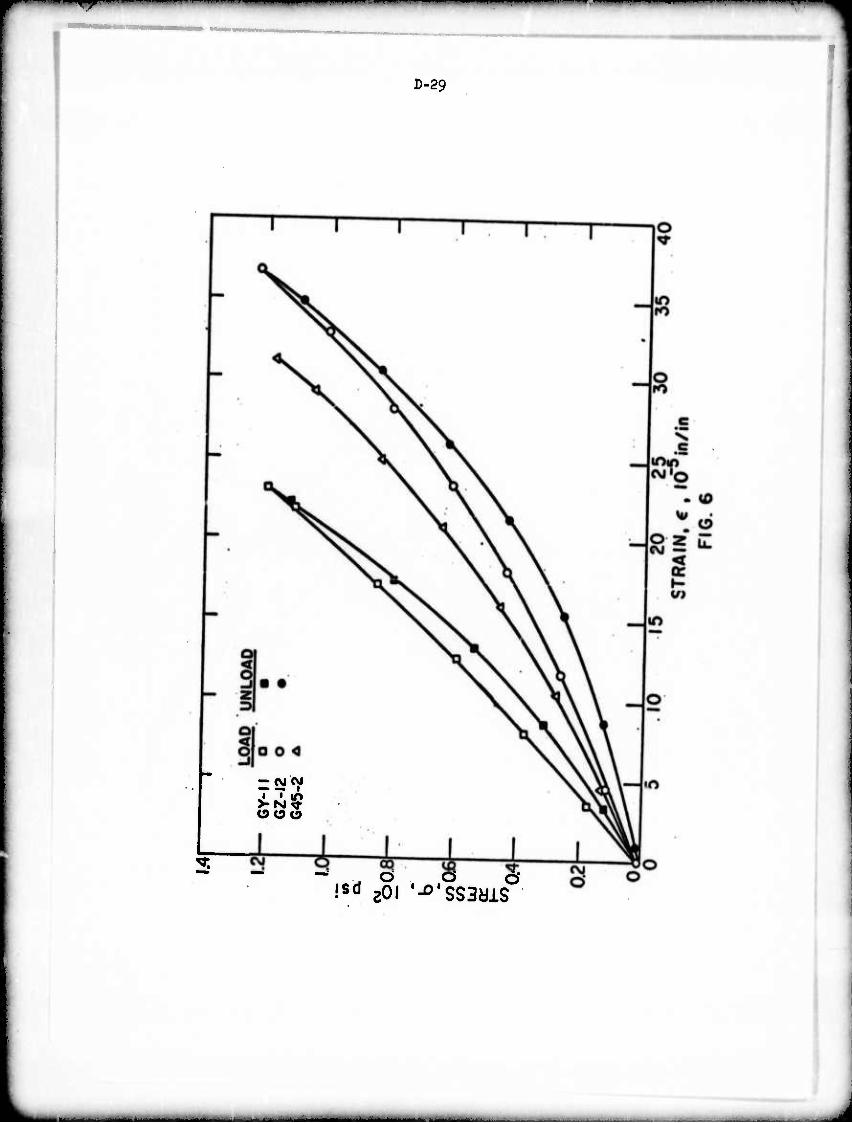
^
D-29
i8" zoi '-o'sssais
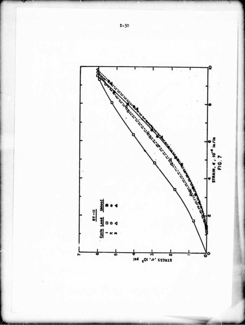
Tr
D-30
!«<» toi •^' SS3aiS
■
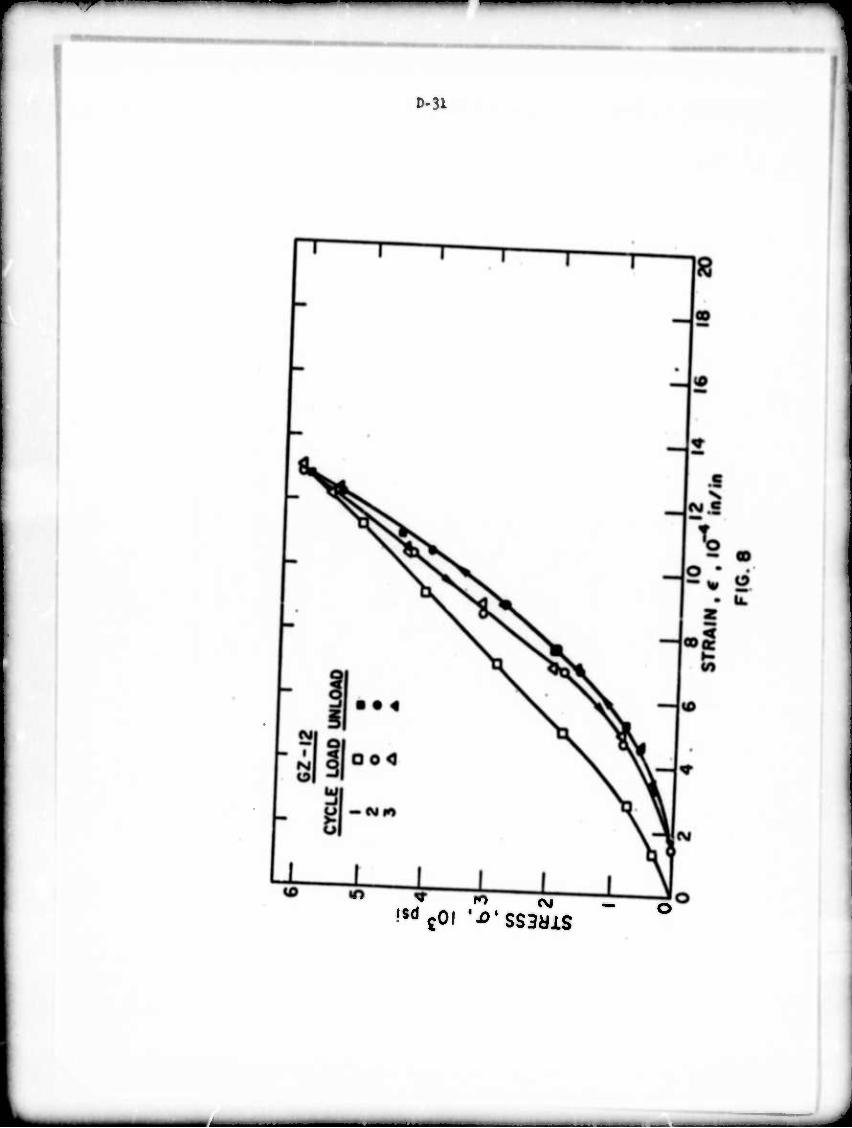
T"
D-31
,sdcOi '-o'ssawis — o
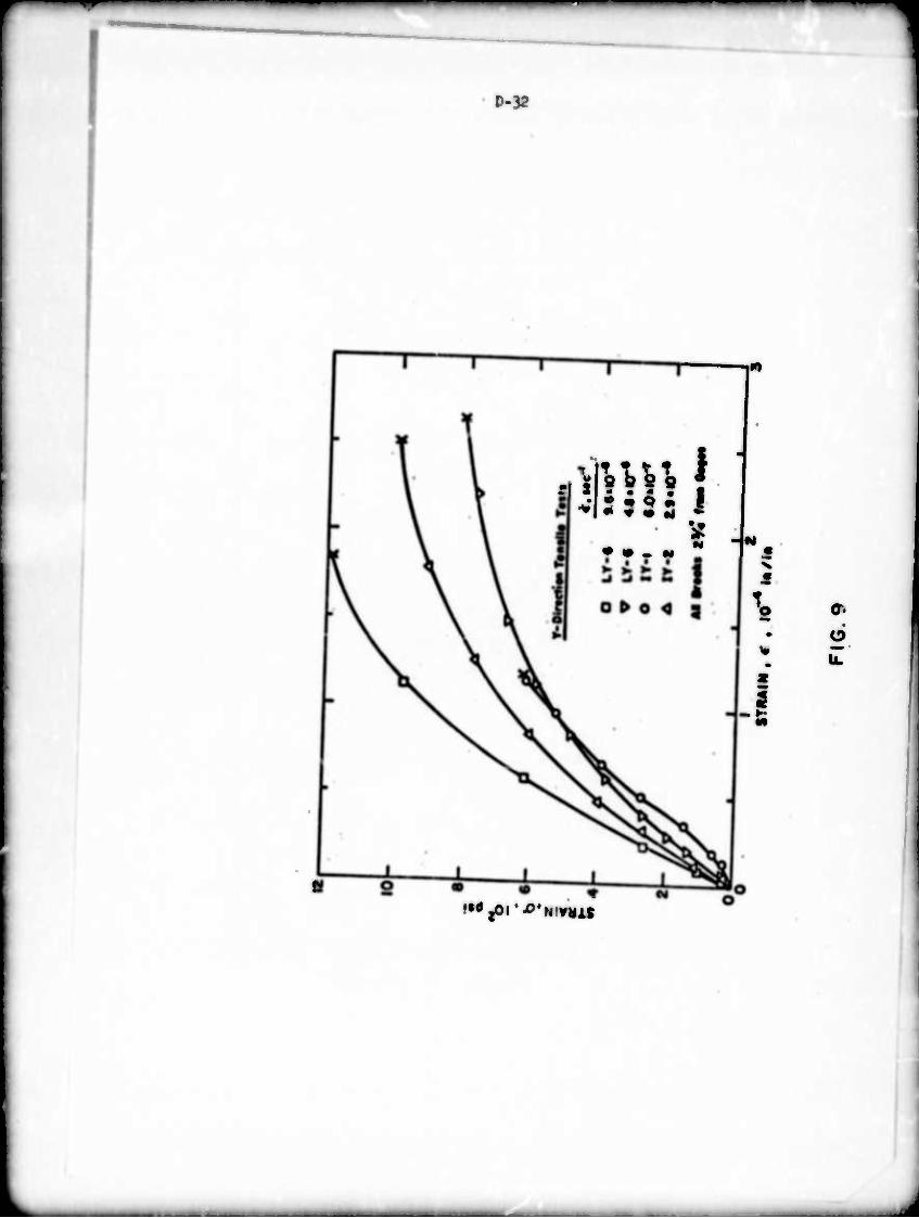
*m
D-32
mMW \ '• 2 Q • \
a - M
X
a. o
Üf JM*^*MMMI
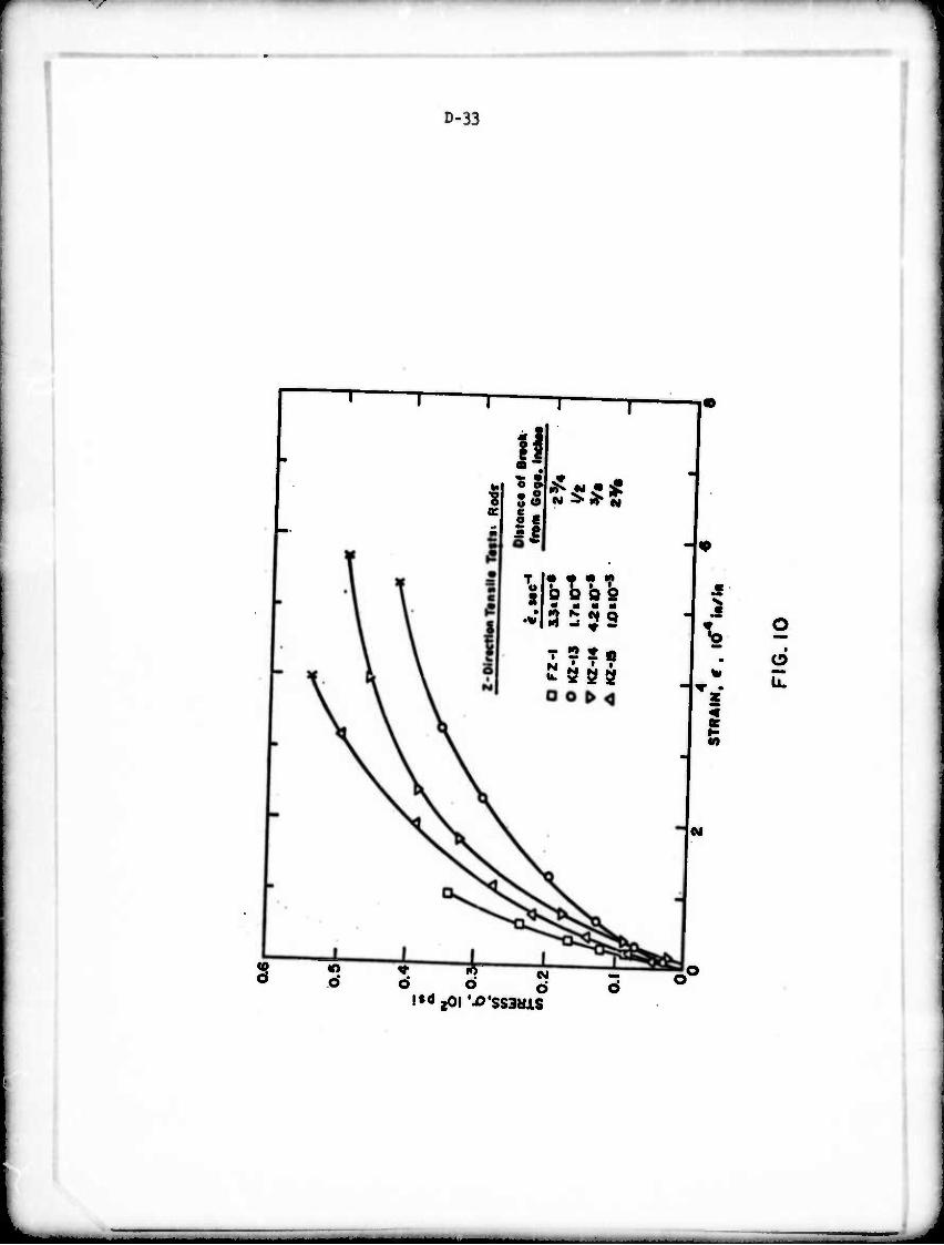
D-33
—!•
s
If (C C
II T !• • •» «
So bob ^ I • ■ « ■
T 2 S« •u • • •
5 "S" « o o ö l'äjOl 'JO'SSSMIS
J
-
.s
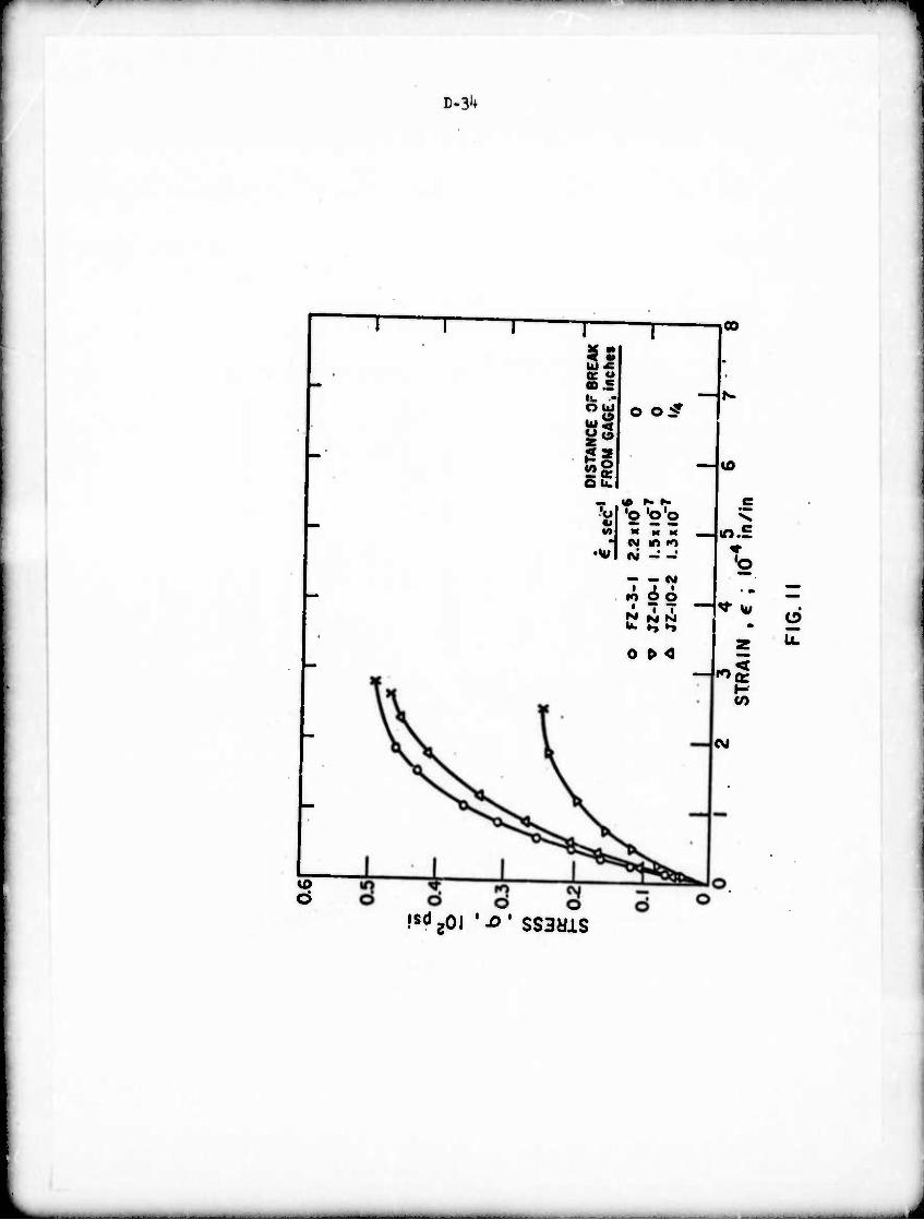
D-31*
1
oo
iß Ö
I! et o co.£
si _ Q: ou.
— .fC
O O S
'ül 'o 'o'o
H evi m -o
— — CVJ i I •
to O O
0 t> O
CM
c
IO.S
'o
CO
o u.
!sd20l '-o* SS3yiS
J
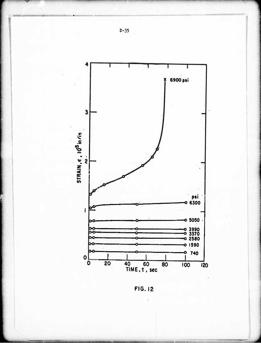
s IW^W^^W**'
D-35
v. e:
'S wi 2 —
<
CO
psi ■o 6300
>o-
>o-
>o- >o-
>o- ol L i
20 40 60 80 TIME.t, sec
-o 5050
■o 3990 o 3370 -o 2580 -o f590
o 740
100 120
FIG.ia
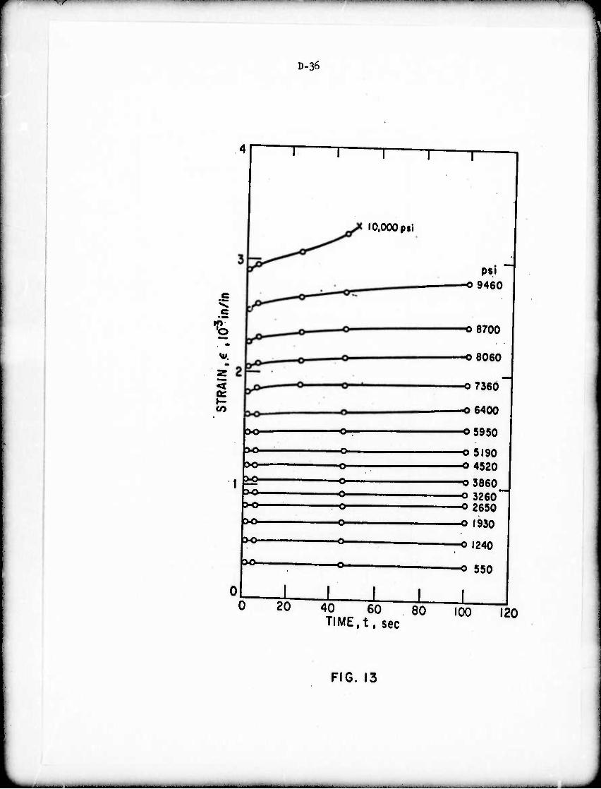
*f ■VPK^HMnpii ii t*rmm*mm immmmm*** ■ ■
D-36
t M*.
or 1-
»o
>o- 00-
x>-
DO-
X)-
X)-
oL
10,000 p si
20
-o- -o- -o-
-o-
I 1 I L 40 60 80 TIME.t. sec
psi -O9460
■O8700
-o 8060
-O7360
-O6400
-O5950
■o 5190 ■O4520
■O3860 -o 3260' -o 2650
■o 1930
o 1240
■o 550
100 120
FIG. 13
- - -
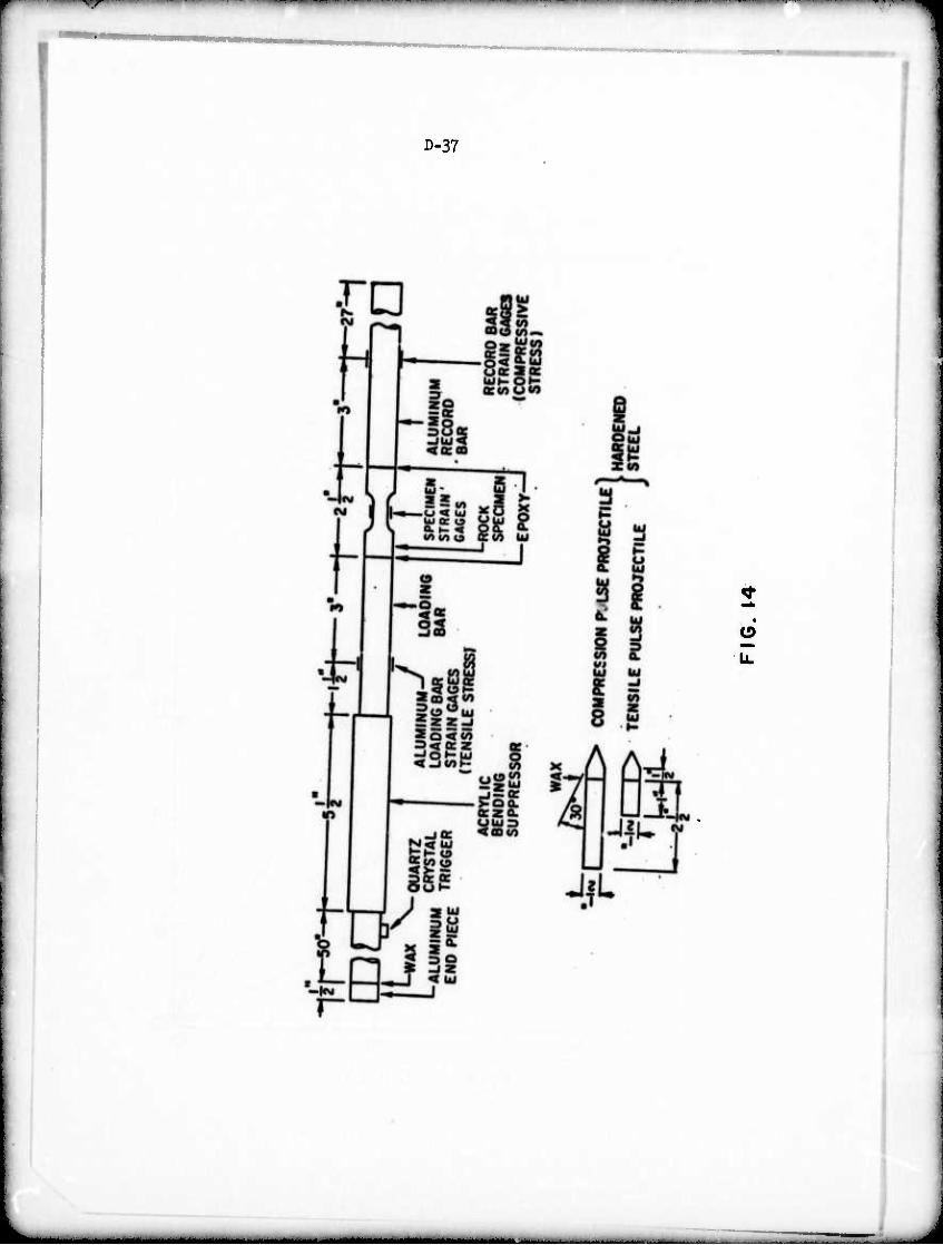
i wp I . ■>■■■■ ■■ ■■■!■
D-37
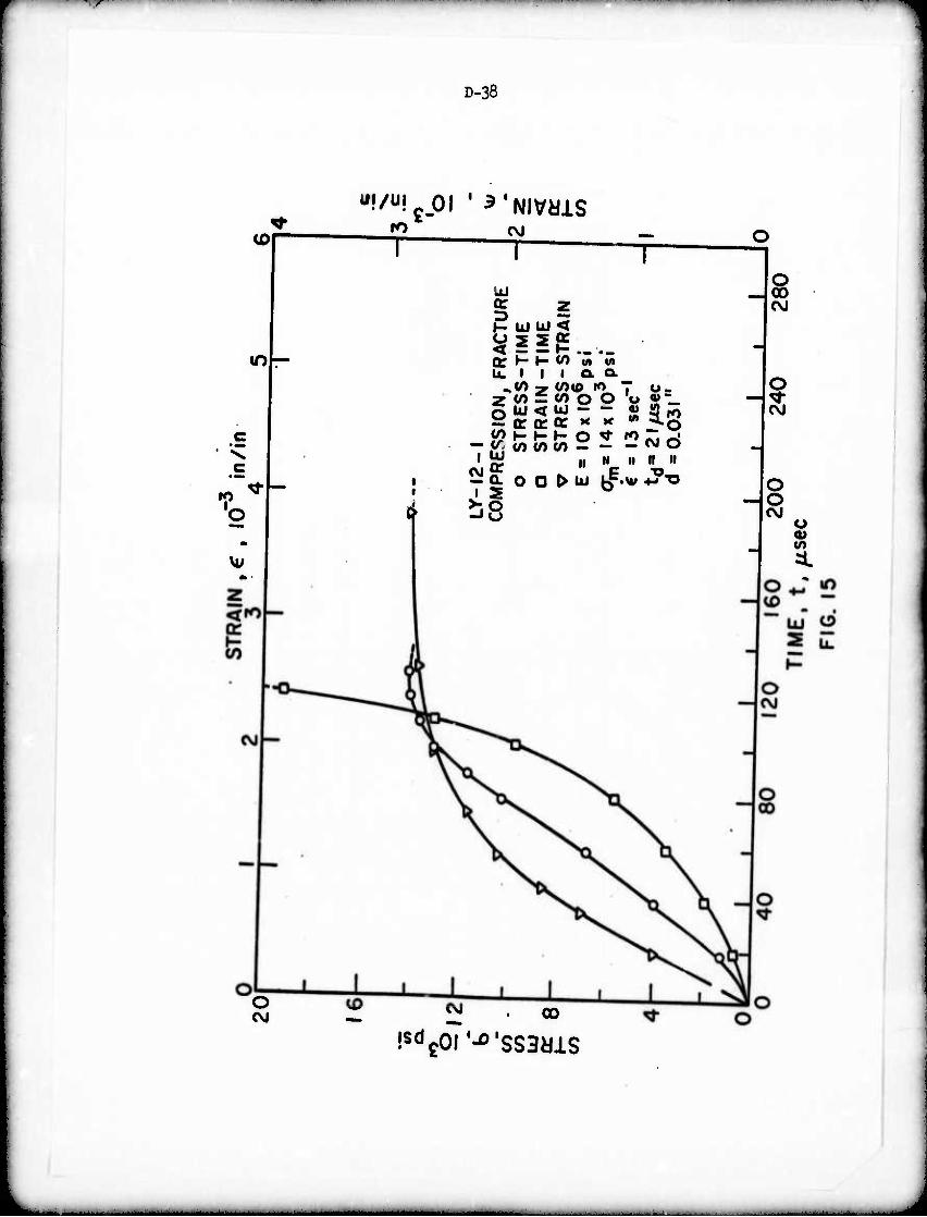
—^ W" "■'■, ■' ' ^»•^^W^W^^f^- "~n~*—
D-38
wf/U!c.OI ' ^'NlVdlS iD
K)
T CM
T
10
UJ
»- ÜJ UJ <
^ — — r- — ._ o: H »- «/) M w U. I I I Q. Q.
2 <n = en o O p; uj < tu
0:0:0:
0) '
c — y. v) </>vy — —
i" V)
UJ
»ra o o ^ o
X
O 1
CO
1
11
UJ
Kg 11 n 11
-JÖ
o 00
O
O O
u
o
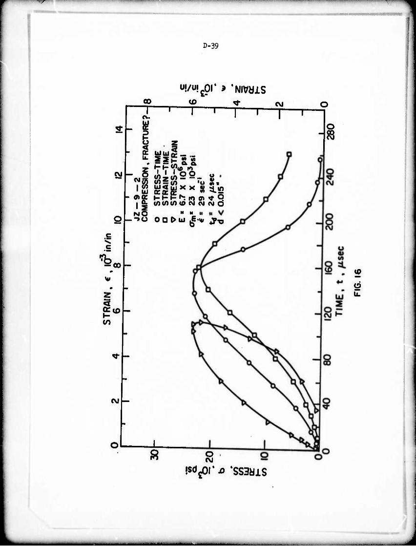
, ^ _^, ■ ■ I —
D-39
U!/U!cpr > 'NIVdiS 00
T CD
T T T
CM — 5 ~ "I h oto:
li NO
— 00
w
- OT a Si 'o S> s i2 SS^><><8{3.2 UJ<UJ X
F»^ I« 0) <• P </)</)(/) <0 OJ CJ (M O
H II
OG ^UJ J-w ^-o
<M
o
T <M
•sd^orjo 'SSBdiS
o -a
(0
•MMtMaa^M^
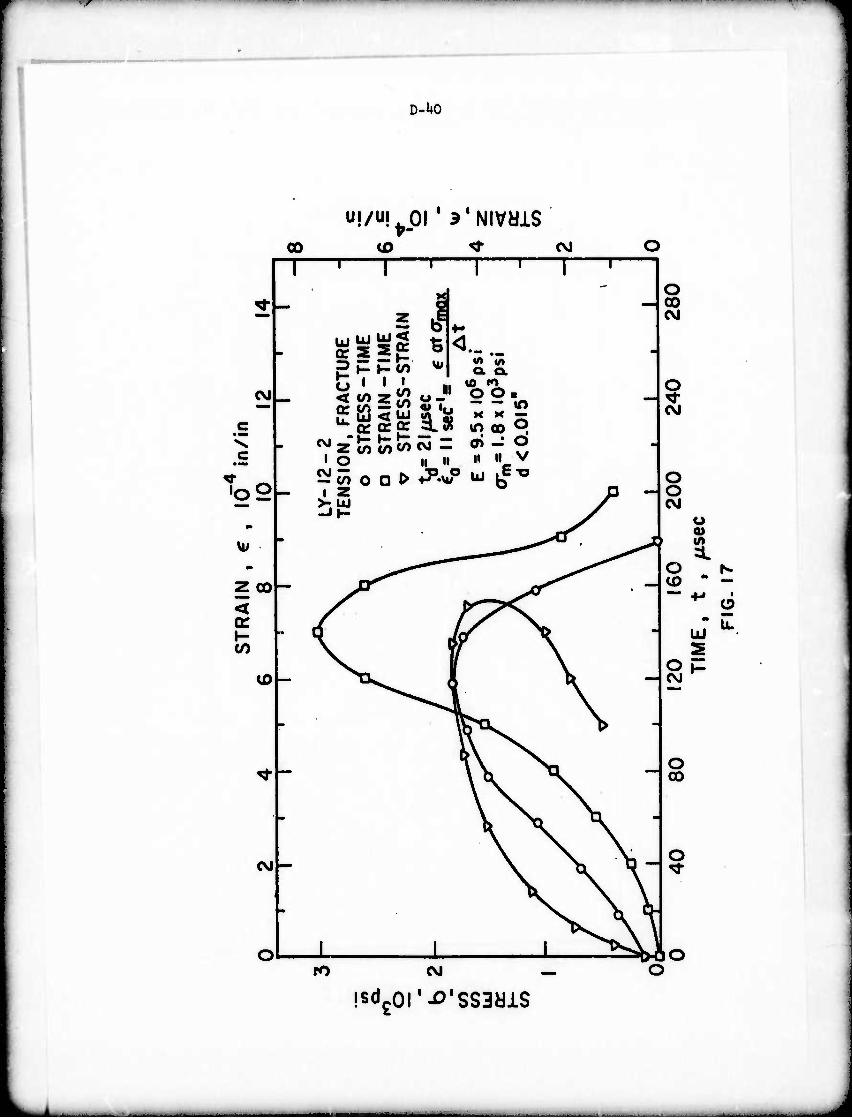
—r ■^^^^^wrr "" "^»^
D-UO
CO a> ^• CVJ O 1 ■ 1 i 1 i 1 1
^r _ rf _
i * 4^
- a. a.
■
—
c - < </> z i2 o -" 0 0 «^ —
c - 1 O ii II ■ •• v
-
Too 1 2 " P - >- UJ J
m -•I- *s
u; - • *sr
^-,
Z GO — a^ * Y^^ . —
< s 0^^\ cr ^r # .^^ ^N k.^
»- ■ C KCT X (n \w jr \
(O
. ^r\ \ .
^
V ^
-
CNJ
-
• 1 ^ ro <\J
O GO CM
O CVJ
O O CVJ
u (A
isdgor-o'ssadis
^M. -- - - -
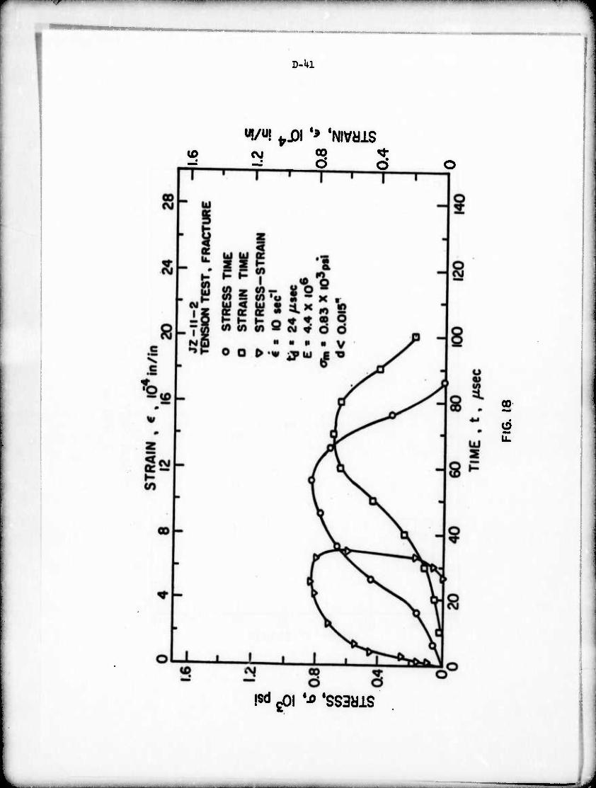
i i ■wwan«wi*wv> -~~^W^«^*^-«WI.IIII ■■■ i mi'** i"i M "i ' '" '"I1^»
D-Ul
to "I/"! fri)l ^ 'NlVdlS
€SI <X> * o o T—'—r
00
isd gOi ^ 'ssadis
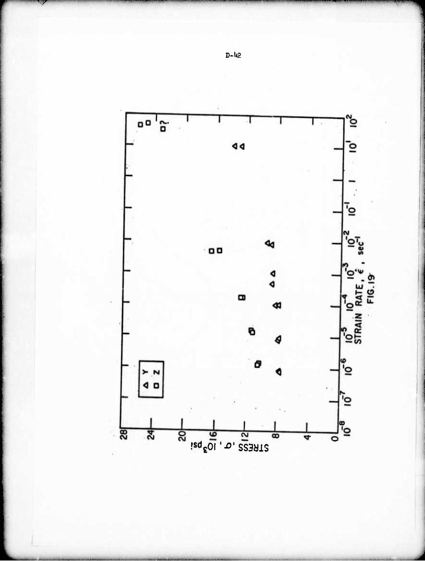
V *? ' ■ ■ ' ' i"" ■" ■ *m*~m^*mi^^~~~~m *WW**
D-l+2
•sd^l'^'SSBdiS
., i ■ - - -
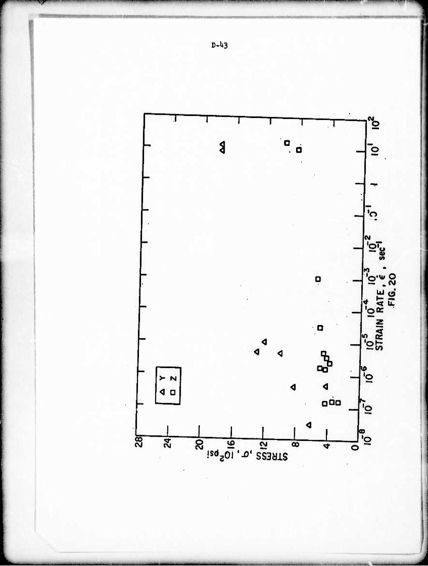
'^^WWITBWMMIW^^PP-^W^^P—W^W^" l •^•m^rmmm^m^mm wmim^mrmm i ^vnnawa iiivw^anfpi
D-U3
>- N
< O
00 OJ CVJ
t
o CVJ
T l^o
4 < <3
(M
aba
S's
— „Csi uje)
'Oö:
„ <
— CO
to
L I l l CO CVJ 00
— 'o
00 •o
HMMdUMft. ^-- -■ —
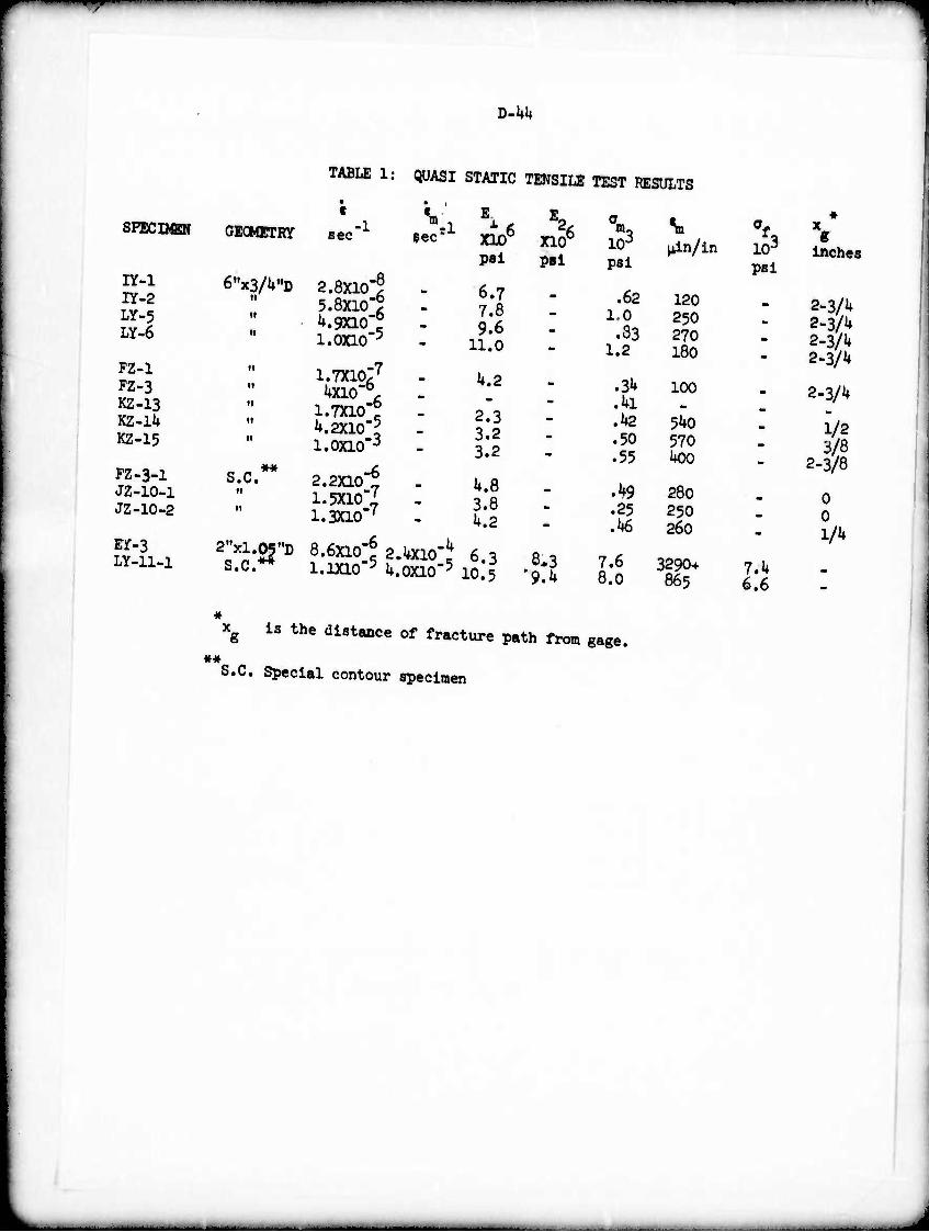
i ■■ i—^^^r *tm T^^^fm
V-kk
TABLE 1: QUASI STATIC TENSILE TEST RESULTS
IY-1 IY-2 LY-5 Ly-6
FZ-1 FZ-3 KZ-13 KZ-lU KZ-15
FZ-3-1 JZ-10-1 JZ-10-2
Ef-3 LY-ll-l
c
6,,x3/U"D
it
n
s.c. II
S.C.**
ra SPECIMEN GECMETRY sec"1 Sec
rl
2.8X10"? 5.8X10'5 ^.9X10"^ 1.0X10"5
i.Txio;7
Uxio"6. 1.7X10"^ h.2X10'l 1.0X10"3
2.2X10"^ 1.5X10"; 1.3X10"'
8.6X10"^ 2^X10-
1.1X10"P U.0X10*
1
xio6
pal
6.7 7.8 9.6
11.0
4.2
2.3 3.2 3.2
k.S 3.8 k.2
6.3 10.5
XIO pel
8,3 '9.k
m3 10-3
pel
.62 1.0 .33
1.2
.ad
.hi
.42
.50
.55
.49
.25 M
7.6 8.0
Hin/in
120 250 270 180
100
540 570 hOO
280 250 260
3290+ 865
103
psi
« x e Inches
2-3/4 2-3/'+ 2-3/4 2-3/4
2-3/4
1/2 3/8
2-3/8
0 0 1/4
7.4 6.6
««
g is the distance of fracture path from gage.
S.C. Special contour specimen
-
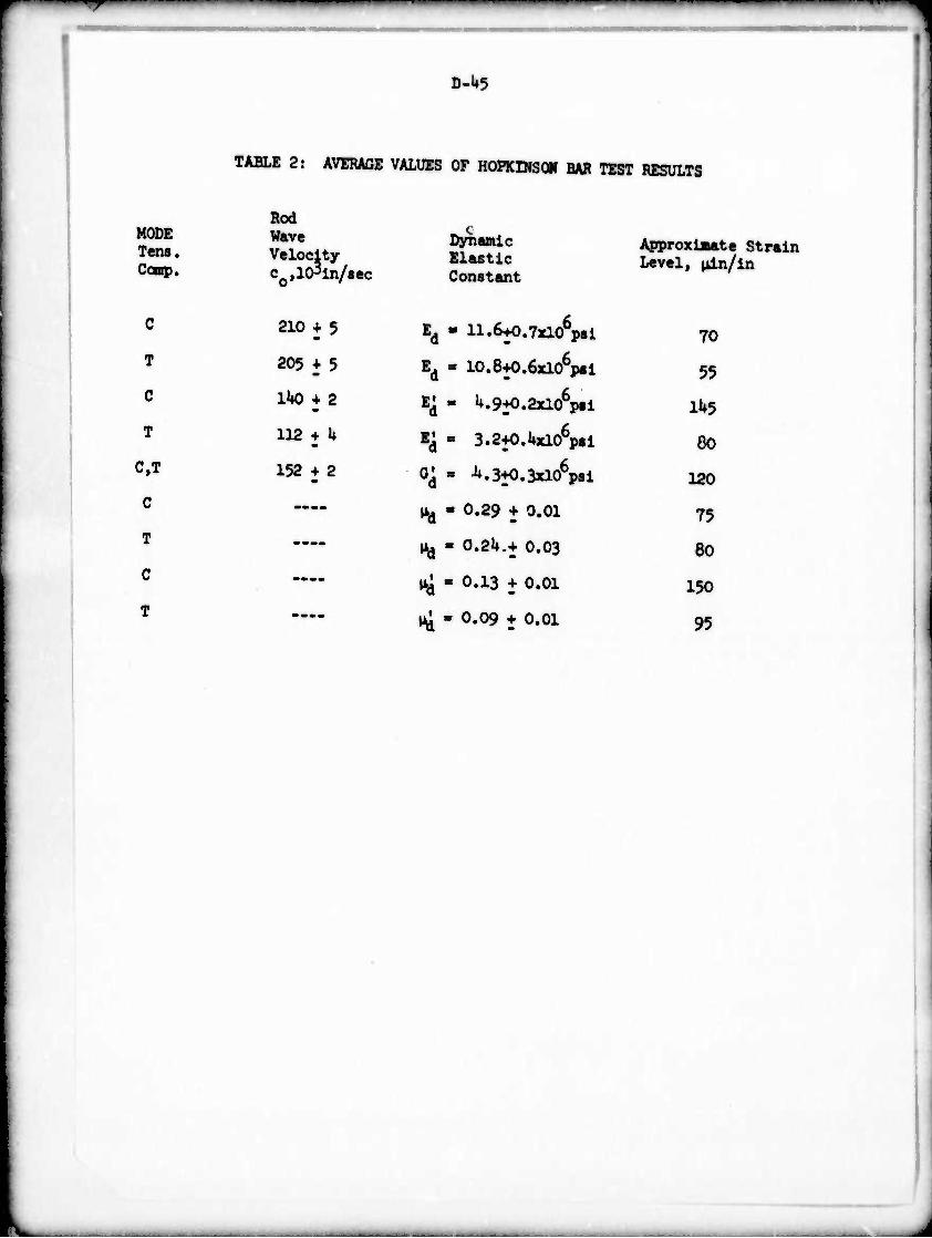
D-U5
TABLE 2: AVERAGE VALUES OF HOPKIHSQIf BAR TEST RESULTS
tmmmmm
MODE Tens. Ccup»
C
T
C
T
C,T
C
T
C
T
Rod Wave Velocity col10
3ln/aec
210 + 5
205 + 5
lUO + 2
112 ^ U
152 + 2
Ed
"a
"d
4
Dynamic Elastic Constant
11.6+O.7xl06p8l
10.8+0.6xl06p«i
1+.9+0.2x10 psl
3.2+O.Uxl06pil
^.3+0.3x10^81
0.29 ♦ 0.01
0.2U.+ 0.03
0.13 + 0.01
0.09 ♦ 0.01
Approximate Strain Level, yXn/in
70
55
1U5
80
120
75
80
150
95
rV
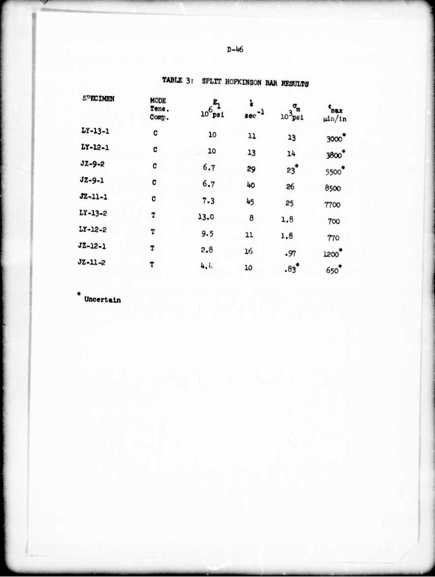
Uncertain
D-U6
1
TABLE 3: SPLIT HOPKDISOH BAR RESULTS
SPECIMEN
Ly-i3-i
Ly-i2-i
JZ-9-2
JZ.9-1
JZ-n-i
LY-13-2
Ly-12-2
JZ-12-1
JZ-ll-2
MODE ens. OB?. 106p«l
10
10
6.7
6.7
7.3
13.0
9.5
2.8
«e<-
u
13
29
uo
8
11
16
10
IOVI
13
II»
23*
26
25
1.8
1.8
.97
.83'
»tin/in
3000#
3800*
5500*
8500
7700
700
770
1200*
650'
J
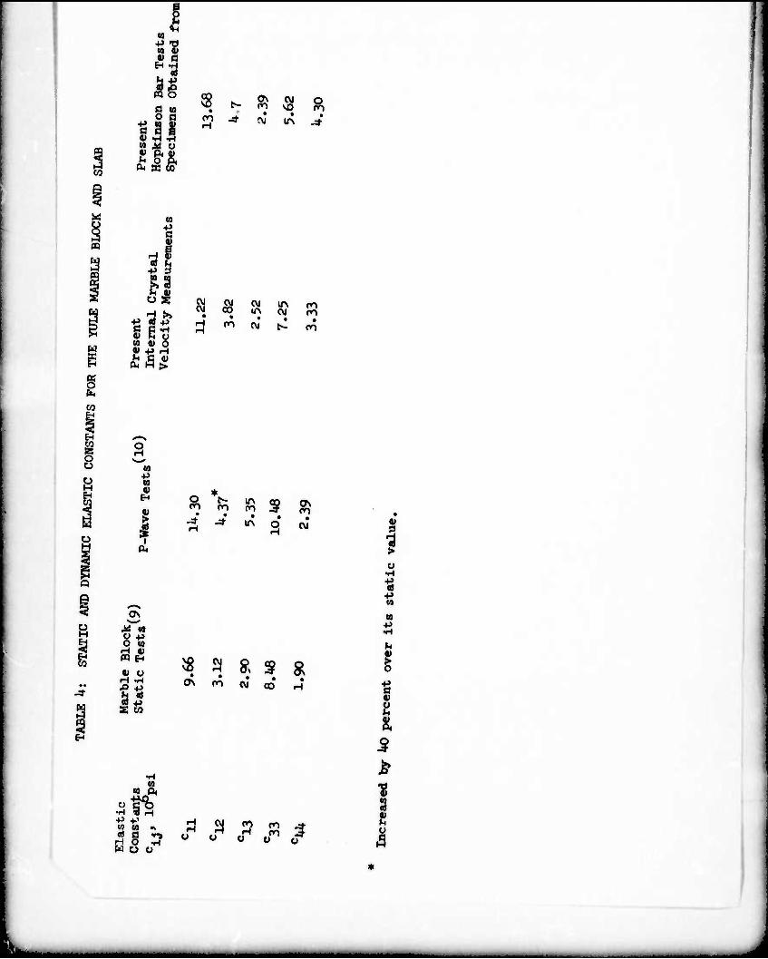
I U i) V ß
O to ^ II g 2 &^
OH K OQ
s co
£ ry IA
I
41 h U (0 0) 0
> ß Ü (1< M >
CVJ 00 00 00 on
CO (vj
I I
o V IA on
in
5 ON on
o\ X w y B O CO d p PQ EH
0) O « 9 R 9 g "O -p
o\ on • • W CD
•
3 +J
-p to
to p.
21% P *' to co K
^ S "^ rH O -H WOO
S 9 B «i o O O
-