basics of machine drawing
TRANSCRIPT
Basics of
Machine Drawing
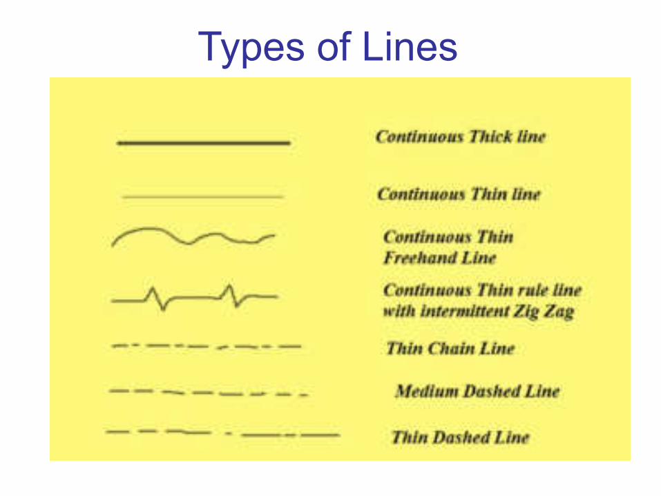
Types of Lines

Orthographic Representation
•Orthogonal Projection
• Requires more than one view to describe an object
• Pictorial representation
• Isometric
• Oblique
• Perspective
Types of Projection
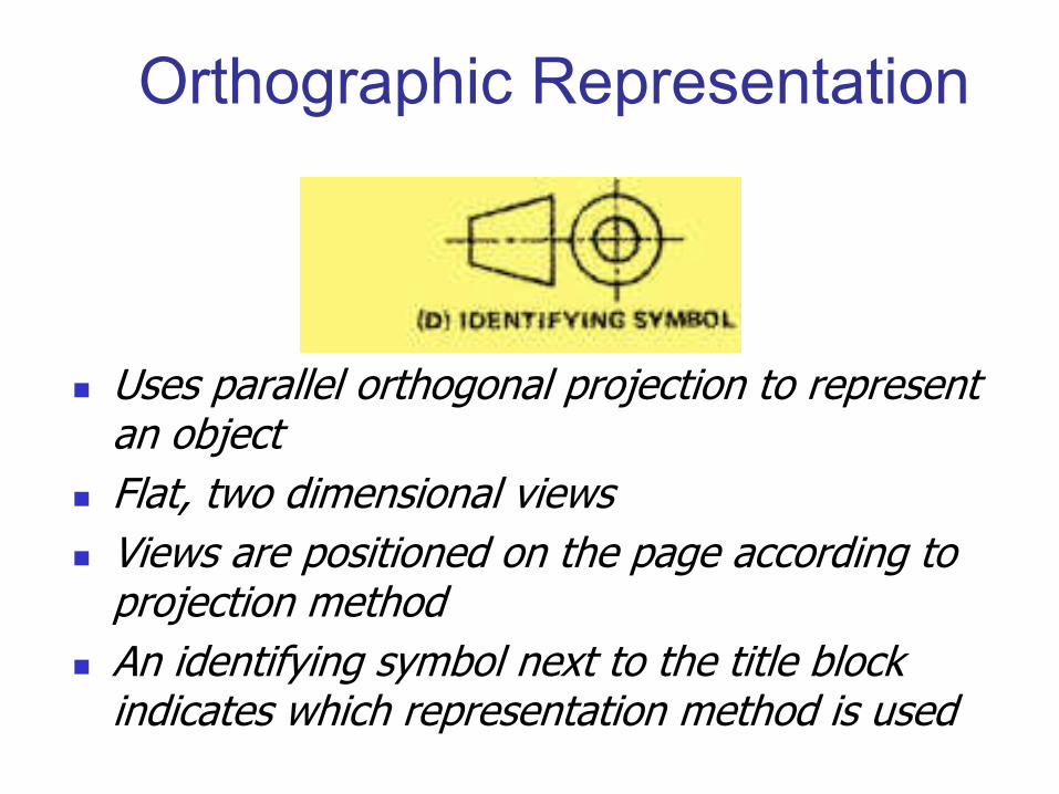
Uses parallel orthogonal projection to represent an object
Flat, two dimensional views
Views are positioned on the page according to projection method
An identifying symbol next to the title block indicates which representation method is used
Orthographic Representation

Orthographic Representation
• First Angle Projection
• Third Angle Projection
• Reference arrows layout
• Mirrored Orthographic Representation
Projection Method
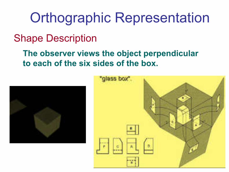
To project the orthographic views of the object,
think of the object enclosed in a “glass box”.The observer views the object perpendicular
to each of the six sides of the box.
Orthographic Representation
Shape Description

Third angle projection
Orthographic Representation
• The object to be
represented appears
behind the coordinate
viewing planes on
which the object is
orthogonally
projected
• Identifying symbol
• The most commonly used
method in the US and Canada

First angle projection
Orthographic Representation
• The object to be
represented appears
between the observer
and the coordinate
viewing planes on
which the object is
orthogonally projected
• Identifying symbol
• The most commonly used
method in Europe and Asia

Reference arrows layout
Orthographic Representation
• No identifying symbol
needed
• Permits various views to be freely positioned
• Used when it is advantageous not to position views
according to strict pattern
• Each view
identified by a
letter.

Location of points
Orthographic Representation
• X axis represents width
• Y axis represents depth
• Z axis represents height
• Origin (0,0,0) can be any
convenient place in drawing
• The coordinates for HJKL
are shown
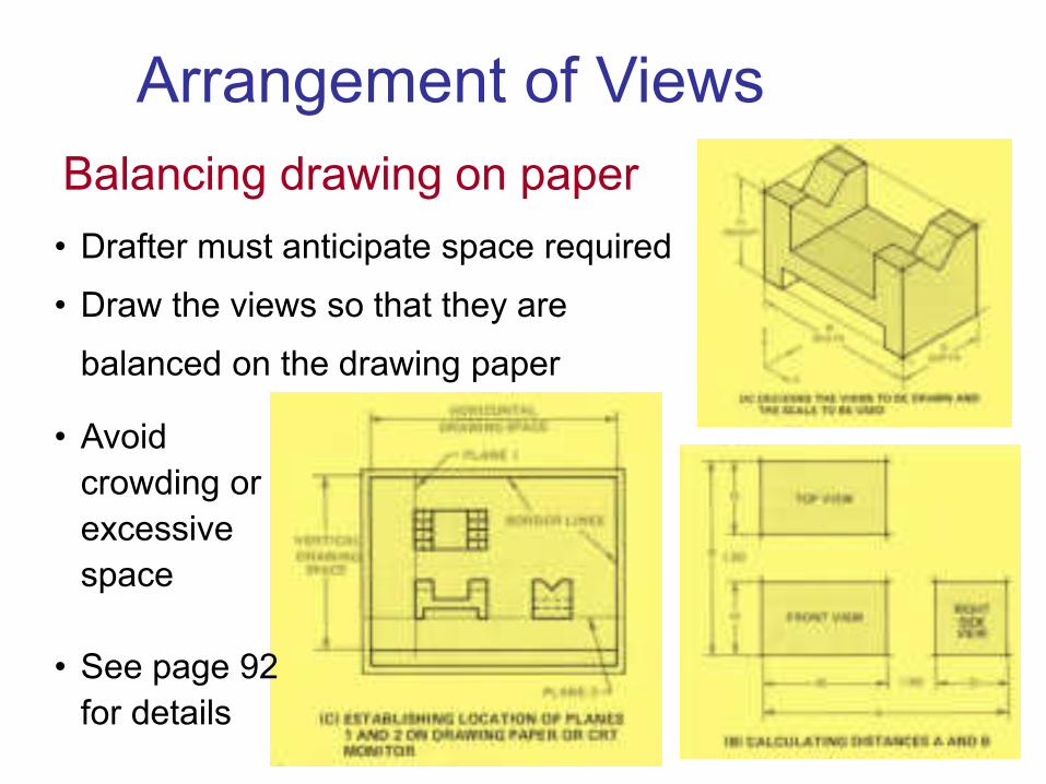
Balancing drawing on paper
Arrangement of Views
• Drafter must anticipate space required
• Draw the views so that they are
balanced on the drawing paper
• Avoid
crowding or
excessive
space
• See page 92
for details

Use of Miter Lines
Arrangement of Views
• 1. Given the TV & FV, project lines to the right of the TV
• 2. Establish how far (from FV) the SV is to be drawn (D)
• 3. Construct
the miter line
at 45° to the
horizontal

• Parallel surfaces appear parallel to the viewing
plane, with and without hidden features
• It will appear as a surface in one view and lines in
the other views
Parallel surfaces
• The length of the lines
in other views are
same as is in the
surface view

Types of Flat Surfaces
• Parallel surfaces that appear parallel
to the viewing plane, with and without
hidden features
• Inclined surfaces that appear inclined
in one plane and parallel to the other
two principal reference planes
• Oblique surfaces that appear inclined
in all three reference planes
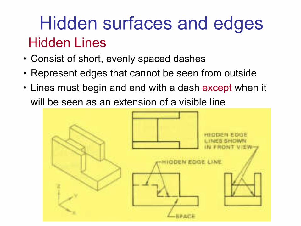
Hidden Lines• Consist of short, evenly spaced dashes
• Represent edges that cannot be seen from outside
• Lines must begin and end with a dash except when it
will be seen as an extension of a visible line
Hidden surfaces and edges
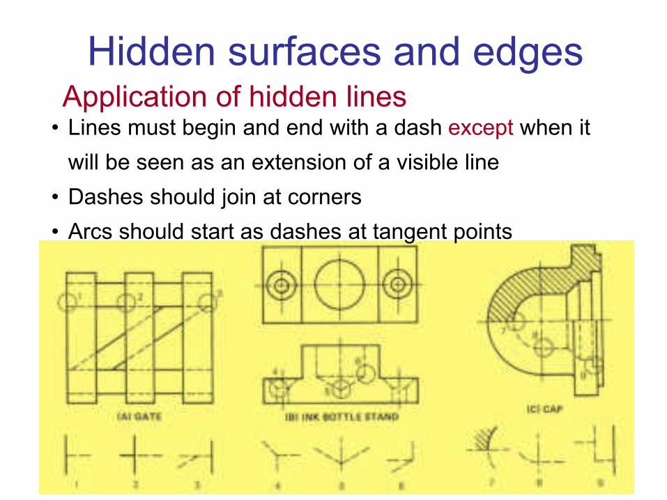
Application of hidden lines• Lines must begin and end with a dash except when it
will be seen as an extension of a visible line
• Dashes should join at corners
• Arcs should start as dashes at tangent points
Hidden surfaces and edges

Inclined Surfaces
• Inclined surfaces that appear inclined in one plane and
parallel to the other two principal reference planes
• It is seen as a distorted surface in two views and
appear as line in one view
• A & B appear as
shortened in TV &
RSV, but the TL of
the surface is seen
as Lines in FV
• True shape ?

Circular Features
• Appear circular in only one view
• No line shown, when curved surface joins flat surface
• Hidden circles, shown as hidden lines
• Use of centre lines
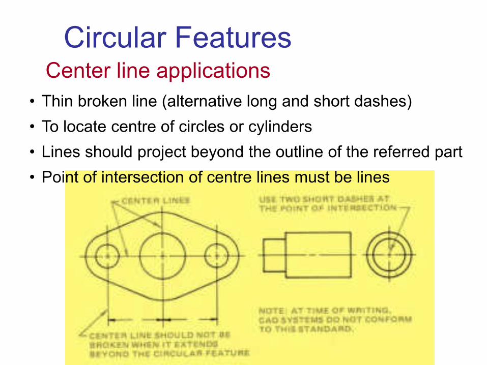
Center line applications
• Thin broken line (alternative long and short dashes)
• To locate centre of circles or cylinders
• Lines should project beyond the outline of the referred part
• Point of intersection of centre lines must be lines
Circular Features
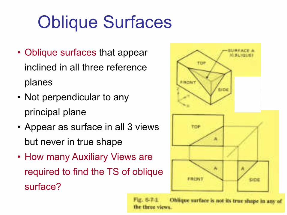
Oblique Surfaces
• Oblique surfaces that appear
inclined in all three reference
planes
• Not perpendicular to any
principal plane
• Appear as surface in all 3 views
but never in true shape
• How many Auxiliary Views are
required to find the TS of oblique
surface?

One and two view drawingsView selection
• Best describe the object to be shown
• Minimum number of views to describe object
• for simple parts, one or two views often enough
• Avoid views with more hidden lines

One and two view drawingsOne View drawing
• Third dim (thickness) expressed as note or symbols
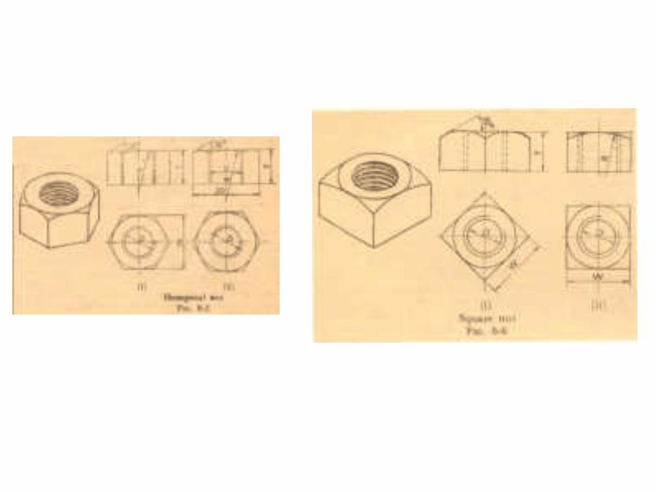
• Abbreviations such as
HEX ACRFLT, DIA, or
• Square sections can be
indicated by crossed lines
on diagonal
• Used even when the
surface is parallel or
inclined to the drawing
plane

One and two view drawingsTwo View drawing
• When cylindrical features have keyway, end view is
required to shown them
• Usually drafters use two views only to define a part
• For cylindrical surfaces, if three views are drawn, any 2
of them will be identical
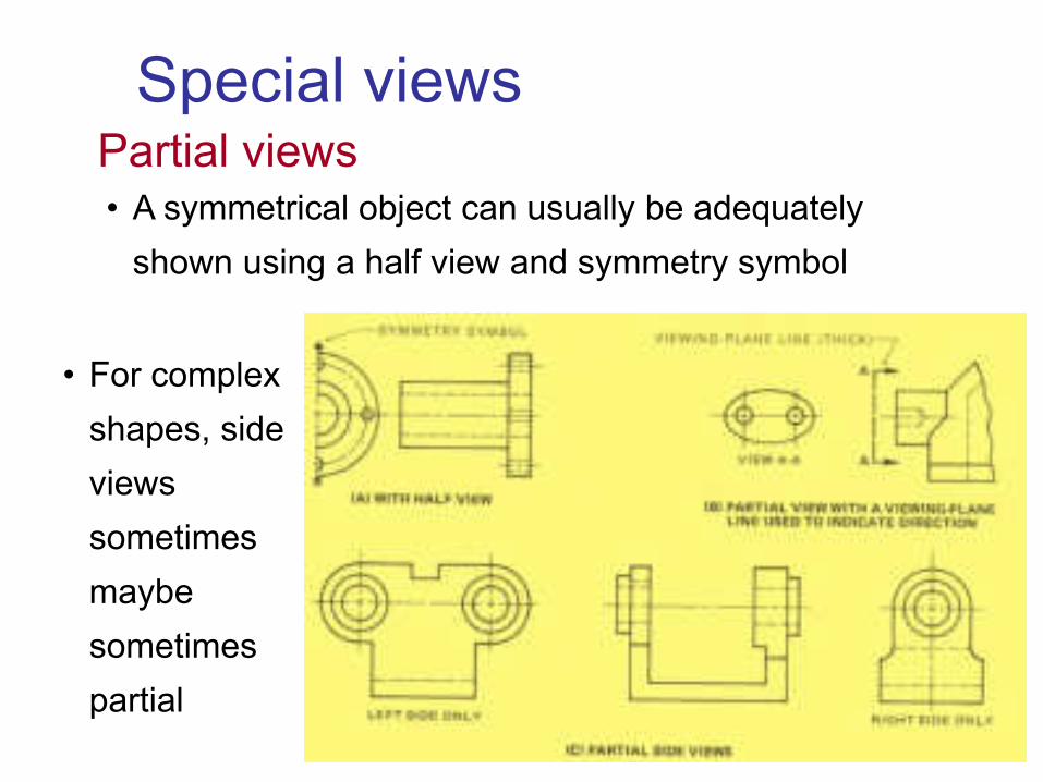
Special views
• A symmetrical object can usually be adequately
shown using a half view and symmetry symbol
Partial views
• For complex
shapes, side
views
sometimes
maybe
sometimes
partial

Special views
• Required to show particular feature with greater
details, in a complex drawing
• Oriented in the same manner as in view
• If rotated, must show details of angle, direction etc..
Enlarged views
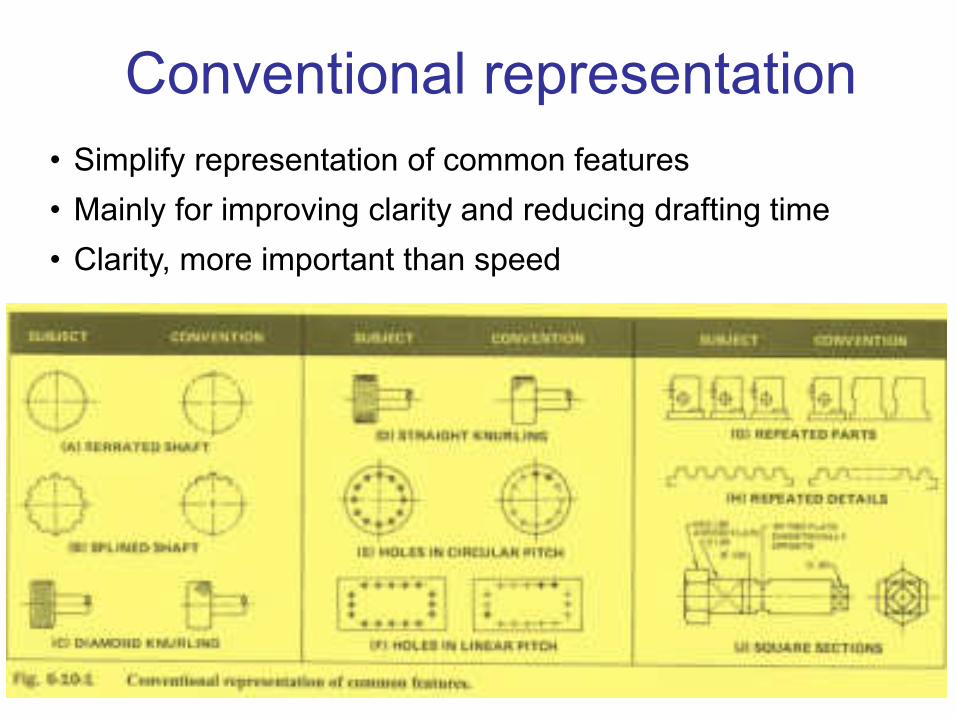
Conventional representation
• Simplify representation of common features
• Mainly for improving clarity and reducing drafting time
• Clarity, more important than speed
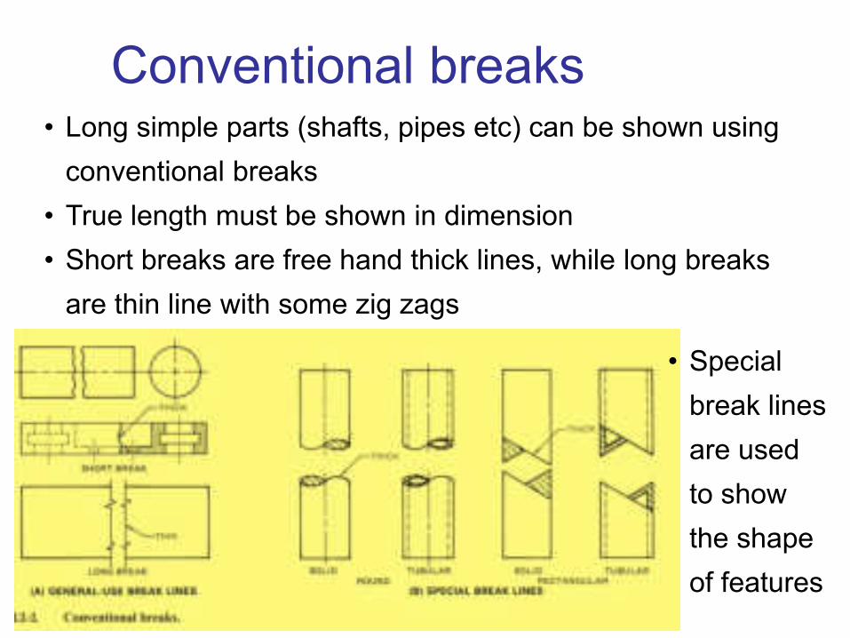
Conventional breaks• Long simple parts (shafts, pipes etc) can be shown using
conventional breaks
• True length must be shown in dimension
• Short breaks are free hand thick lines, while long breaks
are thin line with some zig zags
• Special
break lines
are used
to show
the shape
of features
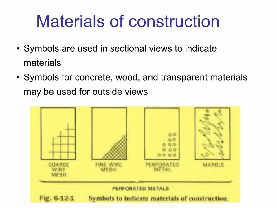
Materials of construction
• Symbols are used in sectional views to indicate
materials
• Symbols for concrete, wood, and transparent materials
may be used for outside views
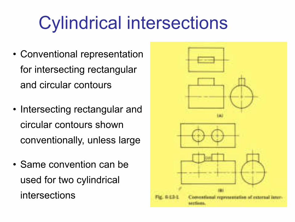
Cylindrical intersections
• Conventional representation
for intersecting rectangular
and circular contours
• Intersecting rectangular and
circular contours shown
conventionally, unless large
• Same convention can be
used for two cylindrical
intersections

Foreshortened projection• When true projection of feature would result in confusing
foreshortening, it should be rotated until it is parallel to the
line of projection
• Drilled holes also need to be rotated rather than showing
true distance

FULL SECTION
Sectional Views
• Shows interior detail
• Describes complicated parts
• Eliminates the need for hidden lines
• Frequently replaces a regular view

Sectional Views
• Shows the location of the cutting plane
• Has arrowheads to show the direction of sight
Cutting plane lines
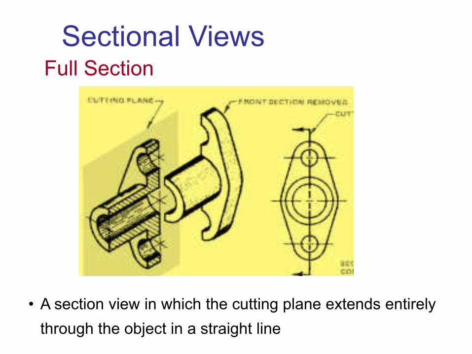
Sectional ViewsFull Section
• A section view in which the cutting plane extends entirely
through the object in a straight line

• Also called crosshatching
• Indicates surface that has been
theoretically cut
• Lining symbols may indicate the
material that makes up the
object
Sectional ViewsSectional lining
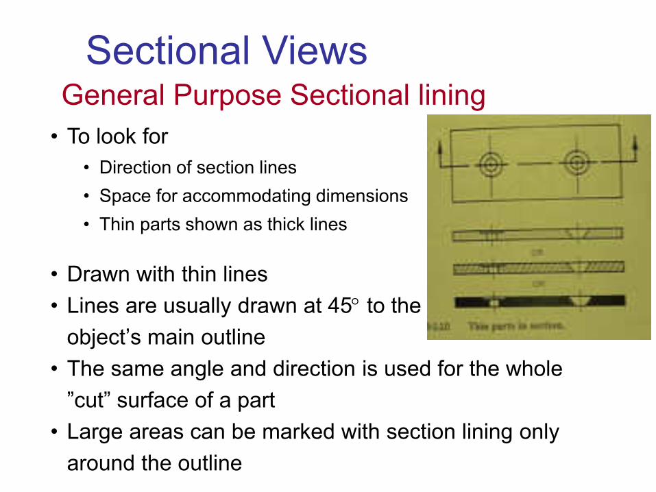
• Drawn with thin lines
• Lines are usually drawn at 45 to the
object’s main outline • The same angle and direction is used for the whole
”cut” surface of a part• Large areas can be marked with section lining only
around the outline
Sectional ViewsGeneral Purpose Sectional lining
• To look for
• Direction of section lines
• Space for accommodating dimensions
• Thin parts shown as thick lines
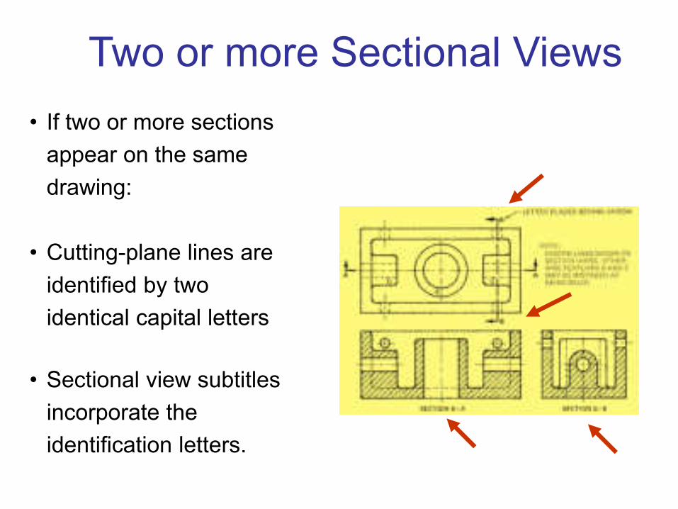
Two or more Sectional Views
• If two or more sections
appear on the same
drawing:
• Cutting-plane lines are
identified by two
identical capital letters
• Sectional view subtitles
incorporate the
identification letters.
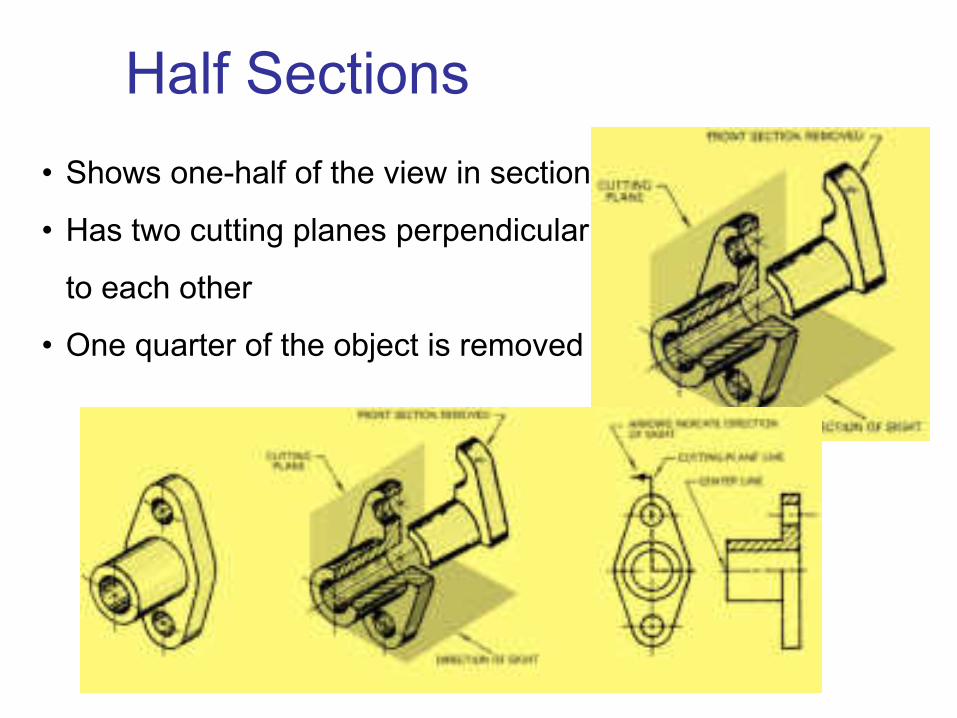
Half Sections
• Shows one-half of the view in section
• Has two cutting planes perpendicular
to each other
• One quarter of the object is removed
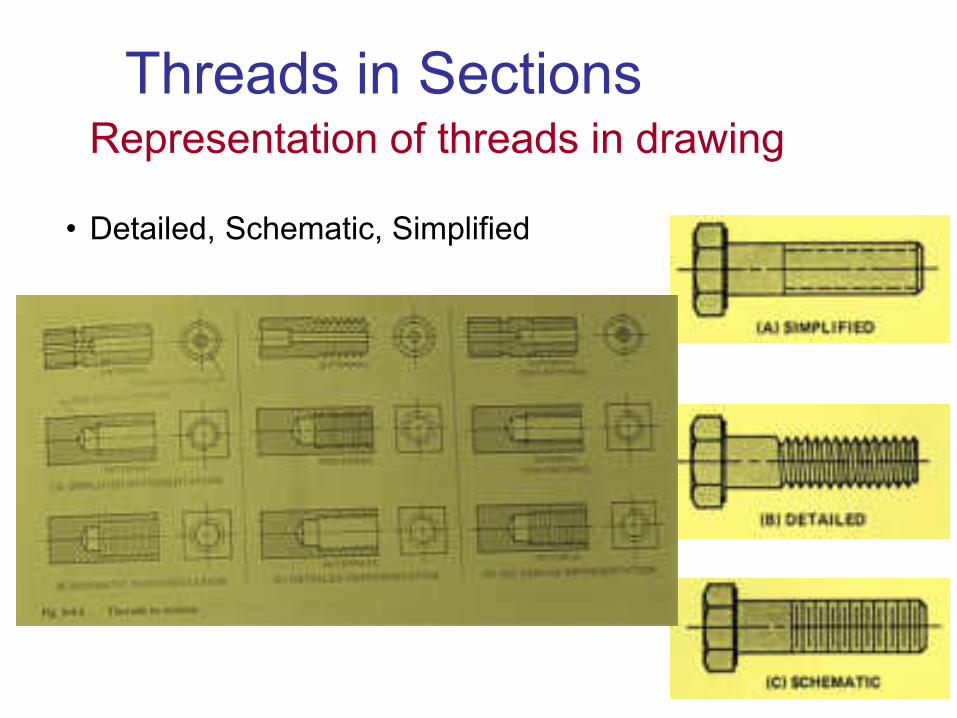
• Detailed, Schematic, Simplified
Threads in SectionsRepresentation of threads in drawing

Assemblies in SectionsSectioning in assembly drawings
• Section lining on assembly drawings
• Shafts, Bolts, Pins, Keyseats

• Use opposite directions for section lining on adjacent parts
• For more than two parts, use lining at a different angle
Assemblies in SectionsSection lining in assembly drawings

• Avoid symbolic section lining on drawings to be
microformed
• If adjacent thin parts are filled in, leave space between
them
Assemblies in SectionsSection lining in assembly drawings

• Shafts
• Bolts
• Pins
• Keyseats
• Similar solid parts
•A broken-out section of a shaft may be used
to describe a key, keyseat, or pin.
Assemblies in SectionsParts generally not sectioned:

Offset Sections
• A cutting plane can be bent to include several
surfaces

• Conventions for aligning ribs, holes
and lugs in section
Ribs, Holes, and Lugs in SectionsParts generally not sectioned:
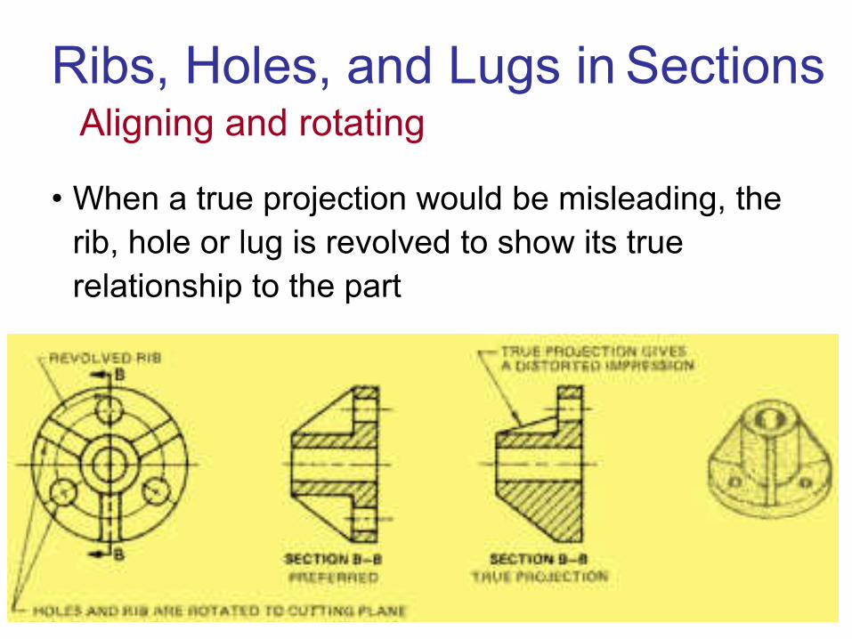
• When a true projection would be misleading, the
rib, hole or lug is revolved to show its true
relationship to the part
Ribs, Holes, and Lugs in SectionsAligning and rotating

Revolved and removed Sections
• Ribs, spokes, and arms
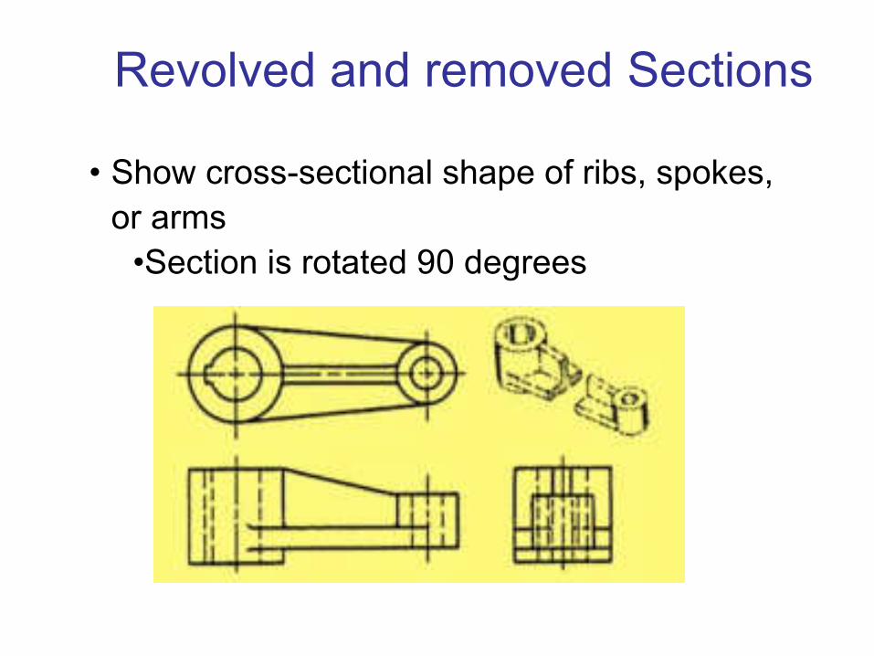
• Show cross-sectional shape of ribs, spokes,
or arms
•Section is rotated 90 degrees
Revolved and removed Sections

• Removed section:
• Removed to an open area
on drawing; may be
enlarged
• Revolved section:
• Section may be superimposed
on regular view of part
• Regular view is broken if needed
for clarity or to add dimensions
Revolved and removed Sections
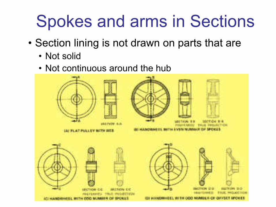
Spokes and arms in Sections• Section lining is not drawn on parts that are
• Not solid
• Not continuous around the hub

Partial or broken out Sections
• Partial sections are indicated with an irregular
break line.
• A cutting-plane line is not required.

Phantom or Hidden Sections
• Used to show interior details of parts that are
not symmetric, or mating parts in assembly
• A phantom section is a sectional view
superimposed on a regular view
• The front portion of the object is not removed
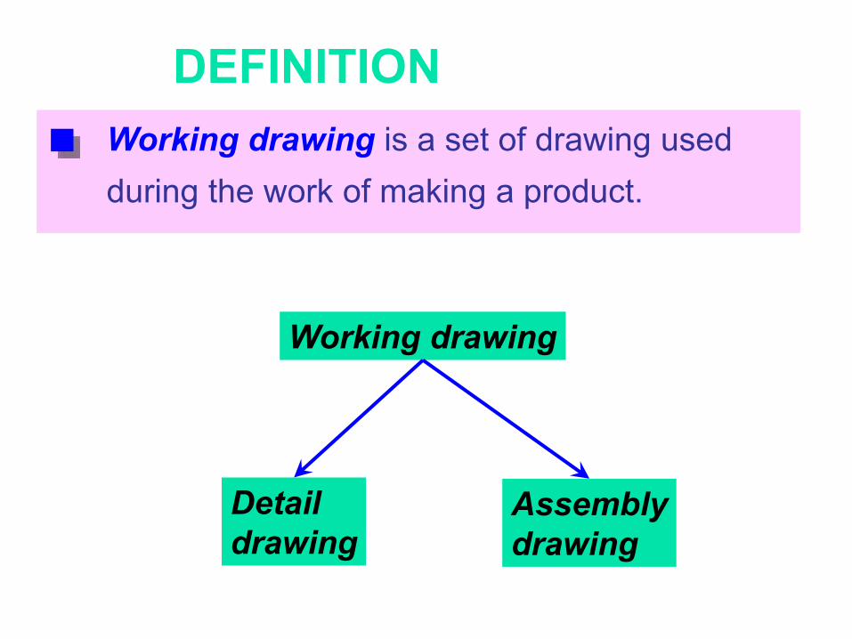
DEFINITION
Working drawing is a set of drawing used
during the work of making a product.
Working drawing
Detail
drawingAssembly
drawing
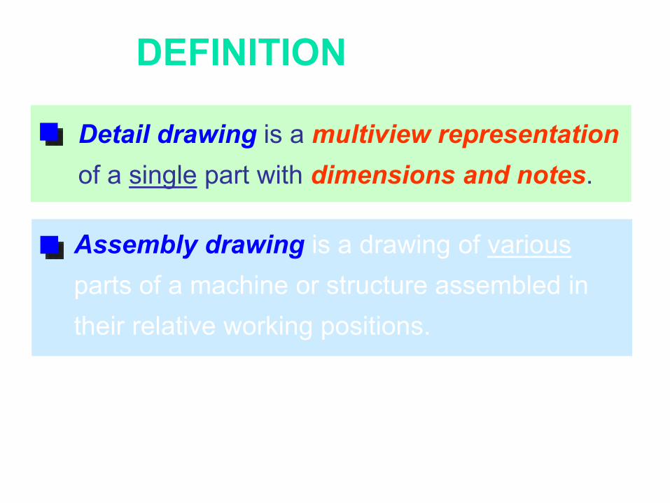
DEFINITION
Detail drawing is a multiview representation
of a single part with dimensions and notes.
Assembly drawing is a drawing of various
parts of a machine or structure assembled in
their relative working positions.
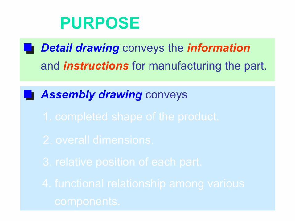
Detail drawing conveys the information
and instructions for manufacturing the part.
4. functional relationship among various
components.
1. completed shape of the product.
2. overall dimensions.
PURPOSE
Assembly drawing conveys
3. relative position of each part.
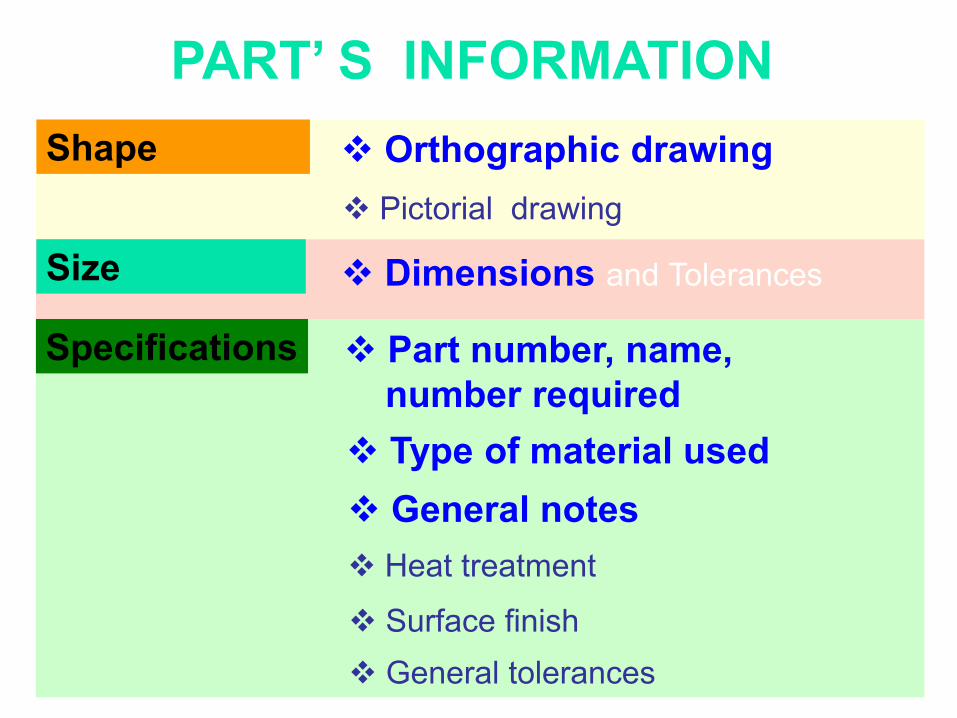
PART’ S INFORMATION Orthographic drawing
Pictorial drawing
Dimensions and Tolerances
Specifications
General notes
Type of material used
Surface finish
General tolerances
Part number, name,
number required
Shape
Size
Heat treatment

EXAMPLE : Interpreting detail drawing
General note
Revision table
Title block
1. Orthographic
views
2. Dimensions
& Tolerances
3. Surface
finishing
ProjectionGen. tolerance

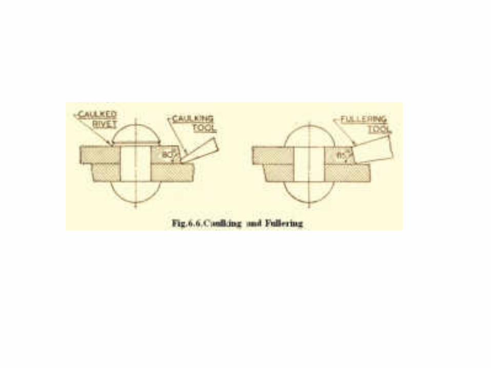
Rivet heads for general purposes


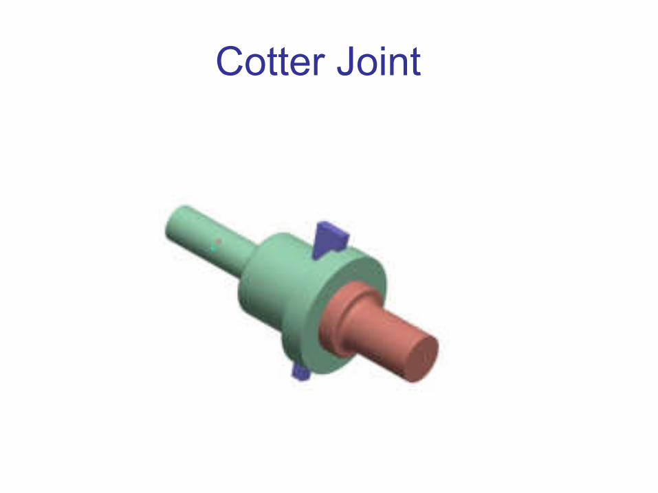
Cotter Joint
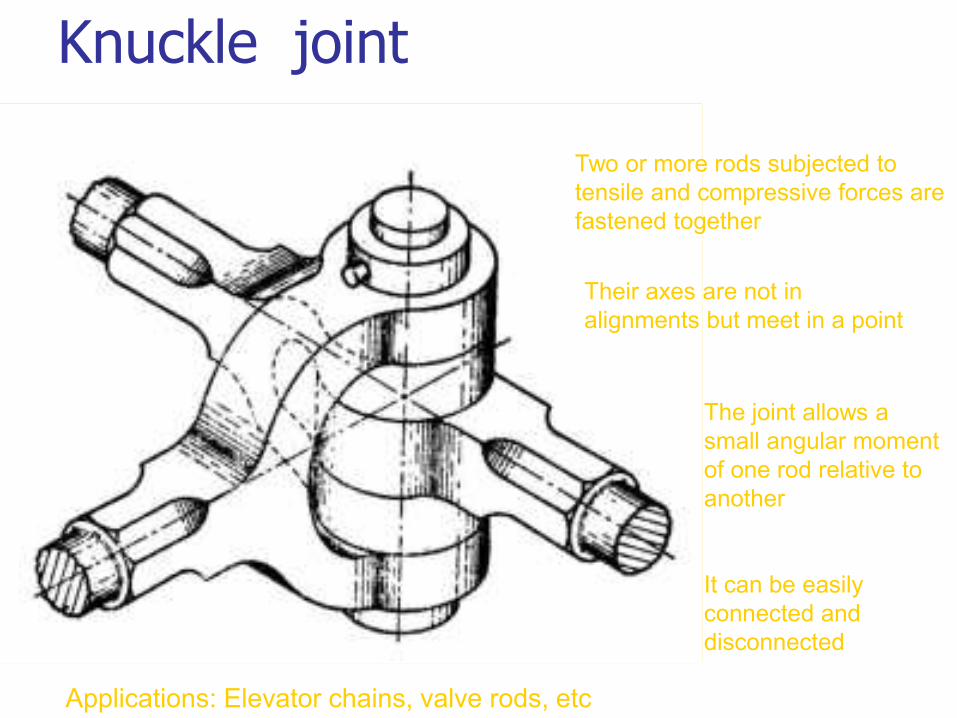
Knuckle joint
Two or more rods subjected to
tensile and compressive forces are
fastened together
Their axes are not in
alignments but meet in a point
The joint allows a
small angular moment
of one rod relative to
another
It can be easily
connected and
disconnected
Applications: Elevator chains, valve rods, etc

Knuckle joint
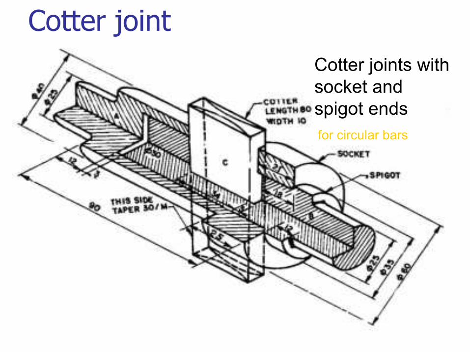
Cotter joint
Cotter joints with
socket and
spigot ends
for circular bars
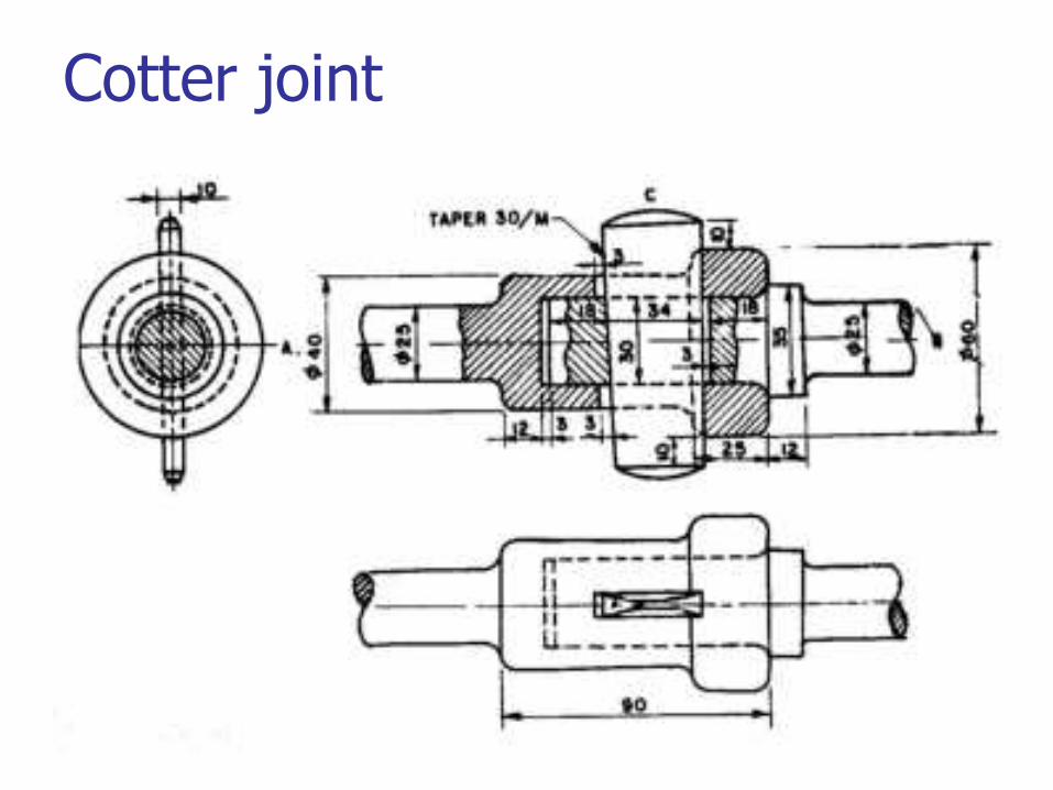
Cotter joint
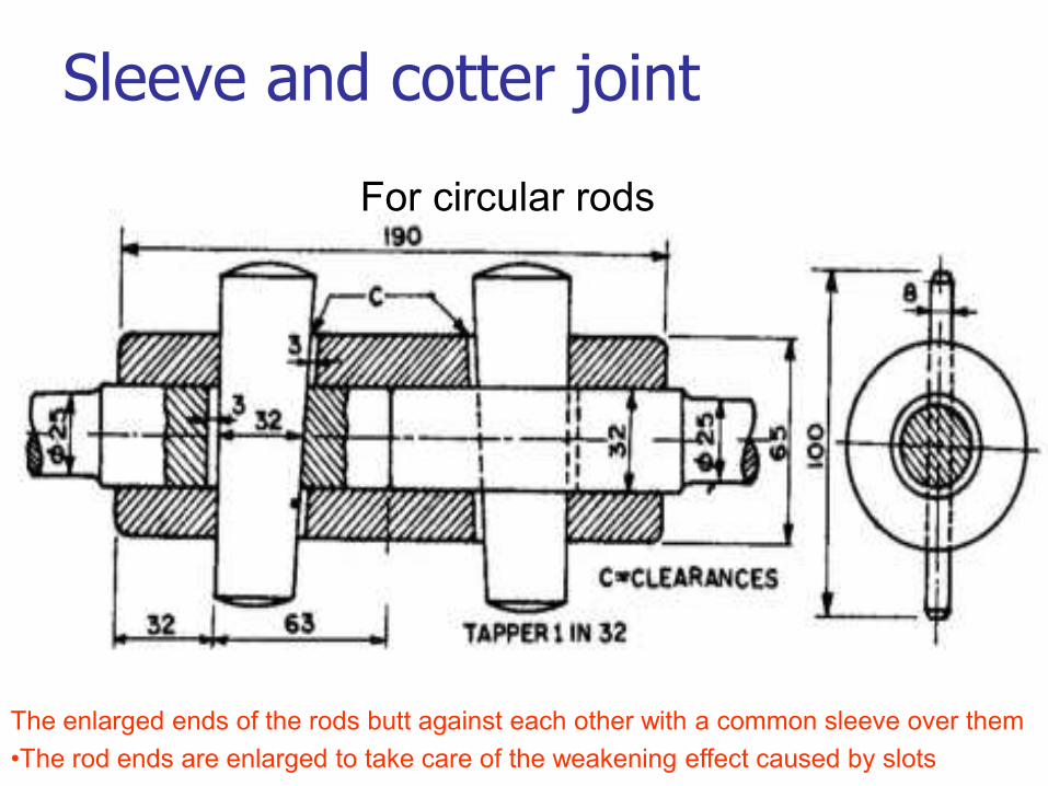
Sleeve and cotter joint
The enlarged ends of the rods butt against each other with a common sleeve over them
•The rod ends are enlarged to take care of the weakening effect caused by slots
For circular rods
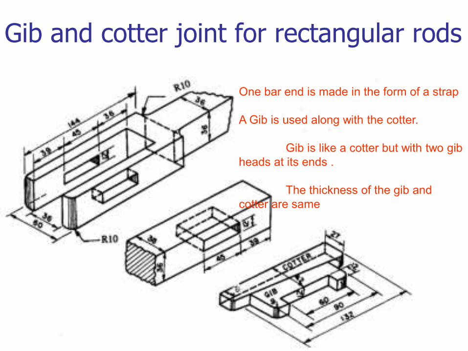
Gib and cotter joint for rectangular rods
One bar end is made in the form of a strap
A Gib is used along with the cotter.
Gib is like a cotter but with two gib
heads at its ends .
The thickness of the gib and
cotter are same
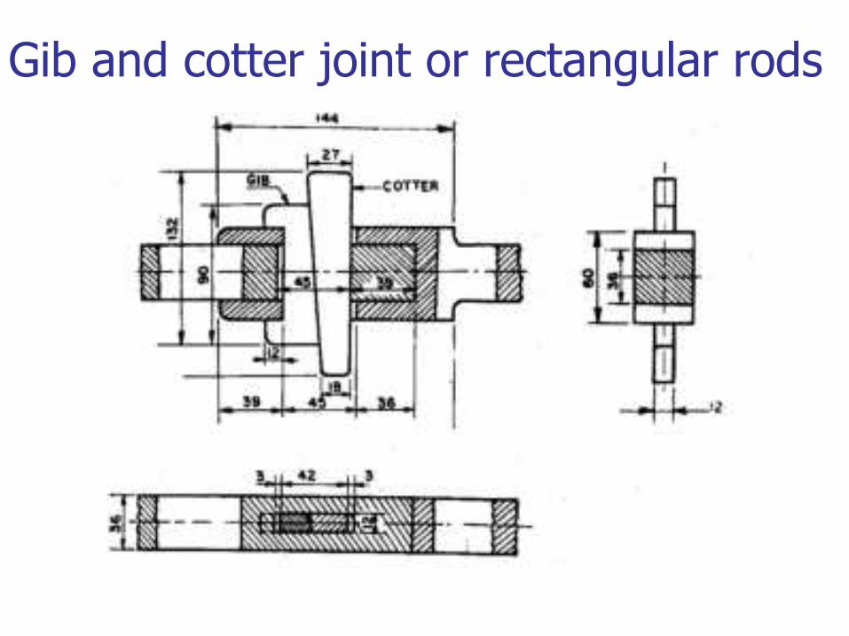
Gib and cotter joint or rectangular rods
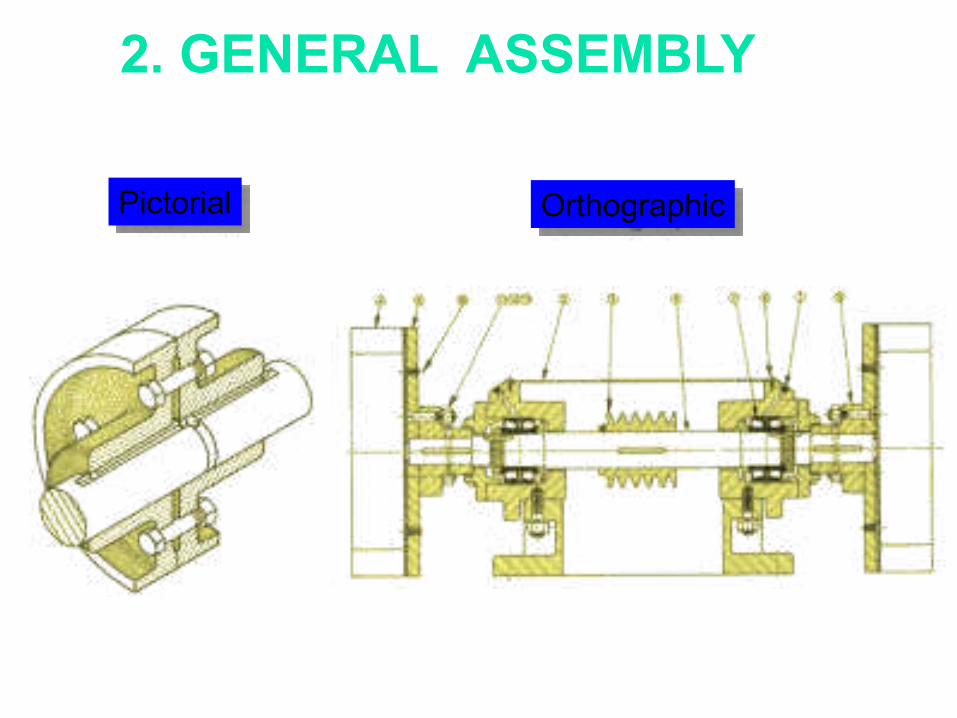
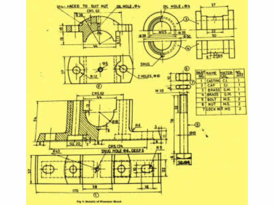
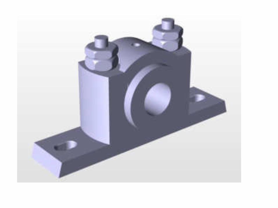
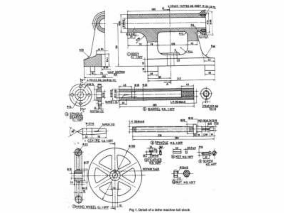
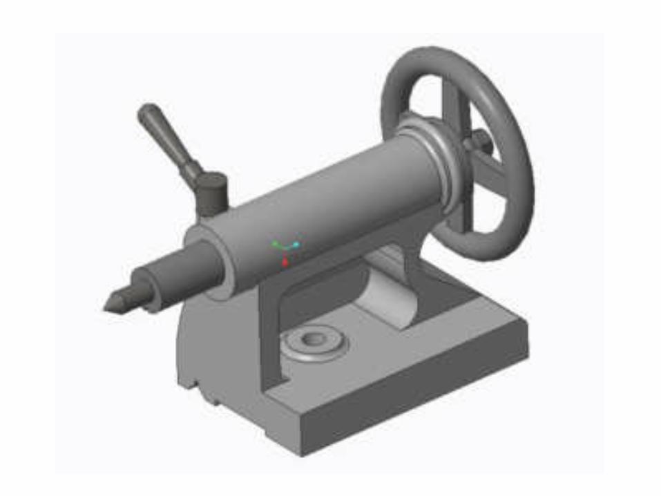
2. GENERAL ASSEMBLY
Pictorial Orthographic

2. GENERAL ASSEMBLY