basics of data communication - nalanda open university
TRANSCRIPT
(177)
Unit 6 Basics of Data CommunicationLesson Structure
6.0 Introduction6.1 Unit Objective6.2 Introduction to Data Communication6.3 Introduction to Computer Networks
6.3.1 Advantages of Networks6.3.2 Network Devices6.3.3 Communication Protocols
6.4 Topology6.5 Switching Networks6.6 Network Models
6.6.1 Classification of Networks: LAN, MAN, WAN & the Internet6.7 OSI Reference Model
6.7.1 Layer Groupings6.7.2 Key Concepts of OSI Models6.7.3 Layers in OSI Model
6.8 TCP/IP Reference Model6.9 Transmission Media
6.9.1 Twisted Pair (Copper Conductors)6.9.2. Coaxial Cable6.9.3 Optical Fibre
6.10 Transmission Modes6.11 Switching Techniques
6.11.1 Message Switching6.11.2 Packet Switching6.11.3 Circuit Switching6.11.4 Cell Switching
6.14 Summary6.15 Key Terms6.16 Questions for Exercise6.17 Further Reading
(178)
6.0 IntroductionIn this unit, you will learn about the basic concepts of computer networks.In the mainframe and minicomputer environment, each user is connectedto the main system through a dumb terminal that is unable to perform anyof its own processing tasks. In this computing environment, processing andmemory are centralized. However, this type of computerization has its mer-its but the major disadvantage is that the system could get easily overloadedas the number of users, and consequently, terminals increase. Second, mostof the information is centralized to one group of people, the systems profes-sionals rather than the end-users. This type of centralized processing sys-tem differs from the distributed processing system used by LANs. In a dis-tributed processing system, most of the processing is done in the memoryof the individual PCs or workstations besides sharing expensive computer re-sources like software, disk files, printers and plotters, etc. You will also learnabout the network topologies. Moreover, you will learn about the categoriesof network. Switching includes ‘plug and play’ element. Nowadays, a fibreoptic switch is used in switching technology because it allows harnessing ofall available bandwidth. Use of an optical switch allows users on a networkto send more information. It also provides huge advantage as immunity toEMI (Electro Magnetic Interference) disturbance and lighting strike which as-sures network security. You will learn about TCP/IP. The TCP/IP model isconsidered the oldest protocol of all computer networks like the ARPANETand its successor, the Internet. It contains two protocols TCP and IP. TCPstands for Transmission Control Protocol and IP for Internet Protocol.6.1 Unit Objective
Discuss the basic concepts of computer networksl Understand the basic concept of topologiesl Discuss the various categories of networksl Describe the various network modelsl Explain about OSI reference modell Discuss what transmission media isl Understand the switching techniques
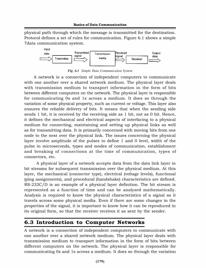
6.2 Introduction to Data CommunicationA data communication system is made up of the message, the source, thedestination, the medium and the protocol. Message is the information needsto be communicated. Source is the device that sends the message to thedestination. Destination is a device to receive the message. Medium is the
Basics of Data Communication
(179)
physical path through which the message is transmitted for the destination.Protocol defines a set of rules for communication. Figure 6.1 shows a simple7data communication system.
Fig. 6.1 Simple Data Communication SystemA network is a connection of independent computers to communicate
with one another over a shared network medium. The physical layer dealswith transmission medium to transport information in the form of bitsbetween different computers on the network. The physical layer is responsiblefor communicating 0s and 1s across a medium. It does so through thevariation of some physical property, such as current or voltage. This layer alsoensures the reliable delivery of bits. It means that when the sending sidesends 1 bit, it is received by the receiving side as 1 bit, not as 0 bit. Hence,it defines the mechanical and electrical aspects of interfacing to a physicalmedium for connecting, maintaining and setting up physical links as wellas for transmitting data. It is primarily concerned with moving bits from onenode to the next over the physical link. The issues concerning the physicallayer involve amplitude of the pulses to define 1 and 0 level, width of thepulse in microseconds, types and modes of communication, establishmentand breaking of connections at the time of communication, types ofconnectors, etc.
A physical layer of a network accepts data from the data link layer inbit streams for subsequent transmission over the physical medium. At thislayer, the mechanical (connector type), electrical (voltage levels), functional(ping assignments), and procedural (handshake) characteristics are defined.RS-232C/D is an example of a physical layer definition. The bit stream isrepresented as a function of time and can be analysed mathematically.Analysis is required to know the physical characteristics of a signal as ittravels across some physical media. Even if there are some changes in theproperties of the signal, it is important to know how it can be reproduced inits original form, so that the receiver receives it as sent by the sender.6.3 Introduction to Computer NetworksA network is a connection of independent computers to communicate withone another over a shared network medium. The physical layer deals withtransmission medium to transport information in the form of bits betweendifferent computers on the network. The physical layer is responsible forcommunicating 0s and 1s across a medium. It does so through the variation
Basics of Data Communication
(180)
of some physical property, such as current or voltage. This layer also ensuresthe reliable delivery of bits. It means that when the sending side sends 1bit, it is received by the receiving side as 1 bit and not as 0 bit. Hence, itdefines the mechanical and electrical aspects of interfacing to a physicalmedium for disconnecting, maintaining and setting up physical links as wellas for transmitting data. It is primarily concerned with moving bits from onenode to the next over the physical link. The issues concerning the physicallayer involve amplitude of the pulses to define 1 and 0 level, width of thepulse in microseconds, types and modes of communication, establishmentand breaking of connections at the time of communication, types ofconnectors, etc.
Networks that are privately owned offer consistent fast pacedcommunication channels which are optimized to connect informationprocessing tools in a restricted geographical area. These are known as LocalArea Networks (LANs).
A shared, local (restricted-distance) packet network for computercommunication is a form of LAN. A common medium is used by LAN to linkperipherals and computers so that the user can share access to databases,files, host computers, peripherals and applications.
LANs in addition to linking the computer equipment available in aparticular premises also provides a connection to other networks eitherthrough a computer, which is attached to both networks, or through adedicated device called a gateway. The main users of LANs include businessorganizations, research and development groups in science and engineering,industry and educational institution.
LANs offer raw bandwidth of 1 Mbps to 100 Mbps or more, althoughactual throughput often is much less. LANs are limited to a maximumdistance of only a few miles or kilometers, although they may be extendedthrough the use of bridges, routers, and other devices. Data is transmittedin packet format, with packet sizes ranging up to 1500 bytes and more.Mostly, IEEE develops LAN specifications, although ANSI and other standardsbodies are also involved.6.3.1Advantages of NetworksLANs are used almost exclusively for data communication over relatively shortdistances, such as within an office, office building or campus environment.LANs allow multiple workstations to share access to multiple host computers,other workstations, printers and other peripherals, and connections to othernetworks. LANs are also being utilized for imaging applications. They arebeing used for video and voice communication as well, although currentlyon a very limited basis.
LAN applications include communication between the workstation and
Basics of Data Communication
(181)
host computers, other workstations and servers. The servers may allowsharing of resources. Resources could be information, data files, e-mail, voicemail, software, hardware (hard disk, printer, fax, etc.) and other networks.
LAN benefits include the fact that a high-speed transmission system canbe shared among multiple devices in support of large number of activeterminals and a large number of active applications in the form of a multi-user, multi-tasking computer network. LAN connected workstations realizethe benefit of decentralized access to very substantial centralized processors,perhaps in the form of mainframe host computer and storage capabilities(information repositories). Additionally, the current technology allowsmultiple LANs to be inter-networked through the use of LAN switches,routers, etc.
Disadvantages of LANs include concern for security of files and accounts.6.3.2 Network DevicesIn general, a computer network is composed of one or more servers,workstations, network interface cards, active and passive hub, routers,bridges, gateways, modem, software components like network operatingsystems and other application software. The following components are widelyused for the construction of networks:ServerIt is the most powerful computer of the network. In a local area network,usually a powerful microcomputer or a super microcomputer with the powerof a minicomputer is used as a server. There are two types of servers normallyemployed in a local area network. They are dedicated servers and non-dedicated servers.
In a dedicated server, the server computer performs functions andservices of the whole network. It helps to efficiently run user applications andincreases the overall system cost. Users cannot run their applications directlyin a dedicated server. It provides e-mail service, sharing of multiple hard disksand other resources and faster response time. For larger networks with heavyload, dedicated servers are usually employed.
In a non-dedicated server, apart from the role of a network controller, aserver also acts as an individual workstation. The server is equipped with largememory. Network operations demand only a portion of server memory. Theremaining portion of the memory may be used for the user applications.Under light load conditions, it is advisable to use a non-dedicated server.Some servers can operate on both modes, according to the requirement ofthe user.File ServerThe primary goal of a computer network is to share data among several users.They also make their attached disk drives, printers, modems and unique
Basics of Data Communication
(182)
communication links available to the various client stations. Providing onecomputer with one or more hard disks facilitates this. All client stations sharethese hard disks. Clients can make their requests to access any of the sharedfacility to the server. The file server is a powerful computer, which runs specialsoftware. It provides the files and other shared resources to different usersin the network. It provides facilities like user authentication, security tovarious user programs, and data integrity. It can be accessed through NetworkOperating System (NOS). Typical configurations of a server are Pentium 4machine with 128 MB or higher capacity RAM, 40 GB or higher capacity harddisk, to serve upto 10 nodes or workstations.
All activities of a file server can be monitored and controlled from themonitor called console. The network administrators are given specialprivileges. They are given supervisory passwords. They perform the networkadministration operation for the entire network. Any user of the networkneeds to get a new network service, they have to contact the networkadministrator and make a request for the specific service they need. The fileserver has a large memory, which is used for caching directories and files,and hashing directories. Novell Netware and Windows NT are the two networkoperating systems that run on a server machine.WorkstationAnother important component of a network is the workstation or a client. Aworkstation is an individual computer with capabilities to communicate withother machines. It must be equipped with the hardware and softwarenecessary to connect to a LAN. Usually a Network Interface Card (NIC) or anEthernet card is used for this purpose. Part of the network operating systemis also available in the workstation. A workstation can communicate with otherworkstations or to the server. The hardware requirement for a workstationdepends on the application and the size of the network. In a typical LAN ofa university computer center, a Pentium III system with 64 MB RAM and 4to 8 GB hard disk capacity, with necessary network interface card can be usedfor a typical workstation. In general, the memory and hard disk capacity ofa workstation is much less than that of the server.Network Interface UnitEvery computer on the network needs one add on card called NetworkInterface Card (NIC) or Ethernet Adapter or Network Interface Adapter. Therole of NIC is to move the serial signals on the network cables, or media intoparallel data stream inside the PC. In some cases, two or more such NICsare used in the server to split the load. These interface units also have theimportant jobs of controlling access to the media. This includes activitiesknown as carrier sense (listen before transmit), sequential station number,and token passing. All these activities are known as Media Access Control.
Basics of Data Communication
(183)
Transmission MediaThe data signal travels through this medium. There are two general categories.They are bounded (guided) and unbounded (unguided) medium. Twisted pair,coaxial cable and fibre optic cables are all bounded media. The data signalstravel within the boundaries of the transmission media. On the other hand,microwave and satellite transmissions, both travel through the air, which hasno boundaries, hence called unbounded transmission.HubThe network hub is a centralized distribution point for all data transmissionin a network. Hub may also be referred to as a concentrator. Data packetfrom a NIC arrives at the hub. The hub receives and rebroadcasts them toother computers connected to it. In general, the hub network is a passivedevice. It does not know the destination of a received data packet. Hence, itis required to send copies to all the hub connections. Hubs can be classifiedinto the following three categories:
• Stackable and non-stackable hubs• Active and passive hubs• Intelligent and non-intelligent hubsStackable hubs are hubs that can be stacked or interconnected to make
a single hub appearance. They are useful for vendors to make hubs of sizesuitable to customer requirement. Non-stackable hubs cannot beinterconnected. They are always provided only a fixed number of connections.
The hubs that connect to the network backbone are known as activehubs. The hubs, which connect only to active hubs, are known as passivehubs.
Intelligent hubs contain a special firmware that can be accessed byremote workstations. The firmware is known as Simple Network ManagementProtocol (SNMP). Network performance and network status data are read fromSNMP.RepeaterA repeater is a communication device that connects between two segmentsof the network cable. It retimes, regenerates, strengthens the digital data,and sends them on their way again. Repeaters are often used to extend thecable length to enlarge LANs. Wide area network contain many repeaters.Ethernet also frequently uses repeaters to extend the length of the bus.BridgeA bridge interconnects two networks using same technology, such as Ethernetor Arcnet. Bridge is more sophisticated than a repeater. A modern bridgereads the destination address of the received packet and determines whether
Basics of Data Communication
(184)
the address is on the same segment of the network cables of the originatingstation. If the destination is on the other side of the bridge, the bridgetransmits the packet into the traffic on that cable segment. Local bridges areused to connect two segments of a same LAN. Remote bridges are used tolink local LAN cables to long distance cables, to link two physically separatednetworks. Network administrators often use bridges to split the big networksinto number of small networks. Bridges are easy to install. They provide aneasy way to perform network management functions.RouterA router transfers data between networks. It is also possible for a router totransfer data between different compatible network technologies, such asEthernet and IBM token ring. Since, Internet consists of thousands ofdifferent network technologies, routers are an integral part of the Internet.A router has the address on the network. A bridge does not have an address.Hence, a router can act as an intermediate destination. In other words, acomputer can send a data packet to the router of another network. The routerwill transfer the packet to the other network. On the other hand, the bridgemust examine all the packets to determine which packets to transmit betweennetworks. As such, computers never send packets directly to a bridge. Arouter examines a packet only if it contains the router’s address.
A router also can act as a bridge. Such a router is known as a brouter.The brouter receives the packet and examines whether it supports theprotocol used by the packet. If not, it simply drops the packet. The packet isbridged using the physical address information.GatewayTwo dissimilar networks can be connected by means of a gateway. Forexample, a mainframe can be connected and accessible to a PC network bymeans of a gateway. Unlike routers, a gateway converts the format of the datasent between two networks.A router adds only addressing information to the data packet. Routers neverchange the content of the message. But a gateway has to identify the protocolsused in the networks, and recognize the data format and convert the messageformat into suitable format to be accepted by the other network. Wide areanetworks often use gateways because there is a large number of dissimilarnetworks present in a WAN. Gateways provide good connectivity to differentkinds of networks on the Internet.ModemAnother significant network component is modem. The term Modem is theshortened version of the name modulator–demodulator. Modem provides two-way communication facility between a computer network and telephone
Basics of Data Communication
(185)
network. As Wide Area Network (WAN) uses the existing telephone networkto connect to a distant network, it always uses a modem to dial-up thetelephone network. Modem converts the digital data from the computer intouseful analog signals that can be transmitted through a telephone network.Similarly, signals from the telephone channels are converted back into digitaldata suitable for a computer.6.3.3 Communication ProtocolsIn telecommunications, a communication protocol is a system of digital rulesfor data exchange within or between Computers. Communicating systems usewell-defined formats (protocol) for exchanging messages. Each message hasan exact meaning intended to elicit a response from a range of possibleresponses pre-determined for that particular situation. Thus, a protocol mustdefine the syntax, semantics, and synchronization of communication; thespecified behavior is typically independent of how it is to be implemented. Aprotocol can therefore be implemented as hardware, software, or both.Communication protocols have to be agreed upon by the parties involved. Toreach agreement, a protocol may be developed into a technical standard. Aprogramming language describes the same for computations, so there is aclose analogy between protocols and programming languages: protocols areto communications as programming languages are to computations.
Messages are sent and received on communicating systems to establishcommunications. Protocols should therefore specify rules governing thetransmission. In general, much of the following should be addressed:
• Data formats for data exchange: Digital message bitstrings areexchanged. The bitstrings are divided in fields and each field carriesinformation relevant to the protocol. Conceptually the bitstring is dividedinto two parts called the header area and the data area. The actualmessage is stored in the data area, so the header area contains the fieldswith more relevance to the protocol. Bitstrings longer than the MaximumTransmission Unit (MTU) are divided in pieces of appropriate size.
• Address formats for data exchange: Addresses are used to identify boththe sender and the intended receiver(s). The addresses are stored in theheader area of the bitstrings, allowing the receivers to determine whetherthe bit strings
are intended for themselves and should be processed or should be ignored.A connection between a sender and a receiver can be identified using anaddress pair (sender address, receiver address). Usually some addressvalues have special meanings. An all-1s address could be taken to meanan addressing of all stations on the network, so sending to this addresswould result in a broadcast on the local network. The rules describing themeanings of the address value are collectively called an addressing scheme.
Basics of Data Communication
(186)
• Address mapping: Sometimes protocols need to map addresses of onescheme on addresses of another scheme. For instance, to translate a logicalIP address specified by the application to an Ethernet hardware address.This is referred to as address mapping.
• Routing: When systems are not directly connected, intermediary systemsalong the route to the intended receiver(s) need to forward messages onbehalf of the sender. On the Internet, the networks are connected usingrouters. This way of connecting networks is called internetworking.Detection of transmission errors is necessary on networks which cannotguarantee error-free operation. In a common approach, CRCs of the dataarea are added to the end of packets, making it possible for the receiver todetect differences caused by errors. The receiver rejects the packets on CRCdifferences and arranges somehow for retransmission.
• Acknowledgements of correct reception of packets: It is required forconnection-oriented communication. Acknowledgements are sent fromreceivers back to their respective senders.
• Loss of information - timeouts and retries: Packets may be lost on thenetwork or suffer from long delays. To cope with this, under some protocols,a sender may expect an acknowledgement of correct reception from thereceiver within a certain amount of time. On timeouts, the sender mustassume the packet was not received and retransmit it. In case of apermanently broken link, the retransmission has no effect so the numberof retransmissions is limited. Exceeding the retry limit is considered anerror.Direction of information flow needs to be addressed if transmissions canonly occur in one direction at a time as on half-duplex links. This is knownas Media Access Control. Arrangements have to be made to accommodatethe case when two parties want to gain control at the same time.
• Sequence control: We have seen that long bitstrings are divided in pieces,and then sent on the network individually. The pieces may get lost ordelayed or take different routes to their destination on some types ofnetworks. As a result pieces may arrive out of sequence. Retransmissionscan result in duplicate pieces. By marking the pieces with sequenceinformation at the sender, the receiver can determine what was lost orduplicated, ask for necessary retransmissions and reassemble the originalmessage. Flow control is needed when the sender transmits faster than thereceiver or intermediate network equipment can process the transmissions.Flow control can be implemented by messaging from receiver to sender.
Getting the data across a network is only part of the problem for a protocol.The data received has to be evaluated in the context of the progress of theconversation, so a protocol has to specify rules describing the context. These
Basics of Data Communication
(187)
kind of rules are said to express the syntax of the communications. Otherrules determine whether the data is meaningful for the context in which theexchange takes place. These kind of rules are said to express the semanticsof the communications.6.4 TopologyLANs are classified depending on the topology, access methods, signallingmethods, transmission medium and transmission mode.
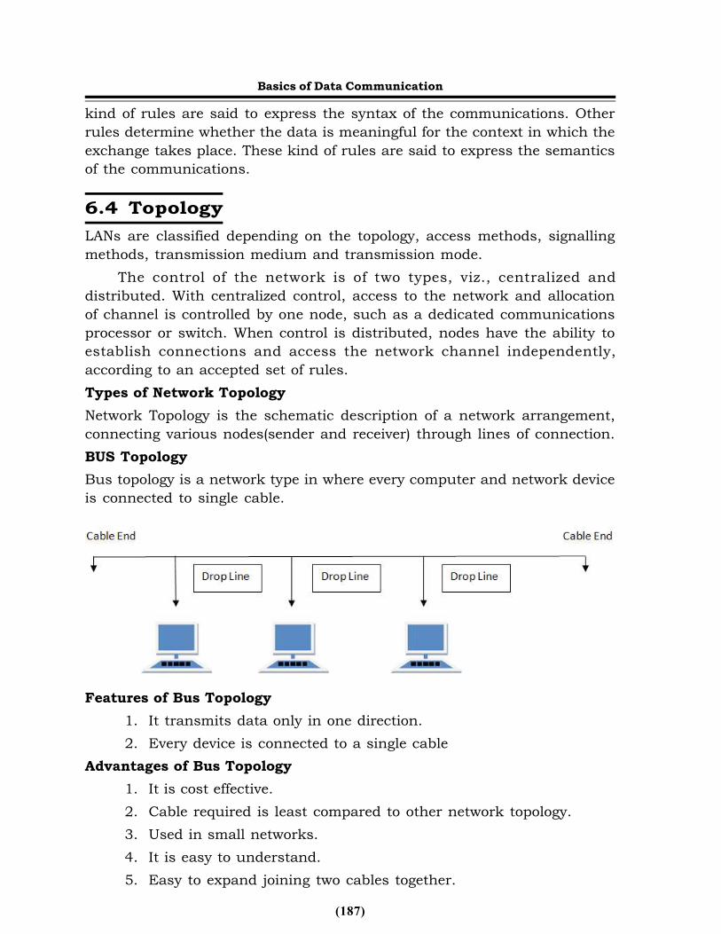
The control of the network is of two types, viz., centralized anddistributed. With centralized control, access to the network and allocationof channel is controlled by one node, such as a dedicated communicationsprocessor or switch. When control is distributed, nodes have the ability toestablish connections and access the network channel independently,according to an accepted set of rules.Types of Network TopologyNetwork Topology is the schematic description of a network arrangement,connecting various nodes(sender and receiver) through lines of connection.BUS TopologyBus topology is a network type in where every computer and network deviceis connected to single cable.
Features of Bus Topology1. It transmits data only in one direction.2. Every device is connected to a single cable
Advantages of Bus Topology1. It is cost effective.2. Cable required is least compared to other network topology.3. Used in small networks.4. It is easy to understand.5. Easy to expand joining two cables together.
Basics of Data Communication
(188)
Disadvantages of Bus Topology1. Cables fails then whole network fails.2. If network traffic is heavy or nodes are more the performance of the
network decreases.3. Cable has a limited length.4. It is slower than the ring topology.
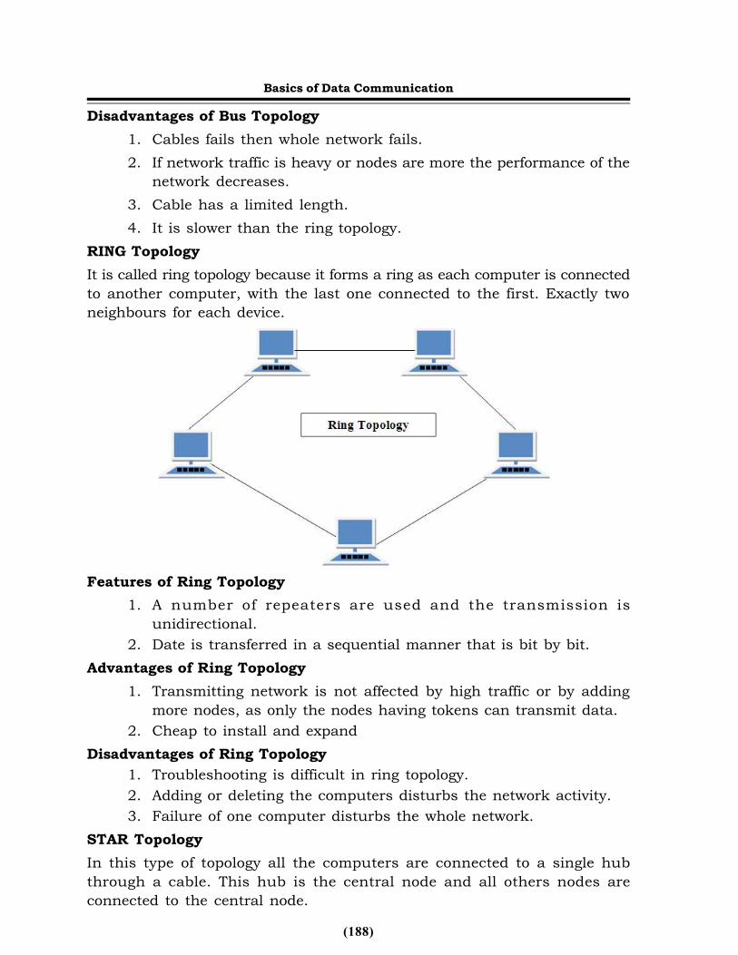
RING TopologyIt is called ring topology because it forms a ring as each computer is connectedto another computer, with the last one connected to the first. Exactly twoneighbours for each device.
Features of Ring Topology1. A number of repeaters are used and the transmission is
unidirectional.2. Date is transferred in a sequential manner that is bit by bit.
Advantages of Ring Topology1. Transmitting network is not affected by high traffic or by adding
more nodes, as only the nodes having tokens can transmit data.2. Cheap to install and expand
Disadvantages of Ring Topology1. Troubleshooting is difficult in ring topology.2. Adding or deleting the computers disturbs the network activity.3. Failure of one computer disturbs the whole network.
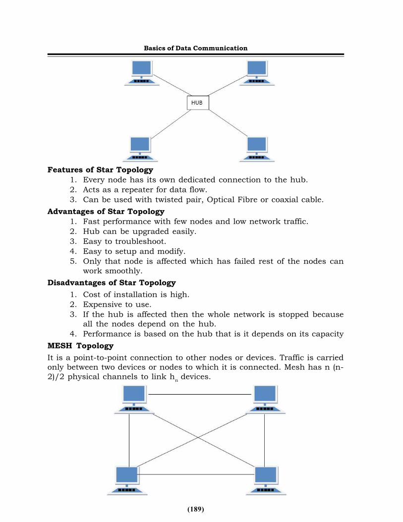
STAR TopologyIn this type of topology all the computers are connected to a single hubthrough a cable. This hub is the central node and all others nodes areconnected to the central node.
Basics of Data Communication
(189)
Features of Star Topology1. Every node has its own dedicated connection to the hub.2. Acts as a repeater for data flow.3. Can be used with twisted pair, Optical Fibre or coaxial cable.
Advantages of Star Topology1. Fast performance with few nodes and low network traffic.2. Hub can be upgraded easily.3. Easy to troubleshoot.4. Easy to setup and modify.5. Only that node is affected which has failed rest of the nodes can
work smoothly.Disadvantages of Star Topology
1. Cost of installation is high.2. Expensive to use.3. If the hub is affected then the whole network is stopped because
all the nodes depend on the hub.4. Performance is based on the hub that is it depends on its capacity
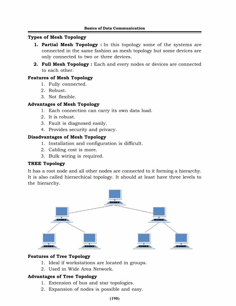
MESH TopologyIt is a point-to-point connection to other nodes or devices. Traffic is carriedonly between two devices or nodes to which it is connected. Mesh has n (n-2)/2 physical channels to link hn devices.
Basics of Data Communication
(190)
Types of Mesh Topology1. Partial Mesh Topology : In this topology some of the systems are
connected in the same fashion as mesh topology but some devices areonly connected to two or three devices.
2. Full Mesh Topology : Each and every nodes or devices are connectedto each other.
Features of Mesh Topology1. Fully connected.2. Robust.3. Not flexible.
Advantages of Mesh Topology1. Each connection can carry its own data load.2. It is robust.3. Fault is diagnosed easily.4. Provides security and privacy.
Disadvantages of Mesh Topology1. Installation and configuration is difficult.2. Cabling cost is more.3. Bulk wiring is required.
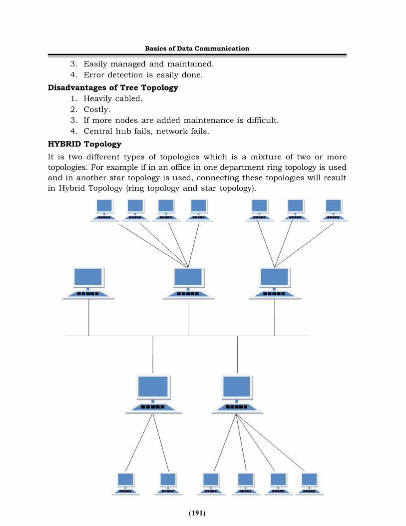
TREE TopologyIt has a root node and all other nodes are connected to it forming a hierarchy.It is also called hierarchical topology. It should at least have three levels tothe hierarchy.
Features of Tree Topology1. Ideal if workstations are located in groups.2. Used in Wide Area Network.
Advantages of Tree Topology1. Extension of bus and star topologies.2. Expansion of nodes is possible and easy.
Basics of Data Communication
(191)
3. Easily managed and maintained.4. Error detection is easily done.
Disadvantages of Tree Topology1. Heavily cabled.2. Costly.3. If more nodes are added maintenance is difficult.4. Central hub fails, network fails.
HYBRID TopologyIt is two different types of topologies which is a mixture of two or moretopologies. For example if in an office in one department ring topology is usedand in another star topology is used, connecting these topologies will resultin Hybrid Topology (ring topology and star topology).
Basics of Data Communication
(192)
Features of Hybrid Topology1. It is a combination of two or topologies2. Inherits the advantages and disadvantages of the topologies included
Advantages of Hybrid Topology1. Reliable as Error detecting and trouble shooting is easy.2. Effective.3. Scalable as size can be increased easily.4. Flexible.
Disadvantages of Hybrid Topology1. Complex in design.2. Costly.
6.5 Switching NetworksSwitching includes ‘plug and play’ element. It determines Ethernet addresseswhich are used on each segment and creates a table of signal packets. Thisfeature connects different network types together just like Ethernet and fastEthernet of the same types. The main advantage of switching is that thereare no protocol issues with switching. Nowadays, a fibre optic switch is usedin switching technology because it allows harnessing of all availablebandwidth. Use of an optical switch allows users on a network to send moreinformation. It also provides huge advantage as immunity to EMI (ElectroMagnetic Interference) disturbance and lighting strike which assures networksecurity.
Switching provides gigabit speeds and several management options.Basic management includes as follows:
• General: Switching manages location, system name, reboot on error,statistics collection, Telnet login, and so on.
• LAN Port: Switching configures speed and flow control, link type andphysical address, to change configuration on each port.
• Console: Switching at this stage changes flow control method, baud rate,modern control, set-up string, enable or disable SLIP (Serial LineInternet Protocol), configure SLIP, SLIP subnet masking.In switching, file transfer packets allow you to identify the port which
is up and the port which is down. The bandwidth option is increased throughthe trunk technique. Basically, it is the process of hooking one switch toanother in full duplex.
Basics of Data Communication
(193)
Basics of Data Communication
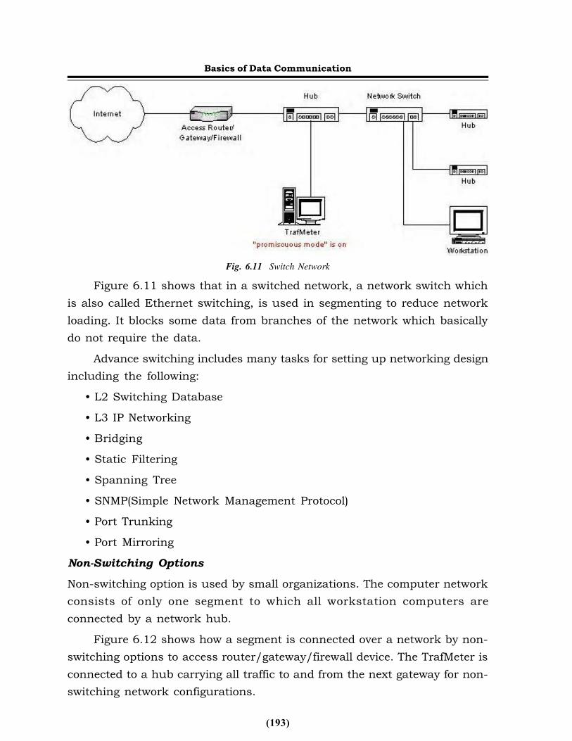
Fig. 6.11 Switch NetworkFigure 6.11 shows that in a switched network, a network switch which
is also called Ethernet switching, is used in segmenting to reduce networkloading. It blocks some data from branches of the network which basicallydo not require the data.
Advance switching includes many tasks for setting up networking designincluding the following:
• L2 Switching Database• L3 IP Networking• Bridging• Static Filtering• Spanning Tree• SNMP(Simple Network Management Protocol)• Port Trunking• Port Mirroring
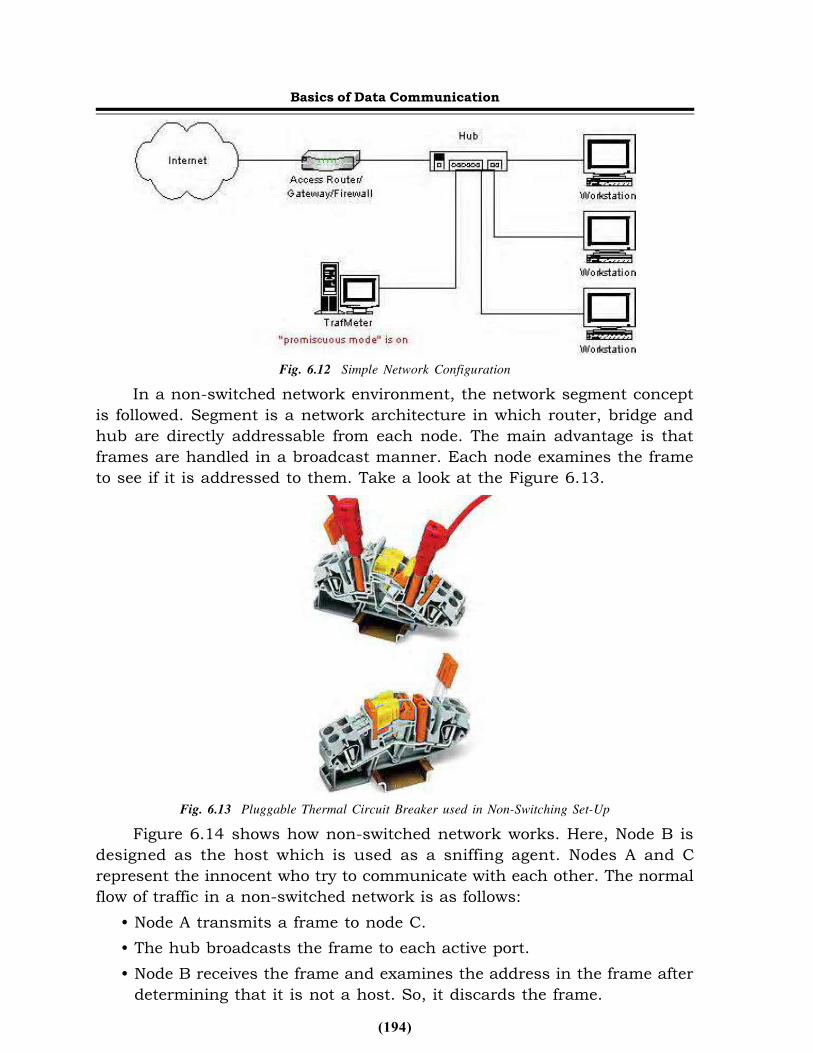
Non-Switching OptionsNon-switching option is used by small organizations. The computer networkconsists of only one segment to which all workstation computers areconnected by a network hub.
Figure 6.12 shows how a segment is connected over a network by non-switching options to access router/gateway/firewall device. The TrafMeter isconnected to a hub carrying all traffic to and from the next gateway for non-switching network configurations.
(194)
Basics of Data Communication
Fig. 6.12 Simple Network ConfigurationIn a non-switched network environment, the network segment concept
is followed. Segment is a network architecture in which router, bridge andhub are directly addressable from each node. The main advantage is thatframes are handled in a broadcast manner. Each node examines the frameto see if it is addressed to them. Take a look at the Figure 6.13.
Fig. 6.13 Pluggable Thermal Circuit Breaker used in Non-Switching Set-UpFigure 6.14 shows how non-switched network works. Here, Node B is
designed as the host which is used as a sniffing agent. Nodes A and Crepresent the innocent who try to communicate with each other. The normalflow of traffic in a non-switched network is as follows:
• Node A transmits a frame to node C.• The hub broadcasts the frame to each active port.• Node B receives the frame and examines the address in the frame after
determining that it is not a host. So, it discards the frame.
(195)
Basics of Data Communication• Node C also receives the frames and examines the address. If it is the
intended host, the further frame process is done in the same way.• Then, network frames are passed to other hosts as well as higher
network layers where it is processed step-by-step.
Fig. 6.14 Non- Switching Set-Up
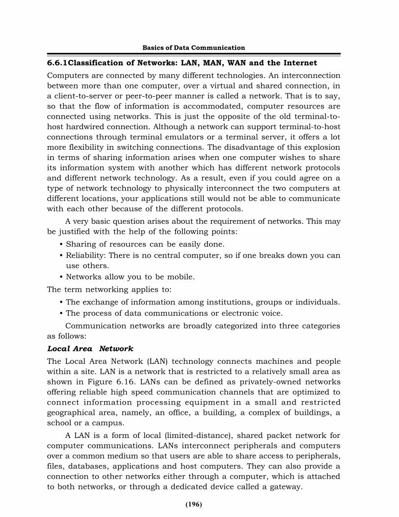
6.6 Network ModelsA network is designed to provide reliable transmission of packets from oneend of the network to other remote parts of the network. A network consistsof several components including the hardware and software devices. However,a simplified network model may be considered as having switching nodes andsource and destination ends. At the source end of the switching nodes,packets of different messages reach at the switching node at different timesand they are queued up according to their time of arrival at the switchingnode. After their traversal through the network, it becomes the responsibilityof the switching node at the destination end to put back all packets of thesame message in sequence to reconstruct the original message. Figure 6.15shows a simplified network model.
Fig. 6.15 Simplified Network Model
(196)
Basics of Data Communication6.6.1Classification of Networks: LAN, MAN, WAN and the InternetComputers are connected by many different technologies. An interconnectionbetween more than one computer, over a virtual and shared connection, ina client-to-server or peer-to-peer manner is called a network. That is to say,so that the flow of information is accommodated, computer resources areconnected using networks. This is just the opposite of the old terminal-to-host hardwired connection. Although a network can support terminal-to-hostconnections through terminal emulators or a terminal server, it offers a lotmore flexibility in switching connections. The disadvantage of this explosionin terms of sharing information arises when one computer wishes to shareits information system with another which has different network protocolsand different network technology. As a result, even if you could agree on atype of network technology to physically interconnect the two computers atdifferent locations, your applications still would not be able to communicatewith each other because of the different protocols.
A very basic question arises about the requirement of networks. This maybe justified with the help of the following points:
• Sharing of resources can be easily done.• Reliability: There is no central computer, so if one breaks down you can
use others.• Networks allow you to be mobile.
The term networking applies to:• The exchange of information among institutions, groups or individuals.• The process of data communications or electronic voice.
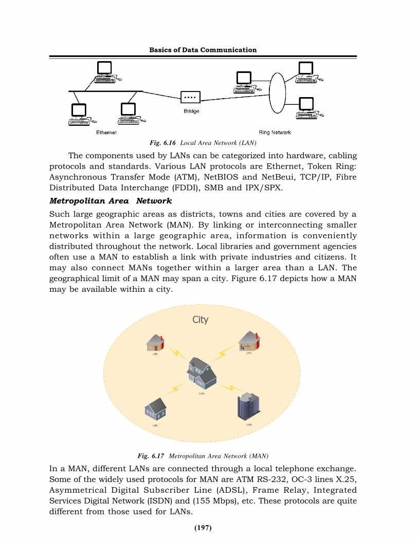
Communication networks are broadly categorized into three categoriesas follows:Local Area NetworkThe Local Area Network (LAN) technology connects machines and peoplewithin a site. LAN is a network that is restricted to a relatively small area asshown in Figure 6.16. LANs can be defined as privately-owned networksoffering reliable high speed communication channels that are optimized toconnect information processing equipment in a small and restrictedgeographical area, namely, an office, a building, a complex of buildings, aschool or a campus.
A LAN is a form of local (limited-distance), shared packet network forcomputer communications. LANs interconnect peripherals and computersover a common medium so that users are able to share access to peripherals,files, databases, applications and host computers. They can also provide aconnection to other networks either through a computer, which is attachedto both networks, or through a dedicated device called a gateway.
(197)
Basics of Data Communication
Fig. 6.16 Local Area Network (LAN)The components used by LANs can be categorized into hardware, cabling
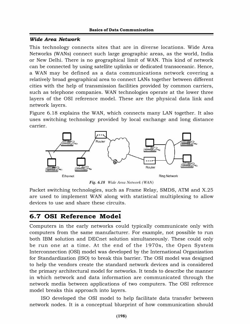
protocols and standards. Various LAN protocols are Ethernet, Token Ring:Asynchronous Transfer Mode (ATM), NetBIOS and NetBeui, TCP/IP, FibreDistributed Data Interchange (FDDI), SMB and IPX/SPX.Metropolitan Area NetworkSuch large geographic areas as districts, towns and cities are covered by aMetropolitan Area Network (MAN). By linking or interconnecting smallernetworks within a large geographic area, information is convenientlydistributed throughout the network. Local libraries and government agenciesoften use a MAN to establish a link with private industries and citizens. Itmay also connect MANs together within a larger area than a LAN. Thegeographical limit of a MAN may span a city. Figure 6.17 depicts how a MANmay be available within a city.
Fig. 6.17 Metropolitan Area Network (MAN)In a MAN, different LANs are connected through a local telephone exchange.Some of the widely used protocols for MAN are ATM RS-232, OC-3 lines X.25,Asymmetrical Digital Subscriber Line (ADSL), Frame Relay, IntegratedServices Digital Network (ISDN) and (155 Mbps), etc. These protocols are quitedifferent from those used for LANs.
(198)
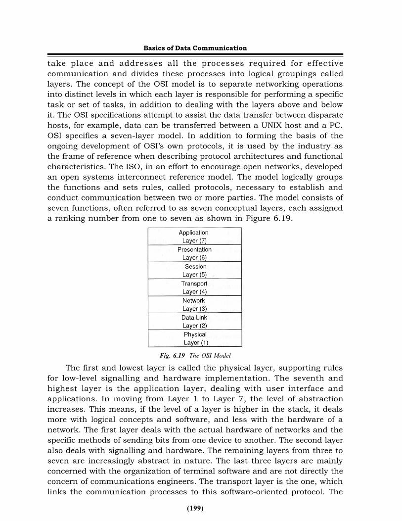
Basics of Data CommunicationWide Area NetworkThis technology connects sites that are in diverse locations. Wide AreaNetworks (WANs) connect such large geographic areas, as the world, Indiaor New Delhi. There is no geographical limit of WAN. This kind of networkcan be connected by using satellite uplinks or dedicated transoceanic. Hence,a WAN may be defined as a data communications network covering arelatively broad geographical area to connect LANs together between differentcities with the help of transmission facilities provided by common carriers,such as telephone companies. WAN technologies operate at the lower threelayers of the OSI reference model. These are the physical data link andnetwork layers.Figure 6.18 explains the WAN, which connects many LAN together. It alsouses switching technology provided by local exchange and long distancecarrier.
Fig. 6.18 Wide Area Network (WAN)Packet switching technologies, such as Frame Relay, SMDS, ATM and X.25are used to implement WAN along with statistical multiplexing to allowdevices to use and share these circuits.6.7 OSI Reference ModelComputers in the early networks could typically communicate only withcomputers from the same manufacturer. For example, not possible to runboth IBM solution and DECnet solution simultaneously. These could onlybe run one at a time. At the end of the 1970s, the Open SystemInterconnection (OSI) model was developed by the International Organizationfor Standardization (ISO) to break this barrier. The OSI model was designedto help the vendors create the standard network devices and is consideredthe primary architectural model for networks. It tends to describe the mannerin which network and data information are communicated through thenetwork media between applications of two computers. The OSI referencemodel breaks this approach into layers.
ISO developed the OSI model to help facilitate data transfer betweennetwork nodes. It is a conceptual blueprint of how communication should
(199)
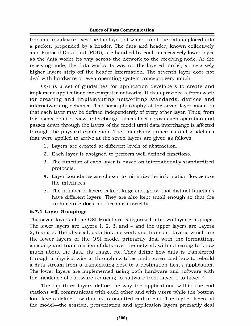
take place and addresses all the processes required for effectivecommunication and divides these processes into logical groupings calledlayers. The concept of the OSI model is to separate networking operationsinto distinct levels in which each layer is responsible for performing a specifictask or set of tasks, in addition to dealing with the layers above and belowit. The OSI specifications attempt to assist the data transfer between disparatehosts, for example, data can be transferred between a UNIX host and a PC.OSI specifies a seven-layer model. In addition to forming the basis of theongoing development of OSI’s own protocols, it is used by the industry asthe frame of reference when describing protocol architectures and functionalcharacteristics. The ISO, in an effort to encourage open networks, developedan open systems interconnect reference model. The model logically groupsthe functions and sets rules, called protocols, necessary to establish andconduct communication between two or more parties. The model consists ofseven functions, often referred to as seven conceptual layers, each assigneda ranking number from one to seven as shown in Figure 6.19.
Fig. 6.19 The OSI ModelThe first and lowest layer is called the physical layer, supporting rules
for low-level signalling and hardware implementation. The seventh andhighest layer is the application layer, dealing with user interface andapplications. In moving from Layer 1 to Layer 7, the level of abstractionincreases. This means, if the level of a layer is higher in the stack, it dealsmore with logical concepts and software, and less with the hardware of anetwork. The first layer deals with the actual hardware of networks and thespecific methods of sending bits from one device to another. The second layeralso deals with signalling and hardware. The remaining layers from three toseven are increasingly abstract in nature. The last three layers are mainlyconcerned with the organization of terminal software and are not directly theconcern of communications engineers. The transport layer is the one, whichlinks the communication processes to this software-oriented protocol. The
Basics of Data Communication
(200)
transmitting device uses the top layer, at which point the data is placed intoa packet, prepended by a header. The data and header, known collectivelyas a Protocol Data Unit (PDU), are handled by each successively lower layeras the data works its way across the network to the receiving node. At thereceiving node, the data works its way up the layered model, successivelyhigher layers strip off the header information. The seventh layer does notdeal with hardware or even operating system concepts very much.
OSI is a set of guidelines for application developers to create andimplement applications for computer networks. It thus provides a frameworkfor creating and implementing networking standards, devices andinternetworking schemes. The basic philosophy of the seven-layer model isthat each layer may be defined independently of every other layer. Thus, fromthe user’s point of view, interchange takes effect across each operation andpasses down through the layers of the model until data interchange is affectedthrough the physical connection. The underlying principles and guidelinesthat were applied to arrive at the seven layers are given as follows:
1. Layers are created at different levels of abstraction.2. Each layer is assigned to perform well-defined functions.3. The function of each layer is based on internationally standardized
protocols.4. Layer boundaries are chosen to minimize the information flow across
the interfaces.5. The number of layers is kept large enough so that distinct functions
have different layers. They are also kept small enough so that thearchitecture does not become unwieldy.
6.7.1 Layer GroupingsThe seven layers of the OSI Model are categorized into two-layer groupings.The lower layers are Layers 1, 2, 3, and 4 and the upper layers are Layers5, 6 and 7. The physical, data link, network and transport layers, which arethe lower layers of the OSI model primarily deal with the formatting,encoding and transmission of data over the network without caring to knowmuch about the data, its usage, etc. They define how data is transferredthrough a physical wire or through switches and routers and how to rebuilda data stream from a transmitting host to a destination host’s application.The lower layers are implemented using both hardware and software withthe incidence of hardware reducing to software from Layer 1 to Layer 4.
The top three layers define the way the applications within the endstations will communicate with each other and with users while the bottomfour layers define how data is transmitted end-to-end. The higher layers ofthe model—the session, presentation and application layers primarily deal
Basics of Data Communication
(201)
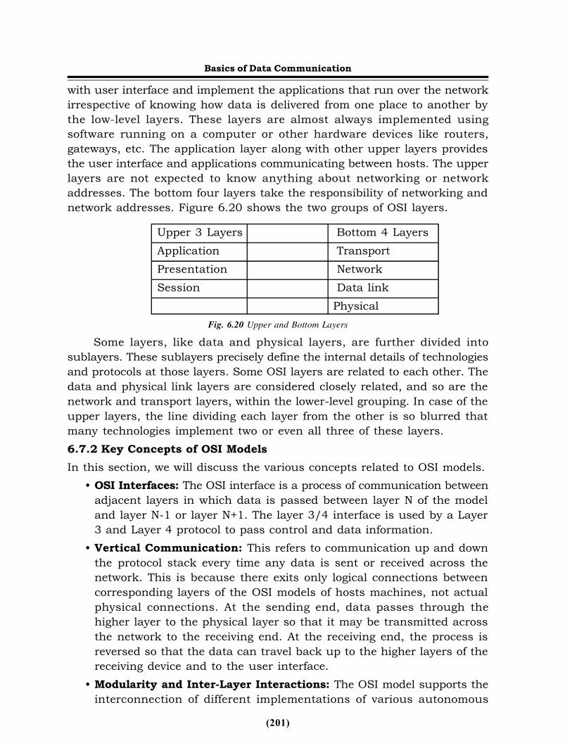
with user interface and implement the applications that run over the networkirrespective of knowing how data is delivered from one place to another bythe low-level layers. These layers are almost always implemented usingsoftware running on a computer or other hardware devices like routers,gateways, etc. The application layer along with other upper layers providesthe user interface and applications communicating between hosts. The upperlayers are not expected to know anything about networking or networkaddresses. The bottom four layers take the responsibility of networking andnetwork addresses. Figure 6.20 shows the two groups of OSI layers.
Upper 3 Layers Bottom 4 LayersApplication TransportPresentation NetworkSession Data link
PhysicalFig. 6.20 Upper and Bottom Layers
Some layers, like data and physical layers, are further divided intosublayers. These sublayers precisely define the internal details of technologiesand protocols at those layers. Some OSI layers are related to each other. Thedata and physical link layers are considered closely related, and so are thenetwork and transport layers, within the lower-level grouping. In case of theupper layers, the line dividing each layer from the other is so blurred thatmany technologies implement two or even all three of these layers.6.7.2 Key Concepts of OSI ModelsIn this section, we will discuss the various concepts related to OSI models.
• OSI Interfaces: The OSI interface is a process of communication betweenadjacent layers in which data is passed between layer N of the modeland layer N-1 or layer N+1. The layer 3/4 interface is used by a Layer3 and Layer 4 protocol to pass control and data information.
• Vertical Communication: This refers to communication up and downthe protocol stack every time any data is sent or received across thenetwork. This is because there exits only logical connections betweencorresponding layers of the OSI models of hosts machines, not actualphysical connections. At the sending end, data passes through thehigher layer to the physical layer so that it may be transmitted acrossthe network to the receiving end. At the receiving end, the process isreversed so that the data can travel back up to the higher layers of thereceiving device and to the user interface.
• Modularity and Inter-Layer Interactions: The OSI model supports theinterconnection of different implementations of various autonomous
Basics of Data Communication
(202)
layers. This is done through interfaces in which each layer shouldprovide a consistent, well-documented interface to the layers above itso that any upper layer implementation can use the lower layerproperly.
• Protocols: These are sets of agreed rules, procedures, instructions and/or functions describing one type of communication between specificsoftware and hardware elements running at the same layer on differentmachines within a network. They have their own language. Some of themare similar to each other while others are quite unique.
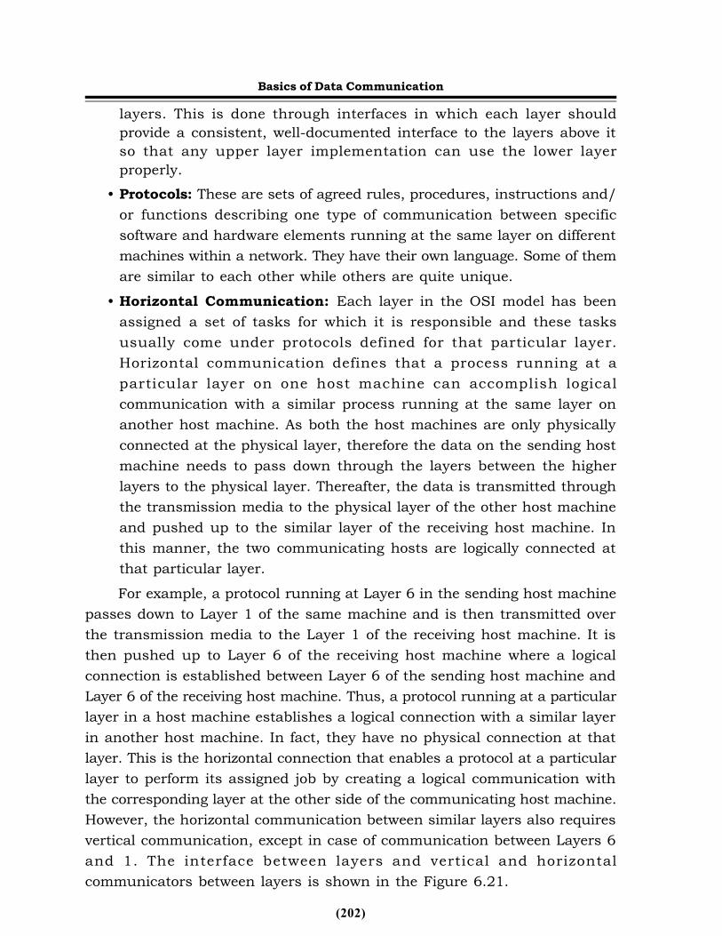
• Horizontal Communication: Each layer in the OSI model has beenassigned a set of tasks for which it is responsible and these tasksusually come under protocols defined for that particular layer.Horizontal communication defines that a process running at aparticular layer on one host machine can accomplish logicalcommunication with a similar process running at the same layer onanother host machine. As both the host machines are only physicallyconnected at the physical layer, therefore the data on the sending hostmachine needs to pass down through the layers between the higherlayers to the physical layer. Thereafter, the data is transmitted throughthe transmission media to the physical layer of the other host machineand pushed up to the similar layer of the receiving host machine. Inthis manner, the two communicating hosts are logically connected atthat particular layer.For example, a protocol running at Layer 6 in the sending host machine
passes down to Layer 1 of the same machine and is then transmitted overthe transmission media to the Layer 1 of the receiving host machine. It isthen pushed up to Layer 6 of the receiving host machine where a logicalconnection is established between Layer 6 of the sending host machine andLayer 6 of the receiving host machine. Thus, a protocol running at a particularlayer in a host machine establishes a logical connection with a similar layerin another host machine. In fact, they have no physical connection at thatlayer. This is the horizontal connection that enables a protocol at a particularlayer to perform its assigned job by creating a logical communication withthe corresponding layer at the other side of the communicating host machine.However, the horizontal communication between similar layers also requiresvertical communication, except in case of communication between Layers 6and 1. The interface between layers and vertical and horizontalcommunicators between layers is shown in the Figure 6.21.
Basics of Data Communication
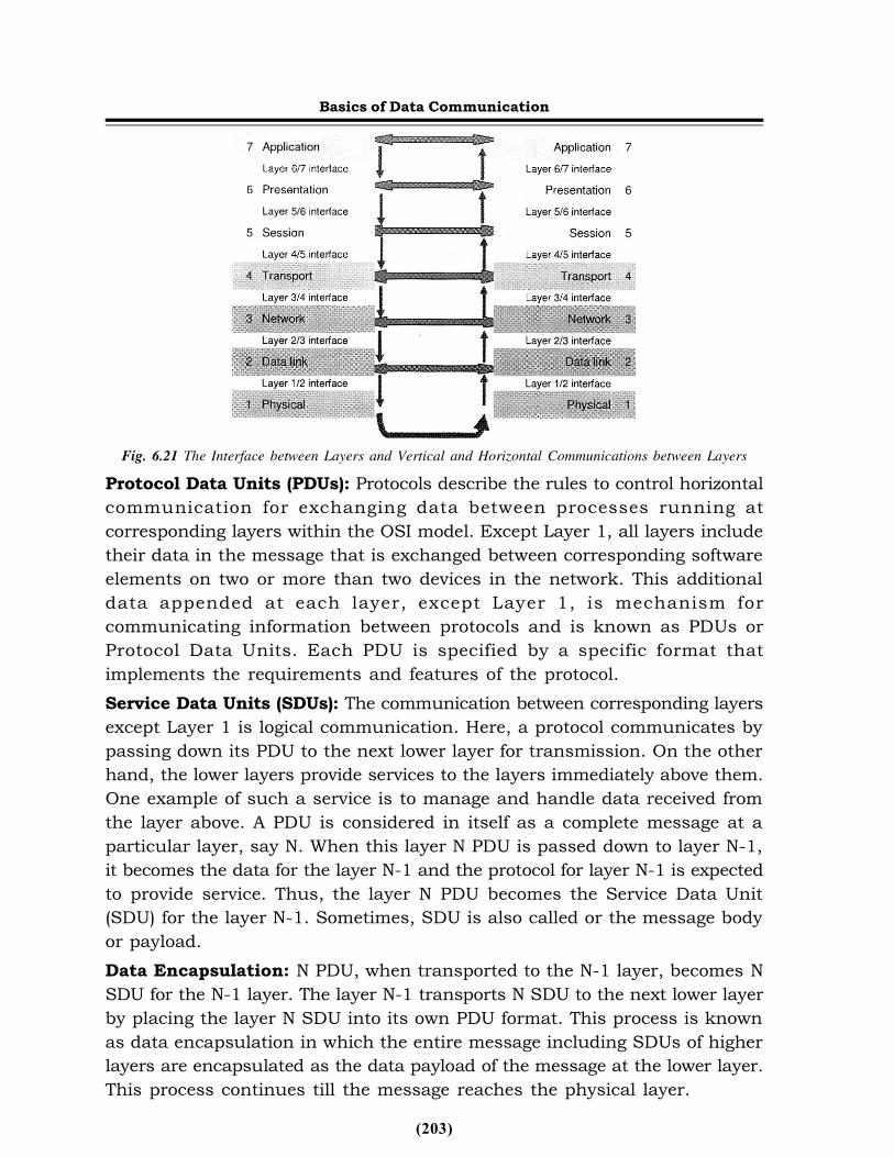
(203)
Fig. 6.21 The Interface between Layers and Vertical and Horizontal Communications between LayersProtocol Data Units (PDUs): Protocols describe the rules to control horizontalcommunication for exchanging data between processes running atcorresponding layers within the OSI model. Except Layer 1, all layers includetheir data in the message that is exchanged between corresponding softwareelements on two or more than two devices in the network. This additionaldata appended at each layer, except Layer 1, is mechanism forcommunicating information between protocols and is known as PDUs orProtocol Data Units. Each PDU is specified by a specific format thatimplements the requirements and features of the protocol.Service Data Units (SDUs): The communication between corresponding layersexcept Layer 1 is logical communication. Here, a protocol communicates bypassing down its PDU to the next lower layer for transmission. On the otherhand, the lower layers provide services to the layers immediately above them.One example of such a service is to manage and handle data received fromthe layer above. A PDU is considered in itself as a complete message at aparticular layer, say N. When this layer N PDU is passed down to layer N-1,it becomes the data for the layer N-1 and the protocol for layer N-1 is expectedto provide service. Thus, the layer N PDU becomes the Service Data Unit(SDU) for the layer N-1. Sometimes, SDU is also called or the message bodyor payload.Data Encapsulation: N PDU, when transported to the N-1 layer, becomes NSDU for the N-1 layer. The layer N-1 transports N SDU to the next lower layerby placing the layer N SDU into its own PDU format. This process is knownas data encapsulation in which the entire message including SDUs of higherlayers are encapsulated as the data payload of the message at the lower layer.This process continues till the message reaches the physical layer.
Basics of Data Communication
(204)
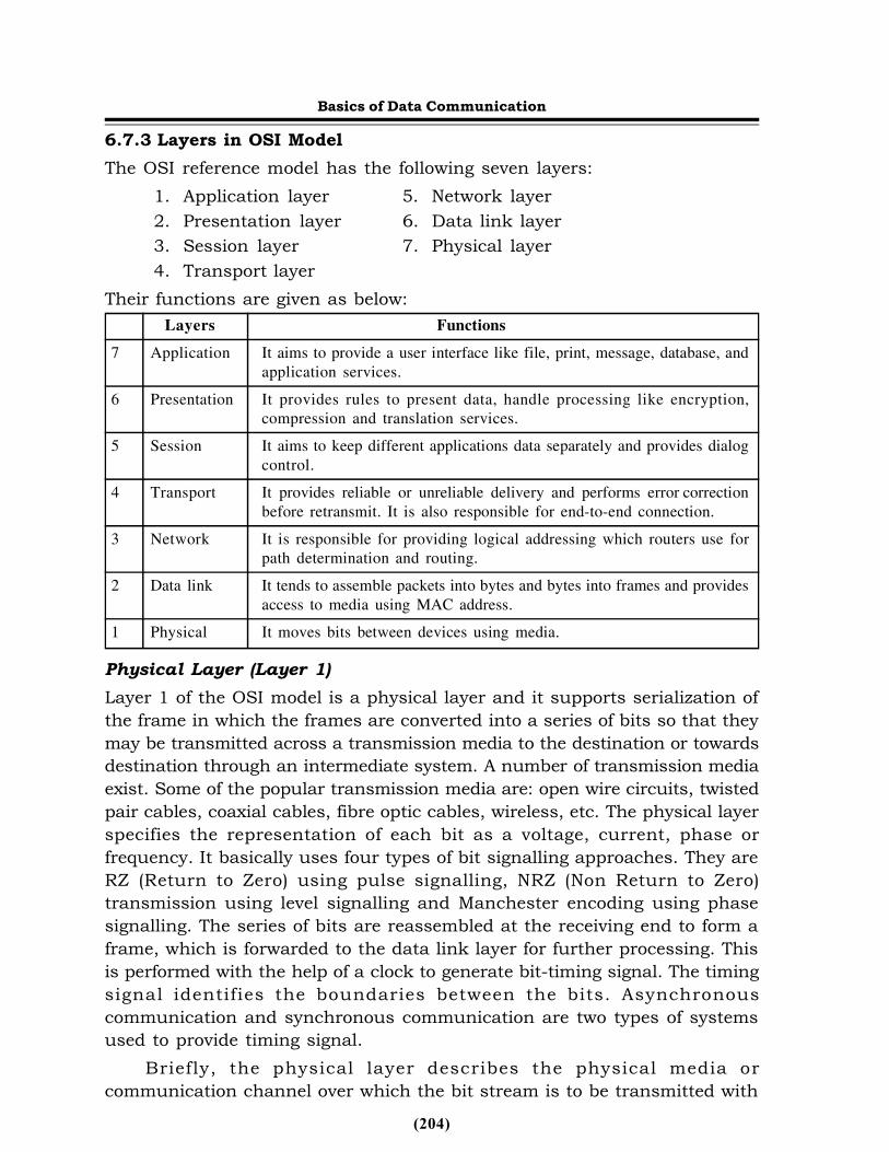
6.7.3 Layers in OSI ModelThe OSI reference model has the following seven layers:
1. Application layer 5. Network layer2. Presentation layer 6. Data link layer3. Session layer 7. Physical layer4. Transport layer
Their functions are given as below:Layers Functions
7 Application It aims to provide a user interface like file, print, message, database, andapplication services.
6 Presentation It provides rules to present data, handle processing like encryption,compression and translation services.
5 Session It aims to keep different applications data separately and provides dialogcontrol.
4 Transport It provides reliable or unreliable delivery and performs error correctionbefore retransmit. It is also responsible for end-to-end connection.
3 Network It is responsible for providing logical addressing which routers use forpath determination and routing.
2 Data link It tends to assemble packets into bytes and bytes into frames and providesaccess to media using MAC address.
1 Physical It moves bits between devices using media.Physical Layer (Layer 1)Layer 1 of the OSI model is a physical layer and it supports serialization ofthe frame in which the frames are converted into a series of bits so that theymay be transmitted across a transmission media to the destination or towardsdestination through an intermediate system. A number of transmission mediaexist. Some of the popular transmission media are: open wire circuits, twistedpair cables, coaxial cables, fibre optic cables, wireless, etc. The physical layerspecifies the representation of each bit as a voltage, current, phase orfrequency. It basically uses four types of bit signalling approaches. They areRZ (Return to Zero) using pulse signalling, NRZ (Non Return to Zero)transmission using level signalling and Manchester encoding using phasesignalling. The series of bits are reassembled at the receiving end to form aframe, which is forwarded to the data link layer for further processing. Thisis performed with the help of a clock to generate bit-timing signal. The timingsignal identifies the boundaries between the bits. Asynchronouscommunication and synchronous communication are two types of systemsused to provide timing signal.
Briefly, the physical layer describes the physical media orcommunication channel over which the bit stream is to be transmitted with
Basics of Data Communication
(205)
the objective that when the sending side sends 1 bit, it is received by thereceiving side as 1 bit, not as 0 bit. Hence, it defines the electrical andmechanical aspects of interfacing to a physical medium for transmitting data,as well as setting up, maintaining, and disconnecting physical links. It isprimarily concerned with moving bits from one node to the next over thephysical link. The issues concerned with the physical layer involve amplitudeof the pulses to define 1 and 0 level, width of the pulse in microseconds, typesand mode of communication, establishment and breaking of connections atthe time of communication, types of connectors, etc. Basically, the physicallayer transforms bits in a computer system into electromagnetic signals fora particular transmission medium like wire, fibre, etc. The physical layerfunctions are as follows:
• Describing Hardware Specifications: It includes specifications of cables,connectors, radio transceivers, network interface cards, etc.
• Encoding and Signalling: The physical layer supports various encodingand signalling functions to convert data, from bit stream to frame andvice versa, to send across the network.
• Data Transmission and Reception: It is responsible for transmitting andreceiving data over the physical media.The physical layer accepts data from the Data Link layer in bit streams
for the subsequent transmission over the physical medium. At this layer, themechanical (connector type), electrical (voltage levels), functional (pingassignments), and procedural (handshake) characteristics are defined. RS-232C/D is an example of a physical layer definition.Data Link Layer (Layer 2)The data link layer is Layer 2 of the OSI model and provides functional andprocedural means to exchange data between network entities. The set ofdevices functioning at the data link layer simply supports the functionalitiesof networking instead of internetworking. Sometimes, the data link layer isalso known as the link layer because it provides links to many wireless andwired Local Area Networking (LAN) technologies like Ethernet, FDDI, IEEE802.11, etc., to function. It tends to correct transmission errors and supportthe deactivation, maintenance and activation of data link connections. It alsogroups bits into message frames and characters, and provides character andflow control, frame synchronization, media access control and error control.Some of the examples of data link layers are HDLC and Ethernet.
It takes the bits received by the physical layers; detects error; ensuresthat messages are delivered to the proper devices; and translates messagesfrom the network layer into bits for the physical layer to transmit. The datalink layer transforms a stream of raw bits (0s and 1s) into a data frame andprovides an error-free transfer from one host to another and allows the layers
Basics of Data Communication
(206)
above it to assume virtually error-free transmission. This establishes an error-free communication path between network nodes over the physical channel,frames messages for transmission, checks the integrity of received messages,manages access to and use of the channel and ensures proper sequence oftransmitted data. Hence, this layer is responsible for the reliable transfer ofdata across the physical link. Its responsibilities include functions, such asdata flow control, breaking the input data, frame formatting, andtransmission of the frames sequentially, error detection, and linkmanagement, etc. In order to provide a reliable service, it also offers processingof the acknowledgement frames, retransmitting of lost or damaged frames,etc. The data link layer is conceptually subdivided into the Logical LinkControl and Medium Access Control (MAC) sublayers to deal with the accesscontrol over the shared channel in broadcast networks. The key functions ofthe data link layer are summarized as follows:
• Logical Link Control (LLC): LLC refers to one of the sublayers of thedata link layer and deals with the functions that enable control andestablishment of logical links between local devices on a computernetwork. LLC has also been given the responsibility to provide servicesto the network layer above it and hides the rest of the details of the datalink layer to allow different technologies to work seamlessly with thehigher layers. Most of the local area networking technologies use theIEEE 802.2 LLC protocol.
• Media Access Control (MAC): MAC refers to one of the sublayers of thedata link layer and specifies the procedures used by devices to controlaccess to the network medium. Its role is to control and manage themedium to avoid conflicts because the design of a computer network isbased on the shared medium that may be composed of a single networkcable or a series of cables that are electrically connected to a singlevirtual medium. Some of the examples of MAC are CSMA/CD forEthernet and token passing for the Token Ring network.
• Data Framing: Messages of higher layer are encapsulated at this layerinto frames so that they may be sent across the network at the physicallayer.
• Addressing: The data link layer also deals with the issue of addressingwhich is popularly known as hardware address or MAC address in whichthe information is labelled with a particular destination location. Eachdevice on a network is provided with a unique number called a hardwareaddress or MAC address, which is used by the data link layer protocolto ensure that the data intended for a specific machine gets to it properly.
• Error Detection and Handling: The data link layer also deals with errorsthat occur at the lower levels of the network stack. For example, a Cyclic
Basics of Data Communication
(207)
Redundancy Check (CRC) field is often used to allow the host receivingdata to detect if it was received correctly.
Network Layer (Layer 3)If the data link layer intends to define specifications for the computernetworking network, then it is the network layer that specifies howinternetworks (Internet) function. The network layer is the first layer in theOSI model that deals with the actual obtaining of data from computers evenif they are on a remote network. While the data link layer is only concernedwith devices that are situated on the same network or local to each other.The key functions of the network layer are as follows:
• Logical Addressing: The devices communicating across a network havelogical addresses which are known as layer three addresses. InternetProtocol(IP) is an example of Layer 3 addressing. Unlike, data link addressingthat deals only with local physical devices, the logical addresses at Layer3 are independent of particular hardware and unique across an entireinternetwork.
• Routing: It is the key function of Layer 3 in which data is routed acrossinterconnected networks to deliver finally at the host destination. Thisis accomplished with the help of devices like routers and softwareroutines that function at the network layer to handle incoming packetsfrom various sources and determine routes for their final destination sothat they could be delivered reliably there.
• Datagram Encapsulation: The network layer functions to encapsulatemessages received from higher layers by placing them into datagramswith a network layer header. Datagrams are also referred to as packets.
• Fragmentation and Reassembly: The network layer passes downmessages to the data link layer for transmission through the physicallayer over the transmission media to other networks or the local network.The network layer also splits large packets into smaller packets accordingto the limits imposed on the length of the packet by the data link layer.This process is called fragmentation. Thus, the fragmented pieces areput together at the network layer of the destination machine. Thisprocess is called the reassembly of packets.The function of the network layer may be summarized as follows: The
main role of the network layer is to accept packets from a source and deliverthem to a destination machine. The network layer provides services thatshould be independent of the router technology. It shields the transport layerfrom the router network details and facilitates consistent network addressing-across networks. Services of the network layer are available in connectionoriented and connectionless modes. Connection-oriented services are useful
Basics of Data Communication
(208)
only when the user wants to send a constant stream of data down the line.The routing algorithms that require selection of a path or route from manypossible routes in the network are part of the router software. The networklayer comprises of software that addresses the PDUs and transports them tothe ultimate destination, setting up the appropriate paths between the variousnodes. The network layer provides routing based on network addressing, andthus it is responsible for transporting traffic between devices that are notlocally attached. If a packet is received on a router interface, the destinationIP address is examined. When the packet is not destined for the router, therouter will look up in the routing table for the destination network address.When an interface exists, the packet will be sent to the interface so that itcan be sent out on the local network. When the entry for the destinationnetwork is not found in the routing table, the router drops the packet.Therefore, the main objective of this layer is to control the operation of thesubnet. It is the layer, which provides Internet Protocol (IP) to use it. It ismainly responsible for providing routing services from the source to thedestination across the Internet. In doing so, it allows internetworking amongheterogeneous networks using different addressing, lengths of packet,protocols, etc. The routing may be static or dynamic. The network layer alsoplays an important role in congestion control. It uses connection-oriented orconnectionless services for delivering packets across the network.
It also shields the above layers from details about the underlying network(the network topology and road map) and the routing technology that mighthave been deployed to connect different networks together. In addition torouting, this layer is responsible for establishing and maintaining theconnection. In broadcast networks, the routing problem is simple, so thenetwork layer is often thin or even nonexistent. The next three layers aretask-oriented and are concerned with the operations performed by the userrather than with the network.Transport Layer (Layer 4)The basic role of the transport layer is to transport data but involves high-level functions as compared to the same functions delivered by the lowerlayers. The Layers 1, 2 and 3 primarily deal with the packaging, addressing,routing and delivery of data; and the Layer 4 acts as an interface betweenthe applications at the higher layers and the functions of Layers 1 to 3. Thus,the transport layer provides the necessary functions to enable communicationbetween software application processes on different computers.
The transport layer accepts data from the session layer and splits it upinto smaller units so that it can be passed to the network layer; and ensuresthat the all pieces arrive correctly at the other end. Thus, this layerguarantees the orderly and reliable delivery of data between end systems afteraccepting data from the session layer. Data is accepted from the session layer
Basics of Data Communication
(209)
and split up into smaller units, if needed. The session layer passes the datato the network layer and ensures that the packets arrive correctly at thereceiving side. The transport layer establishes a distinct network connectionfor each transport connection required by the session layer. Basically, itperforms connection management based upon throughput conditions. Innormal condition, one network connection corresponds to multiple transportconnections. In high throughput condition, one transport connectioncorresponds to multiple network connections. The most popular protocol suiteTCP/IP uses this layer. The transport layer also performs additional functions,such as data multiplexing and de-multiplexing. This layer divides up atransmitting message into packets and reassembles it at the receiving end.Service offered at this layer includes an error-free point-to-point channel todeliver messages in the order in which they were sent. The transport layeris a true source-to-destination or end-to-end layer. Flow control betweenhosts is also needed but is different from the flow control between routers(similar principles will apply to both). Some important functions of thetransport layer are as follows:
• Process-Level Addressing: Like Layers 2 and 3, the transport layer alsodeals with the addressing issue but quite differently in which it is usedto differentiate between software programs or different applications. Thisfunction of the transport layer enables many different software programsor applications to use a network layer protocol simultaneously.
• Multiplexing and Demultiplexing: It enables a sending device tomultiplex the data received from many application programs fortransport, and demultiplex the data received while acting as the receivingside.
• Segmentation, Packaging and Reassembly: According to the specifiedlimit on the length of the data packet at the network layer, the transportlayer (like network layer) segments the large amounts of data intosmaller pieces on the source machine to transmit across the networkand then reassemble them on the destination machine.
• Connection Establishment, Management and Termination: Theconnection-oriented protocols at the transport layer establish aconnection, maintain it as data is sent over it and then terminate theconnection when it is no longer required for the series ofcommunications.
• Acknowledgments and Retransmissions: The transport layer ensuresguaranteed delivery of data reliably which is accomplished by using avariety of techniques, most commonly the combination ofacknowledgments and retransmission of data if data is not deliveredsuccessfully.
Basics of Data Communication
(210)
• Flow Control: It refers to the process of specifying that the data rate ofthe sending device should not be prohibitively excessive so that thereceiver could be saved from being bogged down with data. In otherwords, this function manages mismatches in speed between the senderand the receiver.
Session Layer (Layer 5)The session layer is the lowest of the three upper layers and deals mainlywith software application issues only. It helps enable devices to establish andmanage sessions. Primarily, a session is a persistent logical linking of twosoftware application processes to exchange data over a specified period of time.The session layer is responsible for establishing, maintaining, and arbitratingthe dialogs between communicating applications. It also provides enhancedservices useful in some applications, for example, remote login, remote filetransfer, etc. It is also responsible for orderly recovery from failures byimplementing appropriate checkpointing mechanisms. The applications oneither side of the session can exchange data or send packets to another foras long as the session lasts. The session layer handles session setup, messageexchanges and it terminates when the session ends. It also coordinates andmonitors session identification so that only designated parties can participate.It also provides security services to control access to session information. Thesession layer allows hosts to establish session between them in whichordinary data transport is allowed. The session layer also manages dialoguecontrol.
Establish, Manage and Terminate Sessions: The primary task of sessionlayer protocols is to provide the necessary ways to establish, manage andterminate sessions. These session layer protocols are usually provided tohigher layer protocols through command sets often known as the applicationprogram interfaces or APIs.Some of the common examples of APIs are NetBIOS, TCP/IP sockets, RemoteProcedure Calls (RPCs), etc. The APIs enable an application to completespecified high-level communications over the network successfully and easilywith the help of a standardized set of services.Presentation Layer (Layer 6)The presentation layer is concerned with the presentation of data where itsupports any special processing on the data from the time an applicationattempts to send it till the time it is sent over the network. Thus, it isresponsible for any issues that may arise where data sent from one systemneeds to be viewed in a different way by the other system. The presentationlayer performs functions related to the syntax and semantics of theinformation transmitted. This includes formatting and displaying of receiveddata by terminals and printers. It is concerned with differences in the data
Basics of Data Communication
(211)
syntax used by communicating applications. This layer is responsible forremedying those differences by resorting to mechanisms that transform thelocal syntax (specific to the platform in question) to a common one for thepurpose of data exchange. For example, it performs encoding of data in astandard, agreed-upon way to facilitate information exchange amongheterogeneous systems using different codes for strings, for example,conversion between ASCII and EBCDIC character codes. It facilitates datacompression for reducing the number of bits to be transmitted and encryptsdata for privacy and authentication, if necessary. Some of the specific typesof data handling issues that the presentation layer provides are as follows:
• Translation: Different types of computers like PCs, Macintoshes, UNIXsystems, AS/400 servers, etc., in an internetwork have many distinctcharacteristics and represent data in different ways. It is theresponsibility of the presentation layer to hide these differences betweendifferent machines for seamless and easy exchange of data between twohosts working on different machines. The translation function issometimes not needed.
• Compression: Compression and decompression are also carried out atthe presentation layer to improve the throughput of data. However, thesefunctions are optional.
• Encryption: Some types of encryption and decryption are performed atthe presentation layer to ensure the security of the data as it passesdown the protocol stack. These are also optional.Sometimes, the presentation layer functions are taken care of by the
application layer and the functions like translation, compression/decompression and encryption/ decryption are not always required. Due tothese facts, the presentation layer is often skipped in actual protocol stackimplementations; and it is possible for Layer 7 to directly talk to layer 5 inthe OSI model.Application Layer (Layer 7)The application layer provides support services for user and application taskswhich are programs that actually implement the functions performed by usersto accomplish various tasks over the network. It determines how the user willuse the data network. It allows the user to use the network. For example, itprovides network-based services to the end-user. Examples of network servicesare distributed databases, electronic mail, resource sharing, file transfers,remote file access and network management. This layer defines the natureof the task to be performed. The application layer provides user interface tocommunicate with the computer. It identifies and establishes the availabilityof the intended communicating host and determines if sufficient resources
Basics of Data Communication
(212)
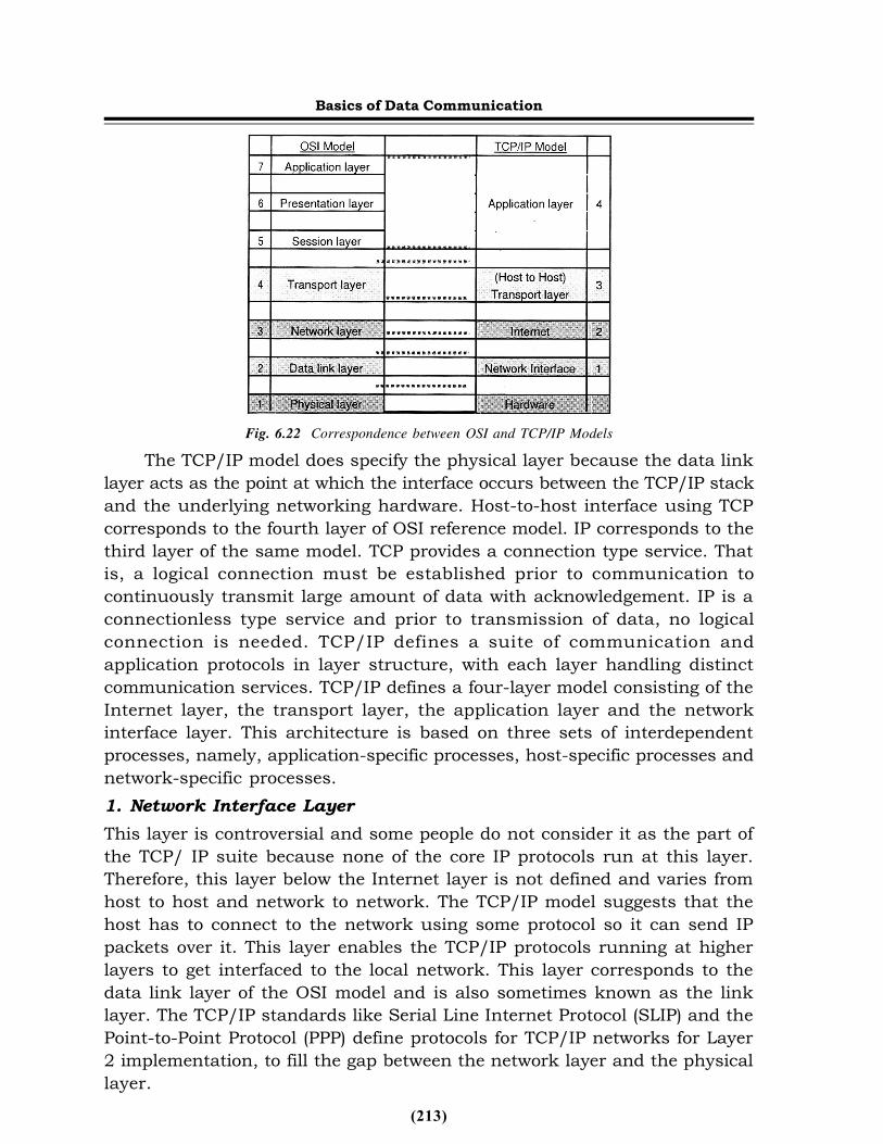
for the intended communication exist. The application layer provides a varietyof protocols that are commonly needed. Some of the characteristics of theapplication layer are to provide an end-user interface for human machineinterface so that the necessary commands may be entered to obtain thenecessary application. Some of the most popular application layer protocolsare HTTP, FTP, SMTP, DHCP, NFS, Telnet, SNMP, POP3, NNTP and IRC.6.8 TCP/IP Reference ModelThe TCP/IP model is considered the oldest protocol of all computer networkslike the ARPANET and its successor, the Internet. It contains two protocolsTCP and IP. TCP stands for Transmission Control Protocol and IP for InternetProtocol. The OSI reference model encompasses seven layers to support afunctional division of the jobs needed to implement a network. The TCP/IPprotocol suite that came before the OSI reference model is another layerednetworking model attempts to divide jobs into layers and components. It wasdeveloped with the objective to specify a suite of protocols capable of providingtransparent communications interoperability services between computers ofall sizes, regardless of the hardware or operating system platforms supportingthem. Over the years, TCP/IP has become the most widespread of protocols.One reason for TCP/IP’s popularity is the public availability of its protocols’specifications. In this sense, TCP/IP can justifiably be considered an opensystem. Most users rely on TCP/IP for the purpose of file transfers, electronicmail (e-mail), and remote login services. The TCP/IP model was aimed toconnect multiple networks together in a seamless way even in case ofbreakdown of the subnet hardware. They not only provide seamlesscommunication, but also provide a flexible architecture that should supportapplications with divergent requirements, ranging from transferring files toreal-time speech transmission. These objectives could be achieved becauseof the inclusion of the research work on packet-switching network to theARPANET.Correspondence Between the OSI and TCP/IP ModelsThe TCP/IP and the OSI models are quite similar even if they do not exhibitnetwork functionality in precisely the same way.TCP/IP Model LayersThe TCP/IP model is composed of four layers which are logically consideredequivalent to the top six layers of the OSI reference model. Figure 6.22 showsthe layers of TCP/ IP and OSI reference models.
Basics of Data Communication
(213)
Fig. 6.22 Correspondence between OSI and TCP/IP ModelsThe TCP/IP model does specify the physical layer because the data link
layer acts as the point at which the interface occurs between the TCP/IP stackand the underlying networking hardware. Host-to-host interface using TCPcorresponds to the fourth layer of OSI reference model. IP corresponds to thethird layer of the same model. TCP provides a connection type service. Thatis, a logical connection must be established prior to communication tocontinuously transmit large amount of data with acknowledgement. IP is aconnectionless type service and prior to transmission of data, no logicalconnection is needed. TCP/IP defines a suite of communication andapplication protocols in layer structure, with each layer handling distinctcommunication services. TCP/IP defines a four-layer model consisting of theInternet layer, the transport layer, the application layer and the networkinterface layer. This architecture is based on three sets of interdependentprocesses, namely, application-specific processes, host-specific processes andnetwork-specific processes.1. Network Interface LayerThis layer is controversial and some people do not consider it as the part ofthe TCP/ IP suite because none of the core IP protocols run at this layer.Therefore, this layer below the Internet layer is not defined and varies fromhost to host and network to network. The TCP/IP model suggests that thehost has to connect to the network using some protocol so it can send IPpackets over it. This layer enables the TCP/IP protocols running at higherlayers to get interfaced to the local network. This layer corresponds to thedata link layer of the OSI model and is also sometimes known as the linklayer. The TCP/IP standards like Serial Line Internet Protocol (SLIP) and thePoint-to-Point Protocol (PPP) define protocols for TCP/IP networks for Layer2 implementation, to fill the gap between the network layer and the physicallayer.
Basics of Data Communication
(214)
2. Internet LayerThis layer matches with the network layer of the OSI model and supportslayer three jobs like logical device addressing, data packaging, manipulationand delivery, routing, etc. The packet format and protocol at this layer is calledInternet Protocol (IP). IP is a connectionless type service that introduces IPpackets into any network. The packets travel independently to thedestination. Prior to transmission of data, no logical connection is needed.The TCP/IP Internet layer corresponds to the network layer of the OSIreference model. Other support protocols like ICMP or Internet ControlMessage Protocol and the routing protocols, such as RIP, OSFP, BGP, etc.,are found at this layer.3. Transport Layer (Host-to-Host)The transport layer of the TCP/IP model corresponds to the transport layerof the OSI reference model as shown in Figure 6.22. The primary job of thislayer is to support end-to-end communication over an internetwork. It isrepresented by two end-to-end protocols namely, TCP (Transmission ControlProtocol) and UDP (User Datagram Protocol) and therefore allows logicalconnections to be made between communicating devices to enable data tobe transmitted either unreliably or reliably. TCP is a reliable connection-oriented protocol and UDP is an unreliable connectionless protocol.4. Application LayerThe TCP/IP model was the first of its kind, and therefore, did not containsession or presentation layers because of its little use to most of theapplications. This layer has all the higher-level protocols, as shown in Figures6.22. Numerous protocols are found at the application layer. They areapplication protocols like HTTP, FTP, SMTP, etc., for providing end-userservices, as well as administrative protocols like SNMP, DHCP, DNS, etc.6.9 Transmission MediaThis section will discuss the types of transmission media over network.Guided MediaGuided media or wired transmission systems employ physical media whichare tangible. Also known as conducted systems, wired media generally employa metallic or glass conductor which serves to conduct a few types ofelectromagnetic energy. For example, a copper medium is employed toconduct electrical energy by a twisted pair and coaxial cable system. Fibreoptic systems conduct light or optical energy, generally using a glassconductor. The term bounded or guided media refers to the fact that the signalis contained within an enclosed physical path. Finally, bounded media refersto the fact that some form of shield, cladding, and/or insulation is employed
Basics of Data Communication
(215)
to bind the signal within the core medium, thereby improving signal strengthover a distance and enhancing the performance of the transmission systemin the process. Twisted pair (both unshielded and shielded), coaxial and fibreoptic cable systems fall into this category.6.9.1Twisted Pair (Copper Conductors)Figure 6.27 shows a pair of copper wires which is twisted together andwrapped with a plastic coating as a twisted pair and which has a diameter of0.4-0.8.The error rate of transmission and the electrical noise is reduced bythe twisting. Each conductor is separately insulated by some low-smoke andfires retardant substance. Polyethylene, polyvinyl chloride, fluoropolymerresin and Teflon(r) are some of the substances that are used for insulationpurposes.
Twisting process serves to improve the performance of the medium bycontaining the electromagnetic field within the pair. Thereby, the radiationof electromagnetic energy is reduced and the strength of the signal withinthe wire is improved over a distance. This reduction of radiated energy alsoserves to minimize the impact on adjacent pairs in a multiple cableconfiguration. This is especially important in high-bandwidth applications ashigher frequency signals tend to lose power more rapidly over distance.Additionally, the radiated electromagnetic field tends to be greater at higherfrequencies, impacting adjacent pairs to a greater extent. Generally, the morethe twists per foot, the better the performance of the wire.
These are popular for telephone network. The energy flow is in guidedmedia. Metallic wires were used almost exclusively in telecommunicationnetworks for the last 80 years, until the development of microwave andsatellite radio communications systems. The copper wire has developed intoan established technology which is strong and cost effective. In certainapplications, copper-covered steel, copper alloy, nickel-and/(or) gold-platedcopper and even aluminium metallic conductors are employed.
The maximum transmission speed is limited in this case. The copperconductor that carries analog data can be used to carry digital data also inassociation with modem. Modem is a device that changes analog signals intodigital signals and vice versa. In this category, data rate is restricted toapproximately 28Kbps.The use of better modulation and coding schemes ledto the introduction of Integrated Services Digital Network (ISDN) along withan increased data rate of 128Kbps. Local Area Networks (LANs) also usetwisted pairs. These networks also upgraded to support for high bit rate realtime multimedia. In Asymmetric Digital Subscriber Lines (ADSL) technology,
Basics of Data Communication
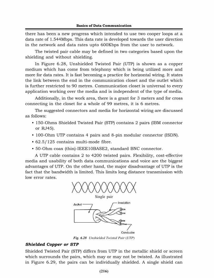
(216)
there has been a new progress which intended to use two cooper loops at adata rate of 1.544Mbps. This data rate is developed towards the user directionin the network and data rates upto 600Kbps from the user to network.
The twisted pair cable may be defined in two categories based upon theshielding and without shielding.
In Figure 6.28, Unshielded Twisted Pair (UTP) is shown as a coppermedium which has come from telephony which is being utilized more andmore for data rates. It is fast becoming a practice for horizontal wiring. It statesthe link between the end in the communication closet and the outlet whichis further restricted to 90 metres. Communication closet is universal to everyapplication working over the media and is independent of the type of media.
Additionally, in the work area, there is a grant for 3 meters and for crossconnecting in the closet for a whole of 99 metres, it is 6 metres.
The suggested connectors and media for horizontal wiring are discussedas follows:
• 150-Ohms Shielded Twisted Pair (STP) contains 2 pairs (IBM connectoror RJ45).
• 100-Ohm UTP contains 4 pairs and 8-pin modular connector (ISDN).• 62.5/125 contains multi-mode fibre.• 50-Ohm coax (thin)-IEEE10BASE2, standard BNC connector.
A UTP cable contains 2 to 4200 twisted pairs. Flexibility, cost-effectivemedia and usability of both data communications and voice are the biggestadvantages of UTP. On the other hand, the major disadvantage of UTP is thefact that the bandwidth is limited. This limits long distance transmission withlow error rates.
Single pair
Fig. 6.28 Unshielded Twisted Pair (UTP)Shielded Copper or STPShielded Twisted Pair (STP) differs from UTP in the metallic shield or screenwhich surrounds the pairs, which may or may not be twisted. As illustratedin Figure 6.29, the pairs can be individually shielded. A single shield can
Basics of Data Communication
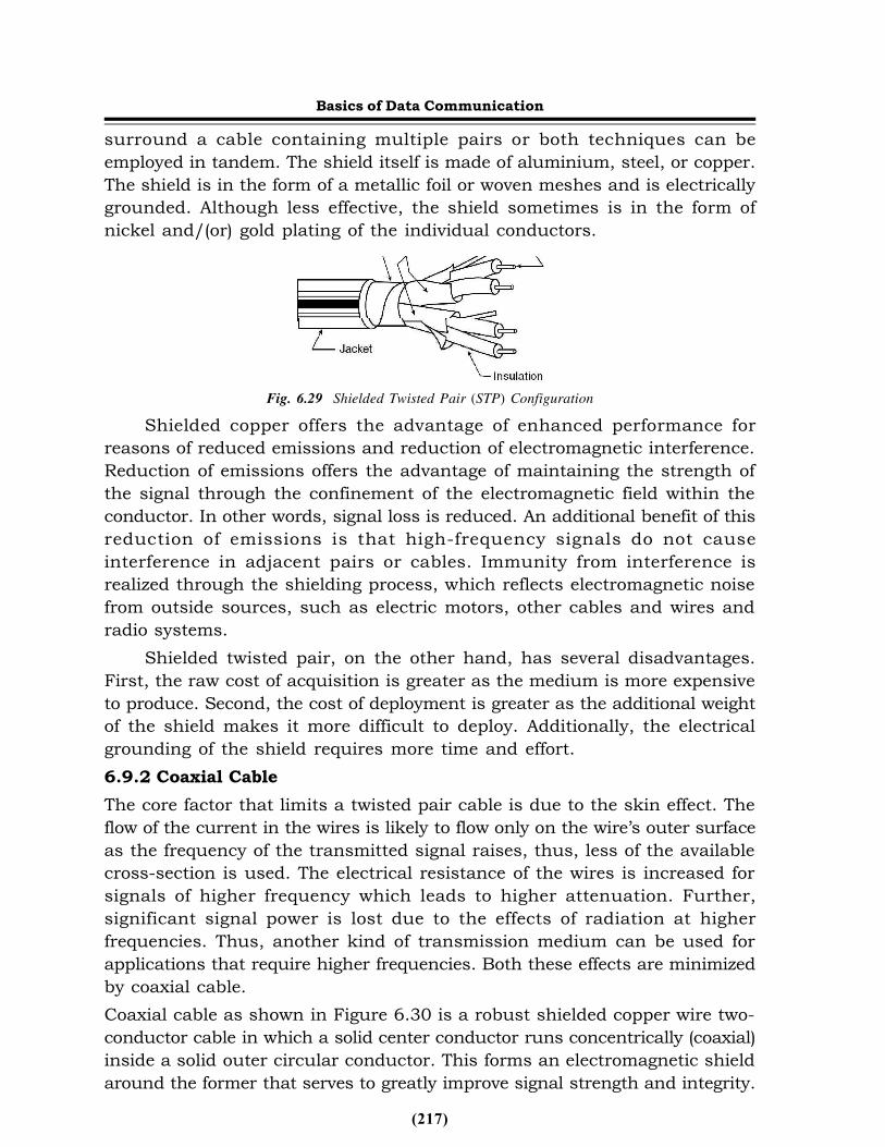
(217)
surround a cable containing multiple pairs or both techniques can beemployed in tandem. The shield itself is made of aluminium, steel, or copper.The shield is in the form of a metallic foil or woven meshes and is electricallygrounded. Although less effective, the shield sometimes is in the form ofnickel and/(or) gold plating of the individual conductors.
Fig. 6.29 Shielded Twisted Pair (STP) ConfigurationShielded copper offers the advantage of enhanced performance for
reasons of reduced emissions and reduction of electromagnetic interference.Reduction of emissions offers the advantage of maintaining the strength ofthe signal through the confinement of the electromagnetic field within theconductor. In other words, signal loss is reduced. An additional benefit of thisreduction of emissions is that high-frequency signals do not causeinterference in adjacent pairs or cables. Immunity from interference isrealized through the shielding process, which reflects electromagnetic noisefrom outside sources, such as electric motors, other cables and wires andradio systems.
Shielded twisted pair, on the other hand, has several disadvantages.First, the raw cost of acquisition is greater as the medium is more expensiveto produce. Second, the cost of deployment is greater as the additional weightof the shield makes it more difficult to deploy. Additionally, the electricalgrounding of the shield requires more time and effort.6.9.2 Coaxial CableThe core factor that limits a twisted pair cable is due to the skin effect. Theflow of the current in the wires is likely to flow only on the wire’s outer surfaceas the frequency of the transmitted signal raises, thus, less of the availablecross-section is used. The electrical resistance of the wires is increased forsignals of higher frequency which leads to higher attenuation. Further,significant signal power is lost due to the effects of radiation at higherfrequencies. Thus, another kind of transmission medium can be used forapplications that require higher frequencies. Both these effects are minimizedby coaxial cable.Coaxial cable as shown in Figure 6.30 is a robust shielded copper wire two-conductor cable in which a solid center conductor runs concentrically (coaxial)inside a solid outer circular conductor. This forms an electromagnetic shieldaround the former that serves to greatly improve signal strength and integrity.
Basics of Data Communication
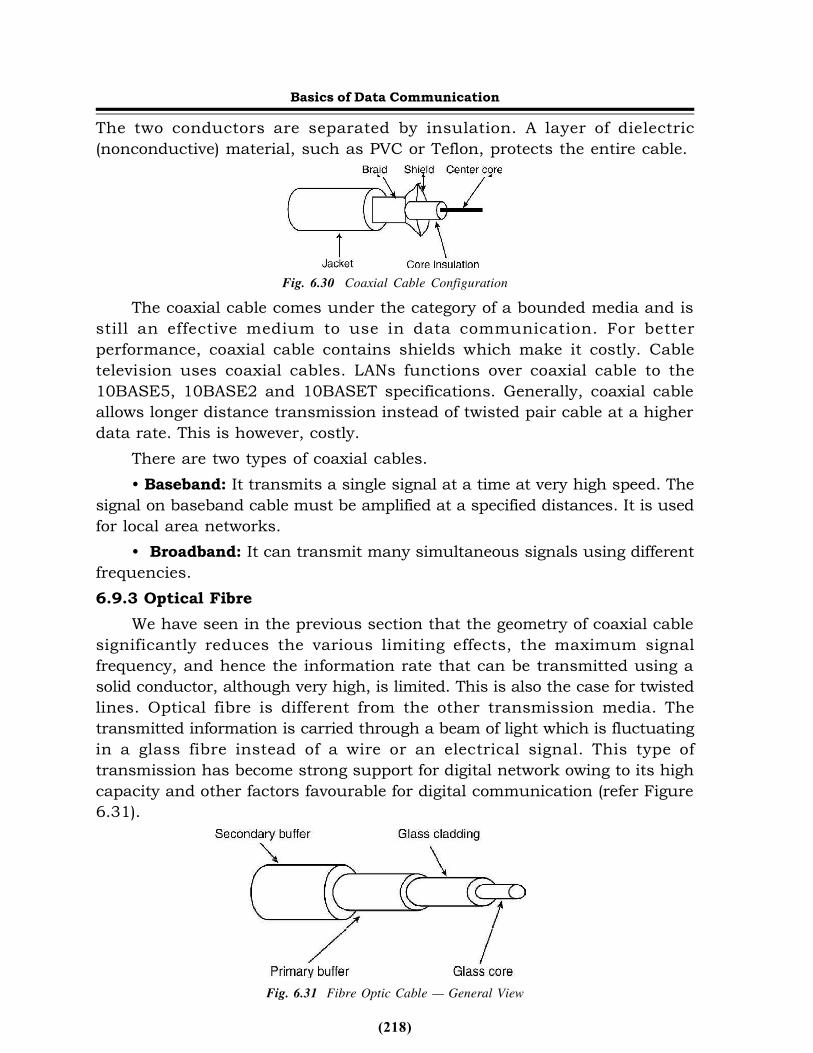
(218)
The two conductors are separated by insulation. A layer of dielectric(nonconductive) material, such as PVC or Teflon, protects the entire cable.
Fig. 6.30 Coaxial Cable ConfigurationThe coaxial cable comes under the category of a bounded media and is
still an effective medium to use in data communication. For betterperformance, coaxial cable contains shields which make it costly. Cabletelevision uses coaxial cables. LANs functions over coaxial cable to the10BASE5, 10BASE2 and 10BASET specifications. Generally, coaxial cableallows longer distance transmission instead of twisted pair cable at a higherdata rate. This is however, costly.
There are two types of coaxial cables.• Baseband: It transmits a single signal at a time at very high speed. The
signal on baseband cable must be amplified at a specified distances. It is usedfor local area networks.
• Broadband: It can transmit many simultaneous signals using differentfrequencies.6.9.3 Optical Fibre
We have seen in the previous section that the geometry of coaxial cablesignificantly reduces the various limiting effects, the maximum signalfrequency, and hence the information rate that can be transmitted using asolid conductor, although very high, is limited. This is also the case for twistedlines. Optical fibre is different from the other transmission media. Thetransmitted information is carried through a beam of light which is fluctuatingin a glass fibre instead of a wire or an electrical signal. This type oftransmission has become strong support for digital network owing to its highcapacity and other factors favourable for digital communication (refer Figure6.31).
Fig. 6.31 Fibre Optic Cable — General View
Basics of Data Communication
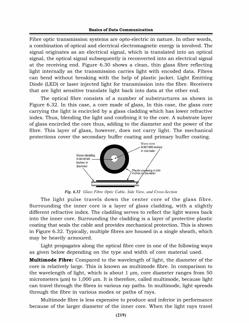
(219)
Fibre optic transmission systems are opto-electric in nature. In other words,a combination of optical and electrical electromagnetic energy is involved. Thesignal originates as an electrical signal, which is translated into an opticalsignal, the optical signal subsequently is reconverted into an electrical signalat the receiving end. Figure 6.30 shows a clean, thin glass fibre reflectinglight internally as the transmission carries light with encoded data. Fibrescan bend without breaking with the help of plastic jacket. Light EmittingDiode (LED) or laser injected light for transmission into the fibre. Receiversthat are light sensitive translate light back into data at the other end.
The optical fibre consists of a number of substructures as shown inFigure 6.32. In this case, a core made of glass, In this case, the glass corecarrying the light is encircled by a glass cladding which has lower refractiveindex. Thus, blending the light and confining it to the core. A substrate layerof glass encircled the core thus, adding to the diameter and the power of thefibre. This layer of glass, however, does not carry light. The mechanicalprotections cover the secondary buffer coating and primary buffer coating.
Fig. 6.32 Glass Fibre Optic Cable, Side View, and Cross-SectionThe light pulse travels down the center core of the glass fibre.
Surrounding the inner core is a layer of glass cladding, with a slightlydifferent refractive index. The cladding serves to reflect the light waves backinto the inner core. Surrounding the cladding is a layer of protective plasticcoating that seals the cable and provides mechanical protection. This is shownin Figure 6.32. Typically, multiple fibres are housed in a single sheath, whichmay be heavily armoured.
Light propagates along the optical fibre core in one of the following waysas given below depending on the type and width of core material used.Multimode Fibre: Compared to the wavelength of light, the diameter of thecore is relatively large. This is known as multimode fibre. In comparison tothe wavelength of light, which is about 1 µm, core diameter ranges from 50micrometers (µm) to 1,000 µm. It is therefore, called multimode, because lightcan travel through the fibres in various ray paths. In multimode, light spreadsthrough the fibre in various modes or paths of rays.
Multimode fibre is less expensive to produce and inferior in performancebecause of the larger diameter of the inner core. When the light rays travel
Basics of Data Communication

(220)
down the fibre, they spread out due to a phenomenon known as modaldispersion. Although reflected back into the inner core by the cladding, theytravel different distances and, therefore, arrive at different times. The receivedsignal thus has a wider pulse width than the input signal with acorresponding decrease in the speed of transmission. As a result, multimodefibre is relegated to applications involving relatively short distances and lowerspeeds of transmission, for example, LANs and campus environments.
Two types of multimode fibres exist. The old and simple sort is the ‘stepindex’ fibre. Here, the refraction index, which is the capability of an objectto bend light, is similar across the fibre core.Step Index Multimode FibreStep index multimode fibre is shown in Figure 6.33. With various means ofpropagation or ray paths, diverse rays traverse various distances, and variedperiods of time for the fibre length to transit are taken. Therefore, in a fibre,if a small pulse of light is infused, the different rays that emanate from theshort pulse will come at the other side of the fibre at various times, and theinput pulse will be of a shorter period of time than the output pulse. This isknown as ‘modal dispersion’ (pulse spreading) which restricts the amountof pulses per second that transmits down the fibre and is recognized asseparate pulses at the different end. Therefore, a bandwidth or bit rate of amultimode fibre is limited. When a bandwidth is around 20 to 30 MHz overone kilometer of a fibre, stated as ‘MHz - km’, there is no effort to compensatefor modal dispersion in case of step index fibres.
Fig. 6.33 Step Index Multimode FibreGraded Index Multimode FibreThe refraction index across the core is altered slowly from the highest at thecenter to the lowest near the edges; therefore, it is termed as the gradedindex. This proves the fact that light passes through rapidly in a low-index-of-refraction material than a high-index material. In the graded index fibre,a short pulse of light is launched which spreads during its transit of the fibre.Therefore, dispersion can be reduced using a core material that has a variablerefractive index. In such multimode graded index fibre light is refracted byan increasing amount as it moves away from the core as shown in Figure 6.34.This results in the narrowing of the pulse width of the received signal in
Basics of Data Communication
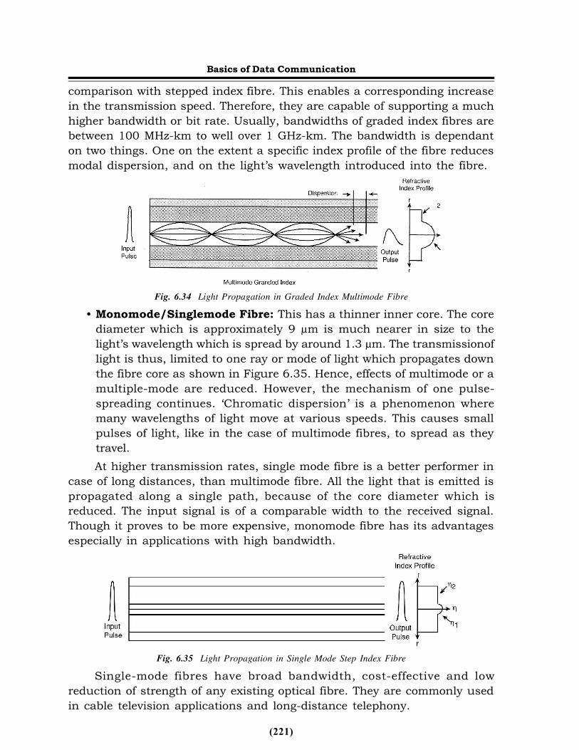
(221)
comparison with stepped index fibre. This enables a corresponding increasein the transmission speed. Therefore, they are capable of supporting a muchhigher bandwidth or bit rate. Usually, bandwidths of graded index fibres arebetween 100 MHz-km to well over 1 GHz-km. The bandwidth is dependanton two things. One on the extent a specific index profile of the fibre reducesmodal dispersion, and on the light’s wavelength introduced into the fibre.
Fig. 6.34 Light Propagation in Graded Index Multimode Fibre• Monomode/Singlemode Fibre: This has a thinner inner core. The core
diameter which is approximately 9 µm is much nearer in size to thelight’s wavelength which is spread by around 1.3 µm. The transmissionoflight is thus, limited to one ray or mode of light which propagates downthe fibre core as shown in Figure 6.35. Hence, effects of multimode or amultiple-mode are reduced. However, the mechanism of one pulse-spreading continues. ‘Chromatic dispersion’ is a phenomenon wheremany wavelengths of light move at various speeds. This causes smallpulses of light, like in the case of multimode fibres, to spread as theytravel.At higher transmission rates, single mode fibre is a better performer in
case of long distances, than multimode fibre. All the light that is emitted ispropagated along a single path, because of the core diameter which isreduced. The input signal is of a comparable width to the received signal.Though it proves to be more expensive, monomode fibre has its advantagesespecially in applications with high bandwidth.
Fig. 6.35 Light Propagation in Single Mode Step Index FibreSingle-mode fibres have broad bandwidth, cost-effective and low
reduction of strength of any existing optical fibre. They are commonly usedin cable television applications and long-distance telephony.
Basics of Data Communication
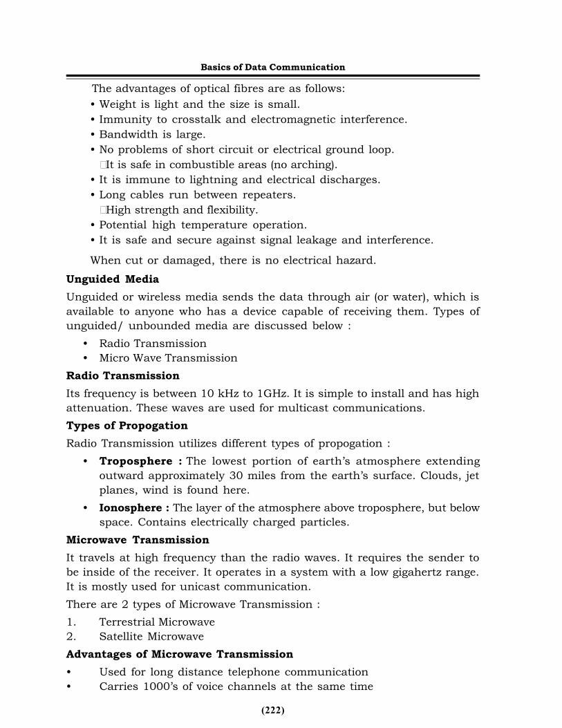
(222)
The advantages of optical fibres are as follows:• Weight is light and the size is small.• Immunity to crosstalk and electromagnetic interference.• Bandwidth is large.• No problems of short circuit or electrical ground loop.It is safe in combustible areas (no arching).
• It is immune to lightning and electrical discharges.• Long cables run between repeaters.High strength and flexibility.
• Potential high temperature operation.• It is safe and secure against signal leakage and interference.When cut or damaged, there is no electrical hazard.
Unguided MediaUnguided or wireless media sends the data through air (or water), which isavailable to anyone who has a device capable of receiving them. Types ofunguided/ unbounded media are discussed below :
• Radio Transmission• Micro Wave Transmission
Radio TransmissionIts frequency is between 10 kHz to 1GHz. It is simple to install and has highattenuation. These waves are used for multicast communications.Types of PropogationRadio Transmission utilizes different types of propogation :
• Troposphere : The lowest portion of earth’s atmosphere extendingoutward approximately 30 miles from the earth’s surface. Clouds, jetplanes, wind is found here.
• Ionosphere : The layer of the atmosphere above troposphere, but belowspace. Contains electrically charged particles.
Microwave TransmissionIt travels at high frequency than the radio waves. It requires the sender tobe inside of the receiver. It operates in a system with a low gigahertz range.It is mostly used for unicast communication.There are 2 types of Microwave Transmission :1. Terrestrial Microwave2. Satellite MicrowaveAdvantages of Microwave Transmission• Used for long distance telephone communication• Carries 1000’s of voice channels at the same time
Basics of Data Communication
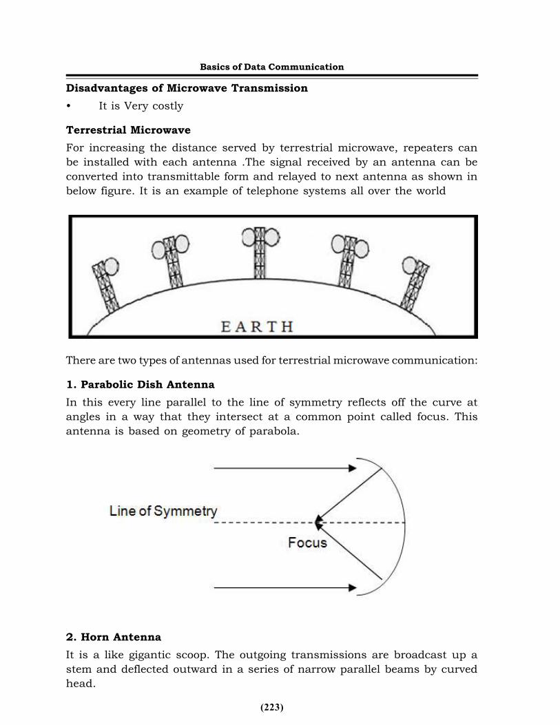
(223)
Disadvantages of Microwave Transmission• It is Very costlyTerrestrial MicrowaveFor increasing the distance served by terrestrial microwave, repeaters canbe installed with each antenna .The signal received by an antenna can beconverted into transmittable form and relayed to next antenna as shown inbelow figure. It is an example of telephone systems all over the world
There are two types of antennas used for terrestrial microwave communication:1. Parabolic Dish AntennaIn this every line parallel to the line of symmetry reflects off the curve atangles in a way that they intersect at a common point called focus. Thisantenna is based on geometry of parabola.
2. Horn AntennaIt is a like gigantic scoop. The outgoing transmissions are broadcast up astem and deflected outward in a series of narrow parallel beams by curvedhead.
Basics of Data Communication
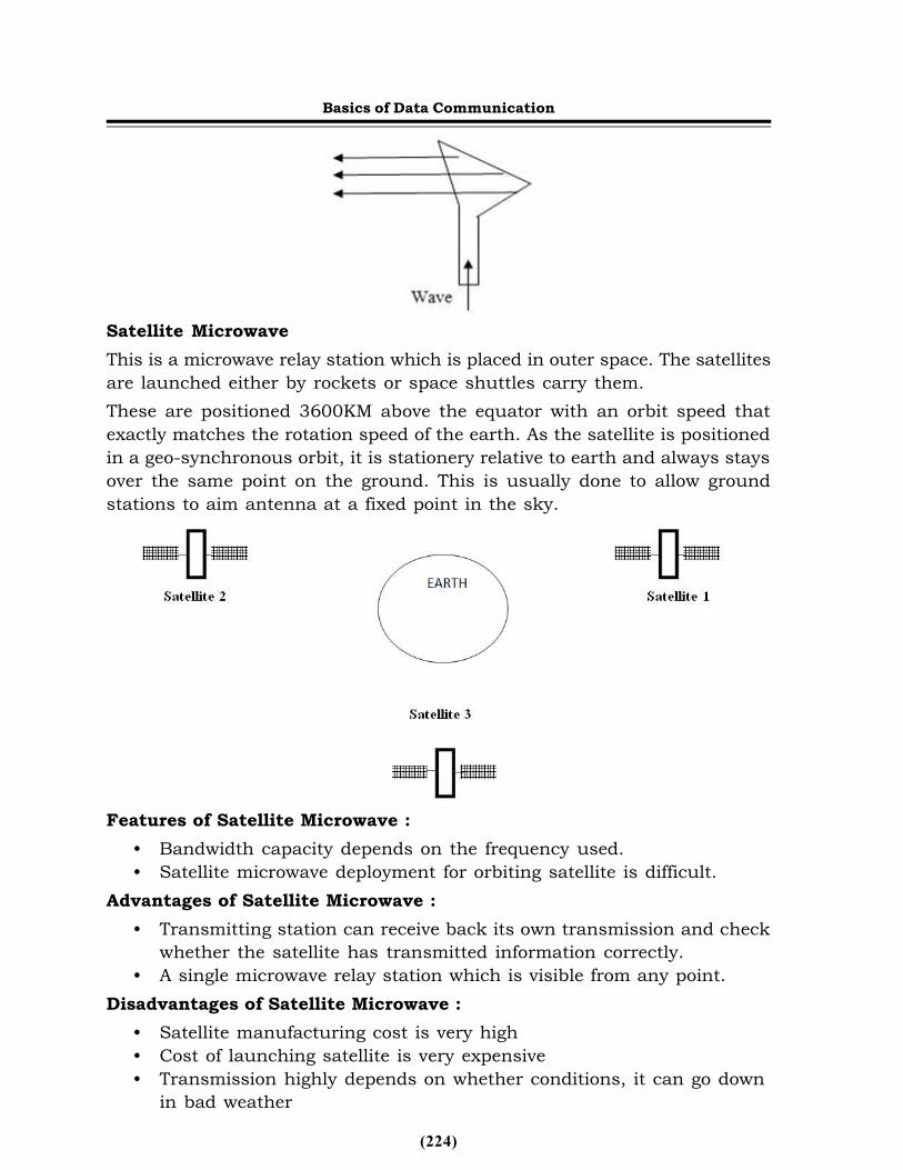
(224)
Satellite MicrowaveThis is a microwave relay station which is placed in outer space. The satellitesare launched either by rockets or space shuttles carry them.These are positioned 3600KM above the equator with an orbit speed thatexactly matches the rotation speed of the earth. As the satellite is positionedin a geo-synchronous orbit, it is stationery relative to earth and always staysover the same point on the ground. This is usually done to allow groundstations to aim antenna at a fixed point in the sky.
Features of Satellite Microwave :• Bandwidth capacity depends on the frequency used.• Satellite microwave deployment for orbiting satellite is difficult.
Advantages of Satellite Microwave :• Transmitting station can receive back its own transmission and check
whether the satellite has transmitted information correctly.• A single microwave relay station which is visible from any point.
Disadvantages of Satellite Microwave :• Satellite manufacturing cost is very high• Cost of launching satellite is very expensive• Transmission highly depends on whether conditions, it can go down
in bad weather
Basics of Data Communication
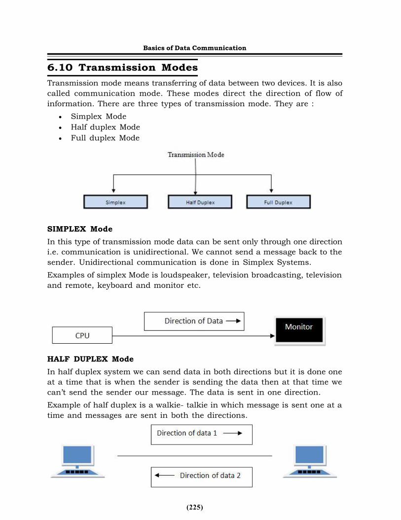
(225)
6.10 Transmission ModesTransmission mode means transferring of data between two devices. It is alsocalled communication mode. These modes direct the direction of flow ofinformation. There are three types of transmission mode. They are :
Simplex Mode Half duplex Mode Full duplex Mode
SIMPLEX ModeIn this type of transmission mode data can be sent only through one directioni.e. communication is unidirectional. We cannot send a message back to thesender. Unidirectional communication is done in Simplex Systems.Examples of simplex Mode is loudspeaker, television broadcasting, televisionand remote, keyboard and monitor etc.
HALF DUPLEX ModeIn half duplex system we can send data in both directions but it is done oneat a time that is when the sender is sending the data then at that time wecan’t send the sender our message. The data is sent in one direction.Example of half duplex is a walkie- talkie in which message is sent one at atime and messages are sent in both the directions.
Basics of Data Communication
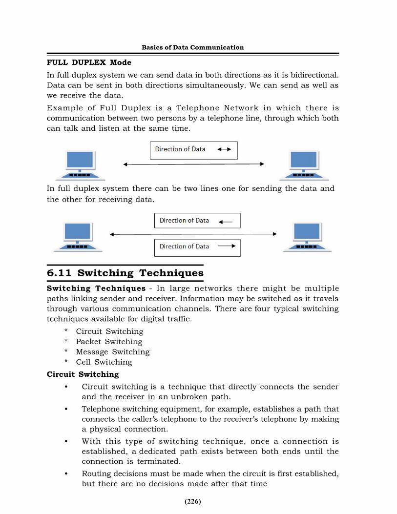
(226)
FULL DUPLEX ModeIn full duplex system we can send data in both directions as it is bidirectional.Data can be sent in both directions simultaneously. We can send as well aswe receive the data.Example of Full Duplex is a Telephone Network in which there iscommunication between two persons by a telephone line, through which bothcan talk and listen at the same time.
In full duplex system there can be two lines one for sending the data andthe other for receiving data.
6.11 Switching TechniquesSwitching Techniques - In large networks there might be multiplepaths linking sender and receiver. Information may be switched as it travelsthrough various communication channels. There are four typical switchingtechniques available for digital traffic.
* Circuit Switching* Packet Switching* Message Switching* Cell Switching
Circuit Switching• Circuit switching is a technique that directly connects the sender
and the receiver in an unbroken path.• Telephone switching equipment, for example, establishes a path that
connects the caller’s telephone to the receiver’s telephone by makinga physical connection.
• With this type of switching technique, once a connection isestablished, a dedicated path exists between both ends until theconnection is terminated.
• Routing decisions must be made when the circuit is first established,but there are no decisions made after that time
Basics of Data Communication
(227)
• Circuit switching in a network operates almost the same way as thetelephone system works.
• A complete end-to-end path must exist before communication cantake place.
• The computer initiating the data transfer must ask for a connectionto the destination.
• Once the connection has been initiated and completed to thedestination device, the destination device must acknowledge that itis ready and willing to carry on a transfer.
Advantages:• The communication channel (once established) is dedicated.
Disadvantages:• Possible long wait to establish a connection, (10 seconds, more on
long- distance or international calls.) during which no data can betransmitted.
• More expensive than any other switching techniques, becausea dedicated path is required for each connection.
• Inefficient use of the communication channel, because the channelis not used when the connected systems are not using it.
Packet Switching* Packet switching can be seen as a solution that tries to combine the
advantages of message and circuit switchingand to minimize thedisadvantages of both.
* There are two methods of packet switching: Datagram and virtualcircuit.
* In both packet switching methods, a message is broken into smallparts, called packets.
* Each packet is tagged with appropriate source and destinationaddresses.
* Since packets have a strictly defined maximum length, they canbe stored in main memory instead of disk; therefore access delayand cost are minimized.
* Also the transmission speeds, between nodes, are optimized.* With current technology, packets are generally accepted onto the
network on a first-come, first-served basis. If the network becomesoverloaded, packets are delayed or discarded (“dropped”).The size of the packet can vary from 180 bits, the size for the Datakit virtual circuit switch designed by Bell Labsfor communications
Basics of Data Communication
(228)
and business applications; to 1,024 or 2,048 bits for the 1PSSswitch, also designed by Bell Labs for public data networking; to 53bytes for ATM switching, such as Lucent Technologies’ packetswitches
* In packet switching, the analog signal from your phone is convertedinto a digital data stream. That series of digital bits is then dividedinto relatively tiny clusters of bits, called packets. Each packet hasat its beginning the digital address — a long number — to which itis being sent. The system blasts out all those tiny packets, as fastas it can, and they travel across the nation’s digital backbonesystems to their destination: the telephone, or rather the telephonesystem, of the person you’re calling.
* They do not necessarily travel together; they do not travelsequentially. They don’t even all travel via the same route.But eventually they arrive at the right point — that digital addressadded to the front of each string of digital data — and at theirdestination are reassembled into the correct order, then convertedto analog form, so your friend can understand what you’re saying.
* Datagram packet switching is similar to message switching in thateach packet is a self-contained unit with completeaddressing information attached.
* This fact allows packets to take a variety of possible paths throughthe network.
* So the packets, each with the same destination address, do not followthe same route, and they may arrive out of sequence at the exit pointnode (or the destination).
* Reordering is done at the destination point based on the sequencenumber of the packets.
* It is possible for a packet to be destroyed if one of the nodes on itsway is crashed momentarily. Thus all its queued packets may be lost.
* In the virtual circuit approach, a preplanned route is establishedbefore any data packets are sent.
* A logical connection is established when a sender send a “callrequest packet” to the receiver and the receiver send back anacknowledge packet “call accepted packet” to the sender if thereceiver agrees on conversational parameters.
• The conversational parameters can be maximum packet sizes, pathto be taken, and other variables necessary to establish and maintainthe conversation.
Basics of Data Communication
(229)
• Virtual circuits imply acknowledgements, flow control, and errorcontrol, so virtual circuits are reliable. That is, they have thecapability to inform upper-protocol layers if a transmission problemoccurs
• In virtual circuit, the route between stations does not mean that thisis a dedicated path, as in circuit switching.
* A packet is still buffered at each node and queued for output overa line.
• The difference between virtual circuit and datagram approaches:* With virtual circuit, the node does not need to make a routing
decision for each packet.* It is made only once for all packets using that virtual circuit. VC’s
offer guarantees that the packets sent arrive in the order sent withno duplicates or omissions with no errors (with high probability)regardless of how they are implemented internally
Advantages:• Packet switching is cost effective, because switching devices do not
need massive amount of secondary storage.• Packet switching offers improved delay characteristics, because there
are no long messages in the queue (maximum packet size is fixed).• Packet can be rerouted if there is any problem, such as, busy or
disabled links.* The advantage of packet switching is that many network users can
share the same channel at the same time. Packet switching canmaximize link efficiency by making optimal use of link bandwidth.
Disadvantages:• Protocols for packet switching are typically more complex.• It can add some initial costs in implementation.• If packet is lost, sender needs to retransmit the data. Another
disadvantage is that packet-switched systems still can’t deliver thesame quality as dedicated circuits in applications requiring very littledelay - like voice conversations or moving images.
Message Switching• With message switching there is no need to establish a dedicated
path between two stations.• When a station sends a message, the destination address is
appended to the message.• The message is then transmitted through the network, in its
entirety, from node to node.
Basics of Data Communication
(230)
• Each node receives the entire message, stores it in its entirety ondisk, and then transmits the message to the next node.
• This type of network is called a store-and-forward network.A message-switching node is typically a general-purpose computer.The device needs sufficient secondary-storage capacity to store theincoming messages, which could be long. A time delay is introducedusing this type of scheme due to store- and-forward time, plus thetime required to find the next node in the transmission path.
Advantages:• Channel efficiency can be greater compared to circuit-switched
systems, because more devices are sharing the channel.• Traffic congestion can be reduced, because messages may be
temporarily stored in route.• Message priorities can be established due to store-and-forward
technique.• Message broadcasting can be achieved with the use of broadcast
address appended in the messageDisadvantages
• Message switching is not compatible with interactive applications.• Store-and-forward devices are expensive, because they must have
large disks to hold potentially long messagesCell Switching
Cell Switching is similar to packet switching, except that the switchingdoes not necessarily occur on packet boundaries. This is ideal for anintegrated environment and is found within Cell-based networks, suchas ATM. Cell-switching can handle both digital voice and data signals.
6.12 IP AddressesEvery computer on network requires an IP address to communicate with
other computer. An IP is a 32-bit number comprised of a host number anda network prefix, both of which are used to uniquely identify each nodewithin a network.
To make these addresses more readable, they are broken up into 4 bytes,or octets, where any 2 bytes are separated by a period. This is commonlyreferred to as dotted decimal notation.
The first part of an Internet address identifies the network on which thehost resides, while the second part identifies the particular host on the givennetwork. This creates the two-level addressing hierarchy.
All hosts on a given network share the same network prefix but must
Basics of Data Communication
(231)
have a unique host number. Similarly, any two hosts on different networksmust have different network prefixes but may have the same host number.
Here is a simple example of an IP address: 192.168.1.1An additional value, called a subnet mask, determines the boundary
between the network and host components of an address.Subnet masks are 32 bits long and are typically represented in dotted-
decimal (such as 255.255.255.0) or the number of networking bits (such as/24). The networking bits in a mask must be contiguous and the host bitsin the subnet mask must be contiguous. 255.0.255.0 is an invalid mask. Asubnet mask is used to mask a portion of the IP address, so that TCP/IP cantell the difference between the network ID and the host ID. TCP/IP uses thesubnet mask to determine whether the destination is on a local or remotenetwork.
Class A subnet mask 255.0.0.0 Class B subnet mask 255.255.0.0 Class C subnet mask 255.255.255.0When dealing with IP addresses, the address is broken into two
components: Network component Defines on what segment, in the network, a
device is located Host component Defines the specific device on a particular network
segmentThe network number uniquely identifies a segment in the network and
a host number uniquely identifies a device on a segment. The combinationof these two numbers must be unique throughout the entire network.
IP addresses are divided in five class.Class A addresses range from 1-126Class B addresses range from 128-191Class C addresses range from 192-223Class D addresses range from 224-239Class E addresses range from 240-2540 is reserved and represents all IP addresses;127 is a reserved address and is used for loop back tasting:255 is a reserved address and is used for broadcasting purposes.It is fairly easy to predict what address belongs to what class. Simply
look at the first number in the dotted-decimal notation and see which rangeit falls into.For example
IP address 159.123.12.2 belongs to class B because 159 [Firstnumber] falls in range 128 - 191
Basics of Data Communication
(232)
IP address 15.12.12.6 belongs to class A because 15 [First number]falls in range 1 - 126
IP address 192.168.1.2 belongs to class C because 192 [Firstnumber] falls in range 192 - 223
When you are dealing with IP addresses, two numbers are alwaysreserved for each network number:
The first address in the network represents the network’s address, andthe last address in the network represents the broadcast address for thisnetwork, called directed broadcast.
When you look at IP itself, two IP addresses are reserved: 0.0.0.0 (thevery first address), which represents all IP addresses, and 255.255.255.255(the very last address), which is the local broadcast address.
As to assigning addresses to devices, two general types of addresses canbe used: public and private.Public addresses
Public addresses are Class A, B, and C addresses that can be used toaccess devices in other public networks, such as the Internet.Private Addresses
Within the range of addresses for Class A, B, and C addresses are somereserved addresses, commonly called private addresses. Anyone can useprivate addresses; however, this creates a problem if you want to access theInternet. Remember that each device in the network (in this case, thisincludes the Internet) must have a unique IP address. If two networks areusing the same private addresses, you would run into reachability issues.To access the Internet, your source IP addresses must have a unique Internetpublic address. This can be accomplished through address translation. Hereis a list of private addresses.
Class A: 10.0.0.0–10.255.255.255 (1 Class A network)Class B: 172.16.0.0–172.31.255.255 (16 Class B networks)Class C: 192.168.0.0–192.168.255.255 (256 Class C networks)IP (Internet Protocol) addressing methods:
Static /DynamicEach device in an IP network is either assigned a permanent address
(static) by the network administrator or is assigned a temporary address(dynamic) via DHCP software. Routers, firewalls and proxy servers use staticaddresses as do most servers and printers that serve multiple users. Clientmachines may use static or dynamic IP addresses. The IP address assignedto your service by your cable or DSL Internet provider is typically dynamicIP. In routers and operating systems, the default configuration for clients isdynamic IP.
Basics of Data Communication
(233)
DHCPDHCP stands for Dynamic Host Configuration Protocol. This protocol
assigns network IP addresses to clients on the network at startup. With DHCP,each client workstation does not need to be set up with a static IP address.DHCP is recommended on large networks. It would be very time consumingto manually assign a static IP address to every workstation on your network.With static IP addressing, the IP address that you assign to a device neverchanges. A DHCP server contains a pool of IP addresses that it can draw fromto assign to devices that are connecting to the network. Other TCP/IPproperties, such as default gateways, DNS servers, and subnet masks canalso be assigned automatically.IPv6
Network industry is moving to adopt new version of IPv6. IPv6 have severalnew features.6.13 DNS PortsDNS PortsA port, in computer networking, is considered as application-specific orprocess-specific software that builds function for a communication endpointutilized by Transport Layer Protocols (TLP) of the Internet Protocol (IP) suitenamely Transmission Control Protocol (TCP) and User Datagram Protocol(UDP). A specific port is recognized by its number termed as the port number,the associated IP address and the communication protocol. DNS helps to lookup names and IP addresses. A port number is a 16-bit unsigned integer thatranges from 0 to 65535. The port numbers are categorized into the followingthree ranges:
• Well-known ports• Registered ports• Dynamic or private ports
The port numbers 0 through 1023 are termed as well-known ports. Thefollowing are important well-known ports:
• 23: Telnet• 53: Domain Name System• 80: World Wide Web HTTP• 119: Network News Transfer Protocol• 443: HTTP over Transport Layer Security/Secure Sockets Layer• 445: Microsoft-DS (Microsoft Directory Service), Server Message Block
over TCP
Basics of Data Communication
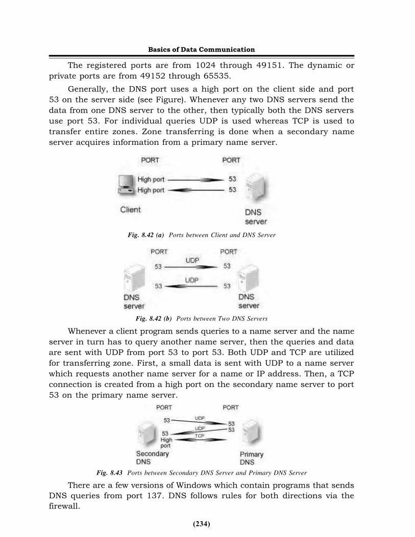
(234)
The registered ports are from 1024 through 49151. The dynamic orprivate ports are from 49152 through 65535.
Generally, the DNS port uses a high port on the client side and port53 on the server side (see Figure). Whenever any two DNS servers send thedata from one DNS server to the other, then typically both the DNS serversuse port 53. For individual queries UDP is used whereas TCP is used totransfer entire zones. Zone transferring is done when a secondary nameserver acquires information from a primary name server.
Fig. 8.42 (a) Ports between Client and DNS Server
Fig. 8.42 (b) Ports between Two DNS ServersWhenever a client program sends queries to a name server and the name
server in turn has to query another name server, then the queries and dataare sent with UDP from port 53 to port 53. Both UDP and TCP are utilizedfor transferring zone. First, a small data is sent with UDP to a name serverwhich requests another name server for a name or IP address. Then, a TCPconnection is created from a high port on the secondary name server to port53 on the primary name server.
Fig. 8.43 Ports between Secondary DNS Server and Primary DNS ServerThere are a few versions of Windows which contain programs that sends
DNS queries from port 137. DNS follows rules for both directions via thefirewall.
Basics of Data Communication
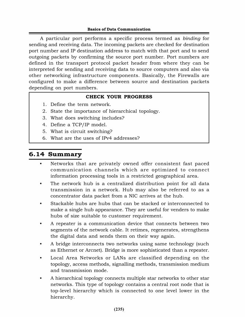
(235)
A particular port performs a specific process termed as binding forsending and receiving data. The incoming packets are checked for destinationport number and IP destination address to match with that port and to sendoutgoing packets by confirming the source port number. Port numbers aredefined in the transport protocol packet header from where they can beinterpreted for sending and receiving data to source computers and also viaother networking infrastructure components. Basically, the Firewalls areconfigured to make a difference between source and destination packetsdepending on port numbers.
CHECK YOUR PROGRESS1. Define the term network.2. State the importance of hierarchical topology.3. What does switching includes?4. Define a TCP/IP model.5. What is circuit switching?6. What are the uses of IPv4 addresses?
6.14 Summary• Networks that are privately owned offer consistent fast paced
communication channels which are optimized to connectinformation processing tools in a restricted geographical area.
• The network hub is a centralized distribution point for all datatransmission in a network. Hub may also be referred to as aconcentrator data packet from a NIC arrives at the hub.
• Stackable hubs are hubs that can be stacked or interconnected tomake a single hub appearance. They are useful for venders to makehubs of size suitable to customer requirement.
• A repeater is a communication device that connects between twosegments of the network cable. It retimes, regenerates, strengthensthe digital data and sends them on their way again.
• A bridge interconnects two networks using same technology (suchas Ethernet or Arcnet). Bridge is more sophisticated than a repeater.
• Local Area Networks or LANs are classified depending on thetopology, access methods, signalling methods, transmission mediumand transmission mode.
• A hierarchical topology connects multiple star networks to other starnetworks. This type of topology contains a central root node that istop-level hierarchy which is connected to one level lower in thehierarchy.
Basics of Data Communication
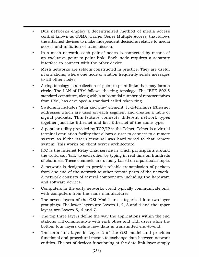
(236)
• Bus networks employ a decentralized method of media accesscontrol known as CSMA (Carrier Sense Multiple Access) that allowsthe attached devices to make independent decisions relative to mediaaccess and initiation of transmission.
• In a mesh network, each pair of nodes is connected by means ofan exclusive point-to-point link. Each node requires a separateinterface to connect with the other device.
• Mesh networks are seldom constructed in practice. They are usefulin situations, where one node or station frequently sends messagesto all other nodes.
• A ring topology is a collection of point-to-point links that may form acircle. The LAN of IBM follows the ring topology. The IEEE 802.5standard committee, along with a substantial number of representativesfrom IBM, has developed a standard called token ring.
• Switching includes ‘plug and play’ element. It determines Ethernetaddresses which are used on each segment and creates a table ofsignal packets. This feature connects different network typestogether just like Ethernet and fast Ethernet of the same types.
• A popular utility provided by TCP/IP is the Telnet. Telnet is a virtualterminal emulation facility that allows a user to connect to a remotesystem as if the user’s terminal was hard wired to that remotesystem. This works on client server architecture.
• IRC is the Internet Relay Chat service in which participants aroundthe world can ‘talk’ to each other by typing in real time on hundredsof channels. These channels are usually based on a particular topic.
• A network is designed to provide reliable transmission of packetsfrom one end of the network to other remote parts of the network.A network consists of several components including the hardwareand software devices.
• Computers in the early networks could typically communicate onlywith computers from the same manufacturer.
• The seven layers of the OSI Model are categorized into two-layergroupings. The lower layers are Layers 1, 2, 3 and 4 and the upperlayers are Layers 5, 6 and 7.
• The top three layers define the way the applications within the endstations will communicate with each other and with users while thebottom four layers define how data is transmitted end-to-end.
• The data link layer is Layer 2 of the OSI model and providesfunctional and procedural means to exchange data between networkentities. The set of devices functioning at the data link layer simply
(237)
supports the functionalities of networking instead of internetworking.
The session layer is the lowest of the three upper layers and dealsmainly with software application issues only. It helps enable devices toestablish and manage sessions.6.15 Key Terms
• Server: It is the most powerful computer of the network, usually apowerful microcomputer or a super microcomputer with the power of aminicomputer is used as a server
• Workstation: An individual computer with capabilities to communicatewith other machines
• Network interface unit: The role of Network Interface Unit or NIU is tomove the serial signals on the network cables or media into parallel datastream inside the PC
• Control frames: Control frames are frames used for controlling andmaintaining the logical ring
6.16 Questions for ExerciseShort-Answer Questions
1. Define the term computer networks.2. List the components of a network.3. What is the difference between LAN, Man and WAN.4. Define the term switching techniques.5. List the transmission modes.
Long-Answer Questions1. Discuss the various LAN topologies with the help of an example of
each type.2. Describe the OSI reference model with the help of a diagram.3. Explain the significance of TCP layer with the help of a diagram.4. Discuss the switching techniques with the help of examples.
6.17 Further ReadingsITL Education Solutions Limited. Introduction to Computer Science,2nd edition. United Kingdom: Pearson.Jaiswal, A. Fundamentals of Computer and Information Technology.New Delhi: Dreamtech Press.