bank of india
TRANSCRIPT

BANK OF INDIA
STAR HOUSE-2, 3RD FLOOR, PREMISES DEPARTMENT, C-4, G-BLOCK, BANDRA KURLA COMPLEX, BANDRA (E), MUMBAI-400051
TENDER DOCUMENT FOR
RESIDENTIAL BUILDING FOR BANK OF INDIA ON CTS NOS. 2292B & 2156/B AT VILLAGE DAHISAR, TAL. BORIVALI, MUMBAI.
Event No. BOI/Mumbai/Premises/4/21-22/ET/5
VOLUME-II Technical Specifications
CLIENT GENERAL MANAGER,
PREMISES DEPARTMENT 3rd FLOOR, STAR HOUSE 2, BKC
BANK OF INDIA Ph: 022-61317529
ARCHITECT & PROJECT MANAGEMENT CONSULTANTS
M/S ARK DESIGNS PVT LIMITED. ARCHITECTS, DESIGNERS AND PROJECT MANAGEMENT CONSULTANTS
101, Anish Tower CHS LTD., Senapati Bapat Marg, Matunga West, Mumbai
Detailed Technical
Specifications
DISMANTLING AND DEMOLISHING TERMINOLOGY (i) Dismantling: The term ‘Dismantling’ implies carefully separating the parts without damage and removing. This may consist of dismantling one or more parts of the building as specified or shown on the drawings. (ii) Demolition: The term ‘Demolition’ implies breaking up. This shall consist of demolishing whole or part of work including all relevant items as specified or shown on the drawings. 1 GENERAL this chapter relates to buildings only. 1.1 Precautions 1.1.1 All materials obtained from dismantling or demolition shall be the property of the Government unless otherwise specified and shall be kept in safe custody until they are handed over to the Engineering-Charge/ authorized representative. 1.1.2 The demolition shall always be well planned before hand and shall generally be done in reverse order of the one in which the structure was constructed. The operations shall be got approved from the Engineer-in-Charge before starting the work. Due care shall be taken to maintain the safety measures prescribed in IS 4130. 1.1.3 Necessary propping, shoring and or under pinning shall be provided to ensure the safety of the adjoining work or property before dismantling and demolishing is taken up and the work shall be carried out in such a way that no damage is caused to the adjoining work or property. Wherever specified, temporary enclosures or partitions and necessary scaffolding with suitable double scaffolding and proper cloth covering shall also be provided, as directed by the Engineer-in-Charge. 1.1.4 Necessary precautions shall be taken to keep noise and dust nuisance to the minimum. All work needs to be done under the direction of Engineer-in-Charge. Helmets, goggle, safety belts etc. should be used whenever required and as directed by the Engineer-in-Charge. The demolition work shall be proceeded with in such a way that it causes the least damage and nuisance to the adjoining building and the public. 1.1.5 Dismantling shall be done in a systematic manner. All materials which are likely to be damaged by dropping from a height or by demolishing roofs, masonry etc. shall be carefully removed first. Chisels and cuters may be used carefully as directed. The dismantled articles shall be removed manually or otherwise, lowered to the ground (and not thrown) and then properly stacked as directed by the Engineer-in-Charge. 1.1.6 Where existing fixing is done by nails, screws, bolts, rivets, etc., dismantling shall be done by taking out the fixing with proper tools and not by tearing or ripping off. 1.1.7 Any serviceable material, obtained during dismantling or demolition, shall be separated out and
stacked properly as directed by the Engineer-in-Charge within a lead of 50 metres. All unserviceable materials, rubbish etc. shall be disposed off as directed by the Engineer-in-Charge. 1.1.8 The contractor shall maintain/disconnect existing services, whether temporary or permanent, where required by the Engineer-in-Charge. 1.1.9 No demolition work should be carried out at night especially when the building or structure to be demolished is in an inhabited area. 625 SUB HEAD 15.0 : DISMANTLING AND DEMOLISHING 1.1.10 Screens shall be placed where necessary to prevent injuries due to falling pieces. 1.1.11 Water may be used to reduce dust while tearing down plaster from brick work. 1.1.12 Safety belts shall be used by labourers while working at higher level to prevent falling from the structure. 1.1.13 First-aid equipment shall be got available at all demolition works of any magnitude.
EXCAVATION
1.0 INDIAN STANDARDS All relevant Standards as specified elsewhere in this Volume are applicable. Indian Standards to be followed are: 1) IS 1498 Classification and identification of soils for general engineering
purpose.
2) IS 3764 Safety code for excavation Work 3) IS 4081 Safety code for blasting and related drilling operation. 4) IS 6313 Part –1 Code of practice for anti-termite measures in
buildings: constructional measures. Part –2 Code of practice for anti-termite measures in buildings: Pre constructional chemical treatment measures.
5) SP 27 Handbook of method of measurement of buildings works.
6) Explosive Rules 1940. 2.0 SITE CLEARANCE 2.1 Prior to the start of any activity of earth work the area under construction shall be cleared of
shrubs, vegetation, grass, brushwood, trees and saplings of girth up to 30cm measured at a
height of 1 meter above ground level. All rubbish must be removed and stacked at distance of
50 cm outside the periphery of the area clearance or location as decided by the EIC.
2.2 The rate of such clearance is to be included in the rate of other earthwork items.
3.0 SITE CONDITIONS AND CONSTRAINTS
3.1 Prior to the submission of the tender, the Contractor is required and deemed to have visited the
Site to fully acquaint himself as to the nature, extent and practicability of the excavation,
earthworks or associated temporary works. The Contractor shall satisfy himself as to the
nature, extent and practicability of the excavation, earthworks or associated temporary works.

The Contractor shall satisfy himself that the existing ground and/or formation levels as shown
on the drawings are correct.
3.2 The award of the Contract shall be based on the understanding that the Contractor is familiar
with the geology of the Site. He shall include in his tender for all costs arising from the nature of
the ground (ground levels, water table level, subsoil conditions etc), climatic conditions, the
availability or lack of access, working space, storage, accommodation, the proximity of adjoining
structures and roads, the local Regulations regarding the obstruction of public highways and any
other limitation imposed by the Site and its surroundings, for the satisfactory completion of the
excavation and earthworks. He shall make due allowance for the effect of these constraints on
his construction operations to ensure on-time completion of the Works. No claim by the
Contractor on the grounds of lack of foresight or knowledge of the site conditions or for under-
provision in connection with the Works will be considered.
3.3 The Contractor shall ensure that his method of excavation is suitable and safe for use at the Site.
The Contractor shall indemnify the Employer against any expense, liability, loss, claim or
proceedings which the Employer may incur or sustain by reason of damage to any property real
or personal other than works, injury or accident to workmen or public, caused by collapse,
subsidence, vibration, weakening or removal of support or lowering of ground water, arising out
of or in the course of or by reason of the excavation of the Works.
4.0 SITE ACCESS
4.1 The Contractor shall be responsible for obtaining all necessary statutory approvals on temporary
access into the Site for the currency of the contract period. He shall comply strictly and
diligently with all conditions attached with these approvals. The access as well as the portion of
public road and walkway connected with it shall be kept clean and safe at all times. Continuous
and adequate security arrangements at access points into the site shall be provided for the full
duration of the contract.
5.0 SUBSOIL DATA
5.1 A soil report for the Site is available to the Contractor for his information. The report is
intended solely as a preliminary and approximate guide to the nature of ground stratification as
the Engineer knows it. The completeness and the accuracy of the information provided is
neither guaranteed nor implied. No responsibility is assumed by the Employer or the Engineer
for any opinion or conclusion given in the soil report.
5.2 The soil report limits itself to identified subsurface conditions only at selected points where soil
samples were taken, when they were taken. The actual conditions in areas not sampled may
differ from the reported findings. Continuing adequacy of the report may be affected by time,
construction operations at or adjacent to the site and by natural events such as floods and
groundwater fluctuations.
5.3 Given the limitations attached to the soil report, the Contractor shall be obliged to place his own
interpretation on the information provided and include in his tender for the cost of providing all
things necessary to ensure the satisfactory completion and the safety of the excavation and
earthworks, such as supplemental soil investigation and adding, upgrading, strengthening,
adapting, modifying, taking down and refixing of temporary works, etc. He shall assess the
limitations of the soil report and make due allowance in his construction operations to ensure
the on-time completion of the Works. No extra time or payment will be considered at a later
date on the grounds of under-provision in the excavation, earthworks or associated temporary
works, incomplete or incorrect information contained in the soil report, or want of knowledge of
foresight.
5.4 The Contractor shall make his own verification of water table level at the Site. No claims will be
considered for any special pumping or baling required in connection with work below the water
table level. The Contractor shall allow in the tender for the cost for any extra supports required
to excavate below the water table level.
5.5 Details and results of all supplemental soil investigation, which the Contractor undertakes in the
course of the Works, shall be made available to the Engineer for his record.

6.0 PROTECTION OF PUBLIC AND PRIVATE SERVICES
6.1 Contractor shall be responsible for detecting, protecting, upholding, up keeping and maintaining
all existing services such as roadside drains, mains, ducts, water supply pipes, sewers, gas
conduits, electrical and telephone cables and the like over and adjacent to the Site during the
currency of the contract, regardless whether or not these services are known to exist at the time
of tender. He shall take extra precautions to prevent undermining of foundations to service
lines, thereby resulting in damage and interruption of supply, and make good any damage due
to any cause within his control at his own expense and time, and/or pay all consequential costs
and charges in connection therewith.
6.2 In the event that damage has been done to services due to the Contractor’s work or any cause
within his control, and should these repairs be carried out by the local Authority, the Contractor
shall make a direct reimbursement to the local Authority for the cost and charges for carrying
out the repairs, failing which the Employer reserves the right to pay the local Authority direct
and deduct the same from any monies due or becoming due to the Contractor.
6.3 Any information made available to the Contractor at the time of the tender is indicative and is
intended only as an approximate guide for the Contractor’s own verification on Site.
Immediately after taking possession of the Site and BEFORE commencing work, the Contractor
shall establish test holes to confirm the locations and levels of all existing underground utilities
within and surrounding the Site that are affected by his excavation works. If the Engineer is of
the opinion that the site verification survey of embedded services is incomplete or inadequate in
any way, he shall order additional confirmatory test holes to be carried out at the Contractor’s
expense. The Contractor shall immediately notify the Engineer and/or the local Authority if he
should encounter services not known to have existed at the time of tender.
6.4 If it becomes essential in the opinion of the Engineer and/or the local Authority to temporarily
or permanently divert any cable, pipe or other service, the Contractor shall give the necessary
notices to the local Authority and arrange for the diversion work to be carried out, regardless
whether or not the service to be diverted is known to exist at the time of tender. The cost of
the diversion will be paid for by the Employer but it shall be the Contractor’s responsibility to
coordinate all service diversion works that are carried out within the currency of the contract
period and ensure that such works do not adversely affect the on-time completion of the Works,
falling which the Contractor shall bear all consequences for any delay incompletion of the Works
due to any cause within his control.
7.0 STABILITY AND SETTLEMENT OF ADJACENT PROPERTIES
7.1 Where foundations or related earthworks are proposed to be constructed or carried out
adjacent to any premises, an investigation of the site shall be undertaken by the Contractor’s
Professional Engineer to establish, to the satisfaction of the Building Authority, the type and
character of the ground on which the foundation or earthworks are to be constructed or carried
out. The report of any investigation carried out by the Contractor’s Professional Engineer shall
contain recommendations on the measures to be taken in connection with the construction of
the foundations or related earthworks so as to prevent any settlement or other movement
which may impair the stability of or cause damage to the whole or part of any adjoining
premises or building.
7.2 The contractor shall be solely responsible for the stability of all adjoining structures and
facilities. The method of construction adopted by the contractor for the execution of the
excavation, earthworks and associated temporary works shall be such that public roadways,
private access roads, undergrounds utilities, principal buildings and permanent facilities in
adjoining properties are adequately protected from the detrimental effects of instability and
ground subsidence.
7.3.1 The contractor shall be required to assess the settlements and ground movements that he
anticipates will occur around the site boundaries due to the excavation work. His calculations
and assumptions on which these assessments will be made shall form a part of his submission to
the local Authority for the purpose of obtaining statutory clearance and securing the permit to
commence work. A copy of such calculations and assumptions shall be made available to the
Engineer for his record.
8.0 LIMITS ON GROUND MOVEMENT
8.1 The contractor shall be responsible for restricting the maximum settlement and lateral
movement of the ground adjacent to the site to the lesser of either the statutory limit imposed
by the local Authority or 50 mm, measured from the initial pre-construction reference level or
line. The contractor’s compliance to these limits shall not relieve him of his sole responsibility to
make good at his own cost and in the manner prescribed by the Engineer and/or the local
Authority, all consequential damages to adjoining structures roads and other properties arising
from ground movements caused by excavation work.
9.0 SETTING OUT 9.1 Bench Marks and Reference Lines shall be finalized by the EIC. The contractor shall prepare
detailed setting out drawings based on the layout of Employer architectural drawings and those
shall be submitted to the EIC prior to commencement of work.
9.2 The contractor shall do the setting out with the use of theodolite or like instruments at site,
based on details given to him. He shall erect timber profiles, masonry pillars, burjis etc. for his
use. All markings on these shall be painted with red colour and they shall be maintained for the
entire duration of the project. Setting out shall be approved by the EIC before the
commencement of any work.
9.3 The rate for the earthwork items shall include expenses for all such work including labour,
material and equipment / instruments etc.
10.0 EXCAVATION IN SOILS 10.1 Excavation over area Excavation exceeding 1 m in width as well as 10 sq. in plan and 30 cm in depth shall be considered as
excavation over area.
10.2 Surface dressing Trimming of natural ground, excavated surfaces and filled up areas to remove vegetation and / or
small inequality not exceeding 15 cm in depth shall be described as surface dressing.
10.3 Rough excavation Excavation not requiring dressing of sides and bottom and reduction to exact levels, such as winning
earth from borrow pits, hill side cuttings, etc. shall be described as rough excavation.
10.4 Surface excavation Excavation exceeding 1 m in width as well as 10 sqm on plan but not exceeding 30 cm in depth shall
be considered as surface excavation.
10.5 Trenches for pipes / cables It shall be detailed with nominal dia of pipe / cable. Required bottom width, allowance for concrete
foundation for laying pipes, working area, grip required for socketed pipe, return fill, ramming and
removal of surplus soil shall be part of this item unless otherwise specified. It shall generally be
measured in running meter unless otherwise noted in the BOQ.
10.6 Post holes Independent post holes (or similar holes) each exceeding 0.5 cu.m. shall generally be enumerated.
Rate shall include return fill, ramming and removal of surplus soil.
10.7 General 10.7.1 The excavated earth, shall be thrown or disposed off beyond 50 m periphery of the building.
Earth suitable for backfilling shall be stacked separately.
Subsequent disposal of the surplus and unsuitable material shall be as per the respective
items. Foundations, trenches shall be dug out to the exact dimensions as shown in the
drawing or as directed by the EIC.
10.7.2 In firm soil, the sides of the trench shall be kept vertical upto a depth of 2 m. If the
trench is to be deeper, if shall be in the form of steps of 50 cm, at every 2 m depth. This
shall be suitably increased or decreased as per site conditions and type of soil met with. This
shall be to the approval of the EIC. Sloping of sides also may be adopted.
10.7.3 The bed of trenches shall be firmly consolidated and leveled by watering and ramming of the
soft soil. Defective spots shall be dug out and filled with concrete of the same mix as of PCC
or as directed by the EIC. Cost of digging and filling with concrete shall be paid extra if
excavation and PCC is measured separately.
If excavation is done to a depth greater than that required, excess depth shall be back filled
with the same mix as of PCC or as directed. Cost of such concrete shall be to the
contractor’s account.
10.7.4 Excavated trenches shall have to be approved by the EIC prior to laying of PCC or any other
Permanent Work.
10.7.5 Excavation for drains shall be carried out with extra care to cut the sides and bottom exactly
to the required shape, slope and gradient. Filling for excess excavation shall be done at the
contractor’s cost in consultation with the EIC.
10.7.6 Excavated materials shall not be placed within 1 m of the edge of the trench or half the
depth of the trench, whichever is more.
10.7.7 Excavations for column footings shall be carried to depths indicated in the drawings. Safe
bearing capacity at such depth shall be verified to comply design requirements. If ordered
by the EIC, appropriate tests shall be carried out by the contractor.
10.8 Protection. 10.8.1 Fencing and / or other suitable measures for protection against risk of accidents due to open
excavation shall be provided by the contractor at his cost.
10.8.2 Where excavation is to be carried out below the foundation level of an adjacent structure,
and to avoid underpinning, precautions such as shoring and strutting, etc must be taken. No
excavation should start till such measures are taken to the satisfaction of the EIC. Payments
for such work shall not be made separately unless specified otherwise.
11.0 EXCAVATION SOFT ROCK 11.1 This shall be carried out by crowbars, pickaxes or pneumatic drills or any other suitable means.
Blasting may be permitted if the contractor so desires but no extra money shall be paid for
blasting.
11.2 Other general details same as clause 10.7 and its sub clauses. 12.0 EXCAVATION IN HARD ROCK 12.1 General 12.1.1 On meeting hard rock that requires blasting, the contractor shall inform the EIC. On approval
in writing, blasting operation shall start if the contractor feels it necessary and so desires.
12.1.1 The contractor shall obtain the necessary license from the District Authorities for undertaking
blasting work and explosive storing as per Explosive Rules 1940, and as updated. Explosive
shall only be procured from an authorized dealer. He shall be responsible for the safe custody
and proper accounting of explosives. The EIC shall have access to the store.
12.1.2 The contractor shall be responsible for any accident to those working on the site, to the
public or to property due to blasting operations.
12.2 Precautions 12.2.1 Safety measures to be adhered to shall be as detailed in IS 4081, Safety Code of Blasting (as
amended from time to time, and to related drilling operations). Also digest No. 37 of C.R.C.
and I.R.C.A. Road tariff No. 18 shall be adhered to.
12.2.2 Blasting operation shall be carried out under the supervision of a responsible authorized agent
of the contractor. Timings shall be as approved by the EIC in writing. Lunch break will be
preferred. The authorized agent of the contractor should be well conversant with the rules
and regulations of blasting operations. Further the contractor shall employ licensed blasters
for actual operation.
12.2.3 All proper precaution for safety shall be taken. All persons shall be moved away to a distance
not less than 200m. All entries shall be sealed and red flags displayed at prominent places.
12.2.4 Blasting shall be done only with gunpowder. Dynamite, gelignite, or any other high explosive
shall be used only with written permission of the EIC.
12.2.5 The number of charges to be fired and the actual number of shots heard shall be counted and
the contractor’s agent shall satisfy himself by examining that all charges have exploded. Only
then shall workmen be allowed to start work. Unexploded charges shall be flooded with
water, a new hole drilled and exploded again.
12.2.6 The EIC shall be informed about all misfires, their causes and the remedial steps taken.
13.0 CLASSIFICAITON 13.1 All soils comprising any of the following; a) Vegetable or organic soil, turf, sand, silt, loam clay, mud, peat, black cotton soil, soft shale or
loose murrum.
b) Any mixture of soils (a) c) Mud concrete below ground level. d) Generally any material which yields to the ordinary application of a pickaxe and shovel or to
pharaoh, rake or other ordinary digging implement and not affording resistance to digging
greater than mentioned in (a) to (c )
e) Stiff heavy clay, hard shale, or compacted murrum requiring close application or a grafting tool
or pick or both and shovel.
f) Gravel and cobblestone (cobblestone is a rock fragment), usually rounded, having maximum dia
in one direction of 75-300mm.
13.2 Soft rock comprising any of the following. a) Soling of roads, paths etc and hard core.
b) Macadam surfaces of any description, (water bound, grouted, tarmac, etc) c) Lime concrete, stone masonry, in lime mortar and brick work in lime or cement mortar, below
ground level.
d) Soft conglomerate, where the stones may be detached from the metric with picks, crow which
may be quarried our split with a crowbar.
e) Limestone, sandstone, laterite, hard conglomerate or other soft or disintegrated rock which may
be quarried or split with a crowbar.
f) Unreinforced cement concrete, which may be broken up with crowbars or pickaxes and stone
masonry in cement mortar, below ground level.
g) Boulders nor requiring blasting, rock fragments usually rounded by weathering, disintegration
and exfoliation or abrasion water or ice, having maximum dia length in any direction of 500 mm,
found loose, embedded etc.
h) Other varieties of rock which would normally be removed with pick, crowbars, wedges and
hammer with only a little difficulty.
13.3 Hard rock comprising any of the following Any rock or cement concrete in excavation for which the use of mechanical equipment or blasting is
required.
Reinforced cement concrete. Boulders bigger than ½ cubic meter requiring blasting. Hard rock as in (a) to (c ) requiring blasting but prohibited from doing so for any reason and
excavation has to be carried out by chiseling, wedging or any other agreed method.
14.0 FILLING 14.1 Filling shall be done where required with approved quality of earth. It may be from excavation
and where possible, cutting and filling shall be done simultaneously to avoid double handling.
14.2 Filling shall be done in layers not exceeding 20 cm in depth. Earth used shall be free from
roots, grass and rubbish and all lumps and clods exceeding 8 cm in any direction shall be
broken down. Each layer shall be watered with optimum moisture content to achieve 90%
consolidation. Consolidation shall be done by mechanical rammers or roller of minimum half-
ton weight. Where the roller cannot work, wooden or steel rammers of seven to ten kg
weight with flat base of 20 sq.cm or 20 cm dia should be used. Labour for ramming shall be
atleast 1 for every 6 diggers. In embankment or banking, every third layer of earth shall be
rolled and consolidated with power roller of minimum eight ton weight.
15.0 PLANKING AND STRUTTING
In case of deep trenches where the soil is soft and not capable of being retained without the help of
support, planking / strutting as required shall be carried out. It shall be the responsibility of the
contractor to take steps to prevent slide / collapse. Method of planking / strutting will be largely
influenced by the type of soil encountered and as approved by the EIC.
16.0 SAND FILLING
The sand shall be free from any organic and deleterious materials as detailed in I.S. It should be
suitable for compaction. Filling shall be in layers of 15 to 20 cm. Watered with optimum moisture
content and mechanical rammers. Measurement shall be for compacted volume in cubic meters.
17.0 MEASURMENT 17.1 The following shall not be measured separately and allowance for the same shall be deemed
to have been made in description of the main item.
a) Setting out works, erecting profiles, etc.
b) Site clearance such as clearing of shrubs, brushwood, small trees not exceeding 30cm in girth
measured at one meter above ground.
c) Unauthorized battering or benching of excavation.
d) Forming (or leaving) DEAD MEN or TELL-TALES in borrow pits and their removal after
measurements.
e) Forming or leaving steps in the sides of deep excavation and their removal after measurements.
f) Excavations for insertion of planking and strutting.
g) Removing slips or falls in excavations.
h) Dewatering by bailing or pumping out of water in excavations from rains, sub-soil water, tides
undercurrents etc.
i) Slinging or supporting pipes electric, cables etc met during excavation or while carrying out any
other item of work.
j) Dressing, trimming of sides, leveling or grading and ramming of bottoms.
17.2 Soils, soft rocks, hard rocks shall be measured as per SP 27 Part I except for the followings:
a) Filling shall be in cubic meter for consolidated volume. The lift shall be considered from made
up ground level.
b) Planking and strutting required to be left in position shall be measured separately. The EIC’s
permission in writing shall have to be obtained for this. In no other case shall payment be made
for planning and strutting, if carried out.
c) Back filling of foundation is part of excavation and not paid separately.
Void percentage considered for computing net quantities shall be
- Loose Earth 20%
- Hard Rock 40%
These deductions shall be made from actual measurements. The EIC may at his discretion conform at
start of work other predetermined percentage for deduction for particular project.
18.0 RUBBLE SOLING: Rubble:
The rubble shall be trap, granite or any other approved stone and shall be sound, hard, tough,
durable, dense, clean, and free from laminations, soft spots, cracks, decay, weathering and other
defects. The stones shall be broken rubble with water absorption as low as possible, but not more
than 5%. The shape of the stones shall be regular as can be obtained by quarrying without attempt at
shaping or dressing, they shall be sufficiently flat-bedded. The stones shall be broken with the
smallest dimensions equal to the specified thickness of soling. The length and breadth shall not
generally exceed twice its thickness.
Preparation of Sub grade:
All the fillings shall be watered and compacted to get maximum consolidation. All the necessary
trimming or filling for the laying of the soling in line and required grade shall be done. Stakes and
strings for the required depth for lying of the soling shall mark the sub grade.
Laying Soling:
Unless otherwise specified the thickness of the rubble soling shall be 230mm. The stones shall be
closely hand packed on the prepared bed with the largest face downwards and in contact with each
other. The stones shall break joints as far as possible. The full thickness of soling shall generally be
made with one stone only. As the laying of rubble advances, the soling shall be hand packed by
wedging and packing with stones of smaller size in the joints of the soling and driving them by
crowbars and hammers etc. so as to fill the voids as completely as possible. Such filling of the
interstices shall be carried out simultaneously with the placing in position of the large stones and shall
be carried out simultaneously with the placing in position of the large stones and shall in no case be
permitted to lag behind. The soling shall be laid and hand packed true to grade and level. The soling
thus laid shall be finished by knocking out projecting stones and filling depressions by chips to come
up to the required level.
Consolidating:
The soling shall be watered and rammed with wooden rams of approved weight. Hollows, which
appear during ramming, shall be made good with smalls. Ramming and making good shall continue till
a closely-knit compacted surface conforming to the required levels is obtained. Earth on no account
shall be used for making good or blinding purposes and if approved by the Architect, sand or gravel as
directed shall be used for blinding purposes. Water shall be lightly sprinkled if required and directed
by the Architect.

Rate To Include:
Apart from other factors mentioned elsewhere in this contract the contractor’s rate quoted shall
include for the following.
(a) Preparing the sub grade.
(b) Providing and laying rubble soling including hand packing.
(c) Consolidating, watering, ramming and blinding with approved sand or gravel as directed.
(d) All labour, materials and use of equipment and tools for carrying out the work satisfactorily.
Mode Of Measurement:
The measurement for rubble soling shall be in cubic meter as provided of specified thickness.
19.0 ANTI TERMITE 19.1 Codes
Anti-termite treatment shall be carried out in accordance with the following standards
unless specified otherwise.
IS 6313 Code of practice for Anti-Termite Treatment
(Part-1) Constructional measures
(Part II) Code of practice for anti-termite measures in Building (pre constructional
chemical treatment)
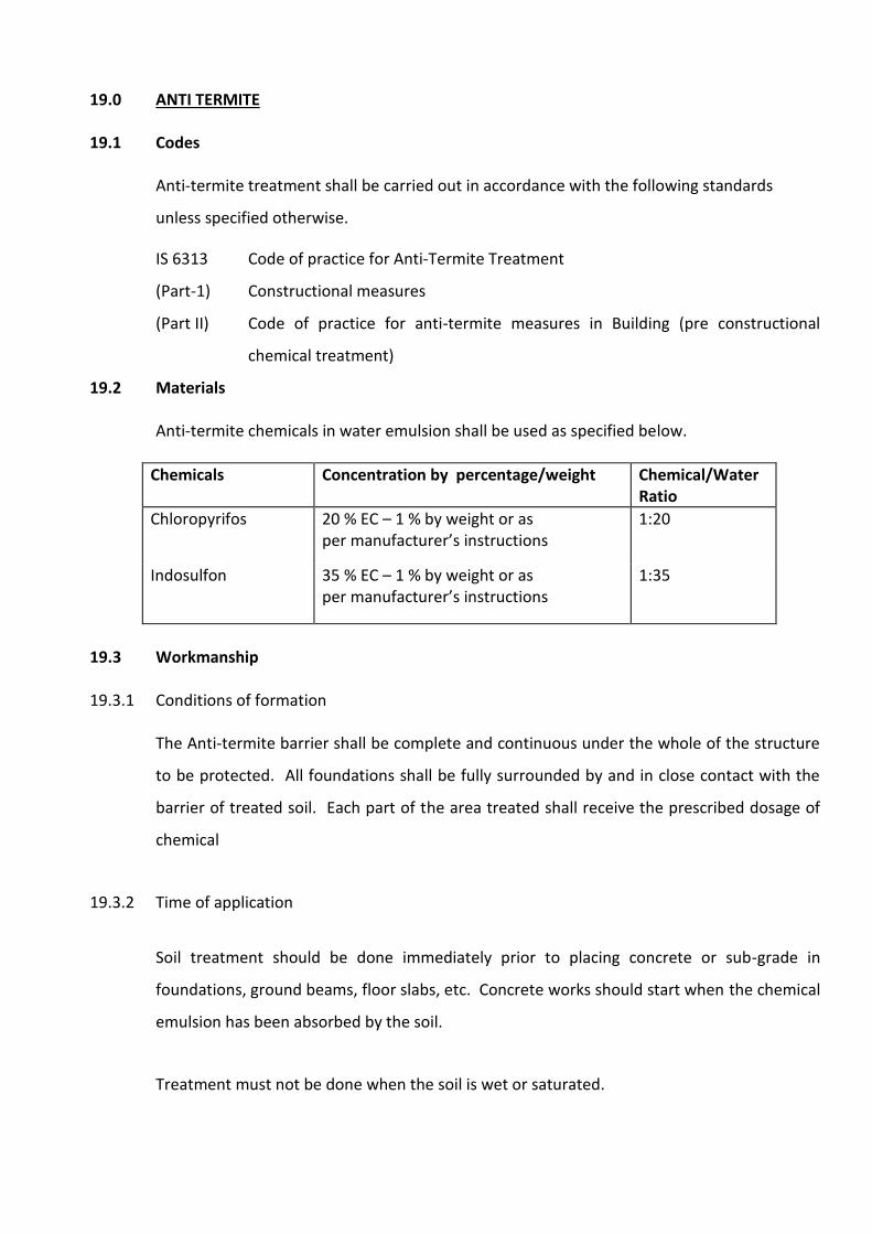
19.2 Materials Anti-termite chemicals in water emulsion shall be used as specified below.
Chemicals Concentration by percentage/weight Chemical/Water Ratio
Chloropyrifos 20 % EC – 1 % by weight or as per manufacturer’s instructions
1:20
Indosulfon 35 % EC – 1 % by weight or as per manufacturer’s instructions
1:35
19.3 Workmanship 19.3.1 Conditions of formation
The Anti-termite barrier shall be complete and continuous under the whole of the structure
to be protected. All foundations shall be fully surrounded by and in close contact with the
barrier of treated soil. Each part of the area treated shall receive the prescribed dosage of
chemical
19.3.2 Time of application
Soil treatment should be done immediately prior to placing concrete or sub-grade in
foundations, ground beams, floor slabs, etc. Concrete works should start when the chemical
emulsion has been absorbed by the soil.
Treatment must not be done when the soil is wet or saturated.
19.3.3 Disturbance
Once formed, treated soil barriers shall not be disturbed. If treated soil barriers are
disturbed, immediate steps shall be taken to restore the continuity and completeness of the
barriers - system.
19.3.4 Termite mound treatment
If termite mounds are found within the plinth area, these shall be destroyed by breaking
open the earthen structure and pouring into the mounds at several places, after, emulsion at
the rate of 4 litres per cubic meter of mound.
19.3.5 Soil Treatment
Treatment of pile caps, ground beams, columns, walls and basement excavations:
The bottom surface and the sides (to a height of 300 mm above concrete foundation level)
of the excavations for pile caps, ground beams, columns, walls and basements shall be
treated with the chemical at the rate of 5 litres per sq.m of surface area. After the concrete
works are above ground level, the back fill in immediate contact with the foundation
structure shall be treated at the rate of 7.5 litres per sq.m of the vertical surface of the sub-
structure. If water is used for ramming the earth fill the chemical treatment shall be carried
out after ramming operation is done by rodding the earth at 150 mm centres close to
concrete surface and spraying the chemical with the above dose. As earth is filled in layers
the treatment shall be carried out in similar stages. The chemical emulsion shall be directed
towards the concrete or masonry surfaces so that earth in contact with these surfaces is well
treated with the chemicals.
19.3.5 Termite Proof Course or DPC (PCC) in Plinth
Where there is the provision of a damp proof course in the construction, it is located just
below the level of the filled earth. Although this acts as an effective barrier impervious to
termite entry the PCC surface should be treated at 5 litres per sqm immediately after the
course is laid and the concrete is green.
Where there is no provision for a DPC, the top surface of the masonry course just below the
level of plinth filling mentioned above should be soaked with the chemical emulsion at the
rate of 5 liters per sq. m. of the surface. The application should be carried out slowly to
enable the masonry surface to absorb the emulsion.
19.3.6 Treatment of Top surface of Plinth Filling
The top surface of the consolidated earth within plinth walls shall be treated with chemical
emulsion at the rate of 5 litres per sq. m of the surface before the sand bed or sub-grade is
laid. If the filled earth has been well rammed and the surface does not allow the emulsion
to seep through, 75mm deep holes at 150 mm centres shall be made with 12 mm diameter
rod to facilitate saturation of the soil with chemical emulsion.
19.3.7 Treatment at junction of walls and floor
Rodding shall be carried out along the junction of walls and earth filling at 150mm centres at
a level slightly below the DPC or the chemical barrier described above. Emulsion shall be
sprayed along the wall junction at 7.5 litre per square meter of the vertical wall or column
surface so that it mixes with the soil and seeps to the DPC level or chemical barrier thus
establishing continuity of the anti-termite layer. The disturbed earth is then to be tamped
back into place.
19.3.8 Treatment of soil along external perimeter
The earth around the external perimeter of the building up to a depth of 300 cm shall be
treated at the rate of 7.5 litres per square meter of the vertical surfaces. To facilitate this
treatment the soil shall be rodded at 150mm centres to a depth of approximately 300 to
break up the soil.
In the event of filling being more than 300 mm, the external perimeter treatment shall
extend to full depth of filling.
19.3.9 Treatment of soil surrounding pipes, wastes and conduits
When pipes and conduits enter the soil inside the area of the foundation, the soil
surrounding the points of entry and exit shall be loosened around each such pipe, waster or
conduits for a distance of 150 mm, and up to a depth of 75 mm before the treatment is
commenced.
19.3.10 Spraying Equipment
A pressure pump shall be used to carry out spraying operations to facilitate uniform spraying
and penetration of chemical into the earth.
19.3.11 Free Service Guarantee
The Contractor shall note that termite proofing work, is subject to a free service guarantee
from the date of completion of the treatment. The Contractor shall give an undertaking in
writing that during the 10 (ten) year guarantee period any infestation of subterranean
termites will be eradicated and necessary treatment carried out to prevent re-infestation,
free of cost to the Employer.
Contractors must ensure that the work is done through a professional pest control operator
who is a member of the National Pest Control Association of USA, Indian Pest Control
Association or other recognized professional body. A list of termite control jobs successfully
undertaken for Government Departments, Statutory bodies or large private organizations
are to be provided to prove that they are capable of handling anti-termite work.
RCC WORKS
1.0 INDIAN STANDARDS
All relevant Standards as specified elsewhere in this Volume are applicable.
Indian Standards to be followed are:
(1) IS 269 Specification for Ordinary and low heat, Portland cement.
(2) IS 383 Specification for Coarse and fine aggregates from natural
sources for concrete.
(3) IS 456 Code of practice for plain and reinforced concrete.
(4) IS 460 Specification for test sieves: (Part I, II & III)
i) Wire cloth test service ii) Perforated plate test sieve iii) Method of examination of test sieve
(5) IS 516 Method of test for strength of concrete
(6) IS 1199 Method of Sampling and analysis of concrete.
(7) IS 1489 Specification for Portland pozzolana cement
(8) IS 1542 Specification for Sand for plaster
(9) IS 2116 Specification for Sand for masonry mortars
(10) IS 2386 Method of test for aggregate concrete.
(Part I, II, & III) i) Particle size and shape ii) Estimation of deleterious materials
and organic impurities iii) Specific gravity, density, voids,
absorption and bulking
(11) IS 2646 Specification for Integral cement water proofing
compound.
(12) IS 3025 Methods of Sampling and test (Physical and Chemical for
water used in Industry
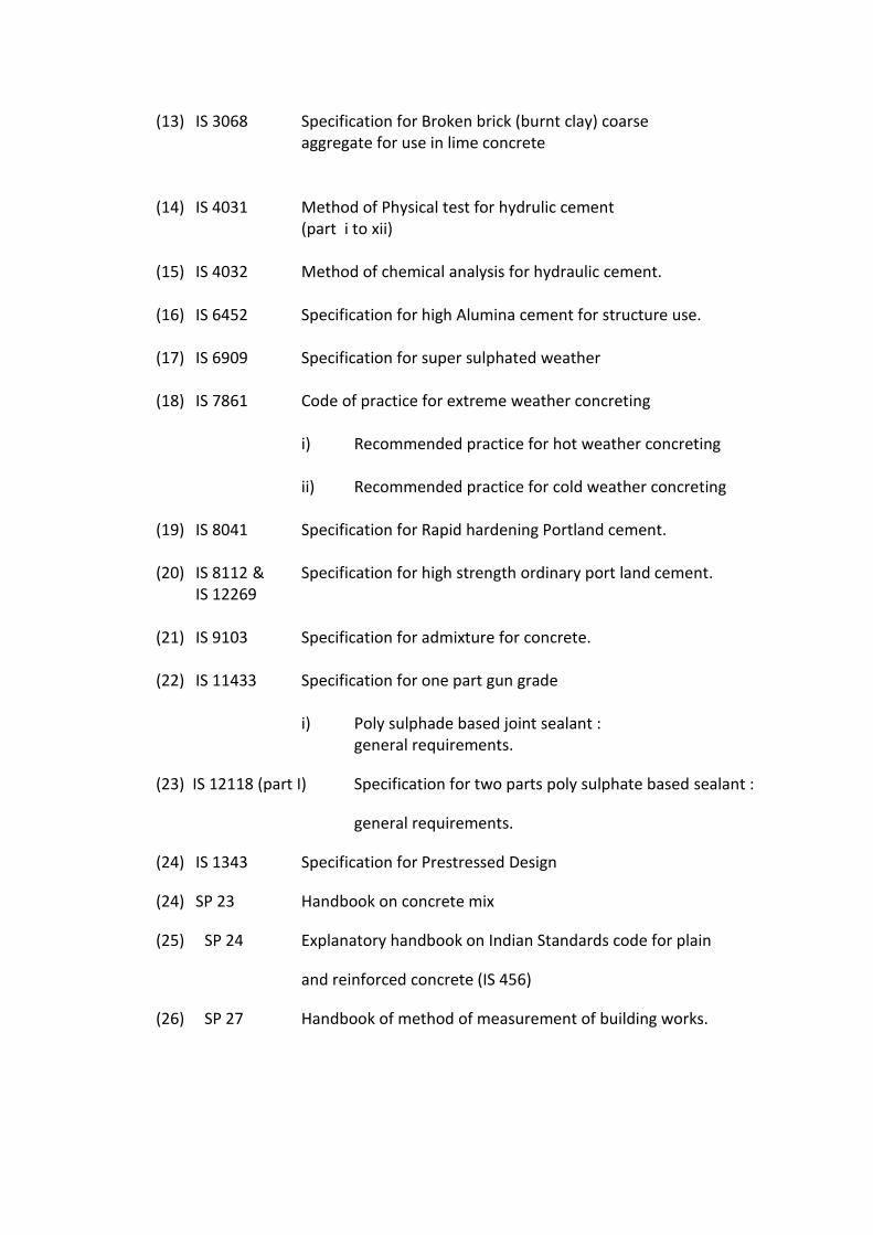
(13) IS 3068 Specification for Broken brick (burnt clay) coarse
aggregate for use in lime concrete
(14) IS 4031 Method of Physical test for hydrulic cement (part i to xii)
(15) IS 4032 Method of chemical analysis for hydraulic cement.
(16) IS 6452 Specification for high Alumina cement for structure use.
(17) IS 6909 Specification for super sulphated weather
(18) IS 7861 Code of practice for extreme weather concreting
i) Recommended practice for hot weather concreting
ii) Recommended practice for cold weather concreting
(19) IS 8041 Specification for Rapid hardening Portland cement.
(20) IS 8112 & Specification for high strength ordinary port land cement. IS 12269
(21) IS 9103 Specification for admixture for concrete.
(22) IS 11433 Specification for one part gun grade i) Poly sulphade based joint sealant : general requirements.
(23) IS 12118 (part I) Specification for two parts poly sulphate based sealant :
general requirements.
(24) IS 1343 Specification for Prestressed Design
(24) SP 23 Handbook on concrete mix
(25) SP 24 Explanatory handbook on Indian Standards code for plain
and reinforced concrete (IS 456)
(26) SP 27 Handbook of method of measurement of building works.
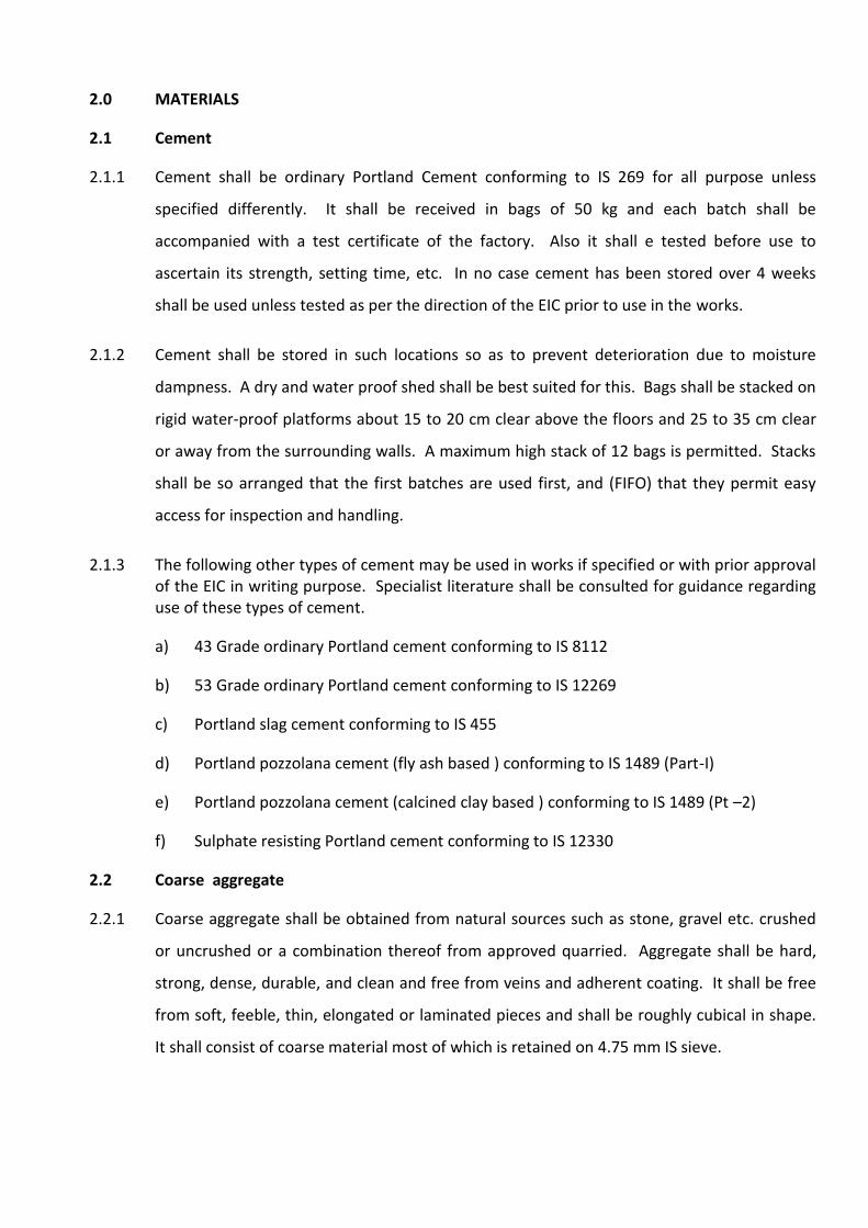
2.0 MATERIALS
2.1 Cement
2.1.1 Cement shall be ordinary Portland Cement conforming to IS 269 for all purpose unless
specified differently. It shall be received in bags of 50 kg and each batch shall be
accompanied with a test certificate of the factory. Also it shall e tested before use to
ascertain its strength, setting time, etc. In no case cement has been stored over 4 weeks
shall be used unless tested as per the direction of the EIC prior to use in the works.
2.1.2 Cement shall be stored in such locations so as to prevent deterioration due to moisture
dampness. A dry and water proof shed shall be best suited for this. Bags shall be stacked on
rigid water-proof platforms about 15 to 20 cm clear above the floors and 25 to 35 cm clear
or away from the surrounding walls. A maximum high stack of 12 bags is permitted. Stacks
shall be so arranged that the first batches are used first, and (FIFO) that they permit easy
access for inspection and handling.
2.1.3 The following other types of cement may be used in works if specified or with prior approval of the EIC in writing purpose. Specialist literature shall be consulted for guidance regarding use of these types of cement.
a) 43 Grade ordinary Portland cement conforming to IS 8112
b) 53 Grade ordinary Portland cement conforming to IS 12269
c) Portland slag cement conforming to IS 455
d) Portland pozzolana cement (fly ash based ) conforming to IS 1489 (Part-I)
e) Portland pozzolana cement (calcined clay based ) conforming to IS 1489 (Pt –2)
f) Sulphate resisting Portland cement conforming to IS 12330
2.2 Coarse aggregate
2.2.1 Coarse aggregate shall be obtained from natural sources such as stone, gravel etc. crushed
or uncrushed or a combination thereof from approved quarried. Aggregate shall be hard,
strong, dense, durable, and clean and free from veins and adherent coating. It shall be free
from soft, feeble, thin, elongated or laminated pieces and shall be roughly cubical in shape.
It shall consist of coarse material most of which is retained on 4.75 mm IS sieve.
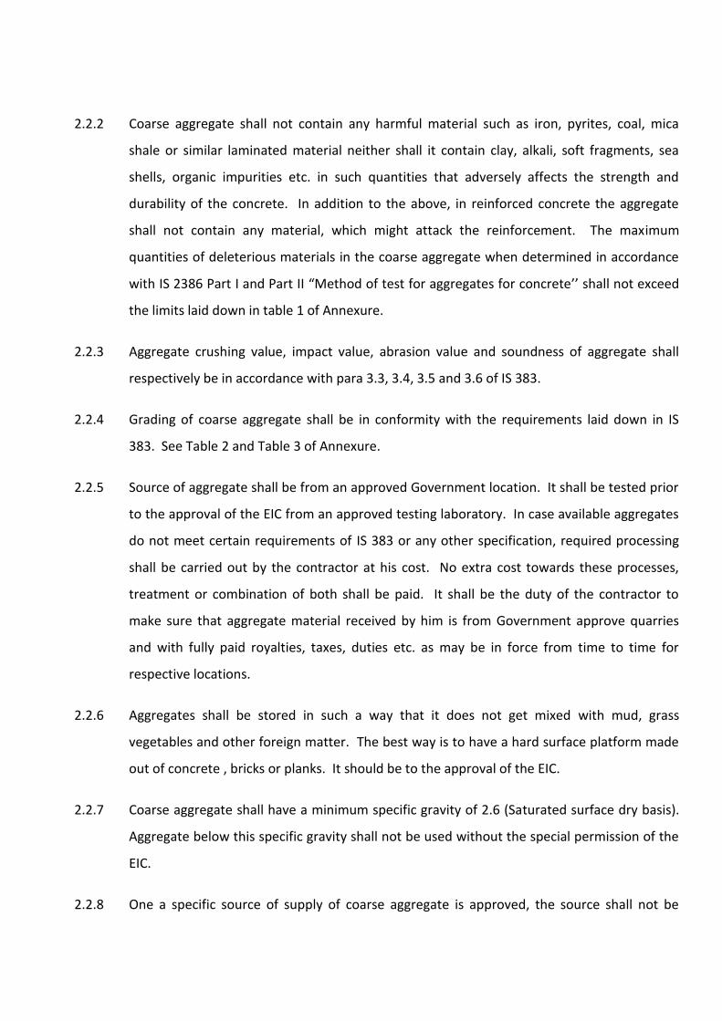
2.2.2 Coarse aggregate shall not contain any harmful material such as iron, pyrites, coal, mica
shale or similar laminated material neither shall it contain clay, alkali, soft fragments, sea
shells, organic impurities etc. in such quantities that adversely affects the strength and
durability of the concrete. In addition to the above, in reinforced concrete the aggregate
shall not contain any material, which might attack the reinforcement. The maximum
quantities of deleterious materials in the coarse aggregate when determined in accordance
with IS 2386 Part I and Part II “Method of test for aggregates for concrete’’ shall not exceed
the limits laid down in table 1 of Annexure.
2.2.3 Aggregate crushing value, impact value, abrasion value and soundness of aggregate shall
respectively be in accordance with para 3.3, 3.4, 3.5 and 3.6 of IS 383.
2.2.4 Grading of coarse aggregate shall be in conformity with the requirements laid down in IS
383. See Table 2 and Table 3 of Annexure.
2.2.5 Source of aggregate shall be from an approved Government location. It shall be tested prior
to the approval of the EIC from an approved testing laboratory. In case available aggregates
do not meet certain requirements of IS 383 or any other specification, required processing
shall be carried out by the contractor at his cost. No extra cost towards these processes,
treatment or combination of both shall be paid. It shall be the duty of the contractor to
make sure that aggregate material received by him is from Government approve quarries
and with fully paid royalties, taxes, duties etc. as may be in force from time to time for
respective locations.
2.2.6 Aggregates shall be stored in such a way that it does not get mixed with mud, grass
vegetables and other foreign matter. The best way is to have a hard surface platform made
out of concrete , bricks or planks. It should be to the approval of the EIC.
2.2.7 Coarse aggregate shall have a minimum specific gravity of 2.6 (Saturated surface dry basis).
Aggregate below this specific gravity shall not be used without the special permission of the
EIC.
2.2.8 One a specific source of supply of coarse aggregate is approved, the source shall not be
changed without the prior approval of the EIC.
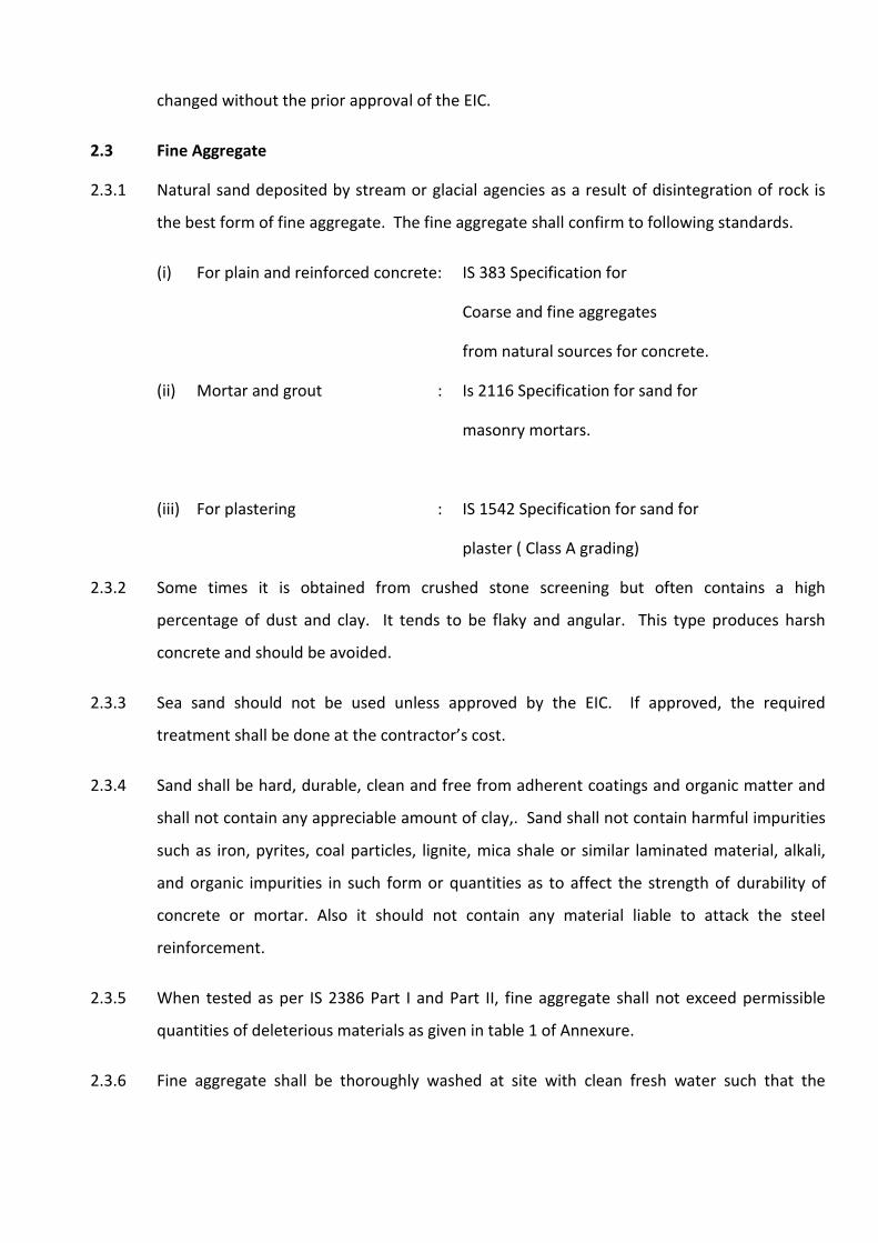
2.3 Fine Aggregate
2.3.1 Natural sand deposited by stream or glacial agencies as a result of disintegration of rock is
the best form of fine aggregate. The fine aggregate shall confirm to following standards.
(i) For plain and reinforced concrete: IS 383 Specification for
Coarse and fine aggregates
from natural sources for concrete.
(ii) Mortar and grout : Is 2116 Specification for sand for
masonry mortars.
(iii) For plastering : IS 1542 Specification for sand for
plaster ( Class A grading)
2.3.2 Some times it is obtained from crushed stone screening but often contains a high
percentage of dust and clay. It tends to be flaky and angular. This type produces harsh
concrete and should be avoided.
2.3.3 Sea sand should not be used unless approved by the EIC. If approved, the required
treatment shall be done at the contractor’s cost.
2.3.4 Sand shall be hard, durable, clean and free from adherent coatings and organic matter and
shall not contain any appreciable amount of clay,. Sand shall not contain harmful impurities
such as iron, pyrites, coal particles, lignite, mica shale or similar laminated material, alkali,
and organic impurities in such form or quantities as to affect the strength of durability of
concrete or mortar. Also it should not contain any material liable to attack the steel
reinforcement.
2.3.5 When tested as per IS 2386 Part I and Part II, fine aggregate shall not exceed permissible
quantities of deleterious materials as given in table 1 of Annexure.
2.3.6 Fine aggregate shall be thoroughly washed at site with clean fresh water such that the
percentage of all deleterious materials is within the permissible limits laid down.
2.3.7 Grading of fine aggregate shall conform to IS and shall fall within limits of one of the four
zones given in table 4 of IS 383 and of Annexure.
2.3.8 Damp and moist sand increases the volume and is called bulking. Due allowance is to be
made while preparing the mixes based on volume measurements. It shall be determined as
per IS 2386 Part III Appendix A. For rough guidance table 5 of Annexure gives the relation
between moisture content and percentage of bulking.
2.3.9 Storing of aggregate shall be as given in clause 2.2.6.
2.4 Water
2.4.1 Water used for mixing and curing shall be clean, reasonably clear and free from
objectionable quantities of silt, oils, alkalies, acids, slats so as not to weaken mortar, or
concrete or cause efflorescence or attach the steel in RCC while curing. It shall be free of
elements, which significantly affects the hydration reaction or otherwise interferes with
hardening of concrete during curing or those elements, which produced objectionable stains
or deposits. Potable water is generally satisfactory but is shall be tested prior to use in the
works.
2.4.2 Water tested shall be in accordance with IS 3025. Maximum permissible limits of
deleterious materials in water as given in IS 456 are reproduced for ready reference in table
6 of Annexure.
2.4.3 Suitability of water shall be ascertained by the compressive strength and initial setting time test as specified under:
a) Average 28 days compressive strength of atleast three 15 cm concrete cubes prepared
with water proposed to be used shall not be less than 90% of the average strength of
three similar concrete cubes prepared with distilled water. Preparation and testing in
accordance of IS 516.
b) The initial setting time of tests blocks made with proposed cement and water to be
used shall not be less than 30 minutes and shall not differ by ± 30 minutes from the
initial setting time o f control test block prepared with the same cement and distilled
water. Preparation and testing of block shall be in accordance with IS 4031
2.4.4 The PH value of water shall not be less than 6 and more than 9.
2.4.5 Water storage tanks shall be such as to prevent any deleterious materials getting mixed with
it.
2.4.6 Water shall be tested and approved in writing by the EIC prior to use in the works.
2.4.7 Sea Water
Seawater in concrete shall not be permitted unless specifically approved in writing by the EIC
for purpose stated. The EIC under unavoidable circumstances may allow mixing or curing of
seawater in concrete construction, which are permanently under seawater.
2.5 Admixtures
2.5.1 These are substances other than cement, aggregate and water and shall be permitted to be
used to modify the properties of concrete for single or a combination of purposes. This shall
be used only on the written approved for specific purpose and at the cost of the contractor.
Good concrete shall be achieved without the aid of any admixtures.
2.5.2 Admixtures should be free from chlorides and sulphate, which might affect concrete or any
other material which may cause problems to the concrete in the due course of time. Also it
should have no effect on the reinforcement in case of Reinforced Cement Concrete.
2.5.3 Admixtures generally in use are classified as under :
a) Accelerators
b) Retarders
c) Workability agents
d) Water -repelling agents
e) Air-entraining agents
f) Gas-forming agents. These are manufactured and sold by various companies under brand names. The contractor
proposing to use any of them shall submit to the EIC technical literature with its chemical
composition, purpose of use and method recommended by the manufacturer and what he
proposes to follow at site for strict control.
2.5.4 The contractor’s proposal shall accompany the following with his request to use admixture.
a) The trade name of the admixture, its source and the manufacturer’s recommended
method of use.
b) Typical dosage rates and the possible detrimental effects of under and over-dosage.
c) Whether the admixture contains chloride in any free form or any other chemical
present as an active ingredient, which is a likely cause of corrosion of reinforcement or
deterioration of concrete.
d) The average expected air content of freshly mixed concrete containing an admixture,
which causes air to be entrained when used at the manufacturer’s recommended rate
of dosage.
3.0 CONCRETE
Concrete is prepared by mixing graded aggregate stone or brick along with cement, in a
specified proportion. Mixing shall be done by a mechanical mixer. Manual hand mixing shall
be permitted in specific cases with the written permission of the EIC on account of small
quantity or location or any other reason acceptable to the EIC.
3.1 Cement concrete.
This shall be classified as plain cement concrete or reinforced cement concrete. Plain
cement concrete shall be in leveling course under foundations, floors, copings etc. and shall
include form work as part of the work. Reinforced cement concrete shall be at all locations
and comprises form work, reinforcement and concrete. Payment of reinforced cement
concrete may be composite or item wise as specified in the BOQ. In PCC payment for form
work shall not be made.
3.1.1 Concrete shall be classified its compressive strength at the 28th day. The concrete grades
shall be as designated in table 2 of IS 456 and are given as ready reference in table 7 of
Annexure.
3.1.2 BOQ shall specify various types of concrete aimed to be used in works. It shall be the
responsibility of the contractor to carry out design mixes and approval of the same shall be
obtained from the EIC at least 35 days in advance from the actual pouring of concrete at site
in the permanent works. The basic aim of mix design shall be to find the most economic
proportion of cement, aggregates and water which will give the desired strength of
concrete, proper workability and durability. Also it is important that the mix should be easily
worked with the help of equipment available at site. The operations involved at site are,
measurement of materials, their mixing, placing, compacting, finishing required and curing.
The design shall be carried out strictly to IS specifications and IS code practice 456, SP 23 and
SP 24.
Further the contractor should ensure that the minimum cement content per cubic meter of
reinforced concrete should not be less than that stipulated in table 23, 24, 25 and 26 of SP
23. For ready reference refer table 8 and 9of Annexure, but the BOQ shall specify minimum
cement content for each item.
3.1.3 For expected strength of cubes tested on the 28th day the design mix at preliminary test and
work site shall be as per table 10 of Annexure. The water cement ratio shall be between 0.5
to 0.52. Additional water may be permitted only at the discretion of the Structural Engineer.
The slump shall be 25 mm to 35 mm depending upon the location and type of work. Higher
slump with use of plasticizers shall be permitted.
3.2 Design mix and trial mixes
3.2.1 As stated above in clause 3.1.2 the contractor shall submit, at least 5 weeks in advance, to
the EIC the mix design that the proposes to use at site. The mix design shall also give basic
details (when tested according to Is 1199 and IS 2386 – Part III, 1963) such as.
a) Slump
b) Bleeding
c) Compacting factor
d) Vee-Bee time
e) Cement required for one cubic meter of concrete.
3.2.2 On receipt of this, the EIC may immediately order to carry out work site test before the final
approval. This shall be done with mixer and materials actually being used at site.
This shall give the contractor additional chance to check for himself actual workability and
make sure that the mix proposed by him will be fully satisfactory with regards to slump,
segregation, bleeding, water –cement ratio and workability.
5 cubes shall be taken from e ach of the 3 batches to test the mix. Cubes shall be cast,
stored, cured, transported and tested to IS 516. The test may be carried out at site or
laboratory as approved by the EIC.
Trial mixes shall be approved provided that average strength of 3 consecutive cubes is not
less than that specified and that one out of three may give a value less than specified but
limited to a maximum of 90% of the specified strength.
3.2.3 In case the trial mix falls below the above criteria, the EIC shall order fresh trial mixes to be
made as before, until the desired strength is arrived at.
3.2.4 This design mix and trial mix hold good so long as the materials continue to be of the same
quality and from the same sources. For any change, the EIC may order fresh design mix and
trial mixes to be carried out before the same is used at site.
3.2.5 It is the responsibility of the contractor to prepare and get the cubes tested and to provide all
the material, labour, moulds, equipment, casting and curing facility, charges for testing etc.
Further, the contractor shall have to provide and maintain all the equipment and staff at the
site throughout to carry out the following tests in a small laboratory or get these tests from
approved laboratories without extra cost to the contract.
a) Grading of coarse and fine aggregates.
b) Silt content of sand.
c) Moisture content of coarse and fine aggregates.
d) Slump test of concrete.
e) Concrete cube test.
The contractor shall maintain full records of all above tests in a register.

The format of records shall be prepared in consultation with the EIC and either he or his
representative shall have full access to the contractor’s laboratory.
The contractor shall include charges for the above work in his rates and no extra whatsoever
shall be admissible on this account of designing, testing maintaining laboratory etc.
3.3 Mixing of concrete
3.3.1 Weight batching shall be preferred at site but the EIC may permit designed mix to be
converted to volumetric if requested by the contractor on specific grounds. The contractor
shall provide required boxes to measure the ingredients of concrete.
3.3.2 The contractor shall provide concrete batch mixes, vibrators, weight batches conforming to
relevant IS specification. The capacity and number of mixers and vibrators required at site
from time to time shall be to the approval of the EIC. No equipment from site shall be
removed without the prior written approval of the EIC. The contractor shall also maintain a
platform weighing scale of capacity 300 kg with fraction upto 100 gms at the site.
As directed by the EIC, a weekly or periodic calibration of all machines shall be done and
records of these calibrations shall be maintained in a register. Regular maintenance of
machinery shall also be carried out on a weekly basis or as directed by the manufacturer of
machines.
3.3.3 The mixer shall be run for a minimum period of 2 minutes after all materials are loaded in
full quantity. The concrete produced shall be uniform in colour and consistency.
3.3.4 The placing temperature of concrete shall not be more than 34o C. If it is more, the EIC may
order addition of ice or chilled water to the concrete. Also the contractor shall take the
following precautions:
a) Mixers and weight batches shall be painted with white colour
b) Aggregate storing bins shall not be exposed to the Sun.
c) Water shall be sprinkled on aggregates well before concreting to keep the temperature low.
3.4 Shrinkage cracks Concreting shall avoided in very warm weather, if necessary, it shall be covered with
damped hessian within 2 hours of placing of concrete.
To achieve good results the concrete shall be immediately covered with a plastic sheet and
not allowed any direct wind contact. This shall eliminate shrinkage cracks.
3.5 Laying of Concrete Concreting shall commence only after form work is approved, reinforcement is recorded and
permission to proceed with concreting has been approved in writing from the EIC.
Formwork should be clean, free from sawdust, pieces of wood or any other foreign material.
It should have been treated by form releasing agent prior to the laying of reinforcement and
concrete.
Concrete shall be as gently deposited as is practically possible. In its final position to avoid
re-handling and shall be so deposited that segregation of aggregates does not occur. In case
of deep trenches and footing, if may be done with the help of a chute. Columns and walls
shall be so adjusted in form work so that maximum depth is 1.5 meter unless consented to
by the EIC. Concrete from wheelbarrows shall not be dumped away from the face concrete
already in place. It shall be dumped into the face of concrete already in place.
Concrete onto a sloping surface shall be discharged by providing a chute with a baffle and a
drop at its end so that the concrete remains on the slope.
Columns and walls shall be concreted in the operation to their full height to avoid any
horizontal construction joints as far as possible.
All slabs, beams, wooden planks and cat-walk shall be provided clear of reinforcement.
Concrete shall be placed in position within 30 minutes from the time it is produced.
Concrete shall be laid during normal working hours. Concreting at night or on holidays shall
be permitted only on the written approval of the EIC.
3.6 Compaction of Concrete Concrete shall be thoroughly compacted, as depositing shall proceed by means of suitable
vibrators. The vibrators shall maintain the entire concrete under treatment in an adequate
state of agitation and shall continue during the whole period occupied by placing of
concrete. Care shall be taken not to over- vibrate the concrete. While withdrawing needles
no holes should be visible in concreting. Compacting shall be completed before the initial
setting time. Concrete already set shall not be disturbed by successive vibrations.
It shall be ensured that the needle vibrators are not applied on reinforcement, which may
destroy the bond between concrete and reinforcement. When electric vibrators are in use,
the standby petrol vibrator must always be available at the concreting point.
3.7 Construction joints
In large pours, it is practically not possible to carry on concreting continuously. Hence
construction joints shall be provided. Location of construction joint shall be submitted by
the contractor for approval of the EIC. Such joints shall be kept to a minimum. The joints
shall be at places where shear force s nil or minimum and these shall be straight and a t right
angles to the direction of the main reinforcement.
Stop ends provided shall be with necessary slots for reinforcement bars to pas feely without
bending or any other obstruction. Also a trapezoidal fillet nailed on stop board shall be
provided to form a regular keyed joint. Joints shall be straight and truly vertical or
horizontal.
Before commencement of concrete, adjacent concrete stopper and surfaces shall be chipped
and roughened to expose aggregate, then wire brushed and cleaned. The concrete surface
shall be sprayed with water for 24 hours before casting and kept wet until casting.
True horizontal joints shall also be provided with a keyed joint by inserting planed greased
timber.
It shall be treated as above prior to the start of fresh concreting.
For vertical joints neat cement slurry shall be applied on the surface just before concreting.
For horizontal joints, the surface shall be covered with a layer of mortar about 10 to 15 mm
thick composed of cement and sand in the same ratio as the cement and sand in the
concrete mix. This layer of cement slurry shall be freshly mixed and applied just before
concreting.
3.8 Expansion joints
Expansion joints shall be formed and located as detailed in the drawing.
3.9 Curing
Curing of concrete is most important. There shall be no comprise on this activity and it is for
the contractor to arrange for everything necessary to make sure that the concrete is cured
to the complete satisfaction of the EIC. As said above in clause 3.1.8, after concrete has
begun to harden i.e. about 1 to 2 hours after laying. It shall be protected from quick drying
with moist or damped hessian cloth or any other material approved by the EIC. After 24
hours of laying of the concrete, the surface shall be cured by flooding with water or covering
with damp hessain cloth for a period of 7 days to keep it moist.
For the next 7 days the surface shall be kept wet all the time by sprinkling water
continuously.
For membrane curing, details as listed in 12.5 of SP 24 shall be followed.
3.10 Finishing
Concrete shall be finished keeping in mind the next operation to be carried out over the
surface. For guidance the following points shall be noted but the EIC shall be consulted prior
to start of concreting and his decision in this regard shall be final.
a) Roof slab shall be troweled even and smooth with a wooden float.
b) The surface that will receive plaster shall be roughened immediately.
c) Surfaces that will be in contract with any masonry work shall be roughened
immediately.
d) The surface that will receive mosaic floor or IPS or any other type of tiled work shall be
roughened while it is green. Every care shall be taken not to disturb the freshly laid
concrete.
3.11 Inspection and corrective measures
3.11.1 On removal of form work, the surface shall be examined by the EIC. Till such time, the
contractor shall carry out no remedial measures. All patching, rectification or chipping shall
be done only on the EIC’s instructions. In case of any violation of this rule, the concrete
poured stands rejected. The decision of the EIC in this regard shall be final and binding on all
parties.
Sagged, buldged, patched, honeycombed work shall stand to be rejected for surface that are
exposed, or required fairface finish or decorative textured finish. The EIC may permit any
work found structurally safe and areas of unexposed faces, for repairing. As directed by the
EIC these works shall be retained and the cost of repair shall be at the contractor’s account.
3.11.2 Cracks observed shall be brought to the notice of the EIC who shall examine them. It shall
be kept under observation and a record shall be maintained for a period of 45 days. It shall
be shown to the Structural Engineer and the following procedure shall be followed.
1. Cracks not developing further and in the opinion of Structural Engineer not detrimental
to the strength of the construction shall be grouted with non-shrinking cement slurry
or as directed by the EIC.
2. Cracks developing further and in the opinion of the Structural Engineer, detrimental to
the strength of construction, shall be tested as per the relevant Indian Standard.
3. Based on result of the test, the EIC in consultation with the structural engineer shall
order remedial measures or order the contractor to dismantle construction, cart away
the debris, replace the construction and carry out all the consequential works thereto.
4. Cost of the above shall be borne by the contractor if the failure was on his part. In case
it is due to design faults, it shall be borne by the employer.
5. The decision of the EIC in this matter shall be final and binding on all parties. This
decision shall not be open for arbitration.
3.12 Quantum of cubes and testing
The minimum frequency of cube casting shall be as follows. Each sample shall consist of 6
cubes.
Concrete quantity Number of Samples.
Upto 5 cu.m. in a day 1
5 cu.m. to 15 cu.m. 2
15 cu.m. to 30 cu.m. 3
30 cu.m. to 50 cu.m. 4
More than 50 cu.m. 4 + one additional per each 50 cu.m. or part thereof.
Three cubes shall be tested on the 7th day and other three cubes on the 28th day.
3.13 Acceptance of Work
It shall be as given in IS 456, SP 23 and SP 24. The guidance brief is as under;
Part or element of work shall be deemed to be accepted, provided the results of the 28th day
cube testing conform to the criteria stated as under
a) The average of the three consecutive cube’s strength shall not be less than the
specified strength.
b) No individual cube strength shall be less than 90% of the specified strength.
c) If the individual cube strength exhibits more than 33% of the specified strength, such a
cube shall be classified as freak and the criteria in (a) and (b) shall be applied to the
remaining two cubes and their acceptability determined.
d) If the concrete testes fail to meet the acceptance criteria of the minimum strength
required for respective grades of concrete, the EIC may take one of the following
decisions:
i) Instruct the contractor to carry out such additional tests (e.g. core tests, load
tests etc) and / or remedial measures to ensure the soundness of the structure
at the contractor’s expense.
ii) Any decision to accept the work shall be entirely at the discretion of the
engineer who may a reduction in the rate of the appropriate item.
iii) The work will be rejected and any consequential action as needed shall be
taken at the contractor’s expense including cutting out and replacing a part or
whole of the work..
3.14 Concreting under special conditions
3.14.1 Work in extreme weather conditions During hot or cold weather the concreting should be done as per the procedure set out in IS
7861 Part I or IS 7861 Part II or as directed by the EIC.
3.14.2 Underwater concreting The procedure set out under 13.2 of IS 456 shall be followed or as directed by the EIC.
3.14.3 Concreting in seawater The procedure set out under 13.3 of IS 456 shall be followed or as directed by the EIC.
3.14.4 Concreting in aggressive soils and water Guidelines laid down in 13.4 of IS 456 shall be followed together with the instruction of the
EIC.
3.15 Measurements 1. All works shall be measured in the decimal system.
a) Dimensions shall be measured to the nearest 0.01 metre except for thickness of slab which shall be measured to the nearest 0.005 metre.
b) Areas shall be worked out to the nearest 0.01 sq.m.
c) Cubic contents shall be worked out to the nearest 0.01 cu.m.
2. All measurements of cutting shall, unless otherwise stated, be held to include the
consequent waste.

3. Cement concrete work shall be classified as under:
a) Concrete cast-in-situ Plain and reinforced
b) Precast concrete Plain and reinforced
c) Prestressed concrete Cast-in-situ or pre-cast
4. All concrete, except as hereinafter provided, shall be measured in cubic meters.
5. The price of concrete shall include ingredient material, mixing, transporting, hoisting to
any height and lowering to any depth, pouring or laying, consolidating, leaving pockets,
holes and protecting them till the next operation or completion of work, hacking the
surface to provide key for further work including cleaning, wetting surface etc. and
preparing construction joints as described in clause 3.19 of this section.
6. Concrete processed in a special manner for any specific purpose, such as cooled,
heated, water-proofed, acid-proofed, heat-resistant shall be measured separately.
7. Admixtures shall be used if necessary at the request of the contractor for workability
and the price for that shall deemed to be included in the contractor’s quoted price of
concrete.
8. No reductions shall be made for :
a) Ends of dissimilar materials (for example beams, posts, girders, purlins, corbels and steps) upto 500 sq. cm in section.
b) Opening upto 0.1 sq.m.
c) Volume occupied by reinforcement.
d) Volume occupied by drainage, water pipes, conduits, etc. not exceeding 100 sq.cm in cross sectional area.
e) Small voids each not exceeding 40 sq.m. in section.
f) Small moulds, drip moulds, chamfers, splays, rounded or covered angles, beads, grooves and rebates upto 10 cm in depth and width.
9. Expansion joints shall be measured in running meter or sq.m. as the case may be. Price
shall include required shuttering, special treatment if any, filler and finishing material
as detailed in drawing or the BOQ.
10. Water proofing of concrete shall be measured separately as an extra over ordinary concrete stating the quantity of waterproofing material inliers or kilograms.
11. Surface treatment shall be measured in square meters stating number of coats and
proportioning of water proofing liquid to water.
12. Cement grouting shall be measured in square meters and the mix specified.
13. Grouting of holding-down bolts and providing temporary boxing or wedges to form holes shall be enumerated. The mix shall be specified. The price shall include required shuttering, grouting etc.
14. To keep surface dry while concreting, dewatering due to rains and seepage shall be
included in the price of concrete.
4.0 READY MIX CONCRETE Ready Mix concrete is concrete supplied by an independent vendor having a ready – mixed plant
outside the site. All specifications for plain and reinforced concrete shall be equally applied to ready
mixed concrete.
READY MIX CONCRETE SUPPLIER
The Contractor shall identify a supplier in such a manner that concrete is available at site with
hindrance and quality is maintained during concreting. Due attention shall be paid to the quality of
plant and machinery, laboratory facilities available with the supplier, proper documentation
procedures maintained by the supplier and trained qualified staff employed by the supplier.
Consideration shall also be given to distance of plant from site, quality of transporting equipments
and documentation procedures maintained by the supplier related to transport. After identifying
Ready – Mix Concrete supplier the Contractor must submit these documents to PMC for their
approval.
Documentations to be submitted and maintained by the Contractor during Construction:-
1. Mix design used for concrete should include type and quality of cement, admixtures,
aggregates, water etc. the documents shall also include laboratory tests carried out for
conformation of workability, strength, setting time etc.

2. A document stating the type and quantity of each component of concrete shall be maintained
for each batch of concrete. The document shall also state the date and time of concrete and
use before time.
3. Documentation for on site tests carried out during concreting.
4. Results of cube tests and other laboratory tests carried out by the supplier in the plant.
TRANSPORTING OF READY MIX CONCRETE
Before loading concrete in the transit mixer, the container shall be thoroughly cleaned, washed
and kept moist.
Method of transportation used shall ensure efficient delivery and no significant alterations of
properties of concrete such as water – cement ratio, slump , air content, homogeneity etc.
PLACING OF READY MIXED CONCRETE
The batching plant operator and the placing crew at site shall work in close co – ordination to
avoid any delay in dispatching the concrete as well as to stop dispatch if the work at site is not
ready for concrete work. Proper record of order, delivery and placement of concrete shall be
maintained by the Contractor on site and submitted to the PMC who shall have direct access to
the batching plant to control all the activities in the production and placement of concrete.
TEMPERATURE
Temperature of concrete at the time of delivery shall be in accordance with IS 4926 (1976) or any
other agreed standard.
DELIVERY TIME
The time period between the initial contact of mixing water with cement and delivery to the
Contractor shall not generally exceed two hours. This figure is a general one and can be reduced
or extended depending upon mix design, ambient temperature and the design criteria of the
structure.
ADDITION OF WATER
Unless otherwise agreed NO additional water shall be added to the concrete after the transit
mixer has left the production plant. The Contractor is responsible for the prevention of any
additional water added to the concrete on site. The only exception is where properly trained
Ready mixed concrete supplier personnel adjust the workability to comply with the specified
slump requirement without exceeding either the specified maximum free water: cement ratio or
slump tolerances. It is suggested that this is performed by using a calibrated water meter. The
quantity of additional water shall be recorded on the delivery ticket and signed by the Ready
mixed concrete supplier’s representatives performance of such concrete shall be ascertained
through normal testing practices.
5.0 MORTARS
5.1 Mortars shall be prepared by mixing fine graded aggregate with cement, in the proportion
specified for respective items of work as detailed in the BOQ. Mixing of mortars shall be done
by mechanical mixers only. Hand mixing may be permitted in specified cases on the written
permission of the EIC.
5.2 Mortars shall be specified by proportion only and not by strength, volumetric mixing shall be
based on dry volumes of each ingredient. For convenience, measurement shall correspond
to volume of one cement bag i.e 0.035 cu.m. Boxes shall be of size of 40 x 35 x 25 cm.
These shall be marked as mortar mixing boxes by red paint and shall be used throughout the
contract. Hand mixing or mechanical mixing proportions shall be done with the use of these
boxes.
5.3 Cement mortar
Cement mortar shall be prepared by mixing cement and sand in specified proportions.
Proportioning shall be carried out as detailed above. Sand shall be added suitably to allow
for bulkage, if required. Bulkage shall be determined as specified in IS 2386 Part III. Cement
and sand added to mixer shall be thoroughly mixed and water shall be added to it gradually.
After addition of water the mixer shall run for a minimum of 3 minutes. The mortar mixed
shall be consumed within 30 minutes of its mixing.
6.0 FORMWORK
The design and construction of the formwork shall be the responsibility of the Contractor.
However, if instructed by the Engineer, the drawings and calculations for the design of the
formwork shall be submitted to the Engineer for approval. Design of formwork shall take
account of safety and surface finish. The formwork shall be sufficiently rigid and tight to
prevent loss of grout or mortar from the fresh concrete.
Formwork shall be designed to withstand the worst combination of self weight,
reinforcement weight, wet concrete weight, concrete pressure, construction and wind loads
together with dynamic effect caused by placing, vibrating and compacting the concrete.
Forms shall be designed and constructed to maintain rigidity throughout the placing,
ramming, vibration and setting of the concrete to the required shape, position and level and
specified class of finish within the allowable tolerances.
All joints shall be sufficiently tight to prevent leakage of grout. If movement or deflection of
the formwork or loss of grout occurs, the damaged concrete supported by such formwork
shall be removed and the concrete re-cast so that the required finish is obtained. Formwork
and its supports should be designed to withstand the worst combinations of self-weight,
reinforcement and wet concrete weights, concrete pressure, construction and wind loads. Due
regard shall be taken to the type of mix when considering the design pressure on the
formwork. The formwork shall be pre-cambered by an amount equal to the expected
maximum deflection shall be as shown on the drawings.
If timber forms are used they shall be of sound, well-seasoned timber free from loose knots.
The forms shall be faced to give the specified class of finish for the structures. The formed
surfaces of exposed concrete shall be smooth, true and free from all irregularities.
For below ground concrete except against existing structures, rough formwork, steel pans etc.,
provided all joints prevent the loss of grout.
The formwork shall be designed and constructed to the shapes, lines and dimensions shown
on the drawings within the tolerances given below:
a) Deviation from specified dimensions of - 6 mm
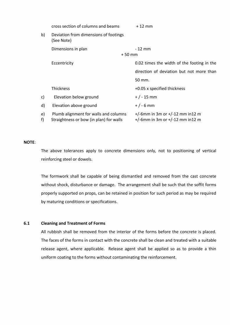
cross section of columns and beams + 12 mm
b) Deviation from dimensions of footings (See Note)
Dimensions in plan - 12 mm + 50 mm
Eccentricity 0.02 times the width of the footing in the
direction of deviation but not more than
50 mm.
Thickness +0.05 x specified thickness
c) Elevation below ground + / - 15 mm
d) Elevation above ground + / - 6 mm
e) Plumb alignment for walls and columns +/-6mm in 3m or +/-12 mm in12 m f) Straightness or bow (in plan) for walls +/-6mm in 3m or +/-12 mm in12 m
NOTE:
The above tolerances apply to concrete dimensions only, not to positioning of vertical
reinforcing steel or dowels.
The formwork shall be capable of being dismantled and removed from the cast concrete
without shock, disturbance or damage. The arrangement shall be such that the soffit forms
properly supported on props, can be retained in position for such period as may be required
by maturing conditions or specifications.
6.1 Cleaning and Treatment of Forms
All rubbish shall be removed from the interior of the forms before the concrete is placed.
The faces of the forms in contact with the concrete shall be clean and treated with a suitable
release agent, where applicable. Release agent shall be applied so as to provide a thin
uniform coating to the forms without contaminating the reinforcement.
6.2 Striking of Form work
In normal circumstances where Ordinary Portland Cement is used, forms shall generally be
removed after the expiry of the following periods:
a) Walls, columns and vertical faces
of all structural members
24 to 48 hours as may be decided
by the Engineer.
b) Slabs (props left under) 3 Days
c) Beam soffits (props left under) 7 Days
d)
Removal of props under slabs :
1) Spanning up to 4.5 m
2) Spanning over 4.5 m
7 Days
14 Days
e) Removal of props under beams
and arches :
1) Spanning up to 6 m
2) Spanning over 6 m
14 Days
21 Days
For other cements, the stripping time recommended for Ordinary Portland Cement shall be
suitably modified. The number, size and position of props left under shall be such as to be
able to safely carry the dead load of the slab, beam or arch, together with any live load likely
to occur during curing or further construction.
Sleeves for through bolts shall not be provided in formwork for liquid retaining structures as
they are potential hazard for leakage. Special device shall be fabricated using two ordinary
M20 nuts separated by two numbers 10 mm rounds welded to opposite flat side of the nuts
or standard water stopper tie-rods (16 dia.) readily available in the market. Standard tie-rods
(16 dia.) with higher load carrying capacity, the required quantity/sqm for forming area will
reduce considerably ultimately reducing the no. of holes in walls.. The faces of the nuts will
have a compressible rubber bush-20 mm thick. The overall dimension of the assembly shall
be 50 mm less than the designed thickness of the concrete. Adjusting bolt shall pass through
formwork and will lock into the nuts. While these bolts are tightened, the formwork will
travel inwards. Once the desired dimension is achieved, concrete will be poured. During
deshuttering, the bolts will be removed to loosen the shuttering plates. The depression will
be sealed using suitable concrete sealant.
6.3 Surface Finishes from Formwork
Generally formwork shall be specified as either wrought or unwrought depending on the
required surface finish.
6.4 Unwrought Formwork
Unwrought Formwork shall consist of sawn boards, brick or concrete block work, sheet
metal or other suitable material to give adequate support to the concrete.
Appearance is not of primary importance for this class of formwork.
Surfaces to which plaster, granolithic or other finish is to be applied shall be roughened
while the concrete is still green.
6.5 Wrought Formwork
Wrought formwork shall be provided for concrete surfaces that are required to be finished
smooth. Wrought formwork shall be lined with metal or plywood having smooth surfaces and
edges.
Formwork shall be furnished in largest practicable sizes to minimize the number of joints.
Care shall be taken that there are no irregularities or roughness between successive sections
of shuttering such that finished surfaces shall be free of board or shutter marks. Upon
removal of formwork, surfaces of finished concrete shall be rubbed down with carborundum
stone where necessary to obtain a uniform and smooth appearance.
The finish shall be such as to require no filling of surface pitting, butt fins, surface
discoloration and other minor defects shall be remedied by approved methods.
Rendering of defective concrete as a means of making good will not be permitted except
that, in case of minor porosity on the surface, approval may be given for the surface to be
treated by rubbing down with a cement mortar of the same fine aggregate/cement ratio as
the concrete. The treatment shall occur immediately after removing the formwork. Both
cement and aggregate shall be from the same source as the concrete materials.
Concrete containing honeycombing, major air holes or similar defects shall be cut out and
replaced as directed. No repair shall be executed without approval.
6.6 TIES
Where is required to use internal ties and spacers, their type, spacing and use shall be
approved. No part of any such tie or spacer remaining permanently embedded in the
concrete shall be nearer than the specified cover to the finished surface of the concrete.
Wire ties projecting through the concrete face shall not be permitted.
6.7 Permanent Formwork.
Permanent formwork for elevated concrete floors in steel structures shall be profiled steel
sheet. The sheet shall be of sufficient thickness to sustain all construction loads plus the
weight of fresh concrete between supporting beams without excessive deflection. The
underside of the sheet shall be coated with an approved corrosive resistant paint. The
material shall conform to IS513 (D) / IS 10748 gr.2. The deflection shall be limited to span /
150.The sheet shall be fixed on the supporting beams at every alternate valley by 10 mm dia
fusion welding with 22 mm dia x 2.5 mm thick
Reinforcing washer. Minimum 100 mm overlap shall be provided. The deck sheet end resting
on wall shall have a seating of 150 mm minimum. Side laps shall be secured with tack
welding to ensure that the slurry does not leak down. End laps shall always be on the
supporting walls or on supporting beams. The overhang of the deck sheet shall be limited to
300 mm maximum. Temporary supports, wherever advised by the construction manager,
shall be firm, un yielding and at the same level as the permanent supports and shall be in
place till the concrete attains its full strength. While removing the temporary supports, care
shall be taken that the slab is not disturbed.
6.8 Formwork for Vibrated Concrete
If external vibrators are to be used for compacting the concrete, the type of vibrator, design
of the formwork and the method of fixing the vibrators shall all be approved.
6.9 Cleaning and Treatment of Forms
Before concreting is commencing the forms and previously cast concrete shall be thoroughly
cleaned and free from all sawdust, tie wire, shavings, dust, dirt and other debris. Temporary
openings shall be provided where necessary to drain away water and remove rubbish.
Release agents shall be applied and be compatible with the class of finish. Care shall be
taken not to contaminate the reinforcement.
7.0 REINFORCEMENT
INDIAN STANDARDS
All relevant Standards as specified elsewhere in this Volume are applicable.
Indian Standards to be followed are
1. IS 226 Specification for structural steel standard quality
2. IS 228 Methods for chemical analysis of steels
3. IS 280 Specification for mild steel wire for general engineering purpose
4. IS 303 Specification for plywood for general purpose.
5. IS 432
Part – 1
Part - 2
Specification for mild steel and medium tensile steel bars and hard drawn steel wires for concrete reinforcement.
Mild steel and Medium tensile steel bars.
Hard drawn steel wire.
6. IS 456 Code of practice for construction and design of reinforced concrete
7. IS 723 Specification for steel counter sunk head wire nails.
8. IS 808 Dimensions for hot rolled steel beams, channels and angle section
9. IS 814 Covered electrodes for metal arc welding of structural steel.
10.
IS 961 Specification for structural steel : high tensile steel bars.
11.
IS 1139 Hot rolled M.S. medium tensile steel and high field strength deformed bars for concrete reinforcement.
12.
IS 1387 General requirements for supply of metallurgical materials.
13.
IS 1599 Method for bend test for steel products other than sheets, strip, wire and tube.
14.
IS 1608 Method of tensile testing: steel products
15.
IS 1730
Part 1
Part 2
Part 3
Dimensions for steel plates, sheets and strip for structural
and general engineering purpose.
Plates
Sheets
Strips
16.
IS 1786 Specification for cold worked steel high strength deformed
steel bars for concrete reinforcement (Superceding IS 1139)
17.
IS 1977 Specifications for structural steel : ordinary quality.
18.
IS 2062 Specification for structural steel : fusion welding quality.
19.
IS 2502 Code of practice for bending and fixing of bars for concrete
reinforcement
20 IS 3696 Safety Code of scaffolds and ladders :
. Part 1
Part 2
Scaffolds
Ladders
21.
IS 4014
(Part 1 & 2)
Code of practice for steel tubular scaffolding.
22.
IS 4082 Recommendation on stacking and storage of construction materials at site.
23.
IS 8989 Safety code for erection of concrete framed structures
24.
IS 9417 Recommendations for welding cold worked steel bars for reinforced concrete construction.
Reinforcement bars used in construction shall be mild steel or medium tensile round bars and
high strength deformed bars.
7.1 M.S. Plain
7.1.1 Rolled mild steel and medium tensile steel plain round bars used in concrete shall conform
to IS 432 Part I. Steel received shall conform to the following IS with regards to
manufacturing and chemical composition.
1. M.S. bar Grade I Steel designation Fe 410-S of IS 226 2. M.S. bar Grade II Steel designation Fe 410-O of IS 1977 3. Medium Tensile Steel designation Fe 540 W-HT IS 961 Steel bars 7.1.2 National sizes and tolerances shall be as specified in IS 432 Part I. Physical requirements shall
be determined in accordance with IS 1608, read in conjunction with IS 226. For ready
reference of minimum requirements, properties are tabulated in table 11 of the Annexure.
7.2 Tor Steel 7.2.1 High strength deformed bars for use as reinforced in concrete shall be of grade Fe 415, Fe
500 and Fe 550 conforming to IS 1786.
7.2.2 Chemical composition shall conform to IS 1786 when made as a relevant part of IS 228.
Permissible limits shall be as shown in table 12 of the Annexure.
7.2.3 Welding of cold work steel bars in reinforcement shall be permitted as per IS 9417
(Recommendation for welding cold worked steel bars for RCC)
7.2.4 Nominal sizes, cross sectional areas and their mass shall be as specified in IS 1786, allowing
due consideration for tolerance specified therein.
7.3 Physical properties
a) It shall satisfy IS 1599 test for bend and re-bend test in conjunction with IS 226.
b) Bond requirements shall be deemed to have been satisfied if it meets clause 4.0 of IS 1786.
c) Tensile, proof stress and percent elongation shall be as per table 3 of IS 1786 and
reproduced as table 13 of Annexure for ready reference. 7.3.1 Material received at site shall have ISI certification mark. Each bundle or coil containing the
bars shall be suitably marked with ISI certification mark. Also bars shall be marked to identify
categories. This shall be done as per IS 1387.
In case bars are without ISI certification mark, the manufacturer shall give a certificate
stating process of manufacturer, chemical composition and mechanical properties. Each
certificate shall indicate the number or identification mark of the batch production / cast to
which it applied. Corresponding number or identification mark should be found on the
material.
7.3.2 All reinforcement material shall be free from loose mill scale, excessive rust, loose rust, pitting,
oil, grease, paint, mud or any foreign deleterious material present on the surface. Cleaning
shall be done to the satisfaction of the EIC.
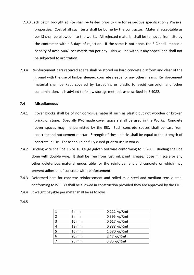
7.3.3 Each batch brought at site shall be tested prior to use for respective specification / Physical
properties. Cost of all such tests shall be borne by the contractor. Material acceptable as
per IS shall be allowed into the works. All rejected material shall be removed from site by
the contractor within 3 days of rejection. If the same is not done, the EIC shall impose a
penalty of Rest. 500/- per metric ton per day. This will be without any appeal and shall not
be subjected to arbitration.
7.3.4 Reinforcement bars received at site shall be stored on hard concrete platform and clear of the
ground with the use of timber sleeper, concrete sleeper or any other means. Reinforcement
material shall be kept covered by tarpaulins or plastic to avoid corrosion and other
contamination. It is advised to follow storage methods as described in IS 4082.
7.4 Miscellaneous 7.4.1 Cover blocks shall be of non-corrosive material such as plastic but not wooden or broken
bricks or stone. Specially PVC made cover spacers shall be used in the Works. Concrete
cover spaces may me permitted by the EIC. Such concrete spaces shall be cast from
concrete and not cement mortar. Strength of these blocks shall be equal to the strength of
concrete in use. These should be fully cured prior to use in works.
7.4.2 Binding wire shall be 16 or 18 gauge galvanized wire conforming to IS 280 . Binding shall be
done with double wire. It shall be free from rust, oil, paint, grease, loose mill scale or any
other deleterious material undesirable for the reinforcement and concrete or which may
prevent adhesion of concrete with reinforcement.
7.4.3 Deformed bars for concrete reinforcement and rolled mild steel and medium tensile steel
conforming to IS 1139 shall be allowed in construction provided they are approved by the EIC.
7.4.4 it weight payable per meter shall be as follows : 7.4.5
1 6 mm 0.222 kg/Rmt
2 8 mm 0.395 kg/Rmt
3 10 mm 0.617 kg/Rmt
4 12 mm 0.888 kg/Rmt
5 16 mm 1.580 kg/Rmt
6 20 mm 2.47 kg/Rmt
7 25 mm 3.85 kg/Rmt
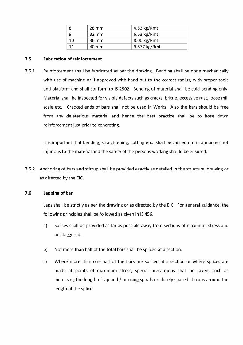
8 28 mm 4.83 kg/Rmt
9 32 mm 6.63 kg/Rmt
10 36 mm 8.00 kg/Rmt
11 40 mm 9.877 kg/Rmt
7.5 Fabrication of reinforcement
7.5.1 Reinforcement shall be fabricated as per the drawing. Bending shall be done mechanically
with use of machine or if approved with hand but to the correct radius, with proper tools
and platform and shall conform to IS 2502. Bending of material shall be cold bending only.
Material shall be inspected for visible defects such as cracks, brittle, excessive rust, loose mill
scale etc. Cracked ends of bars shall not be used in Works. Also the bars should be free
from any deleterious material and hence the best practice shall be to hose down
reinforcement just prior to concreting.
It is important that bending, straightening, cutting etc. shall be carried out in a manner not
injurious to the material and the safety of the persons working should be ensured.
7.5.2 Anchoring of bars and stirrup shall be provided exactly as detailed in the structural drawing or
as directed by the EIC.
7.6 Lapping of bar
Laps shall be strictly as per the drawing or as directed by the EIC. For general guidance, the
following principles shall be followed as given in IS 456.
a) Splices shall be provided as far as possible away from sections of maximum stress and
be staggered.
b) Not more than half of the total bars shall be spliced at a section.
c) Where more than one half of the bars are spliced at a section or where splices are
made at points of maximum stress, special precautions shall be taken, such as
increasing the length of lap and / or using spirals or closely spaced stirrups around the
length of the splice.
d) Lap splices shall not be used for bars larger than 36 mm diameter, for larger diameters,
bars may be welded. In cases where welding is not practical, lapping of bars larger
than 36 mm diameter may be permitted and additional spirals should be provided
around the lapped bars.
e) Lap length including anchorage value of hooks in flexural tension shall be Ld (as defined
in 25.2.1 of IS 456) or 30 dia whichever is greater and for direct tension 2 Ld or 30 dia
whichever is greater. The straight length of lap shall not be less than 15 dia or 20 cm.
Where Ld is the development as described in 25.2.1 of IS 456.
f) When splicing of welded wire fabric is to be carried out, lap splices or wires shall be
made so that the overlap measured between the extreme cross wires shall be not less
than the spacing of cross wires plus 10 cm.
g) The lap length in compression shall be equal to the development length in
compression, calculated as described in 25.2.1 of IS 456 or as specified in drawing but
not less than 24 dia.
7.7 Spacing of bars
Bars shall be placed in position as shown in the drawing. Following guidelines as given in IS 456
shall be followed in case of difficulties or shall be carried out as directed by the EIC.
a) Horizontal distance between two parallel main reinforcing bars shall usually not be less than
the greatest of the following.
1) The diameter of the bars, if the diameters are equal.
2) The diameter or larger bar, if the diameters are unequal, and
3) 5 mm more than the nominal maximum size of coarse aggregate (by using reduced size of
aggregate in congested reinforced area, conditions given hereof should be overcome)
b) Greater horizontal distance should be provided. But when needle vibrators are used, distance
between bars of a group may be reduced to two-third of the nominal maximum size of the
coarse aggregate, provided sufficient space is left between groups of bars to enable the
vibrator to be immersed.
c) Where there are two or more rows, the bars shall be vertically in line and the minimum
vertical distance between the bars shall be 15 mm two third the nominal maximum size of the
aggregate or the maximum size of bar, whichever is more.
7.8 Cover to reinforcement
Reinforcement shall have concrete cover and the thickness of such cover (exclusive of
plaster or other decorative finish) shall be as specified in drawing or as directed by the EIC.
The following guidelines are to be observed in the absence of the above.
a) At each end of the reinforcing bar, not less than 25 mm, nor less than twice the
diameter of such bar. b) For a longitudinal bar in a column, not less than 40 mm, nor less than the diameter of
such bar. In case of columns of minimum dimension of 200mm or under, whose reinforcing bars do not exceed 12 mm, a cover of 25 mm.
c) For longitudinal reinforcing bar in beam, not less than 25 mm, nor less than the
diameter of such bar.
d) For tensile, compressive, shear or other reinforcement, in slab not less than 15 mm, nor less than the diameter of such bar and
e) For any other reinforcement, not less than 15 mm, nor less than the diameter of such
bar.
f) Increased thickness shall be provided in case the concrete members are in the surrounding of harmful chemicals; saline atmosphere etc. and the cover shall be 50 mm or more as directed by the EIC.
g) For concrete members totally immersed in seawater, the cover shall be 40 mm more
than specified above (a) to (f).
This shall be 50 mm more for periodical immersion in seawater.
h) Concrete cover should not exceed 75 mm in any case. Cover to reinforcement shall be as specified in the drawing or as directed by the EIC.
Details given in sub para (a) to (h) are for guidance and shall be followed in absence of any specific
direction.
7.9 Fixing in position
Correctly cut and bent bars shall be accurately placed in position as detailed in the drawing.
Unless otherwise specified by the EIC, reinforcement shall be positioned within the tolerance
as under:
a) For effective depth 200 mm or less 10 mm
b) For effective depth more than 200 mm 15 mm
But in no case shall the cover be reduced by more than 5 mm of that specified. There shall
be no compromise on cover for foundation work.
Reinforcing bars shall be held in position during the placing of concrete by use of PVC or
concrete cover blocks (made of equal / of higher grade strength of well-cured concrete in
use) steel chair spacers, steel hangers, supporting wires, etc. and secured by tying with an
annealed binding wire of 16 to 18 gauge as approved by the EIC.
Layer of bars shall be separated by precast concrete spacer blocks or spacer bars.
Reinforcement shall be in correct position prior to start of concreting. No reinforcing bar
shall be placed on freshly laid concrete for adjusting bar spacing. Care shall be taken to
maintain reinforcement in position and keep it clean, throughout the period till it is
embedded in the concrete. For maintaining cover, pieces of broken stone or brick or
wooden blocks shall not be used at any stage.
Binding wire used shall conform to IS 280.
7.10 Welded joints or mechanical connections
7.10.1 Welded joints or mechanical connections in reinforcement may be used but in all cases or
important connections, tests shall be made to prove that the joints are of the full strength of
the connected bars. Welding of reinforcement shall be done in accordance with IS
recommendation.
7.10.2 Where reinforcement bars are bent aside at construction joints and afterwards bent back
into their original position, care should be taken to ensure that at no time is the radius of the
bend less than 4 bar diameters in case of plain mild steel or 6 bar diameters for deformed
bars. Care shall be taken when bending back bars to ensure that the concrete around is not
damaged / disturbed.
7.10.3 Welding rods used shall conform to IS 814 : covered electrodes for metal arc welding of
structural steel. Work shall be carried out by a competent welder. Samples from Work site
shall be taken at regular. Intervals and tested. Frequency and number of samples shall be as
directed by the EIC.
7.11 Measurements
Reinforcement shall be measured as follows :
1. Lengths of different diameters of bars actually used included authorized overlaps shall
be measured nearest to a centimeter and their weight calculated as given in table 2.4.4
shall be used.
2. Chairs and spacer bars shall not be measured and paid. The contractor shall account
for all these in his quoted price.
3. In case of welded coupled joints, measurement for payment shall be equivalent to the
length of overlap, as per design
4. Price build-up shall include, in addition to cost of material.
a) Cover blocks of PVC or concrete. b) Spacer bars, chairs and unauthorized overlaps (Allowed for convenience) c) Cutting, bending, placing and fixing in position. d) Binding wire as approved. e) Wastage / Rolling margin. f) Cleaning of bars.
5. For purpose of reconciliation, maximum wastage permitted shall be 5% of the actual
material used. Balance shall be charged at 1.5 times the actual market rates as
penalty.
7.12 OPENING / INSERTS 7.12.1 All required openings and pockets should be provided as detailed in the drawing. They may
be enumerated or paid on area basis as detailed in the BOQ. The contractor shall provide for
the required materials, labour, for fixing and supporting during concreting. In his quoted
price. It is imperative that all openings and pockets shall be de-shuttered with care and
all corners of openings shall be preserved. All openings/pocked shall be in a correct line
and level. After concreting, the openings shall be secured against any accident by proper
covering and guardrail and warning notice, if any.
The contractor shall clean and grout the pocket at a later date with a non-shrinking
compound added to the grout mix or non-shrinking cement shall be used. It shall be well-
cured and protected to correct line and level till handling over.
7.12.2 Inserts are material such as timber, steel, plastic, and dowels. Bolts, locks, brackets, pipes, etc.
left in concrete partly or fully embedded to receive connection with foreign member at a later
date. These may be fabricated by the contractor or provided by the owner as received from
specialist, manufacturer, etc. These shall be protected from weathering and damage in course
of the construction. The cleaning required after concreting and any treatment such as oiling,
greasing or covering with paint etc. shall be carried out by the contractor at his cost.
7.12.3 It is very important that the providing and fixing as contemplated in the BOQ shall be carried
out with the “utmost precision” and to the entire satisfaction of the EIC. Any deviation from
that as shown in the drawings or instructions shall be rectified by the contractor at his own
cost and responsibility.
7.13 GROUTING
7.13.1 EQUIPMENT:
Grout agitation:
The grout shall be continuously agitated in a suitable mixer with minimum speed of 1000
RPM and travel of discharge not exceeding 15m per second. The grout shall be maintained
on homogenous state and of uniform consistency so that there is no separation of cement.
7.13.2 GROUT PUMP:
The grout pump shall be positive displacement type and shall be capable of injecting the
grout in a continuous operation and not by way of pulses. The grout pump shall be fitted
with pressure gauge to enable pressure of injection to be controlled. The minimum pressure
the grout to be pumped shall be 3kg/sq.cm and the grout pump shall have a relief
arrangement for by pass of the grout in case the built up pressure is beyond 10kg/sq.cm.
7.13.3 WATER PUMP:
A stand by direct feed high pressure water pump shall be made available at site for an
emergency. In case of any problem due to which the duct cannot be grouted successfully,
such water pump shall immediately by connected to the duct and all grout washed by use of
high pressure water flushing.
7.13.4 GROUT SCREEN
The grouting equipment shall contain a screen having a mesh size of IS 106. Prior to
introduction into the grouting pump. The grout shall be passed through such screen.
7.14 MATERIALS
Only neat cement grout shall be used and the ingredients shall conform to the following
7.14.1 CEMENT
Cement for grouting shall conform to specification laid down in clause of the special
specifications but rapid hardening. Portland cement may be used when grouting is to be
done at temperatures less than 72 degree centigrade. Cement for grouting shall be arranged
by the contractor at his own cost.
7.14.2 WATER
Only clean portable water free from impurities and confirming to clause of special
specifications shall be used for grouting and cleaning of ducts.
7.14.3 ADMIXTURE:
Admixtures may be used after taking prior approval of the consultant only if tests have
shown that their use improves the property of the grout i.e increasing fluidity, reducing
bleeding etc. They shall contain no chloride, nitrate, sulphate or any other ingredients which
may induce corrosion of steel. The admixture, if used shall be at the cost of the contractor.
7.15 GROUT OPENING OR VENTS:
Standard details of fixing outlets and air vents to the ducts anchorage shall be used as
recommended by the supplier of the system of prestressing.
All ducts shall have grout opening at both ends. For this purposes, special openings at both
the ends. For this purposes, special opening shall be provided where such openings are not
available anchorages. Vents shall be provided at all crests and valleys in the duct profile and
at intervals of not more than 15m straight reaches. All grout openings of vents shall include
provisions of preventing grout leakage.
7.16 PROPERTIES OF GROUT:
The water content of the mix shall be kept as low as practicable, consistent with the
workability and the water/cement ratio shall not exceed 0.45. In most cases, a
water/cement ratio of 0.4 will be preferable when using a neat cement grout.
Before grouting, the contractor shall prepare test specimen to check the properties of the
grout and shall obtain approval of the consultant. The compressive strength of the grout at
7days measured on 100cm cubes, shall be not less than 175kg/sq.cm. The test shall be cured
in moist atmosphere for 24 hours and subsequently in water.
7.17 MIXING OF GROUT
Water shall be added to the mixer first, followed by cement and admixture, if any shall be
added at the last in does as recommended by the manufacturer.
Mixing time shall depend upon the type of mixer but shall in no case be less than 2 minutes.
The grout shall be continuously agitated until it is injected. Once mixed, no water shall be
added to the grout to increase its fluidity. Hand mixing shall not be permitted.
After mixing and before introducing in the grouting pump the grout shall be passed through
grout screen as directed by the Consultant.
7.18 GROUTING OPERATION
The grouting shall be carried oyt as early as practicable after the tendon has been tensioned.
Grouting shall be avoided in very cold weather. In case of stage prestressing cable tension in
the first stage shall not remain ungrouted till all cable are tensioned. While grouting one
duct in stage prestressing the other ducts shall be kept filled with water or by running water
in such ducts till such time the grout sets in the ducts which is being grouted. Afterwards the
water from such ducts shall be drained out or removed with compressed air to prevent
corrosion.
Any trace of oil if supplied to steel for preventing corrosion shall be removed before
grouting. The duct shall be removed before grouting. The duct shall be flushed with clean
potable water for cleaning as well as wetting the duct wall immediately before grouting. All
the water should be allowed to drain through lowest vent pipe or by passing compressed air
through the duct. All outlets points including the air vent opening shall be kept open before
commencement of grout injection.
The injection of grout shall be continuous sand shall not be interrupted. Grouting shall be
done from one end only through the opening in the anchorage system. Grout shall be
allowed to flow from vent openings until its consistency at exit is same as that of the grout
injected. The vent openings shall thereafter be firmly closed one after another in the
direction of the flow.
Grouting shall be commenced initially with a low pressure of injection of upto 2 kg per
sq.cm. increasing it until the gout cones out of the openings. When all the openings have
been closed one after the other as described in the clause above, injection shall be

continued till the pressure for above one minute before closing the inlet pipe. Care shall be
taken not to rupture the closing the injection grout unnecessarily under high pressure.
Under no circumstances the pressure shall not be allowed to increase beyond 10kg /sq.cm.
Grout not used within 30 minutes of mixing shall be rejected.
All necessary precautions and procedure for grouting shall be followed as per recommended
practice for grouting of post tensioned cables in prestressed concrete works as given in
Appendix 2 of IRC 4S-1985.
8.0 PRESTRESSED / POST TENSION CONCRETE WORK
8.1 GENERAL
No separate specifications are needed for prestressed / Post tension concrete work so far as
concrete work so far as concrete and formwork are concerned. These have been already under.
However, special items like H.T. Steel tendons, anchors, stressing grouting etc. peculiar to pre-
stressing / Post tension are given hereinafter.
8.2 HIGH TENSILE STEEL
H.T. steel to be used in all pre-stressing work shall conform to relevant I.S. Specification listed in 1
of these specifications. Each consignment or batch of H.T. steel supplied at site shall be
accompanied by the manufacturer’s test certificate.
If so desired by the Design Engineer / PMC additional tests on sample of steel taken from the site
consignment shall be carried out by the Contractors at an approved laboratory and at contractors
own cost and the representatives of PMC shall be given necessary facilities to witness such tests.
The wire shall be stored in weather proof sheds on damp proof platforms at least 300mm above
ground level to avoid contamination with soil, ground water etc.
The H.T. steel before being incorporated in the works shall be free from loose rust, scales grease
and similar other deleterious matter liable to adversely affect its bond with concrete / grout. It
shall also be free of kinks, notches and other mechanical defects liable to adversely affect its
strength.
H.T. steel shall be supplied in straight length or in large diameter coil to lay out straight.
8.3 TOOLS AND TACKLES:
The contractor may be asked to procure his own stressing jacks, pumps, sheathing and such other
appurtenances as are necessary for the workmanlike execution of the work and as are prescribed
by the makers of the respective system. The Contractor is bound to supply the PMC all the
pertinent information for the pre-stressing system adopted by him. However the right to accept
or reject any system of pre-stressing, the sufficiency of other precautions, etc. lies with the PMC
and his decision shall be final and binding.
8.4 SHEATHING
In case of post – tensioned prestressed work all tendons shall be properly encased in galvanized
metal sheathing of proper diameter till the final stressing of the tendon is done. The sheathing
shall be strong enough to bear the cable weight or any other incidental loads and impacts applied
during construction. It should also be flexible enough to adopt smooth curvatures of the tendons.
The sheathing and the connection of the same with anchorages or other pieces of sheathing shall
be leakage – tight in order to avoid ingress of cement slurry inside the ducts during concreting and
leakage of grout during grouting. Suitable acceptance tests for achieving the same may be called
for by the Engineer. The thickness of metal strips forming sheathing shall not be less than 0.24
mm for sheathing upto 48mm I.D. and 0.30mm for sheathing upto 60mm I.D. Higher thickness
may be specified for larger diameter. The density of galvanizing shall not be less than 35 gm / m2
on each surface.
8.5 ANCHORAGES
The anchoring devices shall be such as to hold the pre-stressing tendons firmly and permanently
and be strong enough to resist in all respects, force equal to at least 92% of breaking strength of
the pre-stressing element in anchors. The minimum elongation of wires when tested for above
should not be less than 1.8%. The anchorages shall transfer effectively and distribute evenly the
entire force from the pre-stressing tendons to the concrete without inducing dangerous
secondary stresses. The anchorages shall be adequately protected against damage and corrosion
by encasing them in concrete.
The maximum permissible slip or take – up during the seating of anchorage shall be specified by
the manufacturer and this shall form part of performance specification for the anchorages
accepted for the works. This slip shall not be exceeded during the actual execution of work.
8.6 TENDONS
The steel wires shall be continuous over the entire length of tendon and joints shall not be
permitted. The tendons shall be carefully and accurately located in the exact position and profiles
and the method of fixing them shall be such that they are not displaced during or compaction of
concrete and during tensioning. Type of fixtures used for positioning of tendons shall be such as
not to give rise to friction greater than prescribed codal limits. The fixtures and the entire scheme
of positioning tendons will be duly approved by PMC>
8.7 STRESSING
After the concrete has reached the required strength as well as has achieved prescribed age,
stressing operation may be undertaken. The pre-stressing job shall be done under supervision of
an experienced supervisor approved by the PMC and in the presence of an authorized
representative of the PMC. The force in tendons shall be measured by means of calibrated and
approved pressure gauges attached to the tensioning apparatus as well as by measuring the
extension of steel and relating it to stress – strain curve as per IS : 1343. Variation upto a limit of
5% either for force or elongation will be normally accepted. Variations beyond the above limits
shall be reported to the PMC.
The instructions entered on drawings shall be carefully followed. The Contractor shall forward 3
copies of the entire stressing and elongation data to the PMC in prescribed form. The data so
forwarded will bear signature, both pf representative of PMC and the Contractor’s supervisor
present during stressing. The data shall be true and faithful record of actual measurements at site.
All the equipment such as dial gauges etc. will be checked periodically and check certificates
obtained for record.
8.8 GROUTING
All the tendons will be fully grouted as early as practicable as and not later than 48 hours after
they are finally stressed unless otherwise permitted by the PMC.
The grouting holes shall be left in concrete at such places and in such manner as directed by PMC.
The cable ducts will be first cleaned by passing compressed air through them in order to see than
no obstructions to passage of grout exist. They will then be cleaned thoroughly by water after
which grouting will be started. The grout shall be made to the consistency of thick paste with
water cement ration not exceeding 0.60. After flushing the ducts thoroughly as indicated above,
grout will be injected under a pressure of 3.5 to 7 kg / cm2 from one end till it overflows at the
other end of the duct. Grouting shall be continued till all the water in the duct is expelled and the
consistency of the grout emerging at the exit and is the same as that of the grout being pumped
in. The exit end will then be plugged and grouting continued till pressure gauge consistently
records the pressure of grout being injected.
Necessary tests of consistency, blending and strength shall be carried out for finally deciding upon
the grout mix.
Regrouting will be done to fill up the space formed as a result of settlement of grout after
minimum 24 hours.
TOLERANCE IN PRESTRESSING CABLES:
Prestressed concrete cables will be laid such that their profile is a smooth curve unless otherwise
specified.
The alignment tolerances shall be as under:-
Member with a depth of Tolerance in direction of depth‘d’ of
members
upto 210mm + or – d / 40
210 – 1000mm wide + or – 5mm
more than 1000mm + or – 10mm
Tolerance in direction of width
of member @
the level of tendon.
upto 210mm + or – 5mm
210 – 1000 m wide + or – 10mm
than 1000mm wide + or – 21mm
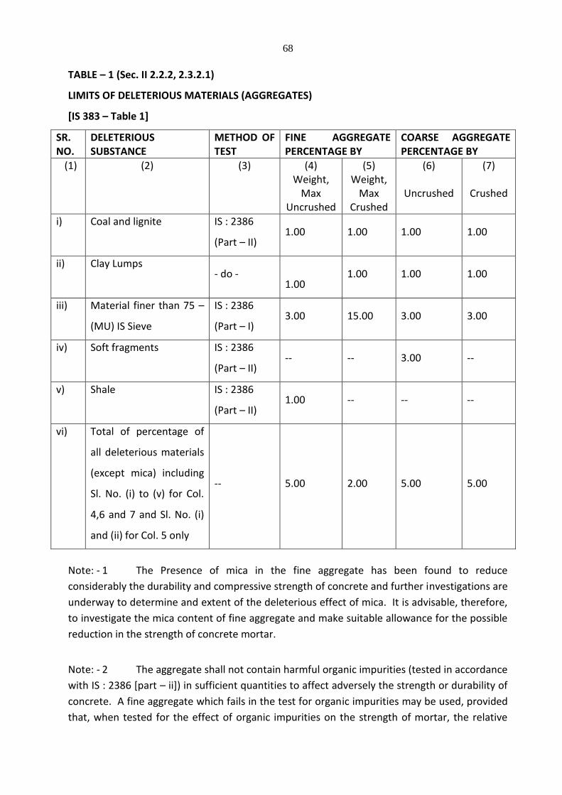
68
TABLE – 1 (Sec. II 2.2.2, 2.3.2.1)
LIMITS OF DELETERIOUS MATERIALS (AGGREGATES)
[IS 383 – Table 1]
SR. NO.
DELETERIOUS SUBSTANCE
METHOD OF TEST
FINE AGGREGATE PERCENTAGE BY
COARSE AGGREGATE PERCENTAGE BY
(1) (2) (3) (4) Weight,
Max Uncrushed
(5) Weight,
Max Crushed
(6)
Uncrushed
(7)
Crushed
i) Coal and lignite IS : 2386
(Part – II) 1.00 1.00 1.00 1.00
ii) Clay Lumps - do -
1.00 1.00 1.00 1.00
iii) Material finer than 75 –
(MU) IS Sieve
IS : 2386
(Part – I) 3.00 15.00 3.00 3.00
iv) Soft fragments IS : 2386
(Part – II) -- -- 3.00 --
v) Shale IS : 2386
(Part – II) 1.00 -- -- --
vi) Total of percentage of
all deleterious materials
(except mica) including
Sl. No. (i) to (v) for Col.
4,6 and 7 and Sl. No. (i)
and (ii) for Col. 5 only
-- 5.00 2.00 5.00 5.00
Note: - 1 The Presence of mica in the fine aggregate has been found to reduce
considerably the durability and compressive strength of concrete and further investigations are
underway to determine and extent of the deleterious effect of mica. It is advisable, therefore,
to investigate the mica content of fine aggregate and make suitable allowance for the possible
reduction in the strength of concrete mortar.
Note: - 2 The aggregate shall not contain harmful organic impurities (tested in accordance
with IS : 2386 [part – ii]) in sufficient quantities to affect adversely the strength or durability of
concrete. A fine aggregate which fails in the test for organic impurities may be used, provided
that, when tested for the effect of organic impurities on the strength of mortar, the relative

69
strength at 7 and 28 days, reported in accordance with 7 of IS : 2386 [ Part – VI] – 1963 is not
less than 95% percent.
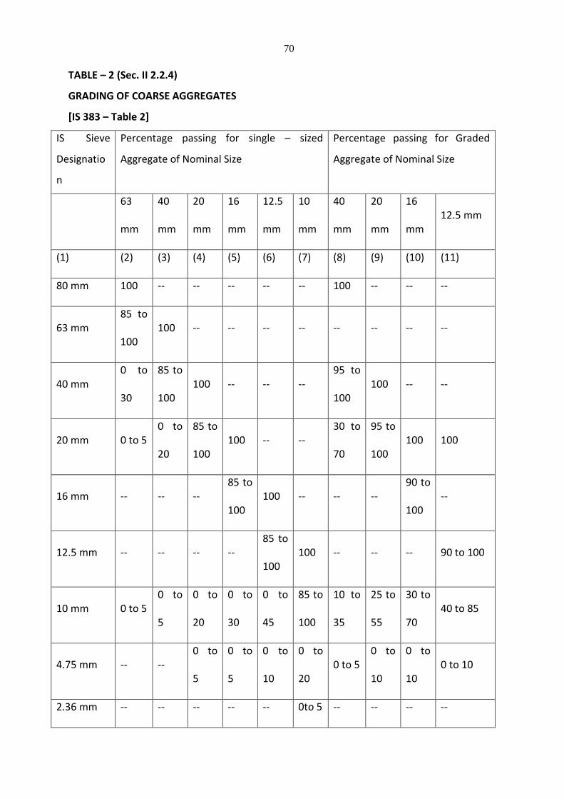
70
TABLE – 2 (Sec. II 2.2.4)
GRADING OF COARSE AGGREGATES
[IS 383 – Table 2]
IS Sieve
Designatio
n
Percentage passing for single – sized
Aggregate of Nominal Size
Percentage passing for Graded
Aggregate of Nominal Size
63
mm
40
mm
20
mm
16
mm
12.5
mm
10
mm
40
mm
20
mm
16
mm 12.5 mm
(1) (2) (3) (4) (5) (6) (7) (8) (9) (10) (11)
80 mm 100 -- -- -- -- -- 100 -- -- --
63 mm 85 to
100 100 -- -- -- -- -- -- -- --
40 mm 0 to
30
85 to
100 100 -- -- --
95 to
100 100 -- --
20 mm 0 to 5 0 to
20
85 to
100 100 -- --
30 to
70
95 to
100 100 100
16 mm -- -- -- 85 to
100 100 -- -- --
90 to
100 --
12.5 mm -- -- -- -- 85 to
100 100 -- -- -- 90 to 100
10 mm 0 to 5 0 to
5
0 to
20
0 to
30
0 to
45
85 to
100
10 to
35
25 to
55
30 to
70 40 to 85
4.75 mm -- -- 0 to
5
0 to
5
0 to
10
0 to
20 0 to 5
0 to
10
0 to
10 0 to 10
2.36 mm -- -- -- -- -- 0to 5 -- -- -- --
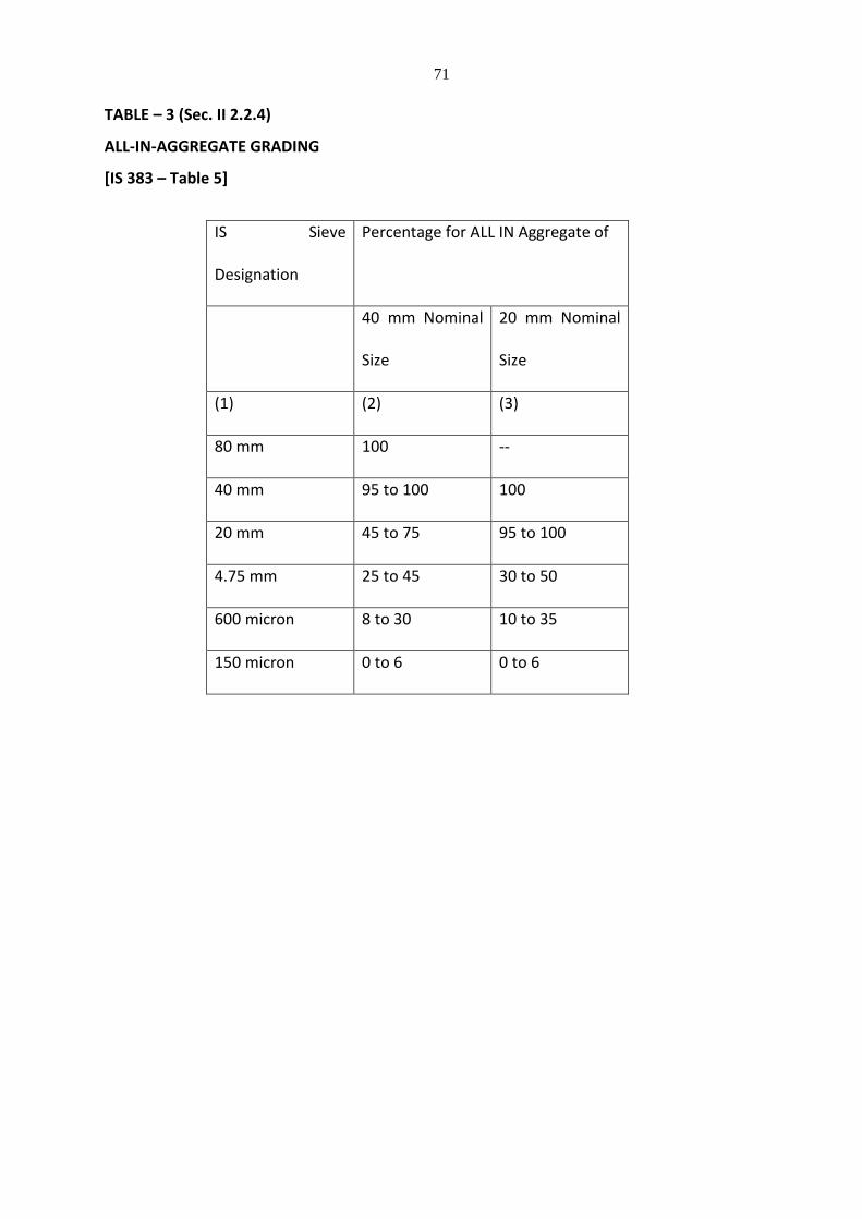
71
TABLE – 3 (Sec. II 2.2.4)
ALL-IN-AGGREGATE GRADING
[IS 383 – Table 5]
IS Sieve
Designation
Percentage for ALL IN Aggregate of
40 mm Nominal
Size
20 mm Nominal
Size
(1) (2) (3)
80 mm 100 --
40 mm 95 to 100 100
20 mm 45 to 75 95 to 100
4.75 mm 25 to 45 30 to 50
600 micron 8 to 30 10 to 35
150 micron 0 to 6 0 to 6
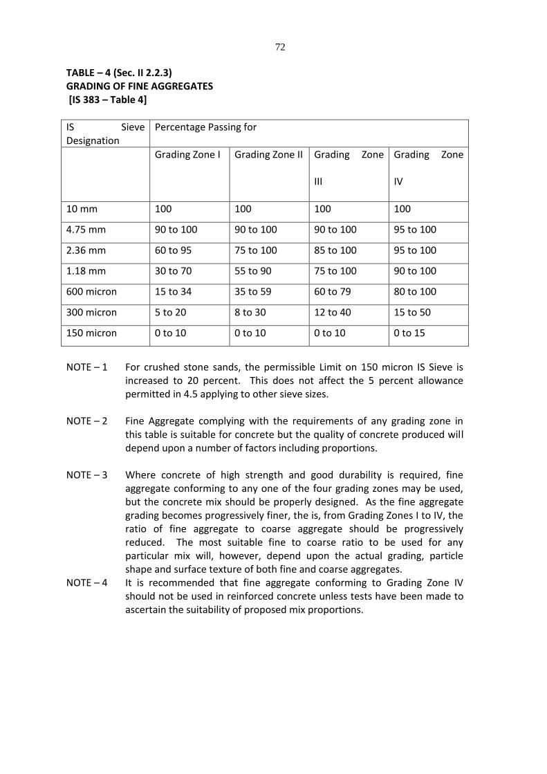
72
TABLE – 4 (Sec. II 2.2.3) GRADING OF FINE AGGREGATES [IS 383 – Table 4]
IS Sieve Designation
Percentage Passing for
Grading Zone I Grading Zone II Grading Zone
III
Grading Zone
IV
10 mm 100 100 100 100
4.75 mm 90 to 100 90 to 100 90 to 100 95 to 100
2.36 mm 60 to 95 75 to 100 85 to 100 95 to 100
1.18 mm 30 to 70 55 to 90 75 to 100 90 to 100
600 micron 15 to 34 35 to 59 60 to 79 80 to 100
300 micron 5 to 20 8 to 30 12 to 40 15 to 50
150 micron 0 to 10 0 to 10 0 to 10 0 to 15
NOTE – 1 For crushed stone sands, the permissible Limit on 150 micron IS Sieve is
increased to 20 percent. This does not affect the 5 percent allowance permitted in 4.5 applying to other sieve sizes.
NOTE – 2 Fine Aggregate complying with the requirements of any grading zone in
this table is suitable for concrete but the quality of concrete produced will depend upon a number of factors including proportions.
NOTE – 3 Where concrete of high strength and good durability is required, fine
aggregate conforming to any one of the four grading zones may be used, but the concrete mix should be properly designed. As the fine aggregate grading becomes progressively finer, the is, from Grading Zones I to IV, the ratio of fine aggregate to coarse aggregate should be progressively reduced. The most suitable fine to coarse ratio to be used for any particular mix will, however, depend upon the actual grading, particle shape and surface texture of both fine and coarse aggregates.
NOTE – 4 It is recommended that fine aggregate conforming to Grading Zone IV should not be used in reinforced concrete unless tests have been made to ascertain the suitability of proposed mix proportions.
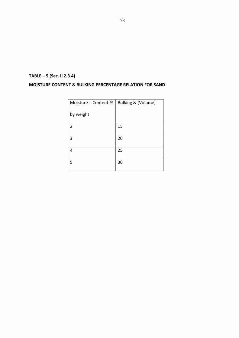
73
TABLE – 5 (Sec. II 2.3.4)
MOISTURE CONTENT & BULKING PERCENTAGE RELATION FOR SAND
Moisture - Content %
by weight
Bulking & (Volume)
2 15
3 20
4 25
5 30
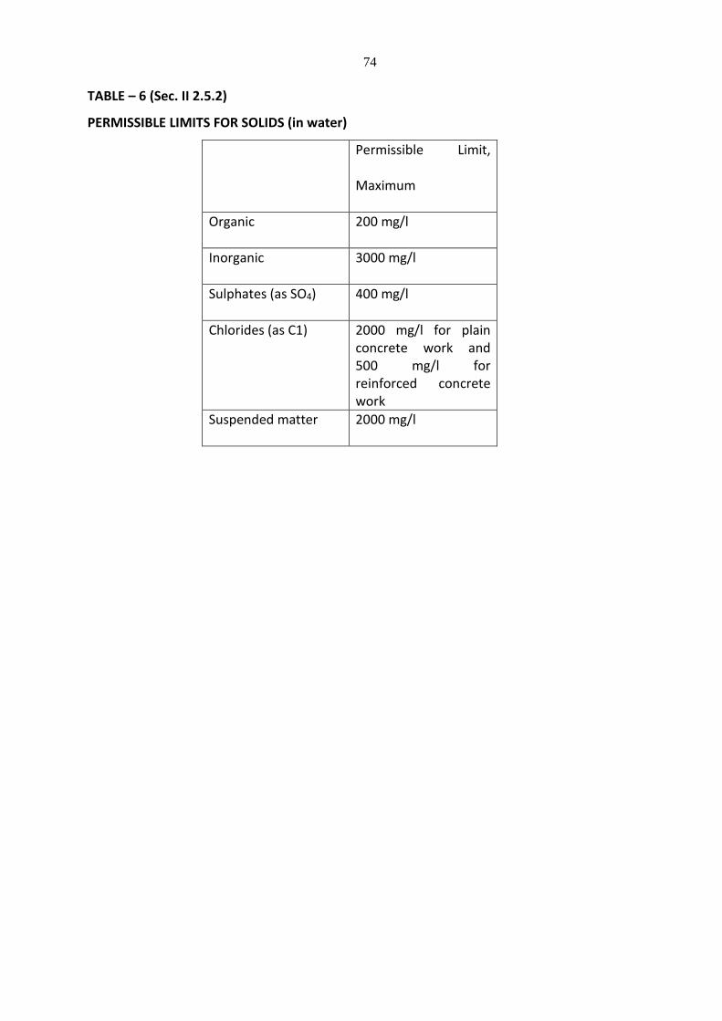
74
TABLE – 6 (Sec. II 2.5.2)
PERMISSIBLE LIMITS FOR SOLIDS (in water)
Permissible Limit,
Maximum
Organic 200 mg/l
Inorganic 3000 mg/l
Sulphates (as SO4) 400 mg/l
Chlorides (as C1) 2000 mg/l for plain concrete work and 500 mg/l for reinforced concrete work
Suspended matter 2000 mg/l
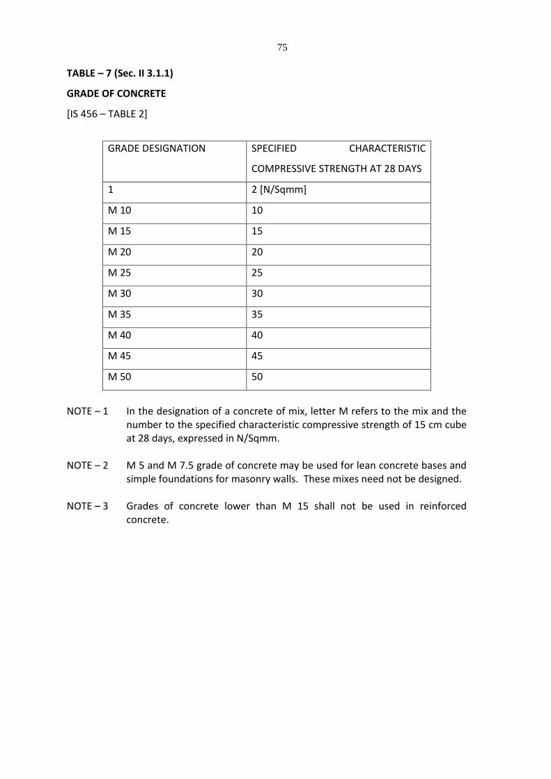
75
TABLE – 7 (Sec. II 3.1.1)
GRADE OF CONCRETE
[IS 456 – TABLE 2]
GRADE DESIGNATION SPECIFIED CHARACTERISTIC
COMPRESSIVE STRENGTH AT 28 DAYS
1 2 [N/Sqmm]
M 10 10
M 15 15
M 20 20
M 25 25
M 30 30
M 35 35
M 40 40
M 45 45
M 50 50
NOTE – 1 In the designation of a concrete of mix, letter M refers to the mix and the
number to the specified characteristic compressive strength of 15 cm cube at 28 days, expressed in N/Sqmm.
NOTE – 2 M 5 and M 7.5 grade of concrete may be used for lean concrete bases and
simple foundations for masonry walls. These mixes need not be designed. NOTE – 3 Grades of concrete lower than M 15 shall not be used in reinforced
concrete.
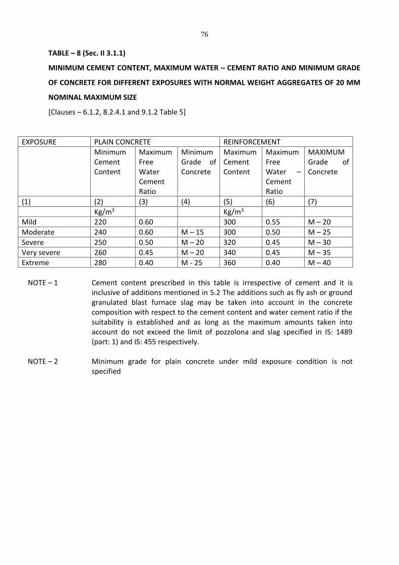
76
TABLE – 8 (Sec. II 3.1.1)
MINIMUM CEMENT CONTENT, MAXIMUM WATER – CEMENT RATIO AND MINIMUM GRADE
OF CONCRETE FOR DIFFERENT EXPOSURES WITH NORMAL WEIGHT AGGREGATES OF 20 MM
NOMINAL MAXIMUM SIZE
[Clauses – 6.1.2, 8.2.4.1 and 9.1.2 Table 5]
EXPOSURE PLAIN CONCRETE REINFORCEMENT
Minimum Cement Content
Maximum Free Water Cement Ratio
Minimum Grade of Concrete
Maximum Cement Content
Maximum Free Water – Cement Ratio
MAXIMUM Grade of Concrete
(1) (2) (3) (4) (5) (6) (7)
Kg/m3 Kg/m3
Mild 220 0.60 300 0.55 M – 20
Moderate 240 0.60 M – 15 300 0.50 M – 25
Severe 250 0.50 M – 20 320 0.45 M – 30
Very severe 260 0.45 M – 20 340 0.45 M – 35
Extreme 280 0.40 M - 25 360 0.40 M – 40
NOTE – 1 Cement content prescribed in this table is irrespective of cement and it is
inclusive of additions mentioned in 5.2 The additions such as fly ash or ground granulated blast furnace slag may be taken into account in the concrete composition with respect to the cement content and water cement ratio if the suitability is established and as long as the maximum amounts taken into account do not exceed the limit of pozzolona and slag specified in IS: 1489 (part: 1) and IS: 455 respectively.
NOTE – 2 Minimum grade for plain concrete under mild exposure condition is not
specified
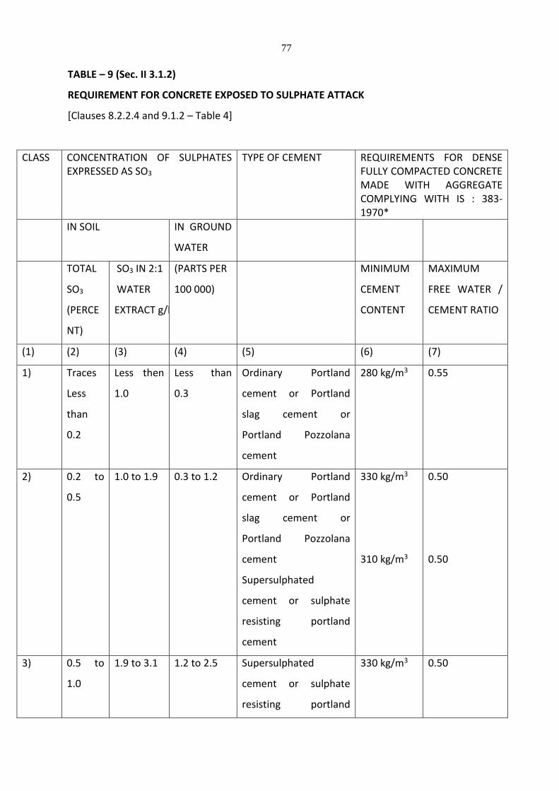
77
TABLE – 9 (Sec. II 3.1.2)
REQUIREMENT FOR CONCRETE EXPOSED TO SULPHATE ATTACK
[Clauses 8.2.2.4 and 9.1.2 – Table 4]
CLASS CONCENTRATION OF SULPHATES EXPRESSED AS SO3
TYPE OF CEMENT REQUIREMENTS FOR DENSE FULLY COMPACTED CONCRETE MADE WITH AGGREGATE COMPLYING WITH IS : 383-1970*
IN SOIL IN GROUND
WATER
TOTAL
SO3
(PERCE
NT)
SO3 IN 2:1
WATER
EXTRACT g/l
(PARTS PER
100 000)
MINIMUM
CEMENT
CONTENT
MAXIMUM
FREE WATER /
CEMENT RATIO
(1) (2) (3) (4) (5) (6) (7)
1) Traces
Less
than
0.2
Less then
1.0
Less than
0.3
Ordinary Portland
cement or Portland
slag cement or
Portland Pozzolana
cement
280 kg/m3 0.55
2) 0.2 to
0.5
1.0 to 1.9 0.3 to 1.2 Ordinary Portland
cement or Portland
slag cement or
Portland Pozzolana
cement
Supersulphated
cement or sulphate
resisting portland
cement
330 kg/m3
310 kg/m3
0.50
0.50
3) 0.5 to
1.0
1.9 to 3.1 1.2 to 2.5 Supersulphated
cement or sulphate
resisting portland
330 kg/m3
0.50
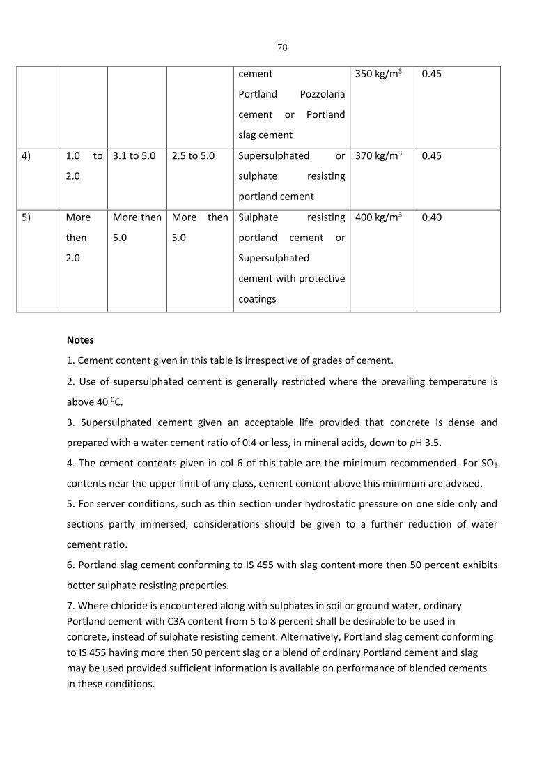
78
cement
Portland Pozzolana
cement or Portland
slag cement
350 kg/m3 0.45
4) 1.0 to
2.0
3.1 to 5.0 2.5 to 5.0 Supersulphated or
sulphate resisting
portland cement
370 kg/m3 0.45
5) More
then
2.0
More then
5.0
More then
5.0
Sulphate resisting
portland cement or
Supersulphated
cement with protective
coatings
400 kg/m3 0.40
Notes
1. Cement content given in this table is irrespective of grades of cement.
2. Use of supersulphated cement is generally restricted where the prevailing temperature is
above 40 0C.
3. Supersulphated cement given an acceptable life provided that concrete is dense and
prepared with a water cement ratio of 0.4 or less, in mineral acids, down to pH 3.5.
4. The cement contents given in col 6 of this table are the minimum recommended. For SO3
contents near the upper limit of any class, cement content above this minimum are advised.
5. For server conditions, such as thin section under hydrostatic pressure on one side only and
sections partly immersed, considerations should be given to a further reduction of water
cement ratio.
6. Portland slag cement conforming to IS 455 with slag content more then 50 percent exhibits
better sulphate resisting properties.
7. Where chloride is encountered along with sulphates in soil or ground water, ordinary
Portland cement with C3A content from 5 to 8 percent shall be desirable to be used in
concrete, instead of sulphate resisting cement. Alternatively, Portland slag cement conforming
to IS 455 having more then 50 percent slag or a blend of ordinary Portland cement and slag
may be used provided sufficient information is available on performance of blended cements
in these conditions.
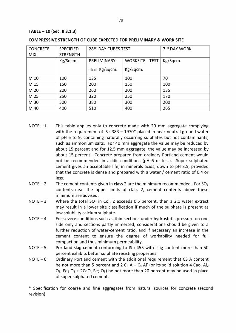
79
TABLE – 10 (Sec. II 3.1.3)
COMPRESSIVE STRENGTH OF CUBE EXPECTED FOR PRELIMINARY & WORK SITE
CONCRETE MIX
SPECIFIED STRENGTH
28TH DAY CUBES TEST 7TH DAY WORK
Kg/Sqcm. PRELIMINARY
TEST Kg/Sqcm.
WORKSITE TEST
Kg/Sqcm.
Kg/Sqcm.
M 10 100 135 100 70
M 15 150 200 150 100
M 20 200 260 200 135
M 25 250 320 250 170
M 30 300 380 300 200
M 40 400 510 400 265
NOTE – 1
This table applies only to concrete made with 20 mm aggregate complying with the requirement of IS : 383 – 1970* placed in near-neutral ground water of pH 6 to 9, containing naturally occurring sulphates but not contaminants, such as ammonium salts. For 40 mm aggregate the value may be reduced by about 15 percent and for 12.5 mm aggregate, the value may be increased by about 15 percent. Concrete prepared from ordinary Portland cement would not be recommended in acidic conditions (pH 6 or less). Super sulphated cement gives an acceptable life, in minerals acids, down to pH 3.5, provided that the concrete is dense and prepared with a water / cement ratio of 0.4 or less.
NOTE – 2 The cement contents given in class 2 are the minimum recommended. For SO3 contents near the upper limits of class 2, cement contents above these minimum are advised.
NOTE – 3 Where the total SO3 in Col. 2 exceeds 0.5 percent, then a 2:1 water extract may result in a lower site classification if much of the sulphate is present as low solubility calcium sulphate.
NOTE – 4 For severe conditions such as thin sections under hydrostatic pressure on one side only and sections partly immersed, considerations should be given to a further reduction of water-cement ratio, and if necessary an increase in the cement content to ensure the degree of workability needed for full compaction and thus minimum permeability.
NOTE – 5 Portland slag cement conforming to IS : 455 with slag content more than 50 percent exhibits better sulphate resisting properties.
NOTE – 6 Ordinary Portland cement with the additional requirement that C3 A content be not more than 5 percent and 2 C3 A + C4 AF (or its solid solution 4 Cao, Al2 O3, Fe2 O3 + 2CaO, Fe2 O3) be not more than 20 percent may be used in place of super sulphated cement.
* Specification for coarse and fine aggregates from natural sources for concrete (second revision)
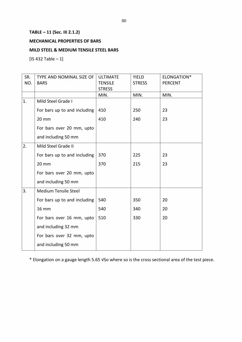
80
TABLE – 11 (Sec. III 2.1.2)
MECHANICAL PROPERTIES OF BARS
MILD STEEL & MEDIUM TENSILE STEEL BARS
[IS 432 Table – 1]
SR. NO.
TYPE AND NOMINAL SIZE OF BARS
ULTIMATE TENSILE STRESS
YIELD STRESS
ELONGATION* PERCENT
MIN. MIN. MIN.
1. Mild Steel Grade I
For bars up to and including
20 mm
For bars over 20 mm, upto
and including 50 mm
410
410
250
240
23
23
2. Mild Steel Grade II
For bars up to and including
20 mm
For bars over 20 mm, upto
and including 50 mm
370
370
225
215
23
23
3. Medium Tensile Steel
For bars up to and including
16 mm
For bars over 16 mm, upto
and including 32 mm
For bars over 32 mm, upto
and including 50 mm
540
540
510
350
340
330
20
20
20
* Elongation on a gauge length 5.65 √So where so is the cross sectional area of the test piece.
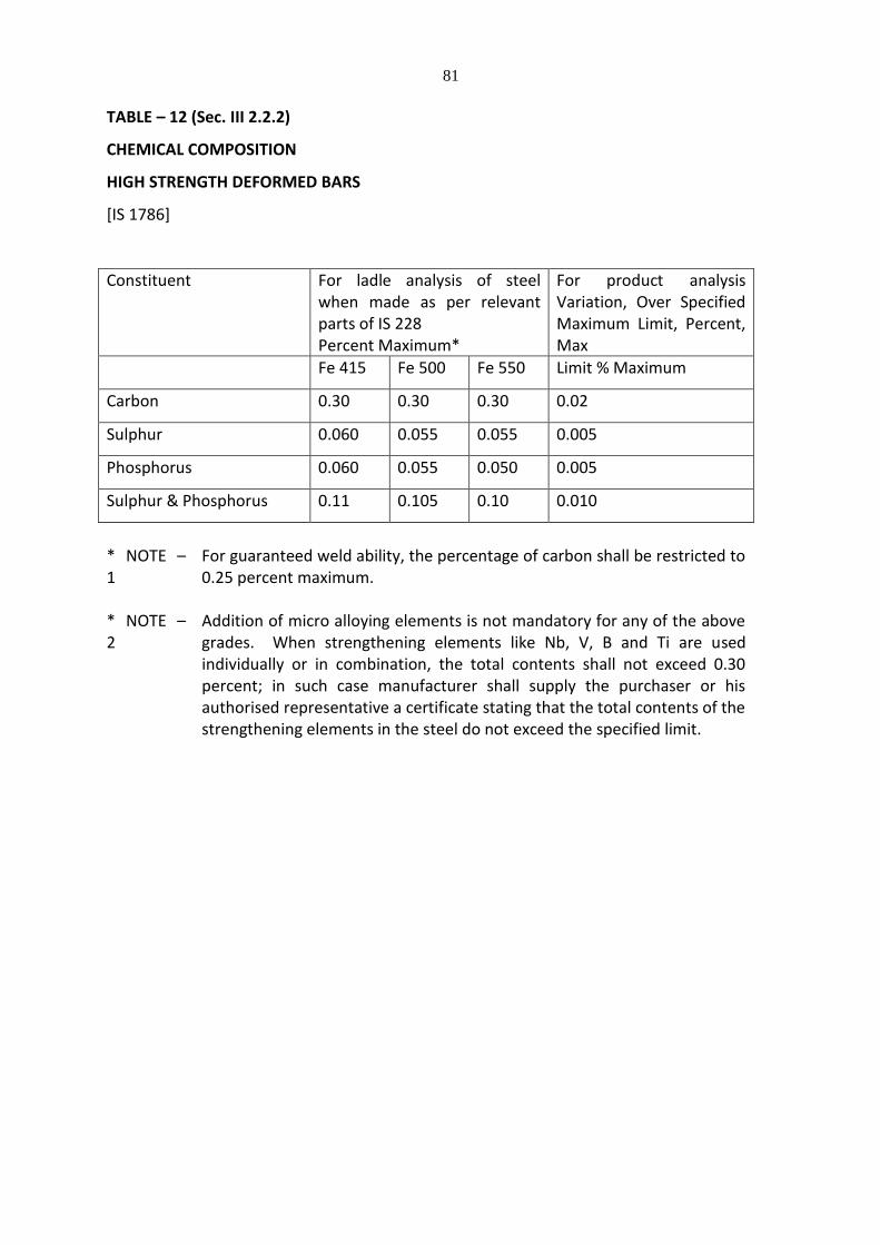
81
TABLE – 12 (Sec. III 2.2.2)
CHEMICAL COMPOSITION
HIGH STRENGTH DEFORMED BARS
[IS 1786]
Constituent For ladle analysis of steel when made as per relevant parts of IS 228 Percent Maximum*
For product analysis Variation, Over Specified Maximum Limit, Percent, Max
Fe 415 Fe 500 Fe 550 Limit % Maximum
Carbon 0.30 0.30 0.30 0.02
Sulphur 0.060 0.055 0.055 0.005
Phosphorus 0.060 0.055 0.050 0.005
Sulphur & Phosphorus 0.11 0.105 0.10 0.010
* NOTE – 1
For guaranteed weld ability, the percentage of carbon shall be restricted to 0.25 percent maximum.
* NOTE – 2
Addition of micro alloying elements is not mandatory for any of the above grades. When strengthening elements like Nb, V, B and Ti are used individually or in combination, the total contents shall not exceed 0.30 percent; in such case manufacturer shall supply the purchaser or his authorised representative a certificate stating that the total contents of the strengthening elements in the steel do not exceed the specified limit.
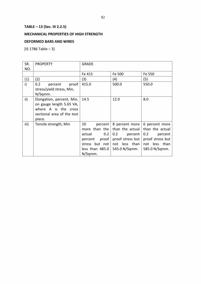
82
TABLE – 13 (Sec. III 2.2.5)
MECHANICAL PROPERTIES OF HIGH STRENGTH
DEFORMED BARS AND WIRES
[IS 1786 Table – 3]
SR. NO.
PROPERTY GRADE
Fe 415 Fe 500 Fe 550
(1) (2) (3) (4) (5)
i) 0.2 percent proof stress/yield stress, Min, N/Sqmm.
415.0 500.0 550.0
ii) Elongation, percent, Min, on gauge length 5.65 VA, where A is the cross sectional area of the test piece.
14.5 12.0 8.0
iii) Tensile strength, Min 10 percent more than the actual 0.2 percent proof stress but not less than 485.0 N/Sqmm.
8 percent more than the actual 0.2 percent proof stress but not less than 545.0 N/Sqmm.
6 percent more than the actual 0.2 percent proof stress but not less than 585.0 N/Sqmm.
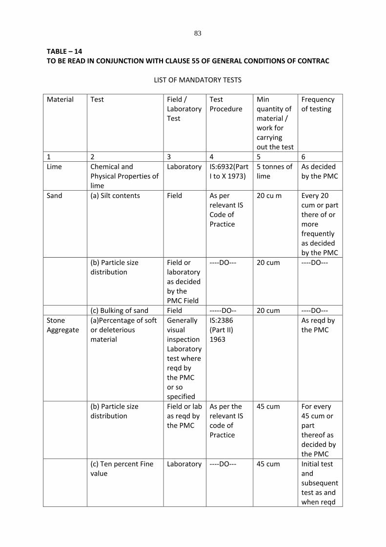
83
TABLE – 14 TO BE READ IN CONJUNCTION WITH CLAUSE 55 OF GENERAL CONDITIONS OF CONTRAC
LIST OF MANDATORY TESTS
Material Test Field / Laboratory Test
Test Procedure
Min quantity of material / work for carrying out the test
Frequency of testing
1 2 3 4 5 6
Lime Chemical and Physical Properties of lime
Laboratory IS:6932(Part I to X 1973)
5 tonnes of lime
As decided by the PMC
Sand (a) Silt contents Field As per relevant IS Code of Practice
20 cu m Every 20 cum or part there of or more frequently as decided by the PMC
(b) Particle size distribution
Field or laboratory as decided by the PMC Field
----DO--- 20 cum ----DO---
(c) Bulking of sand Field -----DO-- 20 cum ----DO---
Stone Aggregate
(a)Percentage of soft or deleterious material
Generally visual inspection Laboratory test where reqd by the PMC or so specified
IS:2386 (Part II) 1963
As reqd by the PMC
(b) Particle size distribution
Field or lab as reqd by the PMC
As per the relevant IS code of Practice
45 cum For every 45 cum or part thereof as decided by the PMC
(c) Ten percent Fine value
Laboratory ----DO--- 45 cum Initial test and subsequent test as and when reqd
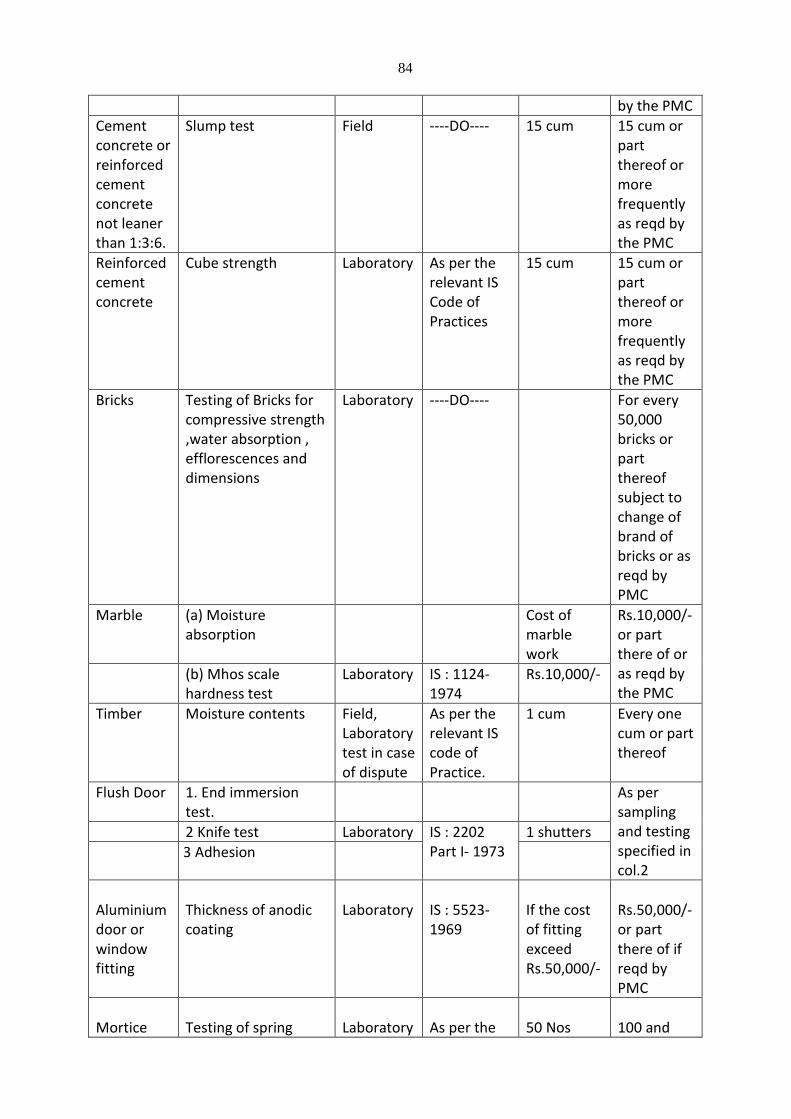
84
by the PMC
Cement concrete or reinforced cement concrete not leaner than 1:3:6.
Slump test Field ----DO---- 15 cum 15 cum or part thereof or more frequently as reqd by the PMC
Reinforced cement concrete
Cube strength Laboratory As per the relevant IS Code of Practices
15 cum 15 cum or part thereof or more frequently as reqd by the PMC
Bricks Testing of Bricks for compressive strength ,water absorption , efflorescences and dimensions
Laboratory ----DO---- For every 50,000 bricks or part thereof subject to change of brand of bricks or as reqd by PMC
Marble (a) Moisture absorption
Cost of marble work
Rs.10,000/- or part there of or as reqd by the PMC
(b) Mhos scale hardness test
Laboratory IS : 1124-1974
Rs.10,000/-
Timber Moisture contents Field, Laboratory test in case of dispute
As per the relevant IS code of Practice.
1 cum Every one cum or part thereof
Flush Door 1. End immersion test.
As per sampling and testing specified in col.2
2 Knife test Laboratory IS : 2202 Part I- 1973
1 shutters
3 Adhesion
Aluminium door or window fitting
Thickness of anodic coating
Laboratory
IS : 5523-1969
If the cost of fitting exceed Rs.50,000/-
Rs.50,000/- or part there of if reqd by PMC
Mortice
Testing of spring
Laboratory
As per the
50 Nos
100 and

85
locks relevant IS Code of Practice
beyond one for each 100 lock.
Steel (if arranged by contractor)
(a) Tensile strength
(b) Bend test
Laboratory IS : 1599-1974
20 Tonnes Every 20 tonnes or part thereof
Terrazo tiles
1. Transverse strength
2. Water absorption
3. Abrasion test
Laboratory IS : 1237-1959
2,000 tile 2,000 tile or part thereof
White glazed tiles
1. Water absorption
2. Crazing test 3. Impact
strength test
Laboratory IS : 777-1970
3,000 Nos 3,000 Nos or part thereof
STRUCTURAL STEEL 1.0 SCOPE OF WORK
1.1 Scope of Specifications
This section shall apply to the fabrication and erection of steel structures for all general
purposes.
The work shall include the supply, delivery, off-loading and erection, and unless
otherwise stated, fastening and fittings of every type which are described in or implied
by this specification whether shown on the Drawings or not, and shall include every
detail required for the works complete in position and in perfect state including shop
drawings etc. The works shall be generally as shown on the Drawings as to overall
dimensions and sizes.
2.0 SHOP DRAWINGS
The Contractor shall submit three (3) complete sets of detailed working and shop
drawings and schedules of all structural steelwork. Fabrication shall not commence until
(1) set of the shop drawings has been returned to the Contractor and stamped by the
Engineer as approved for fabrication.
86
Shop drawings shall be in metric units and shall clearly show all sizes, dimensions,
markings, connections, splices etc. and shall set out the positions, sizes and lengths of all
welds as are necessary for the complete fabrication, assembly and erection of the
steelwork. Marking plans and sufficient elevations shall be included in the shop drawings
to define the positions of all members detailed. Splices may be made only where shown
on the approved shop drawings.
The Contractors in advance of the actual fabrication shall prepare shop Drawings. These
drawings should clearly distinguish between the shop and field bolts and welds. A
marking diagram allotting distinct identification marks to each separate piece of steel
work shall be prepared on the shop drawing. The shop drawings shall be sufficient to
ensure convenient assembly and erection at site. They shall be submitted in triplicate to
the Consultant for their scrutiny. One copy will be returned within 14 days to the
Contractor with the Consultant’s comments for amendment of the drawings and re-
submission till final approval. The Contractor should provide for this period of
submission and re-submission as often as required, in determining the total contractual
time for completion of works. The Consultant will not scrutinize the shop drawings for
numbering off the components or for dimensional accuracy of fit. The shop drawings
shall have to be updated to incorporate changes and revisions during the progress of the
work and finally a triplicate set of As-Built drawings are to be submitted.
No other substitutions in sizes or shapes of members shall be made without prior
approval and no variation to the details shown on the shop drawings shall be made
unless authorised by the Consultant. Minor details not shown on the drawings shall
conform to the relevant Indian code and to the approval of the Consultant.
The Contractor shall note that the Consultant for general conformity with the contract
Drawings and Specification check shop drawings only. The responsibility of all aspects of
the fabrications remains with the Contractor.
The Contractor shall be responsible for checking closing dimensions and detail where
new work connects to existing. The Consultant for lack of fit will consider no payment
for extras.
87
3.0 MATERIALS
3.1 Rolled Sections and Plates
All structural steel shall conform to the requirements of any one of the following
Indian Standards as specified.
IS800 – 1984 Code of Practice for General Construction Steel
IS 2062 - 1992 (MTD) 4 Structural Steel (Standard quality/Fusion welding
quality) / Wieldable Structural Steel
IS 1975-1977 Structural Steel (Ordinary) Fe 410-0
ISP 6 (I) - 1964 Handbook for Engineers (Structural Steel Section)
IS 262 - 1975 Structural Steel (Standard Quality) 5th Revision
Structural steel not conforming to the requirements of any of the above standards
may be used only if permitted in writing by the Consultant. This permission may be
granted after the steel is tested for yield point stress, ultimate tensile stress,
elongation, ductility, weldibility or any other property as required by the Consultant.
The Contractor shall furnish a mill certified report, in triplicate, of the tests for each
grade of steel from which the material is to be fabricated. The certification shall contain
the results of chemical and physical tests required by the specification for the material.
In the event the results of any test are not in conformance with the requirements of
these specifications, the Consultant reserves the right to make additional mill and
laboratory tests. When additional tests are required, the Contractor shall furnish, cut
and machine additional test specimens in accordance with I.S. requirements. The
additional costs of furnishing, cutting and machining additional test specimens shall be
borne by the Contractor.
The Consultant at his discretion may require conducting radiographic and/or other non-
destructive tests on material, welds and workmanship to ensure that the requirements
as described in the codes, specifications and drawings are achieved. Any rectification
and/or replacement of faulty material or workmanship shall be at the Contractors
expense. Remedial work shall not be carried out without prior approval of the Engineer.
88
Costs of satisfactory testing shall be to the Employers expense. Costs of re-testing areas,
which are unsatisfactory, or of extensive testing to isolate unsatisfactory areas will be
charged to the Contractor.
3.2 Cold Formed Sections
Steel and strip used for making these sections shall conform to
IS 1079 - 1994 Specifications for light gauge structural quality hot rolled carbon
steel sheet and strip.
3.3 Bolts & Nuts
All bolts and nuts shall conform to the requirements of
IS: 1367 -1967 Technical supply conditions of threaded fasteners. (First Revision)
All mild steel for bolts and nuts in accordance with IS: 1680-1960 Method for Tensile
Testing of Steel Products Other than Sheet, Strip, Wire and Tube and IS: 1367-1960
Technical Supply Conditions for Threaded Fasteners shall have a tensile strength of not
less than 44 kg/mm2, and a minimum elongation of 23 percent on a gauge length of
3.65A.
3.4 Washers
Plain washers shall be made of steel conforming to IS: 226-1962 Specification for
Structural Steel (Standard Quality) (Third Revision), or St 44-O of IS: 1977-1962
Specification for Structural Steel (Ordinary), or IS: 2062-1992 Specification for Structural
Steel Fusion Welding Quality).
3.5 Electrodes
They shall conform to the requirements of the following Indian Standards as specified.
IS: 814 - 1991 Specifications for covered electrodes for metal arc welding of structural
steel. Part 1 and 2.
IS: 816 - 1996 Classification and coding of covered electrodes for metal arc welding of
mild steel and low alloy high-tensile steel.
89
IS: 822 - 1970 Code of procedure for inspection of welds.
The electrode to be used for all steel welding unless otherwise advised shall be E6013 60
KSE UTS.
3.6 Filler Wire & Flux
The filler wire & flux combination for submerged arc welding shall conform to the
requirements for the desired application as laid down in IS 3613 - 1974, Acceptance tests
for wire flux combination for submerged arc welding.
3.7 Dimensions and Tolerances
The dimensions, form, weight, and tolerances of all hot rolled shapes (and other
members) shall conform to the following Indian Standards and other relevant
standards:
IS 1852-1985 Specifications for rolling and cutting tolerance for hot rolled steel
products.
IS 808 - 1989 Dimensions for hot rolled steel Sections
IS: 1730-1989 Dimensions for steel plate, sheet and strip for structural and general
engineering Purposes.
IS 1732-1989 Dimensions for round and square steel bars for structural & general
engineering purpose.
IS 7215-1974 Tolerances for fabrication of steel structures.
Cold Formed Sections
The dimensions and tolerances of all cold formed light gauge structural steel sections shall
conform to Clauses 5 & 6 of IS: 811-1987, specifications for cold formed light gauge
structural steel sections.
3.8 Bolts, Nuts & Washers
The dimensions and tolerances of all bolts, nuts and washers shall conform to the
requirements of the following Indian Standards.
IS 6639-1970 Specifications for hexagon bolts for steel structures.
IS 5624-1993 Specifications for foundations bolts

90
IS 6761-1994 Specification for countersunk head screws with hexagon socket.
3.9 Welds and Welding
For requirements of welds and welding, reference shall be made as per IS: 816-1969
code of Practice for Use of Metal Arc Welding for General Construction in Mild Steel.
Other materials used in association with steel work shall, wherever appropriate Indian
Standard specifications for the materials exist, conform to such specifications.
4.0 FABRICATION
4.1 Workmanship
Workmanship shall be of the highest quality for all phases of the work. Supervising
engineers, welding supervisors and welders shall be qualified in accordance with the
Standards and Codes designated. The Contractor shall not adopt any practice, which will
damage materials.
The whole of the structural steel fabrications shall be done in the Contractors workshop
unless specific approval has been obtained from the Engineer for the sub-contracting of
any part of the work prior to the placing of the sub-contract.
All steel shall be new and each member shall be free from any butt-welded or other form
of splice for the full length between joints shown in or indicated by the drawings unless
such splice shall have been shown in the approved shop drawings and/or approved in
writing.
Steel sizes shall be as indicated on the drawings. Under no circumstances can any other
member size or type be made without the written approval of the Consultant who will
consider only written application showing specified size and dimensions and required
substitute size and dimensions.
Clamps, magnets, holding devices or other setting up fixtures shall be used in assembling
structural members in order to avoid tack welding whenever practicable.
Finished members shall be free from kinks or bends. Shearing shall be accurately done,
and all portions of the work neatly finished. Corners shall be square and true, unless
91
otherwise shown on the drawings. Where shearing cannot make re-entrant cuts, a
rectangular punch may be used. Re-entrant cuts shall be filleted, unless otherwise
approved by the Consultant. Approved dies shall make bends, except for minor details, or
bending rolls. Where heating is required, precautions shall be taken to avoid overheating
the metal and it shall be allowed to cool in such a manner as not to destroy the original
properties of the metal. Hammer marks shall not be evident. Steel with welds will not be
accepted, except where welding is definitely specified, called for on the Drawings, or
otherwise approved. All bolts, nuts, and screws shall be tight. The ends of pipes, except
for hand railing, shall be reamed.
Fabrication in general shall conform to the requirements of IS 800-1984, Code of practice
for use of structural steel in general building construction
4.2 Strengthening
All materials before being laid off or worked shall be straight and free from twist. If
rectification is necessary, it shall be affected by cold working and applying pressure, but
not by hammering or any other method that will affect or injure the metal. Material with
kinks or bends shall be rejected.
4.3 Dimensional Tolerances for Structural Work
Dimensions shall be measured by means of an approved calibrated steel tape of the same
temperature as the structure at the time of measurement.
An allowable variation of 1 mm is permissible in the overall length of members with both ends
milled. Members without milled ends, which are to be assembled to other steel parts of the
structures, shall not deviate from the dimensions shown on the drawings by more than 1.8
mm for members 10 meters or less in length, and by not more than 3 mm for members over
10 meters in length.
The erection clearance for cleared ends of members connecting steel to steel should
preferably be not greater than 2.0 mm at each end. The erection clearance at ends of
beams without web cleats should be not more than 3 mm at each end, but where, for
92
practicable reasons, greater clearance is necessary, suitably designed seating should be
provided.
4.4 Cutting
Cutting shall be affected by shearing, cropping, sawing or gas cutting and shall be
reasonably square and free from distortion with all burrs removed. If directed by the
Consultant the edges shall be ground afterwards.
For gas cutting high tensile steel, sufficient metal shall be left beyond the required
profile so that all metal that has been flame hardened cube removed later by
machining. Except where the material is subsequently joined by welding, no load-
transmitting surface shall be gas cut.
Plates in built-up members shall be end and edge planed, except where flats with
square edges are used. Plates specified to be planed, milled or chipped, shall be cut in
the first instance to such size as to allow 3 mm to be planed, milled or chipped, from
the sides and ends. Edges of gussets up to and including 8 mm in thickness may be
sheared in a machine, which can take the full side in one cut. Planning, milling or
grinding shall prepare edges of gussets of greater thickness.
Edge preparation for surfaces to be welded shall be carried out by grinding planning but
not shearing or cropping.
4.5 Drilling and Punching
a) Holes through more than one thickness of material for members, such as compound
stanchion and girder flanges shall be drilled after the members are assembled and
tightly clamped or bolted together. Punching may be permitted before assembly,
provided the holes are punched 3 mm less in diameter than the required size and
reamed, after assembly, to the full diameter. The thickness of material punched shall
be not greater than 16 mm.
b) Drilled or reamed holes shall be cylindrical and perpendicular to the surface. They shall
93
not be more than 1.5 mm larger than the specified diameter of bolts up to and
including 25 mm in diameter.
c) When holes are drilled in one operation through two or more separable parts, these
parts, when so specified by the Consultant, shall be separated after drilling and the
burrs removed.
d) Holes in connecting angles and plates, other than splices, roof members and light
framing, may be punched full size though material not over 13 mm thick, except where
required for close tolerance or barrel bolts.
e) Matching holes for bolts shall register with each other so that a gauge of 1.5 mm or 2.0
mm (as the case may be, depending on whether the diameter of the bolt is less than or
more than 25 mm) less in diameter than the diameter of the hole will pass freely
though the assembled members in the direction at right angle to such members.
Finished holes shall be not more than 1.5 mm or 2.0 mm (as the case may be) in
diameter larger than the diameter of the rivet or black bolt passing through them,
unless otherwise specified by the Consultant.
f) Holes for turned and fitted bolts shall be drilled to a diameter equal to the nominal
diameter of the shank or barrel subject to H8 tolerance specified in IS: 919-1959
Recommendations for Limits and Fits for Engineering. Preferably, parts to be connected
with close tolerance or barrel bolts shall be firmly held together by tacking bolts on
clamps and the holes drilled through all the thickness at one operation and
subsequently reamed to size. All holes not drilled through all thickness at one
operation shall be drilled to a smaller size and reamed out after assembly. Where this
is not practicable, the parts shall drilled and reamed separately through hard bushed
steel jigs.
g) A gas cutting process shall not form holes for bolts.
h) All holes shall be free of burrs, fins and other defects
94
i) No holes shall be drilled in structural members at locations other than those indicated
on the drawings unless approved in writing by the Consultant.
4.6 Assembly
The component parts shall be assembled in such a manner that they are neither twisted
nor otherwise damaged, and shall be prepared that the specified combers, if any, are
provided.
4.7 Bolts, Pins, Nuts and Washers
4.7.1 General
All bolts shall be of such a length that at least one full thread but not more than 12mm of
the threaded part of the bolt is exposed beyond the nut, after the nut has been tightened.
Bolts shall comply with IS: 281 and IS: 3757.
All bolts shall be fitted with one washer under the nut. Where a nut or bolt bears on an
inclined surface, a leveled washer of the correct shape shall be used between the surfaces.
Where necessary, washers shall be tapered or otherwise suitably shaped to give the
heads and nuts of bolts a satisfactory bearing.
Bevelled washers shall not be allowed to move out of their correct positions during fabrication
and erection. No connection shall be made with less than two bolts and both shall be not less
than 16 mm diameter, unless otherwise indicated on the drawing.
In all cases where the full bearing area of the bolt is to be developed, the bolt shall be
provided with a washer of sufficient thickness under the nut to avoid any threaded
portion of the bolt being within the thickness of the parts bolted together.
4.7.2 Bolt Tightening
Bolts shall be "snug tightened" as defined as the tightness attained by a few impacts of an
impact wrench or by the full effort of a man using a standard podgier spanner
Snug tightening shall be achieved by using a standard wrench to ensure intimate positive
95
contact between mating surfaces. Bolts, nuts and washers that are snug tightened shall
be hot dipped galvanized and centrifugally spun to remove excess spelter.
5.0 WELDING
5.1 Welding Steel
a) All welders to be employed on the works shall be qualified to an appropriate standard as
per the procedures outlined in the relevant Indian Standard. Testing of all welders shall be
carried out before any work is commenced. Only Welders who pass the test shall be
permitted to work only for those positions for which they were tested and passed.
b) Welding shall be in according with the following Indian Standards as applicable.
IS 816-1969 Code of Practice for use of metal arc welding for general construction in
mild steel.
IS 822-1970 Code of practice for inspection of welds
IS 1024-1979 Code for practice for use of welding in bridges and structures subject to
dynamic loading.
IS 1323-1982 Code of practice for oxy-acetylene welding for structural work in mild steel.
IS 9595-1980 Recommendations for metal-arc welding of carbon and carbon manganese
steels.
c) For welding for any particular type of joint, welders shall submit evidence acceptable to
the Consultant of having satisfactorily completed appropriate tests as described in the
following relevant Indian Standards.
IS: 7307-1974 Approval tests for welding procedure.
IS 7310-1974 Approval tests for welders working to approved welding procedure.
Unless otherwise stated all welds shall be electric metal arc welds.
d) All welding procedures shall be arranged, to suit the details of joints indicated on the
drawings. Welding shall be carried out shall be such as to ensure that the weld metal is full
and satisfactorily deposited throughout the length and thickness of all joints.
Members to be welded shall be securely held in their relative position during welding,
96
either by jigs or tack welding.
Profile of fusion faces may be prepared by shearing, chipping, or gas cutting. In all cases
the faces should be dressed by chipping, filling or grinding and made regular.
For thickness of metal 16 mm and above, electrodes used shall be Supercito (E-7018) or
equivalent. For thicknesses of metal below 16 mm the root run shall be with Phillpe 31 (E
6010) electrodes, (or equivalent) and subsequent runs shall be with Overchord - SS (E-
6013) electrodes (or equivalent). The electrodes shall be dried in an electric oven as per
the recommendations of manufacturers. Only DC current shall be used for welding and
the Contractor shall make his own arrangements of all welding power and for equipment.
Vertical down welding shall not be permitted. All welds shall be back-gouged and welded
from the backside unless specifically approved otherwise.
All welds shall be carried out in such a sequence and manner as to cause minimum
distortion of the welded parts.
Multiple run welds shall be carried out with each run closely following the previous run,
but so that sufficient time is allowed for slag removal.
Welds shall on completion present an even, smooth and regular finish free from defects.
The weld metal shall be solid throughout with complete fusion between weld metal and
parent metal and between successive runs throughout the joints. Caulking shall not be
used to correct defects.
5.2 Surface Cleaning Prior to Welding
Surfaces to be welded shall be free from loose scale, slag, rust, grease, paint and other
foreign materials. Surfaces need not be cleaned of Zinc Silicate primer if present prior to
welding.
97
5.3 Cleaning
Upon completion of each welding pass, the weld shall be cleaned of spatter, slag and flux
deposits. The weld must show a good clean contour and on a cut specimen good fusion
with the parent metal. After welding is complete, adjacent surfaces shall be thoroughly
cleaned of all spatter and deposits.
5.4 Size of Welds
All structural welds shall be continuous around all mating faces and edges of the members
being connected. If not detailed on the drawings welds shall be sized to develop the full
strength of the smaller of the two members being joined and not less than 6mm.
5.5 Compatibility of Welds
All welds shall develop the strength and ductility specified for the steel being welded.
Welds forming connections between steel of different grades shall develop at least the
same unit strength as that specified for the higher strength steel.
5.6 Automatic Welding
Automatic and semi-automatic welding processes may be employed provided they are
approved by the Engineer and conform to the requirements of these specifications. All
equipment for automatic and semi-automatic welding shall be subject to approval by the
Consultant. Pre-heating will be required where any section thickness exceeds 30mm.
Requirements for, and method of, pre-heating shall be submitted to the Consultant for
approval.
5.7 Inspection
Upon completion of steel fabrication and before any surface treatment is applied, the
Contractor shall allow inspection of the steelwork by the Consultant who may reject the
steelwork if it fails to meet the requirements of this Specification.
5.8 Following welding tests shall be carried out as per Consultants directive.
Ultra Sonic test for fillet weld
Die testing on site
Radiography beam to beam joints 6” to 8” weld length
3 segments top & bottom 6” x 2” (twelve)
98
6.0 MISCELLANEOUS METALS
6.1 Fabrication
All miscellaneous metal work shall be formed true to detail, with clean, straight, sharply
defined profiles, and smooth surfaces of uniform colour and texture and free from defects
impairing strength or durability.
Connections and accessories shall be of sufficient strength to safely withstand stresses and
strains to which they will be subjected. Accessories and connections to steel or cast iron
shall be steel, unless otherwise specified. Threaded connections shall be made so that
fitting conceals the threads.
Welded joints shall be rigid and continuously welded. The face of welds shall be dressed
flush and ground smooth. Exposed joints shall be close fitting and joined where least
conspicuous.
Pipe railing panels shall be straight and true to dimensions. Adjacent railing panels shall
align with a variation of not to exceed 1.5 mm. Joints shall be match marked.
6.2 Finishes
All steel work shall be thoroughly cleaned, by effective means, of all loose mill scale, rust,
grease and foreign matter and shall be treated in the workshop prior to transportation. If
painted it shall be applied to dry surfaces and shall be thoroughly and evenly spread and
well-worked into joints and open spaces. Abrasions in field erection shall be touched up
(including primer) immediately after erection.
Galvanised surfaces shall not be painted, unless noted otherwise. Refer to the surface
treatment section of the specification for details.
All aluminum exposed surfaces shall have satin finish, free from die markings, scratches,
welding discolourations, "leave-off-marks" or other surface blemishes. Unless otherwise
specified, aluminium shall be given an anodic oxide treatment. It shall have a finish equal
to IS 11857-1986 Anodised Coating Aluminum for External Employer ural Application. A
coating of methacrylate lacquer shall be applied to all aluminium before shipment from
the factory.
99
All exposed stainless steel surfaces shall be polished finish, free from die markings,
welding discolorations or other surface blemishes. Relevant codes for finishes above
areas follow:
IS 1868 - 1992 Anodic coatings on aluminium and its alloys.
IS 9844 - 1981 Method of testing corrosion resistance of electroplated and
anodized aluminum coatings by neutral salt spray test.
IS 11268 - 1985 Method for estimation of loss of absorptive power of anodic
oxide coatings after sealing dye spot test with prior acid treatment
for anodised aluminium and its alloys.
IS 7088 - 1973 Recommended practice for anodising of aluminium and
its alloys.
6.3 Installation
The Contractor shall install all items furnished including items to be embedded in concrete
or masonry. Items, to be attached to concrete or masonry after such work is completed,
shall be installed in accordance with the details shown. Fastening with wood plugs in
concrete or masonry will not be permitted.
All aluminium surfaces to come in contact with concrete or masonry shall receive a heavy
protective coating of bitumastic applied in a neat manner. All aluminium surfaces to come
in contact with dissimilar metals shall receive a heavy brush coat of zinc - chromate primer
followed by two coats of aluminium paint and a fabric separator. The dissimilar metal
surface shall receive two coats of an approved paint. All procedures and applications shall
be to the approval of the Consultant.
6.4 Bolts and Nuts
Holding down bolts, with or without pipe sleeves, shall be in accordance with the details
shown and include washers and hexagonal nuts.
100
Screw and bolt anchors, that are not shown, shall be cinch anchors, rawl or of the slug-in
type. Anchors shall be minimum "two unit" type. Toggle bolts shall be of the size
indicated and shall be galvanised. Bolt and nut threads shall be galvanised and shall
conform to the aforementioned codes.
6.5 Miscellaneous Shapes
Miscellaneous shapes shall include but not be limited to sump cover plates, floor plates,
angles, beams, fabricated plates, channels, bars and metal anchors for embedment in
concrete or masonry.
Miscellaneous shapes shall be of galvanized mild steel, unless stated otherwise. All
material shall be in accordance with the details shown or specified and relevant I.S. codes
shall be conformed with.
6.6 Stainless Steel
Stainless steel used in the buildings shall be Grade 316 unless noted otherwise. The
sections to be used shall be as shown on the drawings. All welded joints shall be well
buffed to match the finish of the stainless steel.
6.7 Dovetail Anchors
Anchor slots and anchors for anchorage of exterior masonry walls to concrete shall be
fabricated of 16 gauges galvanized sheet to the details indicated on the drawings. Slots
shall run continuously the height of the masonry walls and anchors shall be installed
between every third concrete and hollow brick block course, unless noted otherwise.
Grooves shall be provided with filler material during concreting to prevent concrete
from entering the anchor slot.
6.8 Chemical Anchors
The Contractor shall supply and install all chemical anchors shown on the Drawings.
101
Chemical anchors shall be Hilti - Masonry Rawl Plug anchors or approved equivalent.
Substitution with Dynabolt or expansion bolts shall not be permitted. After completion of
the drilling of the hole for the chemical anchor the hole shall be cleaned of dust using
compressed air.
6.9 Fastenings
Fastenings including anchors, lugs, screws, rivets and the like shall be of approved type,
appropriate to the work, capable of transmitting the loads and stresses imposed, and
sufficient to ensure the rigidity of the assembly. Fastenings to aluminium, including
aluminium alloys, shall be aluminium alloy or non-magnetic stainless steel unless
otherwise specified. Details are as follows:
Self tapping screws: Stainless steel
Nails: Aluminium
6.10 Steel Plate and Protection Angles
Steel plate and protection angles required for the protection of concrete work shall be
erected true to line and grade within the tolerances specified below. The edges of
exposed faces may have a vertical or horizontal distortion from a straight line not greater
than 3 mm per meter of length, provided, that distortion for any single piece shall not
exceed 1 mm and provided, that when the warp is greater than 1.6 mm an extra anchor
hole shall be drilled near the proper corner and the piece drawn into position thereby. All
bolt heads on the exposed face shall be countersunk and fitted or ground so that the
heads are flush with the finished surface. Joints between abutting sections shall be square
and flush and the butting ends shall be sawed or otherwise made smooth and regular.
6.11 Sealing
All tubular, square and rectangular hollow sections shall be welded so as to completely
seal the internal sections against air and moisture. All ends will be fully welded into
adjacent members or capped with 6mm end plates as applicable. To ensure this condition
is met, the Consultant may require the Contractor to carry out pressure tests on internal
sections of any part of the structures, at the Consultant’s discretion and Employers cost.
The Contractor at his cost will rectify any defective areas found by such test.
102
7.0 SURFACE TREATMENT
Following the completion of fabrication all steel shall be cleaned and protective coated in
accordance with the procedures specified in the Surface Treatments Section of this
specification.
Protective coatings damaged during the Contract shall be rectified as specified in the
Surface Treatments Section of this Specification and/ or to the approval of the Engineer at
the Contractor's expense.
All bolts, nuts and washers shall be hot dipped galvanised unless noted otherwise. These
and any other items as detailed on the Drawings and the Specification to be hot dipped
galvanised shall be in accordance with IS: 1239 (Part I and II) or an equivalent approved
standard.
8.0 MISCELLANEOUS
8.1 Marking
The steel work shall be temporarily shop erected complete or as arranged with the Project
Engineer so that accuracy of fit may be checked before dispatch. The parts shall be shop
assembled with a sufficient number of parallel drifts to bring and keep the parts in place.
8.2 Packing
Prior to transportation of the steelwork all projecting plates or bars, and all ends of
members at joints shall be stiffened. All straight bars and plates shall be bundled, all
screwed ends and machined surfaces shall be suitably packed. All rivets, bolts, nuts,
washers and small loose parts shall be packed separately in cases so as to prevent
damage or distortion during transit.
8.3 Inspection and Testing
The Project Engineer shall have free access at all reasonable times to those parts of the
Contractors works which are concerned with the fabrication of the steel work. He shall
be afforded all reasonable facilities for satisfying himself that the fabrication is being
103
undertaken in accordance with the provisions of the Specification. Unless specified
otherwise, inspection shall be made at the place of manufacture prior to dispatch and
shall be conducted so as not to interfere unnecessarily with the operation of the work.
The Contractor shall guarantee compliance with the provisions of the Specification, if
required to do so by the Engineer. Should any structure or part of a structure be found
not to comply with any of the provisions of the Specification, it shall be liable to
rejection. No structure or part of the structure, once rejected shall be resubmitted for
test, except in cases where the Consultant considers the defect as rectifiable. Defects,
which may appear during fabrication, shall be made good by the Contractor with the
consent of, and according to the procedure laid down, by the Consultant.
The Contractor shall supply all gauges and templates necessary to satisfy the
Consultant. The Consultant may, at his discretion, check the test results obtained at the
Contractor’s works by independent tests at the Government Test House or elsewhere.
Should the material tested be found to be unsatisfactory, the costs of such tests shall be
borne by the Contractor, and if satisfactory, the costs shall be borne by the Employer.
9.0 ERECTION
9.1 Plant and Equipment
The suitability and capacity of all plant and equipment used for erection shall be to the
satisfaction of the Consultant. Details of the proposed equipment shall be submitted for
approval 6 weeks prior to erection commencing.
9.2 Storing and Handling
All structural steel should be so stored and handled at the site that the members are
not subject to excessive stresses and damage.
9.3 Setting out
The positioning and leveling of all steel work with accuracy shall be in accordance with
the approved Drawings, Specifications and to the satisfaction of the Consultant.
9.4 Security During Erection
During erection, the steel work shall be securely bolted or otherwise fastened and,
where necessary, temporarily bracing provided for all load to be carried by the
104
structure during erection including those due to erection equipment and its operation.
No permanent bolting or welding should be done until proper alignment has been
obtained.
9.5 Field Connections
All field assembly and welding shall be executed in accordance with the requirements
for shop fabrication, excepting such as manifestly apply to shop conditions only. Where
the steel has been delivered painted, the paint shall be removed before field welding,
for a distance of at least 50 mm on either side of the joints.
9.6 Painting After Erection
Prior to the painting of steel, which is delivered unpainted, commences, all surfaces to be
painted shall be dry and thoroughly cleaned from all loose scale and rust. The specified
protective treatment shall be completed after erection. All bolt heads and site welds shall
be cleaned.
Where the steel has been surface treated in the workshop, the coating shall be
completed on site so as to be continuous over any welds and site rivets or bolts. Bolts,
which have been galvanized or similarly treated, are exempted from this requirement.
Surfaces, which will be inaccessible after site assembly, shall receive the full-specified
protective treatment before assembly.
10.0 TRANSPORT, HANDLING AND STORAGE
Steel shall be handled and transported with care, and in such a manner that parts will not
suffer strain, distortion or abrasion. The Engineer shall reject distorted or damaged
steelwork. All steel shall be stored above the ground and supported in timber packers.
Lifting and handling of all steel, whether painted or not shall be done with synthetic
webbing flat slings or bagged chains. All slings shall comply with the local work place,
health and safety acts. Under no circumstances shall unprotected chains be used for
lifting steel. Paintwork damaged during transport and erection shall be rectified as
specified in the Surface Treatment Section of the Specification.
Where large portal frames are being used, the flexibility of the frames requires that care
105
be taken when accepting delivery, stacking, lifting and erecting. It is expected that a
foreman competent and familiar with all aspects if lifting a large portal frame be
appointed to the site. Beams and trusses shall be lifted such that bending occurs about
the axis for which the member was designed.
11.0 GROUTING
Unless otherwise stated on the Drawings a space of not less than 25mm shall be provided
between undersides of column base plates and between all beam and roof truss bearings,
and concrete pads, footings etc.
After steel work has been wedged up to line and level fixed in position, the space between
steelwork and concrete shall be grouted with a mixture of Portland cement and approved
commercial grit or washed sand. The mix shall be of equal proportion by volume of
cement and sand (or grit) mixed with just sufficient water to form a mixture of "damp
earth" consistency, and shall be used within 20 minutes. The grouting mix shall be
rammed to approval into the space between steelwork and concrete and protected from
damage until it sets.

106
CIVIL WORK
A) MASONRY/ BLOCK WORKS
A – 1) BRICK WORK 100 MM THICK: -
Providing 2nd class BB masonry in conventional type bricks in CM 1:4, (150mm thick) for all
leads and lifts including scaffolding, curing etc. complete. The RCC horizontal stiffeners of
100mm thk in 1:1.5:3 proportions (Cement: Fine aggregates: Coarse aggregates) at every 10th
coarse by using 4 nos. of 8mm dia tor steel reinforcement longitudinal bars and 6mm dia MS
reinforcement bars 300mm centre to centre at right angles to longitudinal steel including
shuttering, formwork etc. complete.
The contractor shall provide all necessary openings for doors and windows or such other
services, and shall be embedded electrical fittings like conduits, boxes for switches, distribution
boxes etc. and fixtures supplied by the other agency if required at no extra cost. Contractor
shall provide all necessary openings at all levels required for architectural features which are
coming in the masonry work without any extra cost. Also shaping of the bricks for the exhaust
fan circular openings shall be carried out at no extra cost.
A – 2) BRICK WORK 200 MM THICK:-
Providing 2nd class BB masonry with conventional type bricks 230 mm thick in foundation

107
plinth and super structures (All leads and lifts) including bailing out water, striking out
exposed joints, scaffolding, curing, raking out joints etc. complete in CM 1:4 etc. complete for
all leads and lifts. The item shall be carried out for all external walls or buildings, common walls
between two adjacent units; parapet walls at all terrace levels all as shown on drawings.
Bricks shall be of uniform size, shape and colour and must be well burnt so as to give a clear
ringing sound when struck. They shall be clean, whole and free from flaws, salt, cracks, stones
or lumps of any kind, especially lime. They shall have sharp edges and angles and even
surfaces and shall be sound and hard to resist compression. They shall be from a source to be
approved by the Engineer
All bricks shall be thoroughly saturated with water before use. Joints shall be broken vertically
and they shall not be less than 10mm in thickness. The work shall not be raised more than
1.00m to 1.20m per day. Horizontal layers should be placed truly horizontally in all layers of
work. It shall be kept constantly wetted for at least 7 days.
Before starting the masonry, the concrete surfaces i.e. plinth beams, columns, slabs, chajjas
etc. shall be thoroughly hacked and washed to remove all mud, dirt, loose particles etc.
concrete faces touching to masonry will be applied with C.M. of same grade which is using the
masonry. When the fresh brick work is to be started on the old brick masonry, the surface
should be thoroughly cleared and washed to remove all moss deposit, loose mortar, mud and
dirt etc.
Striking courses and mouldings shall be set straight and true by projecting brick work with
properly cut and shaped bricks wherever necessary with as fine joints as possible.
The walls shall be carried up regularly in all cases when the nature of work will admit of it, not
leaving any part 1 meter lower than another. When circumstances render it necessary to
carry on the same section of a building in uneven coarse, the bricks shall be raked back so as
to maintain a uniform and effectual bond.
In brick arches and other circular work, the bricks shall be shaped to have joints radiating
108
correctly to the center, from front to back of walls, with thickness not more than 10 mm. The
face bricks shall be of uniform colour and with sharp risers. Where pointing or plastering is
specified the joints in all brick work shall be raked out as the work proceed.
Materials for B.B. Masonry and partition walls
Bricks:
Shall be best locally available, having uniform colour, properly burnt and having a minimum
compressive strength of 35 kg/sqcm (as per relevant IS Codes).
The bricks shall conform to IS-1077:1976, sampling shall be as per IS-5454 : 1978 and to be
tested in accordance with IS-3495 (Part - I to IV) - 1976.
Sand: The sand or fine aggregate for mortar shall be natural sand, crushed stone sand or
crushed gravel sand. The specifications shall conform to Section 4 (2.3). Test results of the
grading of sand shall be submitted to the Engineer-in-Charge for approval. The decision in
accepting the sand, which has deviation from specification, is left to the Engineer-in-Charge.
Cement: Cement to be used shall conform to Specifications as per Section 4
Water: Water shall conform to Specifications as Section 4(2.4)
Construction Procedure:
Cement Mortar: Cement mortar shall meet the requirements of IS: 2250 and shall be prepared
by mixing cement and sand by volume. Proportion of cement and sand shall be as specified or
as directed by the Engineer-in-charge or as shown in drawings. The sand being used for mortar
shall be sieved. The mortar shall be used as soon as possible after mixing and before it has
begun to set and in any case within initial setting time of cement after water is added to the
dry mixture. Mortar unused for more than initial setting time of cement, shall be rejected and
removed from the site of work.
Proportioning: The unit of measurement for cement shall be a bag of cement weighing 50 kgs
109
and this shall be taken as 0.035 cubic metre. Sand shall be measured in boxes of suitable size
on the basis of its dry volume. In case of damp sand, its quantity shall be increased suitably to
allow for bulkage.
Mixing : The mixing of mortar shall be done in mechanical mixer operated manually or by
power. Cement and sand in specified proportions, by volume, shall be thoroughly mixed dry in
a mixer. Water shall then be added gradually and wet mixing continued for at least one minute.
Care shall be taken not to add more water than that which shall bring the mortar to the
consistency of a stiff paste. Wet mix from the mixer shall be unloaded on watertight masonry
platform, made adjacent to the mixer.
Soaking of Bricks : Bricks shall be soaked in water before use for a period that is sufficient for
the water to just penetrate the whole depth of bricks as well as to remove dirt, dust and sand.
Proper soaking of bricks shall prevent the suction of water from the wet mortar as otherwise
mortar will dry out soon and crumble before attaining any strength.
Bad Workmanship : If the workmanship of the brick work laid, or the strengths of mortar after
testing found to be not of acceptable standard, the Engineer-in-charge shall ask the contractor
to demolish the brickwork and redo the brickwork of good quality at the contractors cost.
Curing : Green work shall be protected from rain or any other running water or accumulated
water from any source, by suitable means. Masonry works, as it progresses, shall be kept
thoroughly wet by sprinkling water at regular intervals, on all faces. Curing shall be done after
24 hours of completion of day’s work and shall be done for atleast 7 days after completion.
Testing : The testing of Bricks for its crushing strength, water absorption test etc. shall be
carried out as per relevant IS codes. Tests for grading of sand / fine aggregate, bulkage etc shall
be as specified at Section 4. Tests for cement shall be as specified as under section 4. All the
tests shall have to be carried out as directed and the cost of contractor. The test records shall
be maintained and kept at site for inspection.
Staging/Scaffolding: Staging/scaffolding shall be properly planned and designed by the
110
Contractor.
Item to Include: Item includes supply of accepted standard IInd class bricks, all other material
viz. cement, sand or fine aggregate, water; all labour; scaffolding; tools and equipment; bailing
out the water, mixing of mortar, laying of the brickwork as specified above etc.. The cost of
testing, the machinery hire/depreciation charges, charges for scaffolding, curing etc. are
deemed to be included in the item rate for the brick work. Item also includes providing
openings, fixtures, preparing soffits for beams or other elements, racking of joints on outer
surface etc. upto a lift of + 5 m.
A – 3) STONE MASONRY (RUBBLE MASONRY)
General:
Stones shall be of the kind specified in the item and shall be from an approved quarry. Stone
shall be well – wetted before laying in position. The mortar shall be a specified. Face stone shall
not be less in breadth than in height; it shall also tail in the work more than its height. Jambs of
doors, windows and openings shall be formed with quoins.
Through stones or headers shall be laid in every course at a distance not exceeding 2
meters apart and shall be staggered. They shall be in one piece for walls upto half metre width
and shall be lap jointed in case of walls having thickness more than half meter. The face area of
each header shall not be less than 0.05 sq.m. 1:2:4 cement concrete blocks may also be
allowed where good length headers are not available. Headers shall be marked with oil paint
for ready identification.
Height of quoins shall be same as that of the course. Length of quoins shall be 0.50m
and shall be laid a header and stretcher alternatively. Faces of quoins shall be fair dressed. No
quoin stones shall be less than 0.03 cu.m. in contents. Joints of masonry shall be marked out
and unless otherwise stated shall be raised pointed by using cement mortar 1:1 to all exposed
surfaces. All masonry work shall be well – watered for a period of seven days.
111
a) Coursed Rubble masonry – first Sort:
Height of course shall not be less than 15cm. And all courses shall be of same
height. All stones in the course shall be of same height. In no case height of a course shall
be more than any of the course below it. Bed and sides shall be hammer or chisel dressed
back from the face 75mm. And 3.5mm respectively.
Faces of stones shall be hammer dressed and bushing shall not be more than
35mm. In thickness and joints shall not be more than 10mm. Stones shall break joints by at
least half the height of the course. Work on interior face shall be precisely the same as on
exterior face. Quoins shall be at least 0.5mm. long, laid square on their beds and shall be
fair dressed to a depth of at least 10 cms.
b) Uncoursed Rubble Masonry:
Stones shall be hammer dressed. Nearly 50% of the stones shall be not less than
0.03 cu.m. in content each, and 25% of stone shall tail back in masonry by 40cms. Or more.
Stones shall be so arranged as to break joints as much as possible. Long vertical joints shall
be carefully avoided. Thickness of joints shall in no case exceed 12mm.
Pillar of sets shall be properly dressed with hammer or chisel to form proper
angle. Stones used for backing shall be of fairly large size.
c) Random Rubble Masonry – First Sort:
Stones shall be roughly chisel dressed. They shall be solidly bedded in mortar.
Height of stone shall not be more than width of face or length of tail. Stones shall be of
equal size and so arranged as to break joins s much as possible, avoiding long lines of
horizontal or vertical joints. Quions shall be as described in ‘Coursed Rubble Masonry’ – 1st
sort. All stones shall be carefully fitted. Thickness of face joint shall not exceed 25mm.
Edges of stones shall be chisel dressed for fitting in position properly.
112
d) Concrete Block Work:
All blocks shall be dried for at least one month. The edges of blocks shall be
sharp and surface shall be free of honeycombing. Block work shall not be raised more than
one metre per day. All miscellaneous inserts like structural lintels, anchors etc. shall be
inserted by the Contractor at no extra cost.
The mortar of masonry work shall be as specified in the drawing. The
thickness of the joints shall not be more than 10mm. The joist shall be racked by raking
tools every day for 12mm deep thickness. The excess cement mortar lying on the floor shall
be reused within 30 minutes. The green block work shall be protected from rain. The block
work shall be cured for a minimum period of 8 days. All masonry adjacent to openings shall
be with solid block or void shall be filled in with suitable concrete 1:3:6. Block work shall be
carried out in double scaffolding only. Making holes of any kind for the purpose of
supporting the scaffolding shall not be allowed. The mixing of mortar shall be done by
measuring boxes only.
B – READY MIX PLASTERING
Providing plaster in cement mortar in 1:4 with / without neeru finishing to concrete or masonry
surface in all position including scaffolding and curing complete.
B – 1) 6mm Thick Single Coat.
B – 2) 15mm Thick Single Coat
Material :
Cement : As per specification given in section 4
Sand : As per specification given in section 4(2.3)
Water : As per specification mentioned In section 4 (2.4)
113
Fly Ash:
Polypropylene Fibers
Plasticizers
Cement Mortar : Cement mortar shall meet the requirements of IS: 2250 and shall be prepared
by mixing cement and sand by volume. Proportion of cement and sand shall be as specified or
as directed by the Engineer-in-charge or as shown in drawings. The sand being used for mortar
shall be sieved. The mortar shall be used as soon as possible after mixing and before it has
begun to set and in any case within initial setting time of cement after water is added to the
dry mixture. Mortar unused for more than initial setting time of cement, shall be rejected and
removed from the site of work.
Cement mortar 1:4 shall be prepared as above.
Preparation of Surface : The joints in masonry shall be raked out properly. Dust and loose
mortar shall be brushed out properly. Efflorescence if any, shall be removed by brushing and
scrapping. The surface shall then be thoroughly washed with water, cleaned and kept wet
before plastering is commenced.
Scaffolding : The contractor shall provide scaffolding required for facility of construction.
Quoted rates are deemed to included the cost of scaffolding as required.
Scaffolding will be double or single as is warranted by the work. Scaffolding shall be erected
with steel sections or pipes, of adequate strength so as to be safe for all construction
operations. The contractor shall take all measures to ensure the safety of the work and
working people. Proper scaffolding shall be provided to allow easy approach to every part of
the work.
Application of Plaster: Before commencing the plastering the surface to the plastered shall be
made wet sprinkling water. The patches of mortar, with thickness equivalent to thickness shall
be provided on the area to be plastered. It shall be ensured that the surface all such patches is
in true level/batter/plumb as the case may be; to achieve this the thickness of patches may
vary marginally, but average thickness shall not be less than that specified.
114
1. Ceiling plaster shall be completed before commencement of wall plaster.
2. Plastering shall be started from the top and worked down towards the floor. All putlog holes
shall be properly filled in advance of the plastering as the scaffolding is being taken
down. To ensure even thickness and a true surface, plaster about 15x15 cm shall be first
applied, horizontally and vertically, at not more than 2 m intervals over the entire surface
to serve as gauge. The surfaces of these gauged areas shall be truly in the plane of the finished
plaster surface. The mortar shall then be laid on the wall, between the gauges with trowel. The
mortar shall be applied in a uniform surface slightly more than the specified thickness and then
brought to a true surface by working a wooden straight edge reaching across the gauges, with
small upward and side ways movements at a time. Finally the surface shall be finished off true
with trowel or wooden float according as a smooth or a sandy granular texture is required.
Excessive trawling or over working the float shall be avoided. During this process a solution of
lime putty shall be applied on the surface to make the later workable.
3. All corners, arises, angles and junctions shall be truly vertical or horizontal as the case may
be and shall be carefully finished. Rounding or chamfering corners, arises, provision of grooves
at junction etc. where required shall be done without any extra payment. Such rounding,
chamfering or grooving shall be carried out using proper templates or battens to the sizes
required.
4. When suspending work at the end of the day, the plaster shall be left, cut clean to line both
horizontally and vertically. When recommencing the plastering, the edge of the old work shall
be scrapped cleaned and wetted with lime putty before plaster is applied to the adjacent
areas, to enable the two to properly joint together. Plastering work shall be closed at the end
of the day on the body of wall and not nearer than 15 cm to any corners or arises. It shall not
be closed on the body of the features such as plasters, bands and cornices, nor at the corners
of arises. Horizontal joints in plaster work shall not also occur on parapet tops and coping as
these invariably lead to leakage. No portion of the surface should be left out initially to be
patched up later on.
5. The surface of the under coat on which the punning is to be done shall be left rough. The
115
punning shall be applied, when the under coat is still green. The mortar for punning shall be
applied in a uniform layer slightly more than 3 mm thick between gauged pads, with which to
ensure an even and uniformly thick surface by frequent checking with a wooden straight edge.
It shall be finished to an even and smooth surface with trowels.
Neeru : A watertight tank may be constructed in which lime powder be poured. It should be
noted that the water be added to time and not vice versa. After putting water into lime it
should be properly and continuously shared to form uniform mixture. Lime be allowed to slake
for a period of not less than 3 days. The slaked lime will settle down, and water above be
removed. The slaked lime be screened through rough cotton so that pebbles, lumps are
removed and only fine slaked lime will be separated. The slaked lime be into lime grinder in
which hemp at the rate of 1 Kg/cum and fine screened sand at 0.05 cum of slaked lime be
added. The mixture be grinded at least for 200 rounds of mixture adding adequate water to
form slurry. The lime such grinded be taken to separate tank allowed to slake further for the
period of 3 days. Thus paste of neeru shall form. The neeru shall not be allowed to dry but shall
be maintained wet in paste form.
Finish : The plaster shall be finished to a true level and plumb surface and to the proper degree
of smoothness as required. The work shall be tested frequently as the work proceeds with a
true straight edge not less than 2.5 m long and with plumb bobs. All horizontal lines and
surfaces shall be tested with a level and all jambs and corners with a plumb bob as the work
proceeds.
Thickness : The thickness of the plaster specified shall be measured exclusive of the thickness
of key i.e. grooves or open joints in brick work. The average thickness of plaster shall not be
less than the specified thickness or 12mm. The minimum thickness over any portion of the
surface shall not be less than specified thickness by more than 3mm. The average thickness
should be regulated at the time of plastering by keeping suitable thickness of the gauges. Extra
thickness required in doubling behind rounding of corners at junction of wall or in plastering of
masonry cornices etc. shall not be paid for.
Curing: Curing shall be started 24 hours after finishing the plaster. The plaster shall be kept wet
for a period of seven days. During this period, it shall be suitably protected from all damages at
116
the contractor’s expenses by such means as the Engineer-in-charge may approve. The dates on
which the plastering is done shall be legibly marked on the various sections plastered so that
curing for the specified period thereafter can be watched.
Precautions: Any cracks which appear in the surface and all portions which sound hollow when
tapped, or are found to be soft or otherwise defective shall be cut out in rectangular shape and
re plastered as directed by Engineer-in-charge. When ceiling plaster is done, it shall be finished
to chamfered edge at an angle at its junction with a suitable tool when plaster is being done.
Similarly when the wall plaster is being done, it shall be kept separate from the ceiling plaster
by a thin straight groove not deeper than 6 mm drawn with any suitable method while the
plaster is green. To prevent surface cracks appearing between junction of column/beams and
walls 150 mm wide chicken wire mesh should be fixed with U nails 150 mm c/c in one vertical
plane should be carried out in one go. For providing and fixing chicken wire mesh with U nails,
payment shall be made separately under relevant item.
Item to Include : The item includes providing all materials for plastering, including
transportation, royalty for material, all labour, tools and plants, machinery and equipments,
staging, scaffolding, bailing out water, testing, curing and construction as per above
specifications etc. complete.
Mode of Measurement and Payment : The plaster area shall be measured in sqm and
deduction for openings will be as per IS: 1200
B – 4) External Sand Faced Plaster:-
Providing sand faced plaster (sponged external) 20 mm Thick Two Coats in cement mortar as
specified in all positions including base coat scaffolding, keeping the surface of base coat rough
to receive sand faced treatment, curing etc. complete.
Materials :-
Cement : As per specification given in section 4
117
Sand : As per specification given in section 4(2.3)
Water : As per specification mentioned In section 4 (2.4)
Cement Mortar : Cement mortar shall meet the requirements of IS: 2250 and shall be prepared
by mixing cement and sand by volume. Proportion of cement and sand shall be as specified or
as directed by the Engineer-in-charge or as shown in drawings. The sand being used for mortar
shall be sieved. The mortar shall be used as soon as possible after mixing and before it has
begun to set and in any case within initial setting time of cement after water is added to the
dry mixture. Mortar unused for more than initial setting time of cement, shall be rejected and
removed from the site of work.
Sand Faced Plaster: Before commencing the plastering the surface to the plastered shall be
made wet sprinkling water. The patches of mortar, with thickness equivalent to thickness shall
be provided on the area to be plastered. It shall be ensured that the surface all such patches is
in true level/batter/plumb as the case may be; to achieve this the thickness of patches may
vary marginally, but average thickness shall not be less than that specified.
1. Base Coat: The base coat plaster shall be of cement mortar 1:4. Water proofing compound
of approved shall be added according to the manufacturer’s instructions to make the mortar
waterproof. The plaster with this mortar shall be laid as specified with 12 mm thickness. Keys
shall be formed on the surface by thoroughly combing it with wavy horizontal lines about 12
mm apart and about 3 mm deep when the mortar is still plastic. The base coat shall be cured
for not less than two days.
2. Sand Faced Plaster: The cement mortar for sand faced plaster shall have approved sand with
slightly larger proportion of coarse material. The proportion of cement to sand shall be 1:3. The
water is added gradually to make the mixture homogeneous. The thickness of finishing coat
shall not exceed 8 mm. After application, the surface should be finished with a wooden float
lined with sponge and trapped gently to retain a coarse surface texture. When the finishing
coat has hardened, the surface shall be kept moist continuously for 14 days.

118
8.3 Mode of Measurement and Payment: The measurements for sand faced plaster (sponged
external) in C.M. (1:3) for finished area shall be measured in sq. meters and shall be paid at the
contract rate per sq. meter.
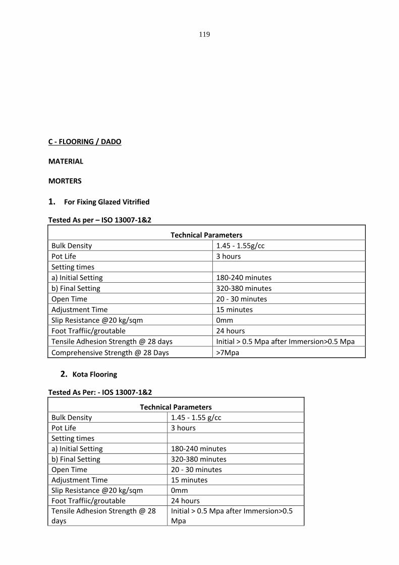
119
C - FLOORING / DADO MATERIAL MORTERS
1. For Fixing Glazed Vitrified
Tested As per – ISO 13007-1&2
Technical Parameters
Bulk Density 1.45 - 1.55g/cc
Pot Life 3 hours
Setting times
a) Initial Setting 180-240 minutes
b) Final Setting 320-380 minutes
Open Time 20 - 30 minutes
Adjustment Time 15 minutes
Slip Resistance @20 kg/sqm 0mm
Foot Traffiic/groutable 24 hours
Tensile Adhesion Strength @ 28 days Initial > 0.5 Mpa after Immersion>0.5 Mpa
Comprehensive Strength @ 28 Days >7Mpa
2. Kota Flooring
Tested As Per: - IOS 13007-1&2
Technical Parameters
Bulk Density 1.45 - 1.55 g/cc
Pot Life 3 hours
Setting times
a) Initial Setting 180-240 minutes
b) Final Setting 320-380 minutes
Open Time 20 - 30 minutes
Adjustment Time 15 minutes
Slip Resistance @20 kg/sqm 0mm
Foot Traffiic/groutable 24 hours
Tensile Adhesion Strength @ 28 days
Initial > 0.5 Mpa after Immersion>0.5 Mpa
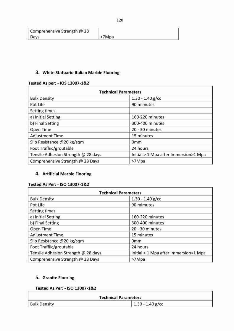
120
Comprehensive Strength @ 28 Days >7Mpa
3. White Statuario Italian Marble Flooring
Tested As per: - IOS 13007-1&2
Technical Parameters
Bulk Density 1.30 - 1.40 g/cc
Pot Life 90 mimutes
Setting times
a) Initial Setting 160-220 minutes
b) Final Setting 300-400 minutes
Open Time 20 - 30 minutes
Adjustment Time 15 minutes
Slip Resistance @20 kg/sqm 0mm
Foot Traffiic/groutable 24 hours
Tensile Adhesion Strength @ 28 days Initial > 1 Mpa after Immersion>1 Mpa
Comprehensive Strength @ 28 Days >7Mpa
4. Artificial Marble Flooring
Tested As Per: - ISO 13007-1&2
Technical Parameters
Bulk Density 1.30 - 1.40 g/cc
Pot Life 90 mimutes
Setting times
a) Initial Setting 160-220 minutes
b) Final Setting 300-400 minutes
Open Time 20 - 30 minutes
Adjustment Time 15 minutes
Slip Resistance @20 kg/sqm 0mm
Foot Traffiic/groutable 24 hours
Tensile Adhesion Strength @ 28 days Initial > 1 Mpa after Immersion>1 Mpa
Comprehensive Strength @ 28 Days >7Mpa
5. Granite Flooring
Tested As Per: - ISO 13007-1&2
Technical Parameters
Bulk Density 1.30 - 1.40 g/cc
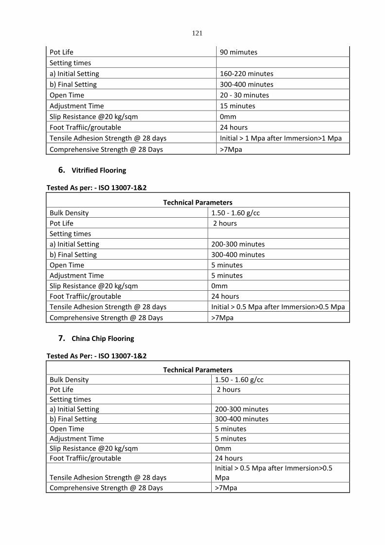
121
Pot Life 90 mimutes
Setting times
a) Initial Setting 160-220 minutes
b) Final Setting 300-400 minutes
Open Time 20 - 30 minutes
Adjustment Time 15 minutes
Slip Resistance @20 kg/sqm 0mm
Foot Traffiic/groutable 24 hours
Tensile Adhesion Strength @ 28 days Initial > 1 Mpa after Immersion>1 Mpa
Comprehensive Strength @ 28 Days >7Mpa
6. Vitrified Flooring
Tested As per: - ISO 13007-1&2
Technical Parameters
Bulk Density 1.50 - 1.60 g/cc
Pot Life 2 hours
Setting times
a) Initial Setting 200-300 minutes
b) Final Setting 300-400 minutes
Open Time 5 minutes
Adjustment Time 5 minutes
Slip Resistance @20 kg/sqm 0mm
Foot Traffiic/groutable 24 hours
Tensile Adhesion Strength @ 28 days Initial > 0.5 Mpa after Immersion>0.5 Mpa
Comprehensive Strength @ 28 Days >7Mpa
7. China Chip Flooring
Tested As Per: - ISO 13007-1&2
Technical Parameters
Bulk Density 1.50 - 1.60 g/cc
Pot Life 2 hours
Setting times
a) Initial Setting 200-300 minutes
b) Final Setting 300-400 minutes
Open Time 5 minutes
Adjustment Time 5 minutes
Slip Resistance @20 kg/sqm 0mm
Foot Traffiic/groutable 24 hours
Tensile Adhesion Strength @ 28 days Initial > 0.5 Mpa after Immersion>0.5 Mpa
Comprehensive Strength @ 28 Days >7Mpa
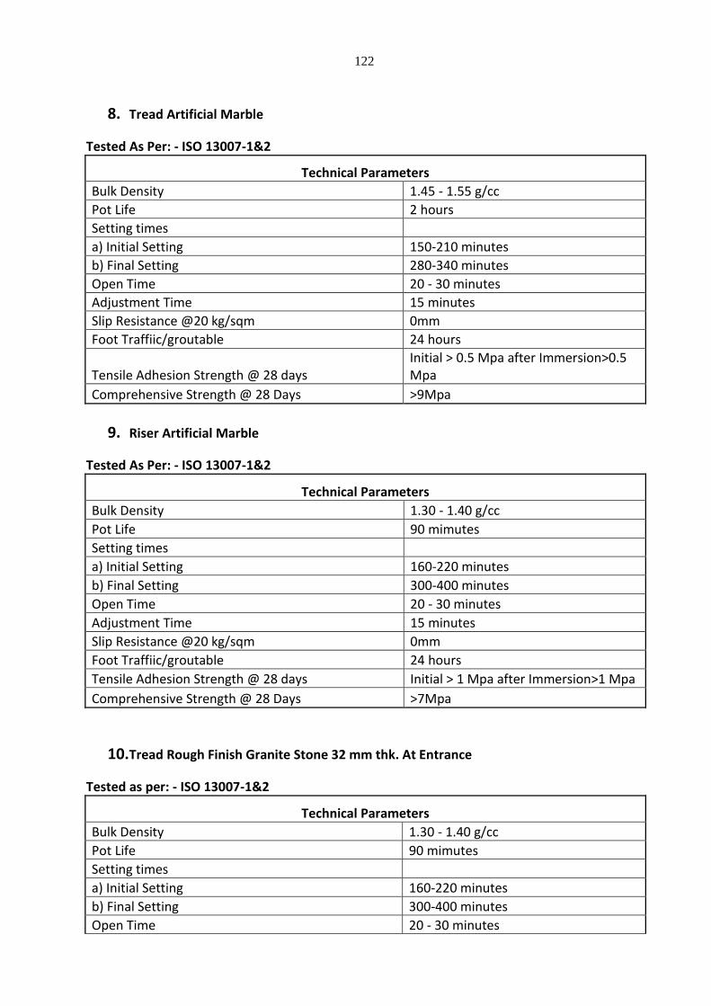
122
8. Tread Artificial Marble
Tested As Per: - ISO 13007-1&2
Technical Parameters
Bulk Density 1.45 - 1.55 g/cc
Pot Life 2 hours
Setting times
a) Initial Setting 150-210 minutes
b) Final Setting 280-340 minutes
Open Time 20 - 30 minutes
Adjustment Time 15 minutes
Slip Resistance @20 kg/sqm 0mm
Foot Traffiic/groutable 24 hours
Tensile Adhesion Strength @ 28 days Initial > 0.5 Mpa after Immersion>0.5 Mpa
Comprehensive Strength @ 28 Days >9Mpa
9. Riser Artificial Marble
Tested As Per: - ISO 13007-1&2
Technical Parameters
Bulk Density 1.30 - 1.40 g/cc
Pot Life 90 mimutes
Setting times
a) Initial Setting 160-220 minutes
b) Final Setting 300-400 minutes
Open Time 20 - 30 minutes
Adjustment Time 15 minutes
Slip Resistance @20 kg/sqm 0mm
Foot Traffiic/groutable 24 hours
Tensile Adhesion Strength @ 28 days Initial > 1 Mpa after Immersion>1 Mpa
Comprehensive Strength @ 28 Days >7Mpa
10. Tread Rough Finish Granite Stone 32 mm thk. At Entrance
Tested as per: - ISO 13007-1&2
Technical Parameters
Bulk Density 1.30 - 1.40 g/cc
Pot Life 90 mimutes
Setting times
a) Initial Setting 160-220 minutes
b) Final Setting 300-400 minutes
Open Time 20 - 30 minutes
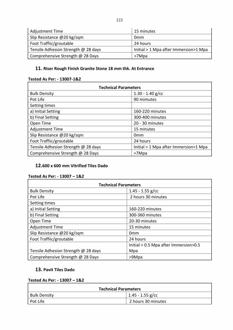
123
Adjustment Time 15 minutes
Slip Resistance @20 kg/sqm 0mm
Foot Traffiic/groutable 24 hours
Tensile Adhesion Strength @ 28 days Initial > 1 Mpa after Immersion>1 Mpa
Comprehensive Strength @ 28 Days >7Mpa
11. Riser Rough Finish Granite Stone 18 mm thk. At Entrance
Tested As Per: - 13007-1&2
Technical Parameters
Bulk Density 1.30 - 1.40 g/cc
Pot Life 90 mimutes
Setting times
a) Initial Setting 160-220 minutes
b) Final Setting 300-400 minutes
Open Time 20 - 30 minutes
Adjustment Time 15 minutes
Slip Resistance @20 kg/sqm 0mm
Foot Traffiic/groutable 24 hours
Tensile Adhesion Strength @ 28 days Initial > 1 Mpa after Immersion>1 Mpa
Comprehensive Strength @ 28 Days >7Mpa
12. 600 x 600 mm Vitrified Tiles Dado
Tested As Per: - 13007 – 1&2
Technical Parameters
Bulk Density 1.45 - 1.55 g/cc
Pot Life 2 hours 30 minutes
Setting times
a) Initial Setting 160-220 minutes
b) Final Setting 300-360 minutes
Open Time 20-30 minutes
Adjustment Time 15 minutes
Slip Resistance @20 kg/sqm 0mm
Foot Traffiic/groutable 24 hours
Tensile Adhesion Strength @ 28 days Initial > 0.5 Mpa after Immersion>0.5 Mpa
Comprehensive Strength @ 28 Days >9Mpa
13. Pavit Tiles Dado
Tested As Per: - 13007 – 1&2
Technical Parameters
Bulk Density 1.45 - 1.55 g/cc
Pot Life 2 hours 30 minutes
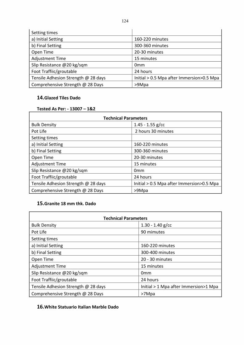
124
Setting times
a) Initial Setting 160-220 minutes
b) Final Setting 300-360 minutes
Open Time 20-30 minutes
Adjustment Time 15 minutes
Slip Resistance @20 kg/sqm 0mm
Foot Traffiic/groutable 24 hours
Tensile Adhesion Strength @ 28 days Initial > 0.5 Mpa after Immersion>0.5 Mpa
Comprehensive Strength @ 28 Days >9Mpa
14. Glazed Tiles Dado
Tested As Per: - 13007 – 1&2
Technical Parameters
Bulk Density 1.45 - 1.55 g/cc
Pot Life 2 hours 30 minutes
Setting times
a) Initial Setting 160-220 minutes
b) Final Setting 300-360 minutes
Open Time 20-30 minutes
Adjustment Time 15 minutes
Slip Resistance @20 kg/sqm 0mm
Foot Traffiic/groutable 24 hours
Tensile Adhesion Strength @ 28 days Initial > 0.5 Mpa after Immersion>0.5 Mpa
Comprehensive Strength @ 28 Days >9Mpa
15. Granite 18 mm thk. Dado
Technical Parameters
Bulk Density 1.30 - 1.40 g/cc
Pot Life 90 mimutes
Setting times
a) Initial Setting 160-220 minutes
b) Final Setting 300-400 minutes
Open Time 20 - 30 minutes
Adjustment Time 15 minutes
Slip Resistance @20 kg/sqm 0mm
Foot Traffiic/groutable 24 hours
Tensile Adhesion Strength @ 28 days Initial > 1 Mpa after Immersion>1 Mpa
Comprehensive Strength @ 28 Days >7Mpa
16. White Statuario Italian Marble Dado
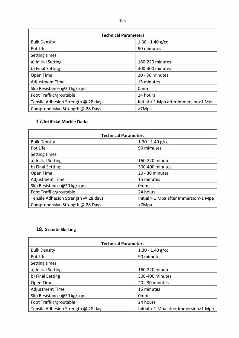
125
Technical Parameters
Bulk Density 1.30 - 1.40 g/cc
Pot Life 90 mimutes
Setting times
a) Initial Setting 160-220 minutes
b) Final Setting 300-400 minutes
Open Time 20 - 30 minutes
Adjustment Time 15 minutes
Slip Resistance @20 kg/sqm 0mm
Foot Traffiic/groutable 24 hours
Tensile Adhesion Strength @ 28 days Initial > 1 Mpa after Immersion>1 Mpa
Comprehensive Strength @ 28 Days >7Mpa
17. Artificial Marble Dado
Technical Parameters
Bulk Density 1.30 - 1.40 g/cc
Pot Life 90 mimutes
Setting times
a) Initial Setting 160-220 minutes
b) Final Setting 300-400 minutes
Open Time 20 - 30 minutes
Adjustment Time 15 minutes
Slip Resistance @20 kg/sqm 0mm
Foot Traffiic/groutable 24 hours
Tensile Adhesion Strength @ 28 days Initial > 1 Mpa after Immersion>1 Mpa
Comprehensive Strength @ 28 Days >7Mpa
18. Granite Skirting
Technical Parameters
Bulk Density 1.30 - 1.40 g/cc
Pot Life 90 mimutes
Setting times
a) Initial Setting 160-220 minutes
b) Final Setting 300-400 minutes
Open Time 20 - 30 minutes
Adjustment Time 15 minutes
Slip Resistance @20 kg/sqm 0mm
Foot Traffiic/groutable 24 hours
Tensile Adhesion Strength @ 28 days Initial > 1 Mpa after Immersion>1 Mpa
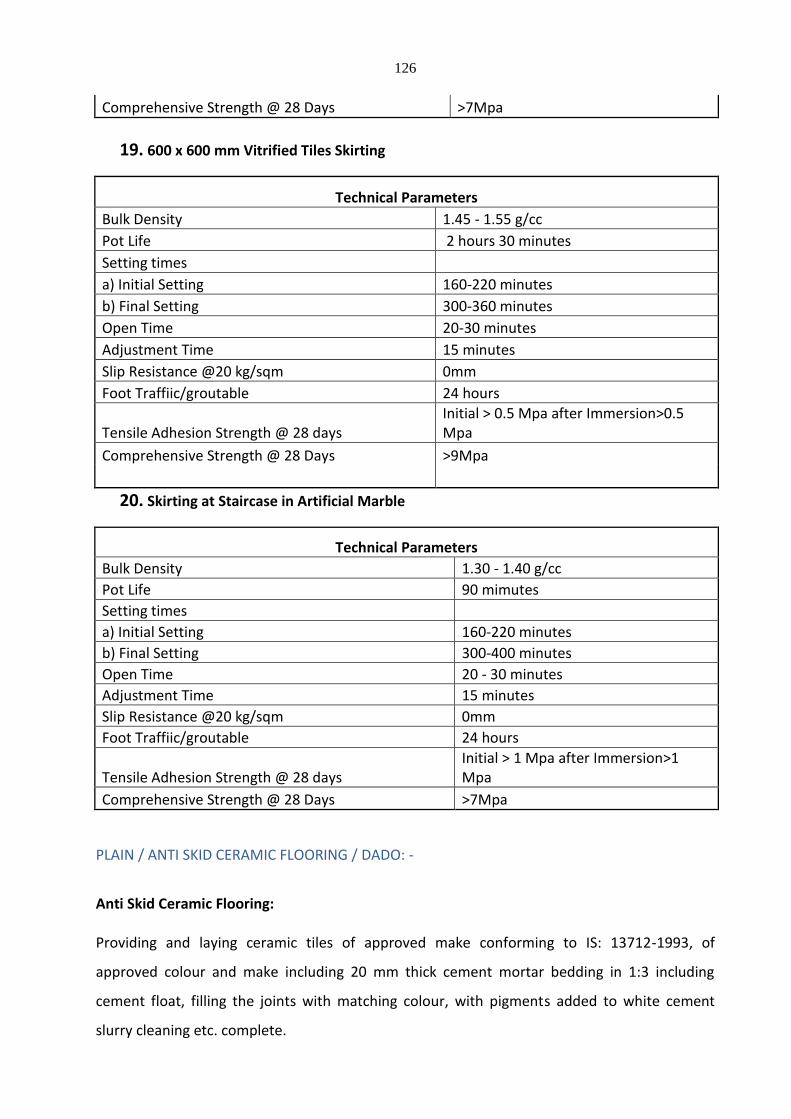
126
Comprehensive Strength @ 28 Days >7Mpa
19. 600 x 600 mm Vitrified Tiles Skirting
Technical Parameters
Bulk Density 1.45 - 1.55 g/cc
Pot Life 2 hours 30 minutes
Setting times
a) Initial Setting 160-220 minutes
b) Final Setting 300-360 minutes
Open Time 20-30 minutes
Adjustment Time 15 minutes
Slip Resistance @20 kg/sqm 0mm
Foot Traffiic/groutable 24 hours
Tensile Adhesion Strength @ 28 days Initial > 0.5 Mpa after Immersion>0.5 Mpa
Comprehensive Strength @ 28 Days >9Mpa
20. Skirting at Staircase in Artificial Marble
Technical Parameters
Bulk Density 1.30 - 1.40 g/cc
Pot Life 90 mimutes
Setting times
a) Initial Setting 160-220 minutes
b) Final Setting 300-400 minutes
Open Time 20 - 30 minutes
Adjustment Time 15 minutes
Slip Resistance @20 kg/sqm 0mm
Foot Traffiic/groutable 24 hours
Tensile Adhesion Strength @ 28 days Initial > 1 Mpa after Immersion>1 Mpa
Comprehensive Strength @ 28 Days >7Mpa
PLAIN / ANTI SKID CERAMIC FLOORING / DADO: -
Anti Skid Ceramic Flooring: Providing and laying ceramic tiles of approved make conforming to IS: 13712-1993, of
approved colour and make including 20 mm thick cement mortar bedding in 1:3 including
cement float, filling the joints with matching colour, with pigments added to white cement
slurry cleaning etc. complete.
127
a) Any size with approved design
Material: Ceramic tiles shall be of approved make and quality and shall conform to IS:777-1988
in all respect. Samples of tiles shall be got approved by the Engineer-in-Charge, who shall keep
them in his office for verification and composition. White cement shall be of approved make.
The samples of the tiles shall be got tested from the approved laboratory as per provisions in
IS:777-1988 by the contractor at his cost. The test results be submitted to the EIC for record.
Mortar Bedding: The mortar shall be of 1:4 proportion and thickness shall be as specified
average, laid on prepared sub-base of appropriate level and grade. The amount of water added
while preparing mortar shall be the minimum necessary to give sufficient plasticity for laying.
Care shall be taken in the preparation of the mortar to ensure that there are no hard lumps
that would interfere with even bedding of the tiles. Before spreading the mortar bed, the base
shall be cleaned of all dirt, scum or laitance and loose materials and then well wetted without
forming any pools by the use of screed battens to proper level of slope. The thickness of the
bedding shall not be less than 20 mm any one place. The tiles shall be laid on the bedding
mortar when it is still plastic but has become sufficiently stiff to offer a fairly firm cushion
for the tiles.
Fixing Tiles : The tiles before laying shall be soaked in water for at least 2 hours. Tiles, which,
are fixed in the floor adjoining the wall, shall be so arranged that the surface of the round edge
tiles shall correspond to the skirting or dado. Neat cement grout of honey like consistency
(4.4kg/sqm) shall be spread over the bedding mortar just to cover so much area as can be tiled
within half an hour. The edges of the tiles shall be smeared with neat white cement slurry or
coloured cement slurry matching colour of the tiles and fixed in this grout one after the other,
each tile being well pressed and gently tapped with a wooden mallet till it is properly bedded
and in level with the adjoining tiles. There shall be no hollows in bed or joints. The joints shall
be 4mm wide and in straight lines. The joints shall be grouted with Hygienic, hardwearing,
impervious, epoxide resin based ceramic tile grout of approved colour which has a high degree
of resistance to chemical attack, abrasion and impact.
Curing : After fixing the tiles finally in an even plane, the flooring shall be covered with wet saw
dust and allowed to mature undisturbed for 7 days.
Cleaning : After the tiles have been laid in a room or at the day's fixing work is completed, the
surplus cement grout that may have come out of the joints shall be cleaned off before it sets.
128
Once the floor has set, the floor shall be carefully washed clean and dried. When dry, the floor
shall be covered with oil free dry saw dust which shall be removed only after completion of the
construction work and just before the floor is occupied.
Item to Include : The item shall include all labour, materials, cement mortar 1:4 mortar
bedding, epoxy grout ofr filling joints, tools and equipment required for the operations to
carry out the for providing and fixing the white or coloured ceramic tiles as specified above.
Mode of Measurement and Payment : The area of the flooring shall be measured in sqm
correct up to 2 decimals. The contract rate shall be per sqm for the specified quality of ceramic
tiles as specified.
Ceramic Dado: Providing and laying ceramic tiles of approved make conforming to IS:13712-1993, of
approved colour and make. Providing and laying ceramic tiles of approved make conforming to
IS:13712-1993, of approved colour and make.
Material : Ceramic tiles shall be of approved make and quality and shall conform to IS:777-
1988 in all respect. Samples of tiles shall be got approved by the Engineer-in-Charge, who shall
keep them in his office for verification and composition. White cement shall be of approved
make. The samples of the tiles shall be got tested from the approved laboratory as per
provisions in IS:777-1988 by the contractor at his cost. The test results be submitted to the EIC
for record.
Fixing of Tiles : Dado or skirting work shall be done only after fixing tiles on the floor. The
white/coloured glazed tiles shall be soaked in water for at least 2 hours before being used for
skirting or dado work. The back of tiles shall be covered with a thin layer of neat cement paste
and the tile shall then be pressed in the mortar and gently tapped against the wall with a
wooden mallet. The fixing shall be done from the bottom of wall upwards without any hollows
in the bed or joints. Each tile shall be fixed with a joint of 4mm in between two tiles which is to
be filled up by Epoxy grout in colour. The tiles hall be in true line and plumb and corner at right
nagles to each other. While fixing tiles in dado work care shall be taken, not to break joints
vertically if the pattern of fixing tiles have not been specified. After fixing the dado, skirting
etc., they shall be kept continuously wet for 7 days. If doors, windows or other openings are
located within the dado area, the sills, jambs, angles etc., shall be provided with ceramic tiles
and appropriate specials according to the foregoing specification and such tiled area shall be

129
measured net along with the dado.
Item to Include : The item includes all material, labour, tools and equipments, for providing
mortar cushioning, fixing of tiles, filling of joints with epoxy grout, curing cleaning etc,
complete.
Mode of Measurement and Payment : The measurement shall be the area of the dado or
skirting provided in sqm correct up to 2 decimal. The tile area provided for jambs, sills etc. shall
be measured, net along with the area of dado or skirting.
C 2, 4, 20 & 21,) VITRIFIED TILE FLOORING, DADO
Materials:
Tiles:
The tiles shall be of approved make as specified and shall generally conform to relevant
Standards. They shall be flat and true to shape, free from cracks, crazing spots, chipped
edges and corners. The glazing shall be of uniform shade.
The tiles shall be as specified in the schedule of quantity or drawings. The length of all four
sides shall be measured correct to 0.1 mm and average length breadth shall not vary more
than 0.8 mm from specified dimensions. The variation of individual dimensions from average
value of length / breadth shall not exceed 0.5 mm. Tolerance in thickness shall be () 0.4 mm.
The thickness of the tiles shall not be less than as specified in the items and shall conform to in
all respects. Samples of tiles shall be got approved by the Engineer-in-charge before use on the
work.
Preparation of Surface and laying of Vitrified Tiles :
130
Sub grade concrete or RCC slab or side brick wall / or plastered surfaces on which tiles are to
be laid shall be thoroughly hacked, cleaned of all mortar scales, concrete lumps etc. brushed,
washed with water to remove mud, dirt etc. from the surface, wetted and mopped.
20/12 mm thick plaster of CM 1.3 shall be applied and allowed to harden minimum for 48
hours. The plaster shall be roughened with wire brushes or by scratching diagonal lines 1.5
mm deep at 7.5 mm centre both ways.
The back of tiles shall be buttered with a cot of grey cement slurry paste and edges with white
cement slurry and set in the bedding mortar. The tiles shall be tapped and corrected to proper
planes and lines. The tile shall be butt jointed in pattern and joints shall be as fine as possible.
The top of skirting / dado shall be truly horizontal and joints truly vertical. For vitrified tiles,
the joints shall be pointed with cementatious grout of matching colour of Bal/Roff make.
After a period of curing of 7 days minimum, the tiles shall be cleaned and shall not sound
hollow when tapped.
The surface during laying shall be checked with a straight edge 2m. long. The surface of
skirting shall be kept flush with plaster with chipping of brick work/concrete wherever
required.
After the tiles have been laid, surplus cement grout shall be cleaned off.
Mortar and Bedding:
Cement mortar for bedding shall be of proportion specified in items schedule and shall
conform to the specification for materials, preparation etc. as specified under cement mortar.
131
The amount of water added while preparing mortar shall be the minimum necessary to give
sufficient plasticity for laying. Care shall be taken in preparation of the mortar to ensure that
there are no hard lumps that would interfere with even bedding of the tiles. Before spreading
the mortar bed the base shall be cleaned of all dirt, scum or laitance and loose materials and
well wetted without forming any pools of water on the surface. The mortar of specified
proportion and thickness shall then be even and smoothly spread over the base by use of
screed battens to proper level or slope.
Cement mortar of thickness and proportion as specified in the schedule for dado shall be
applied to the wall after preparing the wall surface as specified under cement plaster 20 mm
thick and brought to correct line and plumb and the surface left rough to receive the tiles.
Fixing of tiles for flooring:
The tiles before laying shall be soaked in water for at least 2 hours. The tiles shall be laid on
the bedding mortar when it is still plastic but has become sufficiently stiff to offer a fairly firm
cushion for the tiles. Tiles, which are fixed on the flooring adjoining the wall, shall be so
arranged that the surface on the round edge tiles shall correspond to the skirting or dado.
Neat cement mortar grout 1:2, using fine sand (table III, zone IV and as per IS 383) of honey like
consistency shall be spread over the bedding mortar just to cover as much area as can be tiled
within half an hour. The edges of the tiles shall be smeared with neat white cement slurry and
fixed in this grout one after the other, each tile being well pressed and gently tapped with a
wooden mallet till it is properly bedded and in level with the adjoining tiles. There shall be no
hollows in bed or joints. The joints, shall be kept as close as possible and in straight line. The
joints between tiles shall not exceed 1.00 mm, in width. The joint shall be grouted with white
cement slurry. After fixing the tiles, finally in an even plane or slope, the flooring shall be
covered with wet sand and allowed undisturbed for 14 days.
Fixing tiles for Dado:
132
The dado work, shall be done only after fixing the tiles / slabs on the floor. The approved
glazed tiles before laying shall be soaked in water for at least 2 hours. Tiles shall be fixed when
the cushioning mortar is still plastic and before it gets very stiff.
The back of the tile shall be covered with this layer of cement mortar 1:3 using fine sand (table
III, zone IV, IS383-1963), and the edge of the tile smeared with neat white cement slurry. The
tile shall then be pressed in the mortar and gently tapped against the wall with a wooden
mallet. The fixing shall be done from bottom of wall upwards without any hollows in the bed
of joints. Each tile shall be as close as possible to one adjoining. The tiles shall be jointed with
white cement slurry. Any thickness difference in the thickness of the tiles shall be arranged out
in cushioning mortar so that all tiles faces are in one vertical plane. The joints between the tile
shall not exceed 1.00 mm in width and they shall be uniform.
While fixing tiles in dado work, care shall be taken to break the joints vertically. The top of the
dado, shall be touched up neatly with the rest of the plaster above.
After fixing the dado / skirting etc. they shall be kept continuously wet for 7 days.
If doors, windows or other openings are located within the dado area, the corners, sills, jambs
etc. shall be provided with true right angles without any specials. The contractor will not be
entitled to any extra claims on this account for cutting of tiles if required.
Cleaning :
After the tiles have been laid in a room or the day fixing work is completed, the surplus cement
grout that may have come out of the joints shall be cleaned off before it sets. After the
133
complete curing, the dado or skirting over shall be washed thoroughly clean. In the case of
flooring, once the floor has set, the floor shall be carefully washed clean and dried. When dry,
the floor shall be covered with oil free dry saw dust. It shall be removed only after completion
of the construction work and just before the floor is used.
Pointing and Finishing :
The joints shall be cleaned off with wire brush to a depth of 3 mm and all dust and loose
mortar removed. Joints shall then be flush pointed with white cement and floor kept wet for 7
days and then cleaned. Finished floor shall not sound hollow when tapped with a wooden
mallet.
Mode of measurement:
Dado / flooring / skirting shall be measured in sq.m. correct to two places of decimal. Length
and breadth shall be measured correct to 1 cm. between the exposed surfaces of skirting or
dado. No deductions shall be made nor extra paid for any opening of area up to 0.1 sq.m.
The rate shall include all the cost of labour and materials involved.
C – 3, 13, 14, 15, 16, 17, 18 & 19) MARBLE FLOORING / DADO / SKIRTING / CLADDING /
TREADS & RISERS:
Marble Flooring:
Marble shall be hard, sound, dense and homogeneous in texture in accordance to the sample
and of the required size and thickness approved by Engineer. It shall be reasonably uniform in
colour, texture, pattern and shape and free from stains, cracks, decay and weathering and of
specified quality. The marble slabs shall be pre-polished in the factory before delivery. Before
placing order a sample shall be installed at the site and got approved.
134
Dressing of Slabs:
Every stone shall be pre polished and accurately machine cut to the required size and shape so
that a straight edge laid along the side of the stone is fully in contact with it. For patterned
flooring actual dimensions shall be taken at the site and shop drawings in suitable scale
prepared to identify correctly the sizes and shapes of all stones. Each stone shall be marked
with a suitable identification number. All angles and edges of the Marble slab shall be true,
square or angular as required and free from chippings and the surface shall be true and plane.
The thickness of the slabs shall be shown in the drawing with allowable tolerance of + - 2 mm.
in respect of length and breadth of slabs a tolerance of + - 5 mm will be allowed.
Laying:
Sub-grade concrete or the RCC slab on which the slab are to be laid shall be cleaned, wetted
and mopped. For patterned work the stone shall be laid in position loose to ensure
achievement of the required pattern and any adjustments required shall be made and all stone
shall be wetted and washed just before placing and bedding for the slabs shall be with cement
mortar 1:4 (1 cement: 4 coarse sand) or as described in the item.
The average thickness of the bedding mortar under the slab shall be to suite the overall
thickness of flooring specified and the thickness at any place under the slab shall not be less
than 12 mm.
Mortar of the specified mix shall be spread under the area of each slab, roughly to the average
thickness specified in the item. The pre-polished slabs shall first be laid on top of the mortar in
accordance with the approved drawing and pressed tapped with wooden mallet and brought
to proper level in continuity with the adjoining slabs. It shall be lifted and laid aside. The top
surface of the mortar shall then be corrected by adding fresh mortar at hollows. The mortar
shall be allowed to stiffen slightly and uniformly and cement slurry of honey like consistency
shall be spread over the same at the rate of 4.4 kg of cement per sqm. The edges of the slab
already paved shall be buttered with grey or white cement with or without admixture of
pigment to match the shade of the slabs as given in the description of the item. The slab to
paved shall then be lowered gently back in position and tapped with wooden mallet till it is
properly bedded in level and line with as fine a joint as possible. Subsequent slabs shall be laid
135
in the same manner. After each slab has been laid, surplus cement on the surface of the slabs
shall be cleaned off. The flooring shall be cured for a minimum period of seven days.
The surface of the flooring as laid shall be true to falls and, slopes as required. The slabs shall
be matched as shown in drawing or as instructed by the Engineer.
Slabs, which are fixed in the door adjoining the wall, shall enter not less than 12 mm under the
plaster skirting or dado. The junction between wall plaster and floor shall be finished neatly
and without waviness. Wherever required the flooring shall be laid in patterns and / or with
brass divider strips are required.
Curing and Finishing:
The day after the slabs are laid all joints shall be cleaned of the cement grout with a brush and
all dust and loose mortar removed and cleaned. Joints shall then be grouted with white cement
mixed with or without pigment to match the shade of the topping of the wearing layer of the
slabs in a thin coat to protect the surface from abrasive damage.
Before handing over the protective coat shall be removed carefully and the surfaces cleaned
and carefully rubbed with a ‘namdah” block to leave a clean and shining floor without any
defects to the satisfaction of the Engineer. If any slab is disturbed or damaged, it shall be
refitted or replaced and properly jointed. The finished floor shall not sound hollow when
tapped with a wooden mallet.
Item to Include: Item includes all material, bedding cement mortar 1:4, labour, tools and
equipment for cutting, dressing laying and polishing of the slabs for flooring etc. complete.
Mode of Measurement and Payment: The measurement shall be recorded in sqm up to 2 decimals. The contract rate shall be per sqm of stone slab laid. Marble Dado / Skirting / Cladding:
Every tile shall be pre-polished and accurately machine cut. The stone shall be reasonably
uniform in colour, texture, pattern and shape and free from stains, cracks, decay and
weathering and of specified quality, size and thickness, before placing order, a sample of the
marble slab shall be installed at the site and got approved. The surfaces shall be hacked and
136
roughened with wire brushes. The surfaces on which the tiles will be fixed shall be cleaned
thoroughly, washed with water and kept wet before skirting / riser / dado is commenced. The
marble shall be set in grey or white cement 1:3 (1 cement: 3 coarse sand) admixed with or
without pigment to match the shade of stone.
The joints shall be as fine as possible and the joints shall be set in white cement.
Curing, Polishing and Finishing:
Curing, polishing and finishing shall be carried out in the same manner as specified for the
flooring work.
Item to Include: Item includes all material, bedding cement mortar 1:4, labour, tools and
equipment for cutting, dressing laying and polishing of the slabs for dado / cladding etc.
complete.
Mode of Measurement and Payment: The measurement shall be recorded in sqm up to 2
decimals. The contract rate shall be per sqm of stone slab laid.
Marble Tread and Risers:
General:
Providing and fixing Polished Marble Treads and Risers using Marble stone slabs of approved
size, laying on 20 mm cement mortar bed 1:4, filling the joints with a mixture of cement slurry
and pigments as required, curing, polishing, all labour & materials complete.
Stones shall be 25mm thick in Treads and Risers single piece including provision of 2 grooves
for treads with rounded nosing over 20 mm thick bedding of cement mortar 1:4 including
polishing, moulding etc. complete as shown in drawing.
Material:
Marble Stone Slab:
a) 25 mm thick for Treads
b) 25 mm thick for Risers
The slabs shall be of selected quality, in one piece of specified length and width as directed
137
by Engineer in Charge, hard sound, dense and homogeneous in texture free form cracks,
decay, weathering and flaws. They shall be hand or machine cut to the requisite thickness.
They shall be of the colour indicated in the drawings or as instructed by the Engineer-in-
Charge. The slabs shall conform to the size required. Before starting the work the
contractor shall get the samples of slabs approved by the Engineer-in-Charge.
Dressing:
Every slab shall be cut to the required size and shape and fine chisel dressed on the sides to the
full depth so that a straight edge laid along the side of the stone shall be in full contact with it.
The sides (edges) shall be table rubbed with coarse sand or machine rubbed before paving. All
angles and edges of the slabs shall be true, corners at right angle and free from Chippings and
the surface shall be true and plane. The thickness of the slab after it is dressed shall be as
specified in the description of the item. Tolerance of +/- 2 mm shall be allowed for the
thickness. In respect of length and breadth of slabs Tolerance of + 5 mm for hand cut slabs and
+ 2 mm for machine cut slabs shall be allowed.
Preparation of Surface and Laying:
The edges of the slabs to be jointed shall be buttered with gray / white cement, with admixture
of pigment to match the shade of the slab. Before laying, the stone, flags shall be thoroughly
wetted with clean water. Neat cement grout of honey like consistency shall be spread on the
mortar bed over as much area as could be covered with the slabs within half an hour. The
specified type of stone flags shall be laid on the neat cement float and shall be evenly and
firmly bedded to the required level and slope in the mortar bed. Each flag shall be gently
tapped with a wooden mallet till it is firmly and properly bedded. There shall be no hollows
left. If there is a hollow sound on gentle tapping of the slabs, such slabs shall be removed and
reset properly. The mason shall make the joints of uniform thickness and in straight lines. The
joints shall not be thick more than 1.5 mm and filled solidly with mortar for their full depth.
The joints shall be struck smooth. But there shall be no smearing on mortar over the slabs.
When pointing is to be done the joints shall be raked out for not less than the width of the
joints when the mortar is green. The flags shall be laid so as to give continuous parallel long
joints with cross-joints at right angles to them. The edges of the adjoining slabs shall be in one
138
plane.
Item To Include:
Item includes all material, bedding cement mortar 1:4, labour, tools and equipment for cutting,
dressing, laying for treads and risers of steps etc. complete.
Mode of Measurement and Payment:
The measurement shall be recorded in sqm up to 2 decimals. The contract rate shall be per
sqm of Marble treads and risers laid.
C – 12 & 30) GRANITE FLOORING / DADO / TREADS & RISERS, JAMBLINING:
Granite Flooring:
Granite shall be hard, sound, dense and homogeneous in texture in accordance to the sample
and of the required size and thickness approved by Engineer. It shall be reasonably uniform in
colour, texture, pattern and shape and free from stains, cracks, decay and weathering and of
specified quality. The granite slabs shall be pre-polished or matte flamed finished in the factory
before delivery. Before placing order a sample shall be installed at the site and got approved.
The granite slabs mirror polished, wherever required shouls be polished in the factory with
Silicon Carbide abrasives starting from no. “00” up to no. 5 and then using buff / lead strip rolls
with tin oxide for final mirror polish. For flooring and counter top the final tin oxide polish shall
not be used.
Dressing of Slabs:
Every stone shall be pre polished and accurately machine cut to the required size and shape so
that a straight edge laid along the side of the stone is fully in contact with it. For patterned
flooring actual dimensions shall be taken at the site and shop drawings in suitable scale
prepared to identify correctly the sizes and shapes of all stones. Each stone shall be marked
with a suitable identification number. All angles and edges of the granite slab shall be true,
square or angular as required and free from chippings and the surface shall be true and plane.
The thickness of the slabs shall be shown in the drawing with allowable tolerance of + - 2 mm.
in respect of length and breadth of slabs a tolerance of + - 5 mm will be allowed.
139
Laying:
Sub-grade concrete or the RCC slab on which the slab are to be laid shall be cleaned, wetted
and mopped. For patterned work the stone shall be laid in position loose to ensure
achievement of the required pattern and any adjustments required shall be made and all stone
shall be wetted and washed just before placing and bedding for the slabs shall be with cement
mortar 1:4 (1 cement: 4 coarse sand) or as described in the item.
The average thickness of the bedding mortar under he slab shall be to suite the overall
thickness of flooring specified and the thickness at any place under the slab shall not be less
than 12 mm.
Mortar of the specified mix shall be spread under the area of each slab, roughly to the average
thickness specified in the item. The pre-polished slabs shall first be laid on top of the mortar in
accordance with the approved drawing and pressed tapped with wooden mallet and brought
to proper level in continuity with the adjoining slabs. It shall be lifted and laid aside. The top
surface of the mortar shall then be corrected by adding fresh mortar at hollows. The mortar
shall be allowed to stiffen slightly and uniformly and cement slurry of honey like consistency
shall be spread over the same at the rate of 4.4 kg of cement per sqm. The edges of the slab
already paved shall be buttered with grey or white cement with or without admixture of
pigment to match the shade of the slabs as given in the description of the item. The slab to
paved shall then be lowered gently back in position and tapped with wooden mallet till it is
properly bedded in level and line with as fine a joint as possible. Subsequent slabs shall be laid
in the same manner. After each slab has been laid, surplus cement on the surface of the slabs
shall be cleaned off. The flooring shall be cured for a minimum period of seven days.
The surface of the flooring as laid shall be true to falls and, slopes as required. The slabs shall
be matched as shown in drawing or as instructed by the Engineer.
Slabs, which are fixed in the door adjoining the wall, shall enter not less than 12 mm under the
plaster skirting or dado. The junction between wall plaster and floor shall be finished neatly
and without waviness. Wherever required the flooring shall be laid in patterns and / or with
140
brass divider strips are required.
Curing and Finishing:
The day after the slabs are laid all joints shall be cleaned of the cement grout with a brush and
all dust and loose mortar removed and cleaned. Joints shall then be grouted with white cement
mixed with or without pigment to match the shade of the topping of the wearing layer of the
slabs in a thin coat to protect the surface from abrasive damage.
Before handing over the protective coat shall be removed carefully and the surfaces cleaned
and carefully rubbed with a ‘namdah” block to leave a clean and shining floor without any
defects to the satisfaction of the Engineer. If any slab is disturbed or damaged, it shall be
refitted or replaced and properly jointed. The finished floor shall not sound hollow when
tapped with a wooden mallet.
Item to Include : Item includes all material, bedding cement mortar 1:4, labour, tools and
equipment for cutting, dressing laying and polishing of the slabs for flooring etc. complete.
Mode of Measurement and Payment: The measurement shall be recorded in sqm up to 2 decimals. The contract rate shall be per sqm of stone slab laid. Granite Dado:
Every tile shall be pre-polished and accurately machine cut. The stone shall be reasonably
uniform in colour, texture, pattern and shape and free from stains, cracks, decay and
weathering and of specified quality, size and thickness, before placing order, a sample of the
marble slab shall be installed at the site and got approved. The surfaces shall be hacked and
roughened with wire brushes. The surfaces on which the tiles will be fixed shall be cleaned
thoroughly, washed with water and kept wet before skirting / riser / dado is commenced. The
granite shall be set in gray or white cement 1:3 (1 cement: 3 coarse sand) admixed with or
without pigment to match the shade of stone.
The joints shall be as fine as possible and the joints shall be set in white cement.
Curing, Polishing and Finishing:
Curing, polishing and finishing shall be carried out in the same manner as specified for the
141
flooring work.
Item to Include: Item includes all material, bedding cement mortar 1:4, labour, tools and
equipment for cutting, dressing, laying and polishing of the slabs for dado etc. complete.
Mode of Measurement and Payment: The measurement shall be recorded in sqm up to 2
decimals. The contract rate shall be per sqm of stone slab laid.
Granite Tread and Risers:
General:
Providing and fixing Polished Granite Treads and Risers using Granite stone slabs of approved
size, laying on 20 mm cement mortar bed 1:4, filling the joints with a mixture of cement slurry
and pigments as required, curing, polishing, all labour & materials complete.
Stones shall be 25mm thick in Treads and Risers single piece including provision of 2 grooves
for treads with rounded nosing over 20 mm thick bedding of cement mortar 1:4 including
polishing, moulding etc. complete as shown in drawing.
Material:
Granite Stone Slab:
c) 25 mm thick for Treads
d) 25 mm thick for Risers
The slabs shall be of selected quality, in one piece of specified length and width as directed
by Engineer in Charge, hard sound, dense and homogeneous in texture free form cracks,
decay, weathering and flaws. They shall be hand or machine cut to the requisite thickness.
They shall be of the colour indicated in the drawings or as instructed by the Engineer-in-
Charge. The slabs shall conform to the size required. Before starting the work the
contractor shall get the samples of slabs approved by the Engineer-in-Charge.
Dressing:
Every slab shall be cut to the required size and shape and fine chisel dressed on the sides to the
full depth so that a straight edge laid along the side of the stone shall be in full contact with it.
The sides (edges) shall be table rubbed with coarse sand or machine rubbed before paving. All
142
angles and edges of the slabs shall be true, corners at right angle and free from Chippings and
the surface shall be true and plane. The thickness of the slab after it is dressed shall be as
specified in the description of the item. Tolerance of +/- 2 mm shall be allowed for the
thickness. In respect of length and breadth of slabs Tolerance of + 5 mm for hand cut slabs and
+ 2 mm for machine cut slabs shall be allowed.
Preparation of Surface and Laying:
The edges of the slabs to be jointed shall be buttered with gray / white cement, with admixture
of pigment to match the shade of the slab. Before laying, the stone, flags shall be thoroughly
wetted with clean water. Neat cement grout of honey like consistency shall be spread on the
mortar bed over as much area as could be covered with the slabs within half an hour. The
specified type of stone flags shall be laid on the neat cement float and shall be evenly and
firmly bedded to the required level and slope in the mortar bed. Each flag shall be gently
tapped with a wooden mallet till it is firmly and properly bedded. There shall be no hollows
left. If there is a hollow sound on gentle tapping of the slabs, such slabs shall be removed and
reset properly. The mason shall make the joints of uniform thickness and in straight lines. The
joints shall not be thick more than 1.5 mm and filled solidly with mortar for their full depth.
The joints shall be struck smooth. But there shall be no smearing on mortar over the slabs.
When pointing is to be done the joints shall be raked out for not less than the width of the
joints when the mortar is green. The flags shall be laid so as to give continuous parallel long
joints with cross-joints at right angles to them. The edges of the adjoining slabs shall be in one
plane.
Item To Include:
Item includes all material, bedding cement mortar 1:4, labour, tools and equipment for cutting,
dressing laying for treads and risers of steps etc. complete.
Mode of Measurement and Payment:
The measurement shall be recorded in sqm up to 2 decimals. The contract rate shall be per
sqm of Granite treads and risers laid.
143
Granite Jamblining:-
General : Providing and fixing in position & in stepped manner one side mirror polished
machine cut Granite slab 18 mm+/-2mm thick jamb lining for door / window frames of
specified width in neat cement and adhesives such as araldite of required thickness. All
exposed edges to be rounded & polished as per drawings and as per best engineering practice
or as per IS wherever they apply for and as per instructions of Engineer In charge and with
necessary materials and labour costs etc. complete.
Material :
a) Granite Slab 18mm thick (+/- 2 mm tolerance)
b) Neat Cement
c) Rounding & Polishing of edges
Fixing : Providing and fixing in position & in stepped manner one side mirror polished machine
cut Granite slab 19mm thickness jamb lining for door / window frames of specified width in
neat cement and adhesives such as araldite of required thickness. Joints, edges to be floated
and finished on neat cement of the same colour as the slab. After setting, the slabs (if reqd) are
to be machine polished at site to obtain perfect finish. All exposed edges to be rounded &
polished as per drawings and as per best engineering practice or as per IS wherever they apply
for and as per instructions of Engineer In charge.
Item to Include : The rate to include all necessary chipping of brickwork / concrete so that the
slab is 12mm projects from plaster / POP surface with rounding of edges, polishing etc.
complete as shown on drawing & as per directions of Engineer In charge. Note: No payment
will be made for overlapped portion of the jamblining.
Mode of Measurement and Payment: The Granite Slab Jamblining is recorded separately for
each item and measured in sqm of exposed face. The contract rate shall be per sqm for the
specified quality of Granite slab Jamblining as specified.
C - 6) INDIAN PATENT STONE (Ironite Topping): -
Providing Indian patent stone flooring 40 mm thick with M-15 grade concrete using 6 mm to 20
mm metal over bedding laid in proper grade and slope in alternate bays, including compaction,
filling joints with bitumen and sand, marking lines, to give appearance of tiles, finishing smooth
with extra cement curing etc. complete
144
Material : Concrete of M-15 grade shall conform to I.S. Specifications and 456 revised edition.
The coarse aggregates, Fine Aggregates, Water will be as mentioned under Section 4. The
maximum size of coarse aggregate shall be 12 mm. The fine aggregate shall consist of property
graded particles. The proportion of mix shall be M-15. The least amount of mixing water that
will produce in workable mix and will allow finishing without excessive trowelling shall be used.
Generally a water cement ratio of 0.5 should suffice.
Laying :
a) Sub grade: Before placing the concrete flooring, the sub grade shall be passed by the
Engineer-in-Charge. The sub grade for the concrete floor shall be a bedding of cement concrete
of sufficient thickness properly executed as per specifications and shall be paid, under a
separate item in the tender. The sub-grade in all cases shall be formed to proper levels and
slopes, well compacted and cured. The top surface shall be kept slightly rough. Any slope
required to be provided in the floor is to be given to the sub-grade. The surface of the sub-
grade shall be cleaned of all loose materials and moistened immediately before laying the
concrete floor. No slope shall be adjusted in IPS flooring.
b) Formation of Bays : The concrete flooring shall be laid in alternate bays, area not exceeding
6 m2 each. The edge/side of each panel into, which the floor is divided should be supported by
M.S. Flat of 6 to 10 mm or wooden bottom of 6 mm to 10 mm duly oiled to prevent sticking.
Their depth shall be the same as that proposed for the finished floor as mentioned in the item.
The bars should be removed after filling in the adjoining panels. At least 48 hours shall elapse
before concreting in the adjacent bays is commenced.
c) Concrete Flooring : The concrete shall be laid immediately after mixing. While being placed,
the concrete shall be vigorously sliced and spaded with suitable tools to prevent formation of
voids or honey comb pockets. The concrete shall be brought to the specified levels by means of
a heavy straight edge resting on the side forms and drawn ahead with a sawing motion in
combination with a series of lifts and drops alternating with small lateral shifts. While
concreting the adjacent bays, care shall be taken to ensure that the edges of previously laid
bays are not broken by careless or hard tamping. Immediately after laying the concrete, the
surface shall be inspected for high or low spots and any needed correction made up by adding
or removing the concrete. After striking off the surface to the required grade, it shall be
145
compacted with a wooden float. The blows shall be fairly heavy in the beginning but as
consolidation takes place, light rapid strokes shall be given to complete the ramming. Steel
trowelling shall follow the floating after the concrete has hardened sufficiently to prevent
excess of fine material from working to the surface. The finish shall be brought to a smooth
and even surface free from defects and blemishes and tested with straight edges. No dry
cement or mixture of dry cement and sand shall be sprinkled directly on the surface of the
concrete to absorb moisture or to stiffen the mix. After the concrete has been thoroughly
rammed and has dried sufficiently to allow the rendering to be worked up, surface shall be
rendered with a thin coat of 1:1 cement mortar with fine sand and uniformly floated. If so
directed by the Engineer in- Charge, approved mineral colour pigment shall be added to the
cement mortar to give the required colour and shade to the flooring. When the cement mortar
rendering is sufficiently stiff, lines shall be marked on it with strings or by any other device to
give the appearance of tiles 30 cm x 30 cm or any other size laid diagonally or square as
directed by the Engineer-in- Charge. The junction of floor and walls shall be rounded off if so
directed without any extra payment.
d) Filling of Joints : After the concrete in the bays has set, the joints of the panels shall be filled
with cement cream or with suitable bituminastic compound as shown on the drawings or
directed by the Engineer-in-Charge. Vertical edge of the bays shall be neatly marked on the
surface of the concrete with a pointed trowel after filling the joints.
Curing : Curing shall start on the next day after finishing and shall be continued for 7 days.
Item to Include : The item shall include all labour, materials, tools and equipments for cleaning
and preparing the sub-surfaces, formwork, providing concrete of the specified mix (M-15),
compacting, rendering, using coloring pigment when required, marking lines on the surface,
finishing and curing as specified above.
Mode of Measurement and Payment : The linear dimensions shall be measured net between
plastered walls or skirting correct up to 2 places of decimal of a metre and area worked out
correct up to two places of decimals of a square metre. The contract rate shall be per square
metre of the flooring of the specified thickness of 40 mm.
146
Ironite Topping: -
Instead of finishing the top with rendering coat of 1:1 cement mortar, the top shall be finished
with 12 mm thick ironite topping. Unless otherwise specified, one part of ironite and four parts
of ordinary cement by weight shall be mixed thoroughly dry. This dry mixture shall be mixed
with stone grit 6mm and down size or as directed the ration of 1:2 by volume and well turned
over. Just enough water shall be added to this dry mix and mixed thoroughly well and laid to
uniform thickness of 12mm and compacted. After initial set has started thesurface shall be
finished as directed.
C - 11) CHINA MOSAIC CHIPS:
General : Providing and laying China Mosaic Flooring of approved colour including under layer
usually of 20mm thick cement concrete 1:2:4 or as specified and the top layer usually 6mm
thick china mosaic consisting of cement, ceramic /glazed chips in the specified proportion and
water and cleaning etc. complete.
a) As per approved design
Material, Mortar Bedding, Fixing Tiles :
The China mosaic floor consists of two layers, the under layer usually of 20mm thick cement
concrete 1:2:4 or as specified and the top layer usually 6mm thick china mosaic consisting of
cement, marble powder, marble chips in the specified proportion and water.
A. Under layer: Coarse aggregate for cement concrete shall be of granite stone chips of 12mm
gauge, sand shall be coarse, cement shall be fresh Portland cement each of them with their
standard specification. Cement concrete of specified mix usually 1;2:4 shall be prepared
following the standard specifications as for cement concrete work. The bed for the under layer
shall be cleaned and cement slurry @ 2.0 Kg per sqm. shall be applied before laying of under
layer over the cement concrete or R.C.C. surface. The whole area shall be divided into various
patterns as per drawings with their top at proper level, giving slopes. Each panel shall not be
exceeding 2 Sqm. in area. In exposed situations the length of any side of the panel shall not be
more than 1.25 mtrs. Cement slurry @ 2 Kg /Sqm shall be applied before laying the under bed
over concrete or R.C.C. surface. The concrete shall be laid with in the panel and thoroughly
147
compacted with wooden mallet with required thickness generally 20mm and smoothed
wooden floats.
B. Top Layer : A neat cement paste should be laid on the bed prepared to receive china
flooring. If there is more water in paste dry cement should be sprinkle over it. The china portry
chips should be fixed as closed as possible (minimum gap in between chips should be 2 to 3
mm) on it as per required design and pattern. After this procedure dry cement should be
sprinkle over it and the surface should be made cleaned with cloth. Optimum precaution
should be taken while fixing the chips to avoid air pockets from the chips if so the air should be
removed.
Curing: After fixing the China Chips finally in an even plane/ required slope, the flooring shall
be covered with wet saw dust and allowed to mature undisturbed for 7 days.
Cleaning: After the China Chips have been laid or at the day's fixing work is completed, the
surplus cement grout that may have come out of the joints shall be cleaned off before it sets.
Once the floor has set, the floor shall be carefully washed clean and dried. When dry, the floor
shall be covered with oil free dry saw dust which shall be removed only after completion of the
construction work and just before the floor is occupied.
Item to Include: The item shall include all labour, materials, cement concrete, cement mortar /
slurry bedding, tools and equipment required for the operations to carry out the for providing
and fixing the china mosaic flooring as specified above
Mode of Measurement and Payment: The area of the flooring shall be measured in sqm
correct up to 2 decimals. The contract rate shall be per sqm for the specified quality of China
mosaic Flooring as specified.
D – PAINTING
D - 1) Exterior Acrylic Antifungus Paint:
Product Description:
100% Acrylic exterior paint is premium water based, high performance, long lasting exterior
paint, formulated to suit extreme tropical conditions of high rainfall, humidity and heat. The
148
paint should have properties that prevent the fungal and algae growth and ensures constant
surface activity against these irritants for a long period.
Surface Preparation:
The Surface to be prepared must be free of all dust, grease, traces of paint flakes, algae, and
fungus etc. the surface previously coated with paint must be cleaned thoroughly with a stiff
coir brush, to remove dust, dirt, chalking or any friable material and loose flakes. Wash
thoroughly with water and allow to dry. This ensures proper adhesion of the new paint system.
In case of a fungus affected area, apply a liberal coat fungicidal solution. Allow to react for
minimum 6 to 8 hours. For parapet tops and other horizontal surfaces, application of 3 coats is
recommended. All structural cracks must be opened in a V shape and filled with white cement
/ cement based plasters and leakage should be topped before actual painting. Freshly
plastered surfaces must be allowed to cure completely. Apply top coats as follows.
D - 2) ZINC PAINT
a) One coat
b) Two coats
11.1 General : The item pertains to providing and applying Zinc / Lead based paint of approved
colour and shade with specified number of coats including removing oil paint by scrapping or
any other suitable method.
11.2 Preparing the Surface : Before new work is applied paint, the surface shall be thoroughly
brushed free from mortar dropping and foreign matter. In case of old work, all loose particles
and scales shall be scrapped off. Where so specifically ordered by the Engineer-in- Charge, the
entire surface of old paint shall be thoroughly removed by scrapping and this shall be paid for
separately. Where efflorescence is observed the deposits may be brushed clean and washed.
The surface shall then be allowed to dry for at least 40 hours before painting is done.
11.3 Mode of Measurement and Payment:
1. Length and breadth shall be measured correct to a cm. and area shall be calculated in m2
correct to two places of decimals.
149
2. Corrugated surfaces shall be measured flat as fixed and the area so measured shall be
increased by the following percentages to allow for the girthed area.
Corrugated asbestos cement sheet 20% Semi corrugated asbestos cement sheet 10%
3. Cornices and other such wall or ceiling features, shall be measured along the girth and
included in the measurements.
4. The number of coats of each treatment shall be stated. Not exceeding 50 sqm. each with
material similar in composition to the surface to be prepared.
5. Work on old treated surfaces shall be measured separately and so described. The contract
rate shall be per sqm area painted including all material and labour involved in all the
operations described above.
D – 3 & 4) LUSTER PAINT & STIPPLE PAINTING
General
i) Double scaffolding shall be used for work. All painting work shall proceed from top to
bottom. In case of internal painting ceiling shall be painted before walls.
ii) Materials to be used shall be of 1st quality from approved manufacturers of approved
shade.
iii) Work shall be carried out by experienced and skilled workers.
iv) Surface shall be thoroughly cleaned of all dust, dirt, mortar drops oil paints, scales etc.
by wire brushing, scraper tools.
v) In case of ready mixed paints are used and if thinning is required, only the brand
recommended by the paint manufacturer shall be used.
vi) All subsequent coates shall be applied only after the previous coat has dried
thoroughly. One coat shall constitute of one horizontal stroke immediately followed by
one vertical stroke, in all cases.
Paints For Walls / Ceiling
i) New plaster surfaces shall be completely dry before application of paint.
ii) Surface shall be prepared as per IS - 2395 (Part - I): 1966.
iii) A putty of POP and water shall be applied on entire surface including filling up of
150
undulations etc.
iv) The surface shall be sand papered and dusted off with a clean cloth.
v) Alkali resistant cement primer as recommended by manufacturer of paint, shall
be applied (one coat only) and allowed to dry for 48 hours.
vi) Primed surface shall be lightly sand papered and dusted off.
vii) The thinning of plastic emulsion shall be done with water and a thinned coat of
paint shall be applied on the absorbent surface as primer. Surface shall be
perfectly dry before priming coat of Paint is applied.
viii) No subsequent coats shall be applied till the preceding coat has dried for 2 to 3
hours and gets hard. Two or more coats shall be applied on the priming coat by
using roller or spray gun to get a flat uniform and velvet smooth finish.
ix) Washing of surface shall not be done with 3 to 4 weeks of application of paint.
Materials of paint shall be from the approved Manufacturers
The rate of application shall be as per manufacturer’s instructions.
Lustre Paint:
Providing and applying Lustre Paint of superior quality and of approved make, colour and
shade to the old & new surfaces in two coats including scaffolding, preparing the surfaces to
receive the paint and applying primer and putty etc. all complete as per manufacturers
specification and to the satisfaction of Client/Consultant/PMC.
D - 5) WHITE WASH:
Surface Preparation:
The surface shall be thoroughly brushed free from mortar dropping and foreign matters. All
plaster damages shall be made good by cement sand mortar and curing it sufficiently before
the painting work is taken up.
Material:
The white wash shall be prepared from fresh shell lime to which shall be admixed with
sufficient quantity of whiting and gum. The lime and whiting shall be made into thin cream and
screened through clean coarse cloth. 40 gms of gum dissolved in hot water shall be added to
each 10 cu. Decimeter of the cream. Indigo up to 3 gms per kg of lime dissolved in water shall
then be added to the composition. Water at the rate of about 5 litres per kg of lime shall be
151
added to produce a milky solution.
Application:
In case of colour washing approved mineral colours not affected by lime shall be added to the
white wash in required quantities instead of indigo.
The wash shall be applied with approved brushes in minimum 3 coats. Each coat shall be
allowed to dry before applying the next. In case the surface does not present a smooth and
uniform finish throughout to the satisfaction of Engineer. More coats shall be added as
required at no extra cost.
The finished dry surface shall not be powdery and shall not readily come off on the hand when
rubbed.
Item to Include : Item includes all material, labour, tools and equipment for Painting,
preparation of surface to receive the paint, scaffolding etc all complete.
Mode of Measurement and Payment : The measurement shall be recorded in sqm up to 2
decimals.
D) Synthetic Enamel Paint: General: Synthetic enamel paint conforming to IS: 1932-1974 of approved brand and manufacturer and
of the required colour shall be used for the top coat and undercoat of shade to match the top
coat as recommended by the manufacture shall be used.
Painting on New Surfaces: Preparation of surface shall be as specified above or as the case may be. Preparation of Surface:
a) Wood work:
The surface shall be cleaned and all unevenness shall be rubbed down smooth with
sand paper and cleaned removed as specified above. Knots if visible, shall be covered
with a preparation of red lead mixed with strong glue sized and used to. Holes and
indentations on the surface shall be filled in with glazier’s putty or wood putty and
rubbed smooth before painting is done. The surface should be thoroughly dry before
priming coat is applied.
b) Iron and steel work:
152
The priming coat shall have dried up completely before painting is started. Rust and
scaling shall be carefully removed by scrapping or by brushing with steel wire brushes.
All dust and dirt shall be carefully and thoroughly wiped away from surface.
c) Plastered surfaces:
The surface shall not be painted until it has been dried completely, before primer is
applied, holes, undulations shall be filled up with plaster of paris and rubbed.
The primer shall be applied with brushes, worked well into the surface and spread even
and smooth.
Application:
The number of coats including the undercoat shall be as stipulated in the item.
a) Undercoat:
One coat of the specified paint of shade suited to the shade of the top coat shall be
applied and allowed to dry overnight. It shall be rubbed next day with the finest grade
of wet abrasive paper to ensure a smooth and even surface, free from brush marks and
all loose particles dusted off.
b) Top coat:
The painting of approved brand and manufacturer shall be laid on evenly and smoothly
by means of crossing and laying off which consists of covering the area over paint,
brushing the surface hard for the first time over and then brushing alternately at right
angles to the same. The full process of crossing and laying off will constitute one coat.
The number of coats as specified in the item shall be applied and the painted surface
shall present uniform appearance and finish, free from streaks, blisters etc.
E – FALSE CEILING
CALCIUM SILICATE BOARD FLASE CEILING General Introduction
Calcium Silicate Board is manufactured from siliceous & calcareous materials reinforced with
fibers. The boards are made in a laminar process and then autoclaved to give a stable
crystalline structure. Of board can be easily decorated with most of the paints, wallpapers,

153
laminates, veneers etc. these boards are compatible with common building material,
galvanized steel and anodized aluminum.
Appearance:
The board has an off-white surface, which is suitable for all type of decoration. it is light weight
and offers the user the qualities of wood, as it can be cut ,planed, bent and drilled by ordinary
carpenters tool. It can be nailed or screwed easily.
Technical details:
Sr.No. PROPERTIES UNIT VALUES
1 Sizes:
Thickness mm 6,8,10 & 12
Length mm 1220,1830 & 2440
Width mm 1220,610
2 Density Kg / m3 900
3 Compressive strength Kg / cm2 225
4 Tensile strength Kg / cm2 60
5 Bending strength Kg / cm2 100
6 Impact strength J / m2 1700
7 Young’s modulus Kg / cm2 265
8 Flexural strength N / mm2 10 Longitudinal direction 5.5 Transverse direction
9 Fire Protection:
a) Material class - Non-combustible
b) Surface spread of flame - Class – 1
c) Ignitability - Not easily ignitable
d) Fire Propagation Fire Propagation index I = 4.0
10 Thermal conductivity-k W/mk 0.15
11 Thermal resistance-R m2 k / w 0.04/0.05/0.066/ & .08 for 6/8/10 & 12 mm thick boards respectively.
12 Moisture content % Under 15%
Shrinkage dimension (Dry-saturated)
% 0.10%
Length change in water % 0.15%
Biological - No fungus growth
Alkalinity pH 10
Applications:
Calcium silicates Board have a wide range of applications. These can be used in new as well as
existing building as partitions, false ceiling, wall linings, beams & column encasements, tunnel
154
linings, and door, where is a danger of accidental water spoiling the surface. It is also used
where termite & fungus growth are of prime concern.
Cutting:
Score-and-snap:
Scoring is done with hard pointed tool on face side of the by positioning the straight edge along
the line of the cut and repeating the action to obtain adequate depth for a clean break. The
board is then snap upward to achieve break. The boards can also be cut with the carpenter’s
handsaw. The use of circular saw with carbide tipped blade is the most efficient way of getting
neat & clean cut with speed.
Beveling:
Calcium silicate Boards can be beveled easily with carpenter’s tools.
Planning:
The edge of the boards can be smoothened by using carpenters plainer
Bending:
6 mm thick boards can be bend to minimum 600 mm radius, to make curved lining i.e. curved
partitions, false ceiling and wall linings.
Decoration:
The surface of calcium silicate Boards can be decorated with most forms of paints, wallpapers,
soft or hard laminate and ceramic tiles, if required. The boards have an unsanded finish
suitable for semi gloss-acrylics or textured coatings. Before painting, remove any surface dirt
grime or other containments with a soft brush. Do not use water for cleaning and ensure that
the surface is dry before painting.
Fittings and Fixtures:
It is easy and simple to attach different hangings to calcium silicate Boards. Inclined nails can
be fixed to board for light material. For heavier materials, the fastening should be centered on
internal stud work, steel or wood frame behind board, fixed before boarding.
155
Handling and storage:
Calcium silicate Boards should be carried on edge preferably by two persons. The boards
should not be carried in flat position. The boards should be stacked horizontally on a flat
surface under covered area. Wooden pallets/battens, not more than 400 mm apart, can be
used to keep the boards away from the moisture from the ground the boards should be lifted,
not dragged. Protected the boards with heavy water proof covering if stored out side and shift
them inside at the earliest possible if the boards do get damp they should be dried by standing
them at long edge to allow for ventilation never install damp boards.
FEATURES
Non- combustibility:
Calcium silicate boards are non-combustible as per BS:476: part-4-1970
Fire Resistance:
Calcium silicate boards have class-1 surface spread of flame with ignitability as “p” not easily
ignitable hence can provide good fire resistance in the range of 30 minutes to 240 minutes
depending on the construction Design.
Sound insulation and absorption:
Calcium silicate boards help in reduction of sound transmission, because of its nature however
this can be enhanced by putting mineral wool in the cavity of the wall / partition and behind
the board in case of false ceiling perforated calcium silicate boards with non-woven cloth
backing can provide should absorption NRC-value .75 to .85.
Thermal Resistance:
Calcium silicate boards have “k” value of .15 w/mk hence can contribute to energy saving can
provide comfort to the occupants.
Asbestos Free:
Calcium silicate boards are free from asbestos fiber. These are made from minerals and treated
156
cellulose fibers.
Water Resistance:
Calcium silicate boards when immersed in water for 24 hours will loose its strength slightly but
it regains its full strength as soon as it is dry. Hence it is a water resistant boards it has no long-
term effects on the board or most of the decorated surfaces hence these can be used in high
humid areas and or where there is a risk of accident water coming in contact with the board.
Moulds Growth:
Calcium silicates boards are made from natural minerals and are free from mould growth.
Termite Resistance:
Calcium silicate boards are made of inorganic minerals and has stable crystalline structure. This
makes the boards termite resistant and the material will not contribute to fungus growth.
Screw / Nail Holding:
Calcium silicate boards have a good screw/ nail holding capacity they do not require any
backing frame to hang light weight objects like picture frames etc.
Strong & Durable:
The stable crystalline structure makes Calcium silicates boards strong and durable. The boards
are strong enough to take normal impacts. The boards neither degrade/deteriorate Physically
nor turn into powder. These are most suitable for pharmaceutical and hospital industries.
Dimensional stability
Calcium silicate board is cured in high-pressure steam autoclave, which causes an irreversible
chemical change. Thus providing high dimensional and chemical stability accompanied by low
alkalinity.
Light weight:
The boards are light weight therefore can be handled easily the dry density of Calcium silicates
157
board is 900 kg/m2
Easy workability:
Calcium silicate boards are very easy to work with. They can be cut and drilled with ordinary
carpenter’s tools. Sanding is also possible with conventional sandpapers.
Bending:
6 mm thick Calcium silicate Boards can be bent (minimum radius- 600 mm) to provide curved
surfaces. Boards will bend more easily, if bent across their long axis by marking the boards wet.
Light Reflection:
Undercoated boards, provide 75% light reflectance
Compatibility:
The board will not promote corrosion or saponification of paints or affect bituminous
compound these are compatible with common building materials. These may cause corrosion
of unanodised aluminum under humid conditions.
Feature Joints:
Square edge boards can provide featured joint. The boards with joints can be decorated with
mouldings and beadings available in the market they can also be faxed a groove, which can be
in different colours
Tapered Edge:
Calcium silicate Boards are also available with tapered edge (longitudinal direction), which
helps to provide seamless finish.
Seamless Finish:
158
Boards can provide seamless finish decorated with most forms of paints, wall paper &
laminates.
Decoration:
The boards can be decorated with any type of paint, wall papers, wood veneers and hard
laminate Boards, using suitable adhesives
METAL FRAMED SUSPENDED CEILING (Seamless Finish) --
SINGLE LAYER
A non –load bearing system which includes calcium silicate Boards fixed to the G.I frame is
mostly used to provided a suspended false ceiling with seamless finish it is very easy and fast to
erect it can easily accommodate all type of light and air conditioning fittings.
INSTALLATION
Frame work
First of all ceiling is marked on to the wall/partition as per the perimeter of the wall/partition
with nylon sleeves and wood screws (38 mm long) at 457/610 mm centers at the above level
intermediate channel is suspended from the sofit at 1220 mm centers with the help of rowl
plug, sofit cleat and the ceiling angle in one direction ceiling section or intermediate channel
across to it by connecting clips at 610 mm centers. The length of ceiling sections or
intermediate channels can be increased by providing an overlap of 6” and are screw fixed at
four places.
Boards Fixing
Calcium Silicates tapered edge boards of size, 6’x4” are fixed to the under side of ceiling
sections by 25 mm long self drilling & taping screws having Phillips head with under head
cutter at 200 mm c/c. The screws should be 15 mm away from the edges and 40 mm from the
corners. The square edges of the boards are made tapered (40 x 1.5) or chamfered by 4 x 3 mm
159
at site before fixing. The joints between boards are staggered in brick work style to make the
ceiling rigid and properly aligned to the required level.
Jointing & Finishing
Calcium silicate Board joints are finished with specially formulated jointing compound and 48
mm wide, fiber tape to get seamless finish.
METAL FRAMED SUSPENDED CEILING (Seamless)
Main system
Metal framed suspended ceiling comprises of G.I perimeter channel having .55 mm thickness,
two unequal flanges of 20 and 30 mm and web 27 mm is fixed to surrounding wall / partition
using nylon sleeves and screws at 450 mm centers. Then intermediate channel (.91 mm thick)
having two equal flanges of 15 mm each and a web of 45 mm is suspended from the sofit at
1220 mm center with ceiling angle of width 25 mm x 10 mm x 0.55 mm thickness having
knurled web of 50.5 mm and flanges of 26 mm each with lips of 10.5 mm are then fixed to the
intermediate channel with connecting clips across to the intermediate channel, at 610/457 mm
centers. 8 mm thick square / tapered edge calcium silicate Boards are then screw fixed
long/across the ceiling section with 25 mm long self drilling & tapping screw having Phillips
head with under head cutter, at 200 mm centers though the calcium silicate Board fillets.
Joining and Finishing
The joints of the face boards are finished with especially formulated jointing compound and 48
mm wide fiber tape to provide seamless finish.
NOTE:
G.I perimeter channel and supporting material are to be provided to make any opening for
Light fittings, diffusers etc. and should be supported properly to maintain the integrity of the
ceiling and should be charged extra.
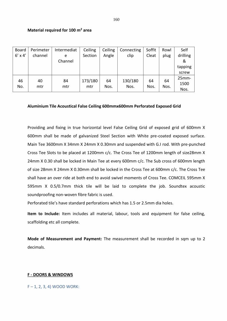
160
Material required for 100 m2 area
Board 6’ x 4’
Perimeter channel
Intermediate
Channel
Ceiling Section
Ceiling Angle
Connecting clip
Soffit Cleat
Rowl plug
Self drilling
& tapping screw
46 No.
40 mtr
84 mtr
173/180 mtr
64 Nos.
130/180 Nos.
64 Nos.
64 Nos.
25mm-1500 Nos.
Aluminium Tile Acoustical False Ceiling 600mmx600mm Perforated Exposed Grid
Providing and fixing in true horizontal level False Ceiling Grid of exposed grid of 600mm X
600mm shall be made of galvanized Steel Section with White pre-coated exposed surface.
Main Tee 3600mm X 34mm X 24mm X 0.30mm and suspended with G.I rod. With pre-punched
Cross Tee Slots to be placed at 1200mm c/c. The Cross Tee of 1200mm length of size28mm X
24mm X 0.30 shall be locked in Main Tee at every 600mm c/c. The Sub cross of 600mm length
of size 28mm X 24mm X 0.30mm shall be locked in the Cross Tee at 600mm c/c. The Cross Tee
shall have an over ride at both end to avoid swivel moments of Cross Tee. COMCEIL 595mm X
595mm X 0.5/0.7mm thick tile will be laid to complete the job. Soundtex acoustic
soundproofing non-woven fibre fabric is used.
Perforated tile’s have standard perforations which has 1.5 or 2.5mm dia holes.
Item to Include: Item includes all material, labour, tools and equipment for false ceiling,
scaffolding etc all complete.
Mode of Measurement and Payment: The measurement shall be recorded in sqm up to 2
decimals.
F - DOORS & WINDOWS
F – 1, 2, 3, 4) WOOD WORK:

161
1. General
1.1. Scope
The section shall cover all woodwork, joinery and similar work in the building. All wood
associated with work of all other sections shall also be done generally according to these
specifications unless specified otherwise. Unless otherwise specified, Timber used in the
work shall be approved quality from the species of wood listed in IS: 399-1963.
1.2. General
No wood work shall be painted, vanished waxed or otherwise finished before specifically
approved by the Engineer.
1.3. Fixing Generally
All wood shall be fixed in the manner as shown in the drawings. If not shown, fixing with
masonry or concrete shall be done with expansion plugs and screws of approved size,
under no circumstances they shall be fixed by wooden plugs.
1.4. Workmanship
All work shall be done in workmanlike manner as per best trade practices by skilled
workmen.
1.5. Starting of work
Unless otherwise instructed, finishing of wooden work on trims, finished frames, etc. shall
not be commenced until all interior plastering and flooring is completed and cured and are
cared of all rubbish. Whenever so required samples of actual work shall be installed at the
site and got approved by the Engineer.
1.6. Timber
162
All wood shall be of best quality klin seasoned timber of its kind specified. Unless otherwise
stated all of the hard wood shall be approved Ghana teak wood except for non-visible
areas, which shall be approved red Assam Hollock wood/ Burma Teak. All timber shall be
treated with approved anti-termite treatment with 10 years guarantee. All wood in contact
with masonry or concrete shall be painted with hot bitumen before placing in position
taking care to ensure that exposed parts of the timber are completely free from any
bitumen. Samples of all wood shall be got approved before ordering. Moisture content of
wood shall be not more than 8% in accordance to IS : 287 – 1993.
1.7. Saving
All scantlings, planks, battens etc. shall be sawn in straight lines, planes, uniform
thickness of full measurements from end to end and shall be sawn in the direction of grain.
They shall be procured with sufficient margins in as to secure the specified dimensions,
lines and planes after being wrought.
2.0 Timber
a) Ghana Teak Wood
Teak wood shall not possess any individual hard and sound knot exceeding 25mm in
diameter and the aggregate area of all the knots shall not exceed one percent of the area
of the piece.
3.0 Door Frames
1. General
These specifications shall be used for wooden frames of doors, if used. The frames shall
be wrought, framed and fixed in positions as per detailed drawings and as directed by
Engineer. It shall be awn in the direction of the grains. Sawing shall be truly straight and
163
square. The scantling shall be planned smooth and accurate to hold full dimensions
with rebates, rounding and mouldings as shown in the drawings before assembling.
Patchwork of plugging of any kind shall not be permitted except as provided. A
tolerance of maximum +(-) 1 mm shall be allowed in the finished cross dimensions of
door frames.
The maximum permissible limits for moisture content shall conform to IS 287-1993.
Wood shall be drawn which are representative of the lot in dimensions, quality and
moisture content.
2. Joints
These shall be of mortice and tenon type, simple, neat and strong. Mortice and tenon
joints shall fit in fully and accurately without wedging or filling. The joints shall be glued
with approved adhesive, framed, put together and pinned with hardwood or bamboo
pins not less than 10mm dia. after the frames are out together pressed in position by
means of a press.
3. Surface Treatment
Wood work shall not be painted, oiled of otherwise treated before it has been
approved by Engineer. All portions of timber abutting against masonry or concrete or
bedded in ground shall be painted with approved bitmastic paint or with boiling
coaltar.
4. Fixing in position
Before the frames are fixed in position these shall be inspected and approved by
Engineer. The frame shall be placed in proper and secured to walls or columns as the
case may be with metallic fastener; iron hold fasts as shown in drawing or as directed
by Engineer. The doorframes without cills, while being placed in position, shall be
suitable strutted and wedged in order to prevent wrapping during construction. Under
164
no circumstances the frames shall be embedded in the floor finish. The frames shall also
be protected from damage, during constructions.
5. Flush door Shutters
Flush door shutters shall be of approved factory make and of the specified type.
Samples of doors shall be tested in an approved laboratory in accordance with the
provisions of the code.
6. Solid Core Type – Decorative Non-decorative
The specifications in general shall conform to Indian Standard Specifications IS – 2202
(Part-I) – 1991 and 2202 (Part-II) –m 1983. Samples of shutters shall be got approved
before ordering in bulk.
7. Core
The core shall be one of the following types :-
i) Block board core
The block board core shall conform to the requirements in Indian Standard
Specification IS – 1659-1990. The wooden strips for the core shall not exceed 25mm in
width. The length of the majority of strips shall extend to the full length of the board.
But end joints are permissible provided the jointed strips are distributed between full-
length strips and the joints are staggered. In any one-block board, the core strips shall
be of one species of timber only. A wooden frame prepared from styles and rails of
well-seasoned and treated good quality wood shall be provided for holding the core.
The width of the members shall not be less than 50 mm and not more than 100 mm.
alternatively; the core shall be of solid board with slots extending for about two third
depths and at approximately 20 mm spacings. The slots shall be made alternatively on
165
two faces of the board.
ii) Particle board core with or without block board
The core shall be either particle board or a combination of block board and particle
board. In a combined construction the width of block board construction shall extend at
least 150mm from inner edge of the style, on either side, and the rest shall be particle
board. Block board shall conform to the requirement of IS:1659-1990. The particle
board shall be either of flat pattern pressed type or extrusion type conforming to IS
3478:1966.
iii) Particle board core
The particle board core shall be three layer of flat layer pressed type.
iv) Laminated Core
It shall be constructed by gluing together under pressure plywood strips in a laminated
way. The frame for holding the core shall be as specified in (a) above.
8. Lipping
Lipping in teak wood shall be provided internally as in the drawing. Unless otherwise
specified, internal lipping shall have a total depth not less than 22mm. Internal lipping
may be provided separately or as one piece with the style.
9. Rebating
In case of double leaved shutters, the meeting of the styles shall be rebated by one
166
third of the thickness of shutter. The rebating shall be either splayed or square type.
Where lipping is provided, the depth of lipping at the meeting of styles shall not be less
than 35mm.
10. Face Panel for Solid Core Board
The face panel shall be formed by gluing by hot press process on both faces of the core
with either plywood or cross – bands and face veneers. The thickness of the cross-
bands as such or in the plywood shall be between 1mm and 3mm. The thickness of the
face veneers as such or in the plywood shall be between 0.5 and 1.5mm for commercial
veneers and between 0.5mm and 1.00 mm for decorative veneers. The combined
thickness of cross bands and face veneers shall not be less than 25mm. The plywood
conforming to these requirements shall be glued under pressure on both faces of the
core. When the panel consists of cross bands and face veneers to those of the core and
glued to its both faces. Face veneer shall then be laid with their grains at night angles to
those of the cross bands. Where it is described to have wooden strips in the block
board core horizontal rather than vertical, this shall be permitted only if 3 ply panel is
pressed on either side of the core and the total is a 7-ply construction. Application of a
decorative face veneer on a finished face panel having veneer in the same direction as
proposed shall be avoided. Wherever specified, the face veneering plywood shall be
with BWP Marine Grade ply conforming to IS 303-1989 and IS 710-1976.
11. Adhesives
Adhesive used for bonding cross-band and plywood to core and face veneers to cross
band, shall be phenol formaldehyde synthetic resin conforming to BWP type specified
in IS:848-1974.
Only synthetic resin adhesive shall be used for binding core members to one another
including core frame, and for lipping, glazing, frame, venetian frame and other exposed
parts where such binding is done.
167
12. Face Panel for cellular and Hollow Board
The plywood forming the face panel shall not be less than 3mm in thickness in the case
of cellular core shutter and not less than 6mm in thickness in the case of hollow core
shutters except for 25mm thick door in which case 4mm thickness may also be
permitted. Two ply face skin construction in a combination of cross band and face
veneers may also be adopted in which case the combined thickness shall not be less
than 4mm. The thickness of face veneers in the plywood shall be between 0.5mm and
1.5mm for commercial veneers and between 3mm and 4mm for decorative veneers.
The plywood face skin assembly conforming to these requirements shall be glued under
pressure on both faces of the core.
4.0 Plywood
Plywood for general purposes shall be of three grades namely BWP, WWR and CWR
depending upon the adhesives used for bonding the veneers. The plywood used for
paneling of door shutters shall be BWP grade and not less than 10mm thickness for two
or more panel construction and 12mm thickness for single panel construction. It shall
have been bonded with BWP (Boiling water proofing) type synthetic resin adhesive.
5.0 Panelled, Glazed or Panelled and Glazed shutters
1. General
The frames for door shall be wrought, framed and fixed in position as pe detailed
drawing and as directed by the Engineer. Specified approved timber shall be used, and
it shall be sawn in the direction of the grains. Sawing shall be truly straight and square.
The timber shall be planed smooth and accyrate to the full dimensions, rebates,
roundings and mouldings made as shown in the drawings, before assembly. Patching or
plugging of any kind shall not ber permitted except as provided. Whereever specified
for factory made paneled door shutter, these shall be of approved make and shall
conform to relevant ISI specifications. The Contractor shall obtain approval from
Engineer before placing the order.
168
2. Panelling
The panels shall be framed into grooves to the full depth of groove leaving an air space
of 1.5mm and the face shall be closely fitted to the sides of the groove. Mouldings to
the edges of panel openings shall be scribed at the joints.
3. Joinery Work
All pieces of timber shall be accurately cut and planed smooth to the full dimensions
without any patching or plugging of any kind. Rebates, roundings and mouldings as
shown in drawings shall be made before assembling. The thickness of styles and rails
shall be as specified for the shutters.
All members of the door shutters shall be straight without any wrap or bow and shall
have smooth, well planed faced at right angles to each other. The corners and edges of
panels shall be finished a shown in drawings, and these shall be feather tongued into
styles and rails. Sash bars shall have mitred joints with the styles. Styles and rails shall
be properly and accurately mortised and tenoned. Rails which are more than 180mm in
width shall have two tenons. Style , rails and bottom rails of shutter shall be made out
of piece of timber only. Intermediate rails exceeding 200mm in width may be made out
of one or more pieces of timber but the width of each pieces shall be not less than
75mm. Where more then one piece of timebr is used, they shall be jointed with a
continuous tongued and grooved joint, glued together with bulk type synthetic resin
adhesive of make approved by the Engineer abd reinforced with metal dowels at
regular intervals not exceeding 200mm or pinned with not less than three wooden /
bamboo pins. Jointed pieces of timber shall belong to the same species. The bottom
lock and top rails shall be inserted 25mm inside the width of the styles. When
assembling a leaf, styles shall be left projecting as a hom. The styles and rails shall have
12mm groove in paneled partition for the panel to fit in.
4. Depth of Rebate
169
The depth of rebate in frames for housing the shutters shall in all cases be 12.5mm and
the rebate in shutters for closing in double shutter doors or windows shall not be less
than 20mm. In the case of double leaved shutters, the meeting of the styles shall be
rebated 20mm. The rebate shall be splayed.
The joinery work shall be assembled and passed by the Engineer, and then the joints
shall be pressed, and secured by bamboo pins of about 6mm diameter. The horns of
styles shall be sawn off.
5. Tolerance
The finished work with a tolerance of +(-) 1mm in thickness and +(-) 2mm in width of
styles and rails below 100mm and +(-) 3mm for 100mm and above shall be accepted. In
case of glazing bars tolerance of +(-) 1mm in width and thickness shall be accepted.
6. Gluing of joints
The surfaces of tenon and mortise shall be treated, before putting together, with bulk
type synthetic resin adhesive conforming to IS : 851 – 1978 suitable for construction in
wood or synthetic resin adhesive (Phenolic and aminoplastic) conforming to IS : 848 –
1974 or polyvinyl acetate dispersion based adhesive conforming to IS : 4835 – 1979 and
pinned with 10mm dia hardwood dowels or bamboopins or star shapped metal pins;
after the frames are put together and pressed in position by means of press.
Stiles and bottom rail shall be made out of one piece of timber only. Intermediate rail
exceeding 200mm in width may be out of one or more pieces of timber. The width of
each piece shall be not less than 75mm. Where more than one piece of timber is used
for rails, they shall be joined with a continuous tongued and grooved joint glued
together and reinforced with metal dowels at regular intervals not exceeding 20mm.
7. Beading
170
Timber, plywood, hard board and particle board panels shall be fixed only with grooves
but additional beading may be provided either on one side or on both sides. 1st class
teak wood moulded beading shall be provided of sizes and pattern as shown in drawing
or as described in the item. In so far as glass panels are concerned, beading shall always
be provided without grooves, where beading is provided without grooves, the beading
shall be only on one side, the other side being supported by rebate from the styles. For
external doors beading shall be fixed on the outside.
8. Glazing
Glass panes shall be fixed by wooden beading having mitred joints as detailed above. A
thin layer of putty of approved make and conforming to IS : 419 – 1967 shall be applied
between glass panes and sash bars and also between glass panes and beading. Fixing
glass panes with simple putty and beads shall not be permitted. Frosted glass panes
shall be fixed with frosted face on the inside.
8. Fittings / Door Closer
All fittings used in the manufacture of the door shall be heavy duty type. The doors shall be
fitted with heavy duty concealed type automatic door closers, of approved make.
9. Hold Fast
Hold fast for the use with wooden doors shall be made from mild steel flats not less than
5mm thick, in accordance to IS:7196-1974 and shall be galvanized. The shutter shall be
supported by 125mm medium duty hinges.
Hold fast shall be fixed with the timber frame by steel screws only. The frames in masonry
wall shall be fixed in cement concrete blocks as per drawing and as directed by Engineer.
10. Anchor Fasteners
Anchor Fasteners shall be used to fix the wooden frame with concrete surface. The anchor
171
shall be internally threaded carbon steel anchor. The anchor fastener shall be of galvanized
steel and the thickness of galvanized coating shall be 8mm.
F – 5) FIRE RETARDANT DOOR:
BOQ Item
Providing fire rated clear glass panes having minimum 2 hrs. fire rating for integrity
performances, 6mm thick, cut to required size and shape and fixing it in position in the paneled
door shutter/wooden frame work for fixed partition using GI angle metal beading of 10 x 10 x
2mm size on both the faces of shutter with necessary stainless steel screws etc. as specified,
including concealing the same by providing and fixing moulded beadings of second class teak
wood, of required size on both the faces of shutter, with necessary concealed fasteners and
10mm x 2mm intumescent strips (provided in “U” shape ie. On both sides of glass as well as
below the glass) in the gap between the glass and the beading & between the glass and the cut
face of the opening / rails for fixing the glass panel, alround the glazing panel on both faces of
shutters etc., all complete as per the Architectural drawings, as specified and as directed by the
Engineer-in-Charge. (For the purpose of payment, overall area of glass panel excluding portion
in the rebate/ beading shall be measured).
Specification
Providing, Supply & Fixing 2 Hours fire rated doors system duly tested for Integrity & Insulation
Criteria as per the IS:3614 Part 2 and BS:476 part 20 at Fire Research Laboratory Central
Building Research Institute Roorkee with standard heating conditions as specified in IS:3809 -
1979 and BS:476 part 20 & 22 1987 to achieve the required integrity & insulation (i.e. to
restrict the heat radiation, temperature rise on the non fire side to the maximum of 140
degree Centigrade above the ambient temperature on the unexposed surface of the shutter),
RedMarenti hardwood frame of section 150mm X 75mm with 1 nos. of brush type Intumescent
strip (Imported) to take care of Hot and cold smoke of size 20mm X 4mm concealed in the
grove of the frame with fixing arrangements of 3 nos. of G.I. hold fast 225mmX20mmX4mm
172
with split end on ether side and wall grouted with cement concrete mix 1:3; 6 adjustable lugs
with split end tail to each jamb and 56mm thick single leaf shutter made out of perimeter
railing of RedMarenti hard wood of size 100mmX30mm and 2 nos. of 9mm thick PROMINA® –
60 board with 30mm thick Non–combustible Fire Retardant compound coated with
Intumescent sealant and faced with 4mm thick Water Proof marine Ply with brush type Fire
and Smoke Intumescent Seal of size 10mm x 4mm mounted in the grooves in the shutter on all
sides except bottom with 10mm thick teak wood beading on all side and Promaseal
Intumescent sealant is used to seal the gaps between Promina-60 Board and shutter beading
along with cold pressing of 1.5mm thick lamination of approved make and shade. The fire
Doors with frame will be as per IS: 3614 part 2 and BS: 476 part 20 at FRL CBRI Roorkee with
standard heating conditions as specified in IS: 3809 - 1979 and BS:476 part 20 & 22 1987 all
complete to the entire specification with the certified copy from M/s.Pomat International Asia
Pacific Ltd. of the valid Test Certificate.
F – 7) Automatic sliding door:
BOQ Item
Providing & fixing of Automatic sliding door operator ES200-Easy Structural opening
4000X2400mm, clear opening: 2000X2400mm Automatic sliding door operator, modular
design, including internal cover.
2-panel sliding door
Operator Dimensions (H x T): 100 x 180 mm.
Microprocessor control, self-learning, reversing when obstruction is encountered.
Clear Passage Width:
2-panel = 800 – 2500 mm
Door weight:
Bi-Parting Door Panel, max. 2 x 85 kg.
Function programs:
Program modes:
Off, Automatic, Permanent open, Partial opening, Exit only, Selfregulating
Partial open, Exit only partial opening, Night-bank facility. Compliant with future European
173
standards and specifications per EN 12650.
Microprocessor-controlled control unit. Self-learning, with adjustable parameters for opening
and closing speed, hold-open time and opening and closing force. With pulse expansion for
cheque card or code card reader or key switch. Class of protection IP 20.
Produced according to the guidelines for power-operated windows, doors and gates BGR
232, the UVV and the VDE regulations. TÜV design tested, tested according to the low-
voltage guidelines, production according to ISO 9001:2000 certification. Fulfils the DIN
V18650 (prEN 12650).
Off, Automatic, Permanent open, Exit only, Partial open, Night-bank switch, Emergency off.
Choice between emergency opening and emergency closing in the event of a power cut (with
optional battery pack).
Safety devices:
Obstruction detection feature, automatic reversing cycle, dynamic and static force limitation,
emergency control unit (emergency stop), connections for light barriers for through-passage
monitoring.
1. Auto Reversal – Inbuilt
2. Light Barrier – 01 Pair (Optional)
Connection:
230 V, 50/60 Hz, UPS Supply.
Activators:
Radar system 02 Nos
Locking:
() Electro-mechanical locking, Bitable
Colour light alloy parts:
() Silver, Anodized E6/C0 - standard
Make:
DORMA ES 200 Easy
G - WATERPROOFING WORK 1.0 GENERAL 1.1 Standards

174
Indian and other international standards followed for this section shall be as listed below.
Any discrepancies or ambiguities seen shall be brought to the notice of the PMC and
clarification / confirmation sought. His decision shall be final. However, as a general rule,
more stringent specifications shall be followed.
(1) I.S. 269 Specifications for 33 grade ordinary and low heat Portland cement. (2) I.S. 283 Specification for coarse and fine aggregates from natural sources. (3) I.S. 2645 Specification for integral cement waterproofing compound (4) I.S. 283 Code of practice for waterproofing of underground
reservoirs and swimming pool. (5) I.S. 8112 Specification for 43 grade ordinary Portland cement. (6) I.S. 12118 Specification for two part polysulphide base cement :
Part-I General requirements (7) I.S. 13826 Method of Test for bitumen based felt. (8) I.S. 3495 Method of Test for Burnt clay building bricks.
1.2 Quality Assurance 1.2.1. Manufacturer’s Qualification
a) Not less than five years experience in manufacturing of membrane roofing.
1. Obtain primary materials from single manufacturer. Manufacturer’s name shall appear on containers and accessories.
2. Provide secondary materials as required by manufacturer of primary
materials. 1.2.2. Applicators Qualification
a) Approved by manufacturer prior to execution of this contract, with experience on at least five projects.
b) Foreman of Fields Crew: Minimum five-year experience with system of
waterproofing being installed. 1.2.3. Certification
Manufacturer’s certifications on manufacturer’s letterhead:
175
1. Certify system design: penetration, transition, and perimeter details; and system specifications are appropriate and satisfactory for this particular project.
2. Certify products proposed for use comply with standards.
3. Certify materials ordered and supplied are compatible with each other, suited
for local and purpose intended and shipped in sufficient quantity to ensure proper timely installation.
4. Certify materials have express warranty of merchantability and fitness for
particular purposes of this project.
5. Certify manufacturer has reviewed project and will issue warranty upon successful completion of installation.
6. Certify materials shipped to site meet membrane manufacturer’s published
performance standards and requirements of this specification.
7. Membrane manufacturer’s approval of insulation type and method of installation.
8. Manufacturer’s approval of installer.
1.3 Submittals
1.3.1 Product Data
Contractor to submit along with his proposal product data for material he proposed to use.
1.3.2 Information Submittals
a) Certifications specified in quality assurances.
b) Manufacturer’s instructions.
1.4 Waterproofing Compounds 1.4.1 Waterproofing compounds shall be cementious (cement based) non-shrinking, self-
curing mixtures. These shall be
Free from sodium and chlorides
Free from material detrimental to concrete and reinforcement.
Able to create a membrane in one or multiple coats as per manufacturer’s
instruction.

176
Membrane capable to prevent infiltration when applied to interior faces and
ponded.
Permeability, shear bond strength, compressive strength, volume changes
meets minimum requirements of codes.
1.4.2 Accessories
All other accessories materials such as primers, bonding agents, polymers etc. shall be as
recommended by waterproofing manufacturer.
1.5 Warranty
A. Special Warranty:
1. Warranty with attachments for full replacement value of completed
installation signed by manufacturer, applicator and contractor warranting
against water infiltration and defects of materials and workmanship for period
of ten years.
2. Provide warranty that covers labour and workmanship, including labour for
access to waterproofing, for watertight warranty.
a. Warrant penetrations, terminations, changes of direction, and
membrane.
b. Warranty shall include removing and reinstalling superimposed work
covering waterproofing.
2. MATERIALS 2.1. Cement 2.1.1 Cement shall be ordinary Portland cement conforming to IS and shall be of grade 43 or
33.
It shall be received in bags of 50 kg and each batch shall be accompanied with a test
certificate of the factory. Also it shall be tested before use to ascertain its strength, setting
time, etc. In case cement has been stored for over 6 months or for any reasons the stored
177
cement shows signs of deterioration or contamination, it shall be tested as per the
direction of the PMC prior to use in the works.
2.1.2 Cement shall be stored in such locations so as to prevent deterioration due to moisture
dampness. A dry and water proof shed shall be provided. Bags shall be stacked on rigid
waterproof platform about 15 to 20 cm clear above the floors and 25 to 35 cm clear or
away from the surrounding walls. A maximum high stack of 12 bags is permitted.
Stacks shall be so arranged that the first batches are used first (FIFO), and that they
permit easy access for inspection and handling.
2.2 Sand 2.2.1. Natural and deposited by stream or glacial agencies as a result of disintegration of rock
is the best form of sand and shall be used.
2.2.2. 2.2.1.1 Sometimes it is obtained from crushed stone screenings but often contains a high
percentage of dust and clay. It tends to be flaky and angular. This type produces
harsh concrete and should be avoided.
2.2.1.2 Sea sand shall not be used. 2.2.2 Sand shall be hard, durable, clean and free from adherent coatings and organic matter
and shall not contain any appreciable ;amount of clay. Sand shall not contain harmful
impurities such as iron, pyrites, coat particles, lignite, mica shale or similar laminated
material, alkali, and organic impurities in such form or quantities as to affect the
strength or durability of concrete or mortar.
2.2.2.1 When tested ;as per IS 2386 Part I and Part II, sand shall not exceed permissible
quantities of deleterious materials as given in table 1 of IS 383.
2.2.3 Grading of sand shall conform to IS and shall fall within limits 2.2.4 Sand shall be stored in such a way that it does not get mixed with mud, grass, vegetable
and other foreign matter. The best way is to have a hard surface platform made out
of concrete, bricks or planks. It should be to the approval of the PMC.
178
2.3 Brick bats 2.3.1 It shall be prepared from well burnt bricks. In no case shall under-burnt bricks be used.
Flaky and elongated pieces shall be avoided. It should also be free from adherent
coatings of soil or silt. Brick bats should be free from alkalies, soft fragments, organic
impurities, etc. In such quantities as not to affect strength and durability of concrete.
2.3.2 Water absorption for the bricks after 24 hours immersion in cold water shall not exceed
15%.
2.4 Water 2.4.1 Water used for mixing and curing shall be clean, reasonably clear and free from
objectionable quantities of silt, oils, alkalise, acids, salts so as not to weaken mortar,
or concrete or cause efflorescence or attach the steel in RCC while curing, acids, salts;
so as not to weaken mortar, or concrete or cause efflorescence or attack the steel in
RCC while curing. It shall be free of elements, which significantly affects the hydration
reaction. Potable water is generally satisfactory but it shall be tested prior to use in
the works.
2.4.2 Water tested shall be in accordance with IS 3025. Maximum permissible limits of
deleterious materials in water should be as given in IS 456.
2.4.3 Water storage tanks shall be such as to prevent any deleterious materials getting mixed
with it.
2.4.4 Water shall be tested and approved in writing by the PMC prior to use in the works.
2.4.5 Stone tiles such as Kota / shahbad shall be of best quality and free from any defects and
of uniform thickness.
2.5 MATERIALS
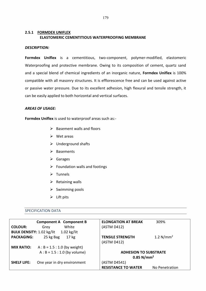
179
2.5.1 FORMDEX UNIFLEX
ELASTOMERIC CEMENTITIOUS WATERPROOFING MEMBRANE DESCRIPTION: Formdex Uniflex is a cementitious, two-component, polymer-modified, elastomeric
Waterproofing and protective membrane. Owing to its composition of cement, quartz sand
and a special blend of chemical ingredients of an inorganic nature, Formdex Uniflex is 100%
compatible with all masonry structures. It is efflorescence free and can be used against active
or passive water pressure. Due to its excellent adhesion, high flexural and tensile strength, it
can be easily applied to both horizontal and vertical surfaces.
AREAS OF USAGE: Formdex Uniflex is used to waterproof areas such as:-
Basement walls and floors
Wet areas
Underground shafts
Basements
Garages
Foundation walls and footings
Tunnels
Retaining walls
Swimming pools
Lift pits
SPECIFICATION DATA
Component A Component B COLOUR: Grey White BULK DENSITY: 1.02 kg/lit 1.02 kg/lit PACKAGING: 25 kg Bag 17 kg MIX RATIO: A : B = 1.5 : 1.0 (by weight) A : B = 1.5 : 1.0 (by volume) SHELF LIFE: One year in dry environment
ELONGATION AT BREAK 309% (ASTM D412) TENSILE STRENGTH 1.2 N/mm2 (ASTM D412)
ADHESION TO SUBSTRATE 0.85 N/mm2
(ASTM D4541) RESISTANCE TO WATER No Penetration
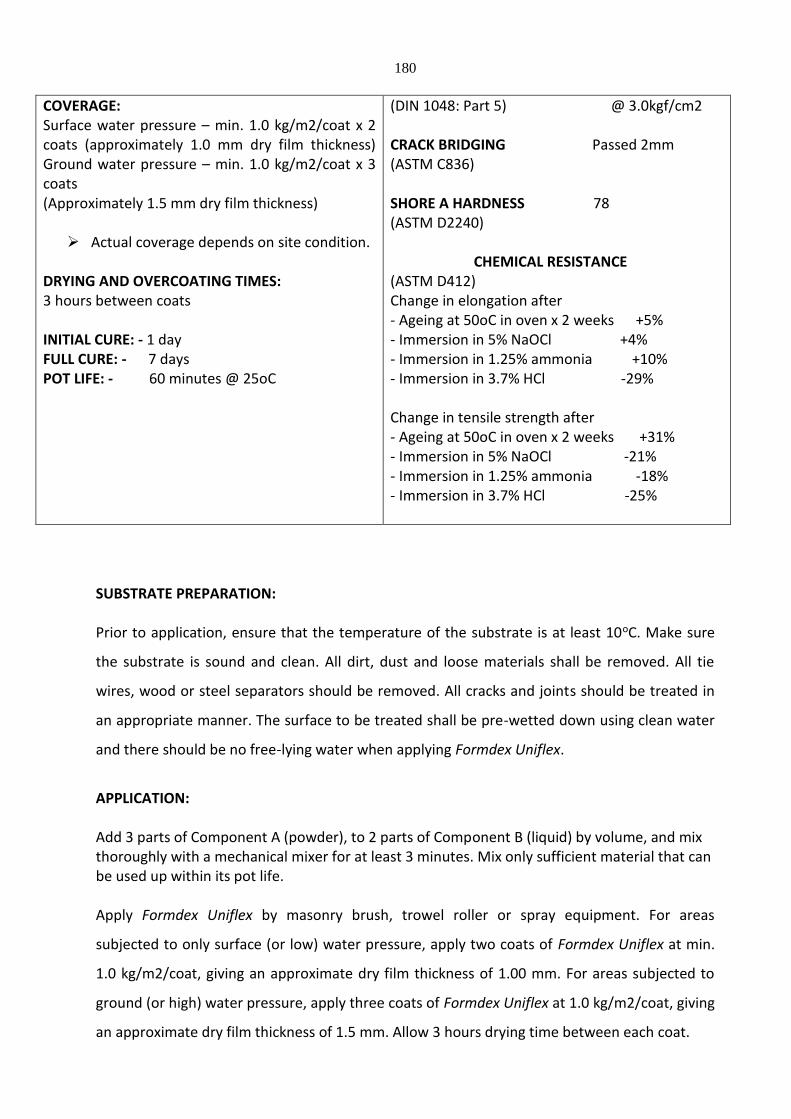
180
COVERAGE: Surface water pressure – min. 1.0 kg/m2/coat x 2 coats (approximately 1.0 mm dry film thickness) Ground water pressure – min. 1.0 kg/m2/coat x 3 coats (Approximately 1.5 mm dry film thickness) Actual coverage depends on site condition.
DRYING AND OVERCOATING TIMES: 3 hours between coats INITIAL CURE: - 1 day FULL CURE: - 7 days POT LIFE: - 60 minutes @ 25oC
(DIN 1048: Part 5) @ 3.0kgf/cm2 CRACK BRIDGING Passed 2mm (ASTM C836) SHORE A HARDNESS 78 (ASTM D2240)
CHEMICAL RESISTANCE (ASTM D412) Change in elongation after - Ageing at 50oC in oven x 2 weeks +5% - Immersion in 5% NaOCl +4% - Immersion in 1.25% ammonia +10% - Immersion in 3.7% HCl -29% Change in tensile strength after - Ageing at 50oC in oven x 2 weeks +31% - Immersion in 5% NaOCl -21% - Immersion in 1.25% ammonia -18% - Immersion in 3.7% HCl -25%
SUBSTRATE PREPARATION: Prior to application, ensure that the temperature of the substrate is at least 10oC. Make sure
the substrate is sound and clean. All dirt, dust and loose materials shall be removed. All tie
wires, wood or steel separators should be removed. All cracks and joints should be treated in
an appropriate manner. The surface to be treated shall be pre-wetted down using clean water
and there should be no free-lying water when applying Formdex Uniflex.
APPLICATION: Add 3 parts of Component A (powder), to 2 parts of Component B (liquid) by volume, and mix thoroughly with a mechanical mixer for at least 3 minutes. Mix only sufficient material that can be used up within its pot life. Apply Formdex Uniflex by masonry brush, trowel roller or spray equipment. For areas
subjected to only surface (or low) water pressure, apply two coats of Formdex Uniflex at min.
1.0 kg/m2/coat, giving an approximate dry film thickness of 1.00 mm. For areas subjected to
ground (or high) water pressure, apply three coats of Formdex Uniflex at 1.0 kg/m2/coat, giving
an approximate dry film thickness of 1.5 mm. Allow 3 hours drying time between each coat.
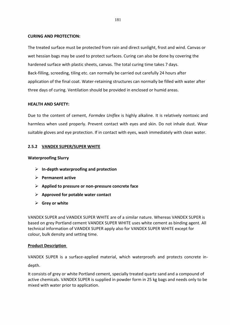
181
CURING AND PROTECTION: The treated surface must be protected from rain and direct sunlight, frost and wind. Canvas or
wet hessian bags may be used to protect surfaces. Curing can also be done by covering the
hardened surface with plastic sheets, canvas. The total curing time takes 7 days.
Back-filling, screeding, tiling etc. can normally be carried out carefully 24 hours after
application of the final coat. Water-retaining structures can normally be filled with water after
three days of curing. Ventilation should be provided in enclosed or humid areas.
HEALTH AND SAFETY: Due to the content of cement, Formdex Uniflex is highly alkaline. It is relatively nontoxic and
harmless when used properly. Prevent contact with eyes and skin. Do not inhale dust. Wear
suitable gloves and eye protection. If in contact with eyes, wash immediately with clean water.
2.5.2 VANDEX SUPER/SUPER WHITE Waterproofing Slurry In-depth waterproofing and protection
Permanent active
Applied to pressure or non-pressure concrete face
Approved for potable water contact
Grey or white
VANDEX SUPER and VANDEX SUPER WHITE are of a similar nature. Whereas VANDEX SUPER is based on grey Portland cement VANDEX SUPER WHITE uses white cement as binding agent. All technical information of VANDEX SUPER apply also for VANDEX SUPER WHITE except for colour, bulk density and setting time. Product Description VANDEX SUPER is a surface-applied material, which waterproofs and protects concrete in-
depth.
It consists of grey or white Portland cement, specially treated quartz sand and a compound of active chemicals. VANDEX SUPER is supplied in powder form in 25 kg bags and needs only to be mixed with water prior to application.
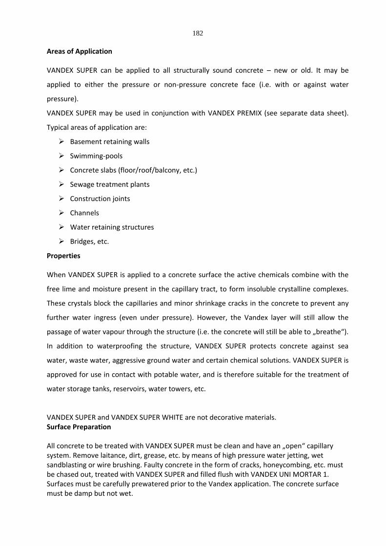
182
Areas of Application VANDEX SUPER can be applied to all structurally sound concrete – new or old. It may be
applied to either the pressure or non-pressure concrete face (i.e. with or against water
pressure).
VANDEX SUPER may be used in conjunction with VANDEX PREMIX (see separate data sheet).
Typical areas of application are:
Basement retaining walls
Swimming-pools
Concrete slabs (floor/roof/balcony, etc.)
Sewage treatment plants
Construction joints
Channels
Water retaining structures
Bridges, etc.
Properties When VANDEX SUPER is applied to a concrete surface the active chemicals combine with the
free lime and moisture present in the capillary tract, to form insoluble crystalline complexes.
These crystals block the capillaries and minor shrinkage cracks in the concrete to prevent any
further water ingress (even under pressure). However, the Vandex layer will still allow the
passage of water vapour through the structure (i.e. the concrete will still be able to „breathe“).
In addition to waterproofing the structure, VANDEX SUPER protects concrete against sea
water, waste water, aggressive ground water and certain chemical solutions. VANDEX SUPER is
approved for use in contact with potable water, and is therefore suitable for the treatment of
water storage tanks, reservoirs, water towers, etc.
VANDEX SUPER and VANDEX SUPER WHITE are not decorative materials. Surface Preparation All concrete to be treated with VANDEX SUPER must be clean and have an „open“ capillary system. Remove laitance, dirt, grease, etc. by means of high pressure water jetting, wet sandblasting or wire brushing. Faulty concrete in the form of cracks, honeycombing, etc. must be chased out, treated with VANDEX SUPER and filled flush with VANDEX UNI MORTAR 1. Surfaces must be carefully prewatered prior to the Vandex application. The concrete surface must be damp but not wet.
183
Mixing VANDEX SUPER is mechanically mixed with clean water to a consistency of thick oil paint.
Approximate mixing ratio is 0.8 parts of water to 2.0 parts of powder (by volume).
Mix only as much material as can be used within 20 minutes and stir mixture frequently. If the mixture starts to set do not add more water, simply restir to restore workability.
Application Slurry consistency. Apply VANDEX SUPER in one or two coats according to specification by
masonry brush or appropriate power spray equipment. When two coats are specified apply the
second coat whilst the first coat is still „green“.
Dry powder consistency (for horizontal surfaces only). The specified amount of VANDEX SUPER
is distributed in powder form through a sieve and trowelled into the freshly placed concrete
once this has reached initial set.
Post treatment. The treated areas should be kept damp for a period of five days and must be
protected against direct sun, wind and frost, by covering with polythene sheeting, damp
hessian or similar.
Note:
Do not apply VANDEX SUPER at temperatures below + 5 °C.
VANDEX SUPER cannot be used as an additive to concrete or plasters. Consumption Concrete surfaces to be backfilled. One coat of VANDEX SUPER at 0.75 kg/m2 followed by one
coat of VANDEX PREMIX at 1.0 kg/m2. Brush or spray applied.
Water retaining structures, internal concrete wall surfaces. Two coats of VANDEX SUPER each
at 0.75 kg/m2. Brush or spray applied.
Concrete slabs. VANDEX SUPER at 1.2 kg/m2 applied in one slurry coat to hardened concrete
or dry sprinkled and trowel applied to fresh concrete when this has reached initial set.
Construction joints. VANDEX SUPER at 1.5 kg/m2 applied in slurry or dry powder consistency
immediately prior to placing the next lift/bay of concrete.
Blinding concrete. VANDEX SUPER at 1.2 kg/m2 applied in slurry or dry powder consistency
immediately prior to placing the overlying concrete slab.
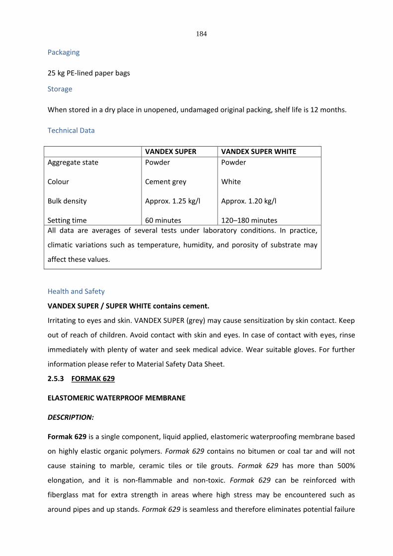
184
Packaging
25 kg PE-lined paper bags
Storage
When stored in a dry place in unopened, undamaged original packing, shelf life is 12 months.
Technical Data
VANDEX SUPER VANDEX SUPER WHITE
Aggregate state Colour Bulk density Setting time
Powder Cement grey Approx. 1.25 kg/l 60 minutes
Powder White Approx. 1.20 kg/l 120–180 minutes
All data are averages of several tests under laboratory conditions. In practice,
climatic variations such as temperature, humidity, and porosity of substrate may
affect these values.
Health and Safety
VANDEX SUPER / SUPER WHITE contains cement.
Irritating to eyes and skin. VANDEX SUPER (grey) may cause sensitization by skin contact. Keep
out of reach of children. Avoid contact with skin and eyes. In case of contact with eyes, rinse
immediately with plenty of water and seek medical advice. Wear suitable gloves. For further
information please refer to Material Safety Data Sheet.
2.5.3 FORMAK 629 ELASTOMERIC WATERPROOF MEMBRANE DESCRIPTION: Formak 629 is a single component, liquid applied, elastomeric waterproofing membrane based
on highly elastic organic polymers. Formak 629 contains no bitumen or coal tar and will not
cause staining to marble, ceramic tiles or tile grouts. Formak 629 has more than 500%
elongation, and it is non-flammable and non-toxic. Formak 629 can be reinforced with
fiberglass mat for extra strength in areas where high stress may be encountered such as
around pipes and up stands. Formak 629 is seamless and therefore eliminates potential failure

185
due to poor joints.
AREAS OF USAGE: Formak 629 should be used as an effective membrane to waterproof wet areas such as
bathrooms, kitchens, ground slabs, walkways and concealed roofing applications. As a liquid
applied system, it is ideal for areas that require a lot of detailing work.
SPECIFICATION DATA
COLOUR: Grey PACKING SIZE: 20 litre pail SHELF LIFE: 2 years in unopened container SOLIDS (by volume): 59% THINNING: As Formak 629 is based on polyisoprene it can not be thinned with water. SPREADING RATE: Refer overleaf under application. DRYING TIMES: 1 - 2 hours for roofing applications
DRY FILM THICKNESS 0.8 to 1.0 mm. ELONGATION 527% nominal (ASTM D412) (unreinforced) TENSILE STRENGTH 7.79 N/mm2 (ASTM D412) CRACK BRIDGING – 2MM No cracks (ASTM C836) WATER VAPOUR TRANSMISSION 116.82/m2.24h (ASTM E96) WATER PENETRATION No penetration (DIN 1048: Part 5)
SUBSTRATE PREPARATION:
Make sure the substrate is clean, dry and free of dirt, oil etc. The structure and substrate have
to be of sound construction, with expansion joints where necessary. New concrete needs to be
cured for a minimum of 28 days before the system can be applied.
APPLICATION:
PRIMING:
Stir Formak 629 primer well before use.
Concrete: - Apply one coat of Formak 629 Primer and allow to dry before over coating.

186
Steel and Galvanized iron: - Mix one part of Formak 629 Primer with one and a half parts of
Portland cement by volume. Mix well by mechanical means until lump free and apply at
5m2/litre. Allow to dry before overcoating.
TREATMENT TO LARGE CRACKS:
Apply one thick coat of Formak 629 and incorporate a strip of fibreglass. Leave to dry.
TREATMENT TO DETAILING:
Apply Formak 629 at 1.0 litre/m2 making certain to dress up at least 150mm from the finished
floor or roof level, around pipes, along walls and upstands. Immediately roll a layer fibreglass
mat and apply another coat of Formak 629 at 0.5 litre/m2.
ROOF APPLICATION:
Apply Formak 629 by roller or brush at 0.6 litre/m2 and leave to dry for at least 16 hours. Apply
two coats.
WET AREAS
Apply Formak 629 by roller or brush at 0.4 litre/m2 and leave to dry for at least 6 hours. Apply
three coats.
HEALTH AND SAFETY
Formak 629 contains ammonia, when used indoors provision should be made to ensure that
adequate ventilation is provided. In cases where ventilation is not adequate, operators should
wear safety masks suitable for use with ammonia. Dry paint can be removed from the skin by
using warm water and soap.
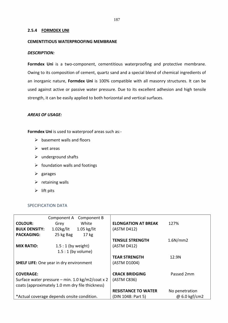
187
2.5.4 FORMDEX UNI CEMENTITIOUS WATERPROOFING MEMBRANE DESCRIPTION: Formdex Uni is a two-component, cementitious waterproofing and protective membrane.
Owing to its composition of cement, quartz sand and a special blend of chemical ingredients of
an inorganic nature, Formdex Uni is 100% compatible with all masonry structures. It can be
used against active or passive water pressure. Due to its excellent adhesion and high tensile
strength, it can be easily applied to both horizontal and vertical surfaces.
AREAS OF USAGE:
Formdex Uni is used to waterproof areas such as:-
basement walls and floors
wet areas
underground shafts
foundation walls and footings
garages
retaining walls
lift pits
SPECIFICATION DATA
Component A Component B COLOUR: Grey White BULK DENSITY: 1.02kg/lit 1.05 kg/lit PACKAGING: 25 kg Bag 17 kg MIX RATIO: 1.5 : 1 (by weight) 1.5 : 1 (by volume) SHELF LIFE: One year in dry environment COVERAGE: Surface water pressure – min. 1.0 kg/m2/coat x 2 coats (approximately 1.0 mm dry file thickness) *Actual coverage depends onsite condition.
ELONGATION AT BREAK 127% (ASTM D412) TENSILE STRENGTH 1.6N/mm2 (ASTM D412) TEAR STRENGTH 12.9N (ASTM D1004) CRACK BRIDGING Passed 2mm (ASTM C836) RESISTANCE TO WATER No penetration (DIN 1048: Part 5) @ 6.0 kgf/cm2
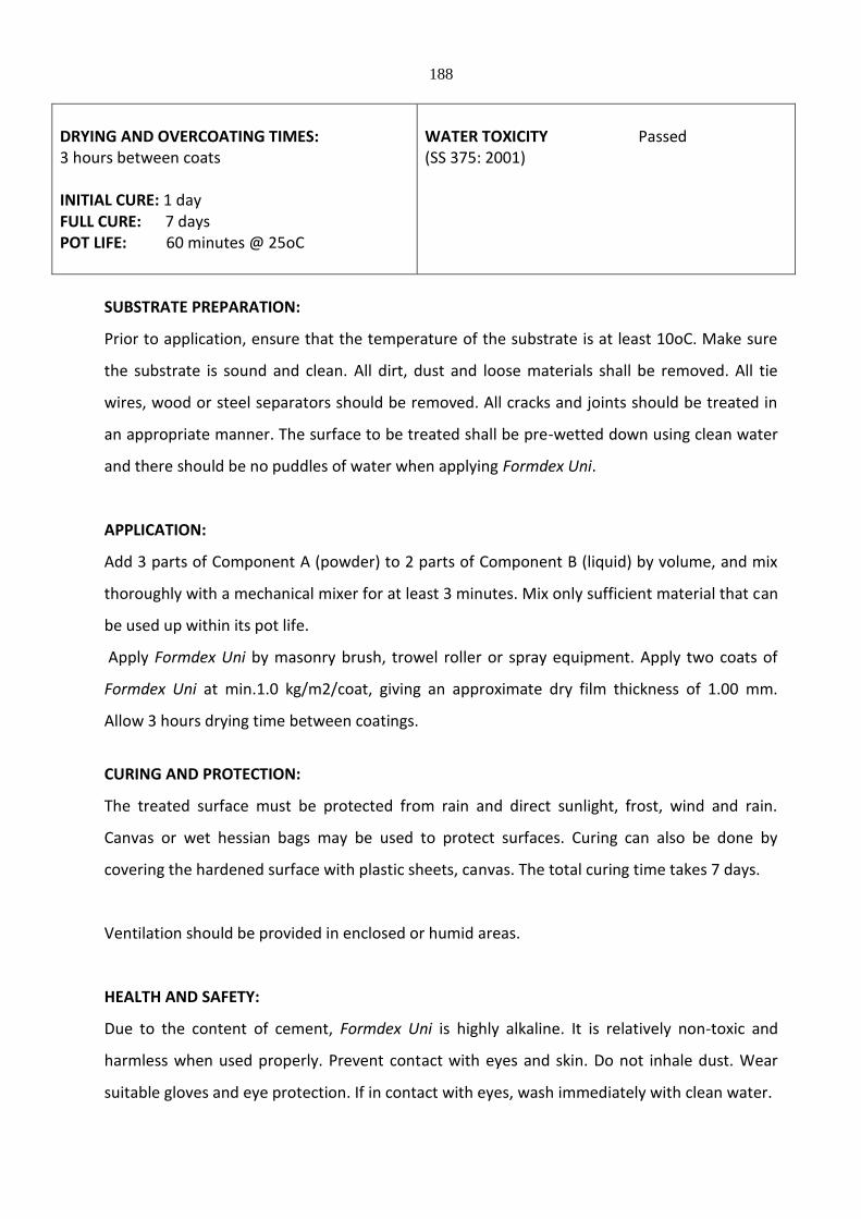
188
DRYING AND OVERCOATING TIMES: 3 hours between coats INITIAL CURE: 1 day FULL CURE: 7 days POT LIFE: 60 minutes @ 25oC
WATER TOXICITY Passed (SS 375: 2001)
SUBSTRATE PREPARATION:
Prior to application, ensure that the temperature of the substrate is at least 10oC. Make sure
the substrate is sound and clean. All dirt, dust and loose materials shall be removed. All tie
wires, wood or steel separators should be removed. All cracks and joints should be treated in
an appropriate manner. The surface to be treated shall be pre-wetted down using clean water
and there should be no puddles of water when applying Formdex Uni.
APPLICATION:
Add 3 parts of Component A (powder) to 2 parts of Component B (liquid) by volume, and mix
thoroughly with a mechanical mixer for at least 3 minutes. Mix only sufficient material that can
be used up within its pot life.
Apply Formdex Uni by masonry brush, trowel roller or spray equipment. Apply two coats of
Formdex Uni at min.1.0 kg/m2/coat, giving an approximate dry film thickness of 1.00 mm.
Allow 3 hours drying time between coatings.
CURING AND PROTECTION:
The treated surface must be protected from rain and direct sunlight, frost, wind and rain.
Canvas or wet hessian bags may be used to protect surfaces. Curing can also be done by
covering the hardened surface with plastic sheets, canvas. The total curing time takes 7 days.
Ventilation should be provided in enclosed or humid areas.
HEALTH AND SAFETY:
Due to the content of cement, Formdex Uni is highly alkaline. It is relatively non-toxic and
harmless when used properly. Prevent contact with eyes and skin. Do not inhale dust. Wear
suitable gloves and eye protection. If in contact with eyes, wash immediately with clean water.
189
2.5.5 VANDEX BB 75
Waterproofing Slurry
Efflorescence-free surface waterproofer
For concrete, masonry and render
Can be used against active or passive water pressure
Approved for drinking water structures
PRODUCT DESCRIPTION
VANDEX BB 75 is a cementitious, ready mixed, efflorescence – free surface water proofer with hydrophobic properties, resistant to water and moisture.
AREAS OF APPLICATION
VANDEX BB 75 is applied to surfaces such as concrete, masonry and render which have to be
sealed and protected against the influence of water and moisture.
PROPERTIES
Owing to its composition of cement, quartz with graded grain – size distribution and special
chemical ingredients of an inorganic nature, VANDEX BB 75 is waterproof (tested upto 7.0 bar).
It can be employed against active and passive water pressures. VANDEX BB 75 is safe to use
with patable water. The initial and final bonding capability of VANDEX BB 75 is excellent,
making its suitable to be applied to horizontal as well as vertical surfaces. It is durable, resistant
to frost and heat after setting, but all the same permeable to vapour. VANDEX BB 75 is not a
decorative material.
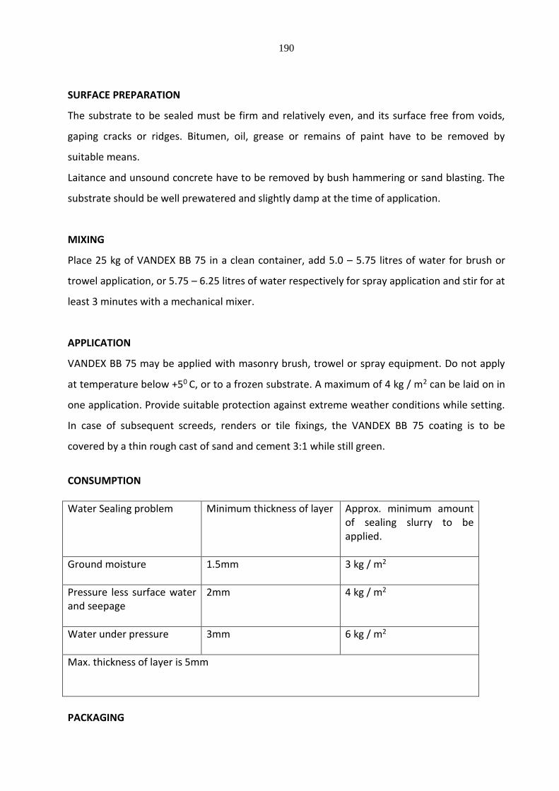
190
SURFACE PREPARATION
The substrate to be sealed must be firm and relatively even, and its surface free from voids,
gaping cracks or ridges. Bitumen, oil, grease or remains of paint have to be removed by
suitable means.
Laitance and unsound concrete have to be removed by bush hammering or sand blasting. The
substrate should be well prewatered and slightly damp at the time of application.
MIXING
Place 25 kg of VANDEX BB 75 in a clean container, add 5.0 – 5.75 litres of water for brush or
trowel application, or 5.75 – 6.25 litres of water respectively for spray application and stir for at
least 3 minutes with a mechanical mixer.
APPLICATION
VANDEX BB 75 may be applied with masonry brush, trowel or spray equipment. Do not apply
at temperature below +50 C, or to a frozen substrate. A maximum of 4 kg / m2 can be laid on in
one application. Provide suitable protection against extreme weather conditions while setting.
In case of subsequent screeds, renders or tile fixings, the VANDEX BB 75 coating is to be
covered by a thin rough cast of sand and cement 3:1 while still green.
CONSUMPTION
Water Sealing problem Minimum thickness of layer Approx. minimum amount of sealing slurry to be applied.
Ground moisture 1.5mm 3 kg / m2
Pressure less surface water and seepage
2mm 4 kg / m2
Water under pressure
3mm 6 kg / m2
Max. thickness of layer is 5mm
PACKAGING
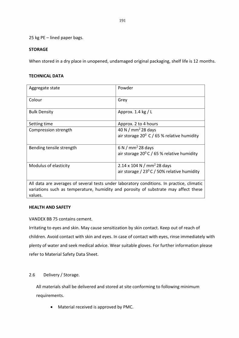
191
25 kg PE – lined paper bags. STORAGE When stored in a dry place in unopened, undamaged original packaging, shelf life is 12 months.
TECHNICAL DATA
Aggregate state Powder
Colour Grey
Bulk Density Approx. 1.4 kg / L
Setting time Approx. 2 to 4 hours
Compression strength 40 N / mm2 28 days air storage 200 C / 65 % relative humidity
Bending tensile strength 6 N / mm2 28 days air storage 200 C / 65 % relative humidity
Modulus of elasticity 2.14 x 10⁴ N / mm2 28 days air storage / 230 C / 50% relative humidity
All data are averages of several tests under laboratory conditions. In practice, climatic variations such as temperature, humidity and porosity of substrate may affect these values.
HEALTH AND SAFETY VANDEX BB 75 contains cement.
Irritating to eyes and skin. May cause sensitization by skin contact. Keep out of reach of
children. Avoid contact with skin and eyes. In case of contact with eyes, rinse immediately with
plenty of water and seek medical advice. Wear suitable gloves. For further information please
refer to Material Safety Data Sheet.
2.6 Delivery / Storage.
All materials shall be delivered and stored at site conforming to following minimum
requirements.
Material received is approved by PMC.

192
Material is in unopened container and labled with manufacturer’s name, brand
name and instruction for use.
Material received shall be along with manufacturer’s certificate for quality and
period by manufacturer.
Material shall be stored in dry, well ventilated and covered storage if so desired
by manufacturer.
Primers, adhesives etc. shall be as recommended by the membrane
manufacturer.
3.0 SCOPE OF WORK. 3.1 Work shall include design, supply, install and test proprietary waterproofing systems to
underground structure, terrace, toilet sunk slabs, UG and Overhead water tanks etc.
this shall be guaranteed for 10 years on Rs. 100/- stamp in preformed to be approved
by the PMC.
a) Waterproofing of basement including sealing of services junctions, drain points,
sumps shall be as per approved box type proprietary treatment.
b) Waterproofing of terrace inclusive of grouting, sealing rainwater down takes
outlets, other services outlets, junctions of walls, slab, beam, columns, parapet
wall etc. where required expansion joints all as per approved terrace proprietary
treatment.
3.2 Waterproofing of toilet sunk portions and water tanks inclusive of grouting, sealing,
outlet pipes of services, junctions of slab, beams, walls and covering with protective
cement sand plaster coat / screed.
3.3 Work shall included design, supply, install and test proprietary box type system for
basement and terrace system for sloped / flat roofs as approved by the PMC. This shall
be guaranteed for 10 years on Rs. 200/- stamp paper in proforma to be approved by the
PMC.

193
Work shall conform to minimum standards specified. Systems detailed hereunder are to
clarify type of waterproofing system expected. Contractor is at liberty to suggest and
submit equivalent system with products meeting / exceeding standards.
3.4 Sub Contractor / Specialist shall be from the approved list and shall be approved by the
PMC in writing before being employed by the contractor.
3.5 The contractor shall submit
1. Statement giving detailed brief of work he proposes to carry out.
a. Name of agency with his experience certificate and quantum of work
carried out.
b. Technical specifications.
c. Product data sheets of material to be used.
d. Shop drawing detailing.
Sections co-ordinated with typical installations details
Vertical termination and sealing
Laps needed if any
Typical expansion, construction and control jointing details with
minimum requirements.
Horizontal fixing and laying details.
Typical finishing arrangement.
Flashings if required.
e. Protective measures to be taken
f. Installation guidance
g. Samples of each product in duplicate fixed over plywood boards or
similar to enable proper cross sections.
h. Manufacturer’s certificate that product and material to be used is
correct and shall give intended results when applied through
authorized agency.
4. WORKMANSHIP
194
4.1. Preparation of Surfaces
a) The surfaces to receive the treatment shall be thoroughly cleaned of
Laitances, scales, loose material on surface.
Grease, oil or other contaminants by etching with 10-15% of solution of
muriatic acid using commercial grade alkaline cleaner, flushing with clean
water drying and vacuuming.
b) Surfaces shall be examined and well-defined cracks grouted by making “V”
groove / notches with cement slurry, shall be cured and dried well before
treatment.
c) Any honeycombs shall be carefully cut and plugged, and cured well before
treatment.
d) Examination of surfaces shall account for the fact that,
Surfaces are cured for 14 days and no condensation has taken place.
Horizontal and vertical surfaces have smooth finish, free from defects.
Surfaces are dry, clean, free of grease, oil, dirt, rust, corrosion, other
coatings and contaminants which could affect bond of waterproofing
system
4.2 Terrace waterproofing (brick bat coba) 4.2.1 Various experienced waterproofing specialists shall carry out the following or similar
types of waterproofing treatments. Terrace and roof slabs shall be treated with integral
cement based waterproofing consisting of brick coba concrete laid to slope. There
treatment shall be taken over vertical surfaces as required / specified. Final finished
surfaces may be laid with paving tiles, stone or finished smooth in cement and marked
with false chequred marking. Points given below are just for guidelines. The actual
steps and details shall be submitted by the contractor for approval of the PMC. Work
shall be carried out as per approved method by the PMC.
4.2.2 Surface preparation
195
The surface to be treated shall be cleaned and inspected thoroughly a) All minor, medium cracks shall be marked.
b) All cracks shall be well defined and “V” groove made. These shall be cleaned
with compressed air, grouted with cement sand mortar 1:4 (1 cement: 4 sand)
slurry mixed with no shrinking and waterproofing compound.
c) Then again surfaces shall be well cleaned of all loose particles, laintances, moss,
oil / greasy material, cement etc
d) Roof areas shall be well marked with spot datums to create ridge, lines, slopes
and drain points for easy draining of water (Nominal slopes shall be about 1:
100)
e) Cement sand mortar mixed in ration 1:4 along with waterproofing and non
shrinking compound as specified by manufacturer shall be mixed with clean
water and layer of about 20 to 30 mm laid over the entire area to be treated;
then well soaked saturated brick bats shall be arranged by proper placing to
create required slope as per datum established. Minimum thickness at draining
point shall be 50 mm. Rain water inlet, pipes etc. shall be well grouted; edge,
corners shall be well rounded (watta) by taking up treatment about 300 mm
above proposed finished level
f) These mortar laid and bat fixed area shall be kept dipped in water for at least 3
days.
g) Slab and roof sofits shall be examined for dampness from under. Any leakage /
dampness noticed shall be treated with pressure grouting and again checked by
dipping the area for 3 days.
h) When no dampness noticed, area shall be drained out and cement0sand mortar
mixed in ratio 1:4 (1 cement : 4 sand) shall be spread over the entire area and
bats well grouted. The top surfaces shall be finished to a neat horizontal datum
level to achieve well-defined ridges, gutters, watta etc. Edges shall be tucked in
grooves in wall / parapet about 300 mm above proposed finished level.
i) Surfaces shall be finished / prepared to receive about 40 mm thick IPS (Indian
Patent Stone) or stone paving etc.
j) All expansion joints shall be cleaned, primed and finished with sealant as
specified by manufacturer of sealant and approved by PMC.
196
4.3 Waterproofing by Chemical coating 4.3.1 Various reputed and experienced chemical companies offers waterproof coatings
thorough their approved applicator or under their direction. RCC slab shall be treated
with approved chemical integral cement based waterproof coating. Slopes to RCC slabs
are achieved by laying the same while concreting or by laying screed / light weight
concrete. Treatment is carried over to watta and on parapet at least 300 mm above
finished surfaces. Chemical coated areas are further finished with 40 mm thick IPS or
by laying paving stone, tiles, china mosaic etc. The actual steps shall be directed by
manufacture chemical and approved by the PMC. For guidance following steps shall be
followed :
4.3.2 Surface preparation
a) All minor, medium cracks shall be marked.
b) All cracks shall be well defined and “V” groove made. These shall be cleaned
with compressed air, grouted with cement sand mortar 1:4 (1 cement: 4 sand)
slurry mixed with non-shrinking and waterproofing compound. Areas well
cured.
c) Then again surfaces shall be well cleaned of all loose particles, laintances, moss,
oil / greasy material, cement etc.
d) Prepared surface shall be finished smooth with cement sand mortar mixed in
ratio CM 1: 4 and applied about 8-10 mm and finished smooth by trowel. (this is
basically to get smooth surface) for application of cement based chemical
coating.
e) Smooth surface cured and moistened
f) Chemical added with cement as per direction of approved manufacturer shall be
mixed, stirred and applied in one, two or three coats allowing required curing
(minimum time gap between two consecutive coats).
g) Surfaces cured as per direction.
h) Surfaces shall be finished with screed about 15-20 mm if to be left long as
protective coarse to receive further specified finish.
197
4.3.3 Measurements shall be in square meter for finished surface area. Rates shall include all
items right from cleaning of surface to completion and testing required against defects
such as leakage, seepage, dampness, sweating etc.
5 TESTING 5.5.1 On completion of installation and prior to next operation or as directed by PMC work
shall be tested by the contractor. Required water shall be arranged sand disposed of by
the contractor at his cost.
a) All openings, drains etc. shall be plugged.
b) Water shall be flooded about 200 mm over the sunk portion. Water shall be
kept for 72 hours.
c) Surfaces shall be observed critically and incase any leakage is observed areas
shall be treated again and tests to be carried out against to the satisfaction of
the PMC
5.5.2 Approval of water test does not relieve the contractor of his obligation of providing
installed waterproofing guaranteed for 10 years as per contract.
5.5.3 All arrangement of material, labour etc. required including preserving and maintaining
areas flooded shall be carried out by the contractor at his cost.
5.5.4 WATERPROOFING MATERIAL /COMPOUND USED IN THE ABOVE TREATMENT SHOULD
BE GOT TESTED FROM THE APPROVED LAB FOR THE PHYSICAL/CHEMICAL
COMPOSITION.
6 GUARANTEE 6.1 All waterproofing system described above are to be referred as guide-lines only. The
contractor shall propose the system along with his tender, giving full description.
6.2 The system shall be guaranteed for 10 years against all defects and liabilities thereof
from the date of completion of project. The guarantee shall be one Stamp Paper of Rs.
100/- in proforma to be approved by engineer by Employer/ PMC (The contractor shall
submit proforma to PMC for approval to employer/ PMC before being written on stamp
paper) The cost of stamp paper shall be to the contractor’s account.
198
6.3 The Waterproofing Treatment to be carried out as per manufacturer's specification. The
Contractor should furnish details of waterproofing treatment for various items
mentioned in the BOQ with respect to agency, chemicals and methodology. The
waterproofing treatment will be approved by the PMC/ Architect/ Client before
commencing of work.
H - MISCELLANEOUS WORKS
Stainless Steel Hand Rail: -
H– 2) Wall Mounted Hand Rail with Brackets: -
Providing and Fixing Wall Mounted Stainless Steel (S.S.) Hand Rail with brackets made up of
Anticorrosive High Grade AISI 316 Stainless Steel
Type : 38 mm S. S. Handrail (Satin finish),
Brackets (Glossy Finish)
199
Material: Stainless Steel Grade AISI 316
Specification
Stainless Steel AISI 316 grade Modular type Handrail with brackets comprises of:
38 mm dia. S. S. Handrail, Brackets fixed on wall. Fixing of Brackets should be with Grub
Bolt & Anchor Fasteners & System should be assembled with Allen Key fixing (no welding
allowed for assembling the hand rail).
Item to Include: Item includes all material, Bolts and anchor fastener system, labour, tools
and equipment for fixing, drilling etc. complete.
Mode of Measurement and Payment: The measurement shall be recorded in running metre up to 2 decimals for the length of Handrail.
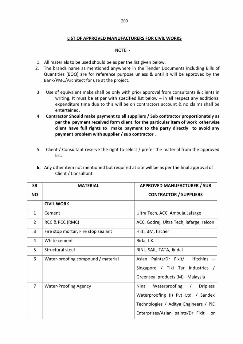
200
LIST OF APPROVED MANUFACTURERS FOR CIVIL WORKS
NOTE: -
1. All materials to be used should be as per the list given below.
2. The brands name as mentioned anywhere in the Tender Documents including Bills of Quantities (BOQ) are for reference purpose unless & until it will be approved by the Bank/PMC/Architect for use at the project.
3. Use of equivalent make shall be only with prior approval from consultants & clients in
writing. It must be at par with specified list below – in all respect any additional expenditure time due to this will be on contractors account & no claims shall be entertained.
4. Contractor Should make payment to all suppliers / Sub contractor proportionately as per the payment received form client for the particular item of work otherwise client have full rights to make payment to the party directly to avoid any payment problem with supplier / sub contractor .
5. Client / Consultant reserve the right to select / prefer the material from the approved list.
6. Any other item not mentioned but required at site will be as per the final approval of
Client / Consultant.
SR
NO
MATERIAL APPROVED MANUFACTURER / SUB
CONTRACTOR / SUPPLIERS
CIVIL WORK
1 Cement Ultra Tech, ACC, Ambuja,Lafarge
2 RCC & PCC (RMC) ACC, Godrej, Ultra Tech, lafarge, relcon
3 Fire stop mortar, Fire stop sealant Hilti, 3M, fischer
4 White cement Birla, J.K.
5 Structural steel RINL, SAIL, TATA, Jindal
6 Water-proofing compound / material Asian Paints/Dr Fixit/ Hitchins –
Singapore / Tiki Tar Industries /
Greenseal products (M) - Malaysia
7 Water-Proofing Agency Nina Waterproofing / Dripless
Waterproofing (I) Pvt Ltd. / Sandex
Technologies / Aditya Engineers / PIE
Enterprises/Asian paints/Dr Fixit or

201
SR
NO
MATERIAL APPROVED MANUFACTURER / SUB
CONTRACTOR / SUPPLIERS
Approved agency by Water-proofing
compound / material manufacturer.
8 Tile / Stone adhesive cement and joint
filling compound
ACC Concrete / Ascolight / Saint-
Gobain weber
9 Glazed tiles (1st Quality) Kajaria, Nittco , RAK, H & R Johnson,
Somany, Simpolo
10 Vitrified tiles / Readymade Trades And
Risers
Kajaria, Nittco, H & R Johnson,
Somany , Pavit, Simpolo
11 Ceramic tiles(1st Quality) Kajaria, Nittco, H & R Johnson,
Somany,Simpolo
12 Italian marble CMC , AGL or approved equivalent
13 Glass mosaic tiles Bisazza or Shinex
14 Paver block 65 mm thk. Shreeji (Navi Mumbai), Siddhi Tile,
Basant Betons
15 Paver Tile Pavit, Somany & H & R Johnson
16 Wooden Flooring Pergo, Armstrong, Floorwalk, Karnav
17 Wooden Decking Anika Global, Prolific Artisans, M.A.
desai & Co.
18 False Flooring Kebao, Uni tiles, Tate, Llyod Insulatio
19 AAC Block CK Birla Aerocon / ACC Concrete /
Ultratech / Ascolight
20 Block joint Mortar ACC Concrete / Ascolight / Saint-
Gobain weber
21 Ready mixed cement plaster ACC / Wall Plast / Ascolite/Saint
Gobain/Birla/ Ultra Tech
22 Composite Marble CMC, AGL or approved equivalent
23 Cementitious screed Ascolite - Ascoscreed / Keracole
HARD WARE /PAINT/PLYWOOD
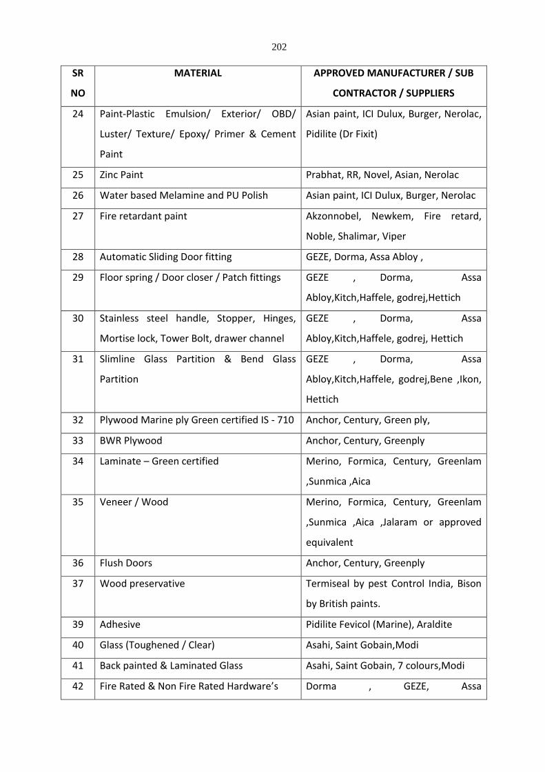
202
SR
NO
MATERIAL APPROVED MANUFACTURER / SUB
CONTRACTOR / SUPPLIERS
24 Paint-Plastic Emulsion/ Exterior/ OBD/
Luster/ Texture/ Epoxy/ Primer & Cement
Paint
Asian paint, ICI Dulux, Burger, Nerolac,
Pidilite (Dr Fixit)
25 Zinc Paint Prabhat, RR, Novel, Asian, Nerolac
26 Water based Melamine and PU Polish Asian paint, ICI Dulux, Burger, Nerolac
27 Fire retardant paint Akzonnobel, Newkem, Fire retard,
Noble, Shalimar, Viper
28 Automatic Sliding Door fitting GEZE, Dorma, Assa Abloy ,
29 Floor spring / Door closer / Patch fittings GEZE , Dorma, Assa
Abloy,Kitch,Haffele, godrej,Hettich
30 Stainless steel handle, Stopper, Hinges,
Mortise lock, Tower Bolt, drawer channel
GEZE , Dorma, Assa
Abloy,Kitch,Haffele, godrej, Hettich
31 Slimline Glass Partition & Bend Glass
Partition
GEZE , Dorma, Assa
Abloy,Kitch,Haffele, godrej,Bene ,Ikon,
Hettich
32 Plywood Marine ply Green certified IS - 710 Anchor, Century, Green ply,
33 BWR Plywood Anchor, Century, Greenply
34 Laminate – Green certified Merino, Formica, Century, Greenlam
,Sunmica ,Aica
35 Veneer / Wood Merino, Formica, Century, Greenlam
,Sunmica ,Aica ,Jalaram or approved
equivalent
36 Flush Doors Anchor, Century, Greenply
37 Wood preservative Termiseal by pest Control India, Bison
by British paints.
39 Adhesive Pidilite Fevicol (Marine), Araldite
40 Glass (Toughened / Clear) Asahi, Saint Gobain,Modi
41 Back painted & Laminated Glass Asahi, Saint Gobain, 7 colours,Modi
42 Fire Rated & Non Fire Rated Hardware’s Dorma , GEZE, Assa
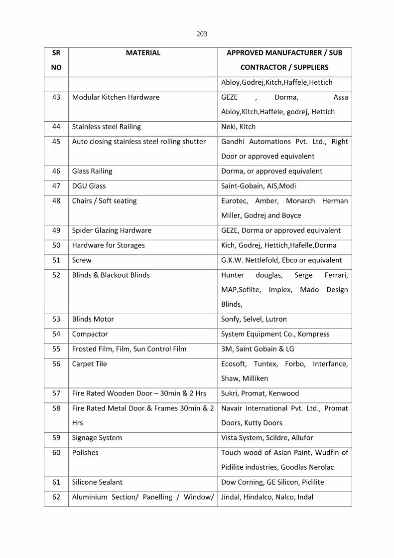
203
SR
NO
MATERIAL APPROVED MANUFACTURER / SUB
CONTRACTOR / SUPPLIERS
Abloy,Godrej,Kitch,Haffele,Hettich
43 Modular Kitchen Hardware GEZE , Dorma, Assa
Abloy,Kitch,Haffele, godrej, Hettich
44 Stainless steel Railing Neki, Kitch
45 Auto closing stainless steel rolling shutter Gandhi Automations Pvt. Ltd., Right
Door or approved equivalent
46 Glass Railing Dorma, or approved equivalent
47 DGU Glass Saint-Gobain, AIS,Modi
48 Chairs / Soft seating Eurotec, Amber, Monarch Herman
Miller, Godrej and Boyce
49 Spider Glazing Hardware GEZE, Dorma or approved equivalent
50 Hardware for Storages Kich, Godrej, Hettich,Hafelle,Dorma
51 Screw G.K.W. Nettlefold, Ebco or equivalent
52 Blinds & Blackout Blinds Hunter douglas, Serge Ferrari,
MAP,Soflite, Implex, Mado Design
Blinds,
53 Blinds Motor Sonfy, Selvel, Lutron
54 Compactor System Equipment Co., Kompress
55 Frosted Film, Film, Sun Control Film 3M, Saint Gobain & LG
56 Carpet Tile Ecosoft, Tuntex, Forbo, Interfance,
Shaw, Milliken
57 Fire Rated Wooden Door – 30min & 2 Hrs Sukri, Promat, Kenwood
58 Fire Rated Metal Door & Frames 30min & 2
Hrs
Navair International Pvt. Ltd., Promat
Doors, Kutty Doors
59 Signage System Vista System, Scildre, Allufor
60 Polishes Touch wood of Asian Paint, Wudfin of
Pidilite industries, Goodlas Nerolac
61 Silicone Sealant Dow Corning, GE Silicon, Pidilite
62 Aluminium Section/ Panelling / Window/ Jindal, Hindalco, Nalco, Indal
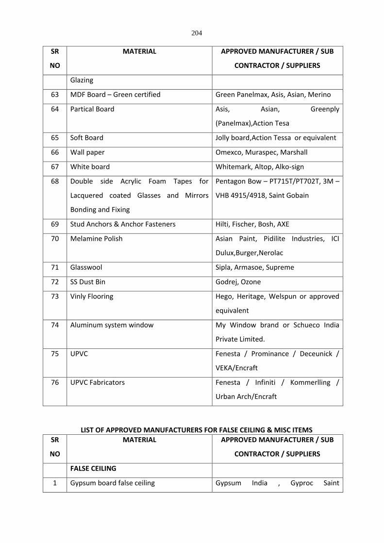
204
SR
NO
MATERIAL APPROVED MANUFACTURER / SUB
CONTRACTOR / SUPPLIERS
Glazing
63 MDF Board – Green certified Green Panelmax, Asis, Asian, Merino
64 Partical Board Asis, Asian, Greenply
(Panelmax),Action Tesa
65 Soft Board Jolly board,Action Tessa or equivalent
66 Wall paper Omexco, Muraspec, Marshall
67 White board Whitemark, Altop, Alko-sign
68 Double side Acrylic Foam Tapes for
Lacquered coated Glasses and Mirrors
Bonding and Fixing
Pentagon Bow – PT715T/PT702T, 3M –
VHB 4915/4918, Saint Gobain
69 Stud Anchors & Anchor Fasteners Hilti, Fischer, Bosh, AXE
70 Melamine Polish Asian Paint, Pidilite Industries, ICI
Dulux,Burger,Nerolac
71 Glasswool Sipla, Armasoe, Supreme
72 SS Dust Bin Godrej, Ozone
73 Vinly Flooring Hego, Heritage, Welspun or approved
equivalent
74 Aluminum system window My Window brand or Schueco India
Private Limited.
75 UPVC Fenesta / Prominance / Deceunick /
VEKA/Encraft
76 UPVC Fabricators Fenesta / Infiniti / Kommerlling /
Urban Arch/Encraft
LIST OF APPROVED MANUFACTURERS FOR FALSE CEILING & MISC ITEMS
SR
NO
MATERIAL APPROVED MANUFACTURER / SUB
CONTRACTOR / SUPPLIERS
FALSE CEILING
1 Gypsum board false ceiling Gypsum India , Gyproc Saint
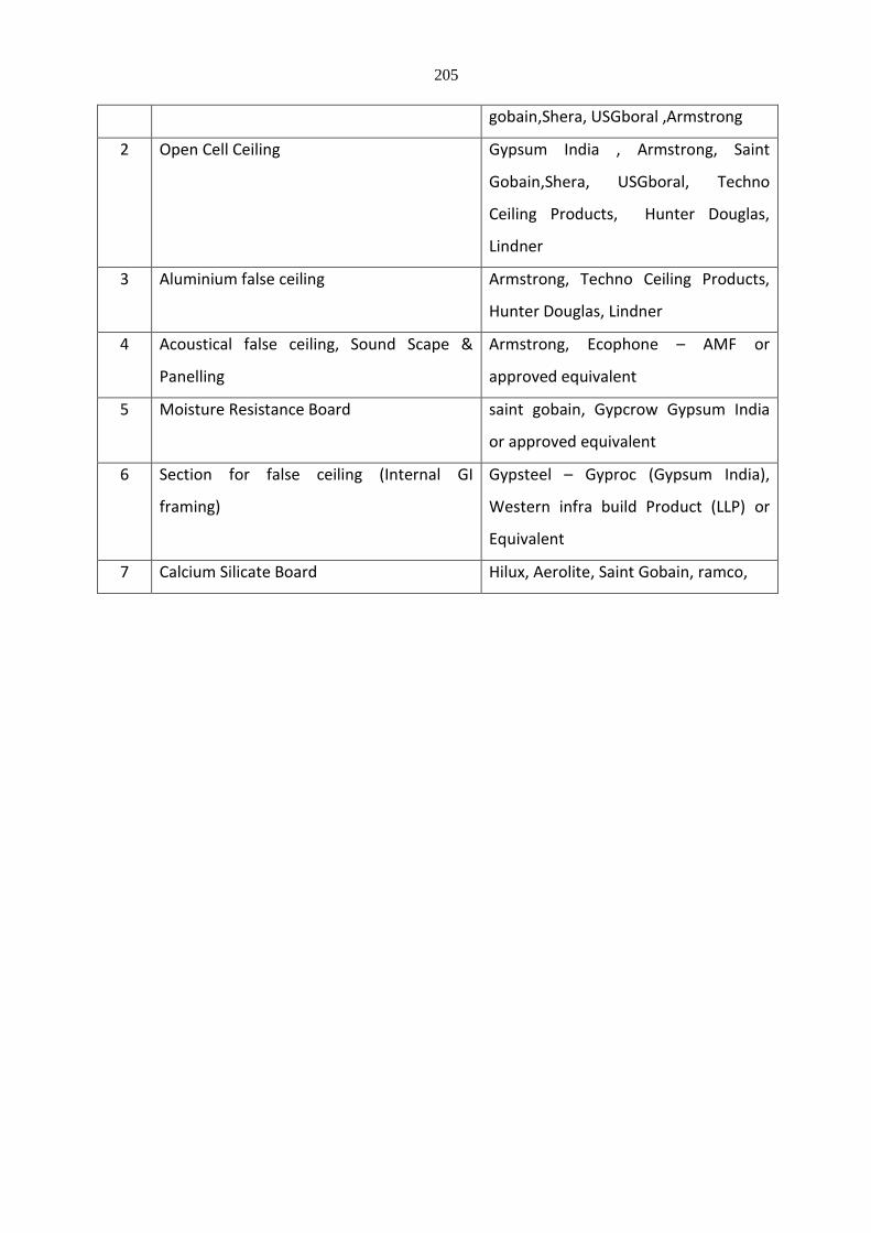
205
gobain,Shera, USGboral ,Armstrong
2 Open Cell Ceiling Gypsum India , Armstrong, Saint
Gobain,Shera, USGboral, Techno
Ceiling Products, Hunter Douglas,
Lindner
3 Aluminium false ceiling Armstrong, Techno Ceiling Products,
Hunter Douglas, Lindner
4 Acoustical false ceiling, Sound Scape &
Panelling
Armstrong, Ecophone – AMF or
approved equivalent
5 Moisture Resistance Board saint gobain, Gypcrow Gypsum India
or approved equivalent
6 Section for false ceiling (Internal GI
framing)
Gypsteel – Gyproc (Gypsum India),
Western infra build Product (LLP) or
Equivalent
7 Calcium Silicate Board Hilux, Aerolite, Saint Gobain, ramco,

206
Section 5
Glass & Glazing
Part 1 – General
1. Scope
1.1. Work as shown shall be specified for all glass and glazing components within the Specification Section. All material and workmanship shall be in accordance with the requirements of the contract documents.
2. Work Included
2.1. The work of this Section includes all labour, material, equipment and services necessary to complete related trades with glazing components as shown on the drawings and specified herein, including but not limited to Composite Glazed Curtain Wall specified in Section 08920.
3. Description
3.1. Glass and glazing shall be comprised of insulated glass that is fabricated to specific size as determined by the window manufacturer to fit within framing elements allowing for proper movement, performance and loading. Window fabricator shall be responsible for the application of said glazing and shall accommodate limitations in regard to fabricated sizes, installation and protection of work in accordance with the design intent illustrated in the design drawings.
4. Design Drawings
4.1. The Facade Consultant’s Drawings indicate the design concept and relation to adjacent construction together with specified “Performance Criteria” tolerances, materials, finishes and standards.
5. Standards
5.1. AAMA “Metal Curtain Wall, Window, Storefront & Entrance Guide Specification Manual”
5.2. FGMA “Glazing Sealing Systems Manual” and “Glazing Manual”
6. Quality Assurance
6.1. The glazing elements shall be installed by a firm with a minimum of five (5) years experience in the design, engineering, fabrication and installation of glazing within the glazed scope of work.
6.2. The work of this section, specifically the application of glazing accessories and glass, determination of size of lites, and installation practices shall be the responsibility of the manufacturer utilizing the glass specified herein. Said manufacturer shall have a minimum of ten (10) years experience installing glass on comparably sized projects and of comparable design complexity.
6.3. Performance
6.3.1. Tempered and heat strengthened glass shall be subject to a maximum spontaneous lites breakage of 8 lites per 1000. Manufacturer shall warrant against breakage exceeding 8 lites per 1000.
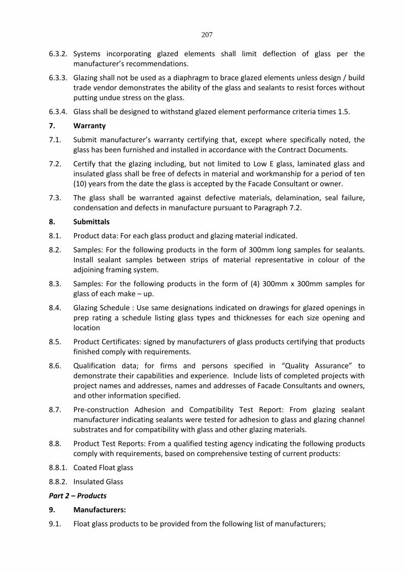
207
6.3.2. Systems incorporating glazed elements shall limit deflection of glass per the manufacturer’s recommendations.
6.3.3. Glazing shall not be used as a diaphragm to brace glazed elements unless design / build trade vendor demonstrates the ability of the glass and sealants to resist forces without putting undue stress on the glass.
6.3.4. Glass shall be designed to withstand glazed element performance criteria times 1.5.
7. Warranty
7.1. Submit manufacturer’s warranty certifying that, except where specifically noted, the glass has been furnished and installed in accordance with the Contract Documents.
7.2. Certify that the glazing including, but not limited to Low E glass, laminated glass and insulated glass shall be free of defects in material and workmanship for a period of ten (10) years from the date the glass is accepted by the Facade Consultant or owner.
7.3. The glass shall be warranted against defective materials, delamination, seal failure, condensation and defects in manufacture pursuant to Paragraph 7.2.
8. Submittals
8.1. Product data: For each glass product and glazing material indicated.
8.2. Samples: For the following products in the form of 300mm long samples for sealants. Install sealant samples between strips of material representative in colour of the adjoining framing system.
8.3. Samples: For the following products in the form of (4) 300mm x 300mm samples for glass of each make – up.
8.4. Glazing Schedule : Use same designations indicated on drawings for glazed openings in prep rating a schedule listing glass types and thicknesses for each size opening and location
8.5. Product Certificates: signed by manufacturers of glass products certifying that products finished comply with requirements.
8.6. Qualification data; for firms and persons specified in “Quality Assurance” to demonstrate their capabilities and experience. Include lists of completed projects with project names and addresses, names and addresses of Facade Consultants and owners, and other information specified.
8.7. Pre-construction Adhesion and Compatibility Test Report: From glazing sealant manufacturer indicating sealants were tested for adhesion to glass and glazing channel substrates and for compatibility with glass and other glazing materials.
8.8. Product Test Reports: From a qualified testing agency indicating the following products comply with requirements, based on comprehensive testing of current products:
8.8.1. Coated Float glass
8.8.2. Insulated Glass
Part 2 – Products
9. Manufacturers:
9.1. Float glass products to be provided from the following list of manufacturers;
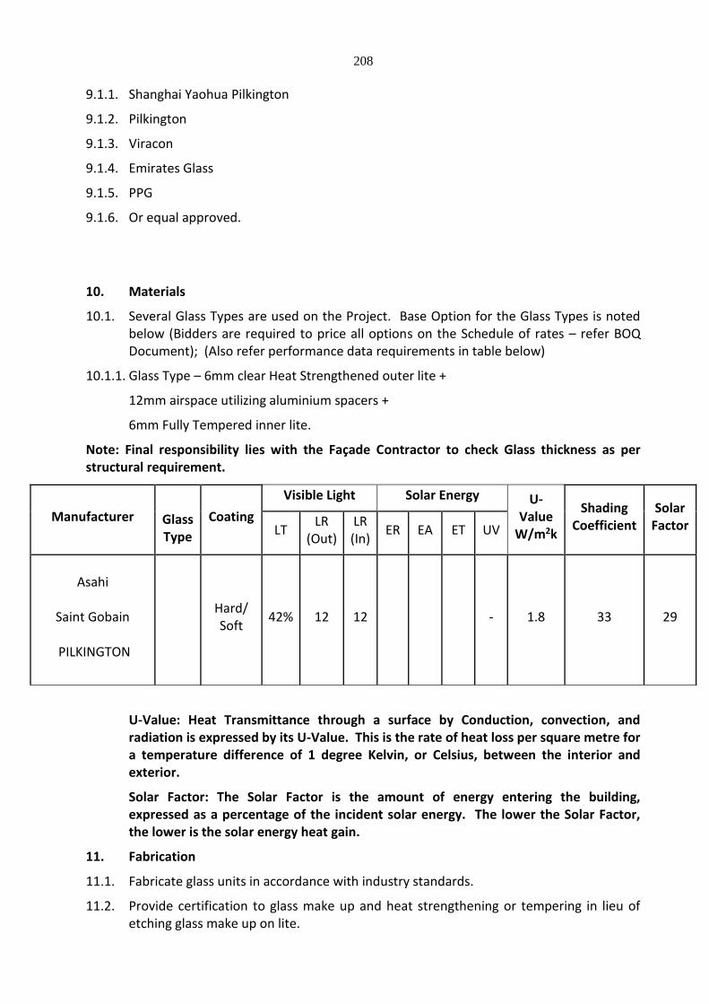
208
9.1.1. Shanghai Yaohua Pilkington
9.1.2. Pilkington
9.1.3. Viracon
9.1.4. Emirates Glass
9.1.5. PPG
9.1.6. Or equal approved.
10. Materials
10.1. Several Glass Types are used on the Project. Base Option for the Glass Types is noted below (Bidders are required to price all options on the Schedule of rates – refer BOQ Document); (Also refer performance data requirements in table below)
10.1.1. Glass Type – 6mm clear Heat Strengthened outer lite +
12mm airspace utilizing aluminium spacers +
6mm Fully Tempered inner lite.
Note: Final responsibility lies with the Façade Contractor to check Glass thickness as per structural requirement.
U-Value: Heat Transmittance through a surface by Conduction, convection, and radiation is expressed by its U-Value. This is the rate of heat loss per square metre for a temperature difference of 1 degree Kelvin, or Celsius, between the interior and exterior.
Solar Factor: The Solar Factor is the amount of energy entering the building, expressed as a percentage of the incident solar energy. The lower the Solar Factor, the lower is the solar energy heat gain.
11. Fabrication
11.1. Fabricate glass units in accordance with industry standards.
11.2. Provide certification to glass make up and heat strengthening or tempering in lieu of etching glass make up on lite.
Manufacturer
Glass Type
Coating
Visible Light Solar Energy U-Value
W/m2k
Shading Coefficient
Solar Factor LT
LR (Out)
LR (In)
ER EA ET UV
Asahi
Saint Gobain
PILKINGTON
Hard/ Soft
42% 12 12 - 1.8 33 29
209
11.3. Fabrication tolerances shall be per FGMA
12. Insulated Glass
12.1. Insulated Glass Units: Pre assembled units consisting of sealed lites of glass separated interspaced and complying with ASTM E 774 for Class CBA units and with requirements article.
12.2. Provide HS (heat strengthened float glass in place of annealed glass wherever thermal stresses induced by differential shading of individual glass lites and to comply with glass design requirements specified in “performance Requirements” clause. Provide FT (Fully tempered) Where safety glass is indicated.
12.2.1. Sealing System: Dual seal with primary and secondary sealants as follows: Manufacturers standard sealants.
12.2.2. Spacer specifications : Manufacturer’s standard spacer material and construction complying with the following requirements ;
12.2.2.1. Aluminium – mill finish / Black Anodised
12.2.2.2. Desiccant: Molecular sieve or silica gel, or blend of both.
12.2.2.3. Corner construction : Manufacturer’s standard corner construction
13. Elastomeric Glazing Sealants
13.1. General: Provide products of type indicated, complying with the following requirements:
13.1.1. Compatibility: Select glazing sealants that are compatible with one another and with other materials they will contact, including glass products ,seals of insulating glass units and glazing channel substrate, under conditions of service and applications, as demonstrated by sealant manufacturer based on testing and field experience.
13.1.2. Suitability; Comply with sealant and glass manufacturers’ written instructions for selecting glazing sealants suitable for applications indicated and for conditions existing at time of installation.
13.1.3. Colours of exposed glazing sealants: As selected by Facade Consultant from manufacturer’s full range for these characteristics
13.1.4. Elastomeric Glazing sealant standard: Comply with ASTM C 920 and other requirements indicated for each liquid – applied, chemically curing sealant in the glazing schedule.
13.1.4.1. Additional Movement Capability: Where additional movement capability is specified in the glazing sealant schedule, provide products with the capability, when tested for adhesion and cohesion under maximum cyclic movement per ASTM C 719, to withstand the specified percentage change in the joint width existing at time of installation and remain in compliance with other requirements in ASTM C 920 for uses indicated.
14. Glazing Gaskets
14.1. Dense Compression Gaskets: Moulded or extruded gaskets of material indicated below ,complying with standard referenced with name of elastomer indicated below, and of profile and hardness required to maintain watertight seal:
14.1.1. Silicone, ASTM C 1115
210
14.2. Soft Compression Gaskets : Extruded or Moulded ,Closed - cell ,integral – skinned gaskets of material indicated below ;complying with ASTM C 509,Type II, black; and of profile hardness required to maintain water tight seal.
14.2.1. Silicone
15. Miscellaneous Glazing Materials
15.1. General: Provide products of material .,size and shape complying with referenced glazing standards, requirements of manufacturers of glass and other glazing materials for application indicated ,and with a proven record of compatibility with surfaces contacted in installation.
15.2. Cleaner, primers and sealers: Types recommended by sealant or gasket manufacturers
15.3. Setting Blocks: Elastomeric material with a Shore A durometer hardness of 85, plus or minus 5
15.4. Spacers: Elastomeric blocks or continuous extrusions with a Shore A durometer hardness required by glass manufacturer to maintain glass lite in place for installation indicated.
15.5. Edge Blocks; Elastomeric material of hardness needed to limit glass lateral movement.
16. Fabrication Of Glass And Other Glazing Products
16.1. Fabricate glass and other glazing products in sizes required to glaze openings indicated for project, with edge and face clearances, edge and surface conditions, and bite complying with written instructions of the product manufacturer and referenced glazing standards, to comply with the system performance requirements.
16.2. Clean – cut or flat – grind vertical edges of butt – glazed monolithic lite in a manner that produces square edges with slight kerfs at junctions with indoor and out door faces.
16.3. Grind smooth and polish exposed glass edges
Part 3 – Installation
17. Factory Inspection
17.1. Inspect all windows prior to installation of glass to ensure glazing pockets are the appropriate size and free of obstructions. Utilize proper setting blocks, anti-walk blocks and specified sundries to ensure a stable glazing installation.
18. Installation
18.1. Install all glazing components in accordance with FGMA standards by experienced installers, in a clean and workmanlike manner.
18.2. Apply all sealing materials in strict compliance with the sealant manufacturer’s recommendations. Before application, remove dirt, dust, moisture and other foreign matter from contact surfaces. Mask adjoining surfaces to maintain a clean and neat appearance. Tool the sealant to fill the joint and provide a smooth finish.
18.3. Protect all installed material to ensure continuity of finishes, sealant joints and glazing.
19. Cleaning & Protection
19.1. Install the glazing elements so as to avoid soiling or smudging of the face of glass.

211
19.2. Clean glass at the time of the installation. Final cleaning shall be conducted prior to final acceptance by Facade Consultant.
***********

212
TECHNICAL SPECIFICATIONS FOR PLUMBING WORKS
Section I General Requirements
1. Scope of work
1.1. The form of Contract shall be according to the "Conditions of Contract". The following clauses shall be considered as an extension and not in limitation of the obligation of the Contractor.
1.2. Work under this Contract shall consist of furnishing all labor, materials, equipment and
appliances necessary and required. The Contractor is required to completely furnish all the plumbing and other specialized services as described hereinafter and as specified in the schedule of quantities and/or shown on the plumbing drawings.
1.3. Without restricting to the generality of the foregoing, the sanitary installations shall
include the following:-
Plumbing Works Sanitary Fixtures Soil, Waste, Vent, Rainwater Pipes & Fittings Water Supply System Under ground drainage
Services rendered under this section shall be done without any extra charge.
Specifications
1.4. Work under this Contract shall be carried out strictly in accordance with specifications
attached with the tender. 1.5. Items not covered under these specifications or due to any ambiguity or misprints, or
additional works, the work shall be carried out as per specifications of the latest Local authority of Water / Drainage Bye-Laws with up to date amendments as applicable in the Contract.
1.6. Works not covered under Para 2.1 and 2.2 shall be carried out as per relevant Codes
& Bureau of Indian Standards and The Uniform Plumbing Code of India.
Execution of work 1.7. The Contractor should visit and examine the site of work and satisfy himself as to the
nature of the existing roads and other means of communication and other details pertaining to the work and local conditions and facilities for obtaining his own information on all matters affecting the execution of work. No extra charge made in consequence of any misunderstanding, incorrect information on any of these points or on ground of insufficient description will be allowed.The work shall be carried out in conformity with the Plumbing drawings and within the requirements of architectural, HVAC, electrical, structural and other specialized services drawings.
1.8. The Contractor shall cooperate with all trades and agencies working on the site. He/They shall make provision for hangers, sleeves, structural openings and other
213
requirements well in advance to prevent hold up of progress of the construction schedule. All supports to the civil structure shall be provided with dash fasteners.
1.9. On award of the work, Contractor shall submit a schedule of construction in the
form of a PERT chart or BAR chart for approval of the Project Manager/Architect/ Consultant. All dates and time schedule agreed upon shall be strictly adhered to within the stipulated time of completion/ commissioning along with the specified phasing, if any.
Drawings
1.10. Contract drawings are diagrammatic but shall be followed as closely as actual
construction permits. Any deviations made shall be in conformity with the architectural and other services drawings.
1.11. Architectural drawings shall take precedence over plumbing or other services drawings
as to all dimensions. 1.12. Contractor shall verify all dimensions at site and bring to the notice of the Project
Manager all discrepancies or deviations noticed. Decision of the Project Manager shall be final.
1.13. Large size details and manufacturers dimensions for materials to be incorporated
shall take precedence over small scale drawings. 1.14. Any drawings issued by the Architects/Consultant for the work are the property of the
Architects/ Consultant and shall not be lent, reproduced or used on any works other than intended without the written permission of the Architects/Consultant.
Inspection and testing of materials
1.15. Contractor shall be required, if requested, to produce manufacturers test certificate
for the particular batch of materials supplied to him. The tests carried out shall be as per the relevant Bureau of Indian Standards.
1.16. For examination and testing of materials and works at the site Contractor shall provide
all testing and gauging equipment necessary but not limited to the following:
a) Steel tapes b) Weighing machine c) Plumb bobs, sprit levels, d) hammer e) Micrometers f) Hydraulic machine
1.17. All such equipment shall be tested for calibration at any approved laboratory, if
required by the Project Manager. All testing equipment shall be preferably located in special room meant for the purpose.
1.18. Samples of all materials shall be got approved before placing order and the
approved samples shall be deposited with the Project Manager.
214
2. Metric conversion 2.1. All dimensions and sizes of materials and equipment given in the tender document are
commercial metric sizes. 2.2. Any weights, or sizes given in the tender having changed due to metric
conversion, the nearest equivalent sizes accepted by Indian Standards shall be acceptable without any additional cost.
3. Reference points 3.1. Contractor shall provide permanent bench marks, flag tops and o t h e r r e f e r en c e
points and check that with other agencies to confirm the same reference point for all the proper execution of work and these shall be preserved till the end of the work.
3.2. All such reference points shall be in relation to the levels and locations, given in the
architectural and plumbing drawings. 4. Reference drawings 4.1. The Contractor shall maintain one set of all drawings issued to him as reference
drawings. These shall not be used on site. All important drawings shall be mounted on boards and placed in racks indexed. No drawings shall be rolled.
4.2. All corrections, deviations and changes made on the site shall be shown on these
reference drawings for final incorporation in the completion drawings to be submitted by the contractor in fulfilment of the conditions of this contract.
4.3. On award of the work the contractor shall be issued four sets of consultant’s working
drawings stamped “good for construction” by the Project Manager. The consultant’s drawings shall be the basis of contractor’s shop drawings. In addition, the Project Manager shall also issue one copy of the Interior Designer’s; Electrical & HVAC approved shop drawings relevant to his work.
4.4. Shop drawings are detailed working drawings which incorporate the contractor's
details for execution of the work and incorporate equipment manufacturer's details and dimensions to ensure that the same can be installed in the space provided.
4.5. All shop drawings should show detailed pipe routing and levels, location of other
services at crossings etc., cable runs, route cable trays and all all ied works and must be fully co- ordinated with other services and approved by the Project Manager before execution of the works. Project Manager shall arrange to issue two copies/prints of services drawings from the respective contracting agencies. Additional copies/prints may be provided on payment of actual cost of the copies/ prints. All drawings will valid only when stamped and issued by the Project Manager.
4.6. Shop drawings shall also be furnished for detailed layout of all equipment, foundation,
bolting and vibration elimination details along with information on dead and dynamic load, vibration etc.
215
4.7. Six sets of manufacturer's equipment drawings, roughing in and wiring diagrams
shall be submitted. 4.8. Contractor shall submit shop drawings furnishing all details of MCC panels, cable
routes, wiring diagrams and connection details as required. 4.9. Three copies of each set of shop drawings shall be submitted for initial scrutiny,
discussion and approval. 4.10. Each submission shall be accompanied by contractor's certificate stating that the
shop drawings meet all the contract requirements and that the piping and equipment can be satisfactorily installed without any obstructions in the space available.
4.11. On approval of the above the contractor shall furnish six sets of the approved shop
drawings for execution of the work.
5. Completion drawings 5.1. On completion of work, Contractor shall submit one complete set of original tracings
and two prints of "As B uilt" drawings to the Project Manager. These drawings shall have the following information.
5.1.1. Run of all piping, diameters on all floors, vertical stacks and location of external
services. 5.1.2. Ground and invert levels of all drainage pipes together with location of all manholes and
connections up to Sewage Treatment Plant with bypasses and/or outfall.
5.1.3. Run of all water supply lines with diameters, locations of control valves, access panels. 5.1.4. Location of all mechanical equipment with layout and piping connections
andmechanical equipment. 5.1.5. All shop drawings shall be updated from time to time for the purpose of making
completion drawings. No completion certificate shall be issued unless the above drawings are submitted.
5.2. Contractor shall provide four sets of catalogues, service manuals, manufacturer's
drawings, performance data and list of spare parts together with the name and address of the manufacturer for all electrical and mechanical equipment provided by him.
5.3. All "warranty cards" given by the manufacturers shall be handed over to the Project
Manager. 5.4. Contractor's rates: Rates quoted in this tender shall be inclusive of cost of
materials, labor, supervision, erection, tools, plant, scaffolding, service connections, transport to site, GST, breakage, wastage and all such expenses as may be necessary and required to completely do all the items of work and put them in a working condition. Rates quoted are for all heights and depths and in all positions as may be

216
required for this work. 5.5. All rates quoted must be for complete items inclusive of all such accessories, fixtures
and fixing arrangements, nuts, bolts, hangers as are a standard part of the particular item except where specially mentioned otherwise.
5.6. All rates quoted are inclusive of cutting holes and chases in walls and floors and making
good the same with cement mortar/concrete/water proofing of appropriate mix and strength as directed by the Project Manager. Contractor shall provide holes, sleeves, recesses in the concrete and masonry work as the work proceeds. All hot and cold water supply pipes crossing masonry walls shall be provided with G.I. pipe sleeves. The annular space between the pipe and sleeve shall be filled up with fire proof sealant after testing. Contractor shall give the pipe sleeves to the civil contractor well in time so that the same can be fixed along with civil works. Any co-ordination gap shall be of contractor’s responsibility.
5.7. The Contractor shall furnish the Project Manager with vouchers & test certificates, on
request, to prove that the materials are as specified and to indicate that the rates at which the materials are purchased in order to work out the rate analysis of n on -tendered items which he/they may be called upon to carryout.
6. Testing 6.1. Piping and drainage works shall be tested as specified under the relevant clauses of the
specifications. 6.2. Tests shall be performed in presence of the Project Manager and test records for the
tests shall be duly signed by Contractor and the Project Manager. 6.3. All materials and equipment found defective shall be replaced and whole work tested
to meet the requirements of the specifications. 6.4. Contractor shall perform all such tests as may be necessary and required by the local
authorities to meet municipal or other bye-laws in force. 6.5. Contractor shall provide all labor, equipment and materials for the performance of the
tests at his/their cost. 7. Site clearance and cleanup
The Contractor shall, from time to time, clear away all debris and excess materials accumulated at the site.
After the fixtures, equipment and appliances have been installed and
commissioned, Contractor shall clean-up the same and remove all plaster, paints, stains, stickers and other foreign matter or discoloration leaving the same in a ready to use condition.
On completion of all works, Contractor shall demolish all stores, remove all
surplus materials and leave the site in a broom clean condition, failing which
217
the same shall be done by the Project Manager at the Contractor’s risk and cost. Cost of the cleanup shall be deducted from the contractor's bills on pro-rata basis in proportion to his contract value.
8 License permits and authorities 8.1 Contractor must hold a valid plumbing or any other as required license by
the municipal authority or other competent authority under whose jurisdiction the work falls.
8.2 Contractor must keep constant liaison with the local development,
municipal/statutory authority and obtain approval of all drainage, water supply, fire suppression and other works carried out by him.
8.3 Contractor shall obtain, from the municipal and other authorities forms as
requifor approval of d ra in a ge and water supply works during execution and the completion certificate with respect to his work as required for occupation of the building. Contractor shall obtain permanent water supply and drainage connections from authorities concerned. The Employer shall re-imbrues the fees paid to the authorities towards the connection charges on production of receipts for money paid.
8.4 Contractor shall get any materials tested from the appropriate authority if
so required with no cost to the Employer. 9 Recovery of cost for materials issued to Contractors free of cost.
If any material issued free of cost by the Employer to the contract for use on the
work and the same is lost, stolen ,pilfered or broken while in contractor’ possession, the cost of the same shall be recovered from the Contractor on the basis of actual cost to Employer. The cost shall include the cost paid, freight, transportation, excise duty, sales tax, octroi (LBT), import duty and other levies, plus 100% as penalty. The decision on the actual cost given by the Employer shall be final and binding on the Contractor.
Contractor has to keep full records of material issued by the Employer with
reference and challans etc. Contractor has to give account of all such materials to the Project Manager.
10 Cutting of Water Proofing Membrane:
No walls terraces shall be cut for making and opening after water proofing has been done without written approval of project manager. Cutting of water proofing membrane shall be done very carefully so as other portion of water proofing is not damaged. On completion of work at such place the water proofing membrane shall be made good and ensured that the opening/cutting is made fully water proof as per specifications and details of water proofing approved by Project Managers.

218
11 Cutting of structural members
No structural member shall be chased or cut without the written permission of the Project Manager
12 Materials supplied by Employer.
The Contractor shall verify that all materials supplied by the Employer conform to the specifications of the relevant item in the tender. Any discrepancy found shall be brought to the notice of the Project Manager.
13 Materials
a. Unless otherwise specified and expressly approved in writing by the Project Manager, only materials of makes and specification as mentioned in the list of approved makes attached with the specifications shall be used.
b. If required, the Contractor shall submit samples of materials proposed to be used
in the works. Approved samples shall be kept in the office of the Project Manager.
End of Section I

219
Section II Sanitary Fixtures 1. Scope of work 1.1. Work under this section shall consist of furnishing all materials & labor necessary
and required to completely install all sanitary fixtures, chromium plated fittings and accessories as required by the drawings specified hereinafter and given in the Schedule of Quantities.
1.2. Without restricting to the generality of the foregoing the sanitary fixtures shall
include the following:- a) Sanitary fixtures b) Chromium plated fittings c) Porcelain or stainless steel sinks d) Accessories e.g. towel rods, toilet paper holders, soap dish, towel rails, coat hooks etc. e) Connections to all kitchens, equipment, pump headers and other equipment
requiring water and drainage connections. 1.3. Whether specifically mentioned or not all fixtures and appliances shall be provided
with all fixing devices, nuts, bolts, screws, hangers as required. 1.4. All exposed pipes within toilets and near fixtures shall be chromium plated brass or
copper unless otherwise specified. 2. General requirements 2.1. Sanitary fixtures and C.P. fittings in manufacturer’s packing as specified in the schedule
of quantities shall be supplied to the Contractors free of cost at the stores of the Employer.
2.2. All fixtures and fittings shall be provided with all such accessories as are required to
complete the item in working condition whether specifically mentioned or not in the Schedule of Quantities, specifications, drawings. Accessories shall include proper fixing arrangement, brackets, nuts, bolts, screws and required connection pieces, WC flexible connectors etc.
2.3. Fixing screws shall be half round head chromium plated brass screws with C.P.
washers where necessary. 2.4. Contractor shall furnish without cost all such accessories and fixing devices that are
necessary and required but not supplied along with the Plumbing Fixtures & CP Fittings by the manufacturers as a part of the original and standard supply.
2.5. All fittings and fixtures shall be fixed in a neat workmanlike manner true to level and
heights shown on the drawings and in accordance with the manufacturer’s recommendations. Care shall be taken to fix all inlet and outlet pipes at correct positions. Faulty locations shall be made good and any damage to the finished floor, tiling or terrace shall be made good at Contractor's cost.

220
2.6. Contractor shall seal all fixtures fixed near wall, marble and edges with an approved type of poly-sulfide sealant appropriate for its application.
3. European W.C 3.1. European W.C. shall be wash down or siphonic-type wall mounted set flushed by
means of Concealed type Cistern with Dual Flow Facility (Concealed Body) with Exposed Shut Off valve Provision, which will be an integral part of the WC system. Framework, walling and finishing will not form a part of the contractor’s work. Where applicable flush pipe/ bend shall be connected to the W.C. by means of a suitable rubber adapter. Wall hung W.C. shall be supported by appropriate brackets for a dry-wall installation.
3.2. Each W.C. set shall be provided with a plastic seat shall be with rubber buffers and
chromium plated hinges. 3.3. Plastic seat shall be so fixed that it remains absolutely stationary in vertical position
without falling down on the W.C. Each W.C. shall be suitable for flushing in low volume of water 3-6 liters.
3.4. Flushing cistern if and when provided shall be provided with all internal flushing
mechanism, 15 mm dia angle cock with unbreakable polythene float and overflow pipe. Any frame work required for fixing cistern has to be provided by the contractor.
4. Urinals 4.1. Urinals shall be white glazed vitreous china of size, shape and type shall be specified in
the Bill of Quantities otherwise selected by architect / interior designer or client. 4.2. Bowl urinals shall be provided with 15 mm dia C.P. spreader, 32 mm dia stainless
steel domical waste and C.P. cast brass bottle trap with pipe and wall flange, and shall be fixed to wall by C.I. brackets and C.I. wall clips as recommended by manufacturers complete as directed by Project Manager.
4.3. Urinals shall be fixed with C.P. brass screws and shall be provided with 32 mm dia
domical waste leading to urinal's trap. 4.4. Flush pipes shall be uPVC pipes concealed in wall chase but with chromium plated
bends at inlet and outlet or as given in Bill of Quantities. 4.5. Urinals shall be flushed by means of fully automatic no-touch battery operated infra-red
sensor having pre & post flushing with water (250 ml & 500 ml consumption). 4.6. Waste pipes for urinals shall be uPVC class III (6 kg/sqcm) conforming to IS: 4985 as
given in schedule of quantities. Waste pipes may be exposed on wall or concealed in chase as directed by the Project Manager.
5. Wash Basins 5.1. Wash basins shall wall mounted type or Counter top type as specified in the BOQ. Size,
shape and type shall be specified in the Bill of Quantities otherwise selected by architect / interior designer or client.

221
5.2. Each basin shall be supported on MS galvanized or CI brackets and clips and the
basin securely fixed to wall or on the counter. The design of the brackets shall suit the basin selected and as recommended by the manufacturer. Installation of pedestal type basins shall be made as per the manufacturer’s specifications.
5.3. Each basin shall be provided with 32 mm dia C.P.waste with overflow, pop-up or
standard waste with rubber plug and chain, 32 mm dia C.P. brass bottle trap with CP pipe to wall and flange.
5.4. Each basin shall be provided with a chrome plated brass auto-closing pillar cock
(metered faucet with 1 ltr discharge per cycle), for wash basin, having foam flow technology and 15mm nominal bore, with pop up waste fittings, 32 mm dia. CP cast brass bottle trap with outlet pipe and wall flange. Washbasins shall be fixed at proper heights as shown on drawings. If height is not specified, the rim level shall be 79 cms or as directed by Project Managers.
6. Sinks 6.1. Sinks shall be stainless steel or any other material as specified in the Bill of Quantities. 6.2. Each sink shall be provided with brackets of approved and securely fixed. Counter top
sinks shall be fixed with suitable brackets or clips as recommended by the manufacturer. Each sink shall be provided with 40 mm dia C.P. waste with chain and plug as given in the Schedule of Quantities. Fixing shall be done as directed by Project Manager.
6.3. Supply fittings for sinks shall be mixing fittings or C.P. taps as specified in the
Schedule of Quantities. 7. Hand Drier 7.1. The hand drier shall be no touch operating type with solid state time delay to allow
user to keep hand in any position. 7.2. The hand drier shall be fully hygienic, rated for continuous repeat use. 7.3. The rating of hand drier shall be such that time required to dry a pair of hands upto
wrists is approximately 30 seconds. 7.4. The hand drier shall be wall mounting type suitable for 230 volts, single phase, 50 Hz,
A.C. power supply. 8. Toilets for Differently Abled 8.1. Where specified in washroom facilities designed to accommodate physically
handicapped, accessories should be provided as directed by the Project Manager. 8.2. Stainless steel grab bars of required size suitable for concealed or exposed mounting
and non-slip gripping surface shall be provided in all washrooms to be used by physically handicapped as directed by the Project Manager.

222
9. Accessories 9.1. Contractor shall install all chromium plated and porcelain accessories as shown on
the drawings or directed by the Project Manager. 9.2. All C.P. accessories shall be fixed with C.P. brass half round head screws and cup
washers in wall with rawl plugs or nylon sleeves and shall include cutting and making good as required or directed by Project Manager.
9.3. Recessed porcelain accessories shall be fixed in walls and set in cement mortar
1:2 (1 cement: 2 coarse sand) and fixed in relation to the tiling work as per Interior Designer’s drawings.
10. Urinal partitions 10.1. Urinal partitions shall be white glazed vitreous china, marble, granite or any other
material selected by the Project Manager. 10.2. Urinal partitions shall be fixed at proper heights with C.P. brass bolts, anchor
fasteners and M.S. Clips as recommended by the manufacturer and directed by Project Manager.
11. Measurement 10.1 Sanitary fixtures and accessories shall be measured by numbers in the
unit given in the Bill of Quantities. 10.2 Rates for all items shall be inclusive of cutting holes and chases and making
good the same, C.P Brass screws, nuts, bolts and any fixing arrangements required and recommended by manufacturers, testing and commissioning.
End of Section II
223
Contractor MMRDA
Section III Soil, Waste, Vent, Rainwater Pipes & Fittings
1. Scope of work 1.1. Work under this section shall consist of furnishing all labor, materials, equipment and
appliances necessary and required to completely install all soil, waste, vent and rainwater pipes and fittings as required by the drawings, and given in the Bill of Quantities.
1.2. Without restricting to the generality of the foregoing, the soil, waste, vent pipes
system shall include the following:-
a. Vertical and horizontal soil, waste, vent pipes, and fittings, joints, clamps, connections to fixtures.
b. Connection of all pipes to sewer lines as shown on the drawings at ground floor levels.
c. Drainage, channels, gratings & floor drains. d. Floor and urinal traps, cleanout plugs, inlet fittings and rainwater
heads/Khurras. e. Testing of all pipe lines.
2. General requirements 2.1. All materials shall be new of the best quality conforming to specifications and subject
to the approval of Project Manager. 2.2. Pipes and fittings shall be fixed truly vertical, horizontal or in slopes as required in a
neat workmanlike manner. 2.3. Pipes shall be fixed in a manner as to provide easy accessibility for repair and
maintenance and shall not cause obstruction in shafts, passages etc. 2.4. Pipes shall be securely fixed to walls and ceilings by suitable clamps intervals specified. 2.5. Access doors for fittings and clean outs shall be so located that they are easily
accessible for repair and maintenance. Any access panel required in the civil structure, false ceiling or marble cladding etc. shall be clearly reported to the Employer in the form of shop drawing so that other agencies are instructed to provide the same.
3. Piping System 3.1. Schedule of Pipes Use stacks for Soil, Waste., Vent & RWP Silent Drain pipes 75,110
,150 mm dia Vt. uPVC pipes 40,50 & 63 mm dia Horizontal. For Soil, Waste, Vent pipes 6 kg/sq cm
4. Soil, Waste & Vent Pipes 4.1. All soil/waste from will be collected in i.c. chambers and after treatment in STP shall
be pumped into sewer line. The Soil & Waste Pipe System above ground as defined in IS : 13592 Two-
Pipe system using the silent- drain system. connections for soil and waste

224
Contractor MMRDA
for kitchen sinks, showers, washbasins and floor drains and is approved by Project Manager subject to approval from local authority or Two-Pipe system using the silent-drain system.
4.2. All soil/waste from will be collected in i.c. chambers and after treatment in STP shall be pumped into sewer line.
5. Rainwater Pipes
All open terraces shall be drained by rain water down comers.
Rainwater down comers are separate and independent of the soil and waste system and will discharge into the open ground Storm water Drainage system / Rainwater harvesting system of the Complex.
Rain water shall be collected in catch basins and connected to the storm water
drain / recharge pits. 6. Sound-Proof Pipes & Fittings 6.1. Pipes and fittings for main vertical stacks & branches 110 mm, & 75 mm dia shall be
(SWR drainage system) with injection molded fittings with approved socket & ‘O’ rubber ring joints.
6.2. Joints shall be done as per the manufacturer’s recommendations. The pipes and fittings
must have matching dimension for perfect joints in the system. ‘O’ ring fittings must have sufficient gap (approx. 10 mm) for thermal expansion of pipes.
6.3. Pipes shall be clamped to the wall with approved type of uPVC saddle clamps/U
clamps and G.I. rod fixed to the angle iron support system within the shaft. Such as to achieve maximum soundproofing.
6.4. Use proper pipe adapters for connections between cast iron pipes, traps & uPVC pipes
where necessary. Such joints shall be made of an approved type of ‘Putty’. 7. Performance Criteria
7.1. All above ground drainage pipework has been designed to IS 13592. Install pipework, fittings and accessories to ensure that:
7.1.1. Appliances drain quickly, quietly and completely at all times without nuisance or risk to health.
7.1.2. Discharge is conveyed without cross flow, back fall, leakage or blockage.
7.1.3. Foul air from the drainage system does not enter the building.
7.1.4. Pressure fluctuations in pipework do not vary by more than +/-38mm water gauge.
7.1.5. All traps to sanitary appliances to retain a water seal of not less than:
WC’s 50mm
225
Contractor MMRDA
Floor Gully 75mm
WHB 75mm
Urinal 75mm
Bath/shower 50mm
Individual shower 50mm
Washing Machine 75mm
7.1.6. The system can be adequately tested, cleaned and maintained.
8. Installation Generally
8.1. Obtain all components for each type of pipework from the same manufacturer unless specified otherwise.
8.2. Cut ends of pipes to be clean and square for solvent joints and chamfered for ring seal joints.
8.3. Allow for adequate thermal expansion/contraction and building movement when jointing and fixing.
8.4. Form junctions using fittings intended for the purpose.
8.5. Prevent entry of foreign matter into any part of the system by sealing openings during construction. Fit all access covers and cleaning eyes as the construction proceeds.
9. Access Points
Provide access points for cleaning purposes at the following:
(a) Access shall be at all changes of direction and at each floor level (1200mm above
finished floor level) on each soil and waste stack.
(b) Provide access on all horizontal branch waste floats.
(c) Check and place appropriately handed access fittings as required.
(d) Locate to allow use of cleaning equipment or the insertion of testing apparatus.
(f) Fit all access doors/covers and cleaning eyes as the construction proceeds.
10. Pipe Routes
To be the shortest practical, with as few bends as possible.
226
Contractor MMRDA
11. Lubricant
Using lubricant recommended by the pipework manufacturers and agreed with the
Engineer prior to installation works commencing.
12. Solvent Cement
Liquid weld cement for jointing PVC-u pipe systems as recommended by the pipework
manufacturers and agreed with the Engineer prior to installation works commencing.
13. Base of Stack
Base of stack shall be formed using 2 x 45 degree bends connected together by an
appropriate length of pipe or a 90o large radius support bend to ensure that the formed
bend is a minimum of two times the outside diameter of the stack.
14. Couplings and Adaptors
Appropriate connections shall be installed to suit pipes and fittings being jointed, refer
to Terrain PVC-u soil and waste system installation guide for manufacturer’s
recommendations.
15. Bends, Branches and Boss Pipe Connections
All branches to be swept in direction of flow at all connections.
Ensure factory moulded and/or pre fabricated fittings are used.
16. Floor Gullies
Compact design PVC-u 75mm trapped floor gully with side sockets to allow waste
connections.
17. Vent Stack
A vent stack shall be considered part of the system and shall be installed using the same
methods required for the soil and waste stacks.
Also provide vent pipe for Starting of ic chambers of the sewer line.
18. Clamps 18.1. For UPVC pipes standard UPVC clamps shall be used. For other pipes M.S. clamps,
supports and hangers provided shall be galvanized. Factory made Pre-fabricated clamps shall be preferred. Contactor may fabricate the clamps of special nature and galvanize
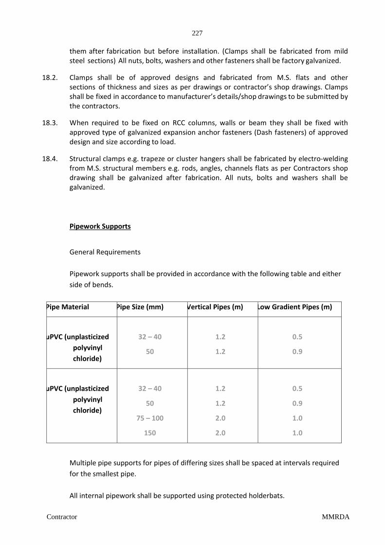
227
Contractor MMRDA
them after fabrication but before installation. (Clamps shall be fabricated from mild steel sections) All nuts, bolts, washers and other fasteners shall be factory galvanized.
18.2. Clamps shall be of approved designs and fabricated from M.S. flats and other
sections of thickness and sizes as per drawings or contractor’s shop drawings. Clamps shall be fixed in accordance to manufacturer’s details/shop drawings to be submitted by the contractors.
18.3. When required to be fixed on RCC columns, walls or beam they shall be fixed with
approved type of galvanized expansion anchor fasteners (Dash fasteners) of approved design and size according to load.
18.4. Structural clamps e.g. trapeze or cluster hangers shall be fabricated by electro-welding
from M.S. structural members e.g. rods, angles, channels flats as per Contractors shop drawing shall be galvanized after fabrication. All nuts, bolts and washers shall be galvanized.
Pipework Supports
General Requirements
Pipework supports shall be provided in accordance with the following table and either
side of bends.
Pipe Material Pipe Size (mm) Vertical Pipes (m) Low Gradient Pipes (m)
uPVC (unplasticized
polyvinyl
chloride)
32 – 40
50
1.2
1.2
0.5
0.9
uPVC (unplasticized
polyvinyl
chloride)
32 – 40
50
75 – 100
150
1.2
1.2
2.0
2.0
0.5
0.9
1.0
1.0
Multiple pipe supports for pipes of differing sizes shall be spaced at intervals required
for the smallest pipe.
All internal pipework shall be supported using protected holderbats.
228
Contractor MMRDA
The holderbats shall either:
1) Locate around fitting sockets to provide an anchor point for support and as a fixed point to control thermal movement.
2) Locate around the pipe to act as a support while still permitting free longitudinal movement of the pipework. Long sections of drains shall be laterally braced to the structure with angle section mild steel to prevent horizontal movement.
3) Pipes in shafts shall be supported using protected mild steel holderbats bolted together with cadmium plated mild steel bolts and nuts and screwed to shaft walls using 50mm no. 10 cadmium plated mild steel screws and plastic wall plugs.
Exposed pipework fixed to walls in occupied areas shall be supported using one piece
brackets screwed to walls using 50mm no. 10 cadmium plated mild steel screws and
plastic wall plugs. 19. Traps 19.1. Floor traps
Floor traps where specified shall be of multi inlet traps (SWR) having a minimum 50 mm deep seal as per the Uniform Plumbing Code of India. The trap and waste pipes when buried below ground shall be set and encased in cement concrete blocks firmly supported on firm ground or when installed on a sunken RCC structural slab. The blocks shall be in 1:2:3 mix (1 cement: 2 coarse sand: 3 stone aggregate 20 mm nominal size).
Contractor shall provide all necessary shuttering and centring for the blocks. Size of the block shall be 30x30 cms of the required depth.
19.2. Urinal traps
Urinal traps/horn shall be multi inlet uPVC traps with or without vent and set in cement concrete block specified for floor traps.
20. Cleanout plugs 20.1. Floor Clean out Plug.
Clean out plug for Soil, Waste or Rainwater pipes laid under floors shall be provided near pipe junctions bends, tees, “Y’s” and on straight runs at such intervals as required as per site conditions. Cleanout plugs shall terminate flush with the floor levels. They shall be threaded and provided with key holes for opening. Cleanout plugs shall be Cast Brass s c r e w e d to the socket. The socket shall be jointed properly to the drain pipes.
21. Waste pipe from appliances 21.1. Waste pipe from appliances e.g. washbasins, sinks and urinals shall be uPVC in all
229
Contractor MMRDA
toilets, kitchen, pantries and service areas where so required, and as given in the Bill of Quantities or shown on the drawings.
21.2. All pipes shall be fixed in gradient towards the connection to stack, trap or drain. Pipes
inside all toilets shall be in chase unless otherwise shown on drawings where so required and shown on drawings or directed by the Project Manager.
22. Encasing in Cement Concrete 22.1. Encasing of pipes is required to provide stability to the line and prevent its damage
during construction.
uPVC soil and waste pipes under floorPipes laid in sunken slabs and in wall chases (when cut specially for the pipe) shall be encased in cement concrete 1:2:3 mix (1 cement: 2 coarse sand: 3 stone aggregate 12 mm size) 75 mm in bed and all round. When pipes are running well above the structural slab, the encased pipes shall be supported with suitable cement concrete pillars of required height at intervals of 1.8 m.
23. Painting 23.1. Paints used shall be of approved quality and shade. Where directed pipes shall be
painted in accordance with approved pipe color code. 23.2. All cast iron, soil, waste, vent, anti-siphonage, rainwater pipe sand CI (LA) Drainage pipes
in exposed locations e.g. in shafts, pipe spaces and service floors or fixed at ceiling levels shall be painted with two or more coats of synthetic enamel paint to give an even shade.
24. Cutting and making good 24.1. Contractor shall provide all holes cut outs and chases in structural members
necessary and required for the pipe work as building work proceeds. Wherever cut outs, holes are left in the original construction, they shall be made good with cement concrete 1:2:3 (1 cement: 2 coarse sand: 3 stone aggregate 20 mm nominal size) or cement mortar 1:2 (1 cement: 2 coarse sand) and the surface restored as in original condition.
25. Sleeves/ Cut-outs.
The contractor shall utilize all cut- outs and sleeves provided during construction to prevent breaking. The annular space between the pipe and the sleeve shall be filled up with approved type of fire retardant sealant. When sleeves are misplaced or inaccurately located contractor shall make the holes in the wall or structural members at his own cost but only with the prior permission of the Project Manager.
26. Testing 26.1. Testing procedure specified below apply to all soil, waste and vent pipes above
ground including spun C.I. pipes laid in ceiling, if any.

230
Contractor MMRDA
26.2. Entire drainage system shall be tested for water tightness and smoke tightness during and after completion of the installation. No portion of the system shall remain untested. Contractor must have adequate number of expandable rubber bellow plugs, manometers, smoke testing machines, pipe and fitting work test benches and any other equipment necessary and required to conduct the tests.
27. Storm Water System
Without restricting to the generality of the foregoing, the drainage system shall interalia include:
Storm water drainage system including, earth works for excavation, disposal, backfilling
and compaction, pipe lines, manholes, catch basins and connections to Rain water Harvesting or connected as indicated by the Architect/Consultants.
Overflow from Rain Water Harvesting Pit shall be discharge to existing Storm Water
drain . All material shall be of the best quality conforming to specification and subject to the
approval of the Engineer-in-charge. Storm Water Drainage lines and open drains shall be laid to the required gradients and
profiles. All drainage work shall be done in accordance with the local municipal bye-laws. Contractor shall obtain necessary approval and permission for the drainage system
from the municipal or any other competent authority if required. 28. Measurements 28.1. General
Rates quoted for all items shall be inclusive of all work and items given in the Specifications and Bill of Quantities.
Rates are applicable for the work in ground, upper floors, in shafts at ceiling level
area and for all depths and heights of buildings. 28.2. Rates are inclusive of cutting holes and chases in RCC and masonry work where no
sleeves or cut outs have been provided during construction and making good the same. 28.3. Rates are inclusive of pre-testing on site, testing of the installations, materials and
commissioning of the works. 28.4. uPVC soil, waste, vent, anti siphonage, rain water pipes, drainage pipes shall be
measured net when fixed correct to a centimeter including all fittings along its finished length.
231
Contractor MMRDA
28.5. Other waste pipes shall be measured per running meter correct to a centimeter for the finished work which shall include fittings e.g. bends, tees, elbows, reducers, crosses, sockets, nipples and nuts. The length shall be taken along center line of the pipes and fittings. All pipes and fittings shall be classified according to their diameter, method of jointing and fixing substance, quality, and finish. The diameters shall be nominal diameter of internal bore.
28.6. Cement concrete around pipes shall be measured along the center of the pipe line
measured per linear meter and include any masonry supports, shuttering and centering cutting complete as described in the relevant specifications.
28.7. Slotted angles/channels shall be measured per linear meter of finished length and
shall include support bolts and nuts embedded in masonry walls with cement concrete blocks and nothing extra will be paid for making good the same.
28.8. Fittings (excluding pipe fittings) (Unit of measurement by numbers) Urinal traps, trap gratings, hoppers, cleanout plugs shall be measured by
number per piece and shall include all items described in the relevant Specifications and Schedule of Quantities.
29. Painting of pipes and fittings shall be measured per running meter.
End of Section III

232
Contractor MMRDA
Section IV Water Supply System 1. Scope of work Work under this section consists of furnishing all labor, materials equipment
and appliances necessary and required to completely install the water supply system as required by the drawings, specified hereinafter and given in the Bill of Quantities.
1.1. Without restricting to the generality of the foregoing, the water supply system shall
include the following:- Distribution system from main supply headers from pump to all fixtures and
appliances for cold & hot water. Cold water supply lines from city water connections to Fire and Under Ground
Water Tanks. Pipe protection and painting. Control valves, masonry chambers and other appurtenances. Connections to all plumbing fixtures, tanks, appliances and municipal mains Inserts for R.C.C. tanks
2. General requirements 2.1. All materials shall be new of the best quality conforming to specifications. All works
executed shall be to the satisfaction of the Project Manager. 2.2. Pipes and fittings shall be fixed truly vertical, horizontal or in slopes as required in a
neat workmanlike manner. 2.3. Short or long bends shall be used on all main pipe lines as far as possible. Use of
elbows shall be restricted for short connections. 2.4. Pipes shall be fixed in a manner as to provide easy accessibility for repair and
maintenance and shall not cause obstruction in shafts, passages etc. 2.5. Pipes shall be securely fixed to walls and ceilings by suitable clamps at intervals
specified. 2.6. Clamps, hangers and supports on RCC walls, columns & slabs shall be fixed only by
means of approved made of expandable metal fasteners inserted by use of power drills. 2.7. All pipe clamps, supports, nuts, bolts, washers shall be galvanized MS steel
throughout the building. Painted MS clamps & MS nuts, bolts & washers shall not be accepted.
2.8. Valves and other appurtenances shall be so located as to provide easy accessibility for
operations, maintenance and repairs.
233
Contractor MMRDA
3. Water Supply System Contractor should study the site plan and the two water supply systems one
for flushing water and other for domestic water supply. Water supply will be acquired from Local Corporations or authority water
mains (as available) to a service connection collected in water storage tanks located underground.
The domestic and flushing system has been connected to a pressurized feed
system from main pump to all parts of the building. The Pumping system shall be hydro-pneumatic variable frequency drive system.
It is proposed to provide Concealed cisterns for all WCs. Infra-red NO-TOUCH flush
valves shall be provided for Urinals. These will be fed from flushing hydro-pneumatic variable frequency drive pumping system.
Domestic water supply shall be provided with cold water system only. These will be
fed from flushing hydro-pneumatic variable frequency drive pumping system.
Hot water provisions to cafeteria kitchen & Pantry shall be through water heater.
The hydro-pneumatic pumping systems should be as follows:
The pumps equipped with one external frequency converter.
The frequency controller should maintain a constant pressure through continuous adjustment of the speed of one of the pumps.
The system performance is adapted to the demand through cutting in/out the required number of pumps and through parallel control of the pumps in operation.
Pump changeover is automatic and depends on load, time and fault.
The system should consist of:
1set(1W+ 1S) vertical multistage centrifugal pumps.
Pump bases and heads of cast iron; other vital parts made of stainless steel. The pumps to be equipped with the service-friendly cartridge shaft seal.
Two manifolds of galvanized steel.
One non-return valve and two isolating valves for each pump.
Pressure gauge and pressure transmitter (analog output 4 - 20 mA).
Base frame of galvanized steel.
234
Contractor MMRDA
Control MPC in a steel cabinet, including main switch, all required fuses, motor protection, switching equipment and microprocessor-controlled CU 351.
Dry-running protection and suitably sized diaphragm tank.
Pump operation is to be controlled by Control MPC with the following functions:
Intelligent pump controller. Constant pressure control through continuously variable adjustment of the speed of
one pump. PID controller with adjustable PI parameters. Constant pressure at setpoint, independent of inlet pressure. On/off operation at low flow. Automatic cascade control of pumps for optimal efficiency. Selection of min. time between start/stop, automatic pump changeover and pump
priority. Automatic pump test function to prevent idle pumps from seizing up. Possibility of standby pumps. Possibility of back-up sensor. Manual operation. Possibility of external set point influence. Possibility of digital remote-control functions: System on/off Max., min. or user-defined duty Up to 7 alternative set points. Digital inputs and outputs can be configured individually. Pump and system monitoring functions: Minimum and maximum limits of current value Inlet pressure Motor protection. Sensors and cables surveyed against malfunction. Alarm log with the previous 24 alarms. - Display and indication functions: 320 x 240 pixels graphical display with back-light Green indicator light for operating indications and red indicator light for fault
indications Potential-free changeover contacts for operation and fault.
235
Contractor MMRDA
4. CPVC & uPVCpipes, fittings & valves 4.1. All pipes inside the buildings for domestic and flushing, hot and cold water supply shall
be CPVC (conforming ASTM F-441 with only CPVC solvent cement confirming to ASTM F-439.)
4.2. Fittings such as tees, elbows, couplers, unions, reducers, brushing etc. including
transition fittings (connection between PB and metal pipes/G.I. ie. Brass adopters conforming to ASTM D-2846) shall be provided.
4.3. All pipes shall be fixed in accordance with layout and alignment shown on the drawings.
Care shall be taken to avoid air pockets. Supply pipes inside toilets shall run above false ceiling with vertical drop in wall chases for all fixtures. No pipes to run inside sunken floor as far as possible. Pipes may run under the ceiling or floors and other areas as shown on drawings.
4.4. Joining Pipes & Fittings
a) Cutting
Pipes shall be cut either with a wheel type plastic pipe cutting or hacksaw blade and care shall be taken to make a square cut. All burrs should be removed for proper contact between pipe and fittings during jointing.
b) Assembly
After applying the solvent cement on both pipe and fitting socket, pipe should be inserted into the fitting socket within 30 seconds, and rotating the pipe ¼ to ½ turn while inserting so as to ensure even distribution of solvent cement with the joint. The assembled system should be held for 10 seconds (approximately) in order to allow the joint to set up.
c) Testing
The system should be hydrostatically pressure tested at 150 psi (10 Bar) for one hour. During pressure testing, the system should be fitted with water and if a leak is found, the joint should be cut out the replaced with new one.
4.5. Transition of PB in metals
When making a transition connection to metal threads, special brass/plastic transition fitting (Male and female adapters) should be used. Plastic threaded connections should not be over torque.
Threaded sealants
Teflon (PTFE) tape shall be used to make threaded connections leak proof. 4.6. Hangers and supports
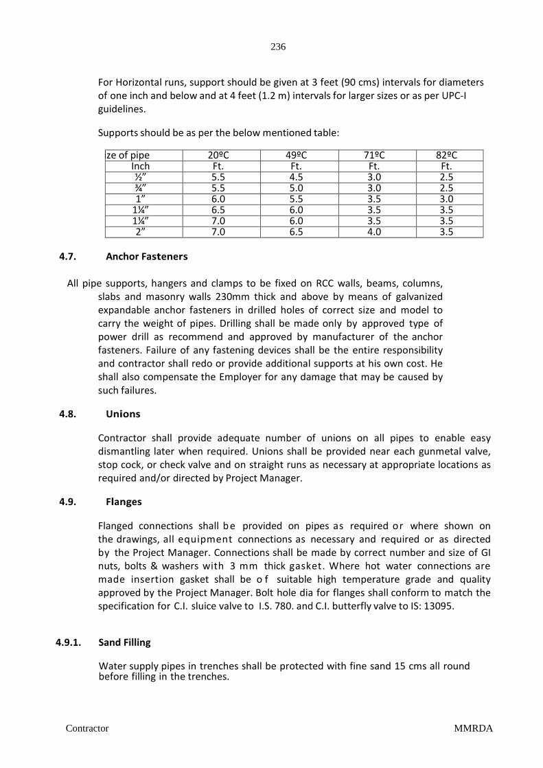
236
Contractor MMRDA
For Horizontal runs, support should be given at 3 feet (90 cms) intervals for diameters of one inch and below and at 4 feet (1.2 m) intervals for larger sizes or as per UPC-I guidelines.
Supports should be as per the below mentioned table:
Size of pipe 20ºC 49ºC 71ºC 82ºC
Inch Ft. Ft. Ft. Ft. ½” 5.5 4.5 3.0 2.5 ¾” 5.5 5.0 3.0 2.5 1” 6.0 5.5 3.5 3.0
1¼” 6.5 6.0 3.5 3.5 1¼” 7.0 6.0 3.5 3.5 2” 7.0 6.5 4.0 3.5
4.7. Anchor Fasteners
All pipe supports, hangers and clamps to be fixed on RCC walls, beams, columns,
slabs and masonry walls 230mm thick and above by means of galvanized expandable anchor fasteners in drilled holes of correct size and model to carry the weight of pipes. Drilling shall be made only by approved type of power drill as recommend and approved by manufacturer of the anchor fasteners. Failure of any fastening devices shall be the entire responsibility and contractor shall redo or provide additional supports at his own cost. He shall also compensate the Employer for any damage that may be caused by such failures.
4.8. Unions
Contractor shall provide adequate number of unions on all pipes to enable easy dismantling later when required. Unions shall be provided near each gunmetal valve, stop cock, or check valve and on straight runs as necessary at appropriate locations as required and/or directed by Project Manager.
4.9. Flanges
Flanged connections shall b e provided on pipes as required or where shown on the drawings, all equipment connections as necessary and required or as directed by the Project Manager. Connections shall be made by correct number and size of GI nuts, bolts & washers with 3 mm thick gasket. Where hot water connections are made insertion gasket shall be o f suitable high temperature grade and quality approved by the Project Manager. Bolt hole dia for flanges shall conform to match the specification for C.I. sluice valve to I.S. 780. and C.I. butterfly valve to IS: 13095.
4.9.1. Sand Filling
Water supply pipes in trenches shall be protected with fine sand 15 cms all round before filling in the trenches.
237
Contractor MMRDA
4.10. Painting
All pipes above ground shall be painted with one coat of red lead and two coats of synthetic enamel paint of approved shade and quality. Pipes shall be painted to standard colour code given in this documents or specified by Project Manager.
4.11. Pipe protection
All pipes in wall chase /below floors or laid underground shall be protected against corrosion by the application of two coats of bitumen paint covered with polythene tape and a final coat of bitumen paint.
Pipes, if any, buried in ground or sunken slab shall be protected with multilayer bitumen membrane tape 3mm thick with a final coat of hot or cold applied bitumen. Pypkote or equivalent.
5. Valves
5.1. Ball Valves
Valves up to 40 mm dia. shall be screwed type Ball Valves with stainless steel balls,
spindle, PTFE seating and gland packing tested to a hydraulic pressure of 20 kg/cm2, and accompanying couplings and steel handles.(to BS 5351)
5.2. Butterfly Valves
Valves 50 mm dia and above shall be cast iron butterfly valve to be used for isolation. The valves shall be bubble tight, resilient seated suitable for flow in either direction and seal in both direction with accompanying flanges and steel handle.
Butterfly valve shall be of best quality conforming to IS: 13095.
5.3. Non Return Valve (Slim Type)
Where specified, non-return valve (swing check type), shall be provided through which flow can occur in only one direction. It shall be single door swing check type of best quality.
5.4. Each Butterfly and Slim Type Swing Check (NRV) Valve shall be provided with a pair
of flanges screwed or welded to the main line and having the required number of galvanized nuts, bolts and washers of correct length.
6. Storage tanks. (Accessories & Connections) 6.1. Storage tanks for water supply shall be in reinforced cement concrete built by the
building Contractor. Each tank shall be provided with lockable type manhole cover fabricated from

238
Contractor MMRDA
M.S. sheets.Manhole covers shall be 450-500 mm dia and fully galvanized after fabrication or as approved by the Project Manager.
6.2. Outlets and overflow
All nozzles for puddle flanges in RCC tank for inlet, outlet, overflow and scour etc. shall be provided by civil contractor or as given in the Schedule of Quantities. Further connections and accessories shall be provided under this contract.
7. Testing
All pipes, fittings and valves after fixing at site, shall be tested by hydrostatic pressure of 1.5 times the working pressure or 10 kg/cm2 whichever is more. Pressure shall be maintained for a period of at least sixty minutes without any drop.
A test register shall be maintained and all entries shall be signed and dated by Contractor(s) and Project Manager.
7.1. In addition to the sectional testing carried out during the construction, Contractor shall
test the entire installation after connections to the tanks or pumping system or mains. He shall rectify all leakages and shall replace all defective materials in the system. Any damage done due to carelessness, open or burst pipes or failure of fittings, to the building, furniture and fixtures shall be made good by the Contractor during the defects liability period without any cost.
7.2. After commissioning of the water supply system, Contractor shall test each valve by
closing and opening it a number of times to observe if it is working efficiently. Valves which do not effectively operate shall be replaced by new ones at no extra cost and the same shall be tested as above.
8. Measurement o Pipes above ground shall be measured per linear meter (to the nearest cm) and shall
be inclusive of o All fittings e.g. coupling, tees, bends, elbows, unions, flanges and U clamps with
nuts, bolts & washers fixed to wall or other standard supports. o Jointing with PTFE tape, white lead and insertion gasket of appropriate
temperature grade. o Cutting holes, and chases in walls, floors, any pipe support required for pipes
below ground & making good the same. o Excavation, back filling, disposal of surplus earth and restoring the ground & floor
in original condition. 8.1. Pipe Supports. Fabricated and galvanized supports shall be measured by weight. Weight
for each type of clamp shall be calculated on basis of the quantity of structural and MS used from the theoretical weight calculated on basis of
239
Contractor MMRDA
the components theoretical weight of the sections.
8.2. Rate quoted for supports & hangers shall be inclusive of:-
a) Expandable anchor fastens. b) Galvanizing of all supports & hangers. c) Cutting holes in walls, ceilings on floors and making good where permitted. d) Nuts, bolts and washers for fixing and assembling. e) Wooden/PVC pipe saddles for vertical or horizontal runs.
8.3. Valves
Gunmetal, cast iron, butterfly and non-return valves and puddle flanges shall be measured by numbers and shall include wheels/caps, GI nuts, bolts, washers and insertion gasket.
8.4. Painting/pipe protection/insulation
Painting/pipe protection/insulation for pipes shall be measured per linear meter over finished surface and shall include all valves and fittings for which no deduction shall be made. No extra payment shall be made for fittings, valves or flanges.
End of Section IV

240
Contractor MMRDA
External Underground Drainage 1. Scope of work 1.1. Work under this section consists of furnishing all labor, materials equipment and
appliances necessary and required to completely install the under-sewer network drainage system as required by the drawings, specified hereinafter and given in the Bill of Quantities.
1.2. Without restricting to the generality of the foregoing, the Underground Drainage system
shall include the following:-
Excavation in soil conditions present on site to lay sewer network. Distribution system underground sewer network. Connection of soil and waste stacks to traps and bends for connection to sewer
lines. Pipe protection and encasing. Venting, inspection chambers, manholes, etc, that may be required as per relevant
municipal norms/bye-laws. Connections to Sewage treatment plant. Terminal connection of excess treated effluent to Muncipal Sewer with sewer trap
chamber. 2. General Requirements. 2.1. Piping for the underground drainage shall be Plastic piping systems for non-pressure
underground drainage and sewerage- structured-wall piping systems of PVC-U duly manufactured out of Polyvinyl Chloride Compound conforming to ISO 21138-2 or EN13476 or compliance IS 15328 with stiffness class of SN4 with selfit connection method. The jointing method should be done using specified solvent cement as per the manufacturer.
2.2. Unless otherwise specified, manholes or inspection chambers of required depth shall be
provided on all external drains, at all change of direction of the drain and where branch drain meets the main drain. All the chambers and manholes should be inclusive of molded base, corrugated shaft and adjustable telescopic adapter for provision of proper seating base of GRP/FRP ring and cover.
3. Chambers / manholes shall be of such size as will allow necessary examination and
clearance of drains. The minimum internal bases as per the requirement of Local authority and their bye-laws if any, shall be adhered to.
4. In the absence of local bye-laws, the requirements stipulated in I.S. 4111 [Part-I] code of
practice for ancillary structures on sewerage system, shall be followed. 5. Excavate to the sizes and depths required for the manholes. Install the manholes and
refill outer space with selected excavation materials and dispose of surplus earth. The
241
Contractor MMRDA
specified size of manholes and chambers refers to inside dimensions. 5.1. Installation of the chambers is to be done with the standard practice and as requirement
of local authorities. 5.2. The chamber base and shaft should be bedded with 1:2:3 mix (1 cement: 2 coarse sand:
3 stone aggregate 12 mm size) 75 mm in bed and all round granular material with aggregates having no sharp edges, for traffic load conditions.
5.3. For FRP / GRP cover and frame, the cover and frame is to be supported on a concrete
base while the chamber is surrounded by granular backfill 150mm wide as recommended. When RCC or other cover is used, the chamber should be fully supported in concrete surround.
5.4. The top level of the manhole with the cover on must be in line with the finished ground
level. However, if required and the finished ground level is not ascertained during construction of the manhole, the contractor shall temporarily fix the manhole cover till such time the final/paved ground level is established, or temporarily cover the built up manhole at no extra cost to owner. In case of any damage to the covers due to traffic or any other reasons during the course of the project, or in the maintenance period attributable to the negligence of the contractor, the same shall be replaced immediately by the contractor at his own cost. The frame and the cover shall be painted with black
Bitumen Anti- corrosive paint. 5.5. Gully traps in all waste pipes shall be of pre-molded plastic 160mm x 110mm as
indicated and laid on a 150 thick 1:3:6 cement bedding. They shall be enclosed in brick and cement mortar masonry with cement plaster forming as inspection chamber with full size 230 x 300 cast iron frame and cover (15 kg) or open grating 300 x 300 as required. Location and details indicated in the drawing.
5.6. Soil stack to be connected using a soil bend directly to the inspection chamber /
manhole.
5.7. There shall be 100 mm. dia vent pipes at the sewer trap chamber and 100 mm.
ventilating pipe at the manhole at the head of the drain to be routed aesthetically as directed.
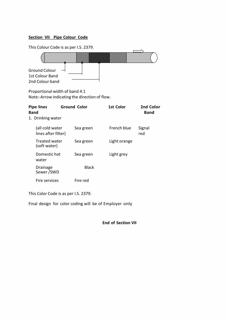
Section VII Pipe Colour Code This Colour Code is as per I.S. 2379. Ground Colour 1st Colour Band 2nd Colour band Proportional width of band 4:1 Note:-Arrow indicating the direction of flow. Pipe lines Ground Color 1st Color 2nd Color Band Band 1. Drinking water
(all cold water lines after filter)
Sea green French blue Signal red
2.
Treated water (soft water)
Sea green Light orange
3.
Domestic hot water
Sea green Light grey
4.
Drainage Sewer /SWD
Black
5.
Fire services Fire red
This Color Code is as per I.S. 2379. Final design for color coding will be of Employer only
End of Section VII
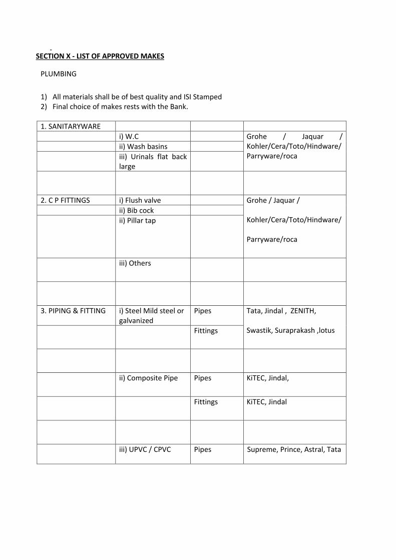
SECTION X - LIST OF APPROVED MAKES
PLUMBING
1) All materials shall be of best quality and ISI Stamped 2) Final choice of makes rests with the Bank.
1. SANITARYWARE
i) W.C Grohe / Jaquar / Kohler/Cera/Toto/Hindware/Parryware/roca
ii) Wash basins
iii) Urinals flat back large
2. C P FITTINGS i) Flush valve Grohe / Jaquar /
Kohler/Cera/Toto/Hindware/
Parryware/roca
ii) Bib cock
ii) Pillar tap
iii) Others
3. PIPING & FITTING i) Steel Mild steel or galvanized
Pipes Tata, Jindal , ZENITH,
Swastik, Suraprakash ,lotus Fittings
ii) Composite Pipe Pipes KiTEC, Jindal,
Fittings KiTEC, Jindal
iii) UPVC / CPVC Pipes Supreme, Prince, Astral, Tata
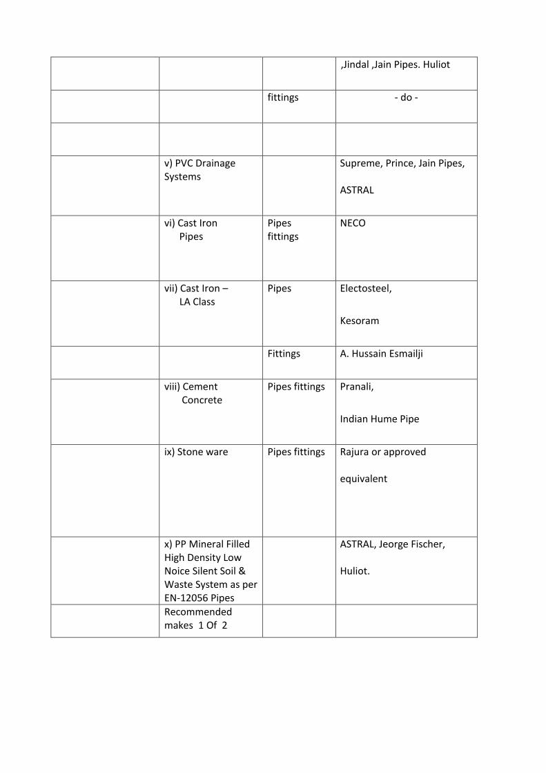
,Jindal ,Jain Pipes. Huliot
fittings - do -
v) PVC Drainage Systems
Supreme, Prince, Jain Pipes,
ASTRAL
vi) Cast Iron Pipes
Pipes fittings
NECO
vii) Cast Iron – LA Class
Pipes
Electosteel,
Kesoram
Fittings A. Hussain Esmailji
viii) Cement Concrete
Pipes fittings Pranali,
Indian Hume Pipe
ix) Stone ware Pipes fittings Rajura or approved
equivalent
x) PP Mineral Filled High Density Low Noice Silent Soil & Waste System as per EN-12056 Pipes
ASTRAL, Jeorge Fischer,
Huliot.
Recommended makes 1 Of 2

4. VALVES i) Gun Metal, gate, globe, NR
RB OR Zoloto/ UTAM / VTM
Ia) check valves ZOLOTO/LEADER/AUDCO/UT
AM / VTM
ii) Cast Iron Sluice, NR
Kirloskar / C&R / UTAM /
VTM
iii) Steel Ball Valves RB, Leader Zoloto, Spirex,
Nirmal, UTAM, VTM
iv) Butterfly valves AUDCO/Keystone/Crawley &
Ray /internal Valve/Key
stone, UTAM, VTM / ZOLOTO
v) Y strainer vi) Motorised Solenoid Valves vii) Pressure reducing valves viii) sluice valves
ZOLOTO/LEADER/AUDCO /
UTAM, VTM
AVCON/INTERNAL VALVE/R.K
ENGINEERING/UTAM/VTM
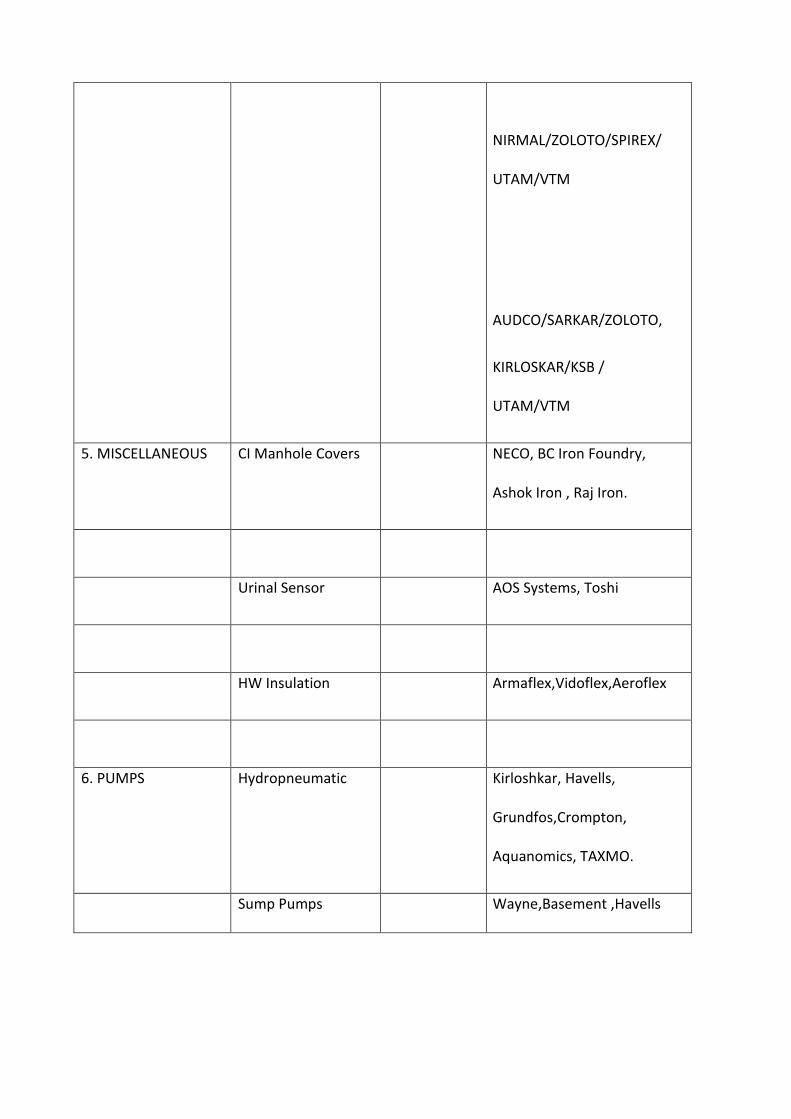
NIRMAL/ZOLOTO/SPIREX/
UTAM/VTM
AUDCO/SARKAR/ZOLOTO,
KIRLOSKAR/KSB /
UTAM/VTM
5. MISCELLANEOUS CI Manhole Covers NECO, BC Iron Foundry,
Ashok Iron , Raj Iron.
Urinal Sensor AOS Systems, Toshi
HW Insulation Armaflex,Vidoflex,Aeroflex
6. PUMPS Hydropneumatic Kirloshkar, Havells,
Grundfos,Crompton,
Aquanomics, TAXMO.
Sump Pumps Wayne,Basement ,Havells
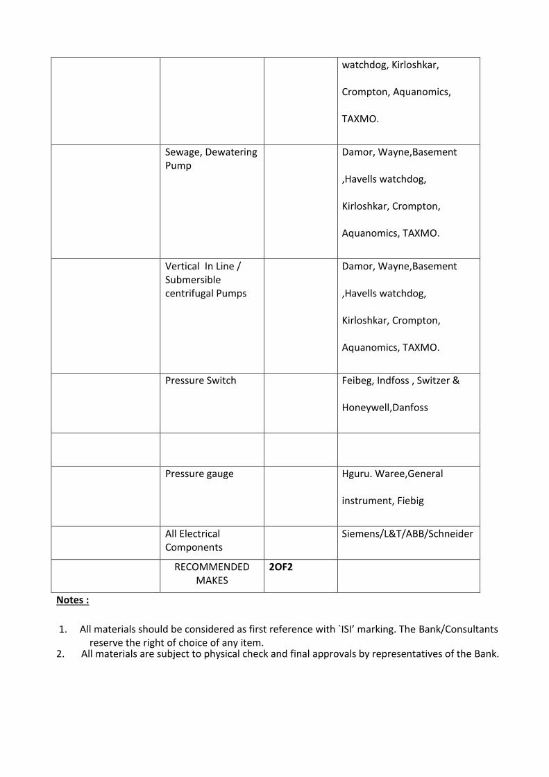
watchdog, Kirloshkar,
Crompton, Aquanomics,
TAXMO.
Sewage, Dewatering Pump
Damor, Wayne,Basement
,Havells watchdog,
Kirloshkar, Crompton,
Aquanomics, TAXMO.
Vertical In Line / Submersible centrifugal Pumps
Damor, Wayne,Basement
,Havells watchdog,
Kirloshkar, Crompton,
Aquanomics, TAXMO.
Pressure Switch Feibeg, Indfoss , Switzer &
Honeywell,Danfoss
Pressure gauge Hguru. Waree,General
instrument, Fiebig
All Electrical Components
Siemens/L&T/ABB/Schneider
RECOMMENDED MAKES
2OF2
Notes :
1. All materials should be considered as first reference with `ISI’ marking. The Bank/Consultants reserve the right of choice of any item.
2. All materials are subject to physical check and final approvals by representatives of the Bank.
TECHNICAL SPECIFICATIONS FIRE FIGHTING 1. Scope of work 1.1. Work under this section shall consist of furnishing all labour, materials, equipment and
appliances necessary and required to completely install wet-riser fire hydrant and sprinkler system as required by the drawings and specified hereinafter or given in the Schedule of Quantities (BOQ)
1.2. Without restricting to the generality of the foregoing, the work shall include but not limited
to the following:-
a) Piping for wet riser hydrant systems and for yard hydrants. b) Landing valves, canvas hose pipes, hose-reels, hose cabinets & connections to mains. c) Fully automatic sprinkler system d) Isolation valves, non-return valves, installation valves, flow control switches and
accessories. 2. General 2.1. All materials shall be new of the best quality conforming to the specifications and subject
to the approval of the Project Manager. 2.2. Pipes and fittings shall be fixed truly vertical, horizontal or in slopes as required in a neat
workman like manner. 2.3. Pipes shall be fixed in a manner as to provide easy accessibility for repair and maintenance
and shall not cause obstruction in shafts, passages etc. 2.4. Pipes shall be securely fixed to walls, and ceilings by suitable clamps at intervals specified.
Only approved type of anchor fasteners shall be used for RCC ceilings and walls. 2.5. Valves and other appurtenances shall be so located that they are easily accessible for
operations, repairs and maintenance. 2.6. The rules and regulations of Local Fire Authority as per the statutory regulations applicable
for obtaining the occupation certificate from the Local Development / Fire Authority.
2.7. Drawings issued with the tenders are schematic and indicate the concept. Contractor shall make his shop drawings on basis of Architectural and Interior design drawings issued by the Engineer-in-Charge. Work will be executed only as per approved shop drawings.
2.8. It is the contractor's responsibility to ensure the competence of design to meet the above requirements.
2.9. Where it is mentioned in the specification that the contractor shall perform certain work or provide certain facilities, it is understood that the contractor shall do so at his cost. The material, design and workmanship shall satisfy the regulations of the TAC / BIS / CFO, the job specifications contained herein and codes referred to where the job specification and TAC / BIS / CFO requirements stipulate in addition to these contained in the standard codes and specification, these additional requirements shall also be satisfied .
3. Interpretation 3.1 In interpretation of specification, the following order of decreasing importance shall be
followed:
a) Schedule of quantities. b) General Technical specifications. c) List of approved make of materials. d) General rules and conditions /Special Conditions.
3.2 Matters not covered by the specifications given in this contract as a whole shall be covered
by relevant and latest Indian Standard Codes. If such codes on a particular subject have not been framed, the decision of the engineer–in–charge/ Project Manager shall be final and binding.
4. Responsibilities of Contractors 4.1 Contractor shall be responsible for procuring supplying and providing all labour, tools and
plant and equipment, etc., required for completing the work in all respects and as per the scope of the contract.
4.2 All expenses towards mobilization at site and demobilization including brining in equipment,
work force and materials, dismantling the equipment, clearing the site, etc. shall be deemed to be included in the rates quoted by the contractor against various items of schedule rates and no separate payment on such expenses shall be entertained .
4.3 The contractor shall acquaint himself with access availability, facilities such as railway siding
local labour, etc., to provide suitable allowance in his quotation. The contractor may have to build temporary access to roads to aid him own work which may also be taken care of while quoting for the work.

4.4 The procurement and supply in sequence and at the appropriate time of all materials and consumables shall be entirely the contractor’s responsibility and his rates for execution of work will be inclusive of supply of all these items.
5. Specifications 5.1 Work shall be carried out strictly in accordance with the specifications attached to the
tender. 5.2 Works not covered in the specifications shall be carried out as per relevant Indian Standard
Code of practice specifications of materials. 6. Execution of work 6.1 The work shall be carried out in conformity with the contract drawings and within the
requirements of architectural, HVAC, plumbing, electrical, structural and other specialised services, drawings.
6.2 The Contractor shall liaise with all traders and agencies working on the site. He shall ensure /
liaison with civil contractor for hangers, sleeves structural openings and other requirements well in advance prevent hold up of the construction schedule.
6.3 On award of work, the contractor shall submit a schedule of construction in the form of Pert
Chart or Bar Chart for approval of consultant / engineer – in – charge, all dates and time schedule, agreed upon shall be strictly adhered to.
6.4 The work shall be executed strictly as per the time schedule given in the tender document. 6.5 A joint program of execution of work will be prepared by the Contractor based on priority
requirement of the project. This program will take in to account the time of completion mentioned above and the time allowed for the priority works by the owner.
6.6 Monthly/weekly construction program will be drawn up by the Owner jointly with the Contractor. Based on availability of work fronts and joint construction program as per 6.5 above. The contractor shall scrupulously adhere to these targets /programs by deploying adequate personnel and construction tools and tackles and he shall also supply himself all materials of his scope of supply in good time to achieve the urgent / program. In all matters concerning the extent of targets set out in the weekly and monthly targets programs and the degree of achievement, the decision of the Owner will be final and binding on the Contractor.
7. Drawings 7.1 Contractor drawings are diagrammatic but shall be followed as actual construction Permits.
Any deviations made shall be in conformity with the architectural and other services
drawings. Shop/working drawings shall be submitted by the Contractor in accordance with para 17 of this chapter.
7.2 Architectural drawings shall take precedence over contract or other services drawings as to
all dimensions. 7.3 Contractor shall verify all dimensions at site and bring the notice of the owner any or all
discrepancy or deviations noticed. The decision of the owner in the regard shall be final. 7.4 Large size details and manufacturer’s dimensions for materials to be incorporated shall take
precedence over small scale drawings. 7.5 Any drawings supplied with the tender shall be returned in good condition along with the
tender. 7.6 All drawings issued by the consultants for the work are the property of the consultants and
shall not be lent, reproduced or used on any other works than intended, without the written permission of the consultants.
8. Tender Information 8.1 The Contractor shall obtain all information relating to the preparation of the tender entirely
on his own responsibility and expense. 8.2 The contractor shall visit the site and familiarize himself with the actual site conditions,
access, availability of materials and other related problems for the speedy execution of the work.
8.3 The contractor shall examine all specifications, tender conditions and drawings before
tendering for the work. 8.4 Information, levels and dimensions given in the tender drawings are supposed to be correct
but the contractor shall make independent inquiries and verify the same. No claims for extras shall be admissible in case of any deviations for incorrectness of the information, levels or dimensions.
8.5 The contractor shall obtain all information relation to the local regulations, bye- laws,
application of any and all laws relating to him work or profession. No additional claims shall be admissible on this account.
9. Materials 9.1 All materials used on this work shall be new, conforming to the specifications.
9.2 Materials shall conform to the latest TAC Regulations/Indian Standards Specifications as amended up to date and carry certification mark, wherever so required.
9.3 All materials used on the project shall be approved by the owner. 9.4 Contractor may be required to purchase such materials of particular make or from a
particular source if in the opinion of the owner the same is necessary and required for the proper and reasonable compliance of the specifications and in the interest of better quality of work.
10. Storage of materials 10.1.1 All materials shall be stored in a proper manner protected from natural element so as to
avoid contamination and deterioration. 10.1.2 Contractor’s stores shall be open to inspection by the owner at all reasonable hours. 10.1.3 Location of stores and stores yards shall be approved by the owner prior to construction and
occupation. 10.1.4 Contractors shall take adequate protection of the stores maintained by him, at his own
expense. 11. Materials by owners 11.1 Materials designated to be supplied by owners shall be supplied at locations given under the
relevant clause of the agreement. 11.2 Any materials supplied by the owners shall be protected and stored as given in para 10
above. 11.3 Any damage during cartage, execution, installation or before formally handing over shall be
made good by the contractor at his own expenses. 12. Inspection and testing of materials 12.1 Contractor shall be required to produce manufacturer’s test certificates for the particular
Batch of materials supplied to him. The test carried out shall be as per the relevant India Standards.
12.2 For examination and testing of materials and works at the site contractor shall provide all
Testing and gauging equipment necessary but not limited to the following :
a) Steel tapes b) Painting / Coating thickness gauge
c) Plum bobs, spirit levels, hammers d) Micrometers / Vernier calipers e) Hydraulic test machine, pressure gauge, flow meter f) Clamp –on – ammeter, megger g) ‘Holiday Test’, machine
12.3 Contractor shall submit calibration Test Certificate not older than 15 days for all such
equipment / instruments. Further if required by the owner, calibration test certificate of any approved laboratory may have to be submitted by the Contractor.
12.4 All testing equipment should be located at the site. 12.5 The contractor shall carryout the various tests as enumerated in the technical specifications
of tender documents. 12.6 All tests whether on the field or outside concerning the execution of the work and supply of
Materials by the contractor shall be carried out by the contractor at his own cost. 12.7 The work is subjected to inspection at all times by the Owner. The contractor shall carry out
all instructions given during inspection and shall ensure that the work is being carried out according to the technical specifications of this tender.
12.8 The contractor shall provide for purpose of inspection access ladders, lighting and necessary
instruments at his own cost. 12.9 All results of inspection and test will be recorded in the inspection reports, performance of
which will be approved the owner .These reports shall form part of the completion documents.
12.10 Any work not conforming to the execution drawings, specifications or codes shall be rejected
forth with and the contractor shall carryout as per the specification at his own cost. 13. Metric 13.1 All dimensions and sizes of materials and equipment given in the tender documents are
Commercial metric sizes. 13.2 Any weights of sizes given in the tender having changed due to metric conversion, the
nearest equivalent sizes accepted by Indian Standards shall be acceptable without any additional cost. The decision of the owner shall be final and binding on the contractor.
14. Reference points 14.1 Contractor shall provide permanent bench marks, flag tops and other reference points for
the proper execution of work and the same shall be preserved till the end of the work.
14.2 All such reference points shall be in relation to the levels and locations given on Architectural
and contract drawings. 15. Reference drawings 15.1 The contractor shall maintain one set of all drawings issued to him as reference drawings.
These shall not be used on site. 15.2 All corrections, deviations and changes made on the site shall be shown on these reference
Drawings for final incorporation. 16. Site order book 16.1 The contractor shall maintain a site order book at the site office. 16.2 All instructions relating to the job shall be recorded by the owner, along with contractor’s
compliance. 16.3 Contractor is bound to carry out all such instructions given to him. 17. Working / shop drawings 17.1 The contractor shall submit to the owner, six copies of the working / shop drawings. 17.2 Working drawings shall be approved by the consultant. Six sets of shop drawings shall be
Submitted for approval showing :
a) Any change in layout from the contract drawings. b) Equipment layout, piping, wiring diagram and instrumentation. c) Manufacturer’s or contractor’s fabrication drawings for any material or equipment.
18. Information to be furnished by tenderer
The following details are required to be furnished along with the tender: 18.1 Tenderer shall submit documentary evidence in support of jobs carried out / under
execution, turnover statements and profit and loss account for the last 3 years. 18.2 Technical information (Catalogues / Leaflets) in duplicate about all equipment’s, materials
which are to be supplied by the tender. 18.3 All letters / information, specification and details shall be submitted in duplicate .
19. Completion drawings 19.1 On completion of works, contractor shall submit one complete set of original tracings and
two prints of “As Built” drawings to the owner. These drawings shall have the following information.
a) Run of all piping, with diameters on all floors and vertical stacks. b) Run of all fire lines with diameters, location of control valves, access panels. c) Location of all mechanical equipment with layout and piping connections. d) Run of control wiring and circuit diagrams of motor control panels.
19.2 Contractor shall provide six sets of catalogues, maintenance manuals, performance data and
list of spare parts together with the name and address of the manufacture for all electrical and mechanical equipment provided by him.
19.3 All “Warranty Cards” given by the manufacturers shall be handed over to the owner. 20. Contractor’s Rates 20.1 Rates quoted in this tender shall be inclusive of cost of materials, labour, supervision,
erection, tools, plant scaffolding, services, connections, transport to site, taxes, octroi and levies, breakage, wastage an all such expenses as may be necessary and required to completely do all the items of work and put them in a working condition to the satisfaction of the owner.
20.2 Rates quoted are for all heights and depths required for this work and must be for complete
items inclusive of such accessories, fixtures and fixing arrangements, nuts, bolts, hangers as are a standard part of the particular item unless given separately in the schedules of quantities.
20.3 All rates quoted must be for complete items inclusive of accessories, fixtures and fixing
arrangements, nuts, bolts, hangers as are standard part of the particular item unless given separately in the schedule of quantities.
20.4 All rates quoted shall be inclusive of cutting holes and chases in walls and making good the
same with cement concrete. Contractor shall provide holes, sleeves, recesses in the concrete and masonry work as the work proceeds.
20.5 The schedule of rates is to be read with all the other sections of this tender document. 20.6 The owner reserves the right to interpolate the rates of such items of work fall in between
similar items of lower and higher magnitude.
20.7 All items of work, in the schedule of rates shall be carried out as per the specifications, drawings and instructions of the owner and the rates shall provide for supply of required materials, consumables, skilled and unskilled labour, supervision, tools and tackles, etc., as called for in the detailed specifications and conditions of the contract .
21. Testing 21.1 Piping system shall be tested as specified under the relevant clause of the TAC Regulations /
BIS Guidelines / Specifications and shall be performed in the presence of the owner/local fire inspector.
21.2 All materials and equipment found defective shall be replaced and the whole work again
tested to meet the requirements of specifications, at the cost of the contractor. 21.3 Contractor shall perform all such tests may be necessary and required by the local authorities
to meet the municipal or other bye – laws in force at his own cost . 21.4 Contractor shall provide free of cost all labour, equipment and materials for the performance
of the test. 22. Site clearance and clean –up 22.1 The contractor shall from time to time, clear away all debris and excess material
accumulated at the site. 22.2 After all the fixtures, equipment and appliances have been installed and commissioned;
contractor shall clean up the same and remove all plaster, paint, stains, stickers and other foreign matter and discoloration leaving the system in a ready to use condition.
23. License and permits 23.1 Contractor must be an experienced firm, approved by the local fire brigade authority for
execution of fire protection system. 23.2 Contractor shall obtain the approval of all works executed by him from the local fire brigade
authority. 24. Electrical works 24.1 Electrical work done under this contract shall be executed by licensed wiremen under the
supervision of licensed electrical supervision as per requirements of the Indian Electricity Act. 24.2 Contractor shall obtain the approval of all electrical installation done under this contract
from the appropriate competent authority before the installation is commissioned.
25. Approval of Fire Installation 25.1 Contractor shall prepare detailed drawings for fire fighting systems and obtain prior approval
of the same from the Local Fire Authority. 25.2 Contractor shall keep a constant liaison with the above authorities to keep them aware of
the progress and standards of works followed, and for the inspections to be carried out during the fabrication / construction phase.
25.3 Contractor shall obtain all NOC/ Approvals / Completion Certificates with respect to the fire
fighting installations from the District Magistrate / Local Fire Officer. 26. Welding 26.1 The welding procedure, types of electrodes etc. shall be in accordance with the following IS
Specifications.
Welding Procedures IS : 823 Welding Electrodes IS : 814, but of approved makes only Testing of Welders IS : 817
26.2 Only welders filling the requirements of IS : 817 and approved by the owner shall be employed by the contractor. 27. Jointing of pipes
Pipes and fittings shall be joined with electrical resistance welding in approved manner. Gasket, for use in between flanged joints, to be of CAF as per IS – 2712, thickness as specified in BOQ.
28. Painting 28.1 All above ground pipes, pipe fittings, hose cabinets, structural steel work pipe supports etc.
shall be painted as per specifications given below. 28.2 Painting shall be done only after completion of fabrication work and testing. 28.3 The instructions of paint manufacture shall be followed as far as possible otherwise the work
is to be done as directed by the Owner. 28.4 All cleaning materials, brushes, tools and tackles, painting, material etc. shall be arranged by
the contractor at site in sufficient quantity.
28.5 All rust, dust scales, welding slag or any other foreign materials shall be removed fully so that a clean and dry surface is obtained prior to painting. Any other oily containment shall be removed by use of a solvent prior to surface cleaning.
28.6 First coat of primer paint must be applied by brush on dry clean surface immediately or in
any case within 3 hours of such cleaning. 28.7 Primer paint – one coat (minimum thickness 100 microns) self – priming epoxy mastic. 28.8 Finishing coats:
a) For production areas – 2 coats (thickness minimum 50 microns each ) of epoxy paint, Fire Red shade as per IS : 5.
b) For other than production areas – 2 coats of synthetic enamel paint, fire red shade as per IS:5.
29. Coating wrapping for underground pipes 29.1 All underground piping shall be protected by coating and wrapping as per the following
procedure. 29.2 The materials and workmanship shall in general confirm to IS: 10221 or as directed by the
owner. 29.3 Cleaning – The pipes shall be thoroughly cleaned off dust, rust will scales, oil, grease etc. by
stiff wire brush and scrappers. The surface shall be coated with the primer immediately after cleaning.
29.4 The ‘Holiday Test’ is to be conducted for detecting any entrapped air or any other defect. 29.5 The contractor is to arrange for the Holiday Test and to rectify the defects if found any.
SPECIFICATIONS 1. Pumps 1.1 Motor driven fire pumps: End suction type, horizontally mounted centrifugal pump (as per IS
1520), TAC approved each capable to deliver required discharge of clear water at minimum developed head, coupled to a suitably electric motor mounted on a common base frame and anti-vibration pads coupling, coupling guard and fixing bolts etc. Motor HP to be suitably selected to suit minimum discharge and residual head at the top most hydrants. The characteristic curve should have a large range of discharge points for different heads.
Note: a) Above pumps shall be capable of furnishing not less than 150% of rated discharge capacity at
a head of not less than 65% of the rated head. The shut-off head shall not exceed 120% of rated head.
b) The pump sets with cushy foots shall have to be installed on RCC floor already constructed and cost of the required civil works viz chipping of floor & concrete base etc (as required), shall be included in the quoted price of respective pump sets.
2. C I Sluice Valve:
C I components of the sluice valve shall be of Grey cast iron conforming to IS 210. The valves shall be flanged having solid wedge gate valve, inside screw, hand wheel with open-close indications etc all conforming to IS 780 but of nominal pressure rating of PN 1.6 as per TAC norms.
Test Pressure at manufacturers’ works
Flange drillings shall normally be as per IS 1538. However, if the manufacturer drills the flanges to other standard specifications, the valves shall be supplied with a pair of matching flanges, nuts, bolts, washers, rubber insertion, etc. and such flanges shall have inside threads to suit pipes of same nominal size as that of the valve.
The quoted price of the valves shall also include cost of arrangement for securing the valves in `open' or `closed' positions by padlock/rivetted strap, where required per TAC norms.
3. G M Valves:
Gun metal components of the peet valves i.e. Gate Valves, Check Valves i.e. non-return valves, and Globe valves etc. shall be of Gun Metal conforming to Grade 2 of IS 318. The valves shall be having flanged or screwed ends, hand wheel with open-close indications etc all conforming to Class-2 Valves of IS 778 (ISI marked) or imported as per ASTM.

4. C I non return valves: C I reflux valves, i.e. swing check type non-return valves, shall be conforming to IS 5312. Test pressures shall be same as per CI sluice valves.
5. G.I. Pipes and Fittings:
All G.I. pipes shall be as per IS 1239 (heavy/medium quality as mentioned in the schedule of items upto 150 mm N B, as per IS 3589 (minimum 6 mm thick) above 150 mm N B, and the fittings shall be of all welded construction, butt weld type flanges shall conform to IS 6392 and gaskets of synthetic moulded rubber approved by Fire Standard.
All pipes outside the building shall be laid underground at a depth of 1 mtr (approx) and laying shall be as per layout drawing, excavation, back filling of earth, cutting holes in existing structure where necessary, providing puddle collars/pipes as required & making good the damages including making the concerned portion of the structure water tight.
Erection of over ground piping shall be complete with necessary pipe supports hangers with MS angles/plate/nut bolts/clamps etc with fabrication as required including providing MS puddle pipes/collars as required for punctures through walls/slabs etc.
Erection of pipe lines shall also include chipping of wall; making holes inside RCC or brick walls, slabs and necessary civil works for restoration of the surface after completion of erection. The quoted tender rate shall include all the above works, as well as the cost of route markers for underground pipe lines as per following specifications.
Route marker with cement concrete 1:2:4 (1 cement : 2 coarse sand : 4 graded stone aggregate 20 mm nominal size) of size 60 cm x 60 cm at bottoms and 50 cm x 50 cm at the top with a thickness of 10 cm including inscription duly engraved as required (spacing approx 15 mtrs or as directed at site). No extra payment will be made on this account.
5.1 Pressure Gauges: Pressure gauges with controlling cocks etc. shall be of approved make
having pressure range, bourdon material and dial size as specified in schedule of items. 5.2 Pressure Switches: Pressure switches with accessories shall be of approved make and design
and shall actuate (`cut-off' and/or `make contact' as required) at pre-set pressures.
6. Landing Valves (Hydrant Valve): Gun metal landing valve (internal/external Fire-Hydrants) with oblique type single outlet as per schedule of quantities complete with hose coupling adaptor of 63 mm size, instantaneous spring lock arrangement and blank cap with chain conforming to IS 5290. External Fire-Hydrants to be provided with stand posts as specified in schedule of quantities. Orifice plates may be provided where inlet pressure is required to be reduced as per WBFS requirement.
7. Branch Pipe:
Gun metal, short type, instantaneous pattern branch pipe to suit fire hose delivery coupling of 63 mm size complete with G M nozzle of 20 mm nominal size conforming to IS 903.
8. Hose with Coupling:
2 Nos 63 mm nominal internal dia. hose, rubber lined woven-jacketed coupling with Type-II (Reinforced Rubber lined type) of IS 636, fire fighting delivery hose 15 M long each, fitted with gun metal coupling of 63 mm size with multi serrated tail and double instantaneous spring lock arrangement comprising of male half at one end and female half at other end complete with rubber cup washer and conforming to IS 903 with double door.
9. Hose Reel:
Swinging hose reel conforming to IS 884 & comprising of 3 ply rubber hose of length specified in schedule of items, 20 mm (3/4") nominal bore (25 kg/cm2/350 psi bursting pressure), mild steel pressed reel with 170 degree swinging, nozzle of G M chromium plated, with non-jamming controlling handle which shall stay at the `ON' `OFF' position as set, wall brackets with `U' shaped reel carrier made of C I complete with 25 mm NB G M valve at the inlet, and orifice plates (if necessary for reducing pressure).
10. Air Vessel (if any):
Mild steel air vessel adequate size to take care of pressure surges during operation of the system and venting of entrapped air in the system shall be complete with air relief valve, pressure gauge, drain valve and shut off valve at the inlet.
11. Valve Chamber:
Valve chamber of adequate size to accommodate external valves shall be constructed as directed per site condition.
12. Fire-Brigade Connections:
Fire-Brigade connections (inlets) to Riser and Under Ground Reservoir shall be with two numbers of 63 mm instantaneous inlets for each connection as per TAC norms. Other aspects of the connection shall be as per IS 904.
13. Sprinkler Installations:
All sprinkler installations shall adhere to IS 15105 : 2002 Sprinkler heads shall be installed in conformity with approved shop drawings and in co- ordination
with electrical fixtures, ventilation ducts, cable galleries and other services along the ceiling.
Following type of sprinklers shall be used:
S.No. Type of Sprinkler Temprature
a) Pendent/Upright type 68°C
13.1 Spacing and coverage of sprinkler shall be in accordance with risk classification of area in which they are installed, design density and TAC regulation.
13.2 Spare Sprinklers
Provide lockable enamel painted steel cabinet including following type of spare sprinklers.
a) Pendent/Upright type 20 13.3 The cabinet should also contain one pair of wrenches (of each size of the same are different)
for the sprinklers.
Spare sprinklers shall be of the same specifications as that of the original sprinklers specified. 14. Testing
All piping in the system shall be tested to a hydrostatic pressure of 1.5 times the working pressure or14kg/sq.cm (whichever is more) without drop in pressure forat-least2 hours.
15. Jointing 15.1 Screwed (50mm dia pipes and below) Joint for black steel pipes and fittings shall be metal to metal thread joints. As mall amount
of red lead may be used for lubrication and rust prevention. Joints shall not be welded or caulked.
15.2 Welded (65mm dia and above)
Joints between M.S. and pipes and fittings shall be made with the pipes and fittings having "V" groove and welded with electrical resistance welding in an approved manner. But welded joints are not acceptable.
15.3 Flanged
a) Flanged joints shall be provided on: b) Straight runs not exceeding 30m on pipelines 80mm dia and above. c) Both ends of any fabricated fittings e.g. bend tees etc. of 65mm dia or larger diameter. d) For jointing all types of valves, appurtenances, pumps, connections with other type of
pipes, to water tanks and other places necessary and required as per good engineering practice.
e) Flanges shall be as per I.S. with appropriate number of G.I. nuts and bolts, 3mm insertion neoprene gasket complete.
16. Unions
Approved type of dismountable unions on pipes lines 65mm and below in similar places as specified for flanges.

17. Excavation
17.1 Excavation for pipelines shall be in open trenches to levels and grades shown on the
drawings or as required at site. Pipelines shall be buried to a minimum depth of 1.2 meter or as shown on drawings.
17.2 Wherever required contractor shall support all trenches or adjoining structures with
adequate timber supports. 17.3 On completion of testing and pipe protection, trenches shall be refilled with excavated earth
in15cmslayersandconsolidated.Contractorshalldisposeoffallsurplusearthwithina 18. Measurement 18.1 Mild steel pipes shall be measured in linear metres of the finished length correct upto one
cm. and shall include all fittings, flanges, and welding, jointing, clamps for fixing to walls or hangers, anchor fasteners, painting and testing complete in all respects.
18.2 Sluice and full way valves, check valves, install at ionvalves, air valves & flow switches shall
be measured by numbers and shall include all items necessary and required for fixing and as given in the specifications and bill of quantities.
18.3 Fire hydrants, hose reels, fire brigade connections, orifice flanges shall be measured by
number and include all items given in the specifications and bill of quantities. 18.4 Fire hose and boxes specified shall be measured by number and include all items given in
specifications and Bill of Quantities. Hand Appliances 1 Scope of work 1.1 Work under this chapter shall consist of furnishing all labour, material, appliances and
equipment necessary and required to install fire extinguishers and appliances. 1.2 Without restricting to the generality of the foregoing the work shall consist of the following:- Install at ionof fully charged and tested fire extinguishers and appliances CO2foam, ABC
Chemical powder type as required by the specifications and/drawings. 2 General requirements 2.1 Fire extinguishers shall conform to the following Indian Standard Specifications and shall be
with ISI approved stamp as revised and amended up to date:-
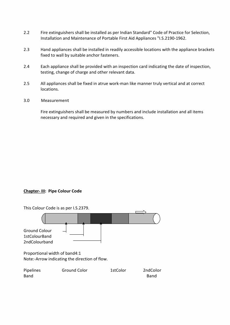
2.2 Fire extinguishers shall be installed as per Indian Standard" Code of Practice for Selection,
Installation and Maintenance of Portable First Aid Appliances "I.S.2190-1962. 2.3 Hand appliances shall be installed in readily accessible locations with the appliance brackets
fixed to wall by suitable anchor fasteners. 2.4 Each appliance shall be provided with an inspection card indicating the date of inspection,
testing, change of charge and other relevant data. 2.5 All appliances shall be fixed in atrue work-man like manner truly vertical and at correct
locations. 3.0 Measurement Fire extinguishers shall be measured by numbers and include installation and all items
necessary and required and given in the specifications. Chapter- III: Pipe Colour Code This Colour Code is as per I.S.2379. Ground Colour 1stColourBand 2ndColourband Proportional width of band4:1 Note:-Arrow indicating the direction of flow. Pipelines Ground Color 1stColor 2ndColor Band Band

1.Drinkingwater
(allcold water lines after filter)
Sea green French blue Signal red
2. Treated water (softwater)
Sea green Light orange
3. Domestic hot water Sea green Light grey
4. Drainage Sewer/SWD
Black
5. Fire services Fire red
This Color Codeis as per I.S.2379. Final design for color coding will be of Employer only

LIST OF APPROVED MAKES FOR EQUIPMENT & MATERIALS SUPPLIED BY FIRE FIGHTING CONTRACTOR
HYDRANT SYSTEMS:- S.No. Details of Materials / Equipment Manufacturer’s Name 1. C.I. (L.A.) Pipes Electro Steel
Kesoram IISCO, Tata Steel Jindal (Hissar) S. Prakash
2. G.I. / M.S. Pipes (IS : 1239 / IS : 3589) Tata Steel Jindal (Hissar),Jindal, Zenith
3. Standard M.S. Fittings Industrial Valves and Company
4. Forged Steel Fittings
5. Gun Metal / Forged Brass Valve Audco, Zoloto, L&T ,Hammer, shah bhogilal
6. CI Sluice Valve Kirloskar, Hammer, Zolato,Kartar
7. Butterfly Valve (IS : 13095 - C.I. Body, S.S. Disc, PN-16)
Audco ,Zolato, Hammer L&T
8. Wafer type check valve (dual plate type PN-16)
Audco ,Zolato, Hammer L&T
9. A) ‘Y’ Strainer B) Pot Strainer
Hammer,Zoloto or approved equivalent Emerald
10. MH Cover & Frame NECO
11. Paints Asian Paints Berger Nerolac, ICI Dulux
S.No. Details of Materials / Equipment Manufacturer’s Name 13. Diesel Engine Cummins, Mather & Platt
Crompton Greaves Kirloshkar
14. Motor ABB, Mather & Platt
Crompton Greaves Siemens Kirloskar
15. Mechanical Seal Burgmann As per pump manufacturers
16. Couplings Lovejoy As per pump manufacturers
17. Anti Vibration Mounting Kanwal Industrial Corporation Dunlop Resistroflex
18. Pressure Switch System Sensor, Danfoss, Indfoss
19. Pressure Gauge ( PSI, 4” dial, S.S. bourden tube - Glycerine filled )
Waaree H Guru,ABP, Fiebig
20. Double / Single Headed Landing Valve (As per IS)
Exflame Shah Bhogilal,Arihant New Age
21. Fire Hose (Canvas – Anti Fungal) Exflame Minimax, Shah Bhogilal New Age,
22. First Aid Hose Reel (20mm Rubber Hose) Exflame Minimax, Shah Bhogilal New Age
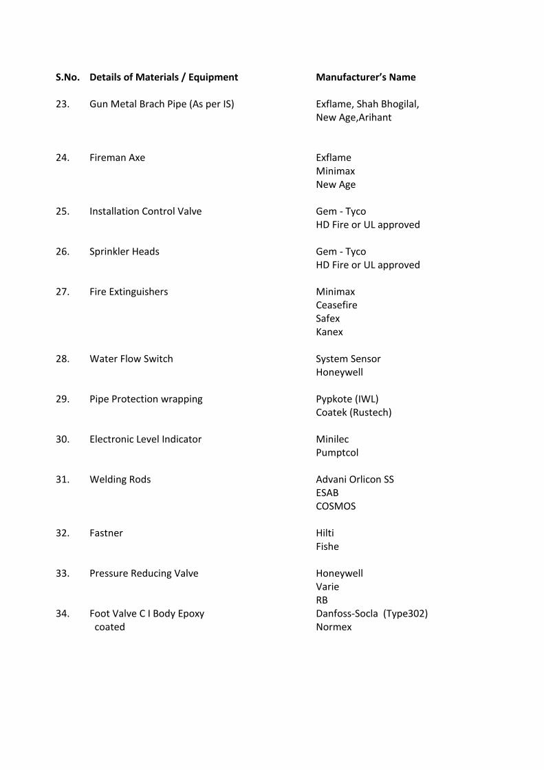
S.No. Details of Materials / Equipment Manufacturer’s Name
23. Gun Metal Brach Pipe (As per IS) Exflame, Shah Bhogilal,
New Age,Arihant
24. Fireman Axe Exflame
Minimax New Age
25. Installation Control Valve Gem - Tyco HD Fire or UL approved
26. Sprinkler Heads Gem - Tyco HD Fire or UL approved
27. Fire Extinguishers Minimax Ceasefire Safex Kanex
28. Water Flow Switch
System Sensor Honeywell
29. Pipe Protection wrapping Pypkote (IWL) Coatek (Rustech)
30. Electronic Level Indicator Minilec Pumptcol
31. Welding Rods Advani Orlicon SS ESAB COSMOS
32.
Fastner Hilti Fishe
33. Pressure Reducing Valve Honeywell Varie RB
34. Foot Valve C I Body Epoxy coated
Danfoss-Socla (Type302) Normex

S.No. Details of Materials / Equipment Manufacturer’s Name
35. G.M. Hose Coupling Minimax ,Shah Bhiogilal,Arihant,
Exflame
36 Fire Bucket Safeguard or equivalent
37. Air Release Valve RB, ITAP, VARIE,new age & Shah Bhogilal
38. Hot dip galvanizing Jenco Industrial Corporation Chincholi Bunder Road, Devrukhkar Wadi, Near Link Road, Malad (W), Mumbai - 64 (Tel : 2872 5402 / 2872 5765)

TECHNICAL SPECIFICATIONS LT INFRASTRUCTURE
AND INTERNAL ELECTRIFICATION WORK 1.0 The following Technical Specifications are made applicable for the Stated Job and
shall be rigidly adhered to while supplying and installing the materials at site. 1.1 Codes And Standards: 1.1.1 The following Codes and Standards shall be applicable for continuous performance of all
electrical equipments to be supplied, delivered at site, erected, tested and commissioned. The Electrical equipments offered shall comply to the relevant Indian Standard Specifications, Fire Insurance Regulations, Tariff Advisory Committee’s Regulations, and in particular to Indian Electricity Rules in all respects with all its latest amendments up-to-date.
1.1.2 For guidelines to the tenderers, few of the Indian Standards are indicated below: IS 116 Circuit Breakers for AC System. IS 159 Busbars and Busbar connections. IS 3043 Code of Practice for earthing. IS 3072 Code of Practice for Installation of Switchgear IS 3106 Code of Practice for Selection, Installation and Maintenance of Fuse (upto 650 Volts) IS 3202 Climate Proofing of Electrical Equipment IS 3427 Metal enclosed Switchgear and Control Gear. IS 3837 Accessories for rigid steel conduits. IS 4047 Heavy Duty Air Break Switches and composite Switch Fuse Units for
voltage not exceeding 100 Volts. IS 4064 Switch Fuse Units for Industries etc. IS 4237 General requirements for Switchgears not exceeding 1000 Volts. IS 4615 Switch Socket Outlets. IS 5133 (Part-I) Sheet Steel Boxes. IS 5216 Guide for safety procedures and practices in electric work. IS 5578 Guide for marking of insulated conductors. IS 5820 Pre-cast concrete cable covers. IS 5908 Method of measurement of electrical installation in building. IS 6381 Specifications for construction and testing of electrical apparatus. IS 1818 Isolator and Earthing Switches. IS 1947 Flood Lights. IS 2147 Degree of Protection provided for enclosure for Switchgear. IS 2208 HRC Cartridge Fuse Units upto 650 Volts. IS 2251 Code of Practice for Danger Notice Plates IS 2268 Call Bells/Buzzers
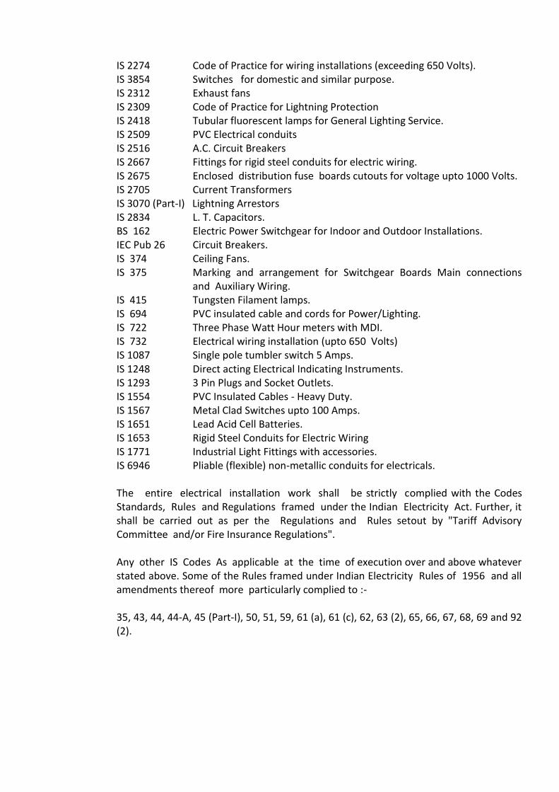
IS 2274 Code of Practice for wiring installations (exceeding 650 Volts). IS 3854 Switches for domestic and similar purpose. IS 2312 Exhaust fans IS 2309 Code of Practice for Lightning Protection IS 2418 Tubular fluorescent lamps for General Lighting Service. IS 2509 PVC Electrical conduits IS 2516 A.C. Circuit Breakers IS 2667 Fittings for rigid steel conduits for electric wiring.
IS 2675 Enclosed distribution fuse boards cutouts for voltage upto 1000 Volts. IS 2705 Current Transformers IS 3070 (Part-I) Lightning Arrestors IS 2834 L. T. Capacitors. BS 162 Electric Power Switchgear for Indoor and Outdoor Installations. IEC Pub 26 Circuit Breakers. IS 374 Ceiling Fans. IS 375 Marking and arrangement for Switchgear Boards Main connections
and Auxiliary Wiring. IS 415 Tungsten Filament lamps. IS 694 PVC insulated cable and cords for Power/Lighting. IS 722 Three Phase Watt Hour meters with MDI. IS 732 Electrical wiring installation (upto 650 Volts) IS 1087 Single pole tumbler switch 5 Amps. IS 1248 Direct acting Electrical Indicating Instruments. IS 1293 3 Pin Plugs and Socket Outlets. IS 1554 PVC Insulated Cables - Heavy Duty. IS 1567 Metal Clad Switches upto 100 Amps. IS 1651 Lead Acid Cell Batteries. IS 1653 Rigid Steel Conduits for Electric Wiring IS 1771 Industrial Light Fittings with accessories. IS 6946 Pliable (flexible) non-metallic conduits for electricals. The entire electrical installation work shall be strictly complied with the Codes
Standards, Rules and Regulations framed under the Indian Electricity Act. Further, it shall be carried out as per the Regulations and Rules setout by "Tariff Advisory Committee and/or Fire Insurance Regulations".
Any other IS Codes As applicable at the time of execution over and above whatever
stated above. Some of the Rules framed under Indian Electricity Rules of 1956 and all amendments thereof more particularly complied to :-
35, 43, 44, 44-A, 45 (Part-I), 50, 51, 59, 61 (a), 61 (c), 62, 63 (2), 65, 66, 67, 68, 69 and 92
(2).
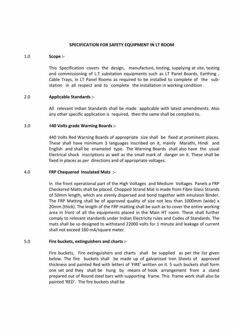
SPECIFICATION FOR SAFETY EQUIPMENT IN LT ROOM 1.0 Scope :- This Specification covers the design, manufacture, testing, supplying at site, testing
and commissioning of L.T substation equipments such as LT Panel Boards, Earthing , Cable Trays, in LT Panel Rooms as required to be installed to complete of the sub-station in all respect and to complete the installation in working condition .
2.0 Applicable Standards :- All relevant Indian Standards shall be made applicable with latest amendments. Also
any other specific application is required, then the same shall be complied to. 3.0 440 Volts grade Warning Boards :- 440 Volts Red Warning Boards of appropriate size shall be fixed at prominent places.
These shall have minimum 3 languages inscribed on it, mainly Marathi, Hindi and English and shall be enameled type. The Warning Boards shall also have the usual Electrical shock inscriptions as well as the small mark of danger on it. These shall be fixed in places as per directions and of appropriate voltages.
4.0 FRP Chequered Insulated Mats :- In the front operational part of the High Voltages and Medium Voltages Panels a FRP
Checkered Matts shall be placed. Chopped Strand Mat is made from Fibre Glass Strands of 50mm length, which are evenly dispersed and bond together with emulsion Binder. The FRP Matting shall be of approved quality of size not less than 1000mm (wide) x 20mm (thick). The length of the FRP matting shall be such as to cover the entire working area in front of all the equipments placed in the Main HT room. These shall further comply to relevant standards under Indian Electricity rules and Codes of Standards. The mats shall be so designed to withstand 22000 volts for 1 minute and leakage of current shall not exceed 160 mA/square meter.
5.0 Fire buckets, extinguishers and charts :- Fire buckets, Fire extinguishers and charts shall be supplied as per the list given
below. The fire buckets shall be made up of galvanised Iron Sheets of approved thickness and painted Red with letters of 'FIRE' written on it. 5 such buckets shall form one set and they shall be hung by means of hook arrangement from a stand prepared out of Round steel bars with supporting frame. This frame work shall also be painted 'RED'. The fire buckets shall be

filled with clean, dry and peddle free sand ready for immediate use for extinguishing fires.
There shall be two such sets kept ready one in the switchyard under a proper weather
protection shed and the other inside the HV/LV Room. The number of Fire extinguishers shall be as per the inspectorate. These shall be ABC type and shall be tested at least once in six months on the site, after erection. This shall be as per relevant Indian Standards of minimum 5.0 Kgs. Instructions charts of restoration of persons suffering from Electric shocks in English, Hindi and Marathi shall be displayed in an enclosed wooden/glass frame work, one in the LV Room and the other in the H.V. Room.
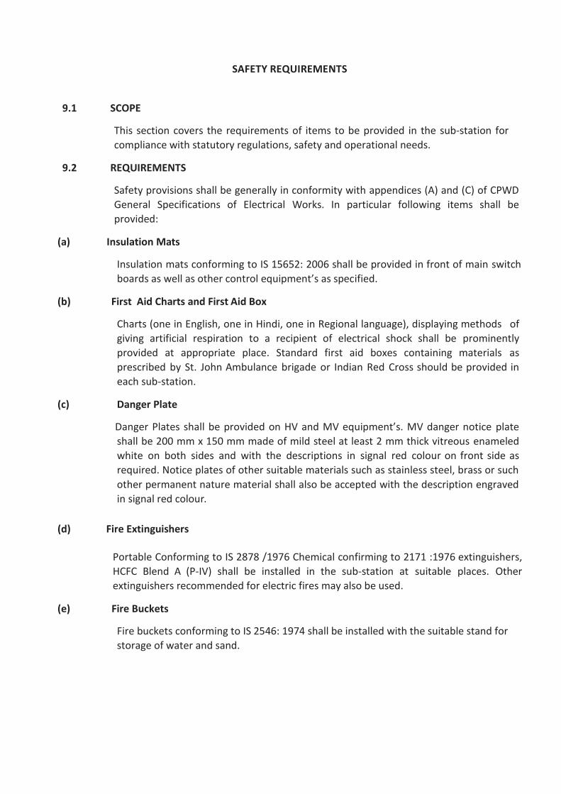
SAFETY REQUIREMENTS 9.1 SCOPE
This section covers the requirements of items to be provided in the sub-station for
compliance with statutory regulations, safety and operational needs. 9.2 REQUIREMENTS
Safety provisions shall be generally in conformity with appendices (A) and (C) of CPWD
General Specifications of Electrical Works. In particular following items shall be
provided: (a) Insulation Mats
Insulation mats conforming to IS 15652: 2006 shall be provided in front of main switch
boards as well as other control equipment’s as specified. (b) First Aid Charts and First Aid Box
Charts (one in English, one in Hindi, one in Regional language), displaying methods of
giving artificial respiration to a recipient of electrical shock shall be prominently
provided at appropriate place. Standard first aid boxes containing materials as
prescribed by St. John Ambulance brigade or Indian Red Cross should be provided in
each sub-station. (c) Danger Plate
Danger Plates shall be provided on HV and MV equipment’s. MV danger notice plate
shall be 200 mm x 150 mm made of mild steel at least 2 mm thick vitreous enameled
white on both sides and with the descriptions in signal red colour on front side as
required. Notice plates of other suitable materials such as stainless steel, brass or such
other permanent nature material shall also be accepted with the description engraved
in signal red colour. (d) Fire Extinguishers
Portable Conforming to IS 2878 /1976 Chemical confirming to 2171 :1976 extinguishers,
HCFC Blend A (P-IV) shall be installed in the sub-station at suitable places. Other
extinguishers recommended for electric fires may also be used. (e) Fire Buckets
Fire buckets conforming to IS 2546: 1974 shall be installed with the suitable stand for
storage of water and sand.

(f) Tool Box
A Standard tool box containing necessary tools required for operation and
maintenance shall be provided in the sub-station. (g) Caution Board
Necessary number of caution boards such as “Man on Line” ‘Don’t Switch on’
etc. shall be available in the sub-station. (h) Key Board
A keyboard of required size shall be provided at a proper place containing castle
keys, and all other keys of sub-station and allied areas.

TECHNICAL SPECIFICATIONS FOR EARTHING
1.0 Scope :
a) Earthing system to be provided shall comprise of earth electrode of copper plate or hot dipped Galvanised plates in earth pits, earth bus/grid of copper flats or GI Flats or Aluminium flats as called for and bare copper earth wires or Galvanised earth wires or aluminium earth wires as called for, for acting as earth continuity conductor.
b) Lightning Protection system shall comprise of earth electrode of Cu or GI plate in
earth pits, earth bus of down conductors of Cu or GI flats. c) Earthing of Compound, Flood Lighting and Road Lighting poles shall be done
by using Cu or GI plates in earth pits near pole and 7/16 size galvanised strained wire for connecting to the pole or as specified in the Schedule or in drawings.
d) Entire earth system shall conform to the Code of Practice as per IS. 3043 of
1987. 2.0 General Requirement : a) Enclosures and frame work of all current carrying equipment and accessories,
structural steel/columns shall be adequately earthed to a single earthing system, unless separate earthing systems are specifically stipulated. All electrical equipment shall be earthed at two distinct points.
b) Earth loads and risers shall follow as direct and short a path as possible. Suitable
risers shall be provided as directed if equipment is not available when earthing is installed.
3.0 Earth Electrodes in Earth Pits : Plate electrodes of Copper shall be 600 x 600 x 3.15 mm thick and 600 x 600 x 12
mm thick for GI unless otherwise specified. 4.0 Earth Bus and Earth Continuity Conductor : a) Earth bus is a copper strip or flat of specified size interconnecting all earth
electrodes. b) Switchgears and Power Distribution Boards shall be earthed by a copper flat
strip.

c) Panels, fused DBs and motors upto 30 KW rating shall be earthed by a continuity conductor, as specified. Minimum size of continuity conductor shall be 25 x 3 mm bare copper strip, soft drawn.
d) Road Lighting Poles shall be earthed with Cu stranded wire conductor while
for lighting and power wiring bare copper conductor shall be provided unless otherwise specified to use insulated conductor.
5.0 Earth Bus Station : Earth Bus Station shall be provided to facilitate tapping of earth continuity
conductor from earth bus/grid very conveniently. It will comprise of a 400 mm long 50 x 6 mm bare copper strips/flat fixed with rawl plugs/bolts securely on wall/column above floor level. Spacers of 20 mm to 25 mm shall be provided to keep the flat away from wall and facilitate connections of earth conductor for which 6 mm dia holes 8 to 10 numbers are provided with proper size brass nuts, bolts, and washers. Earth bus shall be connected to it.
6.0 Lightning Protection System : a) Air termination shall be five prong type copper Rod with round head and the
same shall be securely clamped/installed to withstand severe weather conditions and provide protection against lightning. Horizontal air termination conductors shall be Cu or GI flat/strip and shall be provided where specified.
b) Earth Electrodes for lightning protection system shall be Copper plate installed
in earth pits as per IS. c) The down conductors from air terminals shall be done in tinned Cu or GI
Flat/strip, of size as specified in the schedule of quantities or drawings, but shall not be less than 12.5 x 3mm as required. The down conductors shall follow a direct path to the earth electrode without any sharp bend, turn or kinks. These down conductors shall not be connected to other earthing conductors above ground level but the metallic parts in the vicinity of lighting protection conductor such as ladders, pipes, etc. shall be effectively connected and bonded.
d) A test joint as per IS shall be provided for every down conductor within 1500 mm
above ground level. e) Hardware and clamps shall be similar as used for the earthing systems.
7.0 Artificial Treatment of Soil : If the earth resistance is too high and the multiple electrode earthing does not give
adequate low resistance to earth, then the soil resistivity immediately surrounding the earth electrodes shall be reduced by adding sodium chloride, calcium chloride, sodium carbonate, copper sulphate, salt and soft coke or charcoal in suitable proportions.
8.0 Resistance to Earth : The Contractor shall measure the resistance of the individual earthing pit and
report to the Architect/Consultants. The Contractor will make after due consultation with Architect/Consultants, No. of Earth pits, such that, the overall resistance in the earth mat does not exceed 1.0 ohm.
9.0 Earthing Station : 9.1 Plate Electrode Earthing : Earthing electrode shall consist of a tinned copper plate not less than 600 x 600 x
3.15 mm thick, or, 600 x 600 x 6 mm G.I. as called for in the drawings. The plate electrode shall be buried as far as practicable below permanent moisture level but in any case not less than 3 mts. below ground level. Wherever possible earth electrode shall be located as near the water tap, water drain or a down take pipe as possible. Earth electrodes shall not be installed in proximity to a metal fence.
It shall be kept clear of the buildings foundations and in no case shall it be nearer
than 1 meter from the outdoor face of the wall. The earth plate shall be set vertically and surrounded with 150 mm thick layer of charcoal dust and salt mixture. 20 mm G.I. pipe shall run from the top edge of the plate to the ground level. The top of the pipe shall be provided with a funnel and a mesh for watering the earth through the earth. The main earth conductors shall be connected to the electrode just below the funnel, with proper terminal lugs and checks nuts. The funnel over the G.I. pipe and earth connections houses 300 mm wide and 300 mm deep. The masonry chamber shall be provided with a cast iron cover resting cover a C.I. frame embedded in masonry.
9.2 Pipe Electrode Earthing : Earthing electrode shall consist of a G.I. Pipe (Class 'B') Indian Tube Company
make/ zenith or approved equal, not less than 40 mm dia and 5 meters long. G.I. Pipe electrode shall be cut tapered at the bottom and provided with holes of 12 mm dia. drilled at 75 mm interval upto 2.5 meters length from bottom. The electrode shall buried vertically in the ground as far as practicable below permanent moisture level with its top not less than 200 mm below ground level.
The electrode shall be in one piece and no joints shall be allowed in the electrode. Wherever possible earth electrodes shall be located as near water tap, water drain or a down take pipe. Earth electrode shall not be located in proximity to a metal fence. It shall be kept clear of the building foundations and in no case shall be nearer than 2 meters from the outer face of the wall. The pipe earth electrode shall be kept vertically and surrounded with 150 mm thick layer of charcoal dust and salt mixture upto a height of 2.5 meters from the bottom. At the top of the electrode a funnel with a mesh shall be provided for watering.
10.0 Chemical Earthing using TEREC compound. 10.1 Chemical compound “Terrafill” should provide a simple method to substantially lower the
earth resistance of grounding systems. When used in conjunction with copper grounding equipment. Terrafill should lower the contact resistance to earth by upto 63%.
Terrafill is an easily applied product, which produces lower steady state and stable grounding impedance. Terrafill produces lower surge impedance resulting in faster transient dissipation. Manufactured from environmentally safe and stable products, Terrafill has an excellent shelf life and long term storage has no performance effects.
Terrafill creates a positive, low resistance, electrical connection between the grounding system and the earth. It is manufactured to be compatible with copper grounding system and standard field application methods. It can be used in connection either grounding grids to minimize step and touch potentials. In high resistivity soils, Terrafill can be used to produce acceptable grounding impedance with reasonable size.
The versatility & ease of applying Terrafill to lower ground resistance of grounding equipment allows for a variety of earthing designs to be used which would otherwise not to be economical or practical. Terrafill requires only minimal instruction for application. No special tools are needed.
10.2 Effective:
Should reduce resistance to earth
Should perform in all soil conditions even during dry periods
Should freeze increased resistivity less than 10 percent
It does not depend on the continuous presence of water 10.3 Permanent:
Should not dissolve or decay with time
Requires no Maintenance
Maintains constant resistance for the life of the system
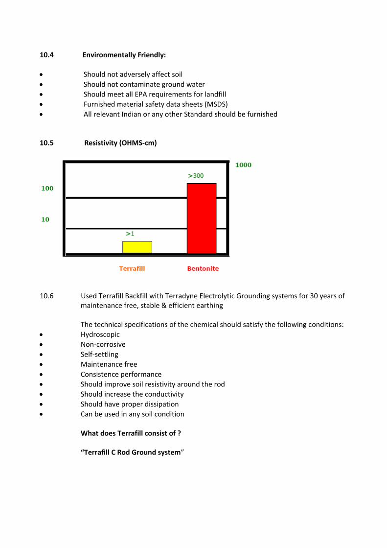
10.4 Environmentally Friendly:
Should not adversely affect soil
Should not contaminate ground water
Should meet all EPA requirements for landfill
Furnished material safety data sheets (MSDS)
All relevant Indian or any other Standard should be furnished 10.5 Resistivity (OHMS-cm)
10.6 Used Terrafill Backfill with Terradyne Electrolytic Grounding systems for 30 years of
maintenance free, stable & efficient earthing
The technical specifications of the chemical should satisfy the following conditions:
Hydroscopic
Non-corrosive
Self-settling
Maintenance free
Consistence performance
Should improve soil resistivity around the rod
Should increase the conductivity
Should have proper dissipation
Can be used in any soil condition What does Terrafill consist of ?
“Terrafill C Rod Ground system”

The system consist of two nos. of copper coated rods 5/8” (coating of 250 microns) joints with a coupler to have minimum 3m, 5m, 6m in lengths as per the site requirements
Diameter of rod 15mm 10.7 Installation Method
Appropriate depth of bore depending upon length of electrode Width of bore should be 6” Make a bed of 6” thick with Terrafill compound Insert the rod Pore the dry backfill compound around the rod (let some be remained) Pore 3-4 bakes of water Let it set and after 2 hour pore the remaining compound and little water to set it Connect the strip of earthing to Rod and your Machine
ELECTRIFICATION WORK
TABLE OF CONTENTS
---------------------------------------------------------------------------------------------------------- Sr. Section Description Page No. No. No. ---------------------------------------------------------------------------------------------------------- 1.0 I LT PANELS AND DISTRIBUTION BOARDS 01 - 00 2.0 II ARMOURED CABLES , TRAYS & TRUNKING 00 - 00 3.0 III EARTHING 00 - 00 4.0 IV POINT WIRING 00 - 00 5.0 V LIGHTING FIXTURES 00 – 00 6.0 VI DATA – NETWORKING SYSTEM 00 – 00 7.0 VII INTELLIGENT ADDRESSABLE FIRE ALARM SYSTEM 00 – 00 8.0 VIII PUBLIC ADDRESS SYSTEM 00 - 00 9.0 IX ACCESS CONTROL SYSTEM 00 - 00 10.0 X SECURITY CAMERA SYSTEM 00 - 00 TECHNICAL SPECIFICATIONS LT INFRASTRUCTURE
AND INTERNAL ELECTRIFICATION WORK 1.0 The following Technical Specifications are made applicable for the Stated Job and
shall be rigidly adhered to while supplying and installing the materials at site. 1.1 Codes And Standards:
1.1.1 The following Codes and Standards shall be applicable for continuous performance of all
electrical equipments to be supplied, delivered at site, erected, tested and commissioned. The Electrical equipments offered shall comply to the relevant Indian Standard Specifications, Fire Insurance Regulations, Tariff Advisory Committee’s Regulations, and in particular to Indian Electricity Rules in all respects with all its latest amendments up-to-date.
1.1.2 For guidelines to the tenderers, few of the Indian Standards are indicated below: IS 116 Circuit Breakers for AC System. IS 159 Busbars and Busbar connections. IS 3043 Code of Practice for earthing. IS 3072 Code of Practice for Installation of Switchgear IS 3106 Code of Practice for Selection, Installation and Maintenance of Fuse (upto 650 Volts) IS 3202 Climate Proofing of Electrical Equipment IS 3427 Metal enclosed Switchgear and Control Gear. IS 3837 Accessories for rigid steel conduits. IS 4047 Heavy Duty Air Break Switches and composite Switch Fuse Units for
voltage not exceeding 100 Volts. IS 4064 Switch Fuse Units for Industries etc. IS 4237 General requirements for Switchgears not exceeding 1000 Volts. IS 4615 Switch Socket Outlets.
IS 5133 (Part-I) Sheet Steel Boxes. IS 5216 Guide for safety procedures and practices in electric work. IS 5578 Guide for marking of insulated conductors. IS 5820 Pre-cast concrete cable covers. IS 5908 Method of measurement of electrical installation in building. IS 6381 Specifications for construction and testing of electrical apparatus. IS 1818 Isolator and Earthing Switches. IS 1947 Flood Lights. IS 2147 Degree of Protection provided for enclosure for Switchgear. IS 2208 HRC Cartridge Fuse Units upto 650 Volts. IS 2251 Code of Practice for Danger Notice Plates IS 2268 Call Bells/Buzzers IS 2274 Code of Practice for wiring installations (exceeding 650 Volts). IS 3854 Switches for domestic and similar purpose. IS 2312 Exhaust fans IS 2309 Code of Practice for Lightning Protection IS 2418 Tubular fluorescent lamps for General Lighting Service. IS 2509 PVC Electrical conduits IS 2516 A.C. Circuit Breakers IS 2667 Fittings for rigid steel conduits for electric wiring.
IS 2675 Enclosed distribution fuse boards cutouts for voltage upto 1000 Volts. IS 2705 Current Transformers IS 3070 (Part-I) Lightning Arrestors IS 2834 L. T. Capacitors. BS 162 Electric Power Switchgear for Indoor and Outdoor Installations. IEC Pub 26 Circuit Breakers. IS 374 Ceiling Fans. IS 375 Marking and arrangement for Switchgear Boards Main connections
and Auxiliary Wiring. IS 415 Tungsten Filament lamps. IS 694 PVC insulated cable and cords for Power/Lighting. IS 722 Three Phase Watt Hour meters with MDI. IS 732 Electrical wiring installation (up to 650 Volts) IS 1087 Single pole tumbler switch 5 Amps. IS 1248 Direct acting Electrical Indicating Instruments. IS 1293 3 Pin Plugs and Socket Outlets. IS 1554 PVC Insulated Cables - Heavy Duty. IS 1567 Metal Clad Switches up to 100 Amps. IS 1651 Lead Acid Cell Batteries. IS 1653 Rigid Steel Conduits for Electric Wiring IS 1771 Industrial Light Fittings with accessories. IS 6946 Pliable (flexible) non-metallic conduits for electrical. The entire electrical installation work shall be strictly complied with the Codes
Standards, Rules and Regulations framed under the Indian Electricity Act. Further, it shall be carried out as per the Regulations and Rules setout by "Tariff Advisory Committee and/or Fire Insurance Regulations".
Any other IS Codes As applicable at the time of execution over and above whatever
stated above. Some of the Rules framed under Indian Electricity Rules of 1956 and all amendments thereof more particularly complied to :-
35, 43, 44, 44-A, 45 (Part-I), 50, 51, 59, 61 (a), 61 (c), 62, 63 (2), 65, 66, 67, 68, 69 and
SPECIFICATION FOR SAFETY EQUIPMENT IN LT ROOM 1.0 Scope :-
This Specification covers the design, manufacture, testing, supplying at site, testing and commissioning of L.T substation equipments such as LT Panel Boards, Earthing , Cable Trays, in LT Panel Rooms as required to be installed to complete of the sub-station in all respect and to complete the installation in working condition .
2.0 Applicable Standards :-
All relevant Indian Standards shall be made applicable with latest amendments. Also
any other specific application is required, then the same shall be complied to. Safety
provisions shall be generally in conformity with appendices (A) and (C) of CPWD
General Specifications of Electrical Works. In particular following items shall be
provided:
3.0 440 Volts grade Warning Boards :- 440 Volts Red Warning Boards of appropriate size shall be fixed at prominent places.
These shall have minimum 3 languages inscribed on it, mainly Marathi, Hindi and English and shall be enameled type. The Warning Boards shall also have the usual Electrical shock inscriptions as well as the small mark of danger on it. These shall be fixed in places as per directions and of appropriate voltages.
4.0 FRP Chequered Insulated Mats :-
In the front operational part of the High Voltages and Medium Voltages Panels and
Low Voltage Switchgear and Panels a FRP Checkered Matts shall be placed. Chopped
Strand Mat is made from Fibre Glass Strands of 50mm length, which are evenly
dispersed and bond together with emulsion Binder. The FRP Matting shall be of
approved quality of size not less than 1000mm (wide) x 20mm (thick). The length of the
FRP matting shall be such as to cover the entire working area in front of all the
equipments placed in the Main HT room. These shall further comply to relevant
standards under Indian Electricity rules and Codes of Standards. The mats shall be so
designed to withstand 22000 volts for 1 minute and leakage of current shall not exceed
160 mA/square meter. Insulation mats conforming to IS 15652: 2006 shall be provided
in front of main switch boards, Distribution Boards, Floor Distribution Boards and all
other control equipment’s as specified
5.0 Fire buckets, extinguishers and charts :- Fire buckets, Fire extinguishers and charts shall be supplied as per the list given
below. The fire buckets shall be made up of galvanized Iron Sheets of approved thickness and painted Red with letters of 'FIRE' written on it. 5 such buckets shall form one set and they shall be hung by means of hook arrangement from a stand prepared out of Round steel bars with supporting frame. This frame work shall also be painted 'RED'. The fire buckets shall be
filled with clean, dry and peddle free sand ready for immediate use for extinguishing fires.
There shall be two such sets kept ready one in the switchyard under a proper weather
protection shed and the other inside the HV/LV Room. The number of Fire extinguishers shall be as per the inspectorate. These shall be ABC type and shall be tested at least once in six months on the site, after erection. This shall be as per relevant Indian Standards of minimum 5.0 Kgs. Instructions charts of restoration of persons suffering from Electric shocks in English, Hindi and Marathi shall be displayed in an enclosed wooden/glass frame work, one in the LV Room and the other in the H.V. Room.
SAFETY REQUIREMENTS 9.1 SCOPE
This section covers the requirements of items to be provided in the sub-station for
compliance with statutory regulations, safety and operational needs. 9.2 REQUIREMENTS
(a) Insulation Mats (b) First Aid Charts and First Aid Box
Charts (one in English, one in Hindi, one in Regional language), displaying methods of
giving artificial respiration to a recipient of electrical shock shall be prominently
provided at appropriate place. Standard first aid boxes containing materials as
prescribed by St. John Ambulance brigade or Indian Red Cross should be provided in
each sub-station. (c) Danger Plate
Danger Plates shall be provided on HV and MV equipment’s. MV danger notice plate
shall be 200 mm x 150 mm made of mild steel at least 2 mm thick vitreous enameled
white on both sides and with the descriptions in signal red colour on front side as
required. Notice plates of other suitable materials such as stainless steel, brass or such
other permanent nature material shall also be accepted with the description engraved
in signal red colour. (d) Fire Extinguishers
Portable Conforming to IS 2878 /1976 Chemical confirming to 2171 :1976 extinguishers,
HCFC Blend A (P-IV) shall be installed in the sub-station at suitable places. Other
extinguishers recommended for electric fires may also be used.
(e) Fire Buckets
Fire buckets conforming to IS 2546: 1974 shall be installed with the suitable stand for
storage of water and sand.
(f) Tool Box
A Standard tool box containing necessary tools required for operation and
maintenance shall be provided in the sub-station. (g) Caution Board
Necessary number of caution boards such as “Man on Line” ‘Don’t Switch on’
etc. shall be available in the sub-station.
(h) Key Board
A keyboard of required size shall be provided at a proper place containing castle
keys, and all other keys of sub-station and allied areas.

CHAPTER - I
TECHNICAL SPECIFICATION FOR 415 VOLTS, MAIN LT PANEL AND DISTRIBUTION BOARDS
1.1 General Specification of Equipment :- 1.2 The scope of work comprises of Designing, Obtaining Approval of the Owner /
Consultants and Fabricating as per approved Drawings, Testing at Works, Packing and Forwarding, Supplying, Storing at Site, Checking at site, Touching Up all Damaged portions, Erection and testing and commissioning at site. Further Touching up of damaged powder coated painting shall be carried at site after the installation of all panels is completed by the contractor.
1.3 The Main Power Control Centre, distribution boards shall be metal clad, totally
enclosed, rigid, floor mounting, air-insulated, cubicle type for use on 415 volts, 3 phase 50 cycles system.
1.4 The equipment shall be designed for operation in high ambient temperature and
high humidity tropical atmospheric conditions. Means shall be provided to facilitate ease of inspection, cleaning and repairs in the installations where continuity of operation is of prime importance.
1.5 Standards :- The equipment shall be designed to conform to the following requirements and to
the latest amendments in the codes or relevant BS applicable standards :-
IS-13947 Marking and arrangement for switchgear bus bars, main connection and auxiliary wiring.
IS-722 Part-I AC Electricity Meters & Part - I General requirements and tests IS-1248 Direct acting indicating analogue electrical measuring instruments and
their accessories IS-1822 AC Motor starters, of voltage not exceeding 1000 volts IS-2147 Degrees of protection provided by enclosures for low voltage
switchgear and control gear IS-2419 Dimensions for panel mounting indicating and recording electrical
instruments IS-2516 Circuit Breakers - Requirements and Test voltages not exceeding 1000V
AC or 1200V DC IS-2607 Air break isolators for voltages not exceeding 1000 volts
IS-2705 Part-I Current Transformer - General Requirements IS-2705 Part-II Current Transformer - Measuring Current Transformers IS 8623 - Factory Built Assemblies of switchgear and control gear. IS 4237 - General requirements for switchgears and control gear for voltages not
exceeding 1000 Volts. IS 2147 - Degrees of protection provided by enclosures for low voltage
switchgear and control-gear.
IS 375 - Marking and arrangement of bus bars. IEC 647-2 and IS 13947-2 Air Circuit Breakers IEC 60947-2 and IS 13947-2. - Molded Case Circuit Breakers IS. 2208:1962 or IS.9224:1979 - HRC Fuse-links IS.3156 - Voltage Transformers IS.3231.- Relays IS 6875. Control Switches & Push Buttons - IS.2959 - AC Contractors
7.0 Scope
This covers supply/ erection/ testing and commissioning of the equipments suitable for
415 Volt, 3 Phase, 50 HZ 4 wire system.
7.1 Requirements
(i) For each equipment, required IP rating and short circuit rating capacity will be
specified. Governing BIS also will be specified.
(ii) All the equipments will be factory fabricated in an approved factory having modern
fabrication and testing process. It shall have seven tank pre-treatment process
comprising of degreasing, rinsing, de-rusting, rinsing, phosphatising, rinsing and
passivation followed by powder coat painting having a paint thickness of 60 microns or
as specified. The powder paint will be subjected to oven-heated process. All panels
will be provided with suitable gasket to make it dust/ vermin proof.
7.1.1 Specification of LT Cubicle Panel
(i) Cubicle panel shall be floor mounted (on a base frame) totally enclosed and
extensible type. The general construction shall conform to IS 8623 : 93. The design
shall include all provisions for safety of operating and maintenance personnel.
Degree of IP protection shall be IP-42 for indoor application and IP-54 for outdoors,
unless otherwise specified.
(ii) The panel shall be compartmentalized type having space and arrangement for
incoming cable/ bus ducting, incoming switchgear/ switchgears, bus coupler,
insulated and properly supported compartmentalized bus bars, outgoing
compartmentalized switchgear, bus bar supports, joint shrouds, cable alleys of
suitable size for cabling routing, support and terminations, inter-connection between
bus bars and switchgear with auxiliary bus bars/ insulated conductors/ strips etc.
Also the panel will be provided with necessary instrumentation like CTs, PTs,
Ammeters, Voltmeters, phase indicating lamps, other required instruments, wiring,
fuses etc.
(iii) It shall be fabricated out of CRCA sheet not less than 2.0 mm thick for load bearing
members and 1.6 mm for doors of LT panels. The framework may be Angle Iron/
Channel/ Bolted type construction. General constructions shall employ the principle
of compartmentalization and segregation of each circuit. Unless otherwise approved,
incomer and bus section panels shall be separate and independent and shall not be
mixed with sections required for feeders. Each section of the rear accessible type
board shall have hinged access door at the rear. Operating handle of the highest unit
shall be at a height not more than 1.7 mt. Overall height of the board shall not
exceed 2.3 metre.
(iv) Arrangement for Incoming/Outgoing Cable Termination
Cable entries shall be provided either from the rear or from the front through cable
alleys of suitable size. Removable gland plate to be provided for each cable entry.
Cable support arrangement to be provided inside cable alley so that cables are
neatly arranged and fixed. From each outgoing switch, insulated strip/ conductor of
suitable size to be provided up to suitable terminal block, which will receive
incoming/ outgoing cable termination. It is desirable that cables are not terminated
directly to switchgear, but terminated through proper terminal blocks.
(v) Specification of Cable Terminal Block
Terminal block of reputed make shall be used. The housing material shall be
polyamide having unbreakable and fire-retardant characteristic. All the metal parts
shall be made up of copper alloy including the screws. Mounting shall be ‘Din’ or ‘G-
rail’ type. Screws shall be self captive type. No protection cover is required, and the
block should be touch proof.
(vi) Bus bars/ Supports/ Clearances
The bus bar system may comprise of a system of main/ auxiliary bus bars run in bus
bar alleys.
For bus bar material, ratings, current density, insulation, supports, bus bar
clearances and joints see para 7.2 (iii).
(vii) Earthing
2 Nos. 20 x 3 mm copper strip for LT panel upto 400 Amp. capacity or 2 Nos. 20 x 5
mm copper strip for LT panel of higher capacity shall be fixed all around the panel
connected to 2 Nos. earth bus copper strips connected to incoming earth
conductors.
(Typical Cubicle Panel is explained in Fig. 8)
(viii) Commissioning
After erection, the LT panel will be commissioned after:
(a) Tightening of all nuts and bolts.
(b) Closing any left out holes to ensure the entire panel is insect proof.
(c) Megger testing.
(d) Earth testing.
7.1.2 Specification of DB
As a general practice only prewired MCB/HRC type DBs shall be used, on account
of their superior technical features, compared to conventional DBs, which don’t
allow for proper wiring space and wiring termination. Rewirable fuse type DBs shall
not be used.
DBs shall have following features:
(i) Recess/ Surface type with integral loose wire box.
(ii) Phase/ neutral/ earth terminal blocks for termination of incoming & outgoing wires.
(iii) Din Channel for mounting MCBs.
(iv) Arrangement for mounting incomer MCB/ RCCB/ RCBO/ MCCB as required.
(v) Copper Bus bar.
(vi) Earthing terminals.
(vii) Wiring from MCBs to phase terminal block.
(viii) Interconnection between terminal block/ incoming switch/ bus bar/ neutral
terminal block/ earth terminal connector with specified size of FRLS preinsulated
copper conductor cable duly fitted with copper lugs/ thimbles.
(ix) Terminal blocks should be suitable for termination of conductor/ cable of required
size but minimum rated cross section of the terminal blocks should be 6 sq. mm.
(x) Terminal block shall be made of flame retardant polymide material.
(xi) Colour terminal blocks and FRLS wires for easy identification of RYB Phases, Neutral
and Earth.
(xii) Prewired DB shall be provided with a detachable cassette for safe removal of MCBs,
RCCBs. Terminal connectors from the DB without loosening the internal cable
connections of phase and neutral circuits. (This is an optional feature.)
(xiii) The prewired DB shall have peelable poly layer on the cover for protection from
cement, plaster, paints etc. during the construction period.
(xiv) Detachable plate with Knock out holes shall be provided at the top/ bottom of
board. Complete board shall be factory fabricated and pre-wired in factory ready
for installation at site. The box and cover shall be fabricated from 1.6mm sheet
steel, properly pre-treated, phosphatized with powder coated finish.
Where specified it shall be of double door construction provided with hinged cover
in the front.
Note: DB will be factory manufactured by reputed manufacturer of MCB DBs.
CHAPTER - II SPECIFICATIONS FOR SUPPLY OF ALUMINIUM /COPPER L.T. XLPE ARMOURED CABLES
1.0 Codes and Standards :
1.1 The design, manufacture, testing and supply of the cables under this specification
shall comply with the latest revisions including amendments of the following standards.
IS : 7098-I - XLPE insulated heavy duty cables for working voltages upto 1100 Volts.
IS : 3961-II - Recommended current ratings for cables. IS : 8130 - Conductors for insulated cables. IS : 5831 - XLPE Insulation and outer sheath of electric cables. IS : 7098-I - Test Procedures for cables. IS : 10418 - Specification for drums for electric cables IS : 3975 - Mild steel wire, strips, and tapes for armouring of cables.
2.0 Technical Requirements :
2.1 All XLPE Aluminium/Copper Power cables shall be 1100 Volts grade, multi core constructed as per IS : 7098 Part-I of 1988 as follows :
a) Stranded Copper conductor in case of 16 sq.mm. and above and solid conductor
in case of 6 sq.mm. and below. b) All Aluminium/Copper XLPE cables insulation shall be of high grade Cross-
linked Polyethylene from insulation for extrusion process. c) Cores laid up
d) The inner sheath should be bonded over with thermo-plastic material for protection against mechanical and electrical damage.
e) Armoring should be provided over the inner sheath to guard against mechanical
damage. Armouring should be Galvanised steel wires or galvanised steel strips. (In single core cables used in A.C. system armouring should be non-magnetic hard aluminium Wires/Strips. Round steel wires should be used where diameter over the inner sheath does not exceed 13 mm; above 13 mm flat steel armour should be used. Round wire of different sizes should be provided against specific request.)
f) The outer sheath should be specially formulated heat resistant black PVC
compound conforming to the requirement of type ST2 of IS : 5831-1984 extruded to form the outer sheath.
2.2 Conductor shall be of electrolytic Aluminum /Copper conforming to IS : 8130 and
are compact circular or compact shaped.
2.3 Insulation shall be of XLPE type as per latest IS general purpose insulation for maximum rated conductor temperature 70 degree centigrade.
2.4 In Inner sheath laid up cores shall be bonded over with thermoplastic material for
protection against mechanical and electrical damage. 2.5 Insulation, inner sheath and outer sheath shall be applied by extrusion and lapping
up process only. 2.6 Armouring shall be of galvanised steel wire/flat. 2.7 Repaired cables shall not be used. 2.8 Current ratings of the cables shall be as per IS : 3961. 2.9.1 The XLPE insulated cables shall conform to latest revision IS read along with this
specifications. The Conductor shall be stranded Aluminium/Copper circular/ sector shaped and compacted. In multi core cables the core shall be identified by red, yellow, blue and black coloring of insulation.
2.9.2 The XLPE insulated 1100 Volts grade power cables shall conform to latest IS and
shall be suitable for a steady conductor temperature of 70 degree centigrade. The conductor shall be stranded Aluminium/Copper as called for in the Schedule of quantities. The outer sheath shall be as per the requirement of type ST-2 of IS:5831 of 1984.
2.10.1 The cables shall be suitable for laying in racks, ducts, trenches, conduits and
underground buried installation with uncontrolled back fill and chances of flooding by water.
2.10.2 Progressive automatic in line sequential marking of the length of cables in meters at
every one meter shall be provided on the outer sheath of all cables. 2.10.3 Cables shall be supplied in non returnable wooden drums as per IS : 10418. Both ends of the cables shall be properly sealed with PVC/Rubber caps so as to
eliminate ingress of water during transportation, storage and erection. 2.10.4 The Cables while laying in shaft other than on trays shall be supported using
perforated Z section clamps of suitable gauge. The cables will be clamped properly or boned to the perforated section using Nylon chords.
3.0 Tests and Test Reports :
Cables shall be subjected to type tests, acceptance tests and routine tests as per
7098 Part - I . The Owner reserves the right to witness any or all the tests for which
at least 20 days advance notice shall be given by the contractor. Six (6) copies of all test reports shall be submitted for approval by owner before despatch of the materials from works.
4.0 Drawings and Data : The Contractor shall furnish technical particulars of cables, type, make and
catalogue for the approval by Owner. 5.0 The product should be coded as per IS :- 7098 Part-I and the codes should be as
follows :-
Aluminium Conductor A XLPE Insulation 2X Steel round wire armour W Steel strip armour F Steel Double round wire armour WW Steel Double strip armour FF Non-magnetic (Al.) round wire armour Wa Non-magnetic (Al.) strip armour Fa PVC outer sheath Y TECHNICAL SPECIFICATION FOR CABLE TRAYS
1.0 Perforated Cable Trays of ladder type and associated accessories tees, bends, elbows and reducers shall be fabricated from 12 gauge (2.5 mm) mild steel. Prefabricated Cable trays of perforated type and associated accessories tees, elbows and reducers shall be fabricated from 14 gauge (2 mm ) White CRCA Sheets. Cable trays shall be made of corrosion resistant material or if made of material shall be adequately protected against the corrosion.
2.0 Cable trays accessories shall be painted with One Shop coat of Red oxide zinc
chromate primer and two side coats of Aluminum alkyd paint. 3.0 Cable trays shall not have sharp edges, burrs or projections that may damage
the insulation jackets of the wiring. 4.0 Cable trays shall not have side rails or equivalent structural members cable trays
shall include fittings or other suitable means for change in direction and elevation of runs.
CABLE TRAY MOUNTING Unless otherwise specifically noted on the relevant layout drawing, all cable tray
mounting works to be carried out the following :
a) Cable tray mounting arrangement type to be as marked on layout drawing.
b) Assembly of tray mounting structures shall be supplied fabricated, erected & painted by the electrical contractor.
c) Tray Mounting structures shall be welded to plate inserts or to structural beams as
approved by the Project Manager. d) Wherever embedded plates & structural beams are not available for welding the tray
mounting structure electrical contractor to supply the MS plate & fix them to floor slab by four anchor fasteners of minimum 16 mm dia having minimum holding power of 5000 Kg, at no extra cost.
e) Maximum loading on a horizontal support arm to be 120 Kg/metre of cable run. f) Width of the horizontal arms of the tray supporting structures to be same as the tray
widths specified in tray layout drawings, plus length required, for welding to the vertical supports.
g) The length of vertical supporting members for horizontal tray runs will be to suit
the number of tray tiers shown in tray layout drawings. h) Spacing between horizontal support arms of vertical tray runs to be 300 mm. i) Cable trays will be welded to their mounting supports. j) Minimum clearance between the top most tray tier and structural member to be
300 mm. k) Cable in vertical race ways to be clamped by saddle type clamps to the horizontal
slotted angles. Clamps to be fabricated from 3 mm. thick aluminium strip at site by the electrical contractor to suit cable groups.
l) The structural steel (standard quality) shall be according to latest revision of IS :
226 & 808. Welding shall be as per latest revision of IS : 816. All structural steel to be painted with one shop coat of red oxide and oil primer followed by a finishing coat of aluminium alkyd paint where any cuts or holes are made on finished steelwork these shall be sealed against oxidation by red oxide followed by the same finishing paint. Steel sheet covers wherever indicated to be similarly painted.
TECHNICAL SPECFICATIONS FOR UNDER FLOOR TRUNKING AND CABLE WAYS ALONG WITH JUNCTION BOXES AND INSPECTION OUTLETS.
1.0 Scope of Work :
The scope of this section comprises the supply, delivery, erection, testing and commissioning of Under floor Trunking along with Floor Outlet Boxes for Power wiring, Data Networking and Tele Networking of the installation.
1.1a Applicable Standards :
The relevant sections of Indian Standard Specifications as more particularly stated herein and broadly to all the codes, statues and regulations as applicable shall be strictly enforced and adhered to. More particularly following codes should be strictly followed.
IS 732 : Wiring Practice. IS 1653 : Metallic Conduits. IEC- 61084-2-2 : Under floor Trunking and Junction Boxes.
1.2 Trunking : 1.2.1 The under floor GI trunking along with its cover to be fabricated using pre galvanized
sheet steel conforming to EN 10142 and 3.
1.2.2 The GI trunking to be manufactured in 14 Gauge hot dipped galvanized sheet steel.
1.2.3 The GI trunking should have the following sections :
a. 50X38 mm
b. 75X38mm
c. 100X38mm 1.2.4 Floor Outlet Boxes junction box should be fabricated using 14 Gauge Pre galvanized hot
dipped Sheet steel. The floor outlet boxes should have adequate space to have trunk entry on all four sides.
1.2.5 They should be available in the following sizes.
150 x 150 x 65 mm ; 300 x 300 x 65 mm , 400mm x 400X65 mm Generally the covers could be of Stainless steel having 10 Gauge, screwed to the junction boxes. Covers are available in the following sizes: 150 x 150mm ; 300 x 300 mm , 450mmX 450mm, 600 mm X600mm
CHAPTER - III
TECHNICAL SPECIFICATIONS FOR EARTHING
8.0 Scope
This chapter covers the essential requirements of earthing system components and
their installation. This shall be read with Appendix F, which lays down criteria for
their design. For details not covered in these specifications IS code of Practice on
Earthing (IS 3043 : 1987) shall be referred to.
8.1 Application
(i) The electrical distribution system in the Department is with earthed neutral (i.e.
neutral earthed at the transformer / generator end). In addition to the neutral
earthing, provision is made for earthing the metallic body of equipment’s and non-
current carrying metallic components in the sub-station, as well as in the internal/
external electrical installations.
(ii) Earthing system is also required for lightning protection, computer installations and
hospital operation theaters, etc. for functional reasons.
(iii) Earthing requirements are laid down in Indian Electricity Rules, 1956, as amended
from time to time, and in the Regulations of the Electricity Supply Authority
concerned. These shall be complied with.
(iv) Application for Internal E.I.
(a) Every sub-main will have earth continuity conductor to run along with sub-main
wiring. In case of 3-phase sub-main wiring two earth continuity conductors shall be
provided.
(b) Every circuit will have its earth continuity conductor to run alongwith circuit wiring.
In case of 3-phase circuit two earth continuity conductors shall be provided.
(c) Looping of earth is allowed only in case of point wiring.
(d) When 2/3 power outlets are looped to one circuit, earth looping of these outlets is
permissible.

299
8.2 Types of Electrodes & Material
8.2.1 Earth Electrodes
8.2.1.1 Types
The type of earth electrode shall be any of the following, as specified. (For selection
criteria in designs, Appendix F may be referred to).
(a) Pipe earth electrode.
(b) Plate earth electrode.
(c) Strip or conductor earth electrode.
8.2.1.2 Electrode Materials and Dimensions
(i) The materials and minimum sizes of earth electrodes shall be as per Table IX
(revised).
(ii) GI pipe electrodes shall be cut tapered at the bottom, and provided with holes of
12 mm dia, drilled not less than 7.5 cm from each other upto 2 m of length from the
bottom.
(iii) The length of the buried strip or conductor earth electrode shall be not less than
15 m. This length shall suitably be increased if necessary, on the basis of the
information available about soil resistance, so that the required earth resistance is
obtained. Prior approval of the Engineer-in-charge shall be taken for any such
increase in length.
(iv) All hardware items used for connecting the earthing conductor with the electrode
shall be of GI in the case of GI pipe and GI plate earth electrodes, and forged
tinned brass in case of copper plate electrodes.
8.2.2. Earthing Conductor & Sizes
(i) The earthing conductor (protective conductor from earth electrode up to the main
earthing terminal/earth bus, as the case may be) shall be of the same material as
the electrode, viz. GI or copper, and in the form of wire or strip as specified.
(a) The size of earthing conductor shall be specified, but this shall not be less than the
following (For calculating the size of the earthing conductor in design, Appendix F
para 3.5.1).
(b) 4 mm dia. (8 SWG) copper wire,
(c) 25 mm x 4 mm in the case of GI strip, or
(d) 20 mm x 3 mm in the case of copper strip.
300
(ii) Earthing conductor larger than the following sectional areas need not be used,
unless otherwise specified.
(a) 150 sq.mm. in case of GI, or
8.2.3 100 sq.mm. in case of copper.
8.2.4 Earth Continuity / Loop Earthing Conductor & Sizes
(i) The material and size of protective conductors shall be as specified below (for
criteria in design of these Appendix F may be referred to):
Size of phase
conductor
Size of protective conductor of the same
material as phase conductor
Upto 4 sq.mm.
Above 4 sq.mm. up to 16 sq.mm.
Above 16 sq.mm. up to 35 sq.mm.
Above 35 sq.mm.
Same size as that of phase conductor
Same size as that of phase conductor
16 sq.mm.
Half of the phase conductor
8.3 Location for Earth Electrodes
(i) Normally an earth electrode shall not be located closer than 1.5 m from any
building. Care shall be taken to see that the excavation for earth electrode does
not affect the foundation of the building; in such cases, electrodes may be located
further away from the building, with the prior approval of the Engineer-in-charge.
(ii) The location of the earth electrode will be such that the soil has a reasonable
chance of remaining moist as far as possible. Entrances, pavements and roadways,
should be avoided for locating earth electrodes.
8.4 Installation
8.4.1 Electrodes
8.4.1.1 Various Types of Electrodes
(i) (a) Pipe electrode shall be buried in the ground vertically with its top at not less than
20 cm below the ground level. The installation shall be carried out as shown in Fig.
11 (revised).
(b) In locations where the full length of pipe electrode is not possible to be installed
due to meeting a water table, hard soil or rock, the electrode may be of reduced
301
length, provided the required earth resistance result is achieved with or without
additional electrodes, or any alternative method of earthing may be adopted,
with the prior approval of the Engineer-in-charge. Pipe electrodes may also be
installed in horizontal formation in such exceptional cases.
(ii) Plate electrode shall be buried in ground with its faces vertical, and its top not
less than 3.0 m below the ground level. The installation shall be carried out as shown in
Fig. 12 (revised).
(iii) When more than one electrode (plate/pipe) is to be installed, a separation of
not less than 2 m shall be maintained between two adjacent electrodes.
(a) The strip or conductor electrode shall be buried in trench not less than 0.5 m deep.
(b) If conditions necessitate the use of more than one strip or conductor electrode,
they shall be laid as widely distributed as possible, in a single straight trench
where feasible, or preferably in a number of trenches radiating from one point.
(c) If the electrode cannot be laid in a straight length, it may be laid in a zigzag
manner with a deviation upto 45 degrees from the axis of the strip. It can also be
laid in the form of an arc with curvature more than 1 m or a polygon.
8.4.1.2 Artificial Treatment of Soil
When artificial treatment of soil is to be resorted to, the same shall be specified
in the schedule of work. The electrode shall be surrounded by charcoal / coke
and salt as indicated in Fig. 11 and 12. In such cases, excavation for earth
electrode shall be increased as per the dimensions indicated in these figures.
8.4.1.3 Watering Arrangement
(i) In the case of plate earth electrodes, a watering pipe 20 mm dia. Medium class
pipe shall be provided and attached to the electrodes as shown in Fig. 11 and
12. A funnel with mesh shall be provided on the top of this pipe for watering the
earth.
(ii) In the case of pipe electrodes, a 40 mm x 20 mm reducer shall be used for fixing
the funnel with mesh.
(iii) The watering funnel attachment shall be housed in a masonry enclosure of size
not less than 30 cm x 30 cm x 30 cm.
(iv) A cast iron / MS frame with MS cover, 6 mm thick, and having locking
arrangement shall be suitably embedded in the masonry enclosure.
8.4.2 Earthing Conductor (Main Earthing Lead)
(i) In the case of plate earth electrode, the earthing conductor shall be securely
302
terminated on to the plate with two bolts, nuts, check nuts and washers.
(ii) In the case of pipe earth electrode, wire type earthing conductor shall be
secured as indicated in Fig. 11 using a through bolt, nuts and washers and
terminating socket.
(iii) A double C-clamp arrangement shall be provided for terminating tape type
earthing conductor with GI watering pipe coupled to the pipe earth electrode.
Galvanized “C” shaped strips, bolts, washers, nuts and check nuts of adequate
size shall be used for the purpose.
(iv) The earthing conductor from the electrode up to the building shall be protected
from mechanical injury by a medium class, 15 mm dia. GI pipe in the case of
wire, and by 40 mm dia, medium class GI pipe in the case of strip. The
protection pipe in ground shall be buried at least 30 cm deep (to be increased to
60 cm in case of road crossing and pavements). The portion within the building
shall be recessed in walls and floors to adequate depth in due co-ordination
with the building work.
(v) The earthing conductor shall be securely connected at the other end to the
earth stud/earth bar provided on the switch board by:
(a) Soldered or preferably crimped lug, bolt, nut and washer in the case of wire,
and
(b) Bolt, nut and washer in case of strip conductor.
In the case of sub-stations or alternators, the termination shall be made on the
earthing terminal of the neutral point on the equipment and/or the earth bus,
as the case may be.
8.4.3 Loop Earthing/ Earth Continuity Conductor
(i) Earth terminal of every switchboard in the distribution system shall be bonded
to the earth bar/ terminal of the upstream switch board by protective
conductor(s).
(ii) Two protective conductors shall be provided for a switchboard carrying a 3-
phase switchgear thereon.
(iii) Loop earthing of individual units will not be however necessary in the case of
cubicle type switchboards.
(iv) The earth connector in every distribution board (DB) shall be securely
connected to the earth stud/ earth bar of the corresponding switch board by a
protective conductor.
(v) The earth pin of socket outlets as well as metallic body of fan regulators shall be

303
connected to the earth stud in switch boxes by protective conductor. Where
the switch boxes are of non-metallic type, these shall be looped at the socket
earth terminals, or at an independent screwed connector inside the switch box.
Twisted earth connections shall not be accepted in any case.
8.5 Earth Resistance
(i) The earth resistance at each electrode shall be measured. No earth electrode
shall have a greater ohmic resistance than 5 ohms as measured by an approved
earth testing apparatus. In rocky soil the resistance may be up to 8 ohms.
(ii) Where the above stated earth resistance is not achieved, necessary
improvement shall be made by additional provisions, such as additional
electrode(s), different type of electrode, or artificial chemical treatment of soil
etc., as may be directed by the Engineer-in-charge.
8.6 Marking
(i) Earth bars/terminals at all switch boards shall be marked permanently, either as
“E” or as
(ii) Main earthing terminal shall be marked “SAFETY EARTH – DO NOT DISCONNECT”
8.7 Use of Residual Current Devices (RCDs)
An extract on selection and application of RCDs (also known as RCCBs) from IS
12640: 1988 is given at Appendix G. Provision of RCD shall be specified in
individual cases keeping in view the type, use, importance, system of earthing
and nature of electrical installations to be protected by the RCCBs, requirements
of the local electric supply company, etc. The sensitivity shall be 30 mA, 100 mA,
300 mA, or 500 mA, as specified.
TABLE IX (Revised)
Materials and Sizes of Earth Electrodes
[Clause 8.2.1.2(i)]
Type of Electrodes Material Size
Pipe GI medium class 40 mm dia, 4.50 m long (without any joint)
304
Plate (i) GI
(ii) Copper
60 cm x 60 cm x 6 mm thick
60 cm x 60 cm x 3 mm thick
Strip (i) GI
(ii) Copper
100 sq. mm section
40 sq. mm section
Conductor (i) Copper 4 mm dia (8 SWG)
Note : Galvanisation of GI items shall conform to Class IV of IS 4736 : 1986. CHAPTER - IV
TECHNICAL SPECIFICATIONS FOR POINT WIRING USING PVC/GI CONDUITS
1.0 Scope of Work : The scope of this section comprises of supply, delivery, store at site, prepare
the conduit assembly, fix and erect in proper position, rigid PVC conduits of minimum 2.0 mm wall thickness and as per IS 2509 of 1973. Concealed work check before casting of slab, measure and tie the assembly to reinforcements, complete with providing GI pull wires.
1.1 Applicable Standards : The relevant sections of Indian Standard Specifications as more particularly
stated herein and broadly to all the codes, statues and regulations as applicable shall be strictly enforced and adhered to. More particularly following codes should be strictly followed.
IS 2509 of 1973 : Rigid non metallic conduits for Electrical work. IS 732 : Wiring Practice. IS 3043 : Code of Practice of Earthing. IS 3202 : Climate proofing of Electrical Work. 2.0 Rigid PVC Conduit Work : 2.1 Material : 2.1.1 The minimum wall thickness of Rigid PVC Conduits permitted for
concealed conduiting shall be 2.0 mm thick. 2.1.2 The tubing must be perfectly circular, without any burrs or kinks.
305
2.1.3 The Conduits shall be of such type, so as to be capable of making tight fitting joints.
2.1.4 The minimum size of Rigid PVC Conduits allowed in concealed work shall be
of 20 mm and above. 2.2 Conduit Accessories : 2.2.1 All conduit accessories that are to be used in concealed work shall be of Rigid
PVC type conforming to latest and relevant IS codes. 2.2.2 Conduit Accessories shall be capable of clean and tight fittings.
2.2.3 All junction boxes of one way or above shall be of high dome type with a depth
of minimum 65 mm and minimum 2 mm wall thickness. 2.2.4 In concealed work, inspection types of bends are not allowed, normal
bends/elbows may be permitted after specific approval. 2.3 Conduit Assembly Work : 2.3.1 The Contractor shall submit to the Architect/Consultant detail layout plan of
conduit network containing particulars regarding size and routes of conduits, number of wires carrying in each conduit, inspection and junction boxes provided along with the routes of the conduits. The number of wires in each conduit shall not exceed as specified in the table of conduit capacity. All the conduits are supported using minimum 16 gauge M.S. Spacers and G.I Saddles fabricated using 16 gauge sheets and fixed using GI Screws.
2.3.2 Initially all drawings for concealed conduit work shall be inspected. Any
discrepancies or otherwise occurring due to site conditions or change in internal layouts or in walls shall be reported. After rectification of the same, then the measurements and marking shall be done for the conduit assembly, on the shuttering of the slab.
2.3.3 All conduits shall be assembled. Wherever straight runs exceeds 3 mts.,
additional pull boxes or junction boxes shall be provided. However, the entire assembly shall be so assembled in order to facilitate renewal of wires etc. in the future.
2.3.4 Wherever fluorescent light fixtures are shown in the layout, the conduit shall
be terminated in a high dome junction box at the centre of the fixture, unless otherwise specified or indicated in drawings.
306
2.3.5 In the concealed conduit work, all junction boxes, bends, elbows shall have PVC tapes on either side to ensure security of the accessories in its place. They shall also be PVC taped at all joints in order to prevent cement, water or slurry entering the Rigid PVC conduit assembly.
2.3.6 All precautions should be taken in concealed work, to ensure no entry of
cement slurry or blocking of conduits due to concreting. 2.3.7 For all circuit wiring, i.e. from Lighting Distribution Boards to Individual
Switchboards, minimum 25 mm Rigid PVC conduits and minimum 2.0 mm wall thickness conduits shall be used.
2.3.8 All PVC conduits drops that are to be taken for the purpose of joining the
Distribution Board or Switch Boards shall be taken out of the shuttering with a clean hole. Sand then shall be provided at the bottom most part of the entry in the shuttering. The projected part of the PVC conduit shall have a coupling over the same.
2.3.9 The entire PVC conduit assembly shall be properly secured and bonded by
means of steel wires, twisted and fixed to the reinforcements. Additional fixing shall be done near joints, junction boxes, pull boxes etc.
2.3.10 The entire Rigid PVC conduit assembly then shall be checked for rigidity and
no movement shall be allowed in the assembly. 2.3.11 The entire Rigid PVC conduit assembly shall be provided with proper GI pull
wires of minimum 14 gauge. 2.3.12 Adequate number of PVC, pull boxes of suitable sizes shall be provided in the
PVC conduit assembly. 2.3.13 It shall be the entire responsibility of the Contractor to supervise the concealed
conduit assembly work during the casting of the slabs. Adequate precautions should be taken to spread fine sand covering the opening of the PVC conduit boxes or junction boxes at the bottom of the slab.
2.3.14 Where the conduit passes through the flooring the same shall be passed
through galvanised pipe of suitable size fixed in the flooring, so that conduits, cables or wires can be renewed at any time without breaking the floor.
2.3.15 Where the conduit runs in brick walls same should be necessarily fixed by
using MS clamps. In the straight run the distance between the two clamps shall not exceed 500 mm and additional clamps should be provided near bend and junction box.
307
2.3.16 The entire jointing in PVC conduit assembly shall be done using PVC solvent
cement only. Wherever the conduits are terminated in PVC switchboard boxes or PVC, socket outlets boxes, the use of collars, male female type of adaptors shall be only used.
2.4 Conduit Capacity :
The maximum capacity of a conduit for drawing in Flame Retardant Low Smoke
(FRLS) wires shall be in accordance with IS 732 of 1963. The minimum size of conduit to be used shall not be less than 20 mm (approx.) and not more than
two circuits connected to same phase be bunched in one conduit. Two different phases are not allowed in one conduit.
Commonly used sizes of 650/1100 Volts Flame Retardant Low Smoke (FRLS)
wires and conduit capacities are as tabulated below :- ----------------------------------------------------------------------------------------------------- Size of Voltage Capacity of the Conduit Wire Grade 20 mm 25 mm ---------------------------------------------------------------------------------------------------- 1.5 sq.mm. 650/1100 5 Nos. 8 Nos. 2.5 sq.mm. 650/1100 5 Nos. 6 Nos. 4.0 sq.mm. 650/1100 3 Nos. 5 Nos. 6.0 sq.mm. 650/1100 2 Nos. 3 Nos. 10.0 sq.mm. 650/1100 ...... 3 Nos. ----------------------------------------------------------------------------------------------------- 2.5 Point Wiring : The wiring shall be of the looping in system as different from the tree
system. Connectors should not be used without specific prior approval. Looping in on the phase side shall be at the switches and that on the neutral side at the ceiling roses. Every light point, fan point and plug point shall have individual control switch unless stated otherwise. Earthing shall be provided for all the points according to the statutory requirement wherever necessary. The number of points per circuit shall not exceed 8 in any case.
2.6 a) The point wiring in conduit consists of wiring from the branch distribution
board in conduit with its ancillary work, such as inspection bends, junction boxes and FRLS wires upto the fixed terminals of ceiling roses, connectors, batten holders, etc. depending upon the type of point.
308
b) For easy identification, wires with different colours shall be used for
phase and neutral as far as practicable. All the wires used should be of Lapp make only.
c) The control switches for lights, fans, wall sockets and fan regulators shall
suitably be grouped on sheet steel cases of all welded design fabricated out of 1.2 mm (approx.). Generally, the bakelite sheet shall be 3 mm thick where SP Piano type flush mounting switches are to be accommodated and in all other cases it shall be 5 mm thick. The bakelite sheet cover shall be fitted above the sheet steel case and shall be levelled on the outer edges. Control accessories for one circuit only shall be grouped on a sheet steel case. Not more than 2 ceiling fan regulators shall be mounted on a sheet steel case. Suitable earthing terminal shall be provided on the sheet steel case. All the conduits entering and leaving D.B. shall be bonded together with 4 sq.mm bare aluminium/copper wire and earth clips (as mentioned in the schedule.).
d) Point Wiring by using Flame Retardant Low Smoke (FRLS) Wires :- This shall be similar to point wiring in conduit system. The fixing of cables
shall, however, be according to the specifications. e) All the Flame Retardant Low Smoke (FRLS) wires shall have a grade
650/1100 Volts for lighting and power wiring. 2.7 Mains and Sub-Mains Wiring : This shall include the cost of all Flame Retardant Low Smoke (FRLS) wires of
Lapp make, conduit, conduit accessories, clamps spacers, Flame Retardant Low Smoke (FRLS) wires on battens depending upon the type of wiring, all masonry work, such as cutting, neat finishing of walls, floor openings etc. Only approximate lengths are included in the Schedule of Quantities and Rates, but the actual lengths of the mains and sub-mains executed will be measured between terminating points and will be paid for. Where the mains and sub-mains pass through the flooring, or through the wall, the same shall pass as specified in 3(b) above. Mains and Sub-Mains risers in conduit shall be bonded together with 4.0 sq.mm. bare aluminium/copper as specifically mentioned in Schedule and earth clips on each floor landing/mid-landing. The Flame Retardant Low Smoke (FRLS) wires are provided as mains and sub-mains, the same shall be fixed as per specifications.
309
3.0 Switches, Sockets & Ceiling Roses :
3.1 Ceiling Roses :
These shall be of bakelite and of approved make and colour and shall not contain fuse terminals. These shall be provided with brass ceiling plate and M. T. Brass screws and washers with cord grip for termination of wires.
4.0 Plate type, moulded design - switches on white Urea Power pressed cover
plates : These shall be of single pole, double pole, two ways, one ways or otherwise
as called for in the Schedule. These shall be manufactured as per relevant IS Codes and shall amply to Indian Electricity Rules. The minimum rating shall be 5 Amp at 250 V AC.
5. 0 Flat switches Switches shall be flat switches with LED indicator 5.0 Socket Outlets With Plugs : These shall be with porcelain base, in 2 Pin and earth design of best quality,
suitable for single phase, 250 volts supply. The earth pin shall be effectively connected to the nearest conduit or earth connections in distribution board with not less than 3 mm2 (No. 14 SWG) copper wire. The socket outlet shall be complete unit shall be with ratings of 5 Amps. 250 Volts or 15 Amps 250 Volts to suit individual requirement as stated in Schedule of Quantities and Rates. The socket outlets shall be in flush mounting or on plate designs as called for in the Schedule.
6.0 Interlocked Metal Clad Switch Fuse Units : a) The Metal Clad switch fuse unit shall be of the heavy duty type, quick
make and quick break action, of approved pattern and capable of carrying continuously the current specified. All the switch fuse units shall have 'U' type contacts on fuse carriers and the switch fuse units of capacities 30 Amps. and above shall be provided with spring type contacts on the fuse bases. Unless otherwise specifically brought out in the Schedule the metal cases shall be of cast iron and shall be provided with knock-outs for incoming and outgoing pipes or cables and earthing terminals. The cover of the switch shall be interlocked with the switch handle so that the cover cannot be opened unless the switch is 'OFF' and the switch cannot be made on unless the cover is fixed.

310
b) The fuse shall be either rewirable type or HRC type as detailed in Schedule of Quantities and Rates. The Switches with HRC fuse links shall be supplied with insulated fuse removers.

311
TECHNICAL SPECIFICATIONS FOR CONCEALED / SURFACE CONDUIT WORK USING GI CONDUIT
1.0 Lighting & Power Wiring Materials : 1.1 Scope : The scope of this section comprises the supply, delivery, erection, testing and
commissioning of GI Conduiting, wiring and Power wiring of the installation. 1.1a Applicable Standards : The relevant sections of Indian Standard Specifications as more particularly
stated herein and broadly to all the codes, statues and regulations as applicable shall be strictly enforced and adhered to. More particularly following codes should be strictly followed.
IS 2509 of 1973 : Rigid conduits for Electrical work. IS 732 : Wiring Practice. IS 3043 : Code of Practice of Earthing. IS 3202 : Climate proofing of Electrical Work. IS 1653 : Metallic Conduits. 1.2 Conduit : Conduit shall be HGBE heavy duty minimum 14/16 gauge GI Conduit, electric
threaded type as per IS 1653 of 1960 including latest amendments and in accordance with the requirements set out in the schedule. The gauge of the conduit shall be 16 BG (minimum) and the tubing must be perfectly circular and capable of clean and tight fitting joints. The Galvanized conduit shall also be used wherever the conduits are exposed to weather i.e. run outside the structure.
1.3 Accessories : GI Conduit accessories shall be of G.I iron and shall comply with IS 2667 of 1964
and be of threaded type with clean tight fitting threads. The cover of accessories for outdoor use shall be made water tight in an approved manner. Normal bends/elbows can be used only after obtaining specific approval. Junction boxes used for suspension of fittings shall be secured to the ceiling, clamps or spacers as the case may be. High dome junction boxes shall be used where a SP tumbler switch is to be mounted or a 15 Amps. porcelain connector is to be housed for looping wires.
312
1.4 Fixing of Conduit : a) The conduit shall be fixed to the structures by means of adequate
numbers and appropriate size of G.I. saddles of minimum 18 Gauge fixed on GI clamps or on GI spacers as specified and shall run throughout adjacent to either steel work, walls or ceiling.
b) Where the conduits or armoured cables pass through the flooring the
same shall be passed through a galvanised pipe of suitable size fixed in the flooring so that conduits, cable or wires can be renewed at any time without breaking the floor. The galvanised pipe shall
extend 75 mm above the flooring and shall be flush with ceiling surface on other side.
c) All conduit wiring in the building, workshops, substations, sheds, pump
houses, shall be fixed on GI clamps or on GI spacers as specified and shall be of appropriate size. The conduit wiring in offices and quarters running at ceiling height shall be fixed on MS spacers, the raising main being fixed on clamps unless otherwise specified in the notes. The minimum size of GI spacers shall be 15mm wide and 4 mm thick.
d) GI clamps for fixing conduits shall normally be prepared from GI. flats of
size 25 x 3 mm. In case more than 5 conduits are running side by side the GI flats of size 30 x 5 mm (minimum) shall be used for this purpose. For suspension of conduits from ceiling or structural member at a distance of more than 100 mm clamps made of flats of size 37 x 5 mm shall be used with additional supports in the run as required to keep the conduits held firm in position.
e) GI clamps for conduit run on brick walls should necessarily be grouted and
on R.C.C. works the same are to be screwed to instructions. Philip or teakwood plug shall be inserted in punched or drilled holes of appropriate size to secure the screws to the walls.
f) The spacing of clamps or spacers in the straight runs shall not exceed 800
mm and additional clamps or spacers shall be provided near bends, curves and under/near junction boxes for fittings so as to make the whole fixture quite rigid.
g) For metallic fastenings, galvanised bolts and nuts shall be used. No holes
shall be drilled in the steel supports of the shed structure for the purpose of fixing or suspending conduit, switch gear, fitting etc. For this purpose suitable clamps shall be provided.
313
h) The run of the conduit must be such as to give an esthetic
appearance to the finished work and with that end in view all the conduits entering or leaving a D.B. or switch should be neatly arranged. Any crossing of conduit should be avoided as far as possible, but if required to cross, the conduits shall be neatly bent and fixed.
i)At every six meters straight run the conduits shall be provided with sufficient
extra threads and a check-nut for easy running of the coupling back on the conduit for the purpose of renewal of wires etc. Sufficient number of inspection bends and junction boxes shall be provided for easy drawing-in of new and repair works in future. Normal bends shall only be used after obtaining specific approval.
j) Termination of the conduit runs must invariably have check nuts on either
side of the entry to the metal clad boards, switches and fittings and shall be provided with insulating bushes of appropriate size screwed tight on to the end of the conduit so as to prevent any cutting of the insulation by rubbing against the ends. Even individual lengths of conduits should have no burrs left on the ends after a die has been run for threading the ends. The continuity of whole conduit system shall conform with the requirements of the Regulations issued by the Institute of Electrical Engineers, London. The entire conduit work shall be given two coats of approved brand and colour of enamel paint on completion of the work. All the threads, running couplers, lock nuts, joins of entry into boxes and abrasions resulting in exposure of the metal shall be given two coats of approved brand of black enamel paint or any other colour shade as approved immediately after erection.
2.1 Point Wiring : The wiring shall be of the looping in system as different from the tree
system. Connectors should not be used without specific prior approval. Looping in on the phase side shall be at the switches and that on the neutral side at the ceiling roses.
Every light point, fan point and plug point shall have individual control switch
unless stated otherwise. Earthing shall be provided for all the points according to the statutory requirement wherever necessary. The number of points per circuit shall not exceed 8 in any case.
2.2 a) The point wiring in conduit consists of wiring from the branch distribution board
in conduit with its ancillary work, such as inspection bends, junction boxes and
314
cable upto the fixed terminals of ceiling roses, connectors, batten holders, etc. depending upon the type of point.
b) For easy identification, wires with different colours shall be used for phase and
neutral as far as practicable.
c) The control switches for lights, fans, wall sockets and fan regulators shall suitably be grouped on sheet steel cases of all welded design fabricated out of 1.2 mm (approx.). Generally, the bakelite sheet shall be 3 mm thick where SP Piano type flush mounting switches are to be accommodated and in all other cases it shall be 5 mm thick. The bakelite sheet cover shall be fitted above the sheet steel case and shall be leveled on the outer edges. Control accessories for one circuit only shall be grouped on a sheet steel case. Not more than 2 ceiling fan regulators shall be mounted on a sheet steel case. Suitable earthing terminal shall be provided on the sheet steel case. All the conduits entering and leaving D.B. shall be bonded together with 4 sq.mm bare aluminium/copper wire and earth clips (as mentioned in the schedule.) .
d) Point Wiring by using Armoured cables :- This shall be similar to point wiring in conduit system. The fixing of cables
shall, however, be according to the specifications. 2.3 Mains and Sub-Mains Wiring :
This shall include the cost of all armoured cable, and, clamps spacers, armoured
cables on battens depending upon the type of wiring, all masonry work, such as cutting, neat finishing of walls, floor openings etc. Only approximate lengths are included in the Schedule of Quantities and Rates, but the actual lengths of the mains and sub-mains executed will be measured between terminating points and will be paid for. Where the mains and sub-mains pass through the flooring, or through the wall, the same shall pass as specified in 3 (b) above. Mains and Sub-Mains risers in conduit shall be bonded together with 4.0 sq.mm. bare aluminium/copper as specifically mentioned in Schedule and earth clips on each floor landing/mid-landing. The PVC heavy duty cable are provided as mains and sub-mains, the same shall be fixed as per specifications.
2.4 Fire resistant Low Smoke – Zero Halon Wires/Cables. The wires to be used for Point wiring shall be minimum 2.5 sq.mm FRLS-ZH
Cables/Wires. The properties should be as under : The conductor should be copper. The grade should be 1.1 KV.
315
The inner Sheath should be having properties which shall satisfy Low Smoke and
Fire retardant. They should also have the property of Zero Halon emission. The Wires used should have the colour code RED, Yellow, Blue, Black and Green
for earthing. 2.5 Conduit Capacity :
The maximum capacity of a conduit for drawing in Flame Retardant Low Smoke
(FRLS) wires shall be in accordance with IS 732 of 1963, IS 1554 Part I and II and IS 7098 Part I and Part II. The minimum size of conduit to be used shall not be less than 20 mm (approx.) and not more than two circuits connected to same phase be bunched in one conduit. Two different phases are not allowed in one conduit.
Commonly used sizes of 650/1100 Volts Flame Retardant Low Smoke (FRLS)
wires and conduit capacities are as tabulated below :- ---------------------------------------------------------------------------------------------------- Size of Voltage Capacity of the Conduit Wire Grade 20 mm 25 mm ---------------------------------------------------------------------------------------------------- 1.5 sq.mm. 650/1100 5 Nos. 8 Nos. 2.5 sq.mm. 650/1100 5 Nos. 6 Nos. 4.0 sq.mm. 650/1100 3 Nos. 5 Nos. 6.0 sq.mm. 650/1100 2 Nos. 3 Nos. 10.0 sq.mm. 650/1100 ...... 3 Nos. -----------------------------------------------------------------------------------------------------
316
CHAPTER - V TECHNICAL SPECIFICATION OF LIGHTING FIXTURE 1.0 Scope: Supply, install, test and commission all the light fittings as per the approved
schedule of the project. Before supply of any of the light fittings the bidder has to take prior approval of the Architect/Consultant/ Client. Before supply of any of the fittings the bidder has to submit the samples of all light fittings and the same needs to be approved from the Owner/Consultant/Architect.
All light fixtures above false ceiling shall be fixed with suitable safety chain with
true ceiling. 2.0 APPLICABLE STANDARDS
The tendered materials should confirm the following Indian standard specification.
16101:2012 General Lighting. LEDs and LED modules Terms and definitions
16102(Part 1):2012 Self Ballasted LED Lamps for General Lighting Services. Part-1 Safety Requirements.
16102(Part 2):2012 Self Ballasted LED Lamps for General lighting Services. Part-2
Performance Requirements. 16103(Part I):2012 LED modules for General lighting Safety Requirements. 15885(Part 2/Sec. 13):2012 Lamp control gear Part 2 particular 16104:2012 D.C. or A.C. Supplied Electronic control gear for LED modules -
Performance Requirements. 16105:2012 Method of Measurement of Lumen maintenance of Solid-state Light
(LED) Sources. 16106:2012 Method of Electrical and photometric Measurements of Solid State
Lighting (LED) Products 16108:2012 Photo biological safety of Lamps and Lamp Systems IS 513 Cold rolled
low carbon steel sheets and strips IS 12063 Classification of degree of protection provided by enclosures.
317
IS 14700 Electro-magnetic compatibility (EMC) – Limits (Part 3/Sec. 2) for
Harmonic current emission – THD < 15% (equipment, input current < 16 Amps. per phase.
IS 9000 (Part 6) Environment testing: Test Z – AD: composite
temperature/humidity cyclic test. IS 15885 Lamp control gear: particular requirements for (Part 2/Sec. 13) DC or AC
supplied electronic control gear IS 16004 – 1 and 2) for LED modules. IS 4905 Method for random sampling Materials meeting with the requirements of other authoritative standards, which
ensure equal or better quality than the standards mentioned above, shall also be considered. In such case the salient points of difference along with advantages between the standards adopted and the specified standards shall be clearly brought out in a schedule.
For values not available in relevant IS, values indicated in the Tender specification
shall be valid. 3.0 TECHNICAL REQUIREMENT FOR LED LIGHTS 3.1 GENERAL:
Rated voltage (Vref): 230 volts 1 ph AC Rated frequency: 50 Hz Usage: Continuous However, the materials should be robust enough to withstand and work
satisfactorily with the following system variations: Voltage: Vref + 30% to – 30% Frequency: 50 Hz +/- 5%
3.2 CONSTRUCTION:
The lamps should be robustly built with adequate mechanical strength, heat resistance, insulation resistance and flame resistant material complying with relevant clauses of IS 16102. The complete housing of the lamp should have an ingress protection level of IP 65/66 for the lamp compartment as well as the driver circuit.
The connecting wires used inside the system, shall be low smoke halogen free, fire
318
retardant PTFE cable and fuse protection shall be provided in input side specifically for LED luminaires. Care shall be taken in the design that there is no water stagnation anywhere. The entire housing shall be dust and water proof protection as per IS 12063.
Driver Circuit: LED modules and drivers shall be compatible to each other. The LED
module driver’s ratings and makes shall be as recommended by corresponding LED manufacturer.
LED Drivers may have following control & protections:- Suitable precision current control of LED. Open Circuit Protection Short Circuit Protection Over Temperature Protection Overload Protection
3.3 MARKING ON THE LAMP: The lamps should be clearly and durably marked with the following mandatory
markings: a. Manufacturer’s name b. Rated voltage (marked “V” or volt) c. Rated wattage (marked “W” or watts) d. Rated lumen e. Rated frequency (marked “Hz”)
3.4 TOTAL HARMONIC DISTORTION: Should be less than 10%
3.5 LAMP EFFICACY:
Should not be less than 100 lumens per watt.
3.6 POWER FACTOR:
Should be greater than 90 % including the driver circuit. 3.7 COLOUR RENDERING INDEX:
Minimum CRI of 70 3.8 DRIVER CIRCUIT EFFICIENCY:
319
Should be greater than 85% 3.9 CORRELATED COLOUR TEMPERATURE
Should be between 4000º K to 7000°K 3.10 LIFE EXPECTANCY:
Should be 50000 glow hours at normal ambient conditions and lumen
maintenance of category 3 or better for L70 as per IS 16102 (Part-2):2012. 3.11 WORKING CONDITIONS:
Temperature: - 5 to 50°C Humidity: 10% to 90% RH
320
CHAPTER - VI TECHNICAL SPECIFICATION OF DATA – NETWORKING SYSTEM 1.0 INTRODUCTION 1.1 BRIEF The intent of this document is to provide a standard specification that will be used
for proposed BANK OF INDIA, MUMBAI facilities requiring cabling installation. This document provides the minimum performance criteria for the components and sub-systems comprising a complete cabling system that shall accommodate Employer’s requirements.
Product specifications, general design considerations, and installation guidelines
are provided in this written document. The successful contractor shall meet or exceed all requirements for the cabling system described in this document. The Category 6 portion of the cabling system shall comply with the proposed link and channel performance requirements of the latest revision of ANSI/TIA-568-C.2“Performance Specifications for 4-pair 100 Ohm Category 6 Cabling”.
The successful contractor / OEM must have a Certified ITS Professional system
integrator or any competent International acceptable authorities to review the drawings and meet with representatives from IT department of the Employer to discuss the project and to ensure that a structured cabling system is installed that provides a comprehensive Data and Telecommunication Networking infrastructure.
1.2 SCOPE This document defines the cabling system and subsystem components to include
cable, termination hardware, supporting hardware, and miscellaneous items to install a complete Data and Telecommunication Networking/Networking system supporting voice and data. The intent of this document is to provide all pertinent information to allow the contractor to bid for the materials, labor, supervision, tooling, and miscellaneous mounting hardware and consumables to install a complete system. However, it is the responsibility of the contractor to identify any and all items required for a complete system not identified in this specification (Data on Cat6 and Voice on Cat6)
321
1.3 APPLICABLE DOCUMENTS The cabling system described in this specification is derived in part from the
recommendations made in industry standard documents. The lists of documents below are incorporated by reference:
1) This Technical Specification and Associated Drawings 2) Telecommunications Distributions Methods Manual, latest edition. 3) ANSI/TIA-568-C.2Commercial Building Telecommunications Cabling Standard 2001. 4) ANSI/TIA/EIA-569-B Commercial Building Standard for Telecommunications Pathways and Spaces 2003. 5) ANSI/TIA/EIA-606-A Administration Standard for the Telecommunications
Infrastructure of Commercial Buildings 2002. 6) ANSI/TIA/EIA-607-A Commercial Building Grounding and Bonding Requirements for
Telecommunications 2002.
7) ISO/IEC 11801 Generic Cabling for Customer Premises. Other standards that contain requirements pertaining to the safety of and access to private and public telecommunications networks include: 1) ANSI/NFPA 70 The National Electrical Code®, current edition. 2) IEEE C2-2002 National Electrical Safety Code (NESC®) current edition. Guidelines and Specifications as provided by the IT Department of the Employer and other special codes that may apply:
If this document and any of the documents listed above are in conflict, then the more
stringent requirement shall apply. All documents listed are believed to be the most current releases of the documents; the contractor is responsible to determine and adhere to the most recent release when developing the proposal for installation.
1.4 The Category 6 Structured Cabling System (SCS) shall further comply with the following
requirements:
322
STANDARDS COMPLIANCE
The Category 6UTP SCS shall comply with the following standards ISO/IEC 11801 EN 50173 Part 1 through Part 5: 2010 and 2011 ANSI/TIA-568-C.2 IEC 60603-7-4 IEEE 802.3 applications as outlined in section 2 Local/National Codes and Regulations
Cat6 UTP Cable
APPLICATION SUPPORT Introduction:-Cat6 4 Pair UTP Cable has been designed for Horizontal Cabling Networks
for Transmission of High Speed Data, Digital and Analog, Voice and Video Signals over LANs. Supports Gigabit Ethernet (1000 Base-T) Standard Suitable for Noisy Environments, High EMI Interference Surroundings and Complies to The Requirement of ANSI/TIA-568-C.2 and ISO/IEC 11801. Performance Verified Up to 600mhz. UL Listed and ETL Verified.
Technical Specifications:-
Mechanical Properties:-Conductor : 23AWG Solid Bare Cable CENTRAL ELEMENT: PE Cross Separator Insulation: High Density Polyethylene Solid Pairs: 4 Pairs Twisted Together Cable Diameter: 5.9+/-0.01MM Rip cord: Yes JACKET: FRPVC/LSZH sheath JACKET Color: Light Grey Bending Radius:< 4X Cable Diameter at -20°C +/- 1°C Pulling Force: 25.35 LBS Operating Temperature: (-20°C to +70°C) Installation Temperature: (-20°C to +70°C) Electrical Properties:-Conductor Resistance: 9.38OHM (For 100M) Mutual Capacitance: 5.6NF (For 100M) Resistance Unbalance (%) : Max 5 Capacitance Unbalance: 330

323
PF(For 100M) Delay Skew (For 100M) : 45NS Propagation Delay Skew: 536BS (For 100M) Current Rating: MAX 1.5A Operating Voltage: 72V Dielectric strength: 1000 V RMS
Keystone, Cat6, UTP, Toolless
Introduction:-Category6 Keystone is Toolless Design 50 Micron Gold Plating Suitable For23~24 AWG Stranded and Solid Wire, EasyForTermination and Compliant to T568A and T568B Wiring Schemes.
Key Features:- • Efficient Rotation Design Tool Free Press with Click to Terminate Wires • Cable Holder with Strain Relief function for Better Termination and Transmission • Reliable IDC Contacts with Color Coding for Better Contact Resistance and Transmission • Fast, Easy, Reliable Termination • Removable Shutter Option • Patented Design • Keystone Jack Can Be Easily Terminated by Hand, Optional Termination by Hand Tool • Support Both RJ11/RJ12 Plug
Technical Specifications:- Electrical:- Current Rating: 1.5amps Insulation Resistance: 500 MΩ minimum Contact Resistance: 10 mΩ maximum DC Resistance: 0.1 Ω maximum Mechanical:- Plug Insertion Life: 750 Cycles minimum Plug & Jack Contact Force: 100 Grams minimumusing FCC-approved PlugPlug Retention Force: 30 lbs minimum Temperature: -40° to 150°F (-40° to 68°C) Physical:- Housing: High impact flame retardant plastic,UL 94V-0 rated PCB: FR4, 1.6mm Thickness JackWire: Phosphor bronze gold over nickel plating Nickel Plating Base(Ni) : 40μ~80μ

324
Gold Plating: 50 microns Connector: Insulation displacement connector (IDC) Accept #23~24 AWG solid wire
Face Plate, One Piece, Single/Dual/Quad Port, W/O Shutter
Introduction:-One Piece Design Face Plate is a ModularStraight without Shutter, Robust and InstallerFriendlyDesign and available in Single/Dual/Quad Ports.
Key Features:- • One Piece design • Robust and Installer Friendly Design • Wall Flush Installation
Technical Specifications:- Port Details:- Port : Single/Dual/Quad Port Material Description:- Base Material : ABS-UL94-V2 Screw Cover Cap Material : ABS-UL94-V2 Mechanical Properties:- Size : 86 X 86 X 12mm (Single/Dual/Quad) Plug Retention Force : 14Kgf (140N)Plug Reliability: 750 Cycles minimum
Patch Cord, Cat6, UTP
Introduction:-Category 6 UTP Patch Cords are Factory Tested for Better Quality and Suitable for the High Speed Data Transmission. Complies to the ANSI/TIA/EIA-568-C.2 Standard. Supports Data Networks Speeds Up to 10/100-Base-T and 1000-Base-T.
Key Features:-
• Available In LSZH Jacket- Reduced Toxic Gasses Emitted During Combustion • RJ45, 8P8C, 2 FORK 50μ’’ Gold Plated Contacts • 100% Factory Tested• Transparent Boot Cable Assemblies • Available in 5 Different Colors
Technical Specifications:-
Conductor Material : Stranded Copper Conductor Diameter: (24 AWG) Insulation Material : HD-PE Insulation Thickness : Min at any point: 0.18mm MAX AVG:0.20mmMin at any point: 0.17mm MAX AVG:0.19mmInsulation Diameter: 0.94±0.01mm/0.92±0.01mm

325
Cross Filler : Transparent 4.2×0.35 Jacket Type : LSZH (Low Smoke Zero Halogen) Jacket Thickness : Min at any point: 0.51mm MAX AVG: 0.55mm Jacket Width : Min at any point: 5.2mm MAX AVG:5.8mm Plug : 50μ’’ Gold Plated Contact Boot : Transparent Standard : ANSI EIA/TIA 568-C.2Colors : Light Grey/Blue/Green/Yellow/Orange
Patch Panel, 24 Port, Cat6, UTP
Introduction:-Category6 UTP Patch Panel is 90 Degree (Top Entry) Punch Down Design For Convenient Network Terminations. Patch Panels Have Integral Cable Management Shelf Ensured For Bend Radius Compliance. Exceeds ANSI/TIA/EIA-568-C.2 Standard and Supports 1000-Base-T.
Key Features:-
• 90 Degree (Top Entry) Punch Down Design for Convenient Network Terminations • Ease of Installation is assured with built in Rear Cable Management • 6x4 Module Specially Designed Jack Configuration • Removable Module Design • 1U Patch Panel to Mount In any Standard Rack • Easy Port Labeling Identification Provision • Accommodates 22~26 AWG Stranded and Solid Wires
Technical Specifications:- Electrical:-
Current Rating : 1.5amps Insulation Resistance :>= 500mΩ Contact Resistance : <=10mΩ DC Resistance :<=0.1Ω DC/AC Volt Endurance : DC 1000V/AC 750V 1 Min
Mechanical:-
Plug Insertion Life : >= 750 Cycles with FCC Compliant RJ-45 Plug Plug& Jack Contact : >=100GramswithFCCCompliantRJ-45Plug Force Plug Retention Force : >= 11 LBF Durability: 200 Termination Cycles Operating Temperature : -10 Degree ~ 60 Degree Operating Humidity: 10% ~ 90% RHStorage Temperature : -40 Degree ~ 68 Degree
326
Physical:-
Panel Frame : SPCC Powder Coating In Black Color Housing : High Impact Flame Retardant Plastic, UL 94V-0 Rated PCB : FR4, 1.6mm Thickness JackWire : 50μ’’ Phosphor Bronze Gold OverNickel Plating Jack Configuration: 6x4 Module Special DesignIDC Conductor: 0.5 mm Phosphor Bronze, Tin Plating Contact Compatibility: 22~26 AWG Stranded and Solid Wires
Multi Mode, Unitube Armoured Cable
Introduction:-Multi Mode UnitubeArmoured Cable is a Direct Burial Cable with Thixotropic jellyin Central Loose tube to prevent Wateringress and Armourwith High QualityElectro Chromium Corrugated Steel Tape. Embedded Strength members byusing 2 steel wires provides bettertensile strength and antibuckling properties. Available in UVHDPE Sheath and LSZH Sheath
Key Features:-
• Suitable for Outdoor Network Direct Burial • Rodent Proof• UV Protection • Polyster based yarns below Armour tape for easy ripping • Thermoplastic Material Tube • Excellent Water Proof Layer and Moisture Resistance • Excellent Crush Resistance Performance • Light Weight and Compact Structure
Mechanical Specifications:- Jacket Material : UV Stabilized HDPE/LSZH-Black Fiber Count : 4F-12F-24F Outer Diameter (mm) : 8.8 +/- 0.5 Nominal Cable Weight : 72/78 and 98/106 (kg/km) (HDPE/LSZH) Tensile Strength (IEC 60794-1-2-E1) : 1800 Crush Load (IEC 60794-1-2-E3) : 4000 (N/100mm) Bend Radius (IEC 60794-1-2-E11/ : 20D IEC 60794-1-2-E6) Torsion (Degree) : 180\ Impact Strength (NM) : 25
FIBER LIGHTGUIDE INTERCONNECT UNIT (LIU)
Introduction:-12 Port Fiber Termination LIU slide type is a 1U configurable rack mount unit

327
for storing and terminating incoming fiber cable. The front of the LIU panel slides open to reveal a recessed configurable patch panel with 2 blank plates. The 24 Port slide type LIU comes with lock and key to prevent unauthorized tampering and safety. Key Features:- • Available in Standard 19” • Cold Rolled Steel as Raw Material • Versatile Panel with Expandable Double Slide Rails for Smooth Sliding • 1RU Installs 2 Pcs Standard Adapter Plates at Different Types • Front Saddles Pivot for Improved Patch Cord Routing and Organization • Comprehensive Accessory Kit for Cable Entry and Fiber Management • Patch Cord Bend Radius Guides Minimize Macro Bending • Different 175 mm Adapter Interface Including ST, SC, FC, LC ETC • Splice Capability is Upto Maximum 48 Fibers with Splice Trays Loaded • Full Assembly Loaded or Empty Panel Technical Specifications:- Adapter Capacity : 12/24 Adapter Plates : 2Splice Tray: 2
FIBER COUPLERS Introduction: -LC Adapters are designed for high density applications and available in Simplex and Duplex types. Available in either Snap mount or Screw mount installation style. Key Features:- • Small Footprint • Telcordia GR-326-Core • RoHS Compliance • Low Insertion and Return Loss • Self Adjusting Metal Panel Clips • Available in Simplex and Duplex Types Specifications:- Insertion Loss :<= 0.20 db for Zirconia Sleeve /ferrule Withdrawal Force : 1.0N ~ 2.5N Durability(1000 Matings) : <= 0.2db Main Body Material : P Pig Tails, Multi Mode (OM3) Type
328
Introduction:-Fiber Optic Single Mode OS2 and Multimode OM1/OM2/ OM3/OM4 Pig Tails are offered In LSZH Jackets with Corning Fiber. Available in a Variety of Different Connections in Simplex and Duplex Options with Low Insertion Loss. Supported for a Wide Variety of Key Features:- • LSZH Jacket-Reduced Toxic Gasses Emitted During Combustion • 100% Factory Tested • Low Insertion Loss and Return Loss • Available with Corning Fiber • Available in PC/APC Type Options • High Precision Ceramic Ferrule with Good Concentricity Technical Specifications:- Connector Type : SC, ST, FC, LC, MTRJ Fiber Type : OM1/OM2/OM3/OM4 (50/125 Corning Clear Curve)OS2(9/125 Corning Clear Curve) Tight Buffer Color : White/yellow Tight Buffer Material :LSZHTight Buffer Diameter (mm) : 0.9 +/- 0.05 Strength Member : Aramid Yarn Jacket Color : Orange for OM1 & OM2, Aqua for OM3 and OM4, Yellow for OS1/OS2 Jacket Material : LSZH Jacket Thickness (mm) : 0.45 +/- 0.05 Cable Diameter (mm) : 2.9(+/-0.1) X 5.9(+/-0.2) Cable Weight (kg/km) : Approx. 13.0 Minimum Bending : 30 (static) Radius (mm) Attenuation (db/km) :<= 1.5 at 1300nm, <= 3.5mm at 850nm Short Term Tensile (n) : 160 Crush Resistance (n/100mm) : 500 Operation Temperature : Minus 20 ~ Plus 70
Patch Cord, Multi Mode, LSZH Type
Introduction:-Fiber Optic Multimode Mode OM1/OM2/OM3/OM4 Patch Cords are Offered in LSZH Jackets with Corning Fiber. Available in a Variety of Different Connectors in Simplex and Duplex Options with Low Insertion Loss. Supported fora Wide Variety of Applications
Key Features:- • LSZH Jacket-Reduced Toxic Gasses Emitted During Combustion • 100% Factory Tested • Low Insertion Loss and Return Loss • Available with Corning Fiber

329
• Available in PC/APC Type Options • High Precision Ceramic Ferrule with Good Concentricity • Available in Simplex and Duplex Modes Technical Specifications:- Connector Type : SC, ST, FC, LC, MTRJ Fiber Type : OM1/OM2/OM3/OM4 (50/125 Corning Clear Curve) Tight Buffer Color : White/yellow Tight Buffer Material : LSZH Tight Buffer Diameter (mm) : 0.9 +/- 0.05 Strength Member : Aramid Yarn Jacket Color : Orange For OM1 & OM2, Aqua for OM3 and OM4 Jacket Material : LSZH Jacket Thickness (mm) : 0.45 +/- 0.05 Cable Diameter (mm) : 2.9(+/-0.1) X 5.9(+/-0.2) Cable Weight (kg/km) : Approx. 13.0 Minimum Bending : 30 (static) Radius (mm) Attenuation (db/km) :<= 1.5 at 1300nm, <= 3.5mm at 850nm Short Term Tensile (n) : 160 Crush Resistance (n/100mm) : 500O Operation Temperature: Minus 20 ~ Plus 70
24PORT SEMI MANAGEBLE GIGABYTE POE SWITH
Key Features:-
• Energy Efficient with Energy saving feature & Fan less design • Advanced Security features including RADIUS & TACACS+ Authentication • Supports Ethernet Ring Protection Switching (ERPS) • Supports Multicast Features including MVR(Multicast VLAN Register)
Technical Specifications:-
HARDWARE FEATURES PORTS
• 24x10/100/1000Base-T- • + 4 x 1000Base- SFP Performance
• Switching Capacity: 56Gbps • Forwarding Rate: 41.7Mpps
330
• MAC address: 16K • Jumbo Frame: 12K • ACL Table : 2K- Queues Per Port :8 • VLAN Table : 4K Physical
• Dimension (W×H×D)- 440mm x 260mm x 43.6mm • Power Input : 100~240VAC, 50~60Hz • Temperature Working : 0°C~50°C, Storage -40°C~70°C • Relative Humidity: - 5%~95%, non-condensing • PoE: IEEE 802.3af POE (15.4W),
IEEE 802.3at POE+ (30W), • PoE Budget: 370w
SFP TRANSCEIVERS SFP Transceivers
The industry-standard ® Small form Factor Pluggable (SFP) transceiver modules are specifically designed for the high performance integrated data link over optical fiber. With the hot pluggability, these modules offer an easy way to be installed into SFP ports at any time without the interruption of the host equipments operating online.
CONTRACTOR REQUIREMENTS
The contractor installing the Data and Data and Telecommunication Networking facilities and equipment herein specified shall be an experienced and Certified ITS Professional or any other competent authority. Experienced meaning that the contractor has been in this type of business for a minimum of (5) Five years and have personnel that have been trained and certified in the installation of Data and Telecommunication Networking facilities equipment. Additionally, the contractor will have successfully completed installation of similar equipment and size to that specified herein within the last year of the project.
2.0 DATA AND TELECOMMUNICATION NETWORKING SYSTEM REQUIREMENTS 2.1 FACILITIES DESCRIPTION
Employer’s facilities vary in function and size. The buildings are divided into offices with personnel may be situated in modular office furniture with hard wall offices around the exterior of the floor. Generally, an under floor trunk system of Aluminum or GI is being used for distribution cabling system. The back bone cabling is proposed to be done using cable trays and conduits if so used. These specifications apply for all Data and Telecommunication Networking cabling installations.
2.2 DATA AND TELECOMMUNICATION NETWORKING SYSTEM DESCRIPTION
2.2.1 Employer’s data distribution network is based on a star topology with a
331
collapsed-backbone. The data cabling should be designed end to end to meet or exceed 1G BASE standard. 2.2.2 As a standard configurationeach work area will consist of an approved brand of communications outlet containing one Cat 6 jacks inserts. 2.2.3 All data jacks are terminated using Category 6 horizontal cables pulled and terminated on Category 6 insulation displacement connector patch panels in the Data and Telecommunication Networking room / Floor Patch Panel. Patch cords/equipment cords are used to connect each jack to the appropriate service connector. 2.2.4 The floor Switches connectivity / TTB connectivity via Category 6 cables and 125 micron – OM3 multi-mode Fiberoptic cables are used as backbone/riser cables for data.
3.2.5 WORK AREA COMMUNICATIONS OUTLET INSTALLATION
3.2.5.1 All outlets shall be installed in the following manner:
†Cables shall be coiled in the in-wall or surface-mount boxes if adequate space is present to house the cable coil without exceeding the manufacturers bend radius. In hollow wall installations where box-eliminators are used, excess wire can be stored in the wall. No more than 12” of slack shall be stored in an in-wall box, modular furniture raceway, or insulated walls. Excess slack may be neatly coiled and stored in the ceiling above each drop location when there is not enough space present in the outlet box to store slack cable. 3.2.5.2 In addition, each cable type shall be terminated as indicated below: † Cables shall be dressed and terminated in accordance with the recommendations made in the Data and Telecommunication Networking Distributions Methods Manual, manufacturer’s recommendations and/or best industry practices. † Pair untwist at the termination shall not exceed .25 inch for Category 6 connecting hardware. † Bend radius of the cable in the termination area shall not be less than 4 times the outside diameter of the cable. † The cable jacket shall be maintained as close as possible to the termination point.
332
3.3 HORIZONTAL DISTRIBUTION CABLE INSTALLATION 3.3.1 The SCS must consist of individual components provided by the same manufacturer. “Mix and Match” products are not allowed as there is no guarantee that the overall channel will meet Category 6 Channel requirements if constructed with components from different vendors. The components provided shall consist of: Horizontal cable Information Outlets Loaded patch panel Patch-cords Zone cords (outlet-to-plug) Pre-Terminated cable assemblies 3.3.2 The following guidelines should be used when installing Horizontal distribution cable: † All horizontal data distribution cable should be Category 6, 100 ohm, UTP of an approved vendor. † Cable shall be installed in accordance with manufacturer’s recommendations and best industry practices. † Cable raceways shall not be filled greater than the NEC maximum fill for the particular raceway type. † Cables shall be installed in continuous lengths from origin to destination (no splices). †Unshielded twisted pair cable shall be installed so that there are no bends less than four times the cables outside diameter (4 X cable O.D.) at any point in the run. †Pulling tension on 4-pair UTP cables shall not exceed 25-pounds for a single cable or cable bundle. †If a J-hook or trapeze system is used to support cable bundles all horizontal cables shall be supported at a maximum of four-foot intervals. At no point shall cable(s) rest on acoustic ceiling grids or panels. †Horizontal distribution cables shall be bundled in groups of not greater than 40 cables. Cable bundle quantities in excess of 40 cables may cause deformation of the bottom cables within the bundle. †Cable shall be installed above fire-sprinkler and systems and shall not be attached to the system or any ancillary equipment or hardware. The cabling system and support hardware shall be installed so that it does not obscure any valves, fire alarm conduit, boxes, or other control devices. †Cables shall not be attached to ceiling grid or lighting support wires. Where light support for drop cable are required, the contractor shall install clips to support the cabling. † Any cable damaged or exceeding recommended installation parameters during
333
installation shall be replaced by the contractor prior to final acceptance at no cost to Employer. †Cables shall be identified by a self-adhesive label in accordance with the System Documentation Section of this specification. The cable label shall be applied to the cable behind the faceplate on a section of cable that can be accessed by removing the cover plate. 3.3.3 When configured in worst-case 100 meter channels with full cross-connects and consolidation points with the other products proposed, the cable shall be capable of delivering the minimum guaranteed channel performance specified in section 3.0 3.3.4 The length of each individual run of horizontal cable from the telecommunications closet on each floor to the telecommunications outlet shall not exceed 90 meters, and shall be continuous without any joints or splices. 3.3.5 Contractor shall observe the bending radius and pulling strength requirements of the 4pair UTP cable during handling and installation. 3.3.6 The cable shall be round in construction, with a separator. 3.3.7 The cable will consist of eight 23 AWG copper conductors. Copper-clad aluminum is not permitted. 3.3.8 3rd Party verification of the Fire Safety/ Environmental tests listed above must be provided as part of the bid response. 3.3.9 The OEM must provide test report along with the products. The test parameters shall include NEXT, PSNEXT, Return Loss, Attenuation, ELFEXT and PSELFEXT. 3.3.10 The Cat 6 horizontal cable shall be available to order in the following options: Cardboard box in 305 meter (1000 foot) lengths Non-returnable reel in 305 meter (1,000 foot) lengths
3.4 HORIZONTAL CABLE TERMINATION
All horizontal distribution runs shall work together to produce optimum efficiency and throughput. All cable and jack combinations must be tested by an independent laboratory to determine their performance when paired together. It is the responsibility of the contractor to make sure that both jack and wire are of the same “category” rating.

334
3.4.1 HORIZONTAL DATA CABLE TERMINATION PATCH All horizontal data cables will be terminated on Category 6 patch panels in the Data and Telecommunication Networking room. The horizontal cables termination patch panels shall be colored black and contained in standard 19” x 7’ rack(s), wall-mount racks or equipment cabinets as specified by the project drawings. All equipment racks shall be properly secured to the floor or wall and augmented with horizontal and vertical management hardware, both front and rear, to properly dress horizontal cables. Patch panels shall provide 24 or 48 modular jack ports, wired to T568B. The front of each module shall be capable of accepting 9mm to 12mm labels. Patch panels shall terminate the building cabling on 110-style insulation displacement connectors. Patch panels shall be of an approved brand. Modular jacks for use in the patch panel must be of the same manufacturer as the jacks used at the work area station outlets.
3.4.2 HORIZONTAL CABLE SUPPORT 3.4.2.1 12” ladder rack system shall be installed in the Data and Telecommunication Networking room to support the cables. The ladder should encompass the room allowing the cables to be properly dressed and supported. † secure the top of all freestanding equipment racks using 12” ladder racks to the wall or intersect with the ladder system encompassing the room. 3.4.2.2 The patch panel type shall be compliant with IEC 60603-7-4.Patch panel must be 24 port keystone type to support 1G. The same must be available in Straight as well as angular pattern. 3rd Party Verification test certificates shall be provided to show compliance to ISO/IEC 11801 testing for Category 6 components. When configured in worst-case 100 meter channels with full cross-connects and consolidation points with the other products proposed in this tender, the panel shall be capable of delivering the minimum guaranteed channel performance specified in section 3.0.
3.6 Labeling Requirements The copper cable assemblies shall be labeled to include the following information when required by the end user: Individual leg number Cable Assembly Part Number Source location
335
Destination location Manufacturer Name 3.6.1 Cable assembly ends shall be labeled as follows to simplify the assembly installation: End A indicating Source Location End B indicating Destination Location Packaging Requirements 3.6.2 The following information shall be included on the outside of the shipping box to allow for easy identification of each copper cable assembly: Cable Assembly source Cable assembly Destination Customer information The cable assembly shall be packed as follows to simplify the installation Cable End A (source location) to be placed at the Top of box Cable End B – (Destination Location) to be placed at the Bottom of box
4.0 BACKBONE CABLE 4.1.1 Data backbone cabling installed between the floor outlets and main Data
and Telecommunication Networking room and each Data and Telecommunication Networking room will consist of one or more of the following types of cable:
† Category 6, 100 ohm, UTP as described in the horizontal distribution section for
data distances upto 90 Mtrs (295’). † 50/125um multimode OM3 optical Fiber(inside building) terminated with LC
connectors. † The minimum strand count for the Fiber optic backbone is 6 strands of MM
which should be terminated on a wall mounted Fiber box or a rack mounted Fiber patch panel in the Main Distribution Room. Connection into Employer’s existing Fiber backbone should be included in all design drawings and bids. This should include splicing, termination, testing, conduit, vaults and boring necessary to provide full connectivity into Employer’s existing Fiber backbone.
† The minimum strand count of Fiber between Data and Telecommunication Networking closets that exist on the same floor of a building shall be 6 strand of MM. All Fiber should be terminated on a wall mounted Fiber box or in a rack mounted termination panel.
† The minimum strand count of Fiber between a server room and the Main Distribution Room shall be 6 strand of MM. All Fiber should be terminated on a
336
wall mounted Fiber box or in a rack mounted termination panel. † A minimum of 25’ of excess Fiber shall be provided at each Fiber termination
point. Such service loops should conform to specifications to include total length and bend radii.
4.1.2 The types and number of cables used for backbone systems will vary for each project
and must be documented in the project specifications and documented on the drawings. Any termination or splice enclosures used for optical Fiber will be listed in the specifications and documented on the drawings.
4.2 BACKBONE CABLE INSTALLATION
4.2.1 All copper backbone cables shall be installed in the following manner: † Backbone cables shall be installed separately from horizontal distribution cables. † Where cables are housed in conduits, the backbone and horizontal cables shall be installed in separate conduits or in separate inner duct within conduits. † Where cables are installed in an air return plenum, the cable shall be installed in conduit, or plenum cable shall be installed in a plenum inner duct to provide protection to the cable † where backbone cables and distribution cables are installed in a cable tray or wire way, backbone cables shall be installed first and bundled separately from the horizontal distribution cables.
4.2.2 For optical Fiber backbone cables:
† do not exceed the cable’s minimum bend radius. Bending cable tighter than the minimum bend Radius may result in increased optical Fiber attenuation or Fiber breakage. † the minimum bend radius for indoor backbone optical Fiber cable is 10 times the cables outside diameter under no load conditions and 15 times the cables outside diameter when being pulled. † do not exceed the cables maximum vertical rise and tensile rating. † where cables are installed in an air return plenum, the cable shall be installed in
conduit, or plenum cable shall be installed in a plenum inner duct to provide protection to the cable
† where backbone cables and distribution cables are installed in a cable tray or wire way, backbone cables shall be installed first and bundled separately from the horizontal distribution cables use inner duct whenever possible.
† all Fiber should be from the same manufacture and preferably the same lot if possible. All lot numbers of Fiber should be documented on drawings.
NOTE: Do not locate backbone cable pathways in elevator shafts. Do not over fill conduits, ducts or sleeves. Refer to the Data and Telecommunication Networking Distributions Methods
337
Manual, latest edition for more information. 6.0 CABLING SYSTEM TESTING
All cables and termination hardware shall be 100% tested for defects in installation and to verify cable performance under installed conditions. The contractor prior to system acceptance shall verify all conductors of each installed cable useable. Any defect in the cabling system installation including but not limited to cable, connectors, feed through couplers, patch panels, and connector blocks shall be repaired or replaced in order to ensure 100% useable conductors in all cables installed. All cables shall be tested in accordance with this document, and best industry practices. If any of these are in conflict, the Contractor shall be responsible to bring any discrepancies to the attention of the project manager for clarification and/or resolution.
6.1 PERFORMANCE VERIFICATION 6.1.1 COPPER
Category 6 data cable shall be performance verified using an automated test set. Test results shall be automatically evaluated by the equipment, using the most up-to-date criteria from the TIA/EIA Standard currently ANSI/TIA-568-C.2, and the result shown as pass/fail. Test results shall be printed directly from the test unit or from a download file using an application from the test equipment manufacturer. The printed test results shall include all tests performed, the expected test result and the actual testresult achieved.
6.1.2 FIBER
All 50/125um multimode optical Fiber and/or Single mode optical Fiber must be manufactured by Approved Brand of Cable Systems and it would be preferable that all Fiber cable is from the same manufacturer lot number. After installation, it must be performance verified using an automated test set. Test results shall be automatically evaluated by the equipment, using the most up-to-date criteria from the TIA/ EIA Standard currently ANSI/TIA-568-C.3, and the results shown as pass/fail. Test results shall be printed directly from the test unit or from a download file using an application from the test equipment manufacturer. The printed test results shall include all tests performed, the expected test result and the actual test result achieved.
338
8.1.1 DEFAULT LABELING SCHEME All cable outlets and termination panels/bays or blocks will be appropriately labeled to match the cable using the following default labeling scheme is an approved scheme has not been negotiated:
† Floor and Room number † – (dash) † Device Code (O-outlet, P-Patch Panel, B-Block) † Device number (devices numbered 1-9 going around the room in a clockwise direction from the entrance) † D or V (for data or voice) † Outlet number on the plate, port number on the panel.
8.2 AS-BUILT DRAWINGS
The installation contractor will be provided with 2 sets of A-1-size drawings at the start of the project. One set will be designated for as the central location to document all as-built information as it occurs throughout the project. The central set will be maintained by the Contractor’s Foreman on a daily basis, and will be available to the Technical representative upon request during the course of the project. Anticipated variations from the build-to drawings may be for such things as cable routing and actual outlet placement. No variations will be allowed to the planned termination positions of horizontal and backbone cables, and grounding conductors unless approved in writing by Employer OR IT personnel of Employer
The Contractor shall provide the central drawing set to the Employer IT PERSONNEL OF EMPLOYER at the conclusion of the project. The marked up drawing set will accurately depict the as-built status of the system including termination locations, cable routing, and all administration labeling for the cabling system. In addition, a narrative will be provided that describes any areas of difficulty encountered during the installation that could potentially cause problems to the Data and Telecommunication Networking system.
8.2.1 Requirements for As-built drawings Backbone diagrams shall include: †One line diagrams for UTP copper cabling with cable counts. †One line diagrams for optical Fiber cabling with cable counts (including lot number). Floor Diagrams shall include:
339
†DTR locations and room numbers. †Work area outlets (WAO) and faceplate labels. †TR wiring zones, which identify WAOs served. †Horizontal cabling pathways including penetrations and fire stopping. TR Diagrams shall include: †TR room number. †Rack locations. †Power outlet locations. †Conduit locations. 8.3 TEST DOCUMENTATION Test documentation shall be provided in a three ring binder(s) within three weeks after the completion of the project. The binder(s) shall be clearly marked on the outside front cover and spine with the words “Test Results”, the project name, and the date of completion (month and year). The binder shall be divided by major heading tabs, Horizontal and Backbone. Each major heading shall be further sectioned by test type. Within the horizontal and backbone sections, and scanner test results (Category 6), shall be segregated by tab. Test data within each section shall be presented in the sequence listed in the administration records. The test equipment by name, manufacturer, model number and last calibration date will also be provided at the end of the document. Unless a more frequent calibration cycle is specified by the manufacturer, an annual calibration cycle is anticipated on all test equipment used for this installation. The test document shall detail the test method used and the specific settings of the equipment during the test. Scanner tests shall be printed on 8-1/2” x 11” paper. When repairs and re-tests are performed, the problem found and corrective action taken shall be noted, and both the failed and passed test data shall be collocated in the binder. 8.3.1 DOCUMENTATION
• The Category 6 Unshielded Twisted Pair (UTP) Structured Cabling System (SCS) shall be
provided with a complete set of documentation such that the design, installation and commissioning of the system can be done properly.
• This documentation shall consist of the following, to be included in the bid response:
• Design and Installation guidelines, which shall include configurations for typical local-
area network and data centre applications for 2, 3 and 4 connector channels
• Performance specifications, which shall state the maximum supportable distance for all protocols which are anticipated to be transported by the SCS
340
• Zone cabling guidelines
• Power separation guidelines 8.3.2 CABLING VENDOR CHECK LIST – in progress, to be filled out for each numbered item
Section Compliance (Yes/No)
Notes
Standards Compliance
Application Support
Channel Performance
Component Requirements
Documentation
9.0 WARRANTY AND SERVICES 9.1 CABLING SYSTEM WARRANTY The Data and Telecommunication Networking contractor shall facilitate a 25-Year extended System Performance Warranty between the manufacturer and Employer OR IT PERSONNEL OF EMPLOYER. The performance warranty shall warrant the installed 250 MHz horizontal copper, and if installed by the contractor both the horizontal and backbone optical Fiber portions of the cabling system. Copper links shall be warranted against the link performance minimum expected results defined in ANSI /TIA -568-C.2 (latest draft) FIBRE OPTIC STRUCTURED CABLING SYSTEM REQUIREMENTS The optical Fiber SCS shall serve as the transport infrastructure for data, video and voice telephony signals throughout the network from designated demarcation points to outlets located at various Desktop, Workstation, Data Centre, Intelligent Building facilities or other locations as indicated on the contract drawings and described herein. The Fiber-optic SCS shall be offered with several options which are tailored to suit the needs of the specific application in the network. The Fiber-optic SCS shall be available with OM3 multimode Fiber, based on network requirement. Optical Fiber connector options shall include at minimum the LC connectors. The Fiber-optic SCS shall comply with the relevant sections below regarding components, in accordance with the type of Fiber optic system being deployed:

341
CHAPTER - VII TECHNICAL SPECIFICATION OF PUBLIC ADDRESS SYSTEM 1.0 The scope of work shall comprise of the following: The scope shall be for Supplying, installation, testing and commissioning of a fully digital Public Address System for public address & voice alarm evacuation and sound management, capable of making manual and automatic announcements from more than one location. The proposed system shall be a Public Address (PA) and Emergency Evacuation System (EVAC), which shall meet and comply with all the requirements of IEC60849 for an emergency sound system. It shall be a fully digital, network controller based system. The network controller, which shall also be a web server, must be capable of handling multiple functions simultaneously. The public address and emergency system shall be using web technology and digital audio transportation and processing. The system shall provide a very user-friendly user interface and shall be based on a network based concept. This means that the system shall allow additional functions to be added at any time by adding more equipment. Every equipment such as the network controller, Class D digital amplifiers, paging/call stations, and similar such interfaces shall support dual network cabling providing a loop through and must be monitor able. The systems shall conform and comply with all the emergency voice evacuation specifications. In case of multiple network controller based scenario, using suitable interfaces, it shall be possible to connect multiple systems on fiber optics and/or CAT5e/CAT6 based Ethernet connectivity while keeping simple management functionality. It shall allow announcement from more than one location, capable of setting priorities, override and multiple simultaneous audio sources. Paging facility shall also be provided to facilitate zone wise announcement or ALL CALL as the case may be The Digital Public Address system shall be based on digital audio processing. The Public Address (PA) system shall have 28 simultaneous audio channels available for audio transportation between any inputs and outputs. The PA system shall be designed for a ring network so that a single break in the system does not affect the system performance. The PA system shall also provide extensive audio processing facilities. The equipment shall be provided with digital audio processing facilities for all audio inputs and outputs. The call stations shall also be provided with audio processing facilities. The audio transport from the call stations to the power amplifier shall be achieved by using digital audio technology right up to the amplifying circuits, before which the digital audio is converted to analog audio.
342
Web-based technology The Public Address system network controller shall be a web server, which can be accessed by any properly authorized workstation connected to the network. It means that for diagnostic & logging or even configuration, there shall be no need to have software installed in the PC. The functional combination Various functions shall be combined and incorporated in each system unit, such as audio processing and speaker line monitoring in the power amplifier. Even the delay function amplifier channel shall also be incorporated in the power amplifiers. It should be possible to add any components – amplifiers, routers, audio processing equipments, call stations, etc. – at any level of connectivity while maintaining the network-redundancy feature of the system. Software The system shall be provided with access to an in-built web server based architecture for configuration and diagnostic & logging as standard. The configuration software can be used to configure all system parameters. The software shall be designed to allow even first-time users to navigate through the configuration and to enter various parameters of the system. The configuration software ensures that if the installer follows the sequence as displayed on the menu, there will be no chance of missing any of the configuration items. The diagnostic & logging software shall provide extensive diagnostic and logging functions. This software shall enable the user to find details of any status changes in the system. The same software shall also be used to display call status in either text or graphic form. Display on equipment The system units shall have a 2 x 16-character display for user interaction. The navigation control shall enable the user to view any change in status of that particular equipment on the display. The user shall be able to carry out enquiries on the status of all units for faults and calls from the network controller. External interfaces The network shall have three types of interfaces; namely RS232, Ethernet and control inputs/outputs for interfacing with other systems. In the public address and emergency systems, the fault status and other status changes have to be reported to a central building management system. The interfaces can be used for these purposes. The system shall be able to accept large numbers of control inputs, which can be used to

343
initiate actions in the system. The system shall come with control outputs, which can be used to interface with external systems.
Easy configuration, but without losing the ability to solve complex requests. A basic mode configuration wizard and an expert mode program interface shall be provided. Fast and correct installation shall be possible, but it shall also be possible to handle complex and specific application requirements. A free programmable Task Engine shall be available via the expert mode program interface. The basic mode wizard shall be able to provide a step-by-step configuration guide that creates a complete IRIS-Net basic system configuration file. It shall be possible to create basic system with just 30 minutes.
Due to its flexibility, the system shall eliminate the project risk right from the start. The matrix structure shall be evident throughout the system. Dynamic routing and intelligent audio power distribution shall make the system suitable for almost any application. The system shall be designed to ensure a system-wide intelligent power management architecture. The system shall raise the bar and creates a PA/EVAC system that uses the lowest power consumption for the application without losing functionality. It shall save batteries and maintenance costs!
The system shall be built by professional sound engineers, and shall add pro-sound audio quality level to the PA/EVAC system. This high-quality level shall enable combined use of Fire/EVAC with applications that requires high-quality audio, such as presentation rooms, school stages, etc. The excellent sound quality shall ensure excellent intelligibility in all kind of situations.
The new Call station shall be designed as a modern device. The new call station shall provide a green LED on the Microphone in to show that a call is going across from the call station. The system shall be able to handle up to 16 call stations
The system shall be capable to address up to 492 zones with a total speaker load up to 40.000 Watt. It shall be able to handle 4 system sources and up to 16 music sources including local source inputs.
It shall be possible to have just one spare amplifier in the system to take over from a duty amplifier in case one fails.
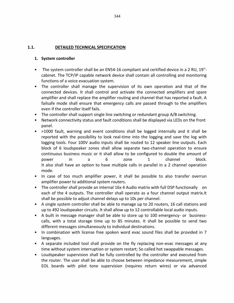
344
1.1. DETAILED TECHNICAL SPECIFICATION
1. System controller
• The system controller shall be an EN54-16 compliant and certified device in a 2 RU, 19”-cabinet. The TCP/IP capable network device shall contain all controlling and monitoring functions of a voice evacuation system.
• The controller shall manage the supervision of its own operation and that of the connected devices. It shall control and activate the connected amplifiers and spare amplifier and shall replace the amplifier routing and channel that has reported a fault. A failsafe mode shall ensure that emergency calls are passed through to the amplifiers even if the controller itself fails.
• The controller shall support single line switching or redundant group A/B switching. • Network connectivity status and fault conditions shall be displayed via LEDs on the front
panel. • >1000 fault, warning and event conditions shall be logged internally and it shall be
reported with the possibility to look real-time into the logging and save the log with logging tools. Four 100V audio inputs shall be routed to 12 speaker line outputs. Each block of 6 loudspeaker zones shall allow separate two-channel operation to ensure continuous business music or it shall allow to be configured to double the amount of power in a 6 zone 1 channel block. It also shall have an option to have multiple calls in parallel in a 2 channel operation mode.
• In case of too much amplifier power, it shall be possible to also transfer overrun amplifier power to additional system routers.
• The controller shall provide an internal 16x 4 Audio matrix with full DSP functionally on each of the 4 outputs. The controller shall operate as a four channel output matrix.It shall be possible to adjust channel delays up to 10s per channel.
• A single system controller shall be able to manage up to 20 routers, 16 call stations and up to 492 loudspeaker circuits. It shall allow up to 12 controllable local audio inputs.
• A built in message manager shall be able to store up to 100 emergency- or business-calls, with a total storage time up to 85 minutes. It shall be possible to send two different messages simultaneously to individual destinations.
• In combination with license free spoken word evac sound files shall be provided in 7 languages.
• A separate included tool shall provide on the fly replacing non-evac messages at any time without system interruption or system restart; So called hot swappable messages.
• Loudspeaker supervision shall be fully controlled by the controller and executed from the router. The user shall be able to choose between impedance measurement, simple EOL boards with pilot tone supervision (requires return wires) or via advanced

345
addressable EOL supervision boards, which requires a ground connection but no additional return wires.
• Zones outputs shall be able to handle a load from 2-500 Watt. • Max 500 Watt per 6 zones shall be provided, if required. The controller shall be able to
handle up to 2000 Watt load. It shall be possible to use connect to a FPA5000 via Ethernet
The controller shall have the following specifications:
16x4 DSP matrix mixing
Priority mixing with ducking, attack and release
3 band parametric PEQ in the inputs
5 band parametric PEQ in the outputs
up to 10s delay per output
Gain adjustment in the in- and outputs
Compressor on the inputs
Limiters on the inputs
Cross point matrix level adjustment with ducking level, fade in and fade out time
2 mic/line inputs (System s/n >= 106dB) – 2x Euro Style - 2x cinch
4 separate call station RJ45 input busses, each can be daisy chained up to 4 call stations
4 output channels for daisy chaining amplifiers via RJ45
12 input contacts; 6x voltage free (isolated) + 6x Supervised, to ensure compliancy to all different standards (like VDE0833 & NEN2575)
12 output contacts; 1x Relay + 12 Open Collector
6 High power output contacts (1A)
8 Analog input contacts with 256 steps resolution
Four input channels (100V, 70V) + 2 spare channel inputs (100V, 70V)
Real time clock with summertime and wintertime switching
DCF77 receiver sync input
Event scheduler
12 zone outputs (100/70V)
12 zone status LED (active – green, fault – yellow, alarm – red)
6 system status LED (general fault, system fault, alarm mode, power indicator, standby mode, network connection status)
Internal router pcb: 2x 2ch x 6zone (2 separate channels can be provided on each 6 zones. Blocks can be daisy chained)
Controller shall be configurable as 6 A/B zones or 12 single zones
Internal sounder
System access shall have password protection
CAN bus between system components
Based on a fully digital platform
Network prepared (remote system racks)
24V DC Input Audio: 16 (internal) audio Channels
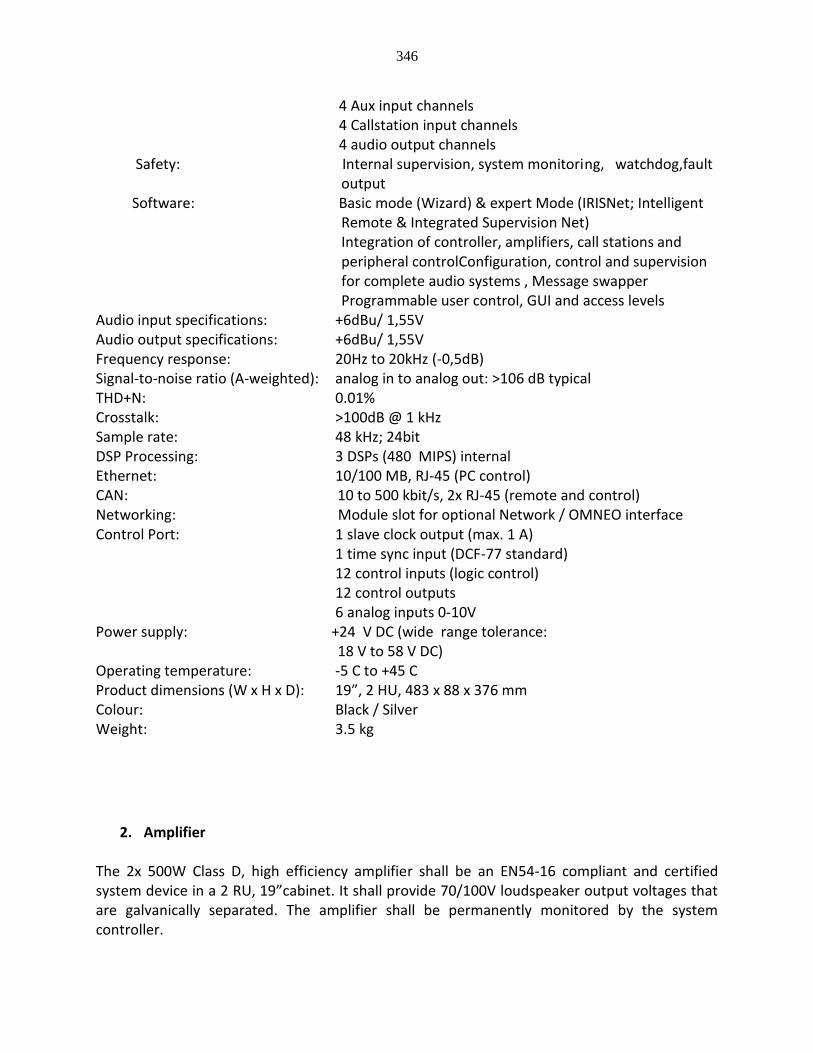
346
4 Aux input channels 4 Callstation input channels 4 audio output channels Safety: Internal supervision, system monitoring, watchdog,fault
output Software: Basic mode (Wizard) & expert Mode (IRISNet; Intelligent
Remote & Integrated Supervision Net) Integration of controller, amplifiers, call stations and peripheral controlConfiguration, control and supervision for complete audio systems , Message swapper Programmable user control, GUI and access levels
Audio input specifications: +6dBu/ 1,55V Audio output specifications: +6dBu/ 1,55V Frequency response: 20Hz to 20kHz (-0,5dB) Signal-to-noise ratio (A-weighted): analog in to analog out: >106 dB typical THD+N: 0.01% Crosstalk: >100dB @ 1 kHz Sample rate: 48 kHz; 24bit DSP Processing: 3 DSPs (480 MIPS) internal Ethernet: 10/100 MB, RJ-45 (PC control) CAN: 10 to 500 kbit/s, 2x RJ-45 (remote and control) Networking: Module slot for optional Network / OMNEO interface Control Port: 1 slave clock output (max. 1 A) 1 time sync input (DCF-77 standard) 12 control inputs (logic control) 12 control outputs 6 analog inputs 0-10V Power supply: +24 V DC (wide range tolerance: 18 V to 58 V DC) Operating temperature: -5 C to +45 C Product dimensions (W x H x D): 19”, 2 HU, 483 x 88 x 376 mm Colour: Black / Silver Weight: 3.5 kg
2. Amplifier
The 2x 500W Class D, high efficiency amplifier shall be an EN54-16 compliant and certified system device in a 2 RU, 19”cabinet. It shall provide 70/100V loudspeaker output voltages that are galvanically separated. The amplifier shall be permanently monitored by the system controller.
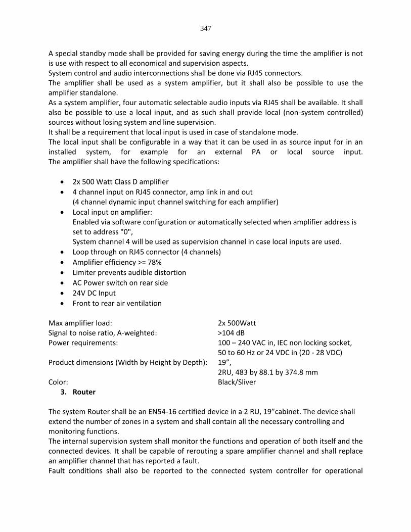
347
A special standby mode shall be provided for saving energy during the time the amplifier is not is use with respect to all economical and supervision aspects. System control and audio interconnections shall be done via RJ45 connectors. The amplifier shall be used as a system amplifier, but it shall also be possible to use the amplifier standalone. As a system amplifier, four automatic selectable audio inputs via RJ45 shall be available. It shall also be possible to use a local input, and as such shall provide local (non-system controlled) sources without losing system and line supervision. It shall be a requirement that local input is used in case of standalone mode. The local input shall be configurable in a way that it can be used in as source input for in an installed system, for example for an external PA or local source input. The amplifier shall have the following specifications:
2x 500 Watt Class D amplifier
4 channel input on RJ45 connector, amp link in and out (4 channel dynamic input channel switching for each amplifier)
Local input on amplifier: Enabled via software configuration or automatically selected when amplifier address is set to address "0", System channel 4 will be used as supervision channel in case local inputs are used.
Loop through on RJ45 connector (4 channels)
Amplifier efficiency >= 78%
Limiter prevents audible distortion
AC Power switch on rear side
24V DC Input
Front to rear air ventilation Max amplifier load: 2x 500Watt Signal to noise ratio, A-weighted: >104 dB Power requirements: 100 – 240 VAC in, IEC non locking socket,
50 to 60 Hz or 24 VDC in (20 - 28 VDC) Product dimensions (Width by Height by Depth): 19”,
2RU, 483 by 88.1 by 374.8 mm Color: Black/Sliver
3. Router
The system Router shall be an EN54-16 certified device in a 2 RU, 19”cabinet. The device shall extend the number of zones in a system and shall contain all the necessary controlling and monitoring functions. The internal supervision system shall monitor the functions and operation of both itself and the connected devices. It shall be capable of rerouting a spare amplifier channel and shall replace an amplifier channel that has reported a fault. Fault conditions shall also be reported to the connected system controller for operational

348
control and logging purposes. A failsafe mode shall ensure that emergency calls are passed to the loudspeakers, even if the unit itself fails. The controller shall support single line assignment or redundant group A/B switching. Connectivity status and fault conditions shall be displayed via LEDs on the front panel, including a zone status LED. It shall be possible to route up to 4 channels into eight 100V audio inputs to 24 speaker line outputs. The router loudspeaker outputs shall be divided in blocks of 6 loudspeaker line outputs. Each block of 6 zones shall allow the same or a different two-channel operation mode to ensure continuous and/or different business music into different zone blocks. The router shall operate as a four in two out matrix (4 channel input matrix to 2-channel zone block output). Zone outputs shall be able to handle a load from 2-500 Watt. Max. 500 Watt per 6 zones shall be provided. The Router shall be able to handle up to a 4000 Watt load. Integrated loudspeaker supervision shall eliminate the need of amplifier power for supervision, which shall result in very low power consumption. The router shall have the following specifications:
24 input contacts; 12x voltage free (isolated) + 12x Supervised
24 output contacts; 24 Open Collector outputs
2 Relay switched outputs
Eight 100V input channels + 4 spare 100V channel inputs
24 zone status LED (active – green, fault – yellow, alarm – red)
4 system status LED (general fault, power indicator, standby mode, network connection status)
Internal router pcb: 4x 2ch x 6zone, were each block can be daisy chained
12 A/B zones or 24 single zones
CAN bus between system components
Max 1000 meter distance
24V DC Input Safety: Internal supervision, system monitoring, watchdog,
fault output CAN: 10 to 500 kbit/s, 2x RJ-45
(remote and control) Control Port: 1 x 8-pin RJ connector
24 control inputs (analog 0-10 V/logic control)
24 input contacts; 12x voltage free (isolated) + 12x supervised, to ensure compliancy to all
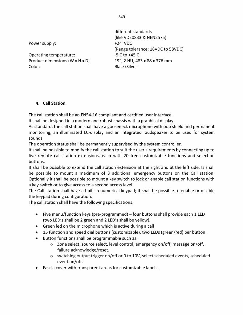
349
different standards (like VDE0833 & NEN2575)
Power supply: +24 VDC (Range tolerance: 18VDC to 58VDC)
Operating temperature: -5 C to +45 C Product dimensions (W x H x D) 19”, 2 HU, 483 x 88 x 376 mm Color: Black/Silver
4. Call Station
The call station shall be an EN54-16 compliant and certified user interface. It shall be designed in a modern and robust chassis with a graphical display. As standard, the call station shall have a gooseneck microphone with pop shield and permanent monitoring, an illuminated LC-display and an integrated loudspeaker to be used for system sounds. The operation status shall be permanently supervised by the system controller. It shall be possible to modify the call station to suit the user’s requirements by connecting up to five remote call station extensions, each with 20 free customizable functions and selection buttons. It shall be possible to extend the call station extension at the right and at the left side. Is shall be possible to mount a maximum of 3 additional emergency buttons on the Call station. Optionally it shall be possible to mount a key switch to lock or enable call station functions with a key switch or to give access to a second access level. The Call station shall have a built-in numerical keypad; it shall be possible to enable or disable the keypad during configuration. The call station shall have the following specifications:
Five menu/function keys (pre-programmed) – four buttons shall provide each 1 LED (two LED’s shall be 2 green and 2 LED’s shall be yellow).
Green led on the microphone which is active during a call
15 function and speed dial buttons (customizable), two LEDs (green/red) per button.
Button functions shall be programmable such as: o Zone select, source select, level control, emergency on/off, message on/off,
failure acknowledge/reset. o switching output trigger on/off or 0 to 10V, select scheduled events, scheduled
event on/off.
Fascia cover with transparent areas for customizable labels.
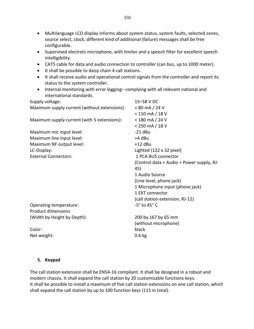
350
Multilanguage LCD display informs about system status, system faults, selected zones, source select, clock, different kind of additional (failure) messages shall be free configurable.
Supervised electrets microphone, with limiter and a speech filter for excellent speech intelligibility.
CAT5 cable for data and audio connection to controller (can bus, up to 1000 meter).
It shall be possible to daisy chain 4 call stations.
It shall receive audio and operational control signals from the controller and report its status to the system controller.
Internal monitoring with error logging– complying with all relevant national and international standards.
Supply voltage: 15–58 V DC Maximum supply current (without extensions): < 80 mA / 24 V < 110 mA / 18 V Maximum supply current (with 5 extensions): < 180 mA / 24 V < 250 mA / 18 V Maximum mic input level: -21 dBu Maximum line input level: +4 dBu Maximum NF output level: +12 dBu LC-Display: Lighted (122 x 32 pixel) External Connectors: 1 PCA BUS connector
(Control data + Audio + Power supply, RJ-45) 1 Audio Source (Line level, phone jack)
1 Microphone input (phone jack) 1 EXT connector (call station extension, RJ-12)
Operating temperature: -5° to 45° C Product dimensions (Width by Height by Depth): 200 by 167 by 65 mm
(without microphone) Color: black Net weight: 0.6 kg
5. Keypad
The call station extension shall be EN54-16 compliant. It shall be designed in a robust and modern chassis. It shall expand the call station by 20 customizable functions keys. It shall be possible to install a maximum of five call station extensions on one call station, which shall expand the call station by up to 100 function keys (115 in total).
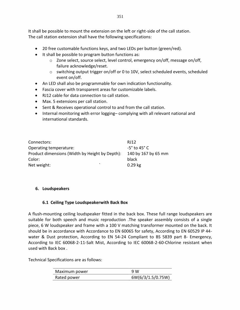
351
It shall be possible to mount the extension on the left or right-side of the call station. The call station extension shall have the following specifications:
20 free customable functions keys, and two LEDs per button (green/red).
It shall be possible to program button functions as: o Zone select, source select, level control, emergency on/off, message on/off,
failure acknowledge/reset. o switching output trigger on/off or 0 to 10V, select scheduled events, scheduled
event on/off.
An LED shall also be programmable for own indication functionality.
Fascia cover with transparent areas for customizable labels.
RJ12 cable for data connection to call station.
Max. 5 extensions per call station.
Sent & Receives operational control to and from the call station.
Internal monitoring with error logging– complying with all relevant national and international standards.
Connectors: RJ12 Operating temperature: -5° to 45° C Product dimensions (Width by Height by Depth): 140 by 167 by 65 mm Color: black Net weight: ` 0.29 kg
6. Loudspeakers
6.1 Ceiling Type Loudspeakerwith Back Box
A flush-mounting ceiling loudspeaker fitted in the back box. These full range loudspeakers are suitable for both speech and music reproduction .The speaker assembly consists of a single piece, 6 W loudspeaker and frame with a 100 V matching transformer mounted on the back. It should be in accordance with Accordance to EN 60065 for safety, According to EN 60529 IP 44- water & Dust protection, According to EN 54‑24 Compliant to BS 5839 part 8- Emergency, According to IEC 60068‑2‑11-Salt Mist, According to IEC 60068‑2‑60-Chlorine resistant when used with Back box . Technical Specifications are as follows:
Maximum power 9 W
Rated power 6W(6/3/1.5/0.75W)
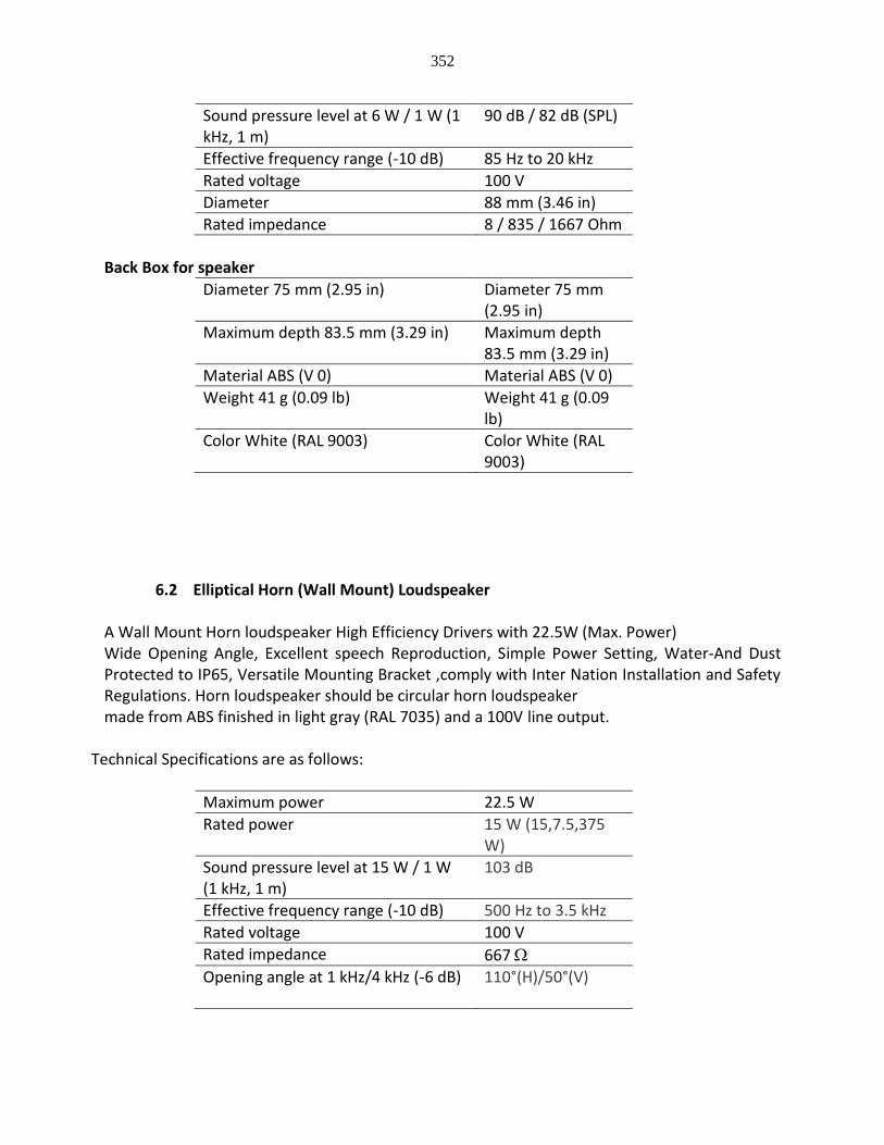
352
Sound pressure level at 6 W / 1 W (1 kHz, 1 m)
90 dB / 82 dB (SPL)
Effective frequency range (-10 dB) 85 Hz to 20 kHz
Rated voltage 100 V
Diameter 88 mm (3.46 in)
Rated impedance 8 / 835 / 1667 Ohm
Back Box for speaker
Diameter 75 mm (2.95 in) Diameter 75 mm (2.95 in)
Maximum depth 83.5 mm (3.29 in) Maximum depth 83.5 mm (3.29 in)
Material ABS (V 0) Material ABS (V 0)
Weight 41 g (0.09 lb) Weight 41 g (0.09 lb)
Color White (RAL 9003) Color White (RAL 9003)
6.2 Elliptical Horn (Wall Mount) Loudspeaker A Wall Mount Horn loudspeaker High Efficiency Drivers with 22.5W (Max. Power) Wide Opening Angle, Excellent speech Reproduction, Simple Power Setting, Water-And Dust Protected to IP65, Versatile Mounting Bracket ,comply with Inter Nation Installation and Safety Regulations. Horn loudspeaker should be circular horn loudspeaker made from ABS finished in light gray (RAL 7035) and a 100V line output.
Technical Specifications are as follows:
Maximum power 22.5 W
Rated power 15 W (15,7.5,375 W)
Sound pressure level at 15 W / 1 W (1 kHz, 1 m)
103 dB
Effective frequency range (-10 dB) 500 Hz to 3.5 kHz
Rated voltage 100 V
Rated impedance 667
Opening angle at 1 kHz/4 kHz (-6 dB)
110°(H)/50°(V)
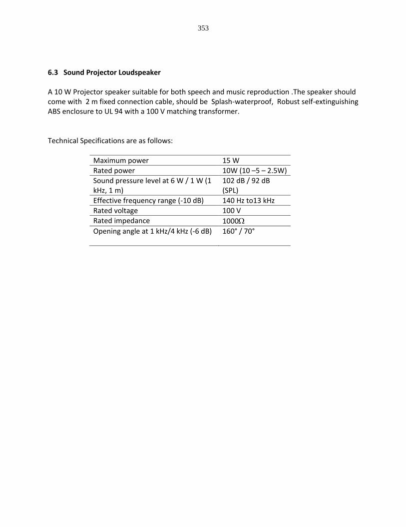
353
6.3 Sound Projector Loudspeaker A 10 W Projector speaker suitable for both speech and music reproduction .The speaker should come with 2 m fixed connection cable, should be Splash-waterproof, Robust self-extinguishing ABS enclosure to UL 94 with a 100 V matching transformer. Technical Specifications are as follows:
Maximum power 15 W
Rated power 10W (10 –5 – 2.5W)
Sound pressure level at 6 W / 1 W (1 kHz, 1 m)
102 dB / 92 dB (SPL)
Effective frequency range (-10 dB) 140 Hz to13 kHz
Rated voltage 100 V
Rated impedance 1000
Opening angle at 1 kHz/4 kHz (-6 dB)
160° / 70°
354
CHAPTER –IX TECHNICAL SPECIFICATION OF SECURITY CAMERA SYSTEM VIDEO MANAGEMENT SYSTEM I Video Management System General Description A. The video management system (VMS) specified is an enterprise-class client/server based IP video security solution that provides seamless management of digital video, audio and data across an IP network. The video management system is designed to work with same brand of CCTV products as part of a total video security management system to provide full virtual matrix switching and control capability. The video management system consists of the following software modules: central server, recording services, configuration client, and Operator Clients. Video from the site may be viewed from single or numerous workstations simultaneously at any time. Cameras, recorders, and viewing stations may be placed anywhere in the IP network. B. The VMS shall support the following recording services: a. Video Recording Manager (VRM) b. Local Storage and Direct-to-iSCSI recording

355
c. Recording Stations c. The software components of the video management system can be deployed on separate PCs and servers to meet systems requirements. d. The central server and the Video Recording Manager shall run as services on latest Windows Server OS e. The Configuration Client software shall run as an application on latest Windows Server OS f. The Operator Client software shall run as an application on latest Windows OS. II Video Management System A. The video management system (VMS) specified shall be a centrally managed, scalable client/server based architecture that allows full virtual matrix switching and control systems. B. The VMS shall be designed to use a structured cabling IT infrastructure and require no special cabling. C. The VMS shall provide a built-in command script editor that allows customized command scripts to be written to control virtually all the system functions. Command scripts may be activated by system operators or automatically in response to alarms or system events. The built-in command script editor shall support C# and VB.NET. D. The VMS shall support Security Systems MPEG-4 and H.264 or H 265 encoders, decoders, IP cameras, IP Domes, iSCSI disk storage (also supporting MPEG-2) and other compatible ATM bridge. E. The VMS shall support Operator Clients that can playback iSCSI disk array storage and VRM recordings at the same time. F. The VMS may allow Operator Clients to export all recording listed in (E) to one single archive G. The VMS specified shall support the English language or shall use the same language as the Operating System language. H. The VMS shall provide up to 10 different and independent programmable recording schedules. The schedules may be programmed to provide different record frames rates for day, night, and weekend periods as well as special days. Advanced task schedules may also be programmed that could specify allowed logon times for user groups, when events may trigger alarms, and when data backups should occur. I. The VMS shall allow the establishment of user groups that have access rights to specific cameras, priority for pan/tilt/zoom control, rights for exporting video, and access rights to system event log files. Access to live, playback, audio, PTZ control, preset control, and auxiliary commands shall be programmable on an individual camera basis.

356
J. The VMS shall support Dual Authorization logon. It shall function as follows: a. Dual Authorization user groups may be created. b. Logon pairs, consisting of any two normal user groups, may be assigned to each dual Authorization user group. c. A separate set of privileges and priorities can be assigned for each Dual Authorization user group. d. For each user group assigned as part of a logon pair, it shall be configurable whether the group can log on either individually or as part of the logon pair- Or log on only as part of the logon pair. e. If a user that is part of logon pair logs on individually, then he shall receive the privileges and priorities of his assigned user group. If the same user logs in as part of a logon pair, i.e. being authorized by the second user, then the user shall receive the privileges and priorities assigned to the Dual Authorization group to which the pair is assigned. f. The logbook shall log the log on procedure to identify a single user or a dual authorization log on. Subsequent user actions shall be logged as the actions of the first user. K. The VMS shall interface with the Intelligent Video Analysis (IVA) techniques of the cameras or the video analytic server to provide advanced motion detection that analyzes object size, direction, and speed as well as detecting objects entering or leaving designated areas. L. The VMS shall support configuring the IVA parameters from the Configuration Client. M. The VMS shall react to events triggered by the IVA of the IP cameras for edge based analytics N. The VMS shall react to events triggered by the IVA of the server O. The VMS workstations may be connected to monitors or video wall where each monitor may be configured to display live streaming video, playback video, site maps, or alarms. P. The VMS shall connect to an arrays of 42” monitors displaying 4x3 or 5x4 number of images from all cameras. Q. The VMS shall support Lightweight Directory Access Protocol (LDAP) that allows integration with enterprise user management systems such as Microsoft Active Directory. R. The VMS shall export video and audio data optionally in ASF format to a CD/DVD drive, a network drive, or a USB drive. The exported data in ASF format may be played back using standard software such as Windows Media Player. S. The VMS shall export video and audio data optionally in its native recording format to a CD/DVD drive, a network drive, or a direct attached drive. The exported data in native recording format shall include all associated metadata. Viewer software shall be included with

357
the export. Once installed, the viewer software allows playback of the streams on any compatible Windows PC. T. The VMS shall auto-discover encoder, decoder, iSCSI disk array, and VRM devices. Device detection shall support devices in different subnets. U. The VMS shall auto-discover associated IP devices with their default IP addresses, and allow auto-assignment of unique IP addresses. V. The VMS shall be able to simultaneously configure multiple encoders or decoders, even of different types. When devices of different types are being configured, only the parameters available in all devices are available for configuration. W. The VMS shall support continuous operation during Central Server down-times as live viewing, playback of recording and export of video data. The Operator Client shall indicate its connection status to the Central Server. X. The VMS shall be designed in such a way that configuration changes to any part of the system shall not interrupt operational tasks, until the operator decides to update re-fresh the workstation configuration. III Video Management System Components A. Central Server software shall provide management, monitoring, and control of the entire system. The central server software should typically be installed on a server-class computer, but may be installed, with all the other video management software modules on one workstation. The Central Server shall also maintain data stream management, alarm management, priority management, central logbook, central configuration and user management. B. Software updates to the Operator Client and Configuration Client shall be automatically deployed from the Central Server. C. The VMS software shall provide recording and playback management of video, audio, and data. The VMS software configures the streaming parameters of the assigned devices. The VMS software administers the data on the connected hard disk drives. D. The VMS shall be designed in such a way the Central Server downtimes do not affect the functionality of the recording services (Video Recording Manager, Recording Station, Local Storage, Direct-to-iSCSI-Recording). Normal recording and Motion recording shall continue during the Central Server downtimes, only Alarm Recording cannot be activated as the Central Server is responsible for evaluating the alarm conditions. During Central Server downtime the recording services shall still be able to change the recording parameters schedule dependent. E. Configuration Client software shall provide the user interface for system configuration and

358
management. F. Operator Client software shall provide the user interface for system monitoring and operation. The Operator Client maintains live monitoring, storage retrieval, and alarm handling. IV Video Recording Manager (VRM) A. The video management system shall be capable of managing multiple VRMs. B. The VRM shall be configured from the VMS Configuration Client. It shall be possible to assign encoders and IP cameras to it. C. The recording parameters shall be configured in the recording tables of the VMS configuration program. These settings will be replicated into the devices from the Central Server. D. The VRM shall offer system wide recording monitoring and management of iSCSI storage, video servers and cameras. E. The VRM shall support the encoders and cameras to directly stream the data to the iSCSI storage. The VRM shall not be involved in the processing of the data. F. The VRM shall manage all disk arrays in the system as a single virtual common pool of storage. It shall dynamically assign portions of that pool to the encoders and IP-Cameras. G. The proposed network switches shall be compatible with the VRM and the transfer rate of the data from the encoder or IP-Camera shall supported by the network and the iSCSI data throughput rate. H. The VRM shall provide redundancy main/ hot standby (load sharing) configuration for storage provisioning and failover design for central recording management service. I. The VRM shall be able to restore a lost recording database from data on the iSCSI storages. J. The VRM shall provide flexible retrieval of recordings. It shall be able to determine on which iSCSI disk array data from each camera or encoder has been stored. K. It shall be possible to secure the access to the VRM software with a password. This shall be done in the Configuration Client. L. The VRM software shall provide status monitoring information as a web interface. The following information shall be provided: a. Uptime of the VRM software

359
b. Bit rate information for the recorded data c. Retention times per camera d. Status on recording and storage M. The video management system shall allow configuring if playback of recordings is streamed through the VRM or is streamed directly from the iSCSI storage. N. The video management system shall support to retrieve the playback information, i.e. from which iSCSI storages to retrieve the video, audio and meta-data, either from the Video Recording Manager or directly from the IP encoder or camera. Playback information directly from the IP encoder or camera is limited in time and should be used while the VRM is not available to increase the reliability of the video management system. V Recording Station support A. The VMS shall be able to integrate Recording Stations. It shall be possible to playback data recorded by Recording Stations. This shall include MPEG-4, H.264 or H 265, and JPEG data. B. The video management system shall be capable of managing multiple Recording Stations. C. The cameras connected via Recording Station shall behave the same as VRM managed IP cameras in the video management system Operator Client. D. The Operator Client shall display live and recorded data from cameras assigned to Recording Stations. In playback mode the Recording Station cameras shall appear in the graphical timeline. E. Changing the configuration of a Recording Station shall require the Recording Station configuration software. VI Monitor Support A. The VMS shall support monitors connected to IP decoders. B. It shall be possible to configure monitors in full screen mode, quad mode or 9 to 1 monitor configuration. When in any mode, the VMS shall be able to select video and control cameras in any quadrant. C. It shall be possible to group monitors into Monitor Groups (MGs). An MG shall specify a monitor arrangement of rows and columns. D. It shall be possible to restrict access to MGs to specified Operator Client workstations.

360
VII Alarm Management Capability A. The video management system shall provide the capability to allow alarms to be schedule-dependent. B. The video management system shall allow alarms to be individually allocated to specific user groups for processing. C. The video management system shall support replication of events such that a single physical event causes multiple system events. These multiple events shall be independently configurable to allow independent handling of the alarms by multiple operator groups, or to be handled differently according to different schedules. D. The video management system shall be programmable to selectively, per alarm and per user group, automatically pop-up the alarm video. E. The video management system shall support display of alarm video in a special Alarm Image Window so users do not have to search their display screens to find the alarm images. F. The video management system shall display alarm video in rows of Alarm Image Panes, with one row per alarm, and with up to 5 Image Panes per row. G. The video management system's Alarm Image Panes shall be configurable to display live video, playback video, text documents, site maps, HTML files, or web sites (URLs). Per alarm one playback video and one site map can be configured. H. The video management system's Alarm Image Pane rows shall be displayed in order of their priority, with rows for higher priority alarms always displayed above lower priority alarm rows. The display order for equal priority alarms shall be selectable between new alarms displayed above existing alarms, or new alarms displayed below existing alarms. I. The video management system shall provide an alarm reaction time of maximum 2 seconds when sufficient network bandwidth is available. J. The video management system shall distribute alarm notifications, via entries in the alarm list of the operator user interface, to all members of the user groups to which the alarm is assigned. The alarms shall appear in all said users' alarm lists. K. The video management system shall operate as follows: when an alarm is accepted by a user, it shall be removed from the other users' alarm lists. L. The video management system shall allow a user to un-accept an alarm he has previously accepted. In this case, the alarm shall re-appear in the alarm lists of all members of the user

361
groups assigned to this alarm. M. The video management system shall support the association of workflows with alarms. Workflows shall consist of action plans and comment boxes. An action plan shall display a text document, HTML page, or web site that typically contains instructions for handling the alarm. Comments entered in the comment boxes shall be logged in the system logbook N. The video management system shall be configurable to force an alarm workflow. In this case, the alarm cannot be cleared until the workflow is processed. O. The video management system shall offer the possibility to automatically clear alarms when the originating event condition is no longer true. P. The video management system shall allow alarms to be configured to send PTZ cameras to prepositions or to execute camera Aux commands on occurrence. Q. The video management system shall be configurable to put any IP-connected camera into alarm recording mode on alarm occurrence. R. The video management system shall be configurable to send an e-mail or SMS message in response to an alarm. S. The VMS shall be capable of displaying video on monitors connected to video decoders in response to alarms. T. The VMS alarm response shall take advantage of the row and column arrangement of monitor groups by associating a row of monitors with each active alarm. Each alarm may display video on multiple monitors, limited by the number of columns in the monitor group. U. As new alarms are received, alarm rows shall stack in priority order on the monitors. V The VMS shall support for alarms to display video on multiple monitor groups, with configurable assignment of individual assignment of alarms to monitor groups. VIII Relays and Digital Inputs A. The open/close states of inputs and relays from devices connected to the system, including IP cameras and PTZ cameras, video encoders and decoders, matrix switchers, and DVRs shall be indicated on the VMS Operator Client user interface and can be queried via the VMS Software Development Kit (SDK). B. Relays from devices connected to the system shall be controllable from command scripts, the VMS SDK, and icons on the Operator Client user interface.

362
C. Input and relay state changes from devices connected to the system shall be recognizable as events in the VMS. IX Logbook A. The system shall protocol every event and alarm in an SQL database. The alarm entry shall contain the camera titles that have been recorded due to this alarm. B. The logbook shall be able to store at least 500,000 entries per hour. If the capacity of the logbook is filled up the oldest entries will be deleted to create space. C. The user shall be able to search the logbook for events and alarms. The user shall be able to export the search results into a comma separated value list (CSV). D. The system shall include and install a ready-to-use SQL database. The system shall optionally allow the usage of a separately installed SQL database. X Digital I/O Interface Connection A. The digital inputs and relay outputs shall provide all of the features and functionality described in the Relays and Digital Inputs section of this document. B. The I/O devices attached to the network shall be automatically discoverable via a network scan. XI SNMP A. The video management system shall be capable of monitoring third-party equipment SNMP protocol. XII Pre-Programmed Camera sequences A. The video management system shall support pre-programmed camera sequences. These sequences will allow cameras to be automatically displayed on the computer image panes and/or monitors connected to decoders. The sequences shall support simultaneous display on multiple image panes or monitors. The sequences shall also support camera prepositions for each PTZ camera on each sequence step. The system shall be configurable such that operators can select these sequences from the logical tree or a site map. B. Pre-programmed camera sequences can be displayed in Operator Client and on Monitor Groups. XIII Command Scripts

363
A. The video management system shall provide a command script interface that allows system operations to be programmatically controlled. B. The system shall provide a built-in editor for the creation of the command scripts. C. The system shall be configurable such that operators can execute the created scripts by double-clicking on representative icons in a logical tree or site map. D. The system shall be configurable such that the created scripts can be executed automatically in response to a system event. The automatic event-driven execution shall optionally be schedule-dependent. E. The system shall be configurable to execute a user-group dependent command script on user logon. F. The system shall be configurable to execute an alarm-dependent command script on user acceptance of the alarm. XIV Virtual Inputs A. The video management system shall provide a software interface that allows third-party software to generate events in the video management system. The software shall support any COM programming languages (e.g. Visual Basic and C++), any .Net programming language (e.g. C#) or JavaScript. B. The VMS shall allow third-party software to include up to 10 data fields and an Alarm ID along with the virtual input event. C. These fields shall be searchable in the system logbook. D. The virtual input data shall be optionally displayed in the Operator Client playback mode synchronously with the associated video. XV Software Development Kit (SDK) A. The video management system shall provide a documented Software Development Kit (SDK) to allow integration to and integration from third-party software. B. The SDK shall expose all functionality of the command scripts, including, but not limited to: • Control of operator workstation image window layout • Assignment of cameras, documents, URLs, and maps to Operator Client workstation image panes
364
• Assignment of cameras to monitors connected to encoders. • Dome control • Alarm generation • Recording mode control • Exporting recorded data • Relay control C. SDK functionality shall require authentication to the system. D. The SDK shall be accessible from all .Net programming languages. XVI OPC Interface A. The VMS shall provide an OPC Server for integration into third-party software systems, such as building-management systems. B. The OPC interface shall follow the OPC Alarms and Events standard. XVII Configuration Changes A. Configuration changes made in the VMS Configuration Client shall modify a working copy of the configuration, and shall not affect the active operating configuration. B. It shall be possible to activate the working copy through a user action in the Configuration Client, at which point the working becomes the new active operating configuration. C. It shall be possible to set a date and time in the future at which the working copy becomes active. D. It shall be possible to view a list of all configuration activations that have been applied to the system. It shall be possible to select any of the activated configurations, and have the system "roll back" to an earlier configuration. E. It shall be possible to activate a configuration and leave it to the operator to refresh the configuration locally instantly or at a later point in time. It shall be possible to enforce a configuration activation for every Operator Client connected to the Central Server.
365
XVIII Operator Client A. The video management system shall provide an administrator-configured Logical Tree. The logical tree shall be freely configurable with any tree structure, with nodes consisting of folders or maps, and leaves consisting of devices (cameras, inputs, and relays), sequences, documents, URLs, or command scripts. Each user group shall only see items in the logical tree for which the administrator has granted access. B. The user shall be able to search the logical tree for item names. C. The video management system shall provide a user-dependent Favorites Tree. The Favorites tree shall allow maps, folders, and devices and complete views (image pane patterns with camera assignments) to be configured by each user in a user-defined structure. The user's favorites tree shall be available irrespective of the computer with which he logs on to the system. D. The video management system shall provide an Image Window that displays a collection of Image Panes. The layout shall be optimized for standard and widescreen monitors. With standard monitors the number of image panes per image window shall be variable between 1 (a single full-window video) and 25, arranged in a 5x5 grid. A slider shall be available allowing the grid size to be changed from 1x1, 2x2, 3x3, 4x4, and 5x5. With widescreen monitors the number of image panes per image windows shall be variable between 1 and 30, arranged in grids of 1x1, 3x2, 4x3, 5x4, and 6x5. The VMS shall allow image panes to be enlarged or decreased in size within the grid. E.g., in a 5x5 grid, a single image pane can be enlarged to use 4 of the grid elements, creating a larger image within the grid. Any pattern can be created within the grid structure. An image pane can be resized by clicking and dragging on any corner, dragging the corner to the desired size. E. The video management shall implement the concept of a selected image pane. The selected image pane shall be highlighted. There shall always be a selected image pane in the Operator Client application. The selected image pane is always used for control commands, e.g. PTZ control, instant playback control, and audio replay. F. The video management system shall support encoders and IP cameras. G. The video management system shall support site maps with hot-spot icons for devices (cameras, relays, and inputs), command script initiation, camera sequence initiation, and links to other site maps. The site maps shall be capable of being zoomed. The hot- spot icons shall be configurable to optionally display the device name or link title. H. The Operator Client shall display live streams from encoders or IP cameras. I. The video management system shall support automatic sequencing. It shall be possible for

366
users to multiple-select cameras (control-click or shift click), and drag the multiple- selection to an image pane or a graphic representing a monitor connected to a decoder. All of the cameras in the selection shall then sequence in the image pane or monitor at a user-selectable rate. It shall also be possible to drag a folder to an image pane or monitor. In this case, all of the cameras contained within the folder shall sequence. J. The video management system shall support PTZ control with a dedicated graphical joystick control, supporting Pan, Tilt, Zoom, Iris, Focus and Aux Command operations. It shall also support PTZ control via clicking the mouse in the image panes. For PTZ cameras, the cursor shall change to indicate the Pan/Tilt direction when hovering over the corresponding image pane. The Pan/Tilt speed shall increase as the cursor moves farther from the center of the image pane. An area in the center of the image pane shall be used for zoom-in/zoom-out control. Once zoom is initiated, the zoom speed shall increase as the cursor is moved farther from the center of the image pane. K. The video management system shall support digital zoom of any image pane. A dedicated graphical control shall be provided in the user interface for this purpose. In addition, the mouse wheel shall control digital zoom when the mouse cursor is hovering over a selected image pane. L. The video management system shall provide an Instant Playback function that displays recorded images on one or multiple image panes. Recorded images from a single camera may also be played back on multiple panes. Instant playback supports pause, play forward, play reverse, single step forward, single step reverse, fast-forward, and fast-reverse. M. The video management system shall support a timeline that provides a graphical overview of video stored on the disk. The timeline shall display a timescale that can be adjusted from at least 15-minutes per division to 1 month per division. For each camera displayed in playback mode, the timeline shall provide a line that depicts the video storage for that camera. The line shall be color-coded to show if video is recorded for the displayed time period, and if so, if it is normal recording, motion recording, or alarm recording. The line shall be cross-hatched if the video is protected from deletion. The line shall also indicate if associated audio is recorded during the displayed time period. N. The video management system shall support simultaneous time-synchronous playback of up to 16 cameras. Playback shall support single-step forward and backwards; play normal speed forward and backwards; play high-speed forward and backwards; and play slow-speed forward and backwards. O. The video management system shall support search of recorded video for motion in user-specified areas of a camera image. This cell based post-recording motion search will work for cameras recorded by disk array storage. P. The video management system shall support search of recorded video with at least the

367
following criteria: object size, object color, direction, and speed as well as detecting objects entering or leaving designated areas. This Intelligent Video Analysis (IVA) based post-recording search will work for cameras recorded by VRM and Local Storage. Q. The video management system shall optionally display the information of the video analytics such as cells with detected motion, object masks, and trajectories in live and playback. R. The video management system shall support searching based on any combination of time/date-rage, event type(s), alarm priority, alarm state, and device(s). It shall be possible to save and recall search parameters. S. The video management system shall graphically display device states on its icons in the logical tree structure and on sitemaps. For cameras, the states shown shall include: loss of the video signal, network connection loss, video recording, video signal too noisy, video signal too bright, video signal too dark, video de-adjusted, and video includes associated audio. For relays and contact inputs, the open or close state shall be indicated. T. The video management system shall support switching of cameras to monitors connected to decoders. The cameras shall be selectable via drag and drop from the logical tree or from the sitemaps. U. The video management system shall support an indication for the Operator Client regarding the connection state to the Central Server. This shall include connected, disconnected, and configuration out-of-sync between Central Server and Operator Client. V. The video management system shall support a centrally stored user profile to store settings individual for each operator. These settings shall include but are not limited to sequence dwell times, instant playback replay time and image pane ratio settings (16:9 or 4:3) individually per monitor. These settings shall be available independently of the physical workstation to the operator.
XV Audio Intercom Functionality
The video management system shall support bidirectional audio intercom functionality. Audio intercom streams audio data from an operator client Workstation to the audio output of the encoders.
The audio intercom function shall be activated by a button in the operator client Workstation. When the button is pressed the operator shall be able to speak into a microphone on the client computer. The audio shall be transmitted to the audio source which is assigned to the currently selected camera.
CCTV Keyboard Control
368
The system shall allow system control via the keyboards.
The keyboards shall support an Enterprise System, i.e. with a keyboard connected to an Enterprise operator client the desired subsystem’s management server shall be selectable.
Keyboard connections shall be possible to operator client Workstations.
When CCTV Keyboards are connected to decoders, it shall be possible to control the analog monitor groups in the system via the CCTV keyboard.
When CCTV Keyboards are connected to decoders, it shall be possible to control PTZ operation of the selected camera using the keyboard joystick.
When CCTV Keyboards are connected to decoders, it shall be possible to control set and call-up PTZ prepositions of the selected camera using the keyboard.
When CCTV Keyboards are connected to decoders, it shall be possible to execute PTZ and Aux-commands of PTZ Cameras on the selected camera using the keyboard.
When CCTV Keyboards are connected to operator client Workstations, it shall be possible to control the current Image Pane selection using the keyboard joystick.
When CCTV Keyboards are connected to operator client Workstations, it shall be possible to control the analog monitor groups in the system or control any Image Pane on the connected operator client Workstation, using the CCTV keyboard.
When CCTV Keyboards are connected to operator client Workstations, it shall be possible to control PTZ operation of the selected cameras using the keyboard joystick.
When CCTV Keyboards are connected to operator client Workstations, it shall be possible to control set and call-up PTZ prepositions of the selected camera using the keyboard.
When CCTV Keyboards are connected to operator client Workstations, it shall be possible to execute PTZ and Aux-commands of the selected Autodome camera using the keyboard.
When CCTV Keyboards are connected to operator client Workstations, it shall be possible to control playback of video, including both Instant Playback and Playback-mode synchronous playback, using the CCTV keyboard.
When CCTV Keyboards are connected to operator client Workstations, playback control should include jog-shuttle emulation using the Keyboard Joystick.
When in Jog-shuttle emulation mode: a) Rotating the Keyboard joystick will control forward and reverse playback, with
playback speed proportional to the amount of joystick rotation. b) Moving the joystick up shall set the video into slow forward playback mode.

369
Additional upward movements shall incrementally increase forward playback speed c) Moving the joystick down shall set the video into slow backward playback mode.
Additional downward movements shall incrementally increase backward playback speed.
d) Moving the joystick right shall set the video into pause mode. Additional rightward movements shall step the video one frame forward.
e) Moving the joystick left shall set the video into pause mode. Additional leftward movements shall step the video one frame backward.
Integration with Intrusion panel
The video management system shall be able to connect to UL-approved intrusion panels and browse the areas and devices configured in the panel in the Configuration Client.
The video management system shall be able to connect to 20 intrusion panels.
The video management system shall be able to map the events of the intrusion panel to events in the video management system in order to use these events in the event and alarm engine of the video management system.
The video management system shall be able to use the events of the intrusion panel to create compound events to trigger actions.
The Operator Client shall indicate the connection and authentication state of the intrusion panels by means of icons.
The video management system shall support the following devices from the intrusion panel: a) Areas b) Doors c) Outputs d) Points
The states of these intrusion devices shall be shown on the icons in the device tree of the operator client as well as on the hot-spot icons of the map. The states that should show are:
The user of an Operator Client shall be able to execute the following operations from the context menu of the intrusion device icons in the device tree as well as from the context menu on the corresponding hot-spot icons on the map:
a) Arm, force arm and disarm areas of an intrusion panels b) Silence areas of the intrusion panel c) Open and close outputs d) Unlock, secure and cycle doors e) Bypass and un-bypass points
All the user actions of the operator with regards to the intrusion devices in the video management system shall be logged

370
The video management system shall provide separate user permissions for the above mentioned operations per user group. A. In the occurrence of an event triggered by the camera due to fire or smoke detection, the
specific alarm shall appear in the Operator Client, indicating, that this alarm is triggered by a fire or smoke detection.
Feature Provision of server based analytics
A. The video management system shall provide an integration with a server based analytics platform which allows to use analytics from many different vendors.
B. On connection with the management server of the video management system, the analytics platform shall retrieve the list of configured cameras into the analytics platform to prevent manual setup of the cameras
C. It shall be possible to configure which video stream (stream 1 or stream 2) provided by the cameras shall be used for the analytics
D. The system should allow the use of a pool of video analytic algorithm on any cameras without limitations. It should be very easy to change an algorithm from a camera to another.
E. The video analytic processing should be able to run on top of a server or to be virtualized using leading virtualization technologies (vmWare, Hyper-V)
F. The video analytic processing should be able to scale seamlessly by adding servers. G. The video analytic processing should be able to be redundant. Server failure should not
impact the functionality of the system, as the analytics on this server failover to another automatically and in a very short time.
H. The system shall offer, at minimum the following video analytic: a. Access Control
i. Iris Recognition ii. NFC+Face Recognition
iii. Palm Veins Recognition iv. Face Recognition
b. Crowd/people management i. Panic
ii. Loitering iii. Tracking People iv. Fall v. Face Recognition
vi. Covered Faces c. Vehicle Management
i. License plate (LPR/ANPR) 1. Being able to cover all countries worldwide
ii. Traffic Management iii. Vehicle Counting iv. Wrong way v. Speed Vehicle

371
vi. Stationary Vehicle d. Freight Management
i. Dangerous Goods ii. Container recognition (ACCR)
iii. Train (LPR/ANPR) iv. Boat (LPR/ANPR)
e. Perimeter, security & safety i. Perimeter and Intrusion
ii. Lost objects iii. Stolen Objects iv. Object Tracking v. Graffiti
vi. Tampering vii. Fire and Smoke
viii. Temperature f. Business Analytics
i. Marketing ii. People Counting
iii. Age and Gender iv. Head Pose v. Expression Recognition
vi. Occupancy Rate vii. Eye Tracking
viii. Queue Management ix. Heat Map x. Bingo Balls
xi. OCR I. It shall be possible to setup several “lists” in the database of the analytics platform. A list
contains License plates or faces and related data. J. The analytics platform shall detect license plates or faces in the live stream provided by
the cameras and shall match them against the license plates and faces stored in data-base of the analytics platform
K. When there is a match an event shall be send to the video management system. Additional data such as the camera and the time of detection shall be included in the event provided to the video management system.
L. When the event provided by the analytics platform triggers an alarm in the Operator Client of the video management system, the following content shall show in a separate Analytics Viewer:
a. The original image of the live camera where the license plate of the face has been detected
b. A cropped extract of the original image just the extracted license plate or face c. The corresponding face or license plate taken from the database of the analytics
platform to allow the operator to compare the captured image with the reference image from data-base

372
d. Additional data related to the face or license plate stored in the data-base of the analytics platform (e.g. name of person etc.)
M. All events and meta-data shall be stored in the logbook of the video management system to allow to search for a license plate or person that triggered an alarm.
Support of video fire detection (Optional)
B. The VMS shall support Video Fire Detection by integrating a Network camera with integrated video-based fire detection and simultaneous intelligent video analysis.
C. Videos shall be processed and analyzed within the camera itself, with no extra hardware required.
D. The video-based fire detection shall offer a fast detection and high false alarm robustness with best picture quality even at challenging light conditions.
E. The video-resolution shall be up to HD with activated video-based fire detection. F. The video-based fire detection shall detect uncovered flames with minimum 1.6% of the
picture width. G. Uncovered uprising smoke shall be detected with minimum 2.3% of the picture width. H. The detection shall detect test fires TF1 to TF8 according to EN54. I. For the detection of flames and smoke a minimum illumination level of 7 Lux shall be
sufficient. J. Results of the video-based fire detection and Intelligent Video Analysis have to be
available as metadata in addition to the video data transmitted for alerting, storage and forensic search.

373
Storage General Characteristics: The IP Video Storage Appliance shall be a RAID-5 protected, all-in-one recording solution for network surveillance systems of up to 200 channels. The IP Video Storage Appliance shall utilize “enterprise-rated” hard drives in a fault tolerant RAID-5 configuration. The IP Video Storage Appliance shall be a Pre-installed, pre-configured IP storage solution with up to 64 TB storage capacity The IP Video Storage Appliance shall offer 576 TB of net capacity storage. The IP Video Storage Appliance shall offer a bandwidth of 550 Mbit/s. The IP Video Storage Appliance shall offer a dual port Gigabit Ethernet network interface, 8 GB system memory and an Intel Xeon Processor. The IP Video Storage Appliance shall offer remote monitoring via a desktop application or a Web browser. Functions The IP Video Storage Appliance shall offer an energy-efficient hot-swap redundant power supply. The IP Video Storage Appliance shall offer hot-swap SATA-III hard drives providing 64 TB (8X8 TB) of gross storage capacity. The IP Video Storage Appliance shall come pre-installed and pre-configured with all necessary software. The IP Video Storage Appliance shall utilize Microsoft Windows Storage Server 2012 R2. The IP Video Storage Appliance shall offer Disk on Module (DoM); a solid-state, non-volatile memory module that contains a backup image of all system software needed to a full system recovery. Management The IP Video Storage Appliance shall offer the Microsoft System Center Suite built-in. The IP Video Storage Appliance shall allow operators to use one central tool for configuration and operations management. Monitoring The IP Video Storage Appliance shall provide SNMP, Remote Desktop and HTTP monitoring support. The IP Video Storage Appliance shall offer high-availability hardware, embedded design, and system wide monitoring. Processor The IP Video Storage Appliance shall contain an Intel Xeon Processor E3-1275 V3 (8M Cache, 3.5 GHz). The IP Video Storage Appliance processor shall contain one (1) socket. The IP Video Storage Appliance processor shall feature an 8 MB Intel Smart Cache Memory. The IP Video Storage Appliance processor shall include ECC Unbuffered memory protection.

374
The IP Video Storage Appliance processor shall contain a 1600 MHz maximum front side Bus. Memory The IP Video Storage Appliance shall have 8 GB, DDR3-1666 ECC UNB (1 x 8 GB) of memory installed. Storage The IP Video Storage Appliance shall contain 8 GB, DDR3-1666 ECC UNB (1 x 8 GB) storage trays. The IP Video Storage Appliance shall have SATA-3, 7200 RPM 64 M 3.5“RAID-5 configuration hard drives installed. The IP Video Storage Appliance shall offer an 8 ports LSI 3108 SAS3 controller RAID card. Electrical: A/C input rating: 100 to 240 V / 50 to 60 Hz Environmental: Operating Temperature: +10°C to +35°C (+50°F to +95°F) Non-operating Temperature: –40°C to +70°C (–40°F to +158°F) Operating Relative Humidity: 8 to 90%, non-condensing Non-operating Relative Humidity: 5 to 95%, non-condensing Certifications and approvals CE & UL Management Server and Mobile Video Service It is recommended to run the Video Recording Manager and the VMS Management Server on the same computer. Operating System Windows Server 2016 (64-bit) Windows 10 Professional (64bit) CPU Intel Xeon E3-1275 V3 (3.5 GHz, 4-core, 8MB, 84W) RAM 8GB HDD 1 TB and above Free disk space 15GB (+ 15% of the hard-drive after installation) Network 1 Gigabit/s network interface card Operator Client All-in-One (AiO) Operating System Windows 10 Professional (64bit) CPU Intel Core i7 4770 3.4 GHz (up to 3.9 GHz) RAM 16GB, Keyboard, Mouse HDD 1 TB and above Free disk space Minimum 5GB for Single Site Minimum 10GB for Enterprise Systems Network 1 Gigabit/s network interface card Display resolution 24" LED Monitor Minimum: 1280 x 1024 Maximum: 1920 x 1080

375
Graphic card Nvidia Quadro K620 or P4000 Intel HD Graphics 530 1080P INDOOR IR HD DOME CAMERA: General Characteristics:
• The camera shall be easy to install. • The camera shall offer 1080p resolution at 30 fps. • The camera shall provide direct network connection using H.264 and JPEG
compression and bandwidth throttling to efficiently manage bandwidth and storage requirements while delivering outstanding image quality.
• A user shall be able to view video on a PC using a Web browser • The camera shall have a mechanical IR cut-off filter for true day/night switching. • The camera shall use Intelligent Dynamic Noise Reduction technology to remove noise
artifacts and reduce the bitrate by up to 50% (giving reduced bandwidth and storage requirements).
• The camera shall utilize Intelligent Defog (iDefog) to effectively remove the haze from the picture and provides a better visibility.
• The camera shall accept power via Power over Ethernet (IEEE 802.3af compliant). • The camera shall offer tamper and intelligent motion detection. • The camera shall offer two-way full duplex audio communication. • The camera shall provide configurable scene modes that give optimized settings for
distinct applications. • The camera shall provide eight independent, fully programmable privacy mask areas. • The camera shall utilize pixel-by-pixel analysis to automatically compensate for bright
areas of a high contrast scene without having to define a window or area. • The camera shall have a CVBS analog video output for hybrid operation. • The camera shall have a built-in active infrared illuminator.
Image processing and compression:
• The camera shall use a progressive scan CMOS image sensor. • The camera shall produce a resolution of 1920 x 1080 pixels with a 16:9 aspect ratio. • The camera shall be fitted with a board-mounted fixed varifocal lens. • The camera shall have a wide dynamic range. • The camera shall have a high sensitivity. • The camera shall have an automatic electronic shutter. • The camera shall be capable of capturing and storing images using the following
compression standards: • H.264 MP (Main Profile) • M-JPEG • The camera shall offer a region of interest to zoom into a specific area of the full
image. • The camera shall allow a region of interest to be sent in a separate stream so it is
possible to view both an overview and a detail at the same time.

376
Night Vision (Infrared): • The camera shall have a LED high efficiency IR array for effective night vision. • The camera shall allow adjusting intensity of IR output to fit with the environment.
Audio:
• The camera shall offer G.711, AAC and L16 audio compression (live and recording). • The camera shall offer full duplex audio communication, with built-in microphone.
Network Video:
• The camera shall provide direct network connection. • The camera shall allow full camera control and configuration capabilities over the
network. • The camera shall deliver video over a 10/100 Base-T, auto-sensing, half/full duplex,
RJ45 Ethernet connection. • The camera shall comply with the IEEE 802.3af Power over Ethernet standard. • The camera shall conform to the ONVIF Profile S standard. • The camera shall support AutoMDIX.
Image Posting: • The camera shall offer periodic JPEG image posting to an FTP server or a Dropbox
account.
Access Security: • The camera shall offer three levels of password protection. • The camera shall support 802.1x authentication using a RADIUS (Remote
Authentication Dial In User Service) server. • The camera shall store a SSL certificate for use with HTTPS. • The camera shall be capable of being independently AES encrypted with 128-bit keys.
Recording and Storage Management: • The camera shall support iSCSI devices to allow video stream to be recorded directly
to an iSCSI RAID array. • The camera shall support iSCSI storage targets to enable the camera to function as a
conventional DVR. • The camera shall have a microSD card slot. • The local storage feature shall be capable of storage for Automatic Network
Replenishment (ANR). • Local Recording: Continuous recording, ring recording, alarm/events/schedule
recording. Alarm Handling Features:
• The camera shall provide the capability on alarm to display up to a 31 character, programmable alarm message.
• The camera shall provide email alarm messaging with optional JPEG posting.
377
Embedded Video Content Analysis: • The camera shall be VCA enabled. • The camera shall be capable of processing and analyzing video within the camera
itself, with no extra hardware required. • The camera shall be capable of detecting and sending alarms for abnormal events. • The camera shall allow users to set up to 10 separate profiles and switch profiles
based on a day/night or holiday schedules. • The camera shall offer MOTION+ video motion analysis that uses an algorithm based
on pixel change. • The MOTION+ feature shall include extended tamper detection capabilities.
Surveillance Software:
• The camera shall be accessible from a web browser • The camera shall be accessible from the mobile app.
General Characteristics: The camera shall be easy to install. The camera shall offer 1080p resolution at 30 fps. The camera shall provide direct network connection using H.264 and JPEG compression and bandwidth throttling to efficiently manage bandwidth and storage requirements while delivering outstanding image quality. A user shall be able to view video on a PC using a Web browser The camera shall have a mechanical IR cut-off filter for true day/night switching. The camera shall use Intelligent Dynamic Noise Reduction technology to remove noise artifacts and reduce the bitrate by up to 50% (giving reduced bandwidth and storage requirements). The camera shall utilize Intelligent Defog (iDefog) to effectively remove the haze from the picture and provides a better visibility. The camera shall accept power via Power over Ethernet (IEEE 802.3af compliant). The camera shall offer tamper and intelligent motion detection. The camera shall offer two-way full duplex audio communication. The camera shall provide configurable scene modes that give optimized settings for distinct applications. The camera shall provide eight independent, fully programmable privacy mask areas. The camera shall utilize pixel-by-pixel analysis to automatically compensate for bright areas of a high contrast scene without having to define a window or area. The camera shall have a CVBS analog video output for hybrid operation. The camera shall have a built-in active infrared illuminator. Image processing and compression: The camera shall use a progressive scan CMOS image sensor. The camera shall produce a resolution of 1920 x 1080 pixels with a 16:9 aspect ratio. The camera shall be fitted with a board-mounted fixed varifocal lens. The camera shall have a wide dynamic range.
378
The camera shall have a high sensitivity. The camera shall have an automatic electronic shutter. The camera shall be capable of capturing and storing images using the following compression standards: H.264 MP (Main Profile) M-JPEG The camera shall offer a region of interest to zoom into a specific area of the full image. The camera shall allow a region of interest to be sent in a separate stream so it is possible to view both an overview and a detail at the same time. Night Vision (Infrared): The camera shall have a LED high efficiency IR array for effective night vision. The camera shall allow adjusting intensity of IR output to fit with the environment. Audio: The camera shall offer G.711, AAC and L16 audio compression (live and recording). The camera shall offer full duplex audio communication, with built-in microphone. Network Video: The camera shall provide direct network connection. The camera shall allow full camera control and configuration capabilities over the network. The camera shall deliver video over a 10/100 Base-T, auto-sensing, half/full duplex, RJ45 Ethernet connection. The camera shall comply with the IEEE 802.3af Power over Ethernet standard. The camera shall conform to the ONVIF Profile S standard. The camera shall support AutoMDIX. Image Posting: The camera shall offer periodic JPEG image posting to an FTP server or a Dropbox account. Access Security: The camera shall offer three levels of password protection. The camera shall support 802.1x authentication using a RADIUS (Remote Authentication Dial In User Service) server. The camera shall store a SSL certificate for use with HTTPS. The camera shall be capable of being independently AES encrypted with 128-bit keys. Recording and Storage Management: The camera shall support iSCSI devices to allow video stream to be recorded directly to an iSCSI RAID array. The camera shall support iSCSI storage targets to enable the camera to function as a conventional DVR. The camera shall have a microSD card slot. The local storage feature shall be capable of storage for Automatic Network Replenishment

379
(ANR). Local Recording: Continuous recording, ring recording, alarm/events/schedule recording. Alarm Handling Features: The camera shall provide the capability on alarm to display up to a 31 character, programmable alarm message. The camera shall provide email alarm messaging with optional JPEG posting. Embedded Video Content Analysis: The camera shall be VCA enabled. The camera shall be capable of processing and analyzing video within the camera itself, with no extra hardware required. The camera shall be capable of detecting and sending alarms for abnormal events. The camera shall allow users to set up to 10 separate profiles and switch profiles based on a day/night or holiday schedules. The camera shall offer MOTION+ video motion analysis that uses an algorithm based on pixel change. The MOTION+ feature shall include extended tamper detection capabilities. Surveillance Software: The camera shall be accessible from a web browser The camera shall be accessible from the mobile app. Technical Specifications Power Input voltage +12 VDC or Power-over-Ethernet (48 VDC
nominal) Power consumption 6.3 W max. PoE IEEE 802.3af (802.3at Type 1) Power level: Class 2 Sensor Sensor type 1/2.7inch CMOS Total sensor pixels 1952 x 1092 (2MP) Video performance - Sensitivity
Sensitivity – (3200K, reflectivity 89% F1.5, 30IRE) Color 0.24 lx Mono 0.05 lx With IR 0.0 lx
Video performance Dynamic range Dynamic range 76 dB Video streaming

380
Video compression H.264 (MP); M-JPEG Streaming Multiple configurable streams in H.264 and
M-JPEG, configurable frame rate and bandwidth.
Regions of Interest (ROI) Overall IP Delay Min. 120 ms, Max. 340 ms GOP structure IP, IBP, IBBP Encoding interval 1 to 30 [25] fps Encoder regions Up to 8 areas with encoder quality settings
per area Video resolution (H x V) 1080p HD 1920 X 1080 720p HD 1280 x 720
D1 4:3 (cropped) 704 x 480 SD upright (cropped) 400 x 720 480p SD Encoding: 704 x 480; Displayed: 854 x 480 432p SD 768 x 432 288p SD 512 x 288 240p SD Encoding: 352 x 240; Displayed: 432 x 240 144p SD 256 x 144
Video functions Day/Night Color, Monochrome, Auto Adjustable picture settings Contrast, Saturation, Brightness White Balance 4 automatic modes, manual mode and
measure Shutter Automatic Electronic Shutter (AES);
Fixed shutter (1/25[30] to 1/15000) selectable;
Default shutter Backlight compensation On/off Noise reduction Intelligent Dynamic Noise Reduction with
separate temporal and spatial adjustments Contrast enhancement On/off Sharpness Sharpness enhancement level selectable Intelligent defog Intelligent Defog automatically adjusts
parameters for best picture in foggy or misty scenes (switchable)
Privacy Masking Eight independent areas, fully programmable
Video Analysis MOTION+
381
Other functions Image mirror, Image flip, Pixel counter, Video watermarking, Display stamping, Scene modes, Location
Night vision Distance 15 m (50 ft) LED 10 LED high efficiency array, 850 nm IR intensity Adjustable Optical Lens type Varifocal 3 to 10 mm, DC Iris F1.5 – 360, IR
corrected Lens mount Board mounted Day/Night Switched mechanical IR filter Horizontal field of view 36° - 117° Vertical field of view 20° - 61° Input/output Analog video out SMB connector, CVBS (PAL/NTSC), 1 Vpp,
75 Ohm Audio line in 0.707 Vrms max, 10 kOhm typical, jack
connector Audio line out 0.707 Vrms at 16 Ohm typical, jack
connector Audio input Built-in microphone (can be permanently
disabled) Alarm input 1 input Alarm input activation Short or DC 5V activation Alarm output 1 output Alarm output voltage 30 VDC, max. load 0.5 A Ethernet RJ45 Audio streaming Standard G.711, 8 kHz sampling rate L16, 16 kHz sampling rate
AAC-LC, 48 kbps at 16 kHz sampling rate AAC-LC, 80 kbps at 16 kHz sampling rate
Signal-to-Noise Ratio >50 dB Audio Streaming Full-duplex / half duplex Local storage Internal RAM 10 s pre-alarm recording Memory card slot Supports up to 32 GB microSDHC / 2 TB
microSDXC card. (An SD card of Class 6 or

382
higher is recommended for HD recording) Recording Continuous recording, ring recording.
alarm/events/schedule recording Software Unit Configuration Via web browser or Configuration Manager Firmware update Remotely programmable Software viewer Web browser, Video Security Client, or
third party software Network Protocols IPv4, IPv6, UDP, TCP, HTTP, HTTPS,
RTP/RTCP, IGMP V2/V3, ICMP, ICMPv6, RTSP, FTP, Telnet, ARP, DHCP, NTP (SNTP), SNMP (V1, MIB-II), 802.1x, DNS, DNSv6, DDNS (DynDNS.org, selfHOST.de, no-ip.com), SMTP, iSCSI, UPnP (SSDP), DiffServ (QoS), LLDP, SOAP, Dropbox, CHAP, digest authentication
Encryption TLS 1.0, SSL, DES, 3DES, AES (optional) Ethernet 10/100 Base-T, auto-sensing, half/full
duplex Connectivity Auto-MDIX Interoperability ONVIF Profile S; GB/T 28181 Mechanical 3-axis adjustment (pan/tilt/rotation) 350º / 130º / 330º Dimensions Diameter: 135 mm (5.32 in) Height: 102 mm (4 in) Weight 450 g (0.99 lb) approx. Color RAL 9004, RAL 9010 Environmental Operating temperature -20 ºC to +50 ºC (-4 ºF to +122 ºF) Storage temperature -30 ºC to +70 ºC (-22 ºF to +158 ºF) Humidity 20% to 90% relative humidity (non
condensing) Certifications: CE, FCC, UL, cUL, RCM, CB, VCCI HD 1080P IR BULLET CAMERA Technical Specifications:
383
Power: Input voltage Power-over-Ethernet (48 VDC nominal);
or 24 VAC ±10% / +12 VDC ±10% PoE IEEE standard IEEE 802.3af (802.3at Type 1)
Power level: Class 3 Power consumption 950 mA (12 VDC) 750 mA (24 VAC)
260 mA (PoE) Video: Sensor type 1/2.8‑inch CMOS Total sensor pixels 1937 (H) x 1097 (V); approximately 2.12MP Sensitivity (3200 K, reflectivity 89%, 30IRE, F1.4) Color 0.052 lx
Mono 0.008 lx With IR 0.0 lx
Dynamic range 92 dB WDR Video compression H.265; H.264; M- JPEG Max. frame rate 1 to 25 [30] fps True Day/Night Auto, Color, Monochrome Noise reduction Intelligent Dynamic Noise Reduction with
separate temporal and spatial adjustments Signal to Noise Ratio >55dB Intelligent defog Intelligent Defog automatically adjusts
parameters for best picture in foggy or misty scenes (switchable)
Shutter speed Automatic Electronic Shutter (AES) Fixed (1/30 [1/25] to 1/15000)
Video resolution 1080p, 720p, 480p, 432p, 288p, 144p IR Distance 60 m (196 ft) IR LED 4 LED high efficiency array, 850 nm Lens type Automatic Varifocal 2.8 to 12 mm, DC Iris
F1.4 – 360, IR corrected Horizontal field of view 33° - 100° Vertical field of view 19° - 52° Lens mount Board mounted
Audio communication Two-way, full duplex Unit Configuration Via web browser or Configuration Manager Ethernet 10/100 Base-T, auto-sensing, half/full duplex Ethernet connector RJ45 Interoperability ONVIF Profile S; ONVIF Profile G; GB/T 28181 Other functions Sharpness, Backlight compensation, Contrast
enhancement, Video authentication, Display stamping, Pixel counter
Memory card slot Supports up to 32 GB microSDHC / 2 TB
384
microSDXC card Analysis type Essential Video Analytics Alarm rules Any object
Object in field Line crossing Enter / leave field Loitering Follow route Idle / removed object Counting Occupancy Crowd density estimation Condition change Similarity search
Protocols: IPv4, IPv6, UDP, TCP, HTTP, HTTPS, RTP/ RTCP, IGMP V2/V3, ICMP, ICMPv6, RTSP, FTP, Telnet, ARP, DHCP, APIPA (Auto-IP, link local address), NTP (SNTP), SNMP (V1, MIBII), 802.1x, DNS, DNSv6, DDNS (DynDNS.org, selfHOST.de, no-ip.com), SMTP, iSCSI, UPnP (SSDP), DiffServ (QoS), LLDP, SOAP, Dropbox, CHAP, digest authentication
Encryption TLS 1.2, SSL, DES, 3DES Mechanical:
3-axis adjustment (pan/tilt/rotation) 360º / 90º / 360º
Color RAL 9006 Environmental:
Operating temperature -40 ºC to +60 ºC (-40 ºF to +140 ºF)
Storage temperature -40 ºC to +70 ºC (-40 ºF to +158 ºF) Operating humidity 5% to 93% relative humidity (non condensing) Storage humidity 0% to 93% relative humidity Ingress protection IP67 Impact protection IK10 Certifications: CE, FCC, UL, cUL, C-tick, CB, VCCI, EAC 1080P HD IR 30X PTZ CAMERA: General Characteristics: Imaging
385
Sensor: star 1/2.8-in. type progressive scan CMOS sensor. Effective number of pixels 1984 x 1225 (2.43 megapixels) aspect ratio 16:9 Lens Focal length 30x Zoom
4.5 mm-135 mm (F 1.6 - F 5.0) Field of View (FOV) 2.4° - 60.9° Sensitivity @ 30 IRE-SensUp on (1/7.5) Day mode-0.05lx, Night Mode (Black and white)
(monochrome)-0.01lx & With infrared (IR)-0lx Focus Automatic with manual override IRIS Automatic WDR 94dB (DWDR) White Balance mode Standard Auto, Sodium Vapor Auto, Basic Auto,
Manual, Hold, Dominant Color Auto. The mode Sodium Vapor Auto automatically compensates for light from a sodium vapor lamp to restore objects to their true color.
Intelligent defog Automatically adjusts parameters for best picture in foggy or misty scenes (switchable)"
Signal-to-noise ratio (SNR) >50 dB Day/night mod Mechanical switchable IR filter (Auto/On/off) and
Monochrome. Backlight Compensation On/Off PTZ Features The camera shall provide the following modes for variable pan/tilt speeds: Turbo Mode (manual control): Pan: 0.1°/s to 240°/s & Tilt: 0.1°/s to 120°/s Normal Mode: Pan: 0.1°/s to 120°/s & Tilt: 0.1°/s to 120°/s Preposition speed Pan: 0.1°/s to 240°/s & Tilt: 0.1°/s to 160°/s Pan range 360° continuous. Tilt range -90° to 3° Preset Accuracy ± 0.1° typ. Presets 256 Tour modes One (1) preset tour capable of 64 sequential pre-
positions and a configurable dwell time between positions. Two (2) separate tours of an operator's keyboard movements consisting of pan, tilt and zoom activities. The recorded tours can be continuously played back.
One (1) 360° AutoPan mode. One (1) AutoPan mode between limits. Miscellaneous Sectors / Titling 16 independent sectors with 20 characters
per title

386
Privacy Masking 24 individually configurable privacy masks Illuminator Object Detection: up to 180 m (590 ft). Electrical Input Voltage: 24 VAC, 50/60 Hz (class 2) PoE+ (IEEE 802.3at, class
4)] Power Consumption (typical): 24 VAC: 23 W PoE+: 25 W Network Video Compression: H.265, H.264, M-JPEG Streaming: Quad streaming Streaming Multiple configurable streams in H.265, H.
264, and M-JPEG; configurable frame rate and bandwidth
Resolution (H x V): 1080p HD: 1920x1080 720p HD: 1280 x 720 D1 4:3 (cropped) SD (432p, 288p)
Protocols: IPv4, IPv6, UDP, TCP, HTTP, HTTPS, RTP/RTCP, IGMP V2/V3, ICMP, ICMPv6, RTSP, FTP, Telnet, ARP, DHCP, APIPA (Auto-IP, link local address), NTP(SNTP), SNMP (v1, MIB-II), 802.1x, DNS, DNSv6, DDNS (DynDNS.org, selftHOST.de, no-ip.com), SMTP, iSCSI, UPnP (SSDP), DiffServ (QoS), LLDP, SOAP, Dropbox, CHAP, digest authentication
Ethernet: 10-Base T/100 Base-TX Encryption: TLS 1.0, SSL, DES, 3DES, AES GOP Structure: IP, IBP, IBBP Data Rate: 10/100 Mbps IEE 802.3 complaint Overall IP Delay: 200 ms Audio Standard: G.711, 8 kHz sampling rate L16, 16 kHz sampling
rate AAC, 16 kHz sampling rate Audio Streaming: Bidirectional (full-duplex) Local Storage Memory Card Slot: MicroSDHC or MicroSDXC memory card (maximum
2 TB) Recording Continuous recording of video and audio,
alarm/events/schedule recording User Connections: Power: RJ-45 100 Base-TX Ethernet PoE+ (IEEE 802.3at,
387
class 4 standard) 24 VAC, 50/60 Hz Video and Control: RJ-45 10/100 Base-TX Ethernet Alarm Inputs (2): 2 supervised / non-supervised; programmable for
“normally open” or “normally closed” Alarm Outputs (1): 1 dry contact relay Audio: Signal Line In: Max. input voltage: 0.9 Vrms
Impedance: 100k ohm Signal Line Out: Max. output voltage: 1Vrms
Impedance: 10k ohm Ingress Protection Rating /Standard (with polycarbonate bubble): IP66 Certifications & Approvals: CE, UL& FCC IP PANORAMIC 12 MP CAMERA Power Power Supply Power-over-Ethernet 48 VDC nominal Power Consumption 140 mA 200 mA (IVA version) PoE IEEE 802.3af (802.3at Type 1) Sensor Type 1/2.3inch CMOS Total sensor pixels 12MP Video performance – Sensitivity – 360° lens (3100K, reflectivity 89%, F2.8, 30IRE)
Color 0.55 lx Mono 0.18 lx
Video performance – Sensitivity – 180° lens (3100K, reflectivity 89%, F2.8, 30IRE)
Color 0.46 lx Mono 0.15 lx
Video performance – Dynamic range Dynamic range 92 dB WDR OR BETTER (92+16 dB with intelligent AE) Video streaming Video compression H.264 (MP); M- JPEG

388
Streaming Multiple configurable streams in H.264 and M-JPEG, configurable frame rate and bandwidth.
Multiple channels with edge dewarping. Overall IP Delay Min. 120 ms, Max. 340 ms Encoding interval 30 fps or better Video functions Day/Night Color, Monochrome, Auto (adjustable
switchover points) Adjustable picture settings Contrast, Saturation, Brightness White Balance 2500 t10000K, 4 automatic modes (Basic,
Standard, Sodium vapor, Dominant color), Manual mode and Hold mode
Shutter Automatic Electronic Shutter (AES) Fixed selectable Default shutter Sharpness Sharpness enhancement level selectable Backlight compensation Off / On / Intelligent Auto Exposure (BLC) Contrast enhancement On/off Noise reduction Intelligent Dynamic Noise Reduction with
separate temporal and spatial adjustments Intelligent defog Intelligent Defog automatically adjusts
parameters for best picture in foggy or misty scenes (switchable)
Exposure region Multiple selectable regions Privacy Masking Eight independent areas, fully programmable Video Motion Analysis Any object, Object in field, Line crossing, Enter /
leave field, Loitering, Follow route, Idle / removed object, Counting, Occupancy, Crowd density estimation, Condition change, Similarity search, Flow / counter flow
Pre-positions Six independent sectors Display stamping Individual names and stamps for all video
channels Other functions Pixel counter, Video watermarking Optical Lens (180° version) 2.1 mm fixed-focus lens (IR corrected), F2.8 or
better Lens (360° version) 1.6 mm fixed-focus lens (IR corrected), F2.8 or
better Lens mount Board mounted Iris control Fixed iris Field of view (180° version) 180°

389
Field of view (360° version) 360° Minimum object distance 0.1 m Day/Night Switched mechanical IR filter Audio Audio input Integrated microphone (can be
permanently disabled) Audio streaming Standard G.711, 8 kHz sampling rate L16, 16 kHz sampling rate AAC-LC, 48 kbps at 16 kHz sampling rate AAC-LC, 80 kbps at 16 kHz sampling rate Signal-to-Noise Ratio >50 dB Audio Streaming Full-duplex / half duplex Local storage Internal RAM 10 s pre-alarm recording Memory card slot Supports up to32 GB SDHC/2 TB SDXC
card an SD card of Class 6 or higher is recommended for HD recording
Recording Continuous recording, ring recording. alarm/events/schedule recording
Software Unit Configuration Via web browser or Configuration Manager Firmware update Remotely programmable Software viewer Web browser or third party software Network Protocols IPv4, IPv6, UDP, TCP, HTTP, HTTPS, RTP/RTCP,
IGMP V2/V3, ICMP, ICMPv6, RTSP, FTP, Telnet, ARP, DHCP, NTP (SNTP), SNMP (V1, MIB-II), 802.1x, DNS, DNSv6, DDNS (DynDNS.org, selfHOST.de, no-ip.com), SMTP, iSCSI, UPnP (SSDP), DiffServ (QoS), LLDP, SOAP, Dropbox, CHAP, digest authentication
Encryption TLS 1.0, SSL, DES, 3DES, AES (optional) Ethernet 10/100 Base-T, auto-sensing, half/full duplex Connectivity Auto-MDIX Interoperability ONVIF Profile S; GB/T 28181 Mechanical Dimensions 158 x 33 mm (6.22 x 1.30 in)
390
Weight 445 g (0.98 lb) Environmental Operating Temperature -20°C to +40°C (-4°F to 104°F) Storage Temperature -20°C to +60°C (-4°F to 140°F) Operating humidity 20% to 93% RH Storage humidity up to 98% RH Vandal resistance IK06 (Lens: IK04) OR BETTER Standards Certificates & approvals CE, UL, cULus, EN, FCC, WEEE, RCM and China
RoHS
LIST OF APPROVED BRANDS/MAKES OF EQUIPMENTS REQUIRED UNDER THIS TENDER.
The following are the list of approved brands/makes of equipments required under this tender. Please note that wherever there is a multiple choice of brands/makes approved, any one make as nominated by the Owners/Consultants will have to be supplied by the Contractor without any extra cost to the owners. No deviation in this will be accepted by the owners. ------------------------------------------------------------------------------------------------------------ Sr. Approved Makes/Brands being No. Description Makes offered by the Contractor. ------------------------------------------------------------------------------------------------------------ 1. Low Tension, 415 Volts AC L & T /
Air Circuit Breaker, 3/4 SCHNEIDER / Pole 50 Hz. 50 KA-STR. SIEMENS /
Micro Processor Based 2. Low Tension, XLPE Armoured, RR / KENTER
1.1 KV grade, Aluminium/ Copper conductor cables
type A2XFY/YRY. 3. Low Tension, TPN SFU with L & T / SCHNEIDER HRC fuses, 415 Volts, AC, SIEMENS /
3 Phase, 50 Hz. 4. Low Tension, TP, Moulded SCHNEIDER
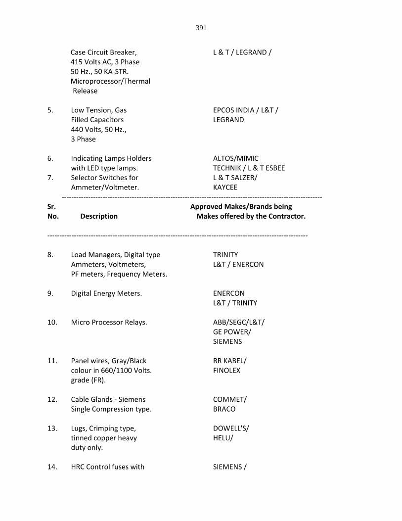
391
Case Circuit Breaker, L & T / LEGRAND / 415 Volts AC, 3 Phase 50 Hz., 50 KA-STR. Microprocessor/Thermal
Release 5. Low Tension, Gas EPCOS INDIA / L&T /
Filled Capacitors LEGRAND 440 Volts, 50 Hz., 3 Phase
6. Indicating Lamps Holders ALTOS/MIMIC
with LED type lamps. TECHNIK / L & T ESBEE 7. Selector Switches for L & T SALZER/
Ammeter/Voltmeter. KAYCEE ------------------------------------------------------------------------------------------------------------ Sr. Approved Makes/Brands being No. Description Makes offered by the Contractor. ------------------------------------------------------------------------------------------------------------ 8. Load Managers, Digital type TRINITY
Ammeters, Voltmeters, L&T / ENERCON PF meters, Frequency Meters.
9. Digital Energy Meters. ENERCON L&T / TRINITY 10. Micro Processor Relays. ABB/SEGC/L&T/ GE POWER/
SIEMENS 11. Panel wires, Gray/Black RR KABEL/
colour in 660/1100 Volts. FINOLEX grade (FR).
12. Cable Glands - Siemens COMMET/
Single Compression type. BRACO 13. Lugs, Crimping type, DOWELL'S/
tinned copper heavy HELU/ duty only.
14. HRC Control fuses with SIEMENS /
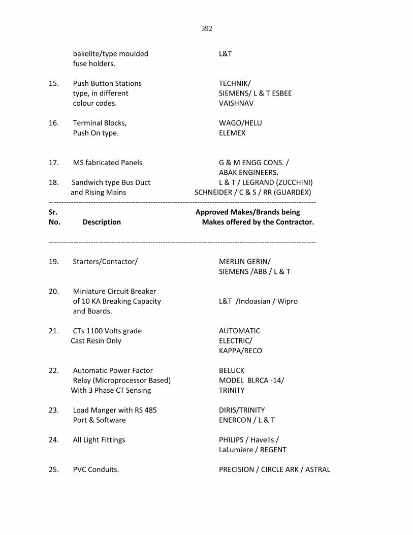
392
bakelite/type moulded L&T fuse holders.
15. Push Button Stations TECHNIK/
type, in different SIEMENS/ L & T ESBEE colour codes. VAISHNAV
16. Terminal Blocks, WAGO/HELU
Push On type. ELEMEX 17. MS fabricated Panels G & M ENGG CONS. /
ABAK ENGINEERS. 18. Sandwich type Bus Duct L & T / LEGRAND (ZUCCHINI) and Rising Mains SCHNEIDER / C & S / RR (GUARDEX) ------------------------------------------------------------------------------------------------------------ Sr. Approved Makes/Brands being No. Description Makes offered by the Contractor. ------------------------------------------------------------------------------------------------------------
19. Starters/Contactor/ MERLIN GERIN/
SIEMENS /ABB / L & T 20. Miniature Circuit Breaker
of 10 KA Breaking Capacity L&T /Indoasian / Wipro and Boards.
21. CTs 1100 Volts grade AUTOMATIC Cast Resin Only ELECTRIC/ KAPPA/RECO 22. Automatic Power Factor BELUCK
Relay (Microprocessor Based) MODEL BLRCA -14/ With 3 Phase CT Sensing TRINITY 23. Load Manger with RS 485 DIRIS/TRINITY Port & Software ENERCON / L & T 24. All Light Fittings PHILIPS / Havells / LaLumiere / REGENT 25. PVC Conduits. PRECISION / CIRCLE ARK / ASTRAL
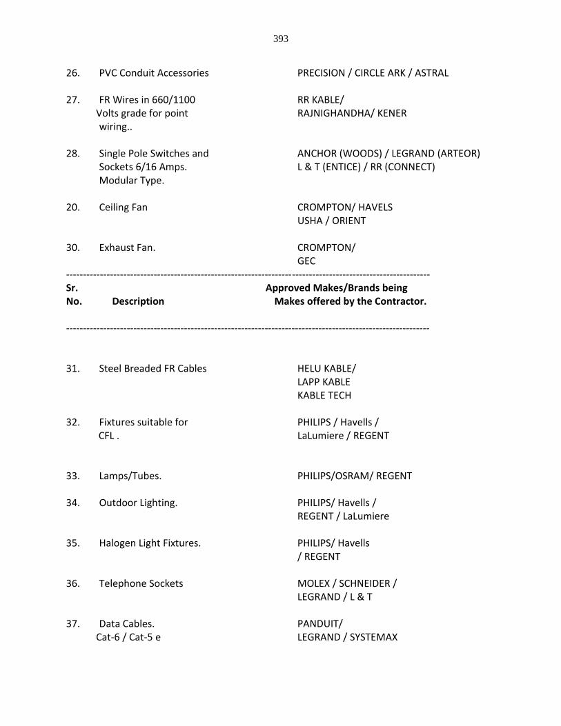
393
26. PVC Conduit Accessories PRECISION / CIRCLE ARK / ASTRAL 27. FR Wires in 660/1100 RR KABLE/ Volts grade for point RAJNIGHANDHA/ KENER
wiring.. 28. Single Pole Switches and ANCHOR (WOODS) / LEGRAND (ARTEOR)
Sockets 6/16 Amps. L & T (ENTICE) / RR (CONNECT) Modular Type.
20. Ceiling Fan CROMPTON/ HAVELS USHA / ORIENT 30. Exhaust Fan. CROMPTON/ GEC ------------------------------------------------------------------------------------------------------------ Sr. Approved Makes/Brands being No. Description Makes offered by the Contractor. ------------------------------------------------------------------------------------------------------------ 31. Steel Breaded FR Cables HELU KABLE/ LAPP KABLE KABLE TECH 32. Fixtures suitable for PHILIPS / Havells / CFL . LaLumiere / REGENT
33. Lamps/Tubes. PHILIPS/OSRAM/ REGENT 34. Outdoor Lighting. PHILIPS/ Havells / REGENT / LaLumiere 35. Halogen Light Fixtures. PHILIPS/ Havells
/ REGENT 36. Telephone Sockets MOLEX / SCHNEIDER /
LEGRAND / L & T 37. Data Cables. PANDUIT/ Cat-6 / Cat-5 e LEGRAND / SYSTEMAX
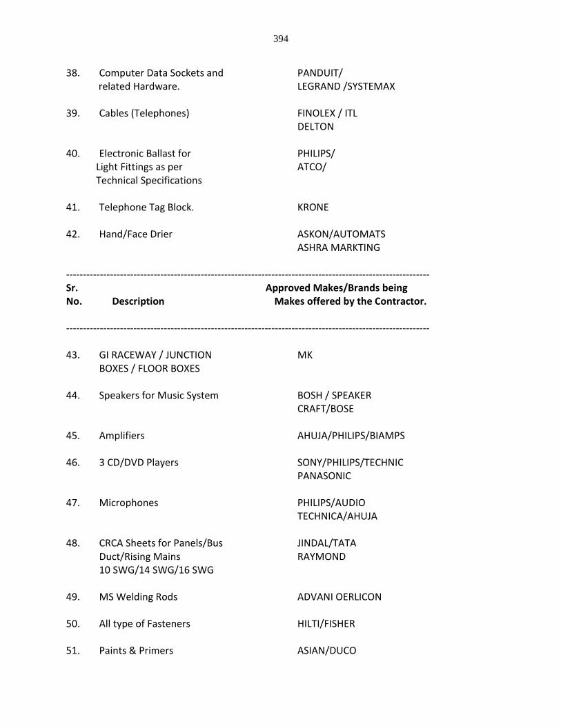
394
38. Computer Data Sockets and PANDUIT/ related Hardware. LEGRAND /SYSTEMAX 39. Cables (Telephones) FINOLEX / ITL DELTON 40. Electronic Ballast for PHILIPS/ Light Fittings as per ATCO/ Technical Specifications 41. Telephone Tag Block. KRONE 42. Hand/Face Drier ASKON/AUTOMATS ASHRA MARKTING ------------------------------------------------------------------------------------------------------------ Sr. Approved Makes/Brands being No. Description Makes offered by the Contractor. ------------------------------------------------------------------------------------------------------------ 43. GI RACEWAY / JUNCTION MK BOXES / FLOOR BOXES 44. Speakers for Music System BOSH / SPEAKER CRAFT/BOSE 45. Amplifiers AHUJA/PHILIPS/BIAMPS 46. 3 CD/DVD Players SONY/PHILIPS/TECHNIC PANASONIC 47. Microphones PHILIPS/AUDIO TECHNICA/AHUJA 48. CRCA Sheets for Panels/Bus JINDAL/TATA Duct/Rising Mains RAYMOND
10 SWG/14 SWG/16 SWG 49. MS Welding Rods ADVANI OERLICON 50. All type of Fasteners HILTI/FISHER 51. Paints & Primers ASIAN/DUCO
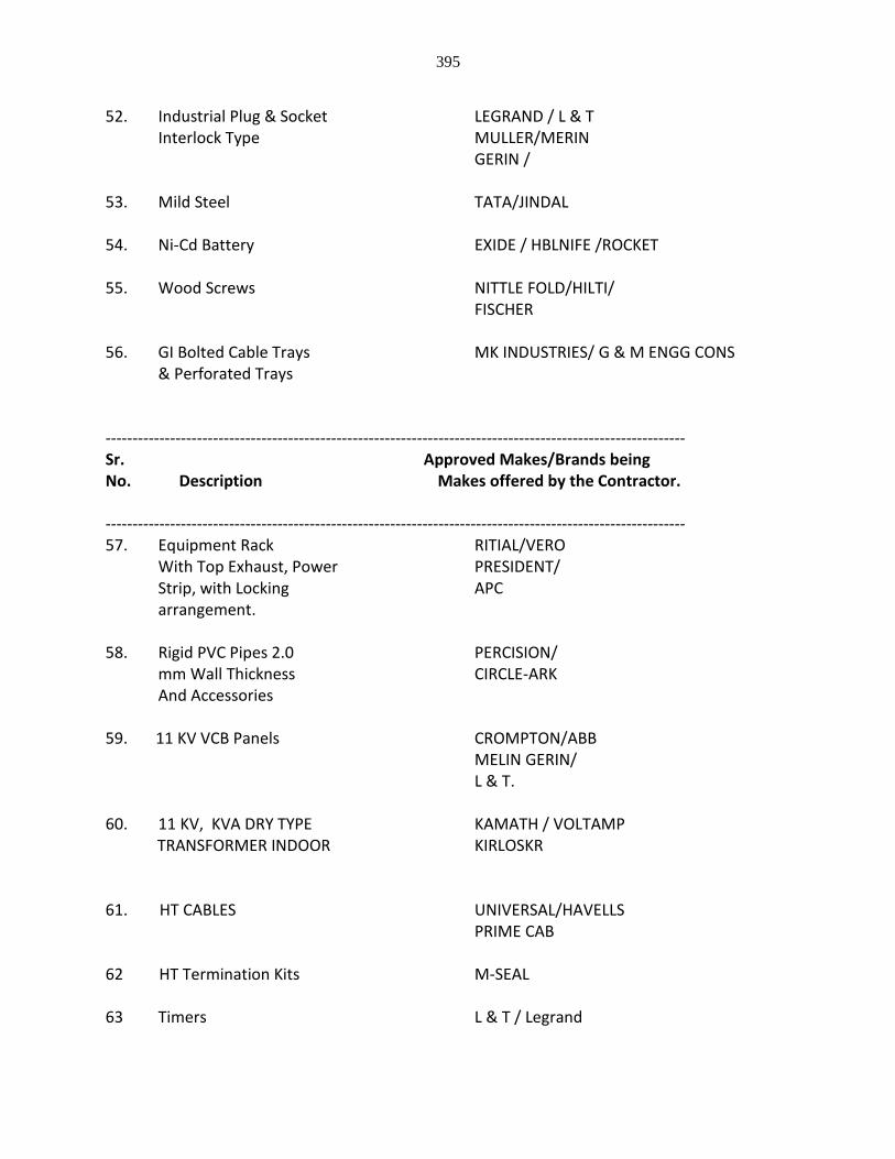
395
52. Industrial Plug & Socket LEGRAND / L & T Interlock Type MULLER/MERIN
GERIN / 53. Mild Steel TATA/JINDAL 54. Ni-Cd Battery EXIDE / HBLNIFE /ROCKET 55. Wood Screws NITTLE FOLD/HILTI/ FISCHER 56. GI Bolted Cable Trays MK INDUSTRIES/ G & M ENGG CONS & Perforated Trays ------------------------------------------------------------------------------------------------------------ Sr. Approved Makes/Brands being No. Description Makes offered by the Contractor. ------------------------------------------------------------------------------------------------------------ 57. Equipment Rack RITIAL/VERO With Top Exhaust, Power PRESIDENT/ Strip, with Locking APC arrangement. 58. Rigid PVC Pipes 2.0 PERCISION/
mm Wall Thickness CIRCLE-ARK And Accessories
59. 11 KV VCB Panels CROMPTON/ABB MELIN GERIN/ L & T. 60. 11 KV, KVA DRY TYPE KAMATH / VOLTAMP TRANSFORMER INDOOR KIRLOSKR 61. HT CABLES UNIVERSAL/HAVELLS PRIME CAB 62 HT Termination Kits M-SEAL 63 Timers L & T / Legrand
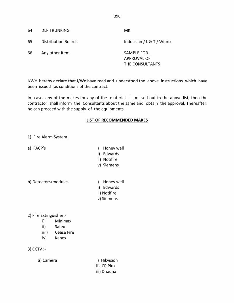
396
64 DLP TRUNKING MK 65 Distribution Boards Indoasian / L & T / Wipro 66 Any other Item. SAMPLE FOR APPROVAL OF THE CONSULTANTS I/We hereby declare that I/We have read and understood the above instructions which have been issued as conditions of the contract. In case any of the makes for any of the materials is missed out in the above list, then the contractor shall inform the Consultants about the same and obtain the approval. Thereafter, he can proceed with the supply of the equipments.
LIST OF RECOMMENDED MAKES
1) Fire Alarm System a) FACP’s i) Honey well ii) Edwards
iii) Notifire iv) Siemens
b) Detectors/modules i) Honey well ii) Edwards
iii) Notifire iv) Siemens
2) Fire Extinguisher:- i) Minimax ii) Safex iii ) Cease Fire iv) Kanex 3) CCTV :- a) Camera i) Hikvision ii) CP Plus iii) Dhauha
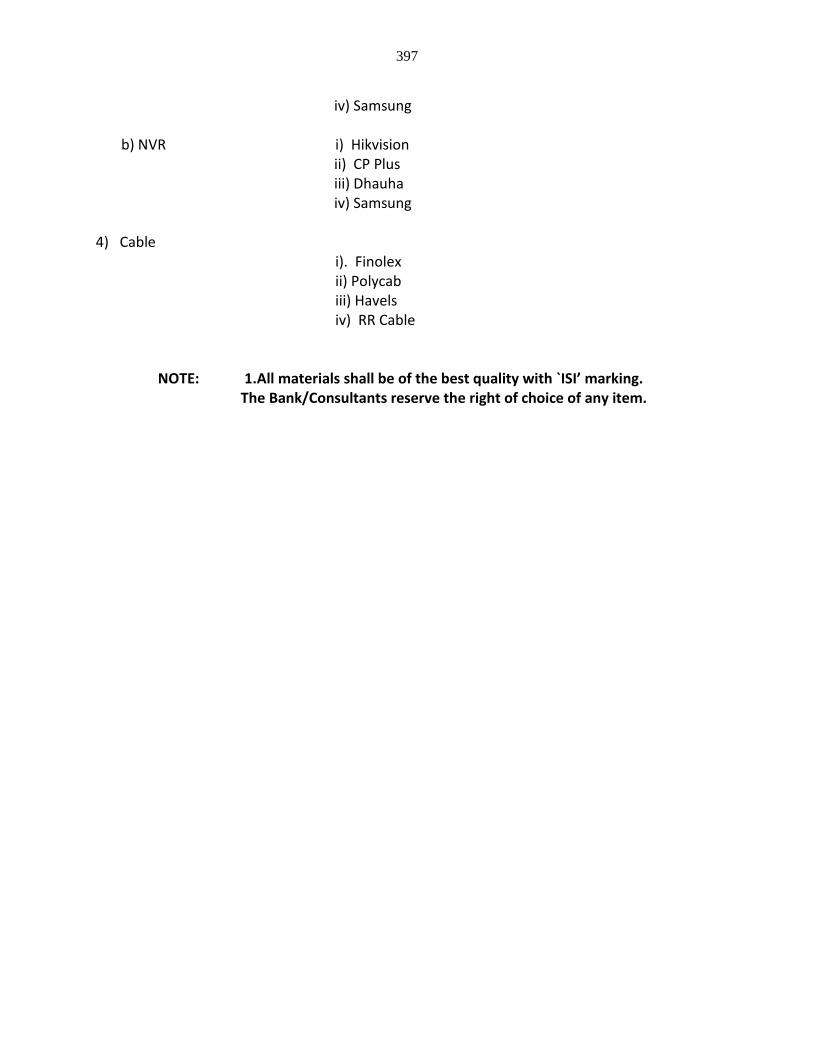
397
iv) Samsung b) NVR i) Hikvision ii) CP Plus iii) Dhauha iv) Samsung 4) Cable i). Finolex ii) Polycab iii) Havels iv) RR Cable
NOTE: 1.All materials shall be of the best quality with `ISI’ marking. The Bank/Consultants reserve the right of choice of any item.