index - reserve bank of india
TRANSCRIPT
Corrections - Nil
Insertions - Nil
Omissions - Nil AE(P) EE(P)/Civil EE(P)/Elect
Page 1
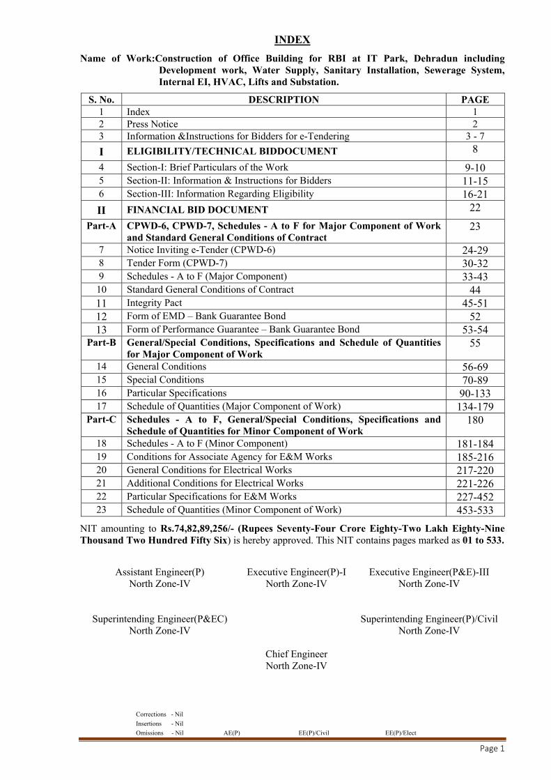
INDEX
Name of Work:Construction of Office Building for RBI at IT Park, Dehradun including Development work, Water Supply, Sanitary Installation, Sewerage System, Internal EI, HVAC, Lifts and Substation.
S. No. DESCRIPTION PAGE 1 Index 1 2 Press Notice 2 3 Information &Instructions for Bidders for e-Tendering 3 - 7
I ELIGIBILITY/TECHNICAL BIDDOCUMENT 8
4 Section-I: Brief Particulars of the Work 9-10 5 Section-II: Information & Instructions for Bidders 11-15 6 Section-III: Information Regarding Eligibility 16-21
II FINANCIAL BID DOCUMENT 22
Part-A CPWD-6, CPWD-7, Schedules - A to F for Major Component of Work and Standard General Conditions of Contract
23
7 Notice Inviting e-Tender (CPWD-6) 24-29 8 Tender Form (CPWD-7) 30-32 9 Schedules - A to F (Major Component) 33-43 10 Standard General Conditions of Contract 44 11 Integrity Pact 45-51 12 Form of EMD – Bank Guarantee Bond 52 13 Form of Performance Guarantee – Bank Guarantee Bond 53-54
Part-B General/Special Conditions, Specifications and Schedule of Quantities for Major Component of Work
55
14 General Conditions 56-69 15 Special Conditions 70-89 16 Particular Specifications 90-133 17 Schedule of Quantities (Major Component of Work) 134-179
Part-C Schedules - A to F, General/Special Conditions, Specifications and Schedule of Quantities for Minor Component of Work
180
18 Schedules - A to F (Minor Component) 181-184 19 Conditions for Associate Agency for E&M Works 185-216 20 General Conditions for Electrical Works 217-220 21 Additional Conditions for Electrical Works 221-226 22 Particular Specifications for E&M Works 227-452 23 Schedule of Quantities (Minor Component of Work) 453-533
NIT amounting to Rs.74,82,89,256/- (Rupees Seventy-Four Crore Eighty-Two Lakh Eighty-Nine Thousand Two Hundred Fifty Six) is hereby approved. This NIT contains pages marked as 01 to 533.
Assistant Engineer(P) North Zone-IV
Executive Engineer(P)-I North Zone-IV
Executive Engineer(P&E)-III North Zone-IV
Superintending Engineer(P&EC) North Zone-IV
Superintending Engineer(P)/Civil North Zone-IV
Chief Engineer North Zone-IV

Corrections - Nil
Insertions - Nil
Omissions - Nil AE(P) EE(P)/Civil EE(P)/Elect
Page 2
PRESS NOTICE
CENTRAL PUBLIC WORKS DEPARTMENT
NOTICE INVITING e-TENDERS
The Executive Engineer, Dehradun Central Division-I, Central Public Works Department, 20-Subhash
Road, Dehradun-248001 invites on behalf of President of India online percentage rate bidsfrom
approved and eligible contractors of CPWD enlisted in appropriate class of composite category and
eligible firms/contractors of repute in two bid systemfor following work:
NIT No.: 239/EE/DCD-I/2018-19/CE NZ-IV Name of Work: Construction of Office Building for RBI
at IT Park, Dehradun including Development work, Water Supply, Sanitary Installation, Sewerage
System, Internal EI, HVAC, Lifts and Substation.,Estimated Cost: Rs. 74,82,89,256/- (Civil work Rs.
60,15,68,911/- + Rs. 14,67,20,345/- Elect. work), Earnest money: Rs. 84,82,893/-, Period of
completion: 24 (Twenty Four) months, Last time and date of submission of bid : 15:00 Hrs on
01/01/2019. Date & Time of opening of Technical bid: At 15:30 Hrs. on 01/01/2019.
Pre-bid conference will be held on 21/12/2018 at 12.00 hrs. in conference room of O/o Chief Engineer
(NZ-IV), CPWD, 20-Subhash Road, Dehradun.
The tender forms and other details can be obtained from the websiteswww.tenderwizard.com/CPWD
or www.cpwd.gov.in or www.eprocure.gov.in& also at rbi website www.rbi.org.in
Assistant Engineer(P)
North Zone-IV
Executive Engineer(P-I)
North Zone-IV
Executive Engineer(P&E)-III
North Zone-IV
Superintending Engineer(P&EC)
North Zone-IV
Superintending Engineer(P)/Civil
North Zone-IV
Chief Engineer
North Zone-IV
Corrections - Nil
Insertions - Nil
Omissions - Nil AE(P) EE(P)/Civil EE(P)/Elect
Page 3
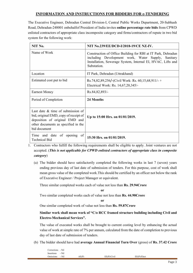
INFORMATION AND INSTRUCTIONS FOR BIDDERS FOR e-TENDERING
The Executive Engineer, Dehradun Central Division-I, Central Public Works Department, 20-Subhash
Road, Dehradun-248001 onbehalfof President of India invites online percentage rate bids from CPWD
enlisted contractors of appropriate class incomposite category and firms/contractors of repute in two bid
system for the following work:
NIT No. NIT No.239/EE/DCD-I/2018-19/CE NZ-IV.
Name of Work Construction of Office Building for RBI at IT Park, Dehradun including Development work, Water Supply, Sanitary Installation, Sewerage System, Internal EI, HVAC, Lifts and Substation.
Location IT Park, Dehradun (Uttrakhand)
Estimated cost put to bid Rs.74,82,89,256/‐(Civil Work: Rs. 60,15,68,911/- + Electrical Work: Rs. 14,67,20,345/-
Earnest Money Rs.84,82,893/-
Period of Completion 24 Months
Last date & time of submission of bid, original EMD, copy of receipt of deposition of original EMD and other documents as specified in the bid document
Up to 15:00 Hrs. on 01/01/2019.
Time and date of opening of Technical Bid
15:30 Hrs. on 01/01/2019.
1. Contractors who fulfill the following requirements shall be eligible to apply. Joint ventures are not
accepted. (This is not applicable for CPWD enlisted contractors of appropriate class in composite
category)
(a) The bidder should have satisfactorily completed the following works in last 7 (seven) years
ending previous day of last date of submission of tenders. For this purpose, cost of work shall
mean gross value of the completed work.This should be certified by an officer not below the rank
of Executive Engineer / Project Manager or equivalent.
Three similar completed works each of value not less than Rs. 29.94Crore
or
Two similar completed works each of value not less than Rs. 44.90Crore
or
One similar completed work of value not less than Rs. 59.87Crore
Similar work shall mean work of “C/o RCC framed structure building including Civil and
Electro-Mechanical Services”.
The value of executed works shall be brought to current costing level by enhancing the actual
value of work at simple rate of 7% per annum, calculated from the date of completion to previous
day of last date of submission of tenders.
(b) The bidder should have had average Annual Financial Turn Over (gross) of Rs. 37.42 Crore

Corrections - Nil
Insertions - Nil
Omissions - Nil AE(P) EE(P)/Civil EE(P)/Elect
Page 4
on civil/electrical construction work during the last three consecutive years balance sheets duly
audited by Charted Accountant. Yearinwhichnoturnoveris shown would also be considered for
working out theaverage.
(c) The bidder should not have incurred any loss (profit after tax should be positive) in more than
two years during the available last five consecutive balance sheets duly audited and certified by
Charted Accountant.
(d) The bidder should have a solvency of Rs. 29.94 Crore certified by his Bankers.
2. The intending bidder must read the terms and conditions of CPWD-6 carefully. He should only
submit his bid if he considers himself eligible and he is in possession of all the documents required.
3. Information and instructions for bidders posted on website shall form part of bid document.
4. The bid document consisting of plans, specifications, schedule of quantities of various types of items
to be executed and the set of terms & conditions of the contract to be complied with and other
necessary documents can be seen and downloaded from website www.tenderwizard.com/CPWD
or www.eprocure.gov.in free of cost.
5. But the bid can only be submitted after deposition oforiginal EMD deposited either in the office of
Executive Engineer inviting bids or division office of any Executive Engineer, CPWD within the
period of bid submission and uploading the mandatory scanned documents such as Demand Draft or
Pay Order or Banker’s Cheque or Deposit at Call Receipt or Fixed deposit Receipts and Bank
Guarantee of any scheduled Bank towards EMD in favour of Executive Engineer as mentioned in
NIT, receipt for deposition of Original EMD to division office of any Executive Engineer (including
NIT issuing EE/AE), CPWD and other documents as specified.
6. Those Bidders not registered on the website mentioned above, are required to get registered
themselves beforehand. If needed they can be imparted training on online bidding process as per
details available on the website.
7. The intending bidder must have valid class-III digital signature to submit the bid.
8. On opening date, the bidder can login and see the bid opening process. After opening of bids, he will
receive the competitor bid sheets.
9. Bidder can upload documents in the form of JPG format and PDF format.
10. Certificate of Financial Turn Over: At the time of submission of bid, bidder may upload
affidavit/certificate from CA mentioning Financial Turn Over of last 5 years or for the period as
specified in the bid document and further details if required may be asked from the contractor after
opening of Technical bids. There is no need to upload entire voluminous balance sheet.
11. Bidder must ensure to quote rate of each item. The column meant for quoting rate in figures appears
in pink colour and the moment rate is entered, it turns sky blue. In addition to this, while selecting
any of the cells a warning appears that if any cell is left blank the same shall be treated as “0”.
Therefore, if any cell is left blank and no rate is quoted by the bidder, rate of such item shall be treated
as “0” (Zero).
However, if a tenderer quotes nil rates against each item in item rate tender or does not quote any percentage above/below on the lowest amount of the tender or any section/sub-head in percentage rate tender, the tender shall be treated as invalid and will not be considered as lowest tenderer.
12. The eligibility (Technical) bid shall be opened first on due date and time as mentioned above. The
Corrections - Nil
Insertions - Nil
Omissions - Nil AE(P) EE(P)/Civil EE(P)/Elect
Page 5
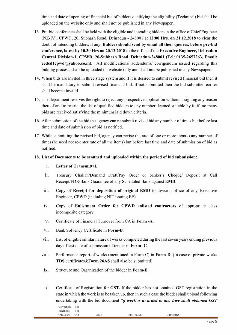
time and date of opening of financial bid of bidders qualifying the eligibility (Technical) bid shall be
uploaded on the website only and shall not be published in any Newspaper.
13. Pre-bid conference shall be held with the eligible and intending bidders in the office ofChief Engineer
(NZ-IV), CPWD, 20, Subhash Road, Dehradun - 248001 at 12:00 Hrs. on 21.12.2018 to clear the
doubt of intending bidders, if any. Bidders should send by email all their queries, before pre-bid
conference, latest by 10.30 Hrs on 20.12.2018 to the office of the Executive Engineer, Dehradun
Central Division-1, CPWD, 20-Subhash Road, Dehradun-248001 (Tel: 0135-2657263, Email:
[email protected]). All modifications/ addendums/ corrigendum issued regarding this
bidding process, shall be uploaded on website only and shall not be published in any Newspaper.
14. When bids are invited in three stage system and if it is desired to submit revised financial bid then it
shall be mandatory to submit revised financial bid. If not submitted then the bid submitted earlier
shall become invalid.
15. The department reserves the right to reject any prospective application without assigning any reason
thereof and to restrict the list of qualified bidders to any number deemed suitable by it, if too many
bids are received satisfying the minimum laid down criteria.
16. After submission of the bid the agency can re-submit revised bid any number of times but before last
time and date of submission of bid as notified.
17. While submitting the revised bid, agency can revise the rate of one or more item(s) any number of
times (he need not re-enter rate of all the items) but before last time and date of submission of bid as
notified.
18. List of Documents to be scanned and uploaded within the period of bid submission:
i. Letter of Transmittal.
ii. Treasury Challan/Demand Draft/Pay Order or banker’s Cheque/ Deposit at Call
Receipt/FDR/Bank Guarantee of any Scheduled Bank against EMD.
iii. Copy of Receipt for deposition of original EMD to division office of any Executive
Engineer, CPWD (including NIT issuing EE).
iv. Copy of Enlistment Order for CPWD enlisted contractors of appropriate class
incomposite category.
v. Certificate of Financial Turnover from CA in Form -A.
vi. Bank Solvency Certificate in Form-B.
vii. List of eligible similar nature of works completed during the last seven years ending previous
day of last date of submission of tender in Form -C.
viii. Performance report of works (mentioned in Form-C) in Form-D. (In case of private works
TDS certificates&Form 26AS shall also be submitted).
ix. Structure and Organization of the bidder in Form-E
x. Certificate of Registration for GST. If the bidder has not obtained GST registration in the
state in which the work is to be taken up, then in such a case the bidder shall upload following
undertaking with the bid document “if work is awarded to me, I/we shall obtained GST

Corrections - Nil
Insertions - Nil
Omissions - Nil AE(P) EE(P)/Civil EE(P)/Elect
Page 6
registration certificate within one month from date of receipt of award letter or before
payment of 1st RA bill.”.
xi. Any other document as specified in the press notice.
Note: Documents at Sl. No. i and v to ix are not required to be submitted by CPWD
contractors enlisted in appropriate class of composite category. Sl. No. (IV) is
applicable only for CPWD contractors enlisted in appropriate class of composite
category.
Signature of the Divisional Officer,
For and on behalf of the President of India
Corrections - Nil
Insertions - Nil
Omissions - Nil AE(P) EE(P)/Civil EE(P)/Elect
Page 7
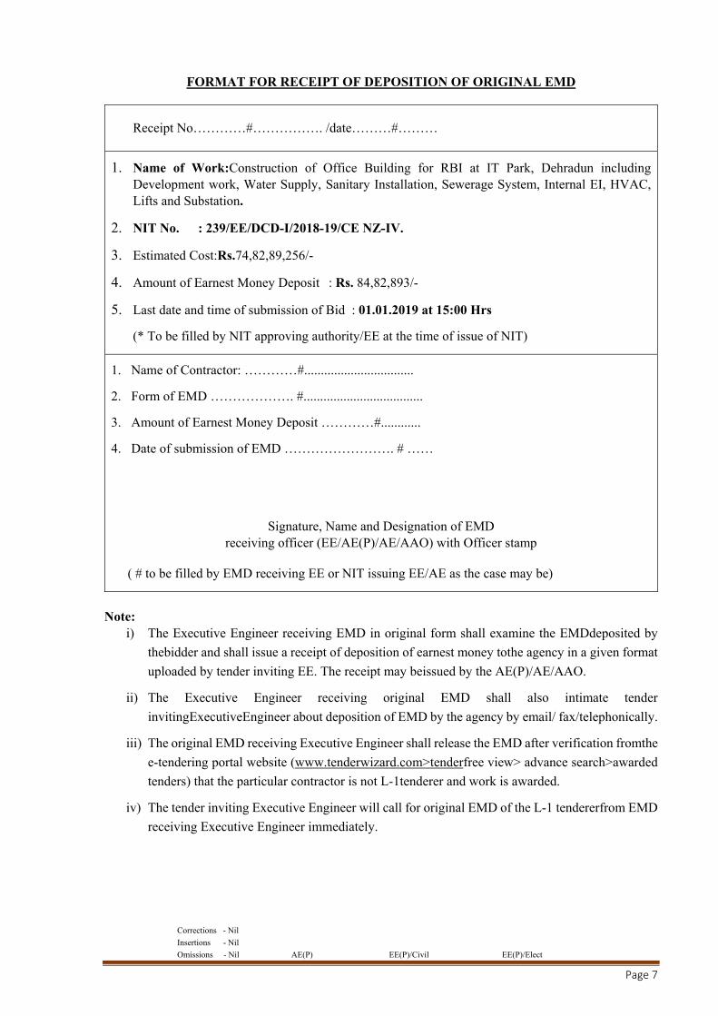
FORMAT FOR RECEIPT OF DEPOSITION OF ORIGINAL EMD
Receipt No…………#……………. /date………#………
1. Name of Work:Construction of Office Building for RBI at IT Park, Dehradun including Development work, Water Supply, Sanitary Installation, Sewerage System, Internal EI, HVAC, Lifts and Substation.
2. NIT No. : 239/EE/DCD-I/2018-19/CE NZ-IV.
3. Estimated Cost:Rs.74,82,89,256/-
4. Amount of Earnest Money Deposit : Rs. 84,82,893/-
5. Last date and time of submission of Bid : 01.01.2019 at 15:00 Hrs
(* To be filled by NIT approving authority/EE at the time of issue of NIT)
1. Name of Contractor: …………#.................................
2. Form of EMD ………………. #....................................
3. Amount of Earnest Money Deposit …………#............
4. Date of submission of EMD ……………………. # ……
Signature, Name and Designation of EMD
receiving officer (EE/AE(P)/AE/AAO) with Officer stamp
( # to be filled by EMD receiving EE or NIT issuing EE/AE as the case may be)
Note:
i) The Executive Engineer receiving EMD in original form shall examine the EMDdeposited by
thebidder and shall issue a receipt of deposition of earnest money tothe agency in a given format
uploaded by tender inviting EE. The receipt may beissued by the AE(P)/AE/AAO.
ii) The Executive Engineer receiving original EMD shall also intimate tender
invitingExecutiveEngineer about deposition of EMD by the agency by email/ fax/telephonically.
iii) The original EMD receiving Executive Engineer shall release the EMD after verification fromthe
e-tendering portal website (www.tenderwizard.com>tenderfree view> advance search>awarded
tenders) that the particular contractor is not L-1tenderer and work is awarded.
iv) The tender inviting Executive Engineer will call for original EMD of the L-1 tendererfrom EMD
receiving Executive Engineer immediately.

Corrections - Nil
Insertions - Nil
Omissions - Nil AE(P) EE(P)/Civil EE(P)/Elect
Page 8
ELIGIBILITY BID
(TECHNICAL BID)
DOCUMENT
Corrections - Nil
Insertions - Nil
Omissions - Nil AE(P) EE(P)/Civil EE(P)/Elect
Page 9
SECTION - I
BRIEF PRTICULARS OF THE WORK
1. Salient details of the work for which tenders are invited are asunder:
Name of work:Construction of Office Building for RBI at IT Park, Dehradun including
Development work, Water Supply, Sanitary Installation, Sewerage System, Internal EI, HVAC, Lifts
and Substation
Estimated cost: Rs. 74,82,89,256/- Civil work: Rs. 60,15,68,911/- Electrical Work: Rs.
14,67,20,345/-
Period of completion: 24 Months.
2. The work is situated at Plot no. 16-17, IT park, Dehradun (Uttarakhand).
PROJECT DESCRIPTION
It is proposed to develop an office Complex for Reserve Bank of India at IT Park, Sahastradhara Road, Dehradun, Uttarakhand. The Complex will consist of highly secured Vault in the campus and related spaces, Public dealing staff, Annex Block, Separated Multi Storied parking system & residence block
Location - Plot no. 16-17, IT park, Dehradun (Uttarakhand).
Plot Area - 17989 sqm (approx).
Total Built up Area – 15524 sqm (approx)
The Complex will consist of:
a) MAIN BUILDING BLOCK - (Vault +2 levels) – Main Building Block consist the high security currency Vault with independent access to the Vault Level. This floor consists of a safety yard, 9m high Vault, Guard rooms and their accommodations, maintenance room, CVPS, Lumber room, Shredding and Briquetting Area. And on ground floor, Public related functions like double height Public Hall, Ombudsman office, Issuing and banking Dept, Executive dining etc are located. First floor is dedicatedly for RBI staff and accommodates Admin & Infrastructure dept, Regional director’s office, Supervisor MI& R, FIDD + CEPD staff, Training Hall and Library.
b) RESIDENCE BLOCK (G+1 level) – Three residential flats have been designed in this block, one
on the ground floor with 2 BHK and two flats on first floor with 1 BHK with a study room in each. Provision for two more floors or two flats on upper floor has been kept for future development.
c) PARKING BLOCK - (G+3) – This is design to accommodate the parking requirement. This is a 3-storied block with 2.7 m floor to floor height. Parking block consist two-way ramp and one car lift for smooth movement of cars.
d) ANNEXE BLOCK - (G+1) – This accommodates Services mainly HVAC and STP at Vault floor level but with a separate entrance. Electrical panel room and UPS & Battery room are on Ground.
e) SECURITY BLOCK(Ground)– Located near the main entrance to the site.
Corrections - Nil
Insertions - Nil
Omissions - Nil AE(P) EE(P)/Civil EE(P)/Elect
Page 10
3. General features and major components of the work are as under:
(i) Building shall be of RCC framed structure.
(ii) Building is targeted to achieve IGBC platinum green rating with all material and other
parameters covered under IGBC to be followed.
(iii) The Walls are built using FAL-G blocks with insulation accommodated in a cavity. All
External Door, Windows and Ventilators frames shall be of Thermal Break Aluminum
profile.Low- E Glass (DGU) toughened used on all external wall windows.Vitrified tile
flooring, Ceramic tile flooring and Kota stone flooring shall be laid as per architectural
drawings and detailed specifications.
(iv) Electrical works, Plumbing works, Firefighting works, Lifts, HVAC works, Security
related works shall be carried out as specified in drawings and specifications.
(v) The Soil report, location plan, master plan, services layout plan, building plans &
elevations are available with EE, DCD1, Dehradun for inspection.
Corrections - Nil
Insertions - Nil
Omissions - Nil AE(P) EE(P)/Civil EE(P)/Elect
Page 11
SECTION-II
INFORMATION & INSTRUCTIONS FOR BIDDERS
1.0 General:
1.1 Letter of transmittal and forms for deciding eligibility are given in Section III.
1.2 All information called for in the enclosed forms should be furnished against the
relevant columns in the forms. If for any reason, information is furnished on a separate
sheet, this fact should be mentioned against the relevant column. Even, if no information is
to be provided in a column, a ‘nil’ or ‘no such case’ entry should be made in that column.
If any particulars/query is not applicable in case of the bidder, it should be stated as ‘Not
applicable’. The bidders are cautioned that not giving complete information called for in
the application forms or not giving it in clear terms or making any change in the prescribed
forms (or) deliberately suppressing the information may result in the bid being summarily
disqualified. Bidsshall be submitted online only and those received in physical form, by
telegram or telex and those received late will not be entertained.
1.3 The bid should be type written. The bidder should sign each page of application, forms and
documents before scanning & uploading.
1.4 Over writing should be avoided. Corrections if any should be made by neatly crossing out,
initialing, dating and rewriting. Pages of the eligibility criteria document are numbered.
Additional Sheets if any added by the Bidder should also be numbered by him. They should
be submitted as a package with signed letter of transmittal.
1.5 References, information and certificate from the respective clients certifying suitability,
technical knowledge or capability of the bidder should be signed by an officer not below the
rank of Executive Engineer or equivalent.
1.6 The bidder may furnish any additional information, which he thinks is necessary to establish
his capabilities to successfully complete envisaged work. He is, however advised not to
furnish superfluous information. No information shall be entertained after submission of
eligibility criteria document unless it is called for by the Employer.
2.0 Definitions:
2.1 In this document the following words and expression have their meaning here by assigned
to them.
2.2 Employer:Means the President of India, acting through the Executive Engineer, Dehradun
Central Division-I, CPWD, Dehradun.
2.3 Bidder:Means the individual, proprietary firm, firm in partnership, limited company (private
or public) or corporation.
2.4 “Year” means “Financial year” unless stated otherwise.
3.0 Method of Application:
3.1 If the bidder is an individual, the application shall be signed by him above his/her full type
written name and current address.
3.2 If the bidder is a proprietary firm; the application shall be signed by the proprietor above
Corrections - Nil
Insertions - Nil
Omissions - Nil AE(P) EE(P)/Civil EE(P)/Elect
Page 12
his/her full type written name and the full name of his firm with its current address.
3.3 If the bidder is a firm in partnership, the application shall be signed by all the partners of the
firm above their full type written names and current addresses or alternatively by a partner
holding power of attorney for the firm. In the latter case a certified copy of the power of
attorney should accompany the application. In both the cases a certified copy of the
partnership deed and current address of all the partners of the firm should accompany the
application.
3.4 If the bidder is a limited company or a corporation, the bid shall be signed by a duly
authorized person holding power of attorney for signing the application and certified copy
of such power of attorney shall also be furnished. The bidder should also furnish a copy of
memorandum of articles of association duly attested by a Public Notary.
4.0 Final Decision-Making Authority:
The Employer reserves the right to accept or reject any bid and to annul the process and reject all bids at any time without assigning any reason or incurring any liability to the bidders.
5.0 Particulars – Provisional:
The particulars of the work given in section - I are provisional. They are liable to change and must be considered only as advance information to assist the bidder.
6.0 Site Visit:
The bidder is advised to visit the site of work, at his own cost, and examine it and its surroundings to himself collect all information that he considers necessary for proper assessment of the prospective assignment.
7.0 Initial Criteria for Eligibility:
Contractors who fulfill the following requirements shall be eligible to apply. Joint ventures are
not accepted. (This is not applicable for CPWD enlisted contractors of appropriate class in
composite category):
7.1 The bidder should have satisfactorily completed the following works in last 7 (seven)
years ending previous day of last date of submission of tenders. For this purpose, cost of
work shall mean gross value of the completed work.This should be certified by an officer
not below the rank of Executive Engineer / Project Manager or equivalent.
Three similar completed works each of value not less than Rs. 29.94 Crore
or
Two similar completed works each of value not less than Rs. 44.90 Crore
or
One similar completed work of value not less than Rs. 59.87 Crore
Similar work shall mean work of “C/o RCC framed structure building including
Civil and Electro-Mechanical Services”.
The value of executed works shall be brought to current costing level by enhancing the
actual value of work at simple rate of 7% per annum, calculated from the date of
completion to previous day of last date of submission of tenders.
7.2 The bidder should have had average Annual Financial Turn Over(gross) of Rs. 37.42
Crore on civil/electrical construction work during the last three consecutiveyearsbalance

Corrections - Nil
Insertions - Nil
Omissions - Nil AE(P) EE(P)/Civil EE(P)/Elect
Page 13
sheets duly audited by Charted Accountant. Yearinwhichnoturnoveris shown would also
be considered for working out theaverage.
7.3 The bidder should not have incurred any loss (profit after tax should be positive) in
more than two years during the available last five consecutive balance sheets duly
audited and certified by Charted Accountant.
7.4 The bidder should have a solvency of Rs. 29.94 Crore certified by his Bankers.
7.5 The bidder should have sufficient number of Technical and Administrative employees
for the proper execution of the contract. The bidder should submit a list of these
employees stating clearly how they would be involved in this work within 15 days of
award of work.
8.0 Evaluation Criteria for Technical Qualification:
8.1 The detailed submitted by the bidders will be evaluated in the followingmanner:
CPWD enlisted contractors of appropriate class in composite category will not be
required to be evaluated for eligibility and they will be directly shortlisted for opening
of financial bid)
8.1.1 The initial criteria prescribed in para 7.0above in respect of experience of eligible similar
class of works completed, loss, solvency and financial turn over etc. will first be
scrutinized and the bidder’s eligibility for the work be determined.
8.1.2 The bidder’s qualifying the initial criteria as set out in para 7.0 abovewill be evaluated
for following criteria by scoring method (Annexure-I/page-15) on the basis of details
furnished by them:
a) Financial strength (Form ‘A’ & ‘B’) Maximum 20 Marks
(i) Turnover 16 Marks
(ii) Solvency 04 Marks
b) Experience in eligible similar nature of work during
last 7 years (Form ‘C’)
Maximum 20 Marks
c) Performance on works (Form ‘D’) - Time overrun Maximum 20 Marks
d) Performance on works (Form ‘D’) - Quality Maximum 40 Marks
Total (Maximum) Marks 100 Marks
To become eligible for short listing for opening of financial bid, the bidder must secure
at least 50% (Fifty percent) marks in each (section a, b, c and d) of the above criteria and
60% (Sixty percent) marks in aggregate.
The department, however reserves the right to restrict the list of such qualified bidders
to any number deemed suitable by it.
Note: The average value of performance of works for time over run and quality
shall be taken on the basis of performance report of the eligible similar
works.
Corrections - Nil
Insertions - Nil
Omissions - Nil AE(P) EE(P)/Civil EE(P)/Elect
Page 14
9.0 Financial Information:
Bidder should furnish the following financial information:
9.1 Annual financial statement for the last Five years in Form ‘A’ and Solvency certificate
in Form ’B’
10.0 Experiences in Works Highlighting Experience in Similar Works:
10.1 Bidder should furnish list of all eligible similar nature of works successfully completed
during last Seven years in Form ‘C’
10.2 Performance reportof each workreferred to in Form ‘C’ certified by an officer not below
the rank of Executive Engineer / Project Manager or equivalent.
10.3 If eligible similar nature of works areexecuted for private firms, certified copy of the tax
deducted at source certificate (TDS) and Form 26AS shall also be furnished along with
the Performance report.
11.0 Organization Information:
Bidder is required to submit the information in respect of his organization in Form- ‘E’.
12.0 Letter of Transmittal:
The Bidder should submit the letter of transmittal attached with the document.
13.0 Opening of Price Bid:
After evaluation of applicants, a list of short listed agencies will be prepared. Thereafter the
financial bids of only the qualified and technically acceptable bidders shall be opened at the
notified time, date and place in the presence of the qualified bidders or their representatives. The
bid shall remain valid for 90 (Ninety) days from the date of opening of Technical bid (eligibility
bid).
14.0 Award criteria:
14.1 The employer reserves the right, without being liable for any damages or obligation to
inform the bidder to :
(a) Amend the scope and value of contract to the bidder.
(b) Reject any or all the applications without assigning any reason.
14.2 Any effort on the part of the bidder or his agent to exercise influence or to pressurize the
employer would result in rejection of his bid. Canvassing of any kind is prohibited.
Corrections - Nil
Insertions - Nil
Omissions - Nil AE(P) EE(P)/Civil EE(P)/Elect
Page 15
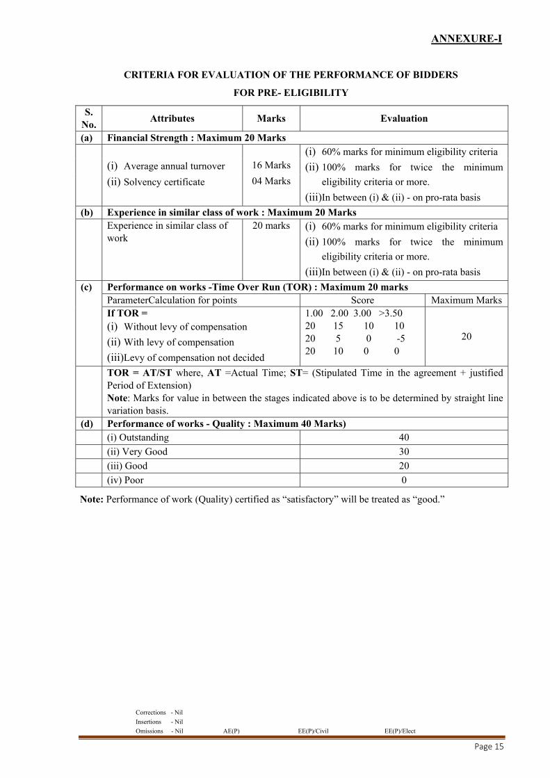
ANNEXURE-I
CRITERIA FOR EVALUATION OF THE PERFORMANCE OF BIDDERS
FOR PRE- ELIGIBILITY
S. No.
Attributes Marks Evaluation
(a) Financial Strength : Maximum 20 Marks (i) 60% marks for minimum eligibility criteria
(ii) 100% marks for twice the minimum
eligibility criteria or more.
(iii)In between (i) & (ii) - on pro-rata basis
(i) Average annual turnover 16 Marks
(ii) Solvency certificate 04 Marks
(b) Experience in similar class of work : Maximum 20 Marks Experience in similar class of
work 20 marks (i) 60% marks for minimum eligibility criteria
(ii) 100% marks for twice the minimum
eligibility criteria or more.
(iii)In between (i) & (ii) - on pro-rata basis (c) Performance on works -Time Over Run (TOR) : Maximum 20 marks
ParameterCalculation for points Score Maximum Marks If TOR = (i) Without levy of compensation
(ii) With levy of compensation
(iii)Levy of compensation not decided
1.00 2.00 3.00 >3.50 20 15 10 10 20 5 0 -5 20 10 0 0
20
TOR = AT/ST where, AT =Actual Time; ST= (Stipulated Time in the agreement + justified Period of Extension) Note: Marks for value in between the stages indicated above is to be determined by straight line variation basis.
(d) Performance of works - Quality : Maximum 40 Marks) (i) Outstanding 40 (ii) Very Good 30 (iii) Good 20 (iv) Poor 0
Note: Performance of work (Quality) certified as “satisfactory” will be treated as “good.”

Corrections - Nil
Insertions - Nil
Omissions - Nil AE(P) EE(P)/Civil EE(P)/Elect
Page 16
SECTION-III
INFORMATION REGARDING ELIGIBILITY
LETTER OF TRANSMITTAL
From : ............................
To : The Executive Engineer Dehradun Central Division-I, CPWD, 20-Subhash Road, Dehradun
Subject: Submission of bids for the work of “Construction of Office Building for RBI at IT Park, Dehradun including Development work, Water Supply, Sanitary Installation, Sewerage System, Internal EI, HVAC, Lifts and Substation”.
Sir,
Having examined details given in press Notice and bid document for the above work, I/we hereby submit the relevant information.
1. I/We hereby certify that all the statements made and information supplied in the enclosed forms A to
E and accompanying statement are true and correct.
2. I / we have furnished all information and details necessary for eligibility and have no further pertinent
information to supply.
3. I/ we submit the requisite certified solvency certificate and authorize the Executive Engineer,
Dehradun Central Division-I, CPWD,Dehradunto approach the Bank issuing the solvency
certificate to confirm the correctness thereof. I/We also authorize Dehradun Central Division-I,
CPWD,Dehradunto approach individuals, employers, firms and corporation to verify our
competence, work experience, and general reputation.
4. I/we submit the following certificates in support of our suitability, technical knowledge and capability
for having successfully completed the following eligible similar works:
Name of work Certificate from
Certificate:
It is certified that the information given in the enclosed eligibility bid are correct. It is also certified that I/We shall be liable to be debarred, disqualified/ cancellation of enlistment in case any information furnished by me/us found to be incorrect.
Enclosures:
Date of submission :
Seal&Signatureof bidder(s)
Corrections - Nil
Insertions - Nil
Omissions - Nil AE(P) EE(P)/Civil EE(P)/Elect
Page 17
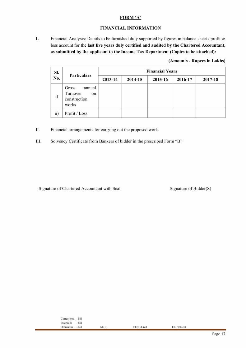
FORM ‘A’
FINANCIAL INFORMATION
I. Financial Analysis: Details to be furnished duly supported by figures in balance sheet / profit &
loss account for the last five years duly certified and audited by the Chartered Accountant,
as submitted by the applicant to the Income Tax Department (Copies to be attached):
(Amounts - Rupees in Lakhs)
Sl. No.
Particulars Financial Years
2013-14 2014-15 2015-16 2016-17 2017-18
i)
Gross annual Turnover on construction works
ii) Profit / Loss
II. Financial arrangements for carrying out the proposed work.
III. Solvency Certificate from Bankers of bidder in the prescribed Form “B”
Signature of Chartered Accountant with Seal Signature of Bidder(S)
Corrections - Nil
Insertions - Nil
Omissions - Nil AE(P) EE(P)/Civil EE(P)/Elect
Page 18
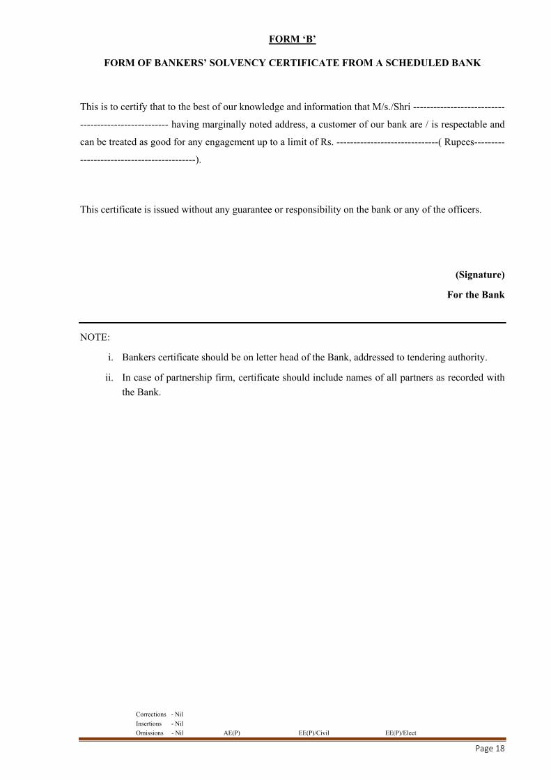
FORM ‘B’
FORM OF BANKERS’ SOLVENCY CERTIFICATE FROM A SCHEDULED BANK
This is to certify that to the best of our knowledge and information that M/s./Shri ---------------------------
-------------------------- having marginally noted address, a customer of our bank are / is respectable and
can be treated as good for any engagement up to a limit of Rs. ------------------------------( Rupees---------
----------------------------------).
This certificate is issued without any guarantee or responsibility on the bank or any of the officers.
(Signature)
For the Bank
NOTE:
i. Bankers certificate should be on letter head of the Bank, addressed to tendering authority.
ii. In case of partnership firm, certificate should include names of all partners as recorded with
the Bank.
Corrections - Nil
Insertions - Nil
Omissions - Nil AE(P) EE(P)/Civil EE(P)/Elect
Page 19
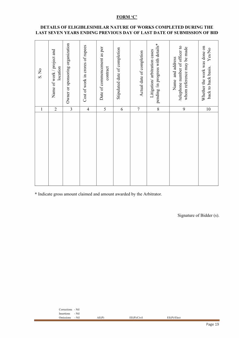
FORM ‘C’
DETAILS OF ELIGIBLESIMILAR NATURE OF WORKS COMPLETED DURING THE LAST SEVEN YEARS ENDING PREVIOUS DAY OF LAST DATE OF SUBMISSION OF BID
S. N
o
Nam
e of
wor
k / p
roje
ct a
nd
loca
tion
Ow
ner
or s
pons
orin
g or
gani
zati
on
Cos
t of
wor
k in
cro
res
of r
upee
s
Dat
e of
com
men
cem
ent a
s pe
r co
ntra
ct
Sti
pula
ted
date
of
com
plet
ion
A
ctua
l dat
e of
com
plet
ion
Lit
igat
ion/
arb
itra
tion
cas
es
pend
ing
/in
prog
ress
wit
h de
tail
s*
Nam
e a
nd a
ddre
ss
/tel
epho
ne n
umbe
r of
off
icer
to
who
m r
efer
ence
may
be
mad
e
Whe
ther
the
wor
k w
as d
one
on
back
to b
ack
basi
s.
Yes
/No
1 2 3 4 5 6 7 8 9 10
* Indicate gross amount claimed and amount awarded by the Arbitrator.
Signature of Bidder (s).
Corrections - Nil
Insertions - Nil
Omissions - Nil AE(P) EE(P)/Civil EE(P)/Elect
Page 20
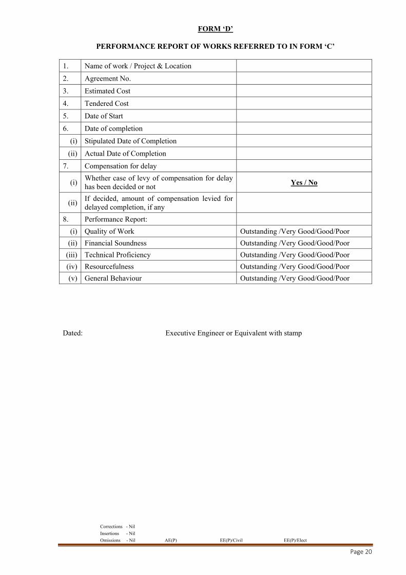
FORM ‘D’
PERFORMANCE REPORT OF WORKS REFERRED TO IN FORM ‘C’
1. Name of work / Project & Location
2. Agreement No.
3. Estimated Cost
4. Tendered Cost
5. Date of Start
6. Date of completion
(i) Stipulated Date of Completion
(ii) Actual Date of Completion
7. Compensation for delay
(i) Whether case of levy of compensation for delay has been decided or not Yes / No
(ii) If decided, amount of compensation levied for delayed completion, if any
8. Performance Report:
(i) Quality of Work Outstanding /Very Good/Good/Poor
(ii) Financial Soundness Outstanding /Very Good/Good/Poor
(iii) Technical Proficiency Outstanding /Very Good/Good/Poor
(iv) Resourcefulness Outstanding /Very Good/Good/Poor
(v) General Behaviour Outstanding /Very Good/Good/Poor
Dated: Executive Engineer or Equivalent with stamp
Corrections - Nil
Insertions - Nil
Omissions - Nil AE(P) EE(P)/Civil EE(P)/Elect
Page 21
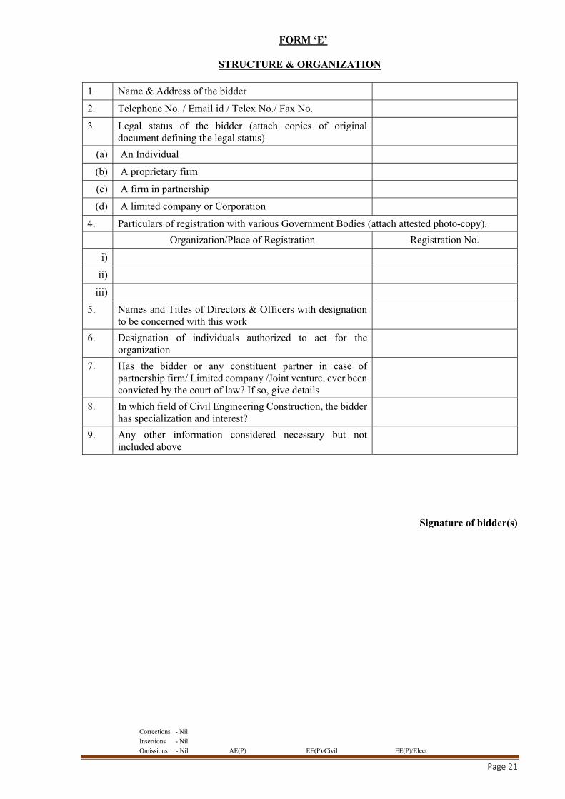
FORM ‘E’
STRUCTURE & ORGANIZATION
1. Name & Address of the bidder
2. Telephone No. / Email id / Telex No./ Fax No.
3. Legal status of the bidder (attach copies of original document defining the legal status)
(a) An Individual
(b) A proprietary firm
(c) A firm in partnership
(d) A limited company or Corporation
4. Particulars of registration with various Government Bodies (attach attested photo-copy).
Organization/Place of Registration Registration No.
i)
ii)
iii)
5. Names and Titles of Directors & Officers with designation to be concerned with this work
6. Designation of individuals authorized to act for the organization
7. Has the bidder or any constituent partner in case of partnership firm/ Limited company /Joint venture, ever been convicted by the court of law? If so, give details
8. In which field of Civil Engineering Construction, the bidder has specialization and interest?
9. Any other information considered necessary but not included above
Signature of bidder(s)

Corrections - Nil
Insertions - Nil
Omissions - Nil AE(P) EE(P)/Civil EE(P)/Elect
Page 22
FINANCIAL BID
DOCUMENT
Corrections - Nil
Insertions - Nil
Omissions - Nil AE(P) EE(P)/Civil EE(P)/Elect
Page 23
PART – A
NOTICE INVITING e-TENDER (CPWD-6), TENDER FORM
(CPWD-7), SCHEDULES - A TO F FOR MAJOR
COMPONENT OF WORK AND STANDARD GCC FOR
CPWD-2014 AMENDED/ MODIFIED UP TO LAST DATE OF
TENDER SUBMISSION
Corrections - Nil
Insertions - Nil
Omissions - Nil AE(P) EE(P)/Civil EE(P)/Elect
Page 24
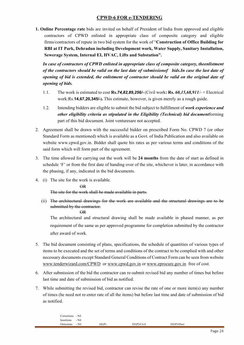
CPWD-6 FOR e-TENDERING
1. Online Percentage rate bids are invited on behalf of President of India from approved and eligible
contractors of CPWD enlisted in appropriate class of composite category and eligible
firms/contractors of repute in two bid system for the work of “Construction of Office Building for
RBI at IT Park, Dehradun including Development work, Water Supply, Sanitary Installation,
Sewerage System, Internal EI, HVAC, Lifts and Substation”.
In case of contractors of CPWD enlisted in appropriate class of composite category, theenlistment
of the contractors should be valid on the last date of submissionof bids.In case the last date of
opening of bid is extended, the enlistment of contractor should be valid on the original date of
opening of bids.
1.1. The work is estimated to cost Rs.74,82,89,256/- (Civil work: Rs. 60,15,68,911/- + Electrical
work:Rs.14,67,20,345/-). This estimate, however, is given merely as a rough guide.
1.2. Intending bidders are eligible to submit the bid subject to fulfillment of work experience and
other eligibility criteria as stipulated in the Eligibility (Technical) bid documentforming
part of this bid document. Joint venturesare not accepted.
2. Agreement shall be drawn with the successful bidder on prescribed Form No. CPWD 7 (or other
Standard Form as mentioned) which is available as a Govt. of India Publication and also available on
website www.cpwd.gov.in. Bidder shall quote his rates as per various terms and conditions of the
said form which will form part of the agreement.
3. The time allowed for carrying out the work will be 24 months from the date of start as defined in
schedule ‘F’ or from the first date of handing over of the site, whichever is later, in accordance with
the phasing, if any, indicated in the bid documents.
4. (i) The site for the work is available.
OR The site for the work shall be made available in parts.
(ii) The architectural drawings for the work are available and the structural drawings are to be submitted by the contractor.
OR The architectural and structural drawing shall be made available in phased manner, as per
requirement of the same as per approved programme for completion submitted by the contractor
after award of work.
5. The bid document consisting of plans, specifications, the schedule of quantities of various types of
items to be executed and the set of terms and conditions of the contract to be complied with and other
necessary documents except Standard General Conditions of Contract Form can be seen from website
www.tenderwizard.com/CPWD or www.cpwd.gov.in or www.eprocure.gov.in free of cost.
6. After submission of the bid the contractor can re-submit revised bid any number of times but before
last time and date of submission of bid as notified.
7. While submitting the revised bid, contractor can revise the rate of one or more item(s) any number
of times (he need not re-enter rate of all the items) but before last time and date of submission of bid
as notified.

Corrections - Nil
Insertions - Nil
Omissions - Nil AE(P) EE(P)/Civil EE(P)/Elect
Page 25
8. When bids are invited in three stage system and if it is desired to submit revised financial bid then it
shall be mandatory to submit revised financial bid. If not submitted then the bid submitted earlier
shall become invalid.
9. Earnest Money in the form of Treasury Challan or Demand Draft or Pay order or Banker`s Cheque
or Deposit at Call Receipt or Fixed Deposit Receipt (drawn in favour of Executive Engineer,
Dehradun Central Division-I, CPWD, Dehradun) shall be scanned and uploaded to the e-tendering
website within the period of bid submission.The original EMD should be deposited either in the office
of Executive Engineer inviting bids or division office of any Executive Engineer, CPWD within the
period of bid submission. The EMD receiving Executive Engineer (including NIT issuing EE/AE)
shall issue a receipt of deposition of Earnest Money deposit to the bidder in a prescribed format
(enclosed) uploaded by tender inviting EE in the NIT.
The receipt shall also be uploaded to the e-tendering website by the intending bidder upto the
specified bid submission date and time.
A part of earnest money is acceptable in the form of bank guarantee also. In such case, minimum
50% of earnest money or Rs.20 lacs, whichever is less, shall have to be deposited in shape prescribed
above, and balance may be deposited in shape of Bank Guarantee of any scheduled bank having
validity for 120 days or more from last date of receipt of bids.
Copy of Enlistment Order and certificate of work experience and other documents as specified in the
bid document shall be scanned and uploaded to the e-tendering website within the period of bid
submission. However, certified copy of all the scanned and uploaded documents as specified in
the bid document shall have to be submitted by the lowest bidder only within a week physically
in the office of tender opening authority.
Online bid documents submitted by intending bidders shall be opened only of those bidders, whose
original EMD deposited with any division of CPWD and other documents scanned and uploaded
are found in order.
The Technical bid submitted shall be opened at 03:30 PM on 01.01.2019.
10. The bid submitted shall become invalid and e-tender processing fee shall not be refunded if:
(i) The bidder is found ineligible.
(ii) The bidder does not deposit original EMD with division office of any Executive Engineer,
CPWD.
(iii) The bidder does not upload all the documents (including GST registration) as stipulated
in the bid documents including the copy of receipt for deposition of original EMD
instrument. If the bidder has not obtained GST registration in the state in which the work is
to be taken up, then in such a case the bidder shall upload following undertaking with the bid
document “if work is awarded to me, I/we shall obtained GST registration certificate within
one month from date of receipt of award letter or before payment of 1st RA bill
(iv) If any discrepancy is noticed between the documents as uploaded at the time of submission
of bid and hard copies as submitted physically by the lowest bidder in the office of tender
opening authority.

Corrections - Nil
Insertions - Nil
Omissions - Nil AE(P) EE(P)/Civil EE(P)/Elect
Page 26
(v) If a tenderer quotes nil rates against each item on item rate tender or does not quote any percentage above/below on the total amount of the tender or any section/sub-head in percentage rate tender, the tender shall be treated as invalid and will not be considered as lowest tenderer.
11. The contractor whose bid is accepted will be required to furnish performance guarantee of 5% (Five
Percent) of the accepted tendered amount within the period specified in Schedule F. This guarantee
shall be in the form of cash (in case guarantee amount is less than Rs.10,000/-) or Deposit at Call
receipt of any scheduled bank/Banker’s cheque of any scheduled bank/Demand Draft of any
scheduled bank/Pay order of any Scheduled Bank of any scheduled bank (in case guarantee amount
is less than Rs. 1,00,000/-) or Government Securities or Fixed Deposit Receipts or Guarantee Bonds
of any Scheduled Bank or the State Bank of India in accordance with the prescribed form. In case the
contractor fails to deposit the said performance guarantee within the period as indicated in Schedule
‘F’including the extended period if any, the Earnest Money deposited by the contractor shall be
forfeited automatically without any notice to the contractor. The earnest money deposited along with
bid shall be returned after receiving the aforesaid performance guarantee.
The contractor whose bid is accepted will also be required to furnish either copy of applicable
licenses/registrations or proof of applying for obtaining labour licenses, registration with EPFO,
ESIC and BOCW Welfare Board including Provident fund code no., if applicable and also ensure
the compliance of aforesaid provisions by the sub-contractors, if any engaged by the contractor for
the said work and Programme Chart (Time and Progress) within the period specified in Schedule
F.
12. Intending Bidders are advised to inspect and examine the site and its surroundings and satisfy
themselves before submitting their bids as to the nature of the ground and sub-soil (so far as is
practicable), the form and nature of the site, the means of access to the site, the accommodation they
may require and in general shall themselves obtain all necessary information as to risks, contingencies
and other circumstances which may influence or affect their bid. A bidder shall be deemed to have
full knowledge of the site whether he inspects it or not and no extra charge consequent on any
misunderstanding or otherwise shall be allowed. The bidder shall be responsible for arranging and
maintaining at his own cost all materials, tools & plants, water, electricity access, facilities for
workers and all other Services required for executing the work unless otherwise specifically provided
for in the contract documents. Submission of a bid by a bidder implies that he has read this notice
and all other contract documents and has made himself aware of the scope and specifications of the
work to be done and of conditions and rates at which stores, tools and plant, etc. will be issued to him
by the Government and local conditions and other factors having a bearing on the execution of the
work.
13. The competent authority on behalf of the President of India does not bind itself to accept the lowest
or any other bid and reserves to itself the authority to reject any or all the bids received without the
assignment of any reason. All bids in which any of the prescribed condition is not fulfilled or any
condition including that of conditional rebate is put forth by the bidders shall be summarily rejected.
14. Canvassing whether directly or indirectly, in connection with bidders is strictly prohibited and the
bids submitted by the contractors who resort to canvassing will be liable to rejection.
15. The competent authority on behalf of President of India reserves to himself the right of accepting the
whole or any part of the bid and the bidder shall be bound to perform the same at the rate quoted.

Corrections - Nil
Insertions - Nil
Omissions - Nil AE(P) EE(P)/Civil EE(P)/Elect
Page 27
16. The contractor shall not be permitted to bid for works in the CPWD Circle (Division in case of
contractors of Horticulture/Nursery category) responsible for award and execution of contracts, in
which his near relative is posted a Divisional Accountant or as an officer in any capacity between the
grades of Superintending Engineer and Junior Engineer (both inclusive). He shall also intimate the
names of persons who are working with him in any capacity or are subsequently employed by him
and who are near relatives to any gazette officer in the Central Public Works Department or in the
Ministry of Urban Development. Any breach of this condition by the contractor would render him
liable to be removed from the approved list of contractors of this Department.
17. No Engineer of Gazetted Rank or other Gazetted Officer employed in Engineering or Administrative
duties in an Engineering Department of the Government of India is allowed to work as a contractor
for a period of one year after his retirement from Government service, without the previous
permission of the Government of India in writing. This contract is liable to be cancelled if either the
contractor or any of his employees is found any time to be such a person who had not obtained the
permission of the Government of India as aforesaid before submission of the bid or engagement in
the contractor’s service.
18. The bid for the works shall remain open for acceptance for a period of Ninety (90) days from the
date of opening of Technical bids. If any bidder withdraws his bid before the said period or issue of
letter of acceptance, whichever is earlier, or makes any modifications in the terms and conditions of
the bid which are not acceptable to the department, then the Government shall, without prejudice to
any other right or remedy, be at liberty to forfeit 50% of the said earnest money as aforesaid. Further
the bidder shall not be allowed to participate in the rebidding process of the work.
19. This notice inviting Bid shall form a part of the contract document. The successful bidder/contractor,
on acceptance of his bid by the Accepting Authority shall within 15 days from the stipulated date of
start of the work, sign the contract consisting of:
(i) The Notice Inviting Bid, all the documents including additional conditions, specifications and
drawings, if any, forming part of the bid as uploaded at the time of invitation of bid and the rates
quoted online at the time of submission of bid and acceptance thereof together with any
correspondence leading thereto.
(ii) Standard CPWD Form-7 or other Standard CPWD Form as mentioned.
20. For CompositeBids
20.1.1. The Executive Engineer in charge of the major component will call bids for the
composite work. The cost of bid document and Earnest Money will be fixed with respect
to the combined estimated cost put to tender for the composite bid.
20.1.2. The bid documentwill include following three components:
Part A:CPWD-6, CPWD-7 including schedule A to F for Major component of the work
andStandard General Conditions of Contract for CPWD 2014 as amended/
modified up to last date of submission of bid.
PartB:General/Special Conditions, Specifications and Schedule of Quantities applicable
to Major component of the work.
Part C: Schedule A to F for minor component of the work(SE/EE in charge of major
component shall also be competent authority under clause 2 and clause 5 as

Corrections - Nil
Insertions - Nil
Omissions - Nil AE(P) EE(P)/Civil EE(P)/Elect
Page 28
mentioned in schedule A to F for major components). General/Special
conditions, Specifications and Schedule of Quantities applicable to Minor
component(s) of the work.
20.1.3. The bidders must associate with himself, agencies of the appropriate class eligible to bid
for each of the minor component individually.
20.1.4. The eligible bidders shall quote rates for all items of major component as well as for all
items of minor components of work.
20.1.5. After acceptance of the bid by competent authority, the EE in charge of major component
of the work shall issue letter of award on behalf of the President of India. After the work
is awarded, the main contractor will have to enter into one agreement with EE in charge
of major component and has also to sign two or more copies of agreement depending
upon number of EE’s/DDH in charge of minor components. One such signed set of
agreement shall be handed over to EE/DDH in charge of minor component. EE of major
component will operate part A and part B of the agreement. EE/DDH in charge of minor
component(s) shall operate Part C along with Part A of the agreement.
20.1.6. Entire work under the scope of composite bid including major and all minor components
shall be executed under one agreement.
20.1.7. Security Deposit will be worked out separately for each componentcorresponding to the
estimated cost of the respective component of works.
20.1.8. The main contractor has to associate agency(s) for minor component(s) conforming to
eligibility criteria as defined in the tender document and has to submit detail of such
agency(s) to Engineer-in-charge of minor component(s) within prescribed time. Name
of the agency(s) to be associated shall be approved by Engineer-in-charge of minor
component(s).
20.1.9. In case the main contractor intends to change any of the above agency/agencies during
the operation of the contract, he shall obtain prior approval of Engineer-in-charge of
minor component. The new agency/agencies shall also have to satisfy the laid down
eligibility criteria. In case Engineer-in-charge is not satisfied with the performance of
any agency, he can direct the contractor to change the agency executing such items of
work and this shall be binding on the contractor.
20.1.10. The main contractor has to enter into agreement with the contractor(s) associated by him
for execution of minor component(s). Copy of such agreement shall be submitted to
EE/DDH in charge of each minor component as well as to EE in charge of major
component. In case of change of associate contractor, the main contractor has to enter
into agreement with the new contractor associated by him.
20.1.11. Running payment for the major component shall be made by EE of major discipline to
the main contractor. Running payment for minor components shall be made by the
Engineer-in-charge of the discipline of minor component directly to the main contractor.
20.1.12. 20.1.12A. The composite work shall be treated as complete when all the components
of the work are complete. The completion certificate of the composite work shall be
recorded by Engineer-in-charge of major component after record of completion
certificate of all other components.

Corrections - Nil
Insertions - Nil
Omissions - Nil AE(P) EE(P)/Civil EE(P)/Elect
Page 29
20.1.12B. Final bill of whole work shall be finalized and paid by the EE of major
component. Engineer(s) in charge of minor component(s) will prepare and pass the final
bill for their component of work and pass on the same to the EE of major component for
including in the final bill for composite contract.
Signature of the Divisional Officer,
For and on behalf of the President of India
Corrections - Nil
Insertions - Nil
Omissions - Nil AE(P) EE(P)/Civil EE(P)/Elect
Page 30
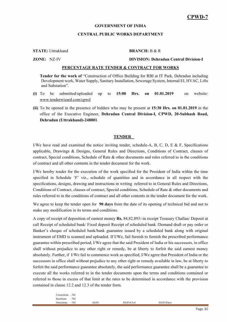
CPWD-7
GOVERNMENT OF INDIA
CENTRAL PUBLIC WORKS DEPARTMENT
STATE: Uttrakhand BRANCH: B & R
ZONE: NZ-IV DIVISION: Dehradun Central Division-I
PERCENTAGE RATE TENDER & CONTRACT FOR WORKS
Tender for the work of “Construction of Office Building for RBI at IT Park, Dehradun including Development work, Water Supply, Sanitary Installation, Sewerage System, Internal EI, HVAC, Lifts and Substation”.
(i) To be submitted/uploaded up to 15:00 Hrs. on 01.01.2019 on website:
www.tenderwizard.com/cpwd
(ii) To be opened in the presence of bidders who may be present at 15:30 Hrs. on 01.01.2019 in the
office of the Executive Engineer, Dehradun Central Division-I, CPWD, 20-Subhash Road,
Dehradun (Uttrakhand)-248001.
TENDER
I/We have read and examined the notice inviting tender, schedule-A, B, C, D, E & F, Specifications
applicable, Drawings & Designs, General Rules and Directions, Conditions of Contract, clauses of
contract, Special conditions, Schedule of Rate & other documents and rules referred to in the conditions
of contract and all other contents in the tender document for the work.
I/We hereby tender for the execution of the work specified for the President of India within the time
specified in Schedule ‘F’ viz., schedule of quantities and in accordance in all respect with the
specifications, designs, drawing and instructions in writing referred to in General Rules and Directions,
Conditions of Contract, clauses of contract, Special conditions, Schedule of Rate & other documents and
rules referred to in the conditions of contract and all other contents in the tender document for the work.
We agree to keep the tender open for 90 days from the date of its opening of technical bid and not to
make any modification in its terms and conditions.
A copy of receipt of deposition of earnest money Rs. 84,82,893/-in receipt Treasury Challan/ Deposit at
call Receipt of scheduled bank/ Fixed deposit Receipt of scheduled bank /Demand draft or pay order or
Banker’s cheque of scheduled bank/bank guarantee issued by a scheduled bank along with original
instrument of EMD is scanned and uploaded. If I/We, fail furnish to furnish the prescribed performance
guarantee within prescribed period, I/We agree that the said President of India or his successors, in office
shall without prejudice to any other right or remedy, be at liberty to forfeit the said earnest money
absolutely. Further, if I/We fail to commence work as specified, I/We agree that President of India or the
successors in office shall without prejudice to any other right or remedy available in law, be at liberty to
forfeit the said performance guarantee absolutely, the said performance guarantee shall be a guarantee to
execute all the works referred to in the tender documents upon the terms and conditions contained or
referred to those in excess of that limit at the rates to be determined in accordance with the provision
contained in clause 12.2 and 12.3 of the tender form.

Corrections - Nil
Insertions - Nil
Omissions - Nil AE(P) EE(P)/Civil EE(P)/Elect
Page 31
Further, I/We agree that in case of forfeiture of Earnest Money or Performance Guarantee as aforesaid,
I/We shall be debarred for participation in the re-tendering process of the work.
I/we undertake and confirm that eligible similar work(s) has/have not been got executed through another
agency on back to back basis. Further that, if such a violation comes to the notice of Department, then
I/we shall be debarred for bidding in CPWD in future forever. Also, if such a violation comes to the
notice of Department before date of start of work, the Engineer-in-charge shall be free to forfeit the entire
amount of Earnest Money Deposited/Performance Guarantee.
I/We hereby declare that I/We shall treat the tender documents, drawings and other records connected
with the work as secret/confidential documents and shall not communicate information/derived there
from to any person other than a person to whom I/We am/are authorized to communicate the same or use
the information in any manner prejudicial to the safety of the State.
Dated: Signature of Contractor
Postal Address:
Witness:
Address:
Occupation:

Corrections - Nil
Insertions - Nil
Omissions - Nil AE(P) EE(P)/Civil EE(P)/Elect
Page 32
ACCEPTANCE
The above tender (as modified by you as provided in the letters mentioned hereunder) is accepted by me
for and on behalf of the President of India for a sum of Rs.……………………………………….(Rupee.
……………………………………………………).
The letters referred to below shall form part of this contract agreement:
(a) …………………………
(b) ………………………….
(c) ………………………….
(For & on behalf of President of India)
Dated: …………….
Signature……………….……………
Designation………….………………

Corrections - Nil
Insertions - Nil
Omissions - Nil AE(P) EE(P)/Civil EE(P)/Elect
Page 33
PROFORMA OF SCHEDULES: A TO F
(FOR MAJOR COMPONANT OF WORK)
SCHEDULE ‘A’
Schedule of quantities for Civil Works(as per PWD-3): As per separate sheets attached
SCHEDULE 'B'
Schedule of material to be issued to the Contractor: Nil
SCHEDULE 'C'
Tools and Plants to be hired to the Contractor: Nil
SCHEDULE ‘D’
Extra schedule for specific requirements/documents for the work, if any: Nil
SCHEDULE ‘E’
Reference to General Conditions of Contract:General Conditions of Contract-2014 as amended /
modified up to the last date of submission of Tenders.
Name of Work: Construction of Office Building for RBI at IT Park, Dehradun including
Development work, Water Supply, Sanitary Installation, Sewerage System,
Internal EI, HVAC, Lifts and Substation.
Estimated cost of work : Civil Work - Rs. 60,15,68,911/-
Electrical work - Rs. 14,67,20,345/-
Total Rs. 74,82,89,256/-
(i) Earnest Money Rs. 84,82,893/-(to be returned after receiving Performance Guarantee)
(ii) Performance Guarantee 5% of the accepted tendered value of the work
(iii) Security Deposit 2.5% of the accepted tendered value of the work.
SCHEDULE 'F'
General Rules & Directions:
Officer inviting Tender: Executive Engineer, Dehradun Central Division-I, CPWD, 20-Subhash
Road, Dehradun - 248001
Definitions:
2(i) Engineer-in-Charge
Executive Engineer, Dehradun Central Division-I,
CPWD, Dehradun (For Civil Work)
(ii) Accepting Authority Chief Engineer (NZ-IV), CPWD, 20, Subhash Road,
Dehradun- 248001.
Corrections - Nil
Insertions - Nil
Omissions - Nil AE(P) EE(P)/Civil EE(P)/Elect
Page 34
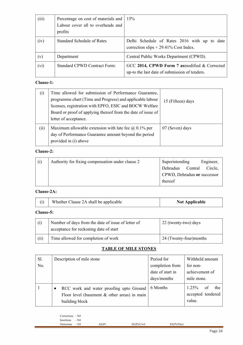
(iii) Percentage on cost of materials and
Labour cover all to overheads and
profits
15%
(iv) Standard Schedule of Rates Delhi Schedule of Rates 2016 with up to date
correction slips + 29.41% Cost Index.
(v) Department Central Public Works Department (CPWD).
(vi) Standard CPWD Contract Form: GCC 2014, CPWD Form 7 asmodified & Corrected
up-to the last date of submission of tenders.
Clause-1:
(i) Time allowed for submission of Performance Guarantee,
programme chart (Time and Progress) and applicable labour
licenses, registration with EPFO, ESIC and BOCW Welfare
Board or proof of applying thereof from the date of issue of
letter of acceptance.
15 (Fifteen) days
(ii) Maximum allowable extension with late fee @ 0.1% per
day of Performance Guarantee amount beyond the period
provided in (i) above
07 (Seven) days
Clause-2:
(i) Authority for fixing compensation under clause 2 Superintending Engineer,
Dehradun Central Circle,
CPWD, Dehradun or successor
thereof
Clause-2A:
(i) Whether Clause 2A shall be applicable Not Applicable
Clause-5:
(i) Number of days from the date of issue of letter of
acceptance for reckoning date of start 22 (twenty-two) days
(ii) Time allowed for completion of work 24 (Twenty-four)months
TABLE OF MILE STONES
Sl.
No. Description of mile stone Period for
completion from
date of start in
days/months
Withheld amount
for non-
achievement of
mile stone.
1 RCC work and water proofing upto Ground
Floor level (basement & other areas) in main
building block
6 Months 1.25% of the
accepted tendered
value.
Corrections - Nil
Insertions - Nil
Omissions - Nil AE(P) EE(P)/Civil EE(P)/Elect
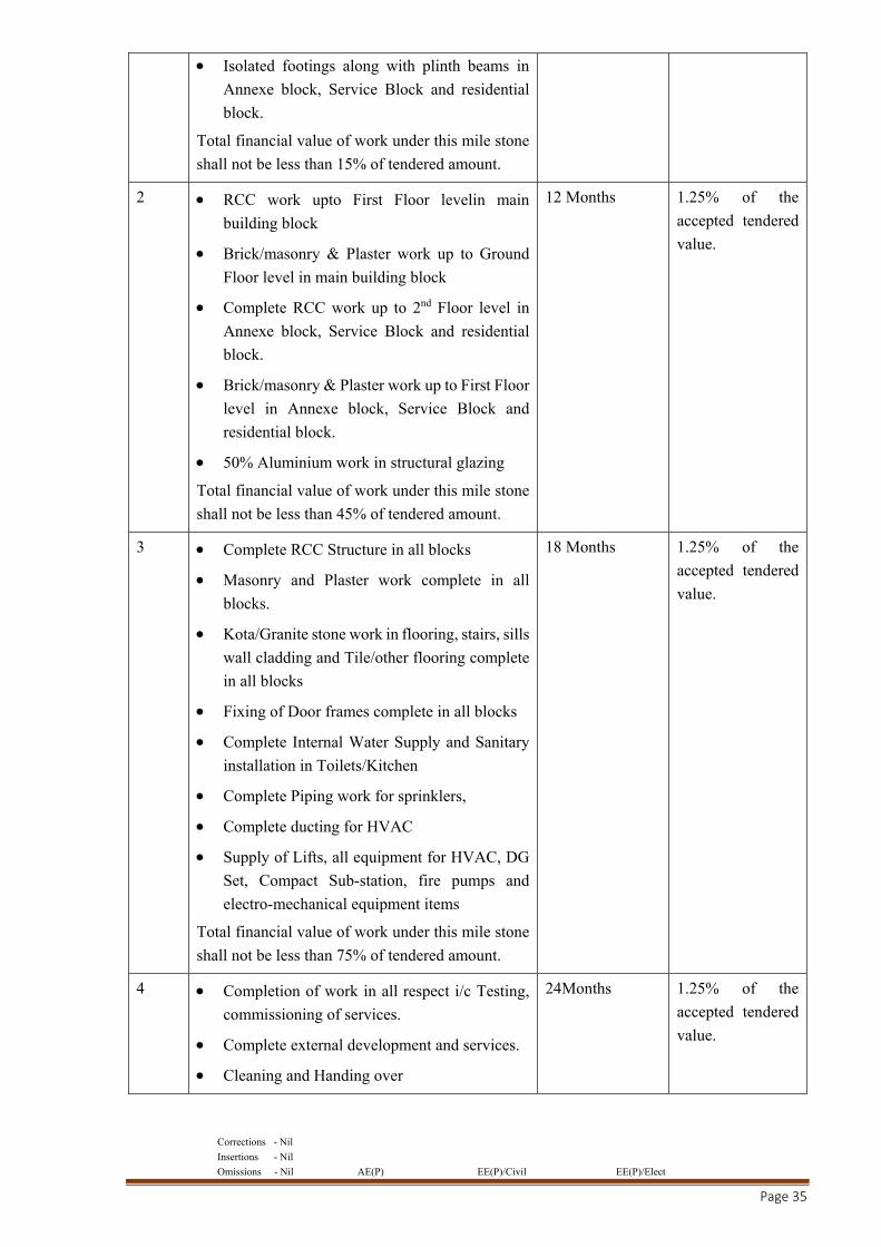
Page 35
Isolated footings along with plinth beams in
Annexe block, Service Block and residential
block.
Total financial value of work under this mile stone
shall not be less than 15% of tendered amount.
2 RCC work upto First Floor levelin main
building block
Brick/masonry & Plaster work up to Ground
Floor level in main building block
Complete RCC work up to 2nd Floor level in
Annexe block, Service Block and residential
block.
Brick/masonry & Plaster work up to First Floor
level in Annexe block, Service Block and
residential block.
50% Aluminium work in structural glazing
Total financial value of work under this mile stone
shall not be less than 45% of tendered amount.
12 Months 1.25% of the
accepted tendered
value.
3 Complete RCC Structure in all blocks
Masonry and Plaster work complete in all
blocks.
Kota/Granite stone work in flooring, stairs, sills
wall cladding and Tile/other flooring complete
in all blocks
Fixing of Door frames complete in all blocks
Complete Internal Water Supply and Sanitary
installation in Toilets/Kitchen
Complete Piping work for sprinklers,
Complete ducting for HVAC
Supply of Lifts, all equipment for HVAC, DG
Set, Compact Sub-station, fire pumps and
electro-mechanical equipment items
Total financial value of work under this mile stone
shall not be less than 75% of tendered amount.
18 Months 1.25% of the
accepted tendered
value.
4 Completion of work in all respect i/c Testing,
commissioning of services.
Complete external development and services.
Cleaning and Handing over
24Months 1.25% of the
accepted tendered
value.
Corrections - Nil
Insertions - Nil
Omissions - Nil AE(P) EE(P)/Civil EE(P)/Elect
Page 36
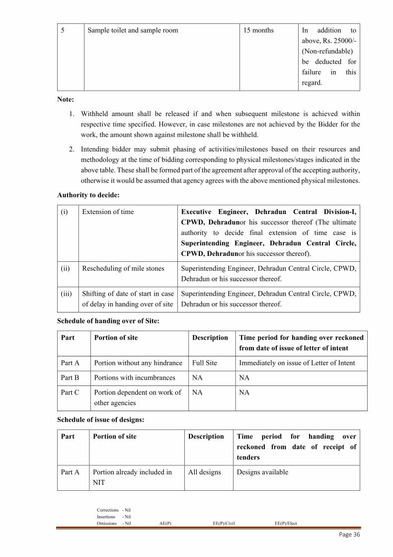
5 Sample toilet and sample room 15 months In addition to
above, Rs. 25000/-
(Non-refundable)
be deducted for
failure in this
regard.
Note:
1. Withheld amount shall be released if and when subsequent milestone is achieved within
respective time specified. However, in case milestones are not achieved by the Bidder for the
work, the amount shown against milestone shall be withheld.
2. Intending bidder may submit phasing of activities/milestones based on their resources and
methodology at the time of bidding corresponding to physical milestones/stages indicated in the
above table. These shall be formed part of the agreement after approval of the accepting authority,
otherwise it would be assumed that agency agrees with the above mentioned physical milestones.
Authority to decide:
(i) Extension of time Executive Engineer, Dehradun Central Division-I,
CPWD, Dehradunor his successor thereof (The ultimate
authority to decide final extension of time case is
Superintending Engineer, Dehradun Central Circle,
CPWD, Dehradunor his successor thereof).
(ii) Rescheduling of mile stones Superintending Engineer, Dehradun Central Circle, CPWD,
Dehradun or his successor thereof.
(iii) Shifting of date of start in case
of delay in handing over of site Superintending Engineer, Dehradun Central Circle, CPWD,
Dehradun or his successor thereof.
Schedule of handing over of Site:
Part Portion of site Description Time period for handing over reckoned
from date of issue of letter of intent
Part A Portion without any hindrance Full Site Immediately on issue of Letter of Intent
Part B Portions with incumbrances NA NA
Part C Portion dependent on work of
other agencies NA NA
Schedule of issue of designs:
Part Portion of site Description Time period for handing over
reckoned from date of receipt of
tenders
Part A Portion already included in
NIT All designs Designs available
Corrections - Nil
Insertions - Nil
Omissions - Nil AE(P) EE(P)/Civil EE(P)/Elect
Page 37
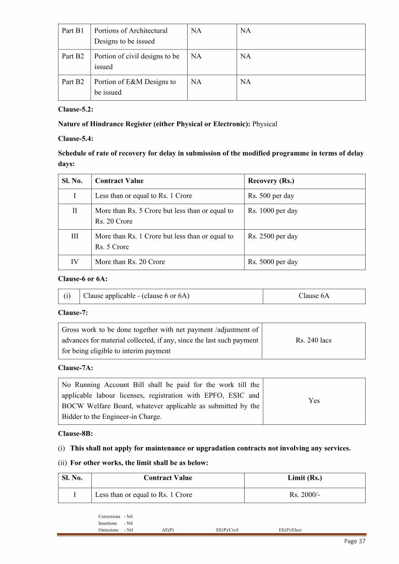
Part B1 Portions of Architectural
Designs to be issued NA NA
Part B2 Portion of civil designs to be
issued NA NA
Part B2 Portion of E&M Designs to
be issued NA NA
Clause-5.2:
Nature of Hindrance Register (either Physical or Electronic): Physical
Clause-5.4:
Schedule of rate of recovery for delay in submission of the modified programme in terms of delay
days:
Sl. No. Contract Value Recovery (Rs.)
I Less than or equal to Rs. 1 Crore Rs. 500 per day
II More than Rs. 5 Crore but less than or equal to
Rs. 20 Crore Rs. 1000 per day
III More than Rs. 1 Crore but less than or equal to
Rs. 5 Crore Rs. 2500 per day
IV More than Rs. 20 Crore Rs. 5000 per day
Clause-6 or 6A:
(i) Clause applicable - (clause 6 or 6A) Clause 6A
Clause-7:
Gross work to be done together with net payment /adjustment of
advances for material collected, if any, since the last such payment
for being eligible to interim payment Rs. 240 lacs
Clause-7A:
No Running Account Bill shall be paid for the work till the
applicable labour licenses, registration with EPFO, ESIC and
BOCW Welfare Board, whatever applicable as submitted by the
Bidder to the Engineer-in Charge.
Yes
Clause-8B:
(i) This shall not apply for maintenance or upgradation contracts not involving any services.
(ii) For other works, the limit shall be as below:
Sl. No. Contract Value Limit (Rs.)
I Less than or equal to Rs. 1 Crore Rs. 2000/-
Corrections - Nil
Insertions - Nil
Omissions - Nil AE(P) EE(P)/Civil EE(P)/Elect
Page 38
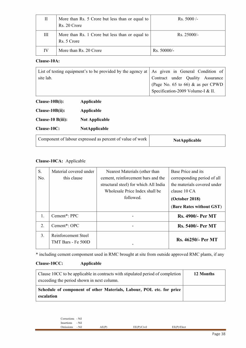
II More than Rs. 5 Crore but less than or equal to
Rs. 20 Crore Rs. 5000 /-
III More than Rs. 1 Crore but less than or equal to
Rs. 5 Crore Rs. 25000/-
IV More than Rs. 20 Crore Rs. 50000/-
Clause-10A:
List of testing equipment’s to be provided by the agency at
site lab.
As given in General Condition of
Contract under Quality Assurance
(Page No. 65 to 66) & as per CPWD
Specification-2009 Volume-I & II.
Clause-10B(i): Applicable
Clause-10B(ii): Applicable
Clause-10 B(iii): Not Applicable
Clause-10C: NotApplicable
Component of labour expressed as percent of value of work NotApplicable
Clause-10CA: Applicable
S.
No. Material covered under
this clause
Nearest Materials (other than
cement, reinforcement bars and the
structural steel) for which All India
Wholesale Price Index shall be
followed.
Base Price and its
corresponding period of all
the materials covered under
clause 10 CA
(October 2018)
(Bare Rates without GST)
1. Cement*: PPC - Rs. 4900/- Per MT
2. Cement*: OPC - Rs. 5400/- Per MT
3. Reinforcement Steel
TMT Bars - Fe 500D
- Rs. 46250/- Per MT
* including cement compoment used in RMC brought at site from outside approved RMC plants, if any
Clause-10CC: Applicable
Clause 10CC to be applicable in contracts with stipulated period of completion
exceeding the period shown in next column. 12 Months
Schedule of component of other Materials, Labour, POL etc. for price
escalation
Corrections - Nil
Insertions - Nil
Omissions - Nil AE(P) EE(P)/Civil EE(P)/Elect
Page 39
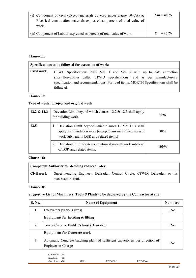
(i) Component of civil (Except materials covered under clause 10 CA) &
Electrical construction materials expressed as percent of total value of
work.
Xm = 40 %
(ii) Component of Labour expressed as percent of total value of work. Y = 25 %
Clause-11:
Specifications to be followed for execution of work:
Civil work CPWD Specifications 2009 Vol. 1 and Vol. 2 with up to date correction
slips.(Hereinafter called CPWD specifications) and as per manufacturer’s
specification and recommendations. For road items, MORTH Specifications shall be
followed.
Clause-12:
Type of work: Project and original work
12.2 & 12.3
Deviation Limit beyond which clauses 12.2 & 12.3 shall apply
for building work. 30%.
12.5 1. Deviation Limit beyond which clauses 12.2 & 12.3 shall
apply for foundation work (except items mentioned in earth
work sub head in DSR and related items) 30%
2. Deviation Limit for items mentioned in earth work sub head
of DSR and related items. 100%
Clause-16:
Competent Authority for deciding reduced rates:
Civil work Superintending Engineer, Dehradun Central Circle, CPWD, Dehradun or his
successor thereof.
Clause-18:
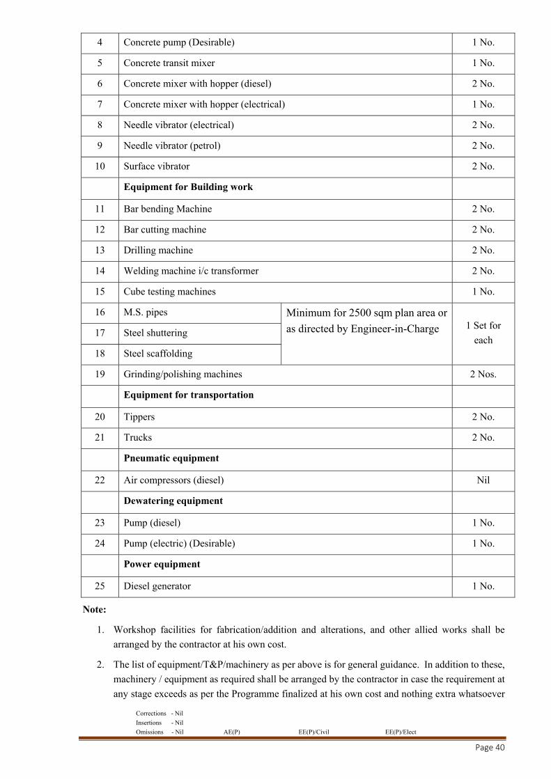
Suggestive List of Machinery, Tools &Plants to be deployed by the Contractor at site:
S. No. Name of Equipment Numbers
1 Excavators (various sizes) 1 No.
Equipment for hoisting & lifting
2 Tower Crane or Builder’s hoist (Desirable) 1 No.
Equipment for Concrete work
3 Automatic Concrete batching plant of sufficient capacity as per direction of
Engineer-in-Charge 1 No.
Corrections - Nil
Insertions - Nil
Omissions - Nil AE(P) EE(P)/Civil EE(P)/Elect
Page 40
4 Concrete pump (Desirable) 1 No.
5 Concrete transit mixer 1 No.
6 Concrete mixer with hopper (diesel) 2 No.
7 Concrete mixer with hopper (electrical) 1 No.
8 Needle vibrator (electrical) 2 No.
9 Needle vibrator (petrol) 2 No.
10 Surface vibrator 2 No.
Equipment for Building work
11 Bar bending Machine 2 No.
12 Bar cutting machine 2 No.
13 Drilling machine 2 No.
14 Welding machine i/c transformer 2 No.
15 Cube testing machines 1 No.
16 M.S. pipes Minimum for 2500 sqm plan area or
as directed by Engineer-in-Charge
1 Set for
each 17 Steel shuttering
18 Steel scaffolding
19 Grinding/polishing machines 2 Nos.
Equipment for transportation
20 Tippers 2 No.
21 Trucks 2 No.
Pneumatic equipment
22 Air compressors (diesel) Nil
Dewatering equipment
23 Pump (diesel) 1 No.
24 Pump (electric) (Desirable) 1 No.
Power equipment
25 Diesel generator 1 No.
Note:
1. Workshop facilities for fabrication/addition and alterations, and other allied works shall be
arranged by the contractor at his own cost.
2. The list of equipment/T&P/machinery as per above is for general guidance. In addition to these,
machinery / equipment as required shall be arranged by the contractor in case the requirement at
any stage exceeds as per the Programme finalized at his own cost and nothing extra whatsoever
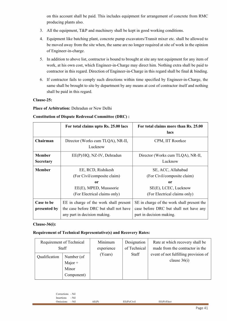
Corrections - Nil
Insertions - Nil
Omissions - Nil AE(P) EE(P)/Civil EE(P)/Elect
Page 41
on this account shall be paid. This includes equipment for arrangement of concrete from RMC
producing plants also.
3. All the equipment, T&P and machinery shall be kept in good working conditions.
4. Equipment like batching plant, concrete pump excavators/Transit mixer etc. shall be allowed to
be moved away from the site when, the same are no longer required at site of work in the opinion
of Engineer-in-charge.
5. In addition to above list, contractor is bound to brought at site any test equipment for any item of
work, at his own cost, which Engineer-in-Charge may direct him. Nothing extra shall be paid to
contractor in this regard. Direction of Engineer-in-Charge in this regard shall be final & binding.
6. If contractor fails to comply such directions within time specified by Engineer-in-Charge, the
same shall be brought to site by department by any means at cost of contractor itself and nothing
shall be paid in this regard.
Clause-25:
Place of Arbitration: Dehradun or New Delhi
Constitution of Dispute Redressal Committee (DRC) :
For total claims upto Rs. 25.00 lacs For total claims more than Rs. 25.00
lacs
Chairman Director (Works cum TLQA), NR-II,
Lucknow CPM, IIT Roorkee
Member
Secretary EE(P)/HQ, NZ-IV, Dehradun Director (Works cum TLQA), NR-II,
Lucknow
Member EE, RCD, Rishikesh (For Civil/composite claim)
or EE(E), MPED, Mussoorie
(For Electrical claims only)
SE, ACC, Allahabad (For Civil/composite claim)
or SE(E), LCEC, Lucknow
(For Electrical claims only)
Case to be
presented by EE in charge of the work shall present
the case before DRC but shall not have
any part in decision making.
SE in charge of the work shall present the
case before DRC but shall not have any
part in decision making.
Clause-36(i):
Requirement of Technical Representative(s) and Recovery Rates:
Requirement of Technical
Staff Minimum
experience
(Years)
Designation
of Technical
Staff
Rate at which recovery shall be
made from the contractor in the
event of not fulfilling provision of
clause 36(i) Qualification Number (of
Major +
Minor
Component)
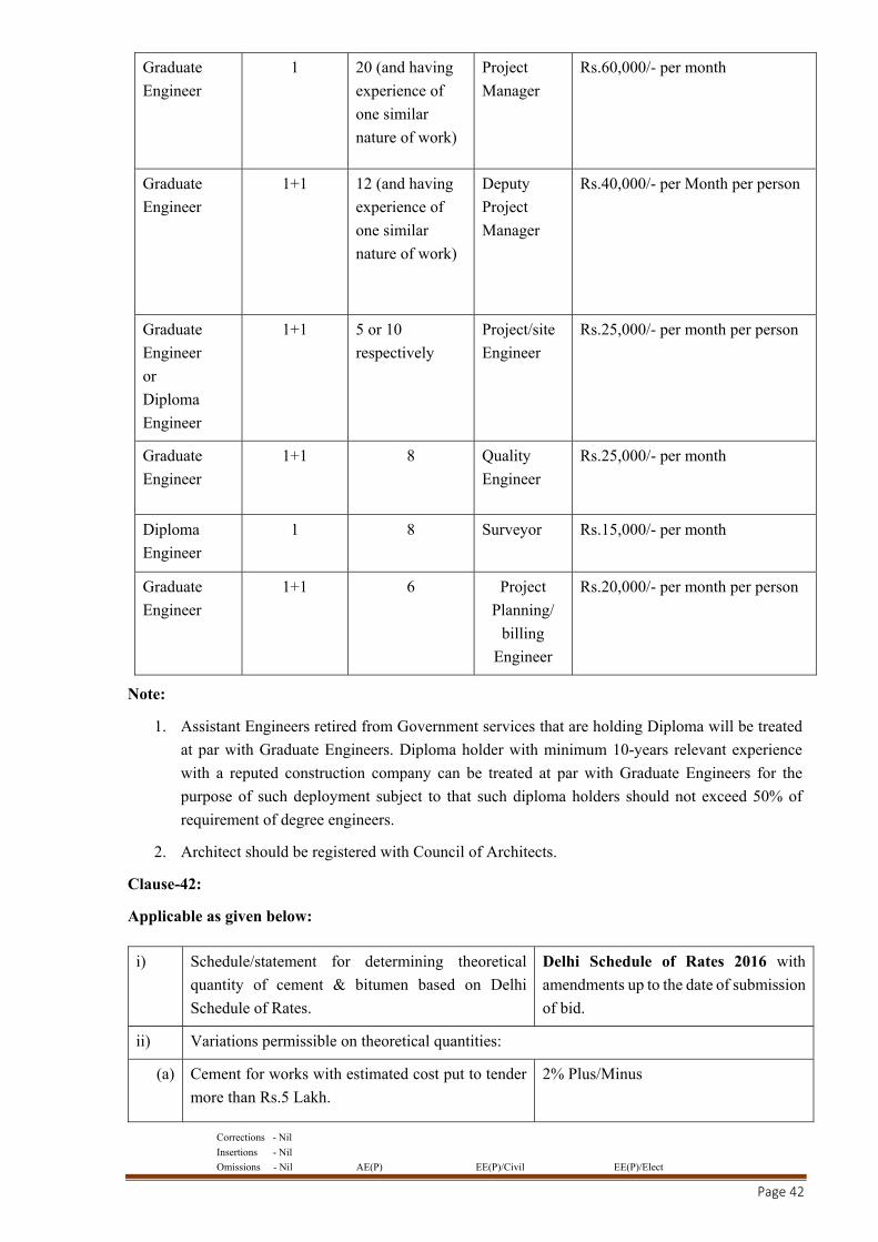
Corrections - Nil
Insertions - Nil
Omissions - Nil AE(P) EE(P)/Civil EE(P)/Elect
Page 42
Graduate
Engineer 1 20 (and having
experience of
one similar
nature of work)
Project
Manager Rs.60,000/- per month
Graduate
Engineer 1+1 12 (and having
experience of
one similar
nature of work)
Deputy
Project
Manager
Rs.40,000/- per Month per person
Graduate
Engineer
or
Diploma
Engineer
1+1 5 or 10
respectively Project/site
Engineer Rs.25,000/- per month per person
Graduate
Engineer 1+1 8 Quality
Engineer Rs.25,000/- per month
Diploma
Engineer 1 8 Surveyor Rs.15,000/- per month
Graduate
Engineer 1+1 6 Project
Planning/
billing
Engineer
Rs.20,000/- per month per person
Note:
1. Assistant Engineers retired from Government services that are holding Diploma will be treated
at par with Graduate Engineers. Diploma holder with minimum 10-years relevant experience
with a reputed construction company can be treated at par with Graduate Engineers for the
purpose of such deployment subject to that such diploma holders should not exceed 50% of
requirement of degree engineers.
2. Architect should be registered with Council of Architects.
Clause-42:
Applicable as given below:
i) Schedule/statement for determining theoretical
quantity of cement & bitumen based on Delhi
Schedule of Rates.
Delhi Schedule of Rates 2016 with
amendments up to the date of submission
of bid.
ii) Variations permissible on theoretical quantities:
(a) Cement for works with estimated cost put to tender
more than Rs.5 Lakh. 2% Plus/Minus
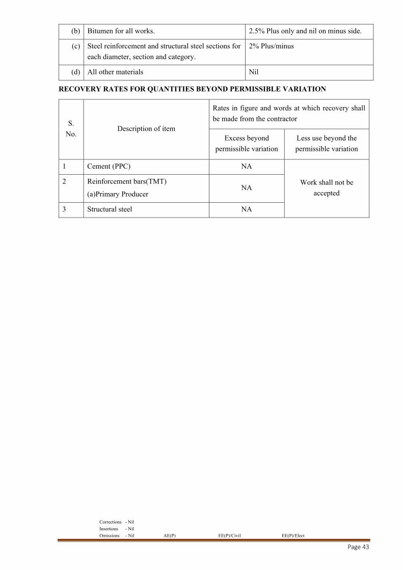
Corrections - Nil
Insertions - Nil
Omissions - Nil AE(P) EE(P)/Civil EE(P)/Elect
Page 43
RECOVERY RATES FOR QUANTITIES BEYOND PERMISSIBLE VARIATION
S.
No. Description of item
Rates in figure and words at which recovery shall
be made from the contractor
Excess beyond
permissible variation Less use beyond the
permissible variation
1 Cement (PPC) NA
Work shall not be
accepted
2 Reinforcement bars(TMT)
(a)Primary Producer NA
3 Structural steel NA
(b) Bitumen for all works. 2.5% Plus only and nil on minus side.
(c) Steel reinforcement and structural steel sections for
each diameter, section and category. 2% Plus/minus
(d) All other materials Nil

Corrections - Nil
Insertions - Nil
Omissions - Nil AE(P) EE(P)/Civil EE(P)/Elect
Page 44
STANDARD GENERAL CONDITIONS OF CONTRACT
1. Latest edition of “General Conditions of Contract (GCC) for CPWD Works – 2014” which is
available in market as CPWD publication and also available on CPWD official website
athttp://www.cpwd.gov.in/Documents/Publication/GCC14.pdf shall be deemed to be part of the
Tender document.
2. The Standard GCC is amended from time to time through issue of OMs under series DG/CON which
are available on CPWD official website at http://www.cpwd.gov.in/Documents/Official Circulars/
DG CON. The said Circulars bearing no. DG/CON/281 onwards issued uptolast date of tender
submission shall also be deemed to be part of tender document.

Corrections - Nil
Insertions - Nil
Omissions - Nil AE(P) EE(P)/Civil EE(P)/Elect
Page 45
INTEGRITY PACT
To,
All Bidders
Subject: NIT No.239/EE/DCD-I/2018-19/CE NZ-IV for the work:C/o Construction of Office Building for RBI at IT Park, Dehradun including Development work, Water Supply, Sanitary Installation, Sewerage System, Internal EI, HVAC, Lifts and Substation.
Dear Sir,
It is here by declared that CPWD is committed to follow the principle of transparency, equity
and competitiveness in public procurement.
The subject Notice Inviting Tender (NIT) is an invitation to offer made on the condition that the
Bidder will sign the integrity Agreement, which is an integral part of tender/bid documents, failing which
the tenderer /bidder will stand disqualified from the tendering process and the bid of the bidder would be
summarily rejected.
This declaration shall form part and parcel of the Integrity Agreement and signing of the same
shall be deemed as acceptance and signing of the Integrity Agreement on behalf of the CPWD.
Yours faithfully
Executive Engineer

Corrections - Nil
Insertions - Nil
Omissions - Nil AE(P) EE(P)/Civil EE(P)/Elect
Page 46
To,
Executive Engineer,
Dehradun Central Division 1,
CPWD, 20 Subhash Road, Dehradun 248001.
Subject: NIT No. 239/EE/DCD-I/2018-19/CE NZ-IV for the work: “C/o Construction of Office Building for RBI at IT Park, Dehradun including Development work, Water Supply, Sanitary Installation, Sewerage System, Internal EI, HVAC, Lifts and Substation.”
Dear Sir,
I/We acknowledge that CPWD is committed to follow the principles thereof as enumerated in
the Integrity Agreement enclosed with the tender/bid document.
I/We agree that the Notice Inviting Tender (NIT) is an invitation to offer made on the condition
that I/We will sign the enclosed integrity Agreement, which is an integral part of tender documents,
failing which I/We will stand disqualified from the tendering process. I/We acknowledge that THE
MAKING OF THE BID SHALL BE REGARDED AS AN UNCONDITIONAL AND ABSOLUTE
ACCEPTANCE of this condition of the NIT.
I/We confirm acceptance and compliance with the Integrity Agreement in letter and spirit and
further agree that execution of the said Integrity Agreement shall be separate and distinct from the main
contract, which will come into existence when tender/bid is finally accepted by CPWD. I/We
acknowledge and accept the duration of the Integrity Agreement, which shall be in the line with Article
1 of the enclosed Integrity Agreement.
I/We acknowledge that in the event of my/our failure to sign and accept the Integrity Agreement,
while submitting the tender/bid, CPWD shall have unqualified, absolute and unfettered right to disqualify
the tenderer/bidder and reject the tender/bid is accordance with terms and conditions of the tender/bid.
Yours faithfully
(Duly authorized signatory of the Bidder)
Corrections - Nil
Insertions - Nil
Omissions - Nil AE(P) EE(P)/Civil EE(P)/Elect
Page 47
TO BE SIGNED BY THE BIDDER AND SAME SIGNATORY COMPETENT / AUTHORIZED
TO SIGN THE RELEVANT CONTRACT WITH CPWD
INTEGRITY AGREEMENT
This Integrity Agreement is made at .............................. on this ........................... day of ...........20......
BETWEEN
President of India represented through Executive Engineer, ..........................(Name of Division)………..,
CPWD, ..................................... (Address of Division) ………., (Hereinafter referred as the
‘Principal/Owner’, which expression shall unless repugnant to the meaning or context hereof include
its successors and permitted assigns)
AND
.................................................................... (Name and Address of the Individual / firm/ Company)
………………. through ........................................... (Hereinafter referred to as the (Details of duly
authorized signatory) “Bidder/Contractor” and which expression shall unless repugnant to the meaning
or context hereof include its successors and permitted assigns)
PREAMBLE:
WHEREAS the Principal / Owner has floated the Tender (NIT No. ...................................) (hereinafter
referred to as “Tender/Bid”) and intends to award, under laid down organizational procedure, contract
for “C/o ……………………………………………………………………………………………
……………………………………………………………………………………..”hereinafter referred
to as the “Contract”.
AND WHEREAS the Principal/Owner values full compliance with all relevant laws of the land, rules,
regulations, economic use of resources and of fairness/transparency in its relation with its Bidder(s) and
Contractor(s).
AND WHEREAS to meet the purpose aforesaid both the parties have agreed to enter into this Integrity
Agreement (hereinafter referred to as “Integrity Pact” or “Pact”), the terms and conditions of which
shall also be read as integral part and parcel of the Tender/Bid documents and Contract between the
parties.
NOW, THEREFORE, in consideration of mutual covenants contained in this Pact, the parties hereby
agree as follows and this Pact witness as under:
ARTICLE 1: Commitment of the Principal/Owner
1) The Principal/Owner commits itself to take all measures necessary to prevent corruption and to
observe the following principles:
(a) No employee of the Principal/Owner, personally or through any of his/her family members,
will in connection with the Tender, or the execution of the Contract, demand, take a promise
for or accept, for self or third person, any material or immaterial benefit which the person is
not legally entitled to.

Corrections - Nil
Insertions - Nil
Omissions - Nil AE(P) EE(P)/Civil EE(P)/Elect
Page 48
(b) The Principal/Owner will, during the Tender process, treat all Bidder(s) with equity and
reason. The Principal/Owner will, in particular, before and during the Tender process,
provide to all Bidder(s) the same information and will not provide to any Bidders(s)
confidential/additional information through which the Bidder(s) could obtain an advantage
in relation to the Tender process or the Contract execution.
(c) The Principal/Owner shall endeavour to exclude from the Tender process any person, whose
conduct in the past has been of biased nature.
2) If the Principal/Owner obtains information on the conduct of any of its employees which is a
criminal offence under the Indian Penal code (IPC)/Prevention of Corruption Act,1988 (PC Act)
or is in violation of the principles herein mentioned or if there be a substantive suspicion in this
regard, the Principal/Owner will inform the Chief Vigilance Officer and in addition can also
initiate disciplinary actions as per its internal laid down policies and procedures.
ARTICLE 2: Commitment of the Bidder(s)/Contractor(s)
1) It is required that each Bidder/Contractor (including their respective officers, employees and
agents) adhere to the highest ethical standards, and report to the Government/Department all
suspected acts of fraud or corruption or Coercion or Collusion of which it has knowledge
or becomes aware, during the tendering process and throughout the negotiation or award of
a contract.
2) The Bidder(s)/Contractor(s) commits himself to take all measures necessary to prevent
corruption. He commits himself to observe the following principles during his participation
in the Tender process and during the Contract execution:
a) The Bidder(s)/Contractor(s) will not, directly or through any other person or firm, offer,
promise or give to any of the Principal/Owner’s employees involved in the Tender
process or execution of the Contract or to any third person any material or other benefit
which he/she is not legally entitled to, in order to obtain in exchange any advantage of
any kind whatsoever during the Tender process or during the execution of the Contract.
b) The Bidder(s)/Contractor(s) will not enter with other Bidder(s) into any undisclosed
agreement or understanding, whether formal or informal. This applies in particular to
prices, specifications, certifications, subsidiary contracts, submission or non-submission
of bids or any other actions to restrict competitiveness or to cartelize in the bidding
process.
c) The Bidder(s)/Contractor(s) will not commit any offence under relevant IPC/PC Act.
Further the Bidder(s)/Contract(s) will not use improperly, (for the purpose of
competition or personal gain), or pass on to others, any information or documents
provided by the Principal/Owner as part of the business relationship, regarding plans,
technical proposals and business details including information contained or transmitted
electronically.
d) The Bidder(s)/Contractor(s) of foreign origin shall disclose the names and addresses of
agents/representatives in India, if any. Similarly, Bidder(s)/Contractor(s) of Indian
Nationality shall disclose names and address of foreign agents/representatives, if any.
Either the India agent on behalf of the foreign principal or the foreign principal directly
could bid in a tender but not both. Further, in cases where an agent participates in a tender

Corrections - Nil
Insertions - Nil
Omissions - Nil AE(P) EE(P)/Civil EE(P)/Elect
Page 49
on behalf of one manufacturer, he shall not be allowed to quote on behalf of another
manufacturer along with the first manufacturer in a subsequent/parallel tender for the
same item.
e) The Bidder(s)/Contractor(s) will, when presenting his bid, disclose (with each tender as
per proforma enclosed) any and all payments he has made, is committed to or intends to
make to agents, brokers or any other intermediaries in connection with the award of the
Contract.
3) The Bidder(s)/Contractor(s) will not instigate third persons to commit offences outlined
above or be an accessory to such offences.
4) The Bidder(s)/Contractor(s) will not, directly or through any other person or firm indulge in
fraudulent practice means a willful misrepresentation or omission of facts or submission
of fake/forged documents in order to induce public official to act in reliance thereof,
with the purpose of obtaining unjust advantage by or causing damage to justified
interest of others and/or to influence the procurement process to detriment of the
Government interests.
5) The Bidder(s)/Contractor(s) will not, directly or through any other person or firm use
Coercive Practices (means the act of obtaining something, compelling an action or
influencing a decision through intimidation, threat or the use of force directly or indirectly,
where potential or actual injury may befall upon a person, his/her reputation or property to
influence their participation in the tendering process).
ARTICLE 3: Consequences of Breach
Without prejudice to any rights that may be available to the Principal/Owner under law or the Contract
or its established policies and laid down procedures, the Principal/Owner shall have the following rights
in case of breach of this Integrity Pact by the Bidder(s)/Contractor(s) and the Bidder/Contractor accepts
and undertakes to respect and uphold the Principal/Owner’s absolute right:
1) If the Bidder(s)/Contractor(s), either before award or during execution of Contract has committed
a transgression through a violation of Article 2 above or in any other form, such as to put his
reliability or credibility in question, the Principal/Owner after giving 14 days’ notice to the
contractor shall have powers to disqualify the Bidder(s)/Contractor(s) from the Tender process
or terminate/determine the Contract, if already executed or exclude the Bidder/Contractor from
future contract award processes. The imposition and duration of the exclusion will be determined
by the severity of transgression and determined by the Principal/Owner. Such exclusion may be
forever or for a limited period as decided by the Principal/Owner.
2) Forfeiture of EMD/Performance Guarantee/Security Deposit: If the Principal/Owner has
disqualified the Bidder(s) from the Tender process prior to the award of the Contract or
terminated/determined the Contract or has accrued the right to terminate/determine the Contract
according to Article 3(1), the Principal/Owner apart from exercising any legal rights that may
have accrued to the Principal/Owner, may in its considered opinion forfeit the entire amount of
Earnest Money Deposit, Performance Guarantee and Security Deposit of the Bidder/Contractor.
3) Criminal Liability: If the Principal/Owner obtains knowledge of conduct of a Bidder or
Contractor, or of an employee or a representative or an associate of a Bidder or Contractor which
constitutes corruption within the meaning of Indian Penal code (IPC)/Prevention of Corruption

Corrections - Nil
Insertions - Nil
Omissions - Nil AE(P) EE(P)/Civil EE(P)/Elect
Page 50
Act, or if the Principal/Owner has substantive suspicion in this regard, the Principal/Owner will
inform the same to law enforcing agencies for further investigation.
ARTICLE 4: Previous Transgression
1) The Bidder declares that no previous transgressions occurred in the last 5 years with any other
Company in any country confirming to the anticorruption approach or with Central Government
or State Government or any other Central/State Public Sector Enterprises in India that could
justify his exclusion from the Tender process.
2) If the Bidder makes incorrect statement on this subject, he can be disqualified from the Tender
process or action can be taken for banning of business dealings/holiday listing of the
Bidder/Contractor as deemed fit by the Principal/Owner.
3) If the Bidder/Contractor can prove that he has resorted/recouped the damage caused by him and
has installed a suitable corruption prevention system, the Principal/Owner may, at its own
discretion, revoke the exclusion prematurely.
ARTICLE 5: Equal Treatment of all Bidders/Contractors/Subcontractors
1) The Bidder(s)/Contractor(s) undertake(s) to demand from all subcontractors a commitment in
conformity with this Integrity Pact. The Bidder/Contractor shall be responsible for any
violation(s) of the principles laid down in this agreement/Pact by any of its Sub-contractors/sub-
vendors.
2) The Principal/Owner will enter into Pacts on identical terms as this one with all Bidders and
Contractors.
3) The Principal/Owner will disqualify Bidders, who do not submit, the duly signed Pact between
the Principal/Owner and the bidder, along with the Tender or violate its provisions at any stage
of the Tender process, from the Tender process.
ARTICLE 6: Duration of the Pact
This Pact begins when both the parties have legally signed it. It expires for the Contractor/Vendor, 12
months after the completion of work under the contract or till the continuation of defect liability period,
whichever is more and for all other bidders, till the Contract has been awarded.
If any claim is made/lodged during the time, the same shall be binding and continue to be valid despite
the lapse of this Pacts as specified above, unless it is discharged/determined by the Competent Authority,
CPWD.
ARTICLE 7: Other Provisions
1) This Pact is subject to Indian Law, place of performance and jurisdiction is the Headquarters of
the Division of the Principal/Owner, who has floated the Tender.
2) Changes and supplements need to be made in writing. Side agreements have not been made.
3) If the Contractor is a partnership or a consortium, this Pact must be signed by all the partners or
by one or more partner holding power of attorney signed by all partners and consortium members.
In case of a Company, the Pact must be signed by a representative duly authorized by board
resolution.

Corrections - Nil
Insertions - Nil
Omissions - Nil AE(P) EE(P)/Civil EE(P)/Elect
Page 51
4) Should one or several provisions of this Pact turn out to be invalid; the remainder of this Pact
remains valid. In this case, the parties will strive to come to an agreement to their original
intensions.
5) It is agreed term and condition that any dispute or difference arising between the parties with
regard to the terms of this Integrity Agreement/Pact, any action taken by the Owner/Principal in
accordance with this Integrity Agreement/Pact or interpretation thereof shall not be subject
to arbitration.
ARTICLE 8: LEGAL AND PRIOR RIGHTS
All rights and remedies of the parties hereto shall be in addition to all the other legal rights and remedies
belonging to such parties under the Contract and/or law and the same shall be deemed to be cumulative
and not alternative to such legal rights and remedies aforesaid. For the sake of brevity, both the Parties
agree that this Integrity Pact will have precedence over the Tender/Contract documents with regard any
of the provisions covered under this Integrity Pact.
IN WITNESS WHEREOF the parties have signed and executed this Integrity Pact at the place and date
first above mentioned in the presence of following witnesses:
………………………..……………………..
(For and on behalf of Bidder/Contractor)
Date:
Place:
……………………….…………………….
(For and on behalf of Principal/Owner)
WITNESSES:
1. …………………………………….
(Signature, name and address)
2. ……………………………………
(Signature, name and address)

Corrections - Nil
Insertions - Nil
Omissions - Nil AE(P) EE(P)/Civil EE(P)/Elect
Page 52
FORM OF EARNEST MONEY DEPOSIT
(BANK GUARANTEE BOND)
WHEREAS, Contractor...................... (Name of contractor) ………. (herein after called "the
Contractor") has submitted his tender dated ........... (date)……. for the work …………………….
………………….. (herein after called "the tender")
KNOW ALL PEOPLE by these presents that we .................................. (name of bank)……..
having our registered office at ................................... (herein after called "the Bank") …….. are bound
unto ……………………….(name and division of Executive Engineer) (hereinafter called the “Engineer-
in-charge”) in the sum of Rs. ......................... (Rupees…….................................................) for which
payment well and truly to be made to the said Engineer-in-charge, the Bank binds itself, his successors
and assigns by these presents.
SEALED with the Common Seal of the said Bank this ................. day of ................. THE
CONDITIONS of this obligation are:
(1) If after Tender opening, the contractor withdraws, his tender during the period of validity of tender
(including extended validity of tender) specified in the Form of Tender;
(2) If the contractor having been notified of the acceptance of his tender by the Engineer-in-charge:
(a) fails or refuses to execute the Form of Agreement in accordance with the Instructions to
Contractor, if required;
OR
(b) fails or refuses to furnish the Performance Guarantee, in accordance with the provisions of
tender document and Instructions to Contractor,
We undertake to pay to the Engineer-in-chargeeither up to the above amount or part thereof upon
receipt of his first written demand, without the Engineer-in-chargehaving to substantiates his demand,
provided that in his demand the Engineer-in-chargewill note that the amount claimed by him is due to
him owing to the occurrence of one or any of the above conditions, specifying the occurred condition or
conditions.
This Guarantee will remain in force up to and including the date ………* …… after the deadline
for submission of tender as such deadline is stated in the Instructions to contractors or as it may be
extended by the Engineer-in-charge, notice of which extension(s) to the Bank is hereby waived. Any
demand in respect of this Guarantee should reach the Bank not later than the above date.
Date: ....................... SIGNATURE OF THE BANK
WITNESS: ..........................
(Signature, Name & Address) SEAL
*Date to be worked out on the basis of validity period of 120 days from the last date of receipt of tender
Corrections - Nil
Insertions - Nil
Omissions - Nil AE(P) EE(P)/Civil EE(P)/Elect
Page 53
FORM OF PERFORMANCE SECURITY (GUARANTEE)
(BANK GUARANTEE BOND)
In consideration of the President of India (hereinafter called “the Government”) having offered to accept
the terms and conditions of the proposed agreement between……………… and ……….. (hereinafter
called “the said contractor(s)”) for the work ……………………… (hereinafter called “the said
agreement”) having agreed to production of an irrevocable Bank Guarantee for Rs. ………….. (Rupees
………………………………… only) as a security/guarantee from thecontractor(s) for compliance of
his obligations in accordance with the terms and conditions in the said agreement,
1. We, …………………………………. (hereinafter referred to as “the Bank”) hereby undertake to pay
to theGovernment an amount not exceeding Rs. …………….. (Rupees ……………………
………………………..only) on demand by the Government.
2. We, ……..… (indicate the name of the bank) ……….. do hereby undertake to pay the amounts due
and payableunder this Guarantee without any demure, merely on a demand from the Government
stating that the amount claimed as required to meet the recoveries due or likely to be due from the
said contractor(s). Any such demand made on the bank shall be conclusive as regards the amount due
and payable by the bank under this guarantee. However, our liability under this guarantee shall be
restricted to an amount not exceeding Rs. …………... (Rupees ……………………….. only).
3. We, the said bank further undertake to pay to the government any money so demanded
notwithstanding any dispute or disputes raised by the contractor(s) in any suit or proceeding pending
before any court or tribunal relating thereto, our liability under this present being absolute and
unequivocal.The payment so made by us under this bond shall be a valid discharge of our liability
for payment thereunder and the contractor(s) shall have no claim against us for making such payment.
4. We, ……..… (indicate the name of the bank) ……….. further agree that the guarantee herein
contained shall remain in full force and effect during the period that would be taken for performance
of the said agreement and that it shall continue to be enforceable till all the dues of the Government
under or by virtue of the said agreement have been fully paid and its claims satisfied or discharged
or till Engineer-in-charge on behalf of the government certified that the terms and conditions of the
said agreement have been fully and properly carried out by the said contractor(s) and accordingly
discharges this guarantee.
5. We, ……..… (indicate the name of the bank) ……….. further agreewith the Government that the
Governmentshall have the fullest liberty without our consent and without effecting in any manner
our obligations hereunder to vary any of the terms and conditions of the said agreement or to extend
time of performance by the said contractor(s) from time to time or to postpone for any time or from
time to time any of the powers exercisable by the government against the said contractor(s) and to
forebear or enforce any of the terms and conditions relating to the said agreement and we shall not
be relieved from our liability by reason of any such variation, or extension being granted to the said
contractor(s) or for any forbearance, act of omission on the part of the government or any indulgence
by the Government to the said contractor(s) or by any such matter or thing whatsoever which under
the law relating to sureties would, but for this provision, have effect of so relieving us.

Corrections - Nil
Insertions - Nil
Omissions - Nil AE(P) EE(P)/Civil EE(P)/Elect
Page 54
6. This guarantee will not be discharged due to the change in the constitution of the Bank or the
contractor(s).
7. We, ……..… (indicate the name of the bank) ……….. lastly undertake not to revoke this guarantee
except withthe previous consent of the Government in writing.
8. This guarantee shall be valid up to ……………, unless extended on demand by Government.
Notwithstanding anything mentioned above, our liability against this guarantee is restricted to
Rs.……………... (Rupees ……………..…………. only) and unless a claim in writing is lodged with
us within six months of the date of expiry or the extended date of expiry of this guarantee all our
liabilities under this guarantee shall stand discharged.
Dated: the…… day of ……………
Seal & Signature with Name & Address
For …(indicate the name of the bank) …
Corrections - Nil
Insertions - Nil
Omissions - Nil AE(P) EE(P)/Civil EE(P)/Elect
Page 55
PART – B
GENERAL/SPECIAL CONDITIONS, SPECIFICATIONS AND
SCHEDULE OF QUANTITIES FOR MAJOR COMPONENT
OF WORK.
Corrections - Nil
Insertions - Nil
Omissions - Nil AE(P) EE(P)/Civil EE(P)/Elect
Page 56
GENERAL CONDITIONS
1. Except for the items, for which Particular Specifications are given or where it is specifically
mentioned otherwise in the description of the items, the work shall generally be carried out in
accordance with the “CPWD Specifications - 2009 (Vol. I & II)for civil works with up to date
correction slips and CPWD Specification for Horticulture works with up to date correction slips
(hereinafter to be collectively referred to as ‘CPWD Specifications’). Wherever CPWD
Specifications are silent, the latest BIS Codes/Specifications, National Building Code 2016, MoRTH
specification or any other specification shall be followed.
2. The order of preference in case of any discrepancy as indicated in condition No. 8.1 under
“Conditions of Contract” given in standard CPWD Contract form may be read as the following:
(i) Nomenclature of items as per Schedule of Quantities
(ii) General/ Special Conditions and Particular Specifications as provided forming part of tender
document.
(iii) CPWD Specifications with up to date Correction slips
(iv) Architectural/Structural drawings
(v) Indian Standard Specifications of BIS
(vi) National Building Code - 2016
(vii) Manufacturers specifications.
(viii) Sound Engineering Practices
(ix) Decision of Engineer-in-charge
A reference made to any Indian Standard Specifications in these documents, shall imply to the latest
version of that standard, including such revisions / amendments as issued by the Bureau of Indian
Standards up to last date of receipt of tenders. The Contractor shall keep at his own cost all such
publications of relevant Indian Standard applicable to the work at site.
3. The proposed building work is a prestigious project and quality of work is of paramount importance.
Contractor shall have to engage well experienced skilled labour and deploy modern T&P and other
equipment to execute the work. Many items like stone masonry & stone cladding work, stone
flooring, flooring work, wood work, precast RCC coffers, polysulphide/ silicone sealant & other
specialized works will specifically require engagement of skilled workers having experience
particularly in execution of such items.
4. The tenderer shall acquaint himself with the proposed site of work, its approach roads, working space
available etc. before quoting his rates and no claim on this account shall be entertained by the
department.
5. The contractor(s) shall get himself acquainted with nature and extent of the work and satisfy himself
about the availability of materials from kiln or approved quarries for collection and conveyance of
materials required for construction.
6. The contractor(s) shall study the soil investigation report for the site, available in the office of the
Engineer-in-charge and satisfy himself about complete characteristics of soil and other parameters at
Corrections - Nil
Insertions - Nil
Omissions - Nil AE(P) EE(P)/Civil EE(P)/Elect
Page 57
site. However, no claim on the alleged inadequacy or incorrectness of the soil data supplied by the
department shall be entertained.
7. The tenderer shall see the approaches to the site. In case any approach from main road is required at
site or existing approach is to be improved and maintained for cartage of materials by the contractor,
the same shall be provided, improved and maintained by the contractor at his own cost. No payment
shall be made on this account.
8. The building work shall be carried out in the manner complying in all respects with the requirements
of the relevant bylaws and regulations of the local body under the jurisdiction of which the work is
to be executed or as directed by the Engineer-in-charge and nothing extra shall be paid on this
account.
9. The contractor(s) shall inform/issue notices to the Municipality, police and other authorities that may
be required as per law and obtain all requisite permission/ licenses for temporary obstructions,
enclosures etc. Contractor(s) shall pay all fee, taxes and charges which may be leviable on account
of these operations in executing the contract. He shall make good any damage to the property whether
public or private and shall supply and maintain lights either for illumination or for cautioning the
public at night.
10. For construction works which are likely to generate malba / rubbish, the contractor shall reuse it at
site as directed by the Engineer-in-charge or hand over to recycling agents or dispose of at his own
cost to the notified/specified Municipal dumping ground. No deduction on this account shall be made
from the agency as well as no extra payment will be made to agency if it is disposed at pre-defined
location within the campus / Municipal dumping ground.
11. The contractor shall take all necessary precautions to prevent any nuisance or inconvenience to the
owners, tenants or occupiers of adjacent properties and to the public in general and to prevent any
damage to such properties and any pollution of smoke, streams and water-ways. He shall make good
at his cost and to the satisfaction of the Engineer-in-Charge, any damage to roads, paths, cross
drainage works or public or private property whatsoever caused thereon by the contractor. All waste
or superfluous materials shall be carried away by the contractor without any reservation entirely to
the satisfaction of the Engineer-in-Charge.
12. Utmost care shall be taken to keep the noise level to the barest minimum so that no disturbance as
far as possible is caused to the occupants / users of building/adjacent properties.
13. The works shall be carried out in accordance with the Architectural drawings and structural drawings,
to be issued from time to time by the Engineer-in-Charge. Before commencement of any item of
work, the contractor shall correlate all the relevant architectural and structural drawings issued for
the work and satisfy himself that the information available thereof is complete and unambiguous.
The discrepancy, if any shall be brought to the notice of the Engineer-in-Charge before execution of
the work. The contractor alone shall be responsible for any loss or damage executing by the
commencement of work on the basis of any erroneous and or incomplete information.
14. The Architectural drawings given in the tender other than those indicated in nomenclature of items
are only indicative of the nature of the work and materials/fixings involved unless and otherwise
specifically mentioned. However, the work shall be executed in accordance with the drawings duly
approved by the Engineer-in-Charge.
Corrections - Nil
Insertions - Nil
Omissions - Nil AE(P) EE(P)/Civil EE(P)/Elect
Page 58
15. Other agencies will also simultaneously execute and install the works of sub-station / generating sets,
air-conditioning, lifts, etc. for the work and the contractor shall afford necessary facilities for the
same. The contractor shall leave such recesses, holes, openings trenches etc. as may be required for
such related works (for which inserts, sleeves, brackets, conduits, base plates, clamps etc. shall be
supplied free of cost by the department unless otherwise specifically mentioned) and the contractor
shall fix the same at time of casting of concrete, stone work and brick work, if required, and nothing
extra shall be payable on this account.
16. The contractor shall conduct work so as not to interfere with or hinder the progress or completion of the work being performed by other contractor(s) or by the Engineer-in-Charge and shall as far as possible arrange his work and shall place and dispose of the materials being used or removed so as not to interfere with the operations of other contractor or he shall arrange his work with that of the others in an acceptable and coordinated manner and shall perform it in proper sequence to the complete satisfaction of others.
17. Some restrictions may be imposed by the security agencies /client on the working and on movement
of labour, materials etc in the campus/site and may require to issue identity cards to all persons
authorized by contractor to do work / visit the work site. The contractor shall be bound to follow all
such restrictions / instructions and no claim whatsoever shall on this account will be entertained. The
loss of time on this account, if any, shall have to be made up by generating additional resources etc.
18. The rates quoted by the contractor are deemed to be inclusive of site clearance, setting out work,
profile, establishment of reference bench mark, spot levels, construction of all safety and protection
devices, barriers, earth embankments, preparatory works, all testing of materials, working during
monsoon, working at all depths, height and locations etc. unless specified in the schedule of
quantities.
19. Royalty at the prevailing rates wherever payable shall have to be paid by the contractor on the
boulders, metal, shingle, sand and bajri etc. Or any other material collected by him for the work direct
to revenue authorities and nothing extra shall be paid by the department for the same.
20. Permission for the Excavation of the Basementand/or any Mining Approval along with carriage and
disposal of surplus excavated earth shall be obtained by the contractor at his own expenses from
Local Administration / Revenue Authority. Departement / Client Department shall only forward the
case to the concerned Authority. Moreover, all the fee including royalty for surplus excavated earth
is to be paid by the contractor to the concerned department. Nothing extra shall be paid on account
of this to the contractor.
21. No payment shall be made for any damage caused by rain, snowfall, flood or any other natural
calamity, whatsoever during the execution of the work. The contractor shall be fully responsible for
any damage to the govt. property and work for which the payment has been advanced to him under
the contract and he shall make good the same at his risk and cost. The contractor shall be fully
responsible for safety and security of his material, T&P, Machinery brought to the site by him.
22. The contractor shall deploy resources e.g. manpower, labour, T&P, Plant & Equipment etc. as
per actual requirement of work. No damages/compensation shall be payable on account of idle
manpower, labour, T&P, Plant and Equipment and loss of profit etc. for whatsoever reason.
23. The rates for all items of work shall, unless clearly specified otherwise, include cost of all labour,
material, tools and plants and other inputs involved in the execution of the item.
Corrections - Nil
Insertions - Nil
Omissions - Nil AE(P) EE(P)/Civil EE(P)/Elect
Page 59
24. The contractor (s) shall quote all-inclusive rates against the items in the schedule of quantities and nothing extra shall be payable for any of the conditions and specifications mentioned. In the tender documents unless specifically specified otherwise.
25. Unless otherwise specified in the schedule of quantities the rates for all items shall be considered as inclusive of pumping/baling out water, if necessary, for which no extra payment shall be made. Those conditions shall be considered to include water from any source such as inflow of flood, surface and sub-soil water etc. and shall apply to the execution in any season.
26. The work shall be executed and measured as per metric dimensions given in the Schedule of quantities, drawings etc. (FPS units wherever indicated are for guidance only).
27. Unless otherwise specified in the schedule of quantities, the rates tendered by the contractor shall be
inclusive of all costs & taxes and shall apply to all leads and lifts and nothing extra shall be payable
on this account.
28. The foundation trenches shall be kept free from water while works below ground level are in progress.
29. No foreign exchange shall be made available by the Department for importing (purchase) of
equipment, plants, machinery, materials of any kind or any other items required to be carried out
during execution of the work. No delay and no claim of any kind shall be entertained from the
Contractor, on account of variation in the foreign exchange rate.
30. All ancillary and incidental facilities required for execution of work like labour camp, stores,
fabrication yard, offices for Contractor, watch and ward, temporary ramp required to be made for
working at the basement level, temporary structure for plants and machineries, temporary barricading
or fencing around the working sites, water storage tanks, installation and consumption charges of
temporary electricity, telephone, water etc. required for execution of the work, protection works,
testing facilities / laboratory at site of work, facilities for all field tests and for taking samples etc.
during execution or any other activity which is necessary (for execution of work and as directed by
Engineer-in-Charge), shall be deemed to be included in rates quoted by the Contractor, for various
items in the schedule of quantities. Nothing extra shall be payable on these accounts. Before start of
the work, the Contractor shall submit to the Engineer-in-Charge, a site / construction yard layout,
specifying areas for construction, site office, positioning of machinery, material yard, cement & other
storage, fabrication yard, site laboratory, water tank etc.
31. For completing the work in time, the Contractor might be required to work in two or more shifts
(including night shifts). Normally contractors shall not be allowed to execute the RCC, electrical and
finishing work at night. Work at night shall, however, be allowed if the site conditions/circumstances
so demand. No claim whatsoever shall be entertained on this account, not with-standing the fact that
the contractor may have to pay extra amounts for any reason, to the labourers and other staff engaged
directly or indirectly on the work according to the provisions of the labour and other statutory bodies
regulations and the agreement entered upon by the contractor with them.
32. The contractor shall maintain in perfect condition, all portions executed till completion of the entire
work allotted to him. Where however phased delivery of work is contemplated these provisions shall
apply separately to each phase.
33. All material shall only be brought at site as per program finalized with the Engineer-in-Charge. Any
pre-delivery of the material not required for immediate consumption shall not be accepted and thus
not paid for.

Corrections - Nil
Insertions - Nil
Omissions - Nil AE(P) EE(P)/Civil EE(P)/Elect
Page 60
34. The contractor(s) shall take instructions from the Engineer-in-Charge regarding collection and
stacking of materials at any place. No excavated earth or building rubbish shall be stacked on areas
where other buildings, roads, services and compound walls are to be constructed. The stacking shall
take place as per stacking plan however, if any change is required, the same shall be done with the
approval of Engineer-in-Charge.
35. The Contractor shall bear all incidental charges for cartage, storage and safe custody of materials
issued by department/arranged by the contractor.
36. The terms machine batched, machine mixed and machine vibrated concrete used elsewhere in
agreement shall mean the concrete produced in concrete batching and mixing plant and if necessary
transported by transit concrete mixers, placed in position by the concrete pumps, tower crane and
vibrated by surface vibrator /needle vibrator / plate vibrator, as the case may be to achieve required
strength and durability.
37. The cost of flooring is inclusive of providing sunken flooring in bath-rooms, kitchen, balcony etc.
and nothing extra on this account shall be payable.
38. Any legal or financial implications resulting out of carriage of earth from outside or disposal of earth
shall be sole responsibility of the contractor. Nothing extra shall be paid on this account.
39. No chase cutting/dismantling of plaster/RCC/CC shall be allowed, so contractor has to execute the
electrical work accordingly. The work should be planned in a systematic manner so that chase
cuttings in the walls, ceilings and floors are minimized. Wherever absolutely essential, the chase shall
be cut using chase cutting machines. Chases will not be allowed to be cut using hammer / chisel. The
electrical boxes should be fixed in walls simultaneously while raising the brick work. The contractor
shall ensure proper coordination of various disciplines viz. sanitary & water supply, electrical, fire-
fighting and any other services.
40. The work of water supply, internal sanitary installations and drainage etc. shall be carried out as per
the bylaws of the Municipal Corporation or any other local body and the contractor shall produce
necessary completion certificates from such authority after completion of work.
41. In case of local Municipal regulations / restrictions by client /non-availability space at site if huts for
labour are not allowed to be erected at the site of work, the contractor shall be required to provide
such accommodation at suitable place at his own cost and nothing extra shall be paid on this account.
42. Any cement slurry added over base surface for continuation of concerting for better bond is deemed
to have been built in the items and nothing extra shall be payable and no extra cement considered in
consumption on this account.Agency has to manage the floor level during casting considering the
varying thickness of different flooring materials to be used at any floor level.Nothing extra shall be
paid for extra mortar for matching the floor level.
43. Existing drains, pipes, cables, over-head wires, sewer lines, water lines and similar service
encountered in the course of the execution of work shall be protected against the damage by the
contractor at his own expense. In case the same are to be removed and diverted. The same shall be
payable to the contractor. The contractor shall work out the cost and the same shall be approved by
Engineer-in-Charge. The contractor shall not store materials or otherwise occupy any part of the site
in a manner likely to hinder the operation of such services.
44. The contractor shall be responsible for the watch and ward / guard of the buildings safety, fittings
and fixtures provided by him against pilferage and breakage during the period of installations and

Corrections - Nil
Insertions - Nil
Omissions - Nil AE(P) EE(P)/Civil EE(P)/Elect
Page 61
thereafter till the building is physically handed over to the department. No extra payment shall be
made on this account.
45. SETTING OUT
45.1. Contractor shall provide permanent bench marks and other reference points for the proper
execution of work and these shall be preserved till the end of work. All such reference points
shall be in relation to the levels and locations, given in the Architectural and plumbing
drawings.
45.2. The contractor shall establish, maintain and assume responsibility for grades, lines, levels and
bench marks. He shall report any errors or inconsistencies regarding grades, lines, levels,
dimensions to the Engineer-in-Charge before commencing work. Commencement of work
shall be regarded as the contractor's acceptance of such grades, lines, levels and dimensions
and no claim shall be entertained at a later date for any errors found.
45.3. If at any time, any error in this respect shall appear during the progress of the work, the
contractor shall, at his own expense rectify such error if so required to the satisfaction of the
Engineer-in-Charge.
45.4. Though the site levels may be indicated in the drawings the contractor shall ascertain himself
and confirm the site levels with respect to GTS bench mark from the concerned authorities.
45.5. The approval by the Engineer-in-Charge of the setting out by the contractor shall not relieve
the contractor of any of his responsibilities.
45.6. The contractor shall be entirely and exclusively responsible for the horizontal, vertical and
other alignment, the level and correctness of every part of the work and shall rectify effectively
any errors or imperfections therein. Such rectifications shall be carried out by the contractor at
his own cost to the instructions and satisfaction of the Engineer-in-Charge.
46. PROGRAMME CHART
46.1. The Contractor shall prepare an integrated programme chart in MS Project, Primavera software
for the execution of work, showing clearly all activities from the start of work to completion,
with details of manpower, equipment and machinery required for the fulfillment of the
programme within the stipulated period or earlier and submit the same for approval to the
Engineer-in-Charge within ten days of award of the contract. Non-submission of such
programme shall attract the recoveries as mentioned in the Schedule-F of the tender document.
46.2. The programme chart should include the following:
(a) Descriptive note explaining sequence of the various activities.
(b) Network (PERT/CPM/BAR CHART) in MS Project/Primavera Software
(c) Programme for procurement of materials by the contractor.
(d) Programme of procurement of machinery / equipment having adequate capacity,
commensurate with the quantum of work to be done within the stipulated period, by the
contractor.
46.3. In addition to above, the contractor shall submit shuttering schedule adequate to complete
structure work within laid down physical milestone etc. and to achieve the progress of work
Corrections - Nil
Insertions - Nil
Omissions - Nil AE(P) EE(P)/Civil EE(P)/Elect
Page 62
as per programme, he must bring sufficient shuttering material required for cement concrete
and R.C.C. works etc.
46.4. If at any time, it appears to the Engineer-in-Charge that the actual progress of work does not
conform to the approved programme referred above, the contractor shall produce a revised
programme showing the modifications to the approved programme to ensure completion of
the work. The modified schedule of programme shall be approved by the Engineer-in-Charge.
Non-submission of such revised programme shall attract the recoveries as mentioned in the
Schedule-F of the tender document.For Periodic inspections of the local body and on
completion of works, the Contractor shall procureapprovals and local body completion
certificates.
46.5. The submission for approval by the Engineer-in-Charge of such programme or the furnishing
of such particulars shall not relieve the contractor of any of the duties or responsibilities under
the contract. This is without prejudice to the right of Engineer-in-Charge to take action against
the contractor as per terms and conditions of the agreement.
47. PROGRESS REPORT
The contractor shall submit to the Engineer-in-charge on the 7th day of each month, 2 hard copies
and one on soft copy (CD) of monthly progress report of the work. Such progress report will include
the project progress, summary, work progress (planned vs actual), CPM chart, status of financial
progress and achievement of milestone, manpower deployment status, inventory of materials and
photographs of important activities. For delay in submission of the report, compensation @ Rs.2000/-
(Rupees Two Thousand only) per day of delay subject to maximum of Rs.20, 000/- for each report
will be recovered from the amount payable to the contractor.
48. SAFETY PRECAUTIONS
48.1. Contractor shall within two weeks of award of work, submit to the Engineer-in-Charge for his
approval, list of measures for maintaining safety of manpower deployed for construction.
48.2. Contractor at his cost put up the barricading all around the construction site through suitable
method for segregating the construction site and also to control the dust pollution in the
campus. Entry to the site shall be controlled for proper security of man and materials and to
avoid accidents.
48.3. The Contractor(s) shall take all precautions to avoid accidents by exhibiting necessary caution
boards, day and night speed limit boards, red flags, red lights and providing barriers. He shall
be responsible for all damages and accidents caused to existing/new work due to negligence
on his part. No hindrances shall be caused to traffic during the execution of the work.
48.4. In case of any accident of labours / contractual staff’s the entire responsibility will rest on the
part of the contractor and any compensation under such circumstances if becomes payable the
same shall be entirely borne by the contractor and department shall have no role on this
account.
48.5. It shall be ensured by the contractor that no electric live wire is left exposed or unattended to
avoid any accidents in this regard.
48.6. Any trenching and digging for laying sewer lines/water lines/cables etc. shall be commenced
by the contractor only when all men, machinery’s and materials have been arranged and
closing of the trench(s) thereafter shall be ensured within the least possible time.
Corrections - Nil
Insertions - Nil
Omissions - Nil AE(P) EE(P)/Civil EE(P)/Elect
Page 63
48.7. For facia work, outer finishing and other RCC works etc. double steel scaffolding having two
sets of vertical supports with steel staircase for inspection of works by engineer in charge shall
be used. The supports shall be sound and strong, tied together with horizontal piece over which
scaffolding planks shall be fixed.
49. QUALITY ASSURANCE
49.1. The contractor shall ensure quality construction in a planned and time bound manner. Any
sub-standard material/work beyond set out tolerance limit shall be summarily rejected by the
Engineer-in-Charge.
49.2. The contractor shall ensure quality control measures on different aspects of construction
including materials, workmanship and correct construction methodologies to be adopted. He
shall have to submit quality assurance programme within two weeks of the award of work. The
quality assurance programme should include method statement for various items of work to
be executed along with check lists to enforce quality control.
49.3. The contractor shall depute Quality Manager exclusively for enforcement of quality control.
Such Quality Manager should be a qualified engineer with minimum Eight years of similar
experience. For other staff to be deployed for quality assurance, the contractor may refer to
clause 36(i) under schedule “F” attached.
49.4. Wherever work is specified to be done through specialized agencies, their names shall be got
approved well in advance from Engineer in charge. Failure to do so shall not justify delay in
execution of work. It is suggested that immediately after award of work, contractor should
negotiate with concerned specialist agencies and send their names for approval to Engineer in
charge.
49.5. All materials obtained from Govt. Stores or otherwise shall be got checked by the Engineer-
in-Charge or his any authorized supervisory staff on receipt of the same at site before use.
49.6. The contractor shall provide at his own cost suitable weighing and measuring arrangements at
site for checking the weight / dimensions as may be necessary for execution of work. The
sealed samples are to be handed over to the testing lab by contractor in the presence of Junior
Engineer/Assistant Engineer-in-Charge of work.
49.7. Samples of various materials required for testing shall be provided free of charges by the
contractor. Testing charges, if any, unless otherwise provided shall be born by the
contractor. All other expenditure required to be incurred for taking the samples;
conveyance, packing etc. shall also be born by the contractor himself.
49.8. The contractor or his authorized representative shall associate in collection, preparation,
forwarding and testing of such samples. In case, he or his authorized representative is not
present or does not associate him, the results or such tests and consequences thereon shall be
binding on the contractor.
49.9. For certain items, if frequency of tests not mentioned in the CPWD Specifications and then
relevant IS code shall be followed and tests shall be carried out as per the frequency specified
therein.
49.10. If any load testing or special testing is to be done for any sample whose strength is doubtful,
the cost of the same shall also be borne by the contractor.
Corrections - Nil
Insertions - Nil
Omissions - Nil AE(P) EE(P)/Civil EE(P)/Elect
Page 64
49.11. Samples of all materials and fittings to be used in the work in respect of brand manufacturer
and quality shall be got approved from the Engineer-in-Charge, well in advance of actual
execution and shall be preserved till the completion of the work. If a particular brand of
material is specified in the item of work in Schedule of Quantity, the same shall be used after
getting the same approved from Engineer-in-Charge. Wherever brand / quality of material is
not specified in the item of work, the contractor shall submit the samples as per approved list
of brand names given in the tender document / additional specifications for approval of
Engineer-in-charge. For all other items, materials and fittings of ISI Marked shall be used with
the approval of Engineer-in-Charge. Wherever ISI Marked material / fittings are not available,
the contractor shall submit samples of materials / fittings manufactured by firms of repute
conforming to relevant specifications or IS codes and use the same only after getting the
approval.
49.12. To avoid delay, contractor should submit samples as stated above well in advance so as to give
timely orders for procurement. If any material, even though approved by Engineer-in-Charge
is found defective or not conforming to specifications shall be replaced / removed by the
contractor at his own risk & cost.
49.13. The contractor shall get the source of all other materials, not specified elsewhere in the
document, approved from the Engineer-in-Charge. The contractor shall stick to the approved
source unless it is absolutely unavoidable. Any change shall be done with the prior approval
of the Engineer-in-Charge for which tests etc. shall be done by the contractor at his own cost.
Similarly, the contractor shall submit brand/ make of various materials not specified in the
agreement, to be used for the approval of the Engineer-in-Charge along with samples and once
approved, he shall stick to it.
49.14. The contractor shall get the water tested with regard to its suitability and conforming to the
relevant IS Code. The contractor shall obtain written approval from the Engineer-in-Charge
before he proceeds by using the same for execution of work. The water testing charges shall
be borne by the contractor. If tube well water is not suitable, the contractor shall arrange
Municipal water or from any other source at his own cost and nothing extra shall be paid on
this account. The water shall be got tested at frequency specified in latest CPWD
Specifications / BIS Code.
49.15. The Stone aggregate/stone, sand shall be brought from any quarries subjected to the said
materials conform CPWD specifications.
49.16. The gradation of fine sand to be used in plaster work shall be strictly as per CPWD
Specifications 2009, conforming to IS:1542-1977. The plastered surface shall be fairly smooth
without any undulation of any kind for applying paint/white wash.
49.17. The contractor shall submit shop drawings of staging and shuttering arrangement, aluminum
work and other works as desired by Engineer-in-charge for his approval before execution. The
contractor shall also submit bar bending schedule for approval of Engineer-in-charge before
execution.
49.18. The contractor shall invariably prepare the samples of finishing items i.e. flooring of different
types, external & internal finishing i/c colour scheme of paint, tiles in dado, flooring in
platforms & staircase, water supply & sanitary fittings and any other item as per direction of
Engineer-in-charge. The contractor shall proceed with further finishing items only after getting
Corrections - Nil
Insertions - Nil
Omissions - Nil AE(P) EE(P)/Civil EE(P)/Elect
Page 65
the samples of these items approved in writing from Engineer-in-charge. Toilets and in case
of construction of residential quarters, one sample quarter complete in all shape for each
category, shall be prepared by the contractor and got approved from Engineer-in-charge in
writing. The contractor shall be allowed to proceed with further quarters only after getting the
sample quarters approved in writing from Engineer-in-charge No extra claim whatsoever
beyond the payments due at agreement rates will be entertained from the contractor on this
account.
49.19. The construction joints shall the provided in predetermined locations only as decided by
Engineer in charge. The cost of shuttering for these construction joints shall be included in
item of Concrete work / RCC work and nothing extra shall be payable on this account to the
contractor.
49.20. Water tanks, taps, sanitary, water supply and drainages pipes, fittings and accessories should
conform to the specifications provided in bidding documents. The contractor(s) should engage
approved, licensed plumbers for the work and get the materials (fixtures/fittings) tested, by the
municipal Body/Corporation authorities, wherever required, at his own cost. The Contractor(s)
shall submit for the approval to the Engineer-in-Charge the name of the plumbing agency
proposed to be engaged by him.
49.21. All the hidden items such as water supply lines, drainage pipes, conduits, sewers etc. are to be
properly tested as per the design conditions submitted before covering.
49.22. The contractor shall give a performance test of the entire installation(s) as per standing
specifications before the work is finally accepted by making his own arrangements for water
supply, electricity etc. and nothing extra whatsoever shall be payable for the same.
49.23. Door/window frames/shutters and other factory-made materials shall be procured from reputed
and approved manufacturers or their authorized dealers. Decision of Engineer-in-charge in this
regard shall be final and binding.
49.24. The contractor shall render all help and assistance in documenting the total sequence of this
project by way of photography, slides, audio-video recording etc. nothing extra shall be
payable to the contractor on this account.
49.25. Testing of Materials:
(i) Laboratory at site: The contractor shall establish a testing lab at site and provide testing
equipment and materials for the field tests mentioned in the list of mandatory tests given in
CPWD Specifications 2009 Vol. 1 & 2. Nothing extra shall be payable to him on this account.
The representatives of the department shall be at liberty to inspect the testing facilities at site
and conduct testing at random in consultation with Engineer in charge. The contractor shall
provide all necessary facilities for the purpose. The laboratory shall be equipped, inter alia,
with the following equipment:
a) Balances:
i) 7 kg to 10 kg capacity, semiself-indicating type – Accuracy 10 gm.
ii) 500 gm capacity, semiself-indicating type Accuracy 1 gm.
iii) Pan Balance- 5 kg Capacity- Accuracy 10 gm.
b) Ovens- Electrically operated, thermostatically controlled up to 1100C- Sensitivity 10C.
Corrections - Nil
Insertions - Nil
Omissions - Nil AE(P) EE(P)/Civil EE(P)/Elect
Page 66
c) Sieves: as per IS: 460
i) IS Sieves – 450 mm internal dia of sizes 100 mm, 80 mm, 63 mm, 50 mm, 40 mm, 25 mm, 20 mm, 12.5 mm, 10 mm, 6.3 mm, 4.75 mm, complete with lid and pan.
ii) IS Sieves – 200 mm internal dia (brass frame) consisting of 2.36 mm, 1.18 mm, 500 microns, 425 microns, 300 microns, 212 microns, 150 microns, 90 microns, 75 microns with lid and pan.
d) Sieve shaker capable of 200 mm and 300 mm dia sieves, manually operated with timing
switch assembly.
e) Equipment for slump test- slump cone, steel plate, taping rod, steel scale, scoop.
f) Equipment for concrete testing
i) Concrete cube moulds 15x15x15cm : 72Nos.
ii) Pruning Rods 2Kg weight length 40cm and ramming face 25mm : 1 No.
iii) Extra Bottom plates for 15cm cube mould : 6 Nos.
iv) Standard Vibration table for cubes : 1 No
v) Dial gauges 25 mm travel- 0.01 mm/division Least count- : 1 No.
vi) Automatic Compression testing machine of 100 tonne capacity. : 1 No.
g) Ultrasonic Pulse Velocity Test Equipment (For concrete) - : 1 No.
h) Any other testing equipment as desired by Engineer-in-charge
Not less than 90% tests for material be performed at site lab with above stated equipment’s,
however at least 10% testing of materials shall be got done from external laboratories.
However, for the tests to be carried out by the external laboratories, the contractor shall supply
free of charge all the materials required for testing, including transportation. If the tests which
were to be conducted in the site laboratory are conducted in other laboratories for any the
reasons the cost of such tests shall be born by the contractor.
(ii) Other Laboratories: The contractor shall arrange carrying out all tests required under the
agreement through the laboratory as approved by the Engineer-in-Charge and shall bear all
charges in connection therewith including charges for testing for all materials except cement
for which separate condition is provided in tender document.
49.26. Maintenance of Site Registers:
(i) All the Site Registers including Tests registers for tests to be carried out at construction site or
in outside laboratories shall be maintained by the contractor which shall be issued to the
contractor by Engineer-in-Charge in the same manner as being issued to CPWD field staff.
(ii) The various registers to be issued to the contractor are:
Materials at site account register.
Cement register.
Corrections - Nil
Insertions - Nil
Omissions - Nil AE(P) EE(P)/Civil EE(P)/Elect
Page 67
Master test registers.
Cube test register.
Paint register.
Inspection register.
Drawing register.
(iii) All the entries in the registers will be made by the designated engineering staff of the contractor
and same should be regularly reviewed by JE/AE/EE.
(iv) All the registers of tests carried out at construction site or in outside laboratories shall be
maintained by the contractor which shall be issued to the contractor by Engineer-in-Charge in
the same manner as being issued to CPWD field staff.
(v) All samples of materials including cement concrete cubes shall be taken jointly with contractor
by JE and out of this at least 50% samples shall be taken in presence of AE in charge. If there
is no JE, all samples of materials including cement concrete cubes shall be taken by AE jointly
with contractor. All the necessary assistance shall be provided by the contractor. Cost of
sampling & testing are to be borne by the contractor and he shall be responsible for safe
custody of samples to be tested at site/ outside laboratory.
(vi) All the tests in field lab at construction site shall be carried out by the Engineering staff
deployed by the contractor and shall be 100% witnessed by JE and 50% of tests shall be
witnessed by AE –in-Charge. At least 10% of the tests are to be witnessed by the Executive
Engineer. Minimum 25% of all samples should be tested in outside approved laboratory/ Govt.
Engineering colleges.
(vii) Submission of copy of all test registers, material at site register along with each alternate
running account bill and final bill shall be mandatory. These registers should be duly checked
by AE(P) in division office.
49.27. Ultrasonic Pulse Velocity Method of Test for RCC
(i) The under lying principle of assessing the quality of concrete is that comparatively higher
velocities are obtained when the quality of concrete in terms of density, homogeneity and
uniformly is good. The consistency of the concrete as regards its general quality gets
established. In case of poorer quality lower velocities are obtained. If there are cracks, voids
or flaws inside the concrete which come in the way of transmission of pulse, lower velocities
are obtained.
(ii) Velocity criterion for Concrete Quality Grading: The quality of concrete in terms of
uniformity, incidence or absence of internal flaws, cracks and segregation etc. indicative of the
level of workmanship employed, can thus be assessed using the guidance given in table below,
which have been evolved for characterizing the quality concrete in structure in term of the
ultrasonic pulse velocity.
Corrections - Nil
Insertions - Nil
Omissions - Nil AE(P) EE(P)/Civil EE(P)/Elect
Page 68
S. No.
Pulse Velocity by Cross Probing (Km/Sec.) Concrete Quality
Grading
1 Above 4.5 Excellent
2 4.5 to 3.5 Good
3 3.5 to 3.0 Medium
4 Below 3.0 Doubtful
Note: In Case of “doubtful” quality it may be necessary to carry further tests
(iii) Pulse velocity method of test of concrete is to be conducted for CPWD works as a routine test.
The acceptance criteria as per the above table will be applicable which is as per IS 13311 (part-
1): 1992. From the above “Good” and “Excellent” grading are acceptable and below these
grading the concrete will not be acceptable
(iv) 5% of the total number of RCC members in each category i.e. beam, column, slab and footing
may be tested by UPV test method for establishing quality of concrete. It is suggested that test
be conducted on RCC beam near joint with column, on RCC column near joint with beam, on
RCC footings and rafts. On RCC rafts a suitable grid can be worked out for determining
number of tests. In addition, doubtful areas such as honeycombed locations, locations, where
continuous seepage is observed, construction joints and visible loose pockets will also be
tested.
(v) The test results are to be examined in view of the above acceptance criteria “Good” and
“Excellent” and wherever concrete is found with less than required quality as per acceptance
criteria, repairs to concrete will be made. Honeycombed areas and loose pockets will be
repaired by grouting using Portland Cement Mortar/Polymer Modifies Cement Mortar /Epoxy
Mortaretc. after chipping loose concrete in appropriate manner. In areas where concrete is
found below acceptance criteria and defects are not apparently visible on surface, injecting
approved grout in appropriate proportion using epoxy grout /acrylic Polymer modified
cements slurry made with shrinkage compensating cement / plain cement slurry etc. will be
resorted to for repairs. (refer relevant chapters from CPWD Hand Book on Repairs and
Rehabilitation of RCC Buildings). Repair to concrete will be done till satisfactory results are
obtained as per the acceptance criteria by retesting of the repaired area. If satisfactory results
are not obtained dismantling and relaying of concrete will be done.
49.28. Removal of Rejected / Sub-standard Materials:
The following procedure should be followed in case of removal of rejected/sub-standard
materials from the site of work.
a) Whenever any material brought by the contractor to the site of work is rejected, entry
thereof should invariably be made in the site order book under the signature of the
AE/AEE giving approximate quantity of such materials.
b) As soon as the material is removed, a certificate to that effect may be recorded by the
AE/AEE against the original entry, giving the date of removal a mode of removal i.e.
whether by truck, carts or by manual labour. If removal is by truck, the registration
number of the truck should be recorded.
Corrections - Nil
Insertions - Nil
Omissions - Nil AE(P) EE(P)/Civil EE(P)/Elect
Page 69
c) When it is not possible for the AE/AEE to be present at the site of work at the time of
actual removal of the rejected/sub-standard materials from the site the required certificate
should be recorded by the Junior Engineer and the AE/AEE should countersign the
certificate recorded by the Junior Engineer.
49.29. Third Party Quality Assurance:
In order to achieve a high standard of quality, it shall be required to go for Third Party Quality Assurance. For this purpose, a separate agency shall be appointed by the CPWD who will carry out independent testing of materials and checking and ensuring overall quality procedures. The contractor shall be required to fully cooperate with agency and facilitate them in taking samples, transportation and examination of various activities including documentation at no extra time and cost to the owner. In case of any adverse findings by the agency, the contractor shall do the needful rectifications at no extra time and cost to the owner. The Engineer-in-charge shall be at liberty for getting quality assurance work done through agencies like IIT, NIT or any other agency approved by competent authority at its own cost. The successful tenderer shall include the provisions of Quality Assurance while framing the proposed methodology for tests.
50. AS BUILT DRAWINGS:
On completion of work, the Contractor(s) shall submit at his own cost four prints of “as built”
drawings to the Engineer-in-Charge within 30 days of completion of work. These drawings shall
have the following information.
(i) Run off all piping and their diameters including soil waste pipes and vertical stacks.
(ii) Ground and invert levels of all drainage pipes together with locations of all manholes and
connections, up to outfall.
(iii) Run off all water supply line with diameters, locations of control valves, access panels etc.
Final bill will not be paid and Security Deposit shall not be released until submission of as built
drawings as above.
Corrections - Nil
Insertions - Nil
Omissions - Nil AE(P) EE(P)/Civil EE(P)/Elect
Page 70
SPECIAL CONDITIONS
1. SPECIAL CONDITIONS FOR CEMENT:
1.1. The contractor shall procure 43 grade Ordinary Portland Cement (OPC) conforming to
IS:8112/Portland Pozzolana Cement (PPC) conforming to IS: 1489 (Part-I) as required in the
work, from reputed manufacturers of cement, such as ACC, Ultratech, Vikram,
ShreeCement, Ambuja, Jaypee Cement, Century Cement, J.K. Cement or from any other
reputed cement Manufacturer having a production capacity not less than one million
tonnes per annum as approved by Chief Engineer/Chief Project Manager for that Zone.
The tenderers may also submit a list of names of cement manufacturers which they propose
to use in the work. The tender accepting authority reserves right to accept or reject name(s)
of cement manufacturer(s) which the tenderer proposes to use in the work. No change in the
tendered rates will be accepted if the tender accepting authority does not accept the list of
cement manufacturers, given by the tenderer, fully or partially.
Supply of cement shall be made in 50 kg. bags bearing manufacturer’s name and ISI marking.
Samples of cement arranged by the contractor shall be taken by the Engineer-in-Charge and
got tested in accordance with provisions of the relevant BIS codes. In case the test results
indicate that the cement arranged by the contractor does not confirm to the relevant BIS code
the same shall stand rejected and shall be removed from the site by the contractor at his own
cost within a week’s time of written order from the Engineer-in-charge to do so.
1.2. The cement shall be brought at site in bulk supply of approximately 50 tonnes or as decided
by the Engineer-in-Charge.
1.3. The cement godown of the capacity to store a minimum of 2000 bags of cement shall be
constructed by the contractor at site of work for which no extra payment shall be made.
1.4. Double lock provision shall be made to the door of the cement godown. The keys of one lock
shall remain with the Engineer-in-charge or his authorized representative and the key of the
other lock shall remain with the contractor. The contractor shall be responsible for the watch
and ward and safety of the cement godown. The contractor shall facilitate the inspection of
the cement godown by the Engineer-in-Charge at any time.
1.5. The cement shall be got tested by the Engineer-in-Charge and shall be used on the work only
after satisfactory test results have been received. The contractor shall supply free of charge
the cement required for testing including its transportation cost to test laboratories.
The cost of tests shall be borne by the contractor/department in the manner indicated
below:
a) By the contractor, if the results show that the cement does not conform to relevant CPWD
Specifications / BIS code or specification mentioned elsewhere in the documents.
b) By the department, if the results show that the cement conforms to relevant CPWD
Specifications / BIS code or specification mentioned elsewhere in the documents.
1.6. The actual issue and consumption of cement on work shall be regulated and proper accounts
maintained as provided in clause 10 of the contract. The theoretical consumption of cement
shall be worked out as per procedure prescribed in clause 42 of the contract and shall be
governed by conditions laid therein. In case the cement consumption is less than theoretical
Corrections - Nil
Insertions - Nil
Omissions - Nil AE(P) EE(P)/Civil EE(P)/Elect
Page 71
consumption including permissible variation, recovery at the rate show prescribed shall be
made. In case of excess consumption, no adjustment need to made.
1.7. The cement brought to site and the cement remaining unused after completion of the work
shall not be removed from site without the written permission of the Engineer-in-Charge.
1.8. The damaged cement shall be removed from the site immediately by the contractor on receipt
of a notice in writing from the Engineer-in-Charge. If he does not do show within three days
of receipt of such notice, the Engineer-in-Charge shall get it removed at the cost of the
contractor.
1.9. Cement bags shall be stored in separate godowns to be constructed by the contractor at his
own cost as per sketch (which is only indicative and actual size will depend on the site
requirements) given in CPWD specifications with weather proof roofs and walls. Each
godown shall be provided with a single shutter door with two locks. The key of one lock
shall remain with Engineer-in-charge or his authorized representative and that of the other
lock with the authorized agent of the contractor at the site of work so that the cement is issued
from the godown according to the daily requirements with the knowledge of both parties and
proper account for the same is maintained in the standard proforma.
1.10. Separate cement registers showing the receipt of the OPC and PPC shall be maintained at
site. The contractor shall construct separate godowns for storage of OPC & PPC at site and
nothing extra on this account shall be payable.
1.11. In order to have an effective control over the issue of cement, the following drill should be
observed:
(i) The cement godown(s) should be properly and effectively double locked, keys of one
of thelocks remaining with the department and that of the other with the contractor.
(ii) The pages of the Cement Register should be as per Appendix-28 of CPWD Works
Manual, machine numbered and each page initialed by the Executive Engineer.
(iii) Periodical checking of cement godown.: The cement godown and the Cement Register
should be checked by the Assistant Engineer/Executive Engineer in-charge of the
work as per following schedule:
a) At least weekly or fortnightly, respectively, in case of works at the headquarters
of the Assistant Engineer/Executive Engineer.
b) Whenever they visit the site of work in case of works that are located outside the
Sub-Divisional/Divisional headquarters.
Corrections - Nil
Insertions - Nil
Omissions - Nil AE(P) EE(P)/Civil EE(P)/Elect
Page 72
2. SPECIAL CONDITIONS FOR STEEL REINFORCEMENT BARS:
2.1. The CPWD/Contractor shall procure IS marked TMT bars of various grades from
2.1.1 The Steel manufacturers such as SAIL, Tata Steel Ltd, RINL, Jindal Steel & Power Ltd
and JSW Steel Ltd or their authorized dealers having valid BIS license for IS:1786-2008
(Amendment -1 November 2012).
2.1.2 The steel manufacturer or their authorized dealers as (as per following selection criteria)
having valid BIS license for IS:1786-2008 (Amendment -1 November 2012).
a) The procured steel should have following qualities:
(i) Excellent ductility, bend ability and elongation of finished product due to possible
refining technology.
(ii) Consumption of steel should be accurate as per design.
(iii) Steel should have no brittleness problem in finished product.
(iv) Steel should carry the quality of corrosion and earthquake resistance.
(v) Quality steel with achievement of proper level of Sulphur and Phosphorus as per
IS: 1786:2008.
b) Selection Criteria of steel manufacturers:
The supply of reinforcement steel for all CPWD works should have following selection criteria of steel manufacturers:
Steel producers of any capacity using iron ore/processed iron ore as the basic raw material adopting advanced refining technologies as given hereunder:
(i) DRI-EAF (Direct Reduced iron – Electric arc furnace)
Or
(ii) BF-BOF (Blast furnace – Basic oxygen furnace)
Or
(iii) COREX-BOF (COREX – Basic oxygen furnace)
For production of liquid steel to finish product at single/multiple locations with NABL or any other similarly placed accrediting Government body which operates in accordance with ISO/IEC17011 and accredits labs as per ISO/IEC 17025 conforming to IS:1786-2008(Amendement-1 November 2012).
The check list for incorporation any quality steel producer is enclosed for technical assessment is given in Annexure-1.
Chief Engineer CSQ (Civil) Unit, Directorate of CPWD shall approve the steel manufactures.
2.2. The contractor shall have to obtain and furnish test certificates to the Engineer-in-charge in
respect of all supplies of steel brought by him to the site of work.
2.3. Samples shall also be taken and got tested by the Engineer-in-Charge as per the provisions
in this regard in relevant BIS codes. In case the test results indicate that the steel arranged by
the contractor does not conform to the specifications, the same shall stand rejected, and it
Corrections - Nil
Insertions - Nil
Omissions - Nil AE(P) EE(P)/Civil EE(P)/Elect
Page 73
shall be removed from the site of work by the contractor at his cost within a week time or
written orders from the Engineer-in-Charge to do so.
2.4. The steel reinforcement bars shall be brought to the site in bulk supply of 10 tonnes or more
as decided by the Engineer-in-charge.
2.5. The steel reinforcement shall be stored by the contractor at site of work in such a way as to
prevent distortion and corrosion and nothing extra shall be paid on this account. Bars of
different sizes and lengths shall be stored separately to facilitate easy counting and checking.
2.6. For checking nominal mass, tensile strength, bend test, re-bend test etc. specimen of
sufficient length shall be cut from each size of the bar at random at frequency not less than
that specified below:
Size of bar For consignment below 100 tonnes
For consignment above 100 tonnes
Under 10mm dia. bars
One sample for each 25 tonnes or part thereof
One sample for each 40 tonnes or part thereof
10mm to16mm dia bars
One sample for each 35 tonnes or part thereof
One sample for each 45 tonnes or part thereof
Over 16mm dia bars
One sample for each 45 tonnes or part thereof
One sample for each 50 tonnes or part thereof
2.7. The contractor shall supply free of charge the steel required for testing including
transportation to testing laboratories. The cost of tests shall be borne by the contractor.
2.8. The actual issue and consumption of steel on work shall be regulated and proper accounts
maintained as provided in clause 10 of the contract. The theoretical consumption of steel
shall be worked out as procedure prescribed in clause 42 of the contract and shall be governed
by conditions laid therein. In case the consumption is less than theoretical consumption
including permissible variations recovery at the rate so prescribed shall be made. In case of
excess consumption, no adjustment need to be made.
2.9. Steel brought to site and steel remaining unused shall not be removed from site without the
written permission of the Engineer-in-charge.
2.10. Steel bars brought by the contractor for use in the work shall be got checked from the
Engineer-in-Charge or his authorized representative of the work on receipt of the same at site
before use.
2.11. In case the contractor brings surplus quantity of steel the same after completion of the work
will be removed from the site by the contractor at his own cost after approval of the Engineer-
in-Charge.
2.12. Reinforcement including authorized spacer bars and overlaps shall be measured in length of
different diameters, as actually (not more than as specified in the drawing) used in the work,
nearest to a centimeter. Wastage and unauthorized overlaps shall not be measured.
2.13. The standard sectional weights referred to as in Table 5.4 under para 5.3.4 in CPWD
Specifications for works 2009 Vol. 1 will be considered for conversion of length of various
sizes of MS bars, Tor steel bars and TMT bars into standard weight.
Corrections - Nil
Insertions - Nil
Omissions - Nil AE(P) EE(P)/Civil EE(P)/Elect
Page 74
2.14. Records of actual sectional weight shall also be kept dia-wise & lot-wise. The average
sectional weight for each diameter shall be arrived at from samples from each lot of steel
received at site. The decision of the Engineer-in-Charge shall be final for the procedure to be
followed for determining the average sectional weight of each lot. Quantity of each diameter
of steel received at site of work each day will constitute one single lot for the purpose. The
weight of steel by conversion of length of various sizes of bars based on the actual weighted
average sectional weight shall be termed as derived actual weight.
2.15. If the derived weight as in para 2.14 above is lesser than the standard weight as in para 2.13
above, the derived actual weight shall be taken for payment. If the derived actual weight is
found more than the standard weight then the standard weight as worked out in para 13 above
shall be taken for payment. In such case nothing extra shall be paid for the difference between
the derived actual weight and the standard weight.
2.16. Mixing of different type of steel/different grades of steel shall not be allowed in the same
structural members as main reinforcement to satisfy clause 26.1 of IS:456.
2.17. Tolerances on Nominal Mass (individual sample) shall be as under:
S. No. Nominal size mm Tolerances on the Nominal Mass (in
%age)
1 Upto and including 10 mm -8%
2 Over 10 upto & including 16 mm -6%
3 Over 16 mm -4%
Corrections - Nil
Insertions - Nil
Omissions - Nil AE(P) EE(P)/Civil EE(P)/Elect
Page 75
3. SPECIAL CONDITIONS FOR PREVENTION OF AIR POLUTION AS PER DIRECTIVES
OF NATIONAL GREEN TRIBUNAL (NGT):
3.1. The contractor shall not store/dump construction material or debris on metalled road.
3.2. The contractor shall get prior approval from Engineer-in-charge for the area where the
construction material or debris can be stored beyond the metalled road. This area shall not
cause any obstruction to the free flow of traffic/inconvenience to the pedestrians. It should
be ensured by the contractor that no accidents occur on account of such permissible storage.
3.3. The contractor shall take appropriate protection measures like raising wind breakers of
appropriate height on all sides of the plot/area using CGI sheets or plastic and/or other similar
material to ensure that no construction material dust fly outside the plot area.
3.4. The contractor shall ensure that all the trucks or vehicles of any kind which are used for
construction purpose or are carrying construction material like cement, sand and other allied
materials are fully covered. The contractor shall take all necessary precautions that the
vehicles are properly cleaned and dust free to ensure that enroute their destination, the dust,
sand or any other particles are not released in air / contaminate air.
3.5. The contractor shall provide mask to every worker working on the construction site and
involved in loading, unloading and carriage of construction material and construction debris
to prevent inhalation of dust particles.
3.6. The contractor shall provide all medical help, investigation and treatment to the workers
involved in the construction of building and carry of construction material and debris
relatable to dust emission.
3.7. The contractor shall ensure that C&D waste is transported to the C&D waste site only and
due record shall be maintained by the contractor.
3.8. The contractor shall ensure compulsory use of wet jet in grinding and stone cutting.
3.9. The contractor shall comply all the preventive and protective environmental steps as stated
in the MoEF guidelines, 2010.
3.10. The contractor shall carry out on road inspection for black smoke generating machinery. The
contractor shall use cleaner fuel.
3.11. The contractor shall ensure that all DG sets comply emission norms notified by MoEF.
3.12. The contractor shall use vehicles having pollution under control certificate. The emissions
can be reduced by a large extent by reducing the speed of a vehicle to 20 KMPH. Speed
bumps shall be used to ensure speed reduction. In cases where speed reduction cannot
effectively reduce fugitive dust, the contractor shall divert traffic to nearby paved areas.
3.13. The contractor shall ensurethat the construction material is covered by tarpaulin. The
contractor shall take all other precaution to ensure that no dust particles are permitted to
pollute air quality as a result of such storage.
3.14. The paving of the path for plying of vehicles carrying construction material is more
permanent solution to dust control and suitable for longer duration projects.
Corrections - Nil
Insertions - Nil
Omissions - Nil AE(P) EE(P)/Civil EE(P)/Elect
Page 76
4. SPECIAL CONDITIONS FOR GREEN BUILDING PRACTICE:
The building/project is targeted to obtain Green Building Certification and for achieving this the
contractor shall strictly adhere to the following conditions as part of his contractual obligations:
4.1. SITE
4.1.1. The contractor shall ensure that adequate measures are taken for the prevention of erosion of
the top soil during the construction phase. The contractor shall implement the Erosion and
Sedimentation Control Plan (ESCP) provided to him by the Engineer in Charge as part of the
larger Construction Management Plan (CMP). The contractor shall obtain the Erosion and
Sedimentation Control Plan (ESCP) Guidelines from the Engineer in Charge and then
prepare working plan for the following month activities as a CAD drawing showing the
construction management, staging & ESCP. At no time soil should be allowed to erode away
from the site and sediments should be trapped where necessary.
4.1.2. The contractor shall ensure that all the top soil excavated during construction works is neatly
stacked and is not mixed with other excavated earth. The contractors shall take the clearance
of the Engineer in Charge before any excavation. Top soil should be stripped to a depth of
20 cm from the areas to be disturbed, for example proposed area for buildings, roads, paved
areas, external services and area required for construction activities etc. It shall be stockpiled
to a maximum height of 40 cm in designated areas, covered or stabilized with temporary
seeding for erosion prevention and shall be reapplied to site during plantation, landscaping
etc. of the proposed vegetation. Top soil shall be separated from subsoil, debris and stones
larger than 50 mm diameter. The stored top soil may be used as finished grade for planting
areas.
4.1.3. The contractor shall carry out the recommendations of the soil test report for improving the
soil under the guidance of the landscape consultant who would also advise on the timing of
application of fertilizers and warn about excessive nutrient levels.
4.1.4. The contactor shall carry out post-construction placement of topsoil or other suitable plant
material over disturbed lands to provide suitable soil medium for vegetative growth. Prior to
spreading the topsoil, the sub-grade shall be loosened to a depth of 50mm to permit bonding.
Topsoil shall be spread uniformly at a minimum compacted depth of 50mm on grade 1:3 or
steeper slopes, a minimum depth of 100mm on shallower slopes. A depth of 300mm is
preferred on relatively flatter land.
4.1.5. The Contractor should follow the construction plan as proposed by the Architect / Engineer
in Charge to minimize the site disturbance such as soil pollution due to spilling. Use staging
and spill prevention and control plan to restrict the spilling of the contaminating material on
site. Protect top soil from erosion by collection storage and reapplication of top soil,
constructing sediment basin, contour trenching, mulching etc.
4.1.6. No excavated earth shall be removed from the campus unless suggested otherwise by
Engineer in Charge. All subsoil shall be reused in backfilling/landscape, etc as per the
instructions of the Engineer in Charge. The surplus excavated earth shall be disposed of by
the contractor at his own cost for reuse after approval from E-in-C. A certificate of reuse as
required by the Engineer-in-Charge shall be submitted by the contractor.
Corrections - Nil
Insertions - Nil
Omissions - Nil AE(P) EE(P)/Civil EE(P)/Elect
Page 77
4.1.7. The contractor shall not change the natural gradient of the ground unless specifically
instructed by the Engineer in Charge. This shall cover all-natural features like water bodies,
drainage gullies, slopes, mounds, depressions, etc. Existing drainage patterns through or into
any preservation area shall not be modified unless specifically directed by the Engineer-in-
charge.
4.1.8. The contractor shall not carry out any work which results in the blockage of natural drainage.
4.1.9. The contractor shall ensure that existing grades of soil shall be maintained around existing
vegetation and lowering or raising the levels around the vegetation is not allowed unless
specifically directed by the Engineer-in-charge
4.1.10. Contractor shall reduce pollution and land development impacts from automobiles use during
construction.
4.1.11. Overloading of trucks is unlawful and creates the erosion and sedimentation problems,
especially when loose materials like stone dust, excavated earth, sand etc. are moved. Proper
covering must take place. No overloading shall be permitted.
4.2. CONSTRUCTION PHASE AND WORKER FACILITIES
4.2.1. The contractor shall specify and limit construction activity in preplanned/ designated areas
and shall start construction work after securing the approval for the same from the Engineer
in Charge. This shall include areas of construction, storage of materials, and material and
personnel movement.
4.3. PRESERVE AND PROTECT LANDSCAPE DURING CONSTRUCTION
4.3.1. The contractor shall ensure that no trees, existing or otherwise, shall be harmed and damage
to roots should be prevented during trenching, placing backfill, driving or parking heavy
equipment, dumping of trash, oil, paint, and other materials detrimental to plant health. These
activities should be restricted to the areas outside of the canopy of the tree, or, from a safe
distance from the tree/plant by means of barricading. Trees will not be used for support; their
trunks shall not be damaged by cutting and carving or by nailing posters, advertisements or
other material. Lighting of fires or carrying out heat or gas emitting construction activity
within the ground, covered by canopy of the tree is not to be permitted.
4.3.2. The contractor shall take steps to protect trees or saplings identified for preservation within
the construction site using tree guards of approved specification.
4.3.3. The contractor shall conserve existing natural areas and restore damaged areas to provide
habitat and promote biodiversity. Contractor should limit all construction activity within the
specified area as per the Construction Management Plan (CMP) approved by Engineer-in-
Charge. All the existing trees should be preserved, if not possible than compensate the loss
by re-planting trees in the proportion of 1:3.
4.3.4. The contractor shall avoid cut and fill in the root zones, through delineating and fencing the
drip line (the spread limit of a canopy projected on the ground) of all the trees or group of
trees. Separate the zones of movement of heavy equipment, parking, or excessive foot traffic
from the fenced plant protection zones.
4.3.5. The contractor shall ensure that maintenance activities during construction period shall be
performed as needed to ensure that the vegetation remains healthy. The preserved vegetated
Corrections - Nil
Insertions - Nil
Omissions - Nil AE(P) EE(P)/Civil EE(P)/Elect
Page 78
area shall be inspected by the Landscape Architect / Architect / Engineer-in-charge at regular
intervals so that they remain undisturbed. The date of inspection, type of maintenance or
restorative action followed shall be recorded in the logbook
4.3.6. Contractor shall be required to develop and implement a waste management plan,
quantifying material diversion goals. He shall establish goals for diversion from disposal in
landfills and incinerators and adopt a construction waste management plan to achieve these
goals. A project-vide policy of “Nothing leaves the Site” should be followed. In such a case
when strictly followed, care would automatically be taken in ordering and timing of materials
such that excess doesn’t become “waste”. The Contractor’s ingenuity is especially called
towards meeting this prerequisite/ credit (IGBC Green new buildings v-3). Consider
recycling cardboard, metal, brick, acoustical tile, concrete, plastic, clean wood, glass,
gypsum wallboard, carpet and insulation. Designate a specific area(s) on the construction site
for segregated or commingled collection of recyclable material, and track recycling efforts
throughout the construction process. Identify construction haulers and recyclers to handle the
designated materials. The diversion may include donation of materials to charitable
organizations and salvage of materials on-site.
4.3.7. Contractor shall collect all construction waste generated on site. Segregate these wastes
based on their utility and examine means of sending such waste to manufacturing units which
use them as raw material or other site which require it for specific purpose. Typical
construction debris could be broken bricks, steel bars, broken tiles, spilled concrete and
mortar etc.The contractor shall maintain record of all construction waste sent for
recycling by means of site challans/receipts with waste quantity mentioned in weight
or volume.
4.3.8. The contractor shall provide potable water for all workers. The contractor shall maintain
monthly test reports highlighting that water is fit for drinking.
4.3.9. The contractor shall provide the minimum level of sanitation and safety facilities for the
workers at their camp/labour site. The contractor shall ensure cleanliness of workplace with
regard to the disposal of waste and effluent; provide clean drinking water and latrines and
urinals as per applicable standard. Adequate toilet facilities shall be provided for the
workman within easy access of their place of work. The total no. to be provided shall not be
less than 1 per 30 employees in any one shift. Toilet facilities shall be provided from the start
of building operations, connection to a sewer shall be made as soon as practicable. Every
toilet shall be so constructed that the occupant is sheltered from view and protected from the
weather and falling objects. Toilet facilities shall be maintained in a sanitary condition. A
sufficient quantity of disinfectant shall be provided. Natural or artificial illumination shall be
provided.
4.3.10. The contractor shall ensure that air pollution due to dust/generators is kept to a minimum,
preventing any adverse effects on the workers and other people in and around the site. The
contractor shall ensure proper screening, covering stockpiles, covering brick and loads of
dusty materials, wheel-washing facility, gravel pit, and water spraying. Contractor shall
ensure the following activities to prevent air pollution during construction:
Clear vegetation only from areas where work will start right away
Vegetate / mulch areas where vehicles do not ply.
Corrections - Nil
Insertions - Nil
Omissions - Nil AE(P) EE(P)/Civil EE(P)/Elect
Page 79
Apply gravel / landscaping rock to the areas where mulching / paving is impractical
Identify roads on-site that would be used for vehicular traffic. Upgrade vehicular roads
(if these are unpaved) by increasing the surface strength by improving particle size, shape
and mineral types that make up the surface & base. Add surface gravel to reduce source
of dust emission. Limit of fine particles (smaller than 0.075mm) - 10 to 20%.
Water spray, through a simple hose for small projects, to keep dust under control. Fine
mists should be used to control fine particulate. However, this should be done with care
so as not to waste water. Heavy watering can also create mud, which when tracked onto
paved public roadways, must be promptly removed. Also, there must be an adequate
supply of clean water nearby to ensure that spray nozzles don’t get plugged. Water
spraying shall be done on:
o Any dusty materials before transferring, loading and unloading
o Area where demolition work is being carried out
o Any un-paved main haul road
o Areas where excavation or earth moving activities are to be carried out
The contractor shall ensure that the speed of vehicles within the site is limited to 10
km/hr.
All material storages should be adequately covered and contained so that they are not
exposed to situations where winds on site could lead to dust / particulate emissions.
Spills of dirt or dusty materials will be cleaned up promptly so the spilled material does
not become a source of fugitive dust and also to prevent of seepage of pollutant laden
water into the ground aquifers. When cleaning up the spill, ensure that the clean-up
process does not generate additional dust. Similarly, spilled concrete slurries or liquid
wastes should be contained / leaned up immediately before they can infiltrate into the
soil / ground or runoff in nearby areas
Provide barricading of not less than 3 meters or higher as per direction of Engineer-in-
charge, along the site boundary, next to a road, around batching plant or other public
area.
Provide dust screens, sheeting or netting to scaffold along the perimeter of the building
Cover stockpiles of dusty material with impervious sheeting
Cover dusty load on vehicles by impervious sheeting before they leave the site
4.3.11. Contractor shall be required to provide an easily accessible area that serves the entire building
and is dedicated to the separation, collection and storage of materials for recycling including
(at a minimum) paper, corrugated cardboard, glass, plastics, and metals. He shall coordinate
the size and functionality of the recycling areas with the anticipated collections services for
glass, plastic, office paper, newspaper, cardboard, and organic wastes to maximize the
effectiveness of the dedicated areas. Consider employing cardboard balers, aluminium can
crushers, recycling chutes, and collection bins at individual workstations to further enhance
the recycling program
4.3.12. The contractor shall ensure that no construction leachate (e.g. cement slurry etc.), is allowed
to percolate into the ground. Adequate precautions are to be taken to safeguard against this
including, reduction of wasteful curing processes, collection, basic filtering and reuse. The
Corrections - Nil
Insertions - Nil
Omissions - Nil AE(P) EE(P)/Civil EE(P)/Elect
Page 80
contractor shall follow requisite measures for collecting drainage water run-off from
construction areas and material storage sites and diverting water flow away from such
polluted areas. Temporary drainage channels, perimeter dike/swale, etc. shall be constructed
to carry the pollutant-laden water directly to the treatment device or facility (municipal sewer
line).
4.3.13. Staging (dividing a construction area into two or more areas to minimize the area of soil that
will be exposed at any given time) should be done to separate undisturbed land from land
disturbed by construction activity and material storage.
4.3.14. The contractor shall comply with the safety procedures, norms and guidelines (as applicable)
as outlined in the document Part 7 Constructional practices and safety, 2005, National
Building code of India, Bureau of Indian Standards. A copy of all pertinent regulations and
notices concerning accidents, injury and first-aid shall be prominently exhibited at the work
site. Depending upon the scope & nature of work, a person qualified in first-aid shall be
available at work site to render and direct first-aid to causalities. A telephone may be
provided to first-aid assistant with telephone numbers of the hospitals displayed. Complete
reports of all accidents and action taken thereon shall be forwarded to the competent
authorities.
4.3.15. The contractor shall ensure the following activities for construction workers safety, among
other measures as specified in NBC-2016:
Guarding all parts of dangerous machinery.
Precautionary signs for working on machinery
Maintaining hoists and lifts, lifting machines, chains, ropes, and other lifting tackles in
good condition.
Durable and reusable formwork systems to replace timber formwork and ensure that
formwork where used is properly maintained.
Ensuring that walking surfaces or boards at height are of sound construction and are
provided with safety rails or belts.
Provide protective equipment; helmets etc.
Provide measures to prevent fires. Fire extinguishers and buckets of sand to be provided
in the fire-prone area and elsewhere.
Provide sufficient and suitable light for working during night time.
4.3.16. The storage of material shall be as per standard good practices as specified in Part 7, Section
2 - Storage, stacking and Handling practices, NBC-2016 and shall be to the satisfaction of
the Engineer in Charge to ensure minimum wastage and to prevent any misuse, damage,
inconvenience or accident. Watch and ward of the Contractor’s materials shall be his own
responsibility. There should be a proper planning of the layout for stacking and storage of
different materials, components and equipment with proper access and proper
maneuverability of the vehicles carrying the materials. While planning the layout, the
requirements of various materials, components and equipment at different stages of
construction shall be considered.
4.3.17. The contractor shall provide for adequate number of garbage bins around the construction
site and the workers facilities and will be responsible for the proper utilization of these bins
Corrections - Nil
Insertions - Nil
Omissions - Nil AE(P) EE(P)/Civil EE(P)/Elect
Page 81
for any solid waste generated during the construction. The contractor shall ensure that the
site and the workers facilities are kept litter free. Separate bins should be provided for plastic,
glass, metal, biological and paper waste and labelled in both Hindi and English with suitable
symbols.
4.3.18. The contractor shall prepare and submit spill prevention and control plans. before the start of
construction, clearly stating measures to stop the source of the spill, to contain the spill, to
dispose the contaminated material and hazardous wastes, and stating designation of
personnel trained to prevent and control spills. Hazardous wastes include pesticides, paints,
cleaners, and petroleum products.
4.3.19. Contractor shall collect & submit the relevant material certificates for materials with high
recycled (both post-industrial and post-consumer) content, including materials like RMC mix
with fly-ash, glass with recycled content, calcium silicate boards etc.
4.3.20. Contractor shall collect the relevant material certificates for rapidly renewable materials such
as bamboo, wool, cotton insulation, agrifiber, linoleum, wheat board, strawboard and cork
etc.
4.3.21. Contractor shall adopt an IAQ (Indoor Air Quality) management plan to protect the HVAC
system during construction, control pollutant sources, and interrupt pathways for
contamination. He shall sequence installation of materials to avoid contamination of
absorptive materials such as insulation, carpeting, ceiling tile, and gypsum wallboard. He
shall also protect stored on-site or installed absorptive materials from moisture damage.
4.3.22. The contractor shall ensure that a flush out of all internal spaces is conducted prior to
handover. This shall comprise an opening of all doors and windows for 14 days to vent out
any toxic fumes due to paints, varnishes, polishes, etc.
4.3.23. Contractor shall make efforts to reduce the quantity of indoor air contaminants that are
odorous or potentially irritating harmful to the comfort and well-being of installer and
building occupants. Contractor shall ensure that the VOC (Volatile Organic Compounds)
content of paints, coatings and primers used must not exceed the VOC content limits
mentioned below:
Paints:
Non-flat - 150 g/L
Flat (Mat) - 50 g/L
Anti-corrosive/ anti rust - 250 g/L
Coatings / Clear wood finishes:
Varnish - 350 g/L
Lacquer - 550 g/L
Floor coatings - 100 g/L
Stains - 250 g/L
Sealers:
Waterproofing sealer - 250 g/L
Sanding sealer - 275 g/L
Other sealers - 200 g/L
Corrections - Nil
Insertions - Nil
Omissions - Nil AE(P) EE(P)/Civil EE(P)/Elect
Page 82
The VOC (Volatile Organic Compounds) content of adhesives and sealants used must be less
than VOC content limits mentioned:
Architectural Applications VOC Limit (g/l less water)
Indoor Carpet adhesives - 50 g/L
Carpet Pad Adhesives - 50 g/L
Wood Flooring Adhesive - 100 g/L
Rubber Floor Adhesives - 60 g/L
Sub Floor Adhesives - 50 g/L
Ceramic Tile Adhesives - 65 g/L
VCT and Asphalt Tile adhesives - 50 g/L
Dry Wall and Panel Adhesives - 50 g/L
Structural Glazing Adhesives - 100 g/L
Multipurpose Construction Adhesives - 70 g/L
Substrate Specific Application VOC Limit (g/l less water)
Metal to Metal - 30 g/L
Plastic Foams - 50 g/L
Porous material (except wood) - 50 g/L
Wood - 30 g/L
Fiber Glass - 80 g/L
4.3.24. Wherever required, Contractor shall meet and carry out documentation of all activities on
site, supplementation of information, and submittals in accordance with IGBC LEED India
New Construction v3.0 (or latest amendment) or GRIHA program standards and guidelines.
Towards meeting the aforementioned building environmental rating standard(s) expert
assistance shall be provided to him up on request.
4.4. WATER USE DURING CONSTRUCTION
4.4.1. Contractor should spray curing water on concrete structure and shall not allow free flow of
water. Concrete structures should be kept covered with thick cloth/gunny bags and water
should be sprayed on them. Contractor shall do water ponding on all sunken slabs using
cement and sand mortar.
4.4.2. The Contractor shall remove from site all rubbish and debris generated by the Works and
keep Works clean and tidy throughout the Contract Period. All the serviceable and non-
serviceable (malba) material shall be segregated and stored separately. The malba obtained
during construction shall be collected in well-formed heaps at properly selected places,
keeping in a view safe condition for workmen in the area. Materials which are likely to cause
dust nuisance or undue environmental pollution in any other way, shall be removed from the
site at the earliest and till then they shall be suitable covered. Glass & steel should be dumped
or buried separately to prevent injury. The work of removal of debris should be carried out
during day. In case of poor visibility artificial light may be provided.
Corrections - Nil
Insertions - Nil
Omissions - Nil AE(P) EE(P)/Civil EE(P)/Elect
Page 83
4.5. MATERIALS & FIXTURES FOR THE PROJECT
4.5.1. The contractor shall endeavour to source most of the materials for construction at this project
from a distance of 400 km radius from the project site. Contractor shall collect the relevant
material certificates to prove the same.
4.5.2. Any material that is to be sourced from outside the prescribed radius shall be done after
securing the necessary approval from the Engineer-in-charge.
4.5.3. Unless otherwise specified, the contractor shall comply following:
All cement used at site for reinforced concrete, precast members, mortar, plaster,
building blocks, etc shall be PPC (Portland Pozzolana Cement). The PPC must meet the
requirements of IS 1489: 1991. Replacement of cement with fly ash in PPC (Portland
Pozzolana Cement) used in the overall RC for meeting the equivalent strength
requirements shall be carried out.
The contractor has to comply as per MoEF issued notification 8.0.763(E) dated 14th
Sept.1999 containing directive for greater fly ash utilization, where it stipulates that
every construction agency engaged in the construction of buildings within a radius of 50
km radius of a Thermal Power Plant, have to use of 100% flyash based bricks/blocks in
their construction. Any brick/block containing more than 25% fly ash is designated as
fly ash brick/block. As per IGBC credits, bricks / blocks should contain a percentage of
fly ash.
The contractor shall ensure that all paints, polishes, adhesives and sealants used both
internally and externally, on any surface, shall be Low VOC products. The contractor
shall get prior approval from the Engineer-in-charge before the application of any such
material.
All plumbing and sanitary fixtures installed shall be as per the direction of the Engineer-
in-charge and shall adhere to the minimum LPM (liters per minute) and LPF (liters per
flush) mentioned.
The contractor shall employ 100% zero ODP (ozone depletion potential) insulation;
HCFC (hydro-chlorofluorocarbon)/ and CFC (chlorofluorocarbon) free HVAC and
refrigeration equipment and/halon-free fire suppression and fire extinguishing systems.
4.6. RESOURCES CONSUMED DURING CONSTRUCTION
4.6.1. The contractor shall ensure that the water and electricity is not wasted during construction.
The Engineer in Charge can bring to the attention any such wastage and the contractor will
have to ensure that such bad practices are corrected.
4.6.2. The contractor shall install necessary meters and measuring devices to record the
consumption of water, electricity and diesel on a monthly basis for the entire tenure of the
project.
4.6.3. The contractor shall ensure that all run-off water from the site, during construction is
collected and reused to the maximum.
4.6.4. The contractor shall use treated recycled water of appropriate quality standards for
construction, if available.
Corrections - Nil
Insertions - Nil
Omissions - Nil AE(P) EE(P)/Civil EE(P)/Elect
Page 84
4.6.5. No lights shall be turned on during the period between 6:00 AM to 6:00 PM, without the
permission of the Engineer-in-charge.
4.6.6. The contractor is encouraged to use bio-diesel in place of petroleum diesel for the running of
generators during construction
4.7. CONSTRUCTION WASTE
4.7.1. Contractor shall ensure that wastage of construction material is within 3%.
4.7.2. All construction debris generated during construction shall be carefully segregated and stored
in a demarcated waste yard. Clear, identifiable areas shall be provided for each waste type.
Employ measures to segregate the waste on site into inert, chemical, or hazardous wastes.
4.7.3. All construction debris shall be used for road preparation, back filling, etc, as per the
instructions of the Engineer in Charge, with necessary activities of sorting, crushing, etc.
4.7.4. No construction debris shall be taken away from the site, without the prior approval of the
Engineer in Charge.
4.7.5. The contractor shall recycle the unused chemical/hazardous wastes such as oil, paint,
batteries, and asbestos.
4.7.6. If and when construction debris is taken out of the site, after prior permissions from the
Engineer in Charge, then the contractor shall ensure the safe disposal of all wastes and will
only dispose of any such construction waste in approved dumping sites.
4.7.7. Inert waste to be disposed of at Municipal Corporation/ local bodies landfill sites.
4.8. DOCUMENTATION
4.8.1. The contractor shall, during the entire tenure of the construction phase, submit the following
records to the Engineer in Charge on a monthly basis:
(i) Water consumption in litres
(ii) Electricity consumption in kwh units
(iii) Diesel consumption in litres
(iv) Quantum of waste (volumetric/weight basis) generated at site and the egregated
waste types divided into inert, chemical and hazardous wastes.
(v) Digital photo documentation to demonstrate compliance of safety guidelines as
specified here and in the Appendix on Safety Conditions.
4.8.2. The contractor shall, during the entire tenure of the construction phase, submit the following
records to the Engineer in Charge on daily basis:
(i) Quantities of material brought into the site, including the material issued to the
contractor by the Engineer-in-charge.
(ii) Quantities of construction debris (if at all) taken out of the site
(iii) Digital photographs of the works at site, the workers facilities, the waste and other
material storage yards, pre-fabrication and block making works, etc as guided by
the Engineer in Charge.
(iv) No. of different categories of labours deployed at site for work (shift wise).
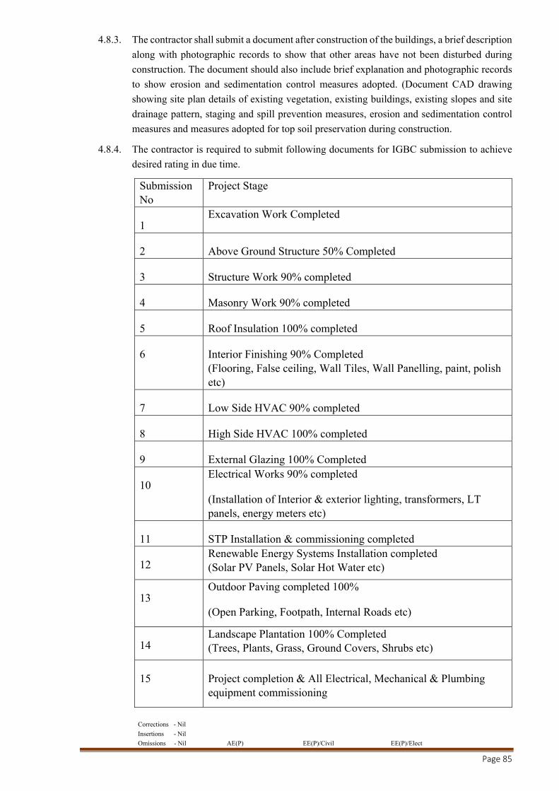
Corrections - Nil
Insertions - Nil
Omissions - Nil AE(P) EE(P)/Civil EE(P)/Elect
Page 85
4.8.3. The contractor shall submit a document after construction of the buildings, a brief description
along with photographic records to show that other areas have not been disturbed during
construction. The document should also include brief explanation and photographic records
to show erosion and sedimentation control measures adopted. (Document CAD drawing
showing site plan details of existing vegetation, existing buildings, existing slopes and site
drainage pattern, staging and spill prevention measures, erosion and sedimentation control
measures and measures adopted for top soil preservation during construction.
4.8.4. The contractor is required to submit following documents for IGBC submission to achieve
desired rating in due time.
Submission No
Project Stage
1 Excavation Work Completed
2 Above Ground Structure 50% Completed
3 Structure Work 90% completed
4 Masonry Work 90% completed
5 Roof Insulation 100% completed
6 Interior Finishing 90% Completed (Flooring, False ceiling, Wall Tiles, Wall Panelling, paint, polish etc)
7 Low Side HVAC 90% completed
8 High Side HVAC 100% completed
9 External Glazing 100% Completed
10 Electrical Works 90% completed
(Installation of Interior & exterior lighting, transformers, LT panels, energy meters etc)
11 STP Installation & commissioning completed
12 Renewable Energy Systems Installation completed (Solar PV Panels, Solar Hot Water etc)
13 Outdoor Paving completed 100%
(Open Parking, Footpath, Internal Roads etc)
14 Landscape Plantation 100% Completed (Trees, Plants, Grass, Ground Covers, Shrubs etc)
15 Project completion & All Electrical, Mechanical & Plumbing equipment commissioning
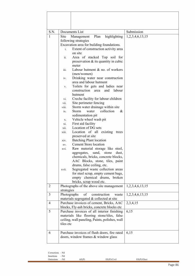
Corrections - Nil
Insertions - Nil
Omissions - Nil AE(P) EE(P)/Civil EE(P)/Elect
Page 86
S.N. Documents List Submission 1 Site Management Plan highlighting
following strategies Excavation area for building foundations.
i. Extent of construction activity area on site
ii. Area of stacked Top soil for preservation & its quantity in cubic meter
iii. Labour hutment & no. of workers (men/women)
iv. Drinking water near construction area and labour hutment
v. Toilets for gets and ladies near construction area and labour hutment
vi. Creche facility for labour children vii. Site perimeter fencing
viii. Storm water drainage within site ix. Storm water collection &
sedimentation pit x. Vehicle wheel wash pit
xi. First aid facility xii. Location of DG sets
xiii. Location of all existing trees preserved at site
xiv. Batching Plant location xv. Cement Store location
xvi. Raw material storage like steel, aggregates, sand, stone dust, chemicals, bricks, concrete blocks, AAC Blocks, stone, tiles, paint drums, false ceiling, etc.
xvii. Segregated waste collection areas for steel scrap, empty cement bags, empty chemical drums, broken bricks, scrap wood etc.
1,2,3,4,6,13,15
2 Photographs of the above site management strategies
1,2,3,4,6,13,15
3 Photographs of construction waste materials segregated & collected at site
1,2,3,4,6,13,15
4 Purchase invoices of cement, Bricks, AAC blocks, Fly-ash bricks, concrete blocks etc
2,3,4,15
5 Purchase invoices of all interior finishing materials like flooring stone/tiles, false ceiling, wall paneling, Paints, polishes, wall tiles etc
6,15
6 Purchase invoices of flush doors, fire rated doors, window frames & window glass
6,15
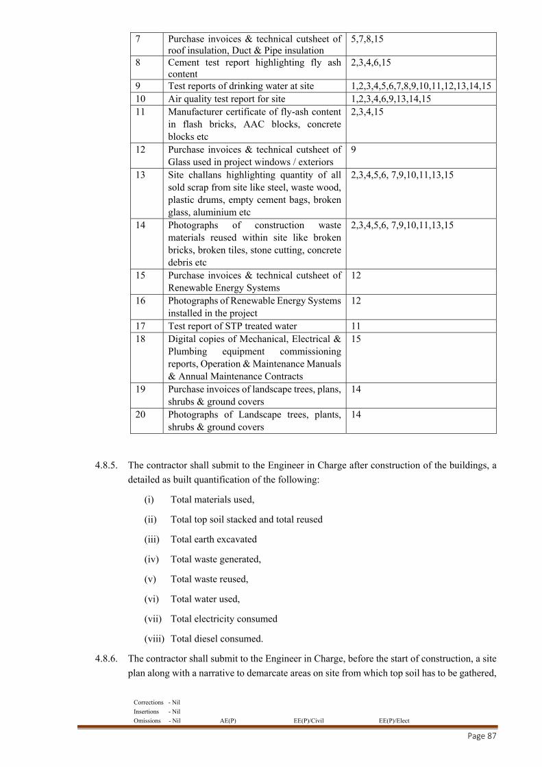
Corrections - Nil
Insertions - Nil
Omissions - Nil AE(P) EE(P)/Civil EE(P)/Elect
Page 87
7 Purchase invoices & technical cutsheet of roof insulation, Duct & Pipe insulation
5,7,8,15
8 Cement test report highlighting fly ash content
2,3,4,6,15
9 Test reports of drinking water at site 1,2,3,4,5,6,7,8,9,10,11,12,13,14,15 10 Air quality test report for site 1,2,3,4,6,9,13,14,15 11 Manufacturer certificate of fly-ash content
in flash bricks, AAC blocks, concrete blocks etc
2,3,4,15
12 Purchase invoices & technical cutsheet of Glass used in project windows / exteriors
9
13 Site challans highlighting quantity of all sold scrap from site like steel, waste wood, plastic drums, empty cement bags, broken glass, aluminium etc
2,3,4,5,6, 7,9,10,11,13,15
14 Photographs of construction waste materials reused within site like broken bricks, broken tiles, stone cutting, concrete debris etc
2,3,4,5,6, 7,9,10,11,13,15
15 Purchase invoices & technical cutsheet of Renewable Energy Systems
12
16 Photographs of Renewable Energy Systems installed in the project
12
17 Test report of STP treated water 11 18 Digital copies of Mechanical, Electrical &
Plumbing equipment commissioning reports, Operation & Maintenance Manuals & Annual Maintenance Contracts
15
19 Purchase invoices of landscape trees, plans, shrubs & ground covers
14
20 Photographs of Landscape trees, plants, shrubs & ground covers
14
4.8.5. The contractor shall submit to the Engineer in Charge after construction of the buildings, a
detailed as built quantification of the following:
(i) Total materials used,
(ii) Total top soil stacked and total reused
(iii) Total earth excavated
(iv) Total waste generated,
(v) Total waste reused,
(vi) Total water used,
(vii) Total electricity consumed
(viii) Total diesel consumed.
4.8.6. The contractor shall submit to the Engineer in Charge, before the start of construction, a site
plan along with a narrative to demarcate areas on site from which top soil has to be gathered,
Corrections - Nil
Insertions - Nil
Omissions - Nil AE(P) EE(P)/Civil EE(P)/Elect
Page 88
designate area where it will be stored, measures adopted for top soil preservation and indicate
areas where it will be reapplied after construction is complete.
4.8.7. The contractor shall submit to the Engineer-in-charge, a detailed narrative (not more than
250 words) on provision for safe drinking water and sanitation facility for construction
workers and site personnel.
4.8.8. Provide supporting document from the manufacturer of the cement specifying the flyash
content in PPC used in reinforced concrete.
4.8.9. The contractor shall submit the following information to the Engineer-in-charge at the end
of construction, for all material brought to site for construction purposes, including
manufacturer’s certifications, verifying information, and test data, where Specifications
sections require data relating to environmental issues including but not limited to:
(i) Source of products: Supplier details and location of the supplier.
(ii) Project Recyclability: Submit information to assist Owner and Contractor in recycling
materials involved in shipping, handling, and delivery, and for temporary materials
necessary for installation of products.
(iii) Recycled Content: Submit information regarding product post-industrial recycled and
post-consumer recycled content, Use the Recycled Content Certification Form, to be
provided by the Commissioning Authority appointed for the Project.
(iv) Product Recyclability: Submit information regarding product and products
component’s recyclability including potential sources accepting recyclable materials
where ever applicable.
(v) Provide final certification of well-managed forest of origin to provide final
documentation of certified sustainably harvested status: Acceptable wood, certified
sustainably harvested, certifications shall include:
Wood suppliers’ certificate issued by one of the Forest Stewardship Council-
accredited certifying agencies;
Suppliers’ invoice detailing the quantities of certified wood products for project;
Letter from one of a certifying agency corroborating that the products on the wood
supplier’s invoice originate from certified well-managed forests.
(vi) Clean tech: Provide pollution clearance certificates from all manufacturers of
materials
(vii) Indoor Air quality and Environmental Issues: Submit emission test data, sourced from
the manufacturers, produced by acceptable testing laboratory listed in Quality
Assurance Article for materials as required in each specific Specification section.
Certifications from manufacturers of Low VOC paints, adhesives, sealant and
polishes used at this particular project site.
Certification from manufacturers of composite wood products/agro fibre products
on the absence of added urea formaldehyde resin in the products supplied to them
to this particular site.
Corrections - Nil
Insertions - Nil
Omissions - Nil AE(P) EE(P)/Civil EE(P)/Elect
Page 89
Submit environmental and pollution clearance certificates for all diesel generators
installed as part of this project.
(viii) Provide total support to Engineer-in-charge and Green Building Consultants appointed
by the Engineer-in-charge in completing all Green Building Rating related formalities,
including signing of forms, providing signed letters in the contractor’s letterhead
whenever required.
4.9. EQUIPMENT
4.9.1. To ensure energy efficiency during and post construction all pumps, motors and engines used
during construction or installed, shall be subject to approval of the Engineer-in-charge.
4.9.2. All lighting installed by the contractor around the site and at the labour quarters during
construction shall be CFL bulbs of the appropriate illumination levels. This condition is a
must, unless specifically prescribed.
4.9.3. The contractor is expected to go through all other conditions of the LEED & GRIHA rating
stipulations. Failure to adhere to any of the above-mentioned items, without approval of the
Engineer-in-charge, shall be deemed as a violation of contract and the contractor shall be
held liable for penalty as per terms of the agreement.
4.9.4. In case any penalty is imposed by any Hon’ble Court, NGT or any other authority due to
non-compliance of any statutory order, or law or guidelines or pollution control or
environmental norms, the same will be borne by the contractor.
4.10. SUBMISSION OF POLLUTION CONTROL PLAN
4.10.1. The contractor shall submit the detailed action plan for control of pollution and for adherence
to all the environmental guidelines/Laws/statutes/Court Orders/NGT orders/orders of
pollution control authorities through the entire period of construction at site. The detailed
action plan shall be submitted to the Engineer-in-Charge within 15 days of the stipulated
date of start of work and shall be got approved from the Engineer-in-charge.
4.10.2. The contractor shall arrange for control measures of all dust/noise/emission from the
construction activities at site of work and shall install screens/curtains/ covers/dust trappers
etc. as per guidelines/orders of the NGT/Court of law/ statutory authorities etc. No hindrance
shall be allowed, arising out of any stay/stopping of work from any court/statutory
authority/NGT/Govt. Authorities as a consequence of the contractor not adhering to any
pollution control guideline/law/order of the state bodies during the construction period.
Nothing shall be paid to the contractor on account of expenses for any
dust/pollution/emission control measures at the site of work or any delay in work due to any
orders passed by any court/ statutory authority/Govt. Authorities during the period of
construction.
4.10.3. A compensation of Rs. 5,000/- per day will be levied and recovered from the dues of the
contractor for each day of delay beyond 15 days for non-submission of pollution control
plan.
4.10.4. The contractor is strongly advised to study all dust/Noise/emission/ pollution control
norms/laws/Court Orders before bidding for the work and quote his rates accordingly for any
liability which may arise on this account during the period of construction.
Corrections - Nil
Insertions - Nil
Omissions - Nil AE(P) EE(P)/Civil EE(P)/Elect
Page 90
PARTICULAR SPECIFICATIONS
1.0 EARTH WORK
1.1 The work shall be done in accordance with CPWD Specifications - 2009 - Vol.I & Vol. II and
National Building Code 2016 with upto date correction slips.
1.2 Excavation shall be undertaken to the width of the Basement / Retaining wall footing including
necessary margins for construction operation as per drawing or directed otherwise. Where the
nature of soil or the depth of the trench and season of the year, do not permit vertical sides, the
contractor at his own expense shall put up the necessary shoring, strutting and planking or cut
slopes with or without steps, to a safer angle or both with due regard to the safety of personnel
and works and to the satisfaction of the Engineer, Measurement of plan area of excavation for
payment shall be permitted only. Nothing extra shall be paid for making steps and slopes etc. as
required.
1.3 The contractor shall make at his own cost all necessary arrangements for maintaining water level,
in the area where works are under execution low enough so as not to cause any harm to the works
or problems in carrying out with the execution and the rates for all items of work shall be
considered as inclusive of pumping out or bailing out water, if required, for which no extra
payment shall be made. This will include water coming from any source, such as rains,
accumulated rain water, floods, leakages from sewer and water mains, subsoil water table being
high or due to any other cause whatsoever. The contractor shall make necessary provision of
pumping, dredging, and bailing out water coming from all above sources and excavation and
other works shall be kept free of water by providing suitable system approved by the Engineer-
in-charge.
1.4 Sub-soil water table at work site is reported to be about 9.0m below general ground level. The
water level may vary due to rainy season or due to dewatering etc. in order to avoid possibility
of basement floor of building being getting uplifted/damaged due to water pressure, the
contractor shall make arrangement for lowering the ground water table below the proposed
foundation level as approved by Engineer-in-charge. Sub soil water table shall be maintained at
least 50 cm below the P.C.C. level during laying of P.C.C., water proofing treatment, laying of
basement raft and beams including filling of earth/sand under the basement floor. The water table
shall not be allowed to rise above base of raft level until completion of outer retaining walls
including water proofing of vertical surface of walls and back filling along the walls up to ground
level and until the structure attains such height to counter balance the uplift pressure. However,
the contractor should inspect the site and make his own assessment about sub-soil water level
likely to be encountered at the time of execution and quote his rates accordingly. Rate of all items
are inclusive of pumping out or bailing out water, if required. Nothing extra on this account
whatsoever shall be paid to him unless otherwise specified. The sequence of construction shall
be got approved by the Engineer-in-charge.
1.5 All the major excavation shall be carried out by mechanical excavator. No extra payment shall
be made for that.
1.6 Any trenching and digging for laying sewer lines/water lines/cables etc. shall be commenced by
the contractor only when all men, machinery’s and materials have been arranged and closing of
the trench(s) thereafter shall be ensured within the least possible time.
Corrections - Nil
Insertions - Nil
Omissions - Nil AE(P) EE(P)/Civil EE(P)/Elect
Page 91
1.7 The rates are inclusive for all depths & nothing extra shall be paid for additional lift etc.
2.0 CONCRETE WORK
2.1 The work shall be done in accordance with CPWD Specifications - 2009 - Vol.I & Vol. II with
upto date correction slips.
2.2 If the quantity of cement actually used in the work is found to be more than the theoretical
quantity of cement including authorized variation, nothing extra shall be payable to the contractor
on this account. In the event of it being discovered that after the completion of the work, the
quantity of cement used is less than the quantity ascertained as herein before provided (allowing
variation on the minus side as stipulated in clause 42) the cost of quantity of cement so less used
shall be recovered from the contractor at the rate as specified in schedule ‘F’. Decision of the
Engineer-in-Charge in regard to the quantity of cement which should have been actually used as
per the schedule and recovery at the rate specified shall be final and binding on the contractor.
2.3 For non-scheduled items, the decision of the Superintending Engineer regarding theoretical
quantity of the cement which should have been actually used shall be final and binding on the
contractor.
3.0 RCC/CC WORK (DESIGN MIX CONCRETE)
3.1 The Design Mix Concrete will be designated based on the principles given in BIS codes IS:456,
IS:10262 & SP:23. The condition and specifications stated herein shall have precedence overall
conditions and specifications stated in relevant BIS codes/CPWD specifications. The concrete
mix shall be designed for specified target mean compressive strength in order to ensure that the
work test results do not fall below the acceptance criteria specified for the concrete mix. The
Contractor shall design mixes for each class of concrete indicating that the concrete ingredients
and proportions will result in concrete mix meeting requirements specified. The mix shall be
designed with quantities of admixture / plasticizer proposed to achieve required workability &
strength. The specifications mentioned here in below shall be followed for Design Mix Concrete.
3.2 The sources of coarse aggregate, fine aggregate & water to be used in concrete work shall be
identified by the contractor & he will satisfy himself regarding their conforming to the relevant
specification & their availability before getting the same approved by the Engineer-in-Charge.
3.3 Coarse Aggregate:As per CPWD Specifications - 2009 - Vol.I & Vol. II with up to date correction
slips.
3.4 Fine Aggregate:As per CPWD Specifications - 2009 - Vol.I & Vol. II with upto date correction
slips.
3.5 Water: It shall confirm to requirements laid down in IS:456-2000 / CPWD Specifications - 2009
- Vol.I & Vol. II with upto date correction slips.
3.6 Cement: PPC shall be used for design mix concrete and shall conform to IS-1489 (part-I).
However, if higher grade of cement is used by the contractor nothing extra shall be paid on this
account.
3.7 Admixtures / Plasticizers: - The admixture shall confirm to IS:9103, wherein required, the
admixture of approved quality and approved make only shall be used to attain the required
workability. Nothing extra shall be paid for use of admixtures.
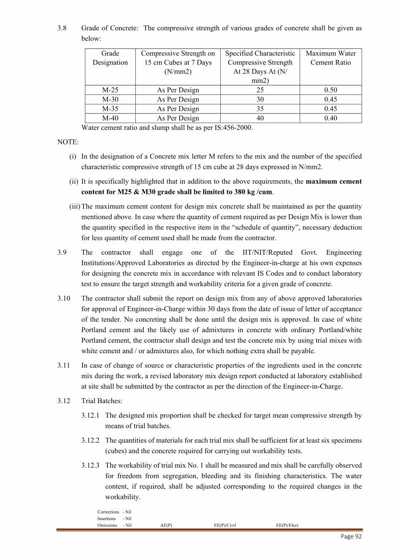
Corrections - Nil
Insertions - Nil
Omissions - Nil AE(P) EE(P)/Civil EE(P)/Elect
Page 92
3.8 Grade of Concrete: The compressive strength of various grades of concrete shall be given as
below:
Grade Designation
Compressive Strength on 15 cm Cubes at 7 Days
(N/mm2)
Specified Characteristic Compressive Strength
At 28 Days At (N/ mm2)
Maximum Water Cement Ratio
M-25 As Per Design 25 0.50 M-30 As Per Design 30 0.45 M-35 As Per Design 35 0.45 M-40 As Per Design 40 0.40
Water cement ratio and slump shall be as per IS:456-2000.
NOTE:
(i) In the designation of a Concrete mix letter M refers to the mix and the number of the specified
characteristic compressive strength of 15 cm cube at 28 days expressed in N/mm2.
(ii) It is specifically highlighted that in addition to the above requirements, the maximum cement
content for M25 & M30 grade shall be limited to 380 kg /cum.
(iii) The maximum cement content for design mix concrete shall be maintained as per the quantity
mentioned above. In case where the quantity of cement required as per Design Mix is lower than
the quantity specified in the respective item in the “schedule of quantity”, necessary deduction
for less quantity of cement used shall be made from the contractor.
3.9 The contractor shall engage one of the IIT/NIT/Reputed Govt. Engineering
Institutions/Approved Laboratories as directed by the Engineer-in-charge at his own expenses
for designing the concrete mix in accordance with relevant IS Codes and to conduct laboratory
test to ensure the target strength and workability criteria for a given grade of concrete.
3.10 The contractor shall submit the report on design mix from any of above approved laboratories
for approval of Engineer-in-Charge within 30 days from the date of issue of letter of acceptance
of the tender. No concreting shall be done until the design mix is approved. In case of white
Portland cement and the likely use of admixtures in concrete with ordinary Portland/white
Portland cement, the contractor shall design and test the concrete mix by using trial mixes with
white cement and / or admixtures also, for which nothing extra shall be payable.
3.11 In case of change of source or characteristic properties of the ingredients used in the concrete
mix during the work, a revised laboratory mix design report conducted at laboratory established
at site shall be submitted by the contractor as per the direction of the Engineer-in-Charge.
3.12 Trial Batches:
3.12.1 The designed mix proportion shall be checked for target mean compressive strength by
means of trial batches.
3.12.2 The quantities of materials for each trial mix shall be sufficient for at least six specimens
(cubes) and the concrete required for carrying out workability tests.
3.12.3 The workability of trial mix No. 1 shall be measured and mix shall be carefully observed
for freedom from segregation, bleeding and its finishing characteristics. The water
content, if required, shall be adjusted corresponding to the required changes in the
workability.
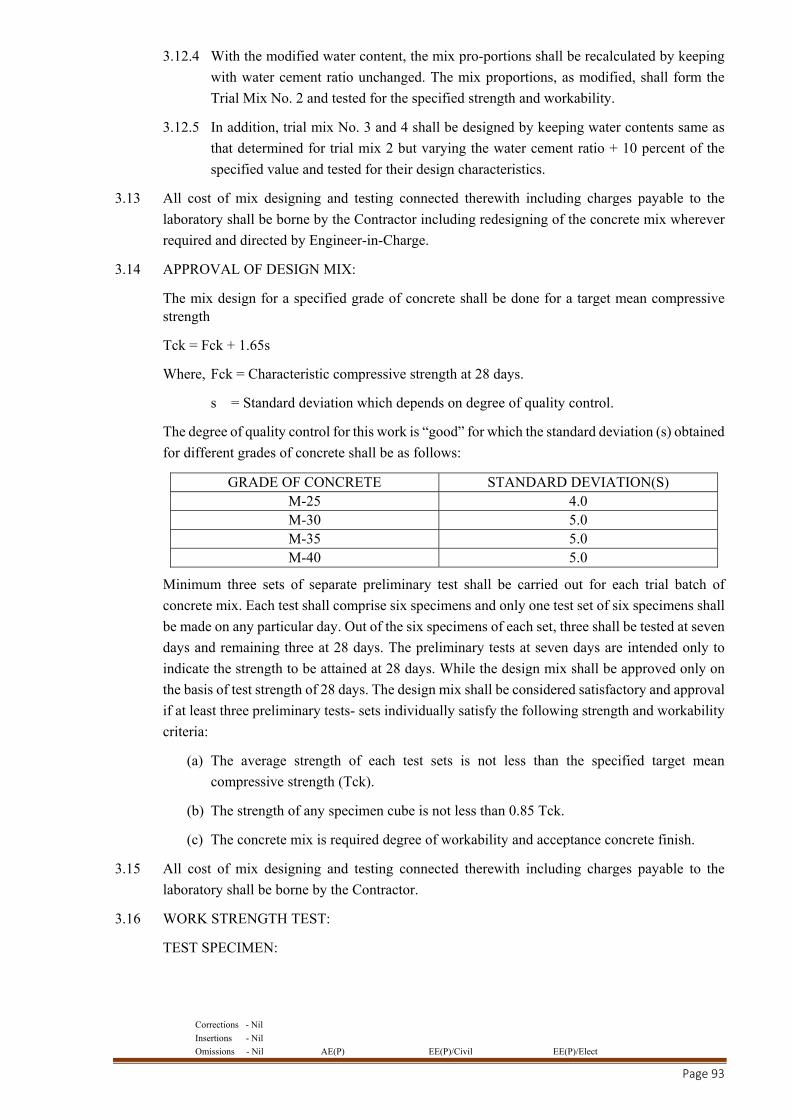
Corrections - Nil
Insertions - Nil
Omissions - Nil AE(P) EE(P)/Civil EE(P)/Elect
Page 93
3.12.4 With the modified water content, the mix pro-portions shall be recalculated by keeping
with water cement ratio unchanged. The mix proportions, as modified, shall form the
Trial Mix No. 2 and tested for the specified strength and workability.
3.12.5 In addition, trial mix No. 3 and 4 shall be designed by keeping water contents same as
that determined for trial mix 2 but varying the water cement ratio + 10 percent of the
specified value and tested for their design characteristics.
3.13 All cost of mix designing and testing connected therewith including charges payable to the
laboratory shall be borne by the Contractor including redesigning of the concrete mix wherever
required and directed by Engineer-in-Charge.
3.14 APPROVAL OF DESIGN MIX:
The mix design for a specified grade of concrete shall be done for a target mean compressive strength
Tck = Fck + 1.65s
Where, Fck = Characteristic compressive strength at 28 days.
s = Standard deviation which depends on degree of quality control.
The degree of quality control for this work is “good” for which the standard deviation (s) obtained
for different grades of concrete shall be as follows:
GRADE OF CONCRETE STANDARD DEVIATION(S) M-25 4.0 M-30 5.0 M-35 5.0 M-40 5.0
Minimum three sets of separate preliminary test shall be carried out for each trial batch of
concrete mix. Each test shall comprise six specimens and only one test set of six specimens shall
be made on any particular day. Out of the six specimens of each set, three shall be tested at seven
days and remaining three at 28 days. The preliminary tests at seven days are intended only to
indicate the strength to be attained at 28 days. While the design mix shall be approved only on
the basis of test strength of 28 days. The design mix shall be considered satisfactory and approval
if at least three preliminary tests- sets individually satisfy the following strength and workability
criteria:
(a) The average strength of each test sets is not less than the specified target mean
compressive strength (Tck).
(b) The strength of any specimen cube is not less than 0.85 Tck.
(c) The concrete mix is required degree of workability and acceptance concrete finish.
3.15 All cost of mix designing and testing connected therewith including charges payable to the
laboratory shall be borne by the Contractor.
3.16 WORK STRENGTH TEST:
TEST SPECIMEN:
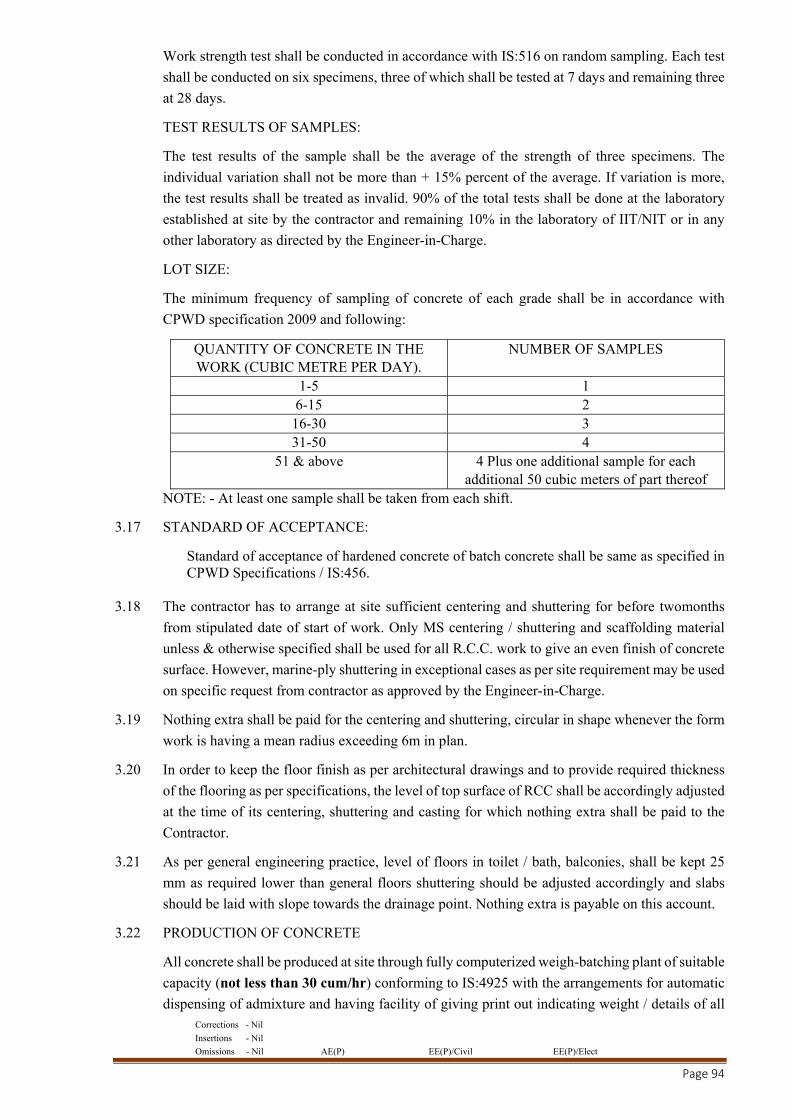
Corrections - Nil
Insertions - Nil
Omissions - Nil AE(P) EE(P)/Civil EE(P)/Elect
Page 94
Work strength test shall be conducted in accordance with IS:516 on random sampling. Each test
shall be conducted on six specimens, three of which shall be tested at 7 days and remaining three
at 28 days.
TEST RESULTS OF SAMPLES:
The test results of the sample shall be the average of the strength of three specimens. The
individual variation shall not be more than + 15% percent of the average. If variation is more,
the test results shall be treated as invalid. 90% of the total tests shall be done at the laboratory
established at site by the contractor and remaining 10% in the laboratory of IIT/NIT or in any
other laboratory as directed by the Engineer-in-Charge.
LOT SIZE:
The minimum frequency of sampling of concrete of each grade shall be in accordance with
CPWD specification 2009 and following:
QUANTITY OF CONCRETE IN THE WORK (CUBIC METRE PER DAY).
NUMBER OF SAMPLES
1-5 1 6-15 2
16-30 3 31-50 4
51 & above 4 Plus one additional sample for each additional 50 cubic meters of part thereof
NOTE: - At least one sample shall be taken from each shift.
3.17 STANDARD OF ACCEPTANCE:
Standard of acceptance of hardened concrete of batch concrete shall be same as specified in CPWD Specifications / IS:456.
3.18 The contractor has to arrange at site sufficient centering and shuttering for before twomonths
from stipulated date of start of work. Only MS centering / shuttering and scaffolding material
unless & otherwise specified shall be used for all R.C.C. work to give an even finish of concrete
surface. However, marine-ply shuttering in exceptional cases as per site requirement may be used
on specific request from contractor as approved by the Engineer-in-Charge.
3.19 Nothing extra shall be paid for the centering and shuttering, circular in shape whenever the form
work is having a mean radius exceeding 6m in plan.
3.20 In order to keep the floor finish as per architectural drawings and to provide required thickness
of the flooring as per specifications, the level of top surface of RCC shall be accordingly adjusted
at the time of its centering, shuttering and casting for which nothing extra shall be paid to the
Contractor.
3.21 As per general engineering practice, level of floors in toilet / bath, balconies, shall be kept 25
mm as required lower than general floors shuttering should be adjusted accordingly and slabs
should be laid with slope towards the drainage point. Nothing extra is payable on this account.
3.22 PRODUCTION OF CONCRETE
All concrete shall be produced at site through fully computerized weigh-batching plant of suitable
capacity (not less than 30 cum/hr) conforming to IS:4925 with the arrangements for automatic
dispensing of admixture and having facility of giving print out indicating weight / details of all
Corrections - Nil
Insertions - Nil
Omissions - Nil AE(P) EE(P)/Civil EE(P)/Elect
Page 95
ingredient of concrete in each lot/ batch and variations from the approved design mix if any.
Fully automatic batching and mixing plant having capacity not less than 30 cum/ hour shall be
installed at the arranged site by the contractor. The batching and mixing plants shall be dedicated
plants for this project. Contractor shall make his own arrangements for the necessary
infrastructure for installation of batching plant and other machineries. However, if due to any
reason, contractor wishes to supplement the concrete from Ready Mix Concrete (RMC) supplier,
he is permitted to procure the same from the source approved by the Engineer-in-charge at his
own cost. In such a situation nothing extra shall be paid to the contractor. All technical
requirements such as cement type and minimum cement quantity, w/c ratio, slump, admixture
etc. shall be conveyed to RMC supplier by the contractor and contractor shall be wholly
responsible for ensuring the property of concrete as required at site, nothing extra shall be paid
to the contractor.
The contractor may take some time to install his own batching plants at the arranged site and till
the batching plants are installed, the contractor is permitted to procure concrete from approved
Ready-Mix Concrete (RMC) supplier for a period of 3 months from date of start of work or the
period as agreed by Engineer-in-Charge. Similarly, when the work is nearing completion and
daily requirement of concrete is very less, if agreed by the Engineer-in-Charge, the contractor
may be permitted to procure the concrete from approved Ready-Mix Concrete (RMC) supplier
and nothing extra shall be paid to the contractor on this account.
3.23 LAND FOR TEMPORARY USE
The land for labour camps & batching Plant shall be arranged by the contractor. The lease/rent
charges shall be borne by the contractor.The Engineer-in-Charge shall extend necessary help and
issue necessary recommendations etc. to the concerned clients / department for temporary
allotment of land during construction period if land is available with them. In such cases, the
contractor shall vacate the land after completion of work in same condition as was at the time of
allotment.
3.24 BATCHING PLANT
The batching and mixing plant shall be fully automatic of suitable capacity not less than
30cum/hour. Automatic batcher shall be charged by devices which when actuated by a single
starter switch will automatically start the weighing operation of each material and stop
automatically when the designated weight of each material is fed in the mixer. The batching plant
shall have automatic arrangement for dispensing the admixture and shall be capable of
discharging water in morethan one stage. A batching plant essentially shall consist of the
following components:
Separate storage bins for different sizes of aggregates, silo for cement and flyash; water
storage tank.
Batching equipment
Mixers
Control Panels
Mechanical material feeding and elevating arrangements
Corrections - Nil
Insertions - Nil
Omissions - Nil AE(P) EE(P)/Civil EE(P)/Elect
Page 96
The compartments of storage bins for aggregates shall be approximately of equal size. The
cement compartment shall be centrally located in the batching plant. It shall be water tight and
provided with necessary air vent, aeration fittings for proper flow of cement & emergency cut
off gate. The aggregate and sand shall be charged by power operated centrally revolving chute.
The entire plant from mixer floor upward shall be enclosed and insulated. The batch bins shall
be constructed so as to be self-cleansing during draw-down. The batch bins shall in general
conform to the requirements of IS:4925.
The batching equipment shall be capable of determining and controlling the prescribed amounts
of various constituent materials for concrete accurately i.e. water, cement, sand, individual size
of coarse aggregates etc. The accuracy of measuring devices shall fall within the following limits.
Measurement of Cement: + 2% of the quantity of cement in eachbatch
Measurement of Water: + 3% of the quantity of water in each batch
Measurement of Aggregate: + 3% of the quantity of aggregate in each batch
Measurement of Admixture: + 3% of the quantity of admixture in each batch
The batching and mixing plant shall have the provision of adjusting the plus / minus quantity of
various ingredients in the next batch so that there is no variation in quantity of ingredients from
design mix in a lot consisting of 5 to 6 batches.
The mixer in the batching plant shall be so arranged that mixing action in the mixer can be
observed from the operator’s station. The mixer shall be equipped with a mechanically or
electrically operated timing, signaling and metering device which will indicate and assure
completion of the required mixing period. The mixer shall have all other components as specified
in IS:4925.
3.25 TRANSPORTATION, PLACING AND COMPACTION OF CONCRETE
Mixed concrete from the RMC / Batching plant shall be transported to the point of placement by
transit mixers and placed in position through concrete pumps and/or steel closed bottom buckets
capable of carrying minimum 0.6 cum concrete. In case the concrete is proposed to be transported
by transit mixer, the mixing speed shall not be less than 4 rev/min. of the drum nor greater than
a speed resulting in a peripheral velocity of the drum 70 m/minutes at its largest diameter. The
agitating speed of the agitator shall be not less than 2 rev/min nor more than 6 rev/min of the
drum. The number of revolution of the mixing drum or blades at mixing speed shall be between
70 to 100 revolutions for a uniform mix, after all ingredients, have been charged into the drum.
Unless tempering water is added, all rotation after 100 revolutions shall be at agitating speed of
2 to 6 rev/min and the number of such rotations shall not exceed 250. The general construction
of transit mixer and other requirement shall conform to IS:5892.
In case concrete is to be transported by pumping, the conduit shall be primed by pumping a batch
of mortar through the line to lubricate it. Once the pumping is started, it shall not be interrupted
(if at all possible) as concrete standing idle in the line is liable to cause a plug. The operator shall
ensure that some concrete is always there in the pump receiving hopper during operation. The
lines shall always be maintained clean and shall be free of dents at all stages. Special precaution
shall be taken that surrounding temperature during concreting shall not exceed 30 degrees
centigrade.

Corrections - Nil
Insertions - Nil
Omissions - Nil AE(P) EE(P)/Civil EE(P)/Elect
Page 97
Except where otherwise agreed to by the Engineer-in-Charge, concrete shall be deposited in
horizontal layers to a compacted depth of not more than 450 mm. Unless agreed to by the
Engineer- in-Charge, concrete shall not be dropped into place from a height exceeding 1.5m. In
order to avoid such situations chutes, tremie pipe or closed bottom buckets shall be used. These
shall be kept clean and used in such a way as to avoid segregation. Slope of the chute shall be
so adjusted that concrete flows without the use of excessive quantity of water. The delivery end
of chute shall be as close as possible to the point of deposit. The chute shall be thoroughly flushed
with water before and after each working period and the water used for this purpose shall be
discharged outside the formwork. The concrete shall be compacted by using immersion type
vibrators. When the concrete is being continuously deposited to a uniform depth along a member,
vibrator shall not be operated within one meter of free end of the advancing concrete. Every
effort shall be made to keep the surface of the previously placed layer of concrete alive so that
the succeeding layer can be amalgamated with it by the vibration process. In case the concrete
in underlying layer has hardened to such an extent that it cannot be penetrated by the vibrator but
is still fresh (that is, just after initial set), un-imposed bond shall be achieved between the top and
underlying layer by first scarifying the lower layer before the new concrete is placed by
systematically and thoroughly vibrating the new concrete. The points of insertion of vibrator in
the concrete shall be so spaced that the range of action overlap to some extent and the freshly
filled concrete is sufficiently consolidated at all locations. The spacing between the dipping
positions of vibrator shall be maintained uniformly throughout the surface of concrete so that
concrete is uniformly vibrated. The vibrating head shall be regularly and uniformly inserted in
the concrete so that it penetrates of its own accord and shall be withdrawn slowly whilst running
so as to allow redistribution of concrete in its way and allow the concrete to flow back into the
hole behind the vibrator. The vibrator head shall be kept in one position till the concrete within
its influence is completely consolidated. Vibration shall be continued until the coarse aggregate
particle have blended into the surface but have not disappeared. The contractor shall keep at least
one additional vibrator in serviceable condition to be used in the event of breakdowns and
maintenance problems.
The vibrator head shall not be brought more than 200 mm near to the formwork as this may cause
formation of water stagnations. The formwork shall be strong and great care shall be exercised
in its assembly. It shall be designed to take up increased pressure of concrete and pressure
variations caused in the neighborhood of vibrating head, which may result in excessive local
stress on the formwork. The joints of the formwork shall be made and maintained tight and close
enough to prevent the squeezing out slurry or sucking in of air during vibration. The formwork
to receive concrete shall be cleaned and made free from standing water, dust, etc. The contractor
shall keep provision for screed and shutter vibrators at site.
No concrete shall be placed in any part of the structure until the approval of Engineer-in-Charge
has been obtained. If concreting is not started within 24 hours of the approval being given, it
shall have to be obtained again from the Engineer-in-Charge. Concreting shall be done
continuously over the area between construction joints. Fresh concrete shall not be placed against
concrete which has been in position for more than 30 minutes unless a proper construction joint
is formed. When concreting has to be resumed on a surface which has hardened, it shall be
roughened, swept, clean, thoroughly wetted and covered with a 13 mm thick layer of mortar
composed of cement and sand in the same ratio as in the concrete mix itself. The 13 mm layer
of mortar shall be freshly mixed and placed immediately before placing of new concrete.
Corrections - Nil
Insertions - Nil
Omissions - Nil AE(P) EE(P)/Civil EE(P)/Elect
Page 98
Where concrete is not fully hardened, all latency shall be removed by scrubbing the wet surface
with wire or bristle brushes. Care shall be taken to avoid dislodgement of particles of coarse
aggregate. The surface shall then be thoroughly wetted, all free water removed and then coated
with neat cement grout. Particular attention shall be given to corners and close spots.
In case of rejection of concrete on account of unacceptable compressive strength, governed by
para “Standard of Acceptance” as above, the work for which samples have failed shall be redone
at the cost of contractor. However, the Engineer-in-Charge may order for additional tests (like
cutting cores, ultrasonic pulse velocity test, load test on structure on part of structure, etc) to be
carried out at the cost of contractor to ascertain if the portion of structure wherein concrete
represented by the sample has been used, can be retained on the basis of results of individual or
combination of these tests. The Contractor shall take remedial measures necessary to retain the
structure as approved by the Engineer-in-Charge without any extra cost. However, for payment,
the basis of rate payable to contractor shall be governed by the 28 days cube test results and
reduced rates shall be regulated in accordance with para 3.24.2.
4.0 SHUTTERING / FORM WORK
4.1 The work shall be done in accordance with CPWD Specifications - 2009 - Vol. I & Vol. II with
upto date correction slips.
4.2 Steel shuttering as approved by the Engineer-in-Charge shall be used by the contractor. Minimum
size of shuttering plates shall be 600mm x 900mm except for the case when closing pieces
required to complete the shuttering panels. Dented, broken, cracked, twisted or rusted shuttering
plates shall not be allowed to be used on the work.
4.3 The shuttering plates shall be cleaned properly with electrically driven sanders to remove any
cement slurry or cement mortar or rust. Proper shuttering oil or debonding compound shall be
applied on the surface of the shutter plates in the requisite quantity before assembly of steel
reinforcement.
4.4 The joint filler shall be resilient closed cell expanded polyethene and non-tainting as
manufactured by Supreme Industries Ltd.
4.5 Providing joint filler of required thickness in position to substrate using either double sided foam
adhesive tape or neoprene synthetic rubber adhesive. When forming expansion joint with the
Board in in-situ concrete, joint sealing slots can be readily formed in the following matter-
a) Before installing, simply cut off a strip of the required depth. Then install the filler flush with
the finished surface.
b) Prior to sealing, the top strip can then be pulled easily from the joint to provide an
uncontaminated sealing slot ready for preparation and sealing.
5.0 REINFORCEMENT
5.1 The reinforcement shall be done as per CPWD Specifications - 2009 - Vol.I & Vol. II with upto
date correction slips.
5.2 The item of reinforcement of RCC work includes all operations including straightening, cutting,
bending, welding, binding with annealed steel or welding and placing in position at all the floors
with all leads and lift complete as per CPWD Specification - 2009 - Vol.I & Vol. II with upto
date correction slips.
Corrections - Nil
Insertions - Nil
Omissions - Nil AE(P) EE(P)/Civil EE(P)/Elect
Page 99
5.3 To avoid displacement of bars in any direction and to ensure proper cover, only factory made
round type/rectangular cover blocks shall be used by the contractor. Nothing extra shall be
payable on this account.
6.0 PRE-CAST RCC WORK
6.1 Pre-cast reinforced concrete units shall be of grade or mix as specified. Provision shall be made
in the mould to accommodate fixing devices such as hooks, flats etc. And forming of notches
and holes. Each unit shall be cast in one operation. A sample of the unit shall be got approved
from Engineer-in-Charge before taking up the work.
6.2 Pre-cast units shall be clearly marked to indicate the top of member and its locations.
6.3 Pre-cast units shall be stored, transported and placed in position in such a manner that these are
not damaged.
7.0 BRICK WORK
7.1 Unless otherwise specified FPS Bricks shall be used in all items of brick work. The classification
of bricks brought by the contractor shall strictly conform to CPWD Specifications – 2009 Vol-1
& II with upto date correction slips or as specified. The work shall also include for leaving chases
/ notches for dowels / cramps for all kinds of cladding to come over brick work.
8.0 RANDOM RUBBLE MASONRY
8.1 Scope: This specification covers materials joints, laying and mode of measurement of Random
Rubble Masonry
8.2 Materials: Stones: The stone shall be of the type specified such as granite, trap, limestone, sand
stone, quartzite etc. and shall be obtained from the quarries, approved by the Engineer in charge.
Stone shall be hard, sound durable and free from weathering decay and defects like cavities,
cracks, flaws, sand holes, injurious veins, patches of loose or soft material and other similar
defects that may adversely affect its strength and appearance. As far as possible. Stones shall
be of uniform colour, quality or texture. Generally, stone shall not contain crypts crystalline silica
or chart, mica and other deleterious materials like iron-oxide organic impurities etc. Stone with
round surfaces shall be not is used.
8.3 Hearting and backing: Where hearting can accommodate a fair proportion of the stones used in
the hearting shall be of large size 25% of them shall exceed 0.01 cum. in content.
8.4 Quoins: The quoins shall be at least 30 cm in average length and 0.01cum in content and laid
alternately as headers and stretchers, out of then stone at course not exceeding 1 meter center to
center, shall be provide with a minimum length of 50cm and cross-sections 200 sq cm (Size of
bond specified above) on each exposed face.
8.5 Jamb Stones: The jambs shall be made with stones specified for quoins except that the stone
which were required to be provided at 1 meter center to center on both the exposed faces shall
here be provided only on the jamb and the length shall be equal to the thickness of the wall for
wall up to 60 cm and a line of headers shall be provided for walls thicker than 60 cm as specified
for bond.
8.6 Courses: The masonry shall be carried out in regular courses of height not exceeding 50 cm and
masonry on any day will not be raised more than 60 cm in height when using mortars having
compressive strength less than 20 kg/sq. cm at 28 days and 100 cm when using mortars exceeding
Corrections - Nil
Insertions - Nil
Omissions - Nil AE(P) EE(P)/Civil EE(P)/Elect
Page 100
this strength. No attempt shall be made to level up the masonry at each course by the use of thin
stones.
8.7 Thickness of Joints: The Joints shall not exceed 30mm at any point on the face. Clips of the
stones and spells shall be wedged into the face beds and joint to avoid excessive bed and joint
thickness.
8.8 Laying: Stones shall be laid on their natural bed and shall be solidly bedded full in mortar with
close joints, chips of stone spells be wedged into the work wherever necessary. No dry work or
hollow spaces shall be allowed and every stone whether large or small shall be carefully selected
to fit snugly the interstices between the large stones. Masonry shall be built breaking joints in all
the three directions. Bone stones and headers shall be properly laid into the work and shall be
marked by the contractor with white lead paint. The bond stones shall be provided at the rate of
two bond stones per sqm of face area.
8.9 Raking out joints: All the joints on the faces to be pointed or plastered shall be racked out with
racking tool to a depth of 20mm while the mortar is still green.
8.10 Mortar: The mortar used for joining shall be as specified.
8.11 Scaffolding: Single scaffolding having one set of vertical supports shall be sound and strong,
tied together by horizontal pieces, over which the scaffolding planks shall be fixed. The inner
end of the horizontal scaffolding member may rest in a hole provided in the masonry. Such holes
however, shall not be allowed in pillars under one metre in width or near the skew back of arches.
The holes left in masonry work for supporting scaffolding shall be filled and made good with
cement concrete 1:3:6 (1 cement : 3 coarse sand : 6 Stone aggregate 20 mm nominal size).
8.12 Protection: Green work shall be protected from rain by suitable covering. The work shall also be
suitable protected from damage, mortar dropping and rain during construction.
8.13 Curing: Masonry work in cement or composite mortar shall be kept constantly moist on all faces
for a minimum period of seven days. In case of masonry with fat lime mortar curing shall for at
least seven days thereafter.
8.14 Measurement: The work shall be measured by volume and the unit shall be cum. Walling curved
on plan to mean radius not exceeding 6 m shall be measured separately inclusive of all cuttings
waste and templates. Walling curved on plan to mean radius exceeding 6m shall be included with
the general walling and shall be measured net only. No deductions or additions on any account
shall be made for:
(i) Opening up to 500 sq. cm. in cross section (in calculating this area the size of the openings
shall include any separate lintel or still but not extra width of rebated reveals if any).
(ii) Ends of dissimilar materials (i.e. joints rafters, girders, purloins, trusses etc.) up to 500 sq.
cm. in cross section.
(iii) Bearings of chhajjas, slabs, steps, shelves etc. when the bearings are not paid for the
respective items.
8.15 Rate: The rate shall include the cost of materials and labour required for all the operations
described above and shall include the following:
8.16 Ranking out joints for plastering or pointing done as a separate item, or finishing flush as the
work proceeds.
Corrections - Nil
Insertions - Nil
Omissions - Nil AE(P) EE(P)/Civil EE(P)/Elect
Page 101
8.17 Preparing tops and sides of existing walls for raising and extending.
8.18 Rough cutting and waste forming gables cores, skew backs or spandrels of arches, splays at eaves
and all rough cutting in the body of walling unless otherwise specified.
8.19 Bond stones or cement concrete bond blocks.
8.20 Leading and making holes for pipes etc.
8.21 Bedding and pointing wall plates, lintels, and sills etc. in or on walls, bedding roof tiles and
corrugates sheets in or on walls.
8.22 Building in ends of joints, beams, lintels etc.
8.23 GUARANTEE:
Work of RR Stone Masonry shall carry five years guarantee to be reckoned from the date after
the expiry of maintenance period prescribed in the contract of the work against faulty
workmanship, finishing, unsound materials, structural instability and other related problems.
Five Years Guarantee bond in prescribed Performa attached herewith as Annexure-I shall be
submitted by the contractor to meet their liability / liabilities under the guarantee bond.
Five percent of the cost of RR Stone Masonry work shall also be retained as security deposit
and the amount so withheld would be released after Five Years to be reckoned from the date after
the expiry of maintenance period prescribed in the contract, if the performance of the work done
is found satisfactory. If any defect is noticed during the guarantee period, it shall be rectified by
the contractor within seven days of receipt of intimation of defects in the work. If the defects
pointed out are not attended to within the specified period, the same will be got done from another
agency at the risk and cost of contractor.
However, the security deposit deducted may be released in full against bank guarantee of
equivalent amount in favour of Engineer in charge, if so decided by the Engineer in charge.
The Security deposit against this item of work shall be in addition to the security deposit
mentioned elsewhere in contract form.
9.0 COURSED RUBBLE FACING MASONRY
9.1 Scope: This specification covers materials, joints, laying and mode of measurement of coursed
rubble facing masonry.
9.2 Materials: As per specification for Random Rubble Masonry.
9.3 Size of Stones:
(i) No dressed-up stone shall be less in length and breadth than its heights. At least 25% stones
shall be headers tailing into the work at least 2/3rd the thickness of wall
(ii) or full thickness of wall for walls 30 cm and less in thickness. Such stones shall be evenly
distributed over the entire face.
(iii) The quoins shall also be of the same height as the courses in which they occur and at least
50 cm in length.
(iv) The jambs shall be made with stones specified for quoins except that the length of stone
in alternate course shall be equal to the thickness of the wall for walls up to 60 cm.
Corrections - Nil
Insertions - Nil
Omissions - Nil AE(P) EE(P)/Civil EE(P)/Elect
Page 102
9.4 Dressing of Stones:
(i) Exposed face of stones shall be brought to near rectangular shape.
(ii) The bushing on exposed surfaces of the stones on outer surface of external walls shall not
exceed 2 cm.
(iii) Stones required to be used on outer surface of external walls; shall be dressed before use
in construction.
(iv) The beds and joints of exposed of stones on outer surface of external walls other than
quoins shall be hammer dressed at least for a distance of 4 cm from the face to be square
with the exposed faces. No rough tooling or chisel drafting would be required. The depth
of gap between the surfaces of sides and bed joints and straight edge held against them
shall not be more than 10 mm.
(v) The beds and joints of quoins & jambs shall be hammer dressed for a distance of at least
8 cm from the face to be square with the exposed faces and with each other. The depth of
gap between the surfaces of sides & beds joints and straight edge held against them shall
not be more than 10mm.
(vi) No rough tooling & chisel drafting would be required on the edges of the quoin & jamb
stones except on the corner edge defining the angle of the quoins & jambs. The corner
edge defining the angle of the quoins & jambs shall have 2.5 cm wide two-line chisel
drafting on both of the angle.
(vii) Masonry work shall be executed from exposed (outer) side of wall.
9.5 Courses: The stones shall be laid in courses not less than 15 cm in height. All the courses shall
be of the same height. When otherwise approved no course shall be thicker than any course below
it. Only one stone be used in the height of the course.
9.6 Thickness of Joint:
(i) The exposed face joints shall be more or less uniform in thickness and thickness of any
joint shall not exceed 20 mm.
(ii) Stones on outer side of wall shall be arranged suitably to stagger the vertical joints and
overlapping of vertical joints shall be avoided.
9.7 Hearting and Interior Face: The hearting and interior face shall be done in Random Rubble
Masonry, By virtue of doing coursed rubble facing on external face of size of stones used and
their dressing is carried out other than specified in the Random Rubble Masonry on internal face,
even than nothing extra shall be paid over and above, the item of Random Rubble Masonry for
internal face.
9.8 Laying: Each stone shall be laid in the work on its natural bed. Stones shall be thoroughly wetted
before laying when mortar used contains cement. The stones shall be laid full in mortar. The face
work, hearting and interior face work shall be brought up simultaneously but no attempt should
be made to level up the Random Rubble Masonry at each step by the use of chips. The masonry
shall be carried truly in plumb and square. The courses shall be horizontal and joints vertical.
9.9 Raking out Joints: As per specification for Random Rubble Masonry.
9.10 Mortar: As per specification for Random Rubble Masonry.
Corrections - Nil
Insertions - Nil
Omissions - Nil AE(P) EE(P)/Civil EE(P)/Elect
Page 103
9.11 Scaffolding: As per specification for Random Rubble Masonry.
9.12 Protection: As per specification for Random Rubble Masonry.
9.13 Curing: As per specification for Random Rubble Masonry.
9.14 Measurement:
(i) The work shall be measured as RR Masonry for the full thickness of walling in cum and
coursed stone facing masonry measured in square meters only over the exposed external
face of the wall which includes the additional work of dressing wastage of material and
extra cost of facing stone, if necessary.
(ii) Walling curved on plan to mean radius not exceeding 6m shall be measured separately
inclusive of all cuttings waste and templates. Walling curved on plan to mean radius
exceeding 6m shall be included with the general walling and shall be measured net only.
(iii) No deductions or additions no any account shall be made for:
a) Opening up to 500 sq. cm. in cross section (In calculating this area the size of the
openings includes any separate lintel or still but not the extra width of rebated reveals
if any.)
b) Ends of dissimilar materials (i.e. joists, beams, rafters, girders, purloins, trusses etc.)
up to 500 sq. cm. in cross section.
9.15 Rate: The rate shall include the cost of materials and labour required for all the operations
described above.
9.16 GUARANTEE:
Work of CR Stone Masonry shall carry five years guarantee to be reckoned from the date after
the expiry of maintenance period prescribed in the contract of the work against faulty
workmanship, finishing, unsound materials, structural instability and other related problems.
Five Years Guarantee bond in prescribed Performa attached herewith as Annexure-I shall be
submitted by the contractor to meet their liability / liabilities under the guarantee bond.
Five percent of the cost of CR Stone Masonry work shall also be retained as security deposit
and the amount so withheld would be released after Five Years to be reckoned from the date after
the expiry of maintenance period prescribed in the contract, if the performance of the work done
is found satisfactory. If any defect is noticed during the guarantee period, it shall be rectified by
the contractor within seven days of receipt of intimation of defects in the work. If the defects
pointed out are not attended to within the specified period, the same will be got done from another
agency at the risk and cost of contractor.
However, the security deposit deducted may be released in full against bank guarantee of
equivalent amount in favour of Engineer in charge, if so decided by the Engineer in charge.
The Security deposit against this item of work shall be in addition to the security deposit
mentioned elsewhere in contract form.
10.0 STONE / MARBLE /GRANITE WORK (OTHER THAN MASONARY)
10.1 The execution of stones work shall be in general as per CPWD Specifications - 2009 - Vol.I &
Vol. II with upto date correction slips.
Corrections - Nil
Insertions - Nil
Omissions - Nil AE(P) EE(P)/Civil EE(P)/Elect
Page 104
10.2 All holes, rebates, recesses etc. for providing fixing and inserts shall be predrilled and precut and
worked using precision machine tools. Nothing extra on this account shall be payable.
10.3 SAMPLES FOR STONE WORK:Samples of each item of stone work either individually or in
combination shall be prepared for approval of Engineer-in-Charge before commencement of
work.
10.4 Sequence of execution for cladding work shall be suggested by the contractor for approval of
Engineer-in-Charge.
11.0 SCAFFOLDING
11.1 Double steel scaffolding having two sets of vertical supports shall be provided. The supports
shall be sound and strong, tied together with horizontal pieces over which scaffolding planks
shall be fixed.
12.0 WOOD WORK
12.1 The wood work in general shall be carried out as per CPWD Specifications - 2009 Vol.I & II
with upto date correction slips.
12.2 The samples of species of timber to be used shall be got approved and deposited by the contractor
with the EE before commencement of the work. The contractor shall produce cash vouchers and
certificates from kiln seasoning or/and chemicaltreatment plants about the timber section to be
used on the work having been kiln seasoned or/and chemically treated by them.
12.3 Factory made shutter as specified shall be obtained from factories approved by the Engineer in
charge. The contractor shall inform well in advance to the Engineer-in-charge the names and
address of the factory from where the contractor intends to get the shutters manufactured. The
contractor will place order for manufacture of shutters only after written approval of the
Engineer-in-charge in this regard is given. The contractor is bound to abide by the decision of
the Engineer-in-charge and recommend a name of another factory from the approved list in case
the factory already proposed by the contractor is not found competent to manufacture quality
shutters. Shutters will however be accepted only if this meet the specified tests. The contractor
will also arrange stage wise inspection of the shutters at factory to the Engineer-in-charge or his
authorized representative. Contractor will have no claim if the shutters brought at site are rejected
by Engineer-in-charge in part or in full lot due to bad workmanship / quality even after inspection
of factory. Such shutters will not be measured and paid and the contractor shall remove the same
from the site of work within 7 days after the written instruction in this regard are issued by
Engineer in Charge or his authorized representative.
12.4 All fittings and fixtures shall be got approved from the Engineer-in Charge before procurement
well in advance and the approved samples shall be kept at site till completion of the work.
12.5 Glazing for toilets shall be of translucent type.
12.6 The shape and size of beading shall be as per drawings. The joints of beading shall be mitred.
13.0 STEEL WORK
13.1 Work shall be carried out as per CPWD Specifications - 2009 - Vol.I & Vol. II with upto date
correction slips.
13.2 The rate of T- angle iron frame shall include the following.
Corrections - Nil
Insertions - Nil
Omissions - Nil AE(P) EE(P)/Civil EE(P)/Elect
Page 105
(a) M.S. sill/tie of 10mm dia bar welded to T-iron frames to keep the frames vertical in correct
position. The sill / tie shall be embedded in floor concrete. No tie is necessary for window
frames.
(b) Each T – iron frame for doors shall have 4 Nos. M.S. lugs 15x3mm, 10 cm long welded to
each vertical member of the frame.
(c) M.S. flat 6 x 25mm, 100mm long having threaded holes (No. of flats shall correspond to the
no. of butt hinges to be fixed to door / window shutters) shall be welded at appropriate places
at the back of the T-iron frames for fixing the required butt hinges to the frame with machine
screws.
13.3 All welded structural steel work shall be tested for quality of weld as laid down in IS:822-1970
before actual erection if required.
14.0 FLOORING
14.1 All work in general shall be carried out as per CPWD Specifications- 2009 - Vol.I & Vol. II with
upto date correction slips.
14.2 Whenever flooring is to be done in patterns tiles/ stone, the contractor shall get samples of each
pattern laid and approved by the Engineer-in-Charge before final laying of such flooring for
which nothing extra shall be paid.
14.3 Different stones/ tiles used in pattern flooring as per the approved architectural drawings and
nothing extra for laying pattern flooring shall be paid. No additional wastage if any shall be
accounted for any extra payment.
14.4 The proper gradient shall be given to flooring for toilets, verandah, kitchen, court yard, etc. as
per the directions of Engineer-in-Charge. For this there may be extra thickness of dry mortar
below the tiles/stone slabs. These gradients should be ensured in the shuttering itself. Nothing
extra shall be paid for this as this is included in the tendered cost.
14.5 The rate of items of flooring is inclusive of providing sunken flooring in bathrooms, kitchen,
balcony etc. and nothing extra on this account is admissible. The samples of flooring, dado &
skirting as per approved pattern shall be prepared & got approved from the Engineer-in-charge
before execution of work.
14.6 Ceramic Tiles/Vitrified Tiles Work/ Granite stone flooring
14.6.1 Work shall be carried out as per CPWD Specifications- 2009 Vol I & II with up to date
correction slips and as per manufactures specifications.
14.6.2 Rates shall be inclusive of all operations including labour, material, T&P, scaffolding
etc. complete. Nothing extra shall be payable on any account.
14.6.3 One-piece Granite stone for treads / risers in staircase shall be used and nothing extra
shall be paid on this account.
15.0 STAINLESS STEEL RAILING/HANDRAILS:
15.1 GENERAL: The contractor shall apply all materials, labour, tools, ladders, scaffolding and other
equipment necessary for the completion and protection of all stainless-steel work.
15.2 MATERIAL: All stainless-steel pipes and plates shall conform to AISI 316 grade and the relevant
clauses associated with this grade of steel to be followed.
Corrections - Nil
Insertions - Nil
Omissions - Nil AE(P) EE(P)/Civil EE(P)/Elect
Page 106
15.3 SURFACE FINISH: Surface finish of all the stainless-steel materials will be in 240 grit satin
finish / matt finish.
15.4 ACCESSORIES: Fixing will be done by stainless steel expansion bolts of approved size and
make as per Engineer-in-charge and welding to be done by using organ welding rods and the
surface being duly finished and cleaned by K2 passivation, which is nitric acid plus fluoric acid
solution treatment by which the chances of corrosion will be eliminated and any burn out makes
on the metal will also be eliminated.
15.5 COATING MASS: All stainless-steel material will have to be coated by a solution of Inox to
avoid finger in prints and avoidance of settlement of environment / atmospheric dust.
16.0 WATER PROOFING TREATMENT
16.1 Work shall be executed as per CPWD Specifications, 2009 Vol I & II with upto date correction
slips.
16.2 The contractor shall associate himself with the specialized firm, to be approved by the Engineer-
in-charge in writing, for water proofing treatment for basement/lower ground floor, underground
tank and on roofs.
16.3 The brick bats shall be from over burnt bricks. The water proofing compound used in integral
water proofing treatment shall satisfy all the performance requirements indicated in IS:2645 and
shall be got tested before its use. The compound shall be used @ 2% by weight of cement used
or as recommended by the manufacturer.
16.4 Total quantity of the water proofing compound required shall be arranged only after obtaining
the prior approved of the Engineer-in-Charge in writing. Materials shall be kept under double
lock and key and proper account of the water proofing compound used in the work shall be
maintained. It shall be ensured that the consumption of the compound is as per specified
requirements.
16.5 The finished surface after water proofing treatment for roof slab shall have smooth slope with
minimum gradient of 1 in 80.
16.6 Before commencement of treatment on roof surface, it shall be ensured that the outlet drain pipes/
spouts have been fixed and the spout opening have been eased and rounded off properly for easy
flow of water.
16.7 The surface where the water proofing is to be done shall be thoroughly cleaned with wire brushes.
All loose scales mortar splashes etc. shall be removed and dusted off. The surface shall be treated
with neat cement slurry admixed with proprietary water proof compound to penetrate into
crevices and fill up all the pores in the surface.
16.8 This cement slurry shall be applied at the junction of parapet and terrace slab including the
vertical face of the parapet.
16.9 After the slurry coat is laid, layer of over burnt brick bats shall be laid in cement mortar of mix
as specified by specialist firm but not leaner than 1:5 (1 cement : 5 coarse sand) admixed with
proprietary water proofing compound to required gradient and joints filled to half the depth. The
bricks bat layer shall be rounded at the junction with the parapet and tapered towards top for a
height of 300mm. Curing of this layer shall be done for 2 days.
Corrections - Nil
Insertions - Nil
Omissions - Nil AE(P) EE(P)/Civil EE(P)/Elect
Page 107
16.10 After curing the surfaces shall be applied with a coat of cement slurry admixed with proprietary
water proofing compound.
16.11 Joints of bricks bat layer shall be filled fully with cement mortar of mix as specified by the
specialist firm but not leaner than 1:5 (1 cement : 5 coarse sand) admixed with proprietary water
proofing compound and finally top finished with average 20 mm thick layers of cement mortar
1:4 (1 cement : 4 coarse sand) and finished smooth with cement slurry mixed with proprietary
water proofing compound. The finished surface shall have marking of 300x300 mm false squares
to give the appearance of tiles.
16.12 Curing of water proofing treatment shall be done for a minimum period of two weeks by flooding
the water by making compartments etc.
16.13 MESUREMENTS: The measurements shall be taken for plan area of terrace only. Length and
breadth shall be measured correct to one centimeter and area shall be worked out to nearest 0.01
sqm. No deduction in measurements shall be made for either opening or recesses for chimneys,
stacks, roof lights and the like of areas up to 0.10 sqm nor anything extra shall be paid for forming
such openings. For similar areas exceeding 0.10 sqm, deductions will be made in measurements
for full openings and nothing extra shall be paid for making such opening.
16.14 Rates: The rate shall include the cost of all labour and materials involved in all the operations
described above.
16.15 GUARANTEE:
The water proofing work shall carry Ten Years guarantee to be reckoned from the date of
completion of the entire work under the contract against faulty workmanship, finishing, unsound
materials, efficiency of water proofing treatment and other related problems.
Ten Years Guarantee bond in prescribed Performa attached herewith as Annexure-II shall be
submitted by the contractor which shall also be signed by both the specialized agency and the
contractor to meet their liability / liabilities under the guarantee bond. However, the sole
responsibility about efficiency of water proofing treatment shall rest with the main contractor.
Ten percent of the cost of water proofing work shall be retained as security deposit. This Ten
percent amount shall be transferred to RBI immidiatly after completion of work. And the amount
so transfrred would be released by RBI after ten years from the date of completion of the entire
work under the contract, if the performance of the work done is found satisfactory. If any defect
is noticed during the guarantee period, it shall be rectified by the contractor within seven days of
receipt of intimation of defects in the work. If the defects pointed out are not attended to within
the specified period, the same will be got done from another agency at the risk and cost of
contractor.
However, the security deposit deducted may be released in full against bank guarantee of
equivalent amount in favour of RBI/Engineer in charge, if so decided by the Engineer in charge.
The Security deposit against this item of work shall be in addition to the security deposit
mentioned elsewhere in contract form.
17.0 FINISHING:
17.1 The work shall be carried out as per CPWD Specifications- 2009 Vol.-I & Vol. II with upto date
correction slips.
Corrections - Nil
Insertions - Nil
Omissions - Nil AE(P) EE(P)/Civil EE(P)/Elect
Page 108
17.2 All painting material shall be brought to the site of work in the original sealed containers. The
material brought to the site of work shall be sufficient for at least 30 days of work. The material
shall be kept under the joint custody of contractor and representative of the Engineer-in-Charge.
The empty contains shall not be removed from the site till the completion of the work without
permission of the Engineer-in-Charge.
18.0 SPECIFICATIONS FOR ALUMINIUM DOOR, WINDOW, VENTILATOR WORKS:
18.1 Extent and Intent:
18.1.1 The work shall be carried out through an approved specialized agency, who shall furnish
all materials, labour, accessories, equipment, tool and plant and incidentals required for
providing and installing aluminum doors, windows, claddings, louvers and other items
as called for on the drawings. The specialized agency for the Aluminium work shall be
got approved from the Engineer-in-charge, well before actual commencement of the item
of work. Necessary performance certificates in respect of agencies proposed to be
engaged shall be submitted within 30 days from the date of issue of acceptance letter to
substantiate technical capability and experience of the agency for prior approval of the
Engineer-in-charge.
18.1.2 The drawings and specifications cover the major requirement only. The supplying of
additional fastenings, accessory features and other items not mentioned specifically
herein, but which are necessary to make a complete installation shall be a part of this
contract.
18.2 General:
18.2.1 Work shall be carried out as per CPWD Specifications- 2009 Vol. I & Vol.II with upto
date correction slips.
18.2.2 Aluminium doors, windows etc. shall be of sizes, section details as shown on the
drawings. The details shown on the drawings indicate generally the sizes of the
components parts and general standards. These may be varied slightly to suit the standard
adopted by the manufacturer. Before proceeding with any manufacturing, the contractor
shall prepare and submit complete manufacturing and installation drawings for approval
of the Engineer-in-Charge and no work shall be performed until the approval of these
drawings is obtained.
18.3 Shop Drawings:
The contractor shall submit the shop drawings of doors. Windows, louvers, cladding and other
aluminum work, based on architectural drawings, to the Engineer-in-Charge for his approval.
The drawings shall show full size sections of doors, windows etc. thickness of metal (i.e. wall
thickness), details of construction, sub frame/ rough ground profile, anchoring details, hardware
as well as connection of windows, doors and other metal work to adjacent work. Samples of all
joints and methods of fastening and joining shall be submitted to the Engineer-in-Charge for
approval well in advance of commencing the work.
18.4 Samples:
Samples of doors, windows, louvers etc. shall be fabricated, assembled and submitted to the
Engineer-in-Charge for his approval. They shall be of sizes types etc. as decided by Engineer-in-
Charge. All samples shall be provided at the cost of the contractor.
Corrections - Nil
Insertions - Nil
Omissions - Nil AE(P) EE(P)/Civil EE(P)/Elect
Page 109
18.5 Sections:
Minimum doors and windows shall be fabricated from extruded section of profile as detailed on
drawings. The sections shall be extruded by the manufacturers approved by the Engineer-in-
charge. The aluminum extruded sections shall conform to relevant IS designation with chemical
composition and technical properties as per IS:733 and IS:1285. The permissible dimensional
tolerance of the extruded sections shall be such as not to impair the proper and smooth function/
operation and appearance of doors and windows.
18.6 Fabrication:
Doors, windows, etc. shall be fabricated to sizes as shown at factory and shall be of section, sizes
combinations and details as shown in the Architectural Drawings. All doors, windows etc. shall
have mechanical joints. All members shall be accurately machined and fitted to form hairline
joints prior to assembly. The joint and accessories such as cleats, brackets, etc. shall be of such
materials as not to cause any bimetallic action. The fabrication of doors, windows, etc. shall be
done in suitable sections to facilitate easy transportation, handling and installation. Adequate
provision shall be made in the door and window members for anchoring to support and fixing of
hardware and other fixtures as approved by the Engineer-in-Charge.
18.7 Anodizing:
Wherever specified, Aluminium sections shall be anodized as per IS:7088 and to required colour
as specified in the item as per IS:1868 grading, after cutting the members to requisite sizes.
Anodizing shall be to the specified grade with minimum average thickness of 15 microns when
measured as per IS:6012. The anodic coating shall be properly sealed by steams or by boiling in
deionized water or cold sealing process as per IS:1868 / IS:6057. Polythene tape protection shall
be applied on the anodized sections before they are brought to site. All care shall be taken to
ensure surface protection during transportation, storage at site and installation. The tape
protection shall be removed on installation. The sample will be tested in the approved laboratory
and cost of samples, cost of testing shall be borne by the contractor.
18.8 Powder Coating:
All aluminum sections shall be powder coated 50 microns to required color as specified in the
item and as per direction of Engineer-in-Charge. Polythene tape protection shall be applied on
the powder coated section before they are brought to site. All care shall be taken to ensure surface
protection during transportation, storage at site and installation. The tape protection shall be
removed on installation. The samples will be tested in the approved laboratory and cost of
samples, cost of testing, shall be borne by the contractor.
18.9 Protection of Finish:
All aluminum members shall be wrapped with approved self-adhesive non- staining masking
tapes.
18.10 Handling and stacking:
18.10.1 Fabricated materials shall be stacking in an approved manner to protect the material
against any damage during transportation. The loading and unloading shall be carried
out with utmost care, on receipt of materials at site, they shall be carefully examined to
detect any damaged pieces. Arrangements shall be made for expeditious replacement of
Corrections - Nil
Insertions - Nil
Omissions - Nil AE(P) EE(P)/Civil EE(P)/Elect
Page 110
damaged piece/ parts. Materials found to be acceptable on inspections shall be repacked
in crates and stored safely.
18.10.2 In the case of Composite windows and doors, the different units are to be assembled first.
The assembled Composite units should be checked for line, level and plumb before final
fixing is done. Units may be serial numbered and identified as how to be assembled in
their final location of situation so warrants.
18.10.3 Where aluminum comes into contact with masonry brickwork, concrete, planter or
dissimilar metals, it shall be coated with approved insulation lacquer, paint or plastic tape
to ensure that electro- chemical corrosion is avoided. Insulation material shall be
trimmed off to a clean flush line on completion.
18.10.4 The contractor shall be responsible for assembling Composite, bedding and filling the
groove with backup roads polysulphide sealant inside and outside, placing the doors,
windows etc. in their respective opening. After the doors/ windows have been fixed in
their correct assigned position, the open hollow sections abutting masonry concrete shall
be fitted with approved polysulphide sealant densely packed and neatly finished.
18.10.5 The contractor shall be responsible for doors, windows, etc. being set straight plumb,
level and for their satisfactory operation after fixing is complete.
18.11 Installation
18.11.1 Just prior to installation the doors, windows etc. shall be uncrated and stacked on edge
on level bearers and supported evenly. The frame shall be fixed into position true to line
and level using adequate number of expansion machine bolts, anchor fasteners of
approved size and manufacturer and in an approved manner. The holes in concrete/
masonry members for housing anchor bolts shall be drilled with an electric drill.
18.11.2 The doors, windows assembled as shown on drawings shall be placed in correct final
position in this opening and marks made on concrete members at jambs, sills and heads
against the holes provided in frames for anchoring. The frame shall then be removed
from the opening and laid aside. Neat hole with parallel sides of appropriate size shall
then be drilled in the concrete members with an electric drill at the marking to house the
expansion bolts. The expansion bolts shall then be inserted in the holes, struck with a
light hammer till the nuts is forced into the anchor shell. The frame shall then be placed
in final position in the opening and anchored to the support through cadmium plated
machine screws of required size threaded to expansion bolts. The frame shall be set in
the opening by using wooden wedges at supported and bar plumbed in position. The
wedges shall invariably be placed at meeting points of glazing bars and frames.
18.12 Neoprene Gaskets:
The contractor shall provide and install Neoprene gaskets of approved size and profile at all
locations as shown and as called for to render the doors, windows etc. absolutely air tight and
weather tight. The contractors shall produce samples of the gaskets for approval and procure after
approval only.
18.13 Fittings:
Hinges, stays, handles, tower bolts, locks and other fittings shall be of excellent quality and
manufacturers shall be approved by the Engineer-in-Charge.
Corrections - Nil
Insertions - Nil
Omissions - Nil AE(P) EE(P)/Civil EE(P)/Elect
Page 111
18.14 Manufacturer’s Attendance:
The manufacturer immediately prior to the commencement of glazing shall adjust and set all
windows and doors and accept responsibility for the satisfactory working of the opening frames.
18.15 Mastic Cement:
The gaps between frames and supports and also any gaps in the windows section shall be raked
out as directed and filled with mastic cement of approved colour and make to ensure complete
water tightness. The mastic cement shall be of such colour and Composition that it would not
stain the masonry/ concrete work, shall receive paint without bleeding, will not sag and shall not
set hard or dry out under any conditions of weather. The samples of mastic cement to be used for
this purpose shall be got approved by the Engineer-in-Charge before its actual use.
18.16 Sealant:
18.16.1 Use modified silicone for joint subject to movement and in glazing.
18.16.2 Surfaces to receive sealant shall be properly prepared, cleaned, primed and excess sealant
removed from finished surfaces.
18.16.3 Sealed joints shall be neatly tooled and surfaces smoothed.
18.16.4 Follow the instruction of the sealant manufacturers.
18.16.5 Colour of the sealant shall be approved by the Engineer-in-Charge.
18.17 Glazing:
18.17.1 Glazing shall generally be accomplished from the inside of building.
18.17.2 The glazing system shall be designed to this end use a continuous EPDM compression
gasket on both sides (Present Gasket on one side of glazing pocket and roll in gasket on
another side). A continuous wet seal shall be employed to ensure a complete water
tightness.
18.17.3 Maintain a minimum glazing bite, edge clearance and surface clearance depending on
the glass as recommended by the glass manufacturer.
18.18 Sealant and Gasket Application:
18.18.1 Sealant and gasket shall be provided wherever shown in the drawings or required for a
permanently weather tight installation. The sealing mechanism is necessary but is not
indicated, it shall be of type recommended by the sub- contractor and approved by the
Engineer-in-Charge.
18.18.2 All adjoining surfaces shall be protected to receive sealant against staining by masking
and/ or other methods.
18.18.3 Joints and joint surfaces shall be clean, dry, and free of any material that may have an
adverse effect on the bonding and/ or seal of the sealant and gasket materials.
18.18.4 Apply sealant and gasket under the conditions recommended by the manufacturer(s).
Prime all surface to receive sealant and gasket unless recommended otherwise, use no
sealant that has started to set in its container or a sealant that has exceeded the self-life
published by the manufacturer.
Corrections - Nil
Insertions - Nil
Omissions - Nil AE(P) EE(P)/Civil EE(P)/Elect
Page 112
18.18.5 Fill all joints continuously and completely with sealant, forming a neat, uniform, concave
bead. Finish the material flush with adjoining surfaces unless shown on the drawings.
All sealant surfaces shall be tooled smooth.
18.18.6 Tensile or shear stress in structural silicone sealant joint shall not exceed 1.4 kg/ sqm.
18.19 Protection & Cleaning: The contractor shall adequately protect all components and accessories
from damage during shipments, storage at job site, erection and after completion of the work. At
such time as may be directed, the sub-contractor shall remove all protective tapes or coating,
thoroughly clean all anodized aluminum and glass surfaces with suitable cleaning agent, make
final adjustments to all ventilators, etc. and hardware leaving all in first class working order.
18.20 Details of Tests
18.20.1 The various tests on aluminum sections shall be conducted in accordance with the
relevant IS codes.
18.20.2 The minimum number of tests for powder coating and corrosion resistance shall be as
given below:
S. No. Details No. of Tests
1 Doors, Windows & Ventilators 5% of Nos. manufactured.
18.20.3 The samples of major member of each unit of doors/ windows shall be selected at random
by Engineer-in-Charge as such that all the aluminum section be got tested.
18.20.4 The cost of samples, carriage or the samples and testing charges, if any, shall be borne
by the contractor.
18.21 Acceptance Criteria:
The Aluminium sections shall conform to the provisions of the relevant items. For payment
purpose only, actual weight of sections shall be taken into account. However, if the sectional
weight of any Aluminium section is higher than the permissible variation then the weight payable
shall be restricted to the weight of the section including permissible variation.
18.22 Measurement:
Payment by weight shall be made for Aluminium sections including beading only and all fixing
angles cleats fittings and fixtures such as handles and hinges etc., shall not be included in the
weight to be paid.
18.23 Rates:
The rates of the items shall include the cost of all materials, labors and inputs required
19.0 SANITARY INSTALLATIONS, WATER SUPPLY AND DRAINAGE
19.1 The scope of work comprises supply, laying, installation, commissioning and testing of water
supply, sewerage and drainage works including sanitary fixtures and fittings. These works shall
be executed as per the specifications of items attached and CPWD specifications- 2009 Vol. I &
II with up-to-date correction slips up to the date of tender submission.
19.2 The work of water supply and sanitary installations shall be got executed by the agency as
approved by Engineer-in-Charge.
Corrections - Nil
Insertions - Nil
Omissions - Nil AE(P) EE(P)/Civil EE(P)/Elect
Page 113
(i) The entire plumbing drawing and sanitary installation drawing/ details shall be submitted by
the contractor and got approved by the Engineer-in-Charge before the execution.
(ii) The entire responsibility for the quality of work will however rest with the building
contractor only.
19.3 The work of water supply, internal sanitary installations and drainage etc. shall be carried out as
per the bylaws of the Municipal Corporation or any other local body and the contractor shall
produce necessary completion certificates from such authority after completion of work.
19.4 All water tanks, taps, sanitary, water supply and drainage pipes fittings and accessories etc. shall
conform to the bylaws and specifications of the Municipal Body/Corporation where CPWD
specifications are not available.
19.5 The contractor shall engage licensed plumbers for the work and the materials (fixtures/fittings)
tested by the local Municipal Body/Corporation wherever required at his own cost. Nothing extra
shall be paid/reimbursed for the same.
19.6 All sanitary wares and fittings shall conform to IS standards and to be procured from approved
makes. The contractor shall submit samples of all fittings and fixtures proposed to be used to the
Engineer-in-charge for his approval. The approved samples shall remain with the Engineer-in-
charge till the completion of the work.
19.7 P or S and floor traps (long arm upto 90 cm length or more) in WCs shall be of deep seal type of
approved make and shall have a minimum water seal of 75 mm. Floor traps (long arm upto 90
cm length or more) shall have a minimum water seal of 50 mm.
19.8 The pig lead to be used in jointing 100 mm, 75mm, 50 mm SCI pipe joints shall not be less than
0.98 kg, 0.88 kg and 0.77 kg per joint respectively. A variation of 5% is allowed on higher side.
However, in case of variation on lower side, the quantity of pig lead less used shall be recovered
from the contractor at market rate to be determined by the Engineer-in-Charge whose decision
in the matter shall be final.
19.9 All fixtures and accessories shall be fixed in accordance with a set pattern matching the tiles or
interior finish as per architectural requirements. Wherever necessary the fittings centered to
dimensions and pattern desired.
19.10 The rates shall include the cost of cutting chases, holes in walls, floors, RCC slabs etc. Wherever
required and making good the same for which nothing extra shall be paid.The work in general
shall be carried out as per CPWD specifications.
19.11 Rate includes all materials, labour and all the operations mentioned in the respective items unless
and otherwise specifically mentioned.
19.12 The SCI pipe wherever necessary shall be fixed to RCC columns, beams etc. with rawl plugs of
approved quality and nothing extra shall paid for on this account.
19.13 All the works shall be completely concealed either within shafts or chases or in fills and dropped
ceilings, unless specifically shown in drawings or required otherwise.
19.14 All the works shall be adequate protected against corrosion, so that the whole work is free from
damage throughout.
Corrections - Nil
Insertions - Nil
Omissions - Nil AE(P) EE(P)/Civil EE(P)/Elect
Page 114
19.15 The contractor shall give a performance test of the entire installation(s) as per standing
specifications before the work is finally accepted by making his own arrangements for water
supply, electricity etc. and nothing extra whatsoever shall be payable for the same.
19.16 The contractor shall give a satisfactory performance test of the entire installation (s) before the
work is finally accepted and nothing extra shall be payable to the contractor on this account.
19.17 The contractor shall be responsible for all the protection of sanitary, water supply fittings and
fixtures against pilferage and breakage during the period of installation until the completion /
handing over of the work.
19.18 Before the work is handed over, the contractor shall clean all fixtures removing all plaster,
stickers, rust stains and other foreign matter, leaving every part in acceptable condition and ready
for use to the satisfaction of the Engineer-in-charge.
19.19 The contractor shall submit completion plans for water supply internal sanitary installations and
building drainage work within thirty days of the date of completion. These plans are to be
submitted on drawings prepared preferably through computers (1 original copy + 3 photocopies)
on suitable scales to show the general arrangement and desired details.
19.20 INSPECTION AND TESTING
Inspection and testing of water supply sewerage and drainage installations shall be carried out as
per National Building Code 2016 with up to date amendments.
20.0 CALCIUM SILICATE TILES
20.1 General:
This section covers the requirements for all materials, labour, tools, scaffolding and equipment
complete in all respect for suspended false ceiling as per nomenclature of the item.
20.2 Codes and Standards: The codes and standards generally applicable are -
BS -476-PART IV – CALCIUM SILICATE – INCOMBUSTIBILITY
I S -277-1982- FOR GALVANIZING OF MS SHEETS
The following clauses are intended to amplify the requirements of the reference documents listed
above and the contractor shall comply with these clauses.
20.3 Materials:
(i) Frame work:
A grid of section 600 mm x 600 mm is to be made up of G.I T sections wherein the
Main tee is duly suspended from the RCC slab roof. The sizes of the members shall be as
under and the entire grid should be able to take a suspended load of minimum 18 kg/sq m.
Perimeter wall angle: 0.40 mm thick gauge having equal flanges of size 22 mm made from
pre-coated G.I. coil of length 3.0m.
Main tees of 3.60m/3.0m length having a web height of 38 mm with a 8mm bulb at the
top having an exposed bottom of 24mm capped with a pre-coated G.I. coil wherein the
coil thickness is 0.33 mm.
Cross tees of length 1.20 m and 0.60 m having a web height of 28mm and an exposed
bottom of 24mm capped with pre-coated G.I. coil wherein the coil thickness is 0.33 mm.
Corrections - Nil
Insertions - Nil
Omissions - Nil AE(P) EE(P)/Civil EE(P)/Elect
Page 115
The grid shall be of standard quality like METAWORTH / TECHNO T GRID /
ARMSTRONG / GRID LINE
(ii) Ceiling Tile:
Light weight calcium silicate tiles and made from hydrated calcium silicate, reinforcing
fibers natural fillers free from formaldehyde and other harmful materials shall not contain
any toxic ingredients. The tiles shall be of size 595 mm x 595 mm having reinforced edges
of 15 mm thickness all around in a collar of width 24 mm and 10 mm thickness at the
center. The tiles shall have an overall density of 350 kg/m3 in the body and 450 kg/m3 at
the edges. The tiles shall be primer coated on both sides and the fair surface shall be
having a factory finish in two coats of white dispersion type solvent free paint.
The tiles should be characterized with 100% relative humidity resistance, incombustibility
as per BS 476, Part IV, thermal conductivity of 0.043w/moKC, and light reflectance >
85%, and an NRC of 0.50 (sound attenuation: 32 dB). The tiles should weight approx. 5.5
kg/m2.
Fire Resistance: The ceiling tiles should be as per BS: 476 (Part IV) and to be classified in
class 1 for spread of flame as per BS: 476 (Part VII) and class O for propagation as per
BS: 476 (Part VI).
Thermal Properties: The tiles should have a low thermal conductivity of 0.43 w/m˚KC.
Acoustic properties: The tiles offer an average NRC of .50 and a sound attenuation STA
– 32 dB.
Effect of temperature: The tiles should be suitable for use in high temperature area due to
their low heat conductivity. They can also be subjected to freezing temperatures without
risk of damages.
20.4 Fixing of G.I. Suspension System to Ceiling:
The main runners of size 38 mm x 24 mm x 3.60mm length spaced at 1200 mm centers shall be
securely suspended with G.I. suspension wire of 4 mm dia. With necessary level adjusters made
from spring steel with adequate tension in one direction. The G.I. wire is to be suspended at 1200
mm centers from the soffit with the aid of soffit cleats made of zinc alloy having dimension 25
mm x 35 mm x 1.6 mm secured to the soffit with metal dash fasteners of size 6 mm x 50 mm.
The last hanger at the end of each main runner should not be greater than 600mm from the
adjacent wall. Then flush fitting cross tees of size 28 mm x 24 mm x 1.20 m length are to be
inserted in the main tees at 600 mm centers at right angles to the main tees. 600 mm x 600 mm
modules are then to be formed by fitting cross tees of size 28mm x 24 mm x 0.6 m length centrally
between the longer cross tees.
The system shall rest on periphery walls / partition on the wall angle of section 0.40 mm thick
gauge having equal flanges of 22mm made from pre-coated G.I. coil of length 3.0m. The entire
grid system shall be designed to bear a distributed load of minimum 15kg /sq.m.
20.5 Precautions:
(i) Storage and Handling Precautions:
Ceiling tiles shall have to be supplied in neatly packed cartons.
Not to store the cartons in flat and wet locations.
Handle cartons and individual tiles with care.
Corrections - Nil
Insertions - Nil
Omissions - Nil AE(P) EE(P)/Civil EE(P)/Elect
Page 116
Do not drop or stand cartons or tiles or edges or corners.
Open cartons completely and using both hands with protective gloves, remove tiles in
pairs with fair faces together.
(ii) Installation Precautions:
The area is dry prior to ceiling installation work.
All wet trades are completed such as plastering, flooring etc.
Air conditioning duct work is completed.
Electrical chasing or drawing lines etc. are in place.
No unauthorized weight is put on ceiling. Lighting fixtures to be suspended
independently.
Calcium Silicate Tiles should be installed by experienced contractors in compliance
with manufacturers specifications and conditions.
Installations shall be done in areas free from chemical fumes / freezing temperatures
and vibrations.
Calcium Silicate Tiles shall not be used to support any unauthorized loads.
Calcium silicate Tiles shall be mechanically suspended properly and shall not be
cemented nor glued to the surface of any other material.
20.6 Cutouts for light and A/C fixtures:
Tendered cost shall include the cost of making cut outs required for fixing light fixtures, air-
conditioning diffusers, and fire detectors, etc. No extra payment shall be made for making cut
outs.
21.0 FIRE CHECK DOORS
21.1 The work shall be carried out through an approved specialized agency/manufacturer, who shall
furnish all materials, labour, accessories, equipment, tool and plant and incidentals required for
providing and installing Fire Check doors. The specialized agency shall be got approved from
the Engineer-in-charge, well before actual commencement of the item of work. Necessary
performance certificates in respect of agencies proposed to be engaged shall be submitted within
30 days from the date of issue of acceptance letter to substantiate technical capability and
experience of the agency for prior approval of the Engineer-in-charge.
21.2 The fire check door shall not collapse during of hot gases or the flames through the rebate of the
gap between the door frame and shutter or through the holes, developed in the shutter during fire.
21.3 Door frame and shutter shall be manufactured as per the nomenclature of the items.
21.4 Door fitting & fixture shall be provided as per the nomenclature of the items.
21.5 Specification: The Fire Check doors shall satisfy:
21.5.1 Stability: The fire check door should not collapse during the rated period of fire under
the specified fire conditions. The fire check doors provide safe access to the escape route
in the building namely protected corridors and staircase.
21.5.2 Integrity: The fire check doors should not allow the passage of hot gases or the flames
or the flames through the rebate or the gap between the door frame and shutters for the
duration of its fire rating.
21.5.3 Insulation: The mean temperature of fire door on unexposed side should not exceed 140
degree C above ambient temperature for the duration of its fire rating.
Corrections - Nil
Insertions - Nil
Omissions - Nil AE(P) EE(P)/Civil EE(P)/Elect
Page 117
21.5.4 The fire/smoke check door assembly being offered shall be as proto-type tested by CBRI,
Roorkee, for the prescribed fire – rating as per BS: 476 Part 20/22 IS: 3614 Part-II.
21.5.5 A test report from CBRI, Roorkee shall be submitted for approval before executing the
work.
21.5.6 The tenderer shall employ specialized agency or manufacturer of the fire check door
assembly, having their own manufacturing facilities and such agency shall be got
approved by the Engineer-in-Charge.
21.5.7 Door frame and shutter in general, be fabricated as per nomenclature of the item of the
work and recommendation of the specialized agencies as approved by the Engineer-in-
Charge.
21.5.8 Fire check doors shall be of 2-hour fire rated and shall satisfy the three performance
criteria of stability, integrity and insulation as per BS 476 part-22 and IS 3614 part-II.
21.5.9 Tenderer shall be responsible for obtaining “No objection Certification from CFO,
Dehradun for the executed work.”
21.6 Hermetically Sealed Unit:
Insulating glass shall be a double-glazed unit comprising two sheets of approved glass panes
separated by a spacer, hermetically sealed using primary and secondary sealants.
The design of insulating glass system shall consist of:
a) Hollow Spacer Bar - The hollow aluminium spacer bar shall be of required size and shape
and shall be colour anodized. The spacer bar shall have two lines of perforations in the inner
surface.
b) Desiccant - The desiccant filled in the aluminium spacer bar shall be synthesized crystalline
compounds of Aluminium Hydroxide, Caustic Soda and Sodium Silicate which absorbs water
molecules. The desiccant shall be of 3 A size (A means Angstrom). The quantity of desiccant
used shall not be less than 35 gm/m length of spacer bar. Filled spacer bar frame shall not be
stored for more than 6 hrs. before assembly and sealing of the unit to ensure proper functioning
of the desiccant. The contractor shall submit documentary proof of using the above material in
the work.
c) Primary Sealant - The primary sealant BUTYL (NAFTOTHERM BU” or equivalent) shall be
single component, thermoplastic solvent free sealing compound based on polyisobutylene. The
sealant surface shall be free from cavities, depression and other defects. The contractor shall
submit documentary proofing of using the above material in this work.
d) Secondary Sealant - The secondary sealant in double glazed unit shall be silicone sealant. The
contractor shall submit documentary proof of using the above material in this work to the entire
satisfaction of Engineer-in-Charge. Before application of silicone/polysulphide, the surface shall
be cleaned and free from oil, grease, dust and other loose matter. The surface shall be cleaned
with alcohol or other suitable solvents. Detergent or soap shall not be used to clean the surfaces.
The polysulphide shall be mixed and applied mechanically using automatic mixing machine in
the manner approved by Engineer-in-Charge.
21.7 Testing:
Corrections - Nil
Insertions - Nil
Omissions - Nil AE(P) EE(P)/Civil EE(P)/Elect
Page 118
One door assembly shall be selected at random out of the entire lot, one for single leaf and one
for double leaf and shall be tested for two hours fire rating. The testing shall be got done from
CBRI, Roorkee or any other test laboratory approved by the Engineer-in-charge. The cost of
materials, for testing and transportation/packing, testing charges and other incidental charges,
shall be borne by the contractor. In case the door fails to meet the requirement, the entire lot
shall be rejected.
21.8 GUARANTEE:
Specialized agency/Manufacturer& Contractor to offer a warrantee on the Fire Doors for a period
of Five Years to be reckoned from the date after the expiry of maintenance period prescribed in
the contract of the work against faulty workmanship, finishing, unsound materials, structural
instability and other related problems.
Five Years Guarantee bond in prescribed Performa attached herewith as Annexure-I shall be
submitted by the contractor to meet their liability / liabilities under the guarantee bond.
Five percent of the cost of Fire Doors shall also be retained as security deposit and the amount
so withheld would be released after Five Years to be reckoned from the date after the expiry of
maintenance period prescribed in the contract, if the performance of the work done is found
satisfactory. If any defect is noticed during the guarantee period, it shall be rectified by the
contractor within seven days of receipt of intimation of defects in the work. If the defects pointed
out are not attended to within the specified period, the same will be got done from another agency
at the risk and cost of contractor.
However, the security deposit deducted may be released in full against bank guarantee of
equivalent amount in favour of Engineer in charge, if so decided by the Engineer in charge.
The Security deposit against this item of work shall be in addition to the security deposit
mentioned elsewhere in contract form.
22.0 STRUCTURAL GLAZING
22.1 General:
The work shall be carried out through an approved specialized agency, who shall furnish all
materials, labour, accessories, equipment, tool and plant and incidentals required for providing
and installing Structural Glazing work. The specialized agency shall be got approved from the
Engineer-in-charge, well before actual commencement of the item of work. Necessary
performance certificates in respect of agencies proposed to be engaged shall be submitted within
30 days from the date of issue of acceptance letter to substantiate technical capability and
experience of the agency for prior approval of the Engineer-in-charge.
The Contract Documents define only the design intent and general performance requirements.
The Contractor is entrusted with total responsibility for design, structural calculations, shop
drawings, fabrications, installation, warranties, certifications and related documentation.
The Contractor shall be entirely responsible for the design, fabrication and erection of the
systems, and all work shall be performed entirely by his own forces.
Design approved metal framing members to accommodate expansion and contraction of
components without buckling, creating stress on glass, structural components and fasteners, joint
seals or other damaging effects.
Corrections - Nil
Insertions - Nil
Omissions - Nil AE(P) EE(P)/Civil EE(P)/Elect
Page 119
The Contractor shall provide to sealant manufacturer samples of all relevant substrates, including
finished aluminium, coated glass, gaskets, setting blocks and brackets.
Sealant manufacturer shall perform tests to verify adhesion, staining and chemical compatibility.
The Contractor shall use sealants and substrates only in combinations for which favourable
addition and compatibility results have been obtained.
Aluminium surfaces in contact with mortar, concrete, plaster, masonry, wet application of the
fire proofing and absorptive materials shall be coated with an anti- galvanic, moisture barrier
material.
22.2 Conceptual design:
Component and hardware description.
Design, fabrication & execution methodologies.
Detailed bar chart & showing all activities from macro to micro details.
Structural design and engineering fabrication, supply and erection of the Structural/
Structural Glazing wall system including but not limited to the following:
Extrusion aluminium framing members.
All interior trim covers and closures.
All anchor clips, fasteners, and brackets.
Glazing, including materials, gaskets, sealants, spacers and related work.
A continuous gutter system at each floor of the unitized Structural Glazing wall.
Field water tests.
22.3 Samples:
Sample of one typical panel shall be fabricated, assembled and installed for approval. It shall be
of type as per approved drawings. All samples shall be provided at no cost to the Project In-
charge.
22.4 Design Considerations:
The Contractor should possess adequate engineering background and facilities inclusive of
trained system personnel from their parent company and should be able to prove their design and
engineering capabilities to meet structural design parameters. The Contractor should carry
adequate Professional Indemnity Insurance supporting a design warranty to the benefit of the
Project In-charge. Copies of the same to be forwarded to the Project In-charge within 2 weeks of
signing the Agreement.
The Contractor shall submit structural calculations for the system and it shall be stamped and
signed by a qualified structural engineer, including mock-up complying with current design rules
of the relevant aluminium code include analysis for wind, dead loads, deflections and if
appropriate seismic loads on framing members and anchors. All Structural Glazing shall have
mechanical joints shall be designed IS 875.
Corrections - Nil
Insertions - Nil
Omissions - Nil AE(P) EE(P)/Civil EE(P)/Elect
Page 120
The design shall also ensure that the maximum deflection of any member shall not exceed 1/175
of the span between supports or 20mm, whichever is less for vertical elements & 1/250 of the
span between supports for horizontal elements. Air leakage through windows should not exceed
0.60 Cu.ft/Sq.ft. Minimum design pressures both inward, outward and acting perpendicular to
glass (including return surfaces) shall be per the requirements the Indian Wind Loading Code IS
875 Part 3 and earthquake regulations.
The framing members should be designed such that deflection perpendicular to the wall plane of
any unsupported span shall not exceed 1/175 or 20mm whichever is the least, under the required
design load both positive and negative. Also, no failure of structural silicone Jolts, damage to
joinery, components, or permanent set in the framing members in excess of 0.2 percent of the
span shall occur under 1.5 times the design load. Deflection in the wall plane of any glazed
horizontal span should not exceed ½ the glass edge clearance dimension below.
The Contractor shall also submit the calculations for the structural silicone joint, size as required.
22.5 Water Tightness:
A complete drainage system must be incorporated into the Structural Glazing wall frame. Water
leakage and condensation shall be drained or discharged to exterior face of the wall and all
internal spaces shall be vented by acceptable means to ensure air-pressure equalization when
possible.
Drainage system shall be sealed off per floor height to prevent infiltrated water from leaking to
lower floors.
Movement of water behind and on exposed surfaces must be controlled to ensure that water is
not retained and that elements will not be damaged or corroded by water and to minimize the
potential for algae and fungus growth as a result of standing or trapped water.
22.6 Shop Drawings:
The Contractor shall prepare detailed shop drawings incorporating all allowances for
construction and fabrication tolerances.
The Contractor shall submit detailed shop drawings for the Structural wall system, aluminium
composite panel cladding works to the Project In-charge for review.
The Architect’s review will be conformance to the design concept and for the general
arrangement only. And such review shall not relieve the Contractor of any responsibilities as
stated herein or any other applicable items herein specified.
The Shop drawings shall show joinery techniques, provisions for horizontal and vertical
expansion, glass and metal thickness, framing and anchor member profiles, identification all
materials including metal alloys, glass types, fasteners and glazing materials, all shop and field
sealants by product name. This shall also show relative
layout of all adjacent walls, beams, columns and slabs with all dimensions to each other and grid
lines/ dimension position of glass edge relative to metal daylight, anchorage details to the
building structure and coping details at the parapet are also to be submitted. The drawing shall
also indicate all gaskets, weather strips and Aluminium extrusions.
Shop Drawings shall be signed and sealed by a Qualified Structural Engineer with specific
experience in Structural Glazing Wall construction and design.

Corrections - Nil
Insertions - Nil
Omissions - Nil AE(P) EE(P)/Civil EE(P)/Elect
Page 121
22.7 Samples:
The Contractor shall submit samples for review three (3) sets of labelled samples of each required
type and colour of metal finish, on300mm long sections of aluminium extrusion shapes. Samples
must show extremes of colour texture variation. Samples will be reviewed by Project In-charge
for colour and texture only. Compliance with other requirements is the responsibility of the
Contractor. Colour and texture range of production material shall match approved samples.
Project In-charge reserves the right to require samples which will show the fabrication techniques
and workmanship of the component parts, and the design of accessories and other exposed
auxiliary items, before fabrication of this work proceeds.
The Contractor shall also submit samples for reviewthree (3) sets of labelled samples of sealant
backers, anchor components, anchor assemblies and epoxies.
22.8 Aluminium:
Extruded aluminium sections should conform to BIS designation HE9WP/HV9WP, the chemical
composition requirements of IS:733, and technical properties as laid down in IS:1285. Standard
commercial tolerances shall apply to finished, fabricated and assembled materials.
The sections of mullions and transoms shall be designed to withstand deflection and wind
pressure as described in specifications and shall be rigid enough to support and retain the glass
and other construction variation as indicated.
Reinforcing member, where used, shall be completely enclosed and if fabricated from steel shall
be galvanized and protected with two coats of zinc chromate where welded shall be treated in the
same way.
The frames shall be formed by integrated PVDF 3 coats (40 – 45 microns) as per AAMA 2605
specification aluminium section with provision to receive fixed glass spandrel and other
construction variation as indicated.
Sections of the frame shall be cut and profiled for assembly in the best workmanlike manner and
finished in a neat and weatherproof construction with proper tempering of aluminium sections.
All dimensions of the Structural Glazing wall shall conform to the overall sizes shown on the
drawings. They shall be fabricated to proven and tested detail designs. All parts shall be supplied
ready for fixing and complete with all necessary fittings. The exact dimensions for frame work
shall be physically checked at site before starting fabrication.
All joints shall be mechanical, jointed with aluminium angles with stainless steel screws.
22.9 Silicone Sealant:
The Contractor shall send a sample of PVDF 3 coats (40 – 45 microns) as per AAMA2605
specification aluminium section & selected glass to the silicon sealant manufacturer and get his
approval.A copy of that certificate to be submitted to Project-In-charge. The cost of samples,
carriage of the samples and testing charges, if any shall be borne by the Contractor.
The Contractor shall submit, for record only, glass manufacturer’s written statement that any
insulated glass, reflective glass and spandrel glass is supported by structural silicone is suitable
for such application.
Corrections - Nil
Insertions - Nil
Omissions - Nil AE(P) EE(P)/Civil EE(P)/Elect
Page 122
The colour/ shade of sealant shall be decided by the Engineer-in-chargeand the Contractor to get
approval before procurement.
22.10 Glass Specification:
Providing and fixing aluminium semi unitized vertical Structural glazing system with single glass
vision panel and spandrel panel of approved make having main frame of verticals and horizontals
made out of specially designed extruded aluminium sections to withstand wind pressure of 175
kg/sqm at a height of 40m and fabricated, fixed at all levels, elevation and heights to the Masonry
/ RC walls with necessary clamps, brackets and anchor fasteners. All clamps and brackets shall
be Mild Steel Hot dip galvanized minimum 80 microns thick and shall conform to IS: 4759-1996.
The extruded aluminium section shall be anodized in approved colour with an anodic coating of
minimum 20 microns. Extruded section shall be of 6063 T5 or T6 alloy conforming to ASTM B
221. Any other fastening straps, nuts, bolts, rivets, washers, Fire stops at all floor levels etc. shall
be in stainless steel SS 304 grade. All tapes shall be of approved make. The system shall be
designed to withstand a wind pressure of 200 kg/Sqm and shall be fixed to the masonry/RC walls
with necessary clamps, brackets and anchor fasteners, clamps and brackets shall be Hot dip
galvanized minimum 80 microns thick all complete as per manufacturer's manual and
specifications. The spandrel panel shall have 50mm thick fiber glass insulation of 48 kg/Cum
density of approved make conforming to IS-8183 and 1.0 mm thick Twiga black tissue
conforming to BS 476 Part 7. This insulation shall be enclosed in a GI tray fabricated out of 1mm
thick. GI sheet and fixed to the glazing framework with stainless steel fasteners. The gap between
the GI framework and the concrete framework shall be sealed with Aluminium flashing fixed
with stainless steel fasteners. All gaps shall be sealed with Silicone sealant of approved brand.
Insulation should be provided in between the Structural glazing aluminium frame work (i.e.,
behind the spandrel glazed panel) and the structure.Providing 6 mm thick toughened fully
tempered hard coated glass of blue/green/blue-green or approved colour having VLT = 32 to 48
%, External reflectance= 6 to 16% ,Internal reflection = 8 to 20%, Solar factor = 0.33 to 0.36,
U Factor = 2.8 to 3.6 W/sqm K etc.
22.11 Accessories:
Silicon gaskets, weather stripping, extruded seals and spacers, which do not come into contact
with structural silicone sealant shall be of Silicon gasket or approved equivalent. Where in
parallel contact with structural silicone sealants, all gaskets, setting blocks and spacers other than
foam glazing tapes shall be of heat cur silicone rubber, chemically compatible with the silicone
sealant and suitable for the specific purpose intended. All extruded gaskets, weather stripping
and spacers other than foam glazing tapes shall have continuous mechanical engagement to
framing members adhesive attachment is not acceptable.
The cladding system shall be constructed with (and shall maintain during its design life) a
standard of seal which shall not result in any reduction of sound insulation performance.
Gaskets, weather stripping and seals used to achieve the required weather proofing and/ or air
tightness shall be selected to accommodate fully the range of dimensional tolerances associated
with fabrication and installation of the cladding system. Gaskets, weather stripping and seals
shall be formed from materials capable of retaining their elastic qualities, dimensions and
Corrections - Nil
Insertions - Nil
Omissions - Nil AE(P) EE(P)/Civil EE(P)/Elect
Page 123
resistance to physical and chemical attack sufficient to maintain the full water tightness, air
tightness and acoustic performance for the design life of the Structural wall.
Extruded gaskets, weather stripping, seals and spacers mechanically engaged by flutes or pockets
extruded in framing member shall be installed without residual tension or extension. Dry
lubricants may be used to reduce drag during installation of synthetic rubber extrusions and to
induce compression so as to prevent gradual elastic shrinkage and retraction from their ends. Wet
lubricants containing detergent shall not be used for any purpose which may bring the liquid into
contact with the coated surfaces of vision and spandrel glass.
22.12 Fabrication & Installation:
Installation shall be in true line vertically and horizontally.
Work shall be done by competent workmen who are thoroughly skilled in their trade. Assemblies
shall be neat and free of defects that impair strength, function or appearance. The work shall be
accomplished in compliance with the specified criteria without buckling opening or joints. Under
stress on fasteners, sealants and gaskets, opening of welds cracking of glass leakage noises and
other harmful effects.
As far as practicable fitting and assembly of the work, shall be done in the shop.
All exposed work shall be carefully matched to produce continuity of line and design.
All joints in exposed metal work, unless otherwise shown or specified shall be accurately fitted
end rigidly secured with joint sizes conforming to industry standards.
Except where otherwise shown specified or directed the method of assembly and joining shall be
as per approved shop drawings. Fabricate and fasten metal work so that the work will not be
distorted nor the fasteners over stressed from the expansion and contraction of the metal.
All welding shall be in accordance with the appropriate recommendations of the Indian welding
codes and shall be done with electrodes and/ or by methods recommended by the manufacturer
of the alloys being welded. All welds behind finished surfaces shall be done as to minimize
distortion and/ or dis-coloration on the finished side. All weld spatter and welding oxides on
finished surfaces shall be removed by de-scaling and/ or grinding.
Unless otherwise shown or specified, all weld beads or exposed surfaces shall be ground and
finished to match and blend with finish on adjacent parent metal. Grinding and polishing of
nonferrous metal shall be done only with clean wheels and compounds free from iron and iron
compounds. No soldering and/ or brazing shall be allowed.
The Contractor shall conceal all the fasteners where visible in the finished work.
All aluminium components shall fabricate before finishing, cutting of components will not be
acceptable.
As the building is exposed to varying weather actions, all fasteners shall be stainless steel, self-
tapping screws with Aluminium brackets. Steel anchors shall be pre-holed and galvanized. The
bolts shall be steel chromium plated along with nuts and covered with butyl sealing compound.
Where aluminium comes into contact with masonry, brickwork, concrete, plaster or dissimilar
metals, it shall be coated with an approved insulation lacquer, paint or plastic tape to ensure that
electro-chemical corrosion is avoided.
Corrections - Nil
Insertions - Nil
Omissions - Nil AE(P) EE(P)/Civil EE(P)/Elect
Page 124
The Contractors shall be responsible for placing in position the Structural Glazing wall frames
for the satisfactory performance and should be totally leak proof for a minimum period of ten
years Sealant and Gasket Application
Sealant and gasket shall be provided wherever shown in the drawings or required for a
permanently weather tight installation. The sealing mechanism for each location and use shall be
as indicated on drawings in those locations where a mechanism is necessary but is not indicated.
It shall be of type recommended by the Contractor and approved by the Project In-charge.
All adjoining surfaces shall be protected to receive sealants against staining by masking and/ or
other methods.
Joints and joint surfaces shall be clean, dry and free of any material that may have an adverse
effect on the bonding and/ or seal of the sealant and gasket materials.
Apply sealants and gasket under the conditions recommended by the manufacturer(s) Prime all
surface to receive sealants and gasket unless recommended otherwise use no sealant that has
started to set in its container or a sealant that has exceeded the self life published by the
manufacturer.
Fill all joints continuously and completely with sealant forming a neat uniform concave bead.
Finish the material flush with adjoining surfaces unless otherwise shown on the drawings. All
sealant surfaces shall be tooled smooth.
22.13 Certification:
The Contractor shall submit a letter of certification from the sealant manufacturer stating that the
sealant has been tested for adhesion and compatibility on production samples of metals, glass,
and other glazing components, and that all sealant details and application procedures shown on
the reviewed shop Drawings are acceptable for use.
Where the Structural Glazing wall and other cladding impinges on, intercepts, covers, is attached
to or supported by the work of other trades, for instance at parapet-level junctions with roof
membranes and back-up walls, the Contractor’s shop drawing and location drawings shall clearly
distinguish elements and components of construction by other.
Anchorage System and Building Frame
Each mullion shall be fixed to the structural slab at each floor level. All steel fasteners shall be
galvanized to minimum 80-90 microns coated with zinc chromate primer and supplied by the
Contractor.
22.14 Water Tightness:
No gross leakage shall be observed when subject to test for water penetration as described in BS
4315 Part-1.
22.15 GUARANTEE:
Contractor& Specialized agency to offer a warrantee on the Fire Doors for a period of Five Years
to be reckoned from the date after the expiry of maintenance period prescribed in the contract of
the work against faulty workmanship, finishing, unsound materials, structural instability and
other related problems.
Corrections - Nil
Insertions - Nil
Omissions - Nil AE(P) EE(P)/Civil EE(P)/Elect
Page 125
Five Years Guarantee bond in prescribed Performa attached herewith as Annexure-I shall be
submitted by the contractor to meet their liability / liabilities under the guarantee bond.
Five percent of the cost of Fire Doors shall also be retained as security deposit and the amount
so withheld would be released after Five Years to be reckoned from the date after the expiry of
maintenance period prescribed in the contract, if the performance of the work done is found
satisfactory. If any defect is noticed during the guarantee period, it shall be rectified by the
contractor within seven days of receipt of intimation of defects in the work. If the defects pointed
out are not attended to within the specified period, the same will be got done from another agency
at the risk and cost of contractor.
However, the security deposit deducted may be released in full against bank guarantee of
equivalent amount in favour of Engineer in charge, if so decided by the Engineer in charge.
The Security deposit against this item of work shall be in addition to the security deposit
mentioned elsewhere in contract form.
23.0 Factory made glazed Steel/Aluminium Doors, Windows &Ventilators shall be
manufactured in a workshop approved by the Engineer-in-charge.
24.0 SPECIALISED ITEMS
24.1 WATER PROOFING TREATMENT WORKS:
24.2 PROCEDURE FOR EXECUTION OF THE SPECIALIZED ITEMS:
Such items should be got executed only through associated agencies specialized in these fields.
The contractor shall indicate the name(s) of his associated specialized agencies those fulfilling
the eligibility conditions as early as possible and within one month of award of work to Engineer-
in-Charge for approval of competent authority.
Specialized Agencies for works shall be approved by the competent authority. The contractors
shall quote the rates after careful study of contract conditions, specifications, drawings &
schedule of quantities.
It shall be the responsibility of main contractor to sort out any dispute / litigation with the
Specialized Agencies without any time & cost overrun to the Department. The main contractor
shall be solely responsible for settling any dispute / litigation arising out of his agreement with
the Specialized Agencies. The contractor shall ensure that the work shall not suffer on account
of litigation/ dispute between him and the specialized agencies / sub-contractor(s). No claim of
hindrance in the work shall be entertained from the Contractor on this account. No extension of
time shall be granted and no claim what so ever, of any kind, shall be entertained from the
Contractor on account of delay attributable to the selection/rejection of the Specialized Agencies.
For specialized items, the main contractor cannot work as a specialized agency unless his name
is already included in the list of approved specialized agencies for these items. The contractor
shall get these items executed through the specialized agencies as approved by competent
authority.
24.3 ELIGIBILITY CONDITIONS FOR APPROVAL OF SPECIALIZED AGENCIES:
The Contractor(s) shall submit his proposal for the approval of the Engineer-in-Charge, the
names of specialized agencies of repute along with their technical capability /experience
proposed to be engaged by him. The agency must be currently actively engaged in execution of
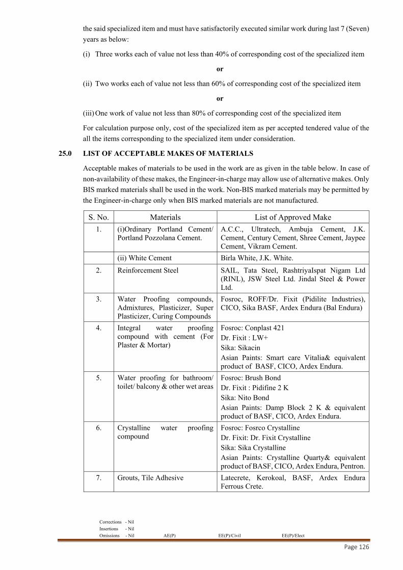
Corrections - Nil
Insertions - Nil
Omissions - Nil AE(P) EE(P)/Civil EE(P)/Elect
Page 126
the said specialized item and must have satisfactorily executed similar work during last 7 (Seven)
years as below:
(i) Three works each of value not less than 40% of corresponding cost of the specialized item
or
(ii) Two works each of value not less than 60% of corresponding cost of the specialized item
or
(iii) One work of value not less than 80% of corresponding cost of the specialized item
For calculation purpose only, cost of the specialized item as per accepted tendered value of the
all the items corresponding to the specialized item under consideration.
25.0 LIST OF ACCEPTABLE MAKES OF MATERIALS
Acceptable makes of materials to be used in the work are as given in the table below. In case of
non-availability of these makes, the Engineer-in-charge may allow use of alternative makes. Only
BIS marked materials shall be used in the work. Non-BIS marked materials may be permitted by
the Engineer-in-charge only when BIS marked materials are not manufactured.
S. No. Materials List of Approved Make
1. (i)Ordinary Portland Cement/ Portland Pozzolana Cement.
A.C.C., Ultratech, Ambuja Cement, J.K. Cement, Century Cement, Shree Cement, Jaypee Cement, Vikram Cement.
(ii) White Cement Birla White, J.K. White.
2. Reinforcement Steel SAIL, Tata Steel, RashtriyaIspat Nigam Ltd (RINL), JSW Steel Ltd. Jindal Steel & Power Ltd.
3. Water Proofing compounds, Admixtures, Plasticizer, Super Plasticizer, Curing Compounds
Fosroc, ROFF/Dr. Fixit (Pidilite Industries), CICO, Sika BASF, Ardex Endura (Bal Endura)
4. Integral water proofing compound with cement (For Plaster & Mortar)
Fosroc: Conplast 421 Dr. Fixit : LW+ Sika: Sikacin Asian Paints: Smart care Vitalia& equivalent product of BASF, CICO, Ardex Endura.
5. Water proofing for bathroom/ toilet/ balcony & other wet areas
Fosroc: Brush Bond Dr. Fixit : Pidifine 2 K Sika: Nito Bond Asian Paints: Damp Block 2 K & equivalent product of BASF, CICO, Ardex Endura.
6. Crystalline water proofing compound
Fosroc: Fosrco Crystalline Dr. Fixit: Dr. Fixit Crystalline Sika: Sika Crystalline Asian Paints: Crystalline Quarty& equivalent product of BASF, CICO, Ardex Endura, Pentron.
7. Grouts, Tile Adhesive Latecrete, Kerokoal, BASF, Ardex Endura Ferrous Crete.
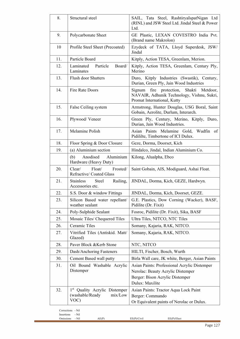
Corrections - Nil
Insertions - Nil
Omissions - Nil AE(P) EE(P)/Civil EE(P)/Elect
Page 127
8. Structural steel SAIL, Tata Steel, RashtiryaIspatNigan Ltd (RINL) and JSW Steel Ltd. Jindal Steel & Power Ltd.
9. Polycarbonate Sheet GE Plastic, LEXAN COVESTRO India Pvt. (Brand name Makrolon)
10 Profile Steel Sheet (Precoated) Ezydeck of TATA, Lloyd Superdesk, JSW/ Jindal
11. Particle Board Kitply, Action TESA, Greenlam, Merion.
12. Laminated Particle Board/ Laminates
Kitply, Action TESA, Greenlam, Century Ply, Merino
13. Flush door Shutters Duro, Kitply Industries (Swastik), Century, Durian, Green Ply, Jain Wood Industries
14. Fire Rate Doors Signum fire protection, Shakti Metdoor, NAVAIR, Adhunik Technology, Vishnu, Sukri, Promat International, Kutty
15. False Ceiling system Armstrong, Hunter Douglas, USG Boral, Saint Gobain, Aerolite, Durlum, Interarch.
16. Plywood/ Veneer Green Ply, Century, Merino, Kitply, Duro, Durian, Jain Wood Industries.
17. Melamine Polish Asian Paints Melamine Gold, Wudfin of Pidililte, Timbertone of ICI Dulux.
18. Floor Spring & Door Closure Geze, Dorma, Doorset, Kich
19. (a) Aluminium section Hindalco, Jindal, Indian Aluminium Co.
(b) Anodised Aluminium Hardware (Heavy Duty)
Kilong, Alualpha, Ebco
20. Clear/ Float/ Frosted/ Refractive/ Coated Glass
Saint Gobain, AIS, Modiguard, Ashai Float.
21. Stainless Steel Railing, Accessories etc.
JINDAL, Dorma, Kich, GEZE, Hardwyn.
22. S.S. Door & window Fittings JINDAL, Dorma, Kich, Doorset, GEZE.
23. Silicon Based water repellant/ weather sealant
G.E. Plastics, Dow Corning (Wacker), BASF, Pidilite (Dr. Fixit)
24. Poly-Sulphide Sealant Fosroc, Pidilite (Dr. Fixit), Sika, BASF
25. Mosaic Tiles/ Chequered Tiles Ultra Tiles, NITCO, NTC Tiles
26. Ceramic Tiles Somany, Kajaria, RAK, NITCO.
27. Vitrified Tiles (Antiskid. Matt/ Glazed)
Somany, Kajaria, RAK, NITCO.
28. Paver Block &Kerb Stone NTC, NITCO
29. Dash/Anchoring Fasteners HILTI, Fischer, Bosch, Wurth
30. Cement Based wall putty Birla Wall care, JK white, Berger, Asian Paints
31. Oil Bound Washable Acrylic Distemper
Asian Paints: Professional Acrylic Distemper Nerolac: Beauty Acrylic Distemper Berger: Bison Acrylic Distemper Dulux: Maxilite
32. 1st Quality Acrylic Distemper (washable/Ready mix/Low VOC)
Asian Paints: Tractor Aqua Lock Paint Berger: Commando Or Equivalent paints of Nerolac or Dulux.
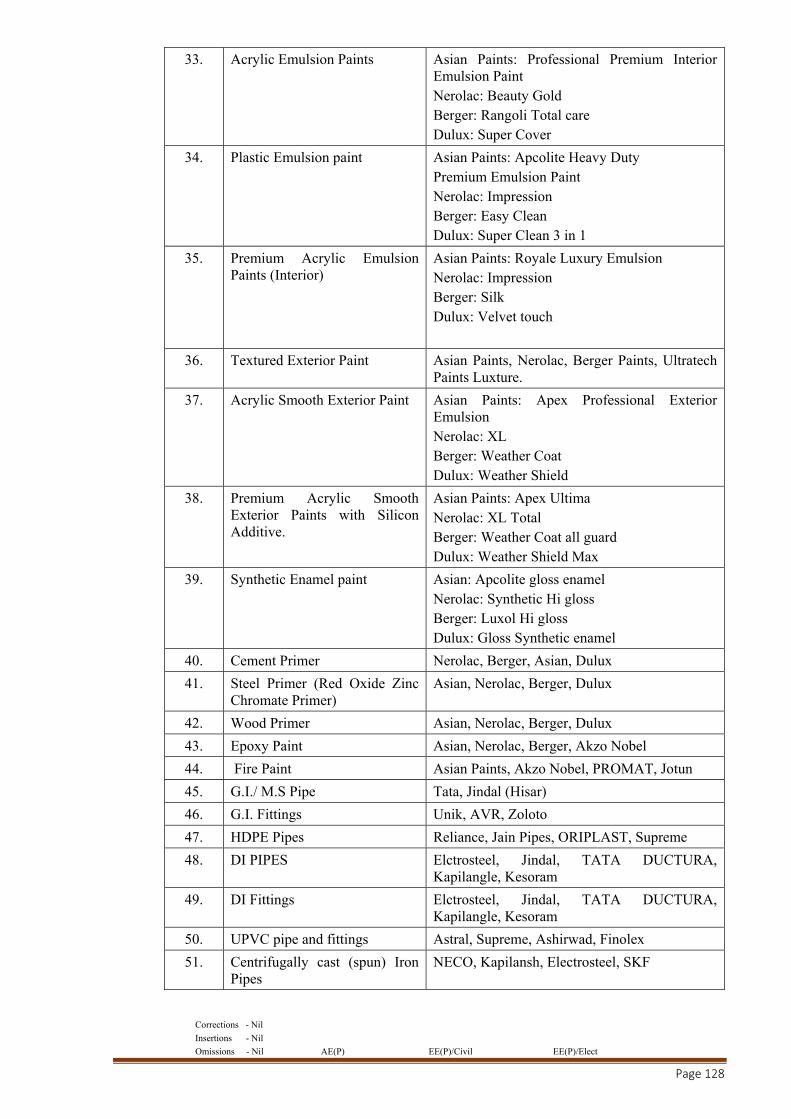
Corrections - Nil
Insertions - Nil
Omissions - Nil AE(P) EE(P)/Civil EE(P)/Elect
Page 128
33. Acrylic Emulsion Paints Asian Paints: Professional Premium Interior Emulsion Paint Nerolac: Beauty Gold Berger: Rangoli Total care Dulux: Super Cover
34. Plastic Emulsion paint Asian Paints: Apcolite Heavy Duty Premium Emulsion Paint Nerolac: Impression Berger: Easy Clean Dulux: Super Clean 3 in 1
35. Premium Acrylic Emulsion Paints (Interior)
Asian Paints: Royale Luxury Emulsion Nerolac: Impression Berger: Silk Dulux: Velvet touch
36. Textured Exterior Paint Asian Paints, Nerolac, Berger Paints, Ultratech Paints Luxture.
37.
Acrylic Smooth Exterior Paint Asian Paints: Apex Professional Exterior Emulsion Nerolac: XL Berger: Weather Coat Dulux: Weather Shield
38. Premium Acrylic Smooth Exterior Paints with Silicon Additive.
Asian Paints: Apex Ultima Nerolac: XL Total Berger: Weather Coat all guard Dulux: Weather Shield Max
39. Synthetic Enamel paint Asian: Apcolite gloss enamel Nerolac: Synthetic Hi gloss Berger: Luxol Hi gloss Dulux: Gloss Synthetic enamel
40. Cement Primer Nerolac, Berger, Asian, Dulux
41. Steel Primer (Red Oxide Zinc Chromate Primer)
Asian, Nerolac, Berger, Dulux
42. Wood Primer Asian, Nerolac, Berger, Dulux
43. Epoxy Paint Asian, Nerolac, Berger, Akzo Nobel
44. Fire Paint Asian Paints, Akzo Nobel, PROMAT, Jotun
45. G.I./ M.S Pipe Tata, Jindal (Hisar)
46. G.I. Fittings Unik, AVR, Zoloto
47. HDPE Pipes Reliance, Jain Pipes, ORIPLAST, Supreme
48. DI PIPES Elctrosteel, Jindal, TATA DUCTURA, Kapilangle, Kesoram
49. DI Fittings Elctrosteel, Jindal, TATA DUCTURA, Kapilangle, Kesoram
50. UPVC pipe and fittings Astral, Supreme, Ashirwad, Finolex
51. Centrifugally cast (spun) Iron Pipes
NECO, Kapilansh, Electrosteel, SKF
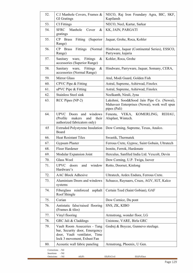
Corrections - Nil
Insertions - Nil
Omissions - Nil AE(P) EE(P)/Civil EE(P)/Elect
Page 129
52. C.I Manhole Covers, Frames & GI Gratings
NECO, Raj Iron Foundary Agra, BIC, SKF, Kapilansh
53. CI Fittings NECO, Neel, Kartar, Sarkar
54. SFRC Manhole Cover & gratings
KK, JAIN, PARGATI
55. CP Brass Fitting (Superior Range)
Jaquar, Grohe, Roca, Kohler
56. CP Brass Fittings (Normal Range)
Hindware, Jaquar (Continental Series), ESSCO, Parryware, kajaria
57. Sanitary ware, Fittings & accessories (Superior Range)
Kohler, Roca, Grohe
58. Sanitary ware, Fittings & accessories (Normal Range)
Hindware, Parryware, Jaquar, Somany, CERA,
59. Mirror Glass Atul, Modi Guard, Golden Fish
60. CPVC Pipe & Fitting Astral, Supreme, Ashirwad, Finolex
61. uPVC Pipe & Fitting Astral, Supreme, Ashirwad, Finolex
62. Stainless Steel sink Neelkanth, Nirali, Jyna
63. RCC Pipes (NP-2) Lakshmi, Sood&Sood Jain Pipe Co. (Newai), Mahaveer Enterprises (Newai), work well spun pipes (Pali)
64. UPVC Doors and windows (Profile makers and their authorized fabricators only)
Fenesta, VEKA, KOMERLING, REHAU, Aluplast, Wintech.
65 Extruded Polystyrene Insulation Board
Dow Corning, Supreme, Texas, Analco.
66. Heat Resistant Tiles Swastik, Thermatek
67. Gypsum Plaster Ferrous Crete, Gyproc, Saint Gobain, Ultratech
68. Floor Hardener Ironite, Ferrok, Hardonate
69. Modular Expansion Joint Herculus, Sanfiled India Ltd. Vexcolt, Devin
70. Glass Wool Dow Corning, U.P. Twiga, Isover
71. UPVC doors and window Hardware’s
Rotto, Doorset, Kinlong
72. AAC Block Adhesive Ultratech, Ardex Endura, Ferrous Crete.
73. Aluminium Doors and windows systems
Schueco, Raynaers, Cruze, AGV, IGT, Kalco
74. Fiberglass reinforced asphalt Roof Shingle
Certain Teed (Saint Gobian), GAF
75. Corian Dow Cornice, Du pont
76. Antistatic false/raised flooring (Frames & tiles)
SNS, ZK, KIBO
77. Vinyl flooring Armstrong, wonder floor, LG
78. GRC Jali & Claddings Unistone, VARE, Birla GRC
79. Vault Room Asseceries - Tang bar, Security door, Emergency door, Vault ventilator, Time lock 3 movement, Exhust Fan
Godrej & Boycee, Gunnevo steelage.
80. Acoustic wall fabric paneling Armstrong, Phoenix, U Gen.
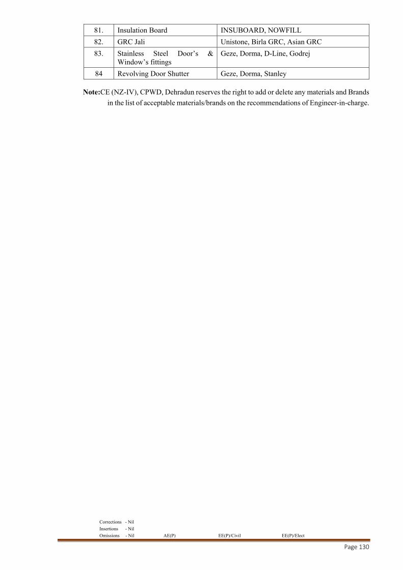
Corrections - Nil
Insertions - Nil
Omissions - Nil AE(P) EE(P)/Civil EE(P)/Elect
Page 130
81. Insulation Board INSUBOARD, NOWFILL
82. GRC Jali Unistone, Birla GRC, Asian GRC
83. Stainless Steel Door’s & Window’s fittings
Geze, Dorma, D-Line, Godrej
84 Revolving Door Shutter Geze, Dorma, Stanley
Note:CE (NZ-IV), CPWD, Dehradun reserves the right to add or delete any materials and Brands
in the list of acceptable materials/brands on the recommendations of Engineer-in-charge.
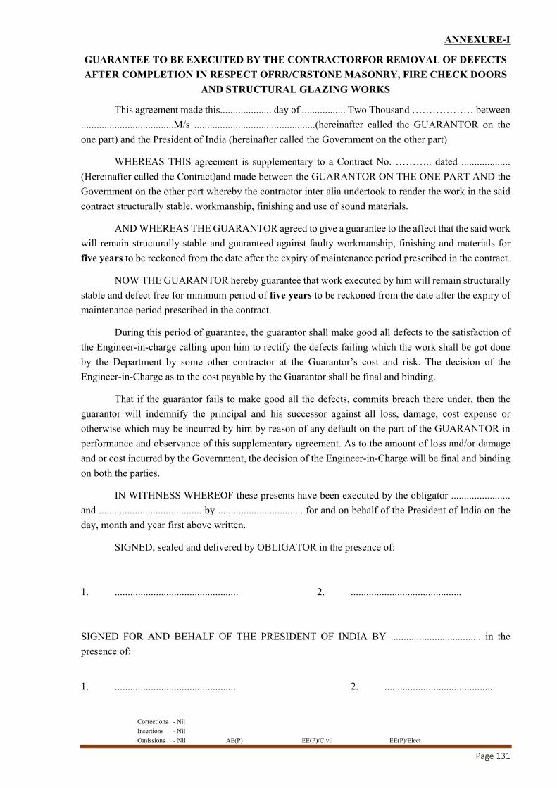
Corrections - Nil
Insertions - Nil
Omissions - Nil AE(P) EE(P)/Civil EE(P)/Elect
Page 131
ANNEXURE-I
GUARANTEE TO BE EXECUTED BY THE CONTRACTORFOR REMOVAL OF DEFECTS
AFTER COMPLETION IN RESPECT OFRR/CRSTONE MASONRY, FIRE CHECK DOORS
AND STRUCTURAL GLAZING WORKS
This agreement made this.................... day of ................. Two Thousand ……………… between
....................................M/s ...............................................(hereinafter called the GUARANTOR on the
one part) and the President of India (hereinafter called the Government on the other part)
WHEREAS THIS agreement is supplementary to a Contract No. ……….. dated ...................
(Hereinafter called the Contract)and made between the GUARANTOR ON THE ONE PART AND the
Government on the other part whereby the contractor inter alia undertook to render the work in the said
contract structurally stable, workmanship, finishing and use of sound materials.
AND WHEREAS THE GUARANTOR agreed to give a guarantee to the affect that the said work
will remain structurally stable and guaranteed against faulty workmanship, finishing and materials for
five years to be reckoned from the date after the expiry of maintenance period prescribed in the contract.
NOW THE GUARANTOR hereby guarantee that work executed by him will remain structurally
stable and defect free for minimum period of five years to be reckoned from the date after the expiry of
maintenance period prescribed in the contract.
During this period of guarantee, the guarantor shall make good all defects to the satisfaction of
the Engineer-in-charge calling upon him to rectify the defects failing which the work shall be got done
by the Department by some other contractor at the Guarantor’s cost and risk. The decision of the
Engineer-in-Charge as to the cost payable by the Guarantor shall be final and binding.
That if the guarantor fails to make good all the defects, commits breach there under, then the
guarantor will indemnify the principal and his successor against all loss, damage, cost expense or
otherwise which may be incurred by him by reason of any default on the part of the GUARANTOR in
performance and observance of this supplementary agreement. As to the amount of loss and/or damage
and or cost incurred by the Government, the decision of the Engineer-in-Charge will be final and binding
on both the parties.
IN WITHNESS WHEREOF these presents have been executed by the obligator .......................
and ........................................ by ................................. for and on behalf of the President of India on the
day, month and year first above written.
SIGNED, sealed and delivered by OBLIGATOR in the presence of:
1. ................................................ 2. ...........................................
SIGNED FOR AND BEHALF OF THE PRESIDENT OF INDIA BY ................................... in the
presence of:
1. ............................................... 2. ..........................................

Corrections - Nil
Insertions - Nil
Omissions - Nil AE(P) EE(P)/Civil EE(P)/Elect
Page 132
ANNEXURE-II
GUARANTEE TO BE EXECUTED BY THE CONTRACTORFOR REMOVAL OF DEFECTS
AFTER COMPLETION IN RESPECT OFWATERPROOFING WORKS
This agreement made this.................... day of ................. Two Thousand .............. between M/s
..................................(hereinafter called the GUARANTOR on the one part) and the PRESIDENT OF
INDIA (hereinafter called the Government on the other part)
WHEREAS THIS agreement is supplementary to a Contract No. ……….. dated ...................
(Hereinafter called the Contract)and made between the GUARANTOR on the one part and the
Government on the other part whereby the contractor inter alia undertook to render the building and
structures in the said contract completely water and leak-proof.
AND WHEREAS THE GUARANTOR agreed to give a guarantee to the affect that the said work
will remain water and leak proof, for Ten Years from the date of completion of the work under the
contract.
NOW THE GUARANTOR hereby guarantee that work executed by him will render the
structures completely leak proof and the minimum life of such water proofing treatment shall be Ten
years to be reckoned from the date of completion of the work under the contract.
Provided that the guarantor will not be responsible for leakage caused by earthquake or
structuraldefects or misuse of roof or alteration and for such purpose:
(a) Misuse of roof shall mean any operation which will damage proofing treatment, like chopping
offirewood and things of the same nature which might cause damage to the roof;
(b) Alteration shall mean construction of an additional storey or a part of the roof or
constructionadjoining to existing roof whereby proofing treatment is removed in parts;
(c) The decision of the Engineer-in-Charge with regard to nature and cause of defect shall be final.
During this period of guarantee, the guarantor shall make good all defects and in case of any
defect being found render the building water proof to the satisfaction of the Engineer-in-Charge calling
upon him to rectify the defects failing which the work shall be got done by the Department by some other
contractor at the Guarantor’s cost and risk. The decision of the Engineer-in-Charge as to the cost payable
by the Guarantor shall be final and binding.
That if the guarantor fails to execute the water proofing or commits breach there under, then the
guarantor will indemnify the principal and his successor against all loss, damage, cost expense or
otherwise which may be incurred by him by reason of any default on the part of the GUARANTOR in
performance and observance of this supplementary agreement. As to the amount of loss and/or damage
and or cost incurred by the Government, the decision of the Engineer-in-Charge will be final and binding
on both the parties.

Corrections - Nil
Insertions - Nil
Omissions - Nil AE(P) EE(P)/Civil EE(P)/Elect
Page 133
IN WITHNESS WHEREOF these presents have been executed by the obligator .......................
and ........................................ by ................................. for and on behalf of the PRESIDENT OF INDIA
on the day, month and year first above written.
SIGNED, sealed and delivered by OBLIGATOR in the presence of:
1. ................................................ 2. ...........................................
SIGNED FOR AND BEHALF OF THE PRESIDENT OF INDIA BY ................................... in
the presence of:
1. ............................................... 2. ..........................................
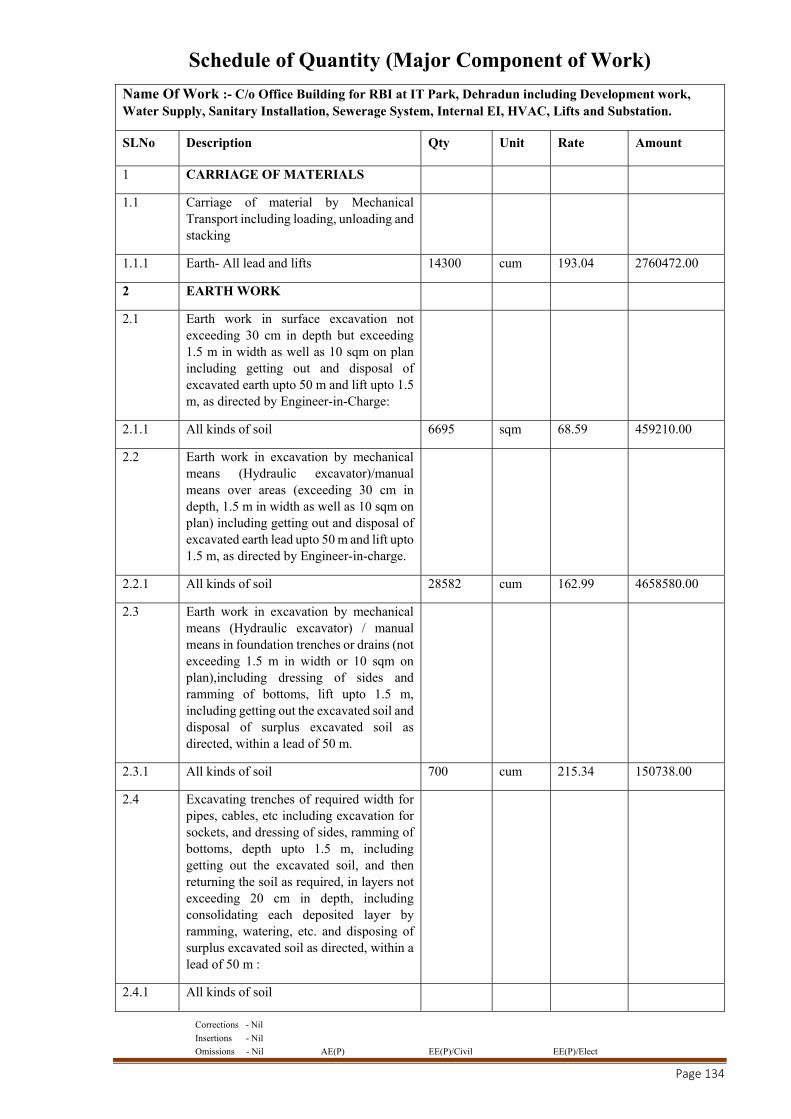
Corrections - Nil
Insertions - Nil
Omissions - Nil AE(P) EE(P)/Civil EE(P)/Elect
Page 134
Schedule of Quantity (Major Component of Work)
Name Of Work :- C/o Office Building for RBI at IT Park, Dehradun including Development work, Water Supply, Sanitary Installation, Sewerage System, Internal EI, HVAC, Lifts and Substation.
SLNo Description Qty Unit Rate Amount
1 CARRIAGE OF MATERIALS
1.1 Carriage of material by Mechanical Transport including loading, unloading and stacking
1.1.1 Earth- All lead and lifts 14300 cum 193.04 2760472.00
2 EARTH WORK
2.1 Earth work in surface excavation not exceeding 30 cm in depth but exceeding 1.5 m in width as well as 10 sqm on plan including getting out and disposal of excavated earth upto 50 m and lift upto 1.5 m, as directed by Engineer-in-Charge:
2.1.1 All kinds of soil 6695 sqm 68.59 459210.00
2.2 Earth work in excavation by mechanical means (Hydraulic excavator)/manual means over areas (exceeding 30 cm in depth, 1.5 m in width as well as 10 sqm on plan) including getting out and disposal of excavated earth lead upto 50 m and lift upto 1.5 m, as directed by Engineer-in-charge.
2.2.1 All kinds of soil 28582 cum 162.99 4658580.00
2.3 Earth work in excavation by mechanical means (Hydraulic excavator) / manual means in foundation trenches or drains (not exceeding 1.5 m in width or 10 sqm on plan),including dressing of sides and ramming of bottoms, lift upto 1.5 m, including getting out the excavated soil and disposal of surplus excavated soil as directed, within a lead of 50 m.
2.3.1 All kinds of soil 700 cum 215.34 150738.00
2.4 Excavating trenches of required width for pipes, cables, etc including excavation for sockets, and dressing of sides, ramming of bottoms, depth upto 1.5 m, including getting out the excavated soil, and then returning the soil as required, in layers not exceeding 20 cm in depth, including consolidating each deposited layer by ramming, watering, etc. and disposing of surplus excavated soil as directed, within a lead of 50 m :
2.4.1 All kinds of soil
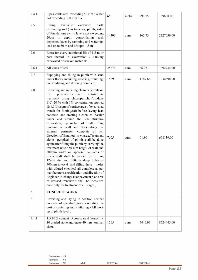
Corrections - Nil
Insertions - Nil
Omissions - Nil AE(P) EE(P)/Civil EE(P)/Elect
Page 135
2.4.1.1. Pipes, cables etc. exceeding 80 mm dia. but not exceeding 300 mm dia
650 metre 291.75 189638.00
2.5 Filling available excavated earth (excluding rock) in trenches, plinth, sides of foundations etc. in layers not exceeding 20cm in depth, consolidating each deposited layer by ramming and watering, lead up to 50 m and lift upto 1.5 m.
14300 cum 162.73 2327039.00
2.6 Extra for every additional lift of 1.5 m or part thereof in excavation / banking excavated or stacked materials.
2.6.1 All kinds of soil 25276 cum 66.97 1692734.00
2.7 Supplying and filling in plinth with sand under floors, including watering, ramming, consolidating and dressing complete.
1629 cum 1187.66 1934698.00
2.8 Providing and injecting chemical emulsion for pre-constructional anti-termite treatment using chloropyriphos/Lindane E.C. 20 % with 1% concentration applied @ 1.5 Lit/sqm of surface area of excavated trench for footing/raft before laying lean concrete and creating a chemical barrier under and around the sub structure excavation, top surface of plinth filling junction of wall and floor along the external perimeter complete as per direction of Engineer-in-charge.Treatment along peripheri of plinth shall be done again after filling the plinth by carrying the treatment upto 450 mm height of wall and 300mm width on appron. Plan area of treanch/raft shall be treated by drilling 12mm dia and 300mm deep holes at 300mm interval and filling these holes with diluted chemical all complete as per manfacturer's specification and direction of Engineer-in-charge.(For payment plan area of dressed trench/raft shall be measured once only for treatment of all stages.)
7605 sqm 91.80 698139.00
3 CONCRETE WORK
3.1 Providing and laying in position cement concrete of specified grade excluding the cost of centering and shuttering - All work up to plinth level :
3.1.1 1:5:10 (1 cement : 5 coarse sand (zone-III): 10 graded stone aggregate 40 mm nominal size).
1565 cum 5446.93 8524445.00
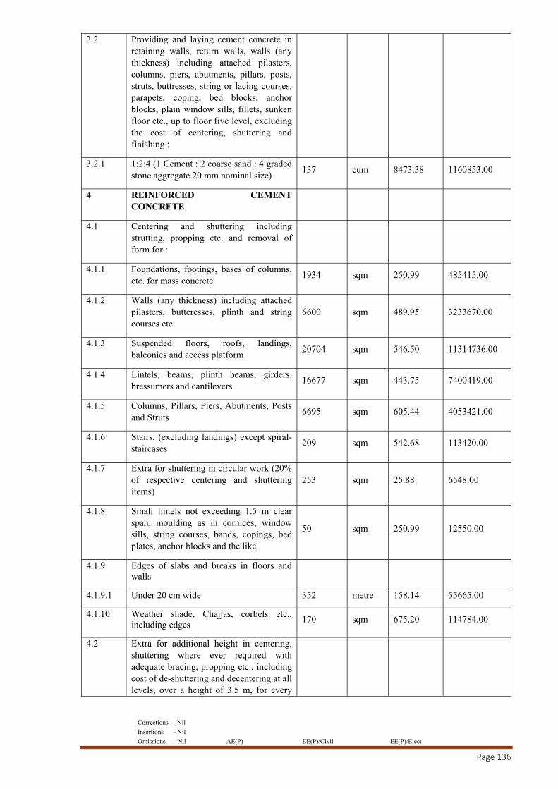
Corrections - Nil
Insertions - Nil
Omissions - Nil AE(P) EE(P)/Civil EE(P)/Elect
Page 136
3.2 Providing and laying cement concrete in retaining walls, return walls, walls (any thickness) including attached pilasters, columns, piers, abutments, pillars, posts, struts, buttresses, string or lacing courses, parapets, coping, bed blocks, anchor blocks, plain window sills, fillets, sunken floor etc., up to floor five level, excluding the cost of centering, shuttering and finishing :
3.2.1 1:2:4 (1 Cement : 2 coarse sand : 4 graded stone aggregate 20 mm nominal size)
137 cum 8473.38 1160853.00
4 REINFORCED CEMENT CONCRETE
4.1 Centering and shuttering including strutting, propping etc. and removal of form for :
4.1.1 Foundations, footings, bases of columns, etc. for mass concrete
1934 sqm 250.99 485415.00
4.1.2 Walls (any thickness) including attached pilasters, butteresses, plinth and string courses etc.
6600 sqm 489.95 3233670.00
4.1.3 Suspended floors, roofs, landings, balconies and access platform
20704 sqm 546.50 11314736.00
4.1.4 Lintels, beams, plinth beams, girders, bressumers and cantilevers
16677 sqm 443.75 7400419.00
4.1.5 Columns, Pillars, Piers, Abutments, Posts and Struts
6695 sqm 605.44 4053421.00
4.1.6 Stairs, (excluding landings) except spiral-staircases
209 sqm 542.68 113420.00
4.1.7 Extra for shuttering in circular work (20% of respective centering and shuttering items)
253 sqm 25.88 6548.00
4.1.8 Small lintels not exceeding 1.5 m clear span, moulding as in cornices, window sills, string courses, bands, copings, bed plates, anchor blocks and the like
50 sqm 250.99 12550.00
4.1.9 Edges of slabs and breaks in floors and walls
4.1.9.1 Under 20 cm wide 352 metre 158.14 55665.00
4.1.10 Weather shade, Chajjas, corbels etc., including edges
170 sqm 675.20 114784.00
4.2 Extra for additional height in centering, shuttering where ever required with adequate bracing, propping etc., including cost of de-shuttering and decentering at all levels, over a height of 3.5 m, for every
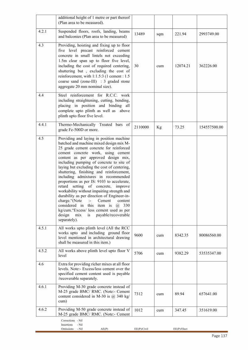
Corrections - Nil
Insertions - Nil
Omissions - Nil AE(P) EE(P)/Civil EE(P)/Elect
Page 137
additional height of 1 metre or part thereof (Plan area to be measured).
4.2.1 Suspended floors, roofs, landing, beams and balconies (Plan area to be measured)
13489 sqm 221.94 2993749.00
4.3 Providing, hoisting and fixing up to floor five level precast reinforced cement concrete in small lintels not exceeding 1.5m clear span up to floor five level, including the cost of required centering, shuttering but , excluding the cost of reinforcement, with 1:1.5:3 (1 cement : 1.5 coarse sand (zone-III) : 3 graded stone aggregate 20 mm nominal size).
30 cum 12074.21 362226.00
4.4 Steel reinforcement for R.C.C. work including straightening, cutting, bending, placing in position and binding all complete upto plinth as well as above plinth upto floor five level.
4.4.1 Thermo-Mechanically Treated bars of grade Fe-500D or more.
2110000 Kg 73.25 154557500.00
4.5 Providing and laying in position machine batched and machine mixed design mix M-25 grade cement concrete for reinforced cement concrete work, using cement content as per approved design mix, including pumping of concrete to site of laying but excluding the cost of centering, shuttering, finishing and reinforcement, including admixtures in recommended proportions as per IS: 9103 to accelerate, retard setting of concrete, improve workability without impairing strength and durability as per direction of Engineer-in-charge.“(Note :- Cement content considered in this item is @ 330 kg/cum.“Excess/ less cement used as per design mix is payable/recoverable separately).
4.5.1 All works upto plinth level (All the RCC works upto and including ground floor level mentioned in architectural drawing shall be measured in this item.)
9600 cum 8342.35 80086560.00
4.5.2 All works above plinth level upto floor V level 5706 cum 9382.29 53535347.00
4.6 Extra for providing richer mixes at all floor levels. Note:- Excess/less cement over the specified cement content used is payable /recoverable separately.
4.6.1 Providing M-30 grade concrete instead of M-25 grade BMC/ RMC. (Note:- Cement content considered in M-30 is @ 340 kg/ cum)
7312 cum 89.94 657641.00
4.6.2 Providing M-50 grade concrete instead of M-25 grade BMC/ RMC. (Note:- Cement
1012 cum 347.45 351619.00
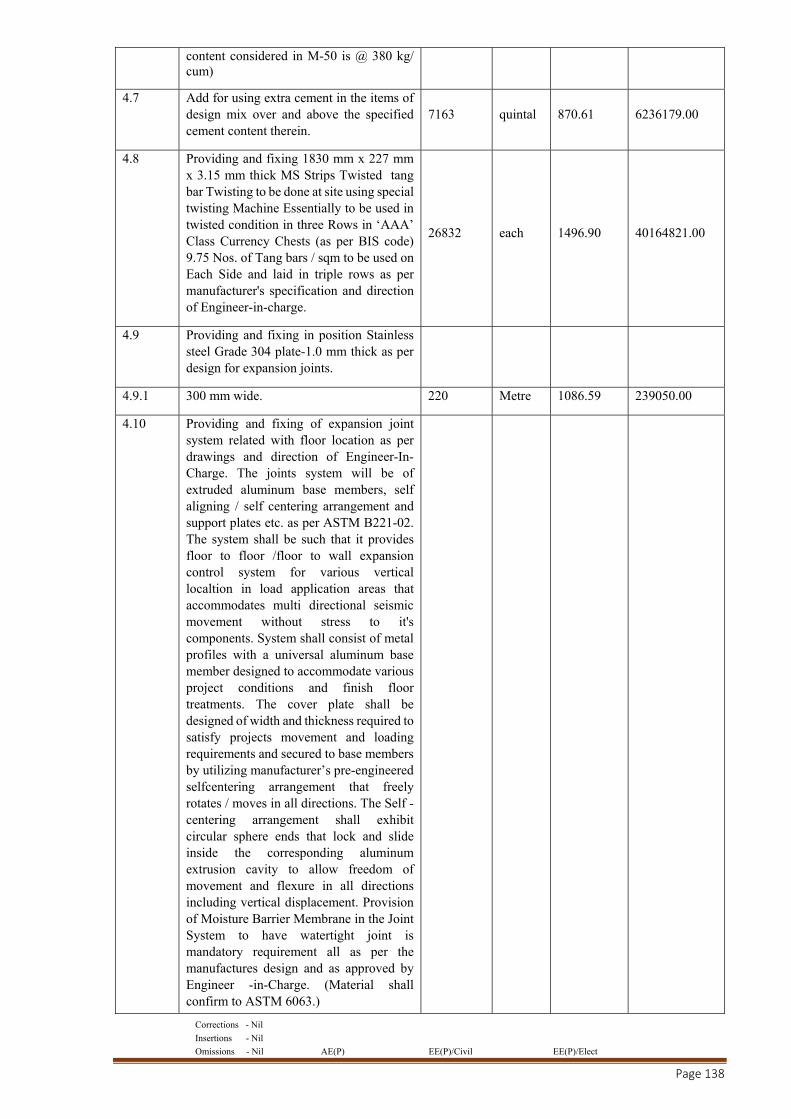
Corrections - Nil
Insertions - Nil
Omissions - Nil AE(P) EE(P)/Civil EE(P)/Elect
Page 138
content considered in M-50 is @ 380 kg/ cum)
4.7 Add for using extra cement in the items of design mix over and above the specified cement content therein.
7163 quintal 870.61 6236179.00
4.8 Providing and fixing 1830 mm x 227 mm x 3.15 mm thick MS Strips Twisted tang bar Twisting to be done at site using special twisting Machine Essentially to be used in twisted condition in three Rows in ‘AAA’ Class Currency Chests (as per BIS code) 9.75 Nos. of Tang bars / sqm to be used on Each Side and laid in triple rows as per manufacturer's specification and direction of Engineer-in-charge.
26832 each 1496.90 40164821.00
4.9 Providing and fixing in position Stainless steel Grade 304 plate-1.0 mm thick as per design for expansion joints.
4.9.1 300 mm wide. 220 Metre 1086.59 239050.00
4.10 Providing and fixing of expansion joint system related with floor location as per drawings and direction of Engineer-In-Charge. The joints system will be of extruded aluminum base members, self aligning / self centering arrangement and support plates etc. as per ASTM B221-02. The system shall be such that it provides floor to floor /floor to wall expansion control system for various vertical localtion in load application areas that accommodates multi directional seismic movement without stress to it's components. System shall consist of metal profiles with a universal aluminum base member designed to accommodate various project conditions and finish floor treatments. The cover plate shall be designed of width and thickness required to satisfy projects movement and loading requirements and secured to base members by utilizing manufacturer’s pre-engineered selfcentering arrangement that freely rotates / moves in all directions. The Self -centering arrangement shall exhibit circular sphere ends that lock and slide inside the corresponding aluminum extrusion cavity to allow freedom of movement and flexure in all directions including vertical displacement. Provision of Moisture Barrier Membrane in the Joint System to have watertight joint is mandatory requirement all as per the manufactures design and as approved by Engineer -in-Charge. (Material shall confirm to ASTM 6063.)
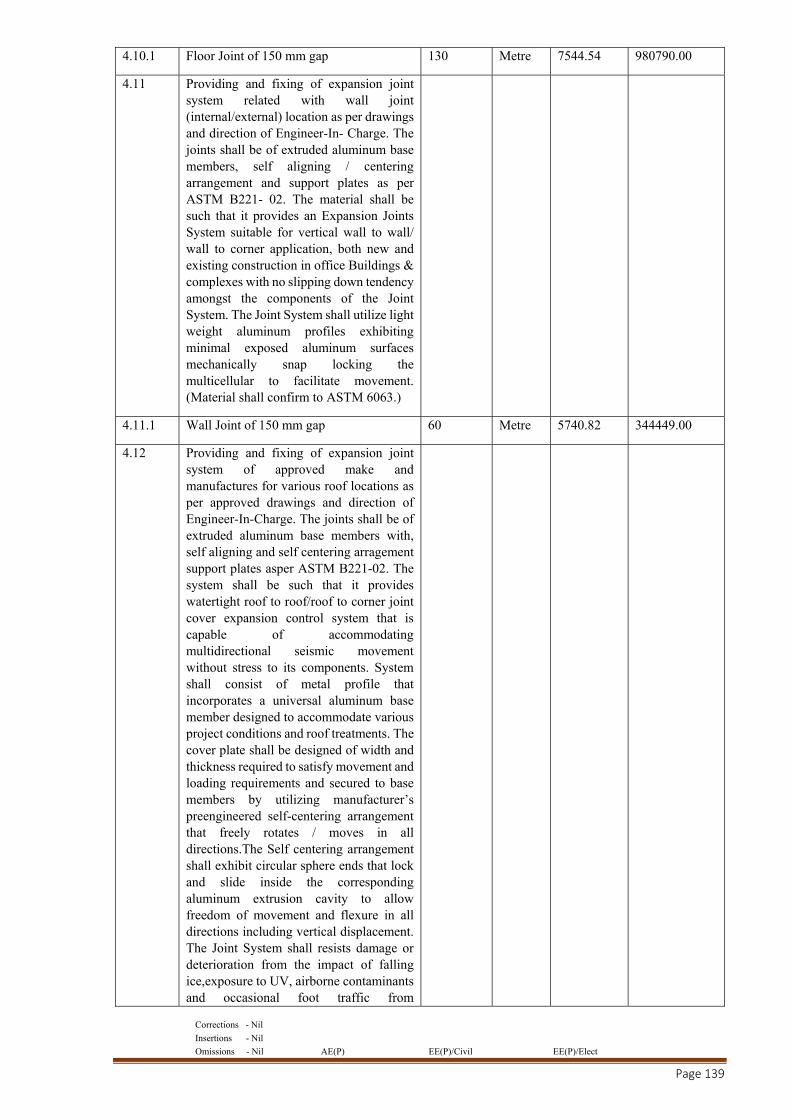
Corrections - Nil
Insertions - Nil
Omissions - Nil AE(P) EE(P)/Civil EE(P)/Elect
Page 139
4.10.1 Floor Joint of 150 mm gap 130 Metre 7544.54 980790.00
4.11 Providing and fixing of expansion joint system related with wall joint (internal/external) location as per drawings and direction of Engineer-In- Charge. The joints shall be of extruded aluminum base members, self aligning / centering arrangement and support plates as per ASTM B221- 02. The material shall be such that it provides an Expansion Joints System suitable for vertical wall to wall/ wall to corner application, both new and existing construction in office Buildings & complexes with no slipping down tendency amongst the components of the Joint System. The Joint System shall utilize light weight aluminum profiles exhibiting minimal exposed aluminum surfaces mechanically snap locking the multicellular to facilitate movement. (Material shall confirm to ASTM 6063.)
4.11.1 Wall Joint of 150 mm gap 60 Metre 5740.82 344449.00
4.12 Providing and fixing of expansion joint system of approved make and manufactures for various roof locations as per approved drawings and direction of Engineer-In-Charge. The joints shall be of extruded aluminum base members with, self aligning and self centering arragement support plates asper ASTM B221-02. The system shall be such that it provides watertight roof to roof/roof to corner joint cover expansion control system that is capable of accommodating multidirectional seismic movement without stress to its components. System shall consist of metal profile that incorporates a universal aluminum base member designed to accommodate various project conditions and roof treatments. The cover plate shall be designed of width and thickness required to satisfy movement and loading requirements and secured to base members by utilizing manufacturer’s preengineered self-centering arrangement that freely rotates / moves in all directions.The Self centering arrangement shall exhibit circular sphere ends that lock and slide inside the corresponding aluminum extrusion cavity to allow freedom of movement and flexure in all directions including vertical displacement. The Joint System shall resists damage or deterioration from the impact of falling ice,exposure to UV, airborne contaminants and occasional foot traffic from
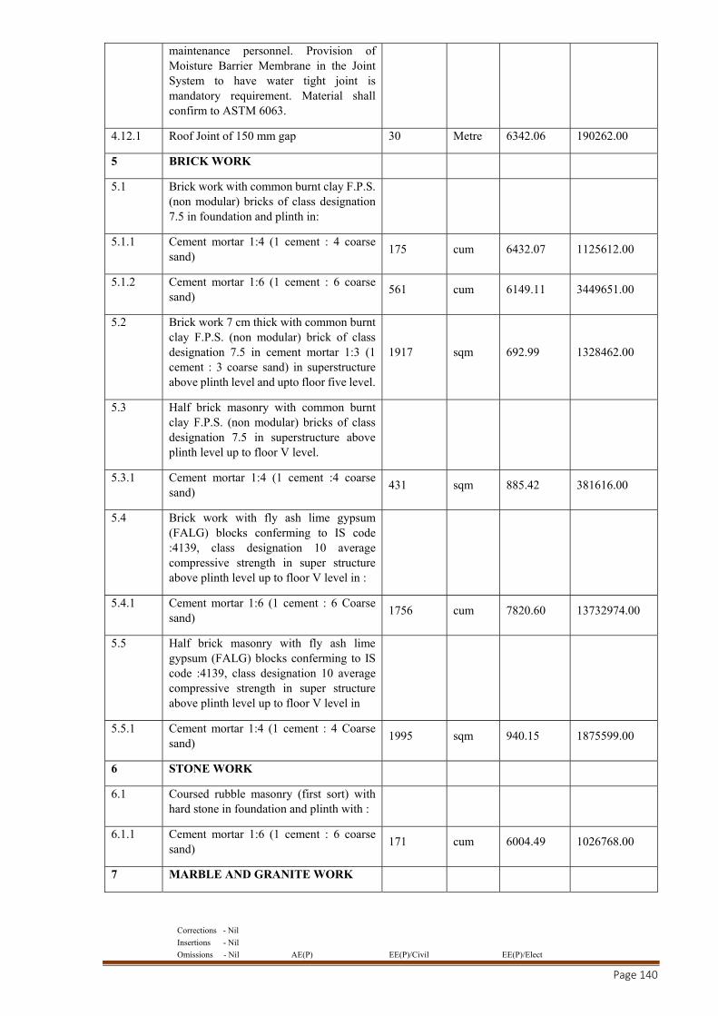
Corrections - Nil
Insertions - Nil
Omissions - Nil AE(P) EE(P)/Civil EE(P)/Elect
Page 140
maintenance personnel. Provision of Moisture Barrier Membrane in the Joint System to have water tight joint is mandatory requirement. Material shall confirm to ASTM 6063.
4.12.1 Roof Joint of 150 mm gap 30 Metre 6342.06 190262.00
5 BRICK WORK
5.1 Brick work with common burnt clay F.P.S. (non modular) bricks of class designation 7.5 in foundation and plinth in:
5.1.1 Cement mortar 1:4 (1 cement : 4 coarse sand)
175 cum 6432.07 1125612.00
5.1.2 Cement mortar 1:6 (1 cement : 6 coarse sand)
561 cum 6149.11 3449651.00
5.2 Brick work 7 cm thick with common burnt clay F.P.S. (non modular) brick of class designation 7.5 in cement mortar 1:3 (1 cement : 3 coarse sand) in superstructure above plinth level and upto floor five level.
1917 sqm 692.99 1328462.00
5.3 Half brick masonry with common burnt clay F.P.S. (non modular) bricks of class designation 7.5 in superstructure above plinth level up to floor V level.
5.3.1 Cement mortar 1:4 (1 cement :4 coarse sand)
431 sqm 885.42 381616.00
5.4 Brick work with fly ash lime gypsum (FALG) blocks conferming to IS code :4139, class designation 10 average compressive strength in super structure above plinth level up to floor V level in :
5.4.1 Cement mortar 1:6 (1 cement : 6 Coarse sand)
1756 cum 7820.60 13732974.00
5.5 Half brick masonry with fly ash lime gypsum (FALG) blocks conferming to IS code :4139, class designation 10 average compressive strength in super structure above plinth level up to floor V level in
5.5.1 Cement mortar 1:4 (1 cement : 4 Coarse sand)
1995 sqm 940.15 1875599.00
6 STONE WORK
6.1 Coursed rubble masonry (first sort) with hard stone in foundation and plinth with :
6.1.1 Cement mortar 1:6 (1 cement : 6 coarse sand)
171 cum 6004.49 1026768.00
7 MARBLE AND GRANITE WORK
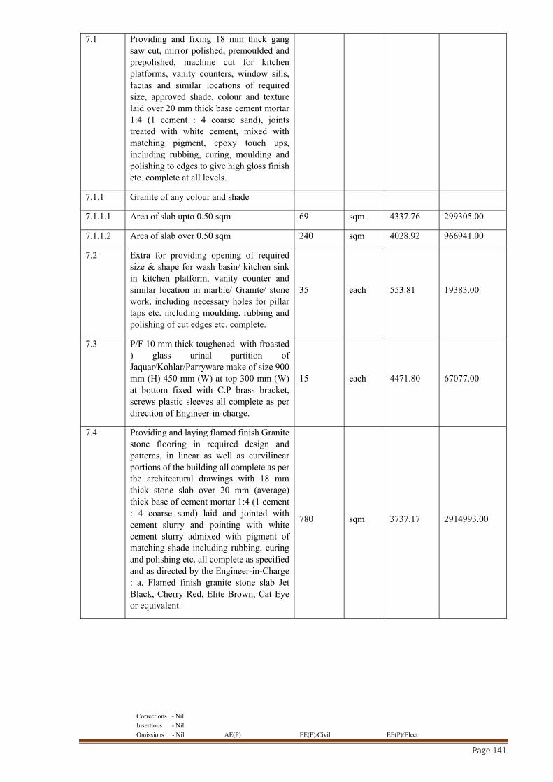
Corrections - Nil
Insertions - Nil
Omissions - Nil AE(P) EE(P)/Civil EE(P)/Elect
Page 141
7.1 Providing and fixing 18 mm thick gang saw cut, mirror polished, premoulded and prepolished, machine cut for kitchen platforms, vanity counters, window sills, facias and similar locations of required size, approved shade, colour and texture laid over 20 mm thick base cement mortar 1:4 (1 cement : 4 coarse sand), joints treated with white cement, mixed with matching pigment, epoxy touch ups, including rubbing, curing, moulding and polishing to edges to give high gloss finish etc. complete at all levels.
7.1.1 Granite of any colour and shade
7.1.1.1 Area of slab upto 0.50 sqm 69 sqm 4337.76 299305.00
7.1.1.2 Area of slab over 0.50 sqm 240 sqm 4028.92 966941.00
7.2 Extra for providing opening of required size & shape for wash basin/ kitchen sink in kitchen platform, vanity counter and similar location in marble/ Granite/ stone work, including necessary holes for pillar taps etc. including moulding, rubbing and polishing of cut edges etc. complete.
35 each 553.81 19383.00
7.3 P/F 10 mm thick toughened with froasted ) glass urinal partition of Jaquar/Kohlar/Parryware make of size 900 mm (H) 450 mm (W) at top 300 mm (W) at bottom fixed with C.P brass bracket, screws plastic sleeves all complete as per direction of Engineer-in-charge.
15 each 4471.80 67077.00
7.4 Providing and laying flamed finish Granite stone flooring in required design and patterns, in linear as well as curvilinear portions of the building all complete as per the architectural drawings with 18 mm thick stone slab over 20 mm (average) thick base of cement mortar 1:4 (1 cement : 4 coarse sand) laid and jointed with cement slurry and pointing with white cement slurry admixed with pigment of matching shade including rubbing, curing and polishing etc. all complete as specified and as directed by the Engineer-in-Charge : a. Flamed finish granite stone slab Jet Black, Cherry Red, Elite Brown, Cat Eye or equivalent.
780 sqm 3737.17 2914993.00
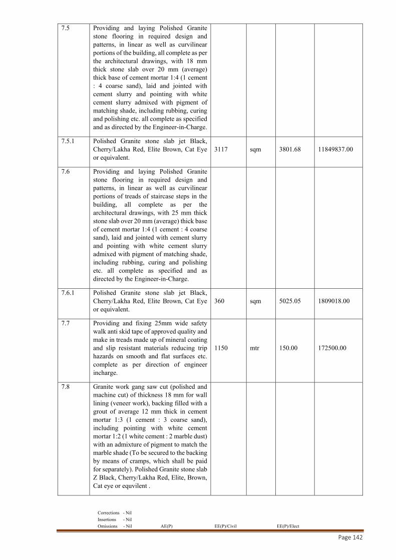
Corrections - Nil
Insertions - Nil
Omissions - Nil AE(P) EE(P)/Civil EE(P)/Elect
Page 142
7.5 Providing and laying Polished Granite stone flooring in required design and patterns, in linear as well as curvilinear portions of the building, all complete as per the architectural drawings, with 18 mm thick stone slab over 20 mm (average) thick base of cement mortar 1:4 (1 cement : 4 coarse sand), laid and jointed with cement slurry and pointing with white cement slurry admixed with pigment of matching shade, including rubbing, curing and polishing etc. all complete as specified and as directed by the Engineer-in-Charge.
7.5.1 Polished Granite stone slab jet Black, Cherry/Lakha Red, Elite Brown, Cat Eye or equivalent.
3117 sqm 3801.68 11849837.00
7.6 Providing and laying Polished Granite stone flooring in required design and patterns, in linear as well as curvilinear portions of treads of staircase steps in the building, all complete as per the architectural drawings, with 25 mm thick stone slab over 20 mm (average) thick base of cement mortar 1:4 (1 cement : 4 coarse sand), laid and jointed with cement slurry and pointing with white cement slurry admixed with pigment of matching shade, including rubbing, curing and polishing etc. all complete as specified and as directed by the Engineer-in-Charge.
7.6.1 Polished Granite stone slab jet Black, Cherry/Lakha Red, Elite Brown, Cat Eye or equivalent.
360 sqm 5025.05 1809018.00
7.7 Providing and fixing 25mm wide safety walk anti skid tape of approved quality and make in treads made up of mineral coating and slip resistant materials reducing trip hazards on smooth and flat surfaces etc. complete as per direction of engineer incharge.
1150 mtr 150.00 172500.00
7.8 Granite work gang saw cut (polished and machine cut) of thickness 18 mm for wall lining (veneer work), backing filled with a grout of average 12 mm thick in cement mortar 1:3 (1 cement : 3 coarse sand), including pointing with white cement mortar 1:2 (1 white cement : 2 marble dust) with an admixture of pigment to match the marble shade (To be secured to the backing by means of cramps, which shall be paid for separately). Polished Granite stone slab Z Black, Cherry/Lakha Red, Elite, Brown, Cat eye or equvilent .
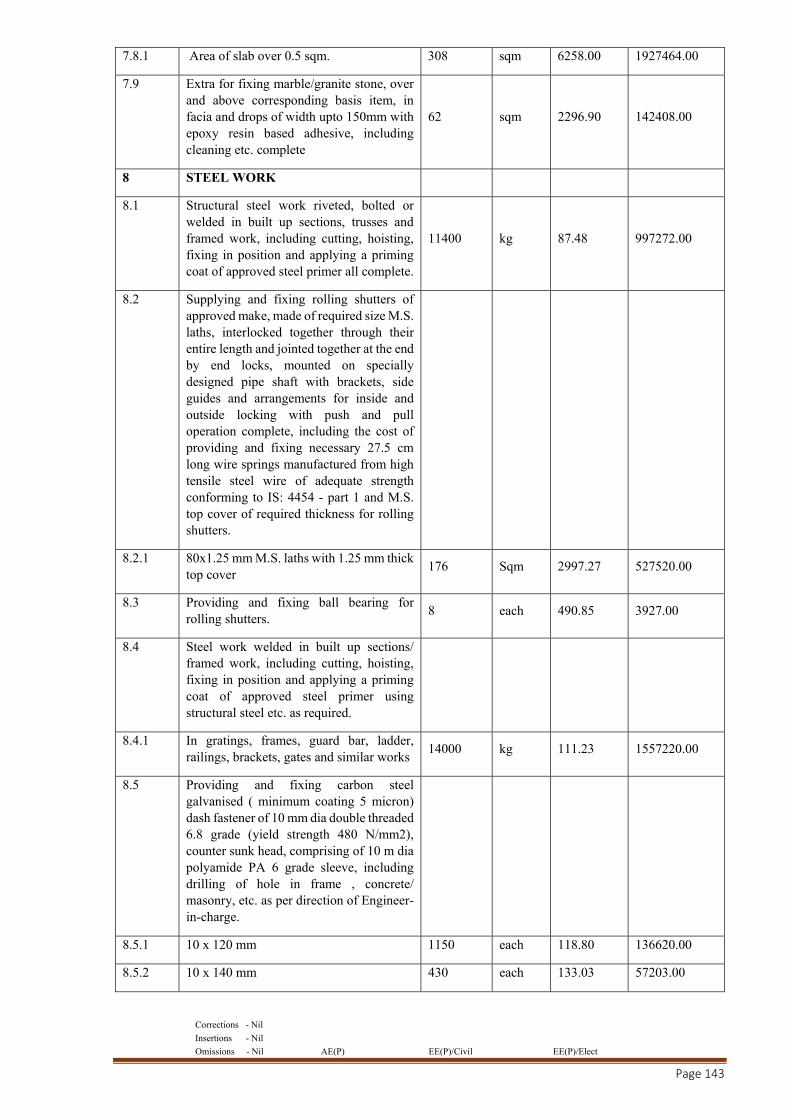
Corrections - Nil
Insertions - Nil
Omissions - Nil AE(P) EE(P)/Civil EE(P)/Elect
Page 143
7.8.1 Area of slab over 0.5 sqm. 308 sqm 6258.00 1927464.00
7.9 Extra for fixing marble/granite stone, over and above corresponding basis item, in facia and drops of width upto 150mm with epoxy resin based adhesive, including cleaning etc. complete
62 sqm 2296.90 142408.00
8 STEEL WORK
8.1 Structural steel work riveted, bolted or welded in built up sections, trusses and framed work, including cutting, hoisting, fixing in position and applying a priming coat of approved steel primer all complete.
11400 kg 87.48 997272.00
8.2 Supplying and fixing rolling shutters of approved make, made of required size M.S. laths, interlocked together through their entire length and jointed together at the end by end locks, mounted on specially designed pipe shaft with brackets, side guides and arrangements for inside and outside locking with push and pull operation complete, including the cost of providing and fixing necessary 27.5 cm long wire springs manufactured from high tensile steel wire of adequate strength conforming to IS: 4454 - part 1 and M.S. top cover of required thickness for rolling shutters.
8.2.1 80x1.25 mm M.S. laths with 1.25 mm thick top cover
176 Sqm 2997.27 527520.00
8.3 Providing and fixing ball bearing for rolling shutters.
8 each 490.85 3927.00
8.4 Steel work welded in built up sections/ framed work, including cutting, hoisting, fixing in position and applying a priming coat of approved steel primer using structural steel etc. as required.
8.4.1 In gratings, frames, guard bar, ladder, railings, brackets, gates and similar works
14000 kg 111.23 1557220.00
8.5 Providing and fixing carbon steel galvanised ( minimum coating 5 micron) dash fastener of 10 mm dia double threaded 6.8 grade (yield strength 480 N/mm2), counter sunk head, comprising of 10 m dia polyamide PA 6 grade sleeve, including drilling of hole in frame , concrete/ masonry, etc. as per direction of Engineer-in-charge.
8.5.1 10 x 120 mm 1150 each 118.80 136620.00
8.5.2 10 x 140 mm 430 each 133.03 57203.00
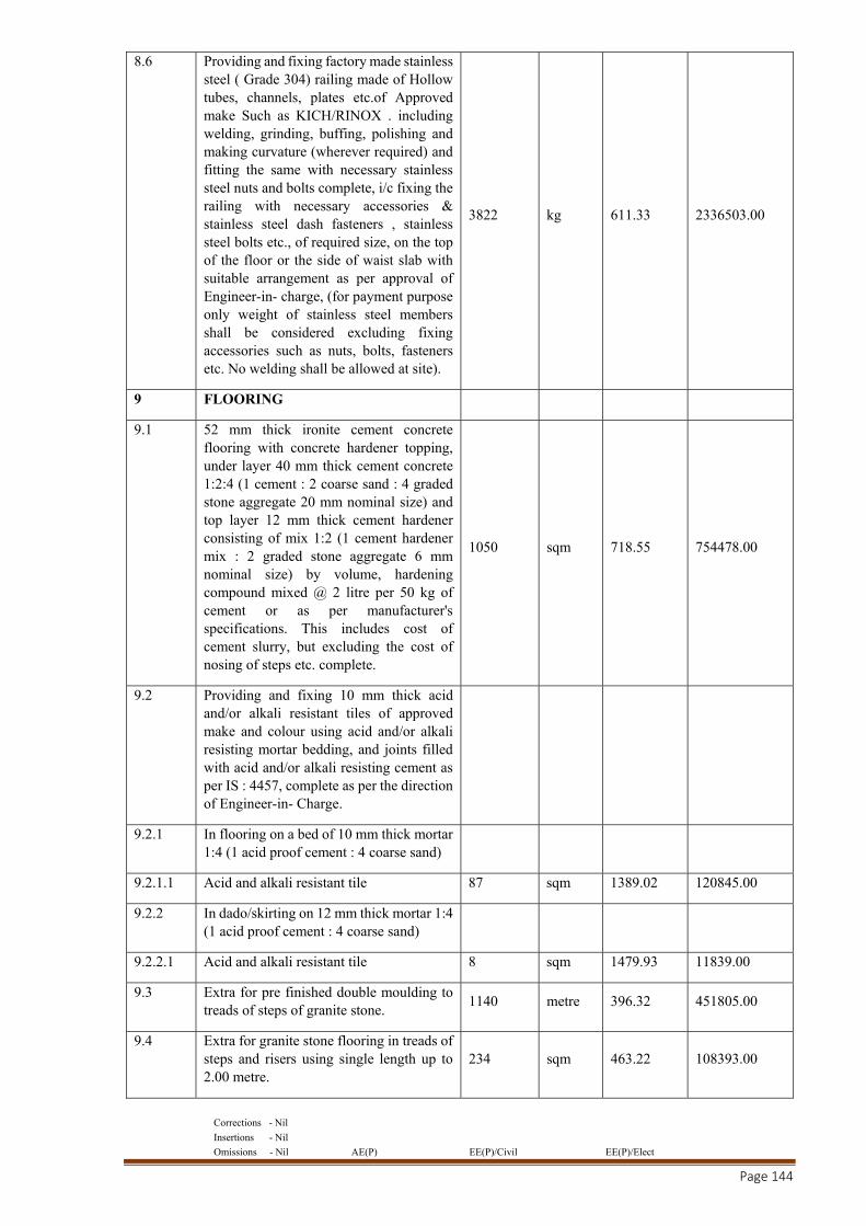
Corrections - Nil
Insertions - Nil
Omissions - Nil AE(P) EE(P)/Civil EE(P)/Elect
Page 144
8.6 Providing and fixing factory made stainless steel ( Grade 304) railing made of Hollow tubes, channels, plates etc.of Approved make Such as KICH/RINOX . including welding, grinding, buffing, polishing and making curvature (wherever required) and fitting the same with necessary stainless steel nuts and bolts complete, i/c fixing the railing with necessary accessories & stainless steel dash fasteners , stainless steel bolts etc., of required size, on the top of the floor or the side of waist slab with suitable arrangement as per approval of Engineer-in- charge, (for payment purpose only weight of stainless steel members shall be considered excluding fixing accessories such as nuts, bolts, fasteners etc. No welding shall be allowed at site).
3822 kg 611.33 2336503.00
9 FLOORING
9.1 52 mm thick ironite cement concrete flooring with concrete hardener topping, under layer 40 mm thick cement concrete 1:2:4 (1 cement : 2 coarse sand : 4 graded stone aggregate 20 mm nominal size) and top layer 12 mm thick cement hardener consisting of mix 1:2 (1 cement hardener mix : 2 graded stone aggregate 6 mm nominal size) by volume, hardening compound mixed @ 2 litre per 50 kg of cement or as per manufacturer's specifications. This includes cost of cement slurry, but excluding the cost of nosing of steps etc. complete.
1050 sqm 718.55 754478.00
9.2 Providing and fixing 10 mm thick acid and/or alkali resistant tiles of approved make and colour using acid and/or alkali resisting mortar bedding, and joints filled with acid and/or alkali resisting cement as per IS : 4457, complete as per the direction of Engineer-in- Charge.
9.2.1 In flooring on a bed of 10 mm thick mortar 1:4 (1 acid proof cement : 4 coarse sand)
9.2.1.1 Acid and alkali resistant tile 87 sqm 1389.02 120845.00
9.2.2 In dado/skirting on 12 mm thick mortar 1:4 (1 acid proof cement : 4 coarse sand)
9.2.2.1 Acid and alkali resistant tile 8 sqm 1479.93 11839.00
9.3 Extra for pre finished double moulding to treads of steps of granite stone.
1140 metre 396.32 451805.00
9.4 Extra for granite stone flooring in treads of steps and risers using single length up to 2.00 metre.
234 sqm 463.22 108393.00
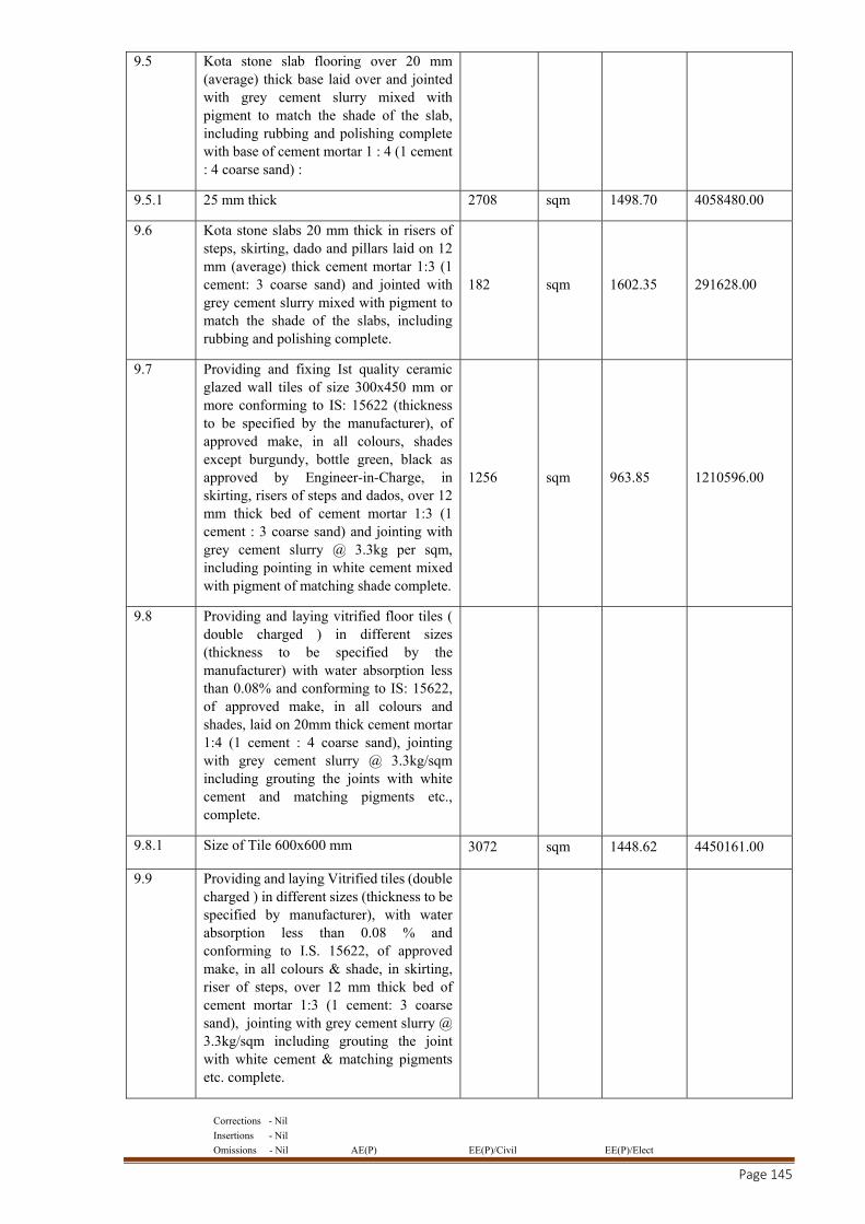
Corrections - Nil
Insertions - Nil
Omissions - Nil AE(P) EE(P)/Civil EE(P)/Elect
Page 145
9.5 Kota stone slab flooring over 20 mm (average) thick base laid over and jointed with grey cement slurry mixed with pigment to match the shade of the slab, including rubbing and polishing complete with base of cement mortar 1 : 4 (1 cement : 4 coarse sand) :
9.5.1 25 mm thick 2708 sqm 1498.70 4058480.00
9.6 Kota stone slabs 20 mm thick in risers of steps, skirting, dado and pillars laid on 12 mm (average) thick cement mortar 1:3 (1 cement: 3 coarse sand) and jointed with grey cement slurry mixed with pigment to match the shade of the slabs, including rubbing and polishing complete.
182 sqm 1602.35 291628.00
9.7 Providing and fixing Ist quality ceramic glazed wall tiles of size 300x450 mm or more conforming to IS: 15622 (thickness to be specified by the manufacturer), of approved make, in all colours, shades except burgundy, bottle green, black as approved by Engineer-in-Charge, in skirting, risers of steps and dados, over 12 mm thick bed of cement mortar 1:3 (1 cement : 3 coarse sand) and jointing with grey cement slurry @ 3.3kg per sqm, including pointing in white cement mixed with pigment of matching shade complete.
1256 sqm 963.85 1210596.00
9.8 Providing and laying vitrified floor tiles ( double charged ) in different sizes (thickness to be specified by the manufacturer) with water absorption less than 0.08% and conforming to IS: 15622, of approved make, in all colours and shades, laid on 20mm thick cement mortar 1:4 (1 cement : 4 coarse sand), jointing with grey cement slurry @ 3.3kg/sqm including grouting the joints with white cement and matching pigments etc., complete.
9.8.1 Size of Tile 600x600 mm 3072 sqm 1448.62 4450161.00
9.9 Providing and laying Vitrified tiles (double charged ) in different sizes (thickness to be specified by manufacturer), with water absorption less than 0.08 % and conforming to I.S. 15622, of approved make, in all colours & shade, in skirting, riser of steps, over 12 mm thick bed of cement mortar 1:3 (1 cement: 3 coarse sand), jointing with grey cement slurry @ 3.3kg/sqm including grouting the joint with white cement & matching pigments etc. complete.
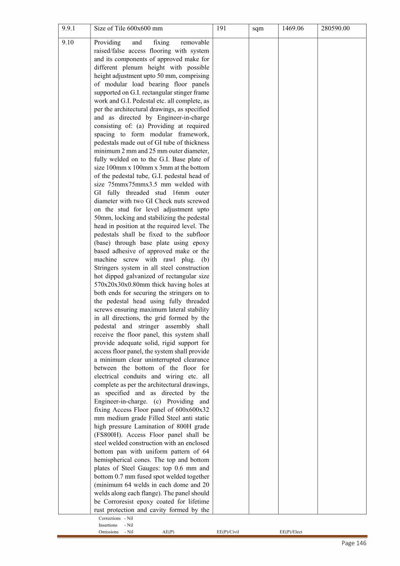
Corrections - Nil
Insertions - Nil
Omissions - Nil AE(P) EE(P)/Civil EE(P)/Elect
Page 146
9.9.1 Size of Tile 600x600 mm 191 sqm 1469.06 280590.00
9.10 Providing and fixing removable raised/false access flooring with system and its components of approved make for different plenum height with possible height adjustment upto 50 mm, comprising of modular load bearing floor panels supported on G.I. rectangular stinger frame work and G.I. Pedestal etc. all complete, as per the architectural drawings, as specified and as directed by Engineer-in-charge consisting of: (a) Providing at required spacing to form modular framework, pedestals made out of GI tube of thickness minimum 2 mm and 25 mm outer diameter, fully welded on to the G.I. Base plate of size 100mm x 100mm x 3mm at the bottom of the pedestal tube, G.I. pedestal head of size 75mmx75mmx3.5 mm welded with GI fully threaded stud 16mm outer diameter with two GI Check nuts screwed on the stud for level adjustment upto 50mm, locking and stabilizing the pedestal head in position at the required level. The pedestals shall be fixed to the subfloor (base) through base plate using epoxy based adhesive of approved make or the machine screw with rawl plug. (b) Stringers system in all steel construction hot dipped galvanized of rectangular size 570x20x30x0.80mm thick having holes at both ends for securing the stringers on to the pedestal head using fully threaded screws ensuring maximum lateral stability in all directions, the grid formed by the pedestal and stringer assembly shall receive the floor panel, this system shall provide adequate solid, rigid support for access floor panel, the system shall provide a minimum clear uninterrupted clearance between the bottom of the floor for electrical conduits and wiring etc. all complete as per the architectural drawings, as specified and as directed by the Engineer-in-charge. (c) Providing and fixing Access Floor panel of 600x600x32 mm medium grade Filled Steel anti static high pressure Lamination of 800H grade (FS800H). Access Floor panel shall be steel welded construction with an enclosed bottom pan with uniform pattern of 64 hemispherical cones. The top and bottom plates of Steel Gauges: top 0.6 mm and bottom 0.7 mm fused spot welded together (minimum 64 welds in each dome and 20 welds along each flange). The panel should be Corroresist epoxy coated for lifetime rust protection and cavity formed by the
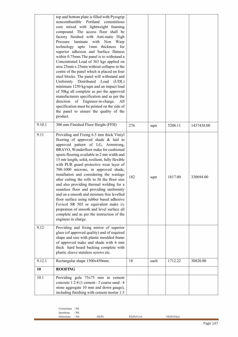
Corrections - Nil
Insertions - Nil
Omissions - Nil AE(P) EE(P)/Civil EE(P)/Elect
Page 147
top and bottom plate is filled with Pyrogrip noncombustible Portland cementitious core mixed with lightweight foaming compound. The access floor shall be factory finished with Anti-static High Pressure laminate with Non Warp technology upto 1mm thickness for superior adhesion and Surface flatness within 0.75mm.The panel is to withstand a Concentrated Load of 363 kgs applied on area 25mm x 25mm without collapse in the centre of the panel which is placed on four steel blocks. The panel will withstand and Uniformly Distributed Load (UDL) minimum 1250 kg/sqm and an impact load of 50kg all complete as per the approved manufacturers specification and as per the direction of Engineer-in-charge. All specification must be printed on the side of the panel to ensure the quality of the product.
9.10.1 300 mm Finished Floor Height (FFH) 276 sqm 5208.11 1437438.00
9.11 Providing and Fixing 6.5 mm thick Viniyl flooring of approved shade & laid in approved pattern of LG, Armstrong, BRAVO, Wonderfloor make for cushioned sports flooring available in 2 mtr width and 15 mtr length, solid, resilient, fully flexible with PUR guard protective wear layer of 700-1000 microns, in approved shade, installation and considering the wastage after cutting the rolls to fit the floor size and also providing thermal welding for a seamless floor and providing uniformity and on a smooth and moisture free levelled floor surface using rubber based adhesive Fevicol SR 505 or equivalent make i/c prepration of smooth and level surface all complete and as per the instruction of the engineer in charge.
182 sqm 1817.00 330694.00
9.12 Providing and fixing mirror of superior glass (of approved quality) and of required shape and size with plastic moulded frame of approved make and shade with 6 mm thick hard board backing complete with plastic sleeve stainless screws etc.
9.12.1 Rectangular shape 1500x450mm. 18 each 1712.22 30820.00
10 ROOFING
10.1 Providing gola 75x75 mm in cement concrete 1:2:4 (1 cement : 2 coarse sand : 4 stone aggregate 10 mm and down gauge), including finishing with cement mortar 1:3
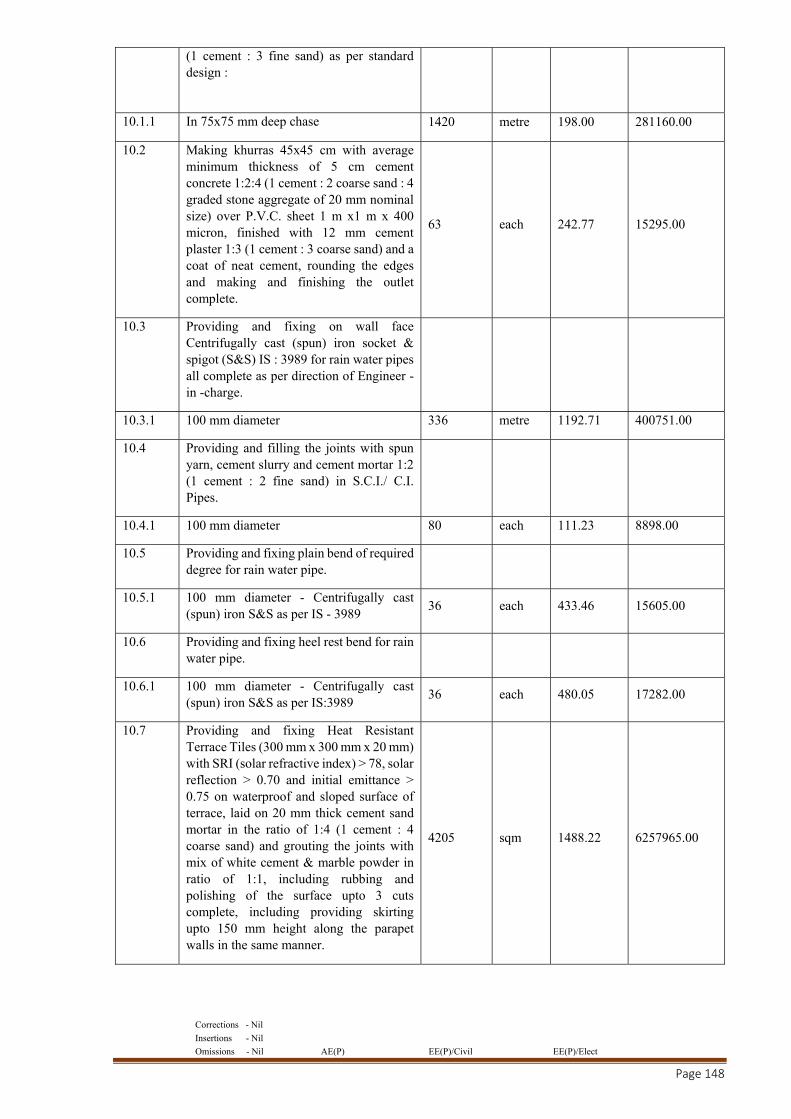
Corrections - Nil
Insertions - Nil
Omissions - Nil AE(P) EE(P)/Civil EE(P)/Elect
Page 148
(1 cement : 3 fine sand) as per standard design :
10.1.1 In 75x75 mm deep chase 1420 metre 198.00 281160.00
10.2 Making khurras 45x45 cm with average minimum thickness of 5 cm cement concrete 1:2:4 (1 cement : 2 coarse sand : 4 graded stone aggregate of 20 mm nominal size) over P.V.C. sheet 1 m x1 m x 400 micron, finished with 12 mm cement plaster 1:3 (1 cement : 3 coarse sand) and a coat of neat cement, rounding the edges and making and finishing the outlet complete.
63 each 242.77 15295.00
10.3 Providing and fixing on wall face Centrifugally cast (spun) iron socket & spigot (S&S) IS : 3989 for rain water pipes all complete as per direction of Engineer -in -charge.
10.3.1 100 mm diameter 336 metre 1192.71 400751.00
10.4 Providing and filling the joints with spun yarn, cement slurry and cement mortar 1:2 (1 cement : 2 fine sand) in S.C.I./ C.I. Pipes.
10.4.1 100 mm diameter 80 each 111.23 8898.00
10.5 Providing and fixing plain bend of required degree for rain water pipe.
10.5.1 100 mm diameter - Centrifugally cast (spun) iron S&S as per IS - 3989
36 each 433.46 15605.00
10.6 Providing and fixing heel rest bend for rain water pipe.
10.6.1 100 mm diameter - Centrifugally cast (spun) iron S&S as per IS:3989
36 each 480.05 17282.00
10.7 Providing and fixing Heat Resistant Terrace Tiles (300 mm x 300 mm x 20 mm) with SRI (solar refractive index) > 78, solar reflection > 0.70 and initial emittance > 0.75 on waterproof and sloped surface of terrace, laid on 20 mm thick cement sand mortar in the ratio of 1:4 (1 cement : 4 coarse sand) and grouting the joints with mix of white cement & marble powder in ratio of 1:1, including rubbing and polishing of the surface upto 3 cuts complete, including providing skirting upto 150 mm height along the parapet walls in the same manner.
4205 sqm 1488.22 6257965.00
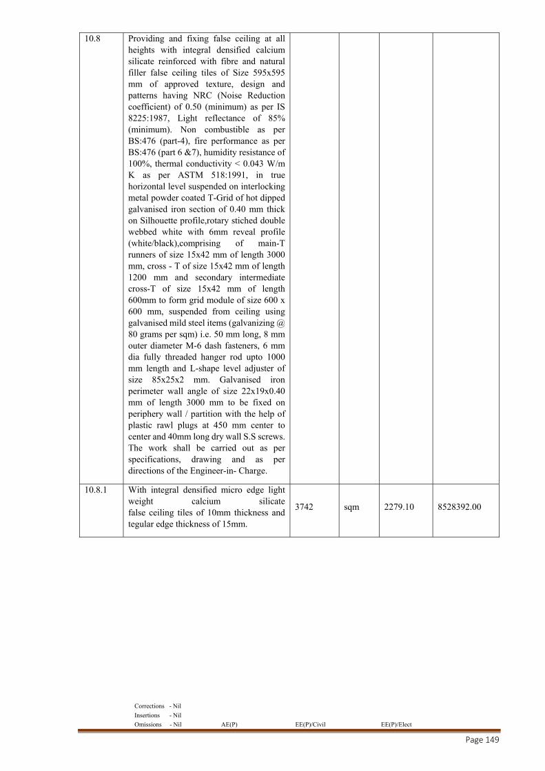
Corrections - Nil
Insertions - Nil
Omissions - Nil AE(P) EE(P)/Civil EE(P)/Elect
Page 149
10.8 Providing and fixing false ceiling at all heights with integral densified calcium silicate reinforced with fibre and natural filler false ceiling tiles of Size 595x595 mm of approved texture, design and patterns having NRC (Noise Reduction coefficient) of 0.50 (minimum) as per IS 8225:1987, Light reflectance of 85% (minimum). Non combustible as per BS:476 (part-4), fire performance as per BS:476 (part 6 &7), humidity resistance of 100%, thermal conductivity < 0.043 W/m K as per ASTM 518:1991, in true horizontal level suspended on interlocking metal powder coated T-Grid of hot dipped galvanised iron section of 0.40 mm thick on Silhouette profile,rotary stiched double webbed white with 6mm reveal profile (white/black),comprising of main-T runners of size 15x42 mm of length 3000 mm, cross - T of size 15x42 mm of length 1200 mm and secondary intermediate cross-T of size 15x42 mm of length 600mm to form grid module of size 600 x 600 mm, suspended from ceiling using galvanised mild steel items (galvanizing @ 80 grams per sqm) i.e. 50 mm long, 8 mm outer diameter M-6 dash fasteners, 6 mm dia fully threaded hanger rod upto 1000 mm length and L-shape level adjuster of size 85x25x2 mm. Galvanised iron perimeter wall angle of size 22x19x0.40 mm of length 3000 mm to be fixed on periphery wall / partition with the help of plastic rawl plugs at 450 mm center to center and 40mm long dry wall S.S screws. The work shall be carried out as per specifications, drawing and as per directions of the Engineer-in- Charge.
10.8.1 With integral densified micro edge light weight calcium silicate false ceiling tiles of 10mm thickness and tegular edge thickness of 15mm.
3742 sqm 2279.10 8528392.00
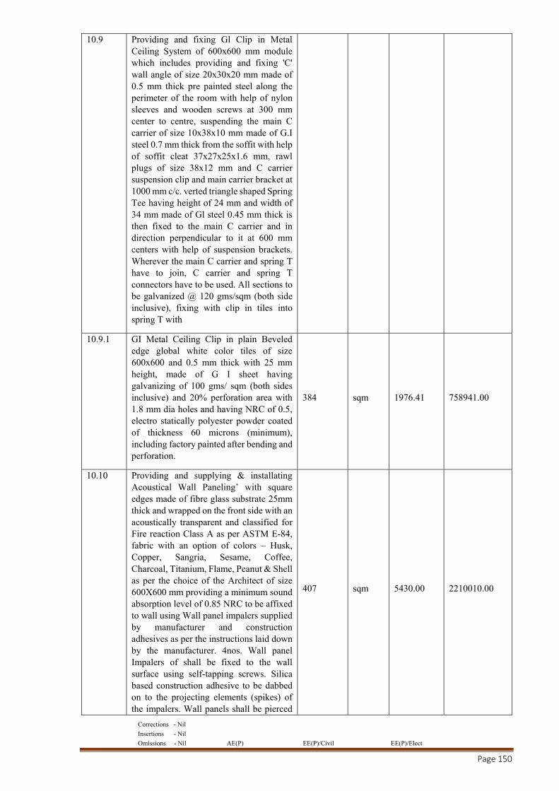
Corrections - Nil
Insertions - Nil
Omissions - Nil AE(P) EE(P)/Civil EE(P)/Elect
Page 150
10.9 Providing and fixing Gl Clip in Metal Ceiling System of 600x600 mm module which includes providing and fixing 'C' wall angle of size 20x30x20 mm made of 0.5 mm thick pre painted steel along the perimeter of the room with help of nylon sleeves and wooden screws at 300 mm center to centre, suspending the main C carrier of size 10x38x10 mm made of G.I steel 0.7 mm thick from the soffit with help of soffit cleat 37x27x25x1.6 mm, rawl plugs of size 38x12 mm and C carrier suspension clip and main carrier bracket at 1000 mm c/c. verted triangle shaped Spring Tee having height of 24 mm and width of 34 mm made of Gl steel 0.45 mm thick is then fixed to the main C carrier and in direction perpendicular to it at 600 mm centers with help of suspension brackets. Wherever the main C carrier and spring T have to join, C carrier and spring T connectors have to be used. All sections to be galvanized @ 120 gms/sqm (both side inclusive), fixing with clip in tiles into spring T with
10.9.1 GI Metal Ceiling Clip in plain Beveled edge global white color tiles of size 600x600 and 0.5 mm thick with 25 mm height, made of G I sheet having galvanizing of 100 gms/ sqm (both sides inclusive) and 20% perforation area with 1.8 mm dia holes and having NRC of 0.5, electro statically polyester powder coated of thickness 60 microns (minimum), including factory painted after bending and perforation.
384 sqm 1976.41 758941.00
10.10 Providing and supplying & installating Acoustical Wall Paneling’ with square edges made of fibre glass substrate 25mm thick and wrapped on the front side with an acoustically transparent and classified for Fire reaction Class A as per ASTM E-84, fabric with an option of colors – Husk, Copper, Sangria, Sesame, Coffee, Charcoal, Titanium, Flame, Peanut & Shell as per the choice of the Architect of size 600X600 mm providing a minimum sound absorption level of 0.85 NRC to be affixed to wall using Wall panel impalers supplied by manufacturer and construction adhesives as per the instructions laid down by the manufacturer. 4nos. Wall panel Impalers of shall be fixed to the wall surface using self-tapping screws. Silica based construction adhesive to be dabbed on to the projecting elements (spikes) of the impalers. Wall panels shall be pierced
407 sqm 5430.00 2210010.00
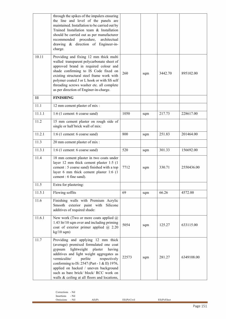
Corrections - Nil
Insertions - Nil
Omissions - Nil AE(P) EE(P)/Civil EE(P)/Elect
Page 151
through the spikes of the impalers ensuring the line and level of the panels are maintained. Installation to be carried out by Trained Installation team & Installation should be carried out as per manufacturer recommended procedure, architectual drawing & direction of Engineer-in-charge.
10.11 Providing and fixing 12 mm thick multi walled transparent polycarbonate sheet of approved brand in required colour and shade confirming to IS Code fixed on existing structural steel frame work with polymer coated J or L hook or with SS self threading screws washer etc. all complete as per direction of Enginer-in-charge.
260 sqm 3442.70 895102.00
11 FINISHING
11.1 12 mm cement plaster of mix :
11.1.1 1:6 (1 cement: 6 coarse sand) 1050 sqm 217.73 228617.00
11.2 15 mm cement plaster on rough side of single or half brick wall of mix:
11.2.1 1:6 (1 cement: 6 coarse sand) 800 sqm 251.83 201464.00
11.3 20 mm cement plaster of mix :
11.3.1 1:6 (1 cement: 6 coarse sand) 520 sqm 301.33 156692.00
11.4 18 mm cement plaster in two coats under layer 12 mm thick cement plaster 1:5 (1 cement : 5 coarse sand) finished with a top layer 6 mm thick cement plaster 1:6 (1 cement : 6 fine sand).
7712 sqm 330.71 2550436.00
11.5 Extra for plastering:
11.5.1 Flewing soffits 69 sqm 66.26 4572.00
11.6 Finishing walls with Premium Acrylic Smooth exterior paint with Silicone additives of required shade:
11.6.1 New work (Two or more coats applied @ 1.43 ltr/10 sqm over and including priming coat of exterior primer applied @ 2.20 kg/10 sqm)
5054 sqm 125.27 633115.00
11.7 Providing and applying 12 mm thick (average) premixed formulated one coat gypsum lightweight plaster having additives and light weight aggregates as vermiculite/ perlite respectively conforming to IS: 2547 (Part - 1 & II) 1976, applied on hacked / uneven background such as bare brick/ block/ RCC work on walls & ceiling at all floors and locations,
22573 sqm 281.27 6349108.00
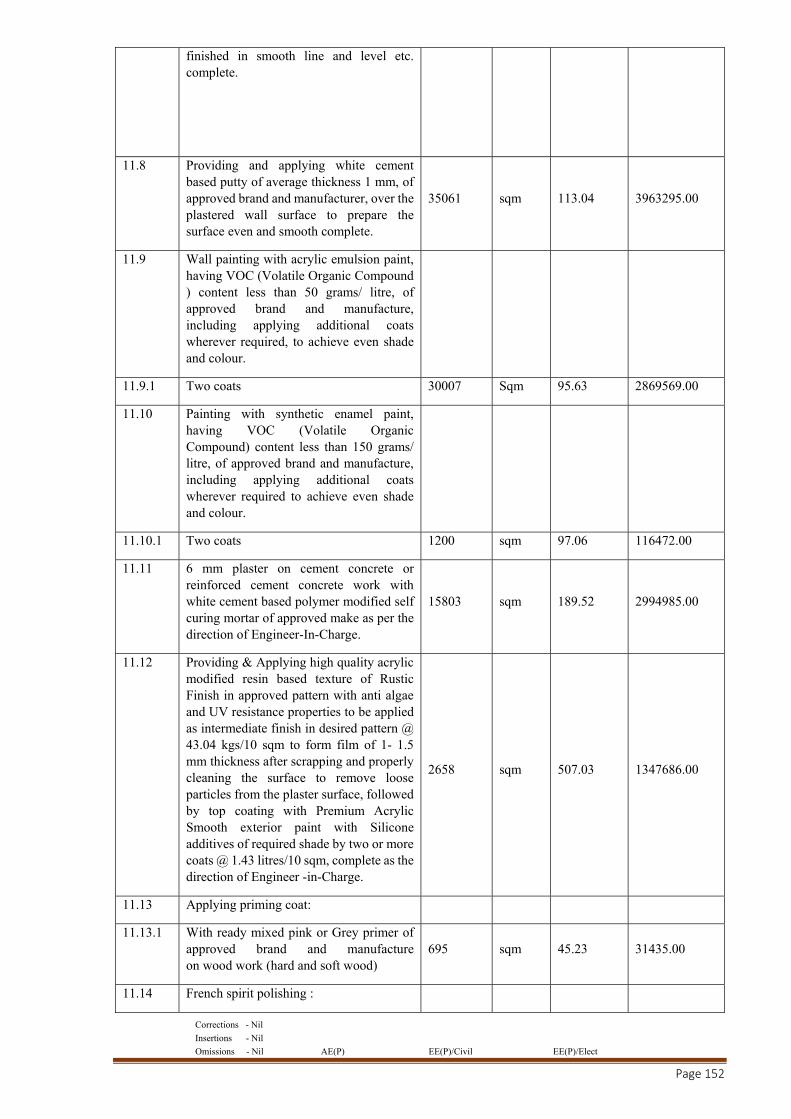
Corrections - Nil
Insertions - Nil
Omissions - Nil AE(P) EE(P)/Civil EE(P)/Elect
Page 152
finished in smooth line and level etc. complete.
11.8 Providing and applying white cement based putty of average thickness 1 mm, of approved brand and manufacturer, over the plastered wall surface to prepare the surface even and smooth complete.
35061 sqm 113.04 3963295.00
11.9 Wall painting with acrylic emulsion paint, having VOC (Volatile Organic Compound ) content less than 50 grams/ litre, of approved brand and manufacture, including applying additional coats wherever required, to achieve even shade and colour.
11.9.1 Two coats 30007 Sqm 95.63 2869569.00
11.10 Painting with synthetic enamel paint, having VOC (Volatile Organic Compound) content less than 150 grams/ litre, of approved brand and manufacture, including applying additional coats wherever required to achieve even shade and colour.
11.10.1 Two coats 1200 sqm 97.06 116472.00
11.11 6 mm plaster on cement concrete or reinforced cement concrete work with white cement based polymer modified self curing mortar of approved make as per the direction of Engineer-In-Charge.
15803 sqm 189.52 2994985.00
11.12 Providing & Applying high quality acrylic modified resin based texture of Rustic Finish in approved pattern with anti algae and UV resistance properties to be applied as intermediate finish in desired pattern @ 43.04 kgs/10 sqm to form film of 1- 1.5 mm thickness after scrapping and properly cleaning the surface to remove loose particles from the plaster surface, followed by top coating with Premium Acrylic Smooth exterior paint with Silicone additives of required shade by two or more coats @ 1.43 litres/10 sqm, complete as the direction of Engineer -in-Charge.
2658 sqm 507.03 1347686.00
11.13 Applying priming coat:
11.13.1 With ready mixed pink or Grey primer of approved brand and manufacture on wood work (hard and soft wood)
695 sqm 45.23 31435.00
11.14 French spirit polishing :
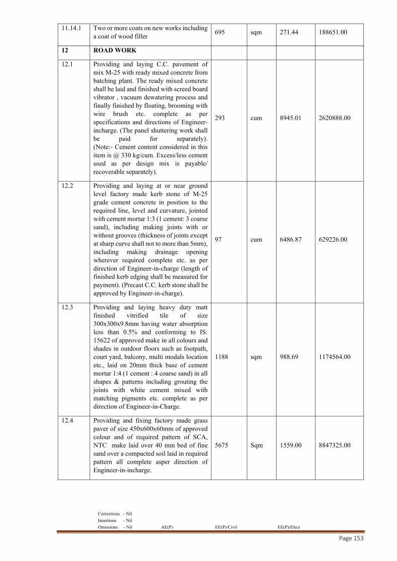
Corrections - Nil
Insertions - Nil
Omissions - Nil AE(P) EE(P)/Civil EE(P)/Elect
Page 153
11.14.1 Two or more coats on new works including a coat of wood filler
695 sqm 271.44 188651.00
12 ROAD WORK
12.1 Providing and laying C.C. pavement of mix M-25 with ready mixed concrete from batching plant. The ready mixed concrete shall be laid and finished with screed board vibrator , vacuum dewatering process and finally finished by floating, brooming with wire brush etc. complete as per specifications and directions of Engineer-incharge. (The panel shuttering work shall be paid for separately). (Note:- Cement content considered in this item is @ 330 kg/cum. Excess/less cement used as per design mix is payable/ recoverable separately).
293 cum 8945.01 2620888.00
12.2 Providing and laying at or near ground level factory made kerb stone of M-25 grade cement concrete in position to the required line, level and curvature, jointed with cement mortar 1:3 (1 cement: 3 coarse sand), including making joints with or without grooves (thickness of joints except at sharp curve shall not to more than 5mm), including making drainage opening wherever required complete etc. as per direction of Engineer-in-charge (length of finished kerb edging shall be measured for payment). (Precast C.C. kerb stone shall be approved by Engineer-in-charge).
97 cum 6486.87 629226.00
12.3 Providing and laying heavy duty matt finished vitrified tile of size 300x300x9.8mm having water absorption less than 0.5% and conforming to IS: 15622 of approved make in all colours and shades in outdoor floors such as footpath, court yard, balcony, multi modals location etc., laid on 20mm thick base of cement mortar 1:4 (1 cement : 4 coarse sand) in all shapes & patterns including grouting the joints with white cement mixed with matching pigments etc. complete as per direction of Engineer-in-Charge.
1188 sqm 988.69 1174564.00
12.4 Providing and fixing factory made grass paver of size 450x600x60mm of approved colour and of required pattern of SCA, NTC make laid over 40 mm bed of fine sand over a compacted soil laid in required pattern all complete asper direction of Engineer-in-incharge.
5675 Sqm 1559.00 8847325.00
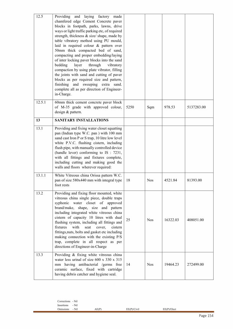
Corrections - Nil
Insertions - Nil
Omissions - Nil AE(P) EE(P)/Civil EE(P)/Elect
Page 154
12.5 Providing and laying factory made chamfered edge Cement Concrete paver blocks in footpath, parks, lawns, drive ways or light traffic parking etc, of required strength, thickness & size/ shape, made by table vibratory method using PU mould, laid in required colour & pattern over 50mm thick compacted bed of sand, compacting and proper embedding/laying of inter locking paver blocks into the sand bedding layer through vibratory compaction by using plate vibrator, filling the joints with sand and cutting of paver blocks as per required size and pattern, finishing and sweeping extra sand. complete all as per direction of Engineer-in-Charge.
12.5.1 60mm thick cement concrete paver block of M-35 grade with approved colour, design & pattern.
5250 Sqm 978.53 5137283.00
13 SANITARY INSTALLATIONS
13.1 Providing and fixing water closet squatting pan (Indian type W.C. pan ) with 100 mm sand cast Iron P or S trap, 10 litre low level white P.V.C. flushing cistern, including flush pipe, with manually controlled device (handle lever) conforming to IS : 7231, with all fittings and fixtures complete, including cutting and making good the walls and floors wherever required:
13.1.1 White Vitreous china Orissa pattern W.C. pan of size 580x440 mm with integral type foot rests
18 Nos 4521.84 81393.00
13.2 Providing and fixing floor mounted, white vitreous china single piece, double traps syphonic water closet of approved brand/make, shape, size and pattern including integrated white vitreous china cistern of capacity 10 litres with dual flushing system, including all fittings and fixtures with seat cover, cistern fittings,nuts, bolts and gasket etc including making connection with the existing P/S trap, complete in all respect as per directions of Engineer-in-Charge
25 Nos 16322.03 408051.00
13.3 Providing & fixing white vitreous china water less urinal of size 600 x 330 x 315 mm having antibacterial /germs free ceramic surface, fixed with cartridge having debris catcher and hygiene seal.
14 Nos 19464.23 272499.00
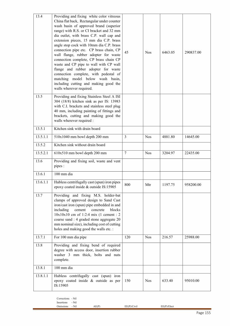
Corrections - Nil
Insertions - Nil
Omissions - Nil AE(P) EE(P)/Civil EE(P)/Elect
Page 155
13.4 Providing and fixing white color vitreous China flat back, Rectangular under counter wash basin of approved brand (superior range) with R.S. or CI bracket and 32 mm dia outlet, with brass C.P. wall cap and extension pieces, 15 mm dia C.P. brass angle stop cock with 10mm dia C.P. brass connection pipe etc. CP brass chain, CP wall flange, rubber adopter for waste connection complete, CP brass chain CP waste and CP pipe to wall with CP wall flange and rubber adopter for waste connection complete, with pedestal of matching model below wash basin, including cutting and making good the walls wherever required.
45 Nos 6463.05 290837.00
13.5 Providing and fixing Stainless Steel A ISI 304 (18/8) kitchen sink as per IS: 13983 with C.I. brackets and stainless steel plug 40 mm, including painting of fittings and brackets, cutting and making good the walls wherever required :
13.5.1 Kitchen sink with drain board
13.5.1.1 510x1040 mm bowl depth 200 mm 3 Nos 4881.80 14645.00
13.5.2 Kitchen sink without drain board
13.5.2.1 610x510 mm bowl depth 200 mm 7 Nos 3204.97 22435.00
13.6 Providing and fixing soil, waste and vent pipes :
13.6.1 100 mm dia
13.6.1.1 Hubless centrifugally cast (spun) iron pipes epoxy coated inside & outside IS:15905
800 Mtr 1197.75 958200.00
13.7 Providing and fixing M.S. holder-bat clamps of approved design to Sand Cast iron/cast iron (spun) pipe embedded in and including cement concrete blocks 10x10x10 cm of 1:2:4 mix (1 cement : 2 coarse sand : 4 graded stone aggregate 20 mm nominal size), including cost of cutting holes and making good the walls etc. :
13.7.1 For 100 mm dia pipe 120 Nos 216.57 25988.00
13.8 Providing and fixing bend of required degree with access door, insertion rubber washer 3 mm thick, bolts and nuts complete.
13.8.1 100 mm dia
13.8.1.1 Hubless centrifugally cast (spun) iron epoxy coated inside & outside as per IS:15905
150 Nos 633.40 95010.00
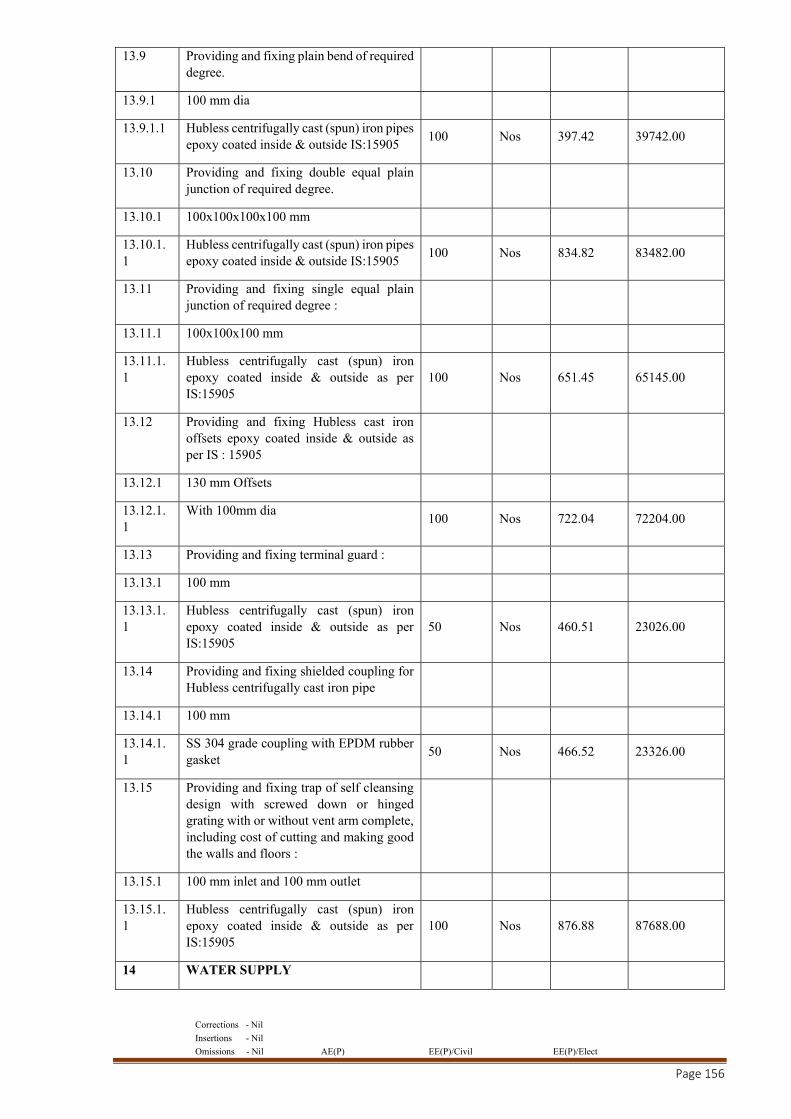
Corrections - Nil
Insertions - Nil
Omissions - Nil AE(P) EE(P)/Civil EE(P)/Elect
Page 156
13.9 Providing and fixing plain bend of required degree.
13.9.1 100 mm dia
13.9.1.1 Hubless centrifugally cast (spun) iron pipes epoxy coated inside & outside IS:15905
100 Nos 397.42 39742.00
13.10 Providing and fixing double equal plain junction of required degree.
13.10.1 100x100x100x100 mm
13.10.1.1
Hubless centrifugally cast (spun) iron pipes epoxy coated inside & outside IS:15905
100 Nos 834.82 83482.00
13.11 Providing and fixing single equal plain junction of required degree :
13.11.1 100x100x100 mm
13.11.1.1
Hubless centrifugally cast (spun) iron epoxy coated inside & outside as per IS:15905
100 Nos 651.45 65145.00
13.12 Providing and fixing Hubless cast iron offsets epoxy coated inside & outside as per IS : 15905
13.12.1 130 mm Offsets
13.12.1.1
With 100mm dia 100 Nos 722.04 72204.00
13.13 Providing and fixing terminal guard :
13.13.1 100 mm
13.13.1.1
Hubless centrifugally cast (spun) iron epoxy coated inside & outside as per IS:15905
50 Nos 460.51 23026.00
13.14 Providing and fixing shielded coupling for Hubless centrifugally cast iron pipe
13.14.1 100 mm
13.14.1.1
SS 304 grade coupling with EPDM rubber gasket
50 Nos 466.52 23326.00
13.15 Providing and fixing trap of self cleansing design with screwed down or hinged grating with or without vent arm complete, including cost of cutting and making good the walls and floors :
13.15.1 100 mm inlet and 100 mm outlet
13.15.1.1
Hubless centrifugally cast (spun) iron epoxy coated inside & outside as per IS:15905
100 Nos 876.88 87688.00
14 WATER SUPPLY
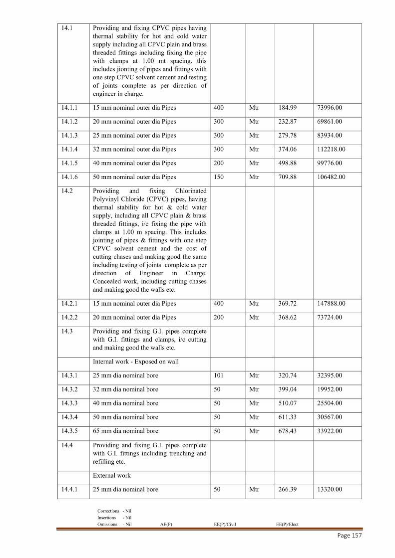
Corrections - Nil
Insertions - Nil
Omissions - Nil AE(P) EE(P)/Civil EE(P)/Elect
Page 157
14.1 Providing and fixing CPVC pipes having thermal stability for hot and cold water supply including all CPVC plain and brass threaded fittings including fixing the pipe with clamps at 1.00 mt spacing. this includes jionting of pipes and fittings with one step CPVC solvent cement and testing of joints complete as per direction of engineer in charge.
14.1.1 15 mm nominal outer dia Pipes 400 Mtr 184.99 73996.00
14.1.2 20 mm nominal outer dia Pipes 300 Mtr 232.87 69861.00
14.1.3 25 mm nominal outer dia Pipes 300 Mtr 279.78 83934.00
14.1.4 32 mm nominal outer dia Pipes 300 Mtr 374.06 112218.00
14.1.5 40 mm nominal outer dia Pipes 200 Mtr 498.88 99776.00
14.1.6 50 mm nominal outer dia Pipes 150 Mtr 709.88 106482.00
14.2 Providing and fixing Chlorinated Polyvinyl Chloride (CPVC) pipes, having thermal stability for hot & cold water supply, including all CPVC plain & brass threaded fittings, i/c fixing the pipe with clamps at 1.00 m spacing. This includes jointing of pipes & fittings with one step CPVC solvent cement and the cost of cutting chases and making good the same including testing of joints complete as per direction of Engineer in Charge. Concealed work, including cutting chases and making good the walls etc.
14.2.1 15 mm nominal outer dia Pipes 400 Mtr 369.72 147888.00
14.2.2 20 mm nominal outer dia Pipes 200 Mtr 368.62 73724.00
14.3 Providing and fixing G.I. pipes complete with G.I. fittings and clamps, i/c cutting and making good the walls etc.
Internal work - Exposed on wall
14.3.1 25 mm dia nominal bore 101 Mtr 320.74 32395.00
14.3.2 32 mm dia nominal bore 50 Mtr 399.04 19952.00
14.3.3 40 mm dia nominal bore 50 Mtr 510.07 25504.00
14.3.4 50 mm dia nominal bore 50 Mtr 611.33 30567.00
14.3.5 65 mm dia nominal bore 50 Mtr 678.43 33922.00
14.4 Providing and fixing G.I. pipes complete with G.I. fittings including trenching and refilling etc.
External work
14.4.1 25 mm dia nominal bore 50 Mtr 266.39 13320.00
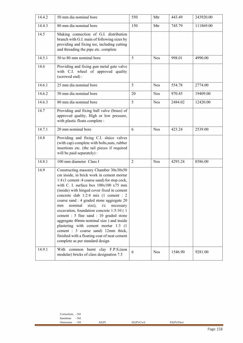
Corrections - Nil
Insertions - Nil
Omissions - Nil AE(P) EE(P)/Civil EE(P)/Elect
Page 158
14.4.2 50 mm dia nominal bore 550 Mtr 443.49 243920.00
14.4.3 80 mm dia nominal bore 150 Mtr 745.79 111869.00
14.5 Making connection of G.I. distribution branch with G.I. main of following sizes by providing and fixing tee, including cutting and threading the pipe etc. complete
14.5.1 50 to 80 mm nominal bore 5 Nos 998.01 4990.00
14.6 Providing and fixing gun metal gate valve with C.I. wheel of approved quality (screwed end) :
14.6.1 25 mm dia nominal bore 5 Nos 554.78 2774.00
14.6.2 50 mm dia nominal bore 20 Nos 970.45 19409.00
14.6.3 80 mm dia nominal bore 5 Nos 2484.02 12420.00
14.7 Providing and fixing ball valve (brass) of approved quality, High or low pressure, with plastic floats complete :
14.7.1 20 mm nominal bore 6 Nos 423.24 2539.00
14.8 Providing and fixing C.I. sluice valves (with cap) complete with bolts,nuts, rubber insertions etc. (the tail pieces if required will be paid separately) :
14.8.1 100 mm diameter Class I 2 Nos 4293.24 8586.00
14.9 Constructing masonry Chamber 30x30x50 cm inside, in brick work in cement mortar 1:4 (1 cement :4 coarse sand) for stop cock, with C. I. surface box 100x100 x75 mm (inside) with hinged cover fixed in cement concrete slab 1:2:4 mix (1 cement : 2 coarse sand : 4 graded stone aggregate 20 mm nominal size), i/c necessary excavation, foundation concrete 1:5:10 ( 1 cement : 5 fine sand : 10 graded stone aggregate 40mm nominal size ) and inside plastering with cement mortar 1:3 (1 cement : 3 coarse sand) 12mm thick, finished with a floating coat of neat cement complete as per standard design
14.9.1 With common burnt clay F.P.S.(non modular) bricks of class designation 7.5
6 Nos 1546.90 9281.00
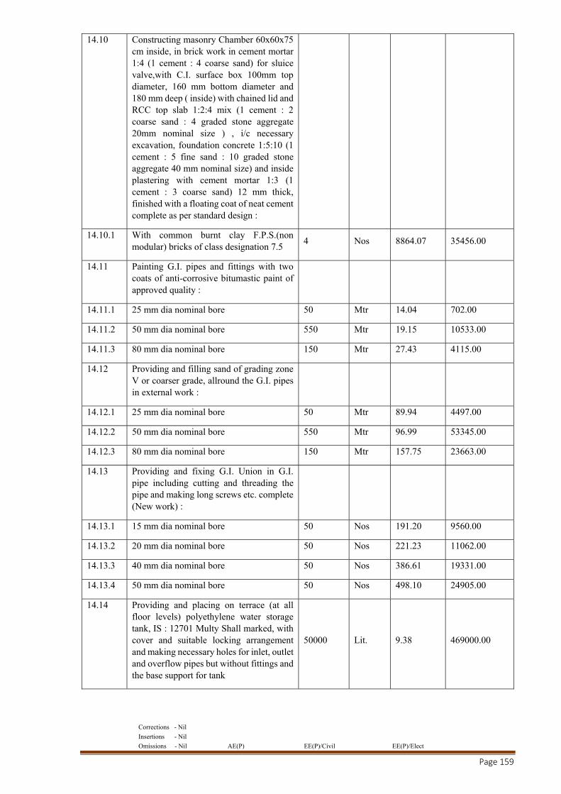
Corrections - Nil
Insertions - Nil
Omissions - Nil AE(P) EE(P)/Civil EE(P)/Elect
Page 159
14.10 Constructing masonry Chamber 60x60x75 cm inside, in brick work in cement mortar 1:4 (1 cement : 4 coarse sand) for sluice valve,with C.I. surface box 100mm top diameter, 160 mm bottom diameter and 180 mm deep ( inside) with chained lid and RCC top slab 1:2:4 mix (1 cement : 2 coarse sand : 4 graded stone aggregate 20mm nominal size ) , i/c necessary excavation, foundation concrete 1:5:10 (1 cement : 5 fine sand : 10 graded stone aggregate 40 mm nominal size) and inside plastering with cement mortar 1:3 (1 cement : 3 coarse sand) 12 mm thick, finished with a floating coat of neat cement complete as per standard design :
14.10.1 With common burnt clay F.P.S.(non modular) bricks of class designation 7.5
4 Nos 8864.07 35456.00
14.11 Painting G.I. pipes and fittings with two coats of anti-corrosive bitumastic paint of approved quality :
14.11.1 25 mm dia nominal bore 50 Mtr 14.04 702.00
14.11.2 50 mm dia nominal bore 550 Mtr 19.15 10533.00
14.11.3 80 mm dia nominal bore 150 Mtr 27.43 4115.00
14.12 Providing and filling sand of grading zone V or coarser grade, allround the G.I. pipes in external work :
14.12.1 25 mm dia nominal bore 50 Mtr 89.94 4497.00
14.12.2 50 mm dia nominal bore 550 Mtr 96.99 53345.00
14.12.3 80 mm dia nominal bore 150 Mtr 157.75 23663.00
14.13 Providing and fixing G.I. Union in G.I. pipe including cutting and threading the pipe and making long screws etc. complete (New work) :
14.13.1 15 mm dia nominal bore 50 Nos 191.20 9560.00
14.13.2 20 mm dia nominal bore 50 Nos 221.23 11062.00
14.13.3 40 mm dia nominal bore 50 Nos 386.61 19331.00
14.13.4 50 mm dia nominal bore 50 Nos 498.10 24905.00
14.14 Providing and placing on terrace (at all floor levels) polyethylene water storage tank, IS : 12701 Multy Shall marked, with cover and suitable locking arrangement and making necessary holes for inlet, outlet and overflow pipes but without fittings and the base support for tank
50000 Lit. 9.38 469000.00
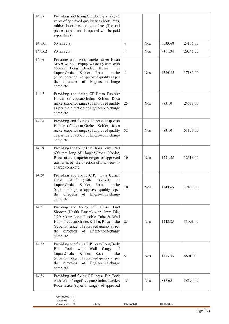
Corrections - Nil
Insertions - Nil
Omissions - Nil AE(P) EE(P)/Civil EE(P)/Elect
Page 160
14.15 Providing and fixing C.I. double acting air valve of approved quality with bolts, nuts, rubber insertions etc. complete (The tail pieces, tapers etc if required will be paid separately) :
14.15.1 50 mm dia 4 Nos 6033.68 24135.00
14.15.2 80 mm dia 4 Nos 7311.34 29245.00
14.16 Provding and fixing single leaver Basin Mixer without Popup Waste System with 450mm Long Braided Hoses of Jaquar,Grohe, Kohler, Roca make (superior range) of approved quality as per the direction of Engineer-in-charge complete.
4 Nos 4296.25 17185.00
14.17 Providing and fixing CP Brass Tumbler Holder of Jaquar,Grohe, Kohler, Roca make (superior range) of approved quality as per the direction of Engineer-in-charge complete.
25 Nos 983.10 24578.00
14.18 Providing and fixing C.P. brass soap dish Holder of Jaquar,Grohe, Kohler, Roca make (superior range) of approved quality as per the direction of Engineer-in-charge complete.
52 Nos 983.10 51121.00
14.19 Providing and fixing C.P. Brass Towel Rail 600 mm long of Jaquar,Grohe, Kohler, Roca make (superior range) of approved quality as per the direction of Engineer-in-charge complete.
10 Nos 1231.55 12316.00
14.20 Providing and fixing C.P. brass Corner Glass Shelf (with Bracket) of Jaquar,Grohe, Kohler, Roca make (superior range) of approved quality as per the direction of Engineer-in-charge complete.
10 Nos 1248.65 12487.00
14.21 Provding and fixing C.P. Brass Hand Shower (Health Faucet) with 8mm Dia, 1.00 Meter Long Flexible Tube & Wall Hookof Jaquar,Grohe, Kohler, Roca make (superior range) of approved quality as per the direction of Engineer-in-charge complete.
25 Nos 1243.85 31096.00
14.22 Providing and fixing C.P. brass Long Body Bib Cock with Wall flange of Jaquar,Grohe, Kohler, Roca make (superior range) of approved quality as per the direction of Engineer-in-charge complete.
6 Nos 1133.55 6801.00
14.23 Providing and fixing C.P. brass Bib Cock with Wall flangof Jaquar,Grohe, Kohler, Roca make (superior range) of approved
45 Nos 857.65 38594.00
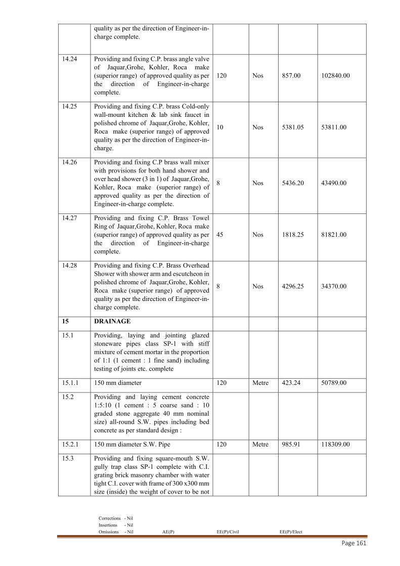
Corrections - Nil
Insertions - Nil
Omissions - Nil AE(P) EE(P)/Civil EE(P)/Elect
Page 161
quality as per the direction of Engineer-in-charge complete.
14.24 Providing and fixing C.P. brass angle valve of Jaquar,Grohe, Kohler, Roca make (superior range) of approved quality as per the direction of Engineer-in-charge complete.
120 Nos 857.00 102840.00
14.25 Providing and fixing C.P. brass Cold-only wall-mount kitchen & lab sink faucet in polished chrome of Jaquar,Grohe, Kohler, Roca make (superior range) of approved quality as per the direction of Engineer-in-charge.
10 Nos 5381.05 53811.00
14.26 Providing and fixing C.P brass wall mixer with provisions for both hand shower and over head shower (3 in 1) of Jaquar,Grohe, Kohler, Roca make (superior range) of approved quality as per the direction of Engineer-in-charge complete.
8 Nos 5436.20 43490.00
14.27 Providing and fixing C.P. Brass Towel Ring of Jaquar,Grohe, Kohler, Roca make (superior range) of approved quality as per the direction of Engineer-in-charge complete.
45 Nos 1818.25 81821.00
14.28 Providing and fixing C.P. Brass Overhead Shower with shower arm and escutcheon in polished chrome of Jaquar,Grohe, Kohler, Roca make (superior range) of approved quality as per the direction of Engineer-in-charge complete.
8 Nos 4296.25 34370.00
15 DRAINAGE
15.1 Providing, laying and jointing glazed stoneware pipes class SP-1 with stiff mixture of cement mortar in the proportion of 1:1 (1 cement : 1 fine sand) including testing of joints etc. complete
15.1.1 150 mm diameter 120 Metre 423.24 50789.00
15.2 Providing and laying cement concrete 1:5:10 (1 cement : 5 coarse sand : 10 graded stone aggregate 40 mm nominal size) all-round S.W. pipes including bed concrete as per standard design :
15.2.1 150 mm diameter S.W. Pipe 120 Metre 985.91 118309.00
15.3 Providing and fixing square-mouth S.W. gully trap class SP-1 complete with C.I. grating brick masonry chamber with water tight C.I. cover with frame of 300 x300 mm size (inside) the weight of cover to be not
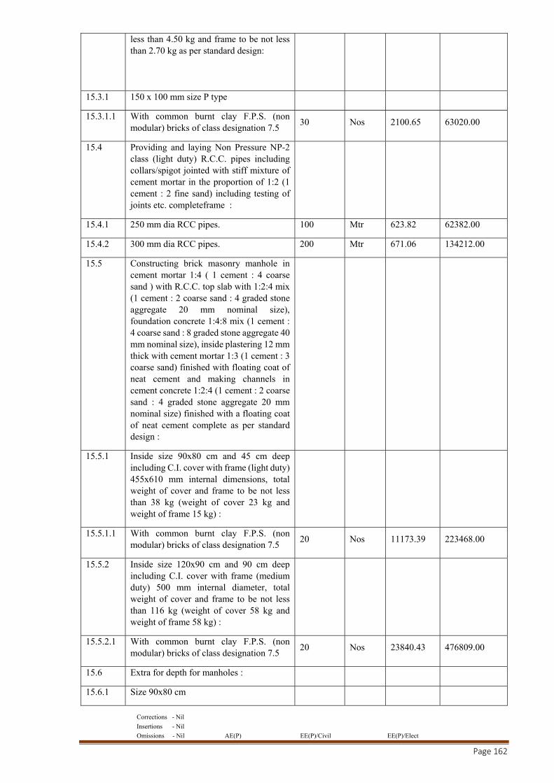
Corrections - Nil
Insertions - Nil
Omissions - Nil AE(P) EE(P)/Civil EE(P)/Elect
Page 162
less than 4.50 kg and frame to be not less than 2.70 kg as per standard design:
15.3.1 150 x 100 mm size P type
15.3.1.1 With common burnt clay F.P.S. (non modular) bricks of class designation 7.5
30 Nos 2100.65 63020.00
15.4 Providing and laying Non Pressure NP-2 class (light duty) R.C.C. pipes including collars/spigot jointed with stiff mixture of cement mortar in the proportion of 1:2 (1 cement : 2 fine sand) including testing of joints etc. completeframe :
15.4.1 250 mm dia RCC pipes. 100 Mtr 623.82 62382.00
15.4.2 300 mm dia RCC pipes. 200 Mtr 671.06 134212.00
15.5 Constructing brick masonry manhole in cement mortar 1:4 ( 1 cement : 4 coarse sand ) with R.C.C. top slab with 1:2:4 mix (1 cement : 2 coarse sand : 4 graded stone aggregate 20 mm nominal size), foundation concrete 1:4:8 mix (1 cement : 4 coarse sand : 8 graded stone aggregate 40 mm nominal size), inside plastering 12 mm thick with cement mortar 1:3 (1 cement : 3 coarse sand) finished with floating coat of neat cement and making channels in cement concrete 1:2:4 (1 cement : 2 coarse sand : 4 graded stone aggregate 20 mm nominal size) finished with a floating coat of neat cement complete as per standard design :
15.5.1 Inside size 90x80 cm and 45 cm deep including C.I. cover with frame (light duty) 455x610 mm internal dimensions, total weight of cover and frame to be not less than 38 kg (weight of cover 23 kg and weight of frame 15 kg) :
15.5.1.1 With common burnt clay F.P.S. (non modular) bricks of class designation 7.5
20 Nos 11173.39 223468.00
15.5.2 Inside size 120x90 cm and 90 cm deep including C.I. cover with frame (medium duty) 500 mm internal diameter, total weight of cover and frame to be not less than 116 kg (weight of cover 58 kg and weight of frame 58 kg) :
15.5.2.1 With common burnt clay F.P.S. (non modular) bricks of class designation 7.5
20 Nos 23840.43 476809.00
15.6 Extra for depth for manholes :
15.6.1 Size 90x80 cm
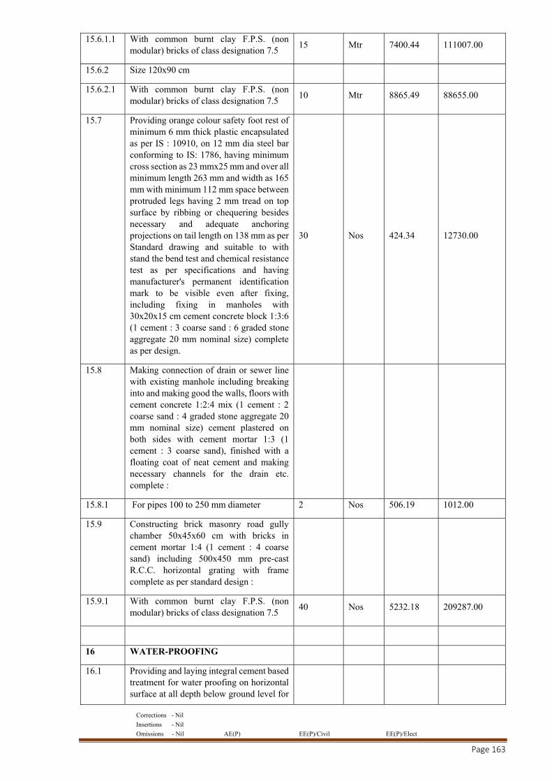
Corrections - Nil
Insertions - Nil
Omissions - Nil AE(P) EE(P)/Civil EE(P)/Elect
Page 163
15.6.1.1 With common burnt clay F.P.S. (non modular) bricks of class designation 7.5
15 Mtr 7400.44 111007.00
15.6.2 Size 120x90 cm
15.6.2.1 With common burnt clay F.P.S. (non modular) bricks of class designation 7.5
10 Mtr 8865.49 88655.00
15.7 Providing orange colour safety foot rest of minimum 6 mm thick plastic encapsulated as per IS : 10910, on 12 mm dia steel bar conforming to IS: 1786, having minimum cross section as 23 mmx25 mm and over all minimum length 263 mm and width as 165 mm with minimum 112 mm space between protruded legs having 2 mm tread on top surface by ribbing or chequering besides necessary and adequate anchoring projections on tail length on 138 mm as per Standard drawing and suitable to with stand the bend test and chemical resistance test as per specifications and having manufacturer's permanent identification mark to be visible even after fixing, including fixing in manholes with 30x20x15 cm cement concrete block 1:3:6 (1 cement : 3 coarse sand : 6 graded stone aggregate 20 mm nominal size) complete as per design.
30 Nos 424.34 12730.00
15.8 Making connection of drain or sewer line with existing manhole including breaking into and making good the walls, floors with cement concrete 1:2:4 mix (1 cement : 2 coarse sand : 4 graded stone aggregate 20 mm nominal size) cement plastered on both sides with cement mortar 1:3 (1 cement : 3 coarse sand), finished with a floating coat of neat cement and making necessary channels for the drain etc. complete :
15.8.1 For pipes 100 to 250 mm diameter 2 Nos 506.19 1012.00
15.9 Constructing brick masonry road gully chamber 50x45x60 cm with bricks in cement mortar 1:4 (1 cement : 4 coarse sand) including 500x450 mm pre-cast R.C.C. horizontal grating with frame complete as per standard design :
15.9.1 With common burnt clay F.P.S. (non modular) bricks of class designation 7.5
40 Nos 5232.18 209287.00
16 WATER-PROOFING
16.1 Providing and laying integral cement based treatment for water proofing on horizontal surface at all depth below ground level for
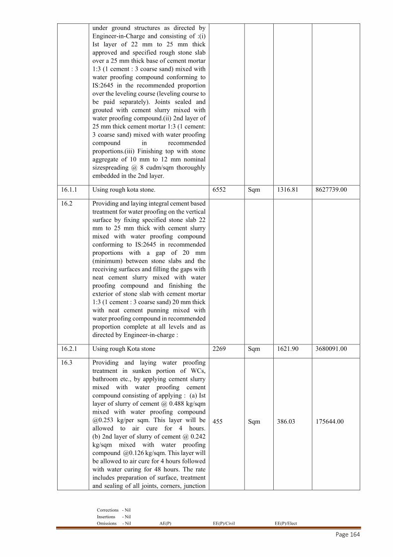
Corrections - Nil
Insertions - Nil
Omissions - Nil AE(P) EE(P)/Civil EE(P)/Elect
Page 164
under ground structures as directed by Engineer-in-Charge and consisting of :(i) Ist layer of 22 mm to 25 mm thick approved and specified rough stone slab over a 25 mm thick base of cement mortar 1:3 (1 cement : 3 coarse sand) mixed with water proofing compound conforming to IS:2645 in the recommended proportion over the leveling course (leveling course to be paid separately). Joints sealed and grouted with cement slurry mixed with water proofing compound.(ii) 2nd layer of 25 mm thick cement mortar 1:3 (1 cement: 3 coarse sand) mixed with water proofing compound in recommended proportions.(iii) Finishing top with stone aggregate of 10 mm to 12 mm nominal sizespreading @ 8 cudm/sqm thoroughly embedded in the 2nd layer.
16.1.1 Using rough kota stone. 6552 Sqm 1316.81 8627739.00
16.2 Providing and laying integral cement based treatment for water proofing on the vertical surface by fixing specified stone slab 22 mm to 25 mm thick with cement slurry mixed with water proofing compound conforming to IS:2645 in recommended proportions with a gap of 20 mm (minimum) between stone slabs and the receiving surfaces and filling the gaps with neat cement slurry mixed with water proofing compound and finishing the exterior of stone slab with cement mortar 1:3 (1 cement : 3 coarse sand) 20 mm thick with neat cement punning mixed with water proofing compound in recommended proportion complete at all levels and as directed by Engineer-in-charge :
16.2.1 Using rough Kota stone 2269 Sqm 1621.90 3680091.00
16.3 Providing and laying water proofing treatment in sunken portion of WCs, bathroom etc., by applying cement slurry mixed with water proofing cement compound consisting of applying : (a) Ist layer of slurry of cement @ 0.488 kg/sqm mixed with water proofing compound @0.253 kg/per sqm. This layer will be allowed to air cure for 4 hours. (b) 2nd layer of slurry of cement @ 0.242 kg/sqm mixed with water proofing compound @0.126 kg/sqm. This layer will be allowed to air cure for 4 hours followed with water curing for 48 hours. The rate includes preparation of surface, treatment and sealing of all joints, corners, junction
455 Sqm 386.03 175644.00
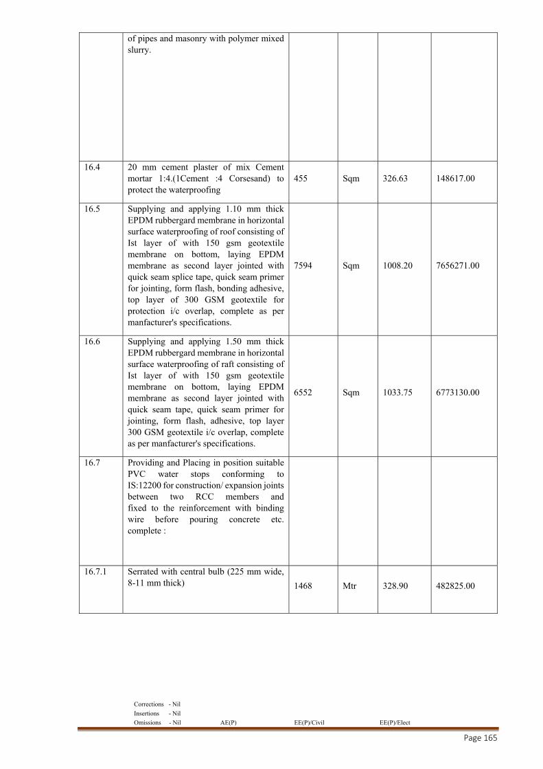
Corrections - Nil
Insertions - Nil
Omissions - Nil AE(P) EE(P)/Civil EE(P)/Elect
Page 165
of pipes and masonry with polymer mixed slurry.
16.4 20 mm cement plaster of mix Cement mortar 1:4.(1Cement :4 Corsesand) to protect the waterproofing
455 Sqm 326.63 148617.00
16.5 Supplying and applying 1.10 mm thick EPDM rubbergard membrane in horizontal surface waterproofing of roof consisting of Ist layer of with 150 gsm geotextile membrane on bottom, laying EPDM membrane as second layer jointed with quick seam splice tape, quick seam primer for jointing, form flash, bonding adhesive, top layer of 300 GSM geotextile for protection i/c overlap, complete as per manfacturer's specifications.
7594 Sqm 1008.20 7656271.00
16.6 Supplying and applying 1.50 mm thick EPDM rubbergard membrane in horizontal surface waterproofing of raft consisting of Ist layer of with 150 gsm geotextile membrane on bottom, laying EPDM membrane as second layer jointed with quick seam tape, quick seam primer for jointing, form flash, adhesive, top layer 300 GSM geotextile i/c overlap, complete as per manfacturer's specifications.
6552 Sqm 1033.75 6773130.00
16.7 Providing and Placing in position suitable PVC water stops conforming to IS:12200 for construction/ expansion joints between two RCC members and fixed to the reinforcement with binding wire before pouring concrete etc. complete :
16.7.1 Serrated with central bulb (225 mm wide, 8-11 mm thick) 1468 Mtr 328.90 482825.00
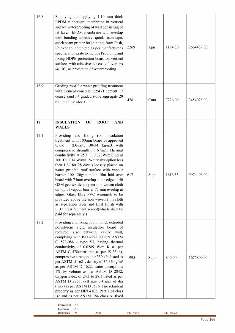
Corrections - Nil
Insertions - Nil
Omissions - Nil AE(P) EE(P)/Civil EE(P)/Elect
Page 166
16.8 Supplying and applying 1.10 mm thick EPDM rubbergard membrane in vertical surface waterproofing of wall consisting of Ist layer EPDM membrane with overlap with bonding adhesive, quick seam tape, quick seam primer for jointing, form flash, i/c overlap, complete as per manfacturer's specifications.rate to include Providing and fixing HDPE protection board on vertical surfaces with adhesives i/c cost of overlaps @ 10% as protection of waterproofing.
2269 sqm 1174.30 2664487.00
16.9 Grading roof for water proofing treatment with Cement concrete 1:2:4 (1 cement : 2 coarse sand : 4 graded stone aggregate 20 mm nominal size ) 478 Cum 7226.00 3454028.00
17 INSULATION OF ROOF AND WALLS
17.1 Providing and fixing roof insulation treatment with 100mm board of approved brand (Density 30-34 kg/m3 with compressive strength 0.3 N/m2 . Thermal conductivity at 250 C 0.028W/mK nd at 100 C 0.014 W/mK. Water absorption less then 1 % for 28 days.) loosely placed on water proofed roof surface with vapour barrier 100-120gsm plain film laid over board with 75mm overlap at the edges. 140 GSM geo textile polyster non woven cloth on top of vapour barrier 75 mm overlap at edges. Glass fibre PVC wiremesh to be provided above the non woven film cloth as separation layer and final finish with PCC 1:2:4 /cement screed(which shall be paid for separately.)
6171 Sqm 1616.35 9974496.00
17.2 Providing and fixing 50 mm thick extruded polystyrene rigid insulation board of required size between cavity wall, complying with ISO 4898:2008 & ASTM C 578-08b - type VI, having thermal conductivity of 0.0289 W/m K as per ASTM C 578(measured as per IS 3346), compressive strength of > 350 kPa listed as per ASTM D 1621, density of 34-36 kg/m³ as per ASTM D 1622, water absorptions 1% by volume as per ASTM D 2842, oxygen index of 24.1 to 28.1 listed as per ASTM D 2863, cell size 0.4 mm of dia (max) as per ASTM D 3576. Fire retardent property as per DIN 4102, Part 1 of class B2 and as per ASTM E84 class A, fixed
1995 Sqm 840.00 1675800.00
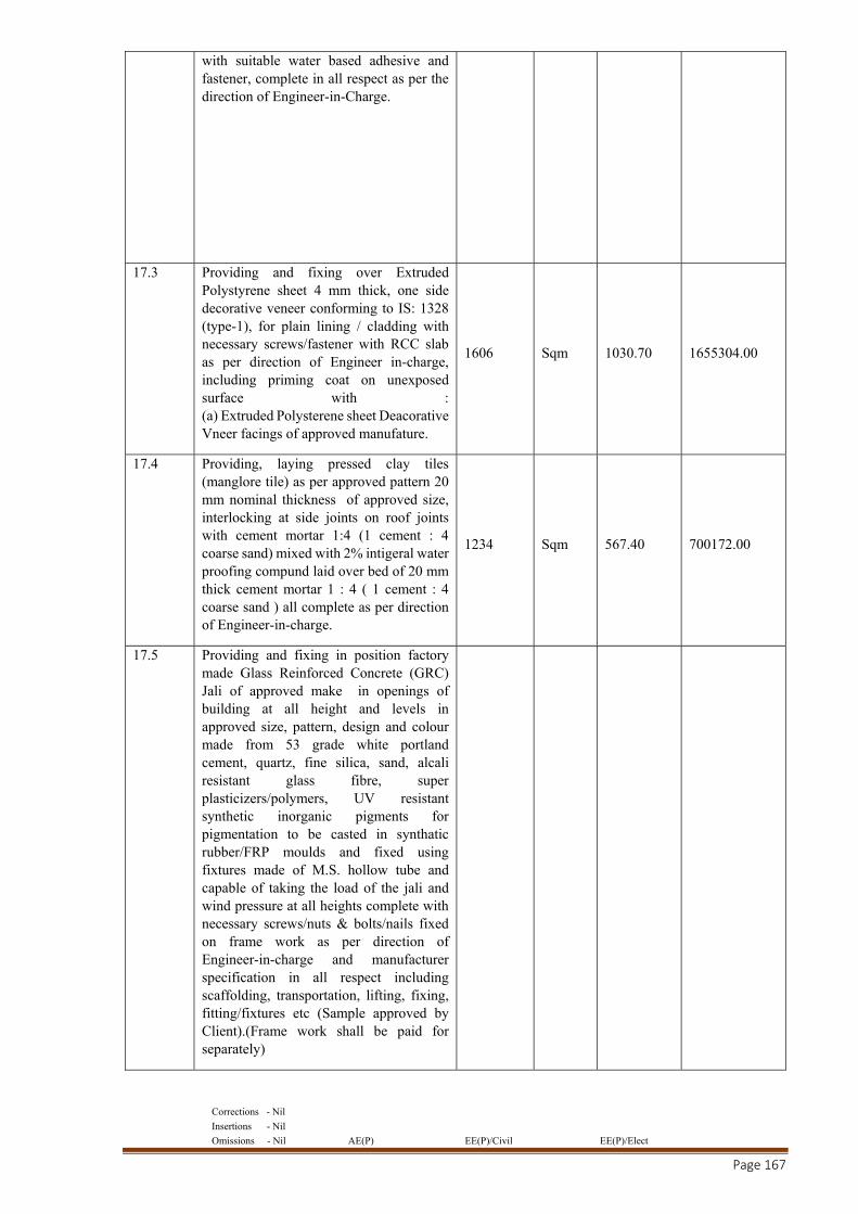
Corrections - Nil
Insertions - Nil
Omissions - Nil AE(P) EE(P)/Civil EE(P)/Elect
Page 167
with suitable water based adhesive and fastener, complete in all respect as per the direction of Engineer-in-Charge.
17.3 Providing and fixing over Extruded Polystyrene sheet 4 mm thick, one side decorative veneer conforming to IS: 1328 (type-1), for plain lining / cladding with necessary screws/fastener with RCC slab as per direction of Engineer in-charge, including priming coat on unexposed surface with : (a) Extruded Polysterene sheet Deacorative Vneer facings of approved manufature.
1606 Sqm 1030.70 1655304.00
17.4 Providing, laying pressed clay tiles (manglore tile) as per approved pattern 20 mm nominal thickness of approved size, interlocking at side joints on roof joints with cement mortar 1:4 (1 cement : 4 coarse sand) mixed with 2% intigeral water proofing compund laid over bed of 20 mm thick cement mortar 1 : 4 ( 1 cement : 4 coarse sand ) all complete as per direction of Engineer-in-charge.
1234 Sqm 567.40 700172.00
17.5 Providing and fixing in position factory made Glass Reinforced Concrete (GRC) Jali of approved make in openings of building at all height and levels in approved size, pattern, design and colour made from 53 grade white portland cement, quartz, fine silica, sand, alcali resistant glass fibre, super plasticizers/polymers, UV resistant synthetic inorganic pigments for pigmentation to be casted in synthatic rubber/FRP moulds and fixed using fixtures made of M.S. hollow tube and capable of taking the load of the jali and wind pressure at all heights complete with necessary screws/nuts & bolts/nails fixed on frame work as per direction of Engineer-in-charge and manufacturer specification in all respect including scaffolding, transportation, lifting, fixing, fitting/fixtures etc (Sample approved by Client).(Frame work shall be paid for separately)
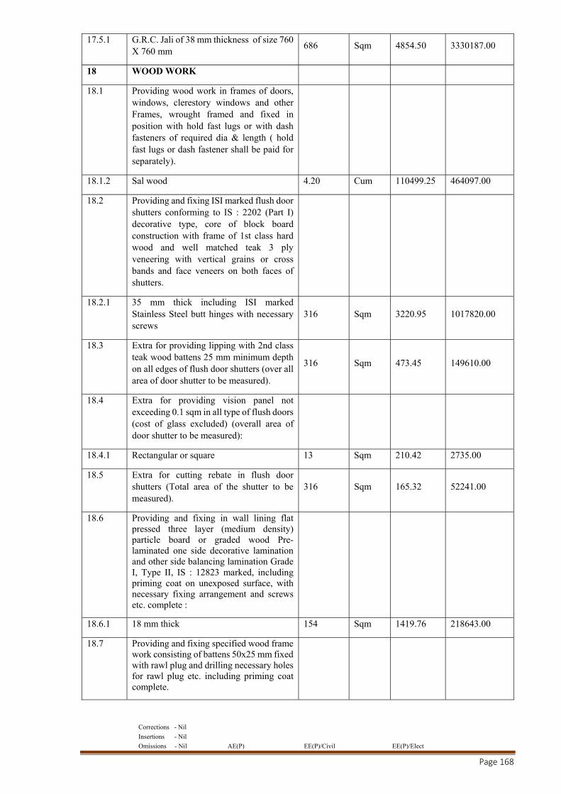
Corrections - Nil
Insertions - Nil
Omissions - Nil AE(P) EE(P)/Civil EE(P)/Elect
Page 168
17.5.1 G.R.C. Jali of 38 mm thickness of size 760 X 760 mm
686 Sqm 4854.50 3330187.00
18 WOOD WORK
18.1 Providing wood work in frames of doors, windows, clerestory windows and other Frames, wrought framed and fixed in position with hold fast lugs or with dash fasteners of required dia & length ( hold fast lugs or dash fastener shall be paid for separately).
18.1.2 Sal wood 4.20 Cum 110499.25 464097.00
18.2 Providing and fixing ISI marked flush door shutters conforming to IS : 2202 (Part I) decorative type, core of block board construction with frame of 1st class hard wood and well matched teak 3 ply veneering with vertical grains or cross bands and face veneers on both faces of shutters.
18.2.1 35 mm thick including ISI marked Stainless Steel butt hinges with necessary screws
316 Sqm 3220.95 1017820.00
18.3 Extra for providing lipping with 2nd class teak wood battens 25 mm minimum depth on all edges of flush door shutters (over all area of door shutter to be measured).
316 Sqm 473.45 149610.00
18.4 Extra for providing vision panel not exceeding 0.1 sqm in all type of flush doors (cost of glass excluded) (overall area of door shutter to be measured):
18.4.1 Rectangular or square 13 Sqm 210.42 2735.00
18.5 Extra for cutting rebate in flush door shutters (Total area of the shutter to be measured).
316 Sqm 165.32 52241.00
18.6 Providing and fixing in wall lining flat pressed three layer (medium density) particle board or graded wood Pre-laminated one side decorative lamination and other side balancing lamination Grade I, Type II, IS : 12823 marked, including priming coat on unexposed surface, with necessary fixing arrangement and screws etc. complete :
18.6.1 18 mm thick 154 Sqm 1419.76 218643.00
18.7 Providing and fixing specified wood frame work consisting of battens 50x25 mm fixed with rawl plug and drilling necessary holes for rawl plug etc. including priming coat complete.
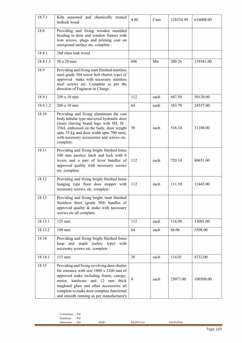
Corrections - Nil
Insertions - Nil
Omissions - Nil AE(P) EE(P)/Civil EE(P)/Elect
Page 169
18.7.1 Kiln seasoned and chemically treated hollock wood
4.80 Cum 128334.99 616008.00
18.8 Providing and fixing wooden moulded beading to door and window frames with iron screws, plugs and priming coat on unexposed surface etc. complete :
18.8.1 2nd class teak wood
18.8.1.1 50 x 20 mm 696 Mtr 200.26 139381.00
18.9 Providing and fixing matt finished stainless steel grade 304 tower bolt (barrel type) of approved make with necessary stainless steel screws etc. Complete as per the direction of Engineer-in Charge.
18.9.1 250 x 10 mm 112 each 447.50 50120.00
18.9.1.2 200 x 10 mm 64 each 383.70 24557.00
18.10 Providing and fixing aluminium die cast body tubular type universal hydraulic door closer (having brand logo with ISI, IS : 3564, embossed on the body, door weight upto 35 kg and door width upto 700 mm), with necessary accessories and screws etc. complete.
58 each 536.34 31108.00
18.11 Providing and fixing bright finished brass 100 mm mortice latch and lock with 6 levers and a pair of lever handles of approved quality with necessary screws etc. complete.
112 each 720.10 80651.00
18.12 Providing and fixing bright finished brass hanging type floor door stopper with necessary screws, etc. complete.
112 each 111.10 12443.00
18.13 Providing and fixing bright /matt finished Stainless Steel (grade 304) handles of approved quality & make with necessary screws etc all complete.
18.13.1 125 mm 112 each 116.08 13001.00
18.13.2 100 mm 64 each 86.06 5508.00
18.14 Providing and fixing bright finished brass hasp and staple (safety type) with necessary screws etc. complete :
18.14.1 115 mm 38 each 114.01 4332.00
18.15 Providing and fixing revolving door shutter for entrance with size 1800 x 2100 mm of approved make including frame, canopy, motor, hardware and 12 mm thick taughned glass and other accessories all complete to make door complete functional and smooth running as per manufacturer's
4 each 25077.00 100308.00
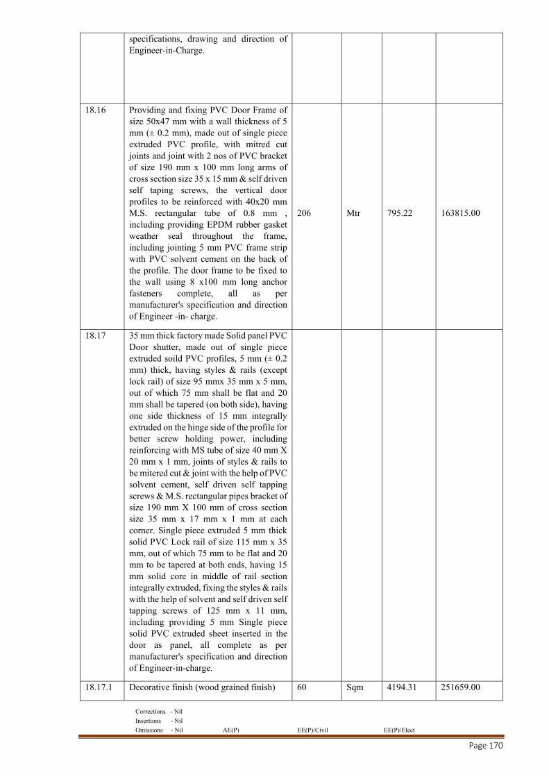
Corrections - Nil
Insertions - Nil
Omissions - Nil AE(P) EE(P)/Civil EE(P)/Elect
Page 170
specifications, drawing and direction of Engineer-in-Charge.
18.16 Providing and fixing PVC Door Frame of size 50x47 mm with a wall thickness of 5 mm (± 0.2 mm), made out of single piece extruded PVC profile, with mitred cut joints and joint with 2 nos of PVC bracket of size 190 mm x 100 mm long arms of cross section size 35 x 15 mm & self driven self taping screws, the vertical door profiles to be reinforced with 40x20 mm M.S. rectangular tube of 0.8 mm , including providing EPDM rubber gasket weather seal throughout the frame, including jointing 5 mm PVC frame strip with PVC solvent cement on the back of the profile. The door frame to be fixed to the wall using 8 x100 mm long anchor fasteners complete, all as per manufacturer's specification and direction of Engineer -in- charge.
206 Mtr 795.22 163815.00
18.17 35 mm thick factory made Solid panel PVC Door shutter, made out of single piece extruded soild PVC profiles, 5 mm (± 0.2 mm) thick, having styles & rails (except lock rail) of size 95 mmx 35 mm x 5 mm, out of which 75 mm shall be flat and 20 mm shall be tapered (on both side), having one side thickness of 15 mm integrally extruded on the hinge side of the profile for better screw holding power, including reinforcing with MS tube of size 40 mm X 20 mm x 1 mm, joints of styles & rails to be mitered cut & joint with the help of PVC solvent cement, self driven self tapping screws & M.S. rectangular pipes bracket of size 190 mm X 100 mm of cross section size 35 mm x 17 mm x 1 mm at each corner. Single piece extruded 5 mm thick solid PVC Lock rail of size 115 mm x 35 mm, out of which 75 mm to be flat and 20 mm to be tapered at both ends, having 15 mm solid core in middle of rail section integrally extruded, fixing the styles & rails with the help of solvent and self driven self tapping screws of 125 mm x 11 mm, including providing 5 mm Single piece solid PVC extruded sheet inserted in the door as panel, all complete as per manufacturer's specification and direction of Engineer-in-charge.
18.17.1 Decorative finish (wood grained finish) 60 Sqm 4194.31 251659.00
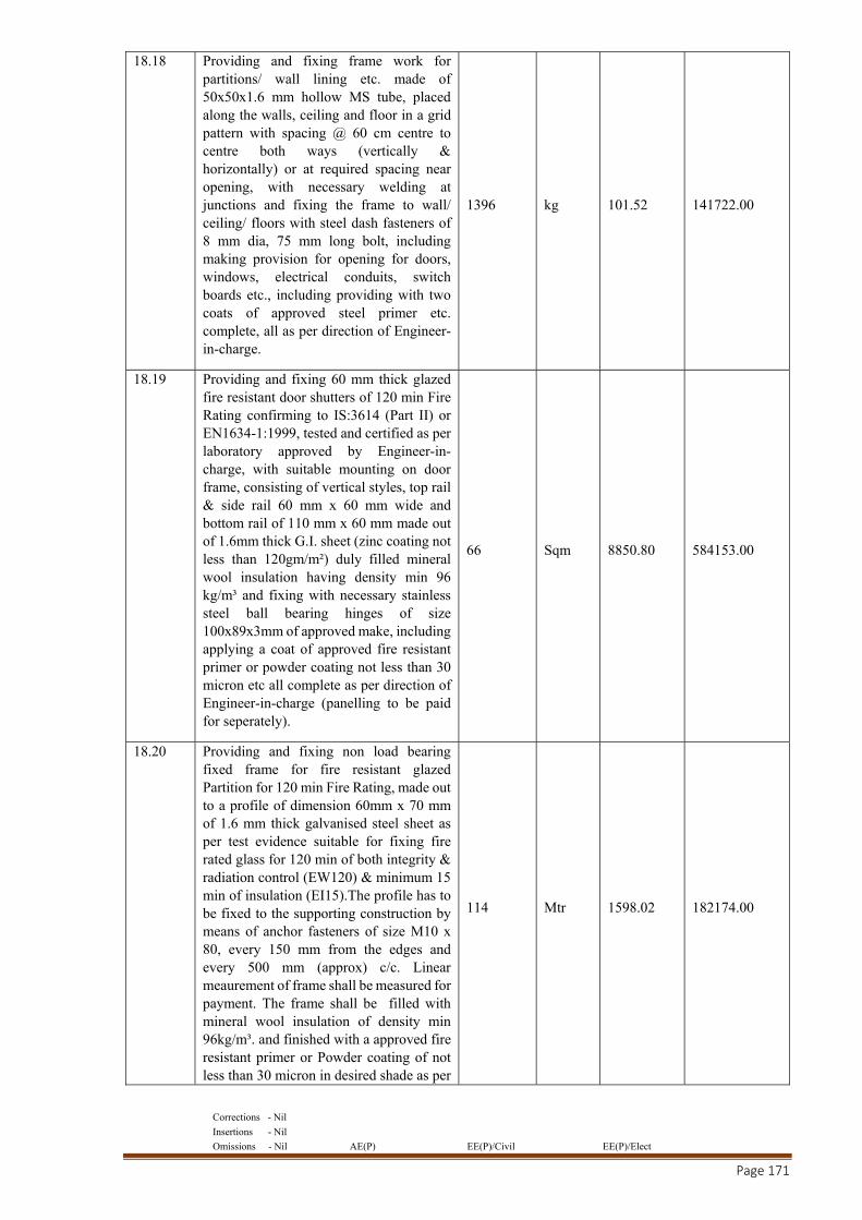
Corrections - Nil
Insertions - Nil
Omissions - Nil AE(P) EE(P)/Civil EE(P)/Elect
Page 171
18.18 Providing and fixing frame work for partitions/ wall lining etc. made of 50x50x1.6 mm hollow MS tube, placed along the walls, ceiling and floor in a grid pattern with spacing @ 60 cm centre to centre both ways (vertically & horizontally) or at required spacing near opening, with necessary welding at junctions and fixing the frame to wall/ ceiling/ floors with steel dash fasteners of 8 mm dia, 75 mm long bolt, including making provision for opening for doors, windows, electrical conduits, switch boards etc., including providing with two coats of approved steel primer etc. complete, all as per direction of Engineer-in-charge.
1396 kg 101.52 141722.00
18.19 Providing and fixing 60 mm thick glazed fire resistant door shutters of 120 min Fire Rating confirming to IS:3614 (Part II) or EN1634-1:1999, tested and certified as per laboratory approved by Engineer-in-charge, with suitable mounting on door frame, consisting of vertical styles, top rail & side rail 60 mm x 60 mm wide and bottom rail of 110 mm x 60 mm made out of 1.6mm thick G.I. sheet (zinc coating not less than 120gm/m²) duly filled mineral wool insulation having density min 96 kg/m³ and fixing with necessary stainless steel ball bearing hinges of size 100x89x3mm of approved make, including applying a coat of approved fire resistant primer or powder coating not less than 30 micron etc all complete as per direction of Engineer-in-charge (panelling to be paid for seperately).
66 Sqm 8850.80 584153.00
18.20 Providing and fixing non load bearing fixed frame for fire resistant glazed Partition for 120 min Fire Rating, made out to a profile of dimension 60mm x 70 mm of 1.6 mm thick galvanised steel sheet as per test evidence suitable for fixing fire rated glass for 120 min of both integrity & radiation control (EW120) & minimum 15 min of insulation (EI15).The profile has to be fixed to the supporting construction by means of anchor fasteners of size M10 x 80, every 150 mm from the edges and every 500 mm (approx) c/c. Linear meaurement of frame shall be measured for payment. The frame shall be filled with mineral wool insulation of density min 96kg/m³. and finished with a approved fire resistant primer or Powder coating of not less than 30 micron in desired shade as per
114 Mtr 1598.02 182174.00
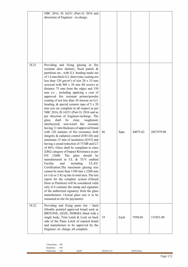
Corrections - Nil
Insertions - Nil
Omissions - Nil AE(P) EE(P)/Civil EE(P)/Elect
Page 172
NBC 2016, IS 16231 (Part-3): 2016 and directions of Engineer - in-charge.
18.21 Providing and fixing glazing in fire resistant door shutters, fixed panels & partitions etc., with G.I. beading made out of 1.6 mm thick G.I. sheet (zinc coating not less than 120 gm/m²) of size 20 x 33 mm screwed with M4 x 38 mm SS screws at distance 75 mm from the edges and 150 mm c/c , including applying a coat of approved fire resistant primer/powder coating of not less than 30 micron on G.I. beading, & special ceramic tape of 5 x 20 mm size etc complete in all respect as per NBC 2016, IS 16231 (Part-3): 2016 and as per direction of Engineer-incharge. The glass shall be clear, toughened, interlayered, non-wired fire resistant having 11 mm thickness of approved brand with 120 minutes of fire resistance both integrity & radiation control (EW120) and minimum 15 min of insulation (EI15) and having a sound reduction of ?37dB and LT of 86%. Glass shall be compliant to class 2(B)2 category of Impact Resistance as per EN 12600. The glass should be manufactured in UL & TUV audited Facility and including UL-EU Certification.The maximum glazing size cannot be more than 1100 mm x 2200 mm (w x h) or 2.42 sq mts in total area. The test report for the complete system (Glazed Door or Partition) will be considered valid only if it contains the stamp and signature of the authorized signatory from the glass manufacturer. (Actual glass size is to be measured at site for payments).
46 Sqm 44075.62 2027479.00
18.22 Providing and fixing panic bar / latch (Double point)of approved brand such as BRITONE, GEZE, DORMA fitted with a single body, Trim Latch & Lock on back side of the Panic Latch of reputed brand and manufacture to be approved by the Engineer- in- charge, all complete.
19 Each 7950.04 151051.00
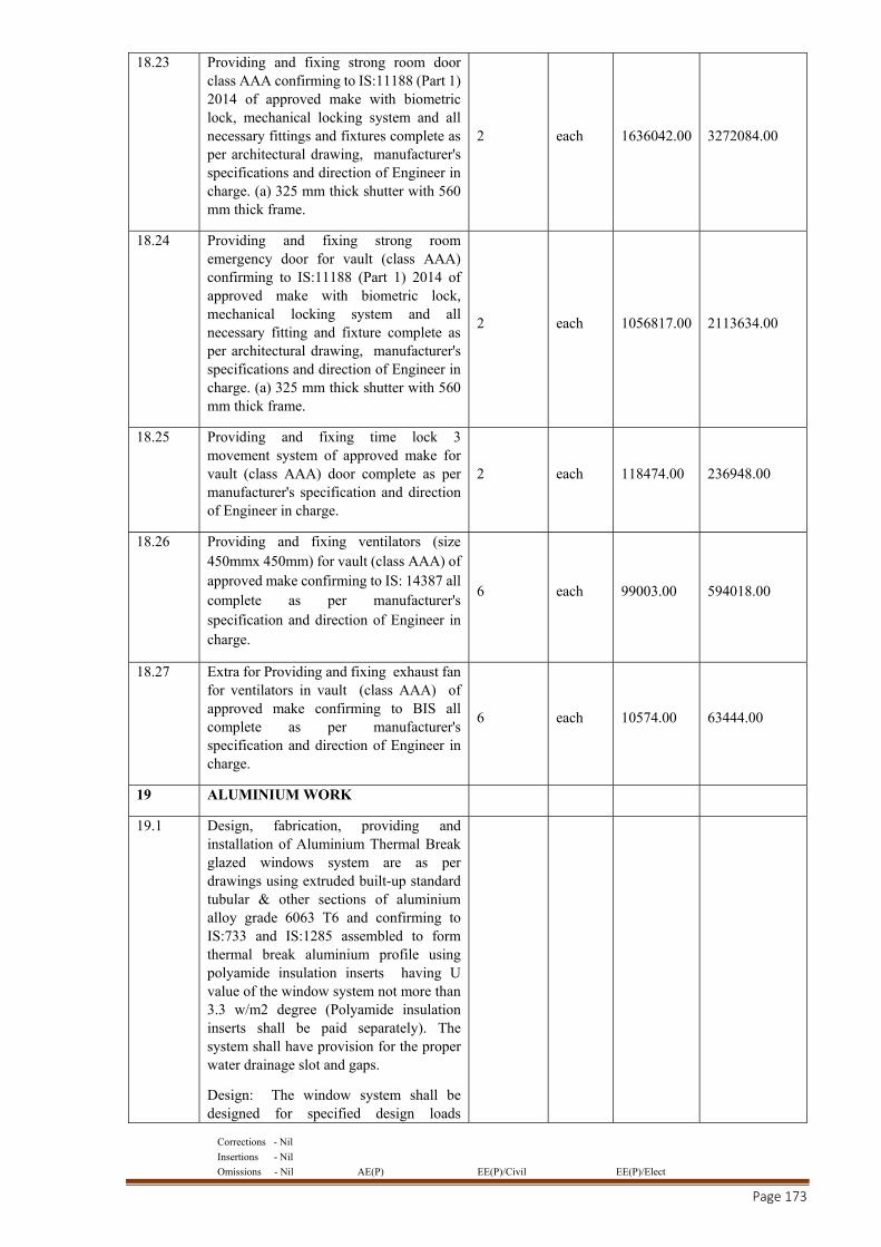
Corrections - Nil
Insertions - Nil
Omissions - Nil AE(P) EE(P)/Civil EE(P)/Elect
Page 173
18.23 Providing and fixing strong room door class AAA confirming to IS:11188 (Part 1) 2014 of approved make with biometric lock, mechanical locking system and all necessary fittings and fixtures complete as per architectural drawing, manufacturer's specifications and direction of Engineer in charge. (a) 325 mm thick shutter with 560 mm thick frame.
2 each 1636042.00 3272084.00
18.24 Providing and fixing strong room emergency door for vault (class AAA) confirming to IS:11188 (Part 1) 2014 of approved make with biometric lock, mechanical locking system and all necessary fitting and fixture complete as per architectural drawing, manufacturer's specifications and direction of Engineer in charge. (a) 325 mm thick shutter with 560 mm thick frame.
2 each 1056817.00 2113634.00
18.25 Providing and fixing time lock 3 movement system of approved make for vault (class AAA) door complete as per manufacturer's specification and direction of Engineer in charge.
2 each 118474.00 236948.00
18.26 Providing and fixing ventilators (size 450mmx 450mm) for vault (class AAA) of approved make confirming to IS: 14387 all complete as per manufacturer's specification and direction of Engineer in charge.
6 each 99003.00 594018.00
18.27 Extra for Providing and fixing exhaust fan for ventilators in vault (class AAA) of approved make confirming to BIS all complete as per manufacturer's specification and direction of Engineer in charge.
6 each 10574.00 63444.00
19 ALUMINIUM WORK
19.1 Design, fabrication, providing and installation of Aluminium Thermal Break glazed windows system are as per drawings using extruded built-up standard tubular & other sections of aluminium alloy grade 6063 T6 and confirming to IS:733 and IS:1285 assembled to form thermal break aluminium profile using polyamide insulation inserts having U value of the window system not more than 3.3 w/m2 degree (Polyamide insulation inserts shall be paid separately). The system shall have provision for the proper water drainage slot and gaps.
Design: The window system shall be designed for specified design loads
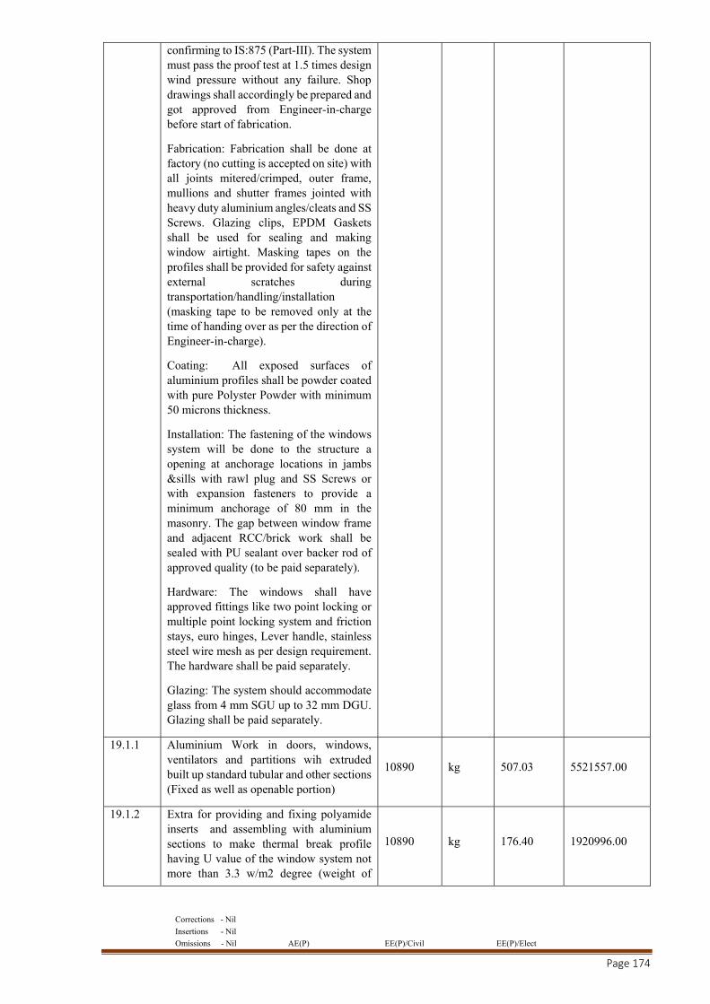
Corrections - Nil
Insertions - Nil
Omissions - Nil AE(P) EE(P)/Civil EE(P)/Elect
Page 174
confirming to IS:875 (Part-III). The system must pass the proof test at 1.5 times design wind pressure without any failure. Shop drawings shall accordingly be prepared and got approved from Engineer-in-charge before start of fabrication.
Fabrication: Fabrication shall be done at factory (no cutting is accepted on site) with all joints mitered/crimped, outer frame, mullions and shutter frames jointed with heavy duty aluminium angles/cleats and SS Screws. Glazing clips, EPDM Gaskets shall be used for sealing and making window airtight. Masking tapes on the profiles shall be provided for safety against external scratches during transportation/handling/installation (masking tape to be removed only at the time of handing over as per the direction of Engineer-in-charge).
Coating: All exposed surfaces of aluminium profiles shall be powder coated with pure Polyster Powder with minimum 50 microns thickness.
Installation: The fastening of the windows system will be done to the structure a opening at anchorage locations in jambs &sills with rawl plug and SS Screws or with expansion fasteners to provide a minimum anchorage of 80 mm in the masonry. The gap between window frame and adjacent RCC/brick work shall be sealed with PU sealant over backer rod of approved quality (to be paid separately).
Hardware: The windows shall have approved fittings like two point locking or multiple point locking system and friction stays, euro hinges, Lever handle, stainless steel wire mesh as per design requirement. The hardware shall be paid separately.
Glazing: The system should accommodate glass from 4 mm SGU up to 32 mm DGU. Glazing shall be paid separately.
19.1.1 Aluminium Work in doors, windows, ventilators and partitions wih extruded built up standard tubular and other sections (Fixed as well as openable portion)
10890 kg 507.03 5521557.00
19.1.2 Extra for providing and fixing polyamide inserts and assembling with aluminium sections to make thermal break profile having U value of the window system not more than 3.3 w/m2 degree (weight of
10890 kg 176.40 1920996.00
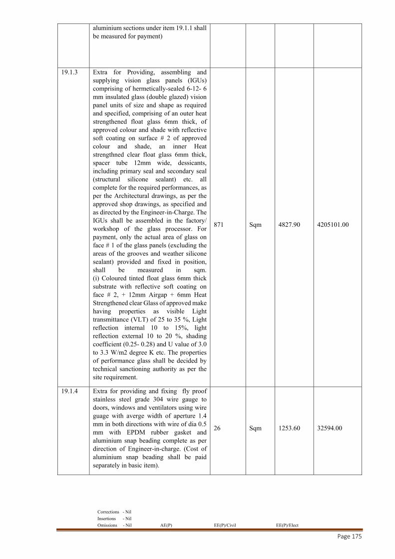
Corrections - Nil
Insertions - Nil
Omissions - Nil AE(P) EE(P)/Civil EE(P)/Elect
Page 175
aluminium sections under item 19.1.1 shall be measured for payment)
19.1.3 Extra for Providing, assembling and supplying vision glass panels (IGUs) comprising of hermetically-sealed 6-12- 6 mm insulated glass (double glazed) vision panel units of size and shape as required and specified, comprising of an outer heat strengthened float glass 6mm thick, of approved colour and shade with reflective soft coating on surface # 2 of approved colour and shade, an inner Heat strengthned clear float glass 6mm thick, spacer tube 12mm wide, dessicants, including primary seal and secondary seal (structural silicone sealant) etc. all complete for the required performances, as per the Architectural drawings, as per the approved shop drawings, as specified and as directed by the Engineer-in-Charge. The IGUs shall be assembled in the factory/ workshop of the glass processor. For payment, only the actual area of glass on face # 1 of the glass panels (excluding the areas of the grooves and weather silicone sealant) provided and fixed in position, shall be measured in sqm. (i) Coloured tinted float glass 6mm thick substrate with reflective soft coating on face # 2, + 12mm Airgap + 6mm Heat Strengthened clear Glass of approved make having properties as visible Light transmittance (VLT) of 25 to 35 %, Light reflection internal 10 to 15%, light reflection external 10 to 20 %, shading coefficient (0.25- 0.28) and U value of 3.0 to 3.3 W/m2 degree K etc. The properties of performance glass shall be decided by technical sanctioning authority as per the site requirement.
871 Sqm 4827.90 4205101.00
19.1.4 Extra for providing and fixing fly proof stainless steel grade 304 wire gauge to doors, windows and ventilators using wire guage with averge width of aperture 1.4 mm in both directions with wire of dia 0.5 mm with EPDM rubber gasket and aluminium snap beading complete as per direction of Engineer-in-charge. (Cost of aluminium snap beading shall be paid separately in basic item).
26 Sqm 1253.60 32594.00
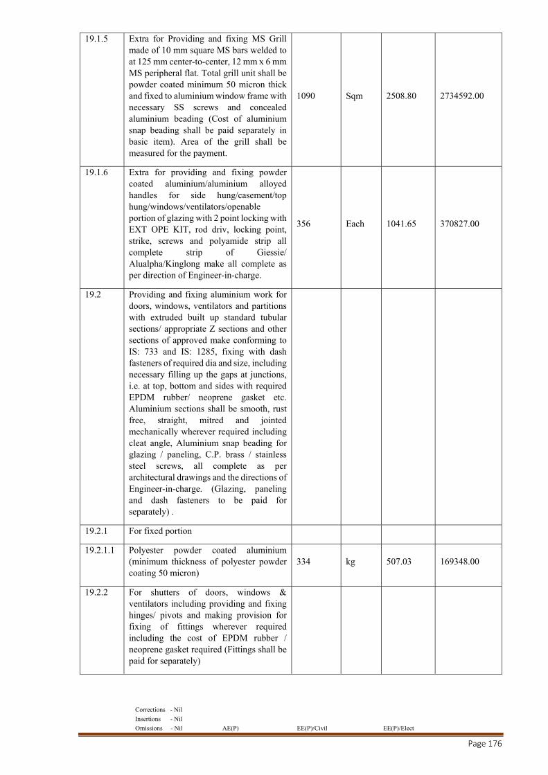
Corrections - Nil
Insertions - Nil
Omissions - Nil AE(P) EE(P)/Civil EE(P)/Elect
Page 176
19.1.5 Extra for Providing and fixing MS Grill made of 10 mm square MS bars welded to at 125 mm center-to-center, 12 mm x 6 mm MS peripheral flat. Total grill unit shall be powder coated minimum 50 micron thick and fixed to aluminium window frame with necessary SS screws and concealed aluminium beading (Cost of aluminium snap beading shall be paid separately in basic item). Area of the grill shall be measured for the payment.
1090 Sqm 2508.80 2734592.00
19.1.6 Extra for providing and fixing powder coated aluminium/aluminium alloyed handles for side hung/casement/top hung/windows/ventilators/openable portion of glazing with 2 point locking with EXT OPE KIT, rod driv, locking point, strike, screws and polyamide strip all complete strip of Giessie/ Alualpha/Kinglong make all complete as per direction of Engineer-in-charge.
356 Each 1041.65 370827.00
19.2 Providing and fixing aluminium work for doors, windows, ventilators and partitions with extruded built up standard tubular sections/ appropriate Z sections and other sections of approved make conforming to IS: 733 and IS: 1285, fixing with dash fasteners of required dia and size, including necessary filling up the gaps at junctions, i.e. at top, bottom and sides with required EPDM rubber/ neoprene gasket etc. Aluminium sections shall be smooth, rust free, straight, mitred and jointed mechanically wherever required including cleat angle, Aluminium snap beading for glazing / paneling, C.P. brass / stainless steel screws, all complete as per architectural drawings and the directions of Engineer-in-charge. (Glazing, paneling and dash fasteners to be paid for separately) .
19.2.1 For fixed portion
19.2.1.1 Polyester powder coated aluminium (minimum thickness of polyester powder coating 50 micron)
334 kg 507.03 169348.00
19.2.2 For shutters of doors, windows & ventilators including providing and fixing hinges/ pivots and making provision for fixing of fittings wherever required including the cost of EPDM rubber / neoprene gasket required (Fittings shall be paid for separately)
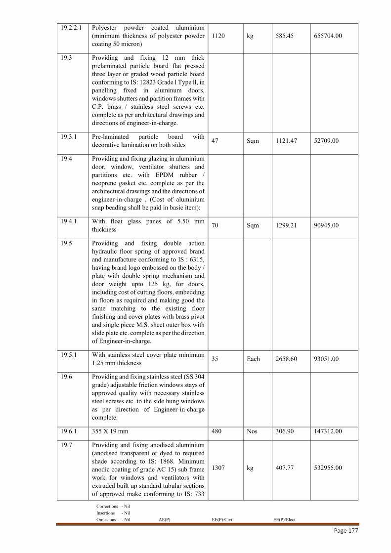
Corrections - Nil
Insertions - Nil
Omissions - Nil AE(P) EE(P)/Civil EE(P)/Elect
Page 177
19.2.2.1 Polyester powder coated aluminium (minimum thickness of polyester powder coating 50 micron)
1120 kg 585.45 655704.00
19.3 Providing and fixing 12 mm thick prelaminated particle board flat pressed three layer or graded wood particle board conforming to IS: 12823 Grade l Type ll, in panelling fixed in aluminum doors, windows shutters and partition frames with C.P. brass / stainless steel screws etc. complete as per architectural drawings and directions of engineer-in-charge.
19.3.1 Pre-laminated particle board with decorative lamination on both sides
47 Sqm 1121.47 52709.00
19.4 Providing and fixing glazing in aluminium door, window, ventilator shutters and partitions etc. with EPDM rubber / neoprene gasket etc. complete as per the architectural drawings and the directions of engineer-in-charge . (Cost of aluminium snap beading shall be paid in basic item):
19.4.1 With float glass panes of 5.50 mm thickness
70 Sqm 1299.21 90945.00
19.5 Providing and fixing double action hydraulic floor spring of approved brand and manufacture conforming to IS : 6315, having brand logo embossed on the body / plate with double spring mechanism and door weight upto 125 kg, for doors, including cost of cutting floors, embedding in floors as required and making good the same matching to the existing floor finishing and cover plates with brass pivot and single piece M.S. sheet outer box with slide plate etc. complete as per the direction of Engineer-in-charge.
19.5.1 With stainless steel cover plate minimum 1.25 mm thickness
35 Each 2658.60 93051.00
19.6 Providing and fixing stainless steel (SS 304 grade) adjustable friction windows stays of approved quality with necessary stainless steel screws etc. to the side hung windows as per direction of Engineer-in-charge complete.
19.6.1 355 X 19 mm 480 Nos 306.90 147312.00
19.7 Providing and fixing anodised aluminium (anodised transparent or dyed to required shade according to IS: 1868. Minimum anodic coating of grade AC 15) sub frame work for windows and ventilators with extruded built up standard tubular sections of approved make conforming to IS: 733
1307 kg 407.77 532955.00
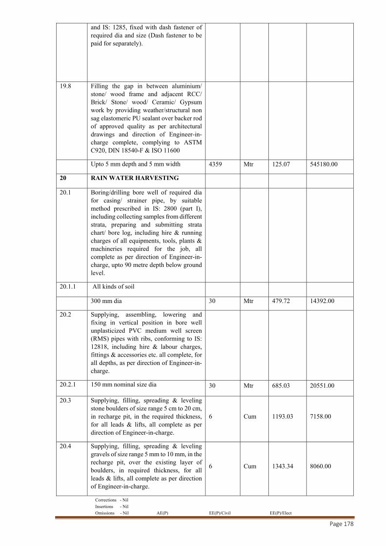
Corrections - Nil
Insertions - Nil
Omissions - Nil AE(P) EE(P)/Civil EE(P)/Elect
Page 178
and IS: 1285, fixed with dash fastener of required dia and size (Dash fastener to be paid for separately).
19.8 Filling the gap in between aluminium/ stone/ wood frame and adjacent RCC/ Brick/ Stone/ wood/ Ceramic/ Gypsum work by providing weather/structural non sag elastomeric PU sealant over backer rod of approved quality as per architectural drawings and direction of Engineer-in-charge complete, complying to ASTM C920, DIN 18540-F & ISO 11600
Upto 5 mm depth and 5 mm width 4359 Mtr 125.07 545180.00
20 RAIN WATER HARVESTING
20.1 Boring/drilling bore well of required dia for casing/ strainer pipe, by suitable method prescribed in IS: 2800 (part I), including collecting samples from different strata, preparing and submitting strata chart/ bore log, including hire & running charges of all equipments, tools, plants & machineries required for the job, all complete as per direction of Engineer-in-charge, upto 90 metre depth below ground level.
20.1.1 All kinds of soil
300 mm dia 30 Mtr 479.72 14392.00
20.2 Supplying, assembling, lowering and fixing in vertical position in bore well unplasticized PVC medium well screen (RMS) pipes with ribs, conforming to IS: 12818, including hire & labour charges, fittings & accessories etc. all complete, for all depths, as per direction of Engineer-in-charge.
20.2.1 150 mm nominal size dia 30 Mtr 685.03 20551.00
20.3 Supplying, filling, spreading & leveling stone boulders of size range 5 cm to 20 cm, in recharge pit, in the required thickness, for all leads & lifts, all complete as per direction of Engineer-in-charge.
6 Cum 1193.03 7158.00
20.4 Supplying, filling, spreading & leveling gravels of size range 5 mm to 10 mm, in the recharge pit, over the existing layer of boulders, in required thickness, for all leads & lifts, all complete as per direction of Engineer-in-charge.
6 Cum 1343.34 8060.00
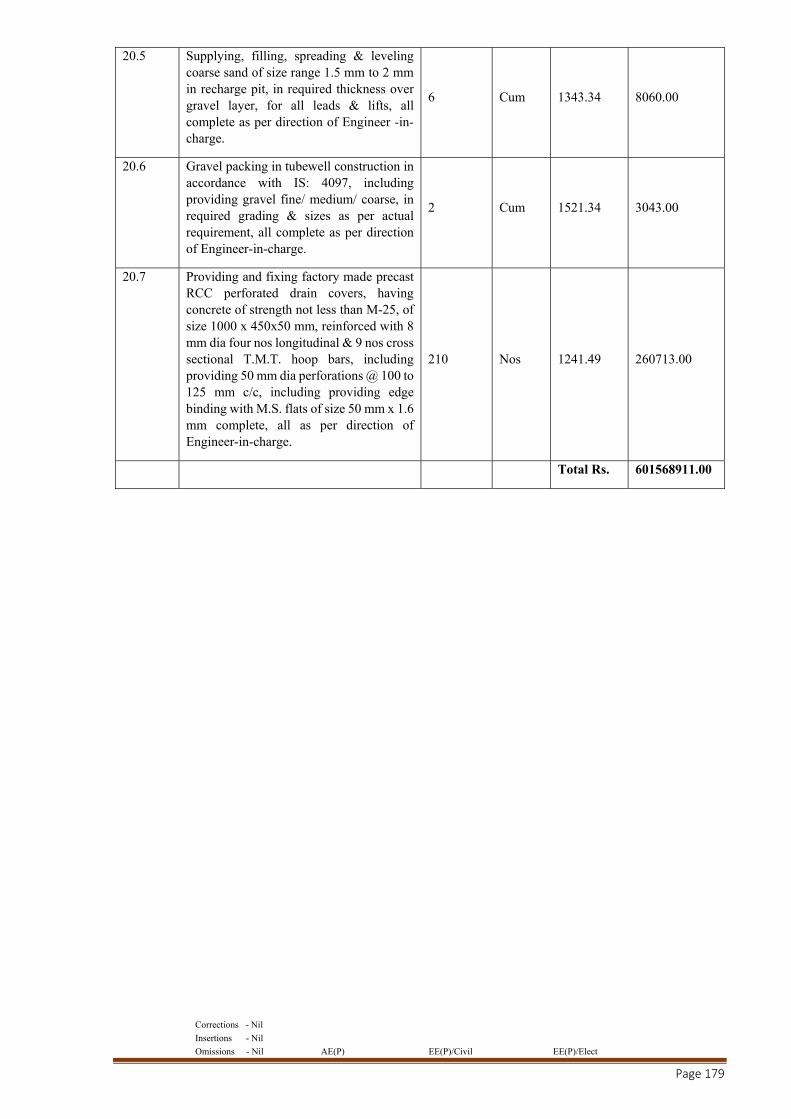
Corrections - Nil
Insertions - Nil
Omissions - Nil AE(P) EE(P)/Civil EE(P)/Elect
Page 179
20.5 Supplying, filling, spreading & leveling coarse sand of size range 1.5 mm to 2 mm in recharge pit, in required thickness over gravel layer, for all leads & lifts, all complete as per direction of Engineer -in-charge.
6 Cum 1343.34 8060.00
20.6 Gravel packing in tubewell construction in accordance with IS: 4097, including providing gravel fine/ medium/ coarse, in required grading & sizes as per actual requirement, all complete as per direction of Engineer-in-charge.
2 Cum 1521.34 3043.00
20.7 Providing and fixing factory made precast RCC perforated drain covers, having concrete of strength not less than M-25, of size 1000 x 450x50 mm, reinforced with 8 mm dia four nos longitudinal & 9 nos cross sectional T.M.T. hoop bars, including providing 50 mm dia perforations @ 100 to 125 mm c/c, including providing edge binding with M.S. flats of size 50 mm x 1.6 mm complete, all as per direction of Engineer-in-charge.
210 Nos 1241.49 260713.00
Total Rs. 601568911.00
Corrections - Nil
Insertions - Nil
Omissions - Nil AE(P) EE(P)/Civil EE(P)/Elect
Page 180
PART – C
SCHEDULES - A TO F, GENERAL/SPECIAL CONDITIONS, SPECIFICATIONS AND SCHEDULE OF QUANTITIES FOR MINOR
COMPONENT OF WORK

Corrections - Nil
Insertions - Nil
Omissions - Nil AE(P) EE(P)/Civil EE(P)/Elect
Page 181
PROFORMA OF SCHEDULES: A TO F (FOR MINOR COMPONANT OF WORK)
SCHEDULE ‘A’
Schedule of quantities (as per PWD-13 for E &M Works: As per separate sheets attached
SCHEDULE 'B'
Schedule of material to be issued to the Contractor: Nil
SCHEDULE 'C'
Tools and Plants to be hired to the Contractor: Nil
SCHEDULE ‘D’
Extra schedule for specific requirements/documents for the work, if any: Nil
SCHEDULE ‘E’
Reference to General Conditions of Contract :General Conditions of Contract-2014 as amended /
modified up to the last date of submission of Tenders.
Name of Work: C/O of Reserve Bank of India office complex building at IT park, Sidcul , Dehradun.
(SH- EI Work, Solar Sytem, EPBAX & CCTV, SECURITY system , Fire alarm
& PA syatem, Fire fighting , HVAC & BMS etc.)
Estimated cost of work : Electrical work - Rs. 14,67,20,345/-
(i) Earnest Money As given in Major Component
(ii) Performance Guarantee 5% of the accepted tendered value of the work
(iii) Security Deposit 2.5% of the accepted tendered value of the work.
SCHEDULE 'F'
General Rules & Directions:
Officer inviting Tender: As given in Major Component
Definitions:
2(i) Engineer-in-Charge
Executive Engineer, Dehradun Central Electrical
Division, CPWD, Dehradun (For Electrical Work)
(ii) Accepting Authority As given in Major Component
(iii) Percentage on cost of materials and
Labour to cover all overheads and
profits
15%
(iv) Standard Schedule of Rates Delhi Schedule of Rates 2016 with up to date
correction slips.
(v) Department Central Public Works Department (CPWD)
(vi) Standard CPWD Contract Form: GCC 2014, CPWD Form 7 as modified & Corrected
up-to the last date of submission of tenders
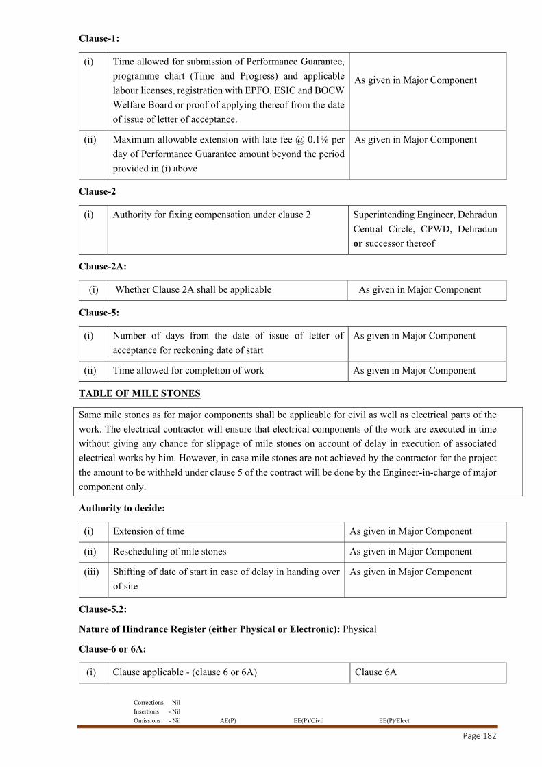
Corrections - Nil
Insertions - Nil
Omissions - Nil AE(P) EE(P)/Civil EE(P)/Elect
Page 182
Clause-1:
(i) Time allowed for submission of Performance Guarantee,
programme chart (Time and Progress) and applicable
labour licenses, registration with EPFO, ESIC and BOCW
Welfare Board or proof of applying thereof from the date
of issue of letter of acceptance.
As given in Major Component
(ii) Maximum allowable extension with late fee @ 0.1% per
day of Performance Guarantee amount beyond the period
provided in (i) above
As given in Major Component
Clause-2
(i) Authority for fixing compensation under clause 2 Superintending Engineer, Dehradun
Central Circle, CPWD, Dehradun
or successor thereof
Clause-2A:
(i) Whether Clause 2A shall be applicable As given in Major Component
Clause-5:
(i) Number of days from the date of issue of letter of
acceptance for reckoning date of start As given in Major Component
(ii) Time allowed for completion of work As given in Major Component
TABLE OF MILE STONES
Same mile stones as for major components shall be applicable for civil as well as electrical parts of the
work. The electrical contractor will ensure that electrical components of the work are executed in time
without giving any chance for slippage of mile stones on account of delay in execution of associated
electrical works by him. However, in case mile stones are not achieved by the contractor for the project
the amount to be withheld under clause 5 of the contract will be done by the Engineer-in-charge of major
component only.
Authority to decide:
(i) Extension of time As given in Major Component
(ii) Rescheduling of mile stones As given in Major Component
(iii) Shifting of date of start in case of delay in handing over
of site As given in Major Component
Clause-5.2:
Nature of Hindrance Register (either Physical or Electronic): Physical
Clause-6 or 6A:
(i) Clause applicable - (clause 6 or 6A) Clause 6A
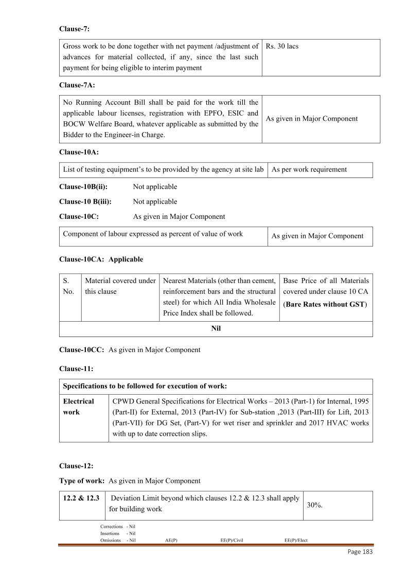
Corrections - Nil
Insertions - Nil
Omissions - Nil AE(P) EE(P)/Civil EE(P)/Elect
Page 183
Clause-7:
Gross work to be done together with net payment /adjustment of
advances for material collected, if any, since the last such
payment for being eligible to interim payment
Rs. 30 lacs
Clause-7A:
No Running Account Bill shall be paid for the work till the
applicable labour licenses, registration with EPFO, ESIC and
BOCW Welfare Board, whatever applicable as submitted by the
Bidder to the Engineer-in Charge.
As given in Major Component
Clause-10A:
List of testing equipment’s to be provided by the agency at site lab As per work requirement
Clause-10B(ii): Not applicable
Clause-10 B(iii): Not applicable
Clause-10C: As given in Major Component
Component of labour expressed as percent of value of work As given in Major Component
Clause-10CA: Applicable
S.
No. Material covered under
this clause
Nearest Materials (other than cement,
reinforcement bars and the structural
steel) for which All India Wholesale
Price Index shall be followed.
Base Price of all Materials
covered under clause 10 CA
(Bare Rates without GST)
Nil
Clause-10CC: As given in Major Component
Clause-11:
Specifications to be followed for execution of work:
Electrical
work CPWD General Specifications for Electrical Works – 2013 (Part-1) for Internal, 1995
(Part-II) for External, 2013 (Part-IV) for Sub-station ,2013 (Part-III) for Lift, 2013
(Part-VII) for DG Set, (Part-V) for wet riser and sprinkler and 2017 HVAC works
with up to date correction slips.
Clause-12:
Type of work: As given in Major Component
12.2 & 12.3
Deviation Limit beyond which clauses 12.2 & 12.3 shall apply
for building work 30%.
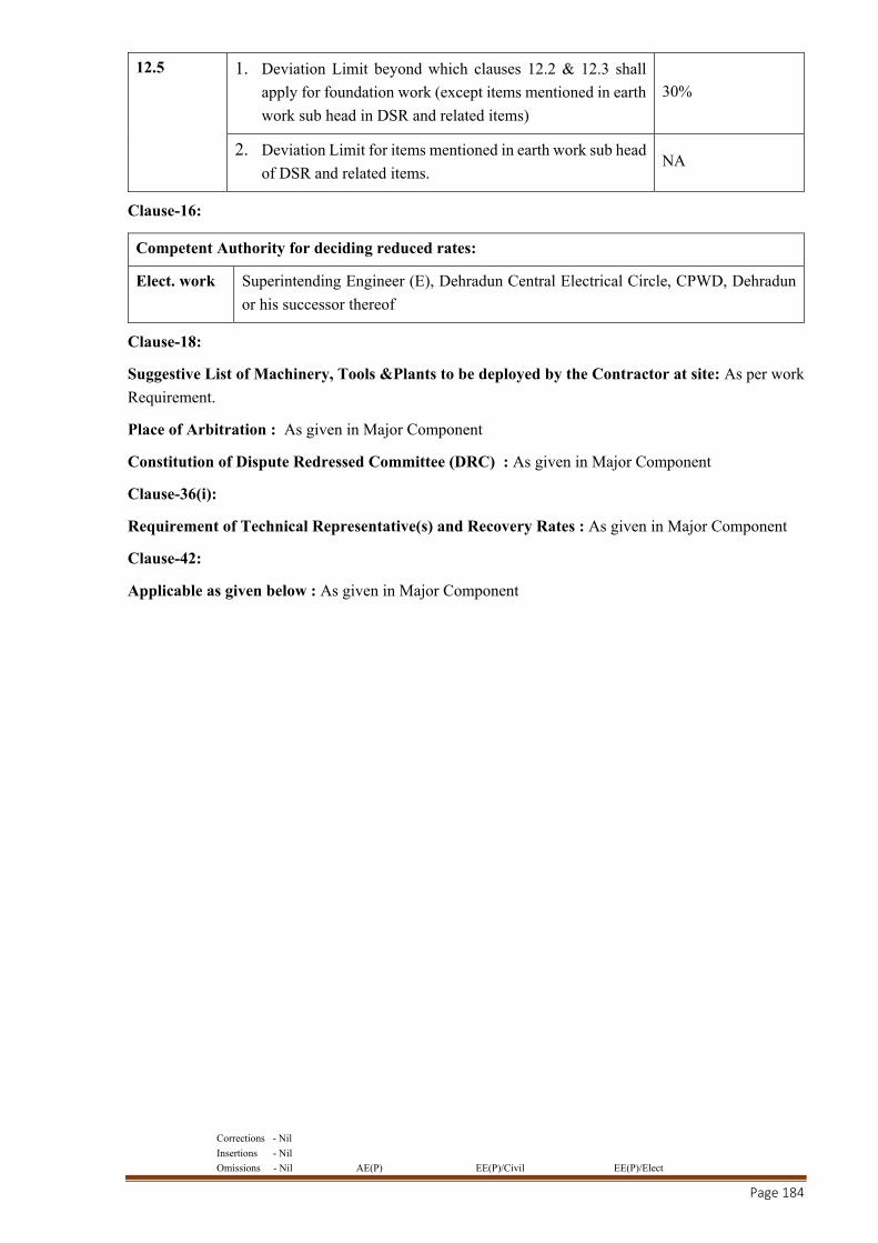
Corrections - Nil
Insertions - Nil
Omissions - Nil AE(P) EE(P)/Civil EE(P)/Elect
Page 184
12.5 1. Deviation Limit beyond which clauses 12.2 & 12.3 shall
apply for foundation work (except items mentioned in earth
work sub head in DSR and related items) 30%
2. Deviation Limit for items mentioned in earth work sub head
of DSR and related items. NA
Clause-16:
Competent Authority for deciding reduced rates:
Elect. work Superintending Engineer (E), Dehradun Central Electrical Circle, CPWD, Dehradun
or his successor thereof
Clause-18:
Suggestive List of Machinery, Tools &Plants to be deployed by the Contractor at site: As per work
Requirement.
Place of Arbitration : As given in Major Component
Constitution of Dispute Redressed Committee (DRC) : As given in Major Component
Clause-36(i):
Requirement of Technical Representative(s) and Recovery Rates : As given in Major Component
Clause-42:
Applicable as given below : As given in Major Component

Corrections - Nil
Insertions - Nil
Omissions - Nil AE(P) EE(P)/Civil EE(P)/Elect
Page 185
CONDITIONS FOR ASSOCIATE AGENCY FOR E&M WORKS
1. The tenderer should either himself meet the eligibility conditions for execution of minor component
of work i.e. E&M work (i/c specialized E&M) Works or otherwise he will have to associate with
agencies, fulfilling the eligibility requirements prescribed in the tender document. After duly taking
prior approval from department (NIT approving authority)
2. In case the main contractor is himself eligible (as per eligibility criteria) for executing all or some
components of E&M work and intends doing job himself, he may not be required to associate with
another agency for such components of E&M work of work. In such cases the main contractor also
has to submit the documents as per eligibility criteria mentioned for associated agency of individual
E&M component(s) within one month of award of work or 15 days before start of electrical related
work whichever is earlier.
3. In case, the main contractor himself is not eligible (as per eligibility criteria) for executing any of the
components of E&M work he will have to associate with him eligible agencies for doing such
components of E&M work of work. In such cases the main contractor has to submit proposal for
approval of associate agency along with documents in support of fulfilling eligibility criteria
mentioned for associated agency of individual E&M components within one month of award of work
or 15 days before start of electrical related work whichever is earlier.
4. Tripartite agreement between composite category contractor, department and specialized agency
shall be executed.
5. In the event of the associated E&M agency not performing satisfactorily or failure of associate agency
to complete the E&M work, the main contractor on written directions of the department, shall remove
the Associate agency deployed on the work and shall submit proposal for approval of new associate
agency without any loss of time or variation in cost to the department. Such new associate agency
shall also give an undertaking along with the main tenderer that both of them shall guarantee for the
equipment already supplied for which payment has been released by the department in part. If any
equipment supplied for the work, during the currency of the earlier associate agency and paid partly
by the department, becomes redundant /not in a position to be installed and commissioned and put to
beneficial use due to change in agency for execution of E&M work, the main contractor shall be
liable for replacement of the equipment(s) at no cost to the department. No change of associate agency
will be allowed without prior approval of the Engineer-in-charge of the work.
6. The main contractor shall be responsible and liable for proper and complete execution of the
Electrical work and ensure coordination and completion of both civil and electrical work.
7. The associate contractor shall attend the inspection of the work by the Engineer-in- charge of E&M
works as and when required.
8. ELIGIBILITY CRITERIA FOR MAIN CONTRACTOR/ASSOCIATED AGENCY
FOR E&M WORKS:
8.1. The tenderer(s) must associate eligible agencies to execute components of E&M Works who
fulfill the prescribed eligibility criteria given below after duly taking prior approval from
department (NIT approving authority). However, the contractor shall also be eligible to carry out
himself any or all of the components of E&M Works without associating any specialized agency
provided:
A. He fulfils the prescribed eligibility criteria respectively for these work(s) and produces

Corrections - Nil
Insertions - Nil
Omissions - Nil AE(P) EE(P)/Civil EE(P)/Elect
Page 186
evidence of fulfilling the eligibility criteria required for the specialized work.
or
B. He directly procures the equipment of approved make from manufacturer and get it installed
from authorized agency/service provider of the manufacturer or specialized agency as per the
eligibility criteria mentioned below:
8.1.1. Internal Electrical Installations, External Lighting/Cabling/Earthing & Service
Connection:
The associate agency shall be registered/enlisted in CPWD in composite category in
appropriate class and should have a valid electrical license.
8.1.2. Lifts:
The contractor shall directly procure the lifts from manufacturers of approved makes of lift
and get it installed by the manufacturer only.
Tripartite agreement between composite category contractor, department and specialized
agency shall be executed.
The contractor shall engage associate agency for execution of the specialized work(s) within
30 days of award of work OR before start of such specialized work whichever is earlier.
8.1.3. Fire Alarm and Fire fighting System:
The Associate agency must have valid electrical license and should have successfully
completed “Similar Works” during last 7 years ending previous day of last date of
submission of tender as under:
Three Similar completed works each of value not less than 40% of Estimated cost of
component of work of Fire Alarm System and Fire Fighting System.
or
Two Similar completed works each of value not less than not less than 60% of Estimated
cost of component of work of Fire Alarm and Fire Fighting System.
or
One Similar completed work each of value not less than not less than 80% of Estimated cost
of component of work of Fire Alarm and fire Fighting System.
Similar work shall mean “SITC of Fire Alarm and fire Fighting System”.
8.1.4. Sub-Station:
The Associate agency must have valid electrical license and should have successfully
completed “Similar Works” during last 7 years ending previous day of last date of
submission of tender as under:
Three Similar completed works each of value not less than 38 Lakh with capacity of
individual Transformer not less than 80% of individual capacity (rounded off to next
available higher capacity) of the transformer proposed in NIT.
or
Corrections - Nil
Insertions - Nil
Omissions - Nil AE(P) EE(P)/Civil EE(P)/Elect
Page 187
Two Similar completed works each of value not less than 57 Lakh with capacity of
individual Transformer not less than 80% of individual capacity (rounded off to next
available higher capacity) of the transformer proposed in NIT.
or
One Similar completed work each of value not less than 76 Lakh with capacity of individual
Transformer not less than 80% of individual capacity (rounded off to next available higher
capacity) of the transformer proposed in NIT.
Similar work shall mean “SITC of 11 KV Sub-station equipments”.
8.1.5. DG Set:
The Associate agency must have valid electrical license and should have successfully
completed “Similar Works” during last 7 years ending previous day of last date of
submission of tender as under:
Three Similar completed works each of value not less than 52 Lakh (40% of Estimated cost
of component of work of DG Set), with capacity of individual DG set not less than 80% of
individual capacity (rounded off to next available higher capacity) of the DG Set proposed
in NIT.
or
Two Similar completed works each of value not less than 78 Lakh (60% of Estimated cost
of component of work of DG Set), with capacity of individual DG set not less than 80% of
individual capacity (rounded off to next available higher capacity) of the DG Set proposed
in NIT.
or
One Similar completed work each of value not less than 104 Lakh (80% of Estimated cost
of component of work of DG Set), with capacity of individual DG set not less than 80% of
individual capacity (rounded off to next available higher capacity) of the DG Set proposed
in NIT.
Similar work shall mean “SITC of DG Set”.
8.1.6. HVAC System& BMS (SH-X&VI):
The Associate agency must have valid electrical license and should have successfully
completed “Similar Works” during last 7 years ending previous day of last date of
submission of tender as under:
Three Similar completed works each of value not less than 40% of Estimated cost of
component of work of HVAC with capacity of individual chiller not less than 80% of
individual capacity (rounded off to next available higher capacity) of the chiller proposed
in NIT.
or
Two Similar completed works each of value not less than 60% of Estimated cost of
component of work of HVAC System with capacity of individual chiller not less than 80%
of individual capacity (rounded off to next available higher capacity) of the chiller proposed
in NIT.

Corrections - Nil
Insertions - Nil
Omissions - Nil AE(P) EE(P)/Civil EE(P)/Elect
Page 188
or
One Similar completed work each of value not less than 80% of Estimated cost of
component of work of HVAC System with capacity of individual chiller not less than 80%
of individual capacity (rounded off to next available higher capacity) of the chiller proposed
in NIT.
Similar work shall mean “SITC of HVAC& BMS System”
8.1.7. Solar Power and Water Heating System (SH-IV):
The Associate agency must have valid electrical license and should have successfully
completed “Similar Works” during last 7 years ending previous day of last date of
submission of tender as under:
Three Similar completed works each of value not less than 40% of Estimated cost of
component of work of Solar Power and Water Heating System.
or
Two Similar completed works each of value not less than 60% of Estimated cost of
component of work of Solar Power and Water Heating System.
or
One Similar completed work each of value not less than 80% of Estimated cost of
component of work of Solar Power and Water Heating System.
Similar work shall mean “SITC of Solar Power and Water Heating System”.
8.1.8. CCTV (SH-VI):
The Associate agency must have valid electrical license and should have successfully
completed “Similar Works” during last 7 years ending previous day of last date of
submission of tender as under:
Three Similar completed works each of value not less than 66 Lakh (40% of Estimated cost
of component of work of CCTV).
or
Two Similar completed works each of value not less than 99 Lakh (60% of Estimated cost
of component of work of CCTV ).
or
One Similar completed work each of value not less than 132 Lakh (80% of Estimated cost
of component of work of CCTV).
Similar work shall mean “SITC of CCTV System”.
8.1.9. Boom Barrier (SH-VI):
The Associate agency must have valid electrical license and should have successfully
completed “Similar Works” during last 7 years ending previous day of last date of
submission of tender as under:
Three Similar completed works each of value not less than 4.07 Lakh (40% of Estimated
cost of component of work of Boom Barrier).
Corrections - Nil
Insertions - Nil
Omissions - Nil AE(P) EE(P)/Civil EE(P)/Elect
Page 189
or
Two Similar completed works each of value not less than 6.1 Lakh (60% of Estimated cost
of component of work of Boom Barrier).
or
One Similar completed work each of value not less than 8.14 Lakh (80% of Estimated cost
of component of work of Boom Barrier).
Similar work shall mean “SITC of Boom Barrier”.
8.1.10. EPBAX System (SH-V):
The Associate agency must have valid electrical license and should have successfully
completed “Similar Works” during last 7 years ending previous day of last date of
submission of tender as under:
Three Similar completed works each of value not less than 40% of Estimated cost of
component of work of EPBAX System.
or
Two Similar completed works each of value not less than 60% of Estimated cost of
component of work of EPBAX System.
or
One Similar completed work each of value not less than 80% of Estimated cost of
component of work of EPBAX System.
Similar work shall mean “SITC of EPBAX System”.
8.1.11. Sewage Treatment Plant (SH-XI):
The Associate agency must have valid electrical license and should have successfully
completed “Similar Works” during last 7 years ending previous day of last date of
submission of tender as under:
Three Similar completed works each of value not less than 40% of Estimated cost of
component of work of Sewage Treatment Plant.
or
Two Similar completed works each of value not less than 60% of Estimated cost of
component of work of Sewage Treatment Plant.
or
One Similar completed work each of value not less than 80% of Estimated cost of
component of work of Sewage Treatment Plant.
Similar work shall mean “SITC of Sewage Treatment Plant based on EBR Technology”.
8.2. Verifiable completion certificates of similar work experience, valid Electrical
Contractor's license, self-attested GST registration and other documents in respect of the
associated agencies, duly attested by both associated agency and the contractor shall be
Corrections - Nil
Insertions - Nil
Omissions - Nil AE(P) EE(P)/Civil EE(P)/Elect
Page 190
submitted within 30 days of award of work OR 15 days before start of specialized work(s)
whichever is earlier.
9. SUBMISSION OF PROPOSAL FOR APPROVAL OF ASSOCIATED
AGENCY:
9.1. In support of the eligibility conditions of the proposed associated E&M agency, copy of
their registration documents, Electrical Contractor’s License, PAN Card, GST Registration
duly attested by the applicants (Main Contractor) and applicable undertaking for carrying out
AMC as per format of NIT ( for Lift, UPS, CCTV, Fire alarm system & EPBAX work) shall
be submitted to the Engineer-in-charge of major component who will submit these
documents to the Engineer-in-charge of minor component for deciding the eligibility within
seven days of receipt of the same. Each such electrical contractor will certify that they are
not debarred as on the day of application for sale of tender. Proposal for associating agency
for minor components of work shall be submitted, as per proforma given in this tender
document, from each associate independently for all E&M components. The associate
agency shall be engaged by the contractor after taking prior approval of the same from
engineer-in-charge (who in turn shall obtain prior approval from NIT approving authority.)
9.2. Proposal for Associating Agency for E&M Components of Work shall be submitted in
prescribed Proforma given herein.
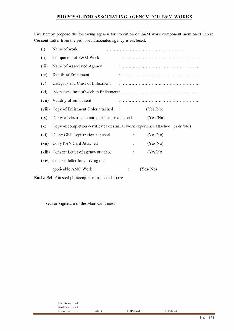
Corrections - Nil
Insertions - Nil
Omissions - Nil AE(P) EE(P)/Civil EE(P)/Elect
Page 191
PROPOSAL FOR ASSOCIATING AGENCY FOR E&M WORKS
I/we hereby propose the following agency for execution of E&M work component mentioned herein.
Consent Letter from the proposed associated agency is enclosed.
(i) Name of work : ………………………………………………
(ii) Component of E&M Work : ………………………. ……………………..
(iii) Name of Associated Agency : ………………………. ……………………..
(iv) Details of Enlistment : ………………………. ……………………..
(v) Category and Class of Enlistment : ………………………. ……………………..
(vi) Monetary limit of work in Enlistment : ………………………. ……………………..
(vii) Validity of Enlistment : ………………………. ……………………..
(viii) Copy of Enlistment Order attached : (Yes /No)
(ix) Copy of electrical contractor license attached: (Yes /No)
(x) Copy of completion certificates of similar work experience attached: (Yes /No)
(xi) Copy GST Registration attached : (Yes/No)
(xii) Copy PAN Card Attached : (Yes/No)
(xiii) Consent Letter of agency attached : (Yes/No)
(xiv) Consent letter for carrying out
applicable AMC Work : (Yes/ No)
Encls: Self Attested photocopies of as stated above
Seal & Signature of the Main Contractor

Corrections - Nil
Insertions - Nil
Omissions - Nil AE(P) EE(P)/Civil EE(P)/Elect
Page 192
CONSENT LETTER FROM ASSOCIATE AGENCY FOR E&M WORKS
Name of Work: ……………………………………………………………………………………....
I / We hereby give my consent to associate with M/s …………………………………, for
executing the ………………… (mention category) component of E&M work of the above-mentioned
work.
I / We will execute the work as per specifications and conditions of the agreement for the work
and as per directions of the Engineer-in-Charge for the said component of E&M work till the completion
of the work.
I / We will be responsible for necessary action to handover the installations and for rectification
of defects and repair during the maintenance / warranty / AMC period.
I / We will employ full time technically qualified Engineer / supervisor for the said component
of E&M work as required for the work.
I / We will attend inspection of officers of the department as and when required.
Dated:
Seal & Signature of Associate Agency for E&M
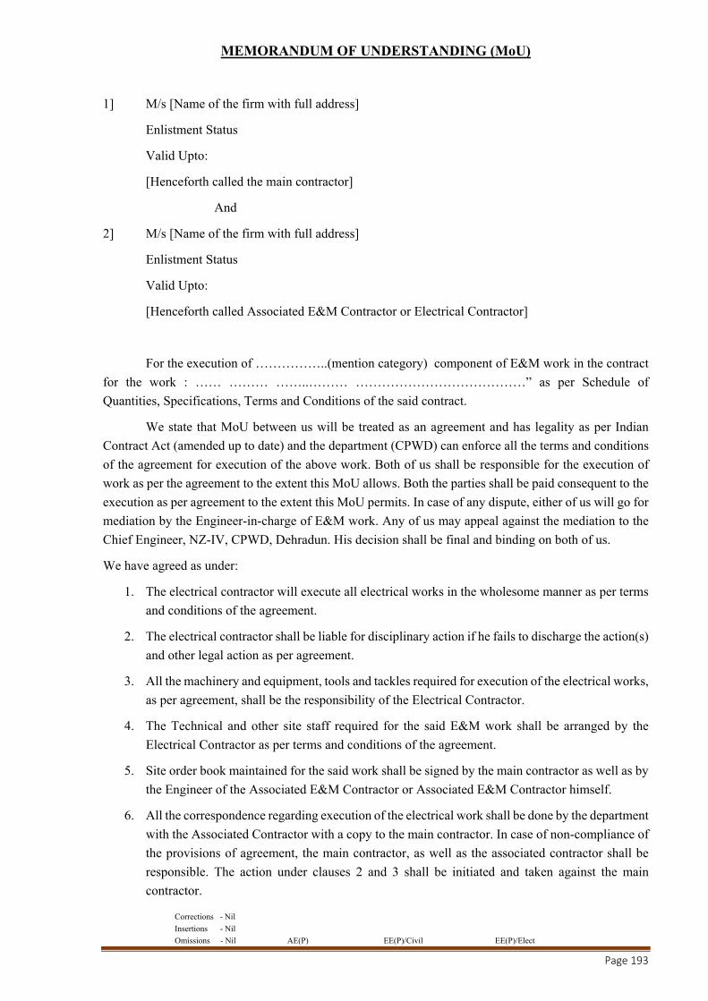
Corrections - Nil
Insertions - Nil
Omissions - Nil AE(P) EE(P)/Civil EE(P)/Elect
Page 193
MEMORANDUM OF UNDERSTANDING (MoU)
1] M/s [Name of the firm with full address]
Enlistment Status
Valid Upto:
[Henceforth called the main contractor]
And
2] M/s [Name of the firm with full address]
Enlistment Status
Valid Upto:
[Henceforth called Associated E&M Contractor or Electrical Contractor]
For the execution of ……………..(mention category) component of E&M work in the contract
for the work : …… ……… ……..……… …………………………………” as per Schedule of
Quantities, Specifications, Terms and Conditions of the said contract.
We state that MoU between us will be treated as an agreement and has legality as per Indian
Contract Act (amended up to date) and the department (CPWD) can enforce all the terms and conditions
of the agreement for execution of the above work. Both of us shall be responsible for the execution of
work as per the agreement to the extent this MoU allows. Both the parties shall be paid consequent to the
execution as per agreement to the extent this MoU permits. In case of any dispute, either of us will go for
mediation by the Engineer-in-charge of E&M work. Any of us may appeal against the mediation to the
Chief Engineer, NZ-IV, CPWD, Dehradun. His decision shall be final and binding on both of us.
We have agreed as under:
1. The electrical contractor will execute all electrical works in the wholesome manner as per terms
and conditions of the agreement.
2. The electrical contractor shall be liable for disciplinary action if he fails to discharge the action(s)
and other legal action as per agreement.
3. All the machinery and equipment, tools and tackles required for execution of the electrical works,
as per agreement, shall be the responsibility of the Electrical Contractor.
4. The Technical and other site staff required for the said E&M work shall be arranged by the
Electrical Contractor as per terms and conditions of the agreement.
5. Site order book maintained for the said work shall be signed by the main contractor as well as by
the Engineer of the Associated E&M Contractor or Associated E&M Contractor himself.
6. All the correspondence regarding execution of the electrical work shall be done by the department
with the Associated Contractor with a copy to the main contractor. In case of non-compliance of
the provisions of agreement, the main contractor, as well as the associated contractor shall be
responsible. The action under clauses 2 and 3 shall be initiated and taken against the main
contractor.

Corrections - Nil
Insertions - Nil
Omissions - Nil AE(P) EE(P)/Civil EE(P)/Elect
Page 194
Date:
Place:
Signature of Main Contractor Signature of Associated E&M Contractor
1. Witness with address 2. Witness with address
(From major component contractor side) (From minor component contractor side)
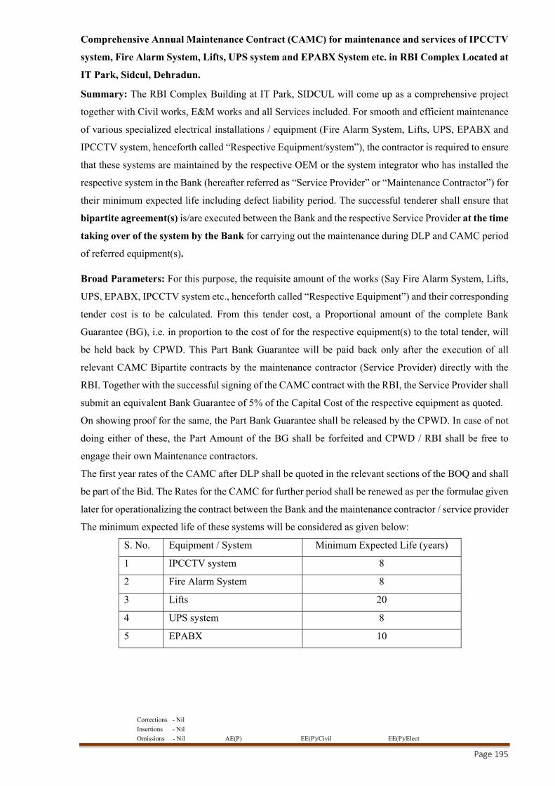
Corrections - Nil
Insertions - Nil
Omissions - Nil AE(P) EE(P)/Civil EE(P)/Elect
Page 195
Comprehensive Annual Maintenance Contract (CAMC) for maintenance and services of IPCCTV
system, Fire Alarm System, Lifts, UPS system and EPABX System etc. in RBI Complex Located at
IT Park, Sidcul, Dehradun.
Summary: The RBI Complex Building at IT Park, SIDCUL will come up as a comprehensive project
together with Civil works, E&M works and all Services included. For smooth and efficient maintenance
of various specialized electrical installations / equipment (Fire Alarm System, Lifts, UPS, EPABX and
IPCCTV system, henceforth called “Respective Equipment/system”), the contractor is required to ensure
that these systems are maintained by the respective OEM or the system integrator who has installed the
respective system in the Bank (hereafter referred as “Service Provider” or “Maintenance Contractor”) for
their minimum expected life including defect liability period. The successful tenderer shall ensure that
bipartite agreement(s) is/are executed between the Bank and the respective Service Provider at the time
taking over of the system by the Bank for carrying out the maintenance during DLP and CAMC period
of referred equipment(s).
Broad Parameters: For this purpose, the requisite amount of the works (Say Fire Alarm System, Lifts,
UPS, EPABX, IPCCTV system etc., henceforth called “Respective Equipment”) and their corresponding
tender cost is to be calculated. From this tender cost, a Proportional amount of the complete Bank
Guarantee (BG), i.e. in proportion to the cost of for the respective equipment(s) to the total tender, will
be held back by CPWD. This Part Bank Guarantee will be paid back only after the execution of all
relevant CAMC Bipartite contracts by the maintenance contractor (Service Provider) directly with the
RBI. Together with the successful signing of the CAMC contract with the RBI, the Service Provider shall
submit an equivalent Bank Guarantee of 5% of the Capital Cost of the respective equipment as quoted.
On showing proof for the same, the Part Bank Guarantee shall be released by the CPWD. In case of not
doing either of these, the Part Amount of the BG shall be forfeited and CPWD / RBI shall be free to
engage their own Maintenance contractors.
The first year rates of the CAMC after DLP shall be quoted in the relevant sections of the BOQ and shall
be part of the Bid. The Rates for the CAMC for further period shall be renewed as per the formulae given
later for operationalizing the contract between the Bank and the maintenance contractor / service provider
The minimum expected life of these systems will be considered as given below:
S. No. Equipment / System Minimum Expected Life (years)
1 IPCCTV system 8
2 Fire Alarm System 8
3 Lifts 20
4 UPS system 8
5 EPABX 10
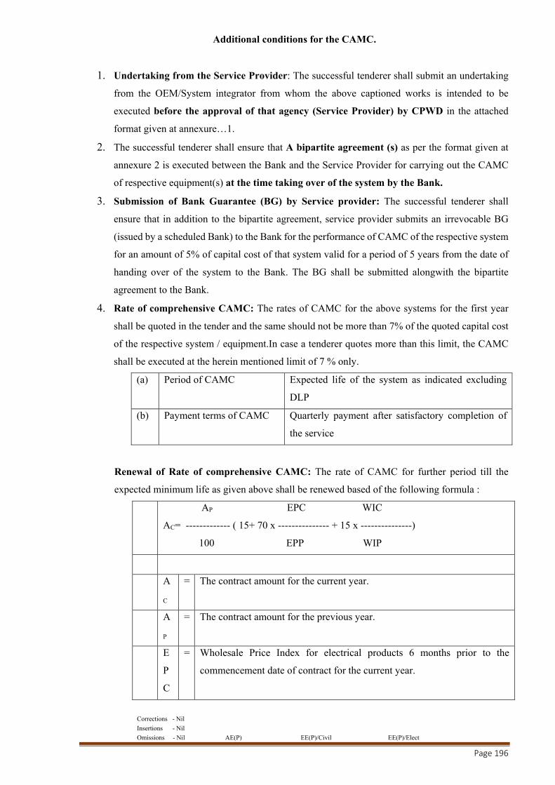
Corrections - Nil
Insertions - Nil
Omissions - Nil AE(P) EE(P)/Civil EE(P)/Elect
Page 196
Additional conditions for the CAMC.
1. Undertaking from the Service Provider: The successful tenderer shall submit an undertaking
from the OEM/System integrator from whom the above captioned works is intended to be
executed before the approval of that agency (Service Provider) by CPWD in the attached
format given at annexure…1.
2. The successful tenderer shall ensure that A bipartite agreement (s) as per the format given at
annexure 2 is executed between the Bank and the Service Provider for carrying out the CAMC
of respective equipment(s) at the time taking over of the system by the Bank.
3. Submission of Bank Guarantee (BG) by Service provider: The successful tenderer shall
ensure that in addition to the bipartite agreement, service provider submits an irrevocable BG
(issued by a scheduled Bank) to the Bank for the performance of CAMC of the respective system
for an amount of 5% of capital cost of that system valid for a period of 5 years from the date of
handing over of the system to the Bank. The BG shall be submitted alongwith the bipartite
agreement to the Bank.
4. Rate of comprehensive CAMC: The rates of CAMC for the above systems for the first year
shall be quoted in the tender and the same should not be more than 7% of the quoted capital cost
of the respective system / equipment.In case a tenderer quotes more than this limit, the CAMC
shall be executed at the herein mentioned limit of 7 % only.
(a) Period of CAMC Expected life of the system as indicated excluding
DLP
(b) Payment terms of CAMC Quarterly payment after satisfactory completion of
the service
Renewal of Rate of comprehensive CAMC: The rate of CAMC for further period till the
expected minimum life as given above shall be renewed based of the following formula :
AP EPC WIC
AC= ------------- ( 15+ 70 x --------------- + 15 x ---------------)
100 EPP WIP
A
C
= The contract amount for the current year.
A
P
= The contract amount for the previous year.
E
P
C
= Wholesale Price Index for electrical products 6 months prior to the
commencement date of contract for the current year.
Corrections - Nil
Insertions - Nil
Omissions - Nil AE(P) EE(P)/Civil EE(P)/Elect
Page 197
E
P
P
= Wholesale Price Index for electrical products 6 months prior to the
commencement date of contract for the previous year.
W
IC
= Consumer Price Index for industrial workers (respective location of
installation city) 6 months prior to commencement date of contract for the
current year.
W
IP
= Consumer Price Index for industrial workers respective location of
installation city) 6 months prior to commencement date of contract for the
previous year.
i.Scope of CAMC: During the CAMC of the above systems, the same shall be maintained by
Service Provider as per the scope indicated in the Annexure
ii.Penalty provisions for non-performance of CAMC: During the CAMC of the above systems
/ equipments, the same shall be maintained as per the scope indicated in the Annexure.
iii.Terms of payment during CAMC: Quarterly payment shall be made subject to statuary
deductions, penalties etc if any, by the Bank directly to the Service Provider after rendering
satisfactory services during the previous quarter by the service provider subject to submission of
bill alongwith requisite service reports etc.
Corrections - Nil
Insertions - Nil
Omissions - Nil AE(P) EE(P)/Civil EE(P)/Elect
Page 198
Annexure 1
(To be submitted by the respective Service Provider (OEM or the system integrator who have installed the IPCCTV system / Fire Alarm System / Lifts / UPS system/ EPABX) on their letter head)
Undertaking for the CAMC of …..(Name of respective equipment)…..
To
CPWD
Dear Sir/Madam
Supply, Installation, Testing and Commissioning of IPCCTV system / Fire Alarm System / Lifts /
UPS system / EPABX in RBI Complex located at IT Park, Sidcul, Dehradun
We hereby confirm that we have understood the followings in respect of the Comprehensive Maintenance
Contract (CAMC) of above referred system:
1. The system provided will be maintained by us during defect liability period of one year and
thereafter under Comprehensive Annual Maintenance Contract (CAMC) for a minimum period
of ……(expected life of the system excluding one year of DLP)….. years after handing over of
the system to the Bank.
2. We have understood the detailed scope of CAMC and its terms and conditions and agree to
abide by the same.
3. The rates for the first year of CAMC after one year of DLP will be (as per BOQ) Totalling
Rs………(Rates quoted by the main contractor) per annum and the rates of CAMC for further
period till the expected minimum life as given above shall be renewed as per the provision
indicated in the attached bipartite agreement.
4. We agree to enter into a bipartite agreement with the Bank for the execution of the said CAMC
as per the enclosed draft. The cost toward the agreement (charges for stamp paper as per stamp
act and other charges) shall be borne by us. A signed copy of the draft agreement in support of
having accepted the Scope, terms and conditions of the CAMC is attached.
5. We agree to submit irrevocable Bank Guarantee to Bank of required amount and required
validity alongwith the bipartite agreement for CAMC, as a performance guarantee for due
fulfilment of the terms of CAMC for specified period.
Yours faithfully,
(Seal and signature)
Enclosure: Signed copy of the draft bipartite agreement for the CAMC along with the annexure for the
scope of work for respective equipment.
Corrections - Nil
Insertions - Nil
Omissions - Nil AE(P) EE(P)/Civil EE(P)/Elect
Page 199
Annexure:2
BIPARTITE AGREEMENT FOR COMPREHENSIVE ANNUAL MAINTENANCE CONTRACT
(CAMC) FOR MAINTENANCE AND SERVICES OF IPCCTV SYSTEM, FIRE ALARM
SYSTEM, LIFTS, UPS SYSTEM, EPABX
This agreement is made on this ________ day of ___________ between M/s.
________________________________(Name of CAMC vendor), having its office at
_____________________________________________ hereinafter referred to as Service Provider, the
party of the FIRST PART, (which expression where the context admits shall this include its successors
in interest and assigns);
And
Reserve Bank of India, constituted under the Reserve Bank of India Act, 1934, having its Central Office
at Mumbai (hereinafter referred to as the “Bank”), through
_________________________________________(Name and address of the Bank’s office where
contract is being executed), (hereinafter called the “Bank”) and collectively the party of the SECOND
PART;
Whereas:
(a) In terms of the Contract Agreement dated _______ between the Bank and the CPWD for the
construction of the _____________________________, the Service Provider herein was
selected by the (Name of the Main contractor) vide Order No.
_______________________________ DATED _____________ after acceptance by CPWD for
Supply, Installation, Testing and Commissioning of IPCCTV System / Fire Alarm System / Lifts
/ UPS System / EPABX system for (Name of the System as applicable) and entered into an
agreement with the Service Provider for the same including carrying out Comprehensive Annual
Maintenance (CAMC) for a period of minimum ……… years (as per expected life mentioned)
after one year of Defect Liability Period.
(b) The Service Provider, being the Original Equipment Manufacturer (OEM) / system integrator of
IPCCTV System / Fire Alarm System / Lifts / UPS System / EPABX system has agreed to
provide Comprehensive Annual Maintenance Contract (CAMC) for the system installed by them
for the captioned project for a period of minimum ….. years (as per expected life mentioned)
after expiry of DLP of one year in consideration of the amount of Rs. ……………Per Annum to
be paid by the Bank subject to revision in the rates as per the formula indicated in this agreement.
AND

Corrections - Nil
Insertions - Nil
Omissions - Nil AE(P) EE(P)/Civil EE(P)/Elect
Page 200
(c) Under the contract agreement with reference to agreement Dated _______between
……………………. (Name of the main contractor) and the CPWD, a bipartite agreement(s) is
required to be executed between the Bank and the Service Provider for smooth implementation
of Comprehensive Annual Maintenance Contract (CAMC) of IPCCTV System / Fire Alarm
System / Lifts / UPS System / EPABX system installed by it at the Bank’s office building at
Dehradun on the terms and conditions as contained herein.
NOW THE PARTIES TO THIS AGREEMENT BEING DESIROUS OF REDUCING TO
WRITING ALL THE TERMS AND CONDITIONS AGREE AS FOLLOWS:
(A) General:
1. The parties hereto shall respectively and faithfully abide by the terms and conditions and
stipulations contained in this agreement and perform/discharge their part of the obligation of the
agreement accordingly.
2. The Indian laws shall apply for interpretation of this Agreement.
3. Four sets of this agreement shall be signed and one set each of this agreement shall remain with
the Service Provider, ……………….(Main Contractor), Bank and the CPWD and the cost
towards the stamp duty for all these agreements shall be borne by Service Provider.
4. The Parties hereto represent and warrant that the respective signatories are duly authorized to
sign this Agreement and bind the respective parties.
5. All disputes arising out of or any way connected with this agreement and the Work Order No.
______________________________(work order issued by Bank for this work), shall be deemed
to have arisen at Dehradun and courts in Dehradun shall have jurisdiction to determine the same.
6. The scope of work and other terms and conditions of the CAMC shall be as per the attached
annexure.
7. The parties to this Agreement agree to settle their disputes arising under this Agreement, by
mutual consultations at the first instance with the aid of an escalation matrix, failing which the
parties agree to settle their disputes by way of arbitration by a sole arbitrator to be appointed by
mutual consent. However, the person to be appointed as the sole arbitrator shall be one who is
adequately qualified and experienced to resolve the dispute sought to be raised before the said
arbitrator. The place of arbitration shall be Dehradun.
8. Where the business or undertaking of the service provider, is taken over by any other person in
any legally recognized mode of take-over, then unless the service provider is entitled to continue
to provide to the Bank the services contemplated under this Agreement, it shall be duty of the
service provider to ensure that such other person is obligated to provide the services contemplated
under this Agreement under the same terms and conditions. In case the service provider does not
so ensure and consequently maintenance services are not provided or the successor of the service
provider fails to honour the terms of this Agreement, then –

Corrections - Nil
Insertions - Nil
Omissions - Nil AE(P) EE(P)/Civil EE(P)/Elect
Page 201
a. Any sums due to the service provider towards CAMC shall be liable to be forfeited and
successors of the service provider shall not be entitled to claim any money due to the
service provider; and
b. The Service Provider shall arrange to get the CAMC services through their successor or
any other service provider mutually agreed with the Bank, at the risk and cost of the
Service Provider/ successor, as the case may be.
9. The Bank shall have right to forfeit the CAMC performance Bank Guarantee submitted by the
Service Provider in case of failure by the Service Provider to provided satisfactory services even
after expiry of written notice period of 15 days to comply with the above.
(B) Obligations of the FIRST PARTY (SERVICE PROVIDER):
1. The FIRST PARTY shall provide all-inclusive Comprehensive Annual Maintenance for the
system which includes periodic routine/preventive and breakdown maintenance and also any
number of breakdown calls along with supply of all spares and labour involved as per Original
Equipment Manufacturer’s O&M Manual for the supplied/installed equipment and its
accessories in order to ensure proper functioning of the system. The CAMC period will
commence from expiry of defects liability period and accordingly shall be valid for a period of
…….. years (as per expected life mentioned).
2. The Service Provider shall make good for any direct damages/loss caused to the Bank due to the
actions/omissions of persons employed by it or because of its actions/omissions during the
execution of the contract.
3. The Service Provider shall submit an irrevocable BG issued to the Bank for the performance of
CAMC of the respective system for an amount of 5% of capital cost of the system for a period
of 5 years from the date of start of CAMC. The BG (issued by a scheduled Bank) shall be
submitted to the Bank at least 15 days before the expiry of DLP.
4. The firm shall ensure that the required spares etc. for proper maintenance are readily available
with them for the complete life span of the lift.
5. The complaints lodged by the Bank/CPWD/(Name of the main Contractor) in respect of the
equipment for any repair or break down (any number of breakdowns) must be attended at top
most priority by the Service Provider.
6. The Complaint/Message may be sent to the address/Telephone Number/ email of the service
provider
7. While submitting the invoice towards annual maintenance to Bank, the Service Provider has to
furnish a satisfactory working service reports from the Bank. The certification given by the Bank
is final and shall not be subject to any question
8. The Service Provider has to replace any defective parts with the Manufacturer’s genuine parts
under intimation to the Bank’s authorized personnel.
Corrections - Nil
Insertions - Nil
Omissions - Nil AE(P) EE(P)/Civil EE(P)/Elect
Page 202
9. The service provider shall be responsible to take and accordingly obtain all the insurance required
for its employees carrying out the CAMC works under this agreement, such as Workmen
Compensation or any other requisite and necessary insurance.
10. The Service provider shall keep the Bank indemnifiedin case any action is taken against them by
any Authority on account of contravention by the Service Provider or its employees, of any of
the provision of any act or rules made there under pertaining to maintenance of the equipment(s).
If the Bank is made liable to pay or reimburse any amount due to non-observance, if any, on the
part of Service Provider, of any provision stipulated in the notification by
law/act/rules/regulations etc., then Bank, shall have the right to deduct any money due to the
Service Provider under this Agreement.
11. The Service Provider shall deploy adequate number of qualified and duly experienced service
engineers and such other skilled personnel with necessary certification wherever necessary for
carrying out the services under this Agreement and considering the nature of working of the
Bank, shall ensure availability of its maintenance personnel as and when required.
12. The Service Provider shall only employ its own employees for rendering the services
contemplated under this Agreement. The service provider shall ensure that all the personnel
deployed by it, act with proper demeanor and in case the Bank notifies the service provider that
any of its personnel need to be replaced for any reason, the service provider shall promptly act
upon such notice by the Bank or college and replace the concerned personnel.
13. The Service Provider shall familiarize itself and fully comply with the provisions of all the
Acts/Rules/Regulations and orders of the State/Central Government applicable to the work,
including the Payment of the Wages Acts, Workman’s Compensation Acts, Contract Labour
(R&A) Act etc. and shall be fully responsible and liable for due observance of the same.
14. The Service Provider shall abide by all existing or future labour related enactments and rules and
regulations made there under, notifications issued, etc. by the State or Central Govt. or Local
Authorities.
(C) Obligations of the SECOND PARTY (Bank):
1. Terms of Payment: Bank shall be responsible for making all payments to Service Provider
during the CAMC period for rendering satisfactory maintenance services as per scope of works stated
herein. Quarterly payment shall be made by the Bank to the service provider after rendering of
satisfactory services during the quarter by the service provider subject to submission of bill alongwith
requisite service reports.
2. Renewal of Rate of comprehensive CAMC: The rate of CAMC for further period till the
expected minimum life as given above shall be renewed based of the following formula.
AP EPC WIC
AC= --------------- ( 15+ 70 x --------------- + 15 x ---------------)
Corrections - Nil
Insertions - Nil
Omissions - Nil AE(P) EE(P)/Civil EE(P)/Elect
Page 203
100 EPP WIP
AC = The contract amount for the current year.
AP = The contract amount for the previous year.
EPC = Wholesale Price Index for electrical products 6 months prior to the
commencement date of contract for the current year.
EPP = Wholesale Price Index for electrical products 6 months prior to the
commencement date of contract for the previous year.
WIC = Consumer Price Index for industrial workers (respective location of
installation city) 6 months prior to commencement date of contract for the
current year.
WIP = Consumer Price Index for industrial workers respective location of
installation city) 6 months prior to commencement date of contract for the
previous year.
The parties hereto agree that the several parts of this contract have been read by all of them and having
fully understood, in witness whereof the parties have hereunto set and subscribe their respective hands
and seals at __________ on the date, month and year above written.
Signed and Delivered
By the said Second Party By the said First Party
Signature Signature.
Name: Name:
Address: : Address:
1) Witness & Signature
Address:
Corrections - Nil
Insertions - Nil
Omissions - Nil AE(P) EE(P)/Civil EE(P)/Elect
Page 204
Annexure3
Annexure for the Bipartite agreement for the CAMC of Lifts
The scope of work shall include the following:
a. Comprehensive AMC of the Lifts shall include the complete lift system including all
hardware and software etc. installed by the service provider.
b. Preventive Maintenance/ Routine servicing/ troubleshooting/ setting/ adjustments/
cleaning/ lubrication/ checking of safeties etc. at least once per month to ensure smooth
running and trouble free working of the lift.
c. Repairs/ replacement to the lift including re-loading software etc. in the event of any
breakdown including replacement of spares/ components/ sub-system/ cards/ motors/
ropes and any other component, part or whole, which may need replacement/ repairs.
d. The rates quoted should include for repair/replacement of the any of component of the
lift in case it develops any defect including re-loading software etc. In case of any defect
in the any of its component, the same shall be repaired within specified period including
replacement of spares/ components/ sub-system/ cards and any other component, part or
whole, which may need replacement/ repairs. In case the repair is not possible due
to any reason what so ever, then the defective item/equipment shall be replaced with the
new equipment without any additional cost to the Bank. During such period of repairs or
replacement, the service provider shall provide similar standby/spare equipment
temporarily for keeping the system in proper working condition.
e. Keeping the sufficient stock (including importing, if required) of the spares at site as
well as at their service centre / site as required for proper functioning of the system. Non
availability of spares/standby units/components will not be accepted as a reason for
waiving of penalty towards delay in rendering prompt service.
f. All manufacturers preventive maintenance schedules/ replacement periodicity of
components like ropes, electrical/ electronic parts including checking of safety devices,
protections like rope slip, load testing etc. shall be strictly followed as per the
manufacturer's periodicity or as required in addition to the scope of maintenance
indicated above.
g. The scope of maintenance in addition to periodic maintenance will also include
attending to /any number of breakdown calls.
h. 24x7 support should be made available by the service provider for all the equipments.
i. The payment towards AMC charges will be made every quarter after satisfactory
completion of the service.
j. During the DLP and the currency of the Comprehensive Annual Maintenance Service
Contract, all care shall be taken so that the downtime of the lift is kept minimum and in
Corrections - Nil
Insertions - Nil
Omissions - Nil AE(P) EE(P)/Civil EE(P)/Elect
Page 205
any case, the lift shall be attended immediately and maximum within 3 hours of receiving
the complaint.
(B) Penalty for delay in service during defect liability period (DLP) and CAMC period:-
a. In case, the lift remains under breakdown for more than a day (requiring repair other than
major repair), then a penalty equivalent to 4 times the daily rate of Comprehensive AMC
charges shall be recovered from the payment due to the contractor during CAMC period
and the warranty period (DLP) will be extended by 4 times the number of days of delay
in rectification of the defects during DLP.
b. If any major repair resulting in stoppage of the lift is not rectified within 3 days then a
penalty equivalent to 4 times the daily rate of Comprehensive AMC charges shall be
recovered from the payment due to the contractor during CAMC period and the warranty
period (DLP) will be extended by 4 times the number of days of delay in rectification of
the defects during DLP. For the purpose of penalty the following items will be
considered as Major repair:
i. Rewinding of motor
ii. Replacement of rope
iii. Replacement of bearings, gears etc. in gear box
iv. Replacement of guide shoes for the car and counter weight
v. Replacement of trailing cables/ control wiring
vi. VVVF Controller replacement
Note: Notwithstanding the above penal provisions, in addition to the penalty, the Bank reserves the right
to encash the BG submitted for the due fulfilment of the terms and obligations the DLP and CAMC
contract.
Corrections - Nil
Insertions - Nil
Omissions - Nil AE(P) EE(P)/Civil EE(P)/Elect
Page 206
Annexure 4
Annexure for the Bipartite agreement for CAMC of UPS
(A) The scope of work shall include the following:
a. Comprehensive AMC of the UPS system shall include all its components, cards, rectifier,
inverters, filters, cables of all types including all hardware and software etc. provided for
functioning of UPS except the batteries.
b. All software updates, releases, Version upgrades, New Versions etc. as and when
required for smooth functioning of the system shall be included in the scope in scope of
CAMC, The service provider shall have to provide all software (IOS) updates, releases,
Version upgrades, New Versions etc. of all the Application Software and Custom
Software including renewal of all licences provided for this system. The service provider
will also undertake to carry out implementation / operationalisation / customisation of
such software updates, releases, Version upgrades, New Versions etc. Accordingly the
service provider should include the cost for the above in the quoted cost for the CAMC.
c. 24x7 support should be made available by the service provider for all the equipments.
d. Preventive maintenance at least once per month shall be carried out to ensure that the
system is running under proper working condition. The servicing shall also include
cleaning of the UPS, removal of dirt and dust etc.
e. During the DLP and the currency of the Comprehensive Annual Maintenance Service
Contract, all care shall be taken so that the downtime of the system is kept minimum and
in any case, not more than the allowed time for attending to repairs as under:
i. Any defects in the UPS affecting the services of UPS partially shall be rectified
/ repaired within 24 hours from the time of reporting complaint in writing
(complaints through SMS, e-mails, fax etc. shall also be treated as complaints in
writing).
ii. Any defects in any of the UPS leading to complete breakdown of the system,
shall be repaired within 8 hours from the time of reporting complaint in writing
(complaints through SMS, e-mails, fax etc. shall also treated as complaints in
writing).
f. The rates quoted should include for repair/replacement of the equipment in case it
develops any defect including re-loading software etc. In case of any defect in the UPS
the same shall be repaired within specified period including replacement of spares/
components/ sub-system/ cards and any other component, part or whole, which may need
replacement/ repairs. In case the repair is not possible due to any reason what so ever,
then the defective item/equipment shall be replaced with the new equipment without any
additional cost to the Bank. During such period of repairs or replacement, the service
Corrections - Nil
Insertions - Nil
Omissions - Nil AE(P) EE(P)/Civil EE(P)/Elect
Page 207
provider shall provide similar standby/spare equipment temporarily for keeping the
system in proper working condition.
g. The service provider shall keep the sufficient stock of the spares at site as well as at their
service centre as required for proper functioning of the system. Non availability of
spares/standby units/components will not be accepted as a reason for waiving of penalty
towards delay in rendering prompt service.
h. The scope of maintenance in addition to preventive maintenance will also include
attending to any number of breakdown calls.
(B) Penalty for delay in service during defect liability (DLP) and CAMC period:
If the down time exceeds the above mentioned period during defect liability period and CAMC
period, penal recovery shall be made from any payments due to the service provider at the
following rates:
o Partial outage of UPS services – @ Rs 500/- per day beyond the authorised
maintenance period
o Partial outage of UPS services leading to failure of entire system - @ Rs 3000/- per
day beyond the authorised maintenance period
Note: Notwithstanding the above penal provisions, in addition to the penalty, the Bank reserves
the right to encash the BG submitted for the due fulfilment of the terms and obligations the DLP
and CAMC contract.
Corrections - Nil
Insertions - Nil
Omissions - Nil AE(P) EE(P)/Civil EE(P)/Elect
Page 208
Annexure 5
Annexure for the Bipartite agreement for the CAMC of IPCCTV System
(A) The scope of work shall include the following:
a. Comprehensive AMC of the IPCCTV system shall include all cameras, servers,
monitors, network switches, storage devices, cables of all types and all hardware and
software etc. provided for IPCCTV system.
b. All software updates, releases, Version upgrades, New Versions etc. as and when
required for smooth functioning of the system shall be included in the scope in scope of
CAMC, The service provider shall have to provide all software (IOS) updates, releases,
Version upgrades, New Versions etc. of all the Application Software and Custom
Software including renewal of all licences provided for this system. The service provider
will also undertake to carry out implementation / operationalisation / customisation of
such software updates, releases, Version upgrades, New Versions etc. Accordingly the
service provider should include the cost for the above in the quoted cost for the CAMC.
c. 24x7 support should be made available by the service provider for all the equipments.
d. Preventive maintenance at least once per month shall be carried out to ensure that the
system is running under proper working condition. The servicing shall include cleaning
of the system, cameras, Lens proper adjustments and setting of cameras and their field
of view, software up gradation etc.
e. During the DLP and the currency of the Comprehensive Annual Maintenance Service
Contract, all care shall be taken so that the downtime of the system is kept minimum and
in any case, not more than the allowed time for attending to repairs as under:
i. Any defects in any of the cameras shall be repaired within 24 hours from the
time of reporting complaint in writing (complaints through SMS, e-mails, fax
etc. shall also be treated as complaints in writing).
ii. Any defects in any of the servers, switches, routers etc., leading to complete
breakdown of the system, shall be repaired within 8 working hours from the
time of reporting complaint in writing (complaints through SMS, e-mails, fax
etc. shall also treated as complaints in writing).
iii. Any defects/ problems associated with the software shall be attended to
immediately, but not later than 4 hours from the time of the problem being
noticed/ reported.
f. The scope of work shall also include all the labour, tools etc. for relocation / shifting of
any camera from one place to another within the Bank’s Premises as per Bank’s
requirements and instructions. For such relocation or shifting, if additional cable/item is
required, the cost of the additional cable/item only shall be paid as per the rates quoted
by the firm in the tender after applying necessary escalation as per the escalation formula

Corrections - Nil
Insertions - Nil
Omissions - Nil AE(P) EE(P)/Civil EE(P)/Elect
Page 209
for CAMC in the tender and no other cost shall be paid. For ascertaining the reasonability
of the rates so arrived, current market cost of same/similar item will be submitted by the
service provider and lesser of the two rates will apply.
g. The rates quoted should include for repair/replacement of the equipment in case it
develops any defect including re-loading software etc.. In case of any defect in the
camera, switch, Storage system, Hard disk, server, monitor or any other equipment etc,
the same shall be repaired within specified period including replacement of spares/
components/ sub-system/ cards and any other component, part or whole, which may need
replacement/ repairs. In case the repair is not possible due to any reason what so ever,
then the defective item/equipment shall be replaced with the new equipment without any
additional cost to the Bank. During such period of repairs or replacement, the service
provider shall provide similar standby/spare equipment temporarily for keeping the
system in proper working condition.
h. The service provider shall keep the sufficient stock of the spares at site as well as at their
service centre as required for proper functioning of the system. Non availability of
spares/standby units/components will not be accepted as a reason for waiving of penalty
towards delay in rendering prompt service.
i. The scope of maintenance in addition to preventive maintenance will also include
attending to any number of breakdown calls.
j. The additional requirement of the equipments during the DLP and CAMC shall be met
by procuring the equipments form the system integrator based on the quotes rates and
variations on the exchange rate, prices indices etc. In case the rates so offered are not
found acceptable by the Bank due to any reason, the Bank may procure the same directly
from the market and the same shall be handed over to the system integrator alongwith
all the warranty documents etc. for installation, testing and commissioning.
The items so installed will be an integral part of the IPCCTV system and the system
integrator shall maintain alongwith entire IPCCTV system. After installation, these items
shall remain under warranty for one year from their installation and thereafter shall be
covered under CAMC. During first year CAMC, the CAMC charges for these items will be
paid to the system integrator on pro rata basis (based on the cost of such additional
installation) at rate the quoted by the system integrator in their tender.
Example:
Capital Cost of IPCCTV system : Say Rs.10,00,000/-
CAMC Charges quoted by the firm in their tender : Say Rs. 60,000/-
Cost of Additional installation : Say Rs.1,00,000/-
The pro rata CAMC Charges for additional hardware : Rs.6,000/-
The CAMC charges will be revised for further years as per the renewal formula in the tender.
Corrections - Nil
Insertions - Nil
Omissions - Nil AE(P) EE(P)/Civil EE(P)/Elect
Page 210
(B) Penalty for delay in service during defect liability (DLP) and CAMC period:
If the down time exceeds the above mentioned period during defect liability period and CAMC
period, penal recovery shall be made from any payments due to the service provider at the
following rates:
o Non-functional cameras – @ Rs 500/- per camera per day beyond the authorised
maintenance period
o Non-functional server/switch leading to entire system failure - @ Rs 3000/- per day
beyond the authorised maintenance period
o Non-functional server/switch leading to failure of a few cameras/ components - @ Rs
1500/- per day beyond the authorised maintenance period
o Non-functional software leading to system failure - @ Rs 3000/- per day or part thereof
beyond the authorised maintenance period
Note: Notwithstanding the above penal provisions, in addition to the penalty, the Bank reserves the right
to encash the BG submitted for the due fulfilment of the terms and obligations the DLP and CAMC
contract.
Corrections - Nil
Insertions - Nil
Omissions - Nil AE(P) EE(P)/Civil EE(P)/Elect
Page 211
Annexure 6
Annexure for the Bipartite agreement for the CAMC of Fire Alarm System
FIRE ALARM SYSTEM:
(A) The scope of work shall include the following:
a. Comprehensive AMC of the Fire Alarm system shall include all detectors, Panels,
Control modules, Hooters, Monitor modules, cables of all types and all hardware and
software etc. provided for Fire Alarm system.
b. All software updates, releases, Version upgrades, New Versions etc. as and when
required for smooth functioning of the system shall be included in the scope in scope of
CAMC, The service provider shall have to provide all software (IOS) updates, releases,
Version upgrades, New Versions etc. of all the Application Software and Custom
Software including renewal of all licences provided for this system. The service provider
will also undertake to carry out implementation / operationalisation / customisation of
such software updates, releases, Version upgrades, New Versions etc. Accordingly the
service provider should include the cost for the above in the quoted cost for the CAMC.
c. 24x7 support should be made available by the service provider for all the equipments.
d. During DLP and CAMC period, full servicing and cleaning of devices once in a quarter
shall be done including attending to ANY NUMBER of breakdown calls.
The System will be required to be checked by deputing a competent, trained service
engineer on WEEKLY basis by creating a fire / smoke simulation in the loops
Critical area detectors viz server rooms/UPS rooms etc should be invariably included and
checked during the weekly and quarterly visits. Suitable log register indicating faults,
rectification done with date & time of breakdown should be maintained and got signed
from the security/Fire officer. Bank will not provide any assistance in the form of
men/material. The service provider will have to make their own arrangements for
deputing a helper to skilled personnel including all necessary spares for rectification of
the defects reported/observed.
e. During the DLP and the currency of the Comprehensive Annual Maintenance Service
Contract, all care shall be taken so that the downtime of the system is kept minimum and
in any case, not more than the allowed time for attending to rectify as under:
Rectification
time*
Penalty
(a) Any defects resulting in total failure of the system 12 hours Rs.2000/-
per day
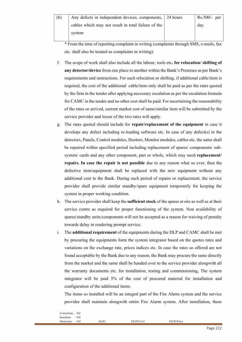
Corrections - Nil
Insertions - Nil
Omissions - Nil AE(P) EE(P)/Civil EE(P)/Elect
Page 212
(b) Any defects in independent devices, components,
cables which may not result in total failure of the
system
24 hours Rs.500/- per
day
* From the time of reporting complaint in writing (complaints through SMS, e-mails, fax
etc. shall also be treated as complaints in writing).
f. The scope of work shall also include all the labour, tools etc. for relocation/ shifting of
any detector/device from one place to another within the Bank’s Premises as per Bank’s
requirements and instructions. For such relocation or shifting, if additional cable/item is
required, the cost of the additional cable/item only shall be paid as per the rates quoted
by the firm in the tender after applying necessary escalation as per the escalation formula
for CAMC in the tender and no other cost shall be paid. For ascertaining the reasonability
of the rates so arrived, current market cost of same/similar item will be submitted by the
service provider and lesser of the two rates will apply.
g. The rates quoted should include for repair/replacement of the equipment in case it
develops any defect including re-loading software etc. In case of any defect(s) in the
detectors, Panels, Control modules, Hooters, Monitor modules, cables etc, the same shall
be repaired within specified period including replacement of spares/ components/ sub-
system/ cards and any other component, part or whole, which may need replacement/
repairs. In case the repair is not possible due to any reason what so ever, then the
defective item/equipment shall be replaced with the new equipment without any
additional cost to the Bank. During such period of repairs or replacement, the service
provider shall provide similar standby/spare equipment temporarily for keeping the
system in proper working condition.
h. The service provider shall keep the sufficient stock of the spares at site as well as at their
service centre as required for proper functioning of the system. Non availability of
spares/standby units/components will not be accepted as a reason for waiving of penalty
towards delay in rendering prompt service.
i. The additional requirement of the equipments during the DLP and CAMC shall be met
by procuring the equipments form the system integrator based on the quotes rates and
variations on the exchange rate, prices indices etc. In case the rates so offered are not
found acceptable by the Bank due to any reason, the Bank may procure the same directly
from the market and the same shall be handed over to the service provider alongwith all
the warranty documents etc. for installation, testing and commissioning, The system
integrator will be paid 5% of the cost of procured material for installation and
configuration of the additional items.
The items so installed will be an integral part of the Fire Alarm system and the service
provider shall maintain alongwith entire Fire Alarm system. After installation, these

Corrections - Nil
Insertions - Nil
Omissions - Nil AE(P) EE(P)/Civil EE(P)/Elect
Page 213
items shall remain under warranty for one year from their installation and thereafter shall
be covered under CAMC. During first year CAMC, the CAMC charges for these items
will be paid to the system integrator on pro rata basis (based on the cost of such additional
installation) at rate the quoted by the system integrator in their tender.
Example:
Capital Cost of Fire Alarm system : Say Rs.10,00,000/-
CAMC Charges quoted by the firm in their tender : Say Rs. 60,000/-
Cost of Additional installation : Say Rs.1,00,000/-
The pro rata CAMC Charges for additional installation : Rs.6,000/-
The CAMC charges will be revised for further years as per the renewal formula in the tender.
Note: Notwithstanding the above penal provisions, in addition to the penalty, the Bank reserves
the right to encash the BG submitted for the due fulfilment of the terms and obligations the DLP
and CAMC contract.
Corrections - Nil
Insertions - Nil
Omissions - Nil AE(P) EE(P)/Civil EE(P)/Elect
Page 214
Annexure 7
Annexure for the Bipartite agreement for the CAMC of EPABX
EPABX SYSTEM:
(A) The scope of work shall include the following:
a. Comprehensive AMC of the EPABX system shall include all its component, cards, all type
hardware and software etc. provided for functioning of EPABX.
b. The service provider will have to provide, at no additional cost to the Bank, all software
updates, releases, Version upgrades, New Versions etc. as and when required for smooth
functioning of the EPABX system.
c. Routine preventive maintenance shall also be carried out during the CAMC period at least
quarterly in accordance with the Bank’s requirements. All performance checks should be
undertaken and recorded in the system log book. As a minimum, the following performance
checks must be undertaken on each maintenance visit.
i. Remove dust and dirt from the exterior of the EPABX system (Inside & outside)
using a soft brush or a lint cloth. A solvent which is harmless to the finishes of metal
and plastic may be applied to more stubborn stains.
ii. Examine the exterior of the enclosure for any signs of damage or loose cable glands
and rectify any faults found.
iii. Remove any dust or dirt form the interior of the EPABX equipment(s) using a soft
brush or a vacuum cleaner.
iv. Examine the printed circuit boards for signs of over-heating, dry joints and/or
damaged tracks.
d. The system shall be maintained by the service provider for a minimum period of 9 years under
CAMC, after the completion of Defect Liability Period (DLP) of one year, at the rate quoted
and terms and conditions
e. 24x7 support should be made available by the service provider for EPABX system
f. The system shall be serviced regularly and maintained in proper working condition round the
clock.
g. The contractor shall keep the sufficient stock of the spares at site as well as at their service
centre as required for proper functioning of the system. Non availability of spares/standby
units/components will not be accepted as a reason for waiving of penalty towards delay in
rendering prompt service.
h. The scope of maintenance will also include attending to any number of breakdown calls in
addition to preventive maintenance schedule.
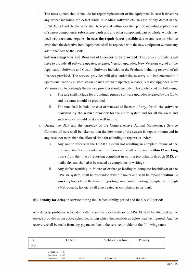
Corrections - Nil
Insertions - Nil
Omissions - Nil AE(P) EE(P)/Civil EE(P)/Elect
Page 215
i. The rates quoted should include for repair/replacement of the equipment in case it develops
any defect including the defect while re-loading software etc. In case of any defect in the
EPABX, its Card etc, the same shall be repaired within specified period including replacement
of spares/ components/ sub-system/ cards and any other component, part or whole, which may
need replacement/ repairs. In case the repair is not possible due to any reason what so
ever, then the defective item/equipment shall be replaced with the new equipment without any
additional cost to the Bank.
j. Software upgrades and Renewal of Licences to be provided: The service provider shall
have to provide all software updates, releases, Version upgrades, New Versions etc. of all the
Application Software and Custom Software included in the Products including renewal of all
licences provided. The service provider will also undertake to carry out implementation /
operationalization / customisation of such software updates, releases, Version upgrades, New
Versions etc. Accordingly the service provider should include in his quoted cost the following:
i. The rate shall include for providing required software upgrades released by the OEM
and the same should be provided.
ii. The rate shall include the cost of renewal of licenses, if any, for all the software
provided by the service provider for the entire system and for all the users and
such renewal should be done well in time.
k. During the DLP and the currency of the Comprehensive Annual Maintenance Service
Contract, all care shall be taken so that the downtime of the system is kept minimum and in
any case, not more than the allowed time for attending to repairs as under:
i. Any minor defects in the EPABX system not resulting in complete failure of the
exchange shall be responded within 2 hours and shall be repaired within 12 working
hours from the time of reporting complaint in writing (complaints through SMS, e-
mails, fax etc. shall also be treated as complaints in writing).
ii. Any defect resulting in failure of exchange leading to complete breakdown of the
EPABX system, shall be responded within 2 hours and shall be repaired within 12
working hours from the time of reporting complaint in writing (complaints through
SMS, e-mails, fax etc. shall also treated as complaints in writing).
(B) Penalty for delay in service during the Defect liability period and the CAMC period:
Any defects/ problems associated with the software or hardware of EPABX shall be attended by the
service provider as per above schedule, failing which the penalties as below may be imposed. And the
recovery shall be made from any payments due to the service provider at the following rates:
Sr. No.
Defect Rectification time Penalty

Corrections - Nil
Insertions - Nil
Omissions - Nil AE(P) EE(P)/Civil EE(P)/Elect
Page 216
1 Defects resulting in failure of exchange 12 working hours
Rs.500/- per day
2 Any other minor defect 12 working hours
Rs.200/- per day
Note: Notwithstanding the above penal provisions, in addition to the penalty, the Bank reserves
the right to encash the BG submitted for the due fulfilment of the terms and obligations the DLP
and CAMC contract
Corrections - Nil
Insertions - Nil
Omissions - Nil AE(P) EE(P)/Civil EE(P)/Elect
Page 217
GENERAL CONDITIONS FOR ELCTRICAL WORK
1. All the works shall be carried out as per CPWD General specification for Electrical Works, Part-I
(Internal) 2013 & Part-II (External) 1995, amended up to date and should also comply with relevant
provisions of the Indian Electricity Rules and Acts as applicable, amended up to date.
2. The order of preference in case of any discrepancy as indicated in condition No. 8.1 under
“Conditions of Contract” given in standard CPWD Contract form may be read as the following:
(a) Nomenclature of item as per Schedule of Quantities.
(b) General/Additional/Special, particular specifications for Electrical Works.
(c) Contract Clauses of General conditions of contract for CPWD 2014.
(d) CPWD specifications for electrical works as applicable.
(e) Architectural/structural drawings and specifications mentioned in drawings.
(f) Indian standard specifications of BIS.
(g) Sound engineering practice as per directions of the Engineer-in-charge.
(h) Manufacturer’s specifications.
A reference made to any Indian Standard Specifications in these documents, shall imply reference
to the latest version of that standard, including such revisions/amendments as issued by the Bureau
of Indian Standards upto last date of receipt of tenders. The contractor shall keep at his own cost all
such publications of relevant Indian Standards applicable to the work at site.
3. The contractor shall take all safety precautions to avoid accidents by exhibiting caution boards, red
flags, red lights and by providing necessary barriers and all other measures required from time to
time. The contractor shall be responsible for all damages and accidents due to negligence on his part.
4. The contractor shall give due notices to Municipality, Police and/or other authorities that may be
required under the law/rules under force and obtain all requisite permissions/licenses for temporary
obstructions/enclosures and pay all charges which may be livable on account of his execution of the
work under the agreement. Nothing extra shall be payable on this account.
5. The contractor shall leave such recesses, holes, openings, etc., as may be required for the electric,
air-conditioning and other related works. (For this purpose, any required inserts, sleeves, brackets,
conduits, base plates, insert plates, clamps etc. shall be arranged by the contractor and fix the same
at the time of casting of concrete, stone work & brick work, if required, and nothing extra shall be
payable on this account.
6. The contractor shall give a trial run of the equipment and machinery for establishing its capability
to achieve the specifications within laid down tolerances to the satisfaction of the Engineer-in-charge
before commencement of work.
7. The work will be carried out in close coordination with the building work and other agencies.
Conduits will be laid in the slab within the specified time and it will have to be ensured that the
casting of slabs is not delayed for want of laying of conduits. The conduits will also be laid in walls
before the Plaster work is undertaken so as to avoid breaking cutting of plaster while making chase
for laying of conduits subsequently. The contractor will have to employ adequate labour for carrying
out the work. No claim regarding the idle labour for any reason will be entertained by the
Department.

Corrections - Nil
Insertions - Nil
Omissions - Nil AE(P) EE(P)/Civil EE(P)/Elect
Page 218
8. No tools and plants including special T&P etc. shall be supplied by the department and the contractor
will have to make his own arrangements at his expenses.
9. All tools, plant and machinery provided by the contractor shall, when brought at the site, be deemed
to be exclusively intended for the construction and completion of this work and the contractor shall
not remove the same or any part thereof (save for the purpose of moving it from one part of the site
to another) without the consent of the Engineer-in-charge.
10. All materials shall be got checked & approved by the Engineer-in-charge on receipt of the same at
site before use and rejected material is to be removed from the site immediately.
11. No foreign exchange shall be made available by the department for the purchase of equipment,
plants, machinery, materials of any kind or any other items required to be carried out in execution
of work.
12. The contractor shall carry out his work, so as not to interfere with or hinder the progress or
completion of the work being performed by other contractor (s) or by the Engineer-in-charge and
shall as far as possible arrange his work and shall place and dispose of the materials being used or
removed, so as not to interfere with the operations of other contractors, or he shall arrange his work
with that of the others in an acceptable and coordinated manner and shall perform it in proper
sequence to the entire satisfaction of Engineer-in-charge.
13. All items which are not covered while carrying out electrical work shall be removed and shall be
cleared by the contractors as soon as the work is completed.
14. The contractor shall give the Engineer-in-charge in every fortnight, a progress report of the work
done during the previous fortnight. The progress of work will be reviewed periodically by the
Engineer-in-charge with the contractor and shortfalls, if any, sorted out. The contractor shall
thereupon take such action as may be necessary to bring back his work to schedule without any
additional cost to the department.
15. It shall be responsibility of the main contractor to sort out any dispute involved with the associated
contractor without any time and cost overrun to the department. The main contractor shall be solely
responsible for settling the dispute/litigation arising out of his agreement with the associate
contractor. The contractor shall ensure that the work shall not suffer on this account.
16. The contractor shall quote his rates considering the specifications, terms & conditions and particular
specifications and special conditions etc. and nothing extra shall be payable whatsoever unless
otherwise specified.
17. The main contractor shall be responsible for coordinating the activities of all works and essential
progress of works as per milestone and laid down program.
18. The contractor shall be responsible for the watch and ward of the site/property/material provided by
him and materials issued by the department against pilferage and breakage during the period of
execution and thereafter till the work is completed and physically handed over to the department.
19. Samples of all materials, fittings and other materials/articles required for execution of the work shall
be got approved from the Engineer-in-charge. Materials/articles manufactured by the firms of repute
as indicated in tender documents and approved by the Engineer-in-charge shall only be used.
Corrections - Nil
Insertions - Nil
Omissions - Nil AE(P) EE(P)/Civil EE(P)/Elect
Page 219
20. The contractor shall ensure quality construction in a planned and time bound manner. Any sub-
standard material or work beyond set out tolerance limits shall be summarily rejected by the
Engineer-in-charge.
21. Even ISI marked materials shall be subjected to quality test at the discretion of the Engineer-in-
charge besides testing of other materials as per the specifications described for the item/material.
Whenever ISI marked materials are brought to the site of work; the contractor shall, if required by
the Engineer-in-charge, furnish manufacturers test certificates to establish that the materials
procured by the contractor for incorporation in the work satisfy the provisions of IS codes relevant
to the material and/or the work done.
22. The contractor shall have to engage well experienced skilled labour and deploy modern T&P and
other equipment to execute the work.
23. The contractor will have to make his own arrangement for storage of materials. No storage space
shall be provided by department.
24. The contractor will have to make his own arrangement for water and power supply for execution of
works.
25. The associate contractors executing the electrical works must possess the valid electrical contractor
license otherwise they will not be permitted to execute the electrical works.
26. The contractor shall be responsible for removal of all defects in the work during the
guarantee/warranty period. The department shall carry out routine maintenance only. However, if
any failure is noticed during this period which is attributable to poor quality of material and bad
workmanship, the contractor will be required to rectify the same at his own cost, failure of which
the department will be at liberty to get the defects rectified at the risk & cost of the contractor. The
contractor will also be required to carry out his own inspection/testing during the guarantee/warranty
period and attend to any defect taking place during this period.
27. Priority to arrange the material shall be decided by the department. However, material required for
the work shall be brought at site only at the appropriate time keeping in view the progress of building
works as well as Electrical & Mechanical works. Decision of Engineer-in -charge in this regard shall
be final.
28. The contractor has to intimate his authorized representative, who will be receiving instructions in
his absence. The contractor /his authorized representative is bound to sign the site order book as and
when required by the Engineer-in-charge and to comply with the instructions therein.
29. Suitable back plates providing for fixing the wall brackets and ceiling flush fittings shall be
supplied by the contractor free of cost.
30. It shall be responsibility of contractor to provide polythene/PVC plastic cover for all SDBs/meter
boards/feeder pillars/panels etc. so as to protect them from wear & tear/damage during execution
stage. Contractor shall provide the covers for the materials if any being supplied departmentally also.
Nothing extra shall be paid on this account.
31. Contractor is fully responsible for any kind of damage to the LT/HT cable during execution of work.
No joints shall be allowed if the cable is damaged. Contractor has to replace the full length at his
own cost.
Corrections - Nil
Insertions - Nil
Omissions - Nil AE(P) EE(P)/Civil EE(P)/Elect
Page 220
32. A suitable brass/tinned copper neutral link shall be fixed at suitable place in the Metallic outlet boxes
of all sizes to terminate neutral wire properly. Nothing extra shall be paid on this account.
33. An earth termination with earth stud of brass/tinned copper i/c 2 No. metallic washers or suitable
earth bar of Brass/tinned copper with tinned copper thimbles/ferrules/lugs should be suitably fixed
at suitable place in the Metallic outlet box for termination of protective earth conductor. Nothing
extra shall be paid on this account.
34. In the outlet boxes, phase from one switch to other switch shall be looped with suitable size of
solid copper conductor. Nothing extra shall be paid on this account. Stranded conductor shall notbe
accepted.
35. Only required number of knockouts should be removed from Metallic outlet boxes for entry of
conduits. If more than required number of knockouts are removed, the Metallic outlet box shall not
be accepted.
36. Separate G.I. boxes shall be used for staircase light switches and bell push. Nothing extra shall be
paid on this account.
37. Metal sheath of Co-axial T.V. cable shall be terminated using 'U' shape thimble/lugs/ferrules.
Nothing extra shall be paid on this account.
38. To facilitate drawing of wires 16/18 SWG GI fish wire be provided along with laying of recessed
conduit. Nothing extra shall be paid on this account.
39. Cable connection to switch gear is deemed to be included in the item of end termination. No extra
payment shall be made for that.
Corrections - Nil
Insertions - Nil
Omissions - Nil AE(P) EE(P)/Civil EE(P)/Elect
Page 221
ADDITIONAL CONDITIONS FOR ELECTRICAL WORKS
1.0 All the works shall be carried out as per CPWD General Specifications for Electrical Works -
2013(Part-1) for Internal, 1995 (Part-II) for External, 2013(Part-IV) for Sub-station,2013 (Part-
III) for Lift, 2013(Part-VII) for DG Set, (Part-V) for wet riser and sprinkler and 2017 HVAC
works, as amended up to date and should also comply with relevant provisions of the Indian
Electricity Rules and Acts as applicable, amended up to date.
2.0 The contractor is advised to visit the site of work to have an idea of the execution of the work;
failure to do so shall not absolve their responsibility to do the work as specified in agreement.
3.0 Rates:
3.1. The work shall be treated as on works contract basis and the rates tendered shall be for complete
items of work (except the materials, if any, stipulated for supply by the department) inclusive of
all taxes (including works contract tax, if any), duties, and levies etc. and all charges for items
contingent to the work, such as packing, forwarding, insurance, freight and delivery at site for
the materials to be supplied by the contractor, watch and ward of all materials (including those
supplied by the department, if any) for the work at site etc
3.2. Prices quoted shall be firm.
4.0 Taxes and Duties:
4.1. Rates are inclusive of GST and all other Taxes, duties, levies and royalties and nothing extra
shall be payable to the contractor on account of this.
4.2. The GST shall be deducted from the bills of the contractor as applicable in at the time of
payments.
5.0 Mobilization Advance:
No mobilization advance shall be paid for the work, unless otherwise stipulated in tender papers
for any individual works/composite work.
6.0 Completeness of Tender:
All sundry fittings, assemblies, accessories, hardware items, foundation bolts, termination lugs
for electrical connections as required, and all other sundry items which are useful and necessary
for proper assembly and efficient working of the various components of the work shall be deemed
to have been included in the tender, whether such items are specifically mentioned in the tender
documents or not.
7.0 Works to be arranged by the department:
Unless and otherwise specified in the tender documents, the following works shall be arranged
by the Department:
(i) Supply of materials to the contractor if stipulated in the tender documents.
8.0 Works to be done by the contractor:
Unless and otherwise mentioned in the tender documents, the following works shall be done by
the contractor, and therefore their cost shall be deemed to be included in their tendered cost:-
(i) Foundations for equipment and components where required, including foundations bolts.
Corrections - Nil
Insertions - Nil
Omissions - Nil AE(P) EE(P)/Civil EE(P)/Elect
Page 222
(ii) Cutting and making good all damages caused during installation and restoring the same to
their original finish.
(iii) Sealing of all floor openings provided by him for pipes and cables, from fire safety point of
view, after laying of the same.
(iv) Painting at site of all exposed metal surfaces of the installation other than pre-painted items
like fittings, fans, switchgear/distribution gear items, cubical switchboard etc. Damages to
finished surfaces of these items while handling and erection, shall however be rectified to
the satisfaction of the Engineer-in-Charge.
(v) Testing and commissioning of completed installation.
(vi) Storage space for all equipment, components and materials for the work
9.0 Storage and Custody of Materials:
The contractor has to make his own arrangement for the storage of the material at site & necessary
watch and ward of the electrical installation during the execution of work till the same is handed
over to the department. No extra payment will be made on this account. The storage space shall
however be arranged by the department at site, if available.
The main contractor shall arrange for proper storage of the electrical fans and fittings at site and
that double lock system shall be arranged for the fans and fittings after receipt at site until the
time they are taken for installation.The contractor shall however be responsible for proper storage
and safe custody of the same till their installation and handing over to the department.
10.0 Electric Power Supply and Water Supply:
Power and water supply will be arranged by the contractor at the site for installation purpose.
However, for final testing purpose after complete installation of the electrical items, electricity
supply will be made available free of cost to the contractor. Contractor will take due care to
ensure safety of electrical installation during execution of work.
11.0 Tools for handling and Erecting:
All tools and tackles required for handling of equipment and materials at site of work as well as
for their assembly and erection and also necessary test instruments shall be the responsibility of
the contractor.
12.0 Payment Terms:
Payment shall be made as per the relevant clauses of form PWD 7/8 forming part of the tender
documents.
13.0 Co-ordination with other agencies:
The contractor shall co-ordinate with all other agencies involved in the building work so that the
building work is not hampered due to delay in his work. Recessed conduit and other works,
which directly affect the progress of building work, should be given priority.
13.1. Care of buildings:
Care shall be taken by the contractor to avoid damage to the building during execution of his part
of the work. He shall be responsible for repairing all damages and restoring the same to their
Corrections - Nil
Insertions - Nil
Omissions - Nil AE(P) EE(P)/Civil EE(P)/Elect
Page 223
original finish at his cost. He shall also remove, at his costs, all unwanted and waste materials
arising out of his work, from the site.
14.0 Structural Alterations to Buildings:
(i) No structural member in the building shall be damaged/altered, without prior approval
from the competent authority through the Engineer-n-charge.
(ii) Structural provisions like openings, cutouts, if any, provided by the department for the
work, shall be used. Where these required modifications, or fresh provisions are required
to be made, such contingent works shall be carried out by the contract at his cost.
(iii) All such openings in floors provided by the department shall be closed by the contractor
after installing the cables/conduits/rising mains etc. as the case may be, by any suitable
means as approved by the Engineer-in-charge without any extra payment.
(iv) All chases required in connection with the electrical works shall be provided and filled
by the contractor at his own cost to the original architectural finish of the buildings.
15.0 Drawings:
(i) The work shall be carried out in accordance with the drawings and the tender documents
and also in accordance with modification thereto from time to time as approved by the
Engineer-in-charge.
(ii) All wiring diagrams shall be deemed to be ‘Drawings’ within the meaning of the term as
used in Clause 11 of the conditions of contract (PWD 7 or PWD 8). They shall indicate
the main switch board, the distribution boards (with circuit numbers controlled by them),
the runs of various mains and sub mains and the position of all points with their controls.
(iii) After award of the work, the firm will be required to submit the drawings for the proposed
work including layout plan, conduit routes showing location of points and height etc.
Work will be carried out as per the approved drawings before start of work.
16.0 Conformity to IE act, IE Rules, and standards:
16.1. All electrical works shall be carried out in accordance with the provisions of Indian Electricity
Act, 1910 and Indian Electricity Rules, 1956 amended up to date (Date of call of tender unless
specified otherwise). List of rules of particular importance to electrical installations under these
General Specifications is given in Appendix C for reference.
17.0 General requirements of components:
17.1. Quality of material: All materials and equipment supplied by the contractor shall be new. They
shall be of such design, size and materials as to satisfactorily function under the rated conditions
of operation and to withstand the environmental conditions at site.
18.0 Inspection of materials and equipment:
18.1. Materials and equipment to be used in the work shall be inspected by the
departmental officers. Such inspection will be of following categories:
(i) Inspection of materials / equipment to be witnessed at the Manufacturer’s premises in
accordance with relevant BIS /Agreement Inspection Procedure.
(ii) To receive materials at site with Manufacturer’s Test Certificate(s)

Corrections - Nil
Insertions - Nil
Omissions - Nil AE(P) EE(P)/Civil EE(P)/Elect
Page 224
(iii) To inspect materials at the authorized dealer’s go downs to ensure delivery of genuine
materials at site.
(iv) To receive materials after physical inspection at site.
18.2. Adequate care to ensure that only tested and genuine materials of proper quality are used in work
shall be ensured by firm. The firm shall ensure that:
(i) Material will be ordered & delivered at site only with the prior approval of the
department to ensure timely delivery.
(ii) As and when the order is placed for the fittings/ fixtures, cables, switchgears, poles, rising
main, other main items etc., its copy shall be endorsed to the CPWD Engineer-in-charge.
(iii) The firm will be required to procure material like exhaust fans, MCB’s & DB’s, switches
& sockets, wires & cables, conduits and switchgears etc directly from the manufacturer/
authorized dealers to ensure genuineness & quality and as per the approved makes only.
Proof in this regard shall be submitted by the contractor before installation at site to the
department.
(iv) Inspection at factory or at godown of the manufacturer, as required, shall be arranged by
the firm for a mutually agreed date. Certificate for genuineness of the fittings shall have
to provided duly signed by the manufacturer’s officer not below the rank of Regional
Manager.
(v) Delivery of material shall be taken up only with the consent of department, after
clearance of the material.
(vi) Department shall reserve the right to waive inspection in lieu of suitable test certificate,
at its discretion.
18.3. Similarly, for fabricated equipment, the contractor will first submit dimensional detailed
drawings for approval before fabrication is taken up in the factory. Suitable stage inspection at
factory also will be made to ensure proper use of materials, workmanship and quality control.
19.0 Ratings of components:
19.1. All components in a wiring installation shall be of appropriate ratings of voltage, current and
frequency, as required at the respective sections of the electrical installations in which they are
used.
19.2. All conductors, switches and accessories shall be of such size as to be capable of carrying the
maximum current, which will normally flow through them, without their respective ratings being
exceeded.
20.0 Conformity to standards:
20.1. All components shall confirm to relevant Indian Standard Specifications wherever existing.
Materials with ISI certification mark shall be preferred.
20.2. Relevant Indian Standards including amendments or revisions thereof up to the date of tender
acceptance shall be applicable in the respective contracts for respective items, firm to ensure its
compliance.
21.0 Interchangeability:
Corrections - Nil
Insertions - Nil
Omissions - Nil AE(P) EE(P)/Civil EE(P)/Elect
Page 225
Similar parts of all switches, lamp holders, distribution fuse boards, Switch gears, ceiling roses,
brackets, pendants, fans and all other fittings of the same type shall be interchangeable in each
installation.
22.0 Workmanship:
22.1. Good workmanship is an essential requirement to be complied with. The entire work of
manufacture/fabrication, assembly and installation shall confirm to sound engineering practice.
22.2. Proper supervision/skilled workmen: The contractor shall be a licensed electrical contractor of
appropriate class suitable for execution of the electrical work. He shall engage suitably
skilled/licensed workmen of various categories for execution of work supervised by supervisors
/ Engineer of appropriate qualification and experience to ensure proper execution of work. They
will carry out instruction of Engineer-in-charge and other senior officers of the Department
during the progress of work.
22.3. Use of quality materials: Only quality materials of reputed make as specified in the tender will
be used in work.
22.4. Fabrication in reputed workshop: Switch boards and LT panels shall be fabricated in a
factory/workshop having modern facilities like quality fabrication, seven tank process,
powder/epoxy paint plant, proper testing facilities, manned by qualified technical personnel.
These shall be as per make / item approved.
23.0 Testing:
All testes prescribed in this General Specification, to be done before, during and after
installation, shall be carried out, and the test results shall be submitted to the Engineer-in-charge
in prescribed Performa, forming part of the Completion Certificate.
24.0 Commissioning on completion:
After the work is completed, it shall be ensured that the installation is tested and commissioned.
25.0 Completion plan and completion certificate:
25.1. For all works completion certificate after completion of work shall be submitted to the Engineer-
in-charge.
25.2. Completion plan drawn to a suitable scale in A2 Sheet (It shall be laminated if desired by the
Site- in-Charge) indicating the following, and three copies of the same shall also be submitted.
(i) General layout of the building.
(ii) Locations of main switchboard and distribution boards, indicating the circuit numbers
controlled by them.
(iii) Position of all points and their controls.
(iv) Types of fittings, viz. fluorescent, pendants, brackets, bulk head, fans, exhaust fans etc.
(v) Name of work, job number, tender reference, actual date of completion, names of
Division/ Sub-division and name of the firm who executed the work with their signature.
(vi) Cable layout showing general distribution diagram alongwith position of cable joints, if
any.
26.0 Guarantee
Corrections - Nil
Insertions - Nil
Omissions - Nil AE(P) EE(P)/Civil EE(P)/Elect
Page 226
The installation will be handed over to the department after necessary testing and commissioning.
The installation will be guaranteed against any defective design/workmanship. Similarly, the
materials supplied by the contractor will be guaranteed against any manufacturing defect, inferior
quality. The guarantee period will be for a period of 12 months from the date of handing over to
the department. Installation/ equipments or components thereof shall be rectified/ repaired to the
satisfaction of the Engineer-in-charge. The firm will be required to submit guarantee of material
from the manufacturer to the department/client.
27.0 Payment Terms : Following payment term shall be applicable:
(i) No advance payment shall be made.
(ii) 80% against delivery of Machinery & equipment at site in good condition along with
manufacture’s test reports.
(iii) 10% on completion of installation in all respect.
(iv) 10% on Testing, Commissioning & handing over to the department
Note : The quantity of material in the BOQ is indicative. Contractor has to assess the actual
requirement of material at site before placing the order, keeping in view the drawing and site
requirement from the shortest route. No claim for payment for unused excess material shall be
entertained.

Corrections - Nil
Insertions - Nil
Omissions - Nil AE(P) EE(P)/Civil EE(P)/Elect
Page 227
PARTICULAR SPECIFICATIONS FOR E&M WORKS
A. GENERAL:
1. All hardware items such as screws, thimbles, connectors, earth/neutral terminals, wires etc. which
are essentially required for completing any item as per specifications will be deemed to have been
included in the item even when the same have not been specifically mentioned.
2. All hardware material such as nuts/bolts/screws/washers etc. to be used in the work shall be
zinc/cadmium plated iron. The galvanized boxes of modular switch/sockets etc. shall be of the same
make as of switch/socket etc.
3. While laying conduit, suitable minimum number of junction boxes shall be left for pulling the wires.
These shall be placed in such a way that the same do not remain noticeable.
4. Any conduit which is not be wired by the contractor shall be provided with GI fish wire for wiring
by some other agency subsequently. Nothing extra shall be paid for the same.
5. Multi stranded FRLS PVC insulated copper conductors wires are to be used in the work. Termination
of multi-stranded conductors shall be done using crimping type copper thimbles at both the ends.
Nothing extra shall be paid for the same.
6. The contractor shall follow the shortest route for circuits, submain, point wiring etc.
7. The connections of switches, sensors, earthing conductors & interconnections cables shall be made
by adequate rating thimbles of approved standard makes only and nothing extra on this account shall
be paid.
8. Check nuts shall be provided while terminating the M.S. conduits in switch board boxes for which
nothing extra shall be paid.
9. All distribution boards shall be marked with circuits controlling the rooms/area/SDB controlled
10. Material to be used in the work shall be ISI marked. The makes of material have been indicated in
the list of acceptable makes. No other make will be acceptable. The material to be used in the work
shall be got approved from the Engineer-in-charge before its use at site. The Engineer-in-charge
shall reserve the right to instruct the contractor to remove the material which, in his opinion, is not
as per specifications
11. While deciding the size of switch boxes for light points/fan point, exhaust fan point items, extra two
modules will be provided for each fan point for fixing of regulator(s) (fan regulator is to be provided
under different item). Wherever extra modules are available, the same shall be provided with
blanking plates without any extra cost.
12. Modular type switches/sockets/telephone outlets/TV sockets are to be provided wherever indicated
in the items. The same shall be of only one make. The modular plates of switches, sockets, telephone
& TV sockets etc. shall be in two parts i.e. plates with frames with in quoted rates.
13. The building shall be provided with false ceiling in various areas. In order to avoid maintenance
problem the contractor will not provide any ceiling rose/connector/looping box etc. above the false
ceiling. The point wiring in that case will be extended up to the fitting/fan etc. directly without
provisions of any termination arrangement in between. The wire from the end point up to the fixture
shall be considered to be included in the point wiring. Nothing extra shall be paid for the same.

Corrections - Nil
Insertions - Nil
Omissions - Nil AE(P) EE(P)/Civil EE(P)/Elect
Page 228
14. Wherever it is not possible to provide rigid conduits, flexible conduit pipe shall be provided for
drawing/running the wires. However, such arrangement has to be kept to the barest minimum and
only with the prior approval of Engineer-in-charge.
15. Earthing and all hidden items of work shall be carried out in the presence of the Engineer-in-charge
or his authorized representative.
16. The fan box cover shall be made from 3mm thick phenolic laminated sheet as per CPWD
specification.
17. The contractor shall provide only metallic junction boxes/looping boxes with cover of required sizes
even in PVC conduiting and such boxes shall be measured as a part of conduit/wiring without any
extra payment.
18. The metallic junction boxes & looping boxes shall be covered with approved makes of phenolic
laminated sheet. For telephone, television & fire alarm system shall be provided at all the floors
within scope of work without any extra cost as per requirement & layout approved by Engineer-in-
charge.
19. The firm has to go through the site order book kept with the Junior Engineer (E) regularly and has
to sign the same and carryout the instructions recorded therein by various officers of the department.
20. The quantities of various items may vary from the quantities given in schedule of work. The agency
shall bring the various items & materials as per actual requirement at site at the time of execution of
work. Excess quantities shall not be accepted & paid by the department.
21. The ceiling roses wherever required to be provided are included in the scope of work without extra
payment and the same shall also be of modular type & of the same make as that of switches &
sockets along with earthing provision.
22. The MCB should be of same make as that of MCB DBs.
23. The MCB distribution boards shall be factory fabricated in the works of the manufacturer of the
MCB’s of any of the makes specified and the same shall be duly pre-wired in the works. The board
shall be brought to site in ready for installation condition. The MCBs and the MCB distribution
board shall be of the same make.
24. MCCB should have centrally adjustable overload setting 80% to 100% & short circuit setting
adjustable from 500% to 1000% of nominal current for thermal type & overload setting 40% to
100% & short circuit setting adjustable from 150% to 1000% of nominal current for microprocessor
type MCCB. All MCCB should be ICS=ICU.
25. Suitable crimping tools shall be used for crimping the lugs/thimbles/ferrules. Nothing extra shall be
paid on this account. The lugs/thimbles/ferrules pressed by conventional/ordinary pliers shall not be
accepted.

Corrections - Nil
Insertions - Nil
Omissions - Nil AE(P) EE(P)/Civil EE(P)/Elect
Page 229
ADDITIONAL CONDITIONS (A.C. Work)
1.0.General
1.1This specification covers manufacturer, testing as may be necessary before dispatch, delivery at site, all preparatory work, assembly and installation, final testing, commissioning, putting into operation & maintenance of plant for one year including one year guarantee period complete with for the following work.
1.2The work shall be executed as per CPWD General Specifications for Air Conditioning Works-2017, as amended up to date, relevant IE rules, relevant IS and as per directions of Engineer-in-Charge. These additional specifications & conditions are to be read in conjunction with above and in case of variations, specifications given in the Additional Specifications & Conditions shall apply. However, nothing extra shall be paid on account of these as the same are to be read along with schedule of quantities for the work.
4.0 Related Documents
These General Specifications shall be read in conjunction with the General conditions of contract. These General Specifications shall also be read in conjunction with the tender specifications, schedule work, drawings and otherdocuments connected with work.
5.0Terminology
The definition of terms used in these specifications shall be in accordance with IS: 3615-“Glossary of terms used in refrigeration and air-conditioning”. Some of the commonly used terms are defined in Appendix ‘A’ of CPWD General HVAC Specification 2017.
6.0Site Information
The tenderer should, in his own interest, visit the site and familiarize himself with the site conditions before tendering. For any clarification, tenderer may discuss with the Engineer-in-Charge.
7.0Heat Load Calculations and Equipment Selection
i) The tenderer should give detailed heat load calculations wherever required as per Appendix ’D’ of CPWD General HVAC Specification 2017 separately for all the seasons in which, the specified conditions are to be maintained.
ii) The tenderer should also give the above heat load calculations wherever required separately for the areas served by each AHU in a central air conditioning / heating system.
iii) The equipment selection shall be made on the basis of the above heat load calculations wherever required.
8.0 Conformity with Statutory Acts, Rules, Standard and Codes
i) All components shall conform to relevant Indian Standard Specifications, wherever existing, amended to date. A list of such standards is appended in Appendix ’B’ of CPWD General HVAC Specification 2017.
ii) All electrical works shall be carried out in accordance with the provisions of Indian Electricity Act, 2003 and Indian Electricity Rules, 1956 amended to date. They shall also conform to CPWD General Specifications for Electrical works, Part-I: Internal, 2013 and Part-II: External, 1994 and Part IV (Sub-station) amended up to date.
Corrections - Nil
Insertions - Nil
Omissions - Nil AE(P) EE(P)/Civil EE(P)/Elect
Page 230
9.0 Works to be Arranged by the Departments
Unless otherwise specified in the tender documents, the following work shall be arranged by the department;
i) Space for accommodating all the equipments and components involved in the work. ii) Make up water tank for condenser water. iii) Power Supply & Water Supply for testing & commissioning and Drain points as mentioned
herein. iv) Masonry ducts within and outside the building for carrying pipe lines and cables wherever
specified. 10.0 Works to be Done by the Contractor Unless otherwise mentioned in the tender documents, the following works shall be done by the contractor and therefore, their cost shall be deemed to be included in their tendered cost-whether specifically indicated in the schedule of work or not: i) Foundations for equipments including foundation bolts and vibration isolation spring/pads. ii) Support columns and beams for cooling towers. iii) Suspenders, brackets and floor/ wall support for suspending/supporting ducts and pipes. iv) Suspenders and/or cable trays for laying the cables.
v) Excavation and refilling of trenches in soil wherever are to be laid directly in ground, including necessary base treatment and supports.
vi) Sealing of all floor slab/ wall openings provided by the Department or contractor for pipes and cables, from fire safety point of view, after laying of the same.
vii) Painting off exposed metal surfaces of equipments and components with appropriate color as mentioned herein.
viii) Making openings in the walls/floors/slabs or modification in the existing openings wherever provided for carrying pipe line, ducts, cables etc.
ix) Providing wooden/ metallic frames for fixing grills/ diffusers.
x) Under deck insulation of top floor slab, if top floor is air conditioned and if specified in schedule of work.
xi) Making good all damages caused to the structure during installation and restoringthe same to their original finish.
11.0 POWER SUPPLY, WATER SUPPLY AND DRAINAGE
11.1 Power Supply
i) Unless otherwise specified, 3 phase, 415 volts, 50 Hz power supply Shall be arranged by the contractor for execution purpose ii) a) The power supply for testing and commissioning of the complete installation shall be made available by the department free of charge to the contractor. For this purpose, the power supply shall be given at the main incomer unit of the main electrical panel (provided by the contractor) throughUG cable, or bus trunking arrangement as specified in the contract. Thetermination of this feeder in the main incomer unit shall be the responsibility of the contractor and nothingextra shall be paid on this account.
b) Unless otherwise specified in the contract, further power distribution tothe various equipments shall be done by the contractor.
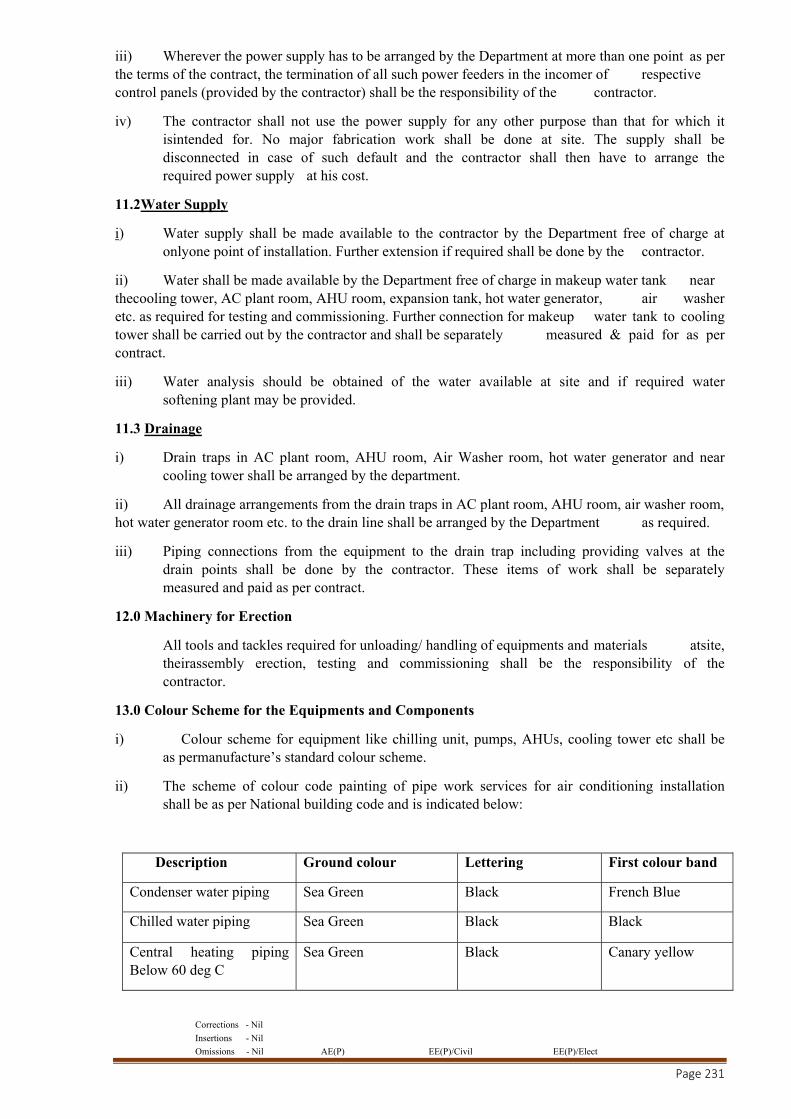
Corrections - Nil
Insertions - Nil
Omissions - Nil AE(P) EE(P)/Civil EE(P)/Elect
Page 231
iii) Wherever the power supply has to be arranged by the Department at more than one point as per the terms of the contract, the termination of all such power feeders in the incomer of respective control panels (provided by the contractor) shall be the responsibility of the contractor.
iv) The contractor shall not use the power supply for any other purpose than that for which it isintended for. No major fabrication work shall be done at site. The supply shall be disconnected in case of such default and the contractor shall then have to arrange the required power supply at his cost.
11.2Water Supply
i) Water supply shall be made available to the contractor by the Department free of charge at onlyone point of installation. Further extension if required shall be done by the contractor.
ii) Water shall be made available by the Department free of charge in makeup water tank near thecooling tower, AC plant room, AHU room, expansion tank, hot water generator, air washer etc. as required for testing and commissioning. Further connection for makeup water tank to cooling tower shall be carried out by the contractor and shall be separately measured & paid for as per contract.
iii) Water analysis should be obtained of the water available at site and if required water softening plant may be provided.
11.3 Drainage
i) Drain traps in AC plant room, AHU room, Air Washer room, hot water generator and near cooling tower shall be arranged by the department.
ii) All drainage arrangements from the drain traps in AC plant room, AHU room, air washer room, hot water generator room etc. to the drain line shall be arranged by the Department as required.
iii) Piping connections from the equipment to the drain trap including providing valves at the drain points shall be done by the contractor. These items of work shall be separately measured and paid as per contract.
12.0 Machinery for Erection
All tools and tackles required for unloading/ handling of equipments and materials atsite, theirassembly erection, testing and commissioning shall be the responsibility of the contractor.
13.0 Colour Scheme for the Equipments and Components
i) Colour scheme for equipment like chilling unit, pumps, AHUs, cooling tower etc shall be as permanufacture’s standard colour scheme.
ii) The scheme of colour code painting of pipe work services for air conditioning installation shall be as per National building code and is indicated below:
Description Ground colour Lettering First colour band
Condenser water piping Sea Green Black French Blue
Chilled water piping Sea Green Black Black
Central heating piping Below 60 deg C
Sea Green Black Canary yellow
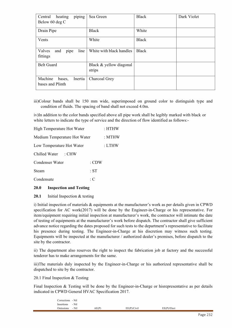
Corrections - Nil
Insertions - Nil
Omissions - Nil AE(P) EE(P)/Civil EE(P)/Elect
Page 232
Central heating piping Below 60 deg C
Sea Green Black Dark Violet
Drain Pipe Black White
Vents White Black
Valves and pipe line fittings
White with black handles Black
Belt Guard Black & yellow diagonal strips
Machine bases, Inertia bases and Plinth
Charcoal Grey
iii)Colour bands shall be 150 mm wide, superimposed on ground color to distinguish type and condition of fluids. The spacing of band shall not exceed 4.0m.
iv)In addition to the color bands specified above all pipe work shall be legibly marked with black or white letters to indicate the type of service and the direction of flow identified as follows:-
High Temperature Hot Water : HTHW
Medium Temperature Hot Water : MTHW
Low Temperature Hot Water : LTHW
Chilled Water : CHW
Condenser Water : CDW
Steam : ST
Condensate : C
20.0 Inspection and Testing
20.1 Initial Inspection & testing
i) Initial inspection of materials & equipments at the manufacturer’s work as per details given in CPWD specification for AC work(2017) will be done by the Engineer-in-Charge or his representative. For item/equipment requiring initial inspection at manufacturer’s work, the contractor will intimate the date of testing of equipments at the manufacturer’s work before dispatch. The contractor shall give sufficient advance notice regarding the dates proposed for such tests to the department’s representative to facilitate his presence during testing. The Engineer-in-Charge at his discretion may witness such testing. Equipments will be inspected at the manufacturer / authorized dealer’s premises, before dispatch to the site by the contractor.
ii) The department also reserves the right to inspect the fabrication job at factory and the successful tenderer has to make arrangements for the same.
iii)The materials duly inspected by the Engineer-in-Charge or his authorized representative shall be dispatched to site by the contractor.
20.1 Final Inspection & Testing
Final Inspection & Testing will be done by the Engineer-in-Charge or hisrepresentative as per details indicated in CPWD General HVAC Specification 2017.
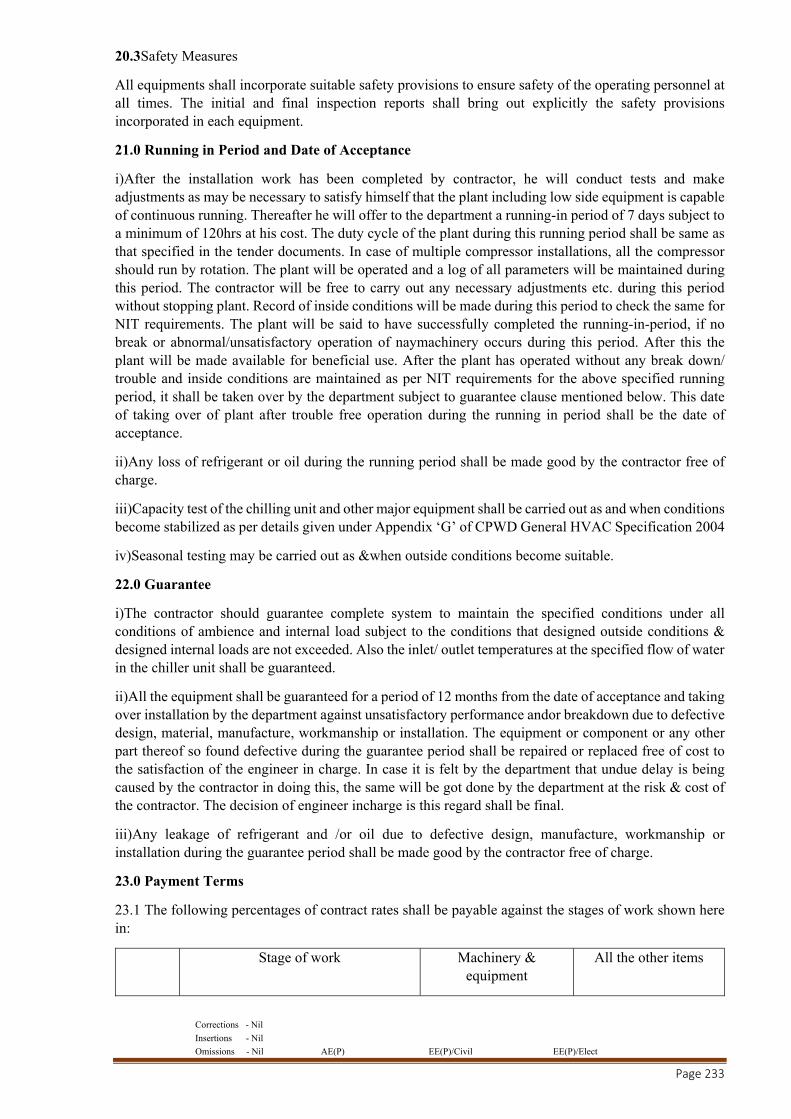
Corrections - Nil
Insertions - Nil
Omissions - Nil AE(P) EE(P)/Civil EE(P)/Elect
Page 233
20.3Safety Measures
All equipments shall incorporate suitable safety provisions to ensure safety of the operating personnel at all times. The initial and final inspection reports shall bring out explicitly the safety provisions incorporated in each equipment.
21.0 Running in Period and Date of Acceptance
i)After the installation work has been completed by contractor, he will conduct tests and make adjustments as may be necessary to satisfy himself that the plant including low side equipment is capable of continuous running. Thereafter he will offer to the department a running-in period of 7 days subject to a minimum of 120hrs at his cost. The duty cycle of the plant during this running period shall be same as that specified in the tender documents. In case of multiple compressor installations, all the compressor should run by rotation. The plant will be operated and a log of all parameters will be maintained during this period. The contractor will be free to carry out any necessary adjustments etc. during this period without stopping plant. Record of inside conditions will be made during this period to check the same for NIT requirements. The plant will be said to have successfully completed the running-in-period, if no break or abnormal/unsatisfactory operation of naymachinery occurs during this period. After this the plant will be made available for beneficial use. After the plant has operated without any break down/ trouble and inside conditions are maintained as per NIT requirements for the above specified running period, it shall be taken over by the department subject to guarantee clause mentioned below. This date of taking over of plant after trouble free operation during the running in period shall be the date of acceptance.
ii)Any loss of refrigerant or oil during the running period shall be made good by the contractor free of charge.
iii)Capacity test of the chilling unit and other major equipment shall be carried out as and when conditions become stabilized as per details given under Appendix ‘G’ of CPWD General HVAC Specification 2004
iv)Seasonal testing may be carried out as &when outside conditions become suitable.
22.0 Guarantee
i)The contractor should guarantee complete system to maintain the specified conditions under all conditions of ambience and internal load subject to the conditions that designed outside conditions & designed internal loads are not exceeded. Also the inlet/ outlet temperatures at the specified flow of water in the chiller unit shall be guaranteed.
ii)All the equipment shall be guaranteed for a period of 12 months from the date of acceptance and taking over installation by the department against unsatisfactory performance andor breakdown due to defective design, material, manufacture, workmanship or installation. The equipment or component or any other part thereof so found defective during the guarantee period shall be repaired or replaced free of cost to the satisfaction of the engineer in charge. In case it is felt by the department that undue delay is being caused by the contractor in doing this, the same will be got done by the department at the risk & cost of the contractor. The decision of engineer incharge is this regard shall be final.
iii)Any leakage of refrigerant and /or oil due to defective design, manufacture, workmanship or installation during the guarantee period shall be made good by the contractor free of charge.
23.0 Payment Terms
23.1 The following percentages of contract rates shall be payable against the stages of work shown here in:
Stage of work Machinery & equipment
All the other items
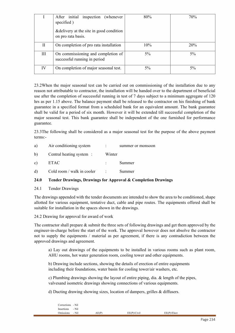
Corrections - Nil
Insertions - Nil
Omissions - Nil AE(P) EE(P)/Civil EE(P)/Elect
Page 234
I After initial inspection (whenever specified )
&delivery at the site in good condition on pro rata basis.
80% 70%
II On completion of pro rata installation 10% 20%
III On commissioning and completion of successful running in period
5% 5%
IV On completion of major seasonal test. 5% 5%
23.2When the major seasonal test can be carried out on commissioning of the installation due to any reason not attributable to contractor, the installation will be handed over to the department of beneficial use after the completion of successful running in test of 7 days subject to a minimum aggregate of 120 hrs as per 1.15 above. The balance payment shall be released to the contractor on his finishing of bank guarantee in a specified format from a scheduled bank for an equivalent amount. The bank guarantee shall be valid for a period of six month. However it will be extended till successful completion of the major seasonal test. This bank guarantee shall be independent of the one furnished for performance guarantee.
23.3The following shall be considered as a major seasonal test for the purpose of the above payment terms:-
a) Air conditioning system : summer or monsoon
b) Central heating system : Winter
c) ETAC : Summer
d) Cold room / walk in cooler : Summer
24.0 Tender Drawings, Drawings for Approval & Completion Drawings
24.1 Tender Drawings
The drawings appended with the tender documents are intended to show the area to be conditioned, shape allotted for various equipment, tentative duct, cable and pipe routes. The equipments offered shall be suitable for installation in the spaces shown in the drawings.
24.2 Drawing for approval for award of work
The contractor shall prepare & submit the three sets of following drawings and get them approved by the engineer-in-charge before the start of the work. The approval however does not absolve the contractor not to supply the equipments / material as per agreement, if there is any contradiction between the approved drawings and agreement.
a) Lay out drawings of the equipments to be installed in various rooms such as plant room, AHU rooms, hot water generation room, cooling tower and other equipments.
b) Drawing include sections, showing the details of erection of entire equipments including their foundations, water basin for cooling tower/air washers, etc.
c) Plumbing drawings showing the layout of entire piping, dia. & length of the pipes, valvesand isometric drawings showing connections of various equipments.
d) Ducting drawing showing sizes, location of dampers, grilles & diffusers.
Corrections - Nil
Insertions - Nil
Omissions - Nil AE(P) EE(P)/Civil EE(P)/Elect
Page 235
e) Electrical wiring diagram of all the electrical equipments and controls including the size andcapacities of various cable and equipments.
f) Dimensioned drawing of all electrical and control panels.
g) Drawing showing the details of all insulations and various barrier works.
h) Drawing showing the details of support for pipes, cable tray and ducts etc.
i) Any other drawing related to work.
24.3 Completion of drawing
Three sets of following laminated drawings shall be submitted by the contractor while handing over the installation to the Department. Out of this one of the set should be laminated on a hard base for display in A.C. plant room. In addition one set will be given in a compact disk.
a) Plant installation drawing giving the complete details of all the equipments including their foundations.
b) AHU room installation drawing.
c) Plumbing layout drawing including insulation giving the sizes and lengths of all the pipes and the sizes and location of all types of valves and including isometric drawing for entire piping including the pipe connections to various equipment and insulation details whenever required.
d) Duct layout drawing with their sizes and locations and sizes and location of all the dampers, grilles & diffusers.
e) Line diagram and layout of all electrical control panels giving switch gear rating and their disposition, cable feeder size and their layout.
f) Control wiring drawings with all the control components and sequence of operations to explain the operation of control circuits.
25.0 Documents to be Furnished on Completion of Installation
Three sets of the following shall be furnished to the Department by the contractor on the completion of work:-
a) Completion drawings as mentioned herein.
b) 3 sets of manufacture’s technical catalogue of all equipments andaccessories.
c) Operation and maintenance manual of all the major equipments detailing all the major adjustments, operations and maintenance procedure.
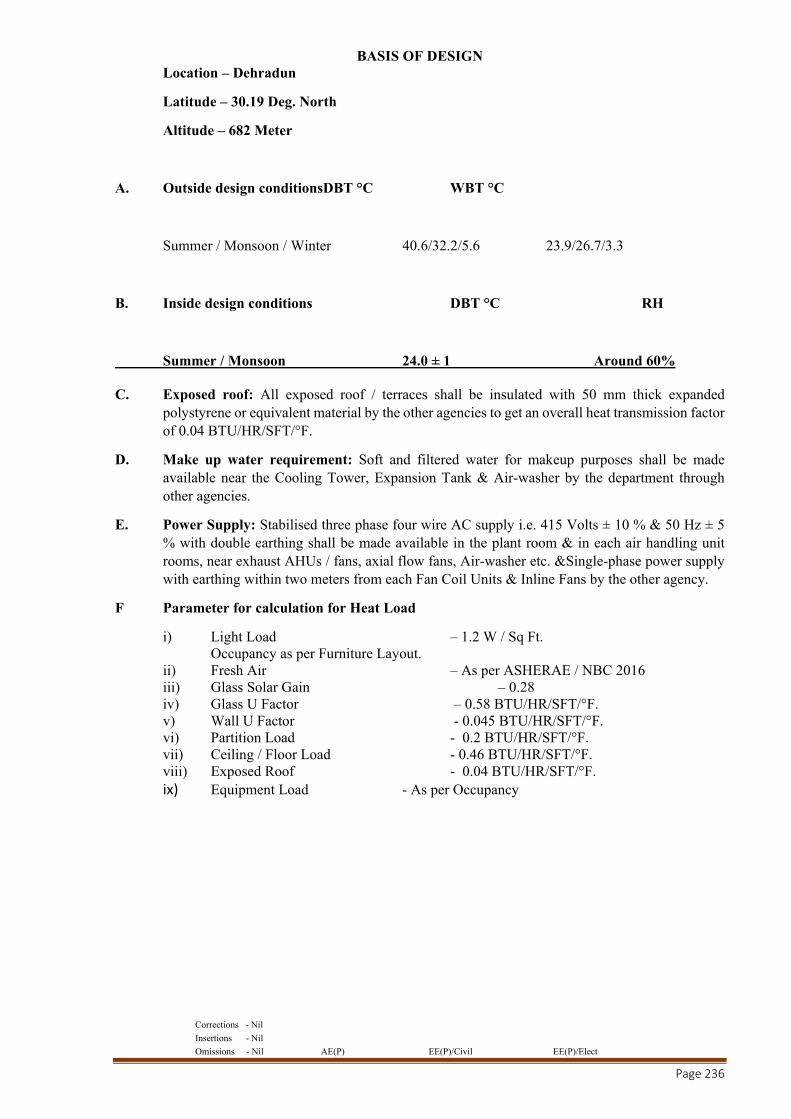
Corrections - Nil
Insertions - Nil
Omissions - Nil AE(P) EE(P)/Civil EE(P)/Elect
Page 236
BASIS OF DESIGN Location – Dehradun
Latitude – 30.19 Deg. North
Altitude – 682 Meter
A. Outside design conditionsDBT °C WBT °C
Summer / Monsoon / Winter 40.6/32.2/5.6 23.9/26.7/3.3
B. Inside design conditions DBT °C RH
Summer / Monsoon 24.0 ± 1 Around 60% C. Exposed roof: All exposed roof / terraces shall be insulated with 50 mm thick expanded
polystyrene or equivalent material by the other agencies to get an overall heat transmission factor of 0.04 BTU/HR/SFT/°F.
D. Make up water requirement: Soft and filtered water for makeup purposes shall be made available near the Cooling Tower, Expansion Tank & Air-washer by the department through other agencies.
E. Power Supply: Stabilised three phase four wire AC supply i.e. 415 Volts ± 10 % & 50 Hz ± 5 % with double earthing shall be made available in the plant room & in each air handling unit rooms, near exhaust AHUs / fans, axial flow fans, Air-washer etc. &Single-phase power supply with earthing within two meters from each Fan Coil Units & Inline Fans by the other agency.
F Parameter for calculation for Heat Load
i) Light Load – 1.2 W / Sq Ft. Occupancy as per Furniture Layout.
ii) Fresh Air – As per ASHERAE / NBC 2016 iii) Glass Solar Gain – 0.28 iv) Glass U Factor – 0.58 BTU/HR/SFT/°F. v) Wall U Factor - 0.045 BTU/HR/SFT/°F. vi) Partition Load - 0.2 BTU/HR/SFT/°F. vii) Ceiling / Floor Load - 0.46 BTU/HR/SFT/°F. viii) Exposed Roof - 0.04 BTU/HR/SFT/°F. ix) Equipment Load - As per Occupancy
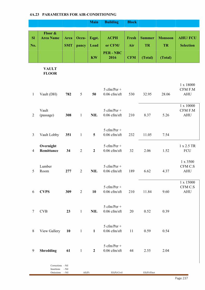
Corrections - Nil
Insertions - Nil
Omissions - Nil AE(P) EE(P)/Civil EE(P)/Elect
Page 237
4A.23 PARAMETERS FOR AIR-CONDITIONING
Main Building Block
Sl Floor &
Area Name Area Occu- Eqpt. ACPH Fresh Summer Monsoon AHU/ FCU
No. SMT pancy Load or CFM/ Air TR TR Selection
KW PER - NBC
2016 CFM (Total) (Total)
VAULT FLOOR
1 Vault (DH) 782 5 50 5 cfm/Per + 0.06 cfm/sft 530 32.95 28.06
1 x 18000 CFM F.M
AHU
2 Vault (passage) 308 1 NIL
5 cfm/Per + 0.06 cfm/sft 210 8.37 5.26
1 x 10000 CFM F.M
AHU
3 Vault Lobby 351 1 5 5 cfm/Per + 0.06 cfm/sft 232 11.05 7.54
4 Overnight Remittance 34 2 2
5 cfm/Per + 0.06 cfm/sft 32 2.06 1.52
1 x 2.5 TR FCU
5 Lumber Room 277 2 NIL
5 cfm/Per + 0.06 cfm/sft 189 6.62 4.37
1 x 3500 CFM C.S
AHU
6 CVPS 309 2 10 5 cfm/Per + 0.06 cfm/sft 210 11.84 9.60
1 x 15000 CFM C.S
AHU
7 CVB 23 1 NIL 5 cfm/Per + 0.06 cfm/sft 20 0.52 0.39
8 View Gallery 10 1 1 5 cfm/Per + 0.06 cfm/sft 11 0.59 0.54
9 Shredding 61 1 2 5 cfm/Per + 0.06 cfm/sft 44 2.55 2.04
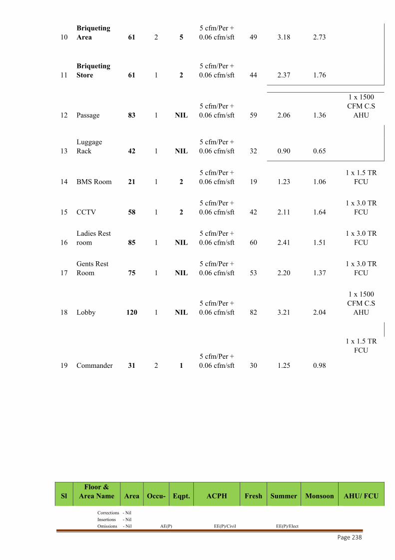
Corrections - Nil
Insertions - Nil
Omissions - Nil AE(P) EE(P)/Civil EE(P)/Elect
Page 238
10 Briqueting Area 61 2 5
5 cfm/Per + 0.06 cfm/sft 49 3.18 2.73
11 Briqueting Store 61 1 2
5 cfm/Per + 0.06 cfm/sft 44 2.37 1.76
12 Passage 83 1 NIL 5 cfm/Per + 0.06 cfm/sft 59 2.06 1.36
1 x 1500 CFM C.S
AHU
13 Luggage Rack 42 1 NIL
5 cfm/Per + 0.06 cfm/sft 32 0.90 0.65
14 BMS Room 21 1 2 5 cfm/Per + 0.06 cfm/sft 19 1.23 1.06
1 x 1.5 TR FCU
15 CCTV 58 1 2 5 cfm/Per + 0.06 cfm/sft 42 2.11 1.64
1 x 3.0 TR FCU
16 Ladies Rest room 85 1 NIL
5 cfm/Per + 0.06 cfm/sft 60 2.41 1.51
1 x 3.0 TR FCU
17 Gents Rest Room 75 1 NIL
5 cfm/Per + 0.06 cfm/sft 53 2.20 1.37
1 x 3.0 TR FCU
18 Lobby 120 1 NIL 5 cfm/Per + 0.06 cfm/sft 82 3.21 2.04
1 x 1500 CFM C.S
AHU
19 Commander 31 2 1 5 cfm/Per + 0.06 cfm/sft 30 1.25 0.98
1 x 1.5 TR FCU
Sl Floor &
Area Name Area Occu- Eqpt. ACPH Fresh Summer Monsoon AHU/ FCU
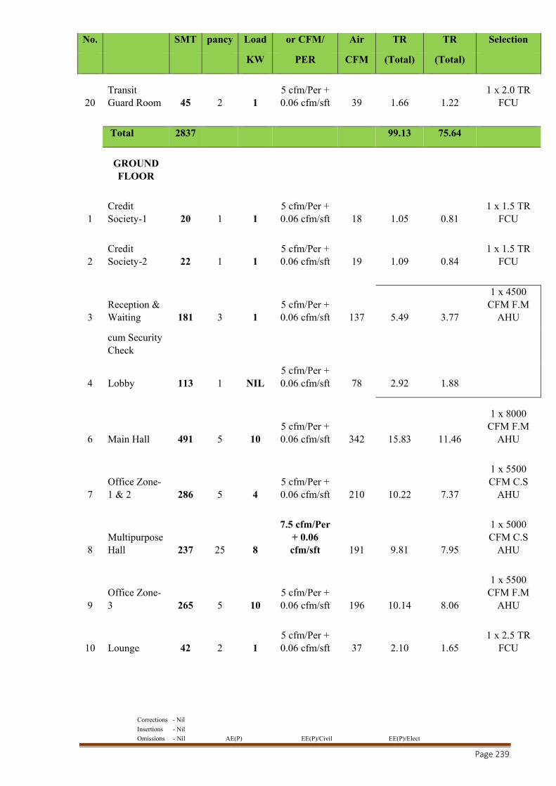
Corrections - Nil
Insertions - Nil
Omissions - Nil AE(P) EE(P)/Civil EE(P)/Elect
Page 239
No. SMT pancy Load or CFM/ Air TR TR Selection
KW PER CFM (Total) (Total)
20 Transit Guard Room 45 2 1
5 cfm/Per + 0.06 cfm/sft 39 1.66 1.22
1 x 2.0 TR FCU
Total 2837 99.13 75.64
GROUND FLOOR
1 Credit Society-1 20 1 1
5 cfm/Per + 0.06 cfm/sft 18 1.05 0.81
1 x 1.5 TR FCU
2 Credit Society-2 22 1 1
5 cfm/Per + 0.06 cfm/sft 19 1.09 0.84
1 x 1.5 TR FCU
3 Reception & Waiting 181 3 1
5 cfm/Per + 0.06 cfm/sft 137 5.49 3.77
1 x 4500 CFM F.M
AHU
cum Security Check
4 Lobby 113 1 NIL 5 cfm/Per + 0.06 cfm/sft 78 2.92 1.88
6 Main Hall 491 5 10 5 cfm/Per + 0.06 cfm/sft 342 15.83 11.46
1 x 8000 CFM F.M
AHU
7 Office Zone-1 & 2 286 5 4
5 cfm/Per + 0.06 cfm/sft 210 10.22 7.37
1 x 5500 CFM C.S
AHU
8 Multipurpose Hall 237 25 8
7.5 cfm/Per + 0.06 cfm/sft 191 9.81 7.95
1 x 5000 CFM C.S
AHU
9 Office Zone-3 265 5 10
5 cfm/Per + 0.06 cfm/sft 196 10.14 8.06
1 x 5500 CFM F.M
AHU
10 Lounge 42 2 1 5 cfm/Per + 0.06 cfm/sft 37 2.10 1.65
1 x 2.5 TR FCU
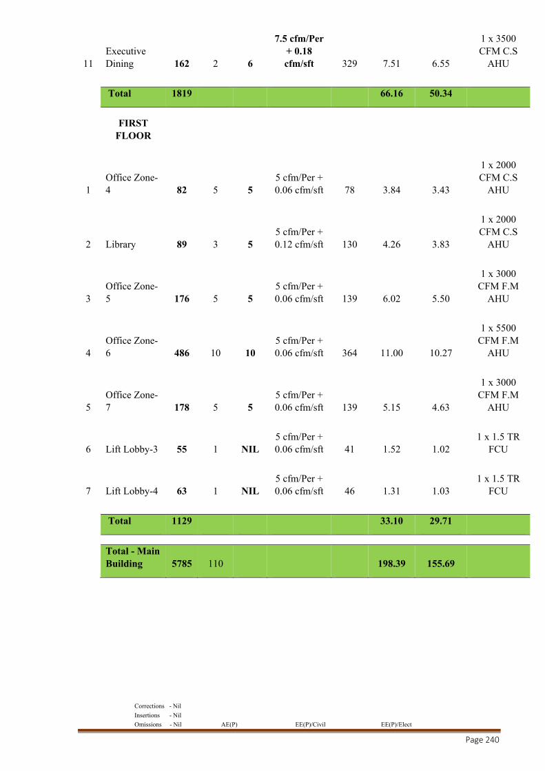
Corrections - Nil
Insertions - Nil
Omissions - Nil AE(P) EE(P)/Civil EE(P)/Elect
Page 240
11 Executive Dining 162 2 6
7.5 cfm/Per + 0.18 cfm/sft 329 7.51 6.55
1 x 3500 CFM C.S
AHU
Total 1819 66.16 50.34
FIRST FLOOR
1 Office Zone-4 82 5 5
5 cfm/Per + 0.06 cfm/sft 78 3.84 3.43
1 x 2000 CFM C.S
AHU
2 Library 89 3 5 5 cfm/Per + 0.12 cfm/sft 130 4.26 3.83
1 x 2000 CFM C.S
AHU
3 Office Zone-5 176 5 5
5 cfm/Per + 0.06 cfm/sft 139 6.02 5.50
1 x 3000 CFM F.M
AHU
4 Office Zone-6 486 10 10
5 cfm/Per + 0.06 cfm/sft 364 11.00 10.27
1 x 5500 CFM F.M
AHU
5 Office Zone-7 178 5 5
5 cfm/Per + 0.06 cfm/sft 139 5.15 4.63
1 x 3000 CFM F.M
AHU
6 Lift Lobby-3 55 1 NIL 5 cfm/Per + 0.06 cfm/sft 41 1.52 1.02
1 x 1.5 TR FCU
7 Lift Lobby-4 63 1 NIL 5 cfm/Per + 0.06 cfm/sft 46 1.31 1.03
1 x 1.5 TR FCU
Total 1129 33.10 29.71
Total - Main Building 5785 110 198.39 155.69
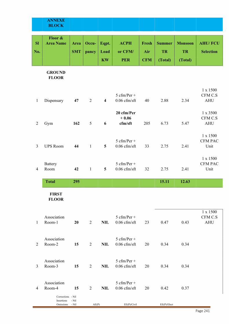
Corrections - Nil
Insertions - Nil
Omissions - Nil AE(P) EE(P)/Civil EE(P)/Elect
Page 241
ANNEXE BLOCK
Sl Floor &
Area Name Area Occu- Eqpt. ACPH Fresh Summer Monsoon AHU/ FCU
No. SMT pancy Load or CFM/ Air TR TR Selection
KW PER CFM (Total) (Total)
GROUND FLOOR
1 Dispensary 47 2 4 5 cfm/Per + 0.06 cfm/sft 40 2.88 2.34
1 x 1500 CFM C.S
AHU
2 Gym 162 5 6
20 cfm/Per + 0.06 cfm/sft 205 6.73 5.47
1 x 3500 CFM C.S
AHU
3 UPS Room 44 1 5 5 cfm/Per + 0.06 cfm/sft 33 2.75 2.41
1 x 1500 CFM PAC
Unit
4 Battery Room 42 1 5
5 cfm/Per + 0.06 cfm/sft 32 2.75 2.41
1 x 1500 CFM PAC
Unit
Total 295 15.11 12.63
FIRST FLOOR
1 Association Room-1 20 2 NIL
5 cfm/Per + 0.06 cfm/sft 23 0.47 0.43
1 x 1500 CFM C.S
AHU
2 Association Room-2 15 2 NIL
5 cfm/Per + 0.06 cfm/sft 20 0.34 0.34
3 Association Room-3 15 2 NIL
5 cfm/Per + 0.06 cfm/sft 20 0.34 0.34
4 Association Room-4 15 2 NIL
5 cfm/Per + 0.06 cfm/sft 20 0.42 0.37
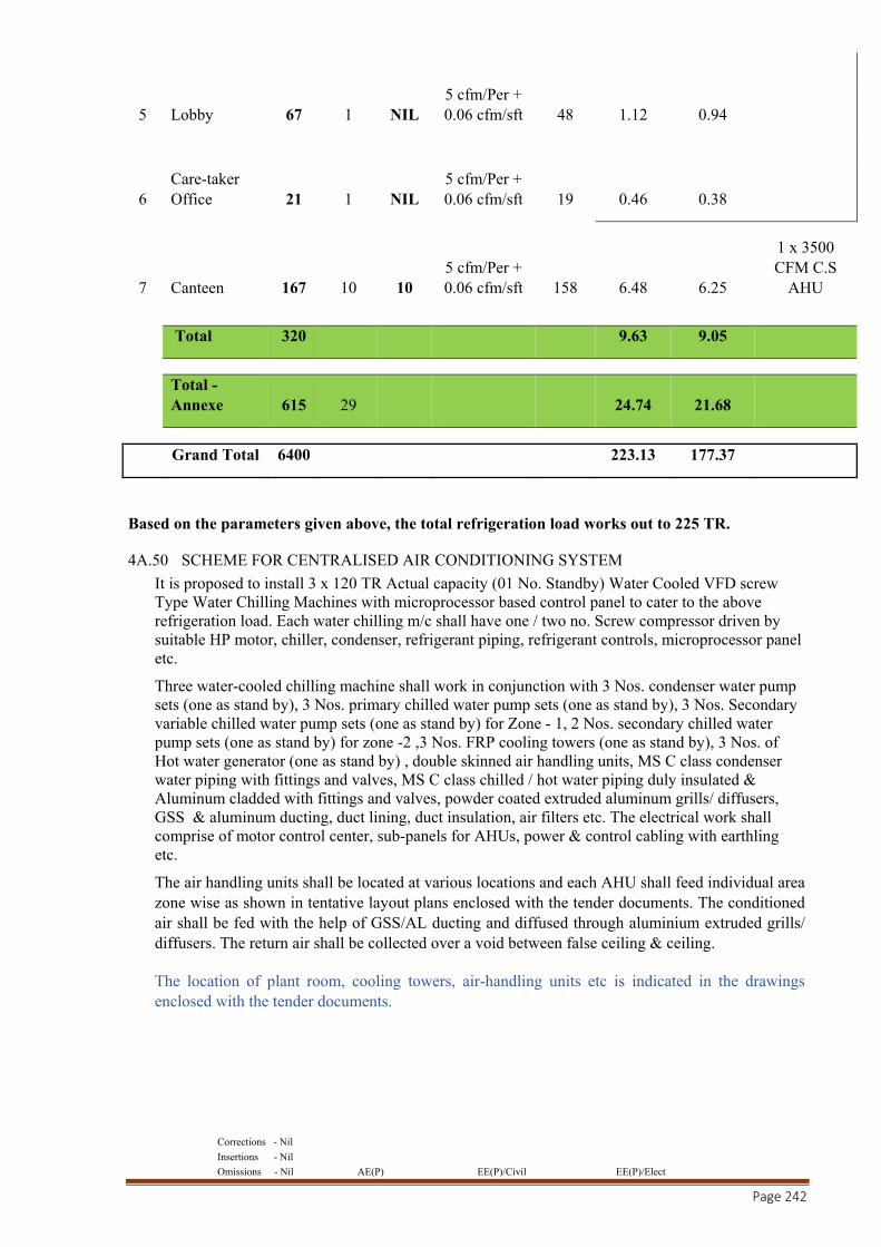
Corrections - Nil
Insertions - Nil
Omissions - Nil AE(P) EE(P)/Civil EE(P)/Elect
Page 242
5 Lobby 67 1 NIL 5 cfm/Per + 0.06 cfm/sft 48 1.12 0.94
6 Care-taker Office 21 1 NIL
5 cfm/Per + 0.06 cfm/sft 19 0.46 0.38
7 Canteen 167 10 10 5 cfm/Per + 0.06 cfm/sft 158 6.48 6.25
1 x 3500 CFM C.S
AHU
Total 320 9.63 9.05
Total - Annexe 615 29 24.74 21.68
Grand Total 6400 223.13 177.37
Based on the parameters given above, the total refrigeration load works out to 225 TR.
4A.50 SCHEME FOR CENTRALISED AIR CONDITIONING SYSTEM
It is proposed to install 3 x 120 TR Actual capacity (01 No. Standby) Water Cooled VFD screw Type Water Chilling Machines with microprocessor based control panel to cater to the above refrigeration load. Each water chilling m/c shall have one / two no. Screw compressor driven by suitable HP motor, chiller, condenser, refrigerant piping, refrigerant controls, microprocessor panel etc.
Three water-cooled chilling machine shall work in conjunction with 3 Nos. condenser water pump sets (one as stand by), 3 Nos. primary chilled water pump sets (one as stand by), 3 Nos. Secondary variable chilled water pump sets (one as stand by) for Zone - 1, 2 Nos. secondary chilled water pump sets (one as stand by) for zone -2 ,3 Nos. FRP cooling towers (one as stand by), 3 Nos. of Hot water generator (one as stand by) , double skinned air handling units, MS C class condenser water piping with fittings and valves, MS C class chilled / hot water piping duly insulated & Aluminum cladded with fittings and valves, powder coated extruded aluminum grills/ diffusers, GSS & aluminum ducting, duct lining, duct insulation, air filters etc. The electrical work shall comprise of motor control center, sub-panels for AHUs, power & control cabling with earthling etc.
The air handling units shall be located at various locations and each AHU shall feed individual area zone wise as shown in tentative layout plans enclosed with the tender documents. The conditioned air shall be fed with the help of GSS/AL ducting and diffused through aluminium extruded grills/ diffusers. The return air shall be collected over a void between false ceiling & ceiling.
The location of plant room, cooling towers, air-handling units etc is indicated in the drawings enclosed with the tender documents.
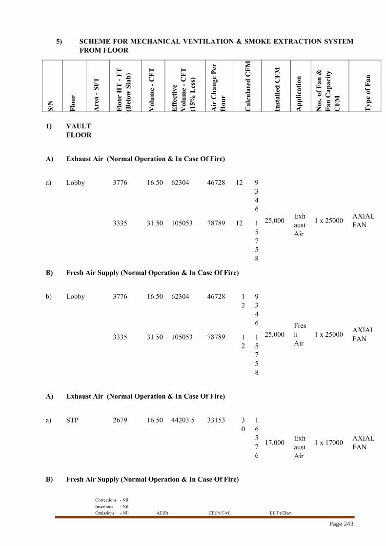
Corrections - Nil
Insertions - Nil
Omissions - Nil AE(P) EE(P)/Civil EE(P)/Elect
Page 243
5) SCHEME FOR MECHANICAL VENTILATION & SMOKE EXTRACTION SYSTEM FROM FLOOR
S/N
Flo
or
Are
a -
SF
T
Flo
or H
T -
FT
(B
elow
Sla
b)
Vol
um
e -
CF
T
Eff
ecti
ve
Vol
um
e -
CF
T
(15%
Les
s)
Air
Ch
ange
Per
H
our
Cal
cula
ted
CF
M
Inst
alle
d C
FM
Ap
pli
cati
on
Nos
. of
Fan
&
Fan
Cap
acit
y C
FM
Typ
e of
Fan
1) VAULT FLOOR
A) Exhaust Air (Normal Operation & In Case Of Fire)
a) Lobby 3776 16.50 62304 46728 12 9346
25,000
Exhaust Air
1 x 25000 AXIAL FAN
3335 31.50 105053 78789 12 1
5758
B) Fresh Air Supply (Normal Operation & In Case Of Fire)
b) Lobby 3776 16.50 62304 46728 12
9346
25,000 Fresh Air
1 x 25000 AXIAL FAN
3335 31.50 105053 78789 1
2 15758
A) Exhaust Air (Normal Operation & In Case Of Fire)
a) STP 2679 16.50 44203.5 33153 30
16576
17,000
Exhaust Air
1 x 17000 AXIAL FAN
B) Fresh Air Supply (Normal Operation & In Case Of Fire)
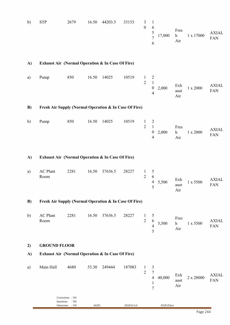
Corrections - Nil
Insertions - Nil
Omissions - Nil AE(P) EE(P)/Civil EE(P)/Elect
Page 244
b) STP 2679 16.50 44203.5 33153 30
16576
17,000 Fresh Air
1 x 17000 AXIAL FAN
A) Exhaust Air (Normal Operation & In Case Of Fire)
a) Pump 850 16.50 14025 10519 12
2104
2,000
Exhaust Air
1 x 2000 AXIAL FAN
B) Fresh Air Supply (Normal Operation & In Case Of Fire)
b) Pump 850 16.50 14025 10519 12
2104
2,000 Fresh Air
1 x 2000 AXIAL FAN
A) Exhaust Air (Normal Operation & In Case Of Fire)
a) AC Plant Room
2281 16.50 37636.5 28227 12
5645
5,500
Exhaust Air
1 x 5500 AXIAL FAN
B) Fresh Air Supply (Normal Operation & In Case Of Fire)
b) AC Plant Room
2281 16.50 37636.5 28227 12
5645
5,500 Fresh Air
1 x 5500 AXIAL FAN
2) GROUND FLOOR
A) Exhaust Air (Normal Operation & In Case Of Fire)
a) Main Hall 4680 53.30 249444 187083 12
37417
40,000
Exhaust Air
2 x 20000 AXIAL FAN
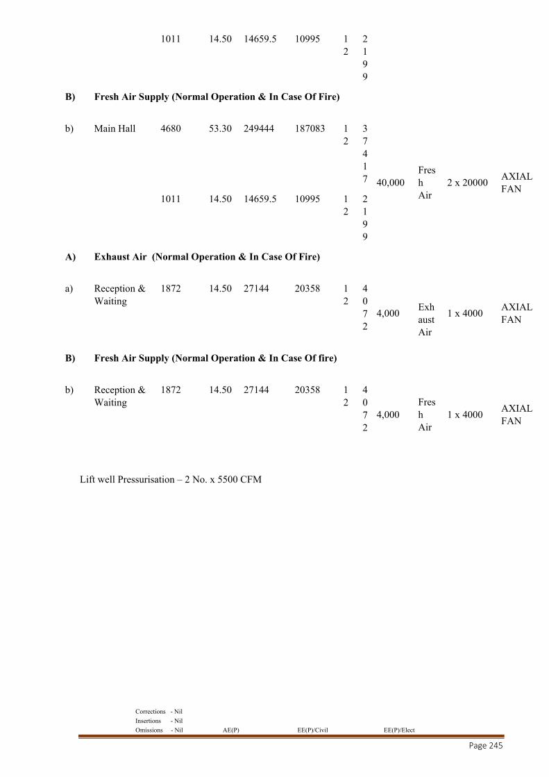
Corrections - Nil
Insertions - Nil
Omissions - Nil AE(P) EE(P)/Civil EE(P)/Elect
Page 245
1011 14.50 14659.5 10995 1
2 2199
B) Fresh Air Supply (Normal Operation & In Case Of Fire)
b) Main Hall 4680 53.30 249444 187083 12
37417 40,000
Fresh Air
2 x 20000 AXIAL FAN
1011 14.50 14659.5 10995 12
2199
A) Exhaust Air (Normal Operation & In Case Of Fire)
a) Reception & Waiting
1872 14.50 27144 20358 12
4072
4,000
Exhaust Air
1 x 4000 AXIAL FAN
B) Fresh Air Supply (Normal Operation & In Case Of fire)
b) Reception & Waiting
1872 14.50 27144 20358 12
4072
4,000 Fresh Air
1 x 4000 AXIAL FAN
Lift well Pressurisation – 2 No. x 5500 CFM
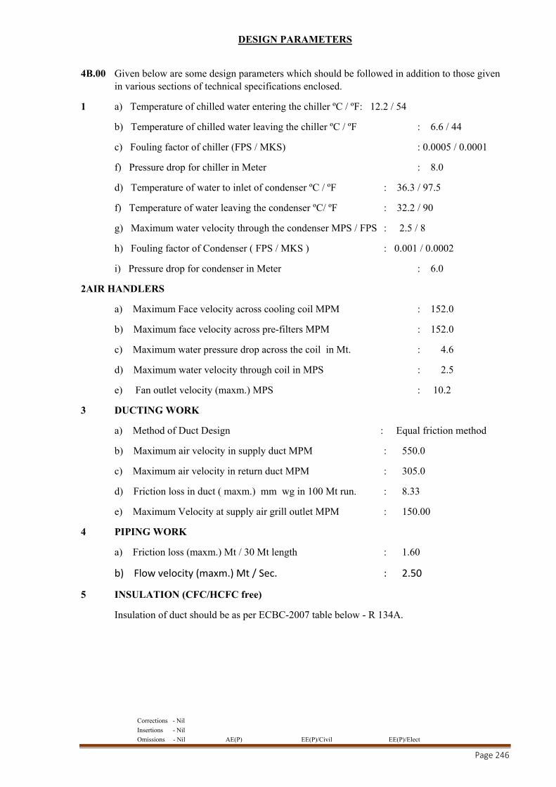
Corrections - Nil
Insertions - Nil
Omissions - Nil AE(P) EE(P)/Civil EE(P)/Elect
Page 246
DESIGN PARAMETERS
4B.00 Given below are some design parameters which should be followed in addition to those given in various sections of technical specifications enclosed.
1 a) Temperature of chilled water entering the chiller ºC / ºF: 12.2 / 54
b) Temperature of chilled water leaving the chiller ºC / ºF : 6.6 / 44
c) Fouling factor of chiller (FPS / MKS) : 0.0005 / 0.0001
f) Pressure drop for chiller in Meter : 8.0
d) Temperature of water to inlet of condenser ºC / ºF : 36.3 / 97.5
f) Temperature of water leaving the condenser ºC/ ºF : 32.2 / 90
g) Maximum water velocity through the condenser MPS / FPS : 2.5 / 8
h) Fouling factor of Condenser ( FPS / MKS ) : 0.001 / 0.0002
i) Pressure drop for condenser in Meter : 6.0
2AIR HANDLERS
a) Maximum Face velocity across cooling coil MPM : 152.0
b) Maximum face velocity across pre-filters MPM : 152.0
c) Maximum water pressure drop across the coil in Mt. : 4.6
d) Maximum water velocity through coil in MPS : 2.5
e) Fan outlet velocity (maxm.) MPS : 10.2
3 DUCTING WORK
a) Method of Duct Design : Equal friction method
b) Maximum air velocity in supply duct MPM : 550.0
c) Maximum air velocity in return duct MPM : 305.0
d) Friction loss in duct ( maxm.) mm wg in 100 Mt run. : 8.33
e) Maximum Velocity at supply air grill outlet MPM : 150.00
4 PIPING WORK
a) Friction loss (maxm.) Mt / 30 Mt length : 1.60
b) Flow velocity (maxm.) Mt / Sec. : 2.50
5 INSULATION (CFC/HCFC free)
Insulation of duct should be as per ECBC-2007 table below - R 134A.
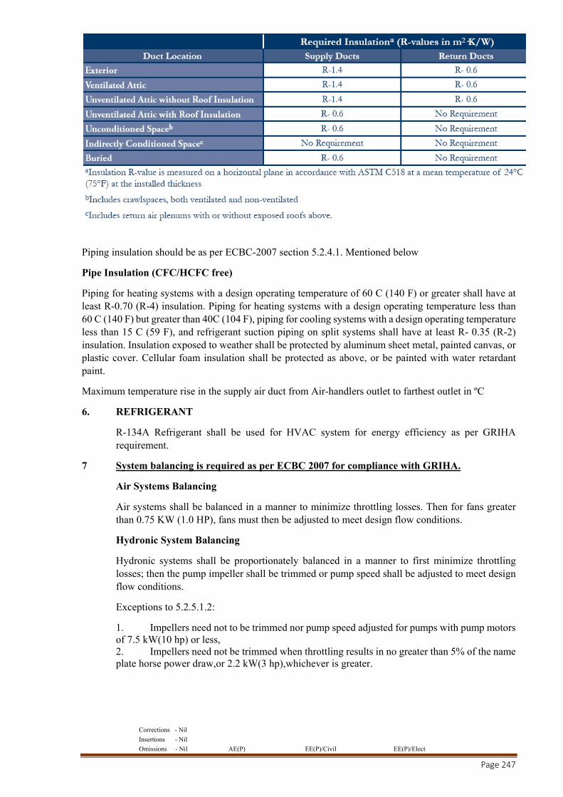
Corrections - Nil
Insertions - Nil
Omissions - Nil AE(P) EE(P)/Civil EE(P)/Elect
Page 247
Piping insulation should be as per ECBC-2007 section 5.2.4.1. Mentioned below
Pipe Insulation (CFC/HCFC free)
Piping for heating systems with a design operating temperature of 60 C (140 F) or greater shall have at least R-0.70 (R-4) insulation. Piping for heating systems with a design operating temperature less than 60 C (140 F) but greater than 40C (104 F), piping for cooling systems with a design operating temperature less than 15 C (59 F), and refrigerant suction piping on split systems shall have at least R- 0.35 (R-2) insulation. Insulation exposed to weather shall be protected by aluminum sheet metal, painted canvas, or plastic cover. Cellular foam insulation shall be protected as above, or be painted with water retardant paint.
Maximum temperature rise in the supply air duct from Air-handlers outlet to farthest outlet in ºC
6. REFRIGERANT
R-134A Refrigerant shall be used for HVAC system for energy efficiency as per GRIHA requirement.
7 System balancing is required as per ECBC 2007 for compliance with GRIHA.
Air Systems Balancing
Air systems shall be balanced in a manner to minimize throttling losses. Then for fans greater than 0.75 KW (1.0 HP), fans must then be adjusted to meet design flow conditions.
Hydronic System Balancing
Hydronic systems shall be proportionately balanced in a manner to first minimize throttling losses; then the pump impeller shall be trimmed or pump speed shall be adjusted to meet design flow conditions.
Exceptions to 5.2.5.1.2:
1. Impellers need not to be trimmed nor pump speed adjusted for pumps with pump motors of 7.5 kW(10 hp) or less, 2. Impellers need not be trimmed when throttling results in no greater than 5% of the name plate horse power draw,or 2.2 kW(3 hp),whichever is greater.
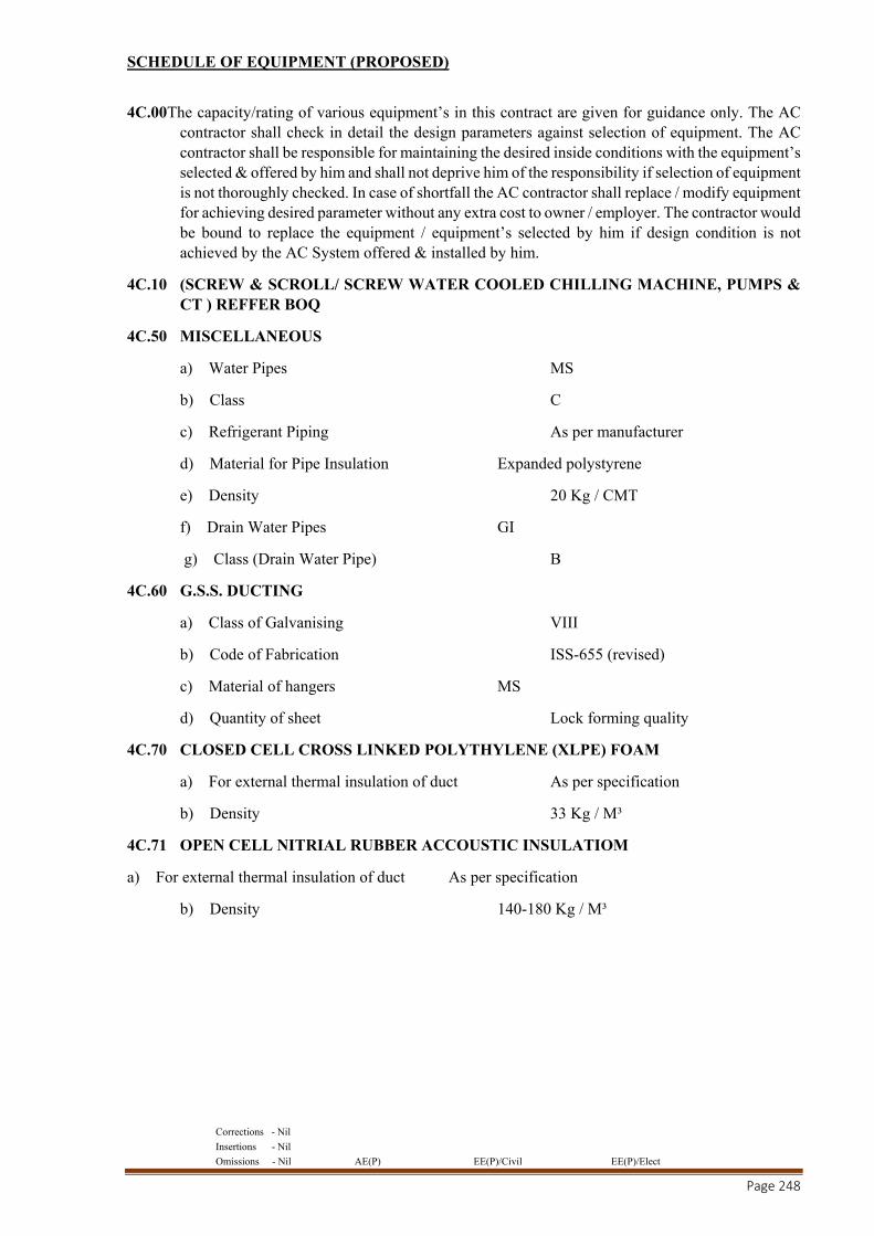
Corrections - Nil
Insertions - Nil
Omissions - Nil AE(P) EE(P)/Civil EE(P)/Elect
Page 248
SCHEDULE OF EQUIPMENT (PROPOSED)
4C.00The capacity/rating of various equipment’s in this contract are given for guidance only. The AC contractor shall check in detail the design parameters against selection of equipment. The AC contractor shall be responsible for maintaining the desired inside conditions with the equipment’s selected & offered by him and shall not deprive him of the responsibility if selection of equipment is not thoroughly checked. In case of shortfall the AC contractor shall replace / modify equipment for achieving desired parameter without any extra cost to owner / employer. The contractor would be bound to replace the equipment / equipment’s selected by him if design condition is not achieved by the AC System offered & installed by him.
4C.10 (SCREW & SCROLL/ SCREW WATER COOLED CHILLING MACHINE, PUMPS & CT ) REFFER BOQ
4C.50 MISCELLANEOUS
a) Water Pipes MS
b) Class C
c) Refrigerant Piping As per manufacturer
d) Material for Pipe Insulation Expanded polystyrene
e) Density 20 Kg / CMT
f) Drain Water Pipes GI
g) Class (Drain Water Pipe) B
4C.60 G.S.S. DUCTING
a) Class of Galvanising VIII
b) Code of Fabrication ISS-655 (revised)
c) Material of hangers MS
d) Quantity of sheet Lock forming quality
4C.70 CLOSED CELL CROSS LINKED POLYTHYLENE (XLPE) FOAM
a) For external thermal insulation of duct As per specification
b) Density 33 Kg / M³
4C.71 OPEN CELL NITRIAL RUBBER ACCOUSTIC INSULATIOM
a) For external thermal insulation of duct As per specification
b) Density 140-180 Kg / M³
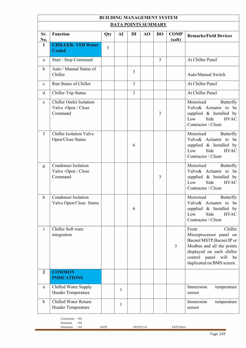
Corrections - Nil
Insertions - Nil
Omissions - Nil AE(P) EE(P)/Civil EE(P)/Elect
Page 249
BUILDING MANAGEMENT SYSTEM
DATA POINTS SUMMARY
Sr. No.
Function Qty AI DI AO DO COMP(soft)
Remarks/Field Devices
1 CHILLER- VFD Water Cooled
3
a Start / Stop Command 3 At Chiller Panel
b Auto / Manual Status of Chiller 3
Auto/Manual Switch
c Run Status of Chiller 3 At Chiller Panel
d Chiller Trip Status 3 At Chiller Panel
e Chiller Outlet Isolation Valve -Open / Close Command 3
Motorised Butterfly Valve& Actuator to be supplied & Installed by Low Side HVAC Contractor / Client
f Chiller Isolation Valve Open/Close Status
6
Motorised Butterfly Valve& Actuator to be supplied & Installed by Low Side HVAC Contractor / Client
g Condenser Isolation Valve -Open / Close Command 3
Motorised Butterfly Valve& Actuator to be supplied & Installed by Low Side HVAC Contractor / Client
h Condenser Isolation Valve Open/Close Status
6
Motorised Butterfly Valve& Actuator to be supplied & Installed by Low Side HVAC Contractor / Client
i Chiller Soft ware integration
3
From Chiller Microprocessor panel on Bacnet/MSTP,Bacnet/IP or Modbus and all the points displayed on each chiller control panel will be duplicated on BMS screen .
2 COMMON INDICATIONS
a Chilled Water Supply Header Temperature 1
Immersion temperature sensor
b Chilled Water Return Header Temperature 1
Immersion temperature sensor
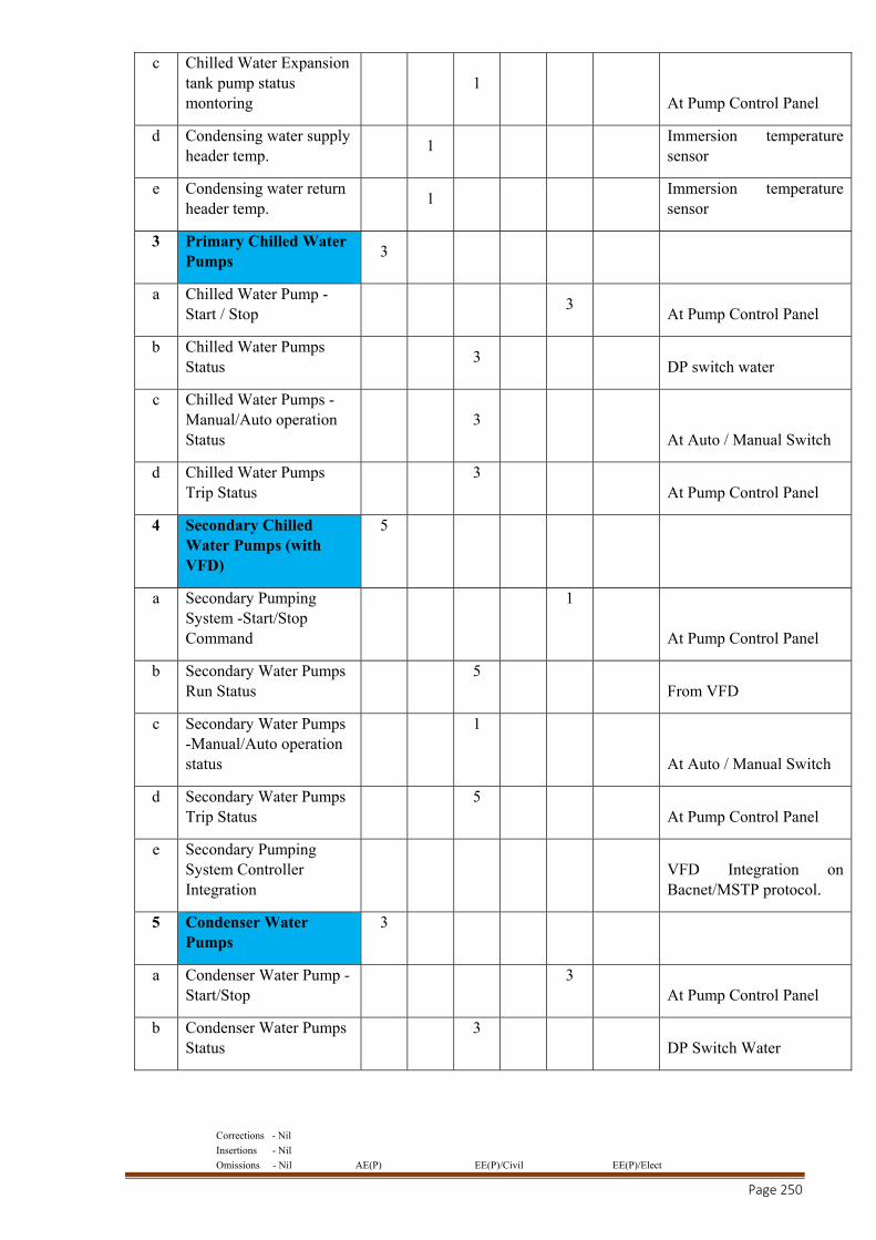
Corrections - Nil
Insertions - Nil
Omissions - Nil AE(P) EE(P)/Civil EE(P)/Elect
Page 250
c Chilled Water Expansion tank pump status montoring
1 At Pump Control Panel
d Condensing water supply header temp. 1
Immersion temperature sensor
e Condensing water return header temp. 1
Immersion temperature sensor
3 Primary Chilled Water Pumps
3
a Chilled Water Pump - Start / Stop 3
At Pump Control Panel
b Chilled Water Pumps Status 3
DP switch water
c Chilled Water Pumps -Manual/Auto operation Status
3 At Auto / Manual Switch
d Chilled Water Pumps Trip Status
3 At Pump Control Panel
4 Secondary Chilled Water Pumps (with VFD)
5
a Secondary Pumping System -Start/Stop Command
1
At Pump Control Panel
b Secondary Water Pumps Run Status
5 From VFD
c Secondary Water Pumps -Manual/Auto operation status
1
At Auto / Manual Switch
d Secondary Water Pumps Trip Status
5 At Pump Control Panel
e Secondary Pumping System Controller Integration
VFD Integration on Bacnet/MSTP protocol.
5 Condenser Water Pumps
3
a Condenser Water Pump -Start/Stop
3 At Pump Control Panel
b Condenser Water Pumps Status
3 DP Switch Water
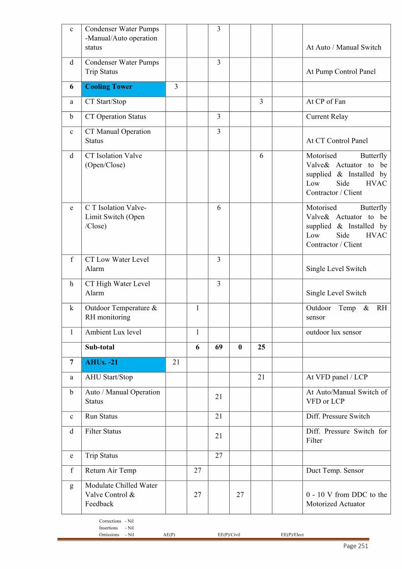
Corrections - Nil
Insertions - Nil
Omissions - Nil AE(P) EE(P)/Civil EE(P)/Elect
Page 251
c Condenser Water Pumps -Manual/Auto operation status
3
At Auto / Manual Switch
d Condenser Water Pumps Trip Status
3 At Pump Control Panel
6 Cooling Tower 3
a CT Start/Stop 3 At CP of Fan
b CT Operation Status 3 Current Relay
c CT Manual Operation Status
3 At CT Control Panel
d CT Isolation Valve (Open/Close)
6 Motorised Butterfly Valve& Actuator to be supplied & Installed by Low Side HVAC Contractor / Client
e C T Isolation Valve-Limit Switch (Open /Close)
6 Motorised Butterfly Valve& Actuator to be supplied & Installed by Low Side HVAC Contractor / Client
f CT Low Water Level Alarm
3 Single Level Switch
h CT High Water Level Alarm
3 Single Level Switch
k Outdoor Temperature & RH monitoring
1 Outdoor Temp & RH sensor
l Ambient Lux level 1 outdoor lux sensor
Sub-total 6 69 0 25
7 AHUs. -21 21
a AHU Start/Stop 21 At VFD panel / LCP
b Auto / Manual Operation Status 21
At Auto/Manual Switch of VFD or LCP
c Run Status 21 Diff. Pressure Switch
d Filter Status 21
Diff. Pressure Switch for Filter
e Trip Status 27
f Return Air Temp 27 Duct Temp. Sensor
g Modulate Chilled Water Valve Control & Feedback
27 27 0 - 10 V from DDC to the Motorized Actuator
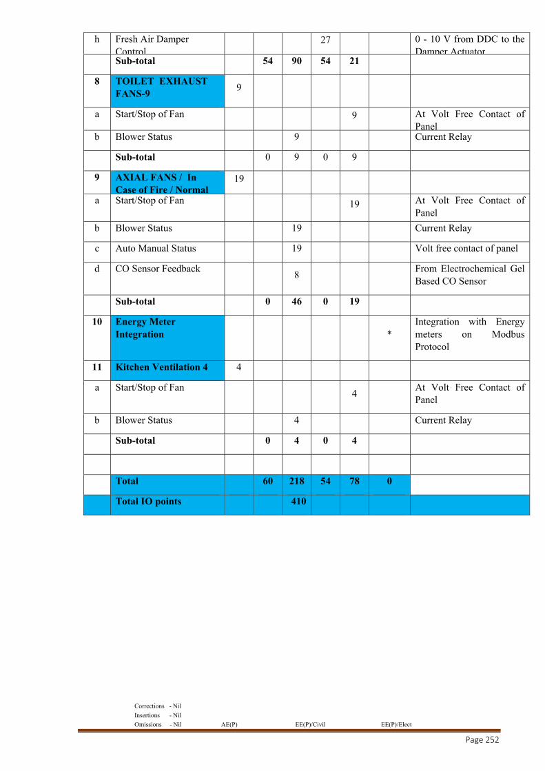
Corrections - Nil
Insertions - Nil
Omissions - Nil AE(P) EE(P)/Civil EE(P)/Elect
Page 252
h Fresh Air Damper Control
27 0 - 10 V from DDC to the Damper Actuator
Sub-total 54 90 54 21
8 TOILET EXHAUST FANS-9
9
a Start/Stop of Fan 9 At Volt Free Contact of Panel
b Blower Status 9 Current Relay
Sub-total 0 9 0 9
9 AXIAL FANS / In Case of Fire / Normal
19
a Start/Stop of Fan 19 At Volt Free Contact of Panel
b Blower Status 19 Current Relay
c Auto Manual Status 19 Volt free contact of panel
d CO Sensor Feedback 8
From Electrochemical Gel Based CO Sensor
Sub-total 0 46 0 19
10 Energy Meter Integration *
Integration with Energy meters on Modbus Protocol
11 Kitchen Ventilation 4 4
a Start/Stop of Fan 4
At Volt Free Contact of Panel
b Blower Status 4 Current Relay
Sub-total 0 4 0 4
Total 60 218 54 78 0
Total IO points 410
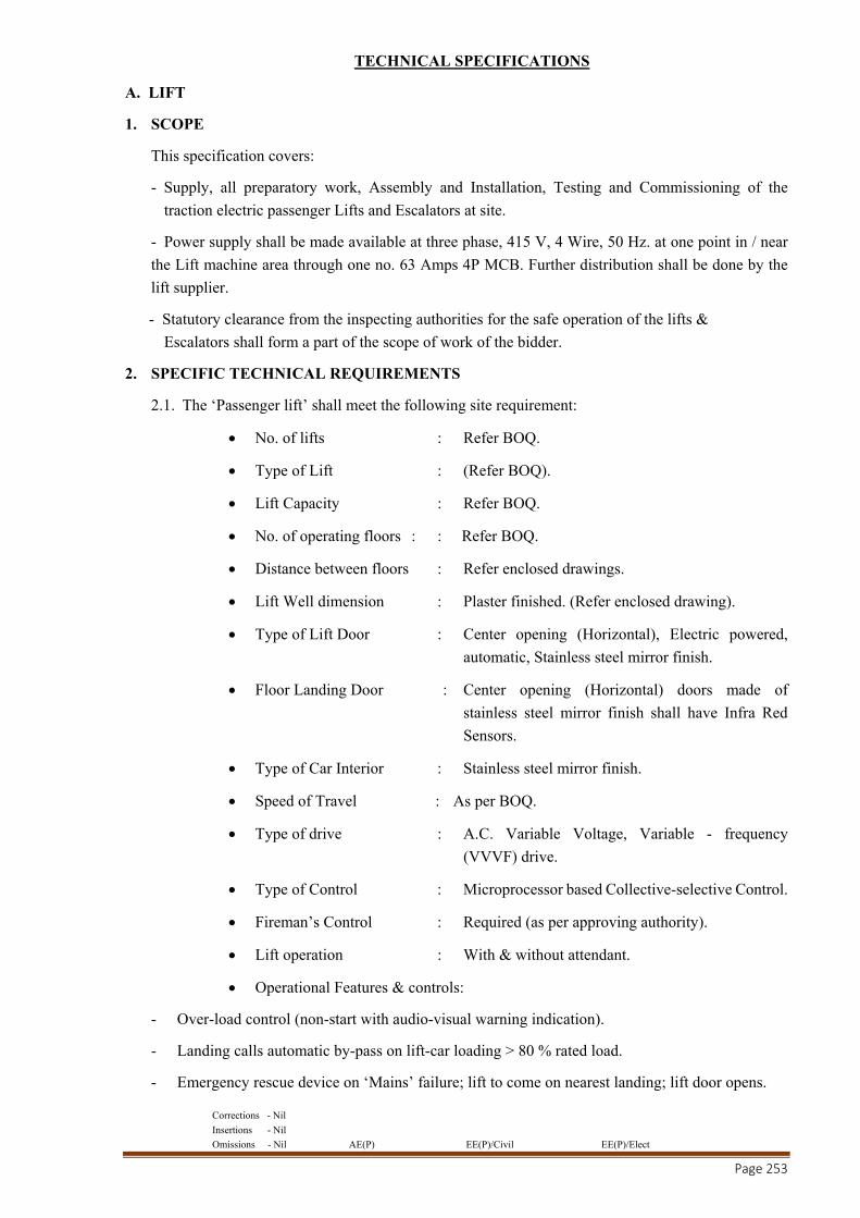
Corrections - Nil
Insertions - Nil
Omissions - Nil AE(P) EE(P)/Civil EE(P)/Elect
Page 253
TECHNICAL SPECIFICATIONS
A. LIFT
1. SCOPE
This specification covers:
- Supply, all preparatory work, Assembly and Installation, Testing and Commissioning of the
traction electric passenger Lifts and Escalators at site.
- Power supply shall be made available at three phase, 415 V, 4 Wire, 50 Hz. at one point in / near
the Lift machine area through one no. 63 Amps 4P MCB. Further distribution shall be done by the
lift supplier.
- Statutory clearance from the inspecting authorities for the safe operation of the lifts &
Escalators shall form a part of the scope of work of the bidder.
2. SPECIFIC TECHNICAL REQUIREMENTS
2.1. The ‘Passenger lift’ shall meet the following site requirement:
No. of lifts : Refer BOQ.
Type of Lift : (Refer BOQ).
Lift Capacity : Refer BOQ.
No. of operating floors : : Refer BOQ.
Distance between floors : Refer enclosed drawings.
Lift Well dimension : Plaster finished. (Refer enclosed drawing).
Type of Lift Door : Center opening (Horizontal), Electric powered,
automatic, Stainless steel mirror finish.
Floor Landing Door : Center opening (Horizontal) doors made of
stainless steel mirror finish shall have Infra Red
Sensors.
Type of Car Interior : Stainless steel mirror finish.
Speed of Travel : As per BOQ.
Type of drive : A.C. Variable Voltage, Variable - frequency
(VVVF) drive.
Type of Control : Microprocessor based Collective-selective Control.
Fireman’s Control : Required (as per approving authority).
Lift operation : With & without attendant.
Operational Features & controls:
- Over-load control (non-start with audio-visual warning indication).
- Landing calls automatic by-pass on lift-car loading > 80 % rated load.
- Emergency rescue device on ‘Mains’ failure; lift to come on nearest landing; lift door opens.
Corrections - Nil
Insertions - Nil
Omissions - Nil AE(P) EE(P)/Civil EE(P)/Elect
Page 254
- Up / Down direction indication on all floors.
- Emergency Alarm & Light inside the lift-cabin with chargeable battery.
- Auto-shut off of car fan when lift is not in operation.
- Two way Intercom device in lift car (One set in the car-cabin & the other in Security office in
Ground Floor with-in 10 Meters).
- Infra-red full door safety screen in addition to the mechanical Aluminum nose safety shoes.
- Audio-visual announcement of lift on approaching the landing with single stroke of gong.
- Voice announcement in the lift car on approaching the landing.
- Door closing over-ride through push button in lift car.
2.2. CAR DOOR
The car doors shall be electrically controlled, automatic center opening type providing automatic
opening and closing of both the car and corresponding landing door simultaneously.
2.3. GUIDE RAILS
‘T’ section single rails shall be anchored on the side walls of the elevator well to serve as a
guided track for the vertical motion of the elevator car.
2.4. SUSPENSION ROPE
Ropes of high tensile wire construction shall be steel-cored to attain the travel height in multiple
modes to suspend the elevator car. Individual rope shall be provided with rope anchor at its ends
to facilitate total flexibility.
2.5. COUNTER WEIGHT
The counter-weight for the lift car shall be designed to balance the weight of the empty lift car
plus 50% of the rated load. It shall be secured for relative movement and two guide shoes to run
on the guide rails anchored on the side walls of the elevator well to serve as a guided track for
the vertical motion of the counter weight.
2.6. CONTROLLER
It shall be housed in a dust proof steel cabinet.
2.7. OVERSPEED GOVERNOR
In case of the failure of suspension rope system, the downward motion over- speed of the lift
car shall be checked by actuating the safety gear and stopping the elevator car. The over-speed
governor shall be calibrated, tested and sealed in accordance with the elevator regulation.
Governor gears shall have self-lubricating bearings which do not require frequent attention as
per I S: 14665.
3. BUFFERS
Suitable hydraulic or spring buffers conforming to IS: 14665 Part 3 & 4 - 2000 shall be provided for
smooth stoppage of car and counter-weights (electric traction lifts) at the extreme limit of travel.
Buffers shall be mounted on steel channels. These channels shall extend between the car and

Corrections - Nil
Insertions - Nil
Omissions - Nil AE(P) EE(P)/Civil EE(P)/Elect
Page 255
counterweight guide rails. The buffers shall be located symmetrically with reference to the vertical
center line of the car frame.
4. TERMINAL STOPPING AND FINAL LIMIT SWITCHES
The lift shall be provided with upper and lower normal terminal limit switches to stop the car
automatically within the limits of top car clearance and bottom run by over travel in normal operation.
Such limit switches shall act independently of the operating device, ultimate or final limit switches
and the buffers.
5. ULTIMATE OR FINAL LIMIT SWITCHES
The lift shall be provided with ultimate or final limit switches arranged to stop the car automatically
within the top and bottom clearances independently of the normal operating device and the terminal
limit switches. The switch shall open before the buffers are engaged.
6. AUTOMATIC RESCUE DEVICE (ARD)
The lifts shall be provided with an Automatic Rescue Device (ARD). In the event of failure of power
supply, the automatic rescue device shall bring the lift to nearest landing and facilitate the rescue of
the passengers in the lift.
7. FACILITIES TO BE PROVIDED BY THE PURCHASER
The lift well of the specified dimension shall be made available in finished condition.
Two nos. building Earth connections shall be extended up to Lift shaft. Further connection shall
be done by the lift supplier.
The power distribution and control of the lifts shall be the responsibility of the Lift supplier.
All inserts, grouting, minor civil work etc. including the scaffolding required; shall be carried out
by the lift vendor.
8. VENDOR’S RESPONSIBILITY
All arrangements other than specifically mentioned as ‘Purchaser’s responsibility’, required for
installation, testing & commissioning of the lifts to make them functional in a safe manner, shall
be made by the Lift vendor.
9. SITE TESTS
Following tests shall be carried out on the lifts on completion of erection in addition to any other tests
that may be required to determine their safe operational requirement:
Insulation of Electrical system (should be > 0.5 M Ohm.)
Earth continuity tests.
Function of Motor, Brake control equipment and Door locking devices.
Rated Load Test of the lifts.
Rated speed test at ‘Full load & No load’.
Safety gear stopping the Lift on Landings at rated Load.
Tests as per the ‘General Specifications for Electrical Works (part-III-Lifts & Elevators) 2013 of
CPWD
Corrections - Nil
Insertions - Nil
Omissions - Nil AE(P) EE(P)/Civil EE(P)/Elect
Page 256
B.Fire Alarm System
1.GENERAL
Work Included
a) The scope of work under this head shall include design (if required) supply and installation of Analogue Addressable Fire Detection Cum Alarm System. The work under this system shall consist of furnishing all materials, equipments and appliances and labour necessary to install the said system complete with Detectors, Hooters and Manual Push Button Stations and Fire Alarm Panel etc.
The Design consists of providing Analogue Addressable Detectors, Hooters, Manual Call Points, Response Indicators and Fire Alarm Panel as per specifications.
It shall include laying of wiring and conduits etc. necessary for installation of the system with supply of detectors as indicated in the specification and schedule of quantities. Any openings/ chasing in the wall/ ceiling required to be made for the installation shall be made good in appropriate manner.
b) Related Work and Obligations
i) The general requirements apply to work specified in this section.
ii) To examine all the other sections of the specification for requirements which may affect work of this section.
iii) Co-ordinate works with all other trades affecting, or affected by activities of this section. Co-operate with such other trades to assure the steady progress of all operations under the Contract.
c) General Requirements
This specification covers requirements for supply, erection, testing and commissioning of Analogue Addressable Fire Alarm System.
d) Codes and Standards
The design, supply, installation and testing of the entire fire alarm system shall confirm to BS : 5839 or NFPA 72. The detectors shall conform to relevant codes for Fire Alarm Systems.
e) Quality Assurance
The Contractor shall ensure that all materials furnished and installed by him under the Contract shall meet the requirements of relevant International and Indian Standards. The Contractor shall also verify all test results and ensure that these are in accordance with the requirements as mentioned in the specifications.
f) Guarantee
Manufacturer shall provide guarantee for work under this section. However, such guarantee shall be in addition to and not in lieu of all other liabilities which manufacturer and Contractor may have by other provisions of the Contract document.
The Fire Alarm System shall be guaranteed against trouble free operation, defective workmanship and materials for a period of 18 months from the date of supply or 12 months from the date of erection and commissioning whichever is earlier. In case of any defects during this period detectors etc. shall be replaced free of cost by the Contractor.
g) Delivery, Handling and Storage
All Detectors, Hooters, MCPs, RIs and Fire Alarm Panel shall be carefully handled and stored at site in a neat and orderly manner for fixing the same at a later date.
2. Products
a) General Detail

Corrections - Nil
Insertions - Nil
Omissions - Nil AE(P) EE(P)/Civil EE(P)/Elect
Page 257
The Fire Alarm System shall conform to BS : 5839 or EN 54 or NFPA 71/ 72 or Under writer’s Laboratory in respect of design and installation and it shall give Audio / Visual Alarm Signals when the temperature in case of Heat Detector or smoke density in case of Photo Electric Detector exceeds the pre-set limit. The system shall give pin point location of fire with warning system and voice communication for commands and instruction if required.
b) Photo Electric Type Smoke Detector Combined with Class ‘AI’ Thermal Sensor.
The Photo Electric Smoke Detector has an optical sensing chamber that operates on the light scattering principle and responds to those particles that exit from optically dense smoke. When Smoke enters the sensing chamber it scatters light which is received by a photo cell. The signal is amplified and digitised for reception by the Panel. The Detector shall activate on receiving smoke particles in the 0.5 to 10 micro meter range. The detector shall be completely solid state with LED indication at the base.
The Photo Electric Smoke Detector shall be combined with Class ‘A1’ thermal sensor. Each element shall have monitoring possible for measuring actual levels, as well as temperature rate of rise. When required it shall be possible to isolate smoke sensing while retaining thermal sensing.
The Detector shall be able to sense incipient fire by detecting the presence of visible and invisible products of combustion. The detector shall be suitable for low voltage (24 volts DC) two wire supply. The detector shall be provided with response indicator (LED) and the sensitivity of the detector shall not vary with change in ambient temperature, humidity, pressure of voltage variation.
Neither its performance shall be got affected by air circuit upto 10 Mtr. Per second. The detector shall be suitably protected against dust accumulation/ ingress and it shall be free from maintenance and functional test at intervals. All detectors shall be identical in construction design and characteristic to facilitate easy replacement. The detector housing shall be damage resistant made of polycarbonate or proprietary self extinguishing material.
The coverage per smoke detector shall be upto a minimum of 70 Sq.M. This coverage area will reduce depending upon structural configurations or partitions etc. It shall be possible to connect Smoke Detector with Heat Detector or Manual Push Button in the same circuit. The sensitivity of detector shall be set / adjusted by the supplier to suit the site requirement.
It shall have in-built safety device to monitor the removal and pilferage of the detector. The detector also must have facility for remote indication. The quiescent current flow must not exceed 50 milli amps and alarm condition current shall be maximum 60 milli amps.
The Photo Electric type Smoke Detector combined with Class ‘A1’ thermal sensor shall be intelligent Analogue Addressable detector with its own manually set digital code and be able to give analogue output to the Fire Alarm Panel regarding its condition. It shall be able to communicate with the Fire Alarm Panel by the pulses emitted from the Panel.
The base of the Detector shall be interchangeable with other Smoke or Heat Detectors. The enclosure shall meet IP 22 protection grade.
It shall be able to withstand temperature variation from 0 Degree Centigrade to 50 Degree Centigrade. Relative Humidity (non Condensing type) upto 95% shall not hamper its performance. The voltage rating shall be from 24 Volts DC, though the voltage may be changed depending upon the working voltages of a proprietary Fire Alarm Panel.
c) Rate of Rise Type Heat Detector
The Heat Detector shall be intelligent Analogue Addressable detector with its own manually set digital code and be able to give a single digitised output to the Fire Alarm Panel regarding its condition. The Detector shall employ the thermistor principle for heat sensing and the fixed temperature setting shall be at 600 Centigrade. It shall be able to communicate with the Fire Alarm Panel by the Electrical pulses emitted from the Panel.
The Base of the Detector shall be interchangeable with other Smoke Detectors and the Construction shall be of poly carbonate or any approved proprietary flame retardant material.

Corrections - Nil
Insertions - Nil
Omissions - Nil AE(P) EE(P)/Civil EE(P)/Elect
Page 258
LEDs shall be provided to indicate locally alarm condition. The enclosure shall meet IP 22 protection grade.
It shall be able to withstand temperature variations from 00 Centigrade to 500 Centigrade. Further, Relative Humidity (non Condensing type) upto 95% shall not hamper its performance. The Voltage rating shall be 24 Volts DC, though the voltage may be changed depending upon the working voltages of a proprietary Fire Alarm Panel.
The detector shall meet the requirements of either EN 54/ FM/ UL and shall be specifically approved by FM/ UL/ LPCB. It shall be possible to test the Detector’s working both from the Panel as well as locally by means as designed by the Bidder. The approved coverage per Detector for unhampered areas shall not be less than 30 M2
d) Manual Call Box.
Manual Push Button shall be of Break Glass or Pull Down type units, completely encased in cast aluminium housing or in 16 gauge MS with provision for cable or conduit coupling. The manual Push Button shall have the word prescribed in clear bold letters on facial window “In case of Fire Break Glass/ Pull Down”.
The Manual Call Box station shall be fully addressable with its own set code and operated by digitized signals sent from the Panel. The voltage range shall be from 24 Volts. It shall have protection as per IP 33. The Operating temperature range shall be from 0 Degree Centigrade to 500 Centigrade. Relative Humidity (non condensing) range for performance parameters shall be between 0 to 95%. Further it shall confirm to BS 5839 or EN 54/ FM/ UL/ Vds/ LPC.
In case the manual call box is indigenous and an Input Card is connected to it then the Manual Call Box with Micro Switch shall be approved by the Consultant.
e) Hooter
The Hooter shall be of electronic type and shall give discontinuous / intermittent audible alarm whenever any detector or call box operates. It shall be possible to control the hooter audible alarm in case it is not required to sound the alarm except for the panel.
It shall be complete with electronic oscillations, magnetic coil (sound coil) and accessories, ready for mounting (fixing).
The sound output from the Hooter should not be less than 100 decibels at the source point. Hooter shall be 4 W each and enclosed in an acoustically lined MS box.
f) Fault Isolator
The Fault Isolator shall be able to detect wire short circuit/ loose wiring/ partial earth fault and similar conditions and shall be able to isolate that segment from the circuit, so that the rest of the circuit continues to operate.
Fault Isolator shall operate in pairs in any loop and whenever any short circuit occurs between any two of them, both immediately shall switch to an open circuit state and isolate the length of wiring between them. The Isolators should automatically return to the closed circuit as soon as the short circuit is corrected.
The Fault Isolator shall be addressable so as to provide indicate of its changed state. It shall also have an inbuilt LED to give local alarm.
g) Fire Alarm Control Panel
1) The fire Alarm Control Panel shall be micro processor based fully Addressable Analogue Control Unit which shall control all addressable detectors, Manual Call Stations, Interface Units and Switching Systems (for disconnecting AHU and power supply) connected to it.
2) All addressable units shall be connected to the Panel through the Loop Cards and shall be addressed through individualized numbers. The Panel shall be able to obtain analogue value for all detectors in the Circuit through a pulsed digitalized current data. The Panel shall be able to analyze all analogue inputs from all addressable units and through its own software and ambient level screening it shall be able to identify Fire, possible Fire or Fault conditions. The unit shall be dynamic and continuous.

Corrections - Nil
Insertions - Nil
Omissions - Nil AE(P) EE(P)/Civil EE(P)/Elect
Page 259
3) The Fire Alarm Panel shall itself have all Zone Cards in it. No isolated mother board or transponder is being considered. Each Loop shall be able to access a minimum of 90 addressable units. The Design has been based on the basis of 90 units per Loop.
4) The Panel shall also give adequate warning signal whenever there is dust accumulation in detectors, and upto the point of its replacement it should be possible to change the level of ambient alarm calibration condition either by the use of software programme operable by the Client or by resetting the detector.
5) Short circuiting, loose wiring or missing units shall also be reported at the Panel with pin point location. In such cases the system through the use of Fault Isolators shall be able to isolate that segment between the two fault isolators.
6) The Panel shall have a Liquid Crystal Display Alpha – Numeric type on it to indicate immediately all conditions. In case of testing of the system from the Panel, the Display shall be able to give readouts of analogue value of all detectors being tested. The Panel shall also be able to carry out continuous self monitoring when in normal condition. The Mother Board shall be of Modular Construction.
7) The Panel shall have either an in-built or external printer coupled to the Panel which shall log all events with time. The printout shall clearly indicate the event – Fire / Pre Alarm / Fault etc. the Unit address and time.
8) The Panel shall also be able to discriminate between false alarms and fire conditions, as well as priority selection of alarm address in case alarm activities in tow or more remotely located units simultaneously. In such cases, the Manual Call Box shall be reported first, group of sequentially laid detectors (in one room for example) second and a detector with the greatest obscuration over a period of time third.
9) The Panel shall also be able to actuate Switches automatically in case of Fire condition, that of AHUs and Power Supply or other Systems such as piped pressurized gas supply. The Bidder will be required to design and install the system in operation in coordination with the relevant Contractors. The Bidder will not be allowed to charge extra on this account, and such charges shall be included in his package.
10) In this respect the Bidder is required to take note of the specifications mentioned above. The Bidder shall indicate in his Bid what facilities shall need to be provided by the Client for completion of this mechanism.
11) The System should be fully safe and adequate safe guards should be under taken that in the event of a failure of a part of the System it shall not handicap the complete system.
12) The Bidder shall undertake the responsibility of the complete installation, commissioning, user trials, training and maintenance of the system as required. The Bidder shall take all responsibility for preparation and installation of system Software into the Panel. The Software shall be such so as to be easily operated by the Client’s Personnel, is secured against Software errors, ability to be upgradable so as to incorporate more Detector units or replacement/ changing of Detector units, can incorporate more features at a later date such as Illumination Control, Security etc.
13) The Panel shall be able to address individual Interface Cards which shall be connected to conventional detectors.
14) The Panel shall have its own Battery Back up of a minimum of 12 hours run. The Battery shall be of Nickel Cadmium or as per Manufacturers Standard of capacity as required and accepted by the Client.
15) The Panel shall also have its own Annunciation System either inbuilt or by external source. The Microphone shall have a selector switch to tune onto the required speaker / speakers and give the necessary voice announcement.
16) It shall be able to withstand temperature variations from 0 Degree Centigrade to 500 Centigrade. Further, Relative Humidity (Non Condensing type) upto 95% shall not hamper its performance. The Voltage rating shall be 24 V DC, though the voltage may be changed depending upon the working voltages of a proprietary Fire Alarm Panel.
Corrections - Nil
Insertions - Nil
Omissions - Nil AE(P) EE(P)/Civil EE(P)/Elect
Page 260
17) The Panel shall be totally enclosed dust and vermin proof type made of minimum 16 gauge dust inhibited sheet with even baked finish. The panel shall be of completely solid state design.
18) The logic circuits shall be based on high noise immunity solid tasted hardware employing modular construction. Logic cards shall be of epoxy fibre glass construction.
19) The System shall meet the BS 5839/ EN 54/ NFPA 71 & 72 standards and all equipments excluding cabling and wiring shall be listed with Under writers Laboratory or Factory Mutual.
20) Further, the system shall be expandable and be able to add atleast 200 more units in the Panel through additional Loops.
21) The Panel shall have an extra Zone/ Loop Card to serve as Standby in case of burn out of or malfunctioning of any operating Zone/ Loop Card. If the Bidder envisages two numbers of 2 Loop cards to serve the 4 Loops of the proposed System, then the extra Loop Card shall also be a 2 Loop Card.
22) The Panel shall have software to cater to the change over of any of the operating Loop Cards to the extra Loop Card. Other Software necessary to actually change the terminals of a Loop from an existing Loop Card to the extra Loop card shall be carried out at site as and when required. Charges for such software, loading, test run etc. shall be indicated when required.
Corrections - Nil
Insertions - Nil
Omissions - Nil AE(P) EE(P)/Civil EE(P)/Elect
Page 261
C. SUB STATION
SPECIFICATION FOR HIGH VOLTAGE PANEL
1.1 SCOPE
These specifications cover the detailed requirements for supply, installation, testing and commissioning of High Voltage Panels.
1.2 TYPE OF PANELS:
(A) VACUUM CIRCUIT BREAKER
1.2 H.V. PANEL
1.2.1 The Panel board shall be of indoor type, having the incoming sectionalisation and outgoing switch gears as per IS 13118-1991 of VCB, IEC 62271-100 for Breakers and -200 for Panels/IS 3427 of switch board. The degree of enclosure protection shall be IP-42.
Detailed requirements shall be in accordance with the schedule of works at Appendix-II.
1.2.2 Rating: All panels assembled to form a board shall be suitable for the nominal operation voltage and rupturing capacity as specified. They should be rated as specified with a minimum of 630 Amps. And suitable for operation on 11 KV, 3 phase 50 Hz system. Type test certificate for the breaking capacity of the panelshall be supplied.
Acircuit breaker for a given duty in service is best selected by considering the individual rated values required by load conditions and fault condition.
1.2.3 Type: The HV panel Board shall be metal clad, indoor, floor mounting, free standing type. It shall be totally enclosed dust, damp and vermin proof.
1.2.4 General Construction: Separately earthed compartments shall be provided for circuit breakers, bus bars, relay & instruments, CT&PT and cable boxes, fully and effectively segregating these from one another so that fault in any one compartment do not cause damage to equipment(s) in other compartment(s). The housing shall be of bolted construction to ensure compact and rigid structure, presenting a neat and pleasing appearance. The sheet steel used should not be less than 2mm thick. The panels shall be bolted together to form a continuous flush front switch gear suitable for front operation of board and for extension at both ends. 2.3.5 General Design Aspects: The HV panel board shall be designed such that the switchgear, instruments, relays, bus bars, small wiring etc. are arranged and mounted with due consideration for the followings:-
(i) Facility for inspection, maintenance and repairs of testing terminals and terminal boards for ease of external connection.
(ii) Minimum noise and vibrations. - Risk of accidental short circuits and open circuits. - Secured and vibration proof connections for power and control circuits.
(iii) Risk of accidental contact and danger to personnel due to live connections.
(iv) Mountings at approachable height
1.3 CIRCUIT BREAKER:
1.3.1 General Arrangements: The circuit breaker panels shall be complete with the following:
(a) Racking in / Racking out mechanism.
(b) Isolating plugs and sockets.
(c) Mechanical inter-locks and safety shutters.
(d) Mechanical ON/OFF indicator.
(e) Minimum of 4 NO and 4 NC Auxiliary contacts directly operated by the circuit breaker. Additional NO & NC contacts can be provided with auxiliary contactors.
Corrections - Nil
Insertions - Nil
Omissions - Nil AE(P) EE(P)/Civil EE(P)/Elect
Page 262
(f) Anti condensation space heaters suitable for operation on 240V, 1Ö 50 Hz A.C. for each panel wherever specified.
(g) Suitable tripping arrangement
(h) Mechanical counter to assess the total number of operations of the breaker (if askedfor specifically).
1.3.2 Type: The circuit breaker shall be of horizontal/ vertical isolation, horizontal draw out pattern.
1.3.3 Breaker Truck: The breaker carriage shall be fabricated from steel, providing a sturdy vehicle for the circuit breaker and its operating and tripping mechanism. The carriage shall be mounted on wheels, moving on guides, designed to align correctly and allow easy movement of the circuit breaker and for removing the carriage for inspection and maintenance purposes. Vacuum interrupters shall be hermetically sealed and shall be designed for minimum contact erosion, fast recovery of dielectric strength, maintenance free vacuum interrupter, suitable for auto-reclosing. The drive mechanism shall preferably be provided with facility for pad locking at any position namely, “Service”, “Test” and “Fully Isolated”. It should be possible for testing the circuit breaker for itsoperation without energizing the power circuit in the “Testing”position.The contacts shall be made only after the breaker is inserted into service position.Interlocking should prevent contacts from being disconnected if circuit breaker is tried to be moved from service position.
1.3.4 General Features: Single break contacts are provided in sealed vacuum interrupter.
1.3.5 Rating: The circuit breakers shall be continuously rated as specified with a minimum rated current of 630 Amps. With voltage rating and breaking capacity as specified.
1.3.6 Operating Mechanism: The operating mechanism shall be one of the following as specified:-
Manually operated spring charged / motor wound spring charged with both mechanical and electrical release for closing. The operating mechanism shall be trip free.
1.3.7 External auxiliary supply shall be made available for charging motors & heaters operation.
1.4 BUS BAR SECTION:
1.4.1General Requirement: The switch board shall be single bus bar pattern with air insulated encapsulated bus bars housed in a separate compartment, segregated from other compartments.
Material: The bus bars shall be of high conductivity electrolytic copper rated as specified with a minimum rated current of 630 Amps. The bus bars shall be sized for carrying the rated and short circuit current without over-heating. Maximum bus bar temperature shall not exceed 95 degree C.
1.5 CURRENT TRANSFORMER:
1.5.1 General Requirements: Accommodation shall be provided in the circuit breaker panel to mount one set of three numbers dual core dual ratio CTs for metering and protection purposes. Access to the CTs for cleaning, testing or changing shall be from the front, back or top of the panel.
1.5.2 Rating: Dual core & dual ratio CTs of suitable burden (but not less than 15 VA) shall be preferred with 5 Amps secondary. The ratio shall normally be one of the following as specified:
(a) 400/200/5/5
(b) 300/150/5/5
(c) 200/100/5/5
(d) 100/50/5/5
(e) such other as required
Note: CT ratio shall be compatible with the loading pattern on HV side.
Corrections - Nil
Insertions - Nil
Omissions - Nil AE(P) EE(P)/Civil EE(P)/Elect
Page 263
The CTs shall conform to relevant Indian Standards. The design and construction shall be robust to withstand thermal and dynamic stresses during short circuits. Secondary terminals of CTs shall be brought out suitably to a terminal block which will be easily accessible for testing and terminal connections. The protection CTs shall be of accuracy class 5 P 10 of IS 2705- Part III-1992.
The metering CTs shall conform to the metering ratio and accuracy class 0.5 of IS 2705-1992 for incomer and class 1 for outgoing Panels.
1.6 VOLTAGE TRANSFORMER:
1.6.1 General Requirements: A voltage transformer of burden not less than 100 VA and of proper ratio as specified shall be provided at the incoming panel.
The accuracy class for the VT shall be class 0.5 as per IS 3156 parts I to III for incomer and class 1 for outgoing Panels.
The transformer shall be of cast epoxy resin construction. It shall be fixed /withdraw able type. HRC fuses/MCBs shall be provided on both HV and LV sides.
1.7 PROTECTION AND TRIPPING ARRANGEMENT:
1.7.1 Protection: The Relays shall be microprocessor based numerical relays with O/L,E/F and S/C protection Tripping relay shall be used for tripping signal to the Shunt Trip Coil of Circuit Breaker operating on 24V/30V D C supply / Power pack / 110 V VT supply.
Note: - 24V/30V DC shall be provided through 2 No. SMF batteries of 12/15 volts of minimum 26 AH capacity with a battery charger as per recommendation of the manufacturer both for protection as well as indications.
Alternatively Power Pack converters fed through PT/230V externally could be provided with 2 Nos., 12/15 volt, 7 AH SMF batteries (Power pack with condenser/ capacitor backup are also available which do not need batteries, these should not be used) for tripping. In cases where tripping is fed through PT, VA burden of PT shall be suitably increased (say 200 VA) as recommended by the manufacturer depending upon the number of panels and connected controls. In addition external 24 volt / 30 volt DC supply shall be provided for indications etc. through 2 No. SMF batteries of 12/15 volts of minimum 26 AH capacity with a battery charger as per recommendation of the manufacturer.
1.7.2 Relays: Over current Relays shall have adjustable setting for current from 50% to 200% and earth fault from 10% to 40% or 20% to 80%. These should be of manual reset type. All relays shall have a LED indicator which will indicate operation for each function. It shall be possible to reset it only by manual operation. The number and types of relays shall be as specified.
1.8 SMALL WIRING
The small wiring shall be carried out with minimum1.5sq. mm FRLS/HFFR insulated copper conductor cables. CT wiring shall be done with minimum 2.5 sq mm wires with colour code: RYB, Gray for auxiliary DC circuits and Black for auxiliary AC circuits The wiring shall be securely fixed and
neatly arranged to enable easy tracing of wires. Identification tags shall be fitted to all wire terminals to render identification easy and to facilitate checking in accordance with IS 375. Necessary terminal blocks and cable entries shall be provided for RTD relay wiring, power supply etc.
2.1 METERING INSTRUMENT, PANEL ACCESSORIES (DIGITAL):
2.1 Metering: Energy metering shall be done either on the incomers or on the feeders as specified in Appendix II.
2.1.2 Voltage Selection Scheme: Where a bus coupler is incorporated and only one incomer feeder (out of two available) is intended to be operated at a time, a VT Transfer Relay shall be
Corrections - Nil
Insertions - Nil
Omissions - Nil AE(P) EE(P)/Civil EE(P)/Elect
Page 264
incorporated to provide necessary potential for metering. This will be necessary when energy metering is done on individual feeders or where VT supply is used for trip circuits. Alternatively PTs shall be provided on both the bus sections (incomers) with individual metering on each incomer.
2.1.3 Instrument Panels: The instrument panel shall form part of the housing. Relays, meters and instruments shall be mounted as per generalarrangement drawings to besubmitted by the tenderer. They shall be preferably of flush mounting type at a maximum height of 1800 mm.
2.1.4 Instrumentation:
(a) A voltmeter of class 1.5 accuracy as per IS-1248 shall be provided at each incomer panel, with selector switch. The instrument shall be calibrated for the ranges specified.
(b) Energy meters of class 1.0 conforming to IS. 722 (Part IX) and power factor meter of class of accuracy of 2 shall be provided, if specified.
(c) Ammeter of specified range of class 1.5 accuracy as per IS-1248 shall be provided at both incomer and outgoing panels alongwith necessary selector switches.
(d) The panel assembly shall also take care of the following requirements:
(i) Lamp indication shall be provided to indicate ON/OFF (BY red green respectively) of switch gear.
(ii) Panel illuminating lamp.
(iii) Mechanical indication for spring charged status. If possible an indicating lamp could be provided.
(iv) Lamp indicating tripping at fault status.
(v) Healthy trip supply shall be indicated by clear lamp.
(vi) Separate fuses/MCBs shall be provided for lamps, heaters, voltmeters and other instrumentation etc. on each panel.
(vii) Anti-condensation space heaters shall be provided, and shall be suitable for operation on 240 V, 1 phase, 50 Hz A.C. for each panel if specified.
(viii) Where there is more than one incomer and bus sections, these shall be castle key interlocked as per interlocking scheme as specified.
3.1 CABLE BOXES
Cable boxes shall be situated in a compartment at the rear / side of the housing as specified.
3.1.1 Cable Entry: provision for top (bus ducts preferred for top entry) / bottom or such other side entry shall be made as per requirement with sufficient head room for cable termination. 3mm thick removable gland plate shall be provided for cable termination.
3.1.2 Earthing: The earthing of the breaker body and moving portion shall be so arranged that the earthing of the non-current carrying structure to the frame earth bar is completed well before the main circuit breaker plugs enter the fixed house sockets.
The entire panel board shall have a common tinned copper earth bar of suitable section with 2 earth terminals for effectively earthing metallic portion of the panels. The frame earthing of panel shall be in accordance with Section 7 of this specifications.
3.1.3 Installation: The installation work shall cover assembly of panels lining up, grouting the units etc. In the case of multi panels switch boards after connecting up the bus bar all joint shall be insulated with HV insulation tape or with approved insulation compound. A common earth
Corrections - Nil
Insertions - Nil
Omissions - Nil AE(P) EE(P)/Civil EE(P)/Elect
Page 265
bar shall be run preferably at the back of the switch board connecting all the sections for connecting the earth system. All protection, indications & metering connections and wirings shall be completed.
Where trip supply battery is installed the unit shall be commissioned, completing initial charging of the batteries. All relay instruments and meters shall be mounted and connected with appropriate wiring. Calibration checks of units as necessary and required by the licensee like CTs , VTs Energy Meters etc. shall be completed before pre-commission checks are undertaken.
4.1 TESTING AND COMMISSIONING
Procedure for testing and commissioning of relay shall be in general accordance with good practice.
Commissioning checks and tests shall include in addition to checking of all small wiring connections, relays calibration and setting tests by secondary injection method and primary injection method. Primary injection test will be preferred for operation of relay through CTs. Before panel board iscommissioned, provision of the safetynamely fire extinguishers, rubber mats and danger board shall be ensured. In addition all routine megger tests shall be performed. Checks and test shall include following.
(a) Operation checks and lubrication of all moving parts.
(b) Interlock function checks.
(c) Continuity checks of wiring, fuses etc. as required.
(d) Insulation tests.
(e) Trip test and protection gear tests.
(f) The complete panel shall be tested with 5000V megger for insulation between poles and poles to earth. Insulation test of secondary of CTs and VT to earth shall be conducted using 500V megger.
(g) Any other tests as may be required by the Licensee / Inspector shall be conducted.
(h) Where specified, the entire switch board shall withstand high voltage test after installation.
(i) Any other test required by the consignee/inspecting officer.
SPECIFICATIONS FOR TRANSFORMERS
5.1.1 General Construction
The Transformers shall comply with the following Indian Standards as amended upto date:
(i) IS 1180-2014(LEVEL II) with latest amendments.
5.1.2Transformers shall be suitable for IP-23 protection
5.1.3 Temperature Rise: The reference ambient temperatures assumed for the purpose of this specification are as follows: -
(a) Maximum ambient air temperature 50 C.
(b) Maximum daily average ambient air temperature 40 C.
(c) Maximum yearly weighted average ambient temperature 32 C.
(d) Minimum yearly weighted average ambient temperature (-) 5 C.
The temperature rise at the above conditions and at the altitude not exceeding 1000 meters shall be as follows: -
Corrections - Nil
Insertions - Nil
Omissions - Nil AE(P) EE(P)/Civil EE(P)/Elect
Page 266
By resistance method 55°C (maximum temperature being 95°C).
By thermometer 50°C.
If the site conditions indicated for a particular job is more severe than the refereed ambient temperature mentioned above, the temperature rise shall be suitably scaled down such that the hot spot temperature shall not exceed the values for the reference conditions.
5.1.4 Tap Changing Device
Tap changing device shall be provided on H.V side, circuit type, with RTCC panel with necessary indications for tap position. It shall be designed for bi-directional operation and shall be of self-positioning type and shall have the following steps: -
± 2.5% ± 5% -7.5% -10% (if required)
5.1.5 Voltage Ratio
Unless otherwise specified, the transformer shall be suitable for a voltage ratio of 11 KV/433 V.
5.1.6 VECTOR GROUP
In case of step down transformers, the winding connections shall conform to vector group dyn11 unless otherwise specified. In case of step up transformer the vector group unless otherwise specified shall be star/ delta.
5.1.7 Cooling
Transformer shall be oil immersed natural air-cooled type (ONAN).
5.1.8Accessories
The transformer shall be a single tank type with termination on bushings or cable end box as specified both on HV and MV side. The MV side shall be suitable to receive bus bar trunking or MV cable inter-connection suitable for full load current of the transformer.
5.1.9 FITTINGS
The transformer shall be complete with the following fittings: -
(a) Oil conservator with oil level indicator, minimum level marking and drain plug .
(b) On LOAD circuit type tap changer with RTCC panel with position indicator for all transformers.
(c) Thermometer pocket with plug.
(d) 100 mm dial type /stem type thermometer with metal guard Dial type thermometer may have max. temperature indicator and resetting device .
(e) Lifting lugs for all transformers.
(f) Bi-directional /Unidirectional Rollers to be specified.
(g) Rating diagram and terminal marking plate for all transformers.
(h) Explosion vent.
(i) Additional Neutral separately brought out on a bushing for earthing for all transformers.
(j) Earth terminals (2 Nos.) for body earthing for all transformers.
(k) Valves for filtration, drainage and filling etc. with necessary plugs.
Corrections - Nil
Insertions - Nil
Omissions - Nil AE(P) EE(P)/Civil EE(P)/Elect
Page 267
(l) Radiator assembly
(m) Silica gel breather
(n) Air release plug.
(o) First filling of oil to IS 335:1993 including make-up fill during installation .
(p) Inspection covers on tank cover for access to terminal connections for all transformers.
(r) Bushing terminations or cable box terminations as specified.
(s) Necessary hardware, clamps, lugs etc. for termination on HV/MV etc.
5.1.10 Explosion Vent
Explosion vent or pressure relief device shall be provided of suffi cient size for rapid release of any pressure that may be generated within the tank and which might result in damage to the equipment. The device shall operate at a static pressure less than the hydraulic test pressure for transformer tank. Means shall be provided to prevent the ingress of moisture and of such a design to prevent gas accumulation.
5.1.11 Accommodation for Auxiliary Apparatus
Where specified, such as, for restricted earth fault protection, facilities shall be provided for the mounting of a neutral current transformer.
5.1.12 RATING AND DIAGRAM PLATES
The following plates shall be fixed to Transformer in a visible position.
(a) A rating plate of weather proof material bearing the data specified in the appropriate clauses of IS 1180:2014.
(b) A diagram plate showing the internal connection and also the voltage vector relationship of the several windings in accordance with IS 1180:2014 and a plan view of the transformer giving the correct physical relationship of the terminals.
5.1.13 Joints and Gaskets
All gaskets used for making oil tight joints shall be of proven material such as granulated cork bonded with synthetic rubber gaskets or synthetic rubber or such other good material.
5.1.14 Cable Box
Cable box shall not be mounted on the tank covers. It shall be feasible to remove the tank covers for inspection during maintenance etc. without recourse to breaking the joints or disturbing the cables already terminated. Necessary removable links in oil approachable through inspection cover in tank cover etc. after lowering oil shall be provided for test purpose.
5.1.16 Tests at Works :
All routine and other tests prescribed by IS 1180:2014 shall be carried out at the manufacturer’s works before dispatch of the transformer in the presence of inspecting officer if required. Copies of the test certificates shall be furnished to the department. In addition to the prescribed routine tests, temperature rise test shall be invariably done on one transformer of each design. A copy of the impulse test certificate done on the same type/ design of the transformer shall be furnished in accordance with IS for purpose of record. If no impulse test was done in an earlier unit of the same design and capacity, one transformer will be subjected to impulse test in consultation with the Inspector at the firm’s cost. Copies of the certificates for pressure test, test for bushings, and type test for short circuit shall be supplied to the Department.
Corrections - Nil
Insertions - Nil
Omissions - Nil AE(P) EE(P)/Civil EE(P)/Elect
Page 268
19.1.17 Tests at Site :
In addition to tests at manufacturer’s premises, all relevant pre-commissioning checks and tests conforming to IS code of practice No. 10028 (Part II & III) shall be done before energization. The following tests are to be particularly done before cable jointing or connecting up the bus bar trunking:
(a) Insulation test between HV to earth and HV to MV with 5000 volts Megger.
(b) Insulation test between MV to earth with 500 volts Megger.
(c) Di-electric strength Test on oil.
All test results are to be recorded and reports should be submitted to the department.
19.1.18 Installation and Commissioning
The transformer shall be installed in accordance with IS 10028 (Part II & III)-Code of practice for Installation and maintenance of transformer. Necessary support channels shall be grouted in the flooring.
19.1.19The transformer shall be moved to its location and shall be correctly positioned. Transformer wheels shall be either locked or provided with wheel stoppers. All parts of the transformers which are supplied loose, such as conservator, radiator banks, Buchholtz relay, dial thermometer, bushing etc. shall be fi tted on the transformer. Transformer oil supplied in drums shall be topped up into the transformer after duly testing/firing upto the correct level required.
19.1.20Wiring of devices such as dial thermometer etc. shall be carried out as per drawings, Earthing of neutral and body of the transformer shall be done in accordance with section (7) of these specifi cations.
19.1.21Drying out of transformer winding will be necessary when the di-ectric strength of the oil is lower than the minimum value as per IS10028 or the transformer has not been energized within 6 months of leaving the works or where the radiator assembly is done at site. The transformer shall be dried out by one of the methods specified in IS 10028. Drying out with centrifugal or vacuum type fi lters will, however, be preferred. The contractor shall carry out the process of drying without interruption and shall maintain a log sheet indicating time, oil temperature and insulation resistance.
19.1.22After complete drying out of the transformer, oil sample shall be collected by the contractor and shall be tested for di-electric strength as specifi ed in IS 335:1993 with approved test kit.
19.1.23All devices such as dial type thermometers, and main alarm and trip contacts shall be checked for satisfactory operation.All tests specified shall be carried out by the contractor in the presence of inspecting officer/consignee free of cost.

Corrections - Nil
Insertions - Nil
Omissions - Nil AE(P) EE(P)/Civil EE(P)/Elect
Page 269
D MEDIUM VOLTAGE SWITCHGEAR:-
1. GENERAL
This section covers specification of Medium Voltage Switchboards incorporating items of switchgear like Air Circuit Breakers, MCCB, MCB, metering and protection
2. STANDARDS AND CODES
The following Indian Standard Specifications and Codes of Practice will apply to the equipment and the work covered by the scope of this contract. In addition the relevant clauses of the Indian Electricity Act 1910 and Indian Electricity Rules 1956 as amended upto date shall also apply. Wherever appropriate Indian Standards are not available, relevant British and/or IEC Standards shall be applicable.
BIS certified equipment shall be used as a part of the Contract in line with Government regulations. Necessary test certificates in support of the certification shall be submitted prior to supply of the equipment.
It is to be noted that updated and current Standards shall be applicable irrespective of those listed below.
Low Voltage switchgear & control gear IS 60947: 1993
Part I : General rules
Part II : Circuit Breakers
Part III : Switches, disconnectors, switch disconnectors and fuse combination units
Part IV : Contactors and Motor starters
Part V : Control circuit devices and switching elements
Marking of Switchgear bus bars IS 11353: 1985
Degree of Protection of Enclosures for low voltage switchgear. IS 2147: 1962
Electrical relays for power system protection IS 3231: 1986
Code of Practice for selection, installation and Maintenance
Of switchgear & control gear IS 10118: 1982
Low voltage switchgear & control gear assemblies IS 8623: 1993
3. SWITCHGEAR
Medium Voltage Air Circuit Breakers
The circuit breaker shall be of the air break type, robust and compact design suitable for indoor mounting and shall comply with the requirement of IS/IEC:60947 part II. Rupturing capacity shall be 35 MVA or 50KA RMS at 415 Volts AC as per schedule of quantities. The ACB should have Ics=Icu=Icw for 1sec. Manufacturer should submit test certificates for Combined sequence as per IS/IEC standards
All 4 Pole ACBs should have 100% Neutral rating (fully rated neutral pole)
Corrections - Nil
Insertions - Nil
Omissions - Nil AE(P) EE(P)/Civil EE(P)/Elect
Page 270
4. CONSTRUCTIONAL FEATURES
The Circuit Breaker shall be of modular construction having double insulation (Class-II) with moving and fixed contacts totally enclosed for enhanced safety, flush front, metal clad, horizontal draw-out pattern, three/four pole as required and fully interlocked. Each Circuit Breaker shall be housed in a separate compartment enclosed on all sides.
The Circuit Breaker cradle shall be designed and constructed to permit smooth withdrawal and insertion. The movement shall be free of jerks, easy to operate and positive.
All current carrying parts in the breaker shall be silver plated and suitable arcing contacts shall be provided to protect the main contacts. In addition, Arc chutes shall be provided for each pole, and these shall be suitable for being lifted out for the inspection of the main and the arcing contacts without using any tools
Self aligning cluster type isolating contacts shall be provided for the Circuit Breaker, with automatically operated shutters to screen live cluster contacts when the Breaker is withdrawn from the cubicle. Sliding connections including those for the auxiliary contacts and control wiring shall also be of the self aligning type. The fixed portion of the sliding connections shall have easy access for maintenance purposes.
The cubicle for housing the Breaker shall be free standing dead front pattern, fabricated from the best quality sheet steel.
It should be possible to know the control voltage ratings for all electrical accessories from ACB front facial.
5.OPERATING MECHANISUM
The Circuit Breaker shall be trip free with independent manual spring operated or motor wound spring operated mechanism as specified and with mechanical ON/OFF indication. The operating mechanism shall be such that the circuit breaker is at all times free to open immediately the trip coil is energised.
The operating handle and mechanical trip push button shall be at the front of and integral with the Circuit Breaker.
The Circuit Breaker shall have the following four distinct and separate positions which shall be indicated on the face of the panel.
"Service" -- Both main and secondary isolating contacts closed
"Test" -- Main isolating contacts open and secondary isolating contacts closed
"Isolated" -- Both main and secondary isolating contacts open
6. CIRCUIT BREAKER INTERLOCKING
Sequence type strain free interlocks shall be provided to ensure the following:
It shall not be possible for the Breaker to be withdrawn from the cubicle when in the "ON" position. To achieve this, suitable mechanism shall be provided to lock the Breaker in the tripped position before the Breaker is isolated. The racking shutter should open only when ACB is OFF and Door interlock is defeated.
It shall not be possible for the Breaker to be switched "ON" until it is either in the fully inserted position or, for testing purposes, it is in the fully isolated position.
It shall not be possible for the Circuit Breaker to be plugged in unless it is in the OFF position.
Mechanical and electrical anti pumping devices shall be incorporated in the ACB's as required.

Corrections - Nil
Insertions - Nil
Omissions - Nil AE(P) EE(P)/Civil EE(P)/Elect
Page 271
7. CIRCUIT BREAKER AUXILIARY
The Circuit Breaker shall have minimum 4 NO/NC auxiliary contacts rated at 16 amps 415 volts 50 Hz. These contacts shall be approachable from the front. They shall close before the main contacts when the Circuit Breaker is plugged in and vice versa when the Circuit Breaker is Drawn Out of the cubicle.
8. PROTECTIVE DEVICES
All ACBs shall be provided with CT operated microprocessor based release having following protections:
Adjustable over Load (Phase & Neutral) with adjustable time delay
Adjustable Short Circuit with adjustable time delay
Adjustable Instantaneous S/C without intentional time delay
Adjustable Earth Fault protections with selectable time delay.
The Release should have LED/LCD display for current metering & fault History with time and date on real time basis.
The release should separate fault indication by LEDs for identification of type of fault
The release shall sense true RMS value of current to avoid nuisance tripping during starting.
The release shall meet the EMI / EMC requirements.
All Incomer ACBs (except bus couplers & APFC panels) shall have following additional protections & features other than mentioned above to be achieved thru Relays / releases:
Under & Over Voltage
Under & Over Frequency
Under Current & Current unbalance (for DG set only)
Maximum Demand
Restricted Earth Fault protection
Trip Circuit supervision
9. SAFETY FEATURES
Draw out ACBs shall be provided with automatically operated safety shutters to prevent accidental contact with live contacts when breaker is withdrawn from the Cradle.
For Draw-out breakers, an arrangement shall be provided to prevent rating mismatch between breaker and cradle. It shall not be possible to interchange two circuit breakers of different thermal ratings.
For safety of users, interlock should be provided between breaker operating mechanism & the are chutes to prevent closing in case the arc chutes are not properly secured.
The insulation material used shall conform to Glow wire test as per IEC60695.
10. ACCESSORIES:
Under/no voltage trip coil as required.
Shunt trip coil for remote operation as required.

Corrections - Nil
Insertions - Nil
Omissions - Nil AE(P) EE(P)/Civil EE(P)/Elect
Page 272
Door Interlock
Neutral CT should be provided for 3Pole ACBs for Earth Fault sensing
Common Fault Indication (O/L & S/C) Micro switch should be provided for all ACBs except bus couplers
11. INSTRUMENT TRANSFORMER
The Circuit Breaker shall have the required Current Transformers as specified for metering and protection mounted outside the Circuit Breaker compartment but within the free standing cubicle. The transformers shall comply to the relevant Indian Standards and the Class of Accuracy required for metering and protection. Separate sets of Current transformers shall be provided.
12. METERING
The metering required to be provided for each Circuit Breaker shall be as per the Schedule of Quantities. Such metering shall not be provided on the front panel of the Circuit Breaker compartment. A separate compartment shall be provided for the metering and Protective relays as required.
Square pattern flush mounting meters complying with the requirements of the relevant Indian Standards shall only be used.
Selector switches of the three ways and OFF pattern complying to the relevant Indian Standards shall be used.
13. INDICATING LAMPS
Neon type indicating lamps shall be provided for indication of phases and Breaker position as required in the Drawings/Schedule of Quantities.
14. CONTROL WIRING
All wiring for relays and meters shall be of copper conductor PVC insulated and shall be colour coded and labelled with appropriate plastic ferrules for identification. The minimum size of control wires to be used shall be 1.5 sq mm.
All control circuits shall be provided with protective MCB. Instrument testing plugs shall be provided for testing the meters.
15. EARTHING
The frame of the Circuit Breaker shall be positively earthed when the Circuit Breaker is racked into the cubicle.
16. TYPE TEST CERTIFICATE
The Contractor shall submit type test certificates from CPRI/ERDA or any International recognized test house for the Circuit Breakers offered.
17. MOULDED CASE CIRCUIT BREAKERS
MCCBs should be current limiting type with trip time of less than 10 msec under short circuit conditions. The MCCB should be either 3 or 4 poles as specified in BOQ.
MCCB shall comply with the requirements of the relevant standards IS/ IEC60947 – Part 2 and should have test certificates for breaking capacities from independent test authorities CPRI / ERDA/ any NABL accredited lab.
MCCB shall comprise of Quick Make -break switching mechanism, arc extinguishing device and the tripping unit shall be contained in a compact, high strength, heat resistant, flame retardant, insulating moulded case with high withstand capability against thermal and mechanical stresses.
Corrections - Nil
Insertions - Nil
Omissions - Nil AE(P) EE(P)/Civil EE(P)/Elect
Page 273
The breaking capacity of MCCB shall be minimum 35 KA or as specified in drawings/schedule of quantities. The rated service breaking capacity should be equal to rated ultimate breaking capacities (Ics=Icu) at 415V AC. The rated operational voltage shall be minimum 415V AC. Rated insulation voltage (Ui): 690V AC and rated Impulse voltage 8 KV.
All MCCBs in Main LT/DG panels and at incomer level of other panels shall be provided with Microprocessor based release having inbuilt adjustable protections Over Load (L), Short Circuit (S) and Ground Faults (G). MCCBs at outgoing level should be provided with Thermal Magnetic type release with adjustable settings for Overload and fixed short circuit protections.
All MCCBs should be provided with the Rotary Operating Mechanism. All rotary mechanism should be with door interlock (with defeat feature) & padlock facility.
MCCB above 63A rating should be provided with Copper spreader links and phase barriers as standard feature
MCCB should have superior quality of engineering grade plastics used for insulation purpose and conform to glow wire test (Ref: IEC60695-2-1)
MCCBs shall be provided with following accessories, if specified in drawings/schedule of quantities
Under voltage trip
Shunt trip
Auxiliary and trip alarm contact
For Motor application, motor duty MCCBs (as SCPD) to be selected with reference to Type 2 coordination chart of manufacturer.
18. POWER CONTRACTOR
The contactors shall comply with the requirements of IEC 60947-4-1/ IS13947 – Part 4-1. Contactors for motor application should be of 3 Pole AC3 duty as specified in standards.
Main contacts of contactors shall be silver plated copper. Coil insulation should be of class H to withstand the higher temperature rise. Spare contact kits & spare coils replacement should be possible for the entire range for maintenance. The maintenance of contactors and replacement of spare kits should be possible with disturbing bus bar / cable termination.
The contactor should be having front and rear parts are in thermoplastics for rugged construction.
The contactor should confirm to glow wire tests as per IEC 60695-2-1 with superior quality of engineering grade plastic used for insulation purpose.Complete range should be suitable for AL termination.
Contactors should have the possibility of having finger proof structure safety feature.
19.THERMAL OVERLOAD RELAY
Thermal Overload Relay used in the circuit with contactor shall be in conformity with IS: 842 part 2-1966 and it shall withstand insulation test to IS: 12083 part 2. The relay shall be provided with adjustable current settings and with a provision of sealing the same to make it tamper proof.
The relay shall have built in single phasing protection and over load protection as per IEC60947- part 4. The relay shall have in built NO & NC contact. The thermal over load relay shall be suitable for Copper / Aluminum termination, with a maximum permissible temperature rise of 65°C, at the terminals, with maximum ambient temperature of 45°C.
For MCC Panels / motor feeders published Type II coordination chart of reputed manufacturers should be followed.
Corrections - Nil
Insertions - Nil
Omissions - Nil AE(P) EE(P)/Civil EE(P)/Elect
Page 274
20. CURRENT TRANSFORMER
CTs shall confirm to IS 2705 (part -I, II and III) in all respects. All CTs used for medium voltage application shall be rated for 1 kV. CTs shall have rated primary current, rated burden and class of accuracy as specified in schedule of quantities/drawings. Rated secondary current shall be 5A unless otherwise stated. Minimum acceptable class for measurement shall be class 0.5 to 1 and for protection class 10. CTs shall be capable of withstanding magnetic and thermal stresses due to short circuit faults of 31 MVA on medium voltage. Terminals of CTs shall be paired permanently for easy identification of poles. CTs shall be provided with earthing terminals for earthing chassis, frame work and fixed part of metal casing (if any). Each CT shall be provided with rating plate indicating:
Name and make
Serial number
Transformation ratio
Rated burden
Rated voltage
Accuracy class
CTs shall be mounded such that they are easily accessible for inspection, maintenance and replacement. Wiring for CT shall be with copper conductor PVC insulated wires with proper termination works and wiring shall be bunched with cable straps and fixed to the panel structure in a neat manner.
21. POTENTIAL TRANSFORMER
PTs shall confirm to IS 3156 (Part-I, II and III) in all respects.
22. MEASURING TRANSFORMER
Direct reading electrical instruments shall conform to IS 1248 or in all respects. Accuracy of direct reading shall be 1.0 of voltmeter and 1.5 for ammeters. Other instruments shall have accuracy of 1.5. Meters shall be suitable for continuous operation between -10o C and +500C. Meters shall be flush mounting and shall be enclosed in dust tight housing. The housing shall be of steel or phenolic mould. Design and manufacture of meters shall ensure prevention of fogging of instrument glass. Pointer shall be black in colour and shall have Zero position adjustment device operable from out side. Direction of deflection shall be from left to right. Selector switches shall be provided for ammeters and volt meters used in three phase system.
23. ENERGY & REACTIVE POWER METER
Trivector meters shall be two element, integrating type, KWH, KVA, KVA hour reactive meters. Meters shall confirm to IEC 170 in all respects. Energy meters, KVA, and KVARH meters shall be provided with integrating registers. The registers shall be able to record energy conception of 500 hours corresponding to maximum current at rated voltage and unity power factor. Meters shall be suitable for operation with current and potential transformers available in the panel.
24. PROTECTION RELAYS
Protection relays shall be provided with flag type indicators to indicate cause of tripping. Flag indicators shall remain in position till they are reset by hand reset. Relays shall be designed to make or break the normal circuit current with which they are associated. Relay contacts shall be of silver or platinum alloy and shall be designed to withstand repeated operation without damage. Relays shall be of draw out type to facilitate testing and maintenance. Draw out case shall be dust tight. Relays shall be capable of disconnecting faulty section of network without causing interruption to remaining sections. Analysis of setting shall be made considering relay errors, pickup and overshoot errors and shall be submitted to Project Manager for approval.
Corrections - Nil
Insertions - Nil
Omissions - Nil AE(P) EE(P)/Civil EE(P)/Elect
Page 275
25. OVER CURRENT & EARTH FAULT RELAYS
Three Phase Numerical 3 over Current + 1 Earth Fault relay with highest protection for both Over current and Earth Fault, Draw out type relay with internal CT shorting links and following features:
Digit seven segment LED display
Selectable Trip time characteristics like Normal Inverse (NI), Very Inverse Extremely Inverse (EI), and Definite Time (DT) etc
CT secondary 1/ 5 A site selectable through menu operations.
4. Relay Settings:
Over Current - 0.2 to 2.0 times In, in steps of 0.05In
High set Over Current [Ihs] - 0.2 to 40 times In, in steps of 0.2 In or Disable
Earth Fault - 0.05 to 0.8 times On in steps of 0.05 On
High set Earth fault - 0.1 to 20 times On in steps of 0.1 On or Disable
Time Multiplier 0.1 to 1.6 in steps of 0.05 (independent settings for O/C & E/F modes)
Separate LED indications for Power ON, Trip status for R, Y, B & E (These LEDs blink when input crosses set point and become steady on when relay has tripped. LEDs have to be manually reset)
Output contacts: 4 NO contacts for trip signal on feeder fault.
Actual Measurement and display - RYB current and zero sequence current
26. OVER/ UNDER VOLTAGE RELAY
Over Voltage/Under Voltage Relay should be microcontroller based single-phase voltage relay suitable for Over voltage/ Under voltage protection schemes in LV, MV and HV Power distribution systems, generators, Synchronous motor, Induction motors, automatic change over schemes etc.
The relay shall have the following features
Two change over contact for tripping
Less Burden at PT & Auxiliary supply
Selectable Trip time characteristics
Selectable Voltage level on site
Separate LED indications for Power On, Over Voltage, Under Voltage Trip status, Trip time current Characteristics
E. POWER FACTOR CORRECTION CAPACITORS
1. SCOPE
This specification covers the requirements of design, manufacture, test and supply of APFC Panel with Detuned Filters (Switch able in Steps) complete with all accessories for efficient and trouble-free operation.
Corrections - Nil
Insertions - Nil
Omissions - Nil AE(P) EE(P)/Civil EE(P)/Elect
Page 276
2. CODES AND STANDARDS
All Panels covered under this specification shall be designed, manufactured and tested in accordance with relevant standards and their latest amendments: IS 13340-1993, IS 13341- 1992, IEC 60831 - 1+2.
3. GENERAL
440V capacitor banks are intended for supplying compensating leading VARs, there improving the overall power factor. Capacitor units shall be mounted inside the APFC panel, in separate cubicles. APFC panels with detuned filters complete with necessary controls, protections and accessories as per the specific requirements listed in this specification shall be supplied.
4.RATING
Capacitor units as specified in the BOQ shall be used to form a bank of capacitors.
5. ENCLOSURE
The panel shall be indoor type, free standing, and floor mounting with IP42 degree of protection. It shall be completely made of CRCA sheet steel. The enclosure shall have sturdy support structure with angle supports as necessary and shall be finished with coating in the approved colour shade/s. The thickness of powder coating should be minimum 60-80 microns. Suitable provisions shall be made in the panel for proper heat dissipation.
Air aspiration louvers for heat dissipation shall be provided as a necessary. The front portion shall house the switchgear and the rear portion shall house capacitors and series reactors. The enclosure is to be suitably sized to accommodate all the components, `providing necessary air clearance between live and non-live parts, providing necessary working clearance.
6. APFC RELAY
Microprocessor based APFC relay (Intelligent controller) shall sense the PF in the system and automatically switch ON / OFF the capacitor unit or stage to achieve the preset target PF. The controller shall have digital settings of parameters like PF, Switching time delay, Step limit etc, indication of PF, preset parameters, Minimum threshold setting of 1% of CT current.
7. CAPACITORS
The Capacitor should comply with the following standards and their latest amendments: IS 13340-1993, IS 13341-1992, IEC 60831-1+2
General Specifications: 3 phase, Delta connected, must be designed to withstand system over voltage, increased voltage due to series reactor and harmonics. The combined KVAR output for reactor and capacitor combination shall be designed at 440V AC. Capacitor should be 3 Phase Delta connected for suitable voltage & KVAR 50 HZ
Capacitor type: Ultra Heavy Duty mixed dielectric low loss with double side metalized tissue paper oil impregnated and self healing type with bi-axially oriented polypropylene film. The dielectric shall be combination of capacitor tissue paper and biaxially oriented polypropylene film impregnated with non PCB bio-degradable impregnate. Capacitor should be fitted with safety device like Pressure sensitive Disconnector. The Capacitor should be low loss type (Total losses should not exceed 0.5 W/ KVAR).
Capacitors shall be provided with permanently connected discharge resistors so that residual voltage of capacitors is reduced to 50 volts or less within one minute after the capacitors are disconnected from the source of supply.
8. DETUNED FILTER
LV Harmonic Filters shall be used with power capacitors to mitigate harmonics, improve power factor and avoid electrical resonance in LV electrical networks. The low voltage filter
Corrections - Nil
Insertions - Nil
Omissions - Nil AE(P) EE(P)/Civil EE(P)/Elect
Page 277
reactor shall be series type having a three phases, iron core copper wound construction suitable for indoor use. The reactor shall be air cooled and the layout shall be in accordance with IEC 60076. The complete unit shall be impregnated under vacuum and over-pressure in impregnation resin.
The reactor shall be tested using a separate source voltage test of 3.0kV (coil to core) for 1 minute as per IEC 60076/3.
9. SWITCHGEAR & PROTECTION
Incomer switchgear shall be TP&N breaker appropriate rating. Suitable capacitor duty contactor for each step shall be used and must be capable of capacitor switching duty at each step for short circuit protection. Busbars shall be suitably colour coded and must be mounted on appropriate insulator supports.
All capacitors shall be suitably protected against over current and short circuit by suitably rated HRC Fuses/ MCCB as mentioned in BOQ.
Power cables used shall have superior mechanical, electrical and thermal properties, and shall have the capability to continuously operate at very high temperatures upto 125 deg.C.
Internal wiring between main bus-bars, breaker, contactor and capacitors shall be made with 1100 V grade, PVC insulated, copper conductor cable of appropriate size, by using suitable copper crimping terminal ends etc. Suitable bus links for input supply cable termination shall be provided.
10. CONTROL CIRCUIT & GENERAL PROTECTION
The control circuit shall be duly protected by using suitable rating MCB. An emergency stop push button shall be provided to trip the entire system (22.5 mm dia, mushroom type, press to stop and turn to reset). Wiring of the control circuit shall be done by using 1.5 sq.mm, 1100 V grade, PVC insulated, multi-stranded copper control wire.
440 V caution board on the panel shall be provided.
11. INSTALLATION
Capacitors banks shall be installed as per installation manual of supplier and shall conform to relevant Indian Standards. All interconnections in the control panel shall be checked before commissioning. Cable end boxes shall be sealed after cable connections to prevent absorption of moisture.
12. TESTING AND COMMISSIONING
The Manufacturer shall furnish the reports of type tests carried out on capacitors within 5 years of the date of bid opening. Tests shall be as per specification and relevant standards conducted on identical components/ systems to those offered /proposed to be supplied under this contract Type test report from external agency such as CPRI/ERDA to be submitted for Capacitor & Reactor.
All routine tests shall be carried out as per applicable standards.
Components to be mounted and wired: Relays, contactors, Auto/ Manual selector switches, indicating instruments, timers, status indicating lamps, push button, fuses etc. required for satisfactory operation.

Corrections - Nil
Insertions - Nil
Omissions - Nil AE(P) EE(P)/Civil EE(P)/Elect
Page 278
F – CCTV System
1.0 DESCRIPTION:
All the cameras would be monitored from the Central Control Room. The objective is to provide high degree of surveillance to the entire premises and monitor the entire area for unwanted, untoward incidents, the movement of people in the premises and to restrict the entry of unauthorized personnel through critical/ restricted areas. The videos of all cameras shall be recorded for specific periods to facilitate investigations of a reported case. The entire system shall be based on non-proprietary open architecture.
All equipment and materials used shall be standard components from the current range of products that are regularly manufactured and used in the system.
2.0 SCOPE:
Overview of the system
Proposed system shall consists of a number of indoor and outdoor IP cameras, servers with Video Management and video analytic software, Network switches, storage systems, workstations, video monitors etc.
The equipment like servers, switches, storage units etc. shall be housed in equipment rack(s). workstation(s), display units etc.
All the IP fixed cameras should use POE functionality to avoid the conventional power cabling but should be capable of receiving separate power also, if it is decided to provide local power. All the cameras should have the capability to stream at 25FPS with full resolution.
Also in case of failure of any one of the server, other running server or spare server should automatically take over the recording of affected server. The servers and the workstations shall be provided with required operating system, video management software, video analytics software, latest anti-virus software of reputed brand (to be decided with the approval of the Bank) and any other required software (s). All the original licenced copies of the software(s) shall be kept in the custody of the Bank.
The system shall consist of following main components:
1. High resolution IP cameras 2. Servers 3. POE switches 4. Storage (RAID 6 configuration) 5. HD LED Monitors 6. Software 7. Cables and accessories
The Bidder will install, test & commission the system as per drawing/ layout. The features/ specifications of various components shall be as per given technical specifications or better as per Bank’s approval.
3.0 APPLICABLE STANDARD:
Original Equipment Manufacturer Standard
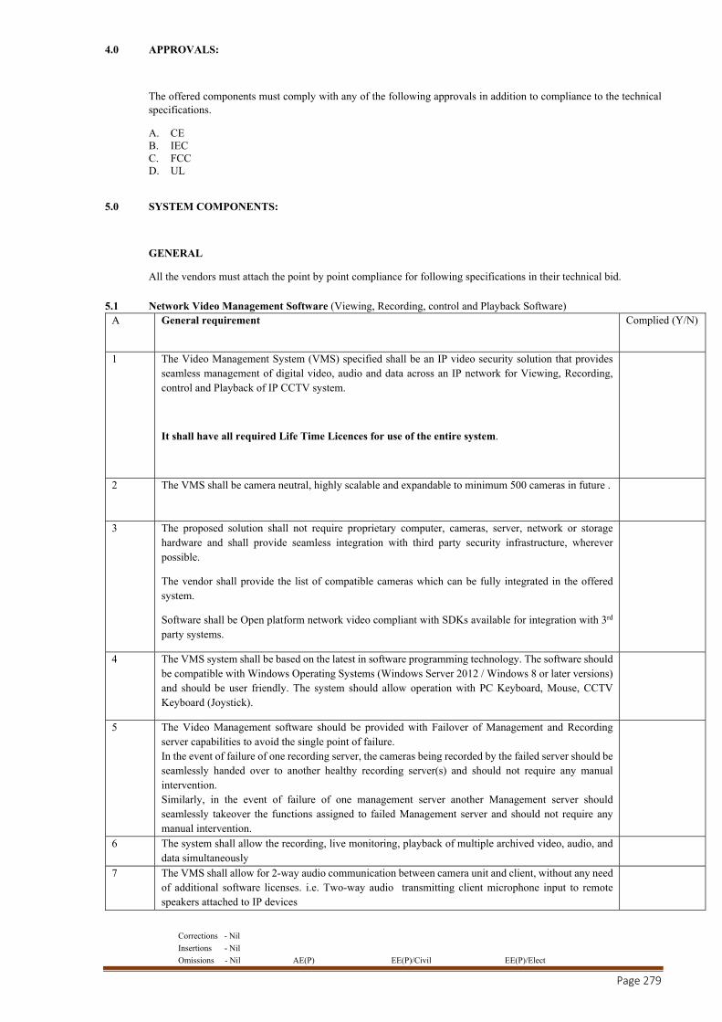
Corrections - Nil
Insertions - Nil
Omissions - Nil AE(P) EE(P)/Civil EE(P)/Elect
Page 279
4.0 APPROVALS:
The offered components must comply with any of the following approvals in addition to compliance to the technical specifications.
A. CE B. IEC C. FCC D. UL
5.0 SYSTEM COMPONENTS:
GENERAL
All the vendors must attach the point by point compliance for following specifications in their technical bid.
5.1 Network Video Management Software (Viewing, Recording, control and Playback Software) A General requirement Complied (Y/N)
1 The Video Management System (VMS) specified shall be an IP video security solution that provides seamless management of digital video, audio and data across an IP network for Viewing, Recording, control and Playback of IP CCTV system.
It shall have all required Life Time Licences for use of the entire system.
2 The VMS shall be camera neutral, highly scalable and expandable to minimum 500 cameras in future .
3 The proposed solution shall not require proprietary computer, cameras, server, network or storage hardware and shall provide seamless integration with third party security infrastructure, wherever possible.
The vendor shall provide the list of compatible cameras which can be fully integrated in the offered system.
Software shall be Open platform network video compliant with SDKs available for integration with 3rd party systems.
4 The VMS system shall be based on the latest in software programming technology. The software should be compatible with Windows Operating Systems (Windows Server 2012 / Windows 8 or later versions) and should be user friendly. The system should allow operation with PC Keyboard, Mouse, CCTV Keyboard (Joystick).
5 The Video Management software should be provided with Failover of Management and Recording server capabilities to avoid the single point of failure. In the event of failure of one recording server, the cameras being recorded by the failed server should be seamlessly handed over to another healthy recording server(s) and should not require any manual intervention. Similarly, in the event of failure of one management server another Management server should seamlessly takeover the functions assigned to failed Management server and should not require any manual intervention.
6 The system shall allow the recording, live monitoring, playback of multiple archived video, audio, and data simultaneously
7 The VMS shall allow for 2-way audio communication between camera unit and client, without any need of additional software licenses. i.e. Two-way audio transmitting client microphone input to remote speakers attached to IP devices
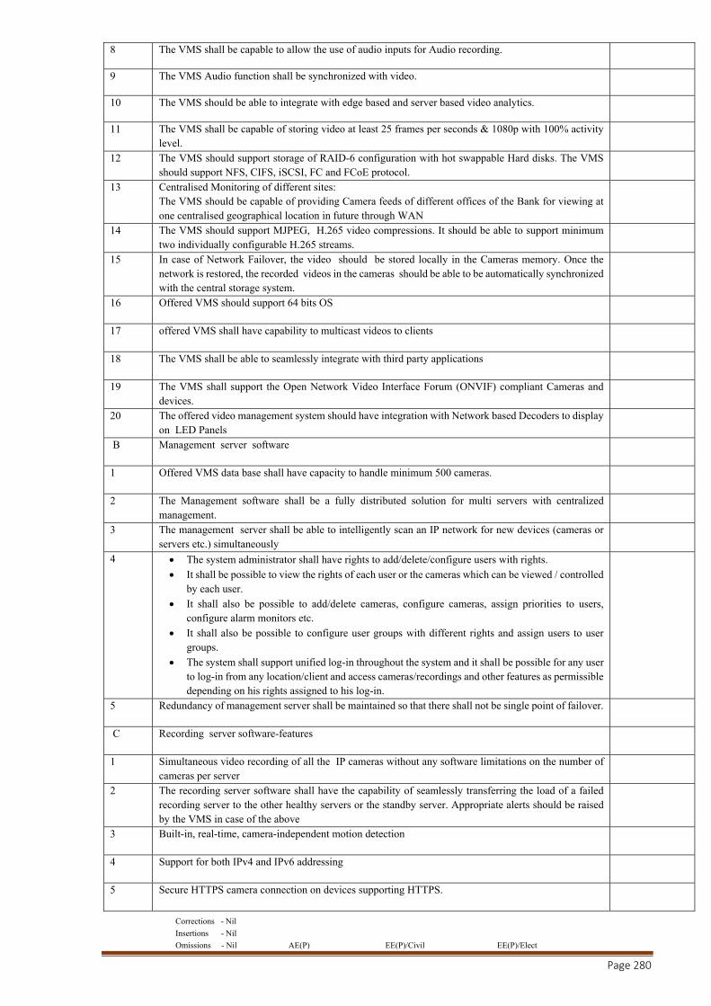
Corrections - Nil
Insertions - Nil
Omissions - Nil AE(P) EE(P)/Civil EE(P)/Elect
Page 280
8 The VMS shall be capable to allow the use of audio inputs for Audio recording.
9 The VMS Audio function shall be synchronized with video.
10 The VMS should be able to integrate with edge based and server based video analytics.
11 The VMS shall be capable of storing video at least 25 frames per seconds & 1080p with 100% activity level.
12 The VMS should support storage of RAID-6 configuration with hot swappable Hard disks. The VMS should support NFS, CIFS, iSCSI, FC and FCoE protocol.
13 Centralised Monitoring of different sites: The VMS should be capable of providing Camera feeds of different offices of the Bank for viewing at one centralised geographical location in future through WAN
14 The VMS should support MJPEG, H.265 video compressions. It should be able to support minimum two individually configurable H.265 streams.
15 In case of Network Failover, the video should be stored locally in the Cameras memory. Once the network is restored, the recorded videos in the cameras should be able to be automatically synchronized with the central storage system.
16 Offered VMS should support 64 bits OS
17 offered VMS shall have capability to multicast videos to clients
18 The VMS shall be able to seamlessly integrate with third party applications
19 The VMS shall support the Open Network Video Interface Forum (ONVIF) compliant Cameras and devices.
20 The offered video management system should have integration with Network based Decoders to display on LED Panels
B Management server software
1 Offered VMS data base shall have capacity to handle minimum 500 cameras.
2 The Management software shall be a fully distributed solution for multi servers with centralized management.
3 The management server shall be able to intelligently scan an IP network for new devices (cameras or servers etc.) simultaneously
4 The system administrator shall have rights to add/delete/configure users with rights.
It shall be possible to view the rights of each user or the cameras which can be viewed / controlled by each user.
It shall also be possible to add/delete cameras, configure cameras, assign priorities to users, configure alarm monitors etc.
It shall also be possible to configure user groups with different rights and assign users to user groups.
The system shall support unified log-in throughout the system and it shall be possible for any user to log-in from any location/client and access cameras/recordings and other features as permissible depending on his rights assigned to his log-in.
5 Redundancy of management server shall be maintained so that there shall not be single point of failover.
C Recording server software-features
1 Simultaneous video recording of all the IP cameras without any software limitations on the number of cameras per server
2 The recording server software shall have the capability of seamlessly transferring the load of a failed recording server to the other healthy servers or the standby server. Appropriate alerts should be raised by the VMS in case of the above
3 Built-in, real-time, camera-independent motion detection
4 Support for both IPv4 and IPv6 addressing
5 Secure HTTPS camera connection on devices supporting HTTPS.
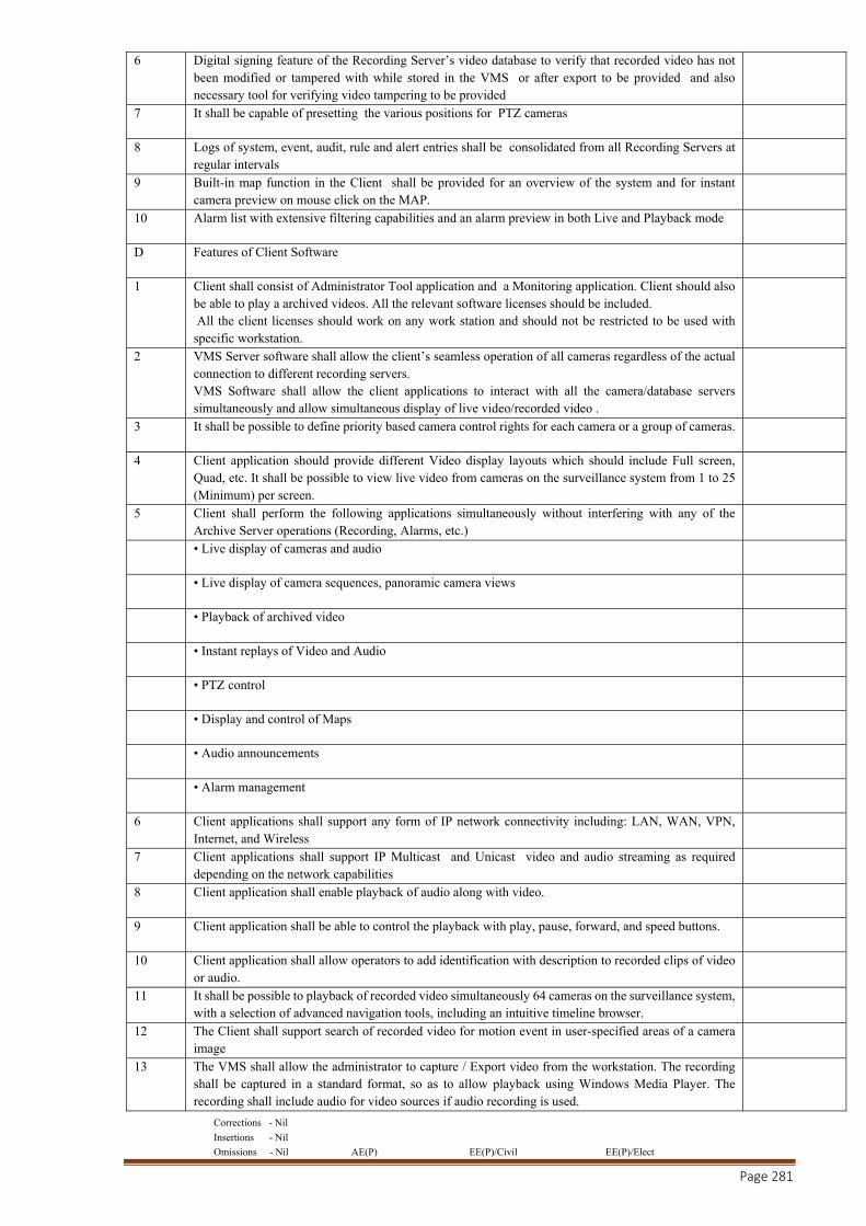
Corrections - Nil
Insertions - Nil
Omissions - Nil AE(P) EE(P)/Civil EE(P)/Elect
Page 281
6 Digital signing feature of the Recording Server’s video database to verify that recorded video has not been modified or tampered with while stored in the VMS or after export to be provided and also necessary tool for verifying video tampering to be provided
7 It shall be capable of presetting the various positions for PTZ cameras
8 Logs of system, event, audit, rule and alert entries shall be consolidated from all Recording Servers at regular intervals
9 Built-in map function in the Client shall be provided for an overview of the system and for instant camera preview on mouse click on the MAP.
10 Alarm list with extensive filtering capabilities and an alarm preview in both Live and Playback mode
D Features of Client Software
1 Client shall consist of Administrator Tool application and a Monitoring application. Client should also be able to play a archived videos. All the relevant software licenses should be included. All the client licenses should work on any work station and should not be restricted to be used with specific workstation.
2 VMS Server software shall allow the client’s seamless operation of all cameras regardless of the actual connection to different recording servers. VMS Software shall allow the client applications to interact with all the camera/database servers simultaneously and allow simultaneous display of live video/recorded video .
3 It shall be possible to define priority based camera control rights for each camera or a group of cameras.
4 Client application should provide different Video display layouts which should include Full screen, Quad, etc. It shall be possible to view live video from cameras on the surveillance system from 1 to 25 (Minimum) per screen.
5 Client shall perform the following applications simultaneously without interfering with any of the Archive Server operations (Recording, Alarms, etc.)
• Live display of cameras and audio
• Live display of camera sequences, panoramic camera views
• Playback of archived video
• Instant replays of Video and Audio
• PTZ control
• Display and control of Maps
• Audio announcements
• Alarm management
6 Client applications shall support any form of IP network connectivity including: LAN, WAN, VPN, Internet, and Wireless
7 Client applications shall support IP Multicast and Unicast video and audio streaming as required depending on the network capabilities
8 Client application shall enable playback of audio along with video.
9 Client application shall be able to control the playback with play, pause, forward, and speed buttons.
10 Client application shall allow operators to add identification with description to recorded clips of video or audio.
11 It shall be possible to playback of recorded video simultaneously 64 cameras on the surveillance system, with a selection of advanced navigation tools, including an intuitive timeline browser.
12 The Client shall support search of recorded video for motion event in user-specified areas of a camera image
13 The VMS shall allow the administrator to capture / Export video from the workstation. The recording shall be captured in a standard format, so as to allow playback using Windows Media Player. The recording shall include audio for video sources if audio recording is used.
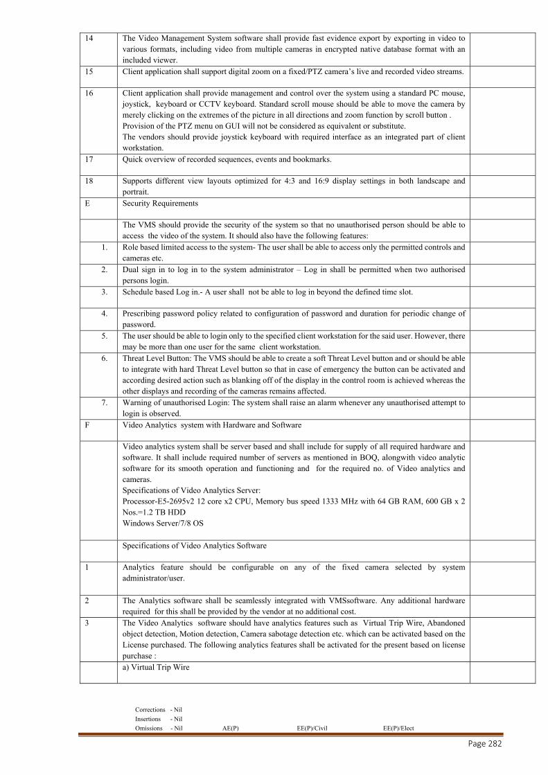
Corrections - Nil
Insertions - Nil
Omissions - Nil AE(P) EE(P)/Civil EE(P)/Elect
Page 282
14 The Video Management System software shall provide fast evidence export by exporting in video to various formats, including video from multiple cameras in encrypted native database format with an included viewer.
15 Client application shall support digital zoom on a fixed/PTZ camera’s live and recorded video streams.
16 Client application shall provide management and control over the system using a standard PC mouse, joystick, keyboard or CCTV keyboard. Standard scroll mouse should be able to move the camera by merely clicking on the extremes of the picture in all directions and zoom function by scroll button . Provision of the PTZ menu on GUI will not be considered as equivalent or substitute. The vendors should provide joystick keyboard with required interface as an integrated part of client workstation.
17 Quick overview of recorded sequences, events and bookmarks.
18 Supports different view layouts optimized for 4:3 and 16:9 display settings in both landscape and portrait.
E Security Requirements
The VMS should provide the security of the system so that no unauthorised person should be able to access the video of the system. It should also have the following features:
1. Role based limited access to the system- The user shall be able to access only the permitted controls and cameras etc.
2. Dual sign in to log in to the system administrator – Log in shall be permitted when two authorised persons login.
3. Schedule based Log in.- A user shall not be able to log in beyond the defined time slot.
4. Prescribing password policy related to configuration of password and duration for periodic change of password.
5. The user should be able to login only to the specified client workstation for the said user. However, there may be more than one user for the same client workstation.
6. Threat Level Button: The VMS should be able to create a soft Threat Level button and or should be able to integrate with hard Threat Level button so that in case of emergency the button can be activated and according desired action such as blanking off of the display in the control room is achieved whereas the other displays and recording of the cameras remains affected.
7. Warning of unauthorised Login: The system shall raise an alarm whenever any unauthorised attempt to login is observed.
F Video Analytics system with Hardware and Software
Video analytics system shall be server based and shall include for supply of all required hardware and software. It shall include required number of servers as mentioned in BOQ, alongwith video analytic software for its smooth operation and functioning and for the required no. of Video analytics and cameras. Specifications of Video Analytics Server: Processor-E5-2695v2 12 core x2 CPU, Memory bus speed 1333 MHz with 64 GB RAM, 600 GB x 2 Nos.=1.2 TB HDD Windows Server/7/8 OS
Specifications of Video Analytics Software
1 Analytics feature should be configurable on any of the fixed camera selected by system administrator/user.
2 The Analytics software shall be seamlessly integrated with VMSsoftware. Any additional hardware required for this shall be provided by the vendor at no additional cost.
3 The Video Analytics software should have analytics features such as Virtual Trip Wire, Abandoned object detection, Motion detection, Camera sabotage detection etc. which can be activated based on the License purchased. The following analytics features shall be activated for the present based on license purchase :
a) Virtual Trip Wire
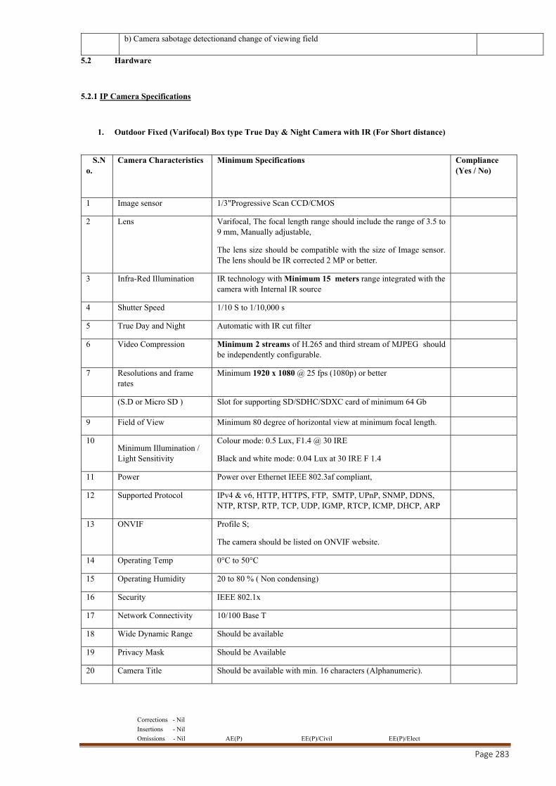
Corrections - Nil
Insertions - Nil
Omissions - Nil AE(P) EE(P)/Civil EE(P)/Elect
Page 283
b) Camera sabotage detectionand change of viewing field
5.2 Hardware
5.2.1 IP Camera Specifications
1. Outdoor Fixed (Varifocal) Box type True Day & Night Camera with IR (For Short distance)
S.No.
Camera Characteristics Minimum Specifications Compliance (Yes / No)
1 Image sensor 1/3"Progressive Scan CCD/CMOS
2 Lens Varifocal, The focal length range should include the range of 3.5 to 9 mm, Manually adjustable,
The lens size should be compatible with the size of Image sensor. The lens should be IR corrected 2 MP or better.
3 Infra-Red Illumination IR technology with Minimum 15 meters range integrated with the camera with Internal IR source
4 Shutter Speed 1/10 S to 1/10,000 s
5 True Day and Night Automatic with IR cut filter
6 Video Compression Minimum 2 streams of H.265 and third stream of MJPEG should be independently configurable.
7 Resolutions and frame rates
Minimum 1920 x 1080 @ 25 fps (1080p) or better
(S.D or Micro SD ) Slot for supporting SD/SDHC/SDXC card of minimum 64 Gb
9 Field of View Minimum 80 degree of horizontal view at minimum focal length.
10 Minimum Illumination / Light Sensitivity
Colour mode: 0.5 Lux, F1.4 @ 30 IRE
Black and white mode: 0.04 Lux at 30 IRE F 1.4
11 Power Power over Ethernet IEEE 802.3af compliant,
12 Supported Protocol IPv4 & v6, HTTP, HTTPS, FTP, SMTP, UPnP, SNMP, DDNS, NTP, RTSP, RTP, TCP, UDP, IGMP, RTCP, ICMP, DHCP, ARP
13 ONVIF Profile S;
The camera should be listed on ONVIF website.
14 Operating Temp 0°C to 50°C
15 Operating Humidity 20 to 80 % ( Non condensing)
16 Security IEEE 802.1x
17 Network Connectivity 10/100 Base T
18 Wide Dynamic Range Should be available
19 Privacy Mask Should be Available
20 Camera Title Should be available with min. 16 characters (Alphanumeric).
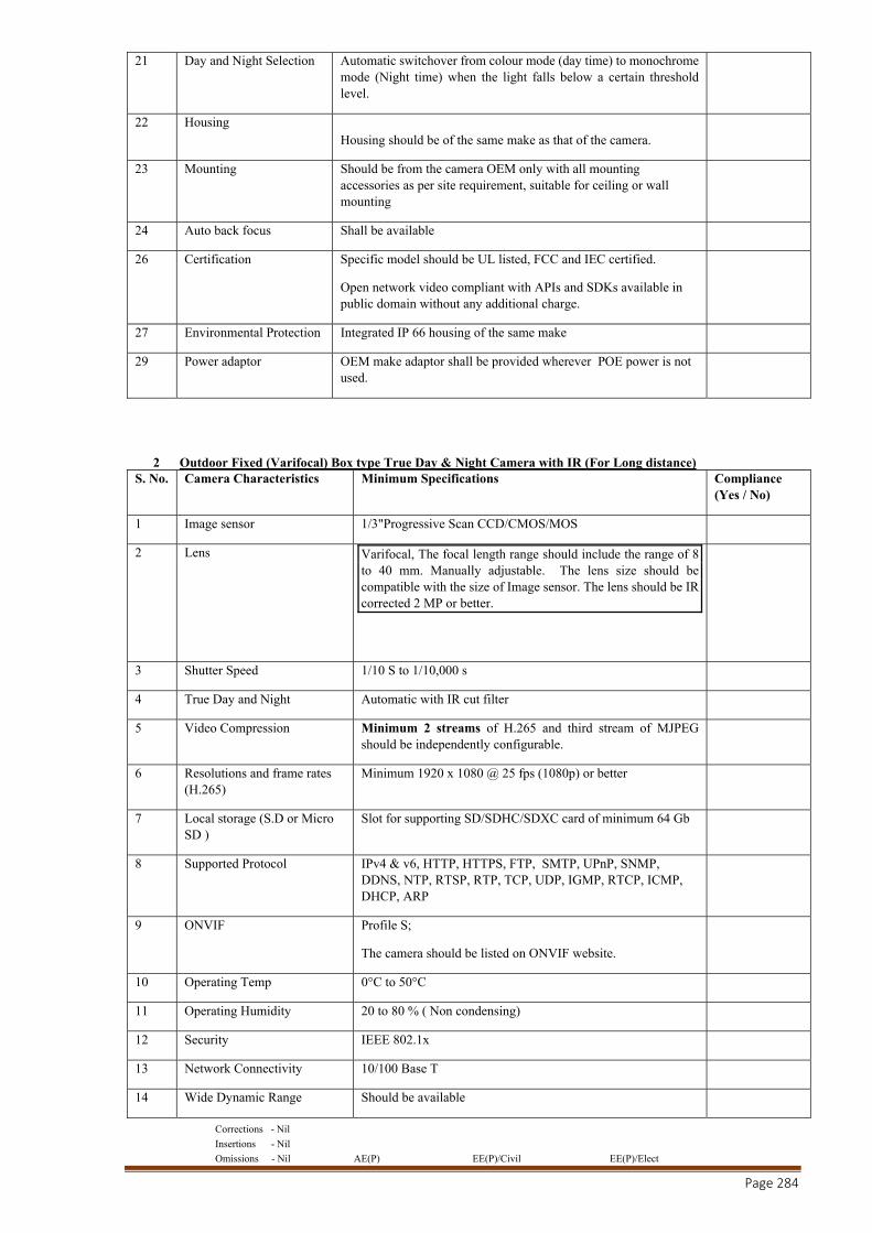
Corrections - Nil
Insertions - Nil
Omissions - Nil AE(P) EE(P)/Civil EE(P)/Elect
Page 284
21 Day and Night Selection Automatic switchover from colour mode (day time) to monochrome mode (Night time) when the light falls below a certain threshold level.
22 Housing Housing should be of the same make as that of the camera.
23 Mounting Should be from the camera OEM only with all mounting accessories as per site requirement, suitable for ceiling or wall mounting
24 Auto back focus Shall be available
26 Certification Specific model should be UL listed, FCC and IEC certified.
Open network video compliant with APIs and SDKs available in public domain without any additional charge.
27 Environmental Protection Integrated IP 66 housing of the same make
29 Power adaptor OEM make adaptor shall be provided wherever POE power is not used.
2 Outdoor Fixed (Varifocal) Box type True Day & Night Camera with IR (For Long distance) S. No. Camera Characteristics Minimum Specifications Compliance
(Yes / No)
1 Image sensor 1/3"Progressive Scan CCD/CMOS/MOS
2 Lens Varifocal, The focal length range should include the range of 8 to 40 mm. Manually adjustable. The lens size should be compatible with the size of Image sensor. The lens should be IR corrected 2 MP or better.
3 Shutter Speed 1/10 S to 1/10,000 s
4 True Day and Night Automatic with IR cut filter
5 Video Compression Minimum 2 streams of H.265 and third stream of MJPEG should be independently configurable.
6 Resolutions and frame rates (H.265)
Minimum 1920 x 1080 @ 25 fps (1080p) or better
7 Local storage (S.D or Micro SD )
Slot for supporting SD/SDHC/SDXC card of minimum 64 Gb
8 Supported Protocol IPv4 & v6, HTTP, HTTPS, FTP, SMTP, UPnP, SNMP, DDNS, NTP, RTSP, RTP, TCP, UDP, IGMP, RTCP, ICMP, DHCP, ARP
9 ONVIF Profile S;
The camera should be listed on ONVIF website.
10 Operating Temp 0°C to 50°C
11 Operating Humidity 20 to 80 % ( Non condensing)
12 Security IEEE 802.1x
13 Network Connectivity 10/100 Base T
14 Wide Dynamic Range Should be available
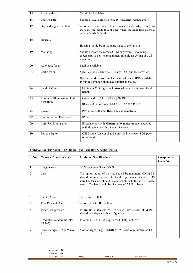
Corrections - Nil
Insertions - Nil
Omissions - Nil AE(P) EE(P)/Civil EE(P)/Elect
Page 285
15. Privacy Mask Should be Available
16. Camera Title Should be available with min. 16 characters (Alphanumeric).
17. Day and Night Selection Automatic switchover from colour mode (day time) to monochrome mode (Night time) when the light falls below a certain threshold level.
18. Housing
Housing should be of the same make of the camera.
19 Mounting Should be from the camera OEM only with all mounting accessories as per site requirement suitable for ceiling or wall mounting;
20 Auto back focus Shall be available
23 Certification Specific model should be UL listed, FCC and IEC certified.
Open network video compliant with APIs and SDKs available in public domain without any additional charge.
24 Field of View Minimum 33.5 degree of horizontal view at minimum focal length.
25 Minimum Illumination / Light Sensitivity
Color mode: 0.5 Lux, F1.4 @ 30 IRE
Black and white mode: 0.04 Lux at 30 IRE F 1.4)
26 Power Power over Ethernet IEEE 802.3af compliant,
27 Environmental Protection IP 66
29 Infra-Red Illumination IR technology with Minimum 40 meters range integrated with the camera with Internal IR source
30 Power adaptor OEM make Adaptor shall be provided wherever POE power is not used.
3.Outdoor Pan Tilt Zoom (PTZ) Dome Type True Day & Night Camera
S. No. Camera Characteristics Minimum Specifications Compliance (Yes / No)
1 Image sensor 1/3"Progressive Scan CMOS
2 Lens The optical zoom of the lens should be minimum 30X and it should necessarily cover the focal length range of 4.5 to 135 mm The lens size should be compatible with the size of Image sensor. The lens should be IR corrected 2 MP or better.
3 Shutter Speed 1/10 S to 1/10,000 s
4 True Day and Night Automatic with IR cut filter
5 Video Compression Minimum 2 streams of H.265 and third stream of MJPEG should be independently configurable.
6 Resolutions and frame rates (H.265)
Minimum 1920 x 1080 @ 30 fps (1080p) or better
7 Local storage (S.D or Micro SD )
Slot for supporting SD/SDHC/SDXC card of minimum 64 Gb
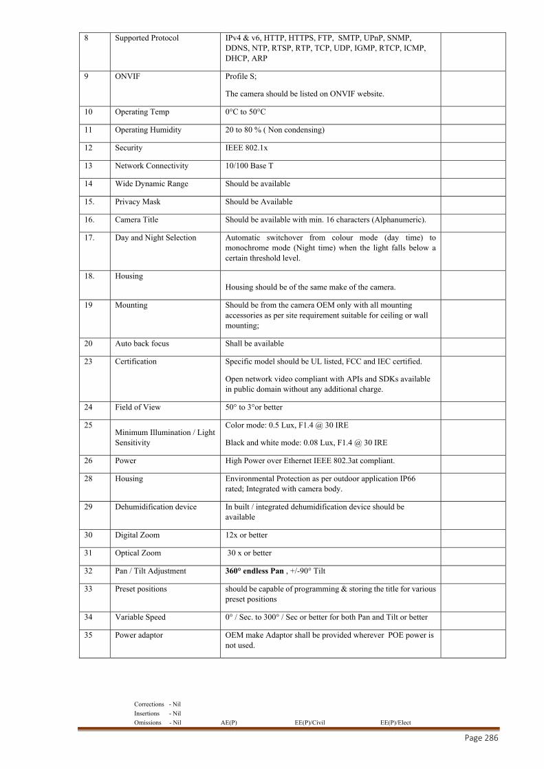
Corrections - Nil
Insertions - Nil
Omissions - Nil AE(P) EE(P)/Civil EE(P)/Elect
Page 286
8 Supported Protocol IPv4 & v6, HTTP, HTTPS, FTP, SMTP, UPnP, SNMP, DDNS, NTP, RTSP, RTP, TCP, UDP, IGMP, RTCP, ICMP, DHCP, ARP
9 ONVIF Profile S;
The camera should be listed on ONVIF website.
10 Operating Temp 0°C to 50°C
11 Operating Humidity 20 to 80 % ( Non condensing)
12 Security IEEE 802.1x
13 Network Connectivity 10/100 Base T
14 Wide Dynamic Range Should be available
15. Privacy Mask Should be Available
16. Camera Title Should be available with min. 16 characters (Alphanumeric).
17. Day and Night Selection Automatic switchover from colour mode (day time) to monochrome mode (Night time) when the light falls below a certain threshold level.
18. Housing Housing should be of the same make of the camera.
19 Mounting Should be from the camera OEM only with all mounting accessories as per site requirement suitable for ceiling or wall mounting;
20 Auto back focus Shall be available
23 Certification Specific model should be UL listed, FCC and IEC certified.
Open network video compliant with APIs and SDKs available in public domain without any additional charge.
24 Field of View 50° to 3°or better
25 Minimum Illumination / Light Sensitivity
Color mode: 0.5 Lux, F1.4 @ 30 IRE
Black and white mode: 0.08 Lux, F1.4 @ 30 IRE
26 Power High Power over Ethernet IEEE 802.3at compliant.
28 Housing Environmental Protection as per outdoor application IP66 rated; Integrated with camera body.
29 Dehumidification device In built / integrated dehumidification device should be available
30 Digital Zoom 12x or better
31 Optical Zoom 30 x or better
32 Pan / Tilt Adjustment 360° endless Pan , +/-90° Tilt
33 Preset positions should be capable of programming & storing the title for various preset positions
34 Variable Speed 0° / Sec. to 300° / Sec or better for both Pan and Tilt or better
35 Power adaptor OEM make Adaptor shall be provided wherever POE power is not used.
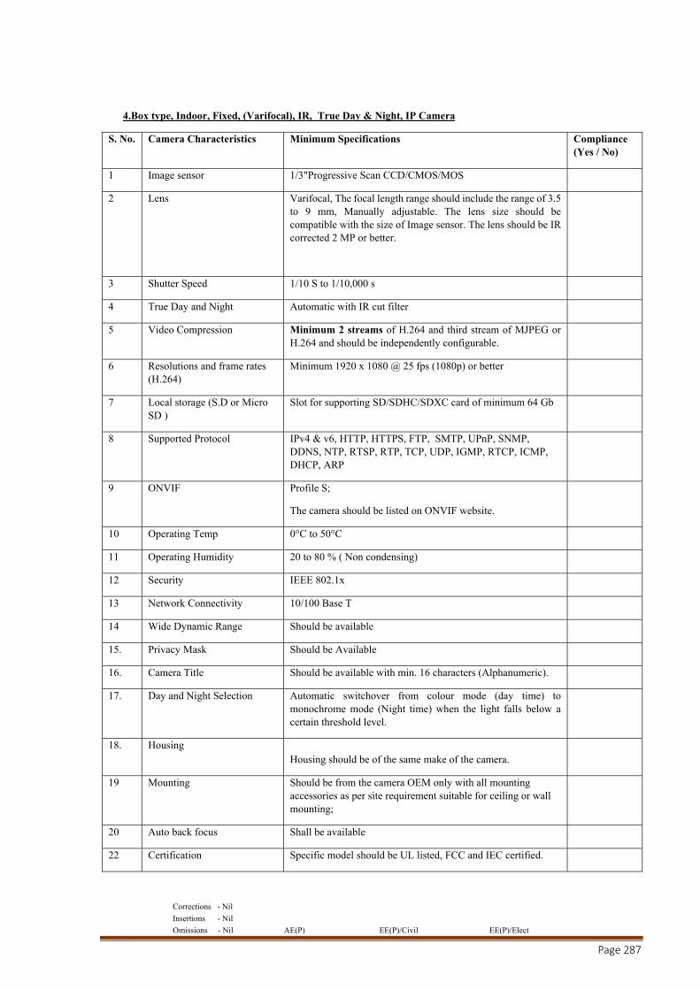
Corrections - Nil
Insertions - Nil
Omissions - Nil AE(P) EE(P)/Civil EE(P)/Elect
Page 287
4.Box type, Indoor, Fixed, (Varifocal), IR, True Day & Night, IP Camera
S. No. Camera Characteristics Minimum Specifications Compliance (Yes / No)
1 Image sensor 1/3"Progressive Scan CCD/CMOS/MOS
2 Lens Varifocal, The focal length range should include the range of 3.5 to 9 mm, Manually adjustable. The lens size should be compatible with the size of Image sensor. The lens should be IR corrected 2 MP or better.
3 Shutter Speed 1/10 S to 1/10,000 s
4 True Day and Night Automatic with IR cut filter
5 Video Compression Minimum 2 streams of H.264 and third stream of MJPEG or H.264 and should be independently configurable.
6 Resolutions and frame rates (H.264)
Minimum 1920 x 1080 @ 25 fps (1080p) or better
7 Local storage (S.D or Micro SD )
Slot for supporting SD/SDHC/SDXC card of minimum 64 Gb
8 Supported Protocol IPv4 & v6, HTTP, HTTPS, FTP, SMTP, UPnP, SNMP, DDNS, NTP, RTSP, RTP, TCP, UDP, IGMP, RTCP, ICMP, DHCP, ARP
9 ONVIF Profile S;
The camera should be listed on ONVIF website.
10 Operating Temp 0°C to 50°C
11 Operating Humidity 20 to 80 % ( Non condensing)
12 Security IEEE 802.1x
13 Network Connectivity 10/100 Base T
14 Wide Dynamic Range Should be available
15. Privacy Mask Should be Available
16. Camera Title Should be available with min. 16 characters (Alphanumeric).
17. Day and Night Selection Automatic switchover from colour mode (day time) to monochrome mode (Night time) when the light falls below a certain threshold level.
18. Housing Housing should be of the same make of the camera.
19 Mounting Should be from the camera OEM only with all mounting accessories as per site requirement suitable for ceiling or wall mounting;
20 Auto back focus Shall be available
22 Certification Specific model should be UL listed, FCC and IEC certified.
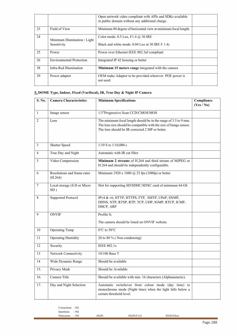
Corrections - Nil
Insertions - Nil
Omissions - Nil AE(P) EE(P)/Civil EE(P)/Elect
Page 288
Open network video compliant with APIs and SDKs available in public domain without any additional charge.
23 Field of View Minimum 80 degree of horizontal view at minimum focal length.
24 Minimum Illumination / Light Sensitivity
Color mode: 0.5 Lux, F1.4 @ 30 IRE
Black and white mode: 0.04 Lux at 30 IRE F 1.4)
25 Power Power over Ethernet IEEE 802.3af compliant
26 Environmental Protection Integrated IP 42 housing or better
38 Infra-Red Illumination Minimum 15 meters range integrated with the camera
29 Power adaptor OEM make Adaptor to be provided wherever POE power is not used.
5. DOME Type, Indoor, Fixed (Varifocal), IR, True Day & Night IP Camera
S. No. Camera Characteristics Minimum Specifications Compliance (Yes / No)
1 Image sensor 1/3"Progressive Scan CCD/CMOS/MOS
2 Lens The minimum focal length should be in the range of 3.5 to 9 mm. The lens size should be compatible with the size of Image sensor. The lens should be IR corrected 2 MP or better.
3 Shutter Speed 1/10 S to 1/10,000 s
4 True Day and Night Automatic with IR cut filter
5 Video Compression Minimum 2 streams of H.264 and third stream of MJPEG or H.264 and should be independently configurable.
6 Resolutions and frame rates (H.264)
Minimum 1920 x 1080 @ 25 fps (1080p) or better
7 Local storage (S.D or Micro SD )
Slot for supporting SD/SDHC/SDXC card of minimum 64 Gb
8 Supported Protocol IPv4 & v6, HTTP, HTTPS, FTP, SMTP, UPnP, SNMP, DDNS, NTP, RTSP, RTP, TCP, UDP, IGMP, RTCP, ICMP, DHCP, ARP
9 ONVIF Profile S;
The camera should be listed on ONVIF website.
10 Operating Temp 0°C to 50°C
11 Operating Humidity 20 to 80 % ( Non condensing)
12 Security IEEE 802.1x
13 Network Connectivity 10/100 Base T
14 Wide Dynamic Range Should be available
15. Privacy Mask Should be Available
16. Camera Title Should be available with min. 16 characters (Alphanumeric).
17. Day and Night Selection Automatic switchover from colour mode (day time) to monochrome mode (Night time) when the light falls below a certain threshold level.
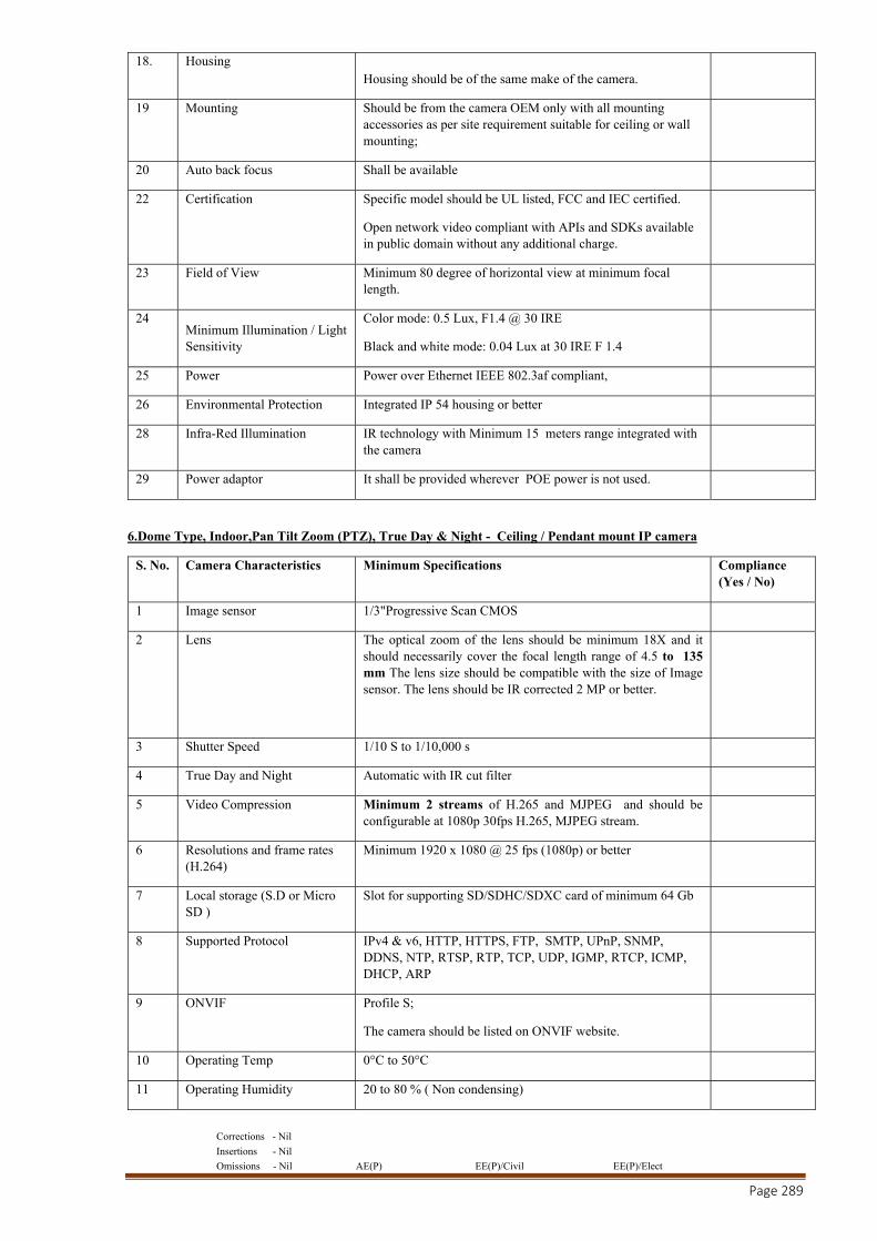
Corrections - Nil
Insertions - Nil
Omissions - Nil AE(P) EE(P)/Civil EE(P)/Elect
Page 289
18. Housing Housing should be of the same make of the camera.
19 Mounting Should be from the camera OEM only with all mounting accessories as per site requirement suitable for ceiling or wall mounting;
20 Auto back focus Shall be available
22 Certification Specific model should be UL listed, FCC and IEC certified.
Open network video compliant with APIs and SDKs available in public domain without any additional charge.
23 Field of View Minimum 80 degree of horizontal view at minimum focal length.
24 Minimum Illumination / Light Sensitivity
Color mode: 0.5 Lux, F1.4 @ 30 IRE
Black and white mode: 0.04 Lux at 30 IRE F 1.4
25 Power Power over Ethernet IEEE 802.3af compliant,
26 Environmental Protection Integrated IP 54 housing or better
28 Infra-Red Illumination IR technology with Minimum 15 meters range integrated with the camera
29 Power adaptor It shall be provided wherever POE power is not used.
6.Dome Type, Indoor,Pan Tilt Zoom (PTZ), True Day & Night - Ceiling / Pendant mount IP camera
S. No. Camera Characteristics Minimum Specifications Compliance (Yes / No)
1 Image sensor 1/3"Progressive Scan CMOS
2 Lens The optical zoom of the lens should be minimum 18X and it should necessarily cover the focal length range of 4.5 to 135 mm The lens size should be compatible with the size of Image sensor. The lens should be IR corrected 2 MP or better.
3 Shutter Speed 1/10 S to 1/10,000 s
4 True Day and Night Automatic with IR cut filter
5 Video Compression Minimum 2 streams of H.265 and MJPEG and should be configurable at 1080p 30fps H.265, MJPEG stream.
6 Resolutions and frame rates (H.264)
Minimum 1920 x 1080 @ 25 fps (1080p) or better
7 Local storage (S.D or Micro SD )
Slot for supporting SD/SDHC/SDXC card of minimum 64 Gb
8 Supported Protocol IPv4 & v6, HTTP, HTTPS, FTP, SMTP, UPnP, SNMP, DDNS, NTP, RTSP, RTP, TCP, UDP, IGMP, RTCP, ICMP, DHCP, ARP
9 ONVIF Profile S;
The camera should be listed on ONVIF website.
10 Operating Temp 0°C to 50°C
11 Operating Humidity 20 to 80 % ( Non condensing)
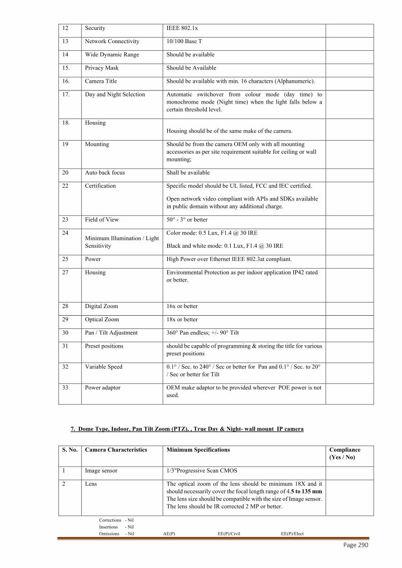
Corrections - Nil
Insertions - Nil
Omissions - Nil AE(P) EE(P)/Civil EE(P)/Elect
Page 290
12 Security IEEE 802.1x
13 Network Connectivity 10/100 Base T
14 Wide Dynamic Range Should be available
15. Privacy Mask Should be Available
16. Camera Title Should be available with min. 16 characters (Alphanumeric).
17. Day and Night Selection Automatic switchover from colour mode (day time) to monochrome mode (Night time) when the light falls below a certain threshold level.
18. Housing Housing should be of the same make of the camera.
19 Mounting Should be from the camera OEM only with all mounting accessories as per site requirement suitable for ceiling or wall mounting;
20 Auto back focus Shall be available
22 Certification Specific model should be UL listed, FCC and IEC certified.
Open network video compliant with APIs and SDKs available in public domain without any additional charge.
23 Field of View 50° - 3° or better
24 Minimum Illumination / Light Sensitivity
Color mode: 0.5 Lux, F1.4 @ 30 IRE
Black and white mode: 0.1 Lux, F1.4 @ 30 IRE
25 Power High Power over Ethernet IEEE 802.3at compliant.
27 Housing Environmental Protection as per indoor application IP42 rated or better.
28 Digital Zoom 16x or better
29 Optical Zoom 18x or better
30 Pan / Tilt Adjustment 360° Pan endless; +/- 90° Tilt
31 Preset positions should be capable of programming & storing the title for various preset positions
32 Variable Speed 0.1° / Sec. to 240° / Sec or better for Pan and 0.1° / Sec. to 20° / Sec or better for Tilt
33 Power adaptor OEM make adaptor to be provided wherever POE power is not used.
7. Dome Type, Indoor, Pan Tilt Zoom (PTZ), , True Day & Night- wall mount IP camera
S. No. Camera Characteristics Minimum Specifications Compliance
(Yes / No)
1 Image sensor 1/3"Progressive Scan CMOS
2 Lens The optical zoom of the lens should be minimum 18X and it should necessarily cover the focal length range of 4.5 to 135 mm The lens size should be compatible with the size of Image sensor. The lens should be IR corrected 2 MP or better.
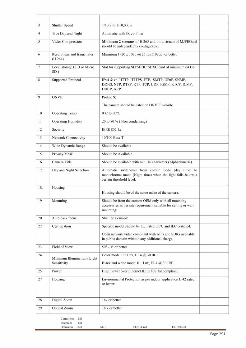
Corrections - Nil
Insertions - Nil
Omissions - Nil AE(P) EE(P)/Civil EE(P)/Elect
Page 291
3 Shutter Speed 1/10 S to 1/10,000 s
4 True Day and Night Automatic with IR cut filter
5 Video Compression Minimum 2 streams of H.265 and third stream of MJPEGand should be independently configurable.
6 Resolutions and frame rates (H.264)
Minimum 1920 x 1080 @ 25 fps (1080p) or better
7 Local storage (S.D or Micro SD )
Slot for supporting SD/SDHC/SDXC card of minimum 64 Gb
8 Supported Protocol IPv4 & v6, HTTP, HTTPS, FTP, SMTP, UPnP, SNMP, DDNS, NTP, RTSP, RTP, TCP, UDP, IGMP, RTCP, ICMP, DHCP, ARP
9 ONVIF Profile S;
The camera should be listed on ONVIF website.
10 Operating Temp 0°C to 50°C
11 Operating Humidity 20 to 80 % ( Non condensing)
12 Security IEEE 802.1x
13 Network Connectivity 10/100 Base T
14 Wide Dynamic Range Should be available
15. Privacy Mask Should be Available
16. Camera Title Should be available with min. 16 characters (Alphanumeric).
17. Day and Night Selection Automatic switchover from colour mode (day time) to monochrome mode (Night time) when the light falls below a certain threshold level.
18. Housing Housing should be of the same make of the camera.
19 Mounting Should be from the camera OEM only with all mounting accessories as per site requirement suitable for ceiling or wall mounting;
20 Auto back focus Shall be available
22 Certification Specific model should be UL listed, FCC and IEC certified.
Open network video compliant with APIs and SDKs available in public domain without any additional charge.
23 Field of View 50° - 3° or better
24 Minimum Illumination / Light Sensitivity
Color mode: 0.5 Lux, F1.4 @ 30 IRE
Black and white mode: 0.1 Lux, F1.4 @ 30 IRE
25 Power High Power over Ethernet IEEE 802.3at compliant.
27 Housing Environmental Protection as per indoor application IP42 rated or better.
28 Digital Zoom 16x or better
29 Optical Zoom 18 x or better
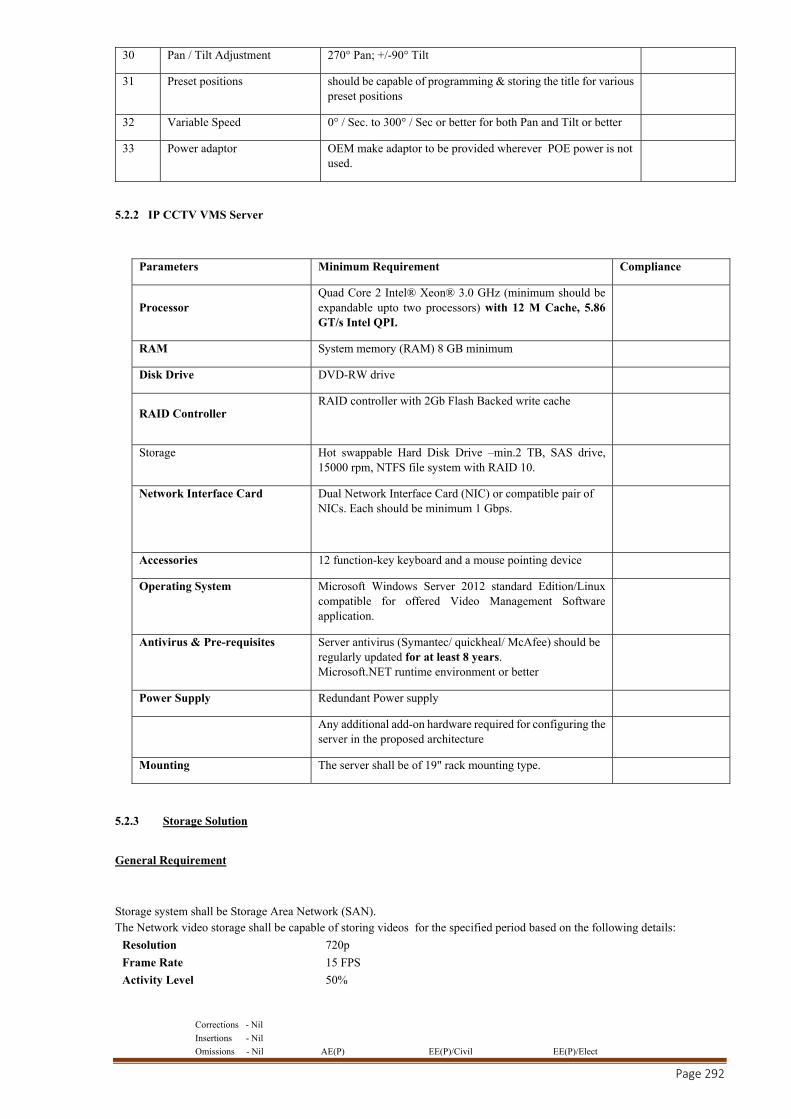
Corrections - Nil
Insertions - Nil
Omissions - Nil AE(P) EE(P)/Civil EE(P)/Elect
Page 292
30 Pan / Tilt Adjustment 270° Pan; +/-90° Tilt
31 Preset positions should be capable of programming & storing the title for various preset positions
32 Variable Speed 0° / Sec. to 300° / Sec or better for both Pan and Tilt or better
33 Power adaptor OEM make adaptor to be provided wherever POE power is not used.
5.2.2 IP CCTV VMS Server
Parameters Minimum Requirement Compliance
Processor Quad Core 2 Intel® Xeon® 3.0 GHz (minimum should be expandable upto two processors) with 12 M Cache, 5.86 GT/s Intel QPI.
RAM System memory (RAM) 8 GB minimum
Disk Drive DVD-RW drive
RAID Controller RAID controller with 2Gb Flash Backed write cache
Storage Hot swappable Hard Disk Drive –min.2 TB, SAS drive, 15000 rpm, NTFS file system with RAID 10.
Network Interface Card Dual Network Interface Card (NIC) or compatible pair of NICs. Each should be minimum 1 Gbps.
Accessories 12 function-key keyboard and a mouse pointing device
Operating System Microsoft Windows Server 2012 standard Edition/Linux compatible for offered Video Management Software application.
Antivirus & Pre-requisites Server antivirus (Symantec/ quickheal/ McAfee) should be regularly updated for at least 8 years. Microsoft.NET runtime environment or better
Power Supply Redundant Power supply
Any additional add-on hardware required for configuring the server in the proposed architecture
Mounting The server shall be of 19" rack mounting type.
5.2.3 Storage Solution
General Requirement
Storage system shall be Storage Area Network (SAN). The Network video storage shall be capable of storing videos for the specified period based on the following details:
Resolution 720p
Frame Rate 15 FPS
Activity Level 50%
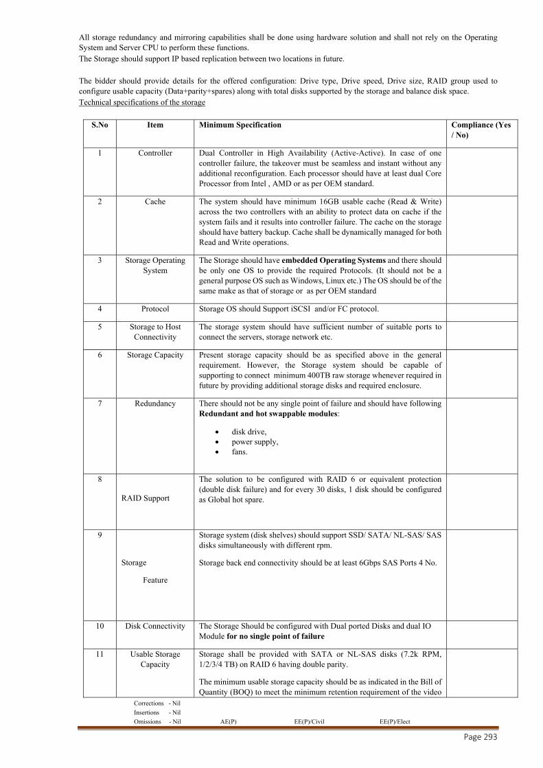
Corrections - Nil
Insertions - Nil
Omissions - Nil AE(P) EE(P)/Civil EE(P)/Elect
Page 293
All storage redundancy and mirroring capabilities shall be done using hardware solution and shall not rely on the Operating System and Server CPU to perform these functions. The Storage should support IP based replication between two locations in future. The bidder should provide details for the offered configuration: Drive type, Drive speed, Drive size, RAID group used to configure usable capacity (Data+parity+spares) along with total disks supported by the storage and balance disk space. Technical specifications of the storage
S.No Item Minimum Specification Compliance (Yes / No)
1 Controller Dual Controller in High Availability (Active-Active). In case of one controller failure, the takeover must be seamless and instant without any additional reconfiguration. Each processor should have at least dual Core Processor from Intel , AMD or as per OEM standard.
2 Cache The system should have minimum 16GB usable cache (Read & Write) across the two controllers with an ability to protect data on cache if the system fails and it results into controller failure. The cache on the storage should have battery backup. Cache shall be dynamically managed for both Read and Write operations.
3 Storage Operating System
The Storage should have embedded Operating Systems and there should be only one OS to provide the required Protocols. (It should not be a general purpose OS such as Windows, Linux etc.) The OS should be of the same make as that of storage or as per OEM standard
4 Protocol Storage OS should Support iSCSI and/or FC protocol.
5 Storage to Host Connectivity
The storage system should have sufficient number of suitable ports to connect the servers, storage network etc.
6 Storage Capacity Present storage capacity should be as specified above in the general requirement. However, the Storage system should be capable of supporting to connect minimum 400TB raw storage whenever required in future by providing additional storage disks and required enclosure.
7 Redundancy There should not be any single point of failure and should have following Redundant and hot swappable modules:
disk drive, power supply, fans.
8
RAID Support
The solution to be configured with RAID 6 or equivalent protection (double disk failure) and for every 30 disks, 1 disk should be configured as Global hot spare.
9
Storage
Feature
Storage system (disk shelves) should support SSD/ SATA/ NL-SAS/ SAS disks simultaneously with different rpm.
Storage back end connectivity should be at least 6Gbps SAS Ports 4 No.
10 Disk Connectivity The Storage Should be configured with Dual ported Disks and dual IO Module for no single point of failure
11 Usable Storage Capacity
Storage shall be provided with SATA or NL-SAS disks (7.2k RPM, 1/2/3/4 TB) on RAID 6 having double parity.
The minimum usable storage capacity should be as indicated in the Bill of Quantity (BOQ) to meet the minimum retention requirement of the video
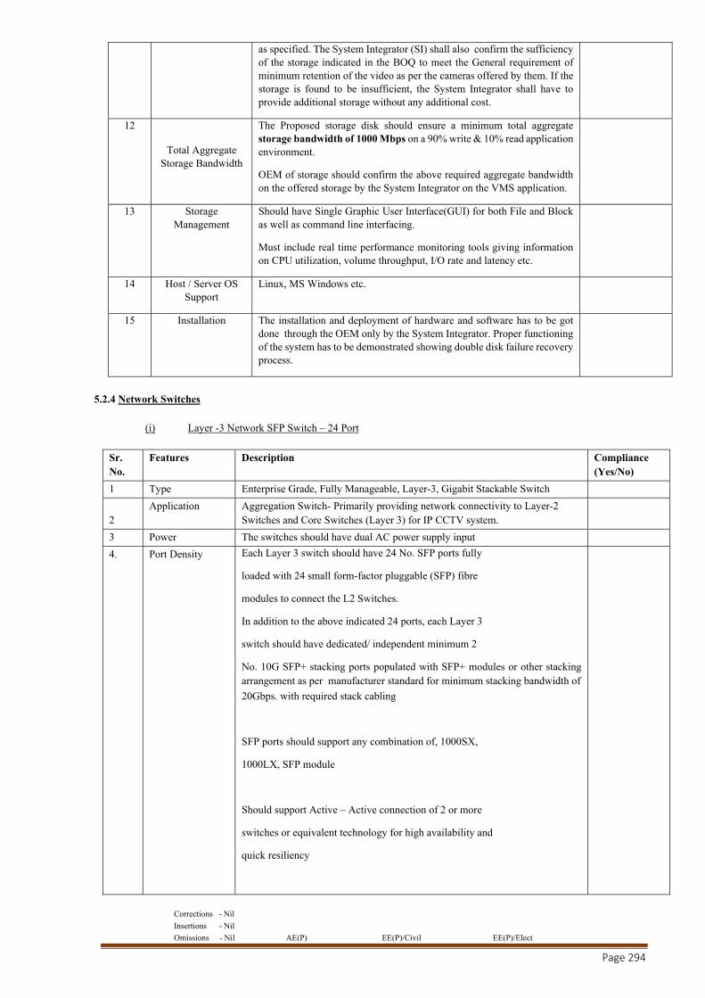
Corrections - Nil
Insertions - Nil
Omissions - Nil AE(P) EE(P)/Civil EE(P)/Elect
Page 294
as specified. The System Integrator (SI) shall also confirm the sufficiency of the storage indicated in the BOQ to meet the General requirement of minimum retention of the video as per the cameras offered by them. If the storage is found to be insufficient, the System Integrator shall have to provide additional storage without any additional cost.
12
Total Aggregate Storage Bandwidth
The Proposed storage disk should ensure a minimum total aggregate storage bandwidth of 1000 Mbps on a 90% write & 10% read application environment.
OEM of storage should confirm the above required aggregate bandwidth on the offered storage by the System Integrator on the VMS application.
13 Storage Management
Should have Single Graphic User Interface(GUI) for both File and Block as well as command line interfacing.
Must include real time performance monitoring tools giving information on CPU utilization, volume throughput, I/O rate and latency etc.
14 Host / Server OS Support
Linux, MS Windows etc.
15 Installation The installation and deployment of hardware and software has to be got done through the OEM only by the System Integrator. Proper functioning of the system has to be demonstrated showing double disk failure recovery process.
5.2.4 Network Switches
(i) Layer -3 Network SFP Switch – 24 Port
Sr. No.
Features Description Compliance (Yes/No)
1 Type Enterprise Grade, Fully Manageable, Layer-3, Gigabit Stackable Switch
2 Application Aggregation Switch- Primarily providing network connectivity to Layer-2
Switches and Core Switches (Layer 3) for IP CCTV system.
3 Power The switches should have dual AC power supply input
4. Port Density Each Layer 3 switch should have 24 No. SFP ports fully
loaded with 24 small form-factor pluggable (SFP) fibre
modules to connect the L2 Switches.
In addition to the above indicated 24 ports, each Layer 3
switch should have dedicated/ independent minimum 2
No. 10G SFP+ stacking ports populated with SFP+ modules or other stacking arrangement as per manufacturer standard for minimum stacking bandwidth of
20Gbps. with required stack cabling
SFP ports should support any combination of, 1000SX,
1000LX, SFP module
Should support Active – Active connection of 2 or more
switches or equivalent technology for high availability and
quick resiliency
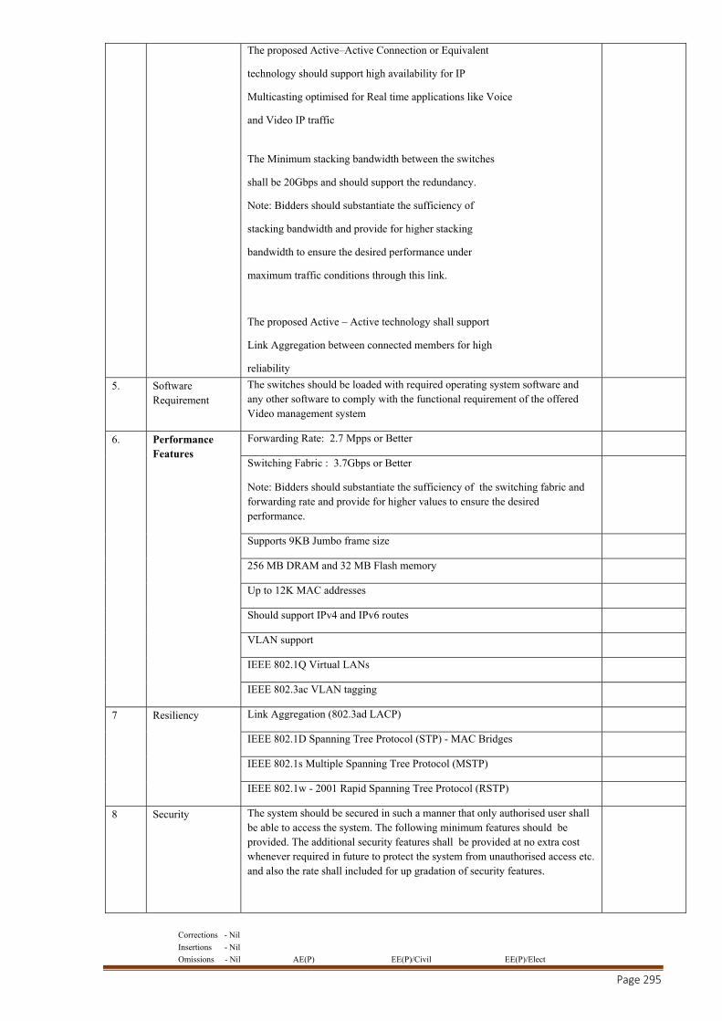
Corrections - Nil
Insertions - Nil
Omissions - Nil AE(P) EE(P)/Civil EE(P)/Elect
Page 295
The proposed Active–Active Connection or Equivalent
technology should support high availability for IP
Multicasting optimised for Real time applications like Voice
and Video IP traffic
The Minimum stacking bandwidth between the switches
shall be 20Gbps and should support the redundancy.
Note: Bidders should substantiate the sufficiency of
stacking bandwidth and provide for higher stacking
bandwidth to ensure the desired performance under
maximum traffic conditions through this link.
The proposed Active – Active technology shall support
Link Aggregation between connected members for high
reliability
5. Software Requirement
The switches should be loaded with required operating system software and any other software to comply with the functional requirement of the offered Video management system
6. Performance Features
Forwarding Rate: 2.7 Mpps or Better
Switching Fabric : 3.7Gbps or Better
Note: Bidders should substantiate the sufficiency of the switching fabric and forwarding rate and provide for higher values to ensure the desired performance.
Supports 9KB Jumbo frame size
256 MB DRAM and 32 MB Flash memory
Up to 12K MAC addresses
Should support IPv4 and IPv6 routes
VLAN support
IEEE 802.1Q Virtual LANs
IEEE 802.3ac VLAN tagging
7 Resiliency Link Aggregation (802.3ad LACP)
IEEE 802.1D Spanning Tree Protocol (STP) - MAC Bridges
IEEE 802.1s Multiple Spanning Tree Protocol (MSTP)
IEEE 802.1w - 2001 Rapid Spanning Tree Protocol (RSTP)
8 Security The system should be secured in such a manner that only authorised user shall be able to access the system. The following minimum features should be provided. The additional security features shall be provided at no extra cost whenever required in future to protect the system from unauthorised access etc. and also the rate shall included for up gradation of security features.
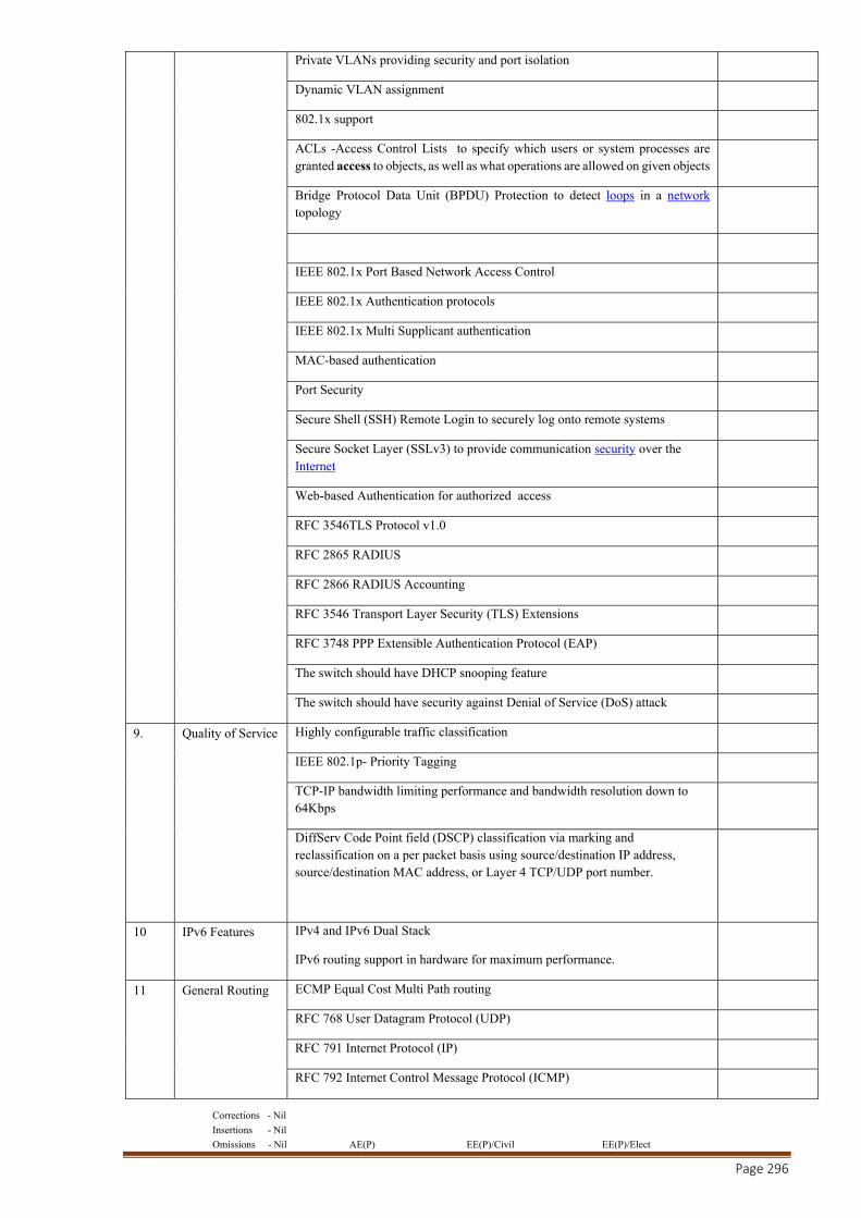
Corrections - Nil
Insertions - Nil
Omissions - Nil AE(P) EE(P)/Civil EE(P)/Elect
Page 296
Private VLANs providing security and port isolation
Dynamic VLAN assignment
802.1x support
ACLs -Access Control Lists to specify which users or system processes are granted access to objects, as well as what operations are allowed on given objects
Bridge Protocol Data Unit (BPDU) Protection to detect loops in a network topology
IEEE 802.1x Port Based Network Access Control
IEEE 802.1x Authentication protocols
IEEE 802.1x Multi Supplicant authentication
MAC-based authentication
Port Security
Secure Shell (SSH) Remote Login to securely log onto remote systems
Secure Socket Layer (SSLv3) to provide communication security over the Internet
Web-based Authentication for authorized access
RFC 3546TLS Protocol v1.0
RFC 2865 RADIUS
RFC 2866 RADIUS Accounting
RFC 3546 Transport Layer Security (TLS) Extensions
RFC 3748 PPP Extensible Authentication Protocol (EAP)
The switch should have DHCP snooping feature
The switch should have security against Denial of Service (DoS) attack
9. Quality of Service Highly configurable traffic classification
IEEE 802.1p- Priority Tagging
TCP-IP bandwidth limiting performance and bandwidth resolution down to 64Kbps
DiffServ Code Point field (DSCP) classification via marking and reclassification on a per packet basis using source/destination IP address, source/destination MAC address, or Layer 4 TCP/UDP port number.
10 IPv6 Features IPv4 and IPv6 Dual Stack
IPv6 routing support in hardware for maximum performance.
11 General Routing ECMP Equal Cost Multi Path routing
RFC 768 User Datagram Protocol (UDP)
RFC 791 Internet Protocol (IP)
RFC 792 Internet Control Message Protocol (ICMP)
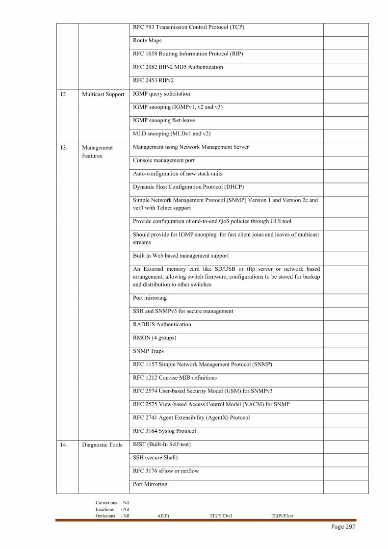
Corrections - Nil
Insertions - Nil
Omissions - Nil AE(P) EE(P)/Civil EE(P)/Elect
Page 297
RFC 793 Transmission Control Protocol (TCP)
Route Maps
RFC 1058 Routing Information Protocol (RIP)
RFC 2082 RIP-2 MD5 Authentication
RFC 2453 RIPv2
12 Multicast Support IGMP query solicitation
IGMP snooping (IGMPv1, v2 and v3)
IGMP snooping fast-leave
MLD snooping (MLDv1 and v2)
13. Management
Features
Management using Network Management Server
Console management port
Auto-configuration of new stack units
Dynamic Host Configuration Protocol (DHCP)
Simple Network Management Protocol (SNMP) Version 1 and Version 2c and ver3 with Telnet support
Provide configuration of end-to-end QoS policies through GUI tool
Should provide for IGMP snooping for fast client joins and leaves of multicast streams
Built in Web based management support
An External memory card like SD/USB or tftp server or network based arrangement, allowing switch firmware, configurations to be stored for backup and distribution to other switches
Port mirroring
SSH and SNMPv3 for secure management
RADIUS Authentication
RMON (4 groups)
SNMP Traps
RFC 1157 Simple Network Management Protocol (SNMP)
RFC 1212 Concise MIB definitions
RFC 2574 User-based Security Model (USM) for SNMPv3
RFC 2575 View-based Access Control Model (VACM) for SNMP
RFC 2741 Agent Extensibility (AgentX) Protocol
RFC 3164 Syslog Protocol
14. Diagnostic Tools BIST (Built-In Self-test)
SSH (secure Shell)
RFC 3176 sFlow or netflow
Port Mirroring
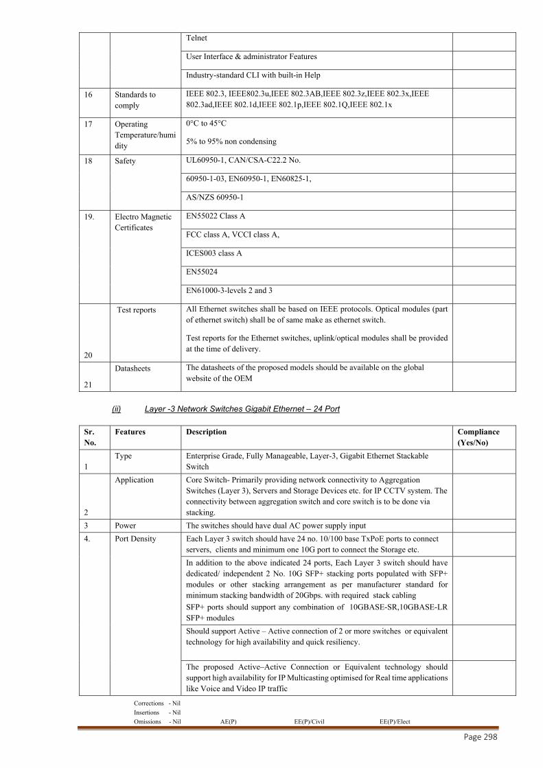
Corrections - Nil
Insertions - Nil
Omissions - Nil AE(P) EE(P)/Civil EE(P)/Elect
Page 298
Telnet
User Interface & administrator Features
Industry-standard CLI with built-in Help
16 Standards to comply
IEEE 802.3, IEEE802.3u,IEEE 802.3AB,IEEE 802.3z,IEEE 802.3x,IEEE 802.3ad,IEEE 802.1d,IEEE 802.1p,IEEE 802.1Q,IEEE 802.1x
17 Operating Temperature/humidity
0°C to 45°C
5% to 95% non condensing
18 Safety UL60950-1, CAN/CSA-C22.2 No.
60950-1-03, EN60950-1, EN60825-1,
AS/NZS 60950-1
19. Electro Magnetic Certificates
EN55022 Class A
FCC class A, VCCI class A,
ICES003 class A
EN55024
EN61000-3-levels 2 and 3
20
Test reports All Ethernet switches shall be based on IEEE protocols. Optical modules (part of ethernet switch) shall be of same make as ethernet switch.
Test reports for the Ethernet switches, uplink/optical modules shall be provided at the time of delivery.
21
Datasheets The datasheets of the proposed models should be available on the global website of the OEM
(ii) Layer -3 Network Switches Gigabit Ethernet – 24 Port
Sr. No.
Features Description Compliance (Yes/No)
1 Type Enterprise Grade, Fully Manageable, Layer-3, Gigabit Ethernet Stackable
Switch
2
Application Core Switch- Primarily providing network connectivity to Aggregation Switches (Layer 3), Servers and Storage Devices etc. for IP CCTV system. The connectivity between aggregation switch and core switch is to be done via stacking.
3 Power The switches should have dual AC power supply input
4. Port Density Each Layer 3 switch should have 24 no. 10/100 base TxPoE ports to connect servers, clients and minimum one 10G port to connect the Storage etc.
In addition to the above indicated 24 ports, Each Layer 3 switch should have dedicated/ independent 2 No. 10G SFP+ stacking ports populated with SFP+ modules or other stacking arrangement as per manufacturer standard for minimum stacking bandwidth of 20Gbps. with required stack cabling
SFP+ ports should support any combination of 10GBASE-SR,10GBASE-LR SFP+ modules
Should support Active – Active connection of 2 or more switches or equivalent technology for high availability and quick resiliency.
The proposed Active–Active Connection or Equivalent technology should support high availability for IP Multicasting optimised for Real time applications like Voice and Video IP traffic
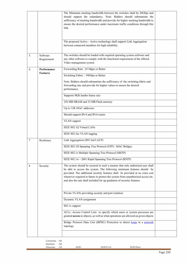
Corrections - Nil
Insertions - Nil
Omissions - Nil AE(P) EE(P)/Civil EE(P)/Elect
Page 299
The Minimum stacking bandwidth between the switches shall be 20Gbps and should support the redundancy. Note: Bidders should substantiate the sufficiency of stacking bandwidth and provide for higher stacking bandwidth to ensure the desired performance under maximum traffic conditions through this link.
The proposed Active – Active technology shall support Link Aggregation between connected members for high reliability
5. Software Requirement
The switches should be loaded with required operating system software and any other software to comply with the functional requirement of the offered Video management system
6. Performance Features
Forwarding Rate: 65 Mpps or Better
Switching Fabric : 94Gbps or Better
Note: Bidders should substantiate the sufficiency of the switching fabric and forwarding rate and provide for higher values to ensure the desired performance.
Supports 9KB Jumbo frame size
256 MB DRAM and 32 MB Flash memory
Up to 12K MAC addresses
Should support IPv4 and IPv6 routes
VLAN support
IEEE 802.1Q Virtual LANs
IEEE 802.3ac VLAN tagging
7 Resiliency Link Aggregation (802.3ad LACP)
IEEE 802.1D Spanning Tree Protocol (STP) - MAC Bridges
IEEE 802.1s Multiple Spanning Tree Protocol (MSTP)
IEEE 802.1w - 2001 Rapid Spanning Tree Protocol (RSTP)
8 Security The system should be secured in such a manner that only authorised user shall be able to access the system. The following minimum features should be provided. The additional security features shall be provided at no extra cost whenever required in future to protect the system from unauthorised access etc. and also the rate shall included for up gradation of security features.
Private VLANs providing security and port isolation
Dynamic VLAN assignment
802.1x support
ACLs -Access Control Lists to specify which users or system processes are granted access to objects, as well as what operations are allowed on given objects
Bridge Protocol Data Unit (BPDU) Protection to detect loops in a network topology
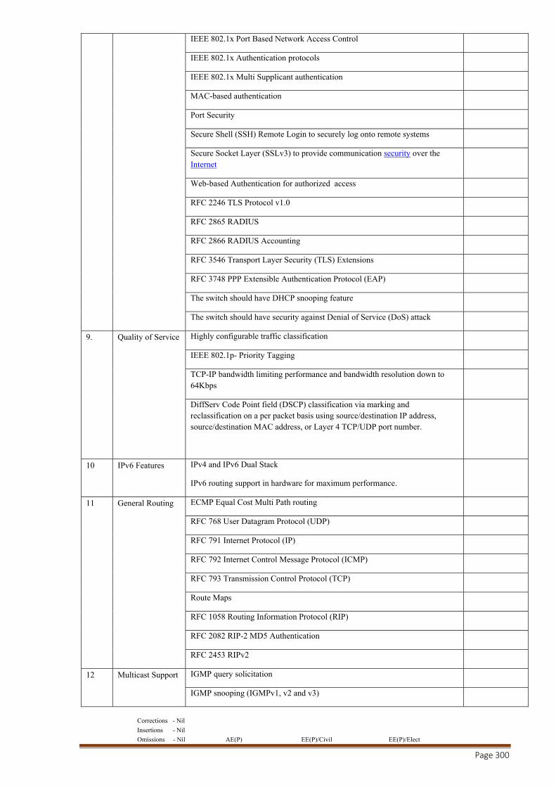
Corrections - Nil
Insertions - Nil
Omissions - Nil AE(P) EE(P)/Civil EE(P)/Elect
Page 300
IEEE 802.1x Port Based Network Access Control
IEEE 802.1x Authentication protocols
IEEE 802.1x Multi Supplicant authentication
MAC-based authentication
Port Security
Secure Shell (SSH) Remote Login to securely log onto remote systems
Secure Socket Layer (SSLv3) to provide communication security over the Internet
Web-based Authentication for authorized access
RFC 2246 TLS Protocol v1.0
RFC 2865 RADIUS
RFC 2866 RADIUS Accounting
RFC 3546 Transport Layer Security (TLS) Extensions
RFC 3748 PPP Extensible Authentication Protocol (EAP)
The switch should have DHCP snooping feature
The switch should have security against Denial of Service (DoS) attack
9. Quality of Service Highly configurable traffic classification
IEEE 802.1p- Priority Tagging
TCP-IP bandwidth limiting performance and bandwidth resolution down to 64Kbps
DiffServ Code Point field (DSCP) classification via marking and reclassification on a per packet basis using source/destination IP address, source/destination MAC address, or Layer 4 TCP/UDP port number.
10 IPv6 Features IPv4 and IPv6 Dual Stack
IPv6 routing support in hardware for maximum performance.
11 General Routing ECMP Equal Cost Multi Path routing
RFC 768 User Datagram Protocol (UDP)
RFC 791 Internet Protocol (IP)
RFC 792 Internet Control Message Protocol (ICMP)
RFC 793 Transmission Control Protocol (TCP)
Route Maps
RFC 1058 Routing Information Protocol (RIP)
RFC 2082 RIP-2 MD5 Authentication
RFC 2453 RIPv2
12 Multicast Support IGMP query solicitation
IGMP snooping (IGMPv1, v2 and v3)
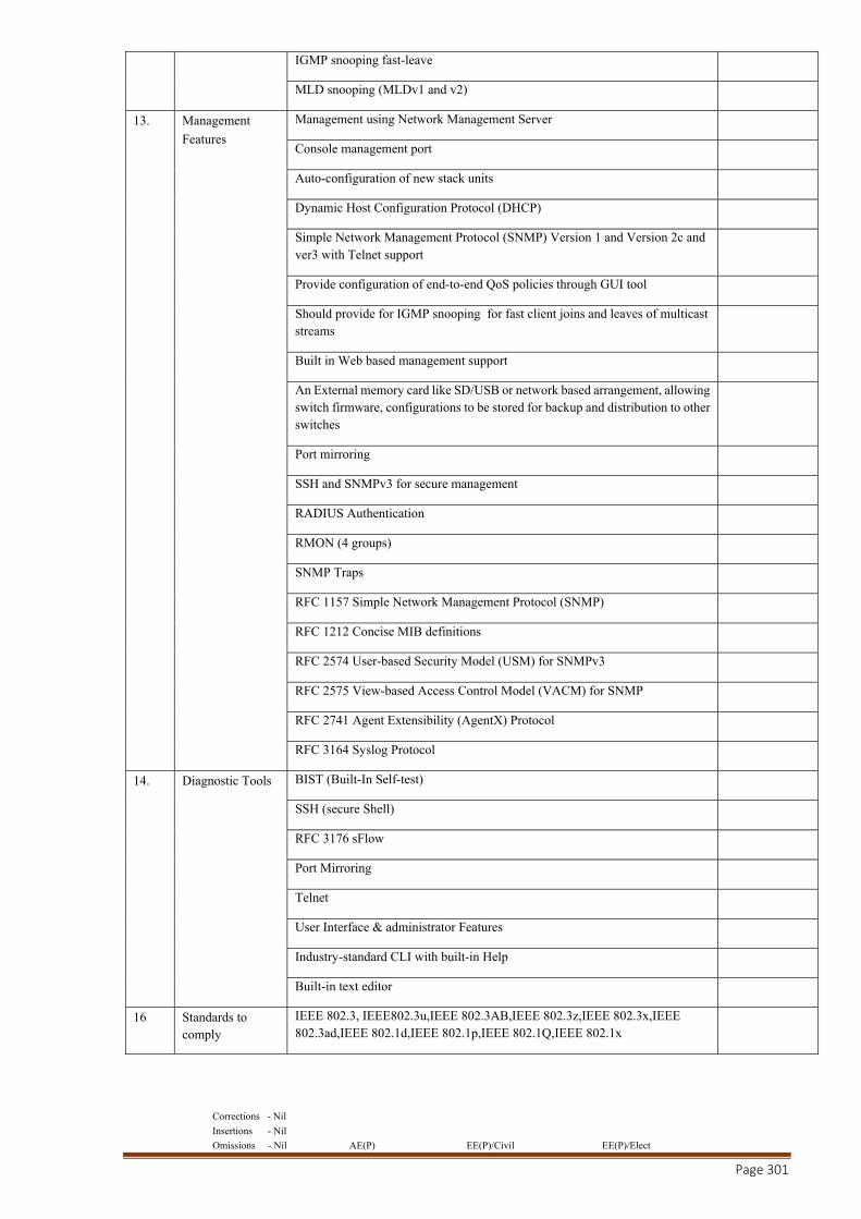
Corrections - Nil
Insertions - Nil
Omissions - Nil AE(P) EE(P)/Civil EE(P)/Elect
Page 301
IGMP snooping fast-leave
MLD snooping (MLDv1 and v2)
13. Management
Features
Management using Network Management Server
Console management port
Auto-configuration of new stack units
Dynamic Host Configuration Protocol (DHCP)
Simple Network Management Protocol (SNMP) Version 1 and Version 2c and ver3 with Telnet support
Provide configuration of end-to-end QoS policies through GUI tool
Should provide for IGMP snooping for fast client joins and leaves of multicast streams
Built in Web based management support
An External memory card like SD/USB or network based arrangement, allowing switch firmware, configurations to be stored for backup and distribution to other switches
Port mirroring
SSH and SNMPv3 for secure management
RADIUS Authentication
RMON (4 groups)
SNMP Traps
RFC 1157 Simple Network Management Protocol (SNMP)
RFC 1212 Concise MIB definitions
RFC 2574 User-based Security Model (USM) for SNMPv3
RFC 2575 View-based Access Control Model (VACM) for SNMP
RFC 2741 Agent Extensibility (AgentX) Protocol
RFC 3164 Syslog Protocol
14. Diagnostic Tools BIST (Built-In Self-test)
SSH (secure Shell)
RFC 3176 sFlow
Port Mirroring
Telnet
User Interface & administrator Features
Industry-standard CLI with built-in Help
Built-in text editor
16 Standards to comply
IEEE 802.3, IEEE802.3u,IEEE 802.3AB,IEEE 802.3z,IEEE 802.3x,IEEE 802.3ad,IEEE 802.1d,IEEE 802.1p,IEEE 802.1Q,IEEE 802.1x
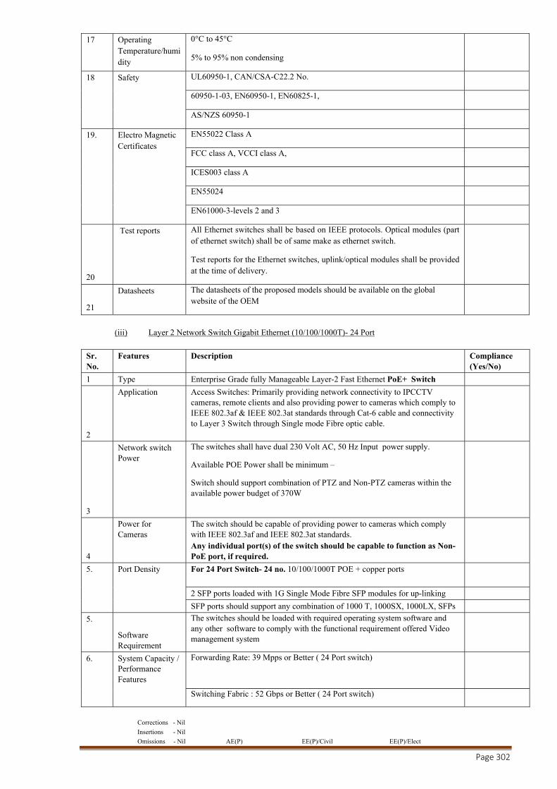
Corrections - Nil
Insertions - Nil
Omissions - Nil AE(P) EE(P)/Civil EE(P)/Elect
Page 302
17 Operating Temperature/humidity
0°C to 45°C
5% to 95% non condensing
18 Safety UL60950-1, CAN/CSA-C22.2 No.
60950-1-03, EN60950-1, EN60825-1,
AS/NZS 60950-1
19. Electro Magnetic Certificates
EN55022 Class A
FCC class A, VCCI class A,
ICES003 class A
EN55024
EN61000-3-levels 2 and 3
20
Test reports All Ethernet switches shall be based on IEEE protocols. Optical modules (part of ethernet switch) shall be of same make as ethernet switch.
Test reports for the Ethernet switches, uplink/optical modules shall be provided at the time of delivery.
21
Datasheets The datasheets of the proposed models should be available on the global website of the OEM
(iii) Layer 2 Network Switch Gigabit Ethernet (10/100/1000T)- 24 Port
Sr. No.
Features Description Compliance (Yes/No)
1 Type Enterprise Grade fully Manageable Layer-2 Fast Ethernet PoE+ Switch
2
Application Access Switches: Primarily providing network connectivity to IPCCTV cameras, remote clients and also providing power to cameras which comply to IEEE 802.3af & IEEE 802.3at standards through Cat-6 cable and connectivity to Layer 3 Switch through Single mode Fibre optic cable.
3
Network switch Power
The switches shall have dual 230 Volt AC, 50 Hz Input power supply.
Available POE Power shall be minimum –
Switch should support combination of PTZ and Non-PTZ cameras within the available power budget of 370W
4
Power for Cameras
The switch should be capable of providing power to cameras which comply with IEEE 802.3af and IEEE 802.3at standards. Any individual port(s) of the switch should be capable to function as Non-PoE port, if required.
5. Port Density For 24 Port Switch- 24 no. 10/100/1000T POE + copper ports
2 SFP ports loaded with 1G Single Mode Fibre SFP modules for up-linking
SFP ports should support any combination of 1000 T, 1000SX, 1000LX, SFPs
5.
Software Requirement
The switches should be loaded with required operating system software and any other software to comply with the functional requirement offered Video management system
6. System Capacity / Performance Features
Forwarding Rate: 39 Mpps or Better ( 24 Port switch)
Switching Fabric : 52 Gbps or Better ( 24 Port switch)
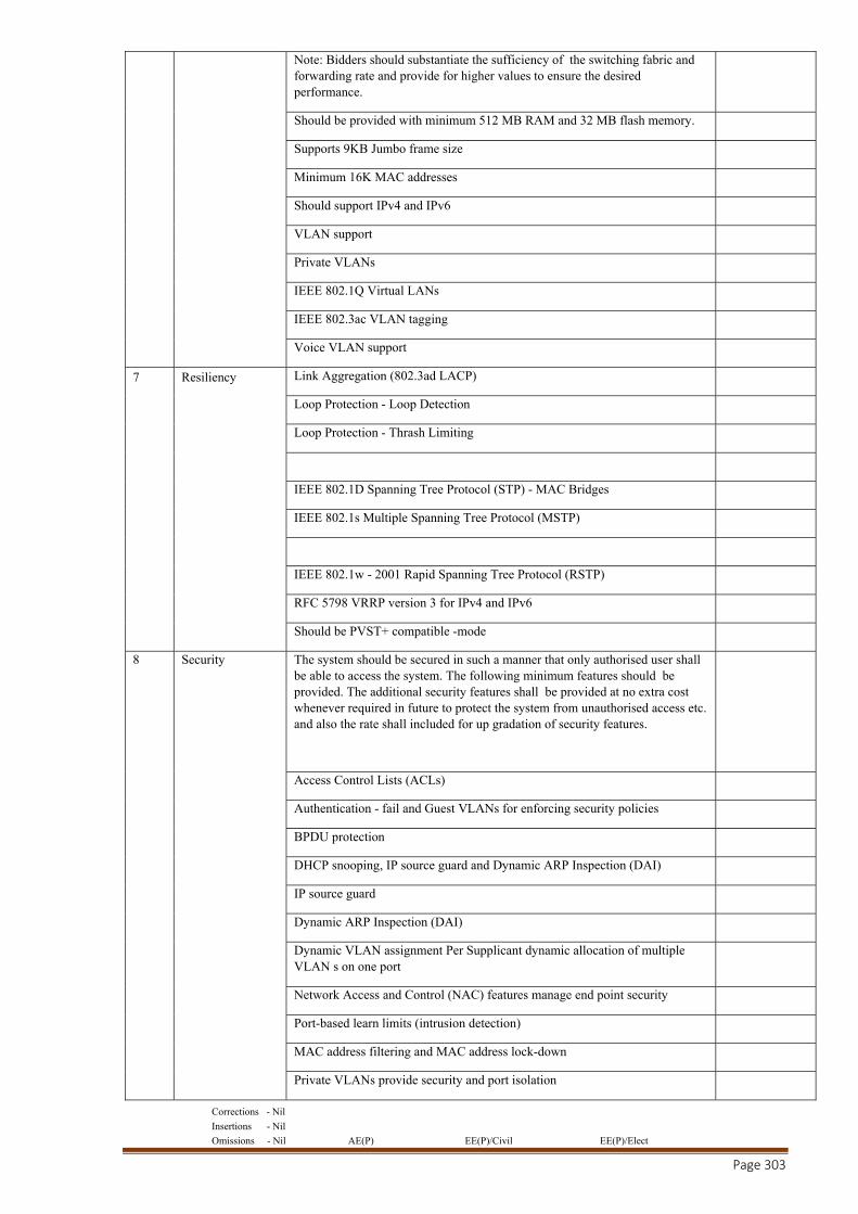
Corrections - Nil
Insertions - Nil
Omissions - Nil AE(P) EE(P)/Civil EE(P)/Elect
Page 303
Note: Bidders should substantiate the sufficiency of the switching fabric and forwarding rate and provide for higher values to ensure the desired performance.
Should be provided with minimum 512 MB RAM and 32 MB flash memory.
Supports 9KB Jumbo frame size
Minimum 16K MAC addresses
Should support IPv4 and IPv6
VLAN support
Private VLANs
IEEE 802.1Q Virtual LANs
IEEE 802.3ac VLAN tagging
Voice VLAN support
7 Resiliency Link Aggregation (802.3ad LACP)
Loop Protection - Loop Detection
Loop Protection - Thrash Limiting
IEEE 802.1D Spanning Tree Protocol (STP) - MAC Bridges
IEEE 802.1s Multiple Spanning Tree Protocol (MSTP)
IEEE 802.1w - 2001 Rapid Spanning Tree Protocol (RSTP)
RFC 5798 VRRP version 3 for IPv4 and IPv6
Should be PVST+ compatible -mode
8 Security The system should be secured in such a manner that only authorised user shall be able to access the system. The following minimum features should be provided. The additional security features shall be provided at no extra cost whenever required in future to protect the system from unauthorised access etc. and also the rate shall included for up gradation of security features.
Access Control Lists (ACLs)
Authentication - fail and Guest VLANs for enforcing security policies
BPDU protection
DHCP snooping, IP source guard and Dynamic ARP Inspection (DAI)
IP source guard
Dynamic ARP Inspection (DAI)
Dynamic VLAN assignment Per Supplicant dynamic allocation of multiple VLAN s on one port
Network Access and Control (NAC) features manage end point security
Port-based learn limits (intrusion detection)
MAC address filtering and MAC address lock-down
Private VLANs provide security and port isolation
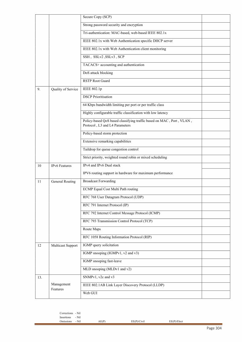
Corrections - Nil
Insertions - Nil
Omissions - Nil AE(P) EE(P)/Civil EE(P)/Elect
Page 304
Secure Copy (SCP)
Strong password security and encryption
Tri-authentication: MAC-based, web-based IEEE 802.1x
IEEE 802.1x with Web Authentication specific DHCP server
IEEE 802.1x with Web Authentication client monitoring
SSH , SSLv2 ,SSLv3 , SCP
TACACS+ accounting and authentication
DoS attack blocking
RSTP Root Guard
9. Quality of Service IEEE 802.1p
DSCP Prioritisation
64 Kbps bandwidth limiting per port or per traffic class
Highly configurable traffic classification with low latency
Policy-based QoS based classifying traffic based on MAC , Port , VLAN , Protocol , L3 and L4 Parameters
Policy-based storm protection
Extensive remarking capabilities
Taildrop for queue congestion control
Strict priority, weighted round robin or mixed scheduling
10 IPv6 Features IPv4 and IPv6 Dual stack
IPV6 routing support in hardware for maximum performance
11 General Routing Broadcast Forwarding
ECMP Equal Cost Multi Path routing
RFC 768 User Datagram Protocol (UDP)
RFC 791 Internet Protocol (IP)
RFC 792 Internet Control Message Protocol (ICMP)
RFC 793 Transmission Control Protocol (TCP)
Route Maps
RFC 1058 Routing Information Protocol (RIP)
12 Multicast Support IGMP query solicitation
IGMP snooping (IGMPv1, v2 and v3)
IGMP snooping fast-leave
MLD snooping (MLDv1 and v2)
13.
Management Features
SNMPv1, v2c and v3
IEEE 802.1AB Link Layer Discovery Protocol (LLDP)
Web GUI
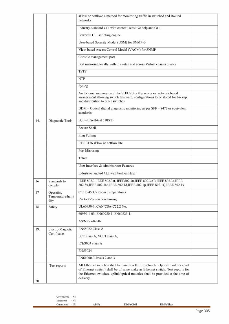
Corrections - Nil
Insertions - Nil
Omissions - Nil AE(P) EE(P)/Civil EE(P)/Elect
Page 305
sFlow or netflow: a method for monitoring traffic in switched and Routed networks
Industry-standard CLI with context-sensitive help and GUI
Powerful CLI scripting engine
User-based Security Model (USM) for SNMPv3
View-based Access Control Model (VACM) for SNMP
Console management port
Port mirroring locally with in switch and across Virtual chassis cluster
TFTP
NTP
Syslog
An External memory card like SD/USB or tftp server or network based arrangement allowing switch firmware, configurations to be stored for backup and distribution to other switches
DDM – Optical digital diagnostic monitoring as per SFF – 8472 or equivalent standards
14. Diagnostic Tools Built-In Self-test ( BIST)
Secure Shell
Ping Polling
RFC 3176 sFlow or netflow lite
Port Mirroring
Telnet
User Interface & administrator Features
Industry-standard CLI with built-in Help
16 Standards to comply
IEEE 802.3, IEEE 802.3at, IEEE802.3u,IEEE 802.3AB,IEEE 802.3z,IEEE 802.3x,IEEE 802.3ad,IEEE 802.1d,IEEE 802.1p,IEEE 802.1Q,IEEE 802.1x
17 Operating Temperature/humidity
0°C to 45°C (Room Temperature)
5% to 95% non condensing
18 Safety UL60950-1, CAN/CSA-C22.2 No.
60950-1-03, EN60950-1, EN60825-1,
AS/NZS 60950-1
19. Electro Magnetic Certificates
EN55022 Class A
FCC class A, VCCI class A,
ICES003 class A
EN55024
EN61000-3-levels 2 and 3
20
Test reports All Ethernet switches shall be based on IEEE protocols. Optical modules (part of Ethernet switch) shall be of same make as Ethernet switch. Test reports for the Ethernet switches, uplink/optical modules shall be provided at the time of delivery.
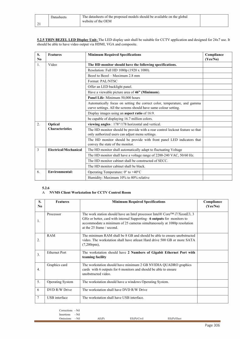
Corrections - Nil
Insertions - Nil
Omissions - Nil AE(P) EE(P)/Civil EE(P)/Elect
Page 306
21
Datasheets The datasheets of the proposed models should be available on the global website of the OEM
5.2.5 THIN BEZEL LED Display Unit- The LED display unit shall be suitable for CCTV application and designed for 24x7 use. It should be able to have video output via HDMI, VGA and composite.
S. No
Features Minimum Required Specifications Compliance (Yes/No)
1. Video The HD monitor should have the following specifications.
Resolution: Full HD 1080p (1920 x 1080).
Bezel to Bezel – Maximum 2.8 mm
Format: PAL/NTSC
Offer an LED backlight panel.
Have a viewable picture area of 46” (Minimum).
Panel Life: Minimum 50,000 hours
Automatically focus on setting the correct color, temperature, and gamma curve settings. All the screens should have same colour setting.
Display images using an aspect ratio of 16:9.
be capable of displaying 16.7 million colors.
2. Optical Characteristics
viewing angles : 178°/178 horizontal and vertical.
The HD monitor should be provide with a rear control lockout feature so that only authorized users can adjust menu settings.
The HD monitor should be provide with front panel LED indicators that convey the state of the monitor.
3 Electrical/Mechanical The HD monitor shall automatically adapt to fluctuating Voltage
The HD monitor shall have a voltage range of 2200-240 VAC, 50/60 Hz.
The HD monitor cabinet shall be constructed of SECC.
The HD monitor cabinet shall be black.
6. Environmental: Operating Temperature: 0 to +40C
Humidity: Maximum 10% to 80% relative
5.2.6 A NVMS Client Workstation for CCTV Control Room
S. No
Features Minimum Required Specifications Compliance (Yes/No)
1.
Processor The work station should have an Intel processor Intel® Core™ i7/XeonE3, 3 GHz or better, card with internal Supporting– 6 outputs for monitors to accommodate a minimum of 25 cameras simultaneously at 1080p resolution at the 25 frame / second.
2. RAM The minimum RAM shall be 8 GB and should be able to ensure unobstructed
video. The workstation shall have atleast Hard drive 500 GB or more SATA (7,200rpm),
3. Ethernet Port The workstation should have 2 Numbers of Gigabit Ethernet Port with
teaming facility
4. Graphics card The workstation should have minimum 2 GB NVIDIA QUADRO graphics
cards with 6 outputs for 6 monitors and should be able to ensure unobstructed video.
5. Operating System The workstation should have a windows Operating System.
6 DVD R/W Drive The workstation shall have DVD R/W Drive
7 USB interface The workstation shall have USB interface.
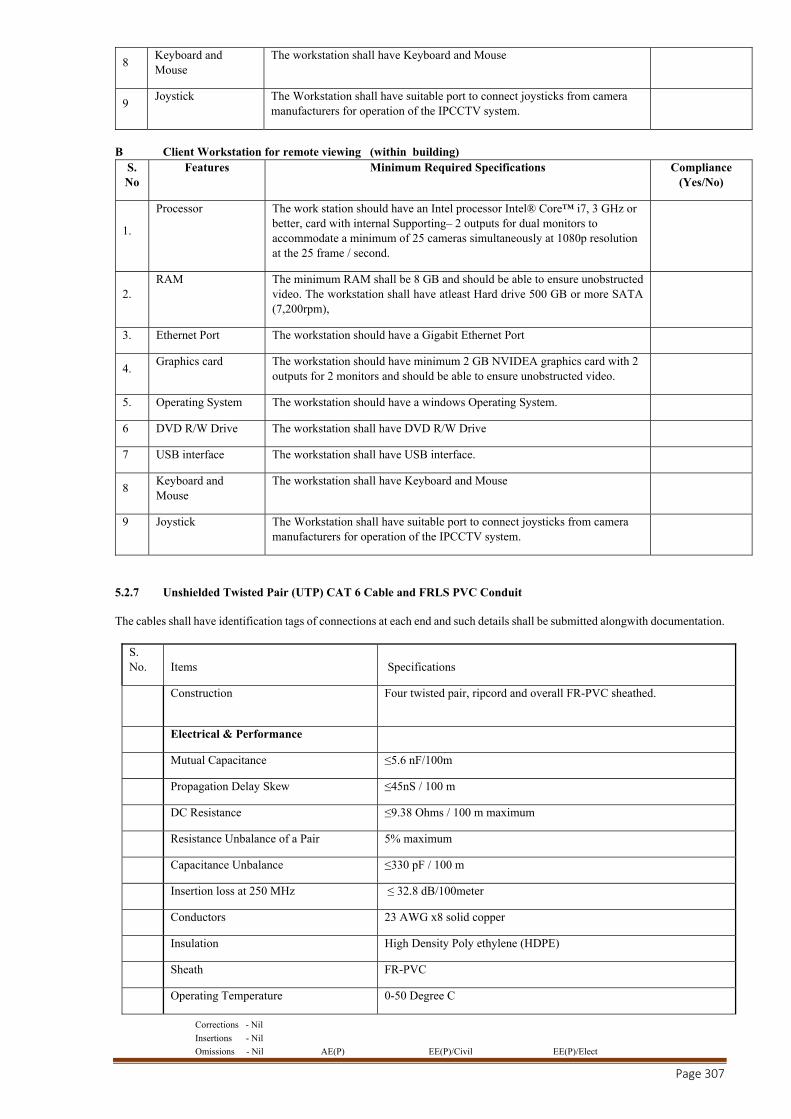
Corrections - Nil
Insertions - Nil
Omissions - Nil AE(P) EE(P)/Civil EE(P)/Elect
Page 307
8 Keyboard and Mouse
The workstation shall have Keyboard and Mouse
9 Joystick The Workstation shall have suitable port to connect joysticks from camera
manufacturers for operation of the IPCCTV system.
B Client Workstation for remote viewing (within building)
S. No
Features Minimum Required Specifications Compliance (Yes/No)
1.
Processor The work station should have an Intel processor Intel® Core™ i7, 3 GHz or better, card with internal Supporting– 2 outputs for dual monitors to accommodate a minimum of 25 cameras simultaneously at 1080p resolution at the 25 frame / second.
2. RAM The minimum RAM shall be 8 GB and should be able to ensure unobstructed
video. The workstation shall have atleast Hard drive 500 GB or more SATA (7,200rpm),
3. Ethernet Port The workstation should have a Gigabit Ethernet Port
4. Graphics card The workstation should have minimum 2 GB NVIDEA graphics card with 2
outputs for 2 monitors and should be able to ensure unobstructed video.
5. Operating System The workstation should have a windows Operating System.
6 DVD R/W Drive The workstation shall have DVD R/W Drive
7 USB interface The workstation shall have USB interface.
8 Keyboard and Mouse
The workstation shall have Keyboard and Mouse
9 Joystick The Workstation shall have suitable port to connect joysticks from camera manufacturers for operation of the IPCCTV system.
5.2.7 Unshielded Twisted Pair (UTP) CAT 6 Cable and FRLS PVC Conduit The cables shall have identification tags of connections at each end and such details shall be submitted alongwith documentation.
S. No. Items Specifications
Construction Four twisted pair, ripcord and overall FR-PVC sheathed.
Electrical & Performance
Mutual Capacitance ≤5.6 nF/100m
Propagation Delay Skew ≤45nS / 100 m
DC Resistance ≤9.38 Ohms / 100 m maximum
Resistance Unbalance of a Pair 5% maximum
Capacitance Unbalance ≤330 pF / 100 m
Insertion loss at 250 MHz ≤ 32.8 dB/100meter
Conductors 23 AWG x8 solid copper
Insulation High Density Poly ethylene (HDPE)
Sheath FR-PVC
Operating Temperature 0-50 Degree C
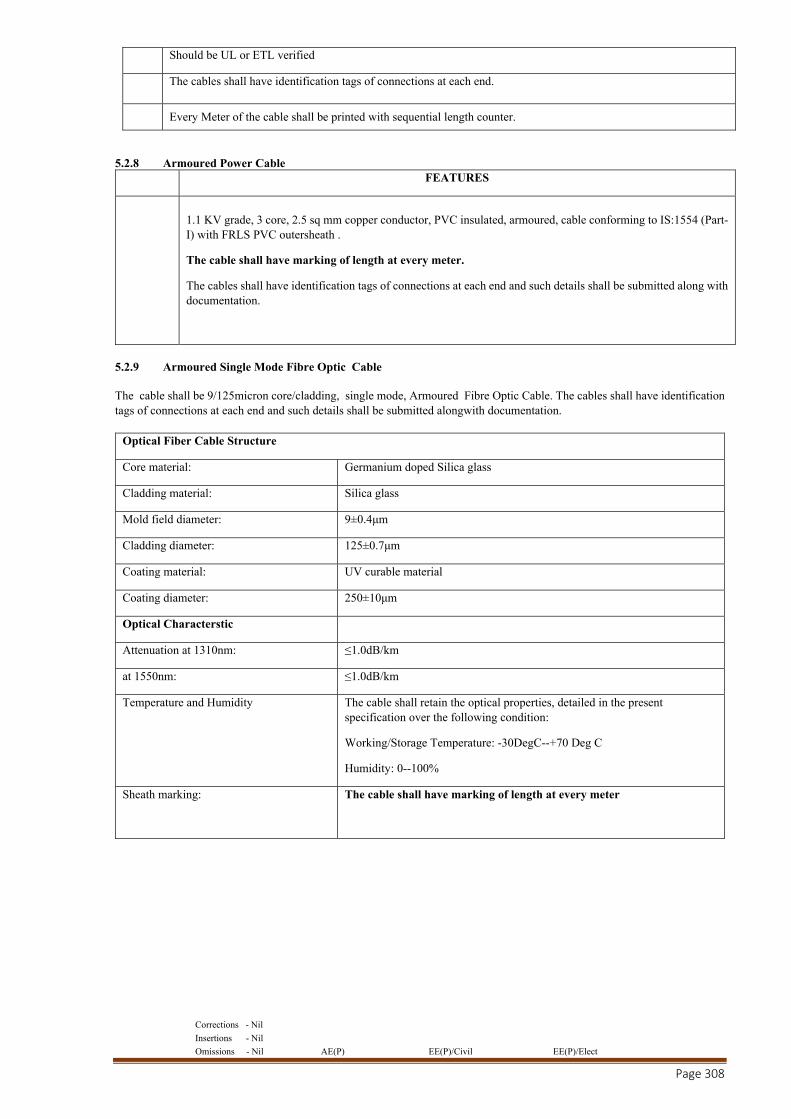
Corrections - Nil
Insertions - Nil
Omissions - Nil AE(P) EE(P)/Civil EE(P)/Elect
Page 308
Should be UL or ETL verified
The cables shall have identification tags of connections at each end.
Every Meter of the cable shall be printed with sequential length counter.
5.2.8 Armoured Power Cable FEATURES
1.1 KV grade, 3 core, 2.5 sq mm copper conductor, PVC insulated, armoured, cable conforming to IS:1554 (Part-I) with FRLS PVC outersheath .
The cable shall have marking of length at every meter.
The cables shall have identification tags of connections at each end and such details shall be submitted along with documentation.
5.2.9 Armoured Single Mode Fibre Optic Cable The cable shall be 9/125micron core/cladding, single mode, Armoured Fibre Optic Cable. The cables shall have identification tags of connections at each end and such details shall be submitted alongwith documentation.
Optical Fiber Cable Structure
Core material: Germanium doped Silica glass
Cladding material: Silica glass
Mold field diameter: 9±0.4μm
Cladding diameter: 125±0.7μm
Coating material: UV curable material
Coating diameter: 250±10μm
Optical Characterstic
Attenuation at 1310nm: ≤1.0dB/km
at 1550nm: ≤1.0dB/km
Temperature and Humidity
The cable shall retain the optical properties, detailed in the present specification over the following condition:
Working/Storage Temperature: -30DegC--+70 Deg C
Humidity: 0--100%
Sheath marking:
The cable shall have marking of length at every meter
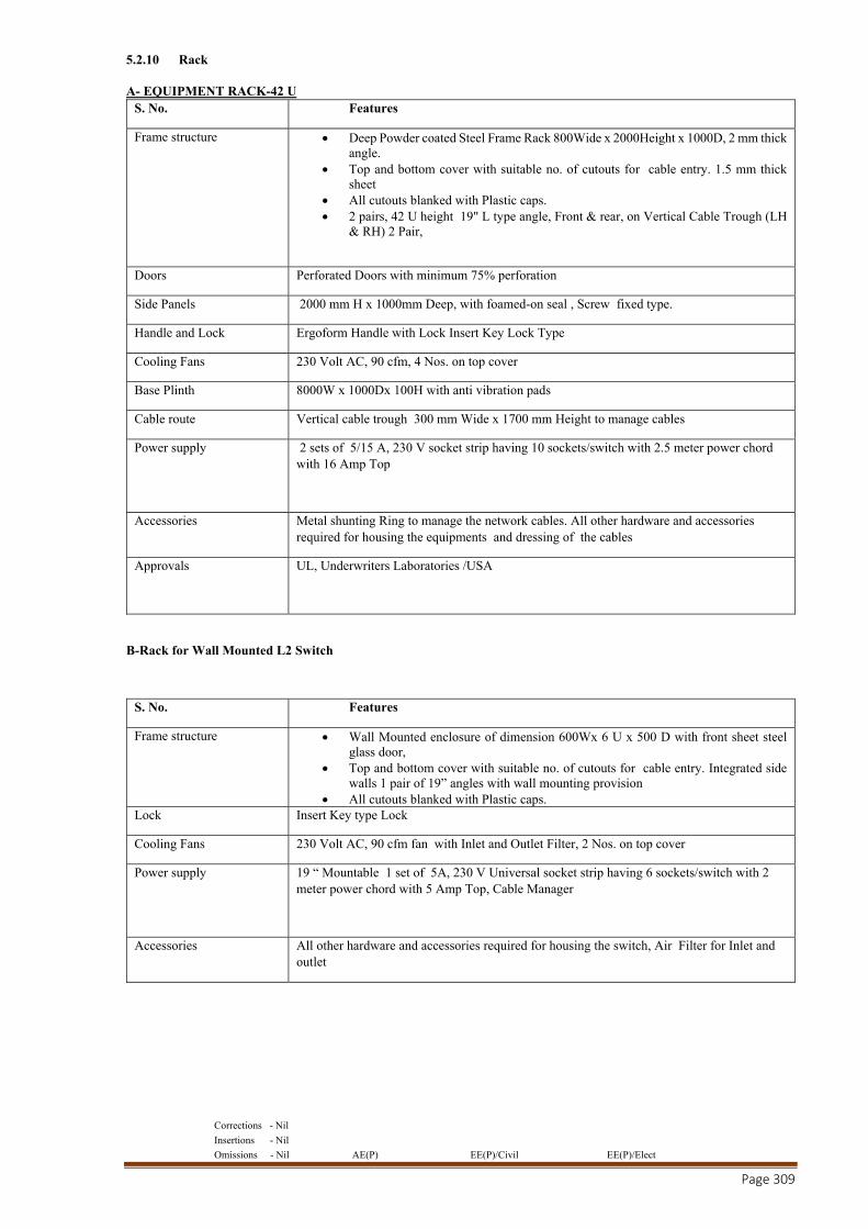
Corrections - Nil
Insertions - Nil
Omissions - Nil AE(P) EE(P)/Civil EE(P)/Elect
Page 309
5.2.10 Rack A- EQUIPMENT RACK-42 U
S. No. Features
Frame structure Deep Powder coated Steel Frame Rack 800Wide x 2000Height x 1000D, 2 mm thick angle.
Top and bottom cover with suitable no. of cutouts for cable entry. 1.5 mm thick sheet
All cutouts blanked with Plastic caps. 2 pairs, 42 U height 19" L type angle, Front & rear, on Vertical Cable Trough (LH
& RH) 2 Pair,
Doors Perforated Doors with minimum 75% perforation
Side Panels 2000 mm H x 1000mm Deep, with foamed-on seal , Screw fixed type.
Handle and Lock Ergoform Handle with Lock Insert Key Lock Type
Cooling Fans 230 Volt AC, 90 cfm, 4 Nos. on top cover
Base Plinth 8000W x 1000Dx 100H with anti vibration pads
Cable route Vertical cable trough 300 mm Wide x 1700 mm Height to manage cables
Power supply 2 sets of 5/15 A, 230 V socket strip having 10 sockets/switch with 2.5 meter power chord with 16 Amp Top
Accessories Metal shunting Ring to manage the network cables. All other hardware and accessories required for housing the equipments and dressing of the cables
Approvals
UL, Underwriters Laboratories /USA
B-Rack for Wall Mounted L2 Switch
S. No. Features
Frame structure Wall Mounted enclosure of dimension 600Wx 6 U x 500 D with front sheet steel glass door,
Top and bottom cover with suitable no. of cutouts for cable entry. Integrated side walls 1 pair of 19” angles with wall mounting provision
All cutouts blanked with Plastic caps. Lock Insert Key type Lock
Cooling Fans 230 Volt AC, 90 cfm fan with Inlet and Outlet Filter, 2 Nos. on top cover
Power supply 19 “ Mountable 1 set of 5A, 230 V Universal socket strip having 6 sockets/switch with 2 meter power chord with 5 Amp Top, Cable Manager
Accessories All other hardware and accessories required for housing the switch, Air Filter for Inlet and outlet
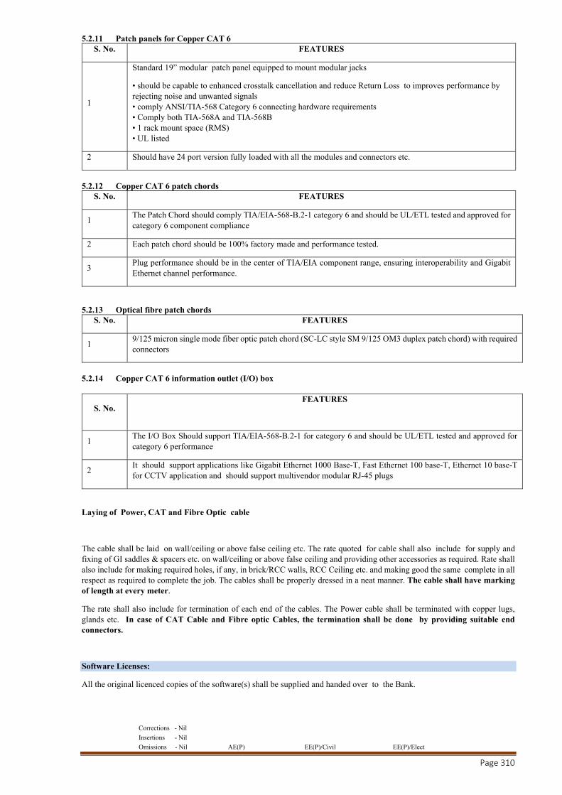
Corrections - Nil
Insertions - Nil
Omissions - Nil AE(P) EE(P)/Civil EE(P)/Elect
Page 310
5.2.11 Patch panels for Copper CAT 6 S. No. FEATURES
1
Standard 19” modular patch panel equipped to mount modular jacks
• should be capable to enhanced crosstalk cancellation and reduce Return Loss to improves performance by rejecting noise and unwanted signals • comply ANSI/TIA-568 Category 6 connecting hardware requirements • Comply both TIA-568A and TIA-568B • 1 rack mount space (RMS) • UL listed
2 Should have 24 port version fully loaded with all the modules and connectors etc.
5.2.12 Copper CAT 6 patch chords
S. No. FEATURES
1 The Patch Chord should comply TIA/EIA-568-B.2-1 category 6 and should be UL/ETL tested and approved for category 6 component compliance
2 Each patch chord should be 100% factory made and performance tested.
3 Plug performance should be in the center of TIA/EIA component range, ensuring interoperability and Gigabit Ethernet channel performance.
5.2.13 Optical fibre patch chords S. No. FEATURES
1 9/125 micron single mode fiber optic patch chord (SC-LC style SM 9/125 OM3 duplex patch chord) with required connectors
5.2.14 Copper CAT 6 information outlet (I/O) box
S. No. FEATURES
1 The I/O Box Should support TIA/EIA-568-B.2-1 for category 6 and should be UL/ETL tested and approved for category 6 performance
2 It should support applications like Gigabit Ethernet 1000 Base-T, Fast Ethernet 100 base-T, Ethernet 10 base-T for CCTV application and should support multivendor modular RJ-45 plugs
Laying of Power, CAT and Fibre Optic cable
The cable shall be laid on wall/ceiling or above false ceiling etc. The rate quoted for cable shall also include for supply and fixing of GI saddles & spacers etc. on wall/ceiling or above false ceiling and providing other accessories as required. Rate shall also include for making required holes, if any, in brick/RCC walls, RCC Ceiling etc. and making good the same complete in all respect as required to complete the job. The cables shall be properly dressed in a neat manner. The cable shall have marking of length at every meter.
The rate shall also include for termination of each end of the cables. The Power cable shall be terminated with copper lugs, glands etc. In case of CAT Cable and Fibre optic Cables, the termination shall be done by providing suitable end connectors.
Software Licenses:
All the original licenced copies of the software(s) shall be supplied and handed over to the Bank.
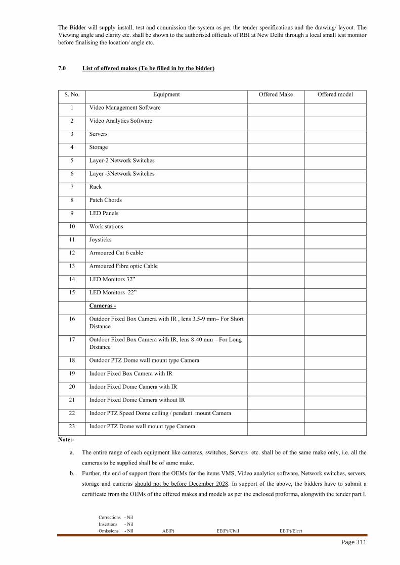
Corrections - Nil
Insertions - Nil
Omissions - Nil AE(P) EE(P)/Civil EE(P)/Elect
Page 311
The Bidder will supply install, test and commission the system as per the tender specifications and the drawing/ layout. The Viewing angle and clarity etc. shall be shown to the authorised officials of RBI at New Delhi through a local small test monitor before finalising the location/ angle etc.
7.0 List of offered makes (To be filled in by the bidder)
S. No. Equipment Offered Make Offered model
1 Video Management Software
2 Video Analytics Software
3 Servers
4 Storage
5 Layer-2 Network Switches
6 Layer -3Network Switches
7 Rack
8 Patch Chords
9 LED Panels
10 Work stations
11 Joysticks
12 Armoured Cat 6 cable
13 Armoured Fibre optic Cable
14 LED Monitors 32”
15 LED Monitors 22”
Cameras -
16 Outdoor Fixed Box Camera with IR , lens 3.5-9 mm– For Short Distance
17 Outdoor Fixed Box Camera with IR, lens 8-40 mm – For Long Distance
18 Outdoor PTZ Dome wall mount type Camera
19 Indoor Fixed Box Camera with IR
20 Indoor Fixed Dome Camera with IR
21 Indoor Fixed Dome Camera without IR
22 Indoor PTZ Speed Dome ceiling / pendant mount Camera
23 Indoor PTZ Dome wall mount type Camera
Note:-
a. The entire range of each equipment like cameras, switches, Servers etc. shall be of the same make only, i.e. all the
cameras to be supplied shall be of same make.
b. Further, the end of support from the OEMs for the items VMS, Video analytics software, Network switches, servers,
storage and cameras should not be before December 2028. In support of the above, the bidders have to submit a
certificate from the OEMs of the offered makes and models as per the enclosed proforma, alongwith the tender part I.
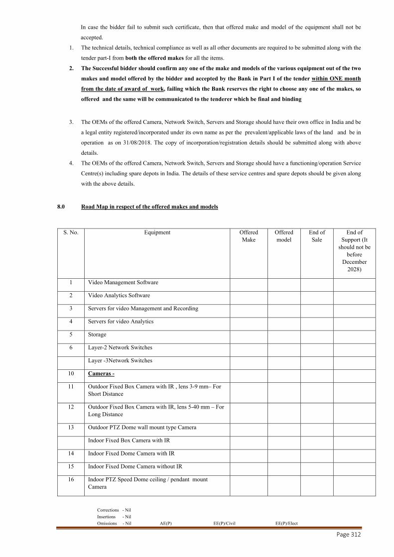
Corrections - Nil
Insertions - Nil
Omissions - Nil AE(P) EE(P)/Civil EE(P)/Elect
Page 312
In case the bidder fail to submit such certificate, then that offered make and model of the equipment shall not be
accepted.
1. The technical details, technical compliance as well as all other documents are required to be submitted along with the
tender part-I from both the offered makes for all the items.
2. The Successful bidder should confirm any one of the make and models of the various equipment out of the two
makes and model offered by the bidder and accepted by the Bank in Part I of the tender within ONE month
from the date of award of work, failing which the Bank reserves the right to choose any one of the makes, so
offered and the same will be communicated to the tenderer which be final and binding
3. The OEMs of the offered Camera, Network Switch, Servers and Storage should have their own office in India and be
a legal entity registered/incorporated under its own name as per the prevalent/applicable laws of the land and be in
operation as on 31/08/2018. The copy of incorporation/registration details should be submitted along with above
details.
4. The OEMs of the offered Camera, Network Switch, Servers and Storage should have a functioning/operation Service
Centre(s) including spare depots in India. The details of these service centres and spare depots should be given along
with the above details.
8.0 Road Map in respect of the offered makes and models
S. No. Equipment Offered Make
Offered model
End of Sale
End of Support (It
should not be before
December 2028)
1 Video Management Software
2 Video Analytics Software
3 Servers for video Management and Recording
4 Servers for video Analytics
5 Storage
6 Layer-2 Network Switches
Layer -3Network Switches
10 Cameras -
11 Outdoor Fixed Box Camera with IR , lens 3-9 mm– For Short Distance
12 Outdoor Fixed Box Camera with IR, lens 5-40 mm – For Long Distance
13 Outdoor PTZ Dome wall mount type Camera
Indoor Fixed Box Camera with IR
14 Indoor Fixed Dome Camera with IR
15 Indoor Fixed Dome Camera without IR
16 Indoor PTZ Speed Dome ceiling / pendant mount Camera

Corrections - Nil
Insertions - Nil
Omissions - Nil AE(P) EE(P)/Civil EE(P)/Elect
Page 313
17 Indoor PTZ Dome wall mount type Camera
9.0 TESTING & COMMISSIONING:
The entire system shall be tested for its proper functioning including carrying out the following tests:
a. Testing of redundancy of Layer 3 Switch
b. Testing of redundancy of uplinks between L2 and L 3 Switch
c. Testing of redundancy of Management Server
d. Testing of redundancy of Recording Server
e. Testing of hard disc failure in Raid6 Configuration of storage
f. Testing of Usable capacity of Storage
g. Testing of video analytics
h. Check PTZ controls of PTZ camera
i. Check recording, playback & other various features randomly
j. Check recording FRAME RATE
k. Check all software server & client has been installed correctly & running without any bug/error
l. Testing of the functionality of the VMS features including Recording, retrieval of footages etc.
Enhanced Commissioning: The Integrated Security System will be required to be checked for its overall performance at the end of Defect Liability Period. Any defect noticed should be rectified to meet the committed performance level without any additional cost to the Bank. No additional payment shall be made by Bank to carry out the Enhanced Commissioning.
10.0 DOCUMENTATION :
The CCTV system bidder, upon completion of the commissioning activity, shall offer the system to the customer for acceptance. For this, the bidder shall provide the customer with the following documentation:
1. Copy of detailed report
2. Component and equipment list
3. Product description sheets
4. System design drawing(s)
6. System schematic diagram(s)
7. System operating manuals
8. Original licensed copies of all the software ( OS, DVMS, Video analytics, Anti- virus, etc.)
11.0 Final acceptance and Handover-takeover:
Prior to final acceptance, the bidder shall provide complete operation and maintenance instruction manuals to the Bank along with all the above mentioned documents. All aspects of system operation and maintenance shall be detailed, including
wiring diagrams of all circuits, a written description of the system design, sequence of operation and drawing(s), illustrating control logic and equipment used in the system.
Checklists and procedures for emergency situations, maintenance operations and procedures shall be included in the manual. The Bank’s engineer and security officer then shall test and inspect the functioning of various components (e.g. cameras, PTZ functions, recording features etc.) and a joint report shall be prepared. In case of any observations from Bank’s side, the same shall be conveyed to the bidder in writing and got attended to by the
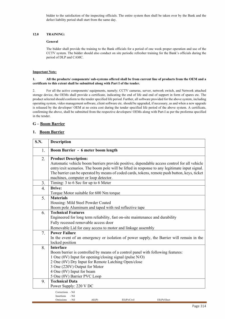
Corrections - Nil
Insertions - Nil
Omissions - Nil AE(P) EE(P)/Civil EE(P)/Elect
Page 314
bidder to the satisfaction of the inspecting officials. The entire system then shall be taken over by the Bank and the defect liability period shall start from the same day.
12.0 TRAINING:
General
The bidder shall provide the training to the Bank officials for a period of one week proper operation and use of the CCTV system. The bidder should also conduct on site periodic refresher training for the Bank’s officials during the period of DLP and CAMC.
Important Note:
1. All the products/ components/ sub-systems offered shall be from current line of products from the OEM and a certificate to this extent shall be submitted along with Part I of the tender.
2. For all the active components/ equipments, namely; CCTV cameras, server, network switch, and Network attached storage device, the OEMs shall provide a certificate, indicating the end of life and end of support in form of spares etc. The product selected should conform to the tender specified life period. Further, all software provided for the above system, including operating system, video management software, client software etc. should be upgraded, if necessary, as and when a new upgrade is released by the developer/ OEM at no extra cost during the tender specified life period of the above system. A certificate, confirming the above, shall be submitted from the respective developers/ OEMs along with Part-I as per the proforma specified in the tender.
G – Boom Barrier
1. Boom Barrier
S.N. Description
1. Boom Barrier - 6 meter boom length
2. Product Description: Automatic vehicle boom barriers provide positive, dependable access control for all vehicle entry/exit scenarios. The boom pole will be lifted in response to any legitimate input signal. The barrier can be operated by means of coded cards, tokens, remote push button, keys, ticket machines, computer or loop detector.
3. Timing: 3 to 6 Sec for up to 6 Meter
4. Drive: Torque Motor suitable for 600 Nm torque
5. Materials Housing: Mild Steel Powder Coated Boom pole Aluminum and taped with red reflective tape
6. Technical Features Engineered for long term reliability, fast on-site maintenance and durability Fully recessed removable access door Removable Lid for easy access to motor and linkage assembly
7. Power Failure In the event of an emergency or isolation of power supply, the Barrier will remain in the locked position
8. Interface Boom barrier is controlled by means of a control panel with following features: 1 One (0V) Input for opening/closing signal (pulse N/O) 2 One (0V) Dry Input for Remote Latching Open/close 3 One (220V) Output for Motor 4 One (0V) Input for beam 5 One (0V) Barrier PVC Loop
9. Technical Data Power Supply: 220 V DC
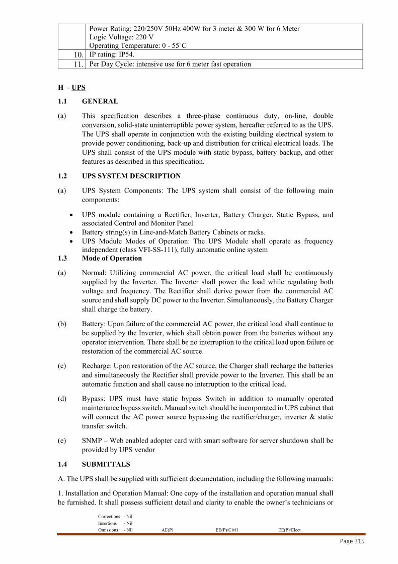
Corrections - Nil
Insertions - Nil
Omissions - Nil AE(P) EE(P)/Civil EE(P)/Elect
Page 315
Power Rating; 220/250V 50Hz 400W for 3 meter & 300 W for 6 Meter Logic Voltage: 220 V Operating Temperature: 0 - 55˚C
10. IP rating: IP54.
11. Per Day Cycle: intensive use for 6 meter fast operation
H - UPS
1.1 GENERAL
(a) This specification describes a three-phase continuous duty, on-line, double conversion, solid-state uninterruptible power system, hereafter referred to as the UPS. The UPS shall operate in conjunction with the existing building electrical system to provide power conditioning, back-up and distribution for critical electrical loads. The UPS shall consist of the UPS module with static bypass, battery backup, and other features as described in this specification.
1.2 UPS SYSTEM DESCRIPTION
(a) UPS System Components: The UPS system shall consist of the following main components:
UPS module containing a Rectifier, Inverter, Battery Charger, Static Bypass, and associated Control and Monitor Panel.
Battery string(s) in Line-and-Match Battery Cabinets or racks. UPS Module Modes of Operation: The UPS Module shall operate as frequency
independent (class VFI-SS-111), fully automatic online system 1.3 Mode of Operation
(a) Normal: Utilizing commercial AC power, the critical load shall be continuously supplied by the Inverter. The Inverter shall power the load while regulating both voltage and frequency. The Rectifier shall derive power from the commercial AC source and shall supply DC power to the Inverter. Simultaneously, the Battery Charger shall charge the battery.
(b) Battery: Upon failure of the commercial AC power, the critical load shall continue to be supplied by the Inverter, which shall obtain power from the batteries without any operator intervention. There shall be no interruption to the critical load upon failure or restoration of the commercial AC source.
(c) Recharge: Upon restoration of the AC source, the Charger shall recharge the batteries and simultaneously the Rectifier shall provide power to the Inverter. This shall be an automatic function and shall cause no interruption to the critical load.
(d) Bypass: UPS must have static bypass Switch in addition to manually operated maintenance bypass switch. Manual switch should be incorporated in UPS cabinet that will connect the AC power source bypassing the rectifier/charger, inverter & static transfer switch.
(e) SNMP – Web enabled adopter card with smart software for server shutdown shall be provided by UPS vendor
1.4 SUBMITTALS
A. The UPS shall be supplied with sufficient documentation, including the following manuals:
1. Installation and Operation Manual: One copy of the installation and operation manual shall be furnished. It shall possess sufficient detail and clarity to enable the owner’s technicians or
Corrections - Nil
Insertions - Nil
Omissions - Nil AE(P) EE(P)/Civil EE(P)/Elect
Page 316
representatives to install and operate the UPS equipment. The manual shall include the following major items:
a) UPS description
b) UPS site planning and unpacking
c) UPS installation
d) Optional accessory installation
e) UPS theory of operation
f) Operating procedures
g) System events
h) UPS maintenance
i) Performance and technical specifications
j) Wiring requirements and recommendations
k) Physical features and requirements
l) Cabinet dimensions
1.5 SAFETY
A. The UPS shall be CE certified in accordance with EN62040-1-1 and EN500091-2.
2.0 PRODUCTS
2.1 UPS MODULE STANDARD FEATURES
The UPS module shall consist of the following standard components:
a. Rectifier/Charger: The rectifier/charger shall convert incoming AC power to regulated DC output for supplying the inverter and for charging the battery. The rectifier/charger shall be a high-frequency PWM design, using Insulated Gate Bi-polar Transistors (IGBTs). The modular design of the UPS shall permit safe and fast removal and replacement of the rectifier/charger module. Mean time to repair (MTTR) for the module shall be no more than 30 minutes in order to return UPS to normal mode. The rectifier shall be capable of drawing power from the utility with a power factor of 0.99 under nominal conditions.
b. Inverter: The inverter shall feature an IGBT pulse-width-modulation (PWM) design with high speed switching. The inverter shall be capable of providing the specified quality output power while operating from any DC source voltage (rectifier or battery) within the specified DC operating range.
c. Static Bypass: The bypass shall serve as an alternative source of power for the critical load when performing maintenance on the UPS, or when a failure prevents operation in normal mode. The bypass shall consist of a fully rated, naturally commutated static switch for high-speed transfers. Transfers to bypass shall be automatically initiated for the following conditions:
Output overload period expired. Critical bus voltage out of limits. Over temperature period expired. Total battery discharge. UPS failure.
Uninterrupted automatic re-transfer shall take place whenever the inverter is capable of assuming the critical load. Uninterrupted automatic re-transfers shall be inhibited for the following conditions:
Corrections - Nil
Insertions - Nil
Omissions - Nil AE(P) EE(P)/Civil EE(P)/Elect
Page 317
In the event of multiple transfers/re-transfer operations the control circuitry shall limit “cycling” to three operations in any ten minute period. The fourth transfer shall lock the critical load on the bypass source.
Static transfer time: No break, complete in less than 4ms. 2.2 Metering
The following components shall provide monitor and control capability:
UPS status Battery status Alarm/event queue Active alarms UPS configurations.
2.3 CONTROLS AND INDICATORS
Normal Operation, Input breaker Open Output breaker Open Transferred the load to the bypass circuit Rectifier Off or failed Inverter Off or failed Battery breaker open Bypass absent Bypass over limit DC Volts over voltage Emergency stop UPS overload
2.4 MECHANICAL DESIGN
Enclosures: The UPS shall be housed in free-standing double front enclosures (safety shields behind doors) equipped with leveling feet. The enclosures shall be designed for computer room applications
Ventilation: The UPS shall be designed for forced-air cooling. Air inlets shall be on the front of the unit. Air outlets shall be on the top. 460 mm of clearance over the UPS outlets shall be required for proper air circulation. Air filters shall be commonly available sizes.
No back or side clearance or access shall be required for the system. The back and side enclosure covers shall be capable of being located directly adjacent to a wall.
Cable entry: Standard cable entry for the UPS rack shall be through either the enclosure bottom or top. A dedicated wire way shall be provided within the UPS rack for routing user input and output wiring.
Front access: All serviceable subassemblies shall be modular and capable of being replaced from the front of the UPS (front access only required). Side or rear access for installation, service, repair or maintenance of the UPS system shall not be required.
Service area requirements: The system shall require no more than thirty-six inches of front service access room and shall not require side or rear access for service or installation.
Corrections - Nil
Insertions - Nil
Omissions - Nil AE(P) EE(P)/Civil EE(P)/Elect
Page 318
2.5 COMMUNICATIONS
The UPS shall be equipped with field configurable communications
RS 232 serial port: The UPS shall have standard or optional communication feature to provide basic or advance UPS monitoring, notification, management, and emergency computer shutdown capabilities.
SNMP Card: Monitoring of the UPS shall also be possible through status indicators on the UPS or elsewhere in the same facility through a device that replicates these indicators. The UPS should be able to integrate into industry standard Network Management System (NMS). The UPS must also be able to be monitored and managed via any standard internet browser (i.e. Internet Explorer and Netscape), PDA or cell phone.
Notification: There shall be a mechanism to send alerts to key personnel via email or SNMP traps. An alarm notification may also be sent by a network message.
3. COMMISSIONING
Factory start-up shall be provided on a 7 x 24 basis. Start-up service shall include but will not be limited to the following visits:
Pre-energize visit to inspect installation and provide guidance to installers as required. Start-up visit to perform all procedures and tests specified within UPS Installation and
Operation manual. Post-start-up visit for alarm notification configuration, operator training, generator
testing, etc.
3.1 The following procedures and tests shall be performed by Field Service personnel during the UPS startup:
Visually inspect all equipment for signs of damage or foreign materials. Observe the type of ventilation, the cleanliness of the room, the use of proper signs,
and any other safety related factors. Check all the power connections for tightness. Check all the control wiring terminations and plugs for tightness or proper seating. Check the DC bus for a possible short circuit. Check input and Bypass power for proper voltages and phase rotation. Energize the UPS module and verify the proper DC, walkup, and AC phase on. Check the DC link holding voltage, AC output voltages, and output waveforms. Check for the proper synchronization. Check for the voltage difference between the Inverter output and the Bypass source.
3.2 WARRANTY
All components of the UPS system (UPS module, batteries, and optional cabinet) shall be covered by a standard 1 year warranty. Manufacturer shall also offer, 7x24 on-site service support with guaranteed response times.
Features Qualifying Minimum Requirements
Rectifier technology The rectifier/charger shall be a high-frequency PWM design, using Insulated Gate Bi-polar Transistors (IGBTs).
Modes of Operation The topology shall be Double Conversion True On-Line.
Corrections - Nil
Insertions - Nil
Omissions - Nil AE(P) EE(P)/Civil EE(P)/Elect
Page 319
System Configuration
The UPS systems should be capable of redundant operations. In case of redundant operation, three UPS should be capable of operating in load sharing mode and provide N+1 redundancy, in case of failure of any one UPS system, the load should transfer to balance UPS systems without interruption.
Cooling System Scientific Cooling with Redundant cooling fans.
Component Accessibility All the critical components should be accessible from the front.
Input Source Mains/Local DG Set Compatibility
Input Voltage 380/400/415 VAC 3 phase, 4 wires
Input Voltage Range 322-436 V
Input Frequency 50 Hz
Input Frequency Range 45 HZ TO 65 HZ
Input Current Harmonics < 3%
Input Power Factor 0.99 Irrespective of load condition
Rated Output Capacity
Output Voltage 380/400/415 VAC 3 phase, 4 wires
Output Voltage Regulation ± 2% - For 100% static load ,
Inverter Efficiency > 96%
Efficiency, Power factor & THDi at:
30 % load 90%, 0.90 , less than 5%
50 % load 92%, 0.99 , less than 4%
75 % load 92.5%, 0.99 , less than 3%
100 % load 93%, 0.99 , less than 3%
Eco mode 98% required
Static Bypass switch A Built-in static transfer switch shall be provided as an integral part of the UPS.
Maintenance bypass switch A Built-in Manual transfer switch shall be provided as an integral part of the UPS
Overload Capacity 120% - 10 mins & 150 % - 1 minute
Battery type Sealed Maintenance Free
Battery make Exide/Amarraja
Desired Backup Sealed Maintenance Free battery bank to give 15 minutes backup for each UPS.
Battery management
Advance Battery Management for:
Periodic Battery Test
Controlling Charging Time and Current

Corrections - Nil
Insertions - Nil
Omissions - Nil AE(P) EE(P)/Civil EE(P)/Elect
Page 320
Increase in Battery Life
Faster recharging than average boost charging when required.
Protection : Battery low Cut-off without draining current
LCD Panel
Front Panel Mounted graphical LCD with Backlight along with text. LCD display shows a system mimic diagram with an outlined power path, current operating mode and event logs.
It also displays UPS status, metering, battery status, alarm/event queue, active alarms and UPS configurations.
RS232 interface 1 Nos. RS232 interface to be provided
Communication SNMP card required
ISO ISO-14001
EMC EN50091-2 Class A
Safety EN62040-1-1
Audible noise <70 db(A)
I - DG SET.
(A) Detailed Specification for Alternator, Turbo-Charged Diesel Engine and AMF Control Panel :- Diesel Generating set complete with turbo charged Diesel Engine, Alternator and Auto Control panel conforming to the specification given below. Turbo charged Diesel engine and alternator shall be closely coupled or provided with flexible coupling and mounted on a base plate of robust in construction.
DG Set shall meet the requirements of environmental protection rules, 1986 as laid down by Ministry of Environmental & Forest read with GSR 371 (E) dated 17.05.2002, GSR 520(E) dated 01.07.2003, GSR 448(E) dated 12.07.2004, GSR 771 (E) dated 11.12.2013 & GSR 232 (E) dated 31.03.2014, Gazette Notification No. 167 dated 31.03.2014 and Gazette Notification No. 578 dated 11.11.2014 amended upto date in respect of “emission norms” for the engine and in respect of “noise norms” for DG sets.
All turbo charged engines shall confirm to IS: 10000/ ISO3046/BS:649/BS5514 (with latest Amendments.).
DG Set should have protection against under voltage, over voltage, under frequency, over frequency, low battery voltage, over current, earth fault, short circuit, phase sequence change etc.
(1) ALTERNATOR: The alternator shall be self excited and self regulated with electronic AVR of specified KVA rating in three phase at 415 Volts, 50 Hz, 1500 RPM & 0.8 PF and shall conform to IS:4722 & IEC:34. The alternator shall be of brushless type only with VG-2 Grade of voltage regulation. The alternators shall be screen protected, drip proof with IP-21 or better degree of protection as per IS: 4722/BS:2613/1970 and IS:4889/BS:269.. The alternator should be suitable to take unbalanced load as per IS: 4722.
(2) TURBOCHARGED DIESEL ENGINE :
Corrections - Nil
Insertions - Nil
Omissions - Nil AE(P) EE(P)/Civil EE(P)/Elect
Page 321
The turbocharged Diesel Engine shall be water cooled, electric start developing required BHP at 1500 RPM with electronic governer to deliver specified continuous KVA output at 0.8 Power Factor Lag at NTP conditions. The diesel engine should be capable of providing 10% overload for one hour in every 12 hours continuous running at full load. The turbocharged diesel engine shall conform to IS: 10,000/ ISO3046/BS:649/BS5514 (with latest Amendments.). Specific fuel consumption (SFC) shall be as per IS Specification.
The Turbocharged Diesel engine shall be complete with the following accessories :
(a) Fuel tank with air breather, drain plug with capacity for 8 hours of continuous running at full load or 990 liters capacity, whichever is lesser fabricated from M.S. sheet with inlet,outlet connection,air vent tap,drain plug and level indicator, M.S.fuel piping from tank to engine with valves,flexible hose connection and floor mounting pedestals.
(b) Engine instrument panel consisting of starting switch with key / password protection, lube oil temperature and pressure gauges, RPM indicator and hour meter with additional feature of auto start/remote start and auto stop.
(c) Safety control to shut down the engine in the event of overspeed, low lube oil pressure and high engine water temperature.
(d) Exhaust silencer residential type. (e) 24 V starting system complete charging alternator or dynamo and cutout. (f) Lead Acid / Semi-maintenance free batteries of suitable ratings with connecting
cables. The batteries shall be supplied dry and in fullycharged condition and shall conform to relevant IS. Only, the make of batteries shall be as per manufacturers standard.
(g) Anti-Vibration mounting for complete DG set in case of flexible coupling and for turbocharged engine in case of direct coupling.
(h) The fuel level should be indicated with the help of fuel gauge meter. (i) There should be provision for filling the fuel from outside (as in case of automobiles)
with locking arrangement. (j) First fill of lubricating oil.
(3) AMF CONTROL PANEL : AMF control panel shall be able to start up the DG set and transfer the load to DG set on the Mains failure without requiring any human intervention. Similarly on restoration of the Mains supply it shall be able to transfer the load to Mains supply and switch off the DG set automatically.
The AMF control panel shall be fabricated from steel sheet of 2.0 mm thickness minimum duly pretreated and aesthetically finished. The control panel shall be totally enclosed, dust and vermin proof, floor mounted type with degree of protection IP-42 as per IS:2147/IEC : 60947 (Part-1) / 2007.
The AMF Control panel shall consists of following instruments of which any of the items can be supplied in a combined relay / meter also.
(a) Microprocessor based AMF relay. (b) AC voltmeter (s) of class 1.5 accuracy, 0-500 volts with selector switch. Separate
voltmeter shall be provided for Mains and Alternator. (c) AC Ammeter (s) of class 1.5 accuracy and of suitable range, with selector switch. (d) Mode selector switch for setting the panel on any on position such as off or auto or
manual or test. (e) Engine ON-OFF switch (push button type). (f) 2 amp 10KA C-series SPMCB-6 nos. for instrumentation and control circuits. (g) Rectangular aluminium bus bars ( 1 No. for each phase, neutral and earthing terminal
) of adequate rating duly colour coded with head shrinkable PVC sleeves.
Corrections - Nil
Insertions - Nil
Omissions - Nil AE(P) EE(P)/Civil EE(P)/Elect
Page 322
(h) Two nos. power contactor and ACB( One for Mains and one for generator )of suitable rating for 750 KVA DG sets complete with O/L, U/V release, short circuit and earth fault protection.
(i) Under voltage relay for mains. (j) Three attempt engine start / engine cranking relay. (k) On delay timer for load change over. (l) On delay timer for engine shut off. (m) Pilot lamps three nos. (n) Battery charger complete with voltage regulator float or booster selector switch, ON-
OFF switch, Voltmeter and Ammeter for charging the battery from Mains. This will be in addition to the battery charging alternator fitted on the engine.
(o) Five nos. indicating lamps to indicate Mains Low Voltage, Load on Mains, DG set running, Load on set and Battery charger ON.
(p) Audio Visual alarm for Low Lubricating Oil pressure, High water temperature, start Failure and DG O/L.
(q) Overcurrent relay protection.
(4) ACCOUSTICS ENCLOSURE : The accoustics enclosure shall conform to the drawings TYPE approved by a Govt. / NABL lab., for conformity to noise norms. This aspect shall also be verified by the department at the time of INSPECTION. The QA officer shall tally the enclosure offered with the approved drawing.
The Accoustic enclosure should consist of following :
(a) The enclosure should be fabricated out of CRCA sheet of minimum 1.6 mm thick. (b) The sheet metal components should be suitably pretreated and should be powder
coated to have long life of enclosure. (c) The battery should be accommodated in a separate tray in the enclosure. (d) There should be provision of drain plugs for draining lube oil and diesel. (e) The doors should be gasketed with quality gaskets to avoid leakage of sound. (f) The door handle should be lockable type. (g) Sound proofing of enclosures should be done with high quality rock wool/ mineral
wool/ foam/ fiberglass wool (h) The rock, mineral, fiberglass wool is further covered with fiberglass cloth and
perforated powder coated sheet. (i) A special residential silencer should be provided along with the enclosure to control
exhaust noise. (j) Specially designed louvers should be provided to control sound at air entry to the
container and exit from the container. (k) It should have Type approval certificate and also COP certificate (if applicable) from
certification agencies mentioning MOEF notification No. 371 (E) dated 17. 05. 2002 or as amended and applicable at the time of supply.
(l) Ambient temperature limit inside the canopy should be specified. (m) There shall be provision for emergency STOP from outside the enclosure. (n) Accoustic Enclosure shall conform to pollution noise norms stipulated in notification
GSR 371 (E) dated 17. 05. 2002, amended upto date.
Corrections - Nil
Insertions - Nil
Omissions - Nil AE(P) EE(P)/Civil EE(P)/Elect
Page 323
J- Central A.C. Plant
STANDARD SPECIFICATION OF ROTARY SCREW WATER CHILLERS
2A.00 Supply, Installation, Testing & Commissioning of factory assembled single piece water-cooled liquid chiller with VFD (Variable Frequency Drive) starter. Contained within the unit shall be unit mounted VFD, factory wiring, piping, controls, refrigerant charge (HFC-134a), refrigeration circuit, semi hermetic screw compressor, electronic expansion valves and equipment required prior to field start-up.
TEST CERTIFICATES AT MANUFACTURERS TEST BED.
It is necessary for the AC contractor to furnish detailed certificates of AHRI Certified tests bed in the factory before dispatch of water chilling units. The AC contractor not conforming & complying with this condition shall render his offer liable for rejection.
2A.10 ROTARY SCREW CHILLERS
Screw Compressor
The compressor shall be field serviceable helical rotary of Same Make Only, mono/twin rotor semi hermetic type using Ozone compatible R-134a refrigerant. The compressor casing shall be horizontal / vertically split so that servicing can be carried out without disturbing the connections and shall be fully field serviceable. The compressor shall be complete with internal muffler, check valve and discharge shut off-valve.
Bearings
The compressor shall incorporate the necessary design features which eliminate both the axial and radial thrusts. The bearing shall be pressure lubricated during operation and shall be completely sequenced and interlocked with the start-up of the machine in such a way that the oil pump should automatically start after some time, provided the oil temperature and pressure is maintained during the start-up period.
Lubrication System
The lubrication system should form one integral part of the compressor assembly and shall enforce complete force feed lubrication ( at a pressure and controlled temperature) to all bearing surfaces under any speed conditions at start-up, at shut down and during operation at various loads.
The lubricating oil system shall include pre-filter and internal filters capable of filtration to 3 microns. The lubricating oil shall be filtered by an externally mounted 10 micron (maximum) replaceable cartridge oil filter equipped with service valves.
An automatic oil return system shall return any oil that has migrated to the refrigerant. Full lubrication must be available to the machine during acceleration and deceleration periods through an oil pump. Further it should include the following:
i. High efficiency oil filters. ii. Low oil pressure cut-out.
iii. Oil coolers and oil heaters.
Corrections - Nil
Insertions - Nil
Omissions - Nil AE(P) EE(P)/Civil EE(P)/Elect
Page 324
iv. Oil level indicator. v. Oil pressure control with pressure gauges and thermometer.
vi. Lubrication failure safety controls. vii. Factory installed and tested oil piping. viii. Oil Separator ix. Any other accessory required.
Capacity Controls
The compressor shall be equipped with an automatic hydraulically activated stepless slide valve/ pilot-operated solenoid valve regulating its capacity from 100% to 20%. The positioning of the valve shall be done by means of thermostatically, actuated electronic temperature controller differential type. The valve will maintain constant temperature of chilled water.
Compressor Control Panel
The chiller package shall be provided with a factory installed and wired micro processor control center. The control panel shall be provided with necessary TPN isolator for termination of incoming power cable (power cable shall be provided by other agencies) along with suitable adopter box.
All controls shall be mounted in an attractively styled panel, the control system shall automatically control the operation of the unit from the time the unit is started, through the operating period, until the unit is stopped. The internal components shall be arranged for easy access.
The control center should include safety devices to protect the unit from mal functions. These controls should shut down the unit and signal the operator with their respective red neon lights. The protective controls are :
a. High condenser pressure cutouts b. Low oil pressure cutout c. High oil temperature cutout d. High discharge temperature cutout e. Solid state motor over current cutout f. Solid state low evaporator temperature control.
The operating controls and circuit shall have neon lights that signal the operator, of certain unit operating conditions. These controls are as follows:
a. Compressor "start-stop" switch with "system run" light. b. Anti-recycle timer which provided 30 seconds time delay between starts and its signal light. c. A low chilled water temperature cutout with an automatic reset. d. Other controls as required. e. The chiller shall be BMS compatible. The control panel shall incorporate hardware cards/
control units for complete integration of chillers to building automation system. Chiller will incorporate Bacnet/Mod-bus interface card and Plant Manager.
Control Console:
The water chilling machine shall be complete with microprocessor based interactive control console mounted directly on the unit and pre- wired with all operating & safety controls.
Corrections - Nil
Insertions - Nil
Omissions - Nil AE(P) EE(P)/Civil EE(P)/Elect
Page 325
The control panel shall have all features as mentioned above but not restricted to control/console the following:
Display of main information such as pressure, temperatures, running current, ser points etc.
Automatic operation of heating and cooling control Set point adjustment Set point drift based on outdoor temperature ( in cooling or heating mode) Switch able double set point High pressure safety Operating time balancing Water flow fault, frost fault, low pressure, high pressure fault-display. Inclusion of pump start up within the unit stat up cycle. Trip History.
INTERLOCKING REQUIREMENTS
Differential pressure switch in the chilled & condenser water line shall be provided. Anti-freeze thermostat in case of chiller. Chilled & condenser water pump for chiller.
Electric Motor
Electric motor shall be suitable for 415+ 10% volts, 3 phase, 50 cycles AC supply. Motor shall be squirrel cage induction motor, designed and guaranteed for continuous operation at name plate rating for open type and motors to be suitable for the refrigerant in case of semi-hermetic type. Temperature sensor shall be provided in motor winding to protect the motor for high temperature rise.
The motor shall be provided with a combination of ball and roller bearings. The roller bearings shall be fitted at the driving end while the ball bearing shall be fitted at the free end and shall have ample capacity to deal with any axial thrust. Limit type lubricators shall be provided to enable the bearings to be correctly greased. Motor cooling shall be provided by direct liquid injection and protected by internal overload thermostat.The tender should also indicate IKW/TR for part load conditions of 25%, 50%, 75%, and 90% besides for 100% under operating conditions. The drive losses should be included in the IKW/TR figures indicated by the bidders for open type compressor.
J. Motor Starter
The motor starter shall be VFD Starter, sheet steel clad, fully automatic, suitable for operation on 415 volts, 3 phase, 50Hz. The panel shall be complete with starter suitably rated triple pole contactors, triple pole CT operated magnetic overload relay, timer and ammeter with CT and indication lamps. Provision shall also be made in the starters for inter locking arrangements.
K. Evaporator (Cooler)
Evaporator shall be shell and tube and even pass type as specified in the Schedule of Equipment. Tubes shall be of 19mm O.D or 10mm O.D. with tube thickness of 20 G copper prime surface or with integral fins and rolled into tube supporting sheets and tube sheets. In either cases, tubes shall be removable without affecting the strength and durability of the support and tube sheets or causing any leakage in the adjacent tube. Tubes shall be adequately supported at a distance not exceeding one meter to prevent vibration. Chillers shall be manufactured to ASME/GB/PED/BIS Codes for unfired pressure vessels and designed for refrigerant side working pressure of 16
Corrections - Nil
Insertions - Nil
Omissions - Nil AE(P) EE(P)/Civil EE(P)/Elect
Page 326
Kg/Sq.cm. However, chillers shall be Hydraulically tested for pressure of 30 Kg/Sq.cm on refrigerant side and 21 Kg/Sq.cm on water side. Chillers shall either be flooded type or DX type. Chiller shall be factory insulated with multilayer 32mm/25mm thick classs ‘O’ closed cell elastomeric insulation material and care should be taken to avoid damage of insulation during transit.
Chillers shall be complete with the following accessories:
a. Thermostatic expansion valves for DX Coolers.
Or
Orifice type expansion device for flooded Coolers.
b. Pilot solenoid valves and filter drier.
c. Necessary drain valves and vent.
d. Anti freeze thermostat.
e. Any other standard accessories, necessary for the equipment supplied.
l. Condenser
Condenser shall be shell and tube, cleanable type, fitted with integral finned copper tubes of 19mm O.D. with tube thickness of 18 G rolled in tube sheets and adequately supported at a distance not exceeding one meter to prevent vibration. These shall be designed for the duty specified in the Schedule of Equipment. Condenser shall be manufactured to ASME/GB/PED/BIS codes for unfired pressure vessels and designed for refrigerant side working pressure of 21 Kg/Sqcm and water side working pressure of 12 Kg/Sqcm.
However, condenser shall be hydraulically tested for pressure of 30 Kg/Sqcm on refrigerant side and 21 Kg/Sqcm on water side.
Condensers shall be complete with the following accessories:
i. Hot gas inlet connection, liquid outlet connection, relief valve, purge valve.
ii. Water inlet and outlet connections with valves complete with descaling connections.
iii. Any other standard accessories, necessary for the equipment supplied.
Accessories
Following accessories and safety and control devices should be included with offered chillers:
Dryer filter
Hygroscopic sight glasses :
Thermostatic expansion valve
Solenoid Valves
Compressor delivery stop valves.
Compressor capacity control
Evaporator freeze up protection system
Corrections - Nil
Insertions - Nil
Omissions - Nil AE(P) EE(P)/Civil EE(P)/Elect
Page 327
High pressure, low pressure cut out
Low Oil pressure cut out.
Discharge temperature measurement system.
Winding overheating protection system.
Checking of starting number and start timing.
Free auxiliary contacts for field wiring signals report.
Miscellaneous
Water chilling unit shall include:
i. Rubber vibration isolator pads or spring of 90% efficiency in preventing transmission of vibrations.
ii. Full charge of refrigerant gas as required to obtain and maintain the design conditions and the required quantity of suitable grade lubrication oil.
iii. Each unit shall include, but not be limited to, all the items listed in the schedule of quantities.
Installation
Chiller housing comprising of compressor, cooler and condenser shall be mounted on a common foundation which will be prepared by the Owner. The Contractor shall supply foundation bolts, nuts, washers, leveling screws, mounting frame or base plate, vibration isolation pads etc. and it shall be his responsibility to see that all the above items are properly and accurately placed in position while the foundation is cast. The contractor shall supply the first fill required quantity of refrigerant, lubricant and other consumables for testing and commissioning the equipment.
After erection, the unit shall be properly leveled before grouting the foundation bolts and the levels should be shown to the Consultants. All the equipment shall be thoroughly tested and checked for leaks. The refrigeration system shall be vacuumized to 7.6mm Hg absolute and maintained for four hours. At the end of this period the pumps shall be stopped and vacuum maintained for twenty four hours without exceeding a vacuum drop of 2.5mm Hg absolute. The Contractor shall certify that the vacuum was maintained as specified above.
All safety controls, low and high refrigerant pressure controls, starter, overload trips shall be suitably set and record of all the setting shall be furnished to the Consultants.
Testing
Equipment capacity in tons of refrigeration shall be computed from the temperature readings and water flow measurements. Flow measurements shall be preferably through flow meters. Computed results should tally with the specified capacities and the power consumption should tally with the figures furnished with the tender.
All instruments, services needed for the tests required for computation of capacity and power consumption shall be furnished by the contractor themselves.
Operational analysis
Control panel shall receive, diagnose and correct/control following parameters
Temperature Control
Corrections - Nil
Insertions - Nil
Omissions - Nil AE(P) EE(P)/Civil EE(P)/Elect
Page 328
Shall check the water temperature and compare it with set values so as to calculate the number of output stages to run or trip.
Frost Limit
Shall check the evaporator water leaving temperature against frosting limit and shall switch off the unit if temperature reaches to the limit and shall also simultaneously start the heater to restart the compressors.
Anti Short Cycle
Shall Control the number of starts of a compressor in an hour
Water flow fault
The control panel shall stop the machine in case the water flow is disrupted due to any reason. The unit shall be capable of restarting automatically if flow is resumed.
Low Pressure Safety
Each refrigerant circuit shall have independent low pressure safety. It shall stop the unit if suction pressure is lower than set valve and shall reset automatically.
High Pressure Safety
Control Panel shall shut off the individual circuit if high pressure exceeds the set points. It shall start only after manual resetting.
Oil Pressure Safety
The control panel shall check the oil pressure of semi-hermatic compressor and shall switch off the compressor in case the oil pressure falls below required level. It shall start the unit only on manual resetting. Each compressor shall have independent oil pressure safety control.
Motor Protection
The control panel shall protect compressor against overload by a thermal relay contact. After the fault clearing the start shall be by reset button.
Starting Priority And Stage Operation
The control panel shall provide choice for starting any individual compressor and its capacity staging with respect to other compressor. If any unit is operating near to frosting limit it shall trip the stage when temperature is at 20 C above freezing set point and shall restart the stage when temperature is 3.50 C above the set point.
Water Pump Control
The pump shall start 10 seconds before the start up of compressor and shall stop with shut down on last control stage or fault.
Differential Temperature Control
The control panel shall provide setting of differential temperature for stage operation and cut off limits.
2A.30 REFRIGERANT Refrigerant circuit components shall include, compressor, oil separator, high and low side pressure relief devices, refrigerant economizer, filter driers, moisture indicating sight glasses, long stroke electronic expansion device, and complete operating charge of both refrigerant HFC-134a and compressor oil.
Corrections - Nil
Insertions - Nil
Omissions - Nil AE(P) EE(P)/Civil EE(P)/Elect
Page 329
02A.31 REFRIGERANT CIRCUIT
A multiple orifice control system consisting of an electronically controlled expansion valve and a fixed orifice would maintain and control refrigerant flow into evaporator.
02A.40 MICROPROCESSOR BASED CONTROL PANEL
Factory mounted microprocessor-based control panel must be provided with at least the following features: 1. Automatic shutdown protection with manual reset for a) Low evaporator refrigerant temperature and pressure, b) High condenser refrigerant pressure, c) Loss of condenser water flow and chilled water flow by DP switch. d) High motor temperature, e) Low oil flow, f) Electrical distribution faults such as Phase reversal, phase loss, Phase imbalance, motor
current overload, g) High compressor discharge temperature.
2. Critical sensor or detection of circuit fault in
a) Starter transition failure.
b) External or local emergency stop. 3. Automatic shutdown protection with automatic reset when condition is corrected for loss of
chilled water and condenser water flow, high compressor discharge temperature, under / over voltage and momentary power loss.
Display Panel should display chilled water Temp In & Out, Condenser Water Temp In & Out & also Current display and Volts & fault annunciation.
The monitoring system should be provided for early detection and warning of refrigerant loss. Microprocessor based chilled water reset based on return water is necessary & must be provided.
The unit control panel should be capable of avoiding unit shutdown due to transient abnormal operating conditions associated with low evaporator refrigerant temperature, high condensing temperature and motor current overload. If the abnormal operating condition persists and the protective limit is reached, the machine will be shut down. The microprocessor based panel should be compatible to building management system.
Interface card & other hardware / software required shall be supplied with the panel of Chilling Machine.
2A.50 SELECTION OF WATER CHILLING UNIT The Water chilling unit should be selected for the duty as specified in Schedule of
Equipment. The water chilling unit should be selected for power consumption of not more than NPLV 0.46 KW/TR & 0.7 (IKW / TR, COP 5.6) at 100 % load at operating conditions.
The Rotary Screw Water Chilling Machine at works Part load such as 25%, 50%, 75% & 100%.
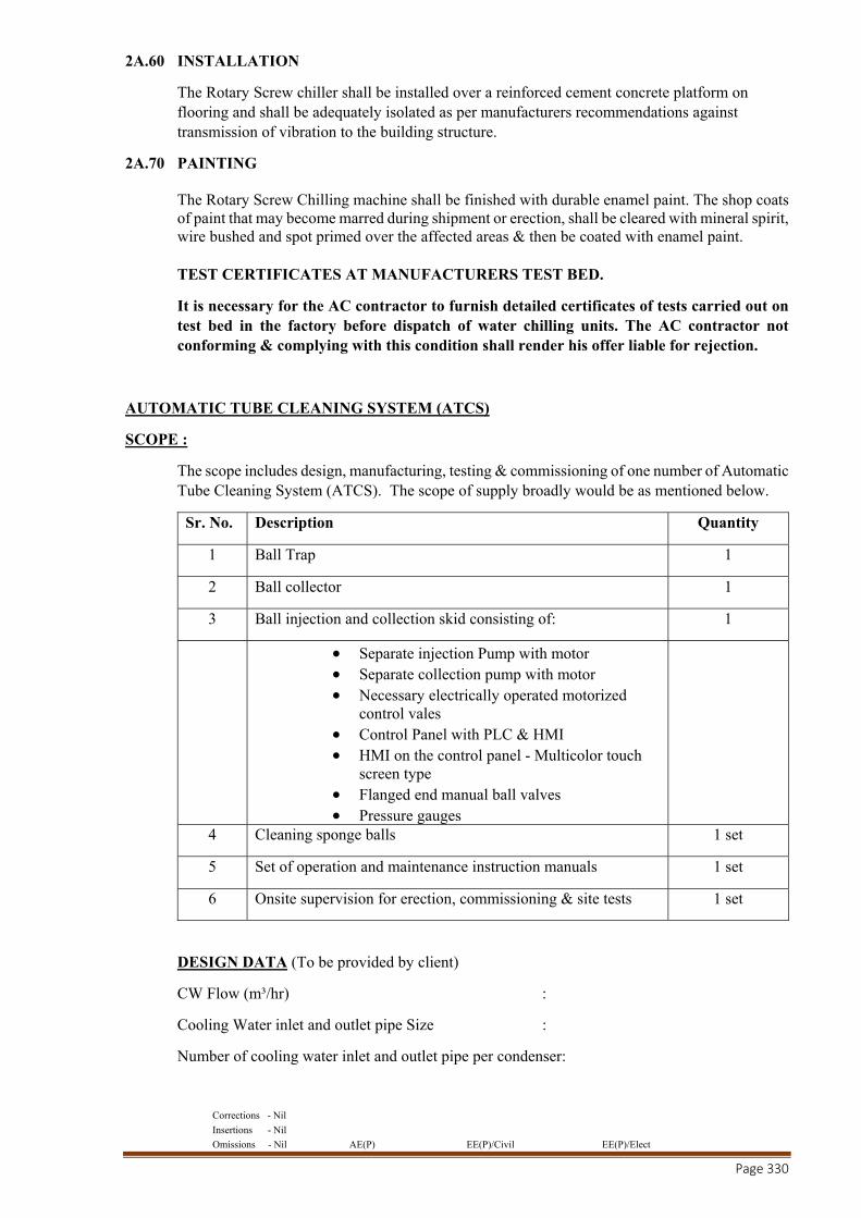
Corrections - Nil
Insertions - Nil
Omissions - Nil AE(P) EE(P)/Civil EE(P)/Elect
Page 330
2A.60 INSTALLATION
The Rotary Screw chiller shall be installed over a reinforced cement concrete platform on flooring and shall be adequately isolated as per manufacturers recommendations against transmission of vibration to the building structure.
2A.70 PAINTING The Rotary Screw Chilling machine shall be finished with durable enamel paint. The shop coats of paint that may become marred during shipment or erection, shall be cleared with mineral spirit, wire bushed and spot primed over the affected areas & then be coated with enamel paint. TEST CERTIFICATES AT MANUFACTURERS TEST BED.
It is necessary for the AC contractor to furnish detailed certificates of tests carried out on test bed in the factory before dispatch of water chilling units. The AC contractor not conforming & complying with this condition shall render his offer liable for rejection.
AUTOMATIC TUBE CLEANING SYSTEM (ATCS)
SCOPE :
The scope includes design, manufacturing, testing & commissioning of one number of Automatic Tube Cleaning System (ATCS). The scope of supply broadly would be as mentioned below.
Sr. No. Description Quantity
1 Ball Trap 1
2 Ball collector 1
3 Ball injection and collection skid consisting of: 1
Separate injection Pump with motor Separate collection pump with motor Necessary electrically operated motorized
control vales Control Panel with PLC & HMI HMI on the control panel - Multicolor touch
screen type Flanged end manual ball valves Pressure gauges
4 Cleaning sponge balls 1 set
5 Set of operation and maintenance instruction manuals 1 set
6 Onsite supervision for erection, commissioning & site tests 1 set
DESIGN DATA (To be provided by client)
CW Flow (m³/hr) :
Cooling Water inlet and outlet pipe Size :
Number of cooling water inlet and outlet pipe per condenser:
Corrections - Nil
Insertions - Nil
Omissions - Nil AE(P) EE(P)/Civil EE(P)/Elect
Page 331
Number of condensers :
Number of passes :
Number of Tubes per condenser :
Condenser tube ID :
Type of water :
Circulating CW inlet Temperature :
Circulating CW outlet Temperature :
DESIGN REQUIREMENTS
The Automatic Tube Cleaning System supplied should strictly comply with the following design requirements:
1. All the wet equipment / components to be designed for minimum / NIL corrosion and erosion due to water.
2. The Automatic Tube Cleaning system should overcome fouling, scaling and clogging of tubes through micro fouling caused by sludge, corrosion products/micro organisms etc which is presently observed by increased cooling water temperature and reducing the heat transfer coefficient particularly due to disturbances in the calcium carbonate, carbon oxide equilibrium as well as precipitation of calcium carbonate, silicate, calcium sulphate, magnesium salts.
3. The pressure drop across the Ball trap should not exceed 500 mm of WC with condenser operating with maximum cooling water flow rate.
4. A separate injection pump would be used to inject the cleaning sponge balls 5. A separate collection pump would be used to collect the cleaning sponge balls from ball trap to
the ball collector 6. There would be no water drain during the collection cycle, neither the CW inlet and outlet water
be mixed during the ball collection cycle 7. The system would operate at the predefined intervals and not continuously 8. The system supplied would ensure that while venting the air from the ball collector during
commissioning or restart, the balls should not come out of the ball collector 9. The HMI on the control panel should display an alarm for ball replacement when the balls are
due for replacement 10. Ball collector would have two separate compartments for ball housing and air vent/water drain
and should have sight glass from the front side for easy viewing and control of cleaning sponge balls
11. The ball trap supplied would have a construction with round mesh so that the ball collection is smooth and the movement of balls is soft and easy and there would be no moving parts in the ball trap
12. The open mesh area provided in the ball trap would be at least 5 times the cross section area of the CW pipe.
13. The cleaning sponge balls should not pass through the pump impeller
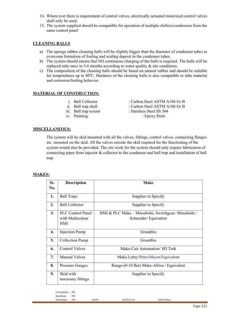
Corrections - Nil
Insertions - Nil
Omissions - Nil AE(P) EE(P)/Civil EE(P)/Elect
Page 332
14. Where ever there is requirement of control valves, electrically actuated motorized control valves shall only be used.
15. The system supplied should be compatible for operation of multiple chillers/condensers from the same control panel
CLEANING BALLS
a) The sponge rubber cleaning balls will be slightly bigger than the diameter of condenser tubes to overcome formation of fouling and scaling deposit in the condenser tubes.
b) The system should ensure that NO continuous charging of the balls is required. The balls will be replaced only once in 3-6 months according to water quality & site conditions.
c) The composition of the cleaning balls should be based on natural rubber and should be suitable for temperatures up to 80ºC. Hardness of the cleaning balls is also compatible to tube material and corrosion/fouling behavior.
MATERIAL OF CONSTRUCTION:
i. Ball Collector : Carbon Steel ASTM A106 Gr B ii. Ball trap shell : Carbon Steel ASTM A106 Gr B
iii. Ball trap screen : Stainless Steel SS 304 iv. Painting : Epoxy Paint
MISCELLANEOUS:
The system will be skid mounted with all the valves, fittings, control valves, connecting flanges etc. mounted on the skid. All the valves outside the skid required for the functioning of the system would also be provided. The site work for the system should only require fabrication of connecting pipes from injector & collector to the condenser and ball trap and installation of ball trap.
MAKES:
Sr. No.
Description Make
1. Ball Traps Supplier to Specify
2. Ball Collector Supplier to Specify
3. PLC Control Panel with Multicolour HMI
HMI & PLC Make – Mitsubishi; Switchgear- Mitsubishi / Schneider/ Equivalent
4. Injection Pump Grundfos
5. Collection Pump Grundfos
6. Control Valves Make-Cair Automation/ SD Tork
7. Manual Valves Make-Lehry/Petro/Micon/Equivalent
8. Pressure Gauges Range-(0-10 Bar) Make-Afriso / Equivalent
9. Skid with necessary fittings
Supplier to Specify
Corrections - Nil
Insertions - Nil
Omissions - Nil AE(P) EE(P)/Civil EE(P)/Elect
Page 333
END OF SECTION HVX-02A
STANDARD SPECIFICATIONS OF PUMP SETS 2B.00 PUMP SETS
This section deals with supply, erection, testing and commissioning of water pump sets conforming to general specification and suitable for the duty selected as indicated in Schedule of Equipment, Section HVX-04C. The type, capacity and size of pumps shall suit the parameters given under Section HVX-04C. The Pumps selected should have high efficiency which should be supported by selection charts and curves.
2B.10 VERTICLE INLINE PUMPSETS
The vertical inline pumps design shall be selected for condenser water / chilled water re-circulation duty.
Pump Casing - Cast Iron for working pressure to 12 bar at 65°C (PN16 flange rating) and Ductile Iron for working pressures to 25 bar at 65°C (PN25 flange rating). Suction and discharge connections shall be flanged and the same size and shall be drilled and tapped for seal flush and gauge connections. The impeller made of bronze shall be double shrouded, single entry, radial flow type. It shall be hydraulically balanced to minimize axial thrust.
A minimum of the following accessories shall be provided with each pump:-
a) Air- vent Cocks. b) Lubrication fittings and seals.
2B.20 The construction Vertical Inline Pumps shall be as follows and as per IS 1520.
Duty Condenser water / chilled water
Casing Cast Iron
Impeller Bronze
Shaft Stainless Steel
Bearings Ball Bearing
Speed (Synchronous) 1500 RPM
Motor TEFC (EF1)
Mechanical seal Factory fitted
The impellers of pumps shall be statically and dynamically balanced.
2B.50 The capacity of motor shall be at least 15% in excess in HP and starter shall be as per Standard Specifications.
The installation of pumps shall be carried out by the contractor as per manufacturers recommendations . As far as possible, the pump sets shall be factory aligned. The pump manufacturer shall provide certification to the effect that the pump and motor coupling has been carried out by them and checked by them. And if necessary site alignments shall be done by experienced and trained personal. The pumps shall be installed in such a manner that maintenance could be done without causing damage to the insulation.
Note : Detailed Calculation & Selection of Pump shall be provided during Technical Bid .
Corrections - Nil
Insertions - Nil
Omissions - Nil AE(P) EE(P)/Civil EE(P)/Elect
Page 334
STANDARD SPECIFICATIONS OF VARIABLE SPEED PUMPING SYSTEM
2BB.00 VARIABLE PUMPING SYSTEM
This section deals with supply Erection, testing and commissioning of variable pumping system confirming to general specification and suitable for the duty selected as indicated in Schedule of Equipment’s / Materials, The type, capacity and size of pumps shall be as selections given under this section only. The Pumps selected should have a very high efficiency and supported by selection charts and curves. The pumps shall be used for air washers recirculation, air-conditioning applications.
2BB.10 VARIABALE SPEED PUMPING SYSTEM
2BB.11 GENERAL
This section includes the following:
A. Variable Speed Pumping Package 1. Individual Components 2. Pump Control Panel 3. Adjustable Frequency Drive 4. Sensor Transmitters 5. Sequence of Operation
2BB.20 The following references has been broadly considered while designing variable pumping system.
A. Hydraulic Institute B. ANSI - American National Standards Institute C. NEMA - National Electrical Manufacturers Association D. UL - Underwriters Laboratories Inc. E. ETL - Electrical Testing Laboratories F. CSA - Canadian Standards Association G. NEC - National Electrical Code H. ISO - International Standard Organization I. IEC - International Electro technical Commission
2BB.30The following submittals shall be submitted but not limited to the list given below by the HVAC CONTRACTOR for approval.
1. System summary sheet 2. Sequence of operation 3. Shop drawing indicating dimensions, required clearances
and location and size of each field connection. 4. Power and control wiring diagrams 5. System profile analysis including variable speed pump curves and
system curve. The analysis shall also include staging points. 6. Pump data sheets The submittals must be specific to this project only & general submittals will not be acceptable.
2BB.40 QUALITY ASSURANCE
A. The pumping package supplier shall assume “Unit Responsibility” for the complete pumping package. Unit responsibility shall be defined as responsibility for interface and successful operation of all system components supplied by the pumping system supplier.
Corrections - Nil
Insertions - Nil
Omissions - Nil AE(P) EE(P)/Civil EE(P)/Elect
Page 335
B. All function of the variable speed pump controller shall be tested at the factory prior to shipment and it shall test all inputs, outputs and program execution specific to this application.
C. AC contractor shall comply with all sections of this specifications relating to packaged pumping system. Any deviations from this specification shall be bid as alternate clearly defined in writing. If exceptions are not defined clearly the contractor shall be bound by these specifications only.
2BB.51 MANUFACTURED UNITS
A. Furnish and install as shown on the plans Variable Speed Pump controller. B. The control system shall include as, a minimum, pumps, the programmable logic pump
controller, adjustable frequency drive(s) and remote sensor / transmitters. C. The pumps, variable speed pump logic controller, adjustable frequency drives and
remote sensor / transmitter (s) shall be shipped as individual components to the job site. D. Pumps, logic controller, adjustable frequency drives, sensor / transmitters and related
equipment shall be installed. E. Line voltage power wiring shall be installed by the HVAC contractor as shown on the
field connection drawings and wiring diagrams supplied with the pumping package. F. Low voltage (24 VDC and 115 VAC) wiring shall be installed by the controls HVAC
Contractor as shown on the field connection drawings and wiring diagrams supplied with the pumping package.
2BB.60 COMPONENTS
2BB.61 PUMP LOGIC CONTROLLER
a) The logic controller assembly to control the pumps shall be listed by and bear the label of Under writer’s Laboratory. The controller shall be specifically designed for variable speed pumping applications, which is either programmed in the VFD mounted & integrated on the Vertical inline pump OR can be part of the controller mounted separately along with the VFDs in an enclosure.
b) The controller shall function to a proven program that safeguards against damaging hydraulic conditions including:
i) Motor overload ii) Pump flow surges iii) Hunting iv) End of Curve.
c) The pump logic controller shall be capable of accepting 1discrete analog inputs from zone sensor / transmitters indicated on the plans. The sensor/ transmitter inputs shall be individually wired to the pump logic controller for continuos scan and comparison feature OR to the VFD & controls mounted & integrated on the Vertical inline pumps. Sensorless control software shall be supplied in the VFD & controls mounted on the pump unit to provide automatic speed control in variable volume systems without the need for pump mounted (internal/external) or remotely mounted differential pressure sensor. Control mode setting and minimum/maximum head set-points shall be adjustable via the built-in programming interface.
Corrections - Nil
Insertions - Nil
Omissions - Nil AE(P) EE(P)/Civil EE(P)/Elect
Page 336
d) The pump logic controller OR the Sensorless control software in the VFD & controls mounted on the pump unit shall select the analog input signal which has deviated from the greatest amount of the set point. The selected signal will be used as the command feedback input for a closed loop hydraulic stabilization function to minimize hunting.
e) The hydraulic stabilization program shall utilize a proportional-integral-derivative control function. The proportional, integral and derivative values shall be user adjustable over an infinite range. The scan can compare rate then selects the command set point and process variable signal shall be continuos and automatically set for optimum performance
f) The pump controller shall be capable of controlling pumps in 1W + 1S configuration
g) The pump logic controller shall be self prompting & all messages shall be displayed in plain English. The following features shall also be provided.
a) Multi-fault memory & recall. b) On – Screen help functions c) LED pilot lights and switches d) Soft‐touch membrane keypad switches.
h) VFD - The variable frequency drive(s) shall be pulse width modulation (PWM) type, microprocessor controlled design. VFD shall be capable of operating in voltage ranges of 240V or 415 V +/- 10% AC, three phase; at frequencies of 48 to 63 Hz. VFD shall be factory fitted and unit mounted in case it is integrated with the vertical inline pump. The iTHD and VTHD should be less than 5% (if it is more than 5% please use filter for same). VFDs shall be motor mounted and IP 54/55 rated.
i) The variable speed pumping system shall be provided with a user friendly operator interface complete with membrane switches and numeric keypad. Display shall be no less than four lines with each line capable of displaying up to twenty characters. The human interface panel shall display the following values :
a) Flow in GPM ( requires optional flow meter) b) Pump On/Off Status c) Pump % Speed d) Temperature in degree F or C e) Individual Alarm Conditions f) Trouble shooting diagnostics g) User adjustable parameters such as alternation, PID, set points, etc.
j) The pump controller OR the Sensorless control software in the VFD & controls mounted on the pump unit shall communicate to the Remote Control Consol / Building Automation System (BAS) by both hard-wired and serial communications.
a.) The following communication features shall be provided to the BAS in “hardwired” form via 4-20 mA analog signals and digital outputs :
1. Remote system start / stop ( dry contact supplied by BAS) 2. Failure of any system component (qty. 1, relay output from pump
controller)
Corrections - Nil
Insertions - Nil
Omissions - Nil AE(P) EE(P)/Civil EE(P)/Elect
Page 337
3. Process variable (qty. 1, 4-20ma analog output supplied by pump controller OR sensed through sensorless control on the pumps)
4. AFD speed (qty. 1, 0-10 VDC analog output supplied by pump controller)
5. Optional : Pumpon / off status & fault condition (qty. 2 relay output supplied by pump controller)
b) The following communication features shall be provided to the Building Automation System via an RS-485cport.
1. All sensor process variable. 2. Individual zone set points. 3. Individual pump failure. 4. Individual pump on / off status. 5. Individual AFD on/off status. 6. AFD speed. 7. Individual AFD Failure. 8. Individual sensor failure (if applicable).
k) The pump logic controller shall be supplied by the pump supplier and the enclosure shall be conforming to NEMA 1 / IP 54.
2BB.62 ADJUSTABLE FREQUENCY DRIVE.
i) The adjustable frequency drive (s) shall be pulse width modulation (PWM) type, microprocessor controlled design.
ii) The AFD, including all factory installed options, shall have CSA approval.
iii) AFD shall utilize a diode bridge rectifier to convert three phase AC to a fixed DC voltage. Power factor shall remain above 0.95 regardless of speed or load. AFDs employing power factor correction capacitors shall not be acceptable.
iv) Insulated gate bipolar transistors shall be used in the inverter section to convert the fixed DC voltage phase adjustable frequency AC output. A DC linereactor shall be provided to minimize harmonic and current distortion of the input power line.
v) The following customer modifiable adjustments shall be provided :
a. Accel time : 0.1 to 1800 seconds
b. Decel time : 0.1 to 1800 seconds
c. Minimum frequency : 0HZ
d. Maximum frequency : 120 HZ
e. Analog input filter : 0.1 to 10 seconds
f. Analog outputs filter : 10 to 1 gain.
g. Overload protection : 70 % - 100% to full load current.
vi) Speed reference signal shall be customer selectable for 1-10 VDC or 4-20 MA.
Corrections - Nil
Insertions - Nil
Omissions - Nil AE(P) EE(P)/Civil EE(P)/Elect
Page 338
vii) The AFD shall be capable of displaying the following information in plain English via a 40 character alphanumeric display :
a. Frequency b. Voltage c. Current d. Kilowatts per hour e. Fault identification f. Percent torque g. Percent power h. RPM i. Setting of O/L protection
The AFD controller shall be suitable for elevation upto 1000 meters above sea level.
The AFD shall incorporate DC link chokes to reduce the DC link ripple current caused by harmonic currents in the main electrical connection. The VFD shall be UL listed and CE marked showing compliance with both the EMC directive 89/336/EEC and the Low Voltage directive 72/23/EEC. RFI filters shall be incorporated within the drive to ensure it meets the emission and immunity requirements of EN61800-3 to the 1st Environment Class C1 (EN55011 unrestricted sales class B). AFD and motor protection shall include: motor phase to phase fault, motor phase to ground fault, loss of supply phase, over voltage, under voltage, motor over temperature, inverter overload, over current. Over current is not allowed ensuring pump units will not overload the motor at any point in the operating range of the unit.
AFD's rated above 7.5 kW shall incorporate an integrated graphical user interface that shall provide running and diagnostic information and identify faults and status in clear English language. Faults shall be logged / recorded for interrogation at a later date. It shall be possible to upload parameters from one AFD into the non-volatile memory of a computer and download the parameters into other drives requiring the same settings. The keypad shall incorporate Hand-Off-Auto push buttons to enable switching between BMS and manual control. AFD shall incorporate a USB port for direct connection to a PC and an RS485 connection with Modbus RTU protocol. Optional protocols available shall include BACnet, and Lonworks.
2BB.63SENSOR / TRANSMITTER ( If Applicable)
To Provide 4 nos. field mounted differential pressure sensor transmitter(s) as indicated on the plans. Unit shall transmit as isolated 42Ma designed indicative of process variable to the pump logic controller via standard two wire 24 DC system. Unit shall have stainless steel wetted parts with 0.25” male NPT process connections. It shall beprotected against ratio frequency interference and shall have a water tight, NEMA 4 electrical enclosure capable of withstanding 200 PSI static pressure with a 0.5” NPTconduit connection. Accuracy shall be within 025% of full span.
2BB.64 SEQUENCE OF OPERATION
i) The system shall consist of a pump logic controller, multiple pump / AFD sets with manual and automatic alternation and pump staging.
ii) The pumping system shall start upon the closure of customer’s contact when the pump logic controller Mode of Operation selector switch is in the REMOTE position.
iii) When the pump logic controller selector switch is in the LOCAL position, the pumping system shall operate automatically.
iv) Sensor / transmitters shall be provided as indicated on the plans.
Corrections - Nil
Insertions - Nil
Omissions - Nil AE(P) EE(P)/Civil EE(P)/Elect
Page 339
v) Each sensor / transmitters shall send a 4-20Ma signal to the pump logic controller, indicative of process variable condition.
vi) The pump logic controller shall compare each signal to the independent, engineer / user determined set points.
vii) When all set points are satisfied by the process variable, the pump speed shall remain constant at the optimum energy consumption level.
viii) The pump logic controller shall continuously scan compare each process variable to its individual set point and control to the least satisfied zone.
ix) If the set point cannot be satisfied by the designed lead pump, the pump logic controller shall initiate a timed sequence of operation to stage a lag pump.
x) The lag pump shall accelerate resulting in the lead pump (s) decelerating until they equalize in speed.
xi) Further change in process variable shall cause the pumps to change speed together. xii) When the set point criteria can be safely satisfied with fewer pumps, the Technologic
pump logic controller shall initiate a timed destage sequence and continue variable speed operation.
xiii) As the worst case zone deviates from set point, the pump logic controller shall send the appropriate analog signed to the AFD to speed up or slow down the pump motor.
xiv) In the event of a system differential pressure failure due to a pump of AFD fault, the Technologic pump logic controller shall automatically start the next variable speed pump / AFD set in sequence and continue variable speed operation.
xv) In the event of the failure of a zone sensor / transmitter, its process variable signed shall be removed from the scan / compare program. Alternative zone sensor / transmitters, if available, shall remain in the scan / compare program for control.
xvi) The zone number corresponding to the failed sensor / transmitter shall be displayed on the operator interface of the pump logic controller.
xvii) In the event of failure to receive all zone process variable signals, all AFDs shall maintain 100% speed, reset shall be automatic upon correction of the zone failure.
xviii) PUMP or AFD fault shall be continuously scrolled through the display on the operator interface of pump logic controller until the fault has been corrected and the controller has been manually reset.
OR the Sensorless control software embedded in the integrated VFD to provide automatic speed control in variable volume systems without the need for pump mounted (internal/external) or remote differential pressure sensor. The default operating mode under sensorless control shall be ‘quadratic pressure control’ whereby head reduction with reducing flow will be according to a quadratic control curve, the head at minimum flow being 40% of the design duty head. Control mode setting and minimum / maximum head setpoints shall be user adjustable via an optional programming interface.
The VFD shall have the following additional features:
Sensorless override for BMS Manual pump control or closed loop PID control Programmable skip frequencies and adjustable switching frequency for noise/vibration control Auto alarm reset Motor pre-heat function, Four programmable digital inputs Two analogue inputs One programmable analogue/digital output One volt-free contact One RS485 port for serial communications to building management systems
2BB.70 SPECIFICATION FOR PUMPS

Corrections - Nil
Insertions - Nil
Omissions - Nil AE(P) EE(P)/Civil EE(P)/Elect
Page 340
2BB.71 END SECTION PUMPS :
Pumps shall be base mounted, single stage, End Section Pump design with a foot mounted volute to allow servicing of the impeller and bearing assembly without disturbing piping connections.
Pumps volute shall be class 30 cast iron with integrally-cast pedestal support free. The impeller shall be cast bronze enclosed type, dynamically balanced, keyed to the shaft and secured by a locking cap screw. The shaft shall be stainless steel.
The liquid cavity shall be sealed off at the pump shaft by an internally-flushed mechanical seal with ceramic seal and carbon seal ring, suitable for continuous operation up to 107 deg. C. A replaceable bronze shaft sleeve shall completely cover the wetted area under the seal. Pump shall be rated for minimum of 175 PSI working pressure. Volute shall have gauge tapping at the suction and discharge nozzles and vent and drain tapping at the top and bottom.
Base plate shall be of structural steel or fabricated steel channel with fully enclosed sides and ends and securely welded with cross members. Grouting area shall be fully open. A flexible type, center drop-out design coupler, capable of absorbing torsional vibration, shall be employed between the pump and motor. Coupler shall be shielded by a coupler guard securely fastened to the base. The Motor shall meet NEMA / IEC specifications and shall be of the size, voltage and enclosure called for on the plans. Pumps and motor shall be aligned by contractor after installation.
Each pump shall be factory tested per Hydraulic Institute standards. It shall then be
thoroughly cleaned and pained with at least one cost of high grade machinery enamel prior to
shipment.
Corrections - Nil
Insertions - Nil
Omissions - Nil AE(P) EE(P)/Civil EE(P)/Elect
Page 341
STANDARD SPECIFICATIONS OF COOLING TOWERS
2C.00 COOLING TOWER
This section deals with supply, erection, testing and commissioning of cooling towers, conforming to general specifications and suitable for the load parameters indicated in Schedule of Equipment.
The function of efficient cooling tower is to cool adequate quantity of water through a range of 4.2 °C efficiently with reference to ambient Wet Bulb Temperature approach of 3.9°C.
TYPES: The cooling tower selected shall be induced draft, counter / cross flow type conforming to their respective specification as under. The cooling tower should be installed in open space where free flow of air is available. The cooling towers shall be constructed conforming to relevant ASME standards
2C.10 FRP INDUCED DRAFT COUNTER FLOW COOLING TOWER
The Fiber Glass reinforced plastic Cooling Tower shall be suitable for outdoor installation. The Cooling Tower shall be vertical, induced draft, counter flow in fibre-glass reinforcement plastic construction, complete with fan, motor, surface and spray section, eliminators, steel supports etc.
a) CAPACITY : The cooling tower capacities shall be as per Schedule of Equipments. b) SIDE CASING :
Side casing shall be made out of FRP with smooth surface for minimum resistance to air flow. It shall have sufficient structural strength to withstand high wind velocities and vibration. The casing
shall be installed in the fibreglass reinforced basin. The tower supporting structure shall be made out of hot dipped galvanized frame. The tower shall have FRP panels reinforced with embedded steel frame.
c) COLD WATER BASIN : The Cold Water Basin shall be a deep fibreglass reinforced sump on which cooling tower
structure shall be supported. Basin fittings shall include the following :
i) Bottom Outlet. ii) Screened suction assembly fixed to the basin. iii) Drain at under side of suction, suction side sheet. iv) Overflow fixed to inside of casing side sheet. v) Ball type automatic make-up water valve. vi) Equalizing connection where required. vii) Quick Fill arrangements
d) DISTRIBUTION SYSTEM
Hot water distribution system shall comprise of header and branch arms system.
e) FILLINGS :
Corrections - Nil
Insertions - Nil
Omissions - Nil AE(P) EE(P)/Civil EE(P)/Elect
Page 342
The Fillings shall be made of corrosion proof and rigid film in cross fluted design and arranged in square / rectangular form and shall be elevated from the floor of the cold water basin to facilitate cleaning and easy replacement. They shall be arranged in such a manner to ensure negligible resistance to air flow and to eliminate back water spots and prevent fouling trough scales that may form. In order to reduce carry-over losses through entrapment of water droplets in air stream, PVC drift eliminators shall be installed. Thickness of PVC fill shall not be less than 0.02 mm.
f) MECHANICAL EQUIPMENT :
The Fan shall be propeller type, light-weight rotor fitted with multiple Aerofoil blades. The entire fan assembly shall be statically balanced. The fan shall be direct / gear driven by TEFC motor suitable for 415 volts ±10%, 3 phase, 50 Hz ± 5%, AC supply conforming to IP 55. The fan shall be protected by fan guard and shall be easily accessible for inspection and maintenance. The mechanical equipment assembly shall be adequately supported on a rugged steel base welded to tubular support assuring vibration-free support. Fan guard shall be provided to prevent birds from nesting during idling periods. All fans shall be direct driven with low RPM suitable for low noise application.
3C.20 INDUCED DRAFT CROSS FLOW:
The induced draft cross flow FRP cooling tower should be complete with corrosion proof construction and all steel components including assembly hardware are hot dip galvanised construction with FRP cold & hot basin .The induced draft propeller fan of the cooling tower shall be direct / gear driven by TEFC squirrel cage motor located outside the moist air stream. The corrosion proof PVC fill should be vacuum formed to provide maximum heat transfer surface. The design should also include cellular drift eliminators and honeycomb air inlet louvers right on the fill sheet. The maintenance on the mechanical equipment should be provided from outside the tower & access to the tower interior should be available through the opening in the centre of cold basin.
WATER DISTRIBUTION SYSTEM
The warm water flows through external piping into a chamber at the top of the tower. The splash box prevents the incoming water from spilling out of the basin and helps in providing uniform water distribution & the water should flow by gravity from the fibreglass basin through nozzles to the fill.
FILL /LOUVERS/DRIFT ELIMINATORS
The fill sheet includes both louvers and drift eliminators & the louvers should prevent water from escaping the fill sheets to assure proper & efficient heat transfer throughout wide variations in the airflow. The HDG steel structural tubes shall support & stabilize the fill in position & shall also hold the fill sheets in position above the cold water basin to facilitate the cleaning of the basin. Suitable screens between the side of the cold water basin & the base of the fill should be provided to prevent foreign materials in the circulating water flow & should be easily removable.
COLD WATER BASIN:
The specification for cold water basin shall be same as given for counter flow cooling tower.
2C.30 PAINTING:
Corrections - Nil
Insertions - Nil
Omissions - Nil AE(P) EE(P)/Civil EE(P)/Elect
Page 343
The cooling tower shall be procured of the color, strictly in accordance with written approval of the Engineer in Charge and should have a striking finish.
2C.40 PERFORMANCE DATA:
The complete performance ratings and power consumption at varying outdoor wet bulb temperatures, shall be submitted and verified at the time of testing and commissioning of the installation. The Capacity of the cooling tower shall be computed as indicated in the testing procedures for air - conditioning equipments.
2C.50 ACCESSORIES:
Each cold water basin shall be provided with a deep leak proof sump complete with a suitable suction strainer having duplicate screen. The strainer shall have handles for its removal.
The cooling tower basin shall be provided with automatic float valve with a stop valve for continuous make up water flow, quick fill arrangement with stop valve, over-flow and drain connections with stop valves.
A hot water bleed connection to the drain line through a stop valve shall be provided. It shall be connected to the drain line below the drain stop valve.
Steel ladders shall be provided in such a manner and location as necessary to give safe and complete access to all parts of tower requiring inspection. Each ladder shall be made of iron sides and 16 mm straps and shall be bolted to the tower on the top and grouted in masonry at the bottom end.
All pipe connections shall be hot dip galvanized and double flanged.
2C.60 TESTING:
The testing of cooling towers shall be conducted as per ASME codes and results should be within ± 5% of the specified capacity.
Corrections - Nil
Insertions - Nil
Omissions - Nil AE(P) EE(P)/Civil EE(P)/Elect
Page 344
STANDARD SPECIFICATIONS OF HOT WATER GENERATOR
2D.00 This section deals with supply, installation, testing and commissioning of electric fired Hot Water Generator System to be supplied as mentioned in Detailed Bill of Quantities.
2D.10 HOT WATER GENERATOR.
Construction: The hot water generator shall be Vertical/Horizontal shell type. The shell shall be constructed out of 6 mm.thick MS Sheet with electric fusion welded seams & in accordance with ASME Boiler & Pressure Vessel Code, Section IV.
The shell shall be duly insulated & shall be mounted in a cabinet of suitable angle iron frame from 16 SWG mild sheet steel covers complete with hinges, locks etc. to make a sturdy compact assembly. The cabinet shall be provided with sufficient ventilation of heaters terminals of the boiler. The angle iron frames shall be provided with lifting lugs & pedestals.
The heaters shall be provided in such a way as to provide balanced distribution of the load. The electrical heater which shall be mounted within seamless copper sheethed electrically resistant U-Tubes, flanges mounted with stainless steel studs. The heaters will be easily removable without opening of terminal plates. The heaters shall be suitable for 240 + 10%, 50 + 5% HZ. Single Phase AC Supply and will be in direct contact with water contained in the shell.
CONTROLS & ACCESSORIES.
The hot water generator will be provided and not limited to following controls & accessories.
a) 100 mm.dia dial type thermometer mercury in bulb at inlet & outlet (Range 0-100 ºC) b) 100 mm.dia pressure guage with ball valve at inlet & outlet (Range 0 to 20 Kg/cm2 ) c) Flow switch, float switch, automatic alarm for low water level and high temperature with
independent indication lights. d) Pressure relief valves. e) Inlet & outlet pipes with flanges. f) Drain points with valves. g) Descaling Valves. h) Automatic airvent. i) Thermostat for individual heater banks or step controller. j) Safety Thermostat .
PRESSURE TESTING.
The hot water generator shall be tested in the factory at 160 PSI.
INSULATION.
The hot water generator shall be insulated with minimum 50mm thick fibre glass of density 24 Kg/m2 & cladded with 0.63 mm aluminium sheet on MS Frame welded on generator body.
ELECTRICAL CONTROL PANEL.
The electrical control panel shall be mounted directly on the main frame confirming to standard specification of Indian Electricity Rules. All controls shall be factory wired & tested. The control panel shall have the following accessories of makes mentioned in Section ACE-19.
a) Incoming MCCB/SFU with copper bus bar. b) On-off Toggle switch for operating individual banks. c) Contactor for individual banks with HRC fuses. d) Indicating on/off lights status for individual banks. e) Fault indicating lights.

Corrections - Nil
Insertions - Nil
Omissions - Nil AE(P) EE(P)/Civil EE(P)/Elect
Page 345
f) Alarm with manual reset. g) Copper connections with cable & control cabling. h) Three phase ammeters & voltmeter with selector switch.
The electrical panel doors should be openable only after total incoming power supply is cut off.
PAINTING
The external surface of the shell shall be derusted, cleaned & applied with three coats of primer & finally have powder coating of approved shade.
2D.20 HUMIDIFICATION ARRANGEMENTS.
The humidification arrangement shall be provided by AC contractors (wherever specified in the Schedule of quantities in section . This shall consist of the following arrangement.
2D.30 PAN TYPE HUMIDIFIER.
A pan type humidifier of required capacity as specified in bill of quantities shall be provided. The pan type humidified shall be constructed from 2 mm thick stainless sheet SS-304 with top cover openable for maintenance. The humidifier shall be complete with quick fill, make up overflow & drain connections. The humidifier shall be insulated with fibre glass of density 32 kg/cm2 & shall be cladded with 22G thick aluminium sheet. The humidifier is divided in two chambers from inside, one bank of heater is always kept on to maintain water temperature between 60 to 70 ºC with thermostat. All controls such as low level cut out, thermostat, float valve shall be provided. It shall be factory wired & tested. The humidifier shall have its own powder coated electrical panel made of 16 G CRCA sheet complete with contactors, MCB Low level cutout, Heating thermostat, fault indicating lamp, high temperature cutout etc. & internally wired.
Corrections - Nil
Insertions - Nil
Omissions - Nil AE(P) EE(P)/Civil EE(P)/Elect
Page 346
SPECIFICATIONS FOR INTELLIGENT AIR HANDLING UNITS
1. SCOPE
The scope of this section, comprises the supply, erection, testing and commissioning of double skin construction air handling units, conforming to these Specifications and in accordance with requirements of drawings and of the Schedule of Quantities
Broadly the guidelines specify compliance of AHU construction in accordance to EN1886.
2. TYPE
The air handling units shall be floor mounted type with horizontal / vertical airflow arrangement with cabinet casing of double skin construction consisting of aluminum profile structure and insulated sandwich panels , draw-thru or blow through type comprising of various sections like – single or double stage filter section, coil sand hydraulics section , starter panel and controller section , Direct drive EC fan section etc. as shown in the schematic layout arrangement drawings and included in schedule of quantities. Customized sections to include components like Hot water coil, mixing box , adiabatic pads , heat recovery wheels , automatic damper modules , heater and humidifiers etc. must be possible to integrate in modules as per requirements.
3. CAPACITY
The air handling capacities, maximum motor horse power and static pressure shall be as shown on Drawings and in Schedule of Quantities. The AHU design must be based on airflow velocities, pressure drops and static requirements as specified.
4. UNIT HOUSING / CASING The unit casing shall be made of double skin design comprising of the chasis structure made of
extruded aluminum framework with thermal break profile of 48mm thickness confirming to class TB2 of thermal bridging as per EN1886 as specified in Bill of Quantities. The panels shall be double skin sandwich type with minimum 1.0 mm thick powder coated/pre coated steel sheet on the outer side and minimum 0.8 mm thick galvanized sheet on inner side with 45 mm ± 2 mm thick rockwool insulation material of density 60 kg/cum between both inner and outer skin. Considering fire safety norms injected PU foam insulation is not acceptable.
The base frame of the AHU shall be made of 100mm high steel profile structure for rigidity.
All sections / panels shall be bolted to each other with Neoprene rubber gasket in between and fixed with steel screws for perfectly aligned and airtight joints. The gaskets shall be held in place by inserting them in the integrated channels in the framework. All panels shall be detachable or hinged. Hinges shall be made of die cast aluminum with stainless steel pivots. Door handles and locks shall be made of self extinguishing thermoplastic nylon filled with glass wool and minerals. Marine lights can be provided in fan & coil sections, if required, to see the inside and shall be interlocked with door opening.
The entire construction of AHU shall confirm to leakage class L1/L1 in accordance with EN1886.
Condensate drain pan shall be provided with multiple slopes towards drain outlet. Condensate drain pan shall be fabricated from SS 304/GI powder coated, insulated with 13 mm thick closed cell elastomeric insulation.
Corrections - Nil
Insertions - Nil
Omissions - Nil AE(P) EE(P)/Civil EE(P)/Elect
Page 347
5. EC - FAN SECTION ( Electronically Commutated ) Unit must be provided with EBM or Zhiel Abegg – German make , direct drive backward curved EC fans each running with DC drive electronically communicated motors, the fans should be aligned and balance statically and dynamically. The fan speed must be controlled based on the room return air temperatures and also must have automatic step-less speed control without manual intervention. The fans can be in multiple numbers as per the manufacturer’s standard.Units shall be factory balanced in accordance with Section 15071, Mechanical Sound and Vibration Control. Fan curves must be provided to confirm selection as and when required. The motor and fan must be from approved manufacturers as one assembly.
Noise Level: Less than 73 db from 2 Mtr. of unit in free filed conditions.
Only direct drive fans to be provided in offered units and centrifugal fans with belt drive is strictly not acceptable.
6. COOLING COIL / EVAPORATOR COIL SECTION The cooling section shall be of Chilled Water Coil as specified in the Bill of Quantities. Coil shall be shall be made from seamless copper tubes with aluminum anti-corrosive corrugated fins/Hydrophilic coated blue fins. The tubes shall be solid drawn copper of not less than 9.5 or 12.5 mm dia and minimum 0.4 mm wall thickness.
Aluminum fins shall be continuous and equally spaced by collars forming integral part of the fins. The number of fins shall not be more than 12 FPI and the thickness of fins shall be minimum 0.11mm. The fins shall be uniformly bonded to copper tubes by mechanical/hydraulic expansion for minimum thermal contact resistance with fins. The fins shall be assembled in a GI or specified in BOQ. Coils shall be sliding track mounted inside the Unit for easy replacement. Each section of the coil shall be fitted with supply & return header of Copper/MS to feed all passes of coil equally. U bends shall be of forged copper and shall be joined to tubes by brazing and silver soldering.
Headers shall be provided with flanged ends for pipe connections. The headers shall also be provided with vent plug at top and drain plug/valve at bottom. The coil shall be designed for a maximum working pressure of 7 Kg/Sq.cm. Each coil shall be factory-tested at 21 kg/Sq.cm air pressure under water. Computerized cooling coil selection output shall be submitted.
Coil selections must ensure total water side pressure drop including header are not exceeding 50 kPa as per design standards.
7. CHILLED WATER CONTROL VALVE The coil and hydraulic section of the air handling unit shall be provided with factory fitted
required size of 2 Way Valve / Pressure Independent Dynamic Balancing Valves with actuators to stabilize the flow and to have better heat transfer resulting in Energy savings and increase in overall performance of the unit. The type of valve to be used shall be in accordance with specification in bill of quantities. Manufacturer to ensure the valve control is possible via integrated control signal based on feedback from temperature sensors of return or supply air as per control logic specified.
8. PREFILTER SECTION
Corrections - Nil
Insertions - Nil
Omissions - Nil AE(P) EE(P)/Civil EE(P)/Elect
Page 348
Each unit shall be provided with a factory assembled filter section containing synthetic media washable air filters with efficiency of 90% down to 10-micron particle size confirming to MERV 8. Filters shall have aluminum frame. Filter face velocity shall not exceed 500 FPM. Filter leakage shall comply to class F9 standard in conformity to EN - 779. Holding frames shall be provided for installing number of filter cells in banks. These cells shall be held within the frames by sliding the cells between guiding channels. Optionally high efficiency filters wherever required can be provided as separate sections.
9. MULTI STAGE PARTICULATE FILTERATION – optional BOQ specification.
Additional filter sections comprising of fine filter (MERV 13) with efficiency of 99% down to 3-micron particle size and other super fine filter to be provided as mentioned in the schedule of quantities.
10. ELECTRICAL PANEL The air handling unit shall have inbuilt integrated electrical starter panel with AUTO/Manual over ride switch for operation. Control cabinet to be provided with Type 2 enclosure, with grounding lug, combination magnetic starters with overload relays, circuit breakers and cover interlock, and fusible control circuit transformer. The electric panel provided for the unit must be equipped with main incoming power isolation switch, additionally the unit must be provided with under voltage / over voltage / phase reversal / single phasing protection in standard for DX systems , all three phase motors must be operated only via 24V / 48V coil voltage contactors and MPCB’s, additionally step down transformer must beprovided for power supply to the unit controller. The electrical panel must also be providing with relay block for common alarm.
11. MICRO PROCESSOR CONTROLLER The controller to be equipped with appropriate capacity processor with minimum 128 MB Flash + 128 MB DDR3 Memory. The controller should have ports for BMS Connectivity using Modbus RTU protocol. The power input to the controller shall be DC 24, with working range of DC 9V-28V, the power consumption should be less than 10W. Display shall be provided as option if specified in the BOQ , in standard the controller / DDC must be compatible to connect to a laptop or display for configuring or viewing unit performance parameters. The controller to have the following outputs :
Temperature / RH / Pressure / Flow sensors (Air, Water) connectivity as per devices options. Power energy meter connectivity (Full point) – optional, if mentioned in the BOQ. Sensor Using Rs485 (modbus slave) connectivity. CO2/VOC sensor connectivity – optional, if mentioned in the BOQ Invertor/VFD connectivity via Rs485 (modbus slave) – optional, if mentioned in the BOQ I/O summary upto 250 devices compatible. Multiple controller (Slave) connectivity. Modbus RTU (485/IP) compatible output to BMS. Wireless connectivity of devices through WLAN Adaptor/Switch. Memory storage through SD card (Optional). Downloading updates/via USB interface software utilities – optional, if mentioned in the BOQ Password Protection. The control should have an auto-restart feature which will return the unit to normal operation
resumption of mains power. Feedback from sensor etc and regulate the fan speed/ valve opening.
Corrections - Nil
Insertions - Nil
Omissions - Nil AE(P) EE(P)/Civil EE(P)/Elect
Page 349
Automatic load / time and alarm sequencing function to be performed by the unit. Microprocessor must have output point for ON/OFF of motorized outlet damper and must be
suitable to be integrated with fire point for unit shut off incase receiving signal from fire panel or fire detectors.
In normal operating mode the screen should display unit number, temperature and relative humidity set points and actual, operating status.
Instrumentation: The following sensors shall be part of AHU package for modulation of fan and control valves
1. Temperature Sensor 2. Pressure Sensor/ DP sensor
12. MIXING BOX - OPTIONAL AHU’s requiring mixing boxes as specified in Schedule of Quantities shall be complete with fresh and return air dampers. 13. DAMPER WITH ACTUATOR - OPTIONAL
Dampers shall be opposed blade type. Blades shall be made GI and assembled within a GI frame. All linkages and supporting spindles shall be made of aluminium or nylon, turning in teflon bushes.
Manual dampers shall be provided with a bakelite knob for locking the damper blades in position. Linkages shall be extended wherever specified for motorised operation. Actuators for manual dampers can be provided as mentioned in the schedule of quantities.
Damper frames shall be sectionalised to minimise blade warping. Air leakage through dampers when in the closed position shall not exceed 1.5% of the maximum design air volume flow rate at the maximum design air total pressure.
Time delay settings for damper On/Off based on signal from unit controller can be provided.
Corrections - Nil
Insertions - Nil
Omissions - Nil AE(P) EE(P)/Civil EE(P)/Elect
Page 350
STANDARD SPECIFICATION OF FAN COIL UNITS
3B.00 This section deals with supply, erection and commissioning of fan c;oil units conforming to general specifications and suitable for duty selected as indicated in Schedule of Equipment.
3B.10 FAN COIL UNITS
The horizontal type of fan coil units shall be complete with centrifugal blowers of aluminum construction, 3 speed permanent split-capacitor type fan motor, cooling coil, sandwiched type insulated drain pan etc.
The outer casing of Fan Coil Unit shall be of 18G cold roll M.S sheet of suitable size to accommodate all piping and controls. The sandwiched drain pan for accommodating all controls shall be of 16G GI sheet duly insulated with 25mm thick expanded polystyrene.
The cooling coil shall be 4 row deep having minimum 4.7 fins / cm. The fins configuration of Sigma flow or plain fin shall be acceptable. The OD of copper tube shall be 9.5 mm minimum & wall thickness of 0.5 mm.
The fan shall be centrifugal, forward curved driven by 3 speed permanent split capacitor type fan motor. The Fan Coil Units shall be provided with the following accessories given below.
a) Double fire retardant Canvass Connection. b) 12 mm thick cleanable aluminium filters with aluminium frame. c) Strainer with ball valve at inlet & ball valve at outlet. d) Balancing valve in return chilled water line. e) Copper connections between chilled water lines, controls etc.
f) Electrical wiring between motors & speed regulator.
It may be noted that all accessories specified above shall be provided along with the Fan Coil Unit and shall be included in the price of Fan Coil Unit.
Each Fan Coil Unit shall be tested at factory & complete in all respects. The sound level of the unit should not exceed 40 dB. The test certificate shall be furnished with each Coil Unit. It is necessary to design the fan coil unit in a way to have silent operation.
The Fan Coil Unit shall be powder coated both internally & externally.
3B.20 PARAMETERS OF FAN COIL UNITS
The Parameters of Fan Coil Units are given below:
FAN COIL UNIT-CEILING SUSPENDED
Capacity 1.5TR 2.0TR 2.5TR
a) Air quantity CMH 1020 1360 1700
b) Fan Static pressure ------------------ 12MM -----------------
c) Face area of cooling Coil --to suit the requirement at 500 FPM--
d) Minimum no. of fins / cm -------------------4.7----------------------
e) No. of rows deep 4 4 4
f) Motor HP ----(Fractional HP, Single phase)---
Corrections - Nil
Insertions - Nil
Omissions - Nil AE(P) EE(P)/Civil EE(P)/Elect
Page 351
g) Sandwiched tray -----------------YES---------------------
h) Type of painting -----Powder coated finish only-------
3B.20 Hydronic Ceiling Cassette Units 1.1 SCOPE
The scope of this section comprises the supply, erection, testing and commissioning of Hydronic Cassette type fan coil units conforming to these Specifications and in accordance with the requirements of the Drawings and Schedule of Quantities.
1.2 TYPE
The Hydronic Cassette type fan coil units shall be Ceiling mounted Type ,mounted within ceiling space . All units shall be complete with chilled water coil, Multi Blade centrifugal fan and motor, cleanable filters and a Drain Pump.
1.3 CAPACITY
The air moving and coil capacities shall be as shown on Drawings and indicated in Schedule of Quantities.
BODY
The body of Hydronic Cassette Type Fan Coil Units shall be light in weight and constructed of
20 gauge galvanized sheet steel.
PANEL
The unit shall have an external attractive Panel for supply & return air with four way supply air grills on sides and return air grill in center .
1.4 DRAIN PUMP
The unit shall have a drain pump with an arrangement of alarm in case of drain Pump failure.
1.5 COOLING / HEATING COIL All cooling coils shall have minimum Two-row staggered seamless copper tube of 9.5mm Outer
Diameter with hydrophilic aluminum fins . Tubes shall be mechanically / hydraulically expanded for minimum thermal contact resistance with fins.
1.6 FANS
Fans shall be Multi Blade centrifugal fan.
1.7 MOTOR
Auto Swing Motor shall be 220 ± 6% volts, 50 cycles single phase, energy efficient, motors shall have minimum three speedand shall be factory wired to a terminal block.
1.8 THERMO SENSORS
Thermo Sensors on Cassette Unit and cordless remote controller shall be provided .The controller shall be able to change the fan speed wherein the auto swing motor will be able to adjust the direction of air flow.
Corrections - Nil
Insertions - Nil
Omissions - Nil AE(P) EE(P)/Civil EE(P)/Elect
Page 352
1.9 ACCESSORIES
All Hydronic cassette type fan coil units shall be equipped with dielectric union and manual air vent at the cooling coil outlet header. In addition, the following accessories may be required at fan coil units; their detailed Specifications are given in individual sections and quantities separately identified in Schedule of Quantities. ALTERNATELY Motorized valve , Ball valve with ‘Y’ strainer, Stop Valve , as shown on Drawings and in Schedule of Quantities.
2.0 PERFORMANCE DATA
Hydronic Cassette type Fan coil units shall be selected for the lowest operating noise level Fan performance rating and power consumption data, with operating points clearly indicated, shall be submitted by the Tenderer and verified at the time of testing and commissioning of the installation.
STANDARD SPECIFICATIONS OF CONTROL SYSTEM
3C.0 This section deals with supply, installation and testing, commissioning of necessary controls (automatic) and instruments conforming to these specifications and shall be in accordance with Bill of Quantities. The various controls listed below shall be electrically operated and in case of low voltage controls the necessary step down transformer shall be provided with each control. All automatic controls shall be as detailed in specifications below, however, if the automatic control is not already installed on the machines, it may be installed by the contractor as per Bill of Quantities.
3C.1 CONTROLS FOR AIR HANDLER
Two way modulating valves:
The two way modulating valves shall be provided in chilled & hot water line to the cooling & heating coil of Air-handlers which is actuated by a proportionating thermostat. The three-way valve shall be selected for valve authority value in the range of 30 % to 60 %. These valves shall consist of bronze metal valve body with stainless steel trim with linear flow characteristics. Modulating motor shall be suitable for operation with a signal of 0-10 volt DC from the IBMS System. The pressure drop across valve for air-handler unit shall not exceed 5.0 PSI. The valve linkages shall be of the same make as of valves & modulating motor.
3C.2THERMOSTATS
a) Snap Acting Humidistat for AHU:-
These shall be electrically operated fixed differential type with the sensing elements located in the return air passage. The exact mounting arrangement, profile etc. shall be derived as per location requirements.
b) Proportionating Thermostat for AHU:-
For Air-handlers, three way mixing valves shall be proportionately operated based on return air temperature & is suitable to operate in the range of 14 to 30 °C.
3C.3 INSTRUMENTS
i)Thermometer: The alcohol filled V-form thermometer shall have range of 50 °C. for air-conditioning application. These shall be provided at inlet / outlet of chillers & air-handers.
ii)Pressure gauges: The pressure gauges shall be dial type of 150 mm dia to be installed at inlet / outlet of chillers, condensers, suction and discharge ends of pump-sets. The air-handlers shall have common pressure gauge for inlet & outlet. The
Corrections - Nil
Insertions - Nil
Omissions - Nil AE(P) EE(P)/Civil EE(P)/Elect
Page 353
pressure gauges shall be connected to the pipes by common dia copper pipe with shut off cocks required for gauges protection during testing.
3C.4 Controls for Fan Coil Units:
‘’Supply, Installation, Testing and Commissioning of 2-way pressure independent control valve diaphragm type in single body construction suitable for operating pressure of 1600 kPa with
ving actuator. Actuator shall be snap acting (ON/OFF) typeflow setting facility without remo &shall be capable of withstanding 400 kPa shut off pressure & supply voltage of 230 Volt from Digital Thermostat.’’ Make: - OVENTROP, DANFOSS, TA.
3C.5 Two-way valve (may also be used as three-way valve) Valve
Supply, Installation, Testing and Commissioning of Two/Three way valve with actuator. Valve body shall be made of cast iron with brass disc, EPDM ‘O’ ring & stainless steel stem. Pressure rating PN-16.
3C.6 ADJUSTABLE FREQUENCY DRIVE.
i) The adjustable frequency drive (s) shall be pulse width modulation (PWM) type, microprocessor controlled design.
iv) The AFD, including all factory installed options, shall have UL approval / BTL listed.
v) AFD shall utilize a diode bridge rectifier to convert three phase AC to a fixed DC voltage. Power factor shall remain above 0.95 regardless of speed or load. AFDs employing power factor correction capacitors shall not be acceptable.
iv) Insulated gate bipolar transistors shall be used in the inverter section to convert the fixed DC voltage phase adjustable frequency AC output. A DC line reactor shall be provided to minimize harmonic and current distortion of the input power line.
v) The following customer modifiable adjustments shall be provided :
a. Accel time : 0.1 to 1800 seconds
b. Decel time : 0.1 to 1800 seconds
c. Minimum frequency : 0HZ
d. Maximum frequency : 500 HZ
e. Analog input filter : 0.1 to 10 seconds
f. Analog outputs filter : 10 to 1 gain.
g. Overload protection : 70 % - 100% to full load current.
vi) Speed reference signal shall be customer selectable for 0-10 VDC or 4-20 MA.
vii) The AFD shall be capable of displaying the following information in plain English via a 40 character alphanumeric display :
j. Frequency k. Voltage l. Current m. Kilowatts per hour
Corrections - Nil
Insertions - Nil
Omissions - Nil AE(P) EE(P)/Civil EE(P)/Elect
Page 354
n. Fault identification o. Percent torque p. Percent power q. RPM r. Setting of O/L protection
viii) The AFD controller shall be suitable for elevation upto 1000 meters above sea level.
The AFD shall incorporate DC link chokes to reduce the DC link ripple current caused by harmonic currents in the main electrical connection. The VFD shall be UL listed and CE marked showing compliance with both the EMC directive 89/336/EEC and the Low Voltage directive 72/23/EEC. RFI filters shall be incorporated within the drive to ensure it meets the emission and immunity requirements of EN61800-3-12 category C2 1st Environment. AFD and motor protection shall include: motor phase to phase fault, motor phase to ground fault, loss of supply phase, over voltage, under voltage, motor over temperature, inverter overload, over current. Over current is not allowed ensuring pump units will not overload the motor at any point in the operating range of the unit.
AFD's shall incorporate an advanced intuitive interface for providing running and diagnostic information and identify faults and status in clear English language. Faults shall be logged / recorded for interrogation at a later date. It shall be possible to upload parameters from one AFD into the non-volatile memory of a computer and download the parameters into other drives requiring the same settings. The keypad shall incorporate Hand-Off-Auto push buttons to enable switching between BMS and manual control. AFD shall incorporate BACnet over MSTP, Modbus over RS485 as a standard to enable BMS communication.
AFD should have swinging chokes to ensure 25% lesser current harmonic ( THDi) as compared to normal 6 pulse drive.
Corrections - Nil
Insertions - Nil
Omissions - Nil AE(P) EE(P)/Civil EE(P)/Elect
Page 355
NOISE AND VIBRATION CONTROLS
2D.00 The air conditioning contractor must take all necessary precautions to have minimum noise generation and its transmission. Minimum vibration as permitted by IS relevant code shall be ensured. A few points for guidance only are given below:
2D.01 a)Double fire retardant flexible connections shall be provided from air discharge to outlet of air-handler to the duct.
b) Vibration isolation pads of suitable thickness commensurate to loading for isolation of vibration shall be provided under all pumps, air handlers fans etc. in consultation with manufacturer for proper selection of vibration isolators
c) Vibration isolation springs of suitable size to suit the weight of water chilling machine if recommended by the manufacturer for elimination of vibrations shall be provided as suitable for type & model of water chilling unit.
d) Flexible conduit connections of minimum diameter of 50mm to motors shall be provided. All loops should be large enough to allow connections to remain flexible.
e) All conduit connection where conduits are 60mm or larger shall be made of 1.2 meters minimum length conduit installed in the shape of U and grossly slack to provide maximum vibration isolation.
f) Operating clearance of 40mm shall be kept between the base and the inertia base.
g) All end suction pumps shall be bolted and grouted to the inertia base which in turn shall be supported on suitable vibration isolation rubber pads duly sandwitched with 24G GI sheets. Concrete inertia blocks shall be formed of suitable thickness and of adequate mass.
h) The floor supported piping shall be mounted on pipe supports with 7.5mm ribbed neoprene pads between the base plate of the pipes and the floors.
i) All items suspended from false ceiling shall be isolated on separate hangers.
j) In case of ducts, conduits, pipes & tubes the annular space between construction and penetrating element shall be sealed with sand cement plaster.
k) The air-conditioning contractor shall take all other precautions or shall make his own arrangements even if not specified in the tender documents for eliminating high noise levels & shall minimise vibrations in all mechanical equipments without any additional cost.
STANDARD SPECIFICATION FOR AIR CIRCULATION SYSTEM
3E.00 This section deals with supply, erection, testing & balancing of GI sheet metal duct work and air registers conforming to specifications as given below:
3E.10 MATERIAL FOR DUCTING (Site & Factory Fabricated)
All the ducts shall of LFQ (Lock Forming Quality) grade prime G.I. raw material furnished with accompanying Mill Test Certificates. Galvanizing shall be 120gms/sq.m. ( total coating on both sides).
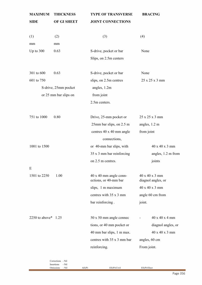
Corrections - Nil
Insertions - Nil
Omissions - Nil AE(P) EE(P)/Civil EE(P)/Elect
Page 356
MAXIMUM THICKNESS TYPE OF TRANSVERSE BRACING
SIDE OF GI SHEET JOINT CONNECTIONS
(1) (2) (3) (4)
mm mm
Up to 300 0.63 S-drive, pocket or bar None
Slips, on 2.5m centers
301 to 600 0.63 S-drive, pocket or bar None
601 to 750 slips, on 2.5m centres 25 x 25 x 3 mm
S-drive, 25mm pocket angles, 1.2m
or 25 mm bar slips on from joint
2.5m centers.
751 to 1000 0.80 Drive, 25-mm pocket or 25 x 25 x 3 mm
25mm bar slips, on 2.5 m angles, 1.2 m
centres 40 x 40 mm angle from joint
connections,
1001 to 1500 or 40-mm bar slips, with 40 x 40 x 3 mm
35 x 3 mm bar reinforcing angles, 1.2 m from
on 2.5 m centres. joints
E
1501 to 2250 1.00 40 x 40 mm angle conn- 40 x 40 x 3 mm ections, or 40-mm bar diagnol angles, or
slips, 1 m maximum 40 x 40 x 3 mm
centres with 35 x 3 mm angle 60 cm from
bar reinforcing . joint.
2250 to above* 1.25 50 x 50 mm angle connec - 40 x 40 x 4 mm
tions, or 40 mm pocket or diagnol angles, or
40 mm bar slips, 1 m max. 40 x 40 x 3 mm
centres with 35 x 3 mm bar angles, 60 cm
reinforcing. From joint.
Corrections - Nil
Insertions - Nil
Omissions - Nil AE(P) EE(P)/Civil EE(P)/Elect
Page 357
* Ducts 2250 mm and larger require special field study for hanging and supporting methods. In addition to above the following points should be also taken into account while fabrication of ducts.
a) All ducts of size larger than 450mm shall be cross broken.
b)All ducts shall be supported from the ceiling / slab by means of MS rods of dia 9mm with MS angle of size 40 x 40 x 5 mm at the bottom with neoprene pad in between the duct & MS angle. The ducts shall be suspended from the ceiling with the help of dash fasteners. Provision for necessary ancillary materials required for hanging the ducts shall be arranged by the contractor.
c) The vanes shall be provided wherever required and shall be securely fastened to prevent noise & vibration.
d) The rubber gasket shall be installed between duct flanges in all connections and joints.
e) All flanges and supports should be primer coated.
f) The flexible joints shall be fitted to the delivery side of AHU fans with Fire Retardant Double canvass. The length of flexible joints should not be less than 150 mm and not more than 300 mm between faces.
g) The ducting work can be modified if deemed necessary in consultation with the Engineer in Charge to suit actual site conditions in the building.
h)Box Type Dampers & Splitters
These dampers shall be provided in the ducting work for proper control and balancing of air distribution. All dampers shall be louver type robust construction. These dampers shall be fitted with easily accessable operating mechanism, complete with links, levers, quadrant for proper control and setting in a desired position. The position of the handle of the damper operating mechanism shall be clearly visible and shall indicate the position of the damper in the duct. All dampers, splitters shall be fabricated out of G.S. sheet of two gauges higher than the duct piece having these fittings. Dampers shall be installed in duct at all required locations. No extra payment shall be made separately since these form part of Air Circulation System.
NOTE: In case angle iron supports are not feasible to be installed for supporting the ducts due to height constraint then the contractor shall support the ducts with M.S flats of at least double the thickness of the angle iron supports.
3E.20 A) THE SUPPLY AND RETURN AIR GRILLS AND CEILING DIFFUSERS
The supply and return air grills and ceiling diffusers shall be made of powder coated extruded aluminum sections. The supply air grills / diffusers shall be provided with screw operated opposed blade volume control device made of extruded aluminum in black anodised finish.
All grills / diffusers shall have soft continuous rubber / foam gasket between the periphery of the grills / diffusers and surface on which it has to be mounted. The colour of grills / diffuser shall be as per the approval of the Engineer in Charge.
B) LINEAR SUPPLY AND RETURN GRILLS

Corrections - Nil
Insertions - Nil
Omissions - Nil AE(P) EE(P)/Civil EE(P)/Elect
Page 358
The linear continuous supply / return air grills shall be made of powder coated extruded aluminum construction with fixed horizontal bars. The thickness of fixed bar louvers shall be 5mm in front and the flange shall be 20mm wide with round edges. The register shall be suitable for concealed fixing and horizontal bars of the grills shall mechanically crimped from the back to hold them.
The colour of grills shall be as per the approval of the Engineer in Charge. The volume control device made of extruded aluminum construction in black anodised finish shall be provided in supply air duct collars only.
C) FRONT FIXED BAR REAR ADJUSTABLE LOUVERED GRILLS.
The grills shall be made of powder coated extruded aluminum construction with front fixed horizontal bar at 0 degree inclination with one way or two way deflection with rear vertical individually adjustable louvers in black shade mounted on Nylon bushes to hold deflection setting under all conditions of velocity and pressure.
The colour of grills shall be as per the approval of the Engineer in Charge. The volume control device of extruded aluminum construction in black anodised finish shall be provided in supply air duct collars.
D)SQUARE / RECTANGULAR CEILING DIFFUSERS.
The square / rectangular ceiling diffusers shall be made of powder coated extruded aluminum construction with flush fixed pattern. The diffusers shall have Anti-Smudge ring and spring loaded removable central core in various pattern for air flow direction. The diffusers shall be mounted by concealed screw fixing arrangement. The volume control device of extruded aluminum construction in black anodised finish shall be provided in supply air diffusers. The colour of diffuser shall be as per the approval of the Engineer in Charge.
E) VOLUME CONTROL DEVICE
The opposed blade volume control device shall be made of Powder Coated extruded aluminum construction in black anodised finish. Opposed blades shall be pivoted to extruded aluminum frame with Nylon bushes. Specially designed blade shall have an overlapping lip which shall ensure a tight closure.
F) FRESH AIR INTAKE LOUVERS WITH BIRD SCREEN
The fresh air intake louvers at least 50mm deep will be made of powder coated extruded aluminum construction. Bird / insect screen will be provided with the intake louvers. The blades shall be inclined at 45 degree on a 40mm blade pitch to minimize water ingress. The lowest blade of the assembly shall be extended out slightly to facilitate disposal of rain water without falling on door / wall on which it is mounted.
The intake louvers shall be provided with factory fitted aluminum construction volume control dampers in black anodised finish.
G) JET NOZZLE
The material of construction of Jet Nozzle shall be aluminium and the angle of swivel of nozzle shall be 30 degree from the mean position. The nozzle shall be complete with adopter suitable for circular duct connection. The nozzle shall be supplied complete with anti smudge design ring on the face of the nozzle.
The nozzle shall be painted white of finish RAL – 9010
3E30 PAINTING
Corrections - Nil
Insertions - Nil
Omissions - Nil AE(P) EE(P)/Civil EE(P)/Elect
Page 359
All ducts collar / shoot behind the grills / diffuser shall be given at least two coats oil black enamel paints.
3E.40 TESTING
The complete duct system shall be tested for air leakage & complete air distribution system shall be balanced in accordance with air quantities indicated on the approved drawing.
STANDARD SPECIFICATION OF THERMAL / ACOUSTIC INSULATION
3F.00 This section deals with supply and fixing of thermal / acoustic insulation of pre insulated ducts, pipes etc. as per the specification given in this section.
3F.10 MATERIAL OF INSULATION ( Class O)
The insulation material of the following kind shall be used for cold insulation.
a) Pre Insulated Duct for Air Conditioning Area
Thermal conductivity: 0.020 W/mK or better. Water absorption shall be less than 0.5% by 24 hours immersion test. Water vapour diffusion: M= infinity resistance.
b) Expanded Polystyrene for Pipe Insulation
The density of expanded polystyrene shall not be less than 20 kg per cubic meter and the thermal conductivity shall not exceed 0.031 Kcal./hr.m C at 10 C meantemperature. Adhesive used for the setting the insulation shall be non flammable, vapour Proof CPRX Compound.
The sample of insulation material shall be submitted for approval to the Engineer in Charge and the sample shall be tested for thermal conductivity values by the contractor at his own expense. Adhesive used for
setting the insulation shall be non-flammable, vapour proof, CPRX compound.
3F.11 INSULATION ON SHEET METAL DUCTING
The thickness of insulation used on ducting shall be as detailed below:
Conditioned space
a) Supply Air Duct 16 /12 / 09 mm thick Closed Cell Cross Linked Polythylene (XLPE) Foam Insulated with factory Laminated Al PE Foil as per the requirement.
b) Return Air Duct 19 mm thick Closed Cell Cross Linked Polythylene (XLPE) Foam Insulated with factory Laminated Al PE Foil.
c) Fresh Air Duct 12 mm thick Closed Cell Cross Linked Polythylene (XLPE) Foam Insulated with factory Laminated Al PE Foil.
d) Plenums 12 mm thick Closed Cell Cross Linked Polythylene (XLPE) Foam Insulated with factory Laminated Al PE Foil.

Corrections - Nil
Insertions - Nil
Omissions - Nil AE(P) EE(P)/Civil EE(P)/Elect
Page 360
e) FCU Collars 12 mm thick Closed Cell Cross Linked Polythylene (XLPE) Foam Insulated with factory Laminated Al PE Foil.
The application of insulation should be carried out in workman like manner as detailed below.
3F.21 INSULATION OF DUCTING WITH ALUMINUM FACED FIBERGLASS
TECHNICAL SPECIFICATIONS OF CLOSED CELL, CHEMICALLY CROSS-LINKED POLYETHLENE (XLPE) INSULATION
The insulation material for the ducts, pipe and under-deck insulation shall be Closed Cell Cross-Linked Fire Retardant Polyethlene Foam. The thermal conductivity of the material shall not exceed 0.035 w/mk at an average temperature of 400c.
Thermal conductivity of the material shall not be affected by ageing, as per DIN 52616. The material must be tested for ageing effect in an accredited laboratory for a minimum period of five years to satisfy the ageing criteria.
The material must be in a single layer upto 12 & 09 mm thickness and not formed by laminating several layers.
The product will have bending trial and the dimensional stability as per DIN 51949 and DIN 53431 for an operating range of – 400c to + 1100c.The density of the material shall be 33 +/- 3 kg/m3 or 0.030 gm/cc.
The material shall be rated as Class 1, as per BS 476 PART 7. The rating as per DIN 4102 shall be B1.The smoke density of the material as per AS-1530.3 shall not exceed 1. There shall be no toxicity in the emitted smoke, both under flaming and non-flaming conditions as per AITM 3.000 (1993).
The water vapour permeability, as per DIN 52615, shall not exceed 0.15ng/m.sec.pa
The material shall have a fire approval from CBRI / FIRE advisor (Govt of India)/Chief fire officer.
For providing UV protection the insulation shall be cladded with minimum 30 micron aluminum PE foil. The cladding shall be factory finished to avoid site work. The minimum thickness will be as per specs.
The duct surfaces will be thoroughly cleaned prior to applying the insulation. Adhesive of suitable grade shall be uniformly applied on the insulation and cured, before sticking to the duct. The insulation can be wrapped around the duct as one piece, where size does not permit the same be cut to exact width/height of duct.
The duct /pipe insulation joints will be overlapped with a self adhesive tape of the same material. The tape shall be minimum 2.5mm thick and 50mm wide.
A self adhesive strip of same material, of suitable thickness (height), to cover the complete height of the flange will be provided around the flanges and the flange joint neatly covered with insulation, so as to reduce heat loss through flages, in addition to covering the flange connection/joint.

Corrections - Nil
Insertions - Nil
Omissions - Nil AE(P) EE(P)/Civil EE(P)/Elect
Page 361
3F.11 MATERIAL FOR PRE INSULATED DUCTING
All the ducts shall be of Pre insulated factory fabricated with CNC machine & Pre insulated duct of sandwich panel made up of Polyisocyanurate (PIR) foam and Aluminum foil.
Pre-insulated aluminum ductwork made of aluminum and Polyisocyanurate sandwich panels, comprising an (PIR) Polyisocyanurate rigid foam board faced on both sides by aluminum foil.
Physical characteristics of the panels shall be as follows:
For Interior Duct – (Inside Building)
Panels Thickness- 20mm
Aluminum Foil thickness and type- 80 Micron (Both side) and Embossed with manufacturer brand name.
Density – 45 kg/m3
For Exterior Duct- (Outside Building)
Panels Thickness- 30mm
Aluminum Foil thickness and type- 80 Micron (inside) and 200 Micron (outside) Embossed with manufacturer brand name.
Density – 50 kg/m3
Both sides of the aluminum foils shall be lacquered with a 3g/m2 weatherproof and ultraviolet rays protection polyester lacquer.
Thermal insulation characteristics shall be as follows:
Insulating material: Close cell rigidPolyisocyanurate foam(PIR), CFC and HCFC free, density 45 Kg/m3, material physiologically and chemically inert and insoluble, vermin proof, fungus proof, non metabolisable.
Thermal conductivity: 0.020 W/mK or better.
Water absorption shall be less than 0.5% by 24 hours immersion test.
Water vapour diffusion: M= infinity resistance.
The aluminium foil covering the panel to be maintained intact after installation to ensure vapour barrier continuity.
Proposed material should have minimum 5 years installation reference in India.
The panel manufacturer should be of European origin.
All the panels to be used should be labelled by authorised international fire laboratories.
The panel manufacturer shall comply with Fire Mideast Product Listing (MPL) and Factory Production Control Certificate (FPC), by authorised international laboratories.
The panel shall be tested and comply with the following standards:
NFPA 101 Life Safety Code Class ‘A’
ASTM E84 Class “1”
NFPA 255
UL 723
Corrections - Nil
Insertions - Nil
Omissions - Nil AE(P) EE(P)/Civil EE(P)/Elect
Page 362
Toxicity Index shall not exceed 5.7 according to NES 713
Class ‘O’ according to BS 476 Part 6 & 7 from
CBRI Roorkee and Warrington Fire Lab UK
Temperature Range:
No relevant reduction of insulation, chemical or physical characteristics of the panels to be measurable, when conveying air in the temperature range of –35oC to +110oC.
Pressure Range:
No relevant modification of insulation, chemical or physical characteristics of the panels to be measurable, when conveying air up to the pressure of 1,000 Pascal with 20mm and 1,750 Pascal with 30mm.
Installation shall be supervised & certified by the manufacturer’s representative.
5-years warranty shall be offered for the insulation material characteristics.
In addition to above the following points should be also taken into account while fabrication of ducts.
b) All ducts of size larger than 1000mm shall be provided proper reinforcement arragement. b) All ducts shall be supported from the ceiling / slab by means of GI rods of dia 6mm with
GI Slotted channel at the bottom. The ducts shall be suspended from the ceiling with the help of fasteners. Provision for necessary ancillary materials required for hanging the ducts shall be arranged by the contractor.
c) The vanes shall be provided wherever required and shall be securely fastened to prevent noise & vibration.
d) All corners of Invisible joint profile shall be properly fixed with corner covers after applying the sealant to ensure zero leakage.
h) The flexible joints shall be fitted to the delivery side of AHU fans with Fire Retardant Double canvass. The length of flexible joints should not be less than 150 mm and not more than 300 mm between faces.
i) The ducting work can be modified if deemed necessary in consultation with the Engineer in Charge to suit actual site conditions in the building.
j) The joints between the ducts shall be using aluminium invisible flanges and slide-in-channel for 30mm panel ducts and polymer invisible flanges and slide-in-channel for 20mm panel ducts to be used and to be connected by special cover corners, having a holding pin, which goes inside the flange and the insulation, to avoid any field connection and to give the system more strength.
Ductwork shall be installed, using supports, as described in DW144 & according to
manufacturer’s requirements. Maximum distance between supports shall not exceed:
- 4000mm for ducts with section not exceeding 1200 x 1000mm.
- 2000mm for ducts with section exceeding 1200 x 1000mm.
3F.22 ACOUSTIC LINING OF DUCT.
Material shall be engineered Nitrile Rubber open cell foam
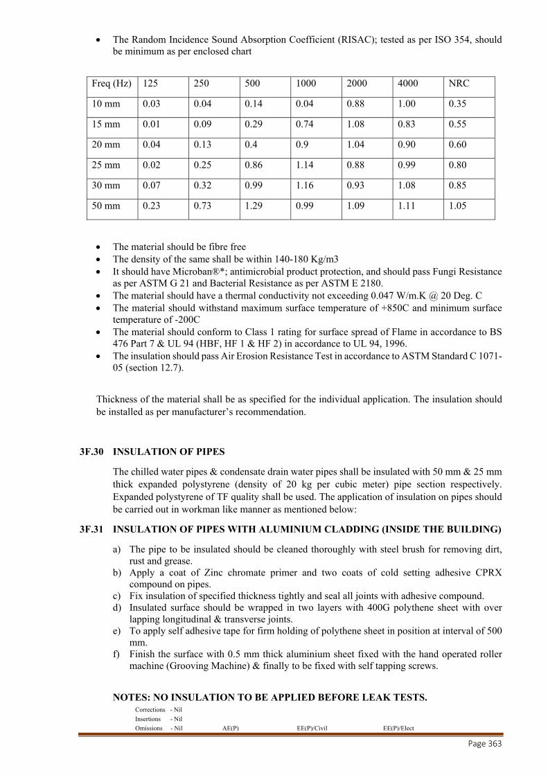
Corrections - Nil
Insertions - Nil
Omissions - Nil AE(P) EE(P)/Civil EE(P)/Elect
Page 363
The Random Incidence Sound Absorption Coefficient (RISAC); tested as per ISO 354, should be minimum as per enclosed chart
Freq (Hz) 125 250 500 1000 2000 4000 NRC
10 mm 0.03 0.04 0.14 0.04 0.88 1.00 0.35
15 mm 0.01 0.09 0.29 0.74 1.08 0.83 0.55
20 mm 0.04 0.13 0.4 0.9 1.04 0.90 0.60
25 mm 0.02 0.25 0.86 1.14 0.88 0.99 0.80
30 mm 0.07 0.32 0.99 1.16 0.93 1.08 0.85
50 mm 0.23 0.73 1.29 0.99 1.09 1.11 1.05
The material should be fibre free The density of the same shall be within 140-180 Kg/m3 It should have Microban®*; antimicrobial product protection, and should pass Fungi Resistance
as per ASTM G 21 and Bacterial Resistance as per ASTM E 2180. The material should have a thermal conductivity not exceeding 0.047 W/m.K @ 20 Deg. C The material should withstand maximum surface temperature of +850C and minimum surface
temperature of -200C The material should conform to Class 1 rating for surface spread of Flame in accordance to BS
476 Part 7 & UL 94 (HBF, HF 1 & HF 2) in accordance to UL 94, 1996. The insulation should pass Air Erosion Resistance Test in accordance to ASTM Standard C 1071-
05 (section 12.7).
Thickness of the material shall be as specified for the individual application. The insulation should be installed as per manufacturer’s recommendation.
3F.30 INSULATION OF PIPES
The chilled water pipes & condensate drain water pipes shall be insulated with 50 mm & 25 mm thick expanded polystyrene (density of 20 kg per cubic meter) pipe section respectively. Expanded polystyrene of TF quality shall be used. The application of insulation on pipes should be carried out in workman like manner as mentioned below:
3F.31 INSULATION OF PIPES WITH ALUMINIUM CLADDING (INSIDE THE BUILDING)
a) The pipe to be insulated should be cleaned thoroughly with steel brush for removing dirt, rust and grease.
b) Apply a coat of Zinc chromate primer and two coats of cold setting adhesive CPRX compound on pipes.
c) Fix insulation of specified thickness tightly and seal all joints with adhesive compound. d) Insulated surface should be wrapped in two layers with 400G polythene sheet with over
lapping longitudinal & transverse joints. e) To apply self adhesive tape for firm holding of polythene sheet in position at interval of 500
mm. f) Finish the surface with 0.5 mm thick aluminium sheet fixed with the hand operated roller
machine (Grooving Machine) & finally to be fixed with self tapping screws.
NOTES: NO INSULATION TO BE APPLIED BEFORE LEAK TESTS.
Corrections - Nil
Insertions - Nil
Omissions - Nil AE(P) EE(P)/Civil EE(P)/Elect
Page 364
3F.33 INSULATION OF VALVES AND FITTINGS IN CHILLED WATER LINE
All valves, fittings, flanges, strainers etc. in the chilled water line shall be insulated in the same manner as described above for chilled water pipes with 50 mm thick uniformly cut pieces from slabs of expanded polystyrene duly aluminium cladded or with sand cement plaster as finalised. Care should be taken to ensure that no damage would be caused to the insulation when valves or strainers are operated.
3F.40 PUMP AND ACCESSORIES
All chilled water pumps and accessories shall be insulated with 50mm thick expanded polystyrene.
3F.50 EXPANSION TANK
The expansion tank shall be of steel construction of vertical type. Expansion tank shall have internal diaphragm and be pre-charged to system fill pressure tested for at least 100 psi working pressure and complete with line size lock shield inlet valve and air charging valve.
Pressurized Expansion Tanks shall be vertical & shall have a butyl membrane separating air & water.
Air side is pre-charged to take care of static. Whenever chiller is stopped, chilled
water in the line shall start expanding. The tank accepts the expansion of water volume & the air pressure increases. When
the chiller starts again, water in the system shrinks & the tank provides the volume of water to the system ensuring that chilled water pumps shall never be starved of water.
Air pressure in the tank shall be checked once in two years after draining water from
the tank. The air pressure should not be less than the static. Air shall be filled by hand pump or portable compressor through the air valve. The
only moving part in the system is bladder which shall have a normal life of 5 years. It is recommended to plan & check the bladder after 5 years for leakage.
For checking the bladder for leakage, the tank shall be isolated from the system & water from Expansion Tank shall be drained off by opening the drain plug. The flanges on top & bottom and the bladder shall be removed & checked for leakage by soap bubble test.
3F.51AIR SEPARATOR
Air Separator shall have required flange connections for the pipe connection. It shall be insulated with the same material of chilled water pipe.
Air Separator is of centrifugal type with tangential enter/exit, it shall act like a hydro cyclone & removes air entrapped in water by a combination of low velocity & Centrifugal action.
As there are no moving parts in the air separator, it does not require periodic maintenance.
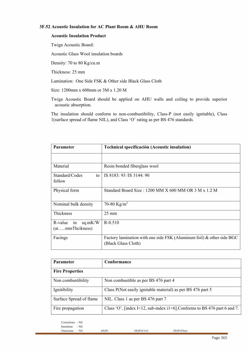
Corrections - Nil
Insertions - Nil
Omissions - Nil AE(P) EE(P)/Civil EE(P)/Elect
Page 365
3F.52 Acoustic Insulation for AC Plant Room & AHU Room
Acoustic Insulation Product
Twiga Acoustic Board:
Acoustic Glass Wool insulation boards
Density: 70 to 80 Kg/cu.m
Thickness: 25 mm
Lamination: One Side FSK & Other side Black Glass Cloth
Size: 1200mm x 600mm or 3M x 1.20 M
Twiga Acoustic Board should be applied on AHU walls and ceiling to provide superior acoustic absorption.
The insulation should conform to non-combustibility, Class-P (not easily ignitable), Class 1(surface spread of flame NIL), and Class ‘O’ rating as per BS 476 standards.
Parameter Technical specificación (Acoustic insulation)
Material Resin bonded fiberglass wool
Standard/Codes to follow
IS 8183: 93 /IS 3144: 90
Physical form Standard Board Size : 1200 MM X 600 MM OR 3 M x 1.2 M
Nominal bulk density 70-80 Kg/m3
Thickness 25 mm
R-value in sq.mK/W (at…..mmThcikness)
R-0.510
Facings Factory lamination with one side FSK (Aluminum foil) & other side BGC (Black Glass Cloth)
Parameter Conformance
Fire Properties
Non combustibility Non combustible as per BS 476 part 4
Ignitibility Class P(Not easily ignitable material) as per BS 476 part 5
Surface Spread of flame NIL. Class 1 as per BS 476 part 7
Fire propagation Class ‘O’, [index I<12, sub-index i1<6].Conforms to BS 476 part 6 and 7.
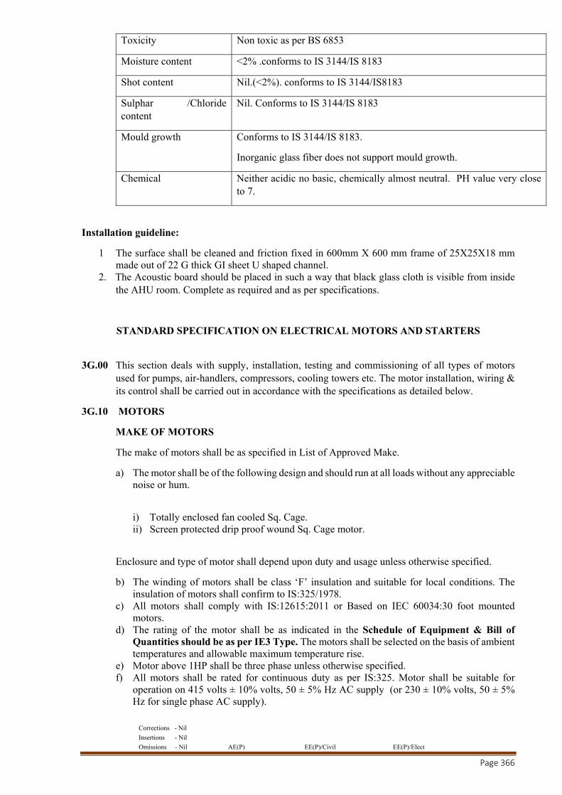
Corrections - Nil
Insertions - Nil
Omissions - Nil AE(P) EE(P)/Civil EE(P)/Elect
Page 366
Toxicity Non toxic as per BS 6853
Moisture content <2% .conforms to IS 3144/IS 8183
Shot content Nil.(<2%). conforms to IS 3144/IS8183
Sulphar /Chloride content
Nil. Conforms to IS 3144/IS 8183
Mould growth Conforms to IS 3144/IS 8183.
Inorganic glass fiber does not support mould growth.
Chemical Neither acidic no basic, chemically almost neutral. PH value very close to 7.
Installation guideline:
1 The surface shall be cleaned and friction fixed in 600mm X 600 mm frame of 25X25X18 mm made out of 22 G thick GI sheet U shaped channel.
2. The Acoustic board should be placed in such a way that black glass cloth is visible from inside the AHU room. Complete as required and as per specifications.
STANDARD SPECIFICATION ON ELECTRICAL MOTORS AND STARTERS
3G.00 This section deals with supply, installation, testing and commissioning of all types of motors used for pumps, air-handlers, compressors, cooling towers etc. The motor installation, wiring & its control shall be carried out in accordance with the specifications as detailed below.
3G.10 MOTORS
MAKE OF MOTORS
The make of motors shall be as specified in List of Approved Make.
a) The motor shall be of the following design and should run at all loads without any appreciable noise or hum.
i) Totally enclosed fan cooled Sq. Cage. ii) Screen protected drip proof wound Sq. Cage motor.
Enclosure and type of motor shall depend upon duty and usage unless otherwise specified.
b) The winding of motors shall be class ‘F’ insulation and suitable for local conditions. The insulation of motors shall confirm to IS:325/1978.
c) All motors shall comply with IS:12615:2011 or Based on IEC 60034:30 foot mounted motors.
d) The rating of the motor shall be as indicated in the Schedule of Equipment & Bill of Quantities should be as per IE3 Type. The motors shall be selected on the basis of ambient temperatures and allowable maximum temperature rise.
e) Motor above 1HP shall be three phase unless otherwise specified. f) All motors shall be rated for continuous duty as per IS:325. Motor shall be suitable for
operation on 415 volts ± 10% volts, 50 ± 5% Hz AC supply (or 230 ± 10% volts, 50 ± 5% Hz for single phase AC supply).
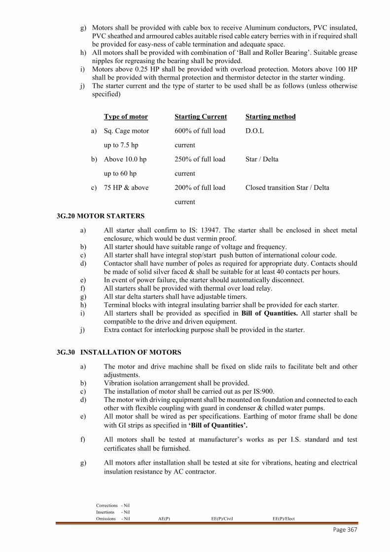
Corrections - Nil
Insertions - Nil
Omissions - Nil AE(P) EE(P)/Civil EE(P)/Elect
Page 367
g) Motors shall be provided with cable box to receive Aluminum conductors, PVC insulated, PVC sheathed and armoured cables auitable rised cable eatery berries with in if required shall be provided for easy-ness of cable termination and adequate space.
h) All motors shall be provided with combination of ‘Ball and Roller Bearing’. Suitable grease nipples for regreasing the bearing shall be provided.
i) Motors above 0.25 HP shall be provided with overload protection. Motors above 100 HP shall be provided with thermal protection and thermistor detector in the starter winding.
j) The starter current and the type of starter to be used shall be as follows (unless otherwise specified)
Type of motor Starting Current Starting method
a) Sq. Cage motor 600% of full load D.O.L
up to 7.5 hp current
b) Above 10.0 hp 250% of full load Star / Delta
up to 60 hp current
c) 75 HP & above 200% of full load Closed transition Star / Delta
current
3G.20 MOTOR STARTERS
a) All starter shall confirm to IS: 13947. The starter shall be enclosed in sheet metal enclosure, which would be dust vermin proof.
b) All starter should have suitable range of voltage and frequency. c) All starter shall have integral stop/start push button of international colour code. d) Contactor shall have number of poles as required for appropriate duty. Contacts should
be made of solid silver faced & shall be suitable for at least 40 contacts per hours. e) In event of power failure, the starter should automatically disconnect. f) All starters shall be provided with thermal over load relay. g) All star delta starters shall have adjustable timers. h) Terminal blocks with integral insulating barrier shall be provided for each starter. i) All starters shall be provided as specified in Bill of Quantities. All starter shall be
compatible to the drive and driven equipment. j) Extra contact for interlocking purpose shall be provided in the starter.
3G.30 INSTALLATION OF MOTORS
a) The motor and drive machine shall be fixed on slide rails to facilitate belt and other adjustments.
b) Vibration isolation arrangement shall be provided. c) The installation of motor shall be carried out as per IS:900. d) The motor with driving equipment shall be mounted on foundation and connected to each
other with flexible coupling with guard in condenser & chilled water pumps. e) All motor shall be wired as per specifications. Earthing of motor frame shall be done
with GI strips as specified in ‘Bill of Quantities’.
f) All motors shall be tested at manufacturer’s works as per I.S. standard and test certificates shall be furnished.
g) All motors after installation shall be tested at site for vibrations, heating and electrical insulation resistance by AC contractor.

Corrections - Nil
Insertions - Nil
Omissions - Nil AE(P) EE(P)/Civil EE(P)/Elect
Page 368
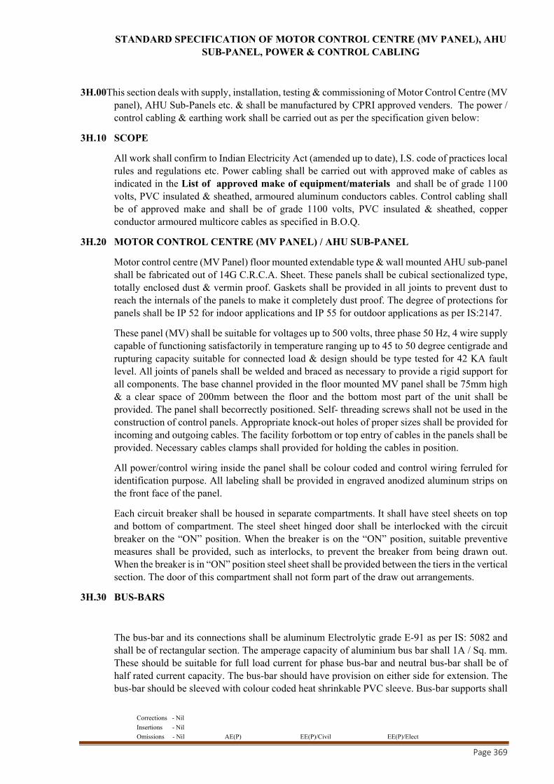
Corrections - Nil
Insertions - Nil
Omissions - Nil AE(P) EE(P)/Civil EE(P)/Elect
Page 369
STANDARD SPECIFICATION OF MOTOR CONTROL CENTRE (MV PANEL), AHU SUB-PANEL, POWER & CONTROL CABLING
3H.00This section deals with supply, installation, testing & commissioning of Motor Control Centre (MV panel), AHU Sub-Panels etc. & shall be manufactured by CPRI approved venders. The power / control cabling & earthing work shall be carried out as per the specification given below:
3H.10 SCOPE
All work shall confirm to Indian Electricity Act (amended up to date), I.S. code of practices local rules and regulations etc. Power cabling shall be carried out with approved make of cables as indicated in the List of approved make of equipment/materials and shall be of grade 1100 volts, PVC insulated & sheathed, armoured aluminum conductors cables. Control cabling shall be of approved make and shall be of grade 1100 volts, PVC insulated & sheathed, copper conductor armoured multicore cables as specified in B.O.Q.
3H.20 MOTOR CONTROL CENTRE (MV PANEL) / AHU SUB-PANEL
Motor control centre (MV Panel) floor mounted extendable type & wall mounted AHU sub-panel shall be fabricated out of 14G C.R.C.A. Sheet. These panels shall be cubical sectionalized type, totally enclosed dust & vermin proof. Gaskets shall be provided in all joints to prevent dust to reach the internals of the panels to make it completely dust proof. The degree of protections for panels shall be IP 52 for indoor applications and IP 55 for outdoor applications as per IS:2147.
These panel (MV) shall be suitable for voltages up to 500 volts, three phase 50 Hz, 4 wire supply capable of functioning satisfactorily in temperature ranging up to 45 to 50 degree centigrade and rupturing capacity suitable for connected load & design should be type tested for 42 KA fault level. All joints of panels shall be welded and braced as necessary to provide a rigid support for all components. The base channel provided in the floor mounted MV panel shall be 75mm high & a clear space of 200mm between the floor and the bottom most part of the unit shall be provided. The panel shall becorrectly positioned. Self- threading screws shall not be used in the construction of control panels. Appropriate knock-out holes of proper sizes shall be provided for incoming and outgoing cables. The facility forbottom or top entry of cables in the panels shall be provided. Necessary cables clamps shall provided for holding the cables in position.
All power/control wiring inside the panel shall be colour coded and control wiring ferruled for identification purpose. All labeling shall be provided in engraved anodized aluminum strips on the front face of the panel.
Each circuit breaker shall be housed in separate compartments. It shall have steel sheets on top and bottom of compartment. The steel sheet hinged door shall be interlocked with the circuit breaker on the “ON” position. When the breaker is on the “ON” position, suitable preventive measures shall be provided, such as interlocks, to prevent the breaker from being drawn out. When the breaker is in “ON” position steel sheet shall be provided between the tiers in the vertical section. The door of this compartment shall not form part of the draw out arrangements.
3H.30 BUS-BARS
The bus-bar and its connections shall be aluminum Electrolytic grade E-91 as per IS: 5082 and shall be of rectangular section. The amperage capacity of aluminium bus bar shall 1A / Sq. mm. These should be suitable for full load current for phase bus-bar and neutral bus-bar shall be of half rated current capacity. The bus-bar should have provision on either side for extension. The bus-bar should be sleeved with colour coded heat shrinkable PVC sleeve. Bus-bar supports shall

Corrections - Nil
Insertions - Nil
Omissions - Nil AE(P) EE(P)/Civil EE(P)/Elect
Page 370
be of fibre glass reinforced thermosetting polyester having in built and tracking barriers to break the path of conducting dust through moulded ribs.
In panels bus-bar connections shall be done by drilling holes with cadmium coated bolts and nuts. Extra cross section shall be provided to compensate drilling of the holes. Insulated aluminum strips of suitable size of full rated current capacity shall be used for interconnecting bus-bar and breaker.
A horizontal / vertical wire way shall be provided for interconnecting control wiring between different vertical sections.
The terminal blocks shall be used for outgoing terminals and neutral link at a suitable located place in the control panel. Separate compartments for outgoing and incomingcable shall be provided. The current transformers of all instruments shall be mounted with terminal blocks.
All live parts including incoming and outgoing link / terminals should be totally shrouded by means of non hygroscopic and fire retardant material.
3H.40 ROTARY SWITCH / SELECTOR SWITCH / SWITCHES / HRC FUSES / STARTERS / SINGLE PHASE PREVENTERS / TOGGLE SWITCH.
These shall be of approved make and conforming to relevant ISI standard. The rupturing capacity of HRC fuses should not less than 80 KA and in case of switches it should be 60 Amps maximum.
3H.50 CURRENT TRANSFORMER
The current transformers shall have accuracy of class I and 5P10 / 10P10 and suitable VA burden for operation of the connected meters and relays.
3H.51 OVERLOAD RELAYS
All the motors shall have overload relay protections conforming to relevant IS.
3H.52 TIME DELAY RELAYS
These shall be adjustable type with time delay adjustments of 0-180 or as per manufacturers standards.
3H.53 INDICATING LAMPS AND METERING
These shall confirm to BS37 & BS39. All meters shall be flush mounted and draw-out type. The indicating lamp shall be filament type and with very low burden & economy resistor.
3H.54 VOLTMETER AND AMMETERS
Motor Control Centre (MV Panel) shall have flush type voltmeter & ammeter of size 96 x 96 mm as detailed in B.O.Q.
3H.55 PUSH BUTTON STATIONS
These shall be suitable for panel mounting and accessible from front without opening. These shall be provided for manual starting and stopping of motors/equipments as per normal practices. The contacts shall be suitable for 6AMP current capacity.
3H.56 CONDUITS
These shall be preferable made of mild steel, stove enameled from inside and outside with minimum wall thickness of 1.6 mm for conduits up to dia of 25mm and 2 mm for conduits above 25 mm diameter.
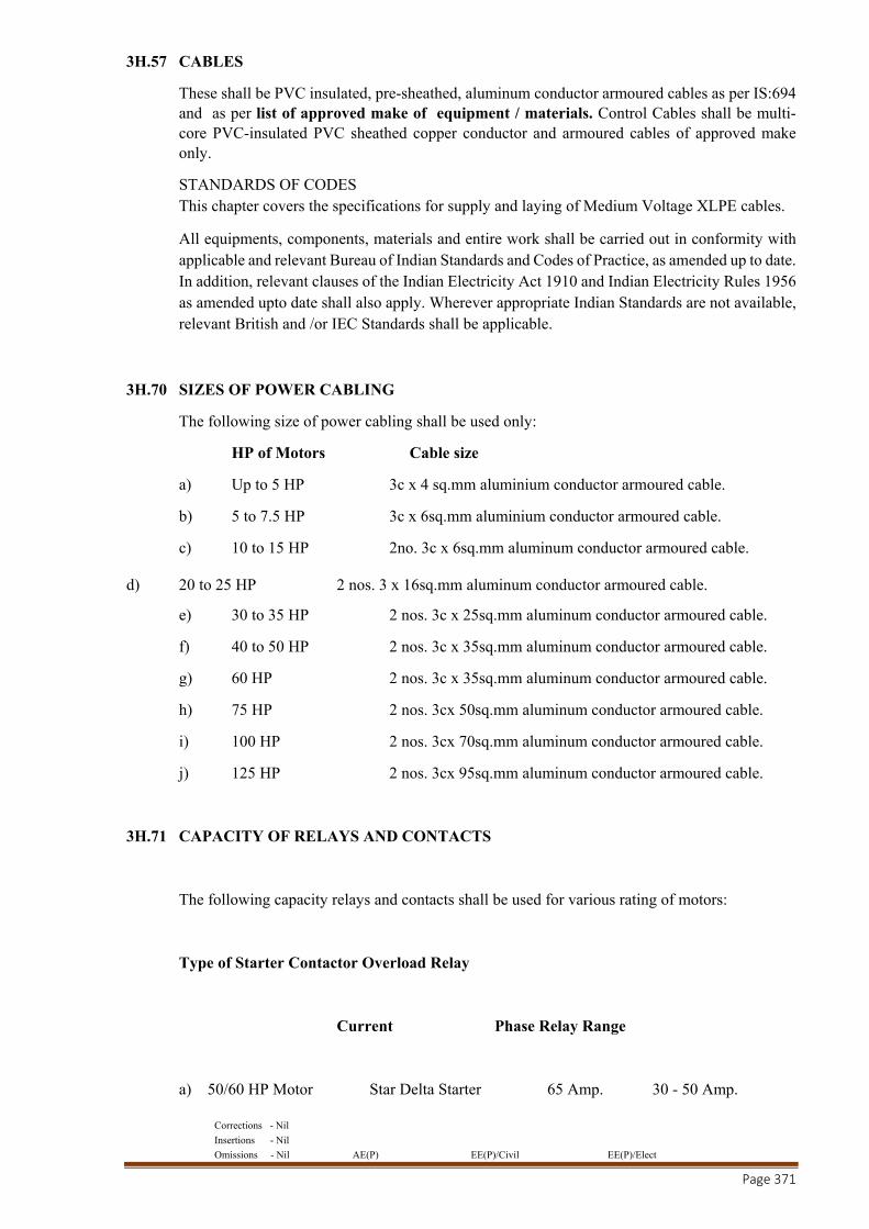
Corrections - Nil
Insertions - Nil
Omissions - Nil AE(P) EE(P)/Civil EE(P)/Elect
Page 371
3H.57 CABLES
These shall be PVC insulated, pre-sheathed, aluminum conductor armoured cables as per IS:694 and as per list of approved make of equipment / materials. Control Cables shall be multi-core PVC-insulated PVC sheathed copper conductor and armoured cables of approved make only.
STANDARDS OF CODES This chapter covers the specifications for supply and laying of Medium Voltage XLPE cables.
All equipments, components, materials and entire work shall be carried out in conformity with applicable and relevant Bureau of Indian Standards and Codes of Practice, as amended up to date. In addition, relevant clauses of the Indian Electricity Act 1910 and Indian Electricity Rules 1956 as amended upto date shall also apply. Wherever appropriate Indian Standards are not available, relevant British and /or IEC Standards shall be applicable.
3H.70 SIZES OF POWER CABLING
The following size of power cabling shall be used only:
HP of Motors Cable size
a) Up to 5 HP 3c x 4 sq.mm aluminium conductor armoured cable.
b) 5 to 7.5 HP 3c x 6sq.mm aluminium conductor armoured cable.
c) 10 to 15 HP 2no. 3c x 6sq.mm aluminum conductor armoured cable. d) 20 to 25 HP 2 nos. 3 x 16sq.mm aluminum conductor armoured cable.
e) 30 to 35 HP 2 nos. 3c x 25sq.mm aluminum conductor armoured cable.
f) 40 to 50 HP 2 nos. 3c x 35sq.mm aluminum conductor armoured cable.
g) 60 HP 2 nos. 3c x 35sq.mm aluminum conductor armoured cable.
h) 75 HP 2 nos. 3cx 50sq.mm aluminum conductor armoured cable.
i) 100 HP 2 nos. 3cx 70sq.mm aluminum conductor armoured cable.
j) 125 HP 2 nos. 3cx 95sq.mm aluminum conductor armoured cable.
3H.71 CAPACITY OF RELAYS AND CONTACTS
The following capacity relays and contacts shall be used for various rating of motors:
Type of Starter Contactor Overload Relay
Current Phase Relay Range
a) 50/60 HP Motor Star Delta Starter 65 Amp. 30 - 50 Amp.
Corrections - Nil
Insertions - Nil
Omissions - Nil AE(P) EE(P)/Civil EE(P)/Elect
Page 372
b) 40 HP Motor Star Delta Starter 45 Amp. 20-33 Amp.
c) 30 HP Motor Star Delta Starter 45 Amp. 20-33 Amp.
d) 25 HP Motor Star Delta Starter 32 Amp. 14-23 Amp.
e) 20 HP Motor Star Delta Starter 32 Amp. 14-23 Amp.
f) 15 HP Motor Star Delta Starter 25 Amp. 9-15 Amp.
g) 10 HP Motor Star Delta Starter 16 Amp. 6-10 Amp.
h) 7.5 HP Motor D.O.L. Starter 16 Amp. 9-15 Amp.
i) 5 HP Motor D.O.L. Starter 16 Amp. 6-10 Amp.
3H.72 EARTHING
The earthing of all equipments shall be carried out by Copper strips / wires as mentioned in Bill of Quantities. All panels / three phase motors shall be earthed with two number distinct and independent Copper strips / wires of the following sizes:
1. Motor upto 5.5 KW 3 sq. mm Copper Wire
2. Motor 7.5 to 12 KW 4 sq. mm Copper Wire
3. Motor 12 to 50 KW 2 5 x 3 mm Copper Strip
4. Motor 51 to 89 KW 32 x 6 mm Copper Strip
The earthing connections shall be connected to main earth station or main earth grid. The earth connections shall be connected to equipments after removal of paint, grease etc.
3H.90 POTENTIAL FREE CONTACTS
The AC contractor shall provide fire shunt relay contact in his panel wherever necessary either it is specified in the Schedule of Quantities or not free of cost along with auto / manual mode selector switch in the outgoing feeder for AHU Fan, Ventilation & Pressurization fan etc. to take fire input signal (Potential Free Contact).
STANDARD SPECIFICATION ON PIPING WORK
This section deals with supply, installation, testing & commissioning of chilled water / condenser water / drain water pipes, pipe fittings and valves etc. as detailed below in specifications. All pipes, fittings and valves etc. shall conform to relevant Indian standards.
WATER PIPING
3I.00 The pipes, fittings and valves shall be of approved make given in the NIT.
3I.10 Chilled water / Condenser water pipes shall be "C" Class M.S. E.R.W Black pipes & shall conform to IS:1239 (Part 1) - 1991 & IS:3589 - 1991 with latest amendments. The wall thickness of "C" Class M.S. E.R.W. Black pipes as per IS:1239 (Part 1) shall be as follows:-
Corrections - Nil
Insertions - Nil
Omissions - Nil AE(P) EE(P)/Civil EE(P)/Elect
Page 373
Nominal Pipe Dia Wall Thickness of Pipe
in mm in mm
a) 25 4.00 b) 32 4.00 c) 40 4.00 d) 50 4.50 e) 65 4.50 f) 80 4.80 g) 100 5.40 h) 125 5.40 i) 150 5.40 j) 200 6.30 k) 250 6.30 l) 300 6.30 m) 350 6.30 n) 400 6.30
3I.11 Drain water / make up water pipes shall be "B" Class GI Pipe & shall Conform to IS: 4736.
3I.12The pipes shall be sized for individual liquid flow & shall ensure smooth noiseless balanced circulation of fluid.
3I.13 All piping and their steel supports shall be throughly cleaned and primer coated before installation.
3I.20 PIPE FITTINGS
The pipe fittings for screwed piping shall be malleable iron and for piping with welded joints shall of weldable quality. Also the fittings shall be suitable for same pressure ratings as for the piping system.
3I.21 All bends up to sizes 150 mm dia shall be ready made of heavy duty wrought steel of appropriate class.
3I.22 All bends in sizes 200 mm and above shall be fabricated from the same dia and thickness of pipe in at least four sections and having a center in radius of at least 1.5 times diameter of pipes. Fittings such as tees, reducers etc. shall be fabricated from the same pipe and its length shall be at least twice the diameter of the pipe.
3I.23 The dead ends shall be formed with flanged joints & shall have 6 mm thick blank between flange pair for 150 mm and over.
3I.24 FLANGES
All flanges shall be of mild steel as per IS: 6392 / 71 (with latest amendments) & shall be slip on type welded to the pipes. Flanged thickness shall be to suit Class II pressure. 3 mm thick gasket shall be used in between the flanges.
Flanged pair shall be used on all such equipments which are required to be isolated or removed for service for example condenser / chilled water pumps, chilling m/c, AHU etc.
3I.30 VALVES (BUTTERFLY VALVES)
Butterfly valves shall be of PN 1.6 rating as per IS 13095 preferably with fixed linear design to suit duty and flanges as per IS 6392 Table "E". Valves of sizes 32 mm and above diameter shall be made of cast iron close end body, cast iron epoxy coated disc, Nitrile Seat and SS 410 Stem
Corrections - Nil
Insertions - Nil
Omissions - Nil AE(P) EE(P)/Civil EE(P)/Elect
Page 374
with tefflon bush. Valves up to 150mm NB shall be with detachable hand lever operation whereas valves above 150 mm NB shall have warm gear operation.
These valves shall be installed in condenser / chilled water lines, make up / drain water piping lines. All valves shall be supplied with factory test reports and the manufacturer must have test facilities at their works.
3I.31 NON-RETURN VALVE (DUCT PLATE CHECK VALVES)
The dual plate check valves shall be used for horizontal / vertical run of pipes & shall conform to PN 1.6 rating .The valve design shall confirm to API 594 and tested as per ANSI SERIES.
The valves shall have cast iron body, and SS 410 plates, SS 410 Shaft & Nitrile Seat. All valves shall be supplied with factory test reports and the manufacturer must have test facilities at their works.
3I.32 Y-STRAINER & POT STRAINER
The Y-strainer shall be fabricated out of MS `C’ class pipe two size higher than that of strainer pipe size. Flanges as per BS 10 shall be provided at inlet & outlet of connections. The body shall be pressure tested at 10 Kg/Sq. cm and shall be hot dip galvanized. Permanent magnet shall be provided in the body of the strainer to arrest MS particles. Filter element shall be of nonmagnetic 20 gauge SS sheet with 3 mm perforation. Strainer shall be provided at inlet of each AHU & chilled water pumps,
Pot Strainer body shall be fabricated out of MS plate IS 226. Thickness of sheet shall be as per size of the strainer chamfered pipes with flanges shall be provided at inlet / outlet connections of the strainer. The tangential entry of water shall create a centrifugal action and due to velocity shall separate sediments and deposit on the inner surface of filter element and at bottom of the Strainer. Butterfly valves shall be provided at inlet/ outlet connections as shown in drawing and included in BOQ. The strainer body shall have two separate chambers properly sealed to avoid mixing of filtered and unfiltered water. A powerful magnet shall be provided in the body to arrest MS particles. Filter element of Pot Strainer shall be of non magnetic 18 gauge SS sheet properly reinforced to avoid damage of the element. A cone with sufficiently large drain pipe with butterfly valve shall be provided at the bottom chamber to flush-out foreign particles. This arrangement shall avoid frequent opening of Pot Strainer for cleaning of filter element. Gauge connection shall be provided at inlet and out let connection.
A set of MS flanges with tongue and groove arrangement and neoprene rubber gasket shall be provided on the top cover and Pot Strainer flange with sufficient bolts and nuts to make the joint water tight. Bearing loaded lope cover lifting and swinging arrangement shall be provided. The pot strainer body shall be properly de-rusted and epoxy coated from inside and outside. Manufacturers Test Certificate shall be provided with each Pot Strainer.
Size of various Pot Strainer, Filter Element and Thickness of MS sheet shall be as under.
Pipe Size Pot Dia Pot HT Element Dia. Element HT MS Plate Thickness
(mm) (mm) (mm) (mm) (mm) (mm)
50 300 400 200 240 6
80 350 450 250 250 6
100 450 500 300 280 6
125 500 600 330 340 8
Corrections - Nil
Insertions - Nil
Omissions - Nil AE(P) EE(P)/Civil EE(P)/Elect
Page 375
150 540 700 360 390 8
200 610 815 400 470 8
250 710 915 500 570 8
400 910 1050 600 700 8
500 9500 1150 700 800 8
The Y-Strainer & Pot Strainer confirming to SSPL 107 & SSPL 106 shall have cast iron body and factory tested at works at 16 Kg/sq. cm pressure. The screen shall be made out of 3 mm perforated stainless steel sheet. It should be easily removable when required to be cleaned. Isolating butterfly valves at either end of the pot strainer shall be provided.
3I.33 BALANCING VALVES
The automatic balancing control and shut off valves with built in pressure drop measuring facility shall be provided in return water lines for air-handling units, chillers, condensers as given in the tender drawings.
The valves of sizes 32 mm to 65mm dia. shall be of gun metal / cast iron construction with screwed ends angular design digital hand wheel with locking facility. Whereas valves of sizes 75mm and above shall be of cast iron construction with internal parts of SS 410 and EPDM / nitrile seat with flanged ends. The test cocks should be long enough to protrude out of valve insulation.
The valves shall be designed for PN 1.6 and tested for the seat at 1.1 times the design pressure and 1.5 times the design pressure for the shell. All valves shall be supplied with test certificates and the manufacturer must have test facilities at their works.
3I.34 SUPPORTS FOR PIPES
In plant room pipe shall not be supported from ceiling and shall have steel supports of adequate strength firmly fixed to the floor only.
3I.35 LAYOUT AND SIZING OF PIPE LINES
The sizes and layout given in the drawings / bill of quantities are for guidance purpose only. The A/C Contractor shall prepare and submit detailed drawings after the award of contract to the Engineer in Charge for his approval. No work at site shall be started before final approval of drawings if given. The drawings shall indicate sizes of pipes, quantity of water flow in each length of pipe. All details of fittings, location of all valves, air vents, pipe supports etc. shall be clearly indicated in the drawings.
3I.40 INSTALLATION OF CHILLED / CONDENSER / DRAIN / MAKE UP WATER PIPING
a) All pipes shall be securely supported or suspended on stands, hangers, clamps etc. as required. The Air-conditioning contractor shall design all brackets, saddles, anchors, clamps etc. & shall be responsible for structural adequacy.
b) All pipe supports shall be of steel, coated with two coats of anti-corrosive paint and finally finished with paint.
c) The pipe spacing shall be as follows :
Dia of Pipe Spacing between supports
Corrections - Nil
Insertions - Nil
Omissions - Nil AE(P) EE(P)/Civil EE(P)/Elect
Page 376
Up to 25mm 1.5 mt
30 mm to 50 mm 2.0 mt
65 mm to 75 mm 2.5 mt
100 mm to 125 mm 3.0 mt
150 mm 3.5 mt
200 mm & above 4.0 mt
d) The vertical rises shall run parallel to walls and should be straight to wall duly checked with plumb line.
e) In case pipes with/ without insulation while passing through the wall / slab, shall be provided with sleeve 50mm higher in size than the pipe with / without insulation.
f) Wherever insulated pipes are running, it should be supported in such a way that no undue pressure is exerted on the insulated pipe.
g) The expansion-joints or expansion-loops shall be provided to take care of the expansion and contraction in pipes due to temperature rises.
3I.50 TESTING OF PIPE SYSTEM
a) All tools, tackles, labours etc. shall be arranged by A/C Contractor. b) All pipes shall be tested hydraulically at 3 times the maximum operating pressure for a
period of 48 hours. The test pressure should not be less than 10 Kg/sq.cm at any times. All leaks occurring during testing shall be rectified to the satisfaction of the Engineer in Charge. After repairs of leak it shall be tested again at the same pressure.
c) In case piping is tested in parts, these sections shall be securely sealed and capped during testing.
d) The A/C Contractor should ensure that there should be minimum vibration / noise in the chilled water / condenser water circuit due to water turbulence.
3I.60 AIR-VENTS
Air vents for purging of air trapped in piping system shall be provided at the highest point. Globe valves of the size as indicated below shall be provided &no additional price shall be paid.
Pipe Size Valve Size
Upto 100mm 25mm dia
Above 100mm to 300mm 40mm dia
3I.61 PRESSURE GAUGES / THERMOMETERS
PRESSURE GAUGES
Pressure gauges of 100mm dia & of suitable range shall be provided at the following locations:
a) Chiller / Condenser / Cooling coils of AHU - Inlets and outlets.
b) All pumps - Suction & discharge
The water pressure gauge shall be made of stainless steel grade SS-304. All parts shall be made of copper alloy & stainless steel to prevent from corrosion. The dial plate shall be of white colour & numbers in black & in red colour for better visibility. Pressure gauge shall have a stainless steel “U” Tube of 15 mm dia & 400 mm in length both side threaded with stainless steel nut & a ball valve shall also be provided at one end of tube for protecting gauge during testing of system.
Corrections - Nil
Insertions - Nil
Omissions - Nil AE(P) EE(P)/Civil EE(P)/Elect
Page 377
INDUSTRIAL TYPE THERMOMETER
Direct reading V form type thermometer alcohol filled of suitable range / length shall be provided at the following locations:
a) Condenser / Chiller / Cooling coil – Inlets and outlets in separate wells.
The V form thermometer shall be made of aluminium die casting with golden colour anodizing. The thermometer shall have a V groove in the body to protect the refill from the damages during the installation. The refill shall be filled with blue colour mercury. The thermometer shall be complete with brass well & the calibration of temperature shall be in Celsius & Fahrenheit
Corrections - Nil
Insertions - Nil
Omissions - Nil AE(P) EE(P)/Civil EE(P)/Elect
Page 378
STANDARD SPECIFICATION OF FIRE DAMPERS
3J.00This section deals with supply, erection and commissioning of fire dampers and box type dampers, conforming to general specification and suitable for duty selected, indicated in Schedule of Equipment & Bill of Quantities.
3J.10 MOTORISED COMBINED SMOKE & FIRE DAMPERS - SPRING RETURN TYPE
a) All supply air Ducts in AHU room crossing shall be provided with approved make fire and smoke dampers of at least 90 minutes fire rating certified by CBRI, Roorkee as per UL555:1973.
b) The fire damper blades & outer frame shall be formed of 1.6 mm galvanised steel sheet. The damper blade shall be pivoted on both ends using chrome plated spindles in self lubricating bushes. Stop seals shall be provided on top & bottom of the damper housing made of 16G Galvanised steel sheet. For preventing smoke leakage side seals will be provided. In normal operating conditions damper blade shall be held in open position with the help of a 24 V operated electric actuators thereby providing maximum air passage without creating any noise or chatter.
c) The damper shall be actuated through electric actuator. The actuator shall be energised with the help of a signal from smoke detector installed in AHU Room / R. A. Duct. The fire damper shall close due to temp. rise in S. A. Ducts through the electric temp. sensor which is factory set at 165 °F .
d) Each motorized smoke cum fire damper shall have its own panel which will incorporate necessary circuit required to step down voltage available from UPS or emergency power supply to show status of the damper (open or close), to allow remote testing of damper, indication in event of damper closure due to signal from smoke sensor / temp. sensor & reset button. Additional terminal will be provided to have audio cum video signal in Central Control Room.
e) Damper actuator shall be such that it should close the damper in the event of power failure automatically and open in the same in case of Power being restored.
f) The fire Damper shall be mounted in fire rated wall with a duct sleeve 600 MM long. The sleeve shall be factory fitted on fire damper. The joints at sleeve end shall be slip on type. Minimum thickness of GI Sheet shall be 18G.
g) The damper shall be installed in accordance with the installation method recommended by the manufacturer.
h) Hinged access doors of suitable size complete with air tight gaskets shall be provided in all fire dampers & plenums.
Corrections - Nil
Insertions - Nil
Omissions - Nil AE(P) EE(P)/Civil EE(P)/Elect
Page 379
MODE OF MEASUREMENT
The following measurement code shall apply to the Contract:
3K.00 SHEET METAL WORK
1. DUCTING
a) The final finished sheet area in sq. mt shall be measured only. b) Vanes, splitters, flanges, access doors etc. shall not be separately measured. These shall
be treated as part of duct work. c) Bends, Elbows, Transformation, pieces etc. shall be measured along the centre line and
measured as per duct work. d) Canvas connections, Duct Supports, Stiffening members, frames etc. shall not be
measured separately and shall form part of duct work.
2. GRILLS / DIFFUSERS / FIRE DAMPERS
All Grills / Diffusers / Fire Damper areas will be measured in terms of effective area (Neck Area). Any Extruded aluminum grill / diffusers having an area less than 0.1 sq.mt shall be accounted as 0.1 sq.mt.
3. BOX DAMPERS
a) No separate measurement of box dampers shall be done since they form part of duct. b) Fresh air dampers shall be measured as effective areas only. No separate measurements
for bird screen inlet / outlet louvers shall be done.
3K.10 PIPING WORK
a) The length of piping accessories & fittings shall be measured along its centre line in meters and no measurements for bends, elbows, tees etc. shall be made. All such fittings / accessories shall be treated as part of the piping work.
b) Flanges shall not be measured, as they form part of piping work. c) For thermometer wells & pressure gauge sockets no measurement shall be done
separately. d) All kinds of supports, hangers etc shall be part of piping work & no extra measurements
shall be done. e) No additional price for installation of purge & descaling valves as required at site shall
be paid.
3K.20 INSULATION
3K.21 A) Insulation Of Duct
1. This shall be measured on the basis of bare duct surface area i.e. the area of duct insulation & area of duct shall be same.
B) Insulation of Chilled Water / Drain Water.
i) Insulation of pipes shall be measured in terms of linear length of pipe for each size.
Corrections - Nil
Insertions - Nil
Omissions - Nil AE(P) EE(P)/Civil EE(P)/Elect
Page 380
ii) For insulation of bends, elbows, tees etc. it shall be measured along with the center line of insulation and shall be measured in meters.
iii) Insulation of valves shall be separately accounted as per bill of quantities.
C) Insulation of Chiller / Expansion Tank / Suction Line
The insulation of the above equipment’s shall be deemed to form part of equipment and no separate measurements for insulation of such items will be accounted for.
D) Acoustic Lining Of Duct & Plenum
This shall be measured on the basis of bare duct surface area i.e. the area of duct lining & area of duct shall be same.
3K.30 ELECTRICAL CABLING WORK
a) All power cables / controls cables shall be measured on linear basis in meters.
b) No extra price shall be paid on account of end termination of cables which includes thimble, gland etc.
3K.40 STRUCTURAL SUPPORTS
No extra price shall be paid on account of structural supports required for piping, ducting & cabling work.
Corrections - Nil
Insertions - Nil
Omissions - Nil AE(P) EE(P)/Civil EE(P)/Elect
Page 381
PERFORMANCE TEST READINGS
The Test Readings shall be recorded on hourly basis during the summer / monsoon seasons after satisfactory commissioning of AC System at site as per the Performa indicated below.
3N.00 OUTSIDE DESIGN CONDITIONS
a) Season :
b) Dry bulb temp. °C :
c) Wet bulb temp. °C :
3N.10 INSIDE DESIGN CONDITIONS IN EACH AREA .
a) Dry bulb temp. °C :
b) Wet bulb temp. °C :
c) Relative Humidity % :
3N.11 COMPRESSOR
a) Suction temp. Deg. C./ :
b) Suction pressure Kg/Sq.cm :
c) Discharge temp. Deg. C. :
d) Discharge pressure Kg/Sq.cm :
e) R.P.M. of compressor :
3N.12 COMPRESSOR MOTOR RATING ATVARIOUS LOADS
Motor current - AMPs :
Voltage - AMPs :
AC Load Status :
3N.13 CONDENSER
a) Water flow rate LPM :
b) Entering water temp. °C :
c) Leaving water temp. °C :
d) Pressure drop through : condenser Kg/Sq.cm (PSI)
3N.14 EVAPORATOR
a) Water flow rate LPM :
b) Entering water temp. °C :
Corrections - Nil
Insertions - Nil
Omissions - Nil AE(P) EE(P)/Civil EE(P)/Elect
Page 382
c) Leaving water temp. °C :
d) Pressure drop through : evaporator Kg/Sq.cm (PSI)
3N.15 CAPACITY TEST FOR CHILLING MACHINE ON
TR of M/C Current Drawn by M/C
100 % load ------------- ----------------------------
3N.20 AIR HANDLERS UNIT
a) Air quantity CFM :
b) Air velocity ft/min. :
c) Entering air temperature DB/WB °C :
d) Leaving air temperature DB/WB °C :
e) Entering water temp. °C :
f) Leaving water temp. °C :
g) Entering water pressure Kg/Sq.cm :
h) Leaving water pressure Kg/Sq.cm :
3N.30 MOTOR DRIVE FOR AIR HANDLERS
a) Actual voltage / current :
3N.40 CHILLED WATER PUMP
a) Flow rate LPM :
b) Suction pressure Kg/smt :
c) Discharge pressure Kg/Sq.cm :
d) Actual voltage / current :
3N.50 All electrical panels / cables / starters / single phase preventer etc. shall be tested as per standard code of practice.
Corrections - Nil
Insertions - Nil
Omissions - Nil AE(P) EE(P)/Civil EE(P)/Elect
Page 383
INSPECTION & TESTING PROCEDURE
3O.00 INSPECTION PROCEDURE FOR CENTRAL AIR-CONDITIONING PLANT.
All major equipments such as Chilling machine, AHUs, Electrical Panel, Control Console Panel etc. shall be got inspected & tested before dispatch of equipments by the Engineer in Charge at works if he so desires. All type of routine and type tests shall be carried out at the works. The Engineer shall be free to witness any or all tests if he so desires. In case the Engineer in charge or his representative is unable to witness the test at the manufacturer’s works, the contractor shall furnish the manufacturers test certificate to the satisfaction of the Engineer in charge. The AC contractor shall intimate the Engineer in Charge in advance about the date of readiness of equipments for inspection & testing. The inspection procedure for testing of AC equipments are given below:-
3O.10 INITIAL INSPECTION
a) CHILLING MACHINE
1. Salient features such as model no. of compressor, chiller & condenser, dimension of the machine, microprocessor panel etc shall be verified against the requirement.
2. Manufacturer’s internal test certificate shall be scrutinised to check compliance with the requirement as per specification.
3. Salient features of condenser & chiller such as number of tubes, inside diameter of tubes, tube thickness & material, No. of passes, type of fins, length of condenser & chiller etc. shall be verified.
b) COOLING COILS:
1. Salient features of cooling coils such as material of tube, tube diameter, tube wall thickness, fin material & no. of fins per inch, gauge of fins & no. of rows shall be furnished and verified with reference to contract requirement.
2. Manufacturer’s internal test certificate indicating results of pneumatic / hydraulic pressure test shall be scrutinised to check compliance with the requirement as per specification.
c) AIR HANDLING UNITS:
1. Salient features such as model, size, physical dimension & other details of various section, fan motor details, fan dimension etc. shall be verified against the contract requirement.
2. Manufacturer’s internal test certificate for the motor and air handling units shall be furnished and scrutinised as per contract requirement.
3. Test certificate for static and dynamic balancing of the blower should be furnished.
d) PUMPS:
1. Salient features such as model and make shall be checked as per contract requirement.
2. The manufacturer’s test certificate will be furnished and verified against contract quirement.
Corrections - Nil
Insertions - Nil
Omissions - Nil AE(P) EE(P)/Civil EE(P)/Elect
Page 384
e) SWITCH, GEAR, CONTROL GEAR, MEASURING INSTRUMENTS & POWER /CONTROL
CABLES:
1. They should be of approved make. For air circuit breakers manufacturer’s test certificate shall be furnished by the contractor and the same shall be verified as per contract requirement.
f) ELECTRIC MOTOR:
1. Electric motor should be of approved make. Test certificate for electric motor shall be furnished & verified as per contract.
g) PIPES & VALVES :
1. Make of pipe & valves shall be verified as per contract.
2. Wall thickness of pipes shall be verified as per contract. h) DUCTING:
1. The GS sheet used for ducting shall be checked for physical test at site. The physical test should include the sheet thickness, bend test and galvanising test as per relevant IS specifications.
i) THERMAL ACOUSTIC / INSULATION:
1. Physical verification for thickness and make should be as per contract before application of insulation.
2. Manufacturer’s test certificate for density & thermal conductivity should be furnished.
3O.20 FINAL INSPECTION
After completion of entire installation, as per specifications in all respects, the AC contractor shall demonstrate trouble free operation of the AC equipment for a period of minimum of 120 hours of running. Any defects found during this operation shall be rectified immediately before the initial test period of seven days is over. The test readings during initial test run shall be recorded in the performa given in section ACE 26.
The initial test which has to be carried out by the contractor at his own expense & shall be as follows but not limited to:
a) To check satisfactory functioning of all major equipments such as Rotary Screw Water Chilling m/c, electrical motors, pumps, cooling tower, switch gear, air handlers etc.
b) To check alignments of motors. c) To operate chilling m/c, cooling towers, pump sets, air handlers etc. and adjust water flow in all
line i.e. condenser water line, chilled water line and in the cooling coils. d) To check and balance air distribution system.
NOTE: All test instruments such as thermometer, psychrometer, pressure gauges, anemometer, flowmeter, decibel meter or any other necessary instrument shall be arranged by the contractor at his own expense.
Corrections - Nil
Insertions - Nil
Omissions - Nil AE(P) EE(P)/Civil EE(P)/Elect
Page 385
After initial test the plant shall be run continuously for a period of 30 days before the guarantee comes into force. In addition to the initial test as explained in this section the contractor shall also give the two continuos running test of the system during peak summer and monsoon for 3 days each of 10 hours duration when the ambient are closed to the designed conditions.
In case, the peak ambient conditions in the respective seasons are not found to be close to designed ambient conditions, the test shall be conducted on closest ambient conditions and capacity of equipments shall be computed and compared with capacities indicated in the contract. Water and power for testing and commissioning of the system shall be provided free of cost by the Department.
In case, seasonal tests are not possible to be performed by the contractor due to reasons not attributable to the contractor, then the guarantee of plant shall begin after 30 days of continuous run of plant.
3O.30 CAPACITY OF PLANT
The test readings as per test reading performa given in section ACE 29 shall be recorded & capacity of various of major equipments such as, compressor, condenser, chiller, cooling coil, cooling tower, fan coil units, pump sets etc. shall be worked out as per computation formulas given in this section.
POWER CONSUMPTION / CAPACITY OF VARIOUS EQUIPMENT. a) Compressor
IKW. / Ton = Power input in KW
Compressor Cap. in tons
The capacity & IKW/TR of compressor shall be compared from manufacturers computer selections supplied by the contractor.
b) Condenser / Chiller Heat Rejection of Condenser =
Water flow through condenser (Usgpm) x Temp. Difference Deg.F. 24
c) Cooling Coils of Air Handlers and Fan Coil Units
Capacity of cooling coil = CFM x 60 (he – hl)
Avg specific volume V x 12000
Where as he = Enthalpy of entering air in btu / lb
hl = Enthalpy of leaving air in btu / il
V = Ve + V1
= Specific volume of air entering CFT /lb of air + specific volume of
leaving air CFT / lb of air.
The interlocking connection of compressor motor with condenser and chilled water pumps cooling tower fan etc. shall be checked.
Corrections - Nil
Insertions - Nil
Omissions - Nil AE(P) EE(P)/Civil EE(P)/Elect
Page 386
STANDARD SPECIFICATION OF SUPPLY & EXHAUST AIR BLOWER
1.00 SCOPE
This section deals with supply, installation, testing and commissioning of various types of blower for forced ventilation of required capacities and sizes as enumerated under Detailed Bill of Quantities & Schedule of equipment and conforming to the following specifications.
2.10 TYPE
The blower shall be of Tube Axial Flow fans / Centrifugal Fans / Inline fans / Propeller Fans with or without ducting system & shall be of floor mounted / ceiling hung type.
3.11 CAPACITY
The capacity of Tube Axial Flow fans / Centrifugal Fans / Inline fans / Propeller Fans, diameter, maximum motor H.P & static pressure etc. shall be according to schedule of equipment & Bill of Quantities.
4.00 AXIAL FLOW FANS
The exhaust air blower shall be long casing Tube Axial Flow fans connected to the duct & shall be of floor / ceiling / wall mounted type as specified in the Bill of Quantities. The capacity of tube axial flow fans, diameter, maximum motor H.P & static pressure etc. shall be according to schedule of equipment & Bill of Quantities. The noise level of axial fan shall be less than 80 dBA at a distance of 2.5 mt from the fan.
The cylindrical casing should be made from welded carbon steel sheet. The inlet & outlet of the casing shall be fitted with flanges for duct work connection & other accessories as required. The surface finish shall be epoxy coated. The blade of axial flow fan shall be made of die cast aluminium alloy. The blade angle shall be set at manufacturing place & shall also have facility to modify latter. The hub shall consist of two half-hubs pressed in carbon steel & the centre boss shall be made of die-cast aluminium alloy. The blade feet shall be locked in two half - hubs. The impeller assembly shall be fixed on the shaft by means of a double cone type expansion bush. The design shall facilitate the alteration of blade angle without disconnecting the hub from the motor shaft. The fan shall be directly driven by TEFC sq. cage induction motor. The fan motors shall be 415±10% volts 50HZ ± 5%, 3 phase TEFC SQ. Cage induction motor. The motor shall be specially designed for quiet operation & motor RPM shall be as given in Bill of Quantities. After assembling the impeller shall be statically & dynamically balanced.
The mounting ring shall be of CRCA / sheet steel with brackets to connect the frame, with the Fan / Motor assembly. Rubber mounts shall be provided between the mounting frame and the mounting brackets.
5.00 CENTRIFUGAL FANS
The Centrifugal blowers shall be double / single inlet, double / single width, as given in the BOQ & of non-overloading type of suitable construction. The blower performance must be rated in accordance with approved test codes and procedures. The centrifugal fans should confirm to IS – 4894 – 1987 (Revised as on date) The blower housing comprising of scroll & side plates shall be accurately cut of heavy gauge all welded sectional construction and reinforced with angle bracings. Outlets shall be flanged to assure proper duct connection. Inlet cones shall be spun venturi type, to ensure smooth air entry. The base frame shall be angle iron in bolted / welded construction. Impeller shall be fabricated from sheet steel with backward / forward curved,
Corrections - Nil
Insertions - Nil
Omissions - Nil AE(P) EE(P)/Civil EE(P)/Elect
Page 387
properly designed blades, with heavy C.I. Hub and shall be both dynamically and statically balanced, to a close tolerance for quiet and vibration free performance. Shaft shall be hot rolled steel or forged steel, sized adequately, but in no case or less than 40 mm diameter and shall be accurately ground and polished to a close tolerance. Bearings shall be self aligned, heavy duty ball or tapered roller type with integral dust and grease seals. After assembly, the complete fan shall be painted with rust proof and two coats of synthetic enamel paint. Fan having wheel diameter of 1220 mm or more, shall be supplied with split, bolted housing for convenience of handling and installation.
Drive assembly for each blower shall consist of blower pulley, motor pulley, a set of ‘V’ belts, belt guards, and belt tension adjusting devices. Pulleys shall be selected to provide the required speed. They shall be multi-groove type, with section and grooves selected to transmit 33% more load than the required power and shall be statically balanced. The belt guards shall be of M.S. sheet with angle iron reinforcements and expanded metal screen.
The fan motors shall be 415±10% volts 50HZ ± 5%, 3 phase TEFC SQ. Cage induction motor. The motor shall be specially designed for quiet operation & motor RPM shall be as given in Bill of Quantities.
6.00 PROPELLER FANS
The Propeller Fan blades shall be pressed steel of aerofoil design for high fan efficiency and static pressure. The blades shall be riveted to a central steel hub. The motor and blades assembly shall be mounted in a cast iron / sheet steel frame with steel brackets. Rubber mounts shall be provided between the mounting frames and brackets. The fan motor shall be totally enclosed type.
7.10 IN-LINE FANS
Inline fans shall be complete with centrifugal impeller, casing, direct driven motor, vibration isolators, direction of discharge and rotation position shall be as per the job requirement and shall be marked on the fan assembly. Housing shall be constructed of hot rolled GSS sheet metal construction. Housing metal parts shall be either spot-welded or screwed or mounted together with rivets. Indication showing rotation arrow and make, model number and duty conditions of the fan shall be available on the housing. Fan wheel shall be forward curved type, statically and dynamically balanced. The fan shall be provided with ball bearings can be used in any mounting position at maximum indicated temperature.
8.00 ACCESSORIES.
All necessary accessories shall be provided for proper operation and shall also include as part of Unit Price.
7.01 Dunlop cushy foot vibration isolators for the blowers.
7.02 Double canvas connections at the outlets of each fan
7.03 Nuts, Bolts, Shims etc. as required for the grouting of the equipment.
7.04 Slide rails for mounting the motor and belt adjustments.
7.05 Bird Screens in the Inlet.
7.06 Detachable and washable fresh air filters at the inlets.

Corrections - Nil
Insertions - Nil
Omissions - Nil AE(P) EE(P)/Civil EE(P)/Elect
Page 388
K- STANDARD SPECIFICATION OF BUILDING MANAGEMENT STSTEMS
PART- 1 Introduction
An intuitive and easy to use building management system (BMS) shall supervise, control and manage the different techniques applied in this building. The BMS platform has to be fully compliant to the current information technology (IT) standards. The different BMS components (Building Control Units, PC workstations) can easily be connected to the building’s Ethernet network. Easy access to the BMS through the intranet/internet is one of the basic requirements.
The BMS platform shall natively support standard communication protocols such as Lontalk® and BACnet™.
In some specific cases proprietary communication protocols can be applied but the usage of standard protocols is highly preferred.
A set of preprogrammed applications shall be available within the BMS. The BMS software shall natively provide extended functions such as Chiller Plant Control, Space Comfort Management, Energy Optimization applications etc.
The BMS shall provide different user access levels, each level providing different data access rights.
The control system accommodates simultaneous multiple user operation. Access to the control system data should be limited only by operator login and password. An operator will be able to log onto any workstation on the control system and have access to data related to his user access level.
The control system can be designed in such a way that in the event of a network communication failure, or the loss of any other controller, the control system will continue to independently operate.
Communication between the control panels and all workstations will be over an Ethernet TCP/IP network. All nodes on this network will be peers. The operator will not have to know the panel identified or located to view or control an object.
Direct Digital Control (DDC) technology is to be used to provide the functions necessary for control of HVAC systems on this project.
SYSTEM PERFORMANCE
Performance Standards. The system will conform to the following minimum requirements:
1. Graphic Display. An unlimited number of dynamic points can be displayed on any graphic display. The static part of the graphic display will appear within [2] seconds. The dynamic data of a typical graphic display (containing 20 datapoints) will appear within [5] seconds of the request.
2. Graphic Refresh. The system will update all dynamic points with current data within [10] seconds.
3. Object Command from BMS workstation. The maximum time between the command of a binary object by the operator and the reaction by the device will be [30] seconds. Analog objects will start to adjust within [30] seconds.
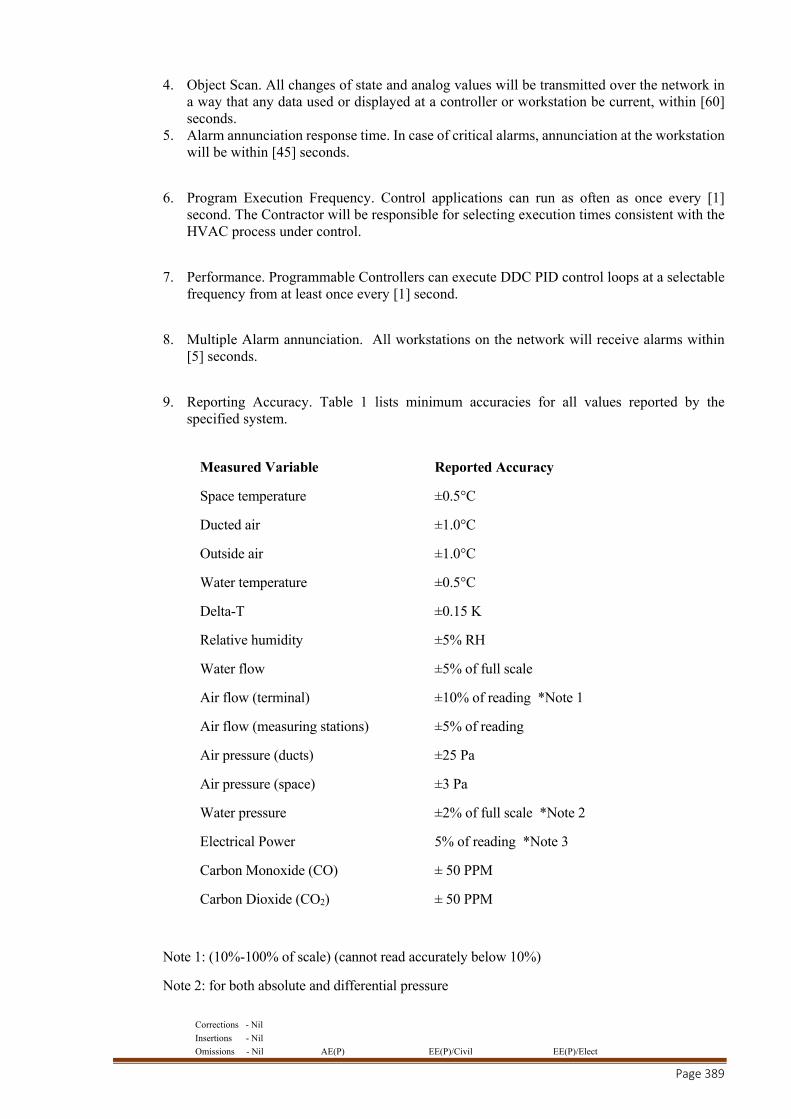
Corrections - Nil
Insertions - Nil
Omissions - Nil AE(P) EE(P)/Civil EE(P)/Elect
Page 389
4. Object Scan. All changes of state and analog values will be transmitted over the network in a way that any data used or displayed at a controller or workstation be current, within [60] seconds.
5. Alarm annunciation response time. In case of critical alarms, annunciation at the workstation will be within [45] seconds.
6. Program Execution Frequency. Control applications can run as often as once every [1] second. The Contractor will be responsible for selecting execution times consistent with the HVAC process under control.
7. Performance. Programmable Controllers can execute DDC PID control loops at a selectable frequency from at least once every [1] second.
8. Multiple Alarm annunciation. All workstations on the network will receive alarms within [5] seconds.
9. Reporting Accuracy. Table 1 lists minimum accuracies for all values reported by the specified system.
Measured Variable Reported Accuracy
Space temperature ±0.5°C
Ducted air ±1.0°C
Outside air ±1.0°C
Water temperature ±0.5°C
Delta-T ±0.15 K
Relative humidity ±5% RH
Water flow ±5% of full scale
Air flow (terminal) ±10% of reading *Note 1
Air flow (measuring stations) ±5% of reading
Air pressure (ducts) ±25 Pa
Air pressure (space) ±3 Pa
Water pressure ±2% of full scale *Note 2
Electrical Power 5% of reading *Note 3
Carbon Monoxide (CO) ± 50 PPM
Carbon Dioxide (CO2) ± 50 PPM
Note 1: (10%-100% of scale) (cannot read accurately below 10%)
Note 2: for both absolute and differential pressure

Corrections - Nil
Insertions - Nil
Omissions - Nil AE(P) EE(P)/Civil EE(P)/Elect
Page 390
Note 3: * not including utility supplied meters
SUBMITTALS
A. Contractor will provide wiring diagrams and manufacturers’ standard specification data sheets on all hardware and software to be provided. No work may begin on any segment of this project until the Engineer and/or Owner have reviewed submittals for conformity with the plan and specifications. [2] copies are required. All wiring diagrams can be provided to the Owner electronically.
B. Quantities of items submitted will be reviewed by the Engineer and/or Owner.
C. Submit the following within [30] days of contract award:
1. A complete bill of materials of equipment to be used indicating quantity, brand and model number.
2. Provide technical documentation, including:
a) Sequence of operations for each system under control. This sequence will be specified for the use of the Control System being provided for this project;
b) Proposal for Graphical navigation architecture c) Color prints of sample graphics for each equipment, application within de scope of the
project; d) System architecture drawing showing system configuration, device locations, addresses,
and cabling; e) Project plan identifying the major implementation phases and milestones f) Detailed wiring diagrams showing all required field and factory terminations. Terminal
numbers will be clearly labeled; g) Points list and the proposed point names, types, …; h) Material list with delivery confirmation tracking i) Datasheets for Building Control Units; j) Datasheets for Controllers; k) Datasheets for Auxiliary Control Devices l) Provide a BACnet Product Implementation Conformance Statement (PICS) for each
BACnet device type in the submittal; m) User Manual for Operator Workstation
D. Project Record Documents: Upon completion of installation submit three (3) copies of record (as-built) documents. The documents will be submitted for approval prior to the final completion and include:
1. Project Record Drawings - These will be as-built versions of the submittal wiring diagrams and system architecture.
2. Testing and Commissioning Reports and Checklists. : These reports will be automatically produced by and from the BMS system (from Operator Workstation) to ensure integrity of the informations. Manual Reports and Checklist will not be accepted.
3. Operating and Maintenance (O & M) Manual. In addition the submittals required, the O & M manual will include:

Corrections - Nil
Insertions - Nil
Omissions - Nil AE(P) EE(P)/Civil EE(P)/Elect
Page 391
a) Name, address and telephone number of Contractor’s Service representative. b) Manual Operators with procedures for daily operation of the system, including logging
on/off, alarm handling, producing point reports, trending data, overriding computer control, and changing set points and other variables.
c) Installation and Maintenance Manual(s) which explains how to replace or install new hardware; do preventive maintenance; debug hardware problems;
d) An electronic system backup at the time of acceptance will be provided on CD. Including project database, graphics, custom programs, controller programs and configuration.
e) Complete original issue media for all software provided including operating systems and BMS workstation software.
f) Licenses and warranty documents for all equipment and systems.
E. Training agenda: The Contractor will provide a course agenda detailing summary of content and schedule for all training classes at least six weeks prior to the first class. Review and approval by Owner and Engineer and will be completed at least 3 weeks prior to first class.
WARRANTY
A. Warrant all work as follows:
1. Labor & materials for control system specified will be warranted free from defects for a period of twelve (12) months after provisional acceptance by the Owner. Control System failures during the warranty period will be adjusted, repaired, or replaced with no charge or reduction in service to the Owner.
2. At the end of the final start-up/testing, if equipment and systems are operating satisfactorily to the Owner and Engineer, the Owner will sign certificates certifying that the control system's operation has been tested and accepted in accordance with the terms of this specification. The date of Owner's acceptance will be the start of the warranty.
3. Operator workstation software, database, and firmware updates (service packs) will be provided to the Owner with no charge during the warranty period. Written authorization by Owner must, however be granted prior to the installation of such changes.
OWNERSHIP, COPYRIGHTS and INTELLECTUAL PROPERTY of MATERIAL & SOFTWARES
A. The following items will become the property of the Owner:
1. Project custom graphics,
2. User Licence for BMS Operator Workstation Software
2. Project As-built file,
3. Project database backup,
4. All project specific documentations.
B. The following items remain the property of the BMS provider:

Corrections - Nil
Insertions - Nil
Omissions - Nil AE(P) EE(P)/Civil EE(P)/Elect
Page 392
1. Copyright and Intellectual property of all BMS softwares,
2. Copyright and Intellectual property of all Programming codes,
3. Copyright and Intellectual property of all Standard graphics and images.
Part –2 Product
OPERATOR INTERFACE
Option 1:
[A. Operator Interface. Furnish [__] PC based workstations as shown in the system drawings. Each of these workstations will be able to access all information in the system. These workstations will reside with the same Ethernet TCP/IP network so as the building controllers, and be able to dial into the system as well.]
[B. Workstation information access will use the BACnet™ Protocol. Communication will use the ISO 8802-3 (Ethernet) Physical/Data Link layer protocol. Remote communications will use the BACnet™ Point to Point Physical/Data Link Layer Protocol.]
Option 2:
[A. Operator Interface. Furnish [__] PC based workstations as shown in the system drawings. Each of these workstations will be able to access all information in the system. These workstations will reside on the Enterprise wide network, which is same Ethernet TCP/IP network as the building controllers. The Enterprise wide network will be provided by the owner and support the Internet Protocol (IP). Workstations will also be able to dial into the system.]
[B. Workstation information access will use the BACnet™ Protocol. Communication will use Annex J of ASHRAE Standard 135-95. Local connections of the workstation will be on ISO 8802-3 (Ethernet). Remote communications will use either the BACnet™ Point to Point Physical/Data Link Layer Protocol or IP over Point to point (PTP).]
A. Workstation hardware characteristics:
1. Personal Computer: The CPU will be a minimum of an Intel Pentium 4 processor and operate to a minimum of 3 GHz. A minimum of 512 Megabytes of RAM, 32X CD Writer, and a 100 Gigabyte hard disk with a minimum access time of 12 milliseconds will be provided. A two-button optical scroll mouse will be provided as well. All required serial, parallel, network communication ports, and all cables for proper system operation will be furnished. The PC will have a minimum of a 17" SVGA monitor and the according graphical card.
2. Modems: auto-dial telephone modems and associated cables as required for communication to remote buildings. The modem will transmit at a minimum speed of 56kBPS, and communicate over voice-grade telephone lines (PSTN).
3. BACnet™: The PC workstation will support the BACnet™ Interoperable Building Blocks (BIBBS) for Read (Initiate) and Write (Execute) Services. That are the Data Sharing BIBBS as follows:
DS-RP-A,B
Corrections - Nil
Insertions - Nil
Omissions - Nil AE(P) EE(P)/Civil EE(P)/Elect
Page 393
DS-RPM-A
DS-WP-A
DS-WPM-A
B. Workstation software characteristics
1. Workstation Software license(s) will be provided with a capacity equal to three times the total number of datapoints of this project.
2. The operator can run the workstation software in any of the following languages: German, English, French, Spanish, Portuguese, Polish, Italian, Hungarian
3. Operating System: will be a commercially available concurrent multi-tasking operating system. Acceptable operating systems are Microsoft® Windows XP Professional or more recent operating system.
4. Workstation Operator Software: The operator software will be graphically oriented, will allows display up to minimum 10 graphic screens at once for comparison and monitoring of system status. It will provide a method for the operator to easily move between graphic displays and change the size and location of them on the screen. The system graphics will be able to be modified while on or off line. An operator with a adequate password level will be able to add, delete, or change dynamic points on a graphic. Dynamic points will include analog and binary values, dynamic text, static text, and animation files. Graphics will have the ability to show animation of the equipment. Graphics will be capable of launching other PC applications.
a) Custom Graphics. Custom graphic files will be created with the use of commonly available graphics packages such as PC Paint. The graphics generation package will create and modify graphics which are saved in industry standard formats such as PCX, BMP, GIF and JPEG.
b) Each HVAC equipment will have its own graphic display containing at least the following information: - equipment name - equipment picture/image - hyperlink to electronic equipment datasheet - equipment address/neuron ID - operating mode - status(es) and measurement(s) - setpoint(s) and override(s) - active diagnostics
c) Graphics Library. Provide a complete library of standard HVAC equipment such as chillers, boilers, air handlers, terminals, fan coils, and unit ventilators. This library will also include standard symbols for other equipment including fans, pumps, coils, valves, piping, dampers, and ductwork. The library will be furnished in a file format compatible with the graphics generation package program.
d) The system will provide dynamic graphic animations showing the actual values of analog inputs and outputs (dampers, valves, water level, Ice level, etc …) and their changes.

Corrections - Nil
Insertions - Nil
Omissions - Nil AE(P) EE(P)/Civil EE(P)/Elect
Page 394
e) The Graphic shall also display status indicators to show the status of both binary and analog overrides. This way the user can immediately see if a manual override is active.
f) Engineering Units. Allow for selection of the engineering units desired (i.e. Inch pound or SI) in the system. Unit selection will be able to be customized by locality to select the desired units for each measurement. Engineering units on this project will be: [Standard Inch Pound] [SI] [Custom as follows:].
A. System Applications.
1. Automatic System Database ‘Save and Restore’. Each workstation will store in the hard disk copy of the current database of each building controller. This database will be updated whenever a change is made in any panel in the system. The storage of this data will be automatic and will not require the operator’s intervention. In the event of a database loss in a building management panel, the first workstation to detect the loss will automatically restore the database for that panel.
2. Manual Database ‘Save and Restore’. A system operator with adequate password clearance will be able to archive the database from any system panel and store in a storage media. The operator will also be able to clear a panel database and manually initiate a download of a specified database to any panel in the system.
3. System Configuration. The workstation software will provide a graphical method to configure the system. The user with proper security will be able to add/remove/edit devices.
4. On-Line Help and Training. Provide a context sensitive, on line help system to assist the operator in operation and editing of the system. On-line help will be available for all applications and will provide the relevant data for that particular screen. Additional help information will be available through the use of hypertext. Provide an interactive tutorial CD, which act as on-line training/help for the systems operator.
5. Security. Each operator will be required to log on to the system with a user name and password in order to view, edit, add, or delete data. System security will be selectable for each operator. The system supervisor will have the ability to set passwords and security levels for all other operators. Each operator password will be able to restrict the operator’s access for viewing and/or changing each system application, full screen editor, and object. User currently logged in to the system will be able to change his password. Each operator will automatically be logged off of the system if no keyboard or mouse activity is detected. This auto logoff time will be set per operator password. All security system data will be stored in an encrypted format.
6. System Diagnostics. The system will automatically monitor building management panels and controllers, including their communication status. The failure of any device will be annunciated to the operator.
7. Alarm Processing. Any object in the system will be configurable to alarm in and out of normal state. The operator will be able to configure the alarm limits, warning limits, states, and reactions for each object in the system.
Corrections - Nil
Insertions - Nil
Omissions - Nil AE(P) EE(P)/Civil EE(P)/Elect
Page 395
a) Alarm Reactions. The operator will be able to determine which actions, if any, are to be taken, by object (or point), during an alarm. Actions will include logging, printing, starting programs, displaying messages, dialing out to remote stations, paging, sending an sms. forwarding to an e-mail address, providing audible annunciation or displaying specific system graphics. Each of these actions will be configurable by workstation and time of day. An object in alarm which has not been acknowledged within an operator specified time period will be re-routed to an alternate operator specified alarm receipt device.
b) Binary Alarms. Each binary object will be set to alarm based on the operator-specified state. Provide the capability to disable alarming when the associated equipment is turned off or is being serviced.
c) Analog Alarms. Each analog object will have both high and low alarm limits and warning limits. Alarming must be able to be automatically and manually disabled.
8. Trend Logs. Setup of trending will be easy and user friendly, even after system commissioning. . From any graphic in the system, by right-clicking on a value, the user can add the data point onto a trend viewer. If the selected value was not trended yet, it will automatically start trending from that moment on.
The Trend Viewer shall allow displaying overrides, alarms and events associated as a part of a datapoint’s graphical trend. It must be possible to scroll through the graphical trends back and forth, zoom in and out, and change date range. While clicking on a given time stamp on the graphic, a hover window shall display the time and the value of the point. The system shall give the user the ability to draw a vertical line in the trend viewer to be able to drag and go back and forth to pinpoint a time for all points on the graphic. The system shall give the user the ability to have multiple trend graphic windows open at the same time and have 10 points per a single trend view. Trended data points can be a mix of any type (analog, binary). Sample period is user selectable for every trend with a minimum value of 30 seconds. Dynamic graphical trend configuration can be saved for later usage.
Definition of trends will include interval, start-time, and stop-time. Trend intervals of 30 seconds, and 1, 5, 15, 30, and 60 minutes as well as once a shift (8 hours), once a day, once a week, and once a month will be selectable. Trended data can also be stored and exported in a tab delimited ASCII format for use by other industry standard word processing and spreadsheet packages.
9. Alarm and Event Log. The operator will be able to view all logged system alarms and events from any location in the system. The operator will be able to easily sort and filter alarms as well as export event log data to external applications. The operator shall be able to distinguish between a high-level alarm and a low-level event without reading the event text. The system shall allow the definition of minimum 5 levels of criticality in order to define the criticality of each alarm in the system.
Corrections - Nil
Insertions - Nil
Omissions - Nil AE(P) EE(P)/Civil EE(P)/Elect
Page 396
The workstation will display configurable counters of the different levels of alarms that will be visible from the toolbar in the BMS workstation. By using easy-to-configure filters, the operator will have the ability to display the active alarm counts, or not yet acknowledged alarms. Clicking on one of the alarm icon buttons will display a sorted alarm log view with the corresponding fixed category on top. The operator shall have the ability to get from an alarm in the Event log directly to the graphic, alarm pop-up, or expanded message of the object that is or was in alarm, througha simple right click. The user shall be able to give additional information for alarms or events through a comment field in the Event log screen. On the arrival of an alarm at the workstation a pop-up dialog box, containing alarm information, should be displayed. This feature can be activated per workstation. Pop-ups can be configured to occur whether a user is logged or not. The user shall have the ability to define what alarm categories will be designated to trigger a pop-up message and what the maximum number should be. When several alarms happen in a short period the operator should be able to “snooze” the pop-ups for a selectable amount of time. Events will be listed chronologically. An operator with the proper access level may acknowledge and clear alarms. All that have not been cleared by the operator will be archived to the hard disk on the workstation.
10. Manual Overrides. The user shall have the ability to manually override output variables in the system. The override ability should be linked to the operator’s security level. Easy to use Override Pop-ups will allow the operator to set the output variable in manual mode and change its value – and vice versa – setting the variable back to automatic mode. Multiple override windows can be open at the same time. When an object is in manual mode, this will be displayed in the corresponding graphic through the appearance of a “hand” symbol.
11. Object and Property Setup. The system will provide a method for the operator with adequate access level to setup any object in the system. The setup will be available by menu or from graphics.
12. Clock Synchronization. The real time clocks in all building control panels and workstations will be synchronized on command of an operator. The system will be able to automatically synchronize all system clocks; daily from any operator designated device in the system. It will automatically adjust for daylight savings and standard time if applicable as well.
13. Reports and Logs. Provide a reporting package which allows the operator to select, modify, or create reports. Each report will be definable as to data content, format. Report data will be archived on the hard disk for historical reporting. Reports will be time and date stamped and will contain a report title and the name of the facility. The system will allow definition of report template that can be used for reports generation. Reports and logs will be stored on the PC hard disk in a format that is readily accessible by other standard software applications including spreadsheets and word processing. Reports and logs will be readily printed to any printer. Reports and logs can be scheduled to be automatically printed / archived on a system

Corrections - Nil
Insertions - Nil
Omissions - Nil AE(P) EE(P)/Civil EE(P)/Elect
Page 397
resource. Reports can be scheduled based on time of the day, day of week, day of month / year.
a) Standard Reports. The following standard system reports will be provided for this project. These reports can be customized to the project by the owner.
i. Electrical Meter Report: provide a monthly report showing the daily electrical consumption and peak electrical demand for each building meter. Provide an annual (12 month) summary report showing the monthly electrical consumption and peak demand for each meter.
ii. All Points in Alarm Report: provide an on demand report showing all current alarms.
iii. All Points in Override Report: provide an on demand report showing all overrides in effect.
iv. Schedule Report: provide a summary of all schedules including Holiday and Exception schedules.
v. Site Commissioning Report: provide a one time report that lists all equipment with the unit configuration and present operation.
vi. Gas Meter Report: provide a monthly report showing the daily natural gas consumption for each meter. Provide an annual (12 month) report that shows the monthly consumption for each meter.
vii. Weather Data Report: provide a monthly report showing the daily minimum, maximum and average outdoor air temperature and the number of heating and cooling degree days for each day. Provide an annual (12 month) report showing the minimum, maximum and average outdoor air temperature for the month and the number of heating and cooling degree days for the month.
viii. Provide standard reports for the following connected equipments: 1) Chillers (centrifugals, scrolls, screw, absorption), 2) Supervisory Controller 3) Ventilation Units, 4) Chiller Plant, 5) Close Control Units, 6) Rooftop Units, 7) Lonmark® DAC/SCC/Chiller/GLD-profile compatible equipments, 8) Fan Coil Units, 9) HVAC-controllers, 10) VAV Units, 11) Variable Air Systems, 12) Boilers, 13) Boiler Plant,

Corrections - Nil
Insertions - Nil
Omissions - Nil AE(P) EE(P)/Civil EE(P)/Elect
Page 398
b) Custom Reports. The system allows the creation of custom report templates. All datapoints in the BMS system can be used in the custom reports. Typical custom reports can be:
1) Lighting controls, 2) Power controls, 3) …
B. User Friendly System Configuration
Daily system configuration modifications will be possible through easy to use, clear language, menu driven system configuration editors at the PC workstation.
Such system configuration can be:
1. Controller Editor: For each type of controller and application, editors will allow the operator with proper password to view and change the configuration such as name, control parameters, and system set-points.
2. Calculation Objects Editor: Standard calculation objects shall be available for functions such as: average, min/max, peak/interval, run time, start/stop, flow rates, totalization, …
3. Graphic Editor: Allow the online modification and creation of graphics, immediately applicable after validation of the operator.
4. Scheduling Editor: Provide a monthly calendar for each schedule. Exception schedules and holidays will be shown clearly on the calendar. Provide a method in allowing several related objects to follow a schedule. The advance and delay time for each object will be adjustable from this master schedule.
5. Task Manager: An editor for scheduling BMS System maintenance tasks will be provided at each workstation. Such BMS maintenance tasks will be, at minimum:
- BMS Database backup
- Alarm & Event Log archive
- Site scan
C. Advanced System Configuration Advanced system configuration (devices / controllers) will be possible online as well as offline from the PC workstation through the use of an embedded technical configuration tool.
After user validation, it will be possible to directly download the adapted configuration to the relevant devices/controllers.
D. Portable Operator's Terminal: Provide a Portable Operator Terminal that will be capable of accessing all system data once plugged into a controller or building control unit. The Portable Operator Terminal will be a touch screen device enabling datapoint reading and override.
Corrections - Nil
Insertions - Nil
Omissions - Nil AE(P) EE(P)/Civil EE(P)/Elect
Page 399
SYSTEM SOFTWARE
A. Provide the following applications software for building management. All software applications will reside and run in the system controllers. Editing of applications will occur at the operator workstation.
B. System Security:
1. User access will be secured using individual security passwords and user names.
2. Passwords will restrict the user to access only the objects, applications, and system functions as assigned by the system manager.
3. User logon/logoff attempts will be recorded.
4. The system will protect itself from unauthorized use by automatically logging off following the last keystroke. The delay time will be used definable.
C. Scheduling: Provide the capability to schedule each object or group of objects in the system. Each of these schedules will include the capability for start, stop, optimal start, optimal stop, and night economizer actions. Each schedule may consist of up to [20] events. When a group of objects are scheduled together, provide the capability to define advances and delays for each member. Each schedule will consist of the following:
1. Weekly Schedule: provide separate schedules for each day of the week.
2. Exception Schedules: provide the ability for the operator to designate any day of the year as an exception schedule. This exception schedule will override the standard schedule for that day. Exception schedules may be defined up to a year in advance. Once an exception schedule is executed it is discarded and replaced by the standard schedule for that day of the week.
3. Holiday Schedules: provide the capability for the operator to define up to [99] special or holiday schedules. These schedules may be placed on the scheduling calendar and be repeated each year. The operator will be able to define the length of each holiday period.
4. Optimal Start/Stop: the scheduling application outlined above will support an optimal start/stop algorithm. This will calculate the thermal characteristics of a zone and start the equipment prior to occupancy to achieve the desired space temperature at the specified occupancy time. The algorithm will calculate separate sets of heating and cooling rates for zones that have been unoccupied for less then and greater than 24 hours. Provide the ability to modify the start/stop algorithm based on outdoor air temperature. Provide an early start limit in minutes to prevent the system from starting before an operator determined time limit.
D. Alarm Reporting: The operator will be able to determine the action to be taken in the event of an alarm. Alarms will be routed to the appropriate workstations based on time and other conditions. An alarm will be able to start programs, be logged in the event log, be printed, be transmitted through SMS or e-mail, generate custom messages graphics.
E. Remote Communications: The building control units will have the ability to dial out in the event of an alarm. Receivers will include PC Workstations, email, and alphanumeric pagers. The alarm message will include the
Corrections - Nil
Insertions - Nil
Omissions - Nil AE(P) EE(P)/Civil EE(P)/Elect
Page 400
name of the calling location, the device that generated the alarm, and the alarm message itself. The operator will be able to remotely access and operate the system using dial up communications in the same format and method used on site under section “Operator Interface”.
F. Demand Limiting:
1. The demand limiting program can monitor building power consumption from signals generated by a pulse generator mounted at the building power meter, or from a watt transducer or current transformer attached to the building power supply lines.
2. The demand limiting program will be based on a predictive sliding window algorithm. The sliding window duration and sampling interval will be set equal to that of the local Electrical Utility.
3. Control system will be capable of demand limiting by resetting HVAC system set-points to reduce load.
4. Input capability will also be provided for an end-of-billing period indication.
G. Chiller Sequencing: Provide applications software to properly sequence the chiller plant to minimize energy use. This application will perform the following functions:
1. The chiller plant control application will have the ability to control a maximum of 25 chillers of any type including centrifugal, helirotor, scroll, reciprocating and absorption machines as detailed in the sequence of operations.
2. This application will be able to control both constant and variable flow systems as well as parallel, series and decoupled piping configurations.
3. The chiller plant control application will be able to control multiple chiller plants per site. 4. Diagnostics/Protection - The chiller plant application program will be able to integrate
individual chiller diagnostics into control action decisions. 5. Event Processing - All chiller plant control and status events will be recorded, at the
operator’s selection, in the building management system event log to facilitate trouble shooting.
6. Alarm Indications - The chiller plant control status screens will display chiller plant and individual chiller alarm messages.
7. Add/Subtract actions – The status screens will provide information when the next chiller add or subtract action occur. The operator will have the ability to manually force a chiller addition or a chiller subtraction.
H. PID Control: A PID (proportional-integral-derivative) algorithm with direct or reverse action and anti-wind-up will be supplied. The algorithm will calculate a time-varying analog value used to position an output or stage a series of outputs. The controlled variable, set-point, and PID gains will be user-selectable. The set-point will optionally be chosen to be a reset schedule.
I. Timed Override:
Astandard application will be utilized to enable/disable temperature control when a user selects on/cancel at the zone sensor, workstation, or the operator display. Time’s amount that override takes precedence be selectable from the workstation.
J. Staggered Start:
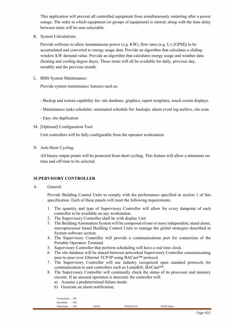
Corrections - Nil
Insertions - Nil
Omissions - Nil AE(P) EE(P)/Civil EE(P)/Elect
Page 401
This application will prevent all controlled equipment from simultaneously restarting after a power outage. The order in which equipment (or groups of equipment) is started; along with the time delay between starts will be user-selectable.
K. System Calculations:
Provide software to allow instantaneous power (e.g. KW), flow rates (e.g. L/s [GPM]) to be accumulated and converted to energy usage data. Provide an algorithm that calculates a sliding-window KW demand value. Provide an algorithm that calculates energy usage and weather data (heating and cooling degree days). These items will all be available for daily, previous day, monthly and the previous month.
L. BMS System Maintenance:
Provide system maintenance features such as:
- Backup and restore capability for: site database, graphics, report templates, touch screen displays.
- Maintenance tasks scheduler: automated schedule for: backups, alarm event log archive, site scan.
- Easy site duplication
M. [Optional] Configuration Tool:
Unit controllers will be fully configurable from the operator workstation.
N. Anti-Short Cycling:
All binary output points will be protected from short cycling. This feature will allow a minimum on-time and off-time to be selected.
SUPERVISORY CONTROLLER
A. General:
Provide Building Control Units to comply with the performance specified in section 1 of this specification. Each of these panels will meet the following requirements.
1. The quantity and type of Supervisory Controller will allow for every datapoint of each controller to be available on any workstation.
2. The Supervisory Controller shall be with display Unit 3. The Building Automation System will be composed of one or more independent, stand-alone,
microprocessor based Building Control Units to manage the global strategies described in System software section.
4. The Supervisory Controller will provide a communications port for connection of the Portable Operators Terminal.
5. Supervisory Controller that perform scheduling will have a real time clock. 6. The site database will be shared between networked Supervisory Controller communicating
peer-to-peer over Ethernet TCP/IP using BACnet™ protocol. 7. The Supervisory Controller will use industry recognized open standard protocols for
communication to unit controllers such as Lontalk®, BACnet™. 8. The Supervisory Controller will continually check the status of its processor and memory
circuits. If an unusual operation is detected, the controller will: a) Assume a predetermined failure mode; b) Generate an alarm notification;
Corrections - Nil
Insertions - Nil
Omissions - Nil AE(P) EE(P)/Civil EE(P)/Elect
Page 402
c) Create a retrievable file of the state of all applicable memory locations at the time of the failure;
d) Automatically reset the Building Control Unit to return to a normal operating mode; e) After power shutdown Building Control Unit will be able to automatically execute a
specific program.
The Building Controller will use the Read (Initiate) and Write (Execute) Services as defined in these BIBBS:
DS-RP-A,B
DS-RPM-A,B
DS-WP-A,B
DS-WPM-B
Option 1
[B. Communications. Each Building Controller will reside on a BACnet inter-network using the ISO 8802-3 (Ethernet) Physical/Data Link layer protocol. Each Building Controller will also perform routing to a network of Custom Application and Application Specific Controllers. Each Building Controller will perform communications to a network of Custom Application and Application Specific Controllers using LonTalk FTT-10 and LonMark profiles. ]
Option 2
[B. Communications. Each Building Controller will reside on the Enterprise wide network, which is same high-speed network as the workstations. The Enterprise wide network be provided by the owner and supports the Internet Protocol (IP). Local connections of the Building Controller will be on ISO 8802-3 (Ethernet). Communications will use Annex J of ASHRAE Standard 135-95. Each Building Controller will also perform routing to a network of Custom Application and Application Specific Controllers. Each Building Controller will perform communications to a network of Custom Application and Application Specific Controllers using LonTalk FTT-10 and LonMark profiles. ]
A. Environment:
Controller hardware will be suitable for the anticipated ambient conditions. Controller used in conditioned ambient will be mounted in an enclosure, and will be rated for operation at 0 C to 50 C.
B. Memory: The Building Controller will maintain all BIOS and programming information in the event of a power loss for at least 72 hours.
C. Immunity to power and noise: Controller will be able to operate at 90% to 110% of nominal voltage rating and will perform an orderly shut-down below 80% nominal voltage.
D. Building Controller Operator Display [optional]
Corrections - Nil
Insertions - Nil
Omissions - Nil AE(P) EE(P)/Civil EE(P)/Elect
Page 403
The building controller will include an operator display allowing the user to perform basic daily operations tasks on the building automation system. At a minimum this operator display will:
1. Support and display multiple languages (English, French, Spanish, German, Portuguese, Polish, Italian and Hungarian) and shall hold in memory all these languages simultaneously. This will allow users to switch from one language to another, without need of a tool, while keeping the system in normal operation.
2. Allow the operator to view custom graphical displays (picture, 3D Graphs …) with dynamic status information.
3. Be installed on the building controller and require no additional power source
4. Consist of a one-quarter VGA touch screen with 320 X 240-pixel resolution. The brightness and the contrast of the backlit touch screen will be adjustable to allow for easy reading of information on the screen.
5. Be capable of having unique user identification and passwords that can be programmed to limit access to the system and operator functions.
6. Display the current state of an input/output point and equipment controller connected to the system.
7. Give the operator the ability to override the current state of an output point or HVAC equipment controller connected to the building controller.
8. Allow the operator to modify the start and stop times of any time-of-day schedule within the system.
9. Provide a visual indication that a system alarm exists and allow for an optional audible alarm annunciation.
10. Provide the ability to view and acknowledge alarms that are annunciated at that building controller.
11. Automatically update displayed system information every 10 seconds.
CONTROLLERS
A. General: Provide Controllers to comply with the performance specified in section 1 of this division. Each of these controllers will meet the following requirements.
1. The programmable controllers processors shall be 32-Bit, 50 MHz. (B) Upgradation of controllers shall be possible by simple downloading of software rather than replacing of chip.(C) Analog to Digital and Digital to Analog resolution shall be 12 bit for greater accuracy. (D) Controllers shall support easy GRAPHICAL programming and shall be able to store the programs in the controller itself rather than storing it in PC. (F) The programmable controller shall have minimum of 12 Universal input points and each input shall be capable of sensing PULSE signals.(G) The unit shall have NEMA-1 enclosure and the complete assembly shall be UL listed. The DDC Controller shall be with display. The DDC controller shall be as per the I/O Summary. The above controllers shall be housed in a vandal proof, lockable and secure MS cabinets to be supplied along with the Controllers. No 16 Bit, 8 Bit Controllers, Multiplexers are allowed. The systems should be on Native BACnet Platform. Each AHU should have a dedicated controller

Corrections - Nil
Insertions - Nil
Omissions - Nil AE(P) EE(P)/Civil EE(P)/Elect
Page 404
2. The controllers are DDC, independent, stand-alone, microprocessor based units able to manage the local strategies described in System software section. The controller should have I/O 10% Spares
3. The following types of equipments will be provided with their factory mounted controller. Factory mounting includes controller mounting, programming, setup and I/O testing. - Fancoil Units - Water Terminal Units - VAV Units - Air Handling Units - Rooftop Units - Closed Control Units - Chillers
4. Controllers that perform scheduling will have a real time clock.
B. Inputs/outputs: The controllers will support various input/output combinations, on-board and/or through distributed extension modules, depending on their type, such as: Analog Inputs The following signal types can be supported: 0 - 10Vdc, 0 - 20mA, 4 - 20mA, NTC 20 K, PT100, linear 20 K. Digital Inputs Digital inputs connect to potential free (dry) input contacts. Analog Outputs The following signal types can be supported: 0(1) - 10Vdc, 0(4) - 20mA. Digital Outputs The following signal types can be supported: voltage free, 230VAC (16A), 24VAC. Pulse Inputs Pulse inputs support max. 3Hz voltage free input signals (totalizations).
C. Environment: Controller hardware will be suitable to anticipate ambient conditions at 0 C to 50 C.
D. Operator Display A local operator interface will be provided at building locations where specified in the sequence of operations or point list. The operator interface will be provided for interrogating and overriding data. A system security password will be available to prevent unauthorized use of the keypad and display.
E. Service ability Provide diagnostic LEDs for power, communications, and processor. All low voltage wiring connections will be made such that the controller electronics can be removed and/or replaced without disconnection of field termination wiring.
F. Memory: The Controller will maintain all BIOS and programming information in the event of a power loss for at least 72 hours.
G. Immunity to power and noise:
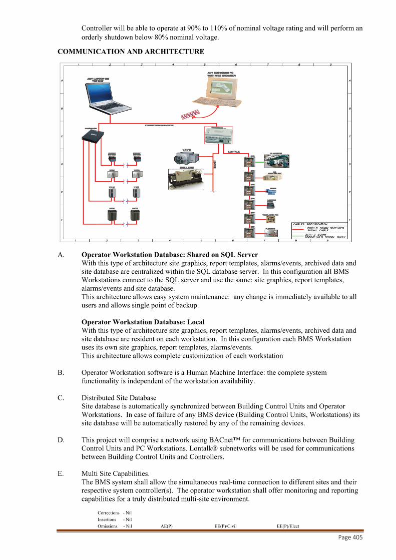
Corrections - Nil
Insertions - Nil
Omissions - Nil AE(P) EE(P)/Civil EE(P)/Elect
Page 405
Controller will be able to operate at 90% to 110% of nominal voltage rating and will perform an orderly shutdown below 80% nominal voltage.
COMMUNICATION AND ARCHITECTURE
A. Operator Workstation Database: Shared on SQL Server With this type of architecture site graphics, report templates, alarms/events, archived data and site database are centralized within the SQL database server. In this configuration all BMS Workstations connect to the SQL server and use the same: site graphics, report templates, alarms/events and site database. This architecture allows easy system maintenance: any change is immediately available to all users and allows single point of backup. Operator Workstation Database: Local With this type of architecture site graphics, report templates, alarms/events, archived data and site database are resident on each workstation. In this configuration each BMS Workstation uses its own site graphics, report templates, alarms/events. This architecture allows complete customization of each workstation
B. Operator Workstation software is a Human Machine Interface: the complete system functionality is independent of the workstation availability.
C. Distributed Site Database Site database is automatically synchronized between Building Control Units and Operator Workstations. In case of failure of any BMS device (Building Control Units, Workstations) its site database will be automatically restored by any of the remaining devices.
D. This project will comprise a network using BACnet™ for communications between Building Control Units and PC Workstations. Lontalk® subnetworks will be used for communications between Building Control Units and Controllers.
E. Multi Site Capabilities. The BMS system shall allow the simultaneous real-time connection to different sites and their respective system controller(s). The operator workstation shall offer monitoring and reporting capabilities for a truly distributed multi-site environment.
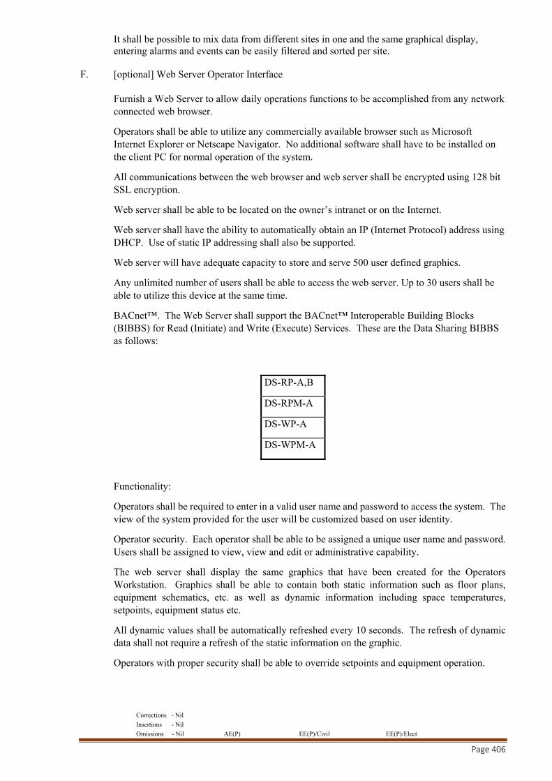
Corrections - Nil
Insertions - Nil
Omissions - Nil AE(P) EE(P)/Civil EE(P)/Elect
Page 406
It shall be possible to mix data from different sites in one and the same graphical display, entering alarms and events can be easily filtered and sorted per site.
F. [optional] Web Server Operator Interface Furnish a Web Server to allow daily operations functions to be accomplished from any network connected web browser.
Operators shall be able to utilize any commercially available browser such as Microsoft Internet Explorer or Netscape Navigator. No additional software shall have to be installed on the client PC for normal operation of the system.
All communications between the web browser and web server shall be encrypted using 128 bit SSL encryption.
Web server shall be able to be located on the owner’s intranet or on the Internet.
Web server shall have the ability to automatically obtain an IP (Internet Protocol) address using DHCP. Use of static IP addressing shall also be supported.
Web server will have adequate capacity to store and serve 500 user defined graphics.
Any unlimited number of users shall be able to access the web server. Up to 30 users shall be able to utilize this device at the same time.
BACnet™. The Web Server shall support the BACnet™ Interoperable Building Blocks (BIBBS) for Read (Initiate) and Write (Execute) Services. These are the Data Sharing BIBBS as follows:
DS-RP-A,B
DS-RPM-A
DS-WP-A
DS-WPM-A
Functionality:
Operators shall be required to enter in a valid user name and password to access the system. The view of the system provided for the user will be customized based on user identity.
Operator security. Each operator shall be able to be assigned a unique user name and password. Users shall be assigned to view, view and edit or administrative capability.
The web server shall display the same graphics that have been created for the Operators Workstation. Graphics shall be able to contain both static information such as floor plans, equipment schematics, etc. as well as dynamic information including space temperatures, setpoints, equipment status etc.
All dynamic values shall be automatically refreshed every 10 seconds. The refresh of dynamic data shall not require a refresh of the static information on the graphic.
Operators with proper security shall be able to override setpoints and equipment operation.

Corrections - Nil
Insertions - Nil
Omissions - Nil AE(P) EE(P)/Civil EE(P)/Elect
Page 407
System schedules shall be easily selected for display. Operators with valid security shall be allowed to make changes to schedules including modifications to start and stop times and creating exception days. These changes shall be made graphically within the web browser.
A log of system alarms and events shall be able to be viewed from the web browser. Operators with proper security shall be able to acknowledge alarms.
System trends shall be able to be selected and viewed. Trends shall be shown graphically with the proper axis scaling automatically selected.
Operators with proper access shall be able to configure the web server using their web browser.
Web Server Hardware.
Provide a solid state web server. This device may not contain any moving parts including but not limited to cooling fans, disk drives, CD Rom drives etc. Hardware such as PC are not accepted.
Web server will have 2 separate Ethernet TCP/IP communication port, to enable physical separation of BMS TCP/IP Network and Site TCP/IP Network.
Web server hardware shall be wall mounted as shown on system drawings.
All user entered information (web pages, security, etc.) shall be stored in non-volatile memory. System operational information and clock functions shall be backed up by battery or other device for a minimum of 72 hours.
G. Third Party Integration The BMS platform shall natively supports open, standard and certified communication protocols such as Lontalk® and BACnet™. For the integration of third party subsystems (HVAC controls, lighting controls, electrical installation monitoring, security monitoring, etc.) preference goes to the usage of these standard communication protocols. The BMS shall also offer integration capabilities through a Modbus compatible gateway. In case that only proprietary communication protocols are available on the subsystem(s) level, the BMS platform can offer an appropriate interface, based on the same Modbus gateway hardware platform.
H. Architectural Drawing. Cf. separate drawing
TECHNICAL SPECIFICATIONS
1. SCOPE
1.1 Scope of this section comprises the supply, installation, testing and commissioning of Building Management System including Building Performance Management.
1.2 DESCRIPTION OF PLANT OPERATION
1.2.1 Central Chilled Water System
The central chilled water system shall consist of the following items of plant :
Corrections - Nil
Insertions - Nil
Omissions - Nil AE(P) EE(P)/Civil EE(P)/Elect
Page 408
a. 3 Nos. Water chilling machines. b. 3 Nos. Primary Chilled water pumps with VFD (variable speed) 3 Nos. Condenser water pumps c. 3 Nos. variable frequency drives. d. 3 Nos. Cooling towers with VFD. e. Total number of Chilled water circuit - 3 Nos.
The following functions shall be carried out by the Building Automation System. a. Enable and disable each chiller unit through Chiller Manger
b. Monitor status and lockout conditions of each chilling unit and subsequently give an alarm.
c. Monitor the status of each variable frequency inverter upon receiving signal from pump controller installed in plant room. d. Switch ON/OFF each pump/ chilling unit/ cooling tower to maintain the chilled water
load demand.
e. Sequence each pump/chilling unit/cooling tower, to maintain equal run time.
f. Carry out chilled water temperature reset with respect to chilled water valve position at the AHU’s.
g. Monitor status of each of the primary chilled water pumps & condenser water pump
through a differential pressure switch and keep a log of run-time. h. Monitor current drawn by each of the chiller compressor and subsequently give an
alarm for abnormal consumption.
i. Monitor the common chilled water supply and return temperatures.
j. Monitor the chilled water supply temperature at outlet of each Chiller.
k. Monitor the chilled water supply/return temperature of each CHW circuit. l. Monitor the common condenser water temperature on both supply and return headers m. Monitor the condenser water temperature at the outlet of each chilling machine. n. Monitor the condenser water return temperature at the outlet of each cooling tower and
accordingly vary the speed of CT fans through VFI. o. Monitor the common chilled water supply pressure through a pressure transmitter.
p. Monitor the chilled water supply & return header pressure on each of the chilled
water circuits.
q. Monitor the chilled water flow rate in the bypass circuit through a flow meter.
r. Monitor the Chilled water flow rate in return header in each of the chilled water circuits.
s. Monitor flow direction in the chilled water bypass line through flow switches.
t. Monitor the outside air temperature and relative humidity.
u. Monitor any item of plant being switched on a manual basis (i.e. an indication/alarm to come on the screen, if any equipment is running in manual mode.
Corrections - Nil
Insertions - Nil
Omissions - Nil AE(P) EE(P)/Civil EE(P)/Elect
Page 409
1.2.1.2. Ventilation & Exhaust System
HVAC Plant Room, Boiler Room/DG Room Fresh Air Fans Exhaust Fans
a. Control Start/Stop of each fan.
b. Indicate any unit running in Manual mode and subsequently give an alarm. c. Carry out monitoring tripping & subsequently give an alarm .
Public Toilet Exhaust Fans
a. Control Start/Stop of each fan.
b. Switch fan to low/hi speed as and when required.
c. Monitor the status (electrical) of each fan.
1.2.1.4. Fans for Laundry & Kitchen, Supply, Exhaust a. Control Start/Stop of each fan.
b. Indicate any unit running in Manual mode and subsequently give an alarm
for abnormal consumption.
c. Switch ON/OFF pumps for AWU.
Air Handling Units (THRU TRANE BMS) a. Programme the start/stop of each air handling unit supply fan and carry out the
duty cycling (from AHU panel). b. Monitor the running status of each blower fan through a differential pressure
switch and keep a log of the number of hours run. c. Monitor filter status of each AHU by a pressure differential switch & give an
alarm in case the filter gets choked. d. Monitor the supply and return air temperature & give an alarm for a high/low supply
air temperature. e. Control the chilled water & hot water two way modulating valve, to maintain the
room conditions. f. Indicate any unit running in Manual mode.
1.2.2 Electrical System
1.2.2.1 Substation & Lt Panel
Corrections - Nil
Insertions - Nil
Omissions - Nil AE(P) EE(P)/Civil EE(P)/Elect
Page 410
a. Monitor Incoming HT voltage
b. Monitor outgoing LT voltage
c. Calculate KW consumption of LT panel
d. Monitor incoming voltage/frequency reading at LT.
e. Monitor current reading at LT panel.
f. Monitor motorised breaker status.
g. Calculate power consumption at all outgoings from LT panel.
1.2.2.2 DG Set 1.2.2.3 Monitor the status of DG set when in running mode and Log number of run hours.
b. Monitor DG Battery status.
c. Control start/stop of each pump and link it to start/stop of D G sets.
d. Indicate any unit running in manual mode.
e. Monitor the condenser water supply header temperature & give an alarm for a high temperature.
f. Monitor the condenser water temperature at the outlet of each cooling tower.
g. Monitor the condenser water return header temperature.
h. Monitor the status of each pump through a differential pressure switch and give an alarm at the failure of the pump.
j. Control Start/Stop of Cooling tower & link it to Start/Stop of DG sets.
k. Indicate any unit running in Manual mode.
l. Monitor status of the isolation valve at the open & close travel limit switches.

Corrections - Nil
Insertions - Nil
Omissions - Nil AE(P) EE(P)/Civil EE(P)/Elect
Page 411
HVAC Motor Control Centre
a. Monitor voltage in each phase at each MCC panels. b. Monitor current in any one phase at each MCC panels. c. Carry out KWH metering at each MCC.
1.2.3 Plumbing Equipment
1.2.3.1 Hydropneumatic Equipment
Raw Water Pumps
Hydropneumatic System Pumps
a. Status of each pump through a differential pressure switch and maintain a Log of run-hours.
b. Status of each pump through the electrical panel.
c. Monitor line pressure of hydropneumatic system.
d. Monitor line pressure in the fire header.
e. Monitor hardness value of water being supplied to cooling towers.
1.2.3.2. Sumps
Sump pump (Waste Water)
Sump Pump (Sewage)
a. Monitor status of each of the above pumps through a differential pressure switch.
b. Monitor high level Alarm Condition for all sumps through level switch.
1.2.3.3 Fire Fighting System
Fire fighting pumps (Electrical)
Jockey pump

Corrections - Nil
Insertions - Nil
Omissions - Nil AE(P) EE(P)/Civil EE(P)/Elect
Page 412
Diesel operated fire fighting pump
a. Monitor status of each of the above pumps through a differential pressure switch.
b. Monitor line pressure through a pressure transmitter.
\ Well Water System
Well water pumps
a. Monitor status of each of the above pumps through a differential pressure switch.
b. Monitor quality of water through a hardness analyser.
Sewage Treatment Plant
STP equipment
Sewage Transfer Pump Waste Water Sump
a. Monitor status through a differential pressure switch.
b. Monitor quality of water through a hardness analyser.
c. Monitor pH of water through pH sensor.
1.2.3.6. Water Tanks And Sumps
Static storage tanks for Fire hydrant & Sprinkler system
Municipal water tanks
Raw water storage tanks
Treated water tanks
Monitor water level alarms for tanks through a level switch/level controller and give an alarm for high / low level.

Corrections - Nil
Insertions - Nil
Omissions - Nil AE(P) EE(P)/Civil EE(P)/Elect
Page 413
1.2.3.7. Swimming Pool Plant
Swimming Pool recirculation pumps
a. Carryout start / stop of pumps
b. Monitor status of each pump through a differential pressure switch.
1.2.3.8. Fountain Supply Pumps
Water recirculation pumps
a. Carryout start / stop of pumps.
b. Monitor status of each pump through a differential pressure switch.
1.2.3.9. Hot Water Generation
Hot Water recirculation pump
a. Monitor HW supply & return temperature.
b. Monitor status of each pump through a differential pressure switch.
CENTRAL CONTROL STATION
The Control stations shall comprise of Personal computers (PC) providing high level operator interface with the system . The terminals shall be capable of providing the operator with the facility for remote system interrogation, control, retrieval/storage of logged data, annunciation of alarms and reports, analysis of recorded data and the formatting of management reports.
The control station shall consist of the following hardware with all of them suitable for the power supply voltage of 230 V AC ± 10% , 50 HZ + 3%.
a. Minimum Specifications for Workstations
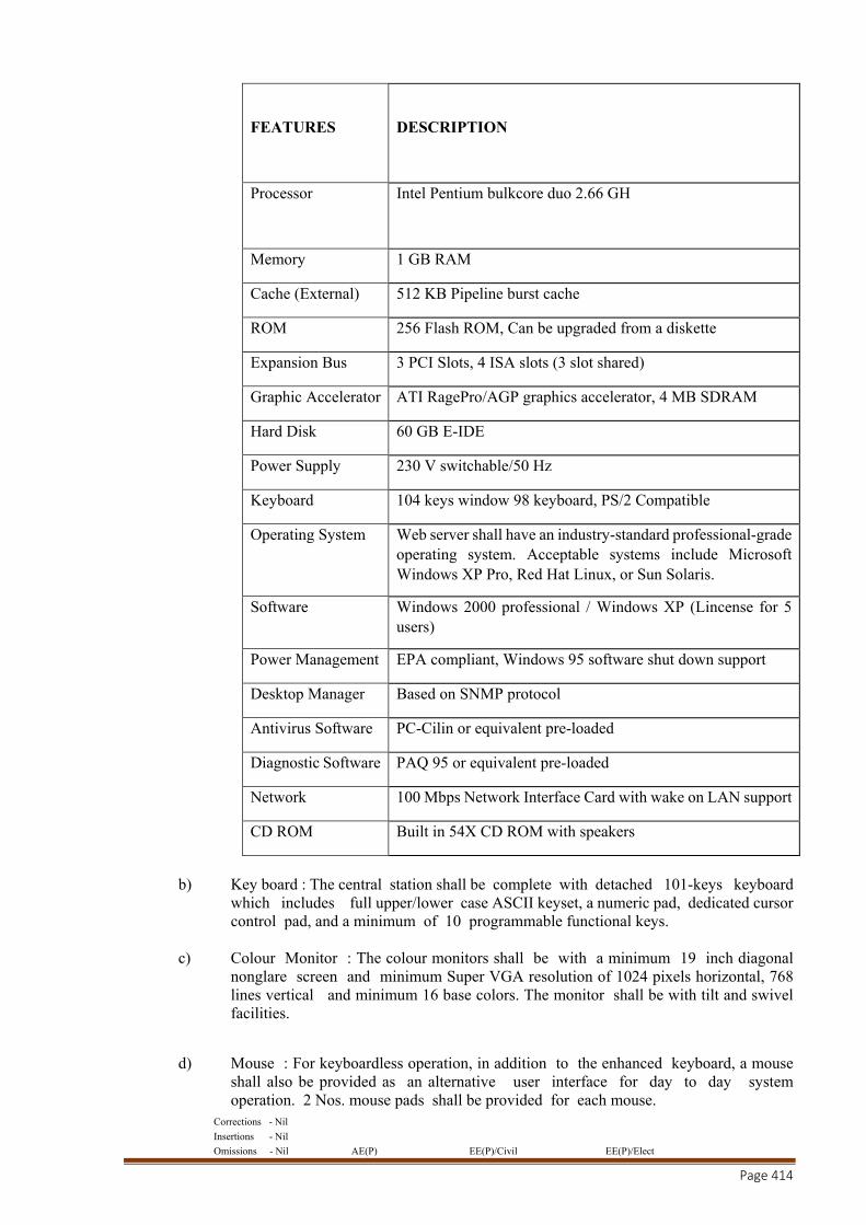
Corrections - Nil
Insertions - Nil
Omissions - Nil AE(P) EE(P)/Civil EE(P)/Elect
Page 414
FEATURES
DESCRIPTION
Processor Intel Pentium bulkcore duo 2.66 GH
Memory 1 GB RAM
Cache (External) 512 KB Pipeline burst cache
ROM 256 Flash ROM, Can be upgraded from a diskette
Expansion Bus 3 PCI Slots, 4 ISA slots (3 slot shared)
Graphic Accelerator ATI RagePro/AGP graphics accelerator, 4 MB SDRAM
Hard Disk 60 GB E-IDE
Power Supply 230 V switchable/50 Hz
Keyboard 104 keys window 98 keyboard, PS/2 Compatible
Operating System Web server shall have an industry-standard professional-grade operating system. Acceptable systems include Microsoft Windows XP Pro, Red Hat Linux, or Sun Solaris.
Software Windows 2000 professional / Windows XP (Lincense for 5 users)
Power Management EPA compliant, Windows 95 software shut down support
Desktop Manager Based on SNMP protocol
Antivirus Software PC-Cilin or equivalent pre-loaded
Diagnostic Software PAQ 95 or equivalent pre-loaded
Network 100 Mbps Network Interface Card with wake on LAN support
CD ROM Built in 54X CD ROM with speakers
b) Key board : The central station shall be complete with detached 101-keys keyboard
which includes full upper/lower case ASCII keyset, a numeric pad, dedicated cursor control pad, and a minimum of 10 programmable functional keys.
c) Colour Monitor : The colour monitors shall be with a minimum 19 inch diagonal
nonglare screen and minimum Super VGA resolution of 1024 pixels horizontal, 768 lines vertical and minimum 16 base colors. The monitor shall be with tilt and swivel facilities.
d) Mouse : For keyboardless operation, in addition to the enhanced keyboard, a mouse shall also be provided as an alternative user interface for day to day system operation. 2 Nos. mouse pads shall be provided for each mouse.
Corrections - Nil
Insertions - Nil
Omissions - Nil AE(P) EE(P)/Civil EE(P)/Elect
Page 415
e) Printers : The contractor shall provide printers as specified in the schematic diagram for printing alarms, operator transactions and reports.
There shall be two printers with each Control Station. One printer shall be dedicated for alarm printing and the second printer for printing reports, trend log, summary, totalizer logging, recording alarms and providing system reports etc. Each of these shall be identical and inter-changeable, and shall have the following characteristics:
i) All the printers shall be Dot matrix printers.
ii) 132 column/300 character per second print speed with minimum 24 pin head.
iii) Adjustable line spacing of six or eight lines per inch with compressed mode option and bidirectional printing and logic seeking.
f) The available PCI slots on the PC shall be used only for communication cards and shall not be utilized for mounting protocol converter cards. If protocol converter cards are used, they shall be external to PC and separately powered and backed-up by the UPS supply.
5 CENTRAL STATION SOFTWARE
The BAS contractor shall provide system software based on a server/thin-client architecture, designed around the open standards of web technology. The BAS server shall communicate using ASHRAE’s BACnet/IP protocol, and in addition, offer concurrent support over the same data-link of the following protocols: LonWorks, MODBUS, and SNMP. Server shall be accessed using a web browser overintranet and remotely over the Internet. The intent of the thin-client architecture is to provide the operator(s) complete access to the BAS system via a web browser. The thin-client web browser Graphical User Interface (GUI) shall be browser and operating system agnostic, meaning it will support Microsoft and Netscape Navigator browsers (5.5 or later versions), and Windows as well as non-Window operating systems. No special software, (active-x components or fat java clients) shall be required to be installed on the PC’s / PDA’s used to access the BAS via a web browser. The BAS server software must support at least the following server platforms (Windows NT, Sun Solaris and Linux). The BAS server software shall be developed and tested by the manufacturer of the system standalone controllers and network controllers/routers. Third party manufactured and developed BAS software is not acceptable. The web browser GUI shall provide a completely interactive user interface and must offer the following features as a minimum:
• Trending • Scheduling • Downloading Memory to field devices • Real time ’live’ Graphic Programs • Tree Navigation • Parameter change of properties
Corrections - Nil
Insertions - Nil
Omissions - Nil AE(P) EE(P)/Civil EE(P)/Elect
Page 416
• Setpoint Adjustments • Alarm / Event information • Configuration of operators • Execution of global commands
5.1 Software Components
All software components of the BAS system software shall be installed and completed in accordance with the specification. BAS system components shall include:
Server Software, Database and Web Browser Graphical User Interface
System Configuration Utilities for future modifications to the system
Graphical Programming Tools
Direct Digital Control software
Application Software 5.2 Third part integrations: The software shall be open architecture & support based for industry standard integrations with third party mechanical & electrical sub-systems. The same shall be capable to support multiple protocols over a TCP/IP Network allowing many equipment items to be connected directly to the main backbone IT protocol The software using BACnet® shall be connected to an IP, ARCNET, MS/TP, or Point to Point (PTP) network segment. The system shall allows for seamless interconnection to equipment using BACnet, Modbus, N2, JBUS, or LonWorks, as well as an extensive list of proprietary protocols.
The software shall mainly cover the following third party integrations:
Chiller Integration Generator Integration Electricity / Water / Steam / Hot water/ D.G.Sets / Car Park / VFD’s
The above Utility systems shall be incorporated for options such as alarming, automatic demand reduction and utility bills. It shall have control everything from mission critical cooling to emergency back-up generators. Special function like unique schedule for a group of rooms shall be provided. Feature like “holiday” schedule to save energy in different space of the building.
The request based feature like For example, if the one of the department is going to work on Saturday and needs air conditioning in the main conference room, the software shall have the feature of occupation schedule for in the real time calendar, and the system shall do the rest. When the rooms need cooling, they will send a request to the air handler telling it to start. If the air handler in turn needs cold water from a chiller, it will send a request to the chiller. With request-based applications, the equipment shall be controlled by the customer’s schedule, rather than forcing the customer to adapt to the equipment’s schedule.
Corrections - Nil
Insertions - Nil
Omissions - Nil AE(P) EE(P)/Civil EE(P)/Elect
Page 417
The system shall have energy management applications, providing features like learning adaptive optimal start, trim and respond, and demand-based setpoint adjustment which automatically fine tune the system to run at peak efficiency.
It shall have networking, trending, alarming, and reporting capabilities,
Boiler Integration:
The software shall be a web based data management tool and consist analysis modules for boiler water and cooling water systems, respectively. These programs are designed for use in monitoring boiler, steam cycle and cooling system performance in industrial or utility boiler installations. Boiler, cooling system and other steam cycle parameters can be trended and alerts can be set for key parameters that are detected to be in an abnormal condition and diagnoses the reason(s) for many common problems in steam plants and cooling water systems. It also calculates the total energy consumed v/s the produced energy (Steam) trending with real time computation of system’s efficiency.
5.8 WEB BROWSER GRAPHICAL USER INTERFACE
The purposed software shall be capable to forfeit the requirement of integrated maintenance management solution. Web based data management software & its application pays a critical part providing a single repository for all assets. This repository is necessary to go from preventive to predictive and proactive maintenance programs Lifetime maintenance and parts costs can be stored with the asset database, and repair or replace decisions become a financial analysis. The system should self diagnostic e.g. enthalpy control, energy recovery lops. With the below specified feature / requirements this software shall be deemed to act in a way to provide the information in “predictive & preventive maintenance.”
5.9 Web Browser Navigation
The Thin Client web browser GUI shall provide a comprehensive user interface. Using a collection of web pages, it shall be constructed to “feel” like a single application, and provide a complete and intuitive mouse/menu driven operator interface. It shall be possible to navigate through the system using a web browser to accomplish 2.2 B thru 2.2 J of this specification. The Web Browser GUI shall (as a minimum) provide a Navigation Pane for navigation, and a Action Pane for display of animated graphics, schedules, alarms/events, live graphic programs, active graphic setpoint controls, configuration menus for operator access, reports, and reporting actions for events.
5.10 Login
On launching the web browser and selecting the appropriate domain name or IP address, the operator shall be presented with a login page that will require a login name and password. Navigation in the system shall be dependent on the operator’s role privileges, and geographic area of responsibility (see 3.2 J below).
5.11 Navigation Pane
The Navigation Pane shall comprise a Navigation Tree which defines a geographic hierarchy of BAS system. Navigation through the GUI shall be accomplished by clicking on appropriate level of a navigation tree (consisting of expandable and collapsible tree control like Microsoft’s Explorer program), and/or by selecting dynamic links to other system graphics. Both the navigation tree shall be displayed simultaneously, enabling the operator to select a specific
Corrections - Nil
Insertions - Nil
Omissions - Nil AE(P) EE(P)/Civil EE(P)/Elect
Page 418
system or equipment, and view the corresponding graphic. The navigation tree shall as a minimum provide the following views: Geographic, Network, Groups and Configuration.
Geographic View shall display a logical geographic hierarchy of the system including:
cities, sites, buildings, building systems, floors, equipment and BACnet objects. Network View shall display the hierarchy of the actual BACnet IP Intranet network. This
can include: Systems, Site, Networks, Routers, Half-Routers, Devices, Equipment and all the BACnet Objects in a device.
Groups View shall display Scheduled Groups and custom reports. Configuration View shall display all the configuration categories (Operators, Schedule,
Event, Reporting and Roles).
The navigation tree shall have a view selector to enable/disable various types of tree ornaments, like a clock to indicate where schedules have been assigned in the building
5.12 Action Pane
The Action Pane shall provide several functional views for each HVAC or mechanical/electrical subsystem specified. A functional view shall be accessed by clicking on the corresponding button:
Graphics: Using animated gifs or other graphical format suitable for display in a web
browser, graphics shall include aerial building/campus views, color building floor-plans, equipment drawings, active graphic setpoint controls, web content, and other valid HTML elements. The data on each graphic page shall automatically refresh at a rate defined by the operator.
Properties: Shall include graphic controls and text for the following: Locking or overriding
BACnet objects, demand strategies, and any other valid data required for setup. Changes made to the properties pages shall require the operator to depress a ‘accept/cancel’ button.
Schedules: Shall be used to create, modify/edit and view schedules based on the systems
geographical hierarchy (using the navigation tree) and in compliance Events: Shall be used to view alarm event information geographically (using the navigation
tree), acknowledge events, sort events by category, actions and verify reporting actions. Trends: Shall be used to display associated trend and historical data, modify colors, date
range, axis and scaling Logic - Live Graphic Programs: Shall be used to display a ‘live’ graphic programs of the
control algorithm for the mechanical/electrical system selected in the navigation tree.
Other actions such as Print, Help, Command, and Logout shall be available via a drop-down window.
5.13. Color Graphics
The Web Browser GUI shall make extensive use of color in the graphic pane to communicate information related to setpoints and comfort. Animated .gif’s or .jpg, active setpoint graphic controls shall be used to enhance usability. Graphics tools used to create Web Browser graphics shall be non-proprietary and conform to the following basic criteria:
Corrections - Nil
Insertions - Nil
Omissions - Nil AE(P) EE(P)/Civil EE(P)/Elect
Page 419
Display Size: The GUI workstation software shall graphically display in 1024 by 768 pixels 24 bit True Color.
General Graphic: General area maps shall show locations of controlled buildings in
relation to local landmarks. Color Floor Plans: Floor plan graphics shall show heating and cooling zones throughout
the buildings in a range of colors, which provide a visual display of temperature relative to their respective setpoints (see section 3.2 F below). The colors shall be updated dynamically as a zone's actual comfort condition changes.
Mechanical Components: Mechanical system graphics shall show the type of mechanical
system components serving any zone through the use of a pictorial representation of components. Selected I/O points being controlled or monitored for each piece of equipment shall be displayed with the appropriate engineering units. Animation shall be used for rotation or moving mechanical components to enhance usability.
Minimum System Color Graphics: Color graphics shall be selected and displayed via a
web browser for the following: a. Each piece of equipment monitored or controlled including each terminal unit b. Each building c. Each floor and zone controlled
5.14. Zone Setpoint Adjustments
Color floor plans displayed via a web browser shall utilize a contiguous band of colors, each corresponding to actual zone temperatures relative to the desired heating and cooling setpoints. The ideal temperature shall be shown as a green color band. Temperatures slightly warmer than ideal shall be shown in yellow, and even warmer temperature band shall be shown in orange. Temperatures slightly cooler than ideal shall be light blue, and even cooler temperatures shall be shown as dark blue. All alarm colors shall be in red.
Active Zone Graphic Setpoint Controls: Utilizing a mouse, it shall be possible to select
occupied or unoccupied setpoints (corresponding to the floor plan colors) and drag the color slide bar(s) to increase or decrease heating and cooling setpoints. In addition to the slide bars, an operator may type the numeric value of the heating and cooling setpoints. The floor plan graphic shall then change colors on a zone-by-zone basis to reflect the actual temperature in each zone relative to the changed heating or cooling setpoint.
5.15 Hierarchical Schedules
Utilizing the Navigation Tree displayed in the web browser GUI, an operator (with password access) shall be able to define a Normal, Holiday or Override schedule for an individual piece of equipment or room, or choose to apply a hierarchical schedule to the entire system, site or floor area. For example, Independence Day ‘Holiday’ for every level in the system would be created by clicking at the top of the geographic hierarchy defined in the Navigation Tree. No further operator intervention would be required and every control module in the system with would be automatically downloaded with the ‘Independence Day’ Holiday.
All schedules that affect the system/area/equipment highlighted in the Navigation Tree shall be shown in a summary schedule table and graph.
BACnet Schedules: Schedules shall comply with the BACnet standard, (Schedule Object,
Calendar Object, Weekly Schedule property and Exception Schedule property) and shall allow events to be scheduled based on:
Corrections - Nil
Insertions - Nil
Omissions - Nil AE(P) EE(P)/Civil EE(P)/Elect
Page 420
Types of schedule shall be Normal, Holiday or Override A specific date, A range of dates, Any combination of Month of Year (1-12, any), Week of Month (1-5, last, any), Day of
Week (M-Sun, Any) Wildcard (example, allow combinations like second Tuesday of every month).
Schedule Categories: The system shall allow operators to define and edit scheduling
categories (different types of “things” to be scheduled; for example, lighting, HVAC occupancy, etc.). The categories shall include: name, description, icon (to display in the hierarchy tree when icon option is selected) and type of value to be scheduled.
Schedule Groups: In addition to hierarchical scheduling, operators shall be able to define
functional Schedule Groups, comprised of an arbitrary group of areas/rooms/equipment scattered throughout the facility and site. For example, the operator shall be able to define an ‘individual tenant’ group – who may occupy different areas within a building or buildings. Schedules applied to the ‘tenant group’ shall automatically be downloaded to control modules affecting spaces occupied by the ‘tenant group’
Intelligent Scheduling: The control system shall be intelligent enough to automatically turn on any supporting equipment needed to control the environment in an occupied space. If the operator schedules an individual room in a VAV system for occupancy, for example, the control logic shall automatically turn on the VAV air handling unit, chiller, boiler, and/or any other equipment required to maintain the specified comfort and environmental conditions within the room.
Partial Day Exceptions: Schedule events shall be able to accommodate a time range
specified by the operator (ex: board meeting from 6 pm to 9 pm overrides Normal schedule for conference room).
Schedule Summary Graph: The schedule summary graph shall clearly show Normal
versus Holiday versus Override Schedules, and the net operating schedule that results from all contributing schedules. Note: In case of priority conflict between schedules at the different geographic hierarchy, the schedule for the more detailed geographic level shall apply.
Schedule Distribution: For reliability and performance, instead of maintaining a single
schedule in a field device that writes over the network to notify other devices when a scheduled event occurs, field devices will only keep their part of the schedule locally. The BAS server software shall determine which nodes a hierarchical schedule applies to and will create/modify the necessary schedule objects in each field device as necessary.
5.16 Events ( & Alarms)
Events and alarms associated with a specific system, area, or equipment selected in the Navigation Tree, shall be displayed in the Action Pane by selecting an ‘Events’ view. Events, alarms, and reporting actions shall have the following capabilities:
Events View: Each event shall display an Event Category (using a different icon for each
event category), date/time of occurrence, current status, event report, and a bold URL link

Corrections - Nil
Insertions - Nil
Omissions - Nil AE(P) EE(P)/Civil EE(P)/Elect
Page 421
to the associated graphic for the selected system, area or equipment. The URL link shall indicate the system location, address and other pertinent information. An operator shall easily be able to sort events, edit event templates and categories, acknowledge or force a return to normal in the Events View as specified in this section.
Event Categories: The operator shall be able to create, edit or delete event categories such
as HVAC, Maintenance, Fire, or Generator. An icon shall be associated with each Event category, enabling the operator to easily sort through multiple events displayed.
BACnet Event Templates: BACnet Event template shall define different types of alarms
and their associated properties. As a minimum, properties shall include a reference name, verbose description, severity of event, acknowledgement requirements, high/low limit and out of range information.
Event Areas: Event Areas enable a operator to assign specific Event Categories to specific
Event Reporting Actions. For example, it shall be possible for an operator to assign all HVAC
Maintenance events on the 1st
floor of a building to email the technician responsible for maintenance. The Navigation Tree shall be used to setup Event Areas in the Graphic Pane.
Event Time/Date Stamp: All events shall be generated at the DDC control module level
and comprise the Time/Date Stamp using the standalone control module time and date. Event Configuration: Operators shall be able to define the type of events generated per
BACnet object. A ‘network’ view of the Navigation Tree shall expose all BACnet objects and their respective Event Configuration. Configuration shall include assignment of event, alarm, type of Acknowledgement and notification for return to normal or fault status.
Event Summary Counter: The view of events in the Graphic Pane shall provide a numeric
counter, indicating how many events are active (in alarm), require acknowledgement, and total number of events in the BAS Server database.
Event Auto-Deletion: Events that are acknowledged and closed, shall be auto-deleted from
the database and archived to a text file after an operator defined period. Event Reporting Actions: Event Reporting Actions specified shall be automatically
launched (under certain conditions) after an event is received by the BAS server software. Operators shall be able to easily define these Reporting Actions using the Navigation Tree and Graphic Pane through the web browser GUI. Reporting Actions shall be as follows: Print: Alarm/Event information shall be printed to the BAS server’s PC or a networked
printer. Email: Email shall be sent via any POP3-compatible e-mail server (most Internet
Service Providers use POP3). Email messages may be copied to several email accounts.
Note: Email reporting action shall also be used to support alphanumeric paging services, where email servers support pagers.
File Write: The ASCII File write reporting action shall enable the operator to append
operator defined alarm information to any alarm through a text file. The alarm information that is written to the file shall be completely definable by the operator. The operator may enter text or attach other data point information (such as AHU discharge temperature and fan condition upon a high room temperature alarm).
Write Property: The write property reporting action updates a property value in a
hardware module.
Corrections - Nil
Insertions - Nil
Omissions - Nil AE(P) EE(P)/Civil EE(P)/Elect
Page 422
SNMP: The Simple Network Management Protocol (SNMP) reporting action sends an
SNMP trap to a network in response to receiving an event. Run External Program: The Run External Program reporting action launches specified
program in response to an event.
Event Simulator: The web browser GUI user shall provide an Event Simulator to test assigned Reporting Actions. The operator shall have the option of using current time or scheduling a specific time to generate the Event. Utilizing the Navigation Tree and drop-down menus in the Graphic Pane, the operator shall be able to select the Event Type, Status, Notification, Priority, Message, and whether acknowledgement is required.
5.17 Trends
Trends shall conform to the BACnet Trend Log Object specification. Trends shall both be displayed and user configurable through the Web Browser GUI. Trends shall comprise analog, digital or calculated points simultaneously. A trend log’s properties shall be editable using the Navigation Tree and Graphic Pane.
a. Viewing Trends: The operator shall have the ability to view trends by using the Navigation
Tree and selecting a Trends button in the Graphic Pane. The system shall allow y- and x-axis maximum ranges to be specified and shall be able to simultaneously graphically display multiple trends per graph.
b. Local Trends: Trend data shall be collected locally by Multi-Equipment/Single Equipment
general-purpose controllers, and periodically uploaded to the BAS server if historical trending is enabled for the BACnet object. Trend data, including run time hours and start time date shall be retained in non-volatile module memory. Systems that rely on a gateway/router to run trends are NOT acceptable.
c. Resolution. Sample intervals shall be as small as one second. Each trended point will have
the ability to be trended at a different trend interval. When multiple points are selected for display that have different trend intervals, the system will automatically scale the axis.
d. Dynamic Update. Trends shall be able to dynamically update at operator-defined intervals. e. Zoom/Pan. It shall be possible to zoom-in on a particular section of a trend for more detailed
examination and ‘pan through’ historical data by simply scrolling the mouse. f. Numeric Value Display. It shall be possible to pick any sample on a trend and have the
numerical value displayed. g. Copy/Paste. The operator must have the ability to pan through a historical trend and copy
the data viewed to the clipboard using standard keystrokes (i.e. CTRL+C, CTRL+V).
5.18 Security Access
Systems that Security access from the web browser GUI to BAS server shall require a Login Name and Password. Access to different areas of the BAS system shall be defined in terms of Roles, Privileges and geographic area of responsibility as specified: 1. Roles: Roles shall reflect the actual roles of different types of operators. Each role shall comprise a set of ‘easily understood English language’ privileges.. Roles shall be defined in terms of View, Edit and Function Privileges.
a. View Privileges shall comprise: Navigation, Network, and Configuration Trees, Operators,
Roles and Privileges, Alarm/Event Template and Reporting Action.
Corrections - Nil
Insertions - Nil
Omissions - Nil AE(P) EE(P)/Civil EE(P)/Elect
Page 423
b. Edit Privileges shall comprise: Setpoint, Tuning and Logic, Manual Override, and Point
Assignment Parameters. c. Function Privileges shall comprise: Alarm/Event Acknowledgement, Control Module
Memory Download, Upload, Schedules, Schedule Groups, Manual Commands, Print, and Alarm/Event Maintenance.
5.19 Geographic Assignment of Roles: Roles shall be geographically assigned using a similar
expandable/collapsible navigation tree. For example, it shall be possible to assign two HVAC Technicians with similar competencies (and the same operator defined HVAC Role) to different areas of the system. GRAPHICAL PROGRAMMING
The system software shall include a Graphic Programming Language (GPL) for all DDC control algorithms resident in standalone control modules. Any system that does not use a drag and drop method of graphical icon programming as described herein is NOT acceptable. GPL is a method used to create a sequence of operations by assembling graphic microblocks that represent each of the commands or functions necessary to complete a control sequence. Microblocks represent common logical control devices used in conventional control systems, such as relays, switches, high signal selectors, etc., in addition to the more complex DDC and energy management strategies such as PID loops and optimum start. Each microblock shall be interactive and contain the programming necessary to execute the function of the device it represents. Graphic programming shall be performed while on screen and using a mouse; each microblock shall be selected from a microblock library and assembled with other microblocks necessary to complete the specified sequence. Microblocks are then interconnected on screen using graphic "wires," each forming a logical connection. Once assembled, each logical grouping of microblocks and their interconnecting wires then forms a graphic function block which may be used to control any piece of equipment with a similar point configuration and sequence of operation.
Graphic Sequence
The clarity of the graphic sequence must be such that the operator has the ability to verify that system programming meets the specifications, without having to learn or interpret a manufacturer's unique programming language. The graphic programming must be self-documenting and provide the operator with an understandable and exact representation of each sequence of operation.
Simulation
Full simulation capability shall be provided with the graphic programming. Operator shall be able to fully simulate the constructed control sequence prior to downloading into field control modules. Simulation capabilities shall include step-by-step, accelerated time, and operator defined simulation criteria like outside weather, demand, and communication status. Multiple graphic programs shall be simulated and displayed in split screens at the same time.
GPL Capabilities
The following is a minimum definition of the capabilities of the Graphic Programming software:
i. Function Block (FB): Shall be a collection of points, microblocks and wires which have been connected together for the specific purpose of controlling a piece of HVAC equipment or a single mechanical system.

Corrections - Nil
Insertions - Nil
Omissions - Nil AE(P) EE(P)/Civil EE(P)/Elect
Page 424
ii. Logical I/O: Input/Output points shall interface with the control modules in order to read various signals and/or values or to transmit signal or values to controlled devices.
iii. BACnet Points: Shall be points that comply with the BACnet structure as defined in the
BIBB’s Addendum B1/B2, and the BACnet standard. iv. Microblocks: Shall be software devices that are represented graphically and may be
connected together to perform a specified sequence. A library of microblocks shall be submitted with the control contractors bid.
v. Wires: Shall be Graphical elements used to form logical connections between microblocks
and between logical I/O. Different wires types shall be used depending on whether the signal they conduct is analog or digital.
vi. Labels: Labels shall be similar to wires in that they are used to form logical connections
between two points. Labels shall form a connection by reference instead of a visual connection, i.e. two points labeled 'A' on a drawing are logically connected even though there is no wire between them.
vii. Parameter: A parameter shall be a value that may be tied to the input of a microblock.. viii. Properties: Dialog boxes shall appear after a microblock has been inserted which has
editable parameters associated with it. Default parameter dialog boxes shall contain various editable and non-editable fields and shall contain 'push buttons’ for the purpose of selecting default parameter settings.
ix. Icon: An icon shall be graphic representation of a software program. Each graphic
microblock has an icon associated with it that graphically describes it function. x. Menu-bar Icon: Shall be an icon that is displayed on the menu bar on the GPL screen, which
represents its associated graphic microblock. xi. Live Graphical Programs: The Graphic Programming software must support a ‘live’ mode,
where all input/output data, calculated data, and setpoints shall be displayed in a ‘live’ real-time mode.
For each piece of equipment, the entire graphic program shall be displayed through the Web Browser GUI. The operator must have the ability to scroll through the entire ‘live’ graphic program as necessary. Piecemeal graphic programs that only show one part of equipment program at any one time are NOT acceptable. For example, when viewing an AHU live graphic program, the operator shall see the entire AHU graphic program, not just the Cooling Coil control
FIELD DEVICES
ELECTRIC AND ELECTRONIC CONTROLS RELATED EQUIPMENT
General Requirements All controls shall be capable of operating in ambient conditions varying between 0-55 deg. C and 90% R.H. non-condensing.
All Control devices shall have a 20 mm conduit knockout. Alternatively, they shall be supplied with adaptors for 20 mm conduit.
Corrections - Nil
Insertions - Nil
Omissions - Nil AE(P) EE(P)/Civil EE(P)/Elect
Page 425
Ancillary Items
When items of equipment are installed in the situations listed below, the BAS contractor shall include the following ancillary items :
(i) Weather Protection
All devices required to be weatherproofed are detailed in the Schedule of Quantities. IP ratings for the equipment is mentioned in the respective section.
(ii) Pipework Immersion
Corrosion resisting pockets of a length suitable for the complete active length of the device, screwed ½” (13 mm) or ¾” (20 mm) NPT suitable for the temperature, pressure and medium.
(iii) Duct Mounting (Metal or Builders Work)
Mounting flanges, clamping bushes, couplings, locknuts, gaskets, brackets, sealing glands and any special fittings necessitated by the device.
Additional features (i) Concealed Adjustment : All two position switching devices shall have concealed adjustment unless detailed otherwise in the Schedule of Quantities.
(ii) Operating Voltage : All two position switching devices shall operate on 230 v a.c and all accessible live parts shall be shrouded. An earth terminal shall be provided.
TEMPERATURE SENSOR
Temperature sensors for space, pipes and ducts, shall be of the Resistance Temperature detector (RTD) type or thermistor. These shall be two wire type and shall conform to the following specifications :
15.2.1 Immersion sensors shall be high accuracy type with a high resistance versus temperature
change. The accuracy shall be atleast ± 0.33 degrees F and sensitivity of atleast 2 ohm/F.
15.2.2 Immersion sensors shall be provided with separate stainless steel thermo well. These shall be manufactured from bar stock with hydrostatic pressure rating of atleast 10 kgf/cm2.
15.2.3 The connection to the pipe shall be screwed ¾ inch NPT (M). An aluminum sleeve shall be
provided to ensure proper heat transfer from the well to the sensor. Terminations to be provided on the head. Flying leads shall not be acceptable.
15.2.4 The sensor housing shall plug into the base so that the same can be easily removed without disturbing the wiring connections.
15.2.5 Duct temperature sensors shall be with rigid stem and of averaging type. These shall be suitable for duct installation.
Corrections - Nil
Insertions - Nil
Omissions - Nil AE(P) EE(P)/Civil EE(P)/Elect
Page 426
15.2.6 Outdoor air temperature sensor shall be provided with a sun shield.
15.2.7 The sensors shall not be mounted near any heat source such as windows, electrical appliances etc.
The temperature sensors may be of any of the following types :
1) PT 100, PT 1000, PT 3000 2) NI 100, NI 1000 3) Balco 500. 4) Thermistor
HUMIDITY SENSOR
Space and duct humidity sensors shall be of capacitance type with an effective sensing range of 10% to 90% RH. Accuracy shall be + 3% or better. Duct mounted humidity sensors shall be provided with a sampling chamber. Wall mounted sensors shall be provided with a housing. The sensor housing shall plug into the base so that the same can be easily removed without disturbing the wiring connections. The sensors shall not be mounted near any heat source such as windows, electrical appliances etc.
FLOW METER
Water flow meters shall be either sonic type or electromagnetic type. For electromagnetic flow meter, teflon lining with 316 SS electrodes must be provided. The housing shall have IP 55 protection. Vendors shall have to get their design/ selection approved by the Consultant, prior to the supply. The exact ranges to be set shall be determined by the contractor at the time of commissioning. It should be possible to ‘zero’ the flowmeter without any external instruments, with the overall accuracy of atleast ± 1% full scale.
PRESSURE TRANSMITTER FOR WATER
Pressure transmitters shall be piezo-electric type or diaphragm type. (Bourdon Tube type shall not be acceptable). Output shall be 4-20mA or 0-10V DC and the range as specified in the data sheet depending on the line pressure. Power supply shall be either 24 V AC, 24 V DC or 230 V AC. Connection shall be as per manufacturer’s standards. The pressure detector shall be capable of withstanding a hydraulic test pressure of twice the working pressure. The set point shall fall within 40%-70% of the sensing range and detector shall have sensitivity such that change of 1.5% from the stabilized condition shall cause modulation of the corrective element. The sensor must be pressure compensated for a medium temperature of -10 o C to 60o C with ambient ranging between 0 o C to 55 o C.
DIFFERENTIAL PRESSURE SWITCH FOR PIPE WORK
These shall be used to measure pressure differential across suction and discharge of pumps. The range shall be as specified in the data sheet. Switch shall be ON with increase in differential. Housing for these shall be weather proof with IP 55 protection. The pressure switch shall be capable of withstanding a hydraulic test pressure of 1.5 times the working pressure. The set point shall fall in 40-70% of the scale range and shall have differentials adjustable over 10%-30% of the scale range. The switches shall be provided with site adjustable scale and with 2 NO/NC contacts.
DIFFERENTIAL PRESSURE SWITCH FOR AIR SYSTEMS

Corrections - Nil
Insertions - Nil
Omissions - Nil AE(P) EE(P)/Civil EE(P)/Elect
Page 427
These shall be diaphragm operated. Switches shall be supplied with air connections permitting their use as static or differential pressure switches.
The switch shall be of differential pressure type complete with connecting tube and metal bends for connections to the duct. The housing shall be IP 54 rated. The pressure switches shall be available in minimum of 3 ranges suitable for applications like Air flow proving, dirty filter, etc. The set point shall be concealed type. The contact shall be SPDT type with 230 VAC, 1 A rating.
The switch shall be supplied suitable for wall mounting on ducts in any plane. It should be mounted in such a way that the condensation flow out of the sensing tips. Proper adaptor shall be provided for the cables.
The set point shall fall within 40%-70% of the scale range and l have differentials adjustable over 10%-30% of the scale range.
The switches shall be provided with site adjustable scale and with 2 NO/NC contacts.
AIR FLOW SWITCHES Air flow switches shall be selected for the correct air velocity, duct size and mounting attitude. If any special atmospheric conditions are detailed in the Schedule of Quantity the parts of the switches shall be suitably coated or made to withstand such conditions. These shall be suitable for mounting in any plane. Output shall be 2 NO/NC potential free. Site adjustable scale shall also be provided. AIR PRESSURE SENSOR
The pressure sensor shall be differential type. The construction shall be spring loaded diaphragm type. The movement of the membrane in relation to the pressure should be converted by an inductive electromagnet coupling which would give an output suitable for the controller. The pressure sensor shall be in a housing having IP 54 ratings in accordance with IEC 529. Suitable mounting arrangement shall be available on the sensor. The sensor shall come complete with the PVC tubes & probes.
WATER FLOW SWITCH
These shall be paddle type and suitable for the type of liquid flowing in the line. Output shall be 2NO/2NC potential free.
Corrections - Nil
Insertions - Nil
Omissions - Nil AE(P) EE(P)/Civil EE(P)/Elect
Page 428
15.11 TRANSDUCERS FOR ELECTRICAL SERVICES
Electrical transducers shall be integrated electronic type and rack mounted on the field. These shall work on 230 V supply with the output being standard type i.e. 4-20 mA, 0- 10 Volts etc.
Power factor, Voltage, Current, Frequency and Kilowatt transducers shall have standard output signal for measurement for the specified variable.
Kilowatt-Hour metering(if any) shall be poly-phase, three- element with current transformer (CT) operated type. The metering shall feature high accuracy with no more than +/- 1% error over the expected load range. The coils shall be totally encapsulated against high impulse levels.
LEVEL SWITCH
The level switches shall have to meet the following requirement :
Type : Float Type/Capacitance type/Conductivity type
Mounting : To suit application.
Connection : Flanged ANSI 150 lbs RF Carbon steel
Float material : 316 SS
Stem Material : 316 SS
Output : 2 NO, 2 NC potential free
Switch Enclosure : IP 55
CONTROL VALVES (AIR HANDLING UNITS)
Control valves for the Air Handling Unit’s shall be globe type, two way suitable for Variable flow hydronic system.
The Manufacturer’s standards shall be applicabvle for these valves.
Valves
a. Type : Two way mixing
b. Stem / Trim : SS-316 or better
c. Plug and seat : SS-316 or better
d. Plug characteristics : Equal Percentage
e. Service : Chilled water
f. Packing : Teflon
Actuator
a. Actuator : Electrical/Electronic/Magnetic.
Corrections - Nil
Insertions - Nil
Omissions - Nil AE(P) EE(P)/Civil EE(P)/Elect
Page 429
b. Actuator type : Proportionating(Modulating)
c. Spring return function : Yes
d. Travel limit switch : 2 Nos. for open and close.
e. Hand wheel : Required
f. Input signal : 0 – 10 V dc, 4 –20 mA
g. Power Supply : 240 V ac
h. Thrust : To be selected by the vendor
i. End Connections : Screwed upto 2” Beyond that ANSI 150
Lb RF
j. Noise Level : Not exceeding 70 DB
k. Weather Proof : NEMAI
Note :
i. Actuator should be directly coupled to the trim. Eccentric linkages not acceptable. ii. Leakage not to exceed 0.1% of flow.
15.14 CONTROL FOR FCU
Control valves for the Air Handling Unit’s shall be globe type, two way suitable for Variable flow hydronic system as indicated in BOQ.
15.14.1 Two way motorized valves
Two way motorized valves shall be provided in chilled water lines at each fan coil units. The valve shall be actuated by space thermostat. Constant space conditions shall be maintained by allowing chilled water through the coil. The valve shall be provided with spring return function so that it revert to fully closed position when fan is shut off. Valve shall be two/three position with flare connections. Valve shall have the facility to replace motor \ actuator without removing the valve body Actuator shall be suitable for 240 V, 50 Hz ac or 24V ac. Maximum close off pressure shall be selected to suite the CV requirement.
15.14.2 Thermostat
Thermostat shall be snap acting fixed differential type thermostat for air-conditioning application for actuating the two way valve at each fan coil unit with HI-MED-LO fan switch and system setting OFF-FAN-COOL. Switching off must break fan circuit. Thermostat shall be provided with necessary relays to operate valve of cooling coil.
15.15 TWO WAY MOTORIZED BUTTERFLY VALVE
15.15.1 Valve
a. Type of valve : Butterfly Valve.
b. Body Material : Carbon steel ASTM A 216
c. Body seat ring (if applicable) : Gr WCB
d. Vane : SS-316
Corrections - Nil
Insertions - Nil
Omissions - Nil AE(P) EE(P)/Civil EE(P)/Elect
Page 430
e. Packing : Teflon
f. Mounting Stool : Required.
g. Shaft : SS-316
h. Seat : Nitrile rubber
J Fasteners : SS-316
15.15.2 Actuators
Type : Electric .
Duty. : On/Off (Maximum 50 operations per day)
Motor power supply : 230 V AC or 415 V 3-phase
Travel limit switches : 2 Nos
Torque limit switches. : 2 Nos
Hand wheel : Required Speed : Approx 150 mm/min
NOTE
a. Actuator must open/ close with one changeover contact. Control panel, if required, must be supplied integral with the Actuator.
b. No gear box is envisaged, however if gear box is provided, the travel limit switches must be connected directly to the valve stem.
c. Cover tube for the valve stem must be provided
BUILDING MANAGEMENT SYSTEM
PROJECT :Reserve Bank of India office Complrex building At IT Park, Sidcul, Utrakhand, Dehradun
DATA POINTS SUMMARY
Sr. No.
Function Qty AI DI AO DO
COMP(soft integration)
Remarks/Field Devices
1 CHILLER- VFD Water Cooled 3
a Start / Stop Command 3 At Chiller Panel
b Auto / Manual Status of Chiller 3 Auto/Manual Switch
c Run Status of Chiller 3 At Chiller Panel
d Chiller Trip Status 3 At Chiller Panel
e Chiller Outlet Isolation Valve -Open / Close Command
3 Motorised Butterfly Valve& Actuator to be supplied & Installed by Low Side HVAC Contractor / Client
f Chiller Isolation Valve Open/Close Status
6 Motorised Butterfly Valve& Actuator to be supplied & Installed by
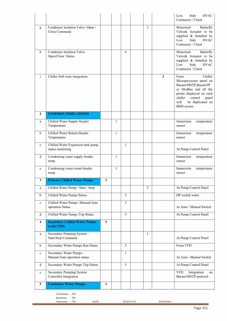
Corrections - Nil
Insertions - Nil
Omissions - Nil AE(P) EE(P)/Civil EE(P)/Elect
Page 431
Low Side HVAC Contractor / Client
g Condenser Isolation Valve -Open / Close Command
3 Motorised Butterfly Valve& Actuator to be supplied & Installed by Low Side HVAC Contractor / Client
h Condenser Isolation Valve Open/Close Status
6 Motorised Butterfly Valve& Actuator to be supplied & Installed by Low Side HVAC Contractor / Client
i Chiller Soft ware integration 3 From Chiller Microprocessor panel on Bacnet/MSTP,Bacnet/IP or Modbus and all the points displayed on each chiller control panel will be duplicated on BMS screen .
2 COMMON INDICATIONS
a Chilled Water Supply Header Temperature
1 Immersion temperature sensor
b Chilled Water Return Header Temperature
1 Immersion temperature sensor
c Chilled Water Expansion tank pump status montoring
1 At Pump Control Panel
d Condensing water supply header temp.
1 Immersion temperature sensor
e Condensing water return header temp.
1 Immersion temperature sensor
3 Primary Chilled Water Pumps 3
a Chilled Water Pump - Start / Stop 3 At Pump Control Panel
b Chilled Water Pumps Status 3 DP switch water
c Chilled Water Pumps -Manual/Auto operation Status
3 At Auto / Manual Switch
d Chilled Water Pumps Trip Status 3 At Pump Control Panel
4 Secondary Chilled Water Pumps (with VFD)
5
a Secondary Pumping System -Start/Stop Command
1 At Pump Control Panel
b Secondary Water Pumps Run Status 5 From VFD
c Secondary Water Pumps -Manual/Auto operation status
1 At Auto / Manual Switch
d Secondary Water Pumps Trip Status 5 At Pump Control Panel
e Secondary Pumping System Controller Integration
VFD Integration on Bacnet/MSTP protocol.
5 Condenser Water Pumps 3
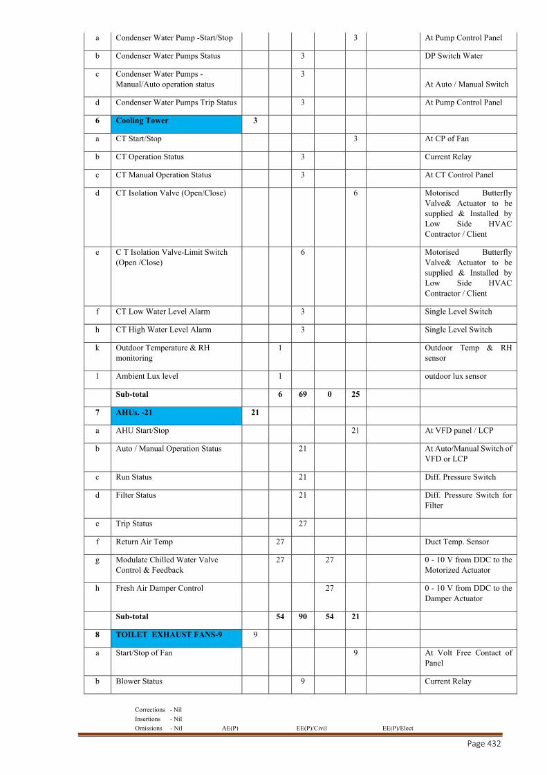
Corrections - Nil
Insertions - Nil
Omissions - Nil AE(P) EE(P)/Civil EE(P)/Elect
Page 432
a Condenser Water Pump -Start/Stop 3 At Pump Control Panel
b Condenser Water Pumps Status 3 DP Switch Water
c Condenser Water Pumps -Manual/Auto operation status
3 At Auto / Manual Switch
d Condenser Water Pumps Trip Status 3 At Pump Control Panel
6 Cooling Tower 3
a CT Start/Stop 3 At CP of Fan
b CT Operation Status 3 Current Relay
c CT Manual Operation Status 3 At CT Control Panel
d CT Isolation Valve (Open/Close) 6 Motorised Butterfly Valve& Actuator to be supplied & Installed by Low Side HVAC Contractor / Client
e C T Isolation Valve-Limit Switch (Open /Close)
6 Motorised Butterfly Valve& Actuator to be supplied & Installed by Low Side HVAC Contractor / Client
f CT Low Water Level Alarm 3 Single Level Switch
h CT High Water Level Alarm 3 Single Level Switch
k Outdoor Temperature & RH monitoring
1 Outdoor Temp & RH sensor
l Ambient Lux level 1 outdoor lux sensor
Sub-total 6 69 0 25
7 AHUs. -21 21
a AHU Start/Stop 21 At VFD panel / LCP
b Auto / Manual Operation Status 21 At Auto/Manual Switch of VFD or LCP
c Run Status 21 Diff. Pressure Switch
d Filter Status 21 Diff. Pressure Switch for Filter
e Trip Status 27
f Return Air Temp 27 Duct Temp. Sensor
g Modulate Chilled Water Valve Control & Feedback
27 27 0 - 10 V from DDC to the Motorized Actuator
h Fresh Air Damper Control 27 0 - 10 V from DDC to the Damper Actuator
Sub-total 54 90 54 21
8 TOILET EXHAUST FANS-9 9
a Start/Stop of Fan 9 At Volt Free Contact of Panel
b Blower Status 9 Current Relay
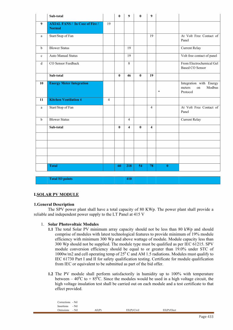
Corrections - Nil
Insertions - Nil
Omissions - Nil AE(P) EE(P)/Civil EE(P)/Elect
Page 433
Sub-total 0 9 0 9
9 AXIAL FANS / In Case of Fire / Normal
19
a Start/Stop of Fan 19
At Volt Free Contact of Panel
b Blower Status 19 Current Relay
c Auto Manual Status 19 Volt free contact of panel
d CO Sensor Feedback 8
From Electrochemical Gel Based CO Sensor
Sub-total 0 46 0 19
10 Energy Meter Integration
*
Integration with Energy meters on Modbus Protocol
11 Kitchen Ventilation 4 4
a Start/Stop of Fan 4 At Volt Free Contact of Panel
b Blower Status 4 Current Relay
Sub-total 0 4 0 4
Total 60 218 54 78 0
Total IO points 410
LSOLAR PV MODULE 1.General Description The SPV power plant shall have a total capacity of 80 KWp. The power plant shall provide a reliable and independent power supply to the LT Panel at 415 V
1. Solar Photovoltaic Modules 1.1 The total Solar PV minimum array capacity should not be less than 80 kWp and should
comprise of modules with latest technological features to provide minimum of 19% module efficiency with minimum 300 Wp and above wattage of module. Module capacity less than 300 Wp should not be supplied. The module type must be qualified as per IEC 61215. SPV module conversion efficiency should be equal to or greater than 19.0% under STC of 1000w/m2 and cell operating temp of 250 C and AM 1.5 radiations. Modules must qualify to IEC 61730 Part I and II for safety qualification testing. Certificate for module qualification from IEC or equivalent to be submitted as part of the bid offer.
1.2 The PV module shall perform satisfactorily in humidity up to 100% with temperature between – 400C to + 850C. Since the modules would be used in a high voltage circuit, the high voltage insulation test shall be carried out on each module and a test certificate to that effect provided.
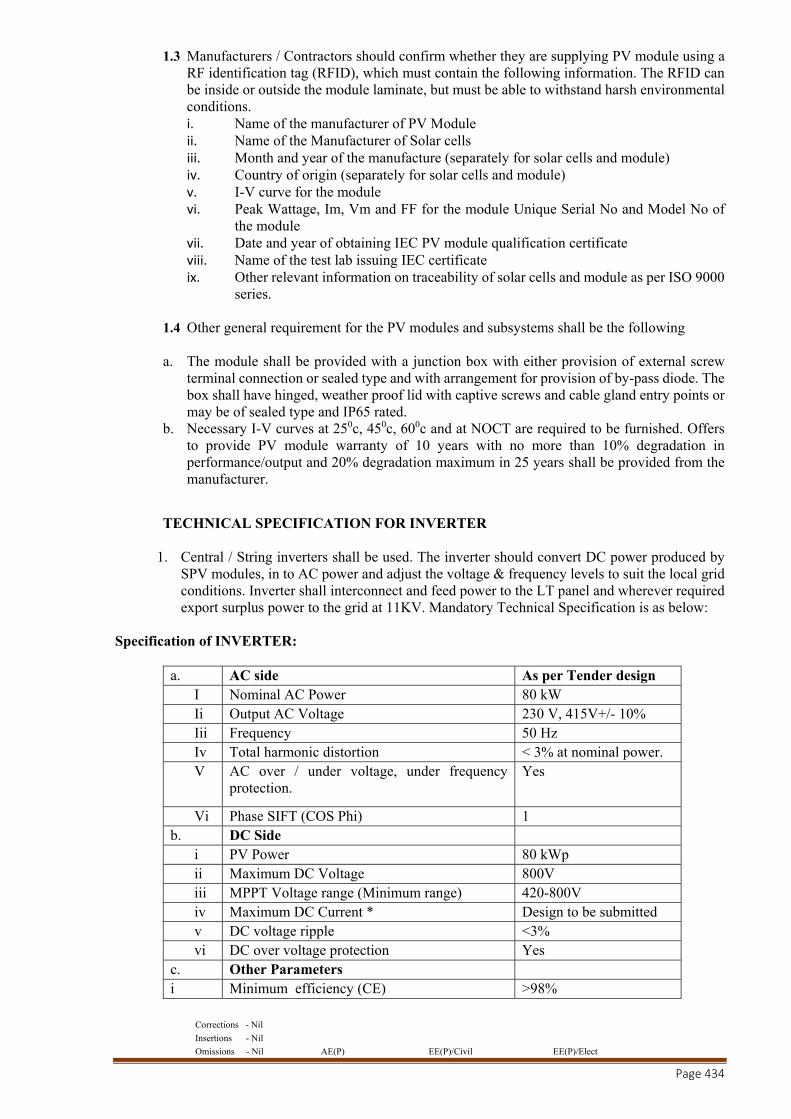
Corrections - Nil
Insertions - Nil
Omissions - Nil AE(P) EE(P)/Civil EE(P)/Elect
Page 434
1.3 Manufacturers / Contractors should confirm whether they are supplying PV module using a RF identification tag (RFID), which must contain the following information. The RFID can be inside or outside the module laminate, but must be able to withstand harsh environmental conditions. i. Name of the manufacturer of PV Module ii. Name of the Manufacturer of Solar cells iii. Month and year of the manufacture (separately for solar cells and module) iv. Country of origin (separately for solar cells and module) v. I-V curve for the module vi. Peak Wattage, Im, Vm and FF for the module Unique Serial No and Model No of
the module vii. Date and year of obtaining IEC PV module qualification certificate viii. Name of the test lab issuing IEC certificate ix. Other relevant information on traceability of solar cells and module as per ISO 9000
series.
1.4 Other general requirement for the PV modules and subsystems shall be the following
a. The module shall be provided with a junction box with either provision of external screw terminal connection or sealed type and with arrangement for provision of by-pass diode. The box shall have hinged, weather proof lid with captive screws and cable gland entry points or may be of sealed type and IP65 rated.
b. Necessary I-V curves at 250c, 450c, 600c and at NOCT are required to be furnished. Offers to provide PV module warranty of 10 years with no more than 10% degradation in performance/output and 20% degradation maximum in 25 years shall be provided from the manufacturer.
TECHNICAL SPECIFICATION FOR INVERTER
1. Central / String inverters shall be used. The inverter should convert DC power produced by SPV modules, in to AC power and adjust the voltage & frequency levels to suit the local grid conditions. Inverter shall interconnect and feed power to the LT panel and wherever required export surplus power to the grid at 11KV. Mandatory Technical Specification is as below:
Specification of INVERTER:
a. AC side As per Tender design I Nominal AC Power 80 kW Ii Output AC Voltage 230 V, 415V+/- 10% Iii Frequency 50 Hz Iv Total harmonic distortion < 3% at nominal power. V AC over / under voltage, under frequency
protection. Yes
Vi Phase SIFT (COS Phi) 1 b. DC Side
i PV Power 80 kWp ii Maximum DC Voltage 800V iii MPPT Voltage range (Minimum range) 420-800V iv Maximum DC Current * Design to be submitted v DC voltage ripple <3% vi DC over voltage protection Yes
c. Other Parameters i Minimum efficiency (CE) >98%
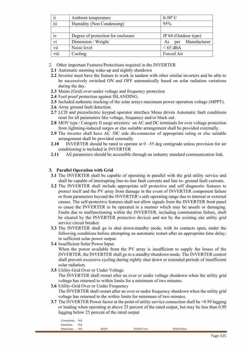
Corrections - Nil
Insertions - Nil
Omissions - Nil AE(P) EE(P)/Civil EE(P)/Elect
Page 435
ii Ambient temperature 0-50º C iii Humidity (Non Condensing) 95% iv Degree of protection for enclosure IP 64 (Outdoor type) vi Dimension / Weight As per Manufacturer vii Noise level < 65 dBA viii Cooling Forced Air
2. Other important Features/Protections required in the INVERTER 2.1 Automatic morning wake-up and nightly shutdown 2.2 Inverter must have the feature to work in tandem with other similar inverters and be able to
be successively switched ON and OFF automatically based on solar radiation variations during the day.
2.3 Mains (Grid) over-under voltage and frequency protection 2.4 Fool proof protection against ISLANDING. 2.5 Included authentic tracking of the solar arrays maximum power operation voltage (MPPT). 2.6 Array ground fault detection. 2.7 LCD and piezoelectric keypad operator interface Menu driven Automatic fault conditions
reset for all parameters like voltage, frequency and/or black out. 2.8 MOV type / Category II surge arresters/ on AC and DC terminals for over voltage protection
from lightning-induced surges or else suitable arrangement shall be provided externally. 2.9 The inverter shall have AC /DC side dis-connector of appropriate rating or else suitable
arrangement shall be provided externally 2.10 INVERTER should be rated to operate at 0 –55 deg centigrade unless provision for air
conditioning is included in INVERTER 2.11 All parameters should be accessible through an industry standard communication link.
3. Parallel Operation with Grid 3.1 The INVERTER shall be capable of operating in parallel with the grid utility service and
shall be capable of interrupting line-to-line fault currents and line to- ground fault currents. 3.2 The INVERTER shall include appropriate self protective and self diagnostic features to
protect itself and the PV array from damage in the event of INVERTER component failure or from parameters beyond the INVERTER‘s safe operating range due to internal or external causes. The self-protective features shall not allow signals from the INVERTER front panel to cause the INVERTER to be operated in a manner which may be unsafe or damaging. Faults due to malfunctioning within the INVERTER, including commutation failure, shall be cleared by the INVERTER protective devices and not by the existing site utility grid service circuit breaker.
3.3 The INVERTER shall go to shut down/standby mode, with its contacts open, under the following conditions before attempting an automatic restart after an appropriate time delay; in sufficient solar power output.
3.4 Insufficient Solar Power Input. When the power available from the PV array is insufficient to supply the losses of the INVERTER, the INVERTER shall go to a standby/shutdown mode. The INVERTER control shall prevent excessive cycling during rightly shut down or extended periods of insufficient solar radiation.
3.5 Utility-Grid Over or Under Voltage The INVERTER shall restart after an over or under voltage shutdown when the utility grid voltage has returned to within limits for a minimum of two minutes.
3.6 Utility-Grid Over or Under Frequency The INVERTER shall restart after an over or under frequency shutdown when the utility grid voltage has returned to the within limits for minimum of two minutes.
3.7 The INVERTER Power factor at the point of utility service connection shall be >0.99 lagging or leading when operating at above 25 percent of the rated output, but may be less than 0.99 lagging below 25 percent of the rated output
Corrections - Nil
Insertions - Nil
Omissions - Nil AE(P) EE(P)/Civil EE(P)/Elect
Page 436
3.8 The high voltage and power circuits of the INVERTER shall be separated from the low-voltage and control circuits. The internal copper wiring of the INVERTER shall have flame resistant insulation. Use of PVC is not acceptable. All conductors shall be made of standard copper.
3.9 The INVERTER shall withstand a high voltage test of 2000 V rms, between either the input or the output terminals and the cabinet (chassis).
3.10 Full protection against accidental open circuit and reverse polarity at the input shall be provided.
3.11 The INVERTER shall not produce Electromagnetic Interference (EMI) which may cause malfunctioning of electronic and electrical instruments including communication equipment, which are located within the facility in which the INVERTER is housed.
3.12 The INVERTER shall have an appropriate display on the front panel to display the instantaneous AC power output and the DC voltage, current and power input. Each of these measurement displays shall have an accuracy of 1 percent of full scale or better. The display shall be visible from outside the INVERTER enclosure. Operational status of the INVERTER, alarms, trouble indicators and ac and the dc disconnect switch positions shall also be communicated by appropriate messages or indicator lights on the front cover of the INVERTER enclosure.
3.13 Communication Modbus protocol with LAN/WAN options along with remote access facility shall be provided.
4. Electrical safety, Earthing and protection 4.1 Internal Faults : In built protection for internal faults including excess temperature,
commutation failure, overload and cooling fan failure (if fitted) is obligatory. 4.2 Galvanic Isolation: Galvanic Isolation is required to avoid any DC component being injected
into the grid and the potential for AC components appearing at the array (required inc central inverters).
4.3 Over Voltage Protection: Over Voltage Protection against atmospheric lightning discharge to the PV array is required. Protection is to be provided against voltage fluctuations in the grid itself and internal faults in the power conditioner, operational errors and switching transients.
4.4 Earth fault supervision: An integrated earth fault device shall have to be provided to detect eventual earth fault on DC side and shall send message to the supervisory system.
4.5 Cabling practice: Cable connections must be made using PVC Cu cables, as per BIS standards. All cable connections must be made using suitable terminations for effective contact. The XLPO DC Grade Cu cables of 1.1 kVgrade must be run in GI trays with covers for protection.
4.6 Fast acting semiconductor type current limiting fuses at the main bus-bar to protect from the grid short circuit contribution. The INVERTER shall include an easily accessible emergency OFF button located at an appropriate position on the unit
4.7 The INVERTER shall include ground lugs for equipment and PV array grounding. The DC circuit ground shall be a solid single point ground connection in accordance with IEC 69042.
4.8 All exposed surfaces of ferrous parts shall be thoroughly cleaned, primed, and painted or otherwise
5. General Features of Inverter:
The INVERTER enclosure shall be weatherproof and capable of surviving climatic changes and should keep the INVERTER intact under all conditions in the room where it will be housed. The INVERTER shall be located outdoor with suitable protection and should be either wall/ pad mounted. Moisture condensation and entry of rodents and insects shall be prevented in the INVERTER enclosure. The enclosure for housing the inverter shall be minimum IP54 protection level. The inverter itself shall be minimum IP20 protection level.
5.1 Components and circuit boards mounted inside the enclosures shall be which shall also serve to identify the items on the supplied drawings
Corrections - Nil
Insertions - Nil
Omissions - Nil AE(P) EE(P)/Civil EE(P)/Elect
Page 437
5.2 All doors, covers, panels and cable exists shall be gasket or otherwise designed to limit the
entry of dust and moisture. All doors shall be equipped with locks. All openings shall be provided with grills or screens with openings no larger than 0.95 cm. (about 3x8 inch).
5.3 In the design and fabrication of the INVERTER the site temperature (5O to 55O C), incident
sunlight and the effect of ambient temperature on component life shall be considered carefully and derating shall be applied. Similar consideration shall be given to the heat sinking and thermal for blocking diodes and similar components.
6. Operating Modes: The following operating modes are to be made available: Night or Sleep mode: Where the inverter is almost completely turned off, with just the timer and control system still in operation, losses should not exceed 1 watts per 5 kilowatt. a. Standby mode : Where the control system continuously monitors the output of the solar
generator until pre-set value is exceeded (typically 10 watts) b. Operational or MPPT tracking mode : The control system continuously adjust the voltage of
the generator to optimize the power available. The power conditioner must automatically re-enter stand-by mode when input power reduces below the standby mode threshold. Front Panel display should prove the status of the INVERTER, including AC Voltage, Current, Power output & DC Current, Voltage and Power input, pf and fault Indication (if any)
M STP PLANT
1. Bar Screen :
Material : Stainless Steel type
Size : 700 x 550 mm
Opening Size : 5 mm
Placing Slope : Approx. 50 Degree Slope
2. Air Grid:
Ejecting Pressure : 0.8 Kg/ cm2
Temperature : 40 Degree Max.
Handling Area : 20 m3 / hr.
Installation : At Bottom Level
3. Air Blower :
Lube : Twin Lube Type
Drive : V-Belt Type
Capacity : 20cum/hr
Head : 3 Meter Head
4. Submersible Pump :
Type : Submerged Type
Corrections - Nil
Insertions - Nil
Omissions - Nil AE(P) EE(P)/Civil EE(P)/Elect
Page 438
Capacity : 5 cum / hr
Head : 5 meter Head
Motor : Dust Proof
5. Self Priming Pumps:
Type : Non Clog Type
Capacity : 1 cum / hr
Head : 5 meter Head
6. V GUARD:
Capability : 20KLD,Two Way Equipped
Finish : Smoother Finish
Design Pressure : Low & High Type
Body : Anti – Corrosive Painted
7. Mono Block Pumps :
Type : Centrifugal Type
Capacity : 5 cum / hr.
Head : 5 meter Head
8. Non – Clog Pump:
Capacity : 1 cum / hr
Head : 5 meter Head
Cooled / Non : Cooled Induction Motor
9. Electromagnetic Bio:
Reactor :
Equipped : Magnetic Electrodes
Material : Mild Steel/ FRP lined
Installation : compact unit
Energiser : Self Energiser Type
10. Electrical Panel:
Material : Extensible Sheet Steel Type
Current Ratting : Three Phase Current

Corrections - Nil
Insertions - Nil
Omissions - Nil AE(P) EE(P)/Civil EE(P)/Elect
Page 439
Body : Powder Coated
Size : 2.5 sqmtr
11. Post Bio Reactor
MOC : ODMS DIA : 1005MM HEIGHT : 12000MM TEMP : 50-60 Deg cent. RETENTION : 0.31Hrs
12. High Volter :
Capability : Displayer Type
Operation : SMPS/ AMPS
Displayer : Semi Digital Type
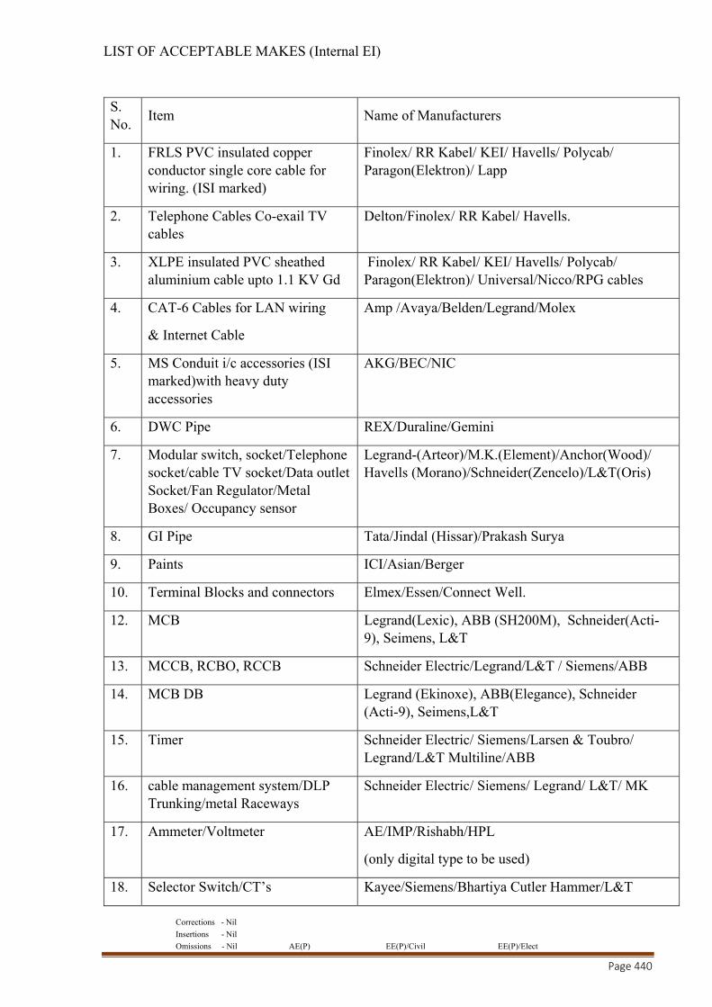
Corrections - Nil
Insertions - Nil
Omissions - Nil AE(P) EE(P)/Civil EE(P)/Elect
Page 440
LIST OF ACCEPTABLE MAKES (Internal EI)
S. No.
Item Name of Manufacturers
1. FRLS PVC insulated copper conductor single core cable for wiring. (ISI marked)
Finolex/ RR Kabel/ KEI/ Havells/ Polycab/ Paragon(Elektron)/ Lapp
2. Telephone Cables Co-exail TV cables
Delton/Finolex/ RR Kabel/ Havells.
3. XLPE insulated PVC sheathed aluminium cable upto 1.1 KV Gd
Finolex/ RR Kabel/ KEI/ Havells/ Polycab/ Paragon(Elektron)/ Universal/Nicco/RPG cables
4. CAT-6 Cables for LAN wiring
& Internet Cable
Amp /Avaya/Belden/Legrand/Molex
5. MS Conduit i/c accessories (ISI marked)with heavy duty accessories
AKG/BEC/NIC
6. DWC Pipe REX/Duraline/Gemini
7. Modular switch, socket/Telephone socket/cable TV socket/Data outlet Socket/Fan Regulator/Metal Boxes/ Occupancy sensor
Legrand-(Arteor)/M.K.(Element)/Anchor(Wood)/ Havells (Morano)/Schneider(Zencelo)/L&T(Oris)
8. GI Pipe Tata/Jindal (Hissar)/Prakash Surya
9. Paints ICI/Asian/Berger
10. Terminal Blocks and connectors Elmex/Essen/Connect Well.
12. MCB Legrand(Lexic), ABB (SH200M), Schneider(Acti-9), Seimens, L&T
13. MCCB, RCBO, RCCB Schneider Electric/Legrand/L&T / Siemens/ABB
14. MCB DB Legrand (Ekinoxe), ABB(Elegance), Schneider (Acti-9), Seimens,L&T
15. Timer Schneider Electric/ Siemens/Larsen & Toubro/ Legrand/L&T Multiline/ABB
16. cable management system/DLP Trunking/metal Raceways
Schneider Electric/ Siemens/ Legrand/ L&T/ MK
17. Ammeter/Voltmeter
AE/IMP/Rishabh/HPL
(only digital type to be used)
18. Selector Switch/CT’s Kayee/Siemens/Bhartiya Cutler Hammer/L&T
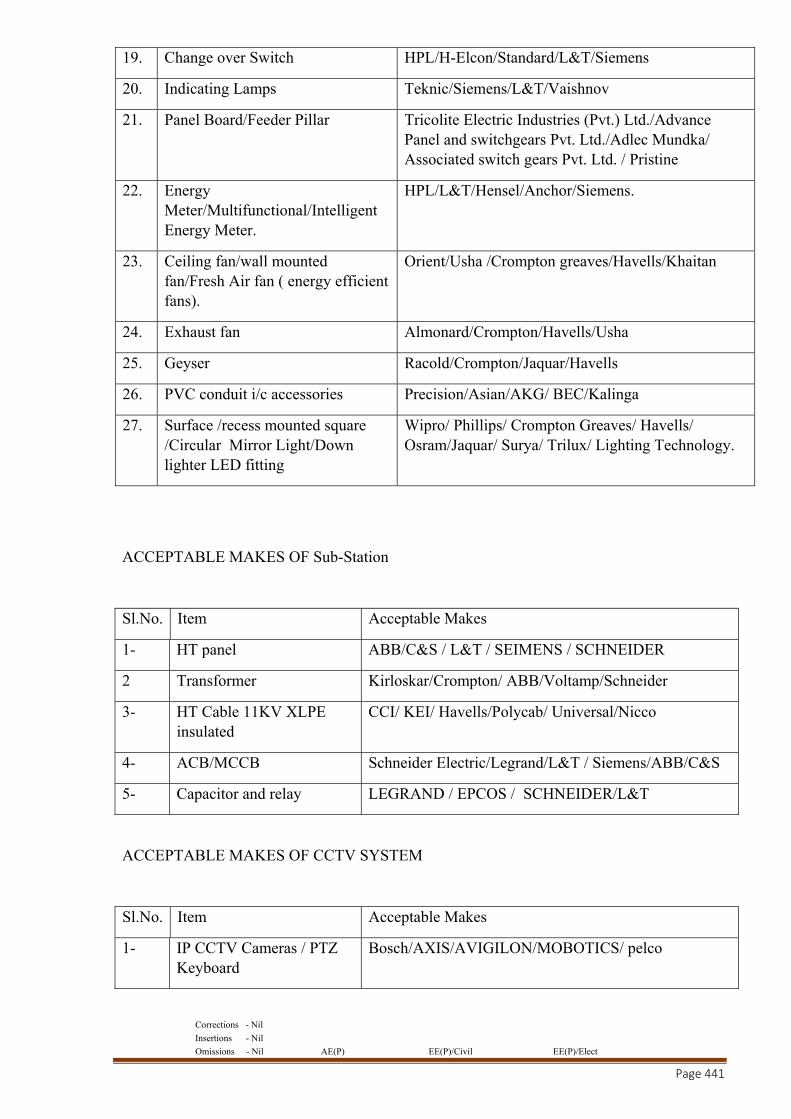
Corrections - Nil
Insertions - Nil
Omissions - Nil AE(P) EE(P)/Civil EE(P)/Elect
Page 441
19. Change over Switch HPL/H-Elcon/Standard/L&T/Siemens
20. Indicating Lamps Teknic/Siemens/L&T/Vaishnov
21. Panel Board/Feeder Pillar Tricolite Electric Industries (Pvt.) Ltd./Advance Panel and switchgears Pvt. Ltd./Adlec Mundka/ Associated switch gears Pvt. Ltd. / Pristine
22. Energy Meter/Multifunctional/Intelligent Energy Meter.
HPL/L&T/Hensel/Anchor/Siemens.
23. Ceiling fan/wall mounted fan/Fresh Air fan ( energy efficient fans).
Orient/Usha /Crompton greaves/Havells/Khaitan
24. Exhaust fan Almonard/Crompton/Havells/Usha
25. Geyser Racold/Crompton/Jaquar/Havells
26. PVC conduit i/c accessories Precision/Asian/AKG/ BEC/Kalinga
27. Surface /recess mounted square /Circular Mirror Light/Down lighter LED fitting
Wipro/ Phillips/ Crompton Greaves/ Havells/ Osram/Jaquar/ Surya/ Trilux/ Lighting Technology.
ACCEPTABLE MAKES OF Sub-Station
Sl.No. Item Acceptable Makes
1- HT panel ABB/C&S / L&T / SEIMENS / SCHNEIDER
2 Transformer Kirloskar/Crompton/ ABB/Voltamp/Schneider
3- HT Cable 11KV XLPE insulated
CCI/ KEI/ Havells/Polycab/ Universal/Nicco
4- ACB/MCCB Schneider Electric/Legrand/L&T / Siemens/ABB/C&S
5- Capacitor and relay LEGRAND / EPCOS / SCHNEIDER/L&T
ACCEPTABLE MAKES OF CCTV SYSTEM
Sl.No. Item Acceptable Makes
1- IP CCTV Cameras / PTZ Keyboard
Bosch/AXIS/AVIGILON/MOBOTICS/ pelco
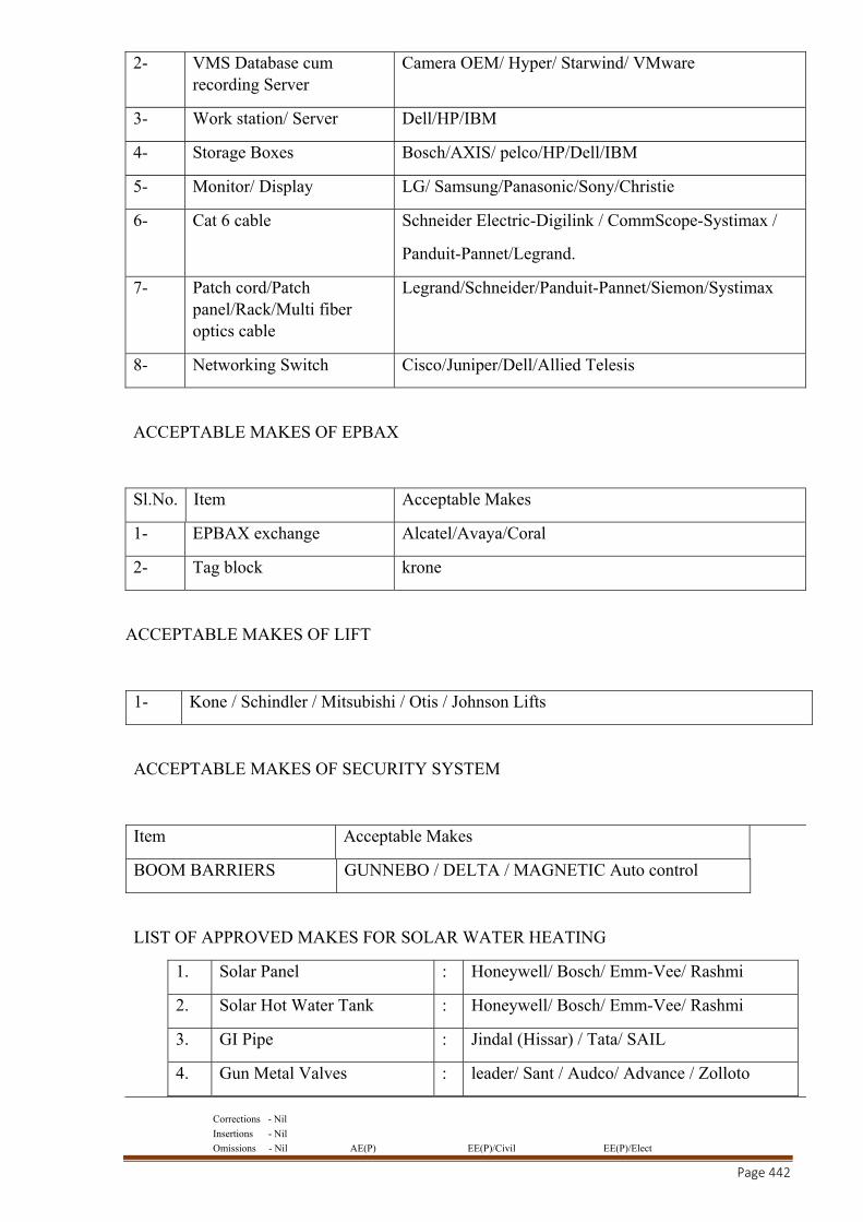
Corrections - Nil
Insertions - Nil
Omissions - Nil AE(P) EE(P)/Civil EE(P)/Elect
Page 442
2- VMS Database cum recording Server
Camera OEM/ Hyper/ Starwind/ VMware
3- Work station/ Server Dell/HP/IBM
4- Storage Boxes Bosch/AXIS/ pelco/HP/Dell/IBM
5- Monitor/ Display LG/ Samsung/Panasonic/Sony/Christie
6- Cat 6 cable Schneider Electric-Digilink / CommScope-Systimax /
Panduit-Pannet/Legrand.
7- Patch cord/Patch panel/Rack/Multi fiber optics cable
Legrand/Schneider/Panduit-Pannet/Siemon/Systimax
8- Networking Switch Cisco/Juniper/Dell/Allied Telesis
ACCEPTABLE MAKES OF EPBAX
Sl.No. Item Acceptable Makes
1- EPBAX exchange Alcatel/Avaya/Coral
2- Tag block krone
ACCEPTABLE MAKES OF LIFT
1- Kone / Schindler / Mitsubishi / Otis / Johnson Lifts
ACCEPTABLE MAKES OF SECURITY SYSTEM
Item Acceptable Makes
BOOM BARRIERS GUNNEBO / DELTA / MAGNETIC Auto control
LIST OF APPROVED MAKES FOR SOLAR WATER HEATING
1. Solar Panel : Honeywell/ Bosch/ Emm-Vee/ Rashmi
2. Solar Hot Water Tank : Honeywell/ Bosch/ Emm-Vee/ Rashmi
3. GI Pipe : Jindal (Hissar) / Tata/ SAIL
4. Gun Metal Valves : leader/ Sant / Audco/ Advance / Zolloto
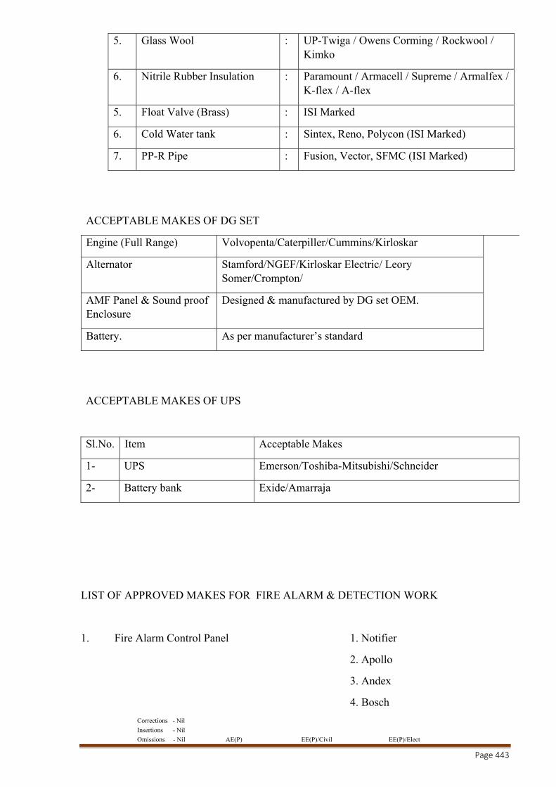
Corrections - Nil
Insertions - Nil
Omissions - Nil AE(P) EE(P)/Civil EE(P)/Elect
Page 443
5. Glass Wool : UP-Twiga / Owens Corming / Rockwool / Kimko
6. Nitrile Rubber Insulation : Paramount / Armacell / Supreme / Armalfex / K-flex / A-flex
5. Float Valve (Brass) : ISI Marked
6. Cold Water tank : Sintex, Reno, Polycon (ISI Marked)
7. PP-R Pipe : Fusion, Vector, SFMC (ISI Marked)
ACCEPTABLE MAKES OF DG SET
Engine (Full Range) Volvopenta/Caterpiller/Cummins/Kirloskar
Alternator Stamford/NGEF/Kirloskar Electric/ Leory Somer/Crompton/
AMF Panel & Sound proof Enclosure
Designed & manufactured by DG set OEM.
Battery. As per manufacturer’s standard
ACCEPTABLE MAKES OF UPS
Sl.No. Item Acceptable Makes
1- UPS Emerson/Toshiba-Mitsubishi/Schneider
2- Battery bank Exide/Amarraja
LIST OF APPROVED MAKES FOR FIRE ALARM & DETECTION WORK
1. Fire Alarm Control Panel 1. Notifier
2. Apollo
3. Andex
4. Bosch

Corrections - Nil
Insertions - Nil
Omissions - Nil AE(P) EE(P)/Civil EE(P)/Elect
Page 444
5. Agni
2. Repeater Panel 1. Notifier
2. Apollo
3. Andex
4. Bosch
5. Agni
3. Addressable Multicriteria Smoke Detectors 1. Notifier
2. Apollo
3. Andex
4. Bosch
5. Agni
4. Fault Isolator with base 1. Notifier
2. Apollo
3. Andex
4. Bosch
5. Agni
6. Addressable Manual Call points 1. Notifier
2. Apollo
3. Andex
4. Bosch
5. Agni
7. Addressable Control Module 1. Notifier
2. Apollo
3. Andex
4. Bosch

Corrections - Nil
Insertions - Nil
Omissions - Nil AE(P) EE(P)/Civil EE(P)/Elect
Page 445
5. Agni
8. Sounder/ Hooter cum Strobe 1. Notifier
2. Apollo
3. Andex
4. Bosch
5. Agni
10. PA System Panel 1. Notifier
2. Esser
3. Cooper
4. Siemens
5. Honeywell
11. Telephone Jack / Hand Set /
Telephone receiver 1. Notifier
2. Esser
3. Cooper
4. Siemens
5. Honeywell
12. Operator Work Station (Computer) 1. HP
2. IBM
3. DELL
4. HCL
13. Printer 1. Canon
2. HP
14. Software 1. Notifier
2. Apollo
3. Andex
4. Bosch
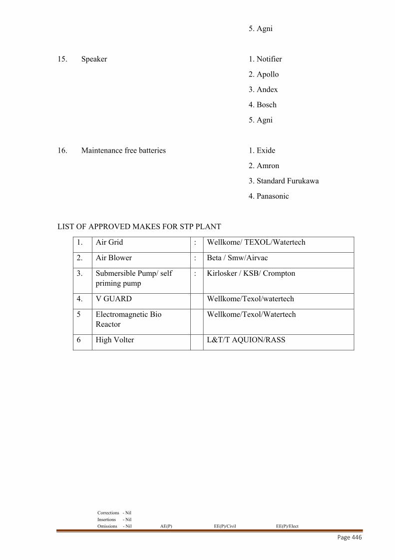
Corrections - Nil
Insertions - Nil
Omissions - Nil AE(P) EE(P)/Civil EE(P)/Elect
Page 446
5. Agni
15. Speaker 1. Notifier
2. Apollo
3. Andex
4. Bosch
5. Agni
16. Maintenance free batteries 1. Exide
2. Amron
3. Standard Furukawa
4. Panasonic
LIST OF APPROVED MAKES FOR STP PLANT
1. Air Grid : Wellkome/ TEXOL/Watertech
2. Air Blower : Beta / Smw/Airvac
3. Submersible Pump/ self priming pump
: Kirlosker / KSB/ Crompton
4. V GUARD Wellkome/Texol/watertech
5 Electromagnetic Bio Reactor
Wellkome/Texol/Watertech
6 High Volter L&T/T AQUION/RASS
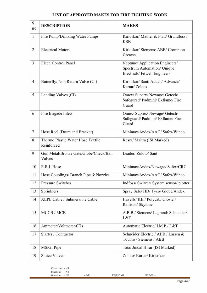
Corrections - Nil
Insertions - Nil
Omissions - Nil AE(P) EE(P)/Civil EE(P)/Elect
Page 447
LIST OF APPROVED MAKES FOR FIRE FIGHTING WORK
S. no
DESCRIPTION MAKES
1 Fire Pump/Drinking Water Pumps Kirloskar/ Mather & Platt/ Grundfoss / KSB
2 Electrical Motors Kirloskar/ Siemens/ ABB/ Crompton Greaves
3 Elect. Control Panel Neptune/ Application Engineers/ Spectrum Automation/ Unique Electrials/ Fitwell Engineers
4 Butterfly/ Non Return Valve (CI) Kirloskar/ Sant/ Audco/ Advance/ Kartar/ Zoloto
5 Landing Valves (CI) Omex/ Superx/ Newage/ Getech/ Safegurad/ Padmini/ Exflame/ Fire Guard
6 Fire Brigade Inlets Omex/ Suprex/ Newage/ Getech/ Safeguard/ Padmini/ Exflame/ Fire Guard
7 Hose Reel (Drum and Bracket) Minimax/Andex/AAG/ Safex/Winco
8 Thermo Plastic Water Hose Textile Reinforced
Kesra/ Maitra (ISI Marked)
9 Gun Metal/Bronze Gate/Globe/Check/Ball Valves
Leader/ Zoloto/ Sant
10 R.R.L Hose Minimax/Andex/Newage/ Safex/CRC
11 Hose Couplings/ Branch Pipe & Nozzles Minimax/Andex/AAG/ Safex/Winco
12 Pressure Switches Indfoss/ Switzer/ System sensor/ plotter
13 Sprinklers Spray Safe/ HD/ Tyco/ Globe/Andex
14 XLPE Cable / Submersible Cable Havells/ KEI/ Polycab/ Gloster/ Rallison/ Skytone
15 MCCB / MCB A.B.B./ Siemens/ Legrand/ Schneider/ L&T
16 Ammeter/Voltmeter/CTs Automatic Electric/ I.M.P./ L&T
17 Starter / Contractor Schneider Electric / ABB / Larsen & Toubro / Siemens / ABB
18 MS/GI Pipe Tata/ Jindal Hisar (ISI Marked)
19 Sluice Valves Zoloto/ Kartar/ Kirloskar
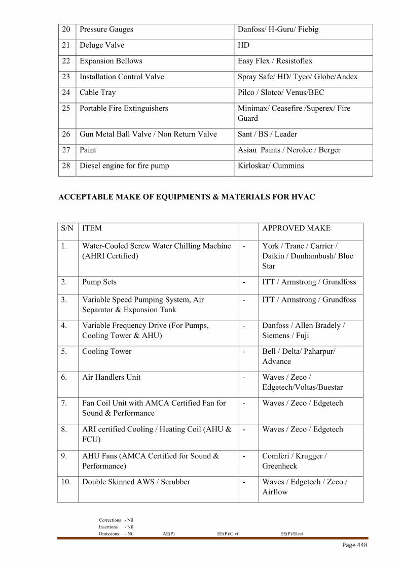
Corrections - Nil
Insertions - Nil
Omissions - Nil AE(P) EE(P)/Civil EE(P)/Elect
Page 448
20 Pressure Gauges Danfoss/ H-Guru/ Fiebig
21 Deluge Valve HD
22 Expansion Bellows Easy Flex / Resistoflex
23 Installation Control Valve Spray Safe/ HD/ Tyco/ Globe/Andex
24 Cable Tray Pilco / Slotco/ Venus/BEC
25 Portable Fire Extinguishers Minimax/ Ceasefire /Superex/ Fire Guard
26 Gun Metal Ball Valve / Non Return Valve Sant / BS / Leader
27 Paint Asian Paints / Nerolec / Berger
28 Diesel engine for fire pump Kirloskar/ Cummins
ACCEPTABLE MAKE OF EQUIPMENTS & MATERIALS FOR HVAC
S/N ITEM APPROVED MAKE
1. Water-Cooled Screw Water Chilling Machine (AHRI Certified)
- York / Trane / Carrier / Daikin / Dunhambush/ Blue Star
2. Pump Sets - ITT / Armstrong / Grundfoss
3. Variable Speed Pumping System, Air Separator & Expansion Tank
- ITT / Armstrong / Grundfoss
4. Variable Frequency Drive (For Pumps, Cooling Tower & AHU)
- Danfoss / Allen Bradely / Siemens / Fuji
5. Cooling Tower - Bell / Delta/ Paharpur/ Advance
6. Air Handlers Unit - Waves / Zeco / Edgetech/Voltas/Buestar
7. Fan Coil Unit with AMCA Certified Fan for Sound & Performance
- Waves / Zeco / Edgetech
8. ARI certified Cooling / Heating Coil (AHU & FCU)
- Waves / Zeco / Edgetech
9. AHU Fans (AMCA Certified for Sound & Performance)
- Comferi / Krugger / Greenheck
10. Double Skinned AWS / Scrubber - Waves / Edgetech / Zeco / Airflow
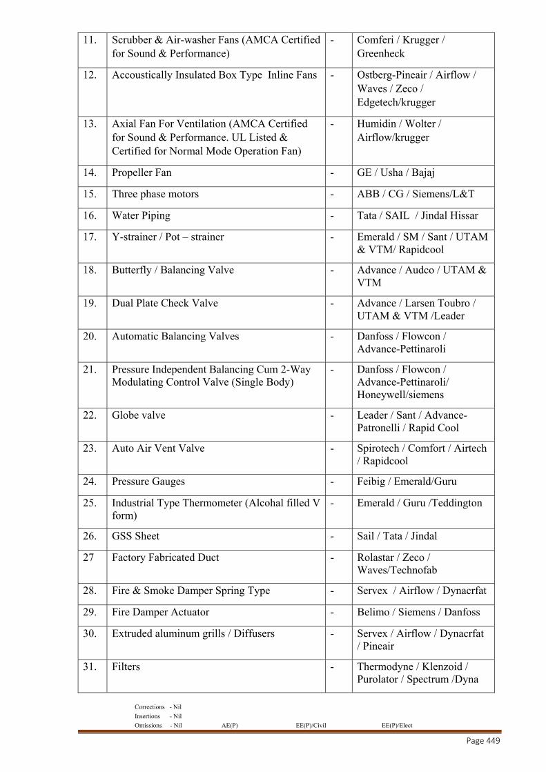
Corrections - Nil
Insertions - Nil
Omissions - Nil AE(P) EE(P)/Civil EE(P)/Elect
Page 449
11. Scrubber & Air-washer Fans (AMCA Certified for Sound & Performance)
- Comferi / Krugger / Greenheck
12. Accoustically Insulated Box Type Inline Fans - Ostberg-Pineair / Airflow / Waves / Zeco / Edgetech/krugger
13. Axial Fan For Ventilation (AMCA Certified for Sound & Performance. UL Listed & Certified for Normal Mode Operation Fan)
- Humidin / Wolter / Airflow/krugger
14. Propeller Fan - GE / Usha / Bajaj
15. Three phase motors - ABB / CG / Siemens/L&T
16. Water Piping - Tata / SAIL / Jindal Hissar
17. Y-strainer / Pot – strainer - Emerald / SM / Sant / UTAM & VTM/ Rapidcool
18. Butterfly / Balancing Valve - Advance / Audco / UTAM & VTM
19. Dual Plate Check Valve - Advance / Larsen Toubro / UTAM & VTM /Leader
20. Automatic Balancing Valves - Danfoss / Flowcon / Advance-Pettinaroli
21. Pressure Independent Balancing Cum 2-Way Modulating Control Valve (Single Body)
- Danfoss / Flowcon / Advance-Pettinaroli/ Honeywell/siemens
22. Globe valve - Leader / Sant / Advance-Patronelli / Rapid Cool
23. Auto Air Vent Valve - Spirotech / Comfort / Airtech / Rapidcool
24. Pressure Gauges - Feibig / Emerald/Guru
25. Industrial Type Thermometer (Alcohal filled V form)
- Emerald / Guru /Teddington
26. GSS Sheet - Sail / Tata / Jindal
27 Factory Fabricated Duct - Rolastar / Zeco / Waves/Technofab
28. Fire & Smoke Damper Spring Type - Servex / Airflow / Dynacrfat
29. Fire Damper Actuator - Belimo / Siemens / Danfoss
30. Extruded aluminum grills / Diffusers - Servex / Airflow / Dynacrfat / Pineair
31. Filters - Thermodyne / Klenzoid / Purolator / Spectrum /Dyna
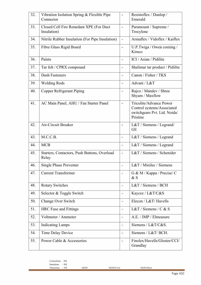
Corrections - Nil
Insertions - Nil
Omissions - Nil AE(P) EE(P)/Civil EE(P)/Elect
Page 450
32. Vibration Isolation Spring & Flexible Pipe Connector
- Resistoflex / Dunlop / Emerald
33. Closed Cell Fire Retardant XPE (For Duct Insulation)
- Paramount / Supreme / Trocylene
34. Nitrile Rubber Insulation (For Pipe Insulation) - Armaflex / Vidoflex / Kaiflex
35. Fibre Glass Rigid Board - U.P.Twiga / Owen corning / Kimco
36. Paints - ICI / Asian / Pidilite
37. Tar felt / CPRX compound - Shalimar tar product / Pidilite
38. Dash Fasteners - Canon / Fisher / TKS
39. Welding Rods - Advani / L&T
40. Copper Refrigerant Piping - Rajco / Mandev / Shree Shyam / Maxflow
41. AC Main Panel, AHU / Fan Starter Panel - Tricolite/Advance Power Control systems/Associated switchgears Pvt. Ltd. Noida/ Pristine
42. Air-Circuit Breaker - L&T / Siemens / Legrand/ GE
43. M.C.C.B. - L&T / Siemens / Legrand
44. MCB - L&T / Siemens / Legrand
45. Starters, Contactors, Push Buttons, Overload Relay
- L&T / Siemens / Schenider
46. Single Phase Preventer - L&T / Minilec / Siemens
47. Current Transformer - G & M / Kappa / Precise/ C & S
48. Rotary Switches - L&T / Siemens / BCH
49. Selector & Toggle Switch - Kaycee / L&T/C&S
50. Change Over Switch - Elecon / L&T/ Havells
51. HRC Fuse and Fittings - L&T / Siemens / C & S
52. Voltmeter / Ammeter - A.E. / IMP / Elmeasure
53. Indicating Lamps - Siemens / L&T/C&S.
54. Time Delay Device - Siemens / L&T/ BCH.
55. Power Cable & Accessories - Finolex/Havells/Gloster/CCI/Grandlay
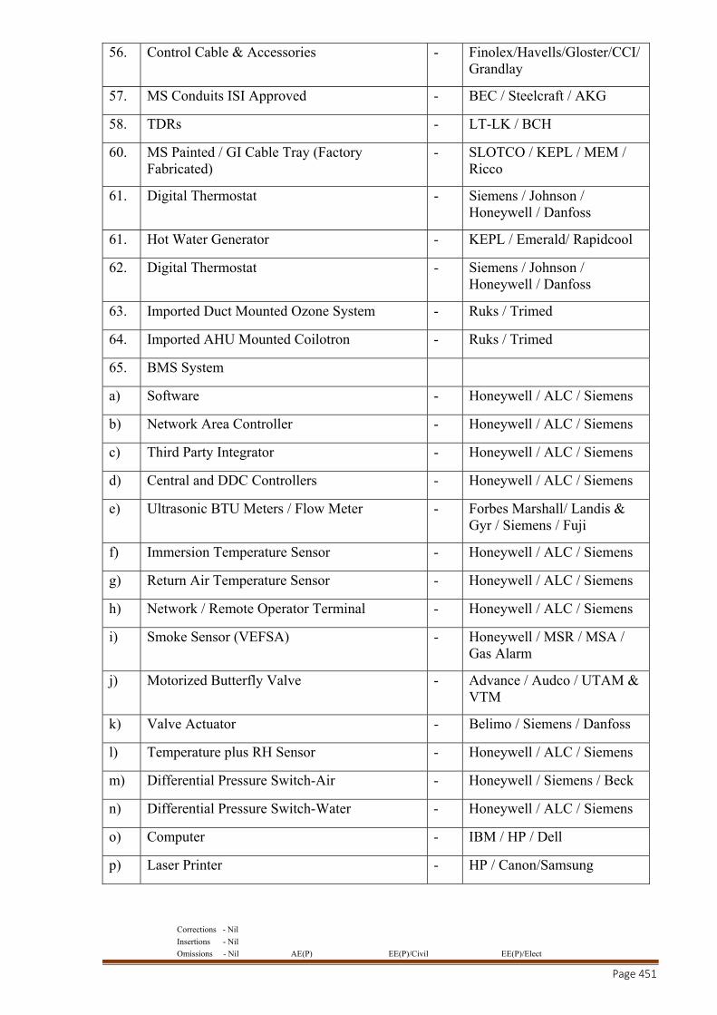
Corrections - Nil
Insertions - Nil
Omissions - Nil AE(P) EE(P)/Civil EE(P)/Elect
Page 451
56. Control Cable & Accessories - Finolex/Havells/Gloster/CCI/Grandlay
57. MS Conduits ISI Approved - BEC / Steelcraft / AKG
58. TDRs - LT-LK / BCH
60. MS Painted / GI Cable Tray (Factory Fabricated)
- SLOTCO / KEPL / MEM / Ricco
61. Digital Thermostat - Siemens / Johnson / Honeywell / Danfoss
61. Hot Water Generator - KEPL / Emerald/ Rapidcool
62. Digital Thermostat - Siemens / Johnson / Honeywell / Danfoss
63. Imported Duct Mounted Ozone System - Ruks / Trimed
64. Imported AHU Mounted Coilotron - Ruks / Trimed
65. BMS System
a) Software - Honeywell / ALC / Siemens
b) Network Area Controller - Honeywell / ALC / Siemens
c) Third Party Integrator - Honeywell / ALC / Siemens
d) Central and DDC Controllers - Honeywell / ALC / Siemens
e) Ultrasonic BTU Meters / Flow Meter - Forbes Marshall/ Landis & Gyr / Siemens / Fuji
f) Immersion Temperature Sensor - Honeywell / ALC / Siemens
g) Return Air Temperature Sensor - Honeywell / ALC / Siemens
h) Network / Remote Operator Terminal - Honeywell / ALC / Siemens
i) Smoke Sensor (VEFSA) - Honeywell / MSR / MSA / Gas Alarm
j) Motorized Butterfly Valve - Advance / Audco / UTAM & VTM
k) Valve Actuator - Belimo / Siemens / Danfoss
l) Temperature plus RH Sensor - Honeywell / ALC / Siemens
m) Differential Pressure Switch-Air - Honeywell / Siemens / Beck
n) Differential Pressure Switch-Water - Honeywell / ALC / Siemens
o) Computer - IBM / HP / Dell
p) Laser Printer - HP / Canon/Samsung
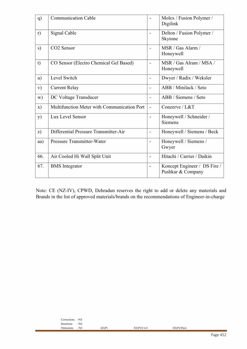
Corrections - Nil
Insertions - Nil
Omissions - Nil AE(P) EE(P)/Civil EE(P)/Elect
Page 452
q) Communication Cable - Molex / Fusion Polymer / Digilink
r) Signal Cable - Delton / Fusion Polymer / Skytone
s) CO2 Sensor - MSR / Gas Alarm / Honeywell
t) CO Sensor (Electro Chemical Gel Based) - MSR / Gas Alram / MSA / Honeywell
u) Level Switch - Dwyer / Radix / Weksler
v) Current Relay - ABB / Minilack / Seto
w) DC Voltage Transducer - ABB / Siemens / Seto
x) Multifunction Meter with Communication Port - Conzerve / L&T
y) Lux Level Sensor - Honeywell / Schneider / Siemens
z) Differential Pressure Transmitter-Air - Honeywell / Siemens / Beck
aa) Pressure Transmitter-Water - Honeywell / Siemens / Gwyer
66. Air Cooled Hi Wall Split Unit - Hitachi / Carrier / Daikin
67. BMS Integrator - Koncept Engineer / DS Fire / Pushkar & Company
Note: CE (NZ-IV), CPWD, Dehradun reserves the right to add or delete any materials and Brands in the list of approved materials/brands on the recommendations of Engineer-in-charge
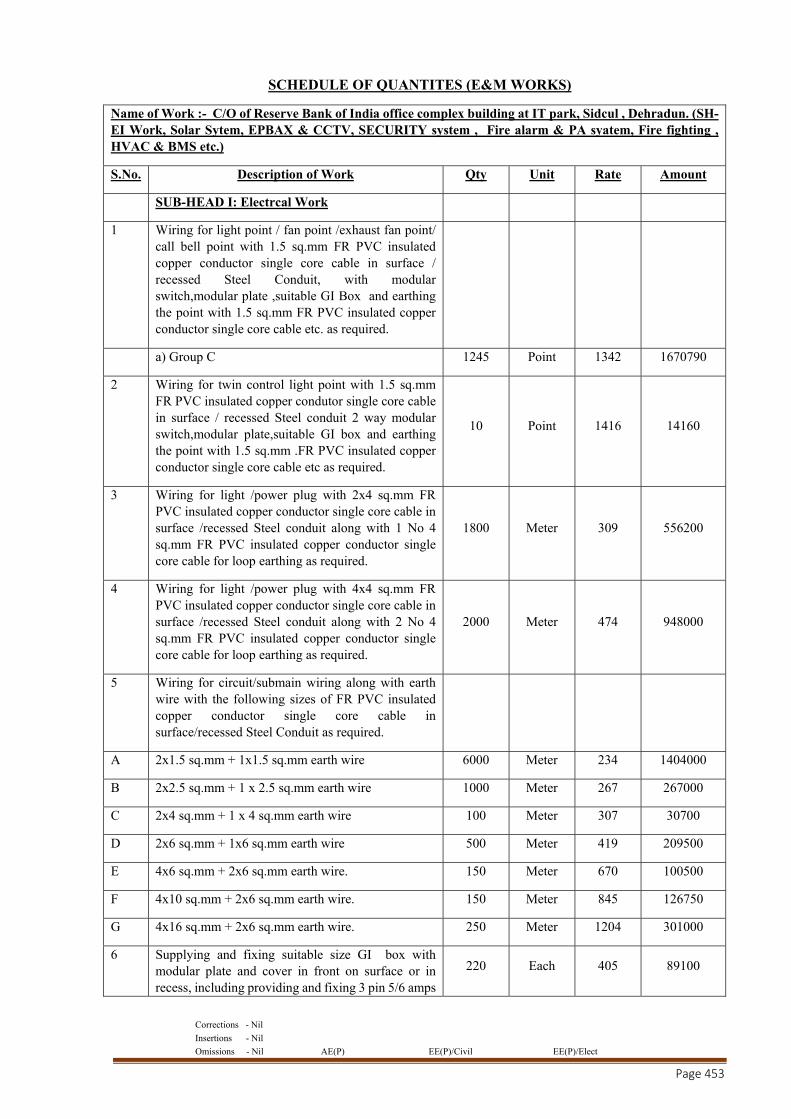
Corrections - Nil
Insertions - Nil
Omissions - Nil AE(P) EE(P)/Civil EE(P)/Elect
Page 453
SCHEDULE OF QUANTITES (E&M WORKS)
Name of Work :- C/O of Reserve Bank of India office complex building at IT park, Sidcul , Dehradun. (SH- EI Work, Solar Sytem, EPBAX & CCTV, SECURITY system , Fire alarm & PA syatem, Fire fighting , HVAC & BMS etc.)
S.No. Description of Work Qty Unit Rate Amount
SUB-HEAD I: Electrcal Work
1 Wiring for light point / fan point /exhaust fan point/ call bell point with 1.5 sq.mm FR PVC insulated copper conductor single core cable in surface / recessed Steel Conduit, with modular switch,modular plate ,suitable GI Box and earthing the point with 1.5 sq.mm FR PVC insulated copper conductor single core cable etc. as required.
a) Group C 1245 Point 1342 1670790
2 Wiring for twin control light point with 1.5 sq.mm FR PVC insulated copper condutor single core cable in surface / recessed Steel conduit 2 way modular switch,modular plate,suitable GI box and earthing the point with 1.5 sq.mm .FR PVC insulated copper conductor single core cable etc as required.
10 Point 1416 14160
3 Wiring for light /power plug with 2x4 sq.mm FR PVC insulated copper conductor single core cable in surface /recessed Steel conduit along with 1 No 4 sq.mm FR PVC insulated copper conductor single core cable for loop earthing as required.
1800 Meter 309 556200
4 Wiring for light /power plug with 4x4 sq.mm FR PVC insulated copper conductor single core cable in surface /recessed Steel conduit along with 2 No 4 sq.mm FR PVC insulated copper conductor single core cable for loop earthing as required.
2000 Meter 474 948000
5 Wiring for circuit/submain wiring along with earth wire with the following sizes of FR PVC insulated copper conductor single core cable in surface/recessed Steel Conduit as required.
A 2x1.5 sq.mm + 1x1.5 sq.mm earth wire 6000 Meter 234 1404000
B 2x2.5 sq.mm + 1 x 2.5 sq.mm earth wire 1000 Meter 267 267000
C 2x4 sq.mm + 1 x 4 sq.mm earth wire 100 Meter 307 30700
D 2x6 sq.mm + 1x6 sq.mm earth wire 500 Meter 419 209500
E 4x6 sq.mm + 2x6 sq.mm earth wire. 150 Meter 670 100500
F 4x10 sq.mm + 2x6 sq.mm earth wire. 150 Meter 845 126750
G 4x16 sq.mm + 2x6 sq.mm earth wire. 250 Meter 1204 301000
6 Supplying and fixing suitable size GI box with modular plate and cover in front on surface or in recess, including providing and fixing 3 pin 5/6 amps
220 Each 405 89100
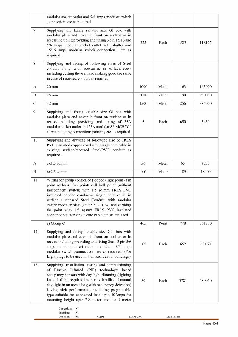
Corrections - Nil
Insertions - Nil
Omissions - Nil AE(P) EE(P)/Civil EE(P)/Elect
Page 454
modular socket outlet and 5/6 amps modular switch ,connection etc as required.
7 Supplying and fixing suitable size GI box with modular plate and cover in front on surface or in recess including providing and fixing 6 pin 15/16 and 5/6 amps modular socket outlet with shulter and 15/16 amps modular switch connection, etc as required.
225 Each 525 118125
8 Supplying and fixing of following sizes of Steel conduit along with acessories in surface/recess including cutting the wall and making good the same in case of recessed conduit as required.
A 20 mm 1000 Meter 163 163000
B 25 mm 5000 Meter 190 950000
C 32 mm 1500 Meter 256 384000
9 Supplying and fixing suitable size GI box with modular plate and cover in front on surface or in recess including providing and fixing of 25A modular socket outlet and 25A modular SP MCB "C" curve including connections painting etc. as required.
5 Each 690 3450
10 Supplying and drawing of following size of FRLS PVC insulated copper conductor single core cable in existing surface/reccesed Steel/PVC conduit as required.
A 3x1.5 sq.mm 50 Meter 65 3250
B 6x2.5 sq mm 100 Meter 189 18900
11 Wiring for group controlled (looped) light point / fan point /exhaust fan point/ call bell point (without independent switch) with 1.5 sq.mm FRLS PVC insulated copper conductor single core cable in surface / recessed Steel Conduit, with modular switch,modular plate ,suitable GI Box and earthing the point with 1.5 sq.mm FRLS PVC insulated copper conductor single core cable etc. as required.
a) Group C 465 Point 778 361770
12 Supplying and fixing suitable size GI box with modular plate and cover in front on surface or in recess, including providing and fixing 2nos. 3 pin 5/6 amps modular socket outlet and 2nos. 5/6 amps modular switch ,connection etc as required. (For Light plugs to be used in Non Residential buildings)
105 Each 652 68460
13 Supplying, Installation, testing and commissioning of Passive Infrared (PIR) technology based occupancy sensors with day light dimming (lighting level shall be regulated as per avilablility of natural day light in an area along with occupancy detection) having high performance, regulating programable type suitable for connected load upto 10Amps for mounting height upto 2.8 meter and for 5 meter
50 Each 5781 289050
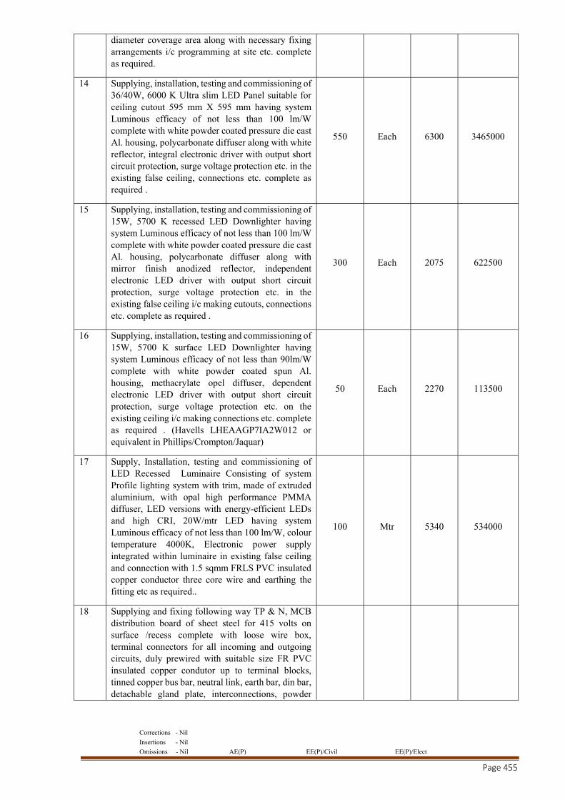
Corrections - Nil
Insertions - Nil
Omissions - Nil AE(P) EE(P)/Civil EE(P)/Elect
Page 455
diameter coverage area along with necessary fixing arrangements i/c programming at site etc. complete as required.
14 Supplying, installation, testing and commissioning of 36/40W, 6000 K Ultra slim LED Panel suitable for ceiling cutout 595 mm X 595 mm having system Luminous efficacy of not less than 100 lm/W complete with white powder coated pressure die cast Al. housing, polycarbonate diffuser along with white reflector, integral electronic driver with output short circuit protection, surge voltage protection etc. in the existing false ceiling, connections etc. complete as required .
550 Each 6300 3465000
15 Supplying, installation, testing and commissioning of 15W, 5700 K recessed LED Downlighter having system Luminous efficacy of not less than 100 lm/W complete with white powder coated pressure die cast Al. housing, polycarbonate diffuser along with mirror finish anodized reflector, independent electronic LED driver with output short circuit protection, surge voltage protection etc. in the existing false ceiling i/c making cutouts, connections etc. complete as required .
300 Each 2075 622500
16 Supplying, installation, testing and commissioning of 15W, 5700 K surface LED Downlighter having system Luminous efficacy of not less than 90lm/W complete with white powder coated spun Al. housing, methacrylate opel diffuser, dependent electronic LED driver with output short circuit protection, surge voltage protection etc. on the existing ceiling i/c making connections etc. complete as required . (Havells LHEAAGP7IA2W012 or equivalent in Phillips/Crompton/Jaquar)
50 Each 2270 113500
17 Supply, Installation, testing and commissioning of LED Recessed Luminaire Consisting of system Profile lighting system with trim, made of extruded aluminium, with opal high performance PMMA diffuser, LED versions with energy-efficient LEDs and high CRI, 20W/mtr LED having system Luminous efficacy of not less than 100 lm/W, colour temperature 4000K, Electronic power supply integrated within luminaire in existing false ceiling and connection with 1.5 sqmm FRLS PVC insulated copper conductor three core wire and earthing the fitting etc as required..
100 Mtr 5340 534000
18 Supplying and fixing following way TP & N, MCB distribution board of sheet steel for 415 volts on surface /recess complete with loose wire box, terminal connectors for all incoming and outgoing circuits, duly prewired with suitable size FR PVC insulated copper condutor up to terminal blocks, tinned copper bus bar, neutral link, earth bar, din bar, detachable gland plate, interconnections, powder
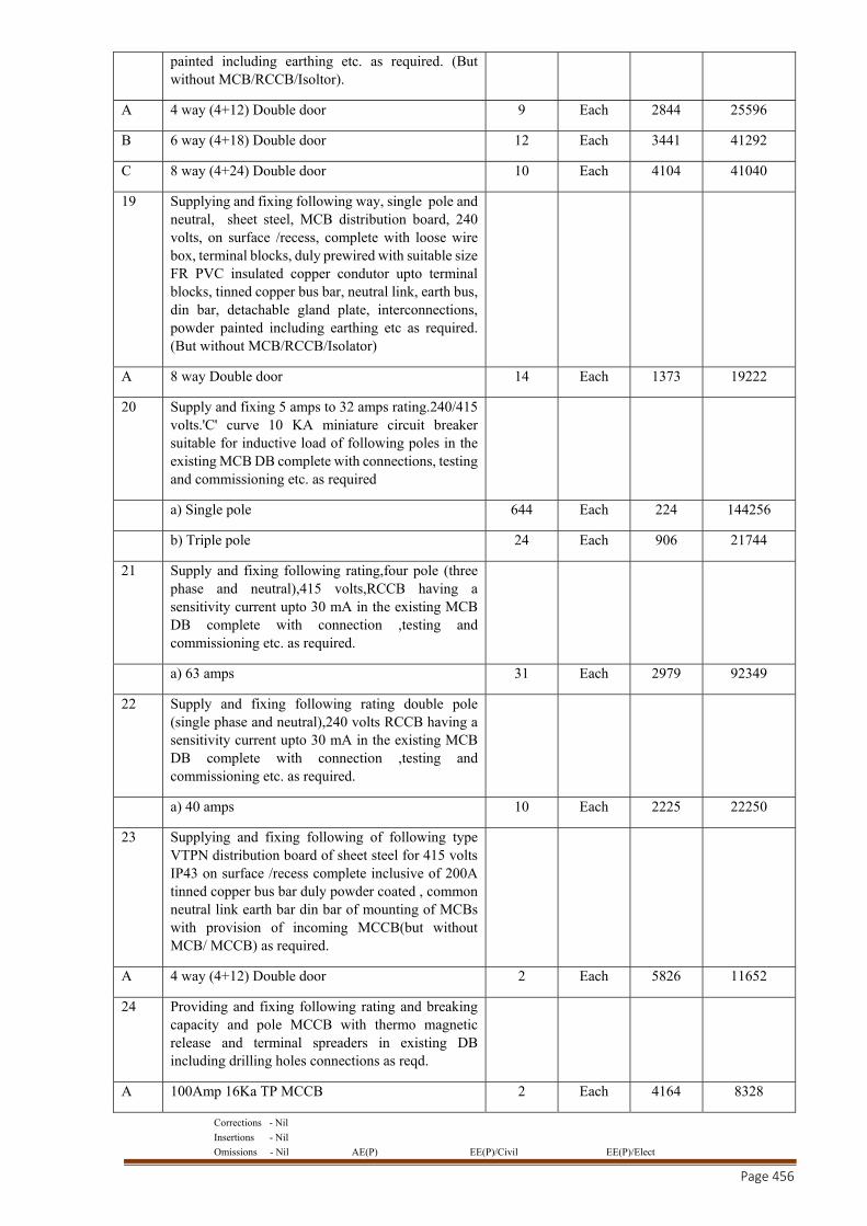
Corrections - Nil
Insertions - Nil
Omissions - Nil AE(P) EE(P)/Civil EE(P)/Elect
Page 456
painted including earthing etc. as required. (But without MCB/RCCB/Isoltor).
A 4 way (4+12) Double door 9 Each 2844 25596
B 6 way (4+18) Double door 12 Each 3441 41292
C 8 way (4+24) Double door 10 Each 4104 41040
19 Supplying and fixing following way, single pole and neutral, sheet steel, MCB distribution board, 240 volts, on surface /recess, complete with loose wire box, terminal blocks, duly prewired with suitable size FR PVC insulated copper condutor upto terminal blocks, tinned copper bus bar, neutral link, earth bus, din bar, detachable gland plate, interconnections, powder painted including earthing etc as required. (But without MCB/RCCB/Isolator)
A 8 way Double door 14 Each 1373 19222
20 Supply and fixing 5 amps to 32 amps rating.240/415 volts.'C' curve 10 KA miniature circuit breaker suitable for inductive load of following poles in the existing MCB DB complete with connections, testing and commissioning etc. as required
a) Single pole 644 Each 224 144256
b) Triple pole 24 Each 906 21744
21 Supply and fixing following rating,four pole (three phase and neutral),415 volts,RCCB having a sensitivity current upto 30 mA in the existing MCB DB complete with connection ,testing and commissioning etc. as required.
a) 63 amps 31 Each 2979 92349
22 Supply and fixing following rating double pole (single phase and neutral),240 volts RCCB having a sensitivity current upto 30 mA in the existing MCB DB complete with connection ,testing and commissioning etc. as required.
a) 40 amps 10 Each 2225 22250
23 Supplying and fixing following of following type VTPN distribution board of sheet steel for 415 volts IP43 on surface /recess complete inclusive of 200A tinned copper bus bar duly powder coated , common neutral link earth bar din bar of mounting of MCBs with provision of incoming MCCB(but without MCB/ MCCB) as required.
A 4 way (4+12) Double door 2 Each 5826 11652
24 Providing and fixing following rating and breaking capacity and pole MCCB with thermo magnetic release and terminal spreaders in existing DB including drilling holes connections as reqd.
A 100Amp 16Ka TP MCCB 2 Each 4164 8328
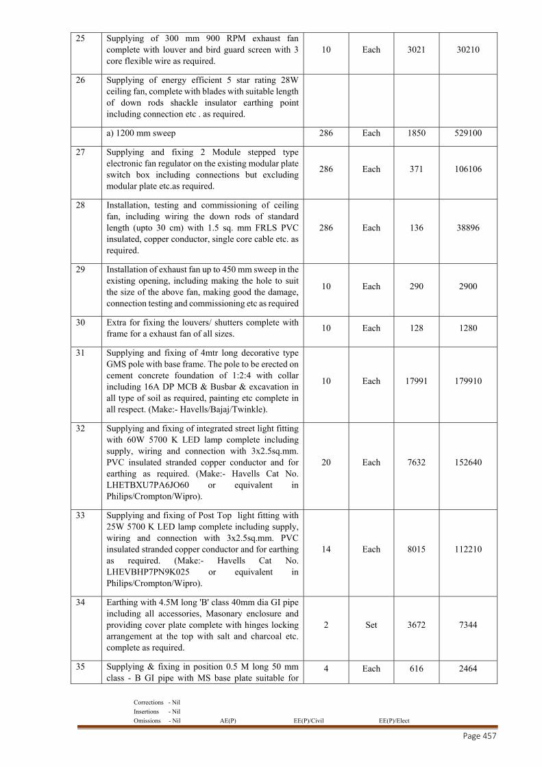
Corrections - Nil
Insertions - Nil
Omissions - Nil AE(P) EE(P)/Civil EE(P)/Elect
Page 457
25 Supplying of 300 mm 900 RPM exhaust fan complete with louver and bird guard screen with 3 core flexible wire as required.
10 Each 3021 30210
26 Supplying of energy efficient 5 star rating 28W ceiling fan, complete with blades with suitable length of down rods shackle insulator earthing point including connection etc . as required.
a) 1200 mm sweep 286 Each 1850 529100
27 Supplying and fixing 2 Module stepped type electronic fan regulator on the existing modular plate switch box including connections but excluding modular plate etc.as required.
286 Each 371 106106
28 Installation, testing and commissioning of ceiling fan, including wiring the down rods of standard length (upto 30 cm) with 1.5 sq. mm FRLS PVC insulated, copper conductor, single core cable etc. as required.
286 Each 136 38896
29 Installation of exhaust fan up to 450 mm sweep in the existing opening, including making the hole to suit the size of the above fan, making good the damage, connection testing and commissioning etc as required
10 Each 290 2900
30 Extra for fixing the louvers/ shutters complete with frame for a exhaust fan of all sizes.
10 Each 128 1280
31 Supplying and fixing of 4mtr long decorative type GMS pole with base frame. The pole to be erected on cement concrete foundation of 1:2:4 with collar including 16A DP MCB & Busbar & excavation in all type of soil as required, painting etc complete in all respect. (Make:- Havells/Bajaj/Twinkle).
10 Each 17991 179910
32 Supplying and fixing of integrated street light fitting with 60W 5700 K LED lamp complete including supply, wiring and connection with 3x2.5sq.mm. PVC insulated stranded copper conductor and for earthing as required. (Make:- Havells Cat No. LHETBXU7PA6JO60 or equivalent in Philips/Crompton/Wipro).
20 Each 7632 152640
33 Supplying and fixing of Post Top light fitting with 25W 5700 K LED lamp complete including supply, wiring and connection with 3x2.5sq.mm. PVC insulated stranded copper conductor and for earthing as required. (Make:- Havells Cat No. LHEVBHP7PN9K025 or equivalent in Philips/Crompton/Wipro).
14 Each 8015 112210
34 Earthing with 4.5M long 'B' class 40mm dia GI pipe including all accessories, Masonary enclosure and providing cover plate complete with hinges locking arrangement at the top with salt and charcoal etc. complete as required.
2 Set 3672 7344
35 Supplying & fixing in position 0.5 M long 50 mm class - B GI pipe with MS base plate suitable for
4 Each 616 2464
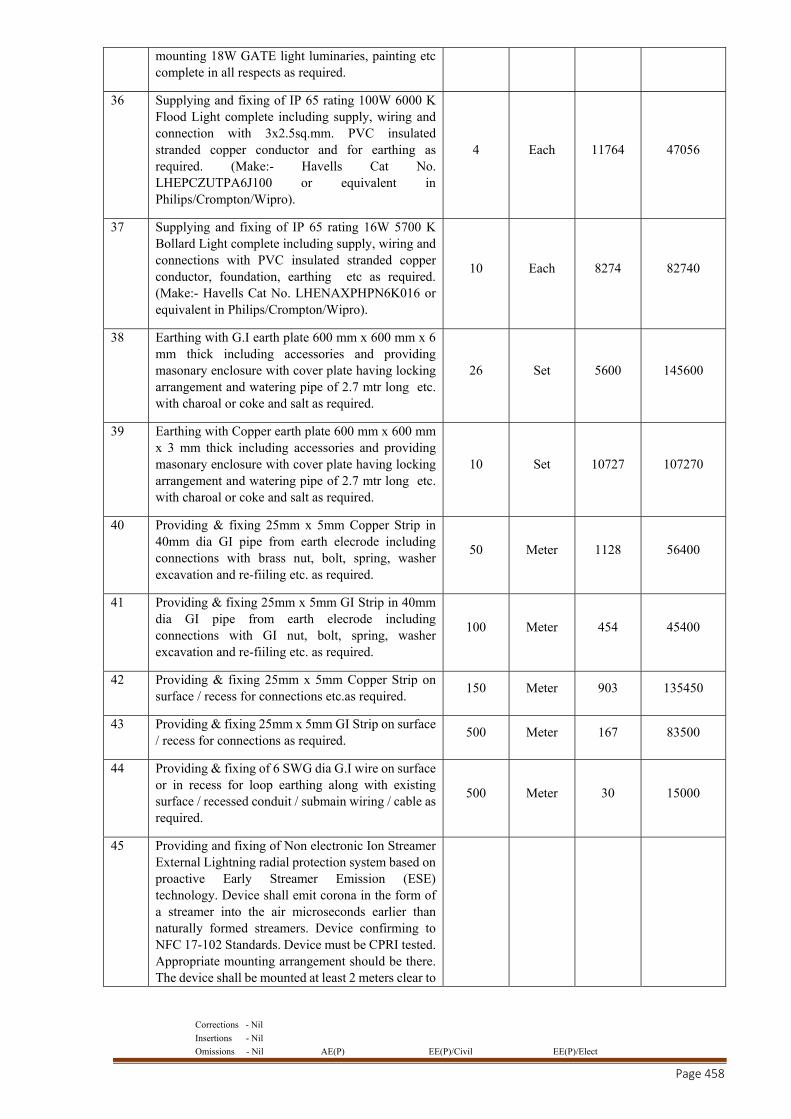
Corrections - Nil
Insertions - Nil
Omissions - Nil AE(P) EE(P)/Civil EE(P)/Elect
Page 458
mounting 18W GATE light luminaries, painting etc complete in all respects as required.
36 Supplying and fixing of IP 65 rating 100W 6000 K Flood Light complete including supply, wiring and connection with 3x2.5sq.mm. PVC insulated stranded copper conductor and for earthing as required. (Make:- Havells Cat No. LHEPCZUTPA6J100 or equivalent in Philips/Crompton/Wipro).
4 Each 11764 47056
37 Supplying and fixing of IP 65 rating 16W 5700 K Bollard Light complete including supply, wiring and connections with PVC insulated stranded copper conductor, foundation, earthing etc as required. (Make:- Havells Cat No. LHENAXPHPN6K016 or equivalent in Philips/Crompton/Wipro).
10 Each 8274 82740
38 Earthing with G.I earth plate 600 mm x 600 mm x 6 mm thick including accessories and providing masonary enclosure with cover plate having locking arrangement and watering pipe of 2.7 mtr long etc. with charoal or coke and salt as required.
26 Set 5600 145600
39 Earthing with Copper earth plate 600 mm x 600 mm x 3 mm thick including accessories and providing masonary enclosure with cover plate having locking arrangement and watering pipe of 2.7 mtr long etc. with charoal or coke and salt as required.
10 Set 10727 107270
40 Providing & fixing 25mm x 5mm Copper Strip in 40mm dia GI pipe from earth elecrode including connections with brass nut, bolt, spring, washer excavation and re-fiiling etc. as required.
50 Meter 1128 56400
41 Providing & fixing 25mm x 5mm GI Strip in 40mm dia GI pipe from earth elecrode including connections with GI nut, bolt, spring, washer excavation and re-fiiling etc. as required.
100 Meter 454 45400
42 Providing & fixing 25mm x 5mm Copper Strip on surface / recess for connections etc.as required.
150 Meter 903 135450
43 Providing & fixing 25mm x 5mm GI Strip on surface / recess for connections as required.
500 Meter 167 83500
44 Providing & fixing of 6 SWG dia G.I wire on surface or in recess for loop earthing along with existing surface / recessed conduit / submain wiring / cable as required.
500 Meter 30 15000
45 Providing and fixing of Non electronic Ion Streamer External Lightning radial protection system based on proactive Early Streamer Emission (ESE) technology. Device shall emit corona in the form of a streamer into the air microseconds earlier than naturally formed streamers. Device confirming to NFC 17-102 Standards. Device must be CPRI tested. Appropriate mounting arrangement should be there. The device shall be mounted at least 2 meters clear to
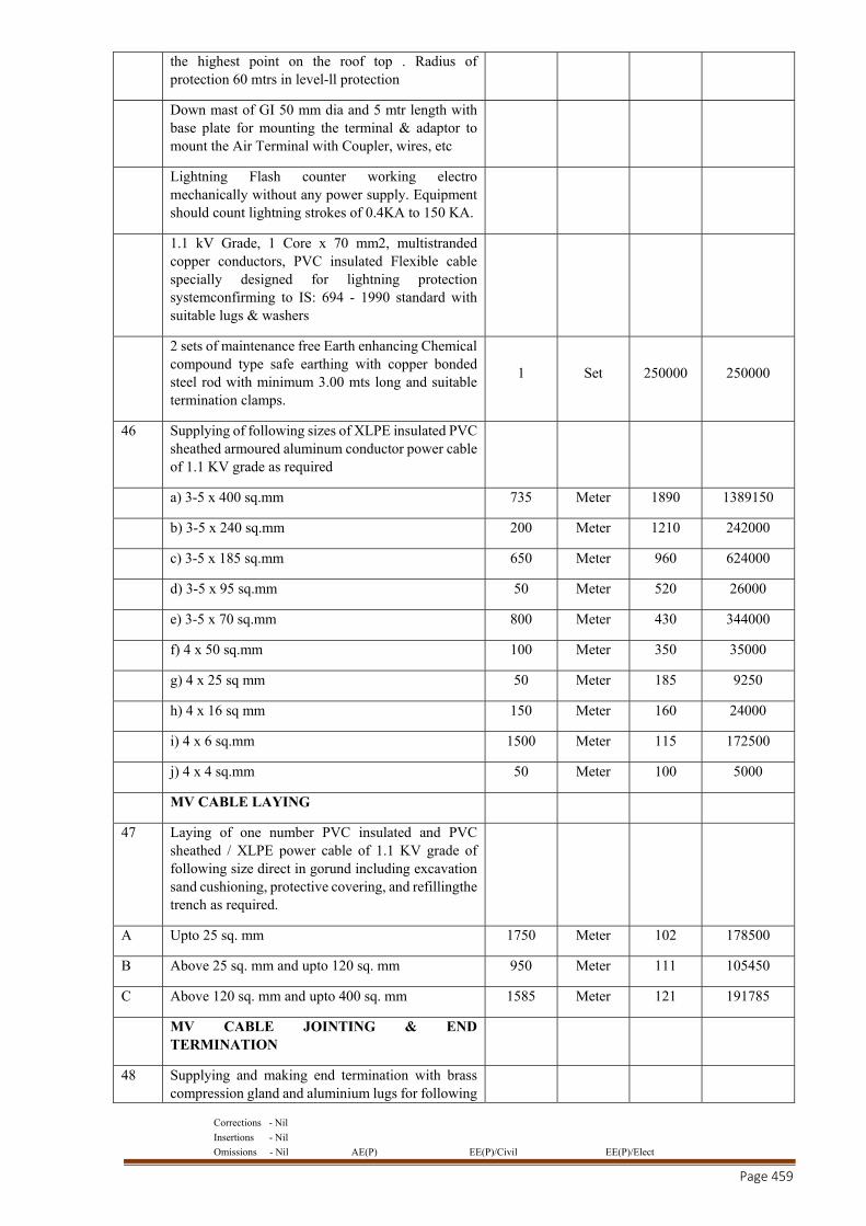
Corrections - Nil
Insertions - Nil
Omissions - Nil AE(P) EE(P)/Civil EE(P)/Elect
Page 459
the highest point on the roof top . Radius of protection 60 mtrs in level-ll protection
Down mast of GI 50 mm dia and 5 mtr length with base plate for mounting the terminal & adaptor to mount the Air Terminal with Coupler, wires, etc
Lightning Flash counter working electro mechanically without any power supply. Equipment should count lightning strokes of 0.4KA to 150 KA.
1.1 kV Grade, 1 Core x 70 mm2, multistranded copper conductors, PVC insulated Flexible cable specially designed for lightning protection systemconfirming to IS: 694 - 1990 standard with suitable lugs & washers
2 sets of maintenance free Earth enhancing Chemical compound type safe earthing with copper bonded steel rod with minimum 3.00 mts long and suitable termination clamps.
1 Set 250000 250000
46 Supplying of following sizes of XLPE insulated PVC sheathed armoured aluminum conductor power cable of 1.1 KV grade as required
a) 3-5 x 400 sq.mm 735 Meter 1890 1389150
b) 3-5 x 240 sq.mm 200 Meter 1210 242000
c) 3-5 x 185 sq.mm 650 Meter 960 624000
d) 3-5 x 95 sq.mm 50 Meter 520 26000
e) 3-5 x 70 sq.mm 800 Meter 430 344000
f) 4 x 50 sq.mm 100 Meter 350 35000
g) 4 x 25 sq mm 50 Meter 185 9250
h) 4 x 16 sq mm 150 Meter 160 24000
i) 4 x 6 sq.mm 1500 Meter 115 172500
j) 4 x 4 sq.mm 50 Meter 100 5000
MV CABLE LAYING
47 Laying of one number PVC insulated and PVC sheathed / XLPE power cable of 1.1 KV grade of following size direct in gorund including excavation sand cushioning, protective covering, and refillingthe trench as required.
A Upto 25 sq. mm 1750 Meter 102 178500
B Above 25 sq. mm and upto 120 sq. mm 950 Meter 111 105450
C Above 120 sq. mm and upto 400 sq. mm 1585 Meter 121 191785
MV CABLE JOINTING & END TERMINATION
48 Supplying and making end termination with brass compression gland and aluminium lugs for following
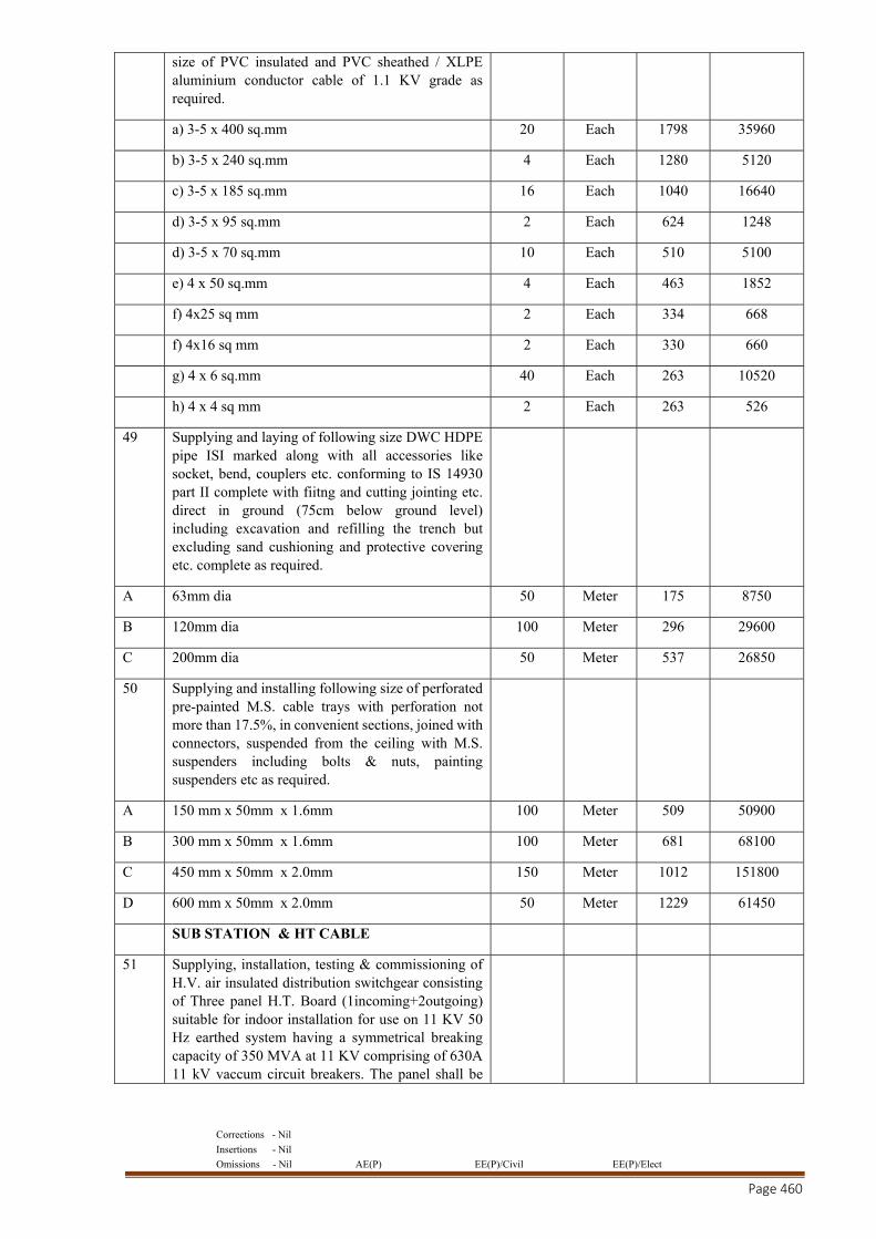
Corrections - Nil
Insertions - Nil
Omissions - Nil AE(P) EE(P)/Civil EE(P)/Elect
Page 460
size of PVC insulated and PVC sheathed / XLPE aluminium conductor cable of 1.1 KV grade as required.
a) 3-5 x 400 sq.mm 20 Each 1798 35960
b) 3-5 x 240 sq.mm 4 Each 1280 5120
c) 3-5 x 185 sq.mm 16 Each 1040 16640
d) 3-5 x 95 sq.mm 2 Each 624 1248
d) 3-5 x 70 sq.mm 10 Each 510 5100
e) 4 x 50 sq.mm 4 Each 463 1852
f) 4x25 sq mm 2 Each 334 668
f) 4x16 sq mm 2 Each 330 660
g) 4 x 6 sq.mm 40 Each 263 10520
h) 4 x 4 sq mm 2 Each 263 526
49 Supplying and laying of following size DWC HDPE pipe ISI marked along with all accessories like socket, bend, couplers etc. conforming to IS 14930 part II complete with fiitng and cutting jointing etc. direct in ground (75cm below ground level) including excavation and refilling the trench but excluding sand cushioning and protective covering etc. complete as required.
A 63mm dia 50 Meter 175 8750
B 120mm dia 100 Meter 296 29600
C 200mm dia 50 Meter 537 26850
50 Supplying and installing following size of perforated pre-painted M.S. cable trays with perforation not more than 17.5%, in convenient sections, joined with connectors, suspended from the ceiling with M.S. suspenders including bolts & nuts, painting suspenders etc as required.
A 150 mm x 50mm x 1.6mm 100 Meter 509 50900
B 300 mm x 50mm x 1.6mm 100 Meter 681 68100
C 450 mm x 50mm x 2.0mm 150 Meter 1012 151800
D 600 mm x 50mm x 2.0mm 50 Meter 1229 61450
SUB STATION & HT CABLE
51 Supplying, installation, testing & commissioning of H.V. air insulated distribution switchgear consisting of Three panel H.T. Board (1incoming+2outgoing) suitable for indoor installation for use on 11 KV 50 Hz earthed system having a symmetrical breaking capacity of 350 MVA at 11 KV comprising of 630A 11 kV vaccum circuit breakers. The panel shall be
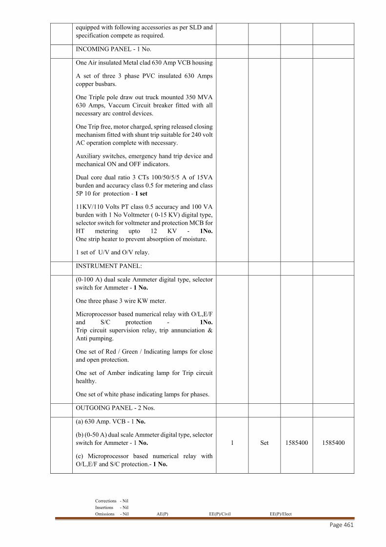
Corrections - Nil
Insertions - Nil
Omissions - Nil AE(P) EE(P)/Civil EE(P)/Elect
Page 461
equipped with following accessories as per SLD and specification compete as required.
INCOMING PANEL - 1 No.
One Air insulated Metal clad 630 Amp VCB housing
A set of three 3 phase PVC insulated 630 Amps copper busbars.
One Triple pole draw out truck mounted 350 MVA 630 Amps, Vaccum Circuit breaker fitted with all necessary arc control devices.
One Trip free, motor charged, spring released closing mechanism fitted with shunt trip suitable for 240 volt AC operation complete with necessary.
Auxiliary switches, emergency hand trip device and mechanical ON and OFF indicators.
Dual core dual ratio 3 CTs 100/50/5/5 A of 15VA burden and accuracy class 0.5 for metering and class 5P 10 for protection - 1 set
11KV/110 Volts PT class 0.5 accuracy and 100 VA burden with 1 No Voltmeter ( 0-15 KV) digital type, selector switch for voltmeter and protection MCB for HT metering upto 12 KV - 1No. One strip heater to prevent absorption of moisture.
1 set of U/V and O/V relay.
INSTRUMENT PANEL:
(0-100 A) dual scale Ammeter digital type, selector switch for Ammeter - 1 No.
One three phase 3 wire KW meter.
Microprocessor based numerical relay with O/L,E/F and S/C protection - 1No. Trip circuit supervision relay, trip annunciation & Anti pumping.
One set of Red / Green / Indicating lamps for close and open protection.
One set of Amber indicating lamp for Trip circuit healthy.
One set of white phase indicating lamps for phases.
OUTGOING PANEL - 2 Nos.
(a) 630 Amp. VCB - 1 No.
(b) (0-50 A) dual scale Ammeter digital type, selector switch for Ammeter - 1 No.
(c) Microprocessor based numerical relay with O/L,E/F and S/C protection.- 1 No.
1 Set 1585400 1585400
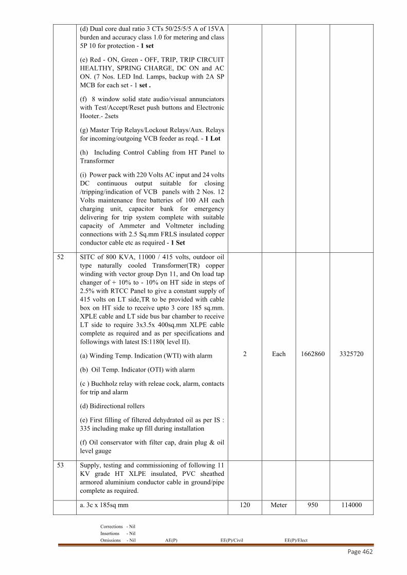
Corrections - Nil
Insertions - Nil
Omissions - Nil AE(P) EE(P)/Civil EE(P)/Elect
Page 462
(d) Dual core dual ratio 3 CTs 50/25/5/5 A of 15VA burden and accuracy class 1.0 for metering and class 5P 10 for protection - 1 set
(e) Red - ON, Green - OFF, TRIP, TRIP CIRCUIT HEALTHY, SPRING CHARGE, DC ON and AC ON. (7 Nos. LED Ind. Lamps, backup with 2A SP MCB for each set - 1 set .
(f) 8 window solid state audio/visual annunciators with Test/Accept/Reset push buttons and Electronic Hooter.- 2sets
(g) Master Trip Relays/Lockout Relays/Aux. Relays for incoming/outgoing VCB feeder as reqd. - 1 Lot
(h) Including Control Cabling from HT Panel to Transformer
(i) Power pack with 220 Volts AC input and 24 volts DC continuous output suitable for closing /tripping/indication of VCB panels with 2 Nos. 12 Volts maintenance free batteries of 100 AH each charging unit, capacitor bank for emergency delivering for trip system complete with suitable capacity of Ammeter and Voltmeter including connections with 2.5 Sq.mm FRLS insulated copper conductor cable etc as required - 1 Set
52 SITC of 800 KVA, 11000 / 415 volts, outdoor oil type naturally cooled Transformer(TR) copper winding with vector group Dyn 11, and On load tap changer of + 10% to - 10% on HT side in steps of 2.5% with RTCC Panel to give a constant supply of 415 volts on LT side,TR to be provided with cable box on HT side to receive upto 3 core 185 sq.mm. XPLE cable and LT side bus bar chamber to receive LT side to require 3x3.5x 400sq.mm XLPE cable complete as required and as per specifications and followings with latest IS:1180( level II).
(a) Winding Temp. Indication (WTI) with alarm
(b) Oil Temp. Indicator (OTI) with alarm
(c ) Buchholz relay with releae cock, alarm, contacts for trip and alarm
(d) Bidirectional rollers
(e) First filling of filtered dehydrated oil as per IS : 335 including make up fill during installation
(f) Oil conservator with filter cap, drain plug & oil level gauge
2 Each 1662860 3325720
53 Supply, testing and commissioning of following 11 KV grade HT XLPE insulated, PVC sheathed armored aluminium conductor cable in ground/pipe complete as required.
a. 3c x 185sq mm 120 Meter 950 114000
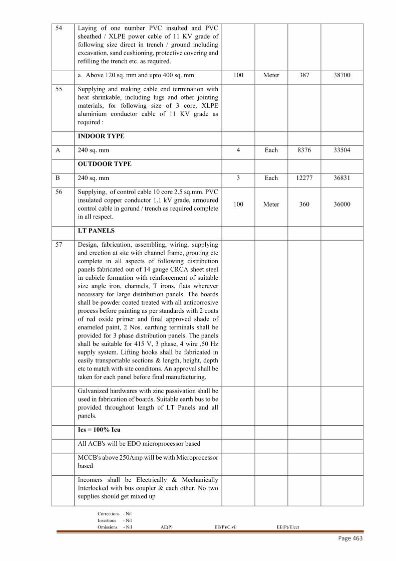
Corrections - Nil
Insertions - Nil
Omissions - Nil AE(P) EE(P)/Civil EE(P)/Elect
Page 463
54 Laying of one number PVC insulted and PVC sheathed / XLPE power cable of 11 KV grade of following size direct in trench / ground including excavation, sand cushioning, protective covering and refilling the trench etc. as required.
a. Above 120 sq. mm and upto 400 sq. mm 100 Meter 387 38700
55 Supplying and making cable end termination with heat shrinkable, including lugs and other jointing materials, for following size of 3 core, XLPE aluminium conductor cable of 11 KV grade as required :
INDOOR TYPE
A 240 sq. mm 4 Each 8376 33504
OUTDOOR TYPE
B 240 sq. mm 3 Each 12277 36831
56 Supplying, of control cable 10 core 2.5 sq.mm. PVC insulated copper conductor 1.1 kV grade, armoured control cable in gorund / trench as required complete in all respect.
100 Meter 360 36000
LT PANELS
57 Design, fabrication, assembling, wiring, supplying and erection at site with channel frame, grouting etc complete in all aspects of following distribution panels fabricated out of 14 gauge CRCA sheet steel in cubicle formation with reinforcement of suitable size angle iron, channels, T irons, flats wherever necessary for large distribution panels. The boards shall be powder coated treated with all anticorrosive process before painting as per standards with 2 coats of red oxide primer and final approved shade of enameled paint, 2 Nos. earthing terminals shall be provided for 3 phase distribution panels. The panels shall be suitable for 415 V, 3 phase, 4 wire ,50 Hz supply system. Lifting hooks shall be fabricated in easily transportable sections & length, height, depth etc to match with site conditons. An approval shall be taken for each panel before final manufacturing.
Galvanized hardwares with zinc passivation shall be used in fabrication of boards. Suitable earth bus to be provided throughout length of LT Panels and all panels.
Ics = 100% Icu
All ACB's will be EDO microprocessor based
MCCB's above 250Amp will be with Microprocessor based
Incomers shall be Electrically & Mechanically Interlocked with bus coupler & each other. No two supplies should get mixed up
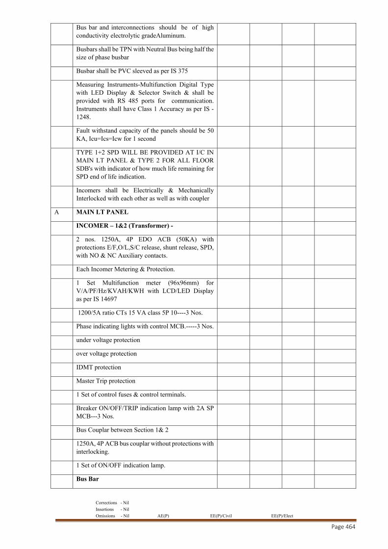
Corrections - Nil
Insertions - Nil
Omissions - Nil AE(P) EE(P)/Civil EE(P)/Elect
Page 464
Bus bar and interconnections should be of high conductivity electrolytic gradeAluminum.
Busbars shall be TPN with Neutral Bus being half the size of phase busbar
Busbar shall be PVC sleeved as per IS 375
Measuring Instruments-Multifunction Digital Type with LED Display & Selector Switch & shall be provided with RS 485 ports for communication. Instruments shall have Class 1 Accuracy as per IS - 1248.
Fault withstand capacity of the panels should be 50 KA, Icu=Ics=Icw for 1 second
TYPE 1+2 SPD WILL BE PROVIDED AT I/C IN MAIN LT PANEL & TYPE 2 FOR ALL FLOOR SDB's with indicator of how much life remaining for SPD end of life indication.
Incomers shall be Electrically & Mechanically Interlocked with each other as well as with coupler
A MAIN LT PANEL
INCOMER – 1&2 (Transformer) -
2 nos. 1250A, 4P EDO ACB (50KA) with protections E/F,O/L,S/C release, shunt release, SPD, with NO & NC Auxiliary contacts.
Each Incomer Metering & Protection.
1 Set Multifunction meter (96x96mm) for V/A/PF/Hz/KVAH/KWH with LCD/LED Display as per IS 14697
1200/5A ratio CTs 15 VA class 5P 10----3 Nos.
Phase indicating lights with control MCB.-----3 Nos.
under voltage protection
over voltage protection
IDMT protection
Master Trip protection
1 Set of control fuses & control terminals.
Breaker ON/OFF/TRIP indication lamp with 2A SP MCB---3 Nos.
Bus Couplar between Section 1& 2
1250A, 4P ACB bus couplar without protections with interlocking.
1 Set of ON/OFF indication lamp.
Bus Bar
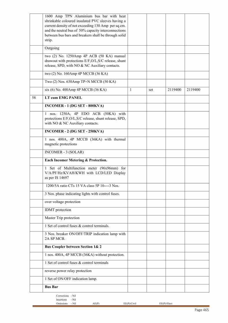
Corrections - Nil
Insertions - Nil
Omissions - Nil AE(P) EE(P)/Civil EE(P)/Elect
Page 465
1600 Amp TPN Aluminium bus bar with heat shrinkable coloured insulated PVC sleeves having a current density of not exceeding 130 Amp per sq.cm. and the neutral bus of 50% capacity interconnections between bus bars and breakers shall be through solid strip.
Outgoing
two (2) No. 1250Amp 4P ACB (50 KA) manual drawout with protections E/F,O/L,S/C release, shunt release, SPD, with NO & NC Auxiliary contacts.
two (2) No. 160Amp 4P MCCB (36 KA)
Two (2) Nos. 630Amp TP+N MCCB (50 KA)
six (6) No. 400Amp 4P MCCB (36 KA) 1 set 2119400 2119400
58 LT cum EMG PANEL
INCOMER - 1 (DG SET - 800KVA)
1 nos. 1250A, 4P EDO ACB (50KA) with protections E/F,O/L,S/C release, shunt release, SPD, with NO & NC Auxiliary contacts.
INCOMER - 2 (DG SET - 250KVA)
1 nos. 400A, 4P MCCB (36KA) with thermal magnetic protections
INCOMER - 3 (SOLAR)
Each Incomer Metering & Protection.
1 Set of Multifunction meter (96x96mm) for V/A/PF/Hz/KVAH/KWH with LCD/LED Display as per IS 14697
1200/5A ratio CTs 15 VA class 5P 10----3 Nos.
3 Nos. phase indicating lights with control fuses.
over voltage protection
IDMT protection
Master Trip protection
1 Set of control fuses & control terminals.
3 Nos. breaker ON/OFF/TRIP indication lamp with 2A SP MCB.
Bus Coupler between Section 1& 2
1 nos. 400A, 4P MCCB (36KA) without protection.
1 Set of control fuses & control terminals
reverse power relay protection
1 Set of ON/OFF indication lamp.
Bus Bar
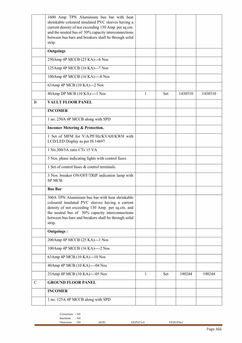
Corrections - Nil
Insertions - Nil
Omissions - Nil AE(P) EE(P)/Civil EE(P)/Elect
Page 466
1600 Amp TPN Aluminium bus bar with heat shrinkable coloured insulated PVC sleeves having a current density of not exceeding 130 Amp per sq.cm. and the neutral bus of 50% capacity interconnections between bus bars and breakers shall be through solid strip.
Outgoings
250Amp 4P MCCB (25 KA)---6 Nos
125Amp 4P MCCB (16 KA)---7 Nos
100Amp 4P MCCB (16 KA)----8 Nos
63Amp 4P MCB (10 KA)---2 Nos
40Amp DP MCB (10 KA)----1 Nos 1 Set 1438510 1438510
B VAULT FLOOR PANEL
INCOMER
1 no. 250A 4P MCCB along with SPD
Incomer Metering & Protection.
1 Set of MFM for V/A/PF/Hz/KVAH/KWH with LCD/LED Display as per IS 14697
1 No.300/5A ratio CTs 15 VA
3 Nos. phase indicating lights with control fuses.
1 Set of control fuses & control terminals.
3 Nos. breaker ON/OFF/TRIP indication lamp with SP MCB.
Bus Bar
300A TPN Aluminium bus bar with heat shrinkable coloured insulated PVC sleeves having a current density of not exceeding 130 Amp per sq.cm. and the neutral bus of 50% capacity interconnections between bus bars and breakers shall be through solid strip.
Outgoings :
200Amp 4P MCCB (25 KA)---1 Nos
100Amp 4P MCCB (16 KA)----2 Nos
63Amp 4P MCB (10 KA)---10 Nos
40Amp 4P MCB (10 KA)----04 Nos
25Amp 4P MCB (10 KA)----05 Nos 1 Set 190244 190244
C GROUND FLOOR PANEL
INCOMER
1 no. 125A 4P MCCB along with SPD
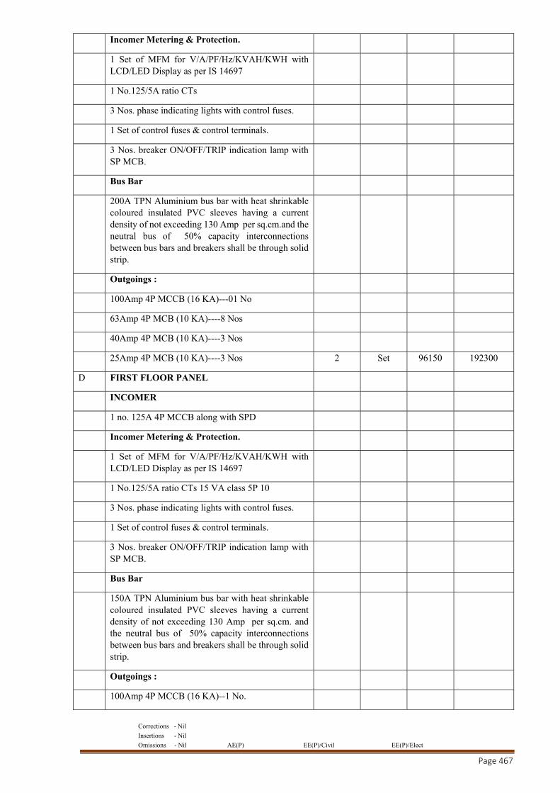
Corrections - Nil
Insertions - Nil
Omissions - Nil AE(P) EE(P)/Civil EE(P)/Elect
Page 467
Incomer Metering & Protection.
1 Set of MFM for V/A/PF/Hz/KVAH/KWH with LCD/LED Display as per IS 14697
1 No.125/5A ratio CTs
3 Nos. phase indicating lights with control fuses.
1 Set of control fuses & control terminals.
3 Nos. breaker ON/OFF/TRIP indication lamp with SP MCB.
Bus Bar
200A TPN Aluminium bus bar with heat shrinkable coloured insulated PVC sleeves having a current density of not exceeding 130 Amp per sq.cm.and the neutral bus of 50% capacity interconnections between bus bars and breakers shall be through solid strip.
Outgoings :
100Amp 4P MCCB (16 KA)---01 No
63Amp 4P MCB (10 KA)----8 Nos
40Amp 4P MCB (10 KA)----3 Nos
25Amp 4P MCB (10 KA)----3 Nos 2 Set 96150 192300
D FIRST FLOOR PANEL
INCOMER
1 no. 125A 4P MCCB along with SPD
Incomer Metering & Protection.
1 Set of MFM for V/A/PF/Hz/KVAH/KWH with LCD/LED Display as per IS 14697
1 No.125/5A ratio CTs 15 VA class 5P 10
3 Nos. phase indicating lights with control fuses.
1 Set of control fuses & control terminals.
3 Nos. breaker ON/OFF/TRIP indication lamp with SP MCB.
Bus Bar
150A TPN Aluminium bus bar with heat shrinkable coloured insulated PVC sleeves having a current density of not exceeding 130 Amp per sq.cm. and the neutral bus of 50% capacity interconnections between bus bars and breakers shall be through solid strip.
Outgoings :
100Amp 4P MCCB (16 KA)--1 No.
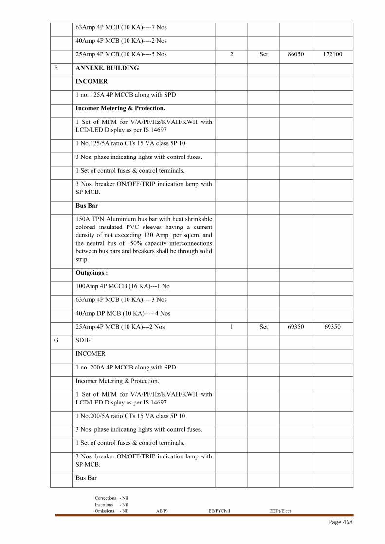
Corrections - Nil
Insertions - Nil
Omissions - Nil AE(P) EE(P)/Civil EE(P)/Elect
Page 468
63Amp 4P MCB (10 KA)----7 Nos
40Amp 4P MCB (10 KA)----2 Nos
25Amp 4P MCB (10 KA)----5 Nos 2 Set 86050 172100
E ANNEXE. BUILDING
INCOMER
1 no. 125A 4P MCCB along with SPD
Incomer Metering & Protection.
1 Set of MFM for V/A/PF/Hz/KVAH/KWH with LCD/LED Display as per IS 14697
1 No.125/5A ratio CTs 15 VA class 5P 10
3 Nos. phase indicating lights with control fuses.
1 Set of control fuses & control terminals.
3 Nos. breaker ON/OFF/TRIP indication lamp with SP MCB.
Bus Bar
150A TPN Aluminium bus bar with heat shrinkable colored insulated PVC sleeves having a current density of not exceeding 130 Amp per sq.cm. and the neutral bus of 50% capacity interconnections between bus bars and breakers shall be through solid strip.
Outgoings :
100Amp 4P MCCB (16 KA)---1 No
63Amp 4P MCB (10 KA)----3 Nos
40Amp DP MCB (10 KA)-----4 Nos
25Amp 4P MCB (10 KA)---2 Nos 1 Set 69350 69350
G SDB-1
INCOMER
1 no. 200A 4P MCCB along with SPD
Incomer Metering & Protection.
1 Set of MFM for V/A/PF/Hz/KVAH/KWH with LCD/LED Display as per IS 14697
1 No.200/5A ratio CTs 15 VA class 5P 10
3 Nos. phase indicating lights with control fuses.
1 Set of control fuses & control terminals.
3 Nos. breaker ON/OFF/TRIP indication lamp with SP MCB.
Bus Bar
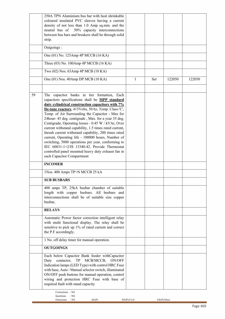
Corrections - Nil
Insertions - Nil
Omissions - Nil AE(P) EE(P)/Civil EE(P)/Elect
Page 469
250A TPN Aluminium bus bar with heat shrinkable coloured insulated PVC sleeves having a current density of not less than 1.0 Amp sq.mm. and the neutral bus of 50% capacity interconnections between bus bars and breakers shall be through solid strip.
Outgoings :
One (01) No. 125Amp 4P MCCB (16 KA)
Three (03) No. 100Amp 4P MCCB (16 KA)
Two (02) Nos. 63Amp 4P MCB (10 KA)
One (01) Nos. 40Amp DP MCB (10 KA) 1 Set 122050 122050
59 The capacitor banks in tier formation, Each capacitors specifications shall be MPP standard duty cylindrical construction capacitors with 7% De-tune reactors, 415Volts, 50 hz, Temp. Class-'C', Temp. of Air Surrounding the Capacitor - Max for 24hour- 45 deg. centigrade , Max. for a year 35 deg. Centigrade, Operating losses - 0.45 W / kVAr, Over current withstand capability, 1.5 times rated current, Inrush current withstand capability, 200 times rated current, Operating life - 100000 hours, Number of switching, 5000 operations per year, conforming to IEC 60831-1+2/IS 13340-42. Provide Thermostat controlled panel mounted heavy duty exhaust fan in each Capacitor Compartment
INCOMER
1Nos. 400 Amps TP+N MCCB 25 kA
SUB BUSBARS
400 amps TP, 25kA busbar chamber of suitable length with copper busbars. All busbars and interconnections shall be of suitable size copper busbar,
RELAYS
Automatic Power factor correction intelligent relay with multi functional display. The relay shall be sensitive to pick up 1% of rated current and correct the P.F accordingly.
1 No. off delay timer for manual operation.
OUTGOINGS
Each below Capacitor Bank feeder withCapacitor Duty contactor, TP MCB/MCCB, ON/OFF Indication lamps (LED Type) with control HRC Fuse with base, Auto / Manual selector switch, illuminated ON/OFF push buttons for manual operation, control wiring and protection HRC Fuse with base of required fault with stand capacity
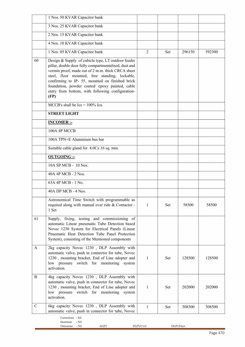
Corrections - Nil
Insertions - Nil
Omissions - Nil AE(P) EE(P)/Civil EE(P)/Elect
Page 470
1 Nos. 50 KVAR Capacitor bank
3 Nos. 25 KVAR Capacitor bank
2 Nos. 15 KVAR Capacitor bank
4 Nos. 10 KVAR Capacitor bank
1 Nos. 05 KVAR Capacitor bank 2 Set 296150 592300
60 Design & Supply of cubicle type, LT outdoor feeder pillar, double door fully compartmentalised, dust and vermin proof, made out of 2 m.m. thick CRCA sheet steel, floor mounted, free standing, lockable, confirming to IP- 55, mounted on finished brick foundation, powder coated/ epoxy painted, cable entry from bottom, with following configuration- (FP)
MCCB's shall be Ics = 100% Icu
STREET LIGHT
INCOMER :-
100A 4P MCCB
100A TPN+E Aluminium bus bar
Suitable cable gland for 4.0Cx 16 sq. mm.
OUTGOING :-
10A SP MCB - 10 Nos.
40A 4P MCB - 2 Nos.
63A 4P MCB - 1 No.
40A DP MCB - 4 Nos.
Astronomical Time Switch with programmable as required along with manual over ride & Contactor - 1 Set
1 Set 58500 58500
61 Supply, fixing, testing and commissioning of automatic Linear pneumatic Tube Detection based Novec 1230 System for Electrical Panels (Linear Pnuematic Heat Detection Tube Panel Protection System), consisting of the Mentioned components
A 2kg capacity Novec 1230 , DLP Assembly with automatic valve, push in connector for tube, Novec 1230 , mounting bracket, End of Line adopter and low pressure switch for monitoring system activation.
1 Set 128500 128500
B 4kg capacity Novec 1230 , DLP Assembly with automatic valve, push in connector for tube, Novec 1230 , mounting bracket, End of Line adopter and low pressure switch for monitoring system activation.
1 Set 202000 202000
C 6kg capacity Novec 1230 , DLP Assembly with automatic valve, push in connector for tube, Novec
1 Set 308500 308500
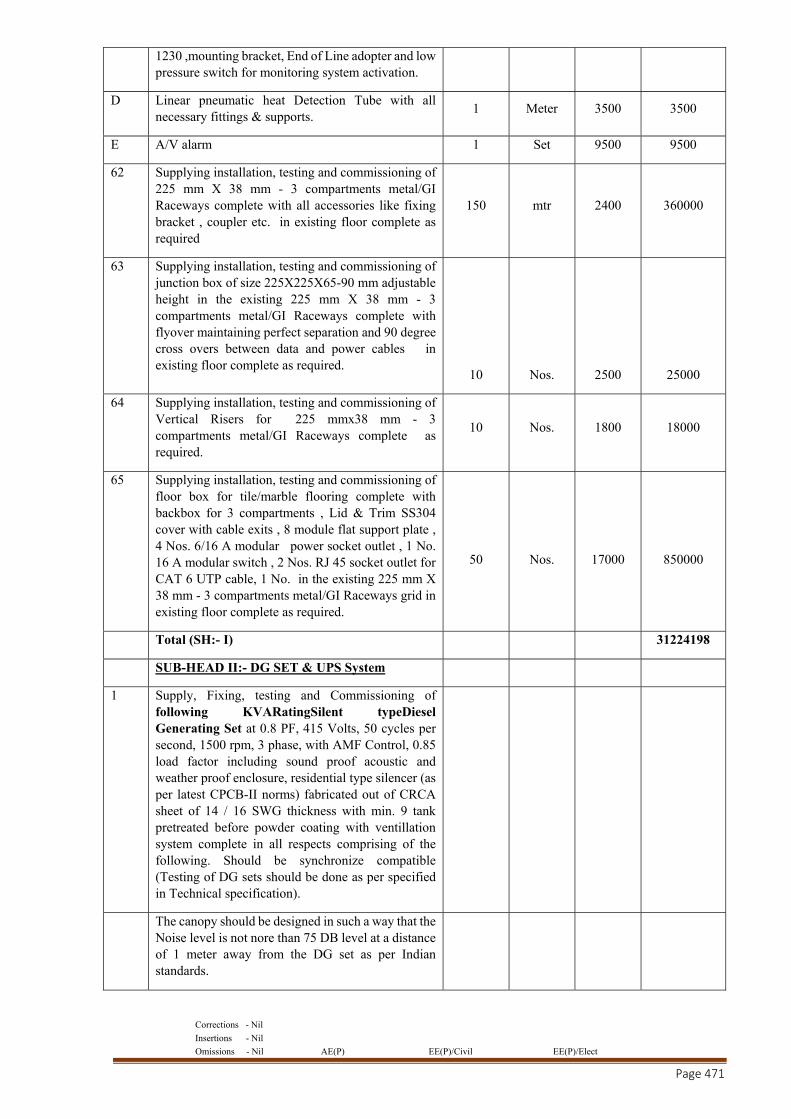
Corrections - Nil
Insertions - Nil
Omissions - Nil AE(P) EE(P)/Civil EE(P)/Elect
Page 471
1230 ,mounting bracket, End of Line adopter and low pressure switch for monitoring system activation.
D Linear pneumatic heat Detection Tube with all necessary fittings & supports.
1 Meter 3500 3500
E A/V alarm 1 Set 9500 9500
62 Supplying installation, testing and commissioning of 225 mm X 38 mm - 3 compartments metal/GI Raceways complete with all accessories like fixing bracket , coupler etc. in existing floor complete as required
150 mtr 2400 360000
63 Supplying installation, testing and commissioning of junction box of size 225X225X65-90 mm adjustable height in the existing 225 mm X 38 mm - 3 compartments metal/GI Raceways complete with flyover maintaining perfect separation and 90 degree cross overs between data and power cables in existing floor complete as required.
10
Nos.
2500
25000
64 Supplying installation, testing and commissioning of Vertical Risers for 225 mmx38 mm - 3 compartments metal/GI Raceways complete as required.
10 Nos. 1800 18000
65 Supplying installation, testing and commissioning of floor box for tile/marble flooring complete with backbox for 3 compartments , Lid & Trim SS304 cover with cable exits , 8 module flat support plate , 4 Nos. 6/16 A modular power socket outlet , 1 No. 16 A modular switch , 2 Nos. RJ 45 socket outlet for CAT 6 UTP cable, 1 No. in the existing 225 mm X 38 mm - 3 compartments metal/GI Raceways grid in existing floor complete as required.
50
Nos.
17000
850000
Total (SH:- I) 31224198
SUB-HEAD II:- DG SET & UPS System
1 Supply, Fixing, testing and Commissioning of following KVARatingSilent typeDiesel Generating Set at 0.8 PF, 415 Volts, 50 cycles per second, 1500 rpm, 3 phase, with AMF Control, 0.85 load factor including sound proof acoustic and weather proof enclosure, residential type silencer (as per latest CPCB-II norms) fabricated out of CRCA sheet of 14 / 16 SWG thickness with min. 9 tank pretreated before powder coating with ventillation system complete in all respects comprising of the following. Should be synchronize compatible (Testing of DG sets should be done as per specified in Technical specification).
The canopy should be designed in such a way that the Noise level is not nore than 75 DB level at a distance of 1 meter away from the DG set as per Indian standards.
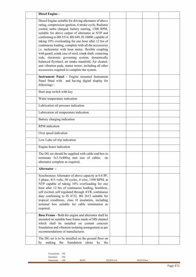
Corrections - Nil
Insertions - Nil
Omissions - Nil AE(P) EE(P)/Civil EE(P)/Elect
Page 472
Diesel Engine -
Diesel Engine suitable for driving alternator of above rating, compression ignition, 4 stroke cycle, Radiator cooled, turbo charged, battery starting, 1500 RPM, suitable for above output of alternator at NTP and confirming to BS 5514, BS 649, IS 10000, capable of taking 10% overloading for one hour after 12 hrs of continuous loading, complete with all the accessories i.e. tachometer with hour meter, flexible coupling with guard, crank case of steel, crank shaft, conncting rods, electronic governing system, dynamically balanced flywheel, air intake manifold, Air cleaner, anti vibration pads, starter motor, including all other accessories required to complete the system.
Instrument Panel - Engine mounted Instrument Panel fitted with and having digital display for followings :
Start stop switch with key
Water temperature indication
Lubrication oil pressure indication.
Lubrication oil temperature indication.
Battery charging indication
RPM indication
Over speed indication
Low Lube oil trip indication
Engine hours indication
The DG set should be supplied with cable end box to terminate 3x3.5x400sq mm size of cables on alternator complete as required.
Alternator -
Synchronous Alternator of above capacity at 0.8 PF, 3 phase, 415 volts, 50 cycles, 4 wire, 1500 RPM, at NTP capable of taking 10% overlioading for one hour after 12 hrs of continuous loading, brushless, self excited, self regulated through AVR, continuous duty confirming to IS 4722, BS 2613 suitable for tropical conditions, class H insulation, including terminal box suitable for cable termination as required.
Base Frame - Both the engine and alternator shall be mounted on suitable base frame made of MS channel which shall be installed on cement concrete foundation and vibration isolating arrangement as per recommendations of manufacturer.
The DG set is to be installed on the ground floor on by making the foundation (done by the
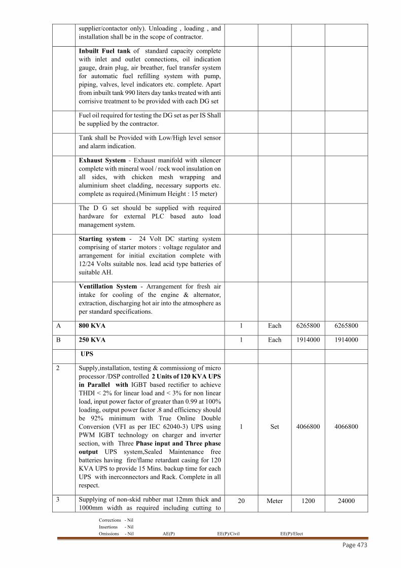
Corrections - Nil
Insertions - Nil
Omissions - Nil AE(P) EE(P)/Civil EE(P)/Elect
Page 473
supplier/contactor only). Unloading , loading , and installation shall be in the scope of contractor.
Inbuilt Fuel tank of standard capacity complete with inlet and outlet connections, oil indication gauge, drain plug, air breather, fuel transfer system for automatic fuel refilling system with pump, piping, valves, level indicators etc. complete. Apart from inbuilt tank 990 liters day tanks treated with anti corrisive treatment to be provided with each DG set
Fuel oil required for testing the DG set as per IS Shall be supplied by the contractor.
Tank shall be Provided with Low/High level sensor and alarm indication.
Exhaust System - Exhaust manifold with silencer complete with mineral wool / rock wool insulation on all sides, with chicken mesh wrapping and aluminium sheet cladding, necessary supports etc. complete as required.(Minimum Height : 15 meter)
The D G set should be supplied with required hardware for external PLC based auto load management system.
Starting system - 24 Volt DC starting system comprising of starter motors : voltage regulator and arrangement for initial excitation complete with 12/24 Volts suitable nos. lead acid type batteries of suitable AH.
Ventillation System - Arrangement for fresh air intake for cooling of the engine & alternator, extraction, discharging hot air into the atmosphere as per standard specifications.
A 800 KVA 1 Each 6265800 6265800
B 250 KVA 1 Each 1914000 1914000
UPS
2 Supply,installation, testing & commissiong of micro processor /DSP controlled 2 Units of 120 KVA UPS in Parallel with IGBT based rectifier to achieve THDI < 2% for linear load and < 3% for non linear load, input power factor of greater than 0.99 at 100% loading, output power factor .8 and efficiency should be 92% minimum with True Online Double Conversion (VFI as per IEC 62040-3) UPS using PWM IGBT technology on charger and inverter section, with Three Phase input and Three phase output UPS system,Sealed Maintenance free batteries having fire/flame retardant casing for 120 KVA UPS to provide 15 Mins. backup time for each UPS with inerconnectors and Rack. Complete in all respect.
1 Set 4066800 4066800
3 Supplying of non-skid rubber mat 12mm thick and 1000mm width as required including cutting to
20 Meter 1200 24000
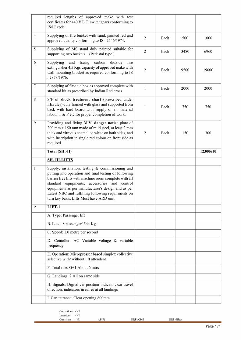
Corrections - Nil
Insertions - Nil
Omissions - Nil AE(P) EE(P)/Civil EE(P)/Elect
Page 474
required lengths of approved make with test certificates for 440 V L.T. switchgears conforming to IS/IE code..
4 Supplying of fire bucket with sand, painted red and approved quality conforming to IS : 2546/1974.
2 Each 500 1000
5 Supplying of MS stand duly painted suitable for supporting two buckets (Pedestal type )
2 Each 3480 6960
6 Supplying and fixing carbon dioxide fire extinguisher 4.5 Kgs capacity of approved make with wall mounting bracket as required conforming to IS : 2878/1976.
2 Each 9500 19000
7 Supplying of first aid box as approved complete with standard kit as prescribed by Indian Red cross.
1 Each 2000 2000
8 S/F of shock treatment chart (prescribed under I.E.rules) duly framed with glass and supported from back with hard board with supply of all material labour T & P etc for proper completion of work.
1 Each 750 750
9 Providing and fixing M.V. danger notice plate of 200 mm x 150 mm made of mild steel, at least 2 mm thick and vitreous enamelled white on both sides, and with inscription in single red colour on front side as required .
2 Each 150 300
Total (SH:-II) 12300610
SH- III-LIFTS
1 Supply, installation, testing & commissioning and putting into operation and final testing of following barrier free lifts with machine room complete with all standard equipments, accessories and control equipments as per manufacturer's design and as per Latest NBC and fulfilling following requirments on turn key basis. Lifts Must have ARD unit.
A LIFT-1
A. Type: Passenger lift
B. Load: 8 passenger/ 544 Kg
C. Speed: 1.0 metre per second
D. Contoller: AC Variable voltage & variable frequency
E. Operation: Microprosser based simplex collective selective with/ without lift attendent
F. Total rise: G+1 About 6 mtrs
G. Landings: 2 All on same side
H. Signals: Digital car position indicator, car travel direction, indicators in car & at all landings
I. Car entrance: Clear opening 800mm
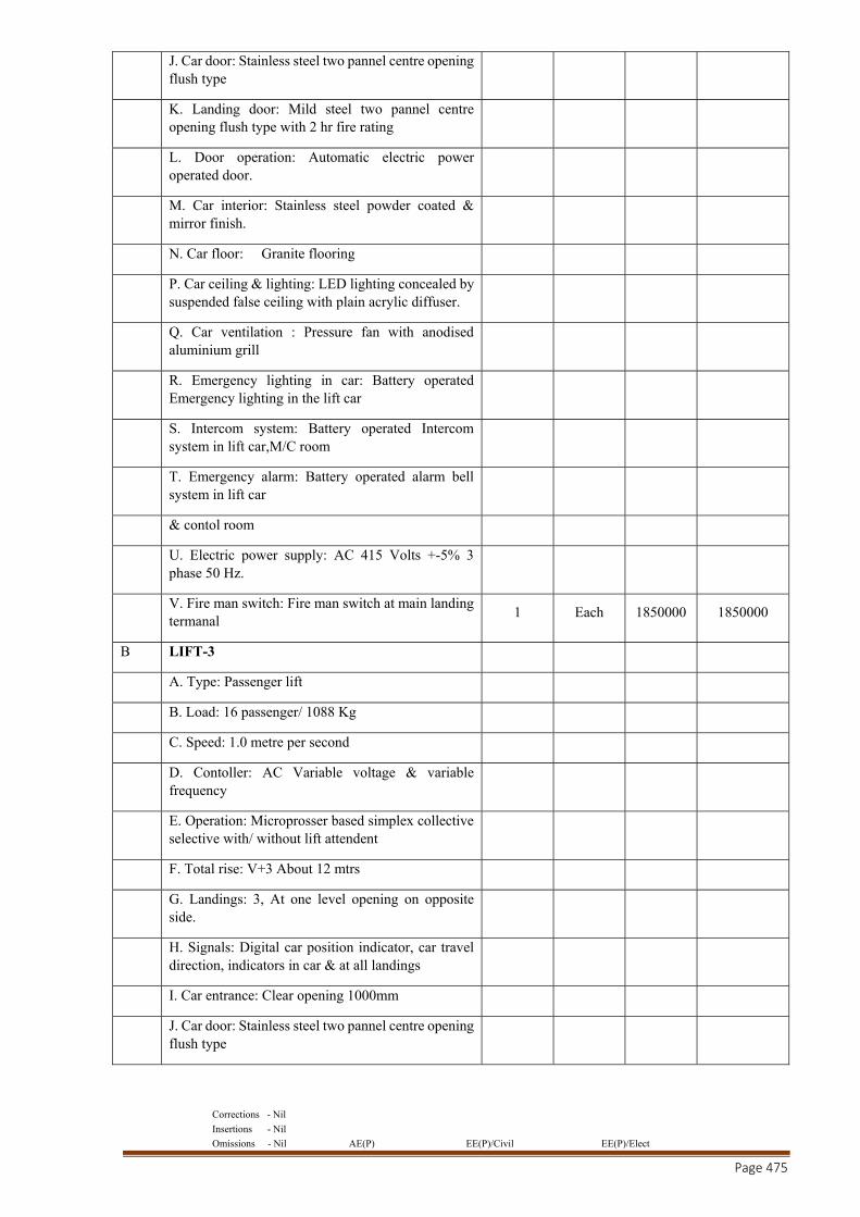
Corrections - Nil
Insertions - Nil
Omissions - Nil AE(P) EE(P)/Civil EE(P)/Elect
Page 475
J. Car door: Stainless steel two pannel centre opening flush type
K. Landing door: Mild steel two pannel centre opening flush type with 2 hr fire rating
L. Door operation: Automatic electric power operated door.
M. Car interior: Stainless steel powder coated & mirror finish.
N. Car floor: Granite flooring
P. Car ceiling & lighting: LED lighting concealed by suspended false ceiling with plain acrylic diffuser.
Q. Car ventilation : Pressure fan with anodised aluminium grill
R. Emergency lighting in car: Battery operated Emergency lighting in the lift car
S. Intercom system: Battery operated Intercom system in lift car,M/C room
T. Emergency alarm: Battery operated alarm bell system in lift car
& contol room
U. Electric power supply: AC 415 Volts +-5% 3 phase 50 Hz.
V. Fire man switch: Fire man switch at main landing termanal
1 Each 1850000 1850000
B LIFT-3
A. Type: Passenger lift
B. Load: 16 passenger/ 1088 Kg
C. Speed: 1.0 metre per second
D. Contoller: AC Variable voltage & variable frequency
E. Operation: Microprosser based simplex collective selective with/ without lift attendent
F. Total rise: V+3 About 12 mtrs
G. Landings: 3, At one level opening on opposite side.
H. Signals: Digital car position indicator, car travel direction, indicators in car & at all landings
I. Car entrance: Clear opening 1000mm
J. Car door: Stainless steel two pannel centre opening flush type
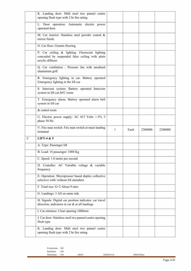
Corrections - Nil
Insertions - Nil
Omissions - Nil AE(P) EE(P)/Civil EE(P)/Elect
Page 476
K. Landing door: Mild steel two pannel centre opening flush type with 2 hr fire rating
L. Door operation: Automatic electric power operated door.
M. Car interior: Stainless steel powder coated & mirror finish.
N. Car floor: Granite flooring
P. Car ceiling & lighting: Fluorscent lighting concealed by suspended false ceiling with plain acrylic diffuser.
Q. Car ventilation : Pressure fan with anodised aluminium grill
R. Emergency lighting in car: Battery operated Emergency lighting in the lift car
S. Intercom system: Battery operated Intercom system in lift car,M/C room
T. Emergency alarm: Battery operated alarm bell system in lift car
& contol room
U. Electric power supply: AC 415 Volts +-5% 3 phase 50 Hz.
V. Fire man switch: Fire man switch at main landing termanal
1 Each 2200000 2200000
C LIFT-4 & 5
A. Type: Passenger lift
B. Load: 16 passenger/ 1088 Kg
C. Speed: 1.0 metre per second
D. Contoller: AC Variable voltage & variable frequency
E. Operation: Microprosser based duplex collective selective with/ without lift attendent
F. Total rise: G+2 About 9 mtrs
G. Landings: 3 All on same side
H. Signals: Digital car position indicator, car travel direction, indicators in car & at all landings
I. Car entrance: Clear opening 1000mm
J. Car door: Stainless steel two pannel centre opening flush type
K. Landing door: Mild steel two pannel centre opening flush type with 2 hr fire rating
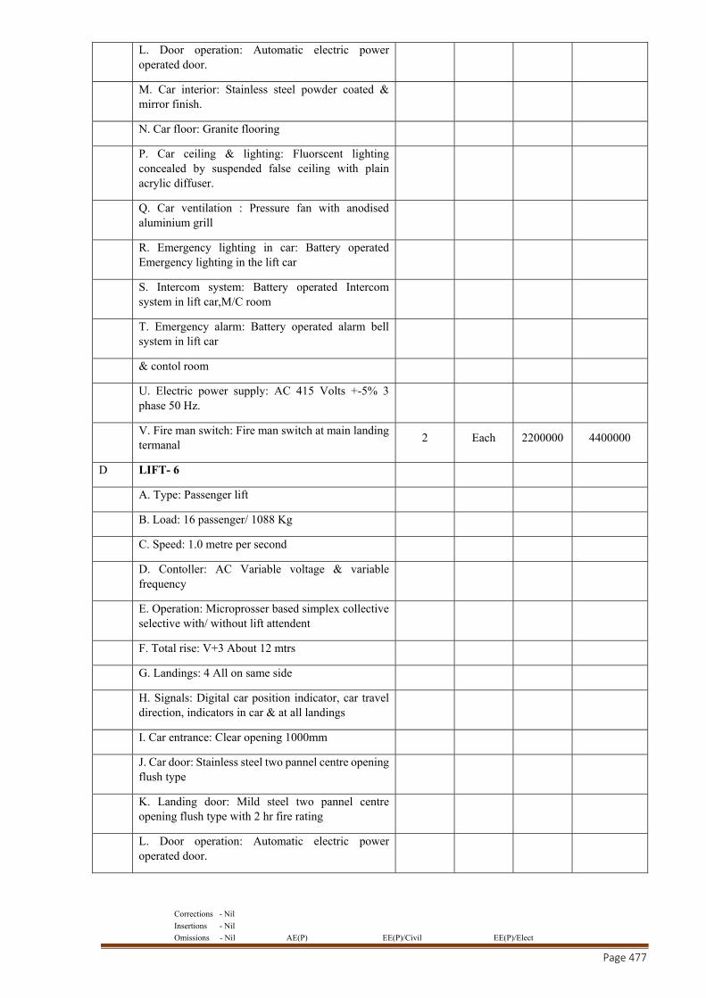
Corrections - Nil
Insertions - Nil
Omissions - Nil AE(P) EE(P)/Civil EE(P)/Elect
Page 477
L. Door operation: Automatic electric power operated door.
M. Car interior: Stainless steel powder coated & mirror finish.
N. Car floor: Granite flooring
P. Car ceiling & lighting: Fluorscent lighting concealed by suspended false ceiling with plain acrylic diffuser.
Q. Car ventilation : Pressure fan with anodised aluminium grill
R. Emergency lighting in car: Battery operated Emergency lighting in the lift car
S. Intercom system: Battery operated Intercom system in lift car,M/C room
T. Emergency alarm: Battery operated alarm bell system in lift car
& contol room
U. Electric power supply: AC 415 Volts +-5% 3 phase 50 Hz.
V. Fire man switch: Fire man switch at main landing termanal
2 Each 2200000 4400000
D LIFT- 6
A. Type: Passenger lift
B. Load: 16 passenger/ 1088 Kg
C. Speed: 1.0 metre per second
D. Contoller: AC Variable voltage & variable frequency
E. Operation: Microprosser based simplex collective selective with/ without lift attendent
F. Total rise: V+3 About 12 mtrs
G. Landings: 4 All on same side
H. Signals: Digital car position indicator, car travel direction, indicators in car & at all landings
I. Car entrance: Clear opening 1000mm
J. Car door: Stainless steel two pannel centre opening flush type
K. Landing door: Mild steel two pannel centre opening flush type with 2 hr fire rating
L. Door operation: Automatic electric power operated door.
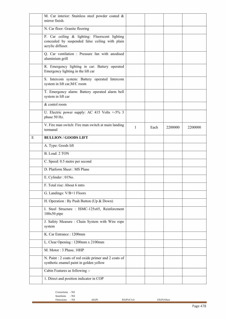
Corrections - Nil
Insertions - Nil
Omissions - Nil AE(P) EE(P)/Civil EE(P)/Elect
Page 478
M. Car interior: Stainless steel powder coated & mirror finish.
N. Car floor: Granite flooring
P. Car ceiling & lighting: Fluorscent lighting concealed by suspended false ceiling with plain acrylic diffuser.
Q. Car ventilation : Pressure fan with anodised aluminium grill
R. Emergency lighting in car: Battery operated Emergency lighting in the lift car
S. Intercom system: Battery operated Intercom system in lift car,M/C room
T. Emergency alarm: Battery operated alarm bell system in lift car
& contol room
U. Electric power supply: AC 415 Volts +-5% 3 phase 50 Hz.
V. Fire man switch: Fire man switch at main landing termanal
1 Each 2200000 2200000
E BULLION / GOODS LIFT
A. Type: Goods lift
B. Load: 2 TON
C. Speed: 0.5 metre per second
D. Platform Sheet : MS Plane
E. Cylinder : 01No.
F. Total rise: About 6 mtrs
G. Landings: V/B+1 Floors
H. Operation : By Push Button (Up & Down)
I. Steel Structure : ISMC-125x65, Reinforcment 100x50 pipe
J. Safety Measure : Chain System with Wire rope system
K. Car Entrance : 1200mm
L. Clear Opening : 1200mm x 2100mm
M. Motor : 3 Phase, 10HP
N. Paint : 2 coats of red oxide primer and 2 coats of synthetic enamel paint in golden yellow
Cabin Features as following :-
1. Direct and position indicator in COP
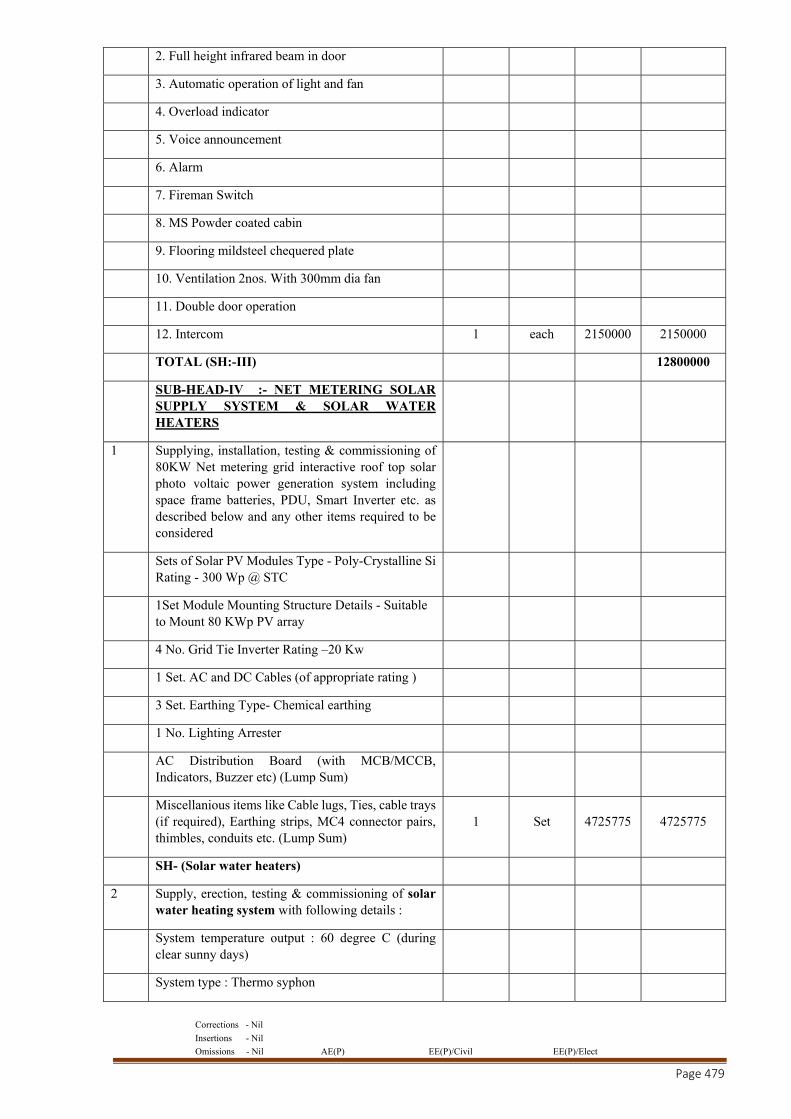
Corrections - Nil
Insertions - Nil
Omissions - Nil AE(P) EE(P)/Civil EE(P)/Elect
Page 479
2. Full height infrared beam in door
3. Automatic operation of light and fan
4. Overload indicator
5. Voice announcement
6. Alarm
7. Fireman Switch
8. MS Powder coated cabin
9. Flooring mildsteel chequered plate
10. Ventilation 2nos. With 300mm dia fan
11. Double door operation
12. Intercom 1 each 2150000 2150000
TOTAL (SH:-III) 12800000
SUB-HEAD-IV :- NET METERING SOLAR SUPPLY SYSTEM & SOLAR WATER HEATERS
1 Supplying, installation, testing & commissioning of 80KW Net metering grid interactive roof top solar photo voltaic power generation system including space frame batteries, PDU, Smart Inverter etc. as described below and any other items required to be considered
Sets of Solar PV Modules Type - Poly-Crystalline Si Rating - 300 Wp @ STC
1Set Module Mounting Structure Details - Suitable to Mount 80 KWp PV array
4 No. Grid Tie Inverter Rating –20 Kw
1 Set. AC and DC Cables (of appropriate rating )
3 Set. Earthing Type- Chemical earthing
1 No. Lighting Arrester
AC Distribution Board (with MCB/MCCB, Indicators, Buzzer etc) (Lump Sum)
Miscellanious items like Cable lugs, Ties, cable trays (if required), Earthing strips, MC4 connector pairs, thimbles, conduits etc. (Lump Sum)
1 Set 4725775 4725775
SH- (Solar water heaters)
2 Supply, erection, testing & commissioning of solar water heating system with following details :
System temperature output : 60 degree C (during clear sunny days)
System type : Thermo syphon
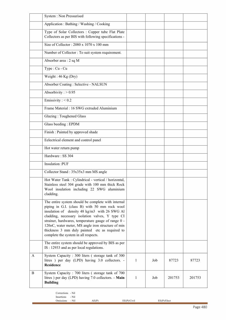
Corrections - Nil
Insertions - Nil
Omissions - Nil AE(P) EE(P)/Civil EE(P)/Elect
Page 480
System : Non Pressurised
Application : Bathing / Washing / Cooking
Type of Solar Collectors : Copper tube Flat Plate Collectors as per BIS with following specifications -
Size of Collector : 2080 x 1070 x 100 mm
Number of Collector : To suit system requirement.
Absorber area : 2 sq M
Type : Cu - Cu
Weight : 46 Kg (Dry)
Absorber Coating : Selective - NALSUN
Absorbivity : > 0.95
Emissivity : < 0.2
Frame Material : 16 SWG extruded Aluminium
Glazing : Toughened Glass
Glass beeding : EPDM
Finish : Painted by approved shade
Eelectrical element and control panel
Hot water return pump
Hardware : SS 304
Insulation :PUF
Collector Stand : 35x35x3 mm MS angle
Hot Water Tank : Cylindrical - vertical / horizontal, Stainless steel 304 grade with 100 mm thick Rock Wool insulation including 22 SWG aluminium cladding.
The entire system should be complete with internal piping in G.I. (class B) with 50 mm rock wool insulation of density 48 kg/m3 with 26 SWG Al cladding, necessary isolation valves, Y type CI strainer, hardwares, temperature gauge of range 0 - 120oC, water meter, MS angle iron structure of min thickness 3 mm duly painted etc as required to complete the system in all respects.
The entire system should be approved by BIS as per IS : 12933 and as per local regulations.
A System Capacity : 300 liters ( storage tank of 300 litres ) per day (LPD) having 3.0 collectors. - Residence
1 Job 87723 87723
B System Capacity : 700 liters ( storage tank of 700 litres ) per day (LPD) having 7.0 collectors. - Main Building
1 Job 201753 201753
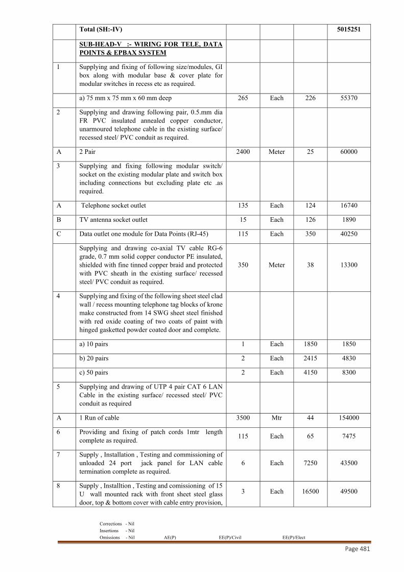
Corrections - Nil
Insertions - Nil
Omissions - Nil AE(P) EE(P)/Civil EE(P)/Elect
Page 481
Total (SH:-IV) 5015251
SUB-HEAD-V :- WIRING FOR TELE, DATA POINTS & EPBAX SYSTEM
1 Supplying and fixing of following size/modules, GI box along with modular base & cover plate for modular switches in recess etc as required.
a) 75 mm x 75 mm x 60 mm deep 265 Each 226 55370
2 Supplying and drawing following pair, 0.5.mm dia FR PVC insulated annealed copper conductor, unarmoured telephone cable in the existing surface/ recessed steel/ PVC conduit as required.
A 2 Pair 2400 Meter 25 60000
3 Supplying and fixing following modular switch/ socket on the existing modular plate and switch box including connections but excluding plate etc .as required.
A Telephone socket outlet 135 Each 124 16740
B TV antenna socket outlet 15 Each 126 1890
C Data outlet one module for Data Points (RJ-45) 115 Each 350 40250
Supplying and drawing co-axial TV cable RG-6 grade, 0.7 mm solid copper conductor PE insulated, shielded with fine tinned copper braid and protected with PVC sheath in the existing surface/ recessed steel/ PVC conduit as required.
350 Meter 38 13300
4 Supplying and fixing of the following sheet steel clad wall / recess mounting telephone tag blocks of krone make constructed from 14 SWG sheet steel finished with red oxide coating of two coats of paint with hinged gasketted powder coated door and complete.
a) 10 pairs 1 Each 1850 1850
b) 20 pairs 2 Each 2415 4830
c) 50 pairs 2 Each 4150 8300
5 Supplying and drawing of UTP 4 pair CAT 6 LAN Cable in the existing surface/ recessed steel/ PVC conduit as required
A 1 Run of cable 3500 Mtr 44 154000
6 Providing and fixing of patch cords 1mtr length complete as required.
115 Each 65 7475
7 Supply , Installation , Testing and commissioning of unloaded 24 port jack panel for LAN cable termination complete as required.
6 Each 7250 43500
8 Supply , Installtion , Testing and comissioning of 15 U wall mounted rack with front sheet steel glass door, top & bottom cover with cable entry provision,
3 Each 16500 49500
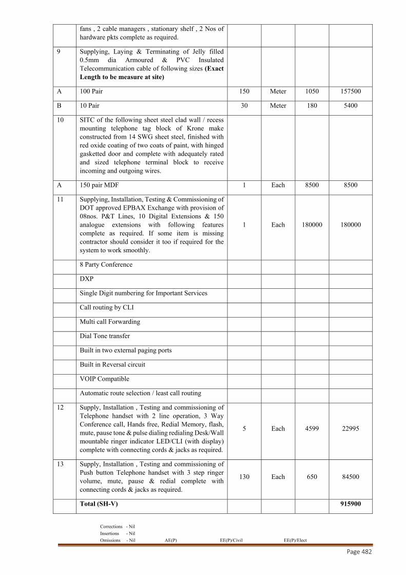
Corrections - Nil
Insertions - Nil
Omissions - Nil AE(P) EE(P)/Civil EE(P)/Elect
Page 482
fans , 2 cable managers , stationary shelf , 2 Nos of hardware pkts complete as required.
9 Supplying, Laying & Terminating of Jelly filled 0.5mm dia Armoured & PVC Insulated Telecommunication cable of following sizes (Exact Length to be measure at site)
A 100 Pair 150 Meter 1050 157500
B 10 Pair 30 Meter 180 5400
10 SITC of the following sheet steel clad wall / recess mounting telephone tag block of Krone make constructed from 14 SWG sheet steel, finished with red oxide coating of two coats of paint, with hinged gasketted door and complete with adequately rated and sized telephone terminal block to receive incoming and outgoing wires.
A 150 pair MDF 1 Each 8500 8500
11 Supplying, Installation, Testing & Commissioning of DOT approved EPBAX Exchange with provision of 08nos. P&T Lines, 10 Digital Extensions & 150 analogue extensions with following features complete as required. If some item is missing contractor should consider it too if required for the system to work smoothly.
1 Each 180000 180000
8 Party Conference
DXP
Single Digit numbering for Important Services
Call routing by CLI
Multi call Forwarding
Dial Tone transfer
Built in two external paging ports
Built in Reversal circuit
VOIP Compatible
Automatic route selection / least call routing
12 Supply, Installation , Testing and commissioning of Telephone handset with 2 line operation, 3 Way Conference call, Hands free, Redial Memory, flash, mute, pause tone & pulse dialing redialing Desk/Wall mountable ringer indicator LED/CLI (with display) complete with connecting cords & jacks as required.
5 Each 4599 22995
13 Supply, Installation , Testing and commissioning of Push button Telephone handset with 3 step ringer volume, mute, pause & redial complete with connecting cords & jacks as required.
130 Each 650 84500
Total (SH-V) 915900
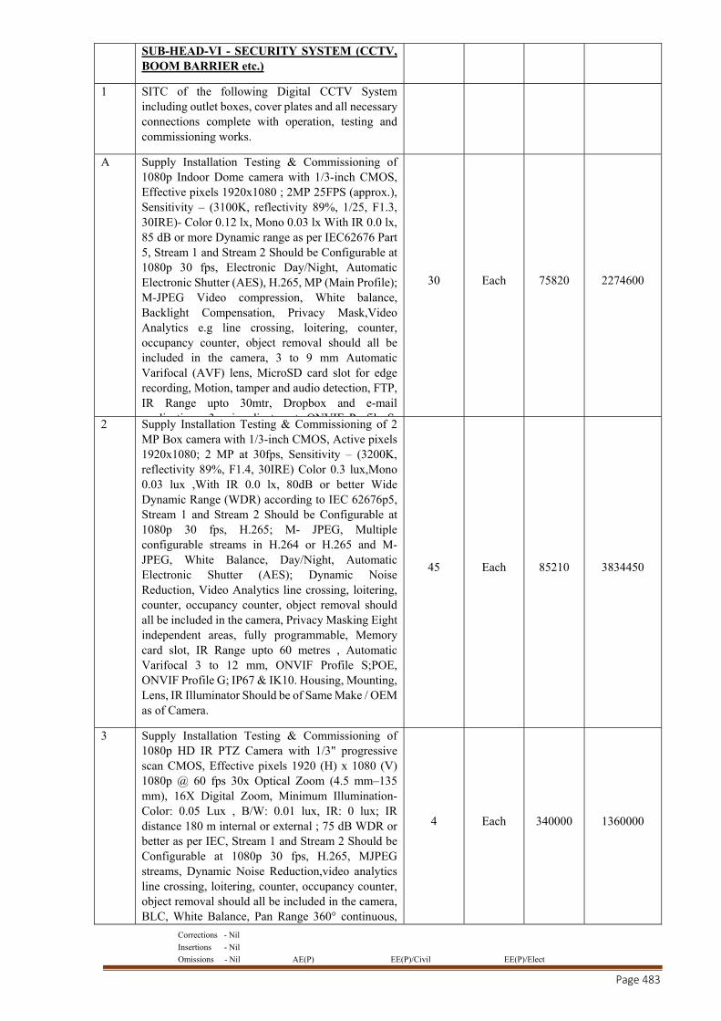
Corrections - Nil
Insertions - Nil
Omissions - Nil AE(P) EE(P)/Civil EE(P)/Elect
Page 483
SUB-HEAD-VI - SECURITY SYSTEM (CCTV, BOOM BARRIER etc.)
1 SITC of the following Digital CCTV System including outlet boxes, cover plates and all necessary connections complete with operation, testing and commissioning works.
A Supply Installation Testing & Commissioning of 1080p Indoor Dome camera with 1/3-inch CMOS, Effective pixels 1920x1080 ; 2MP 25FPS (approx.), Sensitivity – (3100K, reflectivity 89%, 1/25, F1.3, 30IRE)- Color 0.12 lx, Mono 0.03 lx With IR 0.0 lx, 85 dB or more Dynamic range as per IEC62676 Part 5, Stream 1 and Stream 2 Should be Configurable at 1080p 30 fps, Electronic Day/Night, Automatic Electronic Shutter (AES), H.265, MP (Main Profile); M-JPEG Video compression, White balance, Backlight Compensation, Privacy Mask,Video Analytics e.g line crossing, loitering, counter, occupancy counter, object removal should all be included in the camera, 3 to 9 mm Automatic Varifocal (AVF) lens, MicroSD card slot for edge recording, Motion, tamper and audio detection, FTP, IR Range upto 30mtr, Dropbox and e-mail
li ti 3 i dj t t ONVIF P fil S
30 Each 75820 2274600
2 Supply Installation Testing & Commissioning of 2 MP Box camera with 1/3-inch CMOS, Active pixels 1920x1080; 2 MP at 30fps, Sensitivity – (3200K, reflectivity 89%, F1.4, 30IRE) Color 0.3 lux,Mono 0.03 lux ,With IR 0.0 lx, 80dB or better Wide Dynamic Range (WDR) according to IEC 62676p5, Stream 1 and Stream 2 Should be Configurable at 1080p 30 fps, H.265; M- JPEG, Multiple configurable streams in H.264 or H.265 and M-JPEG, White Balance, Day/Night, Automatic Electronic Shutter (AES); Dynamic Noise Reduction, Video Analytics line crossing, loitering, counter, occupancy counter, object removal should all be included in the camera, Privacy Masking Eight independent areas, fully programmable, Memory card slot, IR Range upto 60 metres , Automatic Varifocal 3 to 12 mm, ONVIF Profile S;POE, ONVIF Profile G; IP67 & IK10. Housing, Mounting, Lens, IR Illuminator Should be of Same Make / OEM as of Camera.
45 Each 85210 3834450
3 Supply Installation Testing & Commissioning of 1080p HD IR PTZ Camera with 1/3" progressive scan CMOS, Effective pixels 1920 (H) x 1080 (V) 1080p @ 60 fps 30x Optical Zoom (4.5 mm–135 mm), 16X Digital Zoom, Minimum Illumination- Color: 0.05 Lux , B/W: 0.01 lux, IR: 0 lux; IR distance 180 m internal or external ; 75 dB WDR or better as per IEC, Stream 1 and Stream 2 Should be Configurable at 1080p 30 fps, H.265, MJPEG streams, Dynamic Noise Reduction,video analytics line crossing, loitering, counter, occupancy counter, object removal should all be included in the camera, BLC, White Balance, Pan Range 360° continuous,
4 Each 340000 1360000
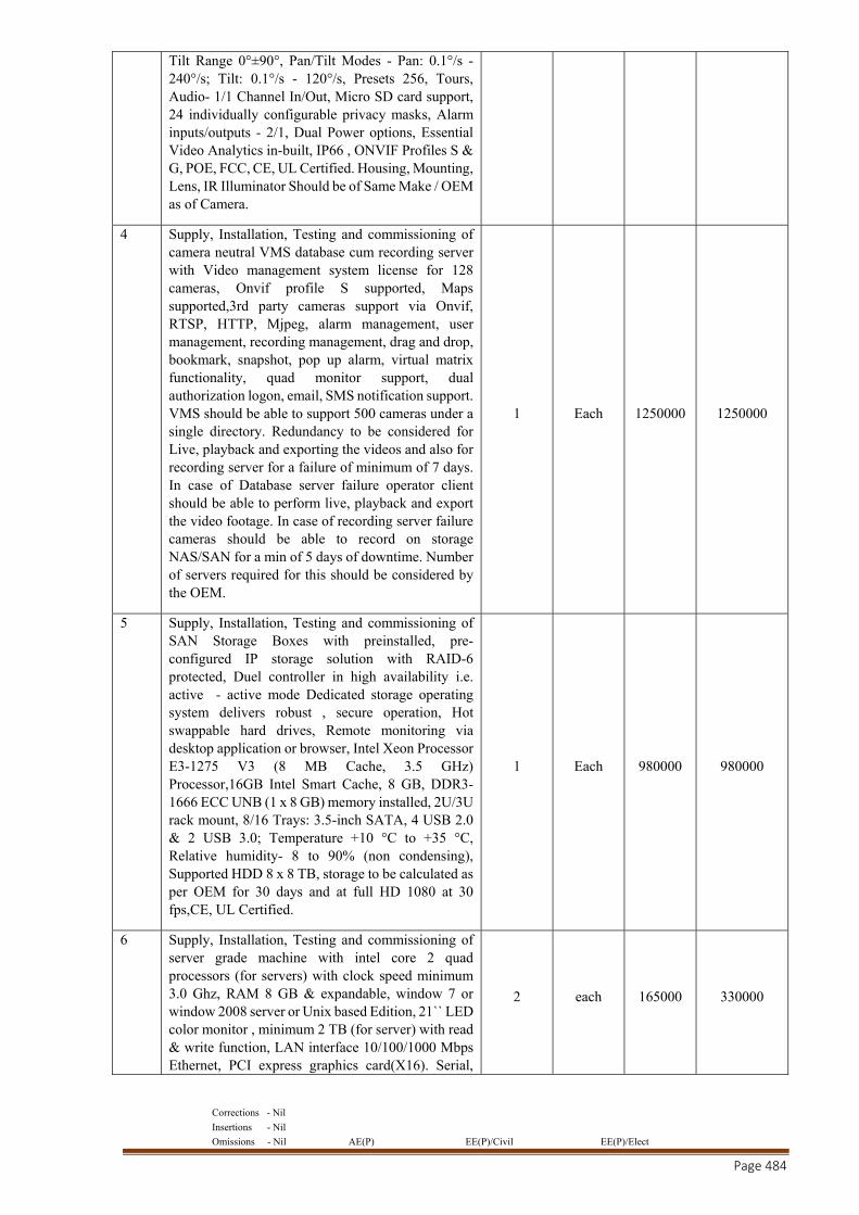
Corrections - Nil
Insertions - Nil
Omissions - Nil AE(P) EE(P)/Civil EE(P)/Elect
Page 484
Tilt Range 0°±90°, Pan/Tilt Modes - Pan: 0.1°/s - 240°/s; Tilt: 0.1°/s - 120°/s, Presets 256, Tours, Audio- 1/1 Channel In/Out, Micro SD card support, 24 individually configurable privacy masks, Alarm inputs/outputs - 2/1, Dual Power options, Essential Video Analytics in-built, IP66 , ONVIF Profiles S & G, POE, FCC, CE, UL Certified. Housing, Mounting, Lens, IR Illuminator Should be of Same Make / OEM as of Camera.
4 Supply, Installation, Testing and commissioning of camera neutral VMS database cum recording server with Video management system license for 128 cameras, Onvif profile S supported, Maps supported,3rd party cameras support via Onvif, RTSP, HTTP, Mjpeg, alarm management, user management, recording management, drag and drop, bookmark, snapshot, pop up alarm, virtual matrix functionality, quad monitor support, dual authorization logon, email, SMS notification support. VMS should be able to support 500 cameras under a single directory. Redundancy to be considered for Live, playback and exporting the videos and also for recording server for a failure of minimum of 7 days. In case of Database server failure operator client should be able to perform live, playback and export the video footage. In case of recording server failure cameras should be able to record on storage NAS/SAN for a min of 5 days of downtime. Number of servers required for this should be considered by the OEM.
1 Each 1250000 1250000
5 Supply, Installation, Testing and commissioning of SAN Storage Boxes with preinstalled, pre-configured IP storage solution with RAID-6 protected, Duel controller in high availability i.e. active - active mode Dedicated storage operating system delivers robust , secure operation, Hot swappable hard drives, Remote monitoring via desktop application or browser, Intel Xeon Processor E3-1275 V3 (8 MB Cache, 3.5 GHz) Processor,16GB Intel Smart Cache, 8 GB, DDR3-1666 ECC UNB (1 x 8 GB) memory installed, 2U/3U rack mount, 8/16 Trays: 3.5-inch SATA, 4 USB 2.0 & 2 USB 3.0; Temperature +10 °C to +35 °C, Relative humidity- 8 to 90% (non condensing), Supported HDD 8 x 8 TB, storage to be calculated as per OEM for 30 days and at full HD 1080 at 30 fps,CE, UL Certified.
1 Each 980000 980000
6 Supply, Installation, Testing and commissioning of server grade machine with intel core 2 quad processors (for servers) with clock speed minimum 3.0 Ghz, RAM 8 GB & expandable, window 7 or window 2008 server or Unix based Edition, 21`` LED color monitor , minimum 2 TB (for server) with read & write function, LAN interface 10/100/1000 Mbps Ethernet, PCI express graphics card(X16). Serial,
2 each 165000 330000
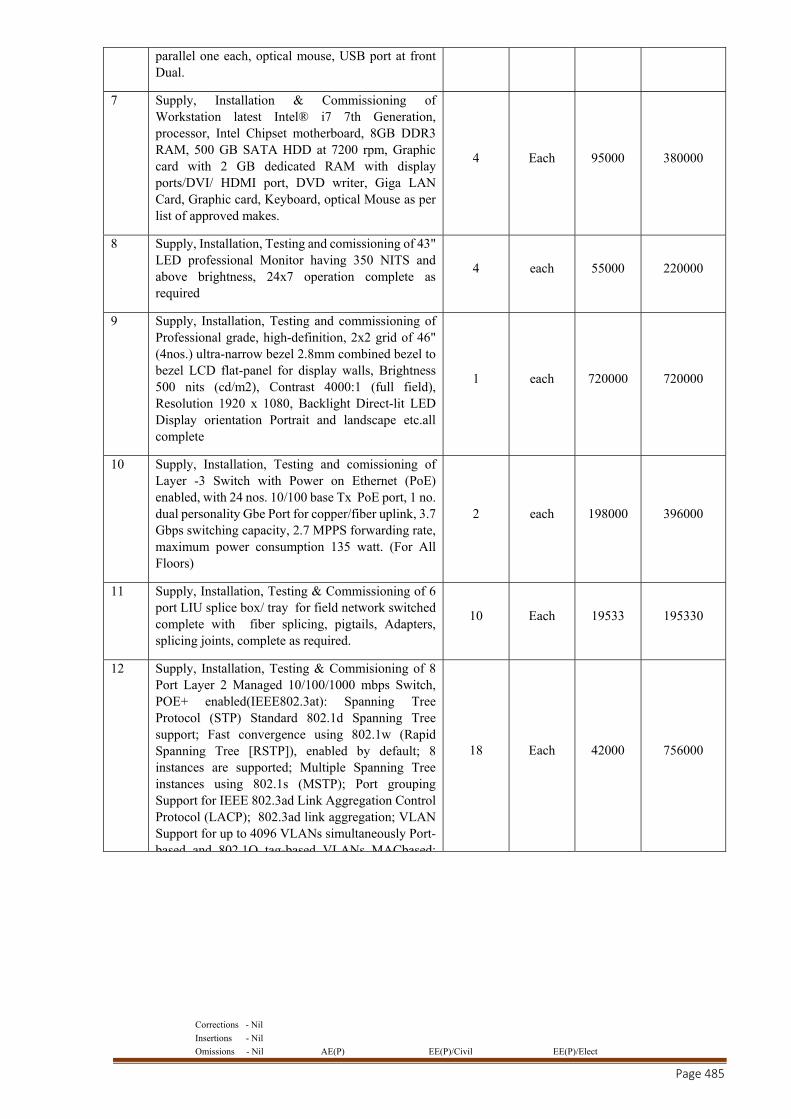
Corrections - Nil
Insertions - Nil
Omissions - Nil AE(P) EE(P)/Civil EE(P)/Elect
Page 485
parallel one each, optical mouse, USB port at front Dual.
7 Supply, Installation & Commissioning of Workstation latest Intel® i7 7th Generation, processor, Intel Chipset motherboard, 8GB DDR3 RAM, 500 GB SATA HDD at 7200 rpm, Graphic card with 2 GB dedicated RAM with display ports/DVI/ HDMI port, DVD writer, Giga LAN Card, Graphic card, Keyboard, optical Mouse as per list of approved makes.
4 Each 95000 380000
8 Supply, Installation, Testing and comissioning of 43" LED professional Monitor having 350 NITS and above brightness, 24x7 operation complete as required
4 each 55000 220000
9 Supply, Installation, Testing and commissioning of Professional grade, high-definition, 2x2 grid of 46" (4nos.) ultra-narrow bezel 2.8mm combined bezel to bezel LCD flat-panel for display walls, Brightness 500 nits (cd/m2), Contrast 4000:1 (full field), Resolution 1920 x 1080, Backlight Direct-lit LED Display orientation Portrait and landscape etc.all complete
1 each 720000 720000
10 Supply, Installation, Testing and comissioning of Layer -3 Switch with Power on Ethernet (PoE) enabled, with 24 nos. 10/100 base Tx PoE port, 1 no. dual personality Gbe Port for copper/fiber uplink, 3.7 Gbps switching capacity, 2.7 MPPS forwarding rate, maximum power consumption 135 watt. (For All Floors)
2 each 198000 396000
11 Supply, Installation, Testing & Commissioning of 6 port LIU splice box/ tray for field network switched complete with fiber splicing, pigtails, Adapters, splicing joints, complete as required.
10 Each 19533 195330
12 Supply, Installation, Testing & Commisioning of 8 Port Layer 2 Managed 10/100/1000 mbps Switch, POE+ enabled(IEEE802.3at): Spanning Tree Protocol (STP) Standard 802.1d Spanning Tree support; Fast convergence using 802.1w (Rapid Spanning Tree [RSTP]), enabled by default; 8 instances are supported; Multiple Spanning Tree instances using 802.1s (MSTP); Port grouping Support for IEEE 802.3ad Link Aggregation Control Protocol (LACP); 802.3ad link aggregation; VLAN Support for up to 4096 VLANs simultaneously Port-based and 802 1Q tag-based VLANs MACbased;
18 Each 42000 756000
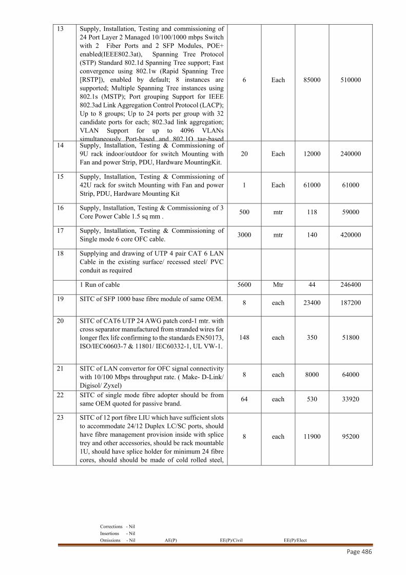
Corrections - Nil
Insertions - Nil
Omissions - Nil AE(P) EE(P)/Civil EE(P)/Elect
Page 486
13 Supply, Installation, Testing and commissioning of 24 Port Layer 2 Managed 10/100/1000 mbps Switch with 2 Fiber Ports and 2 SFP Modules, POE+ enabled(IEEE802.3at), Spanning Tree Protocol (STP) Standard 802.1d Spanning Tree support; Fast convergence using 802.1w (Rapid Spanning Tree [RSTP]), enabled by default; 8 instances are supported; Multiple Spanning Tree instances using 802.1s (MSTP); Port grouping Support for IEEE 802.3ad Link Aggregation Control Protocol (LACP); Up to 8 groups; Up to 24 ports per group with 32 candidate ports for each; 802.3ad link aggregation; VLAN Support for up to 4096 VLANs simultaneously Port-based and 802.1Q tag-based
6 Each 85000 510000
14 Supply, Installation, Testing & Commissioning of 9U rack indoor/outdoor for switch Mounting with Fan and power Strip, PDU, Hardware MountingKit.
20 Each 12000 240000
15 Supply, Installation, Testing & Commissioning of 42U rack for switch Mounting with Fan and power Strip, PDU, Hardware Mounting Kit
1 Each 61000 61000
16 Supply, Installation, Testing & Commissioning of 3 Core Power Cable 1.5 sq mm .
500 mtr 118 59000
17 Supply, Installation, Testing & Commissioning of Single mode 6 core OFC cable.
3000 mtr 140 420000
18 Supplying and drawing of UTP 4 pair CAT 6 LAN Cable in the existing surface/ recessed steel/ PVC conduit as required
1 Run of cable 5600 Mtr 44 246400
19 SITC of SFP 1000 base fibre module of same OEM. 8 each 23400 187200
20 SITC of CAT6 UTP 24 AWG patch cord-1 mtr. with cross separator manufactured from stranded wires for longer flex life confirming to the standards EN50173, ISO/IEC60603-7 & 11801/ IEC60332-1, UL VW-1.
148 each 350 51800
21 SITC of LAN convertor for OFC signal connectivity with 10/100 Mbps throughput rate. ( Make- D-Link/ Digisol/ Zyxel)
8 each 8000 64000
22 SITC of single mode fibre adopter should be from same OEM quoted for passive brand.
64 each 530 33920
23 SITC of 12 port fibre LIU which have sufficient slots to accommodate 24/12 Duplex LC/SC ports, should have fibre management provision inside with splice trey and other accessories, should be rack mountable 1U, should have splice holder for minimum 24 fibre cores, should should be made of cold rolled steel,
8 each 11900 95200
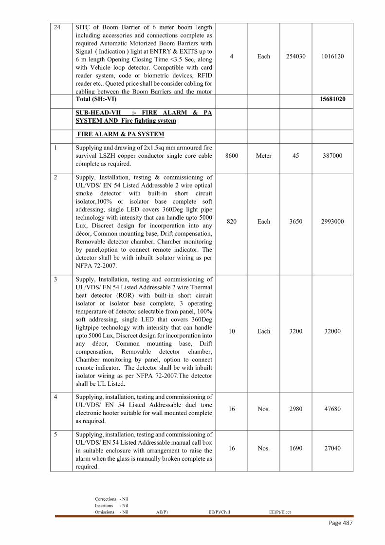
Corrections - Nil
Insertions - Nil
Omissions - Nil AE(P) EE(P)/Civil EE(P)/Elect
Page 487
24 SITC of Boom Barrier of 6 meter boom length including accessories and connections complete as required Automatic Motorized Boom Barriers with Signal ( Indication ) light at ENTRY & EXITS up to 6 m length Opening Closing Time <3.5 Sec, along with Vehicle loop detector. Compatible with card reader system, code or biometric devices, RFID reader etc.. Quoted price shall be consider cabling for cabling between the Boom Barriers and the motor
4 Each 254030 1016120
Total (SH:-VI) 15681020
SUB-HEAD-VII :- FIRE ALARM & PA SYSTEM AND Fire fighting system
FIRE ALARM & PA SYSTEM
1 Supplying and drawing of 2x1.5sq mm armoured fire survival LSZH copper conductor single core cable complete as required.
8600 Meter 45 387000
2 Supply, Installation, testing & commissioning of UL/VDS/ EN 54 Listed Addressable 2 wire optical smoke detector with built-in short circuit isolator,100% or isolator base complete soft addressing, single LED covers 360Deg light pipe technology with intensity that can handle upto 5000 Lux, Discreet design for incorporation into any décor, Common mounting base, Drift compensation, Removable detector chamber, Chamber monitoring by panel,option to connect remote indicator. The detector shall be with inbuilt isolator wiring as per NFPA 72-2007.
820 Each 3650 2993000
3 Supply, Installation, testing and commissioning of UL/VDS/ EN 54 Listed Addressable 2 wire Thermal heat detector (ROR) with built-in short circuit isolator or isolator base complete, 3 operating temperature of detector selectable from panel, 100% soft addressing, single LED that covers 360Deg lightpipe technology with intensity that can handle upto 5000 Lux, Discreet design for incorporation into any décor, Common mounting base, Drift compensation, Removable detector chamber, Chamber monitoring by panel, option to connect remote indicator. The detector shall be with inbuilt isolator wiring as per NFPA 72-2007.The detector shall be UL Listed.
10 Each 3200 32000
4 Supplying, installation, testing and commissioning of UL/VDS/ EN 54 Listed Addressable duel tone electronic hooter suitable for wall mounted complete as required.
16 Nos. 2980 47680
5 Supplying, installation, testing and commissioning of UL/VDS/ EN 54 Listed Addressable manual call box in suitable enclosure with arrangement to raise the alarm when the glass is manually broken complete as required.
16 Nos. 1690 27040
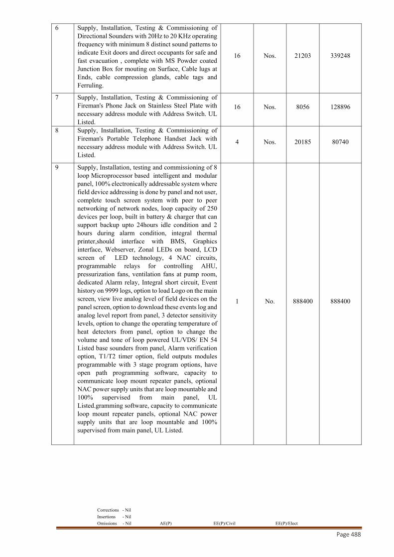
Corrections - Nil
Insertions - Nil
Omissions - Nil AE(P) EE(P)/Civil EE(P)/Elect
Page 488
6 Supply, Installation, Testing & Commissioning of Directional Sounders with 20Hz to 20 KHz operating frequency with minimum 8 distinct sound patterns to indicate Exit doors and direct occupants for safe and fast evacuation , complete with MS Powder coated Junction Box for mouting on Surface, Cable lugs at Ends, cable compression glands, cable tags and Ferruling.
16 Nos. 21203 339248
7 Supply, Installation, Testing & Commissioning of Fireman's Phone Jack on Stainless Steel Plate with necessary address module with Address Switch. UL Listed.
16 Nos. 8056 128896
8 Supply, Installation, Testing & Commissioning of Fireman's Portable Telephone Handset Jack with necessary address module with Address Switch. UL Listed.
4 Nos. 20185 80740
9 Supply, Installation, testing and commissioning of 8 loop Microprocessor based intelligent and modular panel, 100% electronically addressable system where field device addressing is done by panel and not user, complete touch screen system with peer to peer networking of network nodes, loop capacity of 250 devices per loop, built in battery & charger that can support backup upto 24hours idle condition and 2 hours during alarm condition, integral thermal printer,should interface with BMS, Graphics interface, Webserver, Zonal LEDs on board, LCD screen of LED technology, 4 NAC circuits, programmable relays for controlling AHU, pressurization fans, ventilation fans at pump room, dedicated Alarm relay, Integral short circuit, Event history on 9999 logs, option to load Logo on the main screen, view live analog level of field devices on the panel screen, option to download these events log and analog level report from panel, 3 detector sensitivity levels, option to change the operating temperature of heat detectors from panel, option to change the volume and tone of loop powered UL/VDS/ EN 54 Listed base sounders from panel, Alarm verification option, T1/T2 timer option, field outputs modules programmable with 3 stage program options, have open path programming software, capacity to communicate loop mount repeater panels, optional NAC power supply units that are loop mountable and 100% supervised from main panel, UL Listed.gramming software, capacity to communicate loop mount repeater panels, optional NAC power supply units that are loop mountable and 100% supervised from main panel, UL Listed.
1 No. 888400 888400
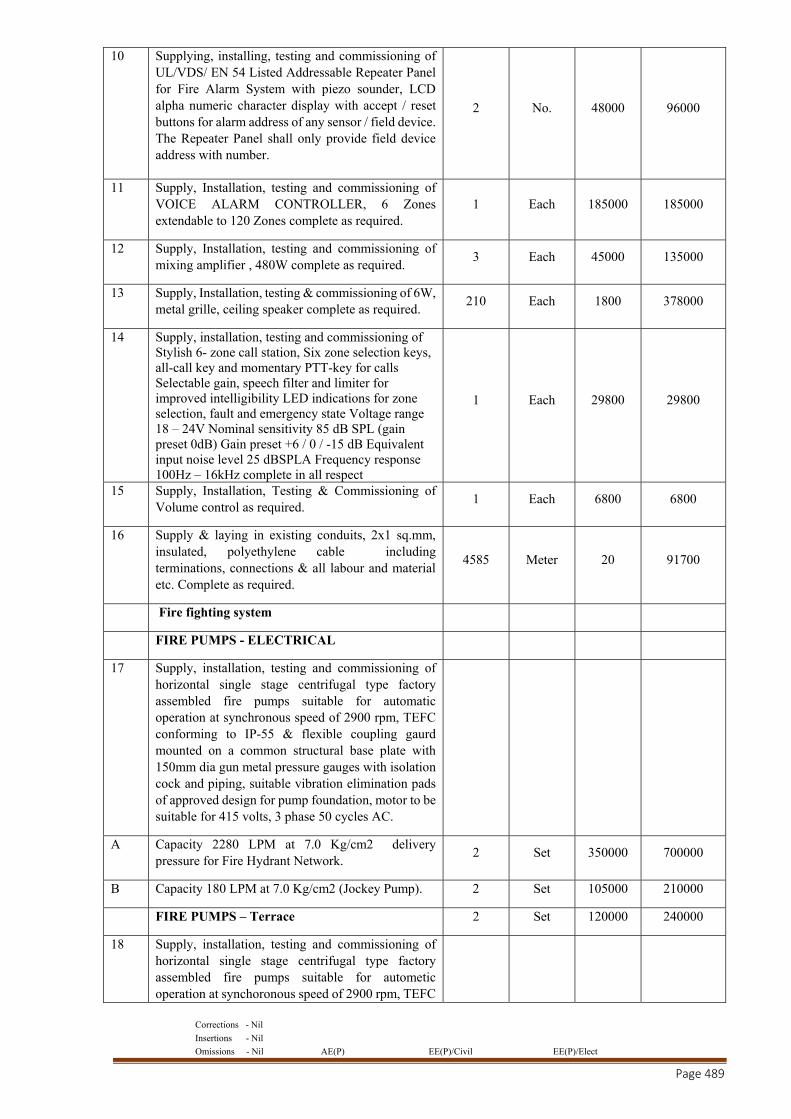
Corrections - Nil
Insertions - Nil
Omissions - Nil AE(P) EE(P)/Civil EE(P)/Elect
Page 489
10 Supplying, installing, testing and commissioning of UL/VDS/ EN 54 Listed Addressable Repeater Panel for Fire Alarm System with piezo sounder, LCD alpha numeric character display with accept / reset buttons for alarm address of any sensor / field device. The Repeater Panel shall only provide field device address with number.
2 No. 48000 96000
11 Supply, Installation, testing and commissioning of VOICE ALARM CONTROLLER, 6 Zones extendable to 120 Zones complete as required.
1 Each 185000 185000
12 Supply, Installation, testing and commissioning of mixing amplifier , 480W complete as required.
3 Each 45000 135000
13 Supply, Installation, testing & commissioning of 6W, metal grille, ceiling speaker complete as required.
210 Each 1800 378000
14 Supply, installation, testing and commissioning of Stylish 6- zone call station, Six zone selection keys, all-call key and momentary PTT-key for calls Selectable gain, speech filter and limiter for improved intelligibility LED indications for zone selection, fault and emergency state Voltage range 18 – 24V Nominal sensitivity 85 dB SPL (gain preset 0dB) Gain preset +6 / 0 / -15 dB Equivalent input noise level 25 dBSPLA Frequency response 100Hz – 16kHz complete in all respect
1 Each 29800 29800
15 Supply, Installation, Testing & Commissioning of Volume control as required.
1 Each 6800 6800
16 Supply & laying in existing conduits, 2x1 sq.mm, insulated, polyethylene cable including terminations, connections & all labour and material etc. Complete as required.
4585 Meter 20 91700
Fire fighting system
FIRE PUMPS - ELECTRICAL
17 Supply, installation, testing and commissioning of horizontal single stage centrifugal type factory assembled fire pumps suitable for automatic operation at synchronous speed of 2900 rpm, TEFC conforming to IP-55 & flexible coupling gaurd mounted on a common structural base plate with 150mm dia gun metal pressure gauges with isolation cock and piping, suitable vibration elimination pads of approved design for pump foundation, motor to be suitable for 415 volts, 3 phase 50 cycles AC.
A Capacity 2280 LPM at 7.0 Kg/cm2 delivery pressure for Fire Hydrant Network.
2 Set 350000 700000
B Capacity 180 LPM at 7.0 Kg/cm2 (Jockey Pump). 2 Set 105000 210000
FIRE PUMPS – Terrace 2 Set 120000 240000
18 Supply, installation, testing and commissioning of horizontal single stage centrifugal type factory assembled fire pumps suitable for autometic operation at synchoronous speed of 2900 rpm, TEFC
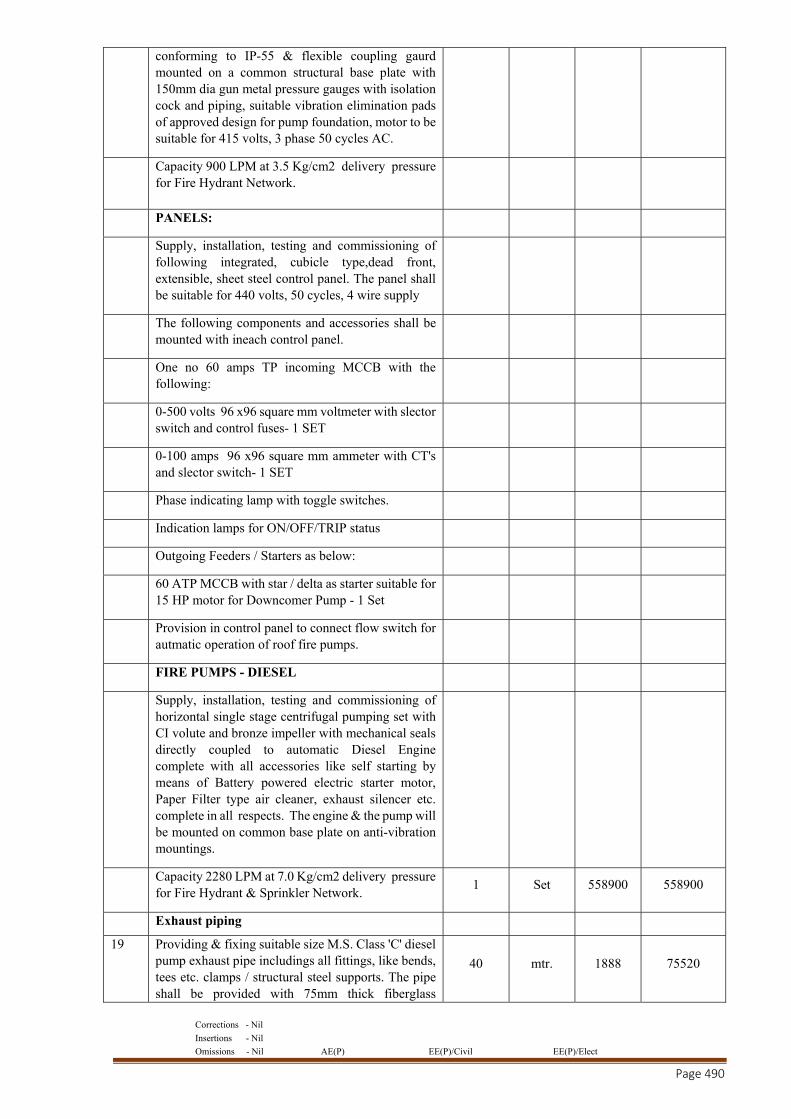
Corrections - Nil
Insertions - Nil
Omissions - Nil AE(P) EE(P)/Civil EE(P)/Elect
Page 490
conforming to IP-55 & flexible coupling gaurd mounted on a common structural base plate with 150mm dia gun metal pressure gauges with isolation cock and piping, suitable vibration elimination pads of approved design for pump foundation, motor to be suitable for 415 volts, 3 phase 50 cycles AC.
Capacity 900 LPM at 3.5 Kg/cm2 delivery pressure for Fire Hydrant Network.
PANELS:
Supply, installation, testing and commissioning of following integrated, cubicle type,dead front, extensible, sheet steel control panel. The panel shall be suitable for 440 volts, 50 cycles, 4 wire supply
The following components and accessories shall be mounted with ineach control panel.
One no 60 amps TP incoming MCCB with the following:
0-500 volts 96 x96 square mm voltmeter with slector switch and control fuses- 1 SET
0-100 amps 96 x96 square mm ammeter with CT's and slector switch- 1 SET
Phase indicating lamp with toggle switches.
Indication lamps for ON/OFF/TRIP status
Outgoing Feeders / Starters as below:
60 ATP MCCB with star / delta as starter suitable for 15 HP motor for Downcomer Pump - 1 Set
Provision in control panel to connect flow switch for autmatic operation of roof fire pumps.
FIRE PUMPS - DIESEL
Supply, installation, testing and commissioning of horizontal single stage centrifugal pumping set with CI volute and bronze impeller with mechanical seals directly coupled to automatic Diesel Engine complete with all accessories like self starting by means of Battery powered electric starter motor, Paper Filter type air cleaner, exhaust silencer etc. complete in all respects. The engine & the pump will be mounted on common base plate on anti-vibration mountings.
Capacity 2280 LPM at 7.0 Kg/cm2 delivery pressure for Fire Hydrant & Sprinkler Network.
1 Set 558900 558900
Exhaust piping
19 Providing & fixing suitable size M.S. Class 'C' diesel pump exhaust pipe includings all fittings, like bends, tees etc. clamps / structural steel supports. The pipe shall be provided with 75mm thick fiberglass
40 mtr. 1888 75520
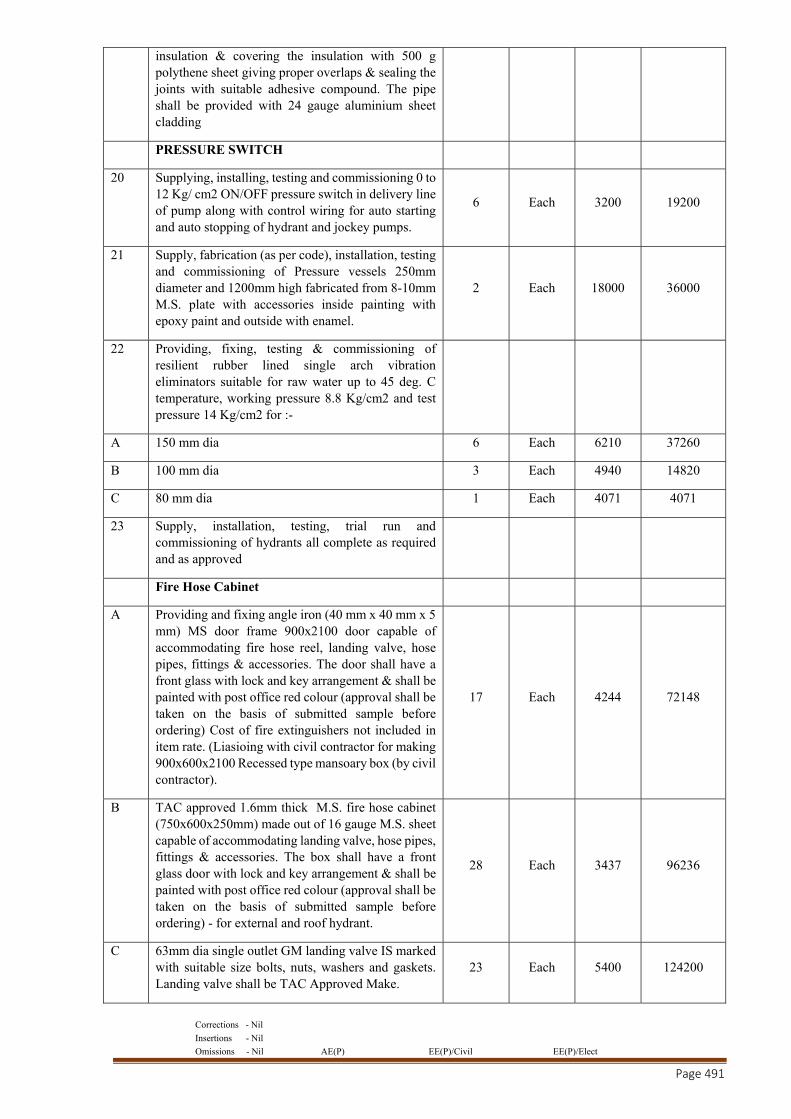
Corrections - Nil
Insertions - Nil
Omissions - Nil AE(P) EE(P)/Civil EE(P)/Elect
Page 491
insulation & covering the insulation with 500 g polythene sheet giving proper overlaps & sealing the joints with suitable adhesive compound. The pipe shall be provided with 24 gauge aluminium sheet cladding
PRESSURE SWITCH
20 Supplying, installing, testing and commissioning 0 to 12 Kg/ cm2 ON/OFF pressure switch in delivery line of pump along with control wiring for auto starting and auto stopping of hydrant and jockey pumps.
6 Each 3200 19200
21 Supply, fabrication (as per code), installation, testing and commissioning of Pressure vessels 250mm diameter and 1200mm high fabricated from 8-10mm M.S. plate with accessories inside painting with epoxy paint and outside with enamel.
2 Each 18000 36000
22 Providing, fixing, testing & commissioning of resilient rubber lined single arch vibration eliminators suitable for raw water up to 45 deg. C temperature, working pressure 8.8 Kg/cm2 and test pressure 14 Kg/cm2 for :-
A 150 mm dia 6 Each 6210 37260
B 100 mm dia 3 Each 4940 14820
C 80 mm dia 1 Each 4071 4071
23 Supply, installation, testing, trial run and commissioning of hydrants all complete as required and as approved
Fire Hose Cabinet
A Providing and fixing angle iron (40 mm x 40 mm x 5 mm) MS door frame 900x2100 door capable of accommodating fire hose reel, landing valve, hose pipes, fittings & accessories. The door shall have a front glass with lock and key arrangement & shall be painted with post office red colour (approval shall be taken on the basis of submitted sample before ordering) Cost of fire extinguishers not included in item rate. (Liasioing with civil contractor for making 900x600x2100 Recessed type mansoary box (by civil contractor).
17 Each 4244 72148
B TAC approved 1.6mm thick M.S. fire hose cabinet (750x600x250mm) made out of 16 gauge M.S. sheet capable of accommodating landing valve, hose pipes, fittings & accessories. The box shall have a front glass door with lock and key arrangement & shall be painted with post office red colour (approval shall be taken on the basis of submitted sample before ordering) - for external and roof hydrant.
28 Each 3437 96236
C 63mm dia single outlet GM landing valve IS marked with suitable size bolts, nuts, washers and gaskets. Landing valve shall be TAC Approved Make.
23 Each 5400 124200
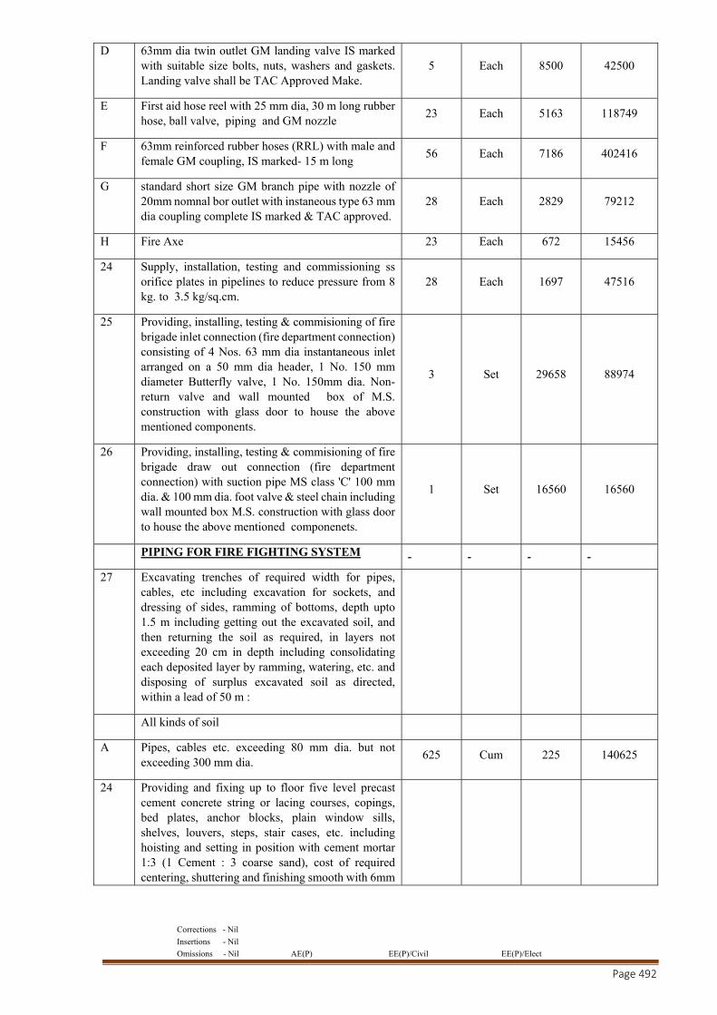
Corrections - Nil
Insertions - Nil
Omissions - Nil AE(P) EE(P)/Civil EE(P)/Elect
Page 492
D 63mm dia twin outlet GM landing valve IS marked with suitable size bolts, nuts, washers and gaskets. Landing valve shall be TAC Approved Make.
5 Each 8500 42500
E First aid hose reel with 25 mm dia, 30 m long rubber hose, ball valve, piping and GM nozzle
23 Each 5163 118749
F 63mm reinforced rubber hoses (RRL) with male and female GM coupling, IS marked- 15 m long
56 Each 7186 402416
G standard short size GM branch pipe with nozzle of 20mm nomnal bor outlet with instaneous type 63 mm dia coupling complete IS marked & TAC approved.
28 Each 2829 79212
H Fire Axe 23 Each 672 15456
24 Supply, installation, testing and commissioning ss orifice plates in pipelines to reduce pressure from 8 kg. to 3.5 kg/sq.cm.
28 Each 1697 47516
25 Providing, installing, testing & commisioning of fire brigade inlet connection (fire department connection) consisting of 4 Nos. 63 mm dia instantaneous inlet arranged on a 50 mm dia header, 1 No. 150 mm diameter Butterfly valve, 1 No. 150mm dia. Non-return valve and wall mounted box of M.S. construction with glass door to house the above mentioned components.
3 Set 29658 88974
26 Providing, installing, testing & commisioning of fire brigade draw out connection (fire department connection) with suction pipe MS class 'C' 100 mm dia. & 100 mm dia. foot valve & steel chain including wall mounted box M.S. construction with glass door to house the above mentioned componenets.
1 Set 16560 16560
PIPING FOR FIRE FIGHTING SYSTEM
27 Excavating trenches of required width for pipes, cables, etc including excavation for sockets, and dressing of sides, ramming of bottoms, depth upto 1.5 m including getting out the excavated soil, and then returning the soil as required, in layers not exceeding 20 cm in depth including consolidating each deposited layer by ramming, watering, etc. and disposing of surplus excavated soil as directed, within a lead of 50 m :
All kinds of soil
A Pipes, cables etc. exceeding 80 mm dia. but not exceeding 300 mm dia.
625 Cum 225 140625
24 Providing and fixing up to floor five level precast cement concrete string or lacing courses, copings, bed plates, anchor blocks, plain window sills, shelves, louvers, steps, stair cases, etc. including hoisting and setting in position with cement mortar 1:3 (1 Cement : 3 coarse sand), cost of required centering, shuttering and finishing smooth with 6mm
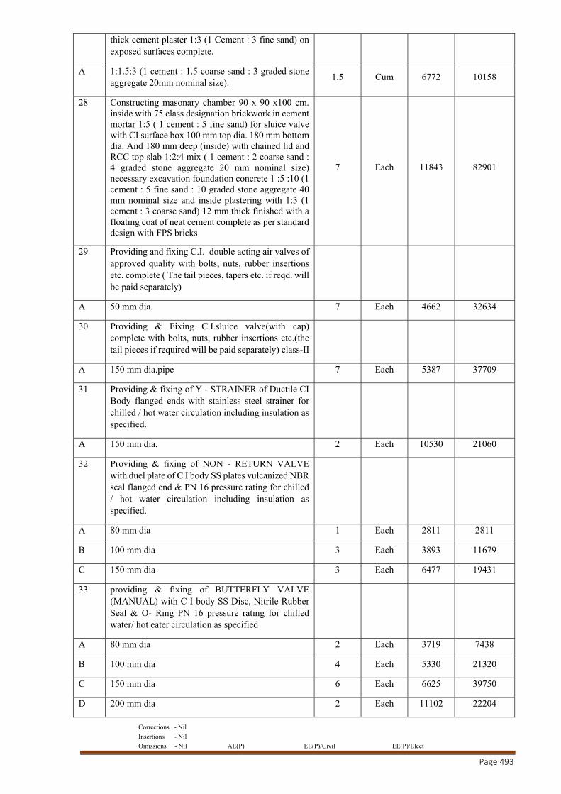
Corrections - Nil
Insertions - Nil
Omissions - Nil AE(P) EE(P)/Civil EE(P)/Elect
Page 493
thick cement plaster 1:3 (1 Cement : 3 fine sand) on exposed surfaces complete.
A 1:1.5:3 (1 cement : 1.5 coarse sand : 3 graded stone aggregate 20mm nominal size).
1.5 Cum 6772 10158
28 Constructing masonary chamber 90 x 90 x100 cm. inside with 75 class designation brickwork in cement mortar 1:5 ( 1 cement : 5 fine sand) for sluice valve with CI surface box 100 mm top dia. 180 mm bottom dia. And 180 mm deep (inside) with chained lid and RCC top slab 1:2:4 mix ( 1 cement : 2 coarse sand : 4 graded stone aggregate 20 mm nominal size) necessary excavation foundation concrete 1 :5 :10 (1 cement : 5 fine sand : 10 graded stone aggregate 40 mm nominal size and inside plastering with 1:3 (1 cement : 3 coarse sand) 12 mm thick finished with a floating coat of neat cement complete as per standard design with FPS bricks
7 Each 11843 82901
29 Providing and fixing C.I. double acting air valves of approved quality with bolts, nuts, rubber insertions etc. complete ( The tail pieces, tapers etc. if reqd. will be paid separately)
A 50 mm dia. 7 Each 4662 32634
30 Providing & Fixing C.I.sluice valve(with cap) complete with bolts, nuts, rubber insertions etc.(the tail pieces if required will be paid separately) class-II
A 150 mm dia.pipe 7 Each 5387 37709
31 Providing & fixing of Y - STRAINER of Ductile CI Body flanged ends with stainless steel strainer for chilled / hot water circulation including insulation as specified.
A 150 mm dia. 2 Each 10530 21060
32 Providing & fixing of NON - RETURN VALVE with duel plate of C I body SS plates vulcanized NBR seal flanged end & PN 16 pressure rating for chilled / hot water circulation including insulation as specified.
A 80 mm dia 1 Each 2811 2811
B 100 mm dia 3 Each 3893 11679
C 150 mm dia 3 Each 6477 19431
33 providing & fixing of BUTTERFLY VALVE (MANUAL) with C I body SS Disc, Nitrile Rubber Seal & O- Ring PN 16 pressure rating for chilled water/ hot eater circulation as specified
A 80 mm dia 2 Each 3719 7438
B 100 mm dia 4 Each 5330 21320
C 150 mm dia 6 Each 6625 39750
D 200 mm dia 2 Each 11102 22204
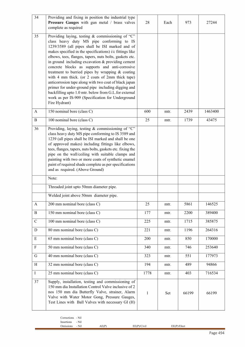
Corrections - Nil
Insertions - Nil
Omissions - Nil AE(P) EE(P)/Civil EE(P)/Elect
Page 494
34 Providing and fixing in position the industrial type Pressure Gauges with gun metal / brass valves complete as required
28 Each 973 27244
35 Providing laying, testing & commissioning of “C” class heavy duty MS pipe conforming to IS 1239/3589 (all pipes shall be ISI marked and of makes specified in the specifications) i/c fittings like elbows, tees, flanges, tapers, nuts bolts, gaskets etc. in ground including excavation & providing cement concrete blocks as supports and anti-corrosive treatment to burried pipes by wrapping & coating with 4 mm thick. (or 2 coats of 2mm thick tape) anticorrosion tape along with two coat of black japan primer for under-ground pipe including digging and backfilling upto 1.0 mtr. below from G.L.for external work as per IS-909 (Specification for Underground Fire Hydrant)
A 150 nominal bore (class C) 600 mtr. 2439 1463400
B 100 nominal bore (class C) 25 mtr. 1739 43475
36 Providing, laying, testing & commissioning of “C” class heavy duty MS pipe conforming to IS 3589 and 1239 (all pipes shall be ISI marked and shall be one of approved makes) including fittings like elbows, tees, flanges, tapers, nuts bolts, gaskets etc. fixing the pipe on the wall/ceiling with suitable clamps and painting with two or more coats of synthetic enamel paint of required shade complete as per specifications and as required. (Above Ground)
Note:
Threaded joint upto 50mm diameter pipe.
Welded joint above 50mm diameter pipe.
A 200 mm nominal bore (class C) 25 mtr. 5861 146525
B 150 mm nominal bore (class C) 177 mtr. 2200 389400
C 100 mm nominal bore (class C) 225 mtr. 1715 385875
D 80 mm nominal bore (class C) 221 mtr. 1196 264316
E 65 mm nominal bore (class C) 200 mtr. 850 170000
F 50 mm nominal bore (class C) 340 mtr. 746 253640
G 40 mm nominal bore (class C) 323 mtr. 551 177973
H 32 mm nominal bore (class C) 194 mtr. 489 94866
I 25 mm nominal bore (class C) 1778 mtr. 403 716534
37 Supply, installation, testing and commissioning of 150 mm dia Installation Control Valve inclusive of 2 nos 150 mm dia Butterfly Valve, strainer, Alarm Valve with Water Motor Gong, Pressure Gauges, Test Lines with Ball Valves with necessary GI (H)
1 Set 66199 66199
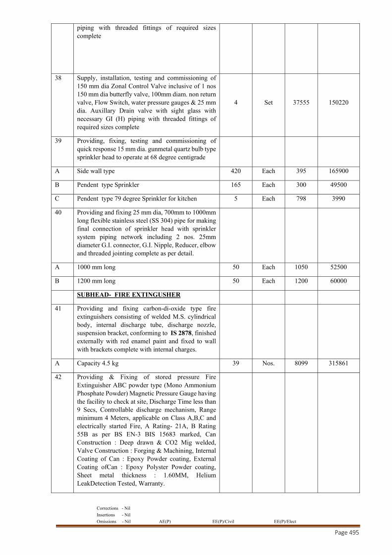
Corrections - Nil
Insertions - Nil
Omissions - Nil AE(P) EE(P)/Civil EE(P)/Elect
Page 495
piping with threaded fittings of required sizes complete
38 Supply, installation, testing and commissioning of 150 mm dia Zonal Control Valve inclusive of 1 nos 150 mm dia butterfly valve, 100mm diam. non return valve, Flow Switch, water pressure gauges & 25 mm dia. Auxillary Drain valve with sight glass with necessary GI (H) piping with threaded fittings of required sizes complete
4 Set 37555 150220
39 Providing, fixing, testing and commissioning of quick response 15 mm dia. gunmetal quartz bulb type sprinkler head to operate at 68 degree centigrade
A Side wall type 420 Each 395 165900
B Pendent type Sprinkler 165 Each 300 49500
C Pendent type 79 degree Sprinkler for kitchen 5 Each 798 3990
40 Providing and fixing 25 mm dia, 700mm to 1000mm long flexible stainless steel (SS 304) pipe for making final connection of sprinkler head with sprinkler system piping network including 2 nos. 25mm diameter G.I. connector, G.I. Nipple, Reducer, elbow and threaded jointing complete as per detail.
A 1000 mm long 50 Each 1050 52500
B 1200 mm long 50 Each 1200 60000
SUBHEAD- FIRE EXTINGUSHER
41 Providing and fixing carbon-di-oxide type fire extinguishers consisting of welded M.S. cylindrical body, internal discharge tube, discharge nozzle, suspension bracket, conforming to IS 2878, finished externally with red enamel paint and fixed to wall with brackets complete with internal charges.
A Capacity 4.5 kg 39 Nos. 8099 315861
42 Providing & Fixing of stored pressure Fire Extinguisher ABC powder type (Mono Ammonium Phosphate Powder) Magnetic Pressure Gauge having the facility to check at site, Discharge Time less than 9 Secs, Controllable discharge mechanism, Range minimum 4 Meters, applicable on Class A,B,C and electrically started Fire, A Rating- 21A, B Rating 55B as per BS EN-3 BIS 15683 marked, Can Construction : Deep drawn & CO2 Mig welded, Valve Construction : Forging & Machining, Internal Coating of Can : Epoxy Powder coating, External Coating ofCan : Epoxy Polyster Powder coating, Sheet metal thickness : 1.60MM, Helium LeakDetection Tested, Warranty.
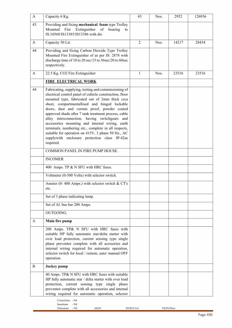
Corrections - Nil
Insertions - Nil
Omissions - Nil AE(P) EE(P)/Civil EE(P)/Elect
Page 496
A Capacity 6 Kg. 43 Nos. 2952 126936
43 Providing and fixing mechanical foam type Trolley Mounted Fire Extinguisher of bearing to IS:10568/IS13385/IS13386 with dis
A Capacity 50 Lit. 2 Nos. 14217 28434
44 Providing and fixing Carbon Dioxide Type Trolley Mounted Fire Extinguisher of as per IS: 2878 with discharge time of 10 to 20 sec/15 to 36sec/20 to 60sec respectively.
A 22.5 Kg. CO2 Fire Extinguisher 1 Nos. 23516 23516
FIRE ELECTRICAL WORK
44 Fabricating, supplying, testing and commissioning of electrical control panel of cubicle construction, floor mounted type, fabricated out of 2mm thick crca sheet, compartmentallised and hinged lockable doors, dust and vermin proof, powder coated approved shade after 7 tank treatment process, cable alley interconnection, having switchgears and accessories mounting and internal wiring, earth terminals, numbering etc., complete in all respects, suitable for operation on 415V, 3 phase 50 Hz., AC supplywith enclosure protection class IP-42as required.
COMMON PANEL IN FIRE PUMP HOUSE.
INCOMER
400 Amps. TP & N SFU with HRC fuses.
Voltmeter (0-500 Volts) with selector switch.
Ameter (0- 400 Amps.) with selector switch & CT's etc.
Set of 3 phase indicating lamp.
Set of Al. bus bar 200 Amps.
OUTGOING.
A Main fire pump
200 Amps. TP& N SFU with HRC fuses with suitable HP fully automatic star/delta starter with over load protection, current sensing type single phase preventor complete with all acessories and internal wiring required for automatic operation, selector switch for local / remote, auto/ manual OFF operation.
B Jockey pump
40 Amps. TP& N SFU with HRC fuses with suitable HP fully automatic star / delta starter with over load protection, current sensing type single phase preventor complete with all accessories and internal wiring required for automatic operation, selector
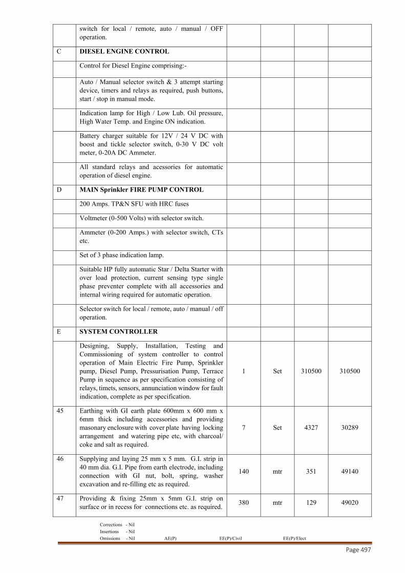
Corrections - Nil
Insertions - Nil
Omissions - Nil AE(P) EE(P)/Civil EE(P)/Elect
Page 497
switch for local / remote, auto / manual / OFF operation.
C DIESEL ENGINE CONTROL
Control for Diesel Engine comprising:-
Auto / Manual selector switch & 3 attempt starting device, timers and relays as required, push buttons, start / stop in manual mode.
Indication lamp for High / Low Lub. Oil pressure, High Water Temp. and Engine ON indication.
Battery charger suitable for 12V / 24 V DC with boost and tickle selector switch, 0-30 V DC volt meter, 0-20A DC Ammeter.
All standard relays and acessories for automatic operation of diesel engine.
D MAIN Sprinkler FIRE PUMP CONTROL
200 Amps. TP&N SFU with HRC fuses
Voltmeter (0-500 Volts) with selector switch.
Ammeter (0-200 Amps.) with selector switch, CTs etc.
Set of 3 phase indication lamp.
Suitable HP fully automatic Star / Delta Starter with over load protection, current sensing type single phase preventer complete with all accessories and internal wiring required for automatic operation.
Selector switch for local / remote, auto / manual / off operation.
E SYSTEM CONTROLLER
Designing, Supply, Installation, Testing and Commissioning of system controller to control operation of Main Electric Fire Pump, Sprinkler pump, Diesel Pump, Pressurisation Pump, Terrace Pump in sequence as per specification consisting of relays, timets, sensors, annunciation window for fault indication, complete as per specification.
1 Set 310500 310500
45 Earthing with GI earth plate 600mm x 600 mm x 6mm thick including accessories and providing masonary enclosure with cover plate having locking arrangement and watering pipe etc, with charcoal/ coke and salt as required.
7 Set 4327 30289
46 Supplying and laying 25 mm x 5 mm. G.I. strip in 40 mm dia. G.I. Pipe from earth electrode, including connection with GI nut, bolt, spring, washer excavation and re-filling etc as required.
140 mtr 351 49140
47 Providing & fixing 25mm x 5mm G.I. strip on surface or in recess for connections etc. as required.
380 mtr 129 49020
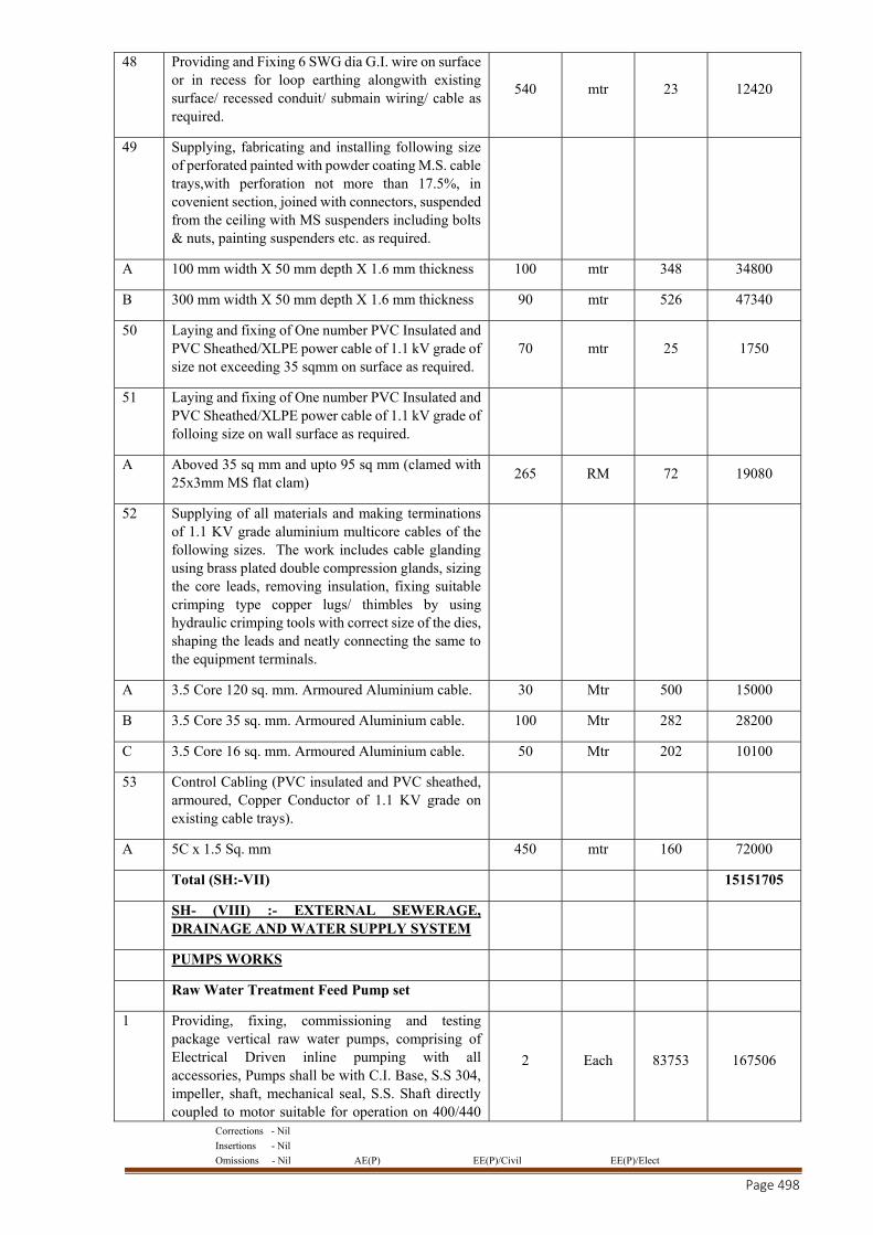
Corrections - Nil
Insertions - Nil
Omissions - Nil AE(P) EE(P)/Civil EE(P)/Elect
Page 498
48 Providing and Fixing 6 SWG dia G.I. wire on surface or in recess for loop earthing alongwith existing surface/ recessed conduit/ submain wiring/ cable as required.
540 mtr 23 12420
49 Supplying, fabricating and installing following size of perforated painted with powder coating M.S. cable trays,with perforation not more than 17.5%, in covenient section, joined with connectors, suspended from the ceiling with MS suspenders including bolts & nuts, painting suspenders etc. as required.
A 100 mm width X 50 mm depth X 1.6 mm thickness 100 mtr 348 34800
B 300 mm width X 50 mm depth X 1.6 mm thickness 90 mtr 526 47340
50 Laying and fixing of One number PVC Insulated and PVC Sheathed/XLPE power cable of 1.1 kV grade of size not exceeding 35 sqmm on surface as required.
70 mtr 25 1750
51 Laying and fixing of One number PVC Insulated and PVC Sheathed/XLPE power cable of 1.1 kV grade of folloing size on wall surface as required.
A Aboved 35 sq mm and upto 95 sq mm (clamed with 25x3mm MS flat clam)
265 RM 72 19080
52 Supplying of all materials and making terminations of 1.1 KV grade aluminium multicore cables of the following sizes. The work includes cable glanding using brass plated double compression glands, sizing the core leads, removing insulation, fixing suitable crimping type copper lugs/ thimbles by using hydraulic crimping tools with correct size of the dies, shaping the leads and neatly connecting the same to the equipment terminals.
A 3.5 Core 120 sq. mm. Armoured Aluminium cable. 30 Mtr 500 15000
B 3.5 Core 35 sq. mm. Armoured Aluminium cable. 100 Mtr 282 28200
C 3.5 Core 16 sq. mm. Armoured Aluminium cable. 50 Mtr 202 10100
53 Control Cabling (PVC insulated and PVC sheathed, armoured, Copper Conductor of 1.1 KV grade on existing cable trays).
A 5C x 1.5 Sq. mm 450 mtr 160 72000
Total (SH:-VII) 15151705
SH- (VIII) :- EXTERNAL SEWERAGE, DRAINAGE AND WATER SUPPLY SYSTEM
PUMPS WORKS
Raw Water Treatment Feed Pump set
1 Providing, fixing, commissioning and testing package vertical raw water pumps, comprising of Electrical Driven inline pumping with all accessories, Pumps shall be with C.I. Base, S.S 304, impeller, shaft, mechanical seal, S.S. Shaft directly coupled to motor suitable for operation on 400/440
2 Each 83753 167506
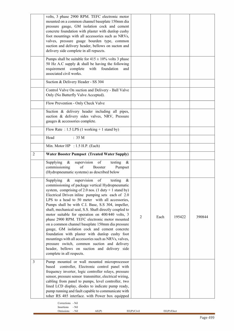
Corrections - Nil
Insertions - Nil
Omissions - Nil AE(P) EE(P)/Civil EE(P)/Elect
Page 499
volts, 3 phase 2900 RPM. TEFC electronic motor mounted on a common channel baseplate 150mm dia pressure gauge, GM isolation cock and cement concrete foundation with plaster with dunlop cushy foot mountings with all accessories such as NRVs, valves, pressure guage bourden type, common suction and delivery header, bellows on sucton and delivery side complete in all repsects.
Pumps shall be suitable for 415 ± 10% volts 3 phase 50 Hz A.C supply & shall be having the following requirement complete with foundation and associated civil works.
Suction & Delivery Header - SS 304
Control Valve On suction and Delivery - Ball Valve Only (No Butterfly Valve Accepted).
Flow Prevention - Only Check Valve
Suction & delivery header including all pipes, suction & delivery sides valves, NRV, Pressure gauges & accessories complete.
Flow Rate : 1.5 LPS (1 working + 1 stand by)
Head : 35 M
Min. Motor HP : 1.5 H.P. (Each)
2 Water Booster Pumpset (Treated Water Supply)
Supplying & supervision of testing & commissioning of Booster Pumpset (Hydropneumatic systems) as described below
Supplying & supervision of testing & commissioning of package vertical Hydropneumatic system, comprising of 2.0 nos. (1 duty + 1 stand by) Electrical Driven inline pumping sets each of 2.0 LPS to a head to 50 meter with all accessories, Pumps shall be with C.I. Base, S.S 304, impeller, shaft, mechanical seal, S.S. Shaft directly coupled to motor suitable for operation on 400/440 volts, 3 phase 2900 RPM. TEFC electronic motor mounted on a common channel baseplate 150mm dia pressure gauge, GM isolation cock and cement concrete foundation with plaster with dunlop cushy foot mountings with all accessories such as NRVs, valves, pressure switch, common suction and delivery header, bellows on suction and delivery side complete in all respects.
2 Each 195422 390844
3 Pump mounted or wall mounted microprocessor based controller, Electronic control panel with frequency inverter, logic controller relays, pressure sensor, pressure sensor transmitter, electrical wiring, cabling from panel to pumps, level controller, two lined LCD display, diodes to indicate pump ready, pump running and fault capable to communicate with toher RS 485 interface. with Power box equipped
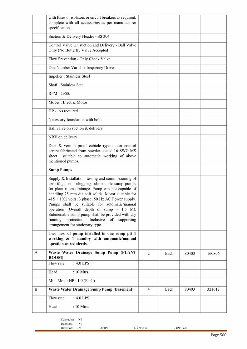
Corrections - Nil
Insertions - Nil
Omissions - Nil AE(P) EE(P)/Civil EE(P)/Elect
Page 500
with fuses or isolators or circuit breakers as required. complete with all accessories as per manufacturer specifications.
Suction & Delivery Header - SS 304
Control Valve On suction and Delivery - Ball Valve Only (No Butterfly Valve Accepted).
Flow Prevention - Only Check Valve
One Number Variable frequency Drive
Impeller : Stainless Steel
Shaft : Stainless Steel
RPM : 2900.
Mover : Electric Motor
HP - As required.
Necessary foundation with bolts
Ball valve on suction & delivery
NRV on delivery
Dust & vermin proof cubicle type motor control centre fabricated from powder coated 16 SWG MS sheet suitable to automatic working of above mentioned pumps.
Sump Pumps
Supply & Installation, testing and commissioning of centrifugal non clogging submersible sump pumps for plant room drainage. Pump capable capable of handling 25 mm dia soft solids. Motor suitable for 415 + 10% volts, 3 phase, 50 Hz AC Power supply. Pumps shall be suitable for automatic/manual operation (Overall depth of sump – 1.5 M). Submersible sump pump shall be provided with dry running protection. Inclusive of supporting arrangement for stationary type.
Two nos. of pump installed in one sump pit 1 working & 1 standby with automatic/manual opration as requireds.
A Waste Water Drainage Sump Pump (PLANT ROOM)
2 Each 80403 160806
Flow rate : 4.0 LPS
Head : 10 Mtrs.
Min. Motor HP : 1.0 (Each)
B Waste Water Drainage Sump Pump (Basement) 4 Each 80403 321612
Flow rate : 4.0 LPS
Head : 10 Mtrs.
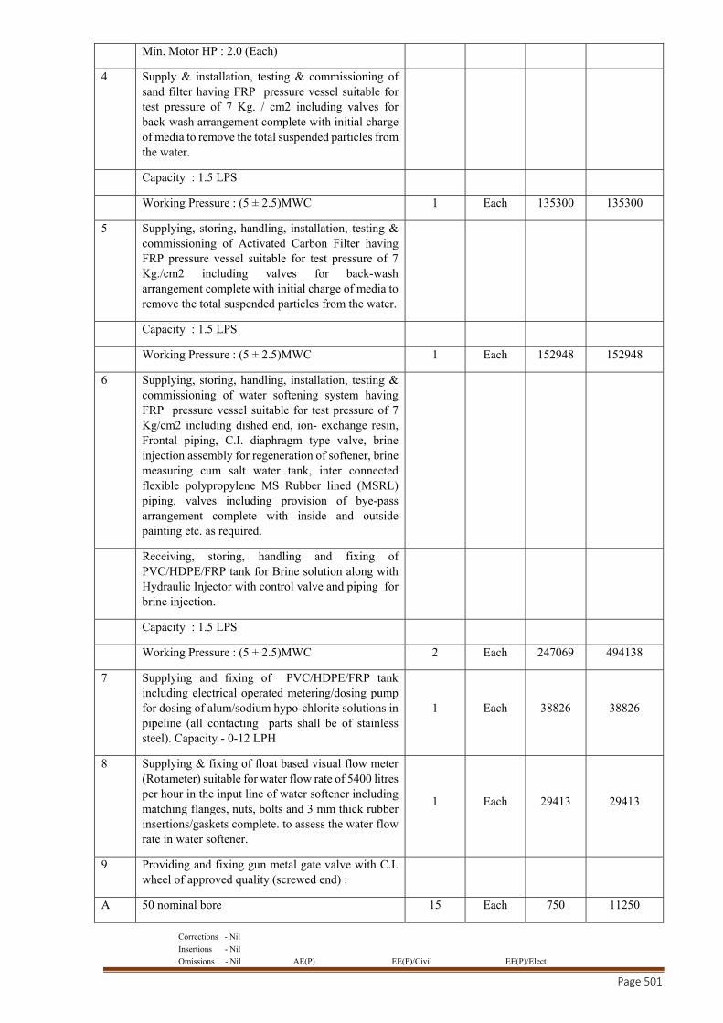
Corrections - Nil
Insertions - Nil
Omissions - Nil AE(P) EE(P)/Civil EE(P)/Elect
Page 501
Min. Motor HP : 2.0 (Each)
4 Supply & installation, testing & commissioning of sand filter having FRP pressure vessel suitable for test pressure of 7 Kg. / cm2 including valves for back-wash arrangement complete with initial charge of media to remove the total suspended particles from the water.
Capacity : 1.5 LPS
Working Pressure : (5 ± 2.5)MWC 1 Each 135300 135300
5 Supplying, storing, handling, installation, testing & commissioning of Activated Carbon Filter having FRP pressure vessel suitable for test pressure of 7 Kg./cm2 including valves for back-wash arrangement complete with initial charge of media to remove the total suspended particles from the water.
Capacity : 1.5 LPS
Working Pressure : (5 ± 2.5)MWC 1 Each 152948 152948
6 Supplying, storing, handling, installation, testing & commissioning of water softening system having FRP pressure vessel suitable for test pressure of 7 Kg/cm2 including dished end, ion- exchange resin, Frontal piping, C.I. diaphragm type valve, brine injection assembly for regeneration of softener, brine measuring cum salt water tank, inter connected flexible polypropylene MS Rubber lined (MSRL) piping, valves including provision of bye-pass arrangement complete with inside and outside painting etc. as required.
Receiving, storing, handling and fixing of PVC/HDPE/FRP tank for Brine solution along with Hydraulic Injector with control valve and piping for brine injection.
Capacity : 1.5 LPS
Working Pressure : (5 ± 2.5)MWC 2 Each 247069 494138
7 Supplying and fixing of PVC/HDPE/FRP tank including electrical operated metering/dosing pump for dosing of alum/sodium hypo-chlorite solutions in pipeline (all contacting parts shall be of stainless steel). Capacity - 0-12 LPH
1 Each 38826 38826
8 Supplying & fixing of float based visual flow meter (Rotameter) suitable for water flow rate of 5400 litres per hour in the input line of water softener including matching flanges, nuts, bolts and 3 mm thick rubber insertions/gaskets complete. to assess the water flow rate in water softener.
1 Each 29413 29413
9 Providing and fixing gun metal gate valve with C.I. wheel of approved quality (screwed end) :
A 50 nominal bore 15 Each 750 11250
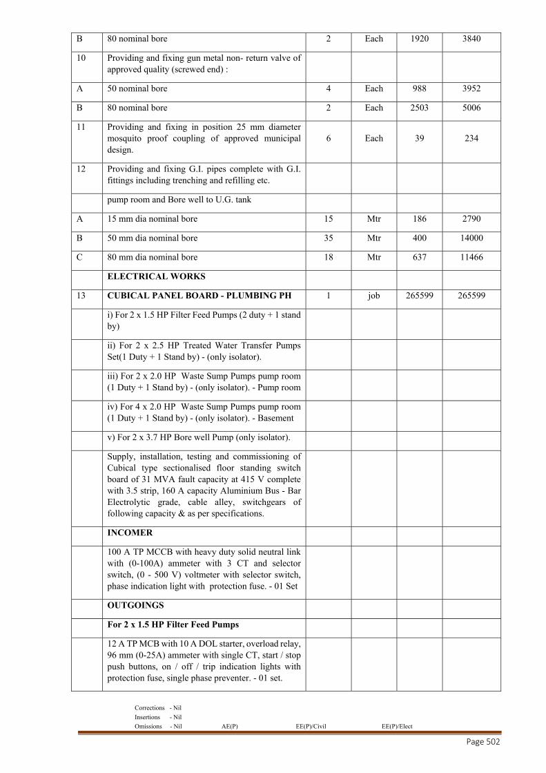
Corrections - Nil
Insertions - Nil
Omissions - Nil AE(P) EE(P)/Civil EE(P)/Elect
Page 502
B 80 nominal bore 2 Each 1920 3840
10 Providing and fixing gun metal non- return valve of approved quality (screwed end) :
A 50 nominal bore 4 Each 988 3952
B 80 nominal bore 2 Each 2503 5006
11 Providing and fixing in position 25 mm diameter mosquito proof coupling of approved municipal design.
6 Each 39 234
12 Providing and fixing G.I. pipes complete with G.I. fittings including trenching and refilling etc.
pump room and Bore well to U.G. tank
A 15 mm dia nominal bore 15 Mtr 186 2790
B 50 mm dia nominal bore 35 Mtr 400 14000
C 80 mm dia nominal bore 18 Mtr 637 11466
ELECTRICAL WORKS
13 CUBICAL PANEL BOARD - PLUMBING PH 1 job 265599 265599
i) For 2 x 1.5 HP Filter Feed Pumps (2 duty + 1 stand by)
ii) For 2 x 2.5 HP Treated Water Transfer Pumps Set(1 Duty + 1 Stand by) - (only isolator).
iii) For 2 x 2.0 HP Waste Sump Pumps pump room (1 Duty + 1 Stand by) - (only isolator). - Pump room
iv) For 4 x 2.0 HP Waste Sump Pumps pump room (1 Duty + 1 Stand by) - (only isolator). - Basement
v) For 2 x 3.7 HP Bore well Pump (only isolator).
Supply, installation, testing and commissioning of Cubical type sectionalised floor standing switch board of 31 MVA fault capacity at 415 V complete with 3.5 strip, 160 A capacity Aluminium Bus - Bar Electrolytic grade, cable alley, switchgears of following capacity & as per specifications.
INCOMER
100 A TP MCCB with heavy duty solid neutral link with (0-100A) ammeter with 3 CT and selector switch, (0 - 500 V) voltmeter with selector switch, phase indication light with protection fuse. - 01 Set
OUTGOINGS
For 2 x 1.5 HP Filter Feed Pumps
12 A TP MCB with 10 A DOL starter, overload relay, 96 mm (0-25A) ammeter with single CT, start / stop push buttons, on / off / trip indication lights with protection fuse, single phase preventer. - 01 set.
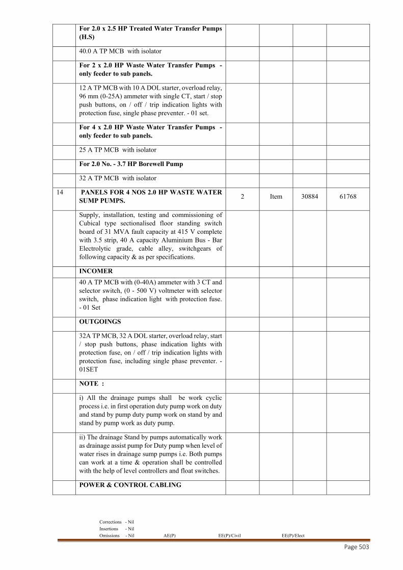
Corrections - Nil
Insertions - Nil
Omissions - Nil AE(P) EE(P)/Civil EE(P)/Elect
Page 503
For 2.0 x 2.5 HP Treated Water Transfer Pumps (H.S)
40.0 A TP MCB with isolator
For 2 x 2.0 HP Waste Water Transfer Pumps - only feeder to sub panels.
12 A TP MCB with 10 A DOL starter, overload relay, 96 mm (0-25A) ammeter with single CT, start / stop push buttons, on / off / trip indication lights with protection fuse, single phase preventer. - 01 set.
For 4 x 2.0 HP Waste Water Transfer Pumps - only feeder to sub panels.
25 A TP MCB with isolator
For 2.0 No. - 3.7 HP Borewell Pump
32 A TP MCB with isolator
14 PANELS FOR 4 NOS 2.0 HP WASTE WATER SUMP PUMPS.
2 Item 30884 61768
Supply, installation, testing and commissioning of Cubical type sectionalised floor standing switch board of 31 MVA fault capacity at 415 V complete with 3.5 strip, 40 A capacity Aluminium Bus - Bar Electrolytic grade, cable alley, switchgears of following capacity & as per specifications.
INCOMER
40 A TP MCB with (0-40A) ammeter with 3 CT and selector switch, (0 - 500 V) voltmeter with selector switch, phase indication light with protection fuse. - 01 Set
OUTGOINGS
32A TP MCB, 32 A DOL starter, overload relay, start / stop push buttons, phase indication lights with protection fuse, on / off / trip indication lights with protection fuse, including single phase preventer. - 01SET
NOTE :
i) All the drainage pumps shall be work cyclic process i.e. in first operation duty pump work on duty and stand by pump duty pump work on stand by and stand by pump work as duty pump.
ii) The drainage Stand by pumps automatically work as drainage assist pump for Duty pump when level of water rises in drainage sump pumps i.e. Both pumps can work at a time & operation shall be controlled with the help of level controllers and float switches.
POWER & CONTROL CABLING
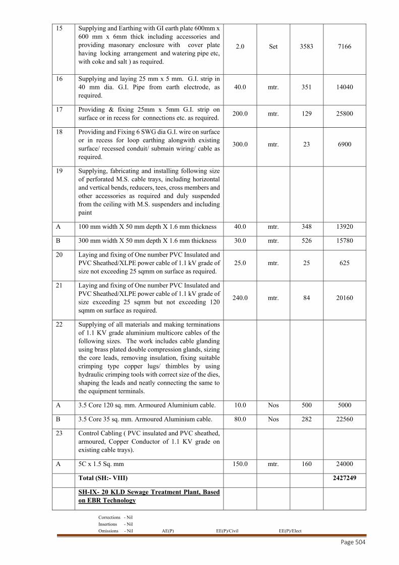
Corrections - Nil
Insertions - Nil
Omissions - Nil AE(P) EE(P)/Civil EE(P)/Elect
Page 504
15 Supplying and Earthing with GI earth plate 600mm x 600 mm x 6mm thick including accessories and providing masonary enclosure with cover plate having locking arrangement and watering pipe etc, with coke and salt ) as required.
2.0 Set 3583 7166
16 Supplying and laying 25 mm x 5 mm. G.I. strip in 40 mm dia. G.I. Pipe from earth electrode, as required.
40.0 mtr. 351 14040
17 Providing & fixing 25mm x 5mm G.I. strip on surface or in recess for connections etc. as required.
200.0 mtr. 129 25800
18 Providing and Fixing 6 SWG dia G.I. wire on surface or in recess for loop earthing alongwith existing surface/ recessed conduit/ submain wiring/ cable as required.
300.0 mtr. 23 6900
19 Supplying, fabricating and installing following size of perforated M.S. cable trays, including horizontal and vertical bends, reducers, tees, cross members and other accessories as required and duly suspended from the ceiling with M.S. suspenders and including paint
A 100 mm width X 50 mm depth X 1.6 mm thickness 40.0 mtr. 348 13920
B 300 mm width X 50 mm depth X 1.6 mm thickness 30.0 mtr. 526 15780
20 Laying and fixing of One number PVC Insulated and PVC Sheathed/XLPE power cable of 1.1 kV grade of size not exceeding 25 sqmm on surface as required.
25.0 mtr. 25 625
21 Laying and fixing of One number PVC Insulated and PVC Sheathed/XLPE power cable of 1.1 kV grade of size exceeding 25 sqmm but not exceeding 120 sqmm on surface as required.
240.0 mtr. 84 20160
22 Supplying of all materials and making terminations of 1.1 KV grade aluminium multicore cables of the following sizes. The work includes cable glanding using brass plated double compression glands, sizing the core leads, removing insulation, fixing suitable crimping type copper lugs/ thimbles by using hydraulic crimping tools with correct size of the dies, shaping the leads and neatly connecting the same to the equipment terminals.
A 3.5 Core 120 sq. mm. Armoured Aluminium cable. 10.0 Nos 500 5000
B 3.5 Core 35 sq. mm. Armoured Aluminium cable. 80.0 Nos 282 22560
23 Control Cabling ( PVC insulated and PVC sheathed, armoured, Copper Conductor of 1.1 KV grade on existing cable trays).
A 5C x 1.5 Sq. mm 150.0 mtr. 160 24000
Total (SH:- VIII) 2427249
SH-IX- 20 KLD Sewage Treatment Plant, Based on EBR Technology
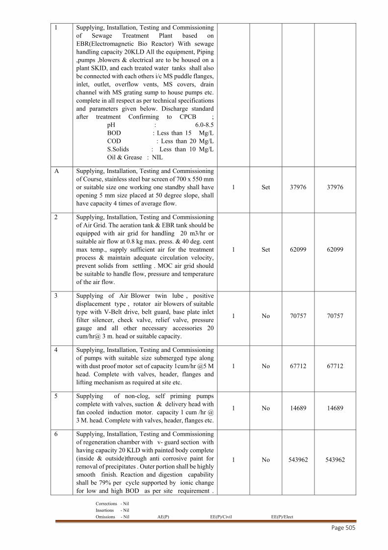
Corrections - Nil
Insertions - Nil
Omissions - Nil AE(P) EE(P)/Civil EE(P)/Elect
Page 505
1 Supplying, Installation, Testing and Commissioning of Sewage Treatment Plant based on EBR(Electromagnetic Bio Reactor) With sewage handling capacity 20KLD All the equipment, Piping ,pumps ,blowers & electrical are to be housed on a plant SKID, and each treated water tanks shall also be connected with each others i/c MS puddle flanges, inlet, outlet, overflow vents, MS covers, drain channel with MS grating sump to house pumps etc. complete in all respect as per technical specifications and parameters given below. Discharge standard after treatment Confirming to CPCB ; pH : 6.0-8.5 BOD : Less than 15 Mg/L COD : Less than 20 Mg/L S.Solids : Less than 10 Mg/L Oil & Grease : NIL
A Supplying, Installation, Testing and Commissioning of Course, stainless steel bar screen of 700 x 550 mm or suitable size one working one standby shall have opening 5 mm size placed at 50 degree slope, shall have capacity 4 times of average flow.
1 Set 37976 37976
2 Supplying, Installation, Testing and Commissioning of Air Grid. The aeration tank & EBR tank should be equipped with air grid for handling 20 m3/hr or suitable air flow at 0.8 kg max. press. & 40 deg. cent max temp., supply sufficient air for the treatment process & maintain adequate circulation velocity, prevent solids from settling . MOC air grid should be suitable to handle flow, pressure and temperature of the air flow.
1 Set 62099 62099
3 Supplying of Air Blower twin lube , positive displacement type , rotator air blowers of suitable type with V-Belt drive, belt guard, base plate inlet filter silencer, check valve, relief valve, pressure gauge and all other necessary accessories 20 cum/hr@ 3 m. head or suitable capacity.
1 No 70757 70757
4 Supplying, Installation, Testing and Commissioning of pumps with suitable size submerged type along with dust proof motor set of capacity 1cum/hr @5 M head. Complete with valves, header, flanges and lifting mechanism as required at site etc.
1 No 67712 67712
5 Supplying of non-clog, self priming pumps complete with valves, suction & delivery head with fan cooled induction motor. capacity 1 cum /hr @ 3 M. head. Complete with valves, header, flanges etc.
1 No 14689 14689
6 Supplying, Installation, Testing and Commissioning of regeneration chamber with v- guard section with having capacity 20 KLD with painted body complete (inside & outside)through anti corrosive paint for removal of precipitates . Outer portion shall be highly smooth finish. Reaction and digestion capability shall be 79% per cycle supported by ionic change for low and high BOD as per site requirement .
1 No 543962 543962
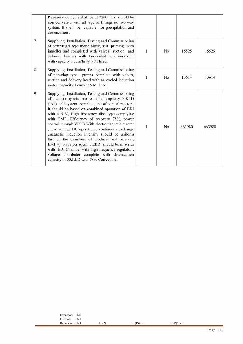
Corrections - Nil
Insertions - Nil
Omissions - Nil AE(P) EE(P)/Civil EE(P)/Elect
Page 506
Regeneration cycle shall be of 72000.ltrs should be non derivative with all type of fittings i/c two way system. It shell be capable for precipitation and deionization .
7 Supplying, Installation, Testing and Commissioning of centrifugal type mono block, self priming with impeller and completed with valves suction and delivery headers with fan cooled induction motor with capacity 1 cum/hr @ 5 M head.
1 No 15525 15525
8 Supplying, Installation, Testing and Commissioning of non-clog type pumps complete with valves, suction and delivery head with an cooled induction motor. capacity 1 cum/hr 5 M. head.
1 No 13614 13614
9 Supplying, Installation, Testing and Commissioning of electro-magnetic bio reactor of capacity 20KLD (1x1) self system complete unit of conical reactor . It should be based on combined operation of EDI with 415 V, High frequency dish type complying with GMP, Efficiency of recovery 78%, power control through VPCB With electromagnetic reactor , low voltage DC operation , continuous exchange ,magnetic induction intensity should be uniform through the chambers of producer and receiver, EMF @ 0.9% per sqcm . EBR should be in series with EDI Chamber with high frequency regulator , voltage distributer complete with deionization capacity of 50.KLD with 78% Correction.
1 No 663980 663980
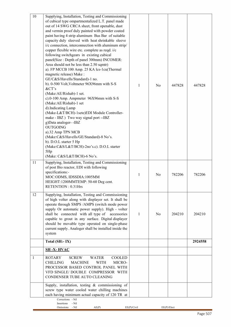
Corrections - Nil
Insertions - Nil
Omissions - Nil AE(P) EE(P)/Civil EE(P)/Elect
Page 507
10 Supplying, Installation, Testing and Commissioning of cubical type ompartmentalized L.T. panel made out of 14 SWG CRCA sheet, front openable, dust and vermin proof duly painted with powder coated paint having 4 strip aluminum Bus Bar of suitable capacity duly sleeved with heat shrinkable sleeve i/c connection, interconnection with aluminum strip/ copper flexible wire etc. complete as reqd. i/c following switchgears in existing cubical panel(Size : Depth of panel 300mm) INCOMER: Area should not be less than 2.50 sqmtr) a). FP MCCB 100 Amp. 25 KA lcs-1cu(Thermal magnetic release) Make : GE/C&S/Havells/Standard)-1 no. b). 0-500 Volt,Voltmeter 96X96mm with S-S &CT’s (Make:AE/Rishab)-1 set. c).0-100 Amp. Ampmeter 96X96mm with S-S (Make:AE/Rishab)-1 set d).Indicating Lamp (Make-L&T/BCH)-1sete)EDI Module Controller- make - IBZ ) Two way signal port --IBZ g)Data analoger- -IBZ OUTGOING a).32 Amp TPN MCB (Make:C&S/Havells/GE/Standard)-8 No’s. b). D.O.L starter 5 Hp (Make:C&S/L&T/BCH)-2no’s.c). D.O.L starter 5Hp (Make: C&S/L&T/BCH)-6 No’s.
1 No 447828 447828
11 Supplying, Installation, Testing and Commissioning of post Bio reactor, EDI with following specifications:- MOC:ODMS, IDSSDIA:1005MM HEIGHT:1200MMTEMP: 50-60 Deg cent. RETENTION : 0.31Hrs
1 No 782206 782206
12 Supplying, Installation, Testing and Commissioning of high volter along with displayer set. It shall be operate through SMPS /AMPS (switch mode power supply Or automatic power supply). High - volter shall be connected with all type of accessories capable to grout in any surface. Digital displayer should be movable type operated on single-phase current supply. Analoger shall be installed inside the system
1 No 204210 204210
Total (SH:- IX) 2924558
SH -X- HVAC
1 ROTARY SCREW WATER COOLED CHILLING MACHINE WITH MICRO-PROCESSOR BASED CONTROL PANEL WITH VFD SINGLE/ DOUBLE COMPRESSOR WITH CONDENSER TUBE AUTO CLEANING
Supply, installation, testing & commissioning of screw type water cooled water chilling machines each having minimum actual capacity of 120 TR at

Corrections - Nil
Insertions - Nil
Omissions - Nil AE(P) EE(P)/Civil EE(P)/Elect
Page 508
chilled water inlet/ outlet temperature of 54 deg.F / 44 degF having evaporator fouling factor of 0.00025 FPS unit with chilled water circulation rate of 288 USGPM and condenser water inlet temperature of 90 deg. F and having condenser fouling factor of 0.0005 FPS unit with circulation rate of 480 USGPM suitable for operation on refrigerant R-134a each comprising the following complete as per specifications and as required. IKW/TR at full load shall be 0.71 max and NPLV shall be 0.4 max. OEM provided Certified software selection sheet in accordance with ARI 550/590 at above mentioned parameters shall be submitted with the bid. The Water Side Pressure Drop in Chiller & Condenser should not exceed 2mtrs and 4 mtrs respectively
1 or more Twin / Mono screw type compressor in semi hermetic construction only, complete with automatic stepless type capacity control from 25 to100%, safety switches, forced feed lubrication system etc, as per specifications.
Suitable Nos & suitable capacity squirrel cage induction motor with class 'F' insulation suitable for operation on 415 volts +10% , 50 Hz, A.C. supply.
Suitable Nos. & suitable capacity Air Cooled VFD starter suitable for compressor motor complete with ammeter, over load protection, under voltage protection, protection against phase reversal & independent single phase preventors etc complete as required. The VFD shall be installed inside the IP 42 rated panel or in case VFD is installed seperately the same shall be IP 54 rated.VFD starter shall be with By Pass Star- Delta Starter.
Necessary drive arrangement
Suitable No. of Sets - Lubrication device consisting of automatic electric oil pump, oil cooler, head tank, oil strainer, automatic pressure regulating valve, oil heater, oil heater thermal switch etc. as per specifications.
1 No. - Matching (ASME/GB/BIS) shell and tube water cooled condenser of M.S. shell and both side integrally finned copper tubes having max. two passes and presssure drop 4 mtr max. Marine Water box shall be provided for ease of maintenance. DP switch for flow detection.
1 No. - Matching (ASME/GB/BIS) shell & tube flooded type chiller for screw type units of MS shell and both side integrally finned copper tubes having max. two passes and pressure drop 2 mtrs max. The chiller shall be duly insulated with 19 mm thick elastomeric nitrile insulation at factory. DP Switch for flow detection.
1 Lot - Refrigerant piping fittings, valves, level sensing electronic expansion valves and accessories
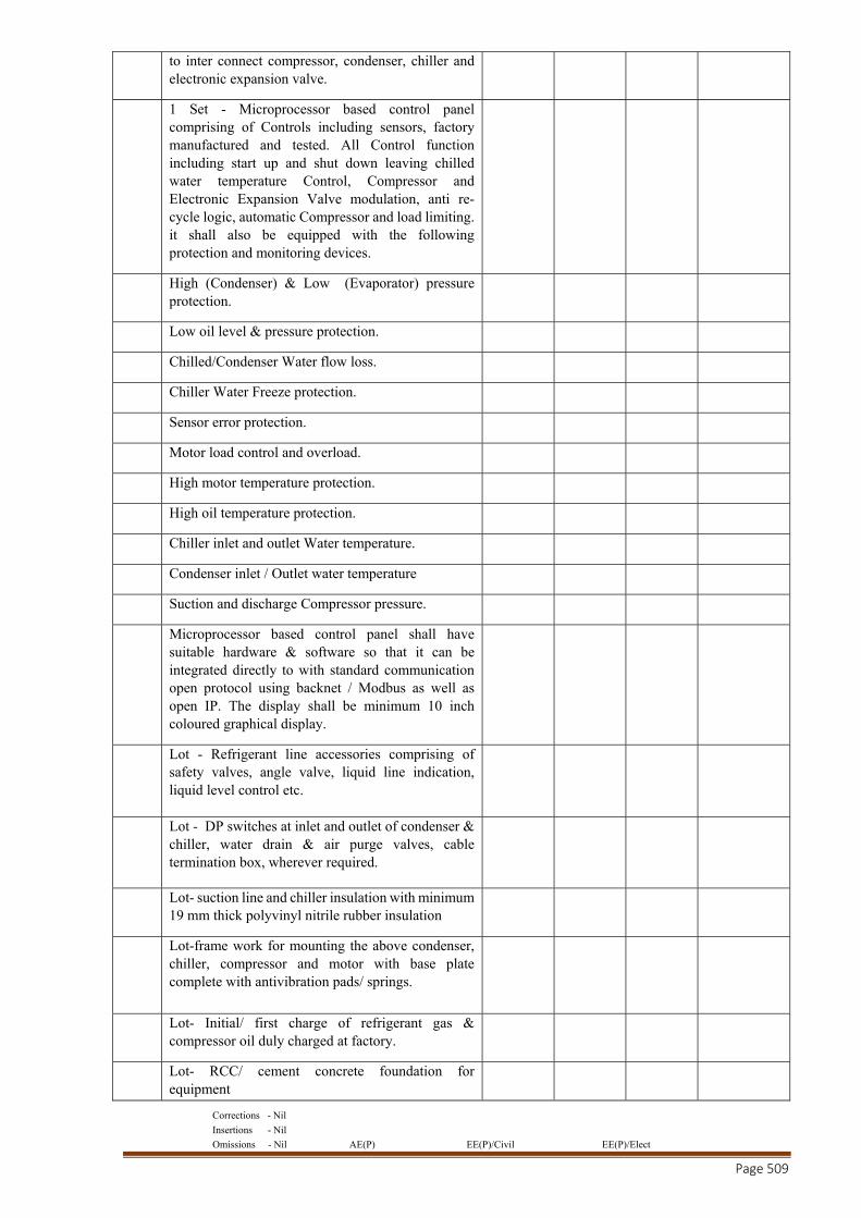
Corrections - Nil
Insertions - Nil
Omissions - Nil AE(P) EE(P)/Civil EE(P)/Elect
Page 509
to inter connect compressor, condenser, chiller and electronic expansion valve.
1 Set - Microprocessor based control panel comprising of Controls including sensors, factory manufactured and tested. All Control function including start up and shut down leaving chilled water temperature Control, Compressor and Electronic Expansion Valve modulation, anti re-cycle logic, automatic Compressor and load limiting. it shall also be equipped with the following protection and monitoring devices.
High (Condenser) & Low (Evaporator) pressure protection.
Low oil level & pressure protection.
Chilled/Condenser Water flow loss.
Chiller Water Freeze protection.
Sensor error protection.
Motor load control and overload.
High motor temperature protection.
High oil temperature protection.
Chiller inlet and outlet Water temperature.
Condenser inlet / Outlet water temperature
Suction and discharge Compressor pressure.
Microprocessor based control panel shall have suitable hardware & software so that it can be integrated directly to with standard communication open protocol using backnet / Modbus as well as open IP. The display shall be minimum 10 inch coloured graphical display.
Lot - Refrigerant line accessories comprising of safety valves, angle valve, liquid line indication, liquid level control etc.
Lot - DP switches at inlet and outlet of condenser & chiller, water drain & air purge valves, cable termination box, wherever required.
Lot- suction line and chiller insulation with minimum 19 mm thick polyvinyl nitrile rubber insulation
Lot-frame work for mounting the above condenser, chiller, compressor and motor with base plate complete with antivibration pads/ springs.
Lot- Initial/ first charge of refrigerant gas & compressor oil duly charged at factory.
Lot- RCC/ cement concrete foundation for equipment
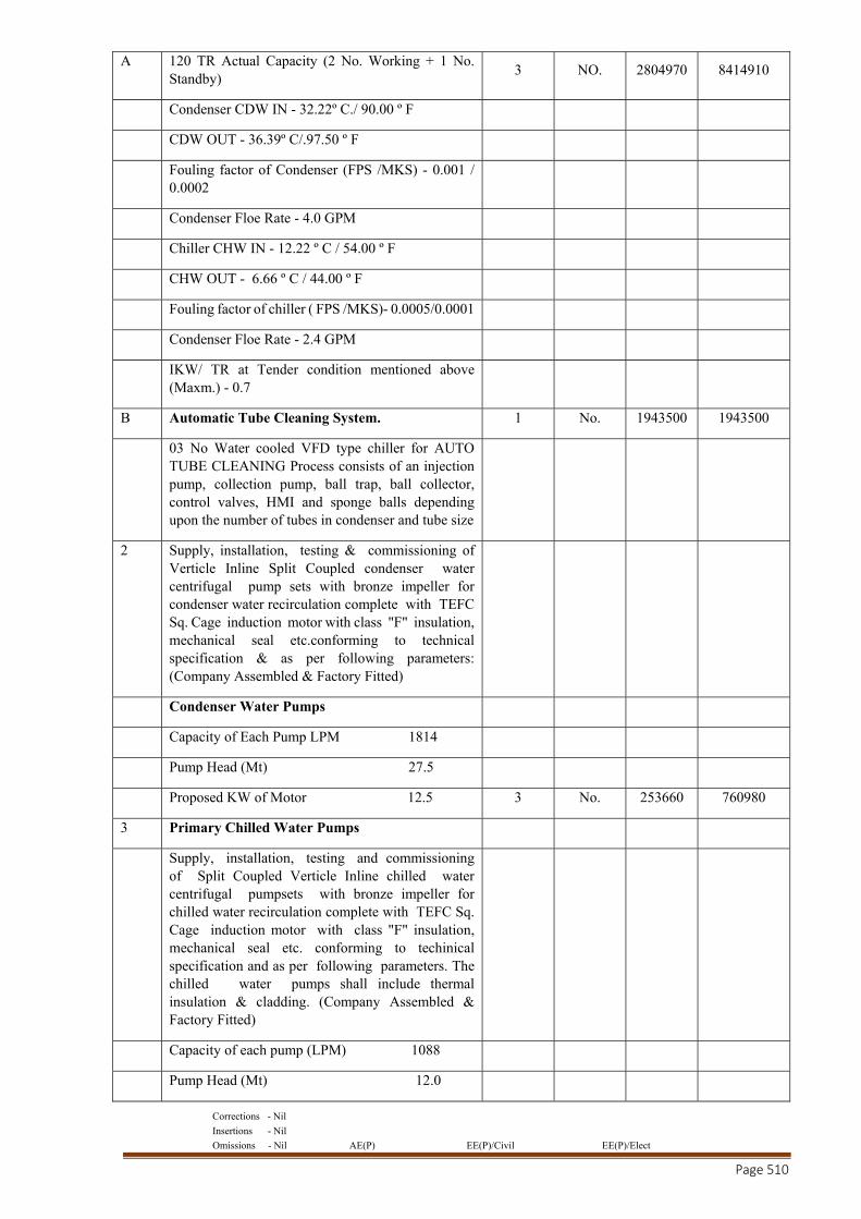
Corrections - Nil
Insertions - Nil
Omissions - Nil AE(P) EE(P)/Civil EE(P)/Elect
Page 510
A 120 TR Actual Capacity (2 No. Working + 1 No. Standby)
3 NO. 2804970 8414910
Condenser CDW IN - 32.22º C./ 90.00 º F
CDW OUT - 36.39º C/.97.50 º F
Fouling factor of Condenser (FPS /MKS) - 0.001 / 0.0002
Condenser Floe Rate - 4.0 GPM
Chiller CHW IN - 12.22 º C / 54.00 º F
CHW OUT - 6.66 º C / 44.00 º F
Fouling factor of chiller ( FPS /MKS)- 0.0005/0.0001
Condenser Floe Rate - 2.4 GPM
IKW/ TR at Tender condition mentioned above (Maxm.) - 0.7
B Automatic Tube Cleaning System. 1 No. 1943500 1943500
03 No Water cooled VFD type chiller for AUTO TUBE CLEANING Process consists of an injection pump, collection pump, ball trap, ball collector, control valves, HMI and sponge balls depending upon the number of tubes in condenser and tube size
2 Supply, installation, testing & commissioning of Verticle Inline Split Coupled condenser water centrifugal pump sets with bronze impeller for condenser water recirculation complete with TEFC Sq. Cage induction motor with class "F" insulation, mechanical seal etc.conforming to technical specification & as per following parameters: (Company Assembled & Factory Fitted)
Condenser Water Pumps
Capacity of Each Pump LPM 1814
Pump Head (Mt) 27.5
Proposed KW of Motor 12.5 3 No. 253660 760980
3 Primary Chilled Water Pumps
Supply, installation, testing and commissioning of Split Coupled Verticle Inline chilled water centrifugal pumpsets with bronze impeller for chilled water recirculation complete with TEFC Sq. Cage induction motor with class "F" insulation, mechanical seal etc. conforming to techinical specification and as per following parameters. The chilled water pumps shall include thermal insulation & cladding. (Company Assembled & Factory Fitted)
Capacity of each pump (LPM) 1088
Pump Head (Mt) 12.0
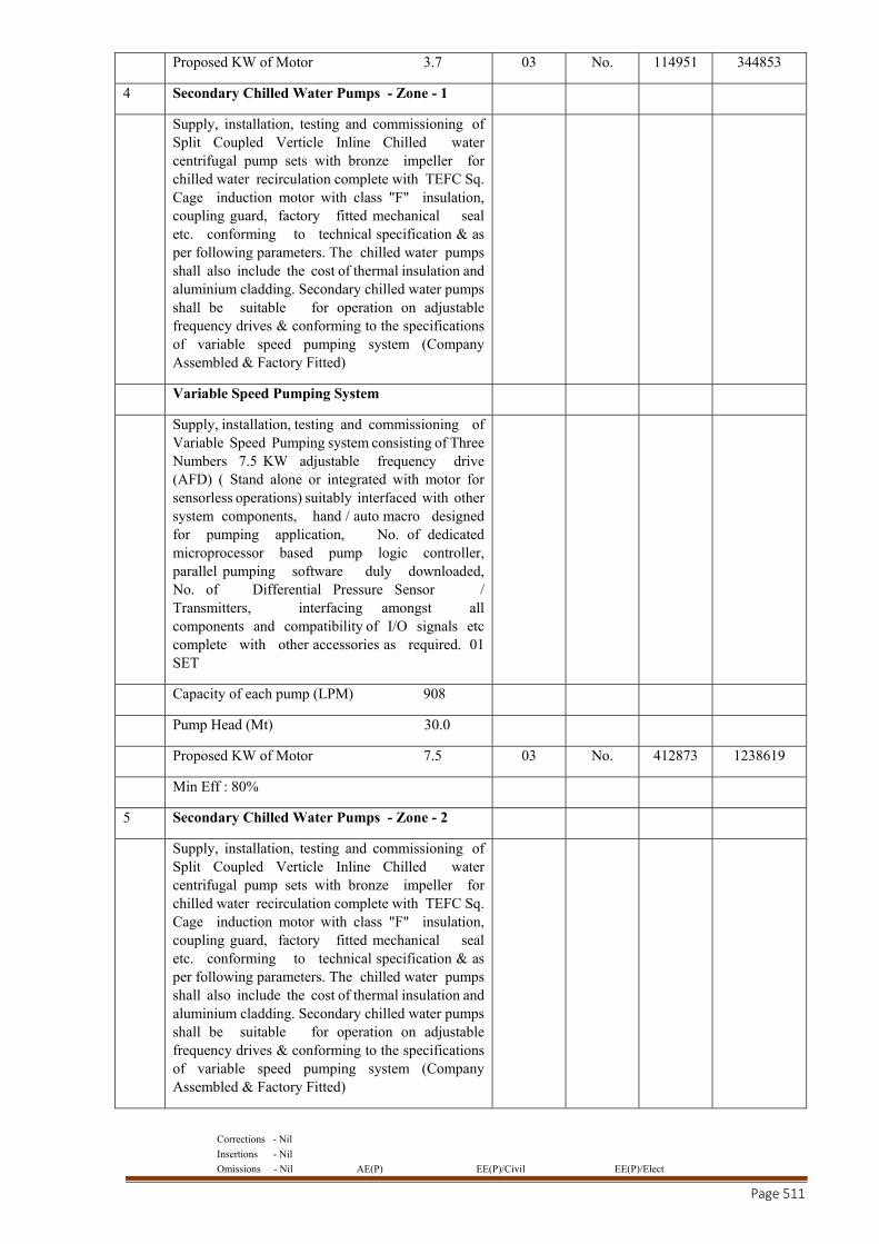
Corrections - Nil
Insertions - Nil
Omissions - Nil AE(P) EE(P)/Civil EE(P)/Elect
Page 511
Proposed KW of Motor 3.7 03 No. 114951 344853
4 Secondary Chilled Water Pumps - Zone - 1
Supply, installation, testing and commissioning of Split Coupled Verticle Inline Chilled water centrifugal pump sets with bronze impeller for chilled water recirculation complete with TEFC Sq. Cage induction motor with class "F" insulation, coupling guard, factory fitted mechanical seal etc. conforming to technical specification & as per following parameters. The chilled water pumps shall also include the cost of thermal insulation and aluminium cladding. Secondary chilled water pumps shall be suitable for operation on adjustable frequency drives & conforming to the specifications of variable speed pumping system (Company Assembled & Factory Fitted)
Variable Speed Pumping System
Supply, installation, testing and commissioning of Variable Speed Pumping system consisting of Three Numbers 7.5 KW adjustable frequency drive (AFD) ( Stand alone or integrated with motor for sensorless operations) suitably interfaced with other system components, hand / auto macro designed for pumping application, No. of dedicated microprocessor based pump logic controller, parallel pumping software duly downloaded, No. of Differential Pressure Sensor / Transmitters, interfacing amongst all components and compatibility of I/O signals etc complete with other accessories as required. 01 SET
Capacity of each pump (LPM) 908
Pump Head (Mt) 30.0
Proposed KW of Motor 7.5 03 No. 412873 1238619
Min Eff : 80%
5 Secondary Chilled Water Pumps - Zone - 2
Supply, installation, testing and commissioning of Split Coupled Verticle Inline Chilled water centrifugal pump sets with bronze impeller for chilled water recirculation complete with TEFC Sq. Cage induction motor with class "F" insulation, coupling guard, factory fitted mechanical seal etc. conforming to technical specification & as per following parameters. The chilled water pumps shall also include the cost of thermal insulation and aluminium cladding. Secondary chilled water pumps shall be suitable for operation on adjustable frequency drives & conforming to the specifications of variable speed pumping system (Company Assembled & Factory Fitted)
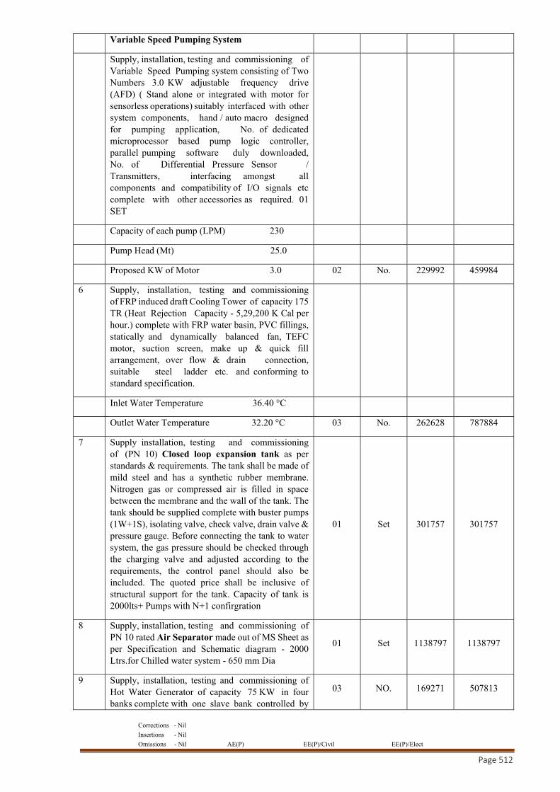
Corrections - Nil
Insertions - Nil
Omissions - Nil AE(P) EE(P)/Civil EE(P)/Elect
Page 512
Variable Speed Pumping System
Supply, installation, testing and commissioning of Variable Speed Pumping system consisting of Two Numbers 3.0 KW adjustable frequency drive (AFD) ( Stand alone or integrated with motor for sensorless operations) suitably interfaced with other system components, hand / auto macro designed for pumping application, No. of dedicated microprocessor based pump logic controller, parallel pumping software duly downloaded, No. of Differential Pressure Sensor / Transmitters, interfacing amongst all components and compatibility of I/O signals etc complete with other accessories as required. 01 SET
Capacity of each pump (LPM) 230
Pump Head (Mt) 25.0
Proposed KW of Motor 3.0 02 No. 229992 459984
6 Supply, installation, testing and commissioning of FRP induced draft Cooling Tower of capacity 175 TR (Heat Rejection Capacity - 5,29,200 K Cal per hour.) complete with FRP water basin, PVC fillings, statically and dynamically balanced fan, TEFC motor, suction screen, make up & quick fill arrangement, over flow & drain connection, suitable steel ladder etc. and conforming to standard specification.
Inlet Water Temperature 36.40 °C
Outlet Water Temperature 32.20 °C 03 No. 262628 787884
7 Supply installation, testing and commissioning of (PN 10) Closed loop expansion tank as per standards & requirements. The tank shall be made of mild steel and has a synthetic rubber membrane. Nitrogen gas or compressed air is filled in space between the membrane and the wall of the tank. The tank should be supplied complete with buster pumps (1W+1S), isolating valve, check valve, drain valve & pressure gauge. Before connecting the tank to water system, the gas pressure should be checked through the charging valve and adjusted according to the requirements, the control panel should also be included. The quoted price shall be inclusive of structural support for the tank. Capacity of tank is 2000lts+ Pumps with N+1 confirgration
01 Set 301757 301757
8 Supply, installation, testing and commissioning of PN 10 rated Air Separator made out of MS Sheet as per Specification and Schematic diagram - 2000 Ltrs.for Chilled water system - 650 mm Dia
01 Set 1138797 1138797
9 Supply, installation, testing and commissioning of Hot Water Generator of capacity 75 KW in four banks complete with one slave bank controlled by
03 NO. 169271 507813
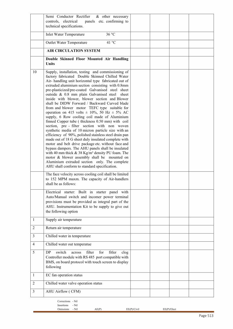
Corrections - Nil
Insertions - Nil
Omissions - Nil AE(P) EE(P)/Civil EE(P)/Elect
Page 513
Semi Conductor Rectifier & other necessary controls, electrical panels etc. confirming to technical specifications.
Inlet Water Temperature 36 °C
Outlet Water Temperature 41 °C
AIR CIRCULATION SYSTEM
Double Skinned Floor Mounted Air Handling Units
10 Supply, installation, testing and commissioning of factory fabricated Double Skinned Chilled Water Air- handling unit horizontal type fabricated out of extruded aluminium section consisting with 0.8mm pre-plasticized/pre-coated Galvanised steel sheet outside & 0.8 mm plain Galvanised steel sheet inside with blower, blower section and Blower shall be DIDW Forward / Backward Curved blade from and blower motor TEFC type suitable for operation on 415 volts ± 10%, 50 Hz ± 5% AC supply, 6 Row cooling coil made of Aluminium finned Copper tube ( thickness 0.50 mm) with coil section, pre - filter section with non woven synthetic media of 10 micron particle size with an efficiency of 90%, polished stainless steel drain pan made out of 18 G sheet duly insulated complete with motor and belt drive package etc. without face and bypass dampers. The AHU panels shall be insulated with 40 mm thick & 38 Kg/m³ density PU foam. The motor & blower assembly shall be mounted on Aluminium extruded section only. The complete AHU shall conform to standard specification.
The face velocity across cooling coil shall be limited to 152 MPM maxm. The capacity of Air-handlers shall be as follows:
Electrical starter: Built in starter panel with Auto/Manual switch and incomer power terminal provisions must be provided as integral part of the AHU. Instrumentation Kit to be supply to give out the following option
1 Supply air temperature
2 Return air temperature
3 Chilled water in temperature
4 Chilled water out temperatue
5 DP switch across filter for fitler clog Controller module with RS 485 port compatible with BMS, on board protocol with touch screen to display following
1 EC fan operation status
2 Chilled water valve operation status
3 AHU Airflow ( CFM)
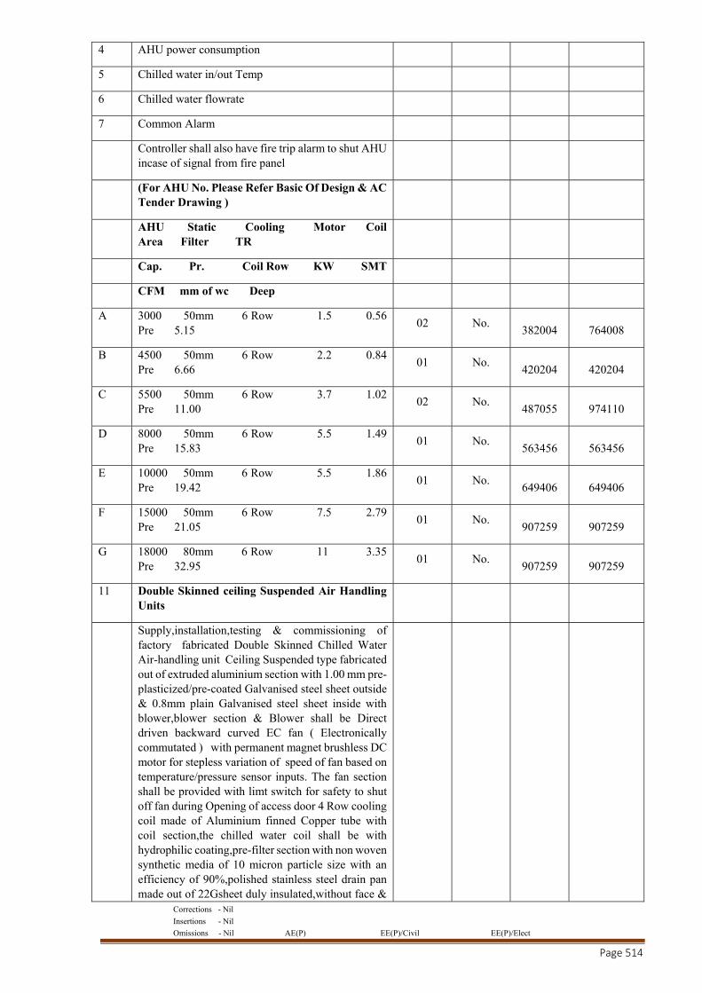
Corrections - Nil
Insertions - Nil
Omissions - Nil AE(P) EE(P)/Civil EE(P)/Elect
Page 514
4 AHU power consumption
5 Chilled water in/out Temp
6 Chilled water flowrate
7 Common Alarm
Controller shall also have fire trip alarm to shut AHU incase of signal from fire panel
(For AHU No. Please Refer Basic Of Design & AC Tender Drawing )
AHU Static Cooling Motor Coil Area Filter TR
Cap. Pr. Coil Row KW SMT
CFM mm of wc Deep
A 3000 50mm 6 Row 1.5 0.56 Pre 5.15
02 No. 382004 764008
B 4500 50mm 6 Row 2.2 0.84 Pre 6.66
01 No. 420204 420204
C 5500 50mm 6 Row 3.7 1.02 Pre 11.00
02 No. 487055 974110
D 8000 50mm 6 Row 5.5 1.49 Pre 15.83
01 No. 563456 563456
E 10000 50mm 6 Row 5.5 1.86 Pre 19.42
01 No. 649406 649406
F 15000 50mm 6 Row 7.5 2.79 Pre 21.05
01 No. 907259 907259
G 18000 80mm 6 Row 11 3.35 Pre 32.95
01 No. 907259 907259
11 Double Skinned ceiling Suspended Air Handling Units
Supply,installation,testing & commissioning of factory fabricated Double Skinned Chilled Water Air-handling unit Ceiling Suspended type fabricated out of extruded aluminium section with 1.00 mm pre-plasticized/pre-coated Galvanised steel sheet outside & 0.8mm plain Galvanised steel sheet inside with blower,blower section & Blower shall be Direct driven backward curved EC fan ( Electronically commutated ) with permanent magnet brushless DC motor for stepless variation of speed of fan based on temperature/pressure sensor inputs. The fan section shall be provided with limt switch for safety to shut off fan during Opening of access door 4 Row cooling coil made of Aluminium finned Copper tube with coil section,the chilled water coil shall be with hydrophilic coating,pre-filter section with non woven synthetic media of 10 micron particle size with an efficiency of 90%,polished stainless steel drain pan made out of 22Gsheet duly insulated,without face &
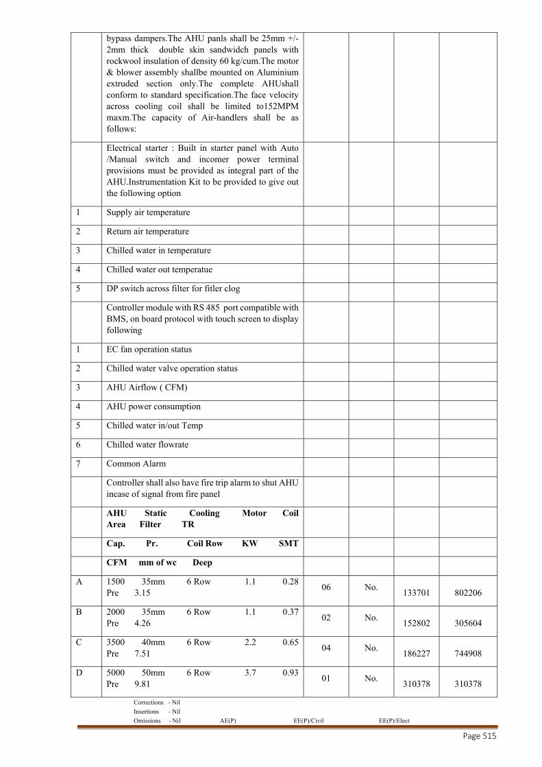
Corrections - Nil
Insertions - Nil
Omissions - Nil AE(P) EE(P)/Civil EE(P)/Elect
Page 515
bypass dampers.The AHU panls shall be 25mm +/- 2mm thick double skin sandwidch panels with rockwool insulation of density 60 kg/cum.The motor & blower assembly shallbe mounted on Aluminium extruded section only.The complete AHUshall conform to standard specification.The face velocity across cooling coil shall be limited to152MPM maxm.The capacity of Air-handlers shall be as follows:
Electrical starter : Built in starter panel with Auto /Manual switch and incomer power terminal provisions must be provided as integral part of the AHU.Instrumentation Kit to be provided to give out the following option
1 Supply air temperature
2 Return air temperature
3 Chilled water in temperature
4 Chilled water out temperatue
5 DP switch across filter for fitler clog
Controller module with RS 485 port compatible with BMS, on board protocol with touch screen to display following
1 EC fan operation status
2 Chilled water valve operation status
3 AHU Airflow ( CFM)
4 AHU power consumption
5 Chilled water in/out Temp
6 Chilled water flowrate
7 Common Alarm
Controller shall also have fire trip alarm to shut AHU incase of signal from fire panel
AHU Static Cooling Motor Coil Area Filter TR
Cap. Pr. Coil Row KW SMT
CFM mm of wc Deep
A 1500 35mm 6 Row 1.1 0.28 Pre 3.15
06 No. 133701 802206
B 2000 35mm 6 Row 1.1 0.37 Pre 4.26
02 No. 152802 305604
C 3500 40mm 6 Row 2.2 0.65 Pre 7.51
04 No. 186227 744908
D 5000 50mm 6 Row 3.7 0.93 Pre 9.81
01 No. 310378 310378
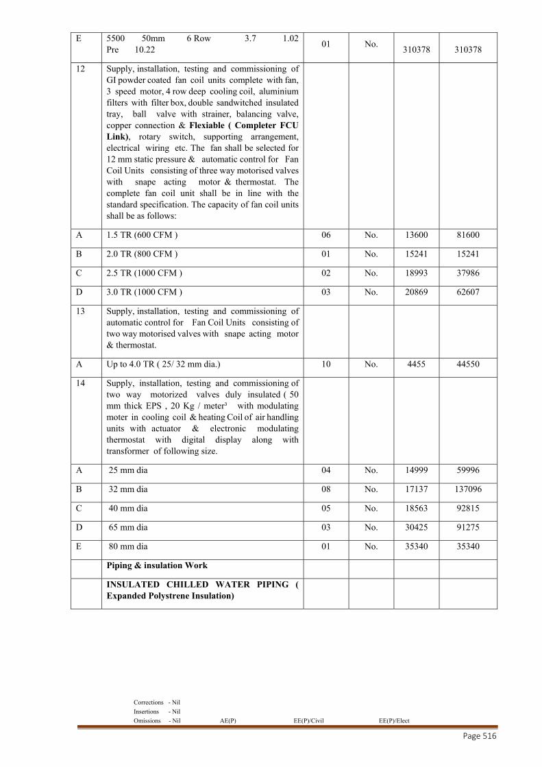
Corrections - Nil
Insertions - Nil
Omissions - Nil AE(P) EE(P)/Civil EE(P)/Elect
Page 516
E 5500 50mm 6 Row 3.7 1.02 Pre 10.22
01 No. 310378 310378
12 Supply, installation, testing and commissioning of GI powder coated fan coil units complete with fan, 3 speed motor, 4 row deep cooling coil, aluminium filters with filter box, double sandwitched insulated tray, ball valve with strainer, balancing valve, copper connection & Flexiable ( Completer FCU Link), rotary switch, supporting arrangement, electrical wiring etc. The fan shall be selected for 12 mm static pressure & automatic control for Fan Coil Units consisting of three way motorised valves with snape acting motor & thermostat. The complete fan coil unit shall be in line with the standard specification. The capacity of fan coil units shall be as follows:
A 1.5 TR (600 CFM ) 06 No. 13600 81600
B 2.0 TR (800 CFM ) 01 No. 15241 15241
C 2.5 TR (1000 CFM ) 02 No. 18993 37986
D 3.0 TR (1000 CFM ) 03 No. 20869 62607
13 Supply, installation, testing and commissioning of automatic control for Fan Coil Units consisting of two way motorised valves with snape acting motor & thermostat.
A Up to 4.0 TR ( 25/ 32 mm dia.) 10 No. 4455 44550
14 Supply, installation, testing and commissioning of two way motorized valves duly insulated ( 50 mm thick EPS , 20 Kg / meter³ with modulating moter in cooling coil & heating Coil of air handling units with actuator & electronic modulating thermostat with digital display along with transformer of following size.
A 25 mm dia 04 No. 14999 59996
B 32 mm dia 08 No. 17137 137096
C 40 mm dia 05 No. 18563 92815
D 65 mm dia 03 No. 30425 91275
E 80 mm dia 01 No. 35340 35340
Piping & insulation Work
INSULATED CHILLED WATER PIPING ( Expanded Polystrene Insulation)
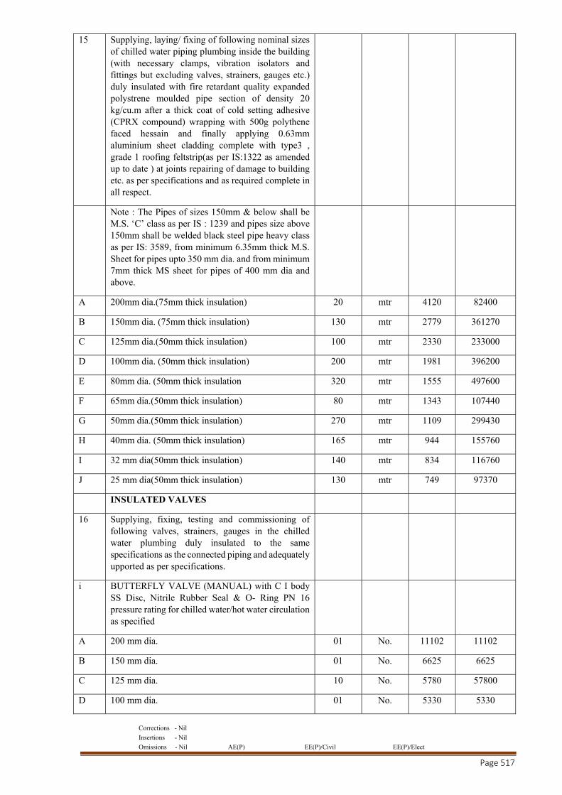
Corrections - Nil
Insertions - Nil
Omissions - Nil AE(P) EE(P)/Civil EE(P)/Elect
Page 517
15 Supplying, laying/ fixing of following nominal sizes of chilled water piping plumbing inside the building (with necessary clamps, vibration isolators and fittings but excluding valves, strainers, gauges etc.) duly insulated with fire retardant quality expanded polystrene moulded pipe section of density 20 kg/cu.m after a thick coat of cold setting adhesive (CPRX compound) wrapping with 500g polythene faced hessain and finally applying 0.63mm aluminium sheet cladding complete with type3 , grade 1 roofing feltstrip(as per IS:1322 as amended up to date ) at joints repairing of damage to building etc. as per specifications and as required complete in all respect.
Note : The Pipes of sizes 150mm & below shall be M.S. ‘C’ class as per IS : 1239 and pipes size above 150mm shall be welded black steel pipe heavy class as per IS: 3589, from minimum 6.35mm thick M.S. Sheet for pipes upto 350 mm dia. and from minimum 7mm thick MS sheet for pipes of 400 mm dia and above.
A 200mm dia.(75mm thick insulation) 20 mtr 4120 82400
B 150mm dia. (75mm thick insulation) 130 mtr 2779 361270
C 125mm dia.(50mm thick insulation) 100 mtr 2330 233000
D 100mm dia. (50mm thick insulation) 200 mtr 1981 396200
E 80mm dia. (50mm thick insulation 320 mtr 1555 497600
F 65mm dia.(50mm thick insulation) 80 mtr 1343 107440
G 50mm dia.(50mm thick insulation) 270 mtr 1109 299430
H 40mm dia. (50mm thick insulation) 165 mtr 944 155760
I 32 mm dia(50mm thick insulation) 140 mtr 834 116760
J 25 mm dia(50mm thick insulation) 130 mtr 749 97370
INSULATED VALVES
16 Supplying, fixing, testing and commissioning of following valves, strainers, gauges in the chilled water plumbing duly insulated to the same specifications as the connected piping and adequately upported as per specifications.
i BUTTERFLY VALVE (MANUAL) with C I body SS Disc, Nitrile Rubber Seal & O- Ring PN 16 pressure rating for chilled water/hot water circulation as specified
A 200 mm dia. 01 No. 11102 11102
B 150 mm dia. 01 No. 6625 6625
C 125 mm dia. 10 No. 5780 57800
D 100 mm dia. 01 No. 5330 5330
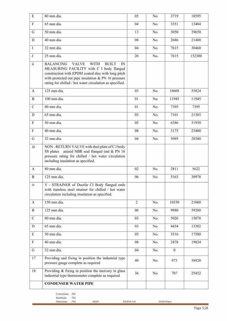
Corrections - Nil
Insertions - Nil
Omissions - Nil AE(P) EE(P)/Civil EE(P)/Elect
Page 518
E 80 mm dia. 05 No. 3719 18595
F 65 mm dia. 04 No. 3351 13404
G 50 mm dia. 13 No. 3050 39650
H 40 mm dia. 08 No. 2686 21488
I 32 mm dia. 04 No. 7615 30460
J 25 mm dia. 20 No. 7615 152300
ii BALANCING VALVE WITH BUILT IN MEASURING FACILITY with C I body flanged construction with EPDM coated disc with long pitch with protected out pipe insulation & PN 16 pressure rating for chilled / hot water circulation as specified.
A 125 mm dia. 03 No. 18608 55824
B 100 mm dia. 01 No. 11945 11945
C 80 mm dia. 01 No. 7395 7395
D 65 mm dia. 03 No. 7101 21303
E 50 mm dia. 05 No. 6386 31930
F 40 mm dia. 08 No. 3175 25400
G 32 mm dia. 04 No. 5095 20380
iii NON - RETURN VALVE with duel plate of C I body SS plates anized NBR seal flanged end & PN 16 pressure rating for chilled / hot water circulation including insulation as specified.
A 80 mm dia. 02 No. 2811 5622
B 125 mm dia. 06 No. 5163 30978
iv Y - STRAINER of Ductile CI Body flanged ends with stainless steel strainer for chilled / hot water circulation including insulation as specified.
A 150 mm dia. 2 No. 10530 21060
B 125 mm dia. 06 No. 9880 59280
C 80 mm dia. 03 No. 5026 15078
D 65 mm dia. 03 No. 4434 13302
E 50 mm dia. 05 No. 3516 17580
F 40 mm dia. 08 No. 2478 19824
G 32 mm dia. 04 No. 0
17 Providing and fixing in position the industrial type pressure gauge complete as required
40 No. 973 38920
18 Providing & fixing in position the mercury in glass industrial type thermometer complete as required
36 No. 707 25452
CONDENSER WATER PIPE
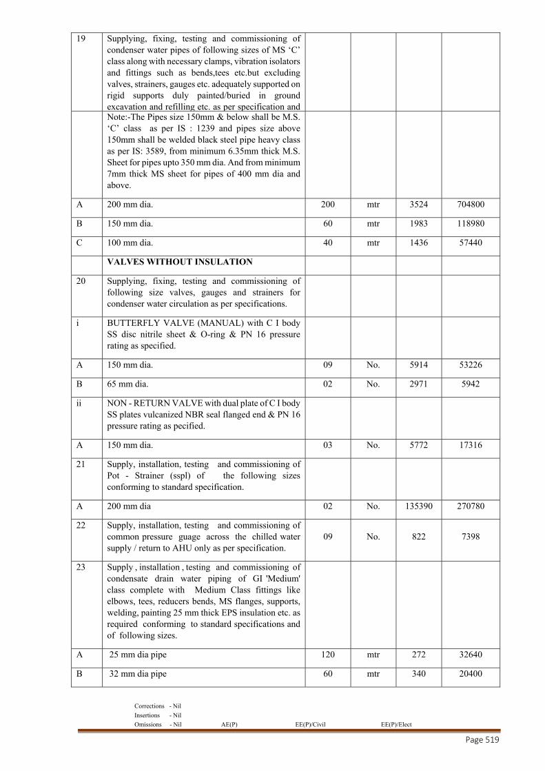
Corrections - Nil
Insertions - Nil
Omissions - Nil AE(P) EE(P)/Civil EE(P)/Elect
Page 519
19 Supplying, fixing, testing and commissioning of condenser water pipes of following sizes of MS ‘C’ class along with necessary clamps, vibration isolators and fittings such as bends,tees etc.but excluding valves, strainers, gauges etc. adequately supported on rigid supports duly painted/buried in ground excavation and refilling etc. as per specification and
Note:-The Pipes size 150mm & below shall be M.S. ‘C’ class as per IS : 1239 and pipes size above 150mm shall be welded black steel pipe heavy class as per IS: 3589, from minimum 6.35mm thick M.S. Sheet for pipes upto 350 mm dia. And from minimum 7mm thick MS sheet for pipes of 400 mm dia and above.
A 200 mm dia. 200 mtr 3524 704800
B 150 mm dia. 60 mtr 1983 118980
C 100 mm dia. 40 mtr 1436 57440
VALVES WITHOUT INSULATION
20 Supplying, fixing, testing and commissioning of following size valves, gauges and strainers for condenser water circulation as per specifications.
i BUTTERFLY VALVE (MANUAL) with C I body SS disc nitrile sheet & O-ring & PN 16 pressure rating as specified.
A 150 mm dia. 09 No. 5914 53226
B 65 mm dia. 02 No. 2971 5942
ii NON - RETURN VALVE with dual plate of C I body SS plates vulcanized NBR seal flanged end & PN 16 pressure rating as pecified.
A 150 mm dia. 03 No. 5772 17316
21 Supply, installation, testing and commissioning of Pot - Strainer (sspl) of the following sizes conforming to standard specification.
A 200 mm dia 02 No. 135390 270780
22 Supply, installation, testing and commissioning of common pressure guage across the chilled water supply / return to AHU only as per specification.
09 No. 822 7398
23 Supply , installation , testing and commissioning of condensate drain water piping of GI 'Medium' class complete with Medium Class fittings like elbows, tees, reducers bends, MS flanges, supports, welding, painting 25 mm thick EPS insulation etc. as required conforming to standard specifications and of following sizes.
A 25 mm dia pipe 120 mtr 272 32640
B 32 mm dia pipe 60 mtr 340 20400
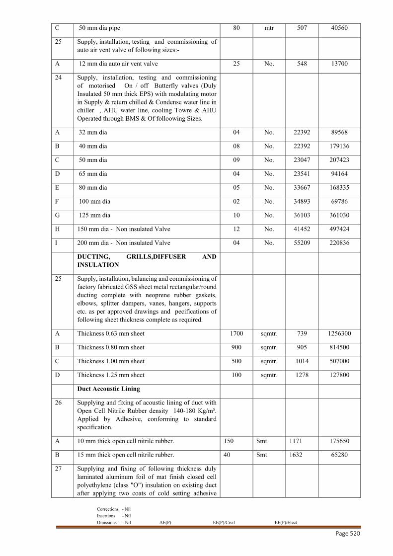
Corrections - Nil
Insertions - Nil
Omissions - Nil AE(P) EE(P)/Civil EE(P)/Elect
Page 520
C 50 mm dia pipe 80 mtr 507 40560
25 Supply, installation, testing and commissioning of auto air vent valve of following sizes:-
A 12 mm dia auto air vent valve 25 No. 548 13700
24 Supply, installation, testing and commissioning of motorised On / off Butterfly valves (Duly Insulated 50 mm thick EPS) with modulating motor in Supply & return chilled & Condense water line in chiller , AHU water line, cooling Towre & AHU Operated through BMS & Of folloowing Sizes.
A 32 mm dia 04 No. 22392 89568
B 40 mm dia 08 No. 22392 179136
C 50 mm dia 09 No. 23047 207423
D 65 mm dia 04 No. 23541 94164
E 80 mm dia 05 No. 33667 168335
F 100 mm dia 02 No. 34893 69786
G 125 mm dia 10 No. 36103 361030
H 150 mm dia - Non insulated Valve 12 No. 41452 497424
I 200 mm dia - Non insulated Valve 04 No. 55209 220836
DUCTING, GRILLS,DIFFUSER AND INSULATION
25 Supply, installation, balancing and commissioning of factory fabricated GSS sheet metal rectangular/round ducting complete with neoprene rubber gaskets, elbows, splitter dampers, vanes, hangers, supports etc. as per approved drawings and pecifications of following sheet thickness complete as required.
A Thickness 0.63 mm sheet 1700 sqmtr. 739 1256300
B Thickness 0.80 mm sheet 900 sqmtr. 905 814500
C Thickness 1.00 mm sheet 500 sqmtr. 1014 507000
D Thickness 1.25 mm sheet 100 sqmtr. 1278 127800
Duct Accoustic Lining
26 Supplying and fixing of acoustic lining of duct with Open Cell Nitrile Rubber density 140-180 Kg/m³. Applied by Adhesive, conforming to standard specification.
A 10 mm thick open cell nitrile rubber. 150 Smt 1171 175650
B 15 mm thick open cell nitrile rubber. 40 Smt 1632 65280
27 Supplying and fixing of following thickness duly laminated aluminum foil of mat finish closed cell polyethylene (class "O") insulation on existing duct after applying two coats of cold setting adhesive
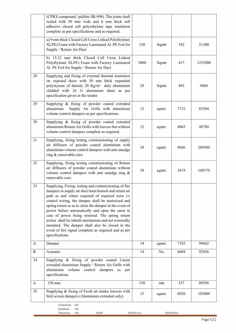
Corrections - Nil
Insertions - Nil
Omissions - Nil AE(P) EE(P)/Civil EE(P)/Elect
Page 521
(CPRX compound / pidilite SR-998). The joints shall sealed with 50 mm wide and 6 mm thick self adhesive closed cell polyethylene tape insulation complete as per specifications and as required.
a) 9 mm thick Closed Cell Cross Linked Polythylene( XLPE) Foam with Factory Laminated Al PE Foil for Supply / Return Air Duct
150 Sqmtr 342 51300
b) 13/12 mm thick Closed Cell Cross Linked Polythylene( XLPE) Foam with Factory Laminated Al PE Foil for Supply / Return Air Duct
3000 Sqmtr 417 1251000
28 Supplying and fixing of external thermal insulation on exposed ducts with 50 mm thick expanded polystyrene of density 20 Kg/m³ duly aluminium cladded with 26 G aluminium sheet as per specification given in the tender.
20 Sqmtr 493 9860
29 Supplying & fixing of powder coated extruded aluminium Supply Air Grills with aluminium volume control dampers as per specifications.
12 sqmtr. 7132 85584
30 Supplying & fixing of powder coated extruded aluminium Return Air Grills with louvers but without volume control dampers complete as required.
12 sqmtr. 4065 48780
31 Supplying, fixing testing commissioning of supply air diffusers of powder coated aluminium with aluminium volume control dampers with anti smudge ring & removable core.
30 sqmtr. 8686 260580
32 Supplying, fixing testing commissioning of Return air diffusers of powder coated aluminium without volume control dampers with anti smudge ring & removable core.
30 sqmtr. 5619 168570
33 Supplying, Fixing, testing and commissioning of fire dampers in supply air duct/main branch and return air path as and where required of required sizes i/c control wiring, the damper shall be motorized and spring return so as to close the damper in the event of power failure automatically and open the same in case of power being restored. The spring return action shall be inbuilt mechanism and not externally mounted. The damper shall also be closed in the event of fire signal complete as required and as per specifications.
A Damper 14 sqmtr. 7103 99442
B Actuator 14 No. 6604 92456
34 Supplying & fixing of powder coated Linear extruded aluminium Supply / Return Air Grills with aluminium volume control dampers as per specifications.
A 150 mm 150 mtr 537 80598
35 Supplying & fixing of Fresh air intake louvers with bird screen dampers (Aluminium extruded only).
15 sqmtr. 6920 103800
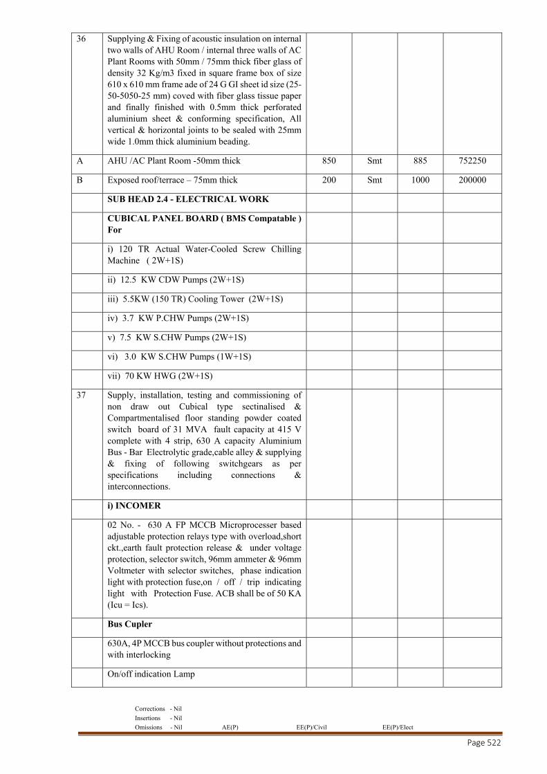
Corrections - Nil
Insertions - Nil
Omissions - Nil AE(P) EE(P)/Civil EE(P)/Elect
Page 522
36 Supplying & Fixing of acoustic insulation on internal two walls of AHU Room / internal three walls of AC Plant Rooms with 50mm / 75mm thick fiber glass of density 32 Kg/m3 fixed in square frame box of size 610 x 610 mm frame ade of 24 G GI sheet id size (25-50-5050-25 mm) coved with fiber glass tissue paper and finally finished with 0.5mm thick perforated aluminium sheet & conforming specification, All vertical & horizontal joints to be sealed with 25mm wide 1.0mm thick aluminium beading.
A AHU /AC Plant Room -50mm thick 850 Smt 885 752250
B Exposed roof/terrace – 75mm thick 200 Smt 1000 200000
SUB HEAD 2.4 - ELECTRICAL WORK
CUBICAL PANEL BOARD ( BMS Compatable ) For
i) 120 TR Actual Water-Cooled Screw Chilling Machine ( 2W+1S)
ii) 12.5 KW CDW Pumps (2W+1S)
iii) 5.5KW (150 TR) Cooling Tower (2W+1S)
iv) 3.7 KW P.CHW Pumps (2W+1S)
v) 7.5 KW S.CHW Pumps (2W+1S)
vi) 3.0 KW S.CHW Pumps (1W+1S)
vii) 70 KW HWG (2W+1S)
37 Supply, installation, testing and commissioning of non draw out Cubical type sectinalised & Compartmentalised floor standing powder coated switch board of 31 MVA fault capacity at 415 V complete with 4 strip, 630 A capacity Aluminium Bus - Bar Electrolytic grade,cable alley & supplying & fixing of following switchgears as per specifications including connections & interconnections.
i) INCOMER
02 No. - 630 A FP MCCB Microprocesser based adjustable protection relays type with overload,short ckt.,earth fault protection release & under voltage protection, selector switch, 96mm ammeter & 96mm Voltmeter with selector switches, phase indication light with protection fuse,on / off / trip indicating light with Protection Fuse. ACB shall be of 50 KA (Icu = Ics).
Bus Cupler
630A, 4P MCCB bus coupler without protections and with interlocking
On/off indication Lamp
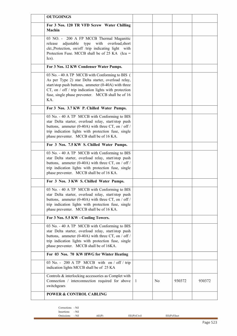
Corrections - Nil
Insertions - Nil
Omissions - Nil AE(P) EE(P)/Civil EE(P)/Elect
Page 523
OUTGOINGS
For 3 Nos. 120 TR VFD Screw Water Chilling Machin
03 NO. - 200 A FP MCCB Thermal Maganitic release adjustable type with overload,short ckt.,Protection, on/off /trip indicating light with Protection Fuse. MCCB shall be of 25 KA (Icu = Ics).
For 3 Nos. 12 KW Condenser Water Pumps.
03 No. - 40 A TP MCCB with Conforming to BIS ( As per Type 2) star Delta starter, overload relay, start/stop push buttons, ammeter (0-40A) with three CT, on / off / trip indication lights with protection fuse, single phase preventer. MCCB shall be of 16 KA.
For 3 Nos. 3.7 KW P. Chilled Water Pumps.
03 No. - 40 A TP MCCB with Conforming to BIS star Delta starter, overload relay, start/stop push buttons, ammeter (0-40A) with three CT, on / off / trip indication lights with protection fuse, single phase preventer. MCCB shall be of 16 KA.
For 3 Nos. 7.5 KW S. Chilled Water Pumps.
03 No. - 40 A TP MCCB with Conforming to BIS star Delta starter, overload relay, start/stop push buttons, ammeter (0-40A) with three CT, on / off / trip indication lights with protection fuse, single phase preventer. MCCB shall be of 16 KA.
For 3 Nos. 3 KW S. Chilled Water Pumps.
03 No. - 40 A TP MCCB with Conforming to BIS star Delta starter, overload relay, start/stop push buttons, ammeter (0-40A) with three CT, on / off / trip indication lights with protection fuse, single phase preventer. MCCB shall be of 16 KA.
For 3 Nos. 5.5 KW - Cooling Towers.
03 No. - 40 A TP MCCB with Conforming to BIS star Delta starter, overload relay, start/stop push buttons, ammeter (0-40A) with three CT, on / off / trip indication lights with protection fuse, single phase preventer. MCCB shall be of 16KA.
For 03 Nos. 70 KW HWG for Winter Heating
03 No. - 200 A TP MCCB with on / off / trip indication lights MCCB shall be of 25 KA
Controls & interlocking accessories as Complet with Connection / interconnection required for above switchgears
1 No 930372 930372
POWER & CONTROL CABLING
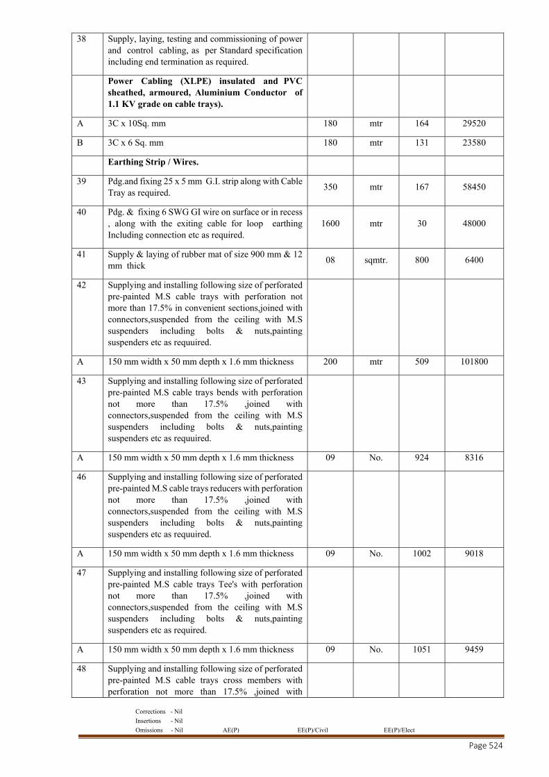
Corrections - Nil
Insertions - Nil
Omissions - Nil AE(P) EE(P)/Civil EE(P)/Elect
Page 524
38 Supply, laying, testing and commissioning of power and control cabling, as per Standard specification including end termination as required.
Power Cabling (XLPE) insulated and PVC sheathed, armoured, Aluminium Conductor of 1.1 KV grade on cable trays).
A 3C x 10Sq. mm 180 mtr 164 29520
B 3C x 6 Sq. mm 180 mtr 131 23580
Earthing Strip / Wires.
39 Pdg.and fixing 25 x 5 mm G.I. strip along with Cable Tray as required.
350 mtr 167 58450
40 Pdg. & fixing 6 SWG GI wire on surface or in recess , along with the exiting cable for loop earthing Including connection etc as required.
1600 mtr 30 48000
41 Supply & laying of rubber mat of size 900 mm & 12 mm thick
08 sqmtr. 800 6400
42 Supplying and installing following size of perforated pre-painted M.S cable trays with perforation not more than 17.5% in convenient sections,joined with connectors,suspended from the ceiling with M.S suspenders including bolts & nuts,painting suspenders etc as requuired.
A 150 mm width x 50 mm depth x 1.6 mm thickness 200 mtr 509 101800
43 Supplying and installing following size of perforated pre-painted M.S cable trays bends with perforation not more than 17.5% ,joined with connectors,suspended from the ceiling with M.S suspenders including bolts & nuts,painting suspenders etc as requuired.
A 150 mm width x 50 mm depth x 1.6 mm thickness 09 No. 924 8316
46 Supplying and installing following size of perforated pre-painted M.S cable trays reducers with perforation not more than 17.5% ,joined with connectors,suspended from the ceiling with M.S suspenders including bolts & nuts,painting suspenders etc as requuired.
A 150 mm width x 50 mm depth x 1.6 mm thickness 09 No. 1002 9018
47 Supplying and installing following size of perforated pre-painted M.S cable trays Tee's with perforation not more than 17.5% ,joined with connectors,suspended from the ceiling with M.S suspenders including bolts & nuts,painting suspenders etc as required.
A 150 mm width x 50 mm depth x 1.6 mm thickness 09 No. 1051 9459
48 Supplying and installing following size of perforated pre-painted M.S cable trays cross members with perforation not more than 17.5% ,joined with
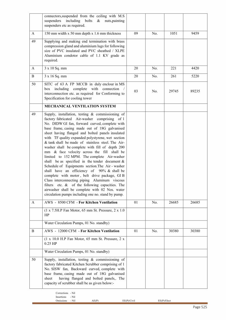
Corrections - Nil
Insertions - Nil
Omissions - Nil AE(P) EE(P)/Civil EE(P)/Elect
Page 525
connectors,suspended from the ceiling with M.S suspenders including bolts & nuts,painting suspenders etc as required.
A 150 mm width x 50 mm depth x 1.6 mm thickness 09 No. 1051 9459
49 Supplying and making end termination with brass compression gland and aluminium lugs for following size of PVC insulated and PVC sheathed / XLPE Aluminium condotor cable of 1.1 KV grade as required.
A 3 x 10 Sq. mm 20 No. 221 4420
B 3 x 16 Sq. mm 20 No. 261 5220
50 SITC of 63 A FP MCCB in duly enclour in MS box including complete with connection / interconnection etc. as required for Conforming to Specification for cooling tower
03 No. 29745 89235
MECHANICAL VENTILATION SYSTEM
49 Supply, installation, testing & commissioning of factory fabricated Air-washer comprising of 1 No. DIDW GI fan, forward curved, complete with base frame, casing made out of 18G galvanised sheet having flanged and bolted panels insulated with TF quality expanded polystyrene, wet section & tank shall be made of stainless steel. The Air-washer shall be complete with fill of depth 200 mm & face velocity across the fill shall be limited to 152 MPM. The complete Air-washer shall be as specified in the tender document & Schedule of Equipments section.The Air - washer shall have an efficiency of 90% & shall be complete with motor , belt drive package, GI B Class interconnecting piping Aluminum viscous filters etc. & of the following capacities. The airwasher shall be complete with 02 Nos. water circulation pumps including one no. stand by pump.
A AWS - 8500 CFM - For Kitchen Ventilation 01 No. 26685 26685
(1 x 7.5H.P Fan Motor, 65 mm St. Pressure, 2 x 1.0 HP
Water Circulation Pumps, 01 No. standby)
B AWS - 12000 CFM - For Kitchen Ventilation 01 No. 30380 30380
(1 x 10.0 H.P Fan Motor, 65 mm St. Pressure, 2 x 0.25 HP
Water Circulation Pumps, 01 No. standby)
50 Supply, installation, testing & commissioning of factory fabricated Kitchen Scrubber comprising of 1 No. SISW fan, Backward curved, complete with base frame, casing made out of 18G galvanised sheet having flanged and bolted panels,. The capacity of scrubber shall be as given below:-
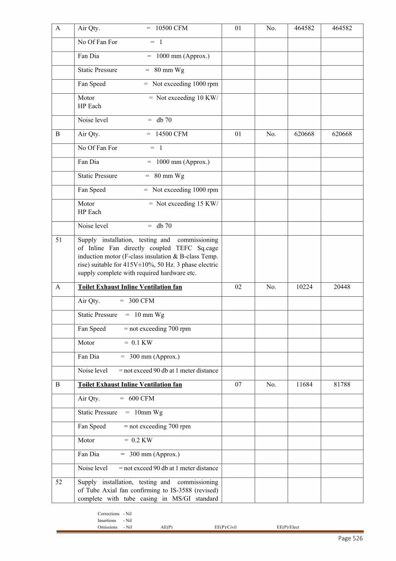
Corrections - Nil
Insertions - Nil
Omissions - Nil AE(P) EE(P)/Civil EE(P)/Elect
Page 526
A Air Qty. = 10500 CFM 01 No. 464582 464582
No Of Fan For = 1
Fan Dia = 1000 mm (Approx.)
Static Pressure = 80 mm Wg
Fan Speed = Not exceeding 1000 rpm
Motor = Not exceeding 10 KW/ HP Each
Noise level = db 70
B Air Qty. = 14500 CFM 01 No. 620668 620668
No Of Fan For = 1
Fan Dia = 1000 mm (Approx.)
Static Pressure = 80 mm Wg
Fan Speed = Not exceeding 1000 rpm
Motor = Not exceeding 15 KW/ HP Each
Noise level = db 70
51 Supply installation, testing and commissioning of Inline Fan directly coupled TEFC Sq.cage induction motor (F-class insulation & B-class Temp. rise) suitable for 415V±10%, 50 Hz. 3 phase electric supply complete with required hardware etc.
A Toilet Exhaust Inline Ventilation fan 02 No. 10224 20448
Air Qty. = 300 CFM
Static Pressure = 10 mm Wg
Fan Speed = not exceeding 700 rpm
Motor = 0.1 KW
Fan Dia = 300 mm (Approx.)
Noise level = not exceed 90 db at 1 meter distance
B Toilet Exhaust Inline Ventilation fan 07 No. 11684 81788
Air Qty. = 600 CFM
Static Pressure = 10mm Wg
Fan Speed = not exceeding 700 rpm
Motor = 0.2 KW
Fan Dia = 300 mm (Approx.)
Noise level = not exceed 90 db at 1 meter distance
52 Supply installation, testing and commissioning of Tube Axial fan confirming to IS-3588 (revised) complete with tube casing in MS/GI standard
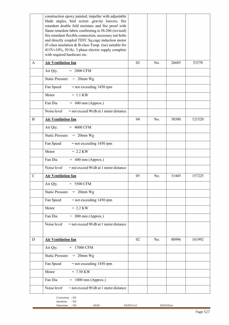
Corrections - Nil
Insertions - Nil
Omissions - Nil AE(P) EE(P)/Civil EE(P)/Elect
Page 527
construction epoxy painted, impeller with adjustable blade angles, bird screen ,gravity louvers, fire retardent double fold moisture and fire proof with flame retardent fabric confirming to IS-206 (revised) fire retardent flexible connection, necessary nut bolts and directly coupled TEFC Sq.cage induction motor (F-class insulation & B-class Temp. rise) suitable for 415V±10%, 50 Hz. 3 phase electric supply complete with required hardware etc.
A Air Ventilation fan 02 No. 26685 53370
Air Qty. = 2000 CFM
Static Pressure = 20mm Wg
Fan Speed = not exceeding 1450 rpm
Motor = 1.1 KW
Fan Dia = 600 mm (Approx.)
Noise level = not exceed 90 db at 1 meter distance
B Air Ventilation fan 04 No. 30380 121520
Air Qty. = 4000 CFM
Static Pressure = 20mm Wg
Fan Speed = not exceeding 1450 rpm
Motor = 2.2 KW
Fan Dia = 600 mm (Approx.)
Noise level = not exceed 90 db at 1 meter distance
C Air Ventilation fan 05 No. 31445 157225
Air Qty. = 5500 CFM
Static Pressure = 20mm Wg
Fan Speed = not exceeding 1450 rpm
Motor = 2.2 KW
Fan Dia = 800 mm (Approx.)
Noise level = not exceed 90 db at 1 meter distance
D Air Ventilation fan 02 No. 80996 161992
Air Qty. = 17000 CFM
Static Pressure = 20mm Wg
Fan Speed = not exceeding 1450 rpm
Motor = 7.50 KW
Fan Dia = 1000 mm (Approx.)
Noise level = not exceed 90 db at 1 meter distance
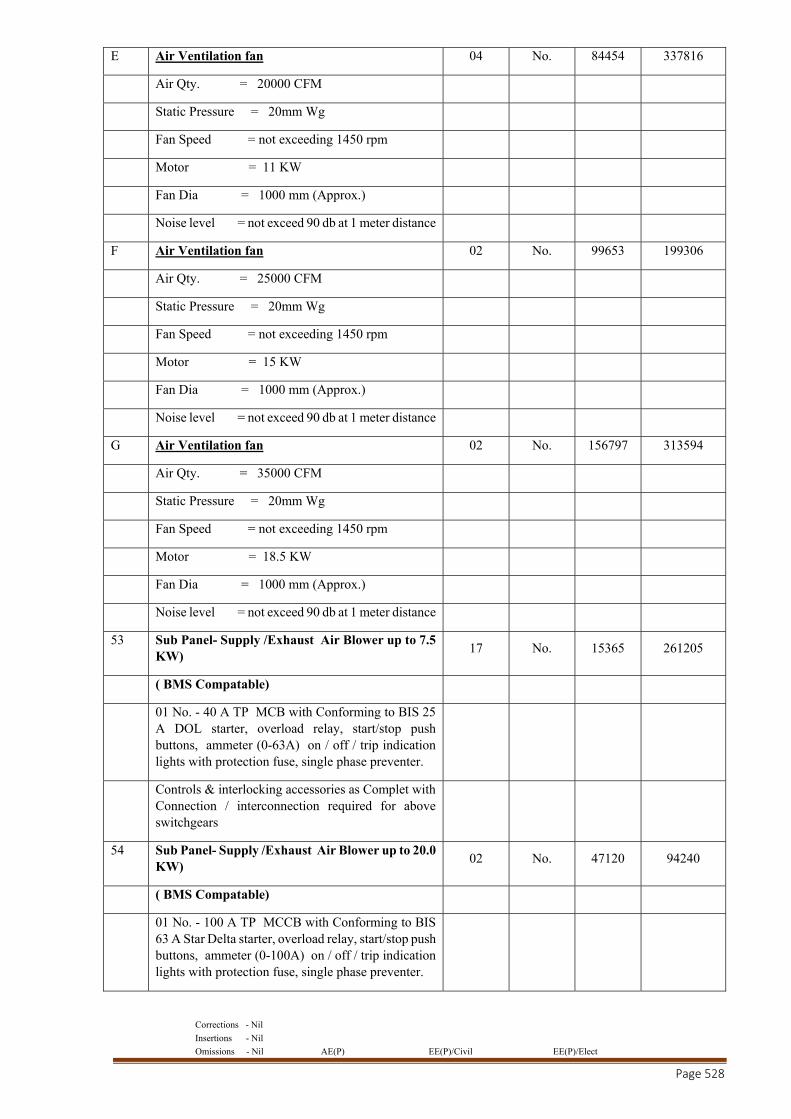
Corrections - Nil
Insertions - Nil
Omissions - Nil AE(P) EE(P)/Civil EE(P)/Elect
Page 528
E Air Ventilation fan 04 No. 84454 337816
Air Qty. = 20000 CFM
Static Pressure = 20mm Wg
Fan Speed = not exceeding 1450 rpm
Motor = 11 KW
Fan Dia = 1000 mm (Approx.)
Noise level = not exceed 90 db at 1 meter distance
F Air Ventilation fan 02 No. 99653 199306
Air Qty. = 25000 CFM
Static Pressure = 20mm Wg
Fan Speed = not exceeding 1450 rpm
Motor = 15 KW
Fan Dia = 1000 mm (Approx.)
Noise level = not exceed 90 db at 1 meter distance
G Air Ventilation fan 02 No. 156797 313594
Air Qty. = 35000 CFM
Static Pressure = 20mm Wg
Fan Speed = not exceeding 1450 rpm
Motor = 18.5 KW
Fan Dia = 1000 mm (Approx.)
Noise level = not exceed 90 db at 1 meter distance
53 Sub Panel- Supply /Exhaust Air Blower up to 7.5 KW)
17 No. 15365 261205
( BMS Compatable)
01 No. - 40 A TP MCB with Conforming to BIS 25 A DOL starter, overload relay, start/stop push buttons, ammeter (0-63A) on / off / trip indication lights with protection fuse, single phase preventer.
Controls & interlocking accessories as Complet with Connection / interconnection required for above switchgears
54 Sub Panel- Supply /Exhaust Air Blower up to 20.0 KW)
02 No. 47120 94240
( BMS Compatable)
01 No. - 100 A TP MCCB with Conforming to BIS 63 A Star Delta starter, overload relay, start/stop push buttons, ammeter (0-100A) on / off / trip indication lights with protection fuse, single phase preventer.
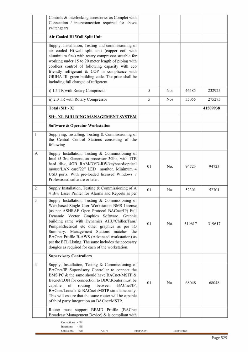
Corrections - Nil
Insertions - Nil
Omissions - Nil AE(P) EE(P)/Civil EE(P)/Elect
Page 529
Controls & interlocking accessories as Complet with Connection / interconnection required for above switchgears
Air Cooled Hi Wall Split Unit
Supply, Installation, Testing and commissioning of air cooled Hi-wall split unit (copper coil with aluminium fins) with rotary compressor suitable for working under 15 to 20 meter length of piping with cordless control of following capacity with eco friendly refrigerant & COP in compliance with GRIHA-III, green building code. The price shall be including full charged of refigerent.
i) 1.5 TR with Rotary Compressor 5 Nos 46585 232925
ii) 2.0 TR with Rotary Compressor 5 Nos 55055 275275
Total (SH:- X) 41509938
SH:- XI- BUILDING MANAGEMENT SYSTEM
Software & Operator Workstation
1 Supplying, Installing, Testing & Commissioning of the Central Control Stations consisting of the following
A Supply Installation, Testing & Commissioning of Intel i5 3rd Generation processor 3Ghz, with 1TB hard disk, 4GB RAM/DVD-RW/keyboard/optical mouse/LAN card/22” LED monitor. Minimum 4 USB ports. With pre-loaded licensed Windows 7 Professional software or later.
01 No. 94723 94723
2 Supply Installation, Testing & Commissioning of A 4 B/w Laser Printer for Alarms and Reports as per
ifi ti
01 No. 52301 52301
3 Supply Installation, Testing & Commissioning of Web based Single User Workstation BMS License (as per ASHRAE Open Protocol BACnet/IP) Full Dynamic Vector Graphics Software. Graphic building same with Dynamics AHU/Chiller/Fans/ Pumps/Electrical etc other graphics as per IO Summary. Management Stations matches the BACnet Profile B-AWS (Advanced workstation) as per the BTL Listing. The same includes the necessary dongles as required for each of the workstation.
01 No. 319617 319617
Supervisory Controllers
4 Supply, Installation, Testing & Commissioning of BACnet/IP Supervisory Controller to connect the BMS PC & the same should have BACnet/MSTP & Bacnet/LON for connection to DDC.Router must be capable of routing between BACnet/IP, BACnet/Lontalk & BACnet /MSTP simultaneously. This will ensure that the same router will be capable of third party integration on BACnet/MSTP.
01 No. 68048 68048
Router must support BBMD Profile (BACnet Broadcast Management Device) & is compliant with
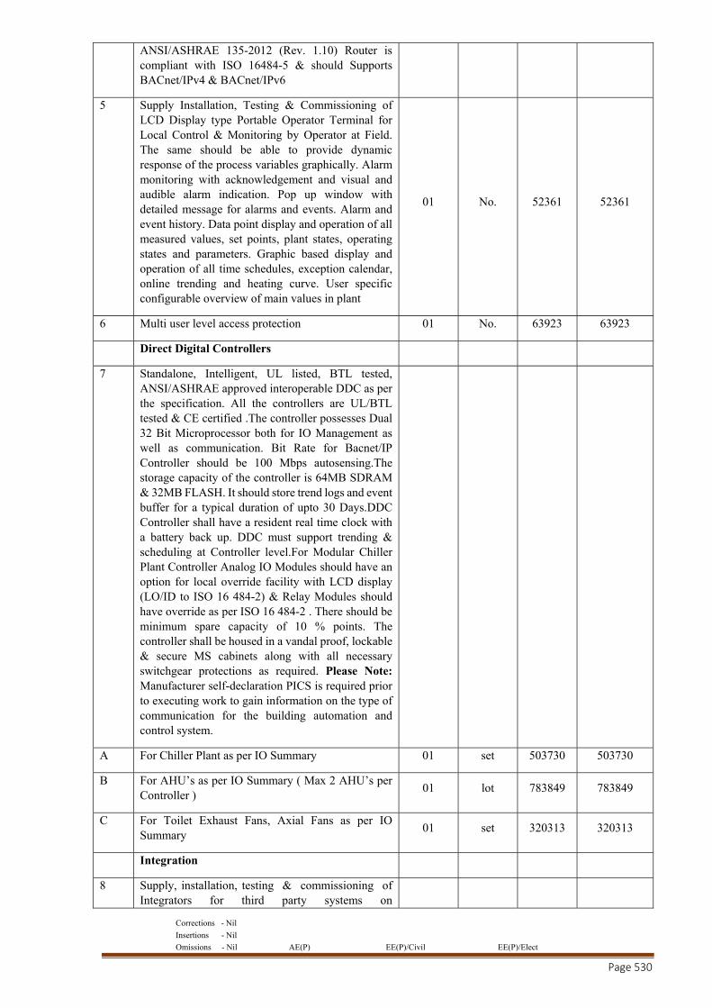
Corrections - Nil
Insertions - Nil
Omissions - Nil AE(P) EE(P)/Civil EE(P)/Elect
Page 530
ANSI/ASHRAE 135-2012 (Rev. 1.10) Router is compliant with ISO 16484-5 & should Supports BACnet/IPv4 & BACnet/IPv6
5 Supply Installation, Testing & Commissioning of LCD Display type Portable Operator Terminal for Local Control & Monitoring by Operator at Field. The same should be able to provide dynamic response of the process variables graphically. Alarm monitoring with acknowledgement and visual and audible alarm indication. Pop up window with detailed message for alarms and events. Alarm and event history. Data point display and operation of all measured values, set points, plant states, operating states and parameters. Graphic based display and operation of all time schedules, exception calendar, online trending and heating curve. User specific configurable overview of main values in plant
01 No. 52361 52361
6 Multi user level access protection 01 No. 63923 63923
Direct Digital Controllers
7 Standalone, Intelligent, UL listed, BTL tested, ANSI/ASHRAE approved interoperable DDC as per the specification. All the controllers are UL/BTL tested & CE certified .The controller possesses Dual 32 Bit Microprocessor both for IO Management as well as communication. Bit Rate for Bacnet/IP Controller should be 100 Mbps autosensing.The storage capacity of the controller is 64MB SDRAM & 32MB FLASH. It should store trend logs and event buffer for a typical duration of upto 30 Days.DDC Controller shall have a resident real time clock with a battery back up. DDC must support trending & scheduling at Controller level.For Modular Chiller Plant Controller Analog IO Modules should have an option for local override facility with LCD display (LO/ID to ISO 16 484-2) & Relay Modules should have override as per ISO 16 484-2 . There should be minimum spare capacity of 10 % points. The controller shall be housed in a vandal proof, lockable & secure MS cabinets along with all necessary switchgear protections as required. Please Note: Manufacturer self-declaration PICS is required prior to executing work to gain information on the type of communication for the building automation and control system.
A For Chiller Plant as per IO Summary 01 set 503730 503730
B For AHU’s as per IO Summary ( Max 2 AHU’s per Controller )
01 lot 783849 783849
C For Toilet Exhaust Fans, Axial Fans as per IO Summary
01 set 320313 320313
Integration
8 Supply, installation, testing & commissioning of Integrators for third party systems on
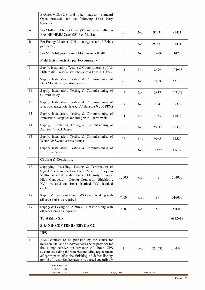
Corrections - Nil
Insertions - Nil
Omissions - Nil AE(P) EE(P)/Civil EE(P)/Elect
Page 531
BACnet/MODBUS and other industry standard Open protocols for the following Third Party Systems
A For Chillers ( 4 Nos. chiller) (30 points per chiller on BACNET/IP,BACnet/MSTP or Modbus
01 No. 91431 91431
B For Energy Meters ( 32 Nos. energy meters, 5 Points per meter )
01 No. 91431 91431
C For VSPS Integration over Modbus over RS485 01 No. 114289 114289
Field instruments As per I-O summary
9 Supply Installation, Testing & Commissioning of Air Differential Pressure switches across Fans & Filters.
42 No. 2499 104958
10 Supply Installation, Testing & Commissioning of Duct Mount Temperature Sensor.
21 No. 2958 62118
11 Supply Installation, Testing & Commissioning of Current Relay
42 No. 2557 107394
12 Supply Installation, Testing & Commissioning of Electrochemical Gel Based CO Sensor ( 0-300 PPM)
08 No. 11041 88328
13 Supply Installation, Testing & Commissioning of Immersion Temp sensor along with Thermowell
04 No. 3133 12532
14 Supply, Installation, Testing & Commissioning of Ambient T+RH Sensor
01 No. 25337 25337
15 Supply Installation, Testing & Commissioning of Water DP Switch across pumps
08 No. 9065 72520
16 Supply Installation, Testing & Commissioning of Lux Level Sensor
01 No. 11622 11622
Cabling & Conduiting
17 Supplying, Installing, Testing & Termination of Signal & communication Cable 2core x 1.5 sq.mm Multistranded Annealed Tinned Electrolytic Grade High Conductivity Copper Conductor, Shielded , PVC insulated, and Inner sheathed PVC sheathed cable.
12000 Rmt 42 504000
18 Supply & Laying of 25 mm MS Conduits along with all accessories as required
7000 Rmt 88 616000
19 Supply & Laying of 25 mm GI Flexible along with all accessories as required.
600 No. 86 51600
Total (SH:- XI) 4212425
SH:- XII- COMPREHENSIVE AMC
UPS
1 AMC contract to be prepared by the contractor between RBI and OEM/Vendor/Service provider for the comprehensive maintenance of above UPS system excluding the batteries including replacement of spare parts after the finishing of defect liablity period of 1 year. So the rates to be quoted accordingly
1 year 254485 254485
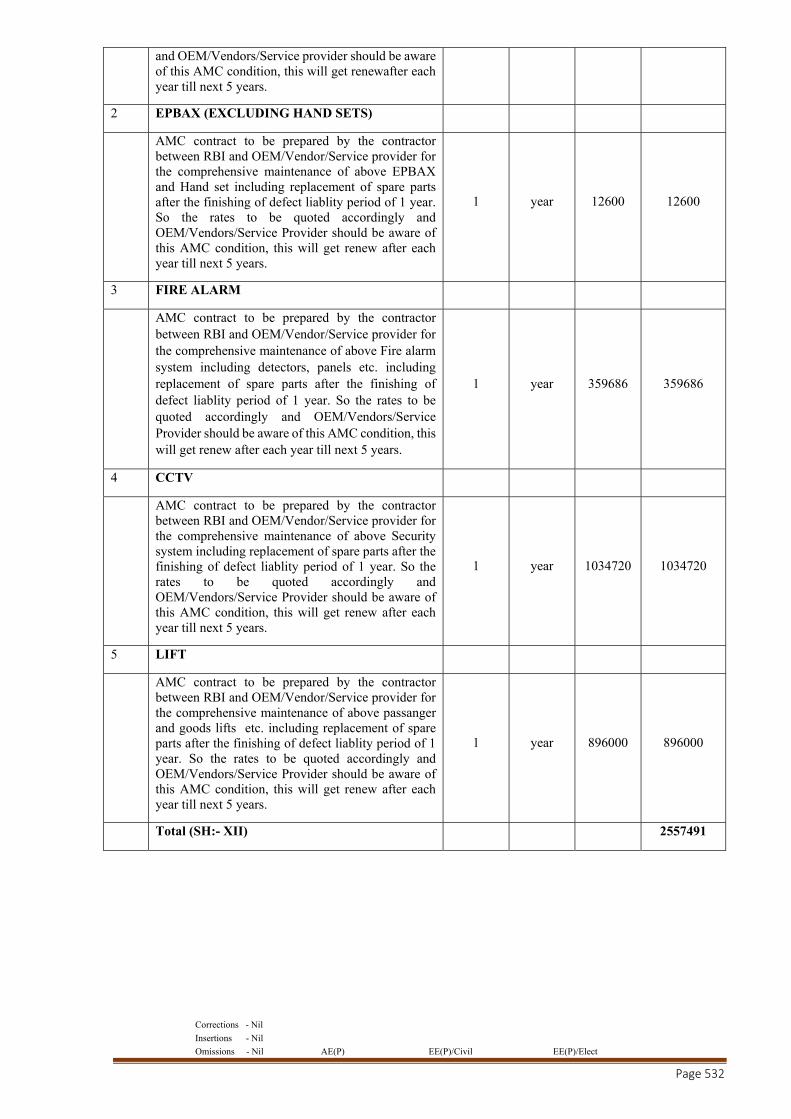
Corrections - Nil
Insertions - Nil
Omissions - Nil AE(P) EE(P)/Civil EE(P)/Elect
Page 532
and OEM/Vendors/Service provider should be aware of this AMC condition, this will get renewafter each year till next 5 years.
2 EPBAX (EXCLUDING HAND SETS)
AMC contract to be prepared by the contractor between RBI and OEM/Vendor/Service provider for the comprehensive maintenance of above EPBAX and Hand set including replacement of spare parts after the finishing of defect liablity period of 1 year. So the rates to be quoted accordingly and OEM/Vendors/Service Provider should be aware of this AMC condition, this will get renew after each year till next 5 years.
1 year 12600 12600
3 FIRE ALARM
AMC contract to be prepared by the contractor between RBI and OEM/Vendor/Service provider for the comprehensive maintenance of above Fire alarm system including detectors, panels etc. including replacement of spare parts after the finishing of defect liablity period of 1 year. So the rates to be quoted accordingly and OEM/Vendors/Service Provider should be aware of this AMC condition, this will get renew after each year till next 5 years.
1 year 359686 359686
4 CCTV
AMC contract to be prepared by the contractor between RBI and OEM/Vendor/Service provider for the comprehensive maintenance of above Security system including replacement of spare parts after the finishing of defect liablity period of 1 year. So the rates to be quoted accordingly and OEM/Vendors/Service Provider should be aware of this AMC condition, this will get renew after each year till next 5 years.
1 year 1034720 1034720
5 LIFT
AMC contract to be prepared by the contractor between RBI and OEM/Vendor/Service provider for the comprehensive maintenance of above passanger and goods lifts etc. including replacement of spare parts after the finishing of defect liablity period of 1 year. So the rates to be quoted accordingly and OEM/Vendors/Service Provider should be aware of this AMC condition, this will get renew after each year till next 5 years.
1 year 896000 896000
Total (SH:- XII) 2557491
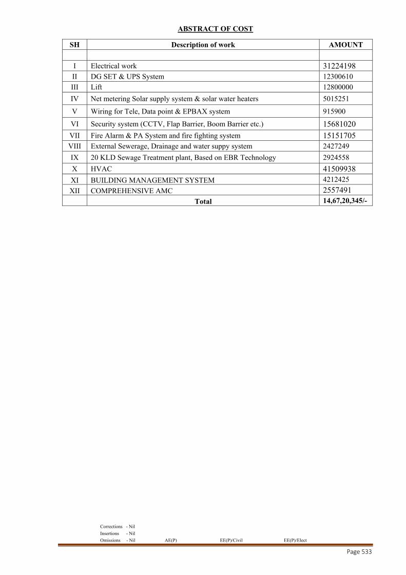
Corrections - Nil
Insertions - Nil
Omissions - Nil AE(P) EE(P)/Civil EE(P)/Elect
Page 533
ABSTRACT OF COST
SH Description of work AMOUNT
I Electrical work 31224198 II DG SET & UPS System 12300610 III Lift 12800000
IV Net metering Solar supply system & solar water heaters 5015251
V Wiring for Tele, Data point & EPBAX system 915900
VI Security system (CCTV, Flap Barrier, Boom Barrier etc.) 15681020 VII Fire Alarm & PA System and fire fighting system 15151705 VIII External Sewerage, Drainage and water suppy system 2427249
IX 20 KLD Sewage Treatment plant, Based on EBR Technology 2924558
X HVAC 41509938 XI BUILDING MANAGEMENT SYSTEM 4212425
XII COMPREHENSIVE AMC 2557491 Total 14,67,20,345/-