autonomous decentralised m2m application service provision
TRANSCRIPT
University of Plymouth
PEARL https://pearl.plymouth.ac.uk
04 University of Plymouth Research Theses 01 Research Theses Main Collection
2018
Autonomous decentralised M2M
Application Service Provision
Steinheimer, Michael
http://hdl.handle.net/10026.1/11957
University of Plymouth
All content in PEARL is protected by copyright law. Author manuscripts are made available in accordance with
publisher policies. Please cite only the published version using the details provided on the item record or
document. In the absence of an open licence (e.g. Creative Commons), permissions for further reuse of content
should be sought from the publisher or author.

Copyright Statement
This copy of the thesis has been supplied on condition that anyone
who consults it is understood to recognise that its copyright rests
with its author and that no quotation from the thesis and no
information derived from it may be published without the author's
prior consent.

Autonomous decentralised M2M Application
Service Provision
by
Michael Steinheimer
A thesis submitted to University of Plymouth in partial fulfilment for the degree of
DOCTOR OF PHILOSOPHY
School of Computing and Mathematics
Darmstadt Node of the Centre for Security, Communications and Network Research (CSCAN)
December 2017


i
Acknowledgements
First and foremost, I would like to thank my supervisors Prof. Woldemar Fuhrmann and Dr.
Bogdan Ghita for their comprehensive support and guidance during this research work.
My special thanks go to my supervisor Prof. Ulrich Trick, who has always been an excellent
mentor for me. Thank you very much for your support during my entire time as a member of the
Research Group for Telecommunication Networks at the Frankfurt University of Applied
Sciences. The research on which this work is based was only possible through your guidance,
support, and motivation.
Many thanks go to current and especially former fellow researchers of the Research Group for
Telecommunication Networks. Thank you for your friendship, support, and great inspiration
during the past years.
Warm thanks to members of both the graduate school, especially Carole Watson for her kind and
comprehensive support in administrative things, as well as the CSCAN Network at University of
Plymouth. I would also like to thank the members of the CSCAN Darmstadt Node for their
support and helpful comments in academic aspects especially during the Ph.D. seminars.
I would like to thank my family and friends for their appreciation of the fact that my priorities in
recent years have been to do this research.
Above all, I would like to thank my loving wife Melanie and our wonderful son Paul for their
understanding, great support, and the sacrifices they made on my behalf. This Ph.D. thesis is
dedicated to you.


iii
Author's declaration
At no time during the registration for the degree of Doctor of Philosophy has the author
been registered for any other University award without prior agreement of the Doctoral
College Quality Sub-Committee.
Work submitted for this research degree at the University of Plymouth has not formed
part of any other degree either at the University of Plymouth or at another establishment.
Relevant scientific seminars and conferences were regularly attended at which work was
often presented, and several papers prepared for publication.
Publications:
Steinheimer, M.; Trick, U.; Ruhrig, P. (2012a), “New approaches for energy optimisation
in Smart Homes and Smart Grids by automated service generation and user integration“,
Proceedings of the Collaborative European Research Conference (CERC), pp. 111-119,
April 2012, Darmstadt, Germany
Steinheimer, M.; Trick, U.; Ruhrig, P. (2012b), “Energy communities in Smart Markets
for optimisation of peer-to-peer interconnected Smart Homes“, Proceedings of the 2012
8th International Symposium on Communication Systems, Networks & Digital Signal
Processing (CSNDSP), pp. 1-6, July 2012, Poznan, Poland, IEEE
Steinheimer, M.; Trick, U.; Ruhrig, P.; Wacht, P.; Tönjes, R.; Fischer, M.; Hölker, D.
(2013a), “SIP-basierte P2P-Vernetzung in einer Energie-Community“ (translated title:
“SIP-based P2P Networking inside an Energy-Community”), Proceedings of the
Eighteenth VDE/ITG Mobilfunktagung, pp. 64-70, Mai 2013, Osnabrück, Germany, VDE
Steinheimer, M.; Trick, U.; Ruhrig, P.; Fuhrmann, W.; Ghita, B. (2013b), “Load
Reduction in Distribution Networks through P2P networked Energy-Community“,
Proceedings of the Fifth International Conference on Internet Technologies and
Applications (ITA 13), pp. 90-97, September 2013, Wrexham, UK
Steinheimer, M.; Trick, U.; Wacht, P.; Ruhrig, P. (2013c), “Decentralised optimisation
solution for Smart Grids using Smart Market aspects and P2P internetworked Energy-
Community“, VDE/IEC World Smart Grid Forum 2013, September 2013, Berlin,
Germany, VDE
Steinheimer, M.; Trick, U.; Wacht, P.; Ruhrig, P.; Fuhrmann, W.; Ghita, B. (2013d),
“Decentralised optimisation solution for provision of value added services and
optimisation possibilities in Smart Grids“, 2013 Collaborative European Research
Conference (CERC), October 2013, Cork, Ireland
Steinheimer, M.; Trick, U.; Fuhrmann, W.; Ghita, B. (2013e), “P2P-based community
concept for M2M Applications“, Proceedings of the Second International Conference on
Future Generation Communication Technologies (FGCT 2013), pp. 114-119, November
2013, London, UK, IEEE
Steinheimer, M.; Trick, U.; Fuhrmann, W.; Ghita, B. (2015a), “P2P based service
provisioning in M2M networks“, Proceedings of the Sixth International Conference on
Internet Technologies and Applications (ITA 15), pp. 132-137, September 2015,
Wrexham, UK, IEEE
iv
Steinheimer, M.; Trick, U.; Fuhrmann, W.; Ghita, B. (2015b), “P2P based service
provisioning in M2M networks“, Second Spanish-Geman Symposium on Applied
Computer Science (SGSOACS), Invited Talk, December 2015, Frankfurt, Germany
Steinheimer, M.; Trick, U.; Fuhrmann, W.; Ghita, B. (2016), “P2P-based M2M
Community Applications“, Proceedings of the Eleventh International Network
Conference (INC 2016), pp. 115-120, July 2016, Frankfurt, Germany
Steinheimer, M.; Trick, U.; Fuhrmann, W.; Ghita, B.; Frick, G. (2017a), “M2M
Application Service Provision: An autonomous and decentralised Approach“, Journal of
Communications, Vol. 12, no. 9, pp. 489-498, 2017
Steinheimer, M.; Trick, U.; Fuhrmann, W.; Ghita, B. (2017b), “Decentralised System
Architecture for autonomous and cooperative M2M Application Service Provision“,
Proceedings of the 2017 IEEE International Conference on Smart Grid and Smart Cities
(ICSGSC 2017), pp. 312-317, July 2017, Singapore, IEEE
Steinheimer, M.; Trick, U.; Fuhrmann, W.; Ghita, B. (2017c), “Autonomous
decentralised M2M Application Service Provision“, Proceedings of the Seventh
International Conference on Internet Technologies and Applications (ITA 17), pp. 18-23,
September 2017, Wrexham, UK, IEEE
Presentations and Conferences attended:
Collaborative European Research Conference (CERC), Darmstadt, Germany, April 2012
8th International Symposium on Communication Systems, Networks & Digital Signal
Processing (CSNDSP), Poznan, Poland, July 2012
18th VDE/ITG Mobilfunktagung, Osnabrück, Germany, Mai 2013
5th International Conference on Internet Technologies and Applications (ITA 13),
Wrexham, UK, September 2013
VDE/IEC World Smart Grid Forum 2013, Berlin, Germany, September 2013
Collaborative European Research Conference (CERC), Cork, Ireland, October 2013
2nd International Conference on Future Generation Communication Technologies (FGCT
2013), London, UK, November 2013
6th International Conference on Internet Technologies and Applications (ITA 15),
Wrexham, UK, September 2015
2nd Spanish-Geman Symposium on Applied Computer Science (SGSOACS), Frankfurt,
Germany, December 2015
11th International Network Conference (INC 2016), Frankfurt, Germany, July 2016
IEEE International Conference on Smart Grid and Smart Cities (ICSGSC 2017),
Singapore, July 2017
7th International Conference on Internet Technologies and Applications (ITA 17),
Wrexham, UK, September 2017
Word count of main body of thesis: 79.804
Signed …...……………………………
Date …...……………………………

v
Autonomous decentralised M2M Application Service Provision
Michael Steinheimer
Abstract
Machine-to-Machine Communication (M2M) service platforms integrate M2M devices and
enable realisation of applications using the M2M devices to support processes, mostly in the
business domain. Many application-specific vertical implementations of M2M service
platforms exist as well as efforts to define horizontal M2M service platforms. Both
approaches usually have central components or stakeholders of which the entire M2M system
or the user depends. With regards to the end-user, more and more M2M devices provide
resources, such as environmental information (e.g. energy consumption data) or control
options (e.g. switching energy consumer). These resources offer great potential for supporting
smart environments and it would be advantageous if these resources could be used by end-
users to create individual smart environments or be accessible for other users to integrate
these resources into their processes. Furthermore, it would be advantageous to avoid
centralised or domain-specific solutions in order to realise flexible and independent M2M
service platforms.
This thesis proposes a novel framework for autonomous and decentralised M2M application
service provision based on native end-user integration and a distributed M2M system
architecture. In order to actively involve end-users in M2M application development, an
intuitive methodology for graphical application design through state machine-based
application modelling is proposed. To achieve independence from the execution
environments, a formal language for modelling M2M applications is introduced enabling a
graphically designed M2M application to be represented by a formally described application
model, which can be processed automatically and platform-independently. The design of a
generalised interface definition enables local M2M applications to be provided as a service
to other users. Based on this, an approach is introduced allowing end-users to combine the
resources available in their personal environments in order to realise cooperative M2M
applications and act as service providers.
The M2M service platform architecture presented does not contain any central components
or stakeholders. The distributive nature of central entities and stakeholders is realised by a
decentralised system architecture being implemented in the end-user domain. The various
M2M service providers and consumers link via a Peer-to-Peer (P2P) network on both the
communication level (using communication protocols Constrained Application Protocol,
CoAP or Session Initiation Protocol, SIP) and on the data storage level (using structured or
unstructured P2P overlay networks). An M2M Community concept complements the P2P
network to enable a social network between different M2M service providers and consumers.
The thesis also presents a prototypical proof-of-concept implementation used to verify the
proposed framework components.


vii
Contents
Contents ......................................................................................................................... vii
List of Figures ................................................................................................................. xi
List of Tables ................................................................................................................ xxi
1 Introduction ................................................................................................................ 1 1.1 Aims and Objectives ............................................................................................. 4 1.2 Thesis Structure .................................................................................................... 6
2 Peer-to-Peer, Machine-to-Machine Communication Systems, Use Cases ............ 9 2.1 Application Execution Environments ................................................................. 10
2.2 Peer-to-Peer Systems .......................................................................................... 12 2.2.1 Classification of Peer-to-Peer Systems .................................................... 12
2.2.2 Classification of P2P System Architectures ............................................. 15
2.3 Machine-to-Machine Communication Systems .................................................. 19
2.3.1 Classification of Machine-to-Machine Communication .......................... 20
2.3.2 M2M System Architecture ....................................................................... 25
2.3.3 Roles and Stakeholder in M2M Ecosystems ............................................ 31
2.3.4 End-User M2M Application Services ...................................................... 33
2.4 Use Cases ............................................................................................................ 35
2.5 Conclusion .......................................................................................................... 41
3 Challenges, Requirements, and Use Cases of M2M Application Service
Provision .................................................................................................................... 43 3.1 Related Work on M2M Service Platforms ......................................................... 44
3.1.1 OneM2M Specification for M2M Systems .............................................. 44
3.1.2 INOX Managed Service Platform ............................................................ 63
3.1.3 M2M Platform Project based on SOA (M2M on SOA) ........................... 69
3.1.4 BOSP Business Operation Support Platform ........................................... 73
3.1.5 IMS enabled M2M Service Platform (IMS M2M SP I) ........................... 77
3.1.6 M2M horizontal Services Platform Implementation over IP
Multimedia Subsystem (IMS M2M SP II) ............................................... 81
3.1.7 e-DSON .................................................................................................... 86
3.1.8 M2SP Concept .......................................................................................... 92
3.1.9 ENERsip Project ....................................................................................... 99

viii
3.1.10 Compose Framework ............................................................................. 103
3.1.11 Distributed Cooperative M2M System for Flood Monitoring
(DistribFloodMon) ................................................................................. 111
3.2 Requirements for a new Framework for Autonomous decentralised M2M
Application Service Provision .......................................................................... 114 3.3 Conclusion ........................................................................................................ 129
4 Proposed Framework for autonomous decentralised Application Provision
in M2M Systems ..................................................................................................... 131 4.1 General Concept ............................................................................................... 131
4.2 Framework Architecture and Components ....................................................... 141 4.3 Conclusion ........................................................................................................ 155
5 Autonomous M2M Application Provision ........................................................... 159 5.1 Multimedia Services Components .................................................................... 160 5.2 Application Behaviour Modelling .................................................................... 170 5.3 Graphical Application Behaviour Design ......................................................... 177
5.4 M2M Device Management and Communication ............................................. 183 5.5 Formal M2M Application Notation .................................................................. 199
5.5.1 Selection of State Machine-based Modelling Language ........................ 199
5.5.2 Principles of Statechart Modelling ......................................................... 212
5.5.3 M2M Application Modelling using Statecharts ..................................... 219
5.6 Service Runtime Environment .......................................................................... 229
5.7 Conclusion ........................................................................................................ 232
6 Cooperative M2M Application Service Provision ............................................... 237 6.1 Provision and Integration of M2M Application Services ................................. 238
6.1.1 M2M Application Service Interface Description ................................... 239
6.1.2 Performing remote M2M Application Service Requests ....................... 243
6.1.3 Integration of remote M2M Application Services ................................. 246
6.2 Networking of Nodes ........................................................................................ 248
6.2.1 P2P Information Exchange ..................................................................... 248
6.2.2 Information Exchange Pattern ................................................................ 256
6.2.3 Selection of appropriate P2P Communication Protocols ....................... 259
6.3 Service Registry and Distributed Data Storage ................................................ 282
6.3.1 M2M Service Registration and Storage of M2M Service IFD .............. 282
6.3.2 Principles of distributed Data Storage .................................................... 284
6.3.3 Analysis of structured and unstructured Overlay Architectures ............ 291
6.4 Cooperative M2M Application Service Provision ........................................... 302 6.4.1 Principles of cooperative M2M Application Service Provision ............. 303
6.4.2 Cooperative M2M Application Configuration and Execution Phase ..... 313
6.4.3 Cooperative M2M Application Validation Algorithm ........................... 319

ix
6.5 M2M Community ............................................................................................. 331 6.6 Conclusion ........................................................................................................ 336
7 Research Prototype and Framework Evaluation ................................................ 343 7.1 Evaluation of Framework Requirements .......................................................... 343 7.2 Research Prototype Architecture and Implementation ..................................... 349 7.3 Proof of Framework Concepts .......................................................................... 363
7.3.1 Local M2M Application Execution with remote M2M Service
Integration .............................................................................................. 365
7.3.2 Cooperative M2M Application Service Provision ................................. 371
7.3.3 Communication Scenarios for M2M Service Requests.......................... 380
7.4 Performance Evaluation .................................................................................... 385 7.5 Conclusion ........................................................................................................ 393
8 Conclusion and Future Work ................................................................................ 395 8.1 Achievements of the Research .......................................................................... 395
8.2 Limitations of the research ............................................................................... 402 8.3 Suggestions and Future Work ........................................................................... 404
References .................................................................................................................... 407
Appendix A – Abbreviations ...................................................................................... 423
Appendix B – Own Publications ................................................................................ 431
Appendix C – Low Level Descriptions ...................................................................... 507


xi
List of Figures
Figure 1.1: End-user’s Personal Environment .................................................................. 2
Figure 2.1: Classification of Execution Environments for Services and Applications acc.
(Steinheimer et al., 2016) ................................................................................................ 10
Figure 2.2: Classification of P2P Systems based on Degree of (de)centralisation acc. (De
Boever, 2007) .................................................................................................................. 16
Figure 2.3: Correlation among WSNs, M2M, CPS, IoT acc. (Wan et al., 2013; Mehmood
et al., 2015) ...................................................................................................................... 22
Figure 2.4: General Perspective of M2M System Architecture acc. (Wan et al., 2013;
Mehmood et al., 2015; Bahga and Madisetti, 2014; Boswarthick et al., 2012; Holler et al.,
2014) ............................................................................................................................... 25
Figure 2.5: Functional Architecture of M2M System acc. (ETSI TS 102 690 V2.1.1, 2013;
Boswarthick et al., 2012) ................................................................................................ 27
Figure 2.6: Integration of MSP in M2M system architecture acc. (oneM2M TR-0001-
V2.4.1, 2016; Elloumi, 2014).......................................................................................... 31
Figure 2.7: Functional Roles in the M2M Ecosystem acc. (oneM2M TS-0002-V1.0.1,
2015) ............................................................................................................................... 32
Figure 2.8: Service Orchestration acc. (Terpak et al., 2016) .......................................... 34
Figure 2.9: Service Choreography acc. (Terpak et al., 2016) ......................................... 34
Figure 2.10: Use Case local Window Monitoring .......................................................... 36
Figure 2.11: Use Case Neighbourhood Weather Station ................................................ 37
Figure 2.12: Use Case Building Surveillance ................................................................. 38
Figure 2.13: Use Case Cooperative Energy Optimisation (Load Reduction) ................. 40
Figure 3.1: M2M Common Service Layer acc. (Damour, 2014) .................................... 45
Figure 3.2: Vertical Pipes of M2M Business Applications acc. (Arndt and Koss, 2014)
......................................................................................................................................... 46
Figure 3.3: oneM2M Horizontal Platform Principle acc. (Arndt and Koss, 2014) ......... 46

xii
Figure 3.4: oneM2M Layered Model and Functional Architecture acc. (oneM2M TS-
0001-V1.13.1, 2016) ....................................................................................................... 48
Figure 3.5: Configurations supported by oneM2M Architecture acc. (oneM2M TS-0001-
V1.13.1, 2016) ................................................................................................................ 50
Figure 3.6: oneM2M functional Architecture of M2M Application acc. (oneM2M TR-
0025-V1.0.0, 2016) ......................................................................................................... 52
Figure 3.7: Possibilities for Node Interconnections acc. (oneM2M TS-0001-V2.10.0,
2016) ............................................................................................................................... 55
Figure 3.8: Scope of addressable M2M Common Services by registered CSEs ............ 56
Figure 3.9: Valid MN-Node Registrations ...................................................................... 56
Figure 3.10: Invalid MN-Node Registrations ................................................................. 57
Figure 3.11: Principle of Information Exchange between Entities acc. (oneM2M TS-
0001-V2.10.0, 2016) ....................................................................................................... 59
Figure 3.12: Primitive Overview acc. (oneM2M TS-0004-V2.7.1, 2016) ..................... 61
Figure 3.13: INOX Managed Service Platform acc. (Clayman and Galis, 2011) ........... 64
Figure 3.14: M2M Network Topologies (traditional and proposed) acc. (Zhang et al.,
2010) ............................................................................................................................... 69
Figure 3.15: M2M Platform Architecture acc. (Zhang et al., 2010) ............................... 70
Figure 3.16: M2M System Architecture acc. (Xiaocong and Jidong, 2010) .................. 74
Figure 3.17: IMS-enabled M2M System Architecture acc. (Foschini et al., 2011) ........ 78
Figure 3.18: M2M horizontal Service Platform acc. (Padilla et al., 2013) ..................... 81
Figure 3.19: M2M Device Registration Process (Padilla et al., 2013) ........................... 83
Figure 3.20: DSON Service Scenario: Home Multimedia Streaming Service acc. (Kim et
al., 2011) ......................................................................................................................... 87
Figure 3.21: e-DSON Platform Model acc. (Kim et al., 2012) ....................................... 88
Figure 3.22: e-DSON Platform Architecture acc. (Kim et al., 2012) ............................. 90
Figure 3.23: M2SP Model acc. (Kim et al., 2014) .......................................................... 93
Figure 3.24: M2SP Architecture acc. (Kim et al., 2014) ................................................ 94
Figure 3.25: M2SP Use Case Scenario acc. (Kim et al., 2014) ...................................... 96

xiii
Figure 3.26: ENERsip Architecture acc. (Lopez et al., 2011a; Lopez et al., 2013) ........ 99
Figure 3.27: Logical Architecture of COMPOSE Framework acc. (Mandler et al., 2013)
....................................................................................................................................... 104
Figure 3.28: Components of COMPOSE framework acc. (Doukas and Antonelli, 2014)
....................................................................................................................................... 105
Figure 3.29: Distributed M2M System acc. (Kitagami et al., 2014) ............................. 112
Figure 4.1: Traditional Approach for M2M Application Service Provision ................. 132
Figure 4.2: M2M Application Service Creation and Provision Process with End-User
Integration ..................................................................................................................... 132
Figure 4.3: ADSP Model: Decentralised M2M Application Design and Execution .... 134
Figure 4.4: HSPU Model: Horizontal M2M Resource Provision and Utilisation ........ 136
Figure 4.5: DCASP Model: Decentralised cooperative M2M Application Service
Provision ....................................................................................................................... 138
Figure 4.6: BSPU Model: Bottom-Up M2M Service Provision and Utilisation .......... 140
Figure 4.7: M2M Application Service Provision Framework Architecture ................. 142
Figure 4.8: Framework Architecture: Service Design Unit (SDU)............................... 144
Figure 4.9: Framework Architecture: Service Creation Unit (SCU) ............................ 145
Figure 4.10: Framework Architecture: Communication Unit (CU).............................. 146
Figure 4.11: Framework Architecture: Service Runtime Environment (SRE) ............. 149
Figure 4.12: Layer Model of Decentralised Networking Aspect .................................. 151
Figure 4.13: P2P connected M2M Environments within the M2M Community .......... 154
Figure 5.1: MSP Multimedia Interfaces ........................................................................ 162
Figure 5.2: Architecture of SR/DTMF MMSC ............................................................. 162
Figure 5.3: SR/DTMF MMSC Parameter Set ............................................................... 164
Figure 5.4: Architecture of AV/TTS MMSC ................................................................ 165
Figure 5.5: AV/TTS MMSC Parameter Set .................................................................. 166
Figure 5.6: Architecture of IM MMSC ......................................................................... 168
Figure 5.7: IM MMSC Parameter Set ........................................................................... 169
xiv
Figure 5.8: Use Case Switch Lighting .......................................................................... 171
Figure 5.9: Use Case Email Service.............................................................................. 172
Figure 5.10: General Structure of M2M Device and MMSC ....................................... 173
Figure 5.11: General Representation of M2M Device and MMSC Connections ......... 173
Figure 5.12: FSM derived from (Wagenknecht and Hielscher, 2015).......................... 174
Figure 5.13: M2M Application Use Case 1 represented as FSM ................................. 175
Figure 5.14: Structure of Service Design GUI acc. (Steinheimer et al., 2013c; Steinheimer
et al., 2015b).................................................................................................................. 179
Figure 5.15: M2M Application Design Process............................................................ 181
Figure 5.16: Principles of oneM2M Device Abstraction acc. (oneM2M TR-0007-V1.0.0,
2014; oneM2M TR-0007-V2.11.1, 2016) ..................................................................... 184
Figure 5.17: Structure of Request Primitive ................................................................. 187
Figure 5.18: Structure of Response Primitive ............................................................... 188
Figure 5.19: M2M Communication Unit (CU) with Abstraction Layer (AL) .............. 188
Figure 5.20: Structure of M2M DCM ........................................................................... 190
Figure 5.21: M2M CU/AL Register Process ................................................................ 192
Figure 5.22: M2M Application/CU/AL Message Exchange ........................................ 193
Figure 5.23: Mapping M2M DCM to Request Primitive Parameters ........................... 195
Figure 5.24: Installation of M2M Device Capability Models ....................................... 197
Figure 5.25: Statecharts Basic State and Default Transitions, derived from (Harel and
Politi, 1998) ................................................................................................................... 213
Figure 5.26: Statecharts AND-State, derived from (Harel and Politi, 1998) ................ 214
Figure 5.27: Statecharts OR-State, derived from (Harel and Politi, 1998) ................... 215
Figure 5.28: SCXML Representation of Basic State and Default Transitions ............. 216
Figure 5.29: SCXML Representation of AND-State .................................................... 218
Figure 5.30: Statechart Representation of Use Case 1 .................................................. 220
Figure 5.31: Principles of State Parameter Definition and Assign in Statecharts ......... 222

xv
Figure 5.32: Graphical Representation OR-/AND M2M Device Combination ........... 223
Figure 5.33: General M2M Application Model ............................................................ 224
Figure 5.34: General State Model ................................................................................. 226
Figure 5.35: Formal M2M Application Description Generation Process ..................... 228
Figure 5.36: Assignment graphical Notation Elements to M2M Application Model ... 229
Figure 5.37: Service Runtime Environment (SRE)....................................................... 230
Figure 5.38: M2M Application Execution Process ....................................................... 231
Figure 6.1: M2M Application Service Principles ......................................................... 239
Figure 6.2: Principles of remoteRainSensor Application Service ................................ 242
Figure 6.3: IFD for remoteRainSensor M2M Application Service............................... 242
Figure 6.4: Service Interface Unit (SIU) ....................................................................... 243
Figure 6.5: SIU: M2M Application Service Request Processing ................................. 244
Figure 6.6: Remote M2M Service Integration .............................................................. 246
Figure 6.7: Extract Formal Application Description Use Case 2.................................. 247
Figure 6.8: RELOAD Architecture acc. (Samaniego et al., 2013; IETF RFC 6940, 2014)
....................................................................................................................................... 249
Figure 6.9: RELOAD Message Exchange for Service Request acc. (IETF RFC 7904,
2016) ............................................................................................................................. 252
Figure 6.10: Comparison RELOAD and proposed Networking Topology .................. 255
Figure 6.11: IxPs acc. (Höller, 2014) adopted from (Carrez et al., 2013) .................... 256
Figure 6.12: General Service Subscription/Notification/Termination Process ............. 262
Figure 6.13: CoAP Reliable Message Transmission acc. (IETF RFC 7252, 2014) ..... 265
Figure 6.14: CoAP Unreliable Message Transmission acc. (IETF RFC 7252, 2014) .. 265
Figure 6.15: CoAP Message Format acc. (IETF RFC 7252, 2014) .............................. 266
Figure 6.16: CoAP Messaging for Service/Information Subscription .......................... 270
Figure 6.17: CoAP Messaging for Service/Information Notification ........................... 271
Figure 6.18: CoAP Messaging for Service/Information Unsubscription ...................... 271

xvi
Figure 6.19: SIP Request Message Format acc. (IETF RFC 3261, 2002) .................... 273
Figure 6.20: SIP Response Message Format acc. (IETF RFC 3261, 2002) ................. 273
Figure 6.21: SIP Messaging for Service/Information Subscription .............................. 277
Figure 6.22: SIP Messaging for Service/Information Notification ............................... 278
Figure 6.23: SIP Messaging for Service/Information Unsubscription .......................... 278
Figure 6.24: M2M Services Registration and Request ................................................. 283
Figure 6.25: Store IFD in structured P2P Overlay ........................................................ 286
Figure 6.26: Request IFD from structured P2P Overlay ............................................... 288
Figure 6.27: Store IFD in unstructured P2P Overlay .................................................... 289
Figure 6.28: Request IFD from unstructured P2P Overlay ........................................... 290
Figure 6.29: Comparison Lookup Costs structured P2P Overlays ............................... 295
Figure 6.30: Comparison Lookup Costs structured P2P Overlays (excl. CAN)........... 296
Figure 6.31: Comparison Lookup Costs unstructured P2P Overlays ........................... 296
Figure 6.32: Comparison Churn Costs structured P2P Overlays .................................. 297
Figure 6.33: Comparison Churn Costs unstructured P2P Overlays .............................. 298
Figure 6.34: Comparison Lookup Costs structured and unstructured P2P Overlays.... 299
Figure 6.35: Comparison Churn Costs structured and unstructured P2P Overlays ...... 300
Figure 6.36: Architecture of remote M2M Service Integration .................................... 304
Figure 6.37: Architecture of remote M2M Service Combinations ............................... 304
Figure 6.38: Variants of cooperative M2M Service Combinations .............................. 305
Figure 6.39: M2M Service Composition Message Exchange ....................................... 306
Figure 6.40: M2M Service Aggregation Message Exchange ....................................... 306
Figure 6.41: Representation of Use Case 3 (Building Surveillance) ............................ 307
Figure 6.42: Statechart Representation AD of cooperative M2M Application Service for
Use Case 3 ..................................................................................................................... 310
Figure 6.43: Representation of Use Case 4 (Energy Optimisation) .............................. 311
xvii
Figure 6.44: Statechart Representation AD of cooperative M2M Application Service for
Use Case 4 ..................................................................................................................... 312
Figure 6.45: M2M Application Configuration Process ................................................ 317
Figure 6.46: M2M Application Execution Process ....................................................... 318
Figure 6.47: M2M Service Connections to demonstrate redundant Application
Configurations ............................................................................................................... 319
Figure 6.48: Distributed M2M Application with redundant Service Instances ............ 320
Figure 6.49: M2M Application Configuration and Execution Phase incl. multiple Service
Instances ........................................................................................................................ 321
Figure 6.50: M2M Application Configuration with partly redundant Service Instance
Connections ................................................................................................................... 322
Figure 6.51: Algorithm for Documentation of Connection Establishments ................. 325
Figure 6.52: Transitive Closure of Peer 1 and Peer 4 based on Figure 6.50 ................. 327
Figure 6.53: Algorithm for Determination of invalid Application Service Configuration
....................................................................................................................................... 329
Figure 6.54: IFD Element AccessControlPolicy for Definition of (Sub-) Community
Assignment .................................................................................................................... 333
Figure 6.55: M2M application service IFD for Social Service ..................................... 335
Figure 7.1: Research Prototype Application Architecture ............................................ 350
Figure 7.2: Research Prototype Emulation System Architecture.................................. 352
Figure 7.3: Research Prototype Emulation System Architecture.................................. 353
Figure 7.4: Research Prototype Architecture Components (illustrated as Packages) ... 354
Figure 7.5: Screenshot of Service Design Unit GUI Web Application ........................ 355
Figure 7.6: Screenshot of SDU GUI showing M2M Device/Service Configuration Section
....................................................................................................................................... 356
Figure 7.7: Screenshot of SDU GUI showing IFD Specification Form ....................... 357
Figure 7.8: Screenshot of Instant Message Client ......................................................... 362
Figure 7.9: Screenshot of SDU GUI Web Application with SM Model Use Case 2 ... 365
Figure 7.10: Use Case 2 M2M Application Description .............................................. 367

xviii
Figure 7.11: Screenshot of Terminal Output ADP Use Case 2 .................................... 368
Figure 7.12: SM generated by ADI Use Case 2 ............................................................ 368
Figure 7.13: Screenshot of Terminal Output ADI Use Case 2 ..................................... 369
Figure 7.14: SM generated by ADI Use Case 2 ............................................................ 370
Figure 7.15: Screenshot of IM Client Use Case 2......................................................... 371
Figure 7.16: Screenshot of SDU GUI Web Application with SM Model Use Case 3 . 372
Figure 7.17: Use Case 3 M2M Application Description .............................................. 374
Figure 7.18: Use Case 3 corporateBuildingMonitoringApp IFD ................................. 375
Figure 7.19: Screenshot of Terminal Output ADP Use Case 3 .................................... 376
Figure 7.20: Screenshot of Terminal Output ADI Use Case 3 remoteSS1 ................... 377
Figure 7.21: Screenshot of Terminal Output ADI Use Case 3 remoteBMS ................. 377
Figure 7.22: Screenshot of Terminal Output ADI Use Case 3 remoteAS .................... 377
Figure 7.23: Distributed SM Use Case 3 ...................................................................... 378
Figure 7.24: M2M Application Configuration Phase Use Case 3 ................................ 378
Figure 7.25: Service Request Process Supporter at remoteBMS Use Case 3 ............... 379
Figure 7.26: M2M Application Execution Process Use Case 3 .................................... 379
Figure 7.27: Screenshot of Terminal Output Supporter receiving Alarm Message Use
Case 3 ............................................................................................................................ 380
Figure 7.28: Screenshot of Wireshark Trace Request Message via CoAP one-time
Subscription .................................................................................................................. 381
Figure 7.29: Screenshot of Terminal Output received Request Primitive via CoAP ... 382
Figure 7.30: Screenshot of Wireshark Trace Response Message via CoAP ................ 382
Figure 7.31: Screenshot of Terminal Output received Response Primitive via CoAP . 383
Figure 7.32: Screenshot of Wireshark Trace Request Message via SIP continuous
Subscription .................................................................................................................. 383
Figure 7.33: Screenshot of Wireshark Trace Terminate Request Message via SIP ..... 384
Figure 7.34: Screenshot of Wireshark Trace Request/Response Messages via SIP one-
time Subscription .......................................................................................................... 386

xix
Figure 7.35: Signalling Effort using centralised M2M Service Platform (MSP) ......... 387
Figure 7.36: Signalling Effort using proposed Framework .......................................... 389
Figure 7.37: Comparison Signalling Effort (# Messages) ............................................ 391
Figure 7.38: Comparison Signalling Effort (Data Volume).......................................... 392


xxi
List of Tables
Table 2.1: Examples of P2P on different levels according to (Hauswirth and Dustdar,
2005) ............................................................................................................................... 15
Table 3.1: Evaluation of related Projects reg. derived Requirements ........................... 128
Table 5.1: M2M Application Component FSM Element Mapping .............................. 175
Table 5.2: M2M Application Component FSM State Mapping Use Case 1 ................ 176
Table 5.3: Relational Operators for logical M2M Device/MMSC Connections .......... 178
Table 5.4: Configuration of TTS MMSC Use Case 1 ................................................... 182
Table 5.5: Parameter Set of Request Resource Message acc. (oneM2M TS-0001-V2.10.0,
2016) ............................................................................................................................. 186
Table 5.6: Parameter Set of Resource Response Message acc. (oneM2M TS-0001-
V2.10.0, 2016) .............................................................................................................. 187
Table 5.7: Evaluation of SM-based Modelling Languages acc. (Steinheimer et al., 2017a)
....................................................................................................................................... 211
Table 6.1: M2M Application Service Interface Description Parameter ....................... 241
Table 6.2: CoAP Message Format acc. (IETF RFC 7252, 2014) ................................. 267
Table 6.3: OneM2M Primitive CoAP Message mapping acc. (oneM2M TS-0008-V1.0.1,
2015) ............................................................................................................................. 268
Table 6.4: SIP Message Format acc. (IETF RFC 3261, 2002; IETF RFC 3265, 2002)274
Table 6.5: OneM2M Primitive SIP Message mapping ................................................. 275
Table 6.6: Comparison of CoAP and SIP as Communication Protocol ........................ 281
Table 6.7: Evaluation P2P Algorithms acc. (Lua et al., 2005; Steinmetz and Wehrle, 2005;
Malatras, 2015) ............................................................................................................. 294
Table 6.8: Lookup Costs P2P Overlay Algorithms acc. (Lua et al., 2005; Steinmetz and
Wehrle, 2005; Malatras, 2015)...................................................................................... 294
Table 6.9: Churn Costs of P2P Overlay Algorithms acc. (Lua et al., 2005; Steinmetz and
Wehrle, 2005; Malatras, 2015)...................................................................................... 295
xxii
Table 6.10: Summary Evaluation of structured and unstructured P2P Overlay Algorithms
....................................................................................................................................... 302
Table 6.11: Adjacency Matrix of Graph illustrated in Figure 6.50 ............................... 325
Table 6.12: Transitive Closure based on Figure 6.50 ................................................... 328
Table 7.1: State Configuration Use Case 2 ................................................................... 366
Table 7.2: Transition Configuration Use Case 2 ........................................................... 366
Table 7.3: State Configuration Use Case 3 ................................................................... 372
Table 7.4: Transition Configuration Use Case 3 ........................................................... 373
Table 7.5: Signalling Effort for Service Request and Service Response ...................... 386
Table 7.6: Performance Analysis central M2M Service Platform for Service Requests
....................................................................................................................................... 388
Table 7.7: Performance Analysis distributed M2M Service Platform Concept for Service
Requests ........................................................................................................................ 390

1
1 Introduction
End-user devices, such as domestic appliances (e.g. refrigerator or washing machine),
lights, heating or electric vehicles are becoming more and more intelligent. The devices
include complex functionality for monitoring and control. Many devices are equipped
with the functionality for communication, which enables remote monitoring and control.
The increasing number of intelligent, so-called Machine-to-Machine Communication
(M2M) devices support the formation of intelligent environments and many new
application fields can be established. (Mackenzie, 2014) predicts 3.4 Billion M2M device
connections up to 2024. (Danila et al., 2015) mentions application fields such as Transport
and Logistic for real time management of vehicles providing vehicle specific data (e.g.
fuel consumption or speed), Intelligent Cities for coordination of traffic or street lights,
and Healthcare for e.g. remote monitoring of health status.
M2M systems realise the integration of such intelligent devices and provision of specific
M2M applications addressing the above mentioned application fields. According to
(Danila et al., 2015) many M2M applications already exist in the business domain using
the control and monitoring functionality of M2M devices to integrate them in their
business processes.
As (Danila et al., 2015) states, the applications for controlling M2M devices and
processing the data generated by the M2M devices are realised via specific vertical
application architectures, which means individual solutions have been developed for each
specific purpose and are executed on central or distributed application servers located in

1.1 Aims and Objectives
2
the Cloud. Because the many different solutions existing for different application fields,
there are efforts, e.g. from oneM2M (oneM2M, 2015) to develop a horizontal M2M
service platform (MSP) that serves as a common basis for M2M applications.
Most of the existing vertical and horizontal MSPs focus on the business domain. They do
not integrate the end-user domain, which is an application field with powerful potential
because the increasing number o7f controllable devices and Smart Home technologies
residing in end-user’s environment (refer to Figure 1.1). The personal environment of the
end-user, illustrated in Figure 1.1, is difficult to access by external entities (other end-
users or service providers), since the activities (controlling and monitoring of M2M
devices) carried out in this area would severely affect the end-user or challenge data
security.
Figure 1.1: End-user’s Personal Environment
External Service
Provider
End-User personal Environment
locked
Photovoltaic
System
Heating
Battery
Electric Vehicle
Lights
Fridge
kWh
Smart Meter Sensors
D
NActuators
...
PC
controls
End-User
Smartphone
End-User End-User
VehicleEnd-UserEnd-User

1 Introduction
3
It would be advantageous if the potential, respectively the resources available in the end-
user domain, could be made accessible for external entities as a service, so that they can
be integrated into external applications or processes. For this, it is necessary to integrate
end-users actively into the service provision process, by having the option to define M2M
applications for their personal environment and additionally having the possibility to
make their applications and M2M device resources available to external entities.
The existing horizontal and vertical MSPs have one or more of the following
disadvantages:
1. The development of applications or utilisation of MSPs requires expert
knowledge. This prevents the end-user from creating applications that integrate
the resources in their personal environment or providing the implemented
functionalities as a service for external entities.
2. The operation of the MSP requires central platform providers or centralised
infrastructures. Both of them are disadvantageous since the users of the M2M
system are dependent of this platform provider or the entire system depends on a
single centralised component in the M2M system architecture.
Often, central MSP providers only provide platforms that are oriented to a specific
application area and thus are restricted in their functionality. Central elements in
the M2M system infrastructure are also disadvantageous since they are very
resource-intensive and can result in bottlenecks or high costs for the operation and
implementation of platform availability.
This research will introduce a more flexible methodology for realisation of M2M systems
with the focus on dissolving the bindings to centralised entities (e.g. MSP providers),

1.1 Aims and Objectives
4
integration of end-users for realisation of M2M applications satisfying their individual
requirements, and realisation without specialised and dedicated M2M infrastructures.
1.1 Aims and Objectives
The aim of this research is to propose a framework for autonomous, decentralised and
cooperative M2M application service provision. The framework should permit M2M
systems to become more flexible and provide the ability to integrate end-users in the
M2M application provision to support their individual requirements. Furthermore, the
framework should dissolve the static binding from M2M application consumer to M2M
application provider as well as avoid the requirement of specialised M2M infrastructures
for M2M application provision.
The main objectives of this research are subsequently outlined:
1. To analyse existing approaches for service provision in M2M systems and to
define the requirements for decentralised M2M application provision with end-
user integration.
2. To specify the architecture and methodologies of the proposed framework for
“Autonomous decentralised M2M Application Service Provision”.
3. To design an approach for graphic-oriented modelling of M2M applications by
combination of building blocks that bases on modelling the behaviour of an M2M
application.

1 Introduction
5
4. To analyse existing formal description languages and methodologies resulting in
a novel formal M2M application description language for automated generation
and execution of the graphically designed M2M application semantics.
5. To design a concept for provision and integration of M2M applications as a
service to other end-users and analysis of methodologies for decentralised
information exchange between M2M application service provider and consumer
based on existing telecommunication infrastructure.
6. To specify a concept for management of M2M application services using
decentralised system architecture components.
7. To design an approach for an M2M application architecture based on the
combination of distributed M2M application services for cooperative and
composed M2M application provision and to specify an algorithm for automated
configuration of distributed cooperative M2M applications based on formal
description language with avoiding of central entities.
8. To produce a proof-of-concept implementation in order to verify and evaluate the
proposed framework for “Autonomous decentralised M2M Application Service
Provision” based on defined use cases.
The order of objectives declared above corresponds to the general structure of this thesis
as presented within the following sections.
Important aspects for research on a framework for autonomous and decentralised M2M
application service provision based on native end-user integration and a distributed M2M
system architecture are the discussion of security and implementation of associated
policies. These aspects are not discussed within this thesis since the research work is part

1.2 Thesis Structure
6
of the research project P2P4M2M (P2P4M2M, 2016) performed by multiple team
members. In order to avoid overlap with fellow researcher the security aspect is not
considered within this research. Publications of fellow researcher, such as (Shala et al.,
2017a) and (Shala et al., 2017b) provide an introduction of security concept for
autonomous and distributed provision of M2M applications.
1.2 Thesis Structure
Chapter 2 describes the theoretical background of the research field in the focus of this
research by introducing the principles of Peer-to-Peer (P2P) and Machine-to-Machine
Communication (M2M) systems. For this purpose, the principle of P2P systems is first
explained and afterwards the different architectural approaches for implementing a P2P
system are presented. Furthermore, the principle of M2M is introduced and the M2M
system architecture is explained. Chapter 2 also presents the various roles and
stakeholders in an M2M ecosystem. Finally, use cases are described that serve for
illustration and evaluation of the presented concepts in the course of this research.
Chapter 0 introduces existing concepts for application and service provision in the M2M
application field. For this purpose, the MSP from the oneM2M standard specification as
well as several MSPs from research field are described and analysed. The main result of
this chapter is the definition of requirements for a novel framework for providing M2M
applications based on the limitations and advantages of the MSPs presented.
Based on the requirements defined in chapter 0, chapter 4 proposes a novel framework
for “Autonomous decentralised M2M Application Service Provision”. Additionally,

1 Introduction
7
chapter 4 briefly introduces the architecture and components of the proposed framework
that enables end-users to design and provide individual and cooperative M2M
applications.
Chapter 5 presents the parts of the proposed framework responsible for local M2M
application design and execution. It presents a concept that enables end-users to design
M2M applications intuitively and describes how end-users can interact with the M2M
platform. Furthermore, chapter 5 describes the integration of M2M devices into M2M
platforms as well as the execution of designed M2M applications.
Chapter 6 introduces the framework components responsible for provision of local M2M
application functionality as a service to other end-users. Additionally, chapter 6
introduces methodologies for combination and management of distributed M2M
application services to provide a cooperative M2M application service.
Chapter 7 focuses on the proof-of-concept of the proposed framework by describing the
prototypical implementation and the evaluation of the proposed framework.
Chapter 8 concludes this research by giving a summary of the achievements and
limitations as well as aspects for future research and extensions of the proposed
framework concept.


9
2 Peer-to-Peer, Machine-to-Machine
Communication Systems, Use Cases
This chapter provides the theoretical background for understanding the concepts used in
this thesis. Section 2.1 introduces different execution environments for applications and
services. Section 2.2 introduces the principles of Peer-to-Peer (P2P) systems, which
provide end-to-end communication between participants and decentralised utilisation and
management of resources. A decentralised, distributed Machine-to-Machine
Communication (M2M) service platform would be beneficial for both providers and
consumers of services because its inclusivity and inherent resilience. Section 2.3
introduces the principles of M2M systems, which enable realisation of applications
integrating M2M device functionality. Section 2.3 also deals with the separation from
M2M to IoT, as both terms are often used simultaneously in literature. Therefore, first, a
general introduction of M2M systems is given (section 2.3.1) and afterwards section 2.3.2
introduces the components and services related to an M2M system architecture. Section
2.3.3 introduces the different roles and stakeholders in a traditional M2M ecosystem to
point out their relationships to each other, which will change in a p2p-based service
provisioning architecture. Finally, section 2.3.4 introduces the service composition
approach followed in this project. This chapter closes with a description of the use cases
in section 2.4, which will be used to illustrate and evaluate the novel framework proposed
in this thesis.

2.1 Application Execution Environments
10
2.1 Application Execution Environments
The realisation of an M2M application or M2M service platform (MSP) requires that a
technical environment exists executing the software modules implementing the
application logic (hosting of applications). This is called the application execution
environment (AEE). The AEE of an application or MSP is to be considered as
independent of the application field of the application/MSP. Therefore, the different
AEEs are introduced at the beginning and in the further course of this project it is referred
to them. Figure 2.1 classifies the different approaches of AEEs based on (Grandison et
al., 2010), (Bonomi et al., 2012), (ETSI, 2014), (LeClair, 2014), and (Vaquero and
Rodero-Merino, 2014), already related to an M2M environment (through integration of
M2M Area Networks).
Figure 2.1: Classification of Execution Environments for Services and Applications acc. (Steinheimer
et al., 2016)
IP Network/ Internet
Ce
ntr
alis
ed
Co
mputin
g
Server 1
Central Computing Cloud Computing
Server n Data Centre 1 Data Centre 2 Data Centre n
VM 1 VM 2 VM n Data Centres
M2M AN 1
M2M
Are
a
Ne
twork
s
Actuators/
Sensors
Fog C
om
putin
g
M2M
Gateway 1
Households,
Companies,
End Devices
etc.
M2M AN 2 M2M AN 3
M2M
Gateway 2
M2M
Gateway n
3GLTE/
EPC4G
Mobile-Edge
FITL DSL
Edge
Edg
e C
om
puting
Base
Station
Router
WiFi
Access
Point
PC Smartphone
Router Router Router Router Router
Base
Station
Base
Station
Access
Point
OLT DSLAM
CompanyONU
VMs in network nodes VMs in network nodes
3G:
4G:
DSL:
DSLAM:
EPC:
FITL:
LTE:
M2M AN:
OLT:
ONU:
VM:
WiFi
3rd Generation Mobile Network
4th Generation Mobile Network
Digital Subscriber Line
DSL Access Multiplexer
Evolved Packet Core
Fibre in the Loop
Long Term Evolution
M2M Area Network
Optical Line Termination
Optical Network Unit
Virtual Machine
Wireless Local Area Network
2 Peer-to-Peer, Machine-to-Machine Communication Systems, Use Cases
11
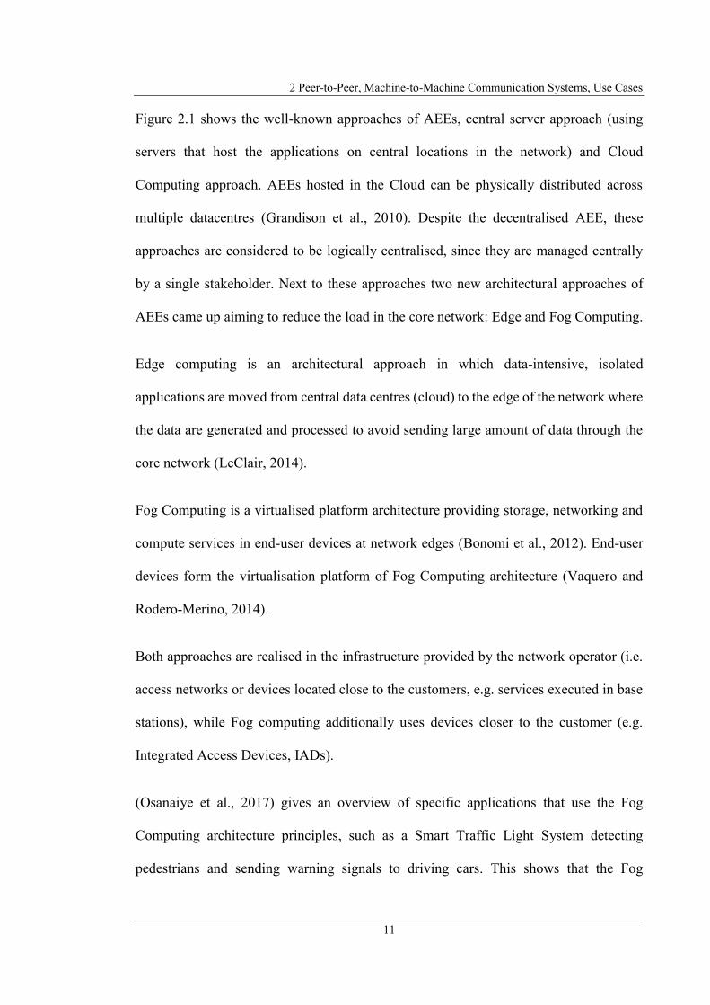
Figure 2.1 shows the well-known approaches of AEEs, central server approach (using
servers that host the applications on central locations in the network) and Cloud
Computing approach. AEEs hosted in the Cloud can be physically distributed across
multiple datacentres (Grandison et al., 2010). Despite the decentralised AEE, these
approaches are considered to be logically centralised, since they are managed centrally
by a single stakeholder. Next to these approaches two new architectural approaches of
AEEs came up aiming to reduce the load in the core network: Edge and Fog Computing.
Edge computing is an architectural approach in which data-intensive, isolated
applications are moved from central data centres (cloud) to the edge of the network where
the data are generated and processed to avoid sending large amount of data through the
core network (LeClair, 2014).
Fog Computing is a virtualised platform architecture providing storage, networking and
compute services in end-user devices at network edges (Bonomi et al., 2012). End-user
devices form the virtualisation platform of Fog Computing architecture (Vaquero and
Rodero-Merino, 2014).
Both approaches are realised in the infrastructure provided by the network operator (i.e.
access networks or devices located close to the customers, e.g. services executed in base
stations), while Fog computing additionally uses devices closer to the customer (e.g.
Integrated Access Devices, IADs).
(Osanaiye et al., 2017) gives an overview of specific applications that use the Fog
Computing architecture principles, such as a Smart Traffic Light System detecting
pedestrians and sending warning signals to driving cars. This shows that the Fog

2.2 Peer-to-Peer Systems
12
Computing architecture is of great relevance for M2M applications. However, (Osanaiye
et al., 2017) shows that Fog Computing, same as Edge Computing contains centralised
elements in their system architecture. The presented applications are either realised by
providers that use the Fog Computing architecture to provide specific, isolated
applications or contain central servers that in turn are localised in the Cloud.
The shifting of computing and data capturing tasks to the edge of the network is a
promising approach and also a major object in this research. This research additionally
goes a step further by presenting a completely decentralised MSP architecture in which
the end-user has the possibility to generate and provide applications and services
independently.
2.2 Peer-to-Peer Systems
P2P systems offer distributed communication and resource management/utilisation. The
following section 2.2.1 describes the principles of P2P systems and different areas in
which P2P systems can be used. P2P systems can be implemented using different
architectural approaches, characterised by their degree of decentralization. Section 2.2.2
introduces the different architectural approaches and describes how resources can be
localised in them.
2.2.1 Classification of Peer-to-Peer Systems
P2P is according to (Steinmetz and Wehrle, 2005) a paradigm for communication on the
Internet, i.e. for Internet Protocol (IP)-based communication systems (IETF RFC 791,

2 Peer-to-Peer, Machine-to-Machine Communication Systems, Use Cases
13
1981), following the end-to-end communication principle. P2P communication
mechanisms can be applied to access globally distributed resources located closely to
peers at network edges.
Commonly instead of the term “P2P system”, also the term “overlay network”, “P2P
overlay” or “P2P overlay network” is used. This illustrates that a P2P system is a higher-
level network with independent topology, built on top of existing IP networks (Steinmetz
and Wehrle, 2005; IETF RFC 7890, 2016).
According to (De Boever, 2007) following characteristics specify a P2P system:
Decentralisation – The participating entities in P2P systems are decentralised.
Cost efficiency – P2P systems utilises resources of peers that are currently unused.
Self-organisation – P2P systems are self-organised.
Sharing of resources – Peers share their resources in P2P systems.
Autonomy – No dependency exist on single entities required for operating a P2P
system.
Scalability – Because sharing resources and distributing content among
participating peers a P2P system is highly scalable and avoids bottlenecks.
P2P systems and applications perform a function in a decentralised way by employing
distributed resources (e.g. processing power, data storage/content or humans and other
resources) provided by participating nodes each adding value to the overall P2P system
(Milojicic et al., 2002; De Boever, 2007). The resources in a P2P system are provided by
the participants in the P2P system instead of by few servers as in traditional client/-server
architectures (IETF RFC 7890, 2016).

2.2 Peer-to-Peer Systems
14
According to (De Boever, 2007), the P2P system approach was developed because the
classical approach of a client/-server model, where resources are managed/deployed by a
central server and queried by clients, is very resource intensive. In this context, the
resources are content generated by the end-user and consumed by other end-users. In
client/-server systems, each user of the system generates additional costs because of the
necessary data transmissions to the central server. Because the increasing amount of data
to be transferred and increasing size of individual data sets, the traditional client/-server
approach is inefficient and its scalability is limited e.g. when network connectivity to
external networks and processing/storage are scarce. With an increasing number of users,
a classical client/-server system can hardly cover the demand for resources for data
transmission (increasing bandwidth requirements) and also for the execution of
computation tasks, so that additionally to the single point of failure (in case of breakdown
of the central server) bottlenecks can also arise. P2P systems meet these disadvantages
because they are naturally very cost-effective and scalable.
According to (Steinmetz and Wehrle, 2005), based on (Oram, 2001) and refined in
(Steinmetz and Wehrle, 2004) a P2P system is a self-organised system in which all
entities (peers) are equal and act autonomously and the overall system does not involve
central entities to organise/coordinate/control utilisation of the resources.
According to (Hauswirth and Dustdar, 2005) P2P architectures can be applied on different
level of abstraction, specified as follows:
Network level – Routing of requests in application-independent way via
physical network.

2 Peer-to-Peer, Machine-to-Machine Communication Systems, Use Cases
15
Data access level – Search/modify resources using application-specific
access structures.
Service level – Combination and expansion of functionalities of the data access
layer to provide higher quality services. The range of these services can vary from
simple file sharing to complex business processes.
User level – Grouping of users ("Communities") and support of user interactions
using the service level for community management and information exchange.
According to (Hauswirth and Dustdar, 2005) Table 2.1 shows typical examples of P2P
architectures on different levels. Combination of this levels and the utilised P2P concept
on individual levels characterise a specific P2P system.
Table 2.1: Examples of P2P on different levels according to (Hauswirth and Dustdar, 2005)
Thus, it can be stated that a P2P system is always advantageous when 1. decentralised
resources are in the focus of an application, 2. a high scalability is required, 3. a resource
is to be provided directly end-to-end and 4. no dependencies on central entities
(stakeholders or system components) should exist.
2.2.2 Classification of P2P System Architectures
P2P systems can be generally classified according to (De Boever, 2007) based on the
degree of decentralisation and “the presence of a structure in object location and routing”.
Table 2.1 has been removed due to Copyright restrictions.
2.2 Peer-to-Peer Systems
16
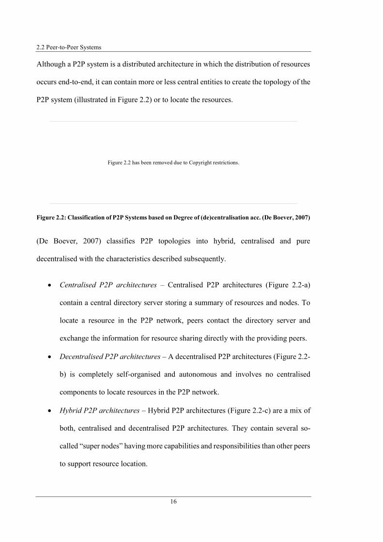
Although a P2P system is a distributed architecture in which the distribution of resources
occurs end-to-end, it can contain more or less central entities to create the topology of the
P2P system (illustrated in Figure 2.2) or to locate the resources.
Figure 2.2: Classification of P2P Systems based on Degree of (de)centralisation acc. (De Boever, 2007)
(De Boever, 2007) classifies P2P topologies into hybrid, centralised and pure
decentralised with the characteristics described subsequently.
Centralised P2P architectures – Centralised P2P architectures (Figure 2.2-a)
contain a central directory server storing a summary of resources and nodes. To
locate a resource in the P2P network, peers contact the directory server and
exchange the information for resource sharing directly with the providing peers.
Decentralised P2P architectures – A decentralised P2P architectures (Figure 2.2-
b) is completely self-organised and autonomous and involves no centralised
components to locate resources in the P2P network.
Hybrid P2P architectures – Hybrid P2P architectures (Figure 2.2-c) are a mix of
both, centralised and decentralised P2P architectures. They contain several so-
called “super nodes” having more capabilities and responsibilities than other peers
to support resource location.
Figure 2.2 has been removed due to Copyright restrictions.
2 Peer-to-Peer, Machine-to-Machine Communication Systems, Use Cases
17
Because avoidance of central entities is in focus of this research project, decentralised
P2P systems are considered in the further course of the project, since centralised and
hybrid P2P system architectures contain central entities.
For implementing a P2P overlay several different approaches exist. A P2P overlay can
have a structured topology (structured P2P overlay) or an unstructured topology
(unstructured P2P overlay). The P2P overlays are generated by algorithms determining
how the structure of an overlay (arrangement of the nodes) is organised. The topology
and algorithms for searching and inserting data sets determine which node in the overlay
stores a specific data set and how the data sets can be located (without centralised
control/coordination) (Steinmetz and Wehrle, 2005).
Structured and unstructured overlays have fundamentally different characteristics in their
topology, search algorithms and data management. The main characteristics of both
approaches are presented subsequently according to (De Boever, 2007).
Structured P2P Overlays – In structured P2P overlays the nodes and the resources
are assigned to specific locations in the topology. “Distributed Hash Tables
(DHT)” enable to identify the location of a specific resource.
Unstructured P2P Overlays – In unstructured P2P overlays resources and nodes
are located in an unstructured way with no relationship between location of the
resource and the topology. Identification of resource locations is performed using
the so-called “query flooding model”.
Structured P2P systems ensure that resources can be localised with limited hops (De
Boever, 2007). The global view of the data distributed over several nodes is provided by
2.2 Peer-to-Peer Systems
18
DHTs without dependence on the actual location (Steinmetz and Wehrle, 2005).
According to (De Boever, 2007) in a DHT every resource is assigned with a distinct key
serving as an ID for the resource. The ID is generated by using hash functions (e.g. SHA-
1, IETF RFC 6234, 2011). Each peer is responsible for a sequence of that IDs. To be able
to locate a resource, the requesting node must know the ID of the resource. When
searching for a resource, the search query is continuously forwarded from one node to
another until the node responsible for the resource is reached. To be able to forward the
search query, each node has a routing table with information about various other nodes
possibly providing the requested resource.
A structured P2P network offers according to (Steinmetz and Wehrle, 2005) and (De
Boever, 2007) two ways to store data:
Direct Storage – The data is stored directly in the overlay at the node responsible
for this data set. The advantage of this variant is that nodes which inserted the data
can leave the overlay after the insertion without losing the inserted data.
Indirect Storage – The data is not stored directly in the overlay, but only a
reference to the data via which the data can be obtained (e.g. link). The data itself
remains on the node that inserted the reference. The advantage of this variant is
that the load in the overlay is reduced because the reference contains less data
volume the data set itself.
In unstructured P2P systems peers only contain an index of data sets stored at their own
location and do not have information about data sets stored at other peers. A search
request for a data set is forwarded to all peers known to a single peer. Therefore, it is
important that one peer knows as many other peers as possible also present in the P2P
2 Peer-to-Peer, Machine-to-Machine Communication Systems, Use Cases
19
overlay. To search a data set a peers forward the search query to all known peers. These
in turn forward the query to all known peers. This floods the network with the search
request. For each search query, a “Time-To-Life” (TTL) value is defined that limits the
number of forwardings of a query. Each peer that passes on the search query decrements
the TTL value. If the TTL value is zero, the search query is no longer forwarded. Because
this process, unstructured P2P systems cannot guarantee to locate specific data sets
because the data set might be stored on a peer that does not receive the search query since
it is outside the scope of query forwarding (De Boever, 2007).
Because of the different mechanisms used to generate a P2P overlay and locate resources,
it is important to note that choosing an appropriate approach depends on the intended
purpose and should be based on criteria such as network load and guarantee to locate a
data set.
2.3 Machine-to-Machine Communication Systems
In order to create a unified terminology and explain how various terms are used in context
of the research project, the following section 2.3.1 describes principles of Machine-to-
Machine Communication (M2M) and how M2M correlates with the Internet of Things
(IoT) since both are used simultaneously in literature. Section 2.3.2 introduces the M2M
system architecture by describing the components of an M2M system and points out how
M2M application services are realised applying an M2M system. Section 2.3.3 introduces
different roles and stakeholders in traditional M2M ecosystem. The different roles will be
introduced to show how these are related to each other, as the role assignment will change
in a p2p-based service provisioning architecture enabling end-users to take on the role of

2.3 Machine-to-Machine Communication Systems
20
service provider additionally to the role of service consumer. Finally, section 2.3.4
introduces the approach of service choreography followed in this research projects for
service provision and shows the difference of it to the approach of service orchestration
used in traditional MSPs.
2.3.1 Classification of Machine-to-Machine Communication
M2M describes a communication paradigm that enables devices (machines) to
communicate with other devices without or with minimal human intervention during
configuration/deployment/operation phase (Dawaliby et al., 2016; Sarigiannidis et al.,
2017; Mehmood et al., 2015). M2M enables autonomous measurement, delivery, and
processing of information using Information and Communication Technologies (ICT)
(Sarigiannidis et al., 2017). Often in publications, such as (Dawy et al., 2017) or
(Dawaliby et al., 2016) the terms M2M and Machine-type communications (MTC) are
equated. In this research project M2M is used to specify the communication between
devices. According to (Dawaliby et al., 2016) M2M can be realised through a P2P or
centralised communication model and according to (Holler et al., 2014) an M2M solution
focuses on supporting a particular task of one stakeholder and does not “take a broad
perspective on solving a larger set of issues or ones that could involve several
stakeholders”.
Through M2M many applications (e.g. monitoring, infrastructure management, eHealth,
smart cities, home automation) are supported or enabled (Dawaliby et al., 2016;
Mehmood et al., 2015). M2M is according to (Mehmood et al., 2015) the fundamental

2 Peer-to-Peer, Machine-to-Machine Communication Systems, Use Cases
21
enabler for the IoT “by providing ubiquitous connectivity between numerous intelligent
devices”.
Publications such as (Kim et al., 2012) mention that M2M and IoT contain the same
aspects. Other publications, such as (Bahga and Madisetti, 2014) or (Holler et al., 2014)
try to separate the aspects of M2M and IoT. According to (Mehmood et al., 2015) M2M
and IoT domain, but also Wireless Sensor Networks (WSNs) and Cyber-Physical Systems
(CPS) domain represent the same key ideas. As stated by (Mehmood et al., 2015) authors
of (Wan et al., 2013) made a correlation of M2M, IoT, WSN and CPS. Since (Wan et al.,
2013) and (Mehmood et al., 2015) precisely describe the aspects of M2M and IoT and
classify the different terms as well as provide the most suitable definitions for the context
of this project, these are presented below. The specifications of (Wan et al., 2013) and
(Mehmood et al., 2015) are used to classify the focus of this project in the described fields.
To illustrate the correlation of M2M, IoT, WSN and CPS, first IoT is introduced since
M2M, WSN, and CPS according to (Wan et al., 2013), from the architectural perspective,
belong to IoT.
Internet of Things (IoT)
According to (Mehmood et al., 2015) the term IoT describes the connection of
“objects/machines” (often defined as “things”) using an Internet-based infrastructure.
According to (Mehmood et al., 2015) and (Wan et al., 2013) the IoT contains the
following fundamental components:
Data Sensing – Sensing and acquiring data of distributed sensors that should be
processed in services and applications.
2.3 Machine-to-Machine Communication Systems
22
Heterogeneous Connectivity – The objects and devices implement different
(incompatible) communication technologies.
Information Processing – The information data acquired needs to be processed to
interpret the captured information.
Services and Applications – Services and applications use the captured
information data to generate a benefit out of them and additionally control
devices/machines.
Fundamentally, according to (Wan et al., 2013) M2M, WSNs, and CPS “belong to IoT”
because they have the same components as described above. The difference between them
is the proportion among these components in system design. Figure 2.3 shows the
correlation among WSNs, M2M, CPS, as well as IoT according to (Wan et al., 2013) and
(Mehmood et al., 2015), while IoT represents the area created by WSNs, M2M, CPS.
Figure 2.3: Correlation among WSNs, M2M, CPS, IoT acc. (Wan et al., 2013; Mehmood et al., 2015)
Figure 2.3 has been removed due to Copyright restrictions.
2 Peer-to-Peer, Machine-to-Machine Communication Systems, Use Cases
23
Despite the similarity of WSNs, M2M, CPS in networking aspects they have “major
differences from architecture and design philosophy” (Wan et al., 2013). Subsequently
the main characteristics of WSNs, M2M, CPS are described according to (Wan et al.,
2013), starting with the aspects of M2M.
Machine-to-Machine Communication (M2M)
Refers to communication between computers, smart sensors/actuators without or
with only minimal human intervention.
M2M systems have the functionality for making decisions and autonomous
control operations to provide value-added services (VAS).
End-to-end communication between devices and focus on “practical applications
(e.g., smart home and smart grid)”.
Through the integration of M2M with WSNs, M2M systems can use the
information provided by the WSNs as a basis for performed actions (i.e. WSNs
support M2M systems).
Wireless Sensor Networks (WSNs)
WSNs, such as Wireless Body Area Networks (WBANs) consist of distributed
sensors monitoring environmental conditions. The autonomous sensors cooperate
with each other to deliver the collected data to a central location.
WSNs and Information generation from all sensors is basic scenario of IoT.
WSNs are the basis of CPS and support M2M.
Cyber-physical System (CPS)
2.3 Machine-to-Machine Communication Systems
24
CPS is according to (Shi et al., 2011) the closely integration of physical processes
into software. Classical application of CPS according to (Shi et al., 2011) are e.g.
an operating room where all devices (health sensors or medicine indication
systems) are fully networked and accessible for monitoring/control. Another
classical CPS application is an “intelligent road with unmanned vehicle”. The CPS
e.g. monitors and controls the actions of the vehicles, such as stopping or turning
left/right.
CPS introduces interactive and more intelligent operations and represents an
enhancement of M2M.
Characteristics of CPS are: “cyber capability in every physical component”, close
integration of all devices, high complexity of system architecture, dynamically
reconfiguration, “high degrees of automation”, dependable and distributed real
time operations.
According to (Wan et al., 2013) M2M and CPS address similar domains. While M2M has
the perspective of autonomous communication and provision of value-added services
supported by WSNs, CPS has the perspective of not only communication but focuses on
applications based on WSNs as well as distributed and real-time control.
Since the aspects of this project focus on providing services via MSPs, the scope of the
project has to be classified in the M2M field.
The following section introduces the architecture of M2M systems starting from a general
perspective of M2M system architecture and refining it afterwards by description of
detailed M2M System architecture as defined by European Telecommunications
Standards Institute (ETSI).

2 Peer-to-Peer, Machine-to-Machine Communication Systems, Use Cases
25
2.3.2 M2M System Architecture
Implementation of VAS in M2M requires an M2M system architecture establishing
connection of devices among each other and with a (usually business) application. These
M2M applications according to (Holler et al., 2014) can be integrated into business
processes of a company to support them.
Figure 2.4 shows the general structure of an M2M system architecture. M2M Devices
(providing capabilities for sensing and actuation) communicate via an IP-based
Communication Network, such as the Internet or Next Generation Networks (NGNs),
with each other and with a single specific application to exchange information (Holler et
al., 2014; Boswarthick et al., 2012). Permission to reproduce Figure 2.4 has been granted
by the publisher John Wiley and Sons.
Figure 2.4: General Perspective of M2M System Architecture acc. (Wan et al., 2013; Mehmood et al.,
2015; Bahga and Madisetti, 2014; Boswarthick et al., 2012; Holler et al., 2014)
Business
Application
Communication Network
(wired/ wireless)
a) The essence of M2M b) Group of devices in an
M2M relationship
Application Servers
c) The mediated M2M
relationship
Business
Application
M2M
Gateway
Communication Network
(wired/ wireless)
M2M Area
NetworkM2M
Device
Communication Network
(wired/ wireless)
Business Application

2.3 Machine-to-Machine Communication Systems
26
M2M applications created by “very specialized developers” realise the main logic to
achieve the requirements of the M2M system. The M2M applications (e.g. “remote car
diagnostics”) usually are deployed on Application Servers inside enterprises (Holler et
al., 2014). An M2M application can address single M2M Devices (Figure 2.4-a) or a group
of M2M Devices (Figure 2.4-b), which can be directly connected to the Communication
Network or via a Gateway (GW) (Figure 2.4-b) forming the mediating interface between
the M2M Area Network and the Communication Network (Boswarthick et al., 2012). For
communication inside an M2M Area Network, several communication technologies and
protocols are used (e.g. Bluetooth, ZigBee, Wi-Fi) (Bahga and Madisetti, 2014).
The following section introduces the functional architecture of an M2M system as
described by ETSI based on (ETSI TS 102 690 V2.1.1, 2013). Figure 2.5 illustrates this
functional architecture according to (ETSI TS 102 690 V2.1.1, 2013) and refined with
information given by (Boswarthick et al., 2012).
The M2M system architecture illustrated in Figure 2.5 is based on so-called Service
Capability Layers. Service Capability Layers provide Service Capabilities, which are
according to (ETSI TR 102 725 V1.1.1, 2013) a set of functions usable commonly by
various applications. In the M2M system architecture it is distinguished between different
kinds of Service Capability Layers referring to the type/location of equipment
implementing these Service Capability Layers. Exemplarily the M2M Device Service
Capability Layer resides on M2M Devices and provides functions usable by the
applications contained in the M2M Devices. Permission to reproduce Figure 2.5 has been
granted by ETSI and the publisher John Wiley and Sons.

2 Peer-to-Peer, Machine-to-Machine Communication Systems, Use Cases
27
Figure 2.5: Functional Architecture of M2M System acc. (ETSI TS 102 690 V2.1.1, 2013;
Boswarthick et al., 2012)
According to (ETSI TS 102 690 V2.1.1, 2013) and (Boswarthick et al., 2012) the M2M
system architecture is separated in the two areas Device and Gateway Domain and
Network and Applications Domain. The Access Network, such as xDSL, HFC, Wi-Fi or
3/4G, enables the Device and Gateway Domain to connect with the (IP-) Core Network
(ETSI TS 102 690 V2.1.1, 2013). Through the Core Network, entities residing in the
Device and Gateway Domain connect to M2M Applications that use the data information
Transport Network
M2M core
M2M gateway
M2M Area Network
M2M Gateway Applications
(runs Service Logic)
Gateway Service Capabilities Layer
provides M2M (Gateway) Service Capabilities
Device and
Gateway
Domain
Access Network
Core Network
Network Service Capabilities Layer
provides M2M Service Capabilities
M2M Applications
(runs Service Logic)
User Interface (e.g. Web
Portal Interface)
Network and
Applications
Domain
M2M
Device
M2M Device
Device Service Capabilities Layer
provides M2M (Device) Service Capabilities
M2M Device
Applications
(runs Service Logic)
M2M
Communication
Modules
M2M Device
Device Service Capabilities Layer
provides M2M (Device) Service Capabilities
M2M Device
Applications
(runs Service Logic)
M2M
Communication
Modules
M2M gateway
© European Telecommunications Standards Institute 2013. Further use, modification, copy and/or distribution are strictly prohibited.

2.3 Machine-to-Machine Communication Systems
28
and capabilities of the M2M Devices to realise VAS for supporting various business
processes. The separated areas indicate where the architectural elements of an M2M
system are located.
An M2M system contains in the Devices and Gateway Domain entities such as M2M
Gateways, M2M Area Networks and M2M Devices. These entities are described
subsequently according to (oneM2M TS-0011-V2.4.1, 2016), (ETSI TR 102 725 V1.1.1,
2013), and (Boswarthick et al., 2012):
M2M Device – An M2M Device is physical equipment that contains capabilities
for communication/computing/sensing/actuation. M2M Devices contain at least
one M2M Device Application (executing the application logic and using M2M
Device Service Capabilities) as well as one M2M Communication Module
(implementing the communication capability).
M2M Area Network – The M2M Area Network provides functionalities, such as
communication technologies/protocols enabling M2M devices to be connected
with an M2M Gateway.
M2M Gateway – A M2M Gateway is equipment implementing connection
functionality between M2M Devices and Network and Applications Domain and
can be implemented as a stand-alone entity or integrated within M2M Devices.
The Network and Applications Domain contains the Transport Network consisting of
various Access Networks and the (IP-based) Core Network forming the communication
infrastructure between the Devices and Gateway Domain and the M2M Applications. The
Network and Applications Domain additionally contains the Network Service Capability
2 Peer-to-Peer, Machine-to-Machine Communication Systems, Use Cases
29
Layer providing functionalities to M2M application service provider (ASP) such as
application registration, data storage or support for NAT traversal.
Since M2M Applications and M2M Services are in the focus of this research these and
corresponding terms should be specified.
(ETSI TR 102 725 V1.1.1, 2013) defines an application as a software entity performing
a specific task to support a user operating on a specific goal. Physical devices, such as
M2M devices or application servers execute software applications, which according to
(ITIL V3.1.24, 2007) realise services. As specified in (ITIL V3.1.24, 2007) software
applications provide functions required by services and can be part of multiple services.
A M2M application consists of one or more underlying services that provide capabilities
to support the M2M applications (ITU-T Y.101, 2000). Service providers provide these
services (ITU-T Y.2301, 2013; OASIS SOA-RM-V1.0, 2006). For using the
functionalities of a service, an interface is required to access these functionalities (OASIS
SOA-RM-V1.0, 2006). Services consist of service components, which form the building
blocks of a service and are combined with other service components to build the whole
service (ISO IEC 20000-1:2011, 2013).
According to (oneM2M TS-0011-V2.4.1, 2016) the logic of an M2M application realises
the M2M application service and is accessible via a specific interface (M2M application
interface). As specified by (UC Santa Cruz, 2017) “applications, themselves, are not
services”. Services are enabled by applications and “may be provided by someone else”.
I.e. an M2M application only is an M2M application service if a stakeholder exists which
operates the M2M application and additionally provides an interface to the M2M

2.3 Machine-to-Machine Communication Systems
30
application that enables an end-user to consume the application logic. The M2M
application service is consumed according to (oneM2M TS-0011-V2.4.1, 2016) by the
end-user that can be as specified in (ITU-T Y.110, 1998) either a company or a private
individual.
Now that the architecture of an M2M system has been described, the following section
describes how M2M applications use the functionality of an M2M system to provide
specific VAS.
An MSP is used to provide M2M applications in an M2M system. This MSP provides the
connectivity between M2M devices and enables the management of participating nodes
as well as the exchange of information between the application and M2M devices. The
standardisation committee oneM2M published several specifications, such as (oneM2M
TS-0007-V2.0.0, 2016) or (oneM2M TS-0001-V2.10.0, 2016) defining the functionality
of an MSP and the interworking of it with other components of an M2M system
architecture. Figure 2.6 illustrates the principle integration of an MSP in the M2M system
architecture according to (oneM2M TR-0001-V2.4.1, 2016; Elloumi, 2014). As Figure
2.6 shows, the MSP is connected to the M2M GW via the Transport Network, which in
turn connects various M2M Devices via an M2M Area Network. The M2M Application is
executed on a central M2M Application Server (e.g. as a Web application) and is provided
via an interface to one or more end-users as an M2M application service. An MSP and
M2M Application Server are usually operated within data centres. It can be derived that
the MSP and M2M Application Server are placed within the Network and Applications
Domain, whereas the M2M Application Servers implementing the application logic are

2 Peer-to-Peer, Machine-to-Machine Communication Systems, Use Cases
31
not part of the MSP. The components of the Device and Gateway Domain are also not
part of the MSP.
Figure 2.6: Integration of MSP in M2M system architecture acc. (oneM2M TR-0001-V2.4.1, 2016;
Elloumi, 2014)
2.3.3 Roles and Stakeholder in M2M Ecosystems
In the M2M ecosystem, several separated roles and stakeholders exist providing,
operating and consuming M2M applications and M2M services. Figure 2.7 illustrates
them as defined by (oneM2M TS-0002-V1.0.1, 2015). Permission to reproduce Figure
2.7 has been granted by ETSI.
As defined by (oneM2M TS-0002-V1.0.1, 2015) and (oneM2M TS-0011-V2.4.1, 2016),
the user (end-user) consumes an M2M solution. End-users represent private individuals
or companies requiring “information-based services” (ITU-T Y.110, 1998; ISO IEC
20000-1:2011, 2013).
Devices and Gateway Domain
Network and Application Domain
M2M
GW
M2M Application
Server
M2M Application
M2M Service
Platform (MSP)
M2M Area Network
Transport Network (wired/ wireless)
M2M Devices

2.3 Machine-to-Machine Communication Systems
32
Figure 2.7: Functional Roles in the M2M Ecosystem acc. (oneM2M TS-0002-V1.0.1, 2015)
The M2M application service provider (ASP) is the entity that provides and operates the
M2M application service consumed by the end-user (oneM2M TS-0011-V2.4.1, 2016;
oneM2M TS-0002-V1.0.1, 2015; ETSI TR 102 725 V1.1.1, 2013).
According to (ETSI TR 102 725 V1.1.1, 2013) and (oneM2M TS-0011-V2.4.1, 2016) the
M2M (common) service provider provides (and operates) the M2M services to the M2M
ASP, which use the services to create the M2M application, or directly to the end-user.
As specified by (oneM2M TS-0011-V2.4.1, 2016) every stakeholder subscribing to M2M
Services is specified as a service subscriber.
According to (ITU-T E.4110 (2010) service providers generally (i.e. M2M ASP and
M2M service provider in particular) offer their services using network resources. The
network operator provides and operates according to (oneM2M TS-0002-V1.0.1, 2015)
these communication networks used to transmit service information.
M2M Applications
M2M Common Services
Connectivity Services
End-User
M2M Solution
operate
M2M Application Service Providers
M2M
Application...
M2M
Application
M2M Service Providers
M2M Common
Service...
M2M Common
Service
Network Operators
Underlying
Network...
Underlying
Network
operate
operate
consume
Company Individual
© 2015. oneM2M TSs and TRs are the property of ARIB, ATIS, CCSA, ETSI, TIA, TSDSI, TTA and TTC who jointly own the copyright in them. They are subject to further modifications and are therefore provided to you as is for information purposes only. Further use is strictly prohibited.

2 Peer-to-Peer, Machine-to-Machine Communication Systems, Use Cases
33
The presentation of the different roles shows that these are different stakeholders.
Especially end-users and service providers have separate roles in the M2M ecosystem
presented. The concept presented in the course of this research project aims on the
dissolution of the static link to a central service provider and enabling end-users taking
on the role of a service provider.
2.3.4 End-User M2M Application Services
The aim of the research project is to enable end-users to act as service providers in order
to make the resources available in their personal environments available to other end-
users. Additionally, it should be possible for different end-users to combine their services
and provide them as a distributed application. Since this is a P2P-based service
provisioning, the service definition from (IETF RFC 7890, 2016) is derived to define an
M2M application service (provided by end-users) in context of this thesis as follows:
M2M Application Service – An M2M application service is a capability provided
by a peer to other peers of the P2P network, while peers can provide different or
same M2M application services.
Combination of service is also referred to as service composition. Service compositions
using traditional MSPs are realised by service orchestration. Service orchestrations
(illustrated in Figure 2.8) according to (Terpak et al., 2016) constitutes a centralised
approach based on “a single executable process” that describe the relationship of the
participating services.

2.3 Machine-to-Machine Communication Systems
34
Figure 2.8: Service Orchestration acc. (Terpak et al., 2016)
Service orchestrations include a central coordinator (service orchestrator) for
coordination of interactions between the participating services. The service orchestrator
actively invokes and combines the services and controls the information exchange
between the services. (Terpak et al., 2016)
The service composition followed in this research project is performed by service
choreography in order to avoid centralised service coordinators. Service choreographies
(illustrated in Figure 2.9) according to (Terpak et al., 2016) constitutes a decentralised
approach.
Figure 2.9: Service Choreography acc. (Terpak et al., 2016)
In service choreography, the combination of the participating services is described
globally. The global description defines the message exchange between the services as
well as the interactions between the service endpoints. In service choreography, each
Service O
Service A
Service D Service C
Service B
© 2016 IEEE
Service A
Service D Service C
Service B
© 2016 IEEE
2 Peer-to-Peer, Machine-to-Machine Communication Systems, Use Cases
35
service is responsible for information exchange with its corresponding service. The
execution of the service composition during runtime takes place without central
controlling of the information exchange between the services. (Terpak et al., 2016)
2.4 Use Cases
The following section presents use cases for M2M services and M2M application
services. The use cases are introduced in this section to increase the overall understanding
of the framework presented in the following chapters. The use cases represent the
different aspects of the framework and will be used later in chapter 7 to evaluate the
framework based on these aspects. Use cases have been defined that address the Smart
Home/Smart Building sector, since this area is also a popular field of application for M2M
solutions and includes the personal environment of the end-user. These use cases or parts
of it are used inside this research to exemplary illustrate specific technologies, functional
approaches, system architectures, and methodologies after they have been generally
introduced. The use cases presented in this section are close-coupled in its functionality
to demonstrate the possibility for realisation of different applications integrating few
similar use cases.
Use Case 1: Local Window Monitoring
The use case “local window monitoring”, illustrated in Figure 2.10, demonstrates a
service realised in a Smart Home of an individual end-user. The use case combines
different M2M device technologies and multimedia communication.

2.4 Use Cases
36
Figure 2.10: Use Case local Window Monitoring
The use case represents an M2M service designed by the end-user and executed in the
personal environment of the end-user, without integration of other external entities. The
service is realised using a single M2M platform located in end-users environment. It
involves a single end-user as actor. The end-user designs the M2M service represented
by the use case illustrated in Figure 2.10. The local M2M service detects two different
sensor states (window open/closed and raining/not raining) on behalf of sensors using
different M2M communication technologies (e.g. ZigBee, Z-Wave) for transmitting their
sensor states. Depending on the evaluation result of these sensor states, the M2M service
initiates an audio call to inform the end-user in case of raining and window opened at the
same time (by playback an announcement).
Use Case 2: Neighbourhood Weather Station
The use case “neighbourhood weather station”, illustrated in Figure 2.11, demonstrates
the combination of a service provided remotely with the combination of a local service.
The use case represents an M2M application service including the provision of an M2M
service by end-user and the utilisation of that M2M service by another end-user.
Local Window Monitoring
End-User
<<extend>> {Rain detected and Window open} <<include>>
Rain
Detection<<include>>
Evaluate Sensor
States
Windows State
DetectionSetup Audio Call

2 Peer-to-Peer, Machine-to-Machine Communication Systems, Use Cases
37
Figure 2.11: Use Case Neighbourhood Weather Station
The use case involves two actors, the SP and the SC. Both actors are end-users. The SP
designs an M2M service for measurement of weather data using its local Smart Home
equipment and provides, if requested, that weather data to other end-users. The SC
designs its individual M2M service with functionality to request and evaluate weather
data provided remotely. For this, the M2M service determines automatically a SP
providing weather data in the neighbourhood and requests the weather data from the
remote service. Depending on the evaluation of the received weather data (e.g. if it is
raining), the M2M service triggers some action (e.g. setup phone call as in previous use
case or trigger an actuator for closing the window automatically).
Use Case 3: Building Surveillance
The use case “building surveillance”, illustrated in Figure 2.12, demonstrates the
concatenation of multiple services provided by multiple SPs. The use case involves five
Neighbourhood Weather Station
Weather Data
Service Provider
Subscribe to
Weather Data
Perform Action
Share Weather
Data
<<extend>>
<<include>>
<<include>>
<<extends>> {Rain detected}
<<include>>
<<include>>
Weather Data
Measurement
Weather Data
Publication<<include>>
Search Weather
Data ProviderEvaluate Weather Data
End-User
Service Consumer
Request
Weather Data
Remote Weather
Data Consumation

2.4 Use Cases
38
actors, which all are end-users. Four actors provide different M2M services. The different
M2M services are combined to form an M2M application service with the task to monitor
specific buildings and react on alerts detected inside that building. The SC consumes the
M2M application service.
Figure 2.12: Use Case Building Surveillance
The building management SP designs and provides an M2M service for monitoring a
sensor in a specific building. If the M2M service evaluates a specific sensor state (e.g.
water intrusion or fire alarm), it publishes that alert case to another M2M SP, the supporter
management SP. The supporter management SP provides an M2M service for
management of supporters. Multiple individual supporters register at that service and
offer (as a service) reacting on an alert appearing in a specific building. The task of the
Building Surveillance
Building Monitoring
Service Provider
Sensor Monitoring
Building Support
Service Provider React on
BuildingEvent
Supporter
Management
Supporter
Registration
Provide
Alarm Service
Supporter Management
Service Provider
Provide Support
Service
Messaging
Service Provider
<<extends>> {building event received}
<<include>>
Publish Alert Case
<<extends>> {alert detected}
Determine Building
Supporter
<<include>>
End-User
Service Consumer
Request Building
Surveillance Service
Request
Alarm Service
<<include>>
Generate
Alert Message
<<extends>> {alert request received}

2 Peer-to-Peer, Machine-to-Machine Communication Systems, Use Cases
39
provided service is to manage the supporters and corresponding buildings. The service
identifies the responsible supporter for the received alarm event and requests a service to
send an alarm notification. Because the supporter management service cannot provide the
functionality for multimedia communication via Instant Message (IM), it requests this
functionality as a service provided by the messaging SP. The messaging SP generates an
IM and sends the IM to the recipients. Recipients and message text is defined by the
supporter management SP and specified at the service request. The building support SP
is a group of actors each providing the service to react on an alert appearing in a specific
building. All participants of that group register at supporter management service and
specify their contact information and specific buildings they support. If an alert appears
in a building, the corresponding supporter receives an IM and afterwards reacts on the
alert.
The use case “building surveillance” illustrates the combination of services provided by
individual SPs, all providing different, encapsulated, and independent services. Each of
these services can be integrated in M2M application services with entirely different
contexts.
Use Case 4: Energy Optimisation
The use case “energy optimisation”, illustrated in Figure 2.13, demonstrates an M2M
application service realised by multiple end-users each providing individual and
independent services in parallel. The functionality of the M2M application service is to
reduce energy load by sharing information regarding the total local energy consumption
between all participating end-users.

2.4 Use Cases
40
Figure 2.13: Use Case Cooperative Energy Optimisation (Load Reduction)
The use case involves a group of end-users as M2M SPs as well as the distribution grid
operator as M2M application service consumer. Each end-user designs and runs a service
locally with the functionality to determine the current local energy consumption and
ability to reduce the local energy consumption. Each end-user publishes its locally
determined total energy consumption to all other involved M2M SPs. The distribution
grid operator as M2M application service consumer specifies at application service
request a threshold for total energy consumption. Each individual M2M SP calculates the
overall consumption after receiving the consumption information of the other
participants. Depending on the local evaluation of the total consumption, the individual
end-user service triggers local reduction of energy consumption by e.g. turning of M2M
devices or start consuming energy from a local energy storage (battery).
Cooperative Energy Optimisation (Load Reduction)
<<include>>
<<extends>> {peak exceeded}
Distribution Grid Operator
Service Consumer
Provide Load
Reduction Service
Detect local
Consumption
Calculate overall
Consumption
Reduce local
Consumption
Publish local
Consumption
Request Load
Reduction Service
Publish Consumption
Threshhold
<<include>>
<<include>>
<<include>>
End-User
Service Provider

2 Peer-to-Peer, Machine-to-Machine Communication Systems, Use Cases
41
2.5 Conclusion
This chapter introduced the main principles of the research field by discussing AEEs as
well as P2P and M2M systems.
Section 2.1 introduced the different AEEs for M2M applications or MSPs. Fog
Computing aspect to shift computing and data capturing tasks to the edge of the network
is a promising approach also included in the framework concepts proposed in the
following chapters.
Section 2.2 presented the P2P communication paradigm that enables to address resources
located at the edge of the network. Using P2P systems can address the disadvantages of
traditional client/-server systems, such as single point of failure or bottlenecks, when large
amount of data needs to be transmitted and processed. Transferring P2P system
approaches to MSPs would be beneficial because a decentralised, distributed MSP could
reduce the load in both system and transport networks. The characteristics of P2P system
architectures have been described that enables autonomous end-to-end communication
between nodes. These principles will be derived to develop a concept for a decentralised
MSP with end-user environment integration. Since avoiding central entities in the
research project is an important topic, the architecture of decentralised P2P systems rather
than centralised or hybrid ones will be applied to the concept of MSP presented in the
following chapters.
The M2M system architecture, as main object of this research, has been introduced in
section 2.3. The principles of M2M have been described as well as its correlation to IoT.
It has been shown that M2M focuses on the provision of value-added services, which is

2.5 Conclusion
42
the subject area addressed in this research. The several components of an M2M system
architecture have been presented and shown how these components are related to each
other. It has been shown that an MSP is located as a separate and centralised element in
traditional M2M system architectures, which will be changed in the concepts developed
in this research to a decentralised and distributed M2M system architecture. The different
roles and stakeholder existing in an M2M ecosystem have been introduced. It has been
highlighted that M2M ASPs and consumer are separated stakeholder. This relationship
will be changed during this research enabling end-users to take the role of both, M2M
ASP as well as consumer. Since M2M services and composition of them are in the focus
of this research, finally the differences of service choreography (common in traditional
MSPs) and service orchestration have been illustrated. Service choreography will be the
approach followed in the course of this research since it does not contain a central
coordinator for service interactions.
The use cases specified in section 2.4 represent exemplary options to link M2M devices
in a Smart Home and to provide the functionality as a service as well as the possibility to
combine several services to realise distributed M2M applications. These use cases will be
applied later in this research to illustrate architectural approaches and methodologies as
well as to evaluate the proposed framework.
The following chapter 0 presents the architecture of MSP defined by standardisation
committees ETSI and oneM2M as well as research projects of MSPs. Advantages and
disadvantages of these approaches will be determined to define the requirements for
optimised architecture and principles for decentralised M2M application service
provision.

43
3 Challenges, Requirements, and Use
Cases of M2M Application Service
Provision
This chapter starts by introducing and analysing in section 3.1 existing concepts for
service/application provision in M2M application field, which partly or completely
address similar topics as addressed in this research, focusing on their benefits and
limitations. The approaches are intended to illustrate how currently M2M service
platforms (MSPs) are implemented. OneM2M's approaches for the specification of an
MSP will be introduced in detail since it is considered as a reference architecture and
because the framework presented in this research should use standardised approaches for
the realisation of an optimised MSP. Furthermore, various research projects on MSPs will
be presented to consider their advantages and disadvantages in the concept of an
optimised MSP. The chapter continues in section 3.2 with an overview of the previously
introduced projects, which forms the basis for establishing the requirements for
decentralised application provision in M2M networks. In order to define the
requirements, the positive aspects of the presented projects are taken into account and
new requirements are defined based on the negative aspects.
3.1 Related Work on M2M Service Platforms
44
3.1 Related Work on M2M Service Platforms
This section introduces the related projects on MSPs. They can be categorised e.g.
according to (Kim et al., 2014) into “commercial M2M platforms” and “research projects
on M2M platforms”. According to (Kim et al., 2014) most of the commercial MSPs are
realised based on the oneM2M standard specification for M2M systems. The oneM2M
standard specification will therefore be introduced as representative of commercial M2M
platforms in section 3.1.1, with the remaining subsections covering related projects from
the research field.
3.1.1 OneM2M Specification for M2M Systems
The standardisation committee oneM2M published several specifications for definition
of an architecture of an MSP, which according to (oneM2M TS-0011-V2.4.1, 2016)
enable to deploy M2M solutions. The purpose of the developed specifications is to
describe a Common Service Layer that enables the connection of myriad devices with
M2M application servers (oneM2M TS-0011-V1.2.1, 2015). This section examines
relevant specifications with focus on the architecture of an MSP according to oneM2M
as well as the mechanisms to realise M2M application services applying the architecture
of an M2M system as defined by oneM2M.
It is specified in (oneM2M, 2015) that the objectives of oneM2M is to define interfaces
that enable “individual industries or businesses” for interoperation, but their objective is
not to standardise the environment across applications. OneM2M defines an MSP

3 Challenges, Requirements, and Use Cases of M2M Application Service Provision
45
(consisting of M2M common services) based on a horizontal service layer (illustrated in
Figure 3.1) that is usable across different application fields. (oneM2M TS-0007-V2.0.0,
2016), which describes the specific M2M common services and their interworking in an
M2M architecture, defines as its scope the “use of the M2M Services within the context
of complex business services”. This indicates that the scope of an oneM2M defined M2M
system does not designate to end-user domain, respectively M2M application provision
by end-users, but describes an M2M system for business applications with the goal to
support business processes. Additionally, (oneM2M TS-0011-V2.4.1, 2016) specifies the
M2M service provider (SP), M2M application service provider (ASP) and the M2M
service consumer (SC) as different stakeholders in an M2M system. Although the scope
of M2M systems according to the architecture defined by oneM2M does not focus on
end-user domain and end-user integration in M2M application provision, in the following
the architecture is introduced in detail to differentiate the concept defined in this thesis
and explain approaches integrated in the proposed framework. Permission to reproduce
Figure 3.1 has been granted by author of the referenced publication.
Figure 3.1: M2M Common Service Layer acc. (Damour, 2014)
The purpose of the specified M2M Common Service Layer of the service layer
architecture defined by oneM2M is to avoid multiple coexistent solutions for M2M
Automotive
Automotive
Application
Home
Home
Application
Energy
Energy
Application
Health
Health
Application
Communication Networks
Communication Technologies & Protocols
Communication Devices & Hardware
Common Service Layer
Common functions applicable to different application domains
3.1 Related Work on M2M Service Platforms
46
business applications, realised by different centralised infrastructures of M2M SPs as
illustrated in Figure 3.2.
Figure 3.2: Vertical Pipes of M2M Business Applications acc. (Arndt and Koss, 2014)
OneM2M specifies an architecture for realisation of applications that “share common
infrastructure, environments and network elements” by definition of a single centralised
horizontal MSP architecture as illustrated in Figure 3.3.
Figure 3.3: oneM2M Horizontal Platform Principle acc. (Arndt and Koss, 2014)
The purpose of the defined horizontal infrastructure is to realise central business
applications by central M2M ASPs, but with application of a shared MSP acting as a
Figure 3.2 has been removed due to Copyright restrictions.
Figure 3.3 has been removed due to Copyright restrictions.

3 Challenges, Requirements, and Use Cases of M2M Application Service Provision
47
middleware that supports the end-to-end data exchange between customer applications
and M2M devices (Arndt and Koss, 2014).
(oneM2M TS-0001-V1.13.1, 2016) defines the following layers (illustrated in Figure 3.4)
comprised in an M2M system to support end-to-end M2M Services. Every Layer can use
the functionalities of the underlying layer.
Application Layer – M2M application services are realised by implementation of
Application Entities (AE) located in the Application Layer. The AEs can use the
functionalities of the Common Services Layer.
Common Services Layer – The Common Services Layer comprises functionalities
that are common for M2M applications of several M2M application fields and
across different M2M platforms (e.g. device or location management).
Network Services Layer – The network services layer provides networking
functionality to the common services layer, which uses the functionalities
provided by the network to connect devices or other entities, using network
communication.
oneM2M defines the functional architecture of an M2M system by specifying several
AEs and service entities (CSEs and NSEs) located in the defined layers as well as various
reference points to connect them for data exchange or to service requests (illustrated in
Figure 3.4). Permission to reproduce Figure 3.4 has been granted by ETSI.

3.1 Related Work on M2M Service Platforms
48
Figure 3.4: oneM2M Layered Model and Functional Architecture acc. (oneM2M TS-0001-V1.13.1,
2016)
Subsequently AE, CSE, NSE of the oneM2M are described as specified in (oneM2M TS-
0001-V1.13.1, 2016).
Application Entity (AE) – AEs are entities implementing application logic (e.g.
applications for remote blood sugar monitoring or a control applications). Each
AE can reside multiple times in various M2M nodes. AEs and CSEs communicate
via the Mca reference point to enable the AE to utilise the services provided by
the CSE. AE and CSE can but need not be located on the same device.
Common Services Entity (CSE) – A CSE is an instance “of a set of common
service functions” such as services for device management (management of
device capabilities) or location service. Other entities of the M2M system can
utilise these common service functions (CSF) through the Mca and Mcc reference
points illustrated in Figure 3.4. CSEs and NSEs connect via the Mcn reference
point to enable the CSE to utilise the services provided by the NSE. Connections
AE
CSE
NSE
InfrastructureDomain
AE
CSE
NSE
Field Domain
Application Layer
Common Services Layer
Network Services Layer
Mcn
Mcc
Mcn
Mca Mca
Mca
Mcc
© 2016. oneM2M TSs and TRs are the property of ARIB, ATIS, CCSA, ETSI, TIA, TSDSI, TTA and TTC who jointly own the copyright in them. They are subject to further modifications and are therefore provided to you as is for information purposes only. Further use is strictly prohibited.

3 Challenges, Requirements, and Use Cases of M2M Application Service Provision
49
between CSEs are established via the Mcc reference point to utilise services
provided by the other CSEs.
Network Services Entity (NSE) – A NSE provides underlying network services to
the CSEs. Such network services are according to (oneM2M TS-0004-V2.7.1,
2016) e.g. device triggering (3GPP TS 23.682, 2016) or location request
(geographical location information).
An oneM2M system consists of several nodes that are whether located in the field domain
or in the infrastructure domain. The Field Domain contains M2M devices, gateways and
M2M Area Networks. The Infrastructure Domain contains the application infrastructure
and the M2M service infrastructure (oneM2M TS-0011-V2.4.1, 2016). According to
(Rayes and Salam, 2017) the Infrastructure Domain contains the communication
networks (e.g. routers) and servers (e.g. data centres) of the M2M SP. The Infrastructure
Domain (i.e. the M2M Service Infrastructure) is according to (oneM2M TS-0011-V1.2.1,
2015) “physical equipment (e.g. a set of physical servers) that provides management of
data and coordination capabilities for the M2M SP and communicates with M2M
Devices”. Therefore the Infrastructure Domain is the place where the main components
of an MSP resides. This is intensified by (oneM2M TS-0007-V2.0.0, 2016) describing
the M2M services that an oneM2M service platform provides, which are “primarily
suitable for the Infrastructure Domain”. As specified in (oneM2M TS-0001-V1.13.1,
2016) a node is considered as a logical entity that is contained in a physical entity such as
the M2M device or M2M application server. Every node provides specific services that
can be consumed by other nodes (CSE of the nodes) in the M2M environment. The AEs,
which are also located in nodes, consume the functionalities (services) provided by the

3.1 Related Work on M2M Service Platforms
50
own node or the functionalities provided by other nodes for implementation of the logic
of an M2M application service.
To consume the functionalities by other nodes, the nodes need to be interconnected via
the defined reference points. Figure 3.5 illustrates the various node types of an M2M
system and shows in which domain they are located. Figure 3.5 also illustrates connection
possibilities of various entities according to (oneM2M TS-0001-V1.13.1, 2016).
Permission to reproduce Figure 3.5 has been granted by ETSI.
Figure 3.5: Configurations supported by oneM2M Architecture acc. (oneM2M TS-0001-V1.13.1,
2016)
Middle Node (MN)
Infrastructure Node (IN)
Mca
Middle Node (MN)
Mca
Application Service
Node (ASN)
Application Dedicated
Node (ADN)
Application Service
Node (ASN)
Application Dedicated
Node (ADN)
McaMca
Field Domain
InfrastructureDomainIN-AE
MN-AE
ASN-CSE
ASN-AE
ASN-CSE
ASN-AEADN-AE ADN-AE
Non-oneM2M
Device Node
(NoDN)
Non-oneM2M
Device Node
(NoDN)
Non-oneM2M
Device Node
(NoDN)
Non-oneM2M
Device Node
(NoDN)
Non-oneM2M
Device Node
(NoDN)
IN-AE
One or more AE Zero or more AE Link out of scope
Mca
McnMcc
IN-CSE
Mcc
Mcc
MccMcn
MN-CSE
McnMca Mcc
Mca
MN-AE
MN-CSE
McnMcn
Mca
Mcc
© 2016. oneM2M TSs and TRs are the property of ARIB, ATIS, CCSA, ETSI, TIA, TSDSI, TTA and TTC who jointly own the copyright in them. They are subject to further modifications and are therefore provided to you as is for information purposes only. Further use is strictly prohibited.

3 Challenges, Requirements, and Use Cases of M2M Application Service Provision
51
According to (oneM2M TS-0001-V1.13.1, 2016) the “Infrastructure Domain of any
particular M2M SP contains exactly one Infrastructure Node” and the Field Domain can
contain multiple Application Service/ Application Dedicated/ Middle/ and Non-oneM2M
Nodes. These node types are described subsequently as specified in (oneM2M TS-0001-
V1.13.1, 2016).
Application Service Node (ASN) – ASNs (e.g. M2M devices) contain one CSE
and at least one AE.
Application Dedicated Node (ADN) – ADNs (e.g. constrained M2M devices)
contain no CSE and at least one AE.
Middle Node (MN) – MNs (e.g. M2M Gateways) contain one CSE and zero or
more AEs.
Infrastructure Node (IN) – The IN is a single centralised element in the
infrastructure of an M2M SP containing one CSE and zero or more AEs.
Non-oneM2M Device Node (NoDN) – NoDNs not contain AEs or CSEs.
To connect between two Infrastructure Nodes (INs) residing in different M2M SP
domains, respectively the CSEs located in the INs, the connection is established using
their Mcc’ reference points. This connection of the INs enable the CSEs of the INs “to
communicate with a CSE of another IN residing in the Infrastructure Domain of another
M2M SP to use its supported services and vice versa”.
After the main architectural components of an oneM2M service platform has been
introduced, subsequently an exemplary M2M application (illustrated in Figure 3.6) is
presented as defined by (oneM2M TR-0025-V1.0.0, 2016). The task of the exemplary
M2M application is to provide functionality for remote monitoring and control of lights

3.1 Related Work on M2M Service Platforms
52
in a Smart Home using a remote light controller application installed on a Smartphone.
The lights (ADNs) are connected to an M2M Gateway (MN) that is connected to the
oneM2M service platform. The “oneM2M service platform is modelled as an IN-CSE”
and located in the Cloud. The Smartphone application (IN-AE) is connected to the MSP
and is controlled by the end-user. Permission to reproduce Figure 3.6 has been granted
by ETSI.
Figure 3.6: oneM2M functional Architecture of M2M Application acc. (oneM2M TR-0025-V1.0.0,
2016)
The Infrastructure Domain illustrated in Figure 3.5 “consists of Application Infrastructure
and M2M Service Infrastructure” (oneM2M TS-0011-V2.4.1, 2016). The M2M
application infrastructure is “equipment (e.g. a set of physical servers of the M2M ASP)
that manages data and executes coordination functions of M2M Application Services”
(oneM2M TS-0011-V2.4.1, 2016). The “Application Infrastructure hosts one or more
M2M Applications” but “specification of Application Infrastructure is not subject of the
current oneM2M specifications” (oneM2M TS-0011-V1.2.1, 2015).
While oneM2M does not specify the Application Infrastructure, they explicitly define the
M2M Service Infrastructure. OneM2M specifies which functionality an MSP should
Mcc
Smartphone with App as a
remote Light Controller
IN-AE
Home Domain
Light 2
ADN-AE 2
Light 1
ADN-AE 1
Mca
Mca
Mca
oneM2M Service Platform
End-UserHome Gateway
MN-CSE
MN-AE
IN-CSE
© 2016. oneM2M TSs and TRs are the property of ARIB, ATIS, CCSA, ETSI, TIA, TSDSI, TTA and TTC who jointly own the copyright in them. They are subject to further modifications and are therefore provided to you as is for information purposes only. Further use is strictly prohibited.
3 Challenges, Requirements, and Use Cases of M2M Application Service Provision
53
provide by specifying so-called M2M common services. According to (oneM2M TS-
0011-V2.4.1, 2016) a common service is a “set of oneM2M specified functionalities that
are widely applicable to different application domains made available through the set of
oneM2M specified interfaces“. M2M common services (also referred to as Common
Service Functions, CSFs) are realised by the CSE of a node that contains a set of M2M
common services. The M2M common services have so-called service capabilities, which
are the functions of an M2M common service usable by AEs or CSEs.
OneM2M separates between definition of functionalities (M2M common services)
specific for an MSP (CSE in IN) and the definition of M2M common services that are
applicable to all nodes in an M2M system. In the following first the M2M common
services, i.e. the functionality of an MSP, is described as specified by (oneM2M TS-0007-
V2.0.0, 2016). After description of the MSP functionality, the M2M common services for
general M2M nodes are described. Because not all M2M common services specified by
oneM2M need to be integrated in an MSP or in M2M nodes, the description of the M2M
common services is limited to the functionalities that are relevant in the scope of this
research.
Service Subscription – Invoke of AEs and associated M2M service capabilities,
i.e. invoke of functionalities provided by a specific AE.
Data Exchange – Possibility for data (information) exchange between AEs
supporting “Subscribe-Publish-Notify” and “Request-Response” data exchange
patterns.
Registration – Functionality to register AEs at the MSP and to refresh or terminate
AE registrations.
3.1 Related Work on M2M Service Platforms
54
The following M2M common services applicable to general nodes are specified by
(oneM2M TS-0001-V2.10.0, 2016).
Communication Management and Delivery Handling (CMDH) – Functionality
for communication with other entities (CSEs, AEs or NSEs). The CMDH controls
(i.e. decides) which communication connection (communication protocol,
network interface) should be used for message delivery. The transmission of the
message is done without consideration of the message content (i.e. the CMDH “is
not aware of the specific operation requested at the target entity”).
Data Management and Repository – Functionality for data storage (of e.g.
application data, subscriber information or location information).
Discovery – Functionality to search for applications and services.
Registration – Registration functionality to enable registered entities (other AEs
or CSEs) to utilise offered services.
Subscription and Notification – Functionality for notification to track events
occurred at a resource. AEs or CSEs have to subscribe for a resource they want to
track. While the resource subscription is active, the hosting CSE sends notification
events to the subscriber.
For realisation of an M2M application service it is necessary to interconnect the nodes,
respectively the CSEs of the nodes to use their provided M2M common services. These
interconnections are done by registration of the nodes with each other, respectively
forming a uni-directional connection of nodes. Figure 3.7 illustrates the possible node
connections and the corresponding cardinalities that can exist in an oneM2M system as

3 Challenges, Requirements, and Use Cases of M2M Application Service Provision
55
specified in (oneM2M TS-0001-V2.10.0, 2016). Permission to reproduce Figure 3.7 has
been granted by ETSI.
Figure 3.7: Possibilities for Node Interconnections acc. (oneM2M TS-0001-V2.10.0, 2016)
ADN-Nodes can register either to an IN-Node or to a MN-Node. An ADN-Node can
exclusively register to a single IN-Node or MN-Node. ASN-Nodes can also directly
register to an IN-Node or to a MN-Node. A single ASN-Node can exclusively register to
a single MN-Node or IN-Node. MN-Nodes can register with other MN-Nodes or with
IN-Nodes. The registration also can be exclusively to a single MN-Node or an IN-Node.
The IN-Node can register to IN-Nodes of other M2M SPs.
The registration of a node (registree) at another node (registrar) enables the registrar node
using the M2M common services provided by the registree node and vice versa.
Additionally, the registration of an AE at a CSE (on same or remote node) enables the
MN Node
AEAE
MN Node
AEAE
IN Node
AEAEMN Node
AEAE
ASN Node
AEAE
ADN Node
AEAE
ADN Node
AEAE
CSE
AE
CSE
AE AE
CSE
CSE
AE
AE
AE
AE
CSE
n
n
n n
n
n
n
1
1
1 1 1
1
n 1or or
1
1 1
n
1
1
1
constrained
M2M Device Application Server1x
constrained
M2M Device
M2M Device
M2M Gateway
M2M Gateway M2M Gateway
AEAEIN-AE
1
n
IN
Node
CSE
1 n
© 2016. oneM2M TSs and TRs are the property of ARIB, ATIS, CCSA, ETSI, TIA, TSDSI, TTA and TTC who jointly own the copyright in them. They are subject to further modifications and are therefore provided to you as is for information purposes only. Further use is strictly prohibited.
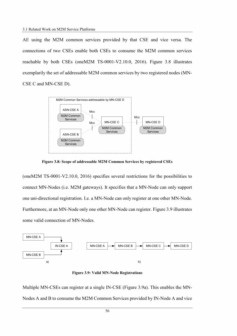
3.1 Related Work on M2M Service Platforms
56
AE using the M2M common services provided by that CSE and vice versa. The
connections of two CSEs enable both CSEs to consume the M2M common services
reachable by both CSEs (oneM2M TS-0001-V2.10.0, 2016). Figure 3.8 illustrates
exemplarily the set of addressable M2M common services by two registered nodes (MN-
CSE C and MN-CSE D).
Figure 3.8: Scope of addressable M2M Common Services by registered CSEs
(oneM2M TS-0001-V2.10.0, 2016) specifies several restrictions for the possibilities to
connect MN-Nodes (i.e. M2M gateways). It specifies that a MN-Node can only support
one uni-directional registration. I.e. a MN-Node can only register at one other MN-Node.
Furthermore, at an MN-Node only one other MN-Node can register. Figure 3.9 illustrates
some valid connection of MN-Nodes.
Figure 3.9: Valid MN-Node Registrations
Multiple MN-CSEs can register at a single IN-CSE (Figure 3.9a). This enables the MN-
Nodes A and B to consume the M2M Common Services provided by IN-Node A and vice
M2M Common Services addressable by MN-CSE D
ASN-CSE A
ASN-CSE B
M2M Common
Services
M2M Common
Services
MN-CSE C
M2M Common
Services
MN-CSE D
M2M Common
Services
Mcc
Mcc
Mcc
a)
IN-CSE A
MN-CSE A
MN-CSE B
MN-CSE A MN-CSE B MN-CSE C MN-CSE D
b)

3 Challenges, Requirements, and Use Cases of M2M Application Service Provision
57
versa. Figure 3.9b illustrates “a concatenation (registration chain) of multiple uni-
directional registrations” (oneM2M TS-0001-V2.10.0, 2016). Here each MN-Node has
maximum registered at one other MN-Node and has maximum one other MN-Node that
is registered to the MN-Node itself. According Figure 3.8 e.g. MN-CSE D can use the
M2M Common Services provided by MN-CSE A, MN-CSE B or MN-CSE C. Figure
3.10 illustrates some invalid connection of MN-Nodes as specified in (oneM2M TS-0001-
V2.10.0, 2016).
Figure 3.10: Invalid MN-Node Registrations
According to (oneM2M TS-0001-V2.10.0, 2016) a MN-CSE can only register at one
other MN-CSE. MN-CSE A therefore cannot register at two other MN-Nodes (Figure
3.10a). The connection of MN-Nodes by e.g. a registration chain (Figure 3.10b and d) are
not allowed to form a loop. Additionally, it is not possible to register more than one MN-
CSE at the same other MN-CSE (Figure 3.10c).
Especially the restrictions for connection of MNs to other entities in an M2M system
highlight why it is necessary to have an IN available in the architecture of an M2M system
specified by oneM2M.
a)
c)
MN-CSE A
MN-CSE C
MN-CSE A
MN-CSE B
MN-CSE B
MN-CSE C
b)
d)
MN-CSE A MN-CSE B MN-CSE C
MN-CSE A MN-CSE B
3.1 Related Work on M2M Service Platforms
58
For realisation of an M2M application service, integrating several M2M devices for
controlling and monitoring, following two approaches exist:
1. All integrated M2M devices are registered at a central IN inside the infrastructure
domain of the M2M SP (directly or using an M2M gateway as proxy, as illustrated
in Figure 3.6) and a centralised AE located at the IN or outside the IN coordinates
the application process (i.e. message exchange between M2M devices) or
2. the M2M application service logic is distributed to the MNs inside the field
domain, which are connected uni-directional by a registration chain as illustrated
in Figure 3.9b.
Realisation according the first approach requires the existence of a central network
element (IN), which is located in the infrastructure domain. This results in several
disadvantages, such as this central entity is a single point of failure, a complex centralised
infrastructure domain is required, and system user are dependent of a single M2M SP.
Realisation according the second approach in principle seems possible without necessity
of a central IN, but limits the flexibility of the M2M system because MNs are only
allowed to connect to one other MN. As a consequence other MNs cannot be connected
to the MN and therefore not use the functionality provided by a specific M2M Gateway
or devices connected to the M2M Gateway.
The following section describes the utilisation of M2M common services by different
nodes after successful registration of the nodes. According (oneM2M TS-0001-V2.10.0,
2016) the utilisation of M2M common services is based upon information exchange
between the provider and the consumer, respectively CSEs and AEs, via the defined

3 Challenges, Requirements, and Use Cases of M2M Application Service Provision
59
reference points. The information exchange is realised by request and response messages
as illustrated in Figure 3.11. Permission to reproduce Figure 3.11 has been granted by
ETSI.
Figure 3.11: Principle of Information Exchange between Entities acc. (oneM2M TS-0001-V2.10.0,
2016)
According to (oneM2M TS-0001-V2.10.0, 2016) and (oneM2M TR-0025-V1.0.0, 2016)
entities that are interested in a specific information provided by another entity, request
that information via a request message. The requested entity responses the requested
information via a response message to the requesting entity. This kind of communication
occurs between AEs and CSEs as well as between CSEs. Inside an M2M system,
everything is considered as a resource, identifiable uniquely by a URI and consumed or
provided by an entity. Controlling of a resource is done in the same way as requesting
information using CRUD (Create Retrieve Update Delete) operations.
The above-specified registrations of nodes are related to a single M2M SP domain and
the intra-domain interconnection of the nodes. This kind of interconnection therefore is
only realisable with existence of a central M2M SP that obtains an infrastructure domain.
Without a central M2M SP the realisation could only be possible if end-users appear in
the role of an M2M ASP hosting an individual IN. For addressing a resource located in
the domain of another M2M SP, it is required to interconnect the domains of both M2M
ReceiverOriginator
Request message
Response message
© 2016. oneM2M TSs and TRs are the property of ARIB, ATIS, CCSA, ETSI, TIA, TSDSI, TTA and TTC who jointly own the copyright in them. They are subject to further modifications and are therefore provided to you as is for information purposes only. Further use is strictly prohibited.
3.1 Related Work on M2M Service Platforms
60
SPs via their INs. The interconnection of the M2M SPs and the routing of messages is
realised including the public domains of the M2M SPs. Precondition is that the domains
of the SPs are reachable via a public DNS server and the IN registers the “public domain
names of the CSEs” at the DNS (oneM2M TS-0001-V2.10.0, 2016).
The disadvantage of this addressing mechanism is that the interconnection of domains is
only possible if INs and additionally registered public domains exist. Both are usually not
common in the application environment of end-users and demonstrate again that the scope
of the defined architecture for M2M systems is limited to the business application field
and not to that of end-user environments.
According to (oneM2M TS-0004-V-2014-08, 2014) the approach for request and control
resources contains an abstraction mechanism for information exchange between entities
and follows the RESTful architecture principles (Fielding, 2000; Bayer, 2002). The
message exchange occurs via Primitives specified in (oneM2M TS-0004-V-2014-08,
2014) that are messages exchanged in the service layer. Figure 3.12 illustrates this kind
of information transmission. Permission to reproduce Figure 3.12 has been granted by
ETSI.
For transport of the messages from one entity to another entity, the primitive is mapped
to application layer communication protocol such as HTTP (IETF RFC 2068, 1997),
CoAP (IETF RFC 7252, 2014), WebSocket Protocol (IETF RFC 6455, 2011) or MQTT
(OASIS mqtt-v3.1.1, 2014). Transport layer protocol (UDP/TCP) with underlying IP
network is used to transmit the messages between the entities. In case of information
exchange between a CSE and a NSE across the Mcn reference point appropriate Mcn
protocols are used. Through the abstraction of the communication inside the

3 Challenges, Requirements, and Use Cases of M2M Application Service Provision
61
application/service layer from communication in transport layer, the Primitives are
transport protocol independent.
Figure 3.12: Primitive Overview acc. (oneM2M TS-0004-V2.7.1, 2016)
Benefit of the oneM2M systems architecture is that the purpose of oneM2M is to share
infrastructure and network elements across multiple M2M applications. This is beneficial
with regards to the MSP because sharing infrastructure elements has various advantages,
such as reducing the costs for platform provision (e.g. for maintenance or operation) or
enable the application provider to focus on the business aspects of their applications
without regard of basic functionalities such as M2M device communication or
accounting. The concept of a central MSP has the advantage that communication among
Response RequestRequest Response
Primitive
Receiver
Binding Functions
Primitive
Originator
Binding Functions
IP-based underlying Network
Application/ Common Service Layer
Application Layer Communication Protocol (e.g.
HTTP, CoAP, MQTT)
Transport Layer Protocol
(UDP/ TCP)
Application Layer Communication Protocol (e.g.
HTTP, CoAP, MQTT)
Transport Layer Protocol
(UDP/ TCP)
© 2016. oneM2M TSs and TRs are the property of ARIB, ATIS, CCSA, ETSI, TIA, TSDSI, TTA and TTC who jointly own the copyright in them. They are subject to further modifications and are therefore provided to you as is for information purposes only. Further use is strictly prohibited.

3.1 Related Work on M2M Service Platforms
62
applications components, M2M devices as well as the structure of M2M application
services is unified. This enables the interoperability of different M2M application services
and M2M devices. Especially the protocol translation functionality of nodes to
interoperate between different M2M protocols, support the integration of multiple M2M
devices in different M2M applications.
Next to the advantages presented above, the MSP architecture of oneM2M contains
several disadvantages presented in the following. First disadvantage is that oneM2M
focuses on the interoperation of industries and businesses and the support of complex
business processes but not the integration of end-user environment or application
provision by end-users. OneM2M does not specify the M2M Application Architecture
and limits its specifications to the MSP architecture. Despite the advantages of a common
service layer regarding the shared functionalities, this platform needs a complex setup of
the environment with additional network elements (physical or virtual servers) and end-
to-end communication technologies. It does not reuse commonly existing communication
technologies and network elements for realisation of the MSP. The M2M ASP are
dependent of a single MSP provider. Furthermore, the M2M application service itself is
designed and realised by a central M2M ASP. Through this, the consumer of an M2M
application service is dependent of the M2M ASP. The M2M system as defined by
oneM2M includes the IN as a single centralised element in an oneM2M system
architecture. The IN is e.g. required for M2M application provision and interconnection
of different M2M SP domains. Required central elements in an architecture usually have
negative aspects because realisation of continuous availability and maintenance result in
large costs for the provider. Furthermore, all other participants in the M2M system are
dependent of the central IN. By considering the OM2M project (Monteil and Alaya, 2014;

3 Challenges, Requirements, and Use Cases of M2M Application Service Provision
63
OM2M, 2016), a specific implementation of the oneM2M architecture, it becomes clear
that not only the design and operation of an oneM2M system requires expert knowledge,
but also creating an application. Because the required expert knowledge development of
oneM2M compliant applications and the provision in a corresponding oneM2M
architecture is not feasible by end-users.
3.1.2 INOX Managed Service Platform
The INOX Managed Service Platform (Clayman and Galis, 2011) specifies “a M2M
service architecture” (Kim et al., 2014). The INOX platform has been designed to avoid
silo applications that coexist next to each other providing monitoring/control functionality
using sensors and smart objects. According to (Amaral et al., 2015) INOX is a platform
that provides a “M2M service architecture for IoT” including functionality to register and
discover things as well as object virtualisation and capabilities for orchestration to control
and manage services.
The purpose of the INOX architecture and infrastructure is to integrate the smart
objects/things with the “common services and management architectural model”
(Clayman and Galis, 2011). INOX provides a framework to combine the smart objects
“for higher-level processing” (Clayman and Galis, 2011). The INOX platform focusses
intensively on the service approach and combination of different sensor networks inside
the platform (Savaglio and Fortino, 2015).
According to (Clayman and Galis, 2011) and (Savaglio and Fortino, 2015) the INOX
Platform contains the following three layers. Figure 3.13 displays these layers including
the platform components contained in them.

3.1 Related Work on M2M Service Platforms
64
Service Layer – The Service Layer contains the Services and Applications
connecting through Service APIs to elements in Platform Layer.
Platform Layer – The Platform Layer provides the functionality for management
and orchestration to deploy Services and Applications as well as virtualises the
Servers, Smart Objects and Things located in the Hardware Layer.
Hardware Layer – The physical devices (e.g. sensors and servers) and devices
(routers) providing networking functionality over the internet via IP-based
communication protocols are located in the Hardware Layer. The functionality
for hosting services and virtual machines is also provided by the servers in the
Hardware Layer.
Figure 3.13: INOX Managed Service Platform acc. (Clayman and Galis, 2011)
Figure 3.13 has been removed due to Copyright restrictions.
3 Challenges, Requirements, and Use Cases of M2M Application Service Provision
65
The physical devices are located in the same local environments or distributed across
different locations. An application provided by the INOX platform should be able to use
every device or service provided by the devices. According to (Clayman and Galis, 2011)
it does not matter if the devices that are used and managed by services are located in
different domains because INOX platform provides capabilities to connect them.
Derived from (Clayman and Galis, 2011) the Platform Layer forms the service platform
middleware and contains the main functional elements of the INOX platform. According
to (Clayman and Galis, 2011) this middleware contains a Resource Virtualization Overlay
representing all resources of the Hardware Layer as virtual resources and links both,
virtual and physical resources. The virtualisation overlay provides APIs for manipulation
of resources abstracted from the real resources (virtual resources) or physical resources
(without virtualisation). The abstraction of the devices isolates the devices in the
Hardware Layer and enables upper layers (services, end-user application) using devices
without considering implementation specific device interfaces.
The Management and Orchestration Functions element in the Platform Layer can be
specified as a kind of resource scheduler which is according to (Clayman and Galis, 2011)
responsible to allocate portions of virtual resources to given tasks. It provides capabilities
for controlling and management of services located in various domains.
The Common Protocols/Communication API/Resource Access API element in the INOX
platform provides the physical interfaces to the devices in Hardware Layer. This element
contains the communication protocol stacks to interact with the specific devices
(Clayman and Galis, 2011).
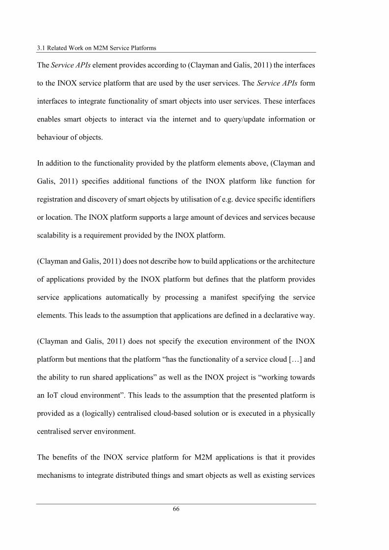
3.1 Related Work on M2M Service Platforms
66
The Service APIs element provides according to (Clayman and Galis, 2011) the interfaces
to the INOX service platform that are used by the user services. The Service APIs form
interfaces to integrate functionality of smart objects into user services. These interfaces
enables smart objects to interact via the internet and to query/update information or
behaviour of objects.
In addition to the functionality provided by the platform elements above, (Clayman and
Galis, 2011) specifies additional functions of the INOX platform like function for
registration and discovery of smart objects by utilisation of e.g. device specific identifiers
or location. The INOX platform supports a large amount of devices and services because
scalability is a requirement provided by the INOX platform.
(Clayman and Galis, 2011) does not describe how to build applications or the architecture
of applications provided by the INOX platform but defines that the platform provides
service applications automatically by processing a manifest specifying the service
elements. This leads to the assumption that applications are defined in a declarative way.
(Clayman and Galis, 2011) does not specify the execution environment of the INOX
platform but mentions that the platform “has the functionality of a service cloud […] and
the ability to run shared applications” as well as the INOX project is “working towards
an IoT cloud environment”. This leads to the assumption that the presented platform is
provided as a (logically) centralised cloud-based solution or is executed in a physically
centralised server environment.
The benefits of the INOX service platform for M2M applications is that it provides
mechanisms to integrate distributed things and smart objects as well as existing services
3 Challenges, Requirements, and Use Cases of M2M Application Service Provision
67
into complex applications. The presented approach of the architecture enables avoiding
previous existing implementations of applications that are statically bound to the
corresponding smart objects (silo-applications). According to (Clayman and Galis, 2011)
previously applications have been realised that were statically connected to the sensors
or smart objects. The approach presented in the INOX project defines a dynamic
architecture that enables sharing of resources between different applications (Clayman
and Galis, 2011). The mechanism integrated in the INOX platform for device lookup
enables the applications to address (search and discover) the devices without regard of
the specific device location or contact address. Providing a service-based infrastructure
enables a unified mechanism for integration and combination of M2M devices as well as
other resources located in the Internet into applications based on common service
principles. The introduced virtualisation layer enables the communication between
devices and applications independent of the applied communication protocol and realises
the inter-networking of different M2M protocols and networks (Clayman and Galis,
2011). The seamless integration of different M2M device technologies enlarges the
flexibility of services and applications because the higher number of usable devices. The
abstraction of the devices from the implementing M2M technology enables the use of the
devices without considering implementation specific technologies and permit focussing
on core application aspects instead of technology aspects for realisation. Device
abstraction additionally enables the portability of services and application regardless of
the M2M technology of the integrated devices. The declarative way to describe
applications instead of statically and execution system specific implementation of
application logic supports the independence of application logic from the execution

3.1 Related Work on M2M Service Platforms
68
environment and enables to move applications from one execution system to a different
one without adapting the application logic description.
Besides the advantages of INOX platform, the presented approach also contains several
disadvantages. As the INOX architecture forms a cloud-based centralised integration
platform of smart objects and because the functionality provided by the platform layer for
orchestration to deploy services and application, the user of the platform (SC) is
dependent of both, the central platform provider (for application development and
platform operation) and the central platform components (for service and application
execution). Centralised platform infrastructures require many resources for service
provision (operating costs for hardware and availability as well as service maintenance
or costs for service development). The large costs for operating the platform are
transferred to the consumer, which in turn enlarges the costs for service utilisation.
Additionally, central infrastructures for storing and calculating data by a single entity
always is critical regarding data safety and end-users privacy. (Clayman and Galis, 2011)
mentions end-user applications which can be considered as applications that are
consumed by end-users and not provided by end-users. It can therefore be concluded that
the end-user is no active stakeholder in the context of application creation and also not
able to provide service based on end-users individual personal environment. Therefore
end-users also cannot cooperate with each other to combine their local M2M resources
and provide their functionality as a cooperative M2M service.

3 Challenges, Requirements, and Use Cases of M2M Application Service Provision
69
3.1.3 M2M Platform Project based on SOA (M2M on SOA)
(Zhang et al., 2010) presents an M2M platform for bridging business applications and
M2M devices using Java 2 Enterprise Edition (J2EE) framework and service oriented
architecture (SOA) concept (Kim et al., 2014). The proposed M2M platform aims to
integrate business applications and M2M devices using Web Service (WS) technology,
which is able to reduce dependencies of system parts and can react on changes in short
terms (Kim et al., 2014; Zhang et al., 2010).
(Zhang et al., 2010) identifies as deficit of traditional M2M solutions (illustrated in Figure
3.14a) that several M2M devices are connected to “different business applications” and
the necessary interfaces are implemented multiple times providing the same functionality.
According to (Zhang et al., 2010) in that architectural approach, all devices are connected
to the applications that integrate the devices. The interfaces to the devices are created
newly for each connection and are rarely reused.
Figure 3.14: M2M Network Topologies (traditional and proposed) acc. (Zhang et al., 2010)
Therefore (Zhang et al., 2010) proposes a platform architecture that has a larger
reusability of interfaces. For this they proposes that a “bridge platform” is used as M2M
Machines Machines
Business Applications Business Applications
b) Proposed M2M Network Topologya) Traditional M2M Network Topology
M2M Platform
...
...
...
...
© 2010 IEEE © 2010 IEEE

3.1 Related Work on M2M Service Platforms
70
platform (illustrated in Figure 3.14b) that connects applications and devices in “star-
topology”. (Zhang et al., 2010) proposes an M2M platform as service-oriented and
distributed system that has a loosely-coupled and multi-layer architecture.
For integration of the M2M Platform with the devices and business applications (Zhang
et al., 2010) proposes a SOA (OASIS SOA-RM-V1.0, 2006) implementation based on
WS and a Message Broker because it enables realisation of applications as encapsulated
services that are accessible via the internet. The participants in such a system structure
includes SP deploying and maintaining services, service broker responsible for
registration and location of services, and service requestor consuming services (Zhang et
al., 2010).
(Zhang et al., 2010) separates an M2M system in four parts: M2M platform, devices,
business applications, and access devices. Figure 3.15 illustrates the parts of the platform
as well as the internal components.
Figure 3.15: M2M Platform Architecture acc. (Zhang et al., 2010)
M2M Devices
M2M PlatformAccess Devices
Business
Applications
Gateway
Module
Gateway
Module
...
Others
DB
Data
Operate
User Interface
Business
Process
Service Broker
Gateway
Other Devices
Cash
Point
Calculator
Surveillance
Cam
TV
Mobile
Phone
PC
© 2010 IEEE
3 Challenges, Requirements, and Use Cases of M2M Application Service Provision
71
In the proposed architecture all parts of the M2M system are separated from each other
(i.e. are executed on separated locations). The M2M devices (e.g. surveillance cameras
or TVs) are connected to the M2M platform via M2M gateways. The gateways are located
at the place where the M2M devices reside. The M2M gateways connect to the M2M
platform via gateway module components of the M2M platform. Business applications
and user interface hardware are also located outside of the M2M platform.
According to (Zhang et al., 2010) the user utilises an end-device (e.g. PC or mobile phone)
to access the business application by sending a request to the M2M platform (or directly
to the business application). The operation request is analysed by the application system,
which connects to the Webservice provided by M2M platform. The M2M platform
afterwards requests the WS that the M2M gateway provides to trigger operation at the
device or request information from it.
As mentioned above, the M2M system proposed by (Zhang et al., 2010) is focused on
services, especially WS. All parts of the M2M system are connected via WS. The service
broker element of the M2M platform provides message routing functionality as well as
functionality for transformation of message format to exchange information between the
WS provided by the system elements (Zhang et al., 2010).
The M2M platform provides the core functionality of the M2M system including a User
Interface for interaction with users (e.g. to display users’ information data). It also
includes internal elements for management of e.g. users, application or M2M devices as
well as functionality for sms/email notification and provides functionality for several
business needs (e.g. payment functionality). For internal data storage and operation, the
M2M platform includes a database system (Zhang et al., 2010).
3.1 Related Work on M2M Service Platforms
72
The architecture of an M2M system as presented by (Zhang et al., 2010) has the following
advantages. The bridge functionality of the platform reduces the dependence of business
applications and M2M devices. Additionally, the SOA-based approach provides the
benefit that the (physical) dependence of applications, application users, the M2M
platform as well as the M2M devices is reduced. The SOA principles as well as the
included asynchronous service/message broker makes the applications and the other
components of the M2M system loosely coupled which enables the M2M system to
quickly response to change request in the runtime system (Zhang et al., 2010). The
presented approach includes the abstraction of communication between device specific
technologies and the platform internal system and application components. This enables
to realise applications without consideration of the specific details of different M2M
device technologies. The M2M system of (Zhang et al., 2010) provides a graphical
interface for the end-user, which enables the user to interact with the M2M system using
commonly available hardware. Additionally, provision of commonly available
communication functionality using email and SMS notification functionality support the
information exchange with the user.
Besides the advantages presented above, the approach of (Zhang et al., 2010) contains
several drawbacks. It focuses exclusively on business applications, which are according
to (ITIL V3.1.24, 2007) and (ISO IEC 20000-1:2011, 2013) provided by single
centralised providers. (Zhang et al., 2010) proposes specifically the realisation of an M2M
system with a single encapsulated M2M platform in the focus that is located in the public
network. This creates a dependency of the platform provider as well as limits the
extension of platform functionality, which requires detailed knowledge about and access
to the M2M platform. The approach considers the end-user as a simple user of the M2M

3 Challenges, Requirements, and Use Cases of M2M Application Service Provision
73
system but does not integrate the end-user in the application design. Implementation of
business applications using the frameworks Struts (Apache Struts, 2017), Spring (Spring,
2017), Hibernate (Hibernate, 2017) as proposed by (Zhang et al., 2010) as well as design
principles of SOA requires expert knowledge to design and implement M2M services or
applications. This especially would make the integration of end-users into application
development impossible.
3.1.4 BOSP Business Operation Support Platform
(Xiaocong and Jidong, 2010) presents an architecture of “a business operation support
platform for M2M” (Kim et al., 2014). The presented business operation support platform
(BOSP) focuses on the support of carriers (Kim et al., 2014; Xiaocong and Jidong, 2010).
(Xiaocong and Jidong, 2010) proposes that carriers operate a BOSP according to
architecture presented subsequently. Smart devices provide functionalities (e.g. video,
phone or sound recording) that can be used by carriers to provide “precise services”.
Additionally (Xiaocong and Jidong, 2010) proposes that carriers provide their abilities
like voice and data communication for external usage. Furthermore, the carriers have
large potential for creating “new abilities by processing the data” that they store, analyse
and integrate from various industries.
The proposed M2M architecture of (Xiaocong and Jidong, 2010), illustrated in Figure
3.16 contains four layer. The Perception Layer contains the various sensor networks,
M2M terminals or other equipment like mobile phones, and provides the functionality for
collecting object information. These devices are connected via gateways to the access
networks and the internet, which both reside in Transportation Layer. M2M applications

3.1 Related Work on M2M Service Platforms
74
reside in the Application Layer and are provided by external ASP that use the
functionalities/data information provided by the carrier. The defined BOSP resides inside
the operation supporting layer (Xiaocong and Jidong, 2010).
Figure 3.16: M2M System Architecture acc. (Xiaocong and Jidong, 2010)
The BOSP according to (Xiaocong and Jidong, 2010) is separated in three layers:
Access Layer – The Access Layer provides protocol adaptation and access control
functions. It translates messages, which are sent to the BOSP in proprietary
protocols into standard protocols for internal processing and vice versa.
Device Management Layer – The Device Management Layer manages the devices
deployed by the carrier and offers a management portal for monitor/control/check
Application LayerTraffic Industry AgricultureCity
ManagementHealth
Operation Supporting Layer
Transportation Layer
Internet
Access Network Access Network
Perception Layer
Mobile
Phones
M2M
TerminalsSensor Networks
Gateway Gateway Gateway
Data
Existing
Abilities:
Voice,
Video,
SMS,
MMS,
etc.
BSS/ OSS
ES
B
CRM
NMS
Billing
BOSP
Ability Formation Layer
Device Management Layer
Access Layer
© 2010 IEEE

3 Challenges, Requirements, and Use Cases of M2M Application Service Provision
75
devices or performing software updates. The Management portal forms the
interface to device vendor for device status feedback, carrier staff for status
monitoring and control of “operating services and associated devices”, and
administrator for device monitoring and account supervision.
Ability Formation Layer – The Ability Formation Layer provides communication
functionalities like voice/video or data transportation and messaging (SMS,
MMS). Additionally, it provides information of devices like geographical
position, temperature, movement, energy consumption.
The BOSP according to (Xiaocong and Jidong, 2010) contains four interfaces for access.
The Data Interface receiving IP packets via heterogeneous networks (e.g. NGN),
Application Interface forwarding the data to the applications, Existing Abilities Interface
used for communication with the BOSP to provide the abilities of carriers’ network to the
applications using Application Interface. The Existing BSS/OSS Interface can connect
various systems already operated by the carrier like customer relationship management
system (CRM), billing system, network management system (NMS) via the Enterprise
Service Bus (ESB) of the carrier (Xiaocong and Jidong, 2010).
The architecture of an M2M system according to (Xiaocong and Jidong, 2010) with a
dedicated BOSP provided and operated by the carrier has various advantages. Especially
the provision of carriers’ abilities like Voice over IP (VoIP) communication and
messaging functionality via mobile networks is advantageous to form an interface to
M2M system users. Integration of VoIP communication and messaging functionality in
M2M systems offers the benefit that it can be applied for communication with end-user
using commonly existing hardware like PC, Smart Phone or fixed telephone that all

3.1 Related Work on M2M Service Platforms
76
usually exist in end-users environment. Additionally, the functionality of device/protocol
abstraction integrated in the BOSP according to (Xiaocong and Jidong, 2010) enlarges
the flexibility for connecting various M2M communication technologies to the platform
without consideration of technology specific aspects in application provision.
Next to the advantages presented above, (Xiaocong and Jidong, 2010) contains several
disadvantages. First disadvantage is that it focusses only on carriers. It does not consider
the integration of the end-user in system or application design. (Xiaocong and Jidong,
2010) announces benefits by using its proposed BOSP for industries like “government,
agriculture, military, manufacturing business, construction business” to make them more
intelligent, but does not promise advantages for the end-user. The end-user interfaces of
the applications have to be provided by the M2M ASP, which can use the application
interfaces of BOSP to integrate the abilities of the M2M devices and communication
functionality. According to (Xiaocong and Jidong, 2010) “carriers are abundant with
information of things because they monopolize perception devices and communication
tunnels”. This in turn is a big disadvantage because the ASP as well as the end-user are
dependent of a single monopolist. Additionally storing and calculating data by a single
entity always is critical regarding data safety and end-users privacy. The threatening “Big-
Brother effect” becomes clear by looking at the provider's goals presented in (Xiaocong
and Jidong, 2010). According to (Xiaocong and Jidong, 2010) the smart devices and the
travellers can be identified. For example by the “abilities offered by carriers, readers in
the doors of the trains and busses will enable an accurate tracking of every connection
and route of every traveller”. Applying standard protocols for M2M technology
abstraction is advantageous because it supports the interoperability and independence of
3 Challenges, Requirements, and Use Cases of M2M Application Service Provision
77
applications, but (Xiaocong and Jidong, 2010) does not give hints regarding the
applied/standardised protocols of BOSP.
3.1.5 IMS enabled M2M Service Platform (IMS M2M SP I)
(Foschini et al., 2011) presents the architecture of an M2M system based on IP
Multimedia Subsystem (IMS) technologies (Magedanz and de Gouveia, 2006; Poikselkä
and Mayer, 2009). The authors present its work with the help of a case study for
realisation of a retractable bollard management system (Kim et al., 2014; Foschini et al.,
2011). The presentation of the case study as well as the system elements explanation has
been used to derive the architecture of an M2M system according to the principles of
(Foschini et al., 2011).
The M2M system introduced by (Foschini et al., 2011) is based on seamless integration
of M2M devices (i.e. M2M area network) into the IMS of a specific provider. In
particular, (Foschini et al., 2011) proposes to reuse existing network technologies and the
services provided by the access network provider or other possibly existing wireless
network infrastructures (e.g. Wi-Fi) for the development and provision of M2M
application services (Foschini et al., 2011).
The M2M system specified by (Foschini et al., 2011), illustrated in Figure 3.17, is a
distributed architecture and separated into three domains: M2M Device Domain, Network
Domain, and Application Domain. The M2M devices reside in the M2M Device Domain.
The Network Domain represents the access network infrastructure and consists of IMS
components as specified in (Trick and Weber, 2015). These components are used to

3.1 Related Work on M2M Service Platforms
78
realise the communication of M2M devices with the M2M servers that are located in the
Application Domain (Foschini et al., 2011).
Figure 3.17: IMS-enabled M2M System Architecture acc. (Foschini et al., 2011)
The core component of the M2M system is according to (Foschini et al., 2011) the M2M
server, residing in the Application Domain. The M2M server interacts with M2M devices
and other elements/systems required for application service provision (authorisation,
authentication, accounting server storing information required for system usage or
application server for M2M application execution) via the IMS. A dedicated application
server of the M2M SP executes the M2M application.
Application DomainHTTP
Network Domain
Internet/ IP Network
M2M Device Domain
SGSN
IMS
P-/I-/S-CSCF
IMS
PS
IMS
P-/I-/S-CSCF
SGSNGGSN
HSSIMS/M2M
profiles
AAA Server
AAA
Data
Application Provider AS 1
Managed
Objects
E-Mail WS
Application 1
Web UI SMS
SQL
M2M Server
IMS AS
Web Services
Device Control
Components
SIP Diameter
Diameter
Diameter
SQL
M2M Device
IMS Client
Device
Data
Device
Functions
Device
Hardware
SIPSIP
Mobile Operator
Network
© 2011 IEEE

3 Challenges, Requirements, and Use Cases of M2M Application Service Provision
79
The application server element communicates with the M2M server via “RESTful
interactions” that are controlled by the WS element in the AS. Additionally, the
application server element provides possibilities for communication (notification of
application user) via SMS or email adopting the communication services of the IMS
(Foschini et al., 2011).
The coordination of information exchange between M2M server and M2M devices via
IMS using SIP messages as well as adopting IMS services (e.g. for sending SMS) is
coordinated by the IMS AS element of the M2M server. The information exchange
between M2M server and M2M devices is based on the Publish/Notify Principle (IETF
RFC 3903, 2004). For realisation of information exchange both, M2M server and M2M
devices subscribe for the presence status of each other at the IMS presence server (IMS
PS). For sending a specific information from M2M device to M2M server and vice versa,
they publish this information to the IMS PS. The IMS PS notifies M2M server or M2M
device about that information by sending a notify message (Foschini et al., 2011).
For realisation of device specific functionality in the M2M devices, the M2M devices
contain corresponding function elements. To persist information in the M2M device, it
contains an element for data storage. Next to the device specific functions an M2M device
requires a component to realise the communication functionality via IMS. For this the
M2M devices host an IMS client (Foschini et al., 2011).
The M2M application user (end-user) can interact with the M2M application service via
“a web-based user interface” (Web UI element), provided by the AS of the application
provider, to monitor the status of the M2M application or M2M devices (Foschini et al.,

3.1 Related Work on M2M Service Platforms
80
2011). The presented case study does not consider controlling the devices but it can be
assumed, that the same user interface is used for device controlling.
The architecture of an M2M system as presented by (Foschini et al., 2011) has the
following advantages. The presented approach utilises already deployed communication
technologies and networks (IMS) for realisation of an M2M system (Foschini et al.,
2011). Reusing existing network technologies and communication services benefits in
that no extra communication networks need to be established. Reusing existing
communication system avoids additional costs for establishing a communication network.
Additionally the M2M system provider can focus on its competence related to M2M and
application service provision without providing and maintaining the communication
network it requires.
Besides the advantages presented above, the approach of (Foschini et al., 2011) contains
the following drawbacks. A single central provider provides M2M server and other
system components required for realisation of an M2M application (application provider
AS and AAA server, see Figure 3.17) as well as M2M application itself. According the
presented approach, the end-user not only is dependent of the M2M system provider, but
also is dependent of the IMS provider whose network elements are seamless integrated
in the M2M system. Particularly the presented approach requires that the M2M ASP have
technical access to the network elements of IMS provider (e.g. HSS). This is a rather
unrealistic scenario, unless the IMS provider itself is the M2M ASP. Furthermore, the
presented approach envisages that network elements of the IMS provider can be used
(IMS PS for Information exchange). Although the utilisation of the IMS is beneficial for
message transport, it can be assumed that functionality of the network elements itself is

3 Challenges, Requirements, and Use Cases of M2M Application Service Provision
81
unavailable for external SP. The presented approach again does not consider the end-user
as M2M ASP.
3.1.6 M2M horizontal Services Platform Implementation over IP
Multimedia Subsystem (IMS M2M SP II)
(Padilla et al., 2013) introduces a horizontal MSP (illustrated in Figure 3.18) applying IP
Multimedia Subsystem (IMS) network elements (Magedanz and de Gouveia, 2006;
Poikselkä and Mayer, 2009). The aim of the presented research project according to
(Padilla et al., 2013) is to connect M2M devices and M2M application server (AS)
through the IMS core network to develop a horizontal MSP. The reason of (Padilla et al.,
2013) to propose using the IMS is because its independency from the access network.
Figure 3.18: M2M horizontal Service Platform acc. (Padilla et al., 2013)
Application Domain
Webserver M2M DB M2M AS
GUI
ShISC
P-CSCF
Network Domain
HSS
Mw Mw
Mw
Cx
Cx
I-CSCF
S-CSCF
M2M Domain
M2M GW
© 2013 IEEE
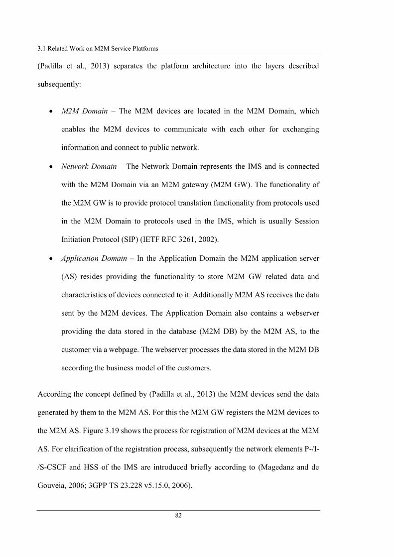
3.1 Related Work on M2M Service Platforms
82
(Padilla et al., 2013) separates the platform architecture into the layers described
subsequently:
M2M Domain – The M2M devices are located in the M2M Domain, which
enables the M2M devices to communicate with each other for exchanging
information and connect to public network.
Network Domain – The Network Domain represents the IMS and is connected
with the M2M Domain via an M2M gateway (M2M GW). The functionality of
the M2M GW is to provide protocol translation functionality from protocols used
in the M2M Domain to protocols used in the IMS, which is usually Session
Initiation Protocol (SIP) (IETF RFC 3261, 2002).
Application Domain – In the Application Domain the M2M application server
(AS) resides providing the functionality to store M2M GW related data and
characteristics of devices connected to it. Additionally M2M AS receives the data
sent by the M2M devices. The Application Domain also contains a webserver
providing the data stored in the database (M2M DB) by the M2M AS, to the
customer via a webpage. The webserver processes the data stored in the M2M DB
according the business model of the customers.
According the concept defined by (Padilla et al., 2013) the M2M devices send the data
generated by them to the M2M AS. For this the M2M GW registers the M2M devices to
the M2M AS. Figure 3.19 shows the process for registration of M2M devices at the M2M
AS. For clarification of the registration process, subsequently the network elements P-/I-
/S-CSCF and HSS of the IMS are introduced briefly according to (Magedanz and de
Gouveia, 2006; 3GPP TS 23.228 v5.15.0, 2006).
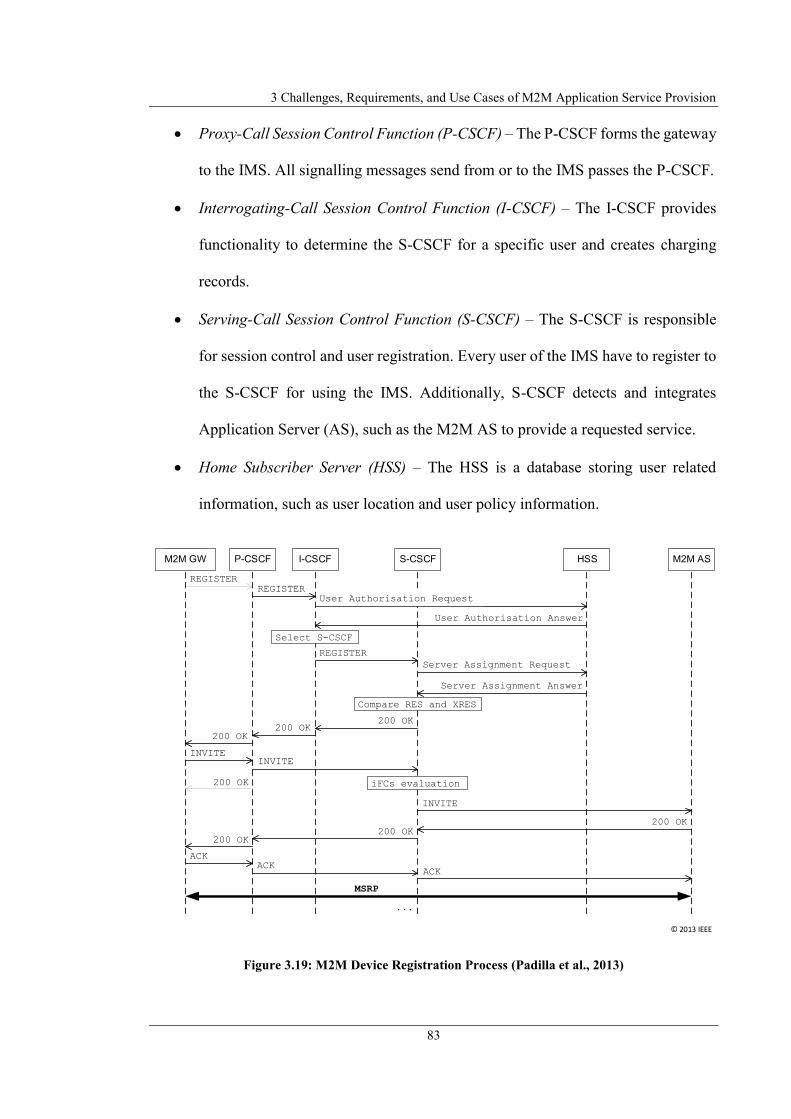
3 Challenges, Requirements, and Use Cases of M2M Application Service Provision
83
Proxy-Call Session Control Function (P-CSCF) – The P-CSCF forms the gateway
to the IMS. All signalling messages send from or to the IMS passes the P-CSCF.
Interrogating-Call Session Control Function (I-CSCF) – The I-CSCF provides
functionality to determine the S-CSCF for a specific user and creates charging
records.
Serving-Call Session Control Function (S-CSCF) – The S-CSCF is responsible
for session control and user registration. Every user of the IMS have to register to
the S-CSCF for using the IMS. Additionally, S-CSCF detects and integrates
Application Server (AS), such as the M2M AS to provide a requested service.
Home Subscriber Server (HSS) – The HSS is a database storing user related
information, such as user location and user policy information.
Figure 3.19: M2M Device Registration Process (Padilla et al., 2013)
REGISTER
M2M ASHSSS-CSCFI-CSCFP-CSCFM2M GW
200 OK
REGISTERUser Authorisation Request
User Authorisation Answer
Select S-CSCF
REGISTER
Server Assignment Request
Server Assignment Answer
Compare RES and XRES
200 OK200 OK
200 OK
INVITEINVITE
iFCs evaluation
INVITE
200 OK200 OK
200 OK
ACKACK
ACK
MSRP
...
© 2013 IEEE

3.1 Related Work on M2M Service Platforms
84
Initially the M2M GW registers itself at the network domain. For doing this the M2M
GW sends a register request to the P-CSCF using SIP REGISTER method (IETF RFC
3261, 2002). The P-CSCF forwards the request to the I-CSCF. The I-CSCF requests the
corresponding S-CSCF for the specific M2M GW at the HSS. After receiving the
response of the HSS, the I-CSCF forwards the register request to the S-CSCF specified
in the response of the HSS After successful registration of the M2M GW at the Network
Domain the M2M GW establishes a session with the M2M AS. The session establishment
is done by sending a SIP INVITE (IETF RFC 3261, 2002) message to the M2M AS. This
SIP INVITE message contains a Session Description Protocol (SDP) message (IETF RFC
4566, 2006) that specifies to use Message Session Relay Protocol (MSRP) (IETF RFC
4975, 2007) for information exchange between M2M AS and M2M GW, respectively the
M2M devices (Padilla et al., 2013).
It can be derived from (Padilla et al., 2013) that after initial session establishment the
M2M GW requests a list of M2M devices from the M2M AS that are connected to the
M2M GW and which should send its information data to the M2M AS. M2M GW and
M2M AS exchange this information via MSRP messages. After receiving the list of M2M
devices, the M2M GW establishes a MSRP session between each of the M2M devices
and the AS. For this, the M2M GW sends a SIP re-INVITE request (IETF RFC 3261,
2002) and (IETF RFC 6141, 2011) to the M2M AS including SDP with specification of
the MSRP URIs of the specific M2M devices. This MSRP URIs include the device-
specific session-IDs which enables both, M2M GW and M2M AS to assign the MSRP
messages to the M2M devices within the same SIP session. After linking the M2M
devices to the M2M AS, the M2M devices start to transmit their information data to the

3 Challenges, Requirements, and Use Cases of M2M Application Service Provision
85
M2M AS which can be monitored by the user via the GUI provided by the webserver
(Padilla et al., 2013).
The architecture of an M2M system as presented by (Padilla et al., 2013) has the following
advantages. The presented approach enables the integration of the M2M devices located
in end-user environments and is based on the IMS. This is advantageous because existing
communication network infrastructure and protocols are utilised to exchange information
between the M2M devices and the MSP. This enables the IMS provider to seamless
integrate M2M systems in its infrastructure and provide the data generated by the M2M
devices as a service to the user. Reusing existing communication network technologies
benefits in that no extra communication networks need to be established which results in
avoiding additional costs for operation and maintenance.
Besides the advantages, the approach of (Padilla et al., 2013) has several drawbacks as
described in the following. The approach only specifies that the M2M GW translates
between protocols in M2M Domain and those in Network Domain but does not specify
the protocol translation between protocols inside the M2M Domain. Interoperability of
M2M device technologies is required to integrate those devices in the M2M platform and
to use their functionality in the M2M services. The architecture of (Padilla et al., 2013)
contains several centralised system entities in the Application Domain and in the Network
Domain (e.g. the M2M AS). The MSP is dependent of these central entities, which limits
the scalability as well as availability of the MSP. Additionally because a central IMS
provider is integrated, the user of the MSP is dependent of this provider. Additionally,
the data storage and processing according customers’ business model is done by the web
server as a centralised element in platform architecture, which might by critical for the

3.1 Related Work on M2M Service Platforms
86
end-user data security and privacy aspects. The functionality of the MSP as introduced
by (Padilla et al., 2013) is limited to monitoring the data, produced by the M2M devices.
The authors do not describe additional functionalities, such as control of the M2M devices
or realisation of control applications.
3.1.7 e-DSON
(Kim et al., 2012) introduced the enhanced Dynamic Service Overlay Network (e-DSON)
platform project that has its focus on distributed service provision. (Kim et al., 2014)
identified the e-DSON platform as “a distributed M2M service platform architecture
using a service overlay network”.
According to (Kim et al., 2012) service overlay networks are used to create “a logical
topology on a physical network” to provide adaptable services and applications. In a
service overlay network, the features of a service are programmable because the service
overlay network is located at application level. The overlay consist of distributed nodes,
each providing controllable services and data delivery. A SP can link the nodes to
compose an individual service.
According to (Kim et al., 2012) the e-DSON platform is based on the DSON platform
introduced in (Kim et al., 2009), (Kim et al., 2010), and (Kim et al., 2011). The DSON
platform is according to (Kim et al., 2012) a “service overlay network framework” that is
based on management of service information and the control of service entities, to realise
the desired application logic. The DSON platform provides the functionality to compose
user-centric distributed multimedia services. Figure 3.21 shows an exemplary scenario of
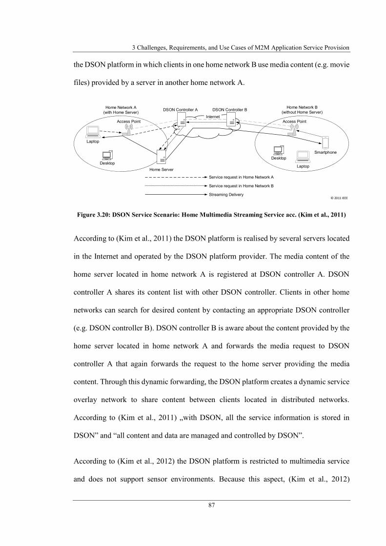
3 Challenges, Requirements, and Use Cases of M2M Application Service Provision
87
the DSON platform in which clients in one home network B use media content (e.g. movie
files) provided by a server in another home network A.
Figure 3.20: DSON Service Scenario: Home Multimedia Streaming Service acc. (Kim et al., 2011)
According to (Kim et al., 2011) the DSON platform is realised by several servers located
in the Internet and operated by the DSON platform provider. The media content of the
home server located in home network A is registered at DSON controller A. DSON
controller A shares its content list with other DSON controller. Clients in other home
networks can search for desired content by contacting an appropriate DSON controller
(e.g. DSON controller B). DSON controller B is aware about the content provided by the
home server located in home network A and forwards the media request to DSON
controller A that again forwards the request to the home server providing the media
content. Through this dynamic forwarding, the DSON platform creates a dynamic service
overlay network to share content between clients located in distributed networks.
According to (Kim et al., 2011) „with DSON, all the service information is stored in
DSON” and “all content and data are managed and controlled by DSON”.
According to (Kim et al., 2012) the DSON platform is restricted to multimedia service
and does not support sensor environments. Because this aspect, (Kim et al., 2012)
Laptop
InternetAccess Point
Desktop
Service request in Home Network A
Service request in Home Network B
Streaming Delivery
DSON Controller A DSON Controller BHome Network B
(without Home Server)
Laptop
Access Point
Desktop
Home Network A
(with Home Server)
Home Server
Smartphone
© 2011 IEEE
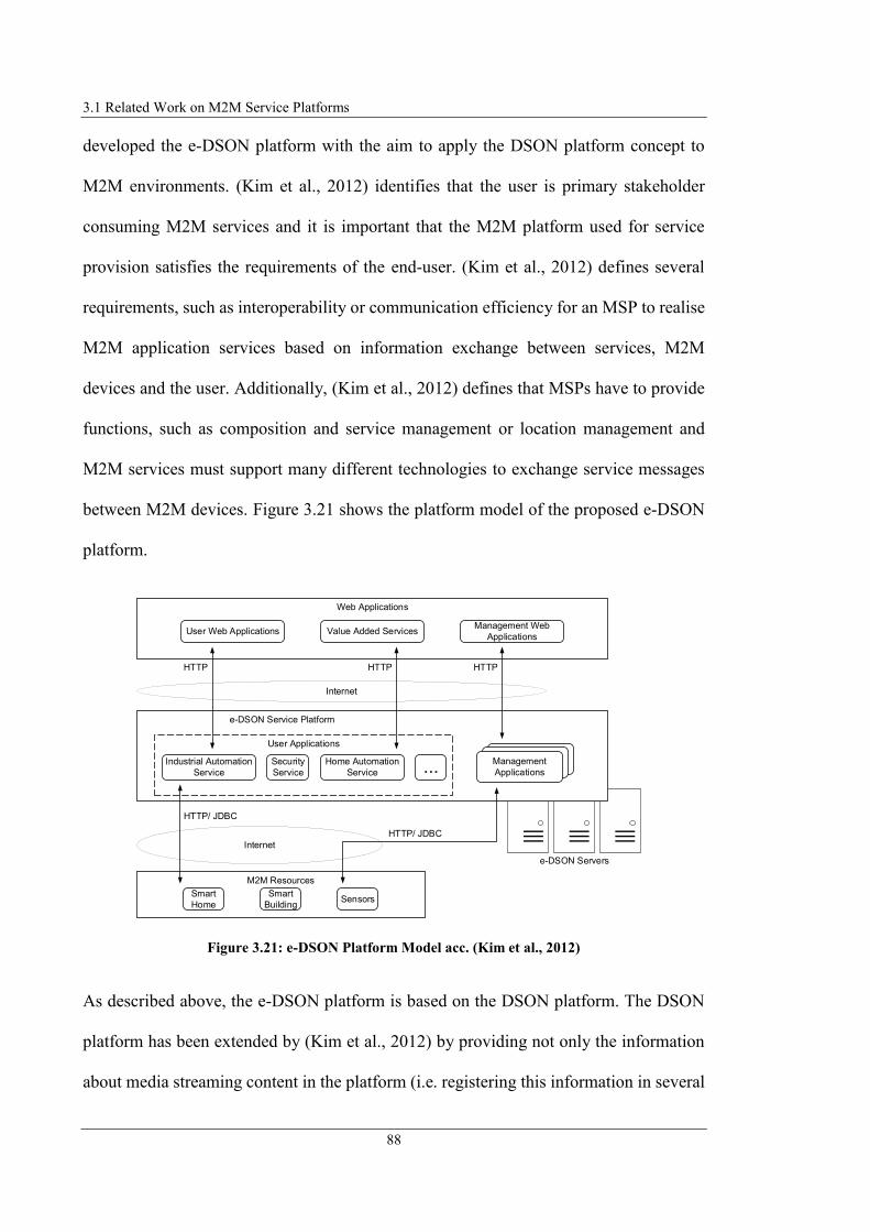
3.1 Related Work on M2M Service Platforms
88
developed the e-DSON platform with the aim to apply the DSON platform concept to
M2M environments. (Kim et al., 2012) identifies that the user is primary stakeholder
consuming M2M services and it is important that the M2M platform used for service
provision satisfies the requirements of the end-user. (Kim et al., 2012) defines several
requirements, such as interoperability or communication efficiency for an MSP to realise
M2M application services based on information exchange between services, M2M
devices and the user. Additionally, (Kim et al., 2012) defines that MSPs have to provide
functions, such as composition and service management or location management and
M2M services must support many different technologies to exchange service messages
between M2M devices. Figure 3.21 shows the platform model of the proposed e-DSON
platform.
Figure 3.21: e-DSON Platform Model acc. (Kim et al., 2012)
As described above, the e-DSON platform is based on the DSON platform. The DSON
platform has been extended by (Kim et al., 2012) by providing not only the information
about media streaming content in the platform (i.e. registering this information in several
Internet
Internet
HTTP/ JDBC
e-DSON Servers
e-DSON Service Platform
M2M Resources
Smart
Home
Smart
BuildingSensors
Management
Applications
User Applications
Industrial Automation
Service
Security
Service
Home Automation
Service ...
HTTP/ JDBC
Web Applications
User Web Applications Value Added ServicesManagement Web
Applications
HTTP HTTP HTTP

3 Challenges, Requirements, and Use Cases of M2M Application Service Provision
89
DSON controllers), but also the information about M2M devices or local services (e.g.
residing in smart buildings). The registered M2M devices and services can now be
combined by linking them via a service overlay network. This makes it possible to offer
applications that are specific to the different requirements of the user (Kim et al., 2012).
The user interface is realised via a web application. The user can access the M2M services
provided by the platform via the user interface or the user can register devices and
services. The e-DSON platform uses HTTP to exchange information from the MSP and
web application because HTTP is a common protocol and available in common user
environments (Kim et al., 2012).
The e-DSON platform contains services of two types: user service and management
service (for things and services). Service and device providers use the management
services for uploading service/device specification. A user service is the user-specific
application provided by the e-DSON platform. A user-specific application is e.g., when
devices trigger events, another device can be controlled by the e-DSON platform (Kim et
al., 2012). Figure 3.22 illustrated details of the e-DSON platform architecture.
According to (Kim et al., 2012) the architecture of the e-DSON platform is separated in
three layers: presentation layer, business layer and data access layer. The presentation
layer is used to provide an interface for the user via a web-based GUI. Using this GUI the
user can interact with the user application. The data access layer provides the interfaces
to the M2M devices and external data sources as well as the smart servers (M2M gateway
in M2M environments) to be connected to the e-DSON platform. The business layer
contains the core functionality of the e-DSON platform and provides the functionality to
realise user-specific applications.
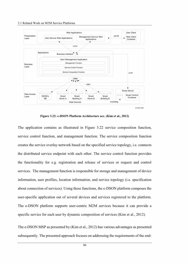
3.1 Related Work on M2M Service Platforms
90
Figure 3.22: e-DSON Platform Architecture acc. (Kim et al., 2012)
The application contains as illustrated in Figure 3.22 service composition function,
service control function, and management function. The service composition function
creates the service overlay network based on the specified service topology, i.e. connects
the distributed service endpoint with each other. The service control function provides
the functionality for e.g. registration and release of services or request and control
services. The management function is responsible for storage and management of device
information, user profiles, location information, and service topology (i.e. specification
about connection of services). Using these functions, the e-DSON platform composes the
user-specific application out of several devices and services registered to the platform.
The e-DSON platform supports user-centric M2M services because it can provide a
specific service for each user by dynamic composition of services (Kim et al., 2012).
The e-DSON MSP as presented by (Kim et al., 2012) has various advantages as presented
subsequently. The presented approach focuses on addressing the requirements of the end-
Presentation
Layer
Web Applications
Business
Layer
Data Access
Layer
Smart Server
HTTP
User Service Web ApplicationsManagement Service Web
Applications
Data Sources
DSON s
DB
Smart
Home A
Smart
Building A
Smart
Home B
Smart
Building B
Smart Control
Container
including
ORM
User/ Management Application
Service Composition Function
Service Control Function
Management Function
Business Interface
HTTP
User Client
Web Client
Container
HTTP
Applications
JDBC
© 2012 IEEE

3 Challenges, Requirements, and Use Cases of M2M Application Service Provision
91
user by providing user-centric, i.e. user individual services and integrates end-users’
environment. The possibility for dynamic composition of services enlarges the flexibility
of the provided M2M applications as well as the re-use of devices and services in multiple
M2M applications. Especially realisation of M2M applications by service composition
using a service overlay network that links several nodes, each providing resources or
services, enables the flexible combination of device resources and services on service
layer. Using common available technologies and interfaces to connect to the service
platform and access the user applications, such as HTTP protocol, XML as data format,
and web interfaces simplifies the integration in external systems and the access of the
users to the M2M application services. According to (Kim et al., 2012) using overlay
networks for service provision reduces the costs for system operation.
Besides the advantages of the e-DSON platform, the presented concept has several
drawbacks as the following section specifies. As illustrated in Figure 3.20 and Figure
3.21, the e-DSON platform architecture is realised by distributed, but centralised operated
servers, located in the Internet. If one or more servers fail, the platform is limited or no
longer available. Furthermore, the user is dependent on a central platform operator that
operates the e-DSON platform. According to (Kim et al., 2012) the e-DSON platform
does the service composition, but specifies that the user “is not involved in the
composition”. That means a separate stakeholder have to be involved defining the service
composition structure which the e-DSON platform interprets and dynamically allocates.
Although the e-DSON platform can be connected to external systems via a HTTP
interface and the user can use the applications via a web interface, it is not described
whether different M2M technologies in the smart environment can be integrated into the
platform. Although the services and resources can be linked dynamically to each other

3.1 Related Work on M2M Service Platforms
92
via a service overlay network, the authors do not give any indication of how this link is
made (whether formally defined or programmed). Because the application is composed
by the e-DSON platform and as specified by (Kim et al., 2011) “all the service
information is stored in DSON“ as well as “all content and data are managed and
controlled by DSON“ it can be derived that the application itself is defined statically and
stored in the e-DSON platform. The defined applications are stored in the business layer
of the e-DSON platform and are therefore centrally defined and coordinated. Therefore,
no dynamic applications are generated, but rather statically defined applications are
linked with resources (e.g. an application for streaming multimedia content is statically
defined in its functionality, the source and the destination of the contents is generated
dynamically). If, on the other hand, a new application is desired, a developer must first
define the service topology and store this configuration in the central e-DSON platform.
The e-DSON platform offers the possibility to provide specific user-based applications,
but such applications as described in (Kim et al., 2014) more target to the business layer
instead of targeted to private individuals.
3.1.8 M2SP Concept
(Kim et al., 2014) classifies and evaluates currently existing concepts for MSPs from
industry and research area. Based on that research (Kim et al., 2014) proposes its
optimised M2M service platform (M2SP) model.
According to (Kim et al., 2014) their proposed M2SP model, illustrated in Figure 3.23,
includes all functionalities of currently existing MSPs from industry and research area.
Additionally (Kim et al., 2014) extends these functionalities by P2P communication from
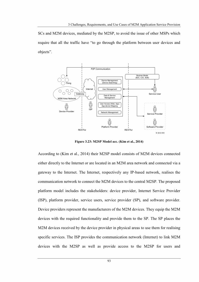
3 Challenges, Requirements, and Use Cases of M2M Application Service Provision
93
SCs and M2M devices, mediated by the M2SP, to avoid the issue of other MSPs which
require that all the traffic have “to go through the platform between user devices and
objects”.
Figure 3.23: M2SP Model acc. (Kim et al., 2014)
According to (Kim et al., 2014) their M2SP model consists of M2M devices connected
either directly to the Internet or are located in an M2M area network and connected via a
gateway to the Internet. The Internet, respectively any IP-based network, realises the
communication network to connect the M2M devices to the central M2SP. The proposed
platform model includes the stakeholders: device provider, Internet Service Provider
(ISP), platform provider, service users, service provider (SP), and software provider.
Device providers represent the manufacturers of the M2M devices. They equip the M2M
devices with the required functionality and provide them to the SP. The SP places the
M2M devices received by the device provider in physical areas to use them for realising
specific services. The ISP provides the communication network (Internet) to link M2M
devices with the M2SP as well as provide access to the M2SP for users and
Internet
M2M Area Network
Thing
Gateway
RESTful
ISPDevice Provider
Device Management
(Device Searching)
User Management
Data & Service
Management
User Access (Web, App)
App-device Mapping
Network Management
Platform Provider
RESTful
Service User
Service Provider
Software Provider
Busines Model
(B2C, C2C, B2B)
P2P Communication
© 2014 IEEE

3.1 Related Work on M2M Service Platforms
94
service/software providers. Software providers develop apps and web applications in
cooperation with the SP to provide specific services that use the devices. The platform
provider provides and operates the M2SP. Service user, SP, and software provider
connect to the M2SP also via the Internet. Additionally, the service user can connect
directly (P2P) to the M2M devices, after mediation by the M2SP, to reduce the load of
the M2SP by continuously forwarding the M2M device data (Kim et al., 2014).
Figure 3.24 shows the architecture of the M2SP and the M2M network which consists
according to (Kim et al., 2014) out of M2M area/access networks and a core network.
M2M area networks are heterogeneous networks implemented by different M2M
technologies. M2M nodes located in the M2M area networks connect either direct or via
an M2M gateway “through various access networks” to the core network. M2M devices
and users “connect through the core network” and the M2SP manages M2M devices and
users as well as provides M2M services.
Figure 3.24: M2SP Architecture acc. (Kim et al., 2014)
The M2SP according to (Kim et al., 2014) consists of four separate platforms described
subsequently that can be executed on different locations but are integrated by a single
M2SP provider.
M2M Service Platform (MSP)
Core Network
M2M Device
Device Profile
Management
Device and M2M Area
Network Management
Device Searching
User
User Profile
Management
Authentication
Charging
M2M Application
Data Collection
Data Control
Connection Management
Access
App Management
App Searching
Web Portal
Access Networks WiFi Ethernet LTE ...
M2M Area
Network
M2M Area
Network...
© 2014 IEEE

3 Challenges, Requirements, and Use Cases of M2M Application Service Provision
95
The M2M Device platform holds a database where all M2M devices register. Services,
managers, and users utilise the M2M device platform. The Device Platform provides
functionality for management of device profiles (e.g. location, type, address), query
devices, monitoring status of devices and controlling of devices (Kim et al., 2014).
The M2M User platform provides functionality for managing user profiles or registration
of M2M service users. The M2M User platform interoperates with the M2M Device
platform and manages access restriction of users to devices and services (Kim et al.,
2014).
The M2M Application platform interoperates with the M2M Device platform and
provides the M2M application consisting of multiple services using data collected from
M2M devices (Kim et al., 2014).
The M2M Access platform provides the access for the users. Users connect with the M2M
Access platform to receive the app or access the web page that both form the interface to
the M2M application that is provided by the M2M Application platform or M2M devices.
App developers use the app management functionality of the M2M Access platform to
register their apps (Kim et al., 2014).
Figure 3.25 illustrates a use case scenario and interaction of platform components and
stakeholders as presented by (Kim et al., 2014).

3.1 Related Work on M2M Service Platforms
96
Figure 3.25: M2SP Use Case Scenario acc. (Kim et al., 2014)
The overall task of the use case is to realise an environmental monitoring application
service. Various M2M devices are placed in an M2M area network monitoring
environmental conditions. User of the application service monitor the M2M devices and
“the M2M service provider manages the M2M area network for service maintenance”
(Kim et al., 2014).
An M2M SP receives several sensor devices from the device provider and places them in
the area of interest as well as register them to the M2M Device Platform. Services which
the devices provide, such as actuation services, are registered additionally at the M2M
Application Platform. A software provider develops an app and registers it to the M2M
Access Platform. M2M service user and administrator register themselves to the M2M
User Platform and their mobile devices to the M2M Device Platform. After registration
“they download the appropriate app for the environmental monitoring services by
searching from the Access-platform”. The M2M Application Platform periodically
receives measurement data from the M2M devices. The M2M service user uses the
M2M
Service
User
Application
Platform
M2M Area
Network/
Device
M2M
Software
Provider
M2M
Device
Provider
M2M
Service
Provider
Device
Platform
User
Platform
Access
Platform
Device purchase & install Device registration
Service registration
Software/ app registration
User registrationUser registration (Administrator)
Device registration (Administrator) User device registration
App downloadSending data
Network monitoring Environmental monitoring
Device control
Alarm
M2M Area Network
© 2014 IEEE

3 Challenges, Requirements, and Use Cases of M2M Application Service Provision
97
environmental monitoring app to access the information of sensor devices, provided from
the M2M application Platform to the app. Additionally, the M2M application (executed
by the M2M Application Platform) contains the functionality to control other M2M
devices (e.g. actuators) and send alarm messages to the M2M service user, depending on
pre-defined conditions (Kim et al., 2014).
The M2SP concept as presented by (Kim et al., 2014) has various advantages presented
subsequently. The presented concept targets not only to the business domain. As (Kim et
al., 2014) specifies its concept for MSPs can address multiple business models, especially
the Customer-to-Customer (C2C) business model, it can be derived that also end-user are
able to register their devices to the platform and therefore their individual environments
can be addressed. The presented concept proposes to use the Internet, respectively an IP
network as communication network between M2M devices, M2SP and other stakeholders
(e.g. service users). This has the advantage that common available communication
network technology is used to realise the networking of the participants. As the M2M
devices can connect directly or via a gateway to the core network it can be derived that
the gateway does protocol translation for connecting M2M devices located in an M2M
area network with the Internet. This offers the possibility to connect multiple M2M
devices, implementing different M2M technologies, in the same way to the M2SP.
Because the central registration of the M2M devices and services as well as the possibility
of the M2SP to combine them, flexible applications can be realised using a single
platform. The M2SP concept proposes to use apps or web interfaces to access the MSP
or the M2M application services. Both are common available technologies that can be
used with common hardware (e.g. smartphone), which enables the platform and SPs to
provide interfaces to the platform in a comfortable way. The P2P communication from

3.1 Related Work on M2M Service Platforms
98
SCs and M2M devices is especially advantageous because it reduces the load of the MSP
and the communication network.
Besides the positive aspects of the M2SP presented above, the MSP concept proposed by
(Kim et al., 2014) contains the following disadvantages. The M2SP represents a
centralised platform architecture with central elements included that request device
information or execute application logic. P2P communication with devices that provide
applications is only possible after mediation by M2SP. The user of the M2SP is dependent
of the central stakeholders, such as SPs, software providers and the central M2MSP
platform provider. The M2SP holds a central database as well as manages the M2M
devices, users, and provides the M2M services. These aspects on the one side create a
dependence of the M2SP provider and SC as well as on the other side risks data safety
and end-user privacy because a single entity stores the data and is able to process the data.
As another central element, the M2SP concept includes the M2M Access Platform for
provision of the web-based GUI as well as the apps. Both, app development and webpage
generation needs to be done by expert developers and especially the apps provide an
interface that is highly dependent of the executing device. It can be derived from (Kim et
al., 2014) that individual apps for different M2M application services are required. This
enlarges the effort for development, provision, and maintaining the apps by different
expert developers and creates a dependence of the end-user access device to the
manufacturer of the device operating system, because individual app stores needs to be
involved for installation of the apps. The authors of (Kim et al., 2014) do not mention
how the application logic is realised (i.e. implemented). They only specify that software
developer provide the application software. Although end-user can register their devices
to the M2SP to be used in M2M applications, the end-user are not involved in the M2M
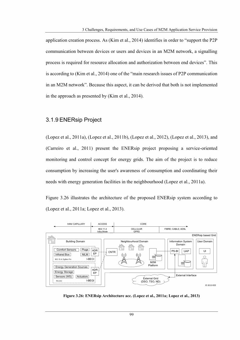
3 Challenges, Requirements, and Use Cases of M2M Application Service Provision
99
application creation process. As (Kim et al., 2014) identifies in order to “support the P2P
communication between devices or users and devices in an M2M network, a signalling
process is required for resource allocation and authorization between end devices”. This
is according to (Kim et al., 2014) one of the “main research issues of P2P communication
in an M2M network”. Because this aspect, it can be derived that both is not implemented
in the approach as presented by (Kim et al., 2014).
3.1.9 ENERsip Project
(Lopez et al., 2011a), (Lopez et al., 2011b), (Lopez et al., 2012), (Lopez et al., 2013), and
(Carreiro et al., 2011) present the ENERsip project proposing a service-oriented
monitoring and control concept for energy grids. The aim of the project is to reduce
consumption by increasing the user's awareness of consumption and coordinating their
needs with energy generation facilities in the neighbourhood (Lopez et al., 2011a).
Figure 3.26 illustrates the architecture of the proposed ENERsip system according to
(Lopez et al., 2011a; Lopez et al., 2013).
Figure 3.26: ENERsip Architecture acc. (Lopez et al., 2011a; Lopez et al., 2013)
ENERsip based Grid
User Domain
UI
Information System
Domain
Neighbourhood DomainBuilding Domain
I-BECI
NILMInfrared Box
PlugsComfort Sensors
I-BEGI
Energy Storage
Sensors (WS) Actuators
Energy Generation Sources
PS-BI UAP
M2M
Platform
CNTRADR
EP
ADR
EP
External Grid
(DSO, TSO, ND)
External Interface
CELLULAR
GPRS
FIBRE; CABLE; ADSL802.11.4
Infra Mode
COREACCESSHAN/ CAPILLARY
802.15.4/ ZigBee Pro
RS-232
© 2013 IEEE

3.1 Related Work on M2M Service Platforms
100
The Building Domain represents the smart buildings with energy generating/consuming
devices and is separated in In-Building Energy Consumption (I-BECI) and In-Building
Energy Generation (I-BEGI) infrastructure. Both parts contain different types of devices:
I-BECI devices are sensors for measuring environment values, plugs switching and
measuring energy consumption of non-intelligent devices, infrared box for controlling
more intelligent devices (e.g. TVs), and the Non-invasive Load Monitoring (NILM)
module determining consumption of devices “based on their electrical signature”. I-BEGI
devices are energy generation/storage devices and actuators controlling these devices or
determining weather conditions. Both, I-BECI and I-BEGI represent the Home Area
Network (HAN), which is connected via an Automated Demand Response End Point
(ADR EP), i.e. an M2M gateway to the M2M core infrastructure (Lopez et al., 2011a).
The core M2M infrastructure according to (Lopez et al., 2011a) is represented by the
neighbourhood domain, which allows remotely control/manage/monitor a large number
of devices producing/consuming energy. The neighbourhood domain provides
functionality for transmitting data produced in the building domain to the information
system (IS) domain and in turn forwarding control commands initiated by the IS to the
building domain. The neighbourhood domain contains a set of concentrators (CNTR) as
well as the M2M platform for managing/monitoring CNTR and forwarding data to the IS
as well as forwarding control commands generated by the IS to the CNTRs (Lopez et al.,
2011a).
According to (Lopez et al., 2011a) the IS domain contains two different components: the
Power Saving Business Intelligence (PS-BI) and the User Application Platform (UAP).
The PS-BI collect all data information generated by the devices, processes them and
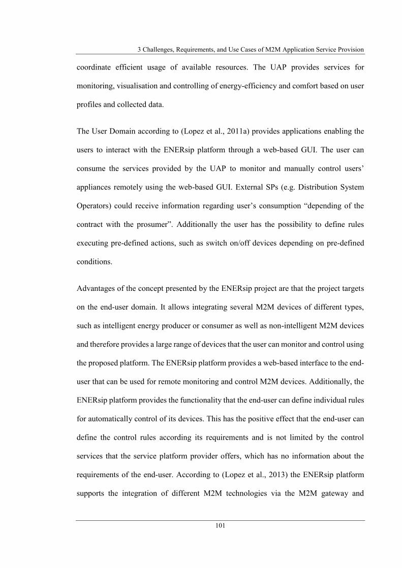
3 Challenges, Requirements, and Use Cases of M2M Application Service Provision
101
coordinate efficient usage of available resources. The UAP provides services for
monitoring, visualisation and controlling of energy-efficiency and comfort based on user
profiles and collected data.
The User Domain according to (Lopez et al., 2011a) provides applications enabling the
users to interact with the ENERsip platform through a web-based GUI. The user can
consume the services provided by the UAP to monitor and manually control users’
appliances remotely using the web-based GUI. External SPs (e.g. Distribution System
Operators) could receive information regarding user’s consumption “depending of the
contract with the prosumer”. Additionally the user has the possibility to define rules
executing pre-defined actions, such as switch on/off devices depending on pre-defined
conditions.
Advantages of the concept presented by the ENERsip project are that the project targets
on the end-user domain. It allows integrating several M2M devices of different types,
such as intelligent energy producer or consumer as well as non-intelligent M2M devices
and therefore provides a large range of devices that the user can monitor and control using
the proposed platform. The ENERsip platform provides a web-based interface to the end-
user that can be used for remote monitoring and control M2M devices. Additionally, the
ENERsip platform provides the functionality that the end-user can define individual rules
for automatically control of its devices. This has the positive effect that the end-user can
define the control rules according its requirements and is not limited by the control
services that the service platform provider offers, which has no information about the
requirements of the end-user. According to (Lopez et al., 2013) the ENERsip platform
supports the integration of different M2M technologies via the M2M gateway and
3.1 Related Work on M2M Service Platforms
102
additional communication technologies are supported in principle as long as a RS-232
hardware modem exists to connect the communications technologies to the M2M
gateway.
Besides the advantages described above, the concept of the ENERsip platform has the
following disadvantages. First disadvantage is, that the use cases of the ENERsip platform
are limited to the smart grid application field by environmental and device monitoring as
well as switching electrical devices. Declarative definition of application logic (in
particular defining control rules) makes the application logic independent from the
execution environment because the rules should be interpretable on different execution
systems by providing an appropriate rules interpreter engine. However, none of the
publications mentioned above specify any underlying mechanism for rule definition or
mention a standard used to ensure the portability. The ENERsip platform architecture
includes several centralised components, such as the M2M platform (server) or the
information system providing the business logic and the user interface. This makes the
ENERsip platform dependent of those centralised elements. Additionally, the user of the
platform is dependent of the ENERsip platform provider as a single stakeholder. As
(Carreiro et al., 2011) specifies the ENERsip platform uses the proprietary ENERsip
protocol inside the platform for communication between the platform components (ADR
EP, CNTR, M2M platform, IS), which limits the compatibility with other M2M systems
and requires an individual protocol stack in each system component, next to common
protocol stacks existing by default. The end-user has no possibility to offer the realised
automation functionality as a service to others instead of e.g. offering the collected
information from its devices to Distribution and Transmission System Operators
“depending on the contract with the prosumer” (Lopez et al., 2011a).

3 Challenges, Requirements, and Use Cases of M2M Application Service Provision
103
3.1.10 Compose Framework
(Doukas and Antonelli, 2013), (Mandler et al., 2013), (Doukas and Antonelli, 2014),
(Doukas et al., 2015), and (Doukas and Antonelli, 2015) present the COMPOSE
(Collaborative Open Market to Place Objects at your Service) framework that provides
according to (Doukas and Antonelli, 2013) infrastructure and methodologies to build
applications communicating with smart objects (smartphones, sensors, actuators). The
COMPOSE framework according to (Doukas and Antonelli, 2015), (Doukas and
Antonelli, 2014), and (Doukas and Antonelli, 2013) provides an end-to-end solution for
developers and entrepreneurs for designing, implementing, and deploying IoT services
and applications. The COMPOSE framework provides tools for development of apps that
form the end-user interface, integrate smart objects for environment integration, a
processing infrastructure to run the applications and tools for service
discovery/composition or application deployment. All components of the COMPOSE
framework (development tools) and back-end infrastructure for running the applications
according to (Doukas and Antonelli, 2015), (Doukas and Antonelli, 2014), and (Doukas
and Antonelli, 2013) run in “a cloud-based infrastructure”. The COMPOSE framework
according to (Mandler et al., 2013) realises a SOA where all resources are consumed and
provided as a service. The COMPOSE framework aims to enable developers to create
applications using existing services and M2M devices.

3.1 Related Work on M2M Service Platforms
104
Figure 3.27: Logical Architecture of COMPOSE Framework acc. (Mandler et al., 2013)
The logical architecture of COMPOSE (illustrated in Figure 3.27) is separated according
to (Mandler et al., 2013) and (Doukas and Antonelli, 2013) in the four layers described
subsequently.
Object Layer – The object layer contain all smart objects, which are physical
devices able to communicate and provide sensing/actuating functionality.
Service Object Layer – The service object layer contains virtual representations
of the objects that can be accessed through the network for obtaining data or
control the actuation functionality. Service objects can represent standalone smart
objects or composite smart objects and can be used by various services.
Service Layer – The service layer contains services, which are “ICT abstractions
of software systems” providing functionality that can be used for a specific task.
Services consume information data from service objects or control them. A
U
O
Service
Objects
Services
End Users
Objects O O
SE
SE
SOSO
Composite
Service ObjectSESE
Composite
Service ObjectSOSO
U
U
U
Open Market
Place
© 2013 IEEE

3 Challenges, Requirements, and Use Cases of M2M Application Service Provision
105
service can be a single service or a composition of services processing data and
implementing the application logic.
End-User Layer – The end-user layer contain the end-users consuming the
services. End-users are persons that access the marketplace using their personal
end devices “through the installation of a given application” or a machine to
integrate the service into their business processes.
The COMPOSE framework consists of three parts. Figure 3.28 shows these parts and the
components of the COMPOSE framework.
Figure 3.28: Components of COMPOSE framework acc. (Doukas and Antonelli, 2014)
The Ingestion Layer contains according to (Doukas and Antonelli, 2013) the smart objects
and devices and forms according to (Doukas and Antonelli, 2014) the interface to these
COMPOSE
Marketplace
Management
Monitoring
Registry/ Repository
Data Mgmt Analytics
Services
Composition Recommend Discovery
Applications
Distribution
Service Objects
Description
SDK IDE GUI End User
High Level Services: Discover/ Download/ Editor/ Development
Run-Time/
Comm.
Infrastructure
Ingestion
Smart Object Smart ObjectSmart ObjectSmart Object
© 2014 IEEE

3.1 Related Work on M2M Service Platforms
106
devices. According to (Doukas and Antonelli, 2015) and (Doukas and Antonelli, 2014)
the devices in the Ingestion Layer communicate with the COMPOSE Runtime Engine via
HTTP or different M2M protocols (MQTT, CoAP) to transmit device information (e.g.
sensor data) or receive control commands.
According to (Mandler et al., 2013) the Runtime Engine “comprise of a cloud
environment” and is responsible for management of services and the platform including
the discovery and monitoring of services and devices as well as control of Smart Objects.
The Runtime Engine contains according to (Doukas and Antonelli, 2014) the service
objects, services, and applications. The services according to (Doukas and Antonelli,
2013) consume the information provided by one or multiple service objects and control
the devices via the service objects “to perform a given task”.
The service registry component according to (Doukas and Antonelli, 2014) provides the
functionality for discovery of services. To implement the service registry component the
COMPOSE framework uses iServe (Pedrinaci et al., 2010) as a central service registry.
Developers use the service registry to query existing services resulting in “a list of
available services and their endpoints that meet the requested criteria”.
Applications are a combination of services and implement a user-specific application
logic to satisfy the requirements of a user.
The COMPOSE Marketplace according to (Doukas and Antonelli, 2013) is an
environment to share services and applications with other developers. According to
(Doukas and Antonelli, 2015) and (Doukas and Antonelli, 2014) the COMPOSE
Marketplace is the “front-end interface” developers use to publish and access services.

3 Challenges, Requirements, and Use Cases of M2M Application Service Provision
107
The COMPOSE Marketplace contains an IDE, libraries and SDKs to create application
logic and apps as well as functionality for registration and discovery of services and the
deployment of applications.
According to (Mandler et al., 2013) developers use the IDE and the SDK to develop
services, applications and apps. In this context applications are the combinations of
services to realise the application logic executed in the COMPOSE runtime and apps are
the smartphone applications to interact with the end-user. The COMPOSE framework
according to (Doukas and Antonelli, 2014) provides the functionality to create
applications graphically using a “visual workflow editor”. The visual workflow editor is
realised according to (Doukas and Antonelli, 2014) using Node-RED (NodeRed, 2017),
which is a Node.js-based tool that enables developers to create workflows of services by
graphical combination of service nodes. The result of the combination of services is a
Node.js application that is executed in the CloudFoundry (CloudFoundry, 2017), which
is a cloud-based application platform.
The GUI element of the COMPOSE Marketplace forms the interface to the end-user.
According to (Doukas and Antonelli, 2013) the smartphone application is the “main
graphical interface the user is using to interact with the application for configuration of
user preferences or receiving information data. The apps bi-directionally communicate
with the back-end infrastructure using Web 2.0 technologies.
To illustrate the mechanisms for service and application development using the
COMPOSE framework, the following describes the development process from the
perspective of a developer. According to (Doukas and Antonelli, 2013), (Doukas and

3.1 Related Work on M2M Service Platforms
108
Antonelli, 2014), and (Doukas and Antonelli, 2015) a developer that is going to create
and deploy applications has to perform the following four steps.
1. Create new services or discover existing services using IDE and SDKs. The
services can either be “a set of classes or high level scripts” that define the service
logic (e.g. request and process specific data information).
2. Defining and implementing the interaction with the smart objects (e.g. request the
information data from specific smart object) using existing SDKs and libraries.
3. Deploying the implemented application to COMPOSE infrastructure.
4. Developing the mobile app for accessing the developed application.
While the developer can use the above-mentioned Node-RED workflow editor to design
the back-end application logic, for development of the mobile app the developer uses a
mobile application framework based on Titanium (Appcelerator, 2017). Titanium is a
development SDK that enables the unified development of mobile apps and
transformation to specific mobile runtimes (mobile operating systems, e.g. iOS or
Android) (Doukas and Antonelli, 2013; Doukas and Antonelli, 2015).
The COMPOSE framework as introduced above contains several advantages presented
subsequently. The approach that developers create services and applications as well as
deploy and register them in a global accessible infrastructure enables other developers to
reuse already existing services and applications. This enlarges the reusability of services
and application which in consequence safe time and costs for development of new
services. Reusing the existing services and creation of new services by composition of
the existing services enlarges the flexibility of the platform because several services can
be used to create applications in multiple application fields. Reusing service

3 Challenges, Requirements, and Use Cases of M2M Application Service Provision
109
functionalities inside new applications also avoid the implementation of many vertical
silo applications as in case of implementing a different M2M application for different use
cases. The COMPOSE framework targets to the end-user domain, but it has to be
considered that in context of COMPOSE framework the end-user is a business
stakeholder that benefits by integration of the M2M application realised with COMPOSE
into its business process. Designing back-end application logic graphically by defining
workflows that combine service nodes is advantageous because that is an intuitive
methodology to create application, even when the developer has less experience in
application development. Using smartphone application, as a GUI for interaction with the
application is advantageous because it is a common available interface technology.
Additionally, communication of apps with the back-end infrastructure using Web 2.0
technologies reuses common existing protocols and prevents to provide an additional
protocol stack for communication in the end device of the end-user.
Besides the advantages presented above, the COMPOSE framework has several
disadvantages as presented in the following. Most of the elements in the COMPOSE
infrastructure, such as central service registry and execution engine for services and
application, is provided by a single platform provider and run in a cloud-based
infrastructure. This makes the user of the platform dependent of the platform provider
and the platform dependent of specific platform components, including the particular
solutions proposed for realisation of platform components, such as CloudFoundry as
central application platform. Especially according to (Doukas and Antonelli, 2015) the
app server providing the user interface apps as well as the COMPOSE server are stand-
alone elements in the COMPOSE architecture. The output of the graphical combination
of services is a Node.js application. This makes the solution dependent of that technology

3.1 Related Work on M2M Service Platforms
110
and complicates the portability and adaptability because Node.js is no standard
specification. Additionally, the services the developer can create and reuse are static
classes or scripts representing the service logic, which are platform dependent. This also
complicates reusing the services in other platforms. Although the smartphone as runtime
environment for the GUI app is commonly available, it is required to develop a specific
app for each application running in the back-end. Although the COMPOSE framework
provides tools that unifies and simplifies the development, still expert knowledge is
required. Although the developer has the possibility to create application logic
graphically, this is not fully integrated in the development process because particular parts
for providing the M2M solution still have to be developed requiring expert knowledge.
E.g., the developer has to use existing libraries or SDKs for creating the mobile app as an
interface for the application. Mobile application framework is based on Titanium
Appcelerator, which is on the one side advantageous with regards to the platform
independency of app development, but on the other side has the negative effect that,
because using the Titanium SDK as development framework, requires expert knowledge
of the developer to develop the app logic. The COMPOSE framework targets to
developers and entrepreneurs, but not to private individuals as end-users. The end-users
are only provided with the possibility to interact with the applications in the back-end
using apps as input/output interface, but are not provided with the functionality to design
applications by themselves. The COMPOSE framework has another disadvantage
regarding the data safety and end-user privacy aspect. Because according to (Doukas and
Antonelli, 2014) “every data transaction between the different entities (users, applications
and smart objects) is logged inside COMPOSE” as well as the data storage engine of
COMPOSE logs every action of the end-user, the COMPOSE provider has generally

3 Challenges, Requirements, and Use Cases of M2M Application Service Provision
111
access to the data created inside the end-user environment. This can represent the
behaviour of the end-user and its environmental conditions.
3.1.11 Distributed Cooperative M2M System for Flood
Monitoring (DistribFloodMon)
(Kitagami et al., 2014) presents a concept of a distributed cooperative M2M system for
the use case of flood disaster prevention. The task of the presented use case is to apply
multiple water level sensors and rainfall sensors in a specific area to realise a system for
flood disaster prevention based on data analysis generated by the sensors. (Kitagami et
al., 2014) proposes to realise the M2M system based on a distributed approach, because
traditional server-centric approaches of M2M systems for data analysis and device control
contain the following disadvantages: M2M devices and the M2M server application
continuously exchange data, which generates a large data volume and delays the control
messages generated by the M2M server. Additionally (Kitagami et al., 2014) criticises
that if communication link between the M2M gateway and the M2M server fails, the
whole system will fail.
Based on this aspects (Kitagami et al., 2014) introduces a distributed M2M system for the
special use case of a flood prevention application as illustrated in Figure 3.29.

3.1 Related Work on M2M Service Platforms
112
Figure 3.29: Distributed M2M System acc. (Kitagami et al., 2014)
According to (Kitagami et al., 2014) the proposed M2M system consists of central M2M
servers located outside of the M2M area networks, respectively outside the domain where
the sensors and actuators reside. The task of the M2M server is to monitor and control the
sensors and actuators to generate statistics about the sensor values for further analytics,
forecasts and in case of an alert, control the actuators. The M2M coordinate server adjusts
and coordinates the M2M gateway and M2M server for the usage in flood disaster
prevention application.
The sensors and actuator are connected to multiple intelligent M2M gateways (M2M
GWs). These intelligent M2M GWs not only connect the sensors and actuator to the
communication network, but also include “a rule-based autonomous control mechanism”.
The measurement values of the sensors are aggregated in the M2M GWs, which send the
aggregated measurement data continuously to the M2M servers and stores the original
measurement values locally for later processing. Additionally, the M2M GWs
autonomously monitor the measurement values and transmits the original values (not
coordinates
coordinates
M2M
Coordinate
Server
...Intelligent
M2M GW
Intelligent
M2M GW
Alarm
Rainfall
Sensors
Water Level Sensors
Intelligent
M2M GW
Flood Disaster Prevention System
M2M
Server
Never Die Network
Network
Nodes
Event-driven Data
Collection
Rule-based
Autonomous Control
© 2014 IEEE

3 Challenges, Requirements, and Use Cases of M2M Application Service Provision
113
aggregated measurement values) for a specific interval to the M2M server if e.g. pre-
defined variations of measurement values occurs (Kitagami et al., 2014).
To prevent a delayed control of the actuators in the area of interest (e.g. alarm actuators)
caused by connection interrupts from M2M server and M2M GWs, the M2M GWs
include a local rule engine for controlling the actuators. The M2M coordinate server
configures the conditions in the gateways for transmission of the detailed measurement
data, i.e. defines the corresponding thresholds by sending the rules in advance to the M2M
GWs (Kitagami et al., 2014).
According to (Kitagami et al., 2014) the M2M GWs connect via a Never Die Network
(Shiratori et al., 2012) with each other and with the M2M servers. The Never Die Network
is a mobile adhoc network including redundancy of links between the nodes.
The presented approach of (Kitagami et al., 2014) includes various advantages specified
as follows. The transmission of aggregated measurement data enables detection and
storing of measurement values. Through this, it is possible to generate statistics of the
measurement values without stressing the communication network because large amounts
of data. Additionally, the autonomous execution of the parts of the application logic by
local monitoring, evaluation and control of sensors/actuators enlarges the system
availability and reduces the disadvantages of traditional server-centric M2M systems.
Besides the advantages presented above, the M2M system introduced by (Kitagami et al.,
2014) includes several drawbacks. (Kitagami et al., 2014) presents only one single and
very static use case, respectively application field of flood monitoring. They does not
define a general concept of distributed M2M applications or providing the application as

3.2 Requirements for a new Framework for Autonomous decentralised M2M Application Service Provision
114
a service for other users. Setup of an underlying Never Die Network for communication
of the participating nodes seems necessary in the case of the introduced flood prevention
application, especially with regard to the area to deploy the application with disrupted or
not existing communication network. However, considering application field of end-user
domain, which usually provides existing and working communication networks,
additional communication networks are not necessary to implement. The overall use case
application is a combination of decentralised control and central management and data
collection, including central system elements, which again results in the negative aspects
of including central elements or stakeholders in the M2M system architecture, as
described in previous sections. The presented approach of does not focus on or include
end-user integration in application development or the integration of M2M devices
located in end-user environment. The application definition by specification of semantical
rules, representing the application logic, enlarges the independence of application logic
from execution systems because e.g. change of an execution system only requires
exchange of rules interpreter engine. However, (Kitagami et al., 2014) does not specify a
standardised language for definition of the rules executed in the intelligent M2M GWs,
which in consequence again limits the platform independency.
3.2 Requirements for a new Framework for Autonomous
decentralised M2M Application Service Provision
The previous section 3.1 introduced current M2M system architectures for M2M
application services. The positive aspects and weaknesses have been mentioned at the end
of the corresponding sections. This section derives requirements for a new approach for
3 Challenges, Requirements, and Use Cases of M2M Application Service Provision
115
application service provision in M2M environments to enable end-users for autonomous
and independent M2M application service provision. The definition of requirements is
based on the strengths and weaknesses of previously introduced M2M system
architectures. For definition of appropriate requirements reasonable aspects of related
work projects will be adopted as requirements and additional ones defined based in order
to avoid the negative related work project aspects. The requirements defined in this
section will be the basis for the proposed framework for “Autonomous decentralised
M2M Application Service Provision” presented in chapter 4.
Many of the related projects introduced above, such as oneM2M specification for M2M
systems focus on the support of interoperation of individual industries or businesses in
professional domains as well as the realisation of complex business applications for
support of business processes. Other ones also focus on the end-user domain with end-
users’ M2M device integration. The personal environment of the end-user has powerful
potential for providing applications with the integration of the M2M devices located at
the end-user environment. Therefore, the end-user environment should be addressable by
the MSP. Based on this aspect, the following requirement can be derived:
End-user environment integration – The MSP should address end-user
environment.
The projects BOSP, ENERsip, COMPOSE, e-DSON, and M2SP satisfy this requirement
because they directly address M2M devices located in end-user environment. The other
projects are related to the business domain or special use cases without integration of end-
users’ M2M devices.

3.2 Requirements for a new Framework for Autonomous decentralised M2M Application Service Provision
116
Considering the related projects, end-users mostly have no option to be involved in
application development for their personal environments. Because the M2M applications
that effect the environment of the end-users have to meet end-users’ individual
requirements, the end-user should get involved in defining the application semantic
individually regarding end-users’ personal requirements. Based on this aspect, the
following requirement can be derived.
End-user integration – The end-user has to be integrated in application creation
for its personal environment.
None of the above-mentioned related projects fully satisfies this requirement.
The e-DSON framework partially satisfies this requirement because the e-DSON
platform has its focus on user-centric M2M applications. The end-user is not explicitly
integrated in the application creation process, but the flexible structure of the application
provision concept via service overlay networks allow the application developer to simply
define individual user applications.
The next set of requirements refer to service provision aspects of an MSP. The approaches
described above to define services for the personal environment are limited to personal
use of the services by the owner of the environment in which the M2M devices reside,
respectively to the end-user who has defined the services. Other end-users or external SPs
could benefit from using the services or resources available inside the end-users' personal
environment to include them in their own environments or processes. This enlarges the
possible functionality of applications defined by others by also including the resources
3 Challenges, Requirements, and Use Cases of M2M Application Service Provision
117
and functionalities of other personal environments into own applications. Therefore, the
following requirement is derived.
End-user service provision and utilisation – End-users should be able to provide
resources and applications inside their personal environment as a service to other
end-users or SPs.
Only the related e-DSON project satisfies this requirement by static development of user-
centric applications including distributed resources that other end-users can offer inside
a centralised system architecture.
Although making services and resources that are available in end-users environment
accessible for other entities is advantageous to enlarge the functionalities of end-user
applications, this would be limited to integrate them in applications for single
environments. As mentioned above the end-user environment has powerful potential for
providing services to others. Combination and coordination of those services could enable
applications with higher impact and flexibility regarding realisable functionalities.
Therefore, the next requirement is defined as follows.
Cooperative end-user service provision – Services of end-users should be
combinable to provide a cooperative application service that can be utilised by
other end-users or SPs.
None of the above projects satisfies this requirement. Only the e-DSON framework
partially satisfies this requirement because the e-DSON platform offers the possibility to
make services of local device resources and services available to others, but does not

3.2 Requirements for a new Framework for Autonomous decentralised M2M Application Service Provision
118
allow to define the cooperative service logic by the end-users themselves, instead a central
expert developer have to define the structure of the service composition.
The next set of requirements refer to the system architecture of the MSP. Almost all of
the related projects are based on centralised architectures or contain centralised elements
in the system infrastructure. Centralised architecture means that the MSPs or parts of the
platforms contain physically central network element (such as a server) or logical central
elements or stakeholders (such as cloud environments or platform providers). This
research should explore alternatives to centralised and cloud-based M2M service platform
architectures. A decentralised system architecture could avoid the following
disadvantages of centralised or partly centralised architectures in context of MSP
provision with end-user integration. 1) A centralised MSP often requires high
performance hardware for providing the platform functionality to be used by many users
or to connect many M2M devices. A single stakeholder has to provide large resources for
service development and maintenance as well as for platform setup, management, and
maintenance. The platform provider additionally has to spend large effort for ensuring
the reliability of the platform. Each of these topics will result in high costs for operating
such a centralised MSP and for developing applications running on those platforms. The
(as usual) companies providing the platforms need to transfer the required costs to the
user of the platform. Since the target group in the focus of this research are the end-users
instead of companies that usually utilise M2M solutions, the costs have to be as low as
possible because the end-users will not accept the costs. 2) The MSP users (SP and SC)
could be dependent on the platform provider as a single stakeholder included in the M2M
system architecture. If that stakeholder stops platform provision, the entire M2M system
solution fails. If a single M2M SP creates and hosts an M2M application service, the

3 Challenges, Requirements, and Use Cases of M2M Application Service Provision
119
consumer of this application service is dependent of that central provider too. 3)
Centralised M2M platform solutions often are limited in flexibility. Centralised service
provision via service platforms mostly intend specific application fields (e.g. MSPs
provides solution for Ambient Assisted Living but is not able to address the requirements
for a Smart Grid solution). I.e. centralised solutions might limit the application fields for
specific domains. 4) A further negative aspect of centralised elements has to be
considered regarding the data safety and end-user privacy. Storing a large amount of data
that is produced by M2M applications at a central location (physically or logically) is
always critical. The stakeholders having access to that data storage could misuse the data
for e.g. analysing the end-users’ behaviour by getting detailed information provided by
their M2M devices. Based on disadvantages of centralised architectures for MSPs
identified above, the next criterion is derived to ensure the independence of central
provider, enlarging the flexibility of the platform, avoiding costs for the end-user and
ensures the privacy aspect, which in consequence enlarges the acceptance by the end-
user.
Decentralised system architecture – The approach for MSP has to avoid
centralised entities in the system architecture to provide the service platform or
the services. Avoidance of centralised entities means that no centralised system
components in the MSP architecture (such as e.g. central service repositories)
should be integrated as well as no central stakeholder involved required for
operation of the MSP and the service provision (development, operation,
maintenance, management, controlling) except the end-user itself.
None of the above-mentioned related projects fully satisfies this requirement.
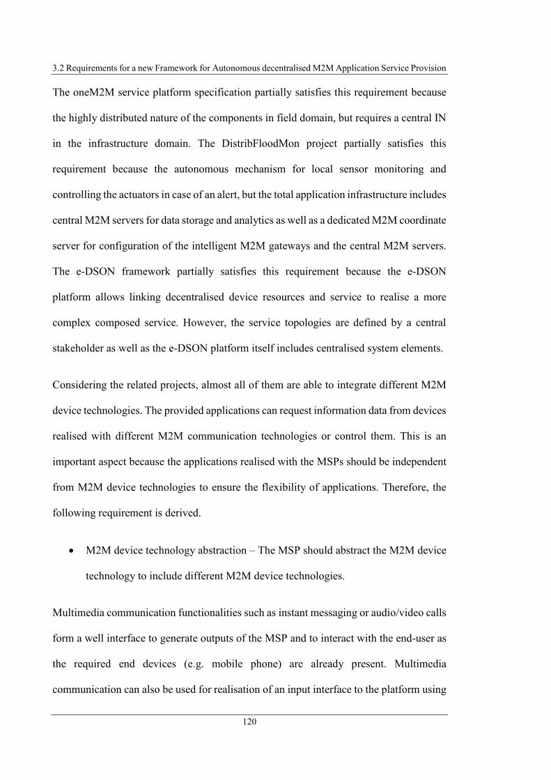
3.2 Requirements for a new Framework for Autonomous decentralised M2M Application Service Provision
120
The oneM2M service platform specification partially satisfies this requirement because
the highly distributed nature of the components in field domain, but requires a central IN
in the infrastructure domain. The DistribFloodMon project partially satisfies this
requirement because the autonomous mechanism for local sensor monitoring and
controlling the actuators in case of an alert, but the total application infrastructure includes
central M2M servers for data storage and analytics as well as a dedicated M2M coordinate
server for configuration of the intelligent M2M gateways and the central M2M servers.
The e-DSON framework partially satisfies this requirement because the e-DSON
platform allows linking decentralised device resources and service to realise a more
complex composed service. However, the service topologies are defined by a central
stakeholder as well as the e-DSON platform itself includes centralised system elements.
Considering the related projects, almost all of them are able to integrate different M2M
device technologies. The provided applications can request information data from devices
realised with different M2M communication technologies or control them. This is an
important aspect because the applications realised with the MSPs should be independent
from M2M device technologies to ensure the flexibility of applications. Therefore, the
following requirement is derived.
M2M device technology abstraction – The MSP should abstract the M2M device
technology to include different M2M device technologies.
Multimedia communication functionalities such as instant messaging or audio/video calls
form a well interface to generate outputs of the MSP and to interact with the end-user as
the required end devices (e.g. mobile phone) are already present. Multimedia
communication can also be used for realisation of an input interface to the platform using

3 Challenges, Requirements, and Use Cases of M2M Application Service Provision
121
the same device. Additionally, multimedia communication forms a flexible interface for
communication between SP and SC to organise service provision/utilisation. Especially
for social services, often personal communication between SP and SC is required to
arrange an appointment (e.g. via email, IM or call). Multimedia communication is
required to build up services such as surveillance services (e.g. monitoring buildings via
video streams). Therefore, the next requirement is defined as follows.
Multimedia communication – The MSP should integrate multimedia
communication functionality.
Only the related projects BOSP and IMS M2M SP I satisfy this requirement. BOSP
integrates carriers’ abilities, such as VoIP communication and messaging functionality
into its platform concept. IMS M2M SP I utilises the IMS communication technologies
for exchange of information data between the M2M system elements. Although IMS
M2M SP I uses only messaging functionality of the IMS, because the IMS integration it
is possible to include also audio/video communication.
The M2M on SOA project partially satisfies this requirement because it includes email
and SMS as notification options of users. The M2M on SOA project restricts multimedia
communication to notification functionality and does not use the same kind of
communication to control applications or integrates audio/video communication.
Considering the related projects, almost all of them include a mechanism to manage the
location of M2M devices or M2M services for addressing them. The related approaches
usually realise this functionality by a central management entity in the system
architecture. Additionally, different end-users reside on different and variable locations

3.2 Requirements for a new Framework for Autonomous decentralised M2M Application Service Provision
122
(geographical and topological), the devices and provided services have to be continuously
addressable. E.g., because end-user environments usually cannot be addressed via static
IP addresses, the changing IP addresses must be managed. As specified above, an MSP
should avoid centralised components adopting such management tasks. Therefore a
decentralised management solution is required, which results in the next requirement.
Device/service lookup mechanism – The devices used for service provision and
the services itself needs to be identifiable and addressable. Therefore a mechanism
for device and service lookup is required.
Beside the functional requirements specified above, several non-functional requirements
can be derived from the related projects as the following section presents. Because no
central entity has to be integrated in M2M system architecture for MSP provision, the
user of the platform, i.e. the end-user is responsible for operating the platform. It is
assumed that the end-user has common technical knowledge but no expert knowledge in
application development or operating a specific service platform. Because the end-user
has to operate the service platform and is responsible for application design, both have to
be simple and intuitive. Based on these aspects the following requirement is derived.
Simplicity – Both, application development and operating the MSP have to be
simple.
None of the above-mentioned related projects satisfies this requirement.
The COMPOSE framework project partially satisfies this requirement because the
developer is enabled to design the back-end application logic graphically by designing
workflows with the included nodes. This simplifies the development process of the back-

3 Challenges, Requirements, and Use Cases of M2M Application Service Provision
123
end application, but operating the system platform, consisting of several different
platforms as well as e.g. development of the GUI apps by using mobile SDKs,
complicates both, application development and platform provision. The ENERsip
platform partially satisfies this requirement because the end-user has the possibility to
define control rules for its devices and can interact with the platform using a web-based
GUI. However, operating multiple system elements located in different parts of the
network that communicate with each other using the specific ENERsip protocol stack
complicates the system architecture.
Most of the related projects contain elements in their platform architecture that require
high performance hardware for e.g. operating central architecture components or network
entities. To ensure less financial effort for the end-user, the components of the MSP
should be executed applying low cost hardware or existing hardware and network
facilities. Therefore, the following requirement is derived.
Minor hardware requirements – The hardware requirements necessary for
providing the MSP as well as accessing the provided applications have to be low.
None of the above-mentioned related projects fully satisfies this requirement.
The IMS M2M SP I and II architecture partially satisfies this requirement because it
reuses existing network topology of the IMS, but also requires central M2M AS inside
the Cloud. Because the IMS M2M SP I and II approach seamless include the network
elements of the IMS, such as P-/I-/S-CSCF/HSS in the M2M system architecture, instead
using the IMS as plain communication network, these entities can be considered as parts
of the MSP.

3.2 Requirements for a new Framework for Autonomous decentralised M2M Application Service Provision
124
Because the increasing amount of M2M devices, as well making the platform usable for
large number of end-user the following requirement is derived.
Scalability – The MSP should meet scalability in both directions (M2M devices
and users).
None of the above-mentioned related projects fully satisfies this requirement.
The oneM2M service platform specification partially satisfies this requirement when
assuming the MSP is operated as a cloud solution, which naturally provides scalability
depending on the allocated resources. However, central elements in system architecture
limits the scalability. The INOX service platform project partially satisfies this
requirement because the authors define scalability as a requirement that is provided by
the INOX platform, but does not specify how the scalability is realised. The INOX service
platform runs as a cloud environment, which requires central elements that again limit the
scalability. The IMS M2M SP I and II approach partially satisfy this requirement. The
presented approaches include the IMS as communication network, which is rather
scalable. However, the included central system components, such as the AS or M2M
server in turn limits the scalability. The COMPOSE framework project partially satisfies
this requirement. (Doukas and Antonelli, 2013) specifies the COMPOSE framework as a
scalable cloud-based solution. However, on the opposite side the central framework
entities, such as the compose server, naturally limits the scalability of an architecture. The
M2SP concept partially satisfies this requirement. Included central elements, such as the
app stores required for app installation as well as the P2P communication possibility with
the devices enable scalable systems. However, other central elements in system

3 Challenges, Requirements, and Use Cases of M2M Application Service Provision
125
architecture, such as the centralised M2M Application Platform or the M2M User
Platform limits the scalability.
Most of the related projects introduced above contain proprietary components in their
architecture or service implementations, which make them dependent of it. Independence
of platform components and service implementations from specific implementation
technologies is necessary to provide best options for adaptability of platform components
as well as ensure the portability of the MSP components. Portability means that the
services and platform components does not have a static binding to the execution
environment (e.g. using proprietary solutions). Using standardised protocols is
advantageous for ensuring portability and adaptability. Portability is especially important
because of the many existing different devices inside end-user environment that should
be used for MSP execution as well as for access the services. Based on these aspects, the
following requirement is derived.
Platform independency – The realisation of M2M platform architecture
components as well as applied methodologies should be platform independent.
Only the INOX service platform project satisfies this requirement due it proposes a
loosely-coupled system architecture with high service orientation and additionally,
defines a declarative way to describe applications instead of static and execution system
specific implementation of application logic.
The oneM2M service platform specification partially satisfies this requirement because
the oneM2M specification does not specify implementation details regarding execution
environments, but also no concept for independent application definition. Examination of
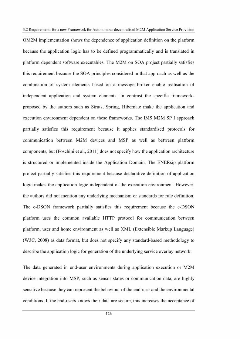
3.2 Requirements for a new Framework for Autonomous decentralised M2M Application Service Provision
126
OM2M implementation shows the dependence of application definition on the platform
because the application logic has to be defined programmatically and is translated in
platform dependent software executables. The M2M on SOA project partially satisfies
this requirement because the SOA principles considered in that approach as well as the
combination of system elements based on a message broker enable realisation of
independent application and system elements. In contrast the specific frameworks
proposed by the authors such as Struts, Spring, Hibernate make the application and
execution environment dependent on these frameworks. The IMS M2M SP I approach
partially satisfies this requirement because it applies standardised protocols for
communication between M2M devices and MSP as well as between platform
components, but (Foschini et al., 2011) does not specify how the application architecture
is structured or implemented inside the Application Domain. The ENERsip platform
project partially satisfies this requirement because declarative definition of application
logic makes the application logic independent of the execution environment. However,
the authors did not mention any underlying mechanism or standards for rule definition.
The e-DSON framework partially satisfies this requirement because the e-DSON
platform uses the common available HTTP protocol for communication between
platform, user and home environment as well as XML (Extensible Markup Language)
(W3C, 2008) as data format, but does not specify any standard-based methodology to
describe the application logic for generation of the underlying service overlay network.
The data generated in end-user environments during application execution or M2M
device integration into MSP, such as sensor states or communication data, are highly
sensitive because they can represent the behaviour of the end-user and the environmental
conditions. If the end-users knows their data are secure, this increases the acceptance of

3 Challenges, Requirements, and Use Cases of M2M Application Service Provision
127
an MSP. Therefore it is necessary to keep this data protected, keep the end-user as owner
of this data, and avoid the so called “Big Brother Effect”. Based on these aspects, the
following requirement is derived.
Data safety, end-user privacy – The MSP has to provide the functionality for data
safety and end-user privacy.
Almost none of the related projects satisfy this requirement mainly because the single
central architecture elements storing the data or single platform providers that could have
access to the data and misuse it e.g. for determination of end-users‘behaviour.
The oneM2M service platform specification partially satisfies this requirement because
the standard specification includes security functionality such as access control. However,
because the oneM2M architecture includes central elements may monitoring or storing
data produced in M2M area networks the requirement is not fully satisfied.
Table 3.1 shows the requirements specified above including the evaluation of the related
projects regarding these requirements. Requirements the related project satisfy are
marked with “+”; requirements not satisfied by the projects are marked with “-“;
requirements the projects partially satisfy are marked with “o”. Evaluations that cannot
be determined based on the published information about the projects are marked with “/”.
Table 3.1: Evaluation of related Projects reg. derived Requirements
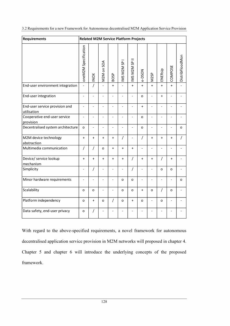
3.2 Requirements for a new Framework for Autonomous decentralised M2M Application Service Provision
128
With regard to the above-specified requirements, a novel framework for autonomous
decentralised application service provision in M2M networks will proposed in chapter 4.
Chapter 5 and chapter 6 will introduce the underlying concepts of the proposed
framework.
Requirements
one
M2M
Spe
cifi
cati
on
INO
X
M2M
on
SOA
BO
SP
IMS
M2M
SP
I
IMS
M2M
SP
II
e-D
SON
M2S
P
ENER
sip
CO
MPO
SE
Dis
trib
Flo
odM
on
End-user environment integration - / - + - + + + + + -
End-user integration - - - - - - o - + - -
End-user service provision and
utilisation
- - - - - - + - - - -
Cooperative end-user service
provision
- - - - - - o - - - -
Decentralised system architecture o - - - - - o - - - o
M2M device technology
abstraction
+ + + + / - / + + + /
Multimedia communication / / o + + + - - - - -
Device/ service lookup
mechanism
+ + + + + / + + / + -
Simplicity - / - - - / - - o o -
Minor hardware requirements - - - - o o - - - - o
Scalability o o - - o o + o / o -
Platform independency o + o / o + o - o - -
Data safety, end-user privacy o / - - - - - - - - -
Related M2M Service Platform Projects

3 Challenges, Requirements, and Use Cases of M2M Application Service Provision
129
3.3 Conclusion
This chapter introduced related projects on MSPs. The oneM2M standard for M2M
system architectures has been introduced as representative of commercial MSPs in
section 3.1 as well as approaches from the research field. Each of the related projects has
been evaluated regarding its strengths and weaknesses. It can be noted that most related
projects pursue a centralised approach by including central entities or stakeholders in their
system architecture. Furthermore, it can be stated that most of the presented approaches
do not integrate the end-user into the application creation, but this is important to take
account of the requirements of the end-user.
Based on the evaluation of the related projects in section 3.2 requirements have been
derived. One of the main requirements is that an MSP not only addresses the end-user
application field, but also integrates the end-user into the application creation process.
Furthermore, it can be noted that it is important to avoid central entities or stakeholders,
such as central platform provider or network element provider, to ensure the
independence of such entities. Reuse of existing resources for operation of an MSP and
networking of M2M devices and services is important because it reduces the cost of
operating the platform and increases the acceptance of an M2M solution. Additionally to
these aspects, it is important that an MSP integrates the different M2M device
technologies and allows them to be combined with each other.

131
4 Proposed Framework for autonomous
decentralised Application Provision in
M2M Systems
This research proposes a novel framework for autonomous and decentralised application
and service provision in M2M systems. The framework addresses the requirements
defined in section 3.2 and eliminates the deficits of currently existing approaches for
application and service provision in M2M systems. In this chapter, section 4.1 first
introduces the overall concept of the proposed framework to enable end-users to design
and provide individual or cooperative M2M applications as a service to other end-users
or central service providers (SPs) such as companies or organisations. Afterwards section
4.2 describes the framework architecture and its components realising the proposed
framework architecture.
4.1 General Concept
The concept described in this research changes the method of M2M application and
service design, provision as well as utilisation significantly from previous approaches.
Figure 4.1 illustrates the process of service and application development, deployment and
utilisation for traditional M2M service platforms. (MSPs)

4.1 General Concept
132
Figure 4.1: Traditional Approach for M2M Application Service Provision
As constituted in section 3.1 in the traditional approaches for provisioning M2M
applications, highly specialised software developers design and implement M2M
applications supporting specific business process. Such M2M applications are deployed
on application servers (AS) running in centralised infrastructures like the Cloud or
dedicated servers. Application consumers (companies, organisations, end-user) utilise
these applications as a service. The M2M applications control and monitor devices
located in the M2M device domains.
This research project proposes, as illustrated in Figure 4.2, that end-users design M2M
applications corresponding to their personal requirements (Steinheimer et al., 2012a;
Steinheimer et al., 2017a).
Figure 4.2: M2M Application Service Creation and Provision Process with End-User Integration
Cloud
Service Creation Environment (SCE)
Create Service
LogicM2M Device Domain
M2M Service
Provider
M2M Application
M2M Application
Server (AS)
Company/Organisation/End-User
Deploy Service
Personal Requirements
IP Network/
Internet
Local Service Delivery Platform (SDP)
Interpreter Execution
Engine
Service Creation Environment (SCE)
End-User
M2M Device Domain
Company/Organisation/End-User
Define M2M
Service Logic
Generate
Formal Service
Description
Deploy M2M
Service

4 Proposed Framework for autonomous decentralised Application Provision in M2M Systems
133
According to (Steinheimer et al., 2013a) and (Steinheimer et al., 2015b) a formal service
description language describes the M2M service logic, which is deployed in the local
environment of the end-user that is also responsible for service execution (instead a
central M2M AS). Here it has to be considered that end-users are no specialised software
developers, but users with common technical knowledge. The designed applications can
be provided as a service to other end-users or SPs (Steinheimer et al., 2013e).
This research defines conceptual models for M2M system architectures enabling
autonomous decentralised M2M service provision as well as horizontal and bottom-up
M2M service provision (Steinheimer et al., 2015a). This project additionally defines new
conceptual models for M2M system architectures to realise cooperative M2M application
service provision consisting of aggregation and composition of M2M services provided
by end-users (Steinheimer et al., 2013e). The conceptual models define novel methods to
provide services and applications in M2M application fields and therefore offer
possibilities for new and highly flexible M2M applications. M2M applications, realised
according to the defined models, are able to address application ranges not addressable
by traditional M2M SPs such as control or monitoring applications including equipment
located in end-users personal environment (e.g. reducing demand for energy by turning
off or shifting energy-consuming devices or monitoring environmental conditions by
accessing devices that include various sensors). The conceptual models are described
subsequently and section 4.2 describes the functional architecture of the framework to
realise these models.

4.1 General Concept
134
Autonomous Decentralised M2M Service Provision (ADSP) Model
As examined in section 3.2 the provision of an M2M service requires an MSP. Most of
the current approaches for M2M application provision require centralised infrastructures
for hosting these service platforms. As examined in section 3.2, such centralised
infrastructures result in less flexibility and dependence on the platform provider/operator
as well as require many resources. More decentralised approaches including Edge or Fog
Computing aspects execute the M2M services closer to end-users, but also do not avoid
the dependence of an MSP provider or make it impossible to use the MSPs by end-users
to deploy their individual services.
To avoid the disadvantages of centralised approaches for M2M service provision, this
research project defines the ADSP model (illustrated in Figure 4.3) as fundamental
structure of the proposed M2M system architecture (Steinheimer et al., 2013a;
Steinheimer et al., 2015b).
Figure 4.3: ADSP Model: Decentralised M2M Application Design and Execution
This conceptual model defines that end-users use the resources available in their personal
environments to design and deploy M2M applications themselves (within their personal
creates
End-User s personal EnvironmentEnd-User
Local Application
Creation
Environment
IAD/ Smartphone
Local Application
Execution Environment
M2M Devices
Heating
D
NActuators Sensors Lights ...
controls/ monitors
End-User
End-User
End-User ...
IP Network/
Internet

4 Proposed Framework for autonomous decentralised Application Provision in M2M Systems
135
environments). The end-users provide the M2M applications without involving a central
entity (e.g. a central MSP provider) or centralised execution environments for M2M
applications. Therefore, the execution environment for M2M applications are arranged in
the areas that are accessible and manageable by the end-users, which are their personal
environments. The personal environment of end-users are either their permanent place of
residence (home/apartment) or their current locations. In the further course of this
research, the local execution environments will be linked so that end-users can realise
cooperative services.
As section 3.2 defines the requirement that the execution system for the MSP does not
require additional hardware, the Integrated Access Device (IAD) already existing at most
permanent locations of end-users is used and the end-user's smartphone at the mobile
location. The IAD represents the M2M-Gateway in end-users environments, which
execute the M2M applications close to the end-user and processes the data where they are
collected (Steinheimer et al., 2013a).
The ADSP model satisfies the requirements of the distributed system architecture and the
end-user is included in the M2M application creation. Compared to the traditional
centralised approaches for MSPs, the above-defined model avoids the resource-intensive
provision of M2M applications by means of additional network elements since the
execution environments use the locally available and cost-efficient resources. This will
make better use of existing resources (network capacity, computing power), avoid
bottlenecks, and reduce the cost of service creation, provision and maintenance. This
satisfies the requirement that low hardware resources are required for platform
provisioning. Furthermore, this model resolves the fixed binding to a central M2M
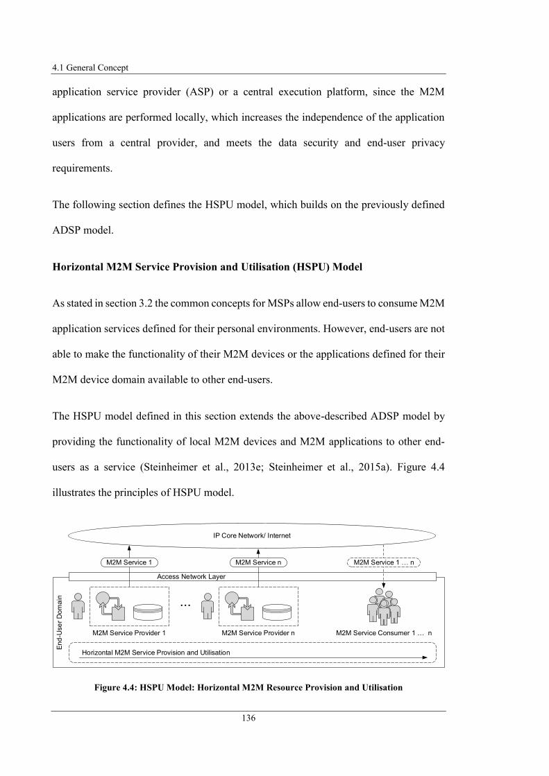
4.1 General Concept
136
application service provider (ASP) or a central execution platform, since the M2M
applications are performed locally, which increases the independence of the application
users from a central provider, and meets the data security and end-user privacy
requirements.
The following section defines the HSPU model, which builds on the previously defined
ADSP model.
Horizontal M2M Service Provision and Utilisation (HSPU) Model
As stated in section 3.2 the common concepts for MSPs allow end-users to consume M2M
application services defined for their personal environments. However, end-users are not
able to make the functionality of their M2M devices or the applications defined for their
M2M device domain available to other end-users.
The HSPU model defined in this section extends the above-described ADSP model by
providing the functionality of local M2M devices and M2M applications to other end-
users as a service (Steinheimer et al., 2013e; Steinheimer et al., 2015a). Figure 4.4
illustrates the principles of HSPU model.
Figure 4.4: HSPU Model: Horizontal M2M Resource Provision and Utilisation
End
-Use
r D
om
ain ...
Access Network Layer
M2M Service Consumer 1 n
Horizontal M2M Service Provision and Utilisation
M2M Service Provider 1
M2M Service 1
M2M Service Provider n
M2M Service n M2M Service 1 n
IP Core Network/ Internet

4 Proposed Framework for autonomous decentralised Application Provision in M2M Systems
137
The service provision and utilisation are performed horizontally at end-user level, i.e.
without any central, mediating entity in the M2M system architecture. According to this
model, an end-user takes on the role of an M2M SP and provides independent M2M
services to other end-users that run in the execution environment of this M2M SP. The
connection of M2M SP and M2M service consumer (SC) as well as every required
information exchange occurs directly (P2P) between the participants (Steinheimer et al.,
2012a).
A MSP based on the architecture implementing the HSPU model has the advantage that
both, M2M service provision and utilisation are realised without any central entity and
M2M SCs are independent of such entities. This again satisfies the requirement of
decentralised system architecture. Additionally, realisation of the HSPU model enlarges
the flexibility of an MSP because provided M2M services can address various application
fields, not limited by the functionality of traditional MSPs that are often implemented for
specific application domains. Because all end-users can publish their individual M2M
services a large diversity of available services can exist (because of large number of
different SPs). End-users can search for M2M services satisfying their individual
requirements. Besides these advantages horizontal M2M service provision and utilisation
reduces the costs for service development and provision because end-users provide their
own resources and no additional system elements are required. The HSPU model includes
a naturally redundancy of M2M services, because multiple M2M SPs can provide
identical services.
The following section defines the DCASP model, which extends the above-specified
conceptual models.
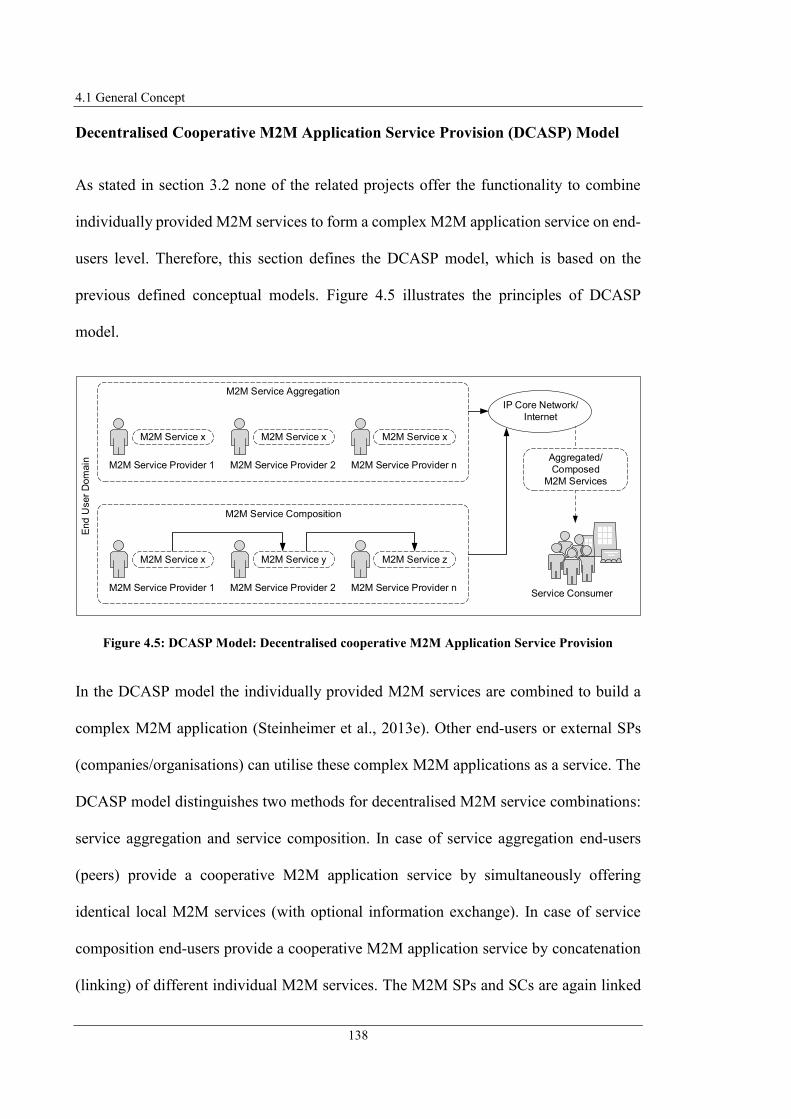
4.1 General Concept
138
Decentralised Cooperative M2M Application Service Provision (DCASP) Model
As stated in section 3.2 none of the related projects offer the functionality to combine
individually provided M2M services to form a complex M2M application service on end-
users level. Therefore, this section defines the DCASP model, which is based on the
previous defined conceptual models. Figure 4.5 illustrates the principles of DCASP
model.
Figure 4.5: DCASP Model: Decentralised cooperative M2M Application Service Provision
In the DCASP model the individually provided M2M services are combined to build a
complex M2M application (Steinheimer et al., 2013e). Other end-users or external SPs
(companies/organisations) can utilise these complex M2M applications as a service. The
DCASP model distinguishes two methods for decentralised M2M service combinations:
service aggregation and service composition. In case of service aggregation end-users
(peers) provide a cooperative M2M application service by simultaneously offering
identical local M2M services (with optional information exchange). In case of service
composition end-users provide a cooperative M2M application service by concatenation
(linking) of different individual M2M services. The M2M SPs and SCs are again linked
End
User
Dom
ain
Serv
ice C
om
positio
n
M2M Service Composition
Service ConsumerM2M Service Provider 1
M2M Service x
M2M Service Provider 2
M2M Service y
M2M Service Provider n
M2M Service z
Serv
ice C
om
positio
n
M2M Service Aggregation
M2M Service Provider 1
M2M Service x
M2M Service Provider 2
M2M Service x
M2M Service Provider n
M2M Service x
Aggregated/
Composed
M2M Services
IP Core Network/
Internet
4 Proposed Framework for autonomous decentralised Application Provision in M2M Systems
139
via a P2P network without any central entity required to manage the service combination
or information exchange.
A M2M system architecture that implements the DCASP model by the distributed
provision of M2M application services, avoids the resource-intensive provision of M2M
applications that central approaches use. This will make better use of existing resources
(network capacity, computing power), avoid bottlenecks, and reduce the cost of M2M
service creation, provision and maintenance. Because multiple end-users can deploy the
same M2M application using this approach, the fixed relationship to a central M2M
service or platform provider is resolved, which in turn increases the independence of the
M2M application users.
The DCASP model offers the possibility to provide different M2M applications in a
flexible way. Different M2M services can be flexibly combined. Through the cooperation
of multiple M2M SPs on end-user level new M2M applications can be realised that could
not be realised before because resources located in end-users’ environments were not easy
accessible. By combining several local M2M applications, various use cases can be
realised that are only possible through the cooperation of end-users, such as the reduction
of the load in the energy distribution grid. Such jointly provided M2M application
services could provide an advantage to the end-users involved, if they receive appropriate
incentives from the application SCs.
The following section describes the BSPU model which is based on the ADSP and
DCASP model.

4.1 General Concept
140
Bottom-Up M2M Service Provision and Utilisation (BSPU) Model
The above-specified conceptual models offer new possibilities to make resources located
in end-users personal environment accessible and enable the combination of them. The
BSPU model (see Figure 4.6) extends the previously defined models by specifying that
end-users can provide their individual or cooperative M2M services to external SPs. This
was not possible before without centralised MSPs or defining certain terms and conditions
between end-users and external SPs, which again would be complicated and individual
solutions. (Steinheimer et al., 2015a; Steinheimer et al., 2016)
Figure 4.6: BSPU Model: Bottom-Up M2M Service Provision and Utilisation
The BSPU model reverses the direction of service delivery. Central SPs do not provide
their services to end-users as before, but distributed end-users provide their M2M services
to the central SPs.
External SPs usually are interested in information regarding the personal environment of
end-users to use that information to create a benefit for their individual business
End
-Use
r D
om
ain
End-Users End-Users Cooperative End-Users
Busin
ess D
om
ain
Top-down
Bottom-up
Company/Organisation Company/Organisation
BSPU Model

4 Proposed Framework for autonomous decentralised Application Provision in M2M Systems
141
processes. Another interest of external SPs could be to control M2M devices located in
the personal environment of the end-user, such as energy consumers. The BSPU model
enables central SPs to address the personal environment of the end-user as an application
field of their M2M applications. This area was previously not addressable, e.g. because
of legal restrictions or data-safety regulatory. It is only possible for central SPs to integrate
the end-users’ personal environment into their business processes, if the end-users
provides their information data or control functionality by themselves to the central SP.
Due to the customers’ active participation in the provision of M2M services, it is within
their discretion to determine the scope of control tasks or data collections in their personal
environments.
4.2 Framework Architecture and Components
The previous section 4.1 introduced the principles of conceptual models that form the
basis of the proposed novel framework for “Autonomous decentralised M2M Application
Service Provision”. The proposed framework aims to eliminate the gaps and
disadvantages of current approaches of MSPs identified in section 3.1 by enabling the
end-users to design individual M2M services and make them available to other end-users
or central SPs. Additionally, the service providing end-users can cooperate with each
other to provide complex M2M application services. Figure 4.7 illustrates the functional
basis for the proposed novel framework for autonomous decentralised service and
application provision in M2M application field, with focus on end-users domain.

4.2 Framework Architecture and Components
142
Figure 4.7: M2M Application Service Provision Framework Architecture
The framework consists of four essential parts: Service Creation Environment (SCE),
Service Delivery Platform (SDP), Conceptual Models for autonomous decentralised
M2M Application Service Provision and Utilisation, and the M2M Community
(Steinheimer et al., 2012a; Steinheimer et al., 2013e). SCE and SDP are completely
decentralised as they are located in end-users’ personal environment. The task of the SCE
is to provide functionality for application and service design by end-users. The SDP is
responsible for M2M application/service management and networking of the
participating platforms in end-users domain. The M2M Community is a component in the
proposed architecture supporting the networking of participants and the management of
Service Creation Environment (SCE) Service Delivery Platform (SDP)
Decentralised Networking
Service Runtime Environment
(SRE)
Framework for autonomous decentralised M2M Service and Application Provision
M2M
Com
munity
Conceptual Models for autonomous decentralised M2M Application Service Provision and Utilisation
Single Service
HSPU Model
BSPU
Model
DCASP Model
Service Aggregation Service Composition
Local Service
ADSP Model
Service/ Application
Registry (SAR)
Service Provision
Unit (SPU)
Service
Interface
Description
Formal Application
Description
Formal
Appl.
DescriptionFormal Application
Description
Service Execution Engine
(SEE)
Multimedia Service
Components (MMSCs)
Application Description
Interpreter (ADI)
M2M Communication Unit (CU)
Device Abstraction Layer (AL)Service
Design Unit
(SDU)
Service
Creation
Unit (SCU)
4 Proposed Framework for autonomous decentralised Application Provision in M2M Systems
143
M2M services. The conceptual models are realised by means of the functional
components of SCE and SDP. While section 4.1 described the principles of the conceptual
models, the subsequently section describes the components of SCE, SDP and M2M
Community.
Service Design Unit (SDU)
Integration of end-users implies that the end-users have the possibility to create M2M
applications for their personal environment (e.g. their Smart Home). Currently no
possibility for comfortable and simple M2M application creation exists as identified in
section 3.1.
An intuitive development of M2M applications could be realised by a graphical
development process and by modelling the behaviour of an M2M application
independently from underlying technologies (Steinheimer et al., 2012b; Steinheimer et
al., 2017b). In the e-SCHEMA research Project (e-SCHEMA, 2015) the graphical
development of M2M applications was demonstrated. The use of the proposed principle
of statemachine-based modelling was evaluated as a practicable approach by probands
with different technical backgrounds. The majority (90 percent) of the candidates stated
that they found it easy to model simple or complex M2M applications using the proposed
approach. Therefore this approach was chosen as methodology to graphically model the
semantics of an M2M application. The graphical design of M2M applications by end-
users for their individual personal environments realises the integration of end-users. The
SDU provides the interface for graphically designing M2M applications via a Graphical
User Interface (GUI). The definition of an M2M application is done by the end-users by
modelling the behavior of the M2M application through the combination of graphical
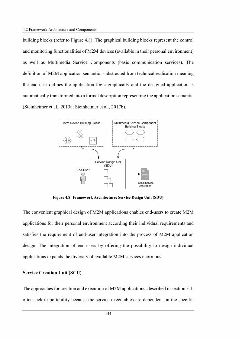
4.2 Framework Architecture and Components
144
building blocks (refer to Figure 4.8). The graphical building blocks represent the control
and monitoring functionalities of M2M devices (available in their personal environment)
as well as Multimedia Service Components (basic communication services). The
definition of M2M application semantic is abstracted from technical realisation meaning
the end-user defines the application logic graphically and the designed application is
automatically transformed into a formal description representing the application semantic
(Steinheimer et al., 2013a; Steinheimer et al., 2017b).
Figure 4.8: Framework Architecture: Service Design Unit (SDU)
The convenient graphical design of M2M applications enables end-users to create M2M
applications for their personal environment according their individual requirements and
satisfies the requirement of end-user integration into the process of M2M application
design. The integration of end-users by offering the possibility to design individual
applications expands the diversity of available M2M services enormous.
Service Creation Unit (SCU)
The approaches for creation and execution of M2M applications, described in section 3.1,
often lack in portability because the service executables are dependent on the specific
Formal Service
Description
End-User
Multimedia Service Component
Building Blocks
D
N
M2M Device Building Blocks
Service Design Unit
(SDU)

4 Proposed Framework for autonomous decentralised Application Provision in M2M Systems
145
platform. I.e. the platform where the service executables are deployed is not simply
exchangeable. Thus, the service executables are close-coupled to the platform and other
execution environments cannot execute them. Only the INOX Managed Service Platform
(Clayman and Galis, 2011) and the ENERsip platform (Lopez et al., 2013) make use of a
declarative description of M2M application logic instead of programmatically
implementing it, but the authors do not mention any standard used for the declarative
description.
This project proposes an abstraction mechanism for service executables. The graphically
designed M2M application logic is not transformed to application code that is dependent
on the execution environment and therefore dependent on the platform. The SDU (refer
to Figure 4.9) automatically transforms the application logic into a formal application
description using a unified, standardised and machine-readable formal description
language describing the application semantic.
Figure 4.9: Framework Architecture: Service Creation Unit (SCU)
The formal application description can be parsed, interpreted, and the application logic
described can be executed independently of the underlying execution environment. This
makes the formally defined M2M application independent of the execution environment
and can be easily ported to other execution environments, which meets the requirements
of platform independence. Each execution environment that contains a parser for the
unified and standardised formal description language is able to execute the application.
End-User
Service Creation
Unit (SCU)
Service Design Unit
(SDU)
Formal M2M Application
Description

4.2 Framework Architecture and Components
146
The machine readability of the formal description language enables the fully automated
application execution. The application of unified mechanisms for M2M application
description using a standardised formal description language supports the realisation of
an application description parser on different platforms.
M2M Communication Unit (CU) with Device Abstraction Layer
The intention of the presented concept is not only the integration of end-users, but also
the M2M device domain of end-users. The basis of M2M application creation is the
integration and the networking of M2M devices. M2M devices have different, mostly
incompatible communication abilities (i.e. the M2M devices communicate via different
M2M technologies). As a result, M2M devices that use communication technology A will
not be able to communicate with other M2M devices that use communication technology
B. Therefore, it is impossible to connect M2M devices using different communication
technologies with each other for controlling or information processing.
The M2M CU, as illustrated in Figure 4.10, includes multiple M2M device technology
interfaces and integrates different device technologies as most of the approaches
introduced in section 3.1 do (Steinheimer et al., 2012a; Steinheimer et al., 2015b).
Figure 4.10: Framework Architecture: Communication Unit (CU)
M2M Communication Unit (CU)
M2M Technology Interfaces
KNX Z-Wave ZigBee HTTP MBus BidCos
Service Execution Engine (SEE)
Device Abstraction Layer (AL)
EventEvent
4 Proposed Framework for autonomous decentralised Application Provision in M2M Systems
147
The unified integration of several M2M device technologies is realised by the Device
Abstraction Layer (AL) component of the proposed framework, which is included in the
M2M CU. According to (Steinheimer et al., 2012a) and (Steinheimer et al., 2015b) the
Device AL abstracts the communication between the execution environment and the
different M2M device technologies. Different M2M devices are represented inside the
M2M CU by a unified interface. An M2M application executed by the Service Execution
Engine (SEE) integrates M2M devices using the unified interface. The M2M application
uses this interface to request data from the M2M device or send control commands to it.
The Device AL converts the unified requests into technology specific requests so that they
can be transferred to the M2M device via a specific M2M technology interface.
The Device AL of the M2M CU accomplishes the compatibility of different M2M device
technologies. This part of the proposed concept also enables the integration of M2M
device technologies defined in the future, by definition and integration of corresponding
M2M device technology interfaces into the M2M CU. This realises the separation and
independence of service functionality from communication technologies of the M2M
devices and satisfies the requirement for M2M device technology abstraction, as defined
in section 3.2.
Multimedia Service Components (MMSC)
As identified in section 3.1 in most MSPs the integration of multimedia communication
is not considered or rather not integrated as essential interface. Often in MSPs no
interfaces exist that are simple operable and comparably flexible.

4.2 Framework Architecture and Components
148
This project proposes to provide reusable MMSCs as part of the SRE, which end-users
can utilise to interact with the MSP using common multimedia communication equipment
(Steinheimer et al., 2013a). Integration of multimedia communication forms an interface
that is usable on several ways. Multimedia interfaces are usable by audio/video
communication (e.g. audio/video call), by textual communication (Instant Message) or
combined (speech recognition, text-to-speech). Therefore, the framework contains
MMSCs the end-user can apply to generate an interface for M2M applications. The
interface can work as input and output interface or as control channel between MSP and
end-user.
Central integration of multimedia communication enables the simple realisation of
intuitive interfaces to MSPs. Through the integration of MMSCs it is possible to receive
and exchange information as well as trigger control instructions, just using multimedia
communication devices such as a mobile phone. The precondition to serve a multimedia
interface still exists in the environment of most involved entities. Most end-user have a
multimedia communication device (e.g. a Smartphone) and are familiar with operating it.
Integration of multimedia communication extends the M2M onto the Machine-to-Human
Communication via natural and human readable language.
Service Runtime Environment (SRE)
The SRE (see Figure 4.11) provides the MMSCs and contains the Application Description
Interpreter (ADI) and the Service Execution Engine (SEE) for realisation of the M2M
application execution. The SRE receives the formal application description from the SCU
and executes the defined application logic on behalf of the ADI (parsing and interpreting

4 Proposed Framework for autonomous decentralised Application Provision in M2M Systems
149
the formal application description) and the SEE (triggering the defined actions)
(Steinheimer et al., 2013a; Steinheimer et al., 2015b).
Figure 4.11: Framework Architecture: Service Runtime Environment (SRE)
Most of the projects introduced in section 3.1 realise the M2M application execution
using remote execution environments or central components in their system architecture.
As mentioned above the SRE is located in the local environments end-users, i.e. the M2M
application is also executed locally and the proposed concept does not require any central
MSP, which satisfies the requirement of decentralised system architecture and also
ensures the data safety and end-user privacy.
The components presented up to this point enable end-users to graphically create a local
M2M application in a simple way and execute it locally. These framework components
enable the realisation of the ADSP model defined in section 4.1. The framework
components described subsequently are proposed to realise the HSPU and BSPU
conceptual models.
Service Runtime Environment (SRE)
Formal M2M
Application Description
Service
Creation
Unit
(SCU)
Application Description Interpreter
(ADI)Multimedia Service
Components (MMSCs)
Service Execution Engine (SEE)
Communication Unit (CU)

4.2 Framework Architecture and Components
150
Service Provision Unit (SPU) and Service/Application Registry (SAR)
For realising the HSPU and BSPU model, a possibility is still required to provide the
M2M application as a service to other users. This is realised by the SPU component,
which extracts an interface description from the formal application description and
registers it at the SAR. The interface description contains all necessary information
describing the M2M service and its interfaces. Users who intent to use an M2M service
offered by another user, request the SAR for available M2M services and integrate the
M2M service into their graphical application description. The SPU contacts the M2M SP
and requests the desired M2M service.
The decentralised structure of the M2M system architecture presented in this project is an
essential aspect of the designed framework. Figure 4.12 shows the designed approach as
a layer model representing the functional architecture for networking of SPs and SCs as
well as for realisation of M2M application services (Steinheimer et al., 2017a;
Steinheimer et al., 2017b; Steinheimer et al., 2017c). The functionality of the respective
layers is described below.
Network Layer
Since the M2M system architecture, as defined in section 3.2, should not require any
additional resources accept the existing at end-users environment, the end-user’s M2M
gateways are connected with each other via an IP based communication network,
respectively the Internet. Therefore, the networking fundamentals are realisable with
minimal infrastructural costs. End-users can be located at different geographic locations
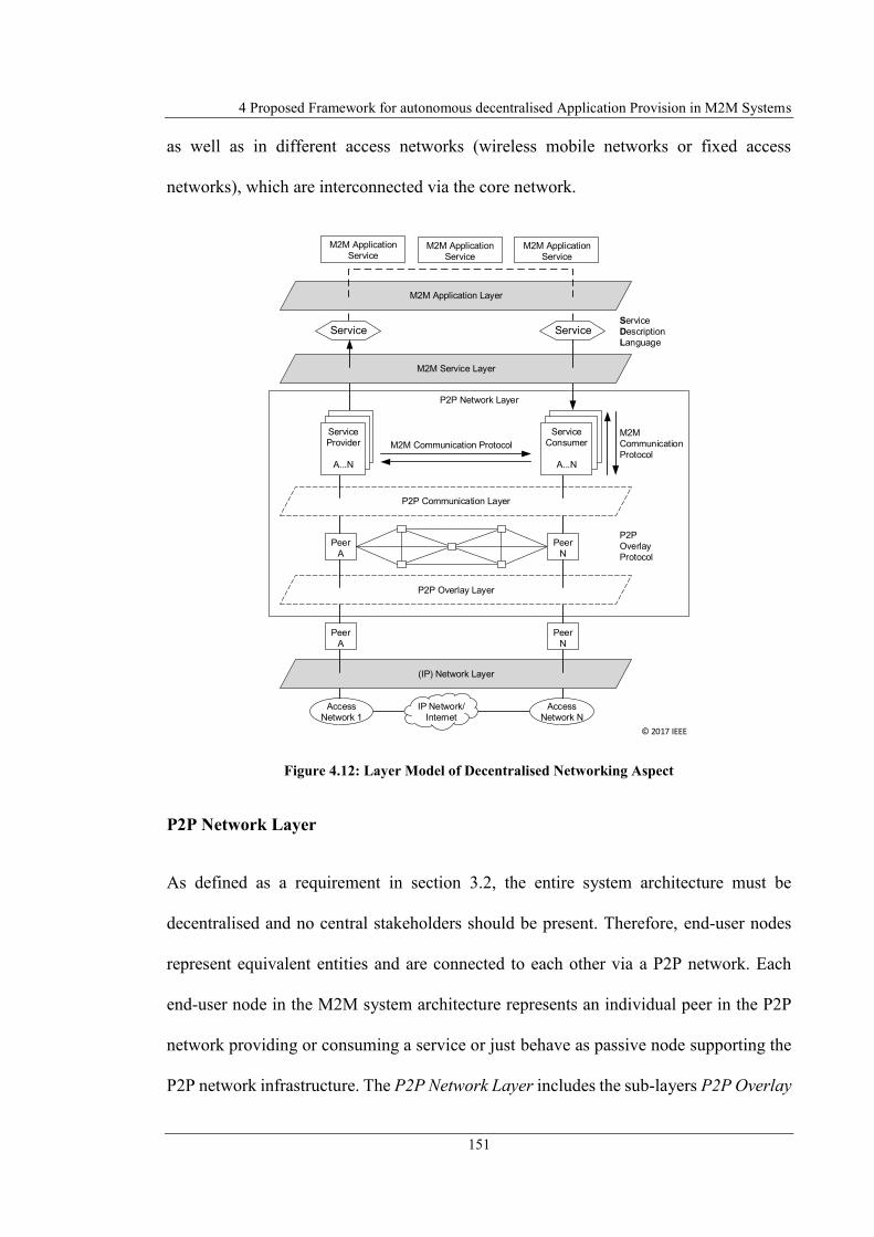
4 Proposed Framework for autonomous decentralised Application Provision in M2M Systems
151
as well as in different access networks (wireless mobile networks or fixed access
networks), which are interconnected via the core network.
Figure 4.12: Layer Model of Decentralised Networking Aspect
P2P Network Layer
As defined as a requirement in section 3.2, the entire system architecture must be
decentralised and no central stakeholders should be present. Therefore, end-user nodes
represent equivalent entities and are connected to each other via a P2P network. Each
end-user node in the M2M system architecture represents an individual peer in the P2P
network providing or consuming a service or just behave as passive node supporting the
P2P network infrastructure. The P2P Network Layer includes the sub-layers P2P Overlay
(IP) Network Layer
P2P Network Layer
P2P Overlay Layer
M2M Application
Service
Service Service
M2M Communication Protocol
M2M Service Layer
M2M
Communication
Protocol
Service Service
Access
Network 1
Access
Network N
IP Network/
Internet
P2P
Overlay
Protocol
M2M Application Layer
Service
Description
Language
M2M Application
Service
M2M Application
Service
Peer
A
Peer
N
Peer
A
P2P Communication Layer
Service
Provider
A...N
Service
Consumer
A...N
Peer
N
© 2017 IEEE
4.2 Framework Architecture and Components
152
Layer and P2P Communication Layer realising a decentralised infrastructure for
communication and data storage.
The P2P Communication Layer realises the information exchange between the
participants (i.e. the peers). The information exchange between the participants for the
service utilisation (service requests, confirmations) as well as the necessary signalling to
generate cooperative applications automatically occurs directly between the peers using
M2M communication protocols (e.g., CoAP, SIP). The communication in the P2P
Communication Layer occurs end-to-end between peers providing and consuming
correspondent services. Peers that are not involved in a specific M2M application context
are not integrated in the communication activities between M2M SP and SC.
In addition to the communication between the participants, the required data management
in the M2M system architecture, such as registration of M2M services, must also be
decentralised to prevent central components in the M2M system architecture. Distributed
data storage can be realised with a P2P overlay network (e.g., Chord, Gnutella). The P2P
Overlay Layer realises this functionality by forming the P2P overlay network out of all
existing end-user nodes. All end-user nodes are member of the P2P overlay network,
independent if they are involved in a specific M2M application context or not. Any data
storage in the presented M2M system architecture is decentralised via the end-user nodes
within the P2P Overlay Layer.
M2M Service Layer
The services defined and provided by the end-users are available via the M2M Service
Layer and can be used via their corresponding interfaces. The service interface is

4 Proposed Framework for autonomous decentralised Application Provision in M2M Systems
153
described by an interface specification and is available in the M2M Service Layer
(explained in section 6.1).
M2M Application Layer
The distributed M2M application services are realised within the M2M Application Layer.
For this purpose, the services available via the M2M Service Layer are combined with
each other following the same approach as defining local M2M applications (combination
of graphical building blocks and application description using formal language). The
exchange of information between the M2M services takes place via the P2P Network
Layer using P2P communication protocols.
The decentralised networking of nodes allows to realise the entire M2M system
architecture decentralised without the inclusion of central entities. The application
composition on the M2M Application Layer makes it possible to compose flexible
applications from fine-grained, independent services. According to the proposed concept,
the infrastructure is provided cooperatively by all participants, whereby the application-
specific communication takes place between the nodes involved in the context of an M2M
application. As a result, the effort required for networking is distributed to the nodes and
does not stress a single system component that would have to be provided centrally.
Because no central component is involved in the networking of nodes, the system
architecture is not dependent on this single component. The entire M2M system
architecture uses existing resources in the end-user domain such as existing IP/NGN
network infrastructure. This makes it possible to realise a communication network for
M2M without providing additional networking infrastructure. Using IP-based
information exchange guarantees the applicability by everyone that has access to the

4.2 Framework Architecture and Components
154
Internet. Therefore, the realisation is possible with minimal costs. The P2P networking
structure offers advantages like redundancy and scalability as well as data security and
end-user privacy because necessary data storage is realised via the P2P overlay network
and distributed over the participating nodes that are decoupled from each other.
The following section describes the M2M Community component of the proposed
framework system architecture.
M2M Community
Up to this point in the proposed framework concept for “Autonomous decentralised M2M
Application Service Provision” it has not been discussed how the participating nodes, i.e.
the end-users, can join the P2P network and how the presented framework manages
different interests of end-users utilising the distributed MSP. To address these topics the
designed concept includes the M2M Community component (see Figure 4.13).
Figure 4.13: P2P connected M2M Environments within the M2M Community
The M2M Community extends the P2P networking approach by adding social networking
functionalities to the P2P network (Steinheimer et al., 2012a; Steinheimer et al., 2013e).
End-users that want to participate in the distributed M2M platform architecture join the
Peer A
SCE
SDP
Sub-Community B
M2M Community
Sub-Community A Mobile M2M Peers
Peer N
SCE
SDP
Peer B
SCE
SDP
Peer D
SCE
SDP
Peer C
SCE
SDP
Data
Sets
M2M Peers
M2M Peers
M2M Peers
Data
Sets
© 2013 IEEE

4 Proposed Framework for autonomous decentralised Application Provision in M2M Systems
155
M2M Community and as part of the community can utilise the MSP functionalities.
Therefore, the M2M Community forms the basis for networking the peers. The M2M
Community follows the principles of a social network in which users with the same
interests group together. The M2M community has the task to create such groups of
interest. The respective groups of interest are represented by sub-communities, which
group the M2M services by their characteristics or the user groups of the M2M services.
For this purpose, it is e.g. possible to form sub-communities that describe a specific
geographic area in which M2M services are available, such as e.g. the neighbourhood of
an end-user. Figure 4.13 illustrates the structure of the P2P connected nodes within the
M2M Community consisting of various sub-communities. It shows that the nodes are
connected P2P with each other inside the M2M Community and some peers form specific
sub-communities. The M2M Community and its sub-communities form logical groups of
M2M nodes independent of the geographical location of the peers.
4.3 Conclusion
This chapter introduced the concept of a novel framework to realise an M2M system
architecture for “Autonomous decentralised M2M Application Service Provision”. The
combination of application and service provision by end-users with Fog Computing
aspects of execution environments next to the end-users with possibility of information
exchange between end-users individual platforms forms a novel concept for provision of
M2M application services and enables end-users to participate in application provision
on end-users domain.

4.3 Conclusion
156
Section 4.1 introduced the general concept of the proposed framework proposing
conceptual models for M2M service design and provision: The ADSP model that enables
end-users to design individual M2M applications by modelling the behaviour of M2M
applications using an intuitive GUI. The designed M2M applications are executed in the
local SDP of the end-users and therefore does not require any remote or centralised entity
involved in the M2M application execution process. The HSPU model enables end-users
to provide the designed M2M application functionality as a service to other end-users.
The BSPU model enables the provision of the M2M service to external SPs not located
in the end-user domain, such as central distribution grid operators. Both models again use
the resources already present in end-users environment and therefore do not require any
additional hardware or networking resources. The DCASP model enables the different
M2M SPs to combine their M2M services as a service aggregation or a service
composition and provide the combined M2M application service to other end-users or
external SPs.
Section 4.2 introduced the proposed framework architecture and components consisting
of SCE and SDP as well as M2M Community. The SCE provides the functionality for
M2M application design and automatically generates a formal application description out
of the designed graphical model. The formal application description is processed for
application execution in the SDP component of the framework. The SDP additionally
provides the functionality for P2P networking of the participating nodes to realise the
decentralised data exchange between M2M SPs and SCs or required decentralised data
storage functionality. Finally, the M2M Community concept realises the management
functionality of different end-user interests and user groups as well as forms the entry
point to the decentralised MSP.

4 Proposed Framework for autonomous decentralised Application Provision in M2M Systems
157
The introduced novel framework concept enables addressing M2M application fields that
traditional concept of MSPs are not able to address, such as monitoring and control
functionalities in end-users personal environment. The proposed framework concept has
the advantage that the M2M system architecture is realisable with cost efficient resources
already existing in end-user’s environments and therefore existing resources (e.g. network
capacity or computing power) are used more efficient. Decentralised M2M application
service provision additionally prevents bottlenecks as well as reduces the costs for M2M
application service creation/provision/maintenance and resolves the binding to a specific
central MSP provider.
This chapter defined the basis for “Autonomous decentralised M2M Application Service
Provision”. The following chapter 5 covers aspects of M2M application creation with
native end-user integration and local execution of M2M applications. The aspects of
cooperative application provision through the composition of distributed M2M services
are discussed in chapter 6. Both chapters introduce related projects that are used to derive
the optimal approaches for the design of individual framework components.

159
5 Autonomous M2M Application Provision
Chapter 4 introduced the principles of the proposed concept for “Autonomous
decentralised M2M Application Service Provision”. This chapter 5 introduces the parts
of the framework responsible for M2M applications design by end-users and their
execution in local M2M environments. The next chapter 6 will cover the distributed and
cooperative M2M application service provision. Section 5.1 presents the Multimedia
Service Components that this project proposes as part of the local M2M platform to
provide an interface between end-user and M2M applications using existing multimedia
communication equipment. Afterwards section 5.2 focuses on the proposed principles of
application design by end-users via graphical application behaviour modelling. It
describes an intuitive, platform independent methodology to define M2M application
semantics. Section 5.3 presents an approach of a GUI that enables end-users to graphically
design the behaviour of an M2M application by combining building blocks representing
the M2M devices in their personal environments and previously mentioned Multimedia
Service Components. Section 5.4 presents the concept to integrate different M2M device
technologies into the local M2M platform and make them available to be integrated in
M2M applications. For this, an abstraction mechanism is specified enabling M2M
application definition without regard of the specific M2M technologies used to
communicate with the M2M devices. Section 5.5 goes back to the principles of M2M
application definition and presents an approach for describing state machine-based
applications using a modelling language. After selecting an appropriate modelling
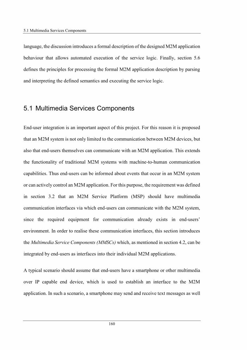
5.1 Multimedia Services Components
160
language, the discussion introduces a formal description of the designed M2M application
behaviour that allows automated execution of the service logic. Finally, section 5.6
defines the principles for processing the formal M2M application description by parsing
and interpreting the defined semantics and executing the service logic.
5.1 Multimedia Services Components
End-user integration is an important aspect of this project. For this reason it is proposed
that an M2M system is not only limited to the communication between M2M devices, but
also that end-users themselves can communicate with an M2M application. This extends
the functionality of traditional M2M systems with machine-to-human communication
capabilities. Thus end-users can be informed about events that occur in an M2M system
or can actively control an M2M application. For this purpose, the requirement was defined
in section 3.2 that an M2M Service Platform (MSP) should have multimedia
communication interfaces via which end-users can communicate with the M2M system,
since the required equipment for communication already exists in end-users’
environment. In order to realise these communication interfaces, this section introduces
the Multimedia Service Components (MMSCs) which, as mentioned in section 4.2, can be
integrated by end-users as interfaces into their individual M2M applications.
A typical scenario should assume that end-users have a smartphone or other multimedia
over IP capable end device, which is used to establish an interface to the M2M
application. In such a scenario, a smartphone may send and receive text messages as well

5 Autonomous M2M Application Provision
161
as audio and video calls. This offers the following possibilities to interact with the M2M
platform or with an M2M application:
Natural Language – Natural language that is converted to text and processed in
the M2M application or natural language that is generated and played back via the
audio channel.
Dual-Tone Multi-Frequency (DTMF) Signalling –DTMF signalling can be used
for signalling during a telephone call using key tones of telephone key pad (ITU-
T Q.23, 1993 and ETSI ES 201 235-1 V1.1.1, 2000).
Text Message – A text message sent to or generated by the M2M platform to
transmit text-based information.
Video – A video stream can be transmitted, generated by a video source inside the
M2M environment during a video call.
In order to enable these communication capabilities, it is proposed that the MMSCs
introduced below use the User Agent (UA) (IETF RFC 3261, 2002) integrated in the end-
user's Integrated Access Device (IAD) to communicate with the end-user's multimedia
devices (refer to Figure 5.1). The MMSCs are designed to make use of the Session
Initiation Protocol (SIP) (IETF RFC 3261, 2002) for communication with IAD UA,
respectively with the end-user’s multimedia device because SIP is the common standard
protocol in multimedia communication for controlling communication sessions and most
end-user IADs are equipped with a SIP stack to serve for public telephony connections.
(Steinheimer et al., 2013a)

5.1 Multimedia Services Components
162
Figure 5.1: MSP Multimedia Interfaces
Speech Recognition/DTMF (SR/DTMF) MMSC:
First the SR/DTMF MMSC (see Figure 5.2) is introduced offering the functionality to
receive audio calls with a SIP UA, which is integrated in the local M2M platform. The
designed SR/DTMF MMSC can serve as an easy operable input interface to the local M2M
platform in two ways:
Detect Spoken Text – During an audio session, this MMSC performs speech
recognition (SR) to detect spoken text by analysing the received Audio Stream.
Detect DTMF Signals – During the audio session, end-users have the possibility
to generate DTMF signals using the dial pad of their multimedia devices.
Figure 5.2: Architecture of SR/DTMF MMSC
Integrated Access
Device (IAD)
End-User
Service Runtime Environment (SRE)
Service Execution Engine (SEE)
Multimedia Service Components
(MMSCs)
UA
Audio/ Video Call,
Instant Message
AV/TTS
MMSC
IM
MMSCSR/DTMF
MMSC
Smartphone (UA)
SR/ DTMF MMSC
Character
Sequence
Audio Stream
{stream}
[Audio Stream]
{stream}
Receive
Audio Call
Stream Analyser
Audio Stream{stream}
[INFO (DTMF Digit)]
{stream}DTMF Digit
Mode Configuration

5 Autonomous M2M Application Provision
163
The SR/DTMF MMSC provides either the text detected from the Audio Stream or the
DTMF Digit sequence as an input value to the local M2M application. It consists of the
three parts Receive Audio Call, Stream Analyser, and Configuration. The Receive Audio
Call part receives the call initiated by the End-user UA executing a SIP Three Way
Handshake (IETF RFC 3261, 2002 and IETF RFC 3665, 2003). The platform UA accepts
the call by confirming the session establishment. After the audio session has been
established, the End-User UA starts transmitting the Audio Stream. The SR/DTMF MMSC
has two options for configuration specifying if it serves detecting DTMF signals or
spoken text. The configuration is managed by the Configuration part of this MMSC in
dependence on the Mode parameter. When the MMSC receives the Audio Stream, it starts
analysing the Audio Stream to detect either the spoken text or the DTMF Digit sequence
(depending on the configuration). If the SR/DTMF MMSC is configured for detecting
spoken text, the Stream Analyser performs the SR. If it is configured for detecting DTMF
signals the Stream Analyser detects the DTMF Digits sent by the End-User UA via one
SIP INFO request per DTMF Digit (IETF RFC 6086, 2011). After call termination the
SR/DTMF MMSC provides the detected Character Sequence for further processing to the
local M2M application.
Figure 5.3 illustrates the parameter set of the SR/DTMF MMSC. The Input parameter
Audio Stream is assigned internally by the Receive Audio Call part of this MMSC and
represents the Audio Stream that corresponds to the RTP (Realtime Transport Protocol)
(IETF RFC 3550, 2003) stream received by the platform UA. The Output parameter
Character Sequence is assigned by the Stream Analyser of the SR/DTMF MMSC and
represents the character sequence detected by this MMSC during audio stream analysis.
This Output parameter is usable for further processing in M2M applications.
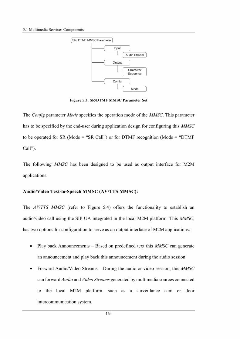
5.1 Multimedia Services Components
164
Figure 5.3: SR/DTMF MMSC Parameter Set
The Config parameter Mode specifies the operation mode of the MMSC. This parameter
has to be specified by the end-user during application design for configuring this MMSC
to be operated for SR (Mode = “SR Call”) or for DTMF recognition (Mode = “DTMF
Call”).
The following MMSC has been designed to be used as output interface for M2M
applications.
Audio/Video Text-to-Speech MMSC (AV/TTS MMSC):
The AV/TTS MMSC (refer to Figure 5.4) offers the functionality to establish an
audio/video call using the SIP UA integrated in the local M2M platform. This MMSC,
has two options for configuration to serve as an output interface of M2M applications:
Play back Announcements – Based on predefined text this MMSC can generate
an announcement and play back this announcement during the audio session.
Forward Audio/Video Streams – During the audio or video session, this MMSC
can forward Audio and Video Streams generated by multimedia sources connected
to the local M2M platform, such as a surveillance cam or door
intercommunication system.
SR/ DTMF MMSC Parameter
Input
Output
Config
Audio Stream
Character
Sequence
Mode
5 Autonomous M2M Application Provision
165
Figure 5.4: Architecture of AV/TTS MMSC
The AV/TTS MMSC consists of the parts Configuration, Generate Announcement File,
Setup Audio/Video Call, and Stream Media. The Setup Audio/Video part establishes an
audio or video session with the target UA of the end-user. The required address
information of receivers are specified via their SIP URIs (IETF RFC 3261, 2002) and
defined by the SIP URI input interface parameter of this MMSC. The Configuration part
manages, in dependence on the Mode parameter, whether the MMSC serves for generating
announcements (TTS) or forwarding an Audio or Video Stream. The Stream Media Part
contains a local Media Server element for generating or forwarding audio/video streams.
Depending on the configuration, the Stream Media part forwards Audio or Video Streams,
which are connected to the Audio or Video Stream input interfaces, to the End-User UA
or plays back an announcement file. The Generate Announcement File part, when MMSC
is configured for TTS, generates an Announcement File (audio) out of the text sequence
defined via the Text input parameter. After the Announcement File has been generated
and the call is established with the End-User UA, the local Media Server starts play back
of this announcement.
AV/TTS MMSC
Audio Stream
{stream}
[Audio Stream]
Setup Audio/
Video Call
{stream}
[Video Stream]
{stream}
Announcement File
[Announcement
File]Video Stream
{stream}
{stream}
Video
Stream
{stream}
Audio
Stream
Generate
Announcement File
Announcement
File
SIP URI
Text
Mode Configuration
Stream URI
Stream URI
Stream Media
Audio Stream
Video Stream
Media
Server

5.1 Multimedia Services Components
166
Figure 5.5 illustrates the parameter set of the AV/TTS MMSC. The Input parameter Text
has to be specified by the end-user during application design. It defines the text that the
AV/TTS MMSC announces after the call has been established with the End-user UA. The
Input parameters Audio and Video Stream is assigned internally by the Stream Media part
of this MMSC representing the Audio or Video Stream that corresponds to the stream that
the MMSC should forward. The Input parameter SIP URI has to be specified by the end-
user during M2M application design and corresponds to the destination address of End-
User UA that should receive the call.
Figure 5.5: AV/TTS MMSC Parameter Set
The Output parameters Audio and Video Stream are assigned by the Stream Media part
of the MMSC. They represents the Audio or Video Stream that is send to the End-User
UA. The Config parameter Mode specifies the operation mode of the MMSC and has to
be specified by the end-user during application design for configuring if the MMSC
forwards audio stream (Mode = “audio”), video stream (Mode = “video”) or announce a
AV/ TTS Call MM Service
Component Parameter
Input
Output
Config
Text
Audio Stream
Video Stream
Audio Stream
Video Stream
Mode
SIP URI
Stream URI

5 Autonomous M2M Application Provision
167
predefined text (Mode = “TTS”). The Config parameter Stream URI has also to be
specified by the end-user during application design and defines the source address of the
stream to be forwarded to the End-User UA, such as Real Time Streaming Protocol
(RTSP) (IETF RFC 2326, 1998) URI (e.g. rtsp://192.168.0.22/surveillanceCam
Indoor.stream1) often used for requesting RTSP media streams of local multimedia
devices.
The following MMSC has been designed to be used as both, text-based input and output
interface for M2M applications.
Instant Message MMSC (IM MMSC):
The IM MMSC (refer to Figure 5.6) offers the functionality for text-based communication
with M2M applications using the SIP UA integrated in the local M2M platform. This
MMSC offers communicating abilities in the following ways depending on its
configuration:
Receiving Instant Message (IM) – The MMSC receives an IM and extracts the
message text for further processing in local M2M applications.
Sending Instant Message – The MMSC generates an IM based on a character
sequence for transmitting information generated by the M2M applications.
The IM MMSC has been designed to serve as communication interface for both, input and
output interface using the SIP protocol extension for Instant Messaging specified in (IETF
RFC 3428, 2002).
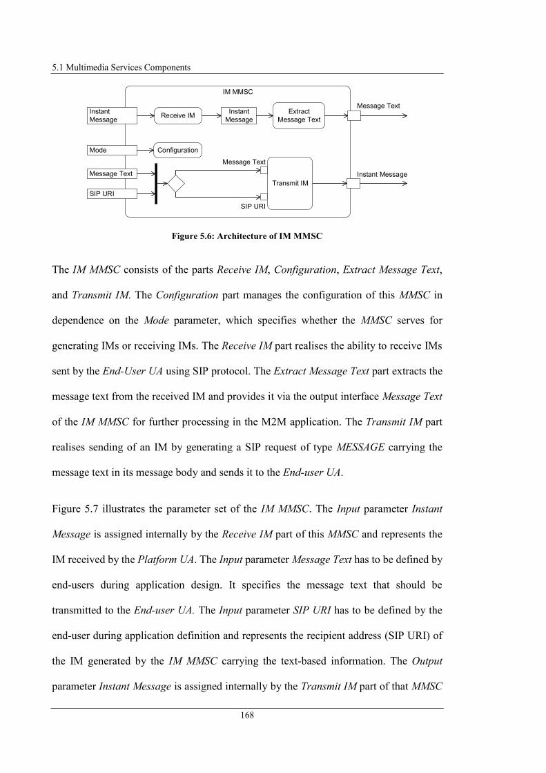
5.1 Multimedia Services Components
168
Figure 5.6: Architecture of IM MMSC
The IM MMSC consists of the parts Receive IM, Configuration, Extract Message Text,
and Transmit IM. The Configuration part manages the configuration of this MMSC in
dependence on the Mode parameter, which specifies whether the MMSC serves for
generating IMs or receiving IMs. The Receive IM part realises the ability to receive IMs
sent by the End-User UA using SIP protocol. The Extract Message Text part extracts the
message text from the received IM and provides it via the output interface Message Text
of the IM MMSC for further processing in the M2M application. The Transmit IM part
realises sending of an IM by generating a SIP request of type MESSAGE carrying the
message text in its message body and sends it to the End-user UA.
Figure 5.7 illustrates the parameter set of the IM MMSC. The Input parameter Instant
Message is assigned internally by the Receive IM part of this MMSC and represents the
IM received by the Platform UA. The Input parameter Message Text has to be defined by
end-users during application design. It specifies the message text that should be
transmitted to the End-user UA. The Input parameter SIP URI has to be defined by the
end-user during application definition and represents the recipient address (SIP URI) of
the IM generated by the IM MMSC carrying the text-based information. The Output
parameter Instant Message is assigned internally by the Transmit IM part of that MMSC
IM MMSC
Instant MessageMessage Text
SIP URI
Message Text
SIP URI
Instant
Message
Extract
Message Text
Message Text
Receive IMInstant
Message
Transmit IM
Mode Configuration

5 Autonomous M2M Application Provision
169
representing the SIP MESSAGE generated by the IM MMSC that is transmitted to the
End-user UA. The Output parameter Message Text is assigned by the Extract Message
Text part of that MMSC corresponding to the message body of the received IM,
respectively the text-based information send from End-user UA.
Figure 5.7: IM MMSC Parameter Set
The Config parameter Mode specifies the operation mode of the IM MMSC. The Mode
parameter has to be specified by the end-user during application design for configuring
that MMSC to be operated as input interface (Mode = “inIM”) or as output interface
(Mode = “outIM”). It can be stated that the MMSCs proposed in this section extend the
interface functionality of the MSPs presented in section 3.1 by the use of multimedia
communication. The designed interfaces can be used with existing equipment, so no
additional devices need to be purchased.
The following section 5.2 introduces the methodology to create M2M applications by the
end-user in a comfortable and intuitive way.
Instant Message (IM) MM
Service Component
Input
Output
Config
Instant
Message
Instant
Message
Mode
Message Text
Message Text
SIP URI
5.2 Application Behaviour Modelling
170
5.2 Application Behaviour Modelling
As identified in section 3.1, in existing platforms for providing M2M applications, the
configuration of automation tasks or the creation of application logic is highly dependent
on the implementing systems. Thus, the tools for definition of M2M applications can be
indicated as domain specific languages, which are utilised for creation of M2M
applications that are strictly bound to the executing system. A portability of the
configured applications to another, different system is not possible without redefining the
application (suitable for the new execution platform). Therefore, this research proposes a
methodology for application creation following MDA (Model Driven Approach)
principles derived from (OMG, 2017a) by defining a platform independent application
model (Steinheimer et al., 2017b). Such an abstract application model is expressed by a
modelling language describing the behaviour of an application, separated from the
technology-specific realisation of it (OMG, 2014; OMG, 2017a). The definition of the
abstracted model is independent of the realising platform and can therefore be modelled
without specific knowledge about the platform that implements the application (Petrasch
and Meimberg, 2006). The executing system has to interpret the abstract description of
the application and convert it into a specific structure that is appropriate to the executing
system. In the concept designed in this project end-users graphically create a behaviour
model of the M2M applications, which allows them to define the M2M application
semantic without having specific knowledge of the executing platform (Steinheimer et
al., 2017a).
In order to specify an adequate methodology how end-users can intuitively model the
behaviour of an M2M application, this project proposes that end-users design state

5 Autonomous M2M Application Provision
171
machines (SMs) describing the activities of an application by connecting building blocks
representing M2M devices and MMSCs (Steinheimer et al., 2017c). According (Rupp et
al., 2007) SMs describe the behaviour of a system that is specified using states. A SM
describes how a system residing in a specific state acts at specific events. This approach
to describe the behaviour of a system has been derived because end-users are able to
understand the principles behind (i.e. describing sequence of activities) as described
subsequently.
Devices have specific functionalities that are executed when the devices are triggered
(e.g. powered on). The functionality of a device is used to perform an activity that
corresponds to the functionality of the device. The end-user knows in principle how a
device works and is familiar with the use case that devices are connected with each other
such as illustrated in Figure 5.8. It shows that if the end-user triggers a device (switch
button by pushing), the switch button activates the lighting.
Figure 5.8: Use Case Switch Lighting
End-users are also familiar in utilising services, respectively service components, such as
illustrated in Figure 5.9. It shows an end-user that uses an email service utilising an
appropriate software, respectively service component on a personal computer (PC) and
inputs the text as well as the email address of the receiver. The service component has
also a specific functionality, which is to generate the email and sends it to the receiver
defined by the end-user as input parameter.
push
Switch Button
D
NEnd-User Lighting

5.2 Application Behaviour Modelling
172
Figure 5.9: Use Case Email Service
Considering both use cases, end-users are able to relate that devices are connected to each
other. It is irrelevant whether they exchange data (as in M2M environments) or are
interconnected by an electrical connection (as in traditional electrical circuits). More
generally speaking, devices and services have inputs from which an activity results which
in turn generates outputs. At this point, three classes of devices are specified that can be
present in the personal environment of an end-user:
Actuators – Actuators control actions depending on the inputs and supply output
values if necessary.
Sensors – Sensors are used to acquire data which they supply as output values,
possibly triggered by an input.
Combined – These devices cannot be assigned directly to one of the other groups,
since they offer both, possibility to control and supply of sensor values. E.g. a
surveillance camera offers abilities to detect movements and to communicate this
as an event and can also be triggered to start recordings.
Figure 5.10 illustrates the general structure of M2M devices/MMSCs defined to specify a
general perspective of them (but also of M2M applications). They can have multiple Input
and Output parameters as well as Config (configuration) parameters whereby all of them
in general perspective are optional.
Service
Component
PC
+
Text
End-User

5 Autonomous M2M Application Provision
173
Figure 5.10: General Structure of M2M Device and MMSC
Input Parameter – Input parameters are processed from an M2M Device/MMSC to
perform the M2M Device/Service Functionality. Input parameters can be set
statically or connected with an Output parameter of another M2M Device/MMSC.
Output Parameters – Output parameters are generated by the M2M Device/MMSC
as a result of the performed activity. Output parameters can be queried for
inspection or directed as an Input parameter to another M2M Device/MMSC.
Config Parameters – Config parameters are used to (statically) predefine specific
configuration options of M2M Devices/MMSCs.
From a general perspective, end-users can define M2M applications by connecting the
Output parameter of one M2M Device with the Input parameter of another M2M Device.
It is defined at this point that not only M2M Devices can be combined, but also M2M
devices and MMSCs because they work according to the same principle (input,
processing, and output). Figure 5.11 shows the general representation of connections
between M2M Devices and MMSCs as described above.
Figure 5.11: General Representation of M2M Device and MMSC Connections
M2M Device/ MMSC
Input 1
Input n
...
Output 1
Output n
...
Config 1 Config n...
...
M2M Device/MMSC
Functionality
M2M Device/
MMSC
Functionality
Input Output
M2M Device/
MMSC
Functionality
Input Output
M2M Device/
MMSC
Functionality
Input Output
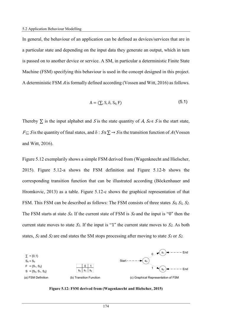
5.2 Application Behaviour Modelling
174
In general, the behaviour of an application can be defined as devices/services that are in
a particular state and depending on the input data they generate an output, which in turn
is passed on to another device or service. A SM, in particular a deterministic Finite State
Machine (FSM) specifying this behaviour is used in the concept designed in this project.
A deterministic FSM A is formally defined according (Vossen and Witt, 2016) as follows.
Thereby ∑ is the input alphabet and S is the state quantity of A, S0 ϵ S is the start state,
F S is the quantity of final states, and : S x ∑ → S is the transition function of A (Vossen
and Witt, 2016).
Figure 5.12 exemplarily shows a simple FSM derived from (Wagenknecht and Hielscher,
2015). Figure 5.12-a shows the FSM definition and Figure 5.12-b shows the
corresponding transition function that can be illustrated according (Böckenhauer and
Hromkovic, 2013) as a table. Figure 5.12-c shows the graphical representation of that
FSM. This FSM can be described as follows: The FSM consists of three states S0, S1, S2.
The FSM starts at state S0. If the current state of FSM is S0 and the input is “0” then the
current state moves to state S1. If the input is “1” the current state moves to S2. As both
states, S1 and S2 are end states the SM stops processing after moving to state S1 or S2.
Figure 5.12: FSM derived from (Wagenknecht and Hielscher, 2015)
(5.1)A = ( , S, , S0, F)
(c) Graphical Representation of FSM
s0Start
s1 End
s2 End
0
1
(a) FSM Definition
S0
F
S
= {0,1}
= S0
= {S1, S2}
= {S0, S1, S2}
0 1
s0 s1 s2
(b) Transition Function

5 Autonomous M2M Application Provision
175
To model an application consisting of linked M2M devices and MMSCs with a FSM, the
components of M2M applications are mapped to the elements of the FSM as specified in
Table 5.1.
Table 5.1: M2M Application Component FSM Element Mapping
The following Figure 5.13 illustrates exemplarily the M2M application as defined by Use
Case 1 (refer to section 2.4) represented as a FSM. The graphical representation of the
FSM is shown in Figure 5.13-c.
Figure 5.13: M2M Application Use Case 1 represented as FSM
To realise Use Case 1, an application is defined that detects whether it rains with the help
of a rain sensor as M2M device. Furthermore, within the application, a window sensor is
used as M2M device to check if the window is opened. If it rains and the window is
opened at the same time, a corresponding information should be transmitted to the end-
M2M Application
Component
FSM Element Description
M2M Device/MMSC
Component
State M2M Device/MMSC components are assigned to the states
of a FSM representing them inside the FSM.
M2M Device/MMSC
Component Connection
Transition Connections between the M2M Devices and MMSCs are
assigned to transitions connecting the states of a FSM and
representing the information flow between M2M Devices
and MMSCs inside the FSM.
(c) Graphical Representation of FSM
RainStartTTS
CallEndWindow
openraining
(a) FSM Definition Use Case 1
S0
F
S
= {raining, open}
= Rain
= {TTS Call}
= {Rain, Window, TTS Call}
raining open
Rain Window Rain
Window Window TTS Call
(b) Transition Function Use Case 1

5.2 Application Behaviour Modelling
176
user by phone call. This is done using the AV/TTS MMSC defined in section 5.1, which
is configured to announce a specific text using TTS.
According to the above defined principles the M2M devices and MMSC are mapped with
the states as specified in Table 5.2. Thus the state quantity S (refer to Figure 5.13-a) of
the FSM is {Rain, Window, TTS Call}.
Table 5.2: M2M Application Component FSM State Mapping Use Case 1
Since the M2M application should check first if it rains, the start state S0 is specified as
Rain (Rain Sensor). As the M2M devices and MMSC have been assigned to the states
of the FSM, the connections between them need to be specified. This is done by first
defining the input alphabet ∑ representing the sensor states. Therefore, the input alphabet
∑ is {raining, open}. Additionally, the Transition Function needs to be defined as
illustrated in Figure 5.13-b. This Transition Function specifies that if checking the state
of rain sensor results in raining, the current state of the FSM moves to Window checking
if its state is open. If this is the case, the current state of the FSM moves to TTS Call,
which is equivalent to establishing the call with the end-user UA using AV/TTS MMSC.
Since the application should terminate after announcing the text to the end-user, the
quantity of final states F is {TTS Call}.
After the principles of behavior-oriented M2M application modelling by means of FSMs
have been introduced and exemplified, the following section describes how the graphical
modelling is proposed.
M2M Application Component FSM Element
M2M Device Rain Sensor FSM state Rain
M2M Device Window Sensor FSM state TTS Call

5 Autonomous M2M Application Provision
177
5.3 Graphical Application Behaviour Design
As described in section 4.2, the graphical design of an M2M application is realised via a
GUI provided by the Service Design Unit (SDU) component of the designed framework.
A GUI is proposed as the end-user interface for application design, since most users are
familiar with the use of GUIs. An interface could also be implemented, e.g. through a
text-based input/output system, but this would not satisfy the requirements for simplicity
and usability.
This section deals with the structure of the GUI and the process of modelling an M2M
application graphically in the form of a state machine (SM) to define the application
semantics, i.e. the application model. The description of the process for the graphical
modelling is again illustrated with the help of M2M application represented by Use Case
1 (refer to section 2.4). As introduced in section 4.2 the graphically designed application
is transformed by the SCU component of the proposed framework into a formal
description, which can be executed by the M2M platform (Steinheimer et al., 2013b).
Section 5.5 will specify an adequate modelling concept, respectively a formal modelling
language to describe the behaviour of an M2M application abstracted as a SM.
A GUI should contain the following aspects to provide an adequate interface to end-users
for M2M application modelling:
M2M Device/MMSC Indication – The GUI should indicate M2M devices and
MMSCs available in the personal environment of end-users (and also remote
available M2M services).

5.3 Graphical Application Behaviour Design
178
M2M Device/MMSC Interface Integration – The interface of the M2M devices
and MMSCs must be available to specify their Input/Output/Config parameters.
Connection of M2M Devices/MMSCs – The M2M device and MMSCs,
respectively their Input and Output interfaces have to be connectable.
Display designed M2M Applications – The GUI should provide the possibility to
manage or change already designed M2M applications.
Specification of Conditions – To create a decision-based M2M application logic,
the logical connections between the M2M Devices/MMSCs should be equipped
with conditions to process the steps in the M2M application workflow in
dependence on defined conditions. Relational operators illustrated in Table 5.3
are proposed for defining conditions that are understandable for end-users.
Table 5.3: Relational Operators for logical M2M Device/MMSC Connections
The GUI is presented in this project as a web-based application, but could also be realised
as e.g. App on a smartphone or tablet. It is not the kind of application that is important,
but a simple interface to the M2M platform making it possible to design a SM for the
M2M applications.
In the following, the structure of the GUI and the process for service creation by end-
users is described starting with the architecture of the GUI (illustrated in Figure 5.14).
Relational Operator Example Descripion
Greater than (>) A > B Checks if a value A is greater than another value B .
Less than (<) A < B Checks if a value A is less than another value B .
Equal to (==) A == B Checks if two values A and B are equal.
Not equal to (!=) A != B Checks if two values A and B are equal.

5 Autonomous M2M Application Provision
179
Figure 5.14: Structure of Service Design GUI acc. (Steinheimer et al., 2013c; Steinheimer et al.,
2015b)
The GUI consists of the subsequently described sections:
M2M Devices Section – The M2M Devices section lists M2M devices present in
end-users’ personal environments (represented by graphical building blocks).
These building blocks represent the interfaces to the M2M Devices and makes
them available for integration in M2M applications.
MMSCs Section – The MMSCs section lists the MMSCs provided by the local
M2M platform also represented by graphical building blocks representing the
interfaces to the MMSCs for integrating them in M2M application workflows.
Service Management GUI
Output
Config
http://192.168.0.1/SmartHomeSCE/
Rain
Upload new M2M Devices/ Service Components: Please select File...
Window
TTS Call
[state == open]
[state == raining]
Input
$state <raining/notraining>
Type
Remote M2M Service
Description
Provides remote Rain Sensor
values.
Rain Parameter
Service Design GUI
Configuration
Rain Specification
WorkbenchM2M Devices
MM Service
Components
Sensors
Actuators
Window
Rain
...
Light Control
Power Plug
...
Combined
Cam
...
TTS Call
A/V Call
DTMF
Control
SR Call
IM
...
Remote M2M
Services
Rain
...

5.3 Graphical Application Behaviour Design
180
Remote M2M Services Section – The Remote M2M Services section lists building
blocks of M2M services provided by other end-user (refer to section 6.1). These
remote services can be integrated into local M2M applications according to the
same principles as integration of M2M devices/MMSCs. Additionally, these
building blocks are used to model cooperative M2M applications (refer to section
6.4).
Configuration Section – The Configuration section provides configuration details
of the individual M2M devices/MMSCs, such as the Config parameters of M2M
devices or information regarding the values provided by Input/Output parameters
(Parameter area). The Configuration section also provides additional information
regarding the specification of M2M devices/MMSCs, such as type specification
of the M2M device (e.g. actuator or sensor), a prose description of the
functionality (e.g. control functionality of an M2M Device) or annotations
regarding the configuration like value ranges parameters (Specification area).
Workbench Section – The Workbench section is used to create the M2M
applications by graphically combining the building blocks of M2M devices and
MMSCs. This process is illustrated in Figure 5.15 and described subsequently.
According to (Steinheimer et al., 2015b) End-users starts modelling the SM of the desired
M2M application by dragging all the M2M device/MMSC building blocks they want to
integrate in their local M2M application to the Workbench section (Select M2M
Device/Service Component Building Blocks). For Use Case 1, integrated into the
illustration of the GUI structure of Figure 5.14, these are the building blocks of Rain
sensor, Window sensor, and TTS Call MMSC. After placing the M2M Device and MMSC
building blocks to the Workbench section the end-user connects the building blocks with

5 Autonomous M2M Application Provision
181
an arrow to specify the semantical workflow of the M2M application (Define Logical
Combinations). In the exemplary Use Case 1 the Rain sensor building block is connected
to the Window sensor building block that again is connected to the TTS Call MMSC
building block.
Figure 5.15: M2M Application Design Process
These connections model that first the Rain Sensor is processed (in particular requested),
then the Window Sensor is processed (also requested) and finally the TTS Call MMSC is
processed (to setup up a call). If the end-users want to design, that a specific step of the
application workflow is processed only if a defined condition becomes true, they can add
a condition to each connection between the M2M Devices and MMSCs. In the exemplary
Use Case 1, illustrated in Figure 5.14 following conditions are defined:
Select M2M Device
Building BlockSelect MMSC
Building Block
Drag Building Block
to Workbench
[yes]
[no]
Select Two Building
Blocks from
Workbench
Design M2M Application
Select M2M Device/MMSC
Building Blocks
Define Logical Combinations
Define Transition between
Building Blocks
[no]
yes
Specify Condition[Conditional]
[Not conditional]
Configure M2M Devices/
MMSCs
Select Building
Block
Configure Building Block
Config Parameter
[yes]
[no]
[yes]
[no]
<<decisionInput>>
integrate additional
Building Blocks
<<decisionInput>>
Additional Combination
<<decisionInput>>
Building Block
requires Configuration
<<decisionInput>>
Building Blocks left

5.3 Graphical Application Behaviour Design
182
[state == raining] – For the connection of Rain sensor and Window sensor it is
specified that the step to process requesting state parameter of Window sensor is
performed, if the state parameter of Rain sensor holds the value “raining”.
Otherwise, the application resides at the step requesting the Rain sensor.
Transferred to the SM paradigm the SM resides in the state corresponding to the
Rain sensor and the transition to the state corresponding to the Window sensor is
performed only if the input of the SM is raining (element of FSM input alphabet).
[state == open] – For the connection of Window sensor and TTS Call MMSC it is
specified that the step to setup the announcement call is performed, if the window
is open, i.e. if the state parameter of the Window sensor holds the value “open”.
Transferred to the SM paradigm the SM resides in the state corresponding to the
Window sensor until the input of the SM is open (element of FSM input alphabet).
After end-users have defined all logical connections between the M2M devices/MMSCs
they configure those (Configure M2M Devices/MMSCs). For this, they select the
corresponding building block in the Workbench section and define the Config parameter
inside the Configuration section of the GUI. In exemplary Use Case 1 the TTS MMSC is
the only building block that requires configuration. Table 5.4 shows its configuration
according the specification of AV/TTS MMSC introduced in section 5.1 to initialise it for
call setup with end-user’s UA and announcement of a pre-defined text.
Table 5.4: Configuration of TTS MMSC Use Case 1
TTS MMSC Parameter Parameter Value Descripion
config.mode TTS Configuration for TTS call.
input.text "warning window open and starts raining" Warning message to be
announced.
input.sipURI "sip:username@domain" Destination SIP URI of end-user
UA specified to receive the call.

5 Autonomous M2M Application Provision
183
This section introduced the architecture of the GUI that provides an easy usable interface
to the end-users for graphical design of M2M applications for their local environment
with integration of M2M devices and MMSCs enabling input/output interfaces of M2M
applications. The process for graphical application design has been introduced in detail
and the behaviour of M2M application representing exemplary Use Case 1 was modelled
graphically, which has been defined in previous section 5.2 by means of a FSM.
5.4 M2M Device Management and Communication
The basis for the creation of an M2M application is the integration of M2M devices into
the M2M platform and the networking of M2M devices. As described in section 3.2, the
M2M devices are mostly implemented with different mutually incompatible M2M
communication technologies. If the necessary details for the connection of different M2M
devices were taken into account in an M2M application (e.g. message format,
communication protocols, control commands), a separate interface would have to be
implemented for each M2M technology within the M2M application. The M2M
application would have to consider the devices as well as M2M technology-specific
details. (ETSI TR 101 584 V2.1.1, 2013) confirms this aspect according to the previously
valid standard for M2M (ETSI TR 102 966 V1.1.1, 2014). In this way, the M2M
application would again be close coupled to the executing platform, or could only be used
with the M2M technologies provided inside the M2M application. Porting the application
to a different system would not be possible. It is therefore essential that the M2M devices
can be connected to the M2M platform and be used in the M2M applications
independently of the underlying technology. Therefore, in (Steinheimer et al., 2013a),
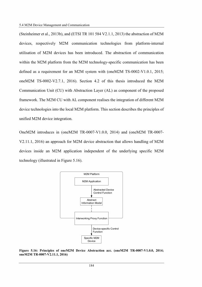
5.4 M2M Device Management and Communication
184
(Steinheimer et al., 2013b), and (ETSI TR 101 584 V2.1.1, 2013) the abstraction of M2M
devices, respectively M2M communication technologies from platform-internal
utilisation of M2M devices has been introduced. The abstraction of communication
within the M2M platform from the M2M technology-specific communication has been
defined as a requirement for an M2M system with (oneM2M TS-0002-V1.0.1, 2015;
oneM2M TS-0002-V2.7.1, 2016). Section 4.2 of this thesis introduced the M2M
Communication Unit (CU) with Abstraction Layer (AL) as component of the proposed
framework. The M2M CU with AL component realises the integration of different M2M
device technologies into the local M2M platform. This section describes the principles of
unified M2M device integration.
OneM2M introduces in (oneM2M TR-0007-V1.0.0, 2014) and (oneM2M TR-0007-
V2.11.1, 2016) an approach for M2M device abstraction that allows handling of M2M
devices inside an M2M application independent of the underlying specific M2M
technology (illustrated in Figure 5.16).
Figure 5.16: Principles of oneM2M Device Abstraction acc. (oneM2M TR-0007-V1.0.0, 2014;
oneM2M TR-0007-V2.11.1, 2016)
M2M Platform
M2M Application
Abstract
Information Model
Interworking Proxy Function
Abstracted Device
Control Function
Device-specific Control
Function
Specific M2M
Device

5 Autonomous M2M Application Provision
185
The presented approach is based on mapping native device interfaces into an abstracted
oneM2M resource addressable by an M2M application. The M2M application does not
communicate with the native device API, but with the abstract representation of the M2M
device. A so-called Abstract Information Model specifies the abstract device, which is a
formal representation of the device including e.g. its operations or parameters. OneM2M
defines the “Interworking Proxy Function” responsible for translating the Abstract
Information Model into the Device-specific Control Functions (oneM2M TR-0007-
V2.11.1, 2016).
As described in section 3.1.1 within an oneM2M architecture according (oneM2M TS-
0001-V2.10.0, 2016) everything is considered as resources that are provided by entities
and are queried or controlled by other entities. Therefore, M2M devices connected to the
M2M platform are considered as resources. Considering now the M2M application as an
entity that consumes a resource and the M2M Technology API as an entity which
provides a resource and the device-specific communication with the physical M2M
equipment, this principle can be transferred to connecting M2M devices to the M2M
platform.
Query and control of resources is done according (oneM2M TS-0001-V2.10.0, 2016)
using specific Create (C), Retrieve (R), Update (U), Delete (D), Notify (N) operations
(CRUDN operations). To query/manipulate a resource, consuming and providing entity
communicate applying the request/response principle described in section 3.1.1.
Table 5.5 and Table 5.6 describe an extract of the parameter sets according (oneM2M TS-
0001-V2.10.0, 2016) that request and response messages contain that are generated by
resource consuming/providing entities.

5.4 M2M Device Management and Communication
186
Table 5.5: Parameter Set of Request Resource Message acc. (oneM2M TS-0001-V2.10.0, 2016)
According (oneM2M TS-0004-V2.7.1, 2016) oneM2M defines Primitives that are
messages exchanged between entities in an M2M system. Originator and receiver can be
located on the same M2M Node or on M2M nodes connected via a network. Primitives
are modelled as a data structure specifying the operations and parameters processed on
the receiver and originator entity. According (oneM2M TS-0004-V2.7.1, 2016) each
(CRUDN) operation related to a resource “comprises a pair of primitives: Request and
Response”. These Primitives become serialised, e.g. as XML or JSON format that can be
exchanged between the entities using e.g. HTTP, CoAP, MQTT protocol to transmit the
Primitives over an IP network. OneM2M specifies so-called Bindings to define unified
Parameter
To
From
Create (C) Creates a new resource at the destination address specified in To
parameter.
Retrieve (R) Requests a resource addressed by the To Parameter.
Update (U) Sets the content of a resource addressed by the To parameter. The
content to be set in the resource is specified in the Content
parameter
Delete (D) Deletes a resource at the destination address specified in To
parameter.
Notify (N) Information that is sent to the receiving resource.
Content
Request Identifier
Description
Address of the resource or URI of an attribute of a resource to be requested.
Operation
Content that should be transferred to the receiving resource and relates to the
operation specified by Operation parameter. Only applicable for following
operations: Create (content of resource to be created), Retrieve (list of attribute
names to be retrieved), Update (content to be updated in the destination
resource), and Notify (information should be notified to the receiver).
Identifies of the specific request message.
Identifier of the message originator.
Operation the receiving resource should execute. The operation parameter is
separated into the specific operations stated below.
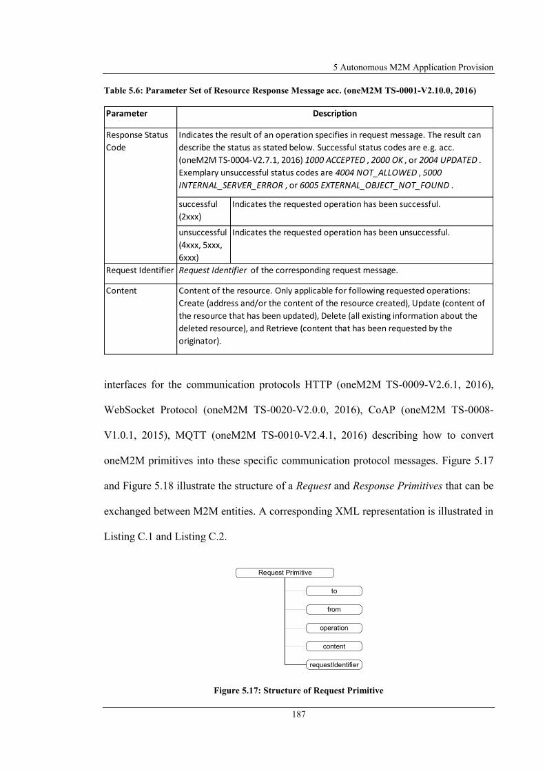
5 Autonomous M2M Application Provision
187
Table 5.6: Parameter Set of Resource Response Message acc. (oneM2M TS-0001-V2.10.0, 2016)
interfaces for the communication protocols HTTP (oneM2M TS-0009-V2.6.1, 2016),
WebSocket Protocol (oneM2M TS-0020-V2.0.0, 2016), CoAP (oneM2M TS-0008-
V1.0.1, 2015), MQTT (oneM2M TS-0010-V2.4.1, 2016) describing how to convert
oneM2M primitives into these specific communication protocol messages. Figure 5.17
and Figure 5.18 illustrate the structure of a Request and Response Primitives that can be
exchanged between M2M entities. A corresponding XML representation is illustrated in
Listing C.1 and Listing C.2.
Figure 5.17: Structure of Request Primitive
Parameter
successful
(2xxx)
Indicates the requested operation has been successful.
unsuccessful
(4xxx, 5xxx,
6xxx)
Indicates the requested operation has been unsuccessful.
Request Identifier
Content
Description
Response Status
Code
Indicates the result of an operation specifies in request message. The result can
describe the status as stated below. Successful status codes are e.g. acc.
(oneM2M TS-0004-V2.7.1, 2016) 1000 ACCEPTED , 2000 OK , or 2004 UPDATED .
Exemplary unsuccessful status codes are 4004 NOT_ALLOWED , 5000
INTERNAL_SERVER_ERROR , or 6005 EXTERNAL_OBJECT_NOT_FOUND .
Request Identifier of the corresponding request message.
Content of the resource. Only applicable for following requested operations:
Create (address and/or the content of the resource created), Update (content of
the resource that has been updated), Delete (all existing information about the
deleted resource), and Retrieve (content that has been requested by the
originator).
Request Primitive
from
operation
content
to
requestIdentifier

5.4 M2M Device Management and Communication
188
Figure 5.18: Structure of Response Primitive
In order to define an appropriate abstract device representation and abstraction
mechanism to integrate M2M devices of different M2M technologies into the M2M
platform, the principles of device handling and communication between M2M entities
have been derived from oneM2M as described subsequently.
The framework architecture designed in this project contains the M2M CU with AL
element (illustrated in Figure 5.19). The M2M CU realises the unified communication
between M2M applications executed inside the M2M platform and the M2M devices of
different M2M technologies connected to the M2M platform. (Steinheimer et al., 2012a;
Steinheimer et al., 2013a; Steinheimer et al., 2015b)
Figure 5.19: M2M Communication Unit (CU) with Abstraction Layer (AL)
Response Primitive
requestIdentifier
content
responseStatusCode
M2M Communication Unit (CU)
Technology-specific
Messages
M2M Technology
Interfaces (TI)
...
M2M Technology
API NM2M Technology
API B
M2M Technology
API A
M2M Technology Mgmt & Forward
M2M Application
Technology-
independent Messages
Abstraction Layer (AL)
Abstract M2M Device
Representatiom
M2M Device
Capability
Model (DCM) M2M Device
Registry
M2M Devices Technology A
D
N
M2M Devices Technology B
D
N
M2M Devices Technology N
D
N

5 Autonomous M2M Application Provision
189
The AL as part of the M2M CU abstracts the devices inside the M2M platform from
specific communication technologies, such as KNX or ZigBee. To achieve this
integration, all devices are considered independent of their specific communication
technologies as Abstract M2M Device Representations. To realise the abstraction of
specific M2M device technologies the AL contains the following functionality:
Message Coordination – The AL coordinates controlling of different types of
M2M equipment and thus offers the possibility to define M2M applications
without depending on the M2M technologies used.
Abstract M2M Device Management – Management of abstracted M2M devices
by M2M device registration, assignment of abstract device-IDs and administration
of the assignments of abstract and specific device-IDs.
To realise the abstraction, derived from (oneM2M TR-0007-V2.11.1, 2016) an abstract
information model has been designed (M2M Device Capability Model, M2M DCM),
describing the M2M devices. The M2M applications do not communicate with the
specific M2M device, but with the abstract device representation within the platform
described by the M2M DCM.
This M2M DCM is also used by the SDU component of the framework to display and
specify an M2M device representation within the GUI. Since also MMSCs are usable in
applications, they are also described with the M2M DCM and processed in the same way.
To specify an appropriate M2M DCM, following information should be included in it:
Device-ID – To uniquely identify an M2M device, a device-ID should be
included.

5.4 M2M Device Management and Communication
190
Input/Output/Config Parameters – In section 5.2 was specified that M2M
devices/MMSCs each have a set of Input/Output/Config parameters. For unified
description of M2M device/MMSC, these parameters should be contained in a
M2M DCM.
Type and Description – In section 5.3 was specified that additional information
on M2M devices/MMSCs should be displayed in the GUI (description and type).
The M2M DCM therefore should also contain these information.
Considering these requirements, a general structure of an M2M DCM is designed as
shown in Figure 5.20.
Figure 5.20: Structure of M2M DCM
...
...
...
M2M Device/MMSC Capability Model
parameter
input
output
config
type
description
inputParameter id=1
inputParameter id=n
outputParameter id=1
outputParameter id=n
configParameter id=1
configParameter id=n
id
name
value
<name>
<value>
name
value
name
value
name
value
name
value

5 Autonomous M2M Application Provision
191
To formally describe this structure of an M2M DCM, the XML format is selected since it
is standardised, expandable and machine-readable. Listing C.3 shows a representation of
an uniformly defined M2M DCM in XML. If only predefined values are allowed for
specification of parameters, this can be defined as enumeration within the parameter
specification in a specific instance of an M2M DCM (e.g. for the rain sensor of Use Case
1 this could be defined in this way: {raining| notraining}).
The M2M Technology Interfaces (M2M TI) element of the CU (see Figure 5.19) realises
management of and communication with M2M devices of various M2M technologies. It
is designed to realise abstracted and M2M technology-specific communication, and
contains various M2M technology-specific APIs communicating with the respective
M2M devices via a device-specific technology.
To realise this management and communication the M2M TI contains the following
functionality:
M2M Device Technology APIs – The M2M TI element contains the M2M
Technology APIs for communication with the M2M devices of the specific
technology to query or control them.
Message Transformation – Transforms abstracted request messages in technology
specific request messages and transforms technology-specific response and
notification messages into abstracted response and notification messages.
Message distribution – Distribute technology-specific messages to M2M
Technology APIs implementing the communication with the M2M equipment.
Device Registration – Registration of technology-specific M2M devices at the AL
component of the M2M CU.

5.4 M2M Device Management and Communication
192
As described above, the M2M application does not communicate with the physical M2M
device but with an abstract representation of it. For this purpose, an application
communicates with the AL to query a value of an M2M device or to control the M2M
device. If the AL receives a request for an abstracted M2M device, it must forward this
request to the corresponding M2M TI. For this purpose, it is necessary for the AL to
manage the allocation of abstract to technology-specific M2M devices. To realise this,
the M2M TI element registers the connected devices at the AL, which records this
registration and assigns them an abstract device-ID. The AL stores the assignment of
abstract and specific device-ID within the M2M Device Registry contained in the CU. The
process of the M2M device registration is shown in Figure 5.21.
Figure 5.21: M2M CU/AL Register Process
To register an M2M device with the AL, the M2M Technology Mgmt & Forward element
sends a Register Request to the AL containing the specific device-ID of the M2M devices.
The AL generates an abstract device-ID for the M2M device specified in the Register
Request and stores it within the M2M Device Registry component. The abstraction of the
M2M devices offers the advantage that the M2M devices, or the technology of an M2M
device can be changed or exchanged, but the M2M application itself is not affected by
such changes since it communicates with the abstracted devices.
Register Request [DeviceID-Spec]
Peer 0M2M Technology
Mgmt & Forward Peer 0Abstraction
Layer (AL)
Generate
Abstracted Device
ID [DeviceID-Abs]
Store Mapping [DeviceID-Abs]
and [DeviceID-Spec] Response OK
Peer 0M2M Device
Registry
Store [DeviceID-Spec, DeviceID-Abs]
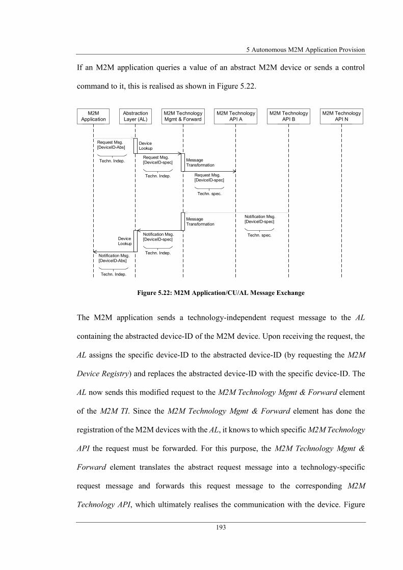
5 Autonomous M2M Application Provision
193
If an M2M application queries a value of an abstract M2M device or sends a control
command to it, this is realised as shown in Figure 5.22.
Figure 5.22: M2M Application/CU/AL Message Exchange
The M2M application sends a technology-independent request message to the AL
containing the abstracted device-ID of the M2M device. Upon receiving the request, the
AL assigns the specific device-ID to the abstracted device-ID (by requesting the M2M
Device Registry) and replaces the abstracted device-ID with the specific device-ID. The
AL now sends this modified request to the M2M Technology Mgmt & Forward element
of the M2M TI. Since the M2M Technology Mgmt & Forward element has done the
registration of the M2M devices with the AL, it knows to which specific M2M Technology
API the request must be forwarded. For this purpose, the M2M Technology Mgmt &
Forward element translates the abstract request message into a technology-specific
request message and forwards this request message to the corresponding M2M
Technology API, which ultimately realises the communication with the device. Figure
Device
Lookup
Request Msg.
[DeviceID-Abs]
Peer 0Abstraction
Layer (AL)Peer 0M2M
Application Peer 0M2M Technology
Mgmt & Forward Peer 0M2M Technology
API A Peer 0M2M Technology
API B Peer 0M2M Technology
API N
Techn. Indep.Request Msg.
[DeviceID-spec]
Techn. Indep.
Message
Transformation
Request Msg.
[DeviceID-spec]
Techn. spec.
Notification Msg.
[DeviceID-spec]
Techn. spec.
Message
Transformation
Device
Lookup
Notification Msg.
[DeviceID-spec]
Techn. Indep.Notification Msg.
[DeviceID-Abs]
Techn. Indep.

5.4 M2M Device Management and Communication
194
5.22 also contains the representation of the message exchange by means of a Notify
message sent from a specific M2M device to an M2M application. In this case, the
transformation of a specific request is done analogously to the described method of a
request message initiated by an M2M application.
The M2M DCM is stored within the AL, but must also be known to the M2M TI element
because the M2M TI element receives a query specified for an abstracted M2M DCM and
has to map this request to a specific M2M device.
Up to now, the communication between the M2M application and the M2M device has
been specified via an abstracted communication mechanism. Additionally, it is necessary
to define a uniform message format, which is used for the exchange of information
between the M2M platform components. For this purpose, the approach defined by
oneM2M is used to exchange messages between entities using Primitives. Following this
approach, a Request Primitive must be defined containing the necessary information to
query or control M2M devices. This Request Primitive is generated by the M2M
application or the M2M TI element and sent to the AL. The AL contains an Abstracted
M2M Device Representation (described by the M2M DCM). The M2M TI element of the
M2M CU also contains the M2M DCM. The M2M DCM is therefore a central component
on which the M2M CU performs the abstracted message exchange between M2M
application and M2M devices. It is therefore necessary to integrate the information into a
Request Primitive that is required for querying or controlling M2M devices, as specified
in the M2M DCM. Figure 5.23 illustrates the M2M DCM (specified in Figure 5.20) as
well as the structure of a Request Primitive (specified in Table 5.5) and assigns the
relevant information of an M2M device to the elements of a Request Primitive. Listing

5 Autonomous M2M Application Provision
195
C.4 illustrates the XML representation of the fully specified Request Primitive template
including the M2M DCM parameters.
Figure 5.23: Mapping M2M DCM to Request Primitive Parameters
Since an M2M device is uniquely identified via an M2M device-ID, this parameter can
be transferred to the To parameter of a Request Primitive. The M2M DCM parameters
...
...
...
M2M Device/MMSC
Capability Model
parameter
input
output
config
type
description
inputParameter id=1
inputParameter id=n
outputParameter id=1
outputParameter id=n
configParameter id=1
configParameter id=n
id
name
value
<name>
<value>
name
value
name
value
name
value
name
value
Request Primitive
from
operation
requestIdentifier
content
to
...
...
...
input
output
config
inputParameter id=1
inputParameter id=n
outputParameter id=1
outputParameter id=n
configParameter id=1
configParameter id=n
name
value
<name>
<value>
name
value
name
value
name
value
name
value
M2M Device/MMSC Parameters Request Primitive Parameters

5.4 M2M Device Management and Communication
196
describe the Input/Output/Config parameters of an M2M device. It is therefore necessary
information that must be transferred to an M2M device. Such information should be
transmitted, as specified in Table 5.5, using the content parameter of a Request Primitive.
Because both, Request Primitive and M2M DCM are specified using XML format, the
Parameter element of M2M DCM as complex datatype can be integrated in the Content
parameter of the Request Primitive XML description. Using these two mappings, all
information required for request/control M2M devices are integrated in the Request
Primitive. Further information, respectively parameter to be specified are:
From Parameter – The From parameter specifies the Request Primitive originator.
Specification of this parameter depends on the element of the M2M platform
originating the request (M2M Application, AL or M2M TI).
Operation Parameter – The operation parameter specifies the operation to be
executed at the request receiver (create for M2M device registration, update for
control and config operations, retrieve for value requests, notify for notification
requests)
Up to this point, it has been specified that the communication of M2M application and
physical M2M equipment occur in an abstracted way and how the communication
between the M2M platform components occurs to exchange information for request and
control of M2M devices. The following approaches are proposed for automatically or
partly automatically integration of machine-readable M2M DCMs into the M2M platform
(illustrated in Figure 5.24 including particular steps of installation process).

5 Autonomous M2M Application Provision
197
Installation by End-user – End-users installs M2M DCMs as files using the GUI
(1.1). The M2M DCMs are stored inside the M2M platform in the M2M Device
Registry (1.2) containing all installed M2M DCMs. During invocation process of
the GUI, available M2M DCMs are requested from M2M Device Registry and
displayed as M2M device/MMSC building blocks in the GUI (1.3,2.3,3.5) to be
available for application design (refer to section 5.3).
Figure 5.24: Installation of M2M Device Capability Models
Installation by M2M Device – The M2M DCMs are stored at the M2M device
that should connect to the M2M platform. While connecting M2M devices to the
M2M platform the M2M DCMs transfer to the M2M platform (2.1) and are stored
in M2M Device Registry (2.2).
Download from M2M Device Vendor – The M2M device to be installed contains
a reference (e.g. a link) incl. M2M device-ID to the vendor of the M2M device
for download the M2M DCM using a network connection to the vendor. While
connecting the M2M device to the M2M platform the reference and M2M device-
IP Network/
Internet
3.4 Device ID 3.2
3.3
Service Design
Unit (SDU)
GUI
1.1
1.3
2.3
3.5
Device ID,
Vendor
M2
M D
evic
e
AL
3.1
Device ID,
Vendor
M2M Device ID
M2M
DCM
1.2
M2M
DCMM2M Device
Registry
M2M
DCM
2.2
M2M
DCMM2M
Device
M2M
Device
2.1
M2M
DCMEnd User
M2M Device
Vendor
M2M
DCM
M2M
DCM
5.4 M2M Device Management and Communication
198
ID transfer to the M2M platform (3.1). The M2M Device Registry contacts the
M2M Device Vendor (3.2) using the provided information and requests the M2M
DCM stored at vendor-side for download (3.3). After downloading the M2M
DCM, the M2M Device Registry stores the M2M DCM in its repository for all
available M2M DCMs (3.4).
The lastly presented approach to automatically download the M2M DCMs from M2M
device vendor has the advantage that M2M devices do not need to provide storage space
for storing M2M DCMs and at the same time enables provision of updated M2M DCMs.
Additionally, the fully automated installation of M2M DCMs is realisable according this
approach. Drawback of this approach is that an active network connection to the
download server of the M2M device vendor must exist. Additional disadvantage is that
the download server represents a centralised element in the M2M system architecture,
which results in risks for e.g. availability (refer to section 3.2) and violates the principle
requirement of the proposed framework to avoid central components. The firstly
presented approach to install M2M DCMs by end-users has the disadvantage, that it
requires manual installation of the M2M DCMs by end-users and therefore is no fully
automated mechanism. Additionally, this approach requires providing the M2M DCM on
a separate installation medium usable for installation or downloading the M2M DCM
from the M2M Device Vendor download server. Therefore, the second approach is the
most practical solution for automated installation of M2M DCMs with the drawback that
the additional storage space on the M2M device needs to be provided.
The following section describes the formal description of graphically designed M2M
application as introduced in section 4.2.

5 Autonomous M2M Application Provision
199
5.5 Formal M2M Application Notation
The previous sections introduced how end-users can model M2M applications in the form
of a SM. This section determines a concept for SM-based modelling (section 5.5.1) and
introduces the principles of modelling using Statecharts (section 5.5.2). Section 5.5.3
describes how a specific M2M application can be modelled and formally described using
Statecharts according to the approach proposed in this research.
5.5.1 Selection of State Machine-based Modelling Language
As introduced in section 5.2, the end-user should describe the M2M application be means
of an abstract model that is based on a SM. Therefore, a modelling language or a
modelling concept is needed which allows to specify the behaviour of an application in
form of a SM.
Describing an M2M application with a FSM allows to map M2M devices/MMSCs to the
states of an FSM and to map the connections between them to state transitions.
Nevertheless a FSM as introduced in section 5.2 cannot be applied to the description of
an M2M application in particular and generally to the description of combinations of
devices and service components since FSMs do not allow state transitions to be equipped
with data that is required for inputs or outputs of states. However, this is necessary if the
introduced concept should be followed by combining input and output of devices and
services. FSMs also do not allow to configure a state because the states do not have
parameters that could be used for this. Since M2M devices/MMSCs are usually
5.5 Formal M2M Application Notation
200
configurable and cannot be controlled or configured exclusively by input parameters,
definition of configuration parameters is required.
Therefore, an alternative is needed to define the behavior of an application, similar to an
FSM. Since this definition is to be made with a formal language, languages and concepts
are presented and compared with each other that enable a behavioural modelling and
formal description of M2M applications.
To identify an appropriate modelling language enabling the formal description of the
graphically modelled application using SM concept, the following section first defines
requirements according to (Steinheimer et al., 2017a) for selecting an optimal modelling
language for this purpose. Subsequently, potential candidates are presented and then
evaluated with regard to the defined requirements.
Standardised language – It should be a standardised modelling language to ensure
portability.
M2M Device/MMSC Mapping – The modelling language must provide elements
that enable representation of M2M devices/MMSCs and connection between
them. The connections between the M2M devices/MMSCs, i.e. information flow
between them or activation should be equipped with a condition.
Intuitive usability – Since the system is to be used by an average technically
experienced end-user after a short training, the complexity of the graphical
notation should be low. Complex and non-intuitive forms of modelling reduce or
eliminate usability.
Parallel flows – Within an application, it should be possible to define parallel
sequences to realise concurrent tasks.

5 Autonomous M2M Application Provision
201
Synchronisation of states – To synchronise parallel flows there must be a
synchronisation possibility.
Machine readability – Since the M2M application should be generated
automatically after graphical modelling and automatically processed by the M2M
platform, the modelling language should be a formal language which is machine-
readable.
State parametrisation – The elements to be combined should be able to be
parameterised (definition of input/output/configuration parameters). Therefore,
the states in the SM must also be parameterisable.
Existing parser/interpreter implementation – To be able to process the formal
language automatically, an implementation of a corresponding parser or
interpreter should exist.
Domain independent – The modelling language cannot be a domain specific
language to prevent limiting the scope to the specific domain.
An application according (Harel and Politi, 1998) can be modelled with three different
views onto the system:
Functional View – The Functional View specifies the processes, activities, and
functions of a system. It includes inputs and outputs of activities, which is the
information flow between the internal and external activities. The Functional
View of a system is described using Activity Diagrams as Modelling Language
(Harel and Politi, 1998). An Activity Diagram describes complex processes,
focuses on the task of the system that has to be divided into single steps, and
5.5 Formal M2M Application Notation
202
answers the question “how a system realises a specific behaviour” (Rupp at al.,
2007).
Behavioural View – The Behavioural View specifies the behaviour of a system.
It specifies how a system acts on defined conditions and when the activities
defined in the Functional View become active and when the information flow
between the activities take place. The Behavioural View of a system is described
using State Diagrams as Modelling Language (Harel and Politi, 1998). A State
Diagram describes the behaviour of a system using states and transitions between
states that are triggered by external or internal events. A state diagram answers
the question “how the system behaves when residing in a specific state and a
specific event occurs” (Rupp at al., 2007).
Structural View – The Structural View specifies the modules and subsystems
“constituting the real system and the communication between them”. The
Structural View is considered as the “physical model” of the system describing
the specific hardware and software implementations (Harel and Politi, 1998).
Since the end-user should describe the application in an abstract way and do not need to
know any hardware- and software-specific details, the application cannot be modelled
according to the Structural View. Because modelling the behaviour of an M2M
application is in the focus of the concept described in this research, formal descriptions
based on the Behavioural View appear to be a suitable approach. According (Rupp et al.,
2007), (ISO/IEC 19514, 2017) and (OMG, 2017b) SMs (Behavioural View) and Activity
Diagrams (Functional View) are equivalent and can describe both the same behaviour of
a system, therefore also modelling languages for process-based modelling are considered
in the evaluation for the optimal modelling language.
5 Autonomous M2M Application Provision
203
According to the above-defined requirements, the following common modelling
languages form a group of SM-based modelling languages that potentially satisfy the
requirements (Steinheimer et al., 2017a):
Business Process Model and Notation (BPMN) (OMG, 2011)
UML Activity Diagram (UML AD) (OMG, 2015)
UML StateMachine Diagram (UML SMD) (OMG, 2011)
These modelling languages are described below and evaluated according to the defined
requirements. The first two modelling languages represent candidates for Functional
View (describing process-oriented modelling, workflows). The last modelling language
represents a candidate for Behavioural View (describing behaviour-oriented modelling).
All of these modelling languages specify a set of elements that can be combined
graphically to describe a process or the behaviour of an application. To evaluate the
modelling language candidates regarding the defined evaluation criteria, the following
section describes if each modelling language can satisfy the specific requirement.
BPMN is a standard, defined by the Object Management Group (OMG) to provide a
formal notation of business processes that is easy to understand by all involved users (e.g.
business analysts, technical developers or people manging/monitoring the defined
processes) (OMG, 2011). BPMN provides a graphical notation that is “widely accepted
for modelling business processes” (Geambasu, 2012).
UML AD is a diagram specified by the Unified Modelling Language standard (OMG,
2015) for describing the behaviour of a system using graphs. The graph consists out of
nodes that are connected to other nodes using edges. Some of the nodes represent “lower-

5.5 Formal M2M Application Notation
204
level steps in the overall Activity” and other nodes “hold data that is input to and output
from executable nodes”. UML AD describes e.g. procedural computations or can be
applied for modelling business processes or workflows in organisations (OMG, 2015).
The focus of modelling with a UML AD is in coordination “lower-level behaviours” of a
system (Geambasu, 2012).
UML SMD is used to model event-driven behaviour of a system with the use of “finite
state-machine formalism”. The finite state-machine formalism applied in UML SMDs is
based on Statecharts as defined by David Harel (Harel, 1987). The UML SMD consists
of states that can be connected to other states by transitions. UML SMD distinguishes
between Simple States without internal transitions or states and Composite States that
contains other states and transitions (OMG, 2011). According (Rupp et al., 2007) UML
StateMachines are an extension of FSMs. The behaviour of a system is specified by means
of states. A SM describes how a system behaves in a certain state during certain events.
It has been defined as a precondition for selecting appropriate candidates that the
modelling language is specified in a common standard. This illustrates the first advantage
against the FSM introduced in section 5.2, which can be described mathematically but is
not specified by any standardisation committee.
M2M Device/MMSC Mapping and Conditional Transition
Using BPMN as modelling language for M2M applications the M2M devices/MMSCs
can by mapped to Activities representing the performed action. Sequence Flows
representing the information flow between M2M devices/MMSCs can connect Activities.
BPMN distinguishes between Conditional Flows and Sequence Flows. A Conditional
5 Autonomous M2M Application Provision
205
Flow can be equipped with a condition specifying whether a Flow is only processed if the
condition is true. In UML AD the M2M devices/MMSCs can be mapped to Actions that
can be connected using Activity Edges. The Activity Edges in an UML AD represent the
control flow of a process and can be used to describe the connection of M2M
devices/MMSCs. The UML AD contains so-called Control Nodes. The Decision Node is
a specific Control Node that can be used for specifying conditional control flows. To
specify a condition the Activity Edge connected to the Decision Node can be equipped
with a condition. The control flow then only is performed if this condition is satisfied.
Using UML SMD as modelling language the M2M devices/MMSCs can be mapped to
States and connected by a Transition. The Transition between two States can be equipped
with a so-called “Guard Condition” specifying if a Transition from one State to another
State is executed only if the “Guard Condition” is fulfilled.
All three candidates include elements in their modelling language specification that
enable the mapping of M2M devices/MMSCs to elements in the modelling language.
Also all candidates provide connection functionality of elements to represent the
connection of M2M devices/MMSCs, respectively the information flow between them.
The connection can be defined with either direct connections or connections based on a
condition.
Intuitive Usability
BPMN offers a wide range of elements that can be used to model processes. BPMN
enables modelling in a very high degree of detail. This makes the language versatile but
also significantly more complex than e.g. UML SMD. Therefore, when using BPMN, it
is important to select the elements describing an M2M application that are understandable

5.5 Formal M2M Application Notation
206
for the users and to limit the number of elements needed to model an M2M application.
UML AD offers the possibility to describe processes in a very detailed way using a large
number of available elements for the modelling. Since there are many different elements
for the modelling of a process using UML AD, UML AD can only be used if the selection
of the available elements is limited. The elements of UML SMD are clear and become
combined graphically. The basic structure of the UML SMD corresponds to the structure
as M2M applications are modelled using the GUI presented in section 5.3. UML SMDs
describes an abstract view of the system. According (Labiak and Miczulski, 2004),
Statecharts offer the possibility to describe the complex behaviour of a system in
sufficient detail, so that it can be used by non-specialists (i.e. persons who do not have
technical training).
BPMN, UML AD, and UML SMD allow the modelling of the behaviour of an application
with their elements. BPMN and UML AD offer here a very large number of available
elements for modelling. At the same time, this represents a high complexity that restricts
the intuitive use of the modelling language. Using BPMN and UML AD, a system is
modelled using the bottom-up approach. An abstract description with the top-down
approach is not possible because the degree of detail. But this would be better for the end-
user to understand, since not the system details but the overall behaviour should be
described. Since the elements available for the modelling of UML SMDs are limited in
their diversity compared to BPMN and UML AD, but the desired behaviour can be
modelled at the same time, intuitive modelling is possible rather than with the other
candidates.
Parallel Flows
5 Autonomous M2M Application Provision
207
BPMN provides a Fork element that can be used to divide a path into multiple paths.
Using the Fork element enables parallel processing of activities and therefore parallel
processing of M2M devices/MMSCs. The UML AD enables describing parallel flows by
providing Fork Nodes for splitting control flows into multiple parallel control flows. This
enables the parallel processing of actions (i.e. the parallel information flow between
different M2M devices/MMSCs). UML SMD distinguishes between simple States and
Composite States. A Simple State does not include other States. A Composite State can
include other States connected by Transitions (i.e. another SM). A Composite State can
be separated into so-called Regions that specify two or more included SMs executed in
parallel.
All three candidates enable modelling of parallel sequences in the application structure.
FSM cannot model this kind of behaviour because it specifies only one target state per
transition and does not allow multiple target states be reachable from one originating
state.
Synchronisation of States
The counterpart to a Fork element in BPMN is the Join element. Via the Join element,
parallel Sequence Flows (i.e. parallel M2M devices/MMSCs) are recombined and
synchronised. UML AD provides Join Nodes as counterpart to Fork Nodes to synchronise
(i.e. recombine) parallel control flows. UML SMDs have so-called Join and Fork nodes.
A Fork node can be used to split a transition and a Join node can merge them again. This
makes it possible to generate parallel sequences, which are also recombined again
synchronously. Above described Parallel Flows defined by regions in a Composite State

5.5 Formal M2M Application Notation
208
can also be synchronised. Then the composite state is left by transition only if all
including parallel SMs have reached their Final States.
All three candidates support merging and synchronisation of parallel flows. This FSM
naturally do not support because missing parallel flow capability.
Machine Readability
BPMN is a graphical notation and not machine-readable. According (OMG, 2011) the
standardised Web Service Business Process Execution Language (WSBPEL) (OASIS,
2007) has been specified as a formal description language for definition of business
processes. WSBPEL is a “web service-based XML execution language” for business
processes and is machine-readable. The BPMN standard specification includes mapping
definitions for a subset of BPMN elements to WSBPEL (Geambasu, 2012 and OMG,
2011). According (Geambasu, 2012) no specification exist that maps the UML AD
components “to any business process execution language”, which means that UML AD
is not machine-readable because no formal description exists. UML SMDs are not
machine-readable, since they are a graphical notation. However, with State Chart
extensible Markup Language (SCXML) (W3C, 2015), an execution language for SMs
specified by World Wide Web Consortium (W3C) exists that is based on Harel
Statecharts (same as UML SMDs) and allows formal description of SMs using XML.
Since SCXML is a formal language, it is machine-readable and can therefore be processed
automatically, which means that through UML SMDs described by SCXML automated
processing of the application description is possible.

5 Autonomous M2M Application Provision
209
None of the three candidates support machine readability out of the box, but for BPMN
and UML SMD standardised execution languages exist enabling the formal description
of modelling languages and therefore are machine-readable. The scope of UML SMDs is
fully implemented by SCXML. WSBPEL only implements a subset of BPMN elements.
For UML AD no standard specification exist for formal description of UML AD which
prohibits the automated execution of M2M applications described using UML AD.
State parametrisation
BPMN represents data using Data Objects that are added to Flows between Activities.
These Data Objects define the data exchanged between the Activities, respectively the
M2M devices/MMSCs. Inside of a BPMN Activity this data need to be associated to Data
Input field of the Activity. The Data produced by Activities are represented as Data
Output field of an Activity. Both, Data Inputs and Data Outputs need to assign the data
contained in the Data Object to the corresponding Input and Output fields of an Activity
using InputOutputSpecification, which is an element of the Activity itself. In a UML AD,
data is represented by Object Nodes exchanged between the Actions. An Action can
generate an Object Node as an output, which in turn is processed as an input in another
Action. The Data Objects leave an Action via an interface and are imported into an Action
via an interface. These interfaces are referred to as parameters of an Action and can be
uniquely identified by name. For the States in UML SMDs, so-called Entry and Exit
Activities can be defined. These Activities are executed as soon as a State is entered or
exited. These Activities are methods that are called and can be used to define input and
output parameters for the State. For input and config parameters the Entry Activity would
be used and for Output parameter the Exit Activity. In SCXML, it is also possible to

5.5 Formal M2M Application Notation
210
explicitly define parameters for a State. They can be used to define the parameters in the
XML description of the Statechart.
All three candidates provide the functionality to equip states with parameter and therefore
enable the configuration of M2M device/MMSC parameters contained in the
corresponding element of the modelling language.
Existing parser/interpreter implementation
For WSBPEL, there are a number of Execution Engines which can interpret and execute
the processes described by WSBPEL, e.g. Apache ODE (Orchestration Director Engine)
(ODE, 2017) or Oracle BPEL Process Manager (Oracle, 2017a). Since UML AD are not
described with a formal language, there is no parser/interpreter implementation. The
Apache Commons Foundation (Commons SCXML, 2016) provides a parser/interpreter
for SMs described with SCXML.
The candidates BPMN and UML SMD therefore satisfy the requirement that a
parser/interpreter exists for the formal description language.
Domain independent
BPMN is a domain independent language but requires WSBPEL as formal execution
language. WSBPEL is a domain specific language because it is limited to integration of
web services. According (Thakar et al., 2016) the WSBPEL standard (OASIS, 2007) is
specified for traditional web service architecture to integrate web services as components
into business processes using Simple Object Access Protocol (SOAP) (W3C, 2000). The
details of the components, such as input and output parameter of services and service
endpoints are described using web services Description Language (WSDL) (W3C, 2001).

5 Autonomous M2M Application Provision
211
The WSDL specification is designed for SOAP-based web service compositions, not
usable for RESTful architectures, which is the architectural approach for M2M
environments (refer to section 3.1.1). UML AD is a domain independent language
because it can describe processes in various application domains. Since SCXML is
realised using XML, it is a domain independent language. Since its application area is not
limited to a specific field SCXML is a domain independent modelling language for SMs.
The modelling languages UML AD, UML SMD, and FSM are not specified for use in a
specific application domain, but can be used for modelling/describing behaviour-based
systems in various application domains. BPMN itself is not limited, but WSBPEL as
execution language is limited for use in web service application field.
Table 5.7 summarises the evaluation results of the modelling language candidates and
compares it with the FSM principle introduced in section 5.2.
Table 5.7: Evaluation of SM-based Modelling Languages acc. (Steinheimer et al., 2017a)
The result of the evaluation is that UML SMDs fully satisfy the requirements and
therefore the standardised description language SCXML as formal service description is
proposed for describing M2M application behaviour. BPMN and UML AD represent both
BPMN UML AD UML SMD FSM
Standardised Language + + + -
M2M Device/MMSC Mapping + + + +
Intuitive Usability o o + +
Parallel Flows + + + -
Synchronisation of States + + + -
Machine Readability + - + -
State Parametrisation + + + -
Existing Parser/ Interpreter + - + -
Domain independent o + + +
Requirements Modelling Language
Functional View Behavioural View
Requirements Evaluation: += satisfied; o= partially satisfied; -=not satisfied

5.5 Formal M2M Application Notation
212
very extensive modelling languages allowing a fine granular and detailed description of
processes, whereby BPMN serves more for the description of business processes. BMPN
also fulfils almost all requirements for the formal description language. However, the fact
that WSBPEL is limited to Web service environments prevents WSBPEL from being
used for the application description in a RESTful M2M environment.
Since UML SMDs, respectively Statecharts as modelling language and SCXML as
execution language were selected, these are presented in detail below.
5.5.2 Principles of Statechart Modelling
The M2M application semantic is graphically designed by creating an SM-based
behaviour model (see section 5.3) that should be described using UML SMDs or Harel
Statecharts in the formal execution language SCXML (see section 5.5.1). The following
section presents the relevant elements and principles for modelling using Statecharts.
The main elements of Statecharts are states and transitions. States are illustrated as boxes
with rounded corners and the name of the state is placed inside the box. Arrows
connecting the states represent transitions (Harel and Politi, 1998). States in the diagram
can be active representing the current state of the system and by a transition, it can move
to another state of the system (Harel and Naamad, 1996). In particular a state represents
an active configuration of a system and can move from one state (i.e. configuration) to
another state based on specific triggers acting on the system, such as external events or
predefined conditions causing the state transition (Harel and Kugler, 2004).
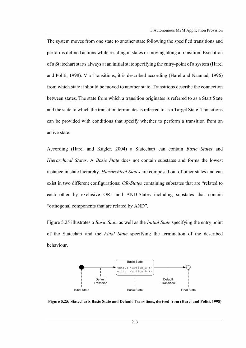
5 Autonomous M2M Application Provision
213
The system moves from one state to another state following the specified transitions and
performs defined actions while residing in states or moving along a transition. Execution
of a Statechart starts always at an initial state specifying the entry-point of a system (Harel
and Politi, 1998). Via Transitions, it is described according (Harel and Naamad, 1996)
from which state it should be moved to another state. Transitions describe the connection
between states. The state from which a transition originates is referred to as a Start State
and the state to which the transition terminates is referred to as a Target State. Transitions
can be provided with conditions that specify whether to perform a transition from an
active state.
According (Harel and Kugler, 2004) a Statechart can contain Basic States and
Hierarchical States. A Basic State does not contain substates and forms the lowest
instance in state hierarchy. Hierarchical States are composed out of other states and can
exist in two different configurations: OR-States containing substates that are “related to
each other by exclusive OR” and AND-States including substates that contain
“orthogonal components that are related by AND”.
Figure 5.25 illustrates a Basic State as well as the Initial State specifying the entry point
of the Statechart and the Final State specifying the termination of the described
behaviour.
Figure 5.25: Statecharts Basic State and Default Transitions, derived from (Harel and Politi, 1998)
Basic State
entry: <action_a()>
exit: <action_b()>
Initial State Basic State Final State
Default
Transition
Default
Transition

5.5 Formal M2M Application Notation
214
A Default Transition to the states in a Statechart connects Initial State and Final State
(Harel and Politi, 1998). States and transitions can be equipped with Actions that are
executed during a transition or while either entering a state (Entry Action) or leaving a
state (Exit Action) (Harel and Kugler, 2004). A Default Transition is a special kind of
transition that cannot by equipped with a condition or action. The Statechart in Figure
5.25 describes that after entering the Basic State the action_a() is executed and while
leaving the Basic State the action_b() is executed. Actions can be static calculations or
method calls to trigger any additional functionality to be executed while residing in a state
or moving from one state to another.
As mentioned above two kinds of hierarchical states exist describing different behaviour.
Figure 5.26 illustrates the hierarchical AND-State A. According (Harel and Politi, 1998)
AND-States consist of one or more orthogonal components (sections) executed
simultaneously. AND-States can therefore be used to describe parallel sequences, which
again are defined by states. For each parallel section it has to be defined which state is the
Initial State and therefore should begin with the execution
Figure 5.26: Statecharts AND-State, derived from (Harel and Politi, 1998)
State B
AND-State A
OR-State O.1 OR-State O.2
State O.11
State O.12
State O.21
State O.22
State O.23
t1 t2 t3
t4
t5
t6
t7
Initial State (1)
Initial State (2) Initial State (3)

5 Autonomous M2M Application Provision
215
In an AND-State, additionally to the enclosing AND-State itself, the embedded states are
always active within a section and execute actions. A Parallel State is left when all
sections have reached their final state (which was not defined in the exemplary AND-
State A, so the AND-State A remains within the contained sections). Another way to leave
an AND-State is when a transition is generated from an inner state to a state outside the
Hierarchical State, or when a transition of the comprehensive Parallel State is triggered.
In the example shown in Figure 5.26, AND-State A is therefore only left when the
transition t7 has been triggered. The active state then changes to State B without regards
of which internal state the AND-State A currently resides.
The second type of Hierarchical State is the OR-State. Figure 5.27 shows an exemplary
OR-State O. The OR-State also contains states that in turn are connected with transitions.
Figure 5.27: Statecharts OR-State, derived from (Harel and Politi, 1998)
An OR-State has no parallel sections, but group’s individual states. It is also necessary to
define for an OR-State which of the contained states is the initial state, i.e. which state
should start processing as soon as the comprehensive OR-State is reached. An OR-State
can terminate its processing when a transition is triggered within the Hierarchical State
(e.g., t5) targeting to a state outside the Hierarchical State. A further possibility to leave
an OR-State is when a transition connected to the comprehensive OR-State is triggered
and leads to an external state (e.g. t6).
OR-State O
t1State O.1 State O.2 State O.3
t4
t2
t3t5
t6
State B

5.5 Formal M2M Application Notation
216
After the principles of modelling using Statecharts have been introduced, the following
section introduces the formal description of Statecharts using SCXML.
SCXML has been specified by W3C as recommendation for an executable SM language
that combines Harel semantics of Statecharts with XML syntax. It has been defined
because UML SMDs only are specified as “graphical specification language” without
XML representation for automated execution (W3C, 2015). Subsequently the basic
structure of a formal description of Statecharts using SCXML is presented using two
examples.
Figure 5.28 shows the formal description by SCXML of the example of a minimal
Statechart, shown in Figure 5.25, consisting of a basic state and two default transitions.
Figure 5.28: SCXML Representation of Basic State and Default Transitions
Since the document format of a SCXML description is XML, every SCXML description
starts in the first line with the XML declaration, specifying the XML version and the
encoding used. Next the root element has to be specified as <SCXML> which is the
element encompassing all components of the Statechart. Inside the root element the
namespace and version of SCXML is specified. The root element additionally contains
<?xml version="1.0" encoding="UTF-8"?>
<scxml
xmlns="http://www.w3.org/2005/07/scxml" version="1.0" name="BasicStateExample"
datamodel="jexl" initial="BasicState">
<state id = BasicState >
<onentry>
<action name= action_a />
</onentry>
<onexit>
<action name= action_b />
</ onexit >
<final id=BasicStateFinal />
</state>
</scxml>
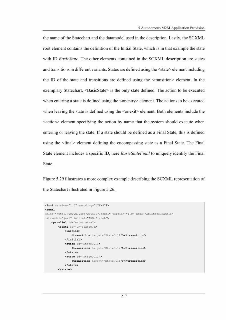
5 Autonomous M2M Application Provision
217
the name of the Statechart and the datamodel used in the description. Lastly, the SCXML
root element contains the definition of the Initial State, which is in that example the state
with ID BasicState. The other elements contained in the SCXML description are states
and transitions in different variants. States are defined using the <state> element including
the ID of the state and transitions are defined using the <transition> element. In the
exemplary Statechart, <BasicState> is the only state defined. The action to be executed
when entering a state is defined using the <onentry> element. The actions to be executed
when leaving the state is defined using the <onexit> element. Both elements include the
<action> element specifying the action by name that the system should execute when
entering or leaving the state. If a state should be defined as a Final State, this is defined
using the <final> element defining the encompassing state as a Final State. The Final
State element includes a specific ID, here BasicStateFinal to uniquely identify the Final
State.
Figure 5.29 illustrates a more complex example describing the SCXML representation of
the Statechart illustrated in Figure 5.26.
<?xml version="1.0" encoding="UTF-8"?>
<scxml
xmlns="http://www.w3.org/2005/07/scxml" version="1.0" name="ANDStateExample"
datamodel="jexl" initial="AND-StateA">
<parallel id= AND-StateA >
<state id= OR-StateO.1>
<initial>
<transition target= StateO.11 ></transition>
</initial>
<state id= StateO.11>
<transition target= StateO.12 ></transition>
</state>
<state id= StateO.12 >
<transition target= StateO.11 ></transition>
</state>
</state>

5.5 Formal M2M Application Notation
218
Figure 5.29: SCXML Representation of AND-State
This example contains an AND-State (AND-StateA), which SCXML specifies using the
<parallel> element and another simple state (StateB). StateB is defined as Final State
using the <final> element. The AND-State, respectively Parallel State encompasses the
two OR-States OR-StateO.1 and OR-StateO.2. Parallel States and OR-States must specify
the Initial State for their containing states. This is done using the <initial> element that
specifies the Initial State as a Transition Target with the ID of the Initial State element.
In the example Statechart for the hierarchical OR-States StateO.11 and StateO.23 are
defined as Initial States. If states are connected to another state by transition, this is
defined using the <transition> element. Inside the <transition> element, ID of the Target
State defines the Target State of a transition.
This section introduced the principles of behaviour modelling with Statecharts as
modelling language and introduced SCXML as standardised SM execution language.
Both bring the possibility to model and describe systems flexible and very detailed but
<state id= OR-StateO.2>
<initial>
<transition target= StateO.23 ></transition>
</initial>
<state id= StateO.21 >
<transition target= StateO.22 ></transition>
</state>
<state id= StateO.22 >
<transition target= StateO.23 ></transition>
</state>
<state id= StateO.23>
<transition target= StateO.22 ></transition>
<transition target= StateO.21 ></transition>
</state>
</state>
<transition target= StateB ></transition>
</parallel>
<state id= StateB >
<final id=StateBFinal />
</state>
</scxml>

5 Autonomous M2M Application Provision
219
with reduced complexity. The following section describes how to apply the power of
Statecharts and SCXML to formally describe M2M applications.
5.5.3 M2M Application Modelling using Statecharts
In the previous sections it was introduced how MMSCs can be integrated into M2M
applications to create an interface to them (section 5.1). Furthermore, a unified structure
for an M2M Devices/MMSCs was specified, consisting of input/output/config parameters
as interfaces to a component performing variable functionality (section 5.2). Moreover, it
was worked out that the end-user graphically models the behaviour of an application in
the form of a SM and thereby defines the application logic (section 5.2 and section 5.3).
The modelling is done using Statecharts that are formally described with SCXML
(Steinheimer et al., 2017b). To determine how such a modelled M2M application can be
formally described by means of Statecharts, it is first necessary to define a general
structure for an M2M application and to transfer this structure to the modelling principles
using Statecharts.
It has already been determined that an M2M device/MMSC is represented as a state. It
was also defined that the connection between M2M devices/MMSCs is made by defining
transitions between the states. This is now to be described using Statecharts. Figure 5.30
exemplarily illustrates the Statechart representation of an M2M application with the help
of Use Case 1 (refer to section 2.4), also described as FSM in Figure 5.13 and graphically
modelled as illustrated in Figure 5.14. The corresponding SCXML representation of the
Statechart is illustrated in Listing C.5.

5.5 Formal M2M Application Notation
220
Figure 5.30: Statechart Representation of Use Case 1
M2M devices/MMSCs each are defined as a state (state-id: “Rain”, “Window”,
“TTScall”). The configuration of an M2M device/MMSC and the data exchange between
the components is defined by the parameters of a state. This can be mapped to the
parameters of a state in Statechart representation, respectively SCXML. To determine
which parameters are defined in a state for the specification of an M2M devices/MMSC,
first it has to be defined which parameters an M2M device/MMSC can have. This has
already been specified by the general structure of an M2M devices/MMSC by having any
M2M device/MMSC 0...n Input/Output/Config parameter. The M2M DCM for each
M2M device describes the device-specific structure. The parameters specified by the
DCM are mapped using the parameters of a state. To obtain the best flexibility in
determining the data structure, JEXL (Java Expression Language) (Commons JEXL,
2017) is proposed as the format for the Data Model. By integrating JEXL as a regular
expression language in SCXML, it is possible to define the structure of the parameter
declaration according to the ANT-style (Apache ANT, 2017). This makes it possible to
Initial State Rain
Rain.output.state = ""
Window
Window.output.state = ""
Cond: $Rain.output.state=raining
TTScall
TTScall.input.text = "Warning window open and
starts raining"
TTScall.input.sipURI = "sip:username@localhost"
TTScall.config.mode = "TTS"
Cond: $Window.output=open
Final State

5 Autonomous M2M Application Provision
221
categorise the parameters according to their structure within their naming according to
input/output/config. The following structure is defined for the parameters:
<deviceID>.input.<parameter name>
<deviceID>.output.<parameter name>
<deviceID>.config.<parameter name>
Each parameter starts with the ID of an M2M device/MMSC followed by a ".". Attached
to this is the category of the parameter. For this purpose, the input/output/config key
words define the type of parameters. Finally, the parameter name is added to this category
with a previous ".". For assigning the parameters to a state, it is necessary to define a Data
Model for the state. This Data Model is an element of the state and contains a separate
element for each parameter defining the name of the parameter via the entry data id, and
the value of the parameter via the entry expr. In the example for Use Case 1 the output
parameters of Rain and Window were created. Since they are output parameters which are
assigned by the M2M device itself, these are not initialised within the Statechart or
SCXML description, but are defined as "". The MMSC TTScall, respectively the state
TTScall, has input and config parameters that must be specified. This is done in the Data
Model of the state TTScall by assigning the corresponding configuration values to the
input and config parameters via the expr entry.
The connection of the M2M devices/MMSCs is realised by the description of a transition
between the M2M device/MMSCs. As described above, the connection between M2M
application components should be conditional. This condition is specified within the
transition element using the entry cond. In the example of Use Case 1, e.g. the following
condition is defined for the state Rain: $Rain.output.state=raining. This condition defines

5.5 Formal M2M Application Notation
222
that the transition is only executed if the Rain.output.state parameter is equal to the value
"raining".
Expressions can be specified not only in the conditions of a transition, but also in <assign>
elements of SCXML, respectively through onentry/ onexit operations or transitions of
states. These elements allow values to be assigned to parameters in the Data Model.
Figure 5.31 shows, by means of two connected states, an overview of definition, query
and assignment of parameters in a Statechart. The corresponding SCXML description in
illustrated in Listing C.6. However, not only the static assignment of values to the state
parameters is possible, but also the access by the expression to the parameters of the states
or the global parameters of the Statechart. The ability to access the parameters of a state
within a regular expression gives the possibility to define not only the values for the
parameters of the states statically, but to access the contents of the parameters by means
of the parameter name with preceding "$".
Figure 5.31: Principles of State Parameter Definition and Assign in Statecharts
DataModelIntroduction
GlobalParam1 = "GlobalValue1"
GlobalParam2 = "GlobalValue2"
GlobalParam3 = "GlobalValue2"
DataState1
DataState1Param1 = "StateValue1"
DataState1Param2 = "StateValue2"
DataState1.output.transferparam = ""
entry: GlobalParam1 = "abc"
Initial State
DataState2
DataState2Param1 = "StateValue1"
DataState2.input.transferParam = ""
entry: GlobalParam3 = "Last"
DataState2Param1 = "State"
Assign:
GlobalParam2 = "xyz"
DataState2.input.transferParam = $DataState1.output.transferparam
Final State

5 Autonomous M2M Application Provision
223
This enables that the M2M device/MMSC receives the output parameters of another
M2M device/MMSC as an input value and can further process it within its service logic.
This extends the original concept by allowing transitions between devices to have
parameters and thus to transfer values to another device or to have transitions without
parameters.
Up to this point it was specified how M2M devices can be connected with each other and
exchange data. It has not been specified yet, how the structure of the application can be
described as generalised as possible. For this purpose, the structure of a Statechart was
derived and transferred to the structure of an M2M application. Thus, an M2M application
can consist of different M2M devices/MMSCs connected sequentially (OR-connections),
or in parallel sequences (AND-connections). Figure 5.32 shows the graphical
representation of a combined OR-/AND-connection. Listing C.7 illustrates the
corresponding SCXML pattern.
Figure 5.32: Graphical Representation OR-/AND M2M Device Combination
Through the generally defined, reusable structure of an M2M application description by
means of SCXML, a possibility is created to formally describe M2M applications
M2M Device A M2M Device F
Parallel Appl Sections
Section 1 Section 2
M2M Device B
M2M Device C
M2M Device D
M2M Device E

5.5 Formal M2M Application Notation
224
according to a unified pattern. This generally defined structure serves for the formal M2M
application description process (described subsequently) to transform the graphically
modelled application into a formal description.
To automate the formal description of the M2M application, the following section
presents the process generating a formal description from the graphically modelled
application. The Service Creation Unit (SCU) of the proposed framework performs this
process. As an input, the process described here receives the graphical notation of the
application description and generates the formal notation from it.
To define an adequate algorithm performing the generation of the formal description, a
General M2M Application Model (see Figure 5.33) and a General State Model (see Figure
5.34) have been derived from the above-described principles of M2M application
modelling by means of Statecharts.
Figure 5.33: General M2M Application Model
M2M Application Model
State 1
Final State
ID
...
State n
AND-State 1
...
AND-State n
OR-State 1
...
OR-State n
State 1
...
State n
Initial State
Initial State
Transition
<Target>

5 Autonomous M2M Application Provision
225
The General M2M Application Model describes the generalised structure of an M2M
application. This defines that M2M applications always have an ID uniquely identifying
them. Furthermore, the entry point must be defined for each M2M application realised by
the Initial State definition. An M2M application also requires a defined exit point marking
the end of the application realised by the Final State element. Additionally to these
mandatory elements, an M2M applications have states as optional elements. These can
be simple states not containing other states or complex states describing parallel
sequences in M2M applications. Parallel sequences are modelled using AND-States,
which have individual sections executed in parallel. For each of the parallel sections, it is
necessary to define an OR-State that includes the states to be executed in parallel. For
each OR-State, it must also be defined which of the contained Simple States is the entry
point (defined as Initial State). Additionally AND-States have a transition to integrate
them into an application flow.
The General State Model describes the generalised structure of a simple state. They have
an ID to uniquely identify the state or the M2M device. Via OnEntry and OnExit elements
of a state, an action can be defined by name that is executed when the state is entered or
exited. Furthermore, a state has a Data Model (input/output/config parameters) that
specifies the interfaces to an M2M component.
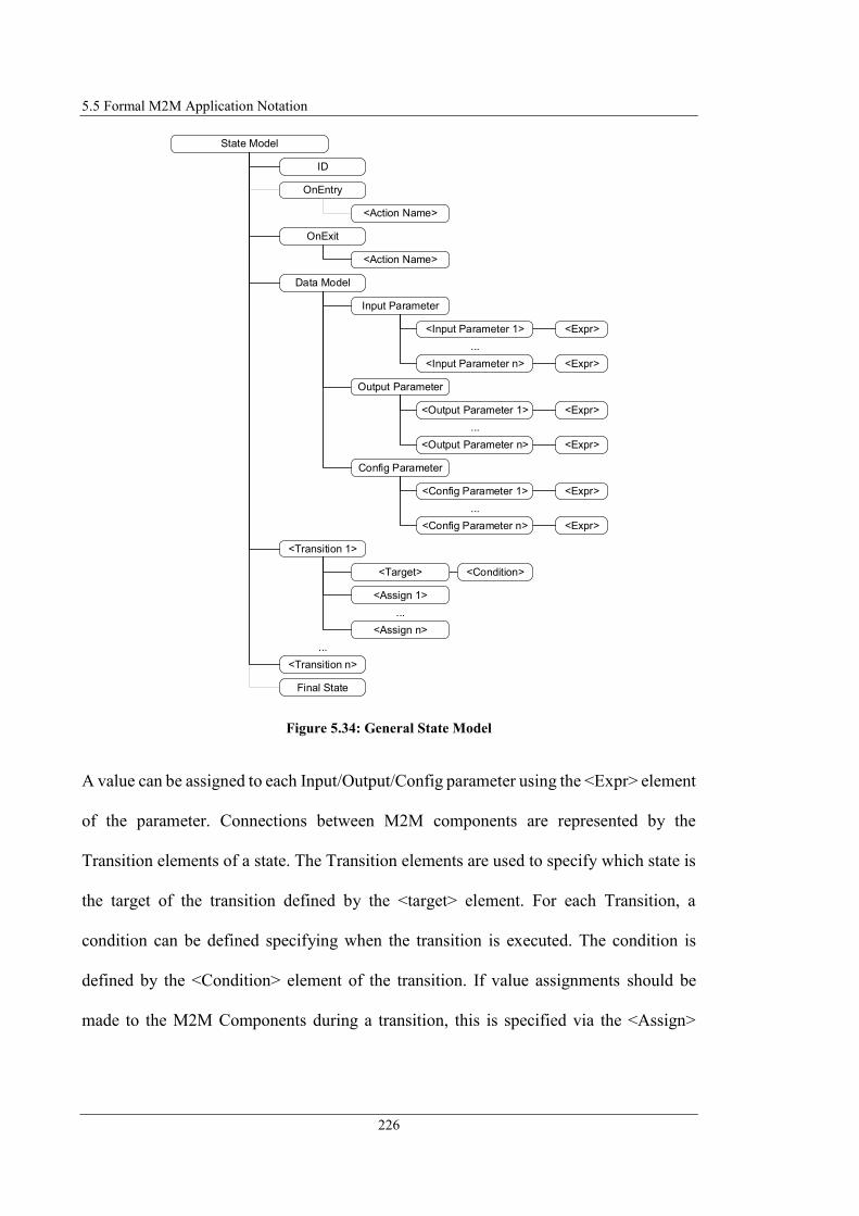
5.5 Formal M2M Application Notation
226
Figure 5.34: General State Model
A value can be assigned to each Input/Output/Config parameter using the <Expr> element
of the parameter. Connections between M2M components are represented by the
Transition elements of a state. The Transition elements are used to specify which state is
the target of the transition defined by the <target> element. For each Transition, a
condition can be defined specifying when the transition is executed. The condition is
defined by the <Condition> element of the transition. If value assignments should be
made to the M2M Components during a transition, this is specified via the <Assign>
State Model
OnEntry
<Action Name>
Final State
ID
OnExit
<Action Name>
Data Model
...
Input Parameter
Output Parameter
...
Config Parameter
...
<Transition 1>
...
<Input Parameter 1> <Expr>
<Input Parameter n> <Expr>
<Output Parameter n> <Expr>
<Output Parameter 1> <Expr>
<Config Parameter 1> <Expr>
<Config Parameter n> <Expr>
<Transition n>
...
<Assign 1>
<Assign n>
<Target> <Condition>
5 Autonomous M2M Application Provision
227
elements of the Transitions. A state can be declared as a Final State. If so, the state
contains a Final State element in the specification.
The SCU now uses the General M2M Application Model, General State Model and the
M2M DCMs to generate the formal M2M application description applying the algorithm
described in Figure 5.35. First, the SCXML frame is generated based on the General
M2M Application Model. Where the name of the modelled application is specified as the
ApplicationID. Furthermore, the start element is defined as initial state. Afterwards, all
graphically modelled states are captured. Each of these states is analysed and inserted into
the SCXML frame based on the result of the analysis. It is first checked whether it is a
simple state or a complex state (parallel flow). If it is a simple state, a state element is
generated based on the General State Model. Figure 5.36 shows the mapping of the
elements from graphical notation into the formal description of the state according to
(Steinheimer et al., 2017b). If it is a parallel sequence element, a parallel state element is
first created in SCXML. All parallel sections are then captured. For each parallel section,
an OR-State element is created and all states that are contained within the parallel section
are captured. The collected states are simple states that are analysed as described above.
After the formal definition of the state is done, the state is inserted into the OR-State
element. After all states are captured and added to the OR-State element, the OR-State
element is added to the previously generated parallel state element. As soon as all parallel
sections have been processed, the parallel state element is added to the SCXML frame.
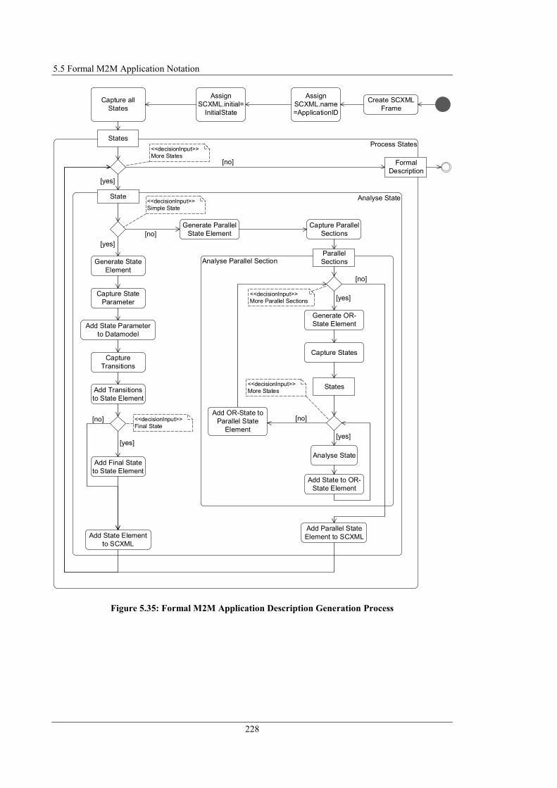
5.5 Formal M2M Application Notation
228
Figure 5.35: Formal M2M Application Description Generation Process
Capture all
States
Process StatesStates
Formal
Description
[no]
Create SCXML
Frame
Assign
SCXML.name
=ApplicationID
Analyse StateState
Generate State
Element
Capture State
Parameter
Add State Parameter
to Datamodel
Capture
Transitions
Add Transitions
to State Element
Assign
SCXML.initial=
InitialState
Add Final State
to State Element
Capture Parallel
Sections
Analyse Parallel SectionParallel
Sections
Add State Element
to SCXML
Add Parallel State
Element to SCXML
Generate OR-
State Element
Capture States
Analyse State
Add State to OR-
State Element
Generate Parallel
State Element
States
Add OR-State to
Parallel State
Element
[yes]
[yes]
[no]
[yes]
[no] [no]
[yes]
[yes]
[no]
<<decisionInput>>
More States
<<decisionInput>>
Final State
<<decisionInput>>
Simple State
<<decisionInput>>
More States
<<decisionInput>>
More Parallel Sections

5 Autonomous M2M Application Provision
229
Figure 5.36: Assignment graphical Notation Elements to M2M Application Model
5.6 Service Runtime Environment
The previous sections introduced the SM-based modelling and automated formal
description of local M2M applications. As described in section 4.2, the formal M2M
application description is passed from the SCU to the SRE for further processing. Figure
5.37 shows the structure of the SRE, which is responsible for executing the application.
Application Name
End Element
Start Element
Tra
nsitio
n
ID
Para
mete
r
Name
Co
nfig
Name
Outp
ut
Name
Input
M2
M D
evic
e C
ap
abili
ty M
odel
Target
Condition
Assign
Para
mete
r V
alu
es
Value
Co
nfig
Value
Outp
ut
Value
Input
Gra
ph
ical N
ota
tio
n
Para
mete
r
Expr
Para
mete
r
Expr
ID Initia
l S
tate
ID Para
mete
r
Expr
Transition
Targ
et
Co
nditio
n
Assig
n
Config
Parameter
Output
Parameter
Input
Parameter
Data Model
State Model
M2M Application Model
Fin
al S
tate
Fin
al S
tate
Final State
Sta
tes

5.6 Service Runtime Environment
230
Figure 5.37: Service Runtime Environment (SRE)
The Application Description Interpreter (ADI) first parses the formal M2M application
description after receipt and generates a SM from the described semantics defining the
application logic. The generated SM is stored in the State Machine Repository (SM Repo)
holding all SMs included in the M2M platform. The Application Executor (AE) holds an
instance of each SM and receives messages containing Input/Output values from the CU
or the MMSCs. By analysing the defined SM behaviour, the AE executes the defined
actions for each state, depending on the defined conditions and parameter values. For
determining the defined behaviour of the M2M application, the SEE holds the current
state of the SM (starting with the initial state). Figure 5.38 illustrates the AE's analysis
process for receiving messages from the CU and the corresponding SM evaluation.
Service Runtime Environment (SRE)
Service Execution Engine (SEE)
Formal M2M
Application
Description (SCXML)
Service
Creation
Unit
(SCU)
Application Description
Interpreter (ADI)
Multimedia Service
Components
(MMSCs)
Application
Executor (AE)
Communication Unit (CU)
State Machine
Repository (SM Repo)

5 Autonomous M2M Application Provision
231
Figure 5.38: M2M Application Execution Process
After receiving a Request Primitive message from the CU or MMSC, the AE loads the
current state of the SM, analyses it and executes the defined operations. First, the AE
checks the transitions. If condition are fulfilled or do not exist the AE checks whether
assigns have been defined to set M2M device/MMSC parameters. If the condition of the
transition is FALSE the SM resides in the current state. If assigns have been defined, then
the AE generates a Request Primitive message with the content of the parameter to be set
Receive Request Primitive Message
from CU or MMSC
Load Current State of
Statemachine
Check Transition Set M2M Device/MMSC Parameter
[condition exists]
[no condition exists]
[assigns defined]
[no assigns defined]
Generate Request
Primitive
Send Request Primitive
Message to CU
[condition
TRUE]
Set Current State
to Target State
[final state]
[no final state]
[restart app]
[do not restart
app]
Reset Initial State
[condition
FALSE]
Set Target State Parameter
[target state
parameter defined]
[no target state
parameter defined]
[set M2M
Device
Parameter]
[set MMSC parameter]
Send Request
Primitive Message to
MMSC
Generate Request
Primitive
Send Request Primitive
Message to CU
[set M2M
Device
Parameter]
[set MMSC parameter]
Send Request
Primitive Message to
MMSC

5.7 Conclusion
232
and sends it to either CU or MMSC, which set the values of the parameter as specified in
the Primitive content. Afterwards the AE checks whether target state parameter have been
defined. If yes, the AE triggers setting the specific parameter by sending Request Primitive
messages. After executing the control operation by setting the M2M device/MMSC
parameter the AE sets the defined target state as the new current state of the SM and
checks if it is a final state. If current state is final state, then the AE checks if application
should restart. If this is the case, the initial state is reset and the application starts from
beginning.
5.7 Conclusion
This chapter 5 introduced MMSCs (section 5.1) that form a comfortable input/output
interface to the M2M platform using existing multimedia communication equipment.
Multimedia communication can serve e.g. for controlling M2M applications or to realise
a communication from M2M platform and end-users to e.g. inform them about events
occurred in their local M2M environment.
The principles of M2M application definition by means of modelling the behaviour of the
M2M application has been introduced in section 5.2. It has been illustrated that the
behaviour of an M2M application can be modelled by defining SM-based application
flows. To achieve this a general structure of M2M device/MMSCs containing
input/output/config parameters has been defined and mapped to the states of a SM. This
enables the representation of an M2M device/MMSC inside the application behaviour
model. The connections of M2M devices/MMSCs have been mapped to the transitions of
the SM and representing the connection between them. The defined concept of

5 Autonomous M2M Application Provision
233
behavioural modelling by means of SMs forms a generalised, intuitive and platform
independent methodology to define the semantic of M2M applications.
Furthermore, it has been presented a structure of a GUI that can be applied for graphical
design of the application model (section 5.3). The GUI forms an end-user interface for
application generation by exposing M2M/MMSCs present in the personal environment
of the end-user. The GUI can be used to graphically design the application model by
combining M2M devices/MMSCs that are represented as building blocks. Conditions can
be defined to make the application flow (connection between M2M devices/MMSCs)
dependent on predefined conditions.
Then, section 5.4 described the principles for integration of different M2M technologies
into the local M2M platform. To achieve this, a concept has been defined to abstract the
communication between the specific M2M technologies and the communication inside
the M2M platform, respectively the communication between M2M devices and defined
M2M application using the AL component of the defined M2M platform architecture.
The communication between M2M devices and M2M platform components takes place
using RESTful communication principles and exchange of Primitive messages. A M2M
DCM has been defined describing the abstract structure of M2M devices/MMSCs and
forms as an interface description of them. It has been specified how to map the M2M
DCM to Primitive messages exchanged between the M2M platform components to realise
a generalised communication principle. Section 5.4 also presented different approaches
for automatically or partly automatically integration of M2M DCMs into the M2M
platform. Presented possibilities were the installation by the end-user, installation by the
M2M device, and the download from M2M device vendor. Installation by the M2M

5.7 Conclusion
234
device has been identified as the most practical way because it prevents manual steps to
be performed by the end-user and does not violate the general requirement of the
presented concept to avoid central entities in M2M platform infrastructure.
Section 5.5 introduced the modelling languages BPMN, UML ADs, and UML SMDs for
SM-based modelling. These modelling languages have been evaluated regarding defined
requirements. The result of the evaluation was that UML SMDs satisfy the defined
requirements and therefore has been selected as graphical modelling language for M2M
applications. Since UML SMDs are based on Harel Statecharts, the principles of
Statechart modelling has been introduced in detail as well as the standardised formal
description language SCXML as machine-readable execution language for Statecharts.
After introduction of Statecharts modelling and SCXML, the semantics have been defined
to model and formally describe M2M applications using Statecharts. For this a general
M2M Application Model and a General State Model were defined enabling the formal
description of M2M applications using SCXML. For automatically generating the formal
M2M application description, a process has been defined that uses the General M2M
Application Model and General State Model to create the SCXML description out of the
graphical notation of the M2M application.
Finally section 5.6 introduced the Service Runtime Environment (SRE) of the proposed
M2M platform architecture concept. The SRE processes the formal M2M application
description by parsing and interpreting the SCXML description and generates a SM from
the described semantics. The SEE of the SRE holds and executes the SMs and therefore
controls the M2M application. To achieve this a process for M2M application execution
5 Autonomous M2M Application Provision
235
has been defined that controls M2M devices/MMSCs as defined by the M2M application
semantics.
This chapter 5 presented a continuous concept of autonomous M2M application provision
starting with the M2M application design by the end-user followed by automated formal
description and execution of the application logic. The M2M device abstraction offers the
possibility to control different M2M devices and enables independence of the used M2M
technology from M2M application execution. The concept includes a loose coupling of
application description and application execution. It is platform independent and
adaptable because M2M application logic is defined at a higher level than realisation by
means of specific programming languages and compilation of application executables.
By using a modelling and description of applications independent of the target language,
the approach is independent of the technical realisation/programming. This makes it
portable to other M2M platforms and does not require reimplementation or recompilation
of application/service logic. The advantage of using a formal description that is based on
an official standard is that there is a loose coupling between the application generation
tool and the executing environment. Therefore, another GUI or approach for application
definition, such as plain text-based application design, could replace the GUI. The
presented concept uses standardised notation for application modelling (UML
SMDs/Statecharts) and SCXML as standardised formal description language for
application description. The presented concept also uses a standardised approach for
communication between the platform components. This makes the presented M2M
platform architecture concept both, adaptable and portable. Because the defined general
structure of an M2M application and the definition of M2M device capabilities, which
describe the query and control of M2M devices and MMSCs, a generic language has been

5.7 Conclusion
236
defined that allows to model various M2M applications. The communication between the
platform components is realised consistently with the RESTful communication principle.
According (Bayer, 2002) the generic interfaces defined in this way make it possible to
implement and offer generic services.
In this chapter it has been illustrated how to model and execute individual M2M
applications. The concept up to this point forms a local M2M platform realisable without
any central entity. It forms the basis for the second part of the proposed framework
(presented in the following chapter 6) that realises a global, distributed MSP and enables
end-users to cooperate and provide fully distributed M2M application services.
237
6 Cooperative M2M Application Service
Provision
The previous chapter 5 introduced the principles of the proposed concept for individual
M2M application design and local execution. Multimedia Service Components (MMSCs)
have been introduced as interface to M2M applications usable with existing multimedia
communication equipment. The end-user integration in M2M application design has been
enabled through modelling the behaviour of application semantic by graphical design. A
concept has been defined for integrating different M2M device technologies by
abstraction of M2M technology-specific communication. Additionally chapter 5 defined
a Statechart-based formal description language for M2M applications describing the
graphically designed M2M applications as machine-readable format for automated
processing and execution.
This chapter 6 introduces the parts of the proposed framework responsible for provision
of local M2M application functionality as a service to other end-users. Additionally this
chapter introduces the principles for combining distributed M2M application services to
provide cooperative M2M application services. Section 6.1 introduces the concept to
make local M2M devices and M2M applications available as a service to other end-users
and integrate them into local M2M applications. For this purpose, an interface description
of the M2M application service is specified and it is described how service requests are
generated and processed inside the M2M platform architecture.

6.1 Provision and Integration of M2M Application Services
238
Afterwards section 6.2 presents the networking principles of the participating nodes by
introducing the P2P communication between nodes and identifying an appropriate
information exchange pattern for data exchange. Additionally, section 6.2 identifies an
appropriate communication protocol for data transmission between distributed M2M
platforms. Section 6.3 introduces the management and distribution of M2M application
service interface descriptions (IFDs) without central entities for data storage applying the
principles of distributed data storage using a P2P overlay network. The common P2P
overlay algorithms are analysed and evaluated to select an optimal methodology for
distributed data storage in context of the proposed framework. Section 6.4 introduces the
concept for cooperative M2M application service provision by defining mechanisms to
enable distributed M2M application service composition and aggregation. Finally, section
6.5 presents details about the M2M community approach enabling networking of end-
users through social networking principles.
6.1 Provision and Integration of M2M Application Services
In section 4.1 it was shown that the functionality of M2M devices/applications should
also be available to other end-users. For this purpose, it is necessary to define an interface
enabling to access those. Following steps need to be performed to provide the
functionality of M2M devices/applications as a service:
1. An interface must be specified to access the M2M devices/applications.

6 Cooperative M2M Application Service Provision
239
2. A component must be integrated into the local M2M platform, which accepts
requests for services, passes them on to the M2M devices/applications and returns
the application's response value to the requestor.
3. It must be specified how to integrate the remotely provided M2M application
services into local M2M applications.
4. It must be specified how to register the M2M application services to make them
available to other end-users and where to store the IFDs.
The following sections 6.1.1 - 6.1.3 address these topics. Section 6.1.1 introduces the IFD
specifying a unified interface to provide M2M application services. Section 6.1.2 shows
how requests for an M2M application service are performed in local M2M platforms of
the M2M application service provider (ASP) and finally, section 6.1.3 introduces how to
integrate remote M2M application services in local M2M applications.
6.1.1 M2M Application Service Interface Description
Figure 6.1 shows the characteristics of applications that are behind an M2M service.
Figure 6.1: M2M Application Service Principles
M2M Device/MMSC
...
M2M Device/MMSC
M2M Device/MMSC
b) Multi Component Servicea) Single Component Service
Input/Config
Parameter
Output
ParameterInput/Config
Parameter
Output
Parameter
6.1 Provision and Integration of M2M Application Services
240
If the functionality of an M2M device should be made available to others, an application
can be defined having only one component whose functionality is to be provided (Figure
6.1-a). A more complex M2M application consists of several connected components
(Figure 6.1-b). The principle of both applications is the same: an application has an input
(these are the Input/Config parameters of the initial state), and an application has an output
(these are the Output parameters of the final state). Therefore, an IFD must contain
information about these parameters (Steinheimer et al., 2017c). Since according to
(oneM2M TS-0001-V1.13.1,2016) M2M applications are considered as resources (refer
to section 3.1.1), the resource type specifications of oneM2M for Application Entity (AE)
resource and Common Resource (CR) (oneM2M TS-0001-V1.13.1, 2016) has been used
as a basis to define an appropriate IFD in the context of this project.
Table 6.1 shows the designed IFD which should be described in machine-readable XML
format to enable automated processing.
Parameters appName, App-ID, pointOfAccess, requestReachability, and
contentSerialisation have been adopted from the resource type specification of AEs as
well as parameters creationTime, lastModifiedTime, and accessControlPolicy from
resource type specification of CRs. Additionally parameters have been added to the IFD
representing the parameters applications expect as input or generate as output. These
parameters could be determined automatically using the formal M2M application
description (AD). For this purpose, it is not necessary to analyse the entire M2M AD, but
only the parts describing initial and final state, since these are start and end points of the
application, respectively represent the input and output interface. These two elements are
already marked as initial and final state in the M2M AD so that they are easily identifiable.

6 Cooperative M2M Application Service Provision
241
The parameters of these states can now be transferred to the IFD. It is sufficient if only
the Input/Config parameters of the initial state are transferred and from the final state only
the Output parameters.
Table 6.1: M2M Application Service Interface Description Parameter
Parameter
appName
App-ID
pointOfAccess
requestReachability
creationTime
lastModifiedTime
contentSerialisation
accessControlOriginators
Defines which originator is
allowed to use the application.
Comma-separated list of
"all"|<OriginatorURIs>|<Groups>|
<SP-Domains or Subdomains>.
accessControlContexts
Defines when and where the
application can be used. Comma-
separated list of <Time-Window
as Unix TimeStamp>|<Location as
GPS Coordination with Radius>.
accessControlOperations
Specifies which of the CRUD
operations can be used for
requesting the application.
expirationTime
input
output
config
description
Description
Application name specified by developer of application. Type: String.
Application identifier. ID of the application itself. Type: String.
Contact address as list of URIs to communicate with the resource. Type:
String.
Specifies if the AE resource can receive requests, i.e. defines if the service is
currently available. Type: Boolean.
Specifies when the application has been created. Specified by the system that
has created the resource. Type: Unix Timestamp.
Specifies when the application has been modified to show if it is a current
development or outdated. Type: Unix Timestamp.
Specifies the supported serialisation formats of primitive content parameter,
such as XML, JSON. Type: String.
accessControlPolicy
privileges
Specifies how long the resource is valid/ exists. Type: Unix
Timestamp.
content Specifies the Input parameter as a list of parameter names.
Type: String.
Specifies the Output parameter as a list of parameter names.
Type: String.
Specifies the Config parameter as a list of parameter names.
Type: String.
Gives a prose description of the application. Type: String.

6.1 Provision and Integration of M2M Application Services
242
Figure 6.2 illustrates exemplarily as part of Use Case 2 (Neighbourhood Weather Station)
an M2M application service providing the status of a local rain sensor. Other end-users
that want to integrate the sensor data in their local M2M application can request for that
service as described in subsequent section 6.1.3. Figure 6.3 shows the corresponding IFD
based on the interface parameter specified in Table 6.1. Listing C.8 illustrates the
corresponding XML representation of the IFD.
Figure 6.2: Principles of remoteRainSensor Application Service
Figure 6.3: IFD for remoteRainSensor M2M Application Service
remoteRainSensor.output.state=raining|notRaining
Local SDP 1
CUSRE
remoteRainSensorOther End-Users
Personal Environment
End-User 1 Personal
Environment
accessControlPolicy
privileges
expirationTime = ""
accessControlOriginators = "all"
appName = "Remote Rain Sensor Service"
App-ID = "remoteRainSensor"
pointOfAccess = "sip:[email protected]"
requestReachability = "true"
creationTime = "2017-08-15"
lastModifiedTime = "2017-09-24"
contentSerialisation = "XML"
accessControlContexts = ""
accessControlOperations = "R"
content
output
input
outputParameter id="1"
accessControlContexts = ""
accessControlOperations = "R"
name = "remoteRainSensor.output.state"
value = "raining; notRaining"
config
Description = "Provides the state of a rain sensor at location Kleiststr.1, D-60318, Frankfurt
a.M., Germany. Possible Output values: remoteRainSensor.output.state=raining|notRaining"
Interface Description (AE)

6 Cooperative M2M Application Service Provision
243
6.1.2 Performing remote M2M Application Service Requests
An application provided as a service can be used by sending a request message to the
service provider's platform. As indicated in section 5.4, the exchange of messages
between M2M entities, which are also the applications, is realised using Primitives. For
requesting a service, the requestor must therefore generate a Request Primitive based on
the IFD (containing the required Input/Output/Config parameter) and send it to the service
provider (SP). This then responds with a Response Primitive (containing, if intended, the
Output parameter). The content and structure of the Primitive messages have already been
described in section 5.4.
As mentioned above, a component in the local M2M platform needs to be defined that
accepts and handles the requests. The M2M Service Interface Unit (SIU) as part of the
Communication Unit (CU) has been designed for this purpose (see Figure 6.4).
Figure 6.4: Service Interface Unit (SIU)
M2M Communication Unit (CU)
M2M Technology
Interfaces M2M Service Interface Unit (SIU)
IFD Repository
IFD
Response
Request
Company/
OrganisationEnd-User
IP Network/
Internet
Request
Response
M2M Application
Service Execution
Engine (SEE)
M2M Device
Abstraction Layer
(AL)
M2M Application
Dispatcher (ADisp)
M2M Application

6.1 Provision and Integration of M2M Application Services
244
The SIU includes an IFD Repository storing the IFDs and an M2M Application
Dispatcher (M2M ADisp) forwarding the service requests to the corresponding M2M
application. Figure 6.5 shows the process of request processing by the SIU.
Figure 6.5: SIU: M2M Application Service Request Processing
The SIU receives the request for a service and extracts the Request Primitive from the
request message. The structure of the Request Primitive essentially corresponds to the
Request Primitive shown in Figure 5.23 containing the Input/Output/Config parameter in
the Content section. If the authorisation should be validated, the Request Primitive
message shall contain the corresponding information for checking the
accessControlPolicies.
M2M Application Dispatcher (M2M ADisp)
[allowed]
[denied]
[Input only Operation] [Output only Operation]
[Input with Output
Operation]
Send Request
Primitive to AL
Generate Response
Primitive
Receive M2M Application
Service Request Message
Determine
Operation Type
Extract Request
Primitive
Extract App-ID, Location Data,
Operation, From Parameter
from Request Primitive
Generate Request
Primitive with Input and
Config Parameter
Generate Request
Primitive with Input and
Config Parameter
Generate Request
Primitive with Output
Parameter
Check
accessControlPolicy
Send Request
Primitive to AL
Send Request
Primitive to AL
Send Request
Primitive to AL
Generate Request
Primitive with Output
Parameter
Send Response
Message to Originator

6 Cooperative M2M Application Service Provision
245
The SIU extracts App-ID, location data, operation, and from parameters from the
Primitive and checks the permissions for application usage based on the IFDs stored in
the IFD Repository. After successful authorisation the M2M ADisp processes the Request
Primitive. The processing steps depend on which operations the M2M application should
perform and can be classified as follows:
Input only Operation – The application is intended to trigger only one action in
the platform (e.g., switch a device). The application has only Input/Config
parameters and no Output parameters.
Input with Output Operation – An operation should be triggered that requires input
values and returns output values (e.g., calculation tasks). The application has both
Input and Output parameters.
Output only Operation – The application has no Input parameters but provides an
Output (e.g., request of a single sensor value).
For operations by which input/config parameters should be set, the M2M ADisp generates
a Request Primitive containing these parameters and the corresponding values and sends
it to the Abstraction Layer (AL) (refer to section 5.4). For operations that request output
parameters, the M2M ADisp generates another Request Primitive containing the output
parameters and sends it to the AL to query the output parameters. The SIU then generates
a Response Primitive (which may contain the output values) and returns it to the
requestor.
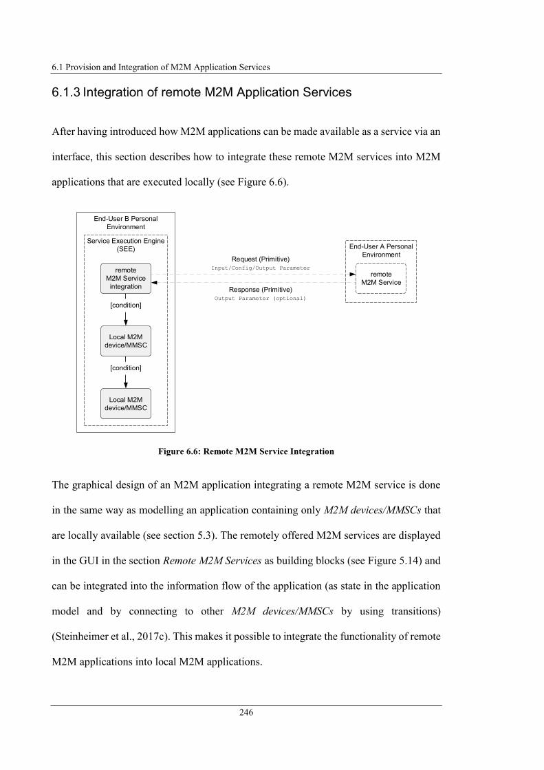
6.1 Provision and Integration of M2M Application Services
246
6.1.3 Integration of remote M2M Application Services
After having introduced how M2M applications can be made available as a service via an
interface, this section describes how to integrate these remote M2M services into M2M
applications that are executed locally (see Figure 6.6).
Figure 6.6: Remote M2M Service Integration
The graphical design of an M2M application integrating a remote M2M service is done
in the same way as modelling an application containing only M2M devices/MMSCs that
are locally available (see section 5.3). The remotely offered M2M services are displayed
in the GUI in the section Remote M2M Services as building blocks (see Figure 5.14) and
can be integrated into the information flow of the application (as state in the application
model and by connecting to other M2M devices/MMSCs by using transitions)
(Steinheimer et al., 2017c). This makes it possible to integrate the functionality of remote
M2M applications into local M2M applications.
Request (Primitive)
Input/Config/Output Parameter
Response (Primitive)
Output Parameter (optional)
End-User B Personal
Environment
[condition]
[condition]
Local M2M
device/MMSC
Local M2M
device/MMSC
Service Execution Engine
(SEE)
remote
M2M Service
integration
End-User A Personal
Environment
remote
M2M Service

6 Cooperative M2M Application Service Provision
247
The formal application description is created in the same way as described in section 5.5.
While in the formal description of a local application, the device/MMSC-IDs are specified
as identifiers for a state (see Figure 5.36), the identifier for the integration of remote
services corresponds to the service-ID (field App-ID in IFD). Figure 6.7 gives an
exemplary section of a formal application description (as part of a Statechart) in which a
remote M2M service is integrated (see Use Case 2). Here it can be seen that there is no
difference to the format when locally available M2M devices/MMSCs are described. The
corresponding SCXML representation is illustrated in Listing C.9.
Figure 6.7: Extract Formal Application Description Use Case 2
The state machine (SM) representing the application semantic is processed as described
in section 5.6 by the Service Execution Engine (SEE) by generating an instance of the SM
and executing it. To utilise a remote M2M service, the Service Execution Engine (SEE)
must identify (e.g., by means of the state-ID) whether the application contains a remote
service that must be requested. Remote services are identifiable because they are defined
by a state whose corresponding device/service logic is locally not available. If such
elements are identified, the service is requested by sending a Request Primitive to the SP
via the CU. The Request Primitive message contains the parameters (Input/Config/Output
parameters) that serve as input for the remote service and are delivered by it as output. If
the requested remote service has a response parameter, it is returned by the service
...
remoteRainSensor
remoteRainSensor.output.state = ""
localWindowSensor
... ...
Cond:
$remoteRainSensor.output.state=raining

6.2 Networking of Nodes
248
providing platform in the Response Primitive message and can be processed further
within the local M2M application.
It should be noted that the formal application description does not contain information
about the specific SP (i.e., no contact data). SPs offering a service register this via the
IFD. This describes the service and contains the information about the addressing options
by specifying the URI of the service endpoint (field pointOfAccess). The administration
of the IFD and how service consumers can request the IFD to obtain this information is
described in section 6.3.1.
6.2 Networking of Nodes
Chapter 4 has proposed that service providers (SPs) and service consumers (SCs)
communicate P2P (i.e. without central entities involved for communication) to exchange
information required for service utilisation. This section introduces how the networking
of SP and SC is proposed in this project. First, the kind of P2P networking between the
nodes is introduced (section 6.2.1). Subsequently, in section 6.2.2, an adequate
information exchange pattern is selected for information exchange between the nodes.
Finally, section 6.2.3 describes which communication protocols can be used to exchange
information between the nodes.
6.2.1 P2P Information Exchange
The P2P Communication Layer (refer to Figure 4.12) realises the communication
between the participating nodes in the proposed framework. P2P communication is a

6 Cooperative M2M Application Service Provision
249
common methodology to avoid central entities in system infrastructures. As avoiding
central entities in the described framework is a mandatory requirement, the
communication between the involved nodes also follows the P2P communication
principle (Steinheimer et al., 2012a; Steinheimer et al., 2017a).
The Resource Location and Discovery Protocol (RELOAD) project (IETF RFC 6940,
2014) specifies a fully decentralised P2P signalling protocol usable over the Internet.
Figure 6.8 shows the architecture of RELOAD adopted from (Samaniego et al., 2013)
and (IETF RFC 6940, 2014). RELOAD enables nodes to route signalling messages to
other nodes with the help of additional peers in the overlay. In the RELOAD project an
overlay topology is created using a specific overlay algorithm, which also defines how to
route the messages in the overlay. The overlay algorithm that is used to generate the
topology is generic, i.e. exchangeable with other overlay algorithms (IETF RFC 6940,
2014). The nodes in a RELOAD overlay request services from other peers or provide
services to them, such as a Traversal Using Relays around NAT (TURN) service (IETF
RFC 7374, 2014). Permission to reproduce Figure 6.8 has been granted by authors of the
referenced publication and IETF.
Figure 6.8: RELOAD Architecture acc. (Samaniego et al., 2013; IETF RFC 6940, 2014)
RELOAD ArchitectureInternet Model
Equivalent in Overlay
Transport
(Routing)
Internet
Internet Model
Application
Message
TransportStorage
Topology Plugin
Forwarding and Link
Management
Usage Layer
SIP
Usage
CoAP
UsageApplication
LinkTransport DTLSTLS
© 2014 IETF RFC 6940
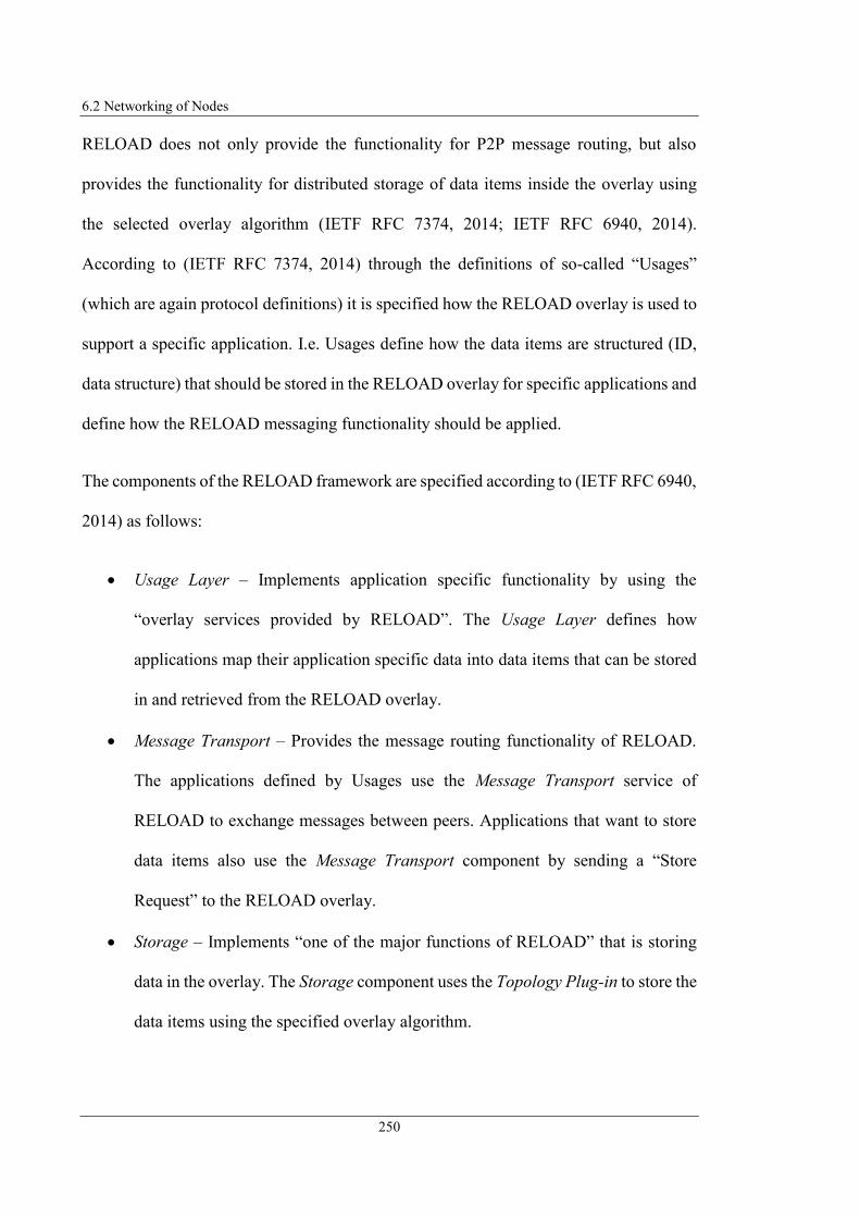
6.2 Networking of Nodes
250
RELOAD does not only provide the functionality for P2P message routing, but also
provides the functionality for distributed storage of data items inside the overlay using
the selected overlay algorithm (IETF RFC 7374, 2014; IETF RFC 6940, 2014).
According to (IETF RFC 7374, 2014) through the definitions of so-called “Usages”
(which are again protocol definitions) it is specified how the RELOAD overlay is used to
support a specific application. I.e. Usages define how the data items are structured (ID,
data structure) that should be stored in the RELOAD overlay for specific applications and
define how the RELOAD messaging functionality should be applied.
The components of the RELOAD framework are specified according to (IETF RFC 6940,
2014) as follows:
Usage Layer – Implements application specific functionality by using the
“overlay services provided by RELOAD”. The Usage Layer defines how
applications map their application specific data into data items that can be stored
in and retrieved from the RELOAD overlay.
Message Transport – Provides the message routing functionality of RELOAD.
The applications defined by Usages use the Message Transport service of
RELOAD to exchange messages between peers. Applications that want to store
data items also use the Message Transport component by sending a “Store
Request” to the RELOAD overlay.
Storage – Implements “one of the major functions of RELOAD” that is storing
data in the overlay. The Storage component uses the Topology Plug-in to store the
data items using the specified overlay algorithm.

6 Cooperative M2M Application Service Provision
251
Topology Plug-in – Provides the implementation of the overlay algorithm and
maintains “the overlay algorithm Routing Table” which the Forwarding and Link
Management Layer contacts for routing of messages.
Forwarding and Link Management Layer – Establishes the network connections
and transports the messages between peers “as determined by the Topology Plug-
in”.
As described above, so-called Usages are defined specifying how a RELOAD overlay is
used to support a specific application. The SIP Usage for RELOAD (IETF RFC 7904,
2016) is presented below and demonstrates the way of operating a RELOAD-based
application, but also indicates the disadvantages of RELOAD.
The SIP Usage for RELOAD provides the functionality for a distributed VoIP system
without the requirement of Registrar or Proxy Server (IETF RFC 7904, 2016). It is
defined for application in “server-less, peer-to-peer SIP deployments” (IETF RFC 7890,
2016). The SIP Usage defines the following functionality according to (IETF RFC 7904,
2016):
Registration – Storage functionality for mapping of SIP User Agent (UA) URIs
to RELOAD Node-IDs and functionality to request the Node-ID of other UAs.
Rendezvous – Functionality for message routing to establish “a direct connection
for exchanging SIP messages”.
Figure 6.9 shows the information flow defined for a service request in a RELOAD overlay
system. It illustrates the principles of RELOAD overlay functionality with the help of
specific SIP Usage according to (IETF RFC 7904, 2016) enabling to establish a SIP
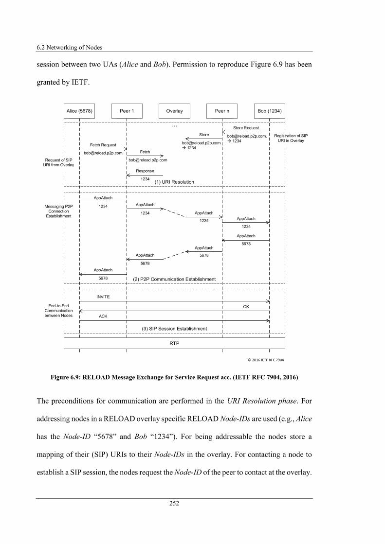
6.2 Networking of Nodes
252
session between two UAs (Alice and Bob). Permission to reproduce Figure 6.9 has been
granted by IETF.
Figure 6.9: RELOAD Message Exchange for Service Request acc. (IETF RFC 7904, 2016)
The preconditions for communication are performed in the URI Resolution phase. For
addressing nodes in a RELOAD overlay specific RELOAD Node-IDs are used (e.g., Alice
has the Node-ID “5678” and Bob “1234”). For being addressable the nodes store a
mapping of their (SIP) URIs to their Node-IDs in the overlay. For contacting a node to
establish a SIP session, the nodes request the Node-ID of the peer to contact at the overlay.
AppAttach
Peer 0Alice (5678)
Peer 0Bob (1234)
Peer 0Peer 1
Peer 0Peer nOverlay
...
AppAttach
AppAttach
AppAttach
AppAttach
AppAttach
AppAttach
AppAttach
RTP
INVITE
OK
ACK
Fetch Request
[email protected] Fetch
Response
1234
Store Request
1234
Store
1234
(1) URI Resolution
1234
1234
1234
1234
5678
5678
5678
5678
(3) SIP Session Establishment
(2) P2P Communication Establishment
Registration of SIP
URI in Overlay
Request of SIP
URI from Overlay
Messaging P2P
Connection
Establishment
End-to-End
Communication
between Nodes
© 2016 IETF RFC 7904

6 Cooperative M2M Application Service Provision
253
The overlay searches and responses the corresponding data item applying the specified
overlay algorithm.
Afterwards (P2P Communication Establishment phase) the peer that wants to establish
the connection generates a RELOAD protocol-specific AppAttach message directed to
the destination Node-ID and sends it to the overlay network, which routes it to the
destination host (applying the specified routing algorithm). The destination host
responses also with an AppAttach message to the requestor (routed through the overlay).
After the originator has received the AppAttach message from destination host, both
nodes are connected and ready for using the provided services.
For final session establishment (SIP Session Establishment phase) the originator initiates
a SIP Three-Way-Handshake directly with the destination host using plain SIP signalling
messages.
Another Usage for RELOAD that has been defined is the Constrained Application
Protocol (CoAP) Usage for RELOAD (IETF RFC 7650, 2015). This describes according
to (Rodrigues et al., 2016) a lookup service for resources and how to cache sensor data in
a RELOAD overlay. This Usage again describes the connection establishment between
the end nodes via routing through the P2P network.
The above-described approach of RELOAD to connect nodes P2P is advantageous for
avoiding central entities in a system architecture. The use of P2P overlay algorithms to
generate a shared, distributed database is also an advantage. At the same time, however,
the RELOAD approach has the following disadvantages:

6.2 Networking of Nodes
254
RELOAD Stack required – RELOAD is a complex system defined by the
RELOAD protocol which requires a corresponding protocol stack to exist at the
runtime environment of the end-user. While most end-users have a SIP stack
integrated in their IAD, this is not the case with a RELOAD stack. Thus end-users
could not use a RELOAD-based system with the available resources and network
access (provided by their Internet Service Provider, ISP).
Networking of Nodes – RELOAD is building its own routing infrastructure on the
underlying Internet/IP network, which already has an infrastructure for addressing
nodes (refer to Figure 6.10-a). To connect two nodes in a RELOAD overlay, they
must first establish a connection with each other using special RELOAD messages
before they can exchange the actual messages that are associated with a service.
The exchange of the service-specific messages is then end-to-end, but beforehand,
other nodes for the routing of the messages are unnecessarily involved.
In order to eliminate these disadvantages, this research proposes an P2P networking
approach for linking SPs and SCs as illustrated in Figure 6.10-b, which is optimised in
the following aspects:
Direct Communication of M2M SP and SC – The communication between the SP
and SC takes place on the application layer exclusively end-to-end between the
nodes involved in a service utilisation, meaning for connecting SP and SC the
messages are exchanged directly between these two nodes without intermediary
entities.
Application of Internet Communication Technology – The involved peers are all
connected to the Internet or another continuous IP network. As a result, the
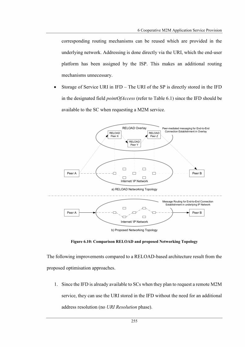
6 Cooperative M2M Application Service Provision
255
corresponding routing mechanisms can be reused which are provided in the
underlying network. Addressing is done directly via the URI, which the end-user
platform has been assigned by the ISP. This makes an additional routing
mechanisms unnecessary.
Storage of Service URI in IFD – The URI of the SP is directly stored in the IFD
in the designated field pointOfAccess (refer to Table 6.1) since the IFD should be
available to the SC when requesting a M2M service.
Figure 6.10: Comparison RELOAD and proposed Networking Topology
The following improvements compared to a RELOAD-based architecture result from the
proposed optimisation approaches.
1. Since the IFD is already available to SCs when they plan to request a remote M2M
service, they can use the URI stored in the IFD without the need for an additional
address resolution (no URI Resolution phase).
a) RELOAD Networking Topology
RELOAD Overlay
Internet/ IP Network
Peer B
Internet/ IP Network
Peer A Peer B
b) Proposed Networking Topology
Peer A
Peer-mediated messaging for End-to-End
Connection Establishment in Overlay
Message Routing for End-to-End Connection
Establishment in underlying IP Network
RELOAD
Peer Y
RELOAD
Peer X
RELOAD
Peer Z

6.2 Networking of Nodes
256
2. No additional nodes on the application layer are required for routing messages,
since the service request is sent directly to the SP (no P2P Communication
Establishment phase). This is possible because the SP's URI is contained in the
IFD.
3. A RELOAD stack in the execution environment is not required since the IP-based
connection functionality of the ISP is used. The SIP stack contained in the end-
user's IAD could also be used for communication between SP and SC. This means
that the resources available to the end-user environment can be used without
having to provide additional communication protocol stacks.
6.2.2 Information Exchange Pattern
For exchanging information between M2M entities several information exchange patterns
(IxPs) exist as specified by (Holler et al., 2014) adopted from (Carrez et al, 2013). This
section describes these IxPs (see Figure 6.11) and evaluates their application for
information exchange in the context of the concept designed in this research. Permission
to reproduce Figure 6.11 has been granted by authors of the referenced publication and
publisher Elsevier.
Figure 6.11: IxPs acc. (Höller, 2014) adopted from (Carrez et al., 2013)
c) Subscribe/ Notify d) Publish/ Subscribe
b) Request/ Responsea) Push
M2M Entity B M2M Entity A
Subscribe
Message Broker
Subscribe
Notify
Notify
M2M Entity C
Publish
M2M Entity BM2M Entity A
Request
Response
M2M Entity BM2M Entity A
Time Push
M2M Entity BM2M Entity A
Subscribe
M2M Entity C
Subscribe
Notify...
Notify...

6 Cooperative M2M Application Service Provision
257
Push IxP
In push IxP (Figure 6.11-a) information are pushed from an M2M entity to another M2M
entity. This IxP requires that the contact information of M2M Entity B is already
configured in M2M Entity A and that M2M Entity B listens for the information might be
pushed (Holler et al., 2014).
Request/Response IxP
In request/response IxP (Figure 6.11-b) an M2M Entity A requests an information at
another M2M Entity B. M2M Entity B responses the information after receiving the
request. The interaction in this IxP is synchronous, i.e. M2M Entity A has to wait for the
response until it continues further processing. In practice, this limitation is addressed by
performing multi-threading capabilities in M2M Entity A. Additionally, M2M Entity B
has to perform capabilities “to handle concurrent requests and responses from multiple
components” (Holler et al., 2014).
Subscribe/Notify IxP
In subscribe/notify IxP (Figure 6.11-c) multiple M2M Entities A and B subscribe for an
information provided by an M2M Entity C. M2M Entity C sends a notify message to all
subscribers of that information once the information is ready for transmission. The
interaction in this IxP is asynchronous. M2M Entity C needs to perform the capability for
storing and managing the contact data and corresponding request topics. The
subscribe/notify IxP is applicable when a single M2M entity provides information of
interest for multiple other M2M entities (Holler et al., 2014).

6.2 Networking of Nodes
258
Publish/Subscribe IxP
In publish/subscribe IxP (Figure 6.11-d) a centralised Message Broker is involved
mediating publications and subscriptions between information publisher and consumer.
M2M entities interested in an information subscribe at the Message Broker for a specific
information. M2M entities that provide that information publish the information to the
Message Broker which send a notify message to the entities interested in that information.
As subscribe/notify IxP, publish/subscribe IxP is also an asynchronous pattern. Different
from the subscribe/notify IxP, here the information producer does not need to manage
information about the information subscriber (Holler et al., 2014).
The evaluation of the IxPs specified by (Holler et al., 2014) leads to the result, that
subscribe/notify IxP is the best fitting pattern to exchange information between M2M
entities in the approach presented in this research with regards to the specified
requirements of section 3.2. The push IxP is not applicable because the contact
information of the receiving M2M entity needs to be configured statically in the
information producing entity. Because the dynamic nature of the services forming an
application in the presented concept, specific service instances cannot be known by
configuration time and furthermore are highly volatile. The request/response IxP is partly
usable for information requests of single services during runtime and receiving
information instantly. However, it is not the best choice for general information exchange
due to the synchronous principle of that pattern and parallel response management that
needs to be performed by the receiving entity. Also for receiving information by multiple
M2M entities during runtime, every M2M entity interested in an information has to
request every information always it wants to consume/process the information.

6 Cooperative M2M Application Service Provision
259
Configuring an application before running the application and validating the correct
application configuration as proposed in this project is not realisable according to the
principle of synchronous information exchange, since service links are not yet available
at configuration time (see section 6.4.3). The publish/subscribe IxP contains a central
Message Broker. This violates the decentralised principle and requirements of the
approach presented in this research. This leads to select the subscribe/notify IxP as the
best choice for information exchange between distributed M2M entities (Steinheimer et
al., 2013e). Benefit of this pattern is that it is based on asynchronous principles and
additionally entities that want to receive an information have to register a single time for
an information at an information producer and keep informed always the information is
ready for transmission.
6.2.3 Selection of appropriate P2P Communication Protocols
After the principles of proposed P2P communication between SP and SC has been
introduced in section 6.2.1 and 6.2.2, a standardised application layer protocol for
exchanging messages via an IP network is required. As transport protocol usually TCP
(IETF RFC 793, 1981) or UDP (IETF RFC 768, 1980) is used. Since UDP avoids
overhead for connection-oriented communication at transport level, this should be
selected as transport protocol. The Primitive messages are then exchanged with an
application layer protocol. OneM2M defines so-called Protocol Bindings (refer to section
5.4) specifying how the Primitive messages between M2M entities (i.e. SP and SC) are
embedded in an application layer communication protocol. OneM2M defined Protocol
Bindings for HTTP (oneM2M TS-0009-V2.6.1, 2016), MQTT (oneM2M TS-0010-

6.2 Networking of Nodes
260
V2.4.1, 2016), CoAP (oneM2M TS-0008-V1.0.1, 2015) and WebSocket protocol
(oneM2M TS-0020-V2.0.0, 2016).
HTTP follows the Request/Response IxP and MQTT uses the Publish/Subscribe IxP with
a central message broker. Both approaches do not meet the requirements of the framework
introduced in this project (avoidance of central components) or are inconvenient for
implementation of application logic (blocking at invocation). WebSocket Protocol
enables bi-directional end-to-end communication, but has the disadvantages that it relies
on the additional protocols HTTP and TCP and therefore WebSocket communication
results in large overhead for connection establishment and termination. WebSocket
connections using UDP are not possible. Each WebSocket connection requires a separate
TCP connection establishment (Three-Way-Handshake) and HTTP Opening Handshake
as well as for closing connection HTTP Closing Handshake and TCP Connection
Teardown. While the connection exists it is required to exchange keep alive messages
continuously keeping the connection open. Beside the unnecessary overhead for
communication with the WebSocket protocol, at least one HTTP, TCP, and WebSocket
stack is required on the platform of both communication partners, which enlarges the
complexity of the system itself and is not commonly existing on end-users equipment.
Therefore, CoAP remains the only protocol suggested by oneM2M for exchanging
messages between M2M entities in this context. Since multimedia communication is a
central component of the introduced framework, Session Initiation Protocol (SIP), which
is the standard protocol for signalling in multimedia communication networks, is
proposed as an alternative to CoAP (Steinheimer et al., 2013e).

6 Cooperative M2M Application Service Provision
261
The following illustrates how Subscribe/Notify IxP can be realised using CoAP and SIP.
For this purpose, a general mechanism is first described to specify how a service can be
requested and how the service providing peer manages and processes the requested
information. Afterwards, CoAP is introduced and the message exchange for the service
request is depicted according to the CoAP Protocol Binding. Subsequently, SIP will be
introduced. Since no Protocol Binding has been defined for SIP so far, this Protocol
Binding is designed to realise the exchange of Primitive messages via SIP.
Principle of Service Subscription, Notification, and Termination
A peer requests a service from other peers by sending a Request Primitive message to
them. Mapping this to the Subscribe/Notify IxP, this means that peers subscribe services
(i.e. send subscribe message to service providing peers). Peers providing services then
execute the individual service logic and, if necessary, delivers requested information to
the requesting peer using a Response Primitive message. Mapping this to the
Subscribe/Notify IxP, this means that service providing peers send a notify message to
service requesting peers.
When requesting services according to Subscribe/Notify IxP, the following cases should
be considered:
Request Once – Requesting peers should be able to request a service once.
Continuous Request – Requesting peers should be enabled to permanently request
information provided by a service and receive their outputs continuously.

6.2 Networking of Nodes
262
Terminate Request – Service requesting peers should be able to terminate a
continuous service request (i.e. inform service providing peers they do not
continue using a service).
Figure 6.12 shows these cases and thus the general principles of service
requests/terminations.
Figure 6.12: General Service Subscription/Notification/Termination Process
Peer 0Service
requesting Peer Peer 0Service
providing Peer
alt
Request
Service
Subscribe (Request Primitive) Receive
Service
Request
Process
Service
Logic
Notify (Response Primitive)[Request Once]
Process
Service
Result
Store in
Subscriber
List
Notify (Response Primitive)
[Continuous Request]
Process
Service
Result
Process
Service
Logic
[Terminate Request]
Delete from
Subscriber
List
Terminate (Request Primitive)
input
config
output
content
input
config
output
content
output
content
output
content

6 Cooperative M2M Application Service Provision
263
A service is requested by sending a Subscribe Request which contains the parameters to
be queried and, if necessary, the parameters to be set. If request are one-time requests of
a service (Request Once), the service providing peers respond directly and return the
output parameters of the service (if defined). These are then processed by the requesting
peer. If the output values of a service are to be transmitted and processed continuously
(Continuous Request), the service providing peers store the contact information (of
requesting peers) in a local subscriber list. To terminate a service subscription (Terminate
Request), the peers that requested the service before send a Terminate Request message
to the service providing peers. The subscriber will then be deleted from the local
subscriber list.
Realisation of Subscribe/Notify IxP using CoAP
CoAP is a protocol for communication in "Constrained RESTful Environments" with the
goal of realising a "REST architecture". A REST architecture is according to (Bayer,
2002) an architectural approach for distributed applications in which all entities or
components are considered as resources. These resources can be addressed directly via a
unique URI. Communication with the resources is done by exchanging representations of
the resources between the client (using the resource) and the server (hosting the resource).
Constrained environments contain nodes that are limited in CPU power, RAM and ROM
capacity. Additionally to the nodes, the networks for transmission of information are also
limited in their transmission capacity (low bandwidth, low power for transmission of
messages) so that message packets to be transmitted should be as small as possible (IETF
RFC 7252, 2014).

6.2 Networking of Nodes
264
According to (IETF RFC 7252, 2014) CoAP offers the following essential features for
message exchange:
UDP binding with (optional) reliability support – Use of UDP for connectionless
transmission and realisation of reliability on CoAP protocol level.
Asynchronous message exchange – Messages can be transmitted asynchronously,
so that senders do not block until they have received a response.
Low Header Overhead and parsing Complexity – CoAP has low header overhead
and because the low complexity of CoAP messages less effort is required to parse
the messages.
Communication between nodes takes place by exchanging messages between so-called
endpoints installed on the nodes. An endpoint is an "entity participating in the CoAP
protocol". Endpoint correspond to a socket on a node (IP address + port) and the
associated additional addressing information of an application that should process the
CoAP messages (URI-Path). CoAP distinguishes between client and server endpoints.
Client endpoints initiate messages and server endpoints receive messages. Server
endpoints process the Request messages and reply with a Response message, which in
turn is processed by the client. The nodes in a CoAP implementation can take on both of
these roles, i.e. in contrast to HTTP implementation, they can act both as clients and
servers (IETF RFC 7252, 2014).
CoAP distinguishes between Confirmable, Non-confirmable, and Acknowledgement
messages to realise the message exchange between endpoints. CoAP enables reliable and
unreliable message transmission as described subsequently.

6 Cooperative M2M Application Service Provision
265
Figure 6.13 shows the "Reliable Message Transmission". Reliability is implemented by
marking the Request message as "Confirmable (CON)". A confirmable message must be
answered by the recipient with an "Acknowledgement message (ACK)". The ACK
message contains the same Message-ID as the corresponding Request message. If no
acknowledgement message is sent, the client repeats the sending of the Request message
(IETF RFC 7252, 2014). Permission to reproduce Figure 6.13 has been granted by IETF.
Figure 6.13: CoAP Reliable Message Transmission acc. (IETF RFC 7252, 2014)
Figure 6.14 shows the "Unreliable Message Transmission". Unreliable message
transmissions does not require acknowledgement messages. Such messages are marked
as "Non-confirmable message (NON)". NON messages also have a Message-ID to enable
duplicate message detection (IETF RFC 7252, 2014). Permission to reproduce Figure
6.14 has been granted by IETF.
Figure 6.14: CoAP Unreliable Message Transmission acc. (IETF RFC 7252, 2014)
CoAP uses, similar as HTTP, the methods GET, PUT, POST, DELETE to request
resources by a client. Subsequently the semantics of these methods are introduced as
described in (IETF RFC 7252, 2014).
Peer 0CoAP
ServerPeer 0CoAP
Client
CON [0x8e45]
ACK [0x8e45]
© 2014 IETF RFC 7252
Peer 0CoAP
ServerPeer 0CoAP
Client
NON [0x9f56]
© 2014 IETF RFC 7252
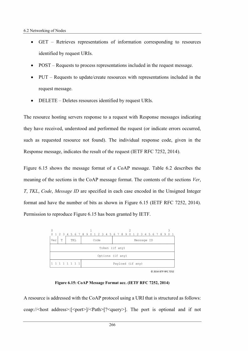
6.2 Networking of Nodes
266
GET – Retrieves representations of information corresponding to resources
identified by request URIs.
POST – Requests to process representations included in the request message.
PUT – Requests to update/create resources with representations included in the
request message.
DELETE – Deletes resources identified by request URIs.
The resource hosting servers response to a request with Response messages indicating
they have received, understood and performed the request (or indicate errors occurred,
such as requested resource not found). The individual response code, given in the
Response message, indicates the result of the request (IETF RFC 7252, 2014).
Figure 6.15 shows the message format of a CoAP message. Table 6.2 describes the
meaning of the sections in the CoAP message format. The contents of the sections Ver,
T, TKL, Code, Message ID are specified in each case encoded in the Unsigned Integer
format and have the number of bits as shown in Figure 6.15 (IETF RFC 7252, 2014).
Permission to reproduce Figure 6.15 has been granted by IETF.
Figure 6.15: CoAP Message Format acc. (IETF RFC 7252, 2014)
A resource is addressed with the CoAP protocol using a URI that is structured as follows:
coap://<host address>:[<port>]/<Path>[?<query>]. The port is optional and if not
Ver
0 1
T
2 3 4 5 6 7 8 9 0 1 2 3 4 5 6 7 8 9 0 1 2 3 4 5 6 7 8 9 0 1
0 1 2 3
Message IDCodeTKL
Options (if any)
1 1 1 1 1 1 1 1 Payload (if any)
Token (if any)
© 2014 IETF RFC 7252

6 Cooperative M2M Application Service Provision
267
specified “default port 5683 is assumed”. The path specifies the resource located at the
server. The query is also optional and specifies arguments that serve “to further
parameterize the resource”. Arguments are often specified as “key=value” pairs (IETF
RFC 7252, 2014).
Table 6.2: CoAP Message Format acc. (IETF RFC 7252, 2014)
The size of a CoAP message should be small enough to be transported in a single IP
packet to avoid IP packet fragmentation. I.e. the CoAP message may only be so large that
it can be encapsulated in the payload of a single UDP message. This depends on the MTU
size of the IP network. If the MTU size is not known, an MTU size of 1280 Byte should
be assumed. Minus the UDP header (IETF RFC 7252, 2014) recommends a maximum
Section Description
Version (Ver) Defines the CoAP version.
Type (T) Defines the type of the CoAP message: 0 (Confirmable), 1 (Non-confirmable), 2
(Acknowledgement).
Tokel Length (TKL) Defines the length of the token specified in the Token field.
Indicates type of message (request or response) and gives details about the
request methods or response status.
Following request method codes are specified: 0.01 (GET), 0.02 (POST), 0.03
(PUT), 0.04 (DELETE).
Exemplary response codes are: 2.01 (Created), 2.02 (Deleted), 4.04 (Not Found),
5.00 (Internal Server Error).
Message ID Indicates a message ID in order to detect corresponding acknowledgement
message (for reliable message transmission) or detect duplicate messages (for
unreliable message transmission).
Token Clients can set the token value that can be used “to correlate requests and
responses”.
Options The CoAP message can include individual options (indicated by numbers)
specifying details corresponding to the CoAP message, such as conditions when
to perform a request or content format.
Payload The CoAP message can carry optional payload that carries application specific
data.
Code

6.2 Networking of Nodes
268
message size of 1152 Byte, whereby 1024 Byte are proposed for the payload size (IETF
RFC 7252, 2014).
OneM2M defines in (oneM2M TS-0008-V1.0.1, 2015) a so-called "CoAP Protocol
Binding" specifying how (Request/Response) Primitive messages are mapped to CoAP
messages. This Protocol Binding defines the mapping of parameters of an oneM2M
Primitive to corresponding message fields of a CoAP message. The following introduces
how to realise the Subscribe/Notify IxP with CoAP messaging.
Table 6.3 shows the mapping of a Primitive message to a corresponding CoAP message
according to (IETF RFC 7252,2014) required in the context of this project.
Table 6.3: OneM2M Primitive CoAP Message mapping acc. (oneM2M TS-0008-V1.0.1, 2015)
OneM2M Primitive
Parameter
To
From
oneM2M operation CoAP Method
CREATE POST
DELETE DELETE
NOTIFY POST
Request Identifier
Response Status Code
Content
Operation Field: Code. Only in case of a request. Operation parameter is mapped to
the CoAP method as follows.
In case of Subscribe message (oneM2M operation CREATE) additionally
Resource Type parameter in URI query ty=23.
Field: Option. Option no 257 (oneM2M-RQI). The Request Identifier
parameter is mapped to the oneM2M-RQI option.
CoAP Message Parameter
URI (in Request message). The To parameter is mapped to the URI-Path of
the CoAP message.
Field: Option. Option no 256 (oneM2M-FR). The From parameter (in
Request message) is mapped to the oneM2M-FR option.
Response Status Code is mapped to the Code field of a Response message.
oneM2M 2000 (OK) corresponds to CoAP status code 2.05 (Content).
Field: Payload. Contains the Service Specific Input/ Config/ Output
Parameter.

6 Cooperative M2M Application Service Provision
269
It should be noted that according to (oneM2M TS-0008-V1.0.1, 2015) both, oneM2M
CREATE requests and oneM2M NOTIFY requests are transmitted with a CoAP POST
(method) message. The distinction between CREATE and NOTIFY requests is realised
using the Resource Type parameter in the URI-query. If this parameter is set, the request
is handled as a CREATE request, i.e. a SUBSCRIBE request. (oneM2M TS-0004-V2.7.1,
2016) defines several Resource Types, such as ty=23 (Subscription). If the parameter has
not been set, the request is handled as a NOTIFY request.
Furthermore, a distinction must be defined as to whether information (i.e., a service)
should be requested once, or whether the requested information should be continuously
sent to the requesting peer. For this purpose, it has been specified that this information is
delivered in the Request message. The option parameter no 259 (oneM2M-OT) is used,
which specifies an originating timestamp as defined in (oneM2M TS-0008-V1.0.1, 2015).
If this is set to "0", the request is handled as a one-time request otherwise it is handled as
a continuous subscription. If the information should be continuously transmitted to the
peer, the information-providing peer stores the contact data locally and sends the
n/a
n/a
n/a
n/a
n/a
n/a
Field Token Length (TKL). Length of the Token field.
Field: Message ID. Unique message ID.
Field: Token. Unique ID set by the client.
Field: Option. Option no 259 (oneM2M-OT) = 0 specifies retrieve of
service/ information once. Otherwise continuous information delivery.
Field: Version (Ver). The Version field should be set to 1.
Field: Type (T). 0 (Confirmable) in case of reliable message transmission, 1
(Non-confirmable) in case of unreliable message transmission, 2
(Acknowledgement) indicates an acknowledgement message.

6.2 Networking of Nodes
270
information continuously to the peer. If this is a one-time request, the peer returns the
information directly and does not store any further information about the requesting peer.
The following Figure 6.16 – Figure 6.18 illustrate the comprehensive message exchange
using the CoAP protocol including the specific protocol message fields to realise the
Subscribe/Notify IxP. Figure 6.16 shows the subscription of an information/service by
sending a CREATE request. The receiving server replies with an Acknowledgement
message. Figure 6.17 shows the notification messages generated by the server delivering
the requested information (once or continuous) to the requesting peer. Figure 6.18
illustrates the message exchange for terminating a subscription. In that case clients
generate a DELETE message indicating that they are not interested in the previously
requested information/service anymore. Message Sequence Charts C.1 – C.3 show the
overall message exchange including message content for subscription, notification, and
termination via CoAP (refer to Appendix C).
Figure 6.16: CoAP Messaging for Service/Information Subscription
Peer 0CoAP
ServerPeer 0CoAP
Client
POST coap://10.0.13.20:5683/m2mservice?ty=23
ACK
MessageID = 3130
Type = Acknowledgement
MessageID = 3130
content
output
outputParameter id = 1
name = remoteM2MapplicationService.output.parameter1
Payload

6 Cooperative M2M Application Service Provision
271
Figure 6.17: CoAP Messaging for Service/Information Notification
Figure 6.18: CoAP Messaging for Service/Information Unsubscription
As described above no Protocol Binding for SIP exist. Therefore, a SIP Protocol Binding
is introduced below to also enable the exchange of Primitive messages using SIP.
Peer 0CoAP
ServerPeer 0CoAP
Client
POST coap://10.0.4.20:5683/m2mservice
ACK
MessageID = 4080
Type = Acknowledgement
MessageID = 4080
content
output
outputParameter id = 1
name = remoteM2MapplicationService.output.parameter1
Payload
value = Parameter-Value1
Peer 0CoAP
ServerPeer 0CoAP
Client
DELETE coap://10.0.13.20:5683/m2mservice
ACK
MessageID = 1528
Type = Acknowledgement
MessageID = 1528
content
output
outputParameter id = 1
name = remoteM2MapplicationService.output.parameter1
Payload
6.2 Networking of Nodes
272
Implementation of Subscribe/Notify IxP using SIP
SIP is a text-based “application-layer control protocol” enabling „internet endpoints“, so-
called user agents (UAs) to establish a session with each other (shared thread in context
of an application) and exchange information data. SIP is independent of underlying
protocols, such as transport protocol TCP or UDP. SIP is the standard protocol for
signalling (controlling communication sessions) in internet-based telephony
environments and therefore its protocol stack is usually available on common IADs in
end-users environment. Same as CoAP, SIP implements an “HTTP-like request/response
transaction model” and integrates a reliability mechanisms. I.e. a transaction consists of
a request invoking a specific method on the server which is answered by a Response
message. An UA can take the role of both, client (User Agent Client, UAC) initiating SIP
requests and server (User Agent Server, UAS) responding to SIP requests (IETF RFC
3261, 2002).
Additionally to the basic SIP standard RFC 3261 extensions of this standard were defined,
such as extension for “SIP-Specific Event Notification” (IETF RFC 3265, 2002) enabling
Subscribe/Notify IxP or „Extension for Instant Messaging“ (IETF RFC 3428, 2002)
enabling Instant Messaging via SIP.
Figure 6.19 illustrates the structure of a SIP Request message and Figure 6.20 shows the
structure of a SIP Response message.

6 Cooperative M2M Application Service Provision
273
Figure 6.19: SIP Request Message Format acc. (IETF RFC 3261, 2002)
Figure 6.20: SIP Response Message Format acc. (IETF RFC 3261, 2002)
A SIP Request message always starts with a Start Line. This specifies the method to be
executed on the UAS containing the address information (SIP URI) of the target SIP UA.
A SIP URI has the following structure: sip:<username>@<host address>:[<port>]. The
port is optional and if not specified default port 5060 is assumed. A SIP Response
message also starts with a Start Line containing information about the corresponding
Request message (e.g. Status Code of message transmission). Beside the Start Line, a SIP
message contains various Header Fields giving more details of the session.
Table 6.4 describes an extract of SIP Header Fields as contained in Request/Response
messages. SIP messages can additionally include a Message Body containing required
information in the application context, such as Session Description Protocol information
(describing details of an audio/video call) (IETF RFC 3261, 2002).
Message BodyMessage
Body
Method Request URI SIP Version CRLFStart Line
Contact Via From To
Call-ID CSeq Content-Type Content-LengthHeader
...
Blank Line
Event Max-Forwards Expires
SIP Version Status Code Reason Phrase CRLFStart Line
CSeq Call-ID From To
Via CSeq Content-Length Max-ForwardsHeader
ExpiresSubscription-
State...

6.2 Networking of Nodes
274
Table 6.4: SIP Message Format acc. (IETF RFC 3261, 2002; IETF RFC 3265, 2002)
Section Description
Start Line in
Request
Messages
The Start Line has the format <Method name > <Request-URI > <SIP-Version >.
Method Name specifies the method to be executed on the UAS. Request-URI
specifies the addressing information (SIP URI) of the UAS. SIP-Version specifies
the Version of the SIP Protocol used (usually “SIP/2.0”)
Start Line in
Response
Messages
The Start Line has the format <SIP Version > <Status Code > <Reason Phrase >. SIP-
Version specifies the Version of the SIP Protocol used (usually “SIP/2.0”). Status
Code indicates the response status of a request (e.g. 200 for successful request).
Reason Phrase is a textual description of the Status Code (e.g. “OK” for Status
Code 200).
Contact Defines the SIP URI of the message originating UA. Indicates where to send
future requests.
Via Contains information about the routing of Response messages (IP + port + branch
parameter to identify a specific transaction). Indicates where the request
initiating UA expects to receive the Response message and possibly other
network elements included in the routing path.
From Contains the SIP URI as well as a display name of the originator of a request.
From header field of Response messages equals to the From header value of the
original Request message.
To Contains the SIP URI as well as a display name of the receiver of a request. To
header field of Response messages equals to the To header value of the original
Request message.
Call-ID Globally unique identifier to correlate messages send in a specific context
(dialog).
CSeq Command Sequence containing an Integer number as well as a method name.
Implements a sequents number that is incremented for every new Request
message inside the same dialog.
Content-Type Specifies the type of content in the Message Body (e.g. application/xml).
Content-Length Describes the length of the Message Body.
Event Indicates the type of event a subscriber registers for. Can contain additional
parameter specifying details about the type of event.
Max-Forwards Integer value indicating the maximum number of hops on the routing path and is
decremented by each forwarding network element.
Expires Defines the time in seconds a avent subscription is active. Value set to “0”
defines terminating a subscription.
Message Body The SIP message can carry optional payload that carries application specific data.
Subscription-State Indicates the status of the subscription. “Active” indicates that the subscription is
active and will be processed by the notifier and “terminated” means that the
subscription is terminated.
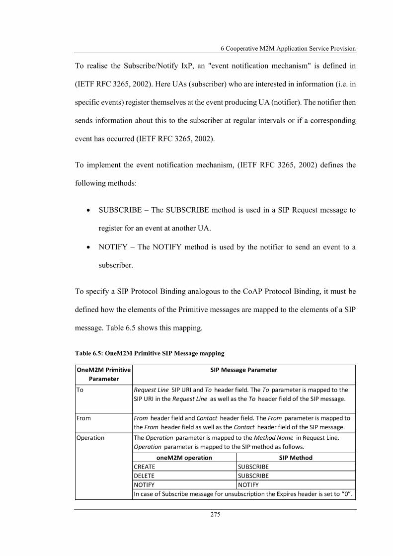
6 Cooperative M2M Application Service Provision
275
To realise the Subscribe/Notify IxP, an "event notification mechanism" is defined in
(IETF RFC 3265, 2002). Here UAs (subscriber) who are interested in information (i.e. in
specific events) register themselves at the event producing UA (notifier). The notifier then
sends information about this to the subscriber at regular intervals or if a corresponding
event has occurred (IETF RFC 3265, 2002).
To implement the event notification mechanism, (IETF RFC 3265, 2002) defines the
following methods:
SUBSCRIBE – The SUBSCRIBE method is used in a SIP Request message to
register for an event at another UA.
NOTIFY – The NOTIFY method is used by the notifier to send an event to a
subscriber.
To specify a SIP Protocol Binding analogous to the CoAP Protocol Binding, it must be
defined how the elements of the Primitive messages are mapped to the elements of a SIP
message. Table 6.5 shows this mapping.
Table 6.5: OneM2M Primitive SIP Message mapping
OneM2M Primitive
Parameter
To
From
oneM2M operation SIP Method
CREATE SUBSCRIBE
DELETE SUBSCRIBE
NOTIFY NOTIFY
Operation The Operation parameter is mapped to the Method Name in Request Line.
Operation parameter is mapped to the SIP method as follows.
From header field and Contact header field. The From parameter is mapped to
the From header field as well as the Contact header field of the SIP message.
In case of Subscribe message for unsubscription the Expires header is set to “0”.
SIP Message Parameter
Request Line SIP URI and To header field. The To parameter is mapped to the
SIP URI in the Request Line as well as the To header field of the SIP message.

6.2 Networking of Nodes
276
The designed SIP Protocol Binding enables transmission of Primitive messages with SIP
and makes it possible to use the existing communication infrastructure, in particular the
existing communication equipment (SIP stack in IAD) in end-users’ environments for
communication between SPs and SCs.
It should be noted that Primitive operations CREATE and DELETE are both sent via a
SIP Request message with the method SUBSCRIBE. The distinction between CREATE
and DELETE is made based on the Expires header field. If this field has the value "0",
the message is handled as an unsubscription message.
It has also been designed to specify whether a service should be used once or whether the
associated information should be transmitted continuously. For this purpose, the
additional parameter “once” has been defined in the Event header field. The parameter
reqId has also been specified as an additional parameter in the Event header field defining
the Request Identifier of a Primitive.
Request Identifier
Response Status
Code
Content
n/a
n/a
n/a
n/a
n/a
n/a
n/a
Field Token Length (TKL). Length of the Token field.
CSeq header field: Command Sequence Number set by the UAC.
Call-ID header field: Unique ID set by the UAC.
Event header parameter reqId has been defining the Request Identifier .
Response Status Code is mapped to the Response Line Status Code of a
Response message. oneM2M 2000 (OK) corresponds to SIP status code 200
(OK).
Message Body . Contains the Service Specific Input/ Config/ Output Parameter.
Content-Length header field. Indicates the size of the Message Body
Via header field: SIP URI of the client, set by the UAC.
Max-Forwards header field. Indicates the maximum number of hops.
Event header parameter once has been specified indicating retrieve of service/
information once (once=true ). Otherwise (once=false ) continuous information
delivery.

6 Cooperative M2M Application Service Provision
277
The following Figure 6.26 - Figure 6.28 illustrate the comprehensive message exchange
using SIP including the specific protocol message fields to realise the Subscribe/Notify
IxP.
Figure 6.26 shows the subscription of an information/service by sending a SUBSCRIBE
request. The receiving UAS replies with an acceptance message. Figure 6.27 shows the
notification message generated by the UAS that delivers the requested information (once
or continuous) to the requesting peer. Figure 6.28 shows the message exchange for
terminating a subscription. In that case the UAC generates a SUBSCRIBE message with
Expires header field set to “0” indicating that it is not interested in the previously
requested information/service anymore. Message Sequence Charts C.4 – C.6 show the
overall message exchange including message content for subscription, notification, and
termination via SIP (refer to Appendix C).
Figure 6.21: SIP Messaging for Service/Information Subscription
Peer 0User Agent ServerPeer 0User Agent Client
SUBSCRIBE sip:[email protected]:5060 SIP/2.0
SIP/2.0 200 OK
Call-ID = [email protected]
Call-ID = [email protected]
Message Body
content
output
outputParameter id = 1
name = remoteM2MapplicationService.output.parameter1
Event = m2mService;reqId=465143 [;once=false/true] if one-time subscr.

6.2 Networking of Nodes
278
Figure 6.22: SIP Messaging for Service/Information Notification
Figure 6.23: SIP Messaging for Service/Information Unsubscription
It should be emphasized once again that all communication is P2P, meaning that no
additional mediating network elements on the application layer are involved in the
communication between SP and SC. Thus, there are no dependencies on additional
network elements or on the operators of the network elements.
Peer 0User Agent ServerPeer 0User Agent Client
NOTIFY sip:[email protected]:5060 SIP/2.0
SIP/2.0 200 OK
Call-ID = [email protected]
Call-ID = [email protected]
Message Body
content
output
outputParameter id = 1
name = remoteM2MapplicationService.output.parameter1
Event = m2mService;reqId=465143 [;once=false/true] if one-time subscr.
value = Parameter-Value1
Peer 0User Agent ServerPeer 0User Agent Client
SUBSCRIBE sip:[email protected]:5060 SIP/2.0
SIP/2.0 200 OK
Call-ID = [email protected]
Call-ID = [email protected]
Message Body
content
output
outputParameter id = 1
name = remoteM2MapplicationService.output.parameter1
Event = m2mService;reqId=465143 [;once=false/true] if one-time subscr.
Expires = 0

6 Cooperative M2M Application Service Provision
279
The entities contained in the architecture of the M2M service platform (MSP) presented
in this research have the possibility to use both, CoAP and SIP as communication
protocols between the peers by using the CoAP Protocol Binding or introduced SIP
Protocol Binding.
In the following, an evaluation of CoAP and SIP as communication protocol in the context
of the presented architectural approach is performed.
Both CoAP and SIP have functionality transporting XML-data and mechanisms for
reliable communication enabling reliable exchange of Primitive messages. CoAP and SIP
are realised in realised in Application Layer (OSI) that offers the functionality to act in
heterogeneous networks. Both protocols can be used for end-to-end communication
between end-users’ platforms. Furthermore, CoAP and SIP offer the functionality for
location-independent availability via unique identifiers (globally defined SIP/CoAP
URIs).
CoAP has an advantage when considering the message size. The header fields of a CoAP
message are smaller than the header fields of a SIP message resulting in more overhead
for a SIP message, because the header fields are not encoded and compressed like in
CoAP, but in text format. The content of the header fields and the payload is the same for
both protocols. However, the overhead of a SIP message according to (IETF RFC 3261,
2002) can be reduced by providing the SIP header fields in a compact form. In this case,
the header fields are abbreviated by a single letter (e.g. compact form of the "From:"
header is "f:"). This reduces the length of the header field name to 4 Byte, since UTF-8
(IETF RFC 3629, 2003) is used for character encoding.
6.2 Networking of Nodes
280
The implementation of the MMSCs within the local M2M platform requires a SIP stack.
The use of SIP as compared to CoAP for message exchange between the distributed M2M
platforms has the advantage that an additional stack is avoided, which in turn reduces the
complexity of the platform architecture. End-users also usually have an end-device (e.g.
smartphone) in which a UA is already included that may be used for communication with
the local M2M platform via SIP. In addition to the implementation of the MMSCs, SIP
can also be used to realise a permanent VoIP communication or messaging (IM) between
SP and SC using additional protocols (e.g., SDP, RTP) whose stacks are also already
included in the common end-user multimedia communication equipment (RTP stack).
This enables communication independent of a public VoIP provider using P2P VoIP
communication. In particular, cellular mobile networks with LTE radio access networks
(3GPP TS 23.002 v8.7.0, 2010) require packet-switched message transport and therefore
SIP is used for implementation of multimedia over IP communication services. SIP
provides in comparison to CoAP integrated presence functionality to request information
regarding the availability of users as well as Instant Messaging functionality for exchange
of text messages between the M2M entities. In contrast to CoAP, a SIP-based platform
architecture could easily be integrated into Next Generation Networks (NGNs) (ITU-T
Y. 2001, 2004; ITU-T Y. 2012, 2006) or IP Multimedia Subsystems (IMS) (ETSI TS 123
228 V11.10.0, 2013) if the provider agrees to do so, since these are based on network
elements, end devices and gateways that communicate with SIP. For example, the
NGN/IMS provider could also act as a provider for the communication platform and, if
necessary, take over some of the platform functionality defined in this research (e.g.
registration of services). Additionally, a standard for NAT traversal practices has already

6 Cooperative M2M Application Service Provision
281
been defined for SIP in (IETF RFC 6314, 2011), which in turn simplifies the integration
of the M2M services in existing end-user equipment.
Table 6.6 summarises the comparison of the protocols CoAP and SIP in the context of
the presented framework.
Table 6.6: Comparison of CoAP and SIP as Communication Protocol
As result of the evaluation it can be stated that both protocols have advantageous
functionality enabling the communication between M2M SP and SC and therefore are
integrated in the proposed MSP architecture. CoAP has the advantage of low header size
and therefore less overhead in message transmission, which is advantageous in
constrained environments. SIP has the advantage that it offers additional (standardised)
functionalities that prevent integration of additional protocol stacks and client interface
CoAP SIP
Application Layer Protocol + +
Reliable Communication + +
Transport of XML Application Data + +
Possibility for end-to-end Communication + +
Location-independent availability + +
Low Overhead + o
No additional Protocol Stacks in Platform required - +
Existing (cliend-side) User Interface - +
Possibility for VoIP Communication - +
Integrated Presence Functionality - +
Possibility for NGN/ IMS integration - +
NAT traversal functionality o +
+: advantageous; o: moderate; -: disadvantageous

6.3 Service Registry and Distributed Data Storage
282
software. Because the extended functionality of SIP, it is therefore suggested to use SIP
as the communication protocol.
6.3 Service Registry and Distributed Data Storage
After explaining how peers can use services offered by other peers, and how networking
is realised between peers, the following section describes the management and
publication of services. For this, section 6.3.1 defines a common data base for the
administration of the IFDs. Section 6.3.2 introduces the concepts to realise the common
database using structured and unstructured P2P overlays. Finally, section 6.3.3 presents
an evaluation of structured and unstructured overlay algorithms in the context of this
project.
6.3.1 M2M Service Registration and Storage of M2M Service IFD
To enable the use of services offered by end-users, it is necessary to register the services
at an accessible location and to make the IFD available to other end-users. In this project,
a distinction is made between a service (service functionality) that can be uniquely
identified by a service-ID and service instances (specific implementation of the service).
A service provides a particular functionality, whereas a service instance is an actual
implementation of a service by an end-user that can be addressed via a service endpoint.
The IFD combines this information by describing the functionality of a service,
specifying the interface and including the service endpoints (pointOfAccess).
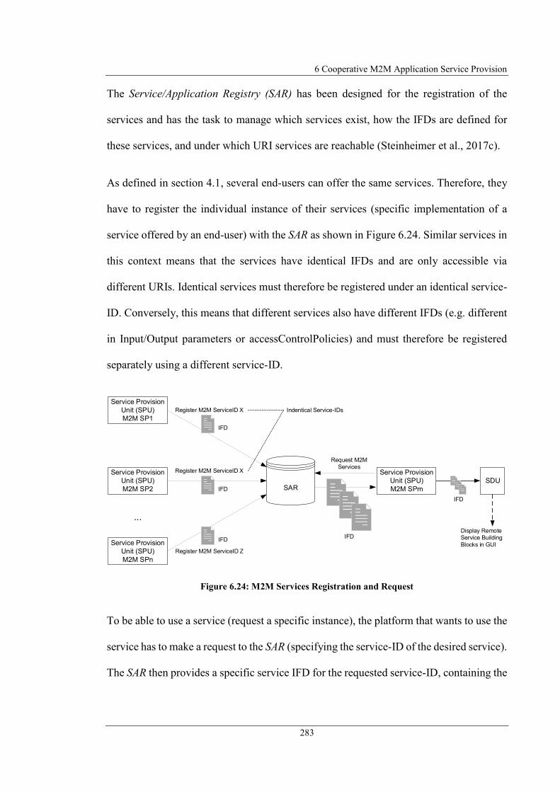
6 Cooperative M2M Application Service Provision
283
The Service/Application Registry (SAR) has been designed for the registration of the
services and has the task to manage which services exist, how the IFDs are defined for
these services, and under which URI services are reachable (Steinheimer et al., 2017c).
As defined in section 4.1, several end-users can offer the same services. Therefore, they
have to register the individual instance of their services (specific implementation of a
service offered by an end-user) with the SAR as shown in Figure 6.24. Similar services in
this context means that the services have identical IFDs and are only accessible via
different URIs. Identical services must therefore be registered under an identical service-
ID. Conversely, this means that different services also have different IFDs (e.g. different
in Input/Output parameters or accessControlPolicies) and must therefore be registered
separately using a different service-ID.
Figure 6.24: M2M Services Registration and Request
To be able to use a service (request a specific instance), the platform that wants to use the
service has to make a request to the SAR (specifying the service-ID of the desired service).
The SAR then provides a specific service IFD for the requested service-ID, containing the
...
Register M2M ServiceID X
Request M2M
Services
IFD
IFD
Register M2M ServiceID X
IFD
IFD
Register M2M ServiceID Z
IFD
Display Remote
Service Building
Blocks in GUI
SAR
Service Provision
Unit (SPU)
M2M SPm
Service Provision
Unit (SPU)
M2M SP1
Service Provision
Unit (SPU)
M2M SP2
Service Provision
Unit (SPU)
M2M SPn
SDU
Indentical Service-IDs

6.3 Service Registry and Distributed Data Storage
284
specific addressing information of the M2M SP (or multiple M2M SPs), so that the local
M2M platform can request the service on the remote M2M platform.
To obtain an overview of all registered services, the Service Provision Unit (SPU) of a
local M2M platform makes a request to the SAR for all registered services, which then
returns the registered IFDs. The resulting IFDs are forwarded by the querying SPU to the
Service Design Unit (SDU), which in turn generates remote service building blocks and
displays them in the GUI (see Figure 5.14).
6.3.2 Principles of distributed Data Storage
As introduced in section 4.2 the P2P Overlay Layer realises the functionality of
distributed data storage by forming the P2P overlay network out of all existing end-user
nodes. Distributed data storage means that data is not stored in one place, but stored in a
network, spread across multiple instances (peers). The aim of the presented approaches
is to entirely avoid central entities; therefore central data storage is declared as not
possible.
Also RELOAD (IETF RFC 6940, 2014) and the Distributed Resource Directory
Architecture for M2M Applications (DRD4M) Project (Liu et al., 2013) propose to use a
P2P overlays for registration and lookup of resources.
According to (Liu et al., 2013) registration of resources means storing the resource
description to the overlay (containing the IP, path, type, content type and name of the
resource). Lookup of resources means searching for a specific resource to request the
content of the resource. DRD4M also proposes to cache the resources in the overlay to

6 Cooperative M2M Application Service Provision
285
reply the resource descriptions and resource content if devices are in sleep mode. To
connect resources, the peers (resources) store their resource content in the overlay and
peers that want to consume the resources, request the content from the overlay.
As mentioned in section 6.2.1 additionally to P2P message routing functionality
RELOAD provides according to (IETF RFC 7374, 2014) and (IETF RFC 6940, 2014)
the functionality for distributed storage of data items inside the overlay using the selected
P2P overlay algorithm.
The approaches of distributed resource registration has been derived and applied to the
concept for distributed M2M service provision presented in this research.
DRD4M uses the structured overlay algorithm Chord (Stoica et al., 2001) to implement
the overlay (Liu et al., 2013). RELOAD also defines the usage of Chord as one mandatory
integrated P2P overlay algorithm. RELOAD enables that other structured or unstructured
P2P overlay algorithms could be used additionally to Chord to extend a RELOAD system
(IETF RFC 6940, 2014).
Since the approaches of structured and unstructured P2P overlays are fundamentally
different, the following section examines how a service registration could be realised
using the respective approaches. The following topics should be clarified:
Storing Service IFD in the Overlay – The specific information about a service
(e.g. SP URI, interface parameters) is stored in the service IFD. To make it
available, it must be stored in the overlay.
Retrieving a Service IFD – To obtain the information about a service the IFD must
be retrievable from the overlay.

6.3 Service Registry and Distributed Data Storage
286
Generate an overview of all existing services or service IFDs – If services are to
be used by other end-users, they must know which services exist at all. Therefore,
a list of all services is required (M2M Service Reference List).
IFD Registration using structured P2P Overlays
In a structured P2P overlay, the data sets are stored in a Distributed Hash Table (DHT)
and are identified by a unique key (refer to section 2.2). The IFD must therefore be stored
as a unique identifiable data item in the DHT. How the storage is carried out is described
below. The corresponding message exchange between the involved peers is shown in
Figure 6.25.
Figure 6.25: Store IFD in structured P2P Overlay
To store an IFD in the P2P overlay the key under which the IFD should be stored and
later searched must be defined. As described in section 6.3.1, an M2M service is uniquely
identified using the service-ID, which is therefore used as a key identifier for the data
item in the DHT. Afterwards, a store request must be sent to the P2P overlay, specifying
the key and the IFD (step 1). The P2P overlay algorithm is used to determine the peer in
Structured P2P Overlay
Peer 5
Peer 7
Peer 3
Peer 8
IFD
Service W
Peer 1
(1) Store IFD
Service X
Peer 9
Peer 2
(2) Store
(3)
Store
IFD
Service Y
IFD
Service ZIFD Service W
Peer 6
IFD
Service X
(4) Store
(5)
Store
Peer 4
M2M Service
Reference List

6 Cooperative M2M Application Service Provision
287
the DHT that is responsible for storing the data item. The IFD is then transferred to the
determined peer (step 2 - 5), which saves this IFD as a data item.
It is still necessary to check whether an IFD for an M2M service already does exist. This
is the case if several peers offer the same service. The verification can be realised sending
a request to the P2P overlay with the service-ID as a key. If the overlay already contains
an associated data record this is returned indicating that a service IFD has already been
stored in the SAR. Then peers can register another instance of that service by adding their
URI to the list of already contained M2M SP URIs in the IFD (pointOfAccess). After
adding the entry, peers save the modified IFD back to the P2P overlay.
Figure 6.26 illustrates the process to retrieve an IFD from the P2P overlay. A peer
requesting an IFD sends a request message to the DHT specifying the service-ID as
identifier for the searched IFD (step 1). The DHT then routes the request according to the
P2P overlay algorithm used to the peer storing the data item (step 2-5). The peer that
stores the record returns it directly to the requesting peer without involving the other peers
(step 6). After the IFD has been received, the information defined in it can be further
processed (e.g., by displaying corresponding M2M service building blocks in the GUI).

6.3 Service Registry and Distributed Data Storage
288
Figure 6.26: Request IFD from structured P2P Overlay
DHTs does not enable to determine all keys contained in it (because requests require
specific keys for data items). Therefore, it is necessary for generating an overview of all
existing M2M services that a list of service-IDs is managed, which is stored under a single
record listing all existing services. For this purpose, the M2M Service Reference List has
been introduced (see Peer 8 in Figure 6.25 and Figure 6.26). Peers that want to register a
service load this M2M Service Reference List from the P2P overlay (similar to querying
a service IFD), add the service-ID of the service that should be registered and store the
M2M Service Reference List back to the P2P overlay. Each peer requested the M2M
Service Reference List has an overview of the registered service-IDs and can query the
corresponding IFDs.
IFD Registration using unstructured P2P Overlays
In unstructured P2P overlays, in contrast to structured overlays, the records are stored
locally at the peers offering (i.e. insert) the data sets (see Figure 6.27). The IFD is thus
stored and managed locally by the peers who offer an M2M service. A data item (i.e., the
Structured P2P Overlay
Peer 5
Peer 7
Peer 3
Peer 8
IFD
Service W
Peer 1
(1) Request IFD
Service X
Peer 9
Peer 2
(2) Request
(3)
Request
IFD
Service Y
IFD
Service Z
IFD
Service X
(4) Request
(5)
Request
Peer 4
IFD Service X (6) Response
Peer 6
M2M Service
Reference List

6 Cooperative M2M Application Service Provision
289
IFD) is stored as a file in the filesystem of the peer. For identifying the IFD the service-
ID of the M2M service is also selected as the identifier for the IFD file.
Figure 6.27: Store IFD in unstructured P2P Overlay
Communication between peers during file storage process is not necessary and takes place
mainly during the search process for the IFD. It is required to manage a separate IFD for
each instance of a service since it is not possible to store files in the filesystems of other
peers (because missing write access). So peers that aim to register a service instance
generate the IFD containing their service endpoint URI and store it in their local
filesystem.
The search mechanism in unstructured P2P overlays (see Figure 6.28, refer to section 2.2)
is also significantly different from the search mechanism in structured P2P overlays.
Unstructured P2P algorithms cannot determine the localisation of data items
independently. Instead, the P2P overlay is flooded by sending a query for an IFD
(corresponding to a specified service-ID) to all neighbouring peers (step 1). The
neighbouring peers also forward the query to their neighbouring peers until the defined
Time-To-Live (TTL) value of the search query has been reached. If a data item is found,
Store StoreStore
Unstructured P2P Overlay
Peer 5
Peer 7
Peer 3
Peer 8
IFD
Service W
Peer 1 Peer 9
Peer 2
IFD
Service Y
IFD
Service Z
Peer 6
IFD
Service X
Peer 4
Store

6.3 Service Registry and Distributed Data Storage
290
the response message from the peer that stores the M2M service IFD is returned to the
requesting peer via the same route (step 2).
Figure 6.28: Request IFD from unstructured P2P Overlay
The query of the IFD is then made by directly information exchange between the peer
that triggered the search query (step 3) and the peer storing the IFD. This then transfers
the service IFD file to the requesting peer (step 4).
An unstructured P2P overlay allows complex search requests. This means that the ID of
the data item does not necessarily have to be exactly known for locating data items. It
may be possible, e.g. to search only for a part of the data item-ID and peers that store data
items corresponding to the searched pattern would respond to the query. Furthermore, a
query can be equipped with metadata in an unstructured overlay, which specifies a
searched data item more detailed. Thus, the requesting peer could e.g. define filter criteria,
such as accessControlPolicy or certain keywords, which specify the search for a service
IFD more detailed.
Unstructured P2P Overlay
IFD
Service Y
IFD
Service Z
IFD
Service X
Peer 5
Peer 7
Peer 3
Peer 8Peer 9
Peer 2 Peer 4(1) Query
IFD
Service X
(2) Query-Hit
IFD Service X
(3) Request IFD Service X
IFD Service X (4) Response
Peer 1 Peer 6
6 Cooperative M2M Application Service Provision
291
It has to be considered that unstructured P2P overlays do not guarantee reliable location
of data items because the flooding mechanism of unstructured P2P overlays for search
requests. The TTL value of search queries defines the maximum number of hops to which
the query is forwarded. If a record is not found within this range, the search request would
be unsuccessful, although a suitable IFD exists.
Compared to the use of a structured P2P overlays, it is not necessary (and not possible)
to have a separate list of all registered M2M services when using an unstructured P2P
overlay. This would be useless anyway, since it cannot be guaranteed that such a list
would be found. To get an overview of all registered services and service instances, peers
need to send a search query to the P2P overlay and query all existing service IFDs (e.g.
via search for "Service*"). Locally, the peers then process all service IFDs (e.g. to display
corresponding remote M2M Service building blocks in the GUI).
6.3.3 Analysis of structured and unstructured Overlay Architectures
RELOAD mentions the use of structured and unstructured P2P overlay networks for the
storage of data sets, but does not make any statement about the performance and
deployment scenario of different overlay algorithms. Therefore, an analysis of multiple
overlay algorithms is given subsequently.
According to (Malatras, 2015), (Steinmetz and Wehrle, 2005) and (Lua et al., 2005)
following common algorithms for structured P2P overlays exist: Pastry (Rowstron and
Druschel, 2001), Tapestry (Zhao et al., 2006), Chord (Stoica et al., 2001), CAN
(Ratnasamy et al., 2001), Kademlia (Maymounkov and Mazieres, 2002), and Viceroy
(Malkhi et al., 2002). Furthermore, following common algorithm for unstructured P2P
6.3 Service Registry and Distributed Data Storage
292
overlays exist: Gnutella 0.4 (Clip2, 2001), Freenet (Clarke, 2000; Freenet, 2000),
FastTrack (Liang et al., 2006), and BitTorrent (Piatek et al., 2007). FastTrack and
BitTorrent contain according to (Lua et al., 2005) centralised entities in their topologies
such as super nodes or central trackers, which violates the requirement of avoiding central
entities in the overall system architecture. Therefore, they cannot be considered as
appropriate candidates to form a P2P overlay, the others are compared subsequently.
First, the essential criteria are listed below that should be considered according to
(Malatras, 2015), (Lua et al., 2005), and (Steinmetz and Wehrle, 2005) for evaluation of
P2P overlay algorithms.
Lookup Performance – Defines the performance of the algorithm for routing
lookup requests in the overlay (Lua et al., 2005). It specifies the efficiency for
discovering the location (node) in the P2P overlay where a specific data item is
stored. Additionally, the Lookup Performance specifies the efficiency of
determining the location where to store specific data items (Steinmetz and Wehrle,
2005).
Churn Performance – Describes the performance of P2P overlay systems when
churn or self-organisation mechanisms of the P2P overlay occurs (Lua et al.,
2005). A single churn process according to (Binzenhöfer and Leibnitz, 2007) is
defined as a peer joins or leaves the overlay. High churn rates represent large
number of peers joining and leaving the overlay. The churn effect according to
(Stutzbach and Rejaie, 2006) characterises a P2P overlay by describing the
behaviour of the P2P overlay system for large number of peers that perform the

6 Cooperative M2M Application Service Provision
293
“join-participate-leave cycle” collectively, which means that many nodes in
parallel join the P2P system, make a request and leave the P2P system again.
Success Guaranty – Defines if the P2P overlay algorithm can guarantee to find
and retrieve a data item (if stored in the overlay).
Fuzzy Search – Possibility to search for a data item whose name is not defined
explicitly. E.g., search for a data item requesting sub-strings of data item identifier
or keyword-based search queries.
Table 6.7 shows the evaluation of the structured and unstructured P2P overlays regarding
the evaluation criteria defined above. The performance parameters define the complexity
class into which the algorithms are assigned and represent the number of nodes involved
(or messages between nodes) for specific operation or effect. The parameter “N” specifies
the number of nodes within the P2P overlay system.

6.3 Service Registry and Distributed Data Storage
294
Table 6.7: Evaluation P2P Algorithms acc. (Lua et al., 2005; Steinmetz and Wehrle, 2005; Malatras,
2015)
To illustrate the lookup and churn performance of different P2P overlay algorithms, Table
6.8 shows the lookup costs and Table 6.9 shows the churn costs for different P2P overlay
algorithms with increasing number of peers.
Table 6.8: Lookup Costs P2P Overlay Algorithms acc. (Lua et al., 2005; Steinmetz and Wehrle, 2005;
Malatras, 2015)
Past
ry
Tape
stry
Cho
rd
CA
N
Kade
mlia
Vic
ero
y
Free
net
Gnu
tella
Lookup
Perform.O(logBN) O(logBN) O(logN) O(dN1/d) O(logBN)+c O(logN) O(N2) O(N2)
Churn
Perform.O(logBN) O(logBN) O(logN)
2 O(2d) O(logBN + c) O(logN) O(1)O(1) (O(N2) for
Join)
Success
Guarantyyes yes yes yes yes yes no no
Fuzzy
Searchno no no no no no yes yes
d=number of dimensions (CAN), c=small constant (Kademlia), B=basis of logarithm, N=number of nodes
Evaluation
Criteria
P2P Overlay Algorithm
structured unstructured
Past
ry
Tape
stry
Cho
rd
CA
N
Kade
mlia
Vic
ero
y
Free
net
Gnu
tella
5 0,6989 0,6989 0,6989 5,1299 0,2902 0,6989 25 25
10 1 1 1 6,4633 0,4152 1 100 100
25 1,3979 1,3979 1,3979 8,772 0,5804 1,3979 625 625
50 1,6989 1,6989 1,6989 11,052 0,7054 1,6989 2500 2500
100 2 2 2 13,9247 0,8304 2 10.000 10.000
250 2,3979 2,3979 2,3979 18,8988 0,9957 2,3979 62.500 62.500
500 2,6989 2,6989 2,6989 23,811 1,1207 2,6989 250.000 250.000
1000 3 3 3 30 1,2457 3 1 m 1 m
Number of
NodesP2P Overlay Algorithm
structured unstructured
m=million

6 Cooperative M2M Application Service Provision
295
Table 6.9: Churn Costs of P2P Overlay Algorithms acc. (Lua et al., 2005; Steinmetz and Wehrle,
2005; Malatras, 2015)
Considering the lookup costs for structured P2P overlays (see Figure 6.29), the effort
involved in the use of the CAN algorithm is noticeably higher compared to the other
structured P2P overlay algorithms. Therefore, Figure 6.30 shows the comparison of the
lookup costs without CAN again.
Figure 6.29: Comparison Lookup Costs structured P2P Overlays
Past
ry
Tape
stry
Cho
rd
CA
N
Kade
mlia
Vic
ero
y
Free
net
Gnu
tella
5 0,6989 0,6989 0,4885 6 0,2902 0,6989 1 1 (25)
10 1 1 1 6 0,4152 1 1 1 (100)
25 1,3979 1,3979 1,9542 6 0,5804 1,3979 1 1 (625)
50 1,6989 1,6989 2,8864 6 0,7054 1,6989 1 1 (2500)
100 2 2 4 6 0,8304 2 1 1 (10.000)
250 2,3979 2,3979 5,7501 6 0,9957 2,3979 1 1 (62.500)
500 2,6989 2,6989 7,2844 6 1,1207 2,6989 1 1 (250.000)
1000 3 3 9 6 1,2457 3 1 1 (1.000.000)
Number of
Nodes
P2P Overlay Algorithm
structured unstructured
0
5
10
15
20
25
30
35
0 200 400 600 800 1000 1200
Loo
kup
Co
sts
Number of Nodes
Lookup Costs Comparison Structured P2P Overlay
Pastry Base 10
Tapestry Base 10
Chord
CAN Dimension 3
Kademlia 8 Bit
Viceroy

6.3 Service Registry and Distributed Data Storage
296
Figure 6.30: Comparison Lookup Costs structured P2P Overlays (excl. CAN)
Considering the lookup costs for structured P2P overlays without the CAN algorithm it
shows that Kademlia requires half as much effort for locating a data item as the other
algorithms.
Figure 6.31 illustrates the effort for search queries in unstructured P2P overlays.
Figure 6.31: Comparison Lookup Costs unstructured P2P Overlays
0
0,5
1
1,5
2
2,5
3
3,5
0 200 400 600 800 1000 1200
Loo
kup
Co
sts
Number of Nodes
Lookup Costs Comparison Structured P2P Overlay (excl. CAN)
Pastry Base 10
Tapestry Base 10
Chord
Kademlia 8 Bit
Viceroy
0
200000
400000
600000
800000
1000000
1200000
0 200 400 600 800 1000 1200
Loo
kup
Co
sts
Number of Nodes
Lookup Costs Comparison Unstructured P2P Overlay
Freenet
Gnutella

6 Cooperative M2M Application Service Provision
297
Unstructured P2P algorithms use a flooding mechanism when nodes sending search
queries for data items to their neighbours (see section 2.2). This results according to
(Steinmetz and Wehrle, 2005) in a massive effort of greater than O(N2).
Figure 6.32 illustrates the churn costs of structured P2P overlay algorithm networks as
specified in Table 6.7.
Figure 6.32: Comparison Churn Costs structured P2P Overlays
It can be seen that the churn performance is the best for Kademlia, and Chord has the
worst churn performance.
0
1
2
3
4
5
6
7
8
9
10
0 200 400 600 800 1000 1200
Ch
urn
Co
sts
Number of Nodes
Churn Costs Comparison Structured P2P Overlay
Pastry Base 10
Tapestry Base 10
Chord
CAN Dimension 3
Kademlia 8 Bit
Viceroy

6.3 Service Registry and Distributed Data Storage
298
Figure 6.33 illustrates the churn costs for unstructured P2P overlays.
Figure 6.33: Comparison Churn Costs unstructured P2P Overlays
The churn costs of unstructured P2P overlays are equal and constant according (Steinmetz
and Wehrle, 2005) O(1). This is because the nodes only connect to their direct neighbours
and only manage their own records. The topology of the overlay does not need to be
restructured when a new node connects to the overlay or leaves it.
Derived from (Malatras, 2015) the effort when entering into a Gnutella overlay should be
O(N2) and when leaving the effort stays at O(1). This is because the fact that a node, after
entering a Gnutella overlay, performs a so-called discovery operation. Such a discovery
operation (node lookup by PING, PONG message) is performed to identify other nodes
when joining the overlay. The discovery operation that uses flooding mechanism is
initiated periodically and therefore the costs should be set to O(N2) (same as for lookup
costs). The Freenet algorithm does not perform any operation when nodes join the
overlay, but nodes only connect to their identified neighbours.
0
0,2
0,4
0,6
0,8
1
1,2
0 200 400 600 800 1000 1200
Ch
urn
Co
sts
Number of Nodes
Churn Costs Comparison Unstructured P2P Overlay
Freenet
Gnutella

6 Cooperative M2M Application Service Provision
299
In a direct comparison of structured and unstructured P2P overlays with respect to the
lookup costs (illustrated in Figure 6.34) it becomes clear that in an unstructured P2P
overlay there is a massive increase of effort for searching data items. This is especially
important when many search queries are directed to the P2P overlay. Structured P2P
overlay algorithms remain in the complexity class O(logN) for the search of data items.
Thus, if many search requests are sent to a P2P overlay, a structured P2P overlay has the
advantage that the load on the entire overlay is significantly lower in terms of number of
messages exchanged between the nodes, but also in terms of the load on the involved
peers. In the case of unstructured P2P networks, all peers that pass the search queries in
the context of the flooding process are integrated into the communication. The same peers
are involved to route the corresponding response message back to the requesting peer.
Figure 6.34: Comparison Lookup Costs structured and unstructured P2P Overlays
Comparing the churn costs, it can be identified, that structured P2P overlay algorithms
have logarithmic costs, O(logN) for churn (illustrated in Figure 6.35) and unstructured
P2P overlays have cost of O(1). If one considers the additional costs of structured P2P
0
200000
400000
600000
800000
1000000
1200000
0 200 400 600 800 1000 1200
Loo
kup
Co
sts
Number of Nodes
Lookup Costs Comparison Structured, Unstructured P2P Overlay
Unstructured
Structured

6.3 Service Registry and Distributed Data Storage
300
overlays compared to unstructured P2P overlays, it can be seen that the increase of the
overhead is around 2-3 nodes. The small additional cost should not be relevant in the
evaluation of efficiency.
Figure 6.35: Comparison Churn Costs structured and unstructured P2P Overlays
Although the effect for churn in structured P2P overlays is only a little higher, (Steinmetz
and Wehrle, 2005) states that unstructured P2P overlays are for better use in mobile
networks with large movement of nodes. This is due to the fact that if peers often join or
leave the P2P overlay, the load on the overlay is significantly higher with a structured
overlay because the churn costs are aggregated. With an unstructured overlay, on the other
hand, the effort for connecting and leaving is constantly low. Furthermore, according to
(Binzenhöfer and Leibnitz, 2007) high churn rates in structured P2P overlays can also
cause routing errors or destroy the overlay. Therefore, an unstructured P2P overlay is
more advantageous at high churn rates.
0
0,5
1
1,5
2
2,5
3
3,5
0 200 400 600 800 1000 1200
Ch
urn
Co
sts
Number of Nodes
Churn Costs Comparison Structured, Unstructured P2P Overlay
Unstructured
Structured

6 Cooperative M2M Application Service Provision
301
When using a P2P overlay to manage the IFDs it is important that the data records can be
located. This is the case in an unstructured overlay because it guarantees that a record is
found. With an unstructured overlay, on the other hand, this cannot be guaranteed, since
due to the limited forwarding, it is not guaranteed that the search query will also reach
the peer who stores the IFD. Therefore, structured overlays are preferable for this
scenario.
Structured overlays enable peers not to store the IFD themselves, but only a reference to
the data set. Nodes storing an IFD could therefore be temporarily unavailable. The peer
who requested the reference to the IFD could contact the unavailable node at a later time
to request the IFD without having to request the reference to the IFD again via the overlay.
If, on the other hand, in an unstructured overlay, a node storing the IFD is temporarily
unavailable, then a search query has to be sent again via the overlay, which would again
stress the network. In an unstructured overlay, the information about offered services is
therefore only available if the peers offering the service are also reachable.
In structured P2P overlays the ID of the IFD must have been uniquely determined when
querying it. Therefore, a search request can only be successful if the service-ID of the
IFD is known. In an unstructured P2P overlay, however, the search does not need to be
based on a specific key. This makes it possible to search IFDs whose exact service-ID are
unknown during search requests. Furthermore, in an unstructured P2P overlay, searching
for a set of IFDs is possible, such as all services belonging to a specific group and contains
specific keywords in their names. These types of search queries can only be realised with
unstructured P2P overlays.
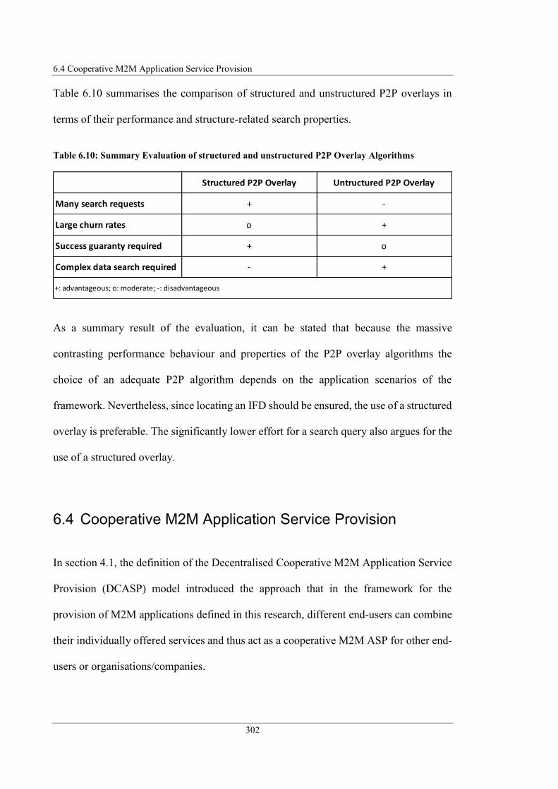
6.4 Cooperative M2M Application Service Provision
302
Table 6.10 summarises the comparison of structured and unstructured P2P overlays in
terms of their performance and structure-related search properties.
Table 6.10: Summary Evaluation of structured and unstructured P2P Overlay Algorithms
As a summary result of the evaluation, it can be stated that because the massive
contrasting performance behaviour and properties of the P2P overlay algorithms the
choice of an adequate P2P algorithm depends on the application scenarios of the
framework. Nevertheless, since locating an IFD should be ensured, the use of a structured
overlay is preferable. The significantly lower effort for a search query also argues for the
use of a structured overlay.
6.4 Cooperative M2M Application Service Provision
In section 4.1, the definition of the Decentralised Cooperative M2M Application Service
Provision (DCASP) model introduced the approach that in the framework for the
provision of M2M applications defined in this research, different end-users can combine
their individually offered services and thus act as a cooperative M2M ASP for other end-
users or organisations/companies.
Structured P2P Overlay Untructured P2P Overlay
Many search requests + -
Large churn rates o +
Success guaranty required + o
Complex data search required - +
+: advantageous; o: moderate; -: disadvantageous
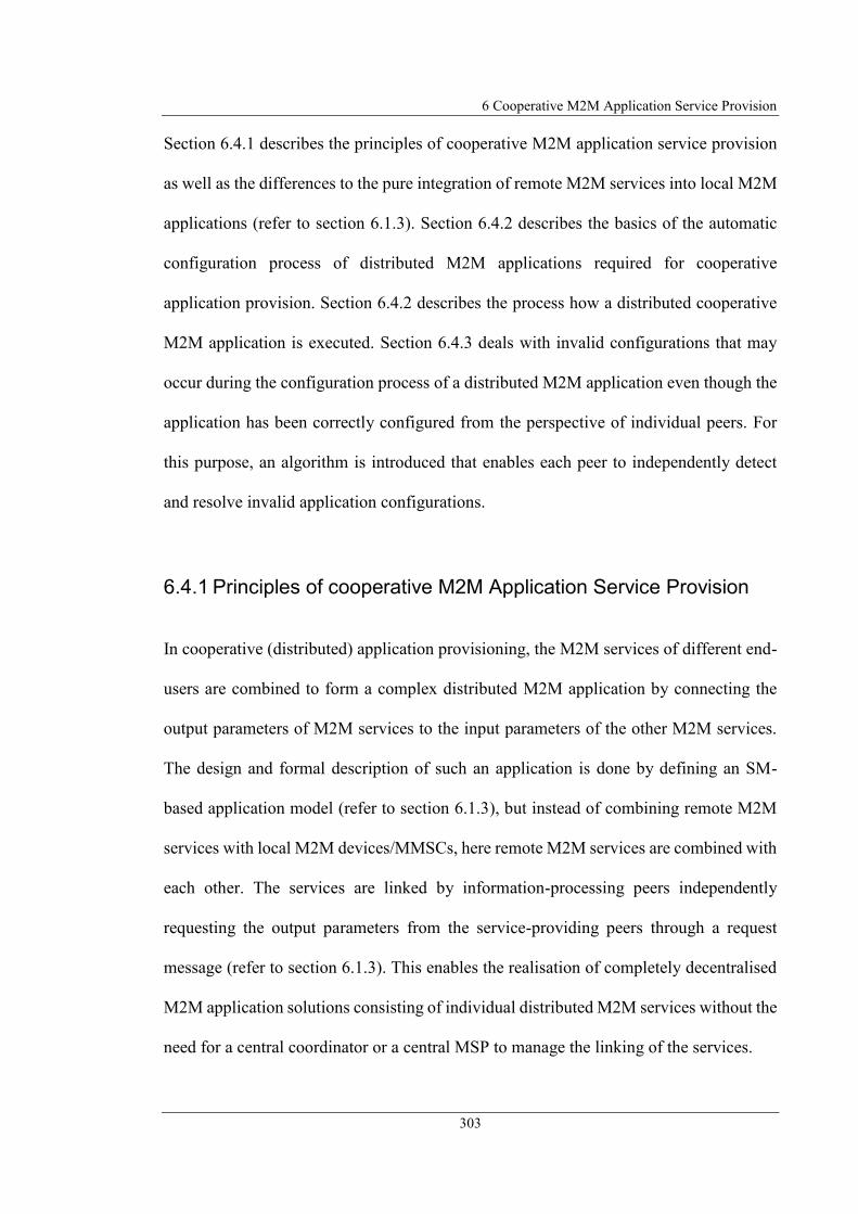
6 Cooperative M2M Application Service Provision
303
Section 6.4.1 describes the principles of cooperative M2M application service provision
as well as the differences to the pure integration of remote M2M services into local M2M
applications (refer to section 6.1.3). Section 6.4.2 describes the basics of the automatic
configuration process of distributed M2M applications required for cooperative
application provision. Section 6.4.2 describes the process how a distributed cooperative
M2M application is executed. Section 6.4.3 deals with invalid configurations that may
occur during the configuration process of a distributed M2M application even though the
application has been correctly configured from the perspective of individual peers. For
this purpose, an algorithm is introduced that enables each peer to independently detect
and resolve invalid application configurations.
6.4.1 Principles of cooperative M2M Application Service Provision
In cooperative (distributed) application provisioning, the M2M services of different end-
users are combined to form a complex distributed M2M application by connecting the
output parameters of M2M services to the input parameters of the other M2M services.
The design and formal description of such an application is done by defining an SM-
based application model (refer to section 6.1.3), but instead of combining remote M2M
services with local M2M devices/MMSCs, here remote M2M services are combined with
each other. The services are linked by information-processing peers independently
requesting the output parameters from the service-providing peers through a request
message (refer to section 6.1.3). This enables the realisation of completely decentralised
M2M application solutions consisting of individual distributed M2M services without the
need for a central coordinator or a central MSP to manage the linking of the services.
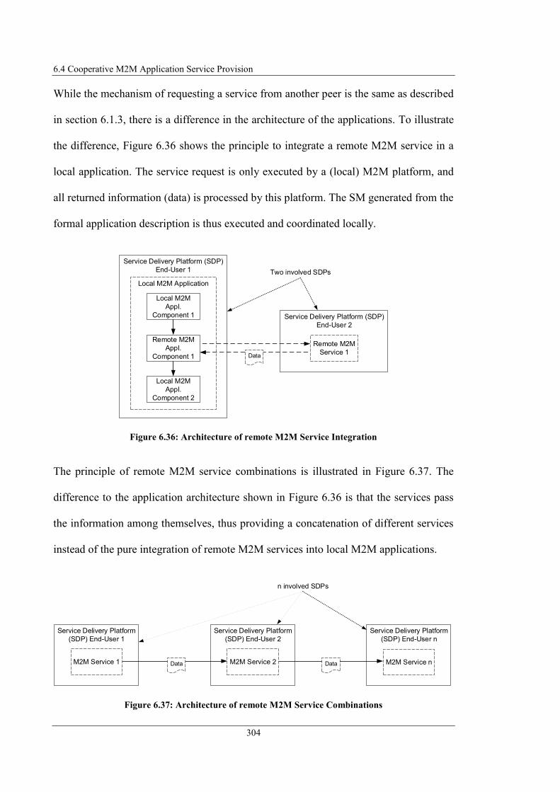
6.4 Cooperative M2M Application Service Provision
304
While the mechanism of requesting a service from another peer is the same as described
in section 6.1.3, there is a difference in the architecture of the applications. To illustrate
the difference, Figure 6.36 shows the principle to integrate a remote M2M service in a
local application. The service request is only executed by a (local) M2M platform, and
all returned information (data) is processed by this platform. The SM generated from the
formal application description is thus executed and coordinated locally.
Figure 6.36: Architecture of remote M2M Service Integration
The principle of remote M2M service combinations is illustrated in Figure 6.37. The
difference to the application architecture shown in Figure 6.36 is that the services pass
the information among themselves, thus providing a concatenation of different services
instead of the pure integration of remote M2M services into local M2M applications.
Figure 6.37: Architecture of remote M2M Service Combinations
Service Delivery Platform (SDP)
End-User 2
Service Delivery Platform (SDP)
End-User 1
Local M2M Application
Local M2M
Appl.
Component 1
Local M2M
Appl.
Component 2
Remote M2M
Service 1
Remote M2M
Appl.
Component 1 Data
Two involved SDPs
n involved SDPs
Service Delivery Platform
(SDP) End-User 1
Service Delivery Platform
(SDP) End-User 2
Service Delivery Platform
(SDP) End-User n
Data DataM2M Service 1 M2M Service 2 M2M Service n

6 Cooperative M2M Application Service Provision
305
When concatenating services, the involved M2M services provide their information to
other M2M SPs, which process the information and, if necessary, provide information to
another M2M SP. There is no instance of a SM that is executed or coordinated locally in
one single platform, but the different distributed peers realise the distributed SM logic.
As described in section 4.1, two variants have been introduced according to (Steinheimer
et al., 2015a) for the cooperative M2M application service provision (illustrated in Figure
6.38).
Figure 6.38: Variants of cooperative M2M Service Combinations
The first option is the previously described composition of M2M services (Figure 6.38-
a). The second option is service aggregation (Figure 6.38-b). In this case, end-users can
each offer the same service (different service instances) and exchange information among
themselves for this one service.
Figure 6.39 shows the exchange of messages for the variant of M2M service
compositions, respectively the service requests for the combination of services that realise
a service chain. In this case, the services/M2M platforms subscribe with the preceding
service in the service chain, since the services should consume the information of that
preceding service.
a) M2M Service Composition b) M2M Service Aggregation
M2M Service 1
End User 2
M2M Service 1
End User n
Data
Data
M2M Service 1
End User 3DataM2M Service 1
End User 1
M2M Service 1
End User 1
M2M Service 2
End User 2
M2M Service n
End User nData Data
Instance 2
Instance 3Instance 1
Instance n

6.4 Cooperative M2M Application Service Provision
306
Figure 6.39: M2M Service Composition Message Exchange
Figure 6.40 shows the message exchange for the variant of M2M service aggregations.
Since all services require the information of the other services, each service subscribes
with the other services to obtain their data information.
Figure 6.40: M2M Service Aggregation Message Exchange
The semantics for modelling a service composition have already been defined (linking
services by defining a transition from a state representing the service to another state that
represents the service to receive the information, refer to section 5.5). No corresponding
semantics have yet been defined for service aggregation. Therefore, it is defined at this
point that a service aggregation is described by the fact that a state receives a reference to
itself, i.e. as the target of the transition, the same service-ID is specified as for the state
from which the transition originates. In the case of a service composition, the peer who
wants to use the corresponding service requests only one instance of a service. In the case
of a service aggregation, however, all instances of the same service are requested and
information about the entire application is exchanged with these instances.
Peer 0M2M Service 1
End-User 1 Peer 0M2M Service 2
End-User 2 Peer 0M2M Service n
End-User n
Service RequestResponse
Service RequestResponse
...
Peer 0M2M Service 1
End-User 1 Peer 0M2M Service 1
End-User 2 Peer 0M2M Service 1
End-User n
Service RequestResponse
Service RequestResponse
Service RequestResponse
Service RequestResponse
Service RequestResponse
Service RequestResponse
...
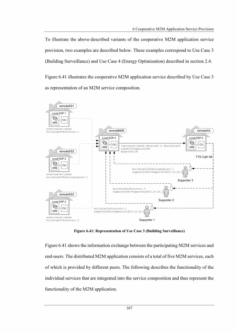
6 Cooperative M2M Application Service Provision
307
To illustrate the above-described variants of the cooperative M2M application service
provision, two examples are described below. These examples correspond to Use Case 3
(Building Surveillance) and Use Case 4 (Energy Optimisation) described in section 2.4.
Figure 6.41 illustrates the cooperative M2M application service described by Use Case 3
as representation of an M2M service composition.
Figure 6.41: Representation of Use Case 3 (Building Surveillance)
Figure 6.41 shows the information exchange between the participating M2M services and
end-users. The distributed M2M application consists of a total of five M2M services, each
of which is provided by different peers. The following describes the functionality of the
individual services that are integrated into the service composition and thus represent the
functionality of the M2M application.
event=water|smoke
buildingID=Kleiststr.1
Local SDP 1
CUSRE
remoteSS1
event=water|smoke
buildingID=Nibelungenplatz 1
Local SDP 2
CUSRE
remoteSS2
event=water|smoke
buildingID=Kleiststr.3
Local SDP 2
CUSRE
remoteSS3
buildingID=Kleiststr.1
buildingID=Kleiststr.3
buildingID=Nibelungenplatz 1
text=water|smoke detected in $buildingID
sipURI=$supporterURI
Mode=TTS|IM
TTS Call/ IM
Supporter 1
Supporter 2
Supporter 3
Local SDP 4
CUSRE
remoteBMS
Local SDP 5
CUSRE
remoteAS

6.4 Cooperative M2M Application Service Provision
308
Remote Sensor Service (remoteSS) 1-3 – RemoteSS (1-3) are each different
services which have similar functionality. They read the status of local sensors
(water sensor and smoke detector). If one of the two sensors has the value "water"
(indicates water detected) or "smoke" (indicates smoke detected), the service
generates an event and forwards it to the Remote Building Monitoring Service
(remoteBMS) together with the building-ID of the respective building. RemoteSS
(1-3) differ only by the assigned building-ID at their output interfaces and thus
monitor the status of different buildings.
Remote Building Monitoring Service (remoteBMS) – RemoteBMS provides the
functionality to aggregate the monitoring of different buildings and to manage the
supporters associated with the buildings. The remoteBMS receives the event that
has occurred in a building and determines the supporter responsible for this
building. Depending on the event, the remoteBMS triggers a Remote Alarm
Service (remoteAS). By the transmitted information, the latter is instructed to
inform the registered supporter about the event, either by Text-to-Speech (TTS)
call (in case of smoke detected) or by IM (in case of water detected).
Remote Alarm Service (remoteAS) – The remoteAS provides the functionality to
send an IM or to initiate a call and announce a text. This service expects as input
parameters the destination SIP URI to which the message should be sent and the
text which should be contained in the IM or which should be announced. Which
of the two notifications to select is defined by the input parameter "mode". If
"mode" parameter has the value "IM", an IM is generated. If "mode" parameter
has the value "TTS", a TTS call is initiated.

6 Cooperative M2M Application Service Provision
309
The supporters offer the service to take care of a specific building. This service is only
loosely coupled to the M2M application service by not being directly part of the
application, but only using the M2M application service functionality to provide the
service. To utilise the Building Surveillance application, the supporter registers with the
remoteBMS. During this registration, the supporters will tell the remoteBMS which
building they are supporting and what is their contact information.
Because the flexibility of the introduced formal description language, multiple variants
are possible to realise the formal application description (AD) for the scenario of Use
Case 3:
Separate ADs per Building – Definition of an individual AD for each building to
monitor. Here the first state corresponds to the remoteSS of the building to
monitor.
One AD for all Buildings – Define one AD for all buildings to monitor. In this
case, the first state of the AD can be modelled as parallel state element containing
one section per remoteSS of the buildings to monitor.
The first variant (separate ADs) has been selected to show an extract of the formal AD
(see Figure 6.42) represented as Statechart, since it has the advantage that an already
existing AD could be reused by simple modifying the parameters corresponding to the
building in focus. Listing C.10 illustrates the corresponding SCXML pattern. In the
second variant, the structure of the AD would have to be customised by adding new states
in the parallel state element and additionally does not hide other monitored buildings in
the AD.
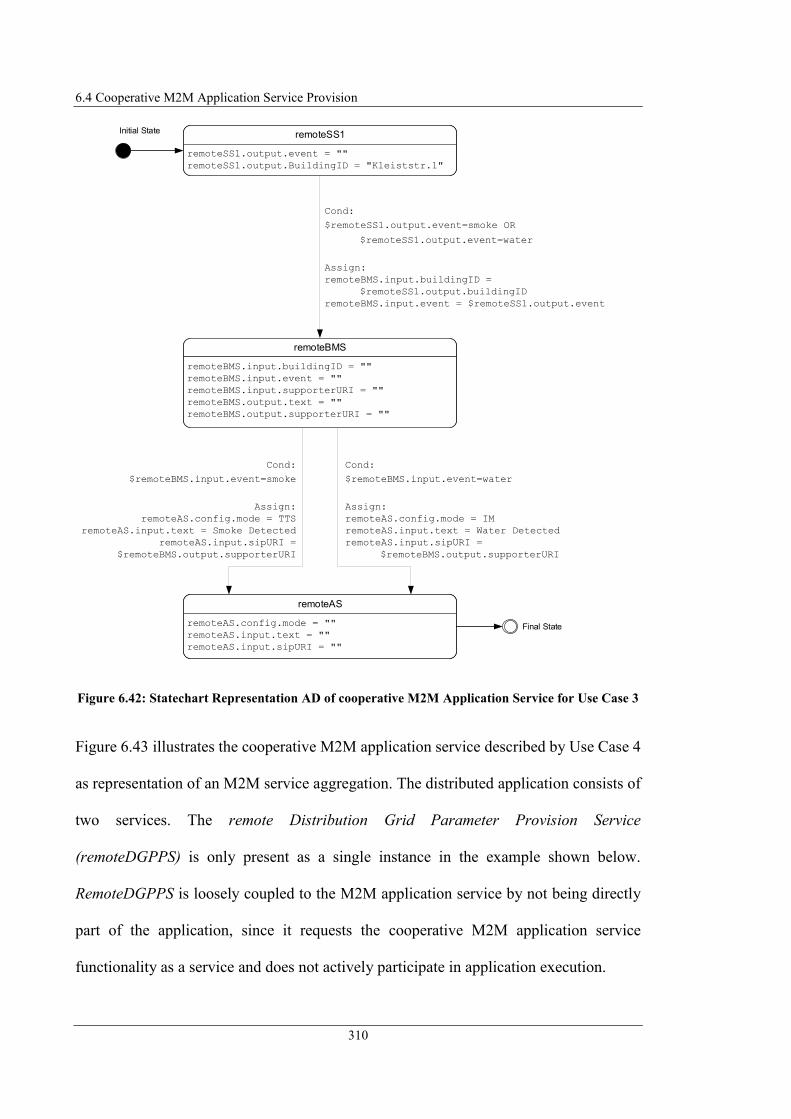
6.4 Cooperative M2M Application Service Provision
310
Figure 6.42: Statechart Representation AD of cooperative M2M Application Service for Use Case 3
Figure 6.43 illustrates the cooperative M2M application service described by Use Case 4
as representation of an M2M service aggregation. The distributed application consists of
two services. The remote Distribution Grid Parameter Provision Service
(remoteDGPPS) is only present as a single instance in the example shown below.
RemoteDGPPS is loosely coupled to the M2M application service by not being directly
part of the application, since it requests the cooperative M2M application service
functionality as a service and does not actively participate in application execution.
Cond:
$remoteSS1.output.event=smoke OR
$remoteSS1.output.event=water
Assign:
remoteBMS.input.buildingID =
$remoteSS1.output.buildingID
remoteBMS.input.event = $remoteSS1.output.event
remoteBMS
remoteBMS.input.buildingID = ""
remoteBMS.input.event = ""
remoteBMS.input.supporterURI = ""
remoteBMS.output.text = ""
remoteBMS.output.supporterURI = ""
remoteAS
remoteAS.config.mode = ""
remoteAS.input.text = ""
remoteAS.input.sipURI = ""
Cond:
$remoteBMS.input.event=water
Assign:
remoteAS.config.mode = IM
remoteAS.input.text = Water Detected
remoteAS.input.sipURI =
$remoteBMS.output.supporterURI
Cond:
$remoteBMS.input.event=smoke
Assign:
remoteAS.config.mode = TTS
remoteAS.input.text = Smoke Detected
remoteAS.input.sipURI =
$remoteBMS.output.supporterURI
Initial State remoteSS1
remoteSS1.output.event = ""
remoteSS1.output.BuildingID = "Kleiststr.1"
Final State
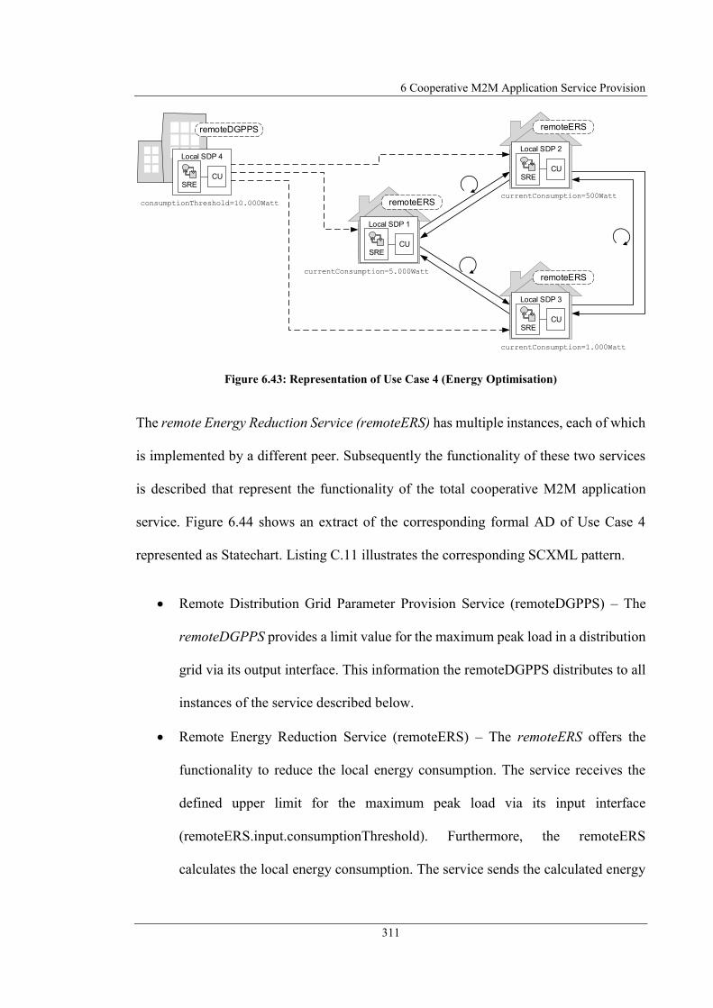
6 Cooperative M2M Application Service Provision
311
Figure 6.43: Representation of Use Case 4 (Energy Optimisation)
The remote Energy Reduction Service (remoteERS) has multiple instances, each of which
is implemented by a different peer. Subsequently the functionality of these two services
is described that represent the functionality of the total cooperative M2M application
service. Figure 6.44 shows an extract of the corresponding formal AD of Use Case 4
represented as Statechart. Listing C.11 illustrates the corresponding SCXML pattern.
Remote Distribution Grid Parameter Provision Service (remoteDGPPS) – The
remoteDGPPS provides a limit value for the maximum peak load in a distribution
grid via its output interface. This information the remoteDGPPS distributes to all
instances of the service described below.
Remote Energy Reduction Service (remoteERS) – The remoteERS offers the
functionality to reduce the local energy consumption. The service receives the
defined upper limit for the maximum peak load via its input interface
(remoteERS.input.consumptionThreshold). Furthermore, the remoteERS
calculates the local energy consumption. The service sends the calculated energy
consumptionThreshold=10.000Watt
currentConsumption=5.000Watt
remoteDGPPS
currentConsumption=500Watt
currentConsumption=1.000Watt
Local SDP 4
CUSRE
Local SDP 1
CUSRE
remoteERS
Local SDP 2
CUSRE
remoteERS
Local SDP 3
CUSRE
remoteERS

6.4 Cooperative M2M Application Service Provision
312
consumption to all other instances of the service. The other instances of the service
perform the same and send their energy consumption back to all other instances.
The energy consumption of the other instances of the service is received via a
separate parameter of the service interface
(remoteERS.input.remoteConsumption). The remoteERS calculates the total
consumption of all participating service instances from the received consumption
values. The service compares the calculated total consumption with the maximum
peak load value obtained from the remoteDGPPS. If the limit is exceeded by the
sum of all consumptions, the service reduces the local consumption (if possible).
The remoteERS then redistributes the new calculated energy consumption to all
other instances of the service.
Figure 6.44: Statechart Representation AD of cooperative M2M Application Service for Use Case 4
For being able to use a cooperative M2M application service an interface must also be
defined for this purpose. As is apparent from the examples above, the interface to a
cooperative M2M application service does not necessarily have to be the first service in
the service combination. The interface that must be served for service utilisation can also
be provided by a service that is located within the service chain. Therefore, additionally
to the derivation of the IFD in section 6.1.1, it is defined that an interface to an M2M
application service can also be specified addressing interface parameter of a service
within the service combination. Additionally, an interface does not have to contain all
remoteERS
remoteERS.input.consumptionThreshold = ""
remoteERS.input.remoteConsumption = ""
remoteERS.output.currentConsumption = ""
Assign:
remoteERS.input.remoteConsumption = $remoteERS.output.currentConsumption

6 Cooperative M2M Application Service Provision
313
interface parameters that the service to be addressed has. Therefore, it is further defined
that the IFD of a cooperative M2M application service can only contain a subset of the
interface parameters of all the services involved.
6.4.2 Cooperative M2M Application Configuration and Execution
Phase
The application configuration phase has been designed as an automated and autonomous
configuration process of the distributed M2M application (Steinheimer et al., 2017a). This
configuration process is preceded of the actual application execution to connect the
specific instances of the services involved. The connection of the services to each other
represents the modelled SM and thus defines the exchange of information between the
services.
The connections between the individual peers, respectively interconnection of the
services, cannot be coordinated centrally since no central entities may be included in the
M2M service architecture according to the requirements specification. This means that
no central entity exists which directs the peers to which specific instances of a service
they should connect to realise a distributed SM. Therefore, a mechanism is required
enabling the peers to integrate themselves into the service chain. This means that the peers
must independently determine the instances of the services with which they should
connect and forward the information according to the application logic to the service
succeeding to them (defined as transition between M2M services).

6.4 Cooperative M2M Application Service Provision
314
Following the approach of processing a SM, the decision to forward information to the
requesting service, i.e. to send a corresponding response message to the requesting peer
(if defined as a transition condition), must be made in the service providing the
information. For this purpose, the introduced concept defines that the distributed M2M
application is initially configured (configuration phase), i.e. the services are linked
together, before the actual application logic is executed (execution phase).
To enable peers to configure their individual parts of the application during the
configuration phase independently, they need corresponding information defined in the
formal AD. Peers can determine this information by automatically parsing the AD and
extracting this information. It is sufficient if each peer only receives the segment of the
AD containing the information necessary to configure their individual service and insert
themselves into the overall context of the application according to the AD.
The following describes the information required by peers to embed themselves in the
application context and from which elements of the formal AD this information can be
extracted.
Service to request – Information about which service (defined by its service-ID)
a peer has to request from another peer. This information can be determined via
the preceding state. The preceding state is identifiable since it has a transition
targeting on its own state. The state-ID corresponds to the service-ID and thus
provides the information about the service that should be requested.
Parameter to request – Information about which parameters should be requested
or set at the remote service. The data model of the preceding states (see section
5.5.3) specifies these parameters containing their identifier and (if necessary)
6 Cooperative M2M Application Service Provision
315
initialise them with a value specifying which parameter content should be
transmitted.
These parameters form the basis for determining the preceding service in the service
chain. The following parameters form the basis for deciding when and which information
should be transmitted to a succeeding service.
Condition when to response – Information about the prerequisites for transmitting
information to a peer who requested this information. This is defined by the
transition condition of the own state. Thus, the decision is made as to when the
distributed SM moves to another state.
Data to response – Information about which data to transmit to the succeeding
state. There are two possibilities for this: 1. the data being transmitted was defined
via the request message, or 2. the <assign> element of the (own) transition defines
which data is sent to which input interface of a succeeding service (see section
5.5.3).
In addition to this information for embedding in the application context, peers need the
following additional information, which they also get from the AD.
Start Point of M2M application – Information about the entry point of the
distributed M2M application, i.e. the first service in the service chain. The first
service is labelled as an initial state in the formal AD and can thus be identified.
End Point of M2M application – Information about the end point of the distributed
M2M application, i.e. the last service in the service chain. This is defined as final
state in the AD.

6.4 Cooperative M2M Application Service Provision
316
Information about the initial and final state is required to validate a correct application
configuration (refer to section 6.4.3).
After peers involved in the distributed M2M application service have extracted the above-
specified configuration information by automated parsing of the formal AD, they
integrate their services autonomously into the overall context of the application. Figure
6.45 illustrates the application configuration process.
First, each peer determines the specific instances of the services (contact information,
URI) to connected to, i.e. determines a list (SP list) of peers offering the service based on
the service-ID. This list is integrated in the IFD. Therefore, peers request the IFD from
the SAR.
The connection to a specific M2M service instance is performed by sending a request
message to the SPs inside the SP list containing the Request Primitive including the
parameter that should be either set (Input/Config parameter) or requested (Output
parameter). If the requested service is available, the requested peer confirms the service
request with a positive response. If the service is not available, the requested peer
responds with a negative response. The requested peer holds a local Requestor List (RL)
to store the requestors contact information and corresponding requested service
parameter.

6 Cooperative M2M Application Service Provision
317
Figure 6.45: M2M Application Configuration Process
In this RL the service providing peer inserts the requested parameter and corresponding
contact information after receiving the service request (if confirmed). If the service
request contains Input/Config parameter data, the service providing peer assigns the
corresponding values to the Input/Config parameter of the local service (e.g. for
configuration of the service). After confirmation of the service request the SP adds the
transition condition to the corresponding entry in RL for later usage to evaluate whether
a response message should be send to the requestor. Additionally, the SP adds the
information about the data that should be transmitted in response message (if defined
using assign element of the transition).
Peer 0Service
Consumer (SC)Peer 0Service
Provider (SP)
M2M Application
Description
M2M Application
Description
Service Request
Confirm Registration
<Request Parameter> Store Requestor URI
+ Parameter in local
Requestor List
Determine Service to
request
Determine Final
Service StateDetermine Transition
Condition + add to
local Requestor List
Determine Data to
transmit (assign) +
add to local
Requestor List
IFD Service X
Peer 0SAR
Request IFD
Service X
Determine Parameter
to request
Determine Initial
Service State
Select Service
Instance
Configure local M2M
Service

6.4 Cooperative M2M Application Service Provision
318
Through this configuration process, a connection between an M2M SP and an M2M SC
was successfully established and it has been defined under which prerequisites specific
information should be transferred from the SP to the SC.
After the configuration of the distributed M2M application is finished, the execution
phase of the application starts (illustrated in Figure 6.46) (Steinheimer et al., 2017a).
Figure 6.46: M2M Application Execution Process
During execution phase, the peers must distinguish whether their service is the first
service in the service chain and thus starts the execution of the M2M application, or
whether their service is a service within the service chain. If it is the first service in the
Analyse Requestor List Entries
Set local M2M
Service Parameter
Execute local M2M
Service Logic
[Response Message received]
[Initial State Service]
Generate Response
Primitive
Select Requestor
List Entry
[Condition defined]
[No Condition defined]
Send Response Message
to registered Receiver
[Condition TRUE]
[Condition FALSE]
[Remaining Entries ] [No Remaining Entries ]
Extract Response
Primitive
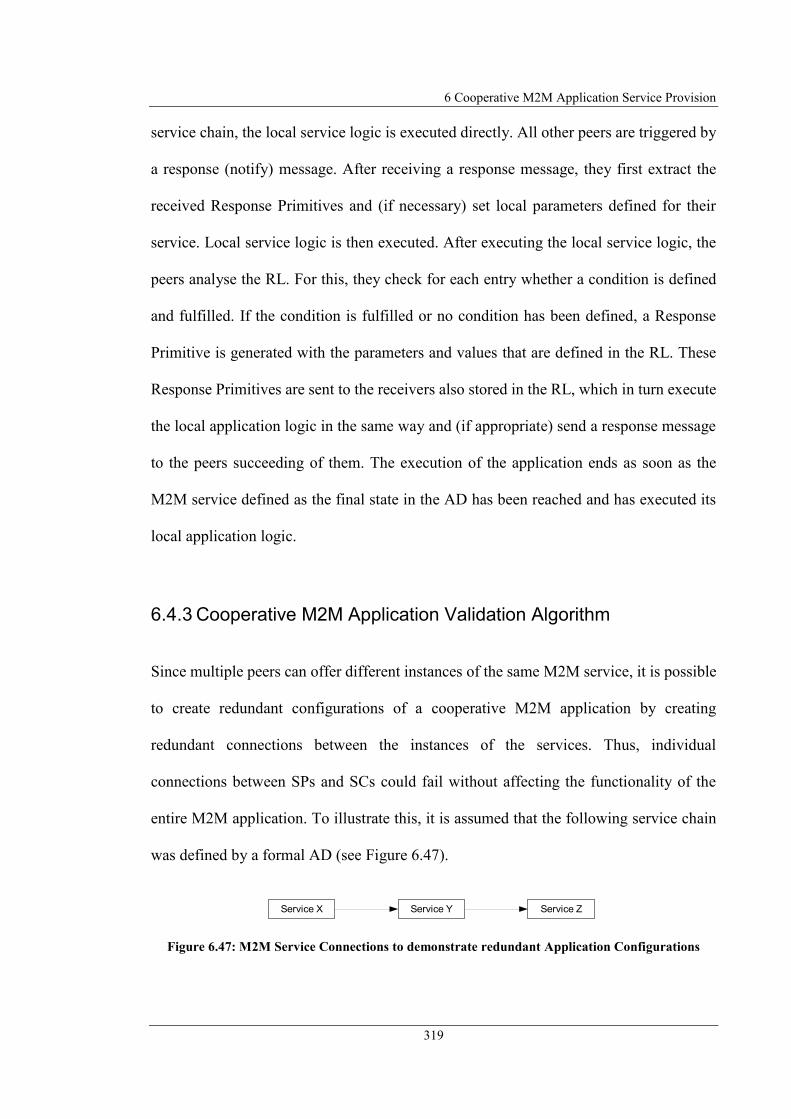
6 Cooperative M2M Application Service Provision
319
service chain, the local service logic is executed directly. All other peers are triggered by
a response (notify) message. After receiving a response message, they first extract the
received Response Primitives and (if necessary) set local parameters defined for their
service. Local service logic is then executed. After executing the local service logic, the
peers analyse the RL. For this, they check for each entry whether a condition is defined
and fulfilled. If the condition is fulfilled or no condition has been defined, a Response
Primitive is generated with the parameters and values that are defined in the RL. These
Response Primitives are sent to the receivers also stored in the RL, which in turn execute
the local application logic in the same way and (if appropriate) send a response message
to the peers succeeding of them. The execution of the application ends as soon as the
M2M service defined as the final state in the AD has been reached and has executed its
local application logic.
6.4.3 Cooperative M2M Application Validation Algorithm
Since multiple peers can offer different instances of the same M2M service, it is possible
to create redundant configurations of a cooperative M2M application by creating
redundant connections between the instances of the services. Thus, individual
connections between SPs and SCs could fail without affecting the functionality of the
entire M2M application. To illustrate this, it is assumed that the following service chain
was defined by a formal AD (see Figure 6.47).
Figure 6.47: M2M Service Connections to demonstrate redundant Application Configurations
Service YService X Service Z
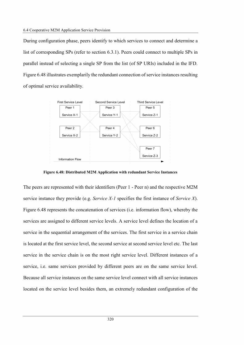
6.4 Cooperative M2M Application Service Provision
320
During configuration phase, peers identify to which services to connect and determine a
list of corresponding SPs (refer to section 6.3.1). Peers could connect to multiple SPs in
parallel instead of selecting a single SP from the list (of SP URIs) included in the IFD.
Figure 6.48 illustrates exemplarily the redundant connection of service instances resulting
of optimal service availability.
Figure 6.48: Distributed M2M Application with redundant Service Instances
The peers are represented with their identifiers (Peer 1 - Peer n) and the respective M2M
service instance they provide (e.g. Service X-1 specifies the first instance of Service X).
Figure 6.48 represents the concatenation of services (i.e. information flow), whereby the
services are assigned to different service levels. A service level defines the location of a
service in the sequential arrangement of the services. The first service in a service chain
is located at the first service level, the second service at second service level etc. The last
service in the service chain is on the most right service level. Different instances of a
service, i.e. same services provided by different peers are on the same service level.
Because all service instances on the same service level connect with all service instances
located on the service level besides them, an extremely redundant configuration of the
Peer 3
Service Y-1
Peer 4
Service Y-2
Second Service Level
Peer 1
Service X-1
Peer 2
Service X-2
First Service Level
Peer 5
Service Z-1
Peer 6
Service Z-2
Peer 7
Service Z-3
Third Service Level
Information Flow

6 Cooperative M2M Application Service Provision
321
distributed M2M application arises since n-1 service instances on each service level can
fail without failing of the application itself.
Figure 6.49 illustrates the application configuration and execution phase and shows the
multiple instances of the services provided by different peers. In addition to a complete
configuration of an application, Figure 6.49 illustrates that invalid configuration of the
M2M application could be generated during configuration phase, although some
individual peers have configured their service connection correctly. Invalid
configurations can be created whenever several service instances exist and should
therefore be considered during the configuration phase.
Figure 6.49: M2M Application Configuration and Execution Phase incl. multiple Service Instances
Connections could arise which do not result in any valid configuration of the application,
since instances of services are connected with each other, which do not guarantee a
Service Level 3Service Level 2Service Level 1
App
lica
tion
Execu
tion P
hase
App
lica
tion C
onfigura
tion P
ha
se
Request Service
Confirm RequestRequest Service
Confirm Request
Invalid Configuration
Valid Configuration
Response Message
OK
Response Message
OK
Peer 2
Service X-2
Peer 1
Service X-1
Peer 4
Service Y-2
Peer 3
Service Y-1
Peer 5
Service Z-1
Peer 6
Service Z-2
Peer 7
Service Z-3
Request Service
Confirm Request Request Service
Confirm Request
© 2017 IEEE

6.4 Cooperative M2M Application Service Provision
322
continuous flow of information through all services. If a peer sends a service request
message to another peer the requested peer could reject the service request, e.g. because
invalid access control policies or simply because the service is currently unavailable, then
the connection to a specific service instance is not established. Figure 6.50 illustrates
exemplarily the connections between service instances that only partly exist redundantly.
Figure 6.50: M2M Application Configuration with partly redundant Service Instance Connections
Figure 6.50 shows that no path exists between all instances of the first service in service
chain (initial state, service at most left service level) and the last services (final states,
service at most right service level). This means that the peers have correctly configured
the configuration for their own service according to the AD, but the application was not
configured correctly in total. A fully configured application has at least one closed path,
through all service levels, starting at an instance at first service level and ending at least
one instance of each service at the most right service level. This means that the sequential
concatenation of the services as defined in the application service description has been
fully configured.
The following concatenations of the services illustrated in Figure 6.50 have been set up
correctly according to the application service description (defined in Figure 6.47):
Second Service LevelFirst Service Level Third Service Level
Information Flow
Peer 3
Service Y-1
Peer 4
Service Y-2
Peer 1
Service X-1
Peer 2
Service X-2
Peer 5
Service Z-1
Peer 6
Service Z-2
Peer 7
Service Z-3
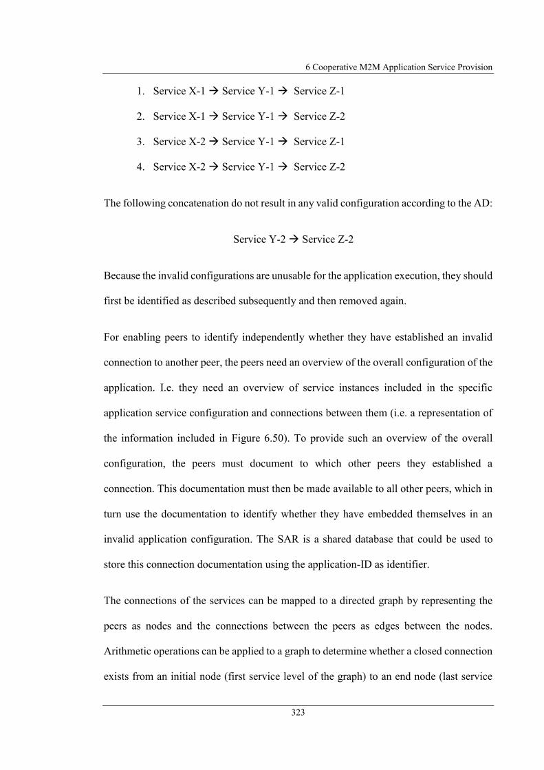
6 Cooperative M2M Application Service Provision
323
1. Service X-1 Service Y-1 Service Z-1
2. Service X-1 Service Y-1 Service Z-2
3. Service X-2 Service Y-1 Service Z-1
4. Service X-2 Service Y-1 Service Z-2
The following concatenation do not result in any valid configuration according to the AD:
Service Y-2 Service Z-2
Because the invalid configurations are unusable for the application execution, they should
first be identified as described subsequently and then removed again.
For enabling peers to identify independently whether they have established an invalid
connection to another peer, the peers need an overview of the overall configuration of the
application. I.e. they need an overview of service instances included in the specific
application service configuration and connections between them (i.e. a representation of
the information included in Figure 6.50). To provide such an overview of the overall
configuration, the peers must document to which other peers they established a
connection. This documentation must then be made available to all other peers, which in
turn use the documentation to identify whether they have embedded themselves in an
invalid application configuration. The SAR is a shared database that could be used to
store this connection documentation using the application-ID as identifier.
The connections of the services can be mapped to a directed graph by representing the
peers as nodes and the connections between the peers as edges between the nodes.
Arithmetic operations can be applied to a graph to determine whether a closed connection
exists from an initial node (first service level of the graph) to an end node (last service
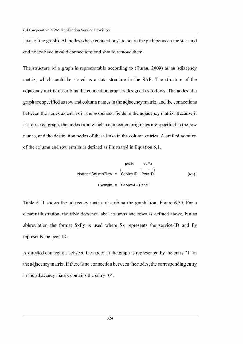
6.4 Cooperative M2M Application Service Provision
324
level of the graph). All nodes whose connections are not in the path between the start and
end nodes have invalid connections and should remove them.
The structure of a graph is representable according to (Turau, 2009) as an adjacency
matrix, which could be stored as a data structure in the SAR. The structure of the
adjacency matrix describing the connection graph is designed as follows: The nodes of a
graph are specified as row and column names in the adjacency matrix, and the connections
between the nodes as entries in the associated fields in the adjacency matrix. Because it
is a directed graph, the nodes from which a connection originates are specified in the row
names, and the destination nodes of these links in the column entries. A unified notation
of the column and row entries is defined as illustrated in Equation 6.1.
Table 6.11 shows the adjacency matrix describing the graph from Figure 6.50. For a
clearer illustration, the table does not label columns and rows as defined above, but as
abbreviation the format SxPy is used where Sx represents the service-ID and Py
represents the peer-ID.
A directed connection between the nodes in the graph is represented by the entry "1" in
the adjacency matrix. If there is no connection between the nodes, the corresponding entry
in the adjacency matrix contains the entry "0".
(6.1)Service-ID – Peer-ID
prefix suffix
Notation Column/Row =
ServiceX – Peer1Example =

6 Cooperative M2M Application Service Provision
325
Table 6.11: Adjacency Matrix of Graph illustrated in Figure 6.50
If peers established a connection according to the AD to other peers, respectively have
associated a service offered by them with another service, they execute the algorithm
shown in Figure 6.51 to document the established connection in the adjacency matrix
(Steinheimer et al., 2017a).
Figure 6.51: Algorithm for Documentation of Connection Establishments
SX-P1 SX-P2 SY-P3 SY-P4 SZ-P5 SZ-P6 SZ-P7
SX-P1 0 0 1 0 0 0 0
SX-P2 0 0 1 0 0 0 0
SY-P3 0 0 0 0 1 1 0
SY-P4 0 0 0 0 0 1 0
SZ-P5 0 0 0 0 0 0 0
SZ-P6 0 0 0 0 0 0 0
SZ-P7 0 0 0 0 0 0 0
[No Adjacency Matrix exists]
Insert Column and Row for
personal Service Instance
Mark Entries in Adjacency Matrix for personal Row.
Assign "0" (no Connection) or "1" (Connection)
[Corresponding service entries exist]
[Corresponding service
entries not exist]
Store Adjacency Matrix to SAR
Create Adjacency
Matrix[Adjacency Matrix already exists]
Load Adjacency Matrix
from SAR

6.4 Cooperative M2M Application Service Provision
326
First, peers load the adjacency matrix of the connection graph from the SAR. If the SAR
does not return the adjacency matrix, it can be interpreted that the adjacency matrix has
not been created yet. In this case peers initialise the adjacency matrix. Then, they insert a
column and a row entry for their own service instance. Afterwards peers validate if the
corresponding service they connected to is already documented in the connection graph
(column/row entry exists). If the corresponding entries do not exist, the peer stores back
the adjacency matrix to the SAR. If the corresponding entries exist, then the entries in the
adjacency matrix for the columns/rows assigned to the peer are marked with "0" for no
connection to other peers and "1" for a connection to other peers. Afterwards the peer
stores the customised adjacency matrix back to the SAR and finishes the algorithm for
documentation of established connections.
Since each peer has executed the steps described above for connection documentation, a
complete connection overview of the graph, respectively of the application, has been
generated and is accessible to all peers contained in the application configuration.
The following describes how peers can use the connection overview to identify and
remove invalid connections.
On graphs arithmetic operations and algorithms can be applied which allow an evaluation
of characteristics of a graph. The Transitive Closure of a binary relation in a graph (link
between nodes), calculated e.g. by the algorithm of Warshall (Warshall, 1962), indicates
which node pairs are mutually accessible. This information determines whether a
destination node is reachable from a start node, possibly with the inclusion of other nodes
(Turau, 2009). The following Figure 6.52 shows the transitive closure of Peer 1 and Peer
4 from application configuration illustrated in Figure 6.50.
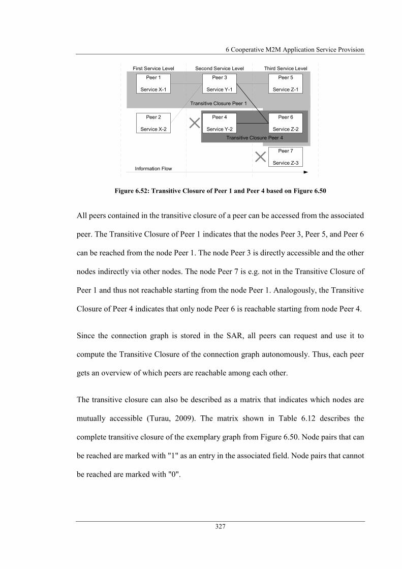
6 Cooperative M2M Application Service Provision
327
Figure 6.52: Transitive Closure of Peer 1 and Peer 4 based on Figure 6.50
All peers contained in the transitive closure of a peer can be accessed from the associated
peer. The Transitive Closure of Peer 1 indicates that the nodes Peer 3, Peer 5, and Peer 6
can be reached from the node Peer 1. The node Peer 3 is directly accessible and the other
nodes indirectly via other nodes. The node Peer 7 is e.g. not in the Transitive Closure of
Peer 1 and thus not reachable starting from the node Peer 1. Analogously, the Transitive
Closure of Peer 4 indicates that only node Peer 6 is reachable starting from node Peer 4.
Since the connection graph is stored in the SAR, all peers can request and use it to
compute the Transitive Closure of the connection graph autonomously. Thus, each peer
gets an overview of which peers are reachable among each other.
The transitive closure can also be described as a matrix that indicates which nodes are
mutually accessible (Turau, 2009). The matrix shown in Table 6.12 describes the
complete transitive closure of the exemplary graph from Figure 6.50. Node pairs that can
be reached are marked with "1" as an entry in the associated field. Node pairs that cannot
be reached are marked with "0".
Transitive Closure Peer 1
Second Service LevelFirst Service Level Third Service Level
Information Flow
Peer 3
Service Y-1
Peer 1
Service X-1
Peer 2
Service X-2
Peer 5
Service Z-1
Peer 7
Service Z-3
Transitive Closure Peer 4
Peer 4
Service Y-2
Peer 6
Service Z-2

6.4 Cooperative M2M Application Service Provision
328
Table 6.12: Transitive Closure based on Figure 6.50
The AD specifies which service is on the first service level (initial state) and which
services are on the last service level (final states). Each peer can use the transitive closure
and the information of services on the first and last service level independently to
determine which connections (according to the AD) are valid or invalid and therefore
have to be removed again.
For checking the complete configuration of the application, each peer first determines for
its own node in the connection graph whether at least one instance (node) of each service
on the last service level is reachable from itself (marked by "1" in the associated field of
the matrix). In the above example, nodes Peer 5 and Peer 6 are accessible from the
perspective of node Peer 3. Thus, from the node Peer 3, there is at least one continuous
connection to a node on the last service level.
In the next step, each peer checks whether the own node in the connection graph is
accessible by at least one node on the first service level. If this is also the case, there is a
SX-P1 SX-P2 SY-P3 SY-P4 SZ-P5 SZ-P6 SZ-P7
SX-P1 0 0 1 0 1 1 0
SX-P2 0 0 1 0 1 1 0
SY-P3 0 0 0 0 1 1 0
SY-P4 0 0 0 0 0 1 0
SZ-P5 0 0 0 0 0 0 0
SZ-P6 0 0 0 0 0 0 0
SZ-P7 0 0 0 0 0 0 0
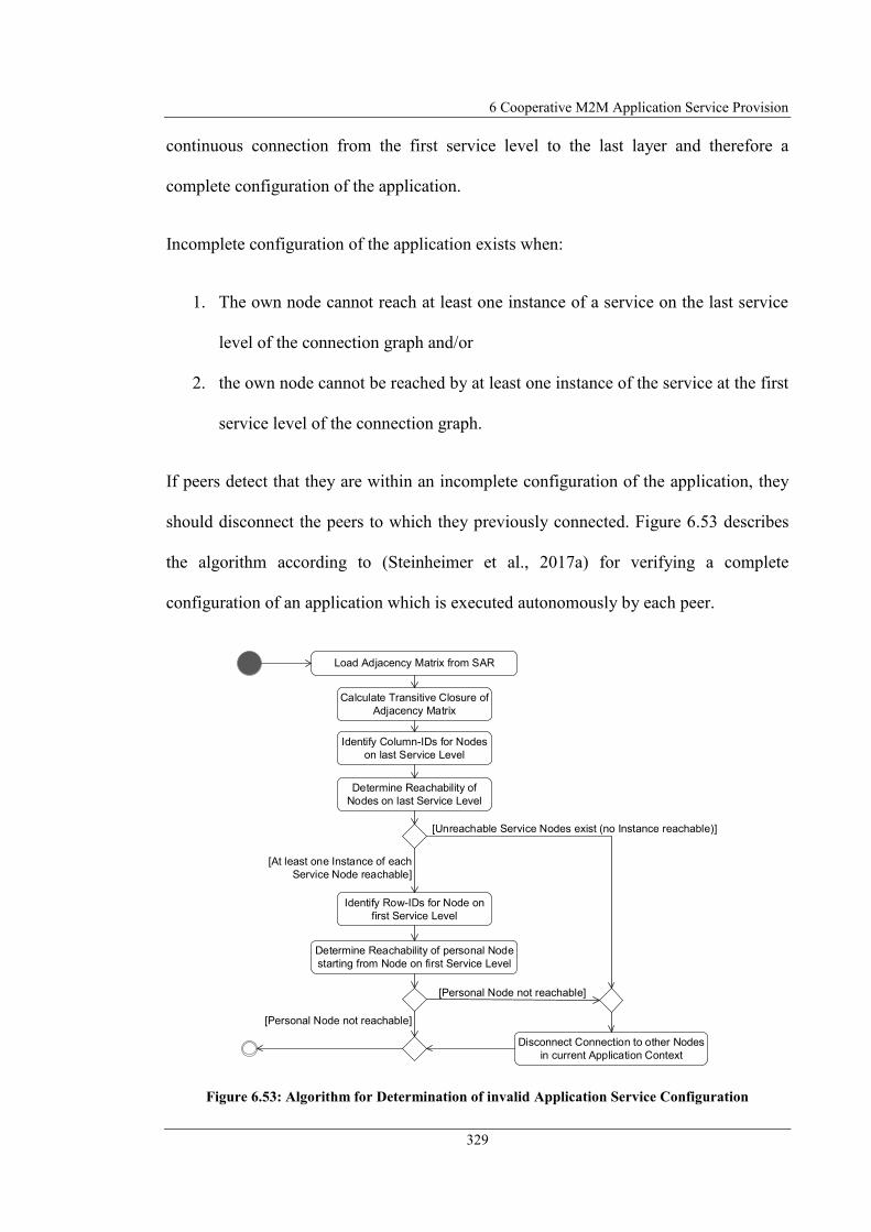
6 Cooperative M2M Application Service Provision
329
continuous connection from the first service level to the last layer and therefore a
complete configuration of the application.
Incomplete configuration of the application exists when:
1. The own node cannot reach at least one instance of a service on the last service
level of the connection graph and/or
2. the own node cannot be reached by at least one instance of the service at the first
service level of the connection graph.
If peers detect that they are within an incomplete configuration of the application, they
should disconnect the peers to which they previously connected. Figure 6.53 describes
the algorithm according to (Steinheimer et al., 2017a) for verifying a complete
configuration of an application which is executed autonomously by each peer.
Figure 6.53: Algorithm for Determination of invalid Application Service Configuration
Load Adjacency Matrix from SAR
Calculate Transitive Closure of
Adjacency Matrix
Identify Column-IDs for Nodes
on last Service Level
Determine Reachability of
Nodes on last Service Level
[Unreachable Service Nodes exist (no Instance reachable)]
Disconnect Connection to other Nodes
in current Application Context
Identify Row-IDs for Node on
first Service Level
[At least one Instance of each
Service Node reachable]
Determine Reachability of personal Node
starting from Node on first Service Level
[Personal Node not reachable]
[Personal Node not reachable]
6.4 Cooperative M2M Application Service Provision
330
First, the peer queries the complete adjacency matrix of the connection graph from the
SAR. For the resulting connection graph, the peer then calculates the Transitive Closure.
Thus, the peer has an overview of which nodes are mutually accessible. The column
entries for the nodes on the last service level are determined afterwards. The
determination of the services at the last service level is made possible since the last
services in the formal AD are marked as "final state". This determines the prefix of the
column description. The calculating peer does not know the suffix, but by the uniformly
defined format of the column names enables the determination of the column name
without knowledge about the suffix. Afterwards, peers check whether these nodes,
starting from the own node, are reachable. This is the case if the corresponding entry in
the matrix of the Transitive Closure is marked with "1". If there is not at least one instance
of each service at the last service level, an invalid configuration of the application exists
and the connection to the peers must be removed again. If connections to the instances at
the last service level exist, the next step checks whether the own node is accessible by an
instance of a service on the first service level. For this purpose, the row-ID of the nodes
on the first service level is first determined. This determination is made possible by
marking the first service in the formal AD as "initial state". This determines the prefix of
the line notation and enables to identify the row-IDs of nodes on the first service level.
Afterwards, peers check whether the own node is accessible from one of these nodes. If
this is the case, a continuous connection from the first to the last service level exists. If
the own node is unreachable, the connection to other peers has to be removed because no
valid configuration of the application has been established. Removing a connection
between the peers is done by sending a request to the connected peer with the request to
disconnect (unsubscription).

6 Cooperative M2M Application Service Provision
331
This section introduced an approach for autonomous and distributed administration of the
entities involved in an application. The approach allows the involved peers to generate an
overview of all service instances integrated in an application configuration. This overview
allows the peers to determine independently whether they have embedded themselves in
valid application configuration. Invalid application configurations are automatically
identified and removed, which ensures that a configuration of an application always takes
place according to the AD.
An alternative to the presented approach for application validation would be if each peer
sends a message to the service instances at the first or last service level for connection
control (something like a "PING message"). They could send this message to the peers
connected to them, which in turn forward the message to their neighbours. The peer that
is arranged in the last or first service level could then send back a reply message directly
to the initiating peer or return a message on the same path as it has received it. However,
this approach has the disadvantage that if peers were temporarily unavailable, although
they are embedded correctly in the application context, the link control message would
not be forwarded. As a result, the path to be checked between initiating and target peers
would be declared invalid. Therefore, a connection-independent management of the
connections between the M2M SPs should be preferred.
6.5 M2M Community
In section 4.2 it was already introduced that the framework presented in this thesis
contains the community approach presented in (Steinheimer et al., 2012b) or (Steinheimer
6.5 M2M Community
332
et al., 2013e). The M2M community is a social network that is built between users of the
MSP.
In essence, the M2M Community is used for the following:
Linking of end-users at interest-level – The community element of the presented
framework enables to manage various interests the end-users using the MSP.
Through the formation of interest groups, the end-users are grouped. To realise
the different groupings, different sub-communities are provided. End-users who
share the same interests enter the same sub-community. The community approach,
enables that services are only released for certain user groups or restricted to
specific geographic areas. If these services should be used, the SC must be
assigned to the relevant sub-community.
Legal Basis – Through the voluntary participation in the M2M community and
the resulting consent for platform utilisation, a basis for the legal certainty can be
created. This is intended to address the topic that in principle no one is authorised
to act within the personal area of an end-user (e.g. trigger control operations) or
to process data (monitor sensor data) from it. For avoiding the need to conclude
appropriate contracts between the end-users or between end-users and
companies/organisations, the voluntary participation and the acceptance of the
usage conditions approves the data processing.
To organise the M2M community with its approaches the IFD can be used. This includes
the element accessControlPolicy, which in turn contains the element privileges with the
attribute accessControlOriginators. This parameter can be used to define a grouping, i.e.
assignment to specific sub-communities. The accessControlPolicy is defined as part of
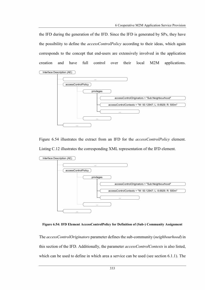
6 Cooperative M2M Application Service Provision
333
the IFD during the generation of the IFD. Since the IFD is generated by SPs, they have
the possibility to define the accessControlPolicy according to their ideas, which again
corresponds to the concept that end-users are extensively involved in the application
creation and have full control over their local M2M applications.
Figure 6.54 illustrates the extract from an IFD for the accessControlPolicy element.
Listing C.12 illustrates the corresponding XML representation of the IFD element.
Figure 6.54: IFD Element AccessControlPolicy for Definition of (Sub-) Community Assignment
The accessControlOriginators parameter defines the sub-community (neighbourhood) in
this section of the IFD. Additionally, the parameter accessControlContexts is also listed,
which can be used to define in which area a service can be used (see section 6.1.1). The
accessControlPolicy
privileges
...
accessControlOriginators = "Sub:Neighbourhood"
...
accessControlContexts = "W: 50.12947; L: 8.6929; R: 500m"
...
...
Interface Description (AE)
accessControlPolicy
privileges
...
accessControlOriginators = "Sub:Neighbourhood"
...
accessControlContexts = "W: 50.12947; L: 8.6929; R: 500m"
...
...
Interface Description (AE)

6.5 M2M Community
334
example shown above maps an IFD to the sub-community neighbourhood and defines
that the associated service at the locality with the GPS coordinates W: 50.12947; L:
8.6929 (Kleiststrasse 1, D-60318 Frankfurt, Germany) is available within a radius of 500
metres.
In order to make the M2M services available grouped according to the sub-communities,
the GUI can be filtered accordingly. Therefore, it is possible that only the M2M services
are displayed which are defined for the sub-community that belongs to an end-user.
Through the community approach and the capabilities of the presented decentralised
MSP, it is possible to realise not only technical services, but also to use the platform
functionality to offer social services (executed by fellow human beings).
Figure 6.55 shows exemplarily an IFD containing the interface parameters necessary for
a service request. For the description of a social service, the prose description is
particularly important, since this is the description of the service. Listing C.12 illustrates
the corresponding XML representation of the IFD.

6 Cooperative M2M Application Service Provision
335
Figure 6.55: M2M application service IFD for Social Service
In the above example, a social service was specified, which is defined for the sub-
community neighbourhood and is only available in a certain place. The prose description
defines the functionality of the service. The example shows an assistance service for
shopping activities. (Social) Peers, i.e. people in the neighbourhood that register this
service offer to assist other people in their shopping activities. Other possible services
from this category are e.g. assistance service to go for a walk or assistance in gardening.
Through the designed framework and the social networking aspect integrated by the
community approach, not only a decentralised MSP was designed, but also a
decentralised social networking platform was created, which can be used for the
administration and mediation of any (not only M2M) services.
accessControlPolicy
expirationTime = ""
accessControlOriginators = "Sub:Neighbourhood"
appName = "Assistance Service Shopping"
App-ID = "AssistanceShoppingService"
pointOfAccess = "sip:[email protected]"
requestReachability = "true"
creationTime = "2017-08-15"
lastModifiedTime = "2017-09-24"
contentSerialisation = "XML"
accessControlContexts = "W: 50.12947; L: 8.6929; R: 500m"
accessControlOperations = "R"
name = "assistanceShoppingService.input.dateTime"
value = ""
config
Description = "Assistence Service in your neighbourhood. Provides the service to assist you in your
shoping activities. Request the service by specifiind the desired date/time using the input parameter of the
service."
Interface Description (AE)
output
input
content
inputParameter id="1"
privileges
6.6 Conclusion
336
6.6 Conclusion
This chapter introduced the mechanisms and approaches for cooperative M2M
application service provision. Section 6.1 specified a mechanism to make the local M2M
applications and M2M devices available as a service to other end-users and integrate them
into local M2M applications. For this purpose, an IFD has been defined that is based on
the specification of M2M resources according to the oneM2M standard and has been
extended with interface parameters for input/output/configuration of M2M applications.
It has been illustrated how the IFD can be generated from the formal AD by extracting
the essential interface parameters and inserting them into the IFD. It was shown how a
remote M2M application that was made available as a service could be used by sending
a request message to the service, which possibly returns a response message. The
exchange of information between the participating entities was carried out according to
the requirements of the oneM2M standard by means of Request/Response Primitives. The
SIU has been specified as part of the CU realising the communication between SP and
SC. It was shown how remote M2M application services can be integrated into the
graphical modelling of a local M2M application so that its functionality can be used
within the local M2M application.
To enable communication between SPs and SCs, section 6.2 described the networking of
them. It has been specified that the communication is done directly P2P between SP and
SC node without involving further nodes at the application level. Different information
exchange patterns were presented and evaluated in the context of this project. The result
of the evaluation was that communication between the nodes according to the
Subscribe/Notify principle is the optimal mechanism for information exchange. Different

6 Cooperative M2M Application Service Provision
337
communication protocols for exchanging Primitive messages between the nodes were
analysed and compared. The protocols CoAP and SIP were identified as optimal
communication protocols. It was shown how the Primitive messages can be exchanged
by means of CoAP in accordance with the oneM2M standard and additionally a SIP
Protocol Binding was defined enabling to exchange Primitive messages by means of SIP.
Section 6.3 described how the service IFDs can be made accessible to other end-users,
and how peers register the instances of their services. For this purpose, the SAR was
introduced as a common database storing the IFDs. Peers who wish to use the IFD or an
instance of a service, query the SAR using the service-ID as the key for the respective
data record. To avoid a central entity responsible for data storage (as it would be the case
with a central database), the distributed data storage was defined using P2P overlays as a
mechanism for the realisation of the SAR. P2P overlays can be realised through structured
or unstructured P2P overlay algorithms. Because structured and unstructured P2P
overlays are fundamentally different in their structure, an approach has been presented
for both types to manage the IFDs and service instances. To determine which P2P overlay
mechanisms are best used in the context of the presented framework, common P2P
overlay algorithms and architectural approaches were compared. The result of the
evaluation was that, depending on the respective application scenario of the framework,
structured or unstructured P2P overlays are advantageous. Structured overlays are
advantageous when a large amount of SAR requests are made, or if the discovery of a
record needs to be guaranteed. Unstructured P2P overlays are advantageous when large
movement of peers exist or complex search queries should be made to the SAR.

6.6 Conclusion
338
Section 6.4 specified the principles of the cooperative M2M application service provision
that allows the services offered by end-users to be combined into a complex distributed
M2M application consisting of a service composition or a service aggregation. The design
of a cooperative M2M application takes place by definition of a SM-based application
model defining the application semantics and is formally described by means of SCXML.
A cooperative M2M application service is also made available via an IFD. Furthermore,
it was specified how a cooperative M2M application is configured and executed. The
configuration process of an application was decoupled from the execution phase of an
application. The peers do the configuration of the services and the connection to the
associated services fully autonomous, i.e. without a central control of the connection
between SPs and SCs. To connect the services, the peer who is supposed to process
information from another peer requests the information data at the information-providing
peer. During the execution phase, the peers provide the information by sending a
notification message to the peer following in the service chain. Through the autonomous
configuration and execution as well as the information processing by the involved
services a distributed SM according to the application description was realised that is
executed completely independently. An autonomous configuration of a cooperative M2M
application could create invalid links between the involved services. For this purpose, an
algorithm was designed to enable each peer (also autonomously) to determine these
invalid links so that they can be removed again.
Finally, section 6.5 described the details of the M2M community approach. Through the
grouping via sub-communities it became possible to link the end-users at interest-level
and create a legal basis for utilisation of the decentralised MSP.

6 Cooperative M2M Application Service Provision
339
This chapter 6 presented the second part of the proposed concept for “Autonomous
decentralised M2M Application Service Provision”. The concept of a decentralised MSP
at the end-user level has been refined and an application architecture for cooperative
M2M application provision has been introduced. The continuous concept has been
extended by the fact that end-user can not only define applications for a local M2M
platform but can also integrate remote offered M2M services into their individual
applications. Furthermore, the concept has been extended in such a way that end-user can
combine their M2M services and thus the possibility exists to appear as a cooperative
M2M application service provider.
By providing local M2M application functionality as a service to other end-users,
resources become available that were previously not addressable. These resources can
now be integrated into other M2M applications. The control and monitoring of M2M
devices are carried out exclusively according to the end-user's requirements, which means
that end-users have full control over the performed activities in their personal
environment. Because the large number of functionalities provided by other local M2M
applications, many new applications can be realised. For example, no longer all M2M
devices have themselves to be present locally, but end-user can integrate the functionality
of other remote M2M devices into their own applications. This extends the available
possibilities to build up a local "smart environment" and at the same time reduces the
costs for the required hardware.
The communication between distributed M2M platforms for provision and integration of
the application functionality as a service is realised again consistently with the RESTful
communication principle. According (Bayer, 2002) the generic interfaces defined in this

6.6 Conclusion
340
way make it possible to implement and offer generic services. The IFD can be generated
automatically from the formal application description. The unified interface cannot just
be used to provide a local M2M application for others. When generalising the principle
of service provision and defining a corresponding interface (e.g. via the MMSCs), non-
technical services, such as supporting services can also be provided via the defined
interface.
Through the fully decentralised structure and the defined decentralised M2M application
architecture, the presented approaches follow continuously the requirement not to contain
any central entity in the MSP architecture. There is therefore no dependency on
stakeholders and single point of failures are avoided. Because the distributed and
decentralised approach, especially through the application of P2P mechanisms for data
management and communication, a high degree of scalability of the MSP is already
achieved in the approach. By specifying different mechanisms to use different types of
P2P overlays, a high degree of flexibility is achieved for realising the MSP. Avoiding
central entities achieves data security and end-user privacy, since only SPs and SCs are
involved in the communication and the data are not stored together in a central location.
The use of SIP as a communication protocol between the peers enables communication
with existing technologies and reuse of existing multimedia communication interfaces at
the end-users‘environment.
Through the combination of distributed resources, the presented concept enables end-
users to cooperate and provide complex and fully distributed M2M application services.
Each peer in the context of an application acts autonomously (both in the configuration

6 Cooperative M2M Application Service Provision
341
of an application and during the execution of an application). This avoids the use of a
central component for controlling the application coordination.
The principle of application creation by the end-users is followed so that the end-users
continue to have control over the modelled applications. The modelling is also graphical
and thus intuitive. Thus, even complex distributed applications can be realised simply,
according to the same principle as local M2M applications. The approach to define a
cooperative M2M application follows the principle of describing the application
semantics using the specified formal description language. This means that the defined
application is independent of the implementation of the execution environment because
only the application description has to be parsed, instead of implementing the application
logic in possibly different programming languages on a platform-dependent basis. Thus,
different local platform technologies can be used, which are linked by the formal
application description to a higher abstraction level. The application logic can be easily
exchanged between platforms, so already defined applications can be used as a template
for new applications.
Through the M2M community element of the proposed framework the flexible MSP
could be enhanced by social networking aspects for linking end-users and enabled a
decentralised social networking platform that can be used also for administration and
mediation of social service.


343
7 Research Prototype and Framework
Evaluation
This chapter introduces the research prototype and evaluates the proposed framework
components. Section 7.1 analyses the defined requirements and describes how they are
fulfilled by the proposed framework aspects. Section 7.2 describes the architecture of the
developed prototype with its components and describes their functionality and how they
were implemented. Section 7.3 discusses the utilisation of the prototype by means of
exemplary M2M application service to evaluate the functionality of the proposed
framework components.
7.1 Evaluation of Framework Requirements
This section evaluates the proposed framework for “Autonomous decentralised M2M
Application Service Provision” in relation to the requirements defined in section 3.2. In
the following, each requirement is evaluated with regard to its fulfilment in the presented
framework.
End-user environment integration – End-user environment integration into the
M2M service platform (MSP) is supported through integration of M2M devices
residing in end-users’ personal environments. These M2M devices can be used to
include their functionality in the application logic to realise an application that

7.1 Evaluation of Framework Requirements
344
processes detected M2M device data or triggers control actions on the devices
(see section 5.4). The M2M devices can be integrated regardless of their M2M
device technology due to defined M2M device technology abstraction
mechanism.
End-user integration – The requirement of end-user integration is fulfilled since
end-users are in focus of interest and continuously integrated in all aspects of the
proposed framework. End-users can participate in application definition by
graphically modelling of the application behaviour according their individual
requirements (see section 5.2). They also participate in MSP provisioning by
providing their local equipment used as Application Execution Environment
(AEE) for hosting the MSP executables. End-users are additionally integrated
essentially when providing/consuming social end-user services (see section 6.5).
End-user service provision and utilisation – The requirement end-user service
provision is fulfilled because end-users have the possibility to provide their local
M2M applications as a service to others. For this purpose, a unified interface has
been defined which contains information on the description of a service, such as
service provider (SP) or time restrictions and specifies the service parameters (see
section 6.1). End-user service provision/utilisation is enabled by the unified
mechanism to request services and exchange information data using
Subscribe/Notify Information exchange Pattern (see section 6.2). Remote M2M
service parameters can be integrated into local M2M applications by processing
their parameters or calling provided method functionality.
Cooperative end-user service provision – The ability of cooperative end-user
service provision is supported through the aspect of the proposed framework to

7 Research Prototype and Framework Evaluation
345
combine end-user services by defining choreographies of end-user services (see
section 6.4). This makes it possible to realise complex M2M applications that are
executed in the end-user environments and that combine the resources provided
by different end-users.
Decentralised system architecture – The requirement of decentralised system
architecture is fulfilled because all components of the proposed framework are
completely decentralised. The services are created locally via the Service Design
Unit (SDU). The application logic as well as all components of the framework are
executed locally on end-user equipment (e.g. IAD) and not on a remote server or
in the Cloud. The communication between SP and service consumer (SC) is P2P
without intermediary entities on the application layer (see section 6.2). By using
P2P overlays, the necessary data storage is decentralised (see section 6.3). The
possibility that services can be offered multiple times means that there is no
dependency on a central SP. The decentralised integration of different M2M
devices provides a high degree of flexibility, so that M2M applications are not
limited to a specific field of application predefined by the MSP. End-users
together provide the MSP so that there is no dependency on a central stakeholder
or central components for MSP provision.
M2M device technology abstraction – The ability to abstract M2M device
communication is provided by the Abstraction Layer (AL) component of the
proposed framework (see section 5.4). The AL abstracts the communication
between devices and the application by communicating with unified M2M device
representations within the platform. The AL translates the uniform commands into

7.1 Evaluation of Framework Requirements
346
technology-specific commands which are then sent to the devices by the
corresponding technology interfaces and vice versa.
Multimedia communication – The multimedia communication aspect of the
proposed framework is supported through the specification of Multimedia Service
Components (MMSCs) enabling to interact with the MSP using existing
telephony equipment (see section 5.1). These MMSCs can be integrated into the
M2M application flow to serve as an input/output interface for audio/video/text
communication.
Device/service lookup mechanism – The prerequisite for this ability is the
provision of a shared database. The aspect is supported through the Service and
Application Registry (SAR) realised by a P2P overlay (see section 6.3). This can
be used to register M2M services and applications. For this purpose, an Interface
Description Model (IFD) was defined containing the parameters and descriptions
required for the service utilisation (see section 6.1). Instantiations of that IFDs
describing specific M2M services can be requested by the Service Delivery
Platforms (SDPs) of other end-users for e.g. displaying it in the SDU or detect
specific M2M service instances. Within a local SDP, the M2M devices are
registered and managed in the M2M Device Registry within the Communication
Unit (CU), so that they can be queried by the SDU and, for example, listed in the
GUI (see section 5.4). To describe the devices (and MMSCs), Device Capability
Models (DCMs) have been specified which define the properties and parameters
of the devices.
Simplicity – The requirement of simplicity is fulfilled through the graphical
modelling methodology of an M2M application (see section 5.2 and section 5.3).

7 Research Prototype and Framework Evaluation
347
The modelling of a state machine (SM) describing the behavior of an application
can be intuitively modelled by the end-user. The unified structure of an M2M
application (connecting building blocks with input/config/output parameters
supports the simple modelling of an application. Apart from modelling the
application, no further steps are required that need to be done manually. The
generation of the formal application description, the configuration of the M2M
application and the execution of the application logic is done automatically (see
section 5.5 and section 5.6).
Minor hardware requirements – The aspects of minor hardware requirements is
supported because the software executables of the framework components have
low footprints and do not require heavy-weight application servers to execute
them. The framework components could by executed locally on existing end-user
equipment, which is powerful enough to run the executables. The entire AEE
could be operated within the IAD, eliminating the need for additional resource-
intensive AEEs such as high-performance servers. It can be assumed that a single-
user application running locally requires significantly less resources than a remote
multi-user application environment. The runtime environment for the prototype
requires little resources: Java SE 8: 124MB RAM, 128MB Disk (Oracle, 2017d);
Java SE Embedded 8: 32MB RAM, 50MB Disk (Oracle, 2017e). The entire
runtime environment has 190MB (Karaf: 60MB, Spring Boot Jar: 10MB, Docker
Container: 120MB). Due to their small size, they can be deployed on an IAD.
Scalability – The requirement for scalability is fulfilled because the P2P
mechanisms integrated in the proposed framework are naturally very scalable.
Since the service provision and communication between the nodes as well as the

7.1 Evaluation of Framework Requirements
348
data storage are P2P, the entire MSP is scalable. The defined framework enables
the same services to be offered by several peers at the same time. The scalability
of service utilisation therefore depends on the load distribution among the peers.
Assuming that the load is equally distributed between the peers, then the load on
the individual peers and subnets is low and the service utilisation scales.
Platform independency – The requirement for platform independency of the
proposed framework is supported through multiple aspects. When designing the
concept, attention was paid to using standardised mechanisms and protocols. An
application is specified by defining a formal application description independent
of the execution environment (see section 5.5). The standardised SCXML was
used as the formal description language. The application description (and also the
modelling process) is independent of the system that interprets the application
description and is therefore platform-independent. The interface description was
also defined platform-independently in XML (see section 6.1). Only the
algorithms used for P2P overlay are not standardised. Here, however, with Chord
and Gnutella two widely used algorithms were used. There is also platform
independence at the communication level. Communication between the platform
components as well as between SP and SC takes place by means of service layer
messages (Primitives) standardised by oneM2M. The communication between SP
and SC is also established using the standardised protocols CoAP or SIP, so that
no proprietary protocols are used. The prototypical implementation was done with
platform-independent concepts. By using Java as a programming language,
platform independence at operating system level is achieved. Through the

7 Research Prototype and Framework Evaluation
349
additional use of Docker, a complete system independence was achieved, so that
the entire SDP can be deployed as a container on the executing platform.
Data safety, end-user privacy – The aspect of data safety and end-user privacy is
supported through the avoidance of central entities storing data. Data is not stored
in a central location, but rather decentralised by the users who do not have access
to the entire data sets. Due to the cooperative platform provisioning at the end-
user level, there is no binding to a central provider that could possibly misuse the
data. The ability to define access control policies includes a mechanism for
controlling access rights. It is possible to define access rights at user/group/time/
or location level.
The essential parts of the proposed framework have been implemented for the proof of
concept. The following section presents the architecture of the research prototype.
7.2 Research Prototype Architecture and Implementation
To demonstrate the essential functionalities of the proposed framework for “Autonomous
decentralised M2M Application Service Provision”, a research prototype has been
developed. The research prototype implements most of the components described in the
framework architecture with required functionality for the proof-of-concept.
Beside the graphical user interface SDU with basic functionalities, trimmed versions of
the Service Creation Unit (SCU) for transforming the graphical application model into
formal application description, and the Service Runtime Environment (SRE) with
Application Description Parser (ADP), Application Description Interpreter (ADI), State

7.2 Research Prototype Architecture and Implementation
350
machine Repository (SM Repo), Service Execution Engine (SEE), and Instant Message
Multimedia Service Component (IMMMSC) have been implemented. Also the CU with
AL have been implemented with communication modules for Session Initiation Protocol
(SIP), Constraint Application Protocol (CoAP), TC IP 1 Control Protocol (TC IP 1, 2013),
and Bidirectional Communication Standard BidCos (eQ-3 BidCos, 2016). Furthermore
basic functionality of Service Provision Unit (SPU) with overlay modules for Chord and
Gnutella and integrated TCP fileserver have been implemented. Additionally as end-user
communication interface a SIP Instant Message Client (representing end-user
smartphone) have been implemented in both GUI variant as well as console-based variant.
To make local M2M devices and MMSCs available to the SDU M2M Device/Service
Capabilities have been specified for localRainSensor, localSmokeDetector,
localWindowSensor, localWaterSensor, and IMMMSC as well as interface descriptions
for remoteSensorService, remoteBuildingMonitoringService, remoteRainSensorService,
remoteAlarmService, remoteEnergyReductionService.
Figure 7.1 shows the structure of the research prototype execution environment.
Figure 7.1: Research Prototype Application Architecture
The research prototype was developed with the Java programming language (Oracle,
2017b) as this is a common programming language for the development of software
Java Runtime Environment (Oracle JRE v1.8)
Linux Operating System (Ubuntu 16.04 LTS)
Apa
che K
ara
f
OSGi
Application Logic Bundles
SDU SCU
Spring Boot
Application Logic Executable Jar
CU SRE SPU

7 Research Prototype and Framework Evaluation
351
applications. Java is also known as a platform-independent language, which supports the
implementation of the prototype on different platforms. In addition to Java as the basis
for the implementation, the frameworks OSGi (OSGi Alliance R5, 2012) and Spring Boot
(Spring Boot R1.5.8, 2017) were used. The use of the two different frameworks
demonstrates the flexibility of the developed prototype. Depending on the preferences, it
is therefore possible to extend the prototype using one or the other framework. The part
responsible for creating the application description was developed with OSGi and the part
responsible for application execution was developed with Spring Boot.
The focus in application development was on the development of loosely coupled
application components to facilitate the simple extensibility of the prototype. This
characteristic is supported by both frameworks. OSGi implements the loose coupling of
application components by a so-called Bundle concept. The application components are
deployed in the form of independent modules (Bundles) in an OSGi container. Apache
Karaf (Apache Karaf, 2017) was used as OSGi container for the prototype
implementation. However, other implementations such as Apache Felix (Apache Felix,
2017) or Eclipse Equinox (Eclipse Equinox, 2017) can also be used as OSGi containers,
so that the implementation is not limited to a specific container environment. The Bundles
are linked by the OSGi Container. This principle of component interconnection is called
Inversion of Control (IOC). IOC is also an essential aspect of Spring Boot, whereby
modularity is implemented by Dependency Injection (DI). Unlike OSGi-based platforms,
running a Spring Boot-based application does not require a separate runtime environment
(OSGi container) for the application modules. Spring Boot applications are deployed and
executed as a single Jar executable. A comparison of these two frameworks is not in the
focus of this work, but it is mentioned here briefly that OSGi has the advantage that
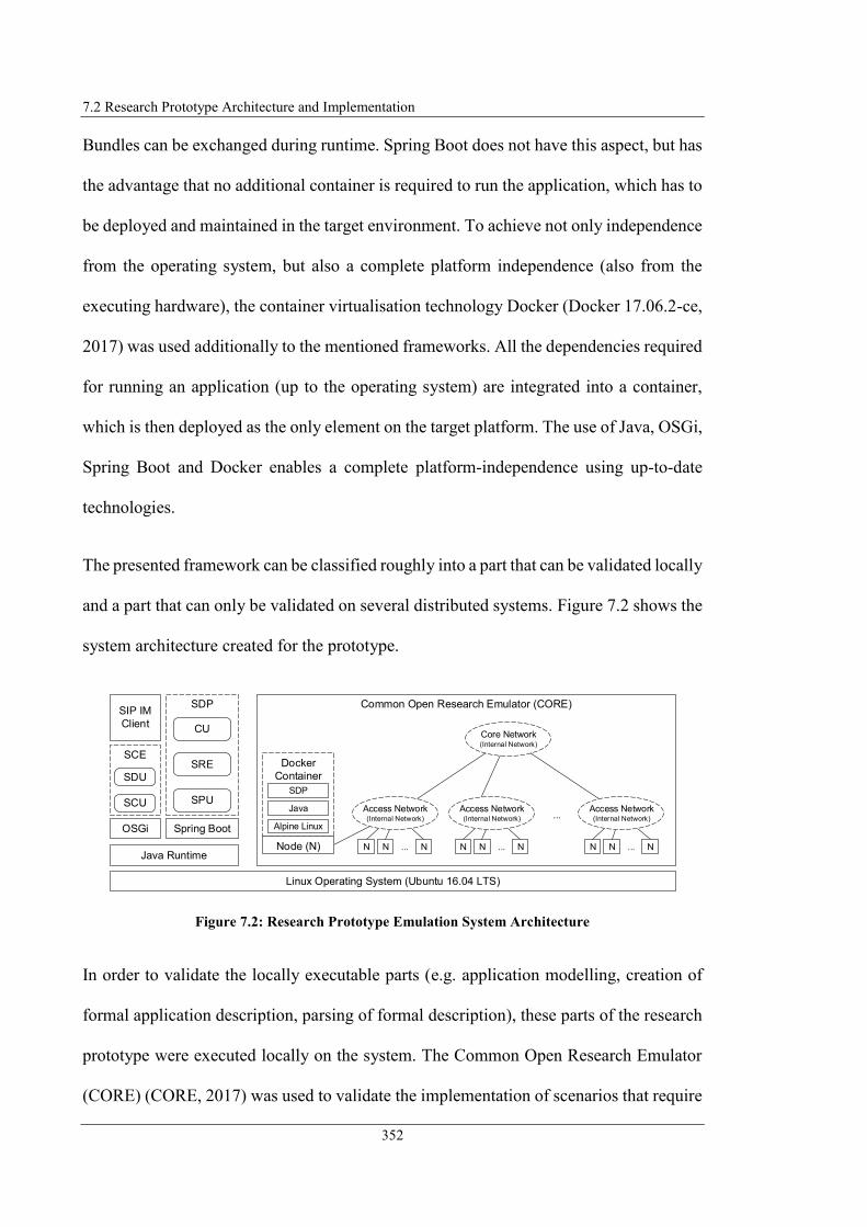
7.2 Research Prototype Architecture and Implementation
352
Bundles can be exchanged during runtime. Spring Boot does not have this aspect, but has
the advantage that no additional container is required to run the application, which has to
be deployed and maintained in the target environment. To achieve not only independence
from the operating system, but also a complete platform independence (also from the
executing hardware), the container virtualisation technology Docker (Docker 17.06.2-ce,
2017) was used additionally to the mentioned frameworks. All the dependencies required
for running an application (up to the operating system) are integrated into a container,
which is then deployed as the only element on the target platform. The use of Java, OSGi,
Spring Boot and Docker enables a complete platform-independence using up-to-date
technologies.
The presented framework can be classified roughly into a part that can be validated locally
and a part that can only be validated on several distributed systems. Figure 7.2 shows the
system architecture created for the prototype.
Figure 7.2: Research Prototype Emulation System Architecture
In order to validate the locally executable parts (e.g. application modelling, creation of
formal application description, parsing of formal description), these parts of the research
prototype were executed locally on the system. The Common Open Research Emulator
(CORE) (CORE, 2017) was used to validate the implementation of scenarios that require
Java Runtime
Linux Operating System (Ubuntu 16.04 LTS)
SIP IM
Client
Spring Boot
SDP
CU
SRE
SPU
Common Open Research Emulator (CORE)
Docker
Container
Java
Alpine Linux
SDP
Node (N)
Core Network(Internal Network)
...
N N N...
Access Network(Internal Network)
N N N...
Access Network(Internal Network)
N N N...
Access Network(Internal Network)
OSGi
SCE
SCU
SDU

7 Research Prototype and Framework Evaluation
353
a distributed system architecture. CORE allows to create different virtual networks and
emulate their behaviour. These virtual networks can be used to connect different nodes
(representing peers) that communicate with each other via virtual networks. It is also
possible to execute application logic on the nodes using CORE. To deploy the application
logic to the respective nodes, the local execution environment (SDP) was packaged into
a Docker container, which was then deployed on the virtual nodes of CORE. Figure 7.3
shows the GUI of CORE with the created networks and nodes for the emulation
environment.
Figure 7.3: Research Prototype Emulation System Architecture
Coming back to the application architecture of the framework prototype, the following
Figure 7.4 illustrates the application architecture of the framework prototype. The

7.2 Research Prototype Architecture and Implementation
354
architecture depicts the individual modules of the prototype and how they are linked with
each other. The modules are classified by name and the implementing Java package. The
communication between the individual modules is represented by arrows. The numbering
on the arrows defines the individual steps in the application creation and execution
process. The different modules are described below and the interaction between them is
explained. The modules are all loosely coupled, so they can be easily extended/replaced.
Figure 7.4: Research Prototype Architecture Components (illustrated as Packages)
(13) deliver [interface description]
(1) deliver [DCs/ SCs\
(7) deliver [stateMachine]
(8) getStatemachine (9) deliver [stateMachine]
(10) processRequestPrimitive
(11) deliver [responsePrimitive]
(6) deliver [primitiveContentList, assignList]
(12) getInterfaceDescription
(3) deliver [application description]
(5) deliver [applicationDescription]
(4) parseApplicationDescription
(2) saveUserServiceDesign
SCXML
XML
Service Creation
Unit (SCU)
de.fuoas.research.scu
Instant Message Multimedia Service
Component (IMMMSC)
de.fuoas.research.p2p4m2m.sre.mmservicecomponents
Service Provision Unit
(SPU)
de.fuoas.research.p2p4m2m.spu
Application Executor (AE)
de.fuoas.research.p2p4m2m.sre.see.ae
Statemachine Repository
(SM Repo)
de.fuoas.research.p2p4m2m.sre.see.smrepo
Application Description Parser
(ADP)
de.fuoas.research.p2p4m2m.sre.see.adi.adp
Application Description
Interpreter (ADI)
de.fuoas.research.p2p4m2m.sre.see.adi
Communication Unit
(CU)
de.fuoas.research.p2p4m2m.cu
Service Design
Unit (SDU)
WebApplication
M2M Device/
Service Registry
IFD

7 Research Prototype and Framework Evaluation
355
Application creation starts with modelling the application. The SDU module has been
developed in the form of a GUI which is illustrated in Figure 7.5.
Figure 7.5: Screenshot of Service Design Unit GUI Web Application
The GUI is provided as a web application enabling the end-user to model the behaviour
of an application as a SM. The WebContainer "Jetty" (Eclipse Jetty, 2017) integrated in
Apache Karaf was used to provide the web application. The SM is modelled by dragging
the building blocks representing M2M devices or M2M services into the workspace and
connecting them to each other. Each building block (state) and the connections between
the building blocks can be configured as described in section 5.5.3. The JavaScript library

7.2 Research Prototype Architecture and Implementation
356
"JsPlumb" (JsPlumb, 2017) was used in Community Edition v1.5.5 for the
implementation of the graphical modelling. JsPlumb allows to graphically model flow
chart diagrams within a web application. To obtain an overview of the available M2M
devices/services, the SDU receives a HashMap with capability objects representing the
device/service capabilities or interface descriptions of the remote M2M services (step 1).
The capability representations are also used to display the configuration area for the states
as an input mask (see Figure 7.6). This defines the configuration parameters of a state and
displays the prose description of the M2M devices/service.
Figure 7.6: Screenshot of SDU GUI showing M2M Device/Service Configuration Section
Using JsPlumb, a data model is generated which describes the states and the connections
between the states. The SDU generates two HashTables describing the states and
transitions including the defined parameter configurations. By calling the
saveUserServiceDesign method, these HashTables containing the application model and
further information about initial and final state are passed to the SCU as a JSON object
(IETF RFC 7159, 2014) (step 2). The SCU module generates a Java object from the

7 Research Prototype and Framework Evaluation
357
received data containing the application information. The SCU then generates a formal
description of a SM that represents the application logic according to the principles
described in section 5.5.3 and transfers the SCXML document to the ADI module (step
3).
In addition to generating the graphical application model, the SCU also generates the
interface description for a modelled application. The content of the interface description
described in section 6.1.1 (e.g. input parameter, AppID, prose description) is defined by
the application creator using an input mask in the SDU (see Figure 7.7). The SDU passes
this information back to the SCU as a JSON object which then generates an interface
description in XML format. This is done by the SCU converting the JSON object with the
interface description information into a Java object. Both, generation of the SCXML
description and interface description is done with JAXB (Oracle, 2017c). This API
enables to import XML documents and process them as Java objects, as well as to
generate an XML document from a Java object.
Figure 7.7: Screenshot of SDU GUI showing IFD Specification Form

7.2 Research Prototype Architecture and Implementation
358
In order for the ADI to be able to process the application logic defined in the application
description, the ADI requires it in a compatible format. To obtain this, the ADI invokes
the method parseApplicationDescription of its internal component ADP (step 4). The
ADP returns the formally described application logic to the ADI in the form of an object
(step 5). The generation of the Application Description Object is done by the ADP reading
and parsing the SCXML representation of the application. Parsing is done using the Java
library "Apache Commons SCXML" (Commons SCXML, 2016) which allows to get a
representation of the statechart described with SCXML in the form of Java objects. The
ADP analyses the generated Java objects and transfers the information on the application
logic (such as applicationID, initialStateID, finalStateID) into an internal application
description model (ADM). Furthermore, the ADP analyses all defined states and transfers
the information defined such as stateDataModel, transitions, assigns, targetStates,
predecessorStates into the ADM.
The ADI now analyses the ADM and interprets the application logic. The ADI must
differentiate between a distributed application and a local application that integrates
remote services. In the case of a local application, the ADI first determines whether
remote services are to be integrated into the local application. This is the case if the ADM
includes states that refer to a remote service or attributes of a remote service are contained
in transition conditions or assignments. The ADI registers remote services to be integrated
in a primitiveContentList which it transfers to the CU module (step 6). In the next step,
the ADI generates a local SM from the ADM, which is represented by an internal SM
model. To create the SM model, the ADI analyses all state information defined in the
ADM and creates an entry for each of the states in the SM. The ADI adds information
about the state transitions (e.g. targetState, condition, stateConfiguration,

7 Research Prototype and Framework Evaluation
359
targetStateConfig) to these entries, which it also extracts from the ADM. Furthermore,
the information about initialState and finalState as well as the currentState of a SM are
added. The generated stateMachine object is passed to the SM Repo module, which
manages the generated SMs in an internal HashMap allStateMachines (step 7). If it is a
distributed application provided by multiple peers, no local SM is created. Instead,
additional information is required for linking to other peers. The ADI also determines this
information by analysing the ADM. In this case, the state within the application
description is in focus that represents the local peer or the service offered by the local
peer. It is necessary to determine which other services a peer should connect to. The ADI
receives this information by determining a list of predecessorStates. Additionally, it is
necessary to determine which parameters of a predecessorStates are to be requested if
necessary. For all states in the predecessorStateList, the ADI therefore determines
whether output parameters are contained in their assign definitions and registers them in
an outputParameterList. Furthermore, the ADI will determine the information to be sent
to a connected service. This is done by analysing the stateTransitionList of its own state.
This creates a list (assignList) which contains the condition and remote parameter
assignments for each successorStateID. The ADI has thus determined all the information
necessary for linking with other peers and transmits this information to the CU module
(step 6).
The module AE executes the local SM. For this purpose, the AE first requests a list of all
existing SMs from the SM Repo. The AE periodically traverses the list of all SMs and
loads the respective SM from the SM Repo using the getStateMachine method (step 8).
The SM Repo provides the AE with the requested SM (step 9), which is executed by the
AE. This is done by the AE determining and analysing the currentState of the SM via the

7.2 Research Prototype Architecture and Implementation
360
currentState attribute. For this active state, the AE sets the stateConfiguration and checks
if the condition (if defined) for the transition to the next state is true. If the condition is
true, the AE sets the parameters defined via targetStateConfig and sets the targetState as
new currentState. To check the condition and to set stateConfiguration and
targetStateConfig, the AE requests the CU via a RequestPrimitive object (step 10) and
receives the parameter value that is required for checking the condition via a
ResponsePrimitive object (step 11).
The CU is responsible for communication with local M2M devices and MMSCs or for
communication with other peers. For communication via CoAP and SIP, communication
modules have been integrated into the CU for both protocols. For this purpose, the Java
libraries "Californium" (Eclipse Californium, 2017) were used as CoAP stack and JAIN
SIP (JAIN SIP, 2017) as SIP stack, which enable generating and receiving of CoAP/SIP
messages via local network interface. For remote service requests using CoAP and SIP,
the communication modules enable the query scenarios as defined in section 6.2.3 (one-
time and continuous subscription of output parameter, termination of subscriptions and
input/config requests). When remote services are requested, the CU traverses the
primitiveContentList to request parameters from the SP. To do this, the CU generates a
service request message as defined in section 6.2.3. To manage subscriptions, the CU
includes the SubscriptionManager component. All active subscriptions are managed in
SubscriptionManager (activeSubscriptionsList). The SubscriptionManager manages
besides the activeSubscriptions also a list of activeNotifications. This stores the requests
for services generated by other peers. If the CU receives a service request from another
peer, it extracts the information defined in it, creates a requestPrimitive object and
transfers it to the AL component for processing. If a parameter is queried by the service

7 Research Prototype and Framework Evaluation
361
request, the CU generates a Request Primitive message and replies it to the requesting
peer. If the service request is a continuous subscription, the CU saves the generated
responsePrimitive object and a defined condition in the activeNotification list. The
component notificationAutomator of the CU runs periodically through the
activeNotifications list and checks if defined conditions are true. If this is the case, or if
no condition has been defined, the notificationAutomator triggers the sending of a
Request Primitive message to the defined receiver via the CoAP or SIP communication
module.
The AL component of the CU is implemented using an internal m2mDeviceServiceCache.
This contains a representation of the parameters defined via the Device Capability Model.
Parameters that are to be set or queried for an M2M device or an MMSC are processed
by this component. To determine the addressing information of an M2M application
service provider, the CU requests the interface description from the SPU module using
the getInterfaceDescription method (step 12), which then returns the
InterfaceDescription for a specific service (step 13).
The SPU implements the connection to a P2P overlay for distributed management of
interface descriptions. The SPU has the functionality to join a Gnutella overlay or a Chord
overlay. To realise the Gnutella overlay functionality, the Java Library “JTella” (JTella,
2016) was used, which is an implementation of the unstructured P2P overlay Gnutella.
To implement the Chord overlay functionality, the Java library "Open Chord" (Open
Chord, 2015) was used, which is an implementation of the Chord DHT. The SPU saves
the URL of an interface description within the overlay and can also query it in the overlay.
The URL of the interface description specifies the peer that stores the interface description
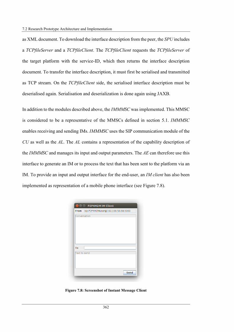
7.2 Research Prototype Architecture and Implementation
362
as XML document. To download the interface description from the peer, the SPU includes
a TCPfileServer and a TCPfileClient. The TCPfileClient requests the TCPfileServer of
the target platform with the service-ID, which then returns the interface description
document. To transfer the interface description, it must first be serialised and transmitted
as TCP stream. On the TCPfileClient side, the serialised interface description must be
deserialised again. Serialisation and deserialization is done again using JAXB.
In addition to the modules described above, the IMMMSC was implemented. This MMSC
is considered to be a representative of the MMSCs defined in section 5.1. IMMMSC
enables receiving and sending IMs. IMMMSC uses the SIP communication module of the
CU as well as the AL. The AL contains a representation of the capability description of
the IMMMSC and manages its input and output parameters. The AE can therefore use this
interface to generate an IM or to process the text that has been sent to the platform via an
IM. To provide an input and output interface for the end-user, an IM client has also been
implemented as representation of a mobile phone interface (see Figure 7.8).
Figure 7.8: Screenshot of Instant Message Client

7 Research Prototype and Framework Evaluation
363
In addition to the communication modules for CoAP and SIP, the CU has also
implemented communication modules for the TC IP 1 control protocol and for BidCos.
The physical integration of M2M devices using TC IP 1 Control Protocol and BidCos
were implemented in the associated e-SCHEMA research project (Steinheimer et al.,
2013b; e-SCHEMA, 2015). The TC IP 1 communication module allows to control several
energy manager devices and to read out the parameters provided by their sensors. The
communication with the devices is realised via datagramSockets, which can be addressed
natively from the Java programming language. To implement the communication via
BidCos it was necessary to use an M2M gateway (so-called Common Control Unit, CCU)
which implements the wireless communication with the M2M devices. The BidCos
communication module communicates with the CCU via XML RPC (XML-RPC, 1999)
to transmit the control commands to the M2M devices or to query parameters from the
M2M devices. To establish a communication channel between the BidCos control module
and the CCU, the communication module must register with the XML-RPC server of the
CCU. Furthermore, it is necessary that an XML RPC server is also used in the BidCos
communication module, so that the CCU can send push messages to the BidCos control
module. Both, the communication with the CCU via XML-RPC and the operation of a
local XML-RPC server is realised using the Java library "Apache XML-RPC" (Apache
XML-RPC, 2017).
7.3 Proof of Framework Concepts
After the architecture and implementation of the research prototype was presented based
on the novel concepts of the framework for “Autonomous decentralised M2M

7.3 Proof of Framework Concepts
364
Application Service Provision”, this section deals with the proof of concept and the
evaluation of the underlying approaches. The research prototype was developed to
demonstrate the essential aspects of the presented framework. To cover as many aspects
of the presented framework as possible, the following use cases from the use cases
presented in section 2.4 were selected:
Use Case 2: Neighbourhood Weather Station – Local execution of SM-based
application logic with remote M2M service integration. A remote M2M service
provides the values of a rain sensor. A local M2M application integrates these
values. If rain is detected and the window is open at the same time, an IM will be
sent with a corresponding message.
Use Case 3: Building Surveillance – Cooperative M2M application service
provision based on horizontal M2M application service composition. A remote
M2M service monitors water and smoke sensor in a building and reports them (in
case of corresponding event occurred) to a remote building monitoring service
that manages supporters of that building. The building monitoring service triggers
another remote alarm service to send an IM with a specific text (depending on the
event) to end-users taking care of the corresponding building.
For both scenarios, the M2M applications must be modelled and transferred to the formal
application description. The application description must be interpreted and the local
system configuration must be performed according to the defined logic. The M2M
application must then be executed. The following section 7.3.1 demonstrates these steps
for Use Case 2 and section 7.3.2 for Use Case 3. Since both contain the service request
from other nodes, this scenario is considered separately in section 7.3.3.

7 Research Prototype and Framework Evaluation
365
7.3.1 Local M2M Application Execution with remote M2M Service
Integration
First, the M2M application for Use Case 2 is graphically modelled. Figure 7.9 shows the
graphical model and a section of the automatically generated formal M2M application
description.
Figure 7.9: Screenshot of SDU GUI Web Application with SM Model Use Case 2
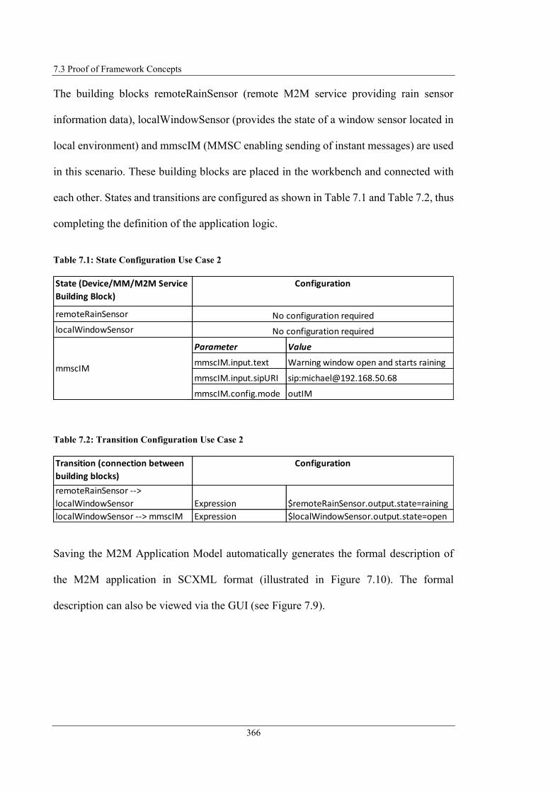
7.3 Proof of Framework Concepts
366
The building blocks remoteRainSensor (remote M2M service providing rain sensor
information data), localWindowSensor (provides the state of a window sensor located in
local environment) and mmscIM (MMSC enabling sending of instant messages) are used
in this scenario. These building blocks are placed in the workbench and connected with
each other. States and transitions are configured as shown in Table 7.1 and Table 7.2, thus
completing the definition of the application logic.
Table 7.1: State Configuration Use Case 2
Table 7.2: Transition Configuration Use Case 2
Saving the M2M Application Model automatically generates the formal description of
the M2M application in SCXML format (illustrated in Figure 7.10). The formal
description can also be viewed via the GUI (see Figure 7.9).
State (Device/MM/M2M Service
Building Block)
remoteRainSensor
localWindowSensor
Parameter Value
mmscIM.input.text Warning window open and starts raining
mmscIM.input.sipURI sip:[email protected]
mmscIM.config.mode outIM
mmscIM
Configuration
No configuration required
No configuration required
Transition (connection between
building blocks)
remoteRainSensor -->
localWindowSensor Expression $remoteRainSensor.output.state=raining
localWindowSensor --> mmscIM Expression $localWindowSensor.output.state=open
Configuration

7 Research Prototype and Framework Evaluation
367
Figure 7.10: Use Case 2 M2M Application Description
Once the application has been formally described, the application description is
transferred to the ADI. The ADI triggers the ADP which then imports the application
description. Figure 7.11 shows the information imported by ADP into an internal
application description object.
<?xml version="1.0" encoding="UTF-8"?><scxml xmlns="http://www.w3.org/2005/07/scxml"
datamodel="jexl" initial="remoteRainSensor" name="remoteRainSensorIntegrationApp"
version="1.0">
<datamodel>
<data expr="remoteRainSensor" id="initial"/>
<data expr="mmscIM" id="final"/>
</datamodel>
<state id="remoteRainSensor">
<datamodel>
<data expr="" id="remoteRainSensor.output.state"/>
<data expr="true" id="initial"/>
</datamodel>
<transition cond="$remoteRainSensor.output.state=raining"
target="localWindowSensor"/>
</state>
<state id="localWindowSensor">
<datamodel>
<data expr="" id="localWindowSensor.output.state"/>
</datamodel>
<transition cond="$localWindowSensor.output.state=open" target="mmscIM"/>
</state>
<state id="mmscIM">
<datamodel>
<data expr="Warning window open and starts raining" id="mmscIM.input.text"/>
<data expr="sip:[email protected]" id="mmscIM.input.sipURI"/>
<data expr="" id="mmscIM.output.messageText"/>
<data expr="outIM" id="mmscIM.config.mode"/>
<data expr="true" id="final"/>
</datamodel>
<final id="mmscIMFinal"/>
</state>
</scxml>

7.3 Proof of Framework Concepts
368
Figure 7.11: Screenshot of Terminal Output ADP Use Case 2
The ADP returns the application description object to the ADI which processes the
information defined in it to configure the application locally. In this case, this means that
the ADI generates a local SM as shown in Figure 7.12 and stores it locally. Figure 7.13
shows the SM object generated by the ADI.
Figure 7.12: SM generated by ADI Use Case 2
$remoteRainSensor.output.state=raining $localWindowSensor.output.state=open
remoteRainSensor mmscIMlocalWindowSensor
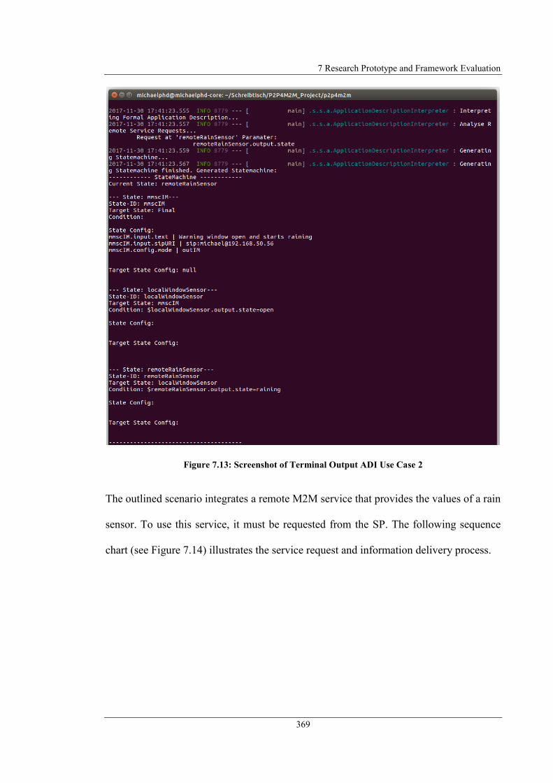
7 Research Prototype and Framework Evaluation
369
Figure 7.13: Screenshot of Terminal Output ADI Use Case 2
The outlined scenario integrates a remote M2M service that provides the values of a rain
sensor. To use this service, it must be requested from the SP. The following sequence
chart (see Figure 7.14) illustrates the service request and information delivery process.

7.3 Proof of Framework Concepts
370
Figure 7.14: SM generated by ADI Use Case 2
After the SP has received the service request, it continuously sends the rain sensor values
to the SC, which stores them locally.
The Application Executor (AE) component periodically executes the SM by checking the
current state. As soon as the value of the remote rain sensor changes to status "raining",
the AE initiates the transition to the next state. If the output value of the local window
sensor now has the value "open", a state transition is also triggered which causes the local
Peer 0
Service
requesting Peer Peer 0
remoteRainSensor
Service providing
Peer
Request
Service
Subscribe (Request Primitive)
<Content>
<output>
<outputParameter id="1">
<name>remoteRainSensor.output.state</name>
</outputParameter>
</output>
</Content>
Receive
Service
Request
Store in
Subscriber
List
Notify (Response Primitive)
<Content>
<output>
<outputParameter id="1">
<name>remoteRainSensor.output.state</name>
<value>notRaining</value>
</outputParameter>
</output>
</Content>
OK
OK
Notify (Response Primitive)
...
Notify (Response Primitive)
<Content>
<output>
<outputParameter id="1">
<name>remoteRainSensor.output.state</name>
<value>raining</value>
</outputParameter>
</output>
</Content>
OK

7 Research Prototype and Framework Evaluation
371
MMSC for sending Instant Messages (mmscIM) to send an IM to the specified user (see
Figure 7.15).
Figure 7.15: Screenshot of IM Client Use Case 2
This section demonstrated the local M2M application creation and execution processes.
The following section demonstrates the cooperative M2M application service provision
and execution.
7.3.2 Cooperative M2M Application Service Provision
The second scenario to demonstrate (Use Case 3) also starts with modelling the M2M
application description in the same way as the previous one (refer to Figure 7.16). In this
scenario the following building blocks are used: remoteSS1 (remote M2M service that
monitors a building and generates information about detected events), remoteBMS
(remote M2M service managing supporter registered for specific buildings), and
remoteAS (remote M2M service providing the ability to send Instant messages).

7.3 Proof of Framework Concepts
372
Figure 7.16: Screenshot of SDU GUI Web Application with SM Model Use Case 3
The configuration of the states and the transitions is illustrated in Table 7.3 and Table 7.4.
Table 7.3: State Configuration Use Case 3
State (Device/MM/M2M
Service Building Block)
Parameter Value
remoteSS1.output.buildingID Kleiststr.1
remoteBMS
remoteAS
remoteSS1
Configuration
No configuration required
No configuration required
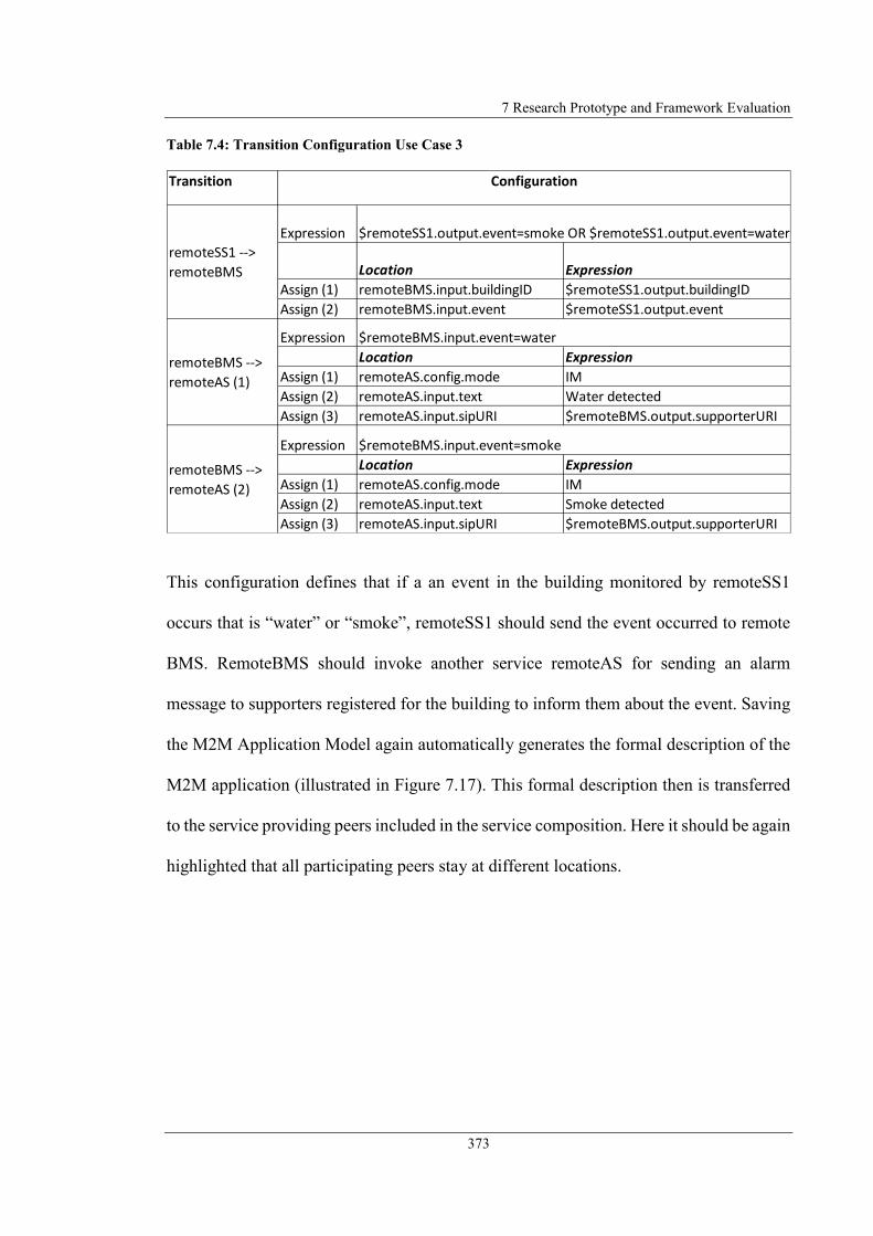
7 Research Prototype and Framework Evaluation
373
Table 7.4: Transition Configuration Use Case 3
This configuration defines that if a an event in the building monitored by remoteSS1
occurs that is “water” or “smoke”, remoteSS1 should send the event occurred to remote
BMS. RemoteBMS should invoke another service remoteAS for sending an alarm
message to supporters registered for the building to inform them about the event. Saving
the M2M Application Model again automatically generates the formal description of the
M2M application (illustrated in Figure 7.17). This formal description then is transferred
to the service providing peers included in the service composition. Here it should be again
highlighted that all participating peers stay at different locations.
Transition
Expression
Location Expression
Assign (1) remoteBMS.input.buildingID $remoteSS1.output.buildingID
Assign (2) remoteBMS.input.event $remoteSS1.output.event
Expression
Location Expression
Assign (1) remoteAS.config.mode IM
Assign (2) remoteAS.input.text Water detected
Assign (3) remoteAS.input.sipURI $remoteBMS.output.supporterURI
Expression
Location Expression
Assign (1) remoteAS.config.mode IM
Assign (2) remoteAS.input.text Smoke detected
Assign (3) remoteAS.input.sipURI $remoteBMS.output.supporterURI
Configuration
remoteSS1 -->
remoteBMS
$remoteBMS.input.event=smoke
$remoteBMS.input.event=water
remoteBMS -->
remoteAS (1)
remoteBMS -->
remoteAS (2)
$remoteSS1.output.event=smoke OR $remoteSS1.output.event=water
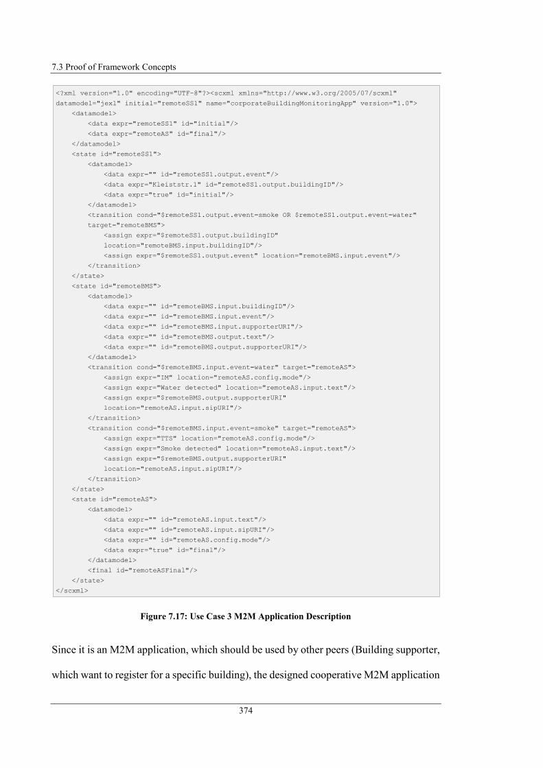
7.3 Proof of Framework Concepts
374
Figure 7.17: Use Case 3 M2M Application Description
Since it is an M2M application, which should be used by other peers (Building supporter,
which want to register for a specific building), the designed cooperative M2M application
<?xml version="1.0" encoding="UTF-8"?><scxml xmlns="http://www.w3.org/2005/07/scxml"
datamodel="jexl" initial="remoteSS1" name="corporateBuildingMonitoringApp" version="1.0">
<datamodel>
<data expr="remoteSS1" id="initial"/>
<data expr="remoteAS" id="final"/>
</datamodel>
<state id="remoteSS1">
<datamodel>
<data expr="" id="remoteSS1.output.event"/>
<data expr="Kleiststr.1" id="remoteSS1.output.buildingID"/>
<data expr="true" id="initial"/>
</datamodel>
<transition cond="$remoteSS1.output.event=smoke OR $remoteSS1.output.event=water"
target="remoteBMS">
<assign expr="$remoteSS1.output.buildingID"
location="remoteBMS.input.buildingID"/>
<assign expr="$remoteSS1.output.event" location="remoteBMS.input.event"/>
</transition>
</state>
<state id="remoteBMS">
<datamodel>
<data expr="" id="remoteBMS.input.buildingID"/>
<data expr="" id="remoteBMS.input.event"/>
<data expr="" id="remoteBMS.input.supporterURI"/>
<data expr="" id="remoteBMS.output.text"/>
<data expr="" id="remoteBMS.output.supporterURI"/>
</datamodel>
<transition cond="$remoteBMS.input.event=water" target="remoteAS">
<assign expr="IM" location="remoteAS.config.mode"/>
<assign expr="Water detected" location="remoteAS.input.text"/>
<assign expr="$remoteBMS.output.supporterURI"
location="remoteAS.input.sipURI"/>
</transition>
<transition cond="$remoteBMS.input.event=smoke" target="remoteAS">
<assign expr="TTS" location="remoteAS.config.mode"/>
<assign expr="Smoke detected" location="remoteAS.input.text"/>
<assign expr="$remoteBMS.output.supporterURI"
location="remoteAS.input.sipURI"/>
</transition>
</state>
<state id="remoteAS">
<datamodel>
<data expr="" id="remoteAS.input.text"/>
<data expr="" id="remoteAS.input.sipURI"/>
<data expr="" id="remoteAS.config.mode"/>
<data expr="true" id="final"/>
</datamodel>
<final id="remoteASFinal"/>
</state>
</scxml>

7 Research Prototype and Framework Evaluation
375
needs to be equipped with an application IFD. This IFD is generated using the SDU GUI
(illustrated in Figure 7.16) and afterwards stored in the P2P overlay. Figure 7.18 shows
the automatically generated IFD.
Figure 7.18: Use Case 3 corporateBuildingMonitoringApp IFD
The ADI of each peers interprets the formal application description by means of the ADP
providing the internal application description object. This step is illustrated in Figure 7.19
once for all peers.
<?xml version="1.0" encoding="UTF-8" standalone="yes"?>
<AE>
<appName>corporateBuildingMonitoringApp</appName>
<App-ID>corpBuildMonApp</App-ID>
<pointOfAccess></pointOfAccess>
<requestReachability></requestReachability>
<creationTime>2017-11-30</creationTime>
<lastModifiedTime>2017-11-30</lastModifiedTime>
<contentSerialisation></contentSerialisation>
<accessControlPolicy>
<privileges>
<accessControlOriginators></accessControlOriginators>
<accessControlContexts></accessControlContexts>
<accessControlOperations></accessControlOperations>
</privileges>
<expirationTime></expirationTime>
</accessControlPolicy>
<content>
<input>
<inputParameter id="1">
<name>remoteBMS.input.buildingID</name>
<value></value>
</inputParameter>
<inputParameter id="2">
<name>remoteBMS.input.supporterURI</name>
<value></value>
</inputParameter>
</input>
<output/>
<config/>
</content>
<description>Manages supporter registered for specific buildings....</description>
</AE>
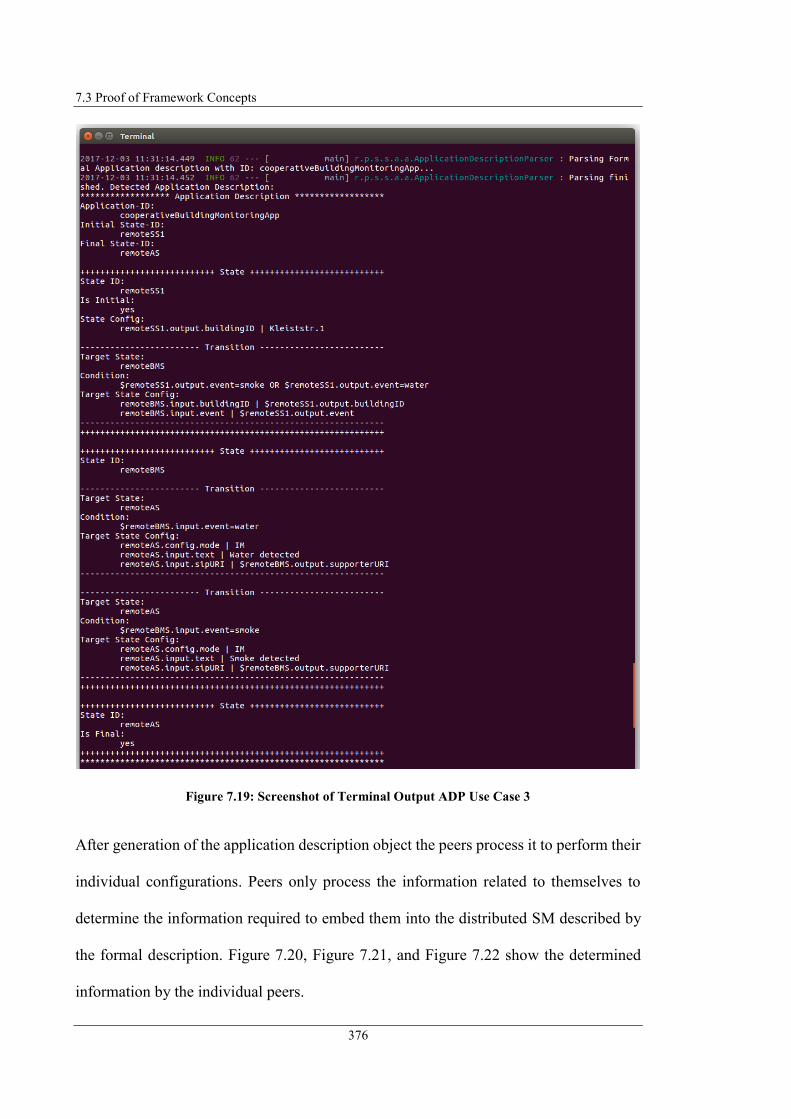
7.3 Proof of Framework Concepts
376
Figure 7.19: Screenshot of Terminal Output ADP Use Case 3
After generation of the application description object the peers process it to perform their
individual configurations. Peers only process the information related to themselves to
determine the information required to embed them into the distributed SM described by
the formal description. Figure 7.20, Figure 7.21, and Figure 7.22 show the determined
information by the individual peers.

7 Research Prototype and Framework Evaluation
377
Figure 7.20: Screenshot of Terminal Output ADI Use Case 3 remoteSS1
Figure 7.21: Screenshot of Terminal Output ADI Use Case 3 remoteBMS
Figure 7.22: Screenshot of Terminal Output ADI Use Case 3 remoteAS

7.3 Proof of Framework Concepts
378
The distributed SM that is to be generated after all peers have automatically connected
with each other is illustrated in Figure 7.23.
Figure 7.23: Distributed SM Use Case 3
To generate this distributed M2M application the signalling illustrated in Figure 7.24 is
performed by the peers. After the signalling process is finished, the distributed
cooperative M2M application has been successfully configured and is ready for
execution. Here it should be again mentioned, that the peers perform their individual part
of the SM logic by checking the condition locally and send the response message (i.e.
perform the state transition) only if the defined condition becomes TRUE.
Figure 7.24: M2M Application Configuration Phase Use Case 3
$remoteSS1.output.event=smoke OR
$remoteSS1.output.event=water $remoteBMS.input.event=water
$remoteBMS.input.event=smoke
remoteSS1 remoteASremoteBMS
Peer 0
remoteSS1
providing Peer Peer 0
remoteBMS
providing Peer
Receive
Service
Request
<outputParameter id="1">
<name>
remoteSS1.output.buildingID
</name>
<value>
Kleiststr.1
</value>
</outputParameter>
<outputParameter id="2">
<name>
remoteSS1.output.event
</name>
</outputParameter>
Request
Service
OK
Subscribe (Request Primitive)
Peer 0
remoteAS
providing Peer
Request
Service
Store in
Subscriber
List
Subscribe (Request Primitive)
<outputParameter id="1">
<name>
remoteBMS.output.supporterURI
</name>
</outputParameter>
OK
Receive
Service
Request
Store in
Subscriber
List

7 Research Prototype and Framework Evaluation
379
In the next step, supporter register for the buildings they take care of by requesting the
M2M application service at the remoteBMS providing peer (illustrated in Figure 7.25).
Figure 7.25: Service Request Process Supporter at remoteBMS Use Case 3
As soon as events “water” or “smoke” occur in the building monitored by remoteSS1 the
M2M application execution starts. The performed message exchange is illustrated in
Figure 7.26.
Figure 7.26: M2M Application Execution Process Use Case 3
RemoteSS1 generates a NOTIFY message and sends it to the remoteBMS providing peer.
This determines the supporter of the building and generates the alarm message text in
Peer 0Supporter Peer
Peer 0
remoteBMS
providing Peer
Request
Service
Subscribe (Request Primitive)
<Content>
<input>
<inputParameter id="1">
<name>remoteBMS.input.buildingID</name>
<value>Kleiststr.1</value>
</inputParameter>
<inputParameter id="2">
<name>remoteBMS.input.supporterURI</name>
<value>[email protected]</value>
</inputParameter>
</input>
</Content>
Receive
Service
Request
Store in
Subscriber
List
OK
Peer 0
remoteSS1
providing
Peer Peer 0
remoteBMS
providing
Peer
n: remoteSS1.output.buildingID
v: Kleiststr.1
n: remoteSS1.output.event
v: water
OK
Peer 0
remoteAS
providing
Peer
Notify (Response Primitive)
Peer 0
Supporter
Peer
n: remoteAS.config.mode
v: IM
n: remoteAS.input.text
v: Water detected in
Kleistst.1
n: remoteAS.input.sipURI
Notify (Response Primitive)
SIP MESSAGE
text: Water detected in
Kleistst.1
OK
200 (OK)

7.3 Proof of Framework Concepts
380
dependence of the occurred event. Afterwards the remoteBMS sends a NOTIFY message
to the remoteAS providing peers, which generated a SIP IM and sends it to the building
supporting peer (illustrated in Figure 7.27).
Figure 7.27: Screenshot of Terminal Output Supporter receiving Alarm Message Use Case 3
This section demonstrated the distributed cooperative M2M application creation and
execution processes. The following section will demonstrate storing and requesting IFDs
in a P2P overlay.
7.3.3 Communication Scenarios for M2M Service Requests
To demonstrate the processes for the service request and the corresponding response
messages, the following two scenarios are presented.
One-time subscription via CoAP – A SC requests once for an M2M
service/resource at an M2M service providing peer using the communication
protocol CoAP.
Continuous subscription via SIP – A SC requests for an M2M service/resource at
an M2M service providing peer using the communication protocol SIP. Requested
resource is continuously sent to the requesting peer.
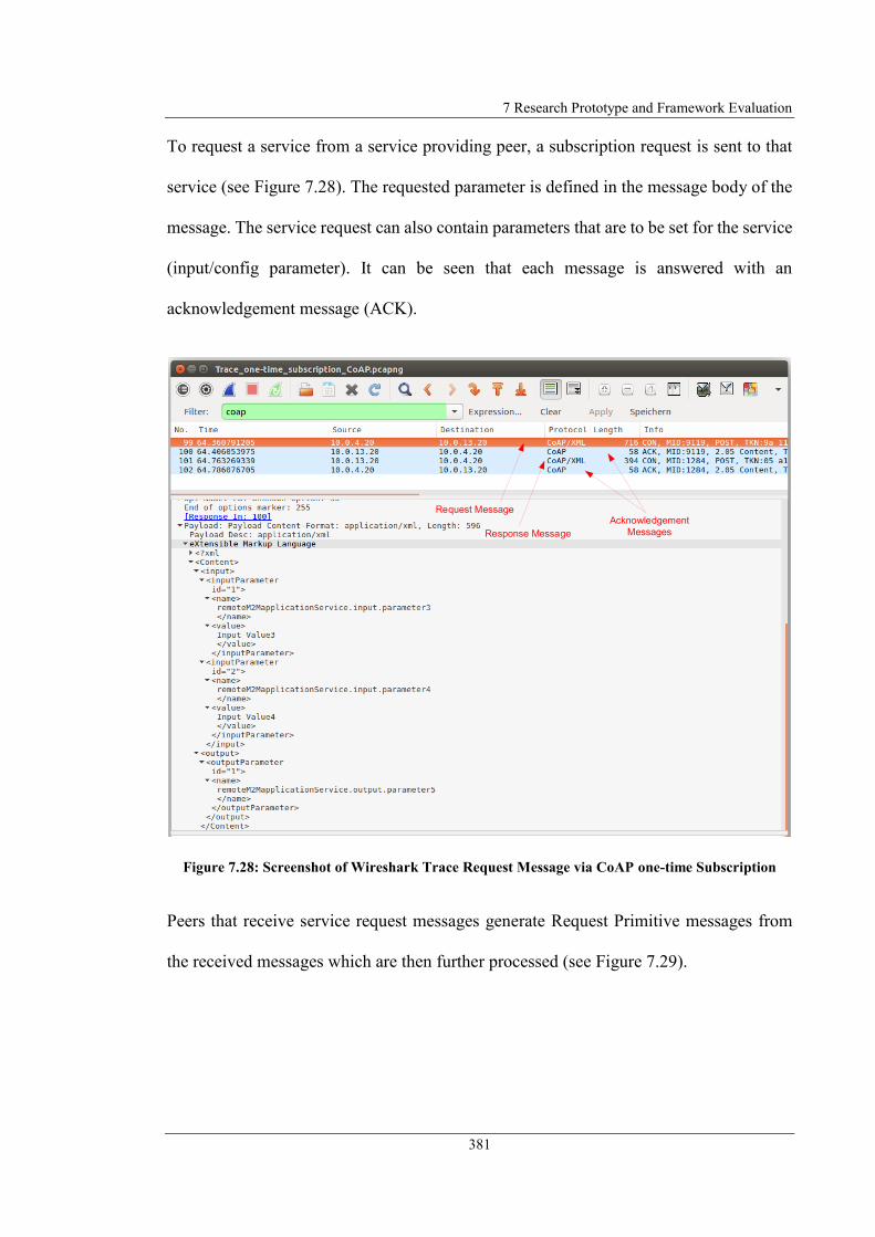
7 Research Prototype and Framework Evaluation
381
To request a service from a service providing peer, a subscription request is sent to that
service (see Figure 7.28). The requested parameter is defined in the message body of the
message. The service request can also contain parameters that are to be set for the service
(input/config parameter). It can be seen that each message is answered with an
acknowledgement message (ACK).
Figure 7.28: Screenshot of Wireshark Trace Request Message via CoAP one-time Subscription
Peers that receive service request messages generate Request Primitive messages from
the received messages which are then further processed (see Figure 7.29).
Request Message
Response Message
Acknowledgement
Messages
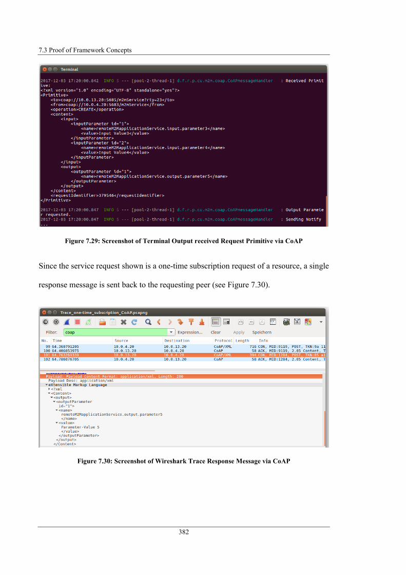
7.3 Proof of Framework Concepts
382
Figure 7.29: Screenshot of Terminal Output received Request Primitive via CoAP
Since the service request shown is a one-time subscription request of a resource, a single
response message is sent back to the requesting peer (see Figure 7.30).
Figure 7.30: Screenshot of Wireshark Trace Response Message via CoAP
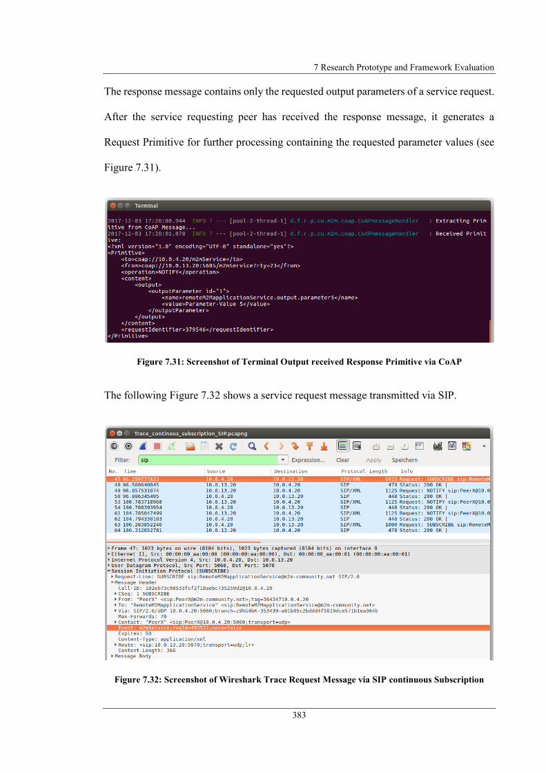
7 Research Prototype and Framework Evaluation
383
The response message contains only the requested output parameters of a service request.
After the service requesting peer has received the response message, it generates a
Request Primitive for further processing containing the requested parameter values (see
Figure 7.31).
Figure 7.31: Screenshot of Terminal Output received Response Primitive via CoAP
The following Figure 7.32 shows a service request message transmitted via SIP.
Figure 7.32: Screenshot of Wireshark Trace Request Message via SIP continuous Subscription

7.3 Proof of Framework Concepts
384
In a continuous subscription, the requested parameter is also specified in the message
body. The information about the continuous request is given in the shown example in the
message header. This causes the SP to send the requested information continuously until
the subscription is terminated (Expires: 0) (see Figure 7.33).
Figure 7.33: Screenshot of Wireshark Trace Terminate Request Message via SIP
In summary, it can be concluded that the framework and the prototype implementation
could be evaluated by implementing different scenarios. The scenarios demonstrate the
implementation of application and framework components without central entities and
the central integration of the end-user into application creation. It could be shown that by
applying the new concepts, M2M applications can be conveniently created and formally
described with distributed provision and execution.

7 Research Prototype and Framework Evaluation
385
7.4 Performance Evaluation
As shown in the proof-of-concept, an M2M application is based on the linking of
distributed services through signalling based on the service request and transmitting
service result via notification messages.
Assuming that when using a central MSP, services are also linked by the same signalling
principle, the effort for the required signalling messages can be compared. The following
scenarios (as illustrated in Figure 7.35 and Figure 7.36) are defined for the comparison:
N Services in same Subnet – N services that are to be connected to each other are
located in the same access network (subnet) and on different nodes.
Two Services in different Subnets – Two services to be linked are located in
different subnets that are not connected to each other by a direct link.
Two Services in different Subnets (direct link) – Two services to be linked to each
other are located in different subnets connected by a direct link.
Furthermore, a uniform data basis for message exchange via CoAP and SIP is required.
For this purpose, the service request message shown in Figure 7.28 is used as CoAP data
basis. The same scenario has been performed via SIP as illustrated in Figure 7.34.
The signalling effort for the request of a service shown in Table 7.5 can be determined
from the displayed messages. To determine the message volume in relation to the number
of messages, the average message size consisting of request and response messages is
used. Derived from Figure 7.28 and Figure 7.34, the average message size for CoAP is
therefore exemplarily set to 306Byte and for SIP 781Byte.

7.4 Performance Evaluation
386
Figure 7.34: Screenshot of Wireshark Trace Request/Response Messages via SIP one-time
Subscription
Table 7.5: Signalling Effort for Service Request and Service Response
Based on the defined scenarios and using a central MSP, Figure 7.35 shows the messaging
effort. It is assumed that the nodes are each connected to an Access Network (AN), which
in turn is connected to the Core Network. The Core Network connects the ANs with each
other and also consists of several Core Subnets (CSNs).
Category Description SIP CoAP
Service Request (Request + Acknowledgement) 1731 Byte 774 Byte
Service Response (Notify + Acknowledgement) 1394 Byte 452 Byte
M2M Communication Protocol
Service Request/
Response

7 Research Prototype and Framework Evaluation
387
Figure 7.35: Signalling Effort using centralised M2M Service Platform (MSP)
A central MSP must always request all services to be linked to each other and receives a
response from these services. Derived from the signalling behaviour shown in Figure
7.35, the message effort for requesting n services that are located in the same subnet can
be derived as shown in Equation 7.1. The variable "m" corresponds to the number of
mediating CSNs located between the CSNs to which the ANs of the service nodes and
the MSP are connected.
For the messaging effort of requesting two services located in different subnets, the
signalling effort shown in Equation 7.2 can be derived. Since a different number of
mediating CSNs can exist in this scenario, this is taken into account by the variable "m1"
and "m2". The messaging effort for the scenario in which the ANs are connected to each
Request/ Ack
Notify/ Ack
Access
Network 1
Node 1 Node 2
Access
Network 2
Node 3 Node 4
Access
Network 3
Node 5 Node 6
Core Network
Core Subnet 1 Core Subnet 2 Core Subnet 3Access
Network 4
M2M ServiceM2M Service
Service in different SubnetsService in same Subnet
M2M Service
Platform
Request/ Ack
Notify/ Ack
Request/ Ack
Notify/ Ack
Request/ Ack
Notify/ Ack
Request/ Ack
Notify/ Ack
Request/ Ack
Notify/ Ack
Request/ Ack
Notify/ Ack
Request/ Ack
Notify/ Ack
Request/ Ack
Notify/ Ack
Request/ Ack
Notify/ Ack
Request/ Ack
Notify/ Ack
Request/ Ack
Notify/ Ack
Request/ Ack
Notify/ Ack
Request/ Ack
Notify/ Ack
Request/ Ack
Notify/ Ack
Request/ Ack
Notify/ Ack
M2M Service M2M Service
Request/ Ack
Notify/ Ack
(7.1)Signalling Messages (S) = n * [ 8 + (4 * m + 4) + 8 ]
# mediating CSN
M2M Server AN CSNM2M Service AN CSN
# Services

7.4 Performance Evaluation
388
other is identical, since the services are requested by the central MSP and therefore there
would be no advantage by connecting ANs.
Table 7.6 shows the messaging effort for signalling using a central MSP for scaling
services (n) and number of mediating CSNs (m), assuming that m1 is equal to m2 and that
in the scenario where n services are connected to each other m is equal to 1 (as shown in
Figure 7.35).
Table 7.6: Performance Analysis central M2M Service Platform for Service Requests
In comparison, Figure 7.36 shows the message effort using signalling approaches from
the proposed framework.
(7.2)Signalling Messages (S) = [ 8 + (4 * m1 + 4) + 8 ]
+
[ 8 + (4 * m2 + 4) + 8 ]
Scenario
n n CoAP SIP
2 48 2 14688 37488
10 240 10 73440 187440
100 2400 100 734400 1874400
m m CoAP SIP
2 56 2 17136 43736
5 80 5 24480 62480
10 120 10 36720 93720
2 services
different subnets
n = number of services; m = number of mediating subnets, mx = different number of mediating subnets
[ 8 + (4 * m1 + 4) + 8 ]
+
[ 8 + (4 * m2 + 4) + 8 ]
# Messages
Central M2M Service Platform
Total Byte
N services same
subnetn * [ 8 + (4 * m + 4) + 8 ]

7 Research Prototype and Framework Evaluation
389
Figure 7.36: Signalling Effort using proposed Framework
Derived from the signalling behaviour shown in Figure 7.36, the messaging effort shown
in Equation 7.3 or requesting n services within the same subnet can be derived. Since the
services are connected P2P, only signalling between the nodes in the same AN is
necessary.
For requesting two services located in different subnets, the signalling effort shown in the
following Equation 7.4 can be derived.
If the ANs are connected to each other by a direct link, the connection via the CSNs can
be reduced. In this way, the signalling effort shown in Equation 7.5 can be derived.
Access
Network 1
Node 1 Node 2
Access
Network 2
Node 3 Node 4
Access
Network 3
Node 5 Node 6
Core Network
Core Subnet 1 Core Subnet 2 Core Subnet 3
Request/ Ack
Notify/ Ack
Request/
Ack
Notify/
Ack
M2M ServiceM2M Service
Notify/
Ack
Request/
Ack
Service in different SubnetsService in same Subnet
M2M Service M2M Service
Request/ Ack
Notify/ Ack
Notify/
AckRequest/
Ack
Request/
Ack
Notify/
Ack
Request/ Ack
Notify/ Ack
(7.3)Signalling Messages (S) = ( n * 4) - 4
# Services
(7.4)Signalling Messages (S) = [ 8 + (4 * m + 4) + 8 ]
# mediating CSN
M2M Service AN2 CSNM2M Service AN1 CSN

7.4 Performance Evaluation
390
Table 7.7 shows the messaging effort for signalling using the proposed framework for
scaling services (n) and number of mediating CSNs (m).
Table 7.7: Performance Analysis distributed M2M Service Platform Concept for Service Requests
The comparison visualised in Figure 7.37 shows the significantly lower signalling effort
using the presented framework. The number of messages required for linking n services
in the same subnet is about one-fifth with the proposed framework. Only half of the
messages are needed to connect two services in different subnets (without a direct link).
If the subnets are connected by a direct link, on the other hand, only 12 messages are
needed constantly.
(7.5)Signalling Messages (S) = [ 4 + 4 + 4 ]
AN1 AN2
M2M Service AN2M2M Service AN1
Scenario
n n CoAP SIP
2 4 2 1224 3124
10 36 10 11016 28116
100 396 100 121176 309276
m m CoAP SIP
2 28 2 8568 21868
5 40 5 12240 31240
10 60 10 18360 46860
SIP
9372
2 services
different subnets[ 8 + (4 * m + 4) + 8 ]
Distributed M2M Service Platform Concept
# Messages Total Byte
N services same
subnet(n * 4) – 4
n = number of services; m = number of mediating subnets
2 services
different subnets
(direct link)
12 (4 + 4 + 4) 12
CoAP
3672

7 Research Prototype and Framework Evaluation
391
Figure 7.37: Comparison Signalling Effort (# Messages)
Figure 7.38 visualises the comparison under consideration of the required data volume.
Again, it can be seen that the effort required by the proposed framework is significantly
lower.
0
500
1000
1500
2000
2500
3000
0 20 40 60 80 100 120
# M
essa
ges
Number of Services
N Services same Subnet
Central M2M Service Platform
Proposed Framework
0
20
40
60
80
100
120
140
0 2 4 6 8 10 12
# M
essa
ges
Mediating Subnets
2 Services different Subnets (no Link)
Central M2M Service Platform
Proposed Framework
0
20
40
60
80
100
120
140
0 2 4 6 8 10 12
# M
essa
ges
Mediating Subnets
2 Services different Subnets (direct Link)
Central M2M Service Platform
Proposed Framework
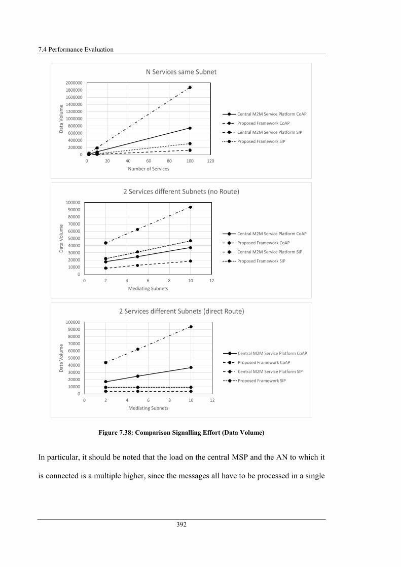
7.4 Performance Evaluation
392
Figure 7.38: Comparison Signalling Effort (Data Volume)
In particular, it should be noted that the load on the central MSP and the AN to which it
is connected is a multiple higher, since the messages all have to be processed in a single
0
200000
400000
600000
800000
1000000
1200000
1400000
1600000
1800000
2000000
0 20 40 60 80 100 120
Dat
a V
olu
me
Number of Services
N Services same Subnet
Central M2M Service Platform CoAP
Proposed Framework CoAP
Central M2M Service Platform SIP
Proposed Framework SIP
0
10000
20000
30000
40000
50000
60000
70000
80000
90000
100000
0 2 4 6 8 10 12
Dat
a V
olu
me
Mediating Subnets
2 Services different Subnets (no Route)
Central M2M Service Platform CoAP
Proposed Framework CoAP
Central M2M Service Platform SIP
Proposed Framework SIP
0
10000
20000
30000
40000
50000
60000
70000
80000
90000
100000
0 2 4 6 8 10 12
Dat
a V
olu
me
Mediating Subnets
2 Services different Subnets (direct Route)
Central M2M Service Platform CoAP
Proposed Framework CoAP
Central M2M Service Platform SIP
Proposed Framework SIP

7 Research Prototype and Framework Evaluation
393
place, whereas the load in the presented framework is distributed among several nodes
and ANs.
7.5 Conclusion
This chapter presented the evaluation of the proposed framework for “Autonomous
decentralised M2M Application Service Provision” (section 7.1). The framework has
been analysed with regard to the requirements defined in section 3.2 and determined
whether or not these requirements are met. All the requirements for the framework were
met by the concepts and the M2M system architecture presented.
Section 7.2 presented the research prototype architecture and implementation. The
relevant developed components were described and the interaction between the
framework components was discussed.
The research prototype was successfully implemented for the proof-of-concept evaluation
of the proposed framework (section 7.3). This demonstrated the main functionality of the
framework and proved its applicability. The proof-of-concept was demonstrated using
previously defined use cases that illustrate the essential aspects of the framework (end-
user integration, formal description of application logic, decentralised SM-based service
execution, combination of distributed M2M application services, and cooperative M2M
application service provision). All the relevant steps for modelling, generating and
executing an M2M application service were illustrated using the respective use cases.
Finally, in section 7.4 the signalling effort for service requests and transmission of service
results required for linking services was considered. The connection of a scaling number

7.5 Conclusion
394
of services in the same AN was analysed. Furthermore, the connection of two services in
different (possibly directly linked) ANs was analysed, which are interconnected by a
scalable number of mediating CNs. The number of messages was determined and based
on exemplary message sizes the required data volume was calculated. The comparison of
the distributed MSP system architecture introduced in this project with a centrally
organised system architecture has shown that the presented approach requires
significantly less effort for signalling (services in the same AN 80%, different ANs 50%,
directly linked ANs constant 12 messages).
395
8 Conclusion and Future Work
This chapter concludes the research project. Section 8.1 summarises the main
achievements. Section 8.2 discusses limitations of the project. Section 8.3 suggests scopes
and ideas for further research.
8.1 Achievements of the Research
The research performed in this project was dedicated to the design of a novel approach
for M2M application service provision. A framework has been designed enabling the
realisation of a distributed M2M service platform (MSP). This showed an alternative to
traditional approaches of MSPs. The proposed MSP eliminates certain disadvantages of
traditional MSPs such as dependencies on central system components or stakeholders.
The MSP, as well as the M2M applications, can be operated autonomously with existing
equipment. The framework is an integrated solution for decentralised M2M application
service provision with native end-user integration. It describes all necessary steps from
application modelling to execution and automated configuration of M2M applications.
The analysis of currently existing approaches in the field of MSPs was presented (refer
to section 3.2). For this purpose, the oneM2M standard and approaches from the research
field were considered. Requirements for a new framework for “Autonomous
decentralised M2M Application Service Provision” were determined on the basis of their
advantages and deficits (refer to section 3.2). It has been analysed whether one of the
8.1 Achievements of the Research
396
considered projects fulfils the requirements with the result that none of them fulfils the
overall requirements catalogue, since the existing approaches for MSPs usually comprise
individual solutions or do not include essential aspects for decentralisation or end-user
integration.
A new framework has been designed based on the requirements resulting from the deficits
and advantages of related projects (refer to chapter 4). The designed framework
architecture contains new conceptual models for M2M system architectures enabling
decentralised, horizontal and cooperative M2M application service provision.
The Decentralised M2M Service Provision (ADSP) model was introduced as the first new
model. With the introduced framework, end-users have the possibility to create their
individual applications with the resources existing in their personal environment and
execute them locally. In the related projects, M2M applications for supporting specific
business processes are created by specialised developers and are executed centrally on
M2M application servers. Often the MSPs are limited to specific application fields and
therefore not flexible enough to cover the end-user's individual field of application. By
integrating end-users into the application creation they can create applications that meet
their individual requirements. Since the end-users themselves provide the execution
environment, they are not dependent on a central platform operator or central system
components that they cannot manage. Additionally, end-users are not dependent on the
functionality of a central MSP, but use the functionality that exists in their personal area
for which the application is intended. By distributing the load across different execution
environments, the platforms that provide the execution environment can have
significantly less system resources than if all applications were running on a central

8 Conclusion and Future Work
397
platform. A further advantage of the decentralised platform architecture and the
avoidance of central stakeholders is that there are no dependencies on them and there is
no central data storage that could compromise end-users' privacy.
The Horizontal M2M Service Provision and Utilisation (HSPU) model was introduced as
the second new conceptual model. The HSPU model allows end-users to provide their
local resources and M2M applications end-to-end as a service to other end-users, but also
to external service providers (SPs) who can then integrate them into their own M2M
applications. As a result of this facility, the end-user is no longer only in the role of a
service consumer (SC), but can also act as a SP. The HSPU model enables external access
to the end-user's personal environment, which is not intended for most existing MSPs.
The integration of resources from the domain of other end-users in M2M applications can
extend their functionality or be integrated into certain business processes.
The third newly introduced Decentralised Cooperative M2M Application Service
Provision (DCASP) model allows end-users to connect their distributed M2M services.
Thereby, the functionality and effectiveness of an M2M application can be extended by
integrating the personal environments of other end-users that were previously not
addressable.
To enable decentralised and autonomous M2M application provisioning, several
approaches and algorithms have been designed enabling the most automatic application
generation and execution (refer to chapter 5).
The prerequisite for M2M application provisioning where the end-user is in focus is the
integration of the end-user into application creation. This is one of the key novelties of

8.1 Achievements of the Research
398
this research. A unified structure of an M2M application was designed and based on it a
concept for the graphical modelling of an M2M application was introduced that is
independent of the execution environment. With the proposed new approach of
application creation, the end-user has the possibility to graphically model the behavior of
an application in an intuitive way as a state machine. Compared to other related
approaches, where the application logic has to be implemented programmatically, no
expert knowledge is required for this kind of application development.
Another key novelty of this research relates directly to the previous one. An approach has
been designed that maps the graphically modelled application logic into a formal
language. For this purpose, different standardised modelling languages were examined
and based on a defined catalogue of requirements, UML StateMachine Diagrams were
selected as the basis for the formal description. Using SCXML as a standardised formal
language, a new description language for M2M applications has been introduced
describing the semantics of the M2M application.
The advantage that the application logic is described in a formal language defines another
novelty of the described framework in the context of MSPs. Due to the formal description,
the application logic is machine-readable and can be executed on other systems that
contain a corresponding parser. New algorithms have been designed with which the
formal description can be generated automatically and to generate an executable state
machine which is executed by the local M2M platform.
Reusable Multimedia Service Components (MMSCs) have been defined which can be
integrated into M2M applications and serve as an input/output interface. This enables to
interact with the M2M platform or M2M applications via a comfortable interface (natural

8 Conclusion and Future Work
399
language or textual) using existing multimedia communication equipment. Although the
principles of these MMSCs are already common communication methods, the integration
into an MSP was not considered in any of the related projects. Through this the scope of
traditional MSPs have been extended to the M2M application field that (Decker, 2012)
classifies as 2nd generation M2M (M2M end-user/devices/environment interaction) and
3rd generation M2M (Social M2M, integration of people and networking of people).
The basis for decentralised and cooperative application provisioning is the networking of
SP and SC as well as the composition of a distributed M2M application. For this purpose,
several approaches and algorithms have been defined, which again focus on automated
execution (refer to chapter 6).
Another key novelty of this research is the provision of local resources and applications
for other end-users and their integration into M2M applications. For this purpose, a
unified interface description for M2M device/application services based on the resource
descriptions defined by oneM2M has been introduced containing all necessary parameters
for service utilisation. An approach was defined how M2M service requests can be
requested and integrated into other M2M applications by exchanging service layer
messages in a standard-compliant manner. Due to the uniformly defined structure of an
M2M application, it is possible to integrate remote M2M services with the same
semantics as local M2M devices into the application logic. The designed parsing
algorithm determines whether the resource is a local or remote resource and requests it
from the SP.

8.1 Achievements of the Research
400
As a central concept of the presented framework and thus as a new approach for the
realisation of an MSP, central components in the platform architecture were completely
avoided. To achieve this, a number of new approaches have been designed.
Networking between SPs and SCs is end-to-end. This means that no intermediary entities
on the application layer are involved in the communication. To achieve this, the P2P
networking approaches were applied to the networking of SPs and SCs. To define an
adequate approach for the exchange of messages, different Information Exchange
Patterns (IxP) have been analysed with the result that the Subscribe/Notify IxP is the most
appropriate pattern. To define an optimal P2P communication protocol, the protocols
suggested by oneM2M were analysed. The evaluation has shown that CoAP is the only
suitable of the proposed protocols considering the defined framework requirements. As
an alternative, SIP was proposed as communication protocol, since the technical
requirements for communication via SIP are already present in the end-user environment.
A new SIP Protocol Binding was specified to enable oneM2M standards-compliant
communication between SP and SC for service utilisation. The comparison of CoAP and
SIP showed that although CoAP has the lower message overhead, SIP should be regarded
as more advantageous, in particular through the newly proposed integration of multimedia
communication in M2M service platforms.
The use of a P2P overlay was proposed to realise decentralised data management for the
administration of the service interface descriptions. Different algorithms for managing
structured and unstructured P2P overlays were analysed in the context of the presented
framework. As a result, structured overlays were found to be advantageous for many

8 Conclusion and Future Work
401
search queries and a required guarantee of success. Unstructured overlays have the
advantage of supporting a high fluctuation of peers.
Another key novelty of this research work is the cooperative M2M application service
provision approach. Approaches and algorithms were defined to carry out a decentralised
composition of the distributed M2M application. The application modelling and the
formal description is also done by modelling a state machine. A mechanism has been
designed to realise a distributed state machine which corresponds to the described
application logic and to build a service overlay network. In this completely new approach,
all nodes involved are able to embed themselves autonomously in the application context
by analysing the relevant part of the formal description. Since the autonomous embedding
in the application context can lead to invalid interconnections, an algorithm has been
designed enabling each peer to recognise independently whether an invalid configuration
exists. This new approach enables realise distributed M2M applications, which in the
existing MSP approaches is only possible with the help of a central service orchestrator.
The new approach for the decentralised M2M application service provision is completed
by the introduction of a new M2M community. The introduction of an M2M community
created the ability for end-users to interlink with each other on the basis of a social
network for offering and utilising services.
The final chapter 7 described the evaluation of the defined requirements (refer to section
3.2) with the result that all the specified requirements are fulfilled by the presented
framework. The verification of the main framework functionalities has been established
by the development of a research prototype. The research prototype has been successfully
adopted for the proof of concept of the proposed framework by demonstrating exemplary

8.2 Limitations of the research
402
use cases for local M2M application modelling and execution with remote M2M service
integration as well as for cooperative M2M application service execution.
Several publications on the different aspects of the research outcomes were presented at
related conferences, which received positive comments from the reviewers and delegates.
8.2 Limitations of the research
Although the overall objectives of research were achieved, some decisions had to be made
that limited the work of this research. In principle, these decisions were made for practical
reasons, to limit the expenditure in areas where no new findings were expected or were
outside the scope of this research. The main restrictions are summarised below.
1. Only the IMMMSC of the defined MMSCs was implemented in the framework
prototype, since its interfaces can be operated with the same client application.
However, the implementation of the other MMSCs would not have been relevant,
since the IMMMSC already serves both input and output interface.
2. The Service Design Unit does not support parallel state elements. This is because
the JsPlumb library does not support nested state elements in the used and freely
available version. However, the modelling of AND-State elements has been
described in detail, so that this functionality can be easily implemented when the
library functionality is available. Furthermore, the conditions for the state
transitions must be defined statically. Here, the definition could be done via
selection lists, but this is only a design aspect of the GUI. The basic functionality
8 Conclusion and Future Work
403
of dynamic conditions (defined in JEXL format) and their evaluation have been
validated so that it can be implemented easily.
3. The implementation of structured and unstructured overlays for Gnutella and
Chord algorithms were integrated into the prototype implementation. However,
the performance is highly dependent on the library implementation and its
configuration options (e.g. stabilisation processes, redundancies or update
intervals), so that no reliable analysis can be performed with the prototype
implementation. However, the performance of the different overlay algorithms
was evaluated based on literature research results. A modular design of the
prototype makes it easy to replace the overlay algorithm.
4. The application validation algorithm has not been implemented. The
mathematical principles used have already been sufficiently proven, so that it can
be assumed that the algorithm is valid. Implementation in the prototype would not
have brought much added value.
5. The integration of the P2P overlay layer into the system architecture enables
completely decentralised data storage, which meets the requirements of avoiding
central entities. Distributed data storage, however, creates additional traffic for
overlay management and searching datasets.
6. The security aspect of the proposed platform architecture is limited to distributed
data storage and the definition of access rights via the IFDs. This prevents data
from being stored at central locations and enables applications to be restricted to
specific user groups. Security aspects such as trustworthiness of applications
provided by end-users, access protection for the overlay or authentication of users
to use M2M applications were not considered.

8.3 Suggestions and Future Work
404
7. The presented framework does not include any approaches to validate the
provided M2M applications in terms of functionality, reliability or availability.
These aspects were not the focus of this project and could be part of further
research.
Despite this restrictions, this research project made valid contributions to knowledge and
provided sufficient evidence of the concept for the proposed approaches.
8.3 Suggestions and Future Work
This research has expanded the field of MSPs by introducing new approaches and ideas
for the decentralised realisation of MSPs with native end-user integration. However, some
areas for future research have been identified during this research. Possible extensions of
this research are listed subsequently.
1. Further research can be undertaken in the area of application modelling. Since
application semantics modelling is independent of the executing component,
alternative approaches for generating the application model could be designed.
Possible are, e.g. the definition of an application model by means of natural
language, in which the connections of the devices and services are described
verbally.
2. Because of the independence from central components that are located somewhere
in the Cloud, it can be investigated whether the described concepts can be used
advantageously in networks that are locally limited in their extent and are not
8 Conclusion and Future Work
405
connected to public networks, e.g. Mobile Ad-hoc networks or Wireless Mesh
Networks.
3. The distributed provision of M2M applications, especially in the end-user domain,
results in new challenges. It can be investigated how the functionality of a
distributed application can be tested. Since according to the described concept
there is no central entity that would test applications as in traditional systems, it is
possible to research how a distributed autonomous test approach could be realised.
Another aspect of testing that can be considered is the compatibility of services
with each other.
4. While some of the aforementioned security restrictions can be solved by
development activities (e.g. access protection), the aspect of trust could be further
examined. Since M2M services are provided by end-users, a mechanism could be
designed that allows a distributed trust determination, so that only trusted M2M
services can connect to each other.
5. In this approach, the application developers define the interface descriptions.
Since this contains many freely definable fields, semantics and ontologies can be
examined for their application in describing M2M services to specify them
uniquely and also to get alternative services offered during the search process.


407
References
1. 3GPP TS 23.002 v8.7.0 (2010), Technical Specification, “Network Architecture
(Release 8)”, 3GPP
2. 3GPP TS 23.228 v5.15.0 (2006), Technical Specification, “IP Multimedia
Subsystem (IMS); Stage 2 (Release 5)”, 3GPP
3. 3GPP TS 23.682 v14.2.0 (2016), Technical Specification, “Architecture
enhancements to facilitate communications with packet data networks and
applications (Release 14)”, 3GPP
4. Amaral, L. A.; Tiburski, R. T.; Matos, E.; Hessel, F. (2015), "Cooperative
Middleware Platform as a Service for Internet of Things Applications",
Proceedings of the 30th Annual ACM Symposium on Applied Computing (SAC’ 15),
pp. 488-493, Salamanca, Spain, ACM
5. Apache ANT (2017), “The Apache ANT Project”, Available at:
http://ant.apache.org/, [accessed 19th February 2017]
6. Apache Felix (2017), “Apache Felix”, Available at: http://felix.apache.org/,
[accessed 07th November 2017]
7. Apache Karaf (2017), “Apache Karaf”, Available at: http://karaf.apache.org/,
[accessed 07th November 2017]
8. Apache Struts (2017), Apache Foundation, “Apache Struts”, Available at:
https://struts.apache.org/[accessed 1st February 2017]
9. Apache XML-RPC (2017), “Apache XML-RPC”, Available at:
https://ws.apache.org/xmlrpc/, [accessed 09th November 2017]
10. Appcelerator (2017), Appcelerator Inc., “Titanium – Cross-platform mobile app
development using JavaScript”, Available at:
http://www.appcelerator.com/mobile-app-development-products/[accessed 15th
February 2017]
11. Arndt, M. and Koss, J. (2014), “ETSI M2M Horizontal Platform Strategy”, DG
Connect & ETSI Workshop on Smart Appliances, ETSI
12. Bahga, A. and Madisetti, V. (2014), “Internet of Things (A Hands-on-
Approach)”, USA, ISBN: 978-0996025515
13. Bayer, T. (2002), “REST Web Services”, Whitepaper, Orientation in Objects
GmbH, Available at: http://www.oio.de/public/xml/rest-webservices.pdf,
[accessed 18th June 2017]
14. Binzenhöfer, A. and Leibnitz, K. (2007), “Estimating Churn in Structured P2P
Networks”, Proceedings of the 20th International Teletraffic Congress (ITC20
2007), pp. 630-641, June 2007, Ottawa, Canada

References
408
15. Böckenhauer, H. and Hromkovic, J. (2013), “Formale Sprachen” (translated title:
“Formal Languages”), Springer, Wiesbaden, Germany, ISBN: 3-658-00725-7,
2013
16. Bonomi, F.; Milito, R.; Zhu, J.; Addepalli, S. (2012), "Fog Computing and Its Role
in the Internet of Things", Proceedings of the First Edition of the MCC Workshop
on Mobile Cloud Computing (MCC ’12), pp. 13-16, Helsinki, Finland, ISBN: 978-
1-4503-1519-7, ACM
17. Boswarthick, D., Elloumi, O., Hersent, O. (2012), “M2M Communications: A
Systems Approach”, Wiley, Chichester, West Sussex, United Kingdom, ISBN:
978-1-119-99475-6
18. Carreiro, A. M.; López, G. L.; Moura, P. S.; Moreno, J. I.; Almeida, A. T.;
Malaquias, J. L. (2011), "In-house monitoring and control network for the Smart
Grid of the future", Proceedings of the 2011 2nd IEEE PES International
Conference and Exhibition on Innovative Smart Grid Technologies, pp. 1-7, IEEE
19. Carrez, F.; Bauer, M.; Boussard, M.; Bui, N.; Jardak, C.; De Loof, J.; Magerkurth,
C.; Meissner, S.; Nettsträter, A.; Olivereau, A.; Thoma, M.; Walewski, J. W.;
Stefa, J.; Salinas, A. (2013), Technical Report, “Deliverable D1.5 - Final
architectural reference model for the IoT v3.0”, The Internet of Things –
Architecture, IoT-A (257521)”, IoT-A
20. Clarke, I.; Sandberg, O.; Wiley, B.; Hong, T. W. (2000), “Freenet: a distributed
anonymous information storage and retrieval system”, Proceedings of the
International workshop on Designing privacy enhancing technologies: design
issues in anonymity and unobservability, pp. 46-66
21. Clayman, S. and Galis, A. (2011), "INOX: A Managed Service Platform for Inter-
Connected Smart Objects", Proceedings of the Workshop on Internet of Things and
Service Platforms (IoTSP 2011), Tokyo, Japan, ACM
22. Clip2 Distributed Search Services (2001), “The Gnutella Protocol Specification
v0.4”, Available at: http://web.stanford.edu/class/cs244b/gnutella_protocol_0.4
.pdf, [accessed 28th April 2014]
23. CloudFoundry (2017), Cloud Foundry Foundation, “Cloud Foundry Platform”,
Available at: https://www.cloudfoundry.org/[accessed 15th February 2017]
24. Commons JEXL (2017), “Java Expression Language (JEXL)”, Available at:
http://commons.apache.org/proper/commons-jexl/, [accessed 19th February 2017]
25. Commons SCXML (2016), “Apache Commons SCXML”, Available at:
http://commons.apache.org/proper/commons-scxml/, [accessed 13th January 2016]
26. CORE (2017), U.S. Naval Research Laboratory, “Common Open Research
Emulator (CORE)”, Available at: https://www.nrl.navy.mil/itd/ncs/products/core
[accessed 08th February 2017]
27. Damour, N. (2014), “oneM2M Taking a Look Inside”, Webcast, Available at:
http://www.etsi.org/news-events/events/831-2014-10-taking-a-look-inside-
onem2m [accessed 16th December 2016], ETSI, oneM2M
References
409
28. Danila, I.; Dobrescu, R.; Popescu, D.; Marcu, R.; Ichim, L. (2015), “M2M service
platforms and device management“, Proceedings of the 9th International
Symposium on Advanced Topics in Electrical Engineering (ATEE), pp. 67-72,
IEEE
29. Dawaliby, S.; Bradai, A.; Pousset, Y. (2016), “In depth performance evaluation of
LTE-M for M2M communications”, Proceedings of the 2016 IEEE 12th
International Conference on Wireless and Mobile Computing, Networking and
Communications (WiMob), pp. 1-8, December 2016, New York, USA, IEEE
30. Dawy, Z.; Saad, W.; Ghosh, A.; Andrews, J. G.; Yaacoub, E. (2017), “Toward
Massive Machine Type Cellular Communications”, IEEE Wireless
Communications, Vol. 24, no.1, pp. 120-128, IEEE
31. De Boever, J. (2007), “Peer-to-Peer Networks as a Distribution and Publishing
Model”, Proceedings of the ELPUB2007 Conference on Electronic Publishing, pp.
175-187, Vienna, Austria
32. Decker, P. (2012), “Facebook of Things – The challenge of Endusers within M2M
Systems”, Symphony Teleca Corporation, M2M Summit 2012, Düsseldorf,
Germany
33. Docker 17.06.2-ce (2017), Docker Inc., “Docker”, Version 17.06.2-ce, Available
at: https://www.docker.com/[accessed 05th November 2017]
34. Doukas, C. and Antonelli, F. (2013), "COMPOSE: Building smart & context-
aware mobile applications utilizing IoT technologies", Proceedings of the Global
Information Infrastructure Symposium (GIIS 2013), pp. 1-6, IEEE
35. Doukas, C. and Antonelli, F. (2014), "A full end-to-end platform as a service for
smart city applications" Proceedings of the 2014 IEEE 10th International
Conference on Wireless and Mobile Computing, Networking and Communications
(WiMob), pp. 181-186, IEEE
36. Doukas, C.; Capra, L.; Antonelli, F.; Jaupaj, E.; Tamilin, A.; Carreras, I. (2015),
"Providing generic support for IoT and M2M for mobile devices", Proceedings of
the 2015 IEEE RIVF International Conference on Computing & Communication
Technologies - Research, Innovation, and Vision for Future (RIVF), pp. 192-197,
IEEE
37. Doukas, C. and Antonelli, F. (2015), "Developing and deploying end-to-end
interoperable & discoverable IoT applications," Proceedings of the 2015 IEEE
International Conference on Communications (ICC), pp. 673-678, IEEE
38. Eclipse Californium (2017), “CoAP in Java”, Available at:
https://www.eclipse.org/californium/, [accessed 08th November 2017]
39. Eclipse Equinox (2017), “Equinox OSGi”, Available at:
http://www.eclipse.org/equinox/, [accessed 07th November 2017]
40. Eclipse Jetty (2017), “Jetty://”, Available at: https://www.eclipse.org/jetty/,
[accessed 10th November 2017]
References
410
41. Elloumi, O. (2014), oneM2M, “oneM2M Service Layer Platform – Initial
Release”, Available at: http://www.onem2m.org/onem2m-showcase/showcase-
presentations [accessed 18th August 2017]
42. e-SCHEMA (2015), Steinheimer, M.; Trick, U.; Wacht, P.; Fischer, M.; Hölker,
D.; Tönjes, R., “e-SCHEMA Schlussbericht” (translated title: “e-SCHEMA Final
Report”), Research Project: easy- Service Creation for Home and Energy
Management (e-SCHEMA), Federal Ministry of Education and Research (BMBF),
Federal Republic of Germany, 2012-2015, Grant Number 17018B11
43. ETSI (2014), “Mobile-Edge Computing–Introductory Technical White Paper”,
Available at: https://portal.etsi.org/Portals/0/TBpages/MEC/Docs/Mobile-
edge_Computing_-_ Intr oductory_Technical_White_Paper_V1%2018-09-14.pdf,
ETSI
44. ETSI ES 201 235-1 V1.1.1 (2000), ETSI Standard, “Specification of Dual Tone
Multi-Frequency (DTMF); Transmitters and Receivers Part 1: General”, ETSI
45. ETSI TR 101 584 V2.1.1 (2013), ETSI Technical Report, “Machine-to-Machine
Communications (M2M); Study on Semantic support for M2M Data”, ETSI
46. ETSI TR 102 725 V1.1.1 (2013), ETSI Technical Report, “Machine-to-Machine
communications (M2M); Definitions”, ETSI
47. ETSI TR 102 966 V1.1.1 (2014), ETSI Technical Report, “Machine-to-Machine
Communications (M2M); Interworking between the M2M Architecture and M2M
Area Network technologies”, ETSI
48. ETSI TS 102 690 V2.1.1 (2013), ETSI Technical Specification, “Machine-to-
Machine communications (M2M); Functional architecture”, ETSI
49. ETSI TS 123 228 V11.10.0 (2013), ETSI Technical Report, “IP Multimedia
Subsystem (IMS); Stage 2; Release 11”, ETSI
50. eQ-3 BidCos (2016), eQ-3 AG, “BidCoS: Funkstandard bei HomeMatic”,
Available at: https://www.homeandsmart.de/bidcos-funkstandard-eq-3-
hausautomation [accessed 7th June 2016]
51. Fielding, R. T. (2000), “Architectural Styles and the Design of Network-based
Software Architectures”, Ph.D. Thesis, University of California, Irvine, USA
52. Foschini, L.; Taleb, T.; Corradi, A.; Bottazzi, D. (2011), “M2M-based
metropolitan platform for IMS-enabled road traffic management in IoT”, IEEE
Communications Magazine, Vol. 49, no. 11, pp. 50-57, IEEE
53. Freenet (2000), “The Freenet Project”, Available at:
https://freenetproject.org/pages/documentation.html, [accessed 10th March 2017]
54. Geambasu, C. V. (2012), "BPMN vs. UML Activity Diagram for Business Process
Modeling", Journal of Accounting and Management Information Systems, Vol. 11,
No. 4, pp. 637-651
55. Grandison, T.; Maximilien, E. M.; Thorpe, S.; Alba, A. (2010), “Towards a Formal
Definition of a Computing Cloud”, Proceedings of the 2010 IEEE 6th World
Congress on Services, pp. 191-192, IEEE

References
411
56. Harel, D. (1987), "Statecharts: a visual formalism for complex systems", Science
of Computer Programming, Vol. 8, No. 3, pp. 231-274
57. Harel, D. and Kugler, H. (2004), “The RHAPSODY Semantics of Statecharts (or,
On the Executable Core of the UML)”, Integration of Software Specification
Techniques for Applications in Engineering, Vol. 3147, pp. 325-354, Springer
58. Harel, D. and Naamad, A. (1996), “The STATEMATE Semantics of Statecharts”,
Transactions on Software Engineering and Methodology (TOSEM), Vol. 5, Issue
4, pp. 293-333, ACM
59. Harel, D. and Politi, M. (1998), “Modeling Reactive Systems with Statecharts: The
Statemate Approach”, McGraw-Hill, New York, USA, ISBN: 0-07-026205-5
60. Hauswirth, M. and Dustdar, S. (2005), “Peer-to-Peer: Grundlagen und Architektur”
(translated title: “Peer-to-Peer: Fundamentals and Architecture”), Datenbank-
Spektrum, Vol. 13, pp. 5-13
61. Hibernate (2017), Red Hat Inc. “Hibernate”, Available at:
http://hibernate.org/[accessed 1st February 2017]
62. Holler, J.; Tsiatsis, V.; Mulligan, C.; Avesand, S.; Karnouskos, S.; Boyle, D.
(2014), “From Machine-to-Machine to the Internet of Things”, Elsevier, Waltham,
USA, ISBN: 978-0-12-407684-6
63. IETF RFC 768 (1980), Request For Comments, “User Datagram Protocol”, IETF
64. IETF RFC 791 (1981), Request For Comments, “Internet Protocol”, IETF
65. IETF RFC 793 (1981), Request For Comments, “Transmission Control Protocol”,
IETF
66. IETF RFC 2068 (1997), Request For Comments, “Hypertext Transfer Protocol --
HTTP/1.1”, IETF
67. IETF RFC 2326 (1998), Request For Comments, “Real Time Streaming Protocol
(RTSP)”, IETF
68. IETF RFC 3261 (2002), Request For Comments, “SIP: Session Initiation
Protocol”, IETF
69. IETF RFC 3265 (2002), Request For Comments, “Session Initiation Protocol
(SIP)-Specific Event Notification”, IETF
70. IETF RFC 3428 (2002), Request For Comments, “Session Initiation Protocol (SIP)
Extension for Instant Messaging”, IETF
71. IETF RFC 3550 (2003), Request For Comments, “RTP: A Transport Protocol for
Real-Time Applications”, IETF
72. IETF RFC 3629 (2003), Request For Comments, “UTF-8, a transformation format
of ISO 10646”, IETF
73. IETF RFC 3665 (2003), Request For Comments, “Session Initiation Protocol (SIP)
Basic Call Flow Examples”, IETF
References
412
74. IETF RFC 3903 (2004), Request For Comments, “Session Initiation Protocol (SIP)
Extension for Event State Publication”, IETF
75. IETF RFC 4566 (2006), Request For Comments, “SDP: Session Description
Protocol”, IETF
76. IETF RFC 4975 (2007), Request For Comments, “The Message Session Relay
Protocol (MSRP)”, IETF
77. IETF RFC 6086 (2011), Request For Comments, “Session Initiation Protocol (SIP)
INFO Method and Package Framework”, IETF
78. IETF RFC 6141 (2011), Request For Comments, “Re-INVITE and Target-Refresh
Request Handling in the Session Initiation Protocol (SIP)”, IETF
79. IETF RFC 6234 (2011), Request For Comments, “US Secure Hash Algorithms
(SHA and SHA-based HMAC and HKDF)”, IETF
80. IETF RFC 6314 (2011), Request For Comments, “NAT Traversal Practices for
Client-Server SIP”, IETF
81. IETF RFC 6455 (2011), Request For Comments, “The WebSocket Protocol”, IETF
82. IETF RFC 6940 (2014), Request For Comments, “REsource LOcation And
Discovery (RELOAD) Base Protocol”, IETF
83. IETF RFC 7159 (2014), Request For Comments, “The JavaScript Object Notation
(JSON) Data Interchange Format”, IETF
84. IETF RFC 7252 (2014), Request For Comments, “The Constrained Application
Protocol (CoAP)”, IETF
85. IETF RFC 7374 (2014), Request For Comments, “Service Discovery Usage for
REsource LOcation And Discovery (RELOAD)”, IETF
86. IETF RFC 7650 (2015), Request For Comments, “A Constrained Application
Protocol (CoAP) Usage for REsource LOcation And Discovery (RELOAD)”,
IETF
87. IETF RFC 7890 (2016), Request For Comments, “Concepts and Terminology for
Peer-to-Peer SIP (P2PSIP)”, IETF
88. IETF RFC 7904 (2016), Request For Comments, “A SIP Usage for REsource
LOcation And Discovery (RELOAD)”, IETF
89. ISO/IEC 19514 (2017), International Standard, “Information Technology – Object
Management Group Systems Modeling Language (OMG SysML), First Edition,
ISO/IEC
90. ISO IEC 20000-1:2011 (2013) “Part 1: Service management system requirements”,
IEEE
91. ITIL V3.1.24 (2007), “Glossary of Terms, Definitions and Acronyms”, ITIL
92. ITU-T E.4110 (2010), Recommendation, “Framework for operations requirements
of next generation networks and services”, ITU-T

References
413
93. ITU-T Q.23 (1993), Recommendation, “Technical Features of Push-Button
Telephone Sets”, ITU-T
94. ITU-T Y.101 (2000), Recommendation, “Global Information Infrastructure
terminology: Terms and definitions”, ITU-T
95. ITU-T Y.110 (1998), Recommendation, “Global Information Infrastructure
principles and framework architecture”, ITU-T
96. ITU-T Y.2001 (2004), Recommendation, “General overview of NGN”, ITU-T
97. ITU-T Y.2012 (2006), Recommendation, “Functional requirements and
architecture of the NGN release 1”, ITU-T
98. ITU-T Y.2301 (2013), Recommendation, “Network intelligence capability
enhancement – Requirements and capabilities”, ITU-T
99. JAIN SIP (2017), “JSR 32: JAIN SIP API Specification”, Available at:
https://jcp.org/en/jsr/detail?id=32, [accessed 09th November 2017]
100. JsPlumb (2017), jsPlumb Pty Ltd, “jsPlumb Toolkit”, Available at:
https://jsplumbtoolkit.com/, [accessed 07th November 2017]
101. JTella (2016), “JTella, a Java API for GNUTella”, Available at:
https://osdn.net/projects/sfnet_jtella/, [accessed 07th January 2016]
102. Kim, E. K.; Kim, Y.; Chong, I. (2009), "Architectural model and service scenario
of dynamic service overlay network (DSON)", Proceedings of the 2009 First
International Conference on Ubiquitous and Future Networks, pp. 52-55, IEEE
103. Kim, Y.; Kim, E.; Chong, I. (2010), "An architectural view of service overlay
networking platform for future user-centric networking", Proceedings of the 2010
Second International Conference on Ubiquitous and Future Networks (ICUFN),
pp. 22-26, IEEE
104. Kim, E. K.; Kim, Y. J.; Chong, I. (2011), "Architecture of service overlay network
platform for web-based multimedia applications", Proceedings of the 2011 Third
International Conference on Ubiquitous and Future Networks (ICUFN), pp. 387-
392, IEEE
105. Kim, Y. J.; Kim, E. K.; Nam, B. W.; Chong, I. (2012), "Service composition using
new DSON platform architecture for M2M service," Proceedings of the
International Conference on Information Network 2012, pp. 114-119, IEEE
106. Kim, J.; Lee J.; Kim, J.; Yun, J. (2014), "M2M Service Platforms: Survey, Issues,
and Enabling Technologies", Proceedings of the 16th IEEE Communications
Surveys & Tutorials, pp. 61-76, IEEE
107. Kitagami, S.; Miyanishi, Y.; Urano, Y.; Shiratori, N. (2014), "Proposal of a
Distributed Cooperative M2M System for Flood Disaster Prevention", Proceedings
of the 2014 IEEE 11th Intl Conf on Ubiquitous Intelligence and Computing and
2014 IEEE 11th Intl Conf on Autonomic and Trusted Computing and 2014 IEEE
14th Intl Conf on Scalable Computing and Communications and Its Associated
Workshops, pp. 637-642, IEEE

References
414
108. Labiak, G. and Miczulski, P. (2004), "UML statecharts and Petri nets model
comparison for system level modelling", Mezdunarodnyj sbornik naucnych trudov:
Progressivnye technologii i sistemy masinostroenija, Vol. 27, pp. 310-314
109. LeClair, D. (2014), Innovation Insights, “The Edge of Computing: It’s Not ALL
About the Cloud”, Available at: http://insights.wired.com/profiles/blogs/the-edge-
of-computing-it-s-not-all-about-the-cloud#axzz3rC9fmJ23 [accessed 11th
November 2015]
110. Liang, J.; Kumar, R.; Ross, K. W. (2006), "The FastTrack overlay: a measurement
study", The International Journal of Computer and Telecommunications
Networking - Overlay distribution structures and their applications, Vol. 50, no.6,
pp. 842-858
111. Liu, M.; Leppänen, T.; Harjula, E.; Ou, Z.; Ramalingam, A; Ylianttila, M.; Ojala,
T. (2013), “Distributed resource directory architecture in Machine-to-Machine
communications”, 2013 IEEE 9th International Conference on Wireless and
Mobile Computing, Networking and Communications (WiMob), pp. 319-324,
October 2013, Lyon, France, IEEE
112. López, G.; Moura, P.; Moreno, J. I.; Almeida, A. (2011a), "ENERsip: M2M-based
platform to enable energy efficiency within energy-positive neighbourhoods",
Proceedings of the 2011 IEEE Conference on Computer Communications
Workshops (INFOCOM WKSHPS), pp. 217-222, IEEE
113. López, G.; Moura, P.; Sikora, M.; Moreno, J. I.; Almeida, A. T. (2011b),
"Comprehensive validation of an ICT platform to support energy efficiency in
future smart grid scenarios", Proceedings of the 2011 IEEE International
Conference on Smart Measurements of Future Grids (SMFG), pp. 113-118, IEEE
114. López, G.; Moura, P. S.; Custodio, V.; Moreno, J. I. (2012), "Modeling the
Neighborhood Area Networks of the Smart Grid", Proceedings of the 2012 IEEE
International Conference on Communications (ICC), pp. 3357-3361, IEEE
115. López, G.; Almeida, A.; Moura, P.; Pérez, M.; Moreno, J.; Blanco, L. (2013),
"Monitoring system for the local distributed generation infrastructures of the Smart
Grid", Proceedings of the 22nd International Conference and Exhibition on
Electricity Distribution (CIRED 2013), pp. 1-4, IEEE
116. Lua, E. K.; Crowcroft, J.; Pias, M. (2005), "A Survey and Comparison of Peer-To-
Peer Overlay Network Schemes", Journal IEEE Communications Surveys &
Tutorials, Vol. 7, no.2, pp. 72-93, IEEE
117. Mackenzie, M. (2014), Analysis Mason, “M2M device connections and revenue:
worldwide forecast 2014 - 2024”, Available at:
http://www.analysysmason.com/Research/Content/Reports/M2M-forecast-2014-
Nov2014-RDME0/[accessed 18th April 2017]
118. Magedanz, T. and de Gouveia, F.C. (2006), “IMS – the IP Multimedia System as
NGN Service Delivery Platform”, Elektrotechnik & Informationstechnik, Vol. 123,
Issue 7-8, pp. 271-276, Springer

References
415
119. Malatras, A. (2015), "State-of-the-art survey on P2P overlay networks in pervasive
computing environments", Journal of Network and Computer Applications, Vol.
55, pp. 1-23
120. Malkhi, D.; Naor, M.; Ratajczak, D. (2002), “Viceroy: a scalable and dynamic
emulation of the butterfly”, Proceedings of the ACM PODC ’02 twenty-first annual
symposium on Principles of distributed computing, pp. 183-192, ACM
121. Mandler, B.; Antonelli, F.; Kleinfeld, R.; Pedrinaci, C.; Carrera, D.; Gugliotta, A.;
Schreckling, D.; Carreras, I.; Raggett, D.; Pous, M.; Villares, C. V.; Trifa, V.
(2013), "COMPOSE -- A Journey from the Internet of Things to the Internet of
Services" Proceedings of the 2013 27th International Conference on Advanced
Information Networking and Applications Workshops, pp. 1217-1222, IEEE
122. Maymounkov, P. and Mazieres, D. (2002), “Kademlia: A Peer-to-Peer Information
System Based on the XOR Metric”, Proceedings of the IPTPS ’01 International
Workshop on Peer-to-Peer Systems, pp. 53-65
123. Mehmood, Y.; Görgn C.; Muehleisen, M.; Timm-Giel, A. (2015), "Mobile M2M
communication architectures, upcoming challenges, applications, and future
directions", EURASIP Journal on Wireless Communications and Networking,
Springer
124. Milojicic, D.; Kalogeraki, V.; Lukose, R.; Nagaraja, K.; Pruyne, J.; Richard, B.;
Rollins, S.; Xu, Z. (2002), “Peer-to-Peer Computing”, Technical Report, HP
Laboratories Palo Alto, Available at:
http://www.hpl.hp.com/techreports/2002/HPL-2002-57R1.pdf [accessed 3rd
September 2017]
125. Monteil, T. and Alaya, M. B. (2014), “OM2M: A flexible ETSI-compliant service
platform for M2M”, Eclipse IoT Day, Grenoble, France
126. NodeRed (2017), JS Foundation, “Node-RED Flow-based programming for the
Internet of Things”, Available at: http://nodered.org/[accessed 15th February 2017]
127. OASIS SOA-RM-V1.0 (2006), “Reference Model for Service Oriented
Architecture 1.0”, OASIS
128. OASIS (2007), OASIS Standard, “Web Services Business Process Execution
Language Version 2.0”, OASIS
129. OASIS mqtt-v3.1.1 (2014), “MQTT Version 3.1.1”, OASIS
130. Object Management Group, OMG (2011), “Business Process Model and Notation
(BPMN)”, Version 2.0, Boston, USA, January 2011, OMG
131. Object Management Group, OMG (2014), “Model Driven Architecture (MDA)
MDA Guide rev. 2.0”, Version 2.0, Boston, USA, June 2014, OMG
132. Object Management Group, OMG (2015), “OMG Unified Modeling Language
(OMG UML)”, Version 2.5, Boston, USA, March 2015, OMG
133. Object Management Group, OMG (2017a), “OMG Model Driven Architecture”,
Available at: http://www.omg.org/mda/[accessed 25th January 2017], OMG

References
416
134. Object Management Group, OMG (2017b), “Information Technology – Object
Management Group Systems Modeling Language (OMG SysML)”, Boston, USA,
Mai 2017, OMG
135. ODE (2017), “Apache ODE”, Available at: http://ode.apache.org/, [accessed 8th
June 2017]
136. OM2M (2016), The Eclipse Foundation, “OM2M Connecting Things”, Available
at: http://www.eclipse.org/om2m/[accessed 22th December 2016]
137. oneM2M (2015), “The Interoperability Enabler for entire M2M and IoT Ecosystem
[White Paper]”, oneM2M
138. oneM2M TR-0001-V2.4.1 (2016), Technical Report, “Use Cases Collection”,
oneM2M
139. oneM2M TR-0007-V1.0.0 (2014), Technical Report, “Study of Abstraction and
Semantics Enablements”, oneM2M
140. oneM2M TR-0007-V2.11.1 (2016), Technical Report, “Study of Abstraction and
Semantics Enablements”, oneM2M
141. oneM2M TR-0025-V1.0.0 (2016), Technical Report, “Application Developer
Guide”, oneM2M
142. oneM2M TS-0001-V1.13.1 (2016), Technical Specification, “Functional
Architecture”, oneM2M
143. oneM2M TS-0001-V2.10.0 (2016), Technical Specification, “Functional
Architecture”, oneM2M
144. oneM2M TS-0002-V1.0.1 (2015), Technical Specification, “Requirements”,
oneM2M
145. oneM2M TS-0002-V2.7.1 (2016), Technical Specification, “Requirements”,
oneM2M
146. oneM2M TS-0004-V-2014-08 (2014), Technical Specification, “Service Layer
Protocol Core Specification”, oneM2M
147. oneM2M TS-0004-V2.7.1 (2016), Technical Specification, “Service Layer
Protocol Core Specification”, oneM2M
148. oneM2M TS-0007-V2.0.0 (2016), Technical Specification, “Service
Components”, oneM2M
149. oneM2M TS-0008-V1.0.1 (2015), Technical Specification, “CoAP Protocol
Binding”, oneM2M
150. oneM2M TS-0009-V2.6.1 (2016), Technical Specification, “HTTP Protocol
Binding TS”, oneM2M
151. oneM2M TS-0010-V2.4.1 (2016), Technical Specification, “MQTT Protocol
Binding”, oneM2M
152. oneM2M TS-0011-V1.2.1 (2015), Technical Specification, “Common
Terminology”, oneM2M

References
417
153. oneM2M TS-0011-V2.4.1 (2016), Technical Specification, “Common
Terminology”, oneM2M
154. oneM2M TS-0020-V2.0.0 (2016), Technical Specification, “WebSocket Protocol
Binding TS”, oneM2M
155. Open Chord (2015), “Open Chord”, Available at:
https://sourceforge.net/projects/open-chord/, [accessed 8th November 2015]
156. Oracle (2017a), Oracle Corporation, “Oracle BPEL Process Manager”, Available
at: http://www.oracle.com/technetwork/middleware/bpel/overview/index.html,
[accessed 8th June 2017]
157. Oracle (2017b), Oracle Corporation, “Java Platform, Standard Edition”, Available
at: http://www.oracle.com/technetwork/java/javase/downloads/index.html
[accessed 05th November 2017]
158. Oracle (2017c), Oracle Corporation, “Java Architecture for XML Binding
(JAXB)”, Available at: http://www.oracle.com/technetwork/articles/javase/index-
140168.html [accessed 09th November 2017]
159. Oracle (2017d), Oracle Corporation, “Windows System Requirements for JDK and
JRE”, Available at: https://docs.oracle.com/javase/8/docs/technotes/guides/
install/windows_system_requirements.html#BABHGIJF [accessed 22th November
2017]
160. Oracle (2017e), Oracle Corporation, “JAVA SE EMBEDDED SYSTEM
REQUIREMENTS”, Available at: http://www.oracle.com/technetwork/java/
embedded/embedded-se/documentation/javase-embedded-sysreq-2043454.html
[accessed 22th November 2017]
161. Oram, A. (2001), “ Peer-to-Peer: Harnessing the Power of Disruptive Technologies
(1st edition)”, O’Reilly & Associates, Inc., Sebastopol, USA, ISBN: 978-
0596001100
162. Osanaiye, O.; Chen, S.; Yan, Z.; Lu, R.; Choo, K.; Dlodlo, M. (2017), “From cloud
to fog computing: A review and a conceptual live VM migration framework”, IEEE
Access Journal Issue: 99, IEEE
163. OSGi Alliance R5 (2012), “OSGi Core Release 5”, OSGi specification, Version
5.0.0
164. P2P4M2M (2016), Steinheimer, M.; Shala, B.; Trick, U.; Ghita, B., “P2P4M2M
Zwischenbericht” (translated title: “P2P4M2M Preliminary Report”), Research
Project: Optimierte P2P-Dienstearchitektur für hochverfügbare M2M-
Applikationen (P2P4M2M) (translated title: Optimised P2P Service Architecture
for highly available M2M Applications (P2P4M2M)), Federal Ministry of
Education and Research (BMBF), Federal Republic of Germany, 2015-2019, Grant
Number 03FH022IX5
165. Padilla, J. E. V.; Lee, J. O.; Kim, J. H. (2013), "A M2M horizontal services
platform implementation over IP multimedia subsystem (IMS)," Proceedings of
the 2013 15th Asia-Pacific Network Operations and Management Symposium
(APNOMS), pp. 1-3, IEEE

References
418
166. Pedrinaci, C.; Liu, D.; Maleshkova, M.; Lambert, D.; Kopecky, J.; Domingue, J.
(2010), “iServe: a linked services publishing platform”, Proceedings of the
Ontology Repositories and Editors for the Semantic Web Workshop at the 7th
Extended Semantic Web Conference, Heraklion, Greece.
167. Petrasch, R. and Meimberg, O. (2006), “Model Driven Architecture”,
dpunkt.verlag, Heidelberg, Germany, ISBN: 978-3-89864-343-6, 2006
168. Piatek, M.; Isdal, T.; Anderson, T.; Krishnamurthy, A.; Venkataramani, A. (2007),
“Do incentives build robustness in bit torrent”, Proceedings of the NSDI'07 4th
USENIX conference on Networked systems design & implementation, Cambridge,
USA
169. Poikselkä, M. and Mayer, G. (2009), “The IMS: IP Multimedia Concepts and
Services (3rd edition)”, John Wiley & Sons Inc, Hoboken, USA, ISBN: 978-0-
4707-2196-4
170. Ratnasamy, S.; Francis, P.; Handley, M.; Karp, R.; Shenker, S. (2001), “A scalable
content-addressable network”, Proceedings of the ACM SIGCOMM 2001
conference on Applications, technologies, architectures, and protocols for
computer communications, pp. 161-172, ACM
171. Rayes, A and Salam, S. (2017), “Internet of Things From Hype to Reality”,
Springer, Heidelberg, Germany, ISBN: 978-3-319-44858-9
172. Rodrigues, L.; Guerreiro, J.; Correia, N. (2016), “RELOAD/CoAP architecture
with resource aggregation/disaggregation service”, 2016 IEEE 27th Annual
International Symposium on Personal, Indoor, and Mobile Radio Communications
(PIMRC), pp. 1-6, September 2016, Valencia, Spain, IEEE
173. Rowstron, A. I. T.; Druschel, P. (2001), "Pastry: Scalable, Decentralized Object
Location, and Routing for Large-Scale Peer-to-Peer Systems", Proceedings of the
IFIP/ACM International Conference on Distributed Systems Platforms, pp. 329-
350, Heidelberg, Germany, ISBN: 3-540-42800-3, ACM
174. Rupp, C.; Queins, S.; Zengler, B. (2007), “UML Glasklar – Praxiswissen für die
UML-Modellierung (3rd edition)“ (translated title: “UML Crystal Clear – Practical
Knowledge for UML Modelling (3rd edition)”), Hanser, Munich, Germany, ISBN
978-3-446-41118-0, 2007
175. Samaniego, M. L.; Yelmo, I. M.; Sanchez, R. G. (2013), "Analysis of relod.net, a
basic implementation of the RELOAD protocol for peer-to-peer networks", Actas
de las Jornadas de Ingeniería Telemática 2013, pp. 147-154, ISBN: 978-84-616-
5597-7
176. Sarigiannidis, P.; Zygiridis, T.; Sarigiannidis, A.; Lagkas, T. D.; Obaidat, M.;
Kantartzis, N. (2017), “Connectivity and coverage in machine-type
communications”, Proceedings of the 2017 IEEE International Conference on
Communications (ICC), pp. 1-6, May 2017, Paris, France, IEEE
177. Savaglio, C. and Fortino, G. (2015), “Autonomic and Cognitive Architectures for
the Internet of Things”, Proceedings of the 8th International Conference on Internet
and Distributed Computing Systems (IDCS 2015), pp. 39-47, Windsor, UK

References
419
178. Shala, B.; Wacht, P.; Trick, U.; Lehmann, A.; Ghita, B.; Shiaeles, S. (2017a),
“Trust Integration for Security Optimisation in P2P-based M2M Applications“,
Proceedings of the 2017 IEEE Trustcom/BigDataSE/ICESS, pp. 949-954, August
2017, Australia, IEEE
179. Shala, B.; Wacht, P.; Trick, U.; Lehmann, A.; Ghita, B.; Shiaeles, S. (2017b),
“Ensuring Trustworthiness for P2P-based M2M Applications “, Proceedings of the
Seventh International Conference on Internet Technologies and Applications (ITA
17), pp. 58-63, September 2017, Wrexham, UK, IEEE
180. Shi, J.; Wan, J.; Yan, H.; Suo, H. (2011), “A Survey of Cyber-Physical Systems”,
Proceedings of the Int. Conf. on Wireless Communications and Signal Processing,
November 2011, Nanjiing, China
181. Shiratori, N.; Inaba, T.; Nakamura, N.; Suganuma, T. (2012), "Disaster-resistant
Green-oriented Never Die Network", Journal of Information Processing Society of
Japan, Vol. 53, no. 7, pp. 1821-1831
182. Spring (2017), Pivotal Software, “Spring Framework”, Available at:
https://spring.io/[accessed 1st February 2017]
183. Spring Boot R1.5.8 (2017), Pivotal Software, “Spring Boot Reference Guide
1.5.8.RELEASE”, Release 1.5.8
184. Steinheimer, M.; Trick, U.; Ruhrig, P. (2012a), “New approaches for energy
optimisation in Smart Homes and Smart Grids by automated service generation
and user integration“, Proceedings of the Collaborative European Research
Conference (CERC), pp. 111-119, April 2012, Darmstadt, Germany
185. Steinheimer, M.; Trick, U.; Ruhrig, P. (2012b), “Energy communities in Smart
Markets for optimisation of peer-to-peer interconnected Smart Homes“,
Proceedings of the 2012 8th International Symposium on Communication Systems,
Networks & Digital Signal Processing (CSNDSP), pp. 1-6, July 2012, Poznan,
Poland, IEEE
186. Steinheimer, M.; Trick, U.; Ruhrig, P.; Wacht, P.; Tönjes, R.; Fischer, M.; Hölker,
D. (2013a), “SIP-basierte P2P-Vernetzung in einer Energie-Community“
(translated title: “SIP-based P2P Networking inside an Energy-Community”),
Proceedings of the Eighteenth VDE/ITG Mobilfunktagung, pp. 64-70, Mai 2013,
Osnabrück, Germany, VDE
187. Steinheimer, M.; Trick, U.; Ruhrig, P.; Fuhrmann, W.; Ghita, B. (2013b), “Load
Reduction in Distribution Networks through P2P networked Energy-Community“,
Proceedings of the Fifth International Conference on Internet Technologies and
Applications (ITA 13), pp. 90-97, September 2013, Wrexham, UK
188. Steinheimer, M.; Trick, U.; Wacht, P.; Ruhrig, P. (2013c), “Decentralised
optimisation solution for Smart Grids using Smart Market aspects and P2P
internetworked Energy-Community“, VDE/IEC World Smart Grid Forum 2013,
September 2013, Berlin, Germany, VDE
189. Steinheimer, M.; Trick, U.; Wacht, P.; Ruhrig, P.; Fuhrmann, W.; Ghita, B.
(2013d), “Decentralised optimisation solution for provision of value added services
References
420
and optimisation possibilities in Smart Grids“, 2013 Collaborative European
Research Conference (CERC), October 2013, Cork, Ireland
190. Steinheimer, M.; Trick, U.; Fuhrmann, W.; Ghita, B. (2013e), “P2P-based
community concept for M2M Applications“, Proceedings of the Second
International Conference on Future Generation Communication Technologies
(FGCT 2013), pp. 114-119, November 2013, London, UK, IEEE
191. Steinheimer, M.; Trick, U.; Fuhrmann, W.; Ghita, B. (2015a), “P2P based service
provisioning in M2M networks“, Proceedings of the Sixth International
Conference on Internet Technologies and Applications (ITA 15), pp. 132-137,
September 2015, Wrexham, UK, IEEE
192. Steinheimer, M.; Trick, U.; Fuhrmann, W.; Ghita, B. (2015b), “P2P based service
provisioning in M2M networks“, Second Spanish-Geman Symposium on Applied
Computer Science (SGSOACS), Invited Talk, December 2015, Frankfurt, Germany
193. Steinheimer, M.; Trick, U.; Fuhrmann, W.; Ghita, B. (2016), “P2P-based M2M
Community Applications“, Proceedings of the Eleventh International Network
Conference (INC 2016), pp. 115-120, July 2016, Frankfurt, Germany
194. Steinheimer, M.; Trick, U.; Fuhrmann, W.; Ghita, B.; Frick, G. (2017a), “M2M
Application Service Provision: An autonomous and decentralised Approach“,
Journal of Communications, Vol. 12, no. 9, pp. 489-498, 2017
195. Steinheimer, M.; Trick, U.; Fuhrmann, W.; Ghita, B. (2017b), “Decentralised
System Architecture for autonomous and cooperative M2M Application Service
Provision“, Proceedings of the 2017 IEEE International Conference on Smart Grid
and Smart Cities (ICSGSC 2017), pp. 312-317, July 2017, Singapore, IEEE
196. Steinheimer, M.; Trick, U.; Fuhrmann, W.; Ghita, B. (2017c), “Autonomous
decentralised M2M Application Service Provision“, Proceedings of the Seventh
International Conference on Internet Technologies and Applications (ITA 17), pp.
18-23, September 2017, Wrexham, UK, IEEE
197. Steinmetz, R. and Wehrle, K. (2004), “Peer-to-Peer Networking & -Computing”,
Informatik-Spektrum, Vol. 27, Issue 1, pp. 51-54, Springer
198. Steinmetz, R and Wehrle, K. (2005), “Peer-to-Peer Systems and Applications”,
Springer, Heidelberg, Germany, ISBN: 978-3-540-29192-3, 2005
199. Stoica, I.; Morris, R.; Karger, D.; Kaashoek, M. F.; Balakrishnan, H. (2001),
“Chord: A Scalable Peer-to-peer Lookup Service for Internet Applications”,
Proceedings of the ACM SIGCOMM 2001 conference on Applications,
technologies, architectures, and protocols for computer communications, pp. 149-
160, ACM
200. Stutzbach, D. and Rejaie, R. (2006), “Understanding churn in peer-to-peer
networks”, Proceedings of the 6th ACM SIGCOMM conference on Internet
measurement, pp. 189-202, ACM
201. TC IP 1 (2013), UDP Control Protocol for TC IP 1 Energy Manager, Available at:
http://www.rutenbeck.de/downloads/softwarefirmwareupdates.html, [accessed
10th July 2013]

References
421
202. Terpak, J.; Horovcak, P.; Lukac, M. (2016), “Mathematical models creation using
orchestration and choreography of web services”, Proceedings of 17th International
Carpathian Control Conference (ICCC), pp. 739-742, IEEE
203. Thakar, U.; Tiwari, A.; Varma, S. (2016), “On Composition of SOAP Based and
RESTful Services”, 2016 IEEE 6th International Conference on Advanced
Computing, pp. 500-505, August 2016, Bhimavaram, India, IEEE
204. Trick, U. and Weber, F. (2015), “SIP und Telekommunikationsnetze (5. Auflage)”
(translated title: “SIP and Telecommunication Networks (5th edition)”), De Gruyter
Oldenbourg, Berlin, Germany, ISBN: 3-486-77853-3
205. Turau, V. (2009), “Algorithmische Graphentheorie (3. Auflage)” (translated title:
“Algorithmic Graph Theory (3rd edition)”), Oldenbourg Wissenschaftsverlag,
Munich, Germany, ISBN: 978-3-486-59057-9
206. UC Santa Cruz (2017), “Is It a Service?”, University of California Santa Cruz,
Available at: https://its.ucsc.edu/itsm/service.html [accessed 20th February 2017]
207. Vaquero, L. M. and Rodero-Merino, L. (2014), "Finding Your Way in the Fog:
Towards a Comprehensive Definition of Fog Computing", ACM SIGCOMM
Journal of Computer Communication Review, Vol. 44, no. 4, pp. 27-32, ACM
208. Vossen, G. and Witt, K. (2016), “Grundkurs Theoretische Informatik” (translated
title: “Basic Course Theoretical Computer Science”), Springer, Wiesbaden,
Germany, ISBN: 978-3-8348-1770-9, 2016
209. W3C (2000), Recommendation, “Simple Object Access Protocol (SOAP) 1.1”,
W3C
210. W3C (2001), Recommendation, “Web Services Description Language (WSDL)
1.1”, W3C
211. W3C (2008), Recommendation, “Extensible Markup Language (XML) 1.0 (Fifth
Edition)”, W3C
212. W3C (2015), Recommendation, “State Chart XML (SCXML): State Machine
Notation for Control Abstraction”, W3C
213. Wagenknecht, C. and Hielscher, M. (2015), “Formale Sprachen, abstrakte
Automaten und Compiler” (translated title: “Formal Languages, abstract Finite
State Machines and Compiler”), Springer, Wiesbaden, Germany, ISBN 3-658-
02692-8, 2015
214. Wan, J.; Chen, M.; Xia, F.; Li, D.; Zhou, K. (2013), "From Machine-to-Machine
Communications towards Cyber-Physical Systems", Computer Science and
Information Systems, Vol. 10, no. 3, pp. 1105-1128
215. Warshall, S. (1962), “A Theorem on Boolean Matrices”, Journal of the ACM
(JACM), Vol. 9, Issue 1, pp. 11-12, ACM
216. Xiaocong, Q. and Jidong, Z. (2010), "Study on the structure of “Internet of
Things(IOT)” business operation support platform", Proceedings of the 12th
International Conference on Communication Technology, pp. 1068-1071, IEEE

References
422
217. XML-RPC (1999), XML-RPC Specification, Available at:
http://xmlrpc.scripting.com/spec.html, [accessed 19th February 2017]
218. Zhang, S. K.; Zhang, J. W.; Li, W. (2010), "Design of M2M Platform Based on
J2EE and SOA", 2010 International Conference on E-Business and E-
Government, pp. 2029-2032, IEEE
219. Zhao, B. Y.; Huang, L.; Stribling, J.; Rhea, S. C.; Joseph, A. D.; Kubiatowicz, J.
D. (2006), "Tapestry: a resilient global-scale overlay for service deployment",
IEEE Journal on Selected Areas in Communications, Vol. 22, no.1, pp. 41-53,
IEEE

423
Appendix A – Abbreviations
3/4G 3rd/4th Generation Mobile Network
3GPP Third Generation Partnership Project
A
AD Application Description
ADI Application Description Interpreter
ADM Application Description Model
ADN Application Dedicated Node
ADP Application Description Parser
ADSP Autonomous Decentralised M2M Service Provision
AE Application Entity, Application Executor
AEE Application Execution Environment
AL Abstraction Layer
AS Application Server
ASN Application Service Node
ASP Application Service Provider
AV Audio/Video
B
BPMN Business Process Model and Notation
BSPU Bottom-Up M2M Service Provision and Utilisation
C
CoAP Constrained Application Protocol

Appendix A – Abbreviations
424
CPS Cyber Physical System
CR Common Resource
CRUD Create Request Update Delete
CSE Common Service Entity
CSF Common Service Function
CU Communication Unit
D
DCASP Decentralised Cooperative M2M Application Service Provision
DCM Device Capability Model
DHT Distributed Hash Table
DI Data Item
DNS Domain Name System
DRD4M Distributed Resource Directory Architecture for M2M Applications
DTLS Datagram Transport Layer Security
DTMF Dual-tone multi-frequency
E
ETSI European Telecommunications Standards Institute
F
FSM Finite State Machine
G
GUI Graphical User Interface
GW Gateway

Appendix A – Abbreviations
425
H
HFC Hybrid Fibre Coaxial
HSPU Horizontal M2M Service Provision and Utilisation
HTTP Hypertext Transfer Protocol
I
IAD Integrated Access Device
ICT Information and Communications Technology
ID Identifier
IEC International Electrotechnical Commission
IEEE Institute of Electrical and Electronics Engineering
IETF Internet Engineering Task Force
IF Interface
IFD Interface Description
IM Instant Message
IMMMSC Instant Message Multimedia Service Component
IMS IP Multimedia Subsystem
IN Infrastructure Node
IoT Internet of Things
IP Internet Protocol
ISO International Organization for Standardization
ISP Internet Service Provider
ITU International Telecommunication Union
IxP Information Exchange Pattern

Appendix A – Abbreviations
426
J
JDBC Java Database Connectivity
JEXL Java Expression Language
JSON JavaScript Object Notation
L
LTE Long Term Evolution
M
M2M Machine-to-Machine Communication
M2M ADisp Application Dispatcher
M2M DCM M2M Device Capability Model
M2M TI M2M Technology Interface
MDA Model Driven Architecture
MM Multimedia
MMSC Multimedia Service Component
MN Middle Node
MQTT Message Queue Telemetry Transport
MSP M2M Service Platform
MSRP Message Session Relay Protocol
N
NGN Next Generation Networks
NSE Network Services Entity
Appendix A – Abbreviations
427
O
OASIS Organization for the Advancement of Structured Information Standards
OMA Open Mobile Alliance
OMG Object Management Group
ORM Object Relational Mapping
P
P2P Peer-to-Peer
R
RELOAD Resource Location and Discovery Protocol
RemoteAS Remote Alarm Service
RemoteBMS Remote Building Monitoring Service
RemoteDGPPS Remote Distribution Grid Parameter Provision Service
RemoteERS Remote Energy Reduction Service
RemoteSS Remote Sensor Service
REST Representational State Transfer
RFC Request for Comments
RL Requestor List
RTP Real-Time Transport Protocol
RTSP Real-Time Streaming Protocol
S
SAR Service/Application Registry
SC Service Consumer
SCE Service Creation Environment

Appendix A – Abbreviations
428
SCU Service Creation Unit
SCXML State Chart extensible Markup Language
SDP Service Delivery Platform, Service Description Protocol
SDU Service Design Unit
SEE Service Execution Engine
SIP Session Initiation Protocol
SIU Service Interface Unit
SM State Machine
SM Repo State Machine Repository
SOA Service Oriented Architecture
SP Service Provider
SPU Service Provision Unit
SR Speech Recognition
SRE Service Runtime Environment
T
TLS Transport Layer Security
TTL Time-to-Live
TTS Text-to-Speech
TURN Traversal Using Relays around NAT
TCP Transmission Control Protocol
U
UA User Agent
UAC User Agent Client
UAS User Agent Server
Appendix A – Abbreviations
429
UDP User Datagram Protocol
UML Unified Modelling Language
UML AD UML Activity Diagram
UML SMD UML Statemachine Diagram
URI Uniform Resource Identifier
V
VAS Value-added Service
VM Virtual Machine
VoIP Voice over Internet Protocol
W
W3C World Wide Web Consortium
Wi-Fi Wireless Local Area Network
WS Webservice
WSBPEL Webservice Business Process Execution Language
WSDL Webservice Description Language
WSN Wireless Sensor Network
X
xDSL Digital Subscriber Line (all variants)
XML Extensible Markup Language

431
Appendix B – Own Publications
Appendices B has been removed due to copyright restrictions
Steinheimer, M.; Trick, U.; Ruhrig, P. (2012a), New approaches for energy optimisation in Smart Homes and Smart Grids
by automated service generation and user integration , Proceedings of the Collaborative European Research Conference
(CERC), pp. 111-119, April 2012, Darmstadt, Germany
Steinheimer, M.; Trick, U.; Ruhrig, P. (2012b), Energy communities in Smart Markets for optimisation of peer-to-peer
interconnected Smart Homes , Proceedings of the 2012 8th International Symposium on Communication Systems, Networks
& Digital Signal Processing (CSNDSP), pp. 1-6, July 2012, Poznan, Poland, IEEE
DOI: https://doi.org/10.1109/CSNDSP.2012.6292732
Steinheimer, M.; Trick, U.; Ruhrig, P.; Wacht, P.; Tönjes, R.; Fischer, M.; Hölker, D. (2013a), SIP-basierte P2P-
Vernetzung in einer Energie-Community (translated title: SIP-based P2P Networking inside an Energy-Community ),
Proceedings of the Eighteenth VDE/ITG Mobilfunktagung, pp. 64-70, Mai 2013, Osnabrück, Germany, VDE
Steinheimer, M.; Trick, U.; Ruhrig, P.; Fuhrmann, W.; Ghita, B. (2013b), Load Reduction in Distribution Networks
through P2P networked Energy-Community , Proceedings of the Fifth International Conference on Internet Technologies
and Applications (ITA 13), pp. 90-97, September 2013, Wrexham, UK
Steinheimer, M.; Trick, U.; Wacht, P.; Ruhrig, P. (2013c), Decentralised optimisation solution for Smart Grids using
Smart Market aspects and P2P internetworked Energy-Community , VDE/IEC World Smart Grid Forum 2013, September
2013, Berlin, Germany, VDE
Steinheimer, M.; Trick, U.; Wacht, P.; Ruhrig, P.; Fuhrmann, W.; Ghita, B. (2013d), Decentralised optimisation solution
for provision of value added services and optimisation possibilities in Smart Grids , 2013 Collaborative European
Research Conference (CERC), October 2013, Cork, Ireland
Steinheimer, M.; Trick, U.; Fuhrmann, W.; Ghita, B. (2013e), P2P-based community concept for M2M Applications ,
Proceedings of the Second International Conference on Future Generation Communication Technologies (FGCT 2013),
pp. 114-119, November 2013, London, UK, IEEE
DOI: https://doi.org/10.1109/FGCT.2013.6767198
Steinheimer, M.; Trick, U.; Fuhrmann, W.; Ghita, B. (2015a), P2P based service provisioning in M2M networks ,
Proceedings of the Sixth International Conference on Internet Technologies and Applications (ITA 15), pp. 132-137,
September 2015, Wrexham, UK, IEEE
DOI: https://doi.org/10.1109/ITechA.2015.7317383
Steinheimer, M.; Trick, U.; Fuhrmann, W.; Ghita, B. (2015b), P2P based service provisioning in M2M networks , Second
Spanish-Geman Symposium on Applied Computer Science (SGSOACS), Invited Talk, December 2015, Frankfurt, Germany
Steinheimer, M.; Trick, U.; Fuhrmann, W.; Ghita, B. (2016), P2P-based M2M Community Applications , Proceedings of
the Eleventh International Network Conference (INC 2016), pp. 115-120, July 2016, Frankfurt, Germany
Steinheimer, M.; Trick, U.; Fuhrmann, W.; Ghita, B.; Frick, G. (2017a), M2M Application Service Provision: An
autonomous and decentralised Approach , Journal of Communications, Vol. 12, no. 9, pp. 489-498, 2017
Steinheimer, M.; Trick, U.; Fuhrmann, W.; Ghita, B. (2017b), Decentralised System Architecture for autonomous and
cooperative M2M Application Service Provision , Proceedings of the 2017 IEEE International Conference on Smart Grid
and Smart Cities (ICSGSC 2017), pp. 312-317, July 2017, Singapore, IEEE
DOI: https://doi.org/10.1109/ICSGSC.2017.8038597
Steinheimer, M.; Trick, U.; Fuhrmann, W.; Ghita, B. (2017c), Autonomous decentralised M2M Application Service
Provision , Proceedings of the Seventh International Conference on Internet Technologies and Applications (ITA 17), pp.
18-23, September 2017, Wrexham, UK, IEEE
DOI: https://doi.org/10.1109/ITECHA.2017.8101904

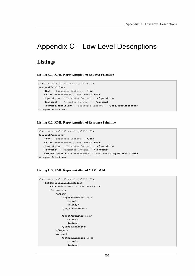
Appendix C – Low Level Descriptions
507
Appendix C – Low Level Descriptions
Listings
Listing C.1: XML Representation of Request Primitive
Listing C.2: XML Representation of Response Primitive
Listing C.3: XML Representation of M2M DCM
<?xml version="1.0" encoding="UTF-8"?>
<requestPrimitive>
<to> ---Parameter Content--- </to>
<from> ---Parameter Content--- </from>
<operation> ---Parameter Content--- </operation>
<content> ---Parameter Content--- </content>
<requestIdentifier> ---Parameter Content--- </requestIdentifier>
</requestPrimitive>
<?xml version="1.0" encoding="UTF-8"?>
<M2MDeviceCapabilityModel>
<id> ---Parameter Content--- </id>
<parameter>
<input>
<inputParameter id=1>
<name/>
<value/>
</inputParameter>
...
<inputParameter id=n>
<name/>
<value/>
</inputParameter>
</input>
<output>
<outputParameter id=1>
<name/>
<value/>

Appendix C – Low Level Descriptions
508
Listing C.4: XML Representation of Request Primitive incl. M2M DCM Parameters
</outputParameter>
...
<outputParameter id=n>
<name/>
<value/>
</outputParameter>
</output>
<config>
<configParameter id=1>
<name/>
<value/>
</configParameter>
...
<configParameter id=n>
<name/>
<value/>
</configParameter>
</config>
</parameter>
<type> ---Parameter Content--- </type>
<description> ---Parameter Content--- </description >
</M2MDeviceCapabilityModel>
<?xml version="1.0" encoding="UTF-8"?>
<requestPrimitive>
<to>
{DeviceID-Abs, DeviceID-Spec}
</to>
<from>
{M2Mapplication, M2MdeviceAL, M2MtechnologyInterfaces}
</from>
<operation>
{create (c), update (u), retrieve(r), notify (n)}
</operation>
<content>
<input>
<inputParameter id=1>
<name/>
<value/>
</inputParameter>
...
<inputParameter id=n>
<name/>
<value/>
</inputParameter>
</input>
<output>
<outputParameter id=1>
<name/>
<value/>
</outputParameter>
...

Appendix C – Low Level Descriptions
509
Listing C.5: SCXML Representation of Use Case 1
<outputParameter id=n>
<name/>
<value/>
</outputParameter>
</output>
<config>
<configParameter id=1>
<name/>
<value/>
</configParameter>
...
<configParameter id=n>
<name/>
<value/>
</configParameter>
</config>
</content>
<requestIdentifier> ---randomID--- </requestIdentifier>
</requestPrimitive>
<?xml version="1.0" encoding="UTF-8"?>
<scxml
xmlns="http://www.w3.org/2005/07/scxml" version="1.0" name="LocalWindowMonitoring"
datamodel="jexl" initial="Rain">
<state id= Rain >
<datamodel>
<data id="Rain.output.state" expr=""/>
</datamodel>
<transition target= Window cond= $Rain.output.state=raining />
</state>
<state id= Window >
<datamodel>
<data id="Window.output.state" expr=""/>
</datamodel>
<transition target= TTScall cond= $Window.output=open />
</state>
<state id= TTScall >
<datamodel>
<data id="TTScall.input.text" expr="Warning window open and starts raining"/>
<data id="TTScall.input.sipURI" expr="sip:username@localhost"/>
<data id="TTScall.config.mode" expr="TTS"/>
</datamodel>
<final id= TTScallFinal />
</state>
</scxml>
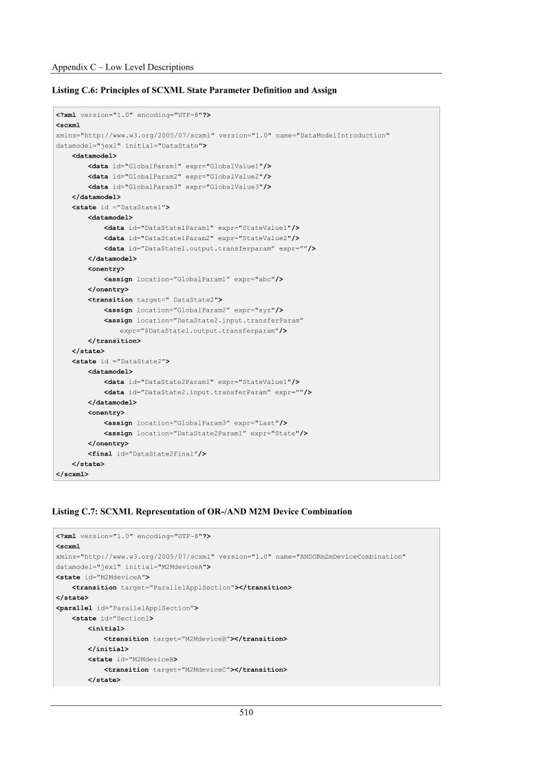
Appendix C – Low Level Descriptions
510
Listing C.6: Principles of SCXML State Parameter Definition and Assign
Listing C.7: SCXML Representation of OR-/AND M2M Device Combination
<?xml version="1.0" encoding="UTF-8"?>
<scxml
xmlns="http://www.w3.org/2005/07/scxml" version="1.0" name="DataModelIntroduction"
datamodel="jexl" initial="DataState">
<datamodel>
<data id="GlobalParam1" expr="GlobalValue1"/>
<data id="GlobalParam2" expr="GlobalValue2"/>
<data id="GlobalParam3" expr="GlobalValue3"/>
</datamodel>
<state id = DataState1 >
<datamodel>
<data id="DataState1Param1" expr="StateValue1"/>
<data id="DataState1Param2" expr="StateValue2"/>
<data id= DataState1.output.transferparam expr= />
</datamodel>
<onentry>
<assign location= GlobalParam1 expr="abc"/>
</onentry>
<transition target=" DataState2">
<assign location= GlobalParam2 expr="xyz"/>
<assign location= DataState2.input.transferParam
expr= $DataState1.output.transferparam />
</transition>
</state>
<state id = DataState2 >
<datamodel>
<data id="DataState2Param1" expr="StateValue1"/>
<data id= DataState2.input.transferParam expr= />
</datamodel>
<onentry>
<assign location= GlobalParam3 expr="Last"/>
<assign location= DataState2Param1 expr="State"/>
</onentry>
<final id= DataState2Final />
</state>
</scxml>
<?xml version="1.0" encoding="UTF-8"?>
<scxml
xmlns="http://www.w3.org/2005/07/scxml" version="1.0" name="ANDORm2mDeviceCombination"
datamodel="jexl" initial="M2MdeviceA">
<state id= M2MdeviceA >
<transition target= ParallelApplSection ></transition>
</state>
<parallel id= ParallelApplSection >
<state id= Section1>
<initial>
<transition target= M2MdeviceB ></transition>
</initial>
<state id= M2MdeviceB>
<transition target= M2MdeviceC ></transition>
</state>

Appendix C – Low Level Descriptions
511
Listing C.8: XML Representation of IFD for remoteRainSensor M2M Application Service
<state id= M2MdeviceC >
<final id=M2MdeviceCFinal />
</state>
</state>
<state id= Section2>
<initial>
<transition target= M2MdeviceD ></transition>
</initial>
<state id= M2MdeviceD>
<transition target= M2MdeviceE ></transition>
</state>
<state id= M2MdeviceE >
<final id=M2MdeviceEFinal />
</state>
</state>
<transition target= M2MdeviceF ></transition>
</parallel>
<state id= M2MdeviceF >
<final id=M2MdeviceFFinal />
</state>
</scxml>
<?xml version="1.0" encoding="UTF-8"?>
<AE>
<appName>Remote Rain Sensor Service</appName>
<App-ID>remoteRainSensor</App-ID>
<pointOfAccess>sip:[email protected]</pointOfAccess>
<requestReachability>true</requestReachability>
<creationTime>2017-08-15</creationTime>
<lastModifiedTime>2017-09-24</lastModifiedTime>
<contentSerialisation>XML</contentSerialisation>
<accessControlPolicy>
<privileges>
<accessControlOriginators>all</accessControlOriginators>
<accessControlContexts></accessControlContexts >
<accessControlOperations>R</accessControlOperations>
</privileges>
<expirationTime></expirationTime>
</accessControlPolicy>
<content>
<input></input>
<output>
<outputParameter id="1">
<name>remoteRainSensor.output.state</name>
<value>raining; notRaining</value>
</outputParameter>
</output>
<config></config>
</content>
<description>
Provides the state of a rain sensor at location Kleiststr.1, D-60318, Frankfurt a.M., Germany.
Possible Output values: remoteRainSensor.output.state=raining|notRaining
</description>
</AE>

Appendix C – Low Level Descriptions
512
Listing C.9: Extract SCXML Representation Use Case 2
Listing C.10: Formal AD of cooperative M2M application service for Use Case 3 in SCXML format
<?xml version="1.0" encoding="UTF-8"?>
<scxml ...> ...
<state id="remoteRainSensor">
<datamodel>
<data id="remoteRainSensor.output.state" expr=""/>
</datamodel>
<transition target="localWindowSensor"cond="$remoteRainSensor.output.state=raining"/>
</state> ...
</scxml>
<?xml version="1.0" encoding="UTF-8"?> <scxml ...>
<state id="remoteSS1">
<datamodel>
<data id="remoteSS1.output.event" expr=""/>
<data id="remoteSS1.output.BuildingID" expr="Kleiststr.1"/>
</datamodel>
<transition target="remoteBMS" cond="$remoteSS1.output.event=smoke OR
$remoteSS1.output.event=water">
<assign location="remoteBMS.input.buildingID"
expr="$remoteSS1.output.buildingID"/>
<assign location="remoteBMS.input.event"
expr="$remoteSS1.output.event"/>
</transition>
</state>
<state id="remoteBMS">
<datamodel>
<data id="remoteBMS.input.buildingID" expr=""/>
<data id="remoteBMS.input.event" expr=""/>
<data id="remoteBMS.input.supporterURI" expr=""/>
<data id="remoteBMS.output.text" expr=""/>
<data id="remoteBMS.output.supporterURI" expr=""/>
</datamodel>
<transition target="remoteAS" cond="$remoteBMS.input.event=water">
<assign location="remoteAS.config.mode" expr="IM"/>
<assign location="remoteAS.input.text" expr="Water Detected"/>
<assign location="remoteAS.input.sipURI"
expr="$remoteBMS.output.supporterURI"/>
</transition>
<transition target="remoteAS" cond="$remoteBMS.input.event=smoke">
<assign location="remoteAS.config.mode" expr="TTS"/>
<assign location="remoteAS.input.text" expr="Smoke Detected"/>
<assign location="remoteAS.input.sipURI"
expr="$remoteBMS.output.supporterURI"/>
</transition>
</state>
<state id="remoteAS">
<datamodel>
<data id="remoteAS.config.mode" expr=""/>
<data id="remoteAS.input.text" expr=""/>
<data id="remoteAS.input.sipURI" expr=""/>
</datamodel>
</state> </scxml>
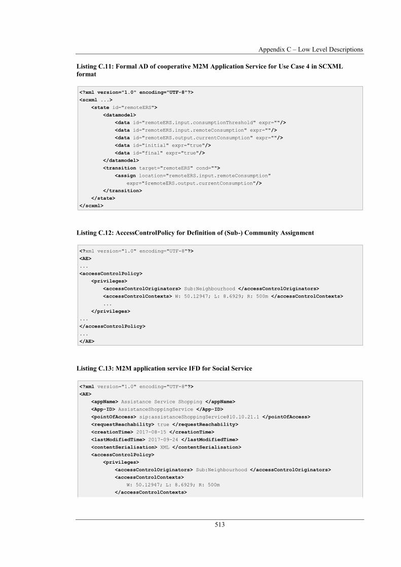
Appendix C – Low Level Descriptions
513
Listing C.11: Formal AD of cooperative M2M Application Service for Use Case 4 in SCXML
format
Listing C.12: AccessControlPolicy for Definition of (Sub-) Community Assignment
Listing C.13: M2M application service IFD for Social Service
<?xml version="1.0" encoding="UTF-8"?>
<scxml ...>
<state id="remoteERS">
<datamodel>
<data id="remoteERS.input.consumptionThreshold" expr=""/>
<data id="remoteERS.input.remoteConsumption" expr=""/>
<data id="remoteERS.output.currentConsumption" expr=""/>
<data id="initial" expr="true"/>
<data id="final" expr="true"/>
</datamodel>
<transition target="remoteERS" cond="">
<assign location="remoteERS.input.remoteConsumption"
expr="$remoteERS.output.currentConsumption"/>
</transition>
</state>
</scxml>
<?xml version="1.0" encoding="UTF-8"?>
<AE>
...
<accessControlPolicy>
<privileges>
<accessControlOriginators> Sub:Neighbourhood </accessControlOriginators>
<accessControlContexts> W: 50.12947; L: 8.6929; R: 500m </accessControlContexts>
...
</privileges>
...
</accessControlPolicy>
...
</AE>
<?xml version="1.0" encoding="UTF-8"?>
<AE>
<appName> Assistance Service Shopping </appName>
<App-ID> AssistanceShoppingService </App-ID>
<pointOfAccess> sip:[email protected] </pointOfAccess>
<requestReachability> true </requestReachability>
<creationTime> 2017-08-15 </creationTime>
<lastModifiedTime> 2017-09-24 </lastModifiedTime>
<contentSerialisation> XML </contentSerialisation>
<accessControlPolicy>
<privileges>
<accessControlOriginators> Sub:Neighbourhood </accessControlOriginators>
<accessControlContexts>
W: 50.12947; L: 8.6929; R: 500m
</accessControlContexts>
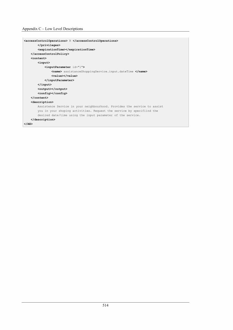
Appendix C – Low Level Descriptions
514
<accessControlOperations> R </accessControlOperations>
</privileges>
<expirationTime></expirationTime>
</accessControlPolicy>
<content>
<input>
<inputParameter id="1">
<name> assistanceShoppingService.input.dateTime </name>
<value></value>
</inputParameter>
</input>
<output></output>
<config></config>
</content>
<description>
Assistence Service in your neighbourhood. Provides the service to assist
you in your shoping activities. Request the service by specifiind the
desired date/time using the input parameter of the service.
</description>
</AE>
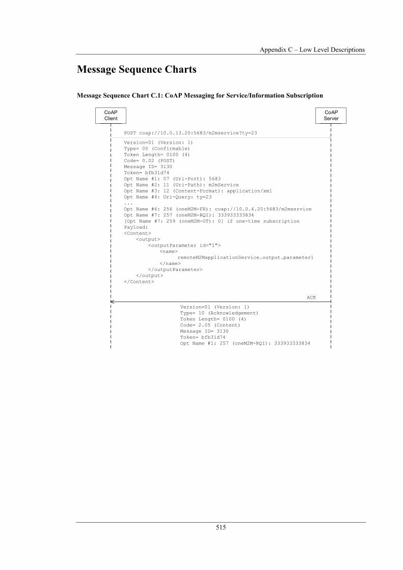
Appendix C – Low Level Descriptions
515
Message Sequence Charts
Message Sequence Chart C.1: CoAP Messaging for Service/Information Subscription
Peer 0CoAP
ServerPeer 0CoAP
Client
POST coap://10.0.13.20:5683/m2mservice?ty=23
Version=01 (Version: 1)
Type= 00 (Confirmable)
Token Length= 0100 (4)
Code= 0.02 (POST)
Message ID= 3130
Token= bfb31d74
Opt Name #1: 07 (Uri-Port): 5683
Opt Name #2: 11 (Uri-Path): m2mService
Opt Name #3: 12 (Content-Format): application/xml
Opt Name #4: Uri-Query: ty=23
...
Opt Name #6: 256 (oneM2M-FR): coap://10.0.4.20:5683/m2mservice
Opt Name #7: 257 (oneM2M-RQI): 333933333834
[Opt Name #7: 259 (oneM2M-OT): 0] if one-time subscription
Payload:
<Content>
<output>
<outputParameter id="1">
<name>
remoteM2MapplicationService.output.parameter1
</name>
</outputParameter>
</output>
</Content>
ACK
Version=01 (Version: 1)
Type= 10 (Acknowledgement)
Token Length= 0100 (4)
Code= 2.05 (Content)
Message ID= 3130
Token= bfb31d74
Opt Name #1: 257 (oneM2M-RQI): 333933333834

Appendix C – Low Level Descriptions
516
Message Sequence Chart C.2: CoAP Messaging for Service/Information Notification
Message Sequence Chart C.3: CoAP Messaging for Service/Information Unsubscription
Peer 0CoAP
ServerPeer 0CoAP
Client
Version=01 (Version: 1)
Type= 00 (Confirmable)
Token Length= 0100 (4)
Code= 0.02 (POST)
Message ID= 4080
Token= 19ff3db4
Opt Name #1: 11 (Uri-Path): m2mService
Opt Name #2: 12 (Content-Format): application/xml
Opt Name #3: 256 (oneM2M-FR): coap://10.0.13.20:5683/m2mservice?ty=23
Opt Name #4: 257 (oneM2M-RQI): 333933333834
Payload:
<Content>
<output>
<outputParameter id="1">
<name>
remoteM2MapplicationService.output.parameter1
</name>
<value>Parameter-Value1</value>
</outputParameter>
</output>
</Content>
POST coap://10.0.4.20:5683/m2mservice
Version=01 (Version: 1)
Type= 10 (Acknowledgement)
Token Length= 0100 (4)
Code= 2.05 (Content)
Message ID= 4080
Token= 19ff3db4
Opt Name #1: 257 (oneM2M-RQI): 333933333834
ACK
...
Peer 0CoAP
ServerPeer 0CoAP
ClientDELETE coap://10.0.13.20:5683/m2mservice
Version=01 (Version: 1)
Type= 00 (Confirmable)
Token Length= 0100 (4)
Code= 0.02 (POST)
Message ID= 1528
Token= bfb31d75
Opt Name #1: 07 (Uri-Port): 5683
Opt Name #2: 11 (Uri-Path): m2mService
Opt Name #3: 12 (Content-Format): application/xml
...
Opt Name #5: 256 (oneM2M-FR): coap://10.0.4.20:5683/m2mservice
Opt Name #6: 257 (oneM2M-RQI): 333933333834
Payload:
<Content>
<output>
<outputParameter id="1">
<name>
remoteM2MapplicationService.output.parameter1
</name>
</outputParameter>
</output>
</Content> ACK
Version=01 (Version: 1)
Type= 10 (Acknowledgement)
Token Length= 0100 (4)
Code= 2.05 (Content)
Message ID= 1528
Token= bfb31d75
Opt Name #1: 257 (oneM2M-RQI): 333933333834

Appendix C – Low Level Descriptions
517
Message Sequence Chart C.4: SIP Messaging for Service/Information Subscription
Message Sequence Chart C.5: SIP Messaging for Service/Information Notification
Peer 0User Agent ServerPeer 0User Agent ClientSUBSCRIBE sip:[email protected]:5060 SIP/2.0
Call-ID= [email protected]
CSeq= 1 SUBSCRIBE
From= "PeerX" <sip:[email protected]>
To= "remoteM2Mservice" <sip:[email protected]>
Via= SIP/2.0/UDP 10.0.4.20:5060
Max-Forwards= 70
Contact= "PeerX" <sip:[email protected]:5060>
Event= m2mService;reqId=465143[;once=false/true] if one-time subscr.
Content-Type= application/xml
Content-Length= 320
Message Body:
<Content>
<output>
<outputParameter id="1">
<name>
remoteM2MapplicationService.output.parameter1
</name>
</outputParameter>
</output>
</Content> SIP/2.0 200 OK
CSeq= 1 SUBSCRIBE
Call-ID= [email protected]
From= "PeerX" <sip:[email protected]>
To= "remoteM2Mservice" <sip:[email protected]>
Via= SIP/2.0/UDP 10.0.4.20:5060
Contact= "remoteM2Mservice"
<sip:[email protected]:5060>
Content-Length= 0
Peer 0User Agent ServerPeer 0User Agent ClientNOTIFY sip:[email protected]:5060 SIP/2.0
Call-ID= [email protected]
CSeq= 1 NOTIFY
From= "remoteM2Mservice" <sip:[email protected]>
To= "PeerX" <sip:[email protected]>
Via= SIP/2.0/UDP 10.0.13.20:5060
Max-Forwards= 70
Contact= "remoteM2Mservice" <sip:[email protected]:5060>
Event= m2mService;reqId=465143[;once=false/true] if one-time subscr.
Content-Type= application/xml
Content-Length= 430
Subscription-State= active (terminated if one-time subscr.)
Message Body:
<Content>
<output>
<outputParameter id="1">
<name>
remoteM2MapplicationService.output.parameter1
</name>
<value>Parameter-Value1</value>
</outputParameter>
</output>
</Content> SIP/2.0 200 OK
CSeq= 1 NOTIFY
Call-ID= [email protected]
From= "remoteM2Mservice" <sip:[email protected]>
To= "PeerX" <sip:[email protected]>
Via= SIP/2.0/UDP 10.0.13.20:5060
Contact= "PeerX" <sip:[email protected]:5060>
Content-Length= 0 ...

Appendix C – Low Level Descriptions
518
Message Sequence Chart C.6: SIP Messaging for Service/Information Unsubscription
Peer 0User Agent
ServerPeer 0User Agent
ClientSUBSCRIBE sip:[email protected]:5060 SIP/2.0
Call-ID= [email protected]
CSeq= 2 SUBSCRIBE
From= "PeerX" <sip:[email protected]>
To= "remoteM2Mservice" <sip:[email protected]>
Via= SIP/2.0/UDP 10.0.4.20:5060
Max-Forwards= 70
Contact= "PeerX" <sip:[email protected]:5060>
Event= m2mService;reqId=465143[;once=false/true] if one-time subscr.
Expires= 0
Content-Type= application/xml
Content-Length= 320
Message Body:
<Content>
<output>
<outputParameter id="1">
<name>
remoteM2MapplicationService.output.parameter1
</name>
</outputParameter>
</output>
</Content> SIP/2.0 200 OK
CSeq= 2 SUBSCRIBE
Call-ID= [email protected]
From= "PeerX" <sip:[email protected]>
To= "remoteM2Mservice" <sip:[email protected]>
Via= SIP/2.0/UDP 10.0.4.20:5060
Contact= "remoteM2Mservice"
<sip:[email protected]:5060>
Content-Length= 0