automobile mechanical and electrical systems - taylor
TRANSCRIPT
AutomobileMechanical andElectrical Systems Automotive Technology: Vehicle Maintenance and Repair

Automobile
Mechanicaland ElectricalSystems
Automotive Technology: Vehicle Maintenance and Repair
Tom Denton BA FIMI MSAE MIRTE Cert Ed
AMSTERDAM • BOSTON • HEIDELBERG • LONDON • NEW YORK • OXFORD • PARIS SAN DIEGO • SAN FRANCISCO • SINGAPORE • SYDNEY • TOKYO
Butterworth-Heinemann is an imprint of Elsevier
Butterworth-Heinemann is an imprint of Elsevier The Boulevard, Langford Lane, Kidlington, Oxford, OX5 1GB 225 Wyman Street, Waltham, MA 02451, USA
First published 2011
Copyright © 2011 Tom Denton. Published by Elsevier Ltd. All rights reserved
The right of Tom Denton to be identifi ed as the author of this work has been asserted in accordance with the Copyright, Designs and Patents Act 1988
No part of this publication may be reproduced or transmitted in any form or by any means, electronic or mechanical, including photocopying, recording, or any information storage and retrieval system, without permission in writing from the publisher. Details on how to seek permission, further information about the Publisher’s permissions policies and our arrangement with organizations such as the Copyright Clearance Center and the Copyright Licensing Agency, can be found at our website: www.elsevier.com/permissions
This book and the individual contributions contained in it are protected under copyright by the Publisher (other than as may be noted herein).
Notices Knowledge and best practice in this fi eld are constantly changing. As new research and experience broaden our understanding, changes in research methods, professional practices, or medical treatment may become necessary.
Practitioners and researchers must always rely on their own experience and knowledge in evaluating and using any information, methods, compounds, or experiments described herein. In using such information or methods they should be mindful of their own safety and the safety of others, including parties for whom they have a professional responsibility.
To the fullest extent of the law, neither the Publisher nor the authors, contributors, or editors, assume any liability for any injury and/or damage to persons or property as a matter of products liability, negligence or otherwise, or from any use or operation of any methods, products, instructions, or ideas contained in the material herein.
British Library Cataloguing-in-Publication Data A catalogue record for this book is available from the British Library
Library of Congress Number: 2011924729
ISBN: 978-0-08-096945-9
For information on all Butterworth-Heinemann publications visit our website at www.elsevierdirect.com
Typeset by MPS Limited, a Macmillan Company, Chennai, India www.macmillansolutions.com
Printed and bound in Italy
11 12 13 14 10 9 8 7 6 5 4 3 2 1
Contents
Preface xi Acknowledgements xiii
Chapter 1 Overview and introduction 1
1.1 Vehicle categories 1
1.1.1 Layouts 1
1.1.2 Types and sizes 3
1.1.3 Body design 3
1.1.4 Chassis type and body panels 3
1.1.5 Main systems 6
1.1.6 Summary 7
1.2 The motor industry 8
1.2.1 Introduction 8
1.2.2 Types of motor vehicle companies 9
1.2.3 Company structure 11
1.2.4 Role of a franchised dealer 12
1.2.5 Reception and booking systems 12
1.2.6 Parts department 12
1.2.7 Estimating costs and times 13
1.2.8 Jobcards and systems 13
1.2.9 Invoicing 14
1.2.10 Warranties 15
1.2.11 Computerized workshop system 15
1.3 Working safely 18
1.3.1 Introduction 18
1.3.2 The key UK regulations and laws 19
1.3.3 Health and safety law: what you need to know 20
1.3.4 Personal protective equipment (PPE) 23
1.3.5 Identifying and reducing hazards 24
1.3.6 Moving loads 25
1.3.7 Vehicle safety 28
1.3.8 Safety procedures 29
1.3.9 Fire 29
1.3.10 Clean working environment 32
1.3.11 Signage 33
1.3.12 Environmental protection 33
vi Contents
1.4 Basic science, materials, mathematics and mechanics 36
1.4.1 Introduction 36
1.4.2 Units 37
1.4.3 Velocity and acceleration 39
1.4.4 Friction 39
1.4.5 Pressure 39
1.4.6 Centre of gravity or centre of mass 40
1.4.7 Oscillation 40
1.4.8 Energy, work and power 40
1.4.9 Force and torque 42
1.4.10 Mass, weight and force 43
1.4.11 Volume and density 43
1.4.12 Heat and temperature 44
1.4.13 Percentages 44
1.4.14 Fractions 44
1.4.15 Ratios 45
1.4.16 Areas 45
1.4.17 Volumes 45
1.4.18 Indices 45
1.4.19 Drawings 46
1.4.20 Mechanical machines 48
1.4.21 Gears 48
1.4.22 Hydraulics 49
1.4.23 Materials and properties 49
1.5 Tools and equipment 51
1.5.1 Hand tools 51
1.5.2 Test equipment 52
1.5.3 Workshop equipment 53
1.6 Workshop bench skills 54
1.6.1 Introduction 54
1.6.2 Fitting and machining 57
1.6.3 Filing 58
1.6.4 Drilling 59
1.6.5 Cutting 59
1.6.6 Thread cutting 60
1.6.7 Joining 62
1.6.8 Nuts and bolts 63
1.6.9 Adhesives 65
1.6.10 Soldering 66
1.6.11 Brazing 66
1.6.12 Welding 67
viiContents
1.6.13 Shrinking 68
1.6.14 Compression fi tting 68
1.6.15 Riveting 69
1.6.16 Gaskets 69
1.6.17 Sealants 70
1.6.18 Oil seals 70
1.7 Servicing and inspections 71
1.7.1 Introduction 71
1.7.2 Rules and regulations 73
1.7.3 Service sheets 73
1.7.4 Road test 74
1.7.5 Effects of incorrect adjustments 76
1.7.6 Maintenance and inspections 76
1.7.7 Information sources 78
Chapter 2 Engine systems 81
2.1 Engine mechanical 81
2.1.1 Introduction and operating cycles 81
2.1.2 Engine operating details 90
2.1.3 Engine components 109
2.2 Engine lubrication 137
2.2.1 Friction and lubrication 137
2.2.2 Methods of lubrication 140
2.2.3 Lubrication system 140
2.2.4 Oil fi lters 143
2.2.5 Oil pumps 145
2.2.6 Standards 147
2.3 Engine cooling 151
2.3.1 Introduction 151
2.3.2 System operation 151
2.3.3 Interior heater 166
2.4 Air supply, exhaust and emissions 168
2.4.1 Air pollution and engine combustion 168
2.4.2 Reducing pollution 169
2.4.3 Air supply system 172
2.4.4 Exhaust systems 176
2.4.5 Catalyst systems 179
2.4.6 Emission control systems 181
2.4.7 Turbocharging and supercharging 184
viii Contents
2.5 Fuel systems 189
2.5.1 Introduction 189
2.5.2 Petrol fuel injection systems 194
2.5.3 Diesel fuel injection systems 217
2.5.4 Alternative fuels 231
2.6 Ignition systems 236
2.6.1 Ignition overview 236
2.6.2 Electronic ignition 241
2.6.3 Distributorless ignition system (DIS) 244
2.6.4 Coil on plug (COP) direct ignition system 246
2.6.5 Spark plugs 247
2.7 Hybrid cars 250
2.7.1 Safety 250
2.7.2 Hybrids overview 253
2.8 Formula 1 engine technology 255
2.8.1 Engines overview 255
2.8.2 FIA technical regulations 258
Chapter 3 Electrical systems 259
3.1 Electrical and electronic principles 259
3.1.1 Electrical fundamentals 259
3.1.2 Electrical components and circuits 264
3.1.3 Electronic components 273
3.2 Engine electrical 275
3.2.1 Batteries 275
3.2.2 Starting system 282
3.2.3 Charging system 287
3.3 Lighting and indicators 293
3.3.1 Lighting systems 293
3.3.2 Stoplights and reverse lights 297
3.3.3 Interior lighting 299
3.3.4 Lighting circuits 299
3.3.5 Indicators and hazard lights 301
3.4 Body electrical and electronic systems 305
3.4.1 Washers and wipers 305
3.4.2 Horns 308
3.4.3 Obstacle avoidance 309
3.4.4 Cruise control 310
3.4.5 Seats, mirrors, sunroofs, locking and windows 312
ixContents
3.4.6 Screen heating 318
3.4.7 Security systems 320
3.4.8 Safety systems 322
3.5 Monitoring and instrumentation 326
3.5.1 Sensors 326
3.5.2 Gauges 329
3.5.3 Global Positioning System (GPS) 332
3.6 Air conditioning 337
3.6.1 Air conditioning fundamentals 337
3.6.2 Air conditioning components 340
3.7 Formula 1 electrical technology 342
3.7.1 Introduction 342
3.7.2 Telemetry 343
3.7.3 FIA technical regulations 344
Chapter 4 Chassis systems 347
4.1 Suspension 347
4.1.1 Overview of suspension 347
4.1.2 Dampers/shock absorbers 356
4.1.3 Suspension layouts 359
4.1.4 Active suspension 364
4.2 Steering 366
4.2.1 Introduction to steering 366
4.2.2 Steering racks and boxes 369
4.2.3 Steering geometry 375
4.2.4 Power steering 383
4.3 Brakes 386
4.3.1 Disc, drum and parking brakes 386
4.3.2 Hydraulic components 394
4.3.3 Brake servo operation 398
4.3.4 Braking force control 400
4.3.5 Anti-lock brake systems 401
4.3.6 Traction control 407
4.4 Wheels and tyres 409
4.4.1 Wheels 409
4.4.2 Tyres 416
4.5 Formula 1 chassis technology (brakes) 422
4.5.1 Brakes overview 422
4.5.2 FIA technical regulations 423
Contents
x Contents
Chapter 5 Transmission systems 425
5.1 Manual transmission clutch 425
5.1.1 Clutch operation 425
5.1.2 Types of clutch 428
5.2 Manual transmission gearbox 434
5.2.1 Gearbox operation 434
5.2.2 Gear change mechanisms 437
5.2.3 Gears and components 441
5.3 Automatic transmission 445
5.3.1 Introduction and torque converter 445
5.3.2 Automatic transmission components 451
5.3.3 Constantly variable transmission 459
5.3.4 Direct shift gearbox 461
5.4 Transmission driveline 467
5.4.1 Propshafts and driveshafts 467
5.4.2 Wheel bearings 472
5.4.3 Four-wheel drive 477
5.5 Final drive and differential 480
5.5.1 Final drive 480
5.5.2 Differential 482
5.6 Formula 1 transmission technology 485
5.6.1 Clutch 485
5.6.2 Gearbox 486
5.6.3 Differential 487
5.6.4 FIA technical regulations 487
Chapter 6 Learning activities 489
6.1 Introduction 489
6.2 Assignments 490
6.3 Tips to help you learn 493
6.4 Practical work 494
6.4.1 Jobcard, jobsheet, repair order 494
6.4.2 Practical task list 494
6.5 Summary 498
Index 499
Preface One of the things that I fi nd most interesting about automotive technology is how it advances and changes. It is also interesting that ideas from many years ago often return to favour. In this book I have therefore concentrated on core technologies, in other words how the technology works, rather than giving too many examples from specifi c vehicles. However, I have included some examples of Formula 1 technology, arguably the pinnacle of automotive engineering. Did you know that the 2011 McLaren MP4-26 F1 car is made of 11 500 components? And that’s counting the engine as one!
This book is the fi rst in the ‘Automotive Technology: Vehicle Maintenance and Repair’ series:
● Automobile Mechanical and Electrical Systems ● Automobile Electrical and Electronic Systems ● Automobile Advanced Fault Diagnosis
The fi rst of its type to be published in full colour, this book concentrates on essential knowledge and will cover everything you need to get started with your studies, no matter what qualifi cation (if any) you are working towards. I have written it to be accessible for all, by sticking to the basics. As you want more detailed information, you can move on to the other two books. I hope you fi nd the content useful and informative. Comments, suggestions and feedback are always welcome at my website: www.automotive-technology.co.uk. On this site, you will also fi nd links to lots of free online resources to help with your studies.
Good luck and I hope you fi nd automotive technology as interesting as I still do.

Acknowledgements Over the years many people have helped in the production of my books. I am therefore very grateful to the following companies who provided information and/or permission to reproduce photographs and/or diagrams:
AA Photo Library AC Delco Alpine Audio Systems ATT Training (UK and USA) Autologic Data Systems BMW UK Bosch Media C&K Components Inc. Citroën UK Clarion Car Audio Delphi Media Eberspaecher Fluke Instruments UK Ford Media Ford Motor Company General Motors GenRad Hella UK Honda Cars UK Hyundai UK Jaguar Cars Kavlico Loctite Lucas UK LucasVarity Mazda Cars UK McLaren Electronic Systems Mercedes Cars UK Mitsubishi Cars UK NGK Plugs Nissan Cars UK Peugeot UK Philips Pioneer Radio Porsche Cars UK Robert Bosch GmbH Robert Bosch UK Rover Cars Saab Cars UK
xiv Acknowledgements
Saab Media Scandmec Snap-on Tools Sofanou (France) Sun Electric UK T&M Auto-Electrical Thrust SSC Land Speed Team Toyota Cars UK Tracker UK Unipart Group Valeo UK Vauxhall UK VDO Instruments Vodafone McLaren Mercedes Volkswagen Cars Volvo Media Wikimedia ZF Servomatic
If I have used any information, or mentioned a company name that is not listed here, please accept my apologies and let me know so it can be rectifi ed as soon as possible.
C H A P T E R
Automobile Mechanical and Electrical Systems.© Tom Denton. Published by Elsevier Ltd. All rights reserved. 2011
1 Overview and introduction
1.1 Vehicle categories
1.1.1 Layouts
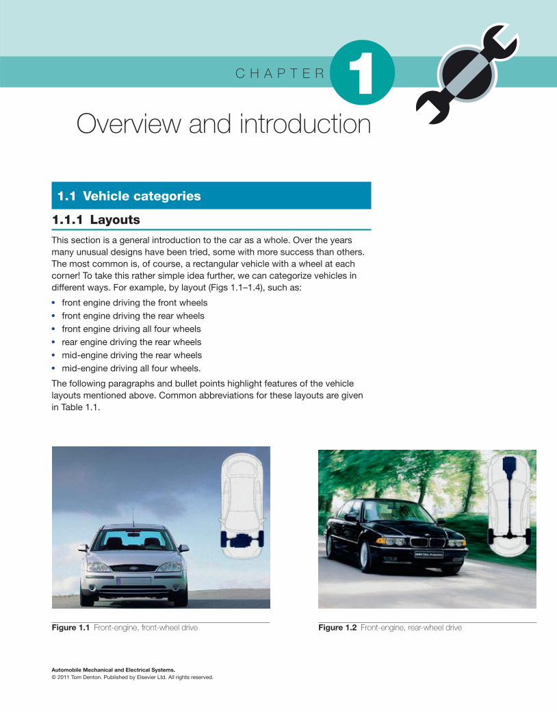
This section is a general introduction to the car as a whole. Over the years many unusual designs have been tried, some with more success than others. The most common is, of course, a rectangular vehicle with a wheel at each corner! To take this rather simple idea further, we can categorize vehicles in different ways. For example, by layout ( Figs 1.1–1.4 ), such as:
● front engine driving the front wheels ● front engine driving the rear wheels ● front engine driving all four wheels ● rear engine driving the rear wheels ● mid-engine driving the rear wheels ● mid-engine driving all four wheels.
The following paragraphs and bullet points highlight features of the vehicle layouts mentioned above. Common abbreviations for these layouts are given in Table 1.1 .
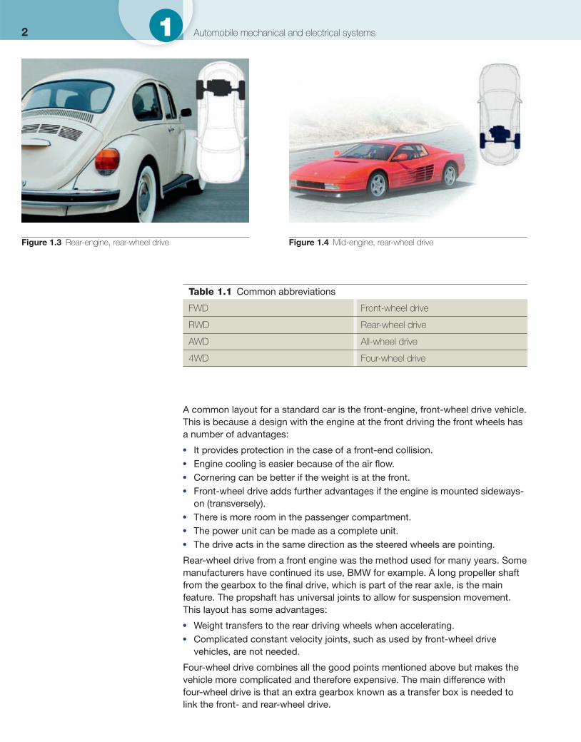
Figure 1.1 Front-engine, front-wheel drive Figure 1.2 Front-engine, rear-wheel drive
2 1 Automobile mechanical and electrical systems
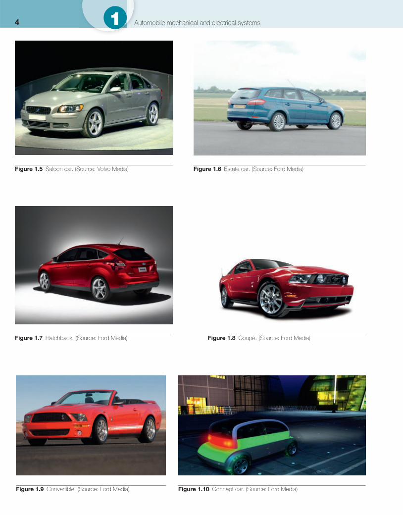
Figure 1.3 Rear-engine, rear-wheel drive Figure 1.4 Mid-engine, rear-wheel drive
Table 1.1 Common abbreviations
FWD Front-wheel drive
RWD Rear-wheel drive
AWD All-wheel drive
4WD Four-wheel drive
A common layout for a standard car is the front-engine, front-wheel drive vehicle. This is because a design with the engine at the front driving the front wheels has a number of advantages:
● It provides protection in the case of a front-end collision. ● Engine cooling is easier because of the air fl ow. ● Cornering can be better if the weight is at the front. ● Front-wheel drive adds further advantages if the engine is mounted sideways-
on (transversely). ● There is more room in the passenger compartment. ● The power unit can be made as a complete unit. ● The drive acts in the same direction as the steered wheels are pointing.
Rear-wheel drive from a front engine was the method used for many years. Some manufacturers have continued its use, BMW for example. A long propeller shaft from the gearbox to the fi nal drive, which is part of the rear axle, is the main feature. The propshaft has universal joints to allow for suspension movement. This layout has some advantages:
● Weight transfers to the rear driving wheels when accelerating. ● Complicated constant velocity joints, such as used by front-wheel drive
vehicles, are not needed.
Four-wheel drive combines all the good points mentioned above but makes the vehicle more complicated and therefore expensive. The main difference with four-wheel drive is that an extra gearbox known as a transfer box is needed to link the front- and rear-wheel drive.
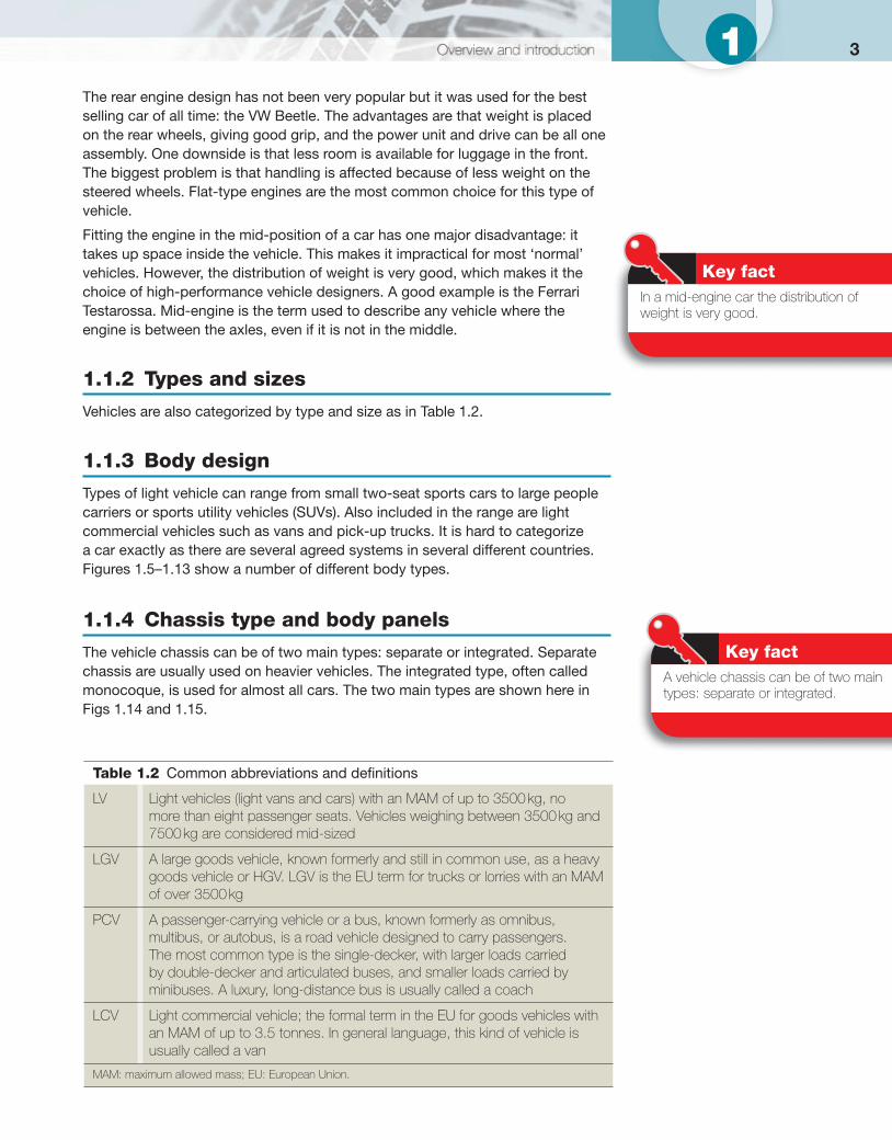
31 The rear engine design has not been very popular but it was used for the best selling car of all time: the VW Beetle. The advantages are that weight is placed on the rear wheels, giving good grip, and the power unit and drive can be all one assembly. One downside is that less room is available for luggage in the front. The biggest problem is that handling is affected because of less weight on the steered wheels. Flat-type engines are the most common choice for this type of vehicle.
Fitting the engine in the mid-position of a car has one major disadvantage: it takes up space inside the vehicle. This makes it impractical for most ‘normal’ vehicles. However, the distribution of weight is very good, which makes it the choice of high-performance vehicle designers. A good example is the Ferrari Testarossa. Mid-engine is the term used to describe any vehicle where the engine is between the axles, even if it is not in the middle.
1.1.2 Types and sizes
Vehicles are also categorized by type and size as in Table 1.2 .
1.1.3 Body design
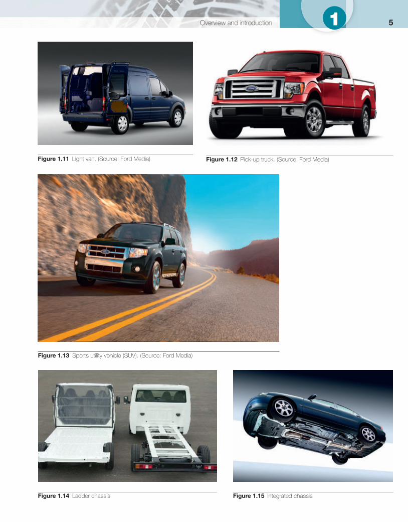
Types of light vehicle can range from small two-seat sports cars to large people carriers or sports utility vehicles (SUVs). Also included in the range are light commercial vehicles such as vans and pick-up trucks. It is hard to categorize a car exactly as there are several agreed systems in several different countries. Figures 1.5–1.13 show a number of different body types.
1.1.4 Chassis type and body panels
The vehicle chassis can be of two main types: separate or integrated. Separate chassis are usually used on heavier vehicles. The integrated type, often called monocoque, is used for almost all cars. The two main types are shown here in Figs 1.14 and 1.15 .
Key fact In a mid-engine car the distribution of weight is very good.
Table 1.2 Common abbreviations and defi nitions
LV Light vehicles (light vans and cars) with an MAM of up to 3500 kg, no more than eight passenger seats. Vehicles weighing between 3500 kg and 7500 kg are considered mid-sized
LGV A large goods vehicle, known formerly and still in common use, as a heavy goods vehicle or HGV. LGV is the EU term for trucks or lorries with an MAM of over 3500 kg
PCV A passenger-carrying vehicle or a bus, known formerly as omnibus, multibus, or autobus, is a road vehicle designed to carry passengers. The most common type is the single-decker, with larger loads carried by double-decker and articulated buses, and smaller loads carried by minibuses. A luxury, long-distance bus is usually called a coach
LCV Light commercial vehicle; the formal term in the EU for goods vehicles with an MAM of up to 3.5 tonnes. In general language, this kind of vehicle is usually called a van
MAM: maximum allowed mass; EU: European Union.
Key fact A vehicle chassis can be of two main types: separate or integrated.
4 1 Automobile mechanical and electrical systems
Figure 1.5 Saloon car. (Source: Volvo Media) Figure 1.6 Estate car. (Source: Ford Media)
Figure 1.7 Hatchback. (Source: Ford Media) Figure 1.8 Coupé. (Source: Ford Media)
Figure 1.9 Convertible. (Source: Ford Media) Figure 1.10 Concept car. (Source: Ford Media)
51
Figure 1.11 Light van. (Source: Ford Media) Figure 1.12 Pick-up truck. (Source: Ford Media)
Figure 1.13 Sports utility vehicle (SUV). (Source: Ford Media)
Figure 1.14 Ladder chassis Figure 1.15 Integrated chassis
6 1 Automobile mechanical and electrical systems
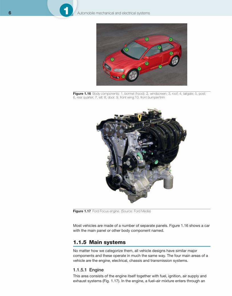
Most vehicles are made of a number of separate panels. Figure 1.16 shows a car with the main panel or other body component named.
1.1.5 Main systems
No matter how we categorize them, all vehicle designs have similar major components and these operate in much the same way. The four main areas of a vehicle are the engine, electrical, chassis and transmission systems.
1.1.5.1 Engine This area consists of the engine itself together with fuel, ignition, air supply and exhaust systems ( Fig. 1.17 ). In the engine, a fuel–air mixture enters through an
1
2
3 4
6
5
9
87
10
Figure 1.16 Body components: 1, bonnet (hood); 2, windscreen; 3, roof; 4, tailgate; 5, post; 6, rear quarter; 7, sill; 8, door; 9, front wing;10, front bumper/trim
Figure 1.17 Ford Focus engine. (Source: Ford Media)
71inlet manifold and is fi red in each cylinder in turn. The resulting expanding gases push on pistons and connecting rods which are on cranks, just like a cyclist’s legs driving the pedals, and this makes a crankshaft rotate. The pulses of power from each piston are smoothed out by a heavy fl ywheel. Power leaves the engine through the fl ywheel, which is fi tted on the end of the crankshaft, and passes to the clutch. The spent gases leave via the exhaust system.
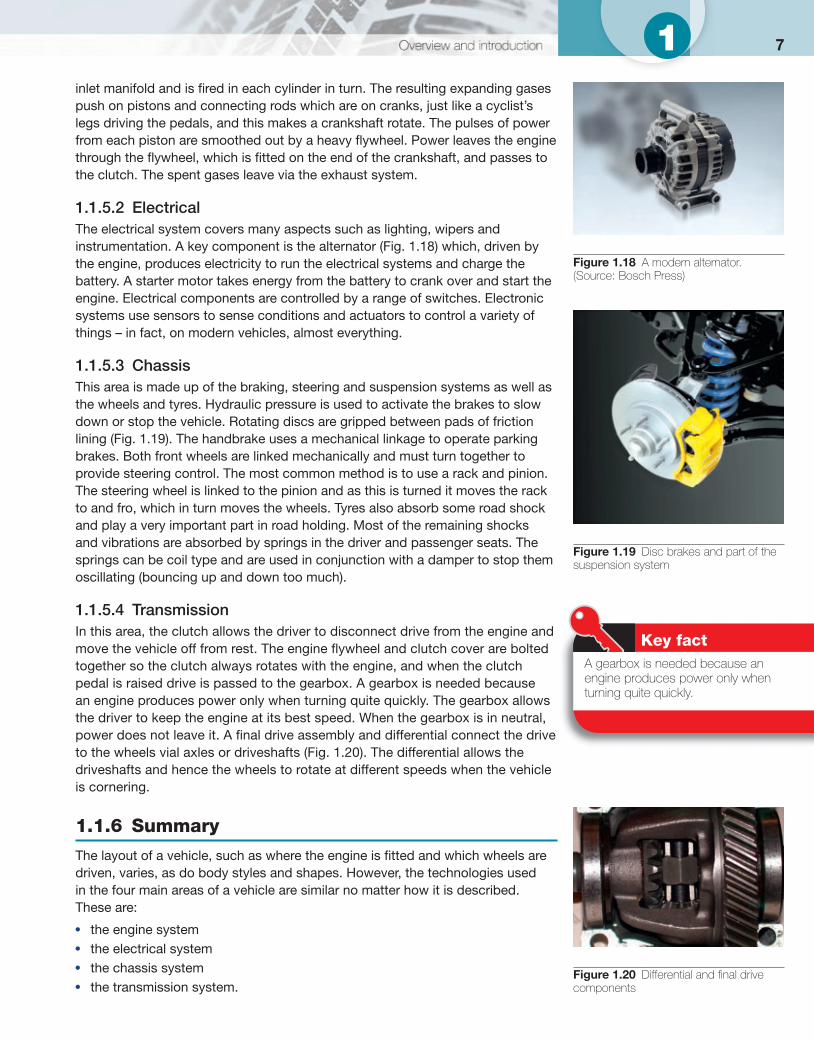
1.1.5.2 Electrical The electrical system covers many aspects such as lighting, wipers and instrumentation. A key component is the alternator ( Fig. 1.18 ) which, driven by the engine, produces electricity to run the electrical systems and charge the battery. A starter motor takes energy from the battery to crank over and start the engine. Electrical components are controlled by a range of switches. Electronic systems use sensors to sense conditions and actuators to control a variety of things – in fact, on modern vehicles, almost everything.
1.1.5.3 Chassis This area is made up of the braking, steering and suspension systems as well as the wheels and tyres. Hydraulic pressure is used to activate the brakes to slow down or stop the vehicle. Rotating discs are gripped between pads of friction lining ( Fig. 1.19 ). The handbrake uses a mechanical linkage to operate parking brakes. Both front wheels are linked mechanically and must turn together to provide steering control. The most common method is to use a rack and pinion. The steering wheel is linked to the pinion and as this is turned it moves the rack to and fro, which in turn moves the wheels. Tyres also absorb some road shock and play a very important part in road holding. Most of the remaining shocks and vibrations are absorbed by springs in the driver and passenger seats. The springs can be coil type and are used in conjunction with a damper to stop them oscillating (bouncing up and down too much).
1.1.5.4 Transmission In this area, the clutch allows the driver to disconnect drive from the engine and move the vehicle off from rest. The engine fl ywheel and clutch cover are bolted together so the clutch always rotates with the engine, and when the clutch pedal is raised drive is passed to the gearbox. A gearbox is needed because an engine produces power only when turning quite quickly. The gearbox allows the driver to keep the engine at its best speed. When the gearbox is in neutral, power does not leave it. A fi nal drive assembly and differential connect the drive to the wheels vial axles or driveshafts ( Fig. 1.20 ). The differential allows the driveshafts and hence the wheels to rotate at different speeds when the vehicle is cornering.
1.1.6 Summary
The layout of a vehicle, such as where the engine is fi tted and which wheels are driven, varies, as do body styles and shapes. However, the technologies used in the four main areas of a vehicle are similar no matter how it is described. These are:
● the engine system ● the electrical system ● the chassis system ● the transmission system.
Figure 1.18 A modern alternator. (Source: Bosch Press)
Figure 1.19 Disc brakes and part of the suspension system
Figure 1.20 Differential and fi nal drive components
Key fact A gearbox is needed because an engine produces power only when turning quite quickly.
8 1 Automobile mechanical and electrical systems
These areas are covered in detail and make up the four main technology chapters of this book, but fi rst, let’s look at the wider picture of the motor industry.
1.2 The motor industry
1.2.1 Introduction
This section will outline some of the jobs that are open to you in the motor trade and help you understand more about the different types of business and how they operate.
It is easy to think that the operation of a business does not matter to you. However, I would strongly suggest we should all be interested in the whole business in which we are working. This does not mean to interfere in areas we do not understand. It means we should understand that all parts of the business are important. For example, when you complete a job, enter all the parts used so the person who writes the invoice knows what to charge.
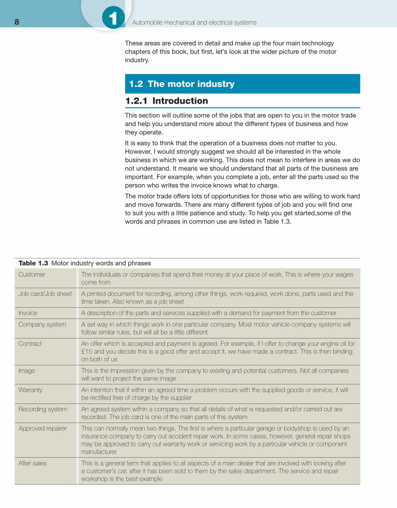
The motor trade offers lots of opportunities for those who are willing to work hard and move forwards. There are many different types of job and you will fi nd one to suit you with a little patience and study. To help you get started,some of the words and phrases in common use are listed in Table 1.3 .
Table 1.3 Motor industry words and phrases
Customer The individuals or companies that spend their money at your place of work. This is where your wages come from
Job card/Job sheet A printed document for recording, among other things, work required, work done, parts used and the time taken. Also known as a job sheet
Invoice A description of the parts and services supplied with a demand for payment from the customer
Company system A set way in which things work in one particular company. Most motor vehicle company systems will follow similar rules, but will all be a little different
Contract An offer which is accepted and payment is agreed. For example, if I offer to change your engine oil for £15 and you decide this is a good offer and accept it, we have made a contract. This is then binding on both of us
Image This is the impression given by the company to existing and potential customers. Not all companies will want to project the same image
Warranty An intention that if within an agreed time a problem occurs with the supplied goods or service, it will be rectifi ed free of charge by the supplier
Recording system An agreed system within a company so that all details of what is requested and/or carried out are recorded. The job card is one of the main parts of this system
Approved repairer This can normally mean two things. The fi rst is where a particular garage or bodyshop is used by an insurance company to carry out accident repair work. In some cases, however, general repair shops may be approved to carry out warranty work or servicing work by a particular vehicle or component manufacturer
After sales This is a general term that applies to all aspects of a main dealer that are involved with looking after a customer’s car, after it has been sold to them by the sales department. The service and repair workshop is the best example
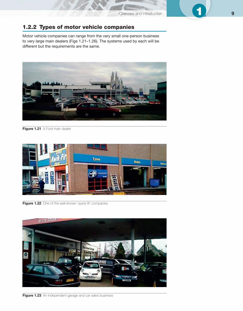
91 1.2.2 Types of motor vehicle companies
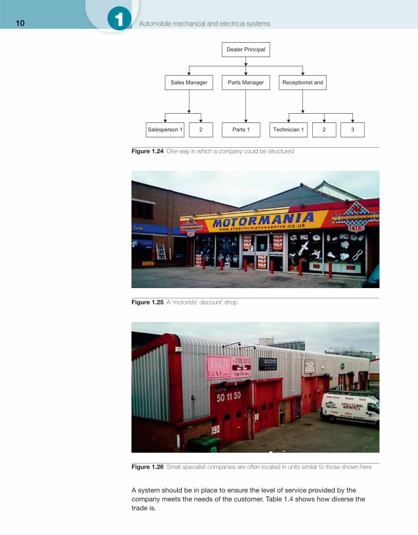
Motor vehicle companies can range from the very small one-person business to very large main dealers ( Figs 1.21–1.26 ). The systems used by each will be different but the requirements are the same.
Figure 1.21 A Ford main dealer
Figure 1.22 One of the well-known ‘quick-fi t’ companies
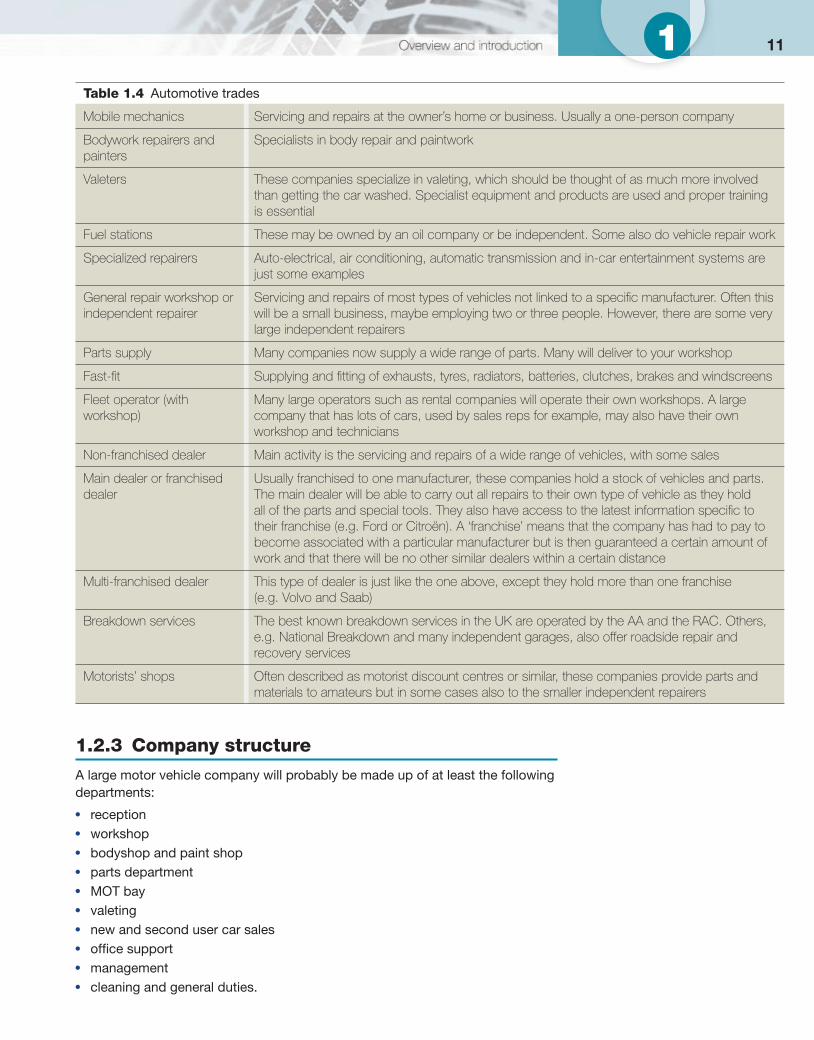
Figure 1.23 An independent garage and car sales business
10 1 Automobile mechanical and electrical systems
A system should be in place to ensure the level of service provided by the company meets the needs of the customer. Table 1.4 shows how diverse the trade is.
Figure 1.25 A ‘motorists’ discount’ shop
Figure 1.26 Small specialist companies are often located in units similar to those shown here
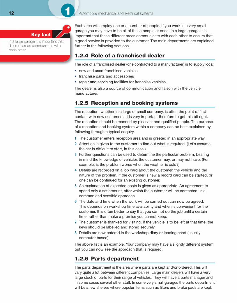
Dealer Principal
Parts ManagerSales Manager
Salesperson 1 Technician 1 3Parts 12 2
Receptionist and
Figure 1.24 One way in which a company could be structured
111
1.2.3 Company structure
A large motor vehicle company will probably be made up of at least the following departments:
● reception ● workshop ● bodyshop and paint shop ● parts department ● MOT bay ● valeting ● new and second user car sales ● offi ce support ● management ● cleaning and general duties.
Table 1.4 Automotive trades
Mobile mechanics Servicing and repairs at the owner’s home or business. Usually a one-person company
Bodywork repairers and painters
Specialists in body repair and paintwork
Valeters These companies specialize in valeting, which should be thought of as much more involved than getting the car washed. Specialist equipment and products are used and proper training is essential
Fuel stations These may be owned by an oil company or be independent. Some also do vehicle repair work
Specialized repairers Auto-electrical, air conditioning, automatic transmission and in-car entertainment systems are just some examples
General repair workshop or independent repairer
Servicing and repairs of most types of vehicles not linked to a specifi c manufacturer. Often this will be a small business, maybe employing two or three people. However, there are some very large independent repairers
Parts supply Many companies now supply a wide range of parts. Many will deliver to your workshop
Fast-fi t Supplying and fi tting of exhausts, tyres, radiators, batteries, clutches, brakes and windscreens
Fleet operator (with workshop)
Many large operators such as rental companies will operate their own workshops. A large company that has lots of cars, used by sales reps for example, may also have their own workshop and technicians
Non-franchised dealer Main activity is the servicing and repairs of a wide range of vehicles, with some sales
Main dealer or franchised dealer
Usually franchised to one manufacturer, these companies hold a stock of vehicles and parts. The main dealer will be able to carry out all repairs to their own type of vehicle as they hold all of the parts and special tools. They also have access to the latest information specifi c to their franchise (e.g. Ford or Citroën). A ‘franchise’ means that the company has had to pay to become associated with a particular manufacturer but is then guaranteed a certain amount of work and that there will be no other similar dealers within a certain distance
Multi-franchised dealer This type of dealer is just like the one above, except they hold more than one franchise (e.g. Volvo and Saab)
Breakdown services The best known breakdown services in the UK are operated by the AA and the RAC. Others, e.g. National Breakdown and many independent garages, also offer roadside repair and recovery services
Motorists’ shops Often described as motorist discount centres or similar, these companies provide parts and materials to amateurs but in some cases also to the smaller independent repairers
12 1 Automobile mechanical and electrical systems
Each area will employ one or a number of people. If you work in a very small garage you may have to be all of these people at once. In a large garage it is important that these different areas communicate with each other to ensure that a good service is provided to the customer. The main departments are explained further in the following sections.
1.2.4 Role of a franchised dealer
The role of a franchised dealer (one contracted to a manufacturer) is to supply local:
● new and used franchised vehicles ● franchise parts and accessories ● repair and servicing facilities for franchise vehicles.
The dealer is also a source of communication and liaison with the vehicle manufacturer.
1.2.5 Reception and booking systems
The reception, whether in a large or small company, is often the point of fi rst contact with new customers. It is very important therefore to get this bit right. The reception should be manned by pleasant and qualifi ed people. The purpose of a reception and booking system within a company can be best explained by following through a typical enquiry.
1 The customer enters reception area and is greeted in an appropriate way. 2 Attention is given to the customer to fi nd out what is required. (Let’s assume
the car is diffi cult to start, in this case.) 3 Further questions can be used to determine the particular problem, bearing
in mind the knowledge of vehicles the customer may, or may not have. (For example, is the problem worse when the weather is cold?)
4 Details are recorded on a job card about the customer, the vehicle and the nature of the problem. If the customer is new a record card can be started, or one can be continued for an existing customer.
5 An explanation of expected costs is given as appropriate. An agreement to spend only a set amount, after which the customer will be contacted, is a common and sensible approach.
6 The date and time when the work will be carried out can now be agreed. This depends on workshop time availability and when is convenient for the customer. It is often better to say that you cannot do the job until a certain time, rather than make a promise you cannot keep.
7 The customer is thanked for visiting. If the vehicle is to be left at that time, the keys should be labelled and stored securely.
8 Details are now entered in the workshop diary or loading chart (usually computer based).
The above list is an example. Your company may have a slightly different system but you can now see the approach that is required.
1.2.6 Parts department
The parts department is the area where parts are kept and/or ordered. This will vary quite a lot between different companies. Large main dealers will have a very large stock of parts for their range of vehicles. They will have a parts manager and in some cases several other staff. In some very small garages the parts department will be a few shelves where popular items such as fi lters and brake pads are kept.
Key fact In a large garage it is important that different areas communicate with each other.
131 Even though the two examples given above are rather different in scale the basic principles are the same and can be summed up very briefl y as follows:
● A set level of parts or stock is decided upon. ● Parts are stored so they can be easily found. ● A reordering system should be used to maintain the stock.
Security is important as most parts cost a lot of money. When parts are collected from the parts department or area, they will be used in one of three ways:
● for direct sale to a customer ● as part of a job ● for use on company vehicles.
In the fi rst case, an invoice or a bill will be produced. In the second case, the parts will be entered on the customer’s job card. The third case may also have a job card; if not, some other record must be kept. In all three cases keeping a record of parts used will allow them to be reordered if necessary. If parts are ordered and delivered by an external supplier, again they must be recorded on the customer’s job card.
1.2.7 Estimating costs and times
When a customer brings his or her car to a garage for work to be carried out, quite understandably he or she will want to know two things:
● How much will it cost? ● When will the car be ready?
In some cases such as for a full service, this is quite easy as the company will have a set charge and by experience will know it takes a set time. For other types of job this is more diffi cult.
Most major manufacturers supply information to their dealers about standard times for jobs. These assume a skilled technician with all the necessary tools. For independent garages other publications are available. These give agreed standard times for all the most common tasks, on all popular makes of vehicle. To work out the cost of a job, you look up the required time and multiply it by the company’s hourly rate. Don’t forget that the cost of parts will also need to be included.
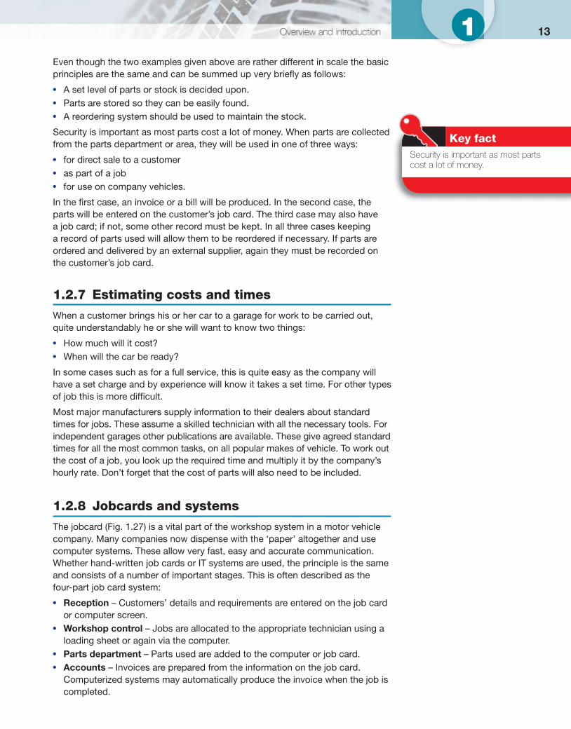
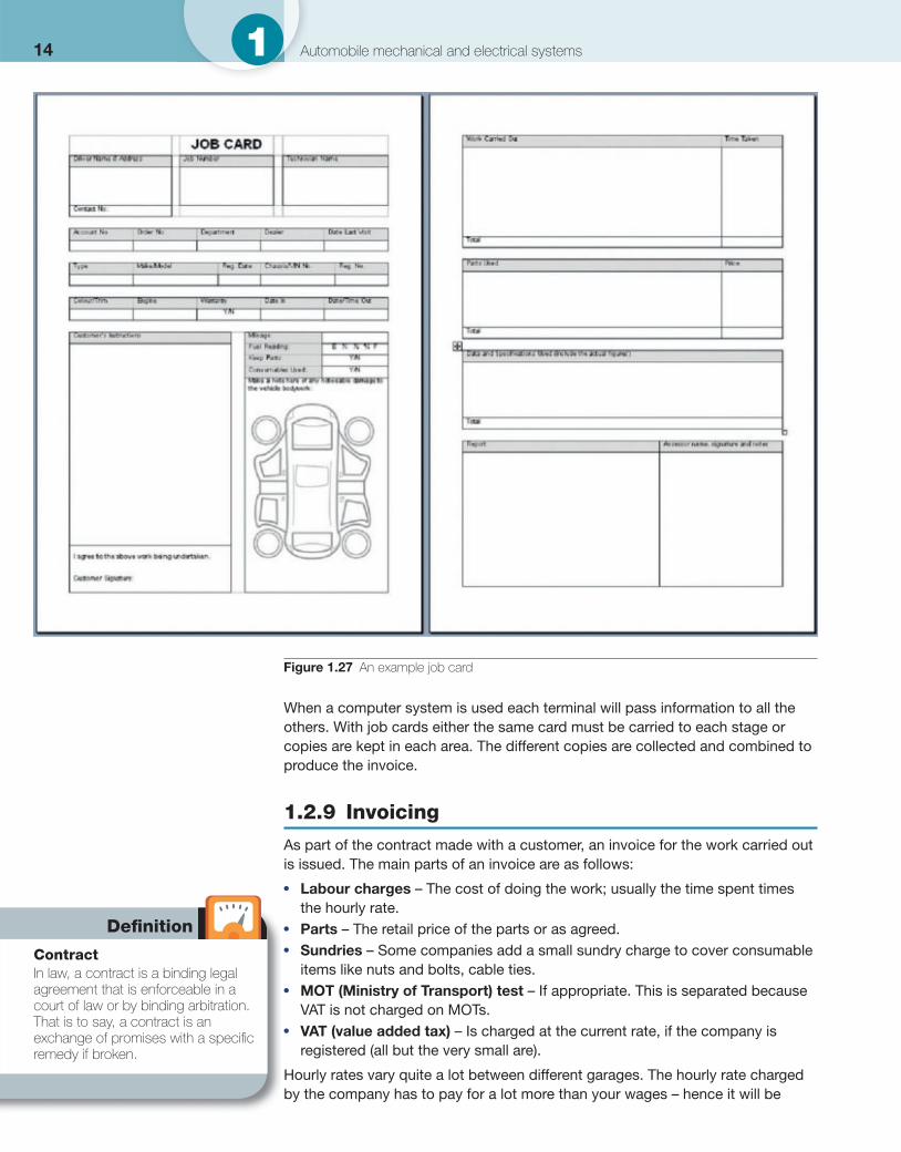
1.2.8 Jobcards and systems
The jobcard ( Fig. 1.27 ) is a vital part of the workshop system in a motor vehicle company. Many companies now dispense with the ‘paper’ altogether and use computer systems. These allow very fast, easy and accurate communication. Whether hand-written job cards or IT systems are used, the principle is the same and consists of a number of important stages. This is often described as the four-part job card system:
● Reception – Customers’ details and requirements are entered on the job card or computer screen.
● Workshop control – Jobs are allocated to the appropriate technician using a loading sheet or again via the computer.
● Parts department – Parts used are added to the computer or job card. ● Accounts – Invoices are prepared from the information on the job card.
Computerized systems may automatically produce the invoice when the job is completed.
Key fact Security is important as most parts cost a lot of money.
14 1 Automobile mechanical and electrical systems
When a computer system is used each terminal will pass information to all the others. With job cards either the same card must be carried to each stage or copies are kept in each area. The different copies are collected and combined to produce the invoice.
1.2.9 Invoicing
As part of the contract made with a customer, an invoice for the work carried out is issued. The main parts of an invoice are as follows:
● Labour charges – The cost of doing the work; usually the time spent times the hourly rate.
● Parts – The retail price of the parts or as agreed. ● Sundries – Some companies add a small sundry charge to cover consumable
items like nuts and bolts, cable ties. ● MOT (Ministry of Transport) test – If appropriate. This is separated because
VAT is not charged on MOTs. ● VAT (value added tax) – Is charged at the current rate, if the company is
registered (all but the very small are).
Hourly rates vary quite a lot between different garages. The hourly rate charged by the company has to pay for a lot more than your wages – hence it will be
Figure 1.27 An example job card
Defi nition
Contract In law, a contract is a binding legal agreement that is enforceable in a court of law or by binding arbitration. That is to say, a contract is an exchange of promises with a specifi c remedy if broken.
much higher than your hourly rate! Just take a look round in any good workshop: as well as the rent for the premises, some of the equipment can cost tens of thousands of pounds. The money has to come from somewhere.
1.2.10 Warranties
When a vehicle is sold a warranty is given, meaning that it is fi t for the purpose for which it was sold. Further to this, the manufacturer will repair the vehicle at no cost to the customer if a problem develops within a set time. For most vehicles this is twelve months, but some periods are now longer. The term generally used for this is ‘guarantee’. Quite often manufacturers advertise their guarantee as a selling point.
It is also possible to have a warranty on a used vehicle or an extended warranty on a new vehicle. These often involve a separate payment to an insurance company. This type of warranty can be quite good but a number of exclusions and requirements may apply. Some examples are listed:
● Regular servicing must be carried out by an approved dealer. ● Only recommended parts must be used. ● Wear and tear is not included. ● Any work done must be authorized. ● Only recognized repairers may be used in some cases.
The question of authorization before work is carried out is very important for the garage to understand. Work carried out without proper authorization will not be paid for. If a customer returns a car within the warranty period then a set procedure must be followed:
1 Confi rm that the work is within the terms of the warranty. 2 Get authorization if over an agreed limit. 3 Retain all parts replaced for inspection. 4 Produce an invoice which relates to standard or agreed times.
Often in the larger garages one person will be responsible for making warranty claims.
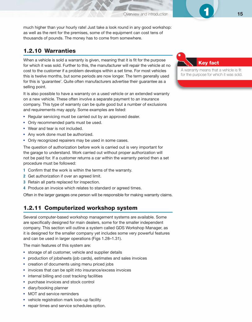
1.2.11 Computerized workshop system
Several computer-based workshop management systems are available. Some are specifi cally designed for main dealers, some for the smaller independent company. This section will outline a system called GDS Workshop Manager, as it is designed for the smaller company yet includes some very powerful features and can be used in larger operations ( Figs 1.28–1.31 ).
The main features of this system are:
● storage of all customer, vehicle and supplier details ● production of jobsheets (job cards), estimates and sales invoices ● creation of documents using menu priced jobs ● invoices that can be split into insurance/excess invoices ● internal billing and cost tracking facilities ● purchase invoices and stock control ● diary/booking planner ● MOT and service reminders ● vehicle registration mark look-up facility ● repair times and service schedules option.
Key fact A warranty means that a vehicle is fi t for the purpose for which it was sold.
151
16 1 Automobile mechanical and electrical systems
Figure 1.28 Main interface of the GDS program showing the customer screen
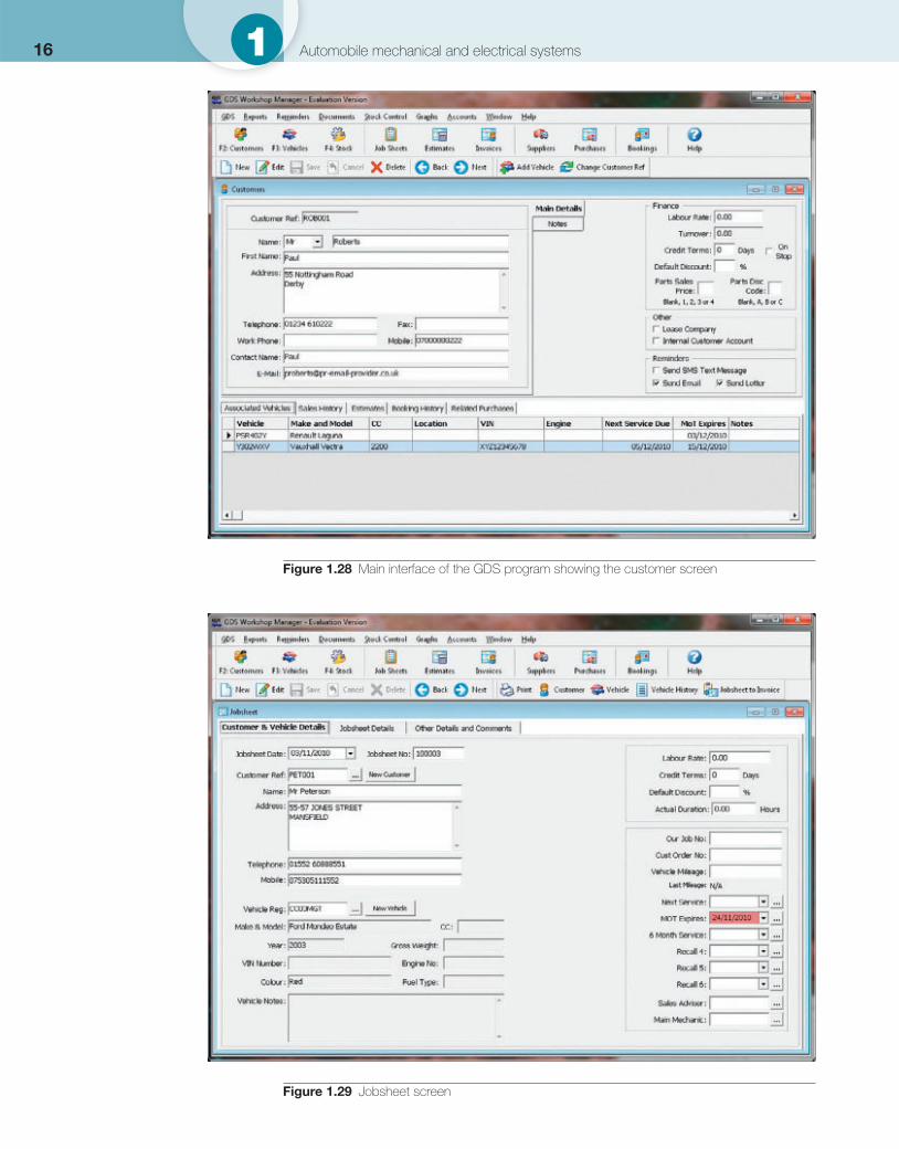
Figure 1.29 Jobsheet screen
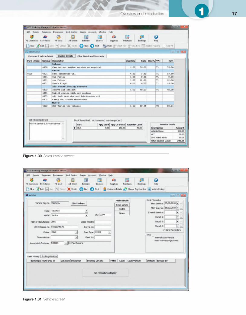
Figure 1.30 Sales invoice screen
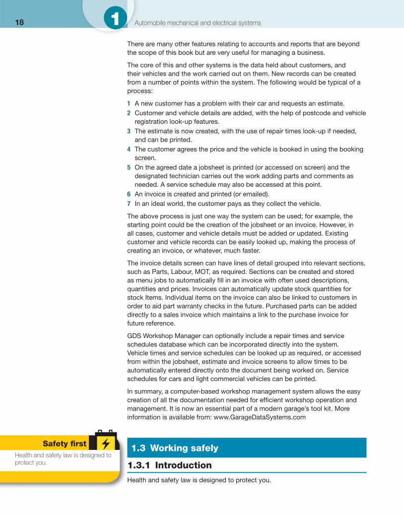
Figure 1.31 Vehicle screen
171
18 1 Automobile mechanical and electrical systems
There are many other features relating to accounts and reports that are beyond the scope of this book but are very useful for managing a business.
The core of this and other systems is the data held about customers, and their vehicles and the work carried out on them. New records can be created from a number of points within the system. The following would be typical of a process:
1 A new customer has a problem with their car and requests an estimate. 2 Customer and vehicle details are added, with the help of postcode and vehicle
registration look-up features. 3 The estimate is now created, with the use of repair times look-up if needed,
and can be printed. 4 The customer agrees the price and the vehicle is booked in using the booking
screen. 5 On the agreed date a jobsheet is printed (or accessed on screen) and the
designated technician carries out the work adding parts and comments as needed. A service schedule may also be accessed at this point.
6 An invoice is created and printed (or emailed). 7 In an ideal world, the customer pays as they collect the vehicle.
The above process is just one way the system can be used; for example, the starting point could be the creation of the jobsheet or an invoice. However, in all cases, customer and vehicle details must be added or updated. Existing customer and vehicle records can be easily looked up, making the process of creating an invoice, or whatever, much faster.
The invoice details screen can have lines of detail grouped into relevant sections, such as Parts, Labour, MOT, as required. Sections can be created and stored as menu jobs to automatically fi ll in an invoice with often used descriptions, quantities and prices. Invoices can automatically update stock quantities for stock Items. Individual items on the invoice can also be linked to customers in order to aid part warranty checks in the future. Purchased parts can be added directly to a sales invoice which maintains a link to the purchase invoice for future reference.
GDS Workshop Manager can optionally include a repair times and service schedules database which can be incorporated directly into the system. Vehicle times and service schedules can be looked up as required, or accessed from within the jobsheet, estimate and invoice screens to allow times to be automatically entered directly onto the document being worked on. Service schedules for cars and light commercial vehicles can be printed.
In summary, a computer-based workshop management system allows the easy creation of all the documentation needed for effi cient workshop operation and management. It is now an essential part of a modern garage’s tool kit. More information is available from: www.GarageDataSystems.com
1.3 Working safely
1.3.1 Introduction
Health and safety law is designed to protect you.
Safety fi rst Health and safety law is designed to protect you.

In the UK the Health and Safety Executive (HSE) is the enforcement and legislative body set up by the government. The HSE has a very helpful website where you can get all the latest information, including a document specially developed for the motor industry. The address is: www.hse.gov.uk ( Fig. 1.32 ).
Similarly, in the USA, with the Occupational Safety and Health Act of 1970, Congress created the Occupational Safety and Health Administration (OSHA) to ensure safe and healthful working conditions for working men and women by setting and enforcing standards and by providing training, outreach, education and assistance. The OSHA has a good website at: www.osha.gov ( Fig. 1.33 ).
In Australia there is the offi ce of the Australian Safety and Compensation Council (ASCC), in the Department of Employment and Workplace Relations. Safe Work Australia is an Australian Government statutory agency established in 2009, with the primary responsibility of improving work health and safety and workers’ compensation arrangements across Australia. The agency is jointly funded by the Commonwealth, state and territory governments facilitated through an intergovernmental agreement signed in July 2008. Safe Work Australia represents a genuine partnership between governments, unions and industry. Together they work towards the goal of reducing death, injury and disease in the workplace. Their website contains some useful content at: www.ascc.gov.au or http://safeworkaustralia.gov.au ( Fig. 1.34 ).
Now back to the UK’s HSE. The emphasis is on preventing death, injury and ill-health in Britain’s workplaces. However, the HSE does have the authority to come down hard on people who put others at risk, particularly where there is deliberate fl outing of the law. Since 2009, HSE has published new versions of its approved health and safety poster and leafl et. The new versions are modern, eye-catching and easy to read. They are set out in simple terms, using numbered lists of basic points, and what employers and workers must do, and tell you what to do if there is a problem.
Employers can, if they wish, continue to use their existing versions of poster and leafl et until 5 April 2014, as long as they are readable and the addresses of the enforcing authority and the Employment Medical Advisory Service are up to date. Employers must display a poster or give a leafl et to workers. This is in the form of a pocket card that is better suited to the workplace.
Employers have a legal duty under the Health and Safety Information for Employees Regulations (HSIER) to display the poster in a prominent position in each workplace or provide each worker with a copy of the equivalent leafl et outlining British health and safety laws ( Figs 1.35 and 1.36 ).
Employers must meet certain criteria, but health and safety is the responsibility of everyone in the workplace. The reason for the poster and the leafl ets is to make everybody aware of this.
1.3.2 The key UK regulations and laws
There are a number of rules and regulation you need to be aware of. Check the details for the country in which you work. Table 1.5 lists some important areas for the UK.
Figure 1.32 UK Health and Safety Executive (HSE) logo
Figure 1.34 Safe Work Australia (SWA) logo
Figure 1.33 USA OSHA logo
Safety fi rst Systems are quite similar, but always check the legislation and law in the country you are working in.
Safety fi rst Health and safety is the responsibility of everyone in the workplace.
19Overview and introduction 1
20 1 Automobile mechanical and electrical systems
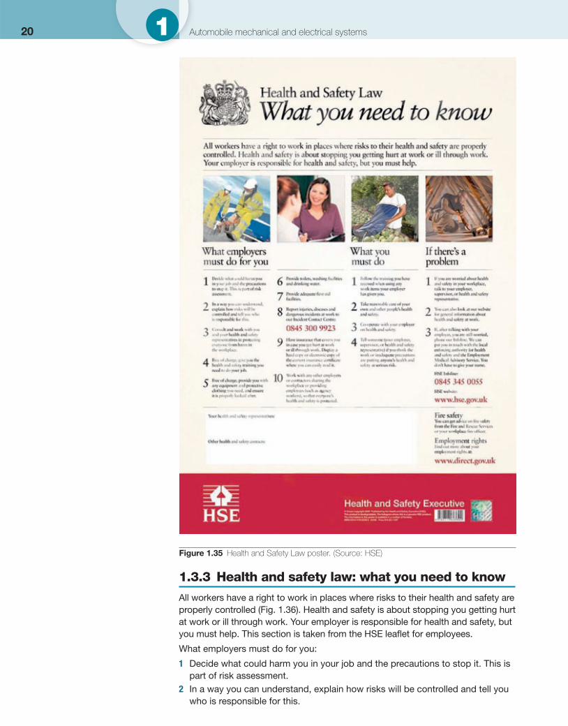
1.3.3 Health and safety law: what you need to know
All workers have a right to work in places where risks to their health and safety are properly controlled ( Fig. 1.36 ). Health and safety is about stopping you getting hurt at work or ill through work. Your employer is responsible for health and safety, but you must help. This section is taken from the HSE leafl et for employees.
What employers must do for you:
1 Decide what could harm you in your job and the precautions to stop it. This is part of risk assessment.
2 In a way you can understand, explain how risks will be controlled and tell you who is responsible for this.
Figure 1.35 Health and Safety Law poster. (Source: HSE)
21Over 1
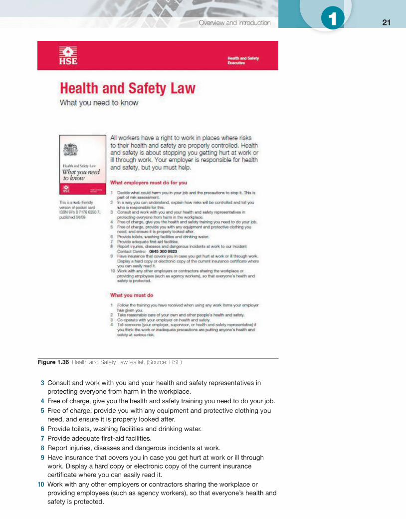
3 Consult and work with you and your health and safety representatives in protecting everyone from harm in the workplace.
4 Free of charge, give you the health and safety training you need to do your job. 5 Free of charge, provide you with any equipment and protective clothing you
need, and ensure it is properly looked after. 6 Provide toilets, washing facilities and drinking water. 7 Provide adequate fi rst-aid facilities. 8 Report injuries, diseases and dangerous incidents at work. 9 Have insurance that covers you in case you get hurt at work or ill through
work. Display a hard copy or electronic copy of the current insurance certifi cate where you can easily read it.
10 Work with any other employers or contractors sharing the workplace or providing employees (such as agency workers), so that everyone’s health and safety is protected.
Figure 1.36 Health and Safety Law leafl et. (Source: HSE)
22 1 Automobile mechanical and electrical systems
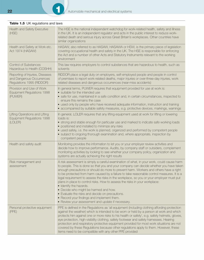
Table 1.5 UK regulations and laws
Health and Safety Executive (HSE)
The HSE is the national independent watchdog for work-related health, safety and illness in the UK. It is an independent regulator and acts in the public interest to reduce work-related death and serious injury across Great Britain’s workplaces. Other countries have similar organizations
Health and Safety at Work etc. Act 1974 (HASAW)
HASAW, also referred to as HASAW, HASAWA or HSW, is the primary piece of legislation covering occupational health and safety in the UK. The HSE is responsible for enforcing the Act and a number of other Acts and Statutory Instruments relevant to the working environment
Control of Substances Hazardous to Health (COSHH)
This law requires employers to control substances that are hazardous to health, such as solvents
Reporting of Injuries, Diseases and Dangerous Occurrences Regulations 1995 (RIDDOR)
RIDDOR place a legal duty on employers, self-employed people and people in control of premises to report work-related deaths, major injuries or over-three-day injuries, work related diseases and dangerous occurrences (near-miss accidents)
Provision and Use of Work Equipment Regulations 1998 (PUWER)
In general terms, PUWER requires that equipment provided for use at work is: ● suitable for the intended use ● safe for use, maintained in a safe condition and, in certain circumstances, inspected to
ensure this remains the case ● used only by people who have received adequate information, instruction and training ● accompanied by suitable safety measures, e.g. protective devices, markings, warnings
Lifting Operations and Lifting Equipment Regulations 1998 (LOLER)
In general, LOLER requires that any lifting equipment used at work for lifting or lowering loads is: ● strong and stable enough for particular use and marked to indicate safe working loads ● positioned and installed to minimize any risks ● used safely, i.e. the work is planned, organized and performed by competent people ● subject to ongoing thorough examination and, where appropriate, inspection by
competent people
Health and safety audit Monitoring provides the information to let you or your employer review activities and decide how to improve performance. Audits, by company staff or outsiders, complement monitoring activities by looking to see whether your company policy, organization and systems are actually achieving the right results
Risk management and assessment
A risk assessment is simply a careful examination of what, in your work, could cause harm to people. This is done so that you and your company can decide whether you have taken enough precautions or should do more to prevent harm. Workers and others have a right to be protected from harm caused by a failure to take reasonable control measures. It is a legal requirement to assess the risks in the workplace, so you or your employer must put plans in place to control risks. How to assess the risks in your workplace: ● Identify the hazards. ● Decide who might be harmed and how. ● Evaluate the risks and decide on precautions. ● Record your fi ndings and implement them. ● Review your assessment and update if necessary.
Personal protective equipment (PPE)
PPE is defi ned in the Regulations as ‘all equipment (including clothing affording protection against the weather) which is intended to be worn or held by a person at work and which protects him against one or more risks to his health or safety’, e.g. safety helmets, gloves, eye protection, high-visibility clothing, safety footwear and safety harnesses. Hearing protection and respiratory protective equipment provided for most work situations are not covered by these Regulations because other regulations apply to them. However, these items need to be compatible with any other PPE provided
231
What you must do:
1 Follow the training you have received when using any work items your employer has given you.
2 Take reasonable care of your own and other people’s health and safety. 3 Co-operate with your employer on health and safety. 4 Tell someone (your employer, supervisor, or health and safety representative) if
you think the work or inadequate precautions are putting anyone’s health and safety at serious risk.
1.3.4 Personal protective equipment (PPE)
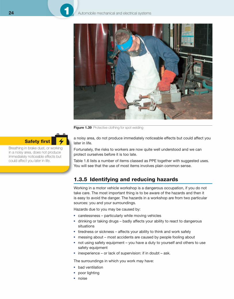
Personal protective equipment (PPE) such as safety clothing is very important to protect you ( Figs 1.38 and 1.39 ). Some people think it clever or tough not to use protection. They are very sad and will die or be injured long before you! Some things are obvious; for example when holding a hot or sharp exhaust you would likely be burnt or cut. Other things such as breathing in brake dust, or working in
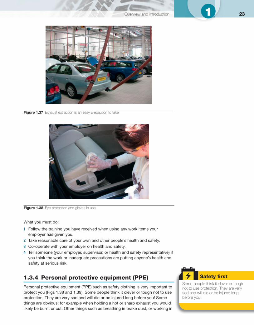
Figure 1.37 Exhaust extraction is an easy precaution to take
Figure 1.38 Eye protection and gloves in use
Safety fi rst Some people think it clever or tough not to use protection. They are very sad and will die or be injured long before you!
24 1 Automobile mechanical and electrical systems
a noisy area, do not produce immediately noticeable effects but could affect you later in life.
Fortunately, the risks to workers are now quite well understood and we can protect ourselves before it is too late.
Table 1.6 lists a number of items classed as PPE together with suggested uses. You will see that the use of most items involves plain common sense.
1.3.5 Identifying and reducing hazards
Working in a motor vehicle workshop is a dangerous occupation, if you do not take care. The most important thing is to be aware of the hazards and then it is easy to avoid the danger. The hazards in a workshop are from two particular sources: you and your surroundings.
Hazards due to you may be caused by:
● carelessness – particularly while moving vehicles ● drinking or taking drugs – badly affects your ability to react to dangerous
situations ● tiredness or sickness – affects your ability to think and work safely ● messing about – most accidents are caused by people fooling about ● not using safety equipment – you have a duty to yourself and others to use
safety equipment ● inexperience – or lack of supervision: if in doubt – ask.
The surroundings in which you work may have:
● bad ventilation ● poor lighting ● noise
Safety fi rst Breathing in brake dust, or working in a noisy area, does not produce immediately noticeable effects but could affect you later in life.
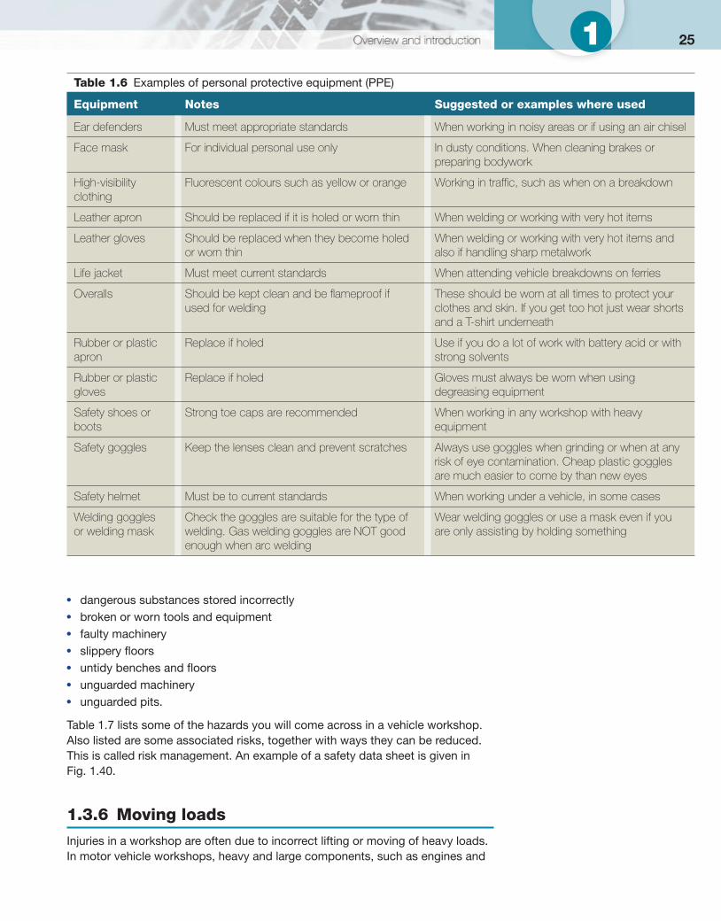
Figure 1.39 Protective clothing for spot welding
251
● dangerous substances stored incorrectly ● broken or worn tools and equipment ● faulty machinery ● slippery fl oors ● untidy benches and fl oors ● unguarded machinery ● unguarded pits.
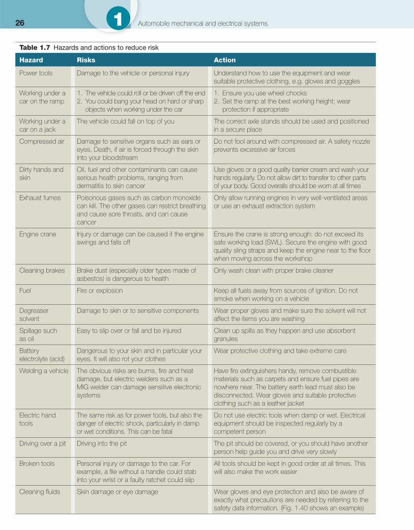
Table 1.7 lists some of the hazards you will come across in a vehicle workshop. Also listed are some associated risks, together with ways they can be reduced. This is called risk management. An example of a safety data sheet is given in Fig. 1.40 .
1.3.6 Moving loads
Injuries in a workshop are often due to incorrect lifting or moving of heavy loads. In motor vehicle workshops, heavy and large components, such as engines and
Table 1.6 Examples of personal protective equipment (PPE)
Equipment Notes Suggested or examples where used
Ear defenders Must meet appropriate standards When working in noisy areas or if using an air chisel
Face mask For individual personal use only In dusty conditions. When cleaning brakes or preparing bodywork
High-visibility clothing
Fluorescent colours such as yellow or orange Working in traffi c, such as when on a breakdown
Leather apron Should be replaced if it is holed or worn thin When welding or working with very hot items
Leather gloves Should be replaced when they become holed or worn thin
When welding or working with very hot items and also if handling sharp metalwork
Life jacket Must meet current standards When attending vehicle breakdowns on ferries
Overalls Should be kept clean and be fl ameproof if used for welding
These should be worn at all times to protect your clothes and skin. If you get too hot just wear shorts and a T-shirt underneath
Rubber or plastic apron
Replace if holed Use if you do a lot of work with battery acid or with strong solvents
Rubber or plastic gloves
Replace if holed Gloves must always be worn when using degreasing equipment
Safety shoes or boots
Strong toe caps are recommended When working in any workshop with heavy equipment
Safety goggles Keep the lenses clean and prevent scratches Always use goggles when grinding or when at any risk of eye contamination. Cheap plastic goggles are much easier to come by than new eyes
Safety helmet Must be to current standards When working under a vehicle, in some cases
Welding goggles or welding mask
Check the goggles are suitable for the type of welding. Gas welding goggles are NOT good enough when arc welding
Wear welding goggles or use a mask even if you are only assisting by holding something
26 1 Automobile mechanical and electrical systems
Table 1.7 Hazards and actions to reduce risk
Hazard Risks Action
Power tools Damage to the vehicle or personal injury Understand how to use the equipment and wear suitable protective clothing, e.g. gloves and goggles
Working under a car on the ramp
1. The vehicle could roll or be driven off the end 2. You could bang your head on hard or sharp
objects when working under the car
1. Ensure you use wheel chocks 2. Set the ramp at the best working height; wear
protection if appropriate
Working under a car on a jack
The vehicle could fall on top of you The correct axle stands should be used and positioned in a secure place
Compressed air Damage to sensitive organs such as ears or eyes. Death, if air is forced through the skin into your bloodstream
Do not fool around with compressed air. A safety nozzle prevents excessive air forces
Dirty hands and skin
Oil, fuel and other contaminants can cause serious health problems, ranging from dermatitis to skin cancer
Use gloves or a good quality barrier cream and wash your hands regularly. Do not allow dirt to transfer to other parts of your body. Good overalls should be worn at all times
Exhaust fumes Poisonous gases such as carbon monoxide can kill. The other gases can restrict breathing and cause sore throats, and can cause cancer
Only allow running engines in very well-ventilated areas or use an exhaust extraction system
Engine crane Injury or damage can be caused if the engine swings and falls off
Ensure the crane is strong enough: do not exceed its safe working load (SWL). Secure the engine with good quality sling straps and keep the engine near to the fl oor when moving across the workshop
Cleaning brakes Brake dust (especially older types made of asbestos) is dangerous to health
Only wash clean with proper brake cleaner
Fuel Fire or explosion Keep all fuels away from sources of ignition. Do not smoke when working on a vehicle
Degreaser solvent
Damage to skin or to sensitive components Wear proper gloves and make sure the solvent will not affect the items you are washing
Spillage such as oil
Easy to slip over or fall and be injured Clean up spills as they happen and use absorbent granules
Battery electrolyte (acid)
Dangerous to your skin and in particular your eyes. It will also rot your clothes
Wear protective clothing and take extreme care
Welding a vehicle The obvious risks are burns, fi re and heat damage, but electric welders such as a MIG welder can damage sensitive electronic systems
Have fi re extinguishers handy, remove combustible materials such as carpets and ensure fuel pipes are nowhere near. The battery earth lead must also be disconnected. Wear gloves and suitable protective clothing such as a leather jacket
Electric hand tools
The same risk as for power tools, but also the danger of electric shock, particularly in damp or wet conditions. This can be fatal
Do not use electric tools when damp or wet. Electrical equipment should be inspected regularly by a competent person
Driving over a pit Driving into the pit The pit should be covered, or you should have another person help guide you and drive very slowly
Broken tools Personal injury or damage to the car. For example, a fi le without a handle could stab into your wrist or a faulty ratchet could slip
All tools should be kept in good order at all times. This will also make the work easier
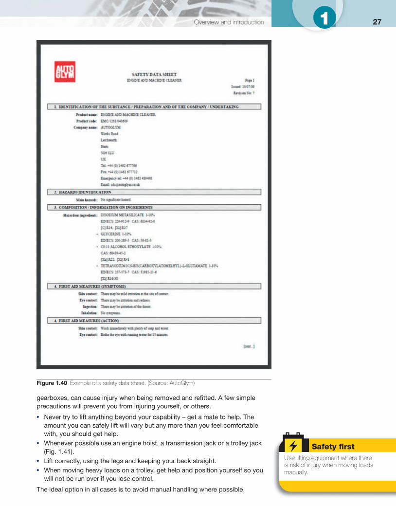
Cleaning fl uids Skin damage or eye damage Wear gloves and eye protection and also be aware of exactly what precautions are needed by referring to the safety data information. ( Fig. 1.40 shows an example)
271
gearboxes, can cause injury when being removed and refi tted. A few simple precautions will prevent you from injuring yourself, or others.
● Never try to lift anything beyond your capability – get a mate to help. The amount you can safely lift will vary but any more than you feel comfortable with, you should get help.
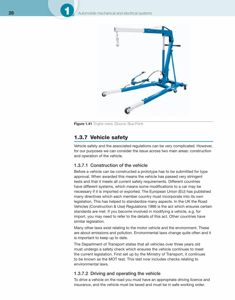
● Whenever possible use an engine hoist, a transmission jack or a trolley jack ( Fig. 1.41 ).
● Lift correctly, using the legs and keeping your back straight. ● When moving heavy loads on a trolley, get help and position yourself so you
will not be run over if you lose control.
The ideal option in all cases is to avoid manual handling where possible.
Figure 1.40 Example of a safety data sheet. (Source: AutoGlym)
Safety fi rst Use lifting equipment where there is risk of injury when moving loads manually.
28 1 Automobile mechanical and electrical systems
1.3.7 Vehicle safety
Vehicle safety and the associated regulations can be very complicated. However, for our purposes we can consider the issue across two main areas: construction and operation of the vehicle.
1.3.7.1 Construction of the vehicle Before a vehicle can be constructed a prototype has to be submitted for type approval. When awarded this means the vehicle has passed very stringent tests and that it meets all current safety requirements. Different countries have different systems, which means some modifi cations to a car may be necessary if it is imported or exported. The European Union (EU) has published many directives which each member country must incorporate into its own legislation. This has helped to standardize many aspects. In the UK the Road Vehicles (Construction & Use) Regulations 1986 is the act which ensures certain standards are met. If you become involved in modifying a vehicle, e.g. for import, you may need to refer to the details of this act. Other countries have similar legislation.
Many other laws exist relating to the motor vehicle and the environment. These are about emissions and pollution. Environmental laws change quite often and it is important to keep up to date.
The Department of Transport states that all vehicles over three years old must undergo a safety check which ensures the vehicle continues to meet the current legislation. First set up by the Ministry of Transport, it continues to be known as the MOT test. This test now includes checks relating to environmental laws.
1.3.7.2 Driving and operating the vehicle To drive a vehicle on the road you must have an appropriate driving licence and insurance, and the vehicle must be taxed and must be in safe working order.
Figure 1.41 Engine crane. (Source: Blue-Point)
291
1.3.8 Safety procedures
When you know the set procedures to be followed, it is easier to look after yourself, your workshop and your workmates. You should know:
● who does what during an emergency ● the fi re procedure for your workplace ● about different types of fi re extinguisher and their uses ● the procedure for reporting an accident.
If an accident does occur in your workplace the fi rst bit of advice is: keep calm and don’t panic! The HASAW states that for companies above a certain size:
● fi rst aid equipment must be available ● employers should display simple fi rst aid instructions ● fully trained fi rst aiders must be employed.
In your own workplace you should know about the above three points. A guide to how to react if you come across a serious accident is given in Table 1.8 .
1.3.9 Fire
Accidents involving fi re are very serious. As well as you or a workmate calling the fi re brigade (do not assume it has been done), three simple rules will help you to know what to do:
1 Get safe yourself, contact the emergency services – and shout FIRE! 2 Help others to get safe if it does not put you or others at risk. 3 Fight the fi re if it does not put you or others at risk.
Of course, far better than the above situation is not to let a fi re start in the fi rst place.
Table 1.8 Actions in the case of an accident
Action Notes
Assess the situation Stay calm: a few seconds to think is important
Remove the danger If the person was working with a machine, turn it off. If someone is electrocuted, switch off the power before you hurt yourself. Even if you are unable to help with the injury you can stop it getting worse
Get help If you are not trained in fi rst aid, get someone who is and/or phone for an ambulance
Stay with the casualty If you can do nothing else, the casualty can be helped if you stay with him. Also say that help is on its way and be ready to assist. You may need to guide the ambulance
Report the accident All accidents must be reported: by law, your company should have an accident book. This is a record so that steps can be taken to prevent the accident happening again. Also, if the injured person claims compensation, underhanded companies could deny the accident happened
Learn fi rst aid If you are in a very small company, why not get trained now, before the accident?
Safety fi rst Keep calm and don’t panic!
30 1 Automobile mechanical and electrical systems
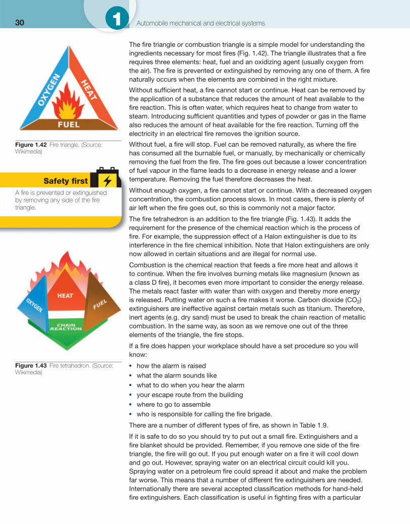
The fi re triangle or combustion triangle is a simple model for understanding the ingredients necessary for most fi res ( Fig. 1.42 ). The triangle illustrates that a fi re requires three elements: heat, fuel and an oxidizing agent (usually oxygen from the air). The fi re is prevented or extinguished by removing any one of them. A fi re naturally occurs when the elements are combined in the right mixture.
Without suffi cient heat, a fi re cannot start or continue. Heat can be removed by the application of a substance that reduces the amount of heat available to the fi re reaction. This is often water, which requires heat to change from water to steam. Introducing suffi cient quantities and types of powder or gas in the fl ame also reduces the amount of heat available for the fi re reaction. Turning off the electricity in an electrical fi re removes the ignition source.
Without fuel, a fi re will stop. Fuel can be removed naturally, as where the fi re has consumed all the burnable fuel, or manually, by mechanically or chemically removing the fuel from the fi re. The fi re goes out because a lower concentration of fuel vapour in the fl ame leads to a decrease in energy release and a lower temperature. Removing the fuel therefore decreases the heat.
Without enough oxygen, a fi re cannot start or continue. With a decreased oxygen concentration, the combustion process slows. In most cases, there is plenty of air left when the fi re goes out, so this is commonly not a major factor.
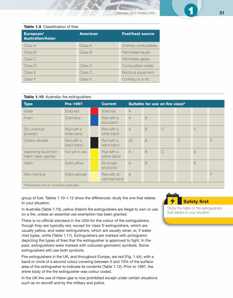
The fi re tetrahedron is an addition to the fi re triangle ( Fig. 1.43 ). It adds the requirement for the presence of the chemical reaction which is the process of fi re. For example, the suppression effect of a Halon extinguisher is due to its interference in the fi re chemical inhibition. Note that Halon extinguishers are only now allowed in certain situations and are illegal for normal use.
Combustion is the chemical reaction that feeds a fi re more heat and allows it to continue. When the fi re involves burning metals like magnesium (known as a class D fi re), it becomes even more important to consider the energy release. The metals react faster with water than with oxygen and thereby more energy is released. Putting water on such a fi re makes it worse. Carbon dioxide (CO 2 ) extinguishers are ineffective against certain metals such as titanium. Therefore, inert agents (e.g. dry sand) must be used to break the chain reaction of metallic combustion. In the same way, as soon as we remove one out of the three elements of the triangle, the fi re stops.
If a fi re does happen your workplace should have a set procedure so you will know:
● how the alarm is raised ● what the alarm sounds like ● what to do when you hear the alarm ● your escape route from the building ● where to go to assemble ● who is responsible for calling the fi re brigade.
There are a number of different types of fi re, as shown in Table 1.9 .
If it is safe to do so you should try to put out a small fi re. Extinguishers and a fi re blanket should be provided. Remember, if you remove one side of the fi re triangle, the fi re will go out. If you put enough water on a fi re it will cool down and go out. However, spraying water on an electrical circuit could kill you. Spraying water on a petroleum fi re could spread it about and make the problem far worse. This means that a number of different fi re extinguishers are needed. Internationally there are several accepted classifi cation methods for hand-held fi re extinguishers. Each classifi cation is useful in fi ghting fi res with a particular
Figure 1.42 Fire triangle. (Source: Wikimedia)
Safety fi rst A fi re is prevented or extinguished by removing any side of the fi re triangle.
Figure 1.43 Fire tetrahedron. (Source: Wikimedia)
311
group of fuel. Tables 1.10–1.12 show the differences: study the one that relates to your situation.
In Australia ( Table 1.10 ), yellow (Halon) fi re extinguishers are illegal to own or use on a fi re, unless an essential use exemption has been granted.
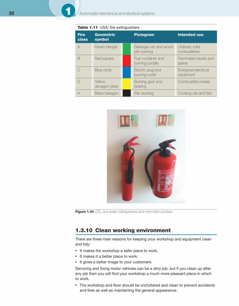
There is no offi cial standard in the USA for the colour of fi re extinguishers, though they are typically red, except for class D extinguishers, which are usually yellow, and water extinguishers, which are usually silver, or, if water mist types, white ( Table 1.11 ). Extinguishers are marked with pictograms depicting the types of fi res that the extinguisher is approved to fi ght. In the past, extinguishers were marked with coloured geometric symbols. Some extinguishers still use both symbols.
Fire extinguishers in the UK, and throughout Europe, are red ( Fig. 1.44 ), with a band or circle of a second colour covering between 5 and 10% of the surface area of the extinguisher to indicate its contents ( Table 1.12 ). Prior to 1997, the entire body of the fi re extinguisher was colour coded.
In the UK the use of Halon gas is now prohibited except under certain situations such as on aircraft and by the military and police.
Safety fi rst Study the table on fi re extinguishers that relates to your situation.
Table 1.9 Classifi cation of fi res
European/Australian/Asian
American Fuel/heat source
Class A Class A Ordinary combustibles
Class B Class B Flammable liquids
Class C Flammable gases
Class D Class D Combustible metals
Class E Class C Electrical equipment
Class F Class K Cooking oil or fat
Table 1.10 Australia: fi re extinguishers
Type Pre-1997 Current Suitable for use on fi re class a
Water Solid red Solid red A
Foam Solid blue Red with a blue band
A B
Dry chemical (powder)
Red with a white band
Red with a white band
A B C E
Carbon dioxide Red with a black band
Red with a black band
(A) B D F
Vaporizing liquid (non-Halon clean agents)
Not yet in use Red with a yellow band
A B C E
Halon Solid yellow No longer produced
A B E
Wet chemical Solid oatmeal Red with an oatmeal band
A F
a Parentheses denote sometimes applicable.
32 1 Automobile mechanical and electrical systems
1.3.10 Clean working environment
There are three main reasons for keeping your workshop and equipment clean and tidy:
● It makes the workshop a safer place to work. ● It makes it a better place to work. ● It gives a better image to your customers.
Servicing and fi xing motor vehicles can be a dirty job, but if you clean up after any job then you will fi nd your workshop a much more pleasant place in which to work.
● The workshop and fl oor should be uncluttered and clean to prevent accidents and fi res as well as maintaining the general appearance.
Figure 1.44 CO 2 and water extinguishers and information posters
Table 1.11 USA: fi re extinguishers
Fire class
Geometric symbol
Pictogram Intended use
A Green triangle Garbage can and wood pile burning
Ordinary solid combustibles
B Red square Fuel container and burning puddle
Flammable liquids and gases
C Blue circle Electric plug and burning outlet
Energized electrical equipment
D Yellow decagon (star)
Burning gear and bearing
Combustible metals
K Black hexagon Pan burning Cooking oils and fats
331
● Your workspace refl ects your ability as a technician. A tidy workspace equals a tidy mind equals a tidy job equals a tidy wage when you are qualifi ed.
● Hand tools should be kept clean as you are working. You will pay a lot of money for your tools; look after them and they will look after you in the long term.
● Large equipment should only be cleaned by a trained person or a person under supervision. Obvious precautions are to ensure that equipment cannot be operated while you are working on it and only using appropriate cleaning methods. For example, would you use a bucket of water or a brush to clean down an electric pillar drill? I hope you answered ‘a brush’!
In motor vehicle workshops many different cleaning operations are carried out. This means a number of different materials are required. It is not possible to mention every brand name here,but the materials are split into three different types in Table 1.13 . It is important to note that the manufacturer’s instructions printed on the container must be followed at all times.
1.3.11 Signage
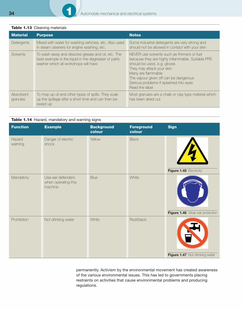
A key safety aspect is fi rst to identify hazards and then to remove them or, if this is not possible, reduce the risk as much as possible and bring the hazard to everyone’s attention. This is usually done by using signs or markings. Signs used to mark hazards are often as shown in Tables 1.14 and 1.15 .
1.3.12 Environmental protection
Environmental protection is all about protecting the environment, on individual, organizational or governmental levels. Owing to the pressures of population and technology the Earth’s environment is being degraded, sometimes
Safety fi rst Identify hazards and then remove them. If this is not possible, make others aware of them using signs.
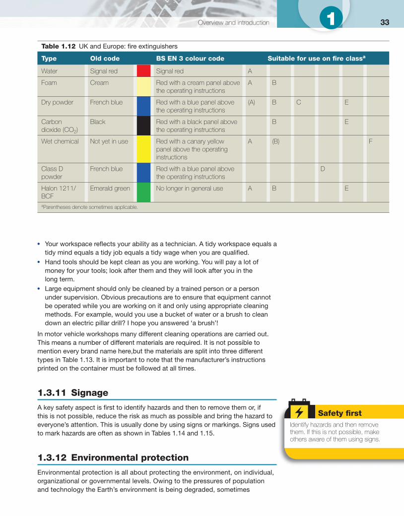
Table 1.12 UK and Europe: fi re extinguishers
Type Old code BS EN 3 colour code Suitable for use on fi re class a
Water Signal red Signal red A
Foam Cream Red with a cream panel above the operating instructions
A B
Dry powder French blue Red with a blue panel above the operating instructions
(A) B C E
Carbon dioxide (CO 2 )
Black Red with a black panel above the operating instructions
B E
Wet chemical Not yet in use Red with a canary yellow panel above the operating instructions
A (B) F
Class D powder
French blue Red with a blue panel above the operating instructions
D
Halon 1211/BCF
Emerald green No longer in general use A B E
a Parentheses denote sometimes applicable.
34 1 Automobile mechanical and electrical systems
permanently. Activism by the environmental movement has created awareness of the various environmental issues. This has led to governments placing restraints on activities that cause environmental problems and producing regulations.
Table 1.13 Cleaning materials
Material Purpose Notes
Detergents Mixed with water for washing vehicles, etc. Also used in steam cleaners for engine washing, etc.
Some industrial detergents are very strong and should not be allowed in contact with your skin
Solvents To wash away and dissolve grease and oil, etc. The best example is the liquid in the degreaser or parts washer which all workshops will have
NEVER use solvents such as thinners or fuel because they are highly infl ammable. Suitable PPE should be used, e.g. gloves They may attack your skin Many are fl ammable The vapour given off can be dangerous Serious problems if splashed into eyes Read the label
Absorbent granules
To mop up oil and other types of spills. They soak up the spillage after a short time and can then be swept up
Most granules are a chalk or clay type material which has been dried out
Table 1.14 Hazard, mandatory and warning signs
Function Example Background colour
Foreground colour
Sign
Hazard warning
Danger of electric shock
Yellow Black
Figure 1.45 Electricity
Mandatory Use ear defenders when operating this machine
Blue White
Figure 1.46 Wear ear protection
Prohibition Not drinking water White Red/black
Figure 1.47 Not drinking water
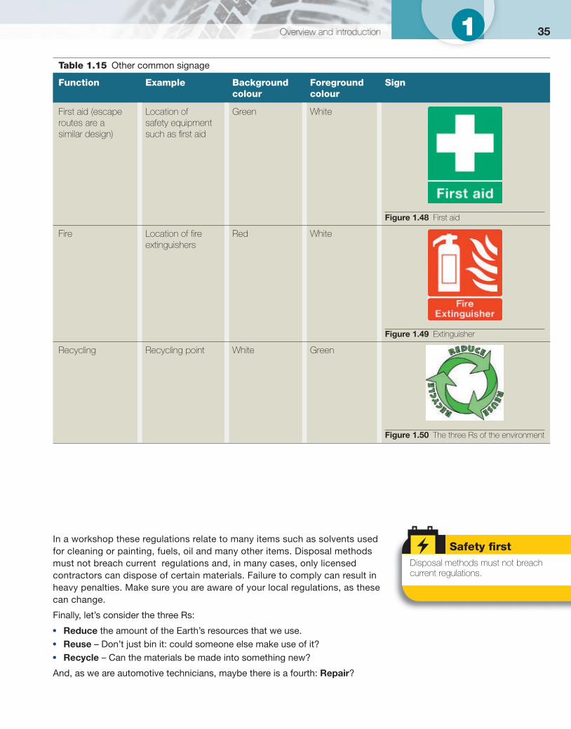
351
In a workshop these regulations relate to many items such as solvents used for cleaning or painting, fuels, oil and many other items. Disposal methods must not breach current regulations and, in many cases, only licensed contractors can dispose of certain materials. Failure to comply can result in heavy penalties. Make sure you are aware of your local regulations, as these can change.
Finally, let’s consider the three Rs:
● Reduce the amount of the Earth’s resources that we use. ● Reuse – Don’t just bin it: could someone else make use of it? ● Recycle – Can the materials be made into something new?
And, as we are automotive technicians, maybe there is a fourth: Repair ?
Safety fi rst Disposal methods must not breach current regulations.
Table 1.15 Other common signage
Function Example Background colour
Foreground colour
Sign
First aid (escape routes are a similar design)
Location of safety equipment such as fi rst aid
Green White
Figure 1.48 First aid
Fire Location of fi re extinguishers
Red White
Figure 1.49 Extinguisher
Recycling Recycling point White Green
Figure 1.50 The three Rs of the environment
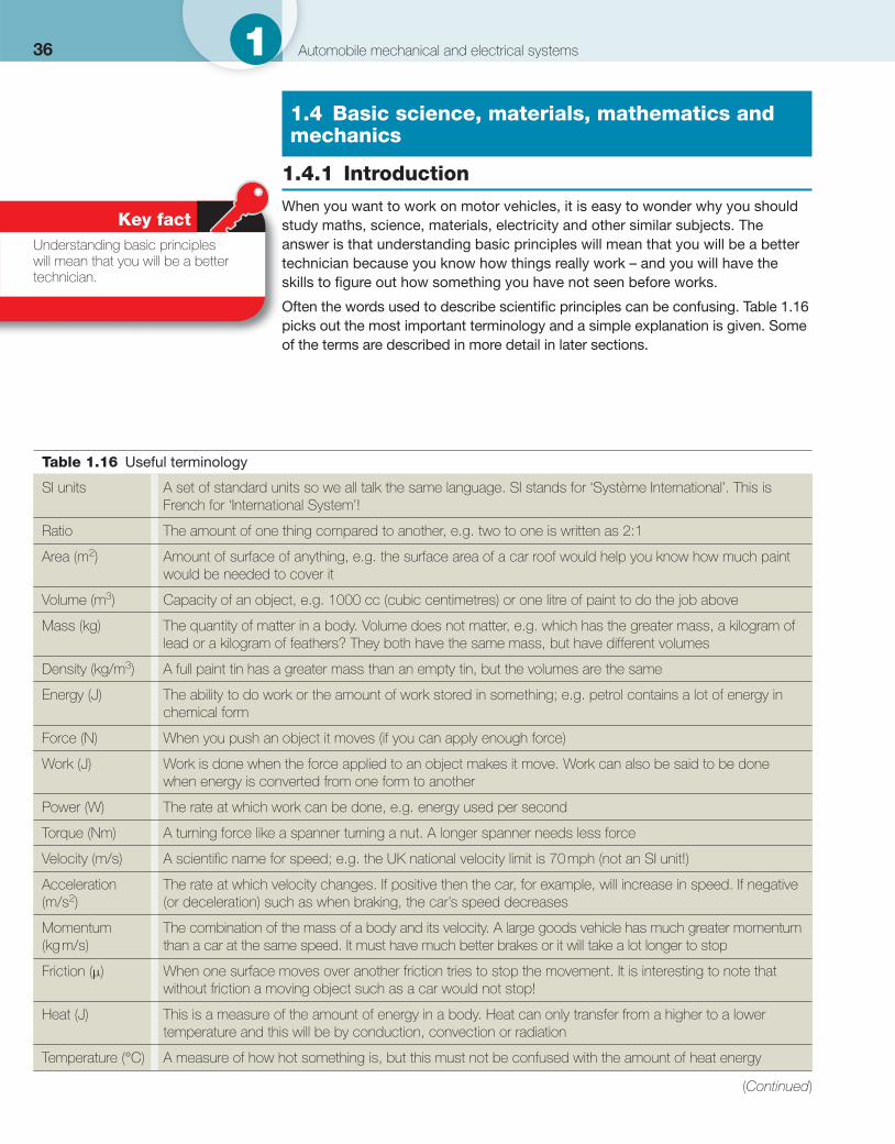
36 1 Automobile mechanical and electrical systems
1.4 Basic science, materials, mathematics and mechanics
1.4.1 Introduction
When you want to work on motor vehicles, it is easy to wonder why you should study maths, science, materials, electricity and other similar subjects. The answer is that understanding basic principles will mean that you will be a better technician because you know how things really work – and you will have the skills to fi gure out how something you have not seen before works.
Often the words used to describe scientifi c principles can be confusing. Table 1.16 picks out the most important terminology and a simple explanation is given. Some of the terms are described in more detail in later sections.
Key fact Understanding basic principles will mean that you will be a better technician.
Table 1.16 Useful terminology
SI units A set of standard units so we all talk the same language. SI stands for ‘Système International’. This is French for ‘International System’!
Ratio The amount of one thing compared to another, e.g. two to one is written as 2:1
Area (m 2 ) Amount of surface of anything, e.g. the surface area of a car roof would help you know how much paint would be needed to cover it
Volume (m 3 ) Capacity of an object, e.g. 1000 cc (cubic centimetres) or one litre of paint to do the job above
Mass (kg) The quantity of matter in a body. Volume does not matter, e.g. which has the greater mass, a kilogram of lead or a kilogram of feathers? They both have the same mass, but have different volumes
Density (kg/m 3 ) A full paint tin has a greater mass than an empty tin, but the volumes are the same
Energy (J) The ability to do work or the amount of work stored in something; e.g. petrol contains a lot of energy in chemical form
Force (N) When you push an object it moves (if you can apply enough force)
Work (J) Work is done when the force applied to an object makes it move. Work can also be said to be done when energy is converted from one form to another
Power (W) The rate at which work can be done, e.g. energy used per second
Torque (Nm) A turning force like a spanner turning a nut. A longer spanner needs less force
Velocity (m/s) A scientifi c name for speed; e.g. the UK national velocity limit is 70 mph (not an SI unit!)
Acceleration (m/s 2 )
The rate at which velocity changes. If positive then the car, for example, will increase in speed. If negative (or deceleration) such as when braking, the car’s speed decreases
Momentum (kg m/s)
The combination of the mass of a body and its velocity. A large goods vehicle has much greater momentum than a car at the same speed. It must have much better brakes or it will take a lot longer to stop
Friction (μ) When one surface moves over another friction tries to stop the movement. It is interesting to note that without friction a moving object such as a car would not stop!
Heat (J) This is a measure of the amount of energy in a body. Heat can only transfer from a higher to a lower temperature and this will be by conduction, convection or radiation
Temperature (°C) A measure of how hot something is, but this must not be confused with the amount of heat energy
(Continued)
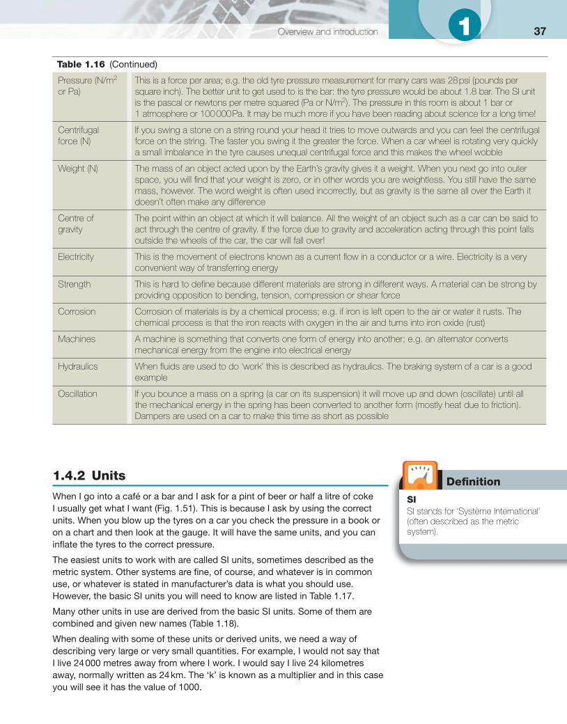
371
1.4.2 Units
When I go into a café or a bar and I ask for a pint of beer or half a litre of coke I usually get what I want ( Fig. 1.51 ). This is because I ask by using the correct units. When you blow up the tyres on a car you check the pressure in a book or on a chart and then look at the gauge. It will have the same units, and you can infl ate the tyres to the correct pressure.
The easiest units to work with are called SI units, sometimes described as the metric system. Other systems are fi ne, of course, and whatever is in common use, or whatever is stated in manufacturer’s data is what you should use. However, the basic SI units you will need to know are listed in Table 1.17 . Many other units in use are derived from the basic SI units. Some of them are combined and given new names ( Table 1.18 ).
When dealing with some of these units or derived units, we need a way of describing very large or very small quantities. For example, I would not say that I live 24 000 metres away from where I work. I would say I live 24 kilometres away, normally written as 24 km. The ‘k’ is known as a multiplier and in this case you will see it has the value of 1000.
Defi nition
SI SI stands for ‘Système International’ (often described as the metric system).
Pressure (N/m 2 or Pa)
This is a force per area; e.g. the old tyre pressure measurement for many cars was 28 psi (pounds per square inch). The better unit to get used to is the bar: the tyre pressure would be about 1.8 bar. The SI unit is the pascal or newtons per metre squared (Pa or N/m 2 ). The pressure in this room is about 1 bar or 1 atmosphere or 100 000 Pa. It may be much more if you have been reading about science for a long time!
Centrifugal force (N)
If you swing a stone on a string round your head it tries to move outwards and you can feel the centrifugal force on the string. The faster you swing it the greater the force. When a car wheel is rotating very quickly a small imbalance in the tyre causes unequal centrifugal force and this makes the wheel wobble
Weight (N) The mass of an object acted upon by the Earth’s gravity gives it a weight. When you next go into outer space, you will fi nd that your weight is zero, or in other words you are weightless. You still have the same mass, however. The word weight is often used incorrectly, but as gravity is the same all over the Earth it doesn’t often make any difference
Centre of gravity
The point within an object at which it will balance. All the weight of an object such as a car can be said to act through the centre of gravity. If the force due to gravity and acceleration acting through this point falls outside the wheels of the car, the car will fall over!
Electricity This is the movement of electrons known as a current fl ow in a conductor or a wire. Electricity is a very convenient way of transferring energy
Strength This is hard to defi ne because different materials are strong in different ways. A material can be strong by providing opposition to bending, tension, compression or shear force
Corrosion Corrosion of materials is by a chemical process; e.g. if iron is left open to the air or water it rusts. The chemical process is that the iron reacts with oxygen in the air and turns into iron oxide (rust)
Machines A machine is something that converts one form of energy into another; e.g. an alternator converts mechanical energy from the engine into electrical energy
Hydraulics When fl uids are used to do ‘work’ this is described as hydraulics. The braking system of a car is a good example
Oscillation If you bounce a mass on a spring (a car on its suspension) it will move up and down (oscillate) until all the mechanical energy in the spring has been converted to another form (mostly heat due to friction). Dampers are used on a car to make this time as short as possible
Table 1.16 (Continued)
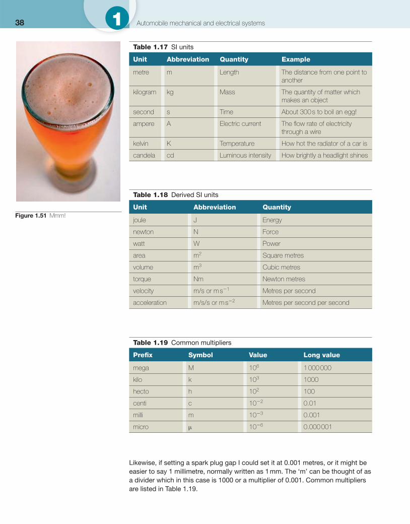
38 1 Automobile mechanical and electrical systems
Likewise, if setting a spark plug gap I could set it at 0.001 metres, or it might be easier to say 1 millimetre, normally written as 1 mm. The ‘m’ can be thought of as a divider which in this case is 1000 or a multiplier of 0.001. Common multipliers are listed in Table 1.19 .
Figure 1.51 Mmm!
Table 1.18 Derived SI units
Unit Abbreviation Quantity
joule J Energy
newton N Force
watt W Power
area m 2 Square metres
volume m 3 Cubic metres
torque Nm Newton metres
velocity m/s or m s �1 Metres per second
acceleration m/s/s or m s �2 Metres per second per second
Table 1.17 SI units
Unit Abbreviation Quantity Example
metre m Length The distance from one point to another
kilogram kg Mass The quantity of matter which makes an object
second s Time About 300 s to boil an egg!
ampere A Electric current The fl ow rate of electricity through a wire
kelvin K Temperature How hot the radiator of a car is
candela cd Luminous intensity How brightly a headlight shines
Table 1.19 Common multipliers
Prefi x Symbol Value Long value
mega M 10 6 1 000 000
kilo k 10 3 1000
hecto h 10 2 100
centi c 10 �2 0.01
milli m 10 �3 0.001
micro μ 10 �6 0.000 001
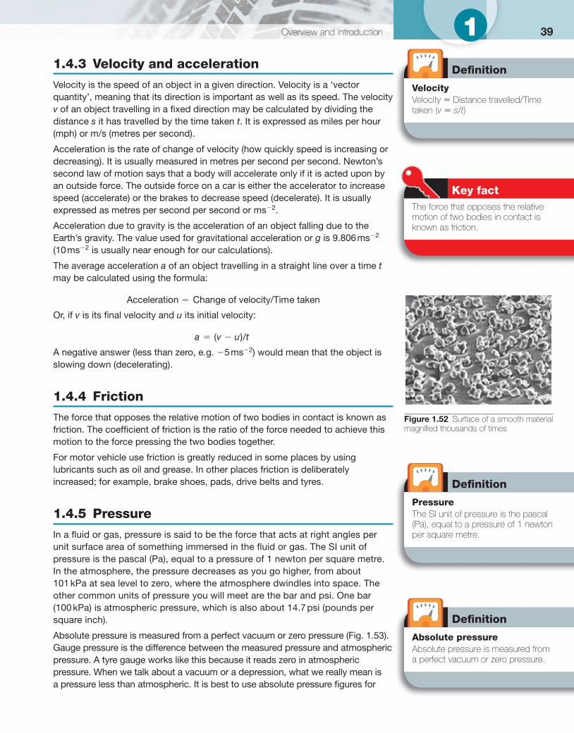
391 1.4.3 Velocity and acceleration
Velocity is the speed of an object in a given direction. Velocity is a ‘vector quantity’, meaning that its direction is important as well as its speed. The velocity v of an object travelling in a fi xed direction may be calculated by dividing the distance s it has travelled by the time taken t . It is expressed as miles per hour (mph) or m/s (metres per second). Acceleration is the rate of change of velocity (how quickly speed is increasing or decreasing). It is usually measured in metres per second per second. Newton’s second law of motion says that a body will accelerate only if it is acted upon by an outside force. The outside force on a car is either the accelerator to increase speed (accelerate) or the brakes to decrease speed (decelerate). It is usually expressed as metres per second per second or ms �2 .
Acceleration due to gravity is the acceleration of an object falling due to the Earth’s gravity. The value used for gravitational acceleration or g is 9.806 ms �2 (10 ms �2 is usually near enough for our calculations).
The average acceleration a of an object travelling in a straight line over a time t may be calculated using the formula:
Acceleration Change of velocity/Time taken�
Or, if v is its fi nal velocity and u its initial velocity:
a v u t( )/
A negative answer (less than zero, e.g. �5 ms �2 ) would mean that the object is slowing down (decelerating).
1.4.4 Friction
The force that opposes the relative motion of two bodies in contact is known as friction. The coeffi cient of friction is the ratio of the force needed to achieve this motion to the force pressing the two bodies together.
For motor vehicle use friction is greatly reduced in some places by using lubricants such as oil and grease. In other places friction is deliberately increased; for example, brake shoes, pads, drive belts and tyres.
1.4.5 Pressure
In a fl uid or gas, pressure is said to be the force that acts at right angles per unit surface area of something immersed in the fl uid or gas. The SI unit of pressure is the pascal (Pa), equal to a pressure of 1 newton per square metre. In the atmosphere, the pressure decreases as you go higher, from about 101 kPa at sea level to zero, where the atmosphere dwindles into space. The other common units of pressure you will meet are the bar and psi. One bar (100 kPa) is atmospheric pressure, which is also about 14.7 psi (pounds per square inch).
Absolute pressure is measured from a perfect vacuum or zero pressure ( Fig. 1.53 ). Gauge pressure is the difference between the measured pressure and atmospheric pressure. A tyre gauge works like this because it reads zero in atmospheric pressure. When we talk about a vacuum or a depression, what we really mean is a pressure less than atmospheric. It is best to use absolute pressure fi gures for
Defi nition
Velocity Velocity � Distance travelled/Time taken ( v � s / t )
Key fact The force that opposes the relative motion of two bodies in contact is known as friction.
Figure 1.52 Surface of a smooth material magnifi ed thousands of times
Defi nition
Pressure The SI unit of pressure is the pascal (Pa), equal to a pressure of 1 newton per square metre.
Defi nition
Absolute pressure Absolute pressure is measured from a perfect vacuum or zero pressure.
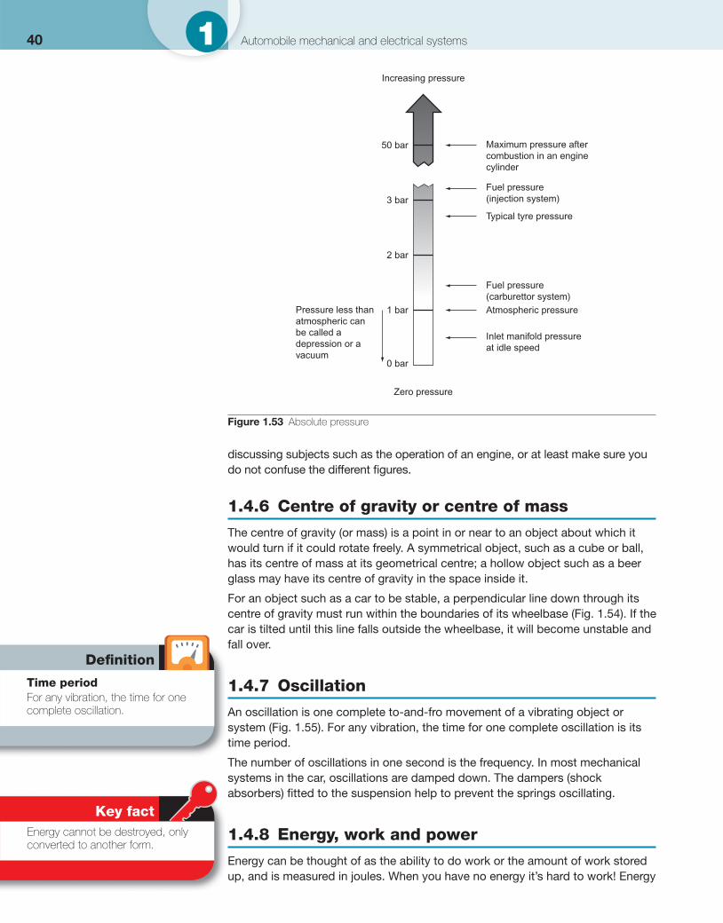
40 1 Automobile mechanical and electrical systems
discussing subjects such as the operation of an engine, or at least make sure you do not confuse the different fi gures.
1.4.6 Centre of gravity or centre of mass
The centre of gravity (or mass) is a point in or near to an object about which it would turn if it could rotate freely. A symmetrical object, such as a cube or ball, has its centre of mass at its geometrical centre; a hollow object such as a beer glass may have its centre of gravity in the space inside it.
For an object such as a car to be stable, a perpendicular line down through its centre of gravity must run within the boundaries of its wheelbase ( Fig. 1.54 ). If the car is tilted until this line falls outside the wheelbase, it will become unstable and fall over.
1.4.7 Oscillation
An oscillation is one complete to-and-fro movement of a vibrating object or system ( Fig. 1.55 ). For any vibration, the time for one complete oscillation is its time period.
The number of oscillations in one second is the frequency. In most mechanical systems in the car, oscillations are damped down. The dampers (shock absorbers) fi tted to the suspension help to prevent the springs oscillating.
1.4.8 Energy, work and power
Energy can be thought of as the ability to do work or the amount of work stored up, and is measured in joules. When you have no energy it’s hard to work! Energy
Increasing pressure
Maximum pressure aftercombustion in an enginecylinder
Fuel pressure(injection system)
Typical tyre pressure
Fuel pressure(carburettor system)Atmospheric pressure
Inlet manifold pressureat idle speed
50 bar
3 bar
2 bar
1 bar
0 bar
Zero pressure
Pressure less thanatmospheric canbe called adepression or avacuum
Figure 1.53 Absolute pressure
Defi nition
Time period For any vibration, the time for one complete oscillation.
Key fact Energy cannot be destroyed, only converted to another form.
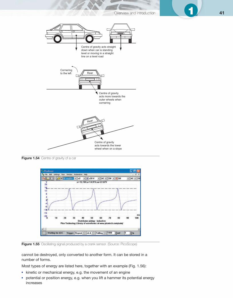
411
cannot be destroyed, only converted to another form. It can be stored in a number of forms.
Most types of energy are listed here, together with an example ( Fig. 1.56 ):
● kinetic or mechanical energy, e.g. the movement of an engine ● potential or position energy, e.g. when you lift a hammer its potential energy
increases
Centre of gravity acts straightdown when car is standinglevel or moving in a straightline on a level road
Corneringto the left
Centre of gravityacts more towards theouter wheels whencornering
Centre of gravityacts towards the lowerwheel when on a slope
Rear
Rear
Figure 1.54 Centre of gravity of a car
Figure 1.55 Oscillating signal produced by a crank sensor. (Source: PicoScope)
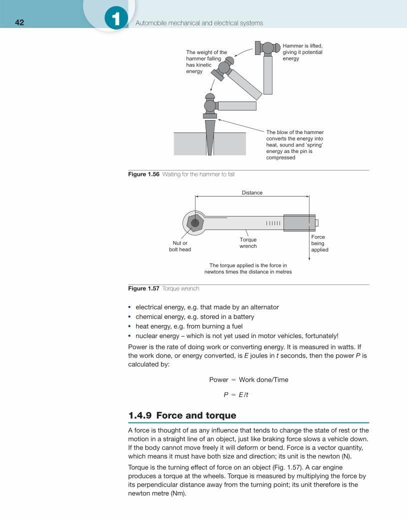
42 1 Automobile mechanical and electrical systems
● electrical energy, e.g. that made by an alternator ● chemical energy, e.g. stored in a battery ● heat energy, e.g. from burning a fuel ● nuclear energy – which is not yet used in motor vehicles, fortunately!
Power is the rate of doing work or converting energy. It is measured in watts. If the work done, or energy converted, is E joules in t seconds, then the power P is calculated by:
Power Work done/Time�
1.4.9 Force and torque
A force is thought of as any infl uence that tends to change the state of rest or the motion in a straight line of an object, just like braking force slows a vehicle down. If the body cannot move freely it will deform or bend. Force is a vector quantity, which means it must have both size and direction; its unit is the newton (N).
Torque is the turning effect of force on an object ( Fig. 1.57 ). A car engine produces a torque at the wheels. Torque is measured by multiplying the force by its perpendicular distance away from the turning point; its unit therefore is the newton metre (Nm).
P E t� /
The weight of thehammer fallinghas kineticenergy
Hammer is lifted,giving it potentialenergy
The blow of the hammerconverts the energy intoheat, sound and ‘spring’energy as the pin iscompressed
Figure 1.56 Waiting for the hammer to fall
Distance
Forcebeingapplied
TorquewrenchNut or
bolt head
The torque applied is the force innewtons times the distance in metres
Figure 1.57 Torque wrench
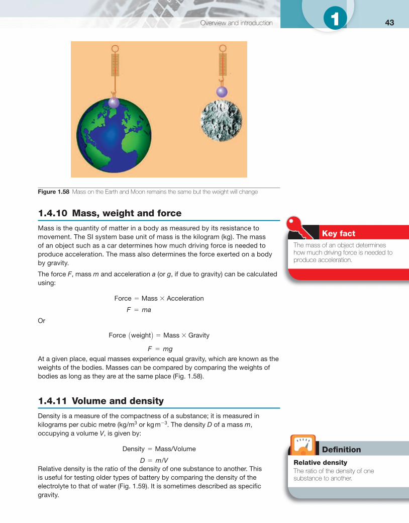
431
1.4.10 Mass, weight and force
Mass is the quantity of matter in a body as measured by its resistance to movement. The SI system base unit of mass is the kilogram (kg). The mass of an object such as a car determines how much driving force is needed to produce acceleration. The mass also determines the force exerted on a body by gravity.
The force F , mass m and acceleration a (or g , if due to gravity) can be calculated using:
Force Mass Acceleration
Or
Force weight Mass Gravity( )
At a given place, equal masses experience equal gravity, which are known as the weights of the bodies. Masses can be compared by comparing the weights of bodies as long as they are at the same place ( Fig. 1.58 ).
1.4.11 Volume and density
Density is a measure of the compactness of a substance; it is measured in kilograms per cubic metre (kg/m 3 or kg m �3 . The density D of a mass m , occupying a volume V , is given by:
Density Mass/Volume�
Relative density is the ratio of the density of one substance to another. This is useful for testing older types of battery by comparing the density of the electrolyte to that of water ( Fig. 1.59 ). It is sometimes described as specifi c gravity.
F ma�
F mg�
D m V� /
Figure 1.58 Mass on the Earth and Moon remains the same but the weight will change
Key fact The mass of an object determines how much driving force is needed to produce acceleration.
Defi nition
Relative density The ratio of the density of one substance to another.
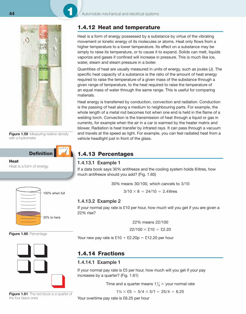
44 1 Automobile mechanical and electrical systems
1.4.12 Heat and temperature
Heat is a form of energy possessed by a substance by virtue of the vibrating movement or kinetic energy of its molecules or atoms. Heat only fl ows from a higher temperature to a lower temperature. Its effect on a substance may be simply to raise its temperature, or to cause it to expand. Solids can melt, liquids vaporize and gases if confi ned will increase in pressure. This is much like ice, water, steam and steam pressure in a boiler.
Quantities of heat are usually measured in units of energy, such as joules (J). The specifi c heat capacity of a substance is the ratio of the amount of heat energy required to raise the temperature of a given mass of the substance through a given range of temperature, to the heat required to raise the temperature of an equal mass of water through the same range. This is useful for comparing materials.
Heat energy is transferred by conduction, convection and radiation. Conduction is the passing of heat along a medium to neighbouring parts. For example, the whole length of a metal rod becomes hot when one end is held in the fl ame of a welding torch. Convection is the transmission of heat through a liquid or gas in currents, for example when the air in a car is warmed by the heater matrix and blower. Radiation is heat transfer by infrared rays. It can pass through a vacuum and travels at the speed as light. For example, you can feel radiated heat from a vehicle headlight just in front of the glass.
1.4.13 Percentages
1.4.13.1 Example 1 If a data book says 30% antifreeze and the cooling system holds 8 litres, how much antifreeze should you add? ( Fig. 1.60 )
30 30 100 3 10% , means / which cancels to /
3 10 8 24 10 2 4/ / litres.
1.4.13.2 Example 2 If your normal pay rate is £10 per hour, how much will you get if you are given a 22% rise?
22 22 100% means /
22 100 10 2 20/ £ £ .
Your new pay rate is £10 � £2.20p � £12.20 per hour
1.4.14 Fractions
1.4.14.1 Example 1
If your normal pay rate is £5 per hour, how much will you get if your pay increases by a quarter? (Fig. 1.61)
Time and a quarter means your normal rate114 �
1 5 5 4 5 1 25 4 6 25¼ £ ./ / /
Your overtime pay rate is £6.25 per hour
Figure 1.59 Measuring relative density with a hydrometer
100% when full
30% to here
Figure 1.60 Percentage
Defi nition
Heat Heat is a form of energy.
Figure 1.61 The red block is a quarter of the four black ones
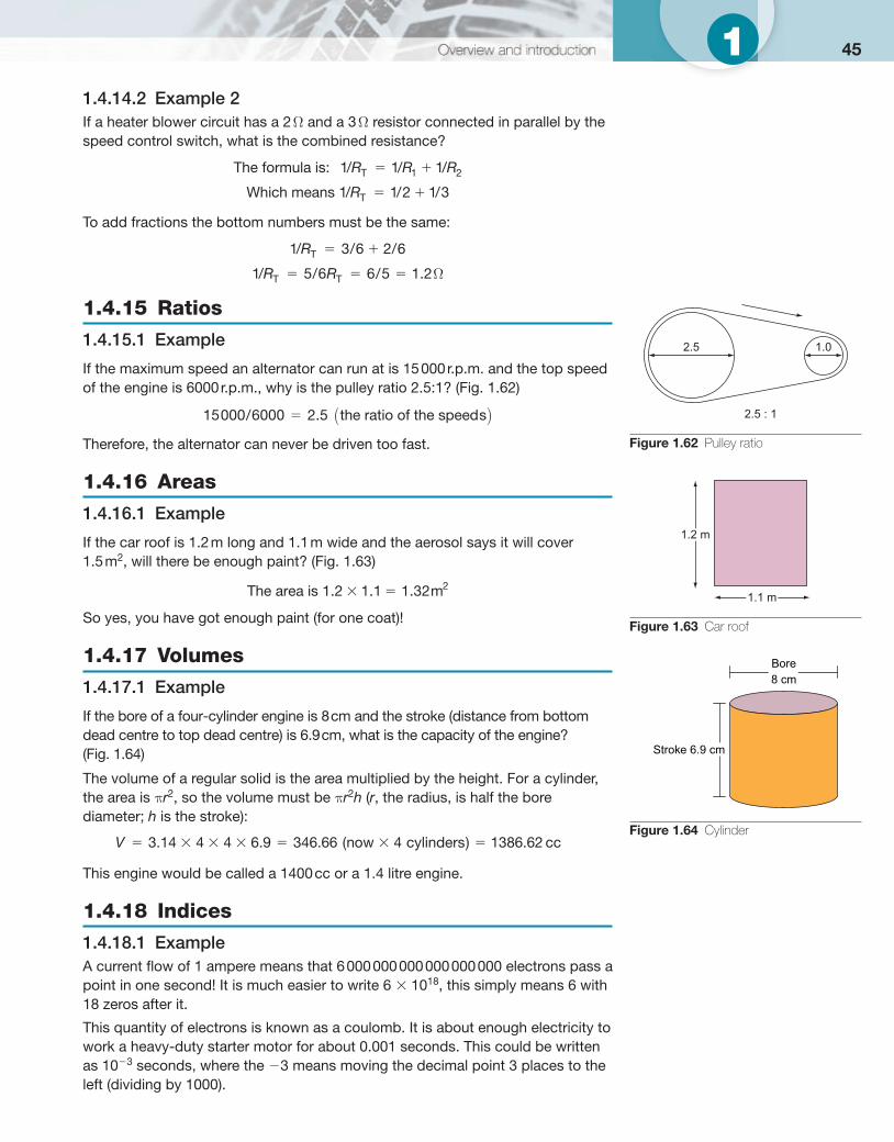
451 1.4.14.2 Example 2 If a heater blower circuit has a 2 Ω and a 3 Ω resistor connected in parallel by the speed control switch, what is the combined resistance?
The formula is / / /T: 1 1 11 2R R R
Which means / / /T1 1 2 1 3R
To add fractions the bottom numbers must be the same:
1 3 6 2 6/ / /TR
1 5 6 6 5 1 2/ / /T TR R� � � . Ω
1.4.15 Ratios
1.4.15.1 Example
If the maximum speed an alternator can run at is 15 000 r.p.m. and the top speed of the engine is 6000 r.p.m., why is the pulley ratio 2.5:1? (Fig. 1.62)
15000 6000 2 5/ the ratio of the speeds� . ( )
Therefore, the alternator can never be driven too fast.
1.4.16 Areas
1.4.16.1 Example
If the car roof is 1.2 m long and 1.1 m wide and the aerosol says it will cover 1.5 m 2 , will there be enough paint? (Fig. 1.63)
The area is m21 2 1 1 1 32. . .
So yes, you have got enough paint (for one coat)!
1.4.17 Volumes
1.4.17.1 Example
If the bore of a four-cylinder engine is 8 cm and the stroke (distance from bottom dead centre to top dead centre) is 6.9 cm, what is the capacity of the engine? (Fig. 1.64)
The volume of a regular solid is the area multiplied by the height. For a cylinder, the area is π r 2 , so the volume must be π r 2 h ( r , the radius, is half the bore diameter; h is the stroke):
V 3 14 4 4 6 9 346 66 4 1386 62. . . ( ) . now cylinders cc
This engine would be called a 1400 cc or a 1.4 litre engine.
1.4.18 Indices
1.4.18.1 Example A current fl ow of 1 ampere means that 6 000 000 000 000 000 000 electrons pass a point in one second! It is much easier to write 6 � 10 18 , this simply means 6 with 18 zeros after it.
This quantity of electrons is known as a coulomb. It is about enough electricity to work a heavy-duty starter motor for about 0.001 seconds. This could be written as 10 �3 seconds, where the �3 means moving the decimal point 3 places to the left (dividing by 1000).
2.5 1.0
2.5 : 1
Figure 1.62 Pulley ratio
1.1 m
1.2 m
Figure 1.63 Car roof
Stroke 6.9 cm
Bore8 cm
Figure 1.64 Cylinder
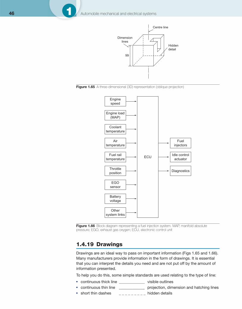
46 1 Automobile mechanical and electrical systems
1.4.19 Drawings
Drawings are an ideal way to pass on important information ( Figs 1.65 and 1.66 ). Many manufacturers provide information in the form of drawings. It is essential that you can interpret the details you need and are not put off by the amount of information presented.
To help you do this, some simple standards are used relating to the type of line:
● continuous thick line _____________ visible outlines ● continuous thin line _____________ projection, dimension and hatching lines ● short thin dashes _ _ _ _ _ _ _ _ _ hidden details
Centre line
Hiddendetail
Dimensionlines
99
Figure 1.65 A three-dimensional (3D) representation (oblique projection)
Enginespeed
Engine load(MAP)
Coolanttemperature
Airtemperature
Fuel railtemperature
Fuelinjectors
Idle controlactuator
DiagnosticsThrottleposition
EGOsensor
Batteryvoltage
Othersystem links
ECU
Figure 1.66 Block diagram representing a fuel injection system. MAP, manifold absolute pressure; EGO, exhaust gas oxygen; ECU, electronic control unit
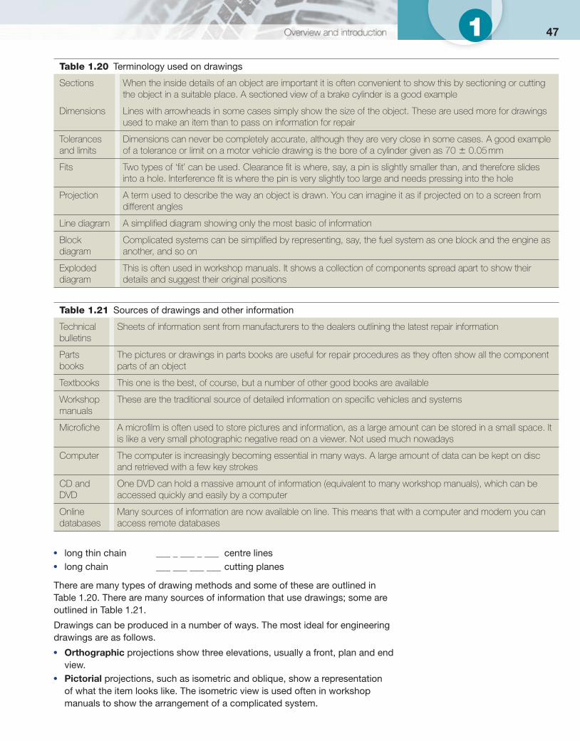
471
● long thin chain ___ _ ___ _ ___ centre lines ● long chain ___ ___ ___ ___ cutting planes
There are many types of drawing methods and some of these are outlined in Table 1.20 . There are many sources of information that use drawings; some are outlined in Table 1.21 .
Drawings can be produced in a number of ways. The most ideal for engineering drawings are as follows.
● Orthographic projections show three elevations, usually a front, plan and end view.
● Pictorial projections, such as isometric and oblique, show a representation of what the item looks like. The isometric view is used often in workshop manuals to show the arrangement of a complicated system.
Table 1.20 Terminology used on drawings
Sections When the inside details of an object are important it is often convenient to show this by sectioning or cutting the object in a suitable place. A sectioned view of a brake cylinder is a good example
Dimensions Lines with arrowheads in some cases simply show the size of the object. These are used more for drawings used to make an item than to pass on information for repair
Tolerances and limits
Dimensions can never be completely accurate, although they are very close in some cases. A good example of a tolerance or limit on a motor vehicle drawing is the bore of a cylinder given as 70 � 0.05 mm
Fits Two types of ‘fi t’ can be used. Clearance fi t is where, say, a pin is slightly smaller than, and therefore slides into a hole. Interference fi t is where the pin is very slightly too large and needs pressing into the hole
Projection A term used to describe the way an object is drawn. You can imagine it as if projected on to a screen from different angles
Line diagram A simplifi ed diagram showing only the most basic of information
Block diagram
Complicated systems can be simplifi ed by representing, say, the fuel system as one block and the engine as another, and so on
Exploded diagram
This is often used in workshop manuals. It shows a collection of components spread apart to show their details and suggest their original positions
Table 1.21 Sources of drawings and other information
Technical bulletins
Sheets of information sent from manufacturers to the dealers outlining the latest repair information
Parts books
The pictures or drawings in parts books are useful for repair procedures as they often show all the component parts of an object
Textbooks This one is the best, of course, but a number of other good books are available
Workshop manuals
These are the traditional source of detailed information on specifi c vehicles and systems
Microfi che A microfi lm is often used to store pictures and information, as a large amount can be stored in a small space. It is like a very small photographic negative read on a viewer. Not used much nowadays
Computer The computer is increasingly becoming essential in many ways. A large amount of data can be kept on disc and retrieved with a few key strokes
CD and DVD
One DVD can hold a massive amount of information (equivalent to many workshop manuals), which can be accessed quickly and easily by a computer
Online databases
Many sources of information are now available on line. This means that with a computer and modem you can access remote databases
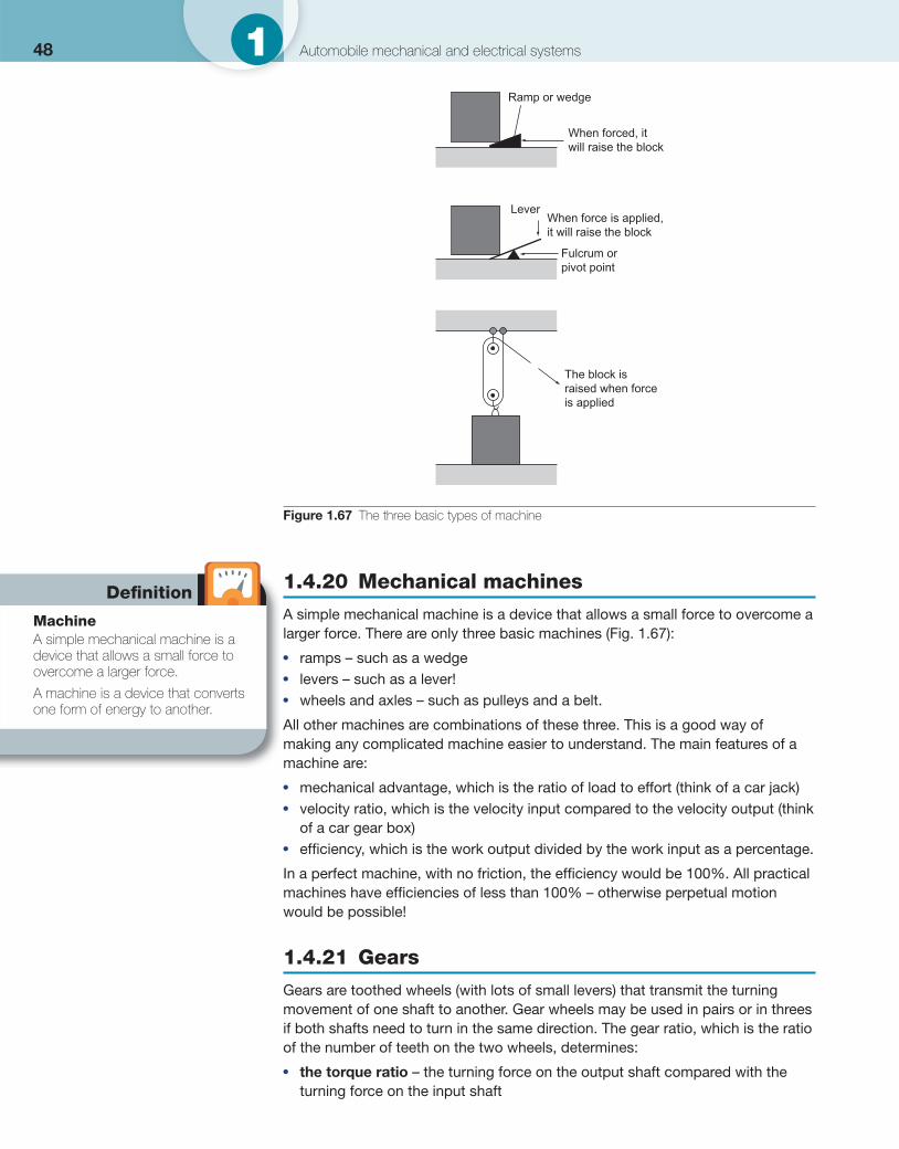
48 1 Automobile mechanical and electrical systems
1.4.20 Mechanical machines
A simple mechanical machine is a device that allows a small force to overcome a larger force. There are only three basic machines ( Fig. 1.67 ): ● ramps – such as a wedge ● levers – such as a lever! ● wheels and axles – such as pulleys and a belt.
All other machines are combinations of these three. This is a good way of making any complicated machine easier to understand. The main features of a machine are:
● mechanical advantage, which is the ratio of load to effort (think of a car jack) ● velocity ratio, which is the velocity input compared to the velocity output (think
of a car gear box) ● effi ciency, which is the work output divided by the work input as a percentage.
In a perfect machine, with no friction, the effi ciency would be 100%. All practical machines have effi ciencies of less than 100% – otherwise perpetual motion would be possible!
1.4.21 Gears
Gears are toothed wheels (with lots of small levers) that transmit the turning movement of one shaft to another. Gear wheels may be used in pairs or in threes if both shafts need to turn in the same direction. The gear ratio, which is the ratio of the number of teeth on the two wheels, determines:
● the torque ratio – the turning force on the output shaft compared with the turning force on the input shaft
Ramp or wedge
When forced, itwill raise the block
Fulcrum orpivot point
The block israised when forceis applied
LeverWhen force is applied,it will raise the block
Figure 1.67 The three basic types of machine
Defi nition
Machine A simple mechanical machine is a device that allows a small force to overcome a larger force.
A machine is a device that converts one form of energy to another.
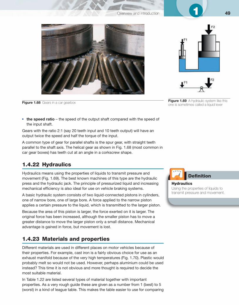
491
● the speed ratio – the speed of the output shaft compared with the speed of the input shaft.
Gears with the ratio 2:1 (say 20 teeth input and 10 teeth output) will have an output twice the speed and half the torque of the input.
A common type of gear for parallel shafts is the spur gear, with straight teeth parallel to the shaft axis. The helical gear as shown in Fig. 1.68 (most common in car gear boxes) has teeth cut at an angle in a corkscrew shape.
1.4.22 Hydraulics
Hydraulics means using the properties of liquids to transmit pressure and movement ( Fig. 1.69 ). The best known machines of this type are the hydraulic press and the hydraulic jack. The principle of pressurized liquid and increasing mechanical effi ciency is also ideal for use on vehicle braking systems. A basic hydraulic system consists of two liquid-connected pistons in cylinders, one of narrow bore, one of large bore. A force applied to the narrow piston applies a certain pressure to the liquid, which is transmitted to the larger piston.
Because the area of this piston is larger, the force exerted on it is larger. The original force has been increased, although the smaller piston has to move a greater distance to move the larger piston only a small distance. Mechanical advantage is gained in force, but movement is lost.
1.4.23 Materials and properties
Different materials are used in different places on motor vehicles because of their properties. For example, cast iron is a fairly obvious choice for use as an exhaust manifold because of the very high temperatures ( Fig. 1.70 ). Plastic would probably melt so would not be used. However, perhaps aluminium could be used instead? This time it is not obvious and more thought is required to decide the most suitable material.
In Table 1.22 are listed several types of material together with important properties. As a very rough guide these are given as a number from 1 (best) to 5 (worst) in a kind of league table. This makes the table easier to use for comparing
Figure 1.68 Gears in a car gearbox
Defi nition
Hydraulics Using the properties of liquids to transmit pressure and movement.
Figure 1.69 A hydraulic system like this one is sometimes called a liquid lever

50 1 Automobile mechanical and electrical systems
one material with another. Note that this table is just to help you compare properties; the league table positions are only rough estimates and will vary with different examples of the same material.
Corrosion is the eating away and eventual destruction of metals and alloys (mixtures of metals) by chemical action ( Fig. 1.71 ). Most metals corrode eventually, but the rusting of ordinary iron and steel is the most common form of corrosion. Rusting of iron or steel takes place in damp air, when the iron
Figure 1.70 Cast iron exhaust manifold
Table 1.22 Comparison of material properties
Material Ease of shaping
Strength Resistance to heat
Electrical resistance
Corrosion resistance
Cost Typical motor vehicle uses
Copper 2 3 2 1 3 4 Wires and electrical parts
Aluminium 2 3 2 1 3 4 Cylinder heads
Steel 3 2 1 1 4 3 Body panels and exhausts
Cast iron 3 2 1 1 4 3 Manifolds and engine blocks
Platinum 3 1 1 1 2 5 Spark plug tips
Soft plastic
1 5 5 5 1 1 Electrical insulators
Hard plastic
1 4 4 5 1 1 Interiors and some engine components
Glass 3 5 2 5 1 2 Screens and windows
Rubber 2 4 5 5 3 2 Tyres and hoses
Ceramics 4 4 1 5 1 4 Spark plug insulators
1 � best; 5 � worst.
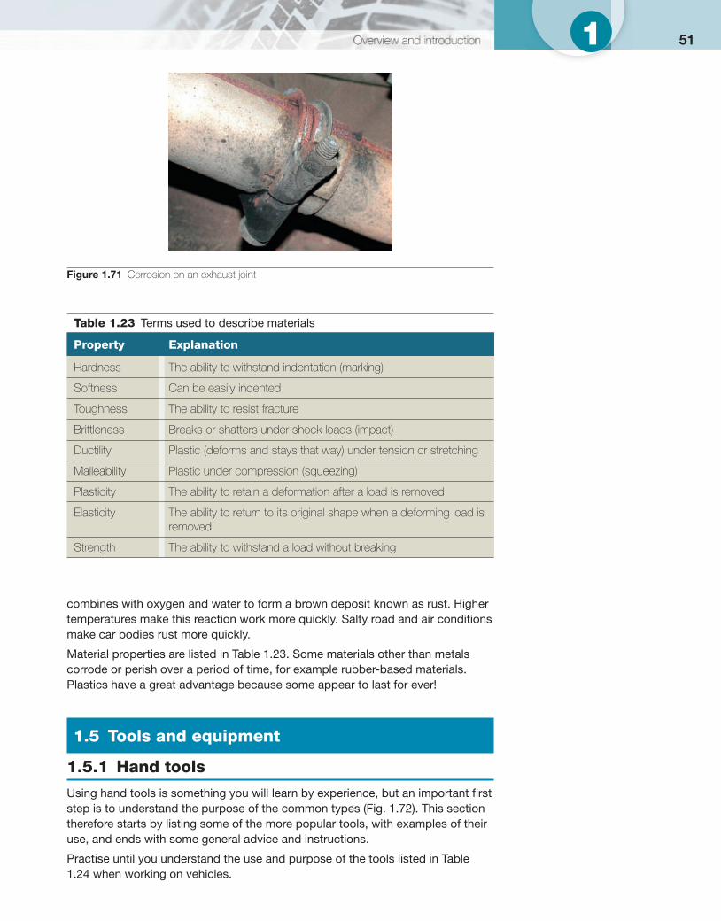
511
combines with oxygen and water to form a brown deposit known as rust. Higher temperatures make this reaction work more quickly. Salty road and air conditions make car bodies rust more quickly.
Material properties are listed in Table 1.23 . Some materials other than metals corrode or perish over a period of time, for example rubber-based materials. Plastics have a great advantage because some appear to last for ever!
1.5 Tools and equipment
1.5.1 Hand tools
Using hand tools is something you will learn by experience, but an important fi rst step is to understand the purpose of the common types ( Fig. 1.72 ). This section therefore starts by listing some of the more popular tools, with examples of their use, and ends with some general advice and instructions.
Practise until you understand the use and purpose of the tools listed in Table 1.24 when working on vehicles.
Figure 1.71 Corrosion on an exhaust joint
Table 1.23 Terms used to describe materials
Property Explanation
Hardness The ability to withstand indentation (marking)
Softness Can be easily indented
Toughness The ability to resist fracture
Brittleness Breaks or shatters under shock loads (impact)
Ductility Plastic (deforms and stays that way) under tension or stretching
Malleability Plastic under compression (squeezing)
Plasticity The ability to retain a deformation after a load is removed
Elasticity The ability to return to its original shape when a deforming load is removed
Strength The ability to withstand a load without breaking
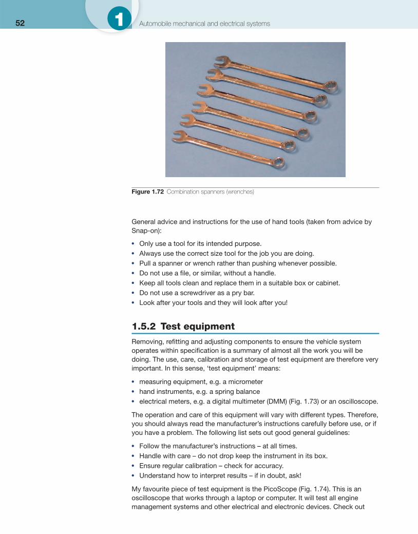
52 1 Automobile mechanical and electrical systems
General advice and instructions for the use of hand tools (taken from advice by Snap-on):
● Only use a tool for its intended purpose. ● Always use the correct size tool for the job you are doing. ● Pull a spanner or wrench rather than pushing whenever possible. ● Do not use a fi le, or similar, without a handle. ● Keep all tools clean and replace them in a suitable box or cabinet. ● Do not use a screwdriver as a pry bar. ● Look after your tools and they will look after you!
1.5.2 Test equipment
Removing, refi tting and adjusting components to ensure the vehicle system operates within specifi cation is a summary of almost all the work you will be doing. The use, care, calibration and storage of test equipment are therefore very important. In this sense, ‘test equipment’ means:
● measuring equipment, e.g. a micrometer ● hand instruments, e.g. a spring balance ● electrical meters, e.g. a digital multimeter (DMM) ( Fig. 1.73 ) or an oscilloscope.
The operation and care of this equipment will vary with different types. Therefore, you should always read the manufacturer’s instructions carefully before use, or if you have a problem. The following list sets out good general guidelines:
● Follow the manufacturer’s instructions – at all times. ● Handle with care – do not drop keep the instrument in its box. ● Ensure regular calibration – check for accuracy. ● Understand how to interpret results – if in doubt, ask!
My favourite piece of test equipment is the PicoScope ( Fig. 1.74 ). This is an oscilloscope that works through a laptop or computer. It will test all engine management systems and other electrical and electronic devices. Check out
Figure 1.72 Combination spanners (wrenches)
531
www.picoauto.com for more information. Figure 1.75 shows a signal from an inductive sensor taken using the PicoScope.
1.5.3 Workshop equipment
In addition to hand tools and test equipment, most workshops will also have a range of equipment for lifting and supporting as well as electrical or air-operated
Key fact An oscilloscope draws a graph of voltage against time.
Table 1.24 Hand tools
Hand tool Example uses and/or notes
Adjustable spanner (wrench)
An ideal standby tool and useful for holding one end of a nut and bolt
Open-ended spanner
Use for nuts and bolts where access is limited or a ring spanner cannot be used
Ring spanner The best tool for holding hexagon bolts or nuts. If fi tted correctly it will not slip and damage both you and the bolt head
Torque wrench Essential for correct tightening of fi xings. The wrench can be set in most cases to ‘click’ when the required torque has been reached. Many fi tters think it is clever not to use a torque wrench. Good technicians realize the benefi ts
Socket wrench Often contains a ratchet to make operation far easier
Hexagon socket spanner
Sockets are ideal for many jobs where a spanner cannot be used. In many cases a socket is quicker and easier than a spanner. Extensions and swivel joints are also available to help reach that awkward bolt
Air wrench Often referred to a a wheel gun. Air-driven tools are great for speeding up your work but it is easy to damage components because an air wrench is very powerful. Only special, extra strong, high-quality sockets should be used
Blade (engineer’s) screwdriver
Simple common screw heads. Use the correct size!
Pozidriv, Phillips and cross-head screwdrivers
Better grip is possible, particularly with the Pozidriv, but learn not to confuse these three very similar types. The wrong type will slip and damage will occur
Torx® Similar to a hexagon tool like an Allen key but with further fl utes cut in the side. It can transmit good torque
Special-purpose wrenches
Many different types are available. As an example, mole grips are very useful tools as they hold like pliers but can lock in position
Pliers Used for gripping and pulling or bending. They are available in a wide variety of sizes, from snipe nose for electrical work, to engineers’ pliers for larger jobs such as fi tting split pins
Lever Used to apply a very large force to a small area. If you remember this you will realize how if incorrectly applied, it is easy to damage a component
Hammer Anybody can hit something with a hammer, but exactly how hard and where is a great skill to learn!
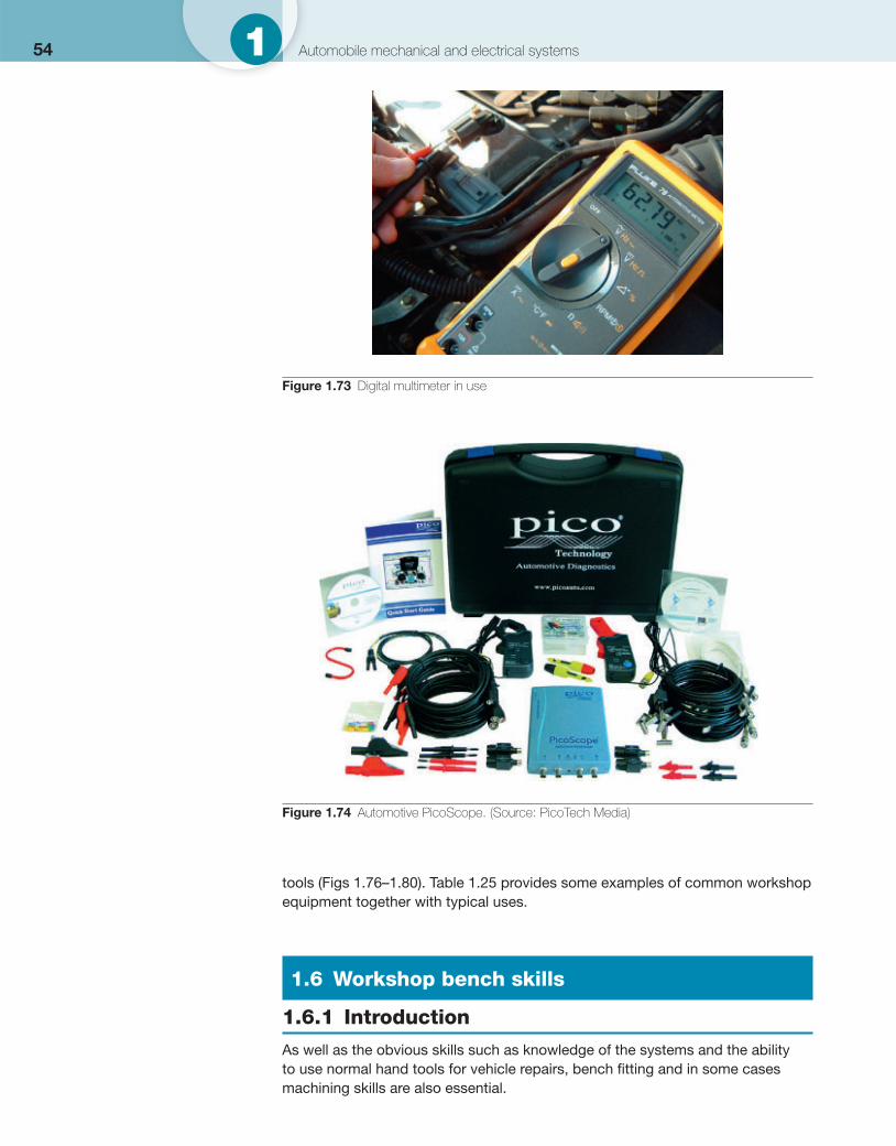
54 1 Automobile mechanical and electrical systems
tools ( Figs 1.76–1.80 ). Table 1.25 provides some examples of common workshop equipment together with typical uses.
1.6 Workshop bench skills
1.6.1 Introduction
As well as the obvious skills such as knowledge of the systems and the ability to use normal hand tools for vehicle repairs, bench fi tting and in some cases machining skills are also essential.
Figure 1.73 Digital multimeter in use
Figure 1.74 Automotive PicoScope. (Source: PicoTech Media)
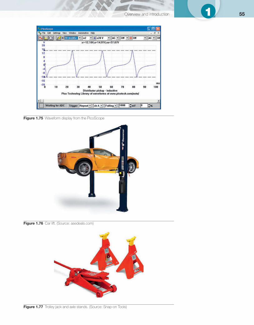
551
Figure 1.75 Waveform display from the PicoScope
Figure 1.76 Car lift. (Source: asedeals.com)
Figure 1.77 Trolley jack and axle stands. (Source: Snap-on Tools)
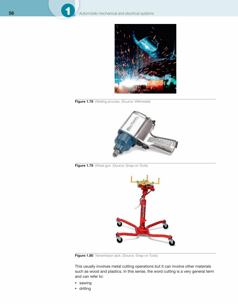
56 1 Automobile mechanical and electrical systems
This usually involves metal cutting operations but it can involve other materials such as wood and plastics. In this sense, the word cutting is a very general term and can refer to:
● sawing ● drilling
Figure 1.78 Welding process. (Source: Wikimedia)
Figure 1.79 Wheel gun. (Source: Snap-on Tools)
Figure 1.80 Transmission jack. (Source: Snap-on Tools)
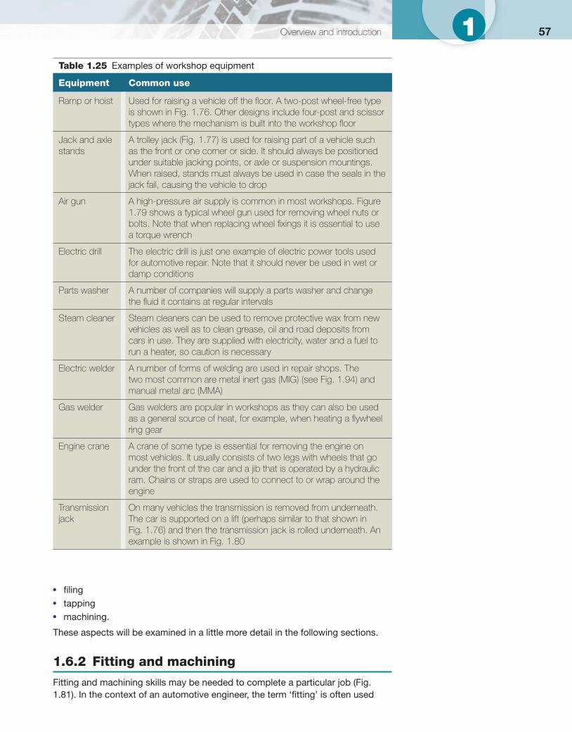
571
● fi ling ● tapping ● machining.
These aspects will be examined in a little more detail in the following sections.
1.6.2 Fitting and machining
Fitting and machining skills may be needed to complete a particular job ( Fig. 1.81 ). In the context of an automotive engineer, the term ‘fi tting’ is often used
Table 1.25 Examples of workshop equipment
Equipment Common use
Ramp or hoist Used for raising a vehicle off the fl oor. A two-post wheel-free type is shown in Fig. 1.76 . Other designs include four-post and scissor types where the mechanism is built into the workshop fl oor
Jack and axle stands
A trolley jack ( Fig. 1.77 ) is used for raising part of a vehicle such as the front or one corner or side. It should always be positioned under suitable jacking points, or axle or suspension mountings. When raised, stands must always be used in case the seals in the jack fail, causing the vehicle to drop
Air gun A high-pressure air supply is common in most workshops. Figure 1.79 shows a typical wheel gun used for removing wheel nuts or bolts. Note that when replacing wheel fi xings it is essential to use a torque wrench
Electric drill The electric drill is just one example of electric power tools used for automotive repair. Note that it should never be used in wet or damp conditions
Parts washer A number of companies will supply a parts washer and change the fl uid it contains at regular intervals
Steam cleaner Steam cleaners can be used to remove protective wax from new vehicles as well as to clean grease, oil and road deposits from cars in use. They are supplied with electricity, water and a fuel to run a heater, so caution is necessary
Electric welder A number of forms of welding are used in repair shops. The two most common are metal inert gas (MIG) (see Fig. 1.94 ) and manual metal arc (MMA)
Gas welder Gas welders are popular in workshops as they can also be used as a general source of heat, for example, when heating a fl ywheel ring gear
Engine crane A crane of some type is essential for removing the engine on most vehicles. It usually consists of two legs with wheels that go under the front of the car and a jib that is operated by a hydraulic ram. Chains or straps are used to connect to or wrap around the engine
Transmission jack
On many vehicles the transmission is removed from underneath. The car is supported on a lift (perhaps similar to that shown in Fig. 1.76 ) and then the transmission jack is rolled underneath. An example is shown in Fig. 1.80
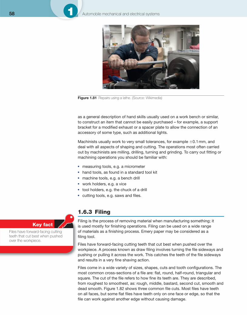
58 1 Automobile mechanical and electrical systems
as a general description of hand skills usually used on a work bench or similar, to construct an item that cannot be easily purchased – for example, a support bracket for a modifi ed exhaust or a spacer plate to allow the connection of an accessory of some type, such as additional lights.
Machinists usually work to very small tolerances, for example �0.1 mm, and deal with all aspects of shaping and cutting. The operations most often carried out by machinists are milling, drilling, turning and grinding. To carry out fi tting or machining operations you should be familiar with:
● measuring tools, e.g. a micrometer ● hand tools, as found in a standard tool kit ● machine tools, e.g. a bench drill ● work holders, e.g. a vice ● tool holders, e.g. the chuck of a drill ● cutting tools, e.g. saws and fi les.
1.6.3 Filing
Filing is the process of removing material when manufacturing something; it is used mostly for fi nishing operations. Filing can be used on a wide range of materials as a fi nishing process. Emery paper may be considered as a fi ling tool.
Files have forward-facing cutting teeth that cut best when pushed over the workpiece. A process known as draw fi ling involves turning the fi le sideways and pushing or pulling it across the work. This catches the teeth of the fi le sideways and results in a very fi ne shaving action.
Files come in a wide variety of sizes, shapes, cuts and tooth confi gurations. The most common cross-sections of a fi le are: fl at, round, half-round, triangular and square. The cut of the fi le refers to how fi ne its teeth are. They are described, from roughest to smoothest, as: rough, middle, bastard, second cut, smooth and dead smooth. Figure 1.82 shows three common fi le cuts. Most fi les have teeth on all faces, but some fl at fi les have teeth only on one face or edge, so that the fi le can work against another edge without causing damage.
Figure 1.81 Repairs using a lathe. (Source: Wikimedia)
Key fact Files have forward-facing cutting teeth that cut best when pushed over the workpiece.
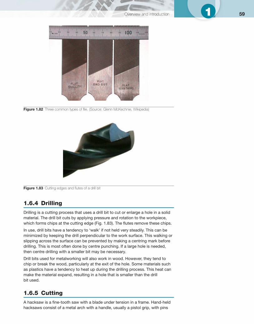
591
1.6.4 Drilling
Drilling is a cutting process that uses a drill bit to cut or enlarge a hole in a solid material. The drill bit cuts by applying pressure and rotation to the workpiece, which forms chips at the cutting edge ( Fig. 1.83 ). The fl utes remove these chips.
In use, drill bits have a tendency to ‘walk’ if not held very steadily. This can be minimized by keeping the drill perpendicular to the work surface. This walking or slipping across the surface can be prevented by making a centring mark before drilling. This is most often done by centre punching. If a large hole is needed, then centre drilling with a smaller bit may be necessary.
Drill bits used for metalworking will also work in wood. However, they tend to chip or break the wood, particularly at the exit of the hole. Some materials such as plastics have a tendency to heat up during the drilling process. This heat can make the material expand, resulting in a hole that is smaller than the drill bit used.
1.6.5 Cutting
A hacksaw is a fi ne-tooth saw with a blade under tension in a frame. Hand-held hacksaws consist of a metal arch with a handle, usually a pistol grip, with pins
Figure 1.82 Three common types of fi le. (Source: Glenn McKechnie, Wikipedia)
Figure 1.83 Cutting edges and fl utes of a drill bit
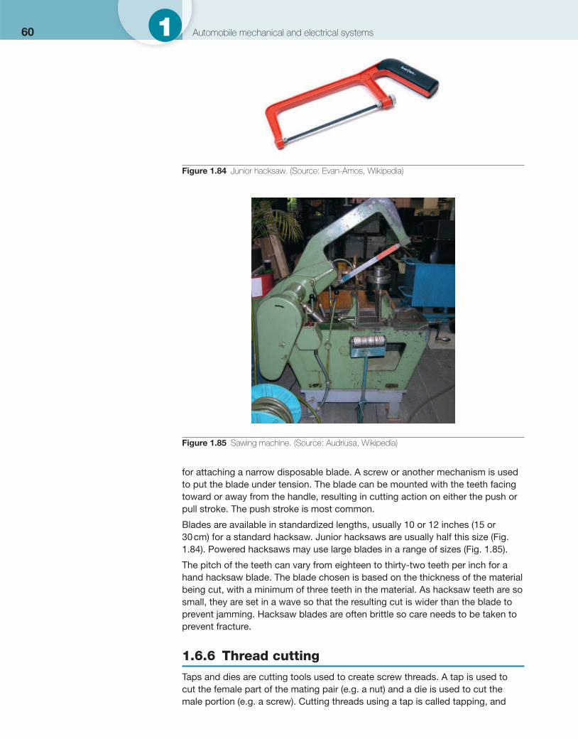
60 1 Automobile mechanical and electrical systems
for attaching a narrow disposable blade. A screw or another mechanism is used to put the blade under tension. The blade can be mounted with the teeth facing toward or away from the handle, resulting in cutting action on either the push or pull stroke. The push stroke is most common.
Blades are available in standardized lengths, usually 10 or 12 inches (15 or 30 cm) for a standard hacksaw. Junior hacksaws are usually half this size ( Fig. 1.84 ). Powered hacksaws may use large blades in a range of sizes ( Fig. 1.85 ).
The pitch of the teeth can vary from eighteen to thirty-two teeth per inch for a hand hacksaw blade. The blade chosen is based on the thickness of the material being cut, with a minimum of three teeth in the material. As hacksaw teeth are so small, they are set in a wave so that the resulting cut is wider than the blade to prevent jamming. Hacksaw blades are often brittle so care needs to be taken to prevent fracture.
1.6.6 Thread cutting
Taps and dies are cutting tools used to create screw threads. A tap is used to cut the female part of the mating pair (e.g. a nut) and a die is used to cut the male portion (e.g. a screw). Cutting threads using a tap is called tapping, and
Figure 1.84 Junior hacksaw. (Source: Evan-Amos, Wikipedia)
Figure 1.85 Sawing machine. (Source: Audriusa, Wikipedia)
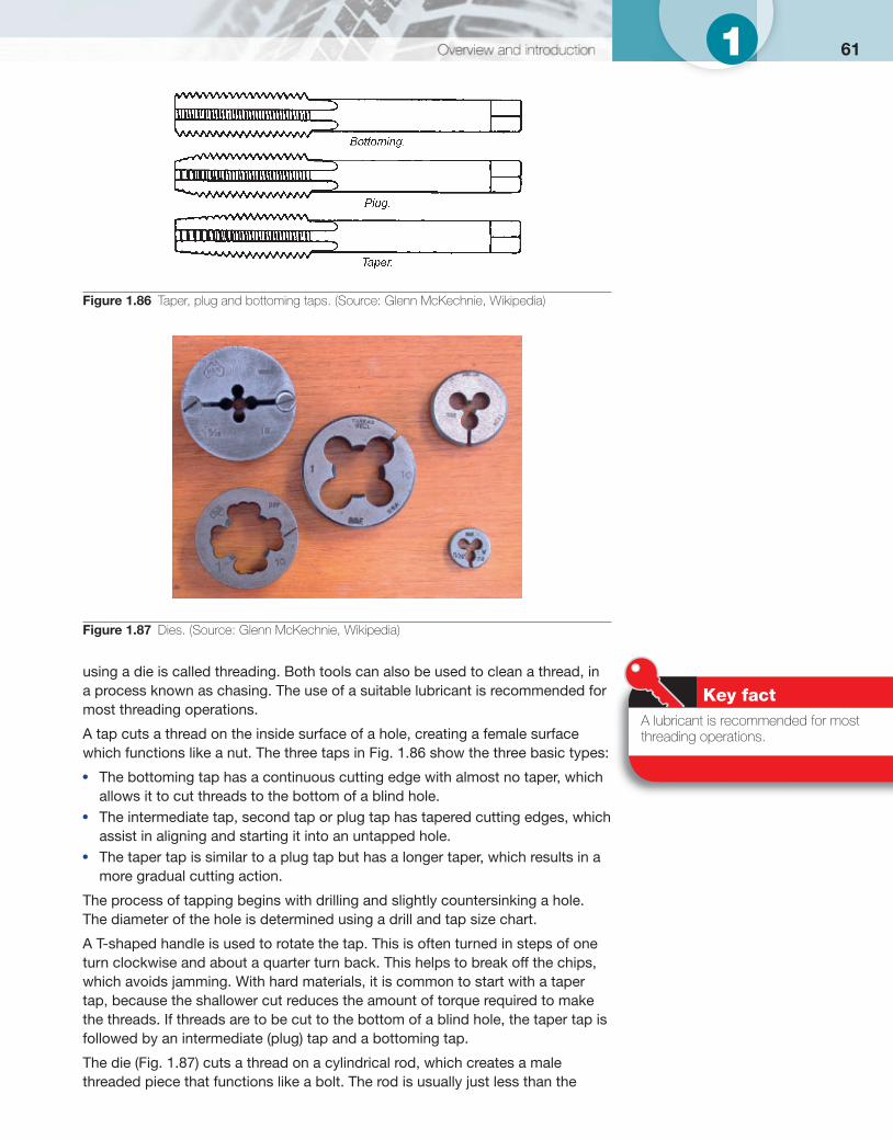
611
using a die is called threading. Both tools can also be used to clean a thread, in a process known as chasing. The use of a suitable lubricant is recommended for most threading operations. A tap cuts a thread on the inside surface of a hole, creating a female surface which functions like a nut. The three taps in Fig. 1.86 show the three basic types:
● The bottoming tap has a continuous cutting edge with almost no taper, which allows it to cut threads to the bottom of a blind hole.
● The intermediate tap, second tap or plug tap has tapered cutting edges, which assist in aligning and starting it into an untapped hole.
● The taper tap is similar to a plug tap but has a longer taper, which results in a more gradual cutting action.
The process of tapping begins with drilling and slightly countersinking a hole. The diameter of the hole is determined using a drill and tap size chart.
A T-shaped handle is used to rotate the tap. This is often turned in steps of one turn clockwise and about a quarter turn back. This helps to break off the chips, which avoids jamming. With hard materials, it is common to start with a taper tap, because the shallower cut reduces the amount of torque required to make the threads. If threads are to be cut to the bottom of a blind hole, the taper tap is followed by an intermediate (plug) tap and a bottoming tap.
The die ( Fig. 1.87 ) cuts a thread on a cylindrical rod, which creates a male threaded piece that functions like a bolt. The rod is usually just less than the
Key fact A lubricant is recommended for most threading operations.
Figure 1.86 Taper, plug and bottoming taps. (Source: Glenn McKechnie, Wikipedia)
Figure 1.87 Dies. (Source: Glenn McKechnie, Wikipedia)
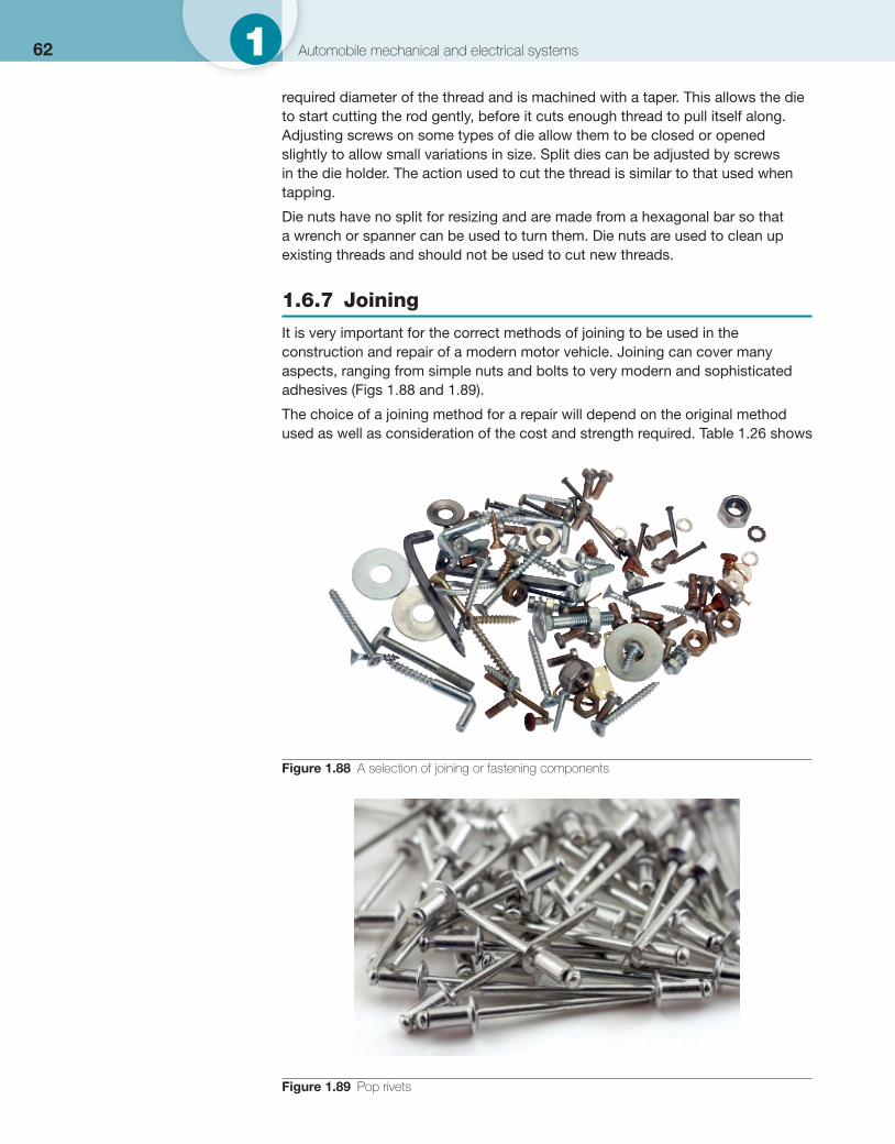
62 1 Automobile mechanical and electrical systems
required diameter of the thread and is machined with a taper. This allows the die to start cutting the rod gently, before it cuts enough thread to pull itself along. Adjusting screws on some types of die allow them to be closed or opened slightly to allow small variations in size. Split dies can be adjusted by screws in the die holder. The action used to cut the thread is similar to that used when tapping.
Die nuts have no split for resizing and are made from a hexagonal bar so that a wrench or spanner can be used to turn them. Die nuts are used to clean up existing threads and should not be used to cut new threads.
1.6.7 Joining
It is very important for the correct methods of joining to be used in the construction and repair of a modern motor vehicle. Joining can cover many aspects, ranging from simple nuts and bolts to very modern and sophisticated adhesives ( Figs 1.88 and 1.89 ).
The choice of a joining method for a repair will depend on the original method used as well as consideration of the cost and strength required. Table 1.26 shows
Figure 1.88 A selection of joining or fastening components
Figure 1.89 Pop rivets
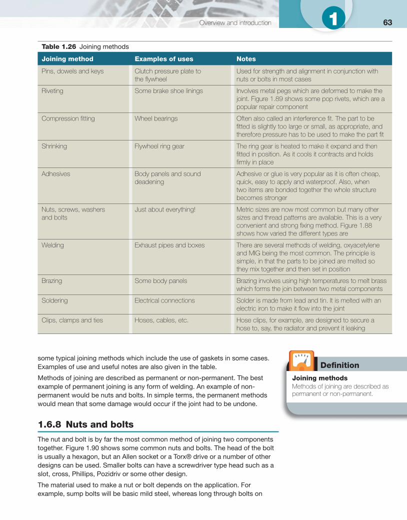
631
Defi nition
Joining methods Methods of joining are described as permanent or non-permanent.
some typical joining methods which include the use of gaskets in some cases. Examples of use and useful notes are also given in the table.
Methods of joining are described as permanent or non-permanent. The best example of permanent joining is any form of welding. An example of non-permanent would be nuts and bolts. In simple terms, the permanent methods would mean that some damage would occur if the joint had to be undone.
1.6.8 Nuts and bolts
The nut and bolt is by far the most common method of joining two components together. Figure 1.90 shows some common nuts and bolts. The head of the bolt is usually a hexagon, but an Allen socket or a Torx® drive or a number of other designs can be used. Smaller bolts can have a screwdriver type head such as a slot, cross, Phillips, Pozidriv or some other design.
The material used to make a nut or bolt depends on the application. For example, sump bolts will be basic mild steel, whereas long through bolts on
Table 1.26 Joining methods
Joining method Examples of uses Notes
Pins, dowels and keys Clutch pressure plate to the fl ywheel
Used for strength and alignment in conjunction with nuts or bolts in most cases
Riveting Some brake shoe linings Involves metal pegs which are deformed to make the joint. Figure 1.89 shows some pop rivets, which are a popular repair component
Compression fi tting Wheel bearings Often also called an interference fi t. The part to be fi tted is slightly too large or small, as appropriate, and therefore pressure has to be used to make the part fi t
Shrinking Flywheel ring gear The ring gear is heated to make it expand and then fi tted in position. As it cools it contracts and holds fi rmly in place
Adhesives Body panels and sound deadening
Adhesive or glue is very popular as it is often cheap, quick, easy to apply and waterproof. Also, when two items are bonded together the whole structure becomes stronger
Nuts, screws, washers and bolts
Just about everything! Metric sizes are now most common but many other sizes and thread patterns are available. This is a very convenient and strong fi xing method. Figure 1.88 shows how varied the different types are
Welding Exhaust pipes and boxes There are several methods of welding, oxyacetylene and MIG being the most common. The principle is simple, in that the parts to be joined are melted so they mix together and then set in position
Brazing Some body panels Brazing involves using high temperatures to melt brass which forms the join between two metal components
Soldering Electrical connections Solder is made from lead and tin. It is melted with an electric iron to make it fl ow into the joint
Clips, clamps and ties Hoses, cables, etc. Hose clips, for example, are designed to secure a hose to, say, the radiator and prevent it leaking
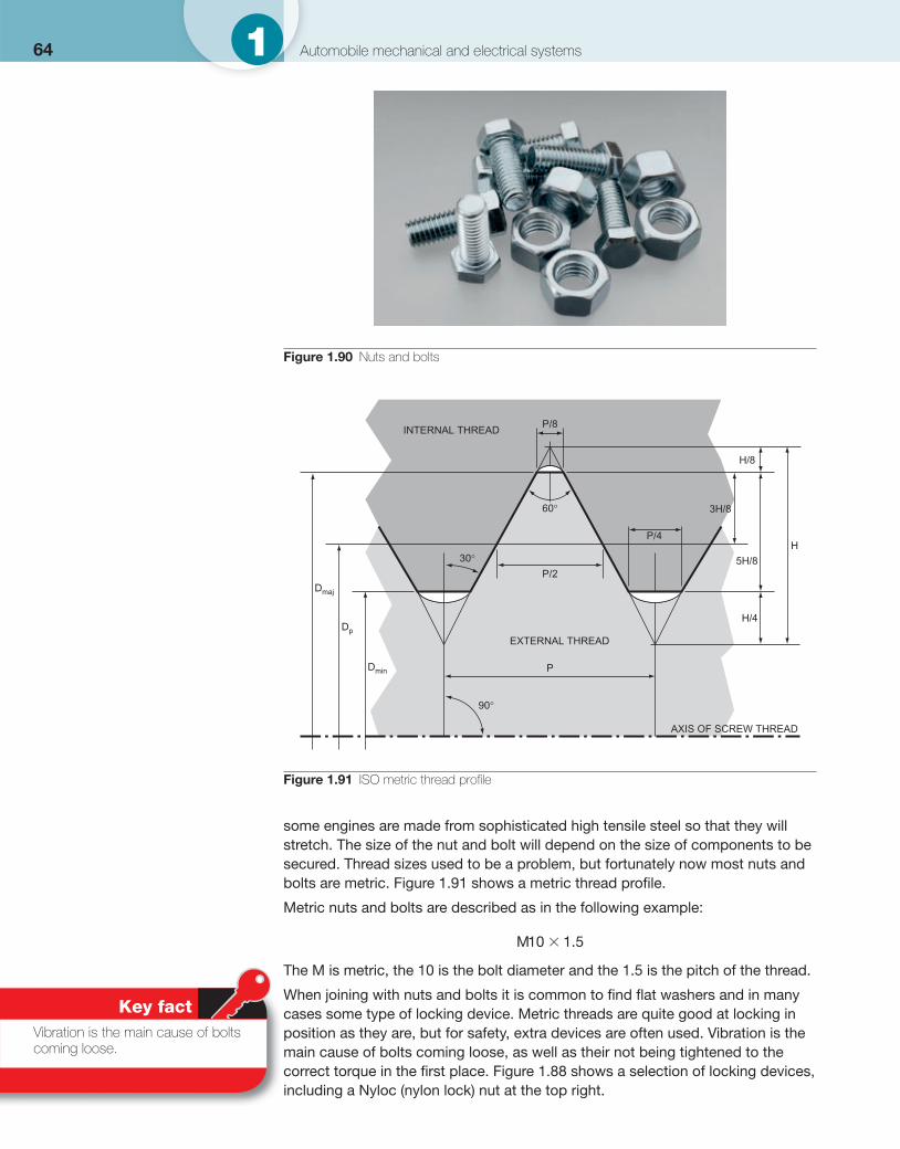
64 1 Automobile mechanical and electrical systems
some engines are made from sophisticated high tensile steel so that they will stretch. The size of the nut and bolt will depend on the size of components to be secured. Thread sizes used to be a problem, but fortunately now most nuts and bolts are metric. Figure 1.91 shows a metric thread profi le.
Metric nuts and bolts are described as in the following example:
M10 1 5� .
The M is metric, the 10 is the bolt diameter and the 1.5 is the pitch of the thread.
When joining with nuts and bolts it is common to fi nd fl at washers and in many cases some type of locking device. Metric threads are quite good at locking in position as they are, but for safety, extra devices are often used. Vibration is the main cause of bolts coming loose, as well as their not being tightened to the correct torque in the fi rst place. Figure 1.88 shows a selection of locking devices, including a Nyloc (nylon lock) nut at the top right.
Figure 1.90 Nuts and bolts
INTERNAL THREADP/8
P/2
P
P/4
H/8
3H/8
5H/8
H/4
H
60°
30°
90°
Dmin
Dmaj
Dp
AXIS OF SCREW THREAD
EXTERNAL THREAD
Figure 1.91 ISO metric thread profi le
Key fact Vibration is the main cause of bolts coming loose.
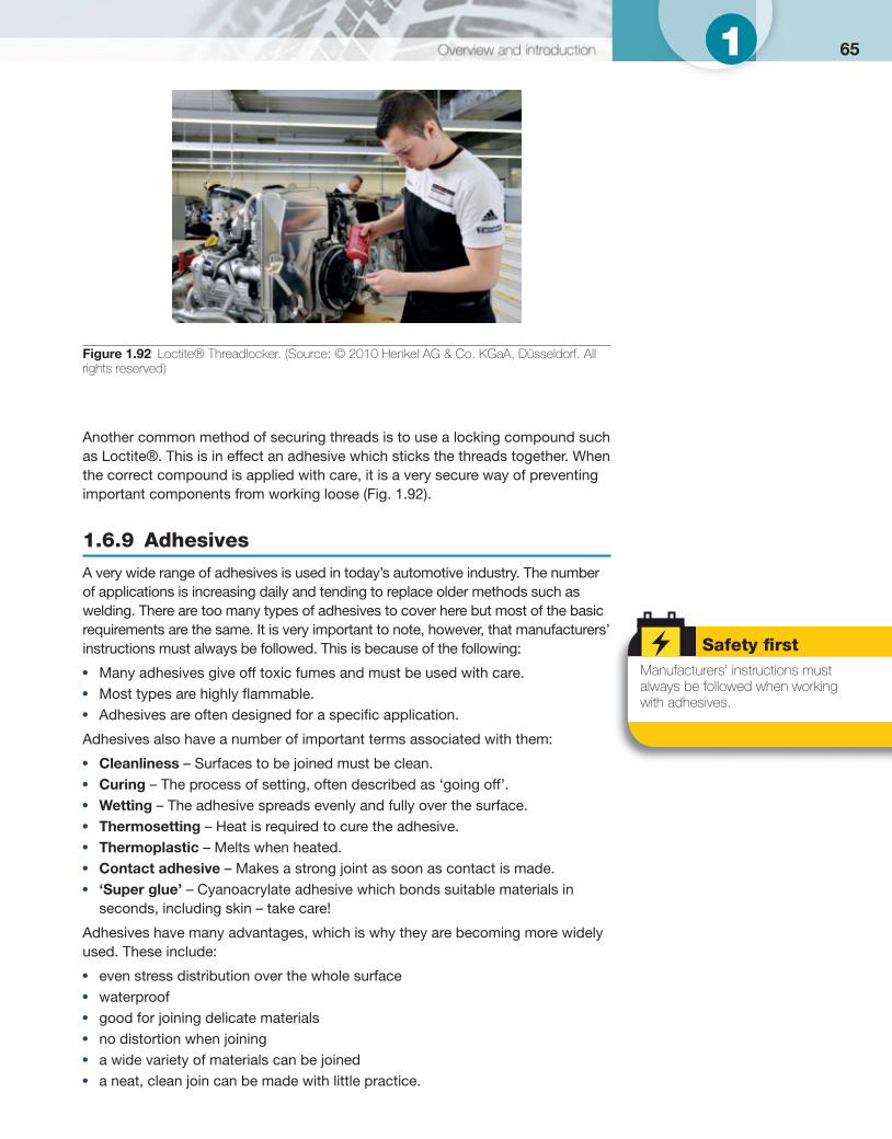
651
Another common method of securing threads is to use a locking compound such as Loctite®. This is in effect an adhesive which sticks the threads together. When the correct compound is applied with care, it is a very secure way of preventing important components from working loose ( Fig. 1.92 ).
1.6.9 Adhesives
A very wide range of adhesives is used in today’s automotive industry. The number of applications is increasing daily and tending to replace older methods such as welding. There are too many types of adhesives to cover here but most of the basic requirements are the same. It is very important to note, however, that manufacturers’ instructions must always be followed. This is because of the following: ● Many adhesives give off toxic fumes and must be used with care. ● Most types are highly fl ammable. ● Adhesives are often designed for a specifi c application.
Adhesives also have a number of important terms associated with them:
● Cleanliness – Surfaces to be joined must be clean. ● Curing – The process of setting, often described as ‘going off’. ● Wetting – The adhesive spreads evenly and fully over the surface. ● Thermosetting – Heat is required to cure the adhesive. ● Thermoplastic – Melts when heated. ● Contact adhesive – Makes a strong joint as soon as contact is made. ● ‘Super glue’ – Cyanoacrylate adhesive which bonds suitable materials in
seconds, including skin – take care!
Adhesives have many advantages, which is why they are becoming more widely used. These include:
● even stress distribution over the whole surface ● waterproof ● good for joining delicate materials ● no distortion when joining ● a wide variety of materials can be joined ● a neat, clean join can be made with little practice.
Figure 1.92 Loctite® Threadlocker. (Source: © 2010 Henkel AG & Co. KGaA, Düsseldorf. All rights reserved)
Safety fi rst Manufacturers’ instructions must always be followed when working with adhesives.
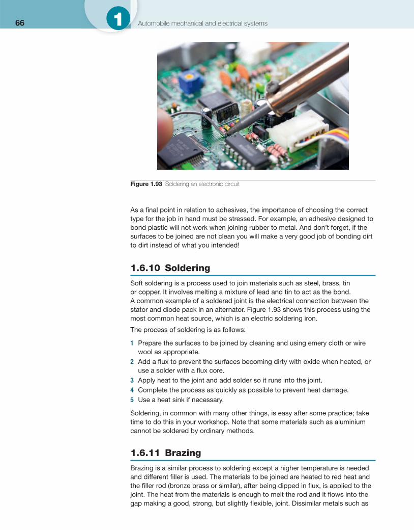
66 1 Automobile mechanical and electrical systems
As a fi nal point in relation to adhesives, the importance of choosing the correct type for the job in hand must be stressed. For example, an adhesive designed to bond plastic will not work when joining rubber to metal. And don’t forget, if the surfaces to be joined are not clean you will make a very good job of bonding dirt to dirt instead of what you intended!
1.6.10 Soldering
Soft soldering is a process used to join materials such as steel, brass, tin or copper. It involves melting a mixture of lead and tin to act as the bond. A common example of a soldered joint is the electrical connection between the stator and diode pack in an alternator. Figure 1.93 shows this process using the most common heat source, which is an electric soldering iron.
The process of soldering is as follows:
1 Prepare the surfaces to be joined by cleaning and using emery cloth or wire wool as appropriate.
2 Add a fl ux to prevent the surfaces becoming dirty with oxide when heated, or use a solder with a fl ux core.
3 Apply heat to the joint and add solder so it runs into the joint. 4 Complete the process as quickly as possible to prevent heat damage. 5 Use a heat sink if necessary.
Soldering, in common with many other things, is easy after some practice; take time to do this in your workshop. Note that some materials such as aluminium cannot be soldered by ordinary methods.
1.6.11 Brazing
Brazing is a similar process to soldering except a higher temperature is needed and different fi ller is used. The materials to be joined are heated to red heat and the fi ller rod (bronze brass or similar), after being dipped in fl ux, is applied to the joint. The heat from the materials is enough to melt the rod and it fl ows into the gap making a good, strong, but slightly fl exible, joint. Dissimilar metals such as
Figure 1.93 Soldering an electronic circuit
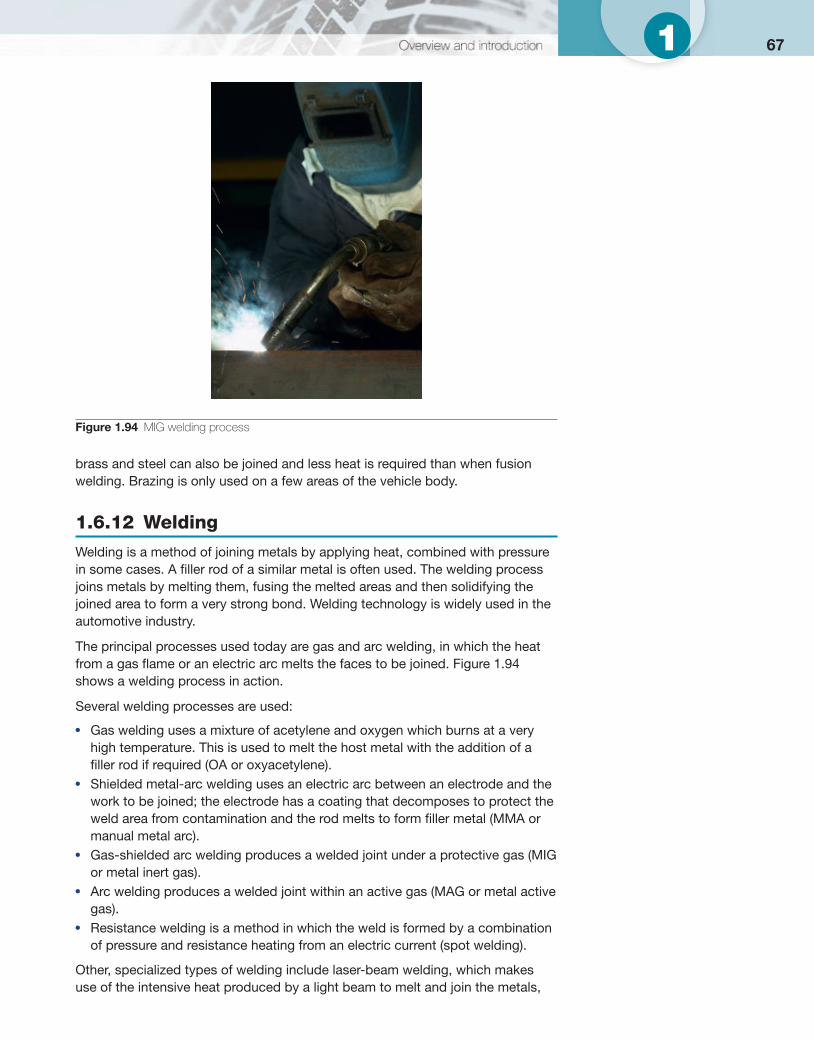
671
brass and steel can also be joined and less heat is required than when fusion welding. Brazing is only used on a few areas of the vehicle body.
1.6.12 Welding
Welding is a method of joining metals by applying heat, combined with pressure in some cases. A fi ller rod of a similar metal is often used. The welding process joins metals by melting them, fusing the melted areas and then solidifying the joined area to form a very strong bond. Welding technology is widely used in the automotive industry.
The principal processes used today are gas and arc welding, in which the heat from a gas fl ame or an electric arc melts the faces to be joined. Figure 1.94 shows a welding process in action.
Several welding processes are used:
● Gas welding uses a mixture of acetylene and oxygen which burns at a very high temperature. This is used to melt the host metal with the addition of a fi ller rod if required (OA or oxyacetylene).
● Shielded metal-arc welding uses an electric arc between an electrode and the work to be joined; the electrode has a coating that decomposes to protect the weld area from contamination and the rod melts to form fi ller metal (MMA or manual metal arc).
● Gas-shielded arc welding produces a welded joint under a protective gas (MIG or metal inert gas).
● Arc welding produces a welded joint within an active gas (MAG or metal active gas).
● Resistance welding is a method in which the weld is formed by a combination of pressure and resistance heating from an electric current (spot welding).
Other, specialized types of welding include laser-beam welding, which makes use of the intensive heat produced by a light beam to melt and join the metals,
Figure 1.94 MIG welding process
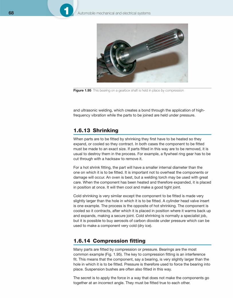
68 1 Automobile mechanical and electrical systems
and ultrasonic welding, which creates a bond through the application of high-frequency vibration while the parts to be joined are held under pressure.
1.6.13 Shrinking
When parts are to be fi tted by shrinking they fi rst have to be heated so they expand, or cooled so they contract. In both cases the component to be fi tted must be made to an exact size. If parts fi tted in this way are to be removed, it is usual to destroy them in the process. For example, a fl ywheel ring gear has to be cut through with a hacksaw to remove it.
For a hot shrink fi tting, the part will have a smaller internal diameter than the one on which it is to be fi tted. It is important not to overheat the components or damage will occur. An oven is best, but a welding torch may be used with great care. When the component has been heated and therefore expanded, it is placed in position at once. It will then cool and make a good tight joint.
Cold shrinking is very similar except the component to be fi tted is made very slightly larger than the hole in which it is to be fi tted. A cylinder head valve insert is one example. The process is the opposite of hot shrinking. The component is cooled so it contracts, after which it is placed in position where it warms back up and expands, making a secure joint. Cold shrinking is normally a specialist job, but it is possible to buy aerosols of carbon dioxide under pressure which can be used to make a component very cold (dry ice).
1.6.14 Compression fi tting
Many parts are fi tted by compression or pressure. Bearings are the most common example ( Fig. 1.95 ). The key to compression fi tting is an interference fi t. This means that the component, say a bearing, is very slightly larger than the hole in which it is to be fi tted. Pressure is therefore used to force the bearing into place. Suspension bushes are often also fi tted in this way.
The secret is to apply the force in a way that does not make the components go together at an incorrect angle. They must be fi tted true to each other.
Figure 1.95 This bearing on a gearbox shaft is held in place by compression
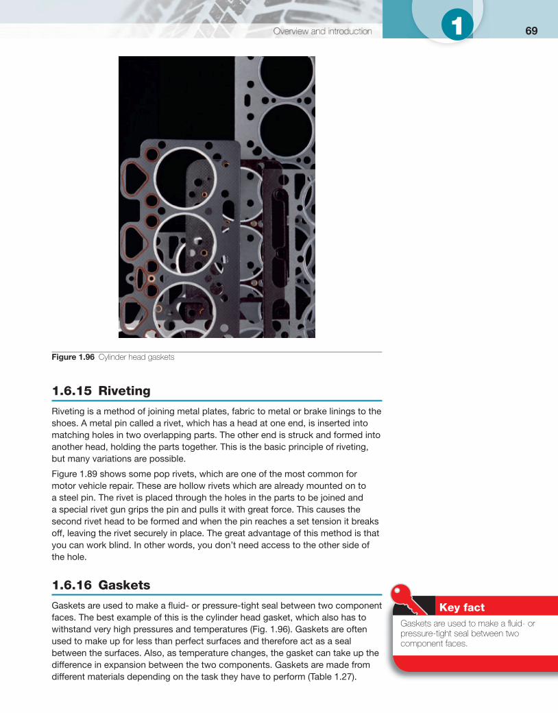
691
1.6.15 Riveting
Riveting is a method of joining metal plates, fabric to metal or brake linings to the shoes. A metal pin called a rivet, which has a head at one end, is inserted into matching holes in two overlapping parts. The other end is struck and formed into another head, holding the parts together. This is the basic principle of riveting, but many variations are possible.
Figure 1.89 shows some pop rivets, which are one of the most common for motor vehicle repair. These are hollow rivets which are already mounted on to a steel pin. The rivet is placed through the holes in the parts to be joined and a special rivet gun grips the pin and pulls it with great force. This causes the second rivet head to be formed and when the pin reaches a set tension it breaks off, leaving the rivet securely in place. The great advantage of this method is that you can work blind. In other words, you don’t need access to the other side of the hole.
1.6.16 Gaskets
Gaskets are used to make a fl uid- or pressure-tight seal between two component faces. The best example of this is the cylinder head gasket, which also has to withstand very high pressures and temperatures ( Fig. 1.96 ). Gaskets are often used to make up for less than perfect surfaces and therefore act as a seal between the surfaces. Also, as temperature changes, the gasket can take up the difference in expansion between the two components. Gaskets are made from different materials depending on the task they have to perform ( Table 1.27 ).
Figure 1.96 Cylinder head gaskets
Key fact Gaskets are used to make a fl uid- or pressure-tight seal between two component faces.
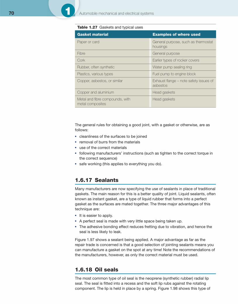
70 1 Automobile mechanical and electrical systems
The general rules for obtaining a good joint, with a gasket or otherwise, are as follows:
● cleanliness of the surfaces to be joined ● removal of burrs from the materials ● use of the correct materials ● following manufacturers’ instructions (such as tighten to the correct torque in
the correct sequence) ● safe working (this applies to everything you do).
1.6.17 Sealants
Many manufacturers are now specifying the use of sealants in place of traditional gaskets. The main reason for this is a better quality of joint. Liquid sealants, often known as instant gasket, are a type of liquid rubber that forms into a perfect gasket as the surfaces are mated together. The three major advantages of this technique are:
● It is easier to apply. ● A perfect seal is made with very little space being taken up. ● The adhesive bonding effect reduces fretting due to vibration, and hence the
seal is less likely to leak.
Figure 1.97 shows a sealant being applied. A major advantage as far as the repair trade is concerned is that a good selection of jointing sealants means you can manufacture a gasket on the spot at any time! Note the recommendations of the manufacturers, however, as only the correct material must be used.
1.6.18 Oil seals
The most common type of oil seal is the neoprene (synthetic rubber) radial lip seal. The seal is fi tted into a recess and the soft lip rubs against the rotating component. The lip is held in place by a spring. Figure 1.98 shows this type of
Table 1.27 Gaskets and typical uses
Gasket material Examples of where used
Paper or card General purpose, such as thermostat housings
Fibre General purpose
Cork Earlier types of rocker covers
Rubber, often synthetic Water pump sealing ring
Plastics, various types Fuel pump to engine block
Copper, asbestos, or similar Exhaust fl ange – note safety issues of asbestos
Copper and aluminium Head gaskets
Metal and fi bre compounds, with metal composites
Head gaskets
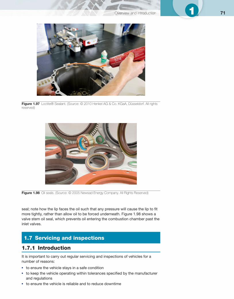
711
seal; note how the lip faces the oil such that any pressure will cause the lip to fi t more tightly, rather than allow oil to be forced underneath. Figure 1.98 shows a valve stem oil seal, which prevents oil entering the combustion chamber past the inlet valves.
1.7 Servicing and inspections
1.7.1 Introduction
It is important to carry out regular servicing and inspections of vehicles for a number of reasons:
● to ensure the vehicle stays in a safe condition ● to keep the vehicle operating within tolerances specifi ed by the manufacturer
and regulations ● to ensure the vehicle is reliable and to reduce downtime
Figure 1.97 Loctite® Sealant. (Source: © 2010 Henkel AG & Co. KGaA, Düsseldorf. All rights reserved)
Figure 1.98 Oil seals. (Source: © 2005 Newsad Energy Company. All Rights Reserved)
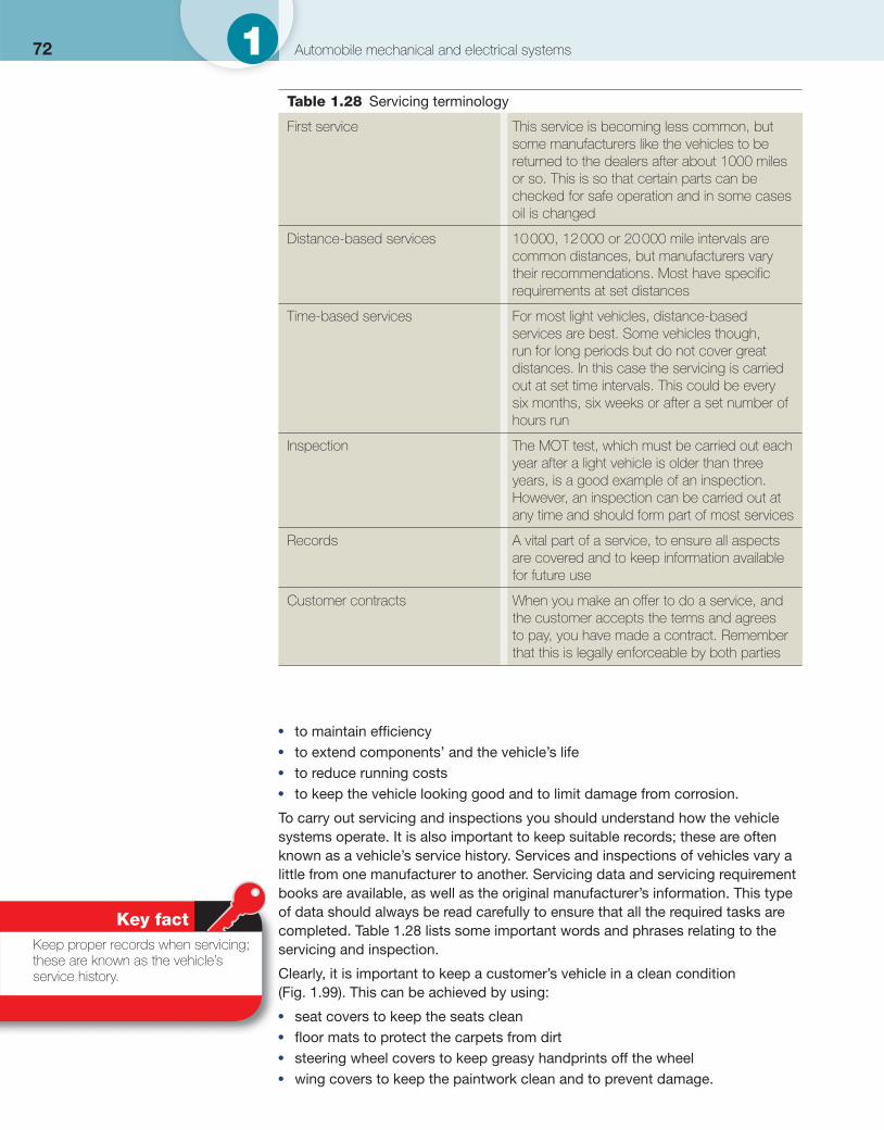
72 1 Automobile mechanical and electrical systems
● to maintain effi ciency ● to extend components’ and the vehicle’s life ● to reduce running costs ● to keep the vehicle looking good and to limit damage from corrosion.
To carry out servicing and inspections you should understand how the vehicle systems operate. It is also important to keep suitable records; these are often known as a vehicle’s service history. Services and inspections of vehicles vary a little from one manufacturer to another. Servicing data and servicing requirement books are available, as well as the original manufacturer’s information. This type of data should always be read carefully to ensure that all the required tasks are completed. Table 1.28 lists some important words and phrases relating to the servicing and inspection. Clearly, it is important to keep a customer’s vehicle in a clean condition ( Fig. 1.99 ). This can be achieved by using:
● seat covers to keep the seats clean ● fl oor mats to protect the carpets from dirt ● steering wheel covers to keep greasy handprints off the wheel ● wing covers to keep the paintwork clean and to prevent damage.
Key fact Keep proper records when servicing; these are known as the vehicle’s service history.
Table 1.28 Servicing terminology
First service This service is becoming less common, but some manufacturers like the vehicles to be returned to the dealers after about 1000 miles or so. This is so that certain parts can be checked for safe operation and in some cases oil is changed
Distance-based services 10 000, 12 000 or 20 000 mile intervals are common distances, but manufacturers vary their recommendations. Most have specifi c requirements at set distances
Time-based services For most light vehicles, distance-based services are best. Some vehicles though, run for long periods but do not cover great distances. In this case the servicing is carried out at set time intervals. This could be every six months, six weeks or after a set number of hours run
Inspection The MOT test, which must be carried out each year after a light vehicle is older than three years, is a good example of an inspection. However, an inspection can be carried out at any time and should form part of most services
Records A vital part of a service, to ensure all aspects are covered and to keep information available for future use
Customer contracts When you make an offer to do a service, and the customer accepts the terms and agrees to pay, you have made a contract. Remember that this is legally enforceable by both parties
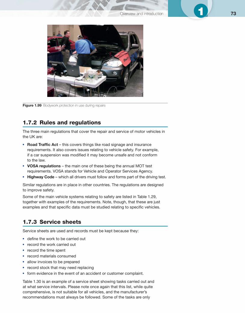
731
1.7.2 Rules and regulations
The three main regulations that cover the repair and service of motor vehicles in the UK are:
● Road Traffi c Act – this covers things like road signage and insurance requirements. It also covers issues relating to vehicle safety. For example, if a car suspension was modifi ed it may become unsafe and not conform to the law.
● VOSA regulations – the main one of these being the annual MOT test requirements. VOSA stands for Vehicle and Operator Services Agency.
● Highway Code – which all drivers must follow and forms part of the driving test.
Similar regulations are in place in other countries. The regulations are designed to improve safety.
Some of the main vehicle systems relating to safety are listed in Table 1.29 , together with examples of the requirements. Note, though, that these are just examples and that specifi c data must be studied relating to specifi c vehicles.
1.7.3 Service sheets
Service sheets are used and records must be kept because they:
● defi ne the work to be carried out ● record the work carried out ● record the time spent ● record materials consumed ● allow invoices to be prepared ● record stock that may need replacing ● form evidence in the event of an accident or customer complaint.
Table 1.30 is an example of a service sheet showing tasks carried out and at what service intervals. Please note once again that this list, while quite comprehensive, is not suitable for all vehicles, and the manufacturer’s recommendations must always be followed. Some of the tasks are only
Figure 1.99 Bodywork protection in use during repairs
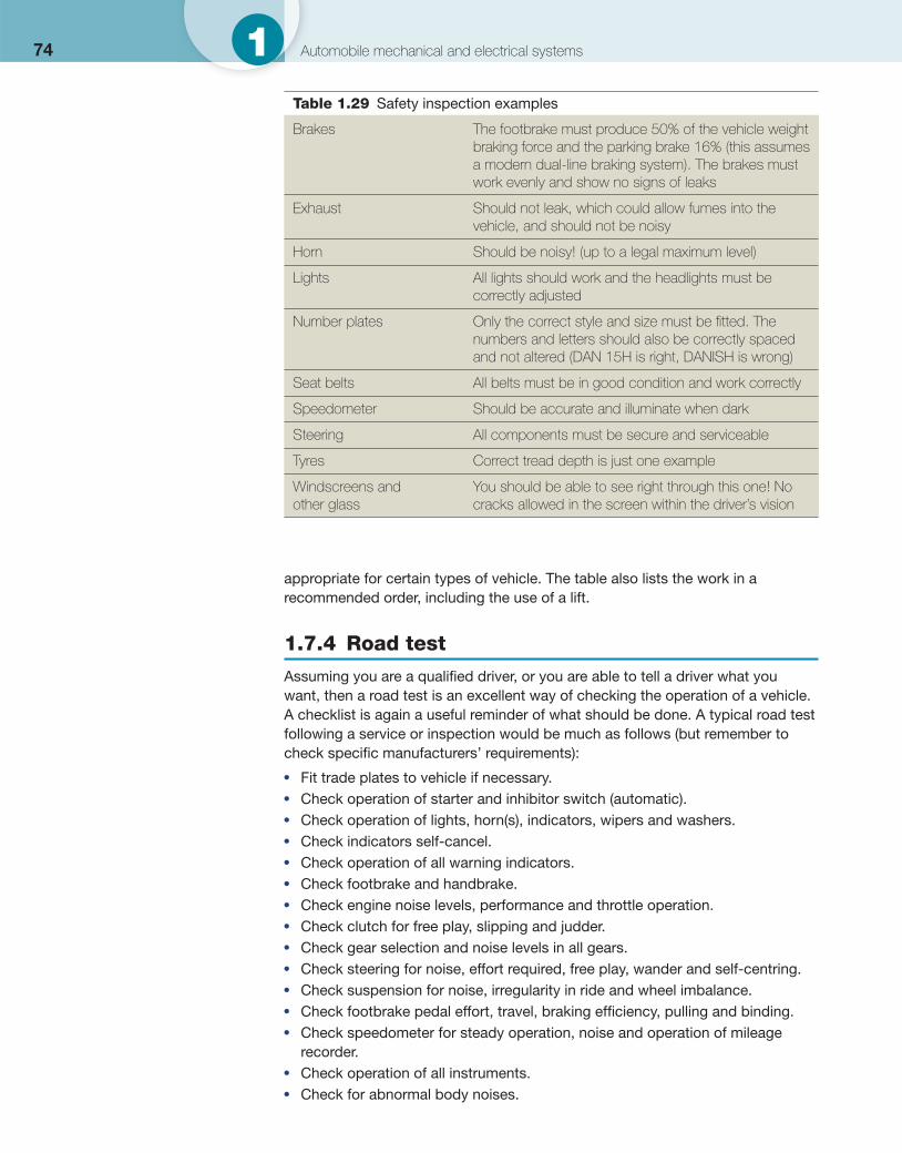
74 1 Automobile mechanical and electrical systems
appropriate for certain types of vehicle. The table also lists the work in a recommended order, including the use of a lift.
1.7.4 Road test
Assuming you are a qualifi ed driver, or you are able to tell a driver what you want, then a road test is an excellent way of checking the operation of a vehicle. A checklist is again a useful reminder of what should be done. A typical road test following a service or inspection would be much as follows (but remember to check specifi c manufacturers’ requirements):
● Fit trade plates to vehicle if necessary. ● Check operation of starter and inhibitor switch (automatic). ● Check operation of lights, horn(s), indicators, wipers and washers. ● Check indicators self-cancel. ● Check operation of all warning indicators. ● Check footbrake and handbrake. ● Check engine noise levels, performance and throttle operation. ● Check clutch for free play, slipping and judder. ● Check gear selection and noise levels in all gears. ● Check steering for noise, effort required, free play, wander and self-centring. ● Check suspension for noise, irregularity in ride and wheel imbalance. ● Check footbrake pedal effort, travel, braking effi ciency, pulling and binding. ● Check speedometer for steady operation, noise and operation of mileage
recorder. ● Check operation of all instruments. ● Check for abnormal body noises.
Table 1.29 Safety inspection examples
Brakes The footbrake must produce 50% of the vehicle weight braking force and the parking brake 16% (this assumes a modern dual-line braking system). The brakes must work evenly and show no signs of leaks
Exhaust Should not leak, which could allow fumes into the vehicle, and should not be noisy
Horn Should be noisy! (up to a legal maximum level)
Lights All lights should work and the headlights must be correctly adjusted
Number plates Only the correct style and size must be fi tted. The numbers and letters should also be correctly spaced and not altered (DAN 15H is right, DANISH is wrong)
Seat belts All belts must be in good condition and work correctly
Speedometer Should be accurate and illuminate when dark
Steering All components must be secure and serviceable
Tyres Correct tread depth is just one example
Windscreens and other glass
You should be able to see right through this one! No cracks allowed in the screen within the driver’s vision
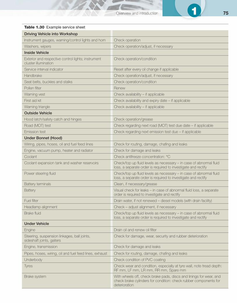
751 Table 1.30 Example service sheet
Driving Vehicle into Workshop
Instrument gauges, warning/control lights and horn Check operation
Washers, wipers Check operation/adjust, if necessary
Inside Vehicle
Exterior and respective control lights; instrument cluster illumination
Check operation/condition
Service interval indicator Reset after every oil change if applicable
Handbrake Check operation/adjust, if necessary
Seat belts, buckles and stalks Check operation/condition
Pollen fi lter Renew
Warning vest Check availability – if applicable
First aid kit Check availability and expiry date – if applicable
Warning triangle Check availability – if applicable
Outside Vehicle
Hood latch/safety catch and hinges Check operation/grease
Road (MOT) test Check regarding next road (MOT) test due date – if applicable
Emission test Check regarding next emission test due – if applicable
Under Bonnet (Hood)
Wiring, pipes, hoses, oil and fuel feed lines Check for routing, damage, chafi ng and leaks
Engine, vacuum pump, heater and radiator Check for damage and leaks
Coolant Check antifreeze concentration: °C
Coolant expansion tank and washer reservoirs Check/top up fl uid levels as necessary – in case of abnormal fl uid loss, a separate order is required to investigate and rectify
Power steering fl uid Check/top up fl uid levels as necessary – in case of abnormal fl uid loss, a separate order is required to investigate and rectify
Battery terminals Clean, if necessary/grease
Battery Visual check for leaks – in case of abnormal fl uid loss, a separate order is required to investigate and rectify
Fuel fi lter Drain water, if not renewed – diesel models (with drain facility)
Headlamp alignment Check – adjust alignment, if necessary
Brake fl uid Check/top up fl uid levels as necessary – in case of abnormal fl uid loss, a separate order is required to investigate and rectify
Under Vehicle
Engine Drain oil and renew oil fi lter
Steering, suspension linkages, ball joints, sideshaft joints, gaiters
Check for damage, wear, security and rubber deterioration
Engine, transmission Check for damage and leaks
Pipes, hoses, wiring, oil and fuel feed lines, exhaust Check for routing, damage, chafi ng and leaks
Underbody Check condition of PVC coating
Tyres Check wear and condition, especially at tyre wall, note tread depth: RF mm, LF mm, LR mm, RR mm, Spare mm
Brake system With wheels off, check brake pads, discs and linings for wear, and check brake cylinders for condition: check rubber components for deterioration
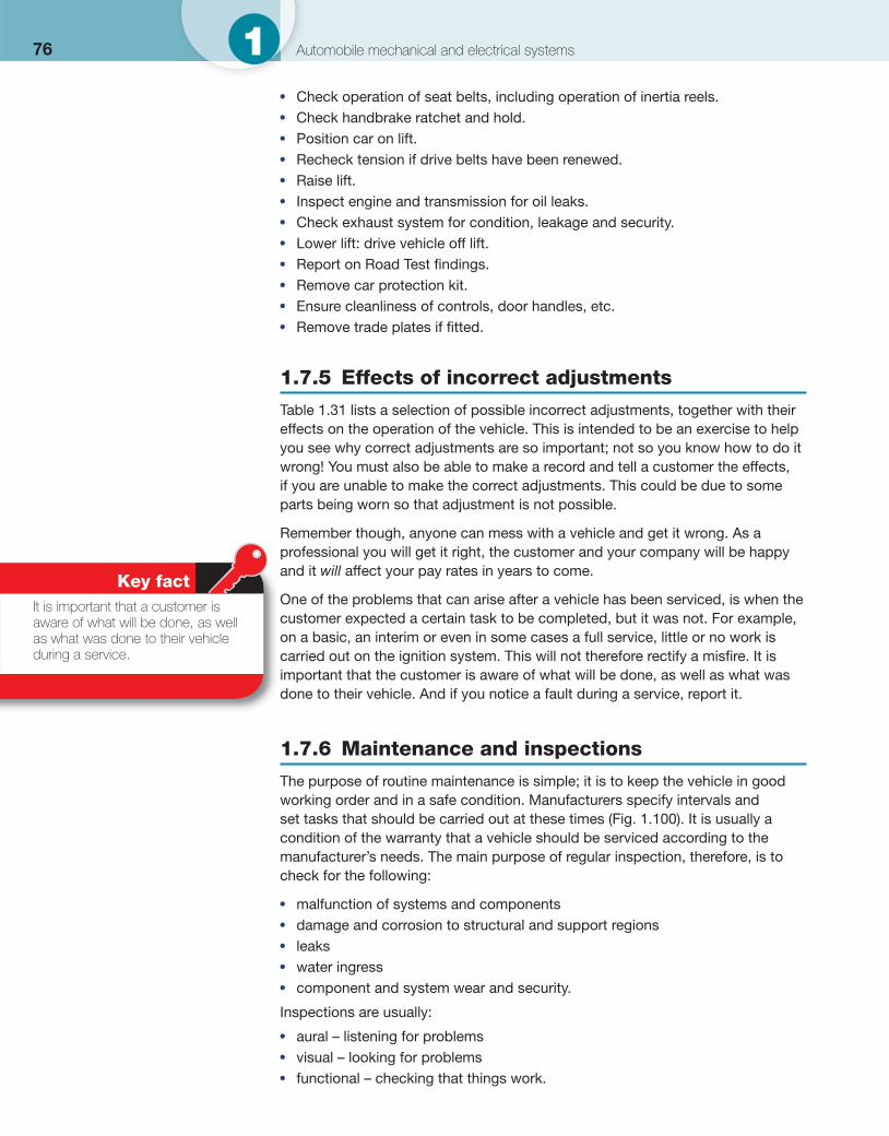
76 1 Automobile mechanical and electrical systems
● Check operation of seat belts, including operation of inertia reels. ● Check handbrake ratchet and hold. ● Position car on lift. ● Recheck tension if drive belts have been renewed. ● Raise lift. ● Inspect engine and transmission for oil leaks. ● Check exhaust system for condition, leakage and security. ● Lower lift: drive vehicle off lift. ● Report on Road Test fi ndings. ● Remove car protection kit. ● Ensure cleanliness of controls, door handles, etc. ● Remove trade plates if fi tted.
1.7.5 Effects of incorrect adjustments
Table 1.31 lists a selection of possible incorrect adjustments, together with their effects on the operation of the vehicle. This is intended to be an exercise to help you see why correct adjustments are so important; not so you know how to do it wrong! You must also be able to make a record and tell a customer the effects, if you are unable to make the correct adjustments. This could be due to some parts being worn so that adjustment is not possible.
Remember though, anyone can mess with a vehicle and get it wrong. As a professional you will get it right, the customer and your company will be happy and it will affect your pay rates in years to come.
One of the problems that can arise after a vehicle has been serviced, is when the customer expected a certain task to be completed, but it was not. For example, on a basic, an interim or even in some cases a full service, little or no work is carried out on the ignition system. This will not therefore rectify a misfi re. It is important that the customer is aware of what will be done, as well as what was done to their vehicle. And if you notice a fault during a service, report it.
1.7.6 Maintenance and inspections
The purpose of routine maintenance is simple; it is to keep the vehicle in good working order and in a safe condition. Manufacturers specify intervals and set tasks that should be carried out at these times ( Fig. 1.100 ). It is usually a condition of the warranty that a vehicle should be serviced according to the manufacturer’s needs. The main purpose of regular inspection, therefore, is to check for the following:
● malfunction of systems and components ● damage and corrosion to structural and support regions ● leaks ● water ingress ● component and system wear and security.
Inspections are usually:
● aural – listening for problems ● visual – looking for problems ● functional – checking that things work.
Key fact It is important that a customer is aware of what will be done, as well as what was done to their vehicle during a service.
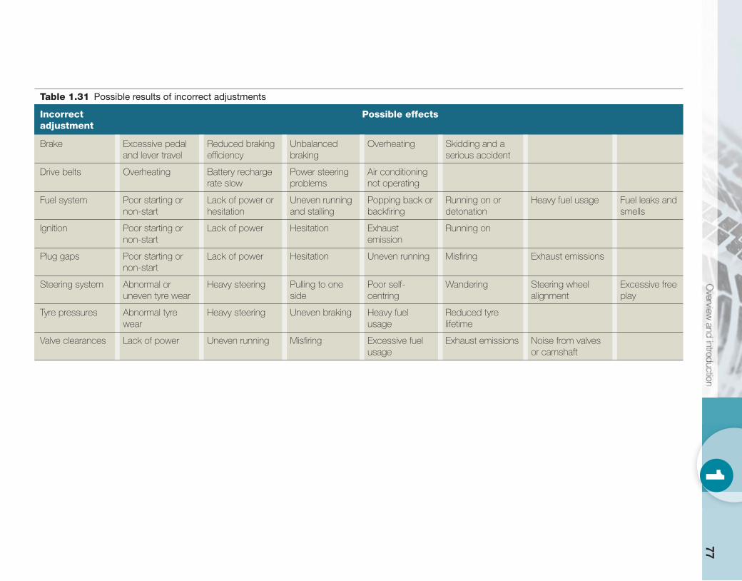
771
Table 1.31 Possible results of incorrect adjustments
Incorrect adjustment
Possible effects
Brake Excessive pedal and lever travel
Reduced braking effi ciency
Unbalanced braking
Overheating Skidding and a serious accident
Drive belts Overheating Battery recharge rate slow
Power steering problems
Air conditioning not operating
Fuel system Poor starting or non-start
Lack of power or hesitation
Uneven running and stalling
Popping back or backfi ring
Running on or detonation
Heavy fuel usage Fuel leaks and smells
Ignition Poor starting or non-start
Lack of power Hesitation Exhaust emission
Running on
Plug gaps Poor starting or non-start
Lack of power Hesitation Uneven running Misfi ring Exhaust emissions
Steering system Abnormal or uneven tyre wear
Heavy steering Pulling to one side
Poor self-centring
Wandering Steering wheel alignment
Excessive free play
Tyre pressures Abnormal tyre wear
Heavy steering Uneven braking Heavy fuel usage
Reduced tyre lifetime
Valve clearances Lack of power Uneven running Misfi ring Excessive fuel usage
Exhaust emissions Noise from valves or camshaft
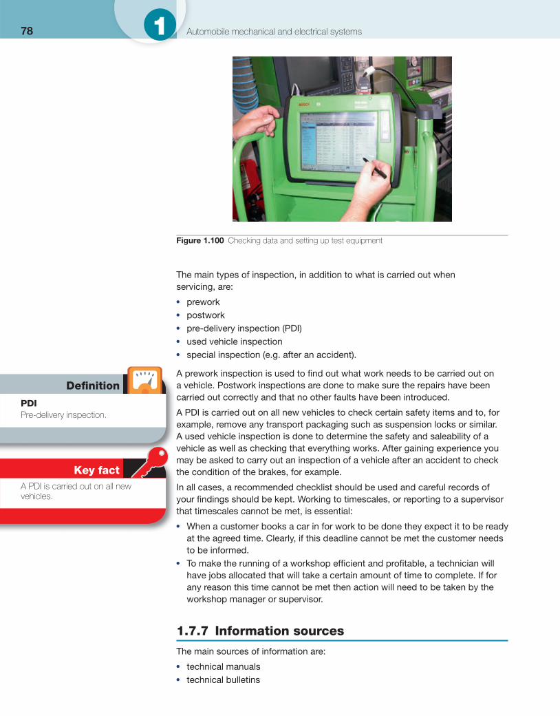
78 1 Automobile mechanical and electrical systems
The main types of inspection, in addition to what is carried out when servicing, are:
● prework ● postwork ● pre-delivery inspection (PDI) ● used vehicle inspection ● special inspection (e.g. after an accident).
A prework inspection is used to fi nd out what work needs to be carried out on a vehicle. Postwork inspections are done to make sure the repairs have been carried out correctly and that no other faults have been introduced.
A PDI is carried out on all new vehicles to check certain safety items and to, for example, remove any transport packaging such as suspension locks or similar. A used vehicle inspection is done to determine the safety and saleability of a vehicle as well as checking that everything works. After gaining experience you may be asked to carry out an inspection of a vehicle after an accident to check the condition of the brakes, for example. In all cases, a recommended checklist should be used and careful records of your fi ndings should be kept. Working to timescales, or reporting to a supervisor that timescales cannot be met, is essential:
● When a customer books a car in for work to be done they expect it to be ready at the agreed time. Clearly, if this deadline cannot be met the customer needs to be informed.
● To make the running of a workshop effi cient and profi table, a technician will have jobs allocated that will take a certain amount of time to complete. If for any reason this time cannot be met then action will need to be taken by the workshop manager or supervisor.
1.7.7 Information sources
The main sources of information are:
● technical manuals ● technical bulletins
Figure 1.100 Checking data and setting up test equipment
Defi nition
PDI Pre-delivery inspection.
Key fact A PDI is carried out on all new vehicles.
791 ● servicing schedules ● job card instructions ● inspection records ● checklists.
All of the main manufacturers have online access to this type of information. It is essential that proper documentation is used and that records are kept of the work carried out. For example:
● job cards ● stores and parts records ● Manufacturers’ warranty systems.
These are needed to ensure that the customer’s bill is accurate and that information is kept on fi le in case future work is required or warranty claims are made.
Results of any tests carried out will be recorded in a number of different ways. The actual method will depend on what test equipment was used. Some equipment will produce a printout, for example. However, results of all other tests should be recorded on the job card. In some cases this may be done electronically but it is the same principle. Remember: always make sure that the records are clear and easy to understand.