department of automobile engineering - madin
TRANSCRIPT
DEPARTMENT OF AUTOMOBILE ENGINEERING
LAB MANUAL
SUBJECT:
CODE:
SEMESTER:
REVISION:
DIESEL ENGIN SERVICE LAB
4057
4 TH
2015
Department Vision
To provide highly competent, efficient manpower to meet the ever-changing needs of the global automotive industry and the society.
Department Mission
To impart quality education and training to the students. To prepare students for creative thinking and innovativeness. To fulfill Industrial requirements globally by Imparting Innovative Knowledge, Ethical
values and Collaborative works.
Program Educational Objectives (PEO’s)
PEO 1:-Students will apply knowledge of automotive engineering & practices to pursue successful career in the field of automotive technology.
PEO 2:-Students will contribute to the academics and research for socio-technological development.
PEO 3:-Students will demonstrate lifelong learning skills by engaging in professional activities and up-gradation of knowledge quotient.
Program Specific Outcomes
PSO1:-Diagnose the automotive system failures and repair / replace the components / systems so as to bring the vehicle in original condition.
PSO2:-Perform the role of motor claim approver and loss assessor with confidence and competence.
PSO3:-Use relevant machinery, materials, equipment and processes to manufacture automobile components.
REVISION-2015 DIESEL ENGINE SERVICE LAB-4057
1 MA‟DIN POLYTECHNIC COLLEGE, MALAPPURAM
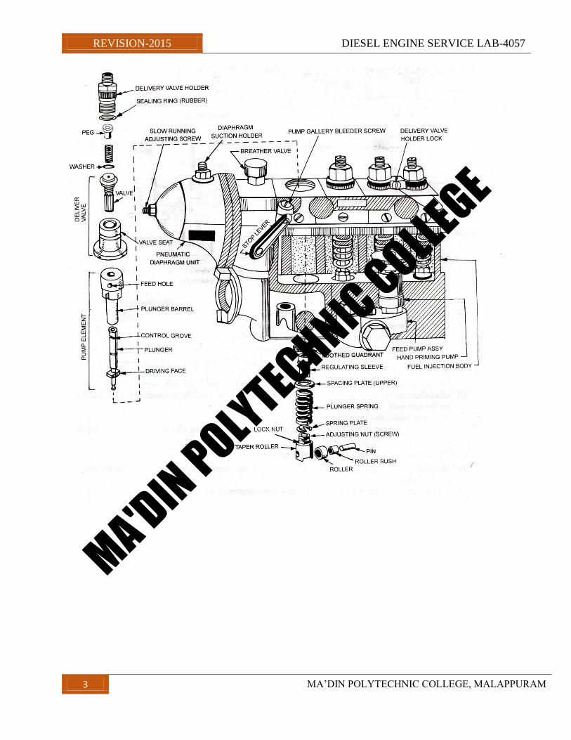
EXPERIMENT 1
OVERHAULING OF FUEL INJECTION PUMP (PNEUMATIC TYPE)
Objective — Removing, Dismantling, Cleaning, Checking, Assembling, Testing and Refitting.
Tools and Equipment Used — Double-ended Spanner Set (inch), Ring Spanner Set (inch), Flat Screw Driver
(6”& 10”), Tray, Swan Neck Pipe (Spill Cut-off Pipe), Socket Set (inch), Hammer (2 „/2 pounds).
Raw Materials: diesel, cotton waste, brush, engine oil
Procedure
1. Disconnected fuel pipe line from fuel pump‟s inlet and outlet from El. pump‟s gallery.
2. Disconnected high pressure pipe from holder and injector and also disconnected vacuum pipe and
Engine stopping wire.
3. Dismounted Fl. pump by unthread its bolts from foundation of engine block and coupling.
4 Wash and clean FI. Pump assembly with diesel.
5. Dismounted inspection plate and checked control rack.
6. Dismantled governor cover and disconnected diaphragm from control rod.
7. Unthreaded nuts of flange (coupling) and dismantled it from control rod.
8. Took out delivery valve from dismantled holder and pulled out plunger assembly by dismantling lower plate
lock. Repeated the same procedure for rest of all plungers. Took out tappets also.
9. Brought out the control rack after dismantling lock cap nut and control rack lock screw.
10. Dismounted feed pump from F.I. Pump. Dismantled front, rear plates and the intermediate bearing, brought
out the cam shaft.
li. Dismounted base plate from F.I. pump.
12. Clean and check all components, found that plungers were defective. Checked taper roller bearing of
Cam shaft, it was not defective at all.
Note — Assembly of plunger and barrel is called element.
13. Mounted both side‟s taper roller bearings and the intermediate bearing and then the cam shaft in F.I. pump
Adjust play.
14. Placed control rod/rack in F.I. pump and locked with its screw.
15. Mounted tappets over cam shaft. Automobile Engineering Practical 227
16. Mounted plunger, plunger return spring, regulating sleeve, and upper washer above tappet assembly,
alreadymounted in fuel injection pump housing.
17. Mount all plungers in same fashion above tappets and lock them.
18. Adjusted element and placed delivery valve on its seat.
MA'DIN POLYTECHNIC COLLEGE
REVISION-2015 DIESEL ENGINE SERVICE LAB-4057
2 MA‟DIN POLYTECHNIC COLLEGE, MALAPPURAM
19. Mount washer, spring, and peg. Rubber sealing ring and holder over delivery valve and tighten the holder
using a socket (11/16”).
20. Placed lock over holder neck and tighten it.
21. Mounted toothed quadrant by the side of control rod and F.I. Pump housing. Checked governor assembly
and found it OK.
22. Replaced inlet and outlet valves of feed pump. Checked piston and outlet pressure of feed pump, which
was found to be up to mark.
23. Mounted and tightened feed pump over cam.
24. Mounted front plate. Connected flange to cam shaft of F.I. Pump and locked it with a nut.
25. Mounted side inspection cover with rubber gasket after filling the specified amount of lubricating in the
pump.
26. Fixed rear plate and mounted new diaphragm with controlling rod. Fixed diaphragm spring properly and
checked vacuum chamber.
Precautions —
1. Phasing and calibration instructions of related manufacturer should be followed.
2. After calibration all toothed quadrants should be tightened.
3. Torn out diaphragm should be replaced.
4. Slow running adjustments should be as per workshop manual.
5. Plunger and barrel should be replaced simultaneously.
6. If there is any play in cam shaft, should be rectified.
7. Control rack (rod) should be freely movable (sliding) and it should not be tight.
8. After phasing tappets should be made “check — nut”.
9. Worn out plunger should not be used.
10. Proper instructions relating to oiling of F.I. Pump should be followed.
11. Feed pump valves should be installed properly and should be mounted carefully.
12. Engine timing setting should be as per workshop manual.
13. Clean diesel (fuel) should be supplied to F.I. pump.
14. Do not work with dirty hands.
15. Proper tools should be used.
MA'DIN POLYTECHNIC COLLEGE
REVISION-2015 DIESEL ENGINE SERVICE LAB-4057
3 MA‟DIN POLYTECHNIC COLLEGE, MALAPPURAM
MA'DIN POLYTECHNIC COLLEGE
REVISION-2015 DIESEL ENGINE SERVICE LAB-4057
4 MA‟DIN POLYTECHNIC COLLEGE, MALAPPURAM
EXPERIMENT 2
OVERHAULING OF DISTRIBUTOR TYPE FUEL INJECTION PUMP (ROTARY PUMP) (LUCAS)
Objective — Removing, Getting Over Hauled, Refitting, Timing Setting and Bleeding of Air.
Tools and Equipment Used — Double Ended Spanner Set (mm), Ring Spanner Set (mm), Allen Key (7 mm),
Flat Screwdriver.
Raw Material required — 13 mm bolts (2 No‟s) of 1.5” to 2” length, Old Dhoti.
Procedure —
1. Dismount the pump from vehicle due to loss in average.
2. Dismounted air cleaner.
3. Timing cover was splatted in two pieces, took out first piece with the help of screwdriver and to remove its
second piece, loosen alternator‟s foundation bolts followed by their unthreading and taking out clamp. To
loosen bolts we used 16, 17 mm sized ring and double end spanner.
4. Bring gear lever in neutral position before dismounting pump.
5. Disconnected battery connections.
6. Dismounted accelerator cable from F.I. pump.
7. Unthreaded banjo bolts of main fuel supply line and return fuel pipe line from F.I. pump.
8. If crank is rotated by two revolutions, cam shaft rotates by one only. If cam shaft‟s timing gear and F.I.
Pump‟s timing gear appears to be in locked position after one revolution, then there is no need for second
revolution.
9. Used an Allen key of 7mm to lock flywheel.
10. Rotate crank pulley or fan while locking flywheel.
11. Rotate crank in clockwise direction.
12. While rotating crank if alien key gets stuck in flywheel then slightly took out Allen key and revolve crank
by 10 - 20 mm, as there are two holes in lock position and if we fit alien key in second hole, it gets stuck with
flywheel and locks it.
13. Piston no. 1 and 4 will be on TDC cam and F.I. pump gear‟s lock position will be there.
14. Threaded 13mm bolt to lock hole provided on F.I. Pump and cam gear and locked pump‟s gear by it.
15. Loosen idler‟s bolt of timing belt and dismounted timing belt from cam and F.I. pump gears.
16. Dismounted high pressure lines and separate them from F.I. pump and injector and disconnect solenoid
switch connection.
17. Loosened both bolts of 13mm, which were threaded to plate mounted on F.I. pump. Loosen F.1.
Pump‟smain nut also. Tighten both 13mm bolts again and further loosened main nut, resultingF.I. pump‟s gear
willcome out. The main nut is threaded in center of plate, having 13mm bolts.
MA'DIN POLYTECHNIC COLLEGE
REVISION-2015 DIESEL ENGINE SERVICE LAB-4057
5 MA‟DIN POLYTECHNIC COLLEGE, MALAPPURAM
18. Took out all three foundation nuts and only bolt from timing plate along with washer. Sent the pump to
authorized dealer/workshop to over it.
Note — Lucas - CAV pump has 3 nuts and one bolt while Mico-Bosch pump has 2 nuts and one bolt.
19. Mounted F.I. pump at its specified place over timing plate and adjusted it. Brought F.I. pump timing mark
and timing plate mark in front of each other and threaded all three nut and bolt along with washers. Tightened
them using 12mm and 13mm sized ring spanner and double ended spanner.
20. Slightly tighten F.I. pump‟s main supply pipe and return pipe bolts with F.I. Pump. Bleeded air from pipes
and tighten the hand priming pump.
21. Mounted F.1. Pump‟s timing gear and tighten (slightly) main nut. Tighten nut over the 13mm bolt, which
was fitted in place of lock, also tighten both bolts of plate mounted on main nut. Fixed F.I. pump gear at
specified space.
22. Tighten high pressure pipes towards F.I. pump side however they kept loose from injectors end.
23. Re-installed solenoid switch‟s connection and connected accelerator wire with F.I. pump.
24. Mounted timing belt over F.I. pump gear and cam shaft gear and adjusted timing with idler. Tighten idler
bolt properly.
25. Unthreaded both bolts of 13mm from cam shaft gear and F.I.P. gear. Unlocked flywheel by taking out alien
key.
26. Rotated two or three revolutions of crank shaft with the help of ring spanner. There should not be any noise
etc.
27. Started the engine and bleed air from injector holders, which were kept loose. Tighten them after bleeding.
Note — do not apply heater while doing air bleeding.
28. Knelt engine on running for approx. 5 minutes and then stopped it for checking timing belt‟s tension. If it is
loose, it should be tighten again.
29. Again dismounted air filter and mounted upper piece of timing cover with the help of screwdriver and
fitted clamp to the other piece for tightening it with alternator‟s bolt.
30. Mounted air filter.
Precautions —
1. First of all air filter should be dismounted otherwise it may create problem for timing cover.
2. Alternator‟s bolt should be loosened before dismounting of timing cover.
3. Battery connection should be disconnected as there is an alien key is to be fitted with flywheel.
4. Flywheel should be locked before dismounting F.I. pump.
5. While locking to F.I.P. gear and cam gear bolts of 13mm and of length 1.5”— 2” should be used. Smaller
length bolts should not be used.
6. While dismounting or mounting timing belt there should not be any foreign matter or lubricant etc. on
hands.
MA'DIN POLYTECHNIC COLLEGE
REVISION-2015 DIESEL ENGINE SERVICE LAB-4057
6 MA‟DIN POLYTECHNIC COLLEGE, MALAPPURAM
7. While fitting or removing FTP. Gear it should be kept locked with the help of 13mm bolt otherwise it will
keep on rotating.
8. While mounting F.I. pump on timing plate, mark of plate and of pump should be in front of each other.
9. Main fuel supply line and return fuel line should be tighten only after air bleeding.
10. Defective copper‟s banjo washers should be replaced.
11. Attain normal running temperature of engine by keeping it running for five minutes and belt‟s tension
should be checked.
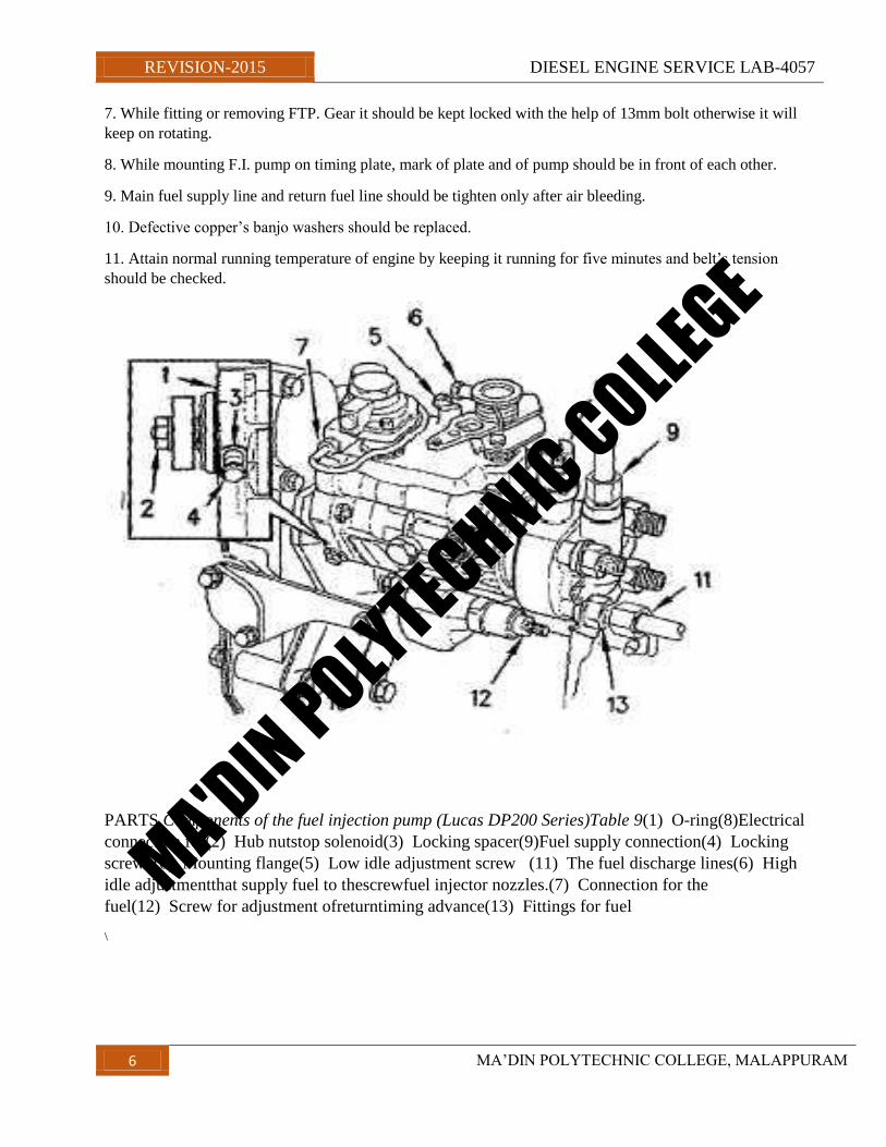
PARTS Components of the fuel injection pump (Lucas DP200 Series)Table 9(1) O-ring(8)Electrical
connection for(2) Hub nutstop solenoid(3) Locking spacer(9)Fuel supply connection(4) Locking
screw(10) Mounting flange(5) Low idle adjustment screw (11) The fuel discharge lines(6) High
idle adjustmentthat supply fuel to thescrewfuel injector nozzles.(7) Connection for the
fuel(12) Screw for adjustment ofreturntiming advance(13) Fittings for fuel
\
MA'DIN POLYTECHNIC COLLEGE
REVISION-2015 DIESEL ENGINE SERVICE LAB-4057
7 MA‟DIN POLYTECHNIC COLLEGE, MALAPPURAM
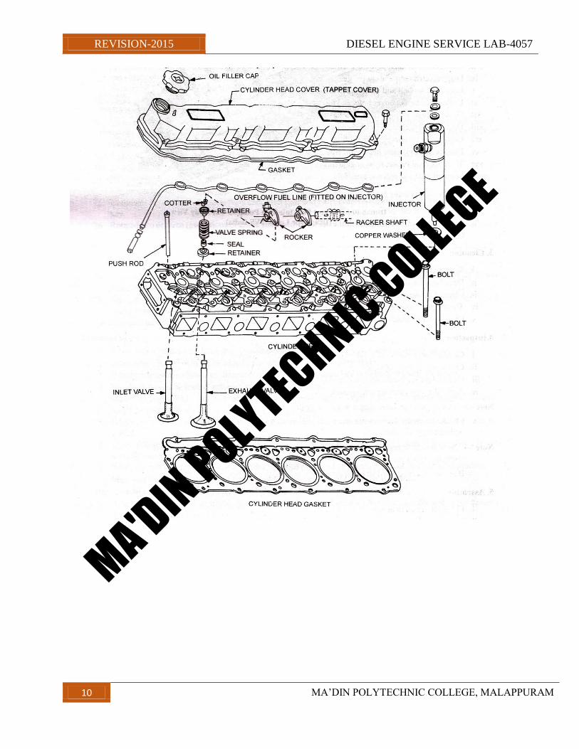
EXPERIMENT 3
OVERHAULING OF CYLINDER HEAD OF DIESEL ENGINE
Objective — Removing, Decarbonizing, Checking, Grinding Valve Seats, Injector Pressure Testing and
Refitting.
Tools and Equipment Used — Ring Spanner Set (inch), Socket Set (inch), Double Ended Spanner Set (inch),
Flat Screwdriver (8” & 10”), Plier (6”), injector Extractor, Valve Spring Compressor, Valve Grinding Stick,
Feeler Gauge, Torque Wrench, Injector Testing Machine, Surface Plate etc.
Raw Material Required — Cylinder Head Gasket, Top over Hauling Kit, Valve Grinding Paste, Kerosene Oil,
Diesel, Petrol, Engine Oil (20W/40), Emery Paper, Old Dhoti, Water and Coolant.
Procedure — we were given an engine of ambassador, which was stand mounted, to overhaul its cylinder head.
1. Dismounting Cylinder Head
i. Drained out all water/coolant from engine through radiator.
ii. Disconnected battery wires from terminals.
iii. Unclamped water hoses. .
iv. Dismounted air cleaner.
y. Took out inlet rubber hose pipe of air compressor from inlet manifold.
vi. Dismounted fuel filters and fuel supply connections of injectors.
vii. Dismounted injector pipes holding clamps from inlet manifold.
vii. Dismounted exhaust pipe from exhaust manifold.
ix. Disconnected temperature gauge.
x. Loosened fan belt and dismounted water pump.
xi. Unthreaded tappet cover bolts and took it out. . .
xii. Took out leak off pipe from injectors and pulled out all injectors with the help of injector extractor.
xiii. Dismounted rocker assembly and push rods.
xiv. Unthreaded all nuts of cylinder head.
xv. Dismounted cylinders head- from engine.
xvi. Took out head gasket from engine block.
xvii. Serrated inlet and exhaust manifold.
2. Dismantling of Cylinder Head
j. Numbered all valves from 1 to 12 using letter punch.
MA'DIN POLYTECHNIC COLLEGE
REVISION-2015 DIESEL ENGINE SERVICE LAB-4057
8 MA‟DIN POLYTECHNIC COLLEGE, MALAPPURAM
ii. Compressed valve springs with the help of spring compressor and took out split cones, collar, seal and
springs.
3. Cleaning
I. Scrapped off all the deposited carbon.
ii. Decarbonize cylinder block also.
iii. Cleaned cylinder head with the help of emery paper.
iv. Thoroughly cleaned cylinder head by immersing it a tray filled with diesel or kerosene oil.
y. Cleaned all passages of inlet and exhaust, and all components.
4. Inspection.
I. Checked unevenness of cylinder head by placing it on surface plate.
ii. Checked scratch marks etc.
iii. Checked pitting marks on valves and their seats.
iv. Applied emery paste on pitting marks and grind using valve grinding stick.
Note — if valve guide or valve seat is worn out or the valves are worn out. Replace all.
y. Checked injector for pressure and dribbling. If nozzle holes are blocked/clogged, they should be cleaned
with the help of cleaning kit.
Note — New injector‟s pressure — 175 kg/sq.cm.
Old injector‟s pressure — 160 kg/sq.cm.
If pressure is less than 150 kg/sq.cm. Overhaul injector.
5. Assembly
I. Fitted all valves in heads.
ii. Mounted cylinder head with new gasket.
iii. Tighten all cylinder head nuts with a tightening torque of 15 gm. or 110 lb. ft.
iv. Mounted rocker assembly and push rod.
y. Mounted all injector and their leak off pipe.
vi. Re-installed connections of exhaust and inlet manifold, fuel lines, air compressor, water pump, radiator
hose and temperature gauge.
vii. Adjusted tappet clearance. (In cold condition — O.5m (0.020”).
viii. Filled radiator with coolant.
ix. Air bleed high pressure pipe lines.
x. Fitted tappet cover with packing on it.
MA'DIN POLYTECHNIC COLLEGE
REVISION-2015 DIESEL ENGINE SERVICE LAB-4057
9 MA‟DIN POLYTECHNIC COLLEGE, MALAPPURAM
xi. Checked engine oil‟s level.
xii. Re — installed battery connections and started the engine.
xiii. Checked engine on high, low and idle speed for leakage and noise.
xiv. Engine‟s performance was up to the mark.
Precautions —
1. Head should be kept precisely over wooden block to avoid it from any scratch, impression etc.
2. Head gasket should be dry while fitting it. No compound etc. should be applied on it.
3. Proper decarbonizing should be done to head and block.
4. Cylinder head should be tightened in clockwise direction with specified torque...
5. Worn out valve guides, seats should be replaced.
6. Properly tight fuel line connection and thoroughly checked for leakage etc.
7. Less injector pressure should be adjusted followed by its fitment.
8. Valves should be checked for locking etc. using cotters.
9. Ferrul „O‟ ring must be fitted for rocker lubrication, while mounting head gasket.
MA'DIN POLYTECHNIC COLLEGE
REVISION-2015 DIESEL ENGINE SERVICE LAB-4057
10 MA‟DIN POLYTECHNIC COLLEGE, MALAPPURAM
MA'DIN POLYTECHNIC COLLEGE
REVISION-2015 DIESEL ENGINE SERVICE LAB-4057
11 MA‟DIN POLYTECHNIC COLLEGE, MALAPPURAM
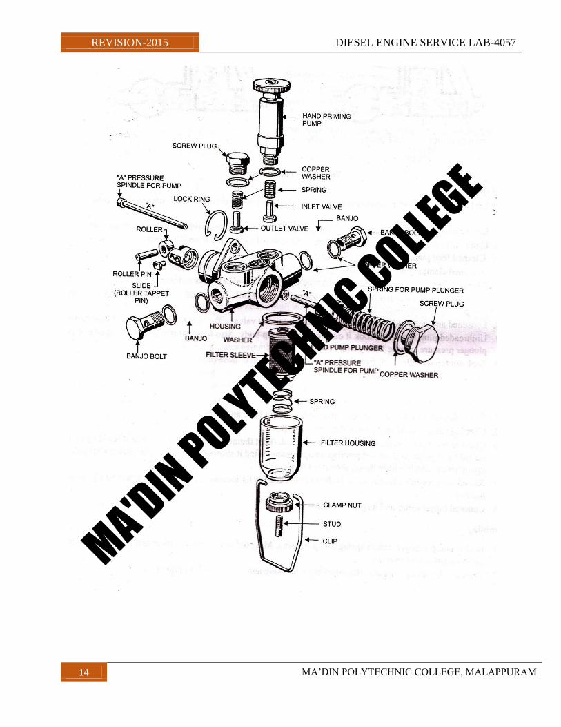
EXPERIMENT4
OVERHAULING OF FEED PUMP
Objective — Removing, Dismantling, Cleaning, Checking, Assembling, Testing and Refitting.
Tools and Equipment Used — Double Ended Spanner Set (mm), Ring Spanner Set (mm), Long Nose Plier
(6”),
Stud Plier, Small Cleaning Tray, Flat Screwdriver (9”), Cleaning Brush (2”).
Raw Material Required — Diesel, Old Dhoti, Copper Washer Kit for Banjo Bolts, Small Container, And
Flexible Flue Pipe.
Procedure —
1. Unthreaded banjo bolt (19mm) which was threaded to main diesel line of feed pump with the help of ring
spanner.
2. Unthreaded outlet diesel line‟s bolt (19mm) going up to diesel filters, with the help of ring spanner.
3. Unthreaded feed pump flange‟s nut (10mm), and serrated feed pump from F.I. pump.
4. Cleaned feed pump assembly by placing it in a small tray.
5. Loosened clamping nut and serrated nylon filter and its housing from feed pump.
6. Clamped feed pump lengthwise in bench vice with small wooden blocks as their packing.
7. Loosened and dismounted hand priming pump. Took out, inlet valve and valve return spring from feed
pump.
S. Loosened and unthreaded outlet plug and took out outlet valve with valve return spring from feed pump.
9. Unthreaded plug screw and took it out from feed pump body. Also took out plunger, return spring, pump
plunger pressure spindle from pump body.
10. Took out tappet roller lock from lock groove with the help of nose plier.
1l. Serrated tappet roller assembly from feed pump.
12. Serrated roller and pin from tappet roller assembly.
13. Cleaned all components with diesel.
14. Checked seats of inlet and exhaust valve both does not have any marks.
15. Checked valve seat of feed pump that too was OK.
16. Check hand priming pump with vacuum method. (Keep thumb or a little pressure over threaded part and
pulled hand pump. If piston of priming pump remains lifted it shows there is a leakage and if after pulling up
the pump settles a little down, then it is OK).
MA'DIN POLYTECHNIC COLLEGE
REVISION-2015 DIESEL ENGINE SERVICE LAB-4057
12 MA‟DIN POLYTECHNIC COLLEGE, MALAPPURAM
17. Rested feed pump‟s plunger in its body and checked for its loosening and also checked it using vacuum
method.
18. Checked tappet roller and its pin for their worn out.
Assembling
1. Rested pump plunger, return spring pump housing. Mounted new copper washer and tighten screw plug
(30mm), using ring spanner.
2. Rested roller spring, tappet roller assembly in housing and locked it using plier.
3. Placed inlet and outlet valve at their seat and placed and hand priming pump over inlet.
4, Tighten outlet screw plug with new copper washer over outlet valve.
5. Mounted new filter housing rubber, cleaned nylon filter and spring in filter housing and tighten clamping nut
by threading it with fingers.
Testing
1. Tighten flexible diesel pipe to inlet with banjo bolt.
2. Immersed the other end in diesel filled jar and moved hand priming pump up and down. Outlet supply was
quite regular.
3. Mounted feed pump with new packing, over F.I. pump by threading all three flange nuts (1Omm).
4. Mounted new washer in banjo bolt of fuel line from diesel tank, connected it with feed pump‟s inlet valve.
5. Connected filter line with outlet of feed pump with banjo washer in the bolt.
6. Moved priming pump up and down and as diesel starts coming out of outlet banjo bolt, immediately tighten
it with inlet of filter assembly.
7. Bleed air from filter assembly through bleeding screws.
8. Started the engine and varied its speed. Engine was running properly with varying speed and it ensured us
that feed pump is working properly.
Precautions —
I. While working over feed pump cleanliness is important.
2. Proper sized spanner should be used while dismantling and assembling priming pump, outlet valve, screw
plug, plunger screw plug.
3. Do not overtight any screw, plug of hand priming pump.
4. Pump plungers „O‟ ring should be replaced while repairing it.
5. Always use new rubber ring of filter housing.
6. Never increase length of inlet and outlet valve return springs by pulling them.
7. Replace inlet and outlet valve seats, if they are pitted or worn.
MA'DIN POLYTECHNIC COLLEGE
REVISION-2015 DIESEL ENGINE SERVICE LAB-4057
13 MA‟DIN POLYTECHNIC COLLEGE, MALAPPURAM
8. Worn out roller, roller pin should be replaced.
9. Fitment of pump plunger in bore should be checked with vacuum method. If this fails replace both.
10. Always new copper washers.
11. Checked hand priming pump with vacuum method.
12. Properly bleed fuel supply system after assembling.
13. Fill F.I. pump‟s lubricating oil, after fitting feed pump to it.
14. Move hand priming pump up and down after installing feed pump and check pressure relief valve. If it is
not working jam, the fuel line may damage.
MA'DIN POLYTECHNIC COLLEGE
REVISION-2015 DIESEL ENGINE SERVICE LAB-4057
14 MA‟DIN POLYTECHNIC COLLEGE, MALAPPURAM
MA'DIN POLYTECHNIC COLLEGE
REVISION-2015 DIESEL ENGINE SERVICE LAB-4057
15 MA‟DIN POLYTECHNIC COLLEGE, MALAPPURAM
EXPERIMENT 5
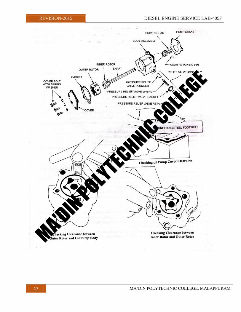
OVERHAULING OF ROTOR TYPE OIL PUMP
Objective — Removing, Cleaning, Checking, Assembling and Refitting.
Tools and Equipment Used — Double Ended Spanner Set (inch), Ring Spanner Set (inch), Feeler Gauge, Steel
Foot Rule, Socket Set (inch). DRIVEN GEAR PUMP GASKET
Raw Material Required — Cotton Waste, Engine Oil, Gasket,
Kerosene Oil, Shellac.
Procedure
1. Drained out engine oil form engine by unplugging drain plug with the help of double ended spanner.
2. Dismounted oil sump from engine by unthreading all bolts of oil sump.
3. Dismounted oil pump by unthreading all three bolts of it.
4. Dismounted oil pump and took out its rotor assembly.
5. Cleaned all components using kerosene oil.
6. Placed inner and outer rotor in oil pump body.
7. Checked clearance between both rotors with the help of feeler gauge. Found it to be 0.003”.
8. Checked clearance between both the outer rotor and the body. Found it to be 0.003”.
9. Placed foot rule over oil pump body and checked rotor‟s end surface which was 0.001”.
10. Mounted oil strainer and plate over oil pump body and tighten both bolts completely.
11. Filled cleaning tray with fresh engine oil (SAE 20—40) and immersed oil pump in it. Mounted drive
gearand rotated inner rotor so that pump sucked the oil.
12. Further rotated drive gear and oil started coming out of outlet with pressure.
13. Mounted oil pump with gasket on engine and tighten all three bolts.
14. Filled four liter of fresh oil through tappet cover‟s filler plug.
15. Started engine and checked engine oil pressure through pressure gauge. Slow engine pressure was 1.5 kg!
Sq.cm. and on full throttle it was 4.5 kg/ sq.cm.
Precautions —
1. Inner and outer rotor clearance should not be more than 0.003”. If it is more, replace both.
2. Clearance between outer rotor and oil pump body should be between 0.002” and 0.005”. If it is more,
Replace outer rotor.
3. Clearance between oil pump body and rotor end should not be more than 0.002”. If clearance is more than
oil strainer plate should be grind with emery paste and glass. Set clearance.
4. Oil pump should be filled with oil before mounting it.
5. New packing should be installed while fitting oil pump with engine.
6. If outer rotor, inner rotor, outer body related data is not known, refer workshop manual.
7. Oil sump should be cleaned before mounting it.
MA'DIN POLYTECHNIC COLLEGE
REVISION-2015 DIESEL ENGINE SERVICE LAB-4057
16 MA‟DIN POLYTECHNIC COLLEGE, MALAPPURAM
8. Oil sump packing should be replaced.
9. Oil sump packing should be installed with shellac on sump side of the packing and grease on other side of it.
10. Oil pump bolts should not be over tightened. If we do so packing may be damaged and oil may leak from
it.
Note — 1. In some oil pumps there is no pressure relief valve is fitted while it is installed in oil gallery. If
pressure is to be adjusted, may be adjusted with it.
2. If oil pressure is low at low speed and high at high speed, then do not overhaul oil pump and first adjust
pressure through pressure relief valve. If it does not works then overhaul pump.
MA'DIN POLYTECHNIC COLLEGE
REVISION-2015 DIESEL ENGINE SERVICE LAB-4057
17 MA‟DIN POLYTECHNIC COLLEGE, MALAPPURAM
MA'DIN POLYTECHNIC COLLEGE
REVISION-2015 DIESEL ENGINE SERVICE LAB-4057
18 MA‟DIN POLYTECHNIC COLLEGE, MALAPPURAM
EXPERIMENT 6
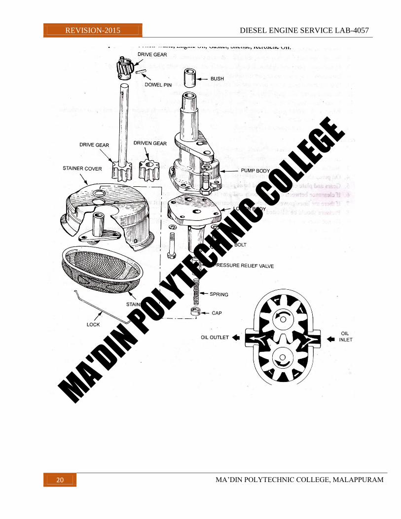
OVERHAULING OF GEAR TYPE OIL PUMP
Objective — Removing, Cleaning, Checking, Assembling and Refitting.
Tools and equipment Used — Double Ended Spanner Set (inch), Ring Spanner Set (inch), Socket Set (inch),
Feeler Gauge (mm), Steel Foot Rule (12”).
Raw Material Required — Cotton Waste, Engine Oil, Gasket, Shellac, Kerosene Oil.
192 - Automobile Engineering Practical
Procedure —
1. Drained out engine oil from engine by unplugging drain plug with the help of double ended spanner.
2. Dismounted oil sump from engine by unthreading all bolts of oil sump.
3. Dismounted oil pump by unthreading foundation bolts.
4. Cleaned oil pump and took out oil strainer.
5. Unthreaded upper plate and took out driven gear. Cleaned all components.
6. Checked back-lash between driver and driven gear with the help of feeler gauge also measured side
clearance.
Back-lash found to be 0.15mm.
7. Measured side clearance, found to be OK.
8. Placed steel foot rule over body and gear, checked clearance, found to be OK.
9. Placed upper plate and tighten all bolts, mounted oil strainer with gasket over oil pump.
10. Immersed oil pump in an engine oil filled tray.
11. Rotated driven gear, so the pump sucked the oil and checked its pressure.
12. Mounted pump with gasket in engine block and tighten all nuts.
13. Mounted oil sump with gasket to engine block. Tighten drain key.
14. Filled SAE 20W40 grade of engine oil through filler plug provided in tappet cover and up to maximum
mark given on dipstick.
15. Started engine and checked oil pressure.
Precautions —
1. Oil sump should be cleaned before mounting it on engine block.
2. Defective oil sump packing should be replaced.
3. Shellac should place towards sump side and grease on engine side of sump packing.
4. Oil pump should be filled with oil before mounting it on engine.
MA'DIN POLYTECHNIC COLLEGE
REVISION-2015 DIESEL ENGINE SERVICE LAB-4057
19 MA‟DIN POLYTECHNIC COLLEGE, MALAPPURAM
5. Gears and plate clearance should be as per manual instructions.
6. If clearance between oil pump body and gear is more, replace them.
7. If there are lines/groves/scratches are appearing on gear plate, grind it with fine emery paste and glass.
8. Pressure should be adjusted through relief valve.
9. Do not work with dirty hands.
10. Oil sump bolts should not be over tightened, because cork packing may get damage and oil may leak
through it.
MA'DIN POLYTECHNIC COLLEGE
REVISION-2015 DIESEL ENGINE SERVICE LAB-4057
20 MA‟DIN POLYTECHNIC COLLEGE, MALAPPURAM
MA'DIN POLYTECHNIC COLLEGE
REVISION-2015 DIESEL ENGINE SERVICE LAB-4057
21 MA‟DIN POLYTECHNIC COLLEGE, MALAPPURAM
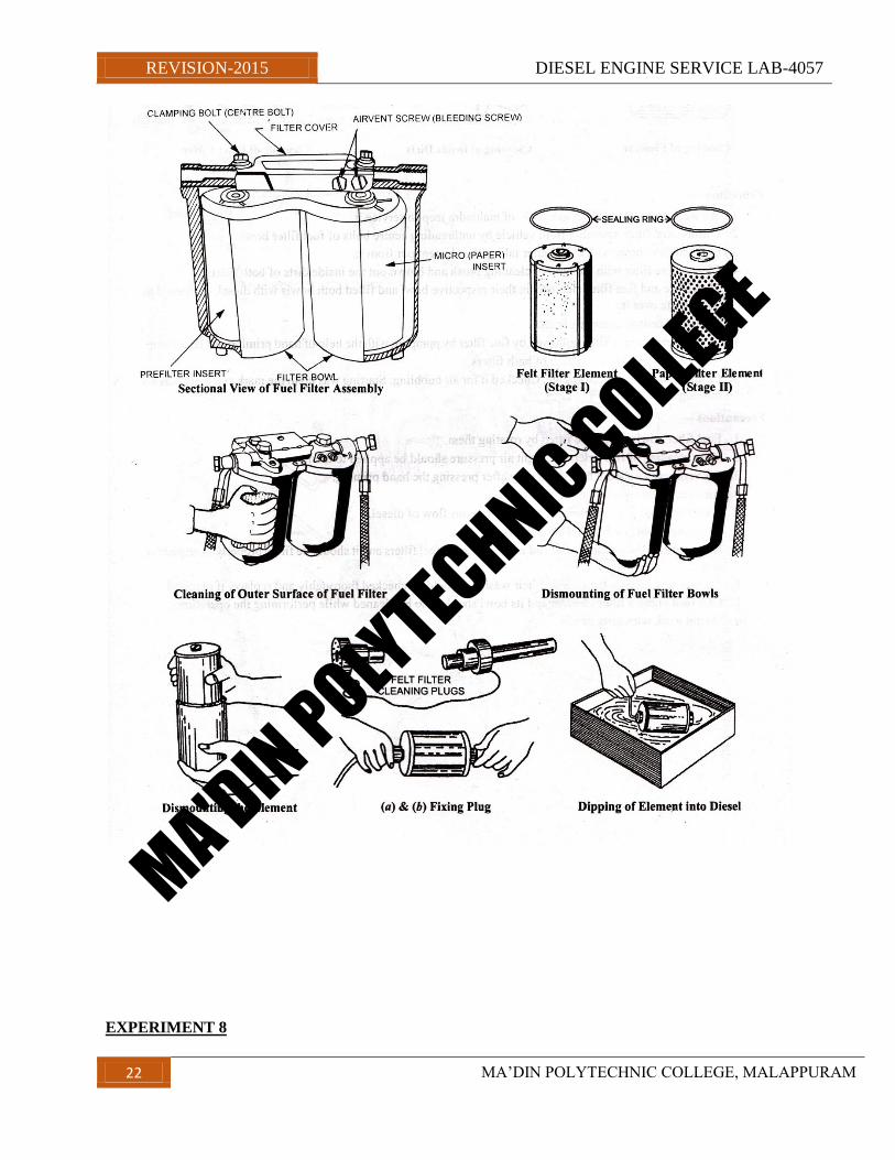
EXPERIMENT 7
SERVICING OF DIESEL FUEL FILTER ELEMENT (PRE AND FINE)
Objective — Dismantling, Cleaning, Checking, Refitting and Bleeding.
Tools and Equipment Used — Ring Spanner Set (mm), Double Ended Spanner Set (mm) and
FlatScrewdriver(10”).
Raw Materials Required — Cotton Waste, Diesel Filters, „O‟ Ring.
Procedure —
1. We were given diesel filter assembly of Tata to service it.
2. Dismounted filter assembly from vehicle by unthreading center bolts of fuel filter bowl.
3. Cleaned filter bowl with diesel after taking the element out from it.
4. Cleaned pre filter with the help of cleaning brush and blown out the inside dirt of both filters.
5. Placed pre and fine filter elements in their respective bowl and filled both bowls with diesel. Tightened to
cover plate over it.
6. Tightened central clamping bolts.
7. First bleed the pre filter followed by fine filter by pumping with the help of hand priming and feed pump.
8. Bleed F. I. Pump after bleeding of both filters.
9. Cranked and then started engine. Checked it for air bubbling. Starting was up to the mark and there was no
missing too. ,
Precautions —
1. Fuel filter bowls should be fitted by rotating them.
2. After cleaning of filter element slight air pressure should be applied to them.
3. Air vent screws should be tighten only after pressing the hand priming.
4. Air vent screws should not be over tighten.
5. Bleeding should be done until there is continuous flow of diesel.
6. F.I. Pump should be bleed after filters.
7. New rubber „O‟ ring should be used while servicing fuel filters and it should be fitted properly in respective
seat.
8. All bleeding screws, banjo bolts, their washers should be checked thoroughly and replace, if required.
9. Fuel feed pump‟s filter element and its bowl should also be cleaned while performing the operation.
10. Do not work with dirty hands.
MA'DIN POLYTECHNIC COLLEGE
REVISION-2015 DIESEL ENGINE SERVICE LAB-4057
22 MA‟DIN POLYTECHNIC COLLEGE, MALAPPURAM
EXPERIMENT 8
MA'DIN POLYTECHNIC COLLEGE
REVISION-2015 DIESEL ENGINE SERVICE LAB-4057
23 MA‟DIN POLYTECHNIC COLLEGE, MALAPPURAM
Draining & refilling coolant(RADIATOR)
Summary
The objective of this procedure is to show you how to drain cooling system and refill with correct mixture of
engine coolant. Some vehicles have drain plugs on the side of the engine block. The shop service manual will
tell you if these need to be opened when draining the coolant.
Part 1. Preparation and safety
Objective
. Drain cooling system and refill with correct mixture of engine coolant.
Personal safety
Whenever you perform a task in the workshop you must use personal protective clothing and equipment that is
appropriate for the task and which conforms to your local safety regulations and policies. Among other items,
this may include:
. Work clothing - such as coveralls and steel-capped footwear
. Eye protection - such as safety glasses and face masks
. Ear protection - such as earmuffs and earplugs
. Hand protection - such as rubber gloves and barrier cream
. Respiratory equipment - such as face masks and valved respirators
If you are not certain what is appropriate or required, ask your supervisor.
Safety check
. Never drain and refill the cooling system of a hot engine. Wait for it to cool down first.
. Always make sure that you wear the appropriate personal protection equipment before starting the job.
It is very easy to hurt yourself even when the most exhaustive protection measures are taken.
. Always make sure that your work area/environment is as safe as you can make it. Do not use damaged,
broken or worn out workshop equipment.
. Always follow any manufacturer‟s personal safety instructions to prevent damage to the vehicle you are
servicing.
. Make sure that you understand and observe all legislative and personal safety procedures when carrying out
the following tasks. If you are unsure of what these are, ask your supervisor.
Points to note
. Some vehicles have drain plugs on the side of the engine block. The shop service manual will tell you if these
need to be opened when draining the coolant.
Part 2: Step-by-step instruction
1. Locate drain plug
MA'DIN POLYTECHNIC COLLEGE
REVISION-2015 DIESEL ENGINE SERVICE LAB-4057
24 MA‟DIN POLYTECHNIC COLLEGE, MALAPPURAM
Locate the cooling system drain plug or valve on the bottom tank of the radiator. Place a clean drain pan large
enough to contain all the coolant underneath the drain valve.
2. Drain radiator
Carefully remove the radiator pressure cap. This will allow air into the cooling system so that it can drain
quickly and completely. Open the drain valve so that the coolant can drain into the pan below. When all the
coolant has drained out, close the drain valve.
3. Refill coolant system
Check the shop service manual for the capacity of the system, and the recommended type and mixture of
coolant for the operating conditions of the vehicle. Measure the recommended amount of coolant and using a
funnel pour it in through the top of the radiator.
4. Start engine and verify
Air can be trapped in the cooling system, so leave the radiator cap off to allow it to escape, and run the Engine
for a few minutes to allow the coolant to circulate and get rid of trapped air. Then replace theradiator cap and
bring the engine up to operating temperature. Check the coolant level in the reservoir and top it up to the high
or hot engine mark.
5. Dispose of waste
Antifreeze is toxic, so dispose of the waste coolant carefully and in an environmentally recommended way
MA'DIN POLYTECHNIC COLLEGE
REVISION-2015 DIESEL ENGINE SERVICE LAB-4057
25 MA‟DIN POLYTECHNIC COLLEGE, MALAPPURAM
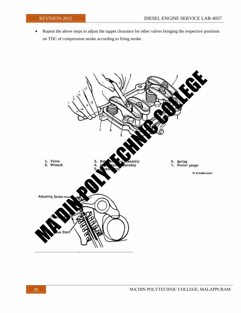
EXPERIMENT9
ADJUSTING THE VALVE TAPPET CLEARANCE (4 CYLINDER/6
CYLINDER ENGINE)
OBJECTIVES
Adjust the valve tappet clearance in a 4 cylinder engine
Adjust the tappet clearance in a 6 cylinder engine
Adjust the tappet clearance in a side valve engine
Job sequence
PRILIMINARY OPERATIONS
Tighten all the cylinder head bolt/nuts in correct sequence to the specified torque(use torque wrench)
Procedure
Turn the crank shaft in the clock wise direction and coincide the flywheels TDC 1/6 OR ¼ MARK
WITH THE FLYWHEEL HOUSING POINTER. Then ensure that the first cylinder is in compression
stroke.
Hold firmly the tappet adjusting screw with a god screw driver.
Loosen the lock nut with a ring spanner .
Insert a feeler guage of the specified thickness between the valve stem and rocker tip.
Tighten the adjusting screw by a screw driver and at the same time move the feeler gauge to and fro
Stop tightening of the adjusting screw when the feeler gauge can be slide with a slight effort but it
should not be jammed.
Hold the adjusting screw in position with the screw driver firmly and tighten the lock nut by a ring
spanner.
Ensure that the adjusting screw does not turn by tightening by the lock nut.
Check again the adjustment by sliding the feeler gauge leaf in the gap and turning the push rod.
MA'DIN POLYTECHNIC COLLEGE
REVISION-2015 DIESEL ENGINE SERVICE LAB-4057
26 MA‟DIN POLYTECHNIC COLLEGE, MALAPPURAM
Repeat the above steps to adjust the tappet clearance for other valves bringing the respective positions
on TDC of compression stroke according to firing stroke.
MA'DIN POLYTECHNIC COLLEGE
REVISION-2015 DIESEL ENGINE SERVICE LAB-4057
27 MA‟DIN POLYTECHNIC COLLEGE, MALAPPURAM
EXPERIMENT10
Overhauling engine block, crankshaft and camshaft
Objectives
Descale water jacket‟s passages
Clean the engine block
Check the engine blocks for cracks
Check the machines surface s of the block for burrs and scores
Check the parent bore for In-line alignment
Remove the liners
Fit the liners
Inspect the flywheel and ring gear
Inspect the crank shaft journal and crank pin
Inspect the cam shaft for bend and twist
Inspect the cam lob and measure the cam lob lift
Inspect the cam shaft journals and bearings
Inspect the cam shaft bearings and sprockets and tensioners
Assemble all the above engine parts
Job sequence
Cleaning and checking engine parts and place the engine block on wooden pieces
Clean the cylinder block with a suitable solvent or in degreasing equipment.. I f
available
Clean the oil passages, remove al sludges, dirt and carbon deposits in the cylinder
blocks. Use a scraper to remove hard deposits. Ensure that the highly finished surfaces
are not damaged. Examine the surface and check for damage.
Remove the Welch plugs. Descale the water passages with pressurized water with a
suitable solvent under high pressure. Fix new plugs.
Clean and dry the block by using compressed air.
Clean the crankshaft using a soft brush with the recommended cleaning solvent
Clean sludge and gum deposits from the drilled oil passages in the crankshaft with a
wire
Blow out the passages with compressed air
Check the engine block thoroughly for minute cracks and inspect visually to detect
cracks ,and if needed, use a magnetic crack detector.
Check for water leakage with a dummy cover and water under pressure. Replace the
block if any water leakage is discovered
Check the flatness of the machined top and bottom surface of the cylinder block with a
straight edge and feeler gauge
Inspect the parent bore of the cylinder block for in-line alignment.(using line boring
bar/straight edge)
MA'DIN POLYTECHNIC COLLEGE
REVISION-2015 DIESEL ENGINE SERVICE LAB-4057
28 MA‟DIN POLYTECHNIC COLLEGE, MALAPPURAM
Measure the main bearing parent bore using a bore dial gauge,for taper and ovality
Measure the cylinder bore diameter for wear,taper,andovality
Remove the cylinder liners
Refit the liners
In some engines liners are not used .reboring of cylinder block is recommended by the
manufacture.follow the manufactures recommendations
INSPECTION OF FLYWHEEL,CRANKSHAFT,CAMSHAFT AND TIMING
GEAR AND SPROCKETS AND CHAIN
Check visually the flywheel surface for cracks,burnt and scored face
Check the warpage of the flywheel friction surface by using a straight edge.if
the warpage is morethan the maximum limit specified by the
manufacturer,then the flywheel should be reground. Ensure that after
regrinding the flywheel thickness is not reduced below the minimum limit
specified by the manufacturer.
Mount the fly wheel on the crank shaft and keep it on the inspection table.
Note down the face-out of the flywheel with the help of a dial indicator.
Check the flywheel ring gear teeth for wear,damage etc.
Check the crankshaft visually for cracks and overheating.
Check the crankshaft journals and crankpin for taper and ovality.if the taper
and ovality are more than the given limit,then the crank shaft should be
reground to the next undersize.
Measure the oil clearance between the crankshaft main journal and the bearing
shell.
Check the fillet radii of the main and connecting rod journals.
Check the run out of journals with a dial indicator. If the run out exceeds the
given limit then the crankshaft should be straightened.
Recommend removal of the bend or replacement of the shaft if the maximum
bend at any one of the places is foudmorethan the limit specified by the
manufacturer.
Clean the cam shaft thoroughly
Inspect the cam shaft journals for scratches,grooves and marks.
Measure each journal for ovality,taper and wear.
Check the camshaft for bend and concentricity.
Check the cam lobe surface for wear.
Measure the base circle diameter of the cam lobe and the lobe height by a
micrometer.measure the lobe height. The difference between the lobe height
and the base circle dia .is the cam lift .replace the cam shaft if the cam lift
found to be lessthan the specified limit.
Check the oil pump drive gear for pitting,wear and damage if any.
Check the cams eccentricity for the fuel pump drive.
Measure the clearance between the thrust washer and the camshaft‟s first
journal
MA'DIN POLYTECHNIC COLLEGE
REVISION-2015 DIESEL ENGINE SERVICE LAB-4057
29 MA‟DIN POLYTECHNIC COLLEGE, MALAPPURAM
Measure the end play of the cam shaft with the help of a dial indicator.
Change the thrust washer if the end play is not asper the manufacturer‟s
recommendation.
Inspect the teeth of the sprocket(for chain drive)
Check the chain for elongation (for chain drive)
Check the teeth of the timing gear (for gear drive)
Check the pully and belt for cracks,damage etc.
Check the belt tensioner. (for chain drive)
ASSEMBLING
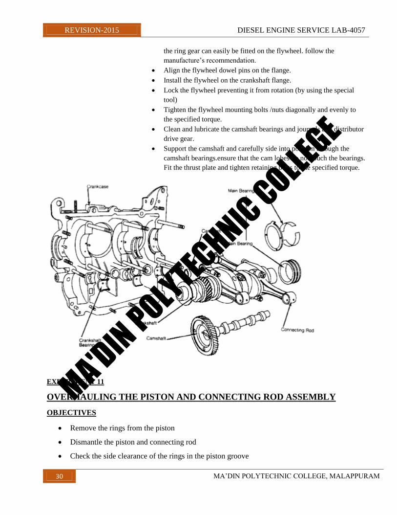
Clean the parent bore of the main bearing in the cylinder block.
Clean the oil holes of the parent bore.
Place the maim bearing shell into its respective parent bore. Ensure
that the oil hole of the bearing shell and that of the parent bore align.
Install the crank shaft rear bearing seal (oil seal).
Insert the rubber packing (rubber rod) in the holes between the
bearing cap and the cylinder block.
The projection of the rubber packing should not be morethan 6mm. if
it is morethan 6 mm,cut off the excess length.
Install the thrust washers into the respective bearings.
Lubricate all the bearing surface with clean engine oil.
Place crankshaft in its position in the cylinderblock.
Place the shell bearing into their respective bearing caps.
Check the bearing liners/shells for spread. The inserts should
“snap”into position in the housing and cap.
Lubricate and install the bearing caps. Ensure that the bearing caps are
fitted in to their orginal positions.
Hand-tighten the main bearing cap bolts.
Tighten the middle bearing cap to the specified torque and check the
crankshaft for free rotation.
Loosen the main bearing caps and bolts on one side check the gap
between the main bearing cap and the cylinderblock surface with a
feelergauge.this gap indicates the bearing crush.
Tighten the bolts of the main bearing caps on either side of the
centrebearing,one by one to the specified torque.
Check the crankshaft for its free rotation after tightening each bearing
cap‟s bolts.
Check the crankchaft end play.
To increase the end play use a thinner thrust washer and to reduce the
end play use a thicker thrust washer.
Fit the ring gear on the flywheel.
Some manufacturers recommended to heat the ring gear up to a
certain temperature before fitting .heat expands the ring gear so that
MA'DIN POLYTECHNIC COLLEGE
REVISION-2015 DIESEL ENGINE SERVICE LAB-4057
30 MA‟DIN POLYTECHNIC COLLEGE, MALAPPURAM
the ring gear can easily be fitted on the flywheel. follow the
manufacture‟s recommendation.
Align the flywheel dowel pins on the flange.
Install the flywheel on the crankshaft flange.
Lock the flywheel preventing it from rotation (by using the special
tool)
Tighten the flywheel mounting bolts /nuts diagonally and evenly to
the specified torque.
Clean and lubricate the camshaft bearings and journals and distributor
drive gear.
Support the camshaft and carefully side into position through the
camshaft bearings.ensure that the cam lobes do not touch the bearings.
Fit the thrust plate and tighten retaining bolts to the specified torque.
EXPERIMENT 11
OVERHAULING THE PISTON AND CONNECTING ROD ASSEMBLY
OBJECTIVES
Remove the rings from the piston
Dismantle the piston and connecting rod
Check the side clearance of the rings in the piston groove
MA'DIN POLYTECHNIC COLLEGE
REVISION-2015 DIESEL ENGINE SERVICE LAB-4057
31 MA‟DIN POLYTECHNIC COLLEGE, MALAPPURAM
Measure the piston rings close gap in the cylinder with a feeler gauge
Measure the clearance between the piston and the liner
Measure the piston diameter at different points
Measure the clearance between the crankpin and the connectingrod big end bearing with a
micrometer and a bore dial gauge
Measure the cylinder/liner for wear/taper/ovality with a micrometer and a bore dial gauge
Check the connecting rods alignment
Assemble the piston with the connecting rod
Assemble the rings in the piston correctly
Job sequence
dismantling
Hold the connecting rod on the vice
Remove the rings from the piston with the help of a ring expander
Remove the circlip of the piston pin,using a circlip plier
Remove the piston pin with help of drift and hammer
Romove the piston by hand( donot drop on the floor)
Repeat the steps for all the pistons
Cleaning and inspection
Remove the carbon deposits on the poiston ring grooves( using special tools)
Clean the piston , piston rings and the connecting rod using kerosne
Check visuallythe piston skirt and the crown for scuffing, cracks, scoring etc.
Check visualy the piston pin circlip groove and the piston for damage
Check the ring side clearence in the ring grovves with feeler guage
Place the ring in the cylinder/liner without the piston and measure the end gap with a
feeler guage
Plce the piston in the liner/cylinder bore and measure the clearence between the liner
and the piston below the gudgeon pin with a feeler guage.
Measure tyh epistion diameter at diiferent points.
Measure the clearence between the crank pin and connectng rod‟s big end bearing with
a micrometer nd bore dial guage.
MA'DIN POLYTECHNIC COLLEGE
REVISION-2015 DIESEL ENGINE SERVICE LAB-4057
32 MA‟DIN POLYTECHNIC COLLEGE, MALAPPURAM
Check the connecting rods small end bush for wear and scoring
Check the connecting rods alignment for bend and twist
Check the gudgeon pin surface for any injury
Place the connecting rod on the alignment fixture
Assembilng
Fit one circlip in the grrove of the piston
align the connecting rods small end bore and the gudgeon pin hole of the
piston
Tap the gudgeon pin into the ppiston pin hole with the help of mallet while
tapping, keep the small end hole aligned to avoid the damage to the connecting
rod bush. Fit another circlip on the groove
Hold te [iston ring in the ring expander and fit it in the piston groove. Ensure
that the word „ top „ stamped on the ring face upward. Fit all the rings to all the
pistons.
place the upper and lower bearing shells in the connecting rods and caps and
keep them in proper order for reassembling purpose
MA'DIN POLYTECHNIC COLLEGE
REVISION-2015 DIESEL ENGINE SERVICE LAB-4057
33 MA‟DIN POLYTECHNIC COLLEGE, MALAPPURAM
EXPERIMENT 12
MA'DIN POLYTECHNIC COLLEGE
REVISION-2015 DIESEL ENGINE SERVICE LAB-4057
34 MA‟DIN POLYTECHNIC COLLEGE, MALAPPURAM
BLEEDING THE FUEL SYSTEM IN DIESEL ENGINE
OBJECTIVES
BLEED THE FUEL SYSTEM IN A DIESEL ENGINE.
JOB SEQUENCE
Loosen the bleeding screw at the fuel filter by two turns to allow the air to escape through the hole in
the bleeding screw.
Pump the fuel by the hand primer in the feed pump till the fuel flows through the bleeding screw vent
hole without air.
Tighten the bleeding screw again.
Repeat the operation till the air in the system is fully drawn out.
Loosen the bleeding screw at f.i.p. by one or two turns so that air can escape through the hole from the
bleeding screw.
Tighten the bleeding screw again.
Repeat the opearation till the air in the system is fully driven out.
MA'DIN POLYTECHNIC COLLEGE