automatic induction machine parameters measurement using standstill frequency-domain tests
TRANSCRIPT
Automatic induction machine parametersmeasurement using standstill frequency-domaintests
M.O. Sonnaillon, G. Bisheimer, C. De Angelo and G.O. Garcıa
Abstract: A new method to measure the induction machine equivalent circuit parameters is pro-posed. The method is based on three frequency-domain tests, performed at standstill, avoidingthen the locked-rotor and no-load tests. The proposed algorithm can be implemented in standardmotor drives in order to automatically perform self-commissioning. Furthermore, the proposedmethod allows a direct measurement of the iron saturation. Experimental results are presented tovalidate the measurement method and the machine equivalent circuit.
1 Introduction
Most modern induction machine (IM) drives use vectorcontrol strategies, such as field-oriented controls [1].These strategies require knowing the position of any ofthe motor magnetic fluxes (rotor, stator or magnetising) tooperate properly. In practical applications, these fluxes arenot directly measured, instead they are computed using esti-mators or state observers [2]. Moreover, many drives usemethods to estimate other motor variables, such as rotorspeed [3] or phase currents [4]. These methods are generallybased on an equivalent electric circuit, which has differentparameters for each particular machine [5].Traditionally, the equivalent circuit parameters (ECPs)
are measured by performing three well-known tests,similar to the transformer tests. These tests are the DCtest, the no-load test and the locked-rotor test [5].Vector-controlled commercial drives [6, 7] have algorithms,usually called self-commissioning, that perform these testsautomatically. The parameters used in the control and esti-mation schemes are computed based on the measurementsobtained in these tests.Traditional tests present some drawbacks [8]. For
instance, the locked-rotor test requires the rotor to be exter-nally locked, and the no-load test needs the rotor to rotatefreely (at almost the synchronous speed). Performingthese tests can be impractical or even impossible in casethe machine has already been coupled to its mechanicalload. For these reasons, it is convenient to replace the tra-ditional tests with standstill tests.The strategies for ECP identification can be grouped in
time-domain (TD) and frequency-domain (FD). TD tech-niques are based on the transient response of phase currents
# The Institution of Engineering and Technology 2007
doi:10.1049/iet-epa:20060512
Paper first received 28th December 2006 and in revised form 4th April 2007
The authors are with CONICET, and also with the Grupo de ElectronicaAplicada (GEA), Facultad de Ingenierıa, UNRC, Ruta Nacional #36 Km. 601,Rıo Cuarto X5804BYA, Argentina
M.O. Sonnaillon is also with Balseiro Institute, S.C. de Bariloche, Argentina
G. Bisheimer is also with the Universidad Nacional del Sur, Bahıa Blanca,Argentina
E-mail: [email protected]
IET Electr. Power Appl., 2007, 1, (5), pp. 833–838
when voltage steps are applied to the motor. The transientinductance (Ls) and the electrical resistances can be com-puted by directly applying the equivalent circuit equations[9, 10] or statistical methods, such as the maximum like-hood method [11] or least-squares method [12].FD techniques consist of measuring the machine response
to sinusoidal waveforms of arbitrary frequencies.Traditional tests can be considered FD techniques sincethey are performed at different excitation frequencies (DCand nominal frequency) and slip frequencies (no-load andlocked-rotor), in order to identify all the ECPs. FD tech-niques are generally more accurate than TD because theyare based on the steady-state response of the machine,allowing then the utilisation of filtering and averaging tech-niques that improve measurements accuracy. Anotheradvantage of FD is that the nonlinear and frequency-dependent effects of the machine can be taken intoaccount (e.g. skin effect and iron losses).Several FD techniques are proposed in the literature.
Kerkman et al. [13] proposed a FD method to computethe transient inductance, showing its advantages against aTD method. Gastli [8] proposed an automated FD methodto measure the IM ECP, based on two measurements atdifferent stator frequencies. This method has the disadvan-tage that each parameter computation is affected by errorsin other parameters, and different equivalent circuits mustbe used to reduce these effects. Ganji et al. [14] measuredthe machine response at different stator frequencies andused a least-squares method to identify the magnetisingcurrent. Gastli and Matsui [15] proposed applying the tra-ditional tests in only one of the three phases, in order toavoid the machine torque generation. Thus, locking therotor in the locked-rotor test will not be necessary. Linand Chen [16] proposed an automated method to applysingle-phase tests. These tests are modified to be appliedin sensorless-field-oriented controllers. Willis et al. [17]used a specific instrument to measure the machine fre-quency response at different powers, and the ECPs are com-puted from these measurements.FD tests can be used to analyse iron saturation in the
machine inductances. This information is useful to maximisethe machine torque for a given current [18]. Klaes [19] pro-posed a method, based on an iterative automated test, toidentify saturation of magnetising and leakage inductances.
833
Castaldi and Tilli [20] proposed a method, based on an adap-tive reference model, to measure the ECP from standstill teststaking the magnetic flux level into account.Although many of the mentioned works produce accepta-
ble ECP estimations, none of them seems to be really attrac-tive to replace the traditional tests in commercial drives[6, 7]. Their main drawback is the implementation complex-ity, since they need specific instruments [17], iterativemethods [19], adaptive reference models [20] or statisticalmethods [14]. A simple and robust method that allowsobtaining each ECP using independent measurements hasnot been proposed.A novel method for measuring the IM ECP in standard
drives, including iron saturation, is proposed. The mainadvantages of the proposal are its simplicity, accuracy andthe elimination of the no-load and locked-rotor tests. Thismethod is based on three tests that measure the machineresponse at suitable frequencies to obtain each ECP. As aresult, errors due machine nonlinearities and other par-ameters uncertainties are avoided. The machine responseis accurately measured using the phase-sensitive detection(PSD) technique, similar to the one used by lock-in ampli-fiers (LIAs) [21, 22].
2 Analysis of traditional tests
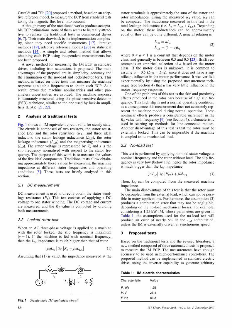
Fig. 1 shows an IM equivalent circuit valid for steady state.The circuit is composed of two resistors, the stator resist-ance (RS) and the rotor resistance (RR), and three idealinductors, the stator leakage inductance (LLS), the rotorleakage inductance (LLR) and the magnetising inductance(LM). The stator voltage is represented by VS and s is theslip frequency normalised with respect to the stator fre-quency. The purpose of this work is to measure the valuesof the five ideal components. Traditional tests allow obtain-ing approximately these values by measuring the machineimpedance at different stator frequencies and operatingconditions [5]. These tests are briefly analysed in thissection.
2.1 DC measurement
DC measurement is used to directly obtain the stator wind-ings resistance (RS). This test consists of applying a DCvoltage to one stator winding. The DC voltage and currentare measured, and the RS value is computed by dividingboth measurements.
2.2 Locked-rotor test
When an AC three-phase voltage is applied to a machinewith the rotor locked, the slip frequency is maximum(s ¼ 1). If the machine is fed with nominal frequency,then the LM impedance is much bigger than that of rotor
jvLM��
�� � RR þ jvLLR
��
�� (1)
Assuming that (1) is valid, the impedance measured at the
Fig. 1 Steady-state IM equivalent circuit
834
stator terminals is approximately the sum of the stator androtor impedances. Using the measured RS value, RR canbe computed. The inductance measured in this test is thetotal leakage inductance (i.e. LL ¼ LLRþ LLS). Dependingon the motor, these inductances can be approximatelyequal or they can be quite different. A general relation is
LLS ¼ aLL
LLR ¼ (1� a)LL(2)
where 0 , a , 1 is a constant that depends on the motorclass, and generally is between 0.3 and 0.5 [23]. IEEE rec-ommends an empirical selection of a based on the motorclass. If the motor class is unknown, it is common toassume a ¼ 0.5 (LLR ¼ LLS), since it does not have a sig-nificant influence in the motor performance. It was verifiedexperimentally by using the proposed measurement tech-nique (see Section 4) that a has very little influence in themotor frequency response.One of the problems of this test is the skin and proximity
effects produced in the rotor bars because of high slip fre-quency. This high slip is not a normal operating condition;as a consequence this measurement does not accurately rep-resent the machine model during normal operation. Thesenonlinear effects produce a considerable increment in theRR value with frequency [9] (see Section 4), a characteristicused in starting up methods for line-connected motors.Another disadvantage of this test is that the rotor must beexternally locked. This can be impossible if the machineis coupled to its mechanical load.
2.3 No-load test
This test is performed by applying nominal stator voltage atnominal frequency and the rotor without load. The slip fre-quency is very low (below 1%); hence the rotor impedanceis much bigger than the LM impedance
jvLM��
�� � RR=sþ jvLLR
��
�� (3)
Then, LM can be computed from the measured machineimpedance.The main disadvantage of this test is that the rotor must
be decoupled from the external load, which can not be poss-ible in many applications. Furthermore, the assumption (3)produces a computation error that may not be negligible,depending on the no-load mechanical losses. For example,considering a 1.25 kW IM, whose parameters are given inTable 1, the assumptions used for the no-load test willproduce an error of nearly 5% in the LM computation,unless the IM is externally driven at synchronous speed.
3 Proposed tests
Based on the traditional tests and the revised literature, anew method composed of three automated tests is proposedto measure the IM ECP. The measurements have enoughaccuracy to be used in high-performance controllers. Theproposed method can be implemented in standard electricdrives using the inverter capability to generate arbitrary
Table 1: IM electric characteristics
Characteristic Value
P, kW 1.25
V, V 25.4
F, Hz 83.2
IET Electr. Power Appl., Vol. 1, No. 5, September 2007
waveforms, and a reduced amount of signal processing per-formed by the digital controller. The main characteristics ofthe proposed tests are the following:
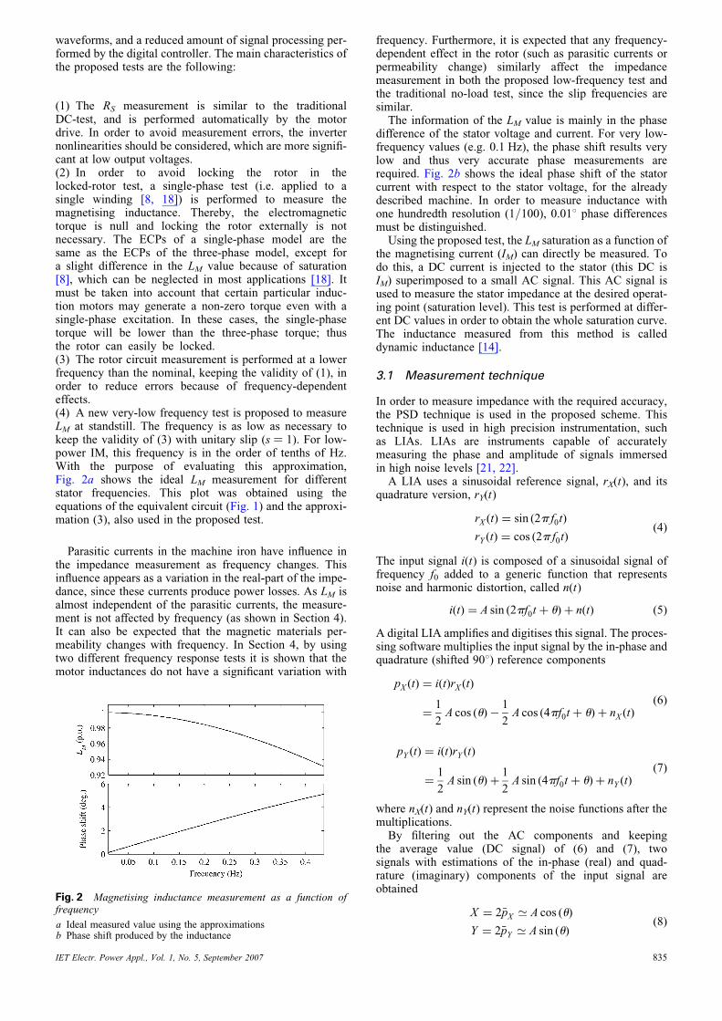
(1) The RS measurement is similar to the traditionalDC-test, and is performed automatically by the motordrive. In order to avoid measurement errors, the inverternonlinearities should be considered, which are more signifi-cant at low output voltages.(2) In order to avoid locking the rotor in thelocked-rotor test, a single-phase test (i.e. applied to asingle winding [8, 18]) is performed to measure themagnetising inductance. Thereby, the electromagnetictorque is null and locking the rotor externally is notnecessary. The ECPs of a single-phase model are thesame as the ECPs of the three-phase model, except fora slight difference in the LM value because of saturation[8], which can be neglected in most applications [18]. Itmust be taken into account that certain particular induc-tion motors may generate a non-zero torque even with asingle-phase excitation. In these cases, the single-phasetorque will be lower than the three-phase torque; thusthe rotor can easily be locked.(3) The rotor circuit measurement is performed at a lowerfrequency than the nominal, keeping the validity of (1), inorder to reduce errors because of frequency-dependenteffects.(4) A new very-low frequency test is proposed to measureLM at standstill. The frequency is as low as necessary tokeep the validity of (3) with unitary slip (s ¼ 1). For low-power IM, this frequency is in the order of tenths of Hz.With the purpose of evaluating this approximation,Fig. 2a shows the ideal LM measurement for differentstator frequencies. This plot was obtained using theequations of the equivalent circuit (Fig. 1) and the approxi-mation (3), also used in the proposed test.
Parasitic currents in the machine iron have influence inthe impedance measurement as frequency changes. Thisinfluence appears as a variation in the real-part of the impe-dance, since these currents produce power losses. As LM isalmost independent of the parasitic currents, the measure-ment is not affected by frequency (as shown in Section 4).It can also be expected that the magnetic materials per-meability changes with frequency. In Section 4, by usingtwo different frequency response tests it is shown that themotor inductances do not have a significant variation with
Fig. 2 Magnetising inductance measurement as a function offrequency
a Ideal measured value using the approximationsb Phase shift produced by the inductance
IET Electr. Power Appl., Vol. 1, No. 5, September 2007
frequency. Furthermore, it is expected that any frequency-dependent effect in the rotor (such as parasitic currents orpermeability change) similarly affect the impedancemeasurement in both the proposed low-frequency test andthe traditional no-load test, since the slip frequencies aresimilar.The information of the LM value is mainly in the phase
difference of the stator voltage and current. For very low-frequency values (e.g. 0.1 Hz), the phase shift results verylow and thus very accurate phase measurements arerequired. Fig. 2b shows the ideal phase shift of the statorcurrent with respect to the stator voltage, for the alreadydescribed machine. In order to measure inductance withone hundredth resolution (1/100), 0.018 phase differencesmust be distinguished.Using the proposed test, the LM saturation as a function of
the magnetising current (IM) can directly be measured. Todo this, a DC current is injected to the stator (this DC isIM) superimposed to a small AC signal. This AC signal isused to measure the stator impedance at the desired operat-ing point (saturation level). This test is performed at differ-ent DC values in order to obtain the whole saturation curve.The inductance measured from this method is calleddynamic inductance [14].
3.1 Measurement technique
In order to measure impedance with the required accuracy,the PSD technique is used in the proposed scheme. Thistechnique is used in high precision instrumentation, suchas LIAs. LIAs are instruments capable of accuratelymeasuring the phase and amplitude of signals immersedin high noise levels [21, 22].A LIA uses a sinusoidal reference signal, rX(t), and its
quadrature version, rY(t)
rX (t) ¼ sin (2p f0t)
rY (t) ¼ cos (2p f0t)(4)
The input signal i(t) is composed of a sinusoidal signal offrequency f0 added to a generic function that representsnoise and harmonic distortion, called n(t)
i(t) ¼ A sin (2pf0t þ u)þ n(t) (5)
A digital LIA amplifies and digitises this signal. The proces-sing software multiplies the input signal by the in-phase andquadrature (shifted 908) reference components
pX (t) ¼ i(t)rX (t)
¼1
2A cos (u)�
1
2A cos (4pf0t þ u)þ nX (t)
(6)
pY (t) ¼ i(t)rY (t)
¼1
2A sin (u)þ
1
2A sin (4pf0t þ u)þ nY (t)
(7)
where nX(t) and nY(t) represent the noise functions after themultiplications.By filtering out the AC components and keeping
the average value (DC signal) of (6) and (7), twosignals with estimations of the in-phase (real) and quad-rature (imaginary) components of the input signal areobtained
X ¼ 2�pX ’ A cos (u)
Y ¼ 2�pY ’ A sin (u)(8)
835
In the proposed method, two LIAs are implemented in themicroprocessor of the motor drive. These LIAs measurethe stator current and voltage at the excitation frequency,obtaining accurate measurements with high noise immu-nity. From these measurements, the machine compleximpedance is computed, and the ECPs are estimated.The computational load required is low enough to allowthe implementation in control-oriented digital signal pro-cessors (DSPs), such as the TMS320F28xx series [24].
3.2 Proposed method details
The sequence proposed to measure the ECP can be summar-ised as follows:Test no. 1: Stator resistance measurement, applying a DCsignal.Test no. 2: Rotor resistance and leakage inductancesmeasurements. A medium-frequency (i.e. nearly half thenominal frequency) is used in order to reduce the nonlinearand frequency-dependent effects.Test no. 3: Magnetising inductance measurement. A verylow frequency (i.e. 0.1 Hz) is used in this test, whichreplaces the no-load test. For inductance saturationmeasurement, the low-level AC signal is superimposed toa high-level DC component.The three tests are performed as single-phase tests, to
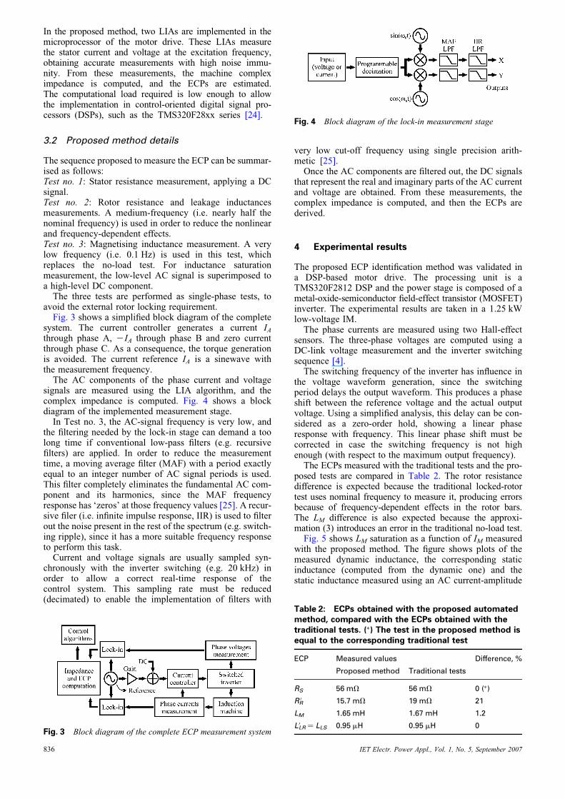
avoid the external rotor locking requirement.Fig. 3 shows a simplified block diagram of the complete
system. The current controller generates a current IAthrough phase A, 2IA through phase B and zero currentthrough phase C. As a consequence, the torque generationis avoided. The current reference IA is a sinewave withthe measurement frequency.The AC components of the phase current and voltage
signals are measured using the LIA algorithm, and thecomplex impedance is computed. Fig. 4 shows a blockdiagram of the implemented measurement stage.In Test no. 3, the AC-signal frequency is very low, and
the filtering needed by the lock-in stage can demand a toolong time if conventional low-pass filters (e.g. recursivefilters) are applied. In order to reduce the measurementtime, a moving average filter (MAF) with a period exactlyequal to an integer number of AC signal periods is used.This filter completely eliminates the fundamental AC com-ponent and its harmonics, since the MAF frequencyresponse has ‘zeros’ at those frequency values [25]. A recur-sive filer (i.e. infinite impulse response, IIR) is used to filterout the noise present in the rest of the spectrum (e.g. switch-ing ripple), since it has a more suitable frequency responseto perform this task.Current and voltage signals are usually sampled syn-
chronously with the inverter switching (e.g. 20 kHz) inorder to allow a correct real-time response of thecontrol system. This sampling rate must be reduced(decimated) to enable the implementation of filters with
Fig. 3 Block diagram of the complete ECP measurement system
836
very low cut-off frequency using single precision arith-metic [25].Once the AC components are filtered out, the DC signals
that represent the real and imaginary parts of the AC currentand voltage are obtained. From these measurements, thecomplex impedance is computed, and then the ECPs arederived.
4 Experimental results
The proposed ECP identification method was validated ina DSP-based motor drive. The processing unit is aTMS320F2812 DSP and the power stage is composed of ametal-oxide-semiconductor field-effect transistor (MOSFET)inverter. The experimental results are taken in a 1.25 kWlow-voltage IM.The phase currents are measured using two Hall-effect
sensors. The three-phase voltages are computed using aDC-link voltage measurement and the inverter switchingsequence [4].The switching frequency of the inverter has influence in
the voltage waveform generation, since the switchingperiod delays the output waveform. This produces a phaseshift between the reference voltage and the actual outputvoltage. Using a simplified analysis, this delay can be con-sidered as a zero-order hold, showing a linear phaseresponse with frequency. This linear phase shift must becorrected in case the switching frequency is not highenough (with respect to the maximum output frequency).The ECPs measured with the traditional tests and the pro-
posed tests are compared in Table 2. The rotor resistancedifference is expected because the traditional locked-rotortest uses nominal frequency to measure it, producing errorsbecause of frequency-dependent effects in the rotor bars.The LM difference is also expected because the approxi-mation (3) introduces an error in the traditional no-load test.Fig. 5 shows LM saturation as a function of IM measured
with the proposed method. The figure shows plots of themeasured dynamic inductance, the corresponding staticinductance (computed from the dynamic one) and thestatic inductance measured using an AC current-amplitude
Fig. 4 Block diagram of the lock-in measurement stage
Table 2: ECPs obtained with the proposed automatedmethod, compared with the ECPs obtained with thetraditional tests. (�) The test in the proposed method isequal to the corresponding traditional test
ECP Measured values Difference, %
Proposed method Traditional tests
RS 56 mV 56 mV 0 (�)
RR0 15.7 mV 19 mV 21
LM 1.65 mH 1.67 mH 1.2
L0LR ¼ LLS 0.95 mH 0.95 mH 0
IET Electr. Power Appl., Vol. 1, No. 5, September 2007
scan. The plot waveform and values are similar to the plotspresented in previous publications, obtained using differenttechniques [14].To verify the proposed measurement system and
measured ECPs in the whole frequency range, two fre-quency response tests were performed. These tests consistof measuring the machine impedance in the 0.2–110 Hzfrequency range, at standstill in the first test and with therotor rotating without load, in the second. The frequencyresponse measurement is performed as it was proposed in[22]. The measured plots are compared with the idealones, computed using the linear equivalent circuit withthe ECPs shown in Table 2. These measurements alsoallow validating the linear model within the analysed fre-quency range.Fig. 6 shows the Bode diagram of the frequency response
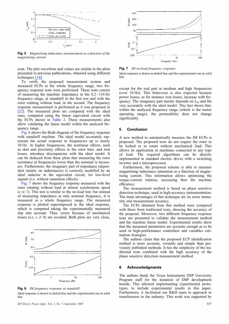
with standstill machine. The ideal model accurately rep-resents the actual response to frequencies up to nearly30 Hz. At higher frequencies, the nonlinear effects, suchas skin and proximity effects in the rotor bars, and ironlosses, introduce discrepancies with the ideal model. Itcan be deduced from these plots that measuring the rotorresistance at frequencies lower than the nominal is necess-ary. Furthermore, the imaginary part of impedance (depen-dent mainly on inductances) is correctly modelled by anideal inductor in the equivalent circuit, for low-levelsignals (i.e. without saturation effects).Fig. 7 shows the frequency response measured with the
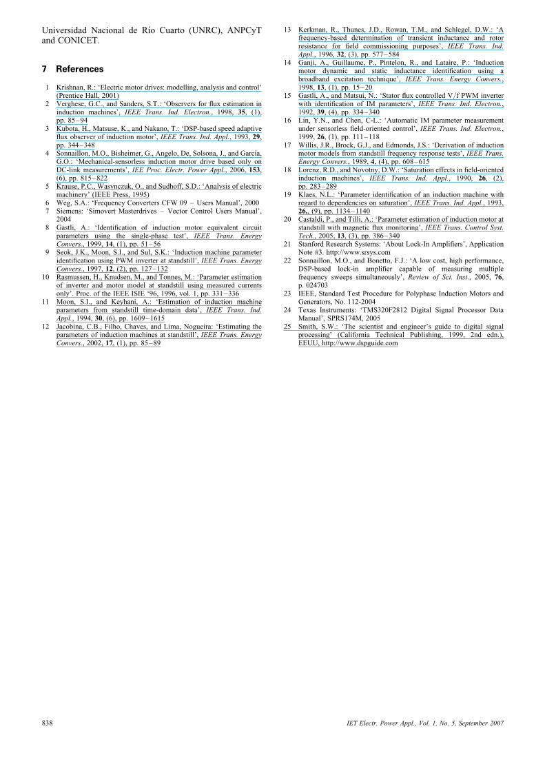
rotor rotating without load at almost synchronous speed(s � 1). This test is similar to the no-load test, but insteadof measuring impedance at only nominal frequency, it ismeasured in a whole frequency range. The measuredresponse is plotted superimposed to the ideal response,which is computed taking the experimentally measuredslip into account. Thus, errors because of mechanicallosses (i.e. s = 0) are avoided. Both plots are very close,
Fig. 6 IM frequency response at standstill
Ideal response is drawn in dotted line and the experimental one in solidline
Fig. 5 Magnetising inductance measurement as a function of themagnetising current
IET Electr. Power Appl., Vol. 1, No. 5, September 2007
except for the real part at medium and high frequencies(over 10 Hz). This behaviour is also expected becausepower losses, as for instance iron losses, increase with fre-quency. The imaginary part mainly depends on LM and fitsvery accurately with the ideal model. This fact shows that,within the analysed frequency range (which is the motoroperating range), the permeability does not changesignificantly.
5 Conclusion
A new method to automatically measure the IM ECPs isproposed. The proposed tests do not require the rotor tobe locked or to rotate without mechanical load. Thisallows its application in machines connected to any typeof load. The required algorithms can be directlyimplemented in standard electric drives with a switchinginverter and a microprocessor.Furthermore, the proposed scheme is able to measure
magnetising inductance saturation as a function of magne-tising current. This information allows optimising thetorque/current relation, increasing then the machineefficiency.The measurement method is based on phase sensitive
detection technique, used in high-accuracy instrumentation.The main advantages of this technique are its noise immu-nity and measurement accuracy.The ECPs obtained from this method were compared
with those from traditional tests, showing the accuracy ofthe proposal. Moreover, two different frequency responsetests are presented to validate the measurement methodand the machine linear model. Experimental results showthat the measured parameters are accurate enough as to beused in high-performance controllers and variables esti-mation strategies.The authors claim that the proposed ECP identification
method is more accurate, versatile and simple than pre-viously published methods. It has the simplicity of the tra-ditional tests combined with the high accuracy of thephase sensitive detection measurement method.
6 Acknowledgments
The authors thank the Texas Instruments DSP UniversityProgram staff for the donation of DSP developmentboards. This allowed implementing experimental proto-types, to include experimental results in this paper.Furthermore, it facilitated our R&D team to approach totransferences to the industry. This work was supported by
Fig. 7 IM no-load frequency response
Ideal response is drawn in dotted line and the experimental one in solidline
837
Universidad Nacional de Rıo Cuarto (UNRC), ANPCyTand CONICET.
7 References
1 Krishnan, R.: ‘Electric motor drives: modelling, analysis and control’(Prentice Hall, 2001)
2 Verghese, G.C., and Sanders, S.T.: ‘Observers for flux estimation ininduction machines’, IEEE Trans. Ind. Electron., 1998, 35, (1),pp. 85–94
3 Kubota, H., Matsuse, K., and Nakano, T.: ‘DSP-based speed adaptiveflux observer of induction motor’, IEEE Trans. Ind. Appl., 1993, 29,pp. 344–348
4 Sonnaillon, M.O., Bisheimer, G., Angelo, De, Solsona, J., and Garcıa,G.O.: ‘Mechanical-sensorless induction motor drive based only onDC-link measurements’, IEE Proc. Electr. Power Appl., 2006, 153,(6), pp. 815–822
5 Krause, P.C., Wasynczuk, O., and Sudhoff, S.D.: ‘Analysis of electricmachinery’ (IEEE Press, 1995)
6 Weg, S.A.: ‘Frequency Converters CFW 09 – Users Manual’, 20007 Siemens: ‘Simovert Masterdrives – Vector Control Users Manual’,
20048 Gastli, A.: ‘Identification of induction motor equivalent circuit
parameters using the single-phase test’, IEEE Trans. EnergyConvers., 1999, 14, (1), pp. 51–56
9 Seok, J.K., Moon, S.I., and Sul, S.K.: ‘Induction machine parameteridentification using PWM inverter at standstill’, IEEE Trans. EnergyConvers., 1997, 12, (2), pp. 127–132
10 Rasmussen, H., Knudsen, M., and Tonnes, M.: ‘Parameter estimationof inverter and motor model at standstill using measured currentsonly’. Proc. of the IEEE ISIE ‘96, 1996, vol. 1, pp. 331–336
11 Moon, S.I., and Keyhani, A.: ‘Estimation of induction machineparameters from standstill time-domain data’, IEEE Trans. Ind.Appl., 1994, 30, (6), pp. 1609–1615
12 Jacobina, C.B., Filho, Chaves, and Lima, Nogueira: ‘Estimating theparameters of induction machines at standstill’, IEEE Trans. EnergyConvers., 2002, 17, (1), pp. 85–89
838
13 Kerkman, R., Thunes, J.D., Rowan, T.M., and Schlegel, D.W.: ‘Afrequency-based determination of transient inductance and rotorresistance for field commissioning purposes’, IEEE Trans. Ind.Appl., 1996, 32, (3), pp. 577–584
14 Ganji, A., Guillaume, P., Pintelon, R., and Lataire, P.: ‘Inductionmotor dynamic and static inductance identification using abroadband excitation technique’, IEEE Trans. Energy Convers.,1998, 13, (1), pp. 15–20
15 Gastli, A., and Matsui, N.: ‘Stator flux controlled V/f PWM inverterwith identification of IM parameters’, IEEE Trans. Ind. Electron.,1992, 39, (4), pp. 334–340
16 Lin, Y.N., and Chen, C-L.: ‘Automatic IM parameter measurementunder sensorless field-oriented control’, IEEE Trans. Ind. Electron.,1999, 26, (1), pp. 111–118
17 Willis, J.R., Brock, G.J., and Edmonds, J.S.: ‘Derivation of inductionmotor models from standstill frequency response tests’, IEEE Trans.Energy Convers., 1989, 4, (4), pp. 608–615
18 Lorenz, R.D., and Novotny, D.W.: ‘Saturation effects in field-orientedinduction machines’, IEEE Trans. Ind. Appl., 1990, 26, (2),pp. 283–289
19 Klaes, N.L.: ‘Parameter identification of an induction machine withregard to dependencies on saturation’, IEEE Trans. Ind. Appl., 1993,26,, (9), pp. 1134–1140
20 Castaldi, P., and Tilli, A.: ‘Parameter estimation of induction motor atstandstill with magnetic flux monitoring’, IEEE Trans. Control Syst.Tech., 2005, 13, (3), pp. 386–340
21 Stanford Research Systems: ‘About Lock-In Amplifiers’, ApplicationNote #3. http://www.srsys.com
22 Sonnaillon, M.O., and Bonetto, F.J.: ‘A low cost, high performance,DSP-based lock-in amplifier capable of measuring multiplefrequency sweeps simultaneously’, Review of Sci. Inst., 2005, 76,p. 024703
23 IEEE, Standard Test Procedure for Polyphase Induction Motors andGenerators, No. 112-2004
24 Texas Instruments: ‘TMS320F2812 Digital Signal Processor DataManual’, SPRS174M, 2005
25 Smith, S.W.: ‘The scientist and engineer’s guide to digital signalprocessing’ (California Technical Publishing, 1999, 2nd edn.),EEUU, http://www.dspguide.com
IET Electr. Power Appl., Vol. 1, No. 5, September 2007