automated generation of software documents consistent with and traceable to and from source code
TRANSCRIPT
Automated Generation of Software Documents
Consistent with and Traceable to and from Source Code
Jay Xiong Lin Li
NSEsoftware, LLC., USA
www.nsesoftware.com
[email protected] ; [email protected]
Abstract: - This paper introduces NSE (Nonlinear Software Engineering paradigm) documentation paradigm
offering methods and techniques and tools for automated generation of software documents which are colorful,
graphical, holistic, interactive, dynamic, accurate, precise, virtual, always consistent with source code,
traceable to and from source code, and executable directly through playing back the captured GUI operations,
or indirectly through the corresponding source code, so that the generated documents are useful for software
understanding, testing, quality assurance, and maintenance.
Key-Words: - diagramming, document automation, maintenance, software documentation, software
understanding, visualization, testing,
I. INTRODUCTION
As pointed by O Paull, eHow Contributor that
“software documentation pervades the software life
cycle. It is the visible part of the software process.
Without it, software cannot be maintained. Without
it, users cannot train and they virtually cannot use the
software. Without it new developers would have to
re-invent the wheel in software development.
Software documentation is the most important
manifestation of software. It is the guide through the
software maze.”
(http://www.ehow.com/about_6706857_importance-
software-documentation.html).
Experience has shown that technical software
documentation are unsatisfactorily maintained. The
implications of outdated documentation are costly
and can even damage the business
(http://www.sig.eu/en/Services/DocGen ).
Software documents can be created manually,
using a "cut and paste" technique, or generated by an
automated tool for a large software product.
Unfortunately, often the documents obtained
using current software documentation methods and
techniques are
* not automatable
* not holistic
* not interactive
* not dynamic
* not accurate
* not precise
* not virtual
* not always consistent with source code
* not traceable to and from source code, and
* not executable directly or indirectly
It makes the obtained documents not really
useful for software understanding, testing, and
maintenance.
For efficiently solving those problems in
software documentation, a new software
documentation paradigm based on complexity
science is established.
II. ESTABLISHMENT OF NSE DOCUMENTATION
PARADIGM
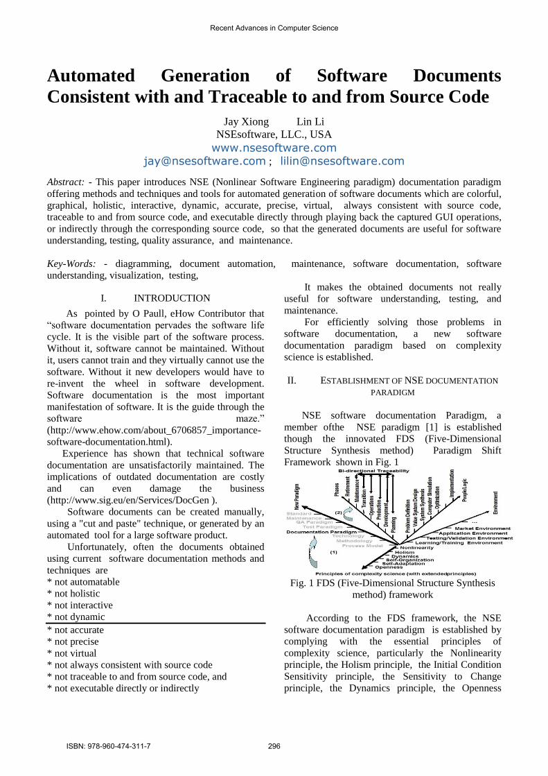
NSE software documentation Paradigm, a
member ofthe NSE paradigm [1] is established
though the innovated FDS (Five-Dimensional
Structure Synthesis method) Paradigm Shift
Framework shown in Fig. 1
Fig. 1 FDS (Five-Dimensional Structure Synthesis
method) framework
According to the FDS framework, the NSE
software documentation paradigm is established by
complying with the essential principles of
complexity science, particularly the Nonlinearity
principle, the Holism principle, the Initial Condition
Sensitivity principle, the Sensitivity to Change
principle, the Dynamics principle, the Openness
Recent Advances in Computer Science
ISBN: 978-960-474-311-7 296
principle, the Self-organization principle, and the
Self-adaptation principle.
III. HOW DOES NSE DOCUMENTATION
PARADIGM WORK
As Harry M. Sneed pointed out that “The
important thing is that one model is enough – either
the code or the diagrams. They should be
reproducible from one another.”[2]
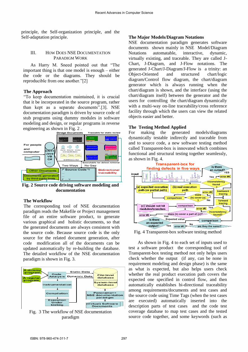
The Approach “To keep documentation maintained, it is crucial
that it be incorporated in the source program, rather
than kept as a separate documents”.[3]. NSE
documentation paradigm is driven by source code of
stub programs using dummy modules in software
modeling and design, or regular programs in reverse
engineering as shown in Fig. 2 .
Fig. 2 Source code driving software modeling and
documentation
The Workflow
The corresponding tool of NSE documentation
paradigm reads the Makefile or Project management
file of an entire software product, to generate
various graphical and holistic documents, so that
the generated documents are always consistent with
the source code. Because source code is the only
source for the related document generation, after
code modification all of the documents can be
updated automatically by re-building the database.
The detailed workflow of the NSE documentation
paradigm is shown in Fig. 3.
Fig. 3 The workflow of NSE documentation
paradigm
The Major Models/Diagram Notations
NSE documentation paradigm generates software
documents shown mainly in NSE Model/Diagram
Notations automatable, interactive, dynamic,
virtually existing, and traceable. They are called J-
Chart, J-Diagram, and J-Flow notations. The
generated J-Chart/J-Diagram/J-Flow is a trinity: an
Object-Oriented and structured chart/logic
diagram/Control flow diagram, the chart/diagram
generator which is always running when the
chart/diagram is shown, and the interface (using the
chart/diagram itself) between the generator and the
users for controlling the chart/diagram dynamically
with a multi-way on-line traceability/cross reference
facility through which the users can view the related
objects easier and better.
The Testing Method Applied For making the generated models/diagrams
dynamically testable indirectly and traceable from
and to source code, a new software testing method
called Transparent-box is innovated which combines
functional and structural testing together seamlessly,
as shown in Fig. 4.
Fig. 4 Transparent-box software testing method
As shown in Fig. 4 to each set of inputs used to
test a software product the corresponding tool of
Transparent-box testing method not only helps users
check whether the output (if any, can be none in
requirement modeling and design phase) is the same
as what is expected, but also helps users check
whether the real product execution path covers the
expected one specified in control flow, and then
automatically establishes bi-directional traceability
among requirements/documents and test cases and
the source code using Time Tags (when the test cases
are executed) automatically inserted into the
description parts of test cases and the code test
coverage database to map test cases and the tested
source code together, and some keywords (such as
Recent Advances in Computer Science
ISBN: 978-960-474-311-7 297
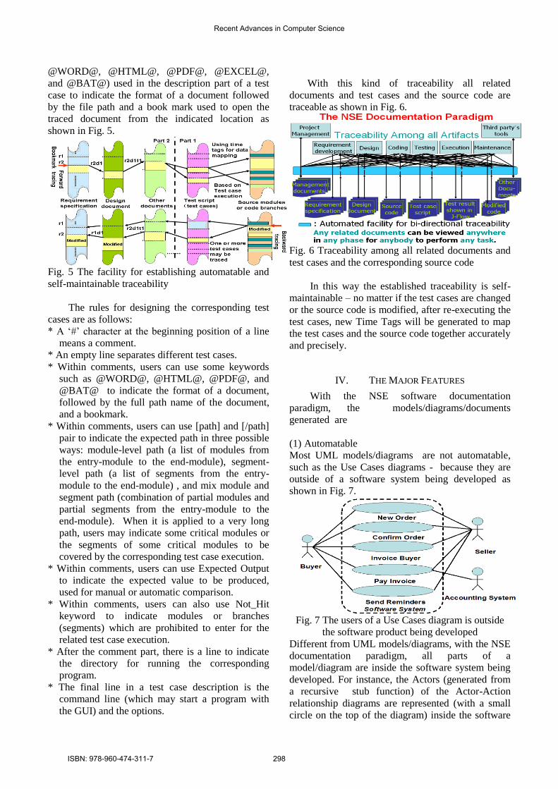
@WORD@, @HTML@, @PDF@, @EXCEL@,
and @BAT@) used in the description part of a test
case to indicate the format of a document followed
by the file path and a book mark used to open the
traced document from the indicated location as
shown in Fig. 5.
Fig. 5 The facility for establishing automatable and
self-maintainable traceability
The rules for designing the corresponding test
cases are as follows:
* A ‘#’ character at the beginning position of a line
means a comment.
* An empty line separates different test cases.
* Within comments, users can use some keywords
such as @WORD@, @HTML@, @PDF@, and
@BAT@ to indicate the format of a document,
followed by the full path name of the document,
and a bookmark.
* Within comments, users can use [path] and [/path]
pair to indicate the expected path in three possible
ways: module-level path (a list of modules from
the entry-module to the end-module), segment-
level path (a list of segments from the entry-
module to the end-module) , and mix module and
segment path (combination of partial modules and
partial segments from the entry-module to the
end-module). When it is applied to a very long
path, users may indicate some critical modules or
the segments of some critical modules to be
covered by the corresponding test case execution.
* Within comments, users can use Expected Output
to indicate the expected value to be produced,
used for manual or automatic comparison.
* Within comments, users can also use Not_Hit
keyword to indicate modules or branches
(segments) which are prohibited to enter for the
related test case execution.
* After the comment part, there is a line to indicate
the directory for running the corresponding
program.
* The final line in a test case description is the
command line (which may start a program with
the GUI) and the options.
With this kind of traceability all related
documents and test cases and the source code are
traceable as shown in Fig. 6.
Fig. 6 Traceability among all related documents and
test cases and the corresponding source code
In this way the established traceability is self-
maintainable – no matter if the test cases are changed
or the source code is modified, after re-executing the
test cases, new Time Tags will be generated to map
the test cases and the source code together accurately
and precisely.
IV. THE MAJOR FEATURES
With the NSE software documentation
paradigm, the models/diagrams/documents
generated are
(1) Automatable
Most UML models/diagrams are not automatable,
such as the Use Cases diagrams - because they are
outside of a software system being developed as
shown in Fig. 7.
Fig. 7 The users of a Use Cases diagram is outside
the software product being developed
Different from UML models/diagrams, with the NSE
documentation paradigm, all parts of a
model/diagram are inside the software system being
developed. For instance, the Actors (generated from
a recursive stub function) of the Actor-Action
relationship diagrams are represented (with a small
circle on the top of the diagram) inside the software
Recent Advances in Computer Science
ISBN: 978-960-474-311-7 298
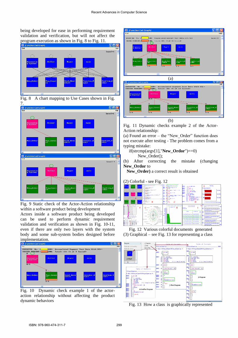
being developed for ease in performing requirement
validation and verification, but will not affect the
program execution as shown in Fig. 8 to Fig. 11.
Fig. 8 A chart mapping to Use Cases shown in Fig.
7.
Fig. 9 Static check of the Actor-Action relationship
within a software product being development
Actors inside a software product being developed
can be used to perform dynamic requirement
validation and verification as shown in Fig. 10-11,
even if there are only two layers with the system
body and some sub-system bodies designed before
implementation.
Fig. 10 Dynamic check example 1 of the actor-
action relationship without affecting the product
dynamic behaviors
(a)
(b)
Fig. 11 Dynamic checks example 2 of the Actor-
Action relationship:
(a) Found an error – the “New_Order” function does
not execute after testing - The problem comes from a
typing mistake:
if(strcmp(argv[1],"New_Ordor")==0)
New_Order();
(b) After correcting the mistake (changing
New_Ordor to
New_Order) a correct result is obtained
(2) Colorful - see Fig. 12
Fig. 12 Various colorful documents generated
(3) Graphical – see Fig. 13 for representing a class
Fig. 13 How a class is graphically represented
Recent Advances in Computer Science
ISBN: 978-960-474-311-7 299
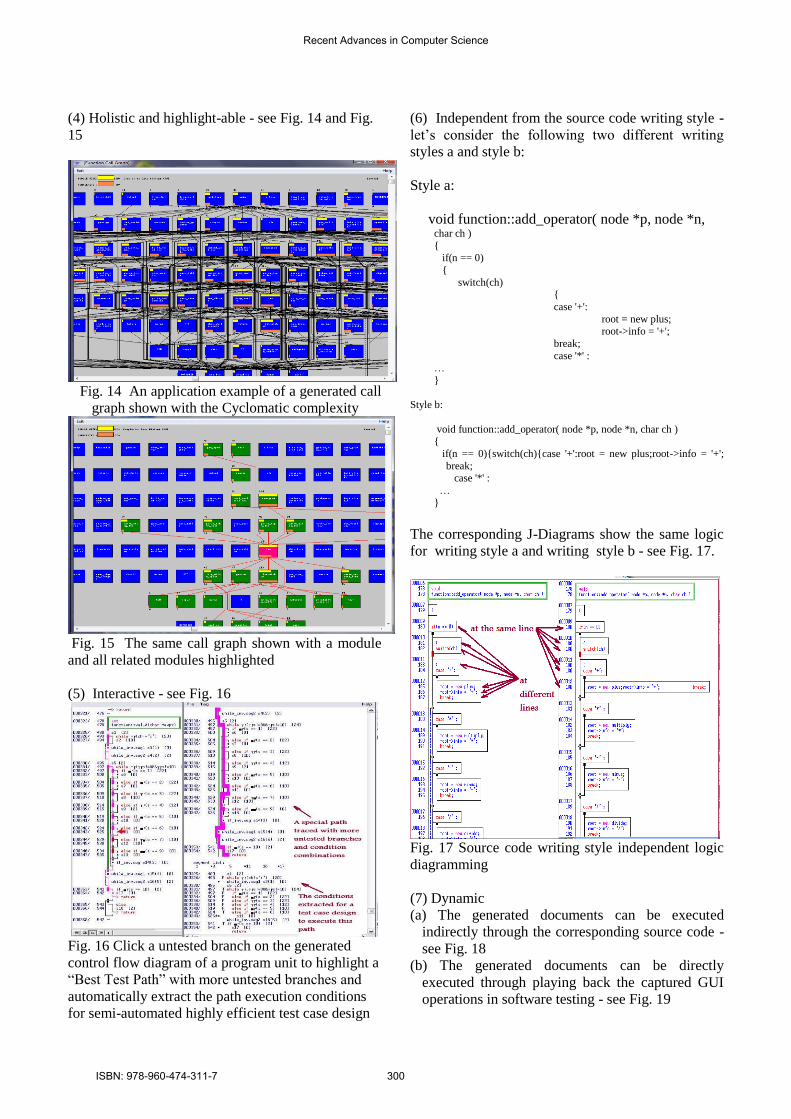
(4) Holistic and highlight-able - see Fig. 14 and Fig.
15
Fig. 14 An application example of a generated call
graph shown with the Cyclomatic complexity
Fig. 15 The same call graph shown with a module
and all related modules highlighted
(5) Interactive - see Fig. 16
Fig. 16 Click a untested branch on the generated
control flow diagram of a program unit to highlight a
“Best Test Path” with more untested branches and
automatically extract the path execution conditions
for semi-automated highly efficient test case design
(6) Independent from the source code writing style -
let’s consider the following two different writing
styles a and style b:
Style a:
void function::add_operator( node *p, node *n, char ch )
{ if(n == 0)
{
switch(ch) {
case '+':
root = new plus;
root->info = '+';
break;
case '*' : …
}
Style b:
void function::add_operator( node *p, node *n, char ch ) {
if(n == 0){switch(ch){case '+':root = new plus;root->info = '+';
break; case '*' :
…
}
The corresponding J-Diagrams show the same logic
for writing style a and writing style b - see Fig. 17.
Fig. 17 Source code writing style independent logic
diagramming
(7) Dynamic
(a) The generated documents can be executed
indirectly through the corresponding source code -
see Fig. 18
(b) The generated documents can be directly
executed through playing back the captured GUI
operations in software testing - see Fig. 19
Recent Advances in Computer Science
ISBN: 978-960-474-311-7 300
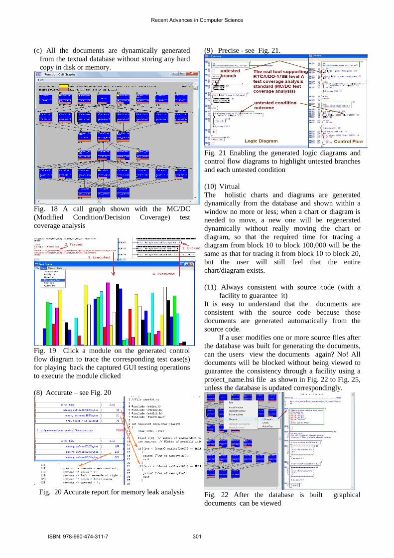
(c) All the documents are dynamically generated
from the textual database without storing any hard
copy in disk or memory.
Fig. 18 A call graph shown with the MC/DC
(Modified Condition/Decision Coverage) test
coverage analysis
Fig. 19 Click a module on the generated control
flow diagram to trace the corresponding test case(s)
for playing back the captured GUI testing operations
to execute the module clicked
(8) Accurate – see Fig. 20
Fig. 20 Accurate report for memory leak analysis
(9) Precise - see Fig. 21.
Fig. 21 Enabling the generated logic diagrams and
control flow diagrams to highlight untested branches
and each untested condition
(10) Virtual
The holistic charts and diagrams are generated
dynamically from the database and shown within a
window no more or less; when a chart or diagram is
needed to move, a new one will be regenerated
dynamically without really moving the chart or
diagram, so that the required time for tracing a
diagram from block 10 to block 100,000 will be the
same as that for tracing it from block 10 to block 20,
but the user will still feel that the entire
chart/diagram exists.
(11) Always consistent with source code (with a
facility to guarantee it)
It is easy to understand that the documents are
consistent with the source code because those
documents are generated automatically from the
source code.
If a user modifies one or more source files after
the database was built for generating the documents,
can the users view the documents again? No! All
documents will be blocked without being viewed to
guarantee the consistency through a facility using a
project_name.hsi file as shown in Fig. 22 to Fig. 25,
unless the database is updated correspondingly.
Fig. 22 After the database is built graphical
documents can be viewed
Recent Advances in Computer Science
ISBN: 978-960-474-311-7 301
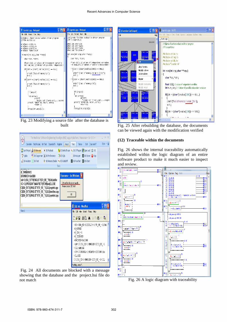
Fig. 23 Modifying a source file after the database is
built
Fig. 24 All documents are blocked with a message
showing that the database and the project.hsi file do
not match
Fig. 25 After rebuilding the database, the documents
can be viewed again with the modification verified
(12) Traceable within the documents
Fig. 26 shows the internal traceability automatically
established within the logic diagram of an entire
software product to make it much easier to inspect
and review.
Fig. 26 A logic diagram with traceability
Recent Advances in Computer Science
ISBN: 978-960-474-311-7 302
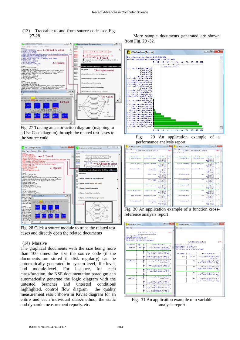
(13) Traceable to and from source code -see Fig.
27-28.
Fig. 27 Tracing an actor-action diagram (mapping to
a Use Case diagram) through the related test cases to
the source code
Fig. 28 Click a source module to trace the related test
cases and directly open the related documents
(14) Massive
The graphical documents with the size being more
than 100 times the size the source code (if the
documents are stored in disk regularly) can be
automatically generated in system-level, file-level,
and module-level. For instance, for each
class/function, the NSE documentation paradigm can
automatically generate the logic diagram with the
untested branches and untested conditions
highlighted, control flow diagram the quality
measurement result shown in Kiviat diagram for an
entire and each individual class/method, the static
and dynamic measurement reports, etc.
More sample documents generated are shown
from Fig. 29 -32.
Fig. 29 An application example of a
performance analysis report
Fig. 30 An application example of a function cross-
reference analysis report
Fig. 31 An application example of a variable
analysis report
Recent Advances in Computer Science
ISBN: 978-960-474-311-7 303
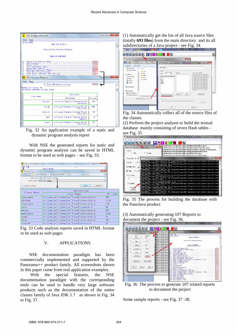
Fig. 32 An application example of a static and
dynamic program analysis report
With NSE the generated reports for static and
dynamic program analysis can be saved in HTML
format to be used as web pages – see Fig. 33.
Fig. 33 Code analysis reports saved in HTML format
to be used as web pages
V. APPLICATIONS
NSE documentation paradigm has been
commercially implemented and supported by the
Panorama++ product family. All screenshots shown
in this paper come from real application examples.
With the special features, the NSE
documentation paradigm with the corresponding
tools can be used to handle very large software
products such as the documentation of the entire
classes family of Java JDK 1.7 as shown in Fig. 34
to Fig. 37.
(1) Automatically get the list of all Java source files
(totally 693 files) from the main directory and its all
subdirectories of a Java project - see Fig. 34.
Fig. 34 Automatically collect all of the source files of
the classes
(2) Perform the project analysis to build the textual
database mainly consisting of seven Hash tables -
see Fig. 35
Fig. 35 The process for building the database with
the PanoJava product
(3) Automatically generating 107 Reports to
document the project - see Fig. 36.
Fig. 36 The process to generate 107 related reports
to document the project
Some sample reports - see Fig. 37 -38.
Recent Advances in Computer Science
ISBN: 978-960-474-311-7 304
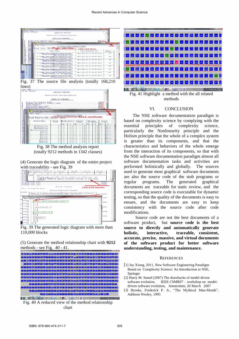
Fig. 37 The source file analysis (totally 168,210
lines)
Fig. 38 The method analysis report
(totally 9212 methods in 1342 classes)
(4) Generate the logic diagram of the entire project
with traceability - see Fig. 39
Fig. 39 The generated logic diagram with more than
110,000 blocks
(5) Generate the method relationship chart with 9212
methods - see Fig. 40 - 41.
Fig. 40 A reduced view of the method relationship
chart
Fig. 41 Highlight a method with the all related
methods
VI. CONCLUSION
The NSE software documentation paradigm is
based on complexity science by complying with the
essential principles of complexity science,
particularly the Nonlinearity principle and the
Holism principle that the whole of a complex system
is greater than its components, and that the
characteristics and behaviors of the whole emerge
from the interaction of its components, so that with
the NSE software documentation paradigm almost all
software documentation tasks and activities are
performed holistically and globally. The sources
used to generate most graphical software documents
are also the source code of the stub programs or
regular programs. The generated graphical
documents are traceable for static review, and the
corresponding source code is executable for dynamic
testing, so that the quality of the documents is easy to
ensure, and the documents are easy to keep
consistency with the source code after code
modifications.
Source code are not the best documents of a
software product, but source code is the best
source to directly and automatically generate
holistic, interactive, traceable, consistent,
accurate, precise, massive, and virtual documents
of the software product for better software
understanding, testing, and maintenance.
REFERENCES
[1] Jay Xiong, 2011, New Software Engineering Paradigm
Based on Complexity Science: An Introduction to NSE,
Springer
[2] Harry M. Sneed (2007) The drawbacks of model driven
software evolution. IEEE CSMR07 – workshop on model-
driven software evolution, Amsterdam, 20 March 2007
[3] Brooks, Frederick P. Jr., “The Mythical Man-Month”,
Addison Wesley, 1995
Recent Advances in Computer Science
ISBN: 978-960-474-311-7 305