automated beam placement for breast radiotherapy using a support vector machine based algorithm
TRANSCRIPT

Automated beam placement for breast radiotherapy using a support vectormachine based algorithm
Xuan Zhao and Dewen KongDepartment of Electrical and Computer Engineering, Polytechnic Institute of New York University,Brooklyn, New York 11201
Gabor Jozsef and Jenghwa ChangDepartment of Radiation Oncology, School of Medicine, Langone Medical Center, New York University,New York, New York 10016
Edward K. WongDepartment of Computer Science and Engineering, Polytechnic Institute of New York University,Brooklyn, New York 11201
Silvia C. FormentiDepartment of Radiation Oncology, School of Medicine, Langone Medical Center, New York University,New York, New York 10016
Yao Wanga)
Department of Electrical and Computer Engineering, Polytechnic Institute of New York University,Brooklyn, New York 11201
(Received 2 March 2011; revised 16 March 2012; accepted for publication 19 March 2012;
published 16 April 2012)
Purpose: To develop an automated beam placement technique for whole breast radiotherapy using
tangential beams. We seek to find optimal parameters for tangential beams to cover the whole ipsi-
lateral breast (WB) and minimize the dose to the organs at risk (OARs).
Methods: A support vector machine (SVM) based method is proposed to determine the optimal
posterior plane of the tangential beams. Relative significances of including/avoiding the volumes of
interests are incorporated into the cost function of the SVM. After finding the optimal 3-D plane
that separates the whole breast (WB) and the included clinical target volumes (CTVs) from the
OARs, the gantry angle, collimator angle, and posterior jaw size of the tangential beams are derived
from the separating plane equation. Dosimetric measures of the treatment plans determined by the
automated method are compared with those obtained by applying manual beam placement by the
physicians. The method can be further extended to use multileaf collimator (MLC) blocking by
optimizing posterior MLC positions.
Results: The plans for 36 patients (23 prone- and 13 supine-treated) with left breast cancer were an-
alyzed. Our algorithm reduced the volume of the heart that receives >500 cGy dose (V5) from 2.7
to 1.7 cm3 (p¼ 0.058) on average and the volume of the ipsilateral lung that receives >1000 cGy
dose (V10) from 55.2 to 40.7 cm3 (p¼ 0.0013). The dose coverage as measured by volume receiv-
ing >95% of the prescription dose (V95%) of the WB without a 5 mm superficial layer decreases
by only 0.74% (p¼ 0.0002) and the V95% for the tumor bed with 1.5 cm margin remains
unchanged.
Conclusions: This study has demonstrated the feasibility of using a SVM-based algorithm to deter-
mine optimal beam placement without a physician’s intervention. The proposed method reduced
the dose to OARs, especially for supine treated patients, without any relevant degradation of dose
homogeneity and coverage in general. VC 2012 American Association of Physicists in Medicine.
[http://dx.doi.org/10.1118/1.3700736]
Key words: breast radiotherapy, automated beam placement, support vector machines
I. INTRODUCTION
Although an effective treatment for breast cancers,1–3 radio-
therapy might cause significant complications in surrounding
organs such as the heart and the lung.4–7 Different treatment
positions (e.g., prone vs supine) and treatment techniques
[e.g., intensity-modulated radiotherapy (IMRT) with differ-
ent beam arrangements and (dynamic) wedged tangent
fields] have been investigated. However, beam placement is
still a manual process that is based on observing anatomical
landmarks. It is a subjective procedure, and the result
depends on the experience and preference of the physician.
The goal of this study is to develop an automated and objec-
tive method for determining the optimal tangential beam
placement that best separates the organs at risk (OARs) and
the region to be treated.
2536 Med. Phys. 39 (5), May 2012 0094-2405/2012/39(5)/2536/8/$30.00 VC 2012 Am. Assoc. Phys. Med. 2536

IMRT for whole breast treatment based on direct aperture
optimization (DAO) was analyzed and reported8,9 using either
jaws-only or multileaf collimators (MLCs). However, for
breast irradiation, tangential beams are generally preferred to
minimize dose to OARs.10 In this paper, we focus on tangen-
tial beams defined by jaws-only aperture but also show the
ability of the method to optimize lung/heart blocking.
Our approach for optimizing tangential beam placement is a
geometrical algorithm. Purdie et al.11 also optimized the tan-
gential beam parameters geometrically; however, their method
was basically an exhaustive search, which is less efficient and
does not guarantee an absolute minimum of the score function.
Support vector machine (SVM) is a general purpose classifi-
cation algorithm. It finds a hyperplane in the multidimensional
parameter space that separates the whole dataset into two dif-
ferent sets so that the gaps between the hyperplane and the sep-
arating sets are as wide as possible. SVM has been widely used
for many machine learning and classification problems. In the
field of radiation oncology, researchers have used SVM to pre-
dict radiotherapy outcomes,12–14 evaluate volume delineation,15
for patient positioning,16 and to judge planning quality.17
The nature behind the SVM is similar to our beam place-
ment problem in that we need to find the equation of the opti-
mal separating plane so that the margin between the OARs
and the whole ipsilateral breast (WB) is maximized. The sepa-
rating plane equation found by SVM is then converted into
three beam placement parameters: gantry angle, collimator
angle, and jaw size. The performance of the SVM-based algo-
rithm on 36 test cases is reported and discussed.
II. METHOD AND MATERIALS
II.A. Problem formulation
Treatment fields are defined by four planes in the three-
dimensional (3-D) space. Three of the planes do not play a
role in separating the target volumes from the OARs and can
be easily set manually; therefore, only the posterior plane
between the OARs and the target volumes needs to be opti-
mized. The beam placement problem is therefore equivalent
to finding the optimal separating plane between the OARs and
the WB with the included clinical target volumes (CTVs).
The OARs include the heart, the ipsilateral lung, and the
contralateral breast. The whole breast is defined as the breast
volume within a preliminary treatment field placed manually
by the physician. This field covers the breast from the clavicu-
lar head to 2 cm below the breast, and its posterior plane is
aligned with the projections of the midsternum and the anterior
aspect of the latissimus dorsi on the skin. Two target volumes
are defined: CTV1 is the WB volume minus a 0.5 cm layer ad-
jacent to the skin, and CTV2 encloses the tumor bed with
1.5 cm margin, and excluding regions that extend outside the
CTV1. (Naturally, WB encloses CTV1 and CTV1 encloses
CTV2.) Our contouring method is described elsewhere.20,21
The OARs and the target volumes are usually not linearly
separable; we therefore need to find a tradeoff between
maximizing the volume of the WB (and the included CTVs)
inside the treatment field and minimizing the volume of OARs
inside the treatment field. Relative significances are assigned
to different volumes (or regions inside thereof). These factors
are based on the following clinical constraints and considera-
tions: (1) the treatment field should cover the WB, especially
the region that is in close proximity to the tumor; (2) heart
sparing is more critical than lung sparing; (3) WB tissue cover-
age beyond CTV1 can be compromised in exchange for signif-
icant dose reduction to the heart and the lung; and (4) dose to
the contralateral breast should be avoided.
II.B. Optimal separating plane by support vectormachines
Let the surface points of the WB and the included CTVs
be labeled þ1 and the surface points of the OARs be labeled
�1, i.e., having a set of 4D vectors v ¼ fxi; yig, where vec-
tor xi are the 3D coordinates of the ith point and yi ¼ þ1 if
xi 2 PTV (CTVs|WB) and yi ¼ �1 if xi 2 OARs, for
i ¼ 1:::N. (N is the total number of surface points.) In the
simplest form of the SVM formulation,18 the equation of the
optimal separating plane, g xð Þ ¼ wTxþ b ¼ 0 is determined
by the solution of the following optimization problem:
Minimizing wTw; subject to yiðwTxi þ bÞ � 1;
which maximizes the margin 2wk k between samples with op-
posite labels.
Usually, the target volumes and the OARs cannot be com-
pletely separated by a plane. In this case, positive variables,
ni, is introduced as a measure of the violation of the con-
straints [shown in Fig. 1(b)]. The penalty term CPN
i¼1 ni is
added to the objective function and new constraints
yiðwTxi þ bÞ � 1 � ni will be applied. Parameter C is the
relative significance factor. In general, the value of C can
vary from point to point. We used this option only for the
WB, in which significance factors were chosen to be inver-
sely proportional to the distance to the closest surface point
of the tumor bed. The optimization problem then becomes
minw;b;nij
1
2wTwþ
Xi2forgansg
XNi
j¼1
Cijnij
8<:
9=;
subject to yijðwTxij � bÞ � 1� nij i 2 forgansg;j ¼ 1;…;Ni; (1)
where Ni is the number of points that belong to organ i, Cij and
nij are the significance factor and the constraint violation mea-
sure for the jth point of organ i. A larger Cij indicates a larger
penalty on misclassification. To solve the optimization problem
in Eq. (1), we use LIBLINEAR,19 an open source library for
large-scale linear SVM classification problems.
The significance factors reported in the paper were deter-
mined experimentally using CT scans of 10 randomly
selected patients. We performed a systematic search in
which at each time one significance factor was adjusted
while the others kept fixed. There are totally about 30 sets
produced and each of them is applied on 10 patients. As mul-
tiple dosimetric objectives were used, we searched for sets
of weights when improving one objective would deteriorate
2537 Zhao et al.: Automatic beam placement using support vector machine 2537
Medical Physics, Vol. 39, No. 5, May 2012

other(s) (i.e., reached a pareto-optimal point), and then, a
subjectively chosen compromise among those points deter-
mines the weight factors. For example, the heart/lung signifi-
cance factor was chosen 3/1. Nevertheless, the user can
modify these significance factors. Those determined signifi-
cance factors were used for all the patients. The derived sep-
arating plane is optimal in the maximal margin sense given
the selected significance factors Cij.
II.C. Tangential field parameters from the separatingplane
Tangential beam placement is controlled by three param-
eters: gantry angle, collimator angle, and jaw size. Figure 2
illustrates two opposite tangential fields and the associated
separating plane. We derived these parameters based on the
separating plane determined by the SVM. To be more
precise, gantry and collimator angles can be derived by solv-
ing the linear equations
w ¼ McMgw0; (2)
where w is the normal vector of the optimal separating plane
determined by the SVM, w0 is the normal vector of the plane
defined by the X2—jaw before gantry and collimator rota-
tions, and Mg and Mc are the rotation matrices for the gantry
and collimator rotations, respectively. The jaw size is given
by the distance from the isocenter to the separating plane.
II.D. Method evaluation
The computed gantry angles, collimator angles, and jaw
sizes were compared with those by physicians. Mean,
FIG. 1. Illustration of the support vector machine. Each
data point is a three-dimensional vector. Circled points
are the support vectors. Solid and dotted lines represent
boundaries of OARs and the WB with the included
CTVs, respectively.
FIG. 2. Two opposite treatment fields in a projection, perpendicular to the Y jaws. The thicker line represents the optimal separating plane determined by the
SVM, r is the angle of the beam divergence, D is the distance between the radiation source and the isocenter, and d is the distance from isocenter to the sepa-
rating plane.
2538 Zhao et al.: Automatic beam placement using support vector machine 2538
Medical Physics, Vol. 39, No. 5, May 2012

standard deviation, and p-value of the differences are com-
puted. The dosimetric measures, including the minimum
dose to the CTV2, the maximum dose to CTV2, the V5 (vol-
ume at 5 Gy) of the heart, the V10 of the ipsilateral lung, the
V95% (volume receiving >95% of the prescribed dose) of
the CTV2, and the V95% of the CTV1, were compared with
the measures of the treatment plans by physicians. For fair
comparison, the minimum CTV2 dose of our method is nor-
malized to the minimum CTV2 dose of the physician’s plan.
Means and standard deviation of dosimetric measures of
manual and automated plans were computed and compared
with paired Student t-test.
II.E. Extension of the SVM to block optimization
The technique can be extended to optimize lung/heart
blocking by optimizing the posterior field shape. After
finding the optimal separating plane based on Sec. II.B., the
field is divided into multiple parallel layers (Fig. 3) perpen-
dicular to the posterior field edge. The thickness of the layers
was chosen to be 0.5 cm (corresponding 1 MLC leaf thick-
ness in our machines). Surface points within each layer are
projected onto the normal vector of the separating plane
(which is parallel to the motion of the MLC, if MLC can be
used). Determining the posterior edge in one layer is now
transformed into a 1-D separation problem, which can be
efficiently solved by SVM.
III. RESULTS
We collected treatment/planning data for 23 prone- and
13 supine-treated patients with left breast cancer enrolled in
the IRB-approved NYU 05-181 clinical protocol.16,19,22,23
The actual significance factors Cij in the objective function
of the SVM were chosen to be 60 for the heart, 20 for the
ipsilateral lung, 120 for the CTV1, 180 for the CTV2, and 60
for the contralateral breast (see Sec. II.B). For the ipsilateral
breast, the significance factor for each surface point pi was
set to 0:1di
, where di is the distance between pi and the nearest
point on the tumor bed.
The mean and standard deviation in the differences
between these parameters for all 36 patients were computed
and tabulated in Table I(a). Two-tailed paired T-test showed
significant differences in jaw size (p¼ 0.0004) and the gan-
try angle (p¼ 0.039), and no differences in the collimator
angle (p¼ 0.90). Results for the prone- and supine-treated
patients are shown separately in Tables I(b) and I(c), respec-
tively. Overall, our proposed method results in smaller jaw
size for both groups, significantly for supine-treated patients
(p¼ 0.0007 for supine-treated patients but not significant to
the 5% level (p¼ 0.067) for prone-treated patients). For
supine-treated patients, our method results in smaller jaw
size for all of the 13 patients, while only for 14 of the 23
patients in the prone position.
The mean values of five dosimetric measures for all 36
patients were computed and tabulated in Table II(a). Our
method reduces the V5 of the heart from 2.7 to 1.7 cm3, and
FIG. 3. Treatment field with MLCs from beam eye view. n is the normal
vector of the separating plane, x and o represent a few projections of the
surface points on the breast and avoidance structures respectively within a
volume of an MLC leaf path to the midplane of that MLC leaf. These pro-
jected points are used in the SVM algorithm to determine that leaf position.
TABLE I. Comparison of the gantry angle, collimator angle, and jaw size in the treatment plans between physicians and SVM method: mean and standard devi-
ation of the differences, and p-value by paired T-test.
Mean Standard deviation p-value
(a) Statistics of beam parameters of all 36 patients (23 prone- and 13 supine-treated)
Difference between gantry angles (degree) �0.88 2.4 0.039
Difference between collimator angles (degree) �0.05 2.2 0.90
Difference between jaw size (mm) 1.4 2.2 0.0004
(b) Statistics of beam parameters of 23 prone-treated patients
Difference between gantry angles (degree) �1.03 2.7 0.092
Difference between collimator angles (degree) 0.49 2.4 0.35
Difference between jaw size (mm) 0.87 2.1 0.067
(c) Statistics of beam parameters of 13 supine-treated patients
Difference between gantry angles (degree) �0.61 1.7 0.24
Difference between collimator angles (degree) �1.01 1.6 0.046
Difference between jaw size (mm) 2.4 1.9 0.0007
2539 Zhao et al.: Automatic beam placement using support vector machine 2539
Medical Physics, Vol. 39, No. 5, May 2012
the V10 of the ipsilateral lung from 55.2 to 40.7 cm3. The
dosimetric measures for prone- and supine-treated patients are
shown separately in Tables II(b) and II(c), respectively. For
prone-treated patients, the V5 of the heart is reduced from 2.1
to 1.7 cm3 and the V10 of the ipsilateral lung is reduced from
8.4 to 7.3 cm3. The differences are not statistically significant.
For supine-treated patients, the reductions are from 3.7 to 1.7
cm3 and from 138.1 to 99.9 cm3, respectively. The difference
for lung is statistically significant (p¼ 0.002). The changes of
the V95% of the CTV1 and the CTV2 and the maximum dose
to CTV2 are very small in all groups.
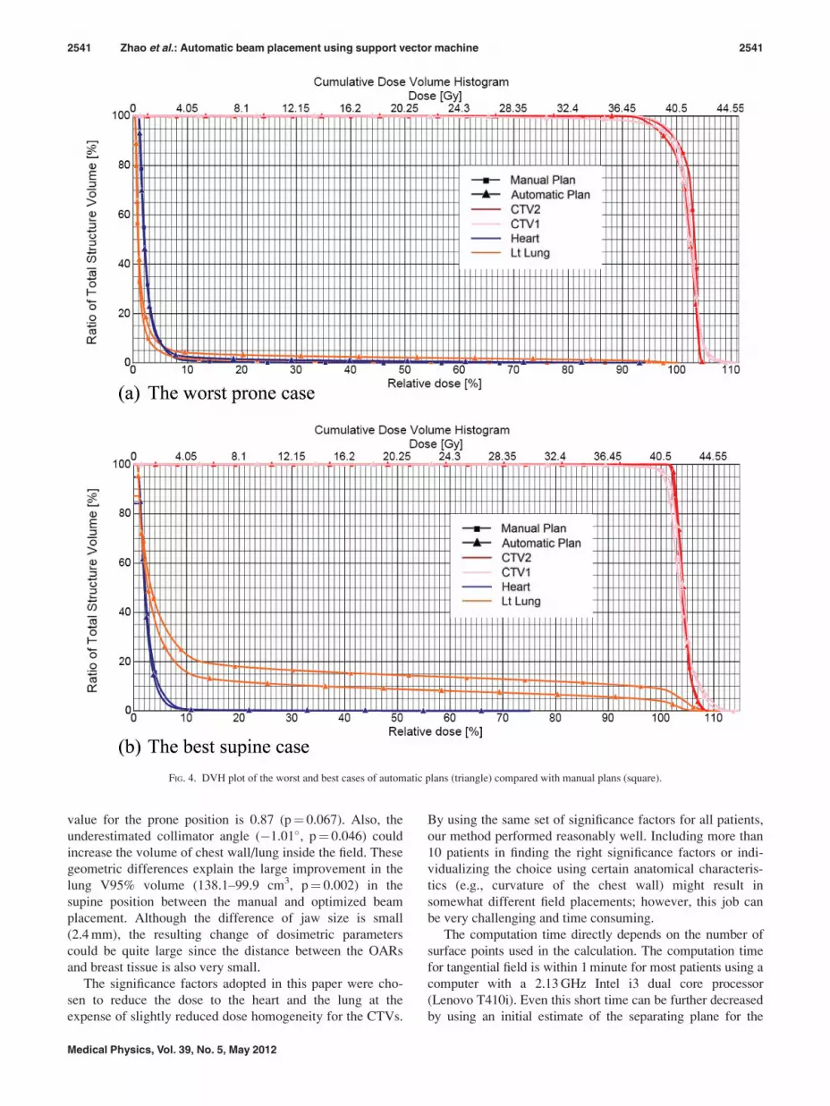
For better comparison, the DVHs of the worst and the
best case of automatic plan results are shown in Fig. 4.
The worst case [Fig. 4(a)] occurred in the prone position.
The dose coverage of CTV1 and CTV2 is slightly worse
than the manual plan, while the dose for lung is higher (V10
of the lung increased from 13.0 to 39.1 cm3). The best
improvement case [Fig. 4(b)] occurred in the supine posi-
tion. The V5 of the heart is roughly the same 2.5 cm3, while
the V10 of the ipsilateral lung is reduced from 201.1 to
130.7 cm3. The V95% of CTV1 is 96.6% compared with
96.1%, while the V95% of CTV2 is the same.
Generally, in the prone position, the difference between
manually and computer generated plans were small. For the
supine cases, most of automatic plans are preferable to the
manual ones because of pronounced dose decreases to heart
and lung.
For the blocked fields, the differences with nonblocking
tangential fields are generally very small. Table III(a) shows
the average dosimetric measures for the six patients tested. An
example with the largest resulting block shown in Fig. 5, and
the corresponding dosimetric measures are in Table III(b).
(The MLC in the Fig. 5 is only for illustration; the dose
distribution is calculated by using manual blocks of the opti-
mized shape as our machine does not allow MLC blocks and
dynamic wedges on the same direction.)
IV. DISCUSSION AND CONCLUSION
The most significant difference between the manual plans
determined by physicians and the automated plans deter-
mined by our method is the jaw size setting. The plans deter-
mined by our method have smaller jaw sizes [see Table
I(a)]. The dosimetric comparison between the manual and
optimized plans for all patients showed significant improve-
ments in the lung V10 volume, close to significant change in
the heart V5 volume, and a very slight but significant
decrease of the V95% of the CTV1 (99.6–98.8, p¼ 0.002).
Patients in the supine position seem to benefit more from
the proposed method when compared to the prone treated
patients. The jaw size is significantly different between the
manual and optimized beam placement in both groups, but
the difference is larger in the supine than in the prone posi-
tion. The dosimetric difference of normal tissue is not signif-
icant in the prone position, with only a very slight decrease
of V95% in the CTV1 (99.4–98.7, p¼ 0.009). For the
supine-treated patient, the radiation to lung is largely
reduced in the automated beam setup and is both statistically
and clinically meaningful. That finding suggests that the
prone position even without optimization offers better spar-
ing of the OARs than the supine, in agreement with earlier
reports,9 and the automatic optimization does not improve it
much further.
The data indicates that for beam placement in the supine
position, the physicians tend to set the beam deeper (2.4 mm,
p¼ 0.0007) into the chest wall than necessary. The same
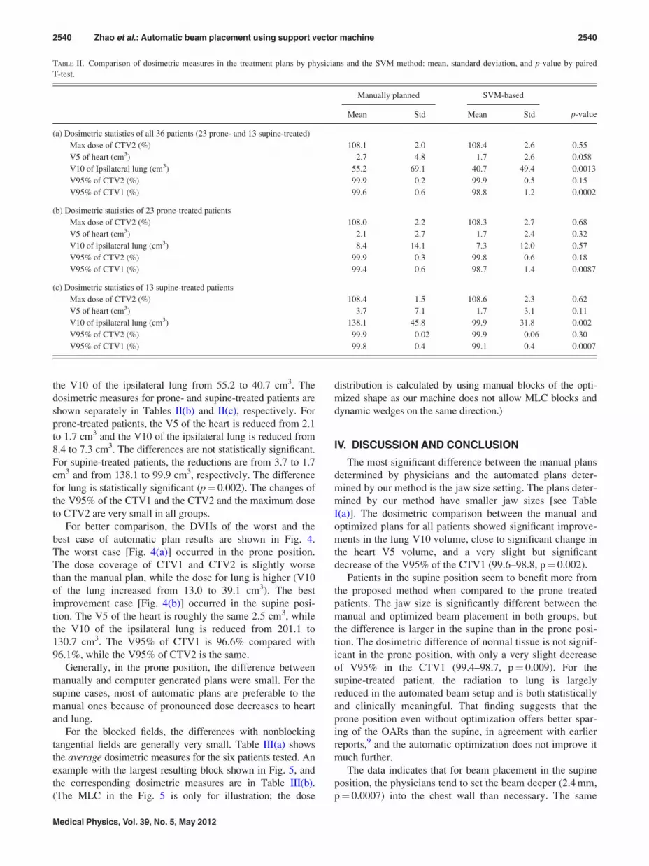
TABLE II. Comparison of dosimetric measures in the treatment plans by physicians and the SVM method: mean, standard deviation, and p-value by paired
T-test.
Manually planned SVM-based
p-valueMean Std Mean Std
(a) Dosimetric statistics of all 36 patients (23 prone- and 13 supine-treated)
Max dose of CTV2 (%) 108.1 2.0 108.4 2.6 0.55
V5 of heart (cm3) 2.7 4.8 1.7 2.6 0.058
V10 of Ipsilateral lung (cm3) 55.2 69.1 40.7 49.4 0.0013
V95% of CTV2 (%) 99.9 0.2 99.9 0.5 0.15
V95% of CTV1 (%) 99.6 0.6 98.8 1.2 0.0002
(b) Dosimetric statistics of 23 prone-treated patients
Max dose of CTV2 (%) 108.0 2.2 108.3 2.7 0.68
V5 of heart (cm3) 2.1 2.7 1.7 2.4 0.32
V10 of ipsilateral lung (cm3) 8.4 14.1 7.3 12.0 0.57
V95% of CTV2 (%) 99.9 0.3 99.8 0.6 0.18
V95% of CTV1 (%) 99.4 0.6 98.7 1.4 0.0087
(c) Dosimetric statistics of 13 supine-treated patients
Max dose of CTV2 (%) 108.4 1.5 108.6 2.3 0.62
V5 of heart (cm3) 3.7 7.1 1.7 3.1 0.11
V10 of ipsilateral lung (cm3) 138.1 45.8 99.9 31.8 0.002
V95% of CTV2 (%) 99.9 0.02 99.9 0.06 0.30
V95% of CTV1 (%) 99.8 0.4 99.1 0.4 0.0007
2540 Zhao et al.: Automatic beam placement using support vector machine 2540
Medical Physics, Vol. 39, No. 5, May 2012
value for the prone position is 0.87 (p¼ 0.067). Also, the
underestimated collimator angle (�1.01�, p¼ 0.046) could
increase the volume of chest wall/lung inside the field. These
geometric differences explain the large improvement in the
lung V95% volume (138.1–99.9 cm3, p¼ 0.002) in the
supine position between the manual and optimized beam
placement. Although the difference of jaw size is small
(2.4 mm), the resulting change of dosimetric parameters
could be quite large since the distance between the OARs
and breast tissue is also very small.
The significance factors adopted in this paper were cho-
sen to reduce the dose to the heart and the lung at the
expense of slightly reduced dose homogeneity for the CTVs.
By using the same set of significance factors for all patients,
our method performed reasonably well. Including more than
10 patients in finding the right significance factors or indi-
vidualizing the choice using certain anatomical characteris-
tics (e.g., curvature of the chest wall) might result in
somewhat different field placements; however, this job can
be very challenging and time consuming.
The computation time directly depends on the number of
surface points used in the calculation. The computation time
for tangential field is within 1 minute for most patients using a
computer with a 2.13 GHz Intel i3 dual core processor
(Lenovo T410i). Even this short time can be further decreased
by using an initial estimate of the separating plane for the
FIG. 4. DVH plot of the worst and best cases of automatic plans (triangle) compared with manual plans (square).
2541 Zhao et al.: Automatic beam placement using support vector machine 2541
Medical Physics, Vol. 39, No. 5, May 2012

SVM algorithm and by selecting only surface points within a
preset distance from the estimated separating plane. However,
introducing the lung/heart blocking increases the computation
time by a factor of 8–10.
Our decision to focus on unblocked fields in this study
stems from practical considerations: In our machines, simul-
taneous use of dynamic wedge and MLC shaping in the
same direction is not possible; therefore, either a physical
wedge or a physical block needs to be used. Nevertheless,
we demonstrated that our technique can be extended to work
with blocks, as the shape of the posterior field border can be
determined with the SVM algorithm.
Due to the usually small resulting blocked area, there
were only limited dosimetric differences between the
blocked and unblocked plans. Table III shows that there is
some amount of dose reduction to lung (V10 from 50.2 to
37.9 cm3 in average), however, at the expense of decreased
CTV1 coverage (V95% from 98.2% to 96.5% in average).
The limited benefit of blocking might be explained by the
fact that the posterior field border and collimator angle is al-
ready optimized. Breast and lung (and heart) normally over-
lap from the beam eye view due to their anatomic geometry.
Blocks cannot spare more lung (and heart) without sacrific-
ing breast coverage in this case.
In conclusion, this study demonstrated the feasibility of
using a SVM algorithm to automatically perform optimal
beam placement for whole breast radiotherapy in both prone
and supine positions. Our SVM-based algorithm used
volume-based criteria to find tradeoffs between heart (and
lung) volumes that lie within the treatment field and breast
volume that lies outside the treatment field. This method is
different from other commonly used optimization procedures
that are based on dosimetric criteria. The proposed method
significantly reduced the dose to the OARs while maintain-
ing acceptable dose homogeneity and coverage over the
breast volume to be treated.
ACKNOWLEDGMENTS
Part of this work was presented at the 52nd AAPM AnnualMeeting, July 18–22, 2010, Philadelphia, PA. This work was
supported in part by a grant from the Varian Medical System.
a)Author to whom correspondence should be addressed. Electronic mail:
[email protected]; Telephone: (718)-260-3469; Fax: (718)-260-3906.1A. Jemal et al., “Cancer statistics, 2008,” Ca-Cancer J. Clin. 58, 71–96
(2008).2M. Clarke et al., “Effects of radiotherapy and of differences in the extent
of surgery for early breast cancer on local recurrence and 15-year survival:
an overview of the randomised trials,” Lancet 366, 2087–2106 (2005).3B. Fisher et al., “Twenty-year follow-up of a randomized trial comparing
total mastectomy, lumpectomy, and lumpectomy plus irradiation for the
treatment of invasive breast cancer,” N. Engl. J. Med. 347, 1233–1241
(2002).4L. B. Marks et al., “The incidence and functional consequences of RT-
associated cardiac perfusion defects,” Int. J. Radiat. Oncol., Biol., Phys.
63, 214–223 (2005).5M. Deutsch et al., “The incidence of lung carcinoma after surgery for
breast carcinoma with and without postoperative radiotherapy,” Cancer
98, 1362–1368 (2003).6C. W. Hurkmans et al., “Reduction of cardiac and lung complication
probabilities after breast irradiation using conformal radiotherapy with or
without intensity modulation,” Radiother. Oncol. 62, 163–171 (2002).7L. F. Paszat et al., “Mortality from myocardial infarction following
postlumpectomy radiotherapy for breast cancer: a population-based study in
Ontario, Canada,” Int. J. Radiat. Oncol., Biol., Phys. 43, 755–762 (1999).8M. A. Earl, M. K. Afghan, C. X. Yu, Z. Jiang, and D. M. Shepard, “Jaws-
only IMRT using direct aperture optimization,” Med. Phys. 34(1),
307–314 (2007).9E. E. Ahunbay, G. P. Chen, S. Thatcher, P. A. Jursinic, J. White, K.
Albano, and X. A. Li, “Direct aperture optimization-based intensity-modu-
lated radiotherapy for whole breast irradiation,” Int. J. Radiat. Oncol. Biol.
Phys. 67(4), 1248–1258 (2007).10G. P. Chen, E. Ahunbay, and X. A. Li, “Automated computer optimization
for 3D treatment planning of breast irradiation,” Med. Phys. 35(6),
2253–2258 (2008).11T. G. Purdie, R. E. Dinniwell, D. Letourneau, C. Hill, and M. B. Sharpe,
“Automated planning of tangential breast intensity-modulated radiother-
apy using heuristic optimization,” Int. J. Radiat. Oncol. Biol. Phys. 81(2),
575–583 (2011).12I. El Naqa, J. D. Bradley, P. E. Lindsay, A. J. Hope, and J. O. Deasy,
“Predicting radiotherapy outcomes using statistical learning techniques,”
Phys. Med. Biol. 54(18), S9–S30 (2009).13K. Jayasurya, G. Fung, S. Yu, C. Dehing-Oberije, D. De Ruysscher, A.
Hope, W. De Neve, Y. Lievens, P. Lambin, and A. L. Dekker,
“Comparison of Bayesian network and support vector machine models for
TABLE III. Comparison of dosimetric measures of manual plans, automatic
plans with and without MLC blocking.
Manually
planned
w/o
blocking
With
blocking
(a) Average dosimetric measures of the 6 patients we tested.
Max dose of CTV2 (%) 109.4 107.6 107.6
V5 of heart (cm3) 2.05 0.77 0.16
V10 of Ipsilateral lung (cm3) 59.6 50.2 37.9
V95% of CTV2 (%) 100 99.9 99.7
V95% of CTV1 (%) 99.8 98.2 96.5
(b) Dosimetric measures of the patient shown in Fig. 5.
Max dose of CTV2 (%) 107.7 104.2 103.3
V5 of heart (cm3) 4.9 2.1 0
V10 of ipsilateral lung (cm3) 127.3 124.8 79.5
V95% of CTV2 (%) 100 100 99.4
V95% of CTV1 (%) 100 98.7 94.4
FIG. 5. Treatment field with blocks. The MLCs are illustrated as the blue
rectangles and the resulting blocks are in yellow curve.
2542 Zhao et al.: Automatic beam placement using support vector machine 2542
Medical Physics, Vol. 39, No. 5, May 2012

two-year survival prediction in lung cancer patients treated with radio-
therapy,” Med. Phys. 37(4), 1401–1407 (2010).14S. Chen, S. Zhou, F. F. Yin, L. B. Marks, and S. K. Das, “Investigation of
the support vector machine algorithm to predict lung radiation-induced
pneumonitis,” Med. Phys. 34(10), 3808–3814 (2007).15J. Gubbi, A. Kanakatte, K. Tomas, D. Binns, B. Srinivasan, N. Mani, and
M. Palaniswami, “Automatic tumor volume delineation in respiratory-
gated PET images,” J. Med. Imaging Radiat. Oncol. 55(1), 65–76 (2011).16X. Zhao, E. K. Wong, Y. Wang, S. Lymberis, B. Wen, S. Formenti, and
J. Chang, “A support vector machine (SVM) for predicting preferred treat-
ment position in radiotherapy of patients with breast cancer,” Med. Phys.
37(10), 5341–5350 (2010).17X. Zhu, Y. Ge, T. Li, D. Thongphiew, F. F. Yin, and Q. J. Wu, “A plan-
ning quality evaluation tool for prostate adaptive IMRT based on machine
learning,” Med. Phys. 38(2), 719–726 (2011).18N. Cristianini and J. Shawe-Taylor, An Introduction to Support Vector
Machines and Other Kernel-Based Learning Methods (Cambridge Univer-
sity Press, Cambridge, England, 2000).19S. Formenti, S. Lymberis, P. Parhar, M. Fenton-Kerimian, C. Magnolfi, B.
Wen, J. Chang, and J. DeWyngaert, “Results of NYU 05-181: A prospec-
tive trial to determine optimal position (prone versus supine) for breast
radiotherapy,” Int. J. Radiat. Oncol. Biol. Phys. 75, S203 (2009).20S. C. Formenti, M. T. Truong, J. D. Goldberg, V. Mukhi, B. Rosenstein,
D. Roses, R. Shapiro, A. Guth, and J. K. Dewyngaert, “Prone accelerated
partial breast irradiation after breast-conserving surgery: preliminary clini-
cal results and dose-volume histogram analysis,” Int. J. Radiat. Oncol.
Biol. Phys. 60(2), 493–504 (2004).21G. Jozsef, J. K. Dewyngaert, S. J. Becker, S. Lymberis, and S. C.
Formenti, “Prospective study of cone-beam computed tomography image-
guided radiotherapy for prone accelerated partial breast irradiation,” Int. J.
Radiat. Oncol. Biol. Phys. 81(2), 568–574 (2011).22S. C. Formenti, D. Gidea-Addeo, J. D. Goldberg, D. F. Roses, A.
Guth, B. S. Rosenstein, and K. J. DeWyngaert, “Phase I-II trial of
prone accelerated intensity modulated radiation therapy to the breast to
optimally spare normal tissue,” J. Clin. Oncol. 25(16), 2236–2242
(2007).23J. Keith DeWyngaert, G. Jozsef, J. Mitchell, B. Rosenstein, and S. C.
Formenti, “Accelerated intensity-modulated radiotherapy to breast in
prone position: dosimetric results,” Int. J. Radiat. Oncol. Biol. Phys. 68(4),
1251–1259 (2007).
2543 Zhao et al.: Automatic beam placement using support vector machine 2543
Medical Physics, Vol. 39, No. 5, May 2012