author's personal copy
TRANSCRIPT
This article appeared in a journal published by Elsevier. The attachedcopy is furnished to the author for internal non-commercial researchand education use, including for instruction at the authors institution
and sharing with colleagues.
Other uses, including reproduction and distribution, or selling orlicensing copies, or posting to personal, institutional or third party
websites are prohibited.
In most cases authors are permitted to post their version of thearticle (e.g. in Word or Tex form) to their personal website orinstitutional repository. Authors requiring further information
regarding Elsevier’s archiving and manuscript policies areencouraged to visit:
http://www.elsevier.com/authorsrights
Author's personal copy
Energy and Buildings 68 (2014) 305–311
Contents lists available at ScienceDirect
Energy and Buildings
j ourna l ho me page: www.elsev ier .com/ locate /enbui ld
Mathematical analysis of the influence of the chimney height andcollector area on the performance of a roof top solar chimney
Hussain H. Al-Kayiem ∗, Sreejaya K.V., Syed Ihtsham Ul-Haq GilaniMechanical Engineering Department, Universiti Teknologi PETRONAS, Bandar Seri Iskandar, 31750 Tronoh, Malaysia
a r t i c l e i n f o
Article history:Received 12 May 2013Received in revised form 8 September 2013Accepted 15 September 2013
Keywords:Mathematical modellingRenewable energyRoof top solar chimneySolar chimneySolar updraftThermal solar system
a b s t r a c t
Determination of the roof top solar chimney behaviour during the day time is essential for the properdesigning and sizing. This paper presents a mathematical model and analysis of an inclined type roof topsolar chimney. The thermal energy and fluid flow processes were simulated mathematically based onthe energy and mass balances. The model was converted to a MATLAB computer program and solved byiteration method. The analysis was carried out at various collector areas (15, 150, and 600 m2) and variouschimney heights (5, 10, and 15 m). The model was validated by comparing the results with the experi-mental measurements. The developed mathematical model was able to predict the dynamic behaviour ofthe system. The results demonstrated that the performance of the system is highly influenced by the solarintensity. The system becomes functional for space ventilation when the solar intensity is higher than400 W/m2 with a 15 m2 collector area and 5 m chimney height, under Malaysia and similar weather con-ditions. As the wind speed increases from 1.5 to 6 m/s, it contributes to reduce the system performanceby 25% at solar intensity of 900 W/m2.
© 2013 Elsevier B.V. All rights reserved.
1. Introduction
Renewable energy technologies are essential contributors tothe future of the energy supply portfolio, as they contribute toreduce the dependency on the main fossil energy resources andprovide opportunities for mitigating greenhouse gases. One of therenewable energy technologies is the solar chimney. It has beeninvestigated for power generation and the experimental proto-type build in Spain proved the concept, Schlaich [1]. The roof topsolar chimney operates based on the same principles of tradi-tional solar chimney power plants but for ventilation applications.It utilises the house roof as the solar absorber, and a translucentcover which is designed to cover the collector which allows thepenetration of the solar radiation. The absorbed radiation is con-verted to thermal energy to heat up the air by energy transfer. Thisair gains kinetic energy and flows to the top of the roof wherea chimney is installed to create buoyancy for the moving air toexit.
Numerous investigations have been reported including exper-imental and mathematical analysis. A few articles have reportedresults from numerical simulation.
Aboulnaga [2] performed an analytical study on a 15 m2 roofsolar chimney assisted by a cooling cavity for natural ventilation in
∗ Corresponding author. Tel.: +60 53687008; fax: +60 5365 6461.E-mail addresses: hussain [email protected],
hussain [email protected] (H.H. Al-Kayiem).
buildings in hot arid climates, particularly in Al-ain city. The separa-tion between the roof solar chimneys walls was varied from 0.08 to0.25 m. The maximum air velocity derived in the chimney is about1.1 m/s.
Ong [3] proposed a mathematical model of heat transfer in asteady state for a solar chimney, and contrasted the model witha real solar chimney. Chen et al. [4] carried out an experimentalstudy on a solar chimney model with a uniform heat flux on onechimney wall with a variable chimney gap-to-height ratio between1:15 and 2:5, and a different heat flux and inclination angles. Resultsshowed that the air flow rate reached a maximum at a chimneyinclination angle of around 45◦ for a 200 mm gap and 1.5 m highchimney.
Bassiouny and Koura [5] carried out an analytical and numericalstudy on a solar chimney of 1 m wide × 1 m height × 1 m depth forthe room ventilation. The study concluded that by increasing thechimney width from 0.1 to 0.3 m improved the air change per hourby 25%, keeping the chimney inlet size fixed. In addition, they foundthat the chimney width has a more significant effect on the spaceflow pattern than the chimney inlet size.
The most common design of the solar chimney for ventilationapplication is the vertical configuration utilising the side wall, orvertical construction on the roof. Bassiouny and Korah [6] contin-ued the study on the effect of the solar chimney inclination angle onthe space flow pattern and ventilation rate, analytically and numer-ically. The analytical results showed that an optimum air flow ratevalue was achieved when the chimney inclination was between 45◦
and 70◦ for latitude of 28.48◦.
0378-7788/$ – see front matter © 2013 Elsevier B.V. All rights reserved.http://dx.doi.org/10.1016/j.enbuild.2013.09.021
Author's personal copy
306 H.H. Al-Kayiem et al. / Energy and Buildings 68 (2014) 305–311
Nomenclature
Ac and Aap area of transparent cover and absorber plate (m2)Ao and Ai outlet and inlet areas (m2)Cair specific heat of air (J/kg K)Cd coefficient of dischargeg gravitational constanthc,ap–air coefficient of convective heat transfer from absorber
plate to collector air (W/m2 K)hc,air–c coefficient of convective heat transfer from trans-
parent cover to collector air (W/m2 K)hr,ap–c radiated heat transfer coefficient from the absorber
plate to cover (W/m2 K)I intensity of solar radiation (W/m2)mair air mass flow rate (kg/s)vw wind speed (m/s)Tap, Tair and Tc (K) mean temperature of the absorber plate,
air and cover respectively (K)Tamb ambient temperature (K)
Greek letters� kinematic viscosity
thermal diffusivity�c transitivity of the cover˛ap absorptivity of the plate� Stephan–Boltzman constantε emissivity of the cover˛c absorptivity of the absorber plate
Punyasompun et al. [7] have experimentally investigated theapplication of the solar chimney for natural ventilation in multi-storey buildings. Two different vertical chimney arrangementswere investigated. The first was continuous and had one opening atthe top, while the second was non-continuous and had three open-ings, each at the same level of the roof of each storey. They alsomodelled the chimney, mathematically. The analysis showed thatthe chimney with one opening at the top provided a better ventila-tion option, and it was suitable for Thailand’s weather conditions.
Arce et al. [8] carried out experimental measurement on verti-cal prototype of RTSC having vertical wall and cover configuration.He achieved 7 ◦C raise in the air temperature at the highest solarintensity of 604 W/m2.
A study by Mathor [9] showed that the optimum inclination iswithin 40◦ to 60◦ depending on the location latitude. His analysishas shown that at 45◦ inclination, the mass flow rate is about 10%higher than the flow rates at 30◦ and 60◦ inclinations.
It can be concluded that the performance of solar chimney forventilation purpose is investigated with focus on the air gap influ-ence (Aboulnaga [2], Ong [3], Chen et al. [4], and Bassiouny andKoura [5]) and the inclination angle influence (Bassiouny and Korah[6], Punyasompun et al. [7], and Mathor [9]).
The objective of the present work has been to mathematicallymodel the RTSC to investigate the influence of the chimney heightand the chimney area on the system performance. The model sim-ulates and analyse the behaviour of the system during the day time.The mathematical model was established from the mass and energybalance principles within the different parts of the RTSC. The sim-ulation was solved computationally at 5, 10, and 15 m chimneyheights and 15, 150, and 600 m2 absorber areas under various solarintensities. After validation, the results are presented in the formof the air flow velocity, mass flow rate and performance indictor asthe multiplication of the temperature rise and mass flow rate. Also,the wind speed effect on the performance has been investigatedand discussed.
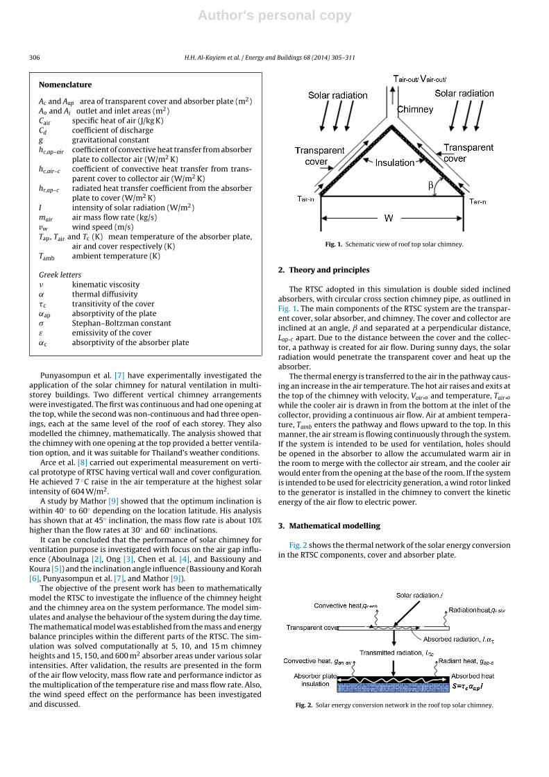
Fig. 1. Schematic view of roof top solar chimney.
2. Theory and principles
The RTSC adopted in this simulation is double sided inclinedabsorbers, with circular cross section chimney pipe, as outlined inFig. 1. The main components of the RTSC system are the transpar-ent cover, solar absorber, and chimney. The cover and collector areinclined at an angle, and separated at a perpendicular distance,Lap-c apart. Due to the distance between the cover and the collec-tor, a pathway is created for air flow. During sunny days, the solarradiation would penetrate the transparent cover and heat up theabsorber.
The thermal energy is transferred to the air in the pathway caus-ing an increase in the air temperature. The hot air raises and exits atthe top of the chimney with velocity, Vair,o and temperature, Tair,owhile the cooler air is drawn in from the bottom at the inlet of thecollector, providing a continuous air flow. Air at ambient tempera-ture, Tamb enters the pathway and flows upward to the top. In thismanner, the air stream is flowing continuously through the system.If the system is intended to be used for ventilation, holes shouldbe opened in the absorber to allow the accumulated warm air inthe room to merge with the collector air stream, and the cooler airwould enter from the opening at the base of the room. If the systemis intended to be used for electricity generation, a wind rotor linkedto the generator is installed in the chimney to convert the kineticenergy of the air flow to electric power.
3. Mathematical modelling
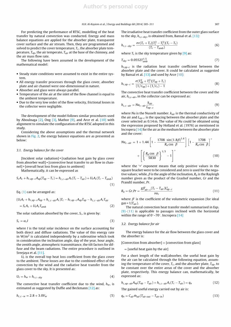
Fig. 2 shows the thermal network of the solar energy conversionin the RTSC components, cover and absorber plate.
Fig. 2. Solar energy conversion network in the roof top solar chimney.
Author's personal copy
H.H. Al-Kayiem et al. / Energy and Buildings 68 (2014) 305–311 307
For predicting the performance of RTSC, modelling of the heattransfer by natural convection was conducted. Energy and massbalance equations are applied for the absorber plate, transparentcover surface and the air stream. Then, they are programmed andsolved to predict the cover temperature, Tc, the absorber plate tem-perature, Tap, the air temperate, Tair at the base of the chimney, andthe air mass flow rate.
The following have been assumed in the development of themathematical model:
• Steady state conditions were assumed to exist in the entire sys-tem.
• All energy transfer processes through the glass cover, absorberplate and air channel were one-dimensional in nature.
• Absorber and glass were always parallel.• Temperature of the air at the inlet of the flow channel is equal to
the ambient temperature.• Due to the very low order of the flow velocity, frictional losses in
the collector were negligible.
The development of the model follows similar procedures usedby Aboulnaga [2], Ong [3], Mathor [9], and Arce et al. [10] withalignment to simulate the configuration of the RTSC adopted in thisstudy.
Considering the above assumptions and the thermal networkshown in Fig. 2, the energy balance equations are as presented asbelow:
3.1. Energy balance for the cover
[Incident solar radiation] + [radiation heat gain by glass coverfrom absorber wall] = [convective heat transfer to air flow in chan-nel] + [overall heat loss from glass to ambient]
Mathematically, it can be expressed as
ScAc + hr,ap−cAap(Tap − Tc) = hc,c−airAc(Tc − Tair) + UtAc(Tc − Tamb)
(1)
Eq. (1) can be arranged as:
(UtAc + hr,ap−cAap + hc,c−airAc)Tc − hr,ap−cAapTap − hc,c−airAcTair
= ScAc + UtAcTamb (2)
The solar radiation absorbed by the cover, Sc, is given by:
Sc = ˛cI (3)
where I is the total solar incidence on the surface accounting forboth direct and diffuse radiations. The value of this energy ratein W/m2 is calculated independently by a subroutine which tookin consideration the inclination angle, day of the year, hour angle,the zenith angle, atmospheric transmittance, the tilt factors for dif-fuse and the beam radiations. The entire procedure is outlined inSreejaya et al. [11].
Ut is the overall top heat loss coefficient from the glass coverto the ambient. These losses are due to the combined effect of theconvection by the wind and the radiative heat transfer from theglass cover to the sky. It is presented as:
Ut = hw + hr,c−sky (4)
The convective heat transfer coefficient due to the wind, hw, isestimated as suggested by Duffie and Beckmann [12] as:
hc,c−w = 2.8 + 3.0Vw (5)
The irradiative heat transfer coefficient from the outer glass surfaceto the sky, hr,c–sky, is obtained from, Bansal et al. [13]:
hr,c−sky = �ε(Tc + Ts)(T2c − T2
s )(Tc − Ts)(Tc − Tamb)
(6)
where Ts is the sky temperature given by [9] as:
Tsky = 0.0552T1.5amb (7)
hr,ap–c is the radiation heat transfer coefficient between theabsorber plate and the cover. It could be calculated as suggestedby Bansal et al. [13] and used by Arce [10]:
hr,ap−c = �(T2ap + T2
c )(Tap + Tc)
(1/εap) + (1/εc) − 1(8)
The convective heat transfer coefficient between the cover and theair, hc,c–air, in the collector can be expressed as:
hc,c−air = Nuc−airkair
Lap−c(9)
where Nu is the Nusselt number. kair is the thermal conductivity ofthe air and Lap–c is the spacing between the absorber plate and thecover selected as 0.14 m. The value of Nu could be obtained usingthe expression proposed by Holland et al. (1976) as mentioned inIncropera [14] for the air as the medium between the absorber plateand the cover:
Nuc−air = 1 + 1.44
[1 − 1708 sin (1.8ˇ)1.6
Ra cos ˇ
][1 − 1708
Ra cos ˇ
]+
+[{
Ra cos ˇ
5830
}1/3
− 1
]+
(10)
where the ‘+’ exponent means that only positive values in thesquare bracket were to be considered and zero is used for the nega-tive values; while, is the angle of the inclination, Ra is the Rayleighnumber given as the product of the Grashof number, Gr and thePrandtl number, Pr.
Ra = Gr.Pr =gˇ′
air−c(Tc − Tair)Lε
ap−c
v˛c(11)
where ˇ′ is the coefficient of the volumetric expansion (for idealgas = 1/Tair).
The natural convection heat transfer model summarised in Eqs.(9)–(11) is applicable to passages inclined with the horizontalwithin the range of 0◦–70◦. Incropera [14]
3.2. Energy balance for air
The energy balance for the air flow between the glass cover andthe absorber is:
[Convection from absorber] + [convection from glass]
= [useful heat gain by the air]
For a short length of the wall/absorber, the useful heat gain bythe air can be calculated through the following equation, assum-ing the temperature of the cover, Tc, and the absorber plate, Tap, tobe constant over the entire areas of the cover and the absorberplate, respectively. This energy balance can, mathematically, beexpressed as:
hc,ap−airAap(Tap − Tair) + hc,c−airAc(Tc − Tair) = qu (12)
The gained useful energy carried out by air is:
qu = Cairmair(Tair-out − Tair-in) (13)
Author's personal copy
308 H.H. Al-Kayiem et al. / Energy and Buildings 68 (2014) 305–311
The velocity of the air in the flow channel that is finally used to cal-culate the mass flow rate through the chimney could be calculatedthrough the mass flow rate using the following equation.
The mass flow rate is evaluated by adopting the formula sug-gested by Bansal et al. [13] and Arce et al. [10]:
m = Cd�air,oAo√
1 + Ar
√2gHc(Tf − Tr)
Tr(14)
where
Ar = Ao
2Ai(15.a)
�o = m
�airAo(15.b)
The experimental investigation of Arce et al. [8] showed that theappropriate value for the discharge coefficient, Cd is about 0.52.
3.3. Energy balance for the absorber plate
Similar to the energy balances for the glass cover and the airchannel, the energy balance for the absorber has also been written.In this case, the absorber plate is insulated at the back side.
[Solar radiation] = [convection to air in flow channel]
+ [long wave re-radiation to glass]
+ [conduction from absorber plate to insulated back]
SapAap = [hc,ap−airAap(Tap − Tair)] + [hr,ap−cAap(Tap − Tc)]
+ [UbAap(Tap − Tamb)] (16)
[hc,ap−airAap + hr,ap−cAap + UbAap]Tap − [hc,ap−airAap]Tair
− [hr,ap−cAap]Tc = SapAap + [UbAap]Tamb (17)
where the convective heat transfer coefficient between theabsorber plate and the air, hc,ap–air, could be calculated by the samemeans of calculating hc,c–air using Eqs. (9)–(11), but the cover tem-perature, Tc, is to be replaced by the absorber plate temperature,Tap.
In the case of using good insulation with the optimum calculatedthickness, the back conduction losses can be neglected.
The solar energy absorbed by the absorber plate, Sap, is:
Sap = �c˛apI (18)
It should be noticed that the mean air temperature in the collector,Tair, depicted in Eqs. (1), (2), (12), (13), (16) and (17) is compensatedby 0.5(Tair,o + Tair,in), where Tair,in = Tamb.
This mathematical model is arranged in a matrix format andconverted to a MATLAB program and solved iteratively to predictthe values of the cover, Tc, absorber plate, Tp, the outlet air temper-atures, Tair,o, air mass flow rate, m and the outlet velocity, Vair,o.
4. Experimental model
The experimental model design parameters were 2.1 m baseheight (house height), 15 m2 collector area, 15 m2 cover area. Basedon the experimental findings of Chen et al. [4], and the analyti-cal and numerical findings of Bassiouny and Korah [6] who statedthat the optimum inclination for RTSC is around 40–60, an incli-nation of 45◦ for the collector and cover is selected for the presentstudy. 0.14 m air inlet gap (distance between cover and collector) isselected which is within the recommended range by Aboulnaga [2].
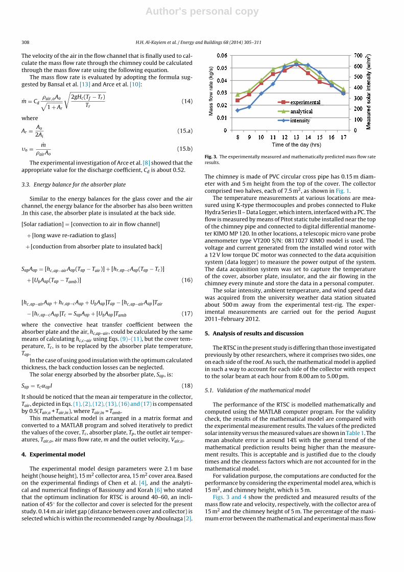
Fig. 3. The experimentally measured and mathematically predicted mass flow rateresults.
The chimney is made of PVC circular cross pipe has 0.15 m diam-eter with and 5 m height from the top of the cover. The collectorcomprised two halves, each of 7.5 m2, as shown in Fig. 1.
The temperature measurements at various locations are mea-sured using K-type thermocouples and probes connected to FlukeHydra Series II – Data Logger, which intern, interfaced with a PC. Theflow is measured by means of Pitot static tube installed near the topof the chimney pipe and connected to digital differential manome-ter KIMO MP 120. In other locations, a telescopic micro vane probeanemometer type VT200 S/N: 0811027 KIMO model is used. Thevoltage and current generated from the installed wind rotor witha 12 V low torque DC motor was connected to the data acquisitionsystem (data logger) to measure the power output of the system.The data acquisition system was set to capture the temperatureof the cover, absorber plate, insulator, and the air flowing in thechimney every minute and store the data in a personal computer.
The solar intensity, ambient temperature, and wind speed datawas acquired from the university weather data station situatedabout 500 m away from the experimental test-rig. The exper-imental measurements are carried out for the period August2011–February 2012.
5. Analysis of results and discussion
The RTSC in the present study is differing than those investigatedpreviously by other researchers, where it comprises two sides, oneon each side of the roof. As such, the mathematical model is appliedin such a way to account for each side of the collector with respectto the solar beam at each hour from 8.00 am to 5.00 pm.
5.1. Validation of the mathematical model
The performance of the RTSC is modelled mathematically andcomputed using the MATLAB computer program. For the validitycheck, the results of the mathematical model are compared withthe experimental measurement results. The values of the predictedsolar intensity versus the measured values are shown in Table 1. Themean absolute error is around 14% with the general trend of themathematical prediction results being higher than the measure-ment results. This is acceptable and is justified due to the cloudytimes and the cleanness factors which are not accounted for in themathematical model.
For validation purpose, the computations are conducted for theperformance by considering the experimental model area, which is15 m2, and chimney height, which is 5 m.
Figs. 3 and 4 show the predicted and measured results of themass flow rate and velocity, respectively, with the collector area of15 m2 and the chimney height of 5 m. The percentage of the maxi-mum error between the mathematical and experimental mass flow
Author's personal copy
H.H. Al-Kayiem et al. / Energy and Buildings 68 (2014) 305–311 309
Table 1Comparison between the predicted and measured values of the solar intensity.
Variable Time (am) Time (pm)
8 9 10 11 12 01.0 02.0 03.0 04.0 05.0
Measured intensity 110 190 350 464 610 678 690 580 400 340Predicted intensity 118 275 378 541 625 743 850 638 414 242Percentage of error 6.8 31 7 14 2.5 8.7 18.8 9.1 3.3 40
rate values is 9.7% as the maximum, while the mean absolute erroris 7%.
The comparison results of the velocity presented in Fig. 4 showthat the simulation results are higher than the measured ones withabout 6% mean absolute error. The maximum calculated error is10.8%.
It is believed that the selected value of the discharge coefficientrequires more attention for higher accuracy. The configuration ofeach chimney is differing than other and it is not advisable to gen-eralise the losses figure.
However, it has been proved that the mathematical model canpredict the performance of RTSC with reasonable accuracy.
5.2. The effect of the collector area
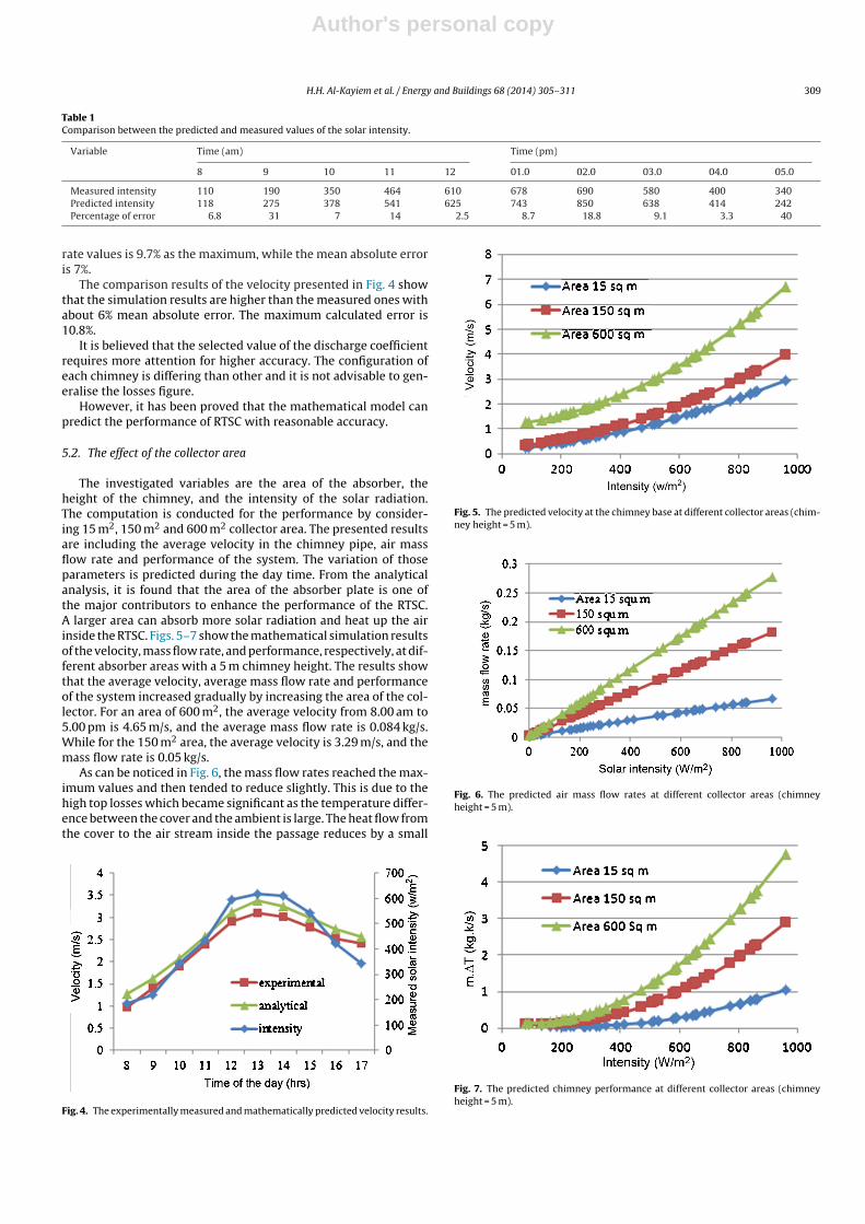
The investigated variables are the area of the absorber, theheight of the chimney, and the intensity of the solar radiation.The computation is conducted for the performance by consider-ing 15 m2, 150 m2 and 600 m2 collector area. The presented resultsare including the average velocity in the chimney pipe, air massflow rate and performance of the system. The variation of thoseparameters is predicted during the day time. From the analyticalanalysis, it is found that the area of the absorber plate is one ofthe major contributors to enhance the performance of the RTSC.A larger area can absorb more solar radiation and heat up the airinside the RTSC. Figs. 5–7 show the mathematical simulation resultsof the velocity, mass flow rate, and performance, respectively, at dif-ferent absorber areas with a 5 m chimney height. The results showthat the average velocity, average mass flow rate and performanceof the system increased gradually by increasing the area of the col-lector. For an area of 600 m2, the average velocity from 8.00 am to5.00 pm is 4.65 m/s, and the average mass flow rate is 0.084 kg/s.While for the 150 m2 area, the average velocity is 3.29 m/s, and themass flow rate is 0.05 kg/s.
As can be noticed in Fig. 6, the mass flow rates reached the max-imum values and then tended to reduce slightly. This is due to thehigh top losses which became significant as the temperature differ-ence between the cover and the ambient is large. The heat flow fromthe cover to the air stream inside the passage reduces by a small
Fig. 4. The experimentally measured and mathematically predicted velocity results.
Fig. 5. The predicted velocity at the chimney base at different collector areas (chim-ney height = 5 m).
Fig. 6. The predicted air mass flow rates at different collector areas (chimneyheight = 5 m).
Fig. 7. The predicted chimney performance at different collector areas (chimneyheight = 5 m).
Author's personal copy
310 H.H. Al-Kayiem et al. / Energy and Buildings 68 (2014) 305–311
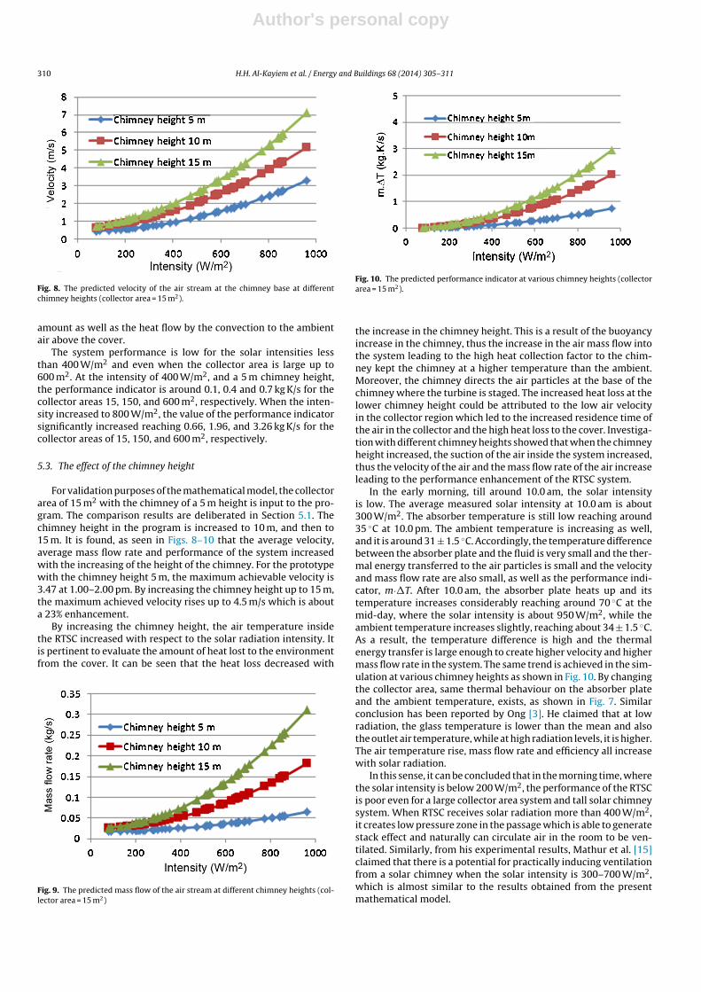
Fig. 8. The predicted velocity of the air stream at the chimney base at differentchimney heights (collector area = 15 m2).
amount as well as the heat flow by the convection to the ambientair above the cover.
The system performance is low for the solar intensities lessthan 400 W/m2 and even when the collector area is large up to600 m2. At the intensity of 400 W/m2, and a 5 m chimney height,the performance indicator is around 0.1, 0.4 and 0.7 kg K/s for thecollector areas 15, 150, and 600 m2, respectively. When the inten-sity increased to 800 W/m2, the value of the performance indicatorsignificantly increased reaching 0.66, 1.96, and 3.26 kg K/s for thecollector areas of 15, 150, and 600 m2, respectively.
5.3. The effect of the chimney height
For validation purposes of the mathematical model, the collectorarea of 15 m2 with the chimney of a 5 m height is input to the pro-gram. The comparison results are deliberated in Section 5.1. Thechimney height in the program is increased to 10 m, and then to15 m. It is found, as seen in Figs. 8–10 that the average velocity,average mass flow rate and performance of the system increasedwith the increasing of the height of the chimney. For the prototypewith the chimney height 5 m, the maximum achievable velocity is3.47 at 1.00–2.00 pm. By increasing the chimney height up to 15 m,the maximum achieved velocity rises up to 4.5 m/s which is abouta 23% enhancement.
By increasing the chimney height, the air temperature insidethe RTSC increased with respect to the solar radiation intensity. Itis pertinent to evaluate the amount of heat lost to the environmentfrom the cover. It can be seen that the heat loss decreased with
Fig. 9. The predicted mass flow of the air stream at different chimney heights (col-lector area = 15 m2)
Fig. 10. The predicted performance indicator at various chimney heights (collectorarea = 15 m2).
the increase in the chimney height. This is a result of the buoyancyincrease in the chimney, thus the increase in the air mass flow intothe system leading to the high heat collection factor to the chim-ney kept the chimney at a higher temperature than the ambient.Moreover, the chimney directs the air particles at the base of thechimney where the turbine is staged. The increased heat loss at thelower chimney height could be attributed to the low air velocityin the collector region which led to the increased residence time ofthe air in the collector and the high heat loss to the cover. Investiga-tion with different chimney heights showed that when the chimneyheight increased, the suction of the air inside the system increased,thus the velocity of the air and the mass flow rate of the air increaseleading to the performance enhancement of the RTSC system.
In the early morning, till around 10.0 am, the solar intensityis low. The average measured solar intensity at 10.0 am is about300 W/m2. The absorber temperature is still low reaching around35 ◦C at 10.0 pm. The ambient temperature is increasing as well,and it is around 31 ± 1.5 ◦C. Accordingly, the temperature differencebetween the absorber plate and the fluid is very small and the ther-mal energy transferred to the air particles is small and the velocityand mass flow rate are also small, as well as the performance indi-cator, m·�T. After 10.0 am, the absorber plate heats up and itstemperature increases considerably reaching around 70 ◦C at themid-day, where the solar intensity is about 950 W/m2, while theambient temperature increases slightly, reaching about 34 ± 1.5 ◦C.As a result, the temperature difference is high and the thermalenergy transfer is large enough to create higher velocity and highermass flow rate in the system. The same trend is achieved in the sim-ulation at various chimney heights as shown in Fig. 10. By changingthe collector area, same thermal behaviour on the absorber plateand the ambient temperature, exists, as shown in Fig. 7. Similarconclusion has been reported by Ong [3]. He claimed that at lowradiation, the glass temperature is lower than the mean and alsothe outlet air temperature, while at high radiation levels, it is higher.The air temperature rise, mass flow rate and efficiency all increasewith solar radiation.
In this sense, it can be concluded that in the morning time, wherethe solar intensity is below 200 W/m2, the performance of the RTSCis poor even for a large collector area system and tall solar chimneysystem. When RTSC receives solar radiation more than 400 W/m2,it creates low pressure zone in the passage which is able to generatestack effect and naturally can circulate air in the room to be ven-tilated. Similarly, from his experimental results, Mathur et al. [15]claimed that there is a potential for practically inducing ventilationfrom a solar chimney when the solar intensity is 300–700 W/m2,which is almost similar to the results obtained from the presentmathematical model.
Author's personal copy
H.H. Al-Kayiem et al. / Energy and Buildings 68 (2014) 305–311 311
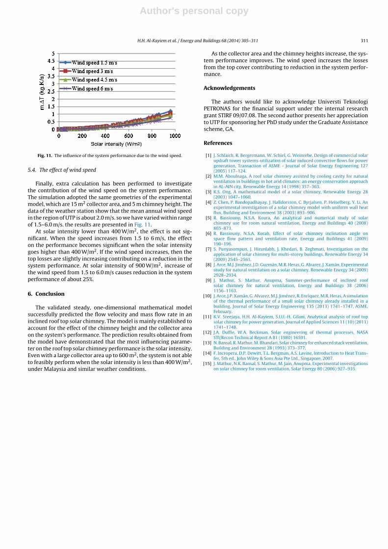
Fig. 11. The influence of the system performance due to the wind speed.
5.4. The effect of wind speed
Finally, extra calculation has been performed to investigatethe contribution of the wind speed on the system performance.The simulation adopted the same geometries of the experimentalmodel, which are 15 m2 collector area, and 5 m chimney height. Thedata of the weather station show that the mean annual wind speedin the region of UTP is about 2.0 m/s. so we have varied within rangeof 1.5–6.0 m/s. the results are presented in Fig. 11.
At solar intensity lower than 400 W/m2, the effect is not sig-nificant. When the speed increases from 1.5 to 6 m/s, the effecton the performance becomes significant when the solar intensitygoes higher than 400 W/m2. If the wind speed increases, then thetop losses are slightly increasing contributing on a reduction in thesystem performance. At solar intensity of 900 W/m2, increase ofthe wind speed from 1.5 to 6.0 m/s causes reduction in the systemperformance of about 25%.
6. Conclusion
The validated steady, one-dimensional mathematical modelsuccessfully predicted the flow velocity and mass flow rate in aninclined roof top solar chimney. The model is mainly established toaccount for the effect of the chimney height and the collector areaon the system’s performance. The prediction results obtained fromthe model have demonstrated that the most influencing parame-ter on the roof top solar chimney performance is the solar intensity.Even with a large collector area up to 600 m2, the system is not ableto feasibly perform when the solar intensity is less than 400 W/m2,under Malaysia and similar weather conditions.
As the collector area and the chimney heights increase, the sys-tem performance improves. The wind speed increases the lossesfrom the top cover contributing to reduction in the system perfor-mance.
Acknowledgements
The authors would like to acknowledge Universti TeknologiPETRONAS for the financial support under the internal researchgrant STIRF 09/07.08. The second author presents her appreciationto UTP for sponsoring her PhD study under the Graduate Assistancescheme, GA.
References
[1] J. Schlaich, R. Bergermann, W. Schiel, G. Weinrebe, Design of commercial solarupdraft tower systems-utilization of solar induced convective flows for powergeneration, Transaction of ASME - Journal of Solar Energy Engineering 127(2005) 117–124.
[2] M.M. Aboulnaga, A roof solar chimney assisted by cooling cavity for naturalventilation in buildings in hot arid climates: an energy conservation approachin AL-AIN city, Renewable Energy 14 (1998) 357–363.
[3] K.S. Ong, A mathematical model of a solar chimney, Renewable Energy 28(2003) 1047–1060.
[4] Z. Chen, P. Bandopadhayay, J. Halldorsson, C. Byrjalsen, P. Heiselberg, Y. Li, Anexperimental investigation of a solar chimney model with uniform wall heatflux, Building and Environment 38 (2003) 893–906.
[5] R. Bassiouny, N.S.A. Koura, An analytical and numerical study of solarchimney use for room natural ventilation, Energy and Buildings 40 (2008)865–873.
[6] R. Bassiouny, N.S.A. Korah, Effect of solar chimney inclination angle onspace flow pattern and ventilation rate, Energy and Buildings 41 (2009)190–196.
[7] S. Punyasompun, J. Hirunlabh, J. Khedari, B. Zeghmati, Investigation on theapplication of solar chimney for multi-storey buildings, Renewable Energy 34(2009) 2545–2561.
[8] J. Arce, M.J. Jiménez, J.D. Guzmán, M.R. Heras, G. Alvarez, J. Xamán, Experimentalstudy for natural ventilation on a solar chimney, Renewable Energy 34 (2009)2928–2934.
[9] J. Mathur, S. Mathur, Anupma, Summer-performance of inclined roofsolar chimney for natural ventilation, Energy and Buildings 38 (2006)1156–1163.
[10] J. Arce, J.P. Xamán, G. Alvarez, M.J. Jiménez, R. Enríquez, M.R. Heras, A simulationof the thermal performance of a small solar chimney already installed in abuilding, Journal of Solar Energy Engineering 135 (2013) 1741–1747, ASME,February.
[11] K.V. Sreejaya, H.H. Al-Kayiem, S.I.U.-H. Gilani, Analytical analysis of roof topsolar chimney for power generation, Journal of Applied Sciences 11 (10) (2011)1741–1748.
[12] J.A. Duffie, W.A. Beckman, Solar engineering of thermal processes, NASASTI/Recon Technical Report A 81 (1980) 16591.
[13] N. Bansal, R. Mathur, M. Bhandari, Solar chimney for enhanced stack ventilation,Building and Environment 28 (1993) 373–377.
[14] F. Incropera, D.P. Dewitt, T.L. Bergman, A.S. Lavine, Introduction to Heat Trans-fer, 5th ed., John Wiley & Sons Asia Pte Ltd., Singapore, 2007.
[15] J. Mathur, N.K. Bansal, S. Mathur, M. Jain, Anupma, Experimental investigationson solar chimney for room ventilation, Solar Energy 80 (2006) 927–935.