augmented belief-propagation decoding of low-density parity-check codes
TRANSCRIPT

1308 IEEE TRANSACTIONS ON COMMUNICATIONS, VOL. 55, NO. 7, JULY 2007
Augmented Belief Propagation Decodingof Low-Density Parity Check Codes
Nedeljko Varnica, Marc P. C. Fossorier, Fellow, IEEE, and Aleksandar Kavcic, Senior Member, IEEE
Abstract—We propose an augmented belief propagation (BP)decoder for low-density parity check (LDPC) codes which can beutilized on memoryless or intersymbol interference channels. Theproposed method is a heuristic algorithm that eliminates a largenumber of pseudocodewords that can cause nonconvergence inthe BP decoder. The augmented decoder is a multistage iterativedecoder, where, at each stage, the original channel messages onselect symbol nodes are replaced by saturated messages. The keyelement of the proposed method is the symbol selection process,which is based on the appropriately defined subgraphs of the codegraph and/or the reliability of the information received from thechannel. We demonstrate by examples that this decoder can be im-plemented to achieve substantial gains (compared to the standardlocally-operating BP decoder) for short LDPC codes decoded onboth memoryless and intersymbol interference Gaussian channels.Using the Margulis code example, we also show that the augmenteddecoder reduces the error floors. Finally, we discuss types of BPdecoding errors and relate them to the augmented BP decoder.
Index Terms—belief propagation (BP) decoding, error floors,low-density parity check (LDPC) codes, pseudocodewords.
I. INTRODUCTION
ABELIEF propagation (BP) decoder of turbo-like codes [1],[2] performs iterative message passing on a code graph
and is derived under the message-independence assumption.This assumption is valid only while the iteration number issmaller than quarter of the girth (size of the smallest cycle) ofthe graph. Unfortunately, the graphs of finite-length low-densityparity check (LDPC) codes [1], [3] with good distance proper-ties contain a large number of cycles [4] and typically have asmall girth. Nevertheless, for very large block lengths, LDPCcodes decoded by BP decoders can be optimized to practicallyachieve the capacities of a variety of channels [5]–[8]. However,when the code block length is short, the presence of cycles inLDPC code graphs introduces a noticeable loss in performanceif the standard BP decoding is performed instead of the optimalmaximum-likelihood (ML) decoding.
Paper approved by A. H. Banihashemi, the Editor for Coding and Communi-cation Theory of the IEEE Communications Society. Manuscript received May2, 2004; revised June 24, 2005 and March 15, 2006. This work was supportedby the National Science Foundation (NSF) under Grants CCR-0098029 andCCR-0118701. This paper was presented in part at the IEEE International Sym-posium on Information Theory, Chicago, IL June-July 2004.
N. Varnica was with Harvard University, Cambridge, MA 02138 USA. Heis now with Marvell Semiconductor, Inc., Santa Clara, CA 95054 USA (e-mail:[email protected]).
M. Fossorier is with the Department of Electrical Engineering, Univer-sity of Hawaii at Manoa, Honolulu, HI 96822 USA (e-mail: [email protected]).
A. Kavcic was with the Division of Engineering and Applied Sciences,Harvard University, Cambridge, MA 02138 USA. He is now with the Universityof Hawaii, Honolulu, HI 96822 USA (e-mail: [email protected]).
Digital Object Identifier 10.1109/TCOMM.2007.900611
One approach that often improves the performance of shortLDPC codes is the algebraic (rather than random) parity checkmatrix construction, which typically controls the minimumdistance and/or code graph girth [9]–[14]. For example, Tanneret al. proposed an algebraic code construction method thatyields a (155,64) code with girth, diameter, and minimumdistance equaling 8, 6, and 20, respectively [9]. Althoughthe performance of the BP decoder for this code on theadditive white Gaussian noise (AWGN) channel is better thanthe performance of the BP decoder for the correspondingrandomly constructed regular Gallager code [1], [3], it is stillabout 1dB away from the performance of the ML decoderfor this code. Many other short LDPC codes have significantBP-to-ML performance gaps; examples of such codes includethe (504,252) MacKay regular and irregular codes [3]. TheBP-to-ML decoding gaps often exist for longer LDPC codes(with block lengths of several thousand symbols); large gapsare typically observed in the error floor region [15].
In this paper, we propose an augmented BP decoder. This al-gorithm relies on the original BP decoder in the initial iterations.However, when the original BP fails (which is detected usingcode parity check constraints), the augmented BP algorithmis employed in a multistage decoding fashion, where, at eachstage, the channel message on a select variable node is replacedby a saturated message. Several node selection algorithms areproposed. These node selection algorithms follow the idea thatthe least reliable symbols are selected first.
The symbol nodes are selected based on their channel infor-mation and their degrees (and the degrees of their neighbors)in the appropriately defined subgraphs of the code graph. Wenote that an algorithm that selects a set of symbol nodes basedon their degrees only and attempts all possible combinationsof saturation values on the selected set was proposed in [16].The major differences between our decoder and the decoderin [16] are that the node selection algorithm is improved andthat the decoding is performed in stages. This leads to decoderperformance improvements for all the codes that we tested.
We demonstrate the performance of the proposed augmenteddecoder on several short code examples. For the (155,64) Tan-ner code, we verify that the performance of the augmented BPdecoder (with a large number of iterations) approaches the MLdecoding performance to within 0.2 dB, while its complexity isfar lower than the complexity of the ML decoder. Generally, theeffectiveness of the proposed algorithm in the waterfall regionreduces as the code block lengths increase. On the other hand, ontwo chosen code examples (one short code and one long code)with high error floors, we show that the algorithm is effectivein the error floor region. For the long Margulis code (which isconsidered here because of its good minimum distance [17]),
0090-6778/$25.00 © 2007 IEEE
Authorized licensed use limited to: UNIV OF HAWAII LIBRARY. Downloaded on March 15, 2009 at 23:26 from IEEE Xplore. Restrictions apply.

VARNICA et al.: AUGMENTED BELIEF PROPAGATION DECODING 1309
we demonstrate that the augmented BP method can reduce errorfloors by at least two orders of magnitude. The complexity–performance tradeoffs can be achieved by choosing the numberof iterations and/or the number of correction stages in the aug-mented BP algorithm. The method is universal in the sense thatit does not depend on the specific parity check code or specificBP decoder implementation (for example, possible implemen-tations include approximate and quantized BP algorithms [18],[19] as well as certain improved BP decoders, e.g., [20]).
The remainder of this paper is organized as follows. In Sec-tion II, we provide necessary definitions regarding LDPC codesubgraphs. In Section III, we present augmented BP decoders. InSection IV, we discuss types of BP decoding errors and relatethem to the proposed decoders. Implementations of the aug-mented BP decoders are addressed in Section V. We interpretour methods using the pseudocodewords perspective [21], [22]in Section VI. Section VII gives decoding performance resultsand Section VIII concludes the paper.
II. DEFINITIONS OF SETS AND SUBGRAPHS
An LDPC code is a linear block code with a sparse paritycheck matrix [1]. Every parity check matrix can be representedby a bipartite graph with two sets of nodes: variable (symbol)nodes, which represent the encoded symbols, and check nodes,which represent the parity check constraints [23]. For a givenLDPC code CH with the parity check matrix H , denote the setof variable nodes by V and the set of check nodes by C. A nodev ∈ V is connected to a node c ∈ C by a single undirected edgeif the symbol represented by v is involved in the parity checkequation represented by c. Denote the set of edges by E. Thebipartite code graph G is defined as a triple of sets V,E, andC, i.e., G = (V,E,C). An (N, k) LDPC code CH has blocklength N = |V | and code size1 |CH | = 2k. Denote the encodedvector of this code by x = [x0, x1, . . . , xN−1]T . Let the numberof parity checks be Nc = |C| ≥ N − k. The parity check vectorz = [z0, z1, . . . , zNc−1]T is given by z = H · x and is typicallya zero vector (except for LDPC coset codes [24]).
Let y be the received vector at the channel output. Denote by
x(L) def= x(L)(y) the decoded vector obtained after L iterationsof BP decoding, initialized with the a priori probabilities yieldedfrom y. A check node corresponding to the parity check zi is said
to be unsatisfied if the ith entry of the syndrome s = H · x(L)
is not equal to zi.
Definition 1 (Node and edge sets)1) Set of unsatisfied checks (SUC) C
(L)S ⊆ C is the set of
check nodes that are unsatisfied after L iterations of thestandard or augmented (to be described promptly) BPdecoding.
2) Set of suspicious variable nodes V(L)S ⊆V is the set of
variable nodes connected to C(L)S by at least one edge in
the LDPC code graph G.
1We consider binary LDPC codes in this paper. The methods presented herecan be extended to decoding of nonbinary LDPC codes in a straightforwardfashion.
3) E(L)S ⊆ E is the set of edges connecting the nodes in V
(L)S
and the nodes in C(L)S .
Definition 2The SUC graph G
(L)S is the graph induced by the SUC C
(L)S ,
i.e., G(L)S = (V (L)
S , E(L)S , C
(L)S ) ⊆ G.
Definition 3 (Variable node degrees with respect to a graph)1) Denote the degree of a variable node v ∈ V with respect
to the code graph G by dG(v).2) Denote the degree of a variable node v ∈ V with respect
to the SUC graph G(L)S by dGS
(v).3) Let dmax
G = maxv∈V
dG(v) and dmaxGS
= maxv∈V
(L )S
dGS(v). De-
note by Smaxv the set of all variable nodes whose degree
dGSequals dmax
GS, i.e., Smax
v = v ∈ V(L)S : dGS
(v) =dmax
GS.
Note that dGS(v) = 0 if v /∈ V
(L)S and dGS
(v) > 0 if v ∈V
(L)S . For brevity, we will sometimes omit the argument of
dGS, which will be clear from the context.
Definition 4 (Neighborhood with respect to SUC graph)Consider a pair of nodes in V
(L)S . We call these two nodes
neighbors with respect to the SUC graph if they are incident to atleast one (common) check node c ∈ C
(L)S . For a node v ∈ V
(L)S ,
we denote by n()v the number of such neighbors whose degree
in the SUC graph is dGS= .
The following three observations are made based on intuitionand empirically confirmed by experiments on the code examplesdiscussed in Section VII. We believe that these observations holdfor many other practical codes, but since we cannot offer proofsfor the observations they would need to be tested for a givenspecific code that one wishes to implement.
Observation 1. The higher the degree dGS(v) of a variable
node v∈V(L)S , the more likely is the decoded symbol corre-
sponding to v to be in error.Next, we make an observation that refines Observation 1. Let
m be the maximum value of for which there exists v ∈ Smaxv
such that n()v > 0. Consider two variable nodes vi, vj ∈ Smax
v .
Observation 2. If n(m )vi < n
(m )vj , the decoded symbol corre-
sponding to the node vi ∈ Smaxv is more likely to be incorrect
than the decoded symbol corresponding to the node vj ∈ Smaxv .
The intuition behind this observation is as follows. FromObservation 1, we have that if a symbol node has a high degreedGS
, the likelihood that this symbol is in error is relatively high.For the symbols which have no high-degree neighbors (withrespect to the SUC graph), this likelihood should be even higheras the probability that one of their neighbors is responsible forthe “check node error” is low.
The final observation is made for memoryless channels only.
For a node vi ∈ V denote by O(vi)= logp(xi =0|y)
p(xi =1|y) its de-
coder input, i.e., its initial message obtained from the receivedvector y. For example, for binary phase-shift keying (BPSK)signaling on the AWGN channel with the noise standard de-viation σ, we have O(vi) = 2·yi
σ2 . The following observa-tion is made based on the statistics of the absolute values ofO(v).
Authorized licensed use limited to: UNIV OF HAWAII LIBRARY. Downloaded on March 15, 2009 at 23:26 from IEEE Xplore. Restrictions apply.
1310 IEEE TRANSACTIONS ON COMMUNICATIONS, VOL. 55, NO. 7, JULY 2007
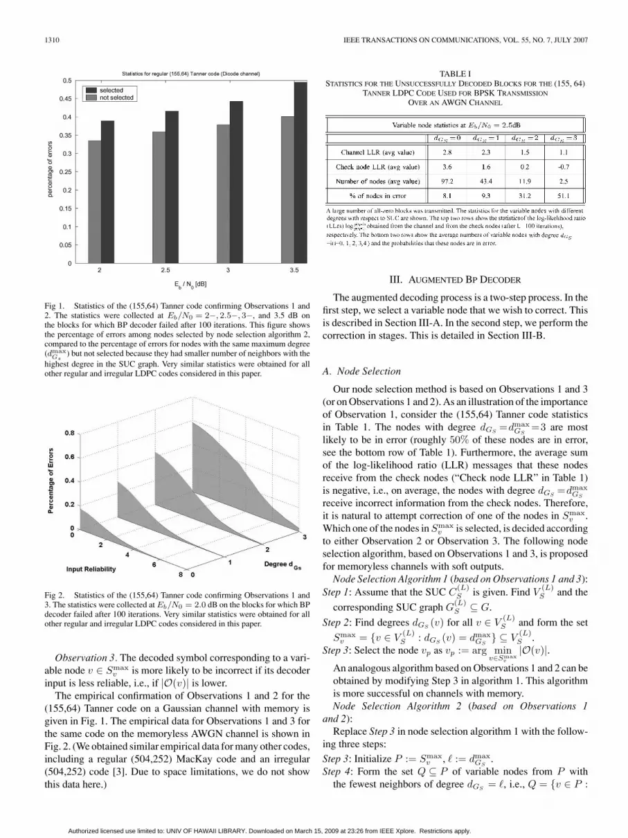
Fig 1. Statistics of the (155,64) Tanner code confirming Observations 1 and2. The statistics were collected at Eb/N0 = 2−, 2.5−, 3−, and 3.5 dB onthe blocks for which BP decoder failed after 100 iterations. This figure showsthe percentage of errors among nodes selected by node selection algorithm 2,compared to the percentage of errors for nodes with the same maximum degree(dmax
Gs) but not selected because they had smaller number of neighbors with the
highest degree in the SUC graph. Very similar statistics were obtained for allother regular and irregular LDPC codes considered in this paper.
Fig 2. Statistics of the (155,64) Tanner code confirming Observations 1 and3. The statistics were collected at Eb/N0 = 2.0 dB on the blocks for which BPdecoder failed after 100 iterations. Very similar statistics were obtained for allother regular and irregular LDPC codes considered in this paper.
Observation 3. The decoded symbol corresponding to a vari-able node v ∈ Smax
v is more likely to be incorrect if its decoderinput is less reliable, i.e., if |O(v)| is lower.
The empirical confirmation of Observations 1 and 2 for the(155,64) Tanner code on a Gaussian channel with memory isgiven in Fig. 1. The empirical data for Observations 1 and 3 forthe same code on the memoryless AWGN channel is shown inFig. 2. (We obtained similar empirical data for many other codes,including a regular (504,252) MacKay code and an irregular(504,252) code [3]. Due to space limitations, we do not showthis data here.)
TABLE ISTATISTICS FOR THE UNSUCCESSFULLY DECODED BLOCKS FOR THE (155, 64)
TANNER LDPC CODE USED FOR BPSK TRANSMISSION
OVER AN AWGN CHANNEL
III. AUGMENTED BP DECODER
The augmented decoding process is a two-step process. In thefirst step, we select a variable node that we wish to correct. Thisis described in Section III-A. In the second step, we perform thecorrection in stages. This is detailed in Section III-B.
A. Node Selection
Our node selection method is based on Observations 1 and 3(or on Observations 1 and 2). As an illustration of the importanceof Observation 1, consider the (155,64) Tanner code statisticsin Table 1. The nodes with degree dGS
=dmaxGS
=3 are mostlikely to be in error (roughly 50% of these nodes are in error,see the bottom row of Table 1). Furthermore, the average sumof the log-likelihood ratio (LLR) messages that these nodesreceive from the check nodes (“Check node LLR” in Table 1)is negative, i.e., on average, the nodes with degree dGS
=dmaxGS
receive incorrect information from the check nodes. Therefore,it is natural to attempt correction of one of the nodes in Smax
v .Which one of the nodes in Smax
v is selected, is decided accordingto either Observation 2 or Observation 3. The following nodeselection algorithm, based on Observations 1 and 3, is proposedfor memoryless channels with soft outputs.
Node Selection Algorithm 1 (based on Observations 1 and 3):Step 1: Assume that the SUC C
(L)S is given. Find V
(L)S and the
corresponding SUC graph G(L)S ⊆ G.
Step 2: Find degrees dGS(v) for all v ∈ V
(L)S and form the set
Smaxv = v ∈ V
(L)S : dGS
(v) = dmaxGS
⊆ V(L)S .
Step 3: Select the node vp as vp := arg minv∈Smax
v
|O(v)|.An analogous algorithm based on Observations 1 and 2 can beobtained by modifying Step 3 in algorithm 1. This algorithmis more successful on channels with memory.Node Selection Algorithm 2 (based on Observations 1
and 2):Replace Step 3 in node selection algorithm 1 with the follow-
ing three steps:
Step 3: Initialize P := Smaxv , := dmax
GS.
Step 4: Form the set Q ⊆ P of variable nodes from P withthe fewest neighbors of degree dGS
= , i.e., Q = v ∈ P :
Authorized licensed use limited to: UNIV OF HAWAII LIBRARY. Downloaded on March 15, 2009 at 23:26 from IEEE Xplore. Restrictions apply.

VARNICA et al.: AUGMENTED BELIEF PROPAGATION DECODING 1311
n()v = min
u∈Pn
()u . Set P :=Q. If |P | =1 and > 1, decrement
( := − 1) and repeat Step 4.Step 5: Select node vp from the set P randomly.
We next show how to use information correction on the se-lected node to potentially correct erroneous nodes.
B. Augmented Decoding Procedures
If nodes vt and cm are connected, we denote by V(vt, cm) themessage transmitted from node vt to the node cm. Similarly, wedenote by C(cm, vt) the message transmitted from node cm tonode vt. The vector C = C(·, ·) denotes the set of messagestransmitted from check to variable nodes. The messages O =[O (v0) ,O (v1) , · · · ,O (vN−1)] denote the soft values fed intothe LDPC decoder from the channel (or the channel detector).The vectorM = (O,C) represents the set of messages receivedby the variable nodes in V .
After selecting node vp using one of the node selection algo-rithms, the testing is performed by replacing the decoder inputO(vp) with the maximum value +S or the minimum value −S,which, due to computer precision or quantization, are used torepresent +∞ and −∞, respectively. The binary tree shownin Fig. 3 depicts the general decoding principle. In Fig. 3, thepredefined maximum number of correction stages jmax is setto jmax = 3. At each stage j (where j ∈ (1, 2, . . . , jmax), weperform node selections and corrections and run additional Lj
decoding iterations. The symbol T, shown inside the circles inFig. 3, denotes the counter of the number of tested combinations.Note that in the jth stage, we select a different node vp for everyT. To prevent selection of the already corrected nodes, duringthe iterations in which O(v) = ±S, we enforce dGS
(v) = 0.The decoding starts with L0 iterations of the standard BP
decoding. If the BP decoder does not reach a codeword af-ter L0 iterations, a symbol node is selected using one of thenode selection algorithms presented in Section III-A. Denotethe node selected for correction at this stage (stage j = 1) byv(0)p and the vector of messages received by the variable nodes
at the end of the L0th decoding iteration by M(0). We thenattempt decoding with changed values of the message O(v(0)
p ).Two tests are performed at this stage: one corresponding to thevalue O(v(0)
p ) = −S (the top branch, corresponding to T = 1,in the tree shown in Fig. 3), the other corresponding to the valueO(v(0)
p ) = +S (the bottom branch, corresponding to T = 2, inthe tree shown in Fig. 3). In both tests, additional L1 decoding it-erations are performed after each correction. If a valid codewordis reached at this stage, the decoder stores it and continues.
At the next stage (stage j =2), new symbol nodes are se-lected and new messages are stored. We denote by M(1) thestored vector of messages and by v
(1)p the node selected af-
ter the L1 decoding iterations performed with O(v(0)p ) = −S.
Similarly, by M(2) and v(2)p we denote the vector of messages
and the selected node (respectively) after the L1 iterations per-formed withO(v(0)
p ) = +S. At this stage, we need to test 2j = 4possibilities:
Fig 3. Branching tree of parallel testing schedule for jmax = 3. The orderof testing is indicated by T (shown inside the circles). The stored values areshown along the corresponding branches in the tree. If the reinitialization isused, messages M(T ) need not be saved.
1) [top two branches in the second stage of the tree in Fig. 3]When O(v(0)
p ) = −S, we test O(v(1)p ) = ±S (denoted by T =3
and T =4).2) [bottom two branches in the second stage of the tree in
Fig. 3]. When O(v(0)p ) = +S, we test O(v(2)
p ) = ±S (denotedby T =5 and T =6).
Each of these four tests is performed by running additional L2
decoding iterations on the code graph with the correspondingcorrected information. This procedure continues until the num-ber of decoding stages jmax is reached. Generally, the number oftests performed at stage j is 2j and, therefore, the total numberof decoding tests is
∑jmaxi=1 2i =2jmax+1−2.
We can either restart or continue the decoding process after theattempted correction of the channel information. If we continuethe decoding without reinitialization, the messages and the nodelocations that the decoder needs to store are indicated alongthe corresponding branches of the tree in Fig. 3. For example,it can be seen from Fig. 3 that when this decoder finishes thetenth decoding test (T = 10 in Fig. 3), to attempt the eleventhdecoding test (T = 11 in Fig. 3), the vector of messages M(5)
and the node location v(5)p need to be restored. (Note that the
messages O(v(0)p ) and O(v(2)
p ) in the vector M(5) are already
set to O(v(0)p ) = +S and O(v(2)
p ) = −S.)
Authorized licensed use limited to: UNIV OF HAWAII LIBRARY. Downloaded on March 15, 2009 at 23:26 from IEEE Xplore. Restrictions apply.

1312 IEEE TRANSACTIONS ON COMMUNICATIONS, VOL. 55, NO. 7, JULY 2007
To restart the decoding after each node selection step inthe augmented BP decoder, we simply need to reinitialize allLLR messages in C to zero. In this scenario we only need tostore and restore v
(i)p and O(v(i)
p ), for i ∈ 0, · · · , 2jmax − 2.The messages M(T) need not be saved in this decodingscenario.
In the earlier description of the decoding principle, it wasassumed that all valid codewords are collected. In fact, this“list decoding” algorithm is only one decoding approach. Theother approach is the “greedy decoding” algorithm, whichstops decoding as soon as the first valid codeword is found.These algorithms are described in algorithms A and B asfollows.
1) Algorithm A: “List Decoding” Algorithm: In the “list de-coding” procedure, we test all combinations and record eachvalid codeword candidate. (A valid codeword candidate is avector w that satisfies the parity check equation H · w = z.)Collected codeword candidates are stored in the set of code-word candidates W . In the end, after exhausting all 2jmax+1−2possibilities, if W = ∅, we pick the most likely candidatein W .
We emphasize several differences with respect to the decod-ing approach in [16] here. In our approach, the node selection isbased on the degrees dGS
and the decoder input reliabilities (orthe neighborhoods with respect to the SUC). This improves theperformance compared to the method in [16], which is based onthe degrees dGS
only. Note that the selection of m > 1 nodes ata time can be achieved in the augmented BP algorithm by set-ting Lj = 0 for j = 1, · · · ,m − 1 and Lm > 0, and similarlyLj = 0 for j = m + 1, · · · , 2m − 1 and L2m > 0, and so on. Itis, however, advantageous to select one node at a time (e.g., setLj = const > 0 for all j) and perform decoding in stages. Withthis approach, if after additional Lj > 0 iterations, a codewordis not reached, the augmented BP method reveals several othersuspicious v nodes in a different graph GS induced by a newlyobtained SUC.
2) Algorithm B: “Greedy Decoding” Algorithm: The“greedy decoding” algorithm terminates as soon as it reachesthe first valid codeword and declares this codeword to be thedecoded vector x. The order of testing in algorithm B influencesits convergence speed (whereas the complexity of algorithm Ais not influenced by the order of testing). Simulations in thewaterfall region reveal that it is beneficial to first test the pos-sibility of incorrect sign of the extrinsic information (receivedfrom the check nodes) [see Table 1]. Referring to Fig. 3, we can,therefore, write the tests performed on a given symbol node v
(i)p
as
O(v(i)
p
):= +S · (−1)T · sign
dG (v
(i)p )∑
k=1
C(
c(k)
v(i)p
, v(i)p
)
where c(k)
v(i)p
denote the check nodes incident to the variable node
v(i)p . This improves the probability that the decoder terminates
in the early tests.
IV. ALGORITHM IMPROVEMENTS BASED ON TYPES OF ERRORS
IN BP DECODING
In this section, we define types of BP decoding errors andrelate them to performances of the augmented BP decoders.
A. Types of BP Decoding Errors
We distinguish three types of BP decoding errors: 1) stableerrors on saturated SUC graphs, 2) stable errors on nonsaturatedSUC graphs, and 3) unstable errors. These types of errors canbe defined by considering whether the decoder converges to asteady (stable) state. To this end, denote by V
(L)e ⊆ V the set
of variable nodes in error after L decoding iterations by a BPdecoder D. That is, V
(L)e = vi ∈ V : x
(L)i = xi.
Definition 5The decoder D is said to have reached a steady state in the
interval [M1,M2] if V(L)e = V
(M1)e for all L ∈ [M1,M2]. If D
reaches a steady state with V(M1)e = ∅ and all the messages in
the SUC graph are saturated,2 then we call this error stable on asaturated SUC graph. If D reaches a steady state with V
(M1)e = ∅
and the messages in the SUC graph are not saturated, then wecall this error stable on a nonsaturated SUC graph. Otherwise, ifD does not reach a steady state, the error is said to be unstable.
In theory, we should let M2 → ∞ in Definition 5. In practice,we can let M2 − M1 be as low as 20 and test the stability withsome choice of maximal M1, say M1 ≤ 100. Note that the setsV
(L)e are not available at the decoder, but that the decoded vec-
tors x(L) (where L∈ [M1,M2]) are sufficient for the stabilitytest.
Observation 4. Stable errors on saturated SUC graphs aredominant in the error floor region [high signal-to-noise ratios(SNRs)], whereas stable errors on nonsaturated SUC graphsare dominant at low SNRs. At medium SNRs (in the water-fall region), the dominant errors are unstable errors, especiallyfor large values of S. As we increase SNR in the waterfall re-gion, observing an increase in the ratio of the number of stableerrors on saturated SUC graphs over the number of unstableerrors is a very good indicator of the proximity of the errorfloor.
Similar to [25], [26], we can use the stability test to obtainan efficient stopping criterion and reduce the average numberof iterations for the standard BP decoders. The decoding pro-cess can be stopped as soon as the steady state on interval[M1,M1 + M ] is achieved, where the interval size M is pre-defined, say M = 20. Here, M1 is defined as the minimal inte-ger that satisfies x(M1) = x(L) for all L ∈ [M1,M1 + M ]. Thismethod is useful for very low and very high SNRs (in the errorfloor region) where almost every error is stable.
B. Error Floors—Stable Errors on Saturated SUC Graphs
The size of SUC in the error floor region is typically verysmall. Naturally, a small-size SUC is very suitable for correction
2In practice, this “saturation value” (denoted by α in the rest of this paper)is decoder-imposed and can be slightly smaller than the predefined maximumvalue S.
Authorized licensed use limited to: UNIV OF HAWAII LIBRARY. Downloaded on March 15, 2009 at 23:26 from IEEE Xplore. Restrictions apply.

VARNICA et al.: AUGMENTED BELIEF PROPAGATION DECODING 1313
since it requires a small number of operations according tonode selection algorithms 1 and 2. The downside of havingsmall-size SUCs in the error floor region is discussed in thefollowing theorem and its corollary. This theorem establishesan important property of the stable errors on saturated SUCgraphs.
Theorem 1. Consider the following check-node update rule forsaturated messages in the decoder: whenever all the messagesthat a check node receives are saturated, the updated messages(sent back to the adjacent variable nodes) are also saturated.3
Assume that for a given block:1) the BP decoder fails after L decoding iterations and the
observed error is stable on a saturated SUC graph;2) for any node c∈C
(L)S and any node v∈V
(L)S that is incident
to c, the message V(v, c) that the node v sends to the node cremains the same in different iterations in steady state.4
Then, for any v ∈ V , we have that dGS(v) ≤ dG (v)
2 . Proof. Proof is given in the Appendix. From Theorem 1, we
have the following corollary.Corollary 1. Under the assumptions 1) and 2) from Theo-
rem 1, for a regular LDPC code with dmaxG = 3, the maximal
variable node degree with respect to the SUC graph is dmaxGS
= 1.Since dmax
GS= 1, for these codes, dGS
plays no role in the nodeselection process in the error floor region. 5 Thereby, in node se-lection algorithm 1, the node is selected from V
(L)S based on its
soft channel value only. While this method still works well forchannels with soft outputs, we present, next, an alternative ap-proach.
Definition 6Extended set of unsatisfied checks (ESUC) C
(L)E is the set of
check nodes connected to at least one variable node in V(L)S . The
ESUC graph G(L)E = (V (L)
S , E(L)E , C
(L)E ) is the graph induced
by V(L)S .
For example, in the error floor region of the Margulis codefirst established in [17], there always exists exactly one checknode c ∈ (C(L)
E \ C(L)S ) whose degree with respect to the ESUC
graph is dGE(c) = 2. (All other check nodes in (C(L)
E \ C(L)S )
have degree dGE= 1.) Thereby, in the node selection algo-
rithms, we can select the pair of variable nodes incident to c(with respect to the ESUC graph). We note that both symbolscorresponding to these variable nodes have to be either correct(which holds for (|V (L)
e |, |C(L)S |) = (12,4) near-codewords [17])
or incorrect (which holds for (|V (L)e |, |C(L)
S |) = (14,4) near-codewords). This simultaneous selection approach combinedwith the attempted corrections on the selected nodes can beused as an alternative to the methods described in algorithms Aand B. Unfortunately, the usage of this alternative approach islimited to near-codewords for which there exists c ∈ C
(L)E with
degree dGE(c) = 2, such as in the Margulis code.
3This assumption is practical as the messages entering check-nodes werepreviously truncated to the saturation value, i.e., the absolute values of thesemessages before truncation were greater than the saturation value.
4These assumptions are realistic for a vast majority of the erroneous blocksin the error floor region of every code that we tested.
5Note that the algorithm in [16] considers only the degrees dGS.
Fig 4. Branching tree of sequential testing schedule for jmax = 3. The orderof testing is indicated inside the circles. The necessary memory locations for stor-ing the messages M and the node addresses vp are shown along the correspond-ing branches in the tree. The additional storage is of the order Ω(|E| · jmax)since the locations can be overwritten. This is indicated by usage of the samesymbols for different branches. For example, after the additional L1 iterationsin step T = 8, the locations M(1) and v
(1)p (used for T = 1) are overwritten.
V. IMPLEMENTATION
There exist several different approaches in implementation ofthe decoding algorithms proposed in Section III-B. For instance,as discussed in Section III-B, if the memory requirements arevery stringent, we can simply restart the decoder every time weselect a new variable node candidate by a node selection algo-rithm. In this way, we only need to store the locations v
(i)p and
the decoder input values O(v(i)p ) of the selected nodes, which
presents a reduction of the additional memory requirements.However, to achieve the same performance at low-to-mediumSNRs, the restart of the decoding process typically requiresmore iterations than the continuation. In the error floor region,due to saturation of a large number of messages, it is sometimesmore beneficial to reinitialize the decoder.
Another approach that softens the memory requirements is torun the sequential testing procedure shown in Fig. 4, rather thanthe parallel testing procedure shown in Fig. 3. The disadvantageof the sequential approach is that the convergence speed ofalgorithm B is reduced, whereas the advantage of this procedureis that it reduces the number of memory locations from O(|E| ·2jmax) to O(|E| · jmax) [compare Fig. 3 and 4].
The choice of jmax, L0 and Lj (j ∈ 1, · · · , jmax), and theoption of employing algorithm A or B, provide complexity ver-sus performance tradeoffs. For very small values of jmax, wenote that |W | is typically 0 or 1 and algorithm B has almostidentical performance as (the slower) algorithm A. For largevalues of jmax, algorithm A has superior performance, whilealgorithm B is faster. Some examples are given in Section VII.Note that the number of iterations L0 can be predeterminedor we can choose L0 based on the stability test, as described in
Authorized licensed use limited to: UNIV OF HAWAII LIBRARY. Downloaded on March 15, 2009 at 23:26 from IEEE Xplore. Restrictions apply.

1314 IEEE TRANSACTIONS ON COMMUNICATIONS, VOL. 55, NO. 7, JULY 2007
Section IV. For instances in which the decoder achieves a steadystate, we can introduce the information correction as soon as thesteady state is reached.
VI. PSEUDOCODEWORDS ELIMINATION PERSPECTIVE
In [21] and [22] the properties of iterative decoders of LDPCcodes were considered using the pseudocodeword perspective.If c is a codeword on a computational tree [21] or on an m-cover[22] of the LDPC code graph G and ωi(c) denotes the fraction oftimes a variable node vi assumes the value xi = 1 in the vector c,then ω(c) = (ω0(c), · · · , ωN−1(c)) is a pseudocodeword of thecode defined by G. The pseudoweight of this pseudocodewordon an AWGN channel is defined as [21](
N−1∑i=0
ωi (c))2
N−1∑i=0
ωi (c)2.
For details we refer the reader to [21] and [22]. Clearly, by us-ing the proposed methods, we enforce the correct values on allthe nodes whose channel information is properly corrected. Forexample, if x = 0 and the augmented BP algorithm selects asymbol xi, for some 0 ≤ i ≤ N − 1, then (assuming that O(vi)is set to +S) all the pseudocodewords with ωi > 0 are elim-inated. Hence, the set of pseudocodewords is reduced and thepseudodistance spectrum is improved. In theory, we can increasethe minimum pseudodistance to match the minimum distance bysetting jmax = N and Lj = 0 for j < N and LN = 1. In prac-tice jmax N , and the node selection process becomes veryimportant. For a given decoder input O, proper selection of onlyfew nodes by the augmented BP algorithms very often eliminatesall the pseudocodewords that, for this particular input, cause thenonconvergence to a codeword. We next consider several codeexamples and show the gains obtained by the augmented de-coders with small values of jmax and L = L1 = · · · = Ljmax inthese examples.
VII. SIMULATION RESULTS
We demonstrate the performance of the augmented BP meth-ods on discrete-time binary-input Gaussian channels given bythe following channel law
Yt =J∑
i=0
hiXt−i + Wt (1)
where Xt ∈ −1,+1 and Yt ∈ R, respectively, denote theinput and the output of the channel at the discrete-time in-stant t; Wt represents the noise at time t and is assumedto be i.i.d. and Gaussian with zero-mean and the vari-ance σ2. The channel memory is captured by the coeffi-cients hi, i ∈ 0, · · · , J, where J denotes the channel ISImemory length. For these channels, Eb/N0 is defined asEb
N0= 10 log10
∑j‖hj ‖2
σ2 − 10 log10(2k/N).
A. Memoryless AWGN Channel
1) Waterfall Region Improvement: For the memorylessAWGN channel (with J =0 and h0 =1), we first demonstratethe performance of the methods for the (3,6)-regular (504,252)
Fig 5. Word-error rate (WER) versus Eb/N0 for the regular (504,252)MacKay code and for an irregular (504,252) code on the AWGN channel.Comparison between algorithm B (with L0 = 100 and L = 10), the originalBP, and the BP-OSD decoder. (The BP-OSD decoder has a significantly higherdecoding complexity than algorithm B.)
Fig 6. WER versus Eb/N0 for the (155,64) Tanner code on the AWGNchannel. Performances of the original BP decoder, algorithm B for L0 = 100,L = 10 and jmax = 4, 6, 8, 11, and algorithm A with L0 = 100, L = 10 andjmax = 11 are shown. Also shown is the performance of Pishro-Nik and Fekridecoder, which selects nine symbols and attempts correction on these symbolssimultaneously.
MacKay code [27] and an irregular (504,252) LDPC code(privately communicated by T. Richardson). In Fig. 5 weshow the performance of algorithm B, with L0 =100 andL=L1 = · · ·=L11 =10, and the original BP performance forthese codes.6 Also shown is the best known (BP-OSD) per-formance [28] for the regular (504,252) code; at SNR>2.0 dB,about 10% of BP-OSD decoding errors are maximum-likelihood(ML) errors.
In Fig. 6 the performances of algorithms A and B, withthe parameters L0 =100, L=L1 =L2 = · · ·=Ljmax =10 and
6We consider word-error rates in this paper. The bit-error rate curves followsimilar trends as the word-error rate curves.
Authorized licensed use limited to: UNIV OF HAWAII LIBRARY. Downloaded on March 15, 2009 at 23:26 from IEEE Xplore. Restrictions apply.

VARNICA et al.: AUGMENTED BELIEF PROPAGATION DECODING 1315
TABLE IIAVERAGE NUMBER OF ITERATIONS IN THE ORIGINAL BP DECODER
(WITH (L0 =400)) AND THE IMPROVED BP DECODERS (WITH
L0 =100, jmax = 4, AND L = 10)
several values of jmax for the (155,64) Tanner code [9] areshown. Also shown are the BP decoding performance and theempirical lower bound for the ML decoding of the (155,64)code [29]. From Fig. 6, we see that algorithm A practicallybridges the gap to the ML decoding performance and outper-forms the standard BP decoding by about 1 dB when the numberof decoding stages is jmax =11.
Note that any desired complexity can be achieved by ad-justing the parameters jmax, L0, and L. Naturally, this affectsthe performance gains. In Table II, the average number of it-erations for the original BP (with the maximum of 400 iter-ations) and for algorithms A and B with L0 =100, jmax =4,and L=10 as a function of Eb/N0 are given for the (155,64)code. From Fig. 6 and Table II, we see that algorithm B withL0 =100, jmax =4, and L=10 outperforms the original BP withthe same maximum number of 400 iterations (and almost iden-tical average number of iterations) at WER=2 × 10⁻³ by about0.35 dB. Also shown in Fig. 6 is the performance of the algo-rithm in [16], which selects symbols based on the their degreesin the SUC graph. Selecting nine symbols using the algorithm in[16] and testing different saturation values on these symbols hasa very similar complexity to the complexity of algorithm B withreinitialization and jmax = 8. The gain of the algorithm B overthe method in [16] is about 0.3 dB for the (155,64) Tanner code.
2) Error Floor Reduction: From Fig. 5, we see that the pro-posed approach reduces the error floor of the irregular (504,252)code. As another example, we tested algorithm B with the si-multaneous symbol correction (based on the ESUC graph defi-nition given in Section IV-B) on the Margulis code which suf-fers from (|V (L)
e |, |C(L)S |)= (12, 4) and (|V (L)
e |, |C(L)S |)= (14,
4) near-codewords [17]. The results for L0 = 200, jmax = 5,and L = 20 are shown in Fig. 7. We see that the performancein the error floor region is improved by at least two orders ofmagnitude.
It is worth noting, however, that error floors are highly de-pendent on the decoding algorithm applied (for some results,see [18] and [30]) and can vary significantly depending on thenumber of quantization levels in the real system applications.For instance, the error floors for the Margulis code can be sig-
Fig 7. WER versus Eb/N0 for the (2640,1320) Margulis code on the AWGNchannel. Comparison between algorithm B (with jmax = 5, L0 = 200, andL = 20) and the original BP.
Fig 8. WER versus Eb/N0 for the (155,64) Tanner code on the Dicode andEPR4 channels. Comparison between algorithm B (with node selection algo-rithm 2 and jmax =11 and L=20) and the original BP. Five LDPC decodingiterations were performed in the LDPC portion of the joint code/channel graphbefore information was updated through the channel trellis portion of the jointgraph.
nificantly lower than the ones given in [17] and shown in Fig. 7if the predefined saturation parameter S is set to a high value,say S = 700.0 (we set the saturation parameter to S = 10.0 inall simulations presented in this paper). Naturally, setting S toa very high value may not be practical for implementations.
B. Intersymbol Interference Channels
To decode a codeword transmitted over a channel with ISI,we combine the channel detector Bahl–Cocke–Jelinek–Raviv(BCJR) trellis with the LDPC decoder graph into a jointcode/channel graph [24]. The only modification in the imple-mentation of algorithms A and B for ISI channels is that the
Authorized licensed use limited to: UNIV OF HAWAII LIBRARY. Downloaded on March 15, 2009 at 23:26 from IEEE Xplore. Restrictions apply.

1316 IEEE TRANSACTIONS ON COMMUNICATIONS, VOL. 55, NO. 7, JULY 2007
correction is performed on both decoder inputs O(v(j)p ) and
the corresponding channel detector (BCJR) inputs. Here, wedemonstrate the performance of the proposed methods on the di-code channel (with J = 1, h0 = h1 = 1√
2and h1 = −1√
2) and the
EPR4 channel (with J = 3, h0 = h1 = 12 , and h2 = h3 = − 1
2 ).The performance results are given for node selection algorithm2, which is based on Observations 1 and 2. The results for the(155,64) Tanner code on dicode and EPR4 channels are shown inFig. 8 for jmax = 11 and L = 20. We performed five iterationsof LDPC decoding before feeding its extrinsic information backto the BCJR detector [8]. The number of detected ML errorsis roughly 15% of the total number of recorded errors suggest-ing that the augmented BP decoders closely approach the MLperformance for this code on ISI channels as well.
VIII. CONCLUSION
We presented augmented BP decoding algorithms forLDPC codes. The methods are based on assigning saturated(maximum-reliable) messages to the select variable (symbol)nodes. The key point of the algorithm is the node selection pro-cess. The nodes are selected based on the LDPC code subgraphobtained from the set of unsatisfied parity check nodes of thecode graph and their corresponding channel output. We haveshown in the (155,64) Tanner code example that the augmentedBP algorithms outperform the standard BP decoding by morethan 1 dB. We have verified that the method approaches theperformance of the optimal ML decoder to within 0.2 dB ifwe allow a very large number of decoding iterations. More im-portantly, the parameters in the proposed scheme can easily bechosen to meet a wide variety of complexity versus performancetradeoffs. We also defined the types of errors and empiricallyobserved that the dominant errors in the waterfall region are“unstable” and that the dominant errors in the error floor re-gion are “stable on saturated subgraphs.” Finally, it was shownthat the augmented BP decoding methods reduce error floorsfor two code examples with high error floors. Although this pa-per demonstrated augmented BP decoding for the memorylessand ISI Gaussian channels, the approach can be extended in astraightforward manner to other channel models (such as binarysymmetric channel and fading channel, for example).
APPENDIX
Lemma 1. Consider a decoded block for which the assump-tions 1) and 2) from Theorem 1 hold. For a node c ∈ C
(L)S in
this block, we have that1) c sends the correct (and saturated) messages to the
incident nodes which are in error; and2) c sends the incorrect (and saturated) massages to the
incident nodes which are not in error. Proof. We can assume without loss of generality that +α
denotes the correct (and saturated) message and −α denotes theincorrect (and saturated) message. We now prove the first claim,i.e., we show that c ∈ C
(L)S cannot send −α to an incident node
v ∈ V(L)e :
If C(c, v) = −α, then there exists v1 /∈ V(L)e such that
V(v1, c) = −α or there exists v2 ∈ (V (L)e \v) such that
V(v2, c) = +α. This, however, is not possible, since v1 /∈ V(L)e
means that
C(c, v1) + V(v1, c) > 0
which together with V(v1, c) = −α implies that C(c, v1) > α,i.e., that C(c, v1) exceeds the saturation value. Similarly,C(c, v2) + V(v2, c) < 0 together with V(v2, c) = +α impliesthat C(c, v2) < −α.
Proof of claim 2) is analogous to the proof of claim 1). We now use this Lemma to prove Theorem 1.Sketch of the Proof of Theorem 1. From Lemma 1, we see
that the message sent from a node c∈C(L)S to a node v∈(V (L)
S ∩V
(L)e ) is saturated and correct. Therefore, since v∈V
(L)e , we
have
O(v) + dGS(v) · (+α) +
dG (v)−dG S(v)∑
k=1
C(c(k)v , v) < 0,
where c(k)v are the nodes from (C \ C
(L)S ) that are incident to v.
Since |O(v)| < α and |C(c(k)v , v)| ≤ α (for all c
(k)v ), it follows
that
dGS(v) · α < (dG(v) − dGS
(v) + 1) · α.
Thereby,
dGS(v) <
dG(v) + 12
,
i.e.,
dGS(v) ≤
⌊dG(v)
2
⌋.
Similarly, for v ∈ (V (L)S \ V
(L)e ), we have
O(v) + dGS(v) · (−α) +
dG (v)−dG S(v)∑
k=1
C(c(k)v , v) > 0
and, hence,
dGS(v) · (−α) > (dG(v) − dGS
(v) + 1) · (−α) .
Thereby, we obtain again
dGS(v) ≤
⌊dG(v)
2
⌋
which completes the proof.
REFERENCES
[1] R. G. Gallager, Low-Density Parity Check Codes. Cambridge, MA:MIT Press, 1962.
[2] C. Berrou, A. Glavieux, and P. Thitimajshima, “Near Shannon limit error-correcting coding and decoding: Turbo-codes,” in Proc. IEEE Int. Conf.Commun., May 1993, pp. 1064–1070.
[3] D. J. C. MacKay and R. M. Neal, “Near Shannon limit performance oflow-density parity-check codes,” Electron. Lett., vol. 32, pp. 1645–1646,1996.
[4] T. Etzion, A. Trachtenberg, and A. Vardy, “Which codes have cycle-freeTanner graphs?,” IEEE Trans. Inf. Theory, vol. 45, no. 6, pp. 2173–2180,Sep. 1999.
Authorized licensed use limited to: UNIV OF HAWAII LIBRARY. Downloaded on March 15, 2009 at 23:26 from IEEE Xplore. Restrictions apply.

VARNICA et al.: AUGMENTED BELIEF PROPAGATION DECODING 1317
[5] M. Luby, M. Mitzenmacher, M. A. Shokrollahi, and D. Spielman, “Im-proved low-density parity-check codes using irregular graphs,” IEEETrans. Inf. Theory, vol. 47, no. 2, pp. 585–598, Feb. 2001.
[6] T. J. Richardson, M. A. Shokrollahi, and R. L. Urbanke, “Design ofcapacity-approaching low-density parity-check codes,” IEEE Trans. Inf.Theory, vol. 47, no. 2, pp. 619–637, Feb. 2001.
[7] S.-Y. Chung, G. D. Forney, Jr., T. J. Richardson, and R. Urbanke, “On thedesign of low-density parity-check codes within 0.0045 dB of the Shannonlimit,” IEEE Commun. Lett., vol. 5, no. 2, pp. 58–60, Feb. 2001.
[8] N. Varnica and A. Kavcic, “Optimized low-density parity-check codes forpartial response channels,” IEEE Commun. Lett., vol. 7, no. 4, pp. 168–170, Apr. 2003.
[9] R. M. Tanner, D. Sridhara, and T. Fuja, “A class of group-structured LDPCcodes,” in presented at the ICSTA 2001, Ambleside, U.K.
[10] Y. Kou, S. Lin, and M. P. C. Fossorier, “Low density parity check codesbased on finite geometries: A rediscovery and new results,” IEEE Trans.Inf. Theory, vol. 47, no. 7, pp. 2711–2736, Nov. 2001.
[11] J. Rosenthal and P. O. Vontobel, “Constructions of LDPC codes usingRamanujan graphs and ideas from Margulis,” in Proc. Allerton Conf.Commun. Control, 2000, pp. 248–257.
[12] A. Prabhakar and K. Narayanan, “Pseudo-random construction of lowdensity parity check codes using linear congruential sequences,” IEEETrans. Commun., vol. 50, no. 9, pp. 1389–1396, Sep. 2002.
[13] X.-Y. Hu, E. Eleftheriou, and D. M. Arnold, “Regular and irregular pro-gressive edge-growth Tanner graphs,” IEEE Trans. Inf. Theory, vol. 51,no. 1, pp. 386–398, Jan. 2005.
[14] H. Xiao and A. H. Banihashemi, “Improved progressive-edge-growth(PEG) construction of irregular LDPC codes,” IEEE Commun. Lett.,vol. 8, no. 12, pp. 715–717, Dec. 2004.
[15] T. Richardson, “Error floors of LDPC codes,” presented at the AllertonConf. Commun. Control, Monticello, IL, 2003.
[16] H. Pishro-Nik and F. Fekri, “Improved decoding algorithms for low-density parity-check codes,” presented at the 3rd Int. Conf. Turbo CodesRelat. Top., Brest, France, Aug. 2003.
[17] D. J. MacKay and M. S. Postol, “Weaknesses of Margulis and Ramanujan–Margulis low-density parity-check codes,” Electron. Notes Theor. Com-put. Sci., vol. 74, pp. 1–8, 2003.
[18] J. Chen, A. Dholakia, E. Eleftheriou, M. P. C. Fossorier, and X.-Y. Hu,“Reduced complexity decoding of LDPC codes,” IEEE Trans. Commun.,vol. 53, no. 8, pp. 1288–1299, Aug. 2005.
[19] J. Zhao, F. Zarkeshvari, and A. H. Banihashemi, “On implementationof min-sum algorithm and its modifications for decoding LDPC codes,”IEEE Trans. Commun., vol. 53, no. 4, pp. 549–554, Apr. 2005.
[20] M. R. Yazdani, S. Hemati, and A. H. Banihashemi, “Improving beliefpropagation on graphs with cycles,” IEEE Commun. Lett., vol. 8, no. 1,pp. 57–59, Jan. 2004.
[21] N. Wiberg, “Codes and decoding on general graphs” Ph.D. dissertation,Linkoping Univ, Linkoping, Sweden, 1996.
[22] R. Koetter and P. O. Vontobel, “Graph-covers and iterative decoding offinite length codes,” presented at the 3rd Int. Symp. Turbo Codes Relat.Top., Brest, France, 2003.
[23] R. Tanner, “A recursive approach to low complexity codes,” IEEE Trans.Inf. Theory, vol. IT-27, no. 5, pp. 533–547, Sep. 1981.
[24] A. Kavcic, X. Ma, and M. Mitzenmacher, “Binary intersymbol interfer-ence channels: Gallager codes, density evolution, and code performancebounds,” IEEE Trans. Inf. Theory, vol. 49, no. 7, pp. 1636–1652, Jul.2003.
[25] J. Hagenauer, E. Offer, and L. Papke, “Iterative decoding of binary blockand convolutional codes,” IEEE Trans. Inf. Theory, vol. 42, no. 2, pp. 429–445, Mar. 1996.
[26] R. Shao, L. Shu, and M. P. C. Fossorier, “Two simple stopping criteria forturbo decoding,” IEEE Trans. Commun., vol. 47, no. 8, pp. 1117–1120,Aug. 1999.
[27] D. J. C. MacKay, “Good error-correcting codes based on very sparsematrices,” IEEE Trans. Inf. Theory, vol. 45, no. 2, pp. 399–431, Mar.1999.
[28] M. Isaka, M. P. C. Fossorier, and H. Imai, “On the suboptimality of iterativedecoding for finite length codes,” presented at the IEEE Int. Symp. Inf.Theory, Lausanne, Switzerland, Jul. 2002.
[29] M. P. C. Fossorier, “Iterative reliability-based decoding of low-densityparity check codes,” IEEE J. Sel. Areas Commun., vol. 19, no. 5, pp. 908–917, May 2001.
[30] D. Declercq and F. Verdier, “A general framework for parallel implemen-tation of LDPC codes.,” IEEE Trans. Inf., to be published.
Nedeljko Varnica received the B.S. degree from theSchool of Electrical Engineering, University of Bel-grade, Belgrade, Serbia, in 2000, and the M.S. andPh.D. degrees from Harvard University, Cambridge,MA, in 2001 and 2005, respectively, all in electricalengineering.
Since 2005, he has been with Marvell Semicon-ductor, Inc., Santa Clara, CA. Prior to this, he waswith Maxtor Corporation, Shrewsbury, MA, and Lu-cent Bell Laboratories, Murray Hill, NJ. He has alsobeen a Visiting Researcher at the University of Hawaii
at Manoa, Honolulu. His current research interests include communication the-ory, information theory, and channel and source coding and their applicationsto digital data storage and wireless communications.
Dr. Varnica was the corecipient, with Aleksandar Kavcic and Xiao Ma, ofthe 2005 IEEE Best Paper Award in Signal Processing and Coding for DataStorage.
Marc P. C. Fossorier (S’89–M’90–SM’00) was born in Annemasse, France,on March 8, 1964. He received the B.E. degree from the National Institute ofApplied Sciences (I.N.S.A.), Lyon, France, in 1987, and the M.S. and Ph.D.degrees from the University of Hawaii at Manoa, Honolulu, in 1991 and 1994,respectively, all in electrical engineering.
He joined the faculty of the University of Hawaii at Manoa in 1996, wherehe is currently an Associate Professor in the Department of Electrical Engi-neering. In 2002, he was a Visiting Professor at Ecole Nationale Superieuredes Telecommunications (ENST), Paris, France. His current research interestsinclude decoding techniques for linear codes, communication algorithms, andstatistics. He is the coauthor (with S. Lin, T. Kasami, and T. Fujiwara) of Trel-lises and Trellis-Based Decoding Algorithms (Kluwer Academic, 1998).
Prof. Fossorier is a member of the IEEE Information Theory and Communi-cations Society. He was the recipient of the 1998 National Science Foundation(NSF) Career Development Award. He has served as an Editor of the IEEETRANSACTIONS ON INFORMATION THEORY, the IEEE COMMUNICATIONS LET-TERS, and the IEEE TRANSACTIONS ON COMMUNICATIONS.
Aleksandar Kavcic (S’93–M’98–SM’04) receivedthe Dipl.-Ing. degree in electrical engineering fromRuhr-University, Bochum, Germany, in 1993, and thePh.D. degree in electrical and computer engineeringfrom Carnegie Mellon University, Pittsburgh, PA, in1998.
From 1998 to 2002, he was an Assistant Professorof electrical engineering in the Division of Engineer-ing and Applied Sciences, Harvard University, wherefrom 2002 to 2006, he was a John L. Loeb AssociateProfessor of Natural Sciences. In the Fall of 2005, he
was a Visiting Associate Professor at the City University of Hong Kong, and inthe Spring of 2006, a Visiting Scholar at the Chinese University of Hong Kong.Since 2007, he has been with the University of Hawaii, Honolulu, where he iscurrently an Associate Professor of electrical engineering.
Prof. Kavcic received the IBM Partnership Award in 1999 and the NSF CA-REER Award in 2000. He is a co-recipient of the 2005 IEEE Best Paper Awardin Signal Processing and Coding for Data Storage. From 2001 to 2004, he wasan Associate Editor for Detection and Estimation of the IEEE TRANSACTIONS
ON INFORMATION THEORY. He is currently the Chair of the Technical Committeefor Data Storage of the IEEE Communications Society.
Authorized licensed use limited to: UNIV OF HAWAII LIBRARY. Downloaded on March 15, 2009 at 23:26 from IEEE Xplore. Restrictions apply.