audio video systems unit :1 microphones - dpg polytechnic
TRANSCRIPT
Page 1
AUDIO VIDEO SYSTEMS
UNIT :1 MICROPHONES
1.1 INTRODUCTION TO MICROPHONES
• Microphone is a transducer which converts sound pressure variations into electrical signals of the
same frequency and phase and of amplitudes in the same proportion as in pressure variations.The
electrical signals in the audible range are called audio signals.(Microphone , in short, is sometimes
written as mic or mike).A microphone is the first 1 ink in sound recording and systems. Audio
signals can be used to cross the barrier of time (by recording) and the barrier of distance (by radio
transmission)
1.2 CHARACTERISTICS OF MICROPHONE The quality of a microphone is determined by the following characteristics:
• Sensitivity
• Signal--to-noise ratio
• Frequency response
• Distortion
• Directivity
• Output impedance These characteristics are defined as under:
1.2.1Sensitivity: It is defined as output in millivolts (or in dB below 1 volt) for the sound pressure of 1 Pa (or ID microbars
at 1000 Hz. As the norm al level of speech provides a sound pressure of l microbar (or 0.1 Pa), the
sensitivity based on this criteria for 1 microbar pressure (or 0.1 Pa) level would be one-tenth the value for 1
Pa pressure. (Some Manufacturers quote the sensitivity in terms of dBm, i.e., power output in dB below 1
milliwatt.)
1.2.2 Signal-to-noise Ratio: Some noise (called self-noise or thermal noise) is generated inside the microphone due to resistance of the
circuit, built-in transformer, etc. It is represented in terms of the sound pressure level (SPL.) that would give
the same output as the noise output. The output is measured by passing it through a weighting filter which
accounts for the reduced sensitivity of the ear at high and low audio frequencies.
1.2.3 There are two types of distortions in microphones, namely, non-linear distortion, and phase distortion. Non-linear Distortion: This disorts the amplitude of the audio signal, which retilts iii production of such
harmonics in the output that are not present in the input sound. For quality microphones. such distortion
should be less the 5%. For high-fidelity sound systems, distortion should not be more than 1%.

Page 2
Page 3
Phase Distortion: This may cause change of phase relationship between different components of a
complex sound wave. Phase distortion occurs when multiple microphones are used causing relative path
difference from the source of sound.
1.2.4 Directivity: The directivity of a microphone is defined with the help of a polar diagram. The
angle for half-power points in a polar diagram represents directivity of a microphone, as shown in
Fig.Maximum power is in the axial direction of the microphone t wards source of sound. When the
microphone's axis deflects away from the source of sound, power output is reduced.
1.3 CARBON MICROPHONE Principle :When fine carbon granules enclosed in a ease are subjected to variations of pressure, the
resistance of the granules changes, When such a device of carbon granules is connected in wiles with a
load through a do supply. The current through the load will vary in accordance with pressure variations
on the carbon granules.
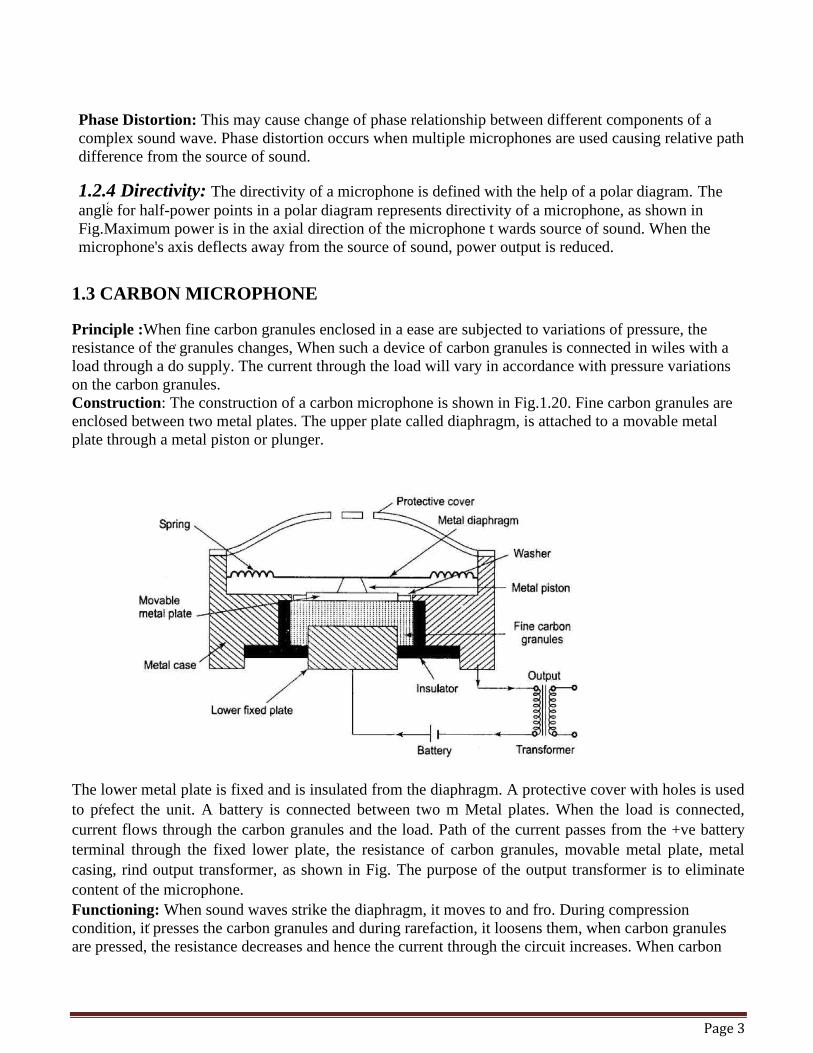
Construction: The construction of a carbon microphone is shown in Fig.1.20. Fine carbon granules are
enclosed between two metal plates. The upper plate called diaphragm, is attached to a movable metal
plate through a metal piston or plunger.
The lower metal plate is fixed and is insulated from the diaphragm. A protective cover with holes is used
to prefect the unit. A battery is connected between two m Metal plates. When the load is connected,
current flows through the carbon granules and the load. Path of the current passes from the +ve battery
terminal through the fixed lower plate, the resistance of carbon granules, movable metal plate, metal
casing, rind output transformer, as shown in Fig. The purpose of the output transformer is to eliminate
content of the microphone.
Functioning: When sound waves strike the diaphragm, it moves to and fro. During compression
condition, it presses the carbon granules and during rarefaction, it loosens them, when carbon granules
are pressed, the resistance decreases and hence the current through the circuit increases. When carbon
Page 4
granules loosen, the resistance increases, decreasing the current through the circuit. In the absence of
sound, a steady current flows. Thus, sound waves superimpose a varying current, or audio current on the
steady dc current.
The net resistance of the carbon granules is given by Eq. 1.4.
where,
r - Net resistance in ohms. -
R0 - Steady resistance in ohms for no sound
δr - Variation of resistance due to sound pressure (it will have positive as well as negative value)
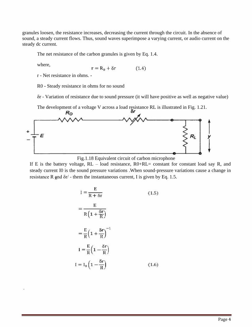
The development of a voltage V across a load resistance RL is illustrated in Fig. 1.21.
Fig.1.18 Equivalent circuit of carbon microphone
If E is the battery voltage, RL – load resistance, R0+RL= constant for constant load say R, and
steady current I0 is the sound pressure variations .When sound-pressure variations cause a change in
resistance R and δr/ - them the instantaneous current, I is given by Eq. 1.5.
Page 5
Equation (1.6), shows that the change in current, and hence the change in voltage across the load is
proportional to the change in resistance r) of the carbon granules, and hence proportional to the
pressure variations due to sound.
When pressure increases, δr decreases and so I increases and the output voltage across the load
increases,
1.3.1Characteristics of a Carbon Microphone
• The Sensitivity will be Very high.The output of a carbon microphone is about 20 dB below 1V
i.e., about 100 mV). Signal-to-noise Ratio Poor random variation of resistance of carbon granules
generates a continuous hiss.
• Frequency Response Carbon microphones have a frequency response of 200 to 5000 Hz, and
therefore are unsuitable for high fidelity work.The resonance peak is at 2000 Hz and overall
frequency bandwidth is usually tip to 5 kHz.
• Distortion is high. The content is rich in harmonics unless variation in resistance (δr) is a very
small percentage of steady resistance R. Distort ion is of the order of 10%. Also, carbon granules
have a tendency to stick to each other which further increases the distortion.
• Directivity of carbon microphone is substantially omnidirectional. However, high frequency
response over 300 Hz falls beyond an angle of 400 from the front of the microphone. Output
Impedance It is about 100Ω
• Other Features-It is mechanically very rigid.It is prone to moisture and heat. It is small in
dimensions. Cost of the microphone is the lowest of all other microphones.
• Advantages: Very rugged,Small size,Very cheap,Good sensitivity.
• Disadvantages: High distortion .Limited frequency response,Not suitable for high fidelity work.
• Applications: Due to limited frequency range, it is useful only in telephones. It is also sometimes
used in portable radio communication sets.
1.4 DYNAMIC (MOVING-COIL) MICROPHONE
1.4.1 Basics: • The moving-coil microphone (also called dynamic microphone) uses the principle of
electromagnetic induction.When sound pressure variations move a coil placed in a magnetic field, there is a change of magnetic flux passing through the coil.
• An emf is, therefore, induced in the coil and this emf forms output of the microphone, (Due to similarity in construction, a moving coil loudspeaker can also work as a moving-coil microphone. The same unit is often used both as microphone and loudspeaker in office intercom systems.
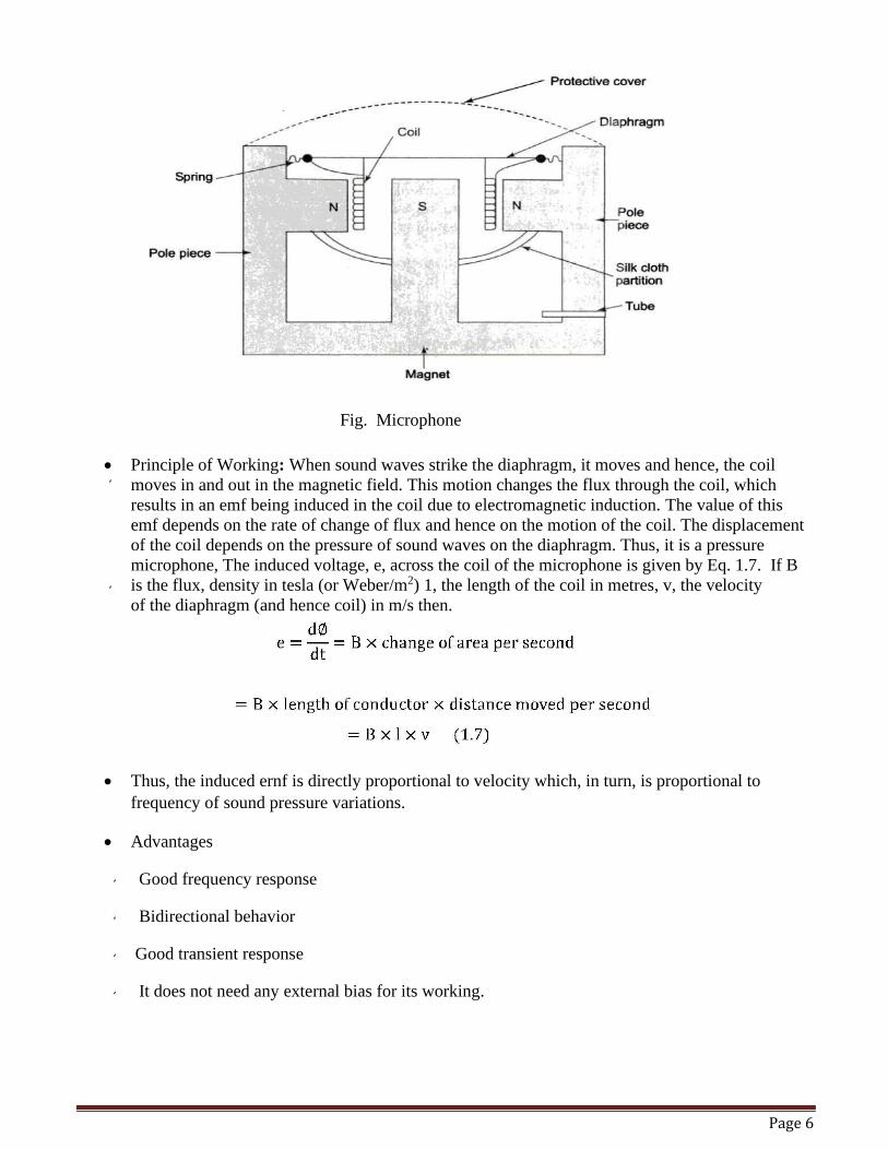
• Construction:The main components of a moving-coil microphone are a magnet, diaphragm and coil. These are shown in Fig. 1.19. The magnet is a permanent magnet of pot type with a central pole piece (south pole) and the peripheral pole piece (north pole). This type of magnet gives a uniform magnetic field in the gap between the pole pieces.The diaphragm is a thin circular sheet of non-magnetic material and is of' light weight. It is slightly domed for extra rigidity. It is fixed to the body of the magnet with the help of springs. The springs provide compliance (equivalent to electrical capacitance) to the motion of a diaphragm. The mass of the diaphragm and coil assembly provide inductive effect. A protective cover (a metal grill) is used to save the delicate diaphragm and coil assembly from being mishandled. A silk cloth partition is used to separate the upper chamber from the lower chamber. A small tube is used in the lower chamber to give access to the free atmosphere.
Page 6
Fig. Microphone
• Principle of Working: When sound waves strike the diaphragm, it moves and hence, the coil
moves in and out in the magnetic field. This motion changes the flux through the coil, which
results in an emf being induced in the coil due to electromagnetic induction. The value of this
emf depends on the rate of change of flux and hence on the motion of the coil. The displacement
of the coil depends on the pressure of sound waves on the diaphragm. Thus, it is a pressure
microphone, The induced voltage, e, across the coil of the microphone is given by Eq. 1.7. If B
is the flux, density in tesla (or Weber/m2) 1, the length of the coil in metres, v, the velocity
of the diaphragm (and hence coil) in m/s then.
• Thus, the induced ernf is directly proportional to velocity which, in turn, is proportional to
frequency of sound pressure variations.
• Advantages
Good frequency response
Bidirectional behavior
Good transient response
It does not need any external bias for its working.
Page 7
• Disadvantages
It is a delicate and expensive microphone
It can be easily damaged due to slight mishandling
Its sensitivity is low
• Applications
Dramas
Music
Radio broadcast
Public address system
1.5 Cordless MICROPHONE:
• The ultimate in mobility is afforded by the wireless (radio microphone) because with this there is
no connecting cable and the user is free to move around over distance of several hundred
meters.There are two basic types, one where the radio transmitter is contained within the casing
of the actual microphone, and the other which takes the form of a slim pocket unit about the size
of a wallet into which an ordinary microphone can be plugged.
• The integral microphone/transmitter unit, Fig. 1.21 is rather larger than a normal gun microphone
as batteries must be accommodated as well as the transducer and transmitter. In order to obtain
sufficient power for the transmitter, the batteries are at least 9V, but the size limits the capacity.
• Disadvantages-It is a delicate and expensive microphone,It can be easily damaged due to slight
mishandling, Its sensitivity is low.
• Applications- Drama, Music, Radio broadcast, Public address system.The average life is three to
five hours, but rechargeable batteries are often fitted to make the instrument more economic to
run. With the separate pocket transmitter a lavalier or tie-clip microphone can be used to give
complete freedom to the user. The aerial takes the rum] of a short flexible lead which trails from
the microphone. Usual length is a quainter wavelength at the permitted frequencies of the carrier
wave.There are fifteen frequencies allocated for wireless microphones and all units work on any
one of these interference is no problem because or the short range, it being unlikely that another
user will be operating on the same frequency within about half a kilometer. The frequencies are
in four groups: firstly group with a wide bandwidth, 174.1, 174.5, 174.8 and 175.0 MHz.The
second group is of narrow bandwidth, the frequencies being 174.6. 174.675,174.77,
174.885, and 175.020 MHz. The third group is also or narrows bandwidth, being reserved for
teaching deaf children in schools: these are 173.4, 173.465, 173.545 and 173.64 MHz.
• In addition, in certain circumstances, the frequencies of 174.6 and 174.95 MHz are allocated for
communication on work sites. Ali ordinary E-M receiver will not pick up wireless microphone
transmissions
Page 8
• The narrow bandwidth specification is for a deviation of +20 kHz and is suitable for most speech
applications.The wide bandwidth allocations Aim- a deviation of +75 kHz and give the better
quality reproduction required by stage and cabaret artists.The transmitter output power must not
exceed 50 mW in the case of narrow band transmitters and 10 mW with the wide band units.
• Certain specifications also apply to the receiver. Signal to noise ratio must be better than 30 dB
and selectivity such that a signal with a deviation of + 10 kHz, 70 kHz away from the wanted
signal in the case of narrow bard receiver, and with a deviation of +2.5 kHz, at 200 kHz away,
from the wanted signal in the case of wide band receiver will not produce an increase of noise
plus unwanted signal of more than 3 dB in the output. •
• An interfering signal of 3mV should not give a signal in the output greater than 10 dB above
noise level in the case of wideband receiver and 20 dB above with that of the narrow hand grit. •
• It is possible for any receiver to generate and radiate a signal from the local oscillator which is
part of the superheterodyne circuit universally used. The specification stipulates that cm) such
signal radiated from the receiver’s aerial should not exceed 2,5 µW at any frequency.
Unit 2: LOUDSPEAKERS
2.1 INTRODUCTION TO LOUDSPEAKER:
• A loudspeaker is a transducer which converts electrical signals of audio frequency into sound
waves of the same frequency. It is also called as output transducer or reverse transducer. A loud
speaker's performance is determined by the following characteristics:
2.2 CHARACTERISTICS • Efficiency: It is defined as the ratio of output sound power to the input audio (electrical power).
Its value depends on proper matching of the mechanical impedance with acoustical impedance of
the air volume being disturbed. (Some manufacturers quote the efficiency in terms of sensitivity
which is defined to be the input signal required to give a sound pressure level of 0.1 Pa or 1
microbar at a distance of 1 metre from the loudspeaker.)
• Noise: The unwanted sound, not contained in the input signal but present in the output of a
loudspeaker is called noise produced by the loudspeaker (the mechanical parts may vibrate at
some resonant frequency, causing noise).
• Signal-to-noise ratio or SNR of the system which is de- fined as ratio of signal output' to the
`output of noise in the absence of signal'.
• Frequency Response: It indicates the loudspeaker's response for the audible frequency range of
sound. Ideally, the response of a loudspeaker should be flat within ± 1 dB for the frequency range
of 16 Hz to 20 kHz. The mass of the diaphragm assembly have high frequencies which are
attenuated; and due to series compliance, low frequencies are attenuated. Moreover, the movable
system may have some natural resonant frequency within the audible range and the output at that
frequency will be emphasized.
Page 9
• Distortion: Any change in frequency, phase and amplitude complexion of the output sound as
compared to the input audio signal is called distortion. •
• Frequency and phase distortions may result due to mass and compliance effect. Amplitude or
non-linear distortion will result due to non-uniformity in the magnetic field in which the coil
moves.
• Directivity: It is the ratio of actual sound intensity at a point (in the direction of maximum
intensity) to the sound intensity that would have been available there, had the loudspeaker been
omnidirectional.
• Power : It is the maximum audio power (indicated in watts) for which it is designed. Power more
than the maximum will damage the speaker.
• Impedance : The input impedance of the loudspeaker is represented in ohms and is an important
parameter, as its matching with the impedance of source amplifier is necessary for the optimum
efficiency. Loudspeakers of more than 25 watts and up to a few hundred watts are of the
electrodynamic type.
• The strong and steady magnetic field is produced by a large field coil wrapped around a core.
The shape of the magnet is pot type with the south pole in the centre and the north pole in the
periphery. The special shape of the core allows magnetic flux to remain concentrated in the
annular gap between pole pieces.
• The voice coil is wound on fibre or aluminium (to keep it light in weight). It is placed in the
annular gap. The audio signal from the amplifier's output transformer is applied to the voice coil.
This signal causes a varying magnetic field.The resultant interaction between the magnetic fields
(one due to electromagnet and the other due to audio current in the voice coil) produces
mechanical vibrations (motor action) in the coil assembly , which correspond to the audio signals.
The vibrations of the coil are transmitted to the attached cone which create sound waves in the air
in the listeners' area, and hence radiate sound energy directly.
• Advantages:Higher power can be obtained Frequency response is better (40 Hz to 5000 Hz)
• Disadvantages-Power supply needed for field coil Heavier weight for the same amount of magnetic field •
Page 10
2.3WOOFERS
• There are two types of low-frequency speaker, the commonly known woofer, and the more recent
addition the sub roofer.
• The latter is used for the reproduction of frequencies below those produced by the woofer, and it
is generally purchased as an odd on to an existing system,
• The low-frequency speaker provides the bass of any hi-fi system.
• Its sole purpose is to reproduce the low-frequency notes of the program source.
• The prime requisite for low-frequency reproduction is a large diaphragm, the larger the better.
• The smallest diaphragm for any halfway decent woofer is 8 inches; for a subwoofer it is 12
inches. • • In addition to large size, the diaphragm must be of fairly heavy construction. Light diaphragms
just can’t hold up under the vibrations encountered under the lower audio ranges.
• A woofer must be able to vibrate back and forth very easily. (i.e.) have high compliance.
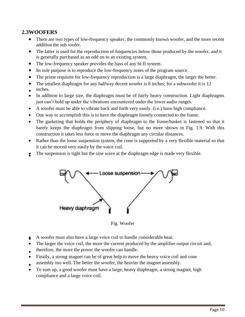
• One way to accomplish this is to have the diaphragm loosely connected to the frame.
• The gasketing that holds the periphery of diaphragm to the frame/basket is fastened so that it
barely keeps the diaphragm from slipping loose, but no more shown in Fig. 1.9. With this
construction it takes less force to move the diaphragm any circular distances.
• Rather than the loose suspension system, the cone is supported by a very flexible material so that
it can be moved very easily by the voice coil.
• The suspension is tight but the sine wave at the diaphragm edge is made very flexible. •
Fig. Woofer
• A woofer must also have a large voice coil to handle considerable heat. • • The larger the voice coil, the more the current produced by the amplifier output circuit and,
therefore, the more the power the woofer can handle. • • Finally, a strong magnet can be of great help to move the heavy voice coil and cone
assembly too well. The better the woofer, the heavier the magnet assembly. • • To sum up, a good woofer must have a large, heavy diaphragm, a strong magnet, high
compliance and a large voice coil.
Page 11
2.4 TWEETERS • • There are two main types of high frequency speakers; the well-known sweeter and the more
recent supertweeter. Supertweeters can be add-ons or they can be integral with the system.Six basic high-frequency speakers (tweeter) exists.
• The cone is a physically disincentive version of the woofer. The dome, so called because of its dome-shaped diaphragm.The horn, so named because it is a horn.The Heil air-motion transformer which uses the principle of lever in its operation, named aid r its inventor, Dr. Oskar Heil.
• High polymer molecular film tweeter, uses the piezoelectric effect for its principle of operation (used exclusively by Pioneer).
• The electrostatic tweeter works on the principle of attraction or repulsion between two metal plates.
2.4.1 CONE TYPE TWEETERS • Since tweeters must reproduce high-frequency notes, they roust resonate at high frequencies.
• High resonant frequencies are obtained with light weight, stiffly supported mechanisms.
• To make the diaphragm of a con type tweeter light, it must be small.
• When the size and weight is reduced the diaphragm in turn, reduce the size of the ice coil also.
• Luckily, high frequencies card only a comparatively small amount of electric power, therefore,
the small voice coil is not subjected to electrical overload.
• Without exception, it is wound with light weight wire such as aluminium wire or ribbon.
• The lightness of the moving system provided by aluminium makes the high frequency response
much better than if copper were used.
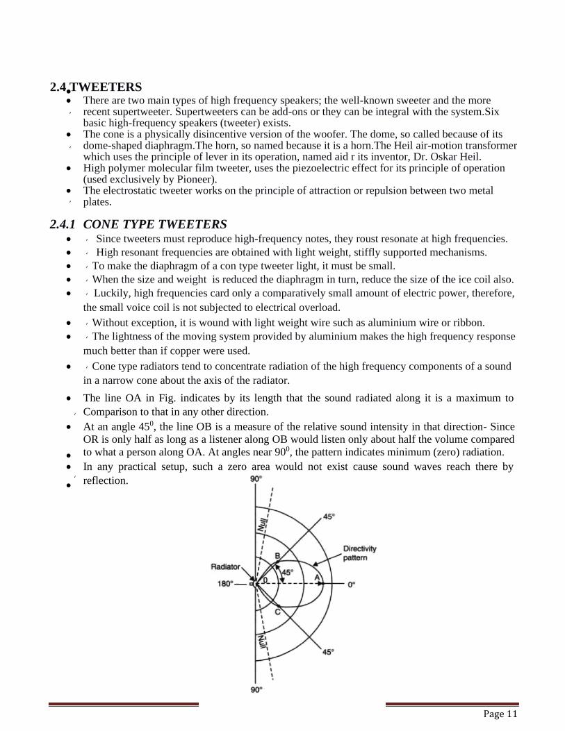
• Cone type radiators tend to concentrate radiation of the high frequency components of a sound
in a narrow cone about the axis of the radiator.
• The line OA in Fig. indicates by its length that the sound radiated along it is a maximum to
Comparison to that in any other direction.
• At an angle 450, the line OB is a measure of the relative sound intensity in that direction- Since
OR is only half as long as a listener along OB would listen only about half the volume compared
to what a person along OA. At angles near 900, the pattern indicates minimum (zero) radiation. • • In any practical setup, such a zero area would not exist cause sound waves reach there by
reflection. •
Page 12
Multiple choice questions.
(i) Magnetic tape constructed by using _____material.
(ii) 1-The ripple frequency of the output wave form of bridge rectifier with a 60 Hz sine
wave is
(A) 100 Hz
(B) 120 Hz
(C) 30 Hz
(D) 60 Hz
(iii) 2-One kwh is equal to
(A) 860 kcal
(B) 800 kcal
(C) 746 kcal
(D) 736 kcal
(iv) 3-A 100W bulb, a 40W fluorescent lamp and a 60W fan in a room operates for an
average duration of 5 hours in a day. What will be the total energy consumed during the
month of June 2017?
(A) 3 kwh
(B) 30 kwh
(C) 300 kwh
(D) 3000 kwh
(v) 4-An alternating current is represented by I=141sin314t. What is the rms value of this
current?
(A) 314 A
(B) 141 A
(C) 100 A
(D) 70.5 A
(vi) 5-Which of the following is not a possible cause for optical fiber lose?
(A) Impurities
(B) Attenuation in glass
(C) Stepped index operation
(D) Micro-bending
Page 13
(vii) 6-Thermocouple works on the principle of
(A) Seebeck effect
(B) Piezoelectric effect
(C) Photo voltaic effect
D) Faraday effect
(viii) Value of E.H.T in monochrome T.V. is___.
(ix) Horizontal trace time of a scanning line is ___.
(x) Which type of microphones used in telephones
Short questions and answers:
(i)Write a short note on Baffles & enclosures.
(ii) Draw & explain in brief the frequency response of direct radiation loudspeaker.
(iii) Show how a moving coil microphone works ?
(iv) Differentiate between Monophony & stereo phony.
(v) What is flicker, how it is removed ?
(vi) What is need of synchronizing and blanking pulses.
(vii) Write main feature of plumbicon camera tube
(viii) What are different advantage of negative modulation ?
(ix) List some important faults and their remedies in monochrome T.V.
(x) Explain in brief grass men’s law.
(xi) What is need of colour different signal.
(xii) What is function of color killer circuit.
(xiii) Define Purity, how it is achieved in colour T.V.
(xiv) Write main features of CATV
(xv) What are main features of V.H.S
Long questions and answers:
(i)Explain how sound recording is performed on magnetic tube.
(ii) Explain the construction and working monochrome picture tube.
(iii) Draw block diagram of PAL receiver , explain its different tubes.
(iv) Which type of mixing is used in colour T.V. and why ?
(v) Write short note on :
(a) RAMNET
(b) DTH
•