atex – flameproof motors - by cantoni group
TRANSCRIPT
P O W E R O F E X P E R I E N C E T O P Q U A L I T Y I N D I V I D U A L P R O F
P R O F E S S I O N A L A P P R O A C H M O R E E N E R G Y T O P Q U A L I T Y
D R I V I N G P R O F E S S I O N A L S E R V I C E I D E A T U R N E D I N T O
I N T O Y O U R E N E R G Y G L O B A L P R E S E N C E C O N T I N U O U S
E N E R G Y B U S I N E S S G L O B A L D E V E L O P S O L I D P A R T N E R N G
C H A L L E N G I N G P R O J E C T S M O S T D E M A N D I N G A P P L I C A T I O S
M O R E E N E R G Y E F F I C I E N T
S O L I D P A R T N E R P O W E R O F
E X P E R I E N C E T O P Q U A L I T Y I N D I V I D U A L A P P R O A C H P R O F E S
EXPLOSION PROTECTED3-PHASE INDUCTION MOTORS
Prod
uct
Cata
logu
e
ATEX – FLAMEPROOF MOTORS
According to the ATEX Directive According to the ATEX Directive 2014/34/EU and new EU minimum 2014/34/EU and new EU minimum efficiency regulation efficiency regulation 2019/1781 & 2021/341 2019/1781 & 2021/341
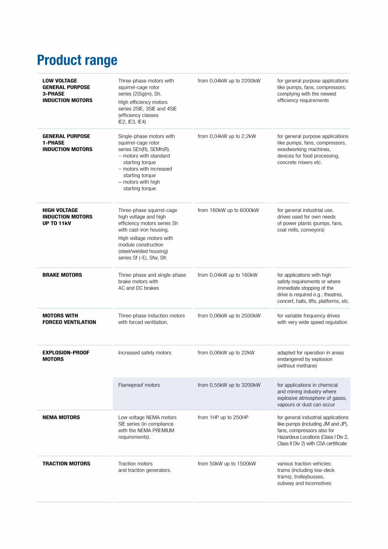
LOW VOLTAGE GENERAL PURPOSE 3-PHASE INDUCTION MOTORS
Three-phase motors with squirrel-cage rotor series (2)Sg(m), Sh.
High efficiency motorsseries 2SIE, 3SIE and 4SIE(efficiency classesIE2, IE3, IE4)
from 0,04kW up to 2200kW for general purpose applications like pumps, fans, compressors; complying with the newest efficiency requirements
GENERAL PURPOSE 1-PHASE INDUCTION MOTORS
Single-phase motors withsquirrel-cage rotorseries SEh(R), SEMh(R).– motors with standard
starting torque– motors with increased
starting torque– motors with high
starting torque.
from 0,04kW up to 2,2kW for general purpose applications like pumps, fans, compressors, woodworking machines, devices for food processing, concrete mixers etc.
HIGH VOLTAGE INDUCTION MOTORS UP TO 11kV
Three-phase squirrel-cagehigh voltage and high efficiency motors series Sh with cast-iron housing.
High voltage motors withmodule construction(steel/welded housing)series Sf (-E), Sfw, Sfr.
from 160kW up to 6000kW for general industrial use, drives used for own needs of power plants (pumps, fans, coal mills, conveyors)
BRAKE MOTORS Three-phase and single-phasebrake motors withAC and DC brakes
from 0,04kW up to 160kW for applications with high safety requirements or where immediate stopping of the drive is required e.g.: theatres, concert, halls, lifts, platforms, etc.
MOTORS WITH FORCED VENTILATION
Three-phase induction motorswith forced ventilation.
from 0,06kW up to 2500kW for variable frequency drives with very wide speed regulation
EXPLOSION-PROOFMOTORS
Increased safety motors from 0,06kW up to 22kW adapted for operation in areas endangered by explosion (without methane)
Flameproof motors from 0,55kW up to 3200kW for applications in chemical and mining industry where explosive atmosphere of gases, vapours or dust can occur
NEMA MOTORS Low voltage NEMA motorsSIE series (in compliance with the NEMA PREMIUMrequirements).
from 1HP up to 250HP for general industrial applications like pumps (including JM and JP), fans, compressors also for Hazardous Locations (Class I Div 2, Class II Div 2) with CSA certificate
TRACTION MOTORS Traction motorsand traction generators.
from 50kW up to 1500kW various traction vehicles:trams (including low-deck trams), trolleybusses,subway and locomotives
Product range
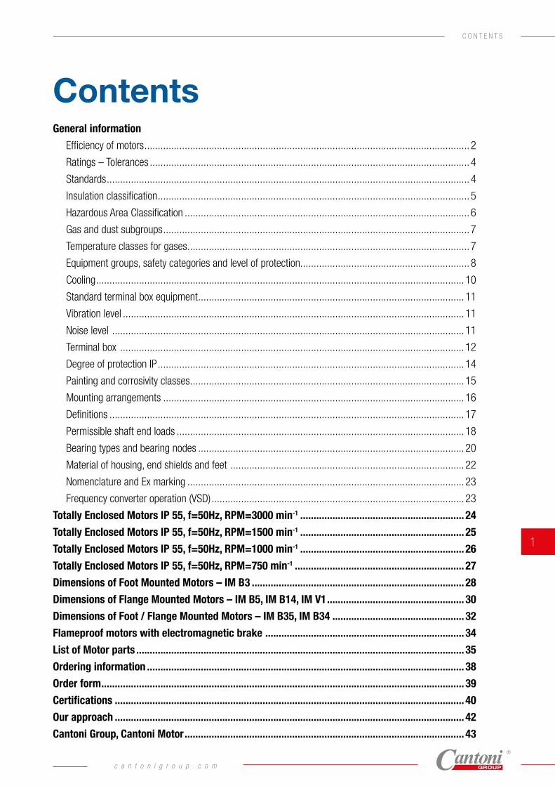
Contents
C O N T E N T S
General information
Efficiency of motors ......................................................................................................................... 2
Ratings – Tolerances ....................................................................................................................... 4
Standards ....................................................................................................................................... 4
Insulation classification .................................................................................................................... 5
Hazardous Area Classification .......................................................................................................... 6
Gas and dust subgroups .................................................................................................................. 7
Temperature classes for gases ......................................................................................................... 7
Equipment groups, safety categories and level of protection............................................................... 8
Cooling ......................................................................................................................................... 10
Standard terminal box equipment ................................................................................................... 11
Vibration level ............................................................................................................................... 11
Noise level ................................................................................................................................... 11
Terminal box ................................................................................................................................ 12
Degree of protection IP .................................................................................................................. 14
Painting and corrosivity classes ...................................................................................................... 15
Mounting arrangements ................................................................................................................ 16
Definitions .................................................................................................................................... 17
Permissible shaft end loads ........................................................................................................... 18
Bearing types and bearing nodes ................................................................................................... 20
Material of housing, end shields and feet ....................................................................................... 22
Nomenclature and Ex marking ....................................................................................................... 23
Frequency converter operation (VSD) .............................................................................................. 23
Totally Enclosed Motors IP 55, f=50Hz, RPM=3000 min-1 ............................................................. 24
Totally Enclosed Motors IP 55, f=50Hz, RPM=1500 min-1 ............................................................. 25
Totally Enclosed Motors IP 55, f=50Hz, RPM=1000 min-1 ............................................................. 26
Totally Enclosed Motors IP 55, f=50Hz, RPM=750 min-1 ............................................................... 27
Dimensions of Foot Mounted Motors – IM B3 ............................................................................... 28
Dimensions of Flange Mounted Motors – IM B5, IM B14, IM V1 ................................................... 30
Dimensions of Foot / Flange Mounted Motors – IM B35, IM B34 ................................................. 32
Flameproof motors with electromagnetic brake .......................................................................... 34
List of Motor parts .......................................................................................................................... 35
Ordering information ...................................................................................................................... 38
Order form ....................................................................................................................................... 39
Certifications .................................................................................................................................. 40
Our approach .................................................................................................................................. 42
Cantoni Group, Cantoni Motor ........................................................................................................ 43
c a n t o n i g r o u p . c o m
1
New efficiency classes for the low-voltage three-phase motors (IE = International Efficiency).
Along with the international discussion on energy efficiency a worldwide harmonized energy efficiency standard classification system has been established for low-voltage three-phase asynchronous motors. For many years low-voltage three-phase motors in the European Union have been sold in three efficiency classes EFF3, EFF2 and EFF1 (CEMEP classification). Aside from this, many different efficiency classification systems have been introduced and well-proven in many countries all over the world.
This was the reason for the International Electrotechnical Commission IEC to develop and publish an energy efficiency standard which replaces all previous national issues. In parallel IEC developed and issued a new standard for determining motor efficiency. The new standard IEC 60034-30-1 defines and harmonizes worldwide the efficiency classes IE1, IE2, IE3 and IE4 for low-voltage three-phase motors in the power range from 0,12 kW to 1000 kW (2p=2, 4, 6, 8).
IE1 = Standard Efficiency
IE2 = High Efficiency
IE3 = Premium Efficiency
IE4 = Super Premium Efficiency
Complying with IEC 60034-30-1 standard the efficiency has to be determined in accordance with the new requirements given in the IEC 60034-2-1 standard.
Efficiency of motors
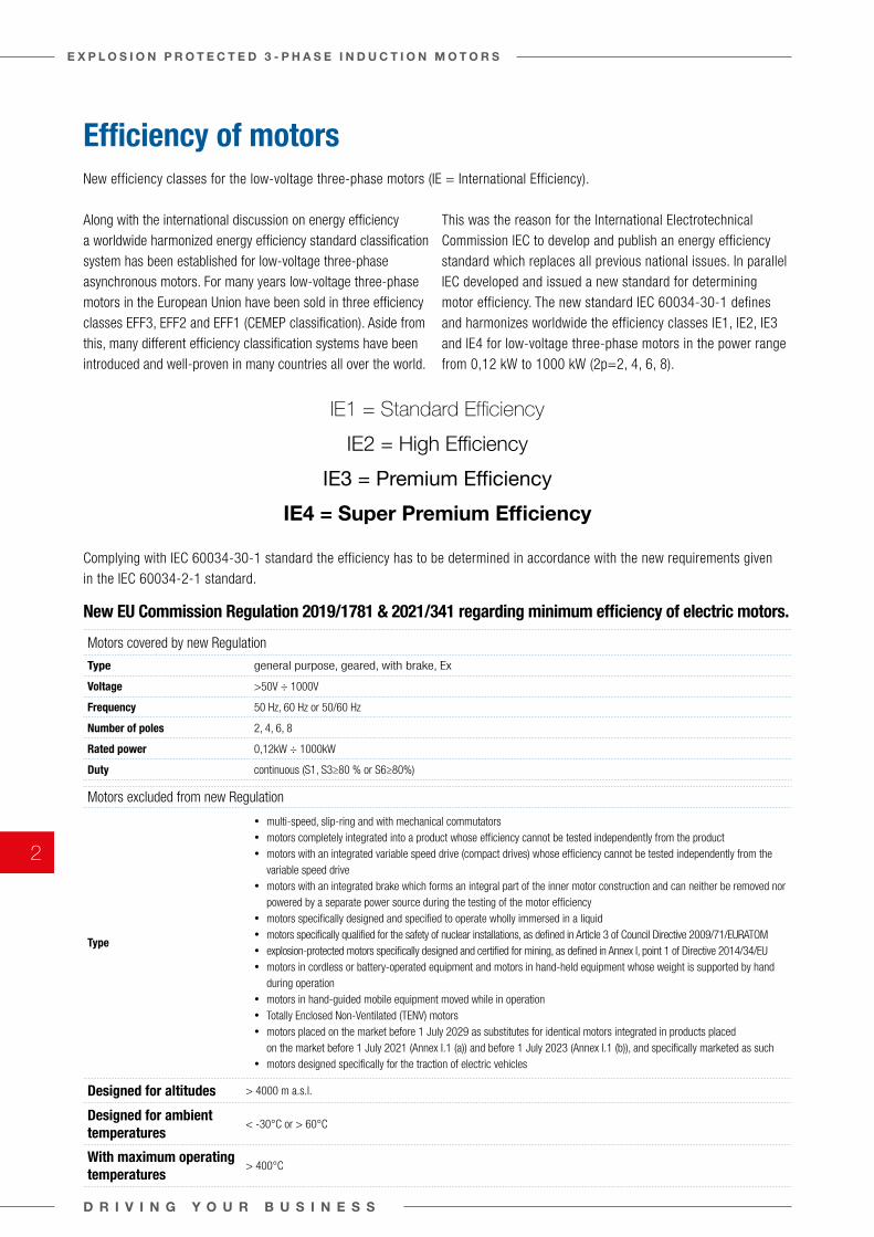
New EU Commission Regulation 2019/1781 & 2021/341 regarding minimum efficiency of electric motors.
Motors covered by new Regulation
Type general purpose, geared, with brake, Ex
Voltage >50V ÷ 1000V
Frequency 50 Hz, 60 Hz or 50/60 Hz
Number of poles 2, 4, 6, 8
Rated power 0,12kW ÷ 1000kW
Duty continuous (S1, S3≥80 % or S6≥80%)
Motors excluded from new Regulation
Type
• multi-speed, slip-ring and with mechanical commutators• motors completely integrated into a product whose efficiency cannot be tested independently from the product• motors with an integrated variable speed drive (compact drives) whose efficiency cannot be tested independently from the
variable speed drive• motors with an integrated brake which forms an integral part of the inner motor construction and can neither be removed nor
powered by a separate power source during the testing of the motor efficiency• motors specifically designed and specified to operate wholly immersed in a liquid• motors specifically qualified for the safety of nuclear installations, as defined in Article 3 of Council Directive 2009/71/EURATOM• explosion-protected motors specifically designed and certified for mining, as defined in Annex I, point 1 of Directive 2014/34/EU• motors in cordless or battery-operated equipment and motors in hand-held equipment whose weight is supported by hand
during operation• motors in hand-guided mobile equipment moved while in operation• Totally Enclosed Non-Ventilated (TENV) motors• motors placed on the market before 1 July 2029 as substitutes for identical motors integrated in products placed
on the market before 1 July 2021 (Annex I.1 (a)) and before 1 July 2023 (Annex I.1 (b)), and specifically marketed as such• motors designed specifically for the traction of electric vehicles
Designed for altitudes > 4000 m a.s.l.
Designed for ambient temperatures
< -30°C or > 60°C
With maximum operating temperatures
> 400°C
D R I V I N G Y O U R B U S I N E S S
E X P L O S I O N P R O T E C T E D 3 - P H A S E I N D U C T I O N M O T O R S
2
G E N E R A L I N F O R M A T I O N
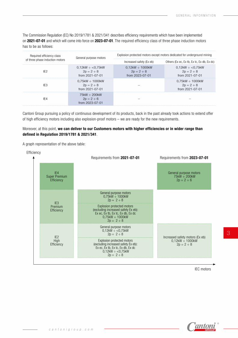
Cantoni Group pursuing a policy of continuous development of its products, back in the past already took actions to extend offer of high efficiency motors including also explosion-proof motors – we are ready for the new requirements.
Moreover, at this point, we can deliver to our Customers motors with higher efficiencies or in wider range than defined in Regulation 2019/1781 & 2021/341.
A graph representation of the above table:
The Commission Regulation (EC) No 2019/1781 & 2021/341 describes efficiency requirements which have been implemented on 2021-07-01 and which will come into force on 2023-07-01. The required efficiency class of three phase induction motors has to be as follows:
Required efficiency class of three phase induction motors
General purpose motorsExplosion protected motors except motors dedicated for underground mining
Increased safety (Ex eb) Others (Ex ec, Ex tb, Ex tc, Ex db, Ex dc)
IE20,12kW ÷ <0,75kW
2p = 2 ÷ 8from 2021-07-01
0,12kW ÷ 1000kW2p = 2 ÷ 8
from 2023-07-01
0,12kW ÷ <0,75kW2p = 2 ÷ 8
from 2021-07-01
IE30,75kW ÷ 1000kW
2p = 2 ÷ 8from 2021-07-01
–0,75kW ÷ 1000kW
2p = 2 ÷ 8from 2021-07-01
IE475kW ÷ 200kW
2p = 2 ÷ 6from 2023-07-01
– –
Efficiency
IEC motors
Requirements from 2021-07-01 Requirements from 2023-07-01
IE2High
EfficiencyExplosion protected motors
(excluding increased safety Ex eb):Ex ec, Ex tb, Ex tc, Ex db, Ex dc
0,12kW ÷ <0,75kW2p = 2 ÷ 8
General purpose motors0,12kW ÷ <0,75kW
2p = 2 ÷ 8Increased safety motors (Ex eb)
0,12kW ÷ 1000kW2p = 2 ÷ 8
IE3 Premium Efficiency
Explosion protected motors (excluding increased safety Ex eb):
Ex ec, Ex tb, Ex tc, Ex db, Ex dc0,75kW ÷ 1000kW
2p = 2 ÷ 8
General purpose motors 0,75kW ÷ 1000kW
2p = 2 ÷ 8
IE4 Super Premium
Efficiency
General purpose motors 75kW ÷ 200kW
2p = 2 ÷ 6
c a n t o n i g r o u p . c o m
3
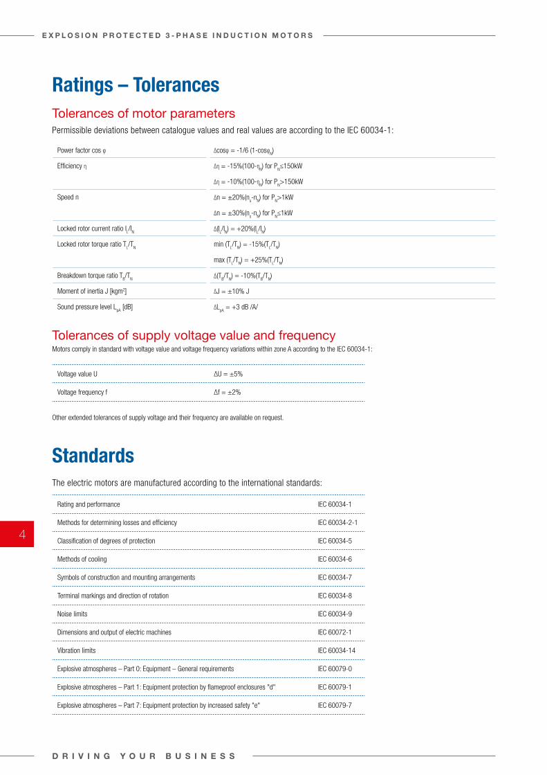
Ratings – Tolerances
Standards
Tolerances of motor parameters Permissible deviations between catalogue values and real values are according to the IEC 60034-1:
Power factor cos φ ∆cosφ = -1/6 (1-cosφN)
Efficiency η ∆η = -15%(100-ηN) for P
N≤150kW
∆η = -10%(100-ηN) for P
N>150kW
Speed n ∆n = ±20%(ns-n
N) for P
N>1kW
∆n = ±30%(ns-n
N) for P
N≤1kW
Locked rotor current ratio IL/I
N ∆(I
L/I
N) = +20%(I
L/I
N)
Locked rotor torque ratio TL/T
N min (T
L/T
N) = -15%(T
L/T
N)
max (TL/T
N) = +25%(T
L/T
N)
Breakdown torque ratio TB/T
N ∆(T
B/T
N) = -10%(T
B/T
N)
Moment of inertia J [kgm2] ∆J = ±10% J
Sound pressure level LpA
[dB] ∆LpA
= +3 dB /A/
The electric motors are manufactured according to the international standards:
Rating and performance IEC 60034-1
Methods for determining losses and efficiency IEC 60034-2-1
Classification of degrees of protection IEC 60034-5
Methods of cooling IEC 60034-6
Symbols of construction and mounting arrangements IEC 60034-7
Terminal markings and direction of rotation IEC 60034-8
Noise limits IEC 60034-9
Dimensions and output of electric machines IEC 60072-1
Vibration limits IEC 60034-14
Explosive atmospheres – Part 0: Equipment – General requirements IEC 60079-0
Explosive atmospheres – Part 1: Equipment protection by flameproof enclosures "d" IEC 60079-1
Explosive atmospheres – Part 7: Equipment protection by increased safety "e" IEC 60079-7
Tolerances of supply voltage value and frequencyMotors comply in standard with voltage value and voltage frequency variations within zone A according to the IEC 60034-1:
Voltage value U ∆U = ±5%
Voltage frequency f ∆f = ±2%
Other extended tolerances of supply voltage and their frequency are available on request.
D R I V I N G Y O U R B U S I N E S S
E X P L O S I O N P R O T E C T E D 3 - P H A S E I N D U C T I O N M O T O R S
4
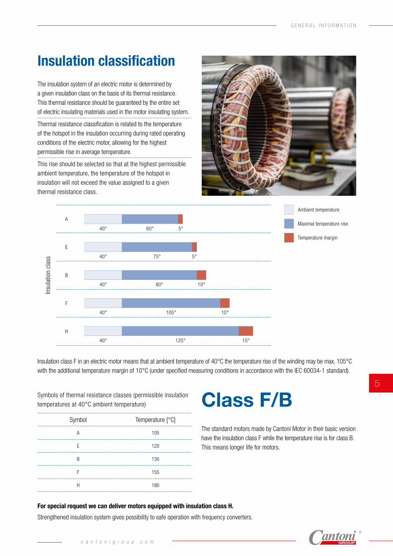
Insulation classificationThe insulation system of an electric motor is determined by a given insulation class on the basis of its thermal resistance.This thermal resistance should be guaranteed by the entire set of electric insulating materials used in the motor insulating system.
Thermal resistance classification is related to the temperature of the hotspot in the insulation occurring during rated operating conditions of the electric motor, allowing for the highest permissible rise in average temperature.
This rise should be selected so that at the highest permissible ambient temperature, the temperature of the hotspot in insulation will not exceed the value assigned to a given thermal resistance class.
The standard motors made by Cantoni Motor in their basic version have the insulation class F while the temperature rise is for class B.This means longer life for motors.
For special request we can deliver motors equipped with insulation class H.
Strengthened insulation system gives possibility to safe operation with frequency converters.
Insulation class F in an electric motor means that at ambient temperature of 40°C the temperature rise of the winding may be max. 105°C with the additional temperature margin of 10°C (under specified measuring conditions in accordance with the IEC 60034-1 standard).
Symbols of thermal resistance classes (permissible insulation temperatures at 40°C ambient temperature)
Symbol Temperature [°C]
A 105
E 120
B 130
F 155
H 180
Class F/B
Ambient temperature
Insu
latio
n cl
ass
A
E
B
F
H
40° 5°
5°
10°
10°
15°
60°
40° 75°
40° 80°
40° 105°
40° 125°
Maximal temperature rise
Temperature margin
c a n t o n i g r o u p . c o m
5
G E N E R A L I N F O R M A T I O N
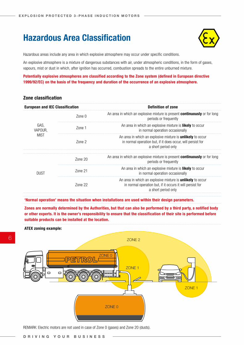
Hazardous Area Classification
Hazardous areas include any area in which explosive atmosphere may occur under specific conditions.
An explosive atmosphere is a mixture of dangerous substances with air, under atmospheric conditions, in the form of gases, vapours, mist or dust in which, after ignition has occurred, combustion spreads to the entire unburned mixture.
Potentially explosive atmospheres are classified according to the Zone system (defined in European directive 1999/92/EC) on the basis of the frequency and duration of the occurrence of an explosive atmosphere.
Zone classification
European and IEC Classification Definition of zone
GAS, VAPOUR,
MIST
Zone 0An area in which an explosive mixture is present continuously or for long
periods or frequently
Zone 1An area in which an explosive mixture is likely to occur
in normal operation occasionally
Zone 2An area in which an explosive mixture is unlikely to occur
in normal operation but, if it does occur, will persist for a short period only
DUST
Zone 20An area in which an explosive mixture is present continuously or for long
periods or frequently
Zone 21An area in which an explosive mixture is likely to occur
in normal operation occasionally
Zone 22An area in which an explosive mixture is unlikely to occur
in normal operation but, if it occurs it will persist for a short period only
‘Normal operation’ means the situation when installations are used within their design parameters.
Zones are normally determined by the Authorities, but that can also be performed by a third party, a notified body or other experts. It is the owner’s responsibility to ensure that the classification of their site is performed before suitable products can be installed at the location.
ATEX zoning example:
REMARK: Electric motors are not used in case of Zone 0 (gases) and Zone 20 (dusts).
D R I V I N G Y O U R B U S I N E S S
E X P L O S I O N P R O T E C T E D 3 - P H A S E I N D U C T I O N M O T O R S
6
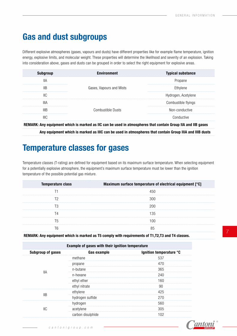
Temperature classes for gases
Temperature classes (T-rating) are defined for equipment based on its maximum surface temperature. When selecting equipment for a potentially explosive atmosphere, the equipment’s maximum surface temperature must be lower than the ignition temperature of the possible potential gas mixture.
Temperature class Maximum surface temperature of electrical equipment [°C]
T1 450
T2 300
T3 200
T4 135
T5 100
T6 85
REMARK: Any equipment which is marked as T5 comply with requirements of T1,T2,T3 and T4 classes.
Example of gases with their ignition temperature
Subgroup of gases Gas example Ignition temperature °C
IIA
methane 537
propane 470
n-butane 365
n-hexane 240
ethyl ether 160
ethyl nitrate 90
IIBethylene 425
hydrogen sulfide 270
IIC
hydrogen 560
acetylene 305
carbon disulphide 102
Gas and dust subgroups
Different explosive atmospheres (gases, vapours and dusts) have different properties like for example flame temperature, ignition energy, explosive limits, and molecular weight. These properties will determine the likelihood and severity of an explosion. Taking into consideration above, gases and dusts can be grouped in order to select the right equipment for explosive areas.
Subgroup Environment Typical substance
IIA
Gases, Vapours and Mists
Propane
IIB Ethylene
IIC Hydrogen, Acetylene
IIIA
Combustible Dusts
Combustible flyings
IIIB Non-conductive
IIIC Conductive
REMARK: Any equipment which is marked as IIC can be used in atmospheres that contain Group IIA and IIB gases
Any equipment which is marked as IIIC can be used in atmospheres that contain Group IIIA and IIIB dusts
G E N E R A L I N F O R M A T I O N
c a n t o n i g r o u p . c o m
7
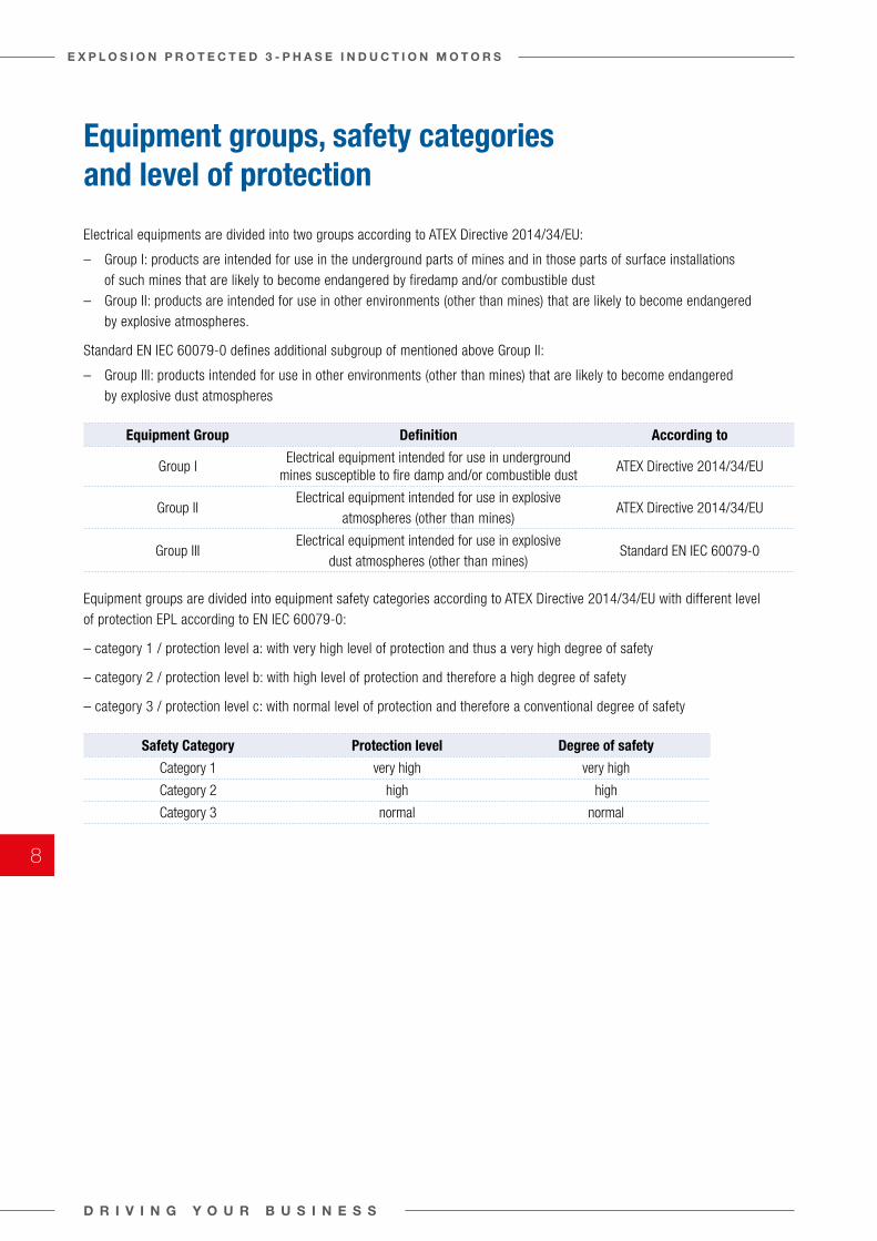
Equipment groups, safety categories and level of protection
Electrical equipments are divided into two groups according to ATEX Directive 2014/34/EU:
– Group I: products are intended for use in the underground parts of mines and in those parts of surface installations of such mines that are likely to become endangered by firedamp and/or combustible dust
– Group II: products are intended for use in other environments (other than mines) that are likely to become endangered by explosive atmospheres.
Standard EN IEC 60079-0 defines additional subgroup of mentioned above Group II:
– Group III: products intended for use in other environments (other than mines) that are likely to become endangered by explosive dust atmospheres
Equipment Group Definition According to
Group IElectrical equipment intended for use in underground
mines susceptible to fire damp and/or combustible dustATEX Directive 2014/34/EU
Group IIElectrical equipment intended for use in explosive
atmospheres (other than mines)ATEX Directive 2014/34/EU
Group III Electrical equipment intended for use in explosive
dust atmospheres (other than mines)Standard EN IEC 60079-0
Equipment groups are divided into equipment safety categories according to ATEX Directive 2014/34/EU with different level of protection EPL according to EN IEC 60079-0:
– category 1 / protection level a: with very high level of protection and thus a very high degree of safety
– category 2 / protection level b: with high level of protection and therefore a high degree of safety
– category 3 / protection level c: with normal level of protection and therefore a conventional degree of safety
Safety Category Protection level Degree of safety
Category 1 very high very high
Category 2 high high
Category 3 normal normal
D R I V I N G Y O U R B U S I N E S S
E X P L O S I O N P R O T E C T E D 3 - P H A S E I N D U C T I O N M O T O R S
8
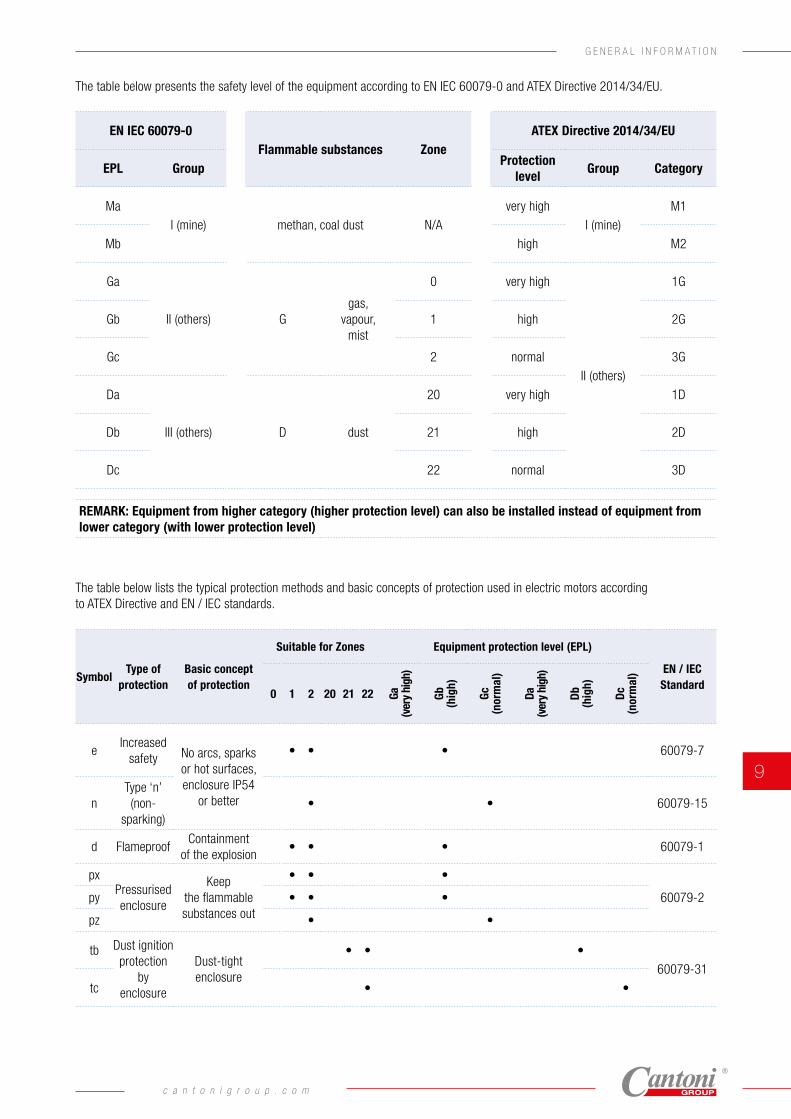
EN IEC 60079-0Flammable substances Zone
ATEX Directive 2014/34/EU
EPL GroupProtection
levelGroup Category
Ma
I (mine) methan, coal dust N/A
very high
I (mine)
M1
Mb high M2
Ga
II (others) Ggas,
vapour, mist
0 very high
II (others)
1G
Gb 1 high 2G
Gc 2 normal 3G
Da
III (others) D dust
20 very high 1D
Db 21 high 2D
Dc 22 normal 3D
REMARK: Equipment from higher category (higher protection level) can also be installed instead of equipment from lower category (with lower protection level)
The table below lists the typical protection methods and basic concepts of protection used in electric motors according to ATEX Directive and EN / IEC standards.
SymbolType of
protectionBasic concept of protection
Suitable for Zones Equipment protection level (EPL)
EN / IEC Standard
0 1 2 20 21 22 Ga
(ver
y hi
gh)
Gb
(hig
h)
Gc
(nor
mal
)
Da
(ver
y hi
gh)
Db
(hig
h)
Dc
(nor
mal
)
eIncreased
safety No arcs, sparks or hot surfaces, enclosure IP54
or better
• • • 60079-7
nType ‘n’ (non-
sparking)• • 60079-15
d FlameproofContainment
of the explosion• • • 60079-1
pxPressurised enclosure
Keep the flammable substances out
• • •
60079-2py • • •
pz • •
tb Dust ignition protection
by enclosure
Dust-tight enclosure
• • •
60079-31
tc • •
The table below presents the safety level of the equipment according to EN IEC 60079-0 and ATEX Directive 2014/34/EU.
c a n t o n i g r o u p . c o m
9
G E N E R A L I N F O R M A T I O N
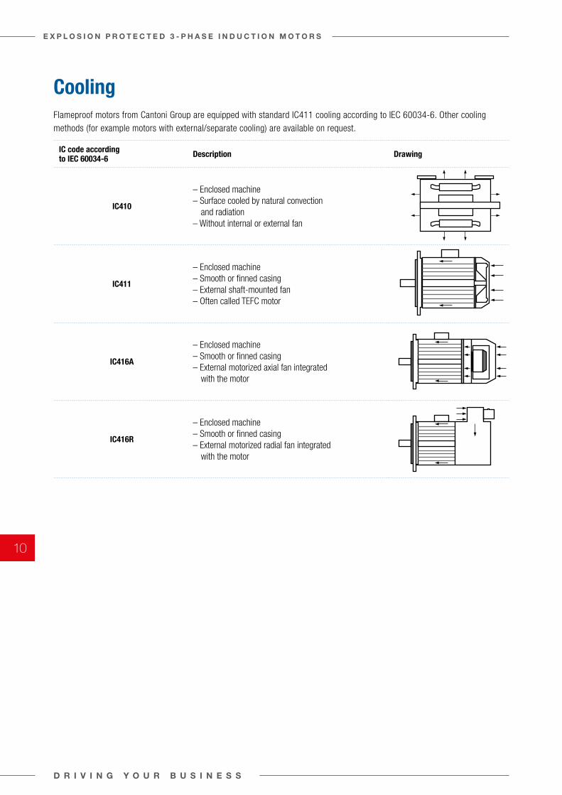
CoolingFlameproof motors from Cantoni Group are equipped with standard IC411 cooling according to IEC 60034-6. Other cooling methods (for example motors with external/separate cooling) are available on request.
IC code according to IEC 60034-6 Description Drawing
IC410
– Enclosed machine– Surface cooled by natural convection
and radiation– Without internal or external fan
IC411
– Enclosed machine– Smooth or finned casing– External shaft-mounted fan– Often called TEFC motor
IC416A
– Enclosed machine– Smooth or finned casing– External motorized axial fan integrated
with the motor
IC416R
– Enclosed machine– Smooth or finned casing– External motorized radial fan integrated
with the motor
D R I V I N G Y O U R B U S I N E S S
E X P L O S I O N P R O T E C T E D 3 - P H A S E I N D U C T I O N M O T O R S
10
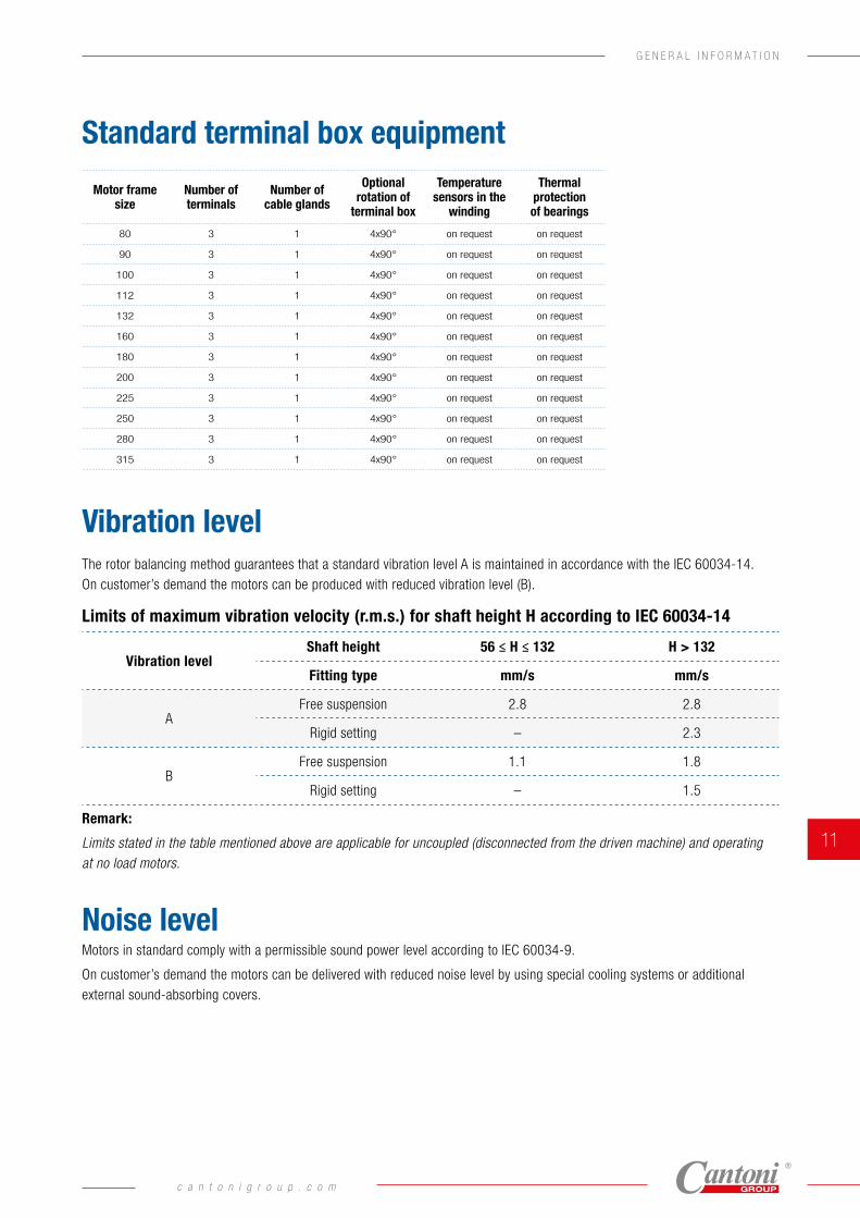
Vibration levelThe rotor balancing method guarantees that a standard vibration level A is maintained in accordance with the IEC 60034-14.On customer’s demand the motors can be produced with reduced vibration level (B).
Limits of maximum vibration velocity (r.m.s.) for shaft height H according to IEC 60034-14
Vibration levelShaft height 56 ≤ H ≤ 132 H > 132
Fitting type mm/s mm/s
AFree suspension 2.8 2.8
Rigid setting – 2.3
BFree suspension 1.1 1.8
Rigid setting – 1.5
Remark:
Limits stated in the table mentioned above are applicable for uncoupled (disconnected from the driven machine) and operating at no load motors.
Noise levelMotors in standard comply with a permissible sound power level according to IEC 60034-9.
On customer’s demand the motors can be delivered with reduced noise level by using special cooling systems or additional external sound-absorbing covers.
Standard terminal box equipment
Motor frame size
Number of terminals
Number of cable glands
Optional rotation of
terminal box
Temperature sensors in the
winding
Thermal protection of bearings
80 3 1 4x90° on request on request
90 3 1 4x90° on request on request
100 3 1 4x90° on request on request
112 3 1 4x90° on request on request
132 3 1 4x90° on request on request
160 3 1 4x90° on request on request
180 3 1 4x90° on request on request
200 3 1 4x90° on request on request
225 3 1 4x90° on request on request
250 3 1 4x90° on request on request
280 3 1 4x90° on request on request
315 3 1 4x90° on request on request
c a n t o n i g r o u p . c o m
11
G E N E R A L I N F O R M A T I O N
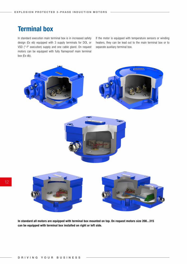
Terminal boxIn standard execution main terminal box is in increased safety design (Ex eb) equipped with 3 supply terminals for DOL or VSD ("-f" execution) supply and one cable gland. On request motors can be equipped with fully flameproof main terminal box (Ex db).
If the motor is equipped with temperature sensors or winding heaters, they can be lead out to the main terminal box or to separate auxiliary terminal box.
In standard all motors are equipped with terminal box mounted on top. On request motors size 200...315 can be equipped with terminal box installed on right or left side.
D R I V I N G Y O U R B U S I N E S S
E X P L O S I O N P R O T E C T E D 3 - P H A S E I N D U C T I O N M O T O R S
12
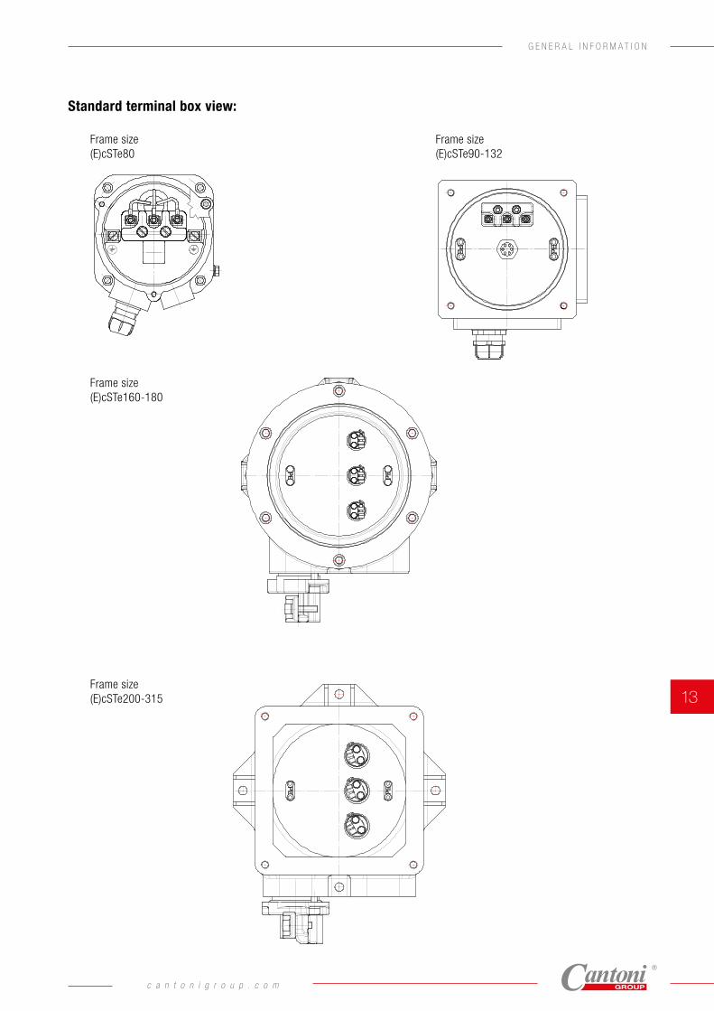
Standard terminal box view:
Frame size(E)cSTe90-132
Frame size(E)cSTe160-180 cSTe200-315
Frame sizeEcSTe200-315
Frame size(E)cSTe 80
Frame size(E)cSTe90-132
Frame size(E)cSTe160-180 cSTe200-315
Frame sizeEcSTe200-315
Frame size(E)cSTe90-132
Frame size(E)cSTe160-180 cSTe200-315
Frame sizeEcSTe200-315
Frame size(E)cSTe80
Frame size(E)cSTe90-132
Frame size(E)cSTe200-315
Frame size(E)cSTe160-180
c a n t o n i g r o u p . c o m
13
G E N E R A L I N F O R M A T I O N
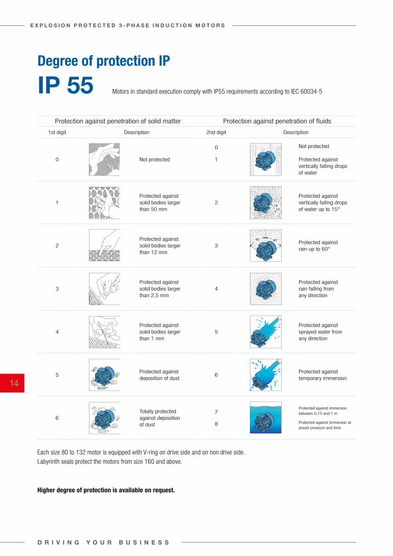
Protection against penetration of solid matter Protection against penetration of fluids
1st digit Description 2nd digit Description
0 Not protected
0
1
Not protected
Protected against vertically falling drops of water
1Protected against solid bodies larger than 50 mm
2Protected against vertically falling drops of water up to 15°
2Protected against solid bodies larger than 12 mm
3Protected against rain up to 60°
3Protected against solid bodies larger than 2,5 mm
4Protected against rain falling from any direction
4Protected against solid bodies larger than 1 mm
5Protected against sprayed water from any direction
5Protected against deposition of dust
6Protected against temporary immersion
6Totally protected against deposition of dust
7
8
Protected against immersion between 0,15 and 1 m
Protected against immersion at preset pressure and time
IP55According to the IEC 60034-5 standard the electric motors are
provided with IP code which determines the degree of protection
(ensured by the housing) against penetration of solid matter and
fluids.
PROTECTION AGAINST PENETRATION OF SOLID MATTER
1st digit DESCRIPTION
0
Not protected
Protected against
1solid bodies larger than50 mm
Protected against
2solid bodieslarger than12 mm
Protected against3 solid bodies
largerthan 2.5 mm
Protected against4 solid bodies
largerthan 1 mm
5Protected againstdeposition of dust
Totally6 protected against
deposition of dust
PROTECTION AGAINST PENETRATION OF FLUIDS
2nd digit DESCRIPTION
0 Not protected
1 Protected against vertically
falling drops of water
Protected against2 vertically falling
drops of water up to 15°
Protected against
3 rain up to 60°
Protected against4 rain falling from any
direction
5Protected againstsprayed waterfrom any direction
Protected against6 temporary
immersion
7 Protected against immersion
between 0.15 and 1 m
8 Protected against immersion at
preset pressure and time
MECHANICAL PROTECTION
3rd digit DESCRIPTION
00 No protection
01
02
03
04
05
06
07
08
09
10Motors with a higher degree of protection areavailable on request.
All Cantoni Group standard motors are manufactured with IP 55 degree of protection according to the standard in force (IEC 60034-5). The following table lists its characteristics.
Each size 80 to 180 motor is equipped with seal rings (Simmerring or V-ring) on drive side and on non drive side. Labyrinth seals protect the motors from size 200 and above.
The terminal box is sealed with a gasket.
6060
1515
150 g
10 cm
200 g
250 g
15 cm
250 g
20 cm
350 g
20 cm
250 g
40 cm
10 cm
0.5 kg
40 cm
1.25 kg
40 cm
2.5 kg
40 cm
5 kg
40 cm
Striking energy:0.15 J
Striking energy:0.20 J
Striking energy:0.37 J
Striking energy:0.50 J
Striking energy:0.70 J
Striking energy:1 J
Striking energy:2 J
Striking energy:5 J
Striking energy:10 J
Striking energy:20 J
IK
INTERNATIONAL PROTECTION MARKING IP
General Purpose 3-phase Induction Motors
09
Degree of protection IP
IP 55
Higher degree of protection is available on request.
Motors in standard execution comply with IP55 requirements according to IEC 60034-5
Each size 80 to 132 motor is equipped with V-ring on drive side and on non drive side. Labyrinth seals protect the motors from size 160 and above.
D R I V I N G Y O U R B U S I N E S S
E X P L O S I O N P R O T E C T E D 3 - P H A S E I N D U C T I O N M O T O R S
14
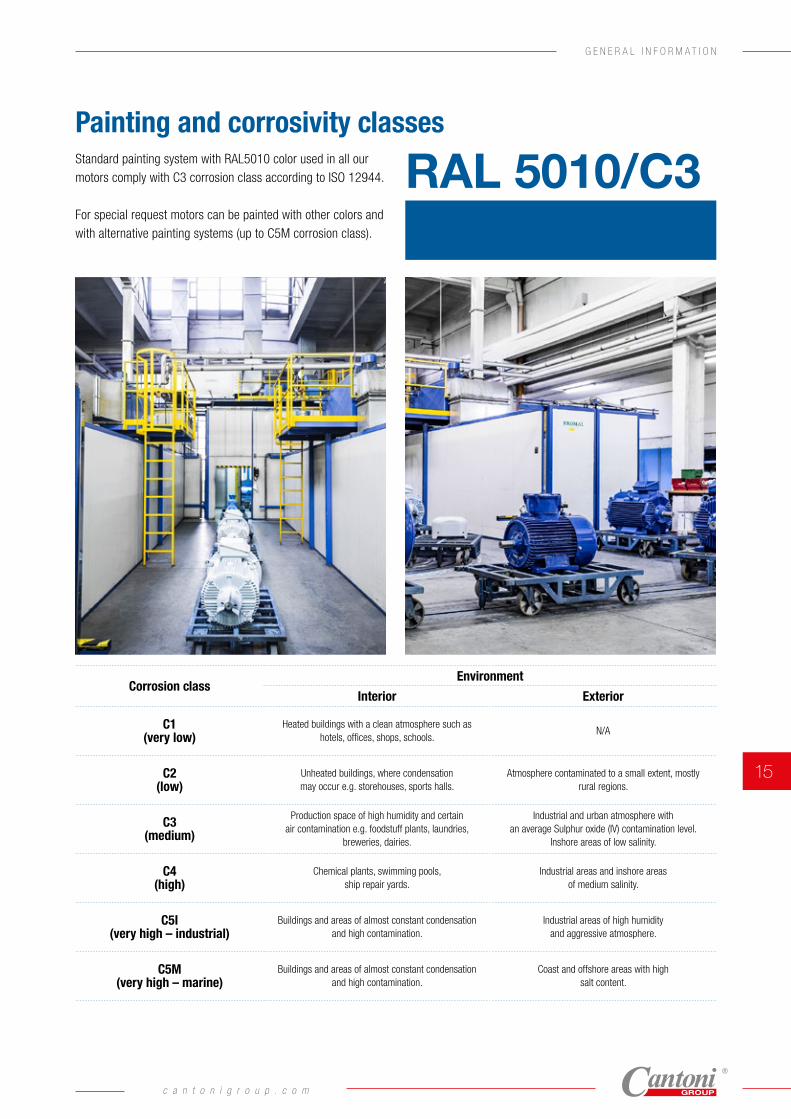
Painting and corrosivity classesStandard painting system with RAL5010 color used in all our motors comply with C3 corrosion class according to ISO 12944.
For special request motors can be painted with other colors and with alternative painting systems (up to C5M corrosion class).
Corrosion classEnvironment
Interior Exterior
C1 (very low)
Heated buildings with a clean atmosphere such as hotels, offices, shops, schools.
N/A
C2 (low)
Unheated buildings, where condensation may occur e.g. storehouses, sports halls.
Atmosphere contaminated to a small extent, mostly rural regions.
C3 (medium)
Production space of high humidity and certain air contamination e.g. foodstuff plants, laundries,
breweries, dairies.
Industrial and urban atmosphere with an average Sulphur oxide (IV) contamination level.
Inshore areas of low salinity.
C4 (high)
Chemical plants, swimming pools, ship repair yards.
Industrial areas and inshore areas of medium salinity.
C5I (very high – industrial)
Buildings and areas of almost constant condensation and high contamination.
Industrial areas of high humidity and aggressive atmosphere.
C5M (very high – marine)
Buildings and areas of almost constant condensation and high contamination.
Coast and offshore areas with high salt content.
RAL 5010/C3
c a n t o n i g r o u p . c o m
15
G E N E R A L I N F O R M A T I O N
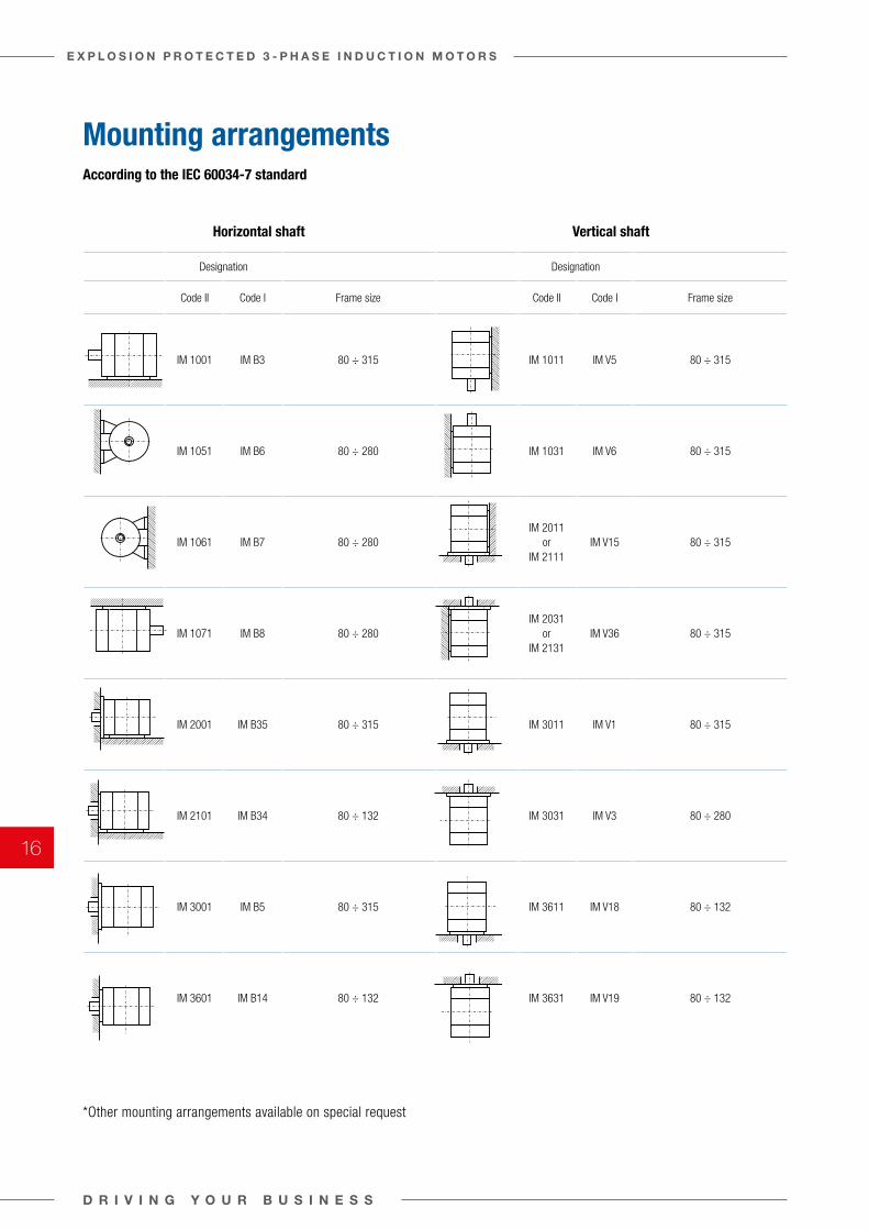
According to the IEC 60034-7 standard
*Other mounting arrangements available on special request
Horizontal shaft Vertical shaft
Designation Designation
Code II Code I Frame size Code II Code I Frame size
IM 1001 IM B3 80 ÷ 315 IM 1011 IM V5 80 ÷ 315
IM 1051 IM B6 80 ÷ 280 IM 1031 IM V6 80 ÷ 315
IM 1061 IM B7 80 ÷ 280IM 2011
or IM 2111
IM V15 80 ÷ 315
IM 1071 IM B8 80 ÷ 280IM 2031
or IM 2131
IM V36 80 ÷ 315
IM 2001 IM B35 80 ÷ 315 IM 3011 IM V1 80 ÷ 315
IM 2101 IM B34 80 ÷ 132 IM 3031 IM V3 80 ÷ 280
IM 3001 IM B5 80 ÷ 315 IM 3611 IM V18 80 ÷ 132
IM 3601 IM B14 80 ÷ 132 IM 3631 IM V19 80 ÷ 132
Mounting arrangements
D R I V I N G Y O U R B U S I N E S S
E X P L O S I O N P R O T E C T E D 3 - P H A S E I N D U C T I O N M O T O R S
16
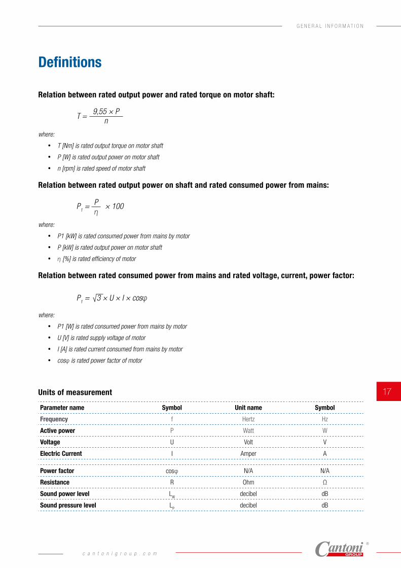
Definitions
Relation between rated output power and rated torque on motor shaft:
where:
• T [Nm] is rated output torque on motor shaft
• P [W] is rated output power on motor shaft
• n [rpm] is rated speed of motor shaft
Relation between rated output power on shaft and rated consumed power from mains:
where:
• P1 [kW] is rated consumed power from mains by motor
• P [kW] is rated output power on motor shaft
• η [%] is rated efficiency of motor
Relation between rated consumed power from mains and rated voltage, current, power factor:
where:
• P1 [W] is rated consumed power from mains by motor
• U [V] is rated supply voltage of motor
• I [A] is rated current consumed from mains by motor
• cosφ is rated power factor of motor
Units of measurement
Parameter name Symbol Unit name Symbol
Frequency f Hertz Hz
Active power P Watt W
Voltage U Volt V
Electric Current I Amper A
Power factor cosφ N/A N/A
Resistance R Ohm Ω
Sound power level LW
decibel dB
Sound pressure level LP
decibel dB
T =
P1 = × 100
9,55 × Pn
P1 = √3 × U × I × cosφ
Pη
c a n t o n i g r o u p . c o m
17
G E N E R A L I N F O R M A T I O N
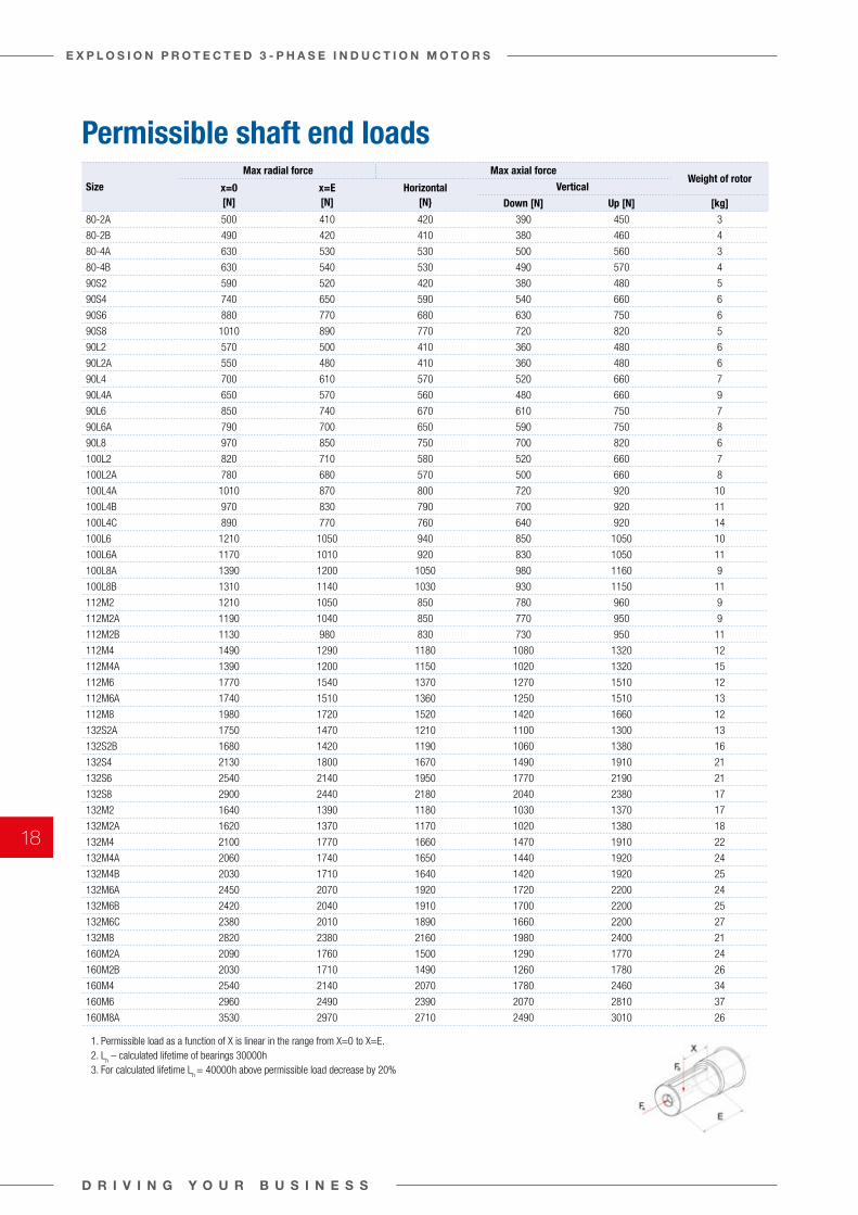
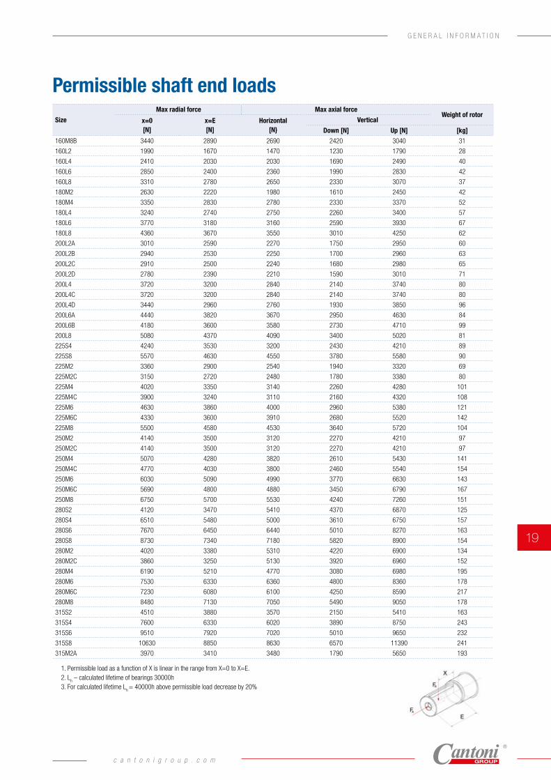
Permissible shaft end loadsSize
Max radial force Max axial forceWeight of rotor
x=0 [N]
x=E [N]
Horizontal [N}
Vertical
Down [N] Up [N] [kg]
80-2A 500 410 420 390 450 3
80-2B 490 420 410 380 460 4
80-4A 630 530 530 500 560 3
80-4B 630 540 530 490 570 4
90S2 590 520 420 380 480 5
90S4 740 650 590 540 660 6
90S6 880 770 680 630 750 6
90S8 1010 890 770 720 820 5
90L2 570 500 410 360 480 6
90L2A 550 480 410 360 480 6
90L4 700 610 570 520 660 7
90L4A 650 570 560 480 660 9
90L6 850 740 670 610 750 7
90L6A 790 700 650 590 750 8
90L8 970 850 750 700 820 6
100L2 820 710 580 520 660 7
100L2A 780 680 570 500 660 8
100L4A 1010 870 800 720 920 10
100L4B 970 830 790 700 920 11
100L4C 890 770 760 640 920 14
100L6 1210 1050 940 850 1050 10
100L6A 1170 1010 920 830 1050 11
100L8A 1390 1200 1050 980 1160 9
100L8B 1310 1140 1030 930 1150 11
112M2 1210 1050 850 780 960 9
112M2A 1190 1040 850 770 950 9
112M2B 1130 980 830 730 950 11
112M4 1490 1290 1180 1080 1320 12
112M4A 1390 1200 1150 1020 1320 15
112M6 1770 1540 1370 1270 1510 12
112M6A 1740 1510 1360 1250 1510 13
112M8 1980 1720 1520 1420 1660 12
132S2A 1750 1470 1210 1100 1300 13
132S2B 1680 1420 1190 1060 1380 16
132S4 2130 1800 1670 1490 1910 21
132S6 2540 2140 1950 1770 2190 21
132S8 2900 2440 2180 2040 2380 17
132M2 1640 1390 1180 1030 1370 17
132M2A 1620 1370 1170 1020 1380 18
132M4 2100 1770 1660 1470 1910 22
132M4A 2060 1740 1650 1440 1920 24
132M4B 2030 1710 1640 1420 1920 25
132M6A 2450 2070 1920 1720 2200 24
132M6B 2420 2040 1910 1700 2200 25
132M6C 2380 2010 1890 1660 2200 27
132M8 2820 2380 2160 1980 2400 21
160M2A 2090 1760 1500 1290 1770 24
160M2B 2030 1710 1490 1260 1780 26
160M4 2540 2140 2070 1780 2460 34
160M6 2960 2490 2390 2070 2810 37
160M8A 3530 2970 2710 2490 3010 26
SILNIKI PRZECIWWYBUCHOWE EXPLOSION-PROOF MOTORS112M6 1770 1540 1370 1270 1510 12
112M6A 1740 1510 1360 1250 1510 13
112M8 1980 1720 1520 1420 1660 12
132S2A 1750 1470 1210 1100 1300 13
132S2B 1680 1420 1190 1060 1380 16
132S4 2130 1800 1670 1490 1910 21
132S6 2540 2140 1950 1770 2190 21
132S8 2900 2440 2180 2040 2380 17
132M2 1640 1390 1180 1030 1370 17
132M2A 1620 1370 1170 1020 1380 18
132M4 2100 1770 1660 1470 1910 22
132M4A 2060 1740 1650 1440 1920 24
132M4B 2030 1710 1640 1420 1920 25
132M6A 2450 2070 1920 1720 2200 24
132M6B 2420 2040 1910 1700 2200 25
132M6C 2380 2010 1890 1660 2200 27
132M8 2820 2380 2160 1980 2400 21
1.Dopuszczalna siła promieniowa jest liniową funkcją X w zakresie od X=0 do X=E.
Permissible load as a function of X is linear in the range from X=0 to X=E.
2.Lh – zakładana trwałóść łożysk 30000h / Lh – calculated lifetime of bearings 30000h
3.Dla twałości łożysk Lh=40000h wartości dopuszczalnych obciążeń należy zmniejszyć o 20% / For calculated lifetime Lh=40000h above permissible load decrease by 20%
43-400 Cieszyn, ul. 3 Maja 19 tel.: (48 33) 4701-700 e-mail: [email protected] www.celma.pl
/2 2
1. Permissible load as a function of X is linear in the range from X=0 to X=E.2. L
h – calculated lifetime of bearings 30000h
3. For calculated lifetime Lh = 40000h above permissible load decrease by 20%
D R I V I N G Y O U R B U S I N E S S
E X P L O S I O N P R O T E C T E D 3 - P H A S E I N D U C T I O N M O T O R S
18
Permissible shaft end loadsSize
Max radial force Max axial forceWeight of rotor
x=0 [N]
x=E [N]
Horizontal [N}
Vertical
Down [N] Up [N] [kg]
160M8B 3440 2890 2690 2420 3040 31
160L2 1990 1670 1470 1230 1790 28
160L4 2410 2030 2030 1690 2490 40
160L6 2850 2400 2360 1990 2830 42
160L8 3310 2780 2650 2330 3070 37
180M2 2630 2220 1980 1610 2450 42
180M4 3350 2830 2780 2330 3370 52
180L4 3240 2740 2750 2260 3400 57
180L6 3770 3180 3160 2590 3930 67
180L8 4360 3670 3550 3010 4250 62
200L2A 3010 2590 2270 1750 2950 60
200L2B 2940 2530 2250 1700 2960 63
200L2C 2910 2500 2240 1680 2980 65
200L2D 2780 2390 2210 1590 3010 71
200L4 3720 3200 2840 2140 3740 80
200L4C 3720 3200 2840 2140 3740 80
200L4D 3440 2960 2760 1930 3850 96
200L6A 4440 3820 3670 2950 4630 84
200L6B 4180 3600 3580 2730 4710 99
200L8 5080 4370 4090 3400 5020 81
225S4 4240 3530 3200 2430 4210 89
225S8 5570 4630 4550 3780 5580 90
225M2 3360 2900 2540 1940 3320 69
225M2C 3150 2720 2480 1780 3380 80
225M4 4020 3350 3140 2260 4280 101
225M4C 3900 3240 3110 2160 4320 108
225M6 4630 3860 4000 2960 5380 121
225M6C 4330 3600 3910 2680 5520 142
225M8 5500 4580 4530 3640 5720 104
250M2 4140 3500 3120 2270 4210 97
250M2C 4140 3500 3120 2270 4210 97
250M4 5070 4280 3820 2610 5430 141
250M4C 4770 4030 3800 2460 5540 154
250M6 6030 5090 4990 3770 6630 143
250M6C 5690 4800 4880 3450 6790 167
250M8 6750 5700 5530 4240 7260 151
280S2 4120 3470 5410 4370 6870 125
280S4 6510 5480 5000 3610 6750 157
280S6 7670 6450 6440 5010 8270 163
280S8 8730 7340 7180 5820 8900 154
280M2 4020 3380 5310 4220 6900 134
280M2C 3860 3250 5130 3920 6960 152
280M4 6190 5210 4770 3080 6980 195
280M6 7530 6330 6360 4800 8360 178
280M6C 7230 6080 6100 4250 8590 217
280M8 8480 7130 7050 5490 9050 178
315S2 4510 3880 3570 2150 5410 163
315S4 7600 6330 6020 3890 8750 243
315S6 9510 7920 7020 5010 9650 232
315S8 10630 8850 8630 6570 11390 241
315M2A 3970 3410 3480 1790 5650 193
SILNIKI PRZECIWWYBUCHOWE EXPLOSION-PROOF MOTORS112M6 1770 1540 1370 1270 1510 12
112M6A 1740 1510 1360 1250 1510 13
112M8 1980 1720 1520 1420 1660 12
132S2A 1750 1470 1210 1100 1300 13
132S2B 1680 1420 1190 1060 1380 16
132S4 2130 1800 1670 1490 1910 21
132S6 2540 2140 1950 1770 2190 21
132S8 2900 2440 2180 2040 2380 17
132M2 1640 1390 1180 1030 1370 17
132M2A 1620 1370 1170 1020 1380 18
132M4 2100 1770 1660 1470 1910 22
132M4A 2060 1740 1650 1440 1920 24
132M4B 2030 1710 1640 1420 1920 25
132M6A 2450 2070 1920 1720 2200 24
132M6B 2420 2040 1910 1700 2200 25
132M6C 2380 2010 1890 1660 2200 27
132M8 2820 2380 2160 1980 2400 21
1.Dopuszczalna siła promieniowa jest liniową funkcją X w zakresie od X=0 do X=E.
Permissible load as a function of X is linear in the range from X=0 to X=E.
2.Lh – zakładana trwałóść łożysk 30000h / Lh – calculated lifetime of bearings 30000h
3.Dla twałości łożysk Lh=40000h wartości dopuszczalnych obciążeń należy zmniejszyć o 20% / For calculated lifetime Lh=40000h above permissible load decrease by 20%
43-400 Cieszyn, ul. 3 Maja 19 tel.: (48 33) 4701-700 e-mail: [email protected] www.celma.pl
/2 2
1. Permissible load as a function of X is linear in the range from X=0 to X=E.2. L
h – calculated lifetime of bearings 30000h
3. For calculated lifetime Lh = 40000h above permissible load decrease by 20%
c a n t o n i g r o u p . c o m
19
G E N E R A L I N F O R M A T I O N
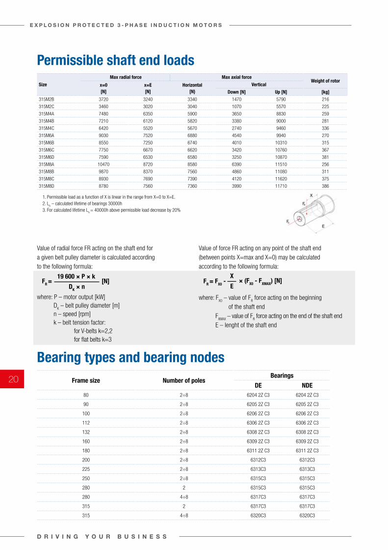
Bearing types and bearing nodesFrame size Number of poles
Bearings
DE NDE80 2÷8 6204 2Z C3 6204 2Z C3
90 2÷8 6205 2Z C3 6205 2Z C3
100 2÷8 6206 2Z C3 6206 2Z C3
112 2÷8 6306 2Z C3 6306 2Z C3
132 2÷8 6308 2Z C3 6308 2Z C3
160 2÷8 6309 2Z C3 6309 2Z C3
180 2÷8 6311 2Z C3 6311 2Z C3
200 2÷8 6312C3 6312C3
225 2÷8 6313C3 6313C3
250 2÷8 6315C3 6315C3
280 2 6315C3 6315C3
280 4÷8 6317C3 6317C3
315 2 6317C3 6317C3
315 4÷8 6320C3 6320C3
Permissible shaft end loads
Value of radial force FR acting on the shaft end for a given belt pulley diameter is calculated according to the following formula:
where: P – motor output [kW] D
K – belt pulley diameter [m]
n – speed [rpm] k – belt tension factor:
for V-belts k=2,2for flat belts k=3
Value of force FR acting on any point of the shaft end (between points X=max and X=0) may be calculated according to the following formula:
where: FX0
– value of FR force acting on the beginning
of the shaft end F
XMAX – value of F
R force acting on the end of the shaft end
E – lenght of the shaft end
FR = FR = FX0 -[N] × (FX0 - FXMAX) [N]19 600 × P × k X
DK × n E
Size
Max radial force Max axial forceWeight of rotor
x=0 [N]
x=E [N]
Horizontal [N}
Vertical
Down [N] Up [N] [kg]
315M2B 3720 3240 3340 1470 5790 216
315M2C 3460 3020 3040 1070 5570 225
315M4A 7480 6350 5900 3650 8830 259
315M4B 7210 6120 5820 3380 9000 281
315M4C 6420 5520 5670 2740 9460 336
315M6A 9030 7520 6880 4540 9940 270
315M6B 8550 7250 6740 4010 10310 315
315M6C 7750 6670 6620 3420 10760 367
315M6D 7590 6530 6580 3250 10870 381
315M8A 10470 8720 8580 6390 11510 256
315M8B 9870 8370 7560 4860 11080 311
315M8C 8930 7690 7390 4120 11620 375
315M8D 8780 7560 7360 3990 11710 386
1. Permissible load as a function of X is linear in the range from X=0 to X=E.2. L
h – calculated lifetime of bearings 30000h
3. For calculated lifetime Lh = 40000h above permissible load decrease by 20%
SILNIKI PRZECIWWYBUCHOWE EXPLOSION-PROOF MOTORS112M6 1770 1540 1370 1270 1510 12
112M6A 1740 1510 1360 1250 1510 13
112M8 1980 1720 1520 1420 1660 12
132S2A 1750 1470 1210 1100 1300 13
132S2B 1680 1420 1190 1060 1380 16
132S4 2130 1800 1670 1490 1910 21
132S6 2540 2140 1950 1770 2190 21
132S8 2900 2440 2180 2040 2380 17
132M2 1640 1390 1180 1030 1370 17
132M2A 1620 1370 1170 1020 1380 18
132M4 2100 1770 1660 1470 1910 22
132M4A 2060 1740 1650 1440 1920 24
132M4B 2030 1710 1640 1420 1920 25
132M6A 2450 2070 1920 1720 2200 24
132M6B 2420 2040 1910 1700 2200 25
132M6C 2380 2010 1890 1660 2200 27
132M8 2820 2380 2160 1980 2400 21
1.Dopuszczalna siła promieniowa jest liniową funkcją X w zakresie od X=0 do X=E.
Permissible load as a function of X is linear in the range from X=0 to X=E.
2.Lh – zakładana trwałóść łożysk 30000h / Lh – calculated lifetime of bearings 30000h
3.Dla twałości łożysk Lh=40000h wartości dopuszczalnych obciążeń należy zmniejszyć o 20% / For calculated lifetime Lh=40000h above permissible load decrease by 20%
43-400 Cieszyn, ul. 3 Maja 19 tel.: (48 33) 4701-700 e-mail: [email protected] www.celma.pl
/2 2
D R I V I N G Y O U R B U S I N E S S
E X P L O S I O N P R O T E C T E D 3 - P H A S E I N D U C T I O N M O T O R S
20
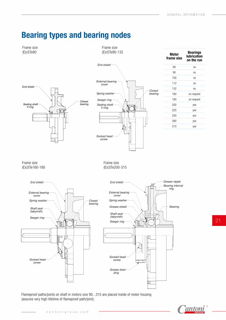
Bearing types and bearing nodes
Frame size(E)cSTe90-132
Frame size(E)cSTe160-180
Frame size(E)cSTe200-315
Grease nippleEnd shield End shieldEnd shield
External bearing cover
External bearing cover
External bearing cover
Spring washer
Spring washer Spring washer
Grease shieldShaft seal(labyrinth)
Shaft seal(labyrinth)Seeger ring
Seeger ringSeeger ring
Bearing internal ring
Sealing shaft V-ring
Socked head screw
Socked head screw
Socked head screw
Grease drain plug
Closedbearing
Bearing
Closedbearing
Frame size(E)cSTe 80
End shield
Sealing shaft V-ring
Closedbearing
Frame size(E)cSTe90-132
Frame size(E)cSTe160-180
Frame size(E)cSTe200-315
Grease nippleEnd shield End shieldEnd shield
External bearing cover
External bearing cover
External bearing cover
Spring washer
Spring washer Spring washer
Grease shieldShaft seal(labyrinth)
Shaft seal(labyrinth)Seeger ring
Seeger ringSeeger ring
Bearing internal ring
Sealing shaft V-ring
Socked head screw
Socked head screw
Socked head screw
Grease drain plug
Closedbearing
Bearing
Closedbearing
Motor frame size
Bearings lubrication on the run
80 no
90 no
100 no
112 no
132 no
160 on request
180 on request
200 yes
225 yes
250 yes
280 yes
315 yes
Frame size(E)cSTe80
Frame size(E)cSTe90-132
Frame size(E)cSTe200-315
Frame size(E)cSTe160-180
Flameproof paths/joints on shaft in motors size 90...315 are placed inside of motor housing (assures very high lifetime of flameproof path/joint).
c a n t o n i g r o u p . c o m
21
G E N E R A L I N F O R M A T I O N
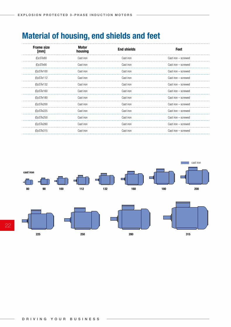
Material of housing, end shields and feetFrame size
[mm]Motor
housing End shields Feet
(E)cSTe80 Cast iron Cast iron Cast iron – screwed
(E)cSTe90 Cast iron Cast iron Cast iron – screwed
(E)cSTe100 Cast iron Cast iron Cast iron – screwed
(E)cSTe112 Cast iron Cast iron Cast iron – screwed
(E)cSTe132 Cast iron Cast iron Cast iron – screwed
(E)cSTe160 Cast iron Cast iron Cast iron – screwed
(E)cSTe180 Cast iron Cast iron Cast iron – screwed
(E)cSTe200 Cast iron Cast iron Cast iron – screwed
(E)cSTe225 Cast iron Cast iron Cast iron – screwed
(E)cSTe250 Cast iron Cast iron Cast iron – screwed
(E)cSTe280 Cast iron Cast iron Cast iron – screwed
(E)cSTe315 Cast iron Cast iron Cast iron – screwed
cast iron
cast iron
80 90 100 112 132 160 180 200
225 250 280 315
D R I V I N G Y O U R B U S I N E S S
E X P L O S I O N P R O T E C T E D 3 - P H A S E I N D U C T I O N M O T O R S
22
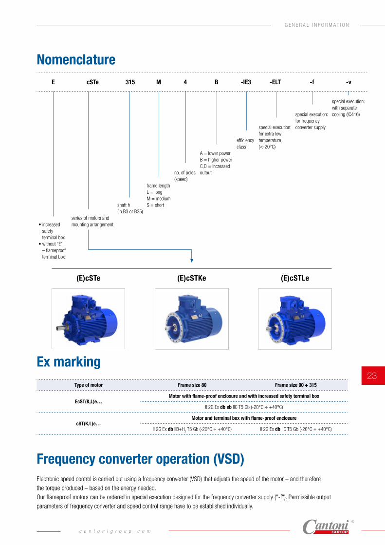
Frequency converter operation (VSD)
Ex marking
Nomenclature
Electronic speed control is carried out using a frequency converter (VSD) that adjusts the speed of the motor – and therefore the torque produced – based on the energy needed. Our flameproof motors can be ordered in special execution designed for the frequency converter supply ("-f"). Permissible output parameters of frequency converter and speed control range have to be established individually.
Type of motor Frame size 80 Frame size 90 ÷ 315
EcST(K,L)e…Motor with flame-proof enclosure and with increased safety terminal box
II 2G Ex db eb IIC T5 Gb (-20°C ÷ +40°C)
cST(K,L)e…Motor and terminal box with flame-proof enclosure
II 2G Ex db IIB+H2 T5 Gb (-20°C ÷ +40°C) II 2G Ex db IIC T5 Gb (-20°C ÷ +40°C)
(E)cSTe (E)cSTKe (E)cSTLe
E cSTe 315 M 4 B -IE3 -ELT -f -v
• increased safety terminal box
• without “E” – flameproof terminal box
series of motors and mounting arrangement
shaft h (in B3 or B35)
frame length L = long M = medium S = short
no. of poles (speed)
A = lower powerB = higher powerC,D = increased output
efficiency class
special execution:for extra low temperature(<-20°C)
special execution: for frequency converter supply
special execution: with separate cooling (IC416)
c a n t o n i g r o u p . c o m
23
G E N E R A L I N F O R M A T I O N
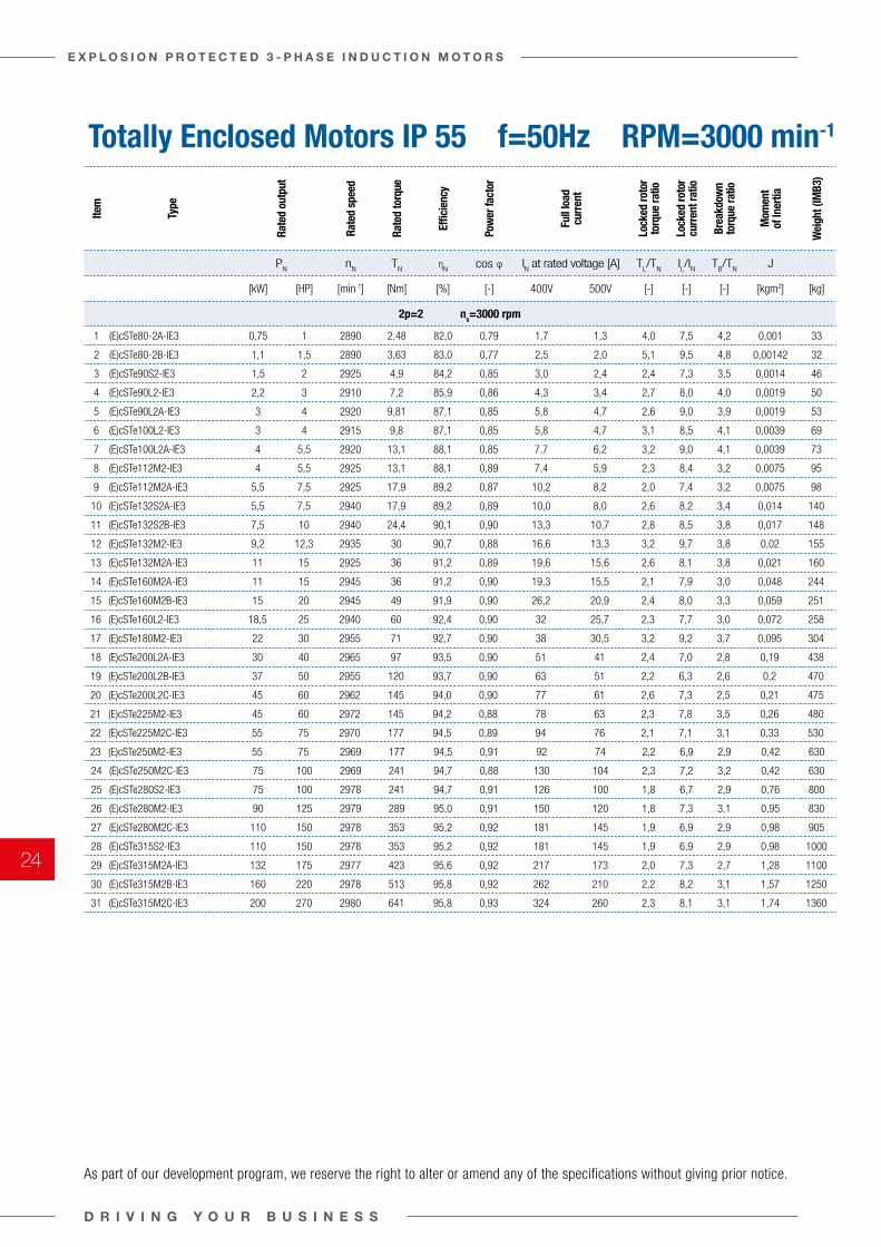
Totally Enclosed Motors IP 55 f=50Hz RPM=3000 min-1
Item
Type
Rate
d ou
tput
Rate
d sp
eed
Rate
d to
rque
Effic
ienc
y
Pow
er fa
ctor
Full
load
cu
rren
t
Lock
ed ro
tor
torq
ue ra
tio
Lock
ed ro
tor
curr
ent r
atio
Brea
kdow
n to
rque
ratio
Mom
ent
of In
ertia
Wei
ght (
IMB3
)
PN
nN
TN η
Ncos φ I
N at rated voltage [A] T
L/T
NIL/I
NT
B/T
NJ
[kW] [HP] [min-1] [Nm] [%] [-] 400V 500V [-] [-] [-] [kgm2] [kg]
2p=2 ns=3000 rpm
1 (E)cSTe80-2A-IE3 0,75 1 2890 2,48 82,0 0,79 1,7 1,3 4,0 7,5 4,2 0,001 33
2 (E)cSTe80-2B-IE3 1,1 1,5 2890 3,63 83,0 0,77 2,5 2,0 5,1 9,5 4,8 0,00142 32
3 (E)cSTe90S2-IE3 1,5 2 2925 4,9 84,2 0,85 3,0 2,4 2,4 7,3 3,5 0,0014 46
4 (E)cSTe90L2-IE3 2,2 3 2910 7,2 85,9 0,86 4,3 3,4 2,7 8,0 4,0 0,0019 50
5 (E)cSTe90L2A-IE3 3 4 2920 9,81 87,1 0,85 5,8 4,7 2,6 9,0 3,9 0,0019 53
6 (E)cSTe100L2-IE3 3 4 2915 9,8 87,1 0,85 5,8 4,7 3,1 8,5 4,1 0,0039 69
7 (E)cSTe100L2A-IE3 4 5,5 2920 13,1 88,1 0,85 7,7 6,2 3,2 9,0 4,1 0,0039 73
8 (E)cSTe112M2-IE3 4 5,5 2925 13,1 88,1 0,89 7,4 5,9 2,3 8,4 3,2 0,0075 95
9 (E)cSTe112M2A-IE3 5,5 7,5 2925 17,9 89,2 0,87 10,2 8,2 2,0 7,4 3,2 0,0075 98
10 (E)cSTe132S2A-IE3 5,5 7,5 2940 17,9 89,2 0,89 10,0 8,0 2,6 8,2 3,4 0,014 140
11 (E)cSTe132S2B-IE3 7,5 10 2940 24,4 90,1 0,90 13,3 10,7 2,8 8,5 3,8 0,017 148
12 (E)cSTe132M2-IE3 9,2 12,3 2935 30 90,7 0,88 16,6 13,3 3,2 9,7 3,8 0,02 155
13 (E)cSTe132M2A-IE3 11 15 2925 36 91,2 0,89 19,6 15,6 2,6 8,1 3,8 0,021 160
14 (E)cSTe160M2A-IE3 11 15 2945 36 91,2 0,90 19,3 15,5 2,1 7,9 3,0 0,048 244
15 (E)cSTe160M2B-IE3 15 20 2945 49 91,9 0,90 26,2 20,9 2,4 8,0 3,3 0,059 251
16 (E)cSTe160L2-IE3 18,5 25 2940 60 92,4 0,90 32 25,7 2,3 7,7 3,0 0,072 258
17 (E)cSTe180M2-IE3 22 30 2955 71 92,7 0,90 38 30,5 3,2 9,2 3,7 0,095 304
18 (E)cSTe200L2A-IE3 30 40 2965 97 93,5 0,90 51 41 2,4 7,0 2,8 0,19 438
19 (E)cSTe200L2B-IE3 37 50 2955 120 93,7 0,90 63 51 2,2 6,3 2,6 0,2 470
20 (E)cSTe200L2C-IE3 45 60 2962 145 94,0 0,90 77 61 2,6 7,3 2,5 0,21 475
21 (E)cSTe225M2-IE3 45 60 2972 145 94,2 0,88 78 63 2,3 7,8 3,5 0,26 480
22 (E)cSTe225M2C-IE3 55 75 2970 177 94,5 0,89 94 76 2,1 7,1 3,1 0,33 530
23 (E)cSTe250M2-IE3 55 75 2969 177 94,5 0,91 92 74 2,2 6,9 2,9 0,42 630
24 (E)cSTe250M2C-IE3 75 100 2969 241 94,7 0,88 130 104 2,3 7,2 3,2 0,42 630
25 (E)cSTe280S2-IE3 75 100 2978 241 94,7 0,91 126 100 1,8 6,7 2,9 0,76 800
26 (E)cSTe280M2-IE3 90 125 2979 289 95,0 0,91 150 120 1,8 7,3 3,1 0,95 830
27 (E)cSTe280M2C-IE3 110 150 2978 353 95,2 0,92 181 145 1,9 6,9 2,9 0,98 905
28 (E)cSTe315S2-IE3 110 150 2978 353 95,2 0,92 181 145 1,9 6,9 2,9 0,98 1000
29 (E)cSTe315M2A-IE3 132 175 2977 423 95,6 0,92 217 173 2,0 7,3 2,7 1,28 1100
30 (E)cSTe315M2B-IE3 160 220 2978 513 95,8 0,92 262 210 2,2 8,2 3,1 1,57 1250
31 (E)cSTe315M2C-IE3 200 270 2980 641 95,8 0,93 324 260 2,3 8,1 3,1 1,74 1360
As part of our development program, we reserve the right to alter or amend any of the specifications without giving prior notice.
D R I V I N G Y O U R B U S I N E S S
E X P L O S I O N P R O T E C T E D 3 - P H A S E I N D U C T I O N M O T O R S
24
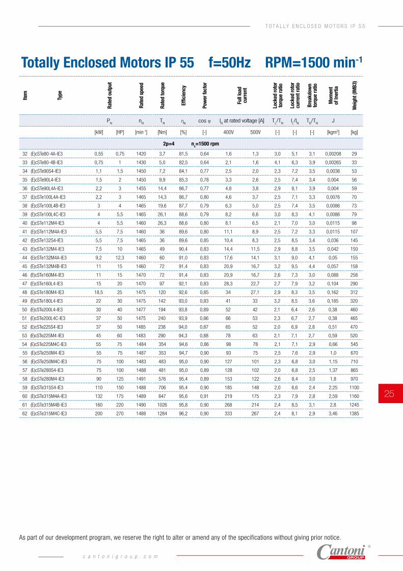
Totally Enclosed Motors IP 55 f=50Hz RPM=1500 min-1
Item
Type
Rate
d ou
tput
Rate
d sp
eed
Rate
d to
rque
Effic
ienc
y
Pow
er fa
ctor
Full
load
cu
rren
t
Lock
ed ro
tor
torq
ue ra
tio
Lock
ed ro
tor
curr
ent r
atio
Brea
kdow
n to
rque
ratio
Mom
ent
of In
ertia
Wei
ght (
IMB3
)
PN
nN
TN η
Ncos φ I
N at rated voltage [A] T
L/T
NIL/I
NT
B/T
NJ
[kW] [HP] [min-1] [Nm] [%] [-] 400V 500V [-] [-] [-] [kgm2] [kg]
2p=4 ns=1500 rpm
32 (E)cSTe80-4A-IE3 0,55 0,75 1420 3,7 81,5 0,64 1,6 1,3 3,0 5,1 3,1 0,00208 29
33 (E)cSTe80-4B-IE3 0,75 1 1430 5,0 82,5 0,64 2,1 1,6 4,1 6,3 3,9 0,00265 33
34 (E)cSTe90S4-IE3 1,1 1,5 1450 7,2 84,1 0,77 2,5 2,0 2,3 7,2 3,5 0,0036 53
35 (E)cSTe90L4-IE3 1,5 2 1450 9,9 85,3 0,78 3,3 2,6 2,5 7,4 3,4 0,004 56
36 (E)cSTe90L4A-IE3 2,2 3 1455 14,4 86,7 0,77 4,8 3,8 2,9 8,1 3,9 0,004 59
37 (E)cSTe100L4A-IE3 2,2 3 1465 14,3 86,7 0,80 4,6 3,7 2,5 7,1 3,3 0,0076 70
38 (E)cSTe100L4B-IE3 3 4 1465 19,6 87,7 0,79 6,3 5,0 2,5 7,4 3,5 0,0086 73
39 (E)cSTe100L4C-IE3 4 5,5 1465 26,1 88,6 0,79 8,2 6,6 3,0 8,3 4,1 0,0086 79
40 (E)cSTe112M4-IE3 4 5,5 1460 26,3 88,6 0,80 8,1 6,5 2,1 7,0 3,0 0,0115 98
41 (E)cSTe112M4A-IE3 5,5 7,5 1460 36 89,6 0,80 11,1 8,9 2,5 7,2 3,3 0,0115 107
42 (E)cSTe132S4-IE3 5,5 7,5 1465 36 89,6 0,85 10,4 8,3 2,5 8,5 3,4 0,036 145
43 (E)cSTe132M4-IE3 7,5 10 1465 49 90,4 0,83 14,4 11,5 2,9 8,8 3,5 0,042 150
44 (E)cSTe132M4A-IE3 9,2 12,3 1460 60 91,0 0,83 17,6 14,1 3,1 9,0 4,1 0,05 155
45 (E)cSTe132M4B-IE3 11 15 1460 72 91,4 0,83 20,9 16,7 3,2 9,5 4,4 0,057 158
46 (E)cSTe160M4-IE3 11 15 1470 72 91,4 0,83 20,9 16,7 2,6 7,3 3,0 0,088 258
47 (E)cSTe160L4-IE3 15 20 1470 97 92,1 0,83 28,3 22,7 2,7 7,9 3,2 0,104 290
48 (E)cSTe180M4-IE3 18,5 25 1475 120 92,6 0,85 34 27,1 2,9 8,3 3,5 0,162 312
49 (E)cSTe180L4-IE3 22 30 1475 142 93,0 0,83 41 33 3,2 8,5 3,6 0,185 320
50 (E)cSTe200L4-IE3 30 40 1477 194 93,8 0,89 52 42 2,1 6,4 2,6 0,38 460
51 (E)cSTe200L4C-IE3 37 50 1475 240 93,9 0,86 66 53 2,3 6,7 2,7 0,38 465
52 (E)cSTe225S4-IE3 37 50 1485 238 94,0 0,87 65 52 2,0 6,9 2,8 0,51 470
53 (E)cSTe225M4-IE3 45 60 1483 290 94,3 0,88 78 63 2,1 7,1 2,7 0,59 520
54 (E)cSTe225M4C-IE3 55 75 1484 354 94,6 0,86 98 78 2,1 7,1 2,9 0,66 545
55 (E)cSTe250M4-IE3 55 75 1487 353 94,7 0,90 93 75 2,5 7,6 2,9 1,0 670
56 (E)cSTe250M4C-IE3 75 100 1483 483 95,0 0,90 127 101 2,3 6,8 3,0 1,15 710
57 (E)cSTe280S4-IE3 75 100 1488 481 95,0 0,89 128 102 2,0 6,8 2,5 1,37 865
58 (E)cSTe280M4-IE3 90 125 1491 576 95,4 0,89 153 122 2,6 8,4 3,0 1,8 970
59 (E)cSTe315S4-IE3 110 150 1488 706 95,4 0,90 185 148 2,0 6,6 2,4 2,25 1100
60 (E)cSTe315M4A-IE3 132 175 1489 847 95,6 0,91 219 175 2,3 7,9 2,8 2,59 1160
61 (E)cSTe315M4B-IE3 160 220 1490 1026 95,8 0,90 268 214 2,4 8,5 3,1 2,8 1245
62 (E)cSTe315M4C-IE3 200 270 1488 1284 96,2 0,90 333 267 2,4 8,1 2,9 3,46 1385
As part of our development program, we reserve the right to alter or amend any of the specifications without giving prior notice.
c a n t o n i g r o u p . c o m
25
T O T A L L Y E N C L O S E D M O T O R S I P 5 5
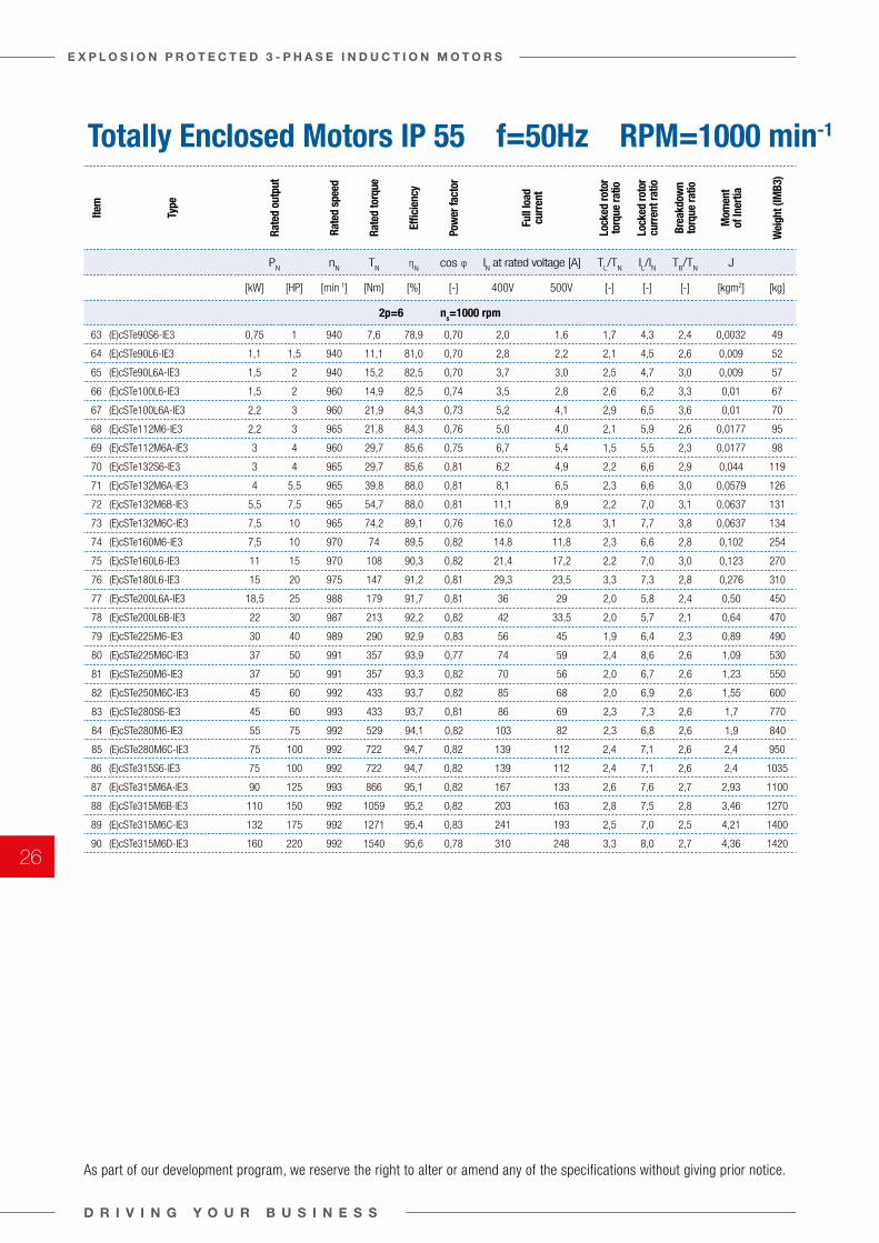
Totally Enclosed Motors IP 55 f=50Hz RPM=1000 min-1
Item
Type
Rate
d ou
tput
Rate
d sp
eed
Rate
d to
rque
Effic
ienc
y
Pow
er fa
ctor
Full
load
cu
rren
t
Lock
ed ro
tor
torq
ue ra
tio
Lock
ed ro
tor
curr
ent r
atio
Brea
kdow
n to
rque
ratio
Mom
ent
of In
ertia
Wei
ght (
IMB3
)
PN
nN
TN η
Ncos φ I
N at rated voltage [A] T
L/T
NIL/I
NT
B/T
NJ
[kW] [HP] [min-1] [Nm] [%] [-] 400V 500V [-] [-] [-] [kgm2] [kg]
2p=6 ns=1000 rpm
63 (E)cSTe90S6-IE3 0,75 1 940 7,6 78,9 0,70 2,0 1,6 1,7 4,3 2,4 0,0032 49
64 (E)cSTe90L6-IE3 1,1 1,5 940 11,1 81,0 0,70 2,8 2,2 2,1 4,5 2,6 0,009 52
65 (E)cSTe90L6A-IE3 1,5 2 940 15,2 82,5 0,70 3,7 3,0 2,5 4,7 3,0 0,009 57
66 (E)cSTe100L6-IE3 1,5 2 960 14,9 82,5 0,74 3,5 2,8 2,6 6,2 3,3 0,01 67
67 (E)cSTe100L6A-IE3 2,2 3 960 21,9 84,3 0,73 5,2 4,1 2,9 6,5 3,6 0,01 70
68 (E)cSTe112M6-IE3 2,2 3 965 21,8 84,3 0,76 5,0 4,0 2,1 5,9 2,6 0,0177 95
69 (E)cSTe112M6A-IE3 3 4 960 29,7 85,6 0,75 6,7 5,4 1,5 5,5 2,3 0,0177 98
70 (E)cSTe132S6-IE3 3 4 965 29,7 85,6 0,81 6,2 4,9 2,2 6,6 2,9 0,044 119
71 (E)cSTe132M6A-IE3 4 5,5 965 39,8 88,0 0,81 8,1 6,5 2,3 6,6 3,0 0,0579 126
72 (E)cSTe132M6B-IE3 5,5 7,5 965 54,7 88,0 0,81 11,1 8,9 2,2 7,0 3,1 0,0637 131
73 (E)cSTe132M6C-IE3 7,5 10 965 74,2 89,1 0,76 16,0 12,8 3,1 7,7 3,8 0,0637 134
74 (E)cSTe160M6-IE3 7,5 10 970 74 89,5 0,82 14,8 11,8 2,3 6,6 2,8 0,102 254
75 (E)cSTe160L6-IE3 11 15 970 108 90,3 0,82 21,4 17,2 2,2 7,0 3,0 0,123 270
76 (E)cSTe180L6-IE3 15 20 975 147 91,2 0,81 29,3 23,5 3,3 7,3 2,8 0,276 310
77 (E)cSTe200L6A-IE3 18,5 25 988 179 91,7 0,81 36 29 2,0 5,8 2,4 0,50 450
78 (E)cSTe200L6B-IE3 22 30 987 213 92,2 0,82 42 33,5 2,0 5,7 2,1 0,64 470
79 (E)cSTe225M6-IE3 30 40 989 290 92,9 0,83 56 45 1,9 6,4 2,3 0,89 490
80 (E)cSTe225M6C-IE3 37 50 991 357 93,9 0,77 74 59 2,4 8,6 2,6 1,09 530
81 (E)cSTe250M6-IE3 37 50 991 357 93,3 0,82 70 56 2,0 6,7 2,6 1,23 550
82 (E)cSTe250M6C-IE3 45 60 992 433 93,7 0,82 85 68 2,0 6,9 2,6 1,55 600
83 (E)cSTe280S6-IE3 45 60 993 433 93,7 0,81 86 69 2,3 7,3 2,6 1,7 770
84 (E)cSTe280M6-IE3 55 75 992 529 94,1 0,82 103 82 2,3 6,8 2,6 1,9 840
85 (E)cSTe280M6C-IE3 75 100 992 722 94,7 0,82 139 112 2,4 7,1 2,6 2,4 950
86 (E)cSTe315S6-IE3 75 100 992 722 94,7 0,82 139 112 2,4 7,1 2,6 2,4 1035
87 (E)cSTe315M6A-IE3 90 125 993 866 95,1 0,82 167 133 2,6 7,6 2,7 2,93 1100
88 (E)cSTe315M6B-IE3 110 150 992 1059 95,2 0,82 203 163 2,8 7,5 2,8 3,46 1270
89 (E)cSTe315M6C-IE3 132 175 992 1271 95,4 0,83 241 193 2,5 7,0 2,5 4,21 1400
90 (E)cSTe315M6D-IE3 160 220 992 1540 95,6 0,78 310 248 3,3 8,0 2,7 4,36 1420
As part of our development program, we reserve the right to alter or amend any of the specifications without giving prior notice.
D R I V I N G Y O U R B U S I N E S S
E X P L O S I O N P R O T E C T E D 3 - P H A S E I N D U C T I O N M O T O R S
26
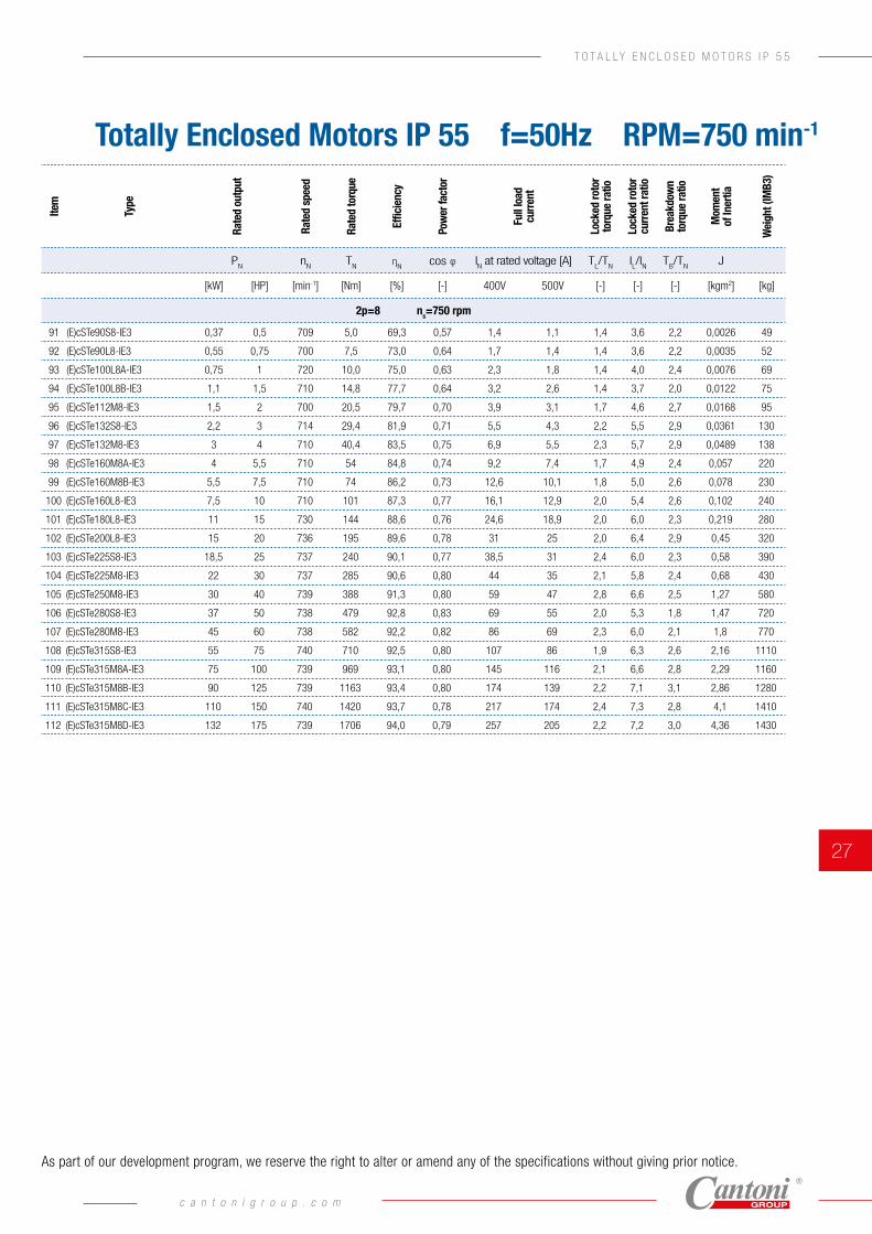
Totally Enclosed Motors IP 55 f=50Hz RPM=750 min-1
Item
Type
Rate
d ou
tput
Rate
d sp
eed
Rate
d to
rque
Effic
ienc
y
Pow
er fa
ctor
Full
load
cu
rren
t
Lock
ed ro
tor
torq
ue ra
tio
Lock
ed ro
tor
curr
ent r
atio
Brea
kdow
n to
rque
ratio
Mom
ent
of In
ertia
Wei
ght (
IMB3
)
PN
nN
TN η
Ncos φ I
N at rated voltage [A] T
L/T
NIL/I
NT
B/T
NJ
[kW] [HP] [min-1] [Nm] [%] [-] 400V 500V [-] [-] [-] [kgm2] [kg]
2p=8 ns=750 rpm
91 (E)cSTe90S8-IE3 0,37 0,5 709 5,0 69,3 0,57 1,4 1,1 1,4 3,6 2,2 0,0026 49
92 (E)cSTe90L8-IE3 0,55 0,75 700 7,5 73,0 0,64 1,7 1,4 1,4 3,6 2,2 0,0035 52
93 (E)cSTe100L8A-IE3 0,75 1 720 10,0 75,0 0,63 2,3 1,8 1,4 4,0 2,4 0,0076 69
94 (E)cSTe100L8B-IE3 1,1 1,5 710 14,8 77,7 0,64 3,2 2,6 1,4 3,7 2,0 0,0122 75
95 (E)cSTe112M8-IE3 1,5 2 700 20,5 79,7 0,70 3,9 3,1 1,7 4,6 2,7 0,0168 95
96 (E)cSTe132S8-IE3 2,2 3 714 29,4 81,9 0,71 5,5 4,3 2,2 5,5 2,9 0,0361 130
97 (E)cSTe132M8-IE3 3 4 710 40,4 83,5 0,75 6,9 5,5 2,3 5,7 2,9 0,0489 138
98 (E)cSTe160M8A-IE3 4 5,5 710 54 84,8 0,74 9,2 7,4 1,7 4,9 2,4 0,057 220
99 (E)cSTe160M8B-IE3 5,5 7,5 710 74 86,2 0,73 12,6 10,1 1,8 5,0 2,6 0,078 230
100 (E)cSTe160L8-IE3 7,5 10 710 101 87,3 0,77 16,1 12,9 2,0 5,4 2,6 0,102 240
101 (E)cSTe180L8-IE3 11 15 730 144 88,6 0,76 24,6 18,9 2,0 6,0 2,3 0,219 280
102 (E)cSTe200L8-IE3 15 20 736 195 89,6 0,78 31 25 2,0 6,4 2,9 0,45 320
103 (E)cSTe225S8-IE3 18,5 25 737 240 90,1 0,77 38,5 31 2,4 6,0 2,3 0,58 390
104 (E)cSTe225M8-IE3 22 30 737 285 90,6 0,80 44 35 2,1 5,8 2,4 0,68 430
105 (E)cSTe250M8-IE3 30 40 739 388 91,3 0,80 59 47 2,8 6,6 2,5 1,27 580
106 (E)cSTe280S8-IE3 37 50 738 479 92,8 0,83 69 55 2,0 5,3 1,8 1,47 720
107 (E)cSTe280M8-IE3 45 60 738 582 92,2 0,82 86 69 2,3 6,0 2,1 1,8 770
108 (E)cSTe315S8-IE3 55 75 740 710 92,5 0,80 107 86 1,9 6,3 2,6 2,16 1110
109 (E)cSTe315M8A-IE3 75 100 739 969 93,1 0,80 145 116 2,1 6,6 2,8 2,29 1160
110 (E)cSTe315M8B-IE3 90 125 739 1163 93,4 0,80 174 139 2,2 7,1 3,1 2,86 1280
111 (E)cSTe315M8C-IE3 110 150 740 1420 93,7 0,78 217 174 2,4 7,3 2,8 4,1 1410
112 (E)cSTe315M8D-IE3 132 175 739 1706 94,0 0,79 257 205 2,2 7,2 3,0 4,36 1430
As part of our development program, we reserve the right to alter or amend any of the specifications without giving prior notice.
c a n t o n i g r o u p . c o m
27
T O T A L L Y E N C L O S E D M O T O R S I P 5 5
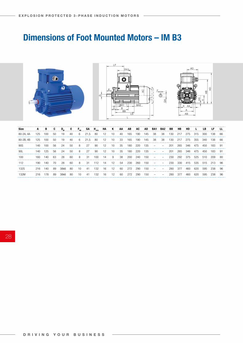
Dimensions of Foot Mounted Motors – IM B3
Size A B C Dj6 E Fh9 GA H-0,5 HA K AA AB AC AD BA1 BA2 BB HB HD L LB LF LL
80-2A, 4A 125 100 50 19 40 6 21,5 80 12 10 40 165 190 145 38 38 130 217 275 315 300 138 66
80-2B, 4B 125 100 50 19 40 6 21,5 80 12 10 33 165 190 145 38 38 130 217 275 355 340 138 66
90S 140 100 56 24 50 8 27 90 12 10 35 180 220 135 – – 201 265 346 475 450 183 91
90L 140 125 56 24 50 8 27 90 12 10 35 180 220 135 – – 201 265 346 475 450 183 91
100 160 140 63 28 60 8 31 100 14 9 38 200 240 150 – – 230 292 375 525 510 209 80
112 190 140 70 28 60 8 31 112 14 12 54 230 260 150 – – 230 330 415 535 515 213 96
132S 216 140 89 38k6 80 10 41 132 16 12 60 272 290 150 – – 280 377 460 620 595 238 96
132M 216 178 89 38k6 80 10 41 132 16 12 60 272 290 150 – – 280 377 460 620 595 238 96
D R I V I N G Y O U R B U S I N E S S
E X P L O S I O N P R O T E C T E D 3 - P H A S E I N D U C T I O N M O T O R S
28
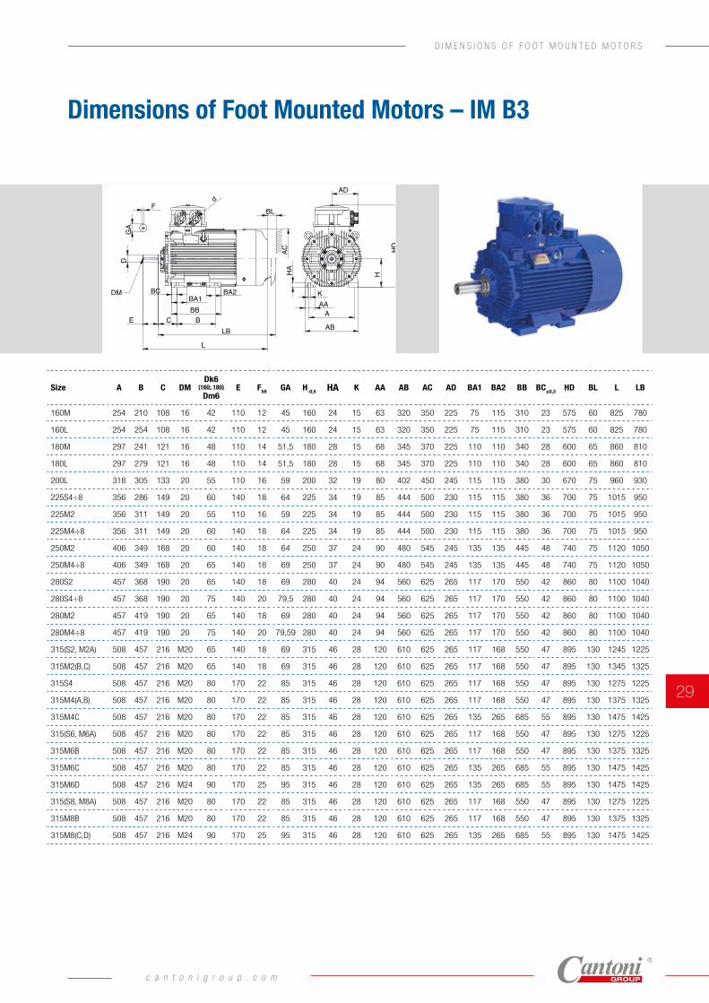
Dimensions of Foot Mounted Motors – IM B3
Size A B C DMDk6
(160; 180)
Dm6E Fh9 GA H-0,5 HA K AA AB AC AD BA1 BA2 BB BC±0,3 HD BL L LB
160M 254 210 108 16 42 110 12 45 160 24 15 63 320 350 225 75 115 310 23 575 60 825 780
160L 254 254 108 16 42 110 12 45 160 24 15 63 320 350 225 75 115 310 23 575 60 825 780
180M 297 241 121 16 48 110 14 51,5 180 28 15 68 345 370 225 110 110 340 28 600 65 860 810
180L 297 279 121 16 48 110 14 51,5 180 28 15 68 345 370 225 110 110 340 28 600 65 860 810
200L 318 305 133 20 55 110 16 59 200 32 19 80 402 450 245 115 115 380 30 670 75 960 930
225S4÷8 356 286 149 20 60 140 18 64 225 34 19 85 444 500 230 115 115 380 36 700 75 1015 950
225M2 356 311 149 20 55 110 16 59 225 34 19 85 444 500 230 115 115 380 36 700 75 1015 950
225M4÷8 356 311 149 20 60 140 18 64 225 34 19 85 444 500 230 115 115 380 36 700 75 1015 950
250M2 406 349 168 20 60 140 18 64 250 37 24 90 480 545 245 135 135 445 48 740 75 1120 1050
250M4÷8 406 349 168 20 65 140 18 69 250 37 24 90 480 545 245 135 135 445 48 740 75 1120 1050
280S2 457 368 190 20 65 140 18 69 280 40 24 94 560 625 265 117 170 550 42 860 80 1100 1040
280S4÷8 457 368 190 20 75 140 20 79,5 280 40 24 94 560 625 265 117 170 550 42 860 80 1100 1040
280M2 457 419 190 20 65 140 18 69 280 40 24 94 560 625 265 117 170 550 42 860 80 1100 1040
280M4÷8 457 419 190 20 75 140 20 79,59 280 40 24 94 560 625 265 117 170 550 42 860 80 1100 1040
315(S2, M2A) 508 457 216 M20 65 140 18 69 315 46 28 120 610 625 265 117 168 550 47 895 130 1245 1225
315M2(B,C) 508 457 216 M20 65 140 18 69 315 46 28 120 610 625 265 117 168 550 47 895 130 1345 1325
315S4 508 457 216 M20 80 170 22 85 315 46 28 120 610 625 265 117 168 550 47 895 130 1275 1225
315M4(A,B) 508 457 216 M20 80 170 22 85 315 46 28 120 610 625 265 117 168 550 47 895 130 1375 1325
315M4C 508 457 216 M20 80 170 22 85 315 46 28 120 610 625 265 135 265 685 55 895 130 1475 1425
315(S6, M6A) 508 457 216 M20 80 170 22 85 315 46 28 120 610 625 265 117 168 550 47 895 130 1275 1225
315M6B 508 457 216 M20 80 170 22 85 315 46 28 120 610 625 265 117 168 550 47 895 130 1375 1325
315M6C 508 457 216 M20 80 170 22 85 315 46 28 120 610 625 265 135 265 685 55 895 130 1475 1425
315M6D 508 457 216 M24 90 170 25 95 315 46 28 120 610 625 265 135 265 685 55 895 130 1475 1425
315(S8, M8A) 508 457 216 M20 80 170 22 85 315 46 28 120 610 625 265 117 168 550 47 895 130 1275 1225
315M8B 508 457 216 M20 80 170 22 85 315 46 28 120 610 625 265 117 168 550 47 895 130 1375 1325
315M8(C,D) 508 457 216 M24 90 170 25 95 315 46 28 120 610 625 265 135 265 685 55 895 130 1475 1425
DM
DG
A
Fd
BA1BA2
BCEBB
LB
L
AC
BL
HAKAA
A
AB
H
HD
AD
BC
c a n t o n i g r o u p . c o m
29
D I M E N S I O N S O F F O O T M O U N T E D M O T O R S
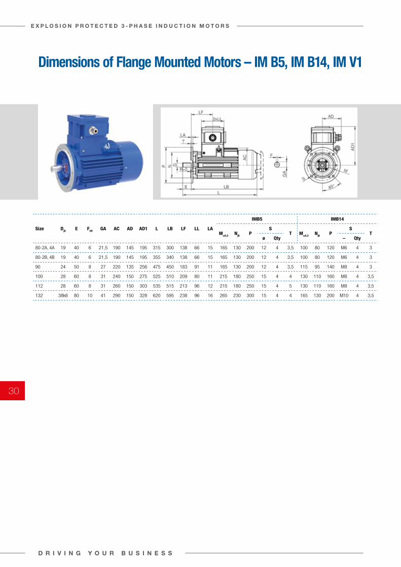
Dimensions of Flange Mounted Motors – IM B5, IM B14, IM V1
Size Dj6 E Fh9 GA AC AD AD1 L LB LF LL LA
IMB5 IMB14
M±0,3 Nj6 PS
T M±0,3 Nj6 PS
Tø Qty – Qty
80-2A, 4A 19 40 6 21,5 190 145 195 315 300 138 66 15 165 130 200 12 4 3,5 100 80 120 M6 4 3
80-2B, 4B 19 40 6 21,5 190 145 195 355 340 138 66 15 165 130 200 12 4 3,5 100 80 120 M6 4 3
90 24 50 8 27 220 135 256 475 450 183 91 11 165 130 200 12 4 3,5 115 95 140 M8 4 3
100 28 60 8 31 240 150 275 525 510 209 80 11 215 180 250 15 4 4 130 110 160 M8 4 3,5
112 28 60 8 31 260 150 303 535 515 213 96 12 215 180 250 15 4 5 130 110 160 M8 4 3,5
132 38k6 80 10 41 290 150 328 620 595 238 96 16 265 230 300 15 4 4 165 130 200 M10 4 3,5
D R I V I N G Y O U R B U S I N E S S
E X P L O S I O N P R O T E C T E D 3 - P H A S E I N D U C T I O N M O T O R S
30
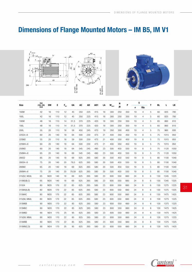
Dimensions of Flange Mounted Motors – IM B5, IM V1
SizeDk6
(160; 180)Dm6
DM E Fh9 GA AC AD AD1 LA M±0,4
N j6
PS
T BL L LBø Qty
160M 42 16 110 12 45 350 225 415 18 300 250 350 19 4 5 60 825 780
160L 42 16 110 12 45 350 225 415 18 300 250 350 19 4 5 60 825 780
180M 48 16 110 14 51,5 370 225 420 18 300 250 350 19 4 5 65 860 810
180L 48 16 110 14 51,5 370 225 420 18 300 250 350 19 4 5 65 860 810
200L 55 20 110 16 59 450 245 470 19 350 300 400 19 4 5 75 960 930
225S4÷8 60 20 140 18 64 500 230 475 21 400 350 450 19 8 5 75 1015 950
225M2 55 20 110 16 59 500 230 475 21 400 350 450 19 8 5 75 1015 950
225M4÷8 60 20 140 18 64 500 230 475 21 400 350 450 19 8 5 75 1015 950
250M2 60 20 140 18 64 545 245 490 23 500 450 550 19 8 5 75 1120 1050
250M4÷8 65 20 140 18 69 545 245 490 23 500 450 550 19 8 5 75 1120 1050
280S2 65 20 140 18 69 625 265 580 20 500 450 550 19 8 5 80 1100 1040
280S4÷8 75 20 140 20 79,5 625 265 580 20 500 450 550 19 8 5 80 1100 1040
280M2 65 20 140 18 69 625 265 580 20 500 450 550 19 8 5 80 1100 1040
280M4÷8 75 20 140 20 79,59 625 265 580 20 500 450 550 19 8 5 80 1100 1040
315(S2, M2A) 65 M20 140 18 69 625 265 580 23 600 550 660 24 8 6 130 1245 1225
315M2(B,C) 65 M20 140 18 69 625 265 580 23 600 550 660 24 8 6 130 1345 1325
315S4 80 M20 170 22 85 625 265 580 23 600 550 660 24 8 6 130 1275 1225
315M4(A,B) 80 M20 170 22 85 625 265 580 23 600 550 660 24 8 6 130 1375 1325
315M4C 80 M20 170 22 85 625 265 580 23 600 550 660 24 8 6 130 1475 1425
315(S6, M6A) 80 M20 170 22 85 625 265 580 23 600 550 660 24 8 6 130 1275 1225
315M6B 80 M20 170 22 85 625 265 580 23 600 550 660 24 8 6 130 1375 1325
315M6C 80 M20 170 22 85 625 265 580 23 600 550 660 24 8 6 130 1475 1425
315M6D 90 M24 170 25 95 625 265 580 23 600 550 660 24 8 6 130 1475 1425
315(S8, M8A) 80 M20 170 22 85 625 265 580 23 600 550 660 24 8 6 130 1275 1225
315M8B 80 M20 170 22 85 625 265 580 23 600 550 660 24 8 6 130 1375 1325
315M8(C,D) 90 M24 170 25 95 625 265 580 23 600 550 660 24 8 6 130 1475 1425
DM
BL
AC
d
T
LA
F
GA
R=0
N D
LB
L
E22,5°
45°
8 x
M
SP
AD1
AD
45°
90°
(4 x
90º
)fo
r 160
-180
(8 x
45º
) fo
r 200
-315
c a n t o n i g r o u p . c o m
31
D I M E N S I O N S O F F L A N G E M O U N T E D M O T O R S
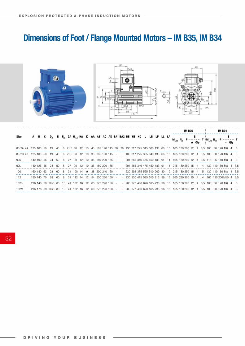
Dimensions of Foot / Flange Mounted Motors – IM B35, IM B34
Size A B C Dj6 E Fh9 GA H-0,5 HA K AA AB AC AD BA1 BA2 BB HB HD L LB LF LL LA
IM B35 IM B34
M±0,3 Nj6 PS
T M±0,3 Nj86 PS
Tø Qty - Qty
80-2A, 4A 125 100 50 19 40 6 21,5 80 12 10 40 165 190 145 38 38 130 217 275 315 300 138 66 15 165 130 200 12 4 3,5 100 80 120 M6 4 3
80-2B, 4B 125 100 50 19 40 6 21,5 80 12 10 33 165 190 145 - - 183 217 275 355 340 138 66 15 165 130 200 12 4 3,5 100 80 120 M6 4 3
90S 140 100 56 24 50 8 27 90 12 10 35 180 220 135 - - 201 265 346 475 450 183 91 11 165 130 200 12 4 3,5 115 95 140 M8 4 3
90L 140 125 56 24 50 8 27 90 12 10 35 180 220 135 - - 201 265 346 475 450 183 91 11 215 180 250 15 4 4 130 110 160 M8 4 3,5
100 160 140 63 28 60 8 31 100 14 9 38 200 240 150 - - 230 292 375 525 510 209 80 12 215 180 250 15 4 5 130 110 160 M8 4 3,5
112 190 140 70 28 60 8 31 112 14 12 54 230 260 150 - - 230 330 415 535 515 213 96 16 265 230 300 15 4 4 165 130 200 M10 4 3,5
132S 216 140 89 38k6 80 10 41 132 16 12 60 272 290 150 - - 280 377 460 620 595 238 96 15 165 130 200 12 4 3,5 100 80 120 M6 4 3
132M 216 178 89 38k6 80 10 41 132 16 12 60 272 290 150 - - 280 377 460 620 595 238 96 15 165 130 200 12 4 3,5 100 80 120 M6 4 3
D R I V I N G Y O U R B U S I N E S S
E X P L O S I O N P R O T E C T E D 3 - P H A S E I N D U C T I O N M O T O R S
32
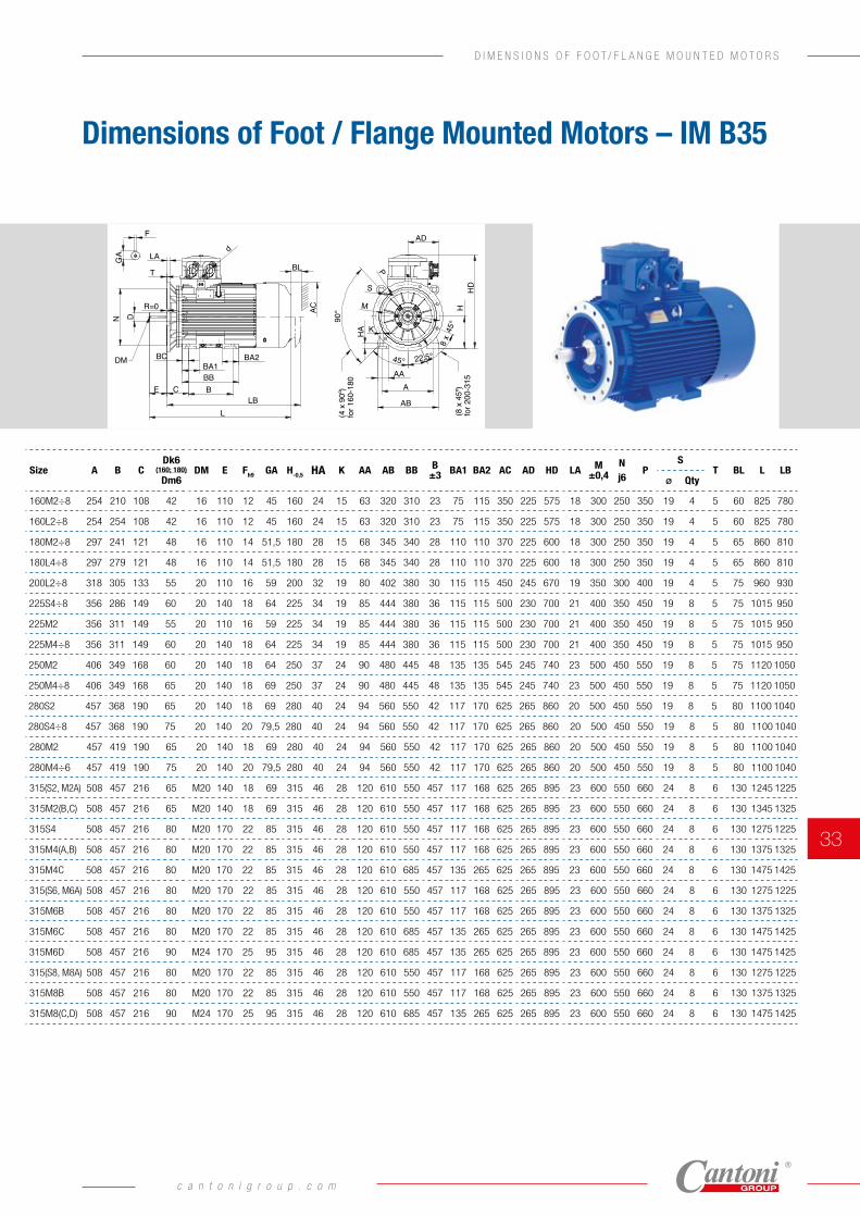
Size A B CDk6
(160; 180)
Dm6DM E Fh9 GA H-0,5 HA K AA AB BB B
±3 BA1 BA2 AC AD HD LA M ±0,4
N j6
PS
T BL L LBø Qty
160M2÷8 254 210 108 42 16 110 12 45 160 24 15 63 320 310 23 75 115 350 225 575 18 300 250 350 19 4 5 60 825 780
160L2÷8 254 254 108 42 16 110 12 45 160 24 15 63 320 310 23 75 115 350 225 575 18 300 250 350 19 4 5 60 825 780
180M2÷8 297 241 121 48 16 110 14 51,5 180 28 15 68 345 340 28 110 110 370 225 600 18 300 250 350 19 4 5 65 860 810
180L4÷8 297 279 121 48 16 110 14 51,5 180 28 15 68 345 340 28 110 110 370 225 600 18 300 250 350 19 4 5 65 860 810
200L2÷8 318 305 133 55 20 110 16 59 200 32 19 80 402 380 30 115 115 450 245 670 19 350 300 400 19 4 5 75 960 930
225S4÷8 356 286 149 60 20 140 18 64 225 34 19 85 444 380 36 115 115 500 230 700 21 400 350 450 19 8 5 75 1015 950
225M2 356 311 149 55 20 110 16 59 225 34 19 85 444 380 36 115 115 500 230 700 21 400 350 450 19 8 5 75 1015 950
225M4÷8 356 311 149 60 20 140 18 64 225 34 19 85 444 380 36 115 115 500 230 700 21 400 350 450 19 8 5 75 1015 950
250M2 406 349 168 60 20 140 18 64 250 37 24 90 480 445 48 135 135 545 245 740 23 500 450 550 19 8 5 75 1120 1050
250M4÷8 406 349 168 65 20 140 18 69 250 37 24 90 480 445 48 135 135 545 245 740 23 500 450 550 19 8 5 75 1120 1050
280S2 457 368 190 65 20 140 18 69 280 40 24 94 560 550 42 117 170 625 265 860 20 500 450 550 19 8 5 80 1100 1040
280S4÷8 457 368 190 75 20 140 20 79,5 280 40 24 94 560 550 42 117 170 625 265 860 20 500 450 550 19 8 5 80 1100 1040
280M2 457 419 190 65 20 140 18 69 280 40 24 94 560 550 42 117 170 625 265 860 20 500 450 550 19 8 5 80 1100 1040
280M4÷6 457 419 190 75 20 140 20 79,5 280 40 24 94 560 550 42 117 170 625 265 860 20 500 450 550 19 8 5 80 1100 1040
315(S2, M2A) 508 457 216 65 M20 140 18 69 315 46 28 120 610 550 457 117 168 625 265 895 23 600 550 660 24 8 6 130 1245 1225
315M2(B,C) 508 457 216 65 M20 140 18 69 315 46 28 120 610 550 457 117 168 625 265 895 23 600 550 660 24 8 6 130 1345 1325
315S4 508 457 216 80 M20 170 22 85 315 46 28 120 610 550 457 117 168 625 265 895 23 600 550 660 24 8 6 130 1275 1225
315M4(A,B) 508 457 216 80 M20 170 22 85 315 46 28 120 610 550 457 117 168 625 265 895 23 600 550 660 24 8 6 130 1375 1325
315M4C 508 457 216 80 M20 170 22 85 315 46 28 120 610 685 457 135 265 625 265 895 23 600 550 660 24 8 6 130 1475 1425
315(S6, M6A) 508 457 216 80 M20 170 22 85 315 46 28 120 610 550 457 117 168 625 265 895 23 600 550 660 24 8 6 130 1275 1225
315M6B 508 457 216 80 M20 170 22 85 315 46 28 120 610 550 457 117 168 625 265 895 23 600 550 660 24 8 6 130 1375 1325
315M6C 508 457 216 80 M20 170 22 85 315 46 28 120 610 685 457 135 265 625 265 895 23 600 550 660 24 8 6 130 1475 1425
315M6D 508 457 216 90 M24 170 25 95 315 46 28 120 610 685 457 135 265 625 265 895 23 600 550 660 24 8 6 130 1475 1425
315(S8, M8A) 508 457 216 80 M20 170 22 85 315 46 28 120 610 550 457 117 168 625 265 895 23 600 550 660 24 8 6 130 1275 1225
315M8B 508 457 216 80 M20 170 22 85 315 46 28 120 610 550 457 117 168 625 265 895 23 600 550 660 24 8 6 130 1375 1325
315M8(C,D) 508 457 216 90 M24 170 25 95 315 46 28 120 610 685 457 135 265 625 265 895 23 600 550 660 24 8 6 130 1475 1425
Dimensions of Foot / Flange Mounted Motors – IM B35
DM
T
LA
F
GA
R=0
N
BA1BA2
BCEBB
LBL
BL
d
AC
K
AAA
AB
HA
HHD
AD
S
M
P
D
22,5°
45°
8 x
45°
90°
(4 x
90º
)fo
r 160
-180
(8 x
45º
) fo
r 200
-315
BC
c a n t o n i g r o u p . c o m
33
D I M E N S I O N S O F F O O T / F L A N G E M O U N T E D M O T O R S
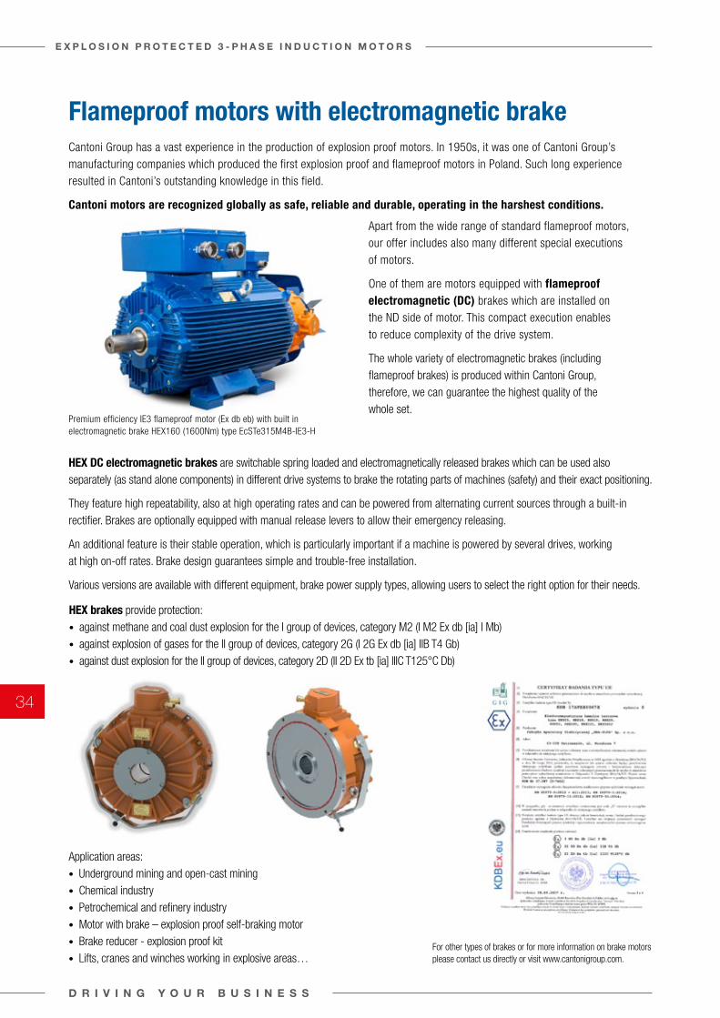
Flameproof motors with electromagnetic brakeCantoni Group has a vast experience in the production of explosion proof motors. In 1950s, it was one of Cantoni Group’s manufacturing companies which produced the first explosion proof and flameproof motors in Poland. Such long experience resulted in Cantoni’s outstanding knowledge in this field.
Cantoni motors are recognized globally as safe, reliable and durable, operating in the harshest conditions.
Apart from the wide range of standard flameproof motors, our offer includes also many different special executions of motors.
One of them are motors equipped with flameproof electromagnetic (DC) brakes which are installed on the ND side of motor. This compact execution enables to reduce complexity of the drive system.
The whole variety of electromagnetic brakes (including flameproof brakes) is produced within Cantoni Group, therefore, we can guarantee the highest quality of the whole set.
Premium efficiency IE3 flameproof motor (Ex db eb) with built in electromagnetic brake HEX160 (1600Nm) type EcSTe315M4B-IE3-H
HEX DC electromagnetic brakes are switchable spring loaded and electromagnetically released brakes which can be used also separately (as stand alone components) in different drive systems to brake the rotating parts of machines (safety) and their exact positioning.
They feature high repeatability, also at high operating rates and can be powered from alternating current sources through a built-in rectifier. Brakes are optionally equipped with manual release levers to allow their emergency releasing.
An additional feature is their stable operation, which is particularly important if a machine is powered by several drives, working at high on-off rates. Brake design guarantees simple and trouble-free installation.
Various versions are available with different equipment, brake power supply types, allowing users to select the right option for their needs.
HEX brakes provide protection:• against methane and coal dust explosion for the I group of devices, category M2 (I M2 Ex db [ia] I Mb)• against explosion of gases for the II group of devices, category 2G (I 2G Ex db [ia] IIB T4 Gb)• against dust explosion for the II group of devices, category 2D (II 2D Ex tb [ia] IIIC T125°C Db)
Application areas:• Underground mining and open-cast mining• Chemical industry• Petrochemical and refinery industry• Motor with brake – explosion proof self-braking motor• Brake reducer - explosion proof kit• Lifts, cranes and winches working in explosive areas…
For other types of brakes or for more information on brake motors please contact us directly or visit www.cantonigroup.com.
D R I V I N G Y O U R B U S I N E S S
E X P L O S I O N P R O T E C T E D 3 - P H A S E I N D U C T I O N M O T O R S
34

Frame size: 90-132Motor series (E)cSTe
1
3
3
2
4
4
7
9
8
10
11
12
13
21
19a
20a
24
23
22
20b19b
18
15
16
6
14
5
17
List of Motor parts
Frame Size: 80÷132
DE – drive endNDE – non drive end
Item Description
1 DE shield
2 rotor
3 shaft seal
4 bearing
5 key
6 stator without feet
7 nameplate
8 left feet
9 right feet
10 NDE shield
11 fan
12 seeger ring
13 fan cover
14 cable bushing
15 terminal box cover
16 terminal board
17 cable gland
18 terminal box housing
19ab seeger ring – except (E)cST(K,L,1)80
20abexternal bearing cover – except (E)cST(K,L,1)80
21 spring washer
22 seeger ring – except (E)cST(K,L,1)80
23 B14 shield
24 B5 shield
L I S T O F M O T O R P A R T S
c a n t o n i g r o u p . c o m
35
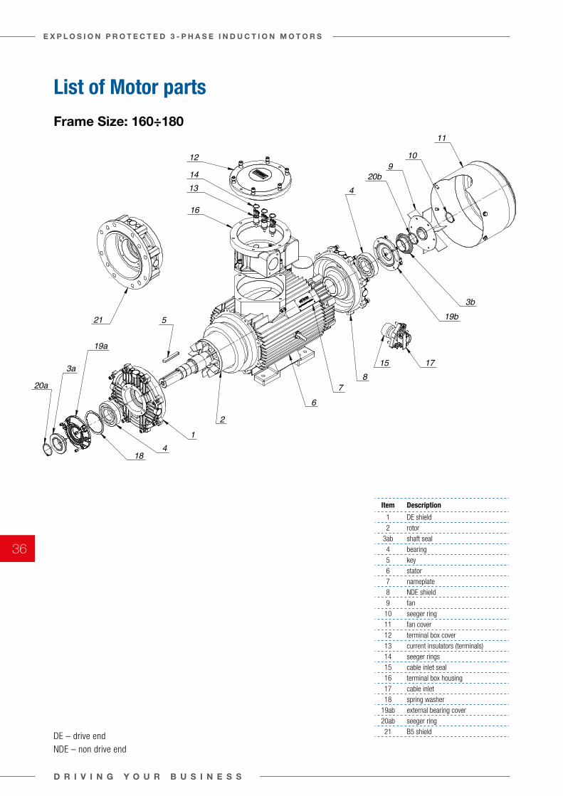
Frame size: 160-180Motor series (E)cSTe
1
2
3a
3b
4
5
109
16
18
20a
21
15
4
7
11
19b
12
14
17
19a
13
6
8
20b
List of Motor parts
Frame Size: 160÷180
DE – drive endNDE – non drive end
Item Description
1 DE shield
2 rotor
3ab shaft seal
4 bearing
5 key
6 stator
7 nameplate
8 NDE shield
9 fan
10 seeger ring
11 fan cover
12 terminal box cover
13 current insulators (terminals)
14 seeger rings
15 cable inlet seal
16 terminal box housing
17 cable inlet
18 spring washer
19ab external bearing cover
20ab seeger ring
21 B5 shield
D R I V I N G Y O U R B U S I N E S S
E X P L O S I O N P R O T E C T E D 3 - P H A S E I N D U C T I O N M O T O R S
36
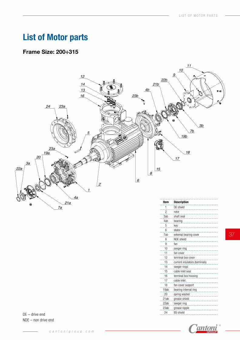
Frame size: 200-315Motor series (E)cSTe
12
3a
3b
4a
4b
5
6
7b
1110
922b
21b
19b
1817
12
16
24
23b
19a20
23a
23a
21a7a
22a8
1314
15
List of Motor parts
Frame Size: 200÷315
DE – drive endNDE – non drive end
Item Description
1 DE shield
2 rotor
3ab shaft seal
4ab bearing
5 key
6 stator
7ab external bearing cover
8 NDE shield
9 fan
10 seeger ring
11 fan cover
12 terminal box cover
13 current insulators (terminals)
14 seeger rings
15 cable inlet seal
16 terminal box housing
17 cable inlet
18 fan cover support
19ab bearing internal ring
20 spring washer
21ab grease shield
22ab seeger ring
23ab grease nipple
24 B5 shield
c a n t o n i g r o u p . c o m
37
L I S T O F M O T O R P A R T S
Ordering information
As part of our development program, we reserve the right to alter or amend any of the specifications without giving prior notice.
Orders for motors should specify » motor type designation, including terminal box design
(Ex db or Ex eb) » ambient temperature, » rated output, » rated speed, » operating duty, » supply voltage and connection, » frequency, » mounting arrangements, » degree of protection, » type of driven machine, » number of cable glands, » other details regarding special requests,
and information concerning additional accessories e.g. » auxiliary terminal box, » thermal protection, » anticondensation heaters, » vibration sensors, » method of start-up (DOL, Y/∆, VSD, Soft-Start), » method of coupling with the driven unit (gears, dimensions
of belt pulleys, etc.).
When ordering spare parts one should specify: » full designation of the motor type including its serial
number (provided on the nameplate), » degree of protection, » mounting arrangement, » name of part, » number of pieces.
In order to select the proper motor and provide you the most accurate offer as the requirements of customer's applications are various, we ask you to specify below motor details:
D R I V I N G Y O U R B U S I N E S S
E X P L O S I O N P R O T E C T E D 3 - P H A S E I N D U C T I O N M O T O R S
38
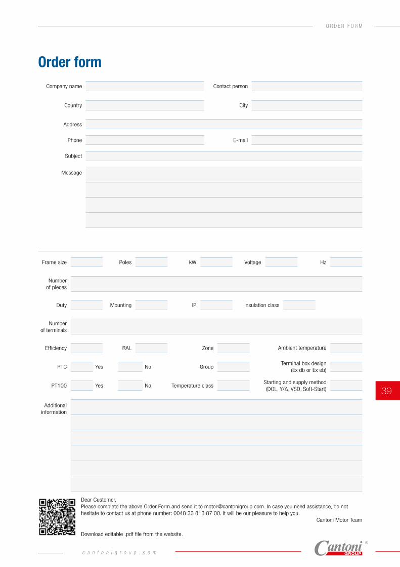
Ambient temperature
Terminal box design (Ex db or Ex eb)
Starting and supply method (DOL, Y/∆, VSD, Soft-Start)
Order form
Frame size Poles kW Voltage Hz
Number of pieces
Number of terminals
Duty Mounting IP Insulation class
Efficiency RAL Zone
Group
Temperature class
Company name Contact person
Country City
Phone E-mail
Address
Subject
Message
Additional information
PTC Yes No
PT100 Yes No
Download editable .pdf file from the website.
Dear Customer,Please complete the above Order Form and send it to [email protected]. In case you need assistance, do not hesitate to contact us at phone number: 0048 33 813 87 00. It will be our pleasure to help you.
Cantoni Motor Team
c a n t o n i g r o u p . c o m
39
O R D E R F O R M
Certifications
Place and date: For the issuing office:Gdynia, 01 December 2020 DNV GL – Business Assurance
ul. Łużycka 6e, 81-537 Gdynia, Poland
Tomasz SłupekManagement Representative
Lack of fulfilment of conditions as set out in the Certification Agreement may render this Certificate invalid.ACCREDITED UNIT: DNV GL Business Assurance B.V., Zwolseweg 1, 2994 LB, Barendrecht, Netherlands. TEL:+31(0)102922689. www.dnvgl.com/assurance
MANAGEMENT SYSTEM CERTIFICATECertificate No:250265-2017-AE-POL-RvA
Initial certification date:15 November 1999
Valid:12 December 2020 - 11 December 2023
This is to certify that the management system of
CELMA INDUKTA S.A.ul. 3 Maja 19, 43-400 Cieszyn, Polandand the sites as mentioned in the appendix accompanying this certificate
has been found to conform to the Environmental Management System standard:ISO 14001:2015
This certificate is valid for the following scope:Design, production and repair of electric machines.
Place and date: For the issuing office:Gdynia, 01 December 2020 DNV GL – Business Assurance
ul. Łużycka 6e, 81-537 Gdynia, Poland
Tomasz SłupekManagement Representative
Lack of fulfilment of conditions as set out in the Certification Agreement may render this Certificate invalid.ACCREDITED UNIT: DNV GL Business Assurance B.V., Zwolseweg 1, 2994 LB, Barendrecht, Netherlands. TEL:+31(0)102922689. www.dnvgl.com/assurance
MANAGEMENT SYSTEM CERTIFICATECertificate No:250264-2017-AQ-POL-RvA
Initial certification date:22 May 1995
Valid:04 December 2020 - 03 December 2023
This is to certify that the management system of
CELMA INDUKTA S.A.ul. 3 Maja 19, 43-400 Cieszyn, Polandand the sites as mentioned in the appendix accompanying this certificate
has been found to conform to the Quality Management System standard:ISO 9001:2015
This certificate is valid for the following scope:Design, production and repair of electric machines.
Cantoni Group’s factory, Celma Indukta was one of the first companies obtaining ISO 9001 certificate in Poland
All Cantoni Group manufacturing plants comply with the most important standards.
ISO 9001 is based on a number of quality management principles including a strong customer focus, the motivation and involvment of top management, the process approach and continuous improvement. Using ISO 9001 helps to ensure that customers get consistent, good quality products and services.
Our aim is to produce high quality products certified according to the most important standards. We always focus our work to provide a product that meets the customer requirements, define the approach to continuous improvement and monitor
customer satisfaction. All employees in our Group are fully engaged and motivated to provide the top quality products. We achieve this thanks to skilled technicians, trained workers and customer oriented attitude.
As a demonstration of our aim to meet all high level international standard requirements, we are also certified ISO 14001 and OHSAS 18001 to prove our internal processes and behaviour.
ISO 14001 certification confirms that the organization manages their environmental responsibilities in an effective and internationally accepted way.
In Cantoni Group we know that taking care of the environment means taking care of our present and future.
D R I V I N G Y O U R B U S I N E S S
E X P L O S I O N P R O T E C T E D 3 - P H A S E I N D U C T I O N M O T O R S
40
This certificate is issued toFABRYKA SILNIKOW ELEKTRYCZNYCH BESEL S.A.
BRZEG - POLAND
for the type of productASYNCHRONOUS MACHINES (Power below 100kW)
Three phase induction motors Type mSh
Requirements:Bureau Veritas Rules for the Classification of Steel ShipsIEC 60034-1 (2010)
Page 1 / 3
Certificate number: 22541/C0 BVFile number: ACE 4/859/1
Product code: 2584HThis certificate is not valid when presented without the full attached schedule
composed of 7 sections
www.veristar.com
TYPE APPROVAL CERTIFICATE
This certificate is issued to attest that Bureau Veritas Marine & Offshore did undertake the relevant approval procedures for the product identifiedabove which was found to comply with the relevant requirements mentioned above.
This certificate will expire on: 01 Jul 2025
For Bureau Veritas Marine & Offshore,At BV KATOWICE, on 01 Jul 2020,Wojciech Lubojanski
This certificate remains valid until the date stated above, unless cancelled or revoked, provided the conditions indicated in the subsequent page(s) are compliedwith and the product remains satisfactory in service. This certificate will not be valid if the applicant makes any changes or modifications to the approved product,which have not been notified to, and agreed in writing with Bureau Veritas Marine & Offshore. Should the specified regulations or standards be amended duringthe validity of this certificate, the product(s) is/are to be re-approved prior to it/they being placed on board vessels to which the amended regulations or standardsapply. This certificate is issued within the scope of the General Conditions of Bureau Veritas Marine & Offshore available on the internet site www.veristar.com.Any Person not a party to the contract pursuant to which this document is delivered may not assert a claim against Bureau Veritas Marine & Offshore for anyliability arising out of errors or omissions which may be contained in said document, or for errors of judgement, fault or negligence committed by personnel of theSociety or of its Agents in establishment or issuance of this document, and in connection with any activities for which it may provide.
The electronic version is available at: http://www.veristarpm.com/veristarnb/jsp/viewPublicPdfTypec.jsp?id=g8sq2qafwpBV Mod. Ad.E 530 June 2017 This certificate consists of 3 page(s)
Certificate of Qualification
This is to certify that
CELMA INDUKTA S.A. Ul. 3 Maja 19, Cieszyn, 43-400
POLAND
has been qualified by CSA Group Testing & Certification Inc., as a Testing Facility for
CSA ENERGY EFFICIENCY VERIFICATION PROGRAM
Based on ISO/IEC 17025:2017 operating as a SMTC
and to test products to the following performance standards: CAN/CSA 390-10
Issued Date: August 09, 2019 Expiry Date: August 08, 2022 Stéphane Larivière Operations Manager
DQD 309-586.31 Doc Rev 2018-12-15 © 2018 CSA Group . All Rights Reserved.
Certificate of Qualification
This is to certify that
CELMA INDUKTA S.A. Ul. 3 Maja 19, Cieszyn, 43-400
POLAND
has been qualified by CSA Group Testing & Certification Inc., as a Testing Facility for
SUPERVISED MANUFACTURER'S TESTING FOR CERTIFICATION PROGRAM
Based on ISO/IEC 17025:2017
Issued Date: August 8, 2019 Expiry Date: August 7, 2022 Stéphane Larivière Operations Manager
DQD 309-586.31 Doc Rev 2018-12-15 © 2019 CSA Group . All Rights Reserved.
With OHSAS 18001 certificate, Cantoni Group confirms the necessity of controlling and improving health and safety aspects within the organization.
Employees are Cantoni Group’s main asset, thus, their well-being and safety are our priority.
Our laboratory Celma Indukta is also ISO 17025 certified by Canadian Standard Association (CSA) for two aspects: safety and energy efficiency verification requirements as independent unit.
The safety part – Supervised Manufacturers Testing Certification (SMTC) confirms that our laboratory is allowed for supervised manufactured safety certification program.
The energy efficiency part confirms that energy verification program for motors operating as SMTC can be performed according to CSA 390 standard at our facilities.
All our prototype motors are tested and approved before series production and samples of our final products are tested periodically to check compliance with all parameters defined. Our production range has also different types of products certifications based on specific technical requirements, like UL-CSA, GOST, EAC, ATEX, IEC Ex, CCC, Bureau Veritas, DNV-GL, etc.
Our technicians are constantly updated, informed and trained about every new regulation in order to provide all possible solutions to meet final customer requirements and also study and engineer ad-hoc products with customers developers.
c a n t o n i g r o u p . c o m
41
C E R T I F I C A T I O N S
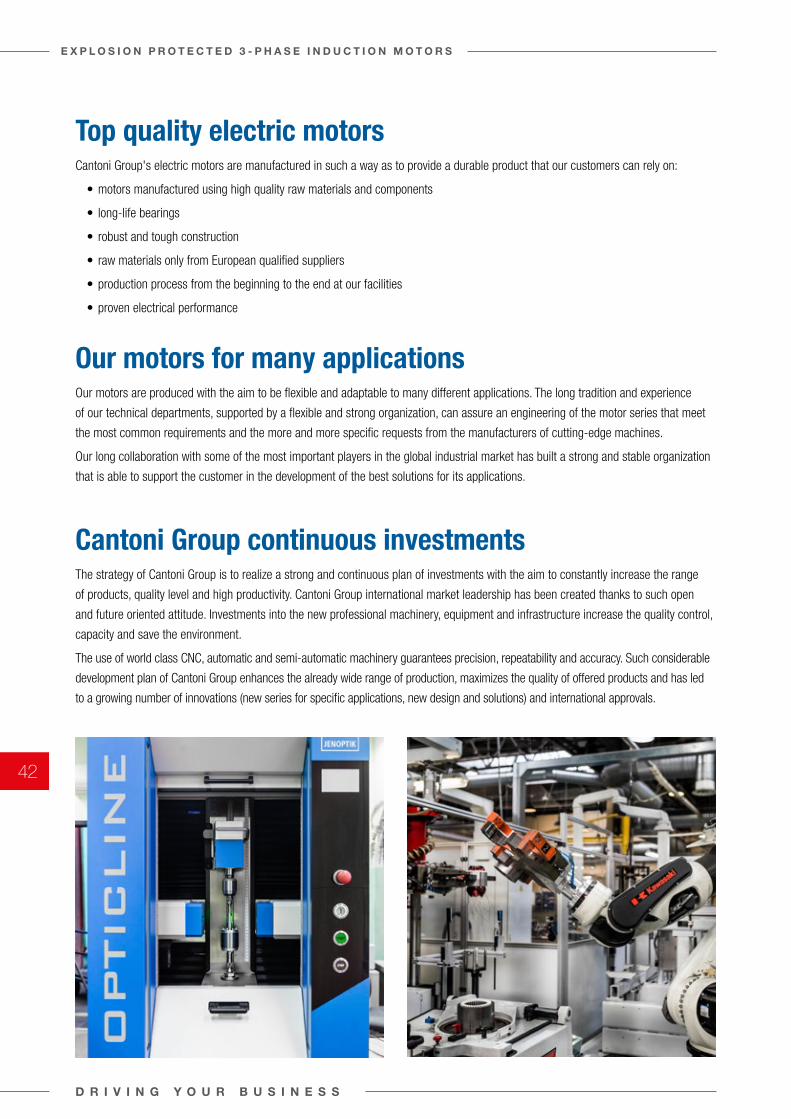
Cantoni Group's electric motors are manufactured in such a way as to provide a durable product that our customers can rely on:
• motors manufactured using high quality raw materials and components
• long-life bearings
• robust and tough construction
• raw materials only from European qualified suppliers
• production process from the beginning to the end at our facilities
• proven electrical performance
Our motors are produced with the aim to be flexible and adaptable to many different applications. The long tradition and experience
of our technical departments, supported by a flexible and strong organization, can assure an engineering of the motor series that meet
the most common requirements and the more and more specific requests from the manufacturers of cutting-edge machines.
Our long collaboration with some of the most important players in the global industrial market has built a strong and stable organization
that is able to support the customer in the development of the best solutions for its applications.
The strategy of Cantoni Group is to realize a strong and continuous plan of investments with the aim to constantly increase the range
of products, quality level and high productivity. Cantoni Group international market leadership has been created thanks to such open
and future oriented attitude. Investments into the new professional machinery, equipment and infrastructure increase the quality control,
capacity and save the environment.
The use of world class CNC, automatic and semi-automatic machinery guarantees precision, repeatability and accuracy. Such considerable
development plan of Cantoni Group enhances the already wide range of production, maximizes the quality of offered products and has led
to a growing number of innovations (new series for specific applications, new design and solutions) and international approvals.
Top quality electric motors
Our motors for many applications
Cantoni Group continuous investments
D R I V I N G Y O U R B U S I N E S S
E X P L O S I O N P R O T E C T E D 3 - P H A S E I N D U C T I O N M O T O R S
42
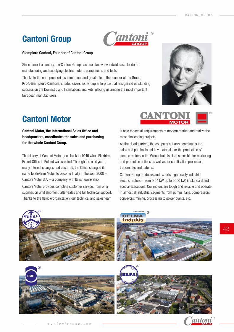
Giampiero Cantoni, Founder of Cantoni Group
Since almost a century, the Cantoni Group has been known worldwide as a leader in
manufacturing and supplying electric motors, components and tools.
Thanks to the entrepreneurial commitment and great talent, the founder of the Group,
Prof. Giampiero Cantoni, created diversified Group Enterprise that has gained outstanding
success on the Domestic and International markets, placing us among the most important
European manufacturers.
Cantoni Motor, the International Sales Office and
Headquarters, coordinates the sales and purchasing
for the whole Cantoni Group.
The history of Cantoni Motor goes back to 1945 when Elektrim
Export Office in Poland was created. Through the next years,
many internal changes had occurred, the Office changed its
name to Elektrim Motor, to become finally in the year 2000 –
Cantoni Motor S.A. – a company with Italian ownership.
Cantoni Motor provides complete customer service, from offer
submission until shipment, after-sales and full technical support.
Thanks to the flexible organization, our technical and sales team
is able to face all requirements of modern market and realize the
most challenging projects.
As the Headquarters, the company not only coordinates the
sales and purchasing of key materials for the production of
electric motors in the Group, but also is responsible for marketing
and promotion actions as well as for certification processes,
trademarks and patents.
Cantoni Group produces and exports high quality industrial
electric motors – from 0,04 kW up to 6000 kW, in standard and
special executions. Our motors are tough and reliable and operate
in almost all industrial segments from pumps, fans, compressors,
conveyors, mining, processing to power plants, etc.
Cantoni Group
Cantoni Motor
c a n t o n i g r o u p . c o m
43
C A N T O N I G R O U P
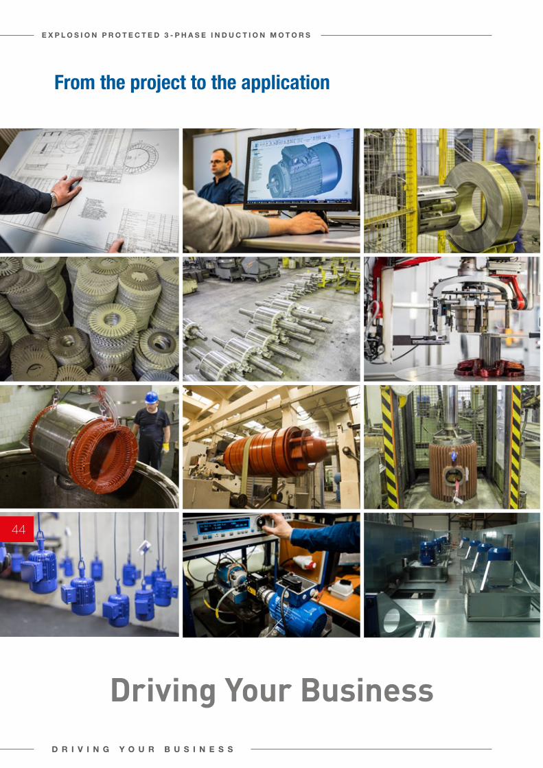
From the project to the application
Driving Your BusinessD R I V I N G Y O U R B U S I N E S S
E X P L O S I O N P R O T E C T E D 3 - P H A S E I N D U C T I O N M O T O R S
44
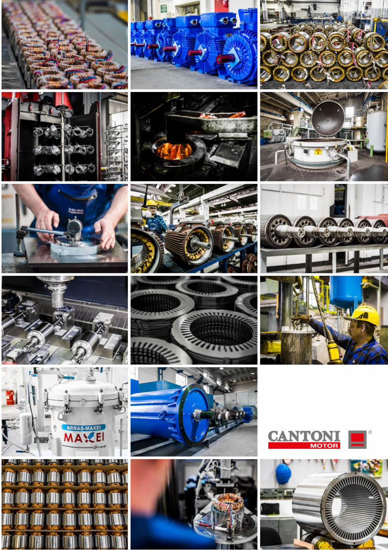

CANTONI MOTOR S.A.3 MAJA 2843-400 CIESZYN, POLANDtel. +48 33 813 87 00fax +48 33 813 87 [email protected]
AT
EX
-EN
/VE
R_A