assemblies of cigar-shaped ferrite nanocrystals: orientation of the easy magnetization axes
TRANSCRIPT
Colloids and Surfaces A: Physicochem. Eng. Aspects 228 (2003) 107–117
Assemblies of cigar-shaped ferrite nanocrystals:orientation of the easy magnetization axes
A.T. Ngo, M.P. Pileni∗
Laboratoire des Matériaux Mésoscopiques et Nanomètriques, Université Pierre et Marie Curie,LM2N, U.M.R 7070, BP 52, 4 place Jussieu, 75005 Paris, France
Abstract
Mesoscopic structures made of cigar-shaped maghemite (�-Fe2O3) nanocrystals differing by their sizes are described. Thestructures were prepared by slow evaporation of a dilute suspension of nanocrystals, to which could be applied a magneticfield parallel to the substrate. If a magnetic field was applied, the nanocrystals rotated their long axis along the magnetic fielddirection to form ribbons whereas without a field the nanocrystals remained deposited on the substrate with a random orientation.The aligned nanocrystals is responsible of the anisotropy of the ribbons as evidence by the hysteresis loops. Moreover, a highdemagnetizing field is observed when the magnetization measurements are made with an applied field normal to the ribbons.© 2003 Elsevier B.V. All rights reserved.
Keywords: Maghemite nanoparticles; Thin magnetic film; Orientation of the easy axes; Hysteresis loops; Demagnetizing field
1. Introduction
Ferromagnetic nanocrystals present a real challengein developing high-density magnetic recording media.Isolated magnetic nanoparticles usually characterizedby a superparamagnetic behavior has been extensivelystudied and is rather well understood[1]. This in-duces random fluctuations of the magnetic moment inthe nanocrystals and then a limit in the storage den-sity. On the other hand, when they are agglomeratedin dense systems such as granular films, the magneticproperties largely differ both from those of the individ-ual nanocrystals and the bulk material[2]. There arenumerous results for granular magnetic solids[1,2],
∗ Corresponding author. Tel.:+33-1-44-272516;fax: +33-1-44-272515.
E-mail address: [email protected] (M.P. Pileni).
but none for 3D superlattices. For non-magnetic ma-terial, 3D “supra” crystals of nanoparticles are pro-duced[3]. By controlling substrate temperature andevaporation rate “supra” crystals made of more thana thousand layers of nanocrystals are obtained. Withmagnetic nanocrystals, until now, it was impossible toproduce “supra” crystals. However very recently[4],in our laboratory, we have been able to make large“supra” crystals. This provides great hope and a fas-cinating new field of physical chemistry. These artifi-cial structures can be manipulated to achieve tailoredmaterials for application and for exploration of physi-cal phenomena, as the magnetic properties of this newclass of materials should, as with dense films, differboth from those of individual nanoparticles and bulkmaterials.
Recently, we discovered collective magnetic prop-erties when cobalt nanocrystals are organized in a 2D
0927-7757/$ – see front matter © 2003 Elsevier B.V. All rights reserved.doi:10.1016/S0927-7757(03)00308-X
108 A.T. Ngo, M.P. Pileni / Colloids and Surfaces A: Physicochem. Eng. Aspects 228 (2003) 107–117
hexagonal network. There is an increase in the block-ing temperature and the magnetization curve, whenmeasured with an applied field parallel to the surface,is squarer than that of the same nanocrystals isolated inliquid solution. This behavior was explained in termsof dipolar interactions between adjacent nanocrystalsin the self-organized monolayer[5]. The organizationinduced by an applied magnetic field enables fabricat-ing 3D superlattices of ferrite nanocrystals[6,7]. Col-lective magnetic properties due to a partial orientationof easy magnetic axes during the deposition were re-ported[7]. In these cases, the major handicap is thatthese collective properties were observed at a very lowtemperature (3 K).
The aim of the work reported here was to demon-strate that it is possible to align the easy magnetizationaxes of nanocrystals, at room temperature with a veryhigh reduced remanence. To do this, cigar-shapedferrite nanocrystals are produced and aligned along agiven direction. The orientation of the easy magneti-zation axes parallel to the substrate direction, alongthe applied field, is demonstrated, from the magneti-zation curves. Moreover, a high demagnetizing fieldis observed when the magnetization measurementsare made with an applied field normal to the substratesurface.
2. Experimental section
2.1. Products
Iron chloride Fe(Cl)3, and nitric acid, HNO3 werefrom Prolabo. Sodium phosphate, NaH2PO4, sodiumcitrate, Na3C6O7H5·2H2O and poly(vinylalcohol),[–CH2CH(OH)–]n were from Aldrich.
2.2. Apparatus
A JEOL (100 kV) model JEM 100 CX II transmis-sion electron microscope was used to obtain micro-graphs of the ferrite nanocrystals. The assemblies ofthese nanocrystals were visualized with a JEOL modelJSM-840A scanning electron microscope.
Hysteresis loops at room temperature were deter-mined with a commercial SQUID magnetometer withfields up to 3.98× 10⁶ Am−1.
2.3. Treatment of the particle-size distribution
The average length, L, width, l and aspect ratio,r, are obtained with more than 500 particles. Thepolydispersity,�, is calculated from the followingequation:
� = [∑
ni(Xi − X)2/(N − 1)]1/2/X; i = 1, ..., N
where X= L, l, r and N is the number of particles,respectively.
2.4. Treatment of magnetic data
If a finite size body of a magnetic material is sub-jected to a magnetic field, free dipoles are induced onboth its ends. This gives rise to a magnetic field in anopposite direction to the magnetization. This field iscalled a demagnetizing field,Hd, and is given by[8]:
HHHd = −NMMM/µ0 (1)
where µ0, M and N are the permeability of vac-uum, the magnetization and the demagnetizing factor(dimensionless quantity), respectively. The demagne-tizing factor,N, depends on the shape of the sample[8]: for spheres,N is 1/3. For cylinders consideredas infinite ellipsoids and subjected to an applied fieldparallel to the long axis c (c= ∞), the demagne-tizing factor is 0. It is also 0, for infinite flat plates,subjected to an applied field in the direction of oneof the two long axes whereas it is 1 in the directionof the short axis (normal to its surface).
The effective field of the material,Heff , is given by:
HHHeff = HHHex + HHHd (2)
whereHex and Hd are the applied external and thedemagnetizing fields, respectively.
When a magnetic material is submitted to an in-creasing magnetic field, its magnetization is increasedand reaches a maximum value called the saturationmagnetization,Ms. After saturation, when the fieldis decreased to 0, the value of the magnetization iscalled the remanent magnetization,Mr. The ratio ofthe remanent magnetization to the saturation magne-tization, Mr/Ms, is called the reduce remanence andvaries from 0 to 1.
The coercive field,Hc, is the magnitude of thefield that must be applied in the negative direction todecrease the magnetization of the material to 0.
A.T. Ngo, M.P. Pileni / Colloids and Surfaces A: Physicochem. Eng. Aspects 228 (2003) 107–117 109
3. Results and discussion
3.1. Synthesis of cigar-shaped nanocrystals
Making slight changes in the well-known synthe-sis described by Matijevic[9] produced elongatedmaghemite nanocrystals. An aqueous solution of iron(III) chloride, [FeCl3] = 2× 10⁻² M, and sodium
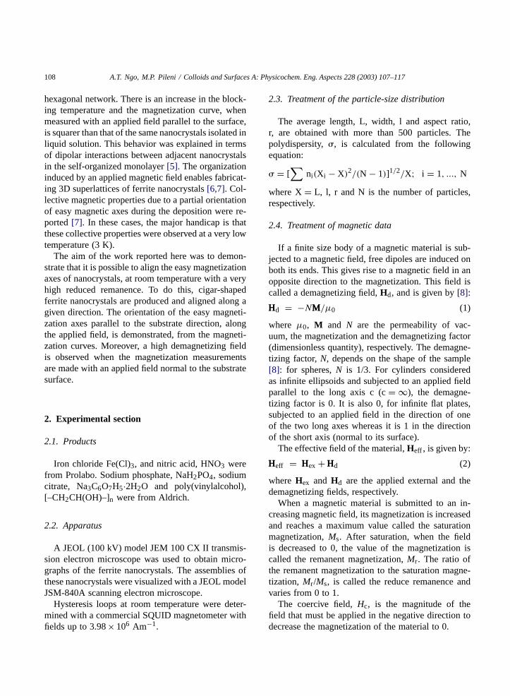
Fig. 1. TEM images of hematite (a, c and e) and maghemite (b, d and f) nanocrystals obtained after 48 h (a and b), 36 h (c and d) and24 h (e and f) of heating of the starting solution.
phosphate, [NaH2PO4] = 4.5× 10⁻⁴ M, is heated at100◦C for 48 h. This is centrifuged, a precipitate ap-pears, the supernatant removed and the nanocrystalsare dispersed again in water. This procedure is re-peated until the supernatant is optically clear withoutany remaining salts. A drop of this solution is de-posited on a carbon grid and TEM image (Fig. 1(a))show cigar-shaped nanoparticles with an average
110 A.T. Ngo, M.P. Pileni / Colloids and Surfaces A: Physicochem. Eng. Aspects 228 (2003) 107–117
length, width and aspect ratio of 350, 50 nm and 7.1,respectively. Electron diffraction indicates formationof hematite monocrystals (�-Fe2O3) [10]. Water isremoved from the solution and the powder is dried inan air oven at 70◦C for 24 h. The dried powder is thenannealed in a furnace at 360◦C under a continuoushydrogen gas flow. After 3 h, the hydrogen flow isturned off and the powder exposed to air. The furnacetemperature is decreased to 240◦C over 2 h. The pow-der is redispersed in aqueous 10−2 M HNO3. Sodiumcitrate, [Na3C6O7H5] = 1.5× 10⁻² M, is added to thesolution, which is stirred for 30 min at 90◦C, and thenanocrystals precipitate on addition of acetone. Afterwashing with a large excess of acetone, the powderis dried in air and the particles coated with citrateions are dispersed in an aqueous solution. A neutralmagnetic fluid of elongated nanocrystals is obtained.Fig. 1(b) shows TEM image obtained by depositionof a drop of solution (10−3% in mass) on the carbongrid. The length (325 nm), width (49 nm) and aspectratio (6.7) of cigar-shaped nanocrystals remain simi-lar to those obtained with the hematite precursor. Theelectron diffraction spots obtained from the measure-ments of nanocrystals are indexed to the maghemitestructure (�-Fe2O3).
Instead of leaving the starting solution 48 h, thistime is reduced to 36 and 24 h. Then, the same pro-cedure as described above is followed. At the end ofthe first part of the process, a control of the nanocrys-tal size of hematite is found (Fig. 1(c) and (e)). Theaverage length and width of hematite produced after36 and 24 h vary whereas the aspect ratio remainsquite unchanged (Table 1). Formation of maghemitenanocrystals is obtained by using the procedure de-
Table 1Variation of the average length, L, width, l, aspect ratio, r andpolydispersity,�, with the heating time of the solution and at theend of the synthesis when maghemite is formed
Heating time (h) L (nm) � (%) l (nm) � (%) r � (%)
Hematite48 350 19 50 16 7.1 1336 260 13 36 12 7.2 1524 170 14 25 14 6.6 18
Maghemite48 325 17 49 13 6.7 1436 205 16 32 13 6.6 16
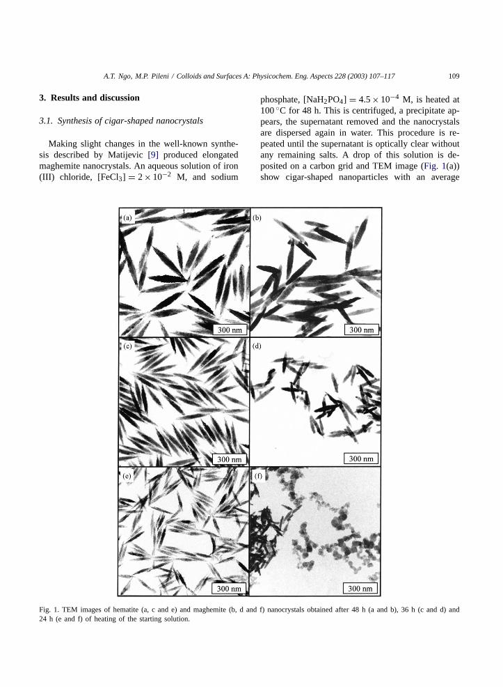
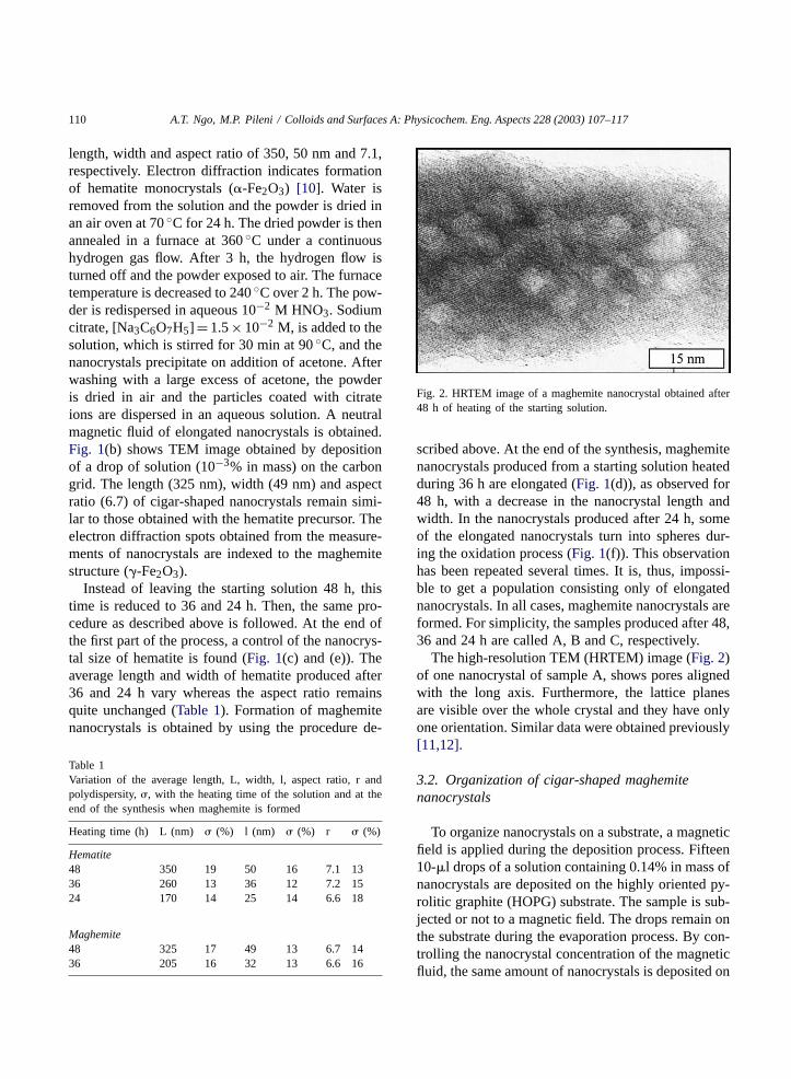
Fig. 2. HRTEM image of a maghemite nanocrystal obtained after48 h of heating of the starting solution.
scribed above. At the end of the synthesis, maghemitenanocrystals produced from a starting solution heatedduring 36 h are elongated (Fig. 1(d)), as observed for48 h, with a decrease in the nanocrystal length andwidth. In the nanocrystals produced after 24 h, someof the elongated nanocrystals turn into spheres dur-ing the oxidation process (Fig. 1(f)). This observationhas been repeated several times. It is, thus, impossi-ble to get a population consisting only of elongatednanocrystals. In all cases, maghemite nanocrystals areformed. For simplicity, the samples produced after 48,36 and 24 h are called A, B and C, respectively.
The high-resolution TEM (HRTEM) image (Fig. 2)of one nanocrystal of sample A, shows pores alignedwith the long axis. Furthermore, the lattice planesare visible over the whole crystal and they have onlyone orientation. Similar data were obtained previously[11,12].
3.2. Organization of cigar-shaped maghemitenanocrystals
To organize nanocrystals on a substrate, a magneticfield is applied during the deposition process. Fifteen10-�l drops of a solution containing 0.14% in mass ofnanocrystals are deposited on the highly oriented py-rolitic graphite (HOPG) substrate. The sample is sub-jected or not to a magnetic field. The drops remain onthe substrate during the evaporation process. By con-trolling the nanocrystal concentration of the magneticfluid, the same amount of nanocrystals is deposited on
A.T. Ngo, M.P. Pileni / Colloids and Surfaces A: Physicochem. Eng. Aspects 228 (2003) 107–117 111
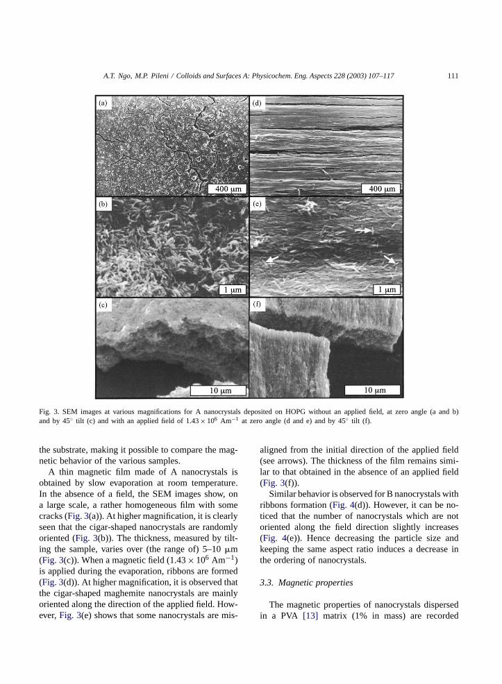
Fig. 3. SEM images at various magnifications for A nanocrystals deposited on HOPG without an applied field, at zero angle (a and b)and by 45◦ tilt (c) and with an applied field of 1.43× 10⁶ Am−1 at zero angle (d and e) and by 45◦ tilt (f).
the substrate, making it possible to compare the mag-netic behavior of the various samples.
A thin magnetic film made of A nanocrystals isobtained by slow evaporation at room temperature.In the absence of a field, the SEM images show, ona large scale, a rather homogeneous film with somecracks (Fig. 3(a)). At higher magnification, it is clearlyseen that the cigar-shaped nanocrystals are randomlyoriented (Fig. 3(b)). The thickness, measured by tilt-ing the sample, varies over (the range of) 5–10�m(Fig. 3(c)). When a magnetic field (1.43× 10⁶ Am−1)is applied during the evaporation, ribbons are formed(Fig. 3(d)). At higher magnification, it is observed thatthe cigar-shaped maghemite nanocrystals are mainlyoriented along the direction of the applied field. How-ever,Fig. 3(e) shows that some nanocrystals are mis-
aligned from the initial direction of the applied field(see arrows). The thickness of the film remains simi-lar to that obtained in the absence of an applied field(Fig. 3(f)).
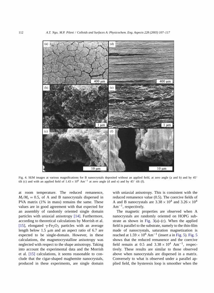
Similar behavior is observed for B nanocrystals withribbons formation (Fig. 4(d)). However, it can be no-ticed that the number of nanocrystals which are notoriented along the field direction slightly increases(Fig. 4(e)). Hence decreasing the particle size andkeeping the same aspect ratio induces a decrease inthe ordering of nanocrystals.
3.3. Magnetic properties
The magnetic properties of nanocrystals dispersedin a PVA [13] matrix (1% in mass) are recorded
112 A.T. Ngo, M.P. Pileni / Colloids and Surfaces A: Physicochem. Eng. Aspects 228 (2003) 107–117
Fig. 4. SEM images at various magnifications for B nanocrystals deposited without an applied field, at zero angle (a and b) and by 45◦tilt (c) and with an applied field of 1.43× 10⁶ Am−1 at zero angle (d and e) and by 45◦ tilt (f).
at room temperature. The reduced remanence,Mr/Ms = 0.5, of A and B nanocrystals dispersed inPVA matrix (1% in mass) remains the same. Thesevalues are in good agreement with that expected foran assembly of randomly oriented single domainparticles with uniaxial anisotropy[14]. Furthermore,according to theoretical calculations by Morrish et al.[15], elongated�-Fe2O3 particles with an averagelength below 1.5�m and an aspect ratio of 6.7 areexpected to be single-domain. However, in thesecalculations, the magnetocrystalline anisotropy wasneglected with respect to the shape anisotropy. Takinginto account the experimental data and the Morrishet al. [15] calculations, it seems reasonable to con-clude that the cigar-shaped maghemite nanocrystals,produced in these experiments, are single domain
with uniaxial anisotropy. This is consistent with thereduced remanence value (0.5). The coercive fields ofA and B nanocrystals are 3.38× 10⁴ and 3.26× 10⁴
Am−1, respectively.The magnetic properties are observed when A
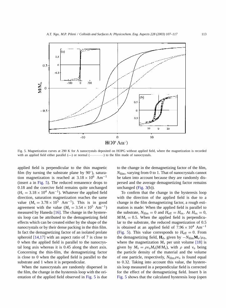
nanocrystals are randomly oriented on HOPG sub-strate as shown inFig. 3(a)–(c). When the appliedfield is parallel to the substrate, namely to the thin-filmmade of nanocrystals, saturation magnetization isreached at 1.59× 10⁶ Am−1 (insert a inFig. 5). Fig. 5shows that the reduced remanence and the coercivefield remain at 0.5 and 3.38× 10⁴ Am−1, respec-tively. These results are similar to those observedabove when nanocrystals are dispersed in a matrix.Conversely to what is observed under a parallel ap-plied field, the hysteresis loop is smoother when the
A.T. Ngo, M.P. Pileni / Colloids and Surfaces A: Physicochem. Eng. Aspects 228 (2003) 107–117 113
Fig. 5. Magnetization curves at 290 K for A nanocrystals deposited on HOPG without applied field, where the magnetization is recordedwith an applied field either parallel (—) or normal (···············) to the film made of nanocrystals.
applied field is perpendicular to the thin magneticfilm (by turning the substrate plane by 90◦), satura-tion magnetization is reached at 3.18× 10⁶ Am−1
(insert a inFig. 5). The reduced remanence drops to0.18 and the coercive field remains quite unchanged(Hc = 3.18× 10⁴ Am−1). Whatever the applied fielddirection, saturation magnetization reaches the samevalue (Ms = 3.78× 10⁵ Am−1). This is in goodagreement with the value (Ms = 3.54× 10⁵ Am−1)measured by Haneda[16]. The change in the hystere-sis loop can be attributed to the demagnetizing fieldeffects which can be created either by the shape of thenanocrystals or by their dense packing in the thin film.In fact the demagnetizing factor of an isolated prolatespheroid[14,17] with an aspect ratio of 7 is close to0 when the applied field is parallel to the nanocrys-tal long axis whereas it is 0.45 along the short axis.Concerning the thin-film, the demagnetizing factoris close to 0 when the applied field is parallel to thesubstrate and 1 when it is perpendicular.
When the nanocrystals are randomly dispersed inthe film, the change in the hysteresis loop with the ori-entation of the applied field observed inFig. 5 is due
to the change in the demagnetizing factor of the film,Nfilm , varying from 0 to 1. That of nanocrystals cannotbe taken into account because they are randomly dis-persed and the average demagnetizing factor remainsunchanged (Fig. 3(b)).
To confirm that the change in the hysteresis loopwith the direction of the applied field is due to achange in the film demagnetizing factor, a rough esti-mation is made: When the applied field is parallel tothe substrate,Nfilm = 0 andHeff = Hex. At Hex = 0,M/Ms = 0.5. When the applied field is perpendicu-lar to the substrate, the reduced magnetization of 0.5is obtained at an applied field of 7.96× 10⁴ Am−1
(Fig. 5). This value corresponds toHeff = 0. Fromthe demagnetizing field,Hd, given by−NfilmMv/µ0,where the magnetizationMv per unit volume[18] isgiven by Mv = ρvoMs(M/Ms), with ρ and vo beingthe particle density of the material and the volumeof one particle, respectively,Nfilmρvo is found equalto 0.32. Taking into account this value, the hystere-sis loop measured in a perpendicular field is correctedfor the effect of the demagnetizing field. Insert b inFig. 5 shows that the calculated hysteresis loop (open
114 A.T. Ngo, M.P. Pileni / Colloids and Surfaces A: Physicochem. Eng. Aspects 228 (2003) 107–117
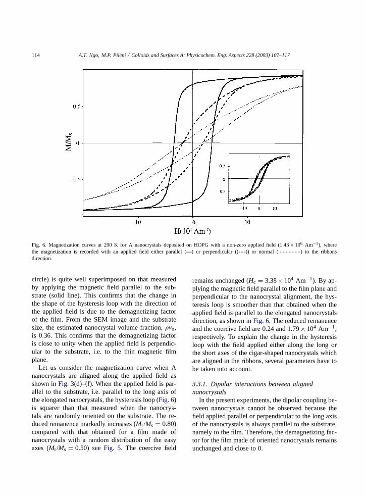
Fig. 6. Magnetization curves at 290 K for A nanocrystals deposited on HOPG with a non-zero applied field (1.43× 10⁶ Am−1), wherethe magnetization is recorded with an applied field either parallel (—) or perpendicular ((- - -)) or normal (···············) to the ribbonsdirection.
circle) is quite well superimposed on that measuredby applying the magnetic field parallel to the sub-strate (solid line). This confirms that the change inthe shape of the hysteresis loop with the direction ofthe applied field is due to the demagnetizing factorof the film. From the SEM image and the substratesize, the estimated nanocrystal volume fraction,ρvo,is 0.36. This confirms that the demagnetizing factoris close to unity when the applied field is perpendic-ular to the substrate, i.e. to the thin magnetic filmplane.
Let us consider the magnetization curve when Ananocrystals are aligned along the applied field asshown inFig. 3(d)–(f). When the applied field is par-allel to the substrate, i.e. parallel to the long axis ofthe elongated nanocrystals, the hysteresis loop (Fig. 6)is squarer than that measured when the nanocrys-tals are randomly oriented on the substrate. The re-duced remanence markedly increases (Mr/Ms = 0.80)compared with that obtained for a film made ofnanocrystals with a random distribution of the easyaxes (Mr/Ms = 0.50) seeFig. 5. The coercive field
remains unchanged (Hc = 3.38× 10⁴ Am−1). By ap-plying the magnetic field parallel to the film plane andperpendicular to the nanocrystal alignment, the hys-teresis loop is smoother than that obtained when theapplied field is parallel to the elongated nanocrystalsdirection, as shown inFig. 6. The reduced remanenceand the coercive field are 0.24 and 1.79× 10⁴ Am−1,respectively. To explain the change in the hysteresisloop with the field applied either along the long orthe short axes of the cigar-shaped nanocrystals whichare aligned in the ribbons, several parameters have tobe taken into account.
3.3.1. Dipolar interactions between alignednanocrystals
In the present experiments, the dipolar coupling be-tween nanocrystals cannot be observed because thefield applied parallel or perpendicular to the long axisof the nanocrystals is always parallel to the substrate,namely to the film. Therefore, the demagnetizing fac-tor for the film made of oriented nanocrystals remainsunchanged and close to 0.
A.T. Ngo, M.P. Pileni / Colloids and Surfaces A: Physicochem. Eng. Aspects 228 (2003) 107–117 115
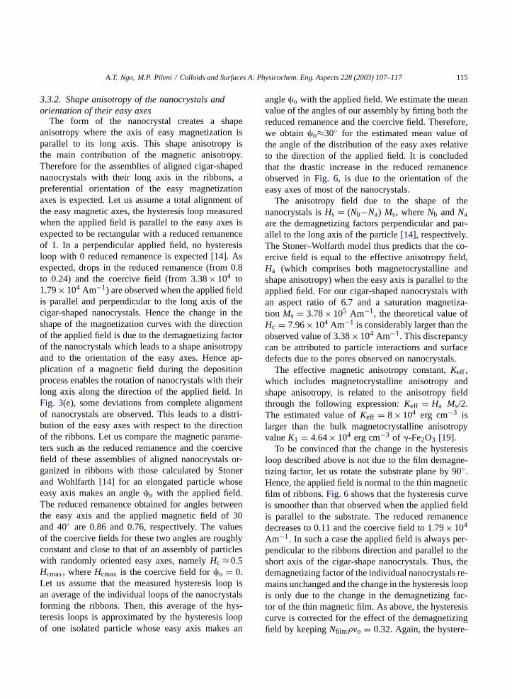
3.3.2. Shape anisotropy of the nanocrystals andorientation of their easy axes
The form of the nanocrystal creates a shapeanisotropy where the axis of easy magnetization isparallel to its long axis. This shape anisotropy isthe main contribution of the magnetic anisotropy.Therefore for the assemblies of aligned cigar-shapednanocrystals with their long axis in the ribbons, apreferential orientation of the easy magnetizationaxes is expected. Let us assume a total alignment ofthe easy magnetic axes, the hysteresis loop measuredwhen the applied field is parallel to the easy axes isexpected to be rectangular with a reduced remanenceof 1. In a perpendicular applied field, no hysteresisloop with 0 reduced remanence is expected[14]. Asexpected, drops in the reduced remanence (from 0.8to 0.24) and the coercive field (from 3.38× 10⁴ to1.79× 104 Am−1) are observed when the applied fieldis parallel and perpendicular to the long axis of thecigar-shaped nanocrystals. Hence the change in theshape of the magnetization curves with the directionof the applied field is due to the demagnetizing factorof the nanocrystals which leads to a shape anisotropyand to the orientation of the easy axes. Hence ap-plication of a magnetic field during the depositionprocess enables the rotation of nanocrystals with theirlong axis along the direction of the applied field. InFig. 3(e), some deviations from complete alignmentof nanocrystals are observed. This leads to a distri-bution of the easy axes with respect to the directionof the ribbons. Let us compare the magnetic parame-ters such as the reduced remanence and the coercivefield of these assemblies of aligned nanocrystals or-ganized in ribbons with those calculated by Stonerand Wohlfarth[14] for an elongated particle whoseeasy axis makes an angle�o with the applied field.The reduced remanence obtained for angles betweenthe easy axis and the applied magnetic field of 30and 40◦ are 0.86 and 0.76, respectively. The valuesof the coercive fields for these two angles are roughlyconstant and close to that of an assembly of particleswith randomly oriented easy axes, namelyHc ≈ 0.5Hcmax, whereHcmax is the coercive field for�o = 0.Let us assume that the measured hysteresis loop isan average of the individual loops of the nanocrystalsforming the ribbons. Then, this average of the hys-teresis loops is approximated by the hysteresis loopof one isolated particle whose easy axis makes an
angle�o with the applied field. We estimate the meanvalue of the angles of our assembly by fitting both thereduced remanence and the coercive field. Therefore,we obtain�o≈30◦ for the estimated mean value ofthe angle of the distribution of the easy axes relativeto the direction of the applied field. It is concludedthat the drastic increase in the reduced remanenceobserved inFig. 6, is due to the orientation of theeasy axes of most of the nanocrystals.
The anisotropy field due to the shape of thenanocrystals isHs = (Nb−Na) Ms, whereNb andNaare the demagnetizing factors perpendicular and par-allel to the long axis of the particle[14], respectively.The Stoner–Wolfarth model thus predicts that the co-ercive field is equal to the effective anisotropy field,Ha (which comprises both magnetocrystalline andshape anisotropy) when the easy axis is parallel to theapplied field. For our cigar-shaped nanocrystals withan aspect ratio of 6.7 and a saturation magnetiza-tion Ms = 3.78× 10⁵ Am−1, the theoretical value ofHc = 7.96× 10⁴ Am−1 is considerably larger than theobserved value of 3.38× 10⁴ Am−1. This discrepancycan be attributed to particle interactions and surfacedefects due to the pores observed on nanocrystals.
The effective magnetic anisotropy constant,Keff ,which includes magnetocrystalline anisotropy andshape anisotropy, is related to the anisotropy fieldthrough the following expression:Keff = Ha Ms/2.The estimated value ofKeff = 8× 10⁴ erg cm−3 islarger than the bulk magnetocrystalline anisotropyvalueK1 = 4.64× 10⁴ erg cm−3 of �-Fe2O3 [19].
To be convinced that the change in the hysteresisloop described above is not due to the film demagne-tizing factor, let us rotate the substrate plane by 90◦.Hence, the applied field is normal to the thin magneticfilm of ribbons.Fig. 6shows that the hysteresis curveis smoother than that observed when the applied fieldis parallel to the substrate. The reduced remanencedecreases to 0.11 and the coercive field to 1.79× 10⁴
Am−1. In such a case the applied field is always per-pendicular to the ribbons direction and parallel to theshort axis of the cigar-shape nanocrystals. Thus, thedemagnetizing factor of the individual nanocrystals re-mains unchanged and the change in the hysteresis loopis only due to the change in the demagnetizing fac-tor of the thin magnetic film. As above, the hysteresiscurve is corrected for the effect of the demagnetizingfield by keepingNfilmρvo = 0.32. Again, the hystere-
116 A.T. Ngo, M.P. Pileni / Colloids and Surfaces A: Physicochem. Eng. Aspects 228 (2003) 107–117
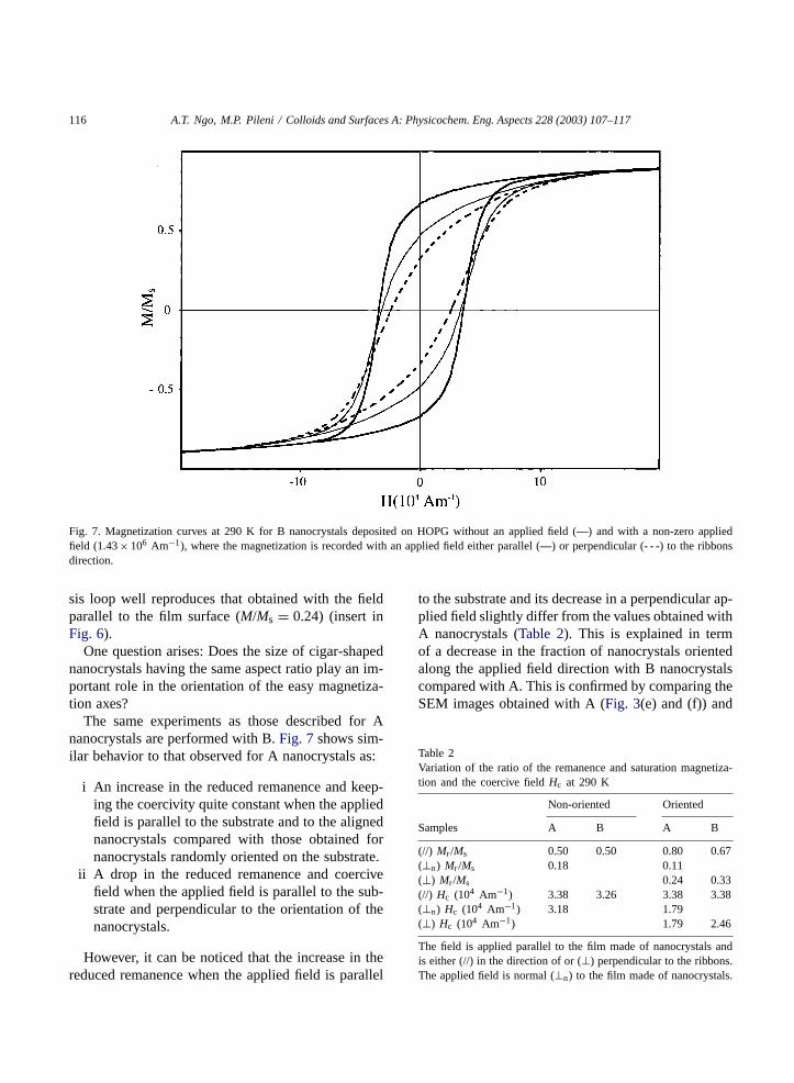
Fig. 7. Magnetization curves at 290 K for B nanocrystals deposited on HOPG without an applied field (—) and with a non-zero appliedfield (1.43× 10⁶ Am−1), where the magnetization is recorded with an applied field either parallel (—) or perpendicular (- - -) to the ribbonsdirection.
sis loop well reproduces that obtained with the fieldparallel to the film surface (M/Ms = 0.24) (insert inFig. 6).
One question arises: Does the size of cigar-shapednanocrystals having the same aspect ratio play an im-portant role in the orientation of the easy magnetiza-tion axes?
The same experiments as those described for Ananocrystals are performed with B.Fig. 7shows sim-ilar behavior to that observed for A nanocrystals as:
i An increase in the reduced remanence and keep-ing the coercivity quite constant when the appliedfield is parallel to the substrate and to the alignednanocrystals compared with those obtained fornanocrystals randomly oriented on the substrate.
ii A drop in the reduced remanence and coercivefield when the applied field is parallel to the sub-strate and perpendicular to the orientation of thenanocrystals.
However, it can be noticed that the increase in thereduced remanence when the applied field is parallel
to the substrate and its decrease in a perpendicular ap-plied field slightly differ from the values obtained withA nanocrystals (Table 2). This is explained in termof a decrease in the fraction of nanocrystals orientedalong the applied field direction with B nanocrystalscompared with A. This is confirmed by comparing theSEM images obtained with A (Fig. 3(e) and (f)) and
Table 2Variation of the ratio of the remanence and saturation magnetiza-tion and the coercive fieldHc at 290 K
Non-oriented Oriented
Samples A B A B
(//) Mr /Ms 0.50 0.50 0.80 0.67(⊥n) Mr /Ms 0.18 0.11(⊥) Mr /Ms 0.24 0.33(//) Hc (104 Am−1) 3.38 3.26 3.38 3.38(⊥n) Hc (104 Am−1) 3.18 1.79(⊥) Hc (104 Am−1) 1.79 2.46
The field is applied parallel to the film made of nanocrystals andis either (//) in the direction of or (⊥) perpendicular to the ribbons.The applied field is normal (⊥n) to the film made of nanocrystals.
A.T. Ngo, M.P. Pileni / Colloids and Surfaces A: Physicochem. Eng. Aspects 228 (2003) 107–117 117
with B (Fig. 4(e) and (f)). It can be clearly seen thatthere is an increase in the nanocrystal order with in-creasing the nanocrystal size. From these data, it is rea-sonable to conclude that the size of the cigar-shapedferrite nanocrystals characterized by the same aspectratio does not play a determining role in the orienta-tion of the easy axes.
For C nanocrystals, the magnetic properties studywas not possible because, as shown inFig. 1(f), thethermal treatment for formation of maghemite inducesformation of a certain number of spheres (this preventsany study).
4. Conclusion
In this paper, it is demonstrated that a thin magneticfilm is obtained by a slow evaporation on a substrate ofa ferrofluid made of cigar-shaped�-Fe2O3 nanocrys-tals. Application of an external magnetic field duringthe evaporation changes the structure of the film at themesoscopic scale. The nanocrystals are assembled inribbons. The reduced remanence measured with a fieldparallel to the ribbons (Mr/Ms = 0.80) drastically in-creases compared with that measured with a field per-pendicular to the ribbons direction (Mr/Ms = 0.24).Similarly, the coercive field measured when the fieldis perpendicular is half that obtained when the fieldis parallel to the ribbons. The angle between the easymagnetization axes and the applied field can be re-duced to a mean value of 30◦. Furthermore, fromthe magnetization measurements with the appliedfield normal to these films, the reduced remanencemarkedly decreases. This clearly indicates a strongeffect of the demagnetizing field perpendicular to thefilm surface. Similar behavior was observed in ourprevious work with maghemite spherical nanocrystals[7]. However, the major difference between these tworesults is the temperature at which the process takesplace. With spherical nanocrystals, such behavior wasobserved at 3 K, whereas it is now observed at roomtemperature.
Acknowledgements
We thank Dr Vincent Russier and Dr JohannesRichardi, of our laboratory, for very fruitful discus-sions. Thanks are also due to Dr A. Thiaville of theLaboratoire de Physique des Solides at the CentreUniversitaire d’Orsay, France, for very fruitful discus-sions and to Dr A. Kahn-Harari from the CNRS UMR7574 of the ENSCP of Paris, for providing the conver-sion of�-Fe2O3 to �-Fe2O3 nanocrystals. We are alsograteful to thank Dr G. Lebras and E. Vincent fromthe Service de Physique de l’Etat Condensé (Saclay)for their help with the SQUID measurements.
References
[1] L. Dorman, D. Fiorani, E. Tronc, in: I. Prigogine, S.A. Rice(Eds.), Advances in Chemical Physics, vol. XCVIII, 1997,p. 283.
[2] C.L. Chien, J. Appl. Phys. 69 (1991) 5267.[3] M.P. Pileni, J. Phys. Chem. B 105 (2001) 3358.[4] I. Lisiecki, P.A. Albouy, M.P. Pileni, Adv. Mater. 15 (2003)
712.[5] V. Russier, C. Petit, J. Legrand, M.P. Pileni, Phys. Rev. B
62 (2000) 3910.[6] A.T. Ngo, M.P. Pileni, Adv. Mater. 12 (2000) 276.[7] A.T. Ngo, M.P. Pileni, J. Phys. Chem. B 105 (2001) 53.[8] S. Chikazumi, Physics of Ferromagnetism, second ed,
Oxford, New York, 1997, p. 13.[9] M. Ozaki, E. Matijevic, J. Colloid Interf. Sci. 107 (1985) 199.
[10] M. Ocana, M.P. Morales, C.J. Serna, J. Colloid Interf. Sci.212 (1999) 317.
[11] S.J. Andress, A. Benedetti, A.R. Corradi, G. Fagherazzi,IEEE Trans. Magn. 22 (1986) 1341.
[12] A.E. Berkowitz, R.P. Goehner, E.L. Hall, P.J. Flanders, J.Appl. Phys. 57 (1985) 3928.
[13] A.T. Ngo, P. Bonville, M.P. Pileni, Eur. Phys. J. B 9 (1999)583.
[14] E.C. Stoner, E.P. Wohlfarth, Phil. Trans. Roy. Soc. A240(1948) 559.
[15] A.H. Morrish, S.P. Yu, J. Appl. Phys. 26 (1955) 1049.[16] K. Haneda, A.H. Morrish, IEEE Trans. Magn. 16 (1980) 50.[17] J.A. Osborn, Phys. Rev. 67 (1945) 351.[18] V. Russier, C. Petit, J. Legrand, M.P. Pileni, Appl. Surf. Sci.
164 (2000) 193.[19] G. Bate, in: D.J. Craik (Ed.), Magnetic Oxides, Wiley,
London, 1975, p. 689.