artefact biography 2.0 the information value of corroded
TRANSCRIPT

Delft University of Technology
Artefact biography 2.0the information value of corroded archaeological bronzesNienhuis, Janneke
DOI10.4233/uuid:b6127e6a-7fcf-40e8-a6d7-59517a06cd8ePublication date2017Document VersionFinal published versionCitation (APA)Nienhuis, J. (2017). Artefact biography 2.0: the information value of corroded archaeological bronzes.https://doi.org/10.4233/uuid:b6127e6a-7fcf-40e8-a6d7-59517a06cd8e
Important noteTo cite this publication, please use the final published version (if applicable).Please check the document version above.
CopyrightOther than for strictly personal use, it is not permitted to download, forward or distribute the text or part of it, without the consentof the author(s) and/or copyright holder(s), unless the work is under an open content license such as Creative Commons.
Takedown policyPlease contact us and provide details if you believe this document breaches copyrights.We will remove access to the work immediately and investigate your claim.
This work is downloaded from Delft University of Technology.For technical reasons the number of authors shown on this cover page is limited to a maximum of 10.


Artefact biography 2.0 the information value of corroded archaeological bronzes
Proefschrift
ter verkrijging van de graad van doctor
aan de Technische Universiteit Delft,
op gezag van de Rector Magnificus prof. ir. K.C.A.M. Luyben;
voorzitter van het College voor Promoties,
in het openbaar te verdedigen op
maandag 3 juli 2017 om 12:30 uur
door
Janneke NIENHUIS
Master of Science in Materials Science & Engineering,
Technische Universiteit Delft, Nederland
geboren te Hardenberg, Nederland

This dissertation has been approved by the promotors: Prof. dr. ir. J. Sietsma and Prof. dr. J. Dik co-‐promotor: Dr. C. Joosten Composition of the doctoral committee: Rector Magnificus chairman Prof. dr. ir. J. Sietsma promotor, Delft University of Technology Prof. dr. J. Dik promotor, Delft University of Technology Dr. C. Joosten co-‐promotor, University of Amsterdam,
Cultural Heritage Agency of the Netherlands
Independent members: Prof. dr. I.M. Richardson 3mE, Delft University of Technology Prof. dr. H. Fokkens Leiden University Prof. M. Pollard University of Oxford T.P.C. Beentjes University of Amsterdam Reserve member: Prof. dr. B.J. Thijsse 3mE, Delft University of Technology This research was financially supported by: Delft University of Technology Leiden University Cultural Heritage Agency of the Netherlands Printed by GVO drukkers & vormgevers, Ede An electronic version of this dissertation is available at www.repository.tudelft.nl
Cover: etched cross-‐section of corroded bronze stud from Oss-‐Zevenbergen

I
Table of Contents Summary VI Samenvatting VIII
1 Introduction to artefact biography 2.0 and structure of thesis 1 1.1 A short explanation of biographies 2 1.2 How artefact biography 2.0 forms the basis of this thesis 3 1.3 Significance of archaeological bronze 4
1.3.1 Significance of metal subject to corrosion 4 1.3.2 Assessment of significance 5 1.3.3 Aim of the current research 6
1.4 An interdisciplinary approach: the Zevenbergen studs 7
2 Materials and methods 11 2.1 Bronzes utilized as samples for analyses 12
2.1.1 Studs from Oss-‐Zevenbergen 12 2.1.2 Malachite curls from the Netherlands and France 15 2.1.3 Artificial patination of corrosion compounds and application of BTAH 17 2.1.4 Bronze substrates for coatings 21
2.2 Diagrams used for the interaction between elements in bronze and with the environment 24 2.2.1 Microstructures and production process described by binary phase diagram 24 2.2.2 Corrosion product prevalence shown by Pourbaix diagram 30
2.3 Analytical techniques employed to obtain information 34 2.3.1 Visual examination by Optical Microscopy (OM) 34 2.3.2 Composition identification with X-‐Ray Fluorescence (XRF) 35 2.3.3 Compound identification with X-‐Ray Diffraction (XRD) 37 2.3.4 Imaging and composition measurements with Scanning Electron
Microscopy with Energy Dispersive X-‐ray Spectrometry (SEM-‐EDS) 38 2.3.5 Molecular vibration measurements in corrosion products with
Surface Enhanced Raman Spectroscopy (SERS) 41 2.3.6 Organic layer thickness and penetration depth measurements with
Rutherford Backscattering Spectrometry (RBS) 43
3 Background on the biography of tin bronzes 47 3.1 Processing of raw materials into bronze in prehistory 48
3.1.1 Smelting ores results in impurities in bronze 49 3.1.2 Deliberate alloying 51 3.1.3 Re-‐melting 51

II
3.2 Casting and working of bronze 52 3.3 Explanations for a tin-‐rich surface on low-‐tin bronzes 55
3.3.1 High-‐tin bronze alloy 56 3.3.2 Tinning 56 3.3.3 Corrosion processes leading to tin enrichment 59
3.4 Use of studs and their role in funerary practices in the Early Iron Age 61 3.4.1 Shapes of studs used as decoration 62 3.4.2 Funerary practices in the Netherlands 63 3.4.3 Burning pyre affects bronze structures 64
3.5 Corrosion effects on buried bronzes 69 3.5.1 Corrosion processes 69 3.5.2 Common corrosion products on archaeological bronze 72 3.5.3 Layered corrosion morphologies 75 3.5.4 Original surface and marker layers 78
3.6 Current practice and materials in conservation 78 3.6.1 Contemporary conservation actions 79 3.6.2 BTAH used as corrosion inhibitor 80 3.6.3 Cyanoacrylate and Paraloid B-‐72 coatings 81
3.7 Future use of archaeological bronze 83
4 Production and use of bronze studs from Zevenbergen 85 4.1 Shapes, sized and colours of Zevenbergen studs 86 4.2 A single batch of bronze 89 4.3 Original microstructural features reveal processing steps 90 4.4 Possible tinning of studs from Zevenbergen 96 4.5 Reconstruction of production process 101
4.5.1 Theoretical considerations about stud production 101 4.5.2 Physical manufacturing reconstruction 102 4.5.3 Concluding remarks on production of studs from Zevenbergen 105
4.6 Decorative function fits prehistoric use life phase of studs 106
5 The artefact after use 109 5.1 Dismantling, transformation and deposition of studs 111 5.2 Pyre influences structure of bronzes from mound 7 112 5.3 Corrosion products observed in studs from Zevenbergen 114 5.4 Curly malachite as corrosion product 121 5.5 Stratified corrosion products in studs from Zevenbergen 125
5.5.1 Green malachite 127 5.5.2 White cassiterite 131 5.5.3 Red-‐yellow-‐green cuprite 134

III
5.6 Corrosion products and inclusions may reflect original microstructure 136 5.6.1 Identification of grain shape and size in corrosion products 137 5.6.2 Inclusions in metallic bronze 139
5.7 Conclusions on sequence of corrosion product formation in studs from Zevenbergen 144
6 Archaeological bronze conservation: now and in the future 147 6.1 BTAH binds to tin-‐containing substrates 149
6.1.1 General approach of SERS-‐outcomes in this study 149 6.1.2 SERS-‐results of BTAH-‐impregnated cassiterite and metallic tin 150 6.1.3 Comparison with BTAH-‐impregnated copper-‐related products 157
6.2 Polymeric coatings on archaeological bronze 158 6.2.1 Corroded surface with polymeric coating generates
wavy appearance 159 6.2.2 Possibility for non-‐destructive determination of Paraloid B-‐72
layer thickness 162 6.3 Influences of conservation on significance of the artefact 164
6.3.1 Coatings have negative effects on technical analyses 164 6.3.2 Change of information value due to conservation 166
6.4 Suggestions to update preservation of bronze artefacts 167 6.4.1 Technical investigations before conservation are most efficient 167 6.4.2 Preventive conservation with BTAH unnecessary? 169 6.4.3 Consider leaving corroded bronze uncoated 170
7 Concluding remarks 171 7.1 Artefact biography 2.0 of bronze studs from Zevenbergen 172 7.2 Generic applicability of interdisciplinary results 175 References 177 Glossary 193 Acknowledgements 203 About the author 207 List of relevant publications 209

IV

SummarySamenvatting

VI
Summary
The different phases in the life of archaeological objects can be described by artefact biography. This thesis defines an updated version: artefact biography 2.0 (Fig. 1.1). Here, corrosion, excavation, preservation and future use like storage, display and study are incorporated in addition to the already included stages of processing, application and deposition in the remote past. Throughout this thesis, the research revolves around information value. Small bronze studs from the Early Iron Age, found in a burial mound in Oss-‐Zevenbergen, the Netherlands, form the corpus of this dissertation. These artefacts are only half a centimetre long and have a thickness of a few millimetres. Valuable contributions to the knowledge about the extraordinary funeral of a man in the Netherlands were possible by elaborating the artefact biography 2.0 of these bronze objects. - It was established that the studs were produced by cold-‐working and annealing,
or by hot-‐working, a single batch of raw material. - The bronze studs have been subsequently intentionally tinned and fastened on a
wooden and/or leather support. - This resulted in horse gear decoration and wear of the tinning layers shows that
the object was thoroughly used. - Subsequently, the artefact with the attached studs was used in the burial ritual of
a man and parts have been in close contact with the funeral pyre. Dismantled, the decorated gear ended up in the soil beneath the burial mound.
- Cuprite (Cu2O), malachite (Cu2(CO3)(OH)2) and cassiterite (SnO2) have developed during the post-‐deposition phase, probably by cyclic and periodic precipitation, leading to stratified corrosion compounds. It is also argued in this research that the specific curly morphology of malachite is expected to be found more often on archaeological bronzes than is currently recognized.
- Contemporary conservation of the fragile studs has enabled their extensive investigation. However, the presence of a polymeric coating has also hindered application of several analytical techniques.
- Storage of the excavated material together with associated find complexes ensures future possibilities for study. By currently displaying multiple finds in a museum, the story of the life of the bronze studs from Zevenbergen is being revealed to the public.
Studying the multiple life phases of the studs from Zevenbergen from an interdisciplinary point of view has allowed the extraction of information that is also applicable to other bronzes and ultimately metals in general. Three explicit results are summarized below.

VII
1. Corrosion products and inclusions may reflect original microstructure After a cross-‐section of a corroded artefact is made, the shape and size of grains from the original metallic microstructure may be recognized, especially when intergranular corrosion and/or cracking has occurred. Pattern formation by inclusions in bronze may enable the determination of the metallic grain shape and size without etching.
2. BTAH binds to Sn and SnO2
Corrosion inhibitor benzotriazole (BTAH) is generally preventively applied to copper alloys because it binds to copper. This study has indicated that BTAH is chemisorbed onto the surface of tin (Sn) and cassiterite (SnO2). The entire BTAH-‐skeleton appears to be involved in the formation of a BTA-‐complex and the formed film is thin: in the order of several molecular layers.
3. Technical investigations before conservation increase information value of
artefact This research has shown that when the application of polymeric coatings is unavoidable, e.g. for consolidation, it is advisable to carry out technical investigations before (partial) conservation of the artefact (ensemble). In that way, the coating does not hinder perception of the object surface and the retrieval of information by experimental techniques is possible. Consequently, the information value of the artefact is increased.

VIII
Samenvatting
De verschillende levensfasen van archeologische objecten kunnen worden beschreven in een artefact biografie. In deze dissertatie wordt een vernieuwde versie gedefinieerd: artefact biografie 2.0 (Fig. 1.1). Daar zijn corrosie, opgraving, behoud en toekomstig gebruik zoals opslag, tentoonstelling en studie geïmplementeerd, naast de al eerder gedefinieerde stadia van verwerking, toepassing en depositie in het verleden. Informatiewaarde is de spil in het onderzoek beschreven in dit proefschrift. De kern van de dissertatie wordt gevormd door kleine bronzen krammetjes uit de Vroege IJzertijd, gevonden in een grafheuvel in Oss-‐Zevenbergen, Nederland. Deze voorwerpen zijn slechts een halve centimeter lang, met een dikte van enkele millimeters. Door de artefact biografie 2.0 van deze bronzen objecten uit te werken, was het mogelijk om waardevolle kennis te vergaren over de buitengewone begrafenis van een man in Nederland. - Het is vastgesteld dat de krammetjes geproduceerd zijn door één partij grondstof
koud te bewerken gevolgd door een warmtebehandeling, of warm te bewerken. - De bronzen krammetjes zijn daarna bewust vertind en bevestigd op een houten
en/of lederen ondersteuning. - Dit resulteerde in versierd paardentuig en slijtage van de vertinning onthult dat
dit object grondig is gebruikt. - Vervolgens is het voorwerp met de bevestigde krammen gebruikt in het
begravingsritueel van een man, waarbij delen in nauw contact zijn geweest met de brandstapel. Ontmanteld eindigde het gedecoreerde tuig in de bodem onder de grafheuvel.
- Cupriet (Cu2O), malachiet (Cu2(CO3)(OH)2) en cassiteriet (SnO2) hebben zich ontwikkeld gedurende de post-‐depositie-‐fase, waarschijnlijk door periodieke precipitatie, hetgeen heeft geleid tot gelaagde corrosieproducten. Ook wordt in dit onderzoek beargumenteerd dat te verwachten is dat de specifieke krullende morfologie van malachiet vaker gevonden zal worden op archeologisch brons dan tot nu toe aangenomen wordt.
- Hedendaagse conservering van de kwetsbare krammetjes heeft uitgebreid onderzoek mogelijk gemaakt. Echter, de aanwezigheid van een polymere afdeklaag heeft ook de uitvoering van enkele analytische technieken bemoeilijkt.
- Opslag van het opgegraven materiaal tezamen met bijbehorende vondstcomplexen verzekert toekomstige studiemogelijkheden. Door meerdere vondsten op dit moment tentoon te stellen in een museum, wordt het levensverhaal van de bronzen krammetjes uit Zevenbergen aan het publiek onthuld.

IX
Door meerdere levensfasen van de krammen uit Zevenbergen vanuit een interdisciplinair perspectief te bestuderen, is het mogelijk geweest om informatie te vergaren die voor andere bronzen, en uiteindelijk metaal in het algemeen, toepasbaar is. Drie kenmerkende resultaten zijn hieronder samengevat.
1. Corrosieproducten en insluitsels weerspiegelen mogelijk originele microstructuur Nadat een dwarsdoorsnede van een gecorrodeerd voorwerp is gemaakt, kunnen de vorm en grootte van korrels van de originele metallische microstructuur mogelijk worden herkend, vooral wanneer interkristallijne corrosie en/of breukvorming heeft plaatsgevonden. Patroonvorming door insluitsels in brons kan bepaling van de metallische korrelvorm en -‐grootte mogelijk maken zonder te etsen.
2. BTAH bindt met Sn en SnO2 Corrosieremmer benzotriazool (BTAH) wordt over het algemeen preventief aangebracht op koperlegeringen, omdat het bindt met koper. Deze studie heeft aangetoond dat BTAH chemisch wordt geadsorbeerd op het oppervlak van tin (Sn) en cassiteriet (SnO2). Het gehele skelet van BTAH lijkt betrokken te zijn bij de formatie van een BTA-‐complex en de gevormde film is dun: in de orde-‐grootte van een aantal molecuullagen.
3. Technisch onderzoek vóór conservering verhoogt de informatiewaarde van een voorwerp Dit onderzoek heeft laten zien dat, als het gebruik van polymere afdeklagen onvermijdelijk is, bijvoorbeeld voor versteviging, het aan te bevelen is om technisch onderzoek uit te voeren voordat (gedeeltelijke) conservering van het voorwerp (of ensemble) plaatsvindt. Op die manier bemoeilijkt de afdeklaag de waarneming van het oppervlak van het voorwerp niet en is het mogelijk om informatie te vergaren met behulp van experimentele analytische technieken. Als gevolg daarvan wordt de informatiewaarde van het voorwerp verhoogd.

X

1
Introduction to artefact biography 2.0and structure of thesis

2
1
This chapter presents the rationale for the research that is described in this interdisciplinary thesis, which combines materials science, archaeology and conservation. The dissertation is, unlike standard practice, structured conform the concept of artefact biography, in which different phases in the history of an artefact are described.
Section 1.1 introduces the models of biographies in archaeology. In section 1.2, an extended version of the commonly used artefact biography is proposed: artefact biography 2.0. Section 1.3 explains why bronze artefacts are considered significant and summarizes the aim of the research described in this dissertation. Section 1.4 presents the background of the artefacts that are studied in this thesis.
Words in italics are explained in the glossary on p. 193, where their definition as used in this thesis is given.
1.1 A short explanation of biographies
Artefacts have a history. And history matters. It tells us about human practices and ultimately about the way people may have thought in a certain culture during a certain time. Therefore, the study of artefact history is relevant. In archaeology, Kopytoff (1986) inspired the frequent use of biographical concepts (Ashby n.d.).
In artefact biography, three different phases that an artefact may experience during its life span are often described: production, use and deposition (LaMotta and Schiffer 2001; Ottaway 2001; Fontijn 2002; Dooijes 2007; Kienlin 2008). These phases require definite human agency and thus express human behaviour (LaMotta and Schiffer 2001, 21). Life histories of the artefact are then reconstructed, often based on the technological manufacturing sequence or ‘chaîne opératoire’. But an artefact biography only concerns specific individual objects. When patterns in life stories become apparent, an image appears of what an ideal course of life is for that type of object in that society. This is called cultural biography (Kopytoff 1986). By comparing possibilities for artefact biographies, insights in idealized cultural biographies arise: desirable, generalized models of the meaning of artefacts in society. To establish meaning, however, there needs to be a certain collective understanding on what the artefact is and why it is important. In other words: an artefact is not only an embodiment of ideas, but also conveys meaning that can be attributed to behaviour of people.
Physical mutations of the artefact can all give crucial information about the cultural and non-‐cultural transformations it underwent, about the way the artefact was used and about the change of its value and meaning through time (Dooijes 2007, 15-‐16; Fontijn 2002, 26-‐30). Therefore, the use of biographies can lead to descriptions of skill and craft, and artefacts are thus used to describe their societal context (Kuijpers Forthcoming).

3
1
1.2 How artefact biography 2.0 forms the basis of this thesis
It is stated in section 1.1 that incorporation of artefact biographies in object studies is useful to gain insight in cultures that have used these artefacts. However, that framework often only describes a limited number of life phases. In our opinion, the life of an artefact entails more than this. Its life is not ended when the artefact is deposited. An example would be a prehistoric bronze item. After the artefact is discarded, its use life during its first time span is finished. But during burial, corrosion processes alter the bronze. This may lead to returning the artefact to dust, but the degraded artefact may also survive and can be excavated and analysed by a modern archaeologist. Consequently, a conservator seeks ways to preserve the artefact. A second ‘use life’ commences, where the artefact functions as information carrier, on display in a museum or stored in a depot. In literature, only few examples of inclusion of corrosion and conservation into bronze artefact biography can be found (Schweizer 1994; Chiavari et al. 2007). Degrigny (2007, 1) recognizes that little attention is paid to possible loss of information that could occur during the conservation treatment. A valuable concept therefore seems to implement a more holistic biography, where the artefact is considered from ore to contemporary use and beyond: artefact biography 2.0. The different recognized phases and associated processes in artefact biography 2.0 as proposed in this dissertation are depicted in Fig. 1.1.
Fig. 1.1: Schematic representation of the proposed artefact biography 2.0 in this dissertation, where the life of an artefact is considered from raw material to future use.

4
1
The artefact biography 2.0 will form the basis of this thesis. The research consistently revolves around the information value of the artefacts. The way in which information is stored in its material largely determines the significance of an artefact as is described in the next section. And significance is an important factor in the decision-‐making process for the conservation of archaeological remains, both in situ and ex situ.
1.3 Significance of archaeological bronze
Multiple aspects play a vital role in forming the information value of archaeological bronze, from the microstructure of the metallic bulk to the corrosion layers. That the importance of bronze artefacts is recognized, is reflected in the conservational actions of today. Countless efforts are made to preserve the artefacts, which are seen as valuable, both in the days they were used in prehistory, as nowadays, as representations of culture (Kuijpers Forthcoming, 25, 33). But what exactly is ‘value’? This will be explained in the current section, by describing the significance of archaeological metal in section 1.3.1 and outlining valuation practices in section 1.3.2.
1.3.1 Significance of metal subject to corrosion
Metal from an archaeological context is always subject to corrosion. Excavated metallic artefacts represent the main information source regarding ancient metallurgy and the corrosion behaviour of metals buried for centuries (Bertholon 2007, 31). The change of environment after excavation from soil to air may be detrimental and conservators have to take care of the artefacts as soon as possible (Huisman 2009, 121). However, the choices that have to be made are often contradictory. Consider, for example, a fragile and partially corroded bronze artefact that has no known counterpart and is therefore unique. On the one hand, there is the desire to preserve the artefact, since it has a high rarity value. But more information about its provenance and manufacturing can be obtained from the artefact if it is not chemically treated for stability and if destructive sampling is allowed. Furthermore, materials scientists, archaeologists and conservators often have conflicting interests. An overview of the dilemmas encountered when dealing with material subject to degradation is shown in Fig. 1.2.
Fig. 1.2: Tree diagram representing the dilemmas that are encountered when dealing with material that is subject to degradation. After Ex 1993, Fig. 1.

5
1
In the current practice, the desire to preserve often prevails over the acceptation of degradation. Eventually, one route or treatment has to be chosen, and since some of the choices are mutually exclusive, authentic elements may be lost at the cost of others (Ex 1993, 22). Nowadays, with interdisciplinary approaches and the development of non-‐destructive techniques, increasingly more information is retrieved before conservation treatment with continuously improved chemicals. This implies that one of the most obvious values of archaeological bronze is information value.
The frequently impeding factor in the gain of information is the corrosive state of the artefact, which hinders the determination of the original composition, microstructure and finishing. The limit between the artefact materials and the surrounding environment at the time of the abandonment of the artefact (or: limitos) may be undetected or even gone. Severe corrosion of the artefact may even lead to it being discarded as a source of information.
1.3.2 Assessment of significance
Groenewoud and Speleers (2014, 5) illustrate that the attention for archaeological remains, and their inherent valuing, has seen a transition from individual objects, to sites, and subsequently to the entire cultural landscape. Initially, the significance of archaeological remains was measured by their monetary value and academic and educational meaning. It was not until the 20th century, and especially from 1990 onwards, that a second perspective on archaeological value was developed. In 1992, the Malta convention considers “the archaeological heritage as source of the European collective memory”1.
In the Netherlands, the evaluation system for the assessment of significance of sites is described in the Kwaliteitsnorm Nederlandse Archeologie (KNA2). It is argued that archaeological remains in the ground are primarily important as unique source of information about people’s lives in the past (Groenewoud and Speleers 2014, 8). Therefore, degradation processes of artefacts and other remains, as well as the assessment, monitoring and in situ preservation of archaeological sites should always be studied from the view-‐point of the (potential) loss of information (Huisman 2009, 15).
At this point, it is appropriate to incorporate guidelines for assessing significance of museum collections, as they offer a wider perspective on artefacts and their context. It follows from the discipline of collection management that value is inextricably linked to the concept of significance, which may be defined as the historic, artistic, scientific and social or spiritual values that items and collections have for past, present and future generations (Russell and Winkworth 2009, 10). A good summary of the possible values items may exhibit is given by a framework for the valuation of collections (see Table 1.1; Versloot 2014). 1 European Convention on the Protection of the Archaeological Heritage (Revised), 1992, CETS 143. 2 Online version: https://www.sikb.nl/archeologie/richtlijnen/brl-‐4000 (accessed on 4 June 2017).

6
1
The more values are rated as ‘high’, the higher the significance of the assessed collection. However, it has to be kept in mind that ideas can change over time and a valuation is a snapshot (Versloot 2014, 5).
Table 1.1: Valuation form as used in the discipline of museum collections in the Netherlands, showing the multitude of values representing significance. After Versloot 2014, p. 60.
Features
Criteria Condition (state, intactness, material authenticity, material integrity) Ensemble (completeness, unity, cohesion, conceptual integrity, conceptual authenticity, contextual authenticity) Provenance (documentation, life story, biography, source, pedigree) Rarity and representatitveness (uniqueness, exemplar value, prototype, type exemplar)
Cultu
re
historical
Historical (biographical, social history, natural history, technological history, scientific history) Artistic (art historical, architectural history, design, workmanship, decorative) Information value (scholarship, science, research, documentation, reference, testimony, archival)
Social &
societal Social
(social, spiritual, religious, political, symbolic, community, identity) Perception (emotions, sense, aesthetic, association)
Use
Museum (presentation, education, research) Economic (working capital, financial, PR, spin-‐off, tourism, reputation)
1.3.3 Aim of the current research
This research is performed in close cooperation with specialists from multiple disciplines: information obtained from materials science will act as input for conservational questions and archaeological issues and vice versa. This results in a truly interdisciplinary approach in object study. The main sample set is formed by prehistoric bronze studs from Zevenbergen, the Netherlands, whose context is described in the following section.
In this dissertation it is aimed to show that an integral approach enables an exhaustive exploitation of the information potential of archaeological bronze.

7
1
1.4 An interdisciplinary approach: the Zevenbergen studs
In 2007, an exceptionally large barrow from the Early Iron Age (ca. 600 BC) was excavated near Oss-‐Zevenbergen, the Netherlands (Fontijn et al. 2013; Fig. 1.3). The centre of this mound (‘mound 7’) contained charcoal, an urn, cremated and decorated bone and around 1000 very small and fragile bronze fragments. Multiple blocks of undisturbed soil with artefacts were lifted, enabling minute excavation in situ and conservation in the laboratory under controlled circumstances. Several remarkable characteristics stood out, like a white surface colouration and a specific arrangement of the bronze artefacts. The nature of these finds, which have been selectively dismantled in prehistory and fragmented, is unique in the Netherlands. Practices from Central Europe seem to have been altered to fit the local culture. The barrow landscape of Oss-‐Zevenbergen is therefore a site with international significance for the study of European prehistory (Fontijn et al. 2013).
Fig. 1.3: Reconstruction, showing the barrow landscape of Oss-‐Zevenbergen during the Early Iron Age, with mound 7 centrally situated without posts. Reproduced from Van Ginkel 2009; inset reproduced from Fontijn et al. 2013, Fig. 1.1.
In all, 1080 bronze items were recovered, of which 992 finds could be ascribed to (fragments of) studs (Fontijn and Van der Vaart 2013, 151). A stud (see Fig. 1.4) is defined as an object with a hemispherical head and two legs, bearing resemblance to modern studs used as decoration in jeans. Typical dimensions are a head diameter and leg length of 5 mm and a thickness of around 1 mm. One can think of many functions for this kind of artefact. Based on parallels in Germany and taking into account the specific arrangements in mound 7, the assumption is that the bronze studs were used as decorations on wooden or leather objects, and/or leather panels attached to wood that have been part of horse gear (section 4.4.1; Fontijn and Van der Vaart 2013, 165).

8
1
The largest cluster of studs found underneath the mound is recorded as V173 and contains nearly 900 (fragments of) studs. It was located at the edge of the central find assemblage of the mound and seemed to represent the remains of a larger, stud-‐decorated artefact that had decayed in situ. In this study, 61 bronzes from this find location (V173) were studied in detail and 5 from another location, 176, which was situated in the central find assembly. In that way, different contexts as present in mound 7 are represented in the sample study and details are described in section 2.1.1. More information on the available bronzes can be found in Nienhuis et al. (2013, Table 9.1).
Fig. 1.4: Corroded Early Iron Age bronze studs, excavated from a burial mound in the Netherlands. Reproduced from Fontijn et al. 2013, Fig. 7.16.
This research will construct an artefact biography of the small, Early Iron Age, bronze studs from Zevenbergen (Fig. 1.4). Being only half a centimetre long, with a thickness of a few millimetres, these artefacts have enabled the enlightening of a large part of the extraordinary funeral of a man in the Netherlands (Fontijn et al. 2013). An analogue with rich burials from the Hallstatt culture in Central Europe has been found by reconstructing a possible production process. Since the majority of the studs is almost entirely corroded, the artefacts are very fragile. Because this is a common problem amongst archaeological finds, their treatments after excavation are outlined and discussed, thereby completing their artefact biography.
Three stages in the lives of bronze studs from Zevenbergen are elaborated and contain new information that is generically applicable. Tinning and corrosion of tinned products, the retrieval of microstructural features from corrosion products and the influence of BTAH and organic coatings on bronze are all tailored to the intended target groups: archaeologists, materials scientists and conservators and related disciplines.

9
1
The studs from Zevenbergen form the main sample set in this thesis. However, multiple artefacts and materials are used, especially when the subject requires a less confined sample set to generate information that is generically applicable. All used materials are described in detail in chapter 2, together with the methods used in this study. Chapter 3 can be read as a general artefact biography 2.0 of bronzes and serves as representative background for the results and discussion about the bronze studs from Zevenbergen. Chapters 4-‐6 chronologically elaborate phases from the artefact biography of these studs, analogous to Fig. 1.1. Chapter 4 describes the processing, including tinning, and use of the studs from Zevenbergen in the Early Iron Age. Chapter 5 is dedicated to the post-‐use phases, including deposition, proximity of bronze to a pyre, and corrosion processes. Chapter 6 discusses contemporary conservation and preservation practices and their influence on artefact significance, specifically the use of benzotriazole (BTAH) as corrosion inhibitor and the application of polymeric coatings. Chapter 7 is based on the results of chapters 4 to 6, where a summary of the stud biography is given, as well as the generic applicability of the results.

10
1

2
Materials and methods

12
2
This thesis revolves around the information value of archaeological bronze. However, this information needs to be extracted from the bronzes in the first place and multiple methods have been utilized in the current research. The principal samples used in this research are the studs from Oss-‐Zevenbergen and the malachite curls from multiple locations. Also, various bronzes have been utilized to test interaction with corrosion inhibitor benzotriazole (BTAH) and visual appearance of polymeric conservation coatings.
The entire sample set and the applied preparation methods are described in section 2.1. Theoretical background will be provided about the use of different types of diagrams to identify metallic microstructures and the prediction of expected corrosion products (section 2.2). Section 2.3 will describe the underlying principles of the employed analytical techniques in corresponding subsections, as well as detailed information on the settings used. The current chapter thus explains underlying principles of diagrams and techniques, whereas chapter 3 provides background information about bronze in order to facilitate the discussions in chapters 4-‐6 and is built up according to the artefact biography as proposed in section 1.2. Some overlap is inevitable and references to sections with complementary information about the same subject will be made.
Words in italics are explained in the glossary on p. 193, where their definition as used in this thesis is given.
2.1 Bronzes utilized as samples for analyses
Samples are crucial in the performance of technical analyses. The current section focuses on the samples and specimens and entails a short description of the artefact, sample set selection and preparation for analysis. The studs from Zevenbergen are represented in section 2.1.1 and the curly malachite material from Uden and Bocholtz in section 2.1.2. The production process and characterization of multiple artificial corrosion products are outlined in section 2.1.3. The application of corrosion inhibitor benzotriazole (BTAH) and polymeric coatings to multiple mock-‐ups and archaeological test bronzes is described in section 2.1.4. The background of the techniques used, together with their implementation in this research, are summarized in section 2.3.
2.1.1 Studs from Oss-‐Zevenbergen
1080 bronze items have been excavated from a burial mound in Oss-‐Zevenbergen, the Netherlands (see section 1.4), of which 992 finds could be ascribed to (fragments of) studs. The context of the find and characterization of the shapes and sizes of the studs are elaborated in section 4.1. In this section, the conditions for selection of the sample set are given1, as well as specimen preparation methods.
1 The following paragraph is largely based on Nienhuis et al. 2013, 213-‐214.

13
2
All intact studs and stud fragments had been mechanically cleaned and had been treated by preventive impregnation with corrosion inhibitor 1,2,3-‐benzotriazole (BTAH). Ethyl-‐2-‐cyanoacrylate (CA) had been applied to consolidate the artefacts and fixate fractures.2
Not all bronze fragments from mound 7 were available for analytical research and a selection was therefore made (see also section 1.4). The sample set is composed of 64 small studs and fragments and two larger studs in order to examine similarities in composition and colour between the two sizes. Also, possibly organic residue had been found in two studs. Since the material has been excavated with the block-‐lifting technique, information concerning the positioning of the studs in the barrow is available (section 1.4; Fontijn et al. 2013). In this research, samples from different locations and levels were examined to determine possible interrelationships between the studs and their position in the burial mound. 61 bronzes from the largest cluster of studs found at the edge of the central find assemblage (V173, see Fig. 2.1) and 5 from the central find assembly (176, Fig. 2.1) were studied in detail. Pieces of bronze with different colours (brownish-‐black, white, green, and red) were selected, since the colouration of the studs gives rise to questions about corrosion processes and original colour(s).
Fig. 2.1: Overview of the artefacts that make up the central find assemblage. In this research, bronzes from locations V173 and 176 were studied. After Van der Vaart et al. 2013, Fig. 5.2.
2 Actions undertaken by conservators from Restaura, a private company in the Netherlands. Details can be found in Kempkens 2013.

14
2
Two studs were cross-‐sectioned (Fig. 2.2) for study using techniques that require access to the interior of the stud in order to be fully examined, such as microstructure analysis with optical microscopy (OM), X-‐ray diffraction (XRD) and scanning electron microscopy (SEM), see Table 2.1. The leg was selected because of its observable white surface layer and corroded centre due to fracture. The intact stud was selected because of the presence of a metallic bronze core, in combination with the variety of colours on the surface. The existence of metal was deduced by analyzing and comparing the density of numerous studs using two non-‐invasive techniques:
1. X-‐radiography Density differences between corrosion products and a metallic core can be qualitatively mapped on a micro-‐scale.3 The instrument used in this research is a General Electric Eresco 280 MF, with the following settings: 60/90 kV; 3.5/2.0 mA. The images were processed using incorporated software.
2. Gas pycnometer
The average density of a small artefact (5-‐10 cm3) can be quantitatively determined.4 The instrument used in this research is a Micromeritics AccuPyc 1330.
Fig. 2.2: Indication of the sectioning process, creating cross-‐sections of the leg and the intact stud (Table 2.1). (1) Top view of sectioning of (embedded) specimen along line a and b (side views of subsequent cross-‐section); (2) resulting quarter of a stud with respective side views. Reproduced from Nienhuis et al. 2013, Fig. 9.13.
During analysis of cross-‐sections, one always has to keep in mind that the area is a two-‐dimensional representation of a three-‐dimensional structure. This is especially important when visual examination is carried out on semi-‐transparent phases, like the study of inclusions in malachite (section 5.5.1). The manner in which the cross-‐section is made and viewed influences the number of twins one can detect, as twins are dependent on the specific crystallographic orientation of the parent grain. Cross-‐sectioning may influence compositional measurements, as the penetration depth of the analysis possibly includes a different phase immediately beneath the visible surface.
3 More information about X-‐radiography can be found in Quinn and Sigl 1980. 4 More information about the technique can be found in Webb 2001, p. 8.

15
2
Table 2.1: Relevant specifications and sampling details of the two cross-‐sectioned studs from Zevenbergen used in this research.
Cross-‐ sections Stud
Specimen Employed techniques Description Mounting Preparation
Fragment
broken pointy leg, facetted white
embedded in Struers EpoFix with EpoDye
sectioning with jeweller’s saw SiC grinding to grade 2400; diamond polishing to 1 μm; ethanol cleaning
OM XRD SEM-‐EDS
Intact
intact parallelogram + pointy leg, facetted brown, green, white
embedded in Struers EpoFix with EpoDye
sectioning with Struers Secotom-‐10; 0.4 μm diamond blade; SiC grind to grade 2400; diamond polish to 1 μm; etched with 1 g FeCl3 in 11 ml ethanol; ethanol cleaning
OM XRD SEM-‐EDS
For the reconstruction of the production process of the studs from Zevenbergen, several materials and tools have been used. These are all described in the corresponding discussion in section 4.5.2.
2.1.2 Malachite curls from the Netherlands and France5
Artefacts from multiple locations in the Netherlands and France contain curly malachite (CM) that has been studied in this research. An overview is found in Table 2.2.
All CM samples were found on or near thin-‐walled (millimetre-‐scale thickness) archaeological bronzes, mostly from burial sites. The curls co-‐occur with the more common massive shaped malachite as corrosion product. For all sites, the curls are found under wet conditions, with intermediate drier periods, yet the soils are not waterlogged. The soils contain particles varying from coarse sand (210-‐2000 µm) to fine silt (~2-‐50 µm). The artefacts date from 300 BC to 300 AD. More differences lie in their specific local burial conditions: inhumation and cremation ritual grave deposits are exemplified. Some of the graves were initially exposed to atmospheric conditions before being covered by soil or sediment. Here, ‘ritual’ refers to deliberate action by people with characteristics repeatedly seen. Examples are the choice for inhumation or cremation, the addition of specific metallic grave goods or the use of a textile shroud. Sites with and without clear evidence of (former, degrading) organic material like textile and bone can be compared in the sample set from this study. Finally, artefacts covered with masses of curls and only isolated curls are present.
5 This subsection is largely based on Nienhuis et al. 2016.

16
2
Table 2.2: Relevant specifications of samples of curly malachite used in this research. -‐ means ‘not determined’.
CM samples
Curly malachite
Context
Artefact
Employed
techniqu
es
(Nie
nhui
s et
al.
2016
for m
ore
deta
ils)
Cont
ext
Soil
char
acte
ristic
s Pr
oxim
ity
orga
nics
Cu
rl lo
catio
n Cu
rl ap
pear
ance
La Fosse
Cotheret
(FR, 300 BC)
buria
l c
ham
ber;
in
itial
ly
atm
osph
eric
sand
y cl
ay
woo
d,
tex
tile?
in h
ollo
w s
ide
of
ron
de-‐b
osse
o
rnam
ent;
w
ithin
ear
thy
crus
t
isol
ated
cur
ls;
mas
s of c
urls
OM
SE
M-‐E
DS
XRD
Tintignac
(FR,
200-‐100 BC)
sanc
tuar
y sa
ndy
clay
-‐
on s
urfa
ce p
atin
a of
c
arny
x;
in e
arth
y cr
ust
isol
ated
cur
ls;
mas
s of c
urls
OM
SE
M-‐E
DS
Bocholtz
(NL, 300 AD)
buria
l c
ham
ber;
in
itial
ly
atm
osph
eric
silt,
cla
y, lö
ss
-‐ in
soi
l sur
roun
ding
j
ug;
insi
de h
ollo
w k
nob
mas
s of c
urls
OM
Zevenb
ergen
(NL, 800 BC)
buria
l m
ound
sa
nd, p
odzo
l w
ood,
l
eath
er?
in h
ollo
w h
ead
of
sm
all s
tud;
on
sur
face
of
lar
ge st
ud
sing
le c
url
in
smal
l stu
d;
mas
s of c
urls
o
n la
rge
stud
OM
Uden
(NL, 800 BC)
inhu
mat
ion
g
rave
sa
nd, p
odzo
l bo
ne,
tex
tile
insi
de h
ollo
w
ank
let;
in s
oil i
nsid
e an
klet
m
ass o
f cur
ls
OM
XR
F SE
M-‐E
DS
XRD
Ra
man

17
2
2.1.3 Artificial patination of corrosion compounds and application of BTAH
Artificial patination allows the creation of a surface layer that closely resembles the corrosion products and their adherence on archaeological bronze. To study the interaction between corrosion inhibitor BTAH (C6H5N3) and multiple corrosion products of copper and tin, artificial tin and copper corrosion products, chemically comparable to those found on the studs from Zevenbergen (section 5.3), have been synthesized. The experimental set-‐up 6 is summarized in Table 2.3, after which the results of the morphological and chemical characterization by SEM-‐EDS and XRD are described. It is uncommon to describe such results in a methods and materials chapter. However, the artificially produced patinas in this research are seen as samples for subsequent study of BTAH-‐interaction. It is thus not the intention to report an extensive characterization. The patinated samples are subsequently impregnated with BTAH. Details about the treatment on these and other samples are outlined in the last part of the current subsection.
Table 2.3: Overview of artificial patination experiments to synthesize multiple copper and tin corrosion products in this research. -‐ means ‘not applicable’.
Patina synthesis Preparation Substrate Solution Employed
techniques
SnO2 heated to 90 °C (10 days) tin foil 0.5 mol/l NaCl SEM-‐EDS XRD
Cu2O
heated with propane burner to cherry red; immediate cooling in demineralized water
copper coupon -‐ SEM-‐EDS XRD
Cu2(CO3)(OH)2
electrochemical patination (at RT): 1. -‐0.20 V vs. OCP (60 s) 2. +0.16 V vs. OCP (48 h) 3. +0.14 V vs. OCP (48 h)
bronze coupon (6 wt% Sn)
0.2 g/l Na2SO4 + 0.2 g/l NaHCO3
SEM-‐EDS XRD
CuO heating in oven at 1000 °C (5 min) copper coupon -‐ SEM-‐EDS XRD
Brownish-‐white regions represent cassiterite (SnO2) (Fig. 2.3a). Both relatively smooth areas and protruding pustules can be discerned on the surface of the embrittled corroded tin foil. The adherent stannic oxide corrosion product has grown into a dendritic structure (Fig. 2.3b). XRD analyses reveal that the artificial patina is solely composed of cassiterite. The thickness of the oxide layer is around 2 µm, the diameter of the pustules is around 10 µm, based on a cross-‐section of the foil with the cassiterite corrosion on top.
6 Experimental research carried out by Pieter Langerhorst under supervision of Harlof Roelen (Hogeschool Leiden), Ineke Joosten (Cultural Heritage Agency of the Netherlands) and Janneke van der Stok-‐Nienhuis. Results of the study are published in a report, in which more details can be found: Langerhorst 2014.

18
2
Fig. 2.3: Cassiterite layer and pustules artificially produced. (a) Brownish-‐white products are composed of SnO2. digital photograph; (b) dendritic morphology of the SnO2 surface structure seen in white, secondary electron image.
Cuprite (Cu2O) can visually be recognized by a pinkish colour (Fig. 2.4a). The cuprite layer is homogeneously covering the copper substrate, although some small cracks can be seen in some areas (Fig. 2.4b). XRD analyses confirm the presence of crystalline cuprite as sole corrosion product in the optically pink regions. The identification of pure copper in the XRD spectra indicates that the thickness of the cuprite layer is smaller than the penetration depth of the X-‐rays, so in the range of several micrometres.
Fig. 2.4: Artificially formed cuprite layer on a copper substrate. (a) Cu2O can be recognized by its pinkish colour, digital photograph; (b) small cracks can be seen in the otherwise homogeneous Cu2O surface layer, backscatter electron image.
(a) (b)
(a) (b)

19
2
Millimetre-‐sized spots of green malachite (Cu2(CO3)(OH)2) have been produced on the surface of a bronze coupon (Fig. 2.5a). This corrosion compound does morphologically not correspond to a homogeneous massive malachite layer, like the one seen on studs from Zevenbergen. The artificial malachite can be characterized by a relatively porous, needle-‐like structure (Fig. 2.5b). XRD analyses indicate that besides crystalline malachite, cuprite is present as a corrosion product. It is assumed here that the cuprite layer is located between the corrosion free bronze coupon and the surface malachite layer (cf. sections 3.5 and 5.3). Copper peaks measured with XRD suggest that the substrate is included in the measurement. This allows estimation for the layer thickness of malachite: in the order of several micrometres.
Fig. 2.5: Spots of malachite artificially produced on a bronze substrate. (a) Green areas represent Cu2(CO3)(OH)2, digital photograph; (b) irregular and needle-‐like morphology of the Cu2(CO3)(OH)2 surface, backscatter electron image.
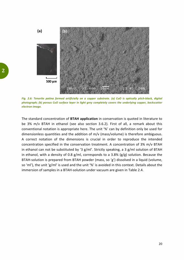
An adhesive, smooth, black layer of tenorite (CuO) covers the copper substrate (Fig. 2.6a). The presence of this crystalline cupric oxide component is confirmed by XRD analyses. Cuprite is also identified. The homogeneous grey colour of the surface in the SEM-‐BSE images (Fig. 2.6b) suggests that the upper layer on the copper substrate is composed of a single component. Combined with the observations of the cuprite/malachite stratification (see above), it is assumed that the cuprite layer is situated beneath tenorite and on top of the metallic bronze substrate. The estimated thickness of the tenorite surface layer, based on X-‐ray penetration depth, is in the order of micrometres. Holes of less than a micrometre in diameter are present inside the tenorite corrosion compound (Fig. 2.6b).
(a) (b)
20
2
Fig. 2.6: Tenorite patina formed artificially on a copper substrate. (a) CuO is optically pitch-‐black, digital photograph; (b) porous CuO surface layer in light grey completely covers the underlying copper, backscatter electron image.
The standard concentration of BTAH application in conservation is quoted in literature to be 3% m/v BTAH in ethanol (see also section 3.6.2). First of all, a remark about this conventional notation is appropriate here. The unit ‘%’ can by definition only be used for dimensionless quantities and the addition of m/v (mass/volume) is therefore ambiguous. A correct notation of the dimensions is crucial in order to reproduce the intended concentration specified in the conservation treatment. A concentration of 3% m/v BTAH in ethanol can not be substituted by ‘3 g/ml’. Strictly speaking, a 3 g/ml solution of BTAH in ethanol, with a density of 0.8 g/ml, corresponds to a 3.8% (g/g) solution. Because the BTAH-‐solution is prepared from BTAH powder (mass, so ‘g’) dissolved in a liquid (volume, so ‘ml’), the unit ‘g/ml’ is used and the unit ‘%’ is avoided in this context. Details about the immersion of samples in a BTAH-‐solution under vacuum are given in Table 2.4.
(a) (b)

21
2
Table 2.4: Relevant specifications of BTAH impregnation of multiple samples in this research. -‐ means not applicable.
BTAH application
Sample BTAH solution Pressure (mbar)
Employed techniques Substrate Preparation Concentration
(g/ml) Solvent
Zevenbergen bronze items mechanical cleaning 3
70% ethanol + 30% water 600 -‐ 800 SERS
Artifical patination
bronze coupon (6 wt% Sn)
SiC grinding grade 800
3 99.8% ethanol 11 SERS
Sn SiC grinding grade 800
SnO2 -‐
Cu2O -‐
Cu2(CO3)(OH)2 -‐
CuO -‐
2.1.4 Bronze substrates for coatings
Coatings are often applied on archaeological bronzes for protection and/or consolidation (section 3.6.3). The change in appearance of coated bronzes is studied in this research and multiple coatings were prepared and applied on different substrates7, see Table 2.5.
Coatings are selected with the purpose of covering different categories. Except for cyanoacrylate (CA), the selected materials are commonly used in metal conservation practice. CA is nevertheless included in the sample set because the bronzes from Zevenbergen have been coated with CA as it acts both as protective layer and as consolidant. The selection of coatings covers both relatively old coating systems such as the Paraloid family and newer coating systems such as ORMOCER OR1. Toluene has a low evaporation rate and its use as solvent may improve the degree of levelling of the Paraloid coating compared to the utilization of acetone. Microcrystalline wax is included in the selection as non-‐polymeric counterpart and because it is appreciated by conservators for its matte appearance.
The used coating systems have been applied on copper test coupons with increasing roughness: smooth copper plate, roughened copper plate and archaeological test bronzes. These bronzes belong to a small collection of archaeological materials of the Cultural Heritage Agency of the Netherlands and to a small private collection of test objects from Peter Northover (University of Oxford). The find context of all these bronzes is unknown, yet the artefacts are seen as representative for buried corroded bronze. The objects are therefore suitable for this type of coating research.
7 Experimental research carried out by Stefania Lorenzotti under supervision of Janine van Reekum (University of Amsterdam), Ineke Joosten (Cultural Heritage Agency of the Netherlands) and Janneke van der Stok-‐Nienhuis. Results of the study are published in a thesis report, in which more details can be found: Lorenzotti 2013.

22
2
Table 2.5: Relevant specifications of used conservation coating systems applied with a soft painting brush and studied samples in this research. -‐ means ‘not
applicable’.
Coating
application
Sample
Coating solutio
n Em
ployed
techniqu
es
Subs
trat
e Pr
epar
atio
n Co
ncen
trat
ion
(g/m
l) So
lven
t
Ethyl-‐2
-‐ cyano
acrylate
(CA
)
Zeve
nber
gen
b
ronz
es
mec
hani
cal c
lean
ing;
BT
AH im
preg
natio
n -‐
-‐ O
M
copp
er
cou
pon
SiC
grin
ding
to g
rade
500
; et
hano
l cle
anin
g -‐
-‐ O
M
SiC
grin
ding
to g
rade
500
; st
eel w
ire b
rush
; et
hano
l cle
anin
g -‐
-‐ O
M
arch
aeol
ogic
al
tes
t bro
nze
mec
hani
cal c
lean
ing;
et
hano
l cle
anin
g -‐
-‐ O
M
Paraloid B-‐48N
co
pper
c
oupo
n
SiC
grin
ding
to g
rade
500
; et
hano
l cle
anin
g 10
acet
one
OM
ac
eton
e +
m
attin
g ag
ent (
SiO
2)
OM
tolu
ene
+ et
hano
l O
M
SiC
grin
ding
to g
rade
500
; st
eel w
ire b
rush
; et
hano
l cle
anin
g 10
acet
one
OM
acet
one
+
mat
ting
agen
t (Si
O2)
O
M
tolu
ene
+ et
hano
l O
M

23
2
Paraloid B-‐48N
(continued)
arch
aeol
ogic
al
tes
t bro
nze
mec
hani
cal c
lean
ing;
etha
nol c
lean
ing
10
acet
one
OM
acet
one
+
mat
ting
agen
t (Si
O2)
O
M
tolu
ene
+ et
hano
l O
M
Paraloid B-‐72
arch
aeol
ogic
al
tes
t bro
nze
SiC
grin
ding
to g
rade
240
0;
diam
ond
polis
hing
to 1
μm
; de
min
eral
ized
wat
er c
lean
ing
13
acet
one
OM
31
acet
one
OM
ORM
OCER OR1
copp
er
cou
pon
SiC
grin
ding
to g
rade
500
; et
hano
l cle
anin
g -‐
-‐ O
M
SiC
grin
ding
to g
rade
500
; st
eel w
ire b
rush
; et
hano
l cle
anin
g -‐
-‐ O
M
arch
aeol
ogic
al
tes
t bro
nze
mec
hani
cal c
lean
ing;
et
hano
l cle
anin
g -‐
-‐ O
M
Microcrystalline
wax
copp
er
cou
pon
SiC
grin
ding
to g
rade
500
; et
hano
l cle
anin
g -‐
-‐ O
M
SiC
grin
ding
to g
rade
500
; st
eel w
ire b
rush
; et
hano
l cle
anin
g -‐
-‐ O
M
arch
aeol
ogic
al
tes
t bro
nze
mec
hani
cal c
lean
ing;
et
hano
l cle
anin
g -‐
-‐ O
M

24
2
2.2 Diagrams used for the interaction between elements in bronze and with the environment
There are two types of diagrams that are useful in the study of bronzes and their corrosion products. Both are schematic representations of the equilibrium state of a material under certain conditions. Boundary lines indicate a state transition and the regions separated by these lines represent a certain state of the material for a certain combination of conditions.
The first diagram used in this research is a binary phase diagram. It represents thermodynamics of bronze in relation to the fraction (or: concentration) of tin and temperature. Eventually, the artefact production process history can be deduced from such a diagram through examination of the microstructure, in combination with kinetics. How one reads such a phase diagram and what kind of information about microstructure it may obtain is described in section 2.2.1.
The second diagram is a Pourbaix diagram. It represents corrosion product stability in soil in relation to pH and redox potential. Such a diagram is useful in determining the history of corrosion interaction between the environment and the artefact. The application of these so-‐called Pourbaix diagrams is enlightened in section 2.2.2.
2.2.1 Microstructures and production process described by binary phase diagram
Microstructure is an assembly of microscale crystals and inclusions in a material, with characteristic features like grain dimension, morphology and phase composition. Grains are defined as individual crystals in a polycrystalline metal. The interface between grains is called a grain boundary. When an object is cast, the grains resemble trees with branches and are called dendrites.
The equilibrium phase composition varies with composition and temperature of the metal and is thus indicative for certain steps in the production process. For an alloy made of two elements, like bronze, this can be shown in a binary phase diagram like Fig. 2.7. It has to be kept in mind that this is a representation of thermodynamics, and does not include kinetics. The phase diagram construction and use are thoroughly described in e.g. Hanson and Pell-‐Walpole (1951), Barry and Thwaites (1983), Scott (1991), Callister (2000) and Porter and Easterling (2001). Although an extensive explanation is beyond the scope of this thesis, the most important characteristics and implications concerning microstructure will be explained below. This serves as a basis for the discussion on the bronze matrix, inclusions and tin-‐rich surfaces of the studs from Zevenbergen (sections 4.3 and 4.4). The phase diagram is also used to explain microstructural developments in bronzes that have been subjected to the elevated temperatures of a pyre (section 3.4.3).

25
2
A binary phase diagram of copper and tin is shown in Fig. 2.7. It represents equilibrium thermodynamics in relation to the fraction of the alloying element (horizontal axis) and temperature (vertical axis). In each phase, the atoms are ordered in a particular way, thereby forming a distinct crystalline structure with a certain composition. The way in which the atoms are ordered determines the crystalline arrangement, or lattice. The Miller indices (hkℓ, e.g. 110) are used as a notation to denote a family of lattice planes.
The concept of a phase is essential to understand phase diagrams. A phase is defined as a portion of a system that has uniform physical and chemical characteristics (Callister 2000, 243) and is denominated by Greek characters. In a phase diagram, each phase region, or field, is defined by the phase(s) that exist(s) over the range of temperatures and compositions delimited by the phase boundary lines (liquidus, solidus, solvus, see Fig. 2.7). The copper-‐tin phase diagram shows single-‐phase and two-‐phase fields, the latter representing a state where two phases coexist in equilibrium. The appearance of single-‐ or two-‐phase fields does not only depend on elemental concentration, but also on temperature.
Fig. 2.7: Equilibrium copper-‐tin phase diagram. After Baker and Okamoto 1992.

26
2
Phase L is a liquid composed of both copper and tin. The liquid phase can also contain other phases, like inclusions (see p. 29, if more elements than copper and tin are present). The α phase is a solid solution of copper and tin with a face-‐centered cubic (FCC) crystal structure, where a maximum of 15.8 wt% tin can atomically dissolve in copper at e.g. 400 °C. Adding more than 16 wt% tin to copper will result in the formation of another phase that has a distinctly different structure, called an intermetallic phase. Depending on the tin fraction, there are several possibilities. The most common intermetallic phases in bronze are β, δ, ε and η, all with a different crystalline structure and chemical composition. Representations of the resulting microstructures after processing can be visualized by tracing the path through the equilibrium phase diagram that will be followed when cooling from the liquid-‐phase field L (Fig. 2.8a). During heating, the inverse route is followed: from the solid phases to L. It is important however, to realize that the material cannot always attain equilibrium when conditions (e.g. temperature) are changing at a certain rate.
Fig. 2.8: Schematic representation of the microstructure development during solidification of a 9 wt% Sn -‐ 91 wt% Cu alloy. (a) Equilibrium; (b) non-‐equilibrium. After Callister 2000, Fig. 9.3 and Fig. 9.4.
(b) (a)

27
2
Equilibrium cooling conditions At point a in Fig. 2.8a, the metal is completely liquid and no microstructural or compositional changes will be realised until point b is reached. The first solid α begins to form, as shown in the circle, with a specific composition (i.e. 2 wt% tin -‐ 98 wt% copper). When the cooling continues, the alloy passes through a two-‐phase field in which both solid and liquid are present. The compositions of α and L will further change and their relative fractions as well. The solid and liquid compositions will follow the solidus and liquidus lines, respectively, and the fraction of α will increase with decreasing temperature. Even though there is a redistribution of copper and nickel between the phases, the average composition will always remain the same and is depicted by the dashed line in Fig. 2.8a. At point d, the solidification of the alloy is complete and the final product is a solid solution of α phase grains that has a uniform 9 wt% tin -‐ 91 wt% copper composition. Subsequent equilibrium cooling will not alter the microstructure or composition. Non-‐equilibrium cooling conditions The abovementioned readjustments in composition due to temperature change are controlled by time-‐dependent diffusion: mass transport by atomic motion. Under equilibrium conditions, there is sufficient time for compositional adjustments. In reality, however, heating and cooling rates are very often too high to allow these readjustments and equilibrium cannot be maintained. These non-‐equilibrium conditions may lead to compositional variations within the microstructure, especially in the solid phase (α), where diffusion is much slower than in the liquid. It is not uncommon to see a segregation phenomenon on micro-‐scale, called coring, in cast bronzes, where the cooling is generally not taking place under equilibrium conditions.
An example of a non-‐equilibrium microstructure is illustrated in Fig. 2.8b. Cooling from point a’ to b’ yields comparable results to the equilibrium situation. At point c’, the α phase that has formed at point b’ has not changed composition appreciably, because diffusion in that phase is relatively slow. However, the tin content of the grains has continuously changed with radial position during solidification and this will be the case throughout the two-‐phase field. The result is a non-‐uniform distribution of the two elements (copper and tin) within the grains, as can be seen in the inset at point f’. The centre of a grain is rich in the high-‐melting element (copper) and the grain boundary rich in the low-‐melting element (tin).
On a macro-‐scale (millimetre-‐size), solidification segregation may also lead to compositional gradients. A heterogeneous bronze shows a pronounced concentration of impurities or constituents in certain parts of the casting. There are three different types of macro-‐segregation and they all have their origin in the different chemical nature of the elements of an alloy in combination with solidification conditions (Hanson and Pell-‐Walpole 1951, 211; Nienhuis 2009, 27-‐29).

28
2
1. Normal (or: ingot) segregation The usual form of solidification is from the mould walls inwards and the inside of the artefact is the zone where the melt solidifies last. When certain elements or impurities have a low solubility in the solid phase, the residual melt becomes saturated with such constituents. Solidifying crystallites push these constituents towards the centre so that the impurities accumulate in the centre of the casting. The degree of segregation increases with the size of the casting and increasing cooling rate.
2. Inverse segregation (sweating)
Generally, a high thermal gradient between outside and centre of the casting and a wide freezing range in the metal lead to inverse segregation. A high fraction of elements with a lower melting temperature than copper (e.g. tin, arsenic, lead and phosphorous) is found at or near the outside of the casting, which may even form a complete skin. The sweating phenomenon is specifically elaborated for tin in copper in section 3.3.2. In general, there are three main explanations for inverse segregation to occur:
a. The contraction of the solidified outer shell exerts pressure on the still molten metal inside and forces it through interdendritic channels to or towards the surface.
b. The evolving gas during solidification, from the melting process or from reactions with mould materials, concentrates in the last part of the liquid and creates a pressure with the same effect as 2a.
c. Molten metal from the centre of the casting is, due to the capillary effect, ‘sucked’ into the interstices of the dendrites growing inwards because of shrinkage of the cooling metal.
3. Gravity segregation
Differences in density between the constituents of solidifying metal gives rise to gravity segregation. Especially if the cooling is slow, formed crystals that are denser than the liquid can sink and less dense crystals can rise towards the top.
In reality, bronze alloys contain more elements than copper and tin and therefore, the assumption of bronze being a binary alloy is a simplification and the use of a binary phase diagram an approximation of a realistic situation. The construction of a phase diagram becomes problematic to visualize when more than three alloy components are incorporated. It has to be kept in mind that the binary phase diagram is a representation of thermodynamics, and does not include kinetics.

29
2
Microstructure The preceding paragraphs have dealt with the main building blocks of the microstructure: phases. However, the microstructure may contain other constituents, which will be described below.
During casting, gas bubbles may be trapped inside the molten metal, which will form spherical pores when the bronze solidifies. Porosity can also be due to holes and channels between dendrites that have not been kept filled with metal during solidification. Pores are manifested as black globules in both optical and electron micrographs. Inclusions are non-‐metallic particles in the bronze matrix, usually located on grain boundaries. They are composed of accumulated impurity elements, like sulphur, oxygen, antimony, arsenic, lead and/or iron. Inclusions originate from the production process, e.g. ore remnants like matte (composed of copper, iron and sulphur), trapped fragments from the mould, or slag particles, or from corrosion processes. An inclusion should not be confused with an intermetallic particle, which is a discrete metal-‐metal compound, like δ (Cu4Sn, see Fig. 2.7), or with a precipitate, which is an extremely small (nanometre-‐sized) intermetallic particle, uniformly dispersed in the original phase matrix. The microstructure of a bronze artefact is affected by working and therefore, important microstructural evolutions due to cold-‐ and hot-‐working are highlighted below. (Scott 1991; Callister 2000; Porter and Easterling 2001)
Cold-‐work at room temperature can result in a brittle object, as the grains and inclusions in the microstructure are heavily plastically (permanently) deformed during hammering and other cold-‐work processes (Fig. 2.9). The grains may develop preferred crystallographic orientations and a deformation texture (i.e. distribution of crystallographic orientations) is then formed. The production of elongated grains by deformation influences material properties, like ductility, which is then dependent on the direction of force exertion. Cold-‐working as first step after casting will alter the dendrites into grains with a different shape, which is schematically shown in Fig. 2.9. Plastic deformation by working an FCC-‐structured material may result in the formation of slip lines and slip bands (Fig. 2.9) in grains. These originate from the shear displacement of adjacent planes of atoms.
An appropriate heat treatment needs to be applied to ensure the integrity of the artefact with sufficient strength: annealing. Annealing increases the ductility of, or: softens, the worked and strain-‐hardened material by heating, holding at a specific temperature and cooling. During annealing, recrystallization is the most important process that occurs at elevated temperature in bronze (~300-‐500 °C; Cuthbertson 1960, 396; McDonald et al. 2007, 450). This is the formation of a new set of strain-‐free, undeformed and equiaxed grains as opposed to the strained and elongated grains after cold-‐working (Fig. 2.9). Generally, a fine-‐grained microstructure is desired for optimum strength, so care needs to be taken to terminate the heat treatment before appreciable grain growth occurs.

30
2
The extent of recrystallization depends on both time and temperature. To homogenize a cored α-‐bronze, heat treatment for several hours at about 600 °C may be necessary (Barry and Thwaites 1983, 70). The formation of stacking faults during annealing after deformation of an FCC phase can lead to a special type of grain boundary: twin boundaries. The density of annealing twins is dependent on several factors. The higher the degree of recrystallization, the more twins can occur.
During hot-‐working or hot-‐forging, the operation temperature is above the temperature at which recrystallization occurs. Therefore, recrystallization will take place simultaneously with and continue after deformation while the workpiece is still hot (Dieter et al. 2003, 148; Higgins 2010, 70).
Working the bronze may result in the elongation of pores and may even eliminate them altogether. Inclusions are usually present in ancient metals as well and these generally break into smaller particles or flatten as the working process proceeds.
Fig. 2.9: Development of microstructural features for solid solution FCC metals as a consequence of heating (annealing) and/or working. After Scott 1991.
2.2.2 Corrosion product prevalence shown by Pourbaix diagram
When metals are deposited in the soil, corrosion processes are initiated. The binary phase diagram as described in section 2.2.1 is no longer applicable, since now, electrochemical interactions between the artefact and the environment need to be taken into account.
hot-‐working
cold-‐working
annealing annealing
cold-‐working
annealing (smaller grains)
cold-‐worked annealed microstructure after casting
cold-‐worked microstructure after annealing or hot-‐working
annealing (smaller grains)
cold-‐
working
(cored) dendrite
equiaxed grain
grain boundary
twin boundary
slip lines slip bands
μm

31
2
Instead, a Pourbaix diagram can be used as visual representation that shows which compound product will form under a given set of environmental conditions: pH and redox potential. These diagrams are frequently used in the fields of geochemistry and corrosion to predict the behaviour of a metal in a specific environment. The underlying principles, construction and examples are thoroughly described in e.g. Pourbaix (1974), Appelo and Postma (1999) and Schüring et al. (2000). In this section, the most important features and applications of the Pourbaix diagrams will be highlighted, thereby forming a basis for their use in sections 5.3 and 5.5 about the observed corrosion products on the studs from Zevenbergen.
A Pourbaix diagram may also be called ‘phase diagram’ (McNeil and Little 1992), but even though an EH-‐pH-‐diagram can be read like a binary phase diagram (section 2.2.1) with a different set of axes, the use of the word ‘phase’ is restricted to metallic phases as defined in section 2.2.1 and the glossary (p. 193).
Fig. 2.10: Pourbaix diagrams. (a) Schematic representation, showing acidic, alkaline, oxidizing and reducing fields in aqueous solutions, as well as the stability field of water. (b) Simplified, for the Cu-‐CO2-‐H2O system. After Schweizer 1994, Fig. 5 and Fig. 6. Cu2(CO3)(OH)2 = malachite, Cu3(CO3)2(OH)2 = azurite, CuO = tenorite, Cu2O = cuprite.
oxidizing and acidic medium
oxidizing and alkaline
medium
reducing and alkaline
medium
reducing and acidic medium
E H (V
)
pH
aerated
anaerobic
limits of H2O stability
Cu2(CO3)(OH)2 Cu3(CO3)2(OH)2
E H (V
)
pH
CuO
Cu2O
(a) (b)

32
2
A Pourbaix diagram is also known as an EH-‐pH-‐ or pϵ/pH-‐diagram. pH is an expression of the H+-‐concentration, used to indicate both acidity (pH < 7), neutrality (pH = 7) and alkalinity (pH > 7). EH is a measure of the transport of electrons, or: the oxidation or reduction potential of the soil. Low EH values correspond to reducing conditions and high EH values to oxidizing conditions. These conditions are represented in fields, which are depicted in Fig. 2.10a. Also indicated is the stability field of water at 1 atmosphere and at 25 °C. Just below the upper limit, the medium is aerated and anaerobic conditions are found just above the lower limit (Degrigny and Senn 2012, 16). As in the equilibrium binary phase diagram (section 2.2.1), any point on the diagram will give the thermodynamically most stable component of that compound (or corrosion product) at a given potential and pH condition, at a fixed temperature and total fractions of dissolved species. Changes in pH and potential cause changes in the corrosion products.
Three main stability fields are shown in Pourbaix diagrams, fields that are formed by lines indicating equal activities of the adjacent species, like in Fig. 2.11. Corrosion, where ions are present and where corrosion can proceed (blue in Fig. 2.11). Immunity, the region where the pure metal is the stable solid (orange in Fig. 2.11). And the area where the solid metal corrosion product is stable is called a passivity field (green, grey, red and yellow in Fig. 2.11).
An example of the Cu-‐CO2-‐H2O system can be found in Fig. 2.10b. It can be observed that malachite (Cu2(CO3)(OH)2) and azurite (Cu3(CO3)2(OH)2) may develop in addition to cuprite (Cu2O) under slightly acidic and oxidizing conditions, while tenorite (CuO) and cuprite may form under alkaline conditions. Such predictions are valid for systems with one metallic component, but alloys are composed of multiple elements. Therefore, multiple Pourbaix diagrams should be used in parallel for more realistic approximations. For bronze, Chase and co-‐workers (2007) have developed a single diagram where both copper and tin are included (Fig. 2.11).
Even though Pourbaix diagrams are helpful tools in the understanding of corrosion, they can only be used for a fixed set of conditions, besides EH and pH, e.g. temperature and species concentration. Variations in these parameters and metastable products are not represented in the diagrams. Next to thermodynamics, kinetics play an important role in the development of corrosion products on artefacts in time and this is not taken into account in the diagrams, as was discussed for the binary phase diagram. In most natural systems, the compound with the highest saturation index may not be the one that is actually formed. Other oversaturated compounds with a lower saturation index but a faster rate of precipitation may form first (Kölling et al. 2000, 60).

33
2
Fig. 2.11: Pourbaix diagram for the Cu-‐Sn-‐CO2-‐H2O system at 25 °C. The fraction of dissolved CO2 is 44 ppm and 10-‐6 M for other aqueous species. Reproduced from Chase et al. 2007, Fig. 5. SnO2 = cassiterite, CH2O5Cu2 = malachite, CuO = tenorite, Cu2O = cuprite, SnO = stannous oxide, SnOH = stannous hydroxide, Cu3Sn = ε.
E H (V
)
pH

34
2
2.3 Analytical techniques employed to obtain information
This section will describe the various techniques that were used in this research. A short introduction to the underlying principles is given per subsection, after which the specific use of the technique in this research is described. An overview of specifications and analyzed samples and specimens is presented. The following techniques are elaborated: optical microscopy (OM, section 2.3.1), X-‐ray fluorescence spectroscopy (XRF, section 2.3.2), X-‐ray diffraction (XRD, section 2.3.3), scanning electron microscopy -‐ energy dispersive X-‐ray spectrometry (SEM-‐EDS, section 2.3.4), surface-‐enhanced Raman spectroscopy (SERS, section 2.3.5) and Rutherford backscattering spectroscopy (RBS, section 2.3.6).
2.3.1 Visual examination by Optical Microscopy (OM)
Optical microscopy (OM) is one of the most used techniques in the visual examination of objects. A short summary of the underlying theory is given here, followed by the use of OM in this research.8 An optical microscope is able to produce magnified images of a sample by using visible light and a system of lenses. Magnifications, with sub-‐micrometre-‐scale spatial resolution up to 1000x can be attained. Different methods of illumination exist, which allow improved contrast. For example, the use of cross-‐polarizers enables the determination of crystallinity and texture of mineral phases. Dark-‐field illumination eliminates the reflection caused by extremely specular metallic surfaces and facilitates the colour visibility of the metal and related corrosion products.
A digital 3D optical microscope can be set up to take pictures of a sample, focussing on sequential height intervals. Synthesizing these partly in-‐focus images results in an image in which the field of view is completely in focus, which enables characterization of external, three-‐dimensional, features of an artefact.
When a polished cross-‐section is made, the microstructure of the metallic artefact may be studied using OM. The presence of inclusions, intermetallic particles and corrosion products can be established, and after etching the specimen, the grain structure can be made visible. Multiple optical microscopes were used in this research for visual examination of numerous specimens and a summary is given in Table 2.6. The images were all processed by optical microscopy software incorporated in the instruments.
8 More information about optical microscopy can be found at http://micro.magnet.fsu.edu/primer/index.html (accessed on 4 June 2017).

35
2
Table 2.6: Relevant specifications of optical microscopes and studied samples and specimens used in this research. -‐ means ‘not applicable’.
Optical microscopy (OM)
Specifications Sample
Owner of instrument Find location Type Studied
Zeiss Axioskop 40 transmitted light with polarizers Bocholtz curly
malachite polished thin section
Cultural Heritage Agency of the Netherlands (Amersfoort)
Zeiss Discovery V8 oblique incident light Zevenbergen stud organic residue
Cultural Heritage Agency of the Netherlands (Amersfoort)
Leica DM 2500 M with UV-‐A-‐filter with polarizers Zevenbergen stud
polished cross-‐section
Cultural Heritage Agency of the Netherlands (Amsterdam)
Zeiss Axioplan 2 dark-‐field Zevenbergen stud polished and etched cross-‐ sections
Cultural Heritage Agency of the Netherlands (Amsterdam)
Hirox KH7700 digital microscope
mixed bright-‐ + dark-‐field
Zevenbergen studs intact (surface)
Rijksmuseum (Amsterdam)
Zevenbergen curly malachite on stud surface
-‐ copper coupons coated surface
-‐ archaeological test bronze coated surface
Hirox KH8700 digital microscope
mixed bright-‐ + dark-‐field
Zevenbergen studs polished cross-‐sections Rijksmuseum
(Amsterdam) with diffuser Uden curly
malachite intact (surface)
2.3.2 Composition identification with X-‐Ray Fluorescence (XRF)
A widely used technique for non-‐invasive chemical analysis of artefacts is X-‐ray fluorescence spectroscopy (XRF). A short summary of the underlying theory is given first, while the XRF instruments and procedures used in this research are outlined next. 9,10 XRF determines the average elemental composition of a material in a very fast way in a layer of approximately 100 μm beneath the surface. The sample material is irradiated with X-‐rays and the interaction with the sample produces secondary (or: fluorescent) X-‐rays with an energy that is element-‐specific.
9 The following paragraph is largely based on Nienhuis et al. 2013, 215. 10 More information about X-‐ray fluorescence can be found in Glinsman 2004 or at http://www.newbooks-‐services.de/MediaFiles/Texts/1/9781461436201_Excerpt_001.pdf (accessed on 4 June 2017).

36
2
The intensity of the specific energies is measured, resulting in a spectrum in which characteristic peaks appear. Qualitative analyses are performed for element identification and quantification is possible when standards are used as reference, or when device-‐specific fundamental parameter methods are applied. A typical spectrum obtained by XRF is shown in Fig. 2.12.
A disadvantage of using XRF on layered and inhomogeneous artefacts is that accurate quantification of the different phases present is difficult. There are multiple considerations that need to be taken into account when spectra are interpreted, especially when corroded bronze has been measured. More details and a discussion can be found in Nienhuis et al. 2013, 217.
Fig. 2.12: Typical XRF spectrum, showing characteristic peaks for the elements present (indicated with A, B, etc.) in the measured sample.
Two XRF instruments were used in the current research for compositional identification in multiple specimens and a summary is given in Table 2.7. Only qualitative analyses were performed and the elements present in the artefacts were identified, due to the inhomogeneity of the studied corroded surfaces. The recorded XRF spectra were analyzed using S1PXRF and ARTAX7 software provided by Bruker.
A B
from source
C D
energy (keV)
inte
nsity
0 5 10 15 20

37
2
Table 2.7: Relevant specifications of X-‐ray fluorescence instruments and studied samples used in this research.
X-‐ray fluorescence (XRF) Specifications
Sample Owner of instrument Find location Type Studied
Bruker Tracer S1 Turbo III-‐SD LE
Rh-‐source 40 kV, 20 μA Ti-‐Fe-‐Mo-‐filter
Zevenbergen studs intact (surface)
Cultural Heritage Agency of the Netherlands (Amsterdam)
Bruker ARTAX Mo-‐source 50 kV, 150 -‐ 300 μA
Uden curly malachite
intact (surface) Rijksmuseum (Amsterdam)
2.3.3 Compound identification with X-‐Ray Diffraction (XRD)
X-‐ray diffraction (XRD) is used to identify crystalline phases in a material in a non-‐invasive way. The underlying principles are briefly described11,12, after which details about the instrument used and samples studied in this research are given. With the XRD set-‐up used in this research, an entire artefact (~10x10x10 cm3) can be placed in the instrument and the surface layers are irradiated with X-‐rays. The underlying principle is to deduce the presence of crystalline structures of solid materials by the diffraction of known incident radiation.
Fig. 2.13: Typical XRD spectrum, showing characteristic peaks with Miller indices (hkℓ) for the crystalline compounds (A, B) present in the measured sample.
11 The following paragraph is largely based on Nienhuis et al. 2013, 216. 12 More information about X-‐ray diffraction can be found at http://eelinux.ee.usm.maine.edu/courses/ele343/362-‐Class2/Introduction%20to%20X-‐ray%20diffraction.doc (accessed on 4 June 2017).
A (1
10)
2θ (°)
inte
nsity
20 30 40 50 60 70
A (2
00)
B (2
20)

38
2
The position and intensity of peaks in the resulting diffraction pattern provide qualitative and quantitative information about the crystalline phases present, so both corrosion products and metal phases. The penetration depth of the radiation is ~10 μm. To get an accurate quantification of the phase composition, powdered scrapings of the material are needed to eliminate possible texture. A typical XRD spectrum is shown in Fig. 2.13. In this research, XRD analyses were performed with a Bruker D8 Discover instrument, equipped with GADDS software, to identify crystalline phases in multiple samples. The details are summarized in Table 2.8. Due to the inhomogeneity of the stud samples, the low penetration depth of the X-‐rays and the impossibility of acquiring scrapings, only qualitative identification of phases was performed with the help of EVA v2 software and the JCPDS powder diffraction spectra database.
Table 2.8: Relevant specifications of the X-‐ray diffraction instrument and studied samples and specimens used in this research. -‐ means ‘not applicable’.
X-‐ray diffraction (XRD)
Specifications Sample
Owner of instrument Find location Type Studied
Bruker D8 Discover
Cu-‐Kα-‐source (λ = 0.154 nm) 40 kV, 30 mA spot size 0.3/0.8 mm
Zevenbergen studs intact (surface)
Cultural Heritage Agency of the Netherlands (Amsterdam)
Zevenbergen studs polished and etched cross-‐ sections
Uden curly malachite intact (surface)
-‐ artificial patination (SnO2, Cu2O, CuO, Cu2(CO3)(OH)2)
intact (surface)
Conservation material
ethyl-‐2-‐cyanoacrylate
solidified droplet
Embedding medium for cross-‐sections
EpoFix with EpoDye
solidified sample
2.3.4 Imaging and composition measurements with Scanning Electron Microscopy with Energy Dispersive X-‐Ray Spectrometry (SEM-‐EDS)
A regularly used technique to study organic and inorganic materials on a (sub-‐)micro-‐scale is scanning electron microscopy (SEM). The elemental composition of the sample can be determined locally and quantitatively by means of an additional feature in the SEM: energy dispersive X-‐ray spectrometry (EDS). The underlying theory will be briefly described below13,14, followed by the use of SEM-‐EDS in this research. 13 The following paragraph is largely based on Nienhuis 2009. 14 More information about scanning electron microscopy with energy dispersive X-‐ray spectrometry can be found at http://www.mee-‐inc.com/hamm/scanning-‐electron-‐microscopy-‐sem/ (accessed on 4 June 2017).

39
2
With SEM-‐EDS, the material is exposed to an accelerated electron beam, which interacts with atoms in the sample. The interaction produces multiple reactions and the SEM instrument detects two of those signals. The electrons that are subsequently released from the specimen through inelastic collisions with beam electrons are called secondary electrons (SE). Secondary electron images show the topography of the surface and provide microstructural information with a spatial resolution smaller than 1 μm. Backscattered electrons (BSE) are primary electrons emitted as a result of elastic collisions with specimen electrons. The emission intensity and energy is related to the atomic type, thereby enabling visualization of compositional and/or density differences in the sample. Characteristic X-‐rays that are produced by the interactions of electrons with the sample can be detected and allow quantitative information about the concentration of a certain type of element. The penetration depth of the electron beam into the specimen is up to a few micrometres. A typical BSE image and EDS spectrum are shown in resp. Fig. 2.14a and Fig. 2.14b.
Fig. 2.14: Typical SEM-‐EDS output. (a) Backscatter electron image, showing composition/density differences in a specimen in grey scale; (b) EDS spectrum, showing characteristic peaks for the elements present (indicated with A, B, etc.) on the measured location.
The analysis of a material with a scanning electron microscope requires the sample to be conductive. A negative charge on non-‐conducting specimen surfaces is built up due to emitted secondary electrons that are not allowed to flow away. This charge causes deflection of electrons travelling to the detector, thereby distorting and blurring the resulting image. Coating the specimen with a monolayer of e.g. carbon or gold or using low vacuum may aid in preventing charging. The extremely low coating thickness, in combination with a high EDS detection limit for carbon, ensures that carbon coating does not significantly influence sample quantification.
A B
E D
energy (keV)
inte
nsity
0 5 10 15
(b) C
F
G
H
(a)

40
2
In the current research, SEM imaging of (micro)structures was performed with a JEOL JSM 5910 LV instrument, equipped with a Thermo Scientific UltraDry SDD (Silicon Drift Detector) detector used for EDS measurements. Elemental concentrations were calculated using NSS 3 software. Details are summarized in Table 2.9. Average quantitative identification was only performed on the etched cross-‐sections of the studs from Zevenbergen, by means of ‘point & shoot’ (in this case area) analyses combined with linescans. It is assumed that FeCl3-‐etching does not remove specific chemical elements and etching does therefore not significantly influence quantification. During measurements under high vacuum, it was observed that malachite and cassiterite products in embedded cross-‐sections were prone to cracking. Plausible reasons for this behaviour are given in section 5.5.
Table 2.9: Relevant specifications of the scanning electron microscope (SEM), coupled to the energy dispersive X-‐ray spectrometer (EDS) and studied samples and specimens used in this research. -‐ means ‘not applicable’.
Scanning electron microscopy w/ energy dispersive
X-‐ray spectrometry (SEM-‐EDS)
Specifications
Sample
Owner of instrument
Find location Type Studied
JEOL JSM 5910 LV w/ Thermo Scientific UltraDry detector
1·∙10-‐5 Pa (HV)/ 30 Pa (LV) 5-‐20 kV
Zevenbergen studs organic residue
Cultural Heritage Agency of the Netherlands (Amsterdam)
Zevenbergen studs intact (surface)
Zevenbergen studs
polished and etched cross-‐sections (coated with C)
Zevenbergen curly malachite
on stud surface
Uden curly malachite intact (surface)
-‐
artificial patination (Sn, SnO2, CuO, Cu2O, Cu2(CO3)(OH)2)
intact (surface)
-‐ artificial patination (SnO2)
cross-‐section
-‐ wax coating on copper coupon
intact (surface)

41
2
2.3.5 Molecular vibration measurements in corrosion products with Surface-‐Enhanced Raman Spectroscopy (SERS)
Raman spectroscopy is a commonly used technique to identify organic materials. The method is based on the different interactions that take place between the incident radiation and the molecules in the substrate. Surface-‐enhanced Raman spectroscopy (SERS) offers an improved sensitivity, e.g. for materials in solution. The underlying principles of SERS are described below15, after which details about the instrument used in this research are given. Light is made up of photons and upon interaction with matter, these photons may be absorbed or scattered.
1. Absorption When the frequency of an incident photon matches that of a molecular vibration, the photon is absorbed and the molecule is promoted to an excited vibrational state.
2. Scattering When there is no frequency matching between the incoming photon and the frequency differences between the ground and excited states, the photon can scatter from the molecules in the specimen.
a. Elastic scattering, also called Rayleigh scattering. Only the molecular electron cloud is involved in the interaction. The photons will be scattered with very small frequency changes, as the electrons are comparatively light. The result is that only the direction of the incoming photon is changed.
b. Inelastic scattering, also called Raman scattering. This process occurs when the atomic nucleus is involved in the scattering process. Energy of the incident photon can be transferred to the specimen molecule (Stokes scattering) and vice versa (anti-‐Stokes scattering). The energy of the scattered photon significantly differs from the incident photon in both cases. Raman spectroscopy uses a single frequency of radiation to irradiate the specimen. The frequency of radiation that scatters from the molecule by Stokes scattering is then detected as a shift in frequency from the frequency of the exciting radiation. The frequency shift is called wavenumber and expressed as cm-‐1 in the resulting spectroscopic spectrum (Fig. 2.15). Molecular identification and structural analysis are possible by characterizing the specific intermolecular vibrations and their corresponding wavenumbers.
15 More information about Raman spectroscopy can be found in Smith and Dent 2005 or at http://partners.metrohm.com/GetDocument?action=get_dms_document&docid=2130618 (accessed on 4 June 2017).

42
2
SERS is a technique in which the Raman signal is enhanced by adsorption of the molecule under study onto a noble metal like silver or gold. The exact mechanism of enhancement is still a matter of debate, but it is now generally agreed that there are two different theories that both have some validity. The electromagnetic theory explains that scattering efficiency of the physically adsorbed molecule is increased by collective oscillation of electrons on the roughened metal surface due to interaction with the incoming beam. The chemical theory proposes that charge transfer between the chemically adsorbed molecule and the metal surface provides the signal enhancement and thus increases peak intensity in the resulting spectrum.
Fig. 2.15: Typical Raman/SERS spectrum, showing characteristic peaks for the molecular vibrational modes present (indicated with A-‐A, A-‐B, etc.) in the measured sample.
In this research, two different Raman instruments were used to analyse the composition and complex-‐formation of multiple specimens and a summary is given in Table 2.10. The incorporated RRUFF-‐database in the software of the Raman microscope 16 allows identification of the phases. Spectra acquired by SERS were interpreted by comparison with data from literature (Bigotto et al. 1996 (BTAH); Chan and Weaver 1999 (BTAH, Cu-‐BTA); Bouchard and Smith 2003 (SnO2)). The malachite curl suffered from heat damage in the form of μm-‐sized burnt areas.
16 Also accessible online at www.rruff.info (accessed on 4 June 2017).
A-‐A A-‐B C-‐C
B-‐D
Raman wavenumber (cm-‐1)
inte
nsity
0 300 600 900 1200
A-‐D
D-‐D
C-‐D
B-‐C

43
2
Table 2.10: Relevant specifications of the Raman spectroscopy instruments and studied samples used in this research.
Raman spectroscopy Specifications
Sample Owner of instrument Find location Type Studied
Thermo Scientific DXR Raman Microscope (Raman)
532 nm laser Uden curly malachite intact (surface)
Naturalis Biodiversity Center (Leiden)
Perkin Elmer Ramanmicro 300 (SERS)
785 nm laser Ag-‐colloid
-‐
artificial patination + BTAH (Sn, SnO2, Cu2O, Cu2(CO3)(OH)2, CuO, bronze)
intact (surface)
Cultural Heritage Agency of the Netherlands (Amsterdam)
2.3.6 Organic layer thickness and penetration depth measurements with Rutherford Backscattering Spectrometry (RBS)
An ion scattering technique used for compositional thin film analysis is Rutherford backscattering spectrometry (RBS), a technique that is not as readily available as e.g. electron microscopy, but offers several beneficial features. A short summary of the underlying theory is given below17, followed by the use of RBS in this research. With RBS, the specimen is irradiated with a beam consisting of high-‐energy ions (protons or α-‐particles). These incident particles can be scattered to the direction from which they came (backscattered) by the atomic nuclei in the specimen and will thereby lose energy. The energy loss of a backscattered ion is dependent on two different scattering events:
1. Ion scatters from atomic nuclei in the sample This process depends on the mass and atomic number of the nuclei. Each different element in the specimen will scatter incident ions to a different degree and with different energies, thereby producing threshold energies that can be detected. The composition of the specimen can thus be established, including light elements like hydrogen and nitrogen.
17 More information about Rutherford backscattering spectrometry can be found in Alford et al. 2007 and at https://www.kth.se/social/upload/5061a2ebf27654562900000e/RBS%202012.pdf (accessed on 4 June 2017).

44
2
2. Ion scatters from electrons in the sample Depending on the electron density and the distance travelled in the specimen, ion interaction with the sample electrons creates a gradual energy loss. This process lowers the energy of ions backscattered from the specimen nuclei with an amount that depends on the depth of the nuclei with regard to the specimen surface. The result is that instead of the sharp backscattered threshold energies one would expect from the first scattering event, the observed peaks observed gradually trail off towards lower energy as the ions are reflected deeper in the specimen. Elements only appearing at a certain depth inside the sample will have their threshold positions shifted, thereby representing the distance the backscattered ion had to travel to reach those nuclei.
Combining the results from both scattering events allows the establishment of a compositional depth profile from an RBS measurement. The elements present in the specimen can be determined from the positions of threshold energies in the energy spectrum (see Fig. 2.16), their relative concentration deduced from their intensities. Depth can be determined from the width and shifted position of threshold energies and formation of peaks for thin layers. RBS is therefore a suitable technique to analyze thin films and multilayer materials. RBS is often combined with Proton-‐Induced X-‐Ray Emission (PIXE). The protons from the incoming beam interact with the atoms in the specimen and element-‐characteristic X-‐rays are emitted. By detecting these X-‐rays, the composition of the irradiated sample can be quantified, including light elements.
Fig. 2.16: Typical RBS spectrum, showing characteristic threshold energies for the elements present (indicated with A, B, etc.) in the measured sample, where the substrate is composed of B.
A B
(edge)
C
D
energy (keV)
inte
nsity
500 1000 1500

45
2
In this research, the RBS measurements have been conducted at the AGLAE facility at the C2RMF in Paris18 to estimate Paraloid B-‐72 film thickness as applied on a polished bronze specimen (see section 2.1.4). The incoming beam consisted of hydrogen ions (or: protons; H+) with an energy of 3 MeV and a helium flow to improve low energy X-‐ray transmission is applied. An area varying in size but of approximately 1.5x0.5 mm2 is scanned and mapped with a step size of 20 or 40 μm and a spot size of 20-‐50 μm. More technical details about the RBS/PIXE set-‐up can be found in Pichon et al. (2014). Simulations were made with the software program SIM-‐NRA to estimate layer thicknesses of films with different concentrations of Paraloid B-‐72. During RBS measurements with a duration of 5-‐10 minutes, bubbling of the Paraloid film was observed, probably due to energy transfer of the protons.
18 Financial support by the Transnational Access to Research Infrastructures activity in the 7th Framework Program of the EU (CHARISMA Grant Agreement n. 228330) is gratefully acknowledged.

46
2

3
Background on the biography of tin bronzes

48
3
As explained in chapter 1, this thesis is intended for conservators, archaeologists, materials scientists and related disciplines. These specialists have different backgrounds and their goals and perspectives on the desired type of information may differ. However, to achieve their objectives, they all utilize the same bronze artefact. Each phase in the life of an object contains particular information that may be consulted. Analogous to the structure of the entire dissertation, the sections in the current chapter give specific background information about each phase in the life of bronze artefacts, from raw material to conservation, following the format of artefact biography 2.0 as outlined in chapter 1. This chapter intends to be a representative background that can be used as basis for the results and discussion (chapters 4, 5 and 6) about the artefacts described in this research: bronze studs from Oss-‐Zevenbergen.
Section 3.1 describes the smelting, melting and recycling practices in prehistory to produce bronze, while section 3.2 is dedicated to further processing of bronze by means of casting and working. Tinning is an even more specific production step and is elaborated in section 3.3. More information about the use of studs, especially in funerary practices in the Early Iron Age, can be found in section 3.4. Section 3.5 summarizes possible corrosion processes in soil, including the resulting common products and banded morphologies. Contemporary conservation practices and materials are listed in section 3.6. Section 3.7 gives an outlook on the contemporary and future use of archaeological bronzes.
Per section, terminology from the respective field is used. Words in italics are explained in the glossary on p. 193, where their definition as used in this thesis is given.
3.1 Processing of raw materials into bronze in prehistory
Bronze can have several origins: the required material can be extracted from ores by smelting (primary production), or semi-‐finished bronze products and recycled metallic objects can be shaped into a (new) artefact by melting (secondary production). Smelting demands several additional steps compared to melting, yet both processes may yield a bronze object with comparable properties (see Fig. 3.1). Most of these properties are a result of the bronze microstructure: the assembly of micro-‐scale crystals and inclusions (section 2.2.1). The microstructure varies with composition and temperature of the metal and is thus indicative for both the used raw material and certain steps in the bronze production process. It is therefore important to describe the types of material and manufacturing techniques that were used in prehistory to produce bronze. The first stage in the cultural biography of bronzes is therefore production.

49
3
The current section will deal with the raw material and its procurement in prehistory. The recognition of used resources in the final artefact is discussed and serves as background for the characterization of the microstructure of the studs from Zevenbergen (section 4.3). The subsequent manufacturing techniques to produce an artefact will be discussed in section 3.2. The use of ore as resource and the extraction of metal through smelting are described in section 3.1.1. Deliberate alloying can be achieved by both smelting and melting and the different methods of alloying are summarized for bronze in section 3.1.2. Re-‐melting and recycling operations and their influences on the resulting artefacts are outlined in section 3.1.3.
Fig. 3.1: Schematic overview of steps in the first life phase of a bronze artefact: production.
3.1.1 Smelting ores results in impurities in bronze
Ore is a mineralization from which metal can be extracted by humans for the production of metals. Deposits of copper and tin ores are known since prehistoric times and are found all over the world. In Europe and the Mediterranean area, these deposits are unevenly distributed (Ottaway and Roberts 2008). Even though it is generally assumed that smelting would not have taken place in the Netherlands (Kuijpers 2008, 20), a background on the use of ores and smelting is given here to enlighten the origin of certain chemical elements encountered in bronze.
Native copper is pure metallic copper that may occur in a mineralization, although rarely. Next to this form, there are two major types of ore from which copper can be extracted using a smelting process: sulphide and oxide ore. Multiple steps are necessary to refine the ore material into metal (Hauptmann 2007, 217-‐254; Nienhuis et al. 2011, 49).
The purity of the resulting copper depends on several factors, the grade of the ore and the efficiency of the employed smelting process being the most important. Nowadays, a level of 99.95% copper can be achieved, but in prehistory this would not have been possible (Biek 1957, 72; Caley and Easby 1959; Ayres et al. 2002). Impurity elements related to the ore and subsequent processing will therefore always be present in prehistoric bronze.

50
3
There are basically two options: either the impurity element is present in solid solution in the copper matrix in concentrations ranging from a few parts per million to several per cent (Bray and Pollard 2012, 854), or the impurity elements accumulate into an inclusion (see section 2.2.1). These impurities are on the one hand desired in the melt, since they facilitate manufacturing. On the other hand, they are undesired since they can negatively influence the mechanical and optical properties of the final artefact. The extent to which impurities affect the performance of the artefact is determined by amongst others the nature of the element and its location in the microstructure during processing, so as trace element in solid solution or in an inclusion.
Iron, oxygen and sulphur are common impurities in prehistoric bronze in the form of inclusions (often called ‘matte’), which may contribute to a relatively high brittleness of the end product. Arsenic and antimony can be both present in solid solution or in inclusions and are inherited from the ore(s). Silicon is either a remnant of the ores used as it is a main constituent in minerals, or it is incorporated from the mould during manufacturing. Trace amounts of lead indicate an unavoidable transfer from the ore to the final artefact and facilitate casting due to lower friction with the mould. In larger quantities, lead will form insoluble globular inclusions in the copper matrix, which may reduce the integrity of the artefact. (Thompson 1958; Nienhuis et al. 2011)
Compositional analyses of ores and artefacts are used as tools for provenance studies and recognition of recycling practices, by trace element or isotope analyses. Provenancing entails characterizing copper ore sources, which are then linked to metal artefacts and the individual stages of their production. Based on the results, mine exploitation and trade routes in prehistory can be proposed. Since the 1950’s, numerous studies have employed different analytical techniques (Coghlan 1955; Derkosch et al. 1956; Biek 1957; Balmuth and Tylecote 1976; Northover 1982; Doonan et al. 1994; Ryndina et al. 1999; Niederschlag et al. 2003; Ottaway and Roberts 2008, 209; Bray and Pollard 2012, 854; El Morr et al. 2013; Krismer et al. 2013; Ling et al. 2014). Large databases of chemical compositions have been created with varying degrees of success in provenancing artefacts. This is partly due to the often-‐employed unilateral research approach, in which e.g. microstructure studies are not included. Other factors hinder accurate provenancing as well. For example, smelted copper cannot be distinguished from once molten native copper (Ottaway and Roberts 2008, 206). Also, the provenance of tin cannot be determined, mainly because it is more pure and contains less lead than copper (Niederschlag et al. 2003, 69). Fokkens et al. (2016, 314) conclude that “provenance of materials is discussed in most analyses [in Dutch archaeology], but coherent interpretations in terms of interaction networks are lacking.”

51
3
3.1.2 Deliberate alloying
As outlined before, ores contain several chemical elements. Smelting a copper ore that contained arsenic probably resulted in the first (unintentional) arsenical copper (Ottaway and Roberts 2008, 197). Intentional arsenical bronze alloys can be produced by co-‐smelting copper oxide ores and arsenic-‐bearing sulphide ores of copper (Lechtman and Klein 1999, 497). However, deliberate tin bronze alloys (gradually) replaced arsenic bronze throughout the Bronze Age (Lechtman 1996, 478). During manufacturing, the composition of tin bronze could be better-‐controlled and mechanical properties like hardness of the alloy proved to be superior to those of arsenic bronze. Also, less toxic fumes were produced during smelting. Tin bronze can be made in four ways (Craddock 1979; Figueiredo et al. 2010, 1623):
1. Smelting naturally occurring copper-‐tin ore like stannite (Cu2(Fe,Zn)SnS4) 2. Melting metallic copper and metallic tin together 3. Intentional co-‐smelting of copper ore and tin ore (cassiterite, SnO2) 4. Addition of cassiterite to molten copper under a charcoal cover
Paradoxically, tin bronze alloying was first introduced and developed around 2200 BC in precisely those parts of Europe that did not have significant sources of tin ores, amongst which the Netherlands (Bradley 1988, 251; Kuijpers 2008, 20). These regions most likely procured their raw materials, probably ingots, semi-‐finished bronzes or scrap, from eastern or British sources through exchange (Northover 1982; Pare 2000; see also section 3.1.3). This implies a trade of knowledge and material transport over long distances. It is argued that the southern Netherlands was linked to a wider, regular system of long-‐distance exchange (Fontijn 2002).
3.1.3 Re-‐melting bronze
A bronze artefact may also be manufactured by secondary production: semi-‐finished bronzes, scrap, ingots and recycled objects can be melted and reshaped. It is a practice that was probably carried out exclusively in the lower countries (Kuijpers 2008, 79). Even though it is hard to identify re-‐melting conventions both archaeologically and archaeometallurgically (Kuijpers 2008; Ottaway and Roberts 2008, 213), several attempts have been made (e.g. Melheim 2012).
Re-‐use of old utilitarian objects and/or scrap metal can either be seen as a buoyant practice, or an indication of poverty and chronic shortage (Bradley 1988, 253). Bradley (ibid., 255, 258) suggests that in the Late Bronze Age in Europe “there was a systematic relationship between the level of consumption of fine metalwork and the frequency of utilitarian hoards. As more and more artefacts were deposited in contexts from which they could not be recovered, increasingly concerted attempts may have been made to reuse what remained in circulation. (…)”

52
3
“The demands of the utilitarian and non-‐utilitarian spheres may have come into conflict as each made increasing claims on the metal supply. It may have been because bronze smiths could not meet these demands that a less exotic material [i.e. iron] came into favour.” Recycling operations have been identified by the characterization of coarse, equiaxed grain microstructures of partially heat-‐distorted bronze pieces (Figueiredo et al. 2010, 1633). Clustered fragments, corroded and/or melted together, may also be an indication for re-‐melting (ibid., 1631).
The concentration of tin and the impurity elements arsenic and antimony in the final metallic object will be lower in re-‐melted bronze than in bronze produced by smelting (Figueiredo et al. 2010; Bray and Pollard 2012). This is even used to calculate the number of re-‐melts a prehistoric copper artefact has undergone, once the original ore source is determined (Bray and Pollard 2012). Furthermore, it is suggested that recycling was conducted with the addition of tin metal or tin ores to compensate for the loss of tin during re-‐melting (Figueiredo et al. 2010, 1633).
3.2 Casting and working of bronze
The production of a bronze artefact consists of multiple steps, as illustrated in Fig. 3.1. The current section will describe the processes of casting and working in prehistory in the Netherlands, intended to raise a discussion about the production steps used to make the studs found in Oss-‐Zevenbergen (section 4.5). There were two important methods in use in the Iron Age to manufacture bronze artefacts (Scott 1991): casting or forging (hot and/or cold), a combination also being possible. Casting yields a fully shaped artefact, where finishing mostly consists of only removing flashes and seams, either by cold-‐working or polishing. A mould is required to define the shape of the object. However, casting of very small objects with thin walls (less than 1 mm) is not easy and very labour-‐intensive. Cold-‐working of bronze is very well possible, but with large dimensional changes, the material needs to be heat-‐treated in order to prevent embrittlement. Thinner but less intricate objects compared to what is possible by casting can be shaped in this way, and thin sheets from which shapes can be cut are readily formed with working.
The differences between these two ways of shaping objects can be identified on an artefact in numerous ways. The least invasive research is looking on a macro-‐scale at the presence of visible traces of the processing steps, e.g. polishing and working. One can also zoom in on the metal and look at the microstructure. This is the assembly of micro-‐scale crystals and inclusions in a material, with characteristic features like grain dimension, morphology and phase composition. The microstructure varies with composition and temperature of the metal and is thus indicative for certain steps in the production process. Several important aspects of the microstructure are highlighted in section 2.2.1. (Scott 1991, Callister 2000)

53
3
Cold-‐work at room temperature results in a brittle object, as the grains and inclusions in the microstructure are heavily plastically deformed during hammering and other cold-‐work processes. Therefore, the artefact is generally subsequently annealed. Annealing softens cold-‐worked material by heating, holding at a specific temperature (usually around 300-‐350 °C for bronze, Cuthbertson 1960, 396) and cooling. Multiple cycles of cold-‐work and annealing may be necessary to yield an object with appreciable ductility. During hot-‐working, or hot-‐forging, the operation temperature is above the recrystallization temperature, around 600-‐750 °C for bronze (Lechtman 1996, 501). The bronze readily oxidizes at these elevated temperatures and often a poor surface finish is obtained. Cleaning and/or polishing are then required. During hot-‐working, the artefact is softer than during cold-‐working, which results in a poorer dimensional control of the shape, yet larger changes in shape can be attained with hot-‐working.
The composition of the bronze plays a role in determining whether cold-‐ or hot-‐working is the preferred method of working, see Table 3.1. Bronze with a tin concentration up to 17 wt% can in theory be readily cold-‐worked. However, in practice the cold-‐working of tin bronzes is limited containing up to 7 wt% tin (Cuthbertson 1960, 395), due to the difficulty of obtaining sound α-‐phased metal without porosity and inverse segregation leading to the presence of the brittle δ phase. Scott (1991, 26) states that between 17 and 19 wt% tin, a film composed of δ forms on the grain boundaries, with the result that the alloy is broken into pieces. It is unclear in which temperature range this δ film forms. Above 19 wt% tin, hot-‐working is possible, especially when the alloy is composed of the β phase. At alloy concentrations above about 7 wt% tin, the bronze is extremely brittle when hot-‐worked (Lechtman 1996, 501), a property called ‘hot short’. There are three main explanations for the difficulties experienced in the hot-‐working of bronzes containing tin roughly between 7 and 19 wt% (Cuthbertson 1960, 397-‐398; Bauser 2006, 178):
1. Porosity, persisting even after homogenization, is detrimental to hot-‐working. 2. A decrease in ductility of the α phase as the temperature is raised may lead to
brittle failure. 3. Impurities like lead, phosphorous and bismuth have a far more deleterious effect
than in cold-‐working.
Table 3.1: The cold-‐ and hot-‐workability of tin bronze depends amongst others on the tin content.
Cold-‐working yes difficult in practice no
Hot-‐working yes no yes
Sn (wt%) 0 7 17 19
Nevertheless, it is assumed that all bronzes containing up to 25 wt% tin, if sound and free from impurities, can be hot-‐worked (Cuthbertson 1960, 398).

54
3
Even though the two working processes are performed differently, the resulting bronze microstructures are comparable. Roughly, these are characterized by equiaxed grains and annealing twins, often in combination with elongated inclusions. However, hot-‐working and cold-‐working with annealing can sometimes be distinguished when the β phase is present. This phase elongates during hot-‐work (Hosler 2002, 141). Also, porosity is often more easily eliminated during hot-‐work than during cold-‐work and annealing. The grain size distribution after forging above the recrystallization temperature may be anisotropic: smaller grains at the surface, larger grains at the centre of the artefact. Anisotropy affects for example the strength of the object, which may be higher at the surface and lower at the centre in the case of tin bronze.
The critical parameters to distinguish both bronze working processes are not well-‐known, which hinders the identification of the used working method(s) in artefacts from the remote past. Elongated inclusions cannot be taken as indicators for hot-‐work because both sulphides and oxides are also cold deformable (Kienlin 2008, 70). Grain size, density of twin boundaries, texture and homogeneity of the microstructure are important properties to study when determining the mode of working of an artefact (Kestens 2015). That means that generally, additional analytical techniques like electron backscatter diffraction (EBSD) have to be utilized. With EBSD, the crystalline structure of a material can be studied and texture and grain deformation may be revealed. Also, comparison with experimental work has to be made to be decisive on the type of forging for a specific artefact (Dungworth 2002). It is remarkable that for most bronzes from the remote past, hot-‐working is hardly ever regarded as a serious option (Rovira 2005; Figueiredo et al. 2010; Valério et al. 2010; Oudbashi and Davami 2014), while there seems to be no reason to discard it from a technological point of view (Cuthbertson 1960, 398; Junk 2003, 170). The main argument seems to be that there is just no need to hot-‐work, because the bronze is ductile enough when cold-‐worked (Northover 2015). However, this only concerns the achievement of a certain shape, without taken other factors into account. From the perspective of a prehistoric smith, the final goal may be crucial in decision-‐making. A definite shape may be required, a specific colour desired, or explicit material properties need to be achieved. Process-‐related parameters would also play an important role (Nerantzis 2015, 334). A single-‐step and relatively fast hot-‐working process may be in favour of multiple cycles of cold-‐work and annealing. Since the microstructure is often not conclusive, both working options should therefore be kept in mind (Kienlin 2008, 69).

55
3
3.3 Explanations for a tin-‐rich surface on low-‐tin bronzes
After casting and/or working, tinning is one of many finishing options. Since compositional analysis of artefacts using hand-‐held X-‐ray fluorescence spectroscopy (XRF, see section 2.3.2) is becoming increasingly popular in the fields of archaeology and conservation, a high tin concentration (more than 16 wt%) is often measured on the surface of bronzes. This is then often attributed to deliberate tinning (e.g. Van Straten and Fermin 2012, 63). However, a high tin content is almost invariably the result of corrosion. XRF measurements on the studs from Zevenbergen revealed that white areas have a higher tin concentration compared to non-‐white parts. The current section will therefore describe the different origins of bronze surfaces with a high tin concentration.
Bronze is an alloy of copper and tin and the concentration of tin can vary. This research focuses on low-‐tin bronzes as the studs from Zevenbergen fall in that category and since the majority of bronzes from the remote past are low-‐tin bronzes. These bronzes have a tin concentration up to 16 wt%, the maximum solid solubility limit of tin in copper (see section 2.2.1). Most bronze artefacts from prehistory are made of low-‐tin alloys (Scott 2002, 402). So, when a high tin content (more than 16 wt%) is measured with a surface technique like XRF, this is unexpected. There are three explanations, roughly based on the found tin compositions (summarized in Table 3.2). In general, a tin concentration of ~16-‐26 wt% is often attributed to a high-‐tin alloy or to several tinning methods. A content of more than 26 wt% tin is almost invariably the result of corrosion.
1. When not only the surface, but also the centre of the artefact contains a high concentration of tin, we speak of a high-‐tin bronze alloy. The occurrence of high-‐tin alloys is briefly described in section 3.3.1.
2. The second explanation for a tin-‐rich surface is tinning. Tinning techniques with their resulting layers and microstructures are described in section 3.3.2.
3. The third alternative for a tin-‐enrichment in archaeological bronze artefacts is corrosion in soil, a process that is outlined in section 3.3.3.

56
3
Table 3.2: Overview of explanations for tin-‐rich surfaces. More information can be found in the following subsections.
Sn (wt%)
Characteristics Process Phases present Layer thickness (µm)
High-‐tin bronze alloy ~21-‐24 -‐ α + δ
no layer formation: entire artefact contains 21-‐24 wt% tin
Tinning ~16-‐26
simple hot-‐tinning
layered α-‐Cu | Cu3Sn | Cu6Sn5 | surface θ-‐Sn
~1-‐25 µm
casssiterite reduction
α + δ with angular α islands ~50-‐450 µm
tin sweat α + δ with irregularly shaped α islands
~10-‐50 µm; penetration of α + δ up to 200 µm deep into bronze matrix
Corrosion >26
decuprification dissolution of Cu from alloy; α (corroded into Cu2O) + δ
varying from ~1 µm to entire artefact
oxide formation
SnO2 varying from ~1 µm to entire artefact
3.3.1 High-‐tin bronze alloy
An artefact can be made of a high-‐tin bronze alloy, defined to have a tin content of 21-‐24 wt% tin (Meeks 1993a; Ingo et al. 2006). In that case, the bulk of the artefact is for the main part composed of eutectoid α + δ (Cu4Sn) and contains 21-‐24 wt% tin on average. We therefore do not speak of surface enrichment. Srinivasan and Glover (2007) give an example of a mirror with an exceptionally high tin content of 32.6 wt%. This alloy is also called ‘speculum’ and is basically pure δ-‐phased metal (see the binary phase diagram, Fig. 2.7) (Chase 1994, 101).
3.3.2 Tinning
A tin-‐rich surface may be attributed to tinning. The methods below are described for copper items, but in principle, this is also applicable to the tinning of low-‐tin bronzes (Meeks 1986, 139, 147). In prehistory, there were basically three intentional tinning processes (Oddy and Bimson 1985; Tylecote 1985; Meeks 1986; Meeks 1993b, 248; Manti 2012, 14-‐15). All methods will result in a grey, silver-‐like appearance of the bronze artefact.

57
3
1. Simple hot-‐tinning1 One way is to wipe molten tin (~300 °C) over the bronze surface after fluxing the bronze with pine resin (rosin) to prevent oxidation and promote a good adherence of the coating on the substrate. In the modern practice of soldering, burnt or clear residue of rosin can be observed on the soldered joint (Schwartz 2014, 50). It is plausible that rosin residue may be present on the bronze surface of artefacts from the remote past, even though recognition and characterization is to our knowledge not described in literature.
Another method of simple hot-‐tinning is to immerse the item in a molten tin bath. More experimental details, e.g. used temperatures and heating times, can be found in Tylecote 1985, 170; Meeks 1986, 139-‐140 and Manti 2012, 37. The process of simple hot-‐tinning bears resemblance to the contemporary practice of soldering (Tu 1996; Lee and Duh 1999; Gagliano and Fine 2001).
In both cases, two layers of intermetallic compounds ε (Cu3Sn) and η (Cu6Sn5) are simultaneously formed at the moment of tinning, with a typical profile: α-‐Cu | Cu3Sn | Cu6Sn5 | surface θ-‐Sn. The underlying theory can be explained with the help of the binary equilibrium phase diagram (Fig. 2.7), even though the tinning process is conducted under non-‐equilibrium conditions. The interdiffusion between the tin and the copper matrix at ~300 °C enables the formation of the (consecutive) phases of η + θ; η; ε + η; ε and, if diffusion is allowed to continue for a longer time, δ + ϵ and α + δ. More information on microstructural changes after tinning can be found in section 3.3.3.
Excess pure tin (θ) at the outer surface is most likely to occur during dipping and gives the artefact a reflective silvery surface. Often the θ phase is not seen at all, due to wiping after tinning and/or corrosion. Basically, tinning thus yields a copper-‐tin coating and not a proper tin coating, as the nomenclature ‘tinning’ suggests. The total layer thickness for simple hot-‐tinning is about 1-‐25 µm.
2. Cassiterite reduction2 The artefact surface is covered with cassiterite (tin ore, SnO2) and charcoal and heated to more than 710 °C. A reducing atmosphere is thereby created, where SnO2 will reduce to Sn, providing the necessary tin for tinning.
Because of the higher process temperature compared to simple tinning, different intermetallic compounds will form. Around 750 °C, the β phase will form. At lower temperature, cooling results in the development of the eutectoid α + δ structure, containing angular α islands. It is this eutectoid configuration that is seen in the tinned layer, which is approximately 50-‐450 µm thick.
1 Meeks 1986; Meeks 1993b; Manti 2012, 15; Ma and Scott 2003 2 Oddy and Bimson 1985; Meeks 1986; Meeks 1993b

58
3
3. Tin sweat3 The last type of tinning discussed here is also called ‘inverse segregation’ (section 2.2.1, p. 28) and this phenomenon can appear during cooling down after casting. The right alloy composition (tin contents of ~8-‐15 wt%, but not more than 20 wt%), fast cooling and the use of closed, bivalve ceramic moulds all contribute to the effect of tin sweat.
In the phase diagram, a wide compositional range of the α + L phase field for a copper-‐tin alloy can be seen (Fig. 2.7). When a low-‐tin bronze is cooled down after casting, large compositional variations will occur in the α-‐dendrites (so-‐called ‘coring’, see section 2.2.1, p. 27). Subsequently, the remaining molten bronze will be enriched in tin. This material can be forced outward due to shrinkage upon cooling and the release of dissolved gas. On the surface of the artefact, this tin-‐enriched bronze solidifies as a layer of α + δ eutectoid, with irregularly shaped α islands, and a thickness of about 10-‐50 µm. It is sometimes accompanied by penetrations of the eutectoid deep (up to 200 µm) into the bronze matrix.
Fig. 3.2: Example of thick tinned copper, showing the whole range of possible tinning structures. (a) Thin diffusion zone of tin in copper (seen as an etched line), eutectoid α + δ, solid δ, ε, η and surface (θ-‐)Sn; (b) another specimen showing eutectoid throughout the layer. Backscatter electron images. After Meeks 1986, Fig. 7.
3 Hanson and Pell-‐Walpole 1951, 211; Meeks 1986; Meeks 1993b
(a)
(b)

59
3
There are other tinning methods, but these were only in use after prehistory. One of those examples is electrolytic tinning, a post-‐medieval process that is still in use today to coat tin cans. This results in a less-‐than-‐nanometre-‐sized diffusion zone of tin in copper (Meeks 1993b). This is again an example of how tinning does not yield a layer of pure tin, but that copper is involved as well. In summary, all structures resulting from tinning are composed of a distinct layered configuration with different intermetallic copper-‐tin phases, on the basis of which they can be resolved (see Fig. 3.2). Simple tinning yields a top layer where ε (Cu3Sn) and/or η (Cu6Sn5) are always present and these compounds are considered evidence of hot-‐tinning on bronzes from the past (Meeks 1986, 144). Cassiterite reduction and tin sweat both produce a eutectoid α + δ (Cu4Sn) layer, but the shape of the α islands is different. High-‐tin bronzes also show α + δ, but that is seen throughout the entire artefact body and this eutectoid is not concentrated at the surface. A thin layer of pure tin at the outer surface is sometimes a result of relatively thick hot-‐tinning, but it is always associated with intermetallic Cu-‐Sn phases. Meeks gives a tabulated overview of the characteristics of the different reproduced tinning methods (1993b, 254).
Concluding, all options listed above can in theory be discriminated by making cross-‐sections of the bronze artefacts and analyzing their microstructure. However, tinned artefacts can also corrode, resulting in microstructures similar to those of artefacts that were not tinned intentionally, but that obtained a tin-‐rich surface due to corrosion processes. This will be outlined in the next section.
3.3.3 Corrosion processes leading to tin enrichment
Post-‐depositional corrosion developments can be the cause of a tin-‐rich (often more than 26 wt% Sn) surface, “… a layer of white metal which can look like a layer of deliberate tinning.” (Oddy and Meeks 1982, 121). It is generally believed that the preferential dissolution of copper (decuprification) in the soil is the first stage of these corrosion processes on bronze (Stambolov 1968, 89; Weisser 1975, 209; Robbiola et al. 1998b; Angelini et al. 2007; Piccardo et al. 2007, 259; Bernard and Joiret 2009, 5200; Francis 2010, 40). The corrosion development depends on the phases present in the microstructure: - When α + δ is present, the copper-‐depleted α phase may be completely
corroded, while the δ phase is left unaltered (Tylecote 1985, 169; Meeks 1986, 153; Chase 1994, 103; Rovira 2005, 368). The presence of this Cu4Sn intermetallic particle is then responsible for the tin enrichment.

60
3
- For a bronze containing only the α phase, tin oxide compounds like (hydrated) SnO2 may form, even without volume change (Weisser 1975, 208; Meeks 1993b, 265; Robbiola et al. 1998a, 2084; Robbiola et al. 1998b, 140; Wang and Merkel 2001, 248; Scott 2002, 11). The α-‐matrix extends to the surface and the tin-‐rich surface is generated by SnO2 formation in combination with decuprification.
It is important to realize that these high concentrations of tin are thus often consequences of corrosion and not of deliberate tinning. SnO2 is a compound that has numerous appearances, from age-‐old mineral to modern semiconductor material. It is called cassiterite in geology and in chemistry it is indicated as stannic oxide, tin (IV) oxide or tin dioxide (SnO2). On ancient bronzes it is manifested as a corrosion product. The establishment of SnO2 on bronze can be attained in several ways. It may be present as an internal corrosion product, as described above, and as a thin film, either as a surface layer of single crystals or as a component in a multilayer. Several occurrences and their characteristics are described in sections 3.5.2 and 3.5.3 about corrosion products on bronze. Tinned layers may also corrode. However, methodical research on the corrosion behaviour of the ‘Cu-‐body | intermetallic compounds of Cu and Sn | surface Sn’-‐system is lacking in literature. Still, several theories have been proposed, comprehensively summarized by Manti (2012, 17-‐19). It has to be kept in mind that corrosion processes may be local in nature and that the results of multiple different processes can be seen on the same artefact (Chase 1994, 103; Nienhuis 2013, 221).
As tin is theoretically less noble than copper (Rabald 1951, 10), pure tin will be anodic to pure copper and low-‐tin bronze (Turgoose 1985, 20, 21; section 3.5.1, p. 71). (Excess) surface tin on tinned bronze is therefore expected to preferentially corrode when in contact with the burial environment. As a consequence, the intermetallic compound layers below are cathodically protected (Weisser 1975, 209; Meeks 1986, 144). The α + δ eutectoid may survive in an isolated form in the mass of corrosion products resulting from the complete corrosion of the bronze remainder (Caley 1952, 162). Meeks (1993b, 265) described that the bronze also corrodes below the protective tinning layer when that coating becomes perforated: “The volume expansion associated with these corrosion products often lifts and cracks the overlying tinning. Some of these copper corrosion products have been seen to completely cover tinned surfaces, which may only be apparent after the corrosion products are removed thus exposing the silver-‐grey coloured tinning below.”
However, complete conversion to tin oxide products is reported in corroded tin solder from the remote past, that contains comparable phases to those found after simple hot-‐tinning (Piccardo et al. 2007). The tin oxide compounds are generally seen as protective to the underlying bulk (more on this in section 3.5.2) and thus partial protection of intermetallic particles may be expected.

61
3
However, Chase and Franklin (1979, 233) observed that corrosion on ancient Chinese bronzes usually begins with the loss of the δ phase, leaving islands of uncorroded α phase. All these different reports complicate the assessment of the corrosion behaviour of tinned layers. Manti (2012, 240) has established the basis for a Cu-‐Sn-‐O at% ternary plot to discriminate between intermetallic compounds and high-‐tin bronze corrosion on low-‐tin archaeological bronzes.
3.4 Use of studs and their role in funerary practices in the Early Iron Age
Until now, the current chapter has described the processes to make and shape bronze. It is now time to consider the use of the resulting artefacts. This thesis focuses on bronze studs from a burial mound (see section 1.4). The multitude of stud shapes used for decoration in prehistory in Central Europe is briefly described in section 3.4.1. Rituals may introduce another functionality to bronze artefacts, as they are frequently part of the personal equipment during inhumation or cremation. Therefore, section 3.4.2 is dedicated to the general outline of funerary conventions in the Early Iron Age in the Netherlands. During cremation, proximity to a pyre is not uncommon. In material terms, these circumstances may induce physical changes in the microstructure of the bronze and the influence of a burning pyre on bronzes is therefore described in section 3.4.3.
Fig. 3.3: Example of a stud found in a burial mound in Oss-‐Zevenbergen. A stud is defined here as an object with a hemispherical head and two pointed legs. Optical micrograph.

62
3
3.4.1 Shapes of studs used as decoration
In the current study, a stud is defined as an object with a hemispherical head and two pointed legs (see Fig. 3.3). German examples are well described, but the terminology used is rather inconsistent and often not translated into English. Equivalent studs are also called ‘Bronzezwecke’ and ‘Rundkopfzwecke’. However, related shapes are seen: U-‐shaped staples (‘Niete’, ‘Krampen’) and conical knobs with an attached small bracket underneath, both with variations in size and detail (Koch 1999; Raub 2002; Van Straten and Fermin 2012). Next to bronze, they can be made of various alloys containing gold and silver as well (Raub 2002).
These artefacts are often fragile, especially after centuries of residing in the soil, as they are small (generally between 5 and 10 mm) and thin (around 1 mm thickness). It is generally agreed that in prehistory, studs were used as decoration on wood, textile or leather (Fontijn and Van der Vaart 2013), unlike studs in modern jeans that act as rivets to reinforce the stress points. Folded ones often represent studs that decorated (thin) leather and bronzes with straight legs have been mostly found in wood (Koch 1999), although thicker leather would prevent their tips sticking out as well. Straight-‐legged studs may have also been inserted into a combination of a thin leather panel or strap onto wood (Fontijn and Van der Vaart 2013, 168).
The stud-‐decorated adornment may be personal (Kurz and Schiek 2002; Claßen et al. 2010, 26; Van Straten and Fermin 2012, 65), like a leather belt used to enrich garments. Another option is the embellishment of horse gear, e.g. tacks and yokes (Koch 1999, see Fig. 3.4). The establishment of the aforementioned functions of studs is invariably inferred by taking the accompanying finds, like rings, bracelets, pieces of wood et cetera and the find context into consideration. Richly embellished artefacts are usually associated with elite burials from the Hallstatt culture. Already in the Hallstatt C period (800-‐625 BC), these artefacts must have been extraordinary and rare (Fontijn 2016).
Fig. 3.4: Example of Iron Age leather horse gear decoration with bronze studs. After Koch 1999, Abb. 92.
It is noteworthy that all stud-‐containing finds as described in this section are correlated with burials. To our knowledge, no studs from a non-‐burial site have been retrieved. This potential bias may be a consequence of the fact that burial locations are frequently excavated sites.

63
3
Another important factor is that the small studs themselves are often prone to decay. They are therefore easily overlooked and thus not retrieved (Fontijn and Van der Vaart 2013, 165), both in funerary context as well as in settlements. Another reason for the lack of bronze finds in the archaeological record is that in the Early Iron Age, the vast majority of metals was intended for recycling, especially in regions where no ores were available for primary production (section 3.1.3). The retrieval of bronze studs used as decorative items may also be related to the practice of selective intentional deposition. In Early Iron Age urnfields in northwestern Europe there is ample evidence for bronze ornaments and dress fittings being part of (often female) burial equipment (Fontijn 2002, 241).
3.4.2 Funerary practices in the Netherlands
Fontijn and Fokkens (2007) describe the development of funerary practices in the region now known as the Netherlands, from the Late Neolithic to the Early Iron Age. Especially for non-‐archaeologists, it proves to be useful background information in order to understand the divergent finds and associated proposed human actions in the case of mound 7 in Oss-‐Zevenbergen. Therefore, a short summary will be given here. Several long-‐term characteristics can be distinguished from ca. 2600 BC: - Interment of the deceased individual underneath a small mound, or in a flat
grave. Both inhumation and cremation were practised, with a peak in the Late Bronze Age when cremation became virtually the exclusive way to treat the body.
- Hardly any metal paraphernalia entered the grave from the start of the Middle Bronze Age.
- As time proceeded, there was a tendency to cluster graves: urnfields emerged during the Late Bronze Age. Ornaments in the burials are often deposited incompletely (‘pars pro toto’). The burial ritual changed: all categories of people, from very young children to elders, are included within the urnfields.
- During the Early Iron Age, hierarchization was developed alongside individualization and the burial ritual lost its egalitarian nature. Large circular mounds contained Hallstatt C weaponry, horse gear, bronze vessels and wagon parts. This is a significant change in the burial rite, as now supraregional elements are included, as opposed to formerly local identities. Also, the emergence of items that characterized Bronze Age warrior appearances (sword-‐spear combinations, toilet articles, body ornaments) no longer seem to play a role. In fact, weaponry was now deposited in burials, where avoidance of martial themes was one of the long-‐term characteristics of the burial ritual until the Hallstatt C period (800-‐625 BC).

64
3
- However, the ‘pars pro toto’ attitude towards grave goods, characteristic of the urnfield burial ritual in region of the Netherlands, applies to the novel items as well. It means that only parts of wagons or horse gear were deposited.
In section 5.1, the meaning of the studs from Zevenbergen in relation to the burial ritual is discussed. Meaning is a term that is often employed without consideration, but it can be defined in many ways. As this research revolves around archaeological artefacts, terminology from the discipline of archaeology is used to define meaning. Fontijn (2002, 23) comprehensively describes the vocabulary utilized in the description of ritual burials. The Oss-‐Zevenbergen site is composed of barrows and selected corresponding finds are the topic of this research. We therefore refer to a simplified version of Fontijn’s reflection on meaning:
“… producing, using and observing an object is not just a physical, but also a mental process. The object is consciously and unconsciously associated with concepts, emotions and feelings. Such a cognitive effect is defined here as ‘meaning’ (Fiske 1993, 46; Hodder 1987, 1).” (Fontijn 2002, 23)
An apt example about the practice of burial rituals is given as well:
“In placing a dirk in an ostentative [i.e. display] grave, the reasons for choosing such an object relate to the meaning it had in the community. And this meaning is the product of cultural tradition, as well as of the specific socio-‐political context of the moment and the agency of the people involved. At the same time, however, by its very use in this prestigious burial ritual, this meaning is affirmed, and reproduced.” (Fontijn 2002, 25)
3.4.3 Burning pyre affects bronze structures
The cremation of deceased individuals is common practice in Europe since the Bronze Age until today. In the Late Bronze Age, cremation became virtually the exclusive way to treat the body in the Netherlands. From the Iron Age onwards, metallic paraphernalia were deliberately placed on or near the pyre. This has consequences for the integrity of the artefacts and the microstructures may alter and corrode. Certain corrosion products may preferentially develop. Tinned surfaces evolve as well and other phases may appear. All these changes induced by cremation can help distinguish items that may have been affected by the pyre from unburnt objects that were separately introduced to the context.

65
3
Pyre characteristics Experimental archaeology has provided a good deal of information about the use of pyres in prehistory and their features (Jonuks and Konsa 2007; Northover 2009; Marshall 2011). Two important aspects in relation to the effects on metalwork are the temperature and the atmosphere during the burn. The maximum temperature as well as fluctuations and duration determine the changes in metallic microstructure. Also, whether the atmosphere is reducing or oxidizing is influential for the type of corrosion products that will be formed. The temperatures generated within the experimental pyres are high, over 1000 °C in the upper part and centre of the pyre and even up to 1200 °C in parts of the fuel load at full burn (Marshall 2011, 28). In these hottest regions, the conditions are highly oxidizing. Fluctuations are present over the locations of the pyre, at the centre as well as at the sides (Marshall 2011, 54, 57). In spatially lower regions it is cooler and less oxidizing conditions prevail. After burning, the ensemble of woodwork, fuel and body cools down relatively slowly and it takes about eight hours after ignition before material like bone and metal can be sorted and collected from the debris (Marshall 2011, 25-‐26; Northover 1999, 181).
During several experiments, smaller bronze items of bronze, typical of personal adornment or weaponry, were fixed to the corpse (Marshall 2011, 31). Because they are present in the hottest and most oxidative parts of the fire, their survival rate after burning is low: less than 20% and the degree of alteration of the remaining material is high. The pyre structure collapses during burning and charred remains continuously fall down on the ground, forming an ash-‐bed. Metallic pyre goods that are free to move during combustion tend to percolate downwards fairly rapidly to this ash-‐bed and have a higher chance of survival (Marshall 2011, 31). This is probably because items covered by ash are protected from oxidation (Northover and Cheel 1999, 178). The condition of bronze remnants may vary from no observable alteration (usually found on the ground surface), through microstructural modification only by heat, to partial or full melting with varying degrees of oxidation (commonly found in the ash-‐bed) (Northover and Montague 1997, 90).
Phosphorus enrichment of the surface layer of the decayed bronze might be due to an environment rich in organic material (e.g. bones), according to Degrigny and Senn (2012, 85). Temperature effects on (partial) melting of bronzes in a reducing atmosphere Fragmentation and deformation of an artefact are visual indications for the possible attribution as pyre good (Northover and Montague 1997, 90). Another apparent change in bronze artefacts is melting and this is often observed for pyre goods (Marshall 2011, 31). Under neutral and reducing conditions, both the temperature and the composition determine whether a solid artefact may be completely or partially molten.

66
3
Reducing conditions may be present near the decaying body in the fire and the use of green or resinous wood promotes reduction as well (Northover and Cheel 1999, 182).
When looking at the binary phase diagram of copper-‐tin alloys (section 2.2.1), the liquid phase field (L) represents the process of complete melting. A surface layer of molten bronze can be formed if only the outside of any bronze artefact reaches for example 1100 °C. If the entire artefact is subjected to that temperature for a longer period, the artefact is integrally molten and will therefore physically deform. Fusing of droplets is then also likely to occur (Northover and Montague 1997, 90; Marshall 2011, 28). Two-‐phase regions of solid + liquid (e.g. α + L) represent partial melting. In that case, the part of the artefact heated to a temperature of e.g. 800-‐1000 °C is partially constituted by a liquid phase.
Tin does not occur as a separate phase in bronze, but the tin atoms are incorporated in the crystalline structure of copper. Since pure tin has a low melting point, it is sometimes thought (Fontijn 2012) that, when subjected to temperatures higher than 232 °C, the tin in the bronze melts and forms a surface layer. According to the phase diagram (Fig. 2.7), this is highly unlikely. First, for a bronze containing up to 26 wt% Sn, the temperature must be higher than 800 °C to form a liquid phase. Second, equilibrium cooling must then continuously be maintained in order to follow the liquidus line and retain the tin-‐rich liquid phase. In a pyre, this will not be the case. The remaining small portion of liquid will eventually solidify to pure tin (θ-‐Sn). But this phase will be finely dispersed throughout the microstructure and does not form a surface layer.
At around 700 °C, a cold-‐worked and annealed recrystallized structure will begin to show excessive grain growth (Northover and Montague 1997, 90). Prolonged heating of a cast artefact under reducing conditions results in a fully homogenized structure at that temperature, with a very large grain size (Northover and Cheel 1999, 182). Unfortunately, this range is not specified, but values of around 100 µm are communicated in other reports (Degrigny and Senn 2012, 85). Figueiredo et al. (2010, 1631) suggest that a large fire in the settlement where bronze artefacts were found has recrystallized their microstructures, with a grain size distribution of about 30-‐80 µm. When completely molten bronze droplets are cooled in air, relatively small grains have been observed and when the droplets solidified in the hot ash, the cooling rate is lower and the resulting grains are relatively large (Northover and Cheel 1999, 178).
Even though these theoretical treatises on temperature effects seem to predict the behaviour of the bronze, reality proves to be more complex. Jonuks and Konsa (2007, 105) have demonstrated that the degree to which artefacts have melted showed no clear relation with how they were originally placed in or on the pyre. It is thus important to realize that bronze artefacts that do not have a fire-‐induced appearance can still be cremation goods.

67
3
Degrigny and Senn (2012, 85) state that extensive intergranular corrosion is characteristic of artefacts that have been exposed to a hot reducing flame either in a house fire or on a funeral pyre. However, the authors do not explain the underlying mechanism. General literature on intergranular corrosion (e.g. Engelberg 2010, 810) reveals that localized attack of grain boundaries may be caused by segregation processes (section 2.2.1), by dealloying (see section 3.3.3), or by the precipitation of a second phase (conform the phase diagram in section 2.2.1). Oxidizing atmospheres lead to oxide products on bronze The extent of oxidation seen in the bronzes from the experimental cremations varies, but could be related to the analysis of the atmosphere at the different locations in the pyre (Northover and Montague 1997, 90). Generally, the upper part of the pyre is the hottest and most oxidative and the lower parts are colder and less oxidative (Marshall 2011).
In an oxidizing atmosphere, the bronze surface will be discoloured at 400 °C and a recognizable oxide scale begins to form at 700 °C. Above this temperature, diffusion of oxygen into the metal initially forms a zone of copper and tin oxide crystals, and after two hours at 900 °C the oxygen uptake will be so extensive that the bronze is almost completely oxidized. (Northover and Montague 1997, 90)
The black copper oxidation product that is invariably linked to form at elevated temperatures (400-‐600 °C) is tenorite (cupric oxide, CuO) (Scott 2002, 95; Mathis 2005, 61; Berger 2015). The presence of tenorite is expected on metallic bronzes that have been subjected to an oxidizing atmosphere at an elevated temperature, which are both conditions seen in funeral pyres. The thicker the layer, the higher the temperature the artefact has been subjected to (Mathis 2005, 182).
Thermal etching at the surface of the metallic artefact is a process that is sometimes associated with pyres (Northover 2015). The high temperatures (approximately between 750 and 1000 °C) induce e.g. the formation of grain boundary grooves and faceting of individual crystals. The exact conditions for thermal etching to occur have not been not investigated for bronze in pyres. However, several parameters besides temperature may be deduced from modern practices. Nowadays, the technique of thermal etching is utilized in microstructure characterization. Samples with a flat and finely polished surface in an inert atmosphere or vacuum have been shown to be prone to thermal grooving (Palizdar et al. 2013, 3). Rapid faceting in copper appears to require an oxidizing atmosphere (Doeser et al. 1976, 773). Evolution of tinned microstructures during heating As described in section 3.3.2, tinning produces several intermetallic compounds: ε (Cu3Sn), η (Cu6Sn5) and α + δ (Cu4Sn) and sometimes a layer of excess surface tin (θ-‐Sn) is seen as well. The microstructures formed during tinning will evolve during heating afterwards to temperatures of 200-‐650 °C, due to diffusional processes of copper into tin (Meeks 1986; Manti and Watkinson 2010; Nienhuis et al. 2013).

68
3
Hot-‐tinned layers contain both ε and η. In the as-‐tinned state, η is granular, but at around 350 °C, grain growth leads to an angular and elongated shape. Upon further heating, η transforms into ε (see Fig. 3.5b). This leads to a layer that is exclusively composed of ε. By further increasing the temperature, to 450 °C, the ε compound undergoes a transformation to δ and subsequently into α + δ. Further heating to about 650 °C will result in a diffusional zone containing only α, a solid solution of tin in copper.
When excess surface tin is present, the situation upon heating is a little different. The δ phase may then form at the boundary between the substrate bronze and ε at around 450 °C (see Fig. 3.5a). Eventually, heating after tinning or subsequent polishing removes some -‐if not all-‐ surface tin, leaving only intermetallic compound layers, which may transform after further heating as described above. Mantell (1970, 410) describes that a mixture of finely dispersed metal and stannic oxide forms upon fusion, when tin is heated nearly to its boiling point in air (i.e. 2270 °C). The mixture can be converted to white SnO2 by prolonged roasting.
Fig. 3.5: Summary diagram of the evolution of tinned structures during heating. (a) In the presence of excess tin; (b) without the presence of excess tin. Reproduced from Meeks 1986, Fig. 8.
(a) (b)

69
3
3.5 Corrosion effects on buried bronzes
Artefacts are intentionally or accidentally deposited in soil or water once their first use phase (see section 1.2) is over. The artefact is subjected to corrosion processes while buried, which has a large impact on its appearance, structural integrity and its function as information carrier. Therefore, the following sections discuss potential alterations of bronzes due to corrosion effects.
At this point, it is appropriate to bring up the term ‘patina’. ‘Patina’ is widely employed in the field of conservation, while chemists use ‘corrosion products’ and mineralogists ‘mineral alteration products’. These terms are regularly interchanged in the field of archaeometallurgy, where multiple of the mentioned specialisms are combined. ‘Patina’, however, often entails aesthetic value and may be associated with intentional, artificial patination (Chase 1994, 86; Bertholon 2000, 214) or with what marks the original surface (see section 3.5.4; Manti 2012, 10). As a contrast, the term ‘natural patina’ is sometimes introduced (Robbiola et al. 1998a). Hence, the definition and use of ‘patina’ is ambiguous and the term will be avoided in this thesis.
In section 3.5.1, the relevant processes present in underground corrosion are described, since the bronze studs studied in this research were buried in a mound. Common copper and tin products on archaeological bronzes are characterized in section 3.5.2. Banded corrosion is elaborated in section 3.5.3. The relevance of original surfaces on bronze artefacts is outlined in section 3.5.4.
3.5.1 Corrosion processes
The field of corrosion is a very large and complex one. Usually, a first categorization is made on basis of the environmental conditions. A general distinction is made between marine, terrestrial (underground) and atmospheric (indoor as well as outdoor) corrosion. Each of these classes has their own specific mechanisms by which deterioration of the artefact develops and the resulting products are often characteristic as well, even though overlap is inevitable. It has to be kept in mind that this research focuses on a limited number of corrosion forms (see chapter 5), originating from terrestrial surroundings. Therefore, the current subsection only gives basic information about bronze corrosion in an underground environment. For each type of corrosion, the general process is outlined first. More details about bronze corrosion are given next, after which the resulting characteristic microstructures are described. The reader is referred to comprehensible overviews as in Scott (2002), corrosion handbooks such as Leidheiser (1979), Francis (2010) and Richardson (2010) and general models for corroding metal systems (Payer et al. 1995; Oliphant 2010) when in need of more background information.

70
3
General corrosion General corrosion involves metal dissolution from a surface due to a chemical reaction and is often called uniform corrosion. In the case of buried bronze, copper is often preferentially dissolved from the bronze alloy when in contact with water, as already mentioned in section 3.3.3. The properties of the water influence the rate at which decuprification occurs, more specifically pH, temperature, dissolved oxygen, and the presence of aggressive ions like chlorine (Francis 2010, 33). After decuprification, several phenomena may occur.
First, as described by Stambolov (1968, 76), Biccari (2010, 46) and Francis (2010, 16) a protective cuprite (Cu2O) film forms and thickens. The film slowly but continually dissolves at the film-‐water interface, and new oxide forms at the metal-‐film interface. The copper that is slowly released from the oxide can accumulate at the interface between the oxide film and the water, until the solubility of Cu in the water is exceeded. Depending on the water composition, copper chlorides (e.g. paratacamite) or basic copper carbonates (e.g. malachite) can be deposited on the surface of the cuprite (Bernard and Joiret 2009, 5202). The dissolved copper from the alloy may also be redeposited in metallic form on the surface, in pre-‐existing cracks or voids or within any other corrosion product on the artefact (Wang and Merkel 2001, 244).
Robbiola et al. (1998a) have proposed a model in which two classes of layered corrosion structures frequently found on bronze archaeological soil finds are defined in order to get more insight into their formation mechanisms. Even though regularly used in archaeometallurgy (e.g. Piccardo 2007, 240; Bernard and Joiret 2009, 5199) a classification in merely two categories proves to be difficult to apply in practice (e.g. Degrigny et al. 2012, 104). There are multiple parameters that are taken into account in the classification, e.g. the number of corrosion layers, layer thickness and the type of corrosion product. While the two different types as defined by Robbiola and co-‐workers exhibit different features, both structures are layered and contain the original surface (see section 3.5.4) at a specific location in the stratigraphy. In both cases, migration of species is involved in the corrosion process, either of positively charged copper ions or of negatively charged ions like oxygen and chloride. The overlap between the two classes, combined with the local nature of corrosion in soil, complicates determination of the underlying corrosion processes. For the studs from Zevenbergen, a classification according to Robbiola et al. (1998a) is not straightforward (Nienhuis et al. 2013, 226) and their model is not utilized in this dissertation.
General corrosion can be seen in the microstructure as a uniform and continuous area on top of and penetrating into the corrosion free metal. Usually, several layers of corrosion products are present. In severe form, the corroded surface may be completely lost.

71
3
Galvanic corrosion Another important process concerning buried bronzes with a tin-‐rich surface is galvanic corrosion. This is a mechanism in which one metal corrodes preferentially to another when both metals are in electrical contact with each other and bridged by an electrolyte, a conductive liquid solution. Because the metals have different natural potentials in the liquid, a current will flow from the anode (more electronegative) to the cathode (more electropositive) to equalize the potentials (Francis 2010, 267). This will increase the corrosion on the anode. For a bronze artefact, the moisture from the soil is the electrolyte and Sn and Cu are the two metals in contact in the bulk, mostly in the form of a tin-‐rich area (intermetallic compounds like δ, ε, η, or the outside of a cored α-‐grain) and the low-‐tin solid solution (α, or the copper rich centre of a cored α-‐grain). The intermetallic particles are reported to be cathodic to both copper and tin and it is generally expected that they will be preserved (Manti and Watkinson 2010, 63). They are then found between an underlying corroded bronze substrate and a corroded tin layer (Manti 2012, 18).
On microstructure level, this corrosion mode manifests itself as a local feature. The grain boundaries are both chemically and physically different from the grains themselves. These boundaries may be more anodic than the grains, and thus corrosion can propagate along these edges. This is called intergranular or intercrystalline corrosion. It is known that pronounced intergranular corrosion, frequently followed by cracking (Kannan and Shukla 2011, 411), is common in the case of forged or hammered artefacts (Robbiola and Portier 2006, 3; Newman 2010, 870). Extensive intergranular corrosion is also reported to be characteristic of artefacts that have been exposed to e.g. a funeral pyre (see section 3.4.3). Underground corrosion Corrosion in soil includes more or less the abovementioned two processes, but entails other mechanisms too and is therefore a complex system depending on many variables. Chemical and physical soil properties, e.g. moisture content, pH and conductivity, climate, burial depth and human activity are just a few important parameters (Nord et al. 2005). The development of a comprehensive model is therefore nearly impossible. However, multiple publications on subsets, including experimental exposure tests, can be found in literature (Nord et al. 2005; Angelini et al. 2007, 203; Francis 2010, 303). Soil conditions can vary considerably, even over a small distance, and this can cause large changes in corrosivity (Francis 2010, 304). Therefore, local variations on a micrometre-‐scale are frequently seen, leading to inhomogeneous corrosion patterns on bronzes. However, chemical elements originating from soil minerals, like silicon and aluminium from clay, are typically reported to be present only in the external layers of the archaeological bronze artefact (Chiavari et al. 2007, 50). After excavation, corrosion compounds may alter or different products may develop due to the change of environment (Huisman 2009, 122).

72
3
Not only exogenous factors influence the corrosion process of buried artefacts. It becomes increasingly complex when one realizes that intrinsic factors affect the mechanisms too. Not only the composition and microstructure of the bronze influence its corrosion, surface finish and thermal damage (e.g. from a pyre) are examples of numerous components contributing to the corrosion processes (Chase 1994, 87). In practice, it is impossible to define all boundary conditions and intermediate (metastable) corrosion products when modeling the corrosion history of an artefact. Eventually, the situation will become (meta)stable, within its specific environment.
3.5.2 Common corrosion products on archaeological bronze
As already mentioned in the previous subsection, the type of environment and its interaction with the metal determines for a large part which corrosion products will develop. Because the studs from Zevenbergen are derived from a burial context, the current subsection will briefly outline the most common corrosion products on buried bronze artefacts. In Fig. 2.11, a Pourbaix diagram shows the stability of Cu-‐ and Sn-‐compounds in an environment that contains CO2 and H2O.
Copper and tin corrosion compounds are ubiquitous on interred bronzes (Gettens 1963; Robbiola et al. 1998a; Scott 2002; Piccardo et al. 2007). Copper and tin are the inorganic constituents and originate from the alloy, and carbon, oxygen, chlorine and sulphur are derived from the burial environment, mainly from soil constituents like clay, organic compounds and water (Sandu et al. 2008, 259). Copper compounds Cuprite (Cu2O) is a cuprous oxide corrosion product frequently found as a thin film on buried copper alloys, as already mentioned in section 3.5.1. It is orange yellow to dark red in colour, depending on impurities and particle size.
Malachite (Cu2(CO3)(OH)2) is a copper carbonate and appears as a uniform green layer overlying cuprite, also called massive, bulky and/or compact, or as grains on top of the artefact surface. Malachite can be formed in two ways: by reaction of cupric ions with carbonate ions from a supersaturated aqueous solution, deposited on a substrate, or by the reaction of cupric oxide (tenorite) or cuprous oxide (cuprite) with carbon dioxide and water (Nienhuis et al. 2016). Curly malachite (CM) is a green, thin, fibrous corrosion product that is encountered on archaeological bronzes, but it is often not recognized (ibid.).
Like malachite, azurite (Cu3(CO3)2(OH)2) is also a copper carbonate, but its colour is bright to dark blue. Azurite may be formed under relative acid conditions at relatively high carbonate activities, a situation that is rather uncommon (Vink 1986, 41). Therefore, malachite is the more common form of copper carbonate on buried bronzes. Azurite (Cu3(CO3)2(OH)2) sometimes co-‐occurs with curly malachite (Nienhuis et al. 2016).

73
3
In the presence of chlorides from the soil, bronzes often exhibit green corrosion crusts that are usually composed of nantokite (CuCl) or (par)atacamite (Cu2(OH)3Cl). The slow, progressive corrosion of bronzes known as ‘bronze disease’ is usually attributed to chlorides. Tin compounds Cassiterite (SnO2) is a stannic oxide corrosion product that is regularly encountered on archaeological bronzes, since it is found to be thermodynamically stable over a large range of pH and potentials (Robbiola et al. 1998a, 2094). Also, since tin is less noble than copper, tin oxide will develop as a corrosion product, often in higher concentrations than in the alloy itself and sometimes to the exclusion of copper oxides (Tuck 2010, 1966). Cassiterite is often considered amorphous (Gettens 1951; Meeks 1995, 187; Ingo et al. 2006, 212) or being composed of nanometric, often fibrous, crystallites (Fabrizi and Scott 1987, 132; Piccardo et al. 2007, 258; Bernard and Joiret 2009, 5203). SnO2 may occur in hydrated form on buried bronzes (Weiser and Milligan 1931; Scott 1994; Piccardo et al. 2007, 259).
There is some confusion over the colour of stannic oxide. While tinned surfaces are invariably described as silvery grey, the SnO2 corrosion product is often described as white (Geilmann 1956; Piccardo et al. 2007; Manti 2012, 17). But in practice, it is “very rarely the ‘expected’ white colour”, as Fabrizi and Scott (1987, 131) strikingly remark. Staining by copper and/or copper oxides or salts may generate various shades of green, blue or black (ibid.; Gettens 1951, 68). Stannous oxide (SnO) is reported to be brown, while SnO2 may be white in hydrated form (Piccardo et al. 2007). In tin glaze on earthenware, finely divided particles of tin (di)oxide in the glass scatter visible light, since they have a relatively high refractive index. This leads to an opaque layer (Mantell 1970, 410; Hamer and Hamer 2004, 366). Pure SnO2 thin films are found to be transparent in the visible spectrum (Thanachayanont et al. 2011, 2610). The following paragraphs describe the formation and morphology of tin oxide films in more detail, because cassiterite is detected in nearly every analyzed stud from Zevenbergen (section 5.3) and since it is associated with the corrosion of tinned bronze in the vicinity of a pyre (section 5.2).
High-‐tin bronzes provide an insight in the different possibilities for the formation of an SnO2-‐film on the artefact surface. First, natural, nano-‐structured black tin-‐oxide surface films of ~100 µm can be formed on hot-‐forged and quenched high-‐tin bronzes that consist of β-‐needles (Chase 1994, 100; Wang et al. 1995). According to Chase (1994, 109), this layer may also be artificially applied by e.g. a heating process. However, specific aspects of these processes are not proposed. Second, Ingo et al. (2006) report the presence of a semi-‐transparent SnO2 film (~100 nm) as a surface layer on two high-‐tin leaded bronze mirrors. They suggest that the artefacts were first deliberately tin-‐enriched via inverse segregation, leading to a surface layer containing α + δ (see section 3.3.2).

74
3
Second, cycles of slight oxidation and corrosion processes (based on pickling solutions of ammonia (Chase 1994, 109)) could have been applied to increase the presence of amorphous-‐like cassiterite (Ingo et al., 615). Detailed observations on the microstructure of the film are not shown in their paper. Yet, synthetically grown thin films (~1 µm) of SnO2 may provide additional information (Batzill and Diebold 2005), as provided in the following paragraph.
Columnar grains or aligned nanorods (see Fig. 3.6) are grown by deposition on a substrate at temperatures from 300 °C or higher (Jeong et al. 2006; Tien et al. 2008; Thanachayanont et al. 2011) or by precursors in solution (Chen and Gao 2004). Essentially, these are processes with a high degree of freedom in the growth of the single crystals. The (110)-‐planes (section 2.2.1, p. 25) in SnO2 with the rutile crystal structure are favourable for non-‐epitaxial growth (Chen and Gao 2004; Batzill and Diebold 2005, 72; Jeong et al. 2006). However, when the layer gets thicker, the crystal growth direction of the surface becomes disordered and zonation in the vertical direction can be seen (Jeong et al. 2006; Thanachayanont et al. 2011).
Fig. 3.6: A cross-‐section of a deposited SnO2 thin film, showing columnar grains. Backscatter electron image. Reproduced from Jeong et al. 2006, Fig. 1a.
Although the specifics of the abovementioned processes are different, the resulting shape and preferred growth directions of SnO2 are often comparable and possibly also applicable to the stannic oxide layers seen on archaeological bronzes. However, tin atoms need to be available and they need to be combined with oxygen in order to form a surface layer of SnO2. This may be the case when excess θ-‐Sn as a result of dip-‐tinning is present (section 3.3.2) in an oxygen-‐rich environment. SnO2 can be produced by roasting tin that has formerly been heated, as mentioned in section 3.3.3. Dissolution of tin from the bronze bulk or from previously formed corrosion products is not expected under the conditions that prevail in underground corrosion (section 3.5.1).
substrate
SnO2 grains

75
3
3.5.3 Layered corrosion morphologies
As mentioned in the previous subsections, corrosion products may manifest themselves in different ways, for example as grains or layers. Another manifestation is the formation of layers. Two variations incorporating layering are relevant in the description of corrosion products on the studs from Zevenbergen (section 5.5): the presence of mixed compounds of copper and tin oxides and the development of banded corrosion products. Both processes and morphologies are described below. Mixed copper and tin oxides As early as in 1951, Gettens reported that tin oxide does not form a distinct separate layer. He observed that white cassiterite was deposited mainly in little disconnected seams throughout cuprite. Also, pseudomorphs of dendrites were visible in the tin oxide. Even though he observed these features in a high-‐tin bronze, his suggestions are often confirmed for low-‐tin bronze by contemporary analyses. Several articles in literature report a mixed nature of corrosion products on bronze, containing both copper and tin. Piccardo et al. (2007, 251) reported several explanations for the occurrence of mixed compounds, even though clear and precise identification of all compounds is missing, as well as their relationship with the corrosion structure: - According to literature, Cu2+ ions could be substituting Sn-‐ions in the Sn (IV) oxide
lattice. If the concentration of cupric ions increases above 7 at%, copper oxide crystals mixed up in the SnO2 lattice will form.
- Another type of intimate elemental mixing was found on ancient Chinese mirrors, where several forms of mixed tin-‐copper oxide were identified.
- Others suggested that insoluble hydrated tin oxide could be mixed with Cu-‐containing compounds.
Robbiola et al. (1998a, 2094) and Piccardo et al. (2007, 258) claim that the corrosion process on buried bronzes does not lead to well-‐defined mixed copper-‐tin compounds. For multiple archaeological artefacts, Bernard and Joiret (2009, 5200) state that substitution of Cu by Sn in the cuprite (Cu2O) phase is never seen. This leads to the conclusion that for archaeological bronze artefacts, copper and tin oxides are generally observed in the form of individual corrosion compounds. Cuprite (Cu2O) and cassiterite (SnO2) can both be present in a single corrosion layer, yet mixed in various proportions along the artefact (Robbiola 1998a, 2094; Bernard and Joiret 2009, 5200). Piccardo et al. (2007, 258) claim that these cuprous and stannic oxides are responsible for the orange and yellow zones seen in the bronze artefact. The two separated oxides are sometimes assumed to keep the metallic structure of α + δ eutectoid intact (Chase 1994, 99; Bernard and Joiret 2009, 5201).

76
3
Scott (1994) proposed a mechanism for a layered structure on bronze, which starts by decuprification of the matrix. The remaining tin forms SnO2, while copper from the bulk continuously keeps dissolving through dendritic pseudomorphs. The copper precipitates on top of the cassiterite and transforms into malachite (Cu2(CO3)(OH)2). In time, SnO2 hydrates, dehydrates, and cracks. Dubey et al. (2011) have found that there are two manifestations of tin dioxide on bronze oxidized in air at 610 °C. The external oxidation scale is built up of several layers: the alloy substrate | a mixed porous layer of Cu2O and SnO2 | a layer of Cu2O | an outer layer of whisker-‐like tenorite (CuO). Internally, they observed lamellar SnO2 precipitating non-‐uniformly in clusters along the α-‐CuSn alloy substrate surface. However, since the crystallographic relation between the stannic oxide compound and the Cu-‐matrix is unknown, the underlying growth mechanisms are not well understood. Banded corrosion products On buried bronzes, the formation of pronounced stratified layers (or: banding) is mainly seen for cuprite, see Fig. 3.7. Seen under an optical microscope (either dark-‐field or bright-‐field with polarized light), these layers show a range of colours, from yellow to dark red. Their thickness is reported to be several micrometres up to 80 µm (Scott 1985).
The stratigraphic features are sometimes categorized under the common denominator ‘ghost structure’, or pseudomorph, as the grain-‐like configurations are reminiscent of the metallic microstructure (Oddy and Meeks 1982; Piccardo et al. 2007). The observed banded grains are considered to be a typical result of isotropic attack of a metallic grain during a soft alteration of an equilibrated material (e.g. bronze after complete recrystallization) (Piccardo et al. 2007, 258). However, rhythmic banding of corrosion products cannot directly be related to concentration differences or banded features in the metallic microstructure (Scott 1985, 49). Care must thus be taken in the description of the specific characteristics of both the initial structure and the stratigraphy of the corrosion products.
Fig. 3.7: Stratified morphology of cuprous and probably stannic oxide layers in the internal altered zone. Dark-‐field optical micrograph. Reproduced from Robbiola et al. 1998a, Fig. 8.

77
3
The colour of the bands is clearly correlated with composition, according to Piccardo et al. (2007, 253) and more specifically the copper and tin content. Red zones are solely composed of Cu2O, the orange and yellow zones are the result of a binary mixture of cuprite and dihydrated stannic oxide (SnO2.2H2O), the yellow areas being richest in tin.
Rhythmic bands on bronze artefacts in soil are also reported to contain other compounds than cuprite and stannic oxide. Banded tin compounds on low-‐tin bronze are reported as well (Meeks 1993b, 265). Stambolov (1968, 97) and Scott (2002, 86, 178) describes a sandwich structure of cuprite and malachite layers and Quaranta and Sandu (2008, 6) present a complex striated textured structure of subsequent layers of cuprite, stannic oxide and malachite. In mineral malachite, macro-‐scale banding is often seen and even though the mechanism responsible for this structure is still under discussion (George et al. 2003, 1260), the banding is usually explained by the Liesegang phenomenon of periodic precipitation. This process will be explained below, where the synthetic formation of banded malachite is described, based on Scott (1985, 50), Hartman et al. (1934) and George et al. (2003).
A copper-‐containing electrolyte is held in a sodium silicate gel and a carbonate-‐containing solution is allowed to permeate through this gel. Subsequently, malachite is formed and deposited as an insoluble precipitate. Therefore, the precipitation region in the gel is depleted in copper. Carbonate-‐containing solution as well as copper from the electrolyte keep on diffusing through this area and when there is a supersaturation of both reactants, new malachite can begin to form. This is a periodic process and the result is the establishment of a large number of very fine bands of malachite separated by silica (SiO2). The spacing between the bands normally increases as the position of the band increases, measured from the first formed band. However, multiple cases have been reported where the spacing between successive bands decreases with increasing distance from the boundary, so-‐called ‘revert spacing’ (Keller and Rubinow 1981, 5007). Equally spaced bands are believed to be the result of a temporally unstable equilibrium state (ibid.).
The Liesegang phenomenon is also suggested to be responsible for the banding observed in the corrosion products of some bronze artefacts (Scott 1985, 56). A colloidal solution of copper and probably hydrous forms of stannic or stannous oxides may be formed and reacts with anions (carbonate, oxygen, etc.) present in the burial environment. Products with a low solubility, e.g. cuprite, malachite and cassiterite, may then periodically be precipitated. Bands composed of stannic acid may acquire a green colour from its front inwards due to formation of malachite (Stambolov 1968, 97), or a brown shade when the band is situated near the outer surface, where humus and iron salts from the soil may be adsorbed (ibid., 95). When banding in archaeological bronze is attributed to Liesegang phenomena, it is thought that the layers do not correspond to typical periodic cycles, such as years or seasons (Scott 1985, 57).

78
3
3.5.4 Original surface and marker layers
An important concept in the characterization of corroded metal artefacts is the location of the ‘original surface’ (Robbiola et al. 1998a, 2091). However, according to Robbiola (1990), the term ‘abandonment surface’ would be more appropriate and this is related to the underlying theory. It is argued that archaeologists want to gain knowledge of (the condition of) an artefact at the time of its burial, at the end of an anthropic period when it was used by man (Bertholon 2007, 33). Information on abandonment phase shape or surface appearance is therefore seen as crucial. In order to obtain this data, the location of the abandonment phase surface must be determined. However, due to physical alterations during burial, its position is often found inside corrosion products and the original surface layer has disappeared. Therefore, the conceptual limit of the original surface is introduced, termed ‘limitos’ (Bertholon 2007, 35). Locating this limit is thus a major point in the study of archaeological artefacts, as it may be possible to recognize the abandonment phase shape.
Even though its information potential is high, a lack of study of the limitos has been revealed by an extensive study by Bertholon (2000). In order to increase the use of the limitos, tools to deal with the problem of locating the original surface limit have been proposed (Bertholon 2007). First, a method for describing heavily corroded materials has to be developed and employed. A promising approach is that of the virtual division of the materials of the artefact into different volumes, called ‘strata’. Their characteristics, including surfaces and interfaces, can be described, measured, or both. Second, one needs to establish whether some strata or interface characters can give reliable indications on locating the limitos. Accordingly, three types of markers have been proposed and their classification corresponds to the possible location of the limitos: superior, inferior and corresponding to the limitos marker. A very common example of the last one is a cuprite layer. It is indicative for the location of the original surface, since it is usually the first oxide to form during the corrosion process (see section 3.5.1; Chase 1994, 97). Nowadays, conservators appreciate the importance of the original surface (Bassett and Chase 1994; Huisman 2009). During cleaning, it has become common practice to look for this layer (Scott 1985, 50; Degrigny 2007, 1; Restaura 2010), even though this is an intuitive practice. The limitos may be difficult to locate without additional analytical techniques if it is situated inside the encrustation of corrosion and dirt.
3.6 Current practice and materials in conservation and preservation
It has become clear in the previous sections that fragile bronzes like studs are still valuable carriers of archaeological information, even though they are corroded. Therefore, there is a tendency to preserve excavated bronze artefacts and to prevent further corrosion. In section 3.6.1, current conservation actions in situ and ex situ are briefly described.

79
3
As this research revolves around the studs from Zevenbergen, materials that have been used in their conservation are described in more detail. Specifically, the use of BTAH as a corrosion inhibitor is illustrated in section 3.6.2 and the use of cyanoacrylate as consolidator and Paraloid B-‐72 as alternative coating in section 3.6.3.
3.6.1 Contemporary conservation actions
A recent statement in archaeology is: “Conservation starts in the field” (Kempkens 2013). Since the signing of the Malta convention (also known as the Valetta treaty) in 1992, the preferred option for preservation of archaeological sites in Europe is in situ, i.e. while still buried in the soil (Huisman 2009, 5). This has resulted in worldwide research on degradation processes, burial environments, monitoring techniques and mitigation. Scholarly articles have been translated into practical guidelines in the Netherlands (Kwaliteitsnorm Nederlandse Archeologie (KNA) 4; Kars and Smit 2003; Huisman 2009). The archaeological process is guided by a programme of requirements, which includes specialist materials research. Also, it is now obliged to present only stabilized excavated material to the provincial depot. When possible, the artefacts are stored in conditioned depots (cf. Logan 2007).
Conservation practices of archaeological metal ex situ have improved as well during the last decades (Moll and Van Reekum, 2000; Degrigny 2007). Following the sequence of awareness, diagnostics and treatment is now convention (Meijers 2000; Groenewoud and Speleers 2014, 7). One of the main advances is that ‘beauty’ is not the primary goal of conservation anymore. Instead, the integrity of the artefact is appreciated and corrosion layers are not cleaned off. Efforts are made to secure the original surface to preserve valuable archaeological information (described in section 3.5.4). Conservation science supports physical conservation and restoration and scientific investigation of artefacts has become more common. Ongoing miniaturization of analytical techniques has led to continuously smaller required amounts of sample. The development of non-‐destructive techniques allows the increased use of non-‐invasive analyses, where no specimen has to be taken at all. However, dissemination of the outcomes of this type of research and the implications for conservation treatments can still be improved (Degrigny 2007, 4).
Preventive measures are part of conservation treatments and are mostly implemented by applying chemical treatments to bronzes, mainly corrosion inhibitors and coatings. In that way, it is attempted to slow down the corrosion rate. However, possible toxicity of some of the chemicals used is an important drawback. Also, among the various systems currently applied, none can combine reversibility, respect for visual appearance, exceptional protection properties and low maintenance (Rocca and Mirambet 2007, 314). The development of adequate systems is therefore continuously in progress.
4 Online version: https://www.sikb.nl/archeologie/richtlijnen/brl-‐4000 (accessed on 4 June 2017).

80
3
3.6.2 BTAH used as corrosion inhibitor
A corrosion inhibitor is a chemical substance that minimizes or prevents corrosion by decreasing the corrosion rate, when added in small concentrations to a liquid or a gas. The most researched and used corrosion inhibitor for copper and its alloys is 1,2,3-‐benzotriazole (BTAH) (Antonijevic and Petrovic 2008, 8). It has a chemical formula of C6H5N3 and a structure as shown in Fig. 3.8, left. Throughout this dissertation, BTAH is used to denote 1,2,3-‐benzotriazole in non-‐complexed form. When it has lost the H-‐atom and has formed a complex, 1,2,3-‐benzotriazole is referred to as BTA (Fig. 3.8, right).
Fig. 3.8: BTAH (left) loses a hydrogen (H) atom and the nitrogen (N) electrons are subsequently delocalized during adsorption on copper, resulting in a new structure: Cu-‐BTA (right). Cu may in principle bind to any N.
BTAH was first used in industry before it was applied to metallic cultural heritage artefacts, a well-‐known sequence. BTAH is classified as an interface inhibitor, which controls the corrosion rate by the formation of a protective film at the surface-‐air interface. BTAH molecules may be physisorbed or chemisorbed on the artefact surface (Finšgar and Milošev 2010). Physisorbed inhibitors are attracted to the surface, electrostatically or polar, and are easily removed due to their relatively weak bonding. Chemisorption is based on covalent bonds between the inhibitor and the surface (Allam et al. 2009, 962). When BTAH is chemisorbed on a copper surface, BTAH loses its hydrogen. The lone pairs of electrons existing on the nitrogen atoms are then delocalized, enabling BTAH to bond itself to the copper surface. Another mechanism is also proposed. A protective and stable polymeric film of Cu(I)-‐BTA can be formed by reaction of copper atoms and BTAH. The conditions under which either the first or the second mechanism prevails are the subject of debate and the exact structure of the complex and its binding mode on the metal surface are still being discussed (Finšgar and Milošev 2010, 2748). Most research has been performed on pure copper or copper oxide surfaces, although copper chlorides and carbonates have acted as substrate as well (Brostoff 2003, 142).

81
3
BTAH is also used to bring the detrimental ‘bronze disease’ to a halt, because a Cu(II)-‐BTA derivative precipitates from solution upon reaction with CuCl (Scott 2002, 377). Since tin is present in significant concentrations in bronze, pure tin is sometimes included in studies concerning the inhibitory action of BTAH (Galtayries 2007). It is concluded that tin is not reactive towards BTAH (Galtayries 2007, 345). Molodkin et al. (1997) report that an Sn(IV)-‐BTA complex is formed upon reaction of several tin chlorides with BTAH. Since tin dioxide is a common corrosion product on archaeological bronze (see section 3.5.2), one would expect that the interaction of BTAH with SnO2 is taken into account as well. Such an approach is however nearly absent in literature. Abu-‐Baker et al. (2013) include SnO2 in their comparative study on the effectiveness of different inhibitors on corroded bronze, including BTAH, altough they have not investigated the molecular structure of possible complexes. As a rule for application of BTAH as corrosion inhibitor in conservation, copper alloy artefacts are immersed in an aqueous or alcoholic solution containing 3 g/ml BTAH (Sease 1978, 81; Scott 2002, 380). Conservators usually impregnate under vacuum when a thick layer of porous corrosion products has been formed. By applying a vacuum, air will be released from the corrosion layer and the BTAH molecules can interact with the entire surface area. BTAH can also be used as a vapour phase inhibitor: artefacts wrapped in BTAH-‐impregnated paper are protected in a satisfactory way, although the long-‐term effects are unidentified (Sease 1978, 82). In fact, BTAH is often used as a precautionary measure, even if no signs of chloride corrosion that may lead to bronze disease are observed. There is a persistent discrepancy between scientific literature and conservation practice (e.g. Restaura 2010) concerning the possible toxicity, and more specific carcinogenicity, of BTAH to human beings. From the earliest guidelines for the use of BTAH for bronze artefacts (Madsen 1967) to contemporary investigations (Laguzzi and Luvidi 2010; Langerhorst 2014), literature invariably classifies BTAH as safe for use in conservation. It is considered harmful rather than toxic and therefore safety regulations about handling BTAH during conservation treatments and storage have been suggested (Langerhorst 2014, 10, 73). Coating the treated artefact as a means of protection has become common (see section 3.6.3). Also, alternative systems for the inhibition of corrosion are being developed.
3.6.3 Cyanoacrylate and Paraloid B-‐72 coatings
Coatings are generally applied on metal to avoid further corrosion. Conservators use coatings on bronze artefacts with the following goals (Lorenzotti 2013, 3): - To protect the metal from further corrosion by protecting it from oxygen and
moisture, since the coating acts as a barrier.

82
3
- To consolidate the artefact, because the coating functions as an adhesive for the fragile parts. In this way, the artefact can be handled safely and breaking and other kinds of failure are avoided.
A major drawback using polymeric coatings, e.g. ethyl-‐2-‐cyanoacrylate (CA) and Paraloid B-‐72, is the alteration of the visual appearance of the bronze. A shiny artefact surface is often the result, after which matting agents have to be applied to render the surface more pleasing, according to the contemporary standards (Madsen 1967, 165). Generally, it is desirable to obtain an artefact surface with low gloss, yet a high transparency after coating.
The final appearance after coating is a complex interaction between the artefact surface and the coating. However, there are two characteristics of the coating that play a major role. When the refractive index of the coating matches that of air, a high transparency will be the result. Large differences may lead to a glossy surface. Viscosity, related to the molecular weight, is the second relevant parameter. The lower the molecular weight, the lower the viscosity and the better the ability of a varnish to level out a rough surface. Also, the use of a solvent with a low evaporation rate enables the coating to level out the surface irregularities, as the coating has more time to flow over the surface. Poor levelling generally tends to reduce gloss, because the coating layer reproduces the surface irregularities. However, when the irregularities on a rough surface are large, the surface will locally appear glossy and wavy. Aspects such as colour, transparency and thickness of the coating can also interfere with the observation of the corroded metal surface. Additionally, coatings are almost invariably applied after the use of BTAH as a corrosion inhibitor, for a number of reasons: - To stabilize the formed Cu-‐BTA film after applying BTAH, which could be unstable
under acidic conditions (Madsen 1967, 165). - For safety reasons. The coating ensures avoiding contact of BTAH with the skin
(see section 3.6.2). It is also believed that BTAH is volatile and could disappear from the artefact in a couple of years (Madsen 1967, 164-‐165).
However, the idea that metal surfaces treated with BTAH need to be coated for safety reasons may be a misconception (Lorenzotti 2013, 3). In fact, once a Cu-‐BTA film is formed, the compound is chemically bonded to the surface. Only excess BTAH, in a recrystallized state, may be still present in the artefact and may come in touch with the skin or airways, so that personal protection is still recommended during contact with the treated artefact (Scott 2002, 381; Langerhorst 2014, 29).

83
3
Based on the abovementioned information, is not clear whether it is necessary to cover an artefact treated with BTAH with a coating or not. Recent research has shown that protective coatings help to slow down the degradation of Cu-‐BTA films as they protect the film from degradation initiated by light and oxygen (Lorenzotti 2013, 3). The bronze studs from Zevenbergen have been stabilized using ethyl-‐2-‐cyanoacrylate (Kempkens 2013, 203). This component polymerizes in situ by reactions between the cyanoacrylate monomers (Horie 2010, 104). Cyanoacrylates (CA) are strong, easy to use, cure quickly and are versatile as they bond well to a variety of surfaces. They are solvent resistant but soluble in acetone. On the other hand, there are concerns in the conservation literature about their reversibility and their long-‐term ageing properties (Down 2001, 35-‐36). Also, air bubbles may be trapped in the polymerized layer due to the fast setting time of CA. CA belongs to the category of the reaction-‐type adhesives that shrink during the polymerization process, which may lead to visible shrinkage cracks along the artefact surface (Horie 2010, 115). An alternative for the use of CA is Paraloid B-‐72, a component that is abundantly used in the conservation of metal (Scott 2002, 384). It is a copolymer of ethyl methacrylate (C6H10O2) and methyl methacrylate (C5H8O2) and the resin can be solved in acetone to be applicable as a coating on bronze. Its long-‐term reversibility and versatile application as a coating, consolidant and adhesive make it a well-‐known workhorse within conservation (Ellis and Heginbotham 2004; Watkinson 2010, 3328-‐3329). However, long-‐term exposure of steel test coupons in museum environments showed failure at artefact edges, producing filiform (i.e. thread-‐like) corrosion (Watkinson 2010, 3329). A 5% solution of Paraloid B-‐72 in ethanol is often used as a protective coating on artefacts treated with BTAH (Scott 2002, 380). In practice, conservators frequently use a 10% solution in acetone for its employment as a coating, whereas a 50% solution of Paraloid B-‐72 in acetone is utilized when strong adhesive action is required (Meijers 2012). It has to be memorized that using the unit ‘%’ is ambiguous and can better be avoided (p. 20).
3.7 Future use of archaeological bronze
After conservation, a second ‘use life’ of the artefact commences, as can be seen in Fig. 1.1. This biographical phase is temporally situated in the present time and in the future. From a contemporary point of view, the archaeological bronze is mainly regarded as information carrier. To that end, most artefacts that are considered significant (see section 1.3) are stored in (conditioned) depots. Ideally, monitoring of the state of the artefacts is regularly performed. These actions with respect to collection care can be classified under the denominator preventive conservation and can therefore also be seen as part of the biographical phase of ‘conservation’. Properly storing the archaeological bronze artefacts ensures availability for further research.

84
3
The continuous development and application of innovative, state-‐of-‐the-‐art analytical methods provides an incentive to re-‐study (excavated) artefacts (Degrigny 2007) or even future study of remains preserved in situ (Jansen et al. 2013).
The ratification of the Valetta treaty (1992) has encouraged activities aimed at promoting public access to important elements of the archaeological heritage in many countries in Europe. Since this includes objects, displaying of archaeological artefacts in exhibitions has become common practice, especially to support stories about the past. Occasionally, information about conservation practices is included in exhibitions (Degrigny 2007, 4).
It is conceivable that other functions for archaeological bronzes arise in the future. Taking care of objects in the best possible way safeguards and enables future beneficial use of archaeological artefacts.

4
Production and use of bronze studs from Zevenbergen

86
4
Bronze studs are amongst the most important finds of the excavation of a burial mound in Zevenbergen (section 1.4). Being only half a centimetre long, with a thickness of a few millimetres, these objects have enabled the enlightening of a large part of the extraordinary funeral of a man in the Netherlands (Fontijn et al. 2013). The understanding of their production process and their possible function is important for the interpretation of the finds from mound 7. Therefore, this chapter is dedicated to the description of the first phases of the biography (Fig. 1.1) of the Early Iron Age studs from mound 7: raw material, processed object and use.
The results of a visual study of the studs from Zevenbergen are presented in section 4.1. In section 4.2, it is deduced whether all studs may originate from the same bronze batch. The stud composition and microstructure are discussed in section 4.3, leading to a plausible description of the manufacturing process. Since a high tin concentration is measured on the surface of the studs, the possibility of tinning is considered in section 4.4. A physical reconstruction of the production sequence to make the studs is made and described in section 4.5. Finally, the presumable use of the Zevenbergen studs is presented in section 4.6.
Words in italics are explained in the glossary on p. 193, where their definition as used in this thesis is given.
4.1 Shapes, sizes and colours of Zevenbergen studs
Carefully looking at the artefact is one of the first things one does when examining it to determine its current state, type and possible function and origin. These observations form an essential part to establish the artefact biography. In the case of the bronze studs from the burial mound in Zevenbergen, the perceptual study of shapes and sizes allows the reconstruction of a possible production process and gives insight in their function, while the current colours are mostly the result of corrosion processes during burial (see section 5.3). The results of the visual observations are described below. As published in Fontijn and Van der Vaart (2013, 162), several shapes of studs can be identified. The basic form of an intact stud comprises a hemispherical hollow head and two legs (see Fig. 4.1). The diameter of the head can vary, thereby defining a smaller and a larger variant (see Table 4.1). The set of studs mainly shows a variation in the model of the legs and the side view of the head. A schematic overview of possible configurations is given in Fig. 4.1.

87
4
Fig. 4.1: Schematic overview of possible configurations in the studs from Zevenbergen.
As outlined in section 2.1.1 and the introduction of this chapter, an assembly of 66 fragments was available for this study. Intact studs as well as detached legs and unidentifiable bronze pieces were present. Fig. 4.2 gives an impression of the variations seen in appearance and shape of the small studs from Zevenbergen in this study. A recognizable leg mostly has a pointed tip, although sometimes blunted or rough edges due to breaking are seen. In about a quarter of the cases also parallelogram-‐shaped legs are encountered, with the tips of the two legs of one stud aligning opposite to each other (see Fig. 4.11, 1B).
For the small studs, two different cross-‐sections of the legs are discerned: those with a rounded outline and those with facetted sides. The legs are mostly straight. Their position with respect to the head is often perpendicular, but there are a few instances where they are skewed. For an estimated 30% of the sample set, the legs are partially bent, either inwards or outwards. They can even be completely folded (Fig. 4.2b), but that is rarely seen. When looking at the open side view of the head, three different shapes can be seen. The majority has a straight side, accentuating the hemispherical shape of the head. In about 20% of the instances, a concave side view is apparent and in an estimated 5-‐10% a zigzag shape is seen (see Fig. 4.1). Only one of the two studied large studs has a leg, which is pointy, round-‐edged and folded completely.

88
4
Fig. 4.2: Optical micrographs showing the different colours on the studs and the shape differences between the bronze artefacts from Zevenbergen. (a) Brownish-‐black stud with legs bent outwards and a zigzag side view of the head; (b) white stud with folded legs; (c) white stud with straight, pointy, round-‐edged legs and black contamination; (d) brownish-‐black stud with green and white regions as well as facetted parallelogram-‐shaped legs. After Nienhuis et al. 2013, Fig. 9.1.
The dimensions of the studs are approximated and represented in Table 4.1. It combines data from the entire set of bronze finds from Fontijn and Van der Vaart 2013 (162, 192) with data gathered from a limited subset of finds from this research. The head diameters and leg lengths of the selected bronzes for this study are in agreement with the definitions as stated by Fontijn and Van der Vaart. In addition, the thickness of the legs is measured in this study and has an average value of about 0.5 to 0.8 mm. The legs are tapered from the adherence point to the head down to the tip, where a thickness of about 0.4 mm is regularly measured.
(a) (b)
(c) (d)

89
4
Table 4.1: Approximated dimensions of several features from small and large studs from Zevenbergen. -‐ means ‘not measurable’.
Small studs (mm)
Large studs (mm) Remark
Head diameter 3 -‐ 5 8 -‐ 10 Fontijn and Van der Vaart 2013
Leg length 4 -‐ 5 6 Fontijn and Van der Vaart 2013
thickness 0.4 -‐ 0.8 -‐ this research
4.2 A single batch of bronze1
This section tries to establish whether the studs were all made from the same batch of bronze, because this may provide insight into whether the studs were made at the same time in the same workshop. In order to achieve this, optical characterization of the intact studs from the study sample and chemical element identification by hand-‐held X-‐ray fluorescence (XRF) was performed on 56 stud fragments (see section 2.3.2 for more details on the used settings and samples).
Fig. 4.3: Representative XRF spectrum of a corroded intact stud from Zevenbergen. Multiple chemical elements are identified: copper (Cu), tin (Sn), lead, (Pb), arsenic (As), nickel (Ni), antimony (Sb) and iron (Fe). (Ag = silver)
1 This section is largely based on Nienhuis et al. 2013, 228.
Fe Ni
Cu
Cu Pb As
As Pb
inelastic from Ag X-‐ray source
Sn
Sn
Sn Sb
Ag (X-‐ray source)
Ag (X-‐ray source)
10 5 energy (keV)
2
4
6
8
10
15 20 25 30
intensity
(1x1
03 pulses)

90
4
All the samples examined in this study contain more or less the same set of elements: copper (Cu), tin (Sn), lead, (Pb), arsenic (As), nickel (Ni), antimony (Sb) and iron (Fe) (Fig. 4.3). Iron is mainly present due to adherence and/or local mineralization of iron-‐containing soil products. The presence of the corrosion products malachite, tenorite, cuprite, and cassiterite explains the appearance of large peaks of copper and tin detected with XRF (see section 5.3). In some cases, not all above-‐mentioned elements were measured with XRF. This can be caused by XRF probing mostly corrosion products and only a small part of the original metallic matrix. These observations lead to the hypothesis that the studs measured with XRF could well be made from the same base alloy, containing copper, tin, lead, arsenic, nickel and antimony.
Since the studs have been experimentally reconstructed (see section 4.5.2), an estimation can be made of the volume of metal required to make a batch of studs. A template for a single stud has a volume of ~0.035 cm3, cf. the dimensions in Fig. 4.11, 1A, B. Fontijn and Van der Vaart (2013, 188) discuss that all recovered studs have belonged to a single object. An estimate is that about 800 studs have been present in mound 7 (ibid., Table 7.2). This leads to a total volume of bronze of ~28 cm3 (or: ml). This corresponds to a cube of ~3 cm x 3 cm x 3 cm, or a sphere with a diameter of ~4 cm. A crucible with this size fits in well with the different crucibles used for metal re-‐melting in the Iron Age (Baley and Rehren 2007, 53), taking into account that the specific volume of liquid bronze is higher than that of solid bronze. This estimation supports the hypothesis that the studs were probably made from a single batch of bronze.
Considering the small dimensional variation of the studs, it is highly likely that they were even made in the same workshop, with similar tools. However, for this to be conclusive, the chemical composition of the corrosion free bulk of multiple studs should be quantified, which is not performed in this study. The additional application of lead isotope analysis would provide more information in order to provenance the copper source(s) of the studs.
4.3 Original microstructural features reveal processing steps
Microstructures can be studied using several analytical techniques. The underlying concepts about working, casting, bronze composition and the resulting microstructures are described in sections 2.2.1, 3.1 and 3.2. To identify the microstructure of the bronzes from Zevenbergen, one stud has been sectioned into four pieces and analysed with several analytical techniques. More information about the sectioning and the applied techniques can be found in section 2.1.1. The characterization of the bronze matrix is described in the current section, as well as the implications of the presence of inclusions and the absence of intermetallic particles. For those who are unfamiliar with the terminology from the materials science discipline, the glossary on p. 193 provides support.

91
4
Fig. 4.4: Images of the etched metallic bronze microstructure in a cross-‐section of a stud from Zevenbergen. (a) Part of the head, optical micrograph; (b) part of the leg, backscatter electron image. CA = ethyl-‐2-‐cyanoacrylate, Cu2O = cuprite, Cu2(CO3)(OH)2 = malachite.
The characterization of the microstructure of a stud leads to the following observations : - The matrix is composed of 9 ± 1 wt% Sn in addition to the major element Cu. - Hardly any porosity is seen (Fig. 4.4). - The microstructure is built up of polygonal, more or less equiaxed, grains.
Cu2O
Cu2(CO3)(OH)2 layer
twin boundaries
CA coating
soil particle
Cu2(CO3)(OH)2
(a)
(b)
Cu2(CO3)(OH)2 grain
metallic bronze
metallic bronze
twin boundaries
inclusions

92
4
- The majority of grains show twinning. - A range of grain sizes is observed, the majority of grains is about 30 µm in size. - Inclusions are present: both elongated and rounded particles of about 1 µm in
size. They contain Cu, S, O and Sn. - Intermetallic phases are not observed. - A relief structure, formed by individual jagged edges, with a specific orientation
per grain is recognized. The average composition of the bronze matrix is an important contribution to the understanding of microstructures (see the phase diagram in Fig. 2.7). The composition of the metallic bronze is determined by scanning electron microscopy (SEM) combined with energy dispersive X-‐ray spectrometry (EDS) on cross-‐sections from a stud from Zevenbergen (see section 2.3.4 for more details). The matrix is composed of 9 ± 1 wt% tin (Sn) in addition to the major element copper (Cu). As far as the limitations of SEM-‐EDS allow (detection limit ~0.1-‐1.0 wt% depending on the element), trace elements are not identified as such in the metallic bronze grains in the studs from Zevenbergen. In only a few per cent of the measurements, aluminium and silicon are found in trace quantities (~0.1 wt%). Chemical identification with X-‐ray fluorescence (XRF) has shown that the elements Pb, As, Ni and Sb are probably present in the metallic bronze (see section 4.2). The apparent disagreement between the XRF and SEM-‐EDS results is most likely inherent to the applied analytical technique. The small spot size used in SEM-‐EDS measurements allows accurate phase quantification on stud cross-‐sections, while XRF does not support discrimination as it is performed on intact studs with a larger spot size. It is therefore assumed that the abovementioned trace elements are largely distributed in (the minority of) inclusions and, if present in the metallic grains, in quantities below the detection limit as imposed by SEM-‐EDS.
When positioning a fraction of 9 wt% Sn in the binary Cu-‐Sn phase diagram, one can see that it falls in the single-‐phased α region: a solid solution of copper and tin in the FCC crystal structure. Since the studs from Zevenbergen have a maximum average concentration of 10 wt% Sn, it is safe to assume that the only phase present in the alloy in equilibrium is the α-‐phase, containing copper, tin and antimony. X-‐ray diffraction (XRD) analyses (see Fig. 4.5) confirm the presence of solely FCC-‐α next to corrosion products.
Metals are often heterogeneous and it is not uncommon to see compositional gradients in (cast) bronzes, on macro-‐ as well as micro-‐scale (section 3.1). These gradients are mostly the result of non-‐equilibrium cooling of the alloy after casting, which leads to segregation of chemical elements throughout the artefact. In the cross-‐sections from the stud from Zevenbergen, no severe compositional differences that are the consequence of segregation are measured across the stud or within the grains.

93
4
Fig. 4.5: Representative XRD spectrum of a corroded intact stud from Zevenbergen. Multiple crystalline phases are identified: copper (Cu), malachite (Cu2(CO3)(OH)2), cuprite (Cu2O), cassiterite (SnO2) and possibly tenorite (CuO). JCPDS reference numbers are given between brackets in the legend.
An etched cross-‐section of a stud from Zevenbergen is shown in Fig. 4.4. Characteristics of the microstructure perceptible with optical and electron microscopy (OM and SEM) are linked to the production process of working and annealing in the following paragraphs.
The microstructure is built up of polygonal, more or less equiaxed, grains. The stud is thus currently not in an as-‐cast state, as no (remnants of) dendrites are found. That means that working must have taken place at some stage during the production process. Inclusion morphology, including shape, is another feature that helps identifying the possible thermal and mechanical actions employed during formation of the artefact.
The observed inclusions are about one to several micrometres in size. Studying multiple cross-‐sections of a single stud (section 2.1.1) allows deduction of the three-‐dimensional shape of the inclusions. It appears that the deformed elongated particles follow the curved outline of the stud head (see Fig. 4.6) and have a more or less cylindrical shape. As opposed to metallic phases, non-‐metallic inclusions generally do not recrystallize as a result of a thermal treatment (Scott 1991, 7). The presence of deformed inclusions in a non-‐deformed matrix can therefore be seen as an indication for working of the artefact. The inclusions seen in the corroded legs appear to be rounded, indicating that the degree of working is lower in the legs than in the stud head.
Cu (01-‐085-‐1326)
25 2θ (°)
50
100
150
200
250
30 40 50
Cu2O (01-‐074-‐1230)
Cu2(CO3)(OH)2 (01-‐076-‐0660)
SnO2 (00-‐041-‐1445)
CuO (00-‐045-‐0937)
intensity
(cou
nts)

94
4
Malachite near the surface of the stud is regularly depleted in inclusions, regardless of the location of the green corrosion area along the stud. Inclusion substructures of submicron size are sometimes observed, especially in the malachite compound.
Fig. 4.6: Inclusion structure in the metallic bronze shows elongated inclusions following the curved structure of the stud head. Optical micrograph.
Since the grains themselves are not elongated in any direction, heating must have been applied in order to invoke recrystallization. The absence of compositional gradients in the stud also indicates that the artefact has been exposed to elevated temperature. Evidence for a thermal treatment can be found in the absence of pores as well.
Another microstructural feature of exposure to elevated temperature is the presence of annealing twins. The twins are straight, not bent, and no additional slip bands can be seen in the recrystallized grains, indicating that the last step of the shaping process has been a final annealing step after cold-‐work, or hot-‐work. Annealing twins may even appear due to heat transfer from the pyre.
A range of grain sizes is observed. Their dimensions reach from about 20 to 150 µm, but the majority of grains is about 30 µm in diameter. It may be that the etching procedure has not revealed all grain boundaries and that the larger grains are actually clusters of currently indistinguishable smaller grains. In a few cases, notably in the head of the stud, smaller grains seem to be located near the surface. Larger grains seem to reside in the centre of the cross-‐section. This distribution is also seen in a completely corroded leg (section 5.3.2, p. 132). However, this is not clearly identified in all specimens and more studs would need to be studied in order to determine whether this is significant. Nonetheless, a fair implication of such a grain size distribution is the application of hot-‐work to achieve the final shape of a stud (see section 3.2).

95
4
Another detail seen in the metallic microstructure of the stud from Zevenbergen is the appearance of features with a specific orientation per grain (Fig. 4.7). The relief structure is formed by individual jagged edges, which are elevated from the surface and have a width of about 0.5 µm. Steps of several micrometres high mark the twins. The most plausible explanation for this phenomenon is preferential etching. The stud cross-‐sections have been briefly etched with ferric chloride (section 2.1.1). Still, the bronze has remained in the FeCl3-‐solution long enough to preferentially attack certain crystallographic planes. Relief-‐forming phenomena like these are known in specimen preparation practices (Stijger 2002; Kwakernaak 2015), but remain unpublished in archaeometallurgical literature. The lamellar appearance and the width dimensions of the jagged edges bear a resemblance to slip bands, sometimes called strain lines (Scott 1991, 9). The orientation of the relief structure differs per grain, as is the case for slip bands. However, slip bands are characterized by long, continuous lines (see e.g. Scott 1991, 113, Fig. 178).
Fig. 4.7: Details of grain structure. (a) Parallel jagged edges form a typical structure and twins are marked by high relief steps; (b) the orientation of the relief structure has a different orientation per grain. Backscatter electron images.
(a)
(b)
parallel jagged edges
twin boundaries

96
4
A high number of slip bands per grain is typical of a highly deformed structure, which can be the result of working an artefact (Ronen and Rozenak 1993, 5577). Since the etched structure shows a high density of jagged edges, one may wonder whether the degree of preferential etching is also related to the degree of residual strain in an artefact due to working. However, the exact interaction between the ferric chloride etchant and the specific crystallographic planes is unknown. Since preferential etching is also seen in artefacts where hardly any features of cold-‐work are present (Northover 2015), it is assumed here that the relief structure seen in the stud from Zevenbergen is an inadvertent effect of overetching, not directly correlated with working processes during manufacturing the studs. This hypothesis is supported by the discussion on the microstructure, which showed that the stud has undergone a final annealing step after working. Thermal etching may produce comparable structures on flat surfaces (Doeser et al. 1976, Fig. 5a; see section 3.4.3). However, the flat stud surface visible in Fig. 4.7 is revealed by cross-‐sectioning a stud after excavation, thereby ruling out thermal etching prior to burial. All in all, the composition of the studs from Oss-‐Zevenbergen is fairly common for a worked bronze (Barry and Thwaites 1983, 78) and not uncommon for an Early Iron Age bronze (Hook 2007). No significant differences between the head and the legs of a single stud are seen with respect to the microstructure and composition of the bronze matrix. To acquire the observed polygonal, equiaxed, recrystallized, twinned, nearly pore-‐free and compositionally homogeneous microstructure, the stud from Zevenbergen has been kept at elevated temperatures during the production process. The resulting microstructure can be achieved with cycles of cold-‐work and annealing, or through hot-‐working the metal, or due to the heat of an adjacent pyre. Both working processes allow a shape change from e.g. sheet bronze to a three-‐dimensional stud (see section 4.5.2).
4.4 Possible tinning of studs from Zevenbergen
Hand-‐held X-‐ray fluorescence (XRF) measurements on intact studs revealed that white areas have a higher tin concentration compared to non-‐white parts (see Fig. 4.8). As outlined in section 3.3, a tin-‐rich surface on low-‐tin bronze may be the result of tinning methods, corrosion, or a combination of both. It will be argued in this section that the studs from Zevenbergen have been deliberately tinned. Afterwards, the burning pyre and subsequent corrosion processes during burial have likely contributed to the altered composition and microstructure of the surface of the studs.
It has to be kept in mind that no unambiguous conclusions on the origin of a tin-‐rich surface can be drawn on the basis of a high tin content alone. The morphology, crystal structure and location of the area enriched in tin have to be known as well. Therefore, cross-‐sections of both a completely corroded stud from mound 7 and a stud with a metallic core have been studied.

97
4
Fig. 4.8: Representative XRF spectra of studs from Zevenbergen. It can be seen that the white areas (red spectrum) have a higher tin fraction (or: concentration) compared to non-‐white parts (black spectrum). Cu = copper, As = arsenic, Pb = lead, Ag = silver, Sn = tin.
Two different types of tin-‐rich surface layers can be recognized on the two studs from Zevenbergen, both continuously observed around the perimeter of a stud, like a limitos, or original surface (section 4.5.4). Type A is white, has a thickness of about 10-‐40 µm and is composed of oriented acicular SnO2-‐crystals with an individual diameter around 0.2 µm (Fig. 4.9a). The layer is markedly different from the corroded bulk grains of the stud. Layer type A forms a distinct surface layer with countless needle-‐like crystals, detached from the bulk. Also, the colour and composition of the layer differ from that of the corroded bulk (compare Table 4.2 with section 5.5.2). Type B contains irregularly shaped tin-‐rich zones, is about 5-‐10 µm thick (Fig. 4.9b) and appears to be transparent. It is positioned in or on malachite corrosion products or metallic bronze bulk. The average composition of type B can be found in Table 4.2.
Cu
Cu
Pb As
Pb
inelastic from Ag X-‐ray source
Sn
Sn
Sn
Ag (X-‐ray source)
Ag (X-‐ray source)
10 keV
5
10
15
15 20 25
white non-‐white
energy (keV)
intensity
(1x1
03 pulses)

98
4
Fig. 4.9: Two types of tin-‐rich layers seen in cross-‐section of studs from Zevenbergen, both seen around the entire perimeter of the stud. (a) Stud with tin-‐rich needles forming a continuous optically white layer type A; (b) stud with tin-‐rich layer type B, adjacent to malachite corrosion. Backscatter electron images. SnO2 = cassiterite, Cu2(CO3)(OH)2 = malachite.
Table 4.2: Normalized composition (wt%) of tin-‐rich layers on studs from Zevenbergen as measured with SEM-‐EDS.
Type Appearance Thickness (μm)
Composition (wt%) O Si Cu Sn
A
optically white acicular SnO2-‐crystals detached from intergranular corroded bulk
10 -‐ 40 18.2 ± 0.5
4.3 ± 0.4
11.8 ± 0.5
65.7 ± 0.7
B irregularly shaped tin-‐rich zones on metallic surfaces as well as on/in malachite corrosion products
5 -‐ 10 27.3 ± 0.3
4.3 ± 0.4
32.0 ± 0.5
36.4 ± 0.5
SnO2 grain
(a)
(b)
adhering soil
tin-‐rich needles SnO2 type A
Cu2(CO3)(OH)2
tin-‐rich zones SnO2 type B
crack

99
4
At this point, the true value of interdisciplinary research like in this study will become obvious. Without further knowledge, a plausible supposition would be that type A and B cannot have the same origin, since their characteristics are distinctly different. However, it will be argued here that both structures are remnants of a single deliberate tinning procedure. The comprehensive approach of the archaeologists has resulted in a thorough mapping of the context of the finds (Fontijn et al. 2013). Mainly the interpretation of the existence and location of the pyre beneath mound 7 proves to be crucial for the explanation of the different layers seen on the bronze studs. It is assumed here that all studs from the original prehistoric artefact have been tinned using a simple hot-‐tinning method, even though cassiterite reduction cannot be ruled out (section 3.3.2). Initially, this would have resulted in a typical layered structure of the tinned surface: Cu-‐body | ε (Cu3Sn) | η (Cu6Sn5) | surface θ-‐Sn. Excess tin may be present in relatively thick tinning layers that have not been wiped after tinning, while there is hardly any excess tin at the stud surface in the case of a thinner layer or wiped layers. During use, the silver-‐coloured coating has worn off completely or only at the head of the studs, while the legs were fastened in a support and the coating stayed intact (Nienhuis et al. 2013, 226).
This decorated material was located very near the pyre where the deceased person was cremated (Van der Vaart et al. 2013, 139). The high temperatures and surrounding atmosphere must have significantly influenced the transformation of the studs (section 3.4.3). Excess surface tin can be converted to tin dioxide in hot air in an oxidizing environment (ibid.). In the case of the studs from Zevenbergen, this is a very plausible explanation for the formation of the cassiterite needles in the surface layer (type A). 2D-‐diffractograms obtained by XRD-‐measurements on layer type A show spotty rings of the cassiterite phase around 2θ = 26.6°, which corresponds to a preferred orientation of the (110)-‐planes. This corresponds to the favourable growth direction for SnO2 nanorods that are grown by deposition on a substrate at elevated temperature. A worn stud would only display excess tin on the legs, so a type A layer develops only at the legs. On a completely intact thick-‐tinned stud, a white type A layer would be present everywhere. This corresponds to the currently visible characteristics of the artefacts from Zevenbergen, where either the entire stud is white, or only the legs.
The decay of the support has probably contributed to the development of reducing conditions, thereby delaying the introduction of oxidizing conditions around the legs. This may lead to the development of thinner SnO2-‐layers on the legs of the studs, compared to the rest of the stud. When a stud with a thick tinned layer is situated further away from the pyre, the heat may still remove the excess surface tin. If no excess tin is present on a stud, the thin tinned layer will evolve from a layered structure containing intermetallic compounds into a diffusional zone, where the tin concentration will depend on the duration and temperature of heating (type B) (see section 3.4.3). Also, the bronze bulk of the stud may start to homogenize and/or recrystallize.

100
4
When the entire tinned surface has been worn off during use, tenorite is likely to be formed on the stud surface. The artefact may undergo an annealing treatment, the extent dependent on the proximity to the pyre. Intermetallic phases may also have survived on artefacts that have not been in the vicinity of the pyre.
Fig. 4.10: Diagram showing the different influences of use wear and proximity to the pyre on thin and thick tinned studs from Zevenbergen. Subsequent underground corrosion processes are not included. SnO2 = cassiterite, CuO = tenorite.
All the different possibilities are outlined in a tree diagram and can be found in Fig. 4.10. Subsequent corrosion processes are not included in this specific diagram to explain all the features seen in and on the studs nowadays; corrosion processes will be discussed in the following chapter (chapter 5).
outside excess tin removed (remains at inside head + at legs)
WEAR during use
YES
NO
PYRE proximity
outside intermetallics removed (remain at inside head + at legs)
YES, reducing
NO
formation surface diffusion zone
intermetallics remain on entire stud
YES, reducing
NO
formation surface diffusion zone
entire stud
excess tin remains on entire stud
NO
formation surface intermetallics/ diffusion zone
formation SnO2 layer type A
YES, reducing
THIN tinned stud
THICK tinned stud
NO
inside head
+ at legs
formation SnO2 layer type A
formation CuO outside head
formation surface diffusion zone
NO
YES
YES, oxidizing
YES, reducing
formation CuO
entire stud
entire stud
entire stud
YES, oxidizing
YES, oxidizing outside head
entire stud
YES, oxidizing
inside head + at legs
entire stud

101
4
It would be very interesting to be able to deduce the temperature profile to which the studs have been subjected, as well as to establish the atmospheric conditions due to both the pyre and the support. The thickness of layer type B may be indicative, since the SnO2-‐crystals grow at a certain rate under certain conditions. The composition of the outer layer of the studs with layer type A needs to be determined with a higher accuracy, so that it can be related to the growth of intermetallic particles during a certain time and temperature of heating. Reconstructions involving tinned studs in and on a pyre could aid in establishing the development of tinned layers under different temperatures and atmospheres. Unfortunately, these calculations and experiments are beyond the scope of the current research. In short, it is suggested that the investigated studs from Oss-‐Zevenbergen have been intentionally tinned. Wear during use and the influence of the nearby pyre have altered the tinned layers, so that currently no layered structures containing intermetallic phases are found on the stud surface. A layer containing oriented acicular SnO2-‐crystals has developed when a stud with excess surface tin, still affixed to its organic support, has been near the burning pyre. Without the presence of excess tin, the intermetallic particles are suggested to have transformed into a diffusion zone of the surface of the stud, and tenorite may have formed.
4.5 Reconstruction of production process
The previous sections of this chapter give essential information to explain the features we see on the small bronze studs from Zevenbergen. But only by combining these characteristics, a part of the stud biography can be constructed: the production process. Some theoretical considerations regarding the production of studs are discussed in section 4.5.1. These were used to reconstruct the most plausible production process. Using this process, several studs were made, as described in section 4.5.2. One has to keep in mind that this physical reconstruction is based solely on visual observations, and no microstructural data and subsequent manufacturing steps like tinning are included. These two options are included in the recommendations for a future reconstruction experiment in section 4.5.3.
4.5.1 Theoretical considerations about stud production2
In the case of the bronze studs from mound 7 in Oss-‐Zevenbergen, casting of the artefacts is unlikely. Even though feasible, casting seems to be way more complicated and time-‐consuming than necessary, considering the relatively simple shape of the studs.
2 This section is largely based on Nienhuis et al. 2013, 230-‐231.

102
4
All casting processes utilize moulds. A mould of sand can be made, but since the mould cannot be reused, several hundreds of them would need to be formed to produce the studs from Zevenbergen. Stone and bronze bi-‐valve moulds are obviously more durable. However, making a bronze mould in the first place would be possible, yet take a lot of effort. This would be considerably easier using clay, which can be shaped into a mould by using a model of a stud. Re-‐use of the mould is not possible because the clay material has to be broken off after casting to retrieve the bronze artefact. But once a stud master model is made, reproductions of the mould can easily be produced.
Hallstatt period studs found in burial places with a slightly different shape and/or composition have been found in Germany, and several production methods are described by Koch (1999) and Raub (2002). These authors suggest that first a parallelogram is cut out of gold or silver ‘foil’ (ca. 300 µm thick) with a stone knife. A U-‐shaped punch is used to bend the shape, and the result is a U-‐shaped stud with pointy legs with a facetted side of around 30°. Rounded sides are found as well, and it is believed that this is the result of finishing after cutting. To produce hemispherical studs, a punch with a hemispherical head is used. Another initial shape can be used for bronze or gold-‐silver alloy foil with a thickness less than 80 µm. A spherical disc is punched from the foil and bent directly around a leather strap. Subsequently, the entire stack of metal with leather is punched to yield a hemispherical shape. For all shapes, mass production originating from one workshop is assumed as they all have (practically) the same size.
In the present research, the assumption is made that the studs have been produced using several working methods, partly conform the observations of Koch and Raub. This hypothesis will be elaborated in the next section, where an actual reconstruction experiment of the stud production from Zevenbergen is described in order to determine in an easy, non-‐destructive way whether cold-‐working could indeed have been used to produce the artefacts.
4.5.2 Physical manufacturing reconstruction3
For this reconstruction, modern materials and tools were used, but in such a way that they have ancient counterparts. The sequence of steps is schematically displayed in Fig. 4.11.
The reconstruction started with a thin (~0.7 mm) sheet of nearly pure copper. A sheet with such a small thickness could be created in the Iron Age by repeated hammering (and annealing) of a cast ingot, preferably cast in a flat shape. The outline of the unfolded stud was cut out and flattened with a hammer. The set found in Zevenbergen mainly shows a variation in the size and model of the legs (section 4.1), which is taken as a starting point for the initial template.
3 This section is largely based on Nienhuis et al. 2013, 231-‐234.

103
4
It is assumed that this variation originates from the use of different forms in the first step of the production process. Not only pointy legs can be cut (Fig. 4.11, 1A), also parallelograms (ibid., 1B). By aligning the templates before cutting, economic material use is obtained. The parallel models will yield a stud that is more stable when it is placed on the surface it needs to be driven into. Some legs seen in the sample set are facetted, other legs and the sides of the hemispherical head have a more rounded outline (section 4.1). This is too pronounced to be the result of (inaccurate) cutting tools alone, or of corrosion processes. It seems likely that rough edges were finished to facilitate handling, but also for aesthetic reasons. Polishing the studs, especially the visible parts, will smoothen the surface and create a lush appearance. A plausible reason to facet legs is that this enhances the driving of the artefact into a solid substrate. Therefore, step two in this reconstruction was to facet the legs, and to make a round edge alongside the head using a fine file (Fig. 4.11, 2).
Now, the flat shape can be transformed into a three-‐dimensional object. A vital tool in this final step is a punch with a rounded (or spherical) head, its size determining the inner diameter of the hollow head of the stud. A metallic punch seems to possess the right hardness to deform the copper sheet, even though wood is an option as well. It was used to preform a hollow shape in the substrate material, on which the flat model was positioned. When this material is too soft (for example wood), a hollow side-‐view of the head is obtained (Fig. 4.1). Removing the finished stud from a soft substrate can cause some trouble. A material with a higher resistance to deformation will prevent this problem and will yield a straight head side-‐view, which is the most observed configuration in the Zevenbergen set. In the reconstruction, the centre part of the template was positioned above a preformed depression in a lead slab (Fig. 4.11, 3). Repeated controlled punching will define the rounded head. When the artefact is removed from the substrate material, the legs will not be positioned in a 90° angle (Fig. 4.11, 3A). Therefore, a last step is needed (Fig. 4.11, 4): the stud was placed on top of the punch and hammered in shape to straighten the legs.
Once finished, the stud was gently driven into a piece of wood with a flat steel hammer. This resulted in visible flattening of the hemispherical head. This is not seen on the studs from Zevenbergen. Either a hollow metallic punch was used to avoid flattening, or more likely, a hollow wooden punch was used, or the support material was composed of a softer material than wood. When the stud is not hit in the centre, it is difficult to align the artefact perpendicular to the wooden surface, and skewed legs can be seen when the stud is removed from the support material. This suggests that studs with opposite parallel tips of the legs are more stable and suitable for driving the stud into a harder material like wood, for which punching is needed. In leather, pointy legs would be sufficient to insert the stud in a pre-‐cut strap.

104
4
Fig. 4.11: Possible production process of the bronze studs from Zevenbergen (by T. Beentjes). After Nienhuis et al. 2013, Fig. 9.11.

105
4
This experiment shows that a nicely finished stud, comparable to those found in the burial mound, can be produced in relatively few steps and with simple tools. The proposed production method explains all dimensional features that are found among the bronzes from Zevenbergen (Fig. 4.1), but does not intend to be the only possible method. The shape of the side of the head is defined by the number of times of hammering with the punch and the sequence is: first a hollow head is formed, then upon hammering a straight side view takes shape and further working will result in a spherical side view. When the template is not exactly centred above the preformed depression, a zigzag shape can be seen at the angle between head and legs. The outline of the template is a result of finishing after cutting the initial shape, where either a facetted or a rounded outline can be obtained. The difference in the tip shapes of the legs (either pointy or parallel) is created in the cutting stage.
The position of the legs seems to be related to the use. They can be folded inwards or outwards to prevent the points sticking out of the support material. Another option is that the partially bent legs have been deformed after use, due to proximity to the pyre. Skewed legs are seen when the stud is not driven in at the centre of the head in the support. Since the studs are all (practically) the same size (section 4.1), it means that they were probably all made using the same production steps and tools, maybe even by the same person. To make the reproduction more realistic, improvements can be made on several points. This could be included in future research and is described in the next section.
4.5.3 Concluding remarks on production of studs from Zevenbergen
The previous two subsections have described the most plausible production process of the studs from Zevenbergen and an experimental physical reconstruction based on this discussion. However, there are several important aspects that have not been taken into account during that reconstruction. These will be discussed here and recommendations for a future reconstruction will be given. Combining all these considerations leads to a final conclusion on the most plausible production process of the bronzes from Zevenbergen.
First, microstructural assessment of a stud cross-‐section containing metallic bronze confirms the hypothesis that the studs have indeed been worked (section 4.3). The final stage in the manufacturing process has definitely not been casting for this specific stud. It is assumed that this is the case for the entire sample set, based on the uniformity of shape. The rounded shape of the inclusions in the legs support the hypothesis that the rough edges have been smoothened with a relatively gently technique, e.g. filing instead of hammering. Based on the microstructure, we cannot distinguish between a cold-‐worked and annealed bronze and a hot-‐worked stud. An experimental reconstruction would provide more insight into the feasibility, advantages and drawbacks of both options.

106
4
Variations in temperature and time should be included to show resulting grain sizes, compositional gradients and the number of cycles of cold-‐work and annealing. One could even start with a cast slab, turning it into a sheet and eventually form the templates into a stud as described in the previous section, since previous processing steps influence the final result. The procurement of the raw materials may be included in the reconstruction and the most plausible option is the re-‐melting of semi-‐finished bronzes, scrap, ingots or recycled objects. There should be enough material to ensure the same composition for the entire batch. Microstructural assessment of the reconstructed studs allows comparison to the stud(s) from Zevenbergen and may provide more insight in the influence of the different steps in the suggested production process.
Second, to obtain the most realistic reconstruction and to assess whether the workability of bronze significantly differs from pure copper in this type of production process, the experiment should be carried out using bronze with a composition as close to the bronze from Oss-‐Zevenbergen as possible. That means that about 9 wt% tin should be present in the copper (see section 4.3). A good approximation can be made to produce an identical composition and initial microstructure.
Third, a tinning step after working (and annealing) has not been performed in the physical reconstruction. This should be included to complete the manufacturing process of the studs. Since the characteristics of the tinned layers correspond best to those obtained by simple hot-‐tinning (see sections 3.3.2 and 4.4), this should be included in the appropriate reconstructive method. Heating in both an oxidizing and reducing environment (i.e. on different locations in a reconstructed pyre) after tinning would support or refute the development of tin rich layers as explained in section 4.4.
Fourth, different substrate materials and tools as used in prehistory should be used instead of modern tools, to see whether the shape and finishing marks are comparable. Leather could be used as additional support material next to wood once the studs are finished.
As can be seen, several options can be explored in various degrees of extensiveness. All will give an indication of the duration of the production process of the studs from Zevenbergen.
4.6 Decorative function fits prehistoric use life phase of studs
Until now, we have dealt with the technological aspects of the production of the bronze studs from Zevenbergen. Chronologically, a new stage in their individual biographies is about to start: their use life. How have these studs been used by the Iron Age people and what purpose did they serve? To answer these questions, it is useful to look at analogous artefacts. In a broader context, a cultural biography of bronze studs as described in chapter 1 may be established. Sticking to the specific phase of use, possible functions for the bronzes from Oss-‐Zevenbergen are described below, mostly drawn from prehistoric parallels.

107
4
Both single studs and clustered studs in the shape of rows and triangles have been identified in the find assemblage of mound 7. No associating materials have been found and the bronzes were not found affixed to some kind of support. As discussed in Fontijn and Van der Vaart (2013) this is probably the result of the poor state of preservation of the finds. Still, they consider it highly likely that the bronzes have been affixed to a support. The marked deviating colouration between the legs and the head seen on some studs serves as an extra argument. By studying find context, the researchers came to the conclusion that the studs have most probably served as decoration material. The additional step of tinning the studs from Zevenbergen as argued in this study (section 4.4) only contributes to this hypothesis, as this would give the artefacts a shiny appearance that stood out from their support material.
The adornment may be personal, as seen in the decorated belt with similar bronze objects that has been found in a burial in the south of Germany (Claßen 2010). Another option that fits the prehistoric perspective is the use of studs for decoration of horse gear. It is relatively regularly seen on well-‐preserved contemporary horse tacks and yokes retrieved from southern Germany (e.g. Koch 1999), an example of which is shown in Fig. 3.4. The identification of function was invariably possible by taking the other grave goods into consideration. In mound 7 in Zevenbergen, two D-‐shaped bronze rings and a hemispherical sheet knob have been found as well. The spatial distribution of the studs revealed numerous geometric patterns. Comparing this to the parallels in Central Europe (Fontijn and Van der Vaart 2013), it is concluded that “the type of stud, the way in which it decorated a now decayed organic object and the association with rings all fit in best with decoration of yokes and horse-‐gear” (ibid., 193). There is no evidence of the type of support material of the studs. However, the position of the stud legs gives rise to several plausible options, as mentioned in section 4.1. Folded ones often represent studs that decorated (thin) leather and bronzes with straight legs have been mostly found in wood (Koch 1999), although thicker leather would prevent their tips sticking out as well. Straight-‐legged studs may have also been inserted into a combination of a thin leather panel or strap onto wood as well. The Zevenbergen researchers conclude that the shape of the studs rules out fixation exclusively on textile (Fontijn and Van der Vaart 2013, 174). A metal head with an attached bracket underneath (as seen in e.g. Van Straten and Fermin 2012, 66) would suit fastening studs on textile better than a head with separated, pointy legs. As can be seen in section 4.1, bent legs are present as well, or ‘flicked in/out’ as they are designated in Fontijn and Van der Vaart 2013. It is argued that the only way in which such a configuration can be achieved is by inserting a stud into a panel of one material which was attached to another panel (ibid., 176). However, the possibility of after-‐use deformation, due to the heat of the pyre and/or corrosion should not be ruled out. Still, this does not detract from multilayer material (leather or textile on wood) being the most probable support for the studs.

108
4
Despite the fact that only the bronze artefacts seem to have survived the prehistoric pyre and the deterioration processes afterwards, it would be interesting to estimate the duration of their use life. Assuming that they were indeed used as horse gear decoration, it is questionable whether this gear was actually functional and intensively used or whether it served solely decorative or status-‐related purposes. As Fontijn and Van der Vaart (2013, 193) claim: “Whatever it was these studs belonged to: it must have been something that was highly valued and considered as inextricably linked to the status and social role of the individual whose remains were burned at this place.” The next chapter will deal with the processes that may have occurred during and after burial, after which it is possible to draw final conclusions on the production and use of the bronze studs from Zevenbergen.

5
The artefact after use

110
5
At a certain point in its life, an artefact from the remote past is deposited in the ground, either on purpose or by accident. When the artefact is deliberately discarded, human agency is involved and therefore the deposition and corrosion phases are important in the description of artefact biography. For individual objects the deposition stage is difficult to establish, but it becomes more obvious when a group of objects is considered and when they show the same patterns at all occasions. That is where cultural biography comes in, as described in chapter 1: an idealized model of artefacts in society may appear. For the Late Iron Age studs from Zevenbergen, the procedure of deposition in the burial mound contributes to this model image. Corrosion processes during burial often show the same patterns at all occasions as well. A buried artefact interacts with the soil it is surrounded with, whether the artefact is intentionally deposited or not. The environmental interaction often leads to corrosion processes and as argued before, this dissertation includes the biographical phase of corrosion.
The emphasis in this chapter will be placed on the artefact as information carrier: what do the corrosion products and their morphology tell us about the history of the artefact? Reoccurring products and development sequences can be distinguished when considering archaeological bronzes that have been subjected to terrestrial corrosion mechanisms. That is nothing new and has been extensively described by numerous authors (see section 3.5). However, special banded forms or curly shapes exist that do not fit the standard corrosion type, but are believed to be more common than currently assumed. Examples and their implications will be described in this chapter.
This chapter will highlight several characteristics that may enlighten human practices and environmental influences concerning the post-‐use-‐phases in the life of the bronze studs from the burial mound in Oss-‐Zevenbergen. Section 5.1 summarizes the research results from Fontijn and Van der Vaart (2013) concerning the transformation of the studs during the burial rite. Section 5.2 describes how a pyre has influenced the structure and corrosion products of the bronze studs. Section 5.3 is dedicated to common products on the studs that arise due to corrosion processes after burial. The following two sections cover the more unusual corrosion products: section 5.4 describes a possible formation mechanism of curly malachite, while section 5.5 concerns different alternating corrosion layers. The presence of grains and inclusions in corrosion products may provide information on original bronze microstructures and this is explained in section 5.6. An overall conclusion on the sequence of corrosion formation processes as deduced for the studs from Zevenbergen is presented in section 5.7.
Words in italics are explained in the glossary on p. 193, where their definition as used in this thesis is given.

111
5
5.1 Dismantling, transformation and deposition of studs
This section deals with the handling of the studs from Zevenbergen when they make an entrance in the burial ritual, after their utilitarian use life has finished. Comparison to common funerary practices is made and the divergent finds and associated proposed human actions are described. Characteristics of the burial ritual in the Netherlands in the Early Iron Age are well-‐known as multiple excavations and studies have contributed to the establishment of an idealized model, as described in section 3.4.2. Hierarchy became more important and large circular mounds appeared. Weaponry was now deposited in burials, where avoidance of martial themes was one of the long-‐term characteristics of the burial ritual until the Hallstatt C period (800-‐625 BC). The mounds contained weaponry, horse gear, bronze vessels and wagon parts from a supraregional context (Hallstatt C). Only a representative part of the paraphernalia was deposited (‘pars pro toto’) as grave goods. Relating the funerary practices encountered in mound 7 in Zevenbergen (Fig. 5.1) to those employed in prehistory in the Netherlands, one may argue that the situation is characteristic of an Iron Age burial rite. The found charcoal, cremated bone, iron piece, urn and bronze studs are scattered and spread out. Van der Vaart et al. (2013) argue that this is the result of deliberate human activity: it is pyre debris that was displaced after burning. They distinguish three separate find concentrations that have led to the deduction of the following sequence of events that took place in the Late Iron Age: - The pyre was constructed on the flat top of a natural elevation and a man and his
goods were cremated. - The burnt material was turned over, searched and shoved aside. This includes the
artefact that was decorated with bronze studs and rings. It had probably burned on the fire and may have been torn or roughly moved aside. Some fragments were left in place, others were taken out, thereby transforming the artefact in some way.
- The urn with cremation remains was dug in and the entire assemblage was carefully covered with sods, in at least two stages.
Much effort has been put into this ritual, thereby indicating that not only the buried urn, but also the pyre debris must have had an added significance (Van der Vaart et al. 2013, 137). One of the most conspicuous things is the artefact that was decorated with over a thousand small bronze studs, that was dismantled and at least elements of it were burned and deliberately deposited. It is unknown whether individual studs have been intentionally torn out of the organic support material. However, clusters of studs that have been found in situ form patterns, which indicates that not all studs have been removed from the artefact (Fontijn and Van der Vaart 2013, 163).

112
5
It is assumed that these studs have corroded together (Fig. 2.1; Fontijn and Van der Vaart 2013, 163, 182). However, the proximity of the pyre may have led to the studs becoming soldered together. The studs with partially bent legs may have been studs where the stress of attachment or due to the pyre has been released, leading to the partial bending.
As Fontijn and Van der Vaart (2013, 193) claim: “Whatever it was these studs belonged to: it must have been something that was highly valued and considered as inextricably linked to the status and social role of the individual whose remains were burned at this place.”
Fig. 5.1: Impression of the cremation of an important male with his goods, showing the pyre on the prepared dune that would afterwards become mound 7 in Zevenbergen. Reproduced from Van Ginkel 2009, p. 60.
5.2 Pyre influences structure of bronzes from mound 7
The site of mound 7 in Oss-‐Zevenbergen includes remnants of a pyre, next to items that have accompanied the deceased individual on the pyre, as described in section 5.1. The bronze studs, being part of those cremation goods, were therefore undoubtedly affected by the high temperatures and atmosphere of the pyre, both during the burn and afterwards. The resulting changes in their microstructure and corrosion products are described in various sections, including later sections in the current chapter. The results have been clustered in this section to discuss the overall effect of the pyre on the bronze studs from Zevenbergen.

113
5
- Melted clumps of studs and studs with clear signs of being burned were described by Van der Vaart and co-‐workers (Van der Vaart et al. 2013, 129). The direct find context of the bronzes also contains remnants of a pyre and burned bone (Van der Vaart et al. 2013). It is therefore assumed that a number of the excavated studs were completely or partially molten under reducing conditions and subjected to high temperatures (i.e. 800-‐1100 °C). This is likely possible in the hottest parts of the pyre and probably in very close proximity to the body, where usually reducing conditions prevail. These conglomerated studs are not analyzed in the present research.
- A recrystallized microstructure is observed in the examined stud (section 4.3).
This indicates that the studs have been subjected to elevated temperatures. Excessive grain sizes are not recognized in the bronze, even though the size distribution of 20-‐150 µm would fit the range described for pyre-‐induced grain growth (section 3.4.3). The mean grain size deduced for the cassiterite corrosion products (section 5.6.1) is slightly larger than that for the bronze bulk grains. This may be a result of proximity to the pyre, especially when other characteristics of the cassiterite grains are taken into account (see below).
- A layer containing oriented acicular SnO2-‐crystals has developed on the stud
surface. This would be possible when an intentionally tinned stud with excess surface tin, still affixed to its organic support, has been near the burning pyre (section 4.4). The hot air and oxidizing environment allows conversion of excess surface tin to tin dioxide.
- The porosity of this SnO2-‐layer, composed of submicron-‐sized crystals, enables
the development of intergranular corrosion of the bronze grains in the stud. The entire bronze bulk will be subjected to corrosion: increased decuprification, the formation of cassiterite and the diffusion of elements from the soil into the artefact (section 5.5.2). Elevated temperatures due to the pyre might even increase the degree of intergranular corrosion (section 3.4.3, p. 67).
- Tenorite has formed on multiple studs (section 5.3) and this corrosion product is
inextricably linked to formation under elevated temperatures in an oxidizing atmosphere: both are conditions seen in funeral pyres. When the entire tinned layer has been worn off during use of the stud, tenorite is likely to be formed on its surface.

114
5
- Partially bent legs seen on several studs may have originated from stresses developed during heating in or near the pyre (section 4.5.2). Boundary conditions and environmental details that would lead to such a configuration are unknown at the moment. Experiments in which reconstructed studs are heated in a reducing and/or oxidizing atmosphere may provide insight into possible bending. Subsequent specific X-‐ray diffraction measurements may determine residual strain, both in the reconstructed studs and the studs from Zevenbergen. Due to time limitations, these actions have not been performed within the current study.
The abovementioned characteristics all indicate that multiple investigated studs from Zevenbergen have been influenced by a pyre. The combination of both reducing and oxidizing conditions as well as elevated temperatures up to 1100 °C leads to the described features, which cannot be explained by a heat treatment (e.g. annealing) alone. Especially the presence of typical corrosion products and morphologies is indirectly the result of definite decisions by Early Iron Age people to incorporate the studs in the burial ritual as performed around mound 7 in Zevenbergen.
5.3 Corrosion products observed in studs from Zevenbergen
When bronze artefacts are excavated, multiple colours prevail. Some colours are originating from adhering soil and conservators often remove these brownish-‐black products during cleaning. But the corrosion products present are often responsible for most colours seen with the naked eye. The usual compounds on the studs from mound 7 in Oss-‐Zevenbergen are characterized in this section. The more exotic species are curly malachite (see section 5.4) and stratified structures of cuprite, malachite and cassiterite, which are elaborated in section 5.5. Several compounds are identified on the studs from Zevenbergen (see Fig. 5.2 and Table 5.1). Corrosion products can be determined by colour, chemical composition and/or crystal structure. In this research, colour has been observed by mixed bright-‐/dark-‐field illumination under an optical microscope and the crystalline products have been identified by X-‐ray diffraction (XRD, section 2.3.3).

115
5
Fig. 5.2: Cross-‐section of an embedded stud, showing a range of colours and corrosion products. Optical micrograph. Cu2(CO3)(OH)2 = malachite, Cu2O = cuprite, SnO2 = cassiterite, CA = ethyl-‐2-‐cyanoacrylate.
Table 5.1: Summary of type and morphology of corrosion products that were identified on the investigated studs from Zevenbergen. More details can be found in the current section.
Corrosion product
Characteristics Location in microstructure Remark
Colour Morphology
Cuprite (Cu2O)
red thin film
interface metallic matrix -‐ malachite surface layer -‐ intergranular
red-‐yellow-‐ green
layer inside metallic bulk; adjacent to malachite surface layer
combined presence cuprite, cassiterite, malachite? grain
Malachite (Cu2(CO3)(OH)2)
green grain
on outer stud surface limitos beneath grains/curls curl
shades of blue-‐green layer
on stud surface, adjacent to cuprite thin film; replacement of metallic matrix
combined presence malachite, cassiterite?; limitos on top or inside layer
Tenorite (CuO) black thin film on outer stud surface
generally on stud heads, occasionally on legs
Cassiterite (SnO2)
white layer type A (needles)
on outer stud surface -‐ transparent
layer type B (irregularly shaped zones)
white; greenish and brownish shades
grains inside stud; replacement of metallic matrix
generally on stud legs
Cu2O layer
metallic bronze
stratified Cu2O/SnO2/
Cu2(CO3)(OH)2
SnO2 layer type A
SnO2 grains
CA coating
Cu2(CO3)(OH)2 layer
sand grain

116
5
Cuprite (Cu2O) is present in two morphologies: - Cuprite forms an optically red film between the metallic bronze and the
malachite surface layer. As cuprite is often the first corrosion product to form after burial, its location on the interface with the bronze matrix is expected. Cuprite may act as a marker layer for the limitos (section 3.5.4), yet it is assumed that this is not the case here, since the cuprite layer does not clearly follow the outline of the stud, while the malachite layer does (see below). An optically red compound, presumably cuprite, penetrates between the grains like a tentacle, tracing a path of intergranular corrosion.
- Stratified red-‐yellow-‐green layers and/or grains are found inside the metallic matrix, generally adjacent to the malachite surface layer (see Fig. 5.3a). The alternating colours in the grains are less common, though not rare. The appearance of banded cuprite in the studs from Zevenbergen is elaborated in section 5.5.3.
Malachite (Cu2(CO3)(OH)2) is another copper corrosion product that has been positively identified. Where green areas on a stud are observed, both with the naked eye and under the optical microscope, this compound is recognized at the surface. XRD analyses identify malachite in green areas and no other crystalline compounds that may cause green regions have been found. In cross-‐section, it can be seen that three different morphologies of malachite can be present, even on a single stud:
- Malachite grains are distinguished on the outside of a stud and they are
considered to be superior limitos markers, implying that the limitos is beneath this specific corrosion product.
- Malachite curls are identified on the stud surface as well. This morphology has not received much attention in literature and in the daily practice of archaeologists and conservators. In this research, a systematic study of the shape of curly malachite (CM) and a phenomenological approach of its formation is performed. The results are described in section 5.4.
- A layer of massive malachite penetrates into the bulk of the stud. The outline of the stud is followed and it is assumed that the limitos is on top or inside the malachite layer. Different shades of blue-‐green can be noticed in the optical micrographs with mixed bright-‐/dark-‐field illumination (Fig. 5.3a). There are two probable causes for these colour variations:
Optical illusion, due to cracks in the corrosion product, combined with the transparency of malachite. The difference in lightness appears distinctively adjacent to cracks in the corrosion product (see Fig. 5.3a).

117
5
Cracks may alter the refraction of light, leading to a different hue of green when the malachite is viewed with the naked eye. Also, when the optical microscope is set to bright-‐field conditions, the lightness variations in the areas with different values of blue-‐green are less pronounced (Fig. 5.3b). Images from the electron microscope (e.g. Fig. 5.11) rule out optical effects due to cracks. It can thus be concluded that optical illusion plays a role in the colour variation in malachite when observed with the naked eye.
Mixed compounds. SEM-‐EDS measurements show that the green layer penetrating into the bulk contains significant concentrations of tin (34 ± 3 wt%). XRD analyses show the combined presence of malachite and cassiterite (e.g. Fig. 4.5). It is very well plausible that these two compounds are existent in close proximity. A banded texture can sometimes be seen in the malachite layer as well, see Fig. 5.3b. This is elaborated in section 5.5.1.
Fig. 5.3: (a) Mixed bright-‐/dark-‐field illumination, showing colours of the corrosion products; (b) reflected light on the same specimen location, showing metallic bronze in white as well as the different corrosion products in grey. Optical micrographs. Cu2(CO3)(OH)2 = malachite, Cu2O = cuprite.
Cu2O layer
metallic bronze
banding in Cu2O
cracks
Cu2(CO3)(OH)2
banding in Cu2(CO3)(OH)2
(a)
(b)

118
5
Tenorite (CuO) is identified in optically pitch-‐black regions on the studs (Fig. 5.4), usually on the heads but also occasionally on the legs. XRD results show that tenorite is invariably observed together with cassiterite.
Tenorite generally only forms at elevated temperatures under an oxidizing atmosphere, like in a pyre (section 3.4.3). It is therefore assumed here that the presence of tenorite is due to the influence of the pyre on mound 7. If tinned, studs whose tinned layer has been completely worn off during use have probably developed a surface layer of tenorite.
Upon examining recent leg fractures of black studs, several legs reveal a greenish white, grainy bulk underneath the black outer layer. At first sight, this corroded grain structure resembles the internal cassiterite structure as seen in Fig. 5.5b. This may explain the identification of cassiterite along with tenorite, although this would indicate that the CuO-‐layer has a thickness smaller than the penetration depth of the X-‐rays in XRD and is in the order of micrometres.
Fig. 5.4: Black regions on the studs are characterized by tenorite. Green malachite grains are also observed on this particular stud. Optical micrograph.
Cassiterite (SnO2) is the only tin corrosion product that is present in nearly all analyzed studs from Zevenbergen. Again, multiple morphologies can be distinguished:
- Thin layers of cassiterite are observed around the perimeter of the stud. Two
types can be distinguished, which are described in detail in section 4.4, together with a discussion on the layers being the result of intentional tinning of the studs:
Needle-‐like (acicular) crystals of cassiterite form a distinct and continuous, optically white, outer layer (Fig. 5.5a), type A in Fig. 4.9a.
Irregularly shaped tin-‐rich zones constitute a layer on metallic surfaces as well as on/in malachite corrosion products, type B in Fig. 4.9b.

119
5
- Grain-‐like structures, probably composed of crystalline cassiterite, may form the internally corroded bulk. Laminae and grooves inside the grains are visible, especially when observed by an electron microscope. Next to a white colouration, greenish and brownish shades can be observed with the naked eye. The grain-‐like morphology of cassiterite is generally seen in the legs of a stud, mostly in combination with a surface layer of acicular cassiterite. Cracks are seen between the grains. The colouration, laminae and cracking modes are discussed in section 5.5.2, as these characteristics seem to correlate to banded corrosion structures. The possibility of recognizing original microstructural features in corrosion products is discussed in section 5.6.
Fig. 5.5: Transversal cross-‐section of an embedded bronze leg from Zevenbergen. A continuous white layer of cassiterite (SnO2) covers the bulk, which consists of several coloured grain-‐like structures. (a) Optical micrograph; (b) backscatter electron image. CA = ethyl-‐2-‐cyanoacrylate. After Nienhuis et al. 2013, Fig. 9.5.
An iron-‐rich compound may be present inside the head of two large studs, based on the shiny black appearance of the grain-‐like component and the identification of iron with SEM-‐EDS. However, adherence of soil particles hinders visibility and identification by XRD of the black product. Also, an iron-‐rich mineral will not necessarily form under standard conditions in poor (i.e. pure quartz) and dry soils as found in Oss-‐Zevenbergen. It is therefore concluded in this thesis that a black tenorite layer is previously mistakenly identified as magnetite (Fe3O4) in Nienhuis et al. 2013, 230.
CA coating
SnO2 layer type A
(a)
(b)
SnO2 grains

120
5
The abovementioned results can be plotted in a Pourbaix diagram, by combining the contemporary equilibrium EH-‐values of the different corrosion products present and the assumed environmental conditions of mound 7 (see Fig. 5.6). It is then seen that the development of corrosion products plotted in the diagram corresponds to the identification of currently present compounds. It has to be kept in mind that metastable compounds may have developed intermediately as well, yet these are not depicted in a Pourbaix diagram (section 2.2.2).
The exact and probably varying direct environmental context of the studs from Zevenbergen during their entire burial time is unknown, but Oss-‐Zevenbergen is situated in sandy soil and the burial mound is composed of podzolic sods (Jansen and Van der Linde 2013). This leads to the assumption that the pH range is ~4 to 7.
Fig. 5.6: Environmental conditions as assumed for Oss-‐Zevenbergen plotted in a Cu-‐Sn-‐H2O-‐CO2-‐Pourbaix diagram, showing a possible corrosion trajectory of the studs, superimposed on Chase et al. 2007, Fig. 1.
1. The presence of wood ash from the burnt pyre enables an initial, temporary
extension of the stability field to a pH of 11.5. Decomposition of fresh organic matter incorporated during burial mound construction will probably have temporarily consumed oxygen and have caused reducing conditions (EH < 0). Cassiterite, and copper or cuprite, may be present, depending on the kinetics.
2. Ash will leach into the acidic soil. After the ash has disappeared, the pH will have dropped to 7 in the poor, sandy, podzolic soil.
1
3
2
E H (V
)
pH

121
5
After the initial oxygen depletion due to decaying organic matter, the relatively coarse, dry and well-‐drained soil will have reverted to oxidizing conditions (0 < EH < 0.8). Cuprite and cassiterite are then present adjacent to the metal.
3. The contemporary situation on the surface of the studs from Zevenbergen: the presence of malachite and cassiterite.
Summarizing, a thin film of cuprite, a massive layer and grains of malachite, as well as cassiterite grains can be appointed as commonly found corrosion products on buried bronze studs from Zevenbergen (cf. section 3.5.2). There appears to be no spatial correlation of the find context location and the type of formed corrosion products.
Curly malachite (CM) is generally not classified as common corrosion product on buried bronzes. Therefore, CM is characterized in section 5.4, along with a proposal for its formation by precipitation. The appearance of stratified corrosion products is described in literature (section 3.5.3), yet the underlying mechanism is not attributed to specific environmental conditions. Therefore, the banded products found on the studs from Zevenbergen are characterized in section 5.5, where periodic precipitation is also suggested to be the underlying formation mechanism. Since precipitation is a relatively simple process, the results in this study will lead to the proposition that curly malachite and stratified compounds can be classified as ‘common’ on archaeological bronzes.
The presence of tenorite and the unexpected morphology of tin-‐rich corrosion layers (section 4.4) however suggest that different environmental conditions were present in Zevenbergen at a certain point, probably as a result of proximity to the pyre before burial in soil.
5.4 Curly malachite as corrosion product1
Malachite is present in a curly shape on several studs from Zevenbergen (Fig. 5.7; Nienhuis et al. 2013, Fig. 9.4, 220). Archaeologists and conservators identify curly malachite (CM) more and more often on archaeological bronzes. Nevertheless, publications other than Scott (1994) and Eggert (2000) on the matter are nearly absent (see Nienhuis et al. 2016, 31-‐32 for an overview of relevant publications). The origins of CM are unknown and it is unexplained whether the formation of CM is related to culturally created site formation processes: does CM prevail in burial sites due to the presence of e.g. textile or leather? Also, the implications of the presence of CM on the (future) state of the artefact remain unclear. Conservators tend to remove CM from the artefact surface, even though it is not known whether CM is detrimental to the artefact or not. Therefore, this section will propose an approach for the morphological characterization of the malachite curls. A proposal for CM formation will also be given.
1 This section is largely reproduced from Nienhuis et al. 2016.

122
5 Fig. 5.7: Example of curly malachite as a mass of curls on archaeological bronze from Zevenbergen. Optical micrograph. After Nienhuis et al. 2016, Fig. 1.
Fig. 5.8: Proposed approach for morphological characterization. N.B. Schematic model with all parameters combined into one overview. Illustration by J. van Donkersgoed. After Nienhuis et al. 2016, Fig. 3.

123
5
To give a clear morphological characterization of the malachite curls, an approach of parameters is developed in this research and schematically shown in Fig. 5.8. Five parameters can be quantified, based on samples from five regions in France and the Netherlands (section 2.1.2): axis length (L), the average thickness of a transversal band (T) and diameter of the curl (D), of a fibre bundle (B) and of an individual crystalline fibre (F). In an attempt to gain a better understanding of the formation of curly malachite, a distinction is made in this study in describing the first two stages of crystal formation: nucleation (of fibres) and growth (of curls). The proposed formation mechanism for malachite curls is schematically illustrated in Fig. 5.9.
Because a malachite curl consists of an aggregate of clearly defined fibres and bands, it is suggested here that CM nucleates according to a precipitation process. Once the bronze artefact is buried in soil, a water film lines irregularities of the artefact surface or pores in the immediately surrounding wet soil (‘cavities’). Cupric ions are then released and dissolve in the (carbonate-‐containing) water (Fig. 5.9a). Changing conditions like water evaporation, pH-‐fluctuations or temperature changes, trigger the formation of a supersaturated aqueous solution of cupric and carbonate ions. Malachite consequently nucleates as a single crystal in a polyhedral shape (Oaki and Imai 2003, 711), with its monoclinic prismatic crystal system enabling the preferential formation of needle-‐like structures or fibres. The substrate can either be the artefact or neighbouring soil particles. Adjacent deposition of polyhedrons leads to a bundle of single-‐crystal fibres (Fig. 5.9b).
The next step is growth and particularly curvature in the case of CM. When adopting the precipitation theory, it is assumed that a fibre elongates by the addition of new material to the tip of the crystal (Self and Hill 2003, 139). In the case of curly malachite, it is hypothesized that the capillary capacity of a bundle of fibres enables the wicking of (supersaturated) water to the fibre tips (Fig. 5.9c). During a drier period the growth of the malachite fibres nearly ceases and a boundary is induced, resulting in the formation of a band (Fig. 5.9d). These bands are slightly wedge-‐shaped, which implies that curvature appears during the growth stage and not the nucleation phase (Fig. 5.9e). The observation from this study that the fibre segments in the studied samples are straight and not curved (Nienhuis et al. 2016, 28) strengthens this hypothesis. Continuous periodic deposition forms a banded malachite curl (Fig. 5.9f). An unequal growth rate between individual (segments or bundles of) fibres and/or a different rate of volume accumulation are seen as the most plausible causes. A larger distance between the fibres may result in less material transport, thereby forming the shorter side of the wedged band. This also correlates to the formation of helictites with random growth directions (Self and Hill 2003, 139).

124
5
Fig. 5.9: Proposed nucleation and growth mechanism for curly malachite (Cu2(CO3)(OH)2). Parameters F, T, D and L as defined in Fig. 5.8. A hexagonal basic crystallographic shape is chosen to represent the malachite nuclei instead of the actual monoclinic prismatic crystal system. (a) Substrate with water film; (b) nuclei deposition from supersaturated solution; (c) fibre formation due to capillary action; (d) band formation; (e) curvature; (f) continuous periodic deposition forms a banded malachite curl. Illustration by J. van Donkersgoed. Reproduced from Nienhuis et al. 2016, Fig. 8.
In the field, the perception exists that curly malachite is a mineralized remains of textile or other organic material, as noticed by the author during discussions with multiple professionals in archaeology and conservation. The results of the current research show that CM is composed of individual fibres and bands, as opposed to the structures seen as pseudomorphs of formerly organic material. It is argued (Nienhuis et al. 2016, 30) that these pseudomorphs are clearly distinguishable from the curly malachite that is the subject of this study.
It is shown in Nienhuis et al. (2016) that curly malachite with equivalent morphological features, like mineral CM grown in mines, can be formed in different soil environments.

125
5
No systematic link between aspects of the burial ritual (such as the proximity of organic material) is found. It is suggested that a certain combination of soil environmental conditions, like pH, moisture content and porosity, triggers nucleation and growth of curly malachite. Possibly, a localization of decomposition products of organic matter (e.g. from grave goods or decomposing bodies) provides an extra incentive. It is therefore argued that it cannot be evidenced that anthropic activities are the cause for the curved morphology to develop, as the existence of curly malachite as a mineral emphasizes. Also, it is indicated that the copper alloy artefact microstructure is probably not an important parameter to take into account (Nienhuis et al. 2016, 30). Most likely, a certain combination of soil conditions, like porosity and pH, and changes in soil moisture content leads to small local deviations in equilibrium conditions that facilitate the formation of curly malachite. This suggests that malachite curls are not restricted to ritual burial sites and it is expected that they appear more often on copper alloy artefacts than currently conveyed.
Because the boundary conditions for curly malachite growth are not yet completely understood, samples of curls should be documented using the five parameters as defined above and stored. Environmental parameters (preferably geochemical characteristics) should be measured or deduced. One should also be alert for the waxy green curly crystals displayed on the interface of copper and organic material, in order to study whether the same growth mechanism may be applied. It is preferable to leave the curls in their original place if they are attached to the artefact, since it enables study of the direct environment. At the moment, there is no reason to assume that CM is detrimental to the artefact. The curls have probably formed on top of the surface of the artefact and therefore any local features have likely not been disturbed (unlike e.g. the formation of tin whiskers by extrusion, Pedigo et al. 2008, 1498). Also, malachite growth will not proceed under atmospheric conditions.
5.5 Stratified corrosion products in studs from Zevenbergen
The different morphologies of cuprite, malachite and cassiterite as seen on the sampled studs from Zevenbergen are listed in section 5.3. These three corrosion products share a common characteristic morphology: they all show a stratified structure. Fig. 5.10 illustrates the layered feature: wavy striae inside the malachite compound (Fig. 5.10a) and inside the grain-‐like cassiterite (Fig. 5.10b) and sequenced red-‐yellow-‐green phases containing cuprite (Fig. 5.10c). Even though common in e.g. mineral malachite, the appearance of stratified layers in corrosion products on bronze is rarely discussed.
In this section, it will be proposed that the stratification in the three compounds may be the result of a single process, possibly the Liesegang phenomenon of periodic precipitation, yet reflected in different corrosion products (p. 135). Details on the stratification characteristics in malachite will be described in section 5.5.1, in cassiterite in section 5.5.2 and in cuprite in section 5.5.3.

126
5
Fig. 5.10: Stratified structures in different corrosion products as seen on cross-‐sections from studs from Zevenbergen. (a) Wavy bands inside malachite; (b) laminae inside cassiterite; (c) banded phases largely containing cuprite. Backscatter electron images. SnO2 = cassiterite, Cu2(CO3)(OH)2 = malachite.
intragranular crack
(a)
(b)
inclusions
(c)
metallic bronze
intergranular crack
SnO2 layer type A
grooves
Cu2(CO3)(OH)2
transgranular crack

127
5
5.5.1 Green malachite
Upon close inspection, the green massive malachite as described in section 5.3 shows wavy bands, which are best seen when observed by the electron microscope (see Fig. 5.11). Apparently every visible dark grey area is composed of alternating bands. There are no differences seen in banding with respect to the location of the corrosion product in the stud: near the surface of the stud or in the centre or in the head or a leg of a stud. The characteristics of the optically green phase with respect to stratification will first be described and then discussed below. Even though this type of lamination is regularly observed in green regions on bronzes from different contexts (Scott 1994; Constantinides et al. 2002; Degrigny and Senn 2012), explanations of the phenomenon are incomplete (see section 3.5.3). Consequences of the banding for the recognition of initial microstructures have not yet been undertaken to our knowledge. A provisional attempt will be made in this section.
Fig. 5.11: Wavy bands seen in malachite (Cu2(CO3)(OH)2, grey phase). Backscatter electron image. SnO2 = cassiterite.
- Parallel bands or rings with a different composition are alternating, based on the two different shades of grey seen in the backscatter electron image (Fig. 5.11). In a backscatter electron image, darker grey phases represent a compound with a relatively low density compared to the lighter grey layers, which reflect a relatively high density.
- Both compounds reveal varying band thicknesses in a range from less than a micrometre to several micrometres. This fluctuation leads to uneven band spacing, while a single band has a relatively uniform thickness along its length.
inclusions
metallic bronze
transgranular crack
SnO2 layer type B
uneven band spacing
band outline resembles grain

128
5
- The parallel bands are wavy and irregular. The laminae can partly follow the outline of an inclusion or incorporate and surround an inclusion. The outline of the bands may resemble a microstructural feature, like a grain, especially in the case of rings (see Fig. 5.11).
- Two different modes of cracking are seen in the optically green compound: Wavy intergranular cracks (between grains along the grain boundary)
can be discerned, which is evident in Fig. 5.10a. Straight intragranular (within a single grain) and transgranular
(across multiple grains) branching cracks can be identified and both can be observed in Fig. 5.10a and Fig. 5.11.
The backscatter electron (BSE) image of the green corrosion layer (Fig. 5.11) suggests that there are two bands of different composition. About 34 wt% tin is measured in the malachite layer (see section 5.3) and XRD spectra of optically green areas allow identification of both malachite and cassiterite. Therefore, it is assumed that the darker grey bands seen in the BSE-‐image are composed of malachite (Cu2(CO3)(OH)2, density of 4 g/cm3) and the lighter bands are formed by cassiterite (SnO2, density of ~7 g/cm3), which also corresponds to the compounds expected from the applied Pourbaix diagram (Fig. 5.6). However, the spatial resolutions of the SEM-‐EDS and the XRD used in this research do not allow accurate determination of the elemental composition and crystalline phase per band. A good XRD-‐fit between the reference cassiterite and the measured phase in the stud from Zevenbergen is attained, but the peak positions and intensities of the identified malachite often do not perfectly match to the reference, which is possibly caused by internal stresses. When two different phases are in close proximity, like sandwiched bands, stresses may arise due to both crystal lattices being unequal. If one of these phases cannot fully accommodate these stresses, the lattice spacing of this phase may be altered and shifted peaks with respect to the reference material can be seen in the XRD spectrum. This is a possible explanation for the deviating peak positions of malachite. However, it is unclear at the moment why the cassiterite phase does not show apparent mismatching with its reference.
Cracks between the grains are most probably due to intergranular corrosion and consequent cracking. Grain boundaries may act as preferred sites for corrosion (see section 3.5.1). The preferential dissolution of copper along these boundaries, with cold-‐work as exacerbating factor, can induce cracking between the grains. Influence of the pyre has been reported, but not explained (Degrigny and Senn 2012, 85). Since the underlying mechanism is not known, it cannot be deduced whether the pyre on mound 7 has had an added influence on the intergranular corrosion cracking in the studs from Zevenbergen during burial. The intra-‐ and transgranular cracks proceed across bands and have been observed to develop during SEM-‐analysis in a vacuum chamber. These cracks are therefore classified as recent, post-‐excavation and probably even post-‐embedding.

129
5
Yet, intra-‐ and transgranular cracking in a burial environment with suitable conditions cannot be ruled out. Dehydration and volume expansion hindered by adherent polymeric embedding material may be possible causes for this brittle type of failure. Features of the original bronze microstructure are thus not likely to be recognized through intra-‐ and transgranular cracks.
The alternating laminae of malachite and cassiterite bear resemblance to bands formed by the Liesegang phenomenon of periodic precipitation (section 3.5.3). It is suggested here that diffusion of a carbonate-‐containing solution through a gelatinous hydrated tin (IV) oxide (known as stannic acid) impregnated with copper ions may form alternating bands of malachite and, after dehydration of the remaining stannic acid, cassiterite. The rhythmic banding may be compared (Stambolov 1968, 96) to the formation of periodically formed alternating bands of malachite and silica as seen in minerals and synthetically reproduced by Hartman et al. (1934). However, the boundary conditions in their experimental set-‐up are not entirely equivalent to those applicable to the underground corrosion of bronze. In a typical Liesegang experiment, the two reactants (i.e. copper and carbonate) are being diffused into a gel in a tube.
This is not comparable to a situation where the atoms are bound in a crystalline bronze matrix. Undoubtedly, microstructural features like grains and inclusions will influence the diffusional behaviour and precipitation of the components necessary to form malachite and cassiterite. This will be reflected in the shape of the bands and the occasional incorporation of inclusions. Deviations from the standard resulting synthetically grown Liesegang structures will be deliberated below: - The direction of growth of bands seen in the green areas in the studs from
Zevenbergen is not conclusively established in this study. The spacing between successive Liesegang bands normally increases as the distance from the initial boundary increases, although the reverse phenomenon is reported as well. Both characteristic options are not clearly identified in the studs from Zevenbergen. However, as argued in section 5.3, it is assumed that the limitos is on top of or inside the green corrosion layer seen at the surface of the studs. Additionally, protruding corrosion products do not significantly disturb the outline of a stud and the stud shape is still well recognizable. Piccardo et al. (2007, 258) argue that zoned areas are the result of isotropic attack from the grain boundaries to the centre of the stud. This leads to the supposition that band formation in studs from Zevenbergen has proceeded inwards from the outer surface. Still, this hypothesis raises issues on the diffusional behaviour of copper and carbonate during band development. First, it is commonly accepted that tin atoms retain their position in the corroded bronze artefact, even though detailed measurements are missing (Stambolov 1968, 95; Piccardo et al. 2007, 259). In this case, it would imply that the cassiterite bands are located on tin-‐rich areas and tin-‐poor areas are transformed into malachite.

130
5
Such a gradient might be present in a cored bronze structure, but even there, such a well-‐defined alternating structure is not observed. Besides, micro-‐ and/or macro-‐segregation are not measured in the metallic bronze of the studs from Zevenbergen (section 4.3) and thus the sandwiched laminae are not assumed to be corresponding to possible compositional variations in the original microstructure. Another process than that responsible for retaining tin oxide on its initial location may have dominated here, but this cannot be deduced with the current set of data. Second, the principle of rhythmic banding does not prescribe which process is responsible for the formation of malachite: reaction and deposition of cupric ions with carbonate ions from a supersaturated aqueous solution, or the reaction of cupric oxide (tenorite) or cuprous oxide (cuprite) with carbon dioxide and water. The supposed presence of malachite in the banded red-‐yellow-‐green corrosion areas (section 5.5.3) however points in the direction of malachite formation by transformation of cuprite. More research will be needed in order to confirm this hypothesis and to give more definitive statements about the growth direction of the laminae.
- The laminae formed in Liesegang laboratory experiments are usually straight, while the malachite-‐cassiterite stratification in the studs from Zevenbergen is wavy. Mineral malachite, supposed to be formed by the Liesegang process, also does not display straight bands. These wavy laminae are probably produced by bands of precipitated copper carbonate following the line of a crack in the gelatinous rock (Hartman et al. 1934, 348). It is hypothesized in this research that wavy bands in corrosion products in the studs from Zevenbergen have analogously formed while encountering microstructural features of the original bronze. A grain boundary is a region where adjacent grains are differently oriented and it can be seen as a defect in the crystalline structure. In that sense, a grain boundary may act like a crack where the laminae can follow the grain boundary outline. An example is shown in Fig. 5.11. Inclusions are another microstructural characteristic that may act as deviating feature during band growth (see Fig. 5.11). Inclusions are seen both incorporated in a band and on the border between two bands. Sometimes an inclusion appears to be in the centre of a series of circular bands (also indicated in Fig. 5.11). The position of an inclusion in or between the bands seems to be related to its position in the original bronze microstructure. If the inclusion is located inside a metallic grain, bands that have grown at a uniform rate from the grain boundaries inwards may enclose it. The closer the inclusion is situated to the centre of a grain, the more the inclusion appears to form the origin of a series of bands. When a band of e.g. malachite is still forming, the inclusion may get incorporated inside that band and when the band just stopped growing, the inclusion will be trapped between the malachite band and the onset of the cassiterite band. In all cases, the bands will attain a wavy shape around the inclusions.
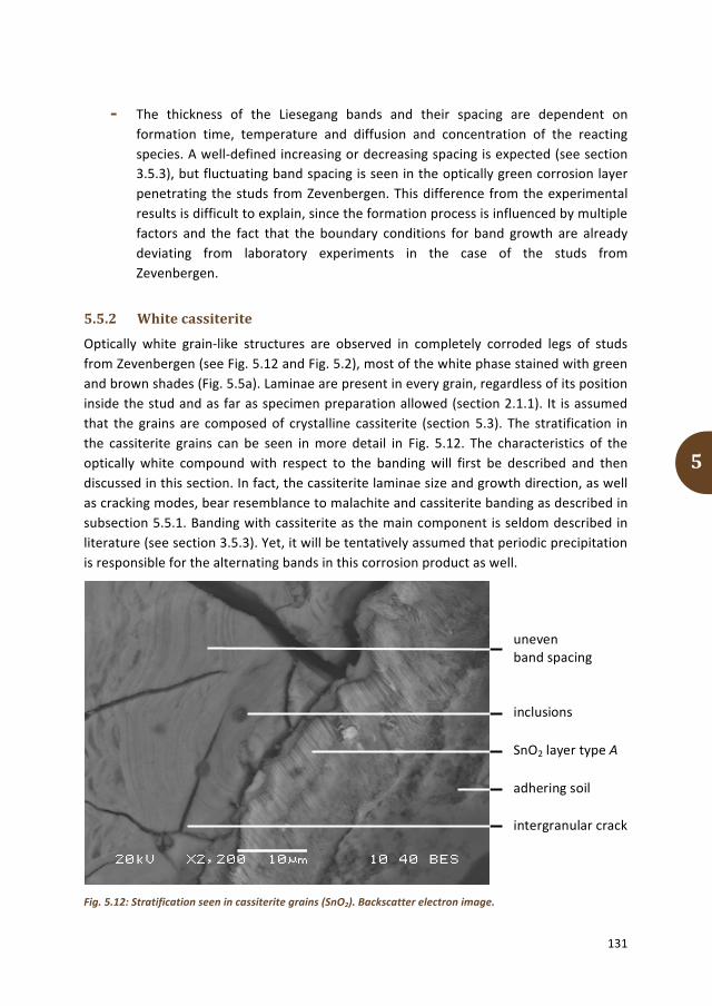
131
5
- The thickness of the Liesegang bands and their spacing are dependent on formation time, temperature and diffusion and concentration of the reacting species. A well-‐defined increasing or decreasing spacing is expected (see section 3.5.3), but fluctuating band spacing is seen in the optically green corrosion layer penetrating the studs from Zevenbergen. This difference from the experimental results is difficult to explain, since the formation process is influenced by multiple factors and the fact that the boundary conditions for band growth are already deviating from laboratory experiments in the case of the studs from Zevenbergen.
5.5.2 White cassiterite
Optically white grain-‐like structures are observed in completely corroded legs of studs from Zevenbergen (see Fig. 5.12 and Fig. 5.2), most of the white phase stained with green and brown shades (Fig. 5.5a). Laminae are present in every grain, regardless of its position inside the stud and as far as specimen preparation allowed (section 2.1.1). It is assumed that the grains are composed of crystalline cassiterite (section 5.3). The stratification in the cassiterite grains can be seen in more detail in Fig. 5.12. The characteristics of the optically white compound with respect to the banding will first be described and then discussed in this section. In fact, the cassiterite laminae size and growth direction, as well as cracking modes, bear resemblance to malachite and cassiterite banding as described in subsection 5.5.1. Banding with cassiterite as the main component is seldom described in literature (see section 3.5.3). Yet, it will be tentatively assumed that periodic precipitation is responsible for the alternating bands in this corrosion product as well.
Fig. 5.12: Stratification seen in cassiterite grains (SnO2). Backscatter electron image.
inclusions
adhering soil
intergranular crack
SnO2 layer type A
uneven band spacing

132
5
- Parallel bands or polygons with a different composition are alternating, based on the two different shades of grey seen in the backscatter electron image (Fig. 5.12).
- The (uniform) band thickness seen in both compounds is mostly submicron, even though band thicknesses of several micrometres are observed as well. Uneven band spacing is recognized.
- The parallel bands are wavy and irregular. The laminae can partly follow the outline of an inclusion or incorporate an inclusion.
- Three different cracking modes can be distinguished: Wavy intergranular cracks (between grains along the grain boundary)
are visible, which can best be seen in Fig. 5.5a. Straight intragranular (within a single grain) and transgranular (across
multiple grains) cracks can be identified and viewed in Fig. 5.12. Grooves between bands are present inside the grain-‐like structures
(Fig. 5.10b). The backscatter electron (BSE) image of the optically white corrosion grains (Fig. 5.12) suggests that bands with different composition are alternating. However, XRD-‐analyses identify only one crystalline phase: cassiterite. SEM-‐EDS-‐measurements indicate that about 13 wt% copper is present in the grains. Since the spatial resolutions of the SEM-‐EDS and XRD used in this research do not allow accurate phase identification per band (sections 2.3.3 and 2.3.4), the composition and structure of the bands remain unclear. Based on the current results, it may be hypothesized that cassiterite is alternating with an amorphous copper-‐rich phase.
Cracking after intergranular corrosion during burial probably causes intergranular cracks in the grain-‐like cassiterite structures, analogous to the formation of this type of cracks in the green corrosion layer (section 5.5.1). The cracks between the grains are more pronounced in the white corrosion phase compared to the green layer, showing a cross-‐section of a stud entirely composed of detached grains. Smaller grains seem to be positioned near the surface and larger grains in the centre of the cross-‐section. The coexistence of a needle-‐like cassiterite layer (type A) surrounding the whitish products may provide a plausible explanation for this phenomenon. As is argued in section 4.4, the studs from Zevenbergen have probably been intentionally tinned. Alterations due to the heat and atmosphere of the adjacent pyre could have transformed excess tin from tinning into the type A layer. This layer consists of submicron-‐sized crystals and would therefore be relatively porous compared to e.g. a malachite layer, allowing corrosive species to penetrate from the environment into the artefact. This transport phenomenon is supported by the presence of about 4 wt% aluminium (Al) and 4 wt% silicon (Si) in the optically white grains as measured with SEM-‐EDS.

133
5
Extensive intergranular corrosion would be able to develop, in agreement with the hypothesis that elevated temperatures might increase the degree of intergranular corrosion (section 3.4.3). Perhaps the decaying organic support surrounding the stud legs has increased the corrosion rate. Intra-‐ and transgranular cracks can be seen as well, and the same explanation as for the green corrosion products can be applied here: these cracks are most probably recent and do not convey information about the original bronze microstructure. Grooves between the bands, following the outline of the laminae, seem to amplify the visibility of the banding. This feature may be a result of surface relaxation, with the same underlying mechanism as that used to explain the shifting of the malachite peaks in the XRD spectra (section 5.5.1). If one phase cannot accommodate the stresses encountered during sandwiching or corrosion, relaxation may be manifested in the form of plastic deformation (i.e. delamination). These stresses may even be released during specimen preparation. The extent to which the relaxation process develops, depends amongst others on the material properties of the bands and the degree of corrosion. Since the crystalline characteristics of the bands that alternate with cassiterite are unknown, it is not possible to verify the groove formation hypothesis at the moment.
It can be deduced from the previous paragraphs that the features of the alternating laminae in the white grains resemble those observed in the green layer. There is a difference in band characteristics though, and that is the combination of an amorphous phase with a crystalline one in the cassiterite grains versus two crystalline compounds in the malachite layer. Still, it is tentatively proposed here that the rhythmic formation of the bands in both corrosion products can be attributed to the Liesegang process and that the amorphous compound has developed due to continuous decuprification of the copper-‐containing band (e.g. cuprite or malachite) during ageing of the corrosion products. To confirm this hypothesis, the amorphous compound should be properly characterized, which was not possible in this research. The crystal lattice would miss a substantial part of its copper atoms, thereby unable to maintain its crystallinity and therefore becoming amorphous. Eventually, the presence of stannic acid and the porous outer layer of cassiterite needles would lead to a completely copper-‐depleted artefact, “resulting in a fragile skeleton of tin oxide as the only indication of the original shape” (Gettens 1951, 70). The large adsorption capacity of gelatinous stannic acid would lead to discolourations and easy material transport through its bulk (Stambolov 1968, 95). Incorporation of e.g. soil particles containing Al and Si would therefore contribute to a brown colouration of the stannic acid, a colour that may remain after dehydration of the stannic acid to cassiterite. Decuprification leads to copper transport throughout the bronze artefact. Malachite may be formed from the stud surface inwards, allowing the coexisting stannic acid to acquire a green colour.

134
5
5.5.3 Red-‐yellow-‐green cuprite
Regions of optically red corrosion products, distinctly banded with yellow and green areas and usually adjoining the green massive malachite layer are observed in the cross-‐sections of the stud from Zevenbergen. Since the three bands are explicitly different in colour, the stratification can best be observed by mixed bright-‐/dark-‐field illumination under the optical microscope and an example is shown in Fig. 5.13. The green compound is not always observed, in which case an alternation between red and yellow bands is displayed. Rhythmic banding of red and yellow zones and red and green zones is reported to occur in archaeological bronzes (section 3.5.3), but the underlying formation mechanisms are not fully understood. In this section, an attempt will be made to provide more insight into the development of the red-‐yellow-‐green sequenced banding. This allows a comparison to the laminae in malachite (section 5.5.1) and cassiterite (section 5.5.2) to find out whether the same formation mechanism applies. Therefore, the characteristics of the banded cuprite regions are described and discussed below.
Fig. 5.13: Sequential red-‐yellow-‐green areas, cuprite (Cu2O), cassiterite and malachite (Cu2(CO3)(OH)2). Optical micrograph.
- Three bands or polygons with a different composition are alternating, based on the optical colouration and different shades of grey seen in the backscatter electron image. A fixed sequence is repeated, which can be recognized by mixed bright-‐/dark-‐field illumination under the optical microscope: red, yellow, green; red, yellow, green, et cetera. In some cases, the bands cannot be clearly distinguished and a colour gradient from red to green is seen. This gradient is most obvious in locations where the banding adjoins the massive malachite layer (see e.g. Fig. 5.3a).
Cu2O
metallic bronze
red band outline resembles equiaxed grain
Cu2(CO3)(OH)2
inclusions

135
5
- The position of the majority of the stratified areas in the stud cross-‐section can be identified as being sandwiched between the central metallic matrix on one side, and the malachite surface layer on the other side. As a result, the green band is usually located at the perimeter of the cluster, while the red band adheres to the metallic phase.
- The band thickness varies in all three compounds, leading to very uneven band spacing. Laminae of several micrometres up to about 40 µm are observed.
- The band shape is irregular, although polygon shapes of different overall size seem to predominate. Inclusions are incorporated in the laminae.
- Cracking is not noticed in the banded cuprite compound. XRD-‐measurements confirm the presence of cuprite in the coloured zone. Its lattice constants are regularly adapted to slightly higher values, indicating stresses in the compound, possibly originating from banding with another phase (see section 5.5.1). Analyses with SEM-‐EDS show that about 20 wt% tin is found in the red-‐yellow-‐green areas. Cassiterite is identified with XRD with a good reference match, which creates a situation comparable to that found in the green malachite layer. In the red-‐yellow-‐green regions, the presence of malachite cannot clearly be established. If identified at all, the malachite fit with its reference spectrum is often not a perfect match. The current results however do suggest that the red bands are composed of cuprite, the yellow bands of a mixture of cuprite and stannic oxide and the green bands of malachite.
A distinct stratified structure composed of three different corrosion products has not been described in literature. However, red-‐yellow and red-‐green laminae are (section 3.5.3). This leads to the hypothesis that the three bands seen in studs from Zevenbergen show intermediate phase formation by the Liesegang process. The possible steps of a simplified model are explained below.
1. Cuprite is formed, due to oxidation as the first stages in soil corrosion described in section 3.5.1. This formation step is supported by the presence of cuprite as a layer between the massive surface malachite and the metallic bronze (section 5.3). Also, the location of the red-‐yellow-‐green areas between metal and malachite and the occurrence of gradients in colour and composition strengthen this assumption.
2. Stannic acid is formed. Tin remaining in the matrix after decuprification will form cassiterite, which develops into stannic acid by hydration (section 3.5.2, p. 73).
3. Diffusion of copper and carbonate-‐containing solution through the gelatinous stannic acid allows the formation of alternating laminae of cuprite and malachite. A low diffusion rate of the species enables the survival of sandwiched layers of stannic acid, which later on dehydrate to cassiterite. Red-‐yellow-‐green bands are the result. When the carbonate concentration would be too low, malachite cannot initially be formed.

136
5
Red-‐yellow bands of cuprite and (eventually) mixed cuprite and cassiterite would then be seen. It remains unclear why a yellow layer forms, composed of mixed cuprous oxide and stannic oxide, instead of ‘pure’ SnO2. Overlapping red cuprite and green malachite may also lead to an optically yellow layer, however, the identification of cassiterite by XRD indicates that this tin oxide compound is incorporated in the stratification.
Concluding, it is proposed in this research that the stratification in the malachite, cassiterite and cuprite compounds is the result of a single process, possibly the Liesegang phenomenon of periodic precipitation as described in the abovementioned model. The development of cuprite and stannic acid are known processes for buried bronzes, and there are no obvious theoretical objections to the diffusion of copper and carbonate-‐containing solution during the long burial time. It is therefore suggested that stratified compounds can be classified as ‘common’ on archaeological bronzes. The development of corrosion products under changing conditions in Zevenbergen as plotted in a Pourbaix diagram (see Fig. 5.6) supports the formation of a layered structure.
However, this is a simplified representation and several issues remain. The exact environmental parameters in mound 7 in Oss-‐Zevenbergen are unknown, as are the diffusion constants and boundary conditions for the formation of cuprite, malachite and cassiterite laminae in the studs. The presence of intermediate (metastable) compounds could not be established. The band thicknesses in cassiterite and malachite are comparable, while the bands in cuprite are thicker, even though accurate spacing determination should be carried out to confirm this statement. It is assumed that varying availability of compounds and formation duration causes the thickness differences, but at the moment it is not possible to accurately establish the formation mechanisms. Finally, it has to be kept in mind that corrosion may be a localized process, influenced by metallic microstructures as well as external conditions, like specific burial conditions. Even though the Liesegang phenomenon as carried out in laboratory set-‐ups seems to be applicable to the formation of bands in the studs from Zevenbergen, adaptions including microstructural features should be made to verify this attribution. A first step is made in the next section, where the reflection of characteristics of the metallic microstructure in the corrosion products is discussed.
5.6 Corrosion products and inclusions may reflect original microstructure
A recurring theme throughout this thesis is the importance of the original microstructure in the construction of artefact biography and the consequent implications for the establishment of cultural biography.

137
5
Since most archaeological bronze artefacts are corroded, it is essential to explore the possibility of recognizing features of the metallic microstructure in corrosion products. The importance of feature recognition in corroded bronze is emphasized by the conception that this is also applicable to other buried metals like iron and even to outdoor metallic objects.
The cross-‐sections of a partly corroded stud from Zevenbergen enable the comparison between features in metallic bronze and in corrosion products. Well-‐perceptible and possibly transferable characteristics of a bronze microstructure are grains and inclusions and therefore, the identification of these two features in corrosion products is discussed in respectively section 5.6.1 and 5.6.2.
5.6.1 Identification of grain shape and size in corrosion products
Grain observation in the metallic bulk through intergranular cuprite corrosion is described in section 5.3, while possible identification of grains in banded corrosion products is mentioned in section 5.5. The conditions for recognition of features from original bronze grains in corrosion products are discussed in this section. In literature, the term ‘ghost structure’ is sometimes used to denote remnant microstructures, but this term will be avoided in this thesis. First, due to intergranular corrosion, the outline of metallic grains can clearly be traced in an unetched bronze cross-‐section. An example is given in Fig. 5.14a. Under the optical microscope, black to red lines can be seen extending from the banded red area into the bronze matrix. Polygon shapes are formed and the outline of grains becomes visible. The front of the malachite surface is often composed of cuprite formed by uniform corrosion (see section 5.3) and grain silhouettes may be discerned on the interface with the metallic bronze (see e.g. Fig. 5.4). To check whether the grains reproduced by intergranular and uniform corrosion are indeed corresponding to metallic grains, etching of the specimen is an effective method. In the case of studs from Zevenbergen, the presence of corrosion free bronze enables this comparison. It can be deduced that the cuprite phase can indeed be used to delineate the perimeter of equiaxed grains from the original bronze microstructure (see Fig. 5.14b).
The determination of grain shape and size using corrosion products is multi-‐interpretable, compared to establishment by bronze etching. Often, corrosion products resolve only half of the grain boundaries. Tracing a possible grain outline therefore introduces an uncertainty in the metallic grain size and shape, which is difficult to quantify. However, the difference between a cast and a worked microstructure can still be qualitatively determined. Twin boundaries generally show a high resistance to intergranular corrosion (Huang 2016, 204). Twins can thus not be recognized by the outline of corrosion products and etching has to be applied in order to identify them with microscopic techniques.

138
5
Intergranular corrosion is well discernable in a metallic matrix, but less well distinguished when the artefact is entirely corroded. When corrosion has advanced to a high degree, intergranular cracking may allow identification of grain boundaries in the same way that intergranular corrosion does. In the studs from Zevenbergen, this can be seen in malachite (section 5.5.1) and cassiterite (section 5.5.2). The grain sizes deduced by the intergranular corrosion features are listed in Table 5.2. In section 4.3, it was remarked that the bronze grains near the stud surface appeared to be smaller than those in the centre. Including the bronze grain sizes for equiaxed grains in Table 5.2 allows comparing. It shows that a relatively good match can be made, especially when the measurement location is taken into account (i.e. near the stud surface only, or including the centre of the stud). This comparison implies that the recognition of grain sizes in corrosion products is indeed possible for the studs from Zevenbergen.
Fig. 5.14: Intergranular cuprite corrosion in a stud cross-‐section from Zevenbergen. (a) Before etching; (b) after etching. Optical micrographs. Cu2O = cuprite, SnO2 = cassiterite, Cu2(CO3)(OH)2 = malachite.
inclusions
stratified Cu2O/SnO2/ Cu2(CO3)(OH)2
metallic bronze
intergranular corrosion
(a)
(b)
twin boundaries

139
5
Second, grain-‐like features can be observed inside several banded corrosion products. Like discussed in section 5.5, the banding an sich can not directly be attributed to a microstructural feature like a grain, or segregation. However, equiaxed or polygon shapes can sometimes be recognized inside clusters of bands, e.g. in cuprite (Fig. 5.13) and malachite (Fig. 5.11). The outline of these polygons can be seen as remnants of grain shapes if it is assumed that corrosion proceeds from the grain boundary inwards (section 5.5.1). Quantitative grain size analysis is then possible and the results for cuprite and malachite are given in Table 5.2. The banding in cassiterite does not allow such an accurate determination of grain shape and size, since the laminae and grooves do not isotropically represent an equiaxed grain. The grain structure seen in Fig. 5.5b and in detail in Fig. 5.10b is probably caused by intergranular cracking, as the grain shapes and dimensions obtained in that way correspond to the actual metallic grain sizes as demonstrated in Table 5.2. Bands and grooves may run across intergranular cracks, do not form definite equiaxed polygons and their orientation does not correspond to the outline of supposed grains. It is therefore assumed that the bands in cassiterite are not indicative for the original microstructure. At the moment, it is unknown why the representativeness of bands is different for the three corrosion products.
Table 5.2: Approximated grain size distribution by intergranular corrosion and/or cracks in metallic bronze as well as corrosion products as seen in cross-‐sections of studs from Zevenbergen.
Grain size distribution (µm) Deduced by Location in stud Conform
Bronze 20 -‐ 150 etching entire cross-‐section heads + legs
Section 5.2
Cuprite 20 -‐ 50 intergranular
corrosion surface heads + legs Fig. 5.14b
20 -‐ 75 polygons in bands entire cross-‐section heads + legs Fig. 5.13
Malachite 20 -‐ 50 intergranular cracks surface
heads + legs Fig. 5.10c
20 -‐ 50 polygons in bands surface heads + legs Fig. 5.11
Cassiterite 50 -‐ 150 intergranular cracks entire cross-‐section leg Fig. 5.5b
5.6.2 Inclusions in metallic bronze
Impurities from the ore or bronze production process can cluster or form secondary phases inside the bronze matrix, thereby forming inclusions in the microstructure (section 3.1.1). There are multiple characteristics to consider when one wants to accumulate information from inclusions. Their composition is one of them, as it may reveal the type of ore used to make the artefact. Morphology, including shape, is another feature that helps identifying the possible thermal and mechanical actions employed during formation of the artefact.

140
5
Furthermore, the position of inclusions in the grain structure is an important aspect as well. Inclusions are often located on grain boundaries. This is most evident in cast structures, but positioning between the grains is also seen in worked structures, although less pronounced. Not only does the position of inclusions enlighten the formation history of the microstructure, these particles are often also present in corrosion layers. This should enable the gain of information about the artefact’s manufacturing process even though the artefact itself is (partly) corroded, in combination with the previously mentioned characteristics. Nevertheless, the implications of using inclusion positions seem relatively unknown.
Usually, the inclusions, intermetallic particles and their location in the bronze microstructure can only be discerned by viewing the cross-‐section of an etched, uncorroded artefact under the optical or electron microscope. But if an artefact is corroded, etching is often not possible due to consequent disintegration of the corrosion products. Here, it will be hypothesized that the position of inclusions in unetched bronze may still enable determination of original grain shape and size. In this section, possible pattern formation in the metallic bronze in the stud from Zevenbergen is described and discussed. A possible extension to reconstruction of original bronze grain structure in corrosion products is elaborated as well. Intermetallic particles (phases that are formed by copper and tin in bronze, see Fig. 2.7) have not been identified in the studs from Zevenbergen and will thus not be incorporated in the current section. The characteristics of the inclusions are elucidated in section 4.3: rounded particles of about 1 µm in size are present, as well as cylindrically elongated inclusions. They contain Cu, S, O and Sn.
Polishing and/or etching of the cross-‐section have resulted in the removal of a number of inclusions on the surface of the metallic bronze. Their location is however still visible, as depressions in the surface are present. Inclusions can also be recognized in malachite, even though they have sometimes disappeared near the outer surface of the stud (see section 4.3). SEM-‐EDS analyses have indicated that the morphology and composition of the inclusions are comparable between the metallic bronze and the corrosion products. It is assumed that the inclusions in the bulk are comparable to those in the corrosion products, even though substructures of submicron size are sometimes observed in the surface malachite layer, possibly due to dissolution processes. The position of the inclusions can still be deduced from the voids that the inclusions have left behind. Inclusions and related voids are also present in cuprite and cassiterite. Their recognition with several analytical techniques is feasible on the basis of colour. The different colours of inclusions and their remains in the bronze as well as the three corrosion products as observed by optical and electron microscopy are listed in Table 5.3, on basis of which representative markers of inclusions could be selected for the following analyses.

141
5
Table 5.3: Colours of inclusions present and remaining voids where inclusions have disappeared after poslishing in metallic bronze, cuprite, malachite and cassiterite as observed by different microscopical techniques. BF = bright field illumination, DF = dark field illumination, -‐ means ‘no image available’.
OM (mixed BF/DF) OM (BF) SEM
Present Void Present Void Present Void
Bron
ze
black reflective black black
grey (cf. bronze, darker grey rim when etched)
dark grey
-‐
Cupr
ite
black -‐ white -‐ light grey -‐
-‐
-‐
-‐
Mal
achi
te
black white white black white; light grey
black
Cass
iterit
e
black -‐ -‐ -‐ white; light grey dark grey
-‐ -‐ -‐
At first sight, the inclusions in the bulk seem to form a regular pattern of equiaxed polygonals. An interpretation of the possible grain distribution is shown in Fig. 5.15b. The estimated grain size of the reconstructed microstructure is 20 to 60 µm, which fits in well with the approximated sizes shown in Table 5.2. Obviously, this reconstruction is a highly subjective issue, as multiple possibilities can be explored. The visible existing grain boundaries, outlined by intergranular corrosion, already guide the eye. Deformed inclusions give an indication for the direction of the grain boundary: parallel along the elongation direction.

142
5
Fig. 5.15: Reconstruction of original grain structure based on inclusion position in metallic bronze in a stud from Zevenbergen. (a) Unaltered image (bright-‐field optical micrograph); (b) reconstruction in red; (c) actual bronze grain structure after etching (mixed bright-‐/dark-‐field optical micrograph) with interpretation from (b) overlaid in black. Cu2O = cuprite.
Cu2O
Cu2O
(a)
(b)
inclusions
(c)
reconstructed grain boundary
reconstructed grain boundary

143
5
By comparing Fig. 5.15b and c, it can be established that the reconstructed grain structure does not perfectly correspond to the actual microstructure. When the stud cross-‐section is etched, it can be seen that the shape and position of grains is different in both cases. Twins do not seem to be explicitly outlined by inclusions and can therefore not be identified by using inclusions for the reconstruction of microstructures. It is visible that the inclusions do not only reside on grain boundaries, but also inside the actual grains (see Fig. 5.16). Whether these positions coincide with former grain boundaries is unknown at the moment. The presence of particles inside bronze grains will probably lead to the estimation of a lower grain size in a reconstruction than that measured in an etched cross-‐section. The presence of inclusions inside grains thus hinders the reconstruction of a reliable microstructure based on inclusions only. However, it can still be deduced that a grain structure composed of equiaxed polygonal grains is present in the metallic bronze, as opposed to a heavily deformed structure or a cast microstructure. It is assumed that inclusions are not removed from their original position by corrosion processes and that in theory, the original bronze grain structure may be reconstructed in corrosion products in the same way as described above for metallic bronze. The examination of inclusion positions in corrosion products however proves to be more difficult. Features like banding, cracks and voids distort the view (see e.g. Fig. 5.10b for cassiterite and Fig. 5.11 for malachite). The transparency of malachite under the optical microscope allows the additional visibility of inclusions deeper inside the compound. Therefore, a metallographic set-‐up of the microscope, using only bright-‐field illumination, should be used to trace possible grain boundaries. As described in section 5.6.1, recognition of original microstructures in corrosion products can best be approached by examining intergranular corrosion, cracks and grain-‐like polygons in bands. An indication for this polygon corresponding to an initially bronze grain may be a centrally situated inclusion.
The exploration of possibilities using inclusion positions to deduce original microstructures is far from complete, but the approach seems promising. It cannot be excluded that in the future, more relevant information can be extracted by applying this method. The utilization of image-‐processing programs like ImageJ and Adobe Photoshop may provide a more accurate selection of inclusion markers, based on (grey-‐scale) contrast between the metal, the inclusions, and corrosion products. This will also allow an estimation of the interparticle distance of the inclusions in all compounds, thereby verifying the steady-‐state positioning of inclusions during corrosion. A preliminary test in this study has shown that the grey-‐scale values of the inclusions overlap with those of malachite. Selection on the basis of optical micrographs obtained with bright-‐field illumination is therefore difficult and unreliable.

144
5
The additional use of SEM-‐EDS-‐mapping may contribute to a more reliable phase selection, but this option has not been explored in the current research. This is also the case for the use of computerized pattern recognition, which may potentially enable more reliable grain structure reconstruction.
To test the general application of the proposed method of microstructure recognition, multiple studs should be examined. Cast artefacts should be included as well and the specimens should be assessed by a multitude of people to decrease the uncertainty due to subjectivity. Elaboration on these points is beyond the scope of the current dissertation.
Fig. 5.16: Microstructure of metallic bronze in a stud from Zevenbergen, after etching. Inclusions do not only reside on grain boundaries, but are also present inside the grains. Optical micrograph.
5.7 Conclusions on sequence of corrosion product formation in studs from Zevenbergen
The previous sections in this chapter have highlighted the presence of a range of corrosion products and morphologies, schematically illustrated in Fig. 5.17. This has given insight into a possible sequence of corrosion product formation in the studs from Zevenbergen, despite a lack of sufficient detailed analyses. In this section, it is intended to provide a hypothetical, yet well-‐argued corrosion sequence containing the information from the available data.
grain boundaries
metallic bronze
twin boundaries
inclusions

145
5
Fig. 5.17: Schematic representation of the corrosion products and morphologies on the studs from Zevenbergen. N.B. Model with all compounds combined into one overview, not to scale.
Two biographical phases can be distinguished: (1) oxidation after proximity to a pyre and (2) corrosion in soil after deposition. Corrosion has progressed from the stud surface inwards, apparently without significantly disturbing the stud shape and leaving the limitos intact in the malachite layer and the type B tin-‐rich layer. This is remarkable, because of the lower density of the corrosion products compared to that of bronze. At the moment, this cannot be explained as extensive diffusion calculations should be performed and correlated with environmental and microstructural data to provide more insight. A short summary of the corrosion process sequence is schematically depicted in Fig. 5.18. Artificially corroded tinned bronze with a comparable microstructure to the studs from Zevenbergen may test the validity of the proposed corrosion sequence, which has unfortunately not been possible in this research. Even though discussed specifically for the studs from Zevenbergen, the results are generally applicable, since the identified corrosion products are common for buried bronzes. It has been argued in section 5.4 and 5.5 that curly malachite and stratified corrosion products should be included in the classification of ‘common corrosion forms on buried bronzes’, because it is hypothesized that both variants are formed by the process of periodic precipitation.
After excavation, all corrosion products on the artefacts described in this dissertation are considered to be stable. The artefact has arrived at its next biographical phase: the present. The preservation of bronze artefacts by using multiple corrosion inhibitors and coatings, as well as their influence on information value, will therefore be described in the next chapter.
stud surface
SnO2 layer type B
CuO layer
metallic bronze
stratified Cu2(CO3)(OH)2/ SnO2/Cu2O
SnO2 layer type A
SnO2 grains
Cu2O layer
Cu2(CO3)(OH)2 grain
Cu2(CO2)(OH)2 layer
Cu2(CO3)(OH)2 curl
inclusions

146
5
Fig. 5.18: Schematic diagram of the corrosion sequence as proposed for the studs from Zevenbergen. Multiple possible surface finishes are depicted in a single image, not to scale. (1) Proximity to a pyre. (1a) Bronze with tinned layer (left) and worn tinned stud (right); (1b) development of SnO2 type A (left) and CuO (right). (2) Corrosion in soil. (2a) Oxidation leads to formation of Cu2O on all surfaces except tinned, where a delayed reaction to Cu2O will take place in a next cycle; (2b) lining of stud with water film leads to decuprification and supersaturated solution; (2c) precipitation of multiple corrosion products; stratified structures form due to the cyclic nature of (2a)-‐(2c); see also Fig. 5.17 for reference. SnO2 = cassiterite, CuO = tenorite, Cu2O = cuprite, Cu2(CO3)(OH)2 = malachite, O2-‐ = oxygen ion, CO3
2-‐ = carbonate ion.

6
Archaeological bronze conservation: now and in the future

148
6
This chapter entails the current stage in the biography of the artefact: the present. This phase however is entangled with the next period: the future. Nowadays, efforts are made to preserve artefacts for generations to come and the use of corrosion inhibitors and coatings has become a commonplace. Like stated in the introduction of this dissertation (p. 2): “Artefacts have a history. And history matters.” Safeguarding the artefacts will enable the gain of information and thereby ultimately tell us about human practices in a certain culture during a certain time. Conservation practice is constantly evolving, incorporating material research and optimizing treatments. For archaeological bronze, benzotriazole (BTAH) is often utilized to prevent further corrosion and polymeric coatings are applied for protection, consolidation and stabilization (section 3.6). Nonetheless, there are several specific aspects that are underexposed and this thesis attempts to bring those facets into the spotlight. The studs from Zevenbergen are used as the starting point from which more generic conclusions can be drawn.
Even though the exact bonding mechanism is unknown, it is generally accepted that a stable and protective barrier layer can be formed by reaction of copper atoms and BTAH. Binding the copper atoms in corroded layers on bronze prevents the formation of possibly detrimental compounds like copper chlorides. Cassiterite (SnO2) is a frequently encountered corrosion product on buried bronze. However, the possibility of BTAH forming a complex with tin is hardly ever considered, yet relevant when this corrosion inhibitor is applied to archaeological bronze.
A study into interaction between BTAH, tin and cassiterite is therefore presented and discussed in section 6.1. The application of polymeric coatings to excavated bronzes undoubtedly has advantages, but also lesser-‐known disadvantages. Coatings do not only influence the visual appearance and aesthetic of bronze artefacts, they can significantly hinder technical investigations. More details are given in section 6.2. The mentioned hindrance of analyses may result in changes in the significance of archaeological bronzes, in particular the decrease of information value, which is described in section 6.3. Based on the discussions in the previous sections, suggestions will be made about updating the preservation of bronze artefacts in section 6.4.
Words in italics are explained in the glossary on p. 193, where their definition as used in this thesis is given.

149
6
6.1 BTAH binds to tin-‐containing substrates
Benzotriazole (BTAH, C6H5N3) is applied on the studs from Zevenbergen (Kempkens and Lupak 2010). BTAH is a frequently used corrosion inhibitor on archaeological bronzes and there are numerous studies devoted to its interaction with copper corrosion products in order to determine the exact mechanism of inhibition (see section 3.6.2). The interaction of BTAH with other than copper-‐containing compounds is sporadically investigated and published (e.g. Molodkin et al. 1997, Galtayries 2007). That is remarkable, since archaeological bronze generally also contains tin dioxide (section 3.5.2). The current section is therefore devoted to the results and discussion of research into the interaction between Sn, SnO2 and BTAH, enabled by the detection of chemical bonds with surface enhanced Raman spectroscopy (SERS) 1 . For comparison, bronze and copper-‐related corrosion products are incorporated in this study. Artificial tin and copper corrosion products, chemically comparable to those found on the studs from Oss-‐Zevenbergen, have been produced and impregnated with BTAH (section 2.1.3).
The general approach in relation to the description of the SERS outcomes will first be elaborated in section 6.1.1. The actual results from the SERS measurements on the tin-‐related compounds are summarized and discussed in section 6.1.2 and on the copper-‐related products in section 6.1.3. The reader is referred to section 2.3.5 for theory about the underlying principles of SERS.
6.1.1 General approach of SERS-‐outcomes in this study
Previous studies on chemisorption of BTAH on substrates have shown that specific functional groups of BTAH-‐molecules are affected by surface binding, while others appear to be unaffected. Throughout this dissertation, BTAH is used to denote 1,2,3-‐benzotriazole in non-‐complexed form. When it has lost the H-‐atom and has formed a complex, 1,2,3-‐benzotriazole is referred to as BTA. In general, insight into substrate-‐BTA electronic interactions is provided by frequencies (or: wavenumbers) associated with functional groups of BTA directly attached to the substrate (Chan and Weaver 1999, 3350). This is translated in a SERS spectrum by peak (in literature often called ‘band’) shifting and/or broadening relative to the reference solid BTAH. A shift indicates a different molecular vibration frequency due to adsorption of the compound. A shift from low to high wavenumbers is called a blue-‐shift, while a red-‐shift represents the opposite: a peak shift from high to low wavenumbers. Broadening occurs upon interaction between the electrons of the BTAH-‐molecule and Cu-‐electrons.
1 Experimental research carried out by Pieter Langerhorst under supervision of Ineke Joosten (Cultural Heritage Agency of the Netherlands) and Janneke van der Stok-‐Nienhuis. Results of the study are published in a thesis report, in which more details can be found: Langerhorst 2014.

150
6
Absence of such features upon adsorption indicates that the molecular component of BTAH is unattached to the substrate. Changes in peak intensities, including appearance of specific peaks, can provide information about the possibly formed BTA-‐complex and its binding to the substrate. Also, relative peak intensities may contribute to the understanding of the adsorbate molecular orientation (Chan and Weaver 1999, 3351). However, an inhomogeneous substrate, irregularities on the surface and contamination have a strong influence on the measured peak intensities. Since the current study has not facilitated repetitive measurements and the use of multiple substrates of the same artificial products, peak intensities will not be taken into account during the following discussions.
With this background knowledge in mind, selected ranges of peak wavenumbers will be compared in this study and assigned to specific molecular bonds in order to determine the state of the chemisorbed BTA-‐molecule onto the substrate. The SERS results will be discussed in the following subsections on the basis of five categories:
1. Peaks for BTAH and substrate products align. 2. Peaks for substrate products can only be attributed to their own vibrational
modes. 3. Peaks associated with BTAH in compound spectra shift with respect to reference
BTAH. 4. Peaks representing BTAH-‐modes are notably absent in compound spectra. 5. Peaks that cannot be attributed to any known reference.
Positive identification in the first and second category will indicate that certain functional groups of BTA(H) do not attach to the substrate, or that residue BTAH is present. The third and fourth classifications allow hypotheses on the formation of BTA-‐complexes with the underlying substrate. Peaks that fall in the fifth category remain unresolved, yet may provide information on contamination and probably even binding. The assignments are extracted from literature on previously measured complexes: Bigotto et al. 1996 (BTAH), Chan and Weaver 1999 (BTAH, Cu-‐BTA) and Bouchard and Smith 2003 (cassiterite).
6.1.2 SERS-‐results of BTAH-‐impregnated cassiterite and metallic tin
Fig. 6.1 shows the overview of SERS spectra of cassiterite and metallic tin, together with the spectrum for solid BTAH as reference. The assignment and interpretation of peaks in the spectra for tin-‐related compounds is performed below. BTAH residue and no interaction The following paragraphs discuss peaks that can be classified in the first and second category as stated above: alignment of peaks and attribution to own vibrational modes.

151
6
There are multiple instances where the peaks for the corrosion inhibitor and the substrates align. All these peaks represent torsion, stretching and bending of (members of) the skeleton of the solid BTAH molecule. ‘Skeleton’ is an indication for the unit consisting of both the benzene ring and the triazole ring (see Fig. 3.8). The presence of those skeleton peaks both in the spectrum of solid, unreacted BTAH and in the spectra for tin-‐related compounds is an indication that the functional groups of the BTAH-‐skeleton do not directly interact with the substrate material. In addition, residue of solid BTAH may be present on the surface of the tin and cassiterite substrates. Characteristic peaks for cassiterite (Sn-‐O) are observed in the spectrum of the treated sample (475 and 776 cm-‐1, possibly also 640 and 844 cm-‐1). Metallic tin is not Raman-‐active, which means that characteristic peaks of tin will not be visible in the SERS spectrum (Langerhorst 2014, 71). During a SERS measurement, only the first layer of molecules is analyzed. The appearance of vibrational modes of cassiterite thus implicates that the surface layer is thin and contains cassiterite. The peaks at wavenumbers 871, 1079 and 1389 cm-‐1 (partly) represent bending modes of the N-‐H part of the triazole ring in BTAH. It is generally thought that this N-‐H bond is responsible for chemisorption of BTAH on a substrate (Chan and Weaver 1999, 3351). Bonding through the triazole ring would therefore result in a disappearance of the peaks at 871, 1079 and 1389 cm-‐1. The presence of these peaks, even though weak, in the spectra for Sn and SnO2 is thus seen as confirmation that there is residue of unbound BTAH present on the substrate surface. The peaks for the substrates considered in this subsection do not appear broadened when compared to the peaks seen for the corrosion inhibitor. However, a reliable quantification requires optimization of the resolution and background removal for the measured tin compounds, which is not performed in the current research. The behaviour of tin and cassiterite with respect to the aligned peaks is equivalent. Peaks representing BTAH appear at similar wavenumbers for both compounds. The main differences can be seen in the peak intensities. Also, the background values vary, especially at the higher wavenumbers. However, as explained in section 6.1.1, explanations concerning peak height will not be considered in this study.
Evidence of binding? The possible formation of attached BTA-‐complexes on tin and cassiterite substrates will be discussed in the following paragraphs, based on peaks that fall in categories 3 and 4 (see section 6.1.1): shifting of BTA(H)-‐peaks and absence of BTAH-‐modes. A selection of peaks appearing in Sn and SnO2 spectra that cannot be attributed to a known reference (category 5) is incorporated in this subsection. In total, 15 peaks seem relevant for possible binding of BTAH to tin-‐related compounds (see lines in Fig. 6.1). An overview with assignments can be found in Table 6.1.

152
6
Table 6.1: Overview of possibly shifted peaks of Sn and SnO2 (indicated with ‘a’; dashed lines in Fig. 6.1), compared to solid BTAH (solid lines in Fig. 6.1), measured with SERS. τ = torsion, δ = in-‐plane bending, γ = out-‐of-‐plane bending, ν = stretching, n.s. = not specified, -‐ means ‘not applicable’.
Peak Wavenumber
#a (cm-‐1)
Related BTAH wavenumber
# (cm-‐1) Compound
Assignment (BTAH) Remark
1 210 -‐ SnO2 unresolved shoulder in Sn?
2, 2a 244 238 Sn, SnO2 τ-‐skeletal / Sn-‐N? shoulder in BTAH?
3, 3a 299 285 Sn τ-‐skeletal also in SnO2?
4, 4a 387 410 Sn, SnO2 δ-‐skeletal -‐
5, 5a 554 539 Sn, SnO2 δ/γ-‐triazole ring /
δ-‐skeletal -‐
6, 6a 640 632 Sn, SnO2 τ-‐triazole ring /
δ-‐skeletal SnO2-‐ref: peak at 635
7, 7a 665 681 SnO2 τ-‐skeletal + γ-‐CH
-‐
8, 8a 1012 1008 SnO2, Sn δ-‐skeletal + δ-‐CH
broadening + coupling 1008 (8), 1023 (9)?
9, 9a 1030 1023 SnO2, Sn δ-‐skeletal + δ-‐CH
broadening + coupling 1023 (9), 1048 (10)?; shoulder in SnO2
10 -‐ 1048 BTAH n.s. shoulder in Sn, SnO2
11, 11a 1264 1270 Sn, SnO2 ν-‐skeletal
+ δ-‐CH + δ-‐NH -‐
12, 12a 1292 1281 Sn, SnO2 ν-‐skeletal
+ δ-‐NH + δ-‐CH -‐
13, 13a 1445 1455 Sn, SnO2 ν-‐skeletal -‐
14, 14a 1464 1469 Sn, SnO2 ν-‐skeletal -‐
15, 15a 1489 1499 Sn ν-‐skeletal 15a + 16a coupled for SnO2
16, 16a 1504 1513 Sn ν-‐skeletal 15a + 16a coupled
for SnO2
The shifting and broadening of peaks suggest binding of Sn and SnO2 to BTAH. Multiple functional groups of BTAH appear to be responsible for the interaction (see Table 6.1):
a. BTAH-‐skeleton The involvement of the skeleton of BTAH in interaction with the substrates under study can be illustrated by e.g. peak 4 (410 cm-‐1), a vibration that can be attributed to in-‐plane peaking of the BTAH-‐skeleton. This peak can be clearly discerned in the solid BTAH spectrum, but is absent in the spectra of both tin-‐containing compounds (see Fig. 6.1). Peak 4a (387 cm-‐1) can be interpreted as a shift of peak 4. In some cases, more specific assignments of peaks to the triazole ring of BTAH (e.g. peak 5/5a) can be made.

153
6
b. C-‐H/N-‐H An example of Sn-‐BTA-‐complex formation through the change of the C-‐H-‐ or N-‐H-‐bond in BTAH can be illustrated by peak 11 (1270 cm-‐1). This peak is clearly visible in the spectrum of solid BTAH (see Fig. 6.1) and is assigned to stretching of the skeleton and in-‐plane bending of CH and NH. In the spectra of Sn and SnO2, the peak at 1264 cm-‐1 (peak 11a) may be the representation of peak 11 shifted to a lower wavenumber. Both arguments lead to the supposition that this peak is an expression of the interaction between BTAH and the tin-‐containing substrates. However, it remains unclear at the moment which of the mentioned functional groups of BTAH is responsible for the BTA-‐complexing.
c. Appearance of Sn-‐N?
Peak 2a (244 cm-‐1) appears to be a shift and broadening of the reference BTAH-‐peak (peak 2) at 238 cm-‐1 (see Fig. 6.1) and a coupling of BTAH-‐peaks at 223 cm-‐1 and 238 cm-‐1. The shift and broadening can be seen in both substrates: Sn and SnO2. For solid BTAH, these peaks are attributed to skeletal torsion and a shift might thus indicate interaction between the BTAH-‐skeleton and the substrate. In literature, peak 2a is associated with the formation of a BTA-‐complex. The formation of an Sn-‐N bond is evidenced by the appearance of peaks at 233 and 237 cm-‐1 for BTAH-‐treated tin (IV) chloride (Molodkin et al. 1997, 548). A treated silver substrate shows an Ag-‐N stretch at 242 cm-‐1 (Thomas et al. 2004, 26) and Cu-‐N at 240 cm-‐1 on copper (Chan and Weaver 1999, 3350). It is therefore likely that peak 2a is associated with an Sn-‐N binding mode. But, remarkably, a small shoulder can be seen at 244 cm-‐1 for unreacted BTAH. In literature, this peak is not recognized for solid BTAH. At the moment, the appearance of a peak at 244 cm-‐1 can therefore only tentatively be attributed to the formation of an Sn-‐BTA-‐complex.
The shifted peaks seen in the spectra of the treated tin-‐containing substrates show more pronounced broadening than the non-‐shifted peaks (see p. 151), also in comparison to peaks of solid BTAH. Differences in behaviour between tin and cassiterite are hard to distinguish, especially because the peak-‐background ratio in the cassiterite spectrum is low in the higher wavenumber region. In literature, broadening is related to substrate-‐BTA electronic interaction. Based on both broadening and shifting, it is thus concluded that BTAH adsorbs on the tin-‐containing substrates. Most probably, an Sn-‐BTA-‐complex is formed on both metallic tin and cassiterite.
The direction of peak shifting may reveal the orientation and/or binding strength of the adsorbed BTA-‐molecule. The peaks designated to triazole ring vibrations (5 and 6) show blue-‐shifts (a shift from low to high wavenumbers). The triazole ring is seen as the functional group through which the BTAH molecule may form a complex with the metallic surface.

154
6
During this binding process, electrons rearrange, thereby changing the vibration of the triazole breathing. A weak interaction would then result in a small shift. The blue-‐shifts seen for peaks 5 and 6 can be classified as intermediate when compared to blue-‐shifting in other metals (Cao et al. 2002, 102). This implicates that not only adsorption of neutral BTAH molecules takes place, but also that a film of metal-‐BTA-‐complex is formed (Cao et al. 2002, 102). The other peaks seen in the spectra display both blue-‐shifts and red-‐shifts and do not seem to be related to a specific molecular vibration. This hinders the establishment of the orientation of the Sn-‐BTA-‐complex. Decreasing intensity or even disappearance of peaks from solid BTAH in tin-‐containing substrate spectra are another indication for electronic interaction (category 4, section 6.1.1). When looking at the SERS-‐overview (Fig. 6.1), there are 6 instances where this may be the case for both substrates: disappearance of BTAH skeleton-‐related peaks 285 cm-‐1, 410 cm-‐1, 899 cm-‐1 (only for Sn) and shoulder formation at 1097 cm-‐1 and 1211 cm-‐1 and possibly at 1310 cm-‐1, which are representative of relatively N-‐H in-‐plane bending and the BTAH skeleton. During chemisorption, the N-‐H bond of BTAH will break and the H-‐atom evades. The involvement of the triazole ring and the skeleton in adsorption is therefore very plausible. In literature, the inclusion of the BTAH-‐skeleton in binding is however not evidenced. A specific recommendation for further research on the basis of the current study is the generation of multiple spectra of higher quality. This would allow optimization of the resolution and background removal and hence a more reliable quantification, so that the engagement of the BTAH-‐skeleton can be verified. Unassigned peaks Peaks that cannot be attributed to a known reference (category 5, section 6.1.1), like at 655 cm-‐1 in the SnO2 spectrum, may be physical contamination on the substrate or the solid BTAH, e.g. dust. These peaks may also belong to unknown complexes, e.g. Sn-‐N. To be conclusive, repetitive SERS-‐measurements on multiple samples will have to be performed, which is not done in this study. Concluding, residue of unbound BTAH can convincingly be found on the surface of the tin-‐containing substrates. Shifting, coupling and broadening of peaks in the spectra of metallic tin and cassiterite indicate that BTAH is chemisorbed onto the surface. The entire BTAH-‐skeleton appears to be involved in the formation of a BTA-‐complex. The presence of characteristic peaks of cassiterite indicates that the formed film is thin. If certain areas are not covered with the BTA-‐film, regions of unprotected surface may be present. This may decrease the effectiveness of the inhibitory action of BTAH on tin-‐containing substrates. However, SERS spectra of higher quality need to be reproduced in order to verify the abovementioned assumptions. Comparison with known Cu-‐BTA-‐complexes may also aid in the assignment of peaks and binding modes, which will be done in section 6.1.3.

155
6
Fig. 6.1: O
verview of SER
S spectra of solid BTA
H, m
etallic tin (Sn) and
cassiterite (SnO
2).
1
2,
2a
3,
3a
4a,
4 5,
5a
6,
6a 7a
, 7
8,
8a
10
9,
9a
11a,
11 12
, 12
a
13a,
13 14
a,
14 15
a,
15 16a,
16
SnO
2
BTAH
Sn

156
6
Cu2O
Cu2(CO
3)(O
H) 2
BTAH
CuO
CuSn
Fig. 6.2: O
verview of SER
S spectra of so
lid BTA
H, cup
rite (Cu 2O), malachite (C
u 2(CO
3)(OH) 2), teno
rite (CuO
) and
bronze (CuSn).

157
6
6.1.3 Comparison with BTAH-‐impregnated copper-‐related products
In section 6.1.2, tentative interpretations of the interaction of BTAH with a tin-‐containing substrate are given, based on SERS-‐results. To construct a better-‐reasoned hypothesis, these results will be compared with BTAH-‐interaction on copper-‐containing surfaces. Next to metallic bronze, the substrates are composed of the same corrosion products found on the studs from Zevenbergen (section 5.3): cuprite, malachite and tenorite. When necessary, specific wavenumbers will be given during the comparison. Otherwise, only the general behaviour on possible residue of BTAH and binding will be discussed.
As can be seen in Fig. 6.2, the spectra of the BTAH-‐impregnated copper-‐containing substrates are comparable. Peaks that shift do so in the same direction with the respect to solid BTAH, although the magnitude of the shift may be different for every compound. BTAH residue and no interaction There are peaks that indicate that residue or unbound BTAH is present on the copper substrate surfaces, like for metallic tin and cassiterite, although less apparent and with relatively lower intensities. This may be the result of a relatively thick layer of Cu-‐BTA-‐complex and less unbound BTAH compared to the tin substrate. Evidence of binding? The spectral characteristics that imply interaction between BTAH and the copper-‐related products are well visible. Shifting, coupling and broadening are features that are omnipresent. Some of these peaks are explicitly attributed to the formation of a Cu-‐BTA-‐complex. When this behaviour is also visible for the tin-‐containing substrates, the possibility of the formation of an Sn-‐BTA-‐complex becomes more realistic.
A Cu-‐N-‐peak around 244 cm-‐1 is present for every copper-‐component (Fig. 6.2). Comparable behaviour for tin and to a lesser extent for cassiterite (peak 2a) implies that an Sn-‐BTA-‐complex formation indeed occurs and that the BTAH-‐triazole ring is involved.
Marked blue-‐shifting of peaks in the Cu spectra of BTAH-‐reference 539 cm-‐1 and 632 cm-‐1 is analogous to the formation of peaks 5a and 6a for tin and cassiterite. These wavenumber shifts reflect the occurrence of substantial triazole ring-‐surface interactions. The strong peak at 782 cm-‐1 and multiple peaks from 1443-‐1620 cm-‐1, assigned to the BTAH-‐skeleton, also show shifting to a lower wavenumber in the copper-‐containing substrate spectra. The blue-‐shifting behaviour is comparable to that of tin and cassiterite in the same regions. The pronounced shifting of peaks characteristic of the BTAH skeleton underline the involvement of the skeleton in the binding of BTA to copper-‐ and tin-‐containing surfaces, even though this has previously not been acknowledged in literature.
More evidence of binding can be found between 1000 and 1055 cm-‐1 and between 1266 and 1292 cm-‐1. The vibrational modes of the triazole ring, bending of the N-‐H bond and the skeleton of BTAH are changed after impregnation of the copper-‐containing substrates, which is reflected in these wavenumber region by (de-‐)coupling.

158
6
The behaviour of cassiterite bears resemblance to that of metallic bronze and tenorite in the range 1000-‐1055 cm-‐1, while that of metallic tin is analogous to the shifting of malachite and cuprite. These differences are not encountered in literature and more research should be conducted to discover their origin. No clear disappearance or shift of the peak of solid BTAH at 1211 cm-‐1 has been observed for both tin-‐containing substrates (see Fig. 6.1) due to possible shoulder formation and/or high background peaks. However, this peak is clearly absent in all Cu spectra and has possibly shifted to 1178 cm-‐1, a peak that is also found for metallic tin and as a shoulder for cassiterite. This behaviour represents electronic interaction of BTAH with the substrate through the triazole ring and the N-‐H bond. This observation for copper-‐related products makes it plausible that metallic tin and possibly cassiterite may interact in the same way. Disappearance of the 699 and 1097 cm-‐1 peaks of solid BTAH in all Cu spectra as well as in the spectrum for metallic tin, contributes to the binding hypothesis. Based on the discussion in this subsection, the behaviour of tin, cassiterite, metallic bronze, tenorite, cuprite and malachite can be seen as comparable. It can be concluded that an Sn-‐BTA complex is formed, like for copper-‐containing substrates, although this interaction appears to be weaker than for copper. This implicates that BTAH may actually be more effective than currently conveyed, since tin and cassiterite may be involved in binding. However, SERS-‐measurements alone are not enough to be conclusive and details about the binding are lacking. Unfavourable thermodynamics, steric hinder or another phenomenon may be responsible for the weaker bonding of BTAH to tin compounds, but further research needs to be conducted in order to obtain more knowledge.
6.2 Polymeric coatings on archaeological bronze
When corrosion inhibitor BTAH is applied to an object, the next step is often to apply a protective coating for stabilization and/or safety reasons (see section 3.6.3). The studs from Zevenbergen have all been preventively treated with BTAH and ethyl-‐2-‐cyanoacrylate (CA) has been subsequently applied for artefact consolidation. However, CA significantly disturbs the visibility of the surface of the bronzes, thereby hindering microscopic investigation. Applying CA thus negatively influences the readability of features essential to the determination of use traces and the colour, type and amount of corrosion. As visual disturbance is a phenomenon that is regularly encountered on coated bronzes, the current section will discuss possible origins.

159
6
Prepared coatings on different substrates have been qualitatively assessed2 and the results are described in section 6.2.1. An approach to non-‐destructively measure the layer thickness of regularly used Paraloid B-‐72 coatings is summarized in section 6.2.2.
6.2.1 Corroded surface with polymeric coating generates wavy appearance
Fig. 6.3: Visual disturbance on bronze stud from Zevenbergen, coated with ethyl-‐2-‐cyanoacrylate as seen under an optical microscope. (a) Shrinkage cracks form fine parallel lines; (b) inhomogeneous reflection of light due to irregularities on the substrate surface. After Nienhuis et al. 2013, Fig. 9.12.
2 Experimental research carried out by Stefania Lorenzotti under supervision of Janine van Reekum (University of Amsterdam), Ineke Joosten (Cultural Heritage Agency of the Netherlands) and Janneke van der Stok-‐Nienhuis. Results of the study are published in a thesis report, in which more details can be found: Lorenzotti 2013.
trapped air bubble
rod
shrinkage cracks (a)
(b)
shrinkage cracks
glossy, wavy effect
glossy, wavy effect

160
6
Fig. 6.3 shows five characteristic features of a cyanoacrylate-‐coated corroded bronze that decrease the readability of the underlying artefact:
1. Inhomogeneous reflection of light, creating a localized glossy, wavy effect. Irregularities on the substrate surface are probably the cause.
2. A distribution of fine parallel lines along the surface. These can be identified as shrinkage cracks, formed during the curing process.
3. Air bubbles trapped in the optically transparent layer. These bubbles are presumably the result of the fast setting time (in the order of seconds) of CA.
4. White, milky colouration resulting in a blurred perception of the surface. This colouration is most likely caused by a relatively thick CA-‐coating and the resulting non-‐uniform transparency.
5. Rod-‐like particles or grains residing on top of the coating. These small fragments appear to be recrystallized cyanoacrylate, remnants of already solidified CA from the coating container, or particles of unknown origin incorporated in the coating during setting.
Fig. 6.4: Coatings applied on an archaeological test bronze. (a) Ethyl-‐2-‐cyanoacrylate (CA), wax and ORMOCER, digital photograph; (b) uncoated surface; (c) surface as in (b) coated with Paraloid B-‐48N in acetone. Indicated in yellow are the areas with increased surface visibility and good colour saturation. Optical micrographs.
CA (a)
(b) (c)
ORMOCER
wax

161
6
The optical perception of coated, prepared metallic plates is compared by analysis with the unaided eye and with optical microscopy in this study. Four types of coating (Paraloid B-‐48N, ORMOCER OR1, ethyl-‐2-‐cyanoacrylate (CA), microcrystalline wax) have been applied on copper test coupons with increasing roughness: smooth copper plate, roughened copper plate and an archaeological bronze surface (see section 2.1.4 for details). Representative visual results are displayed in Fig. 6.4. Discussion of the test results (Lorenzotti 2013) leads to the following conclusions: - Surface roughness is the primary cause of the visual disturbances.
The uncoated reference areas of the rough bronze surface show glossy and wavy regions when viewed under an optical microscope (see Fig. 6.4b), as opposed to the smooth and roughened copper plates. This indicates that the emergence of these disturbances is inherent to the underlying surface.
- Paraloid B-‐48N performs better on rough corroded bronze than CA and
ORMOCER. The irregularities of the underlying surfaces are reproduced by all polymeric coating systems (Fig. 6.4a, c). Distinct disturbing wavy regions are recognized, especially on the bronze substrate. In areas where no glossy effects were observed, the surface is well visible. Good colour saturation and consequently enhanced contrast facilitates the detection of relevant surface details, which is essential to the gain of information from the artefact (Fig. 6.4c).
All Paraloid B-‐48N systems show that the surface is scattered with relatively small glossy areas, while less, but larger regions emerge localized on plates treated with CA and ORMOCER. This implies that the properties of the coating influence the visual perception. The presence of larger glossy features leads to a very glossy, near-‐plasticized and non-‐uniform appearance, which is undesirable (Fig. 6.4a). So, the optical perception of samples coated with Paraloid B-‐48N is preferred above those treated with CA and ORMOCER, even though the levelling capacity of B-‐48N is inferior.
The use of different solvents for Paraloid B-‐48N has not significantly improved levelling and consequent surface visibility. The addition of matting silica particles renders the surface white and blurry and therefore does not provide additional value.
- The application of wax does not lead to glossy, wavy areas.
When wax is applied directly on the artefact, there is no disturbance by glossy areas and the visibility of the underlying surface is good (Fig. 6.4a). This is probably the result of the fact that the refractive index of wax is closer to air than those of the polymeric coatings (Lorenzotti 2013, 43).

162
6
However, the colour saturation in the waxed samples is inferior to that of the polymer-‐coated surfaces. Also, employment of only wax does not provide the desired consolidative action when treating archaeological artefacts. Additional application of wax as a matting layer on top of Paraloid B-‐48N does not contribute to the visibility.
As indicated earlier in this thesis, the final appearance after coating is a complex interaction between the artefact surface and the coating. A corroded bronze surface is inhomogeneous and this will lead to significantly localized distortions. The presence of multiple corrosion products, different in size, colour and shape, also impedes the quantitative determination of the interaction of the coating with the surface. The thickness of the coating may vary along the artefact, also when the manual application by the conservator is taken into account. Last but not least, the aesthetic of a coated artefact is optically perceived. It is therefore inherently subjective matter. The valuation of appearance of corroded bronze may change over time, a topic that is covered in section 6.3.
6.2.2 Possibility for non-‐destructive determination of Paraloid B-‐72 layer thickness
As shown in section 6.2.1, coating layer thickness has influence on the visual appearance of corroded bronzes. Thinner polymeric coatings appear to generate less disturbing features on the coated surface. It would be useful to determine threshold values of film thickness in order to optimize the surface visibility. Thickness information may locally be provided by analysis of cross-‐sections, attained by destructively sectioning samples. Non-‐destructive mapping of these values along an entire surface would therefore be preferable. Conventional elemental measurement methods (X-‐ray fluorescence, electron microscopy) do not provide a means to map the organic polymeric elements in depth with sufficient accuracy and on a micrometre-‐scale. However, accurate mapping may be attained with Rutherford backscattering spectrometry (RBS), combined with proton-‐induced X-‐ray emission (PIXE)3. To investigate its potential, measurements have been carried out using Paraloid B-‐72 on an archaeological corroded bronze sample in this research. The analytical details are described in section 2.3.6.
3 This research has been carried out at the AGLAE facility at the C2RMF in Paris. Financial support by the Transnational Access to Research Infrastructures activity in the 7th Framework Program of the EU (CHARISMA Grant Agreement n. 228330) is gratefully acknowledged.

163
6
Fig. 6.5: RBS spectrum (red) and simulated spectrum (blue) of non-‐corroded bronze coated with Paraloid B-‐72. Copper (Cu) originates from the substrate, carbon (C) and oxygen (O) originate from the Paraloid-‐layer. Helium (He) constitutes the atmosphere between the sample and the RBS-‐detector.
Combining the RBS data with the elemental concentrations of the coated bronze as measured with PIXE, simulations can be made with the program SIM-‐NRA to estimate layer thicknesses of films with different concentrations of Paraloid B-‐72 (Fig. 6.5). The preliminary results are that the layer thicknesses are in the order of 80 μm for a solution of 13 g/ml B-‐72 in acetone. Further elaboration is beyond the scope of this research, but a preliminary conclusion is that the application of this analytical method is useful. To verify the first simulations, one should look at the shift of the copper edge in the RBS spectrum. That edge is shifted to lower energies for the non-‐corroded side of a treated sample compared to an untreated sample due to the Paraloid film on top of the bronze substrate. Since the RBS spectra are recorded on a local micrometre scale, the heterogeneity of the surface of the archaeological bronze can be visualized. It should therefore be possible to link the local layer thickness of the organic polymeric coating to a specific (corrosion) feature of the bronze surface. Unfortunately, this data interpretation is beyond the scope of the current thesis.
He
Cu edge
energy (keV)
channel
Cu
coun
ts
simulated with SIM-‐NRA
RBS data
C O

164
6
6.3 Influences of conservation on significance of the artefact
Significance can be seen as an artefact property that may change during the artefact lifetime and is dependent on all actions that the artefact has undergone, from production to use and from corrosion to conservation treatments. A multitude of values represent significance, and this thesis focuses on information value (section 1.4). It is not always obvious whether conservation treatments help or hinder the gain of information.
The current research has encountered various disadvantages of coating application on archaeological bronze, mainly described in section 6.2.1. The downsides of conservation of the studs from Zevenbergen for the performance of several analytical techniques (section 2.3) are described in section 6.3.14. The influence of the applied conservational actions on the information value on the studs from Zevenbergen and thus on the significance of the bronze artefacts are discussed in section 6.3.2.
6.3.1 Coatings have negative effects on technical analyses
The studs from Zevenbergen were treated using BTAH and ethyl-‐2-‐cyanoacrylate (CA). One of the most obvious features is the near plasticized appearance and distorted perception of the underlying bronze corrosion. Not only does the coating influence the aesthetics, it reflects the light in such a way that a discoloured and less readable image is formed when making optical micrographs, as outlined in section 6.2.1. With the naked eye, this streaked appearance can easily be mistaken for use traces or remains of the production process. Changes in colour due to impregnation with a polymer can be observed for malachite curls (see Fig. 6.6a). This modification can lead to misleading conclusions, like linking colour change to the presence of impurities in the corrosion product (Nienhuis et al. 2016, 30).
More disadvantages of the use of polymeric coatings like CA were encountered during analysis by means of scanning electron microscopy (SEM). Polymers are non-‐conductive and where the artefacts are coated, hardly any details on the surface of the studs can be discerned with SEM (Fig. 6.6b). Also, non-‐conductivity of the coating leads to an electron pile-‐up during the analysis and the formation of a charged area on the sample. Subsequent deflection of the electron beam during imaging may significantly disturb the observations, even in low vacuum. The organic conservation material in principle does not influence compositional measurements with energy dispersive X-‐ray spectroscopy (EDS), a system linked to the SEM-‐instrument, since the elements present in the coatings are too light for an electron microscope or X-‐ray fluorescence (XRF) instrument to detect. However, the elemental analysis of a coated area with SEM-‐EDS cannot be related to the underlying surface structure since the region of interest cannot be mapped or visually checked. The resulting spatial resolution that can be attained with SEM-‐EDS on a coated surface is thus very low. 4 These paragraphs are largely based on Nienhuis et al. 2013, 234.

165
6
A reliable measurement can still be achieved in the case of homogeneous surfaces. However, corroded surfaces are inhomogeneous and the size of their characteristics is smaller than the estimated spatial resolution of the instrument. Therefore, correlation of elemental analysis to surface characteristics is very unreliable for archaeological bronzes coated with a polymer.
Fig. 6.6: Changes in the appearance (encircled areas) of curly malachite from Uden. (a) Colour change, optical micrograph; (b) obscured details, backscatter electron image. Reproduced from Nienhuis et al. 2016, Fig. 7.
Since the substances used for consolidation, restoration, and conservation are generally not crystalline, broad peaks with a width of about 15-‐25° may be distinguished in X-‐ray diffraction (XRD) spectra of bronze cross-‐sections embedded in Epofix and bronze surfaces coated with CA. The appearance of amorphous-‐like broad peaks at low diffraction angles (2θ < 30°) hinders identification of relevant phases with their main diffraction lines in that region. For archaeological bronze, mainly soil-‐related compounds show diffraction at low angles. Often, peaks that lie outside this range are present as well and since identification follows from the fitting of multiple peaks, phase recognition is often still possible.
(a)
(b)

166
6
Light elements are not detected by XRF analysis of the bronze studs, so these materials did not influence the compositional measurements. However, the coating forms an extra layer that the incoming X-‐rays as well as the resulting photons need to pass through. Consequently, the intensity will be decreased and a lower penetration depth and absolute number of counts will be the effect. However, this effect is very small compared to the total number of counts.
An applied coating does in principle not influence the method of microstructure recognition as proposed in section 5.6, because a cross-‐section of the artefact is required for the identification of grains in corrosion products and inclusions in metallic bronze. The coating can be distinguished from the artefact since a definite interface is present, see e.g. Fig 4.4, especially when a coloured embedding medium is utilized. When a coating is applied on a very porous artefact, penetration into the corrosion products occurs, which may lead to visual disturbances and hindrance of microstructure recognition. On the other hand, a penetrated coating may also lead to an outline of for example grain boundaries and thereby aid grain identification.
6.3.2 Change of information value due to conservation
For the bronze finds from Zevenbergen, the value of the conservation of the studs is a little ambiguous. On the one hand, without physical consolidation, the analytical research could not have been performed in the first place since the artefacts would have disintegrated upon touching. However, negative effects of conservation have also been acknowledged and described in section 6.3.1 The current subsection will therefore take stock and construct a general view on changing information value of (un)treated corroded bronzes.
Apart from keeping intact the integrity of the entire artefact, consolidation of corrosion products on the location where they adhere to the artefact surface can be seen as desirable. Several examples of the beneficial effects of consolidations are presented in this thesis. The attribution of white surface layers to corroded tinned layers in section 4.4 has enabled the establishment of the prehistoric silvery appearance of the studs from Zevenbergen. The identification of curly malachite in section 5.4 can be seen as a proof of authenticity of the bronze artefacts (cf. Eggert 2007, 60) and information about the environmental conditions during burial may be deduced. The original microstructure may be recognized in corrosion products (section 5.6), which reveals possible steps in the production process of the artefacts. Study of the find context is an advantage of block lifts being conserved in the laboratory (Fontijn et al. 2013).
A decrease in information value however is obtained when the perception of the surface is hindered by the application of polymeric coatings, regardless of the imaging technique. Identification of use traces, the type of corrosion products and organic remains is obstructed (see section 6.3.1). Multiple stages in the artefact biography lack information and the story is less complete than without the coating on the bronze.

167
6
Destructive sampling and/or making cross-‐sections would partly solve the problem. But since the artefact is not intact afterwards, its significance may be decreased. One can however also argue that for artefacts that have been deliberately destructed in prehistory, like those found in mound 7 in Oss-‐Zevenbergen, partial destruction by sampling may even be a logical step, especially when the amount of information obtained is increased.
6.4 Suggestions to update preservation of bronze artefacts
This thesis has generated knowledge about several aspects of conservation of archaeological bronze artefacts. In practice, the majority of corroded metal from excavations in the Netherlands is being deselected5. It has been shown in this research that corroded bronzes are still valuable objects when their information value is concerned. Therefore, revisions can be made in the conservation practice and suggestions will be given in the following sections. It is not intended to comprehensively take all conservation actions into account, only three facets encountered in this study will be highlighted.
The next stages in the biography of the artefacts can be display in a museum or storage in a depot, which may technically fall under the common denominator ‘preservation’. Since the current section mainly deals with interventive conservation and not with preventive conservation, incorporation of the phases of collection care is considered to be beyond the scope of this thesis.
Since several analytical results are influenced by the application of polymeric coatings on bronze, it is suggested that technical research is performed before treating artefacts with chemicals and/or coatings in section 6.4.1. The use of BTAH as preventive measurement is discussed in section 6.4.2, while the possibility of leaving corroded bronzes uncoated is considered in section 6.4.3.
6.4.1 Technical investigations before conservation are most efficient
Contemporary professionally trained conservators are aware of the benefits, but performing artefact material analyses prior to conservation is not yet standard practice for materials scientists, archaeologists and related disciplines. This dissertation gives a good insight in the amount of information that can be retrieved from corroded bronzes from the past. Altogether, technical investigations should therefore ideally always be carried out and preferably before the actual interventive conservation treatment starts.
Polymeric coatings on archaeological bronze regularly have a negative influence on multiple analysis techniques, as is described in section 6.3.1. Even though a better contrast may be attained after coating, glossy areas may obstruct the visibility of the surface.
5 Based on personal experience of the author and on discussions with professionals in the field of archaeology.

168
6
Valuable information about corrosion products, like identification, texture and location, cannot be recorded with optical microscopy (OM). There is a large influence on the much-‐used technique of electron microscopy imaging (SEM), since the coatings are non-‐conductive and can completely obscure the surface. Imaging of a coated artefact surface therefore reveals much less information than visualizing a non-‐coated artefact. One also encounters problems with the establishment of the essential correlation between elemental composition and specific location on a corroded bronze artefact. The determination of the exact type of corrosion products is crucial in order to e.g. choose the right corrosion inhibitor, as is pointed out in this thesis by the recognition of curly malachite and the interaction of BTAH with tin dioxide. Since polymeric coatings can obstruct compound characterization, it is necessary to avoid analyses on coated surfaces.
A logical recommendation would therefore be to carry out technical analyses before artefact conservation, especially OM and SEM, if possible. Even better, in the light of information gain, would be to consider the necessity of the addition of a coating to the bronze and/or corrosion products, which is also discussed in section 6.4.3. Partially coating an artefact for stabilization, or keeping several artefacts from the entire set untreated are also realistic possibilities.
The argument pleading for performance of analyses before treatment is not only valid for metallic artefacts, but also for organic materials. The excavation of mound 7 in Zevenbergen has provided an example of organics where thorough investigation before conservation would likely have been beneficial. First, multiple large studs have been visually analyzed in search for textile, leather or wood remains (Nienhuis et al. 2013, 228). Not only did the gloss of CA hinder differentiation of black remains on the surfaces, the polymeric CA disturbed the view under the electron microscope (comparable to Fig. 6.6b). This is a problem that is regularly encountered in the investigation of treated textile as well (Nientker 2011). The search for remains of the possibly organic substrate onto which the studs were originally affixed was continued by mass spectrometry, a technique with which small samples of complex solid organic material can be chemically characterized. The high intensity of the markers for organic compounds BTAH and CA overshadowed markers possibly belonging to the organic residue found on the bronze surface (Oudemans 2013). Both examples prove that attempts of the conservators to avoid the impregnation of organic residue on the studs with BTAH and CA have not entirely succeeded. This emphasizes the difficulty of coating practice and stresses that leaving bronzes entirely uncoated is a viable option to increase the significance of the artefacts in question.
Consideration of the purpose of artefacts in an early stage after excavation, but before conservation, would be helpful. Artefacts that are intended to be on display require different handling than those solely reserved for study or storage in a depot. This can be the difference between preventive and remedial conservation (see section 1.3.1). Subsets available for study may be selected from the entire find set to make a division in future purpose from the start and to stay untreated with chemicals.

169
6
Information from this dissertation can aid in the establishment of a decision tree. Unfortunately, the creation of such an extensive flowchart is beyond the scope of this research.
6.4.2 Preventive conservation with BTAH unnecessary?
BTAH is used to stabilize copper corrosion products and to prevent the copper surface from developing the so-‐called ‘bronze disease’. This has resulted in the contemporary practice of preventively impregnating all archaeological copper-‐alloyed artefacts by multiple conservation professionals in the Netherlands, even if the artefact is initially classified as stable. Comparing this active conservation method with subsection 6.4.1, one may wonder whether it is actually necessary to rigorously impregnate every copper-‐alloyed artefact. Every action undoubtedly has its consequences on the state of the artefact, either positive of negative. One should carefully consider whether the consequences outweigh the necessity of (preventive) treatment with BTAH. The progress of international scientific research results in more knowledge about the interactions of BTAH with copper-‐alloyed archaeological artefacts, which should be made applicable to the daily practice of specialists working with these artefacts.
This research has confirmed the likely binding of BTAH to a tin-‐containing surface (section 6.1). This implicates that the scope of corrosion inhibition by BTAH is even bigger than currently conveyed in conservation practice: corrosion of tin and deterioration of tin oxide compounds will probably also be inhibited by BTAH. However, Sn and SnO2 are generally seen as stable under conditions like those in depots and museums (Turgoose 1985). The application of BTAH as preventive tin corrosion inhibitor may then be seen as redundant. Yet, the implications of the interaction between tin (oxide) and BTAH are not well-‐known. More research is required on this matter to be conclusive about the possible protective application of BTAH to tin-‐containing artefacts.
Furthermore, literature consistently classifies the use of BTAH in conservation as safe for human beings and harmful rather than toxic (section 3.6.2). Experimental tests show that the toxicity of BTAH is comparable for solid BTAH in powder form and BTAH dissolved in ethanol (Langerhorst 2014, 73). The standard concentration of BTAH application in conservation is quoted in literature to be 3% m/v BTAH in ethanol (see section 3.6.2), in this dissertation converted to the format ‘3 g/ml’ (see section 2.1.3) due to the ambiguity of the combination of ‘%’ and ‘m/v’. In practice, concentrations from 2.5 to 3.5 g/ml are used (Kempkens 2012; Meijers 2012). Confusion about the unit may be the reason for the varying concentrations of applied solutions, since 3% (g/g) BTAH in ethanol corresponds to 2.5 g/ml. Lowering the concentration even further may be a good suggestion, thereby optimizing the positive effect of the inhibitory action on the artefact and the negative influence of BTAH on the human beings and the environment.

170
6
Altogether, it can be argued that avoiding preventively impregnating archaeological bronzes with BTAH would probably not directly be detrimental and, against modern practice, is worthwhile considering. However, additional future research is essential to establish the extent of possible damage and to be conclusive on the matter. Testing the condition of bronzes that have been in untreated state for tens of years would give more insight in the necessity of preventive impregnation with BTAH.
6.4.3 Consider leaving corroded bronze uncoated6
Based on the observations that coating archaeological bronze may hinder technical analyses (section 6.3.1), it is suggested in section 6.4.1 that performing these investigations before coating is most efficient. It is also proposed to even leave the corroded bronze uncoated to maximize the information gain from the artefact and to keep the number of invasive treatments of the artefact to a minimum. Partial artefact treatment with polymeric coating is an option, even though this appears hard to attain in practice. The most favourable solution when the information value of a collection is considered, is to keep several artefacts from the entire set untreated if possible. Loose curls of malachite form a representative example (section 5.4). Impregnation with polymeric conservation material may change the colour and appearance in such a way that misleading conclusions can be drawn, like linking colour change of the malachite to the presence of impurities. Separating these already loose curls from the artefact and leaving them untreated will preserve their original nature for further investigation.
Organic coatings are often applied on corroded bronzes to ensure avoiding contact of BTA(H) with the skin or airways (see section 3.6.3). With the suggestion of discarding preventive impregnation with BTAH (section 6.4.2) in mind, coating would be redundant in those cases.
Fragile artefacts are commonly stabilized with polymeric coatings. It has been shown in this study that coating with cyanoacrylate or Paraloid B-‐48N leads to colour saturation of the corrosion products and enhanced contrast (section 6.2.1). This may facilitate the visibility of specific details on the artefact surface. Partially coating an artefact for stabilization, after which analyses can be performed, or keeping several artefacts from the entire set unstabilized are also options. Obviously, the decision “to coat or not to coat” is not always straightforward and interdisciplinary discussions will aid in the trade-‐off (section 1.4).
6 Fragments of Nienhuis et al. 2016 are reproduced in this paragraph.

7
Concluding remarks

172
7
In this dissertation it is aimed to show that an integral approach in object studies enables an exhaustive exploitation of the information potential of archaeological bronze (section 1.3.2). The current chapter therefore summarizes the conclusions as obtained in the previous chapters. Section 7.1 describes a reconstructed artefact biography 2.0 of the bronze studs from Oss-‐Zevenbergen. The establishment of this biography has generated new information that is more generically applicable, outlined in section 7.2.
7.1 Artefact biography 2.0 of bronze studs from Zevenbergen
The different phases in the life of archaeological artefacts can be described by artefact biography. This thesis has defined an updated version: artefact biography 2.0 (see Fig. 7.1). Here, corrosion, excavation, preservation and future use like storage, display and study are incorporated next to the already included stages of processing, application and deposition in the remote past.
The small bronze studs from the Early Iron Age, found in a burial mound in Oss-‐Zevenbergen, the Netherlands, form the corpus of this research (section 1.4). These artefacts are only half a centimetre long and have a thickness of a few millimetres. Valuable contributions to the knowledge about the extraordinary funeral of a man in the Netherlands were possible by elaborating the artefact biography 2.0 of the studs, which is outlined below.
Fig. 7.1: Schematic representation of the proposed artefact biography 2.0 in this dissertation, where the life of an artefact is considered from raw material to future use.

173
7
Raw material The metallic composition of a single stud could be quantified and this bronze stud is composed of copper with 9 ± 1 wt% tin and traces of lead, arsenic, nickel and antimony, which is not an uncommon composition for Early Iron Age bronze. It is assumed that most studs have a comparable composition, based on qualitative measurements (section 4.3). Combined with the small dimensional variation of the studs and an estimate of crucible volume, it is highly likely that a single batch of raw material was used to produce all studs, probably even in the same workshop, by re-‐melting and not smelting (sections 4.1 and 4.2). It was not possible to deduce the provenance of this raw material, but re-‐melting recycled bronze or ingot material is seen as most plausible option. This was common practice in regions lacking ore, like the Netherlands, and large inclusions as direct result of ore smelting were not identified in the studied studs. Object The studs from Zevenbergen have most likely been produced by cycles of cold-‐work and annealing or by hot-‐working, rather than directly by casting. This is demonstrated by an observed polygonal, equiaxed, recrystallized, twinned, nearly pore-‐free and compositionally homogeneous bronze microstructure (section 4.3). A physical reconstruction of the manufacturing process supports this production hypothesis since a stud has been made in a few steps (section 4.5). First, a template is cut from a thin sheet of metal and the rough edges are finished. Then, a punch hits the template, above a preformed hole. The stud legs are ultimately straightened and the final shape is obtained by hammering the stud around the punch. Intermediate heat treatments (annealing) could have been performed in order to avoid brittle failure of the stud during hammering.
Intentional tinning of the studs from Zevenbergen by simple hot-‐tinning is evidenced by the presence of white-‐coloured, corroded, tin-‐rich layers at the perimeter of multiple studs (section 4.4), but was not included in the reconstruction as this was based solely on visual observations. In use Unlike modern studs in jeans, the studs from Zevenbergen have probably not been used as reinforcements but as decoration. Taking their number, shape, and the other grave goods into consideration, it is suggested that horse gear made of leather and wood was embellished with about a thousand small tinned bronze studs (section 4.6). Wear of the tinning layers shows that the object was thoroughly used. Buried This decorated artefact was subsequently used in the burial ritual of a man in the Netherlands: it was dismantled and at least elements of it were burned and deliberately deposited (section 5.1).

174
7
Degraded A differentiation is made in the following biographical phase of the studs from Zevenbergen: corrosion. Two processes can be distinguished: oxidation after proximity to a pyre (section 5.2) and corrosion in soil after burial (section 5.3). Multiple stud characteristics have indicated that several studs were adjacent to the pyre, of which the presence of the corrosion products tenorite (CuO) and acicular cassiterite (SnO2) are the most typical. After burial, a thin film of cuprite (Cu2O), both a massive layer and grains of malachite (Cu2(CO3)(OH)2) as well as grains of cassiterite have developed as common corrosion products on the studs from Zevenbergen, indicating that the surroundings in Oss-‐Zevenbergen in general do not deviate from the majority of archaeological sites in the Netherlands. Additionally, curly malachite (CM) (section 5.4) and stratified corrosion products containing cuprite, malachite and cassiterite (section 5.5) were identified. Even though these corrosion products are usually classified as ‘uncommon’, it is argued in this research that they are probably more common than currently assumed. This thesis aims to facilitate a wider documentation of the appearance of CM in order to test the proposed formation mechanism. Especially the presence of CM is regularly linked to the presence of organic material, yet this study has allowed the conclusion that the occurrence of CM is not inextricably linked to human agency, e.g. the use of a textile shroud during burial.
A formation sequence of the different corrosion products as found on the studs from Zevenbergen is proposed (section 5.7). The tin-‐rich layers originating from intentional tinning altered into cassiterite by oxidation due to adjacency to the pyre, and/or due to burial in soil. During burial, first, a thin cuprite film is formed on the stud surface due to oxidation. Then, the bronze studs are lined with water during their burial in soil, after which decuprification and continuing dissolution of copper leads to a supersaturated solution of corrosive agents around the artefacts. Cycles of periodic precipitation may lead to curly malachite on the artefact surface and a layered structure of malachite, cassiterite and cuprite develops at the cost of metallic bronze. Conserved The studs have all been preventively treated with corrosion inhibitor benzotriazole (BTAH) and ethyl-‐2-‐cyanoacrylate (CA) has been subsequently applied for artefact consolidation (Kempkens and Lupak 2010). The advantages of this treatment are prevention of disintegration upon touching and inhibition of copper corrosion in the future, enabling the establishment of an artefact biography as presented in this thesis. However, coating with CA may also hinder the application of technical analyses like electron microscopy due to visual disturbance and charging of the sample (sections 6.2 and 6.3). Stored, displayed and studied As described in Jansen et al. (2013), several bronze studs from Oss-‐Zevenbergen are currently displayed in the permanent exhibition ‘Archaeology of the Netherlands’ in the Rijksmuseum voor Oudheden (RMO) in Leiden.

175
7
Information from the excavation, combined with subsequent research, has allowed a visual artist impression of the burial ritual that took place in Zevenbergen in the Early Iron Age. The research data about mound 7 gathered and interpreted by Fontijn and co-‐workers (Fontijn et al. 2013) is published as an open-‐access document.
The physical find material is included in the depot of the RMO, unlike common practice of storing material in the provincial depot. This exclusive decision has ensured the possibilities for access, loans and future study, and enabled the complex to remain intact in one place. All these examples can be regarded as a confirmation of the high significance of the finds, since the value assigned to a collection plays a key role in displaying items and share knowledge with the public at large (Versloot 2014, 7).
7.2 Generic applicability of interdisciplinary results
Studying the multiple life phases of the studs from Zevenbergen from an interdisciplinary point of view and by using the artefact biography 2.0 has allowed the extraction of information that is applicable to other bronzes and ultimately metals in general. Three explicit results are summarized below.
1. Corrosion products and inclusions may reflect original microstructure After a cross-‐section of a corroded artefact is made, the shape and size of grains from the original metallic microstructure may be recognized, especially when intergranular corrosion and/or cracking has occurred. Pattern formation by inclusions in bronze may enable the determination of metallic grain shape and size without etching. A possible extension to reconstruction of original microstructure in corrosion products is explored in this research (section 5.6). The deliberate tinning of the bronze has been deduced by studying the morphology of the corroded artefact surface and the influence of a pyre on the corrosion process has been established.
Often, the significance of corrosion is not recognized and corrosion products are regularly removed from metallic artefacts. The examples described in this thesis indicate that corrosion layers do contain relevant information, especially about original microstructures. This enables the establishment of (parts of) the artefact biography 2.0. This promising approach, including the study of corrosion products, should therefore be applied when corroded metal is excavated and studied.
Future research should be aimed at more accurate mapping of inclusions in metallic and corroded microstructures, computerized pattern recognition could be applied and more artefacts, both worked and cast, should be included in the sample set.

176
7
2. BTAH binds to Sn and SnO2 Corrosion inhibitor benzotriazole (BTAH) is generally preventively applied to copper alloys because it binds to copper. This study has indicated that BTAH is chemisorbed onto the surface of tin and cassiterite (section 6.1). The entire BTAH-‐skeleton appears to be involved in the formation of a BTA-‐complex and the formed film is thin: in the order of several molecular layers.
Further research is needed in order to verify these assumptions and to confirm the implications that BTAH may actually be more effective than currently conveyed.
3. Technical investigations before conservation increase information value of
artefact Conservation material on bronzes regularly includes (polymeric) coatings for consolidation, thereby keeping the artefact physically intact. This practice in principle allows analytical research and enables the retrieval of information from the artefact, thereby increasing its information value. However, the current research has shown that coatings like Paraloid may also hinder perception of the artefact surface, both by optical study as well as by electron microscopy. Consequently, the information value of the artefact is decreased. This negative influence of coating may be circumvented by performing technical investigations before (partial) conservation of the artefact (ensemble) when coating is unavoidable (section 6.4).

References

178
Abu-‐Baker, A.N., I.D. MacLeod, R. Sloggett, R. Taylor (2013) A comparative study of salicylaldoxime, cysteine and benzotriazole as inhibitors for the active chloride-‐based corrosion of copper and bronze artifacts, European Scientific Journal 9 (33) pp. 228-‐251.
Alford, T.L., L.C. Feldman, J.W. Mayer (2007) Fundamentals of Nanoscale Film Analysis, New York.
Allam, N.K., A.A. Nazeer, E.A. Ashour (2009) A review of the effects of benzotriazole on the corrosion of copper and copper alloys in clean and polluted environments, Journal of Applied Electrochemistry 39, pp. 961-‐969.
Angelini, E., F. Rosalbino, S. Grassini , G.M. Ingo, T. de Caro (2007) Simulation of corrosion processes of buried archaeological bronze artefacts. In: P. Dillmann, G. Beranger, P. Piccardo, H. Matthiesen (eds.) Corrosion of metallic heritage artefacts: Investigation, conservation and prediction for long-‐term behaviour, Cambridge, pp. 203-‐218.
Antonijevic, M.M. and M.B. Petrovic (2008) Copper corrosion inhibitors. A review, International Journal of Electrochemical Science 3, pp. 1-‐28.
Appelo, C.A.J. and D. Postma (1999) Geochemistry, groundwater and pollution, Rotterdam.
Ashby, S.P. (n.d.) Artefact Biographies: implications for the curation of archaeological ivories, Ebur Protocol Document, www.ebur.eu/userfiles/file/Artefact%20biographies%20final%20doc.doc (accessed on 4 June 2017).
Ayres, R.U., L.W. Ayres, and I. Råde (2002) The Life Cycle of Copper, its co-‐products and by products, International Institute for Environment and Development.
Baker, H. and H. Okamoto (1992) ASM Handbook, volume 3: Alloy Phase Diagrams, Ohio. Balmuth, M.S. and R. F. Tylecote (1976) Ancient Copper and Bronze in Sardinia: Excavation
and Analysis, Journal of Field Archaeology 3 (2), pp. 195-‐201. Barry, B.T.K. and C.J. Thwaites (1983) Tin and its alloys and compounds, Chichester. Bassett, J. and W.T. Chase (1994) Considerations in the Cleaning of Ancient Chinese
Bronze Vessels. In: In: D.A. Scott, J. Podany and B.B. Considine (eds.), Ancient & Historic Metals: Conservation and Science Research, The Getty Conservation Institute, pp. 63-‐74.
Batzill, M. and U. Diebold (2005) The surface and materials science of tin oxide, Progress in Surface Science 79, pp. 47-‐154.
Bauser, M. (2006) Metallurgical Principles. In: M. Bauser, G. Sauer, K. Siegert (eds.) Extrusion: Second Edition, Ohio, pp. 141-‐194.
Bayley, J. and Th. Rehren (2007) Towards a functional and typological classification of crucibles. In: S. La Niece, D. Hook and P. Craddock (eds.) Metals and Mines -‐ Studies in Archaeometallurgy, London, pp. 46-‐55.
Berger, D. (2015) Artificial patination in Early Iron Age Europe: an analytical case study of a unique bronze artefact, Journal of Archaeological Science 57, pp. 130-‐141.

179
Bernard, M.C. and S. Joiret (2009) Understanding corrosion of ancient metals for the conservation of cultural heritage, Electrochimica Acta 54, pp. 5199-‐5205.
Bertholon, R. (2000) La limite de la surface d’origine des objets métalliques archéologiques, caractérisation, localisation et approche des mécanismes de conservation, PhD thesis, Université Paris 1 Panthéon-‐Sorbonne.
Bertholon, R. (2007) Archaeological metal artefacts and conservation issues: long-‐rem corrosion studies. In: P. Dillmann, G. Beranger, P. Piccardo, H. Matthiesen (eds.) Corrosion of metallic heritage artefacts: Investigation, conservation and prediction for long-‐term behaviour, Cambridge, pp. 31-‐40.
Biccari, F. (2010) Defects and Doping in Cu2O, PhD thesis, Sapienza -‐ University of Rome. Biek, L. (1957) The Examination of Some Copper Ores: A Report of the Ancient Mining and
Metallurgy Committee, Man 57, pp. 72-‐76. Bigotto, A., A. N. Pandey, C. Zerbo (1996) Polarized Infrared and Raman Spectra and Ab-‐
initio Calculations of Benzotriazole, Spectroscopy Letters 29 (3), pp. 511-‐522. Bouchard, M. and D.C. Smith (2003) Catalogue of 45 reference Raman spectra of minerals
concerning research in art history or archaeology, especially on corroded metals & coloured glass, Spectrochimica Acta Part A 59, pp. 2247-‐2266.
Bradley, R. (1988) Hoarding, Recycling and the Consumption of Prehistoric Metalwork: Technological Change in Western Europe, World Archaeology 20 (2), pp. 249-‐260.
Bray, P.J. and A.M. Pollard (2012) A new interpretative approach to the chemistry of copper-‐alloy objects: source, recycling and technology, Antiquity 86, pp. 853-‐867.
Brostoff, L.B. (2003) Coating strategies for the protection of outdoor bronze art and ornamentation, PhD thesis, University of Amsterdam.
Caley, E.R. (1952) Chemical examination of an ancient sheet of metal of unique composition found in Greece, The Ohio Journal of Science 52 (3), pp. 161-‐164.
Caley, E.R. and D.T. Easby, Jr. (1959) The smelting of sulfide ores of copper in preconquest Peru, American Antiquity 25 (1), pp. 59-‐65.
Callister, W.D. (20005) Materials Science and Engineering: an Introduction, New York. Cao, P.G., J.L. Yao, J.W. Zheng, R.A. Gu, Z.Q. Tian (2002) Comparative Study of Inhibition
Effects of Benzotriazole for Metals in Neutral Solutions As Observed with Surface-‐Enhanced Raman Spectroscopy, Langmuir 18, pp. 100-‐104.
Chan, H.Y.H. and M.J. Weaver (1999) A Vibrational Structural Analysis of Benzotriazole Adsorption and Phase Film Formation on Copper Using Surface-‐Enhanced Raman Spectroscopy, Langmuir 15, pp. 3348-‐3355.
Chase, W.T. and U.M. Franklin (1979) Early Chinese black mirrors and pattern-‐etched weapons, Ars Orientalis 11, pp. 215-‐258.
Chase, W.T. (1994) Chinese Bronzes: Casting, Finishing, Patination, and Corrosion. In: D.A. Scott, J. Podany, B.B. Considine (eds.) Ancient & Historic Metals: Conservation and Science Research, Los Angeles, pp.85-‐118.

180
Chase, W.T., M. Notis, A.D. Pelton (2007) New Eh-‐pH (Pourbaix) diagrams of the copper-‐tin system. In: C. Degrigny, R. van Langh, I. Joosten, B. Ankersmit (eds.) Metal 07: interim meeting of the ICOM-‐CC Metal WG Amsterdam, pp. 15-‐21.
Chen, D. and L. Gao (2004) Facile synthesis of single-‐crystal tin oxide nanorods with tunable dimensions via hydrothermal process, Chemical Physics Letters 398, pp. 201-‐206.
Chiavari, C., M. Degli Esposti, G.L. Garagnani, C. Martini, D. Prandstraller, T. Trocchi (2007) Bronze archaeological finds from the Villanovan necropolis of Orto Granara (Bo): study of manufacturing technologies and evaluation of the conservation state, La Metallurgia Italiana 5, pp. 43-‐52.
Claßen, E., R. Gebhard and S. Wiedmann (2010) Fürstin -‐ Priesterin -‐ Händlerin: Wer bin ich in der Hallstattzeit?, Archäologie in Deutschland 6, pp. 24-‐27.
Coghlan, H.H. (1955) Reports of the Ancient Mining and Metallurgy Committee: Analyses of Three Continental Axes and of Specimens of Irish Ores, Man 55, pp. 6-‐8.
Constantinides, I., A. Adriaens, F. Adams (2002) Surface characterization of artifcial corrosion layers on copper alloy reference materials, Applied Surface Science 189, pp. 90-‐101.
Craddock, P.T. (1979) Deliberate alloying in the Atlantic Bronze Age. In: M. Ryan (ed.) The origins of metallurgy in Atlantic Europe: Proceedings of the fifth Atlantic colloquium, Dublin, pp. 369-‐385.
Cuthbertson, J.W. (1960) Bronzes. In: E.S. Hedges (ed.) Tin and its Alloys, London, pp. 369-‐412.
Degrigny, C. (2007) Examination and conservation of historical and archaeological metal artefacts: a European overview. In: P. Dillmann, G. Beranger, P. Piccardo, H. Matthiesen (eds.) Corrosion of metallic heritage artefacts: Investigation, conservation and prediction for long-‐term behaviour, Cambridge, pp. 1-‐17.
Degrigny, C. and M. Senn (2012) Methodology to study and analyse the microstructures and corrosion forms of ancient and historic metals: application to metallographic samples from Swiss collections (MIFAC-‐Métal), Neuchâtel.
Derkosch, J., F. X. Mayer und H. Neuninger (1956) Spektralanalytische Untersuchungen von urzeitliehen Kupferfunden, Microchimica Acta 44 (11), pp. 1649-‐1661.
Dieter, G.E., H.A. Kuhn and S.L. Semiatin (eds.) (2003) Handbook of workability and process design, Ohio.
Doeser, B.A., S.W. Thomas, J.R. Moon (1976) Thermal etching of copper, Acta Metallurgica 24, pp. 773-‐778.
Dooijes, R. and O.P. Nieuwenhuyse (2007) Ancient Repairs: Techniques and Social Meaning. In: M. Bentz and U. Kästner (eds.), Konservieren oder Restaurieren -‐ die Restaurierung Griechischer Vasen von der Antike bis Heute, München, pp. 15-‐20.

181
Doonan, R.C.P., S. Klemm, B.S. Ottaway, G. Sperl, H. Weinek (1996) The East Alpine Bronze Age copper smelting process: evidence from the Ramsau Valley, Eisenerz, Austria. In: Ş. Demirci, A.M. Özer and G.D. Summers (eds.) Archaeometry 94: Proceedings of the 29th International Symposium on Archaeometry, Ankara, pp. 17-‐22.
Down, J.L. (2001) A literature review of cyanoacrylate adhesives, Reviews in Conservation 2, pp. 35-‐39.
Dubey, M.N., S. Jouen, X. Sauvage, B. Hannoyer (2011) Scaling and internal oxidation of α-‐CuSn alloy, Materials at High Temperatures 28 (4), pp. 377-‐382.
Dungworth, D. (2002) Further Experiments in Annealing Low Tin Bronze (Centre for Archaeology Report 105/2002), Portsmouth.
Eggert, G. (2007) Pseudomorph or Corrosion? The Enigma of the Curly Malachite. In: C. Degrigny, R. van Langh, I. Joosten, B. Ankersmit (eds.) Metal 07: interim meeting of the ICOM-‐CC Metal WG Amsterdam, pp. 57-‐60.
El Morr, Z., F. Cattin, D. Bourgarit, Y. Lefrais, P. Degryse (2013) Copper quality and provenance in Middle Bronze Age I Byblos and Tell Arqa (Lebanon), Journal of Archaeological Science 40, pp. 4291-‐4305.
Ellis, L. and A. Heginbotham (2004) An Evaluation of Four Barrier-‐Coating and Epoxy Combinations in the Structural Repair of Wooden Objects, Journal of the American Institute for Conservation 43 (1), pp. 23-‐37.
Engelberg, D.L. (2010) Intergranular Corrosion. In: T.J.A. Richardson (ed.) Shreir’s Corrosion, pp. 810-‐827.
Ex, N. (1993) Zo goed als oud: de achterkant van het restaureren, Amsterdam. Figueiredo, E., R.J.C. Silva, J.C. Senna-‐Martinez, M.F. Araújo, F.M. Braz Fernandes, J.L.I Vaz
(2010) Smelting and recycling evidences from the Late Bronze Age habitat site of Baiões (Viseu, Portugal), Journal of Archaeological Science 37, pp. 1623-‐1634.
Finšgar, M. and I. Milošev (2010) Inhibition of copper corrosion by 1,2,3-‐benzotriazole: A review, Corrosion Science 52, pp. 2737-‐2749.
Fiske, J. (1993) Introduction to communication studies, London. Fokkens, H., B.J.W. Steffens, S.F.M. van As (2016) Farmers, fishers, fowlers, hunters:
Knowledge generated by development-‐led archaeology about the Late Neolithic, the Early Bronze Age and the start of the Middle Bronze Age (2850-‐1500 cal BC) in the Netherlands, Nederlandse Archeologische Rapporten 53, Amersfoort.
Fontijn, D.R. (2002) Sacrificial Landscapes. Cultural biographies of persons, objects and ‘natural’ places in the Bronze Age of the southern Netherlands, c. 2300-‐600 BC, Leiden (= Analecta Prehistorica Leidensia 33/34).
Fontijn. D. and H. Fokkens (2007) The emergence of early Iron Age 'chieftains' graves' in the southern Netherlands: reconsidering transformations in burial and depositional practices. In: C. Haselgrove and R. Pope (eds.) The Earlier Iron Age in Britain and the Near Continent, Oxford, pp. 354-‐373.
Fontijn, D.R. (2012) personal communication. Function: professor in Archaeology of Early Europe at Leiden University.

182
Fontijn, D., S. van der Vaart, R. Jansen (eds.) (2013) Transformation through destruction. A monumental and extraordinary Early Iron Age Hallstatt C barrow from the prehistoric ritual landscape of Oss-‐Zevenbergen, Leiden.
Fontijn, D. and S. van der Vaart (2013) Dismantled, transformed and deposited – prehistoric bronze from the centre of mound 7. In: D. Fontijn, S. van der Vaart, R. Jansen (eds.) Transformation through destruction. A monumental and extraordinary Early Iron Age Hallstatt C barrow from the prehistoric ritual landscape of Oss-‐Zevenbergen, Leiden, pp. 151-‐193.
Fontijn, D.R. (2016) personal communication. Function: professor in Archaeology of Early Europe at Leiden University.
Francis, R. (2010) The Corrosion of Copper and Its Alloys: A Practical Guide for Engineers, Houston.
Gagliano R. and M. Fine (2001) Growth of η Phase Scallops and Whiskers in Liquid Tin-‐Solid Copper Reaction Couples, JOM 53 (6), pp. 33-‐38.
Galtayries, A., A. Mongiatti, P. Marcus, C. Chiavari (2007) Surface characterisation of corrosion inhibitors on bronzes for artistic casting. In: P. Dillmann, G. Beranger, P. Piccardo, H. Matthiesen (eds.) Corrosion of metallic heritage artefacts: Investigation, conservation and prediction for long-‐term behaviour, Cambridge, pp. 335-‐351.
Geilmann, W. (1956) Verwitterung von Bronzen im Sandboden, Angewandte Chemie 68 (6), pp. 201-‐211.
George, J., I. Paul, P.A. Varughese, G. Varghese (2003) Rhythmic pattern formations in gels and Matalon–Packter law: A fresh perspective, Pramana -‐ Journal of Physics 60 (6), pp. 1259-‐1271.
Gettens, R.J. (1951) The Corrosion Products of an Ancient Chinese Bronze, Journal of Chemical Education, pp. 67-‐71.
Gettens, R.J. (1963) Mineral alteration products on ancient metal objects. In: G. Thomson (ed.) Recent advances in conservation: Contributions to the IIC Rome Conference, London, pp. 89-‐92.
Glinsman, L.A. (2004) The application of X-‐ray fluorescence spectrometry to the study of museum objects, PhD thesis, University of Amsterdam.
Groenewoud, B. and B. Speleers (2014) Archeologisch Erfgoed. In: Rijksdienst voor het Cultureel Erfgoed, Eenheid en verscheidenheid: een zoektocht naar een integrale cultuurhistorische waardestelling van het materiële erfgoed, Amersfoort, pp. 4-‐10.
Hamer, F. and J. Hamer (20045) The Potter's Dictionary of Materials and Techniques, London.
Hanson, D. and W.T. Pell-‐Walpole (1951) Chill-‐cast tin bronzes, London. Hartman, R.J., E.W. Kanning, F. Gretchen Klee (1934) The Liesegang phenomenon applied
to banded malachite, Journal of Chemical Education 11 (6), pp. 346-‐349. Hauptmann, A. (2007) The Archaeometallurgy of Copper: Evidence from Faynan, Jordan,
Berlin.

183
Higgins, R.A. (20105) Materials for Engineers and Technicians, Oxford. Hodder, I. (1987) The contextual analysis of symbolic meanings. In: I. Hodder (ed.) The
Archaeology of Contextual Meaning (New directions in archaeology), Cambridge, pp. 1-‐10.
Hook, D. (2007) The Composition and Technology of Selected Bronze Age and Early Iron Age Copper Alloy Artefacts from Italy. In: A.M. Bietti Sestieri and E. Macnamara (eds.) Prehistoric Metal Artefacts from Italy (3500–720BC) in the British Museum (British Museum Research Publication Number 159), London, pp. 308-‐324.
Horie, C.V. (20102) Materials for conservation: organic consolidants, adhesives and coatings, Oxford.
Hosler, D. (20022) The sounds and colors of power: the sacred metallurgical technology of ancient West Mexico, MIT.
Huang , W., L. Chai, Z. Li, X. Yang, N. Guo, B. Song (2016) Evolution of microstructure and grain boundary character distribution of a tin bronze annealed at different temperatures, Materials Characterization 114, pp. 204-‐210.
Huisman, D.J. (ed.) (2009) Degradation of archaeological remains, Den Haag. Ingo, G.M., P. Plescia, E. Angelini, C. Riccucci, T. de Caro (2006) Bronze roman mirrors: the
secret of brightness, Applied Physics A 83, pp. 611-‐615. Jansen, R. and C. van der Linde (2013) The physical and archaeological landscape of the
Oss-‐Zevenbergen barrow group. In: D. Fontijn, S. van der Vaart, R. Jansen (eds.) Transformation through destruction. A monumental and extraordinary Early Iron Age Hallstatt C barrow from the prehistoric ritual landscape of Oss-‐Zevenbergen, Leiden, pp. 35-‐46.
Jansen, R., L. Amkreutz, S. van der Vaart (2013) Preserving and presenting the mounds and finds of Oss-‐Zevenbergen. In: D. Fontijn, S. van der Vaart, R. Jansen (eds.) Transformation through destruction. A monumental and extraordinary Early Iron Age Hallstatt C barrow from the prehistoric ritual landscape of Oss-‐Zevenbergen, Leiden, pp. 317-‐324.
Jeong, J., S.P. Choi, K.J. Hong, H.J. Song, J.S. Park (2006) Structural and Optical Properties of SnO2 Thin Films Deposited by Using CVD Techniques, Journal of the Korean Physical Society 48 (5), pp. 960-‐963.
Jonuks, T. and M. Konsa (2007) The revival of prehistoric burial practices: three archaeological experiments, Folklore 37, pp. 91-‐110.
Junk, M. (2003) Material Properties of Copper Alloys Containing Arsenic, Antimony, and Bismuth -‐ The Material of Early Bronze Age Ingot Torques, PhD thesis, Technischen Universität Bergakademie Freiberg.
Kannan, M.B. and P.K. Shukla (2011) Stress corrosion cracking (SCC) of copper and copper-‐based alloys. In: V.S. Raja and T. Shoji (eds.) Stress Corrosion Cracking: Theory and Practice, Cambridge, pp. 409-‐426.

184
Kars, H. and A. Smit (eds.) (2003) Handleiding Fysiek Behoud Archeologisch Erfgoed. Degradatiemechanismen in sporen en materialen. Monitoring van de conditie van het bodemarchief (Geoarchaeological and Bioarchaeological Studies 1), Amsterdam.
Keller, J.B. and S.I. Rubinow (1981) Recurrent precipitation and Liesegang rings, The Journal of Chemical Physics 74, pp. 5000-‐5007.
Kempkens, J. (2012) Personal communication. Function: conservator/restorer at Restaura. Kempkens, J. (2013) Conservation starts in the field – the retrieval and conservation of the
finds from Oss-‐Zevenbergen. In: D.R. Fontijn, S.A. van der Vaart, R. Jansen (eds.), Transformation through Destruction. A monumental and extraordinary Early Iron Age Hallstatt C barrow from the prehistoric ritual landscape of Oss-‐Zevenbergen, Leiden, pp. 195-‐212.
Kempkens, J. and T. Lupak (2010) Restauratie-‐ en conservatierapporten blokbergingen en onderzoek Oss Zevenbergen, Heuvel 7, unpublished restoration report.
Kestens, L. (2015) Personal communication. Function: professor in Physical Metallurgy of Metal Alloys at Delft University of Technology and Ghent University.
Kienlin, T.L. (2008) Tradition and Innovation in Copper Age Metallurgy: Results of a Metallographic Examination of Flat Axes from Eastern Central Europe and the Carpathian Basin, Proceedings of the Prehistoric Society 74, pp.74-‐107.
Koch, J.K. (1999) Der Wagen und das Pferdengeschirr aus dem späthallstattzeitlichen Fürstengrab von Eberdingen-‐Hochdorf (Kr. Ludwigsburg), PhD thesis, Christian-‐Albrechts-‐Universität Kiel.
Kölling, M., M. Ebert, H.D. Schulz (2000) A Novel Approach to the Presentation of pϵ/pH-‐Diagrams. In: Schüring, J., H.D. Schulz, W.R. Fischer, J. Böttcher, W.H.M. Duijnisveld (eds.) Redox: Fundamentals, Processes and Applications, Berlin, pp. 55-‐63.
Kopytoff, I. (1986) The Cultural Biography of Things: Commoditization as Process. In: A. Appadurai (ed.) The Social Life of Things: Commodities in Cultural Perspective, Cambridge, pp. 64-‐91.
Krismer, M., U. Töchterle, G. Goldenberg, P. Tropper, F. Vavtar (2013) Mineralogical and petrological investigations of Early Bronze Age copper-‐smelting remains from the Kiechlberg (Tyrol, Austria), Archaeometry 55 (5), pp. 923-‐945.
Kuijpers, M.H.G. (2008) Bronze Age metalworking in the Netherlands (c. 2000-‐800 BC): a research into the preservation of metallurgy related artefacts and the social position of the smith, Leiden.
Kuijpers, M.H.G. (Forthcoming) Early Bronze Age metalworking craftsmanship -‐ An inquiry into skill and craft based on axes in the North-‐Alpine region, PhD thesis, Cambridge University.
Kurz, S. and S. Schiek (eds.) (2002) Bestattungsplätze im Umfeld der Heuneburg, Stuttgart. Kwakernaak, C (2015) Personal communication. Function: staff member Research and
Education in Materials Science at Delft University of Technology.

185
Laguzzi, G. and L. Luvidi (2010) Evaluation of the anticorrosive properties of benzotriazole alkyl derivatives on 6% Sn bronze alloy, Surface & Coatings Technology 204, pp. 2442-‐2446.
LaMotta, V.M. and M.B. Schiffer (2001) Behavioral Archaeology – Toward a New Synthesis. In I. Hodder (ed.) Archaeological Theory Today, Cambridge, pp. 14-‐64.
Langerhorst, P. (2014) Interaction between 1,2,3-‐benzotriazole and corrosion products of bronze, Report, Hogeschool Leiden.
Lechtman, H. (1996) Arsenic Bronze: Dirty Copper or Chosen Alloy? A View from the Americas, Journal of Field Archaeology 23 (4), pp. 477-‐514.
Lechtman, H. and Klein, S. (1999) The Production of Copper–Arsenic Alloys (Arsenic Bronze) by Cosmelting: Modern Experiment, Ancient Practice, Journal of Archaeological Science 26, pp. 497-‐526.
Lee Y.G. and J.G. Duh (1999) Phase Analysis in the Solder Joint of Sn-‐Cu Solder/IMCs/Cu Substrate, Materials Characterization 42 (2-‐3), pp. 143-‐160.
Leidheiser, H. (1979) The corrosion of copper, tin, and their alloys, New York. Ling, J., Z. Stos-‐Gale, L. Grandin, K. Billström, E. Hjärthner-‐Holdar, P. Persson (2014)
Moving metals II: provenancing Scandinavian Bronze Age artefacts by lead isotope and elemental analyses, Journal of Archaeological Science 41, pp. 106-‐132.
Logan, J. (2007) CCI Notes 9/2: Storage of Metals, Ottawa. Lorenzotti, S. (2013) Coatings on bronze and visual alteration of the surface. Researching
an adequate coating system for archaeological bronzes utilised for microscopic investigation, Master’s thesis, University of Amsterdam.
Ma, Q. and D.A. Scott (2003) Tinned Belt Plaques of the Sixth to Fifth Century B.C.E. from Gansu Province, China: A Technical Study. In: P. Jett, J.G. Douglas, B. McCarthy and J. Winter (eds.) Scientific Research in the Field of Asian Art: Proceedings of the First Forbes Symposium at the Freer Gallery of Art, Washington D.C., pp. 60-‐69.
Madsen, H.B. (1967) A preliminary note on the use of benzotriazole for stabilizing bronze objects, Studies in Conservation 12, pp. 163-‐166.
Mantell, C.L. (1970) Tin: its mining, production, technology and applications, New York. Manti, P. and D. Watkinson (2010) Hot-‐tinning of low tin bronzes. In: P. Mardikian, C.
Watters, C. Chemello, P. Hull (eds.) Metal 2010: Proceedings of the Interim Meeting of the ICOM-‐CC Metal Working Group, Charleston, pp. 92-‐98.
Manti, P. (2012) Shiny helmets: investigation of tinning, manufacture and corrosion of Greek helmets (7th-‐5th c. BC), PhD thesis, Cardiff University.
Marshall, A. (2011) Simulation of prehistoric cremation: experimental pyres, and their use for interpretation of archaeological structures, Bar British Series 530, pp. 2-‐79.
Mathis, F. (2005) Croissance et proprietes des couches d’oxydation et des patines a la surface d’alliages cuivreux d’interet archeologique ou artistique, PhD thesis, Université Paris 11, Orsay.
McDonald, D.T., F.J. Humphreys, P.S. Bate, I. Brough (2007) Dynamic Recrystallization in Copper and Copper-‐Tin Alloys, Materials Science Forum 558-‐559, pp. 449-‐456.

186
McNeil, M.B. and B.J. Little (1992) Corrosion mechanisms for copper and silver objects in near-‐surface environments, Journal of the American Institute for Conservation 31 (3), pp. 355-‐366.
Meeks, N. (1993a) Patination phenomena on Roman and Chinese high-‐tin bronze mirrors and other artefacts. In: S. La Niece and P. Craddock (eds.), Metal Plating and Patination -‐ Cultural, Technical and Historical Developments, Oxford, pp. 63-‐84.
Meeks, N. (1993b) Surface characterization of tinned bronze, high-‐ tin bronze, tinned iron and arsenical bronze. In: S. La Niece and P. Craddock (eds.), Metal Plating and Patination -‐ Cultural, Technical and Historical Developments, Oxford, pp. 247-‐275.
Meeks, N. (1995) A Technical Study of Roman Bronze Mirrors. In: S.T.A.M. Mols, A.M. Gerharti-‐Witteveen, H. Kars, A. Koster, W.J.Th. Peters, and W.J.H. Willems (eds.) Acta of the 12th International Congress on Ancient Bronzes, Amersfoort, pp. 179-‐193.
Meijers, H.J.M. (2000) Conservering van archeologisch metaal: Nèt even anders. In: H.A. Ankersmit and J.A. Mosk (eds.) Zeven ijzersterke verhalen over metalen, Amsterdam, pp. 60-‐73.
Meijers, H.J.M. (2012) Personal communication. Function: conservator/restorer at Museum Het Valkhof.
Melheim, A.L. (2012) Recycling Ideas: Bronze Age Metal Production in Southern Norway, PhD thesis, University of Oslo.
Moll, E. and J. van Reekum (2000) Metaalrestauratie; geschiedenis en praktijk. In: H.A. Ankersmit and J.A. Mosk (eds.) Zeven ijzersterke verhalen over metalen, Amsterdam, pp. 13-‐22.
Molodkin, A.K., T.G. Vasilenko, B.E. Zaitsev, S.L. Kuznetsov (1997) Complex Compounds of Tin(II) and Tin(IV) Chlorides with Azoles, Russian Journal of Coordination Chemistry 23 (8), pp. 583-‐589.
Nerantzis, N. (2015) Experimental simulation study of prehistoric bronze working: testing the effects of work-‐hardening on replicated alloys. In: A. Hauptmann and D. Modarressi-‐Tehrani (eds.) Archaeometallurgy in Europe III: Proceedings of the 3rd International Conference Deutsches Bergbau-‐Museum Bochum, Der Anschnitt, Beiheft 26, pp. 329-‐335.
Newman, R.C. (2010) Stress Corrosion Cracking. In: Richardson, T.J.A. (ed.) Shreir’s Corrosion, Vol. 2, Oxford, pp. 864-‐901.
Niederschlag, E., E. Pernicka, Th. Seifert, M. Bartelheim (2003) The determination of lead isotope ratios by multiple collector ICP-‐MS: a case study of Early Bronze Age artefacts and their possible relation with ore deposits of the Erzgebirge, Archaeometry 45, pp. 61-‐100.
Nienhuis, J. (2009) The Production of Bronze Geistingen Axes, Master thesis, Delft University of Technology.

187
Nienhuis, J., J. Sietsma, S. Arnoldussen (2011) The Production Process and Potential Usage of Bronze Geistingen Axes, Journal of Archaeology in the Low Countries 3 (1/2), pp. 47-‐63.
Nienhuis, J., J. Sietsma, D. Fontijn, I. Joosten, J. Dik (2013) Bronze studs: colouring, reconstruction, and conservation. In: D.R. Fontijn, S.A. van der Vaart, R. Jansen (eds.), Transformation through Destruction. A monumental and extraordinary Early Iron Age Hallstatt C barrow from the prehistoric ritual landscape of Oss-‐Zevenbergen, Leiden, pp. 213-‐238.
Nienhuis, J., L. Robbiola, R. Giuliani, I. Joosten, H. Huisman, B. van Os, J. Sietsma (2016) Curly malachite on archaeological bronze: a systematic study of the shape and phenomenological approach of its formation mechanism, e-‐Preservation Science 13, pp. 23-‐32.
Nientker, J. (2011) Personal communication. Function: specialist Maritime Materials at Cultural Heritage Agency of the Netherlands.
Nord, A.G., E. Mattsson, K. Tronner (2005) Factors Influencing the Long-‐term Corrosion of Bronze Artefacts in Soil, Protection of Metals 41 (4), pp. 309-‐316.
Northover, J.P. (1982) The Exploration and Long Distance Movement of Bronze in Bronze Age and Early Iron Age Europe, Institute of Archaeology Bulletin 19, pp. 45-‐72.
Northover, J.P. and R. Montague (1997) Heat-‐altered metal. In: A.P. Fitzpatrick (ed.), Archaeological excavations on the route of the A27 Westhampnett Bypass, West Sussex, 1992: Vol. 2, the cemeteries, Salisbury, pp. 90-‐91.
Northover, J.P. and V. Cheel (1999) Cremated metal. In R. Niblett (ed.) The excavation of a ceremonial site at Folly Lane, Verulamium, London, pp. 177-‐181.
Northover, J.P. (2009) Analysis and metallography of copper alloy metalwork. In: A. Lippert and P. Stadler (eds.), Das spätbronze und frühhallstattzeitliche Gräberfeld von Bischofshofen-‐Pestfriedhof, Bonn, pp. 351-‐384.
Northover, P. (2015) Personal communication. Function: specialist Archaeometallurgy at Oxford University.
Oaki, Y. and H. Imai (2003) Experimental Demonstration for the Morphological Evolution of Crystals Grown in Gel Media, Crystal Growth & Design 3 (5), pp. 711-‐716.
Oddy, W.A. and N.D. Meeks (1982) Unusual phenomena in the corrosion of ancient bronzes, Studies in Conservation 27 (supplement 1), pp. 119-‐124.
Oddy, W.A. and M. Bimson (1985) Tinned Bronze in Antiquity. In: C.E. Miles and S.C. Pollard (eds.), Lead and Tin: Studies in Conservation and Technology, UKIC Occasional Papers No. 3, pp. 33-‐39.
Oliphant, R.J. (2010) Causes of copper corrosion in plumbing systems, Marlow. Ottaway, B.S. (2001) Innovation, production and specialization in early prehistoric copper
metallurgy, European Journal of Archaeology 4 (1), pp. 87-‐112. Ottaway, B.S. and B.W. Roberts (2008) The Emergence of Metalworking. In: A. Jones (ed.)
Prehistoric Europe: Theory and Practice, London, pp. 193-‐225.

188
Oudbashi, O. and P. Davami (2014) Metallography and microstructure interpretation of some archaeological tin bronze vessels from Iran, Materials Characterization 97, pp.74-‐82.
Oudemans, T.F.M. (2013) An attempt to chemically identify the organic material inside the bronze studs from mound 7 using DT-‐MS. In: D. Fontijn, S. van der Vaart, R. Jansen (eds.), Transformation through Destruction. A monumental and extraordinary Early Iron Age Hallstatt C barrow from the prehistoric ritual landscape of Oss-‐Zevenbergen, Leiden, pp. 249-‐256.
Palizdar, Y., D. San Martin, M. Ward, R. C. Cochrane, R. Brydson, and A.J. Scott (2013) Observation of thermally etched grain boundaries with the FIB/TEM technique, Materials Characterization 8 (4), pp. 28-‐33.
Payer, J.H., G. Ball, B.I. Rickett, H.S. Kim (1995) Role of Transport Properties in Corrosion Product Growth, Materials Science and Engineering A 198, pp. 91-‐102.
Pedigo, A.E., C.A. Handwerker, J.E. Blendell (2008) Whiskers, Hillocks, and Film Stress Evolution in Electroplated Sn and Sn-‐Cu Films, Electronic Components and Technology Conference, pp. 1498-‐1504.
Piccardo P., B. Mille, L. Robbiola (2007) Tin and copper oxides in corroded archaeological bronzes. In: P. Dillmann, G. Beranger, P. Piccardo, H. Matthiesen (eds.) Corrosion of metallic heritage artefacts: Investigation, conservation and prediction for long-‐term behaviour, Cambridge, pp. 239-‐262.
Pichon, L., B. Moignard, Q. Lemasson, C. Pacheco, P. Walter (2014) Development of a multi-‐detector and a systematic imaging system on the AGLAE external beam, Nuclear Instruments and Methods in Physics Research B 318, pp. 27–31.
Porter, D.A. and K.A. Easterling (2001) Phase Transformations in Metals and Alloys, Cheltenham.
Pourbaix, M. (1974) Atlas of electrochemical equilibria in aqueous solutions, Houston. Quaranta, M. and I. Sandu (2008) Micro-‐stratigraphy of copper-‐based archaeological
objects: description of degradation mechanisms by means of an integrated approach, 9th International Conference on NDT of Art, Jerusalem, pp. 1-‐8.
Quinn, R.A. and C.C. Sigl (eds.) (1980) Radiography in Modern Industry, New York. Rabald, E. (1951) Corrosion Guide, New York. Raub, C.J. (2002) Untersuchung dekorativer hallstattzeitlicher Gold-‐, Silber-‐ und
Bronzekrampen. In: S. Kurz and S. Schiek (eds.) Bestattungsplätze im Umfeld der Heuneburg, Stuttgart, pp. 143-‐155.
Restaura (2010) Personal communication. Function: staff members of conservation/restoration at Restaura.
Richardson, T.J.A. (ed.) (2010) Shreir’s Corrosion, Oxford Robbiola, L. (1990) Caractérisation de l'altération de bronzes archéologiques enfouis à
partir d'un corpus d'objets de l'Age du Bronze. Mécanismes de corrosion., PhD thesis, Université Pierre et Marie Curie Paris VI.

189
Robbiola L., J.-‐M. Blengino, C. Fiaud (1998a) Morphology and mechanisms of formation of natural patinas on archaeological Cu-‐Sn alloys, Corrosion Science 40 (12), pp. 2083-‐2111.
Robbiola L., N. Pereira, K. Thaury, C. Fiaud, J.-‐P. Labbe (1998b) Decuprification phenomenon of Cu-‐Sn alloys in aqueous solution in nearly neutral pH conditions. In: W. Mourey and L. Robbiola (eds.) Metal 98: Proceedings of the international conference on metals conservation, London, pp. 136-‐144.
Robbiola, L. and R. Portier (2006) A global approach to the authentication of ancient bronzes based on the characterization of the alloy–patina–environment system, Journal of Cultural Heritage 7, pp. 1-‐12.
Rocca, E. and F. Mirambet (2007) Corrosion inhibitors for metallic artefacts: temporary protection. In: P. Dillmann, G. Beranger, P. Piccardo, H. Matthiesen (eds.) Corrosion of metallic heritage artefacts: Investigation, conservation and prediction for long-‐term behaviour, Cambridge, pp. 308-‐334.
Ronen, Y. and P. Rozenak (1993) The development of the screw – an early metallurgy, Journal of Materials Science 28, pp. 5576-‐5579.
Rovira, S. (2005) Tinned surface in Spanish Late Bronze Age swords, Surface Engineering 21 (5-‐6), pp. 368-‐372.
Russell, R. and K. Winkworth (2009) Significance 2.0 -‐ a guide to assessing the significance of collections, Rundle Mall.
Ryndina, N., G. Indenbaum, V. Kolosova (1999) Copper Production from Polymetallic Sulphide Ores in the Northeastern Balkan Eneolithic Culture, Journal of Archaeological Science 26, pp. 1059-‐1068.
Sandu, I., N. Ursulescu, I.G. Sandu, O. Bounegru, I.C.A. Sandu and A. Alexandru (2008) Pedological stratification effect of corrosion and contamination products on Byzantine bronze artefacts, Corrosion Engineering, Science and Technology, 43 (3), pp. 256-‐266.
Schüring, J., H.D. Schulz, W.R. Fischer, J. Böttcher, W.H.M. Duijnisveld (eds.) (2000) Redox: Fundamentals, Processes and Applications, Berlin.
Schwartz, M. (ed.) (2014) Soldering: Understanding the Basics, Ohio. Schweizer, F. (1994) Bronze Objects from Lake Sites: From Patina to ‘Biography’. In: D.A.
Scott, J. Podany and B.B. Considine (eds.), Ancient & Historic Metals: Conservation and Science Research, The Getty Conservation Institute, pp. 33-‐50.
Scott, D.A. (1985) Periodic corrosion phenomena in bronze antiquities, Studies in Conservation, 30 (2), pp. 49-‐57.
Scott, D.A. (1991) Metallography and Microstructure of Ancient and Historic Metals, Los Angeles.
Scott, D.A. (1994) An examination of the patina and corrosion morphology of some Roman bronzes, JAIC, 33 (1), pp. 1-‐23.
Scott, D.A. (2002) Copper and Bronze in Art: Corrosion, Colorants, Conservation, Los Angeles.

190
Sease, C. (1978) Benzotriazole: A Review for Conservators, Studies in Conservation 23, pp. 76-‐85.
Self, C.A. and C.A. Hill (2003) How speleothems grow: An introduction to the ontogeny of cave minerals, Journal of Cave and Karst Studies 65 (2), pp. 130-‐151.
Smith, E. and G. Dent (2005) Modern Raman Spectroscopy -‐ A Practical Approach, Chichester.
Srinivasan, S. and I. Glover (2007) Skilled mirror craft of intermetallic delta high-‐tin bronze (Cu31Sn8, 32.6% tin) from Aranmula, Kerala, Current Science 93 (1), pp. 35-‐40.
Stambolov, T. (1968) The corrosion and conservation of metallic antiquities and works of art: a preliminary survey, Amsterdam.
Stijger, W. (2002) Corus Beoordelingsboek Microstructuur 2002, IJmuiden. Thanachayanont, C., V. Yordsri, C. Boothroyd (2011) Microstructural investigation and SnO
nanodefects in spray-‐pyrolyzed SnO2 thin films, Materials Letters 65, pp. 2610-‐2613.
Thomas, S., S. Venkateswaran, S. Kapoor, R.D’Cunha, T. Mukherjee (2004) Surface enhanced Raman scattering of benzotriazole: a molecular orientational study, Spectrochimica Acta Part A 60, pp. 25-‐29.
Thompson, F.C. (1958) The Early Metallurgy of Copper and Bronze, Man 58, pp. 1-‐7. Tien, L.C., S.J. Pearton, D.P. Norton, F. Ren (2008) Synthesis and characterization of single
crystalline SnO2 nanorods by high-‐pressure pulsed laser deposition, Applied Physics A 91, pp. 29-‐32.
Tu, K.N. (1996) Cu/Sn interfacial reactions: thin-‐film case versus bulk case, Materials Chemistry and Physics 46, pp. 217-‐223.
Tuck, C.D.S., C.A. Powell, J. Nuttall (2010) Corrosion of Copper and its Alloys. In: Richardson, T.J.A. (ed.) Shreir’s Corrosion, Vol. 3, Oxford, pp. 1937-‐1973.
Turgoose, S. (1985) The Corrosion of Lead and Tin: Before and After Excavation. In: C.E. Miles and S.C. Pollard (eds.), Lead and Tin: Studies in Conservation and Technology, UKIC Occasional Papers No. 3, pp. 15-‐26.
Tylecote, R.F. (1985) The apparent tinning of bronze axes and other artifacts, Journal of the Historical Metallurgy Society 19 (2), pp. 169-‐175.
Valério, P., R.J.C. Silva, M.F. Araújo, A.M.M. Soares, F.M. Braz Fernandes (2010) Microstructural Signatures of Bronze Archaeological Artifacts from the Southwestern Iberian Peninsula, Materials Science Forum 636-‐637, pp. 597-‐604.
Van der Vaart, S., D. Fontijn, P. Valentijn (2013) The central find assemblage of mound 7. In: D. Fontijn, S. van der Vaart, R. Jansen (eds.) Transformation through destruction. A monumental and extraordinary Early Iron Age Hallstatt C barrow from the prehistoric ritual landscape of Oss-‐Zevenbergen, Leiden, pp. 119-‐140.
Van Ginkel, E. (2009) Prins onder Plaggen: vorstengrafheuvels op de Maashorst bij Oss, Leiden.

191
Van Straten, K and B. Fermin (eds.) (2012) Het urnenveld van Leesten-‐Meijerink. Archeologisch onderzoek naar een ritueel landschap uit de ijzertijd en bewoningssporen uit de middeleeuwen en nieuwe tijd bij de erven Wekenstro en Meijerink bij Zutphen (ZAP 70), Zutphen.
Versloot, A. (ed.) (2014) Assessing Museum Collections: Collection valuation in six steps, Amersfoort.
Vink, B.W. (1986) Stability relations of malachite and azurite, Mineralogical Magazine 50, pp. 41-‐47.
Wang, C., B. Lu, J. Zuo, S. Zhaug, S. Tan, M. Suzuki, W.T. Chase (1995) Structural and elemental analysis on the nanocrystalline SnO2 in the surface of ancient Chinese black mirrors, Nanostructured Materials 5 (4), pp. 489-‐496.
Wang, Q and J.F. Merkel (2001) Studies on the redeposition of copper in Jin bronzes from Tianma-‐Qucun, Shanxi, China, Studies in Conservation 46, pp. 242-‐250.
Watkinson, D. (2010) Preservation of Metallic Cultural Heritage. In: T.J.A. Richardson (ed.) Shreir’s Corrosion, Vol. 4, Oxford, pp. 3307-‐3340.
Webb, P.A. (2001) Volume and Density Determinations for Particle Technologists, Norcross.
Weiser, H.B. and W.O. Milligan (1931) X-‐ray studies on the hydrous oxides II: stannic oxide and III: stannous oxide, Journal of Physical Chemistry 36, pp. 3030-‐3045.
Weisser, T.S. (1975) The de-‐alloying of copper alloys. In: Conservation in archaeology and the applied arts. Preprints of the contributions to the Stockholm Congress, 2-‐6 June 1975, pp.207-‐214.

192

Glossary

194
The glossary is composed to clarify discipline-‐related terminology and concepts used in this dissertation. It does not intend to be an exhaustive lexicon that can be universally utilized. The terms explained here are formatted in italic in the thesis chapters on their first appearance or when their meaning is considered important in a specific section. Acicular. Of needle-‐like morphology. In this thesis, acicular is used for crystal needles with
a sub-‐micrometer-‐sized diameter. Alloy. A mixture of two (‘binary alloy’) or more metals in order to alter the end product to
have the right combination of characteristics for a specific application. Amorphous. Not crystalline. Amount. A quantity of something, expressed with a unit, e.g. kg. Annealing. A generic term used to denote a heat treatment wherein the microstructure
and, consequently, the properties of a material are altered. It frequently refers to a heat treatment whereby a previously cold-‐worked metal is softened by allowing it to recrystallize.
Anode. The electrode in an electrochemical cell at which oxidation (1) takes place and where the anodic reaction predominates.
Anodic reaction. An electrode reaction that is an oxidation (1) process, a common example of which is metal dissolution.
Artefact. An object made by a human being, typically one of cultural or historical interest. Artefact biography. Detailed description of the different life phases of an artefact.
Artefact biographies provide a framework to understand the diverse lifeways of artefacts, through the reconstruction of life histories.
As-‐cast. The state of a metal when molten and poured from a crucible, without any treatment after casting.
at%. Abbreviation for atomic percent: the percentage of one kind of atom relative to the total number of the mixture of atoms.
Band. A thin layer (typically micrometer-‐size) of material, also called lamina. Banding. The formation of pronounced stratified layers (also called bands or laminae). In
this thesis, banding is used interchangeably with stratification. Binary equilibrium phase diagram. See: phase diagram. Biography. Detailed description of the different life phases of an artefact; as in ‘artefact
biography’. Blue-‐shift. In Raman spectroscopy: a shift from low to high wavenumbers. Body-‐centered cubic (BCC). A crystal structure, where atoms are located at all corner and
cell-‐centered positions in the cubic unit cell. Bronze. In general, a binary alloy of copper and another metallic element, like tin or
arsenic. When a third alloying element is present, it is called a ternary bronze. In this thesis, ‘bronze’ is generally used to denote an alloy of copper and tin, unless indicated otherwise.

195
BTA. Abbreviation for 1,2,3-‐benzotriazole (BTAH) when it has lost an hydrogen atom and has formed a complex with a metal.
BTAH. Abbreviation for corrosion inhibitor 1,2,3-‐benzotriazole in non-‐complexed form. Chemical formula: C6H5N3.
Burial. (1) The stay of objects in the ground. (2) Relating to funerary practices; usually in combination with the words ‘rite’, ‘ritual’, ‘practice’ or ‘site’.
Cassiterite. Stannic oxide (SnO2) with a black, brownish or white colour, occurring as mineral, or as corrosion product on tin or on copper alloys.
Casting. The process of pouring liquid metal into pre-‐shaped forms, called moulds. Cathode. The electrode of an electrochemical cell at which reduction takes place and
where the cathodic reaction predominates. Cathodic reaction. An electrode reaction that is a reduction process, common examples of
which are hydrogen evolution and oxygen reduction. CA. Abbreviation for ethyl-‐2-‐cyanoacrylate. Chemisorption. A kind of adsorption based on chemical (i.e. covalent) bonding between
the adsorbate (e.g. corrosion inhibitor) and the surface. CM. Abbreviation for curly malachite. Coating. A deliberately produced adherent, continuous and functional layer formed on a
substrate. The layer may be organic (e.g. a paint), inorganic (e.g. a film or oxide scale), or metallic (e.g. an electrodeposit).
Cold-‐working. The plastic deformation of a metal at a temperature below its recrystallization temperature. Also called cold-‐forging.
Compound. A substance formed from two or more elements chemically united in fixed proportions.
Concentration. The abundance of a constituent divided by the total volume of a mixture. A commonly used concentration is mass concentration (equivalent to ‘density’): the mass of a constituent divided by the volume of the mixture, expressed in kg/m3 or g/cm3. Strictly speaking, at% and wt% should be classified as ‘fraction’, although it is common practice that at% and wt% are classified as ‘concentration’. In this thesis, at% and wt% are used to express mass concentration.
Conservation. All measures and actions aimed at safeguarding tangible cultural heritage while ensuring its accessibility to present and future generations. Conservation embraces preventive conservation, remedial conservation and restoration. All measures and actions should respect the significance and the physical properties of the cultural heritage item.
Coring. Microscale segregation phenomenon, induced by cooling under non-‐equilibrium conditions. The result is that the centre of a grain is rich in the element with the highest melting temperature and the grain boundary is rich in the element with the lowest melting temperature.

196
Corrosion. A physicochemical interaction leading to a significant deterioration of the properties of either a material, or the environment with which it has interacted, or both of these. Where the material is a metal, the interaction is usually electrochemical.
Corrosion inhibitor. A chemical compound that, when added to a liquid or gas, decreases the corrosion rate of a material, typically a metal or an alloy.
Corrosion product. A species formed as a result of corrosion, most commonly a solid, but may be liquid, gaseous, or ionic.
Crystalline. The state of a solid material characterized by a (long-‐range) periodic and repeating three-‐dimensional array of atoms, ions, or molecules.
Cupric. Of divalent copper (Cu2+, Cu(II)), as in cupric oxide (tenorite): CuO. Cuprite. Red cuprous oxide (Cu2O) occurring as mineral, or as corrosion product on copper
alloys. Cuprous. Of monovalent copper (Cu+, Cu(I)), as in cuprous oxide (cuprite): Cu2O. Curly malachite. Malachite (Cu2(CO3)(OH)2) that occurs as corrosion product in a curly,
fibrous shape, usually with transverse bands. Decuprification. Preferential dissolution of copper in an alloy, especially in bronze. Degradation. (1) A term used to denote the deteriorative processes that occur with
polymeric materials. These processes include swelling, dissolution and chain scission. (2) Occasionally used for the deteriorative processes of (mostly organic) material in general.
Dehydration. Chemically removing water molecules, typically in a crystalline compound. Dendrite. Solidified crystal in metal with a directional, multi-‐branching, tree-‐like structure. Deposition. (1) The act of putting objects in the ground. In this context: deliberately
placing of bronze artefacts in the soil. (2) The settling of the solid that has precipitated from a solution.
Diffusion. Mass transport by atomic motion down a gradient of e.g. temperature, concentration or pressure.
Dislocation. A linear crystalline defect around which there is atomic misalignment. Early Iron Age. In Europe, this is the period between roughly 800 and 500 BC. EBSD. Abbreviation for electron backscatter diffraction. EH. A measure of the transport of electrons, or: the oxidation or reduction potential of the
soil. Elastic deformation. Deformation that is non-‐permanent and totally recovered upon
release of an applied stress. Electrode. An electron conductor (commonly, but not uniquely, a metal) by means of
which electronic charge is provided to, or removed from, an electrode reaction via an electrolyte.
Electrolyte. That which conducts electrical current by movement of ions only. An electrolyte is most commonly a liquid solution of salts dissolved in a solvent.
Equiaxed grain. Grain with approximately the same dimension in all directions.

197
Ethyl-‐2-‐cyanoacrylate. Acrylate polymer adhesive, chemical formula: C6H7NO2. Eutectoid. Structure resulting from a reaction wherein, upon cooling, one solid phase
transforms isothermally and reversibly into two new solid phases that are intimately mixed.
Ex situ. Out of the original place. In this context: removed from its original place of deposition.
Face-‐centered cubic (FCC). A crystal structure, where atoms are located at all corner and face-‐centered positions in the cubic unit cell.
Fraction. Representing a part of a whole, expressed without unit (dimensionless) or in percentage. Strictly speaking, at% and wt% fall in this category, although it is common practice that at% and wt% are classified as ‘concentration’.
Function. The function of an object can be defined as the reason why the object was created. lt may be utilitarian, ritual, symbolic, social, et cetera.
Ghost microstructure. Denotes remnant or mineralized microstructures, especially in metal corrosion products. The preferred term in this dissertation is pseudomorph.
Gloss. Can be defined as the description of a shiny surface, in opposition to a matte surface. Gloss is however an optical perceived phenomenon and as such can be assessed differently by different individuals and therefore is difficult to define.
Grain. An individual crystal in a polycrystalline metal. High-‐tin bronze. Copper with a tin concentration of ~16-‐26 wt%. Hot-‐working. Any metal-‐forming operation that is performed above a metal’s
recrystallization temperature. Also called hot-‐forging. Hydrate. Combine chemically with water molecules, typically in a crystalline compound. Immunity. The region in the Pourbaix diagram where the pure metal is the stable solid. Impurity. A chemical substance inside a confined amount of liquid, gas, or solid, which
differ from the chemical composition of the material or compound. Impurities are either naturally occurring or added during synthesis of a product.
In situ. In the original place. In this context: not moved from its original place of deposition.
Inclusion. A generally non-‐metallic phase within a material (e.g. an oxide, sulphide, silicate, etc.). Not to be confused with an intermetallic particle or a precipitate.
Information value. The value attributed to an artefact or collection based on the information it contains; more specifically type and amount of information and ability to study this information (‘research potential’).
Intergranular corrosion. A form of preferential, localized corrosion of polycrystalline materials that occurs between grains, i.e. at grain boundaries.
Intermetallic particle. A discrete metal-‐metal compound, like δ (Cu3Sn). Intragranular corrosion. A form of preferential, localized corrosion of polycrystalline
materials by propagation within a single grain. Lamina (pl. laminae). A thin layer (typically micrometer-‐size) of material, also called band.

198
Lattice. A regular repeated three-‐dimensional arrangement of atoms, ions, or molecules in a metal or other crystalline solid.
Limitos. Abstract concept of the limit of the original surface, or: the limit between the materials of the artefact and the surrounding environment at the time of the abandonment of the artefact.
Liquidus. The line or boundary on a phase diagram separating liquid and liquid + solid phase regions. For an alloy, the liquidus temperature is that temperature at which a solid phase first forms under conditions of equilibrium cooling.
Low-‐tin bronze. Copper with a tin concentration up to 16 wt%. Malachite. Green copper carbonate (Cu2(CO3)(OH)2) occurring as mineral, or as corrosion
product on copper alloys. Matrix. The phase in a composite or two-‐phase alloy microstructure that is continuous or
completely surrounds the other (or dispersed) phase. Matte. The molten metal sulphide phases typically formed during smelting of e.g. copper.
Impurities from a metal phase may collect in matte. Molten mattes are insoluble in both slag and metal phases.
Meaning. The cognitive effect of consciously and unconsciously associating an object with concepts, emotions and feelings.
Melting. Changing a metal from the solid to the liquid state. Microstructure. The assembly of microscale crystals (phases) and inclusions in a metal. Mineral. A naturally occurring crystalline solid with one specific chemical composition. Mineralization. (1) The deposition of economically important metals in the formation of
ore bodies. (2) The conversion of matter wholly or partly into a mineral or inorganic material or structure.
Nucleation. The initial stage in a phase transformation. It is evidenced by the formation of small particles (nuclei) of the new phase, which are capable of growing.
Object. A material thing that can be seen and touched. OM. Abbreviation for optical microscopy. Ore. A mineralization from which metal can be extracted by humans for the production of
metals. Oxidation. (1) The loss of electrons by a species during a reaction. (2) Corrosion of a metal
exposed to an oxidizing gaseous atmosphere generally at elevated temperature. Oxidizing atmosphere. An oxidizing atmosphere refers to a gaseous atmosphere in which
an oxidation reaction occurs, usually the oxidation of solids. It sometimes refers to an oxygen-‐rich atmosphere.
Paraloid. Acrylate polymer coating. B-‐72 is a copolymer of ethyl methacrylate (C6H10O2) and methyl methacrylate (C5H8O2), B-‐48N is a copolymer of methyl methacrylate (C5H8O2).
Passivity. The region in the Pourbaix diagram where the solid metal corrosion product is stable.

199
Patina. In some disciplines widely employed as definition of a coating on metal of various chemical compounds such as oxides or carbonates formed on the surface during corrosion. However, aesthetic value is often implicitly entailed in this definition and patina may be associated with intentional artificial patination. In this thesis, the term patina will be avoided.
pH. The negative logarithm of the hydrogen ion activity defined as pH = -‐log10(aH+), where aH+ is the activity of the hydrogen ion in an electrolyte.
Phase. A portion of a system that has uniform physical and chemical characteristics. Phase diagram. A graphical representation of the thermodynamical relationships between
the fraction of the alloying element and temperature, ordinarily under conditions of equilibrium. Often indicated as ‘binary equilibrium phase diagram’.
Phase transformation. A change in the number and/or character of the phases that constitute the microstructure of an alloy.
Physisorption. A kind of adsorption based on electrostatical or polar (i.e. relatively weak) attraction of the adsorbate (e.g. corrosion inhibitor) and the surface.
PIXE. Abbreviation for proton-‐induced X-‐ray emission. Plastic deformation. Deformation that is permanent or non-‐recoverable after release of
the applied load. It corresponds to the motion of a large number of dislocations. Polycrystalline. A crystalline material composed of more than one crystal or grain. Polymerize. A process of reacting monomer molecules together in a chemical reaction to
form polymer chains or three-‐dimensional networks. Pore. A closed void or open channel in a material. Potential. The difference in electrical potential (i.e., voltage) between an electrode (e.g.
metal) and a reference electrode in the same electrolyte (e.g. water in soil). The value of this potential is a measure of the oxidizing or reducing power of the interface between the metal and the solution in contact with it.
Pourbaix diagram. A diagram (map) of equilibrium potential as a function of the electrolyte pH showing those species or compounds that are thermodynamically stable when a metal reacts with water or an aqueous electrolyte containing specified ions. Also known as an EH-‐pH-‐ or pε/pH-‐diagram.
Precipitate. (1) The phase formed as a result of precipitation from a supersaturated solution (including from solid materials). (2) A second phase particle within a material; the particle may be deliberately created by material processing (thus improving functions such as strength) or may be benign or detrimental.
Precipitation. The creation of a solid from a solution. Preventive conservation. All measures and actions aimed at avoiding and minimizing
future deterioration or loss. They are carried out within the context or on the surroundings of an item, but more often a group of items, whatever their age and condition. These measures and actions are indirect -‐ they do not interfere with the materials and structures of the items. They do not modify their appearance.

200
Primary production. Extracting required metal for metal production from ores by smelting.
Pseudomorph. A mineral or corrosion product formed by chemical or structural change of another substance, though retaining its original external shape.
Raman. Abbreviation for Raman spectroscopy. RBS. Abbreviation for Rutherford backscattering spectrometry. Recrystallization temperature. The minimum temperature at which complete
recrystallization will occur within approximately one hour for a particular alloy. Recrystallization. The formation of a new set of strain-‐free, undeformed and equiaxed
grains within a previously cold-‐worked material; normally an annealing heat treatment is necessary.
Red-‐shift. In Raman spectroscopy: a shift from high to low wavenumbers. Reducing atmosphere. A reducing atmosphere is an atmospheric condition in which
oxidation is prevented by removal of oxygen and other oxidizing gases or vapours. It lacks free oxygen, and may contain such reactive gases as hydrogen and/or carbon monoxide that oxidize in the presence of oxygen, such as hydrogen sulfide.
Reduction. The gain of electrons by a species during a reaction. Refractive index. The ratio of the velocity of light in a vacuum to its velocity in a specified
medium. The refractive index determines how much light is bent, or refracted, when entering a material.
Remedial conservation. All actions directly applied to an item or a group of items aimed at arresting current damaging processes or reinforcing their structure. These actions are only carried out when the items are in such a fragile condition or deteriorating at such a rate, that they could be lost in a relatively short time. These actions sometimes modify the appearance of the items.
Restoration. All actions directly applied to a single and stable item aimed at facilitating its appreciation, understanding and use. These actions are only carried out when the item has lost part of its significance or function through past alteration or deterioration. They are based on respect for the original material. Most often such actions modify the appearance of the item.
Roasting. A metallurgical process of heating material (usually concentrated ore) to a high temperature in excess of air.
Sample. (1) A small part or quantity intended to show what the whole is like. (2) A specimen taken for scientific testing or analysis. The preferred term in this dissertation for the second definition of sample (2) is specimen.
Secondary production. Melting ingots, semi-‐finished metallic products, scrap and recycled metallic objects into a new metal object.
Segregation. Formation of microscopic and macroscopic differences in composition in an otherwise homogenously structured alloy that consists of mixed phases.
SEM-‐EDS. Abbreviation for scanning electron microscopy with energy dispersive X-‐ray spectrometry.

201
SERS. Abbreviation for surface-‐enhanced Raman spectroscopy. Shear. A force applied so as to (tend to) cause two adjacent parts of the same body to
slide relative to each other, in a direction parallel to their plane of contact. Significance. The quality of being worthy of attention, determined by the combination of
various values (from historical to social). Slag. Non-‐ferrous residue occurring during smelting, containing (a mixture of) oxides,
sulfides and elemental metals. Slip band. Collection of many slip lines. Slip line. A visible line produced at the surface of a metallic material by the presence of
several thousand dislocations. Slip. Plastic deformation as the result of dislocation motion; also, the shear displacement
of two adjacent planes of atoms. Smelting. The process by which a metallic ore is converted to metal through the agency of
heat and chemical energy. Solid solution. A homogeneous crystalline phase that contains two or more chemical
species. Solidus. The locus of points on a phase diagram at which solidification is complete upon
equilibrium cooling, or at which melting begins upon equilibrium heating. Solvus. The locus of points on a phase diagram representing the limit of solid solubility as
function of temperature. Specimen. A sample taken for scientific testing or analysis. Stannic acid. Hydrous or hydrated form of SnO2 (stannic oxide). Stannic. Of tin with a valency of four (Sn4+, Sn(IV)), as in stannic oxide (tin dioxide;
cassiterite): SnO2. Stannous. Of divalent tin (Sn2+, Sn(II)), as in stannous oxide: SnO. Strain line. Occasionally used synonym for slip band. Stratification. The formation of pronounced banded layers (also called bands or laminae).
In this thesis, stratification is used interchangeably with banding. Stud. An object with a hemispherical head and two legs. Supersaturation. A state of a solution that contains more of the dissolved material than
could be dissolved by the solvent under normal circumstances. Tenorite. Black cupric oxide (CuO) occurring as mineral, or as corrosion product on copper
alloys. Texture. Distribution of crystallographic orientations in a metal. Tinning. The deliberate creation of a tin-‐rich layer on the surface of low-‐tin bronze. Transgranular corrosion. A form of preferential, localized corrosion of polycrystalline
materials by propagation across multiple grains. Twin boundary. A special type of grain boundary across which there is mirror lattice
symmetry. Twin. The region of material between the twin boundaries. Use. The utilitarian function of an object.

202
Utilitarian. Designed to be useful or practical rather than attractive. Viscosity. A measure of the resistance of a fluid to gradual deformation by shear stress or
tensile stress. Working. See cold-‐working and hot-‐working. wt%. Abbreviation for weight percent: the percentage of the mass of one kind of atom
relative to the total mass of the mixture of atoms. XRD. Abbreviation for X-‐ray diffraction. XRF. Abbreviation for X-‐ray fluorescence spectroscopy.
Consulted sources of information
Callister, W.D. (20005) Materials Science and Engineering: an Introduction, New York. Richardson, T.J.A. (ed.) (2010) Shreir’s Corrosion, Oxford Scott, D.A. (1991) Metallography and Microstructure of Ancient and Historic Metals, Los
Angeles. www.corrosionpedia.com (accessed on 4 June 2017) www.giessereilexikon.com/en/foundry-‐lexicon/ (accessed on 4 June 2017) www.icom-‐cc.org (accessed on 4 June 2017) www.wikipedia.org (accessed on 4 June 2017)

Acknowledgements

204
When I speak to people who have never carried out a PhD research, they usually think of me as a solitary person, hidden away in a room without windows, autistically focussing on ‘doing research’ all by yourself for at least five years. Even though they are right in some points, they are certainly not right assuming that I did this all by myself. On the contrary, there were many individuals who made this possible. Therefore, I would like to express my gratitude and warm thanks to a large number of people. The list may seem endless as a lot of people are involved in an interdisciplinary study like mine, but trust me: it does come to an end. First of all, I am extremely grateful that my (co-‐)promotors gave me the opportunity to start this research. Although I always said that “I would never do a PhD”, it did happen because they convinced me it would suit me, and they were right. So: thank you very much, and more: Jilt Sietsma (Delft University of Technology, TUD), Joris Dik (TUD) and Ineke Joosten (Cultural Heritage Agency of the Netherlands, RCE). I’m sorry for the delay because of the delivery of two tiny female humans, even though in my opinion, their timing was perfect. Such an extensive research does not come for free and the financial support by Delft University of Technology, Leiden University (UL) and the Cultural Heritage Agency of the Netherlands is highly appreciated. Next to my (co-‐)promotors, multiple people were responsible for the realization of this project, but Janneke Ottens (RCE), David Fontijn (UL) and Thijs van Kolfschoten (UL) have played a major role and I would like to thank them again. Also, the Transnational Access to Research Infrastructures activity in the 7th Framework Program of the EU (CHARISMA Grant Agreement n. 228330) has financially supported measurements at the AGLAE facility at C2RMF in Paris.
Before the research, there was the research proposal. An underestimated issue in this case, I would say, and I think this will become clear when you read the extensive alphabetical list of readers and advisors below. Without their help, this dissertation would not be in front of you now. Karin Abelskamp (ADC ArcheoProjects), Luc Amkreutz (Rijksmuseum voor Oudheden, RMO), Bart Ankersmit (RCE), Tonny Beentjes (University of Amsterdam, UvA), Joosje van Bennekom (Rijksmuseum), Sara Creange (Rijksmuseum), Harry Fokkens (UL), Santiago Garcia Espallargas (TUD), Klaas Helfrich (Stichting Monument & Materiaal), Hans Huisman (RCE), IJsbrand Hummelen (RCE), Jo Kempkens (Restaura), Pieter ter Keurs (RMO), Arjen Kok (RCE), Robert van Langh (Rijksmuseum), Tessa Luger (RCE), Ton Lupak (Restaura), Arjan Mol (TUD), Kati Mol (UvA), Ronny Meijers (Museum het Valkhof), Bertil van Os (RCE), Tatja Scholte (RCE), David Scott (Getty Conservation Institute), Anna Slaczka (Rijksmuseum), Alberto de Tagle (RCE), Annemarieke Willemsen (RMO).

205
Several of these people have additionally volunteered for the task of supervisor and I am very grateful to this group: Jilt Sietsma, Joris Dik, Arjan Mol, Ineke Joosten, Hans Huisman, Bertil van Os and David Fontijn. No analytical research without analytical equipment, knowledge transfer, fruitful discussions and litres of tea. I would like to sincerely thank the following people for assisting me in these issues: Luc Megens, Muriel Geldof, Suzan de Groot, Joke Nientker, Han Neevel, Annelies van Hoesel (all RCE), Jolanda van Iperen (Rijksmuseum/UvA/RCE), Tonny Beentjes (UvA), Claire Pacheco, Quentin Lemasson, Laurent Pichon (all C2RMF), Kees Kwakernaak, Nico Geerlofs, Erik Peekstok, Jack Voncken (all TUD), Hanco Zwaan (Naturalis Biodiversity Center), Arnie Roskam (Kiwa Technology). The colleagues from the Cultural Heritage Agency of the Netherlands, especially in Amsterdam, but also in Amersfoort, have always made me feel welcome and I want to sincerely thank them for that. The same is true for the colleagues from Materials Science and Engineering in Delft.
Materials were very kindly provided by people who acknowledge the value of samples: Luc Amkreutz, Pieter ter Keurs (both RMO), Ad van Pinxteren (Het Noordbabants Museum), Ronald Louer (Provinciaal Depot Bodemvondsten Noord-‐Brabant), Ronny Meijers (Museum Het Valkhof), Peter Northover (Oxford University), Bert Fermin (Gemeente Zutphen). The supervision of students proved to be more fun and instructive than I ever imagined. This change in my narrow-‐minded vision is entirely the merit of the students themselves: Roberta Giuliani (University of Bologna), Stefania Lorenzotti (University of Amsterdam), Pieter Langerhorst (Hogeschool Leiden) and, even though I was less involved in their projects, Marco Mauri (University of Bologna) and Iris Mahu (University of Amsterdam). The published articles are not written alone and I would like to thank my co-‐authors, and especially Luc Robbiola (University of Toulouse), who was not directly involved in my research, but who immediately recognized the potential of publishing on curly malachite. Without the contributions of Sasja van der Vaart-‐Verschoof (UL), Joëlla van Donkersgoed (UL) and Jeroen Peters (independent photographer), the published documents would not have possessed the comprehensible ‘Tantje-‐Betje’-‐style and would have missed magnificent images. Furthermore, I am indebted to numerous people for numerous things and I will thank them here, in alphabetical order: Bert Bakker (TUD), Erma de Boer (RCE), Andrea Bojack (TUD), Ellen van Bork (UvA), Tamar Davidowitz (UvA), Rob Delhez (TUD), Birgit van Driel (RCE/TUD/Rijksmuseum), Rangan Dutta (TUD), Diederik Ellerbroek (Bruker), Hugo Ernst (Bruker), Sepideh Ghodrat (TUD), Ruud Hendrikx (TUD), Richard Jansen (UL), Steven Jongma (Gemeente Delft), Anke Kerklaan-‐Koene (TUD), Leo Kestens (TUD/Ghent University), Julia Koch (Universität Leipzig), Prisca Koelman (TUD), Maikel Kuijpers (UL),

206
Gert Jan Luijendijk (RCE), Iris Mahu (UvA), Marije Meddeler (UvA/Rijksmuseum), Rozemarijn van der Molen (UvA), Nel Oversteegen (RCE), Arie Pappot (Universiteit van Amsterdam/Rijksmuseum), Niek van der Pers (TUD), Restauratieatelier Restaura (Jo Kempkens en Ton Lupak in het bijzonder), Peyman Taheri (TUD), Patrick Valentijn (UL), Olga Wens (TUD). A special word of thanks for Heleen van Meeuwen-‐Schnitger, who made sure I always had a friend to digitally rely on during those solitary computer days. Ernst van der Stok, you gave me your support to bring this PhD research to a happy end, your name and two beautiful daughters. Need I say more?

About the author

208
Janneke van der Stok-‐Nienhuis was born on 23 September 1984 in Hardenberg, the Netherlands. 2010-‐2016 PhD researcher
Delft University of Technology / Cultural Heritage Agency of the Netherlands / Leiden University
2007-‐2009 Master (MSc) Materials Science & Engineering
specialization in Art & Archaeology Delft University of Technology
Master’s thesis: “The production of bronze Geistingen axes” 2007: Student researcher, Delft University of Technology
Project: “The materials science fingerprint of the Alfa Romeo 12C/316, number 51202”
2002-‐2008 Bachelor (BSc) Applied Physics minor Materials Science
Delft University of Technology 2006: Student researcher, Corus Ceramic Research Centre
Bachelor’s thesis: “Production process of chromite-‐coloured Faience from the Late Bronze Age”
1996-‐2002 Gymnasium, profile ‘Physics and Technology’
Vechtdal College Hardenberg

List of relevant publications

210
Nienhuis, J., J. Sietsma, D. Fontijn, I. Joosten, J. Dik (2013) Bronze studs: colouring, reconstruction, and conservation. In: D.R. Fontijn, S.A. van der Vaart, R. Jansen (eds.), Transformation through Destruction. A monumental and extraordinary Early Iron Age Hallstatt C barrow from the prehistoric ritual landscape of Oss-‐Zevenbergen, Leiden, pp. 213-‐238.
Nienhuis, J., L. Robbiola, R. Giuliani, I. Joosten, H. Huisman, B. van Os, J. Sietsma (2016) Curly malachite on archaeological bronze: a systematic study of the shape and phenomenological approach of its formation mechanism, e-‐Preservation Science 13, pp. 23-‐32.