ars c1/c2/c3 ars d1/d2/d3 - arkel
TRANSCRIPT
ARKEL Elektrik Elektronik San. ve Tic. A.Ş. www.arkel.com.tr
ARKEL 1 ARS Cx/Dx
ARS C1/C2/C3 ARS D1/D2/D3
Gearless Synchronous Lift Machine
USER MANUAL EN
ARKEL Elektrik Elektronik San. ve Tic. A.Ş. www.arkel.com.tr
ARKEL 2 ARS Cx/Dx
Publisher ARKEL Elektrik Elektronik San. ve Tic. A.Ş.
Eyüp Sultan Mah. Şah Cihan Cad. No:69 Sancaktepe/Istanbul 34885 TURKIYE
TEL : (+90 216) 540 67 24 - 25
Fax : (+90 216) 540 67 26
E-mail: [email protected]
www.arkel.com.tr Date of issue 10.07.2018
Document version V1.1 This document has been created to be a guide for Arkel customers. Reproduction, transfer, distribution or storage of part or all of the contents in this document in any form without the prior written permission of Arkel is prohibited. Arkel reserves the right to make changes and improvements to any of the products described in this document without prior notice. Arkel is not responsible for those mistakes that may be found in this manual and for the damages that they may cause.
ARKEL Elektrik Elektronik San. ve Tic. A.Ş. www.arkel.com.tr
ARKEL 3 ARS Cx/Dx
CONTENTS
1. SAFETY RULES .......................................................................................................................................................... 4
1.1 GENERAL SAFETY INSTRUCTIONS ............................................................................................................................... 4
1.2 SAFETY PRECAUTIONS ................................................................................................................................................ 5 1.3 INTENDED USE ........................................................................................................................................................... 6
1.4 PACKING AND HANDLING........................................................................................................................................... 6
1.5 STORAGE .................................................................................................................................................................... 7
2. PRODUCT DESCRIPTION ........................................................................................................................................... 7
2.1 MAIN FEATURES ......................................................................................................................................................... 7
2.2 MACHINE NAME DETAILS ........................................................................................................................................... 8
2.3 TECHNICAL DATA........................................................................................................................................................ 8 2.4 ENCODER .................................................................................................................................................................... 9
2.5 BRAKE ......................................................................................................................................................................... 9
2.6 NAMEPLATE DATA ...................................................................................................................................................... 9
3. INSTALLATION ....................................................................................................................................................... 10
3.1 SAFETY PRECAUTIONS .............................................................................................................................................. 10
3.2 FASTENING THE TRACTION MACHINE ...................................................................................................................... 10
4. ELECTRICAL CONNECTIONS .................................................................................................................................... 11
4.1 GENERAL .................................................................................................................................................................. 11
4.2 CONNECTING THE MOTOR ....................................................................................................................................... 13
4.3 CONNECTING THE BRAKE ......................................................................................................................................... 14
4.4 CONNECTING THE ENCODER .................................................................................................................................... 15 4.4.1 ENCODER CONNECTION TABLE ...................................................................................................................... 15
4.4.2 REPLACING THE ENCODER .............................................................................................................................. 16
5. TESTING THE BRAKE SYSTEM (IN ACCORDANCE WITH EN 81-20/50) ...................................................................... 17
5.1 DOUBLE BRAKE TEST (OVERLOAD TEST) ................................................................................................................... 17
5.2 SINGLE BRAKE TEST (BRAKE FAILURE TEST) .............................................................................................................. 17
5.3 BRAKE MICRO-SWITCH/MONITORING TEST ............................................................................................................ 17
6. MAINTENANCE ...................................................................................................................................................... 18
6.1 MAINTENANCE PROGRAM ....................................................................................................................................... 18
6.2 SAFETY PRECAUTIONS DURING MAINTENANCE ....................................................................................................... 18
6.3 TROUBLESHOOTING ................................................................................................................................................. 19
ARKEL Elektrik Elektronik San. ve Tic. A.Ş. www.arkel.com.tr
ARKEL 4 ARS Cx/Dx
1. SAFETY RULES 1.1 GENERAL SAFETY INSTRUCTIONS
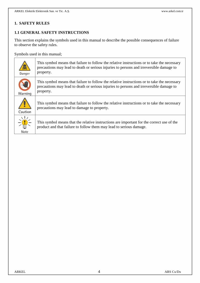
This section explains the symbols used in this manual to describe the possible consequences of failure to observe the safety rules.
Symbols used in this manual;
This symbol means that failure to follow the relative instructions or to take the necessary precautions may lead to death or serious injuries to persons and irreversible damage to property.
This symbol means that failure to follow the relative instructions or to take the necessary precautions may lead to death or serious injuries to persons and irreversible damage to property.
This symbol means that failure to follow the relative instructions or to take the necessary precautions may lead to damage to property.
This symbol means that the relative instructions are important for the correct use of the product and that failure to follow them may lead to serious damage.
ARKEL Elektrik Elektronik San. ve Tic. A.Ş. www.arkel.com.tr
ARKEL 5 ARS Cx/Dx
1.2 SAFETY PRECAUTIONS
ARKEL ARS Cx/Dx traction machines have been designed and manufactured to be used as lifting means for lifts in compliance with the relative standards (EN 81-20/50 and subsequent). Any other use should be considered improper and not authorized by ARKEL. Additionally, these traction machines should never be used to lift persons or objects on lifting systems that are not built in accordance with the relevant regulations and that failed to pass the required tests. These traction machines are not delivered ready for use. They may be used only after being installed on the relevant machines or systems and after ensuring their safety by means of safety grids, barriers, construction features or other devices, depending on the application.
Scheduled and/or special maintenance may be carried out only by qualified and authorized personnel. Maintenance should be performed following the instructions given in this manual or provided in any other supporting documentation supplied by ARKEL.
The personnel should be adequately instructed on the product's installation, assembly and commissioning.
These gearless traction machines are designed to work inside close spaces, such as lift wells, where access is allowed only to qualified and authorized personnel.
The instructions contained in this manual or in any other documentation supplied should be followed at all times in order to avoid injuries or damage to persons and/or to the installation.
These gearless traction machines are not delivered ready for use. They may be used only after being correctly installed and connected to an operating panel.
Before putting the machine into service, make sure that all the conditions for the proper operation of the motor and the brake have been applied.
IT IS EXTREMELY DANGEROUS TO PUT YOUR HANDS near the traction sheave or the lifting ropes.
Some parts of the machine can become very hot during operation (70/80°C). Therefore, it is MANDATORY to ensure that nobody can accidentally touch these parts for maintenance or repairs before a period of time sufficient for the parts to cool down to temperatures suitable for direct contact.
During installation, inspection or maintenance work, DO NOT WEAR necklaces, bracelets or loose items of clothing, such as scarves or wide-sleeved shirts, that might get caught in moving parts.
Repairs may only be carried out by ARKEL personnel.
Unauthorized opening or tampering may result in serious damage to persons and/or to the machine itself.
These gearless traction machines are not designed to be powered directly from the mains. They must be connected to a frequency regulator. Connecting the traction machine directly to the power mains may destroy the machine.
High voltages are present on the connection terminals when the motor is running.
ARKEL Elektrik Elektronik San. ve Tic. A.Ş. www.arkel.com.tr
ARKEL 6 ARS Cx/Dx
1.3 INTENDED USE
The ARKEL ARS Cx/Dx is a state-of-the-art traction machine developed in compliance with the latest technical standards and safety regulations. It may be used only in accordance to the instructions in this manual and with all the relevant safety devices described. ARKEL shall not accept any warranty or liability claims for personal injury or property damage resulting from the following causes:
• Improper use of the traction machine • Improper installation, operation and/or maintenance of the traction machine • Operation of the traction machine without the relative protection and safety devices • Using the product not in accordance with the instructions given in this manual • Unauthorized changes made to the traction machine • Insufficient monitoring of parts subject to wear or failure to perform scheduled maintenance • Emergencies or situations caused by external forces or force majeure
1.4 PACKING AND HANDLING
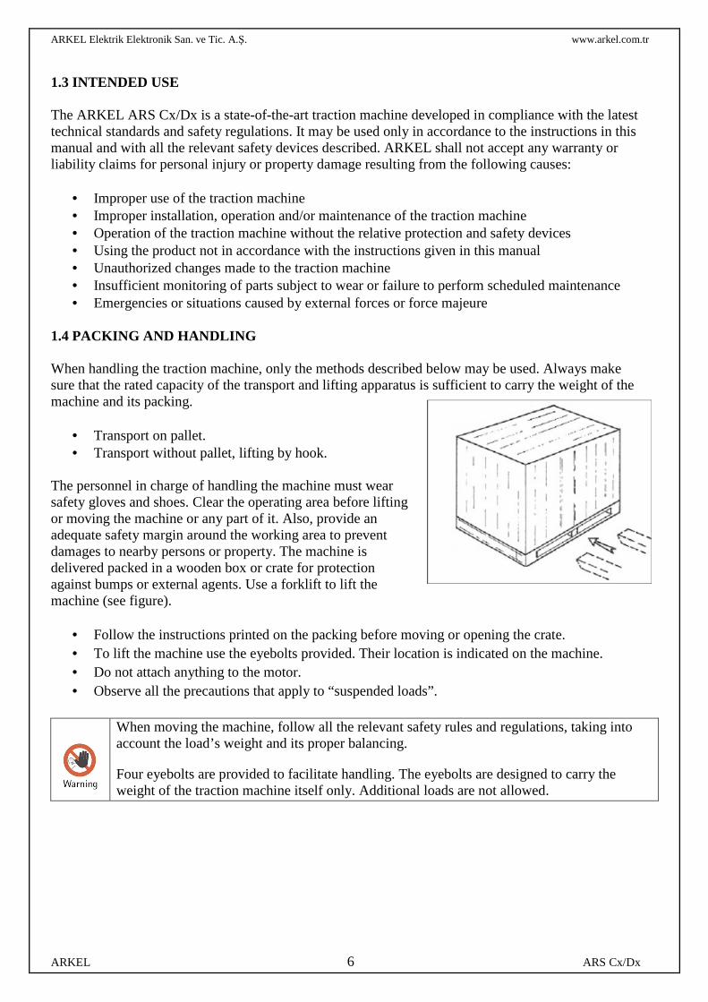
When handling the traction machine, only the methods described below may be used. Always make sure that the rated capacity of the transport and lifting apparatus is sufficient to carry the weight of the machine and its packing.
• Transport on pallet. • Transport without pallet, lifting by hook.
The personnel in charge of handling the machine must wear safety gloves and shoes. Clear the operating area before lifting or moving the machine or any part of it. Also, provide an adequate safety margin around the working area to prevent damages to nearby persons or property. The machine is delivered packed in a wooden box or crate for protection against bumps or external agents. Use a forklift to lift the machine (see figure).
• Follow the instructions printed on the packing before moving or opening the crate. • To lift the machine use the eyebolts provided. Their location is indicated on the machine. • Do not attach anything to the motor. • Observe all the precautions that apply to “suspended loads”.
When moving the machine, follow all the relevant safety rules and regulations, taking into account the load’s weight and its proper balancing.
Four eyebolts are provided to facilitate handling. The eyebolts are designed to carry the weight of the traction machine itself only. Additional loads are not allowed.
ARKEL Elektrik Elektronik San. ve Tic. A.Ş. www.arkel.com.tr
ARKEL 7 ARS Cx/Dx
1.5 STORAGE
2. PRODUCT DESCRIPTION
2.1 MAIN FEATURES The ARKEL ARS Cx/Dx units are gearless traction machines designed for operating lifts (elevators). They can be installed directly inside the lift well and do not require a dedicated machine room. Thanks to their compact dimensions and design concept - based on the projection of the traction sheave - they allow very good size-to-power ratios. These machines are mainly designed to be installed at the top of the lift well, where their small size makes it easy to arrange the various machine parts. These traction machines are equipped with permanent-magnet synchronous motors, allowing excellent performances in terms of:
• Low noise levels • High energy efficiency • High dynamic performance and optimal control of motion profiles • High power-to-weight and torque-to-weight ratios
Being equipped with high-quality shielded bearings with life lubrication and having no parts that work by friction, these machines require very little maintenance. Feedback for the traction machine is provided by a high-quality encoder which, used in combination with a frequency regulator, allows sophisticated motion control and accurate management of the car’s position within the entire speed range. Special attention was given to sizing the electromagnetic section, which was optimized by finite-element analyses to achieve excellent performance in terms of torque and low-speed ripple reduction. Their advanced design and the quality of the construction materials contribute to place ARS Cx/Dx units among the sturdiest and most reliable traction machines.
Store the machine in a closed, dry, dust-free, well-ventilated place free from vibrations.
The storage temperature should be between -20°C and 60°C.
Do not store the traction machine in the open and/or in places exposed to the elements.
Avoid excessive storage periods (recommended: max. 1 year).
After prolonged periods of storage (more than 3 months), make the motor run at low speed (less than 20 rpm) to redistribute the lubricating grease inside the bearings.
Measure the windings’ insulation resistance before starting the machine after a prolonged period of storage. If the resistance has dropped below 1MΩ, the windings will have to be dried or placing the motor in a warm dry atmosphere for a few hours or until the insulation value rises > 1MΩ (Insulation meter voltage: 500V DC).
ARKEL Elektrik Elektronik San. ve Tic. A.Ş. www.arkel.com.tr
ARKEL 8 ARS Cx/Dx
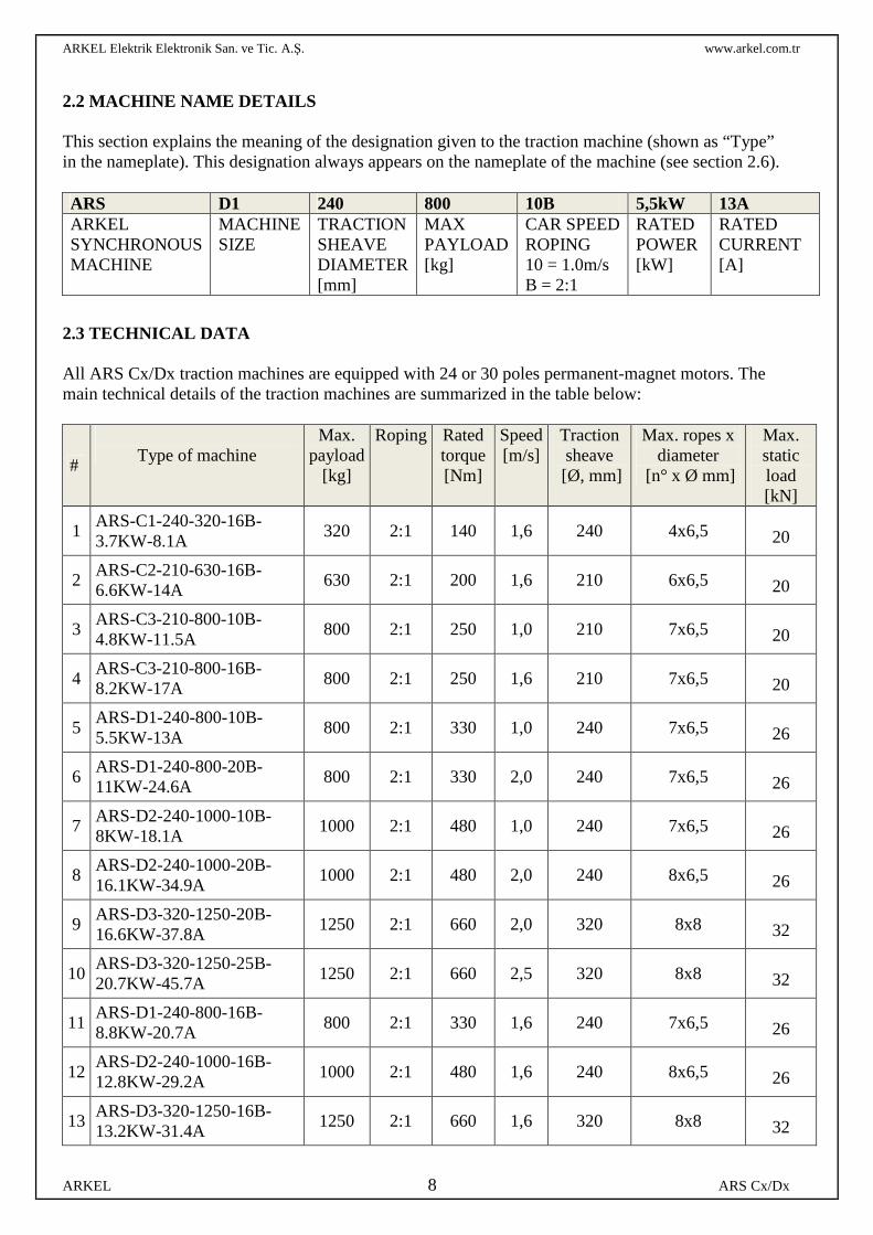
2.2 MACHINE NAME DETAILS This section explains the meaning of the designation given to the traction machine (shown as “Type” in the nameplate). This designation always appears on the nameplate of the machine (see section 2.6).
2.3 TECHNICAL DATA All ARS Cx/Dx traction machines are equipped with 24 or 30 poles permanent-magnet motors. The main technical details of the traction machines are summarized in the table below:
#
Type of machine
Max. payload
[kg]
Roping Rated torque [Nm]
Speed [m/s]
Traction sheave
[Ø, mm]
Max. ropes x diameter
[n° x Ø mm]
Max. static load [kN]
1 ARS-C1-240-320-16B-3.7KW-8.1A
320 2:1 140 1,6 240 4x6,5
20
2 ARS-C2-210-630-16B-6.6KW-14A
630 2:1 200 1,6 210 6x6,5
20
3 ARS-C3-210-800-10B-4.8KW-11.5A
800 2:1 250 1,0 210 7x6,5
20
4 ARS-C3-210-800-16B-8.2KW-17A
800 2:1 250 1,6 210 7x6,5
20
5 ARS-D1-240-800-10B-5.5KW-13A
800 2:1 330 1,0 240 7x6,5
26
6 ARS-D1-240-800-20B-11KW-24.6A
800 2:1 330 2,0 240 7x6,5
26
7 ARS-D2-240-1000-10B-8KW-18.1A
1000 2:1 480 1,0 240 7x6,5
26
8 ARS-D2-240-1000-20B-16.1KW-34.9A
1000 2:1 480 2,0 240 8x6,5
26
9 ARS-D3-320-1250-20B-16.6KW-37.8A
1250 2:1 660 2,0 320 8x8
32
10 ARS-D3-320-1250-25B-20.7KW-45.7A
1250 2:1 660 2,5 320 8x8
32
11 ARS-D1-240-800-16B-8.8KW-20.7A
800 2:1 330 1,6 240 7x6,5
26
12 ARS-D2-240-1000-16B-12.8KW-29.2A
1000 2:1 480 1,6 240 8x6,5
26
13 ARS-D3-320-1250-16B-13.2KW-31.4A
1250 2:1 660 1,6 320 8x8
32
ARS D1 240 800 10B 5,5kW 13A ARKEL SYNCHRONOUS MACHINE
MACHINE SIZE
TRACTION SHEAVE DIAMETER [mm]
MAX PAYLOAD [kg]
CAR SPEED ROPING 10 = 1.0m/s B = 2:1
RATED POWER [kW]
RATED CURRENT [A]
ARKEL Elektrik Elektronik San. ve Tic. A.Ş. www.arkel.com.tr
ARKEL 9 ARS Cx/Dx
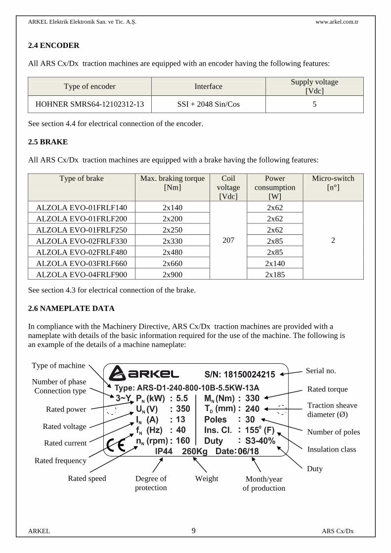
2.4 ENCODER All ARS Cx/Dx traction machines are equipped with an encoder having the following features:
Type of encoder Interface Supply voltage
[Vdc]
HOHNER SMRS64-12102312-13 SSI + 2048 Sin/Cos 5
See section 4.4 for electrical connection of the encoder.
2.5 BRAKE All ARS Cx/Dx traction machines are equipped with a brake having the following features:
Type of brake Max. braking torque
[Nm] Coil
voltage [Vdc]
Power consumption
[W]
Micro-switch [n°]
ALZOLA EVO-01FRLF140 2x140
207
2x62
2
ALZOLA EVO-01FRLF200 2x200 2x62
ALZOLA EVO-01FRLF250 2x250 2x62
ALZOLA EVO-02FRLF330 2x330 2x85
ALZOLA EVO-02FRLF480 2x480 2x85
ALZOLA EVO-03FRLF660 2x660 2x140
ALZOLA EVO-04FRLF900 2x900 2x185
See section 4.3 for electrical connection of the brake. 2.6 NAMEPLATE DATA In compliance with the Machinery Directive, ARS Cx/Dx traction machines are provided with a nameplate with details of the basic information required for the use of the machine. The following is an example of the details of a machine nameplate:
Serial no.
Rated torque
Traction sheave diameter (Ø)
Number of poles
Insulation class
Duty
Number of phase Connection type
Month/year of production
Weight Degree of protection
Rated power
Rated voltage
Rated current
Rated frequency
Rated speed
Type of machine
ARKEL Elektrik Elektronik San. ve Tic. A.Ş. www.arkel.com.tr
ARKEL 10 ARS Cx/Dx
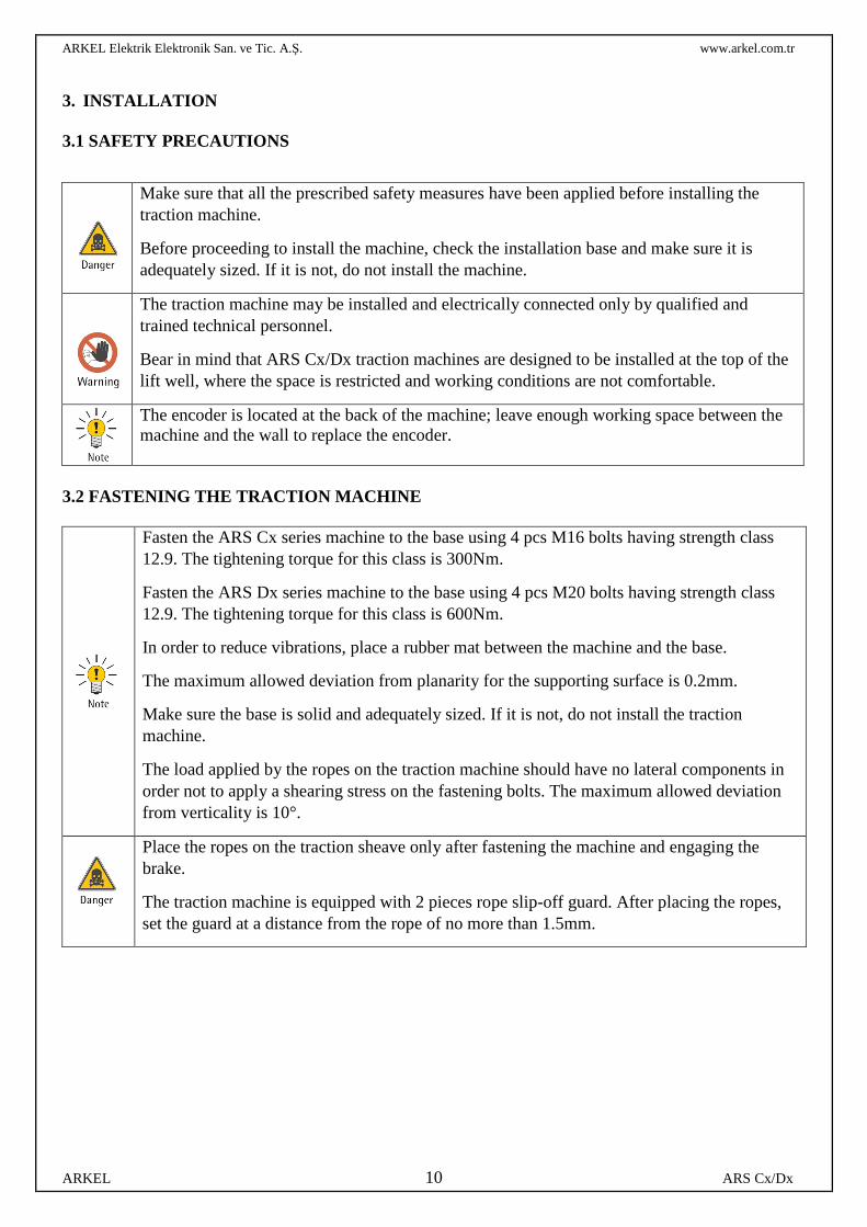
3. INSTALLATION 3.1 SAFETY PRECAUTIONS
3.2 FASTENING THE TRACTION MACHINE
Fasten the ARS Cx series machine to the base using 4 pcs M16 bolts having strength class 12.9. The tightening torque for this class is 300Nm.
Fasten the ARS Dx series machine to the base using 4 pcs M20 bolts having strength class 12.9. The tightening torque for this class is 600Nm.
In order to reduce vibrations, place a rubber mat between the machine and the base.
The maximum allowed deviation from planarity for the supporting surface is 0.2mm.
Make sure the base is solid and adequately sized. If it is not, do not install the traction machine.
The load applied by the ropes on the traction machine should have no lateral components in order not to apply a shearing stress on the fastening bolts. The maximum allowed deviation from verticality is 10°.
Place the ropes on the traction sheave only after fastening the machine and engaging the brake.
The traction machine is equipped with 2 pieces rope slip-off guard. After placing the ropes, set the guard at a distance from the rope of no more than 1.5mm.
Make sure that all the prescribed safety measures have been applied before installing the traction machine.
Before proceeding to install the machine, check the installation base and make sure it is adequately sized. If it is not, do not install the machine.
The traction machine may be installed and electrically connected only by qualified and trained technical personnel.
Bear in mind that ARS Cx/Dx traction machines are designed to be installed at the top of the lift well, where the space is restricted and working conditions are not comfortable.
The encoder is located at the back of the machine; leave enough working space between the machine and the wall to replace the encoder.
ARKEL Elektrik Elektronik San. ve Tic. A.Ş. www.arkel.com.tr
ARKEL 11 ARS Cx/Dx
4. ELECTRICAL CONNECTIONS 4.1 GENERAL
The traction machine may be electrically connected only by qualified personnel.
After connecting the machine and before using it in any way, check the electrical insulation of the terminal box and the operating panel.
Before making any connections, make sure that:
• The connection cables are suitable for their specific application in terms of voltages and currents.
• The cables are correctly installed and not susceptible to twisting, tensile or shearing strains that might affect their characteristics.
• The protective conductor has Protection Class 1 and is properly connected to the earthing system.
• There is no foreign matter or dirt inside the terminal box. • The terminal box is properly sealed and the cable passages prevent the entry of dirt or
dust. • The motor insulation system is adequately sized for connection to frequency
regulators by DC bus having a maximum voltage of 800V.
• The maximum acceptable rate of voltage rise (dU/dt) for the motor is 4kV/us. In case that value is exceeded, suitable reactors should be introduced in the inverter-motor connection.
• The maximum acceptable overvoltage at the machine’s terminals is 1.3kV.
ARKEL Elektrik Elektronik San. ve Tic. A.Ş. www.arkel.com.tr
ARKEL 12 ARS Cx/Dx
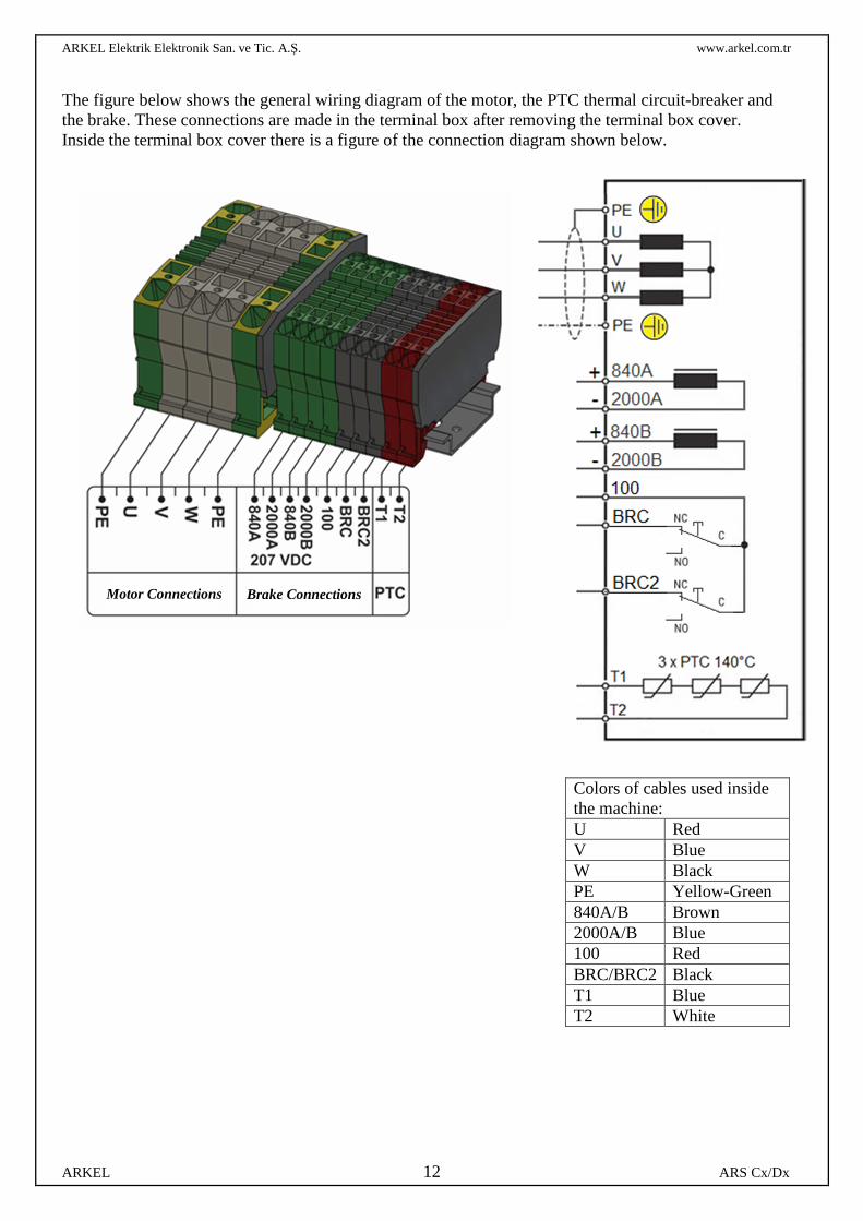
The figure below shows the general wiring diagram of the motor, the PTC thermal circuit-breaker and the brake. These connections are made in the terminal box after removing the terminal box cover. Inside the terminal box cover there is a figure of the connection diagram shown below.
Colors of cables used inside the machine: U Red V Blue W Black PE Yellow-Green 840A/B Brown 2000A/B Blue 100 Red BRC/BRC2 Black T1 Blue T2 White
Motor Connections
Brake Connections
ARKEL Elektrik Elektronik San. ve Tic. A.Ş. www.arkel.com.tr
ARKEL 13 ARS Cx/Dx
4.2 CONNECTING THE MOTOR
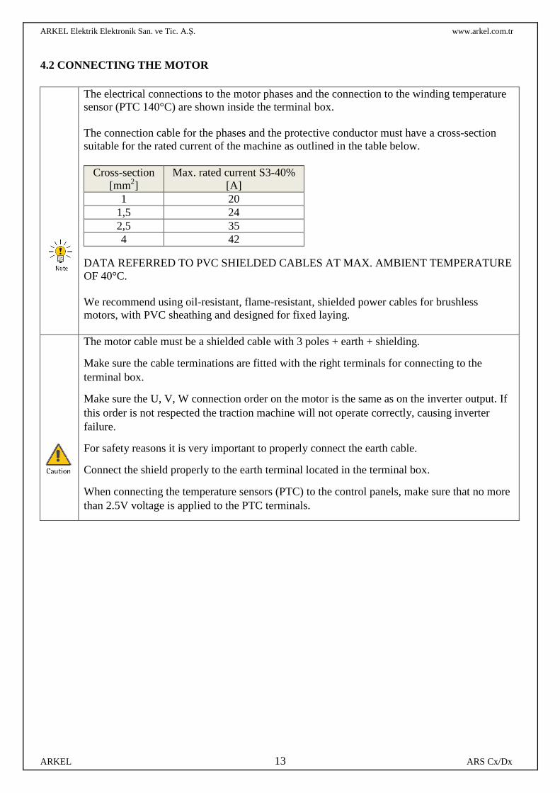
The electrical connections to the motor phases and the connection to the winding temperature sensor (PTC 140°C) are shown inside the terminal box. The connection cable for the phases and the protective conductor must have a cross-section suitable for the rated current of the machine as outlined in the table below.
Cross-section [mm2]
Max. rated current S3-40% [A]
1 20 1,5 24 2,5 35 4 42
DATA REFERRED TO PVC SHIELDED CABLES AT MAX. AMBIENT TEMPERATURE OF 40°C. We recommend using oil-resistant, flame-resistant, shielded power cables for brushless motors, with PVC sheathing and designed for fixed laying.
The motor cable must be a shielded cable with 3 poles + earth + shielding.
Make sure the cable terminations are fitted with the right terminals for connecting to the terminal box.
Make sure the U, V, W connection order on the motor is the same as on the inverter output. If this order is not respected the traction machine will not operate correctly, causing inverter failure.
For safety reasons it is very important to properly connect the earth cable.
Connect the shield properly to the earth terminal located in the terminal box.
When connecting the temperature sensors (PTC) to the control panels, make sure that no more than 2.5V voltage is applied to the PTC terminals.
ARKEL Elektrik Elektronik San. ve Tic. A.Ş. www.arkel.com.tr
ARKEL 14 ARS Cx/Dx
4.3 CONNECTING THE BRAKE
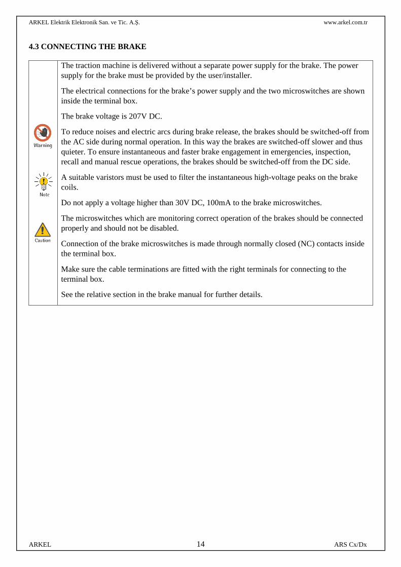
The traction machine is delivered without a separate power supply for the brake. The power supply for the brake must be provided by the user/installer.
The electrical connections for the brake’s power supply and the two microswitches are shown inside the terminal box.
The brake voltage is 207V DC.
To reduce noises and electric arcs during brake release, the brakes should be switched-off from the AC side during normal operation. In this way the brakes are switched-off slower and thus quieter. To ensure instantaneous and faster brake engagement in emergencies, inspection, recall and manual rescue operations, the brakes should be switched-off from the DC side.
A suitable varistors must be used to filter the instantaneous high-voltage peaks on the brake coils.
Do not apply a voltage higher than 30V DC, 100mA to the brake microswitches.
The microswitches which are monitoring correct operation of the brakes should be connected properly and should not be disabled.
Connection of the brake microswitches is made through normally closed (NC) contacts inside the terminal box.
Make sure the cable terminations are fitted with the right terminals for connecting to the terminal box.
See the relative section in the brake manual for further details.
ARKEL Elektrik Elektronik San. ve Tic. A.Ş. www.arkel.com.tr
ARKEL 15 ARS Cx/Dx
4.4 CONNECTING THE ENCODER
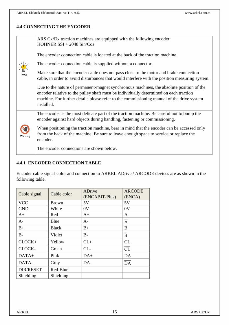
4.4.1 ENCODER CONNECTION TABLE Encoder cable signal-color and connection to ARKEL ADrive / ARCODE devices are as shown in the following table.
ARS Cx/Dx traction machines are equipped with the following encoder: HOHNER SSI + 2048 Sin/Cos The encoder connection cable is located at the back of the traction machine.
The encoder connection cable is supplied without a connector.
Make sure that the encoder cable does not pass close to the motor and brake connection cable, in order to avoid disturbances that would interfere with the position measuring system.
Due to the nature of permanent-magnet synchronous machines, the absolute position of the encoder relative to the pulley shaft must be individually determined on each traction machine. For further details please refer to the commissioning manual of the drive system installed.
The encoder is the most delicate part of the traction machine. Be careful not to bump the encoder against hard objects during handling, fastening or commissioning.
When positioning the traction machine, bear in mind that the encoder can be accessed only from the back of the machine. Be sure to leave enough space to service or replace the encoder.
The encoder connections are shown below.
Cable signal Cable color ADrive (ENCABIT-Plus)
ARCODE (ENCA)
VCC Brown 5V 5V GND White 0V 0V A+ Red A+ A
A- Blue A- A B+ Black B+ B
B- Violet B- B
CLOCK+ Yellow CL+ CL
CLOCK- Green CL- CL DATA+ Pink DA+ DA
DATA- Gray DA- DA
DIR/RESET Red-Blue Shielding Shielding
ARKEL Elektrik Elektronik San. ve Tic. A.Ş. www.arkel.com.tr
ARKEL 16 ARS Cx/Dx
4.4.2 REPLACING THE ENCODER
Replace the encoder only if absolutely necessary due to an encoder fault or malfunction.
Before installing the replacement encoder make sure it is entirely interchangeable with the previous one.
When installing a new encoder, the offset value needs to be adjusted with a specific procedure that depends on the type of inverter (auto-tuning).
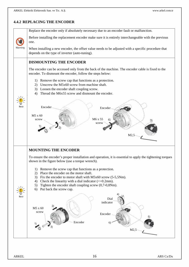
DISMOUNTING THE ENCODER
The encoder can be accessed only from the back of the machine. The encoder cable is fixed to the encoder. To dismount the encoder, follow the steps below:
1) Remove the screw cap that functions as a protection. 2) Unscrew the M5x60 screw from machine shaft. 3) Loosen the encoder shaft coupling screw. 4) Thread the M6x55 screw and dismount the encoder.
MOUNTING THE ENCODER
To ensure the encoder’s proper installation and operation, it is essential to apply the tightening torques shown in the figure below (use a torque wrench).
1) Remove the screw cap that functions as a protection. 2) Place the encoder on the motor shaft. 3) Fix the encoder to motor shaft with M5x60 screw (5-5,5Nm). 4) Check the linearity with a dial indicator (<=0.2mm). 5) Tighten the encoder shaft coupling screw (0,7-0,8Nm). 6) Put back the screw cap.
Encoder
M5 x 60 screw
Encoder
M6 x 55 screw
M2,5
M5 x 60 screw
Encoder
Dial indicator
Encoder
M2,5
6)
ARKEL Elektrik Elektronik San. ve Tic. A.Ş. www.arkel.com.tr
ARKEL 17 ARS Cx/Dx
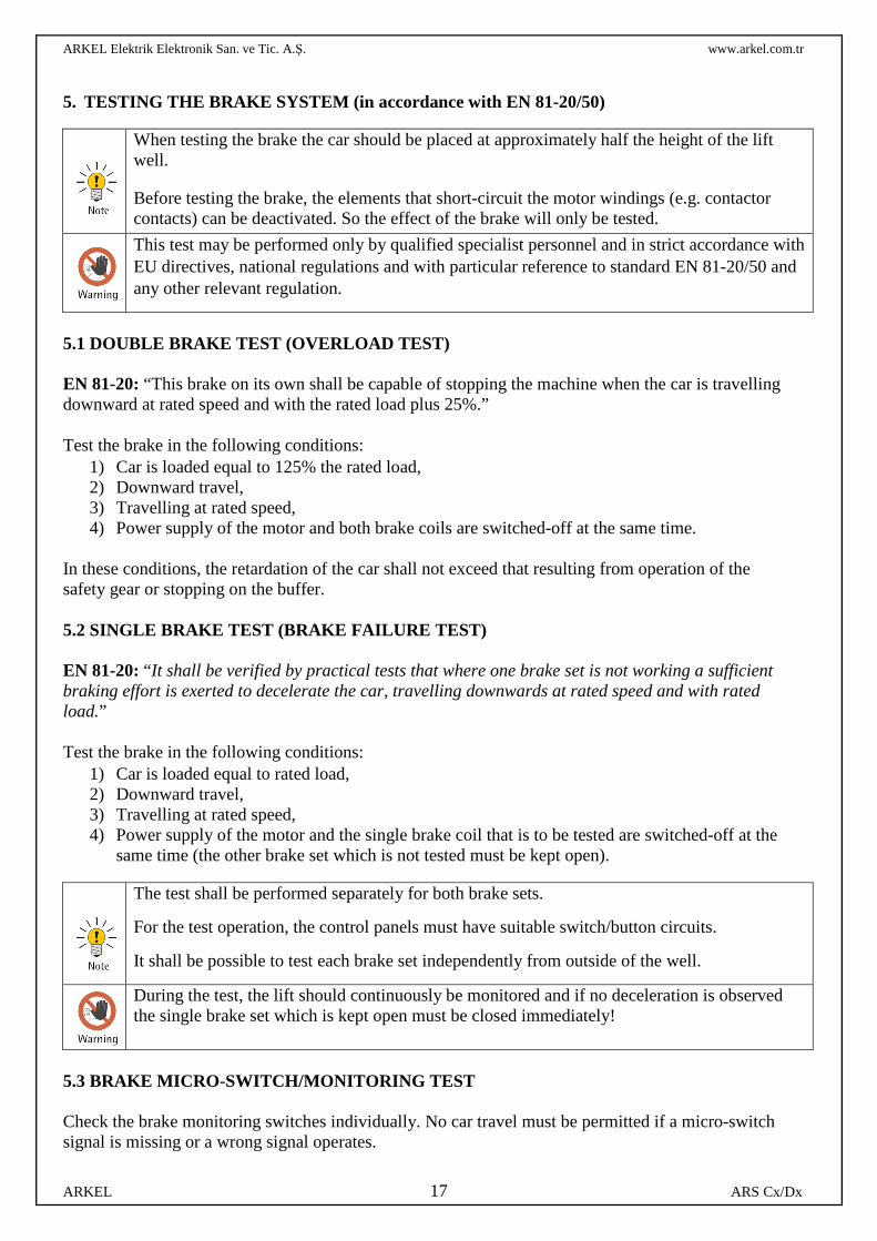
5. TESTING THE BRAKE SYSTEM (in accordance with EN 81-20/50)
5.1 DOUBLE BRAKE TEST (OVERLOAD TEST) EN 81-20: “This brake on its own shall be capable of stopping the machine when the car is travelling downward at rated speed and with the rated load plus 25%.”
Test the brake in the following conditions:
1) Car is loaded equal to 125% the rated load, 2) Downward travel, 3) Travelling at rated speed, 4) Power supply of the motor and both brake coils are switched-off at the same time.
In these conditions, the retardation of the car shall not exceed that resulting from operation of the safety gear or stopping on the buffer.
5.2 SINGLE BRAKE TEST (BRAKE FAILURE TEST) EN 81-20: “It shall be verified by practical tests that where one brake set is not working a sufficient braking effort is exerted to decelerate the car, travelling downwards at rated speed and with rated load.” Test the brake in the following conditions:
1) Car is loaded equal to rated load, 2) Downward travel, 3) Travelling at rated speed, 4) Power supply of the motor and the single brake coil that is to be tested are switched-off at the
same time (the other brake set which is not tested must be kept open).
5.3 BRAKE MICRO-SWITCH/MONITORING TEST Check the brake monitoring switches individually. No car travel must be permitted if a micro-switch signal is missing or a wrong signal operates.
When testing the brake the car should be placed at approximately half the height of the lift well.
Before testing the brake, the elements that short-circuit the motor windings (e.g. contactor contacts) can be deactivated. So the effect of the brake will only be tested.
This test may be performed only by qualified specialist personnel and in strict accordance with EU directives, national regulations and with particular reference to standard EN 81-20/50 and any other relevant regulation.
The test shall be performed separately for both brake sets.
For the test operation, the control panels must have suitable switch/button circuits.
It shall be possible to test each brake set independently from outside of the well.
During the test, the lift should continuously be monitored and if no deceleration is observed the single brake set which is kept open must be closed immediately!
ARKEL Elektrik Elektronik San. ve Tic. A.Ş. www.arkel.com.tr
ARKEL 18 ARS Cx/Dx
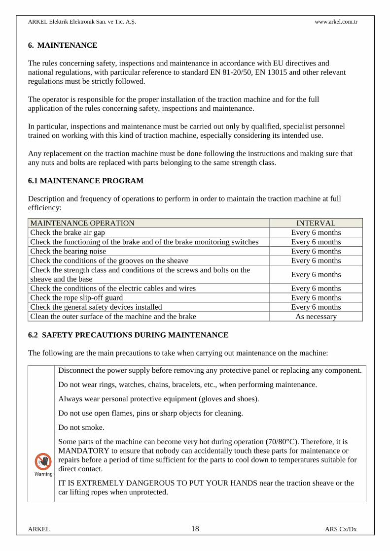
6. MAINTENANCE The rules concerning safety, inspections and maintenance in accordance with EU directives and national regulations, with particular reference to standard EN 81-20/50, EN 13015 and other relevant regulations must be strictly followed. The operator is responsible for the proper installation of the traction machine and for the full application of the rules concerning safety, inspections and maintenance. In particular, inspections and maintenance must be carried out only by qualified, specialist personnel trained on working with this kind of traction machine, especially considering its intended use. Any replacement on the traction machine must be done following the instructions and making sure that any nuts and bolts are replaced with parts belonging to the same strength class. 6.1 MAINTENANCE PROGRAM
Description and frequency of operations to perform in order to maintain the traction machine at full efficiency:
MAINTENANCE OPERATION INTERVAL Check the brake air gap Every 6 months Check the functioning of the brake and of the brake monitoring switches Every 6 months Check the bearing noise Every 6 months Check the conditions of the grooves on the sheave Every 6 months Check the strength class and conditions of the screws and bolts on the sheave and the base
Every 6 months
Check the conditions of the electric cables and wires Every 6 months Check the rope slip-off guard Every 6 months Check the general safety devices installed Every 6 months Clean the outer surface of the machine and the brake As necessary
6.2 SAFETY PRECAUTIONS DURING MAINTENANCE The following are the main precautions to take when carrying out maintenance on the machine:
Disconnect the power supply before removing any protective panel or replacing any component.
Do not wear rings, watches, chains, bracelets, etc., when performing maintenance.
Always wear personal protective equipment (gloves and shoes).
Do not use open flames, pins or sharp objects for cleaning.
Do not smoke.
Some parts of the machine can become very hot during operation (70/80°C). Therefore, it is MANDATORY to ensure that nobody can accidentally touch these parts for maintenance or repairs before a period of time sufficient for the parts to cool down to temperatures suitable for direct contact.
IT IS EXTREMELY DANGEROUS TO PUT YOUR HANDS near the traction sheave or the car lifting ropes when unprotected.
ARKEL Elektrik Elektronik San. ve Tic. A.Ş. www.arkel.com.tr
ARKEL 19 ARS Cx/Dx
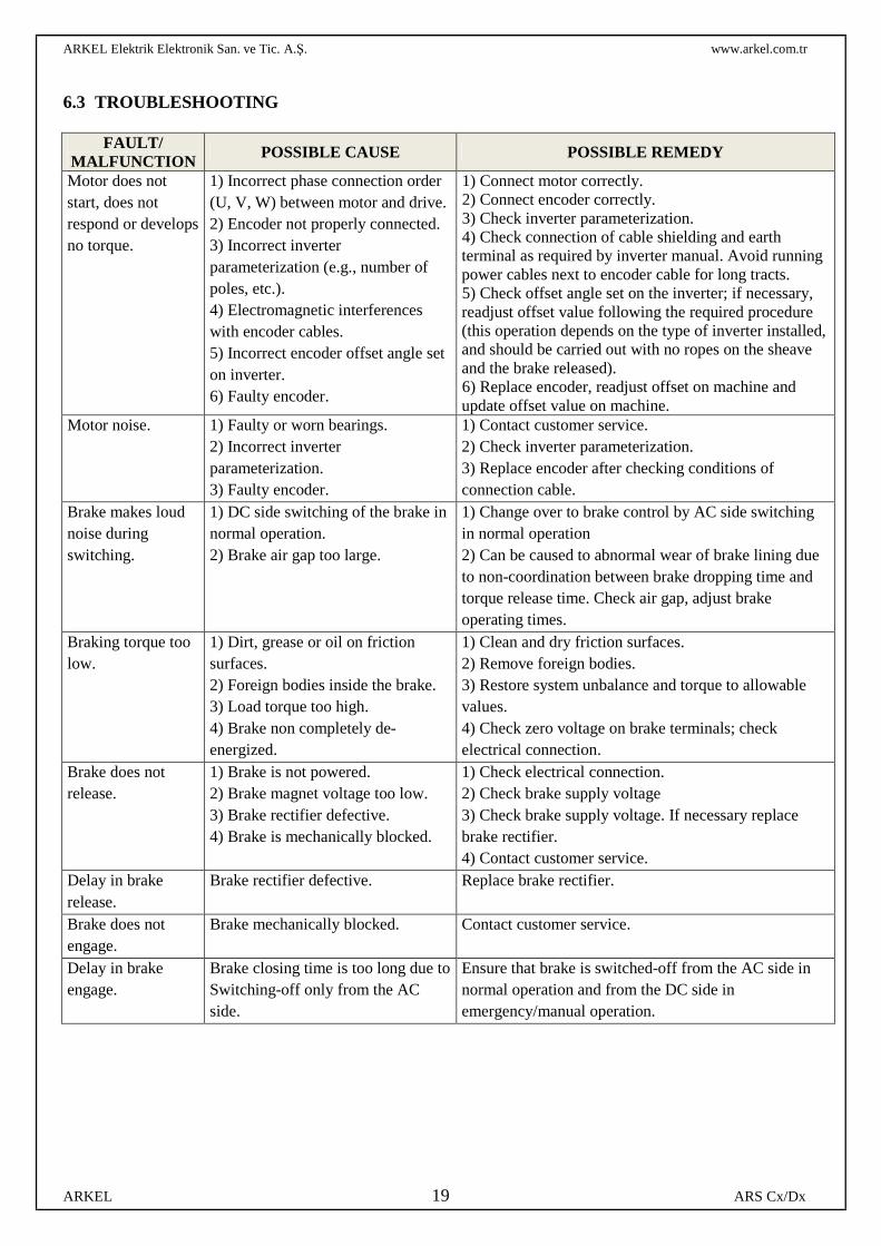
6.3 TROUBLESHOOTING
FAULT/ MALFUNCTION POSSIBLE CAUSE POSSIBLE REMEDY
Motor does not start, does not respond or develops no torque.
1) Incorrect phase connection order (U, V, W) between motor and drive. 2) Encoder not properly connected. 3) Incorrect inverter parameterization (e.g., number of poles, etc.). 4) Electromagnetic interferences with encoder cables. 5) Incorrect encoder offset angle set on inverter. 6) Faulty encoder.
1) Connect motor correctly. 2) Connect encoder correctly. 3) Check inverter parameterization. 4) Check connection of cable shielding and earth terminal as required by inverter manual. Avoid running power cables next to encoder cable for long tracts. 5) Check offset angle set on the inverter; if necessary, readjust offset value following the required procedure (this operation depends on the type of inverter installed, and should be carried out with no ropes on the sheave and the brake released). 6) Replace encoder, readjust offset on machine and update offset value on machine.
Motor noise. 1) Faulty or worn bearings. 2) Incorrect inverter parameterization. 3) Faulty encoder.
1) Contact customer service. 2) Check inverter parameterization. 3) Replace encoder after checking conditions of connection cable.
Brake makes loud noise during switching.
1) DC side switching of the brake in normal operation. 2) Brake air gap too large.
1) Change over to brake control by AC side switching in normal operation 2) Can be caused to abnormal wear of brake lining due to non-coordination between brake dropping time and torque release time. Check air gap, adjust brake operating times.
Braking torque too low.
1) Dirt, grease or oil on friction surfaces. 2) Foreign bodies inside the brake. 3) Load torque too high. 4) Brake non completely de-energized.
1) Clean and dry friction surfaces. 2) Remove foreign bodies. 3) Restore system unbalance and torque to allowable values. 4) Check zero voltage on brake terminals; check electrical connection.
Brake does not release.
1) Brake is not powered. 2) Brake magnet voltage too low. 3) Brake rectifier defective. 4) Brake is mechanically blocked.
1) Check electrical connection. 2) Check brake supply voltage 3) Check brake supply voltage. If necessary replace brake rectifier. 4) Contact customer service.
Delay in brake release.
Brake rectifier defective. Replace brake rectifier.
Brake does not engage.
Brake mechanically blocked. Contact customer service.
Delay in brake engage.
Brake closing time is too long due to Switching-off only from the AC side.
Ensure that brake is switched-off from the AC side in normal operation and from the DC side in emergency/manual operation.